Thermally Tunable, Self-Healing Composites for Soft Robotic Applications

IEEE TRANSACTIONS ON ANTENNAS AND PROPAGATION, VOL. -, NO. -, – – 1
Unit Cell for Frequency-tunableBeamscanning Reflectarrays
Daniel Rodrigo, Student Member, IEEE,, Lluıs Jofre, Fellow, IEEE, Julien Perruisseau-Carrier, Member, IEEE
Abstract—A reflectarray cell able to dynamically control thereflection phase at a variable frequency is presented. Thiscapability enables beam-scanning reflectarrays with frequencyreconfigurability, which is a novel capability with applicationsin frequency-hopping systems, cognitive radio and satellite com-munications. The proposed cell combines switching and variableimpedance loading techniques to maximize the frequency rangeover which a large dynamic phase range can be obtained.Analytical and numerical approaches are used to design andoptimize the reflecting cell, which uses two semiconductor RF-switches and one varactor. An analog phase range above 270o
is achieved over a 50% frequency range, from 1.88 GHz to3.07 GHz, with flat losses of 0.8 dB. For an analog phase rangeof 180o the cell achieves a 1:2 frequency reconfiguration range.It is also verified that the cell preserves good performance,and in particular low crosspolarization, under oblique incidenceas well. A fully operational cell was fabricated and measured,demonstrating good agreement with simulation results.
Index Terms—beam-scanning, beam steering, cognitive radio,microstrip arrays, reconfigurable antennas, reflectarrays
I. INTRODUCTION
Electronically beam-scanning reflectarrays are aperture an-tennas composed of a feed illuminating cells whose reflectionphase can be independently controlled. By individually ad-justing the configuration of each cell, the antenna beam shapeand the direction of radiation can be dynamically adjusted [1],[2]. Beam-scanning reflectarrays combine the simplicity andlow-losses of reflector antennas with the planarity and patternversatility of phased arrays. On the other hand, the bandwidthof reflectarray antennas is significantly narrower than that ofreflectors.
Most of the techniques used in static reflectarrays can beadapted to provide a dynamic radiation pattern by includingreconfiguration elements such as semiconductor switches [3],
Manuscript received – –, 20–; revised – –, 20–.This work has been supported by the EU COST action IC1102 through
the Short-Term Scientific Mission (STSM) program, by the Spanish CICYTunder projects TEC2010-20841-C04-02 and Consolider CSD2008-68 and bythe Hasler Foundation, Project 11149. The work of D. Rodrigo was supportedby the Spanish Ministry of Education through FPU fellowship program. Thework of J. Perruisseau-Carrier was supported by the Swiss National ScienceFoundation (SNSF) under grant n133583.
D. Rodrigo and L. Jofre are with the Department of Signal Theory andCommunications, Technical University of Catalonia, 08034 Barcelona, Spain(e-mail: rodrigo,[email protected])
J. Perruisseau-Carrier is with the group for Adaptive MicroNano WaveSystems, LEMA/Nanolab, Ecole Polytechnique Federale de Lausanne (EPFL),Lausanne CH-1015, Switzerland (e-mail: [email protected]).
Color versions of one or more of the figures in this paper are availableonline at http://ieeexplore.ieee.org.
Digital Object Identifier –.—-/TAP.—-.——-
varactor diodes [4], [5], micro-electromechanical systems (RF-MEMS) [6]–[8], photoinduced plasma [9] and tunable sub-strates such as liquid crystals [10], [11], ferroelectric materials[12], [13] and graphene [14]. Using such technologies thereflectarray cells are dynamically controlled by implementingtunable delay lines [3], [6], [12], [15]–[17] or resonant cellswith a tunable resonance frequency. In this second approach,the cell resonance is shifted by affecting the electrical dimen-sions of the resonator using switches or reactive loading [4],[8], [18] and materials with tunable properties [10], [14].
Currently, significant efforts are devoted to provide ad-ditional capabilities to beam-scanning reflectarrays. Reflec-tarrays with dual band capabilities and independent beams-scanning at each band have been presented [19]. Reconfig-urable cells have been also demonstrated for beam-scanningreflectarrays with flexible polarization and dual-polarizationwith independent scanning for each polarization [20], [21].A third example is presented in [22], where electronic beam-scanning and amplification capabilities [23] are simultaneouslyprovided.
In this paper we present the first implementation of areflectarray cell combining reflection phase tunability withfrequency reconfigurability. Since the main limitation of beam-scanning reflectarrays is their narrow bandwidth [24], it wouldbe extremely useful to provide them with frequency reconfig-urability. Although it is obvious that frequency reconfigurationcan not increase the instantaneous bandwidth of the reflec-tarray, it will be useful for narrow to moderate bandwidthapplications whose operating band changes over a much widerfrequency range. For instance, such a reflectarray would findapplications in frequency-hopping radar and communications,and would constitute an effective steerable frequency-tunableantenna for remote sensing and imaging. In particular, fre-quency reconfigurability would enable electronically-steerablereflectarrays to operate in cognitive radio systems. Finally,the proposed concept could be a interesting solution for Ka-band satellite communications, where a single frequency-tunable reflectarray can cover sequentially the reception andtransmission bands, and provide simultaneously the beam-scanning capabilities required at least at the earth-terminal fortracking and switching between different satellites.
In this context, the main goal of this paper is to demonstratea reconfigurable cell able to dynamically control the reflectionphase at a variable frequency, covering a frequency rangesignificantly larger than that covered by conventional beam-scanning reflectarrays, while keeping a low-complexity in thecell structure.
The rest of the paper is organized as follows. The conceptual
2 IEEE TRANSACTIONS ON ANTENNAS AND PROPAGATION, VOL. -, NO. -, – –
L1
L2
L3
Switch #1
Switch #2
Varactor
X
Y
Groundplane
Y
Z
Top view Side view
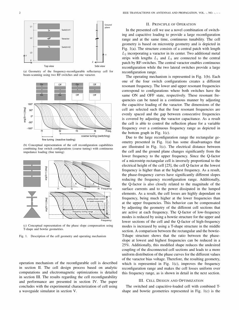
(a) Geometry of the frequency-reconfigurable reflectarray cell forbeam-scanning using two RF-switches and one varactor.
180º
90º
0º
-180º
-90º
Freq.
arg(
SY
Y) [
deg]
f1 f2 f3 f4
fine tuning (reactive loading)coarse tuning (switching)
On
On
Off
On
On
Off
Off
Off
(b) Conceptual representation of the cell reconfiguration capabilitiescombining four switch configurations (coarse tuning) with continuousimpedance loading (fine tuning)
arg(
SY
Y) [
deg]
arg(
SY
Y) [
deg]
Frequency
Frequency
f1 f2 f3 f4
analog phase controlfor beam-scanning
frequency tuning range
(c) Conceptual representation of the phase slope compensation usingT-shape and bowtie geometries.
Fig. 1. Description of the cell geometry and operating mechanism
operation mechanism of the reconfigurable cell is describedin section II. The cell design process based on analyticcomputations and electromagnetic optimizations is detailedin section III. The results regarding the cell reconfigurabilityand performance are presented in section IV. The paperconcludes with the experimental characterization of cell usinga waveguide simulator in section V.
II. PRINCIPLE OF OPERATION
In the presented cell we use a novel combination of switch-ing and capacitive loading to provide a large reconfigurationrange and at the same time, continuous tunability. The cellgeometry is based on microstrip geometry and is depicted inFig. 1(a). The structure consists of a central patch with lengthL2 incorporating a varactor in its center. Two additional metalstrips with lengths L1 and L3 are connected to the centralpatch by RF-switches. The central varactor enables continuousreconfiguration while the two lateral switches provide a largereconfiguration range.
The operating mechanism is represented in Fig. 1(b). Eachone of the four switch configurations creates a differentresonant frequency. The lower and upper resonant frequenciescorrespond to configurations where both switches have thesame ON and OFF state, respectively. These resonant fre-quencies can be tuned in a continuous manner by adjustingthe capacitive loading of the varactor. The dimensions of thecell are selected such that the four resonant frequencies areevenly spaced and the gap between consecutive frequenciesis covered by adjusting the varactor capacitance. As a resultthe cell is able to control the reflection phase for a variablefrequency over a continuous frequency range as depicted inthe bottom graph in Fig. 1(c).
Due to the large reconfiguration range the rectangular ge-ometry presented in Fig. 1(a) has some disadvantages thatare illustrated in Fig. 1(c). The electrical distance betweenthe cell and the ground plane changes significantly from thelower frequency to the upper frequency. Since the Q-factorof a microstrip rectangular cell is inversely proportional to theelectrical height of the cell [25], the cell Q-factor at the lowestfrequency is higher than at the highest frequency. As a result,the phase-frequency curves have significantly different slopesreducing the frequency reconfiguration range. Additionally,the Q-factor is also closely related to the magnitude of thesurface currents and to the power dissipated in the lumpedelements. As a result, the cell losses are highly dependant onfrequency, being much higher at the lower frequencies thanat the upper frequencies. This behavior can be compensatedby adjusting the geometry of the different cell sections thatare active at each frequency. The Q-factor of low-frequencymodes is reduced by using a bowtie structure for the upper andlower sections of the cell and the Q-factor of high-frequencymodes is increased by using a T-shape structure in the middlesection. A comparison between the rectangular and the bowtie-Tshape structure shows that the ratio between the phase-slope at lowest and highest frequencies can be reduced in a25%. Additionally, this modified shape reduces the undesiredcoupling of the disconnected cell sections and leads to a moreuniform distribution of the phase curves for the different valuesof the varactor bias voltage. Therefore, the resulting geometry,which is represented in Fig. 1(c), improves the frequencyreconfiguration range and makes the cell losses uniform overthis frequency range, as is shown in detail in the next section.
III. CELL DESIGN AND OPTIMIZATION
The switched and capacitive-loaded cell with combined T-shape and bowtie geometries represented in Fig. 1(c) is the
RODRIGO et al.: UNIT CELL FOR FREQUENCY-TUNABLE BEAMSCANNING REFLECTARRAYS 3
basic structure used to provide a large phase range over avariable frequency. In this section we further describe theprocedure employed to optimize the cell, starting from aninitial design based on the theoretical operating principle ofthe cell followed by a particular optimization process basedon co-simulation.
The reflectarray cell operation is basically determined by thelength of its different sections. The cell resonance frequencyis inversely proportional to the patch length, which is equalto L2, L1 + L2, L2 + L3 or L1 + L2 + L3 depending on thestatus of the switches. Therefore, these lengths determine thefour main resonance frequencies f1, f2, f3, f4 based on thefollowing system of linear equations
1 1 1
0 1 1
1 1 0
0 1 0
L1
L2
L3
= K
λ1
λ2
λ3
λ4
(1)
where λ1, . . . , λ4 are the free-space wavelengths associatedto the four resonance frequencies f1, . . . , f4 and K is theproportionality constant. The previous expression is an overde-termined system and has solution if and only if
λ1 + λ4 = λ2 + λ3 (2)
As a starting design point we choose equally spaced wave-lengths, which verify the previous equation and lead to almostequally-spaced resonance frequencies
λ1 − λ2 = λ2 − λ3 = λ3 − λ4 = ∆λ (3)
Solving the system of equations (1) for the previous conditionresults in the following lengths
L2 = Kλ4 (4)L1 = 1
2L3 = K∆λ (5)
The length of the middle section (L2) determines the upperfrequency, the length of the top and bottom sections (L1, L3)determine the spacing between frequencies and as long as thereis a factor 2 between L1 and L3 the four resonance frequenciesare almost equally spaced. The accuracy of equation (1) isapproximately 5% and has been computed by comparing withsimulations.
Having determined the basic relations between the celldimensions and the resonant frequencies, the next step isthe computational optimization of the structure to obtain alarge and continuous reconfiguration range. As can be seen inFig. 1(c) this means that the spacing between the four resonantfrequencies should be the same as the maximum frequencyshift produced by the varactor loading. After the optimizationthe cell achieves analog phase control for a variable frequencychanging in a continuous frequency range as represented inthe bottom of Fig. 1(c). Notice that as a result of the antennadesign the varactor position is close to the center of the cellactive region regardless of the switch configuration. As aresult, the frequency shifts produced by the varactor are similarfor all the switch configurations.
The RF-switches and varactor are the MPN7310 andMGV125-26 from Aeroflex Metelics. The length of the gap
TABLE ICIRCUIT MODEL OF THE LUMPED COMPONENTS
RF-switch VaractorON OFF -2V ... -10V ... -21V
Rs[Ω] 2.1 30 2.0 ... 2.2 ... 2.6Ls[nH] 0.59 0.12 0.68 ... 0.64 ... 0.61Cs[pF] – 0.15 3.3 ... 0.80 ... 0.41
between cell sections has been determined by the physicallength of the diodes and has only minor effects over thecell properties. The circuit model of these semiconductorcomponents has been experimentally extracted by perform-ing calibrated measurements. The resulting model has beencorrected in order to be used together with a electromagneticsimulation software by following the method presented in [26].The circuit model correction is an important step to ensurea good agreement between simulation and measurements inreconfigurable antennas. The series RLC circuit models ofthe switch and varactor are detailed in Table I. The switch isforward biased with 20 mA and the varactor is reversed biasedwith voltages from −2 V to −21 V providing a 1:8 capacitancerange from 3.3 pF to 0.41 pF..
The electromagnetic simulations are carried out using AnsysHFSS in combination with the port-loading technique, whichconsists in replacing all lumped components in the 3D modelby lumped ports and extracting the S-parameter matrix usingfull-wave simulations [27]. Then, the cell reflection coefficientis computed for each configuration in a time-efficient post-processing step by loading the S-parameter matrix with theimpedance of each lumped component. This technique is veryaccurate and extremely fast, which is especially useful at theoptimization stage [27]. The optimization process has beencarried out for y-polarization and normal incidence.
A rough optimization has been first performed for the rect-angular design (Fig. 1(c) top) followed by a fine optimizationof the combined bowtie and T-shape structure (Fig. 1(c) bot-tom), leading to the optimized cell presented in Fig. 2 wherethe substrate consists of a 1.5mm-thick RO4003 over Rohacellfoam. During the optimization, first the air gap between thestructure and the ground plane (Ha) has been adjusted tobalance the phase range and the cell losses. Secondly, thelengths L1, L2p, L3 have been fine tuned to maximize thefrequency reconfiguration range. This optimization has beencarried out taking into account the influence of each lengthover the four main resonance frequencies specified in equation(1) without requiring automated optimization tools.
IV. RESULTS
This section presents the performance analysis of the opti-mized cell regarding frequency reconfigurability, phase rangebut also in terms of losses and crosspolarization levels.
The phase of the cell reflection coefficient for y-polarizationis represented in Fig. 3 for each configuration. The foursets of phase curves correspond to the four different switchconfigurations in the order specified in Fig. 1(b). The differentcurves in each set correspond to different capacitance values

4 IEEE TRANSACTIONS ON ANTENNAS AND PROPAGATION, VOL. -, NO. -, – –
L1
L2pL2t
L2pL2t
L3
W3
W1
Lcell
Wcell
W2p
W2t
Wg
Wg
Hs Ha
Lg
X
Y Y
Z
Lg
Lg
Fig. 2. Optimized cell geometry (L1=6.7, L2t=1.1, L2p=4.6, L3=13.3,Lg=1.0, Lcell=43.2, W1=13.3, W2t=11.4, W2p=1.1, W3=26.6, Wg=1.7,Wcell=43.2, Hs=1.5, Ha=8.2, units in mm)
1.75 2.0 2.25 2.5 2.75 3.0 3.25 3.5
180º
135º
90º
45º
0º
-180º
-135º
-90º
-45º
Frequency [GHz]
arg
( SY
Y )
[deg
]
XY Z
Frequency range for 270º phase range
Fig. 3. Simulated phase of the cell reflection coefficient under normalincidence. Each set of curves corresponds to a switch configuration and thedifferent curves in each set correspond to difference values of the varactor.
of the varactor. These curves are obtained when the varactor isbiased by voltages from −2 V to −21 V in constant steps. Thehigher frequency curves in each set correspond to the lowercapacitance values of the varactor which in turn correspond tohigher bias voltages.
The phase curves in Fig. 3 show that a continuous phaserange of 270o can be achieved for any frequency between1.88 GHz and 3.07 GHz. Therefore the reconfigurable cell isable to adjust its reflection phase over 270o and simultaneouslytune its operating frequency over a 50% range. This frequencyrange is almost 20 times larger than the phase bandwidthof beam-scanning reflectarray cells [24], but of course fre-quency reconfigurability does not increase the instantaneousbandwidth of the cell.
There is a clear trade-off between the analog phase rangeand the frequency reconfiguration range. In this case the cellwas optimized for a large phase range of 270o, leading to a rmsphase error of only 6.5o, which is the same rms phase error ob-tained by a 4-bit discrete cell. The expected loss in directivityfor this phase error is approximately 0.1 dB [28], a value thatis corroborated by other publications presenting reflectarraycells with limited phase range [14]. A higher frequencyreconfiguration range can be obtained by reducing the analogphase range at the expense of a higher phase-quantization loss.For instance, a phase range of 180o could be used instead,leading to a phase-quantization loss of approximately 0.8 dB
1.75 2.0 2.25 2.5 2.75 3.0 3.25 3.5
180º
135º
90º
45º
0º
-180º
-135º
-90º
-45º
Frequency [GHz]
arg
( SY
Y )
[de
g]
XY
Z
Fig. 4. Simulated phase of the cell reflection coefficient under obliqueincidence (θi = 30o, φi = 45o).
1.75 2.0 2.25 2.5 2.75 3.0 3.25 3.5
0
-2
-4
-6
Frequency [GHz]
| SY
Y |
[dB
]
-1
-3
-5X
Y Z
Fig. 5. Simulated magnitude of the cell reflection coefficient under normalincidence.
and achieving frequency reconfiguration from 1.75 GHz to3.6 GHz, which corresponds to a 1:2 reconfiguration range.
The performance of the reflectarray cell, which has beenoptimized under normal incidence conditions, was also com-puted for a large oblique incidence, namely, θ=30o, φ=45o.The cell was simulated using a Floquet port and periodicboundary conditions (PBC). Subsequently a change of basiswas applied to transform the simulated 2x2 S-matrix from aTE-TM to a X-Y basis [29]. The phase curves of the cellunder oblique incidence are represented in Fig. 4. They arevery similar to those under normal incidence conditions andthe phase and frequency reconfiguration range is preserved.Different azimuthal angles (φ = 0o, 90o) have been analyzedobtaining very similar results.
The cell losses have been also simulated under normal andoblique incidence conditions and the results are representedin Fig. 5 and Fig. 6 respectively. Under normal incidence,the cell loss vary between 0 dB and 3 − 4 dB dependingon the reflection phase. As expected, losses are lower forphases close to ±180o than around 0o, where the cell operatesat its resonance frequency. On the other hand, as a resultof the bowtie T-shape design, the losses are similar for allthe different switch configurations. The results under obliqueincidence conditions show a very similar response as undernormal incidence but slightly higher losses are produced.
Obviously, the actual gain loss of a reflectarray due to the

RODRIGO et al.: UNIT CELL FOR FREQUENCY-TUNABLE BEAMSCANNING REFLECTARRAYS 5
1.75 2.0 2.25 2.5 2.75 3.0 3.25 3.5
0
-2
-4
-6
Frequency [GHz]
-1
-3
-5 XY
Z
| SY
Y |
[dB
]
Fig. 6. Simulated magnitude of the cell reflection coefficient under obliqueincidence (θi = 30o, φi = 45o).
1.75 2.0 2.25 2.5 2.75 3.0 3.25 3.5
0
-2
-4
-6
Frequency [GHz]
| SY
Y |
[dB
]
-1
-3
-5X
YZ
Fig. 7. Average magnitude of the cell reflection coefficient for a equiprobablephase distribution under normal and oblique incidence.
cell losses is not the peak value but an average value of the celllosses for the different reflection phases. To provide a realisticestimation of this gain loss an average value has been com-puted assuming a equiprobable phase distribution and has beenrepresented in Fig. 7. The resulting gain loss is 0.8±0.1 dB fornormal incidence and 1.0±0.1 dB for oblique incidence, whichcorrespond to radiation efficiencies of approximately 80%. Theorigin of the losses in the cell was investigated, and they wereshown to be almost entirely related to power dissipation inthe PIN and varactor diodes. This result was expected andis similar to previous diode-based reconfigurable reflectarraycells without frequency-reconfiguration capabilities [3], [4]. Asexpected, the losses are higher for oblique incidence becausethe orthogonal component of the wavevector is lower than fornormal incidence. This produces exactly the same effect as alower distance between structure and the ground plane, that is ahigher Q-factor and higher losses. It can be observed also thatthe loss levels are very flat over the whole frequency range.Therefore, the presented cell not only provides a tunable phaseof 270o over the 50% frequency range, but also provides analmost constant loss level.
Finally, the crosspolarization level of the cell is analyzed.Due to the cell symmetry a zero crosspolar is produced fornormal incidence and for oblique incidence with φ-anglesequal to 0o and 90o. The maximum crosspolar level is pro-
−40
−35
−30
−25
−20
−15
−10
−5
0
| SX
Y |
[dB
]
1.75 2.0 2.25 2.5 2.75 3.0 3.25 3.5Frequency [GHz]
XY
Z
Fig. 8. Simulated crosspolarization of the cell for oblique incidenceconditions (θi = 30o, φi = 45o).
duced for φ = ±45o incidence angles and is presented inFig. 8. The crosspolar values are very low, especially atlower frequencies, and are below −20 dB over the wholefrequency reconfiguration range. As is well-known, the overallreflectarray system cross-polarization will be lower than thethe maximum, and even average, cross-polarization at the celllevel [29].
V. EXPERIMENTAL VALIDATION
To validate simulation results the reconfigurable cell hasbeen experimentally characterized using a waveguide simu-lator (WGS). The WGS measurement is a well-known tech-nique that consist in locating a low number of cells inside arectangular waveguide to reproduce the periodicity conditionsof an infinite reflectarray under local periodicity assumption[30]. The WGS technique does not allow to reproduce exactlythe curves presented in the previous section because the mea-surement corresponds to a different incidence angle for eachfrequency. However, the WGS obviously allows to rigorouslyvalidate simulations by comparing them to simulation in thesame setup.
To perform the waveguide measurements a two-cell pro-totype has been fabricated with the dimensions indicatedin Fig. 2. The dimensions of the two-cell structure are43.2×86.4 mm2 which are the same as those of the standardrectangular waveguide WR-340 used for the measurement.The cut-off frequencies of the first and second modes of thiswaveguide are 1.74 GHz and 3.49 GHz respectively, thereforethe WR-340 waveguide simulator allows to measure the wholefrequency reconfiguration range of the cell.
A picture of the fabricated prototype is presented in Fig. 9.To minimize the perturbations produced by the biasing linesthey have been oriented orthogonally to the field polarizationand lumped inductors operating as RF-chokes have beenintroduced. Some trenches have been milled on the groundplane to allocate the biasing wires and enable a perfectcontact between the waveguide and the ground plane. Thebiasing scheme uses three serially-connected independently-controlled voltage sources controlling simultaneously the tworeflecting cells and is represented in Fig. 10. The controlvoltage corresponding to the switches (Vsw1,Vsw2) and thebiasing resistances (Rsw1,Rsw2) are designed so the forwardcurrent of each ON-state switch is 20mA. The voltage Vvar

6 IEEE TRANSACTIONS ON ANTENNAS AND PROPAGATION, VOL. -, NO. -, – –
Fig. 9. Picture of the two-cell prototype used in the rectangular waveguidesimulator.
Vsw1
Vvcap
Vsw2
Rsw1
Rsw2
Inductors
Switch #1
Vcap
Switch #2
Fig. 10. Conceptual representation of the biasing approach controllingsimultaneously the two cells by using three serially-connected voltage sources.
feeds directly the varactor with a reverse-voltage changingfrom is changed from 2V to 21V.
The simulated and measured phases of the reflection coeffi-cient are shown in Fig. 11, demonstrating excellent agreement.This is due to the accuracy of the simulation approach and theaccurate circuit model extraction of the lumped componentsexplained in section III. Since the bias lines were not includedin the model, it can be concluded that they have a negligibleeffect on the phase response. As aforementioned, the cellresponse in the WGS is different from the normal incidenceresponse presented in Fig. 3 due to the oblique incidenceit mimics. In fact, and as reported in the top of the graphsin Fig. 11, very large incidence angles are simulated by theWGS towards low frequencies. The phase curves have beenintentionally shaded for these lower frequencies where theWGS operates near the cut-off frequency simulating a grazingincidence.
The simulated and measured magnitude of the reflectioncoefficient are represented in Fig. 12. An excellent agreementbetween measurements and simulations is again observed. Thecell losses near the waveguide cut-off frequency are muchhigher than for simulated normal incidence case, which is aresult of the grazing incidence simulated at these frequencies.However such extreme incidence angle (θ > 50o) are not usedin actual reflectarrays.
The measured results using the waveguide simulator clearlydemonstrate the accuracy of the simulations presented in theprevious section and as a consequence it constitutes an experi-mental validation of the cell performance regarding frequency
1.75 2.0 2.25 2.5 2.75 3.0 3.25 3.5
83.0º 60.3º 50.5º 44.0º 39.2º 35.4º 32.3º 29.8º180º
135º
90º
45º
0º
-180º
-135º
-90º
-45º
Frequency [GHz]
arg
( SY
Y )
[de
g]
incid. θi
(a) Simulation
incid. θi
1.75 2.0 2.25 2.5 2.75 3.0 3.25 3.5
83.0º 60.3º 50.5º 44.0º 39.2º 35.4º 32.3º 29.8º180º
135º
90º
45º
0º
-180º
-135º
-90º
-45º
Frequency [GHz]
arg
( SY
Y )
[de
g]
(b) Measurement
Fig. 11. Phase of the cell reflection coefficient in the rectangular waveguidesimulator.
reconfigurability, phase range and loss level.
VI. CONCLUSIONS
Reflecting cells able to dynamically control the reflec-tion phase at a variable frequency enable beam-scanningreflectarrays with frequency reconfiguration capability. Thisnovel capability makes reflectarrays clear candidates for futurefrequency-hopping and cognitive radio systems.
In order to achieve continuous reconfiguration over a largefrequency range it is necessary to use cells that combinemultiple reconfiguration techniques. Variable-length switchingand impedance loading are two compatible reconfigurationtechniques which achieve a 50% frequency range. The largefrequency range makes it necessary to equalize the cell Q-factor to obtain a uniform phase slope and constant lossesover the whole frequency range. This can be achieved byadjusting the shape of the different cell sections using T-shapeand bowtie geometries.
The result after the combination of different reconfigurationtechniques and the equalization of the Q-factor is a low-complexity microstrip cell with an analog phase range higherthan 270o and a continuous frequency reconfiguration rangeof 50%. These capabilities allow beam-scanning reflectarrayto operate over much large frequency ranges than those

RODRIGO et al.: UNIT CELL FOR FREQUENCY-TUNABLE BEAMSCANNING REFLECTARRAYS 7
1.75 2.0 2.25 2.5 2.75 3.0 3.25 3.5
83.0º 60.3º 50.5º 44.0º 39.2º 35.4º 32.3º 29.8º0
-2
-4
-6
-8
-14
-12
-10
Frequency [GHz]
| SY
Y |
[dB
]incid. θi
(a) Simulation
1.75 2.0 2.25 2.5 2.75 3.0 3.25
83.0º 60.3º 50.5º 44.0º 39.2º 35.4º 32.3º 29.8º0
-2
-4
-6
-8
-14
-12
-10
Frequency [GHz]
| SY
Y |
[dB
]
incid. θi
3.5
(b) Measurement
Fig. 12. Magnitude of the cell reflection coefficient in the rectangularwaveguide simulator.
covered by current single-frequency and dual-frequency beam-scanning reflectarrays.
ACKNOWLEDGEMENTS
The authors thank Mohsen Yousefbeiki for performing thecircuit model extraction of lumped components. Aeroflex-Metelics is acknowledged for providing the RF-diodes.
REFERENCES
[1] D. Berry, R. Malech, and W. Kennedy, “The reflectarray antenna,” IEEETrans. Antennas Propag., vol. 11, no. 6, pp. 645–651, 1963.
[2] R. Hansen, Microwave scanning antennas. Academic Press, 1966.[3] E. Carrasco, M. Barba, and J. A. Encinar, “X-band reflectarray antenna
with switching-beam using PIN diodes and gathered elements,” IEEETrans. Antennas Propag., vol. 60, no. 12, pp. 5700–5708, 2012.
[4] S. Hum, M. Okoniewski, and R. Davies, “Modeling and design ofelectronically tunable reflectarrays,” IEEE Trans. Antennas Propag.,vol. 55, no. 8, pp. 2200 –2210, aug. 2007.
[5] F. Venneri, S. Costanzo, and G. Di Massa, “Design and validation of areconfigurable single varactor-tuned reflectarray,” 2013.
[6] O. Bayraktar, O. A. Civi, and T. Akin, “Beam switching reflectarraymonolithically integrated with RF MEMS switches,” IEEE Trans. An-tennas Propag., vol. 60, no. 2, pp. 854–862, 2012.
[7] H. Rajagopalan, Y. Rahmat-Samii, and W. A. Imbriale, “RF MEMSactuated reconfigurable reflectarray patch-slot element,” IEEE Trans.Antennas Propag., vol. 56, no. 12, pp. 3689–3699, 2008.
[8] J. Perruisseau-Carrier and A. K. Skrivervik, “Monolithic MEMS-basedreflectarray cell digitally reconfigurable over a 360o phase range,” IEEEAntennas Wireless Propag. Lett., vol. 7, pp. 138–141, 2008.
[9] M. R. Chaharmir, J. Shaker, M. Cuhaci, and A.-R. Sebak, “Novelphotonically-controlled reflectarray antenna,” IEEE Trans. AntennasPropag., vol. 54, no. 4, pp. 1134–1141, 2006.
[10] W. Hu, R. Cahill, J. Encinar, R. Dickie, H. Gamble, V. Fusco, andN. Grant, “Design and measurement of reconfigurable millimeter wavereflectarray cells with nematic liquid crystal,” IEEE Trans. AntennasPropag., vol. 56, no. 10, pp. 3112–3117, 2008.
[11] A. Moessinger, S. Dieter, W. Menzel, S. Mueller, and R. Jakoby, “Re-alization and characterization of a 77 ghz reconfigurable liquid crystalreflectarray,” in Antenna Technology and Applied Electromagnetics andthe Canadian Radio Science Meeting, 2009. ANTEM/URSI 2009. 13thInternational Symposium on, 2009, pp. 1–4.
[12] R. R. Romanofsky, “Advances in scanning reflectarray antennas basedon ferroelectric thin-film phase shifters for deep-space communications,”Proc. IEEE, vol. 95, no. 10, pp. 1968–1975, 2007.
[13] M. Sazegar, A. Giere, Y. Zheng, H. Maune, A. Moessinger, andR. Jakoby, “Reconfigurable unit cell for reflectarray antenna based onbarium-strontium-titanate thick-film ceramic,” in Microwave Conference,2009. EuMC 2009. European, 2009, pp. 598–601.
[14] E. Carrasco, M. Tamagnone, and J. Perruisseau-Carrier, “TunableGraphene Reflective Cells for THz Reflectarrays and Generalized Lawof Reflection,” Dec. 2012, arXiv:1212.3158 [physics.optics].
[15] M. Riel and J.-J. Laurin, “Design of an electronically beam scanningreflectarray using aperture-coupled elements,” IEEE Trans. AntennasPropag., vol. 55, no. 5, pp. 1260–1266, 2007.
[16] M. Barba, E. Carrasco, J. E. Page, and J. A. Encinar, “Electroniccontrollable reflectarray elements in x band,” Frequenz, vol. 61, no. 9-10,pp. 203–206, 2007.
[17] O. Vendik and M. Parnes, “A phase shifter with one tunable componentfor a reflectarray antenna,” Antennas and Propagation Magazine, IEEE,vol. 50, no. 4, pp. 53–65, 2008.
[18] D. F. Sievenpiper, J. H. Schaffner, H. J. Song, R. Y. Loo, and G. Tang-onan, “Two-dimensional beam steering using an electrically tunableimpedance surface,” IEEE Trans. Antennas Propag., vol. 51, no. 10,pp. 2713–2722, 2003.
[19] C. Guclu, J. Perruisseau-Carrier, and O. Civi, “Proof of concept of adual-band circularly-polarized RF MEMS beam-switching reflectarray,”IEEE Trans. Antennas Propag., vol. 60, no. 11, pp. 5451–5455, 2012.
[20] J. Perruisseau-Carrier, “Dual-polarized and polarization-flexible reflec-tive cells with dynamic phase control,” IEEE Trans. Antennas Propag.,vol. 58, no. 5, pp. 1494 –1502, may 2010.
[21] E. Carrasco, J. A. Encinar, and J. Perruisseau-Carrier, “Evaluation of areflectarray with independent scanning of two linearly-polarized beams,”in Proc. 6th European Conf. Antennas and Propagation (EUCAP), 2012,pp. 2967–2970.
[22] K. Kishor and S. Hum, “An amplifying reconfigurable reflectarrayantenna,” IEEE Trans. Antennas Propag., vol. 60, no. 1, pp. 197 –205,jan. 2012.
[23] R. Clark, G. Huff, and J. Bernhard, “An integrated active microstripreflectarray element with an internal amplifier,” Antennas and Propaga-tion, IEEE Transactions on, vol. 51, no. 5, pp. 993–999, 2003.
[24] C. Liu and S. V. Hum, “An electronically tunable single-layer reflectarrayantenna element with improved bandwidth,” IEEE Antennas WirelessPropag. Lett., vol. 9, pp. 1241–1244, 2010.
[25] K. R. Carver and J. Mink, “Microstrip antenna technology,” Antennasand Propagation, IEEE Transactions on, vol. 29, no. 1, pp. 2–24, 1981.
[26] M. Yousefbeiki and J. Perruisseau-Carrier, “A practical technique foraccurately modeling reconfigurable lumped components in commercialfull-wave solvers,” IEEE Antennas Propag. Mag., vol. 54, no. 5, pp.298–303, 2012.
[27] J. Perruisseau-Carrier, F. Bongard, R. Golubovic-Niciforovic, R. Torres-Sanchez, and J. Mosig, “Contributions to the modeling and design ofreconfigurable reflecting cells embedding discrete control elements,”IEEE Trans. Microw. Theory Tech., vol. 58, no. 6, pp. 1621 –1628,june 2010.
[28] R. Mailloux, Phased array antenna handbook. Artech House Boston,2005.
[29] J. Huang and J. A. Encinar, Reflectarray antennas. John Wiley & Sons,Inc., 2008.
[30] P. Hannan and M. Balfour, “Simulation of a phased-array antenna inwaveguide,” IEEE Trans. Antennas Propag., vol. 13, no. 3, pp. 342 –353, may 1965.
8 IEEE TRANSACTIONS ON ANTENNAS AND PROPAGATION, VOL. -, NO. -, – –
Daniel Rodrigo (S’09) was born in Barcelona,Spain, in 1985. He received the M.Sc. degrees inmathematics and electrical engineering in 2009 andthe Ph.D. degree in electrical engineering in 2013from the Technical University of Catalonia (UPC).
In 2010, he was a Visiting Scholar at Utah StateUniversity, Logan, where he was involved in thedesign and microfabrication of microelectromechan-ical antennas. His research interests include recon-figurable antennas, RF-MEMS systems and electro-magnetic optimization algorithms.
Mr. Rodrigo is the recipient of the Amper award of the Spanish Associationof Telecommunication Engineering for his M.Sc. Thesis in 2010 and the firstnational award for academic performance in electrical engineering in 2011.
Luis Jofre (S’79-M’83-SM’07-F’10) was born inCanet de Mar, Spain, in 1956. He received theM.Sc. (Ing.) and Ph.D. (Doctor Ing.) degrees in elec-trical engineering (telecommunication engineering)from the Universitat Politcnica de Catalunya (UPC),Barcelona, Spain, in 1978 and 1982, respectively.
From 1979 to 1980, he was a Research Assis-tant with the Electrophysics Group, UPC, where heworked on the analysis and near-field measurementof antennas and scatterers. From 1981 to 1982, hewas with the Ecole Superieure d’Electricite, Paris,
France, where he was involved in microwave antenna design and imagingtechniques for medical and industrial applications. Since 1982, he has beenwith the Department of Signal Theory and Communications, School ofTelecommunications Engineering, UPC, where he was an Associate Professorand has been a Full Professor since 1989. From 1986 to 1987, he was aVisiting Fulbright Scholar with the Georgia Institute of Technology, Atlanta,where he worked on antennas and electromagnetic imaging and visualization.From 1989 to 1994, he was the Director of the School of TelecommunicationsEngineering, UPC, where he was the Vice Rector for Academic Planningfrom 1994 to 2000. From 2000 to 2001, he was a Visiting Professor withthe Department of Electrical Engineering and Computer Science, The HenrySamueli School of Engineering, University of California, Irvine. He has pub-lished more than 100 scientific and technical papers, reports, and chapters inspecialized volumes. His research interests include antennas, electromagneticscattering and imaging, and system miniaturization for wireless and sensingindustrial and biological applications. Dr. Jofre was the Director of the CatalanResearch Foundation from 2002 to 2004 and has been the Director of theUPC Telefonica Chair and the Director of the Promoting Engineering CatalanProgram EnginyCAT since 2003. He is a member of different higher educationevaluation agencies at Spanish and European levels. Since December 2010, hehas been the General Director of Universities in the Economy and KnowledgeCouncil of the Catalan Government. At international level, he is a fellow ofthe IEEE society.
Julien Perruisseau-Carrier (S’07-M’09-SM’13)was born in Lausanne, Switzerland, in 1979. Hereceived the M.Sc. and Ph.D. degrees from the EcolePolytechnique Federale de Lausanne (EPFL), Lau-sanne, Switzerland, in 2003 and 2007, respectively.
In 2003, he was with the University of Birming-ham, UK, first as a visiting EPFL M.Sc student andthen as a short-term researcher. From 2004 to 2007,he was with the Laboratory of Electromagnetics andAcoustics (LEMA), EPFL, where he completed hisPhD while working on various EU funded projects.
From 2007 to 2011 he was with the Centre Tecnologic de Telecomunicacionsde Catalunya (CTTC), Barcelona, as an associate researcher. Since June 2011he is a FNS Professor at EPFL, where he leads the group for AdaptiveMicroNano Wave Systems. He has led various projects and workpackagesat the National, European Space Agency, European Union, and industriallevels. His main research interest concerns interdisciplinary topics related toelectromagnetic waves from microwave to terahertz: dynamic reconfiguration,application of micro/nanotechnology, joint antenna-coding techniques, andmetamaterials. He has authored +80 and +40 conference and journal papersin these fields, respectively.
Julien Perruisseau-Carrier was the recipient of the Raj Mittra Travel Grant2010 presented by the IEEE Antennas and Propagation Society, and of theYoung Scientist Award of the URSI Intern. Symp. on Electromagnetic Theory,both in 2007 and in 2013. He currently serves as an Associate Editor ofthe IEEE TRANSACTIONS ON ANTENNAS AND PROPAGATION, as theSwiss representative to URSI’s commission B ’Fields and waves’, and as amember of the Technical committee on RF Nanotechnology of the IEEE MTTSociety. He is the chair of the Working Group on Enabling Technologies ofthe EU COST Action IC1102.
Copyright © 2022 FDOKUMEN