Continuously-tunable Cherenkov-radiation-based detectors ...
Upload
khangminh22Category
view
4download
0
Voltage-tunable filters: page 98
Switching pulse-code modulation: page 119
Computer for an orbiting laboratory: page 129

Just
add a
scope...
and you have everything you need for
Quantitative Frequency-Response Measurements
The Type 1025-A Standard Sweep-Frequency Generator is both a sweep
generator and a CW generator, with a marker generator, attenuator, and
output meter . . . all wrapped up in a single package • it can be switched
instantly from swept to CW mode without readjusting, recalibrating, or
reconnecting • it covers 0.7 to 230 Mc/s in 10 overlapping octave ranges •
has two bandspread ranges (400 to 500 kc/s and 10.4 to 11 Mc/s) • has a
"perfect marker" . . . continuously adjustable and accurately calibrated both
in frequency and amplitude, which allows you to take accurate quantitative
data directly from a scope display • output is calibrated, 0.3 gV to 1 V
behind 50 ohms • frequency can be monitored by an external counter
through a connector provided specifically for that purpose • price is $3450,
far less than the total cost of the separate instruments you would need for
comparable performance.
Write for complete information or a demonstration.
BOSTON • NEW YORK • CHICAGO • PHILADELPHIA • WASHINGTON. D.C. SYRACUSE • DALLAS • SAN FRANCISCO • LOS ANGELES • ORLANDO
CLEVELAND • TORONTO • MONTREAL
BOURNE ENO, ENGLAND ZURICH, SWITZERLAND
An experimental 5-stage, single-tuned, 30-Mc i-f strip with 1-Mc bandwidth being aligned with the Type 1025-A Standard Sweep-Frequency Generator. Data measured includes center fre-quency, 6- and 60-dB bandwidths, and gain. The generator can be accurately set to both the 10 MV signal level at the front end as well as to 100 mV at the last stage.
GENERAL RADIO WEST CONCORD, MASSACHUSETTS
Circle 900 on reader service card

GOOD BYE DOWN TIME
these new strip-chart recorders take the downtime out of industrial recording
Four new strip-chart recorders are now available from Hewlett-Packard; 6-inch one or two pen models and 11-inch one or two pen models. Design techniques including solid-state circuits and precision reference allow reliable, trouble-free operation. True modular design makes possible rapid interchange of mod-ules on line with minimum downtime. Oversized inkwells and disposable pen tips provide inexpensive writing convenience. (Or you can have inkless writing on inexpensive electrosensitive
ir paper for long-term unattended monitoring applications.) The modular design also lets you order a low-cost recorder that is tailor-made to fit your application. You have a choice of sensi-tivity and speed. As options you can use up to 6 limit switches, electric pen lift, event markers, and retransmitting pots. Other options include air purge, individual-remote pen lift, remote chart drive, electric writing, and jump speed chart drives. Two 6-inch instruments may be mounted side by side in a single 19-inch relay rack. Standard features include guarded and floating inputs with high CMR and solid-state construction with zener reference. The
removable chart magazine tilts out 45° for easy notations and front loading. It all adds up to recorders that stay on the job, not the repair bench. Call your Hewlett-Packard field engineer for complete informa-tion. Or write Hewlett-Packard, Palo Alto, California 94304, Tel. (415) 326-7000; Europe: 54 Route des Acacias, Geneva. Data subject to change without notice. Prices f.o.b. factory,
SPE Cl FICATIO NS
Sensitivity: Choice from 1 my to 100 y full scale Chart Speed: Choice from 0.5 in hr to 10 in min Accuracy: 0.25% with 0.5 second balance time Input Impedance: Potentiometric 1 my to 100 inv; constant 1 MD. above 100 mv
Prices:
Single pen: Dual Pen:
6-Inch Recorders
5701A S 825.00 5700A $1325.00
HEWLETT PACKARD â MOSELEY
DIVISION
11-Inch Recorders
5703A 5 995.00 5702A $1895.00
S280
Electronics October 3. 1966 Circle 1 on reader service card 1

simple direct
measurements
(
the first rf voltmeter to offer: It 50 ,kev readings with 20 my resolution Ili +5% measurements at 700 MHz (usable to 2 6He) III Linear scale, all ranges III Recorder and "sample hold" outputs III Probe with measurement retention II Priced at only $650!
The Hewlett-Packard 3406A RF Voltmeter provides greater accuracy and sensitivity over a broader frequency range than any comparable instrument available.., and at only $650!
The sampling technique employed in the voltmeter provides a "sample hold" output, which permits high-frequency peak measurements with a low-frequency scope, as well as true rms measurements, when you use the 3400A RMS Voltmeter. The 3406A/3400A combination costs just $1175 for true rms measurements to 1 GHz. The 3406A, with a scope such as the HP 120B Oscilloscope, permits visual measurements over the same bandwidth for just $1145!
Ideal for such applications as radar, high-frequency com-munications, telemetry and research and development labs, where measurements with this resolution and at these fre-quencies previously have been impossible.
10 kili lo 1 Gili
Extra features include a front-panel calibrator, pushbutton range selection and the pushbutton probe which allows re-tention of a measurement. Accessories include the 11072A Isolator Tip, furnished with the instrument, plus these kits, which increase the flexibility of the 3406A:
11064A Basic Probe Kit ($100)
11063A 50 Ohm "T" 11061A 10:1 Divider Tip 10218A BNC Adapter (0950-0090) 50 Ohm Termination
uonA Probe Kit ($185), same as11064A plus: 11013A Pen Type Probe
10219A Type 874A Adapter 10220A Microdot Adapter 11035A Probe Tip Kit
Ask your Hewlett-Packard field engineer for a demonstration, or write for complete specifications to Hewlett-Packard, Palo Alto, California 94304, Tel. (415) 326-7000; Europe: 54 Route des Acacias, Geneva.
Data subject to change without notice. Prices f.o.b. factory.
HEWLETT L PACKARD An extra measure of Quality
2 Circle 2 on reader service card
1976
Elect-lnics ' October 3, 1966

Electronics October 3, 1966 Volume 39, Number 20
News Features
Probing the News 167 Better Vietnam communications 171 Satellite in sight for airlines 177 West Germany steps into space 183 More power in space 187 IC's to hit the road in 1968 cars
Electronics Review 45 Communications: H-f's sharper
bounce; Faster talker; Laying the groundwork
47 Industrial electronics: Tooled for economy; Fingertip control; The long green
49 Medical electronics: Bedside companion
50 Instrumentation: Miss calculation 52 Computer: Faster Fourier 52 Space electronics: Resourceful
satellite; On the right track; Little
nudge 57 Electronics notes
Electronics Abroad 257 Japan: Onward and upward 258 West Germany: A little corner;
Transistor time 259 Soviet Union: R. for R&D 259 East Germany: A certain sameness 260 The Netherlands: End of the lines; 261 Keeping track 263 Great Britain: Light touch 264 France: Green light? 265 Around the World
Departments 4 Readers Comment 8 People 14 Meetings 16 Meeting Preview 23 Editorial 25 Electronics Newsletter 75 Washington Newsletter
193 New Products 236 New Books 238 Technical Abstracts 240 New Literature 251 Newsletter from Abroad
Title R registered U.S. Patent Office; copyright 1966 by McGraw-Hill, Inc. All rights reserved, including the right to reproduce the contents of this publication, in whole or in part.
Technical Articles
I. Design Circuit design 98 FET's call the tune in active filter design
Transistors replace inductors as the tuning element to reduce filter size and cost James M. Loe, PhiIco Corp.
Circuit design 102 Designer's casebook • FET's produce stable oscillators • Switching amplifier converts unipolar
to bipolar pulses • Detector stores peaks of video bursts • Circuit samples a signal, holds it
up to 1 minute • FET stabilizes amplitude of Wien bridge
oscillator
Materials
II. Manufacturing
108 New dimensions in IC's through films of glass (cover) Better glassing methods and new materials permit the best features of monolithic and hybrid integrated circuits to be combined John A. Perri and Jacob Riseman, IBM
111 Portfolio of applications In color, photos show how glass has been used in integrated circuits
II I. Applications
Communications 119 Pcm telephone exchange switches data like a computer Digital voice messages can be switched directly without converting the signals back to analog Andre Chatelon, Laboratoire Central de Telecommunications
Computers 129 For a crew in lonely orbit, something to lean on in space Working in space is harder than scientists expected. A manned laboratory will need a special kind of computer to plan work, monitor astronauts and do the conventional jobs of navigation and control. Andrew Adelman and Jack Cohen, IBM
IV. Engineering Opinion 143 Plain talk about obsolescence
Readers disagree with what an Electronics author had to say about engineers becoming obsolescent.
3

Electronics Editor-in-Chief: Lewis H. Young
Senior editors Design: Samuel Weber
Application: George Sideris
News: Kemp Anderson Jr.
Assistant to the editor: Sally Powell
Senior associate editors: John F. Mason, Donald Christiansen, Robert Henkel,
Joseph Mittleman
Department editors Avionics: W.J. Evanzia Communications: Leonard Weller Computers: Wallace B. Riley Design theory: Joseph Mittlemon Electronics abroad: Arthur Erikson Electronics review: Stanley Zarowin Industrial electronics: Alfred Rosenblatt Instrumentation: Carl Moskowitz Military electronics: John F. Mason New products: William P. O'Brien Special projects: Donald Christiansen Staff writers: Jan Rahm
Regional Bureaus
Domestic
Boston: Thomas Maguire, manager; Robin Carlson Los Angeles: William B. Wallace. manager; June RaniII San Francisco: Walter Barney, manager; Mary Jo Jadin Washington: Robert W. Henkel, manager; William D. Hickman, John Rhea, correspondents; Patricia C. Hoehling
Foreign
Bonn: John Gosch Tokyo: Charles Cohen
Copy editors James J. Moran, David GoIler, William Olcott
Graphic design Art director: Saul Sussman Assistant art directors: Donna M. Griffiths, Ann Melia Production editor: Arthur C. Miller
Editorial secretaries: Claire Bench, Lynn Emery, Lorraine Fabry, Kay Fontana, Patricia Gardner, Lorraine Longo
McGraw-Hill News Service Director: John Wilhelm; Atlanta: Fran Ridgway; Chicago: Reck Johnson; Cleveland: Arthur Zimmerman; Dallas: Marvin Reid; Detroit: N. Hunter; Houston: Ron Lovell; Los Angeles: Michael Murphy, Gerald Parkinson San Francisco: Margaret Drossel Seattle: Ray Bloomberg; Washington: Arthur L. Moore, Charles Gardner, Herbert W. Cheshire, Seth Payne, Warren Burkett, Warren Kornberg
McGraw-Hill World News Service Bonn: John Johnsrud; London: John Shinn; Mexico City: Bruce Cross; Milan: Ronald Taggiasco; Moscow: Howard Rausch; Paris: Peter Kilborn; Rio de Janeiro: Wes Perry; Tokyo: Marvin Petal
Circulation and Research Manager: Milton Drake
Publisher: Gordon Jones
Electronics: October 3, 1966, Vol. 39, No. 20
Printed at 99 North Broadway, Albany, N.Y., 12207 Second class postage paid at Albany, N.Y.
Subscriptions are solicited only from those actively engaged in the field of the publication. Position and company connection must be indicated on orders. Subscription prices: United States and Possessions and Canada. $6.00 one year. $9.00 two years, $12.00 three years. All other countries $20.00 one year. Single copies, United States and Possessions and Canada 75e. Single copies all other countries $1.50.
Published every other Monday by McGraw-Hilt Inc. 330 West 42nd Street, New York, N Founder: James H. McGraw, 1860-1948. Corporate officers: Shelton Fisher, President; John J. Cooke, Secretary; John L. McGraw. Treasurer.
Subscribers: The Publisher, upon written request to our New York office from any subscriber, agrees to refund that part of the subscription price applying to copies not yet mailed. Please send change of address notices or complaints to Fulfillment Manager; subscription orders to Circulation Sales Department, Electronics, at the address below. Change of address notices should provide old as well as new address, including postal zip code number. If possible, attach address label from recent issue. Allow one month for change to become effective.
Postmaster: Please send Form 3579 to Fulfillment Manager, Electronics, P.O. Box 430, Hightstown, New Jersey 08520
Readers Comment
Patent fences
To the Editor: The article, "The laser deci-
sion" [Aug. 22, p. 36], points out the importance of developing pat-ent fences simultaneously with technological development. During October, 1962, I remem-
ber very well the excitement as-sociated with learning of the semi-conductor laser.
Significantly, Bell Laboratories received a basic patent on the semi-conductor laser before the IBM-GE-Lincoln Labs announcement in October of 1962 that they had achieved coherent radiation from gallium-arsenide (Boyle et al, Pat-ent No. 3,059,117, Oct. 16, 1962). It is interesting to note that this patent application was filed Jan. 11, 1960, almost three years before the announcement.
Norman Rautiola Assistant to the president Sparton Corp. Jackson, Mich.
Look for the small ad
To the Editor: I am delighted to see at least one
personnel representative gullible enough to display his infinite wis-dom concerning the industry prac-tices of hiring engineers. Norman Skelton of Fairchild Semiconduc-tors, Mountain View, Calif. has risen to the bait and accused Elec-tronics of presenting an untrue and distorted picture of the industry in general. He has also generated, by his letter "Distorted view?" [Aug. 8, p. 8], the typical arrogance of the great givers of jobs to the de-serving. The odd part about Skelton's dis-
sertation is that he presents him-self as all-knowing about the hiring and advertising practices of a very large industry, but in actuality he works for only one company for whom it seems he is eager to do a public relations job. He feels that the complaint of false advertising is generally unfounded and goes to great pains to emphasize the cost to the company of such a venture.
Actually, nothing could be fur-
4 Electronics October 3, 1966

RESISTORS FOR PERSPICACIOUS DESIGN ENGINEERS
FILMISTOr PRECISION METAL-FILM RESISTORS
Extended-range Filmistor Resistors now give you dramatic space savings in all wattage ratings — 1/20, 1/10, 1/8, 1/4, 1/2, and 1 watt — with ab-solutely no sacrifice in stability!
Filmistors offer extend-ed resistance values in size reductions previously unobtainable. For exam-ple, you can get a 4.5MO resistor in the standard 1/4 watt size, which had conventionally been lim-ited to ,1 MO. Filmistor Metal-Film Resistors are now the ideal selection for "tight-spot" applica-tions in high-impedance circuits, field-effect tran-sistor circuits, etc.
Other key features are *1% resistance toler-ance, low and controlled temperature coefficients, low inherent noise level, negligible coefficient of resistance, and rugged molded case.
Filmistors surpass the performance require-ments of MIL-R-10509E. Write for Engineering
Bulletin 7025C
ACRASIL® PRECISION/POWER WIRE WOUND RESISTORS
These silicone-encapsu-lated resistors combine the best features of both precision and power wire-wound types, giving them unusual stability and re-liability.
Acrasil Resistors are available with tolerances as close as .05%, in power ratings from 1 to 10 watts. Resistance val-ues range from 0.5 ohm to 66,000 ohms.
Their tough silicone coating, with closely matched expansion co-efficient, protects against shock, vibration, mois-ture, and fungus.
Acrasil Resistors meet or exceed the require-ments of MIL-R-26C. Write for Engineering
Bulletin 7450
BLUE JACKET VITREOUS ENAMEL PRECISION/POWER WIRE WOUND RESISTORS
ONO-
«1«
Axial-lead resistors avail-able in ratings from 1 to 11 watts, with resistance tolerances to ±1%. Non-inductive windings avail-able to ±2% tolerance.
All welded end-cap construction securely an-chors leads to resistor body. Vitreous coating and ceramic base have closely matched expan-sion coefficients. Write for Engineering
Bulletins 7410D, 7411A
Tab-terminal Blue Jacket Resistors can be had in a wide selection of ratings from 5 to 218 watts, with several ter-minal styles to meet specific needs.
Tab-terminal as well as axial-lead Blue Jack-ets can be furnished to meet the requirements of MIL-R-26C. Write for Engineering Bulletins 7400B, 7401
KOOLOIEN° CERBIIC-SHELL POWER WIREWOUND RESISTORS
Koolohm Resistors are furnished in axial-lead, axial-tab, and radial-tab styles, in a broad range of ratings from 2 to 120 watts. Both standard and non-inductive windings are available.
Exclusive ceramic-in-sulated resistance wire permits "short-proof" multilayer windings on a special ceramic center core for higher resistance values. The tough non-porous ceramic shell pro-vides complete moisture protection and electrical insulation. Koolohms can be mounted in direct contact with chassis or "live" components.
Axial-lead Koolohm Resistors to MIL-R-26C are available in MIL styles RW55 and RW56.
Write for Bulletins 7300, 7305, 7310
STACK011M® POWER WIRE WOUND RESISTORS
Sprague Stackohm Re-sistors are especially de-signed for equipment which requires power wirewound resistors of minimum height. Their flat silhouette permits stacking of resistor banks in close quarters. Aluminum thru-bars
with integral spacers act as mounting means and also conduct heat from within the resistance ele-ment. Resistance wind-ings are welded to end terminations for maxi-mum reliability. An out-standing vitreous coating protects the assembly against mechanical dam-age and moisture. Ceram-ic core, end terminations, and vitreous enamel are closely matched for co-efficient of expansion.
Stackohm Resistors are available in both 10-watt and 20-watt ratings, and can be furnished with resistance tolerances as close as 11%. Resistance values range from 1 ohm to 6000 ohms. Both 10- and 20-watt
types meet the stringent requirements of MIL-R-26C. Write for Engineering
Bulletin 7430
Send your request to Technical Literature Service, Sprague Electric Co., 35 Marshall St.,
North Adams, Mass. 01247, indicating the engineering bulletins in which you are interested.
ON READER-SERVICE ON READER-SERVICE I ON READER-SERVICE I ON READER-SERVICE I ON READER-SERVICE
CIRCLE 495 CIRCLE 496 CIRCLE 497 CIRCLE 498 CIRCLE 499
SPRAGUE COMPONENTS
RESISTORS
CAPACITORS
TRANS ISTORS
THIN-FILM MICROCIRCU ITS
INTEGRATED MICROCIRCUITS
PULSE TRANSFORMERS
INTERFERENCE FILTERS
PULSE-FORM ING NETWORKS
TOROIDAL INDUCTORS
ELECTRIC WAVE FILTERS
CERAMIC-BASE PRINTED NETWORKS
PACKAGED COMPONENT ASSEMBLIES
BOBBIN and TAPE WOUND MAGNETIC CORES
SILICON RECTIFIER GATE CONTROLS
FUNCT IONAL DIGITAL CIRCU ITS
SPRAGUE® THE MARK OF RELIABILITY
•9.•514,
Electronics October 3, 1966
'Sprague and are registered trademarks of the Sprague Electric Co.
5

New Mercury Relay Applications From Adlake
4411111111.111111.1111111311111.11.111"1".11.11(1111111.111111ONAL)
e—IPAArle
L7. -72()Li
SENSITIVE CONTROL
T EmA-e
MERCURY
DISPLACEMENT
RELAYS
Small Currents Control "Heavy Duty" Load Relay
In applications having extremely sensitive controls, this circuit illustrates how very small currents are capable of controlling an Adlake "Heavy Duty" load relay. Resistive loads of 35, 50 or 75 amperes at 120 volts, 60 cycles, are easily met up to 44 operations per minute. 100 ampere loads at the rate of 6 operations per minute.
MERCURY
WETTED
CONTACT
RELAYS
CONTACT UNBALANCE Z-1%
(DISTORTION)
Ideal for Data Transmission. or Tele-Typing
Adlake Polar Relays—Form C—are ideal for data transmission or tele-typewriting where a series of equal length impulses represent an alpha-numeric character or function. Baud rates up to 120 are available with Contact Un-balance —Distortion — of 1% or less including transition. Transition time is normally 200 microseconds or less.
Backed by sound research and disciplined engineering, Adlake applies the industry's broadest line of mercury displacement and mercury wetted relays to the creative solution of design circuit problems. However unique or special your application, Adlake can assist you in devel-oping it. For prompt, personal and knowledgeable attention to your relay needs, contact the one source that is the complete source in the mercury relay field. Contact Adlake today for catalog and further information.
THE ADAMS & WESTLAKE COMPANY Dept. 2106 • Elkhart, Indiana 46514 • Phone (A.C. 219) CO 4-1141
WINDOWS & CURTAIN WALLS • DOORS & ENTRANCES • TRANSPORTATION EQUIPMENT • MERCURY RELAYS • CONTRACT MANUFACTURING
6 Circle 6 on reader service card Electronics October 3, 1966

ther from the truth. Most of the advertising and recruiting expenses of the larger companies are di-rectly applied to some cost-plus-fixed-fee government contract. This means that the Defense Depart-ment picks up the entire tab at no risk to the company's profit struc-ture. So why not go first class? Although regulations normally do not allow advertising as an expense, cost type contracts, which most of the large companies hold, permit advertising for technical help in trade and technical journals.
Here's the catch. Engineers are scarce, we have been led to believe. The contractor can convince DOD that large splashy advertising is the answer—witness Lockheed, Douglas, Hughes, NAA, etc. ads in the Sunday papers.
Actually, small ads are preferred by the job seeker. They are honest, to the point and usually are paid for by a company that expects nothing more than results from its investment.
Larry L. Gautney Consulting engineer Granada Hills, Calif.
• In all fairness, none of Fairchild Semiconductor Division's recruit-ing advertising is paid for by cost-plu s-fixed-fee government con-tracts. And in the semiconductor industry where sales have been ex-ploding there is a real shortage of engineers.
Neuristor tv display
To the Editor: The Newsletter item [Aug. 8, p.
31] about Japanese plans for devel-opment of a neuristor-driven flat panel television display was read
r—
I SUBSCRIPTION SERVICE
with more than casual interest. I proposed such a display in an in-ternal memorandum at the Applied Physics Lab back in 1960. But at the time, neu- ristors had
only been simulated with some-what complex lumped element cir-cuits, so the idea was impractical. Your report of the Tohoku Univer-sity plans prompted me to take an-other look at the problem in light of 1966 technology. And the temp-tation is to conclude that several microelectronics companies could probably construct a prototype panel within 12 to 18 months using a version of Rosengreen's pnpn neuristor [Electronics, March 1, 1963, p. 25] as the scanning mech-anism. An 18-inch by 25-inch display
could be made from a sandwich of two panels: one containing a matrix of injection luminescent di-odes or (more easily) uniformly dis-tributed electroluminescent phos-phors, and the other an array of neuristors. The neuristor array could be assembled from an inter-connected collection of less than 500 large silicon wafers.
Uniformity of breakdown volt-ages along the neuristors would re-quire selection of the wafers prior to assembly into the panel. The 105 cm/sec velocity reported for Rosengreen's neuristor would have to be increased by a factor of 10 to obtain two 25-inch wide screens. And the polarity of the video signal would probably have to be reversed on a frame-to-frame basis to pro-vide the required a-c excitation of the electroluminescent phosphors. I'm sure a few other problems would crop up along the way.
A.J. Cote Jr. Silver Spring, Md.
I Please include an Electronics Magazine address label to Insure prompt service whenever you
I write us about your subscription.
Mail to: Fulfillment Manager Electronics P.O. Box 430 Hightstown, N.J. 08520
To subscribe mail this form with your payment I and check 12 new subscription D renew my present subscription
! Subscription rates: in the U.S.: 1 year, $6; two I years, $9; three years, $12. Subscription rates
for foreign countries available on request
CHANGE OF ADDRESS • ATTACH If you are moving, please let us know
five weeks before changing your address.
LABEL Place magazine address label here, print
HERE your new address below.
name
address
city state zip code _1
I.
Ask your friends about us.
CUSTOMER UST
our Customer List is our best
Advertisement!
With our communications equip-ment now operating in 32 coun-tries, 37 of the United States, and 7 of the 10 Canadian provinces, you are sure to find a Farinon user near you.
Ask about . . . our SS2000 Solid-State Microwave
for the 2 GHz band, our PT Radio for point-to-point transmission in the VHF and UHF bands, and our LD Multiplex for up to 48 high-quality voice channels.
Farinon 935 Washington Street San Carlos, Calif. 94070
ELECTRIC Area Code:415 593-8491
Please send me:
I D a Farinon Customer List a short-form catalog
Ill a Farinon sales engineer
I Name
I Title
Company
Street
City
State Zip
1
_J
Electronics I October 3, 1966 Circle 7 on reader service card 7

What high-performance HF antenna can you airlift to the field and erect in 2 hours?
Granger Associates has the answer now It's G/ A's Model 747CA air-transportable HF antenna — which is
only 10 feet long when packed, can be erected by five men in two hours, and stands up in 100-mph winds.
This antenna gets messages through when other transportable antennas don't. It does it by concentrating radiation at the elevation angle most likely to be best for the frequency used and the length of the circuit. Produces a useful gain of 10 to 13 db at any frequency from 4 to 30 Mc, with side lobes 14 db down.
Ordinary transportable antennas — like whips, dipoles and sloping V's— can't approach that kind of performance. The 747CA gives field stations an antenna fully comparable to a well-designed fixed-station antenna.
U.S. forces set up a Model 747CA in the Dominican Republic recently. Operated at only lkw power, it delivered a better signal than an ordinary transportable antenna operated at 10 kw.
Send for complete technical data on Model 747CA. Granger
Associates
747CA antenna packed for airlift
AN EQUAL OPPORTUNITY EMPLOYER
1601 California Ave., Palo Alto, California / Telephone: 321-417 5/ TWX: 910-373-1291
Granger Associates Ltd., Walton-on-Thames, Surrey, England / Weybridge 44842
People
Honeywell, Inc., plans to become a strong contender for infrared re-connaissance and mapping sys-tems, which have been pretty, much the do-a main of two or three compa-nies. Honey-well's entree into the field is mercury cad-mium telluride, described as "a unique long-wave detector" and now used in several devices. Developed at Honeywell's research center in Hopkins, Minn., the material was engineered into devices at Honeywell's radiation center in Boston. The radiation cen-ter recently won a Government contract to develop what Honey-well calls a next-generation infra-red reconnaissance system. To direct the push into systems
of this kind, Honeywell has brought to Boston one of "the Michigan crowd." The University of Michigan has been a center of excellence in infrared research for several generations, and more re-cently in electro-optical processing and holography. After 13 years in teaching and research at the uni-versity William L. Wolfe Jr. be-comes chief engineer of electro-optics at the Boston center. "We're expecting to get more out
of infrared systems than histori-cally has been expected of them," says Wolfe, 35, who sees infrared entering a new phase where it will be competing more successfully with radar and other techniques. Only within the last year or two, he says, has there been widespread field experience with optical equip-ment. Radar, on the other hand, has been in military operations for years. One-of-a-kind design, he points out, has not only limited field experiments but raised the cost of infrared systems sky-high. Wide interest. Wolfe says his
group will be interested in "every-thing from a tenth of a micron out to a millimeter." This will include, among early programs, electro-optical trackers for space naviga-tion, a technique that seeks to combine star-field pattern recogni-
8 Circle 8 on reader service card Electronics October 3, 1966

(1ACHLE)T
11r WWI WWI., l• l'esm. tolnil« linedter 1o...dam!
S[114
• •••••••••••••••....••• a••••pe
0 • ....am • 11 •01111c0 •••••
•••111• 11111.
• 41••••••••••••••••.11•11111.
•••• •
•1101/•[10.1
Power tube calculator, applications data— all free from MACHLETT
Use these aids—from Machlett—to make better tube selections, determine optimum cost-performance ratios and to cut operating costs. • Power Tube Calculator provides a simplified method of calculating operat-ing parameters of high power tubes.
• Applications bulletins provide valuable performance and operating data on high power triodes and tetrodes, UHF planar triodes, pulse modulator tubes, variable vacuum capacitors and others.
• Cathode Press, the Machlett technical journal, covers latest developments in power tubes and new installations.
For calculator, bulletins and free subscription to Cathode Press, send reader service card. Or write: The Machlett Laboratories, Inc., Springdale (Stamford), Conn. 06879
THE MACHLETT LABORATORIES, INC. RAYTHEON
Electronics I October 3, 1966
A SUBSIDIARY OF RAYTHEON COMPANY
Circle 9 on reader service card 9

People
Pain Reliever
Cinch-Graphik printed circuits are a sure cure for pack-
aging and production headaches. They are exactingly manufactured by the world's most experienced printed
circuit craftsmen to insure specification compliance, uni-
form assembly and dependable operation...every time.
Caution: Cinch-Graphik's formula of CARE, SKILL and
EQUIPMENT is often habit forming.
CINCH-GRAPHIK
DIVISION OF UNITED-CARR
200 South Turnbull Canyon Road, City of Industry ILos Angeles), Calif. 91744 • Phone 1213) ED 3-1201. Offices in 22 Principal Cities throughout United States, Canada, England and Australia listed under Cinch Mfg. Co. or United-Carr Incorporated • Cinch • Cinch-Monadnock • Howard B. Jones • Ucinite • Palnut
lion with tracking. Honeywell has a contract for star sensors for the Mariner/Mars probe in 1969. He will also be directing work on
horizon-sensing trackers. Honey-well has a contract with the Na-tional Aeronautics and Space Ad-ministration's Langley Research Center on a program to identify the radiation profile of the horizon and thus find ways of making better horizon sensors. "And it's a mistake in electro-
optics to overlook the eyeball," says Wolfe, who will direct further Honeywell work on an oculometer, a device that uses the search and track capabilities of the human eye.
The Sylvania Electric Products, Inc.'s electro-optics team that de-veloped the frequency-modulated and supermode lasers [Electron-ics, Sept. 20, 1965, p. 101] has now been ex-panded. It will form the nu-cleus of a group working in an advanced tech-nology lab that will be responsible for a broad range of electronic proj-ects. The electro-optics group's di-rector, Burton J. McMurtry, 31, was named manager of the new lab at Mountain View, Calif. While the lab will continue to
work with lasers "with at least as much dedication as before," Mc-Murtry says, "my responsibilities now are greater, forcing me to deal in areas from microwaves to op-tics." McMurtry declines to elabo-rate on the new work, but the em-phasis will probably be on multi-ple-sensor equipment and work in the optical portion of the electro-magnetic spectrum. To coordinate diverse techniques
in building a particular system, McMurtry intends to draw upon experts from all the other Sylvania labs. His lab, he explains, repre-sents an expansion of Sylvania's research activities, and other pro-grams aren't going to be deempha-sized. Sylvania is a subsidiary of the General Telephone & Elec-tronics Corp.
10 Circle 10 on reader service card Electronics October 3, 1966

SHOWN APPROXIMATELY HALF ACTUAL SIZE é"
SEMI-CONDUCTOR PACKAGE FLAT PACK TO-3 CASE HEATER ELEMENT LIGHT SENSITIVE CELL
gob HIGH CURRENT SCR AUTOMOTIVE BREAKER POINTS
.te> eel DC Welding Systems tes to 12,500 Watt-Seconds Raytheon weldPOWER® 1103 supplies 12,500 watt-seconds of energy with only 6.6 kVA input.
The Model 1103 is particularly suited to precision welding of large mechanical and electronic components such as hermetic encapsulation of flat packs, semi-conductor devices, crystals, transformers and the like. The 1103 system consists of a Welding Head, Control Unit, Welding Transformer and Capacitor Cabi-net as illustrated above. Power Supply features include: multi-ple pulse selection, polarized welding pulse, electronic voltage regulation of -±-2% for changes in line voltage of 10, —20%; power requirements are only 30 amps at 220 Vac or 15 amps at 440 Vac, single phase.
The Model KA Welding Head features: completely air-operated
and electronically controlled, precise control of "Approach", "Squeeze", and "Hold" time cycles, fast acting, low friction, low inertia, high acceleration, anti-electrode impact, adjustable lin-ear ball bushings, utilizes straight shank electrodes and heat-exchange methods for electrode cooling, adjustable forging force to 3,600 pounds.
Raytheon maintains facilities for analysis and evaluation of your particular welding problems. For details on the 1103 system, other DC or AC welders, or evaluation studies, contact Raytheon Company, Sorensen Operation, Production Equipment Dept., Richards Ave., Norwalk, Connecticut 06856. Tel: 203-838-6571.
RAYTHEON Circle 11 on reader service card

From 2A to 35A, from 100V to 600V...
Whatever your control application, RCA has the right TRIM or SCR at the right price
LOW VOLTAGE SUPPLY VB00 ----- 100 V
120-VOLT SUPPLY VB00 = 200 V
• Flasher or Distress Lights • Model Train Speed Controls • Small DC Motors (Electric Windows) • Fork-Lift Trucks • Battery Chargers and Plating
Supplies
RCA Type Irms
Triacs
TA2892 2.5A
SCRs
TA2888 2A TA2652* 5A 2N3668 12.5A 2N3870 35A 2N3896 35A
• Universal Motor Speed Control (Hand Tools, Floor Polishers, Food Blenders) • Light Dimmers e Vending Machines • Gas Appliances • Fan Controls
RCA Type 111115
TriaCS
TA2893 2.5A TA2676 6A TA2728 6A 142918 6A
SCRs
2N3528 2A TA2889 2A 2N3228 5A TA2653* 5A 40378 7A 2N3669 12.5A 2N3871 35A 2N3897 35A
RCA ELECTRONIC COMPONENTS AND DEVICES, HARRISON, N.J.
The Most Trusted Name in Electronics

From continuous speed control of mass-volume appliances ...to precise control of vital military radar, RCA offers a broad selection of reliable, low-cost Triacs and SCRs ...plus the technical "know-low' to design them into your equipment. Call your local RCA Representative for prices and delivery.
• Space Heaters
• Air Conditioners and Ventilation Equipment
• Welder Control Equipment
• Street Lights
• Ovens and Ranges
240-VOLT SUPPLY VE300 = 400 V
RCA Type 11111S
Triacs
TA2685 6A TA2729 6A TA2919 6A
SCRs
2N3529 2A 2N3525 5A TA2654* 5A 40379 7A 2N3670 12.5A 2N3872 35A 2N3898 35A
HIGH VOLTAGE SUPPLY 1/BOO = 600 V
• Ignition Systems
• Pulse Modulators (Radar?
• Fluorescent Lighting
• Machines and Controls (Motor-Driven Cranes)
• DC Power Supplies
RCA Type irms
SCRs
2N4102 2A 2N4101 5A TA2655* 5A 2N4103 12.5A 2N3873 35A 2N3899 35A 40216 900A
(pulsed)
*Fast-switching SCR, toff = 4 its typ.
ALSO AVAILABLE THROUGH YOUR RCA DISTRIBUTOR
Circle 13 on reader service card

ERRORS make us angry!
that's why we manufacture variable attenuators with error of less than 0.05 db*
Think attenuators ... say the words "Pre-cision Performance"... and you must conclude Jerrold ATV-Series Turret Atten-uators. Small, compact, they cost far less than you might expect.
Jerrold attenuators set the pace with intrinsic quality like coin-silver contacts for maximum conductivity, finest-quality deposited carbon disc and rod pad re-sistors for extreme accuracy, and positive spring-loaded detent mechanism for faultless resolution-in fact all the elec-trical features of "pull-and-turn" atten-uators at one third the cost! Model ATV-1:0-0.9 db in 0.1 db steps (Fixed Attenuation 3 db), Accuracy ±0.05 db at max. attenuation. $275.00 Model ATV-9, 0-9 db in 1 db steps, Accuracy +0.1 db at max. attenuation. $250.00 Model ATV-50, 0-50 db in 10 db steps, Accuracy +0.5 db at max. attenuation. $195.00 Group this with 50 ohm impedance, VSWR of 1.06:1 at 1000 MHz (1.1:1 at 1200 MHz), low insertion loss .1 db max-imum, and you come up with THE BEST BUY IN THE INDUSTRY! If you're oper-ating DC to 1200 MHz...send for com-plete specs today.
MEASUREMENT AND TEST INSTRUMENTATION
JERROLD ELECTRONICS CORPORATION Government and Industrial Division
Philadelphia, Pa. 19105
Meetings
Environmental Test Equipment Show, Institute of Environmental Sciences, Bureau of International Commerce; U.S. Trade Center in Frankfurt, West Germany, Oct. 5-12.
National Electrochemical Society Meeting, Electrochemical Society; Philadelphia, Oct. 9-14.
International Astronautical Congress, American Institute of Aeronautics and Astronautics, International Astronautical Federation; Madrid, Spain, Oct. 9-15.
Underwater Photo-Optics, Society of Photo-Optical Instrumentation Engineers; Miramar Hotel, Santa Barbara, Calif., Oct. 10-11.
.sAerchanisms Conference, American Society of Mechanical Engineers; Purdue University, Lafayette, Ind., Oct. 10-12.
Ultrasonics Symposium, IEEE; Statler Hotel, Cleveland, Oct. 12-15.
Canadian Symposium on Communications, IEEE; Queen Elizabeth Hotel, Montreal, Quebec, Oct. 13-14.
Electrical Insulation Conference, IEEE; Chicago, Oct. 15-19.
Systems Science and Cybernetics Conference, Systems Science and Cybernetics Group, IEEE; International Inn, Washington, Oct. 17-18.
International Exhibition and Congress of Laboratory Measurement and Automation Techniques in Chemistry, Swiss Chemical Society; Swiss Industries Fair, Basel Switzerland, Oct. 17-22.
Military Aircraft Systems Meeting, American Institute of Aeronautics and Astronautics; Dallas, Oct. 18-19.
International Telemetering Conference, International Foundation for Telemetering; Ambassador Hotel, Los Angeles, Calif., Oct. 18-20.
Symposium on Microwave Measurement, the International Measurement Confederation; Budapest, Hungary, Oct. 18-20.
Symposium on Information Display, Society for Information Display; Hotel Bradford, Boston, Oct. 18-20.
Electronic Representatives Association Electronic Show, Electronic Representatives Association; Seattle Center Display Hall, Seattle, Oct. 19-20.
Nuclear Science Symposium, IEEE; Statler-Hilton Hotel, Boston, Oct. 19-21.
International Trade Exhibition of Electronic Components, Electronica 66; Munich, West Germany, Oct. 20-26.
Conference on Vacuum Microbalance Techniques, Newporter Inn, Newport Beach, Calif., Oct. 23-25.
Instrument Society of America Conference & Exhibit, Instrument Society of America; New York Coliseum, New York, Oct. 24-27.
International Symposium on Microelectronics, International Electronics Association, Munich, Germany, Oct. 24-26.
Machine Tools Conference, IEEE, Sheraton-Schroeder Hotel, Milwaukee, Wis., Oct. 24-26.
Machine Tools Industry Technical Conference, IEEE; general application group; Sheraton-Schroeder Hotel, Milwaukee, Wis., Oct. 24-26.
International Instrument Society of America Conference & Exhibit, Instrument Society of America; New York Coliseum, New York, Oct. 24-27.
American Vacuum Conference, American Vacuum Society; San Francisco-Hilton Hotel, San Francisco. Oct. 26-28.
International Electron Devices Meeting, IEEE; Sheraton-Park Hotel, Washington, Oct. 26-28.*
International Congress on Air Technology, Valley Education and Research Foundation; Hot Springs, Ark., Oct. 26-29.
Call for papers
National Aerospace Electronics Con-ference, IEEE; Dayton, Ohio, May 15-17, 1967. Nov. 15 is deadline for submission of 300-word abstract to Charles Goldman, chairman, technical program, '67 Naecon, 2505 England Avenue, Dayton, Ohio 45406.
Symposium on Nondestructive Evalu-ation of Aerospace and Weapons Sys-tems Components and Materials, So-ciety for Nondestructive Testing and Southwest Research Institute, San An-tonio, Texas, April 17-19, 1967. Pa-pers are requested on applications of nondestructive testing methods.
Semiconductor Device Research Con-ference, IEEE; Bad Nauheim, \Vest Germany, April 19-22, 1967. Dec. 15 is deadline for submission of abstracts to W.I. Kleen, S Munchen 8, West Germany, Balanstr. 73.
* Meeting preview on page 16
14 Circle 14 on reader service card Circle 15 on reader service card-›-

Is there really a choice in differential voltmeters? You bet! You can buy Fluke solid state dc, ac/dc, or true rms differential voltmeters or you can buy our vacuum tube versions. After you take a look at the brief specs of each model, it's a sure thing you won't care about anyone else's differential voltmeter (if there are any).
MODEL 8016 825A 821A 871A* 881A" 885A* 895A*
8036 803Er 823A 873A* 883A" 887A*
INPUT VOLTAGE 0-500 VDC 0-500 VDC 0-500 VDC 0-1100 VDC 0-1100 VDC 0-1100 VDC 0-1100 VDC
0-500V AC or DC 0-500V AC or DC 0-500V AC or DC 0-1100V AC or DC 0-11004 AC or DC 0-1100V AC or DC
931A" 0-1100V AC ±-0.05% AC
*Solid State
ACCURACY % OF INPUT i0.05% :±0.02%
:t.-0.02% 2:0.005% ±0.0025% 2:0.0025%
DC DIFFERENTIAL VOLTMETERS INPUT
IMPEDANCE
Infinite at null
Infinite at null to 2:11V 10 Meg above :± 14V Infinite at null to 2-....1100V
AC/DC DIFFERENTIAL VOLTMETERS
MAX. METER RESOLUTION PRICE
50 uV 5 uV 5 uV
10 uV 1 uV 1 uV 1 uV
2.:.0.05% DC, -±0.2% AC ±0.02% DC, 2:0.1% AC Infinite at null DC 1 Meg, 35-50 pf AC 50 uV 5 uV 2z.0.01% DC, :t0.1% AC 5 uV 2:0.02% DC, :4:0.2% AC p1rifiniteat null to 10 10 uV ±0.005% DC, 2:0.1% AC . Meg above 11 VDC 1 uV ±..0.0025% DC, 2:0.05% AC 1 Meg, 40 pf AC 1 uV
TRUE RMS DIFFERENTIAL VOLTMETER 1 Meg, 8 pf with 20 ppm BNC Input of dial
1 Meg, 5 pf with setting probe
NOTES $ 485.00 $ 590.00 +$20 for rack models $ 795.00
$ 825.00 rechargeable $ 565.00 +$130.00 for
$ 965.00 battery pack $1,195.00
$ 875.00 $1,055.00 t$20 for rack models $1,215.00 $ 875.00 Ç.+$160.00 for $1,215.00 rechargeable $1,375.00 battery pack
$ 895.00 +$ 50.00 for permanent probe
4 $100.00 for recharge-able battery pack
FLUKE
FLUKE • Box 7428, Seattle, Washington 98133 • Phone: (206) 774-2211 • TWX: (910) 449-2850
All Fluke differential voltmeters from the least costly on up offer standard lab performance in portable instrumentation. They are "human engineered" for easy use. They give you direct digital readout, with automatic decimal point indicator. Fluke differential voltmeters feature highest possible off-null resistance. Solid state units are available as bench-top models adapt-
able for half-rack or full-rack mounting. All vacuum tube versions are available in cab-net or full-rack configurations. More accessories are available for greater flexibility.
All but one of the solid state models are offered in both line and rechargeable battery operated versions. For full information, please call your Fluke sales
engineer or write us.
• le • •

New from Sprague!
METAN ET
4x actual size
TRUE METAL-FILM PRECISION RESISTOR
NETWORKS Save Space, Time, and Money
• High packaging density-4 to 8 times that of individual corn-
* ponents.
• Fewer components to stock, handle, inspect, install. Entire module can be hand-inserted faster than one axial-lead com-ponent.
• Permit substantial savings over equipment assembled with indi-vidual components.
• Epoxy terminal board keeps pin terminals free of resin coat-ing, unlike conventional dipped components, and provides uni-form lead spacing.
• Stand-off bosses permit effl-
SPRAGUE COMPONENTS
cient flux removal after solder-ing. Also prevent dirt and mois-ture traps around leads. • Extremely stable and reliable. Meet performance requirements of MIL-R-10509E. Resistance tol-erances to -±1%.
• Ceramic capacitors can be incorporated for further savings and size advantages over indi-vidual components.
• • •
For complete information write to Integrated Circuit Application En-gineering Department, Sprague Electric Company, 35 Marshall Street, North Adams, Mass. 01248
RESISTORS CAPACITORS TRANSISTORS INTEGRATED CIRCUITS THIN-FILM MICROCIRCUITS INTERFERENCE FILTERS 430.4145 03
PACKAGED COMPONENT ASSEMBLIES FUNCTIONAL DIGITAL CIRCUITS MAGNETIC COMPONENTS PULSE TRANSFORMERS CERAMIC-BASE PRINTED NETWORKS PULSE-FORMING NETWORKS
SPRAGUE® THE MARK OF RELIABILITY
Sprague' and .(:). are registered trademarks of the Sprague Electric Co.
Meeting preview
Electron devices
When the three-day International Electron Devices Meeting con-venes in Washington on Oct. 26, one of the best attended sessions may be the one on complementary transistors in integrated circuits.
Lateral pnp transistors contain elements that are diffused next to each other, in contrast to regular pnp's that have vertical structures with one element diffused within another. In making IC's the lateral pnp can be made together with npn devices, with no additional processing steps. But circuits made this way generally exhibit poor fre-quency response and low gain. Pa-pers on fabricating techniques that overcome these drawbacks will be given by engineers from the West-inghouse Electric Corp., Hewlett-Packard Co. and Sprague Electric Co.
Expected in '67. Although harder to fabricate, IC's with regular pnp's to complement the npn's can be controlled with .a narrow base width. Two papers, by authors from Radiation, Inc., and Texas In-struments Incorporated, will report on developments in this area. Although IC's using regular pnp transistors as complementary com-ponents aren't being used com-mercially now, the session's or-ganizer, I.A. Lesk of Motorola, Inc., predicts "by next year we should see some on the market."
Several sessions will be devoted to microwave and power tubes. Bertram Green and Eduard G. Dorgelo of the Amperex Electronic Corp. will discuss the field-effect tube, which they call a new device for generating and amplifying ra-dio-frequency energy. It's similar to a triode, but instead of a grid it has a control gate between the anode and the cathode that cannot intercept electrons. As a result, power gains of 8,000 to 10,000 have been achieved with a 2-kilo-watt, continuous-wave tube. An optical modulator of lithium
tantalate that has been successfully used in a pulse-coded system will be discussed by R.T. Denton, T.S. Kinsel and F.S. Chen of the Bell Telephone Laboratories in a ses-sion on quantum electronics.
16 Circle 16 on reader service card Electronics I October 3, 1966

Just in case
When your Hewlett-Packard 3439A or 3440A DVM arrives, it's accompanied by something rather useful, even though you'll prob-ably never use it: a one-year warranty. The warranty covers parts, labor and return shipment. Ill By the time a DVM leaves our plant, we know it's going to be reliable. NI It's been tested and retested. We've put it through an overnight environmental cycling test at 50°C to see if any failures show up. We also test it before it goes into stock. Ill We went to a lot of trouble with your 3439A or 3440A. That's why you have so little trouble with it. A complete service manual is pro-
vided with each instrument describ-
ing how to operate the instrument, theory of operation, calibration and trouble-shooting procedures, and presenting complete sche-matics and parts lists. I Our service centers all over the country are ready to back our warranties... just in case. I The 3439A. Solid state. 4-digit readout. Manual, automatic, and remote rang-
ing. Extra-high sensitivity. Ac/ dc voltage! current resistance measure-ments (dc accuracy better than 0.05% of reading *1 digit). Price, $950. The 3440A has BCD output. Price, $1160. Plug-ins, $40 to $575.
Data subject to change without notice. Prices f.o.b. factory.
HEWLETT â PACKARD An extra measure of quality
1890
Electronics ',October 3, 1966 Circle 17 on reader service card 17

Try to find a connection
The growing popularity of AE's Class E Relay as the "workhorse of the industry" has set off a demand for a wide variety of mounting tech-niques. Now AE can accommodate virtually every type
of circuit connection or mounting used in elec-trical and electronic equipment designs.
Wherever designs call for "wiring in," AE Class
E Relays are available with solder-type, wrapped-wire, taper-tab and printed-circuit terminals. AE has also developed special sockets for
chassis or printed-wiring board mounting, that accommodate Class E Relays with PC or taper-tab terminals. And prewired types with octal plug-in bases. Where extra protection is required, AE Class
18 Electronics , October 3, 1966

you can't make with
E Relays are available in hermetically sealed Relays, ask for Circular 1942-C. Write to the enclosures with either hook terminals or plug-in Director, Relay Control Equipment Sales, Auto-headers. Or plastic dust covers that snap on to matic Electric Company, Northlake, III. 60164. the chassis- or printed-circuit
For full information on the AUTOMATIC ELECTRIC type of socket.
limitless variations in mounting SUBSIDIARY OF
and connections for AE Class E GENERAL TELEPHONE & ELECTRONICS GTE Electronics October 3, 1966 Circle 19 on reader service card 19

How to perform dependable industrial counting and flaw tracking at low cost...
MATERIAL MOVEMENT
PHOTOELECTRIC FLAW DETECTOR
FLAW TRACKING SHIFT REGISTER
The industrial control system described by the above block diagram is intended for use with a roll material process line, in which the material is cut into smaller units at the end of the line.
This Clareed Control system provides a unit count for batching and a shift register function, which (when a flaw in the material is detected) will track the flaw to the cutting station, reject it, inhibit the count for that piece, and resume count-ing when good material follows. It has a counting capability of 100 counts per second, which easily meets the needs of most industrial counting functions. Here's how the system works:
Counting • The Unit Counter is pre-set to the desired batch total by the Units per Batch Selector Switch. • Each cycle of the Cutting Knife activates the Unit Count Switch, which in turn activates the Unit Counter. • When the Unit Counter reaches the desired batch total, a mark is placed on the last piece to indi-cate end of batch. The material is then moved to a packaging area. • The Unit Counter resets itself to zero and begins counting the next batch.
Flaw Tracking and Rejection • If a flaw is recognized by the Photoelectric Flaw Detector, it sets the Shift Register, which is then able to receive shift pulses from the Flaw Track-ing Switch. (These pulses are generated by each cycle of the Cutting Knife, but are not utilized unless the Shift Register is set.) The Shift Reg-ister is so designed that the number of its stages corresponds to the distance between the Flaw Detector and the cutting position, measured in product unit lengths. • The Unit Counter continues to count the good material ahead of the flawed material until the flaw tracking pulse reaches the next-to-last reg-ister stage.
FLAW TRACKING SWITCH , ,
UNIT COUNTING SWITCH
OUTPUT RELAY
CONTROL
REJECT CHUTE
MARKER 4-
UNIT COUNTER
UNITS PER BATCH SELECTOR SWITCH CI
e On the next knife cycle, the Shift Register (which has now tracked the defect to its last stage) in-hibits the Unit Counter so that it will not count the flawed material as it is cut. It also activates the Output Relay controlling the Reject Chute and removes the uncounted defective unit. (When a continuous flaw in the material is detected, the Flaw Detector registers the flaw for each prod-uct unit length, and the Flaw Tracking Shift Register continues to function until all of the pieces are rejected.) • If the material in the next-to-last stage is not flawed, the Unit Counter resumes its batch count and the Shift Register is reset to await the next Flaw Detector signal.
20 Electronics October 3, 1966
...with maintenance-free, long life
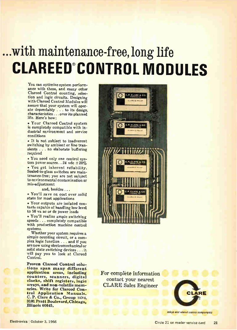
CLAREEWCONTROIL MODULES You can optimize system perform-ance with these, and many other Clareed Control counting, selec-tion and logic circuits. Designing with Clareed Control Modules will assure that your system will oper-ate dependably . . . to its design, characteristics ... over its planned life. Here's how:
• Your Clareed Control system is completely compatible with in-dustrial environment and service conditions
• It is not subject to inadverent switching by ambient or line tran-sients . . . no elaborate buffering required
• You need only one control sys-tem power source...24 vdc ± 20% • You get inherent reliability. Sealed-in-glass switches are main-tenance-free; you are not subject to environmental contamination or mis-adjustment
and, besides. • You'll save on cost over solid state for most applications • Your outputs are isolated con-tacts capable of handling low level to 50 va ac or de power loads • You'll realize ample switching speeds . . . completely compatible with production machine control systems. Whether your system requires a
simple counting circuit, or a com-plex logic function . . . and if you are now using electromechanical or solid state switching devices . . . it will pay you to look at Clareed Control.
Proven Clareed Control solu-tions span many different application areas, including counters, scanners, digital clocks, shift registers, logic arrays, and non-volatile mem-ories. Write for Clareed Con-trol Application Manuals. C. P. Clare & Co., Group 10N4, 3101 Pratt Boulevard, Chicago, Illinois 60645.
For complete information contact your nearest CLARE Sales Engineer
CLARE
Electronics ' October 3, 1966
relays and related control components
Circle 21 on reader service card 21

30 'Day§ Gliae Computer
Not just any computer, either. The approachable,
friendly, personal PDP-8. Delivered.
The PDP-8 is a small, high speed, core memory, full general purpose computer for on-line, real-time in-vestigations. It hath 4K memory, 1.5 usec cycle time, 12 bit words, complete and proven software.
It also has more than 500 owners that you might want to talk to. Physicists, life scientists, chemists, social scientists, instrument and systems makers. No ac-
countants.
d
Basic PDP-8s are available in 30 days. Expanded mem-ories, or special peripherals take a bit longer.
But matching a customer to a delivery slot is controlled by purchase orders. Not phone calls. Not intentions. Purchase orders. $18,000.
Ask about new quantity discounts and new lower price for extra memory.
LINC-8 deliveries are only a little slower. POP-9 de-liveries, PDP-8/S deliveries, and PDP-10 deliveries are not 30 days either. But quicker than you think.
Nan COMPUTERS • MODULES
DIGITAL EQUIPMENT CORPORATION, Maynard, Massachusetts 01754. Telephone: (617) 897-8821 • Cambridge, Mass. • New Haven . Washington, D. C. • Parsippany, N. J. • Rochester, N. Y. • Philadelphia • Huntsville • Pittsburgh • Chicago • Denver • Ann Arbor • Houston • Los Angeles • Palo Alto • Seattle • Carleton Place and Toronto,
Ont. • Reading, England • Paris, France • Munich and Cologne, Germany • Sydney and West Perth, Australia • Modules distributed also through Allied Radio

Electronics , October 3, 1966
Editorials
Engineering makes the difference Travelers returning from Europe this summer have reported an intriguing phenomenon: the technical gap between the United States and West Europe is widening again after 20 years of steadily narrowing.
Although several economic factors are exerting a drag effect in Europe, the big difference seems to be a spurt in the advance of U.S. technology par-ticularly in that segment called engineering. Government spending has been turned on again
full force because of the war in Vietnam. U.S. mili-tary organizations are paying for a lot of the advances in communications, more reliable com-ponents, better antennas, low-light level devices and the packaging of integrated circuits. At the National Aeronautics and Space Adminis-
tration, more money is going into electronic sub-systems and components, even though NASA's total expenditures have stayed about the same. That's because the big investments in propulsion systems have peaked and the major problems in space technology today need to be solved by new electronic gear or components.
In addition, on their own, many companies have diversified their activities or extended their product lines, after having been scared by the plateauing of business in 1962 and 1963. Firms have poured their own money into research and development with an emphasis on development. Thus much of the accelerated activity in the U.S.
falls into the category of development work or the application of known phenomena into new areas or new products. For example, there have been no radical theoretical advances in integrated circuits; mainly, engineers in a variety of companies and industries are learning how to apply them to their own problems and designs.
In Europe, companies have complained about the large sums the U.S. Government pours into re-search and development, which eventually turns up in products with which they must compete. Now, as R&D money in Europe grows even scarcer, many people blame American competition. Turning to export business and establishing sub-
sidiaries in Europe, U.S. electronic companies have bitten deeply into local markets, causing the sales of European firms to plateau or slide on their home grounds. The tough competition has forced some European companies to shrink the traditionally large profit margins they have enjoyed, leaving less money for R&D.
In addition, Europeans have tended to emphasize theoretical work and put development, application and production into secondary roles. In most coun-tries the status of theoretical knowledge is very nearly on a par with that in America, particularly in
physics and mathematics associated with elec-tronics. What's missing, of course, is know-how to apply the theory and to manufacture products that use it. Traveling in most countries of Europe a visitor can see integrated circuits, for example, being built by the dozen in a laboratory at a uni-versity or an industrial firm. But finding large scale production, by the thousands, is another story. Too many Europeans still do not devote enough
energy to what has to be called technology as opposed to science. What's happened in Europe ought to be an object lesson for those who want to turn electronics engineering into the study of physics and mathematics. Although an understand-ing of these subjects is essential to a good engineer, it is not enough. Real progress in a country—or in a company—results from the application of scien-tific phenomena to practical products. That is the U.S.' chief strength in electronics today.
Hybrid IC's: funeral services
were premature Two years ago at the Solid State Circuits Confer-ence in Philadelphia, the experts were ready to bury hybrid integrated circuits. "Batch processing of monolithic IC's will be so economical hybrids won't be able to compete," they said. "In addition, the cost of mechanizing to build hybrids will make them for the rich only." E.A. Sack, an advocate of mono-lithic circuits at the Westinghouse Electric Corp.'s Molecular Electronics division, brought the house down after a discussion of the techniques that build IBM's hybrid circuitry when he quipped, "All of you who have $100 million for automation equip-ment don't have to hear any more."
In October 1966, hybrid circuits are still alive and doing very well. The story on page 187 reports that hybrid IC's have the inside track in automotive electronics which promises to be the second largest market for IC's following close behind computers.
Clearly hybrid and monolithic IC's both have a place in industry. Monolithic circuits, despite their ardent enthusiasts, will never be suitable for some applications: where precision passive components are required; where high frequency and high power is normal; or where volume is not large enough to justify the high costs of making masks to build monolithic circuits.
Similarly, there are applications in which hybrids will never be satisfactory: circuits in which high speed in the nanosecond range is required. Many semiconductor firms have seen the light in
the past nine months. Some very strong advocates of monolithic circuits have started marketing hy-brid IC's too: Fairchild Semiconductor, Motorola Corp., Philco Corp. and Westinghouse.
Rather than dying and disappearing, the hybrid integrated circuit opens up great new potentials.
-4—Circle 22 on reader service card 23

CORNING® &Style Resistors: 1 part to buy,
1 part to inventory, 1 dart to handle
4 sie
Why are you still buying 22684 parts ... and T-0 parts ... and Characteristic D parts ... and "comp" type parts? New CORNING C-Style Resistors meet and beat all four of those specs!
Think of the dollars this true multi-use resistor can save you—in the paperwork of purchasing and in the lower unit price you enjoy on quantity orders for a single part. Think how it can simplify your inventory and simplify handling in assembly. Our new CORNING C-Style Resistors can make your job a whole lot easier, your circuits a whole lot better. Look at the classic CORNING Glass Tin Oxide Film Resistor perform-ance documented in the table. Then send the coupon for your test samples and data.
PERFORMANCE CHARACTERISTICS
Characteristics New CORNING C-Style Resistors Mil-R-226848 Mil-R-10509F Characteristic D•
Temperature Rating 70°C 70°C 125 °C 70°C 70°C
Wattage C 4 (RLO7S) Resistors, 10 ohms to 301K 1/4 lia 1/10 1/4 th
Wattage C 5 (R1205) Resistors, 10 ohms to 1 Meg. 1/, 1/4 1/4 1/5 1/4
Load Life A R 1.0% 0.5% 0.5% 2% 1%
Design Tolerance A R —2 to +4% +2.8% —1.5 to +3% .
Temperature Coefficient from —55°C to +175°C +100 PPM +200 ppm +200 —500 ppm
Dielectric Withstanding Voltage A R +0.10% +0.50% +0.5%
Moisture Resistance A R +0.50% +1.50% +1.5%
Short Time Overload A R +0.25% +0.50% +0.5%
Temperature Cycling A R +0.25% +1.00% +0.5%
Effect of Soldering A R +0.10% +0.50% +0.5%
Low Temperature Operation A R +0.50% +0.50% +0.5%
Shock A R +0.10% +0.50% +0.5%
Vibration A R ±0.10% +0.50% +0.5%
Terminal Strength A R +0.10% 0.50% +0.2%
Voltage Coefficient +0.001%/Volt
Shelf Life A R -I-0.10%/Year -F-1.0%
°For type-marked, military lead Mil-R-10509F, Characteristic D, Resistors, specify CORNING NA-Style Resistors.
1 CORNING GLASS WORKS, 3913 Electronics Dr., Raleigh, N. C. 27602. Send complete data, test samples of new CORNING C-Style Resistors.
Name
Title
Company
Address
City State
CORNING
ZIP
ELECTRONICS
24 Circle 24 on reader service card Electronics October 3, 1965

Electronics Newsletter October 3, 1966
Engineers push Interest in computer-aided design (CAD) is growing. At a conference this month of Honeywell, Inc., engineers, a group of
computer-aided designers urged the company to establish a corporate-wide CAD infor-circuit design mation program.
The program the engineers especially want to use is NET-2, the second-generation CAD program being written at Los Alamos Scientific Labora-tory by Allen F. Malmberg. Goal of the Honeywell engineers is to have NET-2 completely converted into Honeywell machine language "before the ink is dry on Malmberg's program," as one engineer puts it.
Honeywell's Electronic Data Processing division is one of the few com-panies using NET-1 for evaluation and design of monolithic integrated circuits and it has sold the idea to its circuit vendors, which now use a consulting firm for design and evaluation before building the circuits. Other evidence of the attention being given to CAD is a move being
led by Clinton Purdue of the Sandia Corp. At the National Electronics Conference in Chicago this week he will lead an effort to get separate professional status within the Institute of Electrical and Electronics Engi-neers for the fast-growing number of engineers in CAD work. Few engineers were satisfied with a compromise decision to have subgroup recognition granted by the professional group on reliability and quality control at last August's Western Electronics Show and Convention.
Low-noise masers
now attuned
to radar, RCA says
TI and Fairchild
sign semiconductor
licensing deal
The Radio Corp. of America believes that a wider use of low-noise masers in radar systems is now possible. Simpson Adler, a physicist at RCA's Defense Electronics Products division, Moorestown, N.J., has developed a technique for the Navy that overcomes one barrier to its wide use in radar—saturation of the maser by the transmitter pulse, which blocks the receiver for several milliseconds. Adler has shifted the maser's fre-quency response during pulse transmission to prevent saturation. The technique allows the maser to recover in microseconds by operating as a quantum mechanical duplexer that doesn't deteriorate the low-noise capabilities. Other measurements performed by RCA for the Navy indicate that
the maser's gain and phase stability is suitable for monopulse radar. Receiver bandwidths can be varied as needed and bandwidth character-istics can be matched for multichannel receivers. The theory of the maser's duplexing action will be described at the IEEE Aerospace and Electronics Systems meeting in Washington, Oct. 3 to 5.
A cross-licensing agreement has been signed by two of the biggest inte-grated circuit producers, Texas Instruments Incorporated and the Fair-child Camera and Instrument Corp. The agreement covers Fairchild patents for the planar process and TI patents for integrated circuits.
For Fairchild, the attraction of signing such an agreement with TI is clear: aside from getting free IC licenses, the agreement strengthens its hand in negotiating for planar-process royalties with other companies. Industry observers have claimed that Fairchild's patent position wasn't strong, even though as many as 10 other electronics companies have agreed to pay Fairchild royalties for the semiconductor-manufacturing process. The holdouts now are Motorola, Inc., and the Signetics Corp.
Electronics I October 3, 1966

Electronics Newsletter
Inventor claims A Purdue University electronics professor says he has developed an inexpensive two-port circuit that tailors any component's output char-
circuit alters acteristic to simulate a new component without changing the physical device's curve makeup of the original. The professor, Leon Chua, says the six-transistor
circuit can be fabricated for less than $10. A full report on the circuit, called a Rotator, will be given Oct. 5 at the University of Illinois, Allerton Conference in Monticello, Ill. The name Rotator was chosen, Chua says, because the circuit alters a
device's curve by rotation; for example, a true vertical voltage-versus-current curve could result for a diode. Changing the position of this curve in effect simulates a new device. Chua says the Rotator can be used with such devices as diodes, zener
diodes, transistors, capacitors or resistors by connecting them to the input port of the circuit. He says three varieties of the device exist: resistive, inductive and capacitive.
Carriers offer
rate cut in fight
with Comsat
Picture looks bad
for airline tv
IC price cut?
The international common communications carriers are fighting to keep the Communications Satellite Corp. from selling its services directly to customers, and they're willing to slash their Far Eastern rates 40% in exchange for support of their stand by the Federal Communications Commission. The rate-cut proposal follows a contract that Comsat signed directly
with the Pentagon for providing transpacific communications circuits. The carriers, however, objected, claiming that any contract would have to be made through them.
Before the Pentagon-Comsat agreement can become final, the FCC would have to approve it. And the FCC is on record opposing any bypass-ing of the common carriers.
Television entertainment in airlines is dying. One carrier plans to drop inflight television, and others are said to be considering following suit. One reason for the decline in interest is the poor quality of the picture. A technical problem with the television tape recorders used in airliners
occurs when the craft suddenly changes speed or direction; this causes a gyro-type movement of the recorder head, producing picture distortion. In addition, the helical recorders being used produce a much lower qual-ity picture than tv viewers are used to. As a result of a general decline in inflight-tv interest, the Ampex Corp.
has dropped its plan to use the one-tube color monitor developed by the Yaou Electric Co. of Tokyo; this system was to be introduced on Con-tinental Airlines flights. And because of the problems, the Sony Corp., whose black-and-white system has been installed on Pan American Air-ways and American Airlines aircraft, has slowed development of a pro-posed color-tv system.
Texas Instruments Incorporated reportedly has a price cut in the works that is making other integrated circuit manufacturers nervous. For exam-ple, it's said that TI plans a price of $11 for a complex circuit that a competitor is selling for $40. The competitor says it believes it can improve yields to get its price to $22 a circuit but not any lower.
26 Circle 27 on reader service card-*-

AL
4 if9it nr.t.eM
welcome to the greatest show on industrial tapes
presented by MYSTIK See the greatest collection of industrial tapes
ever assembled under one Big Top.
Electrical Tapes • Packaging Tapes • Strapping Tapes Protective Tapes • Masking Tapes • Special Purpose Tapes
Over 100 top performers ... 1,001 applications!

MYSTIK TAPE
THE MARK OF QUALITY
Reduce friction and keep cool with Mystik Teflon Tapes!
When it comes to Electrical Tapes, Mystik is king!
Mystik filament-reinforced Strapping Tapes are strong as a bull!
vde

/11P Mystik Protecto-Mask
is tough as a rhino!
mum ,,jjT Tops for your application. , Binding, s trappi ng, insulating, protecting a or hold-ing, there's 11,1s
ytik Tape that's perfect for your application. New tapes, such as Mystik's Islienex, Kapton and Tedlar are constantly being added to our line to meet new demands of industry.
Your local Mystik distributor help you in the selection of the correcr Your application. will be happy to
He's well trained in tap cations and he is back t tape f01. nient e appli-by Mystik's Field Representatives and Technical Service Depart-
ment. You will find your Mystik distributor listed in the Yellow Pages under "Tape He will save you time and moneys". Call him.
,.
/1/11/ ' '
UNDER THE MUM BIG TOP there's a tape for your application.
5 7'
.1,11.1111.
ELECTRICAL TAPES Mystik Tapes provide physical and performance characteristics of every description and are suit-able for binding, shielding and insulating. Mystik is continually developing new tapes to keep pace with the needs of the rapidly expanding electrical industry.
PACKAGING TAPES Versatile family for hundreds of applications. Sealing, color-coding, strengthening, you do it better for less with a Mystik Packaging Tape. Printable tapes allow an extra sales message for your package.
mi 'mnauum
09 'ON 11Vend
SSV13 ISHId
1
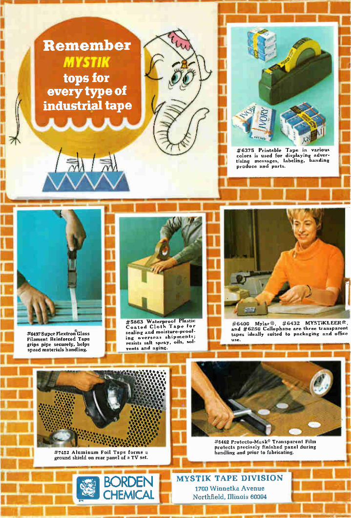
rn I II #6497 Super Flextron Glass
Filament Reinforced Tape
e
Mu grips pipe securely, helps speed materials handling.
111111111`
11.11111r-
RIM RIM
HIM I
I NM Lei
1111111111111111111 11111.11 MIL IBM
Remember MYSTIK tops for
every type of industrial tape
NMI 11111iim mu-- I
#5863 Waterproof Plastic Coated Cloth Tape for sealing and moisture-proof-ing overseas shipments; resists salt spray, oils, sol-vents and aging.
IOU reaMMIM1011
lie•••• •-•-•"••.• • -is eel • • e-e• • • •• • • s. • • 11.• Os • 111 0 .1 ei 0" e o s
ill 0 0 e
Ile1111o0.01, t e 1,à, 0 .114
I". .00,
eee e . e e .• • e es** "•• . e••••••••••• •
..... - • • e- • • • • • ele.
et °Yee ees
#7452 Aluminum Foil Tape forms a ground shield on rear panel of a TV set.
.1•1111••••••••••••IMIR
—UM»
BORDEN CHEMICAL
1
#6375 Printable Tape in various colors is used for displaying adver-tising messages, labeling, banding produce and parts.
1 1
..-±6400 Mylar®, #6432 MYSTiKLEER and #6250 Cellophane are three transparent tapes ideally suited to packaging and office use.
#6462 Protecto-Mask® Transparent Film protects precisely finished panel during handling and prior to fabricating.
L. AM
Ihmitemirmaimor mum min mutt
Mil I
MYSTIK TAPE DIVISION 1700 Winnetka Avenue Northfield, Illinois 60094

In less time than it takes to read this page, you could learn to use this new Universal Impedance Bridge.
Ready? One, two, three, go.
I Adjust the range switch for • an on-scale reading.
(ià 421,DA UNIVERSAL DR4DGE mI•Lit/ • PaCtà.1,
II I 0 4 3
ni• •slb•
Neap D 0
UNRWAIIN
de tre
111
FUNC non L, e-Ciel fk ,L1, Lp
.• e wt.! Arm «PM 1.01. ..61•4) *
\
SONSilWITY
,„% • Obtain a null with the CRL dial. Now, read your measurement.
1 Select the function you want. •
Nothing to it. No interacting controls to adjust and readjust. No multipliers. No non-linear dials. AUTO-BALANCE eliminates all that.
This new Hewlett-Packard Bridge is the first one that takes human beings into account as well as impedance. It's made for engineers who don't have time for a half-hour refresher course every time they want to use it. You get direct digital readout of all C, R,
and L values. Indicator lights show up-scale or down-scale unbalance. Decimal point and an equivalent circuit are automatically indicated. No problem with false or sliding nulls either: unique electronic AUTO-BALANCE takes care of that.
For a D or Q measurement, just switch from AUTO to low or high D or Q and turn the DQ control until you obtain another null. Simple. Particularly for low Q and high D cases.
So if you're the kind of engineer who's tired of complicated impedance bridges, Hewlett-Packard has your number: Mode14260A. $550.
Ask your Hewlett-Packard field engineer for a demonstration. Or write us for complete specs: Palo Alto, California 94304. Tel. (415) 326-7000. Europe: 54 Route des Acacias, Geneva.
Data subject to change without notice.
Price f.o.b. factory.
HEWLETT it& PACKARD An extra measure of qualify.
*—Circle 30 on reader service card Circle 31 on reader service card 31

32 Electronics I October 3, 1966

ONLY 3C OFFERS...
TOTAL DIGITAL CAPABILITY TOTAL BECAUSE ... you get the most complete spectrum of digital hardware, associated software and customer support available today! Products at the base of this capability include: digital logic modules ... core memories... memory test equipment... special systems ... and DDP computers that are the favorites in applications like flight simulation, message switching, freight yard control, laboratory work and computation analysis. And in our own pioneering techniques laboratory we design and develop integrated circuits which are then mass-produced for use in most of our products. Extensive R&D like this helps to assure continued advanced hardware at low cost. TOTAL BECAUSE.. .30 (formerly Computer Control Company, Inc.) is now an operating division of Honeywell's new Computer Group.
To extend our digital capability even further, the computer facilities of the Industrial Division in Fort Washington, Pa. recently became part of our division in Framingham, Mass. This addition to 30 is well known for its H20 control system — ideal in the manufacture of chemicals, steel, food, textiles, and electric utility dispatching.
Result! A concentrated total digital capability under one roof that specializes in on-line real-time plus control applications.
TOTAL BECAUSE ... also a member of the new Computer Group is the EDP Division — a leader when it comes to commercial/ business data processing.
It's easy to see why Honeywell's new Computer Group can satisfy almost any digital application. Why not take a look at 30 total capability now — write for our new brochure, "3C TODAY".
Honeywell, Computer Control Division, Old Connecticut Path, Framingham, Mass.
Honeywell COMPUTER CONTROL DIVISION
Electronics I October 3, 1966 Circle 33 on reader service card 33

YOUR QUICK-SELECTION GUIDE to Spectra-Physics'
STABILITE* Helium-Neon Gas Lasers
1111111111,1111111;11111111111111111111
STABILITE: Spectra-Physics trade-mark for HE-NE Gas Lasers
Send for the Literature:
" New STABILITE 6-page color brochure.
**"GAS LASERS," an article by Dr. A. Bloom, reprinted from the joint issue of Proceedings of the IEEE and Applied Optics, October 1966.
34 Electronics October 3, 1966

Here is the new generation of OW gas lasers, the working generation. These are the lasers being built into today's systems, the lasers that will be doing tomorrow's jobs.
Look these over, match one to your needs; integrate its precision and dependability into your own operations. Your major benefit, aside from the utility of the laser itself, will be the satisfaction of using a product made and guaranteed by Spectra-Physics, leading producer—both quantitatively and qualitatively — of OW gas lasers, ever since their invention.
411••• garb
••••• «If
POWER MODEL TEMoo
632.8nm milliwatts
* 125
* 124
* 123
50
15
7.0
LENGTH overall inches
75
32
22
* 122 3.0 16
119 0.1 9
130B 1.0 14
115
nap
"•••
3.0 29
INSTANTANEOUS SPECTRUM axial modes axial center @ mode
4.7 x 10'4 Hz spacing 632.8nm MHz
PRICE with
exciter (dollars)
83 $8500.
214
I 341
517
1500
500
250
3850.
2900.
1950.
4850.
950.
3490.
APPLICATION
General purpose for exact-ing applications such as holography, Raman Scatter-ing, signal processing. Spe-cially suited for factory installations, original equip-ment manufacturers and military systems configura-tions. Most appropriate STABILITE for a particular application is often deter-mined by price/power/size considerations.
Single wavelength applica-tions in heterodyne setups; long-path difference inter-ferometry.
General purpose where low cost and utility are primary considerations.
Experimentation where mi-crometer adjustments, exci-ter modulation, r-f excita-tion are advantageous.
Laser Technical Bulletins:
• =1. Optical Properties of Lasers as com-pared to Conventional Radiators
=2. Properties of Laser Resonators Giv-ing Uniphase Wave Fronts
=3. Some Demonstration Experiments in Optics Using a Gas Laser
=4. Noise in Lasers and Laser Detectors
#5. Optical Systems for Laser Beams
Please write us at 1255 Terra Bella, Mountain View, California 94040. In Eu-rope, Spectra-Physics, S.A., 18, rue Saint-Pierre, Box 142, 1701 Fribourg, Switzerland.
Spectra-Physics
Electronics I October 3, 1966 Circle 35 on reader service card 35


YOU CAN IMPROVE YOUR CONTROL AND
PRODUCT APPLICATIONS WITH NEW
DESIGNS, TECHNIQUES AND INNOVATIONS IN LIGHTED SWITCHES FROM
SWITCHES THE GOOD LOOKING SUPPLIER LINE THAT
KEEPS AHEAD OF THE FIELD.
Type 04-590
NEW! Extruded bezel 4-lite Finest
dress appearance in the industry. Colors, legends,
snap-in mounting.
Type 44
NEW! Splashproof water-sealed 4-lite
switch. Snap-on switch module. Available in
projected or screen colors, engraved legends.
WRITE FOR LATEST
LICON LIGHTED
SWITCH CATALOG
NEW! Sub-miniature Neon switch for rapid
computer indication. longest possible bulb life.
Type 02-800
NEW! Economy 2-lite designed for
easy snap-in. Front-of-panel mounting, servicing.
Bezel-barriers for hori-zontal or vertical dress mounts.
LICON DIVISION ILLINOIS TOOL WORKS INC. 6615 W. IRVING PARK ROAD • CHICAGO, ILLINOIS 60634
'Remember, ru're riP,eer more ikon a rew feet from a product of TT14)'
Type 01-370
NEW! Slide-base long-life bulb
1-lite push button switch. Plunger action.
Type 01-700
NEW! Economy 1-lite Screw-in
mounting, front-of-panel bulb servicing.
Circle 37 on reader service card 37

n
PARTICULARITY IS A VIDAR DIGITAL DATA SYSTEM
It's a buyer's market today in digital
data acquisition (systems that meas-ure analog data and record it in digital
form). You can order them from Vidar in innumerable combinations of input scanners, integrating digital voltme-ters, clocks, output couplers, record-ers, and what-not. They can be used
for signals ranging from microvolts to thousands of volts. You can have your
readouts served up on printed or per-
forated paper tape, punched cards, or magnetic tape. Somewhere in this data-logging
world — perhaps among our 5 stand-ard systems— there exists an answer to your exact requirement for speed, sensitivity, accuracy, and economy. You can afford to be particular! And you needn't be a Ph.D. to understand or hook up a Vidar system.
Particular people are encouraged
to come to Vidar with their toughest
data-acquisition problems (and the easier ones too!). You may be particu-larly impressed by our response. Get in touch with the Vidar engineering representative in your area, or con-tact us at 67 Ortega Avenue, Moun-tain View, California 94040; tele-phone (415) 961-1000.
"VI TD.A.Ro 38 Circle 38 on reader service card Circle 39 on reader service card—>

DOW. • • new standards of performance and reliability in dielectric coolants
FiEwric Er
a family of 5 fluorocarbon
liquids—offering a complete spectrum of operating ranges
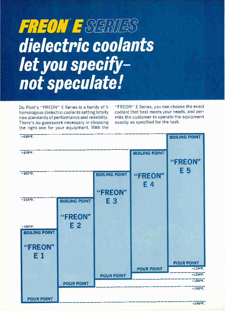
FREON E Miee dielectric coolants let you specify-not speculate! Du Pont's "FREON" E Series is a family of 5 homologous dielectric coolants setting totally new standards of performance and reliability. There's no guesswork necessary in choosing the right one for your equipment. With the
+439°F.
"FREON" E Series, you can choose the exact coolant that best meets your needs, and per-mits the customer to operate the equipment exactly as specified for the task.
±307°F.
-214°F.
102°F.
BOILING POINT
"FREON" E 1
BOILING POINT
"FREON" E 2
POUR POINT
tSUILINU
"FREON" E 3
POUR POINT
BOILING POINT
"FREON" E 4
POUR POINT
BOILING POINT
"FREON" E 5
POUR POINT -1190F.
-138°F.
-160°F.
-190°F.
POUR POINT -246°F.

Here's why FREINE ge' coolants will increase your equipment- performance and reliability: 1. Stable and compatible "FREON" E Series fluorocarbon liquids are not affected at high temperatures (over 550 F!)—are inert with metals, plastics, elastomers.
2. Completely safe No special safety precautions are neces-sary with "FREON" E Series coolants. They are nonflammable and relatively nontoxic. Use them anywhere!
3. Outstanding dielectric properties These insulating fluids provide high dielec-tric strength in liquid and vapor—low losses —high resistivity.
4. Widest temperature ranges The "FREON" E Series offers liquid limits
If you're looking for new standards of per-formance in a dielec-tric coolant, find out
more about the "FREON" E Series.
Simply fill out and mail this card.
from -246 F. up to +439 F. at zero psig. Each coolant has a specific, constant, and extremely wide liquid temperature range. You choose the one to meet your exact needs.
5. Unmatched purity and uniformity Each coolant in the "FREON" E Series is a single, pure compound—not a mixture of several different fluids. Thus composition is always the same—lot to lot—day to day.
6. Precise boiling points and vapor pressures There's no plus-or-minus factor on boiling points .. . and no "averaging." You're al-ways sure of coolant characteristics—and operating temperatures.
I would like to know more about "FREON" E Series cool-ants for use in:
Name
Position
Company
Address
City State Zip

1CI iCgr
fluorocarbons offer new opportunities for creative design... The unique thermal, electrical and chemical prop-erties of "FREON" E Series fluorocarbons provide new opportunities for electronic and space-age engineering... in improving reliability by outstand-ing temperature control... in miniaturizing compo-nents or systems . . . in transmitting hydraulic pressure in systems operating under conditions of extreme temperature changes . . . in optical equipment . . . or you name it. Whatever new ap-plication you can think of, just jot it down on the reply card. We'll help you investigate the new use with necessary technical assistance.
In Europe, mail card to: Du Pont de Nemours In-ternational S.A., "Freon" & "Valclene" Products Department, 81, Route de l'Aire. CH 1211 Geneva. 24 Switzerland.
BUSINESS REPLY CARD No postage stamp necessary if mailed in the United States
Postage will be paid by
E. I. du Pont de Nemours & Co. (Inc.) "Freon" Products Division
Room 4313 Wilmington, Delaware 19898
FIRST CLASS
PERMIT No.9 Wilmington, Del.

ACTUAL SIZE
Motorola's MV1805C
Varactor Multiplier
Sets a New Level
of Power/Frequency
Performance
Now, you can get up to :35 watts of solid-state power at 1 Gigahertz, to drive your higher frequency chains — or, as direct UHF power with Motorola's MV1805C. No other single semiconductor will give you as much output power at this frequency.
Motorola's new MV1805C step-recovery power varactor is an ideal driver for subsequent multiplica-tion stages in communications links, radar and telem-etry systems where designers also want the reliability of solid-state components. In addition, it is un-matched as a final power output stage for lower frequency systems — for example, in mobile commu-nications — to step from 150 to 450 MHz.
In addition, this new device also features the high-efficiency performance you've come to expect from Motorola varactors . specified at 65% (min), tripling, to 750 MHz. More importantly, it's 100% functionally tested at 40 watts Pm — to give you the
assurance of guaranteed, full-range performance in all of your applications!
CHECK THESE "PERFORMANCE-RATED" SPECIFICATIONS
Characteristic Symbol Rating Unit
RF Power input RF Power output Tripler Efficiency Thermal Resistance
P P
n OJC
40 26 (min) 65 (min)' 7 (max)
Watts Watts
io °C/W
'Up to 750 MHz
MICROWAVE "TROUBLE-SHOOTERS" SOLVE CIRCUIT DESIGN PROBLEMS
Motorola's Microwave Applications Group offers engineering help, circuit design assistance and prod-uct samples, in addition to technical literature. So, for fast design aid, call your nearby Motorola sales office, or place a direct request with the Microwave Applications Group. For technical literature, write to Technical Information Center, Motorola Semi-conductor Products Inc., P.O. Box 955, Phoenix, Arizona 85001.
MOTOROLA Semiconductors wieze eiteimieeeedie ihipediehé
-<— Circle 42 on reader service card Circle 43 on reader service card 43

Weight-conscious engineers like what they don't see here.
Bendixe size 08 Autosyne Synchros average only 1.3 ounces. And their maximum diameter is 0.750 inch.
It's this combination that explains the success of the 08 models in such a wide range of applications. In addition,
all 16 standard 08 units feature 12-inch flexible leads, aluminum housings and corrosion-resistant construction. They're also available with stainless steel housings. Some models are accurate and stable at operating
temperatures up to 800° F. Others are radiation-resis-
tant. And if you can't find the 08 that's just right, we can build one to meet your needs exactly. Need a larger size? Check our sizes 10, 11, 15 and 22. Of course, the performance and reliability of every
Bendix Autosyn Synchro are backed by one of the best names in the business. Call us at (717) 278-1161 in Montrose, Pa. Or write for our 42-page catalog.
Montrose Division :77Znoy. CORPORATION'
44 Circle 44 on reader service card Electronics ' October 3, 1966

October 3, 1966
Electronics Review Volume 39
Number 20
Communications
H-f's sharper bounce
"High frequency" is a dirty' word in Government communications circles. Because of fading and mul-tipath problems, h-f communica-tion circuits are used reluctantly, though the United States has mil-lions invested in equipment around the world. But a change may be in sight. In
a couple of months the Mitre Corp. will open an experimental h-f link between its headquarters in Bed-ford, Mass., and the Naval Elec-tronics Laboratory in Point Loma, Calif. The link, called Discol—for digital sounder computer link—will use sounders to explore the sky-wave mode of communications in the h-f range, from 2 to 30 mega-hertz. "The link will be developed along
the lines of a consumers' coopera-tive," says Wilfred A. Fordon of Mitre. "If others want to use the test bed, they can get into the co-operative simply by paying for their own terminal and equipment."
Mitre, systems engineering ad-viser to the Air Force, works prin-cipally for the Electronic Systems Division at Hanscom Field, Mass., which manages development of military communications systems throughout the world for the De-fense Communications Agency. The division put up about $100,000 for the Mitre terminal; the Navy is fi-nancing its own station at Point Loma. The basic goal is to investigate
long - haul communications tech-niques for the military.
Big audience. Closely watching the progress of the test bed are the Strategic Air Command, which relies partly on h-f links, and the managers of programs like 484L, the project to develop secure, ground-air-ground voice and high-speed Teletype links.
Experimental high-frequency link presages new interest in ionospheric bouncing.
Out of Discol may eventually de-velop new antennas and other de-vices for h-f.
In h-f systems, the channel de-pends strictly upon the ionosphere, which bounces signals from the transmitter to the receiver. The ionosphere consists of several lay-ers of ionized gas 100 to 500 kilom-eters above the earth. Efficient re-flection of a specific frequency is determined by the height, thickness and ionization levels within these layers—and these change from day to night, month to month and year to year throughout the sunspot cycle.
At present, optimum frequen-cies are chosen on the basis of three-month advance predictions which define only average condi-tions. The most effective use of h-f is made by veteran radio operators who have learned the h-f medium by long experience.
Fine tuning. The defense com-munications system is evolving into an adaptive network in which com-puters will automatically switch to optimum frequency, power and routing. Where h-f links are used, an adaptive network will require storage of data on the changing status of the ionosphere.
Discol will use synchronized,
stepped-frequency oblique sound-ers at each location to measure characteristics of the propagation path for point-to-point communi-cations. The sounder transmitter and receiver both employ electron-ically controlled frequency chan-nels in exact time synchronization. This is established by locking the timing circuits of individual equip-ment to a very stable quartz clock capable of maintaining synchroni-zation to within a few millionths of a second. At preset time intervals, the
transmitter and receiver initiate a frequency-scan sequence in which they are tuned synchronously across the h-f band in steps of about 10 frequency channels per second. Shape of the pulse. Within the
band in which the sounder signals are detected, the ionosphere dis-torts the shape of the pulses, some-times stretching them to many times their original length. This and other effects are seen in an iono-gram recorded by the receiver. A typical ionogram tells the com-
municator the full range of frequen-cies then usable, how much pulse-stretching is present and at what frequencies this distortion is most severe. The communicator knows at what frequencies he can expect
Electronics I October 3, 1966 45

Electronics Review
reliable communications on that circuit at that time. The test link across the continent
is planned in order to build up an extensive collection of data on sea-sonal variations along that path at least. Other links may be added soon. At Mitre the work will be tied
to other communications projects, such as block error-coding tech-niques. Says Fordon: "The current revolution in digital error control, the development of solid-state dig-ital devices and the rapid move-ment in the military toward digital communications systems are all part of the renewed interest in h-f."
Fast talker Another sign that h-f manufac-turers haven't thrown in the towel despite the growing threat from satellite communications is the con-tinuing research on h-f data mo-dems. The General Dynamics Corp.'s
Electronics division in Rochester, N.Y., for example, is developing data modems for the Air Force which the company says will trans-mit digital data at 4,800 bits per second, about twice the rate of the best h-f systems now available. The reason for such speed, says
a General Dynamics engineer, is "frequency differential phase shift keying. The next best system uses time differential phase shift key-ing." General Dynamics says its system is less affected by h-f multi-path problems and randomly vary-ing signal phase or drifting phase over the transmission path.
Dual tone. Its data modem trans-mits two tones during one time interval rather than a single tone in successive time intervals (the time differential method). Since the tones are close together (a cycle or two apart) they are similarly affected; and the phase shift be-tween the tones, which carry the data information, remains the same. The tone times are also made very long so that signal smearing due to the multipath ef-fect is a small percentage of the total signal time.
According to General Dynamics,
From another angle
How well do the Russians make out with h-f? Many United States communi-
cations specialists think they do very well [Electronics, Oct. 4, 1965, p. 136]. One theory is that the Russians
are in a better geographical posi-tion to achieve a low angle in launch of their signals and are less affected by auroral activity.
There is also some speculation that they use some form of duct-ing. The use of ducts, or natural waveguides in the atmosphere, has been investigated for years in the U.S.
The Air Force plans this year to launch ionospheric communica-tions satellites which will test h-f and vhf guided propagation in the lower ionosphere. Designed by the Raytheon Co., the satellite-to-satellite communications sys-tem will investigate the whisper-ing-gallery effect—the existence of natural waveguides in the iono-sphere which transmit radio waves from one place to another as the curved reflecting surfaces in some large cathedrals transmit sound waves from one end to the other.
the high data rate modem opens a new field of digital data trans-mission. If the data modem is set to operate at 4,800 bits per second and transmits data at 2,400 bits per second, the extra capacity can be used to encode additional in-formation. At the receiver the op-erators can use a computer to de-termine errors and make correc-tions. In this way, General Dynam-ics says, error rates of one in a million are possible.
Laying the groundwork
As the time approaches to choose a contractor in the Pentagon's fast-moving effort to build and put up a tactical communications satellite, work is going on to develop the essential ground terminals. To meet the tactical needs of all
three services, terminals must be compact, inexpensive, lightweight and highly mobile. The terminals are being built around communica-tions gear already developed in order to make the 1968 target date for the satellite system.
In contrast with present portable satellite ground stations that need several trucks to haul them from one site to another, the new ter-minals will have to be small enough to ride in the back of a Jeep, aboard a crowded Navy ship or tucked away in a small aircraft. The Navy last month received
proposals from companies inter-ested in the contract-definition phase for shipboard terminals. The development effort will investigate the tactical satellite's two frequen-cies—ultrahigh frequency (300 to 3,000 megahertz) and X band (5,200 to 10,900 Mhz). At first the Navy will contract for only a hand-ful of the shipboard terminals, but the size of the over-all market is expected to be significant because of the large number of terminals that ultimately will be needed.
Suitcase variety. One of several companies working on the ground terminals and said to have bid on the Navy work is Electronic Com-munications, Inc., of St. Petersburg, Fla., which has put together a ter-minal to work with the tactical satellite using equipment it devel-oped earlier. Calling it a "small suitcase variety," the company says that the terminal, including an-tenna, weighs only 210 pounds and occupies just 6 cubic feet. It needs 4 kilowatts of power. The company is planning a pack-
age that can be used by all the services. The Electronic Communications
terminal is made up of a receiver, transmitter, control box, modulator and demodulator. A special an-tenna developed by the company is an omnidirectional loop V design. Horizontally polarized, it is about 11/4 feet in diameter and is more compact than a directional dish, the company says. For aircraft use, it could be placed under a radome. The gain of the loop V antenna is on the order of 4.5 decibels. The most important parts of the
terminal — recently demonstrated for the military—are the URC-65 demodulator and the URC-66 mod-ulator. Both are solid state and 90% of their circuits are made up of monolithic integrated circuits. These units provide the time-fre-
quency modulation scheme used by
46 Electronics I October 3, 1966

Electronics Review
Electronic Communications to combat transmission problems such as multipath fading and to optimize modulation. In the time-frequency method, each bit is transmitted serially, and utilizes bit, time and frequency redundancies. Because equipment development
is essentially complete, a company official says the terminal could be delivered soon. With it, up to 50 users could share a satellite link simultaneously. The terminal trans-mits teletype only, but vocoded voice can be added.
Anti jam feature. Electronic Com-munications has a general develop-ment program -not necessarily tied to the satellite ground terminal- on a high-speed, frequency-hopping digital synthesizer. Such equipment could improve the multiple access and antijam features of the future satellite terminals, the official says.
Also in development at the Flor-ida company is a building block line of modems for the operational satellite communications terminal. A good part of the microwave equipment is already developed—. such as the URC-65 and URC-66. One or two other units will be added to the completely adaptive system for such things as 60 woud. per-minute teletype and 4.800 bits-per-second vocoded voice. The terminal is designed to wolk
with near synchronous-altitude or synchronous-altitude satellites Working with a satellite precessing at a rate of 30° to 50° a day, a soldier would have to adjust the electronic communication antenna only once every two to three days. Moving fast. The Pentagon is in
a hurry to get the first tactical satel. lite up. It is skipping the contract-definition stage [Electronics, Aug. 8, p. 61] and is selecting the con-tractor team to build the demon-stration satellite from proposals that were submitted by industry in early September. Indications are that selection of the builders may come as early as late October or November. Because of the tight timetable
and the Pentagon requirement for existing equipment, it appears that the proposal accepted will be based on experience with an operational satellite.
Some of the companies that are understood to have bid on the tacti-cal communications satellite in-clude the Hughes Aircraft Co. with the Syncom and Early Bird satel-lites; the Boeing Co. with the Lunar Orbiter satellite; TRW, Inc., with the Orbiting Geophysical Labora-tory; the PhiIco Corp. with the Initial Defense Communications Satellite, and General Electric Co. with the Nimbus spacecraft.
Industrial electronics
Tooled for economy
It's like driving a tack with a sledge - hammer to go through a complex
Operator, right, monitors optical tracer head used to generate numerical-control tape for two-dimensional parts directly from a drawing. Digital display indicates position of tracer head over drawing being traced. Head is mounted on a movable gantry and its position is encoded for the computer that calculates tape data.
program such as the Automatically Programed Tool (APT), or any of its cousins, to generate tapes for numerical control machining of just a few parts. Now, for two-dimen-sional operations at least, a system has been built that generates the tapes directly from optically traced drawings. Developed by Tridea Electronics of South Pasadena, Calif., a subsidiary of the Conduc-tron Corp., the system computes cutter offsets to determine the path of the tool and accepts inputs of program instruction to complete data for the tape. Two of the systems are being
built for the McDonnell Aircraft Corp. of St. Louis and according to A.G. Van Alstyne, director of ad-vanced development for Tridea, his company now plans to market the
Electronics October 3, 1966 47

rib Liecirwiltb nevIew
industrial systems generally. Other companies also have indi-
cated interest in the system, mostly aerospace companies. The Boeing Co., for example, submitted an ir-regularly shaped production part that had taken 80 man-hours to code for APT. On the Tridea sys-tem, the same numerical control tape was produced in 2 minutes.
In addition, savings are possible through numerical control machin-ing of some single items. McDon-nell Aircraft says a control tape for a template that required 2 man-hours of manual layout was done in 20 minutes on the Tridea sys-tem.
Follow the line. The Tridea sys-tem consists of a 5- by 12-foot table with a tracing head mounted on a movable gantry, a linear encoding system, a small computer and an operator's console with a television monitor, manual gantry position controls and a data input terminal. Two dual photodiodes in the trac-ing head scan opposite sides of the line they are following. They pick up reflected light on each side of the line and can be set either posi-tive or negative so they will be compatible with either black-on white or white-on-black drawings. The photodiodes can be rotated to maintain their alignment. Feedback signals from the photodiodes go to a resolver, which controls two d-c torque motors; one drives the gan-try along the tracing table, the other drives the tracing head across the gantry. A tracer scanning only a single
side of a line is likely to follow crossing lines but the dual photo-diode scanner sees both sides of the line and is less likely to be diverted to one side or the other. The resolver drive is continually converging on the line center from both sides to lock the scanner on the line. Some problem areas, such as a Y line junction, must be con-trolled manually by the operator. By watching the monitor, which shows which line the tracer is fol-lowing, the operator sees when the tracer has made a mistake and he switches to a manual mode. Using a joy stick on the console, he can slew the head back to the point where the error started and man-
ually redirect the head onto the correct line. A delay of about 30 seconds be-
tween reading the position of the head and punching the control tape occurs in a buffer memory. This allows time to erase and correct an error before it gets on the tape. When the operator makes a correc-tion, all of the data in the memory, back to the error point, is automati-cally erased. Head position is read by photo-
sensors that scan precision stain-less-steel tapes marked off 500 lines to the inch. One tape lies along the gantry's line of travel and the other locates the position of the tracer on the gantry. A linear encoder, made by Sheffield, Ltd., Scotland, converts the linear measurement directly into digital form.
Tight tolerance. Tridea's Van Al-styne claims that through optical interpolation of the position tapes, the system can duplicate the draw-ing onto the numerical control tape with a tolerance within 0.0005 inch. The buffer memory stores line seg-ments as one point and a slope— the slope being determined from the preceding point. Adjacent slopes are compared to determine if the line is straight or curved. If it is curved, the computer calcu-lates how many points are needed to keep within the specified toler-ance of tangential error and then determines the cutting tool path. A Tridea-designed interface con-
verts the decimal output of the en-coder to the binary coded decimal form required by the DDP 116 com-puter, made by the Computer Con-trol Co., used for data processing. Continuous check. The tv moni-
tor at the control console is fed by a General Electric TE-21A camera, fitted with a beam-splitter mirror. Reflecting the drawing being traced, the mirror also superim-poses a circle representing the cut-ter diameter.
Fingertip control A late model car last month cruised slowly along a deserted country road 80 miles outside of Columbus, Ohio. The trip covered only a few miles, enough to convince a team of
Ohio State University engineers that a control stick they were work-ing on could become one of the elements of an electronically con-trolled car. The stick, which worked as well
on the road as it had in the lab, re-places a car's steering wheel and gas and brake pedal. It also con-tains a device that signals the driver more accurately and more surely than his eyes that the dis-tance between his car and the car ahead is changing.
Accordion effect. With a head-way-warning system, explain thE Ohio State engineers, cars can safely track closely behind othet cars even at superhighway speeds. The system also prevents what highway engineers call the accor-dion effect, in which cars bunch up, then spread out, then bunch up again because drivers fail to main-tain constant headways. By maintaining headway, says
the university engineers, superhigh-ways can be packed more densely and the cars can move along faster with no loss of safety. "We're still far from the develop-
ment of a car that you can drive onto a superhighway and let drive itself," concedes Robert E. Fenton, a staff member of the school's Com-munications and Control Systems Laboratory and manager of the con-trol stick project. But he does see the control stick as an interim step. The headway indicator is built
into the top of the stick, where the driver rests his hand to control the car. When the car moves closer than a predetermined distance to the car in front, a finger-like section in the stick juts forward, pressing against the driver's fingers. When the driver feels this he pulls back slightly on the control stick, sig-naling a special-purpose analog computer in the car's trunk to ease up on the throttle. The farther back the stick is pulled, the more the throttle is eased; if the stick passes a certain point, the computer com-mands braking. When the proper distance is found again, the finger-like section slides back. On the other hand, when the car
is falling back, the finger-like sec-tion slides in the opposite direction, pressing against the palm of the
48 Electronics I October 3, 1966

Electronics Review
hand, and a forward motion of the control stick then speeds up the test car. Quick response. The tactile warn-
ing system was chosen, says Fen-ton, because when a driver is con-centrating on the highway, his eyes scanning the scene ahead, it's best to have a signal that alerts another of the five senses to guar-antee quick response. Fenton explains that with the
control stick a subject can main-tain a 70-foot headway at 70 miles an hour with only a one-foot error; without the control stick the best drivers score a 10-foot error. Obvi-ously, notes Fenton, "we are deal-ing with changes in motion which are considerably below the visual threshold." So far the Ohio State engineers
haven't bothered about the problem of actually determining the distance between cars. "We'll do that later; right now we want to prove that the control technique works reli-ably," Fenton points out. "For the moment we program a
ghost lead car into the computer; later we'll use a second car with a retractable wire strung between cars to measure the headway dis-tance." When the time comes to develop
the headway sensors, Fenton says, three approaches are likely: an op-tical or a radio-frequency radar system or a system of magnetic sensors under the pavement which cars would trigger. Fenton says the magnetic system holds the greatest hope because it's relatively cheap and nearly foolproof. Other experts, however, say that
radar will never work in this appli-cation, that a laser device is a pipe dream, but that an infrared detec-tor could work efficiently. Inte-grated circuits now make such a device economically feasible, they add. The ultimate objective, according
to Fenton, would be to use some roadside or under-the-pavement de-vice to control the control stick, taking the steering, acceleration and braking function out of the driver's hands—and away from his feet.
That, he says, is still many years away.
The long green
Express buses in New York State may eventually have the traffic lights all their own way if a feasi-bility study now being concluded gets into the hardware stage.
Airborne Instruments Labora-tory, a division of Cutler-Hammer, Inc., is studying, under a $15,000 contract from the state's Depart-ment of Public Roads, whether traf-fic lights can be turned from red to green by infrared signals emitted by a gallium arsenide junction di-ode mounted in express buses. Un-der the plan bus drivers could aim the light beam at red traffic lights from as far away as 1,000 feet. An infrared detector in the traf-
fic-light pole would sense the signal from the oncoming bus and pro-duce an output that would begin cycling the light from red to green. After the bus had passed, the traf-fic light would resume its normal operating cycle.
All green. By giving express buses a perpetual green light, New York is hoping to make travel by bus faster and more attractive to commuters. If it becomes attractive enough, travelers may leave their cars at home. A decrease in private cars would reduce congestion on
the highways. Problems being considered by
Airborne Instruments include the effect such an override on traffic lights will have on roads feeding into the bus routes, the best beam-width of the diode signal and its range. The company has already built
a breadboard model of a junction diode signaling system but this was for a contract from the National Academy of Science's highway re-search board. If a hardware con-tract is let by New York State for the bus system, first tests will prob-ably take place in either Rochester or Buffalo.
Medical electronics
Bedside companion
A visual and audio communications system will give hospital patients reassurance in time of need and save valuable steps for overworked nurses.
Besides providing communica-tion between nurses and patients, the system furnishes entertainment, closed-circuit television and can
Patient can easily move and tune the 51/2-pound receiver, which is supported by a gravity-free arm attached to the bed.
Electronics October 3, 1966 49

Electronics Review
monitor physiological probes that measure pulse and heart rate. The system consists primarily of
a tv camera and receiver. When the portable camera is at the nurses' station and the receiver by the patient's bed, the patient can see the nurse. When the equipment is reversed, the nurse can tune in on the patient. For installation convenience the
system operates with a single co-axial cable only 1/8 inch in diam-eter. By contrast, most hospitals have a tangle of wires for tv and intercoms — always an inconven-ience and sometimes a hazard in a patient's room. Some nurse-call systems need as many as 40 wires in the walls just for audio connec-tions. Low voltage. In addition, the sys-
tem, made by Bell Hospital Serv-ices, Inc., of Bridgeport, Conn., op-erates on low voltages. Instead of consuming 300 watts as a conven-tional receiver does, each receiver operates on 12 volts d-c and uses only 8 watts. Each receiver has a 5-inch screen
and is suspended on a counterbal-anced, articulated arm attached to the patient's bed. The patient can easily move and tune the set, free-ing the nurse for other duties. He hears the sound through steri-lized, disposable earplugs, eliminat-ing the nuisance tv often causes in hospital rooms with several beds. The system uses modified tran-
sistorized receivers manufactured by the Sony Corp. Bell removes power supplies and speakers and adjusts a few circuits. The re-sulting weight reduction simplifies balancing the receiver on the grav-ity-free arm. The 5%-pound sets are also light enough to be mailed back to Bridgeport for repairs. Emergency. The control system
for entertainment and closed-cir-cuit tv contains a master antenna, radio tuners, amplifiers, mixers and a power supply. Individual ampli-fiers for each channel furnish im-pedance matching and automatic gain control for signals from the master antenna. Amplified signals are then mixed and relayed to co-axial distribution lines. When addi-tional outlets are installed, ampli-fiers' settings are changed to com-
pensate for added line loss. Power converter. The built-in
power supply converts the hos-pital's a-c to regulated d-c to oper-ate the receivers. Both power and entertainment
signals flow through the single co-axial line.
Instrumentation
Miss calculation
When missile men conduct target practice against expensive drone planes, their aim is to miss—al-though not by very much—so the drone can survive and fly again another day. To determine the ef-fectiveness of the shot, the missile men must know how close they came. For this job, missiles are re-fitted with radio-frequency equip-ment to measure the miss-distance; but weight distribution and aero-dynamic problems result. Now, the International Telephone and Tele-graph Corp. is developing an electro-optical system to replace the miss-distance electronics on the missile with a dab of paint. All of the measuring and score-trans-mitting electronics will be packed into the recoverable drone. The scoring system, being de-
veloped for the Air Force Systems Command at Eglin Air Force Base, Fla., will have an accuracy within 1 or 2 inches over its range of 100 feet. Radio-frequency systems such as pulsed radar or tracked beacons usually have accuracies within 5 and 10 feet over the same range. Continuous-wave radar boasts bet-ter accuracy-1 or 2 feet over a 100-foot range. Time function. ITT's Federal
Laboratories, Los Angeles, has al-ready demonstrated and tested the optical concept with a bread-boarded system. In this model a gallium arsenide diode generates the light, which is directly modu-lated by radio-frequency tones of very stable frequencies. The modu-lated beam is collimated and aimed at a reflective target, such as a dab of paint. The difference of phase between the transmitted and re-
fleeted beam is a function of time; hence, a function of the distance between the light source and the target.
Obviously, if the phase shifted 360° it would be seen as a zero shift and would indicate a direct hit. To eliminate ambiguity within the desired range, two widely sep-arated r-f tones are used. Some-what on the principle of a vernier, a 5-megahertz tone provides the coarse measurement, which is equivalent to a 200-foot wavelength, and a 40-Mhz tone provides the fine measurements of less than 5 feet. If a range greater than 200 feet were required, an appropriate tone of a frequency lower than 5 Mhz would have to be modulated onto the light beam. Stay in phase. The reflected S-
and 40-Mhz signals are received by a photomultiplier sensor and mixed with offset frequencies, which are phase coherent to pro-duce two low-frequency carriers that retain the phase information proportional to the distance. The phase of the low-frequency signals are compared and combined to pro-vide a single binary range word that is transmitted back to a scor-ing station on the ground. One problem that had to be over-
come was the error caused by dop-pler shift, which would also appear as phase shift. A counter frequency detects whether the modulated fre-quencies on the light beam have changed value and by how much. The amount of phase shift attribu-table to frequency change is cal-culated and canceled from the phase-shift information, leaving only that shift caused by distance. If desired, frequency information could be used to measure relative speed between the target drone and the missile.
All sides. Although the bread-boarded system does not provide a way of detecting targets approach-ing from all angles, several ways of doing this are being investigated.
In an operational system, many diodes and sensors could be at-tached on all sides of the drone so it can monitor all possible direc-lions of a missile's approach by electronically sweeping the light beams through an arc. Another pos-
50 Electronics October 3, 1966
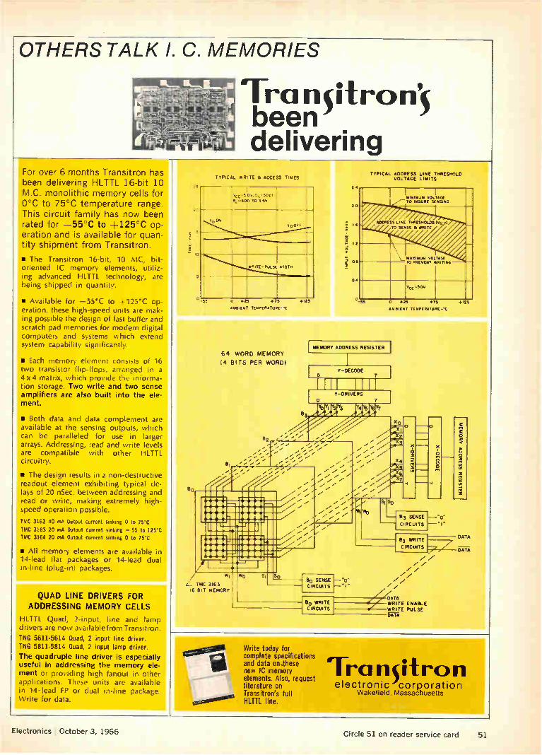
OTHERS TALK I. C. MEMORIES
For over 6 months Transitron has been delivering HLTTL 16-bit 10 M.C. monolithic memory cells for O'C to 75`C temperature range. This circuit family has now been rated for —55`C to +125:C op-eration and is available for quan-tity shipment from Transitron.
• The Transitron 16-bit, 10 MC, bit-oriented IC memory elements, utiliz-ing advanced HLTTL technology, are being shipped in quantity.
• Available for —55°C to +125°C op-eration, these high-speed units are mak-ing possible the design of fast buffer and scratch pad memories for modern digital computers and systems which extend system capability significantly.
si Each memory element consists of 16 two transistor flip-flops, arranged in a 4 x 4 matrix, which provide the informa-tion storage. Two write and two sense amplifiers are also built into the ele-ment.
• Both data and data complement are available at the sensing outputs, which can be paralleled for use in larger arrays. Addressing, read and write levels are compatible with other HLTTL circuitry.
• The design results in a non-destructive readout element exhibiting typical de-lays of 20 nSec. between addressing and read or write, making extremely high-speed operation possible.
TMC 3162 40 mA Output current sinking 0 to 75'C
TMC 3163 20 mA Output current sinking — 55 to 125`C
TMC 3164 20 mA Output current sinking 0 to 75`C
• All memory elements are available in 14-lead flat packages or 14-lead dual in-line (plug-in) packages.
QUAD LINE DRIVERS FOR ADDRESSING MEMORY CELLS
HLTTL Quad, 2-input, line and lamp drivers are now avai table from Transi trou.
INC 5611-5614 Quad, 2 input line driver. INC 5811-5814 Quad, 2 input lamp driver.
The quadruple line driver is especially useful in addressing the memory ele-ment or providing high fanout in other applications. These units are available in 14 -lead FP or dual in-line package. Write for data.
Electronics October 3, 1966
TYPICAL WRITE B ACCESS TIMES
O +20 +75
114181ENT
64 WORD MEMORY
(4 BITS PER WORD)
z• TMC 3163 16 BIT MEMORY
TYPICAL ADDRESS LINE THRESHOLD VOLTAGE LIMITS
MEMORY ADDRESS REGISTER
80 SENSE CIRCUITS
Bo WRITE
CIRCUITS
Write today for complete specifications and data on,these new IC memory elements. Also, request literature on Transitron's full HLTTL line.
Y-DECODE 7
Y-DRIVERS
0 +23 +75 +125
AMBIENT TCYPERATURE-"C
83 SENSE
CIRCUITS
83 WRITE
CIRCUITS
gr"LsE
Tra n it ro n electronic corporation
Wakefield. Massachusetts
Circle 51 on reader service card 51
Electronics Review
sibility, say ITT engineers, is a single diode and sensor mechani-cally rotating through 360°. Care-ful optical fanning of the beam might also be considered, but this would seem less desirable since part of the electro-optical system's advantage is narrow beamwidth. The narrow beamwidth prevents
interference between the trans-mitted and received signals and eliminates the need for frequency separation, such as required in sec-ondary radar. Narrow beamwidth, coupled with high beam density, effectively rejects stray signals and maintains inherent system accuracy.
In addition to missiles, the ITT system could be effective in scoring miss-distance of bullets or any other painted projectile.
Various other uses are also pos-sible. Because of its high accuracy, the electro-optical system might assist space docking and aircraft landings. The system might serve as a proximity fuse.
Computers
Faster Fourier
A new algorithm for Fourier analy-sis can reduce the computer time for performing the analysis by a factor of hundreds or thousands, which means that these problems can be solved in seconds instead of hours. The new algorithm was worked
out by James W. Cooley of the International Business Machines Corp. and John W. Tukey of the Bell Telephone Laboratories, and is included in a package of about 70 programs for the IBM 360. With Fourier analysis, any func-
tion of time, such as a periodic but irregular voltage wave, can be ex-pressed as a series of sines and co-sines. The series can be infinite, but in any practical application only a finite number of terms in the series is used. The larger the num-ber of terms, the closer the series approximates the desired function. To perform the analysis on a digital computer, the function must be
sampled at a number of points, the analysis performed at each point and the results added. Many samples. If the function is
sampled at n points, then at least n terms of the infinite series must be used in the analysis. Therefore the analysis must be carried out for n terms of the series at each of the n points, for a total of n2 multipli-cations and additions. This is the classical approach that takes hours, even for a high-speed compüter, for large values of n. The Cooley-Tukey algorithm is a
method of expanding an analysis at n = 2 points into an analysis at n points using only n operations. Then by carrying out the analysis for n = 2, and repeatedly doubling the value of n, an analysis at any arbitrarily large number of points can be obtained. The process can also be made to work if n is not a power of 2, but for practical ap-plications the power of 2 is good enough. The number of points must be doubled log2 n times to obtain the required value of n; each dou-bling requires n operations: there-fore the total number of operations is n log2n. The ratio of improve-ment is n2/(n log2n) = n/log2n. If n is set arbitrarily at 2'6 = 65,536, then this ratio is 2'6/16 = 4,096; and if n2 operations takes 10 hours, then the improved time is 10/4,096 hours or about 10 seconds.
Space electronics
Resourceful satellite
The Interior Department, tradi-tionally concerned with such mat-ters as water resources and pro-tection of the American Indian, has become the fourth civilian organi-zation in the United States to have its own space program. The pro-gram is called Eros for earth re-sources observation satellite. Gov-ernment officials explain that the word Eros is derived from the Greek, meaning to yearn for scien-tific knowledge and does not have anything to do with the Greek god of love.
Like two of its predecessors in space—the Communications Satel-lite Corp. and the Environmental Science Services Administration— the Interior Department will have the National Aeronautics and Space Administration launch the satellites.
Higher the better. The depart-ment has been working with the space agency for two years to de-termine just what satellites could do in the way of resources measure-ment and whether they. could do it better than airplanes. NASA is-sued two study contracts to the department's Geological Survey— $550,000 to study geology and hy-drology from space and $625,000 to study geography and cartography. The results indicated that only a satellite system could provide glo-bal observations at reasonable cost. During this time NASA scientists
weighed a resources satellite pro-gram of their own but could never get approval from their top man-agement because of tight budgets. The department's decision to
take to satellites was announced last month by Interior Secretary Stewart L. Udall, who immediately named William T. Pecora, director of the Geological Survey, to head the project. Udall also hinted he would like other Federal agencies to share the project cost by point-ing out how useful the satellite resources data would be. He spe-cifically mentioned the Agriculture Department, which has a $900,000 NASA contract to study how satel-lites could help it.
Potential. In discussing potential benefits of the satellite system, Pe-cora said it would cut the cost of updating topographic maps by $100 million a year. He also listed such applications as assessing the health and distribution of crops, discover-ing mineral deposits associated with geological faults, warning of volcanic eruptions by discovering the slight swelling of the earth caused by lava and gases prior to an eruption, mapping the antarctic ice cap and spotting folds in the earth's crust that may contain petroleum deposits.
Pecora considers Eros an evolu-tionary program, beginning with a relatively simple satellite carrying a couple of television cameras and,
52 Electronics I October 3, 1966

1111'..1
If our JXP precision resistor is so superb, how come we're reluctant to discuss its reliability?
Because we don't want you to think of the JXP as a "high reliability" resistor.
It is one, of course. But the term in this case is a bit of an understate-ment (rather like describing the Grand Canyon as a hole in the ground.)
For the same reason, we'd just as soon that you didn't think of the JXP as a "military" resistor, despite its RN classification.
And even the term "metal film" fails to do justice to the JXP. Our Jeffers Electronics Division's metal film re-sistor has characteristics and per-formance capabilities that surpass the best of any resistor art, past or present.
How, then, should you think of the JXP? Simply as a "precision" resis-tor—because it's in this area of pre-cision that our resistor can most clearly be seen to be in a class by itself.
The JXP gives you the highest pre-cision at a reasonable cost, with tol-erances down to 0.02% available upon request. But more than that,this extreme precision is arrived at delib-erately, rather than by happy acci-dent.
We manufacture the JXP under so-phisticated "white room" conditions. We employ a fanatically tight system
My ra Yrompeer
of process and material controls.And we limit ourselves to a narrow popu-lation of resistor characteristics (25 PPM or less). So it's no wonder that our entire resistor output is identical in precision and stability. (In fact, any pair of JXPs can be matched, time and time again, to within 0.01%!)
We'd be delighted to send you com-plete information about our JXP pre-cision resistor (including its military and reliability aspects—if you insist). Just mail us the coupon.
Apatent attempt to win your admiration Even though our various electronic components already offer excellent performance, this never seems to satisfy the restless individuals in our Research Laboratory. They're con-stantly developing new ways to im-prove both our products and our manufacturing processes.
During the last six months alone, Speer Carbon Company and Air Re-duction Company (our parent) have been awarded a significant variety of patents—including: 3,227,983 (U.S.) for Stacked Resistors; 3,238,-151 (U.S.) for Resistor Composition; 3,240,625 (U.S.) for Semiconductor Film Resistors; 727,273 (Canada) for a Method of Capping Film Resistors; 731,781 (Canada) for a Fluorescent Lamp Starter; 648,979 (Belgium) for Resistor Manufacture; 667,242 (Bel-gium) for Composition Resistors; and 49,129 (Luxembourg) for Composi-tion Resistors.
We have no patent on mere excel-lence, of course. But when it comes to perfection ... well, only time will tell.
We've even been distributing Distributors In keeping with our basic policy of quicksilver service, we have been setting up a national network of In-dustrial Electronic Parts Distributors covering every major market area.
These men are hip-deep in both Speer carbon composition resistors and in Jeffers molded chokes. And both inventories, needless to say, of-fer the latest MIL and commercial specifications.
For the name of your helpful Speer Industrial Distributor, contact your Speer representative—or use the coupon.
JEFFERS ELECTRONICS DIVISION SPEER CARBON COMPANY DuBois, Pennsylvania 15801
Speer Carbon Co. is a Division of Air Reduction Company, Inc. El Send complete information on your
JXP precision resistors. D Send the name of my helpful Speer
Industrial Distributor. Name
Title
Company
Street
City State Zip
Electronics October 3, 1966 Circle 53 on reader service card 53

Etch your own PC boards automatically! (Less than five minutes
for one ounce copper.)
ij rt, 1
from this—to 11" x 14"
Shown actual size!
CYCLO-TRONICS "fine line" etcher
Pat applied for
for protypes—limited runs No cooling or venting required!
Etches as fine as .001"!
Cuts costs in half—saves time!
Complete photo processing instructions!
Work is illuminated while etching!
No patterning ... minimum undercutting!
Model No. 201 (illus.), etches two 11"x14"
one-sided boards $695 NOW IN USE BY:
AMP, Inc. /The Bendix Corp./Beta Corp., Sub. of Koppers Co., Inc./Charles Bruning Co., Div. of Ad-dressograph Corp./The University of Chicago/Uni-versity of Colorado/C. G. Conn, Ltd./Fab Tool, Inc.! General Dynamics/Graduate Research Center of the Southwest/IBM Corp./Jordan Electronics, Div. of Victoreen Instrument Co./ Lear Siegler, I nc./Micro Switch, Div. of Honeywell/Microwave Electronics Corp., Div. of Teledyne/Oklahoma State Univ./ Sonotone Corp./Westronics/Woodward Governor Co.
Send for complete information
CYCLO-TRONICS, INC. 3858 N. CICERO—CHICAGO, ILL. 60641
TELEPHONE: (312)-282-6141
Electronics Review
if weight permits, a data-collection system to record environmental data. He envisions flying the first satellite in 1969. Total cost of launching the first craft will be $20 million, he said. William Fischer, research co-
ordinator at the Geological Survey and the man directly responsible for the Eros project, explained that the satellite will carry two 2-inch vidicon camera systems. Each will have picture resolution of 4,000 lines, or good enough to distinguish objects on the ground smaller than 100 feet. The best performance to date has been the two Nimbus weather satellites' 1-inch vidicon systems, with their 800-line resolu-tion that distinguishes objects a quarter-mile across. One of the Eros cameras will be sensitive to the red or near-infrared spectrum for the best viewing of vegetation; the other will operate in the green spectrum and primarily observe the ocean.
Call for bids. The next major step is to ask electronics and aero-space companies for bids on build-ing the satellites. Present plans call for the satellite to resemble the successful Tiros weather craft—a definite advantage for the Radio Corp. of America's Astro-electron-ics division of Princeton, N.J. The division built that satellite for NASA and the Environmental Serv-ices agency and sent the space agency an unsolicited proposal for a similar earth-resources satellite built around the Tiros concept.
Since Eros will be an operational satellite—as opposed to a strictly research craft—all electronics will be within the present technology, Fischer emphasized. The satellites will be launched on improved ver-sions of the workhorse Delta ve-hicle and will use the tracking sta-tions of the space agency's Satellite Tracking and Data Acquisition Network, where Geological Survey personnel will gather and retrans-mit data. When industry can expect a re-
quest for bids depends on how soon the department can find the money. The request could go out almost immediately if Udall decides to reprogram money for the project from the current fiscal year's bud-
get. But Fischer thinks the money will probably come from the budget to be submitted to Congress next January. In that case the request would not go out until after fiscal 1968 begins next July 1.
On the right track
Preliminary data from the Gemini 11 flight indicates that future spacecraft may be able to dock automatically by detecting the ion-electron wake of a spacecraft and centering on it.
In one experiment on the Sept. 13-16 flight three sensors mounted on the target docking adapter at the bow of the Agena measured the concentration of electrons and ions in the ionosphere. The Gem-ini was then maneuvered in five different modes ahead of the Agena to determine the effect of the craft's wake on the sensors. Four of the sequences took place
while Gemini was separated from the Agena and one was carried out at the apogee of the 800-mile orbit while the vehicles were docked. "From the telemetered data we
observed obvious wake effects," said David B. Medved of Electro-Optical Systems, Inc., Pasadena, Calif., which developed the sensors for the National Aeronautics and Space Administration. The com-pany is a subsidiary of the Xerox Corp.
Tracking a man. Medved said the sensors even detected astro-naut Richard Gordon Jr. during his walk in space, as charged par-ticles stuck him and bounced into space. "When he was in a favor-able position we could actually monitor his movements," Medved said. He noted that the data could not
be properly evaluated until it had been analyzed along with radar and photographic data from the flight. "However, the data seems good and we see no obstacle in using the wake as a way of achiev-ing rendezvous." The wake was measured by a
comparison of the voltage and cur-rent relationships of the ion and electron particles as they moved through the sensor apertures onto
54 Circle 54 on reader service card Electronics I October 3, 1966

collecting plates or grids. Incoming signals were averaged by a proc-essor aboard the Agena and fed to an analog-to-digital converter in the Agena telemetry system for real-time transmission. Medved said the equilibrium
electrostatic charge on Agena was also measured and found to be roughly —2 volts. He noted that some scientists had thought that the electrostatic charge might cause problems during docking. During the powered space flight
of the two docked vehicles the charge seemed to change to posi-tive, he said, but declined to say what the voltage was.
Little nudge
Design techniques successfully tested in a new power conditioning and control unit are being used to develop what is expected to be the first ion engine for operational use. The power conditioner and control was part of a complete flight model electric propulsion system that re-cently made a record 1,183-hour vacuum test run at Electro-Optical Systems, Inc. Johns Hopkins University's Ap-
plied Physics Laboratory in Scags-ville, Md., is working on the design of a new satellite, believed to be a synchronous craft, for the Naval Air System Command. While no one will discuss details of the satel-lite, its mission or timetable, it is understood that the spacecraft will include two sets of ion engines to provide thrust' at two levels-10 and 100 micropounds to keep the satellite on station.
Despite several successful flight tests and extensive ground tests with electric propulsion systems, the Pentagon and NASA have dis-played slackening interest. This is particularly true for larger engines —with thrusts of thousandths of a pound—where neither agency feels it has any mission requirement at present. But activity has picked up somewhat in recent months on smaller engines, with thrusts of millionths of a pound, for attitude control and station-keeping of or-biting satellites.
Record run. Electro-Optical,
You're seeing
sharper pictures
today because of
Duraperm pole tips
Taped show or live? Most people can't even guess which is which. Duraperm pole tips—produced to most exacting proper-ties by Hamilton Precision Metals—faithfully record on tape many of your favorite programs, preserving sharp, clear pictures for pleasant viewing.
There are 7 proprietary metals, 112 commercial alloys and 12 pure metals now available. With expanded production facilities, Hamilton Precision Metals is now producing these metals in quantity. Strip and foil are available from 0.10" thick down to 0.000080" thin, and from 1/32" to 12" in width—wire in diameters from 0.1870" to as fine as 0.0010".
Check with Hamilton Precision Metals on your electronic metals requirements for precision strip, foil or wire. Write today for completely new brochure. It gives you complete information on our capabil ies as well as detailed properties on over 100 metals.
timinurom pREcr.,;tom mrirAu.-; division of Hamilton Watch Company a Lancaster, Pa.
Electronics October 3, 1966 Circle 55 on reader service card 55
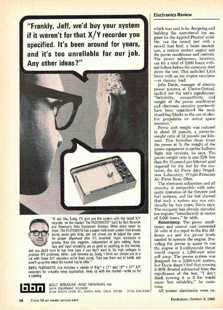
"Frankly, Jeff, we'd buy your system if it weren't for that X/Y recorder you specified. It's been around for years, and it's too unreliable for our job. Any other ideas?"
"If you like, Craig, I'll give you the system with the latest X/Y recorder on the market: The PLOTAMATIC built by Bolt Beranek and Newman's Data Equipment Division. Other users swear by them. The PLOTAMATIC has a paper hold-down system that always works, never gets dirty, and yet allows you to adjust the paper for proper alignment after it's mounted. Input resistance is greater than one megohm, independent of gain setting. Accu-racy and input versatility are as good as anything on the market,
and you don't have to buy time base if you don't want it. No high voltages to produce RFI problems, either. Just between us, Craig, I think our people are in a rut with those X/Y recorders we've been using. They use them out of habit, and aren't up on the latest the market has to offer."
BBN's PLOTAMATIC line includes a variety of Ph" x 11" and 11" x 17" X/Y recorders for virtually every application. Keep up with the market—write us for a catalog.
OM BOLT BERANEK AND NEWMAN INC • • DATA EQUIPMENT DIVISION
2126 SOUTH LYON ST., SANTA ANA, CALIF. 92705 (714) 546-5300
Electronics Review
which was said to be designing and building the operational ion en-gines for the Applied Physics' satel-lite, ran the record test with a zero-G fuel feed, a beam neutral-izer, a cesium contact engine and the power conditioner and controls. The power subsystem, however, ran for a total of 3,000 hours with-out failure before the company shut down the test. This included 1,814 hours with an ion engine simulator —or dummy load. John Davis, manager of electric
power systems at Electro-Optical, spelled out the test's significance: "Reliability, compatibility and weight of the power conditioner and electronic circuitry previously have been considered the main stumbling blocks to the use of elec-tric propulsion on actual space missions." Power unit weight was reduced
to about 35 pounds, a power-to-weight ratio of 12 pounds per kilo-watt. This furnishes three times the power at % the weight of the power equipment in earlier ballistic flight test versions, he says. The power-weight ratio is also 33% less than the 18-pound-per-kilowatt goal required for the test by the cus-tomer, the Air Force Aero Propul-sion Laboratory, Wright-Patterson Air Force Base, Ohio. The electronic subsystem and all
circuitry is compatible with auto-matic operation of the thruster and fuel systems, and the test showed that such a system can run con-tinually for two years, Davis says. The company has already operated ion engines "considerably in excess of 5,000 hours," he adds.
Redundancy. The power condi-tioner and control unit converted 56 volts of d-c input to the five dif-ferent a-c and d-c power levels needed to operate the engine. Pro-viding the power in space to run the engine at 5-millipounds thrust would require a 1,200-watt solar cell array. The power system was designed for a 3,000-watt system, but Davis doesn't feel that running it 50% derated subtracted from the significance of the test. "I don't think running it at 3 kw would cause less reliability," he main-tains.
All system electronics were ex-
56 Circle 56 on reader service card Electronics I October 3, 1966

posed to the vacuum so that vola-tile materials from potting com-pounds would not contaminate the circuits. And no electronics were sealed in pressurized containers. Sealing is the best way to eliminate high-voltage breakdown, Davis says, but it is hard to maintain pressures for long periods. Remove gases. All circuits also
were baked at about 100° C for a couple of days, to remove any gases or impurities. By designing in switching tran-
sistors operating at 10 kilohertz, the company eliminated iron-core mag-netic amplifier units and reduced over-all power conditioner weight by 25%.
Electro-Optical also furnished some circuit redundancy. Parts more likely to fail—or about 25% of the total—were duplicated in the system. But this circuit redundancy was not needed in the 3,000-hour test, Davis notes. The engine uses liquid cesium
for fuel that is vaporized and forced through hot porous tungsten. This strips an electron from the cesium to supply ions. Electric fields ac-celerate and eject these electrically charged particles out of the engine to provide thrust.
Electronics notes
• Super gyro. All major parts of a super-accurate gyroscope now un-der development for the Navy will be made of ceramic. In Norwood, Mass., the precision products de-partment of Nortronics, a division of the Northrop Corp., is working on an inertial navigation gyro for the next generation of missile-car-rying nuclear submarines. It is in-tended for use in the ship's inertial navigation system. Precision fabri-cation techniques include metal to ceramic brazing, ion sputtering of metals on ceramic and machining of ceramic gas spin bearings. In a parallel program at North Ameri-can Aviation, Inc.'s Autonetics di-vision, engineers are exploring ap-proaches to a super-accurate gyro. • More traffic control. San Jose,
Calif.'s three-year-old experiment
Electronics October 3, 1966
Field-proven hp 3400A RMS Voltmeter
basic measuring tools from
HEWLETT PACKARD
Measure true rms value, 100 ,v to 300 v, 10 Hz to 10 MHz
Accuracy is -±1% full scale
High crest factor for accurate pulse, noise measurement
DC output 1 NI at full scale
High maximum input, 1000 y peak
lise it to: Measure level of noise with a crest factor of 100
Measure rms value of pulse trains
Measure true rms current, using hp 456A Current Probe
Make frequency response tests
Convert ac to dc for recorder or DVM operation
The Hewlett-Packard 3400A RMS Volt-meter measures the actual root mean square of ac voltages which are sinu-soidal or nonsinusoidal and have crest factors (ratio of peak to rms) as high as 10 at full-scale deflection and as high as 100 at 10% of full scale. Overload protec-tion to 30 db or 1000 y peak, whichever is less, on each range. Input resistance 10 megohms. Scale calibrated in both rms volts and db, the latter permitting
1C48
HEWLETT
measurement —72 to +52 dbm. Price 3400A, $525; Option 01 (db scale upper-most for better resolution), $550.
Call your Hewlett-Packard field engi-neer for a demonstration of the 3400A or write for complete specifications: Hewlett-Packard, Palo Alto, Calif. 94304, Tel. (415) 326-7000; Europe: 54 Route des Acacias, Geneva.
Data subject to change without notice. Prices f.o.b. factory.
PACKARD An extra 7ncosure of quality
Circle 57 on reader service card 57

Electronics Notes
Did You Know Sprague Makes 32 Types of Foil Tantalum Capacitors?
125 C TUBULAR TANTALEX'CAPACITORS
Type 120D polarized plain-foil
Type 121D non-polarized plain-foil
Type 122D polarized etched-foil
Type 123D non-polarized etched-foil
ASK FOR BULLETIN 3602C
Circle 332 on reader service card
RECTANGULAR TANTALEX CAPACITORS
Type 300D polarized plain-foil
Type 301D non-polar-ized plain-foil
Type 302D polarized etched-foil
Type 303D non-polar-ized etched-foil
ASK FOR BULLETIN 3650
Circle 334 on reader service card
RECTANGULAR TANTALUM CAPACITORS TO MIL-C-3965C
polarized plain-foil CL52 non-polarized plain-foil CL53 polarized etched-foil CL54 non-polarized etched-foil
Circle Jib on reader service card
85C TUBULAR TANTALEX'CAPACITORS
Type 110D polarized plain-foil
Type 111D non-polarized plain-foil
Type 1120 polarized etched-foil
Type 113D non-polarized etched-foil
ASK FOR BULLETIN 3601C
Circle 333 on reader service card
TUBULAR TANTALUM CAPACITORS TO MIL-C-3965C
CL20, CL21 125 C polarized etched-foil CL22, CL23 125 C non-polarized etched-foil CL24, CL25 85 C polarized etched-foil CL26, CL27 85 C non-polarized etched-foil CL30, CL31 125 C polarized plain-foil CL32, CL33 125 C non-polarized plain-foil CL34, CL35 85 C polarized plain-foil CL36, CL37 85 C non-polarized plain-foil
Circle 335 on reader service card
For comprehensive engineering bulle-tins on the capacitor types in which you are interested, write to:
Technical Literature Service Sprague Electric Company 35 Marshall Street North Adams, Mass. 01248
43C-5161
SPRAGUE® THE MARK OF RELIABILITY
'Sprague' and '1— ate ',metered Itedernetits el the SOW.. Eleelt , Co-
to control its traffic by a central digital computer has been so suc-cessful that it is ordering an Inter-national Business Machines Corp. data-acquisition and control sys-tem. The $200,000 system, due in November, will replace an older and more expensive IBM 1710 which has been on loan from the company [Electronics, Nov. 29, 1965 p. 30]. Initially, 59 traffic sig-nals in the city of 365,000 will be tied directly to the computer but this number will be gradually in-creased to include many of San Jose's 235 signals. IBM's approach to traffic control is also finding fa-vor in Wichita Falls, Texas. That city of about 102,000 is installing an IBM 1800 for traffic control. • Homegrown. The Autonetics
division of North American Avia-tion, Inc., has decided to use its own inertial navigators, multimode radars and signal converters in the Mark II avionics systems it is de-veloping for the F-111A tactical fighter and FB-111 strategic bomber under an initial $40-million con-tract. • In the vanguard. Industrial cus-
tomers of Texas Instruments In-corporated's Semiconductor divi-sion will soon be able to get advice about applications at their door-steps. It is outfitting a 25-foot-long trailer with a variety of equipment and a large stock of semiconductors for trips to plants between Detroit and Minneapolis. • Sold American. The tactical air
navigation equipment that the Hoff-man Electronics Corp. developed with its own funds and then sold to the British government for the Phantom aircraft will also be going on the United States Air Force's C-5A transport. The award, amount-ing to more than $3 million for 58 aircraft, was announced by the prime contractor, the Lockheed Air-craft Corp.'s Georgia division. • Water watch. Thirty-eight wa-
ter-quality monitoring systems are being supplied by Honeywell, Inc., to the U.S. Geologic Survey. The systems, to be installed along 12 rivers, will be able to monitor auto-matically as many as 10 water-quality parameters, including tem-perature, conductivity, dissolved oxygen, chlorides and acidity.
58 Circle 322 on reader service card—›-

•
"14 T1ON CONTROLS DIVISION
Technical
Abstracts
on
necord/R., .procitice
Slesterna
Li
?17 NORTH CONEY AVENUE
AZus,A, CA I. ipoRtvi4
TELE. (213) 334-8217
We Wrote the book
'‘nd a free copy is available for you. Its all about the development of magnetic tape recording systems. Write or phone:
LEACH _each Corporation, Controls Division, 1123 Wilshire Blvd., Dept..E-10,Los Angeles, California 90017, Phone (213) 482-0794.

JUST HOW DRY IS A DRY BOX? When it comes to atmospheric pressure
sampling, experienced buyers are com-
ing to CEC. Particularly manufacturers of semiconductors and hermetically
sealed parts who must maintain strict
moisture control during fabrication.
For they have discovered that CEC
makes the moisture monitors which can consistently supply the precise answer.
Namely—the 26-303ME and the
26-304ME.
The reason for these instruments'
superiority is primarily due to the ad-vantages of CEC's Electrolytic Cell.
This unique cell has greater accuracy at low levels than any other, twice the
life, and cannot become shorted by pro-longed storage or disuse. Furthermore, the CEC Electrolytic Cell uses glass-
supported electrodes, is potted for im-
pact resistance, and is replaceable in
seconds without tools.
These instruments are manufac-tured specifically for use with dry boxes. They feature a built-in
vacuum pump, and therefore do not require positive pressure for
sampling.
Now meet the stars:
26-303ME Portable Laboratory Mois-ture Monitor. This is the finest labora-
tory-quality moisture monitor designed for industry—yet it sells for less than
any other comparable moisture meas-uring instrument.
Ask a CEC Moisture Monitor
Performance: Continuously measures
1-1000 ppm water in gas. Fast response —immediate recovery • Accuracy better
than 5%.
26-304ME Hydrogen Moisture Monitor. Especially designed for the continuous measurement of water in hydrogen- or oxygen-rich gas streams, it uses the error-proof CEC Delta Flow principle. Performance: Range 1-1000 ppm with
a gas flow rate of 20 cc/min. • Accuracy 5% of full scale for any attenuator
setting.
For all the facts about the complete
CEC Moisture Monitor line, call or write for CEC Bulletin Kit 9042-X6.
Also available upon request —the book-let, "Moisture Monitor Hints," which covers moisture detection problems
and how to solve them.
CEC Analytical 8c Control Division
CONSOLI DATED ELECTRODYNAMICS A SUBSIDIARY OF BELL & HOWELL/PASADENA. CALIF. 91109 INTERNATIONAL SUBSIDIARIES. WOKING, SURREY, ENGLAND
AND FRIEDBERG (HESSEN>, W. GERMANY
58B Circle 323 on reader service card Circle 324 on reader service card—)'

when
SOLUTIONS TO INTERCONNECTION PROBLEMS
- J-1 e At Bendix... FIE XPRI Mr/CI ultry goes in iL 1_,
*el* lb • • * 42) • 4* •
goes down) 3( !ti o 0000000" 000000 o o o
•
You can hear the same story from many different companies.
In this case ... it's Bendix. Their engineers specified a 4-layer set of Sanders FLEXPRINT Circuitry containing 70 conductors to interconnect 4 subminiature pin-and-socket connectors and various modules in their APN 141 radar altimeter. The result? A 300/0 lower installed wiring cost and greater reliability for this high per-formance equipment.
The reliability comes from the way Sanders produces FLEXPRINT Circuitry. No matter what the configuration or how many reproductions of it you might need, you can always bank on exact circuit repeatability pattern after pattern ... circuit after circuit.
Strict manufacturing tolerances are also one of the basic reasons why you should specify Sanders FLEX-PRINT CirCuitry no matter what the quantity. The Bendix people re-quired each one of their 4-layer FLEXPRINT Circuits to be pro-
duced within --t.005". No problem! Made of DuPont Kapton8 for superior dimensional stability, Sanders pro-duced thousands of these special circuits with no devia-tion in tolerance limitations. That's reliability in volume.
Because Sanders FLEXPRINT Circuitry replaces old fashioned wiring tech-niques, you save the costly, time consuming jobs of wire cutting, stripping, tinning, soldering and lacing.
To learn just how much money you can save with Sanders FLEXPRINT Circuitry or if you have an unusual wire/space problem, call Sanders Associates, Inc. Our representatives cover the country and are fully qualified to give you complete engineering assistance on Sanders FLEX-PRINT Circuitry, FLEXMAX flexible multilayer circuitry or INTRAMAX* multilayer hardboard. For detailed information call or write Sanders Associates, Inc., FLEXPRINT Products Division, Nashua, New Hampshire 03060. Phone: 603-883-3321.
SANDERS ASSOCIATES, INC. FLEXPRINT PRODUCTS DIVISION
Creating New Directions in Electronics

Round Trip Ticket
What more can we say about relay reliability. In the strange en-virons of space, warranty can be a pretty empty word. We like "integ-rity" better...a projectable promise backed by the relay industry's most comprehensive quality assurance program.
Babcock's tenure in space be-gan with the earliest satellites under mission-critical conditions, progressed through the life-critical missions of Mercury and Gemini, and continues now with Apollo. This is not only exper-ience and capability...this is responsibility. To illustrate, let's look at
Apollo—from the ground up.
Transistor Can, SATURN IC stage
10 amp., Crystal Can, Latching & Non-Latching SATURN Il & IV B stages
10 amp., 4 PDT Latching &
Non-Latching APOLLO
service module
O G
• i II ti il 1/2 -Size, Latching and Non-Latching,
APOLLO command module
Each of these units has its own pedigree, and is produced on our own "TLC" line with Tender Loving Care. Each is the result of close customer liaison and ap-plication assistance. Each is the finest, most reliable relay of its type in the world.
Get acquainted with Babcock ...our service and the complete Babcock line of high reliability and general purpose relays. Write Babcock Relays, Division of Bab-cock Electronics Corp., 3501 Harbor Blvd.,Costa Mesa, Calif.; (714) 540-1234.
58D Circle 337 on reader service card Electronics l October 3, 1966

ee1/41‘eSeleel
doe eel ,Ce • "?..
D Vo\-4\0\e'e
s6s s\1\ <'/B") e\eavoes Accee, deeed?,2ee wo*,e. Good back-
\o Cece Vele e\i\O-1 ee compa\l gpvi.
Hire Helipot's 3/8" cermet trimmer for the jobs too tough for wirewounds
Got a big job for a small, square trim-
mer? Sign up the new Helitrim Model 63P
trimming potentiometer. Smallest of its
class in size and price, the tough little 63P
offers essentially infinite resolution, with
ruggedness and reliability twice as high as
you'd expect.
No wonder. Beneath its sealed %"
x Vs" molded plastic housing, the 63P has a heart of cermet. No other resistance
element can match its combination of high
power rating, essentially infinite resolution,
freedom from sudden failure, resistance stability, and wide 10 ohm to 2 megohm
resistance range. Wirewounds or carbon
won't even come close.
References? This new trimmer just grad-
uated from Helipot. It's been thoroughly
checked out and tested again and again.
Beckman
It meets or exceeds requirements of MIL-
R-22097B. We'll vouch for it ... and so
will you, once you've tried it. Send now for full details, or ask a Helipot sales rep
to introduce you.
RESUME
GENERAL
Ambient temp. —65 to +150°C Power rating, watts....0.5 at 85°C, derating
to 0 at 150°C 20 Adjustment turns, nominal
ELECTRICAL
Standard res. range, ohms Resistance tolerance Resolution
10 to 2 meg. -±20%
MECHANICAL
Stop Starting torque, max Weight, approx.
essentially infinite
clutch action, both ends 50 oz -in.
1 gm.
INSTRUMENTS, INC.
HELIPOT DIVISION
FULLERTON, CALIFORNIA • 92634
INTERNATIONAL SUBSIDIARIES: GENEVA; MUNICH; GLENROTHES, SCOTLAND; TOKYO; PARIS; CAPETOWN; LONDON; MEXICO CITY
Electronics October 3, 1966 Circle 59 on reader service card 59

Faulty electronic connectors. They are a nuisance to any cir-cuit design engineer and there's no reason why you should tolerate such aggravation any longer.
Switch to CAMBION cage-type jacks and forget about un-certain reliability. Your circuit interconnections are prac-tically fail-safe . . . even in severe environments of high humidity, vibration, shock and contaminated air.
CAMBION's own "wear out" tests performed under applied current and simulated environmental conditions show no significant difference in contact resistance after as many as 40,000 insertion/extraction cycles.
Take a close look at a CAMBION cage-type jack and you'll see the reason. Three beryllium-copper spring leaves curve inwardly and are shaped to distribute a firm contact pres-sure over a large surface area. You get full pressure contact with up to 70% of the plug circumference as compared with 5% or 10% in competitive connectors.
To meet the growing demand for modern, miniaturized and airborne electronic equipment, CAMBION cage-type jacks
and matching plugs are available in .025-.040- and .080 inch sizes along with hundreds of other standard sizes and shapes each carefully engineered for quick, tight, space-saving connections. Because CAMBION connectors meet common millimeter and decimal measurements, they are compatible with engineering requirements throughout the
world. Restore your equanimity. Specify CAMBION connectors. They're guaranteed for dependable performance and they're available from stock. Our new Catalog #700 including sup-plement is packed with facts. Write for your free copy today. Cambridge Thermionic Corporation, 401 Concord Avenue, Cambridge, Massachusetts 02138. Phone: (617) 876-2800. In Los Angeles, at 8703 La Tijera Boulevard 90045. Phone:
(213) 776-0472. OREG. V.S.
CAMBRIDGE THERMIONIC CORPORATION
CstJBIoN Standardize on CAMBION . . . 21,541 guaranteed electronic components
60 Circle 60 on reader service card Circle 61 on reader service card—,-

A BILLION STANDARD POTS AND TRIMMERS? (well, would you believe 211,209,077?)
Of course a number like two hundred million needs explaining. But if you study the Spectrol Catalog and count up such options as mountings, gangable combinations, resistance values, terminal variations, and other available features, you will find that Spectrol offers you 211,209,077 standard potentiom-eters and trimmers to choose from. But even as one of the industry's leading sources for "standards'
Spectrol still maintains technical leadership in the design and production of "specials:' And, the Spectrol double-edged capability doesn't stop there. For no one else can offer you a broader series of miniature rotary selector switches designed for direct printed-circuit-board application, or more accurate, more readable turns-counting dials.
Still don't believe? Sorry about that. But make your own count. Write for a Spectrol Catalog ...or pick one up at our Wescon Booth 1201-1202.
Spectrol Electronics Corporation SPeCtrOl 17070 East Gale Avenue City of Industry, Calif. 91745

Data Display Devices from Raytheon
The presentation you see above was generated by a Symbolray* Cathode Ray Tube identical to the one lying on the console. A new type of monoscope, the Symbolray can generate alphanu-merics from electrical signals for cathode-ray display or for hard copy print-out. The presentation here is shown on a Raytheon tube (CK1415) used in a Raytheon DIDS-400 display system.
An economical method of gener-ating characters. Priced at less than $100 in quantities of 1,000, the Symbolray provides a more economical method of generating
THIS PRESENTATION IS BEING VIEWED ON A
RAYTHEON DIDS-400 DISPLAY SYSTEM USING
A RAYTHEON CK1414 SYMBOLRAY CHARACTER. GENERATING CRT.
THE SYMBOLRAY TUBE USES THE MONOSCOPE
PRINCIPLE AND HAS A MATRIX OF 64 CHAR ACTERS IN AN 8X8 ARRAY. THE TUBE IS 2
INCHES IN DIAMETER AND 12 INCHES LONG.
1234867890ABCDEFGHIJKLMNOPORSTUVWXYZZ 80‘;'..oCE811$< 1>
electronic displays than using large numbers of circuit cards.
The output of the Symbolray operating as a monoscope is ob-tained by electrically deflecting the electron beam to desired characters on the target and scan-ning them sequentially with small raster. The display cathode ray tube on which this output is viewed is scanned in synchronism. When the Symbolray method is used in conjunction with buffer-memory techniques, full mes-sages can be displayed —as shown above. The Symbolray tube uses electrostatic deflection and
focus, and is available in designs with 64 and 96 character matrices.
Raytheon's wide range of Data-ray* CRTs cover the screen sizes from 7 to 24". Electrostatic, mag-netic and combination deflection types are available for writing alphanumeric characters while raster scanning. Raytheon also offers combination deflection or "diddle plate" types and all stand-ard phosphors. Or, Raytheon can meet your special CRT design requirements. For more information—or a
demonstration—call or write your Raytheon regional sales office.
62 Electronics I October 3, 1966

New Raytheon Projectoray* Tube pro-duces more than double the light output of standard projection-type cathode ray tubes. The tube's light out-put is 38,000-foot lamberts, which results in a light level of 15-foot lam-berts on a 6' x 8' lenticular screen. The tube's expected minimum oper-
ating life is 500 hours — 20 times the life of a standard projection tube. The Projectoray's high light output
and long life are due to its novel design. The design incorporates liquid cooling of the phosphor backplate. This allows the phosphor to be ener-gized with a very intense electron beam. At high beam levels, very high peak light output is obtained. The light image is projected through a 5" optical window in the face of the tube. The electron gun is set at an angle to the phosphor and the deflection sys-tem compensates for keystone effects.
Datavue* Side-View Tubes. New Type CK8650, with numerals close to the front, permits wide-angle viewing. These side-view, in-line visual readout tubes display single numerals 0 through 9 or preselected symbols such as + and — signs. Their 5/4"-high characters are easily read from a distance of 30 feet. Less than $5 each in 500 lots, they also cost less to use because the bezel and filter assembly can be eliminated and because their mating sockets are inex-pensive.
Datastrobe* EM7 Readout Subsystem can display up to 60 messages (in char-acters, symbols, and schematics) at a cost of less than $5 per message, when purchased in production quantities. These messages can be one line of
eight to ten characters, two lines of 40 characters, or three lines of 105 char-acters. A typical display area measures 1/2" high by 23/4" wide. Model EM8 Data-strobe has twice the display capacity— can display 120 messages, either singly or two messages simultaneously. Other formats are easily accommodated. A complete digital readout subsystem
compatible with integrated circuits, the Datastrobe includes decoding, driving and display functions.
Recording Storage Tubes. The minia-ture tubes shown here are Raytheon's single-gun (CK1516) and dual-gun (CK1519). They provide high resolu-tion, long storage, and fast erase ca-pability. Raytheon electronic input-output
storage devices feature the above ca-pabilities and immediate readout. In-formation can be written and stored by sequential techniques or by ran-dom-access writing. Complete, grad-ual or selective erasure is possible.
Raytheon storage tubes are readily available for applications in radar scan conversion, slow-down video, signal processing, signal enhancement, time delay, and stop motion.
Datavue* End-View Tubes. These tubes are easily read in high ambient light — do not wash out like other displays. Erroneous readings due to segment failure do not occur because the char-acters are fully formed. Raytheon Datavue End-View Tubes fit existing sockets and conform to EIA ratings. Models include round (CK8421) and rectangular (CK8422). Ultra-long-life types are designed for 200,000 hours or more of dynamic operation.
Send Reader Service Card for litera-ture on the:
Symbolray CRT 486 Projectoray CRT 487 Recording Storage Tubes 488 Datastrobe Readout Subsystem 489 Datavue Indicator Tubes 490 Dataray CRTs 491
Or call your Raytheon regional sales office. Or write to Raytheon Company, Components Division, 141 Spring Street, Lexington, Mass. 02173.
'Trademark of Raytheon Company
RAYTHEON
Raytheon Components Division — A single source for Transistors/Diodes/Integrated Circuits/ Industrial Tubes/Control Knobs/Panel Hardware/Raysistors/Circuit Modules/Display Devices
Electronics I October 3, 1966 63

Put your data in the form most useful to you
MI M
/ _
• • • • • • • • Hoiolololo Mol 0 0 0 0 0 0 0 0 00 00 0 0 0 0
• l=1 IMI •
•
OM
M
Reliable Sanborn instrumentation puts your data in the form most useful to you, with minimum set-up time and simple, straightforward operating control. Only a few of the many possible functions and versatile variations of these compatible in-struments are shown here — for measure-ment and data handling applications in sci-entific and industrial research, production and environmental testing, quality control, communications, telemetry and process control.
To translate and signal-condition vari-ables, Sanborn makes a wide range of compact, low-cost linear motion, velocity, pressure and force transducers of the dif-ferential transformer type . . . wideband and narrow band de data amplifiers with floating inputs isolated from floating out-puts . . . and individual signal conditioners,
for use in Sanborn systems or as unit ampli-fiers to drive scopes, meters, etc., in general purpose dc, carrier, phase-sensitive demodu-lator, logarithmic, high gain, frequency meter, frequency deviation and accelerom-eter types.
To get clear, permanent proof of dc to 150 cps test or measurement results in graphic, analog form — with rectangular coordinate traces of 4 cycles/mm resolution even at small amplitudes — Sanborn ther-mal writing oscillographs give you complete freedom of choice in number of channels, signal conditioning flexibility, packaging and price. Wide choice of plug-in signal condi-tioners equip any channel to your specific inputs . . . or when individual-channel flexi-bility is not needed (e.g., up to 8 channels of strain gage or low level DC signals), systems can be equipped with low cost 8-
amplifier-channel modules on a single chas-sis. Systems range from portable 100 mm wide chart single-channel models to 6- and 8-channel systems with all-solid-state plug-in signal conditioners. Most have response range from dc to 150 cps within 3 db, at 10 div p-p. Max. sensitivity depends on signal conditioner used, can be as high as 1 uv/div. Two chart speeds in 1-channel systems, four in dual-channel systems, nine in 4- to 8-channel systems (all electrically controlled, except dual-channel systems).
For immediate readout of de to 5 ke signals, high frequency optical oscillographs provide up to 25 channels of precise traces on 8" ultraviolet-sensitive charts, with one set of galvanometers. Choice of four types of 8-channel amplifier modules allows re-cording sensitivities from 500 uv/inch to 500 mv/inch; optional plug-in permits sys-

see Sanborn
1 SANIBIDF99,1 7700
• 00
•
• 00
• •
• 00
• • 00 00
;
• 00
•
• • • • • • • • n o • •• : ••u
tern to to drive 3900 Series tape recorders; front panel controls position traces any-where on chart without mechanical posi-tioning of galvanometer; traces may overlap and occupy full chart width. Paper loading in normal room light, full development a few seconds after exposure, permanency by chemical fixing if desired, and nine paper speeds from 0.25 to 100 inches/sec are additional features of these new 4500 Series optical oscillographs. Complete 8-channel systems from $6950.
To store data from dc to 250 kc in its or-iginal electrical form and play it back with the time base expanded or compressed by ratios as high as 32:1 — on a scope, graphic recorder or numerical readout — new 3900 Series Tape Systems offer IRIG-compatible instrumentation performance at substantial savings. System prices from $8900 (7-chan-
nel) to $13,370 (14-channel). All have unique new H-P transport of simple design with high, maintenance-free reliability . . . 6 electrical speeds with no capstan change . . . 40 db or better S/N ratio, 0.2% p-p flutter (0-1 kc, 30 & 60 ips) . . . all-solid-state plug-in electronics, with record and reproduce amplifiers on the same cards . . . integral footage counter accurate to 99.95% • . . easy snap-on reel loading . . . console, rack or portable case housing. Bandwidths available are (at 60 ips) Direct: 100-100,000 cps. Std., 100-250,000 cps Wideband; FM: 0-10,000 cps Std., 0-20,000 cps Wideband. Low-cost 4-channel 1/4 " tape systems also available with different transport, same elec-tronics, portable case packaging.
To display variables under investigation — in analog or numerical form — Sanborn 760 Series scopes present up to eight bril-
Circle 65 on reader service card
liant traces simultaneously on a long-persis-tence 17" screen, allow positioning and amplitude adjustment of individual traces... and compact new 5601A Numerical Read-out displays three 0.6"-high illuminated numerals and decimal point in each of four channels, with adjustable sampling rate, flashing decimal point for rate display, and capability of driving H-P 562A Digital Recorder for print-out.
Call your local Hewlett-Packard Sales Engineer for specifications and expert ap-plication help on any of these Sanborn instruments, or write: Hewlett-Packard, Sanborn Division, 175 Wyman Street, Waltham, Mass. 02154
HEWLETT PACKARD dk SANBORN
DIVISION

FIRST SOLID STATE SIGNAL GENERATOR
SOLID STATE
7duct ?igeiles FROM MARCONI INSTRUMENTS FAMILY OF TELECOMMUNICATIONS MEASUREMENT EQUIPMENT
Marconi Instruments Signal Generator Model 2002 covers 10kc to 72mc and is fully transistorized. AM: 20cps to 20kc, 0 —100%. May be used for manual or automatic frequency control, FM, phase modulation or sweeping above 100kc. Crystal calibrated: lmc, 100kc, 10kc, lkc.
READER SERVICE CARD NO. 338
MODEL NO. DESCRIPTION RANGE READER SERVICE
CARD NO.
791D FM Deviation Meter 4mc to 1024mc 340
1245-6-7 Q-Meter and Oscillators 1 kc to 300 mc 341
995A/2M FM/AM Signal Generator 1.5 mc to 220 mc 342
2090 Noise Loading Test Set (Transistorized)
Up to 2700 Channels
343
7816 Twelve Channel Noise Generator 300 cps to 3400 cps for mux/demux
344
1313 1/4 % Universal Bridge 7 Decade Ranges LCR
345
Autospec Telegraph Error Correcting Equipment
Up to 75 Bauds 346
A Good Name for Good Measure
MARCONI INSTRUMENTS
Available Upon Request . . . Marconi Instrumenta-tion. A technical Infor-mation Bulletin Issued Quarterly.
READER SERVICE CARD NO. 339
MARCONI
INSTRUMENTATION
DIVISION OF ENGLISH ELECTRIC CORPORATION • 111 CEDAR LANE • ENGLEWOOD, NEW JERSEY • (201) 567-0607
66 Electronics October 3, 1966

Proven in 3rd generation computers—
CTS Series 770 HIGH-POWER PRECISION
CERMET RESISTOR MODULES
can open new design
concepts for you!
Consider these characteristics • Cermet reliability now available for power applica-
tions.
• Compact modular packaging—overall dimensions are only 1.500" by 1.225" by 0.370" with heat sink.
• High power-8 to 20 watts per module depending upon allowable operating temperature, air flow, duty cycle and number of pins used.
• Low inductance—less than 10 nanohenries up to 200 megacycles.
• Layout flexibility—up to 24 external pins on .125" centers can accommodate a dozen or more cermet resistors.
• -L- 1% standard tolerance from 20 ohms to 1 megohm.
• Special low resistance values available down to 10 ohms.
• Available in quantity NOW—over 250,000 already pro-duced.
• Available with copper heat sink bonded to alumina substrate.
• Dual-in-line staked pins for rapid insertion—can withstand 7.5 lbs. tensile or compressive force.
Shown without normal insulative cover coat to illustrate resistor network.
770 Series Environmental Specifications
Load Life: 9 watts for 1,000 hours at 55°C ambient in 300 fpm air flow
Moisture Resistance: 95% R.H. at 70°C, 10 days load, 10 days no load
0.4% A R max. 0.1% A R ay.
0.2% A R max. 0.05% A R ay.
Standard temperature coefficient of resistance —50 to +350 ppm/°C
Thermal Cycling: 5 cycles, —60°C to —125°C no load
Samples are available off the shelf.
Kit of three modules for $13.00.
order yours today!
0.10% A R max. 0.03% A R ay.
Think about Founded 1896
CTS RESEARCH, INC./LAFAYETTE, INDIANA Subsidiary of CTS Corporation, Elkhart, Indiana
Electronics October 3, 1966 Circle 67 on reader service card 67

Tektronix adds a new dimension to spectrum analyzers... now you can take high performance to the job
You can judge its performance by these features ... internal phase lock for stable displays even at 1 kHz/div dispersion ... resolution range of 1 kHz to 100 kHz coupled to calibrated dis-persion for operational simplicity . . . dispersion range of 10 kHz (1 kHz/div) to 100 MHz (10 MHz/div) for direct readings of relative frequency from the display . . . CW sensitivity of —110 to —70 dBm depending on frequency . . . and display flatness of ±1.5 dB over 100 MHz dispersion. With oscilloscope-type triggering and sweep circuitry, you can trigger from internal, external or line sources, and have wide choice of sweep rates from 0.5 s/div to 10 ,us/div in a 1-2-5 sequence. Other features include EMI (RFI) suppression ... trace inten-sification of high speed segments of the waveform ... camera compatibility with the Tektronix Type C-30 for easy, high quality photographs ... bright display, small spot size, long persistence (P-7) phosphor on a new 4-inch rectangular CRT
new Type 491 10 MHz T° 40 GHz
with 8x10 div (1 div equals 0.8 cm) display ... and DC-coupled
recorder output. The Type 491 is only 7" high by 12" wide and 22" deep, weighs less than 40 pounds and requires only 55 watts. Yet it has the broad frequency range and high performance you need for most applications. And setup is easy even e waveguide frequencies—just mount one of the external waveguide mixers to your source and couple it to the Type 491 with a flexible cable. As shown, the carrying handle adjusts for various tilt posi-tions and provides a sturdy support stand. The front panel cover serves as a storage case for the included accessories such as adapters, cables, waveguide mixers and coax attenu-ators. And the rugged construction of the Type 491 lets you carry it on the toughest industrial and military assignments.
Type 491 (with accessories) $4200 U.S. Sales Price f.o.b. Beaverton. Oregon
Tektronix, Inc. For complete information, contact your nearby Tektronix field engineer or write:
Tektronix, Inc., P.O. Box 500, Beaverton, Oregon 97005
70 Circle 70 on reader service card Electronics October 3, 1966

Proven in 3rd generation computers—
CTS Series 770 HIGH-POWER PRECISION
CERMET RESISTOR MODULES
can open new design
concepts for you!
Consider these characteristics • Cermet reliability now available for power applica-
tions.
• Compact modular packaging—overall dimensions are only 1.500" by 1.225" by 0.370" with heat sink.
• High power-8 to 20 watts per module depending upon allowable operating temperature, air flow, duty cycle and number of pins used.
• Low inductance—less than 10 nanohenries up to 200 megacycles.
• Layout flexibility—up to 24 external pins on .125" centers can accommodate a dozen or more cermet resistors.
• ± 1% standard tolerance from 20 ohms to 1 megohm.
• Special low resistance values available down to 10 ohms.
• Available in quantity NOW—over 250,000 already pro-duced.
• Available with copper heat sink bonded to alumina substrate.
• Dual-in-line staked pins for rapid insertion—can withstand 7.5 lbs. tensile or compressive force.
Shown without normal insulative cover coat to illustrate resistor network.
770 Series Environmental Specifications
Load Life: 9 watts for 1,000 hours at 55°C ambient in 300 fpm air flow
Moisture Resistance: 95% R.H. at 70°C, 10 days load, 10 days no load
0.4% A R max. 0.1% A R ay.
0.2% A R max. 0.05% A R ay.
Standard temperature coefficient of resistance —50 to +350 ppm/°C
Thermal Cycling: 5 cycles, —60°C to 0.10% A R max. 125°C no load 0.03% A R ay.
Samples are available off the shelf.
Kit of three modules for $13.00.
order yours today!
Think about it! Founded 1896
CTS RESEARCH, INC./LAFAYETTE, INDIANA Subsidiary of CTS Corporation, EM hart, Indiana
Electronics October 3, 1966 Circle 67 on reader service card 67

McDonnell needed a battery for the Phantom II that pilots could count on!
Mallory made it.
What can we do for you?
Ilif( 11
313411
1.314 11.11 1413
sf3,156413,0"9 3. -35o,l, edit 111
McDonnell needed a battery. A battery that could be relied on when the Phantom II's regular power system failed. A battery that would keep a warning system working in emergencies. A battery able to stand up to the extremes of temperature, vibration and pres-sure that a supersonic aircraft encounters. McDonnell brought its specifications to Mal-lory. Mallory made the battery—a mercury battery completely sealed in epoxy resin to withstand these conditions. A battery pilots can depend on!
TWO TYPES OF PATIENT BATTERIES How long can a battery stand before it's used and still maintain useful capacity? Indefinitely! Some Mallory batteries have their electrolyte stored away from the anode and cathode. They can sit forever until they are needed—then the twist of a screw and they're ready to work. And normal Mallory Mercury and Mallory Alkaline batteries are distin-guished for long shelf life in many applications—emergency transmitters and alarms, cameras and remotely controlled instruments. Mallory Mer-cury batteries lose only a few percent of 'capacity per year at normal
temperatures (21°C)—some have been stored for 12 years and still have retained useful capacity. Mallory Alkaline batteries are completely reli-able even after two or more years of storage.
ALL SIZES, ALL CAPACITIES Mallory is currently producing over 100 batteries of all sizes and capaci-ties. And if we're not actually producing the battery you need, we'll be happy to work with you in designing a new one. Please write us at the Application Engineering Department, Mallory Battery Company, a division of P. R. Mallory & Co. Inc., South Broadway, Tarry-town, N.Y. 10591. Or call 914-591-7000. In Canada: Mallory Battery Com-pany of Canada Limited, Sheridan Park, Ontario.
It's good business to do business with Mallory MALLORY 5 ANNIVERSARY
68 Circle 68 on reader service card Electronics i October 3, 1966

-
new RF Sputtering of Insulators
with PlasmaVac®... First Production System for the
deposition of Insulators
Now, the microelectronics manu-facturer can deposit the dielec-tric in thin-film capacitors, en-capsulate thin film and inte-grated circuits, or carry on sur-face passivation of semi-conduc-tors. CVC's new RF Sputtering
Unit is a versatile addition to the PlasmaVac low-energy sputter-ing system, so successful in the controlled deposition of metals,
alloys, and semi-conductors. This first commercially available sys-tem utilizing RF Sputtering ex-pands PlasmaVac's capability to include materials like quartz, barium titanate, magnesium ox-ide, aluminum oxide, synthetic mica, pyrex and other commer-cial glasses. Sequential deposi-tion of metals and insulators using both dc and RF sputtering to fabricate capacitors can be
done without breaking vacuum. PlasmaVac with RF Sputter-
ing can deposit more materials with better control than any other deposition equipment available today. And, PlasmaVac adapts easily to your production line or laboratory.
Write us today for full details. Consolidated Vacuum Corpora-tion, 1775 Mt. Read Boulevard, Rochester, N. Y. 14603.
Consolidated Vacuum Corporation ROCHESTER, N. Y. 14603 • A SUBSIDIARY OF BELL & HOWELL International Subsidiaries: Woking, Surrey, England & Friedberg, West Germany
See us at the A. V. S. Show, Masonic Temple, San Francisco, Oct. 26-28
Electronics October 3, 1966 Circle 69 on reader service card 69
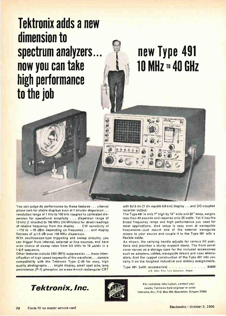
Tektronix adds a new dimension to spectrum analyzers... now you can take high performance to the job
You can judge its performance by these features ... internal phase lock for stable displays even at 1 kHz/div dispersion ... resolution range of 1 kHz to 100 kHz coupled to calibrated dis-persion for operational simplicity . . . dispersion range of 10 kHz (1 kHz/div) to 100 MHz (10 MHz/div) for direct readings of relative frequency from the display . . . CW sensitivity of —110 to —70 dBm depending on frequency . . and display flatness of ±1.5 dB over 100 MHz dispersion. With oscilloscope-type triggering and sweep circuitry, you can trigger from internal, external or line sources, and have wide choice of sweep rates from 0.5 s/div to 10 ,us/div in a 1-2-5 sequence. Other features include EMI (RFI) suppression ... trace inten-sification of high speed segments of the waveform... camera compatibility with the Tektronix Type C-30 for easy, high quality photographs ... bright display, small spot size, long persistence (P-7) phosphor on a new 4-inch rectangular CRT
new Type 491 10 MHz 40 GHz
with 8x10 div (1 div equals 0.8 cm) display .... and DC-coupled
recorder output. The Type 491 is only 7" high by 12" wide and 22" deep, weighs less than 40 pounds and requires only 55 watts. Yet it has the broad frequency range and high performance you need for most applications. And setup is easy even e waveguide frequencies—just mount one of the external waveguide mixers to your source and couple it to the Type 491 with a
flexible cable. As shown, the carrying handle adjusts for various tilt posi-tions and provides a sturdy support stand. The front panel cover serves as a storage case for the included accessories such as adapters, cables, waveguide mixers and coax attenu-ators. And the rugged construction of the Type 491 lets you carry it on the toughest industrial and military assignments.
Type 491 (with accessories) $4200 U.S. Sales Price f.o.b. Beaverton. Oregon
Tektronix, Inc. For complete information, contact your
nearby Tektronix field engineer or write:
Tektronix, Inc., P.O. Box 500, Beaverton, Oregon 97005
70 Circle 70 on reader service card Electronics October 3, 1966

If we can't make the best thermostats, we'd rather not make any. That's why we sell Edison.
\v\
We know Edison thermostats are best because we measure them by the same per-formance and reliability standards our own manufacturing people use for missile guid-ance and communications components.
We know another thing, too. We couldn't make better thermostats than Edison, how-ever much we tried.
Luckily, we don't have to.
As a manufacturer who's also a distributor, we're able to bring you the top lines in the various product categories. Whoever makes them.
So when it comes to thermostats, we bring you Edison.
You get the fast off-the-shelf delivery you expect from a national distributor like Arco.
And you get the engineering assistance and help with application problems you'd normally expect from a manufacturer.
Buy Edison thermostats and time-delay relays from Arco and you get the best of
both of us, manufacturer and distributor.
DIVIDED WE STAND.
Arco Electronics A Division of Loral Corporation
Community Drive, Great Neck, N.Y. Dallas, Texas, Pasadena, California,
Menlo Park, California. Circle 71 on reader service card

Three new 400-volt silicon power transistors for military duty:
UT TWO
They're designed for high efficiency inverters, voltage and current regulators, control and switching circuits and high-power communications where extreme reli-ability is required. DTS-423M is a NPN 3.5-amp 400-volt device in a
TO-3 package, offering high sustaining voltage capa-bility. DTS-431M is a NPN 5-amp 400-volt device in a
TO-3 package, offering higher gain and lower satura-tion resistance. 2N2580M is a NPN 10-amp 400-volt device in
a TO-36 package for extra high power applications. Specifications on all three devices are based on full
THREE
mil-type environmental tests performed in an ap-proved military qualification test lab. Check with our nearest sales office or Delco Radio
Distributor for full details.
TYPE Vcg0 Vceo (Vscucso) ic IB hgE
Vcg =5V R(sat) Max ® IC
Power D iss Max
DTS-423M 400V 400V (3m25inV)
325V (min)
3.5A
5.0A
2.0A
_9 ._
10 (I 2.5A 0(à8 e(1:11111 100W
125W DTS-431M 400V 400V 2.0A 10@ 3.5A 018 ohm (41 2.5A
2N2580M 400V 400V îln2 i‘ii) 10.0A 2.0A 4 @ 10.0A 0é145°.0hAni 150W
FIELD UNION, NEW JERSEY' DETROIT, MICHIGAN SANTA MONICA, CALIFORNIA' SALES Box 1018 Chestnut Station 57 Harper Avenue 726 Santa Monica Blvd.
(201) 687.3770 (313) 873-6560 (213) 870-8807 OFFICES SYRACUSE, NEW YORK CHICAGO, ILLINOIS' General Sales Office:
1054 James Street 5151 N. Harlem Avenue 700 E. Firmin, Kokomo, Ind. (315) 472-2668 (312)775.5411 (317) 459-2175
*Office includes field lab and resident engineer for applications assistance.
DELCO RADIO Division of General Motors
Kokomo, Indiana
GM
72 Circle 72 on reader service card Circle 73 on reader service card—>-

These new
heat shrinkables devour vinyl
spec by spec.
Yet cost no more. That's because new Insultite CP-150 and Insultite SRT are polyolefins. Heat shrinkable, irradiated poly-olefins that provide polyolefin protection at a polyvinyl price. Take new CP-150. It insulates and encapsulates any sub-
ject. Quickly. Tightly. Permanently. Won't split or rupture. Even over the most irregular surfaces. And it's particularly ideal for commercial, automotive, appliance, and computer applications. As for new SRT? Wrap up your capacitor insulation
problems once and for all. This clear, tough, thin-wall polyolefin is perfect for components that are subject to shock and strain, and where space and visual identification are considerations.
E. C. C. heat shrinkables are recognized under UL component file E39100.
Both CP-150 and SRT devour vinyl specs. Like low tempera-ture flexibility, abrasion resistance, structural strength, voltage standoff, and dielectric characteristics. And they shrink at a better than 2 to 1 shrink ratio. Come in a variety of printable colors and sizes. From ii4" to 2" ID. Think shrink with the Insultites. We offehcommercial, mili-
tary grade, flexible and semi-rigid tubing, heat-shrinkable end caps, and exclusive meltable inner-wall tape. Write for free samples today. (Specify diameters, please.)
ELECTRONIZED CHEMICALS CORPORATION A subsidiary of High Voltage Engineering Corpor,'
Box 57, Burlington. Massachusetts. Area Code 617.272-28K

One simple, rugged design adds reliability to all three rectilinear Mil wirewound styles
3-in-1 T-pot design gives you more
for your money!
RI-10, RT-11, RI-12 —Dale meets all three with a
single design. You benefit from this simplifica-tion through increased reliability, faster delivery, better price. Call us today!
ALL-MOLDED HOUSING design eliminates seal problems. Meets MIL-STD-202 and MIL-R-27208A.
(.3. RUGGED COLLECTOR SYSTEM assures you of noise levels " well below mil requirements.
0 FULL LENGTH WINDING allows increased power hand-ling capability. Permits use of large diameter ther-moconductive mandrel which eliminates "hot spots" by acting as high mass heat sink.
r,;\ 1-PIECE WIPER ASSEMBLY of precious metal insures \7.../ setting stability under all environmental conditions.
reN STAINLESS STEEL ADJUSTMENT SCREW has metal-to-metal clutching — prevents over-travel damage.
(A"" CONSTANT LEAD SCREW SEAL is assured by shaft-retaining spring which maintains unvarying pressure against high temperature silicone rubber "O" ring.
RI-11
RI-12
RT- 22
DALE MIL-R-27208A MODELS
Model 691 P.C. Pin
el..— Model 697 Flex. Leads
Model 1287 P.C. Pin Model 1288 Flex. Leads
Model 1680 P.C. Pin Model 1697 Flex. Leads
5000 Series- 1/2 " square-trim models meet RI-22, made with same basic design considerations shown here.
WRITE FOR CATALOG B —containing specifications on 57 Dale T-Pots including many special models.
DALE ELECTRONICS, INC.
74 Circle 74 on reader service card Electronics I October 3, 1966

Washington Newsletter
October 3, 1966
Ilaas endangered
by Vietnam cost ...
... may be replaced
by black boxes
Defense awards
keep coming ...
... but a plateau
may be here
Earlier launch
for next Surveyor?
The future of the Navy's Integrated Light Attack Avionics System (Ilaas) is growing increasingly doubtful. It now appears unlikely that the Navy will equip any of its A-7A Corsair aircraft with Ilaas, which is a com-puter-controlled complex of radars, displays and guidance package. Because development of the integrated system is running late, early A-7A production models already are scheduled to fly without Ilaas. The latest reevaluation, however, appears to be strictly economic. "It's all a budget matter," a Navy source says, indicating that rising Vietnam expenditures are putting the squeeze on other parts of the defense budget. Not only is it likely that Ilaas will miss the Ling-Temco-Vought, Inc.,
A-7A, but the entire program is in danger, according to Navy sources. The current research and development effort is expected to continue, but at a reduced level. However, a firm decision has yet to be made by the Pentagon. The Sperry Gyroscope Co., a division of Sperry Rand Corp., is developing and building four Ilaas prototypes under an initial $23.9 million contract and has been counting heavily on a big production follow-on program.
If Ilaas development continues, the integrated system may be installed on other upcoming Navy attack aircraft including future versions of the A-7A.
An avionics system similar to the one on Douglas Aircraft Co.'s A-4 Sky-hawk will probably be aboard the Navy's A-7A aircraft instead of the planned Ilaas complex. The A-4 nonintegrated system is a collection of subsystems and black boxes purchased and installed by Douglas. The Navy estimates it could save about $230,000 on each A-7A by going to an improved A-24 system rather than using Ilaas.
A good example of how Vietnam war spending is affecting various defense programs is the planned addition by the Pentagon of 280 more fighter planes for delivery in fiscal 1968. The new orders are good news for avionics producers who will share more than $150 million in new business. The total $700 million to be spent, however, will come but of funds earmarked for programs like Ilaas. The money is expected to go for the A-24 Skyhawk, the A-7A Corsair and McDonnell Aircraft Corp.'s F-4 Phantom.
Defense contract awards, which rose $10 billion during fiscal 1966 because of the Vietnam war, may well level off during the last half of this year and the first half of 1967. Washington experts are predicting that this year's awards will continue at about the fiscal 1966 level of $37 billion. However, this is an increase in their projection of last spring that defense orders would drop to $34 billion in fiscal 1967.
The launch date for the United States' third attempt at a soft landing on the moon reportedly has been set by the National Aeronautics and Space Administration for January 24. But the schedule may be speeded up
75

Washington Newsletter
following last month's $85-million flop of Surveyor 2, which was caused by the failure of one of the small vernier motors to fire during a mid-course correction maneuver. The space agency considered adding a sur-face sample experiment on the next flight, but the loss of Surveyor 2 may knock it out. In the experiment, which the space agency says still has "candidate" status, the lunar soil would be scratched in front of the television camera to obtain data on the soil structure.
Because of the success of Suryevor 1, instrumentation for three other experiments is being considered for later spacecraft in the seven flight program: a micrometeorite detector, a single-axis seismometer to measure moonquakes and an instrument to analyze the lunar soil by bombarding it with alpha particles and measuring their reflection.
Approval seen Despite the space agency's silence, indications are that three astronauts will be on board when the Apollo/Saturn 204 flight lifts off from Cape
for first manned Kennedy late next month. The NASA Design Certification Review Board, Apollo flight which meets to review and approve flights, is expected to recommend
that the next flight be a manned one. The board has examined the results of the August 25 Apollo 202 ballistic shot to determine why the com-mand module fell 200 miles short of the planned splashdown point. Program officials report that the guidance computer was working cor-rectly but that wrong data on the reentry angle was fed into it. If astro-nauts had been on board the Apollo they very probably could have landed the spacecraft on target.
Space technology
tackles football
Air Force
set to sign
MOL contracts
The space agency likes to show how aerospace technology is being applied to the solution of problems on earth as one way to justify its multibillion dollar budgets. Two such applications will be discussed at next month's annual American Institute of Aeronautics and Astronautics meeting in Boston: football—a systems challenge; and applications of the systems approach to planning problems of the archdiocese of Wash-ington, D. C.
Before October ends the Air Force will sign contracts with the Douglas Aircraft Co. and the General Electric Co. for the manned orbiting labora-tory (MOL). The Air Force will have as much as $240 million to spend on MOL in the current fiscal year; the total amount depends on how much money it can convince the Pentagon it needs. First launch in the $1.5 billion program, aimed at a manned launch in 1969, is a Gemini capsule suborbital shot next month to test a heat shield modified for MOL.
Nike missile It appears the Army again will lose its annual battle to proceed with pro-duction of the Nike-X antimissile system. With the Pentagon still cool
production may to deploying the system, it looks like another year of research and devel-stall again opment. The Western Electric Co., the prime contractor, has received
$273 million for R&D so far this year and will receive another $170 million before the end of fiscal 1967. This will raise the total amount spent so far on the controversial and long-delayed antimissile program to more than $2.7 billion.
76 Electronics October 3, 1966

New Computer Grade Capacitors with proved
high ripple ratings The new line of Mallory CGS Aluminum Electro-lytic filter capacitors, designed for 65°C ambient,
looks the same as our present CG family .... same case and top construction, but they're different inside.
A completely new set of specifications for ripple current has been established for this line. The new
values are based on Mallory tests of many hun-dreds of capacitors under a variety of environmen-tal conditions and ripple currents. Maximum ripple values stated for the CGS are the proved currents to which you can design with full confidence of long, reliable life. And they are higher than our previous values: for identical case size, about four times higher . . . for identical C-V ratings, over twice as high. ESR specifications are also lower.
Furthermore, you can now get about twice as much capacitance in a given case size as was formerly available in Mallory capacitors. Maximum capaci-tance is now 280,000 mfd at 3 WVDC or 1,800 mfd at 450 WVDC, in the 3" diameter by 5W case. And there are 880 other standard ratings from
which to choose. For complete data, write for your copy of new Bulletin 4-80. Mallory Capacitor Com-pany, a division of P. R. Mallory & Co. Inc., Indianapolis, Indiana 46206.
MALLORY ANNIVERSARY -
Electronics 'October 3, 1966 Circle 77 on reader service card 77

Stackpole Ceramag® ferrite components have been the accepted standard of the Tele-vision Industry for over twenty years.
In 1965, Stackpole began sup-plying Automatic Pincushion Correction Cores, a major advance, for color television receivers. 1964 saw the intro-duction of Stackpole 90° color components including Flyback, Yoke and Convergence Cores. As far back as 1954, these same components were introduced for the 70°color Deflection Systems. The list of contributions
Stackpole engineering and pro-duction know-how has made to the growth of color in television is long, and varied. This same capability has been applied to the continual improvement of
black and white receiving
equipment as well.
To be first with such items as Horizontal Output Transformer
Cores and Automatic Pincush-ion Correction is not enough.
Innovation must stand the test
of performance. Stackpole Cer-
amag® components have, since 1947. Small wonder most manu-facturers have come to depend
so heavily on Stackpole's expe-
rience and quality. Stackpole
Carbon Company, Electronic
Components Division, St. Marys,
Pennsylvania 15857. Phone: 814-
781-8521. TWX: 510-693-4511.
Ceramag® Ferrite Components are Coloring the Entire Television Picture
Îe SIMKPOLE ELECTRONIC COMPONENTS DIVISION
OUR 60th YEAR"
78 Circle 78 on reader service card Eler:t7onics October 3, 1966

•
. TRW oiyes you...
•
rde ,SEICIEwle 5 AMP
baiSSITC Hill 0 %Mal S Ire
S PA er
• •
•
•
SPEED: 80M Hz GAIN: 5Oh FE e lA SATURATION: IV @ 5A
Every characteristic the designer needs for top perform-
ance airborne inverters and switching regulators are
combined in the new TRW 2N4305-2N4312 power tran-
sistors... high frequency.., high gain—low collector saturation voltage.
Another plus factor in this outstanding new series is operating voltage characteristics as high as 120V.
••16
Available in TO-5 packages. Available in Low Profile
Isolated Stud packages, Available NOW from author-
ized distributors everywhere!
For detailed technical information write TRW Semi-conductors Inc., 14520 Aviation Blvd., Lawndale, Calif.
90260. Phone: 679-4561, TWX: 910-325-6206. Cable
TRWSEMICONS / Telex: 67-7148,
TRW SEMICONDUCTORS Electronics October 3, 1966 Circle 79 on reader service card 79

Texas Instruments chooses GAF x-ray film to prove there's not the tiniest mistake \ f f) o Texas Instruments Incorporated, a prime 4 F 11 manufacturer of miniaturized electronic
equipment for both industry and govern-ment, uses GAF industrial x-ray film to
prove zero defects in critical components, assemblies and sub-systems. Diodes, rectifiers, capacitors, resistors and germa-nium and silicon transistors, used in everything from hearing aids to missile guidance control systems, are subjected to exhaustive radiographic examination to assure faultless performance and long life.
In the photograph above, Texas Instruments Quality Control Inspector, Mrs. Dorothy Gross, is studying a GAF Industrial 'H-D' radiograph. Industrial 'H-D' is an ultra-fine grain, very high contrast film designed to yield high image definition—even when radiographing minute subjects and very thin materials. Industrial 'H-D' is available in a wide
variety of package types and sizes. Contact your nearest distributor of GAF x-ray products, and he'll introduce you to the GAF X-ray Representative assigned to your area. Or write directly.
gaF GENERAL ANILINE 6 FILM CORPORATION
140 WEST 51 STREET, NEW YORK, NEW YORK 10020
Att: Customer Service Dept. E-103
Please send me more information on GAF Industrial 'H-D' x-ray film.
Name
Title
Company
Address
City State 7 ip
80 Circle 80 od reader service card Electronics October 3. 1965
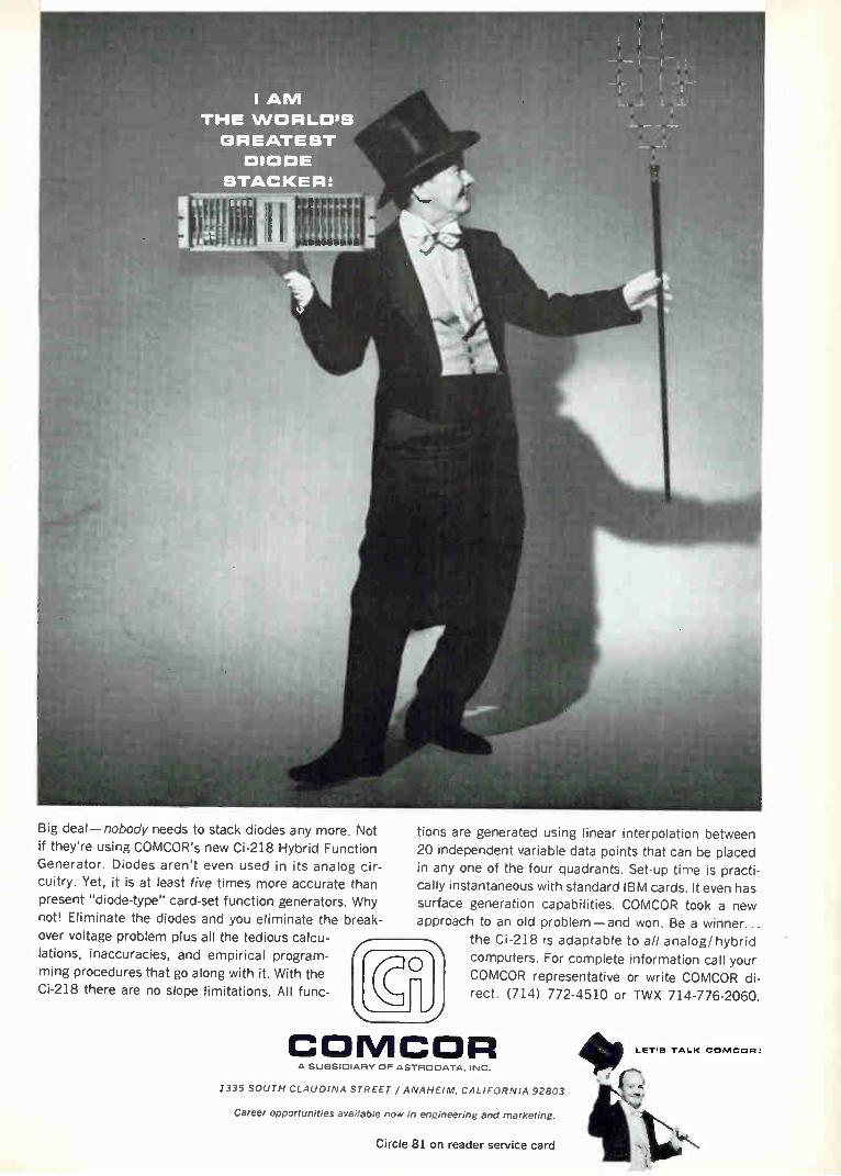
I ANI
THE WORLD'S
GREATEST
DIODE
STACKERS
Big deal—nobody needs to stack diodes any more. Not
if they're using COMCOR's new Ci-218 Hybrid Function Generator. Diodes aren't even used in its analog cir-
cuitry. Yet, it is at least five times more accurate than present "diode-type" card-set function generators. Why
not! Eliminate the diodes and you eliminate the break-over voltage problem plus all the tedious calcu-lations, inaccuracies, and empirical program-
ming procedures that go along with it. With the Ci-218 there are no slope limitations. All func-
tions are generated using linear interpolation between
20 independent variable data points that can be placed
in any one of the four quadrants. Set-up time is practi-cally instantaneous with standard IBM cards. It even has
surface generation capabilities. COMCOR took a new
approach to an old problem —and won. Be a winner...
the Ci -218 is adaptable to all analog/ hybrid
computers. For complete information call your COMCOR representative or write COMCOR di-
rect. (714) 772-4510 or TWX 714-776-2060.
COMCOR A SUBSIDIARY OF ASTROOATA. INC.
1335 SOUTH CLAUDINA STREET / ANAHEIM, CALIFORNIA 92803
Career Opportunities available now in engineering and marketing.
Circle 81 on reader service card
LET'S TALK CONICCIAt

Core, plane or stack problems? Take 'em to the experts. (Us.) Core? Construction? Format? Hos-tile environment? Whatever your problem, we've probably seen— and solved—it before. If not, Fer-roxcube experts always find the shortest path to the right an-swer. For instance — Application: Core memory stack for real-time display system in ship-board fire control computer. Problem: Hostile thermal environ-ment, critically limited space re-strictions. Solution,: Single-area, double mat-ted printed-circuit board construc-tion; bus-wire bridging to allow air-flow cooling of 30-mil wide tem-perature range cores. Application: Core memory stack for navigational guidance comput-er in commercial avionics system.
Problem: Mil-reliability at commer-cial prices; NDRO operation; vol-ume reproducibility. Solution: Single-area, single-mat-ted plane, plastic laminated termi-nal frame construction; bootstrap patterns with 30-mil cores on ex-tremely tight centers.
FERROXCUBE CORPORATION OF AMERICA
Saugerties. New York 914-246-2811
Boston Chicago 617-889-3110 312-261-7880 214-255-0441
Application: Low cost core memory stack for state-of-the-art commer-cial-computer main memory.
Problem: High speed, low noise, high output uniformity, repairabil-ity, expandability, 650 ns cycle time, ease of access and interface. Solution: 21/2 D organization; planar construction to offer lowest cost and convenient access; 20-mil cores; stack mounted diode modules. Application: Core memory stack for guidance computer in missile-borne avionics package. Problem: Extremely hostile me-chanical and thermal environ-ments, critical space limitations. Solution: Continuously-wired, folded-stack construction; wide
temperature range cores wired using novel shock and vibration damping techniques. What's your problem? Cores? We pioneered them. We have 20-, 30-and 50-mil cores in both standard and wide temperature range types covering a broad spectrum of switching and drive current param-eters. Planes and stacks? We use a wide variety of printed circuit board or laminated frame-strip con-struction techniques, 21/2 D, 3D or linear select. Cost? We meet and lick this problem every day. It's part of being the experts.
Want more information? Write for Bulletins 6005 & 6006.
Ferroxcube
Dallas Los Angeles Minneapolis New York Area Phoenix 2-13-837-1484 612-888-4681 201-267-5888 602-265-1792
Philadelphia Washington, D.C. 215-927-6262 703-893-4900
82 Circle 82 on reader service card Electronics , October 3, 1966

Years from now, people can still watch Surveyor's scan of the moon's surface ... thanks to Memorex precision magnetic tapes. When Surveyor relayed its famous closeup photographs of the moon's surface, Memorex tapes at JPL's Goldstone tracking station were busy recording these signals. All told, some 90% of the video and instrumentation tapes used in the Surveyor Program were Memorex. Now used to evaluate the mission, these tapes form a permanent record for future study.
Why was Memorex chosen? Simple. Space officials needed a tape that was rugged and reliable, and stood virtually no chance of missing any data. The logical choice was Memorex. Because of advanced design, careful manufacturing and uncompromising inspection and certification, Memorex tapes consistently outperform all others, reel after reel, year after year. To find out what Memorex can do for you, call at one of
our sales and service offices in this country and abroad, MEMOREX or contact us directly. We guarantee your satisfaction. PRECISION MAG N ET IC TAPE
Ikte-lo,ex Branch Offices in Boston, New York, Ph.lade.ph,, Washington, Atlanta, Orlando. Dayton, Chicago, Detroit, St. Louis, Dallas, Denver, Los Ange,es, San
Francisco, Honolulu. Offices and Affiliates in London, Cologne, and Paris. Distributors in Japan, Canada, India, Australia, and New Zealand.
• Circle 83 on reader service card

How nickel silver improves spring contacts for tuners.
Because it has substantially reduced their complaints and service calls to customers, Standard Kollsman Industries, Inc. uses nickel silver for contacts and springs in their TV tuners.
They find that nickel silver provides three advantages for tuners: extended life, superior performance, and practical cost.
Nickel silver extends tuner life because of its wear resistance and good spring properties. It provides superior performance in wiping contacts because of its low rate of tarnishing. And nickel silver is practical in cost because of its low material cost, excellent workability and the fact that it eliminates the need for expensive coatings.
Standard Kollsman uses nickel silver alloy CA 764 on 130 contact points. Nickel silver alloy CA 770 is used on the ground spring of the stator board assembly.
Nickel silver—a long-lasting, low-cost alloy of copper, nickel and zinc—can be cold-worked to tensile strengths up to 120,000 psi and has an elastic modulus range of 18,500,000 psi to 21,500,000 psi. It's easy to work, readily lending itself to any converitional forming technique.
Next time you want: Improved shelf life. Better performance. Fewer service calls. Consider nickel silver for springs and wiring contacts. In the meantime why not write us for a copy of "A New Look At Nickel Silver." The International Nickel Company, Inc., 67 Wall Street, New York, N.Y. 10005.
INTERNATIONAL NICKEL Nickel—its contribution is quality
84 Circle 84 on reader service card Electronics October 3, 1966

Cinch "Bow-Pin" ...versatile contacts for miniaturized connector applications
ACTUAL SIZE
TARGET PRICE FOR VOLUME
REQUIREMENTS
UNDER 5c A MATED PAIR
Whenever a connector application requires both miniaturization and a high degree of reliability, the Cinch "Bow-Pin" is the answer. This versatile little contact can be utilized in strip connectors (as shown), circular connectors or rack and panel connectors.
This unique "Bow-Pin" principle provides distinct advantages over conventional miniature contact devices.
Positive contact is assured by the flexing action of the bowed spring wires (unattached at the front end) that results when the contact is inserted into a tube having an ID smaller than the widest dimension of the bow.
Rugged construction—The flexing members are of relatively large cross-section to withstand abuse. NO WELDING IS USED IN THE
ASSEMBLY, eliminating the possibility of heat change in spring characteristics.
"Bow-Pin" strip connectors are currently available in 6' lengths with either .075' or .100' center spacing.
Por -more information on "Bow-Pin" contacts and strip connectors, write to Cinch Manufacturing Company, 1026 South Homan Avenue, Chicago, Illinois 60624.
IC I IN1 IC HI
DIVISION OF UNITED-CARR
Circle 85 on reader service card

INSTANT X-RAYS new research, design tool for workbench or lab ... x-ray inspection where and when you want it with office machine simplicity...$1970!
Here is a versatile new instrument that permits you to take your own x-rays— when and where you want them—at your workbench where your problems are.
Now you can obtain immediate insight into your design or research problem— locate, define, modify—speed develop-ment of your project with a quick "in-side" look, step-by-step or any time you need one.
Operation is as routinely safe and simple as a blueprint machine or an office copier. Just insert the subject, select the exposure time and voltage, push a but-ton. With film which processes in 10 sec-onds, the Faxitron 804 will give you clear, sharp radiograph prints on-the-spot in minutes or even seconds—or you can use standard wet films and cassettes up to size 14" x 17". Adjustable voltage from 10 to 100 KV assures excellent contrast over a wide range of object thicknesses and densities. Current of approximately 3 m.a. gives good penetration with a con-venient exposure time.
You can buy the standard Faxitron 804 for $1970 complete, f.o.b. McMinnville, Oregon. An optional extension collar as-sembly to provide full beam coverage for 14" x 17" cassettes is available at slight additional cost. For complete informa-tion, send for descriptive literature—or call collect Area Code 503, 472-5101.
FAXITRON 804
8
Field Emission Emission Corporation McMinnville, Oregon 97128
Pioneers in Pulsed Radiation Sources for Science and Industry
C] Send descriptive literature El Have a sales-engineer contact me
D My potential application is
Name
Company Title
Address Phone
City Zip State
86 Circle 86 on reader service card Electronics October 3, 1966

Cinch "Bow-Pin" ...versatile contacts for miniaturized I connector 1 applications
sIM
ACTUAL
SIZE
TARGET PRICE FOR VOLUME
REQUIREMENTS
UNDER Sc A MATED PAIR
Whenever a connector application requires both miniaturization and a high degree of reliability, the Cinch "Bow-Pin" is the answer. This versatile little contact can be utilized in strip connectors (as shown), circular connectors or rack and panel connectors.
This unique "Bow-Pin" principle provides distinct advantages over conventional miniature contact devices.
Positive contact is assured by the flexing action of the bowed spring wires (unattached at the front end) that results when the contact is inserted into a tube having an ID smaller than the widest dimension of the bow.
Rugged construction—The flexing members are of relatively large cross-section to withstand abuse. NO WELDING IS USED IN THE
ASSEMBLY, eliminating the possibility of heat change in spring characteristics.
"Bow-Pin" strip connectors are currently available in 6" lengths with either .075" or .100 center spacing.
For more information on "Bow-Pin" contacts and strip connectors, write to Cinch Manufacturing Company, 1026 South Homan Avenue, Chicago, Illinois 60624.
DIVISION OF UNITED-CARR
Circle 85 on reader service card
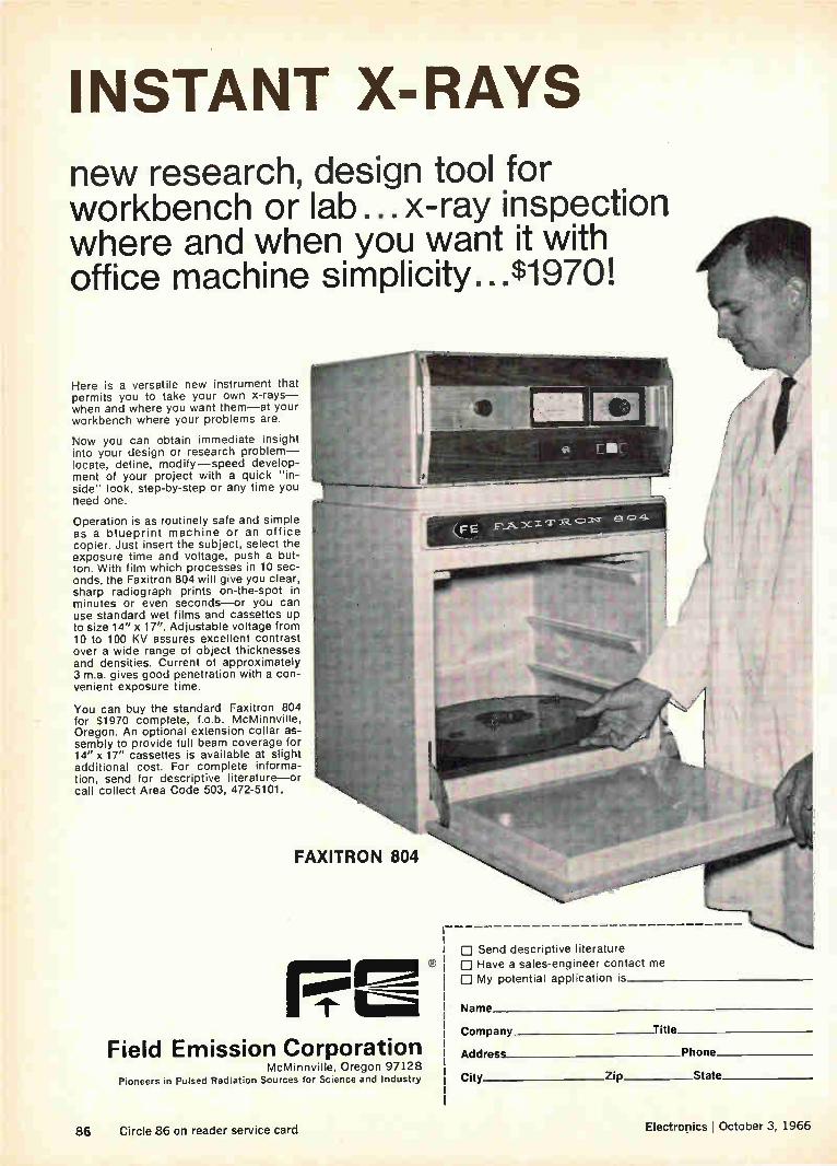
INSTANT X-RAYS new research, design tool for workbench or lab ...x-ray inspection where and when you want it with office machine simplicity...$1970!
Here is a versatile new instrument that permits you to take your own x-rays— when and where you want them—at your workbench where your problems are.
Now you can obtain immediate insight into your design or research problem— locate, define, modify—speed develop-ment of your project with a quick "in-side" look, step-by-step or any time you need one.
Operation is as routinely safe and simple as a blueprint machine or an office copier. Just insert the subject, select the exposure time and voltage, push a but-ton. With film which processes in 10 sec-onds, the Faxitron 804 will give you clear, sharp radiograph prints on-the-spot in minutes or even seconds—or you can use standard wet films and cassettes up to size 14" x 17". Adjustable voltage from 10 to 100 KV assures excellent contrast over a wide range of object thicknesses and densities. Current of approximately 3 ma. gives good penetration with a con-venient exposure time.
You can buy the standard Faxitron 804 for $1970 complete, f.o.b. McMinnville, Oregon. An optional extension collar as-sembly to provide full beam coverage for 14" x 17" cassettes is available at slight additional cost. For complete informa-tion, send for descriptive literature—or call collect Area Code 503, 472-5101.
FAXITRON 804
Fi Field Emission Corporation
McMinnville, Oregon 97128 Pioneers in Pulsed Radiation Sources for Science and Industry
8 D Send descriptive literature El Have a sales-engineer contact me
D My potential application is
Name
Company Title
Address Phone
City 743 State
86 Circle 86 on reader service card Electronics October 3, 1966

2 CHANNEL DISPLAY
LARGE READOUT TUBE (14")
SWEEP SIGNAL N.
GENERATOR
PRECISION
ATTENUATOR
TYPE SWOB
••ry, 1.041 11.4 ••• 11..0 - ROM% • .1041.001, au* FM
1L\ A \ II \ / \ \
\\
/
IMMEDIATE DELIVERY FROM STOCK
TYPE SWOB I $3100 TYPE SWOB II $4200
PoLysKop8 TT YY PP EE Ss Ww 00BB III 00 ..5 TTO : 1420000 MraHtix
XTAL MARKER
GENERATOR
FUNCTION SELECTOR
SWEPT FREQUENCY SYSTEMS
FEATURES
• Replaces 5 Units: Sweeper, Preci-sion Attenuator, Marker Generator, Electronic Switch, Display Unit
• Single Instrument Permits Optimized Design
me Insures High Accuracy By: • Dynamic Testing • 2 Channel Display for Substi-
tution Measurements • Elimination of Parallax Error • Built-in Standards for Atten-
uation, Gain, and Frequency • Large (14") Display Unit
• Broadband System: Sweep width to • 50 MHz
• Saves Time: Makes measurements up to 50 times faster
• Saves Money: Ideally suited for production personnel
Get The Extra Capability, Greater Reliability, and Longer Useful Life Of...
4
APPLICATIONS
Automatic plotting of dynamic characteristics and alignment work for single tuned and multi-stage . circuits and filters, four terminal networks, cables, limiters, wide band amplifiers, TV receivers, dis-criminators, terminating resistors, antennas, etc.
PRODUCTION TESTING Comparison:
Product on and Reference Samples
Frequency Response Standard
T-section RN 4244
Frequency Response Test Item
The Polyskop is a complete visual display sweep frequency measuring system available in two frequency ranges, TYPE SWOB I: 0.5 to 400 MHz (available in 50P or 75e), and TYPE SWOB II: 0.5 to 1200 MHz (50P). They provide an automatic display of the amplitude-frequenc response of a test item instantan` eously, thereby eliminating point by-point measurements. The Poly skops include a sweep frequency generator, with adjustable sweep width and center frequency, precisio output attenuator, crystal marke generator (1, 10, 50 MHz, Ext.). electronic switch for 2 channel pre sentation, high impedance probe and large 14" CRT display. Acces sones available: camera adapter precision extension cables, and Typ USWV to extend dynamic range fro 30 to 80 dB.
AMMfflIMIMI
ROHDE 8t SCHWARZ 111 LEXINGTON AVENUE, PASSAIC, N. J. 07055 • (201) 773-8010
Inquiries outside the U.S.A. should be directed to Rohde & Schwarz, Muehldorfstrasse 15, Munchen 8, West Germany
Electronics October 3, 1966 Circle 87 on reader service card 87

Something every Roman Centurion could have used:
PORTA The Roman soldier would have welcomed a
portable razor, powered by rechargeable batteries, just as today's consumer does. The compact de-sign and engineering excellence make portable products extremely useful items.
GULTON has developed the 'Second Genera-tion' rechargeable battery. It recharges in a frac-tion of the time previously required.
This means that new portable product appli-cations are unlimited. As unlimited as portable
ILITY electric razor sales to Roman soldiers would have been.
Talk to a GULTON battery applications en-gineer about your portable product. He'll design and manufacture a 'Second Generation' battery to
fit your new product idea.
Conte see us at booth 600 at the N.E.C. show in Chicago.
For information, call or write:
G • El GULTON INDUSTRIES, INC Alkaline Battery Division, Metuchen, New Jersey 08840 (201) 548-2800
Manufacturers of: Micro Miniature ''Rit)' 'neo? • Ceramics • Electronic Systems • Instrumentation • Power Supplies • Imlustrial & Consumer Products.
88 Circle 88 on reader service card Electronics October 3, 1966
cottete-A random collection offact, opinion
and miscellany... some of it a blatant attempt to peddle the products
and capabilities of Motorola's. Government Electronics Division.
IS YOH SARNO RUING SIMI MOTES? Then blame your Stanley Steamer dealer, not us.
No one knows more about S-Band transponders than Motorola.* If
you have doubts, ask the people who put together communications and command systems for Apollo, LEM, Ranger. Mariner and like that. They know. But the point is, since we are the number one build-ers of S-Band transponders, we should also be the number one pro-viders of S-Band test systems. Alas, 'tis not exactly the case. Some people are labo-ring under the de-lusion that other people can make the proper test equipment for our units. This, of course, is like taking your Rolls-Royce to a Stanley Steamer dealer for maintenance. So please, Owners of Our S-Band Transponders, at least write to our Aerospace Center for spicy litera-ture on our off-the-shelf, modular, pretty S-Band test equipment. In fact, send for the literature even if you have someone else's trans-ponders. You'll find a mall box on your way to the Stanley Steamer dealership.
* if you even think you know ,.ire than we do, you may know too much to stay on anyone else's payroll. Send a resumé and let us tantalize you with ludicrously lucrative offers.
TWO tiny trusty transponders
If you're in the mood to test your small missiles and sounding rockets under severe environmental con-ditions, lay in a stock of our two new superhet transponders. One is
C-Band (SST-171C), the other X (SST-181X). Both are very rugged and accurate, yet weigh only 3.2 lbs., so you'll be able to pack in lots of other stuff.
ie not a eíblicat name
AROD is "Govtalk" for Airborne Range and Orbit Determination, and our Aerospace Center is build-ing about 2 million dollars worth for NASA's Marshall Space Flight Center. This system has a few tricky nuances that are allowing our boys to show some fancy foot-work in applying integrated elec-tronics to real live hardware. AROD reverses normal design techniques by putting doppler equipment in the space vehicle and the usually vehicle-mounted transponder on the ground. There are some very good reasons for this reversal, not just an innate perversity on the part of Marshall scientists. If we could afford a few more columns, we'd tell you all about it. For more information, write to our Aerospace Center,
P111,01t0T019 SPELLED
BACKWARDS IS
RADAR Besides being a word that reads the same in both directions, radar is something that Motorola knows inside out ... or at least sideways. Our new airborne side-looking reconnaissance radar system, SLR100, gives ample proof. The fruition of 10 years experience in the side-looking field, SLR100 is ideal for aircraft pod-mounting. It will deliver high-resolution terrain mapping and moving-target data recorded on film that can be de-veloped in flight and viewed within seconds. Write Aerospace Center for details.
Also, we have developed an all solid-state radar relay multiplex that, if it weren't so blasted reliable, we'd be telling you how easily maintainable it is. Write to Chicago Center to learn more about this.
Can there possibly be a use for a handsomely styled small box that does little else than silently dis-gorge great quantities of printed paper? Well, Sperry-Rand and NASA seem to think there is be-cause they've ordered a slew of them as readout devices for the UNIVAC 1230 command and tele-metry computers used in the Apollo program. The box in question is our TP-4000 high-speed, non-impact teleprinter. It spews out 3000 wpm, is all solid state, AND incorporates I/C design of such reliability you wouldn't believe it. And it's so quiet you can't tell it's working except for the paper flying out. Our Chicago Center has the spew for you. Write them.
Here it is almost the end and we haven't mentioned a single inte-grated electronics application so far. This would be like GE not mentioning "Progress". So, quickly, here's the word on RIC, an ad-vanced Radar Intercept Calculator developed for Air Force RA DC. RIC contains, among other things, some 2800 DTL fiat packs ...per-forming about 12,000 logic func-tions. If we'd built RIC in the con-ventional manner, it would fill at least three 6-foot relay racks. But this way it occupies only 3/4 of a Cu. ft., weighs but 38 lbs., and uses only 200 watts of power. Our Chi-cago Center would love to send you a shiny new brochure on RIC.
2/A?'xjte.e
We'd love to sell you anything dis-cussed on these pages, but we know some of you would rather make them your-selves. So come do it at Motorola and get paid
(well) for it. Both Centers need scientists and engineers of many disciplines. If you don't want to write for our stimulating sales liter-ature, se .d us a resumé. nt don't just sit there.
0 Government Electronics Division AN EQUAL OPPORTUNITY EMPLOYER
CHICAGO CENTER 1450 N. Cicero Ave.. Dept. 7, Chicago, Illinois
AEROSPACE CENTER 8201 E. McDowell Rd., Dept. 7, Scottsdale, Arizona
MOTOROLA
Electronics October 3, 1966 89

CHEAPAND DIRTY.
NEVER! Look at our new EBR for what it is. A new, low-cost 2 amp, full-wave bridge (single
phase) epoxy rectifier. We mean low cost. Varo's new Epoxy Bridge Rec-
tifier is available (in quantities) for less than a dollar
apiece. More than that, we haven't sacrificed reliability to
bring you lower cost. This neat little rectifier has controlled avalanche
characteristics. It gives you the same reliability that you get with our I 0 amp and 25 amp Integrated Bridge
Rectifiers II BR" I. It's prepackaged. too, so you save plenty of assem-
bly time. Our new EBR rectifiers are available with 200V,
400V. and 600V PRV ratings. The controlled ava-lanche series features 250V, 450V and 650V minimum avalanche voltages. We also make a non-controlled avalanche series.
Output current in the new EBR is 2 amps at 25° C r
(TA) and all devices have 2000V minimum circuit-to-case insulation. And they're available with Faston* "110" terminals or silver leads.
After you've used our EBR's you'll probably start calling them something like those reliable little money savers from Varo.
But cheap and dirty. Never!
'.Trademark of AMP Incorporated
o VARO
SPECIAL PRODUCTS DIVISION .',201WALNUTST..GARLAND.TEXAS75041(AREACODE214)276-6141 TWX214 276 8577
90 Circle 280 on reader service card Electronics October 3, 1966

Lutron needed: the best combination of small size,
reliability and low cost in capacitors for solid state dimmers.
So Lutron chose: capacitors of MYLAR.
"Only capacitors of MYLAR* give us the size and reliability we must have, and at lowcost,"saysJoseph M. Licata, Chief Engineer. Lutron Electronics Co., Inc.
Lutron's broad line of dimmers is min-iaturized to fit single gang boxes for quick, easy installation. Because MYLAR has extremely high dielectric strength in thin gauges, capacitors made from this polyester film can be manufactured small enough to meet *DU PONT'S REGISTERED TRADEMARK FOR ITS POLYESTER nu..
Lutron's requirements. In addition,the capacitance stability of MYLAR provides the long-term reliability needed for trouble-free brightness control of all types of incandescent and fluorescent lighting.
Voltagerequirements for Lutron'sdim-mers are 200 to 600 volts, and in many instances these units operate around the clock. Lutron's own tests and ex-perience indicate capacitors of MYLAR
perform well in these conditions, even under extremes of humidity and temperature. Lutron has also found that in many cases, capacitors of MYLAR cost less than paper. If capacitor size, reliability and price are important to you, check into MYLAR by writing: Du Pont Co., Room 4671A, Wilmington, Delaware 19898. (In Canada write: Du Pont of Canada, Ltd., P.O. Box 660, Mont-real, Quebec.)
Better Things for Better Living...through Chemistry C .. ou pgt MYLAR Electronics , October 3, 1966
Circle 281 on reader service card 91

TO PROVIDE a microcircuit systems approach adaptable to breadboarding, small quantity and production runs
• all-new, highly competitive prices
• built-in drivers, inverters and buffers
eliminate most interconnecting wiring
• up to 18 microcircuits per card enable high density and lower costs
• boards designed to meet MIL- and
NASA standards
• boards keyed to assure proper mounting
• dual in-line packages easily replaced
for ease of maintenance
• off-the-shelf delivery
The Vitro microcircuit systems approach is directly adaptable to a broad range of requirements. Whether the application be for breadboarding, one-
of-a-kind units or total production runs, Vitro Micromodules are designed
to provide the systems engineer with a low-cost, flexible, building-block
approach to designing an integrated-circuit system.
The logic implementation on all Vitro boards has been standardized for
positive NAND logical functions at a voltage swing from 0 to +3 volts. The diode-transistor logic devices employed have individual circuit speeds up .o 10 MHZ, and equipment speeds above 5 MHZ. These circuit boards can be provided as directly off-the-shelf logic, with standardized performance to simplify a logic design application, or can be custom-built accordir7,
customer specifications. High density packaging is utilized providing un
18 removable microcircuits on a single card. Ease of maintenance is assu -:o since all dual in-line circuit packages can be easily removed and replac,r-1
in the field. To further simplify maintenance, Vitro-supplied chassis figurations are constructed of standard components assembled on a
ing block principle. For further information on the complete line of Vitro microcircuits, mount-
ing hardware, card files, wiring accessories, and power supplies, contact the Micromodule Sales Department, VITRO ELECTRONICS, 919 Jesup-Blair Drive, Silver Spring, Maryland 20910, Phone No. (301) 585-1000.
7 II1ELECTRONICS A Division of Vitro Corporation of America
Producers of NEMS-CLARKE Equipment V-23
92 Circle 282 service card Electronics October 3, 1966

A TECHNICAL DIGEST FOR INNOVATORS OF ELECTRONIC EQUIPMENT
Improve Color TV life, reduce costs
How tiny can a transistor get?
Designing small motors? Better check this
new magnetic material.
What's new for peripheral
computer equipment?
Switch to the lowest cost SCR
Multifunction G-E compactrons do the job of 2 or more ordinary tubes 4. ... require less wiring and simplify . gr Ti your circuitry. Now G.E. offers 5 new
:4; i i Igt types. G.E.'s new 6AG9 is the indus-try's first ultra-high transconductance 177(7
I!
i l
video output pentode to incorporate New General Electric 6A-
other functional elements (in this G9, 25CG3, 6HS5, 6EF4 le case, a triode). The 6EF4 is an im- and 40KD6 compactrons
proved 40-watt, high voltage regulator that protects against destructive arcing. The 6HS5 is a new type of high voltage regulator of the pulse-shunting variety. The
40KD6 and the 25CG3 are series-string versions of the 6KD6 and 6CG3 respectively, de-signed for 270-volt large-picture sets. Circle Number 90 for more details.
Actual size
0.07 x 0.07 x 0.085 inches is all G.E.'s new microtab transistors measure. Yet each delivers precisely the same performance as its larger, conventional-sized counterpart. They're perfect for hearing aids, miniature operational amplifiers and very small instruments . . . or for your hybrid circuits, and linear and analog circuits. Equivalents to 2N930, 2N2484 and 2N918 tran-sistors are already available for less than $1.00 in quantities. Circle Number 91 on the magazine inquiry card.
Improved Cast Alnico 8
General Electric's new Improved Cast Alnico 8, the best material for small motor applications, is now available. Al-though this new material can be substituted directly for some existing designs at comparable costs, it is more economical and efficient to redesign the motor to utilize the improved properties available. Improved properties provide greater flux density, high coercive force, extreme temperature stability, and greater useful recoil energy. Circle Number 92 for com-plete information.
Instant response—inertial time constants low as 1 mil-lisecond—is what you get with the new G-E Hyper-Servo* motor. And it accelerates faster than any other motor ever developed by General Electric. Hyper-Servo motors greatly increase the overall capacity of pe-ripheral data processing equipment. They're available in 3.4-, 4.6-, and 4.8-inch diameters. Performances in-clude torque-to-inertia ratios in excess of 350,000 rad/ sec' and continuous torque ratings from 32 oz-in at 2700 rpm to 326 oz-in at 2800 rpm. A wide variety of models can provide the high performance drive motor for nearly every computer peripheral application. Circle magazine inquiry card Number 93. *Trademark of the General Electric Company.
New high-response d-c motor
G-E C106 SCR's cost from 35 to 50c in volume. That's about half the price of other "low cost" SCR's. Yet you buy them at no sacrifice to performance or quality. New, planar C106's are reliable . . . give exceptional electrical uni-formity and long term stability. They feature up to 200-v blocking capability, microamp triggering, and a configuration that's excellent for printed circuits, plug-in sockets, screw mounting, and point-to-point wiring. Circle Number 94 on the magazine inquiry card.
MORE Actual size G-E C106 SCR
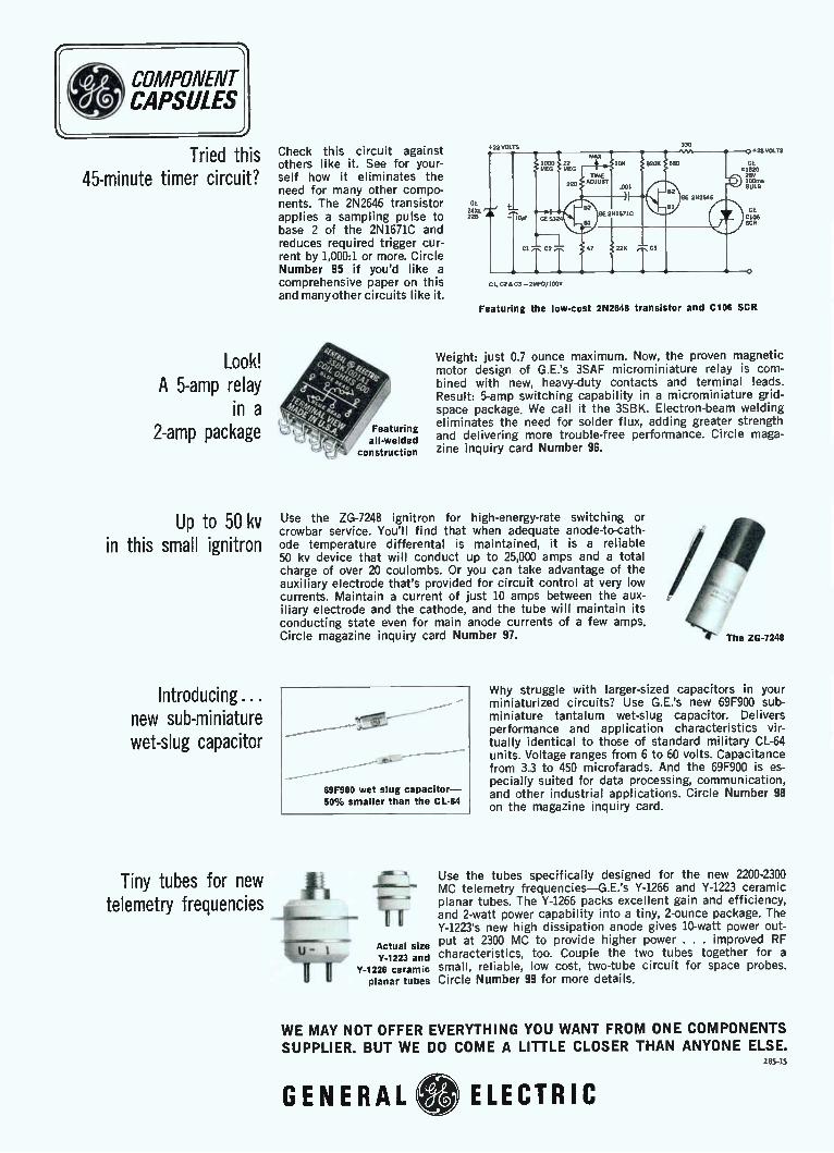
Tried this 45-minute timer circuit?
Look! A 5-amp relay
in a 2-amp package
Up to 50 kv in this small ignitron
Introducing... new sub-miniature wet-slug capacitor
Check this circuit against others like it. See for your-self how it eliminates the need for many other compo-nents. The 2N2646 transistor applies a sampling pulse to base 2 of the 2N1671C and reduces required trigger cur-rent by 1,000:1 or more. Circle Number 95 if you'd like a comprehensive paper on this and many other circuits like it.
Featuring all-welded
construction
GE
228
22 VOLTS
MAX 1000 22 10K 82oec 680 G MEG MEG
TIME DIE E
220 ADJUST .001 41 82 8
81
132 GE 281671C
GE 282646
BI
— 1081 GE 52 BI
1 47 22K C3 C2
Cl. C2 E. C3 — 214FD/100V
28 VOLTS
E 20
LB
E 06
Featuring the low-cost 2N2646 transistor and C106 SCR
Weight: just 0.7 ounce maximum. Now, the proven magnetic motor design of G.E.'s 3SAF microminiature relay is com-bined with new, heavy-duty contacts and terminal leads. Result: 5-amp switching capability in a microminiature grid-space package. We call it the 3SBK. Electron-beam welding eliminates the need for solder flux, adding greater strength and delivering more trouble-free performance. Circle maga-zine inquiry card Number 96.
Use the ZG-7248 ignitron for high-energy-rate switching or crowbar service. You'll find that when adequate anode-to-cath-ode temperature differental is maintained, it is a reliable 50 kv device that will conduct up to 25,000 amps and a total charge of over 20 coulombs. Or you can take advantage of the auxiliary electrode that's provided for circuit control at very low currents. Maintain a current of just 10 amps between the aux-iliary electrode and the cathode, and the tube will maintain its conducting state even for main anode currents of a few amps. Circle magazine inquiry card Number 97.
69F900 wet slug capacitor-50% smaller than the CL-64
Tiny tubes for new e i telemetry frequencies &
IS"r— Actual size Y-1223 and
ir Y-1226 ceramic
planar tubes
4/ #
'
' The ZG-7248
Why struggle with larger-sized capacitors in your miniaturized circuits? Use G.E.'s new 69F900 sub-miniature tantalum wet-slug capacitor. Delivers performance and application characteristics vir-tually identical to those of standard military CL-64 units. Voltage ranges from 6 to 60 volts. Capacitance from 3.3 to 450 microfarads. And the 69F900 is es-pecially suited for data processing, communication, and other industrial applications. Circle Number 98 on the magazine inquiry card.
Use the tubes specifically designed for the new 2200-2300 MC telemetry frequencies—G.E.'s Y-1266 and Y-1223 ceramic planar tubes. The Y-1266 packs excellent gain and efficiency, and 2-watt power capability into a tiny, 2-ounce package. The Y-1223's new high dissipation anode gives 10-watt power out-put at 2300 MC to provide higher power . . . improved RF characteristics, too. Couple the two tubes together for a small, reliable, low cost, two-tube circuit for space probes. Circle Number 99 for more details.
WE MAY NOT OFFER EVERYTHING YOU WANT FROM ONE COMPONENTS SUPPLIER. BUT WE DO COME A LITTLE CLOSER THAN ANYONE ELSE.
285-15
GENERAL ELECTRIC
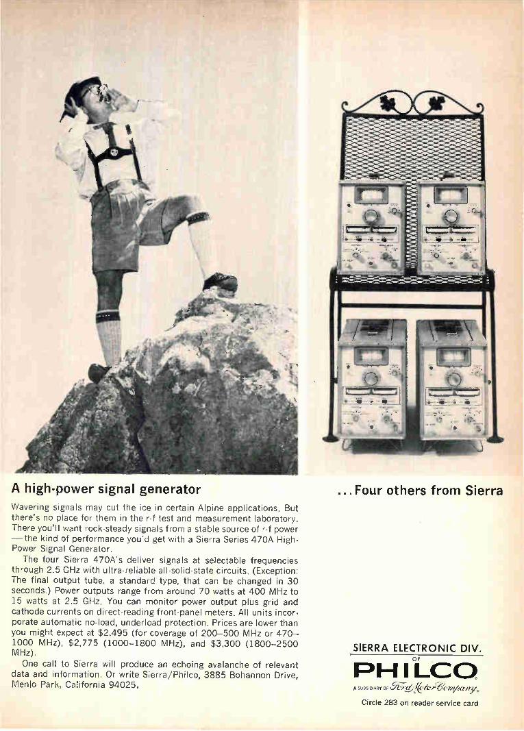
A high-power signal generator Wavering signals may cut the ice in certain Alpine applications. But there's no place for them in the r-f test and measurement laboratory. There you'll want rock-steady signals from a stable source of r-f power —the kind of performance you'd get with a Sierra Series 470A High-Power Signal Generator.
The four Sierra 470A's deliver signals at selectable frequencies through 2.5 GHz with ultra-reliable all-solid-state circuits. (Exception: The final output tube, a standard type, that can be changed in 30 seconds.) Power outputs range from around 70 watts at 400 MHz to 15 watts at 2.5 GHz. You can monitor power output plus grid and cathode currents on direct-reading front-panel meters. All units incor-porate automatic no-load, underload protection. Prices are lower than you might expect at $2,495 (for coverage of 200-500 MHz or 470-1000 MHz), $2,775 (1000-1800 MHz), and $3.300 (1800-2500 MHz).
One call to Sierra will produce an echoing avalanche of relevant data and information. Or write Sierra/Philco, 3885 Bohannon Drive, Menlo Park, California 94025.
...Four others from Sierra
SIERRA ELECTRONIC DIV. OF
PH I LCO A r C./Zy-L/,«_léier'6c.nt/terny,
Circle 283 on reader service card

Only the pen moves. No pulleys. No drive cords. No gears.
An inertial what?
An inertial ink pump for our 2/10 second response Speed Servo® Recorder
It uses the inertia of a small stainless steel ball to pump ink as needed.
It writes a legible record at speeds above 100" per second (2/10 second response over 10"
span). Yet it doesn't bleed at the slowest speeds.
We call it Speed Line Writing. And for this new Speed Servo®, Speed Line
Writing is required. Its servo motor has only one moving part. No gears, pulleys or drive cords.
Want more features? Take off balance input impedance of 500,000 ohms. Accuracy is
+0.4% of span for any range. This recorder meets all specifications to
50,000 ohms source impedance and maintains
rated accuracy to 100,000 ohms. The Speed Servos® feedback potentiometer
is made of conductive plastic and has effectively
infinite resolution. It lasts thousands of hours longer than any wire-wound potentiometer.
Need Adjustable Zero Adjustable Span
(AZAS)? This Speed Servo® option has zero elevation and suppression continuously ad-justable from 0 to 100 MV for any span setting. Span is continuously adjustable from 1 to
100 MV. You can choose from 15, 10 or 5 speed auto-
matic chart drives. Dial speeds from 1/2" per
hour to 8" per second.
um Learn more about this exciting breakthrough in servo recording. Write for our Series "E"
Catalog.
Esterline Angus Instrument Company, Inc.
Box 24000E • Indianapolis, Indiana 46224
Excellence in instrumentation for
over 60 years
96 Circle 284 on reader service card
=I Lre SUMMISIUM 121U'S Electronics I October 3, 1966

October 3, 1966 Highlights of this issue
Technical Articles
FET's call the tune in active filter design:
page 98
New dimensions in IC's through films of glass:
page 108
Pcm telephone exchange switches digital data
like a computer: page 119
For a crew in lonely orbit, something to lean on in
space: page 129
When NASA needed a way to reduce transmission power for voice communications to and from space probes on their way to distant planets, engineers searched for filters that were small and had narrow bandwidth and fast response time. The answer proved to be a voltage-tunable filter that uses field effect transistors as the tuning elements.
Electronics Better glassing methods and new materials allow the best of monolithic and hybrid microcircuits to be combined cheaply. It now seems clear that for many applications, monolithic integrated circuits alone will not be satisfactory. Covering a semiconductor chip with an impervious glass film allows a planar device to be transformed into a three-dimensional structure to do functions
a monolithic circuit can't perform. For the cover, an IBM circuit with 156 components demonstrates the complexity that is possible with new glassing techniques.
One objection to a pulse-code modulation system in telephony has been the requirement to convert the digital signals back to analog ones before they pass through an exchange. Now an all-electronic system has been developed to switch pcm signals without such a conversion. The center is compatible with the pcm system described in Electronics, Sept. 19, 1966. The advantages include smaller and less expensive exchanges, while good signal quality is maintained.
The more man learns about outer space as an environment, the clearer it becomes that working and living there will be more difficult than scientists expected. In the manned labora-tories being considered, some kind of computer will be necessary as a watchdog, programer and calculator. Here is how a machine could do this varied and complex job.
Coming
October 17
• Users' guide to integrated circuits
• Automatic fault location
• Testing integrated circuits on the production line

Circuit design
FET's call the tune in active filter design
A voltage-tunable audio filter uses field effect transistors as the
tuning element instead of inductors; small size and low cost make them
valuable in space communications where narrow bandwidth is required
By James M. Loe Philco Corp., a subsidiary of the Ford Motor Co.
The National Aeronautics and Space Administra-tion was searching for a way to reduce transmission power for voice communications from deep space, possibly as far out as the planet Mars. But that meant filters in the transmission equipment had to be small, response time fast and bandwidth narrow.
Conventional current-controlled variable induc-tors used in filters for tuning were too costly and bulky for space communications. A solution came from engineers at the Philco
Corp., a subsidiary of the Ford Motor Co. They developed a voltage-tunable audio filter that uses field effect transistors (FET's) as the tuning ele-ment in place of inductors. The result saved money and space. The conventional filter weighed two pounds and occupied 10 cubic inches. The new filter measures only 1.5 cubic inches and weighs 11/2 ounces. Four of the filters were included in a speech
bandwidth compression system Philco delivered to NASA under the terms of a $60,000 contract. The system permits transmission from space of a narrow band of encoded information that can be converted into synthetic intelligible speech on earth. Designed for the audio frequency range, the
family of high-Q (up to 100) low-pass, high-pass
The author
James M. Loe is a project engineer at the Communications and Electronics division. He is presently assigned to the Advanced Communications Laboratory where he is engaged in the development of low bandwidth voice encoding equipment.
and bandpass filters can be used up to several hundred kilohertz. The filter frequency is linearly related to control voltages over a 20:1 frequency range; a portion of this range is shown in the curves on page 101. The new filters respond quickly to changes in
control voltages. The rate at which the resonant or corner frequency (frequency at which response is three decibels down from the passband response) changes is a function of the rate at which the FET source-drain resistance varies. This value exceeds 400 Mhz/ sec. This tuning rate, though not needed in NASA's application, may be useful in doppler radar systems, sonar systems and high-speed con-trol systems.
Voltage tuning
A field effect transistor can serve as a voltage-variable resistor by keeping the voltage impressed between the source and the drain small.") For the FET's used in this design the voltage between the source and the drain is typically 0.1 volt peak to peak at a 10:1 tuning range. Under this condition, the variable source-drain
resistance of the field effect transistor is closely approximated by
R. RsD —
1 — K1 Vge (1)
where R. = the resistance at zero gate bias, K1 = a constant, dependent upon FET type,
and Vg. = gate-to-source voltage.
The inverse relationship between the gate-to-source voltage and the source-drain resistance is compatible with active filter designs, which are
98 Electronics October 3, 1966

electrically equivalent to the conventional inductor capacitor (L-C) type of passive filters. Passive L-C filters can be designed to have a wide range of bandpass characteristics. Passive R-C filters are limited with respect to attainable bandpass shapes. The active R-C filters designed with FET's over-come this limitation.
Low-pass filter
The basic active low-pass filter can have a peaked or unpeaked response, as indicated in the diagram below. The response depends upon the damping factor chosen. In the figure above right field effect transistors were substituted for R1 and Ro. In the filter design, attenuation at the required corner frequency is initially specified. The re-quired damping factor is selected from the universal two-pole filter characteristics of filter amplitude response versus frequency to obtain the specified corner attenuation rate.
For the low-pass filter circuit, the design condi-tions to be met are:
> 10Xc2 ROUT < 0.1X,,, R + R2
where Il i>, = input impedance of emitter follower Q3, a function of emitter resistor RE and
ROUT = output impedance of Q. RI, R2 = source-drain resistance of Qi and Q2.
The design equations for the low-pass filter are
1 con =
RMC2
CI when M2 =
SIGNAL INPUT
= resonant or corner frequency (2)
OUTPUT
+V CC
SIGNAL INPUT
CONTROL INPUT
OUTPUT
Ql 02 (R I 1 (R2)
CI
Matched field effect transistors, substituted for R, and R2 in the basic low-pass filter, give an active voltage-tuned filter.
P 2 1— K2 1 M ( 1 )
= M damping factor (3)
where K2 =- voltage gain of Q.
By substituting equation 1 for equation 2, the corner frequency becomes a linear function of the FET gate control voltage,
1 — Ki Va„ = R. MC2 (4)
High-pass filter
Similar principles may be applied to produce a voltage-tunable high-pass filter. The circuit is shown below. After selecting the damping factor at a required corner frequency to meet attenua-tion and overshoot requirements, filter component values are determined. In this case, the emitter— follower parameters are chosen so that
RIN > 10R2; RouT <
p.0.15
--12db / OCTAVE
-VEE FREQUENCY
Basic low-pass filter can have a peaked or unpeaked response depending upon the damping factor.
C1 SIGNAL________ INPUT
OUTPUT
Cl SIGNAL _1 INPUT
-VEE
FET's acting as resistors in the high-pass active filter operate at the same controlling voltage and provide a damping factor of unity.
Electronics October 3, 1966 99

SIGNAL INPUT
RIN
R1
+vcc
GzI.4
-VEE
SIGNAL INPUT
04
(R1
RIN )>R1
C2
-VEE
n o, (Ft2) CONTROL INPUT
+vcc
+V +V CC CC
OUTPUT
eM -VEE -VEE R3
Active, voltage-tuned bandpass filter, derived from the basic bandpass filter, consists of two cascaded amplifier stages, QL and Q2 and emitter follower, Q. Equalizing Ri C. and R2 C2 minimizes the required gain for a given damping factor.
The design equations are
1 2 Rilt2CiC2
where CI = C2
- corner frequency (5)
1+M2 X P - ± (1— K2) = damping factor (6)
2XM 2M
where M 2 = -c-,-C2
and R2
X2 =
and K2 = gain of Q. The corner frequency is linearly related to the
control voltage. As a practical consideration, both FET's operate at the same control voltage, making the source-drain resistances R1 = R2. Under these conditions the damping factor is always unity. In certain designs this is not necessarily desirable. The restraint can be loosened, though, by making Ci r C2, but the filter design then becomes more complex.
Bandpass filter
An active, voltage-tuned bandpass filter is basic-ally quite different from the low and high-pass
Experimental breadboard of voltage-tunable audio bandpass filter can be easily compressed into 1.5 cubic inches for space package. Philco delivered four such audio filters to NASA.
100 Electronics October 3, 1966

SIGNAL INPUT
1.R IN
c I 0.056
01 2N3390
03
R »R IN
02 2N3565
C2 0.056
3.3K
+VEE SU700 (PAIR )
CONTROL INPUT
04 (R4)
OPERATIONAL AMPLIFIER SUCH AS FAIRCHILD »709 I:10K
8 252K
K
it OUTPUT
22pf
115V
10K
An integrated operational amplifier is used in the bandpass tunable filter to insure stability at high values of filter Q.
configuration. A simplified fixed-tuned version shown above, consists of two cascaded amplifier stages with an over-all gain of approximately two. The third stage, emitter follower Q3, provides a low output impedance. The frequency selective networks are a low-pass filter made up of RI and CI and a high-pass filter formed by R. and C.. The products RIC, and 110C2 are equal since this re-sults in the minimum gain required for a given figure of merit, Q. Capacitor Ca and resistor R3 pro-vide a-c coupling and a d-c return path to the base of Q. When field effect transistors replace resistors
that determine frequency, component values may be determined by these equations:
con == RIC resonant frequency
1 @ = 1 — 0.25G i2G - figure of merit
22
CI and C. are the voltage gains of Qi respectively.
RIN (Q1) > 10 Xci, RIN (Q2) < 10 Xc2 (9)
R1 is chosen to equal R. and C1 = C.. In the design of bandpass filters, figure of merit, Q, a function of the damping factor, is the basic parameter. It can be shown that here too, (.„ varies linearly in re-sponse to the control voltages.
Practical considerations
When a high Q bandpass filter is required it be-comes difficult to satisfy the requirement of high amplifier input impedance and low output imped-ance. In addition, when the Q is high, slight am-plifier gain variations strongly affect the figure of merit. To overcome these problems, an integrated operational amplifier, connected as shown in the
(7)
(8)
and Q2
CONTROL VOLTAGE
3
2.5
2
1.5
0.5
O 0 500 1,000 1,500 2,000 2,500 3,000 3,500 4,000
CORNER FREQUENCY (Hz)
Linear relationship exists between corner frequency and control voltage in the low-pass critically damped filter and between the resonant frequency and control voltage in the bandpass filter.
--- CORNER FREQUENCY VS. CONTROL VOLTAGE FOR LOW PASS CRITICALLY DAMPED FILTER
— — RESONANT FREQUENCY VS. CONTROL VOLTAGE FOR BANDPASS FILTER WITH Q.26
diagram above is a useful substitute for the output transistor and provides a high range of Q from 10 to 100. The field effect transistors in the active voltage-
tuned filters are matched for operation over the 20:1 frequency range. The resistances at zero gate voltage, R., are matched within 5%, the resistances at 4R0 are matched within 10%, and at 20R0 matched within 20%. The field effect transistors limit maximum peak-
to-peak output signal swing to about 0.1 volt. At greater signal amplitudes the output signal becomes distorted.
Reference
1. James S. Sherwin, "FET's as Voltage Controlled Resistors," Solid State Design, August 1965.
Electronics October 3, 1966 101

e
Circuit design
Designer's casebook
FET's produce stable oscillators
By Tom F. Prosser
Microelectronics Division, Philco Corp., Santa Clara, Calif.
Oscillators that are inexpensive but stable can be made with field effect transistors. The oscillators can be tuned to frequencies ranging from subaudio to near gigahertz and, with modifications, can sweep through a wide frequency range. An example of the manually tuned type of r-f
oscillator is shown in the circuit below. The cir-cuit features load leveling for constant output volt-age. Basically, it is a Colpitts oscillator. The drain-source voltage of one FET, Qi, is
limited by the variable resistance of a second, Q0. Consequently, the oscillator's output voltage is lim-ited. Oscillations occur when the drain-source volt-age of Q1 is as low as 6 volts. Transistor Q1, made by Amelco Semiconductor, a division of Teledyne, Inc., has high mutual conductance (gn, = 5,000 mi
0.01
300
C.)
2, 250
CC
cr
cn o
200
Designer's casebook is a regular feature in Electronics. Readers are invited to submit novel circuit ideas, packaging schemes, or other unusual solutions to design problems. Descriptions should be short. We'll pay $50 for each item published.
2 3 4 5 6 7 8 9 10 II 12 13 14
INPUT BIAS IN VOLTS
Frequency control characteristics of the sweep oscillator indicate that the oscillator can sweep over more than 100 Mhz in a nonlinear manner, or over a narrow range in a linear manner. The equation indicates the angular frequency of oscillation.
NOTE: ALL CAPACITANCES ARE IN MICROFARADS UNLESS INDICATED.
Load leveling is achieved in the oscillator when one FET, Q, acts as a variable resistance. Despite load variations, Q,'s drain-source voltage remains fixed.
102 Electronics I October 3, 1966

V cc +20V
25K LINEAR SWEEP
NOTE: ALL CAPACITANCES ARE IN MICROFARADS UNLESS INDICATED.
SWEEP DEVIATION
10K
Transistor Q.'s triangular shaped output sweeps Varicap tuning capacitors D. and D8 and the oscillator frequency via the buffer amplifier, Q. Load leveling is accomplished by Q. and Q11.
cromhos and generates low self-noise, under 4 microvolts. The circuit produces an unloaded output voltage
of up to 15 volts peak to peak in the 300- to 400-megahertz region. A portion of this voltage is cou-pled through the transformer, rectified by diode DI and filtered by R1 and C1. The setting of resistor R1 controls the operating point of FET Q2 and hence the output amplitude. R1 is set for a full-load oscillator output of 10 volts peak to peak. A sweep-frequency version of the load-leveling
oscillator is shown above. Components D2 and D3 are voltage-variable capacitances covering a fre-quency range from 200 to 300 Mhz. The voltage
output curve of unijunction transistor Qs is tri-angularly shaped. This output voltage buffered by amplifier Q. changes the capacitance of the Vaxi-caps and hence the oscillator frequency. Resistor R2 sets the sweep deviation by controlling the am-plitude of the voltage applied to the Varicaps. De-pending upon the setting of 112, the oscillator can sweep a wide range nonlinearly or a narrow range linearly. C2 and C3 refer to the capacitances of D2 and D3 in the formula on the graph. As in the fixed-frequency oscillator, transistors
Qi and Q2 respond to output load change with fast leveling action while supplying high output voltages with low harmonic distortion.
Switching amplifier converts unipolar to bipolar pulses
By W.D. Waddle Texas Gas Transmission Corp., Owensboro, Ky.
Conversion of positive pulses to positive and nega-tive pulses is accomplished with the circuit on page 104 in both transistor logic circuits and interface amplifiers. Such unipolar-bipolar converters are often used
in business machines and data transmission sets. To achieve the conversion the input circuit is con-
nected directly to the output of a transistorized logic circuit. When the input of the converter circuit is at
zero potential, transistor Q1 becomes forward biased and conducts heavily. Under this condition Qi furnishes a low resistance path for the cur-rent from supply voltage E1 through part of resistor R to the load RL. Thus, a positive voltage E. is dropped across RI.
Variable resistor R (a low value resistor, about 10% of R.) is set to the limit of the positive pulse swing. During the rise of the input pulse, diode D1 blocks current. Thus, resistor R becomes part of a voltage divider on the positive output voltage swing. The application of a positive voltage (ap-proximately equal to El) to the input of Q1 causes
Electronics October 3, 1966 103

ECC -25v
E0
-I V
o - o
+ 8v
E IN
Rg 68k
_L +6 1 3— = +8v
During the positive part of the input waveform, Q, conducts and produces a positive output voltage, E,.. When the input voltage reaches the value E,, transistor Q, becomes reverse-biased, stops conducting and causes a negative output storage, —E..
y E0
the transistor to be reverse-biased and subse- age swing. Bias supply E2 and diode D2 limit quently cut off. Now that transistor Qi is not conducting, there
is a high-resistance path for current from E1 to 11/.. Supply voltage E,. is then free to provide current through resistor Re, diode DI and load resistor RI, to develop a negative voltage across 118, approximately equal to voltage supply E2.
Diode DI passes current on the negative pulse and bypasses resistor R on the negative output volt-
the signal when the output swing is negative. Typical operating values are as shown. The
characteristics of diodes DI and D2 are selected according to the switching rate required and the current through the diode on the negative output pulse. A transistorized buffer amplifier added at the input is a simple method of accomplishing the switching action. Resistor Re is found on the basis of E„, required on the negative output swing.
Detector stores peaks
of video bursts
By David S. Greenstein Honeywell, Inc., Boston
The peak detector shown senses the highest peak of an amplitude-modulated 2-megahertz burst to within 5 millivolts. Peak values from 5 millivolts to 1 volt are stored for approximately 100 micro-seconds and each time the peak exceeds the stored value a pulse is produced. This detection is use-ful where position information about a video signal is required. Burst detectors are found in radar, sonar and video and are used for sam-pling time delay signals.
Conventional diode detectors cannot achieve such accuracy or range because diode junctions are sensitive to temperature changes and require large turn-on voltages. Furthermore, conventional detectors don't usually furnish a signal when the storage is updated. The comparator detects the amplitude of the
1250 nsec ONE-SHOT
COMPARATOR
Comparator senses when the amplitude of the 2-Mhz signal becomes 5 millivolts or more than the voltage stored on capacitor C.
2-Mhz signal when it exceeds the voltage stored on capacitor C by 5 millivolts [see block diagram]. On sensing the amplitude, the comparator trig-gers the 250-nanosecond one-shot multivibrator, producing an output pulse. This pulse, coupled with one from the synchronized pulse generator, turns on the field effect gate circuit, raising the voltage stored on the capacitor to a new value.
104 Electronics October 3. 1966

2-Mhz BURST IMPULSE
10k
2N918
150- nsec DELAY LINE
+9v -I2v +4.5v AMPLIFIER AND FIELD EFFECT STORAGE
2N9I8
R2
100k
3.6k 1k
+4.5v +9v
10k 2N3209
2N918
10k 2N3209
2N918
03 2N918
2N918
2N918
2N9I8
180
2k
SCHMITT TRIGGER 1---14 ONE-SHOT rell
2N918
2N3209
2k Q1 120M f 4700 iok
—4.5v CM603
2N918
+9v
CM603
1.5k 2N3209
2N9I8
2N3209
2N918
820 200
—4.5v
1
2N3209
510
+12v
D
COMPARATOR
200
2N918
2N3209
51k
—4 5v —4.5v
AND GATE r i
R5
+4.5v
2N3209
0.1 if
SYNC PULSE
The peak is stored for 100 microseconds by capacitor C1. To assure storage for this period the capacitor must discharge with a time constant of at least 20 milliseconds.
A 125-nanosecond pulse from the synchronized pulse generator ensures that the gate is turned off after 90° of the 2-Mhz sinusoidal waveform. It is essential that the field effect gate be turned off or the capacitor will discharge. The synchronized pulse generator is not neces-
sary if the 2-Mhz maximums are flatter than those of a sine wave or if the input frequency is much below 2 Mhz. Compensation for the delay in the
field effect gate driving pulse is provided by the 150-nanosecond delay line, caused by propaga-tion delays and the fact that the comparator trig-gers a one-shot at some time during the first 90° of the 2-Mhz signal.
Over-all gain for the amplifier and field effect storage section shown schematically must be 1 because the output of this circuit is the stored voltage that is compared with the 2-Mhz input;
Electronics October 3, 1966 105

capacitor C1 is the storage capacitor. To store a voltage for 100 microseconds within 0.5%, the capacitor must discharge with a time constant of at least 20 milliseconds. Resistor R1 in parallel with C1 provides the required time constant.
Field effect transistors Q1 and Q2 have a neg-ligible effect on the time constant because of their high impedance. Because of the finite gate-source capacitance, the turn-on pulse at the gate of Qi feeds through to the storage capacitor and appears as a negative step with an amplitude of approxi-mately 1 volt. This step is constant for all signal levels. Compensation for the step is accomplished by adjusting the d-c level with potentiometer R2. Gain is adjusted with potentiometer R3. Pontenti-ometer 114 zero-adjusts the source follower.
N-channel field effect transistors, CM603, manu-factured by Crystalonics, Inc., are used because of their low "on" resistance of 35 ohms maximum
and high gain-bandwidth product of 400 Mhz. The on resistance must be low because the low-pass network made up of the on resistance of Qi and capacitor Ci must pass the 2-Mhz signal frequency. The comparator is a three-stage, direct-coupled
differential amplifier with a gain of approximately 800 in the frequency range of 25 lchz to 9 Mhz. Low-frequency feedback is provided by R5 and 116 to produce low d-c gain. The comparator drives a Schmitt trigger that fires a 250-nanosecond one-shot. Improvements in the performance are pos-sible since the sensitivity is largely a function of the gain and stability of the comparator. To eliminate unwanted oscillations, the com-
ponents are assembled on a sheet of brass. Tran-sistor sockets are not used and the cases of Qs, Q4, Q5 and Qg are mounted upside down in individual heat sinks bolted to the brass plate for positive grounding and isolation.
Circuit samples a signal,
holds it up to 1 minute
By Robert S. Cuikay Northeastern University, Boston
Where pulse information is required, as in data systems, the circuit shown is used to sample sig-nals and store them for up to 1 minute. These sig-nals vary less than 5%. The circuit has a high cur-rent transfer ratio and operates from —55° to +85°C with low power consumption. The signal to be sampled is applied to the base
of transistor Q1. Forward biasing the base-to-emitter junction of Q3 with a positive voltage, V2, saturates Q3. Transistor Q3 must be saturated dur-ing a specified sampling time, set by the input gate signal. Thus the collector of Q3 saturates from a positive voltage of V1 to approximately the emitter voltage of Q3 and provides a current return path for the previously inhibited transistors Q1 and Q2. The sampled signal is then transferred to the stor-age capacitor CI through a signal path indicated by:
= e„ — VBE1 VD1 VIM VD3
where
V, = sampled input signal voltage = input signal
VBE1 =
VD1
base-to-emitter voltage junction drop of transistor Qi
forward junction voltage drop of the
INPUT SIGNAL TO 8E SAMPLED
es
_11_, v2 H INPUT GATE SIGNAL
2.8K
+VI
100
Q2 2N2604
10
vs
cl 2 I 2.2/Lf
FD300
10K
3 2N2222
10K
Sampling and holding an input signal up to 1 minute is possible with this high energy circuit. The circuit operates well over a temperature range of +85° to —55° C.
emitter-to-base protection diode VD2 = forward junction voltage drop of isolation
diode = forward junction voltage drop of compen-
sation diode. To make the sampled signal equal to the input
VD3
106 Electronics 'October 3, 1966

signal (V. = e.), VBE1, VD1, VD2 and VD3 must total zero. Although the junction drops of VBE1, VD1 and VG2 may not be properly matched, the adjustment of VD3 by a potentiometer across diode DB will allow for compensation of any voltage-junction drop dif-ferences. When the sampling gate time ends, the voltage
on the base of Qz equals the emitter's voltage. The equalization cuts off Qz and allows the collector node to rise to a positive voltage level of Vi. The voltage V1 reverse biases the protection diode DI and the isolation diode D2, stopping the sampling of the input signal. Thus transistors Qi and Q2 are cut off. Now, the
only discharge or leakage paths for the sampled and stored input signal voltage on capacitor CI are: the load impedance in parallel with the storage capacitor; the reverse biased base-to-emitter junc-
tion of transistor Qz; the reverse leakage of the isolation diode and the capacitor leakage. It can then be read out as V.. The circuit has several features: • The sampled signal transfer rate from circuit
input to the holding capacitors is equal to the square of the current transfer ratio (hFE2) of tran-sistors Qi and Q2. If a beta of 100 is given, the sig-nal transfer ratio approaches 10,000. So high-beta transistors are not required. • The input impedance of the circuit is given as
IIFE2 Ri„ in parallel with R.. Numerical values of R. and Ri under typical circuit conditions are 107 and 8 x 10⁷ ohms respectively. These resistor values yield an input impedance of approximately 8.8 X 10⁶ ohms. • The driving impedance to the storage capacitor
and equivalent loads is less than 900 ohms.
FET stabilizes amplitude
of Wien bridge oscillator
By Joseph J. Panico Technology Division, GCA Corp., Bedford, Mass.
When the drain-source voltage, VGB, of a field effect transistor approaches zero, the FET behaves very much like a linear variable resistance, and remains nearly linear at higher voltages below pinch-off. This characteristic makes FET's useful as a stabilizing element in oscillator circuits like the Wien bridge oscillator below.
eR 20K
c •—• 0.018
VDS
T° 01
-15V
5K
FET-P CHANNEL 2N2608
vG5
Oscillator output V., will be distortionless if it exceeds
In the circuit, output voltage V. is rectified by Di and filtered by 113C1. Potentiometer R2 sets the gate-source voltage, VGB, which in turn estab-lished the output amplitude.
Oscillations occur when
R5 Vim -----V ' 115 - where V.' = (V.).
3
the frequency of oscillation co = 1/RC. The circuit provides distortionless output over a
frequency range of d-c to 100 kilohertz if the tran-sistor's Vim does not exceed several hundred milli-volts. The drain-source resistance, RDs, becomes nonlinear at greater voltages than this. However, by adding a resistor in series with the FET drain, larger amplitudes can be obtained, with low dis-tortion and very little sacrifice in control.
+15V
PHILBROOK OPERATIONAL AMPLIFIER, PP65A, OR EQUIVALENT
IRR4
5
R2 200K AMPLITUDE TRIM
c,
10.2
R3 56K FD3309
10 volts, provided V„/V„' is greater than 10 to 1.
Electronics October 3, 1966 107

Materials
New dimensions in IC's through films of glass
Better glassing methods and new materials, such as silicon nitride,
may permit the best features of monolithic and hybrid integrated
circuits to be combined in bigger, better, cheaper IC's
By John A. Perri and Jacob Riseman Components Division, International Business Machines Corp. Hopewell Junction, N.Y.
From the marriage of monolithic and hybrid in-tegrated circuit technology may come a new genera-tion of circuits that will not require external com-ponents to function properly. To pursue the analogy further, the marriage bond
is likely to be glassing technology. This encom-passes various methods of applying impervious glass films to the basic semiconductor devices and the development of better glasses. Glassy silicon nitride, for example, is now being investigated as a means of improved semiconductor processing and as an insulator that may allow fabrication of more complex, yet more stable, devices. Covering a chip with an impervious, insulating
film allows a planar device to be transformed into a three-dimensional structure. Extra wiring layers can be added—as in the multicircuit chip shown on the
The authors
John A. Perri heads a development group responsible for device metallurgy and insulator technology at IBM's Components division. Since joining IBM in 1958, he has been concerned especially with glass passivation of semiconductors. He has a doctorate in solid-state chemistry.
Jacob Riseman, whose doctorate is in physical chemistry, also joined IBM in 1958 and has held many managerial posts in semiconductor and magnetic development. He is now in charge of silicon and thin-film technology.
cover—or thin-film passive components, or both, as illustrated on page 114. The multilayer approach adds two key advan-
tages of hybrid IC's to the attractions of monolithic IC's—more versatility in intraconnection and high-quality passive components. But the circuit remains integral. It is batch-fabricated, not an assembly of devices and wiring. Gains in performance can be expected. For instance, keeping all the passive de-vices and intraconnections within distances of a few thousandths of an inch is one way to get maximum speed in a logic or memory circuit. Device cost and reliability is improved by the absence of individu-ally fabricated connections and bonds.' The use of a single package to house a score or more of circuits on one chip further improves cost and reliability.
The best of two worlds
It has been conventional to consider monolithic IC technology as exclusively a semiconductor field, emphasizing intrinsic technology [see "Extrinsic and intrinsic technologies," right]. The monolithic approach2 has also emphasized fabrication of the entire circuit within the silicon crystal.
In the main, this approach exists in the fabrica-tion of complex circuits and IC arrays. However, the arrays represent an important trend—the striv-ing to get the most out of silicon technology by meeting the need for higher device speeds through smaller geometries and better intraconnection and packaging. This trend has focused attention on photolithographic problems and glassing tech-niques that solve them. Remaining as a significant disadvantage of mono-
lithic technology is the fact that passive components made of diffused silicon are poor performers
108 Electronics October 3, 1966

compared with discrete and film components. This limits the performance of monolithic IC's, as does the impracticality of designing an IC for best per-formance of each diffused device. Selecting a diffu-sion process ideal for one device generally impairs the performance of the others. A partial solution, effective in some IC's, is to de-
posit passive thin-film devices on the silicon dioxide coating that passivates the silicon surface and acts as a substrate for the thin-film intraconnections. This is frequently inadequate, if only because the thin-film components are large compared to the ac-tive devices and restrict the amount of intraconnec-tion area available. As a result, hybrid IC's must often be used. Now, the monolithic and hybrid technologies
show signs of merging, to gain the best of the two worlds.
Ball-and-solder joints
A good illustration of a hybrid technique that can serve as the jumping-off point for a more advanced IC is the International Business Machines Corp.'s well-known Solid Logic Technology (SLT).8 Chip semiconductors are bonded face-down to
a ceramic substrate that carries thick-film wiring and passive components. The chip is coated with glass to eliminate the need for expensive hermeti-cally sealed packages and to allow interconnection by the low-cost, solder reflow method. The method is as reliable as the usual wire bonding.4
After diffusion, the devices are coated with 60 microinches of glass by the fired-frit process° de-scribed on page 115. Small areas of the lands (thin-film electrodes on the device) are exposed by etch-
Extrinsic and intrinsic technologies
In the last 10 years, silicon transistor costs have de-creased from dollars to pennies while performance, measured by speed, has risen into the nanosecond range.
This cost-performance improvement has resulted largely from developments in what is sometimes called intrinsic silicon technology—the steps required to make a basic semiconductor device. The develop-ments include planar processing that allows a greater amount of batch fabrication; better diffusion methods; high-resolution photolithographic techniques; the use of thin epitaxial layers of silicon and better ways of controlling the distribution of impurities in the silicon crystal. Of almost equal importance now and of consider-
ably greater importance in the future is extrinsic semi-conductor technology—the steps that take place after the semiconductor junctions are formed. These steps include intraconnecting devices and terminals on the same silicon chip, interconnecting the chip to the next packaging level and providing a safe environment for the sensitive semiconductor junctions and the closely spaced metal lands.
Glass has played a starring role in the extrinsic technology during the past five years, allowing more sophisticated device fabrication and packaging tech-niques.", 28 It is certain to become more important in the future and may well determine the direction of semiconductor technology.
ing holes in the glass. The holes are filled with solder and tiny metal balls are placed in the holes, as in the diagram of a transistor on page 112. Then the silicon wafer is sliced into individual devices and soldered to the substrate. The ball-and-solder joints between the chip and
substrate, in the photo on page 112, are clearly the forerunners of the contacts of the complex IC's shown on the cover and page 113. The latter, a 16-bit memory circuit° is bonded to a module sub-strate by solder reflow. The glassing techniques have been extended to allow intraconnection of many devices. A similar contact could be used atop the more complex structure on page 114.
Numbers game
On the single SLT devices, the glass protects the semiconductor junctions and contacts, shielding them from mechanical damage during handling and automated assembly of the SLT modules. The glass is the package, but the devices are essentially the same as those packaged in metal cans. The glass's function changes when the device
grows into a monolithic IC. IC's sharply reduce de-vice packaging, handling and intraconnection costs. Since a single package already contains many de-vices, the economies of glass are no longer as pronounced. Here, the numbers game comes into play—a chip containing a score or more of circuits requires a complex, hermetically sealed package, but since the cost is shared by 100 or more com-ponents it is less than one package per device.
Therefore, glass as a package is likely to be of lesser importance in monolithic IC's than glass as a stable insulating film between multilevel wiring. If the wiring isn't multilevel, the amount of integra-tion possible will be severely curtailed.
Levels of wiring
Single-level wiring is the simplest use of glass. One thin film of glass protects the device and the thin-film wiring during solder reflow or thermo-compression bonding. Two wiring levels require more sophisticated
glassing techniques. The glass between the levels must insulate the many wiring crossovers yet allow for vias through the glass to connect the two levels. Vias are used in the circuit on the cover; the closeup photo on page 113 shows them clearly. A top layer of glass protects the upper wiring level and is the mechanical structure for the contacts to the next packaging level. In a sense, the result is a printed circuit board several orders of magnitude smaller than conventional boards.
Multilevel wiring allows more devices or circuits on a chip and reduces resistance and impedance in the lands by shortening the wiring. Typically, an aluminum-film land is 1 micron thick. As an elec-trode, carrying current from the surface into the de-vice, it has a resistance of at least 0.03 ohm per square. When the land extends over the insulating surface, the added resistance of a 0.3-mil-wide (0.0003 inch) land is 0.1 ohm per mil of length. The
Electronics I October 3, 1966 109

crossovers and vias of multilevel wiring permit the designer to use a shorter, more direct path between devices in most cases. Sometimes the additional sub-strate area of the extra glass layer offers the option of widening the wiring, thus lowering the resistance by reducing the number of squares iin a given length. Three or more wiring levels further extend elec-
trical capability by adding substrate area that can be used for deposition of thin-film components, as in the diagramed example on page 114, to obtain the precision passive components needed by high-speed digital circuits and linear circuits. The resistor on an intermediate glass film is protected by the glass above it. This is a return to hybrid technology, ex-cept that thin-film intraconnections replace external interconnections.
Glass's other job
Although this report is concerned primarily with the extrinsic role of glass—its application after sili-con processing—glass has some important intrinsic uses. The prime one is as silicon dioxide formed by the thermal oxidation of the silicon. This glassy phase, without grain boundaries, is a good diffusion barrier. It is etched to form a diffusion mask.
Glassy silicon nitride is being investigated as a diffusion mask for silicon and other semiconductors but its ultimate worth is still difficult to judge. It may prove superior to silicon dioxide as a diffusion mask, allowing smaller device geometries; improve device stability, because of lower ionic drift; and its higher resistance can lead to better dielectric isolation of high-speed devices.7"°
Glass is actually the diffusion source in some processes, especially if diffusion is done under oxi-dizing conditions. Glass containing the diffusant is applied directly to the silicon. A particularly inter-esting result of this approach is the phosphosilicate glass formed during phosphorus diffusion. The process is not understood well, but the glass en-hances device stability."
Matching silicon and glass
Because the silicon in an IC is thicker than its glass covering, silicon dominates the extrinsic struc-ture. The closer the glass's thermal" coefficient of expansion matches the silicon's, the better the glass grips the silicon. Mismatches of a factor of 2 can be tolerated if the
glass film is thin, about 1.5 microns or less, and the glass is in tension. Greater mismatches can be toler-ated if the glass's coefficient is lower than silicon's, placing the glass in compression.
Nevertheless, thermal expansion is a critical prop-erty in multilayer structures because the glass films must be thicker than for single-layer wiring. One reason IC designers are considering silicon nitride is its close match to silicon in its bulk coefficient of thermal expansion. Thermal stability is also important. The glass
must not soften or decompose, of course, at process temperatures used after the film is formed, nor dur-ing long use of the IC. Good thermal conductivity
helps dissipate heat from the circuit during use. Most dielectrics are poor heat conductors, but sili-con nitride is better than silicon dioxide. Chemical stability is necessary during processing
and to allow the glass to withstand adverse environ-ments, such as humid air. Moisture leaches some films, hydrates others, dissolves others and leaves some glass essentially unaffected."." The rule— with some startling exceptions—is: the higher a glass's softening temperature, the better its chem-ical stability. Silicon nitride's ability to withstand long exposure to water at 1,000° C is another reason it is intriguing.
Permeability of the film to the ambient, especially water, is closely related to density. Naturally, the designer doesn't want a glass that is porous, nor one that contains water or contaminants such as partly decomposed organic molecules. Films with grain boundaries are also shunned, because diffusants may attack the semiconductor junctions through the boundaries.
Dielectric constant should be low to hold down parasitic capacitances in the devices. Generally, this isn't a problem because the dielectric area (area be-tween metals acting as capacitor electrodes) is small in IC's. Resistivity of the film should be 10" ohm-cm or greater, to insure leakage currents less than normal junction leakage currents—in other words, negligible.
Ionic migration in glass films is a more complex problem. It can lead to electrolytic reactions that degrade thin-film resistors, semiconductor surface properties and crossovers." Glasses that have a low concentration of diffusioning species, such as so-dium, and also low mobility are scarce. One of sili-con nitride's outstanding features is a low rate of ionic migration; for example, sodium ion migration is, at 200° C, several orders of magnitude lower in silicon nitride than in silicon dioxide. An essential mechanical property is the ability to
remain a good substrate for thin-film deposition af-ter the glass is handled. It must also be machinable by methods fully compatible with silicon technol-ogy, so that well-defined contact holes can be formed in the film. In this, silicon dioxide and sili-cate glasses are outstanding; acid fluorides etch only the glass, not the other device materials. Other glasses need special masking films, requir-
ing additional deposition and etching steps. This is a major drawback to the use of silicon nitride, even though it is a better diffusion barrier and insulator and can thus be used in thinner layers to obtain smaller devices and contact holes. Etchants for sili-con nitride are powerful, so a chromium mask is used to protect areas that are not to be etched.
Glassing techniques
Glass is usually made by rapidly cooling certain liquids, chiefly molten oxides of silicon and boron. This, in essence, is the basis for the SLT glassing process, firing glass particles on the silicon wafer. Two other basic ways of glassing semiconductors
are: chemical deposition, consisting of reactions in
110 Electronics October 3, 1966

Out of the crucible and into the sputtering chamber
Glass is essential ingredient of multilevel wiring and protective coatings for integrated circuits.
Its composition is easier to control if it is made in bulk and
fused or sputtered onto the semiconductor wafers, instead of
being deposited by other methods.
Violet glow discharge bathes wafers in r-f sputtering chamber. Wafers are showered by molecules of glass dislodged from the cathode above by ion bombardment.
Silicon nitride coats these wafers; it is superior to silicon dioxide as an insulator, but is harder to process. The colors vary because optical interference between light reflected from the silicon and glass surfaces varies with coating thicknesses. Thicknesses are about 2,000 angstroms for the yellowish coating, 2,500 A for the bluish one and 3,200 A for the reddish glass. Silicon nitride is shinier than silicon dioxide because it has a higher refractive index.
Electronics ! October 3, 1966 111

Ball contacts: three for a transistor and 15 for a 16-bit memory circuit
Single-device chip soldered to interconnections on a ceramic substrate. Contacts are the
tiny metal balls shown in the diagram below.
Three steps in forming a fired-frit coating are illustrated (left to right) by a silicon wafer bare except for its silicon dioxide coating, a wafer coated with frit and a wafer after firing of the glass.
SOLDER
PROTECTIVE GLASS LAYER
I
( 5 METAL CONNECTING BALLS
) P
Transistor chip for hybrid integrated circuits has ball contacts fused into contact holes in 60-microinch-thick layer of glass. Glassing permits automation of assembly.
CONTACT STRIPS
N
N +
112 Electronics [ October 3, 1966
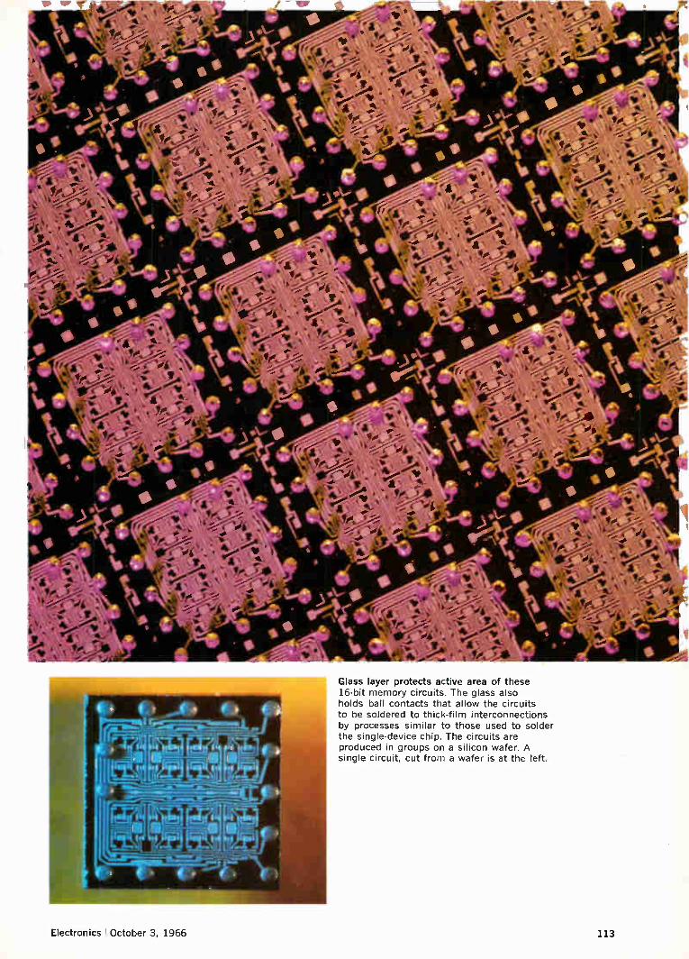
Electronics October 3, 1966

Extra glass means extra circuit performance
Optical pyrometer checks temperature of wafers in r-f heated furnace. Wafers, barely visible on a glowing carrier, are being glassed by chemical reaction.
CONTACT HOLE
N DIFF
P+ P DIFF
N EPITAXY
[ii
P+
P-SUBSTRATE
N DIFF I P DIFF
P+/
o GLASS • THIN-FILM RESISTOR LEGEND
CIMETALLIZATION El GROWN SiO2
Monolithic-hybrid circuit with three wiring levels. Extra layer of glass provides the substrate area needed to deposit and intraconnect precision thin-film part.
Two levels of wiring on monolithic integrated circuit are insulated by glass layer. This is a closeup of part of the IC shown on the cover, a developmental device containing eight current-switch circuits and a total of 156 components. The small spots of metal are vias through the glass, connecting wiring on one level to wiring on the other level.
114 Electronics !October 3, 1966

chemical vapors, or reaction at the wafer surface of volatile compounds of the glass's constituents, or both; and vacuum deposition, including evaporation and sputtering. All other things being equal, the ideal glassing process would be the one done at lowest temperature. However, compromises are re-quired to obtain the glass with the best combina-tion of properties and compatibility with other de-vice materials. Some materials won't form stable glass in bulk
form, but will do so in thin-film form. Silicon nitride is one of these, but it cannot be prepared by melting because decomposition occurs at its melting point of 1,900° C—a temperature so high that silicon ni-tride cannot be supercooled without crystallization. Besides, that temperature destroys diffused devices. Dense films of silicon nitride can be formed by py-rolytic (high temperature chemical decomposition) or sputtering techniques.
Fusing glass frit
The frit-firing method produces pinhole-free glass films of controlled composition and thickness. It is a simple process, well suited to mass production. The frit is finely ground glass particles, about 0.1
micron in size, suspended in a mixture of ethyl ace-tate and isopropyl alcohol. The frit is compacted onto the silicon wafer, usually by centrifuging, and then fused to the silicon by firing it at or slightly below the glass's softening point.
Because of the small particle size, a 1-micron-thick film is formed in a few minutes of firing. Thickness of a 1.5-micron film can be held to ±-0.03 micron over a wafer and average thickness from wafer to wafer can he held to .±-0.06 micron. Films thinner than 0.5 micron can be made. The thickness control greatly facilitates the etching of contact holes in the glass; resolution is comparable to sili-con dioxide and undercutting is at a minimum, mak-ing for low reject rates. One advantage over other techniques is that the
glass composition selected for the powder is the glass deposited—neither chemical complexity nor changes in composition during deposition are fac-tors in selection. Also, the fusion flows the glass, forming an excellent bond to the wafer surface. The major disadvantage is that the choice of glass
is restricted by the allowable firing temperature, which thus becomes the dominant factor. Higher-temperature glasses would be desirable for chemi-cal stability and better thermal expansion match with silicon. One process boundary is the maximum tempera-
ture that metal lands and metal-semiconductor con-tacts can stand. Metal lands must be used under the glass on most high-speed transistors and monolithic IC's so that electrodes can fan out to conveniently spaced terminals from very small, closely spaced emitter and base contact holes. If the lands are alu-minum, the temperature limit is the aluminum-silicon eutectic temperature of approximately 577° C. Lands are not required under the glass on diodes, since the single terminal can be placed di-
Another role for glass
Besides its extrinsic uses on devices made in single-crystal silicon, glass itself is a promising semiconduc-tor material. Two reports on this newest role of glass appeared
in the Sept. 19 issue of Electronics. The first, "Look-ing through the glasses for new active components," [p. 129] also provides additional details on subjects such as ionic migration and the formation of unusual glasses. The second, "Transistors face an invisible foe," [p. 191] tells how one company makes switches, transducers and memory devices with glass films.
If the hopes of researchers pushing glass semicon-ductor development come true, glass will become a competitor of silicon, not merely its servant.
George Sideris
rectly on the contact area. Secondly, if gold is used to control carrier lifetime
in the silicon, the glass firing temperature must be compatible with the gold diffusion or activation temperature of about 1,050° C. This is not a serious restriction because several glasses can be fired near 1,050° C. These two considerations demonstrate that the frit-fusion method must be made part of the process at the start of device design, not as an after thought.
Chemical deposition
Pyrolytic decomposition and reactions such as oxidation and hydrolysis are closely related chemi-cal glassing methods, similar to the processes that grow epitaxial layers on silicon crystal. The reaction is made to occur at the substrate surface, usually by making the substrate the hottest part of the deposi-tion system. Reaction in the gas phase, an old tech-nique, gives a loose, poorly adhering deposit.
Pyrolysis has been extensively investigated as a way to form silicon dioxide, the simplest silicate glass. Decomposition of ethylorthosilicate, Si(OEt)4, is an example of pyrolysis; oxidation of SiH4 illus-trates oxidation; and SiC14 plus water is an example of the hydrolysis method.", " To form silicon nitride, SiH4 or SiC14 may be reacted with NH3.8
Volatile compounds of the glass elements must be introduced simultaneously into the vapor phase to form more complex glasses, such as a borosilicate or an aluminum borosilicate. The compounds must also react at the substrate surface, in essence form-ing the glass in situ." Borosilicate-depositing com-pounds include B2H6, BCI3 and B(Me0)3, methyl-borate. Examples of volatile aluminum compounds are AlC13 and aluminum isopropoxide.
In principle, chemical methods deposit high-tem-perature glasses at relatively low temperatures and at relatively high rates, around 1,000 angstroms per minute. Offsetting these two advantages are several disadvantages: • The process temperature limitations are the
same as those for the fusion method. The composi-tion and the thickness of the film is more difficult to control than in fusion or vacuum deposition. Control depends on vapor-phase composition and uniform-ity of substrate temperature.
Electronics October 3, 1966 115

• Only the simpler glasses can be deposited. This limits material selection. So does the requirement that the chemicals not attack the semiconductor structure, nor its metal parts. • Reaction products and reactants include water
and decomposed organic materials, which can be-come trapped in the glass layer in amounts that in-crease as formation temperature goes down.
Sputtering insulators
Straightforward vacuum evaporation of glass gives poor-quality films that vary in composition with thickness. Attempts to evaporate glass result in appreciable decomposition and fractionation. Even a film of simple glass, such as silicon dioxide, is poorly defined, varies in composition (SiO2,) and is highly stressed and porous." The two vacuum-deposition techniques worth dis-
cussing here are direct-current reactive sputtering and radio-frequency sputtering of insulators. At first, only conductors and semiconductors were
sputtered. In d-c sputtering, the target is a metal cathode in a d-c glow discharge. Atoms or molecules are ejected from the target by the impact of ions from the plasma. However, if the cathode is an in-sulator, the ion bombardment builds up a positive charge on the target surface; the charge can't be neutralized by conduction, so the process stops. D-c sputtering can be used to deposit insulators
by adding to the sputtering atmosphere a gas that will chemically react with the sputtered conductor to form an insulator. This reactive sputtering pro-vides good quality metal-oxide films when the sub-strate temperature is kept high and the sputtering rate is kept low. 18-21
Glasses don't deposit as easily as oxide films. To sputter a simple borosilicate glass requires the simultaneous reactive sputtering of boron and sili-con. Or, one can be the cathode while the second is introduced by some other method. The second con-stituent either deposits on the cathode and is trans-ported to the substrate with the first, or the two react at the substrate surface. The latter happens when a volatile boron compound is added to the glow bombarding a silicon cathode. Composition control is poor and only simple
glasses can be deposited. Film quality improves as substrate temperature is raised, but deposition can take place below 500° C.
R-f sputtering transports insulators straight from the cathode to the substrate. Film quality is high and, in principle, films are not limited to simple glasses. The d-c problem of charge buildup is elim-inated by applying a high-frequency potential to a metal electrode behind the insulator.22-25 Then, ions and electrons alternately bombard the insulator. The ions provide the energy that dislodges the insulator molecules and the electrons neutralize the surface charge. Deposition rates are increased by an applied magnetic field that increases ion density and con-fines the glow.
R-f reactive sputtering is a useful process when high-purity insulator cathodes are not available.
Silicon nitride, for instance, can be formed by sput-tering a silicon cathode in nitrogen or mixtures of nitrogen and argon. Fused quartz and many glasses can be deposited
by r-f sputtering at high rates, up to 2,000 angstroms a minute. Temperatures can be kept low, composi-tions are easily controlled and films with properties close to those of fused glass films can be depos-ited.26 Good thickness uniformity can be main-tained. However, large, defect-free cathodes must be fabricated, the equipment is complex and the temperature of the substrate is difficult to control.
References 1. W. C. Seelbach and C. D. Phillips, "More Complex Computer Logic Circuits from the Marriage of Diffusion and Film Technologies," Proceedings of the National Electronics Conference. Chicago, Oct., 1965. 2. A. B. Phillips, "Monolithic Integrated Circuits," IEEE Spectrum, June, 1964, p. 83. 3. E. M. Davis, W. E. Harding, R. S. Schwartz, and J. J. Corning, "Solid Logic Technology: Versatile, High Performance Microelectronics," IBM Journal, April, 1964, p. 102. 4. J. A. Perri, "Glass Encapsulation," Semiconductor Products and Solid State Technology, May, 1965, p. 21. 5. W. A. Pliskin and E. E. Conrad, "Techniques for Obtaining Uniform Thin Glass Films on Substrates," Electrochemical Technology, July-Aug., 1964, p. 196. 6. B. Agusta, P. Bardell, and P. Castrucci, "Sixteen-Bit Monolithic Memory Array Chip," Electron Devices Meeting, Washington, Oct., 1965. 7. V. Y. Doo, "Silicon Nitride, A New Diffusion Mask," IEEE Transactions on Electron Devices, July 1966, p. 561. 8. S. M. Hu, "Properties of Amorphous Silicon Nitride Films," Journal of the Electrochemical Society, July, 1966, p. 693. 9. Thomas Maguire, "Silicon's new wonder drug," Electronics, Jan. 10, 1966, p. 156. 10. D. R. Kerr, J. S. Logan, P. J. Burkhardt and W. A. Pliskin, "Stabilization of SiO2. Passivation Layers with P205," IBM Journal, Sept., 1964, p. 376. 11, W. A. Pliskin, "The Stability of Glazed Silicon Surfaces to Water Attack," Proceedings of the IEEE, Dec., 1964, p. 1468. 12. W. A. Pliskin, "The Effect of Moisture on RF Sputtered and Fused Glass Films," American Ceramic Society Meeting, Washington, May, 1966. 13. D. R. Kerr, "Effect of Temperature and Bias on Glass-Silicon Interfaces," IBM Journal, Sept., 1964, p. 385. 14. E. L. Jordon and D. J. Donohue, Spring Meeting of the Electrochemical Society, Chicago, May, 1960. 15. J. Klerer, "Method for Deposition of SiO2 at Low Temperatures," Journal of the Electrochemical Society, Nov., 1961, p. 1070. 16. D. R. Peterson, H. B. Bell, and A. L. Epstein, "Passivation of Semiconductor Surfaces by Vapor Deposited Vitreous Films;" D. L. Tolliver, H. C. Evitts and A. L. Epstein, "Glass Surface Sealing of Planar Transistors:" H. W. Cooper and J. J. LaBrie, "AC Evaluation of Passivating Coatings," Fall Meeting of the Electrochemical Society, Washington, Oct., 1964. 17. W. A. Pliskin, "Reactivity and Bond Strain of Electron Gun Evaporated SiO2," Spring Meeting of the Electrochemical Society, SanFrancisco, May, 1965. 18. W. R. Sinclair and F. G. Peters, "Preparation of Oxide Glass Films by Reactive Sputtering," Journal of the American Ceramic Society, Jan., 1965, p. 20. 19. E. Bjorck, Le Vide, Vol. 19, 1963, p. 262. 20. C. R. Fuller and S. S. Baird, Spring Meeting of the Electrochemical Society, April, 1963. 21. R. M. Valletta, J. A. Perri and J. Riseman, "Reactively Sputtered SiO2 Films," Electrochemical Technology, to be published. 22. G. K. Wehner, "Advances in Electronics and Electron Physics," Vol. 7, 1955, p. 239. 23. G. S. Anderson, W. N. Mayer and G. K. Wehner, "Sputtering of Dielectrics by High-Frequency Fields," Journal of Applied Physics,
Oct., 1962, p. 2991. 24. P. D. Davidse and L. I. Maissel, "RF Sputtering of Insulators," 3rd International Vacuum Congress, Stuttgart Germany, July, 1965; P. D. Davidse and L. I. Maissel, "Dielectric Thin Films Through RF Sputtering," Journal of Applied Physics, Feb., 1966,
p. 574. 25. P. D. Davidse and L. I. Maissel, "RF Sputtering of Insulator Films Offers Many Advantages," Insulation, April, 1966, p. 41. 26. W. A. Pliskin, P. D. Davidse, H. S. Lehman and L. I. Maissel, "Properties of Insulating Thin Films Deposited by RF Sputtering," IBM Journal, to be published. 27..1. A. Perri, H. S. Lehman, W. A. Pliskin, and J. Riseman, "Surface Protection of Silicon Devices with Glass Films," Electrochemical Society Fall Meeting, Detroit, Oct. 2, 1961. 28. J. L. Langdon, W E. Mutter, R. P. Pecoraro and K. K. Schuegraf, "Hermetically Sealed Silicon Chip Diodes and Transistors." Electron Devices Meeting, Washington, Oct. 27, 1961.
116 Electronics October 3, 1966

Thin stuff
Kodak photographic film —the genuine silver-halide-sensitized article—can now be made pretty thin if you want it that way, and with a resolving power of 200 lines/mm for a test-object contrast as low as 1.6 : I. ESTAR Ultra Thin Base, nominally 11/2 mils thick, is getting down to resemble cellophane. Film that limp calls for careful attention to the design of your cam-eras, processors, and printers to handle it. If you are still game and want some for a few experiments, state your case to Special Applications, Eastman Kodak Company, Rochester, N.Y. 14650 (phone 716-325-2000, ext. 6156). One experiment should be tried even before phoning. Send
the boy out for a couple of rolls of KODAK VER1CHROME Pan Film and make a few exposure tests to decide whether an emulsion only about 1/30 as fast is likely to serve your purpose. Such is the only film we can supply at present on ESTAR Ultra Thin Base and no vast quantities of that.
Optical memory, ready for shipment, cheap
Business in KODAK IR Phosphor Screens was fine as long as we advertised them, but then we got to wondering if the game was worth the candle. When the advertising slacked off, so did the sales. They are cards coated with SrS:Eu, Sm and sealed in
plastic. Left to lie around under daylight or fluorescents, they store up energy which is re-emitted as an orange glow when the card is hit by infrared. The infrared stimulation spectrum peaks around 1µ. Well worth the price* when interested in making an infrared laser beam visible. Now comes a new reason for interest in the item. Proceed-
ings of the IEEE (54:425, 1966) carries a letter to the editor that beefs up its importance somewhat. Dr. Richard A. Soref of the Sperry Rand Research Center has been inspired to look at it as an erasable optical memory offering random access, high capacity, destructive readout (when the infrared hits it), and several hours of storage time. He comes up with the fol-lowing estimates, which t we hope will be regarded as tantalizing: With I.15µ emission from a He-Ne laser focused to 3000
x 3'-$25 8' x 10'-$95 I 20' x 24'-S375 4' x S'-$49 I 14' x 17'-$195 I
fln combination with electro-optic light deflectors (IBM J. Res. Dee., 8:64, 1964; Bell Sys. Tech. J., 43:821, 1964).
2
W/cm2, 5 x 105 bits of data per second could be serially read out and erased. With 1.06µ Nd'" emission, the erasure efficiency should double. Spatially, the phosphor has a mini-mum element size of 4 x 10⁻⁴ cm2. Writing to exploit this packing density would take 0.8W at 0.488µ from an argon ion CW laser, and the reading would take 1.2W of CW Nd+++ laser light.
Order KODAK IR Phosphor Screens from Eastman Kodak Company, Apparatus and Optical Division, Rochester, N.Y. 14650 (716-325-2000, ext. 5166).
Same address is being kept busier by the discovery that KODAK IRTRAN 4 Optical Material is the top choice in a win-dow material for the CO2 lasers that have focused attention at 10.6µ in the heart of the great clear 8-14µ atmospheric window. IRTRAN 4 Material contributes virtually no absorption of its own in this spectral region. It takes the necessary optical quality and retains the vital flatness and parallelism at elevated temperature. A drop of rain or sweat won't pit it. IRTRAN 2 Material is even more rugged and costs less if you
can afford a bit more absorbance. We furnish either one with plano-plano surfaces or, for
confocal reflection in the cavity, plano-concave of long radius. No size request of the many to date has strained our capacity.
But they can still have hairy ears
EASTMAN Q-Switch Solution 9740 for neodymium lasers has an absorption cross-section around 5 x 10-16 cm2 and an excited lifetime around 4 x 10-11 sec if one assumes a 3-level model for the dye. That these data should be considered by our engineers to be useful to the engineers who buy this saturable dye will clue the mere onlooker to what is happening in the profession of engineering, the discipline of quantum electronics, and the science of physics.
This is the saturable dye which first made possible the achievement of mode locking. Calculations based on this work (App. Phys. Letters, 8:174) have shown that it should be pos-sible to concentrate millijoule pulses into gigawatt slugs of infrared only 0.006 cm thick. The following curves of the transmittance of EASTMAN 9740 Solution for 20-nanosecond pulses depict its saturation characteristics:
0-.80 — To-.62 To- .48 _ To-.27
To -Small Signal Transmittance
1 2 3 4 6 8 10 15 20 30 40 MEGAWATTS/cm2
Further details from Distillation Products Industries, Rochester, N.Y. 14603 (Division of Eastman Kodak Company), which for $100 supplies 100 ml of the dye solution and a quantity of solvent with which to reduce a from its stock solution value of 25 cm-1.
Prices subject to change without notice.
The hope of doing each other some good prompts these advertisements
Electronics October 3, 1966 117
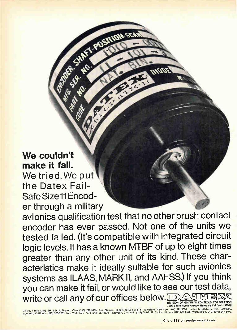
We couldn't make it fail. We tried.We put the Datex Fail-Safe Sizell Encod-er through a military avionics qualification test that no other brush contact encoder has ever passed. Not one of the units we tested failed. (It's compatible with integrated circuit logic levels. It has a known MTBF of up to eight times greater than any other unit of its kind. These char-acteristics make it ideally suitable for such avionics systems as ILAAS, MARK II, and AAFSS) If you think you can make it fail, or would like to see our test data, write or call any of our offices below.`,- D)
DIVISION OF GIANNINI CONTROLS CORPORATION 1307 South Myrtle Avenue. Monrovia, California 9101
Dallas, Texas 12141 EM 3-641 7. Dayton. Ohio (513) 299-5565. Des Plaines, Illinois (312) 827-81 41. Elmsford. New York (914) 592-5500. Huntsville. Alabama (205) 539-9396. Monrovia, California (213) 359-5381. New York, New York (212) 687-3330. Pasadena. California (213) 681-7152. Skokie, Illinois 131 2/ 676-3636. Washington. D.C. (202) 244-8700.
Circle 118 on reader service card

Communications
Pcm telephone exchange switches digital data like a computer
Voice messages that are pulse-code modulated can now be switched
directly through an all-electronic telephone exchange built
of logic circuits and a series of memories
By Andre Chatelon
Laboratoire Central de Telecommunications, Paris
Existing telephone networks employing pulse-code modulation within their transmission systems must have the digital signals converted back to analog signals before they pass through an exchange. Now an all-electronic telephone exchange has been suc-cessfully tested that switches pcm signals such as those in the transmission system described in Elec-tronics Sept. 19, 1966 [pp. 139-148]. The com-patibility of the two systems is excellent. The resulting integrated network drastically re-
duces the size and cost of an exchange—less equip-ment is needed while signal quality is kept high. Since digital-to-analog conversion is no longer necessary in the exchange, the crosspoints in the exchange are simple gate circuits, driven by control logic instead of electromechanical switches and re-lays [see "Telephone exchanges: past, present and future," p. 122]. Savings will further increase as monolithic integrated circuits replace the present discrete circuits in the network designed by Lab-oratoire Central de Télécommunication (LCT) in Paris. The small size of the transistorized equip-ment is evident in the photo on the next page.
Computerized calling
The exchange handles digital data much like a computer, storing incoming signals and control in-formation in memories and routing and switching the signals with logic circuits. The coded signals and control functions can be time-division multi-plexed, simplifying the interconnections between exchanges and within exchanges.' ,2 Signaling infor-mation, such as "line busy," can also be handled digitally. Advanced developments in computer technology
can be applied directly to the design of the ex-
change. For example, the gate circuits are low-cost computer types. Temperature variations and aging of the circuits do not affect signal quality, making the system reliable.
Also, as in a computer, functional flexibility is high. Often, only the information stored in a mem-ory need be changed—not hardware and wiring— to change the exchange's logic operation and pro-vide new telephone services.
Nevertheless, the difficulties of an all-digital net-work should not be underestimated. Large ex-changes will have to handle many hundreds of millions of bits a second, since each two-way tele-phone call requires a traffic capacity of 128,000 bits a second. The maximum clock frequency at present is 6 megahertz. Very fast devices were not used in the prototype
exchange to keep costs down. Exchanges require a great deal of redundant equipment because tele-phone reliability requirements are more stringent than those of computers. The digital circuits are conventional diode-transistor logic or direct coupled transistor logic circuits made of components such as 2N914 and 2N2369 transistors and 1N914 diodes.
Next—integrated circuits
Pcm exchanges utilizing integrated circuits are being designed, however integrated circuits were too costly for commercial exchanges at the time the system described here was being designed. Now that IC's are readily available at low cost, there is no doubt that they will be used in the next generation of telephone switching equipment to fur-ther reduce system costs. The advantages of using IC's in exchanges are
expected to be as great as those realized in the
Electronics I October 3, 1966 119

Transistorized logic circuitry and a high-speed diode-capacitor memory are basic elements of experimental pcm exchange. The memory's read-write cycle is 600 nanoseconds and maximum storage time is 125 microseconds.
pcm transmission system, although not necessarily for the same reasons. In the transmission system, for example, they reduce cross talk problems by lowering the switching levels. In the exchange, the greatest advantage is simplfying the interconnec-tions of many parts of the equipment. This, plus smaller size, the expansion of exchange capacity with modular units and better reliability, will make future exchanges more economical.
System interfaces
In designing a pcm integrated network it is necessary to • consider the interfaces with analog systems as well as with other pcm terminals and exchanges. Three particular problem areas exist. The first is at an audio interface where there is a pcm-audio conversion. For example, in the dia-gram upper right, an audio interface exists be-tween a pcm terminal and a subscriber line or between a remote pcm concentrator synchronized to the exchange and a subscriber line. An audio inter-face also occurs when a pcm exchange is coupled to an existing electromechanical exchange. A concentrator controls a small group of sub-
scriber lines, multiplexing them onto a single line that goes into the exchange. Since it can be ex-pected that all subscribers will not use their telephones simultaneously, the concentrator's line capacity to the exchange is smaller than the number of subscriber lines to which it is connected.
The second problem is synchronizing the multi-plexed pcm signals that pass from one pcm ter-minal to another. For example, in the lower figure at the right there can be synchronizing problems be-tween the pcm terminal and the pcm terminal exchange or between the pcm terminal exchange and the pcm transit exchange. The more terminals or exchanges the pcm signal must pass through the more difficult the synchronizing problems. The third problem—switching pcm signals—oc-
curs at all the pcm exchanges. Audio interface problems are most difficult at
the junction between a pcm exchange and sub-scriber equipment. Various solutions have been pro-posed for solving the subscriber interface prob-lem;3,4 the technique developed by the LCT will use remote and local concentrators, like those out-lined in the upper diagram at the right. The inter-face between the electromechanical and pcm ex-change (lower figure), although similar to that at a local pcm concentrator, presents fewer problems because there is no need to send large ringing signals or supply large d-c voice currents. The main problem at the subscriber interface is
not the analog-digital conversion, but the require-ment to send ringing signals and large currents for the telephone's transmitter. For example, ring-ing signals are thousands of times higher than the speech signals transmitted over the same line. In addition, if line amplifiers were used they would
120 Electronics I October 3. 1966

;e.
have to be protected from being damaged by the ringing current.
4.1though multiplexing and analog-pcm conver-sion equipment is used on pcm trunk lines, it is not economical to use similar equipment for each subscriber line. In a trunk line the equipment cost is shared among many subscribers; equipment for each subscriber line would be too costly. Also sub-scriber equipment characteristics vary widely, pre-venting the design of a single pcm unit that could be used on every line.
It is fortunate that only one pcm-analog con-version occurs at the subscriber line because this reduces noise problems. Even in difficult cases, the extra cost of installing a hybrid coil and a low-pass filter on the subscriber line is justified. That cost is offset by large savings in other parts of the network. These savings include increased capacity by multiplexing, inexpensive time-division switching and shorter subscriber transmission lines resulting from the use of a concentrator.
AUDIO
AUDIO
In the future, when it will be feasible to use semiconductor amplifiers in the telephone itself, it will be possible to significantly reduce the amount of line equipment needed for analog transmission through the use of microphones that require less power and by incorporating electronic ringing cir-cuits within the telephone.
Synchronizing the exchanges
The pcm exchange developed by LCT and illus-trated in the block diagram on page 123 has the major advantage of being the most flexible one for telephone switching. In contrast to other systems,5 this new system works on a fully asynchronous basis. Clock frequencies may vary considerably without causing a traffic interruption. However, speech quality may be impaired if the clock fre-quency drifts more than one part in a million from its nominal value. The purpose of synchronization is to get the in-
coming digital pulses in time positions that coin-
ELECTRO-MECHANICAL
EXCHANGE
IMMI 41Me 11.1.
AUDIO 'REMOTE PCM PCM JUNCTION
ILINE - CONCENTRATOR É eeeae
AUDIO EM EXCHANGE OR EM LINE-CONCENTRATOR
AUDIO JUNCTION
LOCAL I PCM CONC.
PCM TERMINAL EXCHANGE
AUDIO JUNCTION
PCM
PCM JUNCTION
PCM JUNCTION
PCM TRANSIT EXCHANGE
PCM
Mixture of pcm exchanges, pcm terminals and electromechanical exchanges would be typical in any telephone network. Units enclosed in solid color are autonomous pcm units that have their own clocks. The local pcm line concentrator in the exchange is controlled by the exchange's clock. Remote pcm concentrator (dashed colored line) would be slaved to the pcm exchange. Interfacing problems occur at the junction between audio lines and pcm terminals. Synchroniza-tion problems exist between autonomous pcm exchanges because their clocks must be synchronized.
SUBSCRIBER LINES (AUDIO)
SUBSCRIBER
LINE EQUIPMENT
SUBSCRIBER
LINE EQUIPMENT
SLAVED CLOCK
ADDRESS MEMORY AND DISTRIBUTION LOGIC
DECODER-ENCODER
PCM LINK 1.6 megabits is
LPOWER SUPPLY
DISTRIBUTION LOGIC
DECODER -ENCODER
REPEATER
PAIR OF UNLOADED WIRES
PAIR OF UNLOADED WIRES
CLOCK CONTROL
FROM TO PCM SWITCH
Concentrators form the interface at a junction of subenbers audio (analog) lines and the pcm system. A concentrator can serve many subscribers over a trunk that has limiteckepecity because telephones are not all used at one time. A pcm concentrator remote from the exchange, (top diagrams pPóVtdes a more flexible configuration than a local pcm concentrator located in exchange from which it obtains power and clock signals (lower diagram). Blocks in color outline main sections of pcm equipment.
••••,-
Electronics October 3, 1966 121

cide with those given by the local clock. Synchroni-zation must be achieved with clock frequencies that vary at remote terminals and with transmission lines that may have varying delays or phase shifts.
Synchronizing incoming signals is a function shared by three sections of the exchange: a synchro-nizing junction, called synchro-junction equipment, group equipment and common framing equipment. A synchro-junction unit is connected in each line and performs the major portion of the synchroniza-tion. Synchro-junction equipment also converts the serial pcm word one pulse after another—into a parallel word—a pulse appearing simultaneously on each of eight lines. Eight synchro-junction units deliver their parallel words and the channel num-bers for each word to a group equipment unit. The group equipment stores 192 words that are subsequently switched across the exchange under the control of the central clock. Framing equipment is shared by all junctions in
the exchange; consequently the framing equipment
represents a small portion of the exchange's cost. The framing equipment detects the position of the synchronizing pulses in the incoming pcm signals. It is only used when the equipment is turned on or when the synchronization or the channel position has accidentally been lost. Since the framing equip-ment is similar to equipment in a pcm terminal, it will not be described further.
Synchro-junction equipment
The main purpose of the synchro-junction equip-ment is to simultaneously deliver to the group equipment the encoded pcm words for 24 telephone calls and an indication of the channel to which each word belongs. As indicated in the block dia-gram on page 124, an incoming serial word to a synchro-junction unit is first regenerated—that is the pulses are reshaped. The word is then written into a row of the junction memory. Each of the three rows of the memory is filled consecutively under the control of a three-position writing counter
Telephone exchanges: past, present and future
Electromechanical techniques dominate the design of telephone switching exchanges, even though elec-tronic techniques are commonplace in transmission lines. Only in the past few years have exchanges be-come electronic and then only on a modest scale. The lag in development of electronic exchanges
has been because of the nature of the signals . switched and previous inadequacies in electronic components. Most exchanges switch analog speech information, even though the switching equipment is basically digital in that the routing of the signals is controlled by the on-off operation of electrome-chanical relays and switches. Two trends, the increase in complexity of modern
telephone exchanges and the development of reli-able, inexpensive transistors, have led to the sub-stitution of electronic logic circuits for electromech-anical relay logic. However, electronic circuits con-trol the switching; they do not form the switching contacts at the intersection of transmission lines, except in relatively few exchanges such as the one being developed by Laboratoire Central de Télé-communications (LCT). Even so, electronic control is an important devel-
opment since control functions represent about half the cost of an exchange. Control circuitry costs less than electromechanical controls because an electronic unit can control many operations on a time-division basis, replacing many slower electromechanical units. This saving and others—such as the ability to change control functions by programing rather than component changes—have been realized with transistor logic. Integrated circuits offer further economies.
Crosspoints. The switching contact itself is an-other matter. Despite two decades of effort, exchange designers have not found a generally satisfactory electronic substitute for metallic-contact crosspoints to switch analog signals from one telephone trans-mission line to another. The analog speech signals may have to go through
as many as seven crosspoints in each exchange and pass through many exchanges before reaching their
destination. Therefore, contact losses must be kept low—a requirement met by relays, but difficult to satisfy with electronic components.
Series resistances of closed metallic contacts arc only a few millioluns. When the contacts are opened, their capacitances are only a few picofarads and the very high leakage impedance that results helps to 'educe cross talk. In contrast, electronic switches have closed resistances of a few ohms and open resistances of generally less than 100 megohms.
Although electronic switches can be very reliable, metallic crosspoints often operate for tens of years without failure. Finally, the cost of a metallic cross-point is very low.
Incompatibility. Despite the advantages of relay-type crosspoints, they are becoming less suited for telephone switching. The newer, larger exchanges require as many as 20 crosspoints per line, lowering the cost advantage of metallic contacts. As the com-plexity of the switching system rises, electronic con-trol becomes more necessary. With electronic control the exchange designer is
faced with the problem of matching electromechani-cal devices to electronic digital circuits. Although relays can switch in 1 or 2 milliseconds, they are slow compared with electronic logic. Also, the elec-tronic circuits require lower power levels than relays, so special driving circuits are needed for the relay coils. The lack of a straightforward electronic replace-
ment for metallic crosspoints has led exchange de-signers to seek two other solutions. One, represent-ing a transition between conventional electromechan-ical switching systems and fully electronic systems, is the development of miniature switches and relays such as reed relays that are designed to be con-trolled by electronic circuits.
LCT's use of pulse-code modulation in an all digital system exemplifies the other approach. While taking advantage of the added capacity and im-proved voice quality offered by pcm transmission, it is possible to eliminate the relay and its metallic crosspoint and substitute digital gate circuits.
122 Electronics I October 3, 1966

and a bit counter that are both driven in synchro-nism with the incoming bit frequency. By having three rows in the synchro-junction
memory, it is possible to avoid overlap between the writing and reading times for a particular word. One word is written into the memory while another word is read out. Under control of the central clock, the informa-
tion in the synchro-junction memory is read out as an eight-bit parallel word. During the read cycle the clock also advances the channel counter at the output. However, since the incoming bit frequency and
the bit frequency set by the local clock usually differ, the time at which a given row is read tends to approach the writing time of the same row. An overlap detector measures the interval between the read and write times. If the time difference be-comes too small it is stored in the overlap memory until the next synchronizing code arrives. During this synchronizing time slot, the writing counter is shifted in the direction that best separates the writing and reading time. Simultaneously, the chan-nel counter is shifted to maintain agreement be-tween the channel number and the information readout of the synchro-junction memory. Shifting is done only during the synchronizing time slot to prevent losing information in the memory.
Supermultiplexing
The series-to-parallel conversion that is per-formed in the synchro-junction memory is an im-portant function in a pcm exchange. The logic ele-ments can process parallel pcm signals faster than serial pcm signals. For example, a parallel word can be shifted in the time that it takes to shift a single bit of a serial word. The increase in speed allows a large number of parallel words to be multiplexed onto one channel of the input of a group unit. This is called supermultiplexing.
Supermultiplexing reduces the number of com-mon access lines needed for the memories of the group and cord circuits. In a moderate size mem-ory, a reduction in the number of access lines is important because the access equipment of each line, such as registers and address decoders, can represent a large fraction of the memory's cost.
Group equipment
A typical grouping unit, G, such as the one shown on page 126, assembles coded speech from eight synchro-junction units. Since each synchro-junction unit handles 24 calls as shown at the right, the group equipment's high-speed memory stores a supermultiplexed collection of 192 eight-bit words. Under the control of the exchange's clock the
group memory is read out cyclically as parallel words that appear on a supermultiplex highway at an input of the switching unit. The supermulti-plex highway is a set of eight wires that carry many multiplexed parallel words from many input channels. Incoming speech channels are synchronized so
EM EXCHANGE
AUDIO JUNCTIONS 4.
AUDIO JUNCTION EQUIPMENT
DISTRIBUTION LOGIC
DECODER-ENCODER
{CONTROL CLOCK
4- FROMIPCM
TO SWITCH
Electromechanical exchange interfacing with pcm equipment is similar to interface of subscriber's line and local pcm concentrator.
SERIAL PCM WORD
SYNCHRO- GROUP JUNCTIONS EQUIPMENT
1 PARALLEL UNITS
WORDS 1 PCM
8 PCM INPUTS.
24 CALLS PER, INPUT
6' -WIRE' 'LINES:
G1 192 8-BIT WORDS
SUPERMULTIPLEXED HIGHWAYS
PCM SWITCH
CORD
L
JLI ,1 2
DIGITAL INTERFACE
COMMON CONTROL
JL3
_J
CENTRAL CLOCK
CODER-DECODER I
Switching configuration in a pcm exchange is a crossbar type that operates with time-division multiplexed signals. Synchro-junction equipment (S-J) converts words from serial to parallel and also helps synchronize incoming pcm signals with local clock. Group equipment (G) gathers coded speech information from synchro junctions to form 192 eight-bit code words. Cord circuits (JL) switch the information to the supermultiplex highways.
that a given channel always appears on the same row of the group memory; consequently when it it is read out, a given channel appears on the same time slot at the input to the switching unit. This is an important factor in operating the pcm switch-ing unit.
If only local pcm interfaces are used, the group equipment plays a minor role in synchronization
Electronics I October 3, 1966 123

TO AND FROM COMMON FRAMING EQUIPMENT
T 1'
JUNCTION TERMINAL REPEATER
1 INCOMING BIT FREQUENCY
WRITING COUNTER
WRITE
SERIAL CODE WORD
OVERLAP MEMORY
OVERLAP DETECTOR
BIT COUNTER
JUNCTION MEMORY
3 X 8
;--0
READ
OVERLAP SHIFT
SYNCHRO CHANNEL DECODER
CHANNEL COUNTER
L;
1
TO GROUP EQUIPMENT
Synchro-junction equipment regenerates information in the repeater before converting serial input to parallel words. Colored lines show path of main information flow. Discrepancies between the incoming bit rate and local clock are detected and corrected by overlap circuitry. Channel counter indicates channel to which coded speech word belongs. Junction memory stores three 8-bit words.
since the local clock is already controlling the con-version of the audio signal to pcm. When no pcm signals are being transmitted, it
is possible to suppress the synchronizing equip-ment. Also worth noting is that slave units, such as remote concentrators, greatly simplify the synchro-nizing problem because they are locked to the ex-change's clock.
Cord circa
A pcm switching system difiers' from an gnalog type switching system in that the information to be exchanged through two highways may not be present simultaneously on these highways. Because the pcm exchange deals with multiplexed digital words, the appropriate highways must be connected as the information comes up for switching. The cord circuit that controls switching of a set
of crosspoints is illustrated in the block diagram at the right. Five random memories are needed in the cord circuit to store addresses and coded speech information and to control the operation of the circuit. Information is read into or written out
LOCAL CLOCK
of these memories during either an even or an odd time slot of the circuit's timing cycle. There are 192 time slots for transferring information. These memories operate at high speeds because
information is exchanged through the highways at a rate of 8,000 times a second. A memory's read-write cycle is 600 nanoseconds and the maximum storage time is 125 microseconds. Diode-capacitor storage is employed to allow the use of inexpensive access circuitry. When a coded speech word is exchanged it first
comes from a group unit and is stored in the speech information memory (IM). Then the coded speech is read out of the information Memory g_rld directed to its destination—another group unit.
For the cord circuit to route the information that is extracted from the group equipment, it needs the addresses of the highways through which the information is to be exchanged. These addresses are stored in two memories called the odd space switching memory (SSMO) and the even space switching memory (SSME). A fourth memory—the time switching memory
124 Electronics I October 3, 1966

ree-rsiii,4 •
(TSM)—stores the time position (channel number) of coded speech signals that are to be exchanged. This memory also stores the address of the row in the information memory into which the coded speech signals are written. A fifth memory (CM) in the cord circuit stores supervisory information. These memories have 96 rows, half the number
of words in a group equipment, because it is con-venient to have an equal number of cord circuits and group equipment. During each 125-sec sam-pling period, a cord circuit processes 96 two-way calls, or 192 words. To switch the 96 calls in 125 µsec the cord
circuit's cycle is divided into 200 timing slots each about 600 nsec long. Only 192 of these time slots are used for speech signals; the remaining eight time slots are used for transmitting synchronizing characters. Four consecutive elementary logic operations—
each 150 nsec long—are performed during each of the 192 time slots: • The contents of the space switching memory
is read. • This number is decoded. • Coded speech word corresponding to one sub-
scriber is read out of the information memory. • The coded speech word corresponding to the
other subscriber is written into the same row of the information memory. Thus by performing control operations during
the same time slots in which words are transferred,
FROM {
e
CONTROL t CLOCK
SUPER MULTIPLEX HIGHWAY
ALL MEMORIES HAVE 96 ROWS
ADDRESS\
(CM) CONTROL MEMORY
6-BITS
ROW X
(SSMO) SPACE SWITCHING MEMORY
3-BITS
ADDRESS
one word in the information memory is replaced by a new one every 600 nsec.
Multiple crosspoints—switching points -at the intersection of two sets of lines—connect a cord circuit to a highway. The multiple crosspoints are necessary because code words are transferred in parallel and because information transmitted in one direction is handled by one set of crosspoints and information in the other direction by another set of crosspoints.
Since the control operations in a pcm exchange are like those in any centralized control exchange, signaling and other auxiliary information may be transmitted over lines similar to the one used for the coded speech. Consequently, as indicated by the exchange block diagram on page 123, the common control receives its information from the junctions through a supermultiplex highway. A pcm exchange can also send control signals
toward the junction over the same path used for receiving. If these signals are not digital, a coder-decoder is used at the interface between the high-ways and the control equipment.
Establishing a connection
Assume that a cord J1,1 in the diagram on page 123 is to connect a channel x in a group G. to a channel y in a group G. The basic requirement for performing this operation in the cord circuit below is as follows:
Information corresponding to the x'th channel in
{FROM
TO 4
e' e 8
n,1
{
FROM
TO 4 P e'
FROM MARKER
(SSME) SPACE SWITCHING MEMORY
1•••1•I•mr
(TSM) TIME SWITCHING MEMORY
8-BITS
CODED SPEECH
s (IM) SPEECH INFORMATION MEMORY
8-BITS
ROW x
4—
Cord circuit controls switching operation in exchange. Diagram represents cord circuit JL, in the figure on page 123 so crosspoints are given subscript 1. Only supermultiplex highways from group equipment Gr and G. are shown with their crosspoints in the pcm switch (color). Space switching memories store addresses of the crosspoints over which speech information is to be transferred. Speech information memory stores coded speech words. Time switching memory stores the time position (channel number) of the speech information to be transferred; during a connection this memory also stores the addresses of the rows into which coded words are written.
Electronics October 3, 1966 125

FROM SYNCHRO-JUNCTION EQUIPMENT
8x 5 1 18 x 8
TO COMMON FRAMING EQUIPMENT
CHANNEL ADDRESS REGISTER
4
INFORMATION INPUT REGISTER
GROUP MEMORY 192 8- BIT WORDS
OUTPUT REGISTER
.1 81
LOCAL
CLOCK
SUPER-MULTIPLEX
*HIGHWAY TO PCM SWITCH
Group equipment's high-speed memory gathers 192 eight-bit words and reads these words out to the pcm switch under control of the local clock. Colored lines show flow of coded speech. Eight synchro-junction units each supply 24 eight-bit coded speech words to the group memory.
group G. will appear on the highway to the cord circuit during an odd time slot, te., and will be stored in the information memory. The term t0. refers to an odd time slot during which a code word from the x channel is processed. This in-formation must be transferred to the y channel of Gp during the even time slot, tes. When informa-tion is traveling in the reverse direction, informa-tion from G, appearing in the time slot te, is transferred to Gr, during the time slot tex. To start the connection process, the common
control sends the address, n, of the P„,1 crosspoint to the x'th row of the odd space switching memory (SSMO). At the same time the y'th row of the time switching memory (TSM) receives the time position (channel number) of the x'th channel. Similarly, the common control sends the address p of the
crosspoint to the y'th row in the even space switching memory (SSME). This transmission of addresses and time positions is done only once for each call, providing no rearrangement is necessary. Once the addresses are transmitted, the central
clock controls the cord circuit's operation. During each sampling period, the cord circuit cyclically processes all 96 calls for which it is responsible. During the odd time slots, te., the following op-
erations are performed: • The address, n, in the x'th row of SSMO is
read and the decoded output activates a multiple crosspoint, Pro. • The speech information, S„., in the x'th row
of the information memory (IM) is read. This information, which is one of the speech signals to be transferred, was previously obtained from the
y channel of the Gp group (see last step under even time-slots below). • The parallel eight-bit speech word S. is trans-
ferred toward the G. group through the activated crosspoint Pn,1. • The information on the supermultiplex highway
coming from Gr, is transferred to the x'th row of the speech information memory where Se. has just been extracted.
In the odd time slot, toy, the address x in the y row of the time switching memory is read. This information is stored in the access circuit of in-formation memory where it is decoded. It is used during the next even time slot, tey.
In even time slots tey, the following operations are performed for the y channel in the Gp group. • The address p in the y'th row of SSME is
read and the decoded output activates a multiple crosspoint • The coded speech information Sex of the x'th
row of the information memory is read. This in-formation which came from the x'th channel of the Gn group, was sent to the information memory during the previous t„, time slot. • The parallel eight-bit speech word Sex is trans-
ferred toward the Gp group through the activated crosspoint • The information on the supermultiplexed high-
way coming from the G„ group is transferred to the x'th row of the information memory from which Sex has just been extracted. Performing these operations exchanges the
speech information of channel x in group G. and channel y in group G. When a single pcm switch-ing stage is used, the digital information must be converted from parallel to serial words before transmission. When no pcm transmission is in-volved the parallel digital words may be converted directly to analog. Coded signals on the transmission line are re-
generated as needed and decoded for subscriber-line transmission as conventional analog signals. The rearrangement process6 may be used to
avoid blocking in the switching stage. Blocking occurs when a new call cannot be routed. In a pcm exchange this can occur when an incoming call has no access to outgoing lines that may be free. A rearrangement process can provide the access by changing the row in the cord circuit memory to which the call is assigned. In such a system, the memories must have 192 rows.
References 1. P. Mornet, A. Chatelon, J. Le Corre, "Application of PCM to an Integrated Telephone Network," Electrical Communication 1, 1963. 2. C. Dumousseau, "An Integrated PCM Exchange," (in French), Second International Congress on Telecommunications Techniques, Madrid, November, 1965. 3. H.E. Vaughan, "Research for Time Separation Integrated Communication," Bell System Technical Journal, July, 1959. 4. A. Pinet, "A Time Division Switching System," (in French), Commutation et Electronique. March, 1966. 5. D.H. Harding, "An Approach to a Tandem Exchange for an Integrated PCM Network," International Congress of Electronic Switching, Paris, 1966. 6. E. Touraton, J. Le Corre, French patent No. 1,212,984.
19K Electronics I October 3, 1966

Here's a little extra design freedom in
toggle switches
A AT Series Assembliee —Combine up to 12 SPDT Switches.
B TL Series—MeetS MIL-S-3950A. Momentary, maintained, pull-to-unlock. 1, 2, or 4 pole.
C TW Series—Miniature, 5 amp. SPOT or D PDT. 2 and 3 position.
D TS Series—Up to 25 amp. 1 or 2 pole.
E ET Series—Magnetie• hold, remote-release. Environment-proof.
F TP Series—Rocker-actuated, 20 amp. 1, 2, or 4 pole.
You are free to select the exact combination of features you need when you look in the broad MICRO SWITCH line. Size, circuitry, capacity and toggle action to answer most any requirement. Special features too, right off the shelf. For example, environment-proof construction, magnetic-hold-in, electric memory and dry circuit capabilities. You may even pick up some extra design ideas as well—
ways to simplify circuit design, combine functions in fewer controls, improve operator efficiency.
Catalog 73 gives details. Call a Branch Office or Authorized Distributor (see Yellow Pages, "Switches, Electric"). Or write...
MICRO SWITCH FREEPORT, ILLINOIS 61032
A DIVISION OF HONEYWELL
HONEYWELL INTERNATIONAL—Sales and service offices in all principal citiesof the world. Manufacturing In United States, United Kingdom, Canada, Netherlands, Germany, France, Japagy
Electronics October 3, 1966 Circle 127 on reader service card 127

3M Brand Inert Fluorochemical Liquids cut component failure rates drastically by removing
heat faster.
Power input BIMMIIIMMIIMIO
PRACTICALLY EVERYTHING we can say
about 3M Fluorochemical Inert Liquids
adds up to one thing for the designer and
engineer: INCREASED RELIABILITY.
Why? Because component failure
rates increase sharply as component
temperatures increase. Efficient heat
removal lowers the temperature
and increases reliability.
3M Inert Liquids are far more efficient
at removing heat than air or other
conventional dielectric coolants.
Results: LOWER COMPONENT
TEMPERATURES, LOWER FAILURE
RATES, HIGHER RELIABILITY.
FOR THE FULL STORY: chemical inertness,
non-flammability, high temperature
stability, compatibility, high electric
strength, low dissipation factors, write:
3M Company, Dept. KAX-96,s
St. Paul, Minn. 55119.
Chemical Division 3E1 128 Circle 128 on reader service card Electronics I October 3, 1966

Computers
For a crew in lonely orbit, something to lean on in space
Computer for astronaut laboratory will navigate, arrange experiments
and even devise new work schedules when someone falls ill during
the long and demanding trips of the future
By Andrew Adelman and Jack Cohen
International Business Machines Corp., Bethesda, Md.
In an orbiting space laboratory a scientist-astronaut seated at a console enters the name of the star Alpha Centauri into a computer. A large telescope mounted outside the spacecraft swivels on its mount and comes to rest pointed at that star. Inside the spacecraft a cathode-ray tube driven by the com-puter displays the strength and wavelength of the star's spectroscopic lines. Another astronaut puts on his pressure suit, steps
into space through an air lock, and begins to as-semble parts of a large antenna. As he labors, the sanie computer gathers data on the amount of work that a man can do in space before becoming dan-gerously fatigued. The scientist at the console moni-tors the computer as it analyzes the astronaut's physiological responses, such as pulse rate, body temperature and breathing rate. Suddenly the com-puter detects a sharp increase in heart rate and
Electronics I October 3, 1966 129
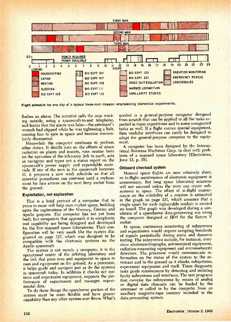
FIRST MAN
SECOND MAN
IVA THIRD MAN
1111111E •• ::::::::
22.M.1„0
0.51 POWER REQUIRED POWER AVAILABLE
0 1 2 3 4 5 5 :9 9 LEGEND:
HOUSEKEEPING 7 BIO EXPT 103 1111111
In BIO EXPT 104 BIO EXPT 107
BIO EXPT 108
BIO EXPT 1 II
=• BIO EXPT 113
m EATING
RESTING
SLEEPING
r7-7-1 10 I I 13 HOURS
114 15
r-r1 16 17
BIO EXPT 120
1310 EXPT 201
SPACE SUIT EVALUATION
MANNED LOCOMOTION
CAPILLARITY STUDIES
1'8 Trr, 19 20 21 22 23 24
RADIATION MONITORING
EMERGENCY RESCUE
UNSCHEDULED
Flight schedule for one day of a typical three-man mission emphasizing biomedical experiments.
flashes an alarm. The scientist calls the man work-ing outside, using a spacecraft-to-suit telephone, and learns that the alarm was false—the astronaut's wrench had slipped while he was tightening a bolt, causing him to spin in space and become momen-tarily disoriented. Meanwhile the computer continues to perform
other duties. It distills data on the effects of space radiation on plants and insects, runs routine tests on the operation of the telemetry link to earth, acts as navigator and types out a status report on the spacecraft's power supply and expendable mate-rials. If one of the men in the spacecraft becomes ill, it prepares a new work schedule so that all essential procedures can continue until a replace-ment for him arrives on the next ferry rocket from the ground.
Exploitation, not exploration
This is a brief portrait of a computer that in years to come will help man exploit space, building upon the explorations of the Mercury, Gemini and Apollo projects. The computer has not yet been built, but computers that approach it in complexity and capability are being designed and developed for the first manned space laboratories. Their con-figuration will be very much like the system dia-gramed on page 137, which was designed to be compatible with the electronic systems on the Apollo spacecraft. The system is not merely a computer, it is the
operational center of the orbiting laboratory and the link that joins men and equipment in space to men and equipment on the ground. As a processor, it helps guide and navigate just as do the systems in spacecraft today. In addition it checks out sys-tems and experiment equipment, supports the per-formance of experiments and manages experi-mental data. To do these things the spaceborne portion of the
system must be more flexible and have greater capability than any other system ever flown. What's
needed is a general-purpose computer designed from scratch that can be applied to all the tasks ex-pected in many expeditions and to some unexpected tasks as well. If a flight carries special equipment, then modular interfaces can easily be designed to adapt the general-purpose computer to the equip-ment. A computer has been designed by the Interna-
tional Business Machines Corp. to deal with prob-lems of a manned space laboratory [Electronics, June 13, p. 25].
Onboard checkout system Manned space flights are now relatively short,
so in-flight maintenance of electronic equipment is unnecessary. But long space laboratory missions will not succeed unless the crew can repair sub-systems in space. The effect of in-flight mainte-nance on the reliability of a mission is estimated in the graph on page 131, which assumes that a single spare for each replaceable module is carried on board. The graph was developed during a sim-ulation of a spaceborne data-processing run using the computer designed at IBM for the Saturn V rocket.
In space, continuous monitoring of subsystems and experiments would require sampling hundreds of signals periodically during static and dynamic testing. The subsystems include, for instance, mini-ature electrocardiographs, astronomical equipment, radiation-measuring equipment and micrometeorite detectors. The processor would communicate in-formation on the status of the system to the as-tronaut and to the ground as it checks subsystems, experiment equipment and itself. These diagnostic tests guide maintenance by detecting and isolating faulty subsystems and interfaces. The test programs that exercise the subsystems by means of analog or digital data channels can be loaded by the astronaut or called in by the computer from an auxiliary magnetic-tape memory included in the data-processing system.
130 Electronics October 3, 1966

Supporting the experiments
The onboard data-processing system schedules the experiments, equipment use and the crew mem-bers' time; processes and displays data as the ex-periments proceed; and prepares the results for re-cording or telemetering.
Scheduling is important because the number of experiments will be large and the spacecraft's equipment and the crew's time must be used ef-fectively. Scheduling must take into account sub-system monitoring, data and program setup (or housekeeping), experiment priorities and, for earth-oriented experiments, special requirements such as geographical location and amount of illumina-tion. And of course the crew members must eat and sleep too.
Part of a schedule for a three-man spacecraft, shown at left, indicates the tasks to be per-formed during one typical day and shows the op-erating profile for a typical subsystem—the electri-cal power system. This flight carries many bio-medical and behavioral experiments; the numbered experiments include automatic urinalysis, the re-sponse of the circulatory system to stimuli, and measurement of senses and perception. Schedules like this would be prepared for any mission, what-ever experiments were planned. And the onboard computer must alter them if
unforeseen circumstances arise. If an experiment runs longer or uses more material than had been planned, or if a crew member is injured or ill, the computer must determine the best use of the re-maining time and material.
DISPLAYS AND MANUAL CONTROLS
POINTING AND TRACKING SYSTEM
TELESCOPE GUIDANCE SYSTEM
DISPLAY DATA
MANUAL INPUTS
CONTROL
FEEDBACK
CONTROL
FEEDBACK
TRANSLATION AND ROTATION COMMANDS
SPACECRAFT STABILIZATION AND CONTROL
Data-processing system supports an astronomical telescope experiment by pointing the telescope, coordinating its guidance with the spacecraft stabilization, reducing data and storing it for ground communication.
VEHICLE RATE DATA
1.0
IN-FLIGHT MAINTENANCE
NO IN-FLIGHT MAINTENANCE
0 0 250 500 750 1000 1250 1500 1750 2000 2250
MISSION TIME (HOURS)
Reliability of a space laboratory can be
greatly improved if spare parts are available so that astronauts can make repairs in space.
Reliability is the probability of mission success.
Controlling the equipment
In the Mercury and Gemini programs, and in hypothetical mission profiles, the crew's time usu-ally limits the number of adjustments that can be made in an experiment. The onboard data proces-sor can ease the crew's work load and therefore speed up experiments. The astronauts normally must physically install
and connect the equipment for each experiment. Then the computer can go to work, beginning with calibration tests. In these, known inputs to the ex-periment equipment produce responses that are recorded for comparison with predicted values and the results of tests before launch. Later analysis
COMPUTER
NON-REAL-TIME DATA
REAL-TIME DATA
INITIALIZING AND UPDATING
STELLAR SPECTRAL CHARACTERISTICS
MAGNETIC TAPE STORAGE
GROUND COMMUNICATIONS
SPACECRAFT STELLAR GUIDANCE SYSTEM
Electronics October 3, 1 966 131

Computer requirements for a telescope experiment
Add times per second
Executive and diagnostics
Automatic telescope scan
Initialization
Sensor calibration
Integration
Fine-guidance drive control
Coordinate transformation
Sun angle computation
Spacecraft atti-tude commands
Precision pointing
Image motion compensation
Celestial body catalog storage and search
Total
Memory requirements (8-bit bytes)
Instructions Data
180 1,510 760
1,100 900 200
1,500 720 720
520 430 150
2,010 430 150
3,500 210 130
3,250 1,120 3,200
200 80 40
200 20 50
4,270 100 320
400 90 40
200 20 5,000
17,330 5,360 10,760
CHANNEL A
76.8 kbps
CHANNEL B
640 bps
CHANNEL C
1,000 hz
CHANNEL D
2,000 hz
CHANNEL E
2,400 bps
LOW—PASS FILTERS
1 fc.38.4khz
CHANNEL F
76.8 k bps
fc =320 hz
fc =1,200 hz
fc. 38.4 khz
SUBCARRIER OSCILLATORS
120.8 +2 khz
+4 khz
+4 khz
+4khz
+38.4 khz
of the experiment output data also demands com-parison with the calibration data.
A typical experiment
Planned for the Extended Apollo Program is an astronomical telescope package like the one shown at the bottom of page 131 with its integra-tion into the data-processing system. The data-processing system supplies guidance
in pointing the telescope and other sensors, com-pensates for errors in pointing, generates signals for the servo drive, compensates for the space-craft's motion, provides displays for the astronauts and allows for manual control by the astronauts. By means of the pointing and tracking system
the astronaut initially aims the telescope and sets up its cameras and spectrometers. With inputs from the pointing and tracking system the com-puter generates signals to keep the telescope aimed correctly, converting from the spacecraft's inertial coordinates to the telescope's equatorial or other coordinates. Closed-loop operation of the fine-guidance controls together with the stabilization controls insures that the vehicle will not be dis-turbed during the operation. The computer auto-matically inserts a sunshade over the telescope when it's pointing almost directly at the sun.
Photographic recording of stellar and galactic objects requires three-axis stabilization so that the image won't move and cause blurring. To insure stability the entire telescope is mounted on its own gimbals and is independently stabilized against pitch and yaw as shown in the typical mounting arrangement on the opposite page.
TELEMETRY TRANSMISSION SUBSYSTEM
LINEAR MIXER
TELEMETRY TRANSMITTER
ANTENNA SYSTEM
MULTICOUPLER
TV INPUT
Telemetry subsystem would include filters to transform digital signals into analog for the mixer, subcarrier oscillators to make the signals separable at the receiver and provision for a television input at the antenna. The fo numbers are center frequencies, which are within the bandwidths specified for the subcarrier oscillators.
••••
132 Electronics October 3, 1966

Data display
The astronauts will frequently be guided by dis-plays while performing many kinds of experiments over a range of scientific and technical fields. The' crew members are not expected to rely on memory in performing experiments, even though they un-dergo extensive training before launch.
Small quantities of data to back up experiments can be prepared in printed manuals. Larger quan-tities for other experiments will be placed on micro-film, which permits the computer to select and se-quence the data. For some applications, the data will be generated in real time—for example, the in-structions for pointing the astronomical telescope.
In many cases the display data will be a by-product of the computations. For example the computer determines error signals for redirection of the astronomical telescope from the original pointing data. To support an astronomical telescope experi-
ment, a processor must be capable of doing many things, as shown in the table at the left. In pre-paring it, manual inputs, inputs telemetered from the ground and generation of control commands to the telescope were all taken into account. The estimates are based on programs written for ex-perimental programs on the ground, simulation of spaceborne projects and the characteristics of data-processing systems. The analysis assumes that: • The computer is a hypothetical design with
architecture and logic structure compatible with the IBM System 360. • The computer performs all navigation and
onboard checkout tasks needed for the experiments. • The basic program, which in general is re-
SIMPLEX CONFIGURATION
POWER SUPPLY 0.9964
REDUNDANT CONFIGURATION
DUPLEX POWER SUPPLY 0.9999
CENTRAL PROCESSING UNIT 09413
DIGITAL ENCODER
The mounting of an astronomical telescope on a spacecraft must have its own set of gimbals and controls to stabilize it independently of the spacecraft.
TORQUE MOTOR AND TACHOMETER
TORQUE MOTOR DIGITAL AND TACHOMETER ENCODER
peated over and over, requires one second for each execution. "Add times per second" refers to the length of
time required to perform each detail function (the horizontal rows). The time required to add two numbers is sometimes taken as a typical elementary function in a computer. The time required to do something could be specified as so many micro-seconds, but this would depend heavily on the exact design of the computer. Specifying it by add times is less dependent on the design and serves as a better index of time.
For instance, in one second of program execution time the executive and diagnostic functions take as long as the adding of 180 pairs of numbers; ini-tializing (setting up at the start of a run) takes as long as 1,500 additions, and so on.
Storage requirements are based on estimates of the number of instructions required for each func-tion and on the amount of data required. As in
HARD CORE PROCESSOR 0.9993
32 K MEMORY 0 8340
PROCESSOR WITH MODULAR SPARES 0.9999
SIX 8K-BYTE MEMORIES
0 9978
Reliability of a computer with redundant subsystems is improved by a factor of 75 over that of a simplex system (one without redundancy). The numbers in the blocks are the reliabilities or probabilities of nonfailure of each component; the numbers in color represent the reliability of the entire system, as obtained from the component reliabilities.
Electronics October 3, 1966 133

The IBM System 360, storage is expressed in terms of the number of eight-bit bytes; each byte cor-responds approximately to one alphabetic charac-ter or two numeric digits. System 360 instructions are either two, four or six bytes long, depending on the operation. Both the execution times and the storage re-
quirements are estimates, so that ample margins for error or contingency must be allowed. A 10% margin for execution time puts the total at about 19,000 operations per second; a 25% margin for storage requires about 20,500 eight-bit bytes.
If the data-processing system supports more than one experiment at a time, it must have additional capability. The astronomical telescope experiment alone requires 20,500 eight-bit bytes; if other pro-grams or data require "live" storage at the same time, it must be provided. Likewise, if other ex-periments are running, the system must be capable of executing instructions for them in addition to the 19,000 instructions per second required for the telescope.
What the program does
Tasks required of the laboratory experiment pro-gram include: • Calibrating sensor performance and correlating
it with experiment data. • Identifying experiment data by time, space-
craft position, crew status and other operational data. • Displaying quick-look performance data for
evaluation by the astronaut. • Compacting data and eliminating redundancy
on board the spacecraft. • Buffering or temporarily storing data in the
process of recording it or transmitting it to the groun d. Because they are intermittent tasks, calibrating
sensors and recording operational data do not over-burden the data-processing system. Data display and data reduction are continuous, but requiring the computer to perform them lightens the load on the communication system, which would otherwise have to transmit a large amount of superfluous data to the ground.
Processing requirements from one experiment to the next will vary considerably and in some the data load may be quite heavy. Before each mission the data processor size and complexity must be evaluated against the complexity of the data-com-munications systems and the time required for the transmission of data to receiving stations on the ground.
Data-buffering requirements for a hypothetical Apollo Applications Program mission illustrate the magnitude of the data-handling task, as shown in the table on page 136. This mission includes bi-omedical and behavioral measurements with an on-board centrifuge, X-ray spectroscopy, a life-support system test, radiation environment monitoring, an astronomical telescope, a test of wideband r-f trans-mission and a solar-cell test. The biomedical and
Welcome backseat driver Without computers on board manned spacecraft could still orbit the earth and take long rides through space on trajectories computed and controlled by earth sta-tions. John Glenn proved it in the first Mercury flight.
But the worth of putting a computer at the disposal of the space crew is being underlined by Gemini, the present phase of the manned space program. Gemini computers are showing a spectacular ability to plan and control split-second maneuvers, which will help astronauts cope with unexpected flight conditions. Gemini computers have had a checkered past, but
the one on Gemini 11, the flight in September, did fine. It helped the crew rendezvous and link up with the Agena target on the first orbit. On the last orbit, it guided Gemini 11 into a hands-off reentry and land-ing virtually down the stacks of the recovery ships.
Without assurance of such precision in landing and rendezvous, it would be foolhardy to send men to the moon. The Lunar Excursion Module of the Apollo pro-gram has to descend safely as well as take off and rendezvous with the command module for the long trip home. At each step, guidance and navigation com-puters will be directing the hands on the controls.
Orbiting laboratories. Spacecraft designers are al-ready planning stations that could remain aloft sev-eral years. As the accompanying article makes clear, the computers in these laboratories will have much to do besides flight control. The first full-scale space lab is expected to be the
Air Force's Manned Orbiting Laboratory (MOL). A modified Gemini spacecraft hitched to a 25-foot-long laboratory module will probably be launched into orbit by a Titan-3C rocket. Little can be said about the electronic equipment because MOL is classified.
However, the computer may resemble the design outlined in the main article. It is a general design based on concepts developed by the International Business Machines Corp. and others during feasibility studies that took place before the MOL project. These in-cluded the Air Force's Orbiting Space Station Study and the National Aeronautics and Space Administra-tion's Apollo Applications Program and the Large Or-biting Research Laboratory. NASA's ideas include orbiting a 22-foot sphere either
at an altitude of 200 miles, or at a seemingly stationary position 22,500 miles high. Crews would be ferried to the station in Gemini or Apollo spacecraft. A grander concept of the space agency is a giant
cylinder, 33 feet in diameter, 120 feet long and weigh-ing over 100 tons. Once in orbit, the craft would un-fold into a huge, three-bladed, propeller-like structure that would remain in orbit five years. A start in Gemini. Although the Gemini computers
are highly flexible [Electronics, May 3, 1965, p. 71], they are not versatile enough for space labs. The Gemini computers can be programed for many
maneuvers. Taped programs can be loaded into the newer models by the astronauts; older models were programed on the ground. With his control panel, the astronaut can insert data manually and select the op-erating mode: prelaunch, ascent, orbital maneuver, rendezvous or reentry. Seven dials, resembling an au-tomobile odometer, verify data inserted from a key-board or display data taken from the memory. The amount of thrust needed in each of three axes
134 Electronics October 3, 1966

PRIMARY GUIDANCE a NAVIGATION
RADAR
COMPUTER
INERTIAL
MEASUREMENT
ABORT GUIDANCE SYSTEM
TRIM AND THROTTLE
ATTITUDE TRANSLATION
ENGINE ON/OFF
ENGINE ON /OFF
ENGINE CONTROLS
ATTITUDE
TRANSLATION
DESCENT OR
ASCENT
RATE GYRO
GIMBAL DRIVE (PITCH a ROLL)
MANUAL COMMANDS
Lunar excursion module for Apollo will have its own guidance and navigation system.
for a particular spacecraft maneuver is displayed by the computer on an incremental-velocity indicator. As the astronaut operates the thrust controls, the com-puter continually recalculates and displays the addi-tional thrust needed. When the readings reach zero, the astronaut shuts off the motors.
Acting on the stored programs, the computer proc-esses the data serially, one bit at a time, with discrete-component diode-transistor logic circuits. Only one of the Gemini computers seriously malfunctioned. Data in the Gemini 4 computer became garbled because of a power-supply difficulty, not a computer flaw, and
THRUST ON-OFF COMMANDS
the craft had to be brought down under ground control. Apollo's computer. Because the Apollo flights are
longer and more difficult, the Apollo computer will have more things to do than Gemini's. Also, the new computers are being built with integrated circuits.
In the Apollo command module, the computer will monitor the performance of the guidance and naviga-tion subsystems and warn the crew of malfunctions. Periodically, it will calculate course corrections and update the inertial navigation system with the aid of celestial data obtained with an optical subsystem. Gemini's inertial reference is established before launch. The celestial system is a little brother, in some
ways, to the astronomical telescope experiment de-scribed on page 132. An Apollo ci-ew member will find a star or lunar landmark with a telescope, steering the spacecraft if necessary to widen his field of view. At the instant a sextant is on target, a mark command will make the computer take in the angle and time data needed to calculate velocity and position of the space-craft. The astronaut won't need the navigational tables that sailors use. A fixed memory in the computer will store essential data.
Landing control. Once they reach the moon, two of the Apollo crew will get into the lunar module, which also has a guidance and navigation computer. The computer will depend on radar for most of its data.
During descent to the moon, a landing radar will provide altitude and altitude change-rate information. Converted into engine commands, these will allow the module to settle gently. After takeoff, data that helps the lunar module rendezvous with the command mod-ule will be provided by another radar.
After rendezvous, the guidance and navigation com-puter in the command module will get fresh celestial and landmark fixes, plot the trajectory to home, aim the spacecraft and send it on its way.
Wallace B. Riley George Sideris
ATTITUDE COMMANDS
COUPLING DISPLAY
POSITION UNIT
11.11•1111MMUIllrr
APOLLO GUIDANCE COMPUTER
ATTITUDE ERRORS
ATTITUDE
INCREMENTAL VELOCITY
OPTICS
INERTIAL MEASURE-MENT UNIT
FLIGHT DIRECTOR ATTITUDE INDICATOR
BODY RATES
RATE GYRO ASSEMBLY
ROTATE TRANSLATE COMMANDS
ROTATION CONTROLLER
TRANSLATION CONTROLLER
THRUST ON-OFF
f y COMMANDS
STABIL-IZATION AND CONTROL ELECTRONICS ..11.M•Mr116,
BODY RATES
THRUST ON-OFF PITCH AND YAW ERRORS COMMANDS 3
SERVICE PROPULSION SYSTEM
Apollo spacecraft will have a computer-controlled guidance and navigation system.
REACTION CONTROL SYSTEM
FORCES a TORQUES
SPACECRAFT
GIMBAL POSITIONING
GIMBAL POSITION CONTROL AND INDICATOR
Electronics I October 3, 1966 135

Typical data buffer needs
Number of channels
Samples per second
1/60* 1/30* 1/10*
1 2 5 10 20 100 200 300 400
1,000 1,500
Engineering
Digital Analog
Totals
2
12 21 5 3 5
48
48 8
9 5
4
74
Bio-med 8-bit
bytes per second
Analog
15
12 1 5 2 4 2 2 1 2
46
Digital
.03
1.2 21 10 15 50
100
Analog
1 .25
24 10 60 50 100 200 800 600 800
1,000 3,000
6,645
* The first three sample rates are respectively 1, 2 and 6
per minute
behavioral experiments impose the major data-processing load, with sampling rates as great as 1,500 per second for an electrocardiogram. Engi-neering experiments require lower sampling rates, from 10 per second for a spectrometer to one a minute for telescope gimbal angle. Assuming that all analog outputs can be digitized into one eight-bit byte per sample, which allows a maximum res-
EXPERIMENT LIBRARY TAPE
EXPERIMENT SUBROUTINE
•EXPERIMENT SUBROUTINE
EXPERIMENT SUBROUTINE
EXPERIMENT SUBROUTINE
LOADER
olution of one part in 256, the total processing re-quirement is less than 7,000 bytes per second. This estimate does not allow any margin for error as was allowed in the estimate of the size of the processor.
Ground support versus onboard processing
To conserve power and weight the onboard com-puter should be used only to monitor experiments and other operations, to obtain experimental re-sults that are needed in real time—that is, during or immediately after the experiment—and to reduce other data before telemetering it to receiving sta-tions on the ground.
Telemetered data is recorded on magnetic tape at tracking and data-acquisition stations for later analysis. Data-reduction stations process some of the data immediately, particularly that from data-acquisition stations in North America, for quick-look analysis and evaluation. The telemetry system includes equipment for
time- and frequency-division multiplexing, analog-to-digital conversion, programing and transmission of information from the spacecraft to the ground. The system also receives and demultiplexes data telemetered by astronauts or unmanned systems outside the spacecraft. Both pulse-code-modulation and frequency-mod-
ulation systems are used. The pcm systems acquire data through addressable multiplexers, which are time-shared with data processing and computing systems. Functions to be telemetered are sampled under program control to permit switching between different modes of operation and variable formats. All the data generated for telemetry transmission while the spacecraft is out of range of ground sta-
FLIGHT COMPUTER
BASIC EXPERIMENT SUBROUTINE
I
EXECUTOR EXPERIMENT OPERATIONAL PROGRAMS
INTERRUPTS Ii MANUAL CONTROL CONSOLE
INPUT-OUTPUT GROUND LOADING
Programs for various experiments in the space laboratory are in the form of subroutines that can be called in by an executor and loader program, which supervises the operation of the entire data-processing system.
136 Electronics I October 3, 1966

COMMANDS AND DATA FROM GROUND
GUIDANCE AND NAVIGATION SYSTEM
EXPERIMENT
PACKAGES ANALOG
DATA
SIGNAL
CONDITIONER AND A/D
CONVERTER
DIGITAL DATA
ME UN LC T ID
PE L R E X E
CONTROLS
O
E S
O
O
SERIAL FORMAT DATA
(VARIABLE FRAME FORMAT)
NARROW -BAND ANALOG DATA
WIDEBAND ANALOG DATA
ANALOG TAPE RECORDER
TEST PANEL
DISPLAY
DIGITAL COMPUTER
MULTIPURPOSE DISPLAYS AND CONTROLS
TV CAMERAS
ANALOG TAPE RECORDER
EDIT
CONSOLE
EDIT
RECORDER
_ el TV
MONITOR
_el VIDEO RECORDER
EDIT
CONSOLE EDIT RECORDER
Data-processing system for a space laboratory. This organization is compatible with the Apollo project; the layout would be similar for a general-purpose system.
tions is recorded on magnetic tape. A typical telemetry system provides f-m sub-
carriers for continuous analog signal transmission and high-data-rate pcm/fm channels for digital transmission as shown in the diagram on page 132. Six telemetry channels with input rates from 640 to 76,800 bits per second modulate subcarrier os-cillators at different frequencies. A television chan-nel is added at the antenna multicoupler stage, and all seven signals are transmitted in the same pri-mary frequency band.
Backup on the ground
The program of experiments in an orbiting lab-oratory must be planned on the ground and all ex-periments must be monitored from the ground.
E
E
E
Y
S
Y S
E
PA
These are special requirements of orbiting labora-tories, and they call for an experiment management and a control facility that generates detailed test plans, sequences and procedures. The facility also must estimate the probable results of experiments as a guide and monitor and support all operations during the laboratory's flight. It would determine in advance how much equipment would be required for real-time processing and data reduction on the ground and how much for later exhaustive analysis and evaluation. Some voluminous data that is not easily reduci-
ble on board and is not needed immediately on the ground can be photographically recorded on board, perhaps under computer control. These records would be available for analysis only after the mis-
Electronics October 3, 1966 137

sion was over. Because of its high storage density, film has a recording capacity greater than any other data recording or transmission system. High-resolution film can record as much as 300 bits per millimeter on a linear scale or 90,000 bits per square millimeter.
Data systems configurations
Variations of experiment equipment and opera-tions from flight to flight and the time-phasing of operations during long missions require a general-purpose computer with a configuration similar to that of a large commercial and scientific ground installations. The following design criteria are essential for
manned space missions: • A high-speed memory capable of modular ex-
pansion in increments of about 8,000 words. • Compatibility upward between configurations
of different sizes—so that a bigger model can run a program written for a smaller one. • Compatibility with ground-based computers. • Floating-point arithmetic, which automatically
keeps track of the decimal (or binary) point. • Built-in parity checking to detect errors. • Rapid-access bulk storage for data not actively
involved in computation. • Modular input-output capability which permits
real time data channels to be added or withdrawn as needed. • Software packages—special programs to assist
in the preparation of application programs, to check out the equipment, to perform utility func-tions and to control over-all operation. For compatibility with ground-based computers
the spaceborne computer must have an instruction repertoire that is a subset of the ground-computer repertoire and that operates identically. This com-patibility would enable the experimenter to write, operate, simulate and debug his flight program package on the ground and know that it will op-erate in space. Compatibility also permits coding in Fortran-like, problem-oriented languages using existing scientific and data-processing subroutines and simulating flight hardware on existing com-mercial equipment. The data processor that IBM has designed for
real time space systems is built with advanced microelectronic technology to meet the require-ments of light weight, low power consumption, small dimension and high reliability. Most missions will require high data-processing
speeds. The telescope experiment calls for 19,000 operations a second, or one operation every 521/2 microseconds, and that experiment will not neces-sarily demand the fastest operation. The data-handling demands of experiments and laboratory housekeeping carried out simultaneously can in-crease the rate considerably. But a computer that can add two numbers in one microsecond will prob-ably have ample speed. Thc spaceborne computer, if it is to be reliable
throughout a long mission, requires redundancy in
every major subassembly. Extra banks of memory, with distributed crossbar switching, will furnish the necessary memory redundancy; for instance, a 32,000-byte memory might be made of six 8,000-byte blocks, including two redundant blocks. Re-dundancy in the central processor is provided by means of switches between prime and spare mod-ules. Backup supplies can be switched in if any of the main supplies fail. The effect of redundancy on the reliability of a
typical computer configuration for a 30-day mis-sion is shown on page 133. The numbers in each block represent the probability of success; an in-crease here is equivalent to a decrease in the prob-ability of failure by a factor of about 75.
Programing the flight
Experience with ground computing systems for data-processing functions and loads that vary as do those in a space laboratory shows that the spaceborne computer should have a flexible pro-graming arrangement with an executor-loader ar-rangement as shown on page 136. Experiment and operations subroutines are first
written in a problem-oriented language compatible with the ground support system; they are stored aboard the spacecraft on magnetic tape. An executor program controls the entire system,
bringing appropriate subroutines into the main memory of the processor, combining the subrou-tines and controlling the input and output func-tions to produce a flight-program package as ex-periments proceed. Input and output devices can interrupt the executor, as can a ground-to-space command link that updates programs and informa-tion. The astronaut can override the executor man-ually.
This arrangement provides the flexibility that a space laboratory requires in flight, and accommo-dates the variations in experiments and supporting equipment from flight to flight.
The authors
Jack Cohen is the manager of Advanced Manned Space Programs for IBM's Federal Systems divi-sion. Previously he worked for NASA on Project Mercury and Project Apollo.
Andrew Adelman is a senior engi-neer in the Advanced Space Pro-grams department at IBM. He has been with IBM since 1954 and has worked on many types of digital computer systems.
138 Electronics October 3, 1966
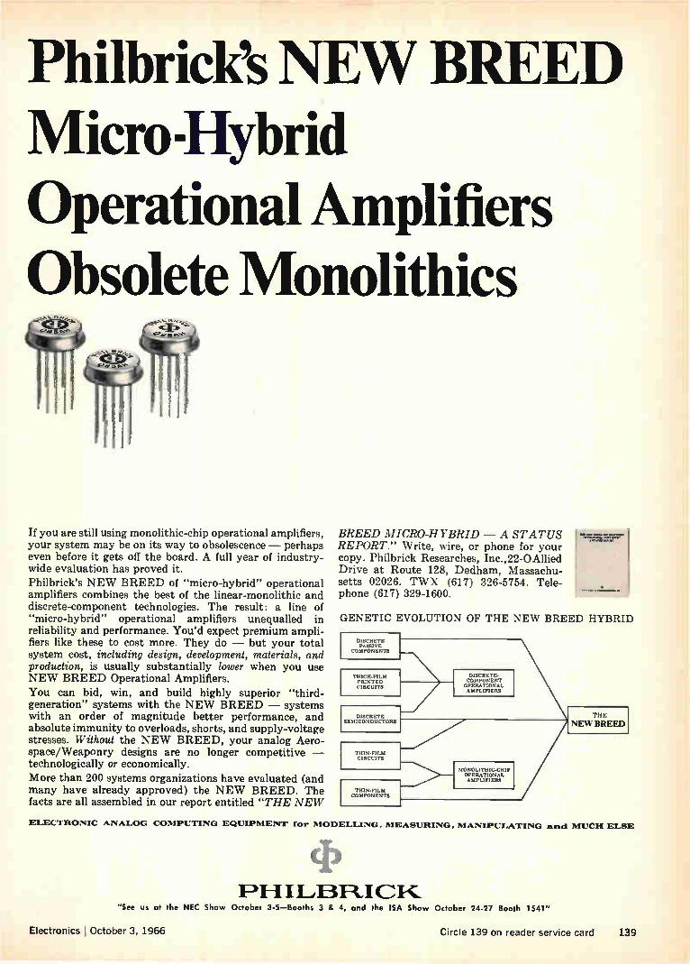
Philbrick's NEW BREED Micro-Hybrid Operational Amplifiers Obsolete Monolithics
If you are still using monolithic-chip operational amplifiers, your system may be on its way to obsolescence — perhaps even before it gets off the board. A full year of industry-wide evaluation has proved it. Philbrick's NEW BREED of "micro-hybrid" operational amplifiers combines the best of the linear-monolithic and discrete-component technologies. The result: a line of "micro-hybrid" operational amplifiers unequalled in reliability and performance. You'd expect premium ampli-fiers like these to cost more. They do — but your total system cost, including design, development, materials, and production, is usually substantially lower when you use NEW BREED Operational Amplifiers. You can bid, win, and build highly superior "third-generation" systems with the NEW BREED — systems with an order of magnitude better performance, and absolute immunity to overloads, shorts, and supply-voltage stresses. Without the NEW BREED, your analog Aero-space/Weaponry designs are no longer competitive — technologically or economically. More than 200 systems organizations have evaluated (and many have already approved) the NEW BREED. The facts are all assembled in our report entitled "THE NEW
BREED MICRO-HYBRID — A STATUS REPORT." Write, wire, or phone for your copy. Philbrick Researches, Inc.,22-0Allied Drive at Route 128, Dedham, Massachu-setts 02026. TWX (617) 326-5754. Tele-phone (617) 329-1600.
1 Maammidl..001.11•M
• 601.1•1•0•11/
GENETIC EVOLUTION OF THE NEW BREED HYBRID
DISCRETE PASSIVE
COMPONENTS
THICK-FILM PRINTED CIRCUITS
DISCRETE SEMICONDUCTORS
DISCRETE-COMPONENT OPERATIONAL AMPLIFIERS
THIN-FILM CIRCUITS
ci»Hrieen
MONOLITHIC-CHI P OPERATIONAL AMPLIFIERS
THE
NEW BREED
ELECTRONIC ANALOG COMPUTING EQUIPMENT for MODELLING, MEASURING, MANIPULATING and MUCH ELSE
C
F)1-11LABFLICK.. "See us at the NEC Show October 3-5—Booths 3 & 4, and the ISA Show
Electronics October 3, 1966
October 24-27 Booth 1541"
Circle 139 on reader service card 139

LOOK TO THE LEADER IN INTEGRATED CIRCUITS
TEST THE BEST...WITH 50 before you buy..try Ties new
Our proposition is simply this: We'll give you 50 molded TI integrated circuits with each order of 1000 units or more placed before No-vember 1, 1966. Do anything you like with these samples ... ham-
mer them ... test to destruction ... wire into your cir-cuits ... soak in boiling water .... compare with any others. Prove to yourself that they're best — by test!
Money-back guarantee—If you're still not convinced that TI molded integrated circuits do your job better than any competitive types available, just return the unused circuits. We'll give you full credit for them. This offer is good for 60 days from date of any order placed before November 1, 1966.
Offer includes popular series—Devices included in this offer are the popular digital circuits from the 930-type DTL and Series 74 TTL families shown below right. Series 74 TTL is first choice of many designers for new equipment. Circuits in this line typically are 48% faster, have 25% higher fan-out and 15% better noise margin than DTL . at competitive prices. Whether your system design calls for DTL or TTL
circuits, you'll find a wide selection of single and mul-tiple gates and flip-flops available. With either series, high-speed logic is now available to you at lower prices per function than ever before.
Rugged design proved by test —TI molded inte-grated circuits offer outstanding durability. The rugged, high-density package is molded from the same encap-sulant used in millions of SILECTrm transistors and is backed by over 2,000,000 actual hours of test. Resis-tance to impact, heat and moisture are further borne out by successful testing to the following rigorous schedule: Thermal Shock —MIL Std. 750, Method 1056A; 7'emperature Cycling — MIL Std. 750, Meth-od 1051. Moisture Resistance —MIL Std. 202C, Method 10613, Hydropressure —3% JOY, 110 PSI for four hours.
Exclusive features save you money —You realize big reductions in total manufacturing costs with TI molded integrated circuits because they are specifically designed for use in automatic handling, assembly and test facilities. Exclusive features such as the positive index notch, pretinned leads and side-mounted lead design make it possible. Even the cartridge-type ship-ping container lends itself to automated production line use.
Fast delivery — Deliveries of TI molded integrated circuits are prompt ... prototype shipments can typi-cally be made within days. And Ti's high production rates assure continued availability to meet your most critical production schedules. To obtain your 50 free evaluation samples immedi-
ately, just place your order with any TI sales office or authorized TI distributor.
All these devices are included—
Series 74 TTL 0° to 70°C Operating Temp.
SN7400N Quad 2-input NAND Gate SN7410N Triple 3-input NAND Gate SN7420N Dual 4-input NAND Gate SN7430N 3-input NAND Gate SN7440N Dual 4-input NAND
"power" Gate SN7456N Expandable Dual
AND-OR-INVERT Gate SN 7451N Dual AND-OR-INVERT Gate SN7453N Expandable 2-input 4-wide
AND-OR-INVERT Gate SN7454N 2-input 4-wide .
AND-OR-INVERT Gate
SN7460N Dual 4-input expander SN7470N Single-phase Flip-flop SN7472N MaNter,Ial,e J-K hip-flop
930 Type DTL 0° to 70°C
SN15830N Dual 4 Nand Gate SNI 5831N RS/JK Flip-flop SN15832N Dual 4 Buffer SN 15833N Dual 4 Expander SNI5844N Dual 4 Power Gate SN 15845N RS/JK Flip-Hop SN15846N Quad 2 Nand Gate SNI5850N Pulsed AC Flip-flop SN 15851 N One Shot SN 15862N Triple 2 Nand Gate
140 Electronics October 3, 1966

FREE SAMPLES FROM TI molded integrated circuits
RESISTS SHOCK ... TI molded integrated circuits resist impacts that would smash metal packages and shat-ter ceramic packages as shown in top photo. You benefit from fewer failures in handling accidents and greater reli-ability in service. The solid molded construction gives extreme resistance to acceleration, vibration and shock as proven in acual test (see opposite page).
EASY TO ASSEMBLE... TI molded integrated circuits are ideal for mechanized assembly, including auto-matic insertion and wave soldering. Faster, easier handling cuts total man-ufacturing costs. You realize big sav-ings because of the in-line rigid lead pattern and convenient indexing notch. These features simplify assembly when compared with transistor-type circular lead packages.
RESISTS DAMAGE ... You also realize savings from fewer rejects while achieving higher end-product quality because TI molded integrated circuits have outstanding durability. For in-stance, they'll hold up to heat that would induce failures in many compe-titive devices. Result: fewer assembly rejects due to high soldering tempera-tures.
SEE THESE TESTS FOR YOURSELF! CALL YOUR TI SALES ENGINEER
\.A. i- TEXAS INSTRUMENTS LI INCORPORATED
13500 N. CENTRAL EXPRESSWAY P. o. BOX 5012 • DALLAS 22. TEXAS
SEMICONDUCTOR PLANTS IN BEDFORD, ENGLAND • NICE, FRANCE • FREISING, GERMANY • DALLAS, TEXAS
Electronics !October 3, 1966 Circle 141 on reader service card 141

STRENGTH
A tree trunk — codex in early Latin — naturally
grows just strong enough to support its height and type of crown according to its environment.
Codex error detecting-and-correcting equipment is by design just strong enough to overcome transmission errors in telegraphy, microwave, troposcatter, undersea and H. F. radio channels. By varying the strength of the new convolutional
forward-acting code developed for these systems,
CODEX
Codex tailors the error-correcting capability of each device to the frequency and kind of error common to any type of communications system.
The economy and flexibility makes Codex equipment the most effective and the least expensive on the market. To get your messages or data through, in spite of channel disturbances, turn to Codex . . . the people who know error detection and correction from the ground up.
CORPORATION • 222 ARSENAL STREET, VVATERTOVVN, MASSACHUSETTS • ZIP CODE 02172 • (8173 S28-3000 • TELEX 094-6332 •
142 Circle 142 on reader service card Electronics I October 3, 1966

Opinion
Plain talk about obsolescence
•-•
The myth of obsolescent knowledge
cam.,
111 based«, ken
Gde,ID War.en
pya
lee .1
*foe row,
—tr.—
.10
.111
In the June 13, 1966 issue, pages 142 to 146, Electronics published "The myth of obsolescent knowl-edge" an opinion article. Its author, Gerd D. Wallenstein, tried to lay to rest the engineer's fear of obsoles-cence of knowledge. He suggested that a certain kind of knowledge never loses its value and proposed a theory of perspective. Clearly the article stimulated a lot of think-ing on the subject. Many read-ers wrote applauding his thesis; some disagreed with the concept and the way Wallenstein would face up to technological progress. Here are some of the dissident let-ters which the editors feel contrib-ute substantially to the discussion of obsolescence of knowledge.
I. Blaming management
Management should investigate research areas in
which technological change can affect the company,
then train its engineers.
Gerd D. Wallenstein's article "The myth of obsolescent knowledge" is correct as far as the statement that all knowledge has value, that a per-son builds on his knowledge by adding new knowledge, and that an individual has a responsibility to do so. But an engineer has difficulty determining just what new skills or knowledge should be acquired to make him valuable to his company. It is especially difficult for him to develop skills in anticipation of a technological advancement because management will determine if it will adopt any particular techno-logical innovation.
Thus, management has to be alert to possible technological ad-vancements or changes. Managers should investigate research areas in which technological changes can affect company goals. They should attempt to predict or anticipate the effect any such change will have and to make policies redirecting the company's procedures and aims accordingly. The problem of staff obsoles-
cence in an organization lies on management's doorstep. The fact that employees are not qualified for their assigned tasks of the fu-ture is the fault of top manage-
ment. If the management of an or-ganization is alert and dynamic in its perspective, it will be capable of handling what the future will demand by training its personnel to meet the needs caused by changes in technology. Advances in technology most certainly de-mand new skills and knowledge. Management should welcome such change rather than fear it.
Inertia is resistance to change, and often management settles in a state of inertia. This is why ‘`management by crisis" occurs in an organization that does little or no planning for the future. Top management's role is to lead, but if the leaders are not alert to change, they are just as obsolete as the scientists and engineers they accuse of being obsolete. Does it -make sense to spend
$5,000 recruiting a specialist with a particular skill and to fire the in-dividual he is replacing when, by planning for technological ad-
Electronics I October 3, 1966 143

vances, the presently employed en-gineer can be trained for the same skill for $2,000? In addition, this is no way to build morale and loyalty in an organization.
Training is the answer to the obsolescence of scientists and en-gineers, and training is the respon-sibility of management. When the management of a company com-plains constantly and bitterly about its personnel being unqualified for their tasks, investigation always
II. Rationalizing antiquity
shows that this particular company has little or no training program. If a company is not growing, it is dy-ing; for a company to grow, it must train its personnel for the future.
Technological advancements and changes are not easy to predict or ascertain. This fact alone makes it doubly difficult to evaluate training needs. Training is expensive and time-consuming, but it can solve the most vexing problems, one of which is meeting the demands and
Progress comes from a critical,
not appreciative, evaluation of the past
An excellent case can be presented against "The myth of obsolescent knowledge," and it is unfortunate that its author did not do so. Like many who take the overview ap-proach, Gerd Wallenstein restricts himself to favoritism, and this lim-ited viewpoint defeats the perspec-tive he claims. The verities of truth, beauty, and
human nature are ubiquitous as well as eternal, and are not found best expressed in those esoteric ex-amples he cites. Bertrand Russell's social projectivity has been by-passed by mass communication falling on the base of a peasant's r-f stage. We learn more of human nature from Bill Cosby than from Franz Kafka. Beauty is more widely appreciated in a Wescon design winner than in old Chinese art. The rules of electron flow do not
vary, whether governed by space charge or minority carriers, inte-grated or segregated. However, their application in economies of design—the eternal verity of sound engineering—change with available tools. The philosophic trap which can
really lead to intellectual obsoles-cence, and the one which Wallen-stein springs on himself, is that of attempting to validate antiquarian-ism: archaic examples, like old trees, obscuring the forests of knowledge. Truth, beauty, and hu-
man nature abide—they are time-proved. Their application in old art, old literature, and old circuitry are transient—they are time-worn. Cre-ativity and progress can come only from a critical, not appreciative, evaluation of the record of the past. Total skepticism is necessary to sift the truth from its provincial and temporal chaff.
Henry Stude Jr.
Newark, Del.
The author replies:
If I understand him correctly, Stude believes that eternal verities of beauty, truth, etc., are directly ac-cessible at all times. If this were so, then there is nothing to be learned from their manifestations of the past. Each new design, in-vention, work of art would auto-matically obsolete any previous one. But, this thinking is the epit-ome of the obsolescence syndrome.
needs of knowledge and skills for the future. Top management's re-sponsibility to the company is leadership. If it does not cope with the problem of change in tech-nology by preparing company per-sonnel for such a change, it is not meeting the challenge of its obliga-tions and does not earn the right to lead the company.
Robert A. Sinclair
Illinois State Water Survey Urbana, Ill.
Integrated circuits have not been found in a naive fundamentalist search for the most compacted cir-cuitry possible with new tools, but by extension of knowledge and experience developed with the vacuum tube, transistor and printed circuit technology. For examples of nonobsolescent
knowledge, the reader is welcome to seek his own. One can substitute Rembrandt or Picasso for Chinese Sung painting, without departing from the concept of lasting values on which our culture is built. Ex-amples by themselves do not mat-ter, it is rather the contributions of our knowledge and culture made by those who produced them.
Skepticism and appreciation are inseparable companions—without some appreciation one would have no reference to use skepticism against. Total skepticism would deny value to the Wescon design winner as much as to anything else. If no achievements of the past have value to him, how will Stude go about finding truth, beauty, hu-man nature? And where will he be 10 years from now when his present examples will have become past?
Gerd Wallenstein
Lenkurt Electric Co.

Ill. Shirking responsibility
An engineer claims that technical men do become
obsolete and the fault usually lies with their companies
Gerd D. Wallenstein presents a strong case for being philosophical but ignores an important question: how did obsolescence happen to conscientious, hardworking, stu-dious and experienced scientists and engineers? He discusses obso-lescence as if it were a state of mind rather than a fact of life. With such an outlook, the author
misses a key point: many engineers do fall prey to industrial obsoles-cence. To me, the real burden of preventing obsolescence lies with industry. Few working engineers have the breadth of view of eco-nomics and the market place to recognize which obscure scientific phenomenon will grow into to-morrow's bread-and-butter tech-nology. Management should if it is doing its job. According to Wallenstein's argu-
ment, the fear of obsolescence is the major factor to avoid. An en-gineer or scientist can avoid obso-lescence by merely revising his thinking to acquire an understand-ing of history so that the distant past and future acquire less im-portance than the immediate past and future. Thus the engineer realizes he can learn without fear of obsolescence. Such a view, to me, is existential-
ist philosophy but has little bearing on the engineer's problem. Accord-ing to a writer and philosopher, William Barrett, "One final and central point common to the exis-tentialists is their emphasis upon time and history as fundamental dimensions of human experience. Our lives become meaningful to the degree that we bind together tomorrow, today and yesterday in an active whole."
Engineers, like most other pro-fessional people, endeavor to learn and to grow. Obsolescence comes not from a lack of engineering in-centive but from a change of in-dustrial objective. The problem is inherent in the
very definition of engineer: a
person concerned making prop-erties of matter and sources of energy useful to man in structures, machines and products. This is quite different from the definition of a scientist, which might be con-sidered as a person concerned with observation and classification of facts and especially with the estab-lishment of verifiable laws. Thus the success of an engineer's job can be directly measured in terms of his company's profit as reflected by the marketability of its products.
Since the average engineer de-signs specific solutions to concrete problems, he is affected the most by changing technology. One scientist, Theodore N. Fer-
dinand, has identified three kinds of obsolescence: professional obso-lescence, aerial obsolescence and ex officio obsolescence. He defines obsolescence this way: "Obso-lescence exists when an individual uses viewpoints, theories, con-cepts, or techniques that are less effective in solving problems than others currently available in his field of specialization." He explains that professional obsolescence oc-curs when one does not have a broad grasp of his discipline; aerial obsolescence when one does not have a thorough knowledge of his immediate specialty; and it is ex officio obsolescence when an ad-ministrator does not have the tech-nical knowledge required for the position he holds. Some engineers never fall into
any of these classes of obsoles-cence, but more because of circum-stances than philosophy. Those who demonstrate superior
technical ability are inevitably as-signed to engineering in the new technologies and are afforded the latitude to become expert in them. Those who have the freedom to at-tend schools or pursue independent studies study those technical areas or disciplines which become im-portant to their companies. And those whose administrative and ex-
ecutive ability are more valuable than their engineering talent can follow the broad development of new technologies rather than spec-ializing narrowly. On the other hand, circumstances
can make another category of en-gineer obsolescent in several ways, but the three most common are: • A company assigns an engineer
to an area for which he is not trained or has not considered as consistent with his career objec-tives, background or training. • Conflicting outside responsibil-
ities or lack of availability of schools prevent the engineer from continuing his studies. When younger engineers, who are paid less, come along with knowledge of the new technology, the older man is made obsolete by economics. • An engineer pursues his studies
diligently, learning all he can about a specialty, even becoming an ex-pert in that specialty, but his serv-ices are not needed when the spe-cialty becomes obsolete. Or to put it another way, the industry be-comes obsolete and the engineer is obsolete.
In real life, it is easy for an en-gineer to become wedded to a nar-row specialty. As an engineer strives for success, he measures his progress in terms of money, status, or both. His company rewards him commensurate with his contribu-tions, urging him to produce in such a way that the company stays com-petitive. Under corporate prodding, the engineer reads and studies ma-terial which is related to his work; he does not study unrelated sub-jects except as a hobby or avoca-tion. If he's fortunate, he might pursue a field in a new technical area as an avocation that would allow him to switch his working specialty, but such an occurrence is a rarity. Broad technical reading can be accomplished only during the time reserved for vocational study. Unfortunately there is not enough time for such reading. Usu-ally, the engineer has only enough time to study his specialty or he becomes noncompetitive and the company stops rewarding him.
Thus, the responsibility turns back to the management of a com-pany. Although some companies do allow their engineers to take ad-
Electronics I October 3, 1966 145

Rolled Metal Ribbon & strips
(THINK OF CROSS FIRST)
MAJOR MICROWAVE
MANUFACTURERS DO!
Top manufacturers like Microwave Associates, Watkins-Johnson, Varian Associates and Raytheon use CROSS-rolled ribbons for their most finicky chores.That's because CROSS rolls molybdenum and tungsten down to tolerances of ± .0001. CROSS is the only company to do so on a pro-duction basis. CROSS rolls tantalum, columbium,
zirconium, rhenium moly, titanium, vanadium, copper, nickel, alloys and standard metals. CROSS will roll strips to precise order, meet any demand for precision metals.
There's a good reason why top com-panies think of CROSS first—because if CROSS does it—it's right the first time! Join the top manufacturers who've found out how perfectly CROSS meets your most exacting metal requirements. Phone or write today.
H. CROSS CO. 363 Park Ave.
Weehawken, N.J.
201- UNion 3-1134
vanced courses and broaden them-selves professionally, most restrict the courses to those that are strictly applicable to the engineer's present assignment. Management should provide the opportunity for engi-neers to do enough studying so they do not become obsolete. Un-fortunately most firms do no such thing because they themselves have become obsolete or are in a state of advanced decay. A company and an industry grow
old in a subtle fashion, usually not discernible to those who are re-sponsible for its growth. Generally, as long as profits remain at some predetermined level, members of management believe they are suc-cessful. When profits drop, the usual prescription is to tighten belts and "send the salesmen out." Rarely will the company do some-thing as basic as review the prod-uct line or how the company is meeting five- or ten-year goals. Only when profits or sales vol-
ume fall substantially below ac-cepted levels for successive years does a product review start. By that time, the company concludes it is noncompetitive and the only way to become competitive is to hire a new team of technical specialists or merge with a company that has capability in up-to-date technol-ogies. In either case, an unsuspect-ing enginer who has been perform-ing in acceptable fashion suddenly finds his services are no longer needed. He's become obsolete. Because a company cannot pro-
vide employment in anticipation of future work except for a few key employees, it normally shifts the burden of readjustment to its em-ployees. When applied to engi-
neers, such a process is extremely wasteful. Engineering experience is a valuable business resource, though a perishable one. When a company replaces its engineering staff, it loses a team that has known how to meet objectives within the company's organizational structure. The real tragedy is that this kind
of an upset is not necessary. There are many unexploited opportunities that have not materialized because the electronics industry has lacked willingness to risk product develop-ment. Atomic energy, solid-state physics, computers, rocket propul-sion, low-temperature physics and game theory were in obscurity for a generation before economics de-manded that many companies ob-tain a working knowledge of these subjects. Only recently have schools started teaching through interdis-ciplinary departments. Another approach to keeping a
company competitive uses both the specialized knowledge of a young engineer and the experience of a professional engineer. The brain-child of a Harvard University pro-fessor, Theodore Levitt, this tech-nique would have a specialized group in the company to receive ideas, work them out, and follow them through so that management receives planning information in a useful and timely manner. I would agree with Wallenstein
that engineers need not become ob-solete. But I feel that the responsi-bility for avoiding obsolescence is not only the engineer's but also his company's. Most companies fall far short of their end of the bargain.
A.W. Reickford
Princeton. N.J.
146 Circle 146 on reader service card Electronics October 3, 1966

We're glad so many of you like our high-performance field
effect transistors.
ACTUAL SIZE
We think you'll like our stable new film
capacitors, too. KEMET Flat-Kap film-foil capacitors have such an effective dielectric they're 99.9+% stable, yet up to 95% smaller than other film types. But FET's and Flat-Kaps are only two of the
products designed for today's fast-shifting market. We're also committed to leader-ship in such areas as advanced laser sys-tems ... a family of single crystals and crys-
tal products ... integrated and modular circuits ... solid tantalum capacitors. They're all aimed at problems on the frontiers of electronics. All backed by the technology of Union Carbide.
For data on new film capacitors, write for Bulletin #22, Dept. E-101, Electronics Divi-sion, Union Carbide Corporation, 270 Park Avenue, New York 10017.
Electronics October 3, 1966
ELECTRONICS KEMET is a registered trade mark of Union Carbide Corporation
Circle 147 on reader service card 147
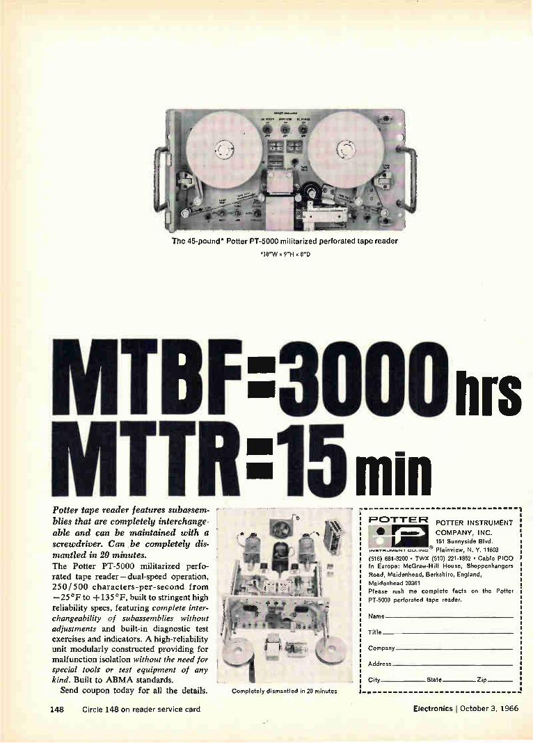
The 45-pound" Potter PT-5000 militarized perforated tape reader
*18"W x 9"H x 8"D
TEIF 3000 nrs TIR15min
Potter tape reader features subassem-blies that are completely interchange-able and can be maintained with a screwdriver. Can be completely dis-mantled in 20 minutes. The Potter PT-5000 militarized perfo-rated tape reader — dual-speed operation, 250/500 characters-per-second from —25°F to +135°F, built to stringent high reliability specs, featuring complete inter-changeability of subassemblies without adjustments and built-in diagnostic test exercises and indicators. A high-reliability unit modularly constructed providing for malfunction isolation without the need for special tools or test equipment of any kind. Built to ABMA standards. Send coupon today for all the details. Completely dismantled in 20 minutes
1=101-TE F2 POTTER INSTRUMENT
• mu. COMPANY, INC.
151 Sunnyside Blvd.
Ines-rnunIEN-r co..,,,c® Plainview, N. Y. 11803
(516) 681-3200 • TWX (510) 221-1852 • Cable PICO In Europe: McGraw-Hill House, Shoppenhangers
Road, Maidenhead, Berkshire, England,
Maidenhead 20361 Please rush me complete facts on the Potter
PT-5000 perforated tape reader.
Name
Title
Company
Address
City State Zip
14-8 Circle 148 on reader service card Electronics October 3, 1966

Whose dual in-line 930 DTL?
ITT
OTHERS
Only your
purchasing agent knows
for sure
ITT offers all series 930 DTL circuits in a
dual in-line package. Circuits manufactured
by ITT are identical to and perfectly inter-
changeable with the other leading brand.
If you're convinced that dual in-line
packaging is your answer — if you want
the lower component insertion cost, heavier
leads and all-ceramic construction that only
dual in-line can give you, evaluate ITT.
You can order any series 930 DTL in dual
in-line today! Call your ITT distributor or
factory representative.
ITT SEMICONDUCTORS
EFT SEMICONDUCTORS IS A DIVISION OF THE INTERNATIONAL TELEPHONE AND TELEGRAPH CORPORAT1011
FACTORIES IN WEST PALM BEACH FLORIDA. PALO ALTO. CALIFORNIA LAWRENCE MASSACHUSETTS, HARLOW AND FOOTSCRAy ENGLAND. FREIBURG AND NURENBERG. GERMANY
Electronics October 3, 1966 Circle 149 on reader service card 149

What marking job can we help you do better?
Hard-to-mark surfaces, hard-to-hold objects
IF+ o
<" rri
ea =,
Identification including eie sequential numbering \
'J Cramped message space
These are only a few of hundreds of marking jobs you can do more efficiently and more economically with Markem machines. So why waste time improvising and experimenting?
Call in a Markem man and get acquainted with today's broadest line of marking equipment. New high-speed color banding machines — some capable of putting three tiny bands on a miniature diode. Machines that combine sequential numbering with identification. Type so small you can print 14 characters plus trademark in an 0.125" diameter area. Quick-change type for short or pilot runs. New techniques combining special ink with flash-curing to help you meet severe durability specs. A produc-tion-speed imprinter so gentle you can safely mark flat pack ceramic com-ponents. And many other machines, specialty inks and printing elements. Right now our research engineers and chemists are working on even better ways to mark components. We'd like to be working with. you. Markem Machine Company, 305 Congress St., Keene, N.H.
HELPING YOUR PRODUCT SPEAK FOR ITSELF
150 Circle 150 on reader service card Electronics October 3, 1966

ITT 2N3375s
are 100% factory tested to give you POE of more than
5 watts e 400 MHz
28V CLASS B POWER OUTPUT VS FREQUENCY
POWER OUTPUT (WATTS)
15
10
5
o
TT 253315 MINIMUM
E,A ,PEC 2.A3375
VCC 27V
0 100 200 300 400 FREQUENCY (MHz)
Every ITT 2N3375 gives you 66% more POE than EIA specs demand. The secret lies in ITT's unusually close control of resistivity, combined with interdigitated construction.
Order ITT 2N3375s today. They're on your distributor's shelf for immediate delivery.
ITT SEMICONDUCTORS
ITT SEMICONDUCTORS IS A DIVISION OF THE INTERNATiONAL TELEPHONE AND TELEGRAPH CORPORATION
FACTORIES IN WEST PALM BEACH FLOROA PALO ALTO CALIFORNIA. LAWRENCE. MASSACHUSETTS HARLOW AND FOOTSCRAY ENGLAND FREIBURG AND NURENBERG GERMANY
Electronics October 3, 1966 Circle 151 on reader service card 151

Weston Model 1423 Integrating DVM
1g1/ Sensitivity at 50 MO for $1950.
FEATURES: Strain gage and thermocouple type measurements are made with meaningful
accuracy due to integrating and high sensitivity features of Model 1423. High common mode
rejection allows low level measurement of potentials well above ground. Loading errors
are reduced by 1000 times as compared to conventional DVM's.
SPECIFICATIONS: Accuracy: 0.02% *1 digit. Common Mode
Rejection: 150 db DC & 130 db at 60Hz—with up to 5K unbalance
between input leads, and filter in use. Series (Normal) Mode
Rejection: 60 db at 60Hz with filter. Overranging: 15% with fifth
digit display. Display Time Control: From 4 reading/second to
1 reading/15 seconds. Overall Dimensions: 6X" x 14X"x 16X".
Price: Bench mount, $1950; rack mount, $1995. Price subject
to change without notice.
Input Impedance & Sensitivity
Input Impedance Range Minimum Sensitivity
10.000 mV 50 megohms* 1 µV
100.00 mV 500 megohms• 10 µV
1000.0 mV 5000 megohms* 100 µV
10 000 100.00/1000.0 volts 10 megohms 1/10/100 mV
'Typical values twice as large
Contact Weston Instruments, Inc., Rotek Division, 11 Galen Street, Watertown, Mass. 02172
WESTONI ® prime source for precision . . . since 1888
152 Circle 152 on reader service card Electronics October 3, 1966

seno is a car
saved
Overheated journals play the villain when it comes to derailments, damage and delay. Servo gets to the heart of the problem. Our Servosafe® Hot Box De-tective System examines the journal box. Not the frame, the axle, the hub, or blue sky. We catch trouble in the making, before it becomes serious. The infrared scanning unit, pictured above, is
basic to all Servosafe Hot Box Detective Systems. Scanning units are easily mounted at trackside, and monitor journal temperature of trains passing at
any speed. Servosafe offers building-block flexi-bility, consisting of trackside warning and recording equipment, or expanded systems, including remote indicators, automatic alarms and data storage and command equipment, in conjunction with CTC.
Other Servo divisions produce systems and prod-ucts which are designed to serve safety through science: the Servodynamics Division, the Infrared & Electro-Optics Division, and the Communications & Navigation Division.
servo corporation of america
111 new south road* hicksville, Ii., new york 11e2 516 938-9700
Circle 153 on reader service card

Last week,
you needed
a
switchlite.
Today,
you need a
pushbutton
switch,
Tomorrow, a
subminiature
toggle
switch.
Next Tuesday, a
hermetically-
sealed
switch.
Good thing Control Switch is around to help.
We're unique among switch suppliers. No other manufacturer makes all the kinds of switches we make. And some don't make any of them.
When we're around to help, you can have your choice of: 3,150 toggle switches 4,200 pushbutton switches 1,240 hermetically-sealed switches 1,800 lighted pushbutton panel switches 460 basic precision switches
1,180 indicator lights.
Plus countless more standard variations. Get any or all of the catalogs listed at the right and see our line-up for yourself.
These are quality switches and switchlites. For computers, aircraft, missiles, equipment and controls that demand reliable components.
Keep your Control Switch distributor . . . or us... in mind. Today. Tomorrow. Next Tuesday.
C CONTROLS COMPANY OF AMERICA
CONTROL SWITCH DIVISION 1420 0.imar Drive. Folcroft, Pennsylvania 19032
Build a reference file! Check num-bers on the Reader Service Card corresponding to those below for any or all catalogs you want.
*450
*451
e452 *453 e454 *455 *456
Condensed Switch Catalog 100 Basic Snap-Action Switch Catalog 110 Toggle Catalog 181 Indicator Light Catalog 120 Hermetic Switch Catalog 130 Switchlite Catalog 220 Pushbutton Catalog 190
154 Electronics i October 3, 1966

is self extinguishing
ppoo POLYPHENYLENE OXIDE
(UL GROUP I)
Even in a section just 30 mils thick, PPO® polyphenylene oxide is self ex-tinguishing and nondripping. That's one-half the thickness of the minimum of 62 mils demanded by UL for our Group I rating (the toughest there is). Furthermore, PPO can be dip soldered, copper clad, staked and easily cleaned with Freon TF. These are key features of PPO, the
new wide temperature range engi-neering thermoplastic from General Electric. PPO also has superior electrical
properties. Dissipation factor and di-electric constant are very low... and Lvery constant ... over a wide tempera-
takes dip soldering
turc and frequency range. Dielectric strength is high. As an engineering material, PPO
offers: 1) a heat deflection point of 375°F @ 264 psi. 2) a tensile modulus of 310,000 psi at 300°F. 3) only 1% creep after 10,000 hours at 73°F and under 2% at 200°F. 4) excellent dimensional stability, with a maximum water ab-sorption of 0.12 percent. 5) moldability to close tolerances. What design of yours would go bet-
ter in PPO? For a starter, look at the pictures. You'll see a tv tuner strip . . . connector . . . tv deflection yoke, . . . thin-walled electrical shell . . . and molded printed circuit board. Each of
(UP TO 800 -F)
them end up better and less expensive' in PPO. The same characteristics make PPO a candidate for double insulated housings. Our technical people know of many
more areas where you can benefit with PPO. They'll be glad to help solve your problem. Call your local Chemi-cal Materials Sales Representative, or write Section 6J2, Polymer Products Operation, General Electric Company, One Plastics Ave., Pittsfield, Mass.
(By the way, PPO is also the greatest hot water resistant engineering ther-moplastic yet developed.)
GENERAL
ellet% e n - . 114tirt>-1--'-1
ELECTRIC
Circle 155 on reader service card

rf-A • uittef.;,
" 10
Boost signal strength ...
Increase receiver sensitivity. .
Broaden mobile communications system's range...
INCREASE
COMMUNICATIONS
SYSTEM
EFFICIENCY
with
•CAVAM P
How? With Sinclair's Cavamp. For use in compact duplex or
multicoupler systems, Cavamp combines amplifier with filter to
reduce noise while boosting signal strength.
Cavamp is capable of quieting receivers of .6 microvolt sensitivity with less than .2 microvolt signals,
supplying gains of up to 14 Db at a 5Db
noise figure. It incorporates a double-ended 8058 nuvistor that insures greater
overload protection (1 milliwatt maximum
input) and lower intermodulation product levels.
Cavamp incorporates a narrow band pass filter to increase receiver selectivity.
Transmission line losses are offset, or receiver front end sensitivity
is increased, improving system performance.
Designed for the 150 and 450 MHz range, Cavamp is factory tuned to your specific frequency, however,
can be easily field retuned to any frequency in the band by making two
screwdriver adjustments.
Rx2
Rx3
R.4
HYBRID POWER SPLITTER
CAVAMP
SIGNAL GENERATOR
DIRECTIONAL COUPLER
CAVAMP
FREQUENCY COUNTER
> TO UNIT UNDER TEST
Clip the coupon and attach to your letterhead for full details
and prices.
SINCLAIR RADIO LABORATORIES, INC. 523 FILLMORE AVE. DEPT. 101-P TONAWANDA, NEW YORK
Receiver multicoupling for • closely spaced receivers: Four receivers, separated by 50 KHz, connected to a hybrid power splitter providing each with 25 Db isolation: power splitter loss of 6.5 Db offset by Cavamp with 12 Db gain. Band pass filter characteristic also protects receivers from nearby transmitters.
Receivers and transmitters connected to a common antenna with a passive multicoupler for an expandable system:
Transmitter, Txl, separated from receiver, Rai, by 500 KHz. Cavities C1,2,3,4 insert 6 Db loss at Rxl fre-quency, 80 Db attenuation against Txl. Cavities 5,6,7 insert 1.5 Db loss at Txl frequency, attenuate Txl noise at Rai frequency by 35 Db or more. 6 Db insertion loss not degrading to receiver operation: Cavamp offsets filter losses, provides 6.0 Db gain on Rx 1.
Increasing sensitivity of frequency measuring system: Where frequency counter is used, high signal strength is often required to drive the counter. Cavamp in-creases counter sensitivity while the selectivity reduces false triggering from unwanted signals.
FREE LITERATURE TO: SINCLAIR RADIO LABORATORIES, INC,
Dept. 10I-P 523 Fillmore Avenue Tonawanda, New York 14152
Name*
Title.
Company*
Address*
City* State' 7ip•
156 Circle 156 on reader service card Electronics October 3, 1966

After a trip down a hot, corrosive oil well,
cable jacket of Kynar* stands up,
nylon breaks up.
That's what Ball Brothers Research Corporation found when it needed a jacket to protect instrumentation cable in deep oil well jobs.
The combination of temperatures above 200°F, chemical attack by sul-fur bearing compounds and other corrosives, and constant rubbing against down-well piping was too much for other materials. Kynar made the grade in the toughest of tests ... the
test of successful down-well per-formance.
Why not check your present insula-tion against the toughness, and cut-through resistance of Kynar? Write today for information relating to your specific application.
Plastics Department, Pennsalt Chemicals Corporation, 3 Penn Center, Philadelphia, Pa. 19102
Kynar1. the fluoroplastio that's tough! *Kynar is Pennsalt Chemicals Corporation's registered trademark for its vinylidene fluoride resin.
Electronics I October 3, 1966
eilmimmulmvD
'PENN SA Ur% CHEMICALS • EQUIPMENT
Circle 157 on reader service card 157

The Absolute Ohm How a classic ESI system can bring you closer to the absolute in
resistance measurement, and why it can be of more than academic interest in many electronic labs and plants.
The Absolute Ohm is a theoretical ideal, which can be ever more closely approached, but never attained.
Its legal value is the resistance standard maintained by The National Bureau of Standards. The accuracy of your resistance measurement depends on the degree of "direct traceability" to this NBS standard. The ESI 242 Resistance Measuring System permits a
chain of measurements to any resistance level from a single, directly traceable reference standard—with com-parison accuracies of 1 ppm. Measurements can be
made swiftly and simply; results are read directly, without calculation.
Even when you are not looking for greater accu-racy in your resistance measurement and calibra-tion, you may have good reason to consider our 242. It could help you speed up the pace of lab or quality control operations. Or in-
The legal residence of The Abso-lute Ohm is Washington, D.C.— at the National Bureau of Standards.
crease reliability. Or get better results from less ex-perienced people on your production line. The 242 includes Ratio
Bridge, Decade Standard, Generator-Detector and 4-Term mal accessories. We can't promise The
Absolute Ohm in resistance measurements. But with the 242, we do offer The Defin-itive System. ESI, 13900 NW Science Park Drive, Portland, Oregon (97229).
000 * . •
IT
IT
The Absolute Ohm's home away from home — our 242 Resistance Measuring System. Price: $3400.
DIRECT REMO ACCURACY N..... DEVIATION DIAL ACCURACY 1
RANGE x0.0I eel
0
0.1
1, ),
100
10
0.1
0.01
0.001
0.0001 till.. 1 1111.11•1 I 1111111 111.11.• 1 I lb. 11111. \ILIUM 11,1
10 100 i ,,L... n•, 2L>oj v lioi .31 ‘.. ,o loo 1 ..1 10 eo j ' 0
mil ; MEG Accuracy of 242 System over specified ranges.
le
Electro Scientific Industries eI si i e 158 Circle 158 on reader service card
Electronics , October 3, 1966

FOR EASIER ROTARY SWITCH SPECIFICATION.. TRY THESE:
FOR LOWER COST PRECISION ROTARY SWITCHING ...TRY THESE:
FOR TRULY OUTSTANDING DRY CIRCUIT SWITCHING ...TRY THESE:
SERIES 2
SERIES 2
FOR FASTER ROTARY SWITCH DELIVERY...TRY THESE:
IF YOU DO, you'll find that Shallcross Series 1, 2 and 4 precision rotary switch lines offer: LOWER TOTAL COST — INITIAL COSTS ARE NORMALLY LOWER (often 25 per-cent or more) than those for rotary switch counterparts claiming comparable quality. INSTALLATION COSTS ARE RE-DUCED by easily wired flared terminals (identified for location) and rugged con-struction features that virtually elimi-nate switch damage during harnessing. MAINTENANCE AND REPLACEMENT COSTS ARE REDUCED to the vanishing point by: (1) 50 in/lb stop strength rat-ings, (2) multiple contact wipers (for reliable circuit "making"), (3) positive action long life detents, (4) dust protec-tion for internal switch parts, and (5) material-design combinations that re-duce voltage breakdown and insulation
resistance failures. Add these cost "savers" to lower specification costs (below), and you'll see why Shallcross has the most economical top quality ro-tary switch line in the industry — as a matter of fact, an investigation will prove that Shallcross switches are often less in total cost than the lowest priced "clip types."
OUTSTANDING DRY CIRCUIT SWITCH-ING — Negligible "thermals," low con-tact resistances (1-2 milliohms typical from input to output), and low switching noise provide ideal dry circuit switching.
EASIER SPECIFICATION — Comprehen-sive cataloging, reproducible specifica-tion sheets (for easier drawing creation), and easily used part number systems expedite specification.
FASTER DELIVERY — Day-in-day-out deliveries for standard Shallcross switches equal any in the industry (eight distributors stock 1-3 deck "standards" — production quantities are normally shipped in two to three weeks).
The best values in quality rotary switch-ing wear this brand—try them.
11-1 C .....
Sklik11988
SUBSIDIARY OF CUTLER•HAMMER
SHALLCROSS MANUFACTURING COMPANY, SELMA, N. C.
ZIP CODE 27576 • TEL. 919 965-2341. TWX 919 770-7839.
Electronics ; October 3, 1966 Circle 159 on reader service card 159

20 kW Anode vapor cooled
3 kW
12 kW
1,5
The most complete range of ceramic-metal tubes for U.H.F. Transmitters.
In operation for more than two years in a large number of U.H.F. Television Transmitters (BAND IV - BAND V)
THOMSON CFTH HOUSTON
• EASY OPERATION
• LOW COST
• HIGH RELIABILITY
• LONG LIFE
DIVISION TUBES ÉLECTRONIQUES - 8, RUE CHASSELOUP-LAUBAT - PARIS XV ° - TÉL. : 5 6 6.70.04 US OFFICE : THOMSON ELECTRIC Co INC. 50 ROCKEFELLER PLAZA • ROOM 916 • NEW YORK 20 (NY) USA • Phone: Circle 5.0444
160 Circle 160 on reader service card Electronics October 3, 1966

The World's Best Receiver Systems use LEI Receiver Components Like Theses,
RF PRESELECTOR
Strip Transmission Line RF Preselector FSB 2250-100-5-T-NF
Freq. range 2200-2300MC
Response Tchebychev Insertion loss ldb max.
Stop band loss 40db
Skirt shape 5 poles
Fixed tuned
1st CONVERTER
Solid-State Mixer Preamplifier Model Series — 9
RF range 125MC-400C (more than 60 coax or waveguide mixers are available within this range)
N.F. (overall) 9db (typ.)
IF cf 160MC
Bandwidth @ 3db 50MC
Gain (RF/IF) 30db
Lin. output -I-10dbm
effli LEL6
2nd CONVERT
Solid-State High Level Converter Internal Xtal LO. Model RTC-1
RF cf 160MC
RF bandwidth 35MC
IF cf 60MC
IF bandwidth 20MC
Gain 10db
Noise Figure 12.5db
Lin. input —10dbm
Solid-State Log Amplifier Model ITL-2
IF cf 60MC
Bandwidth @ 3db 20MC Dyn. Range 80db
Sensitivity 20MV/db
Solid-State Linear Amplifier Model ITA-5
IF cf 60MC
Bandwidth @ 3db 20MC
Gain 70db
AGC 60db
Noise Figure 7db max.
LEL's catalog is a good place for you to choose from thousands of standard units engi-
neered and manufactured with special receiver applications like yours in mind. Chances are
you'll find just what you need. If not, we'll modify any catalogued item in short order .... or build to your specifications. Why not call LEL now?
ArEAL, DiviSiON varian /akron street /copiague /new york 11726/516 AM4-2200/516 PY9-8200/TWX 516-691-5085
Solid-State Limiter Discriminator Model ITF-1
IF cf 60MG Bandwidth @ 3db ioMc Sensitivity 1v/MG
Input 50 ohm
Output Vid. Oct.
Electronics ' October 3, 1966 Circle 161 on reader service card 161

up. down.
on the ground. the place for new electronics advances is Lockheed.
Whatever environment you now work in—land, sea, or space—you'll find it to your advantage to look into opportunities at Lockheed. Take Agena and Poseidon for example. Major tech-nical expansion is under way on both of these vital programs. And both Agena and Poseidon share the need for new concepts and major tech-nical advances. Typical Agena assignments will include: digital communication systems for data transmission and command, digital and analog flight control systems, optical and infrared sen-sors, solar power panels, and power condition-ing. D Poseidon's general area of requirements ranges from weapon effects on electronics to the design and use of state-of-the-art test check-
LOCKHEED
out equipment in one of the largest checkout programs ever mounted. D Undersea, Lockheed is active in the expanding field of deep sub-mersibles and ocean mining. Now under way— the Navy's unique Deep Submergence Rescue Vehicle and Lockheed's Deep Quest research vehicle designed to operate down to 8000 feet. On land, Lockheed is engaged in the devel-
opment of unique land vehicle systems, infor-mation systems for states and hospitals, and many other important programs. D For more complete information, you are invited to write Mr. R. C. Birdsall, Professional Employment Manager, P.O. Box 504, Sunnyvale, California. Lockheed is an equal opportunity employer.
MISSILES & SPACE COMPANY A Cf.rOJA 0 ,eSiOn OF LOC.L..1.0 co.eo....treav
162 Circle 163 on reader service card—›-

Allen-Bradley Active Filters, which offer a 60 db attenuation over the range of 10Hz (3Hz*) to 100KHz
A
ACTIVE LOW PASS FILTER 36 VOLTS D.C.
ALLEN-BRADLEY MILWAUKEE * mies ea us• WISCONSIN
Allen-Bradley active filters can provide as much as a 50 to 1 reduction in size and a corresponding reduction in weight over conventional passive elements.
The diagram below and performance curve at right illustrate how Allen-Bradley active filters prevent current fluctuations in the power distribution system above 10Hz (3Hz*), developed by pulse modulated communications equipment, suc as teletypewriters and other randomly varying loads.
DC SUPPLY FILTER
RANDOMLY SWITCHING LOADS
INTERFERENCE FLOW WITHOUT FILTER
INTERFERENCE FLOW WITH FILTER
• Directly as the result of some new ideas applied to the field of ElectroMagnetic Compatibility, Allen-Bradley has been able to produce a new active low pass filter that provides an attenuation of greater than 60 db over the range of 10Hz (3Hz*) to 100KHz. The maximum de component of the load current is 5 amperes.
The primary purpose of this filter in the above applica-tion is to prevent impulses generated by rapid load fluc-tuations, which may be carrying information of a confi-dential nature, from being reflected back through the power supply and into the power distribution system.
These new filters are designed to satisfy specific require-ments. For instance, power line filters are under develop-ment for 60Hz and 400Hz power frequencies. Here, a sharp pass band is afforded the power frequency while greatly attenuating all other frequencies.
2 A/div ( 10 A/div*)
WITHOUT FILTER
2 mA/div WITH FILTER
10ms/div
Typical example of A-B Active Filter performance
Allen-Bradley active filters produce a far greater at-tenuation of unwanted signals than is possible with a filter composed of conventional passive elements, occupy-ing the same volume. By using the A-B active filter, a size reduction of 50 to 1 is attained, together with correspond-ing savings in weight. These filters employ solid-state circuitry. No external power source is required other than that supplying the power to the load. In addition, com-plete inrush and short circuit protection is provided.
Allen-Bradley specialists in filter engineering are avail-able to discuss with you such problems for which these new active filters might offer the best solution. Please write: Allen-Bradley Co., 222 West Greenfield Avenue, Milwaukee, Wis. 53204. In Canada: Allen-Bradley Canada Limited. Export Office: 630 Third Ave., New York, N. Y., U. S. A. 10017.
*WITH EXTERNAL CAPACITOR
66-09-6E
ALLEN -RRADLEY QUALITY ELECTRONIC COMPONENTS

This Wilcox Model 914 ATC transponder uses Allen-Bradley Type CB 1/4 -watt and Type EB 1/2-watt fixed resistors, Type G variable resistors, and Type R adjustable fixed resistors. The Model 914 transponder is for aircraft operating under ground control radar.
Prompt shipment of HOT MOLDED FIXED RESISTORS in all standard EIA and MIL-R-11 resistance values and tolerances. Values above and below standard limits can be furnished. Resistors are shown actual size.
TYPE BB lie W ATT
TYPE CB 1/4 W ATT
TYPE EB 1/2 W ATT
TYPE GB 1 W ATT
TYPE MB 2 W ATTS
MIL TYPE RC 05
MIL TYpE RC 07
MIL TYPE RC 20
MIL TYPE RC 32
MIL TY PE RC 42
Our experience shows no
failure ever of an A-B resistor
unless subjected to overload caused
by a tube or transistor failure
Wilcox Electric Co., Inc.
Type R Hot Molded Adjustable Fixed Resistors are rated V4 watt at 70°C. Supplied in resistance values from 100 ohms to 2.5 megohms.
›'ç
Type G Hot Molded Variable esistors are rated 1/2 watt at 0°C. Resistance values from 00 ohms to 5.0 megohms.
"No failure ever" is an impressive record, especially since Allen-Bradley fixed and variable resistors have been used in Wilcox transponders for around ten years.
The reason for this consistently high performance is the unique hot molding process developed and used only by Allen-Bradley. In fixed resistors, it produces such com-plete uniformity that long term A-B resistor performance can be accurately predicted. Catastrophic failures don't occur with Allen-Bradley hot molded resistors.
Use of the hot molded resistance element in the Allen-Bradley Type G variable resistors assures very smooth operation—there are never any abrupt changes in re-sistance during adjustment. The Type G controls have
a very low initial noise factor, becoming lower with use.
Type R adjustable fixed resistors also have a solid molded resistance track. Adjustment of resistance is so smooth, it approaches infinite resolution. Settings will remain fixed under severe vibration or shock. The Type R molded enclosure is dustproof and watertight—it can be potted after adjustment.
For more complete details on the full line of A-B quality electronic components, please write for Publi-cation 6024: Allen-Bradley Co., 222 W. Greenfield Ave., Milwaukee, Wisconsin 53204.
Export Office: 630 Third Ave., N.Y., N.Y., U.S.A. 10017.
58-01-6E
ALLEN-BRADLEY QUALITY ELECTRONIC COMPONENTS

Dense between the ears—but what an 1.Q.*!!
111111 1111 ///11/1/1 111111///f 41l
Data _ -MP 202Et45-1 66-23-5
e_m p 2 02844 1
Between the ears of the A-MP* 750 Series Box Contact Connector are 100 contacts in a space of less than 4 inches—that's pretty dense! Yet this connector offers you the industry's lowest per line applied cost for a highly reliable two-piece printed circuit connector —that's economy plus Installed Qualityl
High density is achieved with two rows of 50 box contacts located on .075" centers. Receptacle contact tails are staggered to permit larger spacing between printed circuit wiring paths. Headers contain channel shaped pins which are latched in the header and have flat tails for easy connection to daughter boards.
The 750 Series Box Contact Connector provides econ-omy in overall applied cost. Socket contacts are highly flexible allowing wide margins of misalignment of pins and eliminating the need for costly precision card guides. Low insertion and extraction forces permit mating of a large number of contacts without me-chanical screws or cams. The 750 Series connector has contacts which can be easily replaced without removal of the connector.
High electrical integrity is assured by four elliptical spring beams arranged at right angles forming a box. These beams provide four areas of contact on the mat-ing pin, whether it is square, round, rectangular, or channel shaped. The walls of the housing limit spring deflection and prevent overstressing of the contacts, even when subjected to severe shock and vibration.
This adds up to a rugged, tolerant miniature connector for your most demanding applications. Examine these unduplicated features:
Contacts on .075" centers High misalignment tolerance Latched-in contacts can be easily replaced Gold over nickel plated beryllium copper contacts Polarized housings Sturdy diallyl phthalate housings Four redundant contacts for high reliability Resistant to vibration and shock Low installed cost
If your design calls for tight specifications requiring a tolerant, reliable, high density connector—all with an eye on economy, then the A-MP 750 Series Box Contact Connector is for you. Write immediately for complete details.
*Trademark ol AMP INCORPORATED
INCORPORATED
Harrisburg, Pennsylvania
A-MP* products and engineering assistance are available through subsidiary companies in: Australia • Canada • England • France • Holland • Italy •Japan • Meseco• Spain •West Germany
-4—Circle 164 on reader service card Circle 165 on reader service card 165

EPDXY JUNCT 5oe
ON FET
Pay less, get more: Fairchild's new 2N4360 is a low noise, low cost P-Channel junction FET you
can get. You can get it immediately in any quantity, and pay much less than you would for devices
with lesser performance specifications (only 50¢ in quantities of 1000). The 2N4360 features an
extremely low noise figure, high gain, and high input impedance. The TO-18 epoxy package with-
stands an operating junction temperature of +125°C and can be stored at any temperature
—55°C to +125°C. (T0-18 cans also available, 2N4381,
2N4382.) Get samples from your Fairchild Distributor, MAIRCHIL-CI
or get our data sheet. SEMICONDUCTOR
2N4360 Typical Specifications:
Equivalent Input Noise Voltage O 02pV/Hz @ f =100Hz
Equivalent Input Noise Figure 0 ldb @ f =100Hz
Gate to Source Breakdown Voltage (BVGss) 20V min.
Forward Tranceadmittance (Y,,) 4000µmhos @ flkHz
Drain Current (loss) 10mA
Gate Reverse Current (Is) O 15nA
FAIRCHILD SEMICONDUCTOR/A Division of Fairchild Camera and Instrument Corporation la 313 Fairchild Drive, Mountain View, California (415) 962.5011 • TWX, 910-379.643
166 Circle 166 on reader service card Electronics October 3, 1966

Probing the News Military electronics
To improve tropo transmission over short-haul links, frequencies are being changed from 1 Ghz to 2 Ghz on some of the 60-foot billboard antennas like these at Nha Trang. Elsewhere, 120-foot billboards and a variety of parabolas, up to 60-feet in diameter, are being installed.
Vietnam communications network growing into Southeast Asia's best Building communications terminals in a war zone is tough,
but the U.S. is completing a permanent tropo network
in Vietnam and Thailand and doing it on schedule
By William Hickman Washington Electronics Bureau
The amazing engineering feat of building a gigantic, sophisticated communications network in the middle of a war continues unabated in South Vietnam and Thailand with $50-million worth of new con-tracts ready to be signed. The cost of this backbone network, known officially as the Integrated Wide-band Communications System (IWCS), is thus passing the $175-million mark and there will prob-ably be more contracts.
This month, the first portion of the upgraded tropospheric/ scatter and microwave network will be turned on. By May, 1967, all of it will be ready, providing more sites and three times as many channels as at present. The links now handle from 48
to 72 channels. The upgraded links will carry 300 channels and in some cases as many as 600. New antennas. The upgraded
IVVCS will have 24 additional
billboard reflector antennas-12 are 60 feet high and 12 are 120 feet high. There will be 59 new parabo-las: twelve 60-foot, fourteen 40-foot, twenty 30-foot, six 15-foot and seven 10-foot dishes. The tropo equipment used with the billboard antennas—the exciters, amplifiers and receivers—is being built with solid-state equipment wherever possible. It's the first time the United States military has used solid-state components in tropo-
Electronics 1 October 3, 1966 167

8ANGK
PHITSANULOKE
KATHIEM,
Integrated Wideband Communications System ties together bases in South Vietnam and Thailand with over a quarter of a million miles of troposcatter and microwave voice links. Page Communications is prime contractor for the system in South Vietnam, Philco in Thailand.
o
11f r ---,
,.? - ‹....1
l `-`•-? \.. ,
e ' 0 '''.e ,x ,,-- 5' \ UDON THANI .
ft----- '''',. \ .e..L. 11 ----..,,SKONNAO1pN I \ • ...,,Is
... ..,...,,,,
1KHON KAEN MAKD ..AHli \ I - ' I ',.,....
r.' HI/ IAILAND 1 i t i UBON I
PHILCO
PAGE COMMUNICATIONS
MBODIA
SOC IRA
'H AINAN
RAI MONKEY MT.
HA LAI UANG NGAI
e HON CONG MT NAO TN
BAN ME THuoT DALAI-
COMMAND WOO
'JUNG :HUA MT OUI NHON
NANA PHASE
AM RANH BAY
PHAN RANG PHAN THIET
JUNG TAU vUNG TAU AIRBASE
t,
5 o ollk
rte' 5 £r`
spheric scatter equipment. In addition, some of the existing
60-foot reflectors are being modi-fied. Short-haul transmission links will be changed from the standard 1 gigahertz to 2 Ghz to improve transmission. The 120-foot bill-boards, which provide only long-haul links, will all operate at 1 Ghz. The parabolic antennas operate
with the opposite technique. Bather than using 2 Ghz for short-haul, the higher frequency is being used for the longest tropo link in Southeast Asia, from Vung Tau at the south-ern tip of South Vietnam to Green Mountain near Bangkok. Some ex-perts say this may be why the long parabolic link isn't too good.
I. Blending civilian and military
Installation of the IWCS is being supervised by the Army Strategic Communications Command, under the direction of Major General Richard J. Meyer. Prime contrac-tors are the Page Communications Engineers, Inc., a subsidiary of Northrop Corp., for the work in
South Vietnam, and the Communi-cations and Electronics division of Philco Corp., a subsidiary of the Ford Motor Co., for the work in Thailand.
Page's contracts have already hit $70 million, with $30 million more in new contracts soon to be signed. Philco has received $50 million so far and will get $20 million more. New areas. The new contracts
will take Page to the Mekong Delta, south of Saigon, to install tropo and microwave terminals and Philco to new sites in Thailand to support the growing number of U.S. troops there. Lockheed Electronics Co., a divi-
sion of the Lockheed Aircraft Corp., has recently been given a role in the IWCS. Under four cost-plus-fixed-fee contracts totaling more than $5 million, Lockheed will monitor the installation of the equipment, evaluate its perform-ance, and make recommendations regarding each portion's accepta-bility. The system is managed by the
Defense Communications Agency and operated by the Army Strategic Communications Command.
II. System grows stronger
The communications system has been built with great speed and, according to Army officials, there have been no significant cost over-runs or schedule slippages. And it should be noted that civilian engi-neers are working in a war zone. IWCS also is noteworthy in several technical areas: • The circuits meet the quality
standards of the Defense Com-munications Agency, which are roughly comparable to those of the American Telephone and Tele-graph Co. in the U.S. • No more than 10 to 12 minutes
of outage per year is permitted per circuit. • A tropo link spanning more
than 450 miles without repeaters is installed—the longest tropo link in Southeast Asia. All the links form a 250,000-mile chain.
Hardware. While the equipment specifications to both Page and Philco were identical, the contrac-tors chose different approaches. Page picked billboard antennas, and Philco selected parabolas. Page adopted REL 2600 tropo
transmitters and receivers built by Radio Engineering Laboratories, Long Island City, N.Y., a division of the Dynamic Corp. of America. The equipment is solid state, provides 300 voice channels and has high reliability; it exceeds the signal-to-noise ratio of 55 decibels that had
W.D. Carter, assistant director of engineering at Page, is responsible for the firm's work in Vietnam.
168 Electronics 1 October 3, 1966

been the previous military stand-ard. The Government gave Philco its
own LRC-3 transmitting-receiving equipment which Philco had manu-factured and sold to the Govern-ment some years ago for the Mili-tary Assistance Program. The equipment was intended for Indo-nesia, but when U.S.-Indonesian relations cooled it was never sent. When the IWCS program came along the Army pulled the equip-ment from warehouses on the West Coast and furnished it to Philco. For microwave equipment, Page
bought an AN/FRC-109 radio sys-tem from the Lenkurt Electric Co., Inc., San Carlos, Calif., a subsidiary of General Telephone and Elec-tronics Corp. Philco used some AN/FRC-109 equipment and some of its own CLR-2 series gear.
Lenkurt supplied Page with AN/ FCC-17 multiplex equipment. And Philco bought its multiplexers, the AN/FCC-18, from General Elec-tric Corp. One new piece of equipment is
the technical control center, lo-cated at each site. Each center is equipped with patch panels to switch calls and serves as an inter-face for tactical transmissions. It is also equipped with automatic fault finders that display malfunc-tions. Each technical control facility
keeps open e few channels for tac-tical use and provides the neces-sary signal converters. Since IWCS is composed of fixed stations, all signaling is done at 2.6 kilohertz. Most tactical military radio equip-ment is set at 1.6 khz. Only two points in the IWCS
network link Page's system in Viet-nam to Philco's system in Thailand: at Ubon in Thailand and Vung Tan in South Vietnam. A much dis-cussed, but highly classified, cable system to link the Bangkok area with the Saigon area is believed to be going in.
III. Enemy uses network too
Although the fixed communica-tions sites are protected by U.S. forces, they are still very vulnerable to attack. Surprisingly, no damage has ever been inflicted by the en-emy on the backbone communica-tions system. U.S. communications veterans from Vietnam tell of see-ing fierce fighting around the corn-
How to design outstanding performance into antennas for business aircraft?
How to double the range for VOR reception?
How to achieve major reductions in VOR and ILS bearing errors?
ow to produce antennas that protect against htning strike damage?
ow to produce antennas that reduce Inerability to precipitation static?
Pilots of business aircraft using D&M antennas agree that Dome &. Margolin has the answers to these problems. More than 20 years of dedicated work ... continuing research ... successful development ... and highly specialized manufacturing experi-ence ... these are the reasons why, when it comes to aircraft antennas and related equip-ment, pilots can say with
•.•011 NI K assurance:
Are you experienced in antenna engineering and skilled at problem solving? Do you want to assume responsibility on projects involving flight safety, communications, navigation or telemetry? Call or write. Chief Engineer at our new Bohemia plant or at Chatsworth.
orne an INCORPOR
WEST COAS
ATED
pie e oneroft Avenue 2950 Veterans Memori41 Highway
Chatsworth, California 91311 8011011Y. 11716 er,à et\ 11111WIt
20 Years of Leadership in Aircraft and Missile Antennas
Electronics October 3, 1966 Circle 169 on reader service card 169

IF YOUR COMPUTER SYSTEM REQUIRES
A-D or D-A Conversion
where:
A—resolver or synchro
D=10 to 16 bits
JUST PICK UP THE PHONE.
North Atlantic
offers a complete line of
resolver /synchro interfaces
for computer systems,
aircraft/space vehicle simulation,
antenna position/programming,
and airborne use.
All silicon solid•state, 10 to 16 bits,
multi-speed, multiplexed inputs/outputs,
60 cps to 10KC.
As we said, just pick up the phone.
I•T 0 Ft I—I A. TLA. TICI•T ind'ustries, inc.
TERMINAL DRIVE. PLAINviEw. NEW YORK • (516) 681.8600
munications sites with the stations never receiving a hit. According to some U.S. officials
who have served in Vietnam, the main reason the enemy hasn't touched the network is because they are using it too. The South Vietnamese Army
has the use of two channels throughout the system and the army is infiltrated by the Vietcong. Vietnam veterans say a Vietcong
agent in the South Vietnamese Army could easily use the system as a command and control network. As one American officer who has served in Vietnam said: "When two Vietnamese are talking to one an-other, neither I nor any other offi-cer I know of can tell whose side they are on." American officials resign them-
selves to this fact of life, saying philosophically that it's better for the enemy to use the system than to destroy it.
After the war. Another reason the Vietcong or North Vietnamese communist forces haven't touched the network is its permanence. Since 120-foot antennas embedded in concrete can't be moved easily, South Vietnam is in for a fine civil-ian communications network when the war is over. "It will be the envy of the Far East," says W.D. Carter, assistant director of engineering for Page. An Army official doubts, how-
ever, that the Vietnamese govern-ment will be financially able to operate it? If the U.S. forces stay on, as they have in Korea, the engi-neers working for Page and Philco might have life-long careers. Jamming threat Much of the
IWCS equipment is also vulnerable to jamming, officials admit, but they are not particularly concerned with this possibility in the near fu-ture. They say the enemy does not now have the technical know-how or equipment to jam the signals. The possibility of jamming does exist, however. The IWCS link from Green
Mountain near Bangkok to Vung Tau on the coast of Vietnam crosses over Cambodia for much of its 450-mile hop. Officials say jammers along this route, where allied forces aren't allowed, could be damaging. The communications network
also crosses Laos, but this nation
is friendly to the U.S. and South Vietnam. American aircraft are based in the country and engineers are currently putting in a communi-cations link there.
IV. Reaching outside Asia
Communications to outside the IWCS area is handled mainly by the 60-channel Wet Wash subma-rine cable, built by Page, that runs from Nha Trang to the Philippines. There, commercial cables are avail-able to send messages on to Cali-fornia. Two Syncom synchronous-alti-
tude satellites are also available, but they have only two voice chan-nels each and do not provide much relief for the Wet Wash cable.
Maj. Gen. Richard J. Meyer, left, heads up the Army Strategic Com-munications Command (Stratcom) which is directing the construction of the Integrated Wideband Com-munications System in Southeast Asia and will operate it. Colonel Joyce B. James, deputy chief of staff for operations for Stratcom, will be in charge of operating the system when it's completed.
The Initial Defense Communica-tions Satellite project, with seven satellites in orbit and plans for sev-eral more, can assist some, but each satellite's channel capacity is also set at two. There are other alternatives to
reach outside Asia—mainly high-frequency radio. However, h-f radio is dependent upon atmospheric conditions and does not offer the necessary reliability. The h-f links feed terminals in Ethiopia, Guam and Formosa. When the military has its tactical
satellites in operation in about two years another alternate means will be available. The IWCS equipment is being built to interface with these Tacsats.
170 Circle 170 on reader service card Electronics I October 3, 1966

Communications
Satellite in sight for airlines Comsat's newest customer will be commercial airlines; they'll have a
satellite of their own in 1968 for communications over the Atlantic
By Robert Henkel
Eiectronics Washington Bureau
Comsat is moving again after bog-ging down last summer in its plans to put up a communications satel-lite for commercial airlines. It now looks as though a satellite to dem-onstrate this new role will be op-erational in 1968—more than a year behind the original schedule. The technical hitches that de-
layed the project are "close to a satisfactory solution," says Edward J. Martin, head of advanced sys-tems for the Communications Satel-lite Corp. • The design approach for the
spacecraft's very high frequency, antenna, the major stumbling block, has been selected. • Another earlier problem was
the difficulty in designing the satel-
lite within the payload limitations of the launch vehicle. This ap-parently has been solved by switch-ing to a more powerful booster that will lift 10% to 30% more payload into the 22,300-mile synchronous orbit. The satellite—called Aerocom—
will be located over the equator between Africa and South America. It will relay aircraft transmissions to two ground stations—one in North America and the other in Europe—over existing 4-gigahertz and 6-Chz satellite frequencies. Communications between the satel-lite and the aircraft will be on the present aeronautical uhf band. The airlines are enthusiastic
about the new communications
Aerocom, Comsat Corp.'s satellite will be stationed over the equator in the middle of the Atlantic Ocean to provide commercial airlines voice communica-tions with both sides of the ocean. To avoid interference, different fre-quencies will be used for ground-satellite and satellite-aircraft links.
link. W.W. "Buck" Buchanan, di-rector of systems planning for Aer-onautical Radio, Inc. (Arinc), says that no development in airline op-erational communications since the radiotelephone "has offered so much promise or generated as much enthusiasm and support from the airlines." Not only is the service needed
now, but it will be essential when the supersonic transports start fly-ing in the 1970's. While Comsat is now sure it can provide the service by 1968, there are still some engi-neers who say satellite aircraft communications are feasible as an experiment but not as an opera-tional system. Besicles communica-tions for transatlantic aircraft, Aer-ocom is also expected to provide technical and operational experi-ence needed to expand the service on a global basis. Three satellites would be required. One is esti-mated to cost $5.2 million, two would be about $8.6 million and three would run about $13 million.
I. System limitations
Transatlantic airliners will com-municate with the satellite on the 118 to 136 Megahertz band. Cur-rently a pilot can reach a ground station on vhf only within line of sight—about 300 miles. Beyond this, he must switch to high-fre-quency radio, which was a much poorer quality because it is affected by deep fading, severe static and magnetic storms. "We are woefully far behind in providing adequate long-range, air-ground communica-tions," admits Buchanan. "All long-range aircraft operations over the oceans and over land masses that lack radio communications are now vitally dependent on high fre-quency." Tough road. Feasibility of satel-
Electronics October 3, 1966 171

SCIENCE/SCOPE
New lightweight shipboard satellite communications systems developed by Hughes will enable shipboard commanders to communicate directly with each other, though separated by continents. One of seven such sets scheduled for delivery
to the U.S. Navy by November was demonstrated at the August Western Electronics
Show and Convention (WESCON) in Los Angeles. The system is designed to trans-mit and receive voice and teletype messages through DOD's random-orbiting mili-tary satellite network. Its mast-mounted antenna is unaffected by ship's pitch
and roll or winds up to 75 knots.
First installation of the Phoenix missile control system in a U.S. Navy F-111B interceptor was completed August 16, 30 days ahead of schedule. In its first guided launch (from an A3A Skywarrior), the Phoenix located a tiny jet target drone at long range and destroyed it with a direct hit.
Newborn storms will be detected quickly by a new cloud camera aboard the first Applications Technology Satellite (ATS), scheduled to be put in a synchronous orbit over the equator later this year. The ATS will be stabilized by spinning on an axis parallel to earth's, enabling the new "spin-scan" camera to scan the earth from west to east on a latitudinal parallel. It will complete a 2000-line picture every 22 minutes, covering nearly all of North and South America and broad expanses of the Pacific and Atlantic. By comparing successive pic-tures, meteorologists will be able to position and track cloud elements, and
thus spot rapidly developing disturbances. Camera was developed by Santa Bar-bara Research Center, a Hughes subsidiary.
New Hughes system for welding insulated wires, designated the HMT600, elimin-ates separate stripping, cleaning, and welding operations. It uses a heated electrode to melt insulation...removes it only in immediate area of weld. Welding current is triggered automatically after insulation is penetrated.
Canadian Westinghouse Co.,_ Ltd. has recently been awarded a contract by Hughes Ground Systems Group estimated at 1.6 million dollars. The contract calls for the manufacture of electroluminescent display panels for Naval Tactical Data Systems (NTDS), which Hughes is developing for the U.S. Navy. Award of the contract to the Canadian firm is in support of the objectives of the Canada-U.S. defense production sharing program begun in 1958. Hughes is actively
pursuing other contracts in Canada for similar programs.
Interest in the Army's new anti-tank weapon system, TOW, brought military men from nine Free World nations to Hughes this summer. Representatives of Bel-
gium, Canada, Denmark, Italy, The Netherlands, Spain, Switzerland, Sweden, and
West Germany came at the invitation of the U.S. Army.
One Hughes employee out of four is either a scientist or an engineer (just six years ago it was only one in eight). And still our need continues to grow. If you're interested in our advanced programs, please write Mr. J. C. Cox, Hughes
Aircraft Company, Culver City, California. An equal opportunity employer.
Creating a new world with electronics
HUGHES ntiGHES AIRCRAFT COMPANY
172 Circle 172 on reader service card Electronics I October 3, 1966

.. although very high frequency won out, work on ultrahigh-frequency should not stop..
lite communications for aircraft was proved in January, 1965, when an airliner communicated with Camp Roberts, Calif., via the space agency's Syncom III satellite at 136.47 Mhz. But it's "obviously a tortuous road between a demon-stration and an international op-erating system," says Buchanan. Because of problems the first
time around, Comsat is sensitive about discussing when it expects to issue the request for proposals and when the system will be opera-tional. There is no general agree-ment even within Comsat on when the request for proposals will be mailed to prospective contractors, but it will probably be close to mid-1969. Mid-1968 has been dis-cussed as a completion date, but one Comsat engineer involved in the project says, "I'd be surprised if it is operational by then. Some-time near the end of 1968 would be more like it."
ti. More tests
This schedule will give Comsat enough time to work in initial test data from aircraft communications tests with the vhf transponder on the Applications Technology Satel-lite-B to be launched later this year. At least 200 flight hours should be accumulated by mid-1967 in air-craft transmissions with the satel-lite, which will be placed in syn-chronous equatorial (stationary) orbit over the Pacific Ocean. The satellite transponder will receive signals on 149.2 Mhz with an 8-element phased array and transmit on 135.6 Mhz with an effective ra-diated power of 200 watts. Anne, which is coordinating the
ATS-B tests, says that aircraft will be equipped for conducting voice and low-speed data tests with air-borne and ground instruments measuring signal characteristics. At least three different types of air-craft antennas will be evaluated. Data from the tests will be used to design a data link and other future equipment not planned for the ini-tial Aerocom. The Aerocom satellite will only
handle voice transmissions to pro-vide integration with existing op-erating environment. Also, further
analysis of satellite-aircraft prop-agation path characteristics is needed before a data transmission system can be designed. Aerocom's double channel simplex mode means that aircraft pilots will talk on a party-line basis—the same way they do today. The number of ground stations having access to the system will be limited so that coordination is not expected to pre-sent any difficulties.
Disagreement. There were differ-ent viewpoints on vhf versus uhf but vhf was selected. The uhf fre-quencies discussed—the 1,540- to 1,660-Mhz band—pose no particu-lar problems for the satellite de-signer, but do for aircraft elec-tronics.
In the first place, Buchanan says, new aircraft equipment would be needed and airborne antenna prob-lems that are difficult enough at vhf exceed the state of the art at uhf. He believes this would mean a technical development period of 5 to 10 years.
Because of these problems, a vhf plan will be presented to the No-vember meeting of the Interna-tional Civil Aviation Organization. The plan will call for two segments in the existing vhf band, each 200 Idiz wide and separated by 7 Mhz to be made available by mid-1968 for satellite communications sys-tems. This would provide eight voice channels for the aircraft-satellite link, which Buchanan says would be adequate for the opera-tional-evaluation period. The plan should have no trouble gaining ap-proval of the international organi-zation. Uhf should not be forgotten,
however, says Comsat's Martin. At the same time vhf is being initiated, he believes an aggressive research and development program should be started to determine the poten-tial of the uhf band.
III. One year later
The Aerocom program started moving inauspiciously about a year ago. Comsat made several studies and discussed require-ments and feasibility with Anne, the airlines and the Federal Avia-tion Agency. Comsat issued a re-
quest for proposals in March. The specifications were based on the Applications Technology Satellite and Comsat's Intelsat-2 satellite, built by the Hughes Aircraft Co. By using an improved Delta
booster and the Surveyor space-craft's third-stage motor, weight of the spin-stabilized satellite was set at 474 pounds on the launch pad and 210 pounds in orbit. Minimum effective radiated power was to be 25 decibels above one watt for vhf and 11 dbw for 4 ghz. Also speci-fied was a circularly polarized vhf antenna that was essential to elim-inate vhf signal fading. Conceptual designs for such an antenna on a spinning satellite were available but no test models had been built. Comsat invited exceptions to
these specifications to get more companies to enter the competi-tion, Martin notes. But only one of the 69 companies invited to bid re-sponded—Hughes [Electronics, June 27, 1966, p. 25]. And even the Hughes proposal didn't guar-antee key specifications because of the difficulty of designing a vhf an-tenna, he says. The antenna was also the primary concern to many of the other prospective contrac-tors. Because of this poor response, Comsat felt it could not proceed and it notified the FAA it planned to resolve these technical questions before going any further.
Design. Martin says only one de-sign approach has offered any promise for early use. This antenna is a circular array of equivalent loop-dipole antenna elements prop-erly phased to provide a directive beam oriented toward earth. Within the next few months, Com-sat expects to have an efficient de-sign in line with its weight require-ments. This design will have been shown experimentally to meet gain and polarization requirements. This data will come from inde-pendent work being done by sev-eral companies and from a Comsat-sponsored design study being performed by Sylvania Electric Products, Inc., which currently is developing electronically despun microwave antennas for both NASA and the Air Force. Comsat expects to have the re-
sults of the Sylvania study by De-cember. The electronically despun system will probably consist of two 8-element vhf antennas
Electronics I October 3, 1966 173

One of these
connectors will outlast the equipment
it was built for...
THE OTHER WON'T! Some connectors are built so that they barely scrape by minimum acceptance specs ... others are designed with long, satisfactory life, as well as specifica-tions, in mind. And often there's little or no price differential between them.
RAGA SPRING
HELPER SPRING
- COINER WIPER SPRING
TERMINAL LOCKS
TRANSITRON PCD* printed circuit connectors, for example. Pick one up and you know it's built to last. You can see and feel precision in the molded body, in the spacing and setting of the contacts, in the finish of the metal. And there's hidden quality .... where it counts. In the patented Tri-Spring con-tacts, triple, independent leaf-spring action grips the board firmly over the entire contact area, significantly reduc-ing wear, peel-back, and scoring. In-ductive effect is entirely eliminated by shorting paths between board contact and wired tab.
And, interestingly enough, Transitron PCD Printed Circuit Connectors are no more expensive, in quantity, than many units which barely meet specifications.
Send today for this new condensed cata-log which provides complete data on these and other fine PCD connectors. plc
Precision Connector
Tro nsitron electronic corporation Wakefield, Massachusetts
Division
mounted on each end of the satel-lite, Martin says. One wavelength at vhf measures about 8 feet so the elements will be arranged in a circular 8-foot array. ATS-B has dipoles in an 8-foot array but it is a single array of eight ele-ments with linear polarization. No decision has been made on where to mount the microwave antenna on Aerocom. Comsat hopes to get some answers on this from bid-ders. The antenna could be mounted on the satellite's midsec-tion, located on one end or built out from the satellite body.
IV. Weight problem
Progress to date on the vhf an-tenna has been encouraging. Com-sat now feels the design approach under study can meet specifications on the critical element, although at a heavier weight than originally estimated. "We were figuring a weight of
about 12 pounds or so for the vhf array, but this was optimistic," Martin says. Another study indi-cated the weight would be more like 60 pounds, but he believes this is pessimistic. He says antenna weight will be somewhere between the two.
Total satellite weight has to be within the lifting capability of the long tank Thor first-stage booster, he points out. The one year post-ponement of the Aerocom launch makes it possible for Comsat to use a booster with more payload capacity.
Triple trouble. There are three vhf propagation problems that must be considered in designing the Aerocom satellite: fading caused by Faraday rotation, ionospheric fluctuation and sea-water multi-path fades. The polarization plane of a sig-
nal passing through the ionosphere rotates proportionally to the inte-grated electron density and the square of the wavelength; this phenomenon is called Faraday ro-tation. The method for eliminating this fading is to make the antenna insensitive to signal polarization or to use a circularly polarized an-tenna at both ends of the trans-mission path. With Comsat close to a design solution on the satel-lite antenna, a proven design ap-proach is needed for the aircraft vhf antenna. If this aircraft an-
terma can perform comparably with the anticipated spacecraft an-tenna, fading can be reduced to a "few tenths of a db," Martin says. The ionosphere also causes am-
plitude fluctuations for short peri-ods of time. Much more operating experience is needed over a variety of flight paths before the detailed impact on vhf satellite voice-link performance is known, according to Martin. But, he says, there is enough data to indicate that this fading will not be catastrophic and that the effect will be observed only a very small part of the time. The design philosophy to counter-act this problem would be to in-clude a system margin of a few decibels for the more likely fading periods. Decreases in the voice channel signal-to-noise ratio should be accepted for the rarer periods when such a margin proves inade-quate, Martin believes. The third propagation problem
arises when a sea-reflected signal cancels the phase of the direct satellite-to-aircraft signal. Again, circularly polarized antennas at both ends of the link are needed. A look at preliminary results of airborne experiments made by the Massachusetts Institute of Tech-nology's Lincoln Laboratories con-firms the magnitude of this fading problem if linearly polarized, un-shielded aircraft antennas are used, Martin notes. While the reflected signal undergoes a reversal in po-larization isolation at the aircraft receiver with a circularly polarized antenna, complete circular polar-ization can never be achieved by the antenna. Thus additional pro-tection is needed. This is accom-plished by suppressing the aircraft antenna radiation pattern at angles below the horizon. Based on FAA's vhf antenna work, some 3 db of fading must be accounted for in the satellite design.
V. Definition search
Comsat faced a rather muddy definition of requirements for ground-to-air voice channel per-formance during mid-ocean opera-tions. The best definition it has re-ceived so far is that circuit relia-bility must be much better than high-frequency radio and quality must be such that the voice is highly intelligible. This has been interpreted in several ways. Martin
174 Circle 174 on reader service card Electronics ! October 3, 1966

says a simple link calculation shows about 10-db margin above single channel preparation on the critical satellite-to-aircraft path. This as-sumes vhf output power in the Aerocom specifications, aircraft receiver performance now under-stood to be available in prototype form, and a zero db aircraft an-tenna. This margin, he says, can be applied to increase channel ca-pacity and handle possible persist-ent multipath fades. The remainder can be assigned as a safety margin for the occasional transmission degradation. The demonstrated performance
of aircraft antennas, however, will be the primary factor in determin-ing this margin.
Hardware. Anne's Buchanan agrees, stating that the aircraft an-tenna currently is the most press-ing aircraft hardware design prob-lem. He notes aircraft antennas used for vhf service lack adequate gain, power-handling capability and suitable radiation characteris-tics for satellite communications. He says the Boeing Co., the Doug-las Aircraft Co., Dome and Margo-lin, Inc., the Bendix Corp., the Col-lins Radio Co., the FAA and others are struggling with this problem. Some prototype designs have emerged and have been tested on a limited basis and prototype pro-duction is near on other designs. One of the continuing problems is that to keep up with the current system schedule, the antenna must fit on existing aircraft without structural modification. The aircraft electronics for the
satellite system is expected to cost approximately $12,000 for each air-craft. Bendix equipment, now in prototype production, has worked in a number of flight tests. This includes a low-noise receiver, which is needed because signal levels from the satellite are far be-low the level required for most re-ceivers now working in the 118- to 136-Mnx band. Bendix has also de-veloped a 500-watt vhf transmitter amplifier and a frequency modula-tion-phase modulation modulator. The use of constant amplitude sig-nals, such as f-m, is necessary be-cause of the power limitations of the satellite repeater.
Present air-ground vhf aeronauti-cal communications use amplitude modulation.
Versatility and simplicity in variable, regulated power supplies
REFERENCE AND REGULATION TO 30KV Voltage regulation can never be better, nor more stable,
than the reference voltage. And you'll never find a better reference than Victoreen diodes, high-voltage equivalents of Zener diodes. But, unlike Zeners, Victoreen HV diodes are available in voltage ranges from 350 to 30,000 volts.
Unexcelled as a stable reference voltage source, a Victoreen HV diode can also be used alone as a simple shunt regulator, as a DC coupling element, etc. For Space-Age applications, you get a lot of bonuses, too — small cubage, light weight, resistance to high heat, high vibration and high accelerations to 2000g in some models. Victoreen HV diodes are unaffected by ambient light. From the positively exotic to the commercial, if you
have a voltage regulation problem in the range of 350 - 30,000 volts, quickly contact our Applications Engineering Department.
Components Division
THE VICTOREEN INSTRUMENT COMPANY 10101 WOODLAND AVENUE • CLEVELAND, OHIO 44104 EUROPEAN SALES OFFICE GROVE HOUSE LONDON RO ISLEWORTN MIDDLESEX ENGLAND VICTOREEN
7324.A
Electronics October 3, 1966 Circle 175 on reader service card 175

o ordinary ilicone rubber ould pass the UL ertical flame test
until G.E. developed SE-9041
Ordinary silicone rubber wire insulation was only half-safe. It met Underwriters' Laboratories requirements when held horizontally over a flame, but flunked UL's vertical flame test. That's why General Electric devel-oped SE-9041 — the first economical silicone rubber insulation to pass both UL flame tests. New SE-9041 meets UL specifications as insulation for any size conductors without flame-retardant exterior braids or saturants.
SE-9041 is versatile too. Although it was originally developed specifically for television wiring, this new
For horizontal wiring requirements, any silicone rubber insulation provides superior resistance to flame propagation. It's on the vertical jobs that SE-9041 built a reputation as a firefighter. First among lower-priced silicone insulations to pass the demanding UL vertical flame test.
GENERAL ELECTRIC
silicone compound can be used in any high voltage circuit from ignition wiring to klystron wiring. In electrostatic precipitators or magnetrons, for example.
But that's only part of the story. SE-9041 is also superior in dielectric strength. A No. 22 AWG con-ductor insulated with a 75 mil wall of SE-9041 would have a typical breakdown voltage of 500 volts/mil a-c. About 50% higher than values obtained with previous silicone rubber compounds! We especially formulated this new silicone rubber insulation to hold high-voltage stresses for prolonged periods of time.
Want a sample for evaluation? Be our guest.
Section N10236, Silicone Products Dept.
General Electric Co., Waterford, N. Y. 12188
Send me a free sample of SE-9041, plus all the literature
you can put your hands on.
Name
Title
Company
Address
City State Zip
.m.01•110
Circle 176 on reader service card
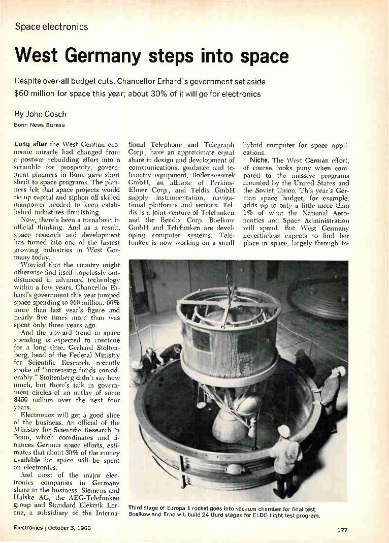
Space electronics
West Germany steps into space Despite over-all budget cuts, Chancellor Erhard's government set aside
$60 million for space this year; about 30% of it will go for electronics
By John Gosch
Bonn News Bureau
Long after the West German eco-nomic miracle had changed from a postwar rebuilding effort into a scramble for prosperity, govern-ment planners in Bonn gave short shrift to space programs. The plan-ners felt that space projects would tie up capital and siphon off skilled manpower needed to keep estab-lished industries flourishing. Now, there's been a turnabout in
official thinking. And as a result, space research and development has turned into one of the fastest growing industries in West Ger-many today. Worried that the country might
otherwise find itself hopelessly out-distanced in advanced technology within a few years, Chancellor Er-hard's government this year jumped space spending to $60 million, 66% more than last year's figure and nearly five times more than was spent only three years ago. And the upward trend in space
spending is expected to continue for a long time. Gerhard Stolten-berg, head of the Federal Ministry for Scientific Research, recently spoke of "increasing funds consid-erably." Stoltenberg didn't say how much, but there's talk in govern-ment circles of an outlay of some $450 million over the next four years.
Electronics will get a good slice of the business. An official of the Ministry for Scientific Research in Bonn, which coordinates and fi-nances German space efforts, esti-mates that about 30% of the money available for space will be spent on electronics. And most of the major elec-
tronics companies in Germany share in the business. Siemens and Halske AG, the AEG-Telefunken group and Standard Elektrik Lor-enz, a subsidiary of the Interna-
tional Telephone and Telegraph Corp., have an approximate equal share in design and development of communications, guidance and te-lemetry equipment. Bodenseewrek GmbH, an affiliate of Perkins-Elmer Corp., and Teldix GmbH supply instrumentation, naviga-tional platforms and sensors. Tel-dix is a joint venture of Telefunken and the Bendix Corp. Boelkow GmbH and Telefunken are devel-oping computer systems. Tele-funken is now working on a small
hybrid computer for space appli-cations.
Niche. The West German effort, of course, looks puny when com-pared to the massive programs mounted by the United States and the Soviet Union. This year's Ger-man space budget, for example, adds up to only a little more than 1% of what the National Aero-nautics and Space Administration will spend. But West Germany nevertheless expects to find her place in space, largely through in-
Third stage of Europa 1 rocket goes into vacuum chamber for final test. Boelkow and Erno will build 24 third stages for ELDO flight test program.
Electronics j October 3, 1966 177

New From Andersen
HIGH FREQUENCY SERIAL
MEIYORIES
,..‘ , -„. . , ,..,., ... ...0,
l
Model 5000 High Frequency Serial Memory
Storage capacity up to 2500 bits Data rate up to 40 Mc Logic levels from 3 to 12 V (± 3 V to
1:12 V) Availability of micro logic and tran-sistorized circuitry
Andersen, a primary supplier of serial memories, now offers a new high frequency serial mem-ory in a simple, compact and highly adaptable unit totally packaged on a 71/2 " x 4'/2' printed circuit card. Inputs may be either RZ or NRZ mode, either polarity logic may be used, and a choice is offered of either trail-ing or leading edge clocking. Out-put voltage may be RZ or NRZ and of any level from 2.8 to 6 volts of either polarity. Comple-mentary outputs for the systems can supply and absorb up to 25 ma and drive up to 200 pf load capacita nce.
Ask Andersen, first in High and Low Frequency Serial Memories and other advanced signal and data processing systems for radar, sonar, communi-cation, telemetry, simulation, naviga-tion and analysis.
ANDERSEN LABORATORIES, INC. 501 NEW PARK AVENUE,
WEST HARTFORD, CONN. 06110
Boelkow developed complex test bench•to monitor performance of Europa 1 third stage. Here, technician checks third-stage control unit.
ternational projects. Currently, the industry's bread
and butter comes from a pair of-international efforts. For the Euro-pean Launcher Development Or-ganization (ELDO), West Germany is handling the third stage of the three-stage ELDO Europa I rocket. A German company is prime con-tractor for an experimental satellite ordered by ELDO's sister organi-zation, the European Space Re-search Organization (ESRO). And joint U.S.-German space projects lie ahead. The Germans have also mounted
a modest national program that will fill some of the holes in space re-search left when the U.S. cut deep space probes from its program be-cause of heavy spending for Apollo —the project to put a man on the moon by the end of the decade. And studies have started for com-mercial satellites that would put Germany in the space communica-tions business.
I. Third stage first
By and large, the companies that stand to benefit most from the bur-geoning West German space effort are young, team-oriented outfits that have sprung up since the war. Perhaps the most prominent is Boelkow GmbH, headquartered in Ottobrunn on the outskirts of Mun-ich. Ludwig Boelkow, now 54, started a three-man consulting of-fice in Stuttgart 18 years ago. To-day, Boelkow heads a 3,000-man
company that last year had sales of $50 million. Almost half the 3,000 people are
engineers and scientists, often called the Boelkow Eierkopfen (eggheads). As you'd expect, they have a hand in the third stage for Europa I—West Germany's first major space effort. Boelkow de-signed and developed the attitude control and operational monitoring systems for the stage. It is also re-sponsible for design integration, check-out, reliability and testing. For the third stage, Boelkow is
working with another fast-moving aerospace company, Entwicklungs-ring Nord (Erno). Erno is a joint venture of Vereinigte Flugtech-nische Werke GmbH and Ham-burger Flugzeugbau GmbH. Two American companies—indi-
rectly—have a piece of the action. The Boeing Co. bought a 25% stake in Boelkow for $2 million two years ago and has also advanced an addi-tional $1 million for plant invest-ments. The United Aircraft Corp. has a 30% holding in Vereinigte Flugtechnische.
Together, Boelkow and Erno will build two dozen Europa I third stages; 10 have been completed.
II. Highly eccentric
Additional experience in building space hardware under international auspices is coming from the HEOS-A satellite (for Highly Eccentric Orbit Satellite) that ESRO has slated for a late-1968 launching.
178 Circle 178 on reader service card Electronics I October 3, 1966

HEOS-A, if all goes well, will measure the energy distribution of charged particles in interplanetary space. It will orbit out to an apogee of 138,000 miles for the interplane-tary readings and then dip back to a perigee of 120 miles—inside the earth's magnetosphere—to take readings there since the charge dis-tribution in space depends on the earth's magnetic field.
In the ESRO competition for the cimtract to build this satellite, a European group headed by Junkers Flugzeug und Motorenwerke AG came out the winner. Junkers is a subsidiary of the old-time plane maker Messerschmitt. In on the HEOS-A project with junkers are Etudes Techniques et Construc-tions Aerospatiales of Belgium, So-ciété Nationale d'Etude et de Con-struction de Moteurs d'Aviation of France and the British Aircraft Corp. The Lockheed Corp. is advis-ing the group.
Junkers has over-all responsibil-ity to EST«) for the 86.4-million HEOS-A satellite and ji nkers en-gineers say their main desilm Pre-occupation is keeping the satiety free of magnetism. To inert the soecifications, the magnetic field of the spacecraft must be smaller than 10 -5 gauss, or less than one hun-dred thousandth of the earth's field. As a result, basic construction ma-terials for HEOS-A will be alum-inum and magnesium alloys. And Junkers has set up a special mag-netics laboratory for the project at a spot 24 miles outside Munich where the earth's magnetic field is relatively low. By Jupiter. Along with coopera-
tive projects with European part-ners, joint efforts with the U.S. seem almost certain to give a lift to the fast growth of the \Vest Ger-man aerospace industry. So far there's no firm program, but the foundations for U.S.-German co-operation in deep space probes were laid when Chancellor Erhard met with President Johnson last December. With funds from the German
science ministry, both Boelkow and Erno have made feasibility studies pointed toward probes at Jupiter [Electronics, March 21, p. 222]. Boelkow looked at three possibili-ties with spacecraft ranging from 770 pounds to several tons. Erno's Jupiter probe plan calls for a 1,-130-
Electronics ; October 3;1966
A vacuum relay. .
Carries high rf currents clue to large surface area of contacts.
Smallest size for its power rating. Operates faster than other high
voltage relays due to small contact separation.
Will interrupt high dc power. Has highest voltage ratings due
to vacuum dielectric. Has long contact life.
Low and stable contact resistance from dc through 30 mc.
Requires no contact maintenance.
Jennings vacuum Pave the additional benefit of 18 years of constant development effort and manufactur-
relays. II ing experience. All Jennings vacuum relays
have been field tested and proven successful in countless applications.
consequently. . Jennings vacuum relays are unexcelled for use in high voltage communication systems particularly in aerospace, land, or marine vehicles that cannot tolerate heavy weight and have limited space. Within their size and voltage range they also have no equal for switching dc or pulse forming networks.
Thorough knowledge of the characteristics of vacuum relays is a most useful tool in any electronic engineer's hands. It can easily be obtained by requesting Jennings new vacuum relay catalog No. 103.
Jennings Radio Manufacturing Corporation, a subsidiary of Inter-national Telephone and Telegraph Corporation, 970 McLaughlin Avenue, San Jose, California 95108.
. k..1..,
RJ1A
. •
f‘,.....
RJ2A
PI-
•
RF10
e.W".
RB7A RB1E
447-›..e •
RB4
Contact Arrangement SPDT SPDT SPDT DPDT SPDT 4PDT
Test Voltage (Peak KV) 5 18 20 9 18 17
Operate Voltage (Peak KV) (16 mc) 2 8 io 3 a 10
Continuous Current Amps RMS (16 mc) 7 15 30 4 6 6
Interrupt DC Power (KW) N/A 1 50 1 1 1
Contact Resistance (Max. ohms) .010 .012 .012 .020 .012 .010
I T TBEnniengS
Circle 179 on reader service card 179
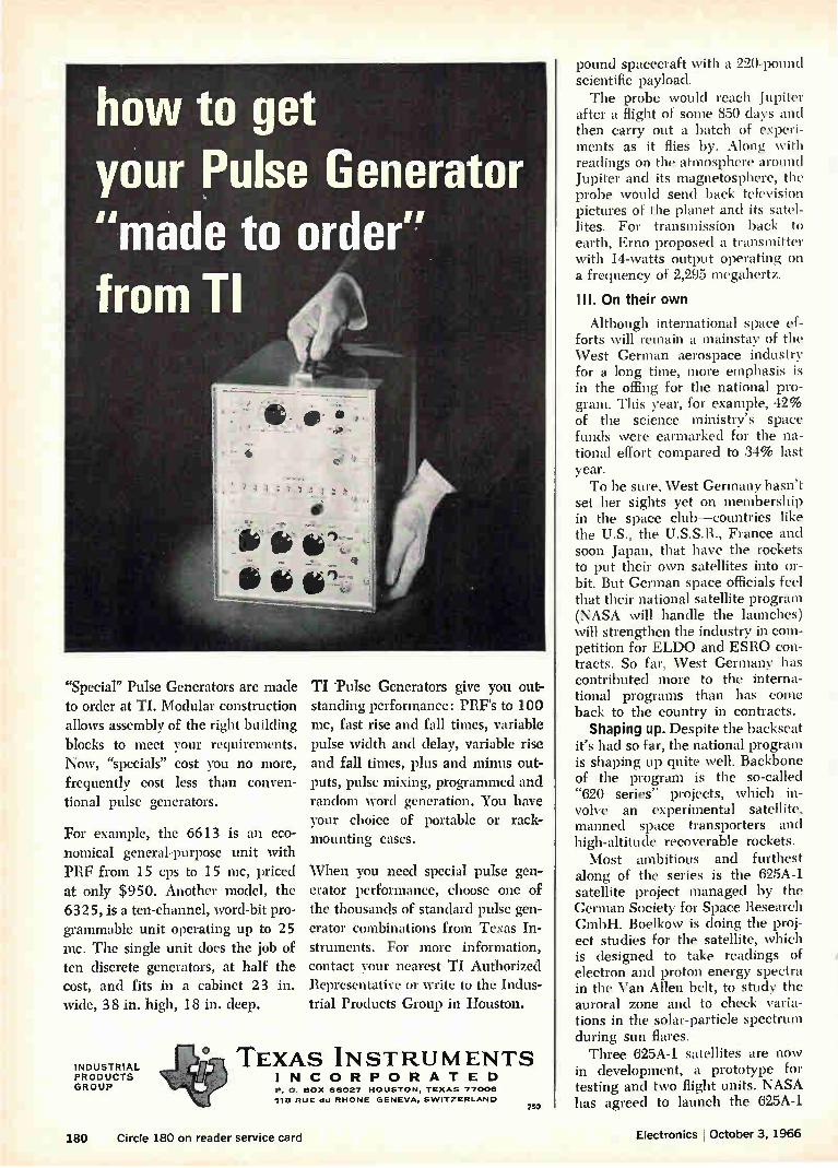
how to get your Pulse Generator "made to order" from TI
"Special" Pulse Generators are made to order at TI. Modular construction allows assembly of the right building blocks to meet your requirements. Now, "specials" cost you no more, frequently cost less than conven-tional pulse generators.
For example, the 6613 is an eco-nomical general-purpose unit with PRF from 15 cps to 15 mc, priced at only $950. Another model, the 6325, is a ten-channel, word-bit pro-grammable unit operating up to 25 mc. The single unit does the job of ten discrete generators, at half the cost, and fits in a cabinet 23 in. wide, 38 in. high, 18 in. deep.
INDUSTRIAL PRODUCTS GROUP
TI 'Pulse Generators give you out-standing performance: PRF's to 100 mc, fast rise and fall times, variable pulse width and delay, variable rise and fall times, plus and minus out-puts, pulse mixing, programmed and random word generation. You have your choice of portable or rack-mounting cases.
When you need special pulse gen-erator performance, choose one of the thousands of standard pulse gen-erator combinations from Texas In-struments. For more information, contact your nearest TI Authorized Representative or write to the Indus-trial Products Group in Houston.
\..,. ° TEXAS INSTRUMENTS g INCORPORATED
P. 0. BOX 66027 HOUSTON, TEXAS 77006
118 RUE du RHONE GENEVA, SWITZERLAND 750
pound spacecraft with a 220-pound scientific payload. The probe would reach Jupiter
after a flight of some 850 days and then carry out a batch of experi-ments as it flies by. Along with readings on the atmosphere around Jupiter and its magnetosphere, the probe would send back television pictures of the planet and its satel-lites. For transmission back to earth, Erno proposed a transmitter with 14-watts output operating on a frequency of 2,295 megahertz.
III. On their own
Although international space ef-forts will remain a mainstay of the West German aerospace industry for a long time, more emphasis is in the offing for the national pro-gram. This year, for example, 42% of the science ministry's space funds were earmarked for the na-tional effort compared to 34% last year. To be sure, West Germany hasn't
set her sights yet on membership in the space club—countries like the U.S., the U.S.S.R., France and soon Japan, that have the rockets to put their own satellites into or-bit. But German space officials feel that their national satellite program (NASA will handle the launches) will strengthen the industry in com-petition for ELDO and ESRO con-tracts. So far, West Germany has contributed more to the interna-tional programs than has come back to the country in contracts. Shaping up. Despite the backseat
it's had so far, the national program is shaping up quite well. Backbone of the program is the so-called "620 series" projects, which in-volve an experimental satellite, manned space transporters and high-altitude recoverable rockets. Most ambitious and furthest
along of the series is the 625A-1 satellite project managed by the German Society for Space Research GmbH. Boelkow is doing the proj-ect studies for the satellite, which is designed to take readings of electron and proton energy spectra in the Van Allen belt, to study the auroral zone and to check varia-tions in the solar-particle spectrum during sun flares. Three 625A-1 satellites are now
in development, a prototype for testing and two flight units. NASA has agreed to launch the 625A-1
180 Circle 180 on reader service card Electronics I October 3, 1966

- *.of.ief
with a Scout rocket at the Western Test Range in the fall of 1968.
Recovery. Also in the national space lineup is project "621", aimed at developing recoverable high-al-titude sounding rockets. Dornier System GmbH last year made a successful low-altitude recovery with a paraglider that unfolds its wings for descent. Next step in the program is recovery from an alti-tude of 24 miles. For the Dornier paraglider a telemetry and control system has been designed by Tele-funken AG and Standard Elektrik Lorenz, an affiliate of the Inter-national Telephone and Telegraph Corp. Boelkow has designed a fixed-
wing rocket—intended for iono-spheric studies—that can be re-covered from 48 miles. The pivotal element in the electronic recovery system is a rocket-mounted search antenna with lobar characteristics. The antenna is defocused 30° from the axis of the rocket so that when the rocket rolls the axis of the an-tenna describes a cone. As long as the rocket points directly toward the homing transmitter on the ground, the unmodulated signal re-ceived at the antenna remains con-stant. But if the rocket points off the line of sight, the signal is am-plitude-modúlated at the rocket's roll frequency. The modulation is detected by a receiver on the rocket to develop an input for the control system that actuates the rocket's spoilers.
Blue sky. The science ministry has added a touch of blue sky to its program with feasibility studies for manned space transporters that would cost $500 million or more to develop. Both Junkers and Erno have submitted schemes to the ministry but there's no question at the moment of earmarking space money for manned transporter hardware. Much more likely to get a sub-
stantial chunk of the additional funds the government plans to spend for space over the next few years is a project still not officially on the ministry's program—a com-munications satellite called "Olym-pia." Boelkow made headlines this summer with a proposal that West Germany put Olympia up in time for live tv broadcasts of the 1972 Olympic Games at Munich [Elec-tronics, July 25, p. 230].
*A word we have coined to dramatize exactly how unique physically stable Phelps Electronics
Styroflex coaxial cable actually is. Essentially an air dielectric cable, Styroflex inherently exhibits lower attenuation and higher propagation than solid dielec-tric types. The effect of temperature cycling on at-tenuation is minute and results from changes in metal resistivities amounting to less than 11Vo per 5`C temperature change. Continuous support assures per-fect centering of the conductor during the load cycling.
If you are concerned with circuit design in AM, FM, VHF and UHF transmission, CATV, microwave communications, radar, forward scatter systems and telemetering, multichannel long line telephone net-works or general pulse work, here is a coaxial cable worth knowing more about. Available, from stock, in 3/8", Vt", 74", 13/4", 31W' diameters in 50 ohm imped-ance, on 1000' reels, custom cut lengths or specially fabricated assemblies.
PHELPS DODGE ELECTRONIC PRODUCTS NORTH HAVEN, CONNECTICUT
Electronics October 3, 1966 Circle 181 on reader service card 181

in our NEW, Competitively Priced DC Motors
DC MOTOR TYPE I3-DM-A-1
cone CLIFTON PRECISION OCT
svpn of MON Precision ',rage .1
The illustration of our Solar System shows the nine planets and their 31 satellites in scale with each other and the enormous sun. The pro-cession starts with Mercury at the left and ends with Pluto on the far right.
Circle 182 on reader service card
Built to exacting Clifton and MIL-E-5272 standards, these DC motors are a completely new design. They offer many advan-tages such as: stainless steel, corrosion resistant housings and ball bearings, and brush springs which maintain constant pressure over brush life. Brush life itself is up to 1000 hours depending upon environmental conditions and application. These motors feature a five bar commutator. Due to the in-
herent design, the rotor produces a magnetic detent under zero excitation which minimizes gear train drift. Units avail-able in both 14 and 28 volt excitation. Special voltages, shafts
and housings available upon request. Clifton Precision Products, Division of Litton Industries,
Clifton Heights, Pa., Colorado Springs, Colo.
effe CLIFTON PRECISION PRODUCTS DIVISION OF LITTON INDUSTRIES

Components
More power in space Giant solar cell arrays are under development to provide
power in kilowatt level for satellites of the future
y John Rhea
Electronics Washington Bureau
Like the residents of Kansas City in the musical -Oklahoma," solar cell efficiencies "have gone about as far as they can go." Neverthe-less the National Aeronautics and Space Administration will push cells as the principal source of soacecraft power for another dec-ade—even to kilowatt power levels in competition with the more glam-orous nuclear systems. The space agency feels that solar
cells are more attractive than nu-clear systems right now because the basic research and develop-ment on cells has been completed. Not all problems have been solved in nuclear power development— and with today's tight space bud-gets, the agency is less than keen about pouring more development money into it.
If solar cells can't be made more efficient than their present 10% to 11%, and this is generally con-ceded, then the space agency wants to cram more of them onto a satel-lite. So work is on to develop giant arrays that can be folded com-pactly at launch and then unfurled in space to catch the sun's energy and convert it into electricity. Ar-vin H. Smith, head of solar and chemical power systems projects at the agency's Office of Advanced Research and Technology, points out that space has two big natural resources: plenty of sunlight and unlimited room.
I. To new levels
To capitalize on these, the agency is in the midst of a tech-nology effort on solar cell arrays to attain power levels believed im-practical a few years ago. Several firms are working on arrays that could provide as much as 50 kilo-watts, a big jump from the agency
Electronics 1 October 3, 1966
high of 1 kw put out by the Orbit-ing Astronomical Observatory launched April 8. A secret Air Force "spy" satellite reportedly ob-tained a power level of 1.5 kw us-ing solar cells, the Mariner 4 flyby of Mars got 700 watts, and the Nimbus weather satellites gener-ated 500 watts. Fuel cells, although used in the
Gemini and Apollo spacecraft, are not being considered for future long-duration missions because of the great weight of the hydrogen and oxygen needed for them. Going up. Within the next 10
years, Smith predicts some satel-lites will demand at least 4.5 to 5
kw. Two examples are communica-tions satellites for direct television broadcasting to home receivers and large orbiting telescopes to be car-ried into space by Apollo astro-nauts and left there to operate alone. In these applications solai cells may be able to compete with the potential of nuclear power gen-erators such as the SNAP-8 (Sys-tems for Nuclear Auxiliary Power), which promises to provide 30 kw, although the technical problems are far from being solved. SNAP-8 has never had the full support of the agency's top management de-spite Congressional prodding. However, the agency is continu-
Solar cell paddles unfold like road maps to an area 30 by 60 feet. Boeing is studying ways to rig large cells arrays to increase power levels for satelites.
Window shade system unrolls a large flexible sheet covered with solar cells to a distance of 60 feet.
183
Force satellite launched last month.
Electronicsl October 3, 1966
....a Kau., • a ...A 1.1‘.11,11 e.,4•3
I you the crisp legibility of IEE readouts. Phone: (213) 787-0311 • TWX (910) 495-1707 Representatives in Princ,pal Cities •
Circle 185 on reader service card 185

mcc itc mint nroeram with the i ir
ULTRA-PERFORMANCE TELONIC'S NEW MODEL 1001 SOLID-STAT
EEP/ SIGNAL GENERATOR DELIVERS UNMAT
FLEXIBILITY AND PERFORMANCE FOR FREQUENCY
AND CW TESTING FROM 100 kHz TO 20 MHz
ULTRA-WIDE SWEEP RATIO
R. Crystal filter response, 3 'dh . bandwidth is 2.8 kHz wid MHz center frequency.
ULTRA-STABLE
e /10 the sweep WI
e 1001 sweeps frequency in three ranges from below 200 Hz up to the full range of 20 MHz—that's a ratio of 100,000 to 1 overall—plus CW and modu-!I • lated CW! This one instrumen serves for narr and broadband applications in RF, IF, and video
« frequencies.
New solid-state power supplies for the 1001 provide exceptional fre-quency stability of 100 Hz for shor term operatio (1 min.), and 5 kHz over long term (1 hour). Calibrating and adjusting are minimized, te results more dependable.
ULTRA-NAR OW MARKERS
oca on o r y marker is difficult to
cd marker permits precise determination.
monje (1 MHz) and variable (100 kHz-20 MHz) frequency markers may be deviated from 10 kHz to as narrow as 100 Hz for precise fre-quency determina-tion. Unique time-sharing circuit allows any combi-nation of markers to be displayed simultaneously without inter-ference. Marker tilt control pro-vides precise read-ings even on steepest part of skirt,
PLUS
VARIABLE SWEEP RATE FROM .01 TO 60 Hz
MANUAL OR EXTERNAL SWEEPING FOR XY PLOT
1 VRMS OUTPUT WITH 103 db ATTENUATION
THE
1001 SWEEP/SIGNAL GENERATOR
100 kHz - 20 MHz
SPECIFICATIONS
(1 a à ... •
CENTER FREQUENCY 100 kHz • 20 MHz
SWEPT RANGE 100 kHz - 20 MHz
SWEEP WIDTH Narrow Range 200 Hz - 200 kHz
Intermediate Range 1 kHz - 2 MHz
Wide Range 10 kHz - 20 MHz
SWEEP RATE Variable 0 01 - 60 Hz
Line-Lock 50/60 Hz OUTPUT 1 VRMS into 50 ohms
STABILITY Short Term (1 min.) 100 Hz
Long Term (1 hour) 5 kHz
HARMONIC MARKER 1 MHz VARIABLE MARKER, RANGE 100 kHz - 20 MHz
VARIABLE MARKER, WIDTH:
Narrow 100 Hz
Intermediate 1 kHz
Wide 10 kHz
APPLICATION DATA FILE DESCRIBING USE OF TELONIC SWEEP GENERATORS IN RESEARCH, PRODUCTION AND Q.C. APPLICATIONS AVAILABLE ON REQUEST.
INSTRUMENTS 60 NORTH FIRST AVENUE BEECH GROVE, INDIANA 46107
TEL: (317) 787-3231 TWX: 810-341-3202
Representatives in all major cities in the U.S. and foreign countries. Factory offices located at Maidenhead, England and Frankfurt, Germany
186 Circle 186 on reader service card Electronics October 3, 1q66

Components
More power in space Giant solar cell arrays are under development to provide
power in kilowatt level for satellites of the future
,=3y John Rhea
Electronics Washington Bureau
Like the residents of Kansas City in the musical "Oklahoma," solar cell efficiencies "have gone about as far as they can go.- Neverthe-less the National Aeronautics and Space Administration will push cells as the principal source of spacecraft power for another dec-ade—even to kilowatt power levels in competition with the more glam-orous nuclear systems. The space agency feels that solar
cells are more attractive than nu-clear systems right now because the basic research and develop-ment on cells has been completed. Not all problems have been solved in nuclear power development— and with today's tight space bud-gets, the agency is less than keen about pouring more development money into it.
If solar cells can't be made more efficient than their present 10% to 11%, and this is generally con-ceded, then the space agency wants to cram more of them onto a satel-lite. So work is on to develop giant arrays that can be folded com-pactly at launch and then unfurled in space to catch the sun's energy and convert it into electricity. Ar-vin H. Smith, head of solar and chemical power systems projects at the agency's Office of Advanced Research and Technology, points out that space has two big natural resources: plenty of sunlight and unlimited reom.
I. To new levels
lo capitalize on these, the agency is in the midst of a tech-nology effort on solar cell arrays to attain power levels believed im-practical a few years ago. Several firms are working on arrays that could provide as much as 50 kilo-watts, a big jump from the agency
high of 1 kw put out by the Orbit-ing Astronomical Observatory launched April 8. A secret Air Force "spy" satellite reportedly ob-tained a power level of 1.5 kw us-ing solar cells, the Mariner 4 flyby of Mars got 700 watts, and the Nimbus weather satellites gener-ated 500 watts.
Fuel cells, although used in the Gemini and Apollo spacecraft, are not being considered for future long-duration missions because of the great weight of the hydrogen and oxygen needed for them. Going up. Within the next 10
years, Smith predicts some satel-lites will demand at least 4.5 to 5
kw. Two examples are communica-tions satellites for direct television broadcasting to home receivers and large orbiting telescopes to be car-ried into space by Apollo astro-nauts and left there to operate alone. In these applications solai cells may be able to compete with the. potential of nuclear power gen-erators such as the SNAP-8 (Sys-tems for Nuclear Auxiliary Power), which promises to provide 30 kw, although the technical problems are far from being solved. SNAP-8 has never had the full support of the agency's top management de-spite Congressional prodding.
However, the agency is continu-
Solar cell paddles unfold like road maps to an area 30 by 60 feet. Boeing is studying ways to rig large cells arrays to increase power levels for satelites.
Window shade system unrolls a large flexible with solar cells to a distance of 60 feet.
sheet covered
Electronics I, October 3, 1966 183

WHEN THE CHAIN TO SPACE DOESN'T
TOLERATE A WEAK LINK.
Of critical importance to present day telemetry sys-tems is the reliableperform-ance of high frequency patch-ing components. COAX com-ponents assure the most de-pendable communication links available today • A unique cable strain relief feature in the single plug illustrated here is just one of several features which make COAX components superior • Write for complete data on all COAX component
à DIVISION Of m•GNETIC CONTROLS CO.
6405 CAMBRIDGE STREET • MINNEAPOLIS, MINN. 55426
ing its joint program with the Atomic Energy Commission to de-velop nuclear power devices for the advanced spacecraft being con-sidered for the late 1970's. These craft are expected to need mega-watts of power, and Smith con-cedes that only nuclear systems are compact enough to do that job. The joint nuclear program is cost-ing nearly $100 million a year. The agency's solar cell research
budget has been running around $9 million a year for the past three years, most of it aimed at develop-ing the large arrays and reducing the per unit costs through better manufacturing techniques such as automation.
II. Neatly packed
The biggest contract for develop-ing the arrays went to the Boeing Co., Seattle, in May. A $5-million, three-year effort calls for the firm to build a solar array nearly 60 feet long using beryllium for the structure and mounting 8-mil-thick solar cells with epoxy fiberglass. The array consists of individual panels, each 8 by 13 feet, and must be strong enough to survive a launch folded into a spacecraft's protective shroud. It then must un-fold in space like a giant road map. A smaller. program to develop fold-ing arrays is being conducted by Electro-Optical Systems, Inc., Pas-adena, Calif., a subsidiary of the Xerox Corp.
In another approach an array un-rolls itself like a window shade. Tubular booms extend once a satel-lite is in orbit to pull out a flexible sheet covered with solar cells. The Ryan Aeronautical Co., San Diego, and Fairchild Hiller Corp., Rockville, Md., have study awards.
It's relative. A major goal of solar cell research is to reduce the weight of the panels in relation to the amount of electricity produced. While retaining the conventional 18-mil-thick solar cells, the agency has been able to reduce structural weight and thus decrease the ratio from 200 pounds per kilowatt of electricity for the 1962 Mariner 2 Venus flyby to 100 pounds per kw for the 1964 Mariner 4 mission to Mars. The immediate goal is to further reduce this ratio to 50 pounds per kw by using cells 8 mils thick and even lighter struc-tures; the long-range goal is 25
If you are in the Electronics Industry you probably belong in MARYLAND
AVAILABILITY OF LABOR
The availability of personnel, par-ticularly engineers and scientists, is recognized as a chief criterion govern-ing the location of an electronics firm.
There are almost 30,000 scientists and over 25,000 engineers living and working in Maryland and the District of Columbia. And the number is in-creasing every day.
PROXIMITY TO FEDERAL AGENCIES
Proximity to major decision makers in the industry, such as federal agen-cies in Washington, D. C., afford the unique advantage of constant personal contact, which is considered an increas-ingly important locational criterion. No other state is as convenient to
as many Federal agencies as Maryland. For example, Maryland's major gov-ernment scientific installations include NASA, AEC, NIH, the National Bureau of Standards, plus some 20 others.
THESE PRIME REQUIREMENTS,
(plus others)
CAN BE MET IN MARYLAND! Get All The Facts
Write, Wire or Phone Collect
MARYLAND DEPARTMENT OF
ECONOMIC DEVELOPMENT Division E • State Office Bldg • Annapolis, Md
184 Circle 184 on reader service card Circle 320 on reader service card

Components
More power in space Giant solar cell arrays are under development to provide
power in kilowatt level for satellites of the future
Sy John Rhea
Electronics Washington Bureau
Like the residents of Kansas City in the musical -Oklahoma," solar cell efficiencies "have gone about as far as they can go." Neverthe-less the National Aeronautics and Space Administration will push cells as the principal source of spacecraft power for another dec-ade—even to kilowatt power levels in competition with the more glam-orous nuclear systems. The space agency feels that solar
cells are more attractive than nu-clear systems right now because the basic research and develop-ment on cells has been completed. Not all problems have been solved in nuclear power development— and with today's tight space bud-gets, the agency is less than keen about pouring more development money into it.
If solar cells can't be made more efficient than their present 10% to 11%, and this is generally con-ceded, then the space agency wants to cram more of them onto a satel-lite. So work is on to develop giant arrays that can be folded com-pactly at launch and then unfurled in space to catch the sun's energy and convert it into electricity. Ar-vin H. Smith, head of solar and chemical power systems projects at the agency's Office of Advanced Research and Technology, points out that space has two big natural resources: plenty of sunlight and unlimited room.
I. To new levels
To capitalize on these, the agency is in the midst of a tech-nology effort on solar cell arrays to attain power levels believed im-practical a few years ago. Several firms are working on arrays that could provide as much as 50 kilo-watts, a big jump from the agency
high of 1 kw put out by the Orbit-ing Astronomical Observatory launched April 8. A secret Air Force "spy" satellite reportedly ob-tained a power level of 1.5 kw us-ing solar cells, the Mariner 4 flyby of Mars got 700 watts, and the Nimbus weather satellites gener-ated 500 watts.
Fuel cells, although used in the Gemini and Apollo spacecraft, are not being considered for future long-duration missions because of the great weight of the hydrogen and oxygen needed for them. Going up. Within the next 10
years, Smith predicts some satel-lites will demand at least 4.5 to 5
kw. Two examples are communica-tions satellites for direct television broadcasting to home receivers and large orbiting telescopes to be car-ried into space by Apollo astro-nauts and left there to operate alone. In these applications solai cells may be able to compete with the potential of nuclear power gen-erators such as the SNAP-8 (Sys-tems for Nuclear Auxiliary Power), which promises to provide 30 kw, although the technical problems are far from being solved. SNAP-8 has never had the full support of the agency's top management de-spite Congressional prodding. However, the agency is continu-
Solar cell paddles unfold like road maps to an area 30 by 60 feet. Boeing is studying ways to rig large cells arrays to increase power levels for satelites.
Window shade system unrolls a large flexible sheet covered with solar cells to a distance of 60 feet.
Electronics October 3, 1966 183

• WHEN THE CHAIN TO SPACE DOESN'T
:TOLERATE WEAK LINK...
Of critical importance to present day telemetry sys-tems is the reliable perform-ance of high frequency patch-ing components. COAX com-ponents assure the most de-pendable communication links available today • A unique cable strain relief feature in the single plug illustrated here is just one of several features which make COAX components superior • Write for complete data on all COAX component
ADC PRODUCT • DIVISION or or...TIC cortrooLs co.
6405 CAMBRIDGE STREET • MINNEAPOLIS, MINN. 55426
ing its joint program with the Atomic Energy Commission to de-velop nuclear power devices for the advanced spacecraft being con-sidered for the late 1970's. These craft are expected to need mega-watts of power, and Smith con-cedes that only nuclear systems are compact enough to do that job. The joint nuclear program is cost-ing nearly $100 million a year. The agency's solar cell research
budget has been running around $9 million a year for the past three years, most of it aimed at develop-ing the large arrays and reducing the per unit costs through better manufacturing techniques such as automation.
II. Neatly packed
The biggest contract for develop-ing the arrays went to the Boeing Co., Seattle, in May. A $5-million, three-year effort calls for the firm to build a solar array nearly 60 feet long using beryllium for the structure and mounting 8-mil-thick solar cells with epoxy fiberglass. The array consists of individual panels, each 8 by 13 feet, and must be strong enough to survive a launch folded into a spacecraft's protective shroud. It then must un-fold in space like a giant road map. A smallert-program to develop fold-ing arrays is being conducted by Electro-Optical Systems, Inc., Pas-adena, Calif., a subsidiary of the Xerox Corp.
In another approach an array un-rolls itself like a window shade. Tubular booms extend once a satel-lite is in orbit to pull out a flexible sheet covered with solar cells. The Ryan Aeronautical Co., San Diego, and Fairchild Hiller Corp., Rockville, Md., have study awards.
It's relative. A major goal of solar cell research is to reduce the weight of the panels in relation to the amount of electricity produced. While retaining the conventional 18-mil-thick solar cells, the agency has been able to reduce structural weight and thus decrease the ratio from 200 pounds per kilowatt of electricity for the 1962 Mariner 2 Venus flyby to 100 pounds per kw for the 1964 Mariner 4 mission to Mars. The immediate goal is to further reduce this ratio to 50 pounds per kw by using cells 8 mils thick and even lighter struc-tures; the long-range goal is 25
If you are in the Electronics Industry you probably belong in MARYLAND
AVAILABILITY -9F LABOR The availability of personnel, par-
ticularly engineers and scientists, is recognized as a chief criterion govern-ing the location of an electronics firm. There are almost 30,000 scientists
and over 25,000 engineers living and working in Maryland and the District of Columbia. And the number is in-creasing every day.
PROXIMITY TO FEDERAL AGENCIES
Proximity to major decision makers in the industry, such as federal agen-cies in Washington, D. C., afford the unique advantage of constant personal contact, which is considered an increas-ingly important locational criterion. No other state is as convenient to
as many Federal agencies as Maryland. For example, Maryland's major gov-ernment scientific installations include NASA, AEC, NIH, the National Bureau of Standards, plus some 20 others.
THESE PRIME REQUIREMENTS,
(plus others) CAN BE MET IN MARYLAND! Get All The Facts
Write, Wire or Phone Collect
MARYLAND DEPARTMENT OF
ECONOMIC DEVELOPMENT Division E • State Office Bldg • Annapolis. Md
184 Circle 184 on reader service card Circle 320 on reader service card

pounds per kw with 4-mil cells. New materials? Despite years of
intensive searching for new ma-terials, the single crystal silicon solar cell still dominates the field and will continue to do so for at least 10 more years, according to William Cherry, head of the space power technology branch at the agency's Goddard Space Flight Center.
Gallium arsenide was once con-sidered the great hope, but this material has never consistently achieved efficiencies much above 6% in space and the cells were a 100 times as costly as silicon cells. Other materials that never caught on include indium phosphide, cadmium telluride, silicon carbide, gallium phosphide and selenium. Cadium sulfide shows great
promise since the connection prob-lems caused by moisture were solved by deposition and encapsu-lation techniques. The agency's Lewis Research
Center in Cleveland recently claimed a major advance in weight reduction with a thin-film solar cell made by depositing a cadmium sulfide on .a light metallized sub-strate. The cells were built for Lewis by the Clevite Corp., also of Cleveland. Although these cells were less efficient than conven-tional types—the average was only 5.2%—the reduced weight resulted in a ratio of 10 pounds per kw, ac-cording to Adolph E. Spakowsik, head of the center's photovoltaic fundamentals section. A major test program is under way there. With so many solar cells needed
for higher power, a major goal is to reduce the cost of each. This is strictly a manufacturing problem. Smith says, and automation is es-sential. Manufacturers are moving to production-line techniques—par-ticularly in the elimination of hand soldering. On the line. One technique, fab-
rication of silicon solar cell junc-tions by heavy ion bombardment instead of chemical diffusion [Elec-tronics, April 19, 1963, p. 26], has moved from the laboratory to the assembly line. Ion Physics Corp.. of Burlington, Mass., a subsidiary of the High Voltage Engineering Corp., has begun production of the ion-implanted cells, and the first ones were flown on a secret Air Force satellite launched last month.
Why IEE rear-projection readouts make good reading Not the kind of good reading you'd curl up with on a rainy night. But a more important kind if you're designing equipment that requires message dis-play. Reason is that IEE readouts are the most readable readouts around. If you've seen them, you know this to be fact. If you haven't as yet, here is why our readouts make such good reading:
SINGLE-PLANE PRESENTATION No visual hash of tandem-stacked fila-ments. IEE readouts are miniature rear-projectors that display the re-quired messages, one at a time, on a non-glare viewing screen. Only the message that's "on" is visible.
EASY-TO-READ CHARACTERS
Since IEE readouts can display any-thing that can be put on film, you're not limited to thin wire filament, dotted, or segmented digits. Order your IEE read-outs with familiar, highly legible char-acters that meet human factors and Mil Spec requirements. This section from our sample type sheet gives you an idea of the styles available that offer opti-mal stroke/width/height ratio for good legibility.
BALANCED BRIGHTNESS/CONTRAST RATIO The chart below is a reasonable fac-simile of character brightness and how
8 8 8 it affects readability. The background is constant, but the brightness increases from left to right. You can draw your own conclusions, armed with the fact that IEE readouts give you up to 90 foot lamberts of brightness. Brightness, however, isn't the sole factor in judging readability. Background contrast is equally important — a fact we've simu-lated below, reading from left to right.
8 8 Obviously, brightness without contrast or vice versa, doesn't do much for read-ability. A balanced ratio of both gives you the crisp legibility of IEE readouts.
WIDE-ANGLE READABILITY IEE's unique combination of single-plane projection, flat viewing screen, balanced ratio of brightness/contrast, and big, bold characters makes for wide-angle clarity and long viewing distances.
OTHER WAYS IEE READOUTS MAKE GOOD SENSE As if the superior readability of our readouts weren't enough, here are a few reasons why IEE readouts make good sense in other areas:
A -TOP
INFINITE DISPLAY VERSATILITY Because our readouts use lamps, lenses, film, and a screen, they can display lit-erally anything that can be put on film. That means you have up to 12 message positions with each readout to display any combination of letters, words, num-bers, symbols, and even colors!
FIVE SIZES TO PICK FROM
IEE readouts now come in five sizes providing maximum character heights of %", %", 1", 2", and 3%". The smallest is the new Series 340 readout that's only :Y4." H x 1/2" W, yet can be read from 30 feet away. The largest, the Series 80, is clearly legible from 100 feet away.
EASY TO OPERATE
IEE readouts are available with volt-age requirements from 6 to 28 volts, depending on lamps specified. Commer-cial or MS lamps may be used, with up to 30,000 hours of operation per lamp. Lamps may be rapidly replaced without tools of any kind. Our readouts operate from straight
decimal input or will accept conven-tional binary codes when used with IEE low-current driver/decoders.
For more proof why IEE rear-projec-tion readouts make good reading, send us your inquiry. You'll see for yourself why they've been making the best seller list, year after year
(IEE) 7720 Lemona Avenue, Van Nuys, California
Phone: (213) 787-0311 • TWX (910) 495-1707 Representatives in Principal Cities • ,96G
INDUSTRIAL ELECTRONIC ENGINEERS, INC.
Electronics October 3, 1966 Circle 185 on reader service card 185

ULTRA- E TELONIC'S NEW MODEL 1001 SOLID-STATE
SWEEP/SIGNAL GENERATOR DELIVERS UNMATCHED
FLEXIBILITY AND PERFORMANCE FOR FREQUENCY
AND CW TESTING FROM 100 kHz TO 20 MHz
CE
ULTRA-WIDE SWEEP RATIO
Crystal filter response. 3 db bandwidth is 1.8 kHz wide at 10.7 MHz center reauency.
ULTRA-STABLE
C. aim, with 1/10 the sweep width (100 Hz/Div.).
Five minutes later, no significant dri bird), marker is 100 Hz wide.
determination.
ULTRA-NARROW MARKERS
ifficult to
e 1001 sweeps frequency in three ranges from below 200 Hz up to the full range of 20 MHz—that's ratio of 100,000 to 1 overall—plus CW and modu-lated CW! This one instrument serves for narrow and broadband applications in RF. IF, and video frequencies.
New solid-state power supplies for the 1001 provide exceptional fre-quency stability of 100 Hz for sho term operation (1 min.). and 5 kHz over long term (1 hour). Calibrating and adjusting are minimized, test results more dependable.
rmonic (1 MHz) and variable (100 kHz-20 MHz) frequency markers may be deviated from 10 kHz to as narrow as 100 Hz for precise fre-quency determina-tion. Unique time-sharing circuit allows any combi-nation of markers to be displayed simultaneously without inter-ference. Marker tilt control pro-vides precise read-ings even on steepest part of skirt
PLUS
VARIABLE SWEEP RATE FROM .01 TO 60 Hz
MANUAL OR EXTERNAL SWEEPING FOR XY PLOT 1 VRMS OUTPUT WITH 103 db ATTENUATION
THE
1 001 SWEEP/SIGNAL GENERATOR
100 kHz - 20 MHz
SPECIFICATIONS
CENTER FREQUENCY 100 kHz • 20 MHz SWEPT RANGE 100 kHz • 20 MHz
SWEEP WIDTH Narrow Range 200 Hz . 200 kHz
Intermediate Range 1 kHz - 2 MHz
Wide Range 10 kHz • 20 MHz
SWEEP RATE Variable 0.01 • 60 Hz
Line Lock 50/60 Hz OUTPUT 1 VRMS into 50 ohms
STABILITY Short Term (1 min.) 100 Hz Long Term (1 hour) 5 kHz
HARMONIC MARKER 1 MHz VARIABLE MARKER, RANGE 100 kHz - 20 MHz
VARIABLE MARKER, WIDTH:
Narrow 100 Hz
Intermediate 1 kHz Wide 10 kHz
APPLICATION DATA FILE DESCRIBING USE OF TELONIC SWEEP GENERATORS IN RESEARCH, PRODUCTION AND Q.C. APPLICATIONS AVAILABLE ON REQUEST.
INSTRUMENTS 60 NORTH FIRST AVENUE
BEECH GROVE, INDIANA 46107
TEL: (317) 787-3231 TWX: 810-341-3202
Representatives in all maim cities in the U.S. and foreign countries. Factory offices located at Maidenhead, England and Frankfurt, Germany
186 Circle 186 on reader service card Electronics October 3, 1q66

Consumer electronics
IC's to hit the road in 1968 model automobiles Experts predict a 10-million-a-year demand for integrated-circuit
voltage regulators by 1969 and say the automotive market
will eventually be the second biggest
By Lewis H. Young
Editor-in-chief
U.S. automakers will put the first integrated circuits into 1968 mod-els, thus opening a market which many IC experts see as their sec-ond biggest—behind computers. The pioneering application will
be a voltage regulator made of a hybrid IC—that is, transistor and diode chips mounted on a ceramic substrate with thick or thin-film passive elements. They will be in-stalled in luxury models produced by the Ford Motor Co. and the Chrysler Corp. and in trucks made by the General Motors Corp.
Official statements from auto executives have tended to minimize the impact of IC's on the auto industry. But informed engineers who have followed developments closely agree that pessimistic talk about IC's is a smoke screen, de-signed to conceal developments and throw the competition off guard. "It's definitely go on IC's for 1968 models," one auto execu-tive confided.
Circuit cost. At the semicon-ductor companies, key executives have already seen the quantities re-quired for 1968 and have agreed on prices. Each of the big three auto-makers wants 100,000 IC voltage regulators for 1968 models. Ford and Chrysler will pay about $3 per circuit for the regulator to be in-stalled in the Thunderbird, Lincoln, most expensive model Mercury and top-of-the-line Chrysler. General Motors will pay about $3.30 for a sturdier model for a truck. By 1969, the IC regulator will be
installed across the board in all models according to current plans.
Target cost for 1969 is $1.40 a cir-cuit. Experts are predicting a de-mand for 10 million IC regulators a year for 1969 and 1970. Then the market will grow sharply. Firm orders for IC regulators for
1968 model production will soon be in the hands of the Westinghouse Electric Corp. and the Fairchild Semiconductor division of the Fair-child Camera tk Instrument Co. Also bidding for a share of the starting business are Motorola Inc. and the Philco Corp., a subsidiary of Ford.
I. Second biggest market
Semiconductor men are saying that the auto industry may be the second biggest market for inte-grated circuits, after the computer industry which is the largest. One engineer who studied possible ap-plications believes that an auto eventually will contain more than 100 integrated circuits. Automen believe that the IC now
makes it economically feasible to consider replacing all the electro-mechanical controls of an auto with electronic devices to save space, money and power. "Many applica-tions that now use a relay will eventually have IC's instead," said one executive.
IC's will turn up in devices that drivers and engineers never ex-pected to see go electronic at all, for example, the automatic trans-mission. Currently the automatic transmission is switched by hy-draulic fluids that are slow and relatively inefficient. Electronic switching could be faster and more
efficient, improving gasoline con-sumption. Chevrolet, a division of General Motors, has already in-stalled an electronically controlled transmission in the Chaparral rac-ing car with spectacular results. It, of course, has discrete components.
Safety checks. Another possible application is a tiny multiplexing system that would scan up to 50 key variables such as water tern-perature, oil and tire pressure and whether the doors are closed and seat belts fastened. It would also warn the driver if a critical or dangerous situation existed. Ford has developed a rotating drum on which are mounted many driver messages—such as "check oil and water"—which could work with the electronic multiplexer. Elsewhere in the industry, study is under way to produce a tiny cathode-ray tube to display similar warnings to the driver when the electronic system detected a critical situation. But if such applications are sev-
eral years away, some others will follow close behind the integrated-circuit voltage regulator.
Philco, for example, has already designed a car radio with five hy-brid circuits in it, each a so-called Philco electronic module. Ford has not yet decided whether this radio will go into 1968 models or not; the decision will depend on economics. If Ford can envision the cost of the IC's dropping enough to make the new radio as cheap as a conven-tional transistorized one or cheaper, the company will go ahead.
Siliconix, Inc. and Motorola also have hybrid IC's for auto radios
Electronics I October 3, 1966 187

Adhesive Backed
SHIELDMU FASTER TO APPLY
high permeability magnetic shielding tape and foil with adhesive backing!
• protects your sensitive electronic and
electrical components against electro-magnetic interference
• strips to expose an adhesive that grips
components firmly
• eliminates taping and spot welding
• cuts with scissors to provide an easier way to form shields firmly in place
• offers 2 to 3 times more shielding effi-ciency than material currently available
• offers ductility without significant deg-radation of magnetic shielding properties
• is available in 4 levels of permeability
performance
Write, wire or call your local elec-
tronic distributor. He has Adhesive
Backed SHIELDMU packaged to meet your needs on spools and in
individual sampler albums. Or,
contact:
Raell —.9tuludrie4,
96 Station Plaza, Lynbrook, N. Y 11563
Phone: (516) 887-9000
Product of
MAGNETIC METALS COMPANY also manufacturers of.
Transformer Laminations • Motor Lamina-tions • Tape Wound Cores • Powdered Molybdenum Permalloy Cores • Electro-magnetic Shielding • Metallurgical Serv-ices • Custom Heat Treating • Photo
Etched Precision Parts
ready for 1968 models. Transistorized ignition. Most au-
tomen believe the transistorized ig-nition system will be the next suc-cessful application of integrated circuits in the auto. In it, an IC preamplifier and amplifier would magnify the signal generated by a magnetic pickup but a discrete power transistor would switch the high voltage. Up to now, the transistorized ig-
nition system has not been a com-mercial success, except on racing cars, because it costs too much. Consumers will not pay a $65 to $75 premium for such a system, particularly when the average driver cannot see the benefits.
At Chrysler, engineers predict they can build an ignition system with an IC preamplifier and ampli-fier costing a premium of only $5 to manufacture. The consumer will then pay only about $20 more than for a conventional system.
Incidentally, with IC's, the auto companies can build an ignition system with no distributor points and thus eliminate a maintenance problem. To do this previously re-quired a preamplifier and amplifier with so many discrete components, its cost was out of line. But in an IC, components are so cheap, their cost no longer is restrictive.
Engineers at Ford are studying a variable reluctance magnetic pickup instead of breaker points; Chrysler engineers prefer a light source and a photo cell.
Moving the radio
IC's seem likely to solve one other problem that automen say is critical—electronic tuning for the radio so it can be moved out of the dashboard. With electronic tuning, the auto designer can put the radio almost anywhere—in the trunk, behind the seat or even in the roof or floor. "The dash is so crowded we have to move the radio out," explained one auto company executive. "In addition, if the safety people have their way, we will move the dashboard farther from the driver, so far he won't be able to tune the radio mechanically." Because of the performance re-
quirements of auto radios, particu-larly the demand for high tonal quality even when the volume is turned high, and the demand for a cost competitive with a mechanical
tuner, the electronic tuner has proved to be a major stumbling block. Philco, for example, is try-ing three different approaches, but none is on the verge of success.
Immediate future. Over the next five years, IC's are likely to appear in many places in the automobile. These are some examples close to acceptance. • Temperature controller for the
passenger compartment. • Headlight dimmers. • Electronic speedometers and
odometers more accurate than cur-rent models. Ford has done a lot of work on this project and is running an electronic speedometer at its Advanced Development Laboratory in Dearborn, Mich. • Electronic tachometer. Ford and
the Stewart-Warner Corp. are jointly developing such a device. • Windshield wiper controls.
Electronic regulation would mean the driver could choose any speed of operation from barely moving to top speed instead of being limited to only two or three. In addition, electronic control would dissipate less power and not heat up as rheo-stats do now. • Optimum performance control.
A closed loop system can vary the timing of the spark to produce op-timum performance for the speed the engine is running. • Small motor controls. Cars are
adding more and more d-c motors and each needs a speed control. The Chrysler Imperial, for example, has 36 motors to do chores from running windshield wipers to mov-ing seats.
III. Emphasis on safety
In the past year, the auto com-panies have been taking their lumps from Congress on safety. With electronic devices made eco-nomically feasible by integrated circuits, automen believe they can make driving much safer. For ex-ample, a pressure gauge consisting of a tiny silicon transducer and a signal processing amplifier on a chip, can be placed in the gasoline tank to weigh the fuel accurately and read out on the dashboard in gallons or be placed in a tire to read out air pressure. One reason auto companies are
moving to integrated circuitry so fast is growing pressure from top executives to develop devices that
188 Circle 188 on reader service card Electronics I October 3, 1966

contribute to safer driving. At Ford, the chairman of the
board, Henry Ford II, is personally prodding the work. The company's subsidiary, Philco, has been given the responsibility to develop new automotive electronics. A labora-tory for this purpose is being estab-lished at Philco's facility in Blue Bell, Pa. At the Delco-Remy division of
General Motors there was no inter-est in integrated circuits for autos as recently as last March. But dur-ing the spring, conditions changed and Delco now has several IC pro-grams in progress at its Indian-apolis plant. Other auto suppliers who are
working on IC devices are the Prestolite Corp. in Toledo and the Leece-Neville Co. in Cleveland, pri-marily developing voltage regula-tors and transistorized ignition sys-tems for police cars.
Impact of hybrids. To many semiconductor specialists the role hybrid circuits will play in auto equipment is surprising. Many of them were ready to bury hybrids only a year or so ago [see p. 23]. But in auto applications, hybrids appear to have the inside track for many years to come. The reason is simply economics. One auto executive explained,
"With hybrid circuits we don't have to pay all the costs of mask-making required for monolithic IC's. Our volumes are not nearly as large as the computer makers' and we can't afford such costs now."
Proof of how cheaply and quickly the hybrids can be put together comes from an experience at Fair-child, which did not even make a hybrid circuit when Ford asked it to submit samples about seven months ago. In fact, Fairchild ig-nored the first request. After Ford persisted, the company decided the potential in the automotive market warranted its entering this part of the business.
Late this summer, when Fair-child submitted its latest batch of samples, seven out of ten circuits met the auto company's specifica-tions, a performance automen con-sider fantastic in such a short time. Although the regulator is still
considered a trial balloon by auto executives, they will accelerate de-velopment of other IC devices for autos throughout 1967.
Superior Pulse Response
with Time Domain Crystal Filters
Damon applies advanced insertion loss design techniques to
realize Time Domain Crystal Filters with prescribed transient
behavior. Overshoot and ringing can now be eliminated in
pulse systems. Damon has supplied filters with Gaussian, Bessel
and Thomson polynomial characteristics. Completely elimi-
nated are the pitfalls inherent in attempting to obtain desired
pulse behavior from "equivalent" steady state design. Damon
Time Domain Filters are aligned and tested under pulse con-
ditions simulating actual equipment operation. Applications
include Pulse Doppler Radar, FM-CW Radar, Spectrum Analysis,
Pulse Interference Rejection, and Pulse Data Communications
Systems such as PCM, FSK.
Write for Data on Time Domain Crystal Filters.
DAMON ENGINEERING, INC. 240 HIGHLAND AVENUE, NEEDHAM HEIGHTS 94, MASS.
(617) 449-0800
Electronics 1 October 3, 1966 Circle 189 on reader service card 189

Announcing the Brush Mark 250, first strip chart recorder for the perfectionists of the world. Meet the fastest, most accurate strip chart recorder on record: The new Brush Mark 250. When you read about all the features you'll know why we call it the first recorder for the perfectionists of the world!
Unmatched frequency response.
Flat to 10 cycles on full 41/2 " span !Useful responseto100cycles. Nobody has a strip chart recorder
in the same league.
2 Wide selection of signal condi-tioners. Choose from 21 inter-
changeable preamps. Use one to-
day; plug in a different one when
your recording requirements
change.
3 Crisp, clean rectilinear writing. Patented, pressurized inking
system puts smudge-proof trace
into the paper not just on it.
A Contactless, non-wearing feed--1. back system. Same one used in
our multi-channel Mark 200 re-corders. (No slide wires !)Accuracy?
Better than 1/2 %!
g Multiple chart speeds. Push-
'e button choice of twelve ... from
5 inches/second to 1/10 of an inch/ minute (up to 8 days of continuous
recording).
6 Portable or Rack mounting. And ‘" either way you get the exclusive
new dual position writing table.
7 Removable chart paper maga-zine. Great for desk top record
reviews. Man-sized manual wind-
ing knobs let you roll chart forward and back. Chart reloading is a cinch.
See what we mean? The Mark 250
is for the perfectionists of the world.
Ask your Brush Sales Engineer for a demonstration. Or, write for chart sample and specifications. Clevite
Corporation, Brush Instruments
Division, 3633 Perkins Ave.. Cleve-
land, Ohio 44114.
--h rush CLEVITE
NSTRUMENTS DIVISION
Shown approx. 76% of actual size with 1 pv preamplifier RD 4215-70; event markers optional.
Circle 493 on reader service card-

contribute to safer driving. At Ford, the chairman of the
board, Henry Ford II, is personally prodding the work. The company's subsidiary, Philco, has been given the responsibility to develop new automotive electronics. A labora-tory for this purpose is being estab-lished at Philco's facility in Blue Bell, Pa. At the Delco-Remy division of
General Motors there was no inter-est in integrated circuits for autos as recently as last March. But dur-ing the spring, conditions changed and Delco now has several IC pro-grams in progress at its Indian-apolis plant. Other auto suppliers who are
working on IC devices are the Prestolite Corp. in Toledo and the Leece-Neville Co. in Cleveland, pri-marily developing voltage regula-tors and transistorized ignition sys-tems for police cars.
Impact of hybrids. To many semiconductor specialists the role hybrid circuits will play in auto equipment is surprising. Many of them were ready to bury hybrids only a year or so ago [see p. 23]. But in auto applications, hybrids appear to have the inside track for many years to come. The reason is simply economics. One auto executive explained,
"With hybrid circuits we don't have to pay all the costs of mask-making required for monolithic IC's. Our volumes are not nearly as large as the computer makers' and we can't afford such costs now."
Proof of how cheaply and quickly the hybrids can be put together comes from an experience at Fair-child, which did not even make a hybrid circuit when Ford asked it to submit samples about seven months ago. In fact, Fairchild ig-nored the first request. After Ford persisted, the company decided the potential in the automotive market warranted its entering this part of the business.
Late this summer, when Fair-child submitted its latest batch of samples, seven out of ten circuits met the auto company's specifica-tions, a performance automen con-sider fantastic in such a short time. Although the regulator is still
considered a trial balloon by auto executives, they will accelerate de-velopment of other IC devices for autos throughout 1967.
DAMON
CW Filter Time Domain Filter
Superior Pulse Response
with Time Domain Crystal Filters
Damon applies advanced insertion loss design techniques to
realize Time Domain Crystal Filters with prescribed transient
behavior. Overshoot and ringing can now be eliminated in
pulse systems. Damon has supplied filters with Gaussian, Bessel
and Thomson polynomial characteristics. Completely elimi-
nated are the pitfalls inherent in attempting to obtain desired
pulse behavior from "equivalent" steady state design. Damon
Time Domain Filters are aligned and tested under pulse con-
ditions simulating actual equipment operation. Applications
include Pulse Doppler Radar, FM-CW Radar, Spectrum Analysis,
Pulse Interference Rejection, and Pulse Data Communications
Systems such as PCM, FSK.
Write for Data on Time Domain Crystal Filters.
DAMON ENGINEERING, INC 240 HIGHLAND AVENUE, NEEDHAM HEIGHTS 94, MASS.
(617) 449-0800
Electronics I October 3, 1966 Circle 189 on reader service card 189

Announcing the Brush Mark 250, first strip chart recorder for the perfectionists of the world. Meet the fastest, most accurate strip chart recorder on record: The new Brush Mark 250. When you read about all the features you'll know why we call it the first recorder for the perfectionists of the world!
1 Unmatched frequency response. Flat to 10 cycles on full 41/2 "
span !Useful responseto100cycles. Nobody has a strip chart recorder
in the same league.
2 Wide selection of signal condi-tioners. Choose from 21 inter-
changeable preamps. Use one to-day; plug in a different one when
your recording requirements change.
3 Crisp, clean rectilinear writing. Patented, pressurized inking
system puts smudge-proof trace into the paper not just on it.
Contactless, non-wearing feed-' back system. Same one used in
our multi-channel Mark 200 re-
corders. (No slide wires!) Accuracy?
Better than 1/2 %!
5 Multiple chart speeds. Push-button choice of twelve ... from
5 inches/second to 1/10 of an inch/
minute (up to 8 days of continuous recording).
6 Portable or Rack mounting. And either way you get the exclusive
new dual position writing table.
7 Removable chart paper maga-. zine. Great for desk top record
reviews. Man-sized manual wind-
ing knobs let you roll chart forward and back. Chart reloading is a
cinch.
See what we mean? The Mark 250
is for the perfectionists of the world. Ask your Brush Sales Engineer for a demonstration. Or, write for chart sample and specifications. Clevite
Corporation, Brush Instruments Division, 3633 Perkins Ave., Cleve-
land, Ohio 44114.
CLEVITE -brush INSTRUMENTS DIVISION
Shown approx. 76% of actual size with 1 pv preamplifier RD 4215-70; event markers optional.
Circle 493 on reader service card-

11 chart speed inches/sec
CI :1
inches /min
paper
5
2
1
.5
.2
stop
RK 250
11111111111111
•
•
VITE brush
r' power
D.C. AMPLIFIER
sensitivity
2
oot'
x 1000
zero suppresstor vernier rave
o,,
sensitivity pen position
interlock warning
The Brush Mark 250 First recorder for perfectionists
Circle 494 on reader service card

trims size, cuts cost and eliminates temperature compensating circuits
o +100
New IRC metal film resistors with any specified TC between -100 and +100ppm Controlled Temperature Characteristic—a new IRC line of high-stability precision metal film resistors—is made by a technology so refined that TC can be controlled to any desired point between —100 and +100ppm, ±5ppm.
In analog computers, CTC resistors offer fast rise times, precision and stability over a wide temperature range. They can simplify or completely eliminate temperature compensating devices in a wide range of delicate sensing instruments.
Inductance and capacitance are negligible. CTC resistors replace wire-wound types with space and cost savings, and are far more reliable . even at higher resistance values. Write for complete data and prices. IRC, Inc., 401 North Broad Street, Philadelphia, Pa. 19108.
CAPSULE SPECIFICATIONS
SIZE RN65
TC Any TC between —100 and +100ppm, ±5ppm
TEMP. SPAN Any 50°C increment be-tween —55°C and 165°C
RESISTANCE 50n. to 360Kn
POWER %-W @ 125°C, %-W @ 70°C
STD. TOLERANCES 0.1, 0.05, 0.025%
INDUSTRY'S LARGEST SELECTION OF METAL FILM RESISTORS
7 " .---
, ASSURED HIGH DEPOSITED
zille RELIABILITY - METAL FILM
, STABILITY V METAL FILM
ECONOMICAL METAL FILM V CARBON FILM
.7. An industry first. 0.1, 0.01 or Molded and coated types, in-
.77-
Molded and coated types for Molded types from Vs to 2
0.001% levels. 1/20 to 2 watts. cluding microminiature, 1/10 to MIL-R-10509. TC guaranteed to watts, coated types from 1/2
20 ohms to 1 meg. + 25, 50 and 2 watts. 30 ohms to 10 meg. 8 within 100ppm. 1/10 to 2 watts, to 2 watts. 10 ohms to 1 meg.
100ppm. 0.25, 0.5 and 1% TC's from + 25ppm.Tolerances 10 ohms to 10 meg. 0.5 and 1% 0.5, 1 and 2% tolerances.
tolerances. from 0.055. .tolerances. MIL-R-10509.
192 Circle 192 on reader service card Electronics I October 3, 1966

New Products
Feedback circuit conquers oscillator drawback
Solid-state oscillator maintains accuracy of 1% from 100 kilohertz
to 110 megahertz by converting frequency to voltage
The heterodyning technique that is the basis of most low-frequency sweep oscillators has a serious drawback—inaccuracies that may be relatively small at microwave frequencies survive the mixing process undiminished in absolute value and are thus proportionately much greater at the final frequency. However, the Hewlett-Packard Co. will soon introduce a unit with spe-cial feedback circuitry to maintain frequency accuracy of 1% from 100 kilohertz to 110 megahertz. The unit plugs into the company's model 8690 main frame oscillator. The new oscillator, model 8698A,
obtains its frequency range by beat-ing the second harmonic of a 100-Mhz crystal oscillator against a 200- to 310-Mhz voltage-tunable oscillator. The 4-Mhz variation that would result from a ± 1% inaccu-racy in the voltage-tuned oscilla-tor's frequency would be disastrous in the lower range. In fact, this so-called residual frequency modula-tion normally determines the mini-mum sweep in low-frequency in-struments, the company says. To reduce residual frequency modula-tion, the H-P unit has a feedback circuit whose main components are a second mixer similar to the first, a video amplifier, a binary divider, a pulse-count discriminator and a differential amplifier. The video amplifier is necessary
to make up the mixing loss. The signal then goes to the divider, where its frequency is reduced by a factor of 8, and then to the dis-criminator—basically a one-shot multivibrator that generates a fixed-width pulse whose voltage is a function of frequency.
This pulse is one input to the differential amplifier. The other is a tuning voltage of 1 to 5 volts. If these two voltage ramps differ, the amplifier produces an error signal that is fed back to the voltage-tuned oscillator (vto).
0-110 Mhz OUTPUT
VIDEO AMPL
,--RANGE SWITCH
MIXER
DIVIDE
BY 8 DIVIDER
BYPASS
PULSE-COUNT DISCR
LOW-PASS FILTER
MODULATION
VOLTAGE
DIVIDER
TUNING VOLTAGE
"What we've done," says de-signer Doug Gray, "is to lock the vto to the discriminator to achieve linearity and accuracy." The speci-fied linearity is =L-. 0.5%. Gray dem-onstrated it by mixing the radio-frequency output with that of a 10-Mhz crystal, producing a zero beat and a marker on an oscillo-scope waveform every 10 Mhz. The markers appeared directly over the graticule lines on the scope.
Residual frequency modulation is less than 100 hertz from 100 khz to 11 Mhz and less than 360 hertz at from 1 to 100 Mhz. The frequency ranges overlap because the binary divider is only in the loop to bring the radio-frequency signal down to a frequency where it can be han-dled by the multivibrator. At the lower frequency range, the binary divider is switched out. "We originally tried a phase-lock
approach, which is very `in' these days," Gray says, "but we found that while we got good stability that way, the frequency accuracy was poor. With the pulse-count dis-criminator, we sacrificed a little stability for linearity and accuracy." The 8698A joins a family of seven
TO DETECTOR AND R-F OUTPUT
200- 310 Mhz I 200-310 Mhz OUTPUT
VTO
SHAPING
D- C AM PL 1 EMITTER FOLLOWER
SWEEP REFERENCE OUTPUT
other plug-in units that covers a range of 1 to 40 gigahertz. These units all contain backward-wave oscillators; H-P had to switch to heterodyning for the new unit be-cause bwo's do not operate well under 1 Ghz. H-P hopes to modify the new circuitry to build a plug-in to cover the remaining gap, from 110 Mhz to 1 Ghz. Because the new unit is used
with the 8690 main frame, it has all of the latter's flexibility. Most low-frequency sweepers operate in the delta-F mode, sweeping a variable bandwidth on either side of a given frequency. With the 8690, start-stop frequencies, as well as interim marker frequencies for looking at a particular part of the spectrum, can be dialed. The unit also operates continuous wave.
Priced at $950, the 8698A is not a piece of production-line test equipment. H-P does expect it to be of use in sweeping intermediate-frequency amplifiers, in determin-ing filter characteristics and in similar low-frequency applications.
Hewlett-Packard Co., 1501 Page Mill Road, Palo Alto, Calif.
Circle 350 on reader service card.
Electronics October 3, 1966 193

LC Filters?
We'll try anything! If you have a tough, tricky or unusual problem in LC filters, try Bulova first! Bulova has built a reputation for being willing to "try anything". Even jobs that other companies "can't be bothered with"!
Are we crazy? Like foxes! Fact is, we can do things others can't—and that's the way we win friends and customers!
We'll custom-design units to solve your unique problems. We'll supply prototypes when you need them—in 2 weeks or less! We'll schedule production units to meet your schedule —and give you solid proof we can do it!
And what a range! High pass, low pass, band pass, lumped constant delay lines, IRIG filters—you name it! Frequencies from DC to 50M Hz! Sharpest shape factors! Just tell us your requirements—when you need it —and let us tackle it. Our hot engineering group will show you why you should "Try Bulova first"!
For more information, write to us at Dept. E-25.
Try Bulova First! FREQUENCY CONTROL PRODUCTS ELECTRONICS DIVISION OF BULOVA WATCH COMPANY, INC.
61-20 WOODSIDE AVENUE WOODSIDE, N.Y. 11377, (212) DE 5-6000
New Components and Hardware
Miniature switch
boasts high capacity
A rotary switch only 1 inch in di-ameter has an exclusive indexing mechanism and molded, high strength plastic stators. The manu-facturer claims it has 20% greater switching capacity than existing switches of this size. The rugged indexing mecha-
nism, called Unidex, consists of a cast housing made of zinc alloy and fitted with simple parts for high reliability. Operational life is said to surpass other indexing systems by many thousands of operations and torque is constant for the full switch life. Molded stators of diallyl phthal-
ate per MIL-M-14 provide im-proved dielectric performance even though the maximum number of contacts for the new stators is greater than previous 1-in, switch stators. This is assured by molded insulation barriers between con-tacts, which increase the dielectric path. These barriers also securely position contacts. The switch, known as type • A,
utilizes a newly designed contact, which has a smaller jaw and a larger solder eyelet than previous units. The smaller jaw permits use of 22 contacts on the 1-in, stator vs 18 on older models—a 20% in-crease in switching capacity with no increase in size. The new con-tacts have the ruggedness of con-tacts previously used in larger switches and the larger solder eye-let permits easier wiring. Type A switches meet the requirements of MIL-S-3786. They are available in
almost unlimited configurations. Detent angles of 30, 36, 45, 60 and 90 degrees are possible. Switches with just one section or with more than 12 sections can be supplied. Switching capacity per section is determined by the detent angle and the number of poles.
Contacts are rated up to 1 amp at 28 v d-c (resistive load) or 0.5 amp at 110 y a-c. Other contact types for higher ratings or induc-tive circuits are available. Torque range is from 8 in.-oz to 30 in.-oz. Commercial versions of the type
A switch have a temperature range of —25° to 85°C; military versions from —65° to 85°C. Special units are available for up to 125°C tem-peratures. Oak Manufacturing Co., a division of Oak Electro/Netics Corp., Crystal Lake, I II. [351]
Circular pot
offers low torque
A low torque circular potentiom-eter may be used as a sensing ele-ment in precision instrumentation systems. The CP39 has applica-tions as a pickoff device for oceano-graphic current direction sensors and magnetic compass devices. It may serve as a low torque feedback element in a miniature servo sys-tem. Other applications include use as an electrical transducer con-nected to pressure gages, flow meters, scales and so forth. An all-metal case construc-
tion and miniature ball-bearing-mounted shaft make the unit rugged and reliable. The standard CP39 has a 10,000-ohm resistance element with mechanical rotation continuous and 355° minimum elec-
194 Circle 194 on reader service card Electronics October 3, 1966

trical travel. Starting and running torque is less than 1.0 gram cm. The unit may be operated im-mersed in silicone fluid. The theoretical resolution is
0.20° and independent linearity is -±0.5%. The unit will operate in a temperature range of —65° to +185°F. Humphrey, Inc., 2805 Canon St., San Diego, Calif., 92106. [352]
Trimming pots
feature small size
Two trimming potentiometers are only 0.02 Cu in. in volume. The Squaretrim pots, designed for com-mercial or industrial use, feature the same wire-in-the groove resistance element as the company's line of military pots.
Measuring -Pir in. square x 3/16 in. thick, the series 504 (horizontal mounting) and 505 (vertical mount-ing) pots are 1/6 the size of units with equivalent ratings. Standard resistance ranges of the single-turn pots are 10 ohms to 20,000 ohms, with higher ratings available on request. The power rating is 0.6 w at 70°C, over the entire resist-ance range. Their tolerance is ±5% and resolution is as low as 0.124%.
Temperature range of the 504 and 505 series is —55° to +150°C and the temperature coefficient is 70 ppm/ °C maximum. The pots weigh about 0.5 gram, require 3.0 in.-oz. maximum torque and have plated A nickel leads. The wiper idles at either end and rotational life is 200 cycles. Load life of the series is 2,000
hours maximum at rated power, continuous at 55°C. Momentary overload rating is 2.5 times the rated power for 5 seconds. Insula-
Short course on how to choose a demineralizer... 1. Its not easy.
Every plant has different pure-water needs .Your company's raw water, processes and equipment usually differ sharply from the next company's.
2. Look for a demineralizer manufacturer who can advise you with total objectivity.
Barnstead is a good choice, because we make over 100 types of demineralizers, from midgets to monsters. And if a still is called for, you'll find we make a huge line of these, too — plus a broad range of accessory equipment. Check the chart below, to see where your
demineralizer requirements might fit. Then contact Barnstead for a no-obligation recommendation.
•
THE PROBLEM THE SOLUTION
Take 10 common minerals out of "average" water.
Barnstead 2-Bed Demineral-izers, 50 to 2500 gph and larger.
Get extra removal power for silica, CO2; ultra-high electrica I resistance; constant pH.
Barnstead Mixed-Bed Demineralizers, 30 to 3,000 gph.
Purify water with unusually heavy mineral concentrations; lengthen operating cycles; minimize per-gallon operating costs.
Barnstead 4-Bed Demineral-izers. 30 to 3,000 gph.
Eliminate full shutdowns for regeneration,
Two Barnstead 2-Bed De-mineralizers, in parallel.
Eliminate manual labor involved in regeneration,
Barnstead demineralizers that automatically regenerate themselves.
Reduce maintenance and equipment investment to absolute minimum.
Barnstead throw-away or regenerable Cartridge Type Demineralizers, 5 to 3,000 gph.
Pretreat water loaded with sediment, organics, coloring, odors. .
Barnstead sand, carbon, or-ganic removal filters; coagu-lant feeders; water softeners; stills.
Still and Sterilizer Co. 317 Lanesville Terrace, Boston, Mass. 02131
Electronics October 3, 1966 Circle 195 on reader service card 195

FILTHY VARIA SOURCE? just
with TELONIC TUNABLE BAND PASS FILTERS • 50 MHz to 4 GHz • Pre-calibrated Telonic has now made your bandpass requirements a matter of simple selection. These new Tunable Filters are available in over
50 standard versions, including 3 and 5-section types, a special
telemetry series, and even minia-ture versions, all stock-delivery.
All models cover a full octave and you may select a tuning
range at any frequency between 50 MHz and 4 GHz.
But the primary advantage of a Telonic Tunable Filter is evident the first time you use it. All dials
are pre-calibrated at the factory; you don't have to extrapolate or
interpolate values or use calibration charts; repeat settings are
accurate within ±1%.
The Standard TIF Series, the Telemetry TTF Series and the
Miniature TTA Series all exhibit low insertion loss, and low VSWR in the passband. Full specifications on
all series are available on request.
le _ -% i a New Telon icMicrowave ,iFrioiwtearvDesign a 1
Slide Rule quickly I determines I exact filter
type to
I Just write, wire, or call. meet your requirements. I
‘... —...... ......— -ii,
- iSleGINEERING CO. Dnosion of Telomc Industries Inc. 480 Mermaid Street, Laguna Beach, California
Tel: (714) 494-7581 TWX: 714. 673-1120
New Componets
tion resistance is 1,000 megohms minimum at 500 y d-c and dielec-tric strength is 1,000 y rms for one minute. The equivalent noise resist-ance is 100 ohms per MIL-R-27208. Weston Instruments, Inc., Archbald, Pa. [353]
Compact program board
for matrix switching
11111111111111111111•111111111111111111111111111111111111111111111111,
A mixed-level matrix program board has been developed, to meet a need for a variety of matrix switching all in one board. The unit shown contains: two patch areas with three-deck bussed con-tacts; one area with a two-deck bussed contact matrix; the fourth area with a two-level matrix hav-ing bussed contacts in deck one and isolated contacts in deck two. This mixed-level program board is 3/4 in. thick, and eliminates the necessity for three separate units. The manufacturer can also pro-
vide mixed-level switching in any combination of two through six decks in a single package. The de-sign includes a 0.250 grid for com-pactness with phenolic block con-struction for toughness. Contacts may be provided with gold or silver plating, and panels may be sup-plied blank, silk-screened or en-graved per customer's specification.
Prices depend on the specifica-tion required. Typical delivery time for mixed matrix units is four weeks after receipt of order. Co-Ord Switch, 102-48 43rd Ave., Cor-ona, N. Y. [354]
Universal connector
for plug-in IC's A microelectronic connector allows the interconnection of all popular
196 Circle 196 on reader service card Circle 197 on reader service card--›-


g4;4
,«Zu
bti•leëL•e..;si—r..r.;:taiumansima
COAXIAL CABLE — Chester Cable Corp. offers a complete line of coaxial cable for military and commercial applications. Manufactured in accordance with MIL-C-17, JAN-C-17 and commercial specifications. Constructions include solid, air-spaced and foam dielectrics with conventional braid shields or flat copper tape shields, having PVC or polyethylene jackets. Custom designed constructions of triaxial cable and high frequency-high voltage cable are also available.
MULTI-CONDUCTOR CABLE — Wide range of custom designs available, manufactured in accordance with such industry standards as MIL specs., U/L, CSA, IPCEA, EIA, IMSA, ASTM, etc.
Chester Cable Corp. is a preferred source for quality elec-tronic and electrical cable, insulated and jacketed with ther-moplastic materials such as polyvinylchloride, polyethylene and nylon. Custom designs of shielded or unshielded cable in-clude: Control Cable • TV Camera Cable • Missile Cable • In-tercom Cable • Computer Cable • Special Hi-Voltage Cable and Parallel Bonded Ribbon Cable.
—
qiiMimmilemernsumminrommouriumi
MIL-SPEC WIRE — Made in accordance with specifications MIL-W-16878 (Types B, C & D), MIL-W-76B (Types LW, MW & HW) and MIL-W-5086A for electronic systems. Avail-able in single or multiple constructions, shielded or un-shielded, with or without nylon or PVC jackets.
WIRE AND CORD FOR THE APPLIANCE INDUSTRY — U/L and CSA approved, 60°C — 80°C — 90°C — 105°C appliance wiring material — SVT, SJT, ST cord, SJTO & STO oil-resistant cord, SJT & ST oil-proof cord, SPT cord with or without individually insulated ground wire. Used for washers, dryers, refrigerating, air conditioning, vending, heating, X-ray and other electrical and electronic equipment.
RADIO AND TV CIRCUIT WIRE AND CABLE —U/L and CSA approved, 60°C — 80°C — 90°C — 105°C appliance and radio circuit wire, microphone cable, shielded and unshielded audio circuit wire, twin lead antenna wire, phonograph cable, parallel-bonded color convergence ckt. cable, braided hook-up wire, hi-anode wire, hot chassis lead, balun-coil wire, shielded constructions with spiral, braided, aluminum-Mylar tape and conductive materials; all available in Thrif-T-Bonde tinned over-coated conductors.
MISCELLANEOUS WIRE AND CABLE—Machine Tool Wire • Bus Drop Cable • Flexible Test Lead Wire • Municipal Signal Cable • Low Energy Circuit Control Cable • Station Control Cable • Inter-Office Communication and Signaling Cable • Deep-Well Submersible Water Pump Cable • Gas Tube Sign and Oil Burner Ignition Cable • Intercom Cable • Gasoline and Oil Resistant Wire • Computer Cable • Uninsulated Bus Wire • Parallel and Jacketed Cord • Braided Ground Strap, and special custom designed cable for your applications.
Write or phone for further information.
CHESTER CABLE CORP., A Subsidiary of Tennessee Corporation, CHESTER, NEW YORK 10918 Phone: 914 — 469-2141 • TWX: 914 — 469-7011 Printedn U.S A

New Components
in-line or plug-in flatpack types of integrated circuits with flat or round leads. Called the universal Pin Pack connector, the device per-mits plug-in and operation of up to 16-position integrated circuit de-vices for purposes of testing, proto-type design and production pack-aging. The connector is available with
0.025-in, square wire-wrap termi-nals or solder tails. Various models are available for 14-lead devices, 16-lead devices, 0.100- by 0.200-in. spacing, 0.100 x 0.300-in, spacing or any combination. Other features include a Poly-
sulfone body for 150°C operation, choice of press-fit or screw-down mounting, removable contacts, and indexing guide and molded-in num-bering of all positions. The connec-tor is rated for multiple insertions. Metals & Controls Inc., a division of Texas Instruments Incorporated, 34 Forest St., Attleboro, Mass., 02703 [355]
Crystal oscillator
mounts on p-c cards
The PL series crystal oscillator pro-vides accurate frequency stabilities within the temperature range of 0° to 60°C. Typical frequency toler-
TRG's new 104A laser system
Rugged • Reliable • Versatile • Economical TRG's new 104A laser system has been designed specifically to meet the needs of the scientific researcher and the industrial laser technologist. A medium-power, economical laser system that is capable of operation under a wide range of conditions — including those outside a laboratory environ-ment — the TRG 104A can be used for many applications, such as: Atmos-pheric Studies; Ballistic Research; Chemical Research; High-speed Pho-tography; Medical and Biological Research; Optical Ranging; Vacuum Evaporation of Thin Films; Microwelding.
Special Features • Maintenance-free operation in excess of 25,000 cycles • Flashlannp replacement does not require realignment of optics • Simple function switch permits rapid selection of either normal pulse or
Q-switched operation • Optical alignment is maintained under normal operating conditions of shock and vibration
Accessories 104A-4 — Second Harmonic Generator 104A-5 — Liquid 0-switch 109A — Daly-Sims Single-Pulse Accessory 109-4A — Baseplate for mounting laser,
0-switch, and 109A accessory.
Specifications Output
Normal mode 3 to 5 joules Q-switched mode 1 to.1.5 joules Wavelength 6943A Minimum Recycle Time — 15 seconds
For more complete information write: TRG Inc., Section Melville (Long Island), New York 11746, Tel. (516) 531-6343.
CONTROL DATA CORPORATION
, Route 110,
MG A SUBSIDIARY OP COITTROL TWA CORPORATION
4-Circle 198 on reader service card Circle 199 on reader service card 199

IEIWGIEZIOANZED Silvaloy 355 accomplishes
void-free joint brazing in Hewlett-Packard waveguide tubing
Ordinarily, the standard 85% filling/15% void ratio is quite acceptable in joint brazing . . . even in critical aircraft applications. But the Hewlett-Packard Company, Palo Alto, Cali-
fornia, had something much more critical in mind when they approached Engelhard engineers. The task: to provide after machining a completely void-free joint on flange microwave tubing. The reason: any voids on the brazing of the completed joint would trap plating solutions . . . and these solutions would eventually corrode and ruin the waveguide.
For the answer, Hewlett-Packard brought the prob-lem to Engelhard, one of the world's foremost special-ists in the application of precious metals and brazing technology. Recommended was a system which em-ployed Engelhard Silvaloy 355 silver brazing alloy and #1100 flux. As a result, the joints of Hewlett-Packard's waveguide tubing are now completely void-free . . . safe from the danger of corrosion. For complete details on Silvaloy 355 and #1100 flux
for a wide variety of brazing applications, write to the Technical Service Department today. 147A
200 Circle 200 on reader service card Electronics I October 3, 1966

Some other ENIGELAVAGIERED
products
PLATINIZED TITANIUM ELECTRODES
recent developments in platinized tita-
nium electrodes allow optimization of
configurations and coating types affect-ing many new applications in chemicals
production and electroplating fields.
PRECIOUS METAL CONTACTS in pure or alloyed forms of silver, platinum,
palladium and gold provide unmatched
resistance to atmospheric corrosion
and electrical pitting. Engelhard will
manufacture to specification or pro-vide material in wire, rod or sheet form.
RHODIUM PLATING of electrical and electronic parts offers outstanding pro-
tection against surface corrosion, re-duces noise level of moving parts, and
improves efficiency wherever a low-resista nce, long-wearing, oxide-free
component is required.
TIN WIRE AND FOIL are produced by
Engelhard's Baker Platinum Division
to meet rigid electronic design re-quirements. Both extruded and Taylor
Process tin wire are available in di-
ameters as small as .001". Thin-
gauge foil is supplied in sheets up to 8" x 18.
SEMICONDUCTOR MATERIALS are supplied in a wide range of precious
and base metals and their alloys. These include solid sheet, wire, tape,
base tab materials and clad products. New materials are constantly under development. Technical assistance is available.
LAMINATED CONTACT MATERIALS are
produced in virtually any combination
of precious metals and alloys with
base metals and alloys. Types include edge, strip, inlay, spot, single or
double-face laminations. Supplied in flat lengths, in strip, coil or fabricated forms.
IENIGELNAREP I NDUSTRIES, r NC
EXECUTIVE OFFICES:
113 Astor Street. Newark. New Jersey 07114
New Components
ances of ±0.001% can be met within the frequency range of 5 Mhz to 100 Mhz.
Available supply voltages of 5 d-c to 28 y make the unit ideal
as a frequency source for integrated circuitry. Typical output voltages are greater than 3 y peak-to-peak square wave with less than 20 nsec rise time and greater than 2 y rms sine wave with less than 10% dis-tortion into a 1,000-ohm load are typical. Various other output and supply voltages are available.
Physical dimensions of the PL series are 2x2x% in. with four No. 6-32 mounting studs. Solder-type pins are used to provide adequate printed-circuit card mounting. Price range is $71.50 to $169.75. Accutronics, Inc., 12 S. Island Ave, Batavia, III. [356]
Silicon resistors
with axial leads
A line of silicon resistors is avail-able in 1/4 and 1/4 watt packages. These Durapak encapsulated resis-tors range in value from 10 ohms to 2,200 ohms and offer a posi-tive temperature coefficient of +0.7%/°C.
Units are available in two series, both having standard tolerances of 20%, 10% and 5%, and are sup-plied with axial leads of No. 22 Awg nickel-clad copper. Series 1/4 S1OD through 1/8S2.2KD5 has body dimensions of 0.140 in. diam-eter by 0.406 in. length. Series 1/4 810D through 1/4 S2.2KD5 has body dimensions of 0.200 in. diam-eter by 0.585 in. length. As temperature compensating
elements, silicon resistors function to stabilize a given circuit param-eter in a variety of electronic cir-cuits. Typical stabilizing applica-tions include: gain in amplifiers,
livability (an industrial location advantage)
There's pleasant living for you and
your employees when you locate your plant in prosperous WESTern
PENNsylvania. Ski on nearby slopes ... fish for wary trout and bass ...
hunt big and small game ... water-ski ... golf... listen to music by a top symphony orchestra ... go
to art festivals, operas, big-league ball games and
straw hat theaters . . . or visit reminders of an historic past. Large and small industrial sites are available, many on rivers and streams. There's room
to spread out ... to live and grow. This four-season livability .... plus 100% financing at low, low inter-
est rates . .. fair tax climate . . . pre-production training of a work force, usually at no cost to you
... gives WESTern PENNsylvania a top combina-tion of plant-location values.
WESTern PENNsylvania
West Penn Power Part of the Allegheny Power System A
Area Development Department, Room 664 WEST PENN POWER—Greensburg, Pa. 15601 Phone: 412-837-3000 In strict confidence, I'd like to know more about WESTern PENNsylvania's: D Four-Season Livability 1:1 Fair Tax Climate D Financing Plans D Pre-Production Training
Please have your Plant Location Specialist call.
Name
Title
Company
Address
City State
Zip Code Phone
Electronics ' October 3, 1966 Circle 201 on reader service card 201

from BARNES...
THE MOST ADVANCED LINE OF SOCKETS FOR SEMICONDUCTOR AND OTHER MINIATURE DEVICES
• for production, test, aging, and breadboarding applications
• for flat pack and multi-lead TO-5 packaged I.C. s, transistors, relays and other miniature com-ponents
• for mounting on P.C. boards, chassis, breadboards, or use with mating base connectors
• for hard wiring, dip soldering, wire wrap, welding, tab or pin base mounting, compression fit-ting, or saddle mounting
• flat pack carriers and contactors, flip-top sockets for flat packs, module test connectors, and breadboard test connectors
Choose from over 3,000 standard sizes, configurations and materials.
And Barnes can quickly produce custom sockets to meet any require-
ment. Call or write for complete
technical data.
barnes DEVELOPMENT COMPANY
LANSDOWNE PA 19050 I (215) MA 2-1525
New Components
sensitivity in transducers, fre-quency in oscillators and pulse width in pulse generators. These silicon resistors have been
designed to operate under military test conditions of temperature cycl-ing, barometric pressure, moisture resistance, vibration, shock, and dielectric strength. The Durapak encapsulant has previously been used in the manufacture of high-
voltage rectifiers and has more than 100,000 hours of life-test data behind it. Dickson Electronics Corp., 310 South Wells Fargo Ave., Scottsdale, Ariz., 85252. [357]
Plug/jack patch cord
with molded insulation
The Cambion 3705 plug/jack patch cord is available with molded plas-tic insulation. The finger-size unit's versatility and flexibility permit multiple patching and component economy. Digital logic can easily be optimized with the aid of these miniature patch cords.
Ruggedness of the molded in-sulation jacket insures long life even with rough handling. A high dielectric material, molded ABS (acrylonitrile - butadiene - styrene) plastic insulation provides high electrical stability, greater physical strength and resistance to mois-ture and most common acids. The configuration of this rugged
patch cord permits self-stacking for multiple connections at a single point. The 3705 is made in the popular international 1-mm (0.040 in.) size, providing unlimited ap-plications for prototype and pro-duction. The combination patch cord is
202 Circle 202 on reader service card Electronics I October 3, 1966

Leadership is no accident!
risosnoens for ALPHA'S ea ALPHA'S LEADERSHIP
Alpha Soldering Technology Seminars are held regularly at leading technical schools all over the country. They provide design and production engineers with an increased understand-ing of soldering in the space age. These 2-day sessions, with slides, films, and other visual aids, are conducted by recognized soldering authorities. To supplement this program, Alpha's Field Engineers and Customer Service Personnel continually conduct in-plant round table discussions directed at satisfying specific needs — solving soldering problems, recommending special soldering chemicals, suggesting preform applications and dis-cussing unique semi-conductor materials. Additional reasons for Alpha's leadership include prompt, reliable service; an out-standing Research and Development Department geared to problem solving; unequalled know-how and experience in the development and production of solders, soldering chemicals, preforms and ultra-high purity metal fabrications for the semi-conductor industry; and the most complete quality product line available anywhere.
BULLETIN A103 TELLS THE ALPHA STORY. WRITE FOR YOUR FREE COPY TODAY.
alpha metals, inc. 56 WATER STREET, JERSEY CITY, N. J. 07304 201• 434-6778
Los Angeles, Calif. • Alphaloy Corp. (Div.), Chicago, Ill. Alpha Metals, Inc. (U.K.) Ltd., Hounslow, Middlesex, Eng.
Designed for
Advanced
Data Systems ...
The Series 400
TELCOM Receiver
Look at these features ...
• All solid state design
• Superior performance
• Completely modular, plug-in construction
• RF heads for VHF and S-Band telemetry, sweep tuned and wide band heads for surveillance applications
• Plug-in pre-detection recording converter, spectrum display, electrically switchable IF Filters
Interested? Get the detailed specifications. Write
for your free copy of the DCS Series 400 TELCOM
Receiver brochure.
Would you like an appointment to see a TELCOM
Receiver for yourself? Just call the DCS office below
nearest you ...
Dept. E10-66, East Liberty Street, Danbury, Conn. 06813
Telephone: 203-743-9241 • TWX 744-1990
DATA-CONTROL SYSTEMS INC. Imeduemteetalicut Ze4eaned
Sales Offices Silver Spring, Md., Huntsville, Winter Park, Long Beach, Santa Clara,
Albuquerque
Copenhagen London Rome Paris Munich Amsterdam
Circle 288 on reader service card Circle 203 on reader service card 203

111<07 CCCCC i• • on. 7.111 11.»
Leading cable makers coasttoxcoast demand
If Scotchp# polyester film is tough enough for cable... how about your needs? From Anaconda Wire & Cable Co. in New York, to Western In-sulated Wire Company in Los Angeles, cable makers across the country pick tough "SCOTCHPAR - polyester film. It serves as a
barrier, separator, insulator and manufacturing aid. Think how well "SCOTCHPAR" film could serve your needs. It combines out-standing dielectric properties with physical strength and resistance
to moisture and solvents. It stays stable over a wide range of
temperatures. It won't get brittle with age. Resistant to oils, impregnants, varnish. refrigerants. It's inert to fungus. Won't corrode copper. There is a thickness and type of "SCOTCHPAR" film to meet your exact requirements. Call or write: Film & Allied Products Division, 3M Co., 2501 Hudson Rd., St. Paul, Minn. 55119, Dept. ICL-106. 3 COMPANY
New Components
available from stock and is priced at 53 to 56 cents each in quantities of 500 to 999. Cambridge Thermionic Corp., 445 Con-cord Ave., Cambridge, Mass., 02138. [358]
Miniature trimmers
use foil dielectric
A series of miniature foil-dielectric trimmers, the C010, is avialable in four capacitance values-5, 10, 20 and 60 pf—and has a maximum permissible working voltage of 50
d-c. The trimmers combine compact
size and light weight with high stability and adjustment accuracy. Considering their design and di-mension and the fact that they can be operated at frequencies higher than 100 Mhz, the units find wide application in mobile communica-tions, citizens' band, portable ra-dios, car radios and miniaturized industrial equipment. Their low op-erating torque (less than 150 gcm) and full 360° rotation angle make possible the extremely accurate trimming required. The trimmer dielectric consists
of thin, specially treated, polyethy-lene foils, which have a high isola-tion resistance even under humid conditions. Both the foils and vanes are closely stacked on a sturdy plastic base whose structure is highly resistant to vibration. Thus, once the trimmer has been ad-justed, no change in capacitance will occur. Amperex Electronic Corp., Hicksville, L.I., N.Y., 11802. [359]
204 Circle 204 on reader service card Electronics ' October 3, 1966

PRECISION Sc th CO. prrcents
telephone quality handsets There is no higher standard for handsets. Specify famous Stromberg-Carlson known to telephony since 1894.
Both models shown incorporate push-to-talk switches and high-gain receivers and transmitters.
No. 33 lightweight handset is furnished with a rocker bar switch.
No. 35 comes with a button switch, or with both the button and rocker bar switches.
Write for complete technical data.
Stromberg-Carlson 114 Carlson Road • Rochester, N.Y. 14603
Circle 290 on reader service card
Precision High Vacuum Pumps are job-rated From this newest, most complete line of internal vane mechanical vacuum pumps you can select a model with guaranteed perform-ance matched to your requirements. For lab use, for roughing or backing a system, or for integral use in your product—take your choice of both single and two stage models in capacities from 25 to 1500 liters/minute (free air) at prices from $100 to $1500. Guar-anteed ultimate vacuum runs to 0.1 micron of mercury. And these pumps are quieter, smaller and more efficient than any on the mar-ket today. Consult your Precision Scientific distributor, or send for 24-page Bulletin 650.
PRECISION SCIENTIFIC CO.
3737 W. Cortland St., Chicago, III. 60647
Local Offices: New York . Chicago • Los AngeleS
SIMPLIFY DESIGN WITH COMPACT MOTORS Globe, the largest manufacturer of compact motors, is head-
quarters for a.c. and d.c. motors and gearmotors from 1 1000
to 1/5 hp. With Globe commercial and military motors you can cut size and weight, increase performance and reliability,
and save money, too. Globe also produces an extensive line
of blowers and fans and custom-built motorized devices.
For complete information on the entire Globe line, request Catalog C. Globe Industries, Inc., 2275 Stanley Ave., Dayton, Ohio 45404, Tel. 513 222-3741
Circle 289 on reader service card Circle 205 on reader service card 205

how can you compress more magnetic action into a given space?
A start with Pfizer's new soft magnetic iron oxides! You'll find several significant advances in magnetic particle research, engineered into Pfizer's new IRN® magnetic iron oxides. Ill Pfizer has succeeded in
producing free-flowing magnetic iron oxides with a smooth texture—free of undesirable hard aggregates. These surface treated oxides are available in commercial quantities. Because these new IRN oxides are high in apparent density, it is possible to pack more magnetic action into a given volume. This permits production of thin coatings with the needed sensitivity for audio, high bit density computer, wide band instrumentation and video tape applications.
11 IRN magnetic iron oxides provide exceptional magnetic and physical uniformity.
Pfizer—leader in magnetic particle technology—has a continuing program of research into all phases of this growing field. If you have any specific problems that demand new oxide answers, we'll be glad to put our staff to work on them. For details write Pfizer.
Pioneering in Physical Chemicals
MINERALS T- G M EN TS &IVIETALS DIVISION CHAS. PFIZER & CO. INC.
f-)fiz Dept. 75, 235 East 42nd Street
New York, N. Y. 10017
New Semiconductors
IC's wedge bottom means better fit
Wedge bottoms are the newest lictpe in dual in-line integrated cir-
cuit packages. The wedge acts as a built-in standoff for the package leads, keeping them clear of a printed circuit board during solder-ing.
Inside the epoxy package is the Philco Corp.'s new line of diode-transistor logic (DTL) circuits, which are packaged and tested at a new plant in Taiwan. Philco's Microelectronics division says that prices per gate function of the line are among the lowest offered. In quantities of 100 to 999 circuits, prices range from $1.40 for a dual four-input expander to $2.80 for a JK flip-flop.
Called the E-Line, the circuit family includes the standard 930 series of gates, buffers, line drivers and expanders. Typical toggle rate for the JK flip-flops is 25 megahertz. Fan-out and noise immunity levels are equivalent to those of circuits in hermetically sealed packages at temperatures of 0° to 75°C, accord-ing to Philco. The packages have round Kovar
leads, with the standard dual in-line spacings-100 mils between lead centers and 300 mils between lead ranks. The shape of the pack-age makes it adaptable to auto-matic insertion into circuit boards
•and the materials are immune to cleaning solvents, the company says. Philco Corp., Microelectronics division, 2920 San Ysidro Way, Santa Clara, Calif. [361]
Operational amplifier
features high gain
0.11,1 OFFSET ADJUST ADJUST
thiPUT OUTPUT
LAO LAG
High gain and temperature stabil-ity are combined in an integrated circuit operational amplifier whose offset voltage and closed-loop gain are adjustable. The amplifier, model MC15336,
has a minimum open-loop voltage gain of 40,000; the typical figure is 60,000. The maximum input offset voltage at 25°C is 5 millivolts. The offset voltage shows relatively little change with temperature. With an
206 Circle 206 on reader service card Electronics October 3, 1966

Solder 14 Flatpack
Leads In 2 Seconds!
Weltek's new semi-automatic MODEL 900 solders all 14 leads of a flatpack to a P.C. board in just 2 seconds. A proven product, capable of full automation. Send for details.
P t( M ICROJOINING M ACHINES by WELLS ELECTRONICS, INC.
1701 S. Main Street, South Bend, Indiana, U.S.A.
Circle 291 on reader service card
FREE NEW 1967
ALLIED INDUSTRIAL ELECTRONICS CATALOG
552 Value-Packed Pages Here's the standard of the industry from Allied, the world's largest distributor of electronic components and equipment. 552 pages. 64,000 items, scores of new products. Factory OEM prices. Some-day shipment. Get your personal copy now.
‘ [ ALLIED —WORLD'S LARGEST DISTRIBUTORS
P8,,B RELAYS
OF FAMOUS QUALITY BRANDS, FEATURES
WIDEST SELECTION • SAME-DAY SHIPMENT
See your Allied Catalog for Potter & Brumfield Relays: General Purpose, Special Purpose, Power, High Performance, Mercury Wetted Contact, Telephone types — all in stock at Allied.
For FREE catalog, check reader servIc• card or write direct to:
4iLl ED ELECTRONICS Our 46th Year
Subsidiary of ALLIED RADIO CORPORATION 100 N. Western Ave., Dept. 82-K, Chicago, III. 60680
Ettl Where Tung-Sol Tu-Pin Subminiature Lamps help hold down Computer Assembly costs Electronic Associates, Inc., Long Branch, New Jersey, manufac-turer of analog, hybrid and digital computers, is a major user of Tung-Sol Tu-Pin molded base lamps. EAI has found that ease of assembly and the negligible reject rate with Tung-Sol lamps contribute substantially to production economy.
Designed especially for computer applications, these self-mounted lamps provide transistor-like installation convenience. Tu-Pin lamps have a molded nylon encapsulation instead of a cemented-on base. No mounting socket is needed. Lamps are soldered directly into the circuit board. Assembly may be done with automated equipment.
Molding provides almost unlimited latitude for base configu-rations. Bases may be color-coded for accurate identification.
More information about Tu-Pin lamps and other molded base subminiature types will be supplied on request.
Molding permits extreme flexibility of base configuration.
TUNG -SOISM:MDIENDIABTAUSREE LAMPS
Circle 292 on reader service card
Tung-Sol Electric Inc., Newark, N. J. 07104
Circle 207 on reader service card 207

Rotary strokes up to 45°
New Semiconductors
WO MILLION ACTUATIONS This is a Ledex Endurance Engineered rotary solenoid.
Life expectancy without any field relubrication is 50 million cycles-100 million when you apply our Lube 2 every 10 million cycles. A precision needle bearing, plus special materials, heat
treatments and surface finishes make the difference. Six sizes are available, with torque output from 12 to
445 ounce-inches.
Available in left or light hand stroke
Snap action in milliseconds. with spring return to starting position
Stud Hole Shal t
[hive linkage can be designed to suit your application
High torquelesi e rotary motion a d high thrust.to-si e
piston action
Cam
Ledex rotary solenoids are used to step, turn, pull, push, index, hammer, punch or trigger—wherever there's a need for fast, remote action. Have an actuating problem? Longlife requirements?
We'll design a solution for you. Write or phone 513-224-9891. Let's talk it over.
32-page catalog describes endurance engi-neered, standard and stock model rotary sole-noids. Ask for C-264.
LEDEX INC., 123 WEBSTER STREET, DAYTON, OHIO 4.5.02 Designers d Manufacturers Electronic Seam-Mechanical Components .1 Remote Control Switching Systems
external resistor, the offset voltage can be adjusted to zero.
Input offset voltage temperature coefficient from 25° to 125°C is typically 3 p.v/°C and from —55 to +25°C is typically 5 pNI°C. Input impedance is 500 kilohms mini-mum, 1 megohm, typical. Output voltage swing is zf..-.12 volts mini-mum, with ± 15 volt power supply and 10-kilohm load resistance. Typ-ical common-mode rejection ratio is 100 decibels. The 14-transistor device is con-
structed on a monolithic silicon substrate and is packaged in a TO-5 can. It can be used as a sum-ming amplifier, an integrator or a high-gain amplifier with operating characteristics determined by exter-nal feedback components. The amplifiers sell for $34 each
for lots of 100 or more and delivery is immediate. Motorola, Inc., Semiconductor Products division, Box 955, Phoenix, Ariz. 85001 [362]
Thermistor packaged
in hard glass
A solid-state, positive-temperature-coefficient thermistor is announced. The silicon 1/8-watt Sensistor is packaged in hermetically sealed, hard glass. Designated TG1/8, it is suited for temperature-sensing and temperature-compensating applica-tions in electronics circuitry, such as transistor-bias control.
Previously, Sensistors were avail-able in axial molded packages and in TO-5 cans. The TG1/8 package is a hard-glass (borosilicate) sleeve sealed on each end to molybdenum plugs. The resulting hermetically sealed package is only one-third the volume of the molded package, making it especially useful for mi-
208 Circle 208 on reader service card Electronics I October 3, 1966

NATIONAL Readout Tube Drivers TTL Integrated Circuit Drivers designed for National Readout Tubes.
Now available: Decoder/Driver and Decimal Counter/Driver.
• 15 MHz Counting Rate
• Compatible with all side view and end view readout tubes.
NATIONAL REQUEST BULLETIN
ELECTRONICS, INC. a yarian subsidiary PHONE (3121 232-4300 • GENEVA, ILLINOIS, U S A
Circle 293 on reader service card
GROWING PAINS Great care is taken . . . and a newly developed growing technique is used . . to produce the high quality Czochralski crystals offered by Meller. These CZ sapphires are characterized by their high purity and low dislocation density.
The resultant combination of physical and chem-ical properties of the material is of particular value in substrate applications.
Meller offers as stock ¡terns CZ sapphire sub-strates, x-ray oriented [(1012) and (0001)], with diameters of 1/2", 3/4", or 1", and a thickness of .020". Substrates with other orientations, diam-eters, and thicknesses can be custom fabricated.
For a painless way of finding out how this new material can be of use in your work, contact
Founded 1921
ADOLF MELLER CO. P.O. Box 6001
Providence, R.I. 02904 Tel: 401-331-3717
this WHl explode all tour 0111 ífleas about programmiou devices..
a-piedecee-ce--
aersfee7 (2
eizeria:eekc-
7== ›cfe4a-a--
leb,76,-2,
,c2.2e;necé.,
NEW CHERRY SELECTOR SWITCH CONNECTS ANY ONE OF 48 INPUT CIRCUITS TO ANY ONE OF 58 OUTPUT CIRCUITS—to program practically any device. And it does it without costly time-consuming soldering or slow, in-volved assembly work—and with complete visual clarity.
Like to learn more about this unusual programmer?
Write today for full details on the Cherry
Selector Switch.
C10-20A
CHERRY ELECTRICAL PRODUCTS CORP.
1656 Old Deerfield Road • Highland Park, 111.60035
Circle 294 on reader service card Circle 209 on reader service card 209

You can depend on us! The above photograph shows a Thermal Circuit Breaker Cali-
bration Test. All units are adjusted to trip within specified trip bands and hold 100% of rated current with ultimate trip at 135% of rated current. Transfer of auxiliary contacts for remote indication is also checked during this test.
There are other specs and other tests, lots of them, but
they all have one purpose in common —to assure the most reliable performance in the industry. If it's by Wood Electric
—you can depend on it!
Wood Electric also manufactures a complete line of Mag-netic Circuit Breakers that hold 100% of rated current indefi-nitely and operate at specified trip settings regardless of ambient temperatures. Choose from a wide variety of proven commercial and military type Circuit Breakers to meet the specific needs of your application. Models are available with
ratings from 1/2 to 50 amps . . . AC or DC . . . single poles
two pole and three pole. Write for Circuit Breaker Catalog CB-10-65
WOOD ELECTRIC CORPORATION
244 Broad St Lynn, Massachusetts (617) 598-5313
New Semiconductors
crominiature circuitry. The hard-glass packaging technique has been used for eight years on the manu-facturer's line of carbon-film re-sistors, accumulating more than 70 million unit test hours with a fail-ure rate of 0.002%/1,000 hours at a 60% confidence level. The TC1/8 Sensistor features a
linear resistance curve at tempera-tures between —55° and +125°C and has a large positive tempera-ture coefficient of approximately 0.7%/°C. It can accurately retrace its resistance-vs-temperature curve over this range within a -±-2% tol-erance. The thermistors also fea-ture uniformity in characteristics from lot to lot, making continuing circuit recalibrations unnecessary.
This Sensistor is designed to meet or exceed electrical and mechanical requirements of MIL-T-23648A, including moisture re-sistance, shock, vibration and im-mersion. It is available in 32 ohmic values, ranging from 10 ohms to 2.7 kilohms, in both 5% and 10% tolerances. An example price is $2.80 for
1,000 to 4,999 units (10% tolerance, 10 ohms to 2.7 kilol;ms.) Texas Instruments Incorporated, 13500 North Central Expressway, Dallas, Texas. [363]
Power transistors
offer fast switching
The SDT8800 series of high-volt-age, fast switching, silicon npn planar power transistors can dissi-pate 100 watts at 100°C case tem-perature. They are suitable for military, commercial, and indus-trial uses. The devices, in a TO-63 package,
are capable of collector-to-emitter sustaining voltages as high as 300 v, with 10-amp gains of 15 to 45 and typical beta of 50 at 5 amps. The gain curve is virtually flat from 10 ma to 2 amps. Saturation voltage collector-to-emitter is typi-cally 0.6 y at 10 amps with gain-bandwidth-product of 40 Mhz. Switching times are in the micro-second range. Solitron Devices, Inc., 1177 Blue Heron Blvd., Riviera Beach, Fla. [364]
210 Circle 210 on reader service card Electronics J October 3, 1966

r.
9 Wire Marking with a
KINGREy Wire & Tube I
Marking Machine
right in your plant!
Now you can permanently mark wire or tubing di-rectly on the insulation... quickly .... economically-. right in your own plant!
Cut costs and speed produc-tion with the same machine that has consistently prov-en so successful in the air-craft/missile field.
KMACHINESY 850 CAHUENGA • (213)469-7243
HOLLYWOOD, CAL 90038
A.207
Circle 295 on reader service card
Pick up your free copy of this valuable index of
Japanese Electronics Manufacturers & Products
at BOOTH 739 McCormick Place, Chicago
at the
i NATIONAL ELECTRONICS CONFERENCE • OCT 3-4-5
and discover a host of new, reliable sources V to meet your specific product requirements.
INDEX OF .1APANESt ELECTRONIC MANUFACTURERS
, ........,....
ELECTRONIC INDUSTRIES
ASSOCIATION OF JAPAN
Electronics Division Japan Light Machinery Information Center
Am 437 5thAve..NewYork.N.Y.10016.(2121MU6 0731
Lighted Pushbutton Switches
USECO offers greatest capacities, smallest sizes. USECO'S ORCON switches combine exclusive multi-circuit capacity, isolated contacts, sliding-wiping action, independent light circuit and connector convenience in 3/4 " and 11/16" diameter sizes. Standard and custom available. Plus indicator lights, ganged assemblies, multi-light units, adapters and accessories. For brochure, contact USECO, 13536 Saticoy Street, Van Nuys, Calif. 91409. (213) 873-3520.
Division of Litton Industries III Circle 296 on reader service card Circle 211 on reader service card 211
INGSLE

Elimi nate your cable assembly problems. Let Times take over.
Here's what happens when Times takes on the job of getting your cable assembly problems off the ground: 1) Discussion of the problem. We'll find out quickly what can and cannot be done. 2) Quick delivery of a prototype and evaluation. 3) Specs written and 4) production started.
We have the staff and facilities to solve your problems—from design through manufacture. And the know-how to answer questions like:
How to achieve VSWR of 1.05 across C-Band. What is the phase temperature coefficient of RG-14213/ U and RG-214/ U. How to achieve 2% balance in a balanced transmission line. A computer cable with MTBF of 106 hours. A cable with a delay of 80 nanoseconds per foot. An adjustable HF delay line. A flexible cable with 30 db/ 100 ft. loss at 10 gigocycles.
For immediate assistance you are invited to call and discuss your problems with our Product Engineers, and to send for our helpful Assembly Design Check List.
Send for free catalog. Write or call our Product Engineering Department
TIMES WilvenedçAME
A division of The International Silver Company
New Instruments
Bidirectional counter
reverses rapidly
An absolute accuracy, high-speed bidirectional counter display, the model 650 series, will count in either direction and reverse at any rate between zero and 5 Mhz. It uses highly reliable silicon inte-grated circuits. The unit accepts quadrature or pulse input signals. Sine waves may range from 1 y to 30 y peak to peak, and square waves can have peak-to-peak am-plitudes of 500 mv to 15 v.
This counter display is directly applicable for use with a wide va-riety of commercially available in-cremental position encoders. Op-tional axis-crossing detection mod-ules may be ordered to multiply encoder resolutions by factors of 1, 2 and 4 (depending on system requirements). Up to 17 decimal decades can be accommodated by the cabinet illustrated. Single or dual in-line counters are also avail-able. Model 650 provides polarity
sensing and indication; the model 630 is a complementary counting instrument. Other options include electrical outputs for digital record-ers or computers; d-c to d-c con-verters for portable operation from standard batteries or system power supplies; and a power supply to energize associated encoders. "Pre-set", "start count", "stop count" are available. Units are available without displays for electronic data-processing applications. Mány other options are available for com-plete system versatility.
Operating temperature range is 0° to 50°C (32° to 122°F). Size is 31/2 in. high x 17 in. wide x 14 in. deep.
Price range is $1,095 to $1,695;
delivery, 6 weeks after receipt of order. Janus Control Corp., 296 Newton St., Waltham, Mass. [372]
Plug-in unit
improves scopes
A spectrum analyzer plug-in has been announced for the company's type 530, 540, 550 and (with adapter) 580 series oscilloscopes. Type 1L5 plug-in unit extends lab-oratory display capabilities of the scope to include calibrated vertical deflection to measurements of spec-trum analysis in the frequency range of 50 hz to 1 Mhz.
Permitting simple and accurate measurements directly from the crt display, the type 1L5 offers such features as dispersion range of 100 hz (10 hz/cm) to 1 Mhz (100 khz/ cm) in nine steps and variable; resolution range of 10 hz to 1 khz coupled to calibrated dispersion; analyzer sensitivity of 10 sv (rms)/ cm to 2 y (rms)/cm; center fre-quency range of 50 hz to 1 Mhz; and display flatness of ±-0.5 db at 10 mv/cm to 2 v/cm, and +0.5 db, —3 db, 10 pv/cm to 50 py/cm. A recorder output is available for
providing a d-c coupled analog output of the spectral display for chart recorders or other uses—with 10 mv/cm deflection, linear with input voltage (d-c coupled from 600-ohm source impedance).
In addition to its use for spec-trum analysis with the oscilloscope, the type 1L5 can also be used for .conventional displays at a band-width of 10 hz to 1 Mhz with
212 Circle 212 on reader service card Electronics October 3, 1966

Now, Clean Room Copper-Clad Laminated Plastics from Stock
Synthane Corporation makes and stocks a large supply of copper-clad laminated sheets in popular grades, thicknesses and foil thicknesses. All produced under clean room conditions. We probably have what you want ready to ship. If not, we can make it quickly from our equally large inventory of semi-finished materials waiting only to be pressed. Try Synthane first for copper-clad laminates. Synthane Corporation 36 River Road, Oaks, Pa.
Laminated Plastic Sheets, Rods, CSYNIPANe Tubes and Fabricated Parts CORPORATION Is OAKS, PENNA.
Circle 297 on reader service card
What's NEW in laminated plastics? Synthane FR-16!
It's a lower-cost flame-retardant, glass epoxy laminate
Designed specifically for printed circuits used in computers Write for FR-16 Engineering Bulletin to Synthane Corporation 36 Ri N er Road, Oaks, Pa. 19456.
SYN-111ANC
Wafer capacitors offering
the ultimate in Q...
Capacitors shown enlarged 30%
JFD Uniceram Uniceram monolithic High Q ceramic fixed capacitors are now available as multi-layer wafers with metalized edges. Leads are eliminated—so is the associated lead inductance. Uniceram wafers combine the ultimate in Q with ex-
ceptional stability and reliability. Offered in over 1,000 models with capacitance values from 0.5 to 3000 pf. Uniceram wafers are ideal for high speed switching and
for operation at VHF and higher frequencies where low inductance is essential. These wafers, or chips, can be used in hybrid integrated circuits, can be soldered directly to printed circuit boards or used as discrete components.
Write for Catalog UNM 65-2
"TODAY'S COMPONENTS BUILT FOR TOMORROW'S CHALLENGES'.
JFD ELECTRONICS CO. / COMPONENTS DIVISION 15th Avenue at 62nd Street Brooklyn, N. Y. 11219 / Phone 212-331-1000 • Sales Offices—Arcadia, Calif. Chi., Ill. / Bait., Md. / Saxonville,•Mass. / Bklyn., N. Y. / New Hartford, N. Y. Cinn., Ohio / Phila., Pa. / Pitts., Pa. / Paris, France f Azor, Israel
Laminated Plastic Sheets, Rods, Tubes and Fabricated Parts
Circle 298 on reader service card Circle 213 on reader service card 213

New!--Ballantine Solid State True RMS Voltmeter
Model 323
4.11311111111 arrumarm.
a. Mira .1
11111111311111111
"AIM millaM7,
"ItIMMIZZINF -mew-
Measures from 10 Hz to 20 MHz regardless of Waveform
Ballantine's new Model 323 is a rugged, all-solid-state voltmeter for True RMS measurements for 10 Hz to 20 MHz . . . and for a wide variety of waveforms. Use it as a completely portable instrument isolated from line effects (due to built-in rechargeable batteries), or plug it into the power line. (Model 323-01 is for use on power line, only.)
FEATURES:
* Measures True RMS of sine waves, square waves, noise voltages and a range of pulses
* Frequency range of 10 Hz to 20 MHz
* Voltage range of 300 I.LV to 330 V. (As null detector to 70 1.tV)
* Unmatched accuracy: 2% of indication, 50 Hz to 10 MHz; 3% of indication, 20 Hz to 15 MHz; 5% of indication, 10 Hz to 20 MHz. Ballantine's accuracy of 2% means 2% of the actual indication, whether at the top or bottom of a scale
* Operates from built-in rechargeable batteries or line power
* Ideal for recorder applications — DC output of 0.1 to 1.0 V for each range simultaneous with meter reading
* Crest factor: 5 at full scale to 15 at down scale
* Separate isolated signal and case grounds
* Optional 80 dB Attenuator Probe, Model 1301, for operation up to 10,000 V
Prices: Model 323, $520 (Battery & Line) Model 323-01, $485 (Line only)
Write for complete technical data today
11111r BALLAN''' 117nRATORIES IN..
11 ilk
Boonton, New Jersey CHECK WITH BALLANTINE FIRST FOR DC AND AC ELECTRONIC VOLTMETERS'AMMETERS/OHMMETERS, REGARDLESS OF YOUR RE.
QUIREMENTS. WE HAVE A LARGE LINE, WITH ADDITIONS EACH YEAR. ALSO AC/DC LINEAR CONVERTERS, AC/DC CALIBRATORS, WIDE BAND AMPLIFIERS, DIRECT-READING CAPACITANCE METERS, AND A LINE OF LABORATORY VOLTAGE STANDARDS FOR 0 TO 1,000 MHz.
New Instruments
sensitivity of 1 mv/ cm to 100 vi ern.
Price of the 1L5 is $950. Avail-ability is expected after October. Tektronix, Inc., P. 0. Box 500, Beaver-ton, Ore., 97005. [373]
Constant-amplitude
lab phase shifter
Model C phase generator, for lab-oratory measurements and experi-ments, will produce a constant-am-plitude phase shift which may be continuously varied between 0° and 360°. The resulting phase-shift is directly indicated in degrees on a dial face. Absolute accuracy is within 30 minutes of arc. Phase ac-curacy and zero position will not be affected by loads that vary from open circuit down to 10,000 ohms, Use and application of the phase
shifter are similar to those of com-monly employed RC networks, except that the inconvenience of various amplitude and phase-shift calculations have been eliminated.
Input for the Model C is 115 v, 400 hz (other models available to handle signal frequencies 60 hz to 5 khz). Output is variable from 0 o to 35 y by means of a 10-turn pot
Price is $550; delivery, 4 weeks. Theta Instrument Corp., Saddle Brook, N.J., 07662. [374]
True rms voltmeter
covers 3001£v to 330v
A solid state, true rms voltmeter, model 323, is available with built-in rechargeable batteries for battery or line use. A version for line op-eration is also available. Both have a range of 300 ity to 330 y
214 Circle 214 on reader service card Electronics I October 3, 1966

For solderless wrapped connections, a new automatic wire stripper
The Model 841 Solderless-Wrap Wire Stripper
offers high speed preparation of 20-30 AWG solid
conductor wire for insertion in a wrapping tool. It cuts wire to lengths of 1" to 50' and fully
strips 1/8" to 1 9/16" from each end without
nicking or scraping, whether the insulation be
PVC or something as tough as Mil-Ene, Teflon
or Kynar. With optional assemblies, you can also
use it for shorter stripping of 10-32 AWG
stranded wire. Write for information on this
and other Eubanks wire strippers.
III! Wire is fully stripped, ready for wrapping tool.
Remaining insulation can be short as 1/2 ".
Eubanks ENGINEERING COMPANY 225 West Duarte Road • Monrovia, California
Circle 299 on reader service card
Career Opportunity in
Norfolk 69 Virginia Beach
Resort Area for Engineers
and Engineer-Writers Engineering writer positions open at Grades GS-9
thru GS-13 (salary range $8,479 to $16,905) to perform review, evaluation, quality assurance and management of electronic technical documentation programs. Posi-tions commensurate with background and technical documentation experience in the fields of Sonar, Radar, Communications, ECM and NTDS.
Engineering positions open to develop installation standards, test requirement outlines, and test pro-cedures for insuring optimum installation perform-ance and operational readiness of Shipboard Radar, Communications, Countermeasures and Sonar equip-ments. A chance to express yourself and sell your ideas.
Excellent opportunities for advancement in rapidly expanding Navy activity. Local community provides excellent public, private and parochial schools. Sev-eral institutions for higher education are also avail-able providing graduate programs.
Call Collect—Area Code 703-444-2743, or mall appli-cation for employment (Standard Form 57), available at any post office) to:
Naval Ship Engineering Center Norfolk Division, Code 1902A
U.S. Naval Station, Norfolk, Va. 23511
An Equal Opportunity Employer
Al/CC to be Sure POLYESTER FILM CAPACITORS
fil i
Type MXT
— - 0 47,
Type MFL.
deed Flat Shape. Capacitance
Range : 001 MED to 41 MFO Voltages : 35v, 50e. 100v, 200v OC
In Plastic Tuhe Capacitance
Range : 001 NEO to .22 MFD Voltages : 100v, 200v, 400v, 600v DC.
Type MFK.
-dipped Flat Shape. Non-Inductive Construction. Capacitance
Range : .01 MFD to .22 MFO.
Voltages : 100v, 200v, 400v, 600v DC
METALLIZED POLYESTER FILM CAPACITORS
Type FNX-H
IMF SOLID TANTALUM CAPACITORS
Type TSL. Sealed with Epoxy Resin
Type TAX.
MIL-C-266554 Hermetically Sealed.
MYlaT Wrapped Semioval With Epoxy End Seal. Capacitance
Range : 1 MU to 10 MED. Voltages : 50v DC.
Capacitance
Range: 1 1411 to 220 LIFO. Voltages: 3v,6v,10v,15v,20v, 26v,
MATSUO ELECTRIC CO., LTD. HEAD OFFICE: Ichome, Sennori•cho, Toyorialca-shi, Osokajopon.
Coble Address "NCC AIATSUO" OSAKA
Electronics ' October 3, 1966 Circle 215 on reader service card 215

New Automatic Conveyor Control
assures uniform etching of printed circuits regardless of length of production run This new Automatic Conveyor Control monitors and adjusts etching time to make sure that the last piece to come off the etcher is exactly the same as the first. Variations in quality due to etchant depletion are eliminated, and no boards are lost due to over or under etching. You get complete use of the etchant to economical depletion. The machine operator, freed from in-process qc test-ing, can give full attention to overall production.
This new control system is available as optional equipment on Chemcut models 502 and 1000 horizontal conveyorized spray etchers. Since operating voltages for the system are obtained from the control panels supplied with 502 and 1000 etchers, the Automatic Conveyor Control can easily be retrofitted to etchers already in service.
1 ci-laiviclJT We invite your inquiry.
CHEMCUT CORPORATION 500 Science Park, State College, Pa. 16801
Circle 300 on reader service card
STANDARD SOLUTIONS... .SPECIAL SITUATIONS....
ARe. COO ,: .3 ,2 945 - 0211
Get to know and rely on Robinson/Nugent for fast, frequent and reliable sockets and connectors for all standard TO-packages, relays, crystals, diodes, IC's, lab, test, prototype and module packages. Production packaging and unique designs ... lead lengths from .1" to —; spacing from .05" to —; diameters from .01" to .1" ... ma-chined and molded. Robinson/Nugent ... imagination to —!
--,\
Robin.sont\i
9 Ni Li Cer E T .
802 E EIGHTH STREET • NEW ALBANY. INDIANA 47150
New Instruments
with a sensitivity of 70 ¿Iv for null measurements. Frequency range is 10 hz to 20 Mhz. The instrument has an accuracy
of 2% of indication at midband. Five-inch log voltage scales provide high uniform accuracy and resolu-tion over their entire length. A 10-db scale is also provided. D-c output for a recorder is 1 volt for each db range. The instrument occupies half of
a standard 19-in. rack. Power re-quirement for the model 323 is built-in batteries, or 115/230 v, 50 to 420 hz; and for the model 323-01, it is 115/230 v, 50 to 420 hz, only. Ballantine Laboratories, Boonton, N J [375]
Test set measures
transistor noise
Transistor noise figure test set, model 340, directly measures the noise figures of transistors and FET's at radio frequencies. It is de-signed to use plug-in filters and is available with test frequency heads of 455 khz, 1 Mhz or 10 Mhz. The unit has a noise figure range
of 0 to +30 db; base resistance range of 50, 100, 200, 500, 1,000, 2,000, and 5,000 ohms; collector voltage range of ± 1 to 30 v; collec-tor current range of 30 ,tta to 30 ma. Model 340 offers transistor
manufacturers and users the oppor-tunity to measure the noise figures of transistors at the actual fre-quencies at which they will oper-ate, before they are assembled into finished products. Quan-tech Laboratories, 43 South Jef-ferson Road Whippany, N.J. [376]
216 Circle 216 on reader service card Electronics October 3, 1966

New Subassemblies and Systems
Laser needs no adjusting
Mirror alignment is so critical for laser action that even lasers with built-in mirrors must be carefully adjusted before use. However, a technique has been developed by a West Coast glass-blowing company to align the mirrors and lock them into position during the manufac-turing process, making possible a helium-neon laser that needs no ad-justment. It's switched on like a light bulb. The device has been dubbed the
Lasertron by the new company that will market it, University Labora-
tories Inc. The alignment and lock-ing technique was developed by Western Scientific Apparatus of Berkeley, Calif.
Since the finished tube can be put into a protective housing and does not have to be bent, it can be coaxial. The extra space is a reser-voir for a supply of helium-neon gas that gives the tube a guaran-teed life of 1,000 hours. The laser's wavelength is 6,328 angstroms. The Lasertron runs off its own
regulated, filtered d-c power sup-ply, which can be plugged into 110-volt current. Operation is in the uniphase mode (TEM00), with an unpolarized output power of more than 0.3 milliwatt. University Lab-oratories' president, Richard A. jaenicke, says he expects the de-vice will be used for industrial alignment tasks, as well as for classroom demonstrations. The laser will be available next
month and will be priced at $195, with a power supply and mounting costing an additional $100. University La boratories Inc., 1740 Un i-versity Ave., Berkeley, Calif. [381]
Hybrid junctions cover
audio to microwave
The Hj and Hj-K series of broad-band hybrids are four-port net-works featuring high isolation, low vswr and low insertion losses. Typ-ical applications include in-phase or out-of-phase signal dividers, sig-nal combiners, phase comparators, impedance comparators, reflectom-eters, balanced mixers and steering and tracking systems.
The HJ series covers the fre-quency 'range of 10 khz to 400 Mhz. The Hj-K series provides overlap-ping coverage, ranging from 200 Mhz to 2 Ghz. In both series, power applied to any of the four ports is split equally between two other arms while the fourth arm is iso-lated. Models in the Hj series include
the HJ-17, covering 2 to 32 Mhz; Hj-55, covering 10 to 100 Mhz; and HJ-200, covering 100 to 300 Mhz. Specifications for all three models are identical, including 30 db isolation; 0.2 db amplitude bal-ance; phase equality of 0/180° 1'; vswr, 1.3:1; impedance, 50 ohms; insertion loss, 0.5 db and power to 5 watts average. All three models are priced at $135 in small quantities.
Typical HJ-K models include HJ-0.3K, covering 200 to 400 Mhz;
1Stays supple in continuous
operation at
very high
temperatures
THERMOFLEX
Fiberglass Sleeving is designed for application where temper-
atures run as high as 1200°F. Constructed
of closely woven 100% fiberglass, it pro-
vides maximum abrasion resistance and
great flexibility. It is specially treated to
remove all organic matter and to make it
fray-resistant. Because dielectric strength
is determined by the space factor,
Thermoflex is available in regular, double
or special construction in various wall
thicknesses. Especially recommended
where high flexibility is required. Write
for samples, data and prices.
L. FRANK MARKEL 8( SONS
MARKEL SINCE 1922
Circle 217 on reader service card—>-Norristown, Pennsylvania 19404
INSULATING TUBINGS AND SLEEVINGS
HIGH TEMPERATURE WIRE AND CABLE

INSTANTANEOUS, AUTOMATIC READING AND VERIFICATION
OF PUNCHED CARDS BY IBM
with Bausch & Lomb FIBER OPTICS LIGHT WIRES®
The sensing units in the IBM 59 Card Verifier have been changed from a mechanical to an optical system, utilizing Bausch & Lomb Light Wires* Result? Speed and reliability are increased. Plus ... no mechanical failures, no parts to wear out. The IBM development uses three Light Wire bundles connected to a common
light source. The fibers in two of the bundles are each divided into twelve sep-arate output points corresponding to the hole locations of the data cards. When cards are in reading (or sensing) position of the Verifier, light is transmitted through the punched hole, via the Light Wires, to an attached photo cell. Non-punched areas, being opaque, do not transmit. The other assembly, the emitter, serves as a timing mechanism.
Because of their unique properties, Bausch & Lomb Light Wires can do many things—simply and efficiently. Light Wires transmit light from a single source to multiple receptors. Pipe beams over and around obstacles. Bring light into tiny openings. Transform the shape of a beam. Monitor CRT tubes and radar screens. Illuminate explosive areas safely. We will work with your engineers on fiber optics applications. Our capability
extends from design and development to prototype and production of fiber optics and requisite hardware. Send for Catalog 32-2045, Bausch & Lomb, 61434 Bausch Street, Rochester, New York 14602.
*Bausch & Lomb Light Wires are incoherent fiber optics that transmit light. We also manufacture Flexiscope® which transmits images through coherent fiber optics.
BAUSCH & LOMB Visit our Booth =619 at the National Electronics Conference, Chicago, Oct. 3-5.
New Subassemblies
HJ-0-375K covering 250 to 500 Mhz and HJ-0.75, covering 500 to 1,000 Mhz. These models also have identical performance characteris-tics, including isolation typically 40 to 50 db; 0.3 db maximum insertion loss; vswr, 1.35:1; impedance, 50 ohms; amplitude balance, ± 0.15 db; phase balance, 180° ± 1° for E arm feed, and 0° ± 1° for H arm feed and power to 100 watts aver-age. All three models are priced at $195 in small quantities. Merrimac Research and Development, Inc., 517 Lyons Ave., Irvington, N.J.
[382]
Shaft encoding system
produces 115 v, 5 amps
The high-power series of Decitrak shaft encoders produces a direct-decimal output of 115 y d-c, 5 amps by means of its scr logic system. Capable of actuating almost any parallel entry digital printer and digital display, performancc. of new Decitraks will not be affected by distances of 10,000 ft between en-coding transmitter and readout.
In addition to its high-power level, the new encoding system fea-tures on-the-fly output. Data may be taken, without effect upon life, while the encoder shaft is turning at a rate of 1,000 rpm. Conventional brush encoders are severely limited in the amount of current which can be passed through the brushes during rotation. Intended for such applications as
a tracking antenna indicator, weighing scale digitizer, and table readout, the system features a di-rect decimal output so that expen-sive conversion from computer codes is unnecessary. Transmitter size is 21/2 in. diam-
eter, 4 in. long. Available ranges
218 Circle 218 on reader service card Electronics , October 3, 1966

are 0 to 3,599, ±-1,799, and 0 to 9,999. Accuracy is 1 part in 10,000. The Theta Instrument Corp., Saddle Brook, N.J., 07663. [383]
D-c power conditioner
with regulated output
High power silicon microcircuit power conditioners have been de-veloped to replace d-c power sup-plies. These units operate from 115v, 47 to 63 hz. They are intended to supply 1 y to 32 y d-c power to equipment employing microcircuits or any d-c load requiring precision regulation. Model PD units employ almost
entirely digitalized microcircuit components, resulting in extremely small size and high reliability (with a 100,000 hour mean-time-between-failure). A 50-watt module is only 1.5 in. x 2 in. x 3 in. in volume. The manufacturer has available
184 standard units to 1 kw. Specials to 10 kw are also avail-able.
Price ranges from $200 to $800 each. General Power Corp, 6050 W. Jefferson Blvd., Los Angeles, Calif, 90016 [384]
Batch counters use
solid state circuits
Electronic batch counters, series SC-Al2, feature high-speed count-ing (up to 2,000 counts per minute), solid state circuitry, modular con-struction, direct dial presetting from 1 to 99, visual readout, and rapid automatic and manual reset. A number of optional features
are offered, including choice of in-puts, energized, contact, or photo-electric, dual preset and choice of mounting methods. There are but two moving parts in the process, both long-lived and easily replace-able. Because of its versatility, the SC-
Al2 is a direct replacement for counters of the electromechanical type. It measures 43/4 in. wide x 5-Ar in. high x 43/4 in. deep without its cabinet. Prices start at $112. JMR Electronics Corp, 2133 Boston Road, Bronx, N Y , 10460 [385]
if you want...
PRECISE POSITIONING
RAPID ACCELERATION
• IMMEDIATE RESPONSE
IN YOUR TAPE TRANSPORT
CAPSTAN DRIVE
INLAND MOTOR has the answer in its DC DIRECT DRIVE TORQUE MOTORS
Precise Positioning ...No gears — No backlash. The direct-drive torque motor shaft IS THE capstan itself...ensures high coupling "stiffness." It gives high mechanical resonant frequency offering design capabilities of an extremely wide servo bandwidth.
Rapid Acceleration and Deceleration ... Produces more torque, size for size, than any other electro-mechanical de-vice. As a capstan drive it has the highest, practical torque-to-inertia ratio.
Immediate Response... Since its torque is a direct function of applied current, independent of speed. response is posi-tive and instantaneous at all operating speeds— limited only by the charac-teristics of the tape.
Direct Coupling ,
High Torque - _
Low Inertia -
DC Control =
INLAND
Precise Positioning
Rapid Acceleration
Immediate Response
TORQY SAYS:
If you would like full infor-mation on Inland's Torque Motors used as a capstan drive in a tape transport application or engineering assistance on a particular servo design problem, let us know...we'll be glad to help.
CORPORATION RADFORD, VIRGINIA
703-639-3973
SUBSIDIARY OF ICOLI-.1V/ORGEN
Electronics October 3, 1966 Circle 219 on reader service card 219
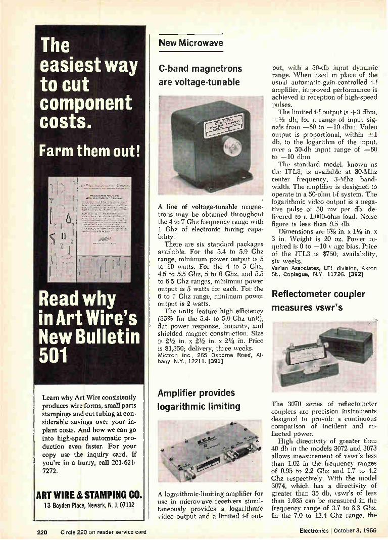
The easiest way to cut component costs.
Farm them out!
Read why in Art Wire's New Bulletin 501
Learn why Art Wire consistently produces wire forms, small parts stampings and cut tubing at con-siderable savings over your in-plant costs. And how we can go into high-speed automatic pro-duction even faster. For your copy use the inquiry card. If you're in a hurry, call 201-621-7272.
ART WIRE & STAMPING CO. 13 Boyden Place, Newark, N. J. 07102
New Microwave
C-band magnetrons
are voltage-tunable
A line of voltage-tunable magne-trons may be obtained throughout the 4 to 7 Ghz frequency range with 1 Ghz of electronic tuning capa-bility. There are six standard packages
available. For the 5.4 to 5.9 Ghz range, minimum power output is 5 to 10 watts. For the 4 to 5 Ghz, 4.5 to 5.5 Ghz, 5 to 6 Ghz, and 5.5 to 6.5 Ghz ranges, minimum power output is 5 watts for each. For the 6 to 7 Ghz range, minimum power output is 2 watts. The units feature high efficiency
(35% for the 5.4- to 5.9-Ghz unit), flat power response, linearity, and shielded magnet construction. Size is 21/2 in. x 21/2 in. x 2% in. Price is $1,350; delivery, three weeks. Mictron Inc., 265 Osborne Road, Al-bany, N.Y., 12211. [391]
Amplifier provides
logarithmic limiting
A logarithmic-limiting amplifier for use in microwave receivers simul-taneously provides a logarithmic video output and a limited i-f out-
put, with a 50-db input dynamic range. When used in place of the usual automatic-gain-controlled i-f amplifier, improved performance is achieved in reception of high-speed pulses. The limited i-f output is +3 dbm, 1/2 db,' for a range of input sig-
nals from —60 to —10 dbm. Video output is proportional, within -1=1 db, to the logarithm of the input, over a 50-db input range of —60 to —10 dbm. The standard model, known as
the ITL3, is available at 30-Mhz center frequency, 3-Mhz band-width. The amplifier is designed to operate in a 50-ohm i-f system. The logarithmic video output is a nega-tive pulse of 50 my per db, de-livered to a 1,000-ohm load. Noise figure is less than 9.5 db.
Dimensions are 6% in. x 11/8 in. x 3 in. Weight is 20 oz. Power re-quired is 0 to —10 y age bias. Price of the ITL3 is $750; availability, six weeks. Varian Associates, [EL division, Akron St., Copiague, N.Y. 11726. [392]
Reflectometer coupler
measures vswr's
The 3070 series of reflectometer couplers are precision instruments designed to provide a continuous comparison of incident and re-flected power. High directivity of greater than
40 db in the models 3072 and 3073 allows measurement of vswr's less than 1.02 in the frequency ranges of 0.95 to 2.2 Ghz and 1.7 to 4.2 Ghz respectively. With the model 3074, which has a directivity of greater than 35 db, vswr's of less than 1.035 can be measured in the frequency range of 3.7 to 8.3 Ghz. In the 7.0 to 12.4 Ghz range, the
220 Circle 220 on reader service card Electronics I October 3, 1966

model 3075 has a directivity of greater than 33 dl) thus allowing vswr's of less than 1.05 to be meas-ured. Each reflectometer coupler is
mounted in a wooden case and is equipped with a 7 mm to type N male, 7 mm to type N female and a precision 7 mm short. Price of each of the models, 3072 through 3075, is $975 complete with case, precision short and two 7 mm te type NM and NF transitions. The Narda Microwave Corp., Plainview, L I. N.Y. [393]
Parametric amplifier
available in 4 models
A range of parametric amplifiers is offered with improved low noise performance at room temperature. Four models are available covering the range 1 to 5 Ghz.
Typically, model VCA/ S22 cov-ers the frequency range 1 to 2 Ghz, with a noise temperature at 70°K. It has a tuning range of 150 Mhz and a 3-db bandwidth of 20 Mhz at 20-db gain. The amplifier uses approximately 10 mw of pump power at a frequency of 16 Ghz.
Amplifiers are supplied with a four-port circulator and pump klys-tron. Price is $6,000; and availabil-ity, 100 to 120 days. Ferranti Electric, Inc., East Bethpage Road, Plainview, N.Y., 11803. [394]
Small, lightweight
mixer-preamplifiers
Miniature mixer-preamps are de-signed for militarized environments and for use in radar, communica-tions and electronic countermeas - ure systems. The mixers, which incorporate
replacement diodes, are mounted to the cast aluminum housing of the
Bong, Bong, Bong. Ladeez an' Genlemen. We now present a strong, rugged, lightweight, who is unbeaten in its bouts with heat. From IMC, "The Boxer."
There are 2 dozen different, but standard, interchangeable fans for Industrial, Military, & Consumer uses Contact IMC Magnetics Corp., Eastern Division, 570 Main St., Westbury, N.Y. 11591. Phone 516 334 7070 or TWX 516 333 3319.
If you need data sheets for reference or consideration for future projects, write IMC's Marketing Division at the same address.
Circle 301 on reader service card
Push-pull, push-pull, push-pull, push-pull, push-pull, push-pull, That's the
push-pull, push-pull, push-pull, push-pull, push-pull, push-pull, monotony
push-pull, push-pull, push-pull, push-pull, push-pull, push-pull, push-pull, push-pull, push-pull, push-pull, push-pull, push-pull. of reliability.
Monotonous reliability characterizes IMC's solenoids, even at 4 millisecond speeds. There's a whole catalog of them in stock at IMC's Western Division, in sizes and configurations for avionics, instrumentation, computer peripherals and other systems.
If you need to push-pull, or to Indicate, Measure, and Control using steppers, synchros, resolvers, flag indicators or solenoids, contact the Applications Section at 6058 Walker Ave., Maywood, Calif., 90270. Phone (213) 583-4785 or TWX 910 321 3089.
For the catalog or data sheets contact the Marketing Div., 570 Main St., Westbury, N.Y. 11591 or circle the inquiry number.
UMM
Electronics , October 3, 1966 Circle 221 on reader service card 221

Capacitors and Resistors
42\ "e'iezz, \
fal
Relays
P4>°
Our parts go into everything electronic
001" -
Connectors
Producers of all types of electronic components have their reasons for relying on Volkert Stampings. It comes out in the extra things Vol kert does. Like converting a multi-piece design to a single stamping. Or con-sistently using high-speed equip-ment to reduce per-part costs. Write or call Volkert Stampings,
Inc., 222-35 96th Avenue. Queens Village. L. I., New York 11429. Telephone 212-464-8400.
rOkIÉSravpuss,,,vc. Subsidiary of The Stanley Works
Circle 302 on reader service card
''The LIGHT Touch in Automation and Control"
1239 Broadway, New York, N. Y. 10001
212 MU 4-0940
New Microwave
preamp. The housing thus com-bines rigid lightweight construc-tion and excellent r-f shielding, ac-cording to the manufacturer.
Standard models are available in frequencies from 0.25 to 12 Chz, gain at 20 to 25 db. and typical noise figure of 10 db or better. Di-mensions of typical units are 2.55 in. x 1.95 in. x 0.88 in. Post ampli-fiers are also available on special order. RS Electronics Corp.. 795 Kifer Road, Sunnyvale, Calif.. 94086. [395]
Airborne radar
microwave assembly
A lightweight microwave assembly has been developed for ztirborne radar applications. The unit com-bines the company's Air-Strip tech-nique for low-power miniature cir-cuits and standard waveguide emu-ponents for higher-power applica-tions in a compact package. The Air-Strip section contains
two phase-coherent. low-noise bal-anced mixers; an automatic fre-quency control mixer: a single side-band generator: and a local oscilla-tor network, including a newly de-veloped 0' to 180 differential local oscillator phase shifter. two isola-tors preceding and one following the single sideband generator and variable attenuators in the local oscillator input and automatic fre-quency control signal arms. The high-power ‘vavegtaide coin-
ponents, as %-ell as the local oscil-lator. mount directly on the Air-
Strip package. The entire assembly operates over the temperature range of —54' to +125— C, and withstands full a irborne shock and vibration environments. Micro-Radionics, Inc., 14844 Oxnard St., Van Nuys, Calif., [396]
222 Circle 222 on reader service card Circle 223 on reader service card-*

Make sure Honey-well's revolution-ary new Auto-Torque mechanism is inside. It's the first substantial improvement in meter technology
in ages a new kind of band-type meter — first to be machine manu-factured. Auto-Torque is more reliable (since there are 50% fewer parts, you can practically wave
good-bye to service prob-lems). Auto-Torque is more durable (since the moving system is suspended on metal bands under ten-sion, there's no friction and wear). Auto-Torque is more accurate (since the mechanism is self-shielded, it can be mounted on any panel without special calibration — without worrying about "sticks", either).
Auto-Torque is more economical (quantity-order prices for volume buy-ers are below comparable pivot and
jewel meters). Auto-Torque is under the hood of the world's smartest-looking meters. And there are plenty of styles to choose from. In fact, Auto-Torque meters come to you in the widest selection of band-type meters available today . . .
For more information on Auto-Torque, write to Honeywell Precision Meter Division in Manchester, N. H. 03105.
Honeywell Auto-Torque Meters
Before you pick out a new meter,
better look under the hood.

..r
e
"JREr
Greatest Reliability—Unlimited Life Repeatable Data over Years of Continuous, Unattended Operation High Shock and Vibration Proof Low Milliwatt Power Consumption Wide Band Wieh Clean Sine Wave Output
without Resonant Filtering
THERE IS NO SUBSTITUTE FOR
RELIABILITY
Micro "Mag Mods" Sil\IL YYAYL (Ali tjUl —INO I LINED FILTERS!
"MAG MODS"® provide four quadrant op-eation, extreme stability with negligible change of phase, gain and zero position over a wide temperature range. Design is simple, featherweight and rugged—with no cuum tubes, semiconductors or moving
arts to limit life. These Modulators are vailable in micro, miniaturized and stand-
ard sizes depending on requirements, and feature an essentially drift-free, wide-band width circuit with superior phase and
gain stability.
Amphtude Response
iQUESÍ BULLEI IN MM 101X
Circuit and Fundamental Principles of Magnetic Modulators are covered by U.S. Pat. No. 2758162
Magnetic Division Modules
FEATURES;
Micro-miniature Size
Completely Solid State
Low Power Consumption
Wide Numerator and Denominator
Ranges
REQUEST BULLETIN MM 710
GM Magnetic Components have been proven superior in thou-sands of commercial, space and military applications. They conform to MILT-27A and MIL-E-5400 specifications and pro-vide a ready solution to problems involving solid state, micro circuit, analog computer design. Call or write for Bulletins.
ACCURACY 01' I% 0k b1 ftk
These Analog Division Modules employ a concept which elimi-nates high gain operational am-plifiers and logarithmic circuitry used in electronic dividers. The result is fewer components, ex-cellent stability, micro-minia-ture size, lower cost. The com-bination of magnetic and semiconductor circuitry results in analog division accuracy of 1% or better.
8
.1, 'AC AIM tnueANATOR *Ce CYA
New Production Equipment
Heated within, welder strips wire
Closer control over the welding of insulated leads to components is obtained when thej welding elec-trode that melts tFe insulation is heated internally, a cording to the Hughes Aircraft Co. So, in its HMT-60 welder, the company put the heater into a rerpovable capsule that fits inside th electrode and also squezed in thermocouple
for temperature control. The machine can weld an insu-
lated lead to a component in less than a second. Insulations such as Formvar, Thermaleze, Soldereze, varnish and some types of vinyl don't have to be stripped from the wire because the heated tip of the electrode penetrates the insulation and bares the metal at the weld spot. Hughes says that inside heating
and temperature monitoring has several advantages over external heating. Eliminating the air gap between the heater and electrode improves heat transfer. This allows closer temperature control and re-duces temperature fluctuations whenever contact with the work-piece draws heat from the elec-trode. Closer control helps prevent
Specifications
Heater temperature range
Ambient to 1,000°F
Dwell time 0.5 to 3 seconds Power input 105-125 y, 1 amp, 60 hz,
single phase Pulse time 2-10 msec. Head welding force 8 oz to 20 lbs Dimensions 61/2 X 9 X 71/4 Weight 10 lbs . Price without power $715.00
supply Delivery Two weeks after receipt
of order
deformation of the workpieces. Mechanically, internal heating is
advantageous, the company adds, since it allows great flexibility in the external shape of the electrode. Nor can the heater intrfere with the application of the welding elec-trode. The electrode acts first as a hot stripper, penetrating and melt-ing the electrode for a preset dwell time. Then the welding power sup-ply is automatically triggered and a normal weld schedule is followed. The HMT-60 system includes a
VTA-60 precision weld head, an HMT-540 electrode heater control,
224 Electronics October 3, 1966

wi agneic icro oc ALL UNITS SHOWN ACTUAL SIZE
Analog Voltage Multiplier WORLD'-
FEATURES;
Four Quadrant Multiplication or Squaring Monolithic Micro
Circuit Block for Analog Voltage Multiplying of DC and
AC Voltages
Addition, Subtraction, Multipli-cation, Division and Extracting a Root of Many Voltage Variables may be Handled by one G/M
Magnetic Microblock
Product Accuracy of up to 0.2% of Full Scale, with very slight
Derating over a Wide Temperature Range
Available as small as 0.1 cubic inch and weighing as little as 0.1 ounce, Micro Magnetic Multipliers feature extreme stability with negligible change of product over wide temper-ature range, high shock and vibra-tion proof. Band-width may be ex-
tended into the kilocycle range. Low mil I iwatt power con-sumption; four quadrant operation.
REQUEST BULLETIN MM 709
Magnetic Demodulators HIGH RELIABILITY — SMALL SIZE!
The new G/M Magnetic Demodulator is a solid state circuit for converting phase reversing AC signal voltages into phase detected polarity re-versing DC voltages. The amplitude and polarity of the DC output are directly proportional to the phase and amplitude of the AC signal. High ref-erence impedance results in very small refer-ence power requirements.
Output as High as -- 10 v. DC in Present Units
Very Low DC Offset Null Voltages (As low as 0.1% of full scale)
Operation Over Wide Environmental Conditions
Completely Solid State- No Moving Parts
General Magnetics • Inc
135 BLOOMFIELD AVENUE, BLOOMFIELD, N. J. 07003 —Tel. (201) 743-2700
Circle 303 on reader service card
When your design is just an idea, don't specify a special transformer...
Until you've checked your TRIAD catalog. You'll find more than 1700 transformers ready off-the-shelf for immediate delivery. One may fit your need, cut costly sampling, and get prototypes on their way faster. Try TRIAD first for standard transformers—and custom made items, too. TRIAD has the resources and the skill to solve your transformer, inductor and filter problems. And make your ideas pay off. TRIAD Distributor Division, 305 North Briant St., Huntington, Indiana.
Circle 225 on reader service card
DIVISI011 lPb ot Lino industries CO

la CONTROL KNOBS FROM RAYTHEON
• rnê Military knobs, aluminum cap knobs, color knobs
for every panel requirement
You can meet military specs, select styles and colors that harmonize or contrast with any panel design and decor — when you specify Raytheon control knobs.
Because, Raytheon offers the largest selection of military and commercial knobs. And makes them promptly available to you through distributors from coast to coast.
Meet MS91528C Military Specifications from more than 300 standard types. Raytheon has custom de-signed over 2,000 "specials."
Every knob in the Standard Series is functionally designed. All styles have an integrated design to give uniformity to your panel. And each knob meets MS91528C for resistance to flame, torque, temperature and humidity extremes, salt spray and
ultraviolet radiation. Colors include black, red, gray or to your special order.
Or, specify aluminum-cap knobs. These handsome knobs are made of strong plastic with satin finish aluminum caps. Raytheon aluminum caps are treated with an epoxy coating for corrosion resist-ance. Colors: black, gray, or to your order.
Color knobs highlight panels. Choose from eight colors plus black — in ten styles — to harmonize or contrast with commercial equipment design. Raytheon makes these 400 Series Knobs of dura-ble high-impact ABS.
Call your distributor or nearest Raytheon regional sales office for catalogs and data sheets. Or, circle the reader service card. Raytheon Company, Com-ponents Division, Lexington, Mass. 02173.
Raytheon Components Division—A single source for Transistors/Diodes/Integrated Circuits/Industrial Tubes/Control Knobs/Panel Hardware/Circuit Modules/Display Devices
RAYTHEON
226 Circle 226 on reader service card Electronics I October 3, 1966

RAYTHEON MECHANICAL
COMPONENTS
Select from Raytheon's broad line of panel components. Binding posts and all standard and subminiature test jacks and printed circuits meet military specifi-cations. Fuse and resistor clips meet BuShips Spec 16E4 and MIL-E-16400.
Raytheon knob and shaft locks provide smooth locking action with simple ad-justment—prevent slip in control settings or adjustments—meet military specs.
Select Raytheon panel hardware for re-liability. economy. Terminal board brack-ets meet MI L-E-16400A, MIL-E-5400, MIL-P-11268. Unique captive hardware assembly meets MIL-E-16400.
For more information, call your dis-tributor or Raytheon regional sales office. Or write: Raytheon Company, Compo-nents Division. 141 Spring Street, Lexing-ton, Mass. 02173.
RAYTHEON
Production Equipment
actuator and mount, costing a total of $715. For a complete setup, °nu of four Hughes welding power sup-plies can be added at a cost rang-ing from $550 for a supply that delivers 50 watt seconds to $1,267, for a 550-watt-second model. Cop-per wires as thin as 0.002 inch and as thick as 0.020 inch have been welded. Hughes Aircraft Co., Vacuum Tube Products division, 2020 Oceanside Blvd., Oceanside, Calif. [397]
Probing system tests
semiconductor chips
A probing system for testing semi-conductors is fully automatic from first test through complete wafer. Model 2818 features wafer contact stepping, which is monitored by a detector head, eliminating excess stepping beyond the wafer area while accommodating %-in. chips to 2-in, diameter wafers. The wafer moves to contact probe points, thus reducing over-all mass movement of the probe head. X and Y stage travel are both automatic and man-ual for rapid aligning. A sensor indexing system incor-
porates a grid mask, which is used together with a photodetector to obtain a higher degree of stepping accuracy. This precision is deter-mined in the mask accuracy, which is estimated at -.±0.5 micron. The device registration that results is within approximately 0.0002 in., thus eliminating the accumulated tolerances that occur with conven-tional use of lead screw indexing. The system has a speed of less than 250 msec, or more than 4 steps per sec, based on chip center-to-center spacing of 0.0250 in. Model 2818 is provided with the
Con winding engineers... what do you want in Dielectric Tubing?
Preez'sion offers you.,,
The Best Materials and combinations for your specific
requirements.
The Exact Size for your arbor and core laminations.
The Right Strength to eliminate production headaches.
Properly Made on the latest equipment to exacting requirements.
Consistently Made without variation from order to order.
High Temp. Tubing and tubing for abrasion and humid-ity resistance.
On Time Delivery to flow smoothly into your produc-tion schedule.
plus. „ Personal Contact to make sure you get what you want!
NEW! Send for Dielectric Tubing Material-Selector Guide and Tubing Data Sheets.
_Preeision PAPER TUBE COMPANY 1033 S. Noel Ave., Wheeling, III. 60090
Phones: Chicago. 631-1445
Long Distance, 312-537-4250
Electronics October 3. 1966 Circle 227 on reader service card 227
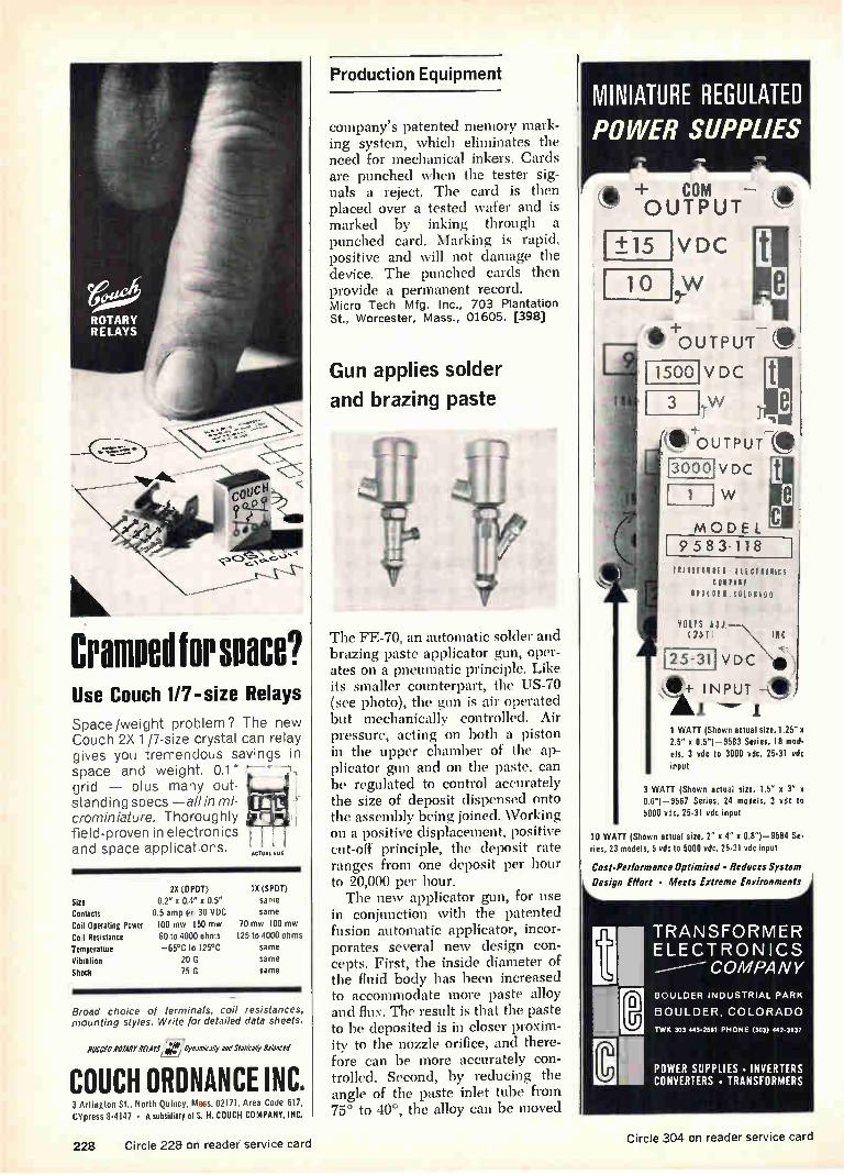
3fleeleir
-111.11
Cramped for space? Use Couch 1/7-size Relays
Space/weight problem? The new Couch 2X 1 /7-size crystal can relay gives you tremendous savings in space and weight. 0.1" grid — plus many out-standing specs —a//in mi-crominiature. Thoroughly field-proven in electronics and space applications. ACTUAL SIZE
2X (DPDT) 1X (SPOT)
Size 0.2" x 0.4" x 0.5" same Contacts 0.5 amp rrr2 30 VDC same
Coil Operating Power 100 mw 150 mw 70 mw 100 mw Coil Resistance 60 to 4000 ohms 125 to 4000 ohms Temperature —65°C to 125°C same Vibration 20 G same
Shock 75 G same
Broad choice of terminals, coil resistances, mounting styles. Write for detailed data sheets.
»CM ROW PEWS Oynenk .1* end SlJth* Osbnced
COUCH ORDNANCE INC. 3 Arlington St., North Quincy, Mas. 02171, Area Code 617, CYpress 8-4147 • A subsidiary of S. H. COUCH COMPANY, INC.
Production Equipment
company's patented memory mark-ing system, which eliminates the need for mechanical inkers. Cards are punched when the tester sig-nals a reject. The card is then placed over a tested wafer and is marked by inking through a punched card. Marking is rapid. positive and will not damage the device. The punched cards then provide a permanent record. Micro Tech Mfg. Inc., 703 Plantation
St., Worcester, Mass., 01605. [398]
Gun applies solder
and brazing paste
The FE-70, an automatic solder and brazing paste applicator gun, oper-ates on a pneumatic principle. Like its smaller counterpart, the US-70 (see photo), the gun is air operated but mechanically controlled. Air pressure, acting on both a piston in the upper chamber of the ap-plicator gun and on the paste, can be regulated to control accurately the size of deposit dispensed onto the assembly being joined. Working on a positive displacement, positive cut-off principle, the deposit rate ranges from one deposit per hour to 20,000 per hour. The new applicator gun, for use
in conjunction with the patented fusion automatic applicator, incor-porates several new design con-cepts. First, the inside diameter of the fluid body has been increased to accommodate more paste alloy and flux. The result is that the paste to be deposited is in closer proxim-ity to the nozzle orifice, and there-fore can be more accurately con-trolled. Second, by reducing the angle of the paste inlet tube from 75° to 40°, the alloy can be moved
MINIATURE REGULATED POWER SUPPLIES
•••
+0 U W IUT
+15
10
VDC
0 1-OUTPUT 10
1500
3
VDC
.w
ero UTPUT—. 3000
1
VDC
MODEL 9 583.118 1
OR VI R I It CIWICS
0 R C0101110(1
tolls 10J 2 5 1 INC
L2 5 - 31 V D C tfie
It- INPUT —4 1
1 WATT (Shown actual size, 1.25" x 2.5" x 0.5")-9583 Series, 18 mod-els, 3 vdc to 3000 vdc, 25-31 vdc
input
3 WATT (Shown actual size, 1.5" x 3" x 0.6")-9587 Series, 24 models, 3 vdc to
5000 vdc, 25-31 vdc input
10 WATT (Shown actual size, 2" x 4" x 0.81-9584 Se-
ries, 23 models, 5 vdc to 5000 vdc, 25-31 vdc input
Cost-Performance Optimized • Reduces System
Design Effort • Meets Extreme Environments
TRANSFORMER ELECTRONICS
COMPANY
BOULDER INDUSTRIAL PARK
BOULDER, COLORADO
TWO 303 443-2561 PHONE (303) 442-3831
POWER SUPPLIES • INVERTERS
CONVERTERS • TRANSFORMERS
228 Circle 228 on reader service card Circle 304 on reader service card

See For Yourself By Testing Sankyo's Family of Time Switches, Timing Motors and Elec-tro-Mechanical Parts!
DFC
TS60 -5 ..Spring wound time switch, 60 minutes, 100 to 240 VAC, 50 or 60 cps. 5 amp. Other models for 5, 15 and 45 minute timers are also available. Automatic defrost timer for refrigerators. Defrost time 30 minutes for every 12 hours. Other specifications are available. 100 to 240 VAC, 50 or 60 cps. 1 to 5 amp.
DFC
indid%—e"ges..3
GMD
sium3,44 .
ATM
GMD Synchronus type timing motor, 100 to 240 VAC, 50 or 60 cps. 2 to 3W, 3 550 to 3.6 rpm, 0.2 to 3 kg-cm torque. Other model GMC, GME Synchronus types) and GMA (Inductor type) are available.
ATM DC motor driven automatic tuning mechanism for ra• dios. Rated voltage is 6 VDC. Used for AM & FM radios of portable, home and car radios.
TS-2H AC motor driven time switch, 2 hours, 100 to 240 VAC, 50 or 60 cps, 5 amp. Other models are available upto 24 hours interval.
DFS Automatic defrost timer with thermostat for refrig-erators. Defrost at fixed time and terminate at fixed temperature. 100 to 240 VAC, 50 or 60 cps, 5 amp.
ATA Spring wound automatic tuning mechanism for ra-dios.
I T H Tape counter for tape-recorders.
Sankyo AMERICAN SANKYO CORP: Hm, 808.10. 95 Madi-son Ave N.Y.0 N.Y . U S.A. Tel. LE-2-8020 SANKYEr (EUROPE) EXPORT-IMPORT G.M.B.H.: 4 Düsseldorf, Bahnstra11e 45.47, W. Germany lei. 25652 3 SANKYO SEIKI MFG. CO.. LTD.: Shimbashi, Tokyo, lapas Tel 591-8371
into the fluid body under less pres-sure. Because the paste is a semi-solid, semiliquid substance, this reduction in pressure virtually eliminates the chance of separation typical of material of this consis-tency. As a further improvement, the
piston rod has been increased in size from 1/8 in. to in. This new rod makes it possible to deposit a larger amount of paste at the joint area, and also to insure proper seat-ing at the nozzle orifice. Fusion Inc., 4658 East 355th St., Wil-loughby, Ohio. [399)
Automatic blast unit
deflashes components
«Mlle
SIbb,
A dry blast unit has been devel-oped for the automatic high pro-duction rate deflashing of capac-itors and resistors. It has been designed to eliminate costly. con-ventional manual procedures for removing excess plastic flash. The complete installation con-
sists of a blast cabinet with an in-terior air blow-off vestibule and in-tegral dust collector through which a conveyor is moved. The unit measures 84 in. long x 76 in. deep x 72 in. high. Within the blast cab-inet, eight suction type blast guns are mounted on an adjustable de-vice. Each gun is fed abrasives through a common manifold with individual controls. This allows ap-propriate blast coverage for the areas to be finished. The air blow-off vestibule is a baffled compart-ment within the blast cabinet which serves the purpose of removing residual abrasive from the work-holding fixtures and conveyor. The conveyor is a roller chain
driven by a variable speed drive supported throughout its entire horizontal length on impregnated hardwood rails. Different types of
ELGENCO Noise
Generators
1 Model 610A
SOLID STATE NOISE GENERATORS
Model 602A 5 cps to 5 mc. 3 Ranges $ 290 Model 603A 5cps to 5 mc. 3 Ranges $ 495 Model 610A 5 cps to 5 mc. 8 Ranges $1,175
Series 624 (Fixed frequency) 5 cps to 500 kc $245 to $490. Write for details on frequency ranges and spectral flatness.
VACUUM TUBE NOISE GENERATORS
Model 301A DC to 40 cps $1,995 Model 311A Two outputs DC to 40 cps and 10 cps to 20 kc $2,395
Model 312A Two outputs DC to 120 cps and 10 cps to 20 kc $2,495
Model 321A DC to 120 cps $2,095 Model 331A 10 cps to 20 kc $1,275
••••
••••• ••••• «moo
emu.
Model 3602A
NOISE GENERATOR CARDS
Series 3602, 3603, and 3606 $144 to $389
Various frequency ranges and output flat-ness available. Size: 41/2 "x 61/2 "x 1". Write for details.
ENCAPSULATED NOISE SOURCE MODULES
Series 1602, 1603, and 1606 .$95 to $340 Various frequency ranges and output flat-ness available. Size: 13/4 "x 11/2 "x 3/4". Write for details.
ELGENCO INCORPORATED
1550 Euclid Street Santa Monica, California Phone: (213) 451-1635 TWX: (213) 879-0091
DEMONSTRATOR MODELS AVAILABLE See EEM or Write for Name of Nearest Rep.
Circle 305 on reader service card Circle 229 on reader service card 229

CRYSTAL FILTERS PIMA
Microsonics manufactures crystal
filters that provide high selectivity
with excellent temperature stabil-
ity and a wide range of frequency
characteristics. Center frequency
of the filters range from 10 KC to 150 mc. Bandpass, band re-
ject, and linear discriminators are
produced to the highest stand-
ards including qualification to MIL-F-18327.
Microsonics has unique ability to
design and measure actual phase
characteristics of crystal filters to
a tolerance of a fraction of a de-gree. For example the character-
istics of our Model P119BA are shown below:
SPECIFICATIONS Center Frequency 10.7 mc = 1 kc
Bandwidth at 1 db 47 kc min at 3 db 50 kc ±-1 kc at 60 db 100 kc max
Differential phase between two filters over 3 db bandwidth — 3.5° max
Phase slope over the 3 db bandwidth "--400 ° approx.
Insertion Loss 3 db max
Ripple 0.5 db max
z in / Z out 400
Operating Temperature Range —45'C to +85 °C
Write for Bulletin 4350, P119BA
MICROSONICS,INC. a subsidiary of the
SANGAMO ELECTRIC COMPANY
60 Winter Street Weymouth, Massachusetts 02188
Area Code 617 337-4200
Production Equipment
work-holding fixtures may be mounted on the chain, depending upon the size and shape of the work to be finished. In the greatest number of applications involving capacitors and resistors, the parts to be deflashed are mounted on a chipboard card. The chipboard card is then manually loaded onto grip spring type fixtures, passed through the blast cabinet, and re-turned to the operator for unload-ing. Pressure Blast Manufacturing Co., Inc., 27 Pleasant St., Manchester, Conn. [400]
Production bonder
depends on ultrasonics
ewe*
An ultrasonic production bonder, model 2905, is designed for wire bonding of hybrid circuits. It also offers improved features for bond-ing and die mounting transistors and integrated circuits. The ultrasonic wire bonder fea-
tures a work station that can move over an area of 1.10 in. x 1.10 in. using a micromanipulator with a reduction ratio of 5 to 1. Two push-buttons on the positioner allow the work station to be rotated 360° in either direction, and templates may be used below the positioner for rapid location of bonding points. The bonder handles aluminum and gold wire sizes from 1/2 mil to 2 mils.
In 30 minutes the bonder may be converted to a flip-chip die mounter capable of bonding flip-chip diodes, transistors and integrated circuits over a 2-in. x 3-in, area at the rate of 300 per hour. The unit may also be modified to mount conventional semiconductor dice ultrasonically
Distinctively Styled
eV A .6 «A,
MILLIAMPERES 70 DIRECT CURRENT
11/2 in. AM-I (actual size)
high torque, self-shielded panel meters
Clean, modern styling ... easy scale readability sizes 1M to 4W. High torque mechanism
gives 1% linearity, 2% accuracy and sensitivity to 20 ua. Magnetic system completely shields external field influences, permitting bezel-to-bezel mounting on any material without inter-action or effect on calibration. Choice of colors or finishes, custom dials—ASA/MIL 4-stud mtg.
AMMON AMMON INSTRUMENTS, INC.
345 Kelley Street, Manchester, N. H. 03105
Circle 331 on reader service card
çu\s
Basic and special REED RELAYS and/or COILS for high reliability and sophisticated switching
Reed Relays
/7\ u\
Operating Inputs: low as lmA. and 15mW. Standard Coil Voltages: 6, 12, 24, 32, 48V in stock
for immediate delivery. Special Voltage or Resistance, multiple windings for
flip flop, memory and crosspoint selection appli-cations — to customer specifications.
Relay Contacts in Form A, B, C and latching. Also high vacuum type 5000V Form A.
Write for Bulletin and Prices
Coto Coil COMPANY INC.
61 Pavilion Ave. Providence, R. I. 02905 Phone: (401) 941-3355
230 Circle 230 on reader service card Circle 319 on reader service card

Need... FAST REVERSING ACTION?
Need... TIMED MEASUREMENT?
Need ... to meet CHANGING PRESSURES?
turn the the job over to SYNCHRON® MOTORS! Any time you have any motor ap-plication that requires extreme flexibility, extreme versatility and extreme accuracy, think first of Synchron motors. Here at Hansen Manufacturing, we specialize in working with you to help you in design, engineering and production problems. Come to us for the motors, and the application expe-rience you want. Call us — or if you're not in a hurry, write today for complete specifications on the type of motor and application you have in mind. No obligation, of course.
HANSEN MANUFACTURING COMPANY, INC.
tt,),
PRINCETON,
s-e INDIANA
HANSEN REPRESENTATIVES, CAREY & ASSOCI-ATES, Houston, Tex., R. S. HOPKINS CO., Sher-man Oaks, Calif., MELCHIOR & MACPHERSON, INC., San Carlos, Calif., THE FROMM CO., Elmwood Park, Ill., H. C. JOHNSON AGENCY, INC., Rochester, N. Y., WINSLOW ELECTRIC CO., Essex, Conn., Norberth, Pa., and New York, N. Y. EXPORT DEPARTMENT, 64-14 Wood-side Ave., Woodside, N. Y.
at higher production rates. Basic price of the model 2905 is
$4,100 without optics. Hughes Aircraft Co., Microelectronic di-vision, 500 Superior Ave., Newport Beach, Calif. [401]
Work-viewer system
aids p-c production
This SteroRama work-viewer sys-tem is a 3-in-1 combination instru-ment designed to aid electronic production and facilitate zero re-ject programs. The multiple opti-cal tool offers a complete work and inspection station comprising a precision lens head and illumina-tion source, both mounted on a free-swinging (panoramic) arm. It provides a large work-viewing area (over 40 sq. in.), with ample dis-tance between lens and work ma-terial for the free use of hands with microwelding, microsoldering or other instruments. One of the chief applications of this work-view station is in the production of printed circuit boards. The manufacturer says the depth
of field of the precision lens head eliminates the need to make fre-quent adjustments. Work remains in sharp focus as it is moved freely through all focal point depths and distances—up and down, or side-ways. This eliminates eye strain and fatigue which commonly ac-company the use of an ordinary magnifying lens, according to the manufacturer. Only fingertip pressure is needed
to swing the lens .away from the work in process. The 3-joint arm can be raised a distance of 19 in.
CUSTOM DESIGNED
POWER
SUPPLIES
10
Mil-E-16400
Mil-E-5400
Mil-E-4158
Mil-T-21200
Mil-P-11268
NASA-200-2
Mil-I-983
Mil-F-18870
Detailed data on facilities, capabilities and contract
accomplishments on request.
SYSTEMS, INC.
90 ROME STREET
FARMINGDALE, NEW YORK 11735
Phone 516-694-5484
TWX 516-694-1505
Circle 306 on reader service card Circle 231 on reader service card 231

THE HULL STORY...
ENCAPSULATION
BY TRANSFER MOLDING
For components like these...
why do the world's leading manufacturers* depend on Hull packaged systems ? Here's why: RECOMMENDATIONS BASED UPON
OVER 500 INSTALLATIONS—Since
1956, Hull has accumulated a wealth of encapsulation know-how to guide selection of the right production equipment.
UNDIVIDED SYSTEM RESPONSIBILITY —The Hull "package" includes press, molds, loading frames, and auxiliary handling equipment . . . assuring smooth, economical flow of production parts.
INTO PRODUCTION, FASTER, SURER
—Hull can help steer system design for optimum encapsulation while product is at "bread-board" stage... minimizing lost motion and delays.
LOW-COST, QUALITY PRODUCT AS-SURED— Hull encapsulation systems offer a proven method for rapid, pre-cise, and economical packaging of electronic components and circuits, large or small.
FOR MORE OF THE HULL STORY on encapsulation by transfer molding, write for a copy of Bulletin P963. HULL CORPORATION, 6036 Davis-ville Road, Hatboro, Pa. 19040. Telepnone: (215) 675-5000. Export: 1505 Race St., Phila., Pa. 19102. 'Texas Instruments. General Electric, IBM. Motorola, Philips. Fairchild Semiconductor. Siemens & Halske—to name a few.
Production Equipment
from the working surface and it extends 19 in. from its main pivot. This enables it to travel in a com-plete circle over a large lighted area. The small, high-intensity, air-cooled floodlight attaches to any part of the arm.
Price is $179; delivery, immedi-ate. The Ednalite Research Corp, 210 North Water St, Peekskill, N.Y. [402]
Slicing machine
is fully automatic
Type TS3 machine is designed for fully automatic slicing of ger-manium and silicon for transistor production, also for sawing quartz, ruby, glass, tungsten carbide and ceramic materials. It makes pos-sible the most precise and clean cutting-off jobs, using relatively thin diamond-charged cutting blades, to obtain laminations of 0.15 to 15-mm thickness. This will enable savings in material and time, according to the manufac-turer.
All combinations of motions per-formed by the machine are auto-matically actuated by an electro-hydraulic control unit, feed rates being infinitely adjustable. A limit switch will stop the machine after it has completed its operational cycle. The work piece is fixed onto a
rotary table 200 mm in diameter,
IMPROVE ACCURACY of THERMOCOUPLE CIRCUITRY
WITH KAYE —
Thermocouple Binding Posts
El] 0
Terminal Blocks Especially designed to prevent spurious emfis.
Available in gold-plated copper, constantan, iron, chromel and alumel.
Send for Catalogue 115.
JOSEPH KAYE & COMPANY, INC. 737 CONCORD AVE. • CAMBRIDGE 38, MASSACHUSETTS
TEL. 617-868•7080
Circle 307 on reader service card
ul e iVi'dés-ii ,noun.
1. A single new instrument that com-pletely replaces digital voltmeters, digital ratiometers, differential voltme-ters, Wheatstone bridges, Kelvin bridges, Wenner bridges, Mueller bridges, potentiometers, voltboxes, op-tical galvanometers, universal ratio sets, Kelvin-Varley dividers, direct-reading ratio sets, temperature regulated oil baths, mercury-stand re-sistance standards and all other tra-ditional D-C tools.
2. An inexpensive D-C instrument that offers superior speed, accuracy, sim-plicity, reliability, convenience and flexibility.
3. A new tool that modernizes D-C re-search, design, test capability as the oscilloscope end electric counter did for all modern AC and time domain capability.
Ask for a simple demonstration of the many ways in which the Multi-Vider can increase output and reduce costs for your company. Write Dept. C to
JULIE RESEARCH LABORATORIES, INC. 211 West 61st Street
New York, New York 10023 05
232 Circle 232 on reader service card Circle 308 on reader service card

6 BIT A TO D CONVERTER 15,000,000 CONVERSIONS PER SECOND
.0 a 4 4.4,44C,
MODEL 834A ANALOG TO DIGITAL CONVERTER Well-suited for telemetering or process control Long life and high stability All solid state, silicon semi-conductors
SPECIFICATIONS Method: successive comparison. Digital output: B.C.D. 12 bit parallel. Stability: ±-0.2%/6 months. Conversion time: approximately 240ps. Operating temperature: —10°C to +50°C.Width:480 mm. Height: 199 mm. Depth: 2250 mirn. AC input: 100/110/220/240V±10% 50 or 60 c s.
MODEL 198C DATA LOGGING SYSTEM
All solid state Random access analog scanner High reliability and accuracy Operates over large temperature ranges Low cost
SPECIFICATIONS Scanning capability: 16 channels. Scanning speed: up to 5 channels per second. Accuracy: 0.1%. Output: printing paper tape. Logging cycles: 10 seconds to 1 hour (specify on ordering). AC Input: 100/110/220/240V ±10% 50 or 60 cps (specify on ordering).
yee.roli
MODEL 507C DIGITAL VOLTMETER
All solid state and high speed. SPECIFICATIONS Measuring range: (1) 0.001 to 1.599 volts
(2) 0.01 to 15.99 volts (3) 0.1 to 159.9 volts (4) 1 to 1.599 volts
Accuracy: 0.1% of full scale. AID conversion time: 600ps. Max. repetition rate: 1 kc. Reading mode auto: 100 cis repetition rate. Digital output: 4 digit decimal icCi. parallel code connectable to the line
printer Operating temperature: 0 to 40'C. Width:480 mm. Height: 199 mm. Depth: 350 mm. Weight: approx. 13 kg. AC input: 100/110/220,240V 50 or 60cps.
CHUO ELECTRONICS CO., LTD. No. 21 Motohongo-rnachi Hachioji-shi,
Japan
which can be rotated to 360° and tilted to 15°. Setting is read off a vernier to 3 minutes-of-arc accur-acy. A fine-adjustment table, with reading to 1 minute-of-arc, can be supplied if so required. The work table has 260-mm longitudinal tra-vel and 160-mm step-wise cross motion. Falcone Engineering Inc., 487 Orange St., Newark, NI , 07107. [403]
Automatic tool
installs terminals
An automatic-feed tool can install solderless terminals on wire at a rate of over 1,000 per hour. A port-able hand model and a bench-mounted model are available. A Mylar plastic belt holds the
terminals as they are fed into the compression dies, which are self-aligning and self-adjusting and can be snapped in and out. Based on straight-line action, the terminal in-stallation tool will not release the terminal until the proper amount of pressure has been applied. In-spection integrity dots are em-bossed on the terminal automati-cally to indicate visually that the proper installation has been made. The tool has only five moving
parts, meaning long service with-out the need for maintenance. The tool operates on 90 to 100-lb air pressure. The bench model (No. 11907) is mounted on a hand rubbed 3/4-in, birch plywood base with four friction feet to prevent movement. The lightweight port-able model (No. 11906) is for panel and harness board wiring. The Thomas & Betts Co., 36 Butler St., Elizabeth 1, N.J. [404]
2 .4 .6 .8 o
crisp, classic Horizon Line?
0.0 VOLTS
trim, built-in Horizon Line?
You can get it... from General Electric's full line Built-in or front-mounted, G-E
HORIZON LINES panel meters add
quiet sophistication that accents,
never dominates, your electronic
equipment. All ratings are avail-
able in 21/2 ", 31/2 ", and 41/2 " sizes.
See the complete General Electric
panel meter line at your depend-
able electronic distributor. 892-26
Circle 309 on reader service card Circle 233 on reader service card 233

NEW CHEMELEC® TFE TEST SOCKETS
RELIABILITY FOR TESTAcm tÍLI: AFTER TEST AFTER TEST (UP TO 100,000)
Unique contact design gives Chemelec test sockets their extra, long-term relia-bility—makes them ideal for in-and-out service. In each pin hole are three beryl-lium copper leaves that bow in toward the center. Every time a lead is inserted, the leaves deflect to let it slide in easily, but press firmly against it to assure good contact. Tapered entry holes and low insertion
force (less than 1 oz. per lead) make them easy to plug into, and a built-in barb pre-vents accidental pull-out of the contact assembly. The gold-over-nickel-on-beryllium-cop-
per contacts in TEE fluorocarbon plastic bodies—to appropriate MIL specs—create sockets you can safely use in heat sinks or cryogenic environments, as well as in normal applications. Three body sizes, with 3 to 14
contacts, in .100 to .325 pin circles.
For more information, write for Bulletin ST-1. e 1
G 1=L C1 1E-K ELECTRONIC PRODUCTS
OARLOCK INC.
Cherry Hill, N.J. 08034 • Phone (609) 424-1470
InEurope:EuropélecS.A.,LesClayes-Sous-Bois,France
Inthe United Kingdom :Lectropon,Ltd.,Slough,England
New Materials
Leak-detecting fluid
foams white
A leak-detecting fluid, called For-mula No. 577-V, is designed for vacuum testing. Its simplest appli-cation is to the connections and seals of a vacuum system that can easily be pressurized. Any leakage down to 1/10 of a standard cubic centimeter in three hours will be pinpointed by a white foam. If the vacuum is impossible to pressurize, then 577-V applied to the outside of the evacuated system will pene-trate any leak and foam will be evident internally when viewed through ports in the system. Formula 577-V may also be used
for vacuum box weld testing and for locating leaks in small electronic components containing gas. In the latter case, the parts are dipped in 577-V and placed under a glass bell jar. Upon evacuation, foam forms wherever there is any leakage.
Additional properties of 577-V include low outgassing, high elec-trical resistance and excellent pene-tration of pinholes, hairline cracks and porous welds. Residue content upon evaporation is extremely small and the material is noncor-rosive and nontoxic. Leak-Tec division, American Gas & Chemicals, Inc., 511 E. 72nd St., New York, N.Y., 10021. [406]
Nonporous-coated
evaporation sources
Aluminum - oxide - coated evapora-tion sources are used for the con-tamination-free deposition of thin films. They find application in the field of optics, microcircuitry, semi-
conductor and thin-film deposition industries.
Characterized by the application of high purity (99.9%) A120 ap-plied to a refractory metal base of molybdenum (99.9% pure), these devices will operate up to 1,900°C. The A1203 coating prevents the evaporant from alloying with or at-tacking the refractory metal and according to the manufacturer results in longer product life, im-purity-free deposition, high operat-ing temperatures and greater depo-sition control. The aluminum-oxide is nonpor-
ous and is applied to the refractory base material in such a manner as to avoid chipping, cracking or peel-ing. This enhances the life of the evaporation source and allows the vacuum engineer to deposit a va-riety of materials such as gold, Inconel, Chromel, Kanthal, Ni-chrome and many others. Designated the PB series, these
sources come in a variety of sizes and configurations, and cost from $5.85 to $7.95 each, with off-the-shelf delivery. Evaporation Apparatus Inc., 2208 South Wright St., Santa Ana, Calif., 92705 [407]
YAG crystals available
for laser work
Yttrium-aluminum garnet (YAC) crystals are now available for use as essential components in lasers. They are offered with up to 1.5 atom % doping of Neodymium, and are guaranteed to lase. The crystals are available in
three standard rod sizes as raw blanks, with ground ends, polished ends, or as finished components
234 Circle 234 on reader service card Electronics October 3, 1966

M OITOINI).e
SINE
l t. cs
-• •
•_ ., '420) - _
. *Dip ....sk e
'SQUARE OSCILLATOR MODEL 3 1 ir$71.50] FOB JAPAN
5Hz -560kHz, 6000
.., 1
IIIIM ' 1
e i 2 5f
g i
e '
HIGH SENSITIVE AC VTVM
"DEL 1 2 16 0 6.3 (FOB JAPAN)
full scale 1.5mV-500Vr BHz --500 kliz
, •
• isem
- • i ..LL ià im
g • ..... 9- 0 •
i , maw 0
• if e .....
n
é ail _Lila_
REGULATED DC POWER SUPPLIES 29 models are available. For par-
ticulars, please apply for catalog. RIPPLE: 3mVpp
MODEL VOLTS AMPS REGULATION FOB JAPAN
521A 1,,,18V 0.5A ±20mV 41.50
541 A 1,-.35V 0.25A ±20mV 46.50
543 1-35V 0.5A ±20mV 73.50
5318 0-35V 1 A ±10mV 84.00
sasc 0-35V 5 A ± 3mV 250.00
• Specialized dealers wanted s Write today for details.
CZ> aietrotti,e corp.
76, CHOFU-CHIDORI-CHO, OTA-KU, TOKYO
with dielectric coatings on both ends. Standard 3 mm diameter YAC crystals are 30, 50, or 75 mm long. A typical 30 mm YAC crystal
with dielectric coatings on both ends and guaranteed to lase costs $815. Aremco Products, Inc., P.O. Box 145, Briarcliff Manor, New York, 10510. [408].
Fluorinated liquid
cools flashtubes Designed to withstand high energy pulses from xenon flashtubes, a fluorinated liquid can be used as a laser and flashtube coolant. The transparent FC-104 flashtube
coolant provides wide liquid range (less than —80°F to approximately +215°F); and improved heat trans-fer capabilities compared to other conventional coolants such as sili-cone oils. Its dielectric strength is greater than 35 kv per 0.1 in. The nonflammable liquid has high tem-perature stability (greater than +600°F) and is compatible with construction materials. 3M Co., 2501 Hudson Road, St. Paul, Minn., 55119. [409]
Fluid epoxy system
bonds Mylar films
A two-part fluid epoxy system, known as X-11964, may be cured at room temperature or in 30 minutes with 100°C. The cured system is said to be very flexible and resilient with excellent adhesive property. The X-11964 was formulated par-
ticularly for good adhesion to My-lar film material such as Mylar coated components and panels; however, it is an excellent adhesive for wood, glass, plastics, and fer-rous and nonferrous metals. Kenics Corp., One Southside Road, Danvers, Mass., 01923. [410]
40 60 80 20 .. 4."4 "1'.t. 1,,, 100
D-C AMPERES 120 6111,11.0!", MOO.
distinctive Big Look?
You can get it... from General Electric's full line
Add bold, exciting, truly distinc-
tive styling to your electronic
equipment with General Electric's
BIG LOOK' panel meters. All rat-
ings are available in 11/2 ", 21/2", 31/2",
41;2" sizes. See the complete General
Electric panel meter line at your
dependable electronic distributor.
592-27
GENERAL ELECTRIC
Circle 312 on reader service card Circle 235 on reader service card 235

DUAL OUTPUT
POWER SUPPLIES
Guaranteed 3-DAY
Shipment!
Dual output power supplies are housed in one case 3-5/16" x 4-5/32" x 4-11/16" high. Identical or different output volt-ages from 1.5 to 75 are available in 1 volt increments for each of the DC out-puts. The graph below furnishes maxi-mum current corresponding to output voltage. Select the two outputs needed and telephone Acopian for all the de-tails — plus guaranteed 3-day shipment after receipt of your order.
output .It
age
(volts D
.C.]
75
60
50
40
30
20
10
1.5 100 200 300 400 500
OUTPUT CURRENT (MA.)
TYPICAL SPECIFICATIONS Input Voltage: 105 to 125 VAC Line Regulation: ±-0.5 to -±0.05% (depending on model)
Load Regulation: ±1.0 to -±0.05% (depending on model)
Ripple: 5 to 1 mv (depending on model) No additional external heat sinking required. Write for Acopian's 16-page catalog and price list to: Acopian Corp., Easton, Penna., or call collect (215) 258-5441.
New Books
Switching theory Introduction to Switching and Automata Theory Michael A Harrison McGraw-Hill Book Co., 499 pp., $16.50
In the title the word "introduction" should not be taken to imply sim-plicity. This is a textbook—and by no means for beginners. The theory is difficult enough to warrant clari-fication and explanation, and the selection of topics is wide enough for development along several ave-nues.
Problems at the end of each chapter make the book suitable for an undergraduate. However, the material is sophisticated enough for graduate study. Afterward the book could serve as an excellent refer-ence. The treatment lies between the
fields of engineering and mathe-matics, never entering fully into either. This is not necessarily a detriment; the book can serve as a guide into either field according to the reader's desire. A good bibliog-raphy allows pursuit of specific areas. The author attempts to develop
a permanent basic theory and then expand it with almost entirely ab-stract mathematics. There is little discussion of practical equipment.
Harrison ranges from Boolean algebra to probability theory. To cope with the many subjects, he has introduced a large collection of short word forms, abbreviations and mathematical symbols. A glos-sary of these would have made reading easier. A related problem afflicts the appendixes, since they rely heavily on textual develop-ments. The table of minimal switch-ing circuits, for instance, is coded without being explained, leaving the reader to find the meanings of the designations in the text. A preliminary section on mathe-
matical background contains a good collection of basic thoughts on number theory, abstract algebra and mapping—material which pro-vides a good, quick reference source. The description of Boolean algebra, slanted toward the classi-cal theory rather than practical op-erations, helps the reader to understand the role this algebra
plays in the well-ordered mathe-matical structure that the author develops. Development of the structure
splits the rest of the book into sections called "combinational" and "sequential." In the combinational section, logic circuits are intro-duced, which is unfortunate since they date the text and do not im-part enough information to be of any value to a circuit designer.
Harrison's treatment of minimi-zation is noteworthy because the graphical Karnaugh map and the more mathematical Quine's algo-rithm are both presented. The dis-sertation on Quine's method is dif-ficult to follow without previous background. An important part of minimization's role—reducing cost —is mentioned, but no further ref-erence to cost functions is under-taken. A highly advanced chapter on
transformation and equivalence of groups of switching structures is concerned mainly with reduction of functions—it helps to give under-standing to the tables of functions listed in the appendixes. The use of matrixes to transform Boolean functions is described clearly. A good descriptive and manipu-
lative discussion of tree networks is given (the practical considera-tion of "sneak paths" is one of the exercise problems). Also presented are an algorithm for constructing uniform contact folded trees and the Lyapunov tree, which is possibly more economical. The author in-cludes an interesting discussion on the upper and lower bounds of the number of contacts needed to define a function of n variables. Some studies into the reliability
of two-terminal contact networks are made, but simplified by assum-ing independent element and non-time-varying probabilities. Borrow-ing terms from chess (opening, middle and end game), the author outlines a procedure for designing a known reliability factor into a switching network. In addition, arguments are presented on the probability bounds of the networks. The text assumes some prior knowl-edge of probability theory, but the background need not be extensive.
236 Circle 236 on reader service card Electronics l October 3, 1966

Who needs 55% efficiency in a micro motor 20mm or less in diameter?
No one. But it is a testimony to Mitsumi's
ability to meet unusual speciality
micro-electronics requirements. Micro motor efficiency over 50(:ó has
been considered impossible for a
motor as small as 20mm in diameter.
Adoption of a new system in the mag-
netic circuit has upset this common concept.
Both electrical and mechanical
noises have practically been elimi-
nated by a built-in noise suppressor,
and a specially constructed brush
which has improved the rectifying
capacity.
Ask for Mitsumi when you need a
reliable, quality micro motor for port.
able tape-recorders, record-players,
measuring instruments and 8mm 2.
speed movie cameras. Over 30 types
of AC or DC micro motors are imme-diately available.
Mitsumi is the world's leading mak-
er of polyethylene variable capaci-
tors, I-F transformers, synchronous
motors, front-end FM tuners, UHF &
VHF TV tuners, CdS photoconductive
cells, trimming potentiometers, coils,
sockets, trimmer capacitors, termi-
nals, and fuse holders.
MITSUMI
MITSUMI ELECTRIC COMPANY, LIMITED 1056 Koadachi, Komae.machi, Tokyo. 415-6211 302, Cheong Hing Bldg., 72 Nathan Road, Kowloon, Hong Kong. 666-925 Marienstrasse 12, Dusseldorf, W. Germany MITSUMI ELECTRONICS CORPORATION 11 Broadway, New York 4, N.Y. 10004. HA5 3085 333 N. Michigan Avenue. Chicago, III. 60601 263-6007
In the section devoted to sequen-tial machines, a completely new set of symbols is used to characterize the memory or state capabilities of this class of networks. Numerous diagrams and examples help de-velop the structure of sequential machines in a mathematical sense and the machines' responses to in-put stimuli. Machine states are in-vestigated first without considering output and then with output. As in the combinational section,
the reader is led into areas of analysis, synthesis, equivalence and minimization of sequential ma-chines—although not necessarily in that order. The definition and be-havior of a probabilistic sequential machine is given in some detail. Reference is made to reliability, but it is not dwelled upon. As a final attempt to touch upon
all the basic branch studies pertain-ing to automata (in the sense that the author uses that word), con-text-free languages are given con-sideration. Whether it is because the subject matter deals with a new fundamental philosophy and therefore the reader has little ex-perience to draw on or because the text requires more development, the presentation does not provide an adequate introduction.
Robert C. Joseph Airborne Instruments Laboratory Deer Park, N.Y.
Recently published
Introductory Computer Programming, Frederic Stuart, John Wiley & Sons, 155 pp., $5.95
The Challenge of the Computer Utility, D.F. Parkhill, Addison-Wesley Publishing Co., 207 pp., $7.95
High-Power Electronics, Vol. 2, edited by P.L. Kapitza and L.A. Wainstein, Pergamon Press, 117 pp., $8
Circuits, Devices, and Systems, Ralph J. Smith, John Wiley & Sons, 776 pp., $11.95
Antenna Analysis, Edward A. Wolff, John Wiley & Sons, 514 pp., $25
Mathematics for Electrical Circuit Analysis, D.P. Howson, Pergamon Press, 170 pp., $3.50
Electronics: A Bibliographical Guide-2, C.K. Moore and K.J. Spencer, Plenum Press, 369 pp., $18
Signal Detection Theory, John C. Hancock and Paul A. Wintz, McGraw-Hill Book Co., 247 pp., $11.95
Applications Manual for Computing Amplifiers: for Modelling Measuring Manipulating & Much Else, Philbrick Researches, Inc., Dedham, Mass., 116 pp., $3
Zero Defects: A New Dimension in Quality Assurance, Jame-. F. Halpin, McGraw-Hill Book Co., 228 pp., $10.50
What Kind of Panel Meter Do You 9 Need •
ln
0 25 50 75 I00 DC VOLTS
0 25 50 75 IGO OC VOLTS
smart, slim edgewise?
You can get it... from General Electric's full line
Besides saving you valuable panel
space, General Electric slim-line
21,4" Type 185 EDGEWISE panel
meters add exceptional styling and
readability to your electronic
equipment. Mount individually or
in clusters of two, three, or more.
See the complete General Electric
panel meter line at your depend-
able electronic distributor. 592-28
GENERAL
Circle 313 on reader service card Circle 237 on reader service card 237

4
HATHAWAY H0.1
DINED
smort peeloice
The form "C"— another of Hathaway's refined electronic - switching elements. The FCD in your choice of 4 double throw relay packages—
SPDT to 4 PDT. Distributed Nationally by
COMPAR CORPORATION
For detail information call or write...
HATHAWAY INSTRUMENTS, INC. 5250 EAST EVANS AVENUE
DENVER, COLORADO 80222
(303) 756-8301 • TWX 292-2935
Technical Abstracts
Interplanetary computers
Logical design techniques for error control Jack Goldberg, Stanford Research Institute, Menlo Park, Calif.
Failure probability of only about 1% is all that will be allowed for the computers that will be carried on spacecraft setting out on jour-neys lasting six months to three years. Since each computer may have as many as 100,000 active de-vices, any of which might fail, the reliability goal is virtually impossi-ble to achieve on the basis of in-herent device reliability.
Therefore, the computers will need a high degree of automatic self-diagnosis and, since elements will inevitably fail, the ability to reassign functions among the ele-ments that still work. Present re-dundancy techniques are inefficient and unsuited to reconfiguration— that is, they don't have the flex-ibility needed to make full use of fault-free elements as faults ac-cumulate. To illustrate the problems in sys-
tem organization and network de-sign, a reconfigurable computer is hypothesized. It is a general proc-essor for counting, index-register storage and arithmetic and micro-program control. A given processing step is done
by combining the data in a selected register with data in the accumula-tor and distributing the result to a register or the accumulator. Se-lection and operation is under ex-ternal control. Information is ex-changed with the external system via a commutation switch. To by-pass a faulty column, the switch must be able to direct n' bits to any subset of size n' among the n columns. Each module of the processor
can decode the selection and oper-ation control signals, reducing the types of modules and the number of terminals. Information transfer between adjacent modules is re-stricted to a single bit from a selec-ted register, transmittable in either direction, and a carry bit for arith-metical operations, transmittable in only one direction. Bypassing a stage for lateral information is ac-complished simply by bussing cor-
responding transverse input and output lines in both directions. To communicate around internal
faults, a sequential network is pro-posed. It is essentially an asyn-chronous shift register of 2n stages, with parallel inputs to the first n stages and parallel outputs from the second n stages. Information on data channel quality is stored at cells corresponding to each chan-nel. Data propagates toward higher index stages and comes to rest in a stable configuration. Symbols from valid source channels are col-lected in a contiguous string. Cells corresponding to faulty channels are skipped. Although the system has inherent
delay, it requires no internal clock-ing. For some switch sizes, it is more economical than the equiva-lent combinational network. A directory table and a routing
switch can also be used to program data commutation. The table identi-fies receivers by function and loca-tion. The stored identification is added to a data message, to route the message through a switch. For ordinary logical transfers, this method is time-consuming, al-though it has the advantage of flexibility. It is a convenient way to shift blocks of data out of a memory when failures in the access switch make portions of the mem-ory unusable.
Faults in networks may be diag-nosed by comparing redundant sig-nals from the networks and dupli-cate networks, but this is costly and subject to error under multiple-fault conditions. Actually testing a given network is better. Despite re-cent advances in fault diagnosis, important problems in both analy-sis and synthesis remain. At pres-ent, methods of designing short test schedules are inadequate for com-binational networks larger than 100 gates, multiple-output combina-tional networks and sequential net-works.
Before reconfigurable computers can be built, advances are needed in analyzing the reliability of re-dundant networks, diagnosing faults in complex networks and syn-thesizing modular, programable and easily diagnosable networks
238 Circle 238 on reader service card Electronics October 3, 1966

MICO NEW MODEL 885
SEVEN RATIO WIDE-RANGE ENGRAVER
NO 885 FOR LONG AND
MULTI-LINE WORK
AMERICAN
MADE
• A time-saver for large plate work.
• Engraves 3" x 19" area in one set-up. • Seven pantograph ratios—from 1.5:1 to 6:1.
• Choice of 3-ball-bearing spindle assemblies for 4", 3/16" or taper-shank cutters.
• MSS. COBALT and Solid Carbide Cutters. • Single and multi-line copy carriers for holding
blanks ,á" to 34" high. • Accommodates Mica standard accessories.
Send for bulletin, and lerl.
MICO INSTRUMENT CO. 77 Trowbridge St. Cambridge, Mass. 02138
Circle 314 on reader service card
rdmienizi upe T High SenPitirity
SOUND LEVEL METER MICROPHONE DYNAMIC TYPE,
Sp•cificoliens • Frequency Response 20 - 16,000%
±1.568 • Impedance: 50 9 .ICei •Senue•ty- -141dEl • 2d13 • Dornenuons. 354,220mm • Wought: 730"
DM- 1332
F ca (dog 11 ri e to
PRIMO COMPANY LTD. 2043 MURE, MITAKASHI, TOKYO, JAPAN
TEL.0422-43-3121 Calling from Tokyo
Technical Abstracts
that will include both logic and communication.
Presented at the Western Electronics Show and Convention, August 23-26, 1966.
Stacked lasers
High power stacked GaAs laser array D.R. Muss, C.S. Duncan and S. Souro Westinghouse Research Laboratories, Pittsburgh
A unique, closely packed array of gallium arsenide laser diodes ar-ranged as a series stack proves to be a highly efficient source of pulsed light in the near infrared. It is capable of peak powers greater than 300 watts at repetition rates below 200 pulses per second. The emission is nearly monochromatic at about 8,450 angstroms from a luminous area 0.05 by 0.05 centi-meters; the beam emerges as a cone about 0.01 steradians when operated at 77°K.
Stacks of as many as H diodes have been fabricated; these are connected directly to one another by a very thin solder layer in a series of pn layers, as shown be-low, with heavy molybdenum elec-trodes at the ends and a common optical cavity for all the diodes. The laser array is fabricated by
diffusing a p-layer 25 microns deep on a thick n-substrate and dicing the large wafer. Lapping of the n-substrates of the dice to a 25-micron thickness results in a pn die 50 microns thick. The elec-trodes and the dice are assembled in a jig and soldered together. Two opposite faces of the stacks are rough lapped and the other two faces are lapped and polished flat, parallel to each other and perpen-dicular to the plane of the junc-tions. Stacks of 5, 10 and 11 diodes have been fabricated in this way.
Efficiency of the stacks is meas-ured in terms of the peak light "current" out (assigning one elec-tronic charge for each photon measured) divided by the peak drive current. The highest efficiency attained is 20%, with a drive cur-rent of 130 amperes. Peak output power is 380 watts.
Presented at the Conference on Preparation and Properties of Electronic Materials for the Control of Radiative Processes, Boston, Aug. 29-31.
MINUTES
0 0 0 0 0 o
GENERAL @ELECTRIC
P Min . 01
style-matched time meters?
You con get it... from General Electric's full line
The distinctive styling of the G-E
BIG LOOK panel meter line is
yours with "look-alike" elapsed
time meters. These accurate time
meters measure hours or minutes
and are offered with or without a
reset knob. All ratings are avail-
able in 21 2" and 31 2" sizes. See
the complete General Electric
panel meter line at your depend-
able electronic distributor. 592-29
GENERAL ELECTRIC
Circle 315 on reader service card Circle 239 on reader service card 239

Your plant may be ready
for new electronics equipment...
but how about your people?
Every day more sophisticated electronic equip-
ment is used by more companies to perform more critical operations. Computers. Calculators.
Control systems. Process instrumentation. Com-munications equipment. It's highly efficient ... as long as you have qualified electronic technicians
who understand it, know how to maintain it... and can fix it fast if it ever fails. A good way to build a competent staff of skilled
electronics technicians is to up-grade your pre-sent technical personnel. And a good way to do it is with a Cleveland Institute of Electronics
Training Program. CIE "AUTO-PROGRAMMED" Courses are fast, effective and economical. What's more they can be "tailored" to your specific training needs. There are other advantages,
too ... and hundreds of satisfied users. Learn about them. Send coupon today for FREE details. Cleveland Institute of Electronics, Dept. E-22, 1776 E. 17th St., Cleveland, Ohio 44114.
SEND COUPON TODAY
Cleveland Institute of Electronics
Dept. E-22, 1776 E. 17th St., Cleveland, Ohio
Gentlemen: I am interested in learning more about your Electronics Home Study Programs. Please send complete information.
Name
Title
Company
Address
City State Zip Accredited Member, National Home Study Council.
I.
New Literature
Pressure transducers. Robinson-Halpern Corp., 5 Union Hill Road, West Con-shohocken, Pa., 19428, has issued a four-page technical bulletin on its line of P40 series standard and high accur-acy pressure transducers. Circle 420 on reader service card.
Electronic filters. Spectrum Instru-ments, Inc., Box 474, Tuckahoe, N.Y., 10707, offers a short-form catalog pro-viding comprehensive technical data and specifications on its complete line of tunable electronic filters. [421]
Capacitance/inductance meter. Boonton Electronics Corp., Route 287 Parsip-pany, N.J., 07054. A technical bulletin describes the model 71A, an instru-ment that provides instant, direct-reading measurement of three-terminal capacitance and two-terminal induc-tance over ranges of 0 to 1,000 pf and 0 to 1,000 i.th, respectively, at 1 Mhz. [422]
Indicator lights. Dialight Corp., 60 Stewart Ave., Brooklyn, N.Y., 11237. Catalog L-201 presents complete data, drawings and new catalog number des-ignations for the company's subminia-ture and miniature press-to-test indi-cator lights. [423]
Servo components. Inland Motor Corp., 501 First St, Radford, Va., 24141, has published a six-page, d-c direct-drive servo components condensed selection guide. [424]
Noise suppressors. Weinschel Engineer-ing, Gaithersburg, Md. A two-page data sheet describes the model 936 noise suppressors for microwave test sys-tems. [425]
Phase angle voltmeter. North Atlantic Industries, Inc., Terminal Drive, Plain-view, N.Y., offers a two-page data sheet on its model 214, a four-frequency phase angle voltmeter. [426]
General-purpose relay. Sigma Instru-ments, Inc., 170 Pearl St., Braintree, Mass., 02185. A catalog bulletin covers the 4 pdt a-c and d-c series 67 minia-ture general-purpose relay and mount-ing sockets. [427]
Solid-state switches. TRW Equipment Operations, 23555 Euclid Ave., Cleve-land, Ohio, 44117. A four-page bro-chure explains solid-state, automatic a-c bus transfer switches that feature speed, dependability, and maintenance-free operation. [428]
Relay selector chart. Cornell-Dubilier Electronics, 50 Paris St., Newark, N.J., 07101, has published a four-page selector chart describing its relay product line. [429]
Angular divider. Theta Instrument Corp., Saddle Brook, N.J., 07662, announces a four-page bulletin describing an angu-
lar divider for testing synchros and resolvers. [430]
Laminated tube sockets. Connector Corp., 6025 N. Keystone Ave., Chicago, III., 60646. Technical bulletin 40A con-tains eight dimensional drawings and 76 photos of laminated assemblies, as well as two dimensional drawings and one photo of electrolytic mounting plates. [431]
Magnetic shielding. Magnetic Shield division, Perfection Mica Co., 1322 N. Elston Ave., Chicago, III., 60622. Short form catalog No. 67 illustrates and de-scribes various permanently stable, nonshock sensitive Netic and Co-Netic magnetic shieldings. [432]
Power transformers and inductors. Fer-roxcube Corp. of America, Saugerties, N.Y., has published at 32-page engi-neering reference manual on proce-dures and techniques for the design of power transformers and inductors. [433]
Relays. Solid-State Electronics Corp., 15321 Rayen St., Sepulveda, Calif., 91343, has issued a 28-page catalog providing data on miniature, solid-state optoelectronic and reed relays. [434]
Cylindrical substrates. American Lava Corp., Chattanooga, Tenn., 37405. Bul-letin 667 describes AlSiMag 531 and AlSiMag 614 cylindrical substrates for discrete film resistors. [435]
Resolvers. Reeves Instrument Co., a division of Dynamics Corp. of America, Garden City, N.Y., offers two brochures on its compensated and uncompen-sated Size 15 and 23 resolvers. [436]
Panel meters. International Instruments Inc., 8826 Marsh Hill Road, Orange, Conn., 06477. Bulletin 391 covers a comprehensive line of edgewise panel meters. [437]
Transducer performance characteristics. Cohu Electronics, Inc., Box 623, San Diego, Calif., 92112. An illustrated bro-chure (5-27) discusses verification of transducer performance characteristics by a digital voltmeter/ratiometer. [438]
Chart recorder. Nesco Instruments, a division of Datapulse Inc., 509 Hindry Ave., Inglewood, Calif., 90306. The re-corded chart may be pulled out for review and then automatically rerolled onto a take-up reel in the model 210 transistorized chart recorder described in technical bulletin 210. [439]
Test instruments. The Triplett Electrical Instrument Co., Bluffton, Ohio, 45817. Catalog No. 49-T describes a line of panel and portable electrical and elec-tronic test instruments. [440]
Subminiature relays. Airpax Electronics Inc., Cambridge, Md., 21613. A bulletin
240 Circle 240 on reader service card Electronics October 3, 1966

Decisions! Decisions!
The big ones are made
where the best things happen
Now as always at the grand-old,
brand-new Roston Staller
lome of the NeW Trader Vic's!
Phone any Hilton Reservation
Service ... for instant,
confirmed accommodations.
Circle 316 on reader service card
NOW! APPLY KODAK PHOTO RESISTS
this new AEROSOL way
QUICK CONVENIENT ECONOMICAL
Three types to suit all your etching needs now available at local industrial photo dealers
TYPE-P containing Kodak KPR* —for copper, copper-clad laminates, other metals. 16 oz. $5.95 TYPE-61 containing Kodak KMER•—for aluminum, stain-less steel, titanium, other metals. 16 oz. $5.95 TYPE-T containing Kodak KTFR• — for high resolution etching of thin films. 16 oz. $6.95 *KPR, KMER, KTFR are prod-ucts of Eastman Kodak Co.
INDUSTRIAL CHEMICAL SPECIALTIES CORPORATION
1595 Black Rock Tpke., Fairfield, Conn.
Please rush me more information on Spray Resist products and, also, name of nearest dealer:
NAME
COMPANY
CITY STATE
describes the use of Ugon fast, sensi-tive, subminiature relays in such appli-cations as uhf signal switching, meter-ing relays and instrumentation systems. [441]
Function generators. Electronic Assoc-iates, Inc., West Long Branch, N.J. A four-page engineering data sheet de-scribes two card-programed diode func-tion generators that minimize setup time for analog or hybrid facilities. [442]
Temperature control. Sprague Electric Co., 35 Marshall St., North Adams, Mass., 01247. Bulletin No. 89000.2 outlines an economical approach to precise proportional temperature con-trol of heaters, ovens and environ-mental chambers. [443]
Analog power supply. Deltron, Inc., 4th & Cambria Streets, Philadelphia, Pa., 19133. Bulletin 202A describes a com-pact ultraprecision 0.001% power sup-ply for analog computers with output range of ± 100 y at 10 amps. [444]
Silicon avalanche rectifiers. Sarkes Tarzian Inc., 415 North College Ave., Bloomington, Ind. A 48-page book on silicon avalanche rectifiers contains in-formation on semiconductor theory. rectifier manufacturing methods and characteristics, and test circuits [445]
Tape recorders/reproducers. Raymond Engineering Laboratory, Inc., Middle-town, Conn., has available literature de-scribing high reliability tape recorders/ reproducers for rugged environments. [446]
Industrial coils and chokes. The J.W. Miller Co., 5917 S. Main St., Los An-geles, Calif., 90003, announces a 68-page catalog covering r-f chokes, r-f coils, i-f transformers and filters. [447]
Digital plug-in modules. Decision Con-trol, Inc., 1590 Monrovia Ave., New-port Beach, Calif., has issued a 40-page catalog, No. 105, describing Versa-Logic, a complete proprietary line of digital plug-in modules. [448]
IC logic modules. Wyle Laboratories, Products division, 133 Center St., El Segundo, Calif. The series M line of integrated-circuit logic modules is de-scribed in a set of detailed specifica-tion sheets. [449]
Capacitors for transistorized tv. Nu-cleonic Products Co., Inc., 3133 E. 12th St., Los Angeles, Calif., 90023, has published a four-page application note titled "Metallized Lacquer Film Capac-itors in the Horizontal Deflection Circuit of Transistorized T.V." [457]
Synthesized power zeners. Trio Labo-ratories, Inc., Dupont St., Plainview, N.Y., offers a technical bulletin de-scribing a line of 80-watt, 3-ampere synthesized power zeners, featuring flatpack encapsulated construction, ad-justable zener voltages and milliohm impedances. [458]
bright, bold meter relay?
You can get it... from General Electric's full line Add years-ahead BIG LOOK® styling
to your equipment with G-E Type
195 contactless meter relays, fea-
turing solid-state, light-sensitive
switching for the ultimate in
simplicity and readability. All rat-
ings are available in 21/2", 31/2 ", 41/2"
sizes with single or double set-
points. See the complete General
Electric panel meter line at your
dependable electronic distributor.
592-30
IGENERAL ELECTRIC
Circle 321 on reader service card Circle 241 on reader service card 241

Employment Electronics Opportunities
QUALIFICATION FORM FOR POSITIONS AVAILABLE
ATTENTION: Engineers, Scientists, Physicists This Qualification Form is designed to help you advance in the electronics industry. It is unique and compact. Designed with the assistance of professional personnel manage-ment, it isolates specific experience in electronics and deals only in essential background
information. The advertisers listed here are seeking professional experience. Fill in the Qualification
Form below.
Strictly Confidential Your Qualification Form will be handled as "Strictly Confidential" by Electronics. Our processing system is such that your form will be forwarded within 24 hours to the proper
executives in the companies you select. You will be contacted at your home by the interested companies.
What To Do 1. Review the positions in the advertisements. 2. Select those for which you qualify.
3. Notice the key numbers. 4. Circle the corresponding key number below the Qualification Form.
5. Fill out the form completely. Please print clearly. 6. Mail to: Classified Advertising Div., Electronics, Box 12, New York, N. Y. 10036.
COMPANY
AMELCO SEMI-CONDUCTOR Mountain View, Calif.
ATOMIC PERSONNEL INC. Phila.. Pa.
BELL AEROSYSTEMS Tucson. Arizona
CORCORAN. JOSEPH P. Lafayette Hill, Pa.
ELECTRONIC COMMUNICATIONS INC.
St. Petersburg. Fla. GENERAL DYNAMICS ELECTRONICS DIV.
Rochester. New York
GENERAL DYNAMICS FORT WORTH DIV.
Fort Worth. Texas GRUMMAN AIRCRAFT
Bethpage. Long Island, N.Y.
HEWLETT PACKARD Palo Alto. Calif.
IBM LEAR SIEGLER INC.
Grand Rapids. Michigan
• These Advertisements appeared in the September 19th issue.
COMPANY PAGE KEY
2611 1
243 2
243 3
176* 4
242 5
247 6
176' 7
270.271' 8
249 9
241 10 248 II
PAGE KEY
LOCKHEED MISSILES & SPACE CO. 180* 12 Div. of Lockheed Aircraft Corp.
MARTIN COMPANY 277' 13 Orlando, Fla.
241* 14 Electronics Div
NATIONAL CASH REGISTER
Hawthorne. Calif.
NEWPORT NEWS SHIPBUILDING 203* 15 Newport News. Virginia
PAN AMERICAN 267' 16 Cocoa Beach. Fla.
SANDERS ASSOCIATES. INC. 246 17 Nashua. New Hampshire
TEXAS INSTRUMENTS 194' 18 Dallas. Texas
UNION CARBIDE CORP. 268* 19 Oak Ridge. Tenn.
U. S. NAVY 269' 20 Naval Ordnance Lab. White Oak. Maryland
SPERRY RAND CORP. 269* 21 UNIVAC DIV.
St. Paul. Minn.
(cut here) (cut here) Electronics QUALIFICATION FORM FOR POSITIONS AVAILABLE
(Please type or print clearly. Necessary for reproduction.) Personal Background
Name Home Address City Home Telephone
State
Professional Degree(s) Major(s) University Date(s)
Education
Zip Code
Fields D Aerospace D Antennas
ASW ID Circuits D Communications D Components D Computers D ECM D Electron Tubes D Engineering Writing
of Experience (Please D Fire Control D Human Factors CI Infrared n Instrumentation D Medicine D Microwave E Navigation D Operations Research o Optics E] Packaging
Check) 10/3 ,66 D Radar D Radio—TV D Simulators D Solid State D Telemetry E Transformers D Other
o o
Category of Specialization Please indicate number of months experience on proper lines.
Technical Experience Supervisory Experience (Months) (Months)
Research (pure, fundamental, basic) Research (Applied) Systems (New Concepts) Development (Model) Design (Product) Manufacturing (Product) Field Service) Sales (Proposals & Products)
Circle Key Numbers of Above Companies' Positions That Interest You 1 2 3 4 5 6 7 8 9 10 11 12 13 14 15 16 17 18 19 20 21
COMMUNICATIONS ENGINEERS
RF ENGINEERING ECI, a recognized leader in high performance RF communications equipment, has immediate and chal-lenging opportunities for outstand-ing RF engineers.
The AN/ART-47 and AN/ARR-71, an airborne transmitter/receiver combination, typify the challenges being met at ECI. This equipment has 1 kW transmitter output, and it covers 3500 UHF channels with AM or FM duplex capability. Yet the transmitter/receiver combina-tion occupies only 2.65 cubic feet.
Many other equally ambitious programs are in progress. They in-clude communication equipment for satellite, airborne, shipboard and
AN/ART-47 and AN/ARR-71 transmitter/receiver combination.
ground transportable applications in voice or data link systems.
You can work on these exciting programs — and live in one of America's most desirable locations — if you are an unusually compe-tent RF engineer. You'll need at least a BS degree, three years of appropriate experience and sound knowledge of solid-state design theory.
Find out about ECI opportunities in RF equipment design. Send your resume, in confidence, to Budd Cobb, ECI, Box 12248E , St. Peters-burg, Florida, or call him collect at (813) 347-1121. (An equal oppor-tunity employer.)
ELECTRONIC COMMUNICATIONS, INC. St. Petersburg, Florida
242 Electronics !October 3, 1966

ra
M-3B'ffl For FEE PAID positions
throughout U.S.
Send Coupon Today ATOMIC PERSONNEL, INC.
Suite L. 1518 Walnut St., Phila., Pa. Experienced Engineers... Working
"Full Time"... For You!
Send resume today. (If none, send coupon for confidential application.)
Name
Address
City State
The Scientists and Engineers served by Corcoran in the last year have found the difference between "a job" and "the job." • Nationwide. Fee paid. • Please airmail background to:
JOSEPH P. CORCORAN Personnel Consultants
505 B Germantown Pike
Lafayette Hill, Pa. 19444
(215) 825-0818
SPECIAL SERVICES
Technical Writing--electronics, data proc-essing, servo systems: send circuit or logic diagram and designer's notes, and receive back, by airmail, full description and operat-ing detail: from qualified UK engineer—
Elt•ut
• Li Do you need electronics engi-neers or technical manage-
ment men? Electronics maga-zine is the way to recruit them. Electronics is designed spe-cifically for the working engi-neer. 68,000 subscribers and an additional 133,000 pass-
along readers turn to it to keep up with their industry. You can find the man that meets your qualifications with an ad-vertisement in the Employ-ment Opportunities Section.
For rates & information write: Electronics, a McGraw-Hill Publication. Classified Adver-
tising Division, Post Office Box 12, New York 10036.
jebraria.iniiinv
ENGINEERS Et. SCIENTISTS Like to predict the unpredictable
in the expanding field of
communications-electronics?
Join BELL AEROSYSTEMS COMPANY
in Tucson, Arizona
Communications equipment is only as good as its ability to operate without interruption due to unanticipated interference by other "friendly" electronic equipments, or by enemy ECMs. This entire subject is undergoing penetrating study and analysis by Bell Aerosystems as prime contractor to the Army's Electromagnetic Environmental Test Facility.
The current program is using analytical and experimental methods such as interference prediction modeling, computers, laboratory and field development and validation tests to analyze and define the incompatibility and vulnerability of existing equipments and systems, to recommend modifications and to test new equipment under development.
In addition, studies are being performed on the application of electro-optic devices and principles, advanced signal processing methods to communications. electronics systems and the increasing requirements for computer model analysis in the design and performance evaluation of complex systems.
Bell is expanding its research team in the areas above. The men who engage in this work will necessarily be in an unusually advantageous position to lead the field of communications-electronics.
POSITIONS AVAILABLE
ADVANCED PLANNING/CONCEPT DEVELOPMENT ENGINEERS & SCIENTISTS
Experienced in aspects of propagation theory, detection theory, signal processing, analog/digital simulation, electromagnetics and field theory. Should be research. oriented with a strong interest in new concept development and analysis. These positions relate to advanced studies in support of research laboratory marketing and program development functions. Openings from the BSEE through PhD level.
SENIOR DEVELOPMENT ENGINEERS
Experienced in radar systems analysis, radar detection theory, pulse transmission methods of voice communications, propagation studies or antenna development. Work includes theoretical analysis, mathematical modeling, coordination on com-
puter programming and support of shop and field tests necessary for model development. BSEE plus 2-10 years experience.
OPERATIONS RESEARCH ENGINEERS
Experienced in communications systems engineering and operations research, in-cluding military TO&E, deployments and radio frequency measurements. BS/MSEE, math or physics plus 2-10 years experience.
OTHER POSITIONS SENIOR, INTERMEDIATE & JUNIOR
Many additional openings in the areas of scientific programming, mathematical analysis of communications systems, test engineering, mechanical design of facilities and instrumentation, design of radar and radio transmitters and supervision of test engineering tasks. All positions require appropriate de-grees plus 0-10 years experience.
Excellent salaries, a comprehensive benefit program and liberal relocation and resettlement allowances are provided.
Please address your resume to Mr. R. M. Davidson, Manager, Industrial Relations. All inquiries will be acknowledged promptly.
BELL_ AEROSYSTEN1S A jrnezon COMPANY
1050 E. Valencia Road, Tucson, Arizona 85706
An Equal Opportunity Employer
Electronics October 3, 1966
243

Look closely. That position you've been looking for may be listed here.
If you've been searching for a position offering personal and professional advance-ment with a growth company, take a closer look at IBM's facility in East Fishkill, New York. Here you can enjoy an excep-tional scientific environment with a growing division of IBM—THE leader in THE major growth industry: information handling and control. Read on! Your new career may be here.
Component Engineers: Match com-ponents to circuit applications, considering component quality, reliability and cost. Design and implement evaluation testing to analyze component design. Aid circuit designer in selection of component parameters to achieve best compromise between component and circuit perform-ance. Background in electrochemical or circuits design required. Position will encompass work in transistors, diodes, integrated circuits, pulse transformers,
delay lines, capacitors and resistors.
Industrial and Cost Engineers: Experienced in one or more of the following areas: estimating labor, materials and tooling cost of small components and assemblies, MTM, budgets, learning curves, manufacturing processes and methods, manpower planning, plant layout, space planning, packaging and materials handling.
Materials Engineers: Requires experi-ence in cpitaxial deposition of semi con-ductor materials related to device oriented laboratory. Positions are also available in developing diffusion processes and inves-tigating related phenomena for device applications.
Quality Control Reliability Engineers: For final test quality control, failure analysis, reliability analysis, chemical laboratory, standards laboratory and test equipment maintenance and calibration.
IBM®
Process Engineers: Opportunities exist in semiconductor device development, semiconductor manufacturing vendor liaison, pilot line or manufacturing engi-neering. Includes development of individual components, device design, diffusion, silk screening, printed circuits, plastic encap-sulants, X-ray fluorescent analysis, instrumentation methods, photo resist, etching and materials processing.
These positions require a B.S. or advanced degree in Electrical Engineering, Mechani-cal Engineering, Chemical Engineering, Industrial Engineering, Physics or Metal-lurgy, plus one to five years' experience.
Please write, outlining your qualifications and interests, to: C. E. J. Cassidy, Depart-ment 554-X1M, IBM Corporation, East Fishkill Facility, Route 52, Hopewell Junction, N.Y., 12533. IBM is an Equal Opportunity Employer.
244 Electronics j October 3, 1966

POINT: GROWTH POTENTIAL IS IMPORTANT TO YOUR FUTURE
FACT: G.E. CREATED 217 RADAR /SONAR JOBS IN 1965
• G.E.'s Heavy Military Electronics Department gives an engineer room to stretch-out ... breathe ... ob-
tain professional growth and personal satisfaction. Your immediate contributions at HMED are but start-
ing points to new responsibilities and challenges.
Our radar/sonar engineers need not adopt present successes as the ultimate. They can grow with their ideas—realizing that at least one-third of the products
and equipment General Electric will be making in the
1970's are not in existence today. Just last year HMED created 217 engineering positions to support its new
contracts and to meet its increased responsibilty for
designing and developing major radar/sonar systems.
Technical challenge, advanced education and fine community living—all this is part of the climate con-ducive to your professional growth at HMED. There is ample opportunity for creative work and self-ex-pression thanks to the big and exciting radar/sonar defense contracts held by the Department. Formal
graduate study, through our Tuition Refund Plan, is
also available at educational facilities in the area; and a wide variety of "in-plant" technical courses are
open to you each year. Our engineers and their families are able to take advantage of the excellent recreational activities in the Syracuse community, too.
SEND FOR SPECIFIC JOB INFORMATION. Remember,
opportunities for growth and advancement are avail-able in the radar/sonar field right now. To make sure we send the most appropriate job information, send
a resume in confidence to: L. M. Bessant, Manager,
Professional Placement, Box 44, Bldg. 4, Court Street, Heavy Military Electronics Department, General Elec-tric Co., Syracuse, N. Y. 13201. 177-84
ACT: WRITE NOW FOR MORE FACTS
HEAVY MILITARY ELECTRONICS DEPARTMENT
GENERAL ELECTRIC An Equal Opportunity Employer
Electronics October 3, 1966 245

ENGINEERS
Ever come up with an elegant solution only to discover that nobody appreciated the thorniness of the problem let alone the subtleties of your approach to it?
It's not likely to happen at Sanders.
ELECTROMECHANICAL DESIGN & DEVELOPMENT ENGINEERS To be responsible for D&D of state-of-the-art inertial instruments. Requires BSME with 2 to 5 years experience in D&D of precision electromechanical inertial instruments, gyros or accelerometers, with knowledge of materials, bearings and assembly techniques, and ability to carry concept through to hardware stage.
PRODUCT ENGINEER To be responsible for production process-ing, production improvement, prepara-tion of methods and process sheets, design tooling and test equipment, cost and schedule estimates, and preparation of technical reports on precision parts fabrication and assembly. Requires BSME with 3 to 5 years experience in electro-mechanical instrumentation, hydraulic components or precision inertial instru-mentation.
SENIOR ECM STUDY ENGINEER To join a group engaged in the theoretical and practical evaluation of ECM systems problems. Will develop simple analytical models, bench and flight tests to verify models and study advanced radar and ECM systems and techniques. The most desirable background for this work would be 3-5 years in the development of radar hardware coupled with analytical experi-ence in such phases as external param-eters, system error, operations and use, or any aspect of system performance and trade-offs. ECM, Elint, or communications work will also be considered. Military experience highly desirable. BSEE or MSEE preferred.
SENIOR CIRCUIT DESIGN ENGINEER Candidates should have 3 or more years in circuit design and analysis using vacuum tubes, transistors, and other solid state devices. Background should include extensive experience in the design and engineering of circuits of these types: digital and logic, video and pulse, RF and audio, power supplies and regulator cir-cuits, etc., for military systems. Advanced degree desired.
SENIOR RECEIVER DESIGN ENGINEER Require 5 or more years in the design and development of complex receivers for communications, radar and missile sys-tems. These receivers are generally air-borne, covering frequency ranges through UHF, and requiring the application of solid state devices. Must have specific experience designing sophisticated AFC, phase-lock loops, low noise front ends, stable local oscillators, IF strips, etc. Will supervise other engineers and techni-cians. BSEE or Physics with 5 or more years experience.
MECHANICAL ENGINEER— Heat Transfer & Packaging. Desired back-ground would include 5 or more years experience in military electronics involv-ing high-density packaging of electronic equipment, design of components for severe shock and vibration, heat transfer as related to packaging, refrigerating and liquid coolants and applications of struc-tural design. Assignment fields may include radar, missiles, ECM, ASW, com-munications systems or others. BSME required.
Write in confidence to Mr. Lloyd Ware, Staff Engineer.
sanders associates, inc. An Equal Opportunity Employer
NEW DIRECTIONS IN
ELECTRONICS SYSTEMS
NASHUA, NEW HAMPSHIRE
246 Electronics October 3, 1966

ENGINEERS
You can almost sense its intelligence. (Testing it is a little more complex.)
The F-111. A magnificent new fighting machine. How-ever, our AGE engineers see it mostly as a fascinating complex of signals, information conversions and dis-plays.
In more rigorous language, the Aerospace Ground Equipment we're developing to analyze the many pulses of the F-111 is a highly automated system in itself.., including a video station, receiver/transmitter modulator station, indicator/controls station, central air data computer station, radar servo and indications station, computer station, penetration aids station, attitude and rate station, UHF communications station, HF communications station, TACAN station, HF com-munications flight-line tester, IR station, and UHF guidance station.
Other programs bring our engineers into equally sophisticated internal and external checkout systems for missiles like Atlas, Nike-Zeus, and Polaris. Some new work now underway in AGE encompasses the ANEW anti-submarine warfare system ... flight-line and depot systems for terrain-following radar...SSB equip-
ment ...sonobuoy system test generators, radar simu-lators, transponder test sets, and an ever-lengthening list of others.
Theoretically, this kind of AGE has to be more advanced in its "state-of-the-art" than the equipment it serves. If you doubt the hypothesis, the Electronics Division of General Dynamics may be the best of all places for you to test it. And yourself.
Opportunities are available now to graduate Electronic. Engineers with related experience in systems integra-tion, radar AGE design, IR AGE design, ECM AGE de-sign, HF SSB systems design, analog computer circuitry design and digital logic design.
Or you might like to pit your intellect against a provoc-ative study or development program in one of our other laboratories — radio communications, data equipment, ASW, reconnaissance & countermeasures, space com-munications & navigation aids, tracking systems.
Please send resumes to Mr. L. A. Corwin, Dept. 155
GENERAL DYNAMICS
Electronics Division
1400 N. Goodman St., Rochester, New York 14601 An equal opportunity employer (M&F)
Electronics 1 October 3, 1966 247

FOP SS 1- ,-, ,-z -NEW ADVANCES IN AVIONICS -KEEP AN EvE_ON
With all the companies offering the same positions,
how do you find the right one?
Look to the company consistently active in major projects. Lear Siegler hardware is involved in all the significant aerospace programs. LSI Instrument Division products are currently in use on over 70 aircraft, spacecraft and missies. And, we have been actively applying new concepts in the design and production of advanced flight navigation and reference systems and cockpit displays for more than 30 years.
Exercise and elbow room are what you get at LSI. In a half-million square feet of newly-completed aerospace facilities. For the right position: CIRCUIT DESIGN ENGINEERS - TEST EQUIPMENT DESIGN ENGINEERS -
NAVIGATION & COMMUNICATIONS SYSTEMS ENGINEERS-AGE. DESIGN ENGI NEERS . . . send your resume in confidence, or write for information to:
E. B. Mellinger Professional Employment Manager
LEAR SIEGLER,INC.
INSTRUMENT DIVISION 51 41 EASTERN AVE., S. E., GRAND RAPIDS, MICHIGAN 49508
SEARCHLIGHT SECTION
AUTOTRACK ANTENNA MOUNT
360 degree azimuth. 210 degree elevation sweep with better than 1 mil. accuracy. Missile velocity acceleration and stewing rates. Amplidyne and servo control. Will handle up to 20 ft. dish. Sup-plied complete with con-trol chassis. In stock-immediate delivery. Used world over by NASA. USAF, MP-61-B. Type OCR-584. Nike Ajax mounts also in stork.
PULSE MODULATORS
MIT MODEL 9 PULSER 1 MW-HARD TUBE maim: 25k, 40 amp Duty cycle. 002. pulse lengths 25 to 2 microsec. Also .5 to 5 inicrosec. and .1 to .5 niicrosee. Uses 6121. Input 115v 60 cycle AC. Mfg. GE. Complete with driver and high voltage power supply. Ref: MIT Rad. Lab. Series, Vol. 5, p. 152.
2 MEGAWATT PULSER Output 30 kv at 70 atop. Duty cycle .001. Rep rates. I inicrosec 600 pos. I or 2 mace 300 pPs. Uses 5948 hydrogen thyratron. Input 120/208 VAC 60 cycle. Mfr. GE Complete with high voltage power supply.
15 KW PULSER-DRIVER Biased inultivihrtear IY0). pulse generator using 3E29 Output 3kv at 5 amp. Pulse lizth, .5 to 5 MiCroSPC-easily asti, ro .1 to .5 inset.. Input 115y 60 ry AC. 0373, Net. MIT Itad Lab. Series. Vol. 5, Pre. 157-160.
MIT MODEL 3 PULSER Output r 144 kw (12 kv at 12 amp.) Duty ratio: .001 max. Pulse duration: 5. 1 and 2 microsec. Input: 115 y 400 to 2000 cps and 24 vd0. $325 ea. Full dese. Vol. 5. MIT liad. Lab, series. pg. 140.
250 KW HARD TUBE PULSER output 16 kv 16 amp. Duty cycle .002. Pulses can 00 coded. Uses 5D21, 715C or 4PR60A. Input 115 Ito Cy. AC $1200 ea. PLAN POSITION INDICATOR CONSOLE Complete PPI console operating from 115 volt 60 cycle AC. 10" CRT range 4 to 250 miles. Digital height readout. Complete AN/UPA-25. Price $1200.
SCR 584 AUTOTRACK RADARS Our 584s in like new condition, ready to go, and in stock for immediate delivery. Ideal for telemetry re-search and development, missile tracking, satellite tracking. Fully Desc. MIT Red. Lab. Series. Vol. 1, tips. 207-210, 228, 284-286. Comp. Inst. Bk avail-able $25.00 each.
MICROWAVE SYSTEMS
BAND RF PKG. 20 KW peak 990 to 10 40 MC. Pulse width .7 to 1.2 micro sec. Rep. rate 180 to 420 pps. Input 115 var. inri. Receiver 01200
200-225 mc RADAR SYSTEM 1 Megawatt output. 200 nautical mile range for long range detection of medium and high altitude jet air-craft as well as general search, Complete system in stork. Input 120 '208 V, 60 eY. Type TPS-2 8. Mfg. Ranch ine
C-BAND RADAR 250 KW output. C-band. PPI indicator. 5122 thyra-tron modulator. Antenna hi gain parabolic section. Input 115 volts 60 cycle AC. complete $2750.00.
200 TO 2400 MC RF PKG. 200 to 2400 511' Tuneahlo Transmitter 10 to no Watto. A- MI, IT:.
500 KW L BAND RADAR 500 kui 1220-1350 'use. 160 nautical mile search range P.P.I. and A scopes. MT!. thyratron mod 5J26 magnetron. Complete syst em.
100 KW X BAND RADAR Complete 100 kw output airborne system with AMTI. 5C22 thyr. mod. .1.152 magnetron. PPI, 360 deg ax sweep. 60 deg. elev. sweep, gyro stabilizer, hi-gain revr. Complete with all plugs and cables.
AN/GPG-1 SKY. SWEEP TRACKER 3 ctn. automatic track-ing radar system. Com-plete package with in-dicator system. Full target acquisition and automatic tracking. In-put 115 volts 60 cycle. New. In stock for im-mediate delivery. Entire System 6' long. 3' wide. 10' high. Ideal for Infrared Tracker. Drone Tracker, Missile Tracker. R. & 1). 500KW S BAND RADAR 250 miles search 115V 60 cy AC. Mfg. OR.
RADAR AUTO-TRACK S. TELEMETRY ANTENNA PEDESTALS 3 8. 10 CM. SCR 584 AUToTRACK RADARS. M.33 RADAR TPS-10 SEARCH. ARS-45 TPS-10D HT. FINDERS. WO RADARS. FPN•32GCA. APS.10 APS-15B APS-27 (AMTI) SEARCH. • • APN•102 DOPPLER. DOZENS MORE. CARCINOTRONS. PEN'S. .25-.5-1-2.3,6 MEGAWATT PULSE MODULATORS. CAVITIES. PULSE TRANSFORMERS. IF STRIPS. WAVEGUIDE. BENDS 200 MC. I KMC. 3 KMC. 6 KMC. 9 KMC. 24 KMC. RF PKGS.
RADIO RESEARCH INSTRUMENT CO. 550 5TH AVE.. NEW YORK 36, N.Y. JU 6-4691
PROFESSIONAL
SERVICES
GIBBS & HILL, Inc. Consulting Engineers
Systems Engineering Operations Research • Development Field Studies • Design • Procurement
Power • Transportation • Communications Water Supply . Waste Treatment
393 Seventh Avenue New York 1. N T.
SEARCHLIGHT
CAPACITORS MFD VOLTS PRICE MFD VOLTS PRICE I 3000 3.30 4 i()KV 57.50 I 5000 4.90 6 600 1.49 1 7500 5.95 6 2500 5.95 1 13KV 24.95 7 800 1.79 1 25KV 49.50 8 600 1.39 2 1000 .69 8 1000 2.15 2 3000 4.50 8 1500 2.98 2 6000 14.95 9 10KV 89.50 2 7500 23.75 10 600 1.98 2 10KV 39.50 10 1000 2.35 2 16KV 89.95 10 2000 5.30 4 .89 10 4000 12.59 4 1000 1.95 10 5000 40.00 4 41100 8.05 75 6000 80.98 4 10181 25.50 190 5500 79.95
Requirements Solicited
MONMOUTH RADIO LABS BOX 247 OAKHURST, N.J.
TEL 201-222-0121 ART HANKINS, PROP.
FOR SALE:
ELECTRIC, GAS, and VACUUM FURNACES
Forming Gas Generators, Nitrogen Generators. Endo-thermic Generators. Ammonia Dissorlators. Induction Heaters. Vacuum Metallizers. Strip Chart Recorders. Temperature Controllers. Programmers. Mass Spec-trometers. Spectrophotometers. Refrartometers. Gas Purifiers. Eleetron Tube Manufacturing. Aging. and Testing Equipment.
INSTRUMENTS & MACHINES INC. 1200 Grove Street Irvington, N.J.
201 -371 -7900
CIRCLE 966 ON READER SERVICE CARD
TEST EQUIPMENT For over 20 years specializing in top brands
only. Write for our latest listing.
We buy complete inventories.
ELECTRONIC SALES 1413 Howard Street. Chicago. Illinois 60626
Telephone ROgers Park 4-0600
CIRCLE 968 ON READER SERVICE CARD
ELECTRON TUBES KLYSTRONS • ATTI & IR • MAGNETRONS SUBMINIATURES • C.R.T. • T.W.T. • 5000-
6000 SERIES • SEND FOR NEW CATALOG A2 •
A 8, A ELECTRONICS CORP. 1063 PERRY ANNEX WHITTIER. CALIF.
696-7544
CIRCLE 969 ON READER SERVICE CARD
SPOT WELDING TWEEZERS "eAcIMié=
TWI - 36" Lead $11.65 AC and Stored Energy Power Supplies and Welding Heads
EWALD INSTRUMENTS CORP. KENT, CONN. 06757
CIRCLE 970 ON READER SERVICE CARD
248 Electronics October 3, 1966

One of our
most important
fringe benefits: We won't let an engineer become obsolete.
Ever consider the possibility of coming to work some morning and finding your job has been invented away?
This can't happen to you at Hewlett-Packard. Hewlett-Packard makes its contributions to
the science of measurement by supplying the best possible instruments at the lowest price. To do this, and to put our trademark on 1600 instru-ments covering the whole spectrum of electronics, medical and chemical instrumentation, requires that our engineers keep up with technology. There is no other way.
The longer you are on the job, the sharper you get. Keeping our products up to date and creating new ones doesn't give you time to get obsolete.
Could you return to school after ten years and knock down A's and B's in tough technical courses, in competition with the new crop of students? Our engineers have done it. Perhaps you could, too. The reason? You never stop learning on the job.
If this kind of continual growth interests you, write Ray Wilbur, 1501 Page Mill Road, Palo Alto, California 94304. An equal opportunity employer.
HEWLETTâ PACKARD
Electronics October 3, 1966
1710
249
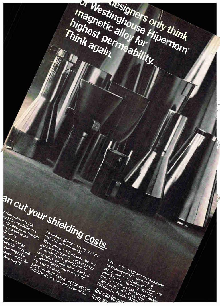

Newsletter from Abroad October 3, 1966
Spain jockeying
to make the most
of color-tv split
Italian set makers
in color quandary
Japanese selling
small computers
on installment plan
Spain intends to turn the split in Western Europe over color television into an advantage for her fast-growing tv industry. At this summer's plenary session of the International Radio Consulta-
tive Committee (CCIR) at Oslo, where a last-ditch attempt was made to adopt a single color-tv standard for Western Europe, Spanish telecom-munications officials stayed on the fence. Now they've made it clear they plan to jump into the most profitable pasture. The government-controlled broadcasting network, Television Espanola,
recently sent letters to the developers of the two competing systems— PAL and Secam—asking them to spell out their offers on royalty fees and licensing arrangements. PAL (for phase-alteration-line) was developed by West Germany's Telefunken AG and has been selected by most West European countries. Secam (for sequential and memory) was developed in France and will be used there and in the Soviet-bloc as well. The right to export color tv sets may be the deciding factor in the
Spanish decision. The Spanish industry has its eyes on an "Iberian" mar-ket embracing Portugal and Spanish Morocco along with Spain itself. Both presumably will follow Spain's lead in color tv.
In the bargaining for a deal on color tv, Spanish officials will use a burgeoning market as a lure to dangle before Telefunken and the Com-pagnie Francaise de Television, which owns the rights to Secam. The black-and-white market has grown 20% annually in recent years as Spain's economy has boomed. The Spanish industry expects to turn out between 650,000 and 700,000 sets this year, compared to 550,000 sets in 1965. Television Espanola will make its color tv choice—strictly on a commercial basis—late in 1967. Limited color programing will begin in the fall of 1968. By 1969, when the network expects to have substantial color programing, the market for color sets should number about 70,000. It should reach 150,000 sets annually within a few years.
If it manages to color Spain PAL, Telefunken will partly recoup a setback in Italy, where the expectation of an early lift from color tv has been quashed by Premier Aldo Moro's coalition government. After backing the PAL system and giving the impression that all was set for starting color broadcasts late next year on the state-owned network, the government had to backtrack when the left-wing opposition kicked up a fuss over costs. Now the government says there'll be no color until 1970.
This puts the set makers in a quandary. Most Italian companies can't afford to make capital investments now to gear up for color tv produc-tion with no payoff in sight for several years. On the other hand, they're certain they'll be clobbered by imports from other Common Market countries later on if they don't do something now. To make matters worse, dealers already have felt a slowdown in black-and-white replacement sales as consumers, waiting for color, hang on to their old sets.
Japan's six digital-computer manufacturers this month started offering small computers on a time-payment plan. This is a switch from the gov-ernment-backed rental system and it's aimed at forestalling turn-in of old computers as new models come onto the market. The scheme applies only to computers with list prices below $139,000;
-4—Circle 250 on reader service card 251
Newsletter from Abroad
for larger models, the manufacturers will continue to sell to the Japan Electronic Computer Co., the government-sponsored firm that leases the computers to users. JECC has the right to return computers. To finance the outright sales to users, the manufacturers lined up two
Japanese banks that have pledged to make $16.7 million available for loans repayable in up to 54 months. The interest rate is a stiff 11.55%, but the computer makers still think time-payments will catch on. Prices will be right. Outright buyers will get late-model computers at 10% discount on the selling price to JECC. For computers introduced before the Inter-national Business Machines unveiled its 360 series in April, 1964, the discount is 35%. Anyone wanting an obsolescent computer no longer handled by JECC can get it at 65% off the former price to JECC. The switch to installment buying for small computers comes when
there's a boom in sight for electronic desk calculators. This year's output will reach about 38,000 units. The figure is expected to surge to 59,000 next year and to 80,000 in 1968.
Swedish industry
anxious over space
Electronics, communications and aviation companies in Sweden have started a drive aimed at getting the government to set up some sort of space program. But the ruling Social-Democratic party most likely will sidestep the push. The companies, banded together in a Space Technology Committee,
have warned Education Minister Ragnar Edenman that the aerospace industry can't get off the ground without a lift from the government. As a starter, the committee wants a high-level agency established to run the space effort; and the committee is urging an adequately funded national space program. For the Social Democrats, the warning to Edenman came at an embar-
rassing time—just after the party had suffered severe losses late last month in local elections largely because of inflation and housing short-ages. And just two days after the committee sounded its alarm, the European Space Research Organization (ESRO) inaugrated its missile-launching site at the Arctic-circle mining town of Kiruna, putting space —and the industry's plight—into the headlines. The industry insists it's handicapped in getting electronics contracts from ESRO, to which Swe-den belongs, because pf the government's small contribution.
Beset by inflation, the government can't soothe the industry with more funds for space now. But the Social-Democrats very likely will move soon to ward off any attempt to make space an issue during the nation-wide elections in 1968. The probable tactic: a long study that would pigeonhole the issue until after the elections.
Swiss watch The Swiss Federation of Clock and Watch Manufacturers now expects to U S inroads have the prototype of an electronic wristwatch ready by next April. The .. date came to light during the furor caused by the takeover last month of
with alarm a major Geneva watchmaker, Universal AG, by the Bulova Watch Co. The Bulova-Universal merger, following by a few months a deal in
which the Hamilton Watch Co. acquired a Swiss watch firm, provoked outraged howls about U.S. inroads in the industry and charges of a sellout of the Federation's electronic watch development. Universal's president is also a vice-president of the Federation.
252 Electronics October 3, 1966

Molten-solder temperatures won't hurt G-E 150-grid relays During degassing, G-E 150-grid relays get even hotter than the 356F it takes to melt solder. And it's good for them. High-temperature degassing removes much more of the organic volatiles that can contaminate a relay at normal operating temperatures.
Not many relays can stand the heat. G-E 150-grid relays can because they have a polyimide coil insulation and a welded can-to-header seal. Polyimide insulation withstands 50% more heat than conventional fluorocarbons. And a weld won't melt like a soldered joint.
New materials and fabrication methods are constantly being developed and used by General Electric to make its sealed relays more reliable. Get the full story from your G-E Electronic Components Sales Engineer. Or write for bulletin GEA-8024B, Section 792-39, General Electric Co., Schenectady, New York.
Specialty Control Department, Waynesboro, Va.
- 11ir'11
GENERAL ELECTRIC Circle 253 on reader service card

Engineers and Scientists:
The Hughes Aircraft Company
is proud to announce the establishment of
THE HUGHES PROFESSIONAL
CAREER DEVELOPMENT PROGRAM This new Program emphasizes individual career growth through a sequence of
selected work assignments for graduate engineers who have acquired between
two and eight years of professional ex-perience. It is designed primarily for two
types of development:
Specialized, in-depth assignments
to develop unusual proficiency in a spe-
cific area of interest.
2. Broad, systems-types of assign-ments to prepare for system and project
engineering responsibilities. There will be a maximum of three
assignments which will be determined
jointly by the participant and the Profes-
sional Development Section.The assign-ments, which are flexible in length would
normally extend for one year each. They may be selected from a broad spectrum
of aerospace electronics hardware and systems-oriented programs and will be designed to provide optimum back-
grounds in specialized areas of interest.
The Program will be limited to 50 par-
ticipants in 1966. These will be selected from candidates who are graduates in
E.E., M.E. or Physics from fully-accredit-
ed universities and who have acquired
from two to eight years of professional-level technical experience. U.S. citizen-
ship is required. Those in the Program will receive sal-
aries commensurate with levels estab-
lished by their overall experience and qualifications. We invite interested Engineers and
Physicists to submit their qualifications
for consideration. Please forward your resume including
details of your educational and experi-
ence background to: Mr. Robert A. Martin Head of Employment
HUGHES Aerospace Divisions 11940 W. Jefferson Blvd. Culver City 56, California
HUGHES HUGHES AIRCRAFT COMPANY
AEROSPACE DIVISIONS
An equal opportumly employer
254 Circle 255 on reader service card—)-

We've got your crimp contact needs
all wrapped up.
ON\ oil ‘Ntbut,t
‘\‘‘‘
Insertable/removable precision machined crimp contacts for power or shielded signal applications. Miniature and subminiature sizes to fit a wide assortment of Winchester connector styles or others made to MIL C 22857. In addition, protective shells, hoods, jackscrews and other accessory hardware are available, including a broad selection of hand Ilk and automatic feed crimping tools.
That's what you'll find neatly packaged in the Winchester Electronics Hand-book of Standard Connectors. Get your copy today. Then you can wrap up
your contact problems.' Write Winchester Electronics,
." Main Street and Hillside Ave., Oakville, Connecticut.

Circle 256 on reader service card
Electronics 1 October 3, 1
966
2=0
>al
rn
rn
Cà' C/3
o
o
C2: CD
04)
c=1.
SPECIFICATIONS
THE G4 IS A COMPLETELY NEW MECHANICAL CHOPPER
THE MECHANISM IS NOVEL (A PATENT IS PENDING)
OPERATION IS UNIFORM FROM 0 TO 1,500 CYCLES
THE NOISE IS MUCH LESS THAN ONE MICROVOLT
THE OFFSET IS MUCH LESS THAN ONE MICROVOLT
THE DESIGN IS INHERENTLY OF HIGH RELIABILITY
THE OPERATING LIFE WILL EXCEED 10,000 HOURS
THE G 4 IS UNAFFECTED BY SHOCK AND VIBRATION -
CONTACT ACTION: SPDT, BBM CONTACT RATING: 20V lma resistive
POWER CONSUMPTION: 200mw max. CONTACTS TO GROUND: 5uuf max.
TRANSFER TIME: 50 minimum DWELL TIME: 165° ± 10° DISSYMMETRY: 10° maximum PHASE ANGLE: 75° ± 10°
VIBRATION: MIL STD 202B Method 204A, Cond. B, maximum contact derangement 7°
SHOCK: 100 G per Mil Std 202B Method 202A, maximum contact derangement 10°
INSU L. RESIS.: 10 K meg.at 100 VDC TEMPERATURE: — 65°C to + 125°C
CASE VOLUME: 0.11 cu. inches WEIGHT: 8 grams

r3,1966
ectronics Abroad ne:
and upward
! around the stands at the Mectronics Show left no at the industry once again ng high. show closed its doors last
fter a nine-day run at international fair grounds, stry had in sight a $2.8 bil-r, putting it back onto a upward trend after last lump. Much of the lift is from an unexpected revival stic consumer goods mar-d with semiconductor sales components makers have fted out of their doldrums. specially well are silicon e producers; they've tripled mthly output since the first ,ear. better, strong trade winds .rospect for Japanese inte-circuit manufacturers. This how was the first at which 'shed IC's in earnest. And h United States producers ing for a crack at the mar-were effectively shut out
owing their wares at Tokyo. roducts that can be freely d were allowed; an import on quietly put into effect ril by the Ministry of In-mal Trade and Industry 1 foreign-made digital IC's 'ear circuits having 35 or ements. dozen. Judging from the ex-nd the after-hours shop talk the show, the Nippon Elec-. is the leader among the zen Japanese companies ing IC's or about to. NEC ms out about 60,000 circuits h, expects to hit a level of monthly by next spring.
orking on wafers at Fujitsu Ltd. With IC's on upsurge, Japanese ompanies have invested heavily
in new production facilities.
Much of NEC's production goes into its own computers. The com-pany currently makes diode-tran-sistor-logic circuits for its new Series 2200 Model 50 computer [Electronics, Sept. 5, p. 2001. It also had on display a high-gain, wideband monolithic operational amplifier whose gain can be varied through an external resistor. In de-velopment at NEC are 4-bit metal-oxide-semiconductor memories with write-in and readout times of 100 nanoseconds. Early next year, NEC plans to have on the market cur-rent-mode-logic circuits with prop-agation time of 3 nanoseconds and power consumption of 120 milli-watts per stage.
Behind NEC in the Japanese IC ranking comes Kyodo Electronics Laboratories Ltd. [Electronics, June 27, p. 195]. Kyodo expects to have its output of transistor-tran-sistor-logic circuits up to a level of about 60,000 units a month by the end of the year. Following Kyodo is Fujitsu Ltd., which recently poured more than $1 million into IC production facilities. Fujitsu re-ports that it's producing 10,000 cir-cuits a month, most of them for its upcoming new generation of computers. But like NEC and Kyodo, Fujitsu is on the lookout for outside customers. Along with the trio already in
substantial production, two other
I« I October 3, 1966 257

Electronics Abroad
companies have readied for IC's. Hitachi Ltd. has set itself up with a $3-million production facility and will start out with current-mode logic circuits for the version of the Spectra 70 computer it builds under license from the Radio Corp. of America. Tokyo Shibaura Electric Co.
(Toshiba), too, has a $2.5 million facility just getting into production. Although digital circuits figure to be the bread-and-butter item for IC makers at the outset, Toshiba showed a two-band amplitude modulation receiver built essen-tially around three linear circuits. But Toshiba has no plans to put the set into production—the IC's cost too much. A sixth company, Oki Electric
Industry Co., turned up at the show with some digital circuits it has in development, but Oki wasn't ready to talk business.
Color up. As expected, color television captured the spotlight in consumer electronics. Even before the show opened, the Electronic Industries Association of Japan had to revise its forecast made in the spring for color tv sales. From 300,-000 sets, the estimate was bounced up last month to 400,000 sets, half of them for export. Some say that the new estimate is still too low and that 450,000 sets seems more likely. The major drawback for color set
producers—a shortage of picture tubes—will soon be eased. Toshiba has just invested $5.5 million to exnand its monthly output to 60,-000 tubes by next spring. The other two major manufacturers of color tubes, Hitachi and Matsushita Elec-tronics Corp., will have their monthly outputs up to 25,000 to 30,000 by the end of the year. Mat-sushita Electronics is a joint ven-ture of the Matsushita Electric Industrial Co. and Philips Gloei-lampenfabrieken N.V. of Holland. Ashai Glass Co., which supplies all the bulbs for these tube manufac-turers, is set to keep pace. It has added some $2.75 million worth of production machinery to its plant and by the end of the year will have its monthly canacity boosted from the current 80,000 bulbs to 150,000.
West Germany
A little corner
There's a lot of talk in Germany these days about United States' domination of the country's com-puter industry—and small wonder. An estimated 85% of the German electronic data-processing market has been gobbled up by American firms or their European subsidi-aries. Now, to make matters worse, there are rumors that Germany's oldest computer firm may be sold to an American company—report-edly Control Data Corp.—that wants to strengthen its postion in the market.
In a recent speech, former De-fense Minister Franz-Josef Strauss had mentioned that the big Swiss electrical equipment maker, Brown-Boyen i and Cie., wanted to sell its German subsidiary, Zuse KG. Brown-Boyen i acquired Zuse two years ago [Electronics, Oct. 19, 1964, p. 154]. Strauss fears that Zuse may be taken over by an American concern. Although with-out portfolio, he still wields con-siderable power as a party leader. No comment. Strauss intimated
that a consortium of German firms or a European group, presumably consisting of French and German partners, should be formed to pre-vent an American takeover of Zuse. The board chairman of Brown-
Boveri's German affiliate in Mann-heim, Dr. Kurt Lotz, reportedly has approached CDC. Brown-Boyeni in Mannheim merely says that it has been conducting talks with sev-eral firms for some time but it isn't saying with whom. CDC, which would like to get a bigger foothold in Europe, has a share of less than 1% in the German market. Offi-cials at CDC in Minneapolis re-fused to comment on the report. Brown-Boyen i is said to be asking $30 million for Zuse—twice what it paid two years ago.
Disenchanted. Strauss brought to light something that had been ru-mored in German computer circles for a long time. Ever since Brown-Boyen i took over Zuse things haven't worked out as expected. As one industry observer puts it,
"BBC failed to integrate the com-pany effectively into its own opera-tions." Zuse engineers became dis-satisfied with the Brown-Boyeni management. Many people left and general stagnation set in. The re-sult was that Zuse started to lose money. "Now BBC wants to pull out," says one man in the know.
Transistor time
Clock makers always have a watch out for new ways to cut down fric-tion in timepieces since less fric-tion means more accurate, longer-lasting movements. One method they've found is to
mechanically isolate the time-gov-erning element from the mechanism that drives the hands. But so far this approach has been limited to expensive precision timepieces, such as quartz clocks. Now, engineers at West Ger-
many's Diehl-Werke in Nurem-burg—birthplace nearly 500 years ago of the world's first spring-operated portable clock—have de-veloped a two-transistor circuit that in effect replaces the mechanical links between the balance-wheel and hands in conventional clocks. The company currently turns out 500 Dilectron household clocks a day; retail prices in Germany start at $12. The clock runs for a year
VOLTAGE—DEPENDENT RESISTOR
Two-transistor circuit in Dilectron
clock replaces mechanical link used in conventional movements. Output of oscillator coil synchronizes the motor that drives the hands.
258 Electronics I October 3, 1966

Electronics Abroad
volt dry cell with time de-3ss than 10 seconds daily. of course, isn't the first to the market with an elec-usehold clock. But Amen-panics that beat Diehl in into the market—some by as five years—generally
ansistor drive only for the wheel. ansistors. In the Dilectron, nce wheel is fitted with An oscillator coil, split
rol and driving windings, iiched between the mag-the balance wheel moves . forth, alternating current d in the control winding. egative half of the cycle, transistor Qo switches
..urrent flows through the winding. The resulting /es the balance wheel a keeps it running at 6-%
ns a second. A voltage-de-resistor holds the ampli-he driving pulse constant ttery voltage drops. ..running impulse micro-'Nees the hands of the clock. turning by a circuit that,
oscillator circuit, consists nsistor and a voltage-de-resistor. otor coil is split into three ;—one for transistor con-for driving, and one for
,izing. As the rotor turns, develops across the con-
ling. In the negative half-3 induced voltage switches motor transistor and this Dower pulse into the driv-ling—one of the two driv-es fed into the motor coil revolution. ther driving pulse comes oscillator driving winding, in series with the synchro-iinding of the motor coil. illator current bucks the urrent to keep the rotor Trichronized with the bal-eel. says it could shrink its it to wristwatch size. The r admits, however, it still t of development work to e it will have a competitor Accutron of the Bulova o. and the X8 of Japan's Watch Co.
Soviet Union
Rx for R&D In their bid for world leadership in science and technology, the Soviets have built up a sprawling research and development establishment that today has about 2.5 million people at work at some 2,000 in-stitutions. But despite Russia's im-pressive achievements in space, the country's economic planners all too often have found that the sprawl meant a stall in the advance of technology. Now, sweeping changes are in
sight. Last month, the government laid down a whole package of de-crees designed to tighten the ap-plied research and development ef-fort. More money. For one thing, the
government plans to boost its spending on research. The pack-age of measures, for example, ear-marks up to $2.75 million for new buildings and new equipment at each of some 800 research facilities affected by the reorganization. And, taking a cue from the suc-
cess they've had with profit incen-tives in manufacturing plants, the Russian leaders will adopt the same tack for research institutes. The institutes will receive rebates of 75% of the profits they make in their dealings with state-owned business enterprises. Few Soviet production outfits run extensive R&D programs on their own. Most contract the work from specialized institutes or, that failing, buy tech-nology from Western countries.
In addition to profits for insti-tutes, the directives call for bo-nuses for originators of new tech-niques and products.
School ties. Along with money incentives to get more mileage out of the R&D talent now available, the government plans to tighten the ties that link colleges and uni-versities throughout the 15 Soviet republics. Under the new directive, all of the country's 754 institutions of higher learning will come under control of the Ministry of Educa-tion in Moscow. Before, more than half of them were under the wing
of other government agencies. Nearly all the medical institutes, for example, previously were under the jurisdiction of health ministries in the 15 republics. One of the toughest tasks edu-
cation officials face with their ex-panded responsibility is breaking down the long-standing tradition among scientists in the country to concentrate on fundamental re-search. Says a Western observer in Moscow, "Research here is com-pletely compartmentalized. It is al-most never related to production." Pravda, the Communist Party or-gan, agrees. In an editorial lauding the educational reforms it com-plained that "scientists of these higher educational establishments took an insufficient part in investi-gations that have important eco-nomic value."
Getting status-conscious acad-emicians to work closely with fac-tory researchers may be more easily decreed than done; but as a Western economist puts it, "These changes definitely get at the basic problems of Soviet research."
East Germany
A certain sameness
Among the officials who ride herd on East Germany's economy, the vogue these days is for "rational-isierung" — streamlining produc-tion. Judging from this year's Leip-zig Fall Fair, the vogue is already strong in the electronics industry.
Industry officials at the fair made much ado about the results they've achieved through a push to stand-ardize product lines and automate production lines. They say that new manufacturing techniques have cut production costs by almost $700,-000 so far this year in the 27 East German plants that turn out tele-communications hardware and test equipment. In consumer electronics they maintain they've stepped up productivity to the point where their 29-plant home-entertainment industry turns out a television set every 24 seconds, a superhetero-
:s I October 3, 1966 259

Electronics Abroad
The Donja 1201 is one of 29 different sets produced in East Germany using just three standard chassis.
dyne receiver every 20 seconds and a portable radio every 25 seconds.
Look -alikes. In their effort to streamline production the East Germans have heavily standardized their hardware. In test equipment the same chassis and cabinets turn up again and again. And wherever possible, circuits like input stages and amplifiers are common. Western observers at the Leipzig
Fair were struck by the uniformity in styling; but they rated the equipment high in quality and per-formance. Among Eastern-bloc countries, East Germany is con-sidered in the forefront in telecom-munications and test equipment. About 45% of the industry's output is exported to other countries in the bloc. And East German engi-neers are directing 'a bloc-wide ef-fort to develop electronic tele-phone-exchange equipment. The same sort of standardization
has slashed the number of hours needed to produce consumer goods in East Germany. For television sets, the standardization level now has climbed to 82%; that is, 82 out of every 100 components are com-mon to all the sets manufactured in the country. As a result it takes only 5.4 man-
hours to produce a tv set compared with 27 hours in 1957. The stand-ardization level is even higher—
better than 90%—for table radios. As with test equipment, the East
Germans use only a few standard chassis for their radio and tv sets. There are 29 tv set models, varia-tions on three basic chassis. For superheterodyne receivers there are just four basic chassis but 54 diff-erent "models." The goal is even more standardization. In a few years, East German tv plants will all work with a single basic chassis.
Industry officials assert, how-ever, that despite standardization there's enough variation in the sets to satisfy consumers. But for fair-goers from Western countries the sameness in styling in radio and tv sets was just as marked as it was for test equipment.
The Netherlands
End of the lines
Many a traveler jetting around Europe has found that he spends as much time waiting in lines at air terminals as he does in actual flight. And even for long intercon-tinental flights, passengers' laments stem in large part from outdated, overlong procedures for checking in. [Electronics, Sept. 19, p. 23].
Now the end of the lines is in sight for travelers who enplane at Amsterdam's Schiphol Airport, one of the busiest in Europe. When new terminal facilities there open next April, an electronic data-processing system for ground handling will help whisk passen-gers onto their planes. The system, called Airlord (for
airlines load optimization recording and display), can handle up to 40 departing flights at a time, enough for projected traffic at Schiphol 10 years from now. Before then, Air-lord very likely will be keeping travelers reasonably content at other airports. Although the Dutch airline KLM will be the first to in-stall the system, its developers say that other carriers are sizing up its possibilities. Airlord is pro-duced by Spoorweg Sein Industrie N.V., a subsidiary of Philips Gloe-ilampenfabrieken N.V.
Tabs. In a central processor and memory Airlord keeps tabs on all the data involved in the ground-handling operation. As each flight comes up for loading, the opera-tions control room feeds in the type of aircraft plus the weight of fuel, crew baggage and company ma-terial the flight will carry. To this data is added the weight of freight, mail and the catering department's load. At the check-in counters (there'll
be 22 at the Schiphol installation), passengers won't be limited to one or two counters per flight as they are now. Through their input-unit keyboards, check-in clerks can feed passenger data for any flight into the central processor. The clerks also can query the central proces-sor to see if passengers without reservations have any chance of getting on a flight. When he processes a passenger,
the clerk punches into his keyboard the flight number and destination, plus the weight and number of pieces of baggage. Then he slips the ticket and a boarding pass in a slot in the input unit. If there's been no slip-up in the reservation, the central processor signals back "accepted" and the input unit prints out a boarding pass with the flight number and departure gate number on it. The near-instanta-
260 Electronics I October 3, 1966

neous flow of data between the check-in counter and the central processor slashes check-in time compared to the usual procedure of phoning, list-checking and then writing out a boarding pass.
In view. As each passenger checks in, the central processor calculates in less than a second the new total weight for the flight and the number of seats still available in first class and economy class. A complete up-to-the-second status for each called flight is displayed on panels in the operations room. At other spots around the terminal like the freight department, mail department, catering department and the boarding gates there are displays to show the flight data needed at the spot. The boarding gate display, for
example, shows the number of pas-sengers that checked in for a flight and the number of passes collected as the passengers file through the gate. When the two numbers match, the gate official flashes a "boarding completed" signal to the flight controller.
Although Airlord should bring an end to long lines at Schiphol's check-in counters, travelers there still will have to queue up a second time for seat assignments at the departure gate. Looking forward to eliminating that nuisance, Spoor-weg has designed the system so it could be extended to handle seat-allocation at the check-in counter. The system is also set up so that it could be linked to a computer-controlled reservations system. And Spoorweg says Airlord could be tied into self-service check-in counters when electronically read-able tickets are introduced.
Keeping track
As Europe becomes more and more a common market, keeping track of freight cars is becoming more and more of a headache. In countries like Belgium, France, West Ger-many and the Netherlands, foreign freight cars often account for 30% to 40% of the total that carry goods. To keep track of boxcars, Eu-
rope's railroads are turning to elec-tronic data processing. And within
Electronics 1 October 3, 1966
It), red with a video-modulated microwave signal. With a 2-milli-watt laser, maximum range of trans-mission was about 20 miles on a clear day. That works out to a threshold sensitivity of 0.3 micro-watt with receiver bandwidth of 10 megahertz, receiver noise figure of
... your assurance of quality
--ei/or's iota/ rebkéthety plane Glass-Epoxy
ad in sheets, panels or punched blanks to your
specifications and reliability requirements
Accepted by an increasing number of major OEMs and commercial etchers who give their stamp of ap-proval, because . . .
.1)11 -"Pit e,Q0
. . . in atmosphere-controlled white rooms, under extremely tight quality control procedures, to produce cop-per-clad . . .
rain
. . . then deliver when promised, or in an emergency, from plant or ware-house stocks in special packages.
. . . they get highest quality level assurance from two fully-equipped copper-clad plants using white-glove techniques . . .
. . . to specifications and established reliability requirements in standard sheets, ultra-thin sheets and multi-layer prepregs . . .
Let us prove the advantages of Taylor's TOTAL RELIABILITY PLAN to you! Ask for a demonstra-tion today. Write for a sample (give grade designation and copper com-bination) and Bulletin GB-2.
—rwarylor copper -dad TAYLOR CORPORATION • Valley Forge, Pa. 19481
Phone: 215-666-0300 TWX: 215-666-0659
West Coast Plant: La Verne, Calif.
Also manufacturer of Taylor laminated plastics, Taylorite® vulcanized fibre and Tayloron® prepregs
Circle 261 on reader service card 261
. - IdLy L., 41.l.JUU •
Tungsten Road, Cleveland, Ohio 44117. Tel: (216) 266-2971.
73-ogress /s Our Most /mporiant Product
GENERAL ELECTRIC Electronics I October 3, 1966
shipped dismantled- and listed on look at interference among stations invoices as machinery parts. The using the 150 to 285 khz band.
Circle 263 on reader service card 263 -..._-.
BOSTON, MASSACHUSETTS • 0 2114
Electronics , October 3, 1966 Circle 265 on reader service card 265

to 1001a charge for
Electronics Abroad
the next year, the International Railway Union, which sets techni-cal standards for railroad equip-rxw_iint axikon flinv nfrvul- interna-
Electronics advertisers October 3, 1966
ADC Products 184 John Gompper & Associates
API Instruments 262 George Z. Griswold Advertising
o AMP Incorporated 165 Garceau, Hargrave & McCullough Inc.
Acopian Corporation 236 Mort Barish Associates Inc.
Adams & Westlake Company 6 E. H. Brown Advertising Agency Inc.
Airpax Electronics Inc. 256 Welch. Mirabile & Company Inc.
Allen Bradley Company 163, 164 Fensholt Advertising Agency Inc.
Allied Radio Corporation 207 Marvin H. Frank Company
Alpha Metals Inc. 203 Black Russell-Morris Inc.
• Ammon Instruments Inc. 230 Culver Advertising Inc.
Andersen Laboratories Inc. 178 Smith, Dorian & Burman Inc.
Anelex Corporation 265 James J. Cavella Advertising
• Arco Electronics Division of Loral Corporation 71 Campbell Ewald Company
a Art Wire & Stamping Company 220 Williams & London Advertising
a Automatic Electric Company 18, 19 Tatham-Laird & Kudner Inc.
Babcock Relays Inc. Leland Oliver Company
• Ballantine Laboratories Lang-Lawrence Advertising Inc.
• Barnes Development Company Industrial Public Relations Inc.
Barnstead Still & Sterilizer Company Creamer, Trowbridge & Case Inc.
• Bausch & Lomb Inc. Wolff Associates Inc.
Beckman Instruments Inc. Helipot Division Hixson & Jorgensen Inc.
CI Beckman Instrument International Hixson & Jorgensen Inc.
• Bendix Corporation, Montrose Division MacManus John & Adams Inc.
Bolt Beranek & Newman Inc. Leland Oliver Company
Borden Chemical Company, Mystik Tape Division Conahay & Lyon Inc. Advertising
• Brush Instruments Division of Clevite Corporation Carr Liggett Advertising
Bulova Watch Company Electronics Division Frank Best & Company Inc.
Cl C. S. F. SPI Agency
• CTS Corporation Burton Browne Advertising
Cambridge Thermionic Corporation Chirurg & Cairns Incorporated
Chemcut Corporation Adams Associates Inc.
Cherry Electrical Products Corporation K & A Incorporated
• Chester Cable Corporation Lewis Advertising Agency
Chuo Denshi K. K. Standard Advertising Inc.
Cinch Manufacturing Company Stral Advertisin9 Company
• Cinch Graphik Division of United Carr Fastener Company Reach, McClinton & Company Inc.
• Clairex Corporation Michel-Cather Inc.
Clare & Company, C. P. Reincke, Meyer & Finn Inc.
Cleveland Institute of Electronics Foote, Cone & Belding Inc.
• Clifton Precision Products Company Ivey Advertising Inc.
Codex Corporation Weston Associates Inc.
Comcor Inc. Sub. of Astrodata Inc. Marketing Directions
Computer Control Company Inc. Franklin P. Folts Inc.
Consolidated Electrodynamics Corporation Hixson & Jorgensen Inc.
Consolidated Vacuum Corporation Wolff Associates Inc.
• Control Switch Division of
OAS 2
67
60
216
209
197, 198
233
85
10
222
20, 21
240
182
142
58 D
214
202
195
218
Controls Company of America Harry P. Bridge Company
Corning Glass Works, Electronics Division Rumrill-Hoyt Inc.
Coto Coil Company Inc. The Williams Company
Couch Ordnance Inc. Culver Advertising Inc.
Cross & Company, H. Leo Hecke Incorporated
Cyclo-Tronics Inc. T. W. Blakeslee Advertising Inc.
Power to drive the oscillators and ring counter is picked up by induction as the boxcar passes rail-side readout units. They put out a
Electronics Abroad
154
24
230
228
146
54
• Dale Electronics Inc. 74 Swanson. Sinkey, Ellis Inc.
Damon Engineering Incorporated 189 L. K. Frank Company Inc.
Data Control Systems 203 Bodge-Eade Incorporated
Datex Company 118 Faust/Day Incorporated
um Delco Radio Division of General Motors Corporation 72 Campbell-Ewald Company
Digital Equipment Corporation 22 Kalb & Schneider Incorporated
II Dome & Margolin Incorporated 169 Snow & Depew Advertising
a DuPont de Nemours & Company Freon Division 39 to 42 Batten. Barton, Durstine & Osborn Inc.
• DuPont de Nemours & Company, Mylar Division 91 Batten, Barton, Durstine & Osborn Inc.
Eastman Kodak Company Rumrill-Hoyt I nc.
Electro Scientific Industries Nadler & Larimer Inc.
Electronized Chemicals Corporation 59 Kenyon & Eckhardt Inc. Advertising
a Elgenco Incorporated OAS 6 Wesco Advertising
Engelhard Industries Inc. 200, 201 44 Keyes, Martin & Company
Esterline Angus Instrument Company 96 56 Caldwell, Larkin & Sidener Van Riper Inc.
Eubanks Engineering Company 215 Moore Bergstrom Company
27 to 30
190, 191
117
158
73
229
a Fairchild Semiconductor Inc. 166 Faust/Day Inc.
Farinon Electric Company 7 Thomas D. Boyd
194 Public Relations Consultant Ferroxcube Corporation of America 82
Solow/Wexton Inc. Field Emission Corporation 86
Ken Webber Advertising Fluke & Company, John 15
Bonfield Associates Inc. Garlock Company Incorporated 234
Richardson, Thomas, Bushman Inc. General Aniline & Film Corporation 80
Hazard Advertising Company Inc. 3 General Electric
Company 233, 235, 237, 239, 241 George R. Nelson Inc.
• General Electric Company 93, 94, 267 George R. Nelson Inc.
a General Electric Company, Lamp Metals & Components 263 Dix & Eaton Inc.
a General Electric Company, Polymer Products Operation Div. 155 Ross Roy Inc.
a General Electric Company, Silicone Products Dept. 176 Ross Roy Inc.
a General Electric Specialty Control Dept. 253 George R. Nelson Inc.
General Magnetics Inc. 224, 225 George Homer Martin Associates
General Radio Company 2nd Cover K. E. Morang Company
81 Globe Industries Inc. 205 Odiorne Industrial Advertising
32, 33 Granger Associates 8 West Associates
Gulton Industries Inc. 88 Di Russo & Falborn Inc.
58 B
69 Hamilton Watch Company
Beaumont, Heller & Sperling Inc.
è.m% pad ABP
effli ;mg
Hansen Mfg. Company Inc. 231 Keller-Crescent Company
• Hathaway Instruments Inc. 238 Eby & Everson Inc.
• Hewlett Packard, Colorado Springs Division 3rd Cover Tallant/Yates Inc.
• Hewlett Packard International 31 Lennen & Newell Inc.
• Hewlett Packard Loveland Division 2, 17, 57 Lennen & Newell Inc.
• Hewlett Packard Moseley Division 1 Lennen & Newell Inc.
• Hewlett Packard, Sanborn Division 64, 65 Culver Advertising Inc.
Honeywell PMD Division 223 Batten, Barton. Durstine & Osborn Inc.
Hughes Aircraft Company 172, 254 Foote. Cone & Belding Inc.
• Hull Corporation 232 Michener Company Advertising
• IMC Magnetics Corporation 221 Monad Advertising Design
IRC Incorporated 192 Gray & Rogers Inc.
Industrial Chemical Specialties Corporation 241 Robert A. Paul Advertising Agency
Industrial Electronic Engineers Inc. 185 Gumpertz, Bentley & Dolan Inc.
Inland Motor Corporation Sub. of Kollmorgen Corporation 219 S. Gunnar Myrbeck & Company
International Nickel Company Inc. 84 The Marschalk Company Inc.
• ITT Jennings Radio Mfg. Company Division 179 L. H. Waldron Advertising Agency
ITT Semiconductor Division 149, 151 Neals & Hickok Inc.
• ..1 F 13 Electronics Corporation 213 Michel-Cather Inc.
Japan Lite Machinery Corp. Electronic Association of Japan Div. 211 Pace Advertising Agency
Jerrold Corporation 14 Lescarboura Advertising Inc.
Julie Research Laboratories Inc. 232 Conti Advertising Agency
Kaye & Company Incorporated, Joseph 232 Robert Hartwell Gabine Inc.
Kingsley Machine Company 211 Nides Cini Advertising Inc.
w Leach Corporation Jay Chiat & Associates
Ledex Incorporated Yeck & Yeck Incorporated
• LEL Division of Varian Associates Snow & Depew Advertising
58 A
208
161
Classified Advertising F. J. Eberle, Busniess Mgr.
EMPLOYMENT OPPORTUNITIES
EQUIPMENT MERCHANDISE
(Used or Surplus New) For Sale
ADVERTISERS INDEX
A & A Electronics Corp Atomic Personnel Inc. Bell Aerosystems Corcoran Personnel Consultants, J. P. Electronic Communications Inc. Ewald Instruments Corp. General Dynamics
Electronics Division General Electric Hewlett Packard Instruments & Machines Inc. Lear Siegler Inc. Monmouth Radio Laboratories Norman Electronic Sales Radio Research Instrument Co. Sanders Associates Inc.
242-249
248
248 243 243 176 242 248
247 245 249 248 248 248 248 248 246
• For more information on complete product line see advertisement in the latest Elec-tronics Buyers' Guide
55 c Advertisers in Overseas Advertising Section following newsletter from abroad
Executive. editorial, circulation and advertising offices: McGraw-Hill Building. 330 West 42nd Street, New York, N.Y., 10036. Telephone (212) 971-3333. Teletype TWX N.Y. 212 640-4646. Cable: McGrawhill, N.Y. Officers of the McGraw-Hill Publications: Joseph H. Allen, President; Bayard E. Sawyer, Executive Vice President; Vice Presidents: J. Elton Tuohig. Operations; John R. Callaham, Editorial; Donald C. McGraw, Jr., Marketing; John M. Holden, Marketing Services; Huber M. Gemmill. Circulation; Angelo R. Venezian, Produc-tion; Robert M. Wilhelmy, Controller. Officers of the Corporation: Donald C. McGraw, Chairman of the Board; Shelton Fisher, President; L. Keith Goodrich, Hugh J. Kelly and Robert E. Slaughter, Executive Vice Presidents:. John J. Cooke, Vice President and Secretary; John L. McGraw. Treasurer. Title R registered U.S. Patent Office; S copyright 1966 by McGraw-Hill, Inc. All rights reserved, including the right to reproduce the contents of this publication, in whole or in part.
266 Electronics October 3, 196E

neous flow of data between the check-in counter and the central processor slashes check-in time compared to the usual procedure of phoning, list-checking and then writing out a boarding pass.
In view. As each passenger checks in, the central processor calculates in less than a second the new total weight for the flight and the number of seats still available in first class and economy class. A complete up-to-the-second status for each called flight is displayed on panels in the operations room. At other spots around the terminal like the freight department, mail department, catering department and the boarding gates there are displays to show the flight data needed at the spot. The boarding gate display, for
example, shows the number of pas-sengers that checked in for a flight and the number of passes collected as the passengers file through the gate. When the two numbers match, the gate official flashes a "boarding completed" signal to the flight controller.
Although Airlord should bring an end to long lines at Schiphol's check-in counters, travelers there still will have to queue up a second time for seat assignments at the departure gate. Looking forward to eliminating that nuisance, Spoor-weg has designed the system so it could be extended to handle seat-allocation at the check-in counter. The system is also set up so that it could be linked to a computer-controlled reservations system. And Spoorweg says Airlord could be tied into self-service check-in counters when electronically read-able tickets are introduced.
Keeping track
As Europe becomes more and more a common market, keeping track of freight cars is becoming more and more of a headache. In countries like Belgium, France, West Ger-many and the Netherlands, foreign freight cars often account for 30% to 40% of the total that carry goods. To keep track of boxcars, Eu-
rope's railroads are turning to elec-tronic data processing. And within
77y/orPs heed relier.6illty plan:
Glass-Epoxy
COPOOPC ad in sheets, panels or punched blanks to your
specifications and reliability requirements
Accepted by an increasing number of major OEMs and commercial etchers who give their stamp of ap-proval, because . . .
Qt.
*11::#1.01Pleb
. . . in atmosphere-controlled white rooms, under extremely tight quality control procedures, to produce cop-per-clad . . .
. . . then deliver when promised, or in an emergency, from plant or ware-house stocks in special packages.
•••your aSSUrilleCO of quality
. . . they get highest quality level assurance from two fully-equipped copper-clad plants using white-glove techniques . . .
. . . to specifications and established reliability requirements in standard sheets, ultra-thin sheets and multi-layer prepregs . . .
Let us prove the advantages of Taylor's TOTAL RELIABILITY PLAN to you! Ask for a demonstra-tion today. Write for a sample (give grade designation and copper com-bination) and Bulletin GB-2.
177efor copper-c/ad TAYLOR CORPORATION • Valley Forge, Pa. 19481
Phone: 215-666-0300 TWX: 215-666-0659
West Coast Plant: La Verne, Calif.
Also manufacturer of Taylor laminated plastics, Taylorite® vulcanized fibre and Tayloron® prepregs
Electronics I October 3, 1966 Circle 261 on reader service card 261

0 to 1001.a charge for o tracking taut-band
ffered only by a p API is the only manufacturer who ers *I% tracking and frictionless ut-band construction as standard cifications for production-quantity • ters, at no extra cost. Precise tracking is the most useful tribute of a panel meter in modern ectronic applications. Taut-band eters give truer readings, respond smaller signals, resist damage from ock or vibration and do not de-riorate in operation.
Order from Stock Best of all, API also offers quick elivery from stock of DC panel eters with the double-header bonus f taut-band plus 1% tracking. You get all this in the most popular
anges of nine models in API's conomically priced Stylist and Pan. list lines (illustrated). Take your pick f these full-scale DC ranges:
Microamperes Millivolts 0— 20 0-5 0— 50 0-10 0-100
(You also get the double header in e 0-25 millivolt range, but it isn't
tocked.)
If precise tracking is a real fetish ith you, don't forget that API can 'ye you 0.5% tracking at reasonable xtra cost. No other manufacturer eatures this "super-calibration" and acks it up with catalog prices.
Bulletin 47-A describes all API panel meters and pyrometers ISA Show—Booth No. 1405
api ISTRUMENTS CO.
Electronics Abroad
the next year, the International Railway Union, which sets techni-cal standards for railroad equip-ment when they affect interna-tional operations, will select a sys-tem for automatic identification of freight cars as they pass key check-points. A leading contender for the se-
lection is the so-called Wagtag system, developed jointly by Spoorweg Sein Industrie N.V. and the research laboratories of its parent company, Philips Gloeil-ampenfabrieken NY. The system now is undergoing field trials in both Holland and France.
After a look at optical systems, Spoorweg couldn't see the light and instead turned to an induction system. Wagtag, Spoorweg claims, can read out faultlessly the stand-ard 12-digit international railcar identification code at train speeds up to 100 miles per hour and trans-mit the information to a data-pro-cessing system. No ambiguity. For the system,
each railcar would carry a book-size unit containing five code oscil-lators, a synchronizing oscillator, a 12-cell ring counter, a pickup coil, and a rectifier. The oscillators, which operate in a frequency range of 50 to 130 kilohertz, drive small ferrite transmitting rods.
Power to drive the oscillators and ring counter is picked up by induction as the boxcar passes rail-side readout units. They put out a 15-khz field that is picked up in-ductively by the coil in the boxcar unit and rectified. As the boxcar enters the induc-
tion field of the readout unit, all five code oscillators start emitting. And when it receives all five fre-quencies at once, the railside unit transmits a start pulse that turns on the ring counter. Each cell of the counter has a diode matrix that quenches two of the five oscillators so an unambiguous three-out-of-five digit code is transmitted as each cell goes on in turn. The cells are monolithic integrated circuits each having a transistor and three di-odes. The railside unit thus receives
a series of 12 digit codes represent-ing the identification number of the car. To keep the railside receiver synchronized with the boxcar code signals, the synchronizing oscillator is quenched by the diode matrix in every other cell of the counter. A full readout cycle takes just
25 milliseconds, fast enough to take three readings on each boxcar at speeds up to 100 miles per hour. The three readings are stored in the railside receiver's memory and
Wagtag unit on boxcar automatically transmits series of 12 code signals that identifies the car as it passes railside readout unit.
CHESTERLAND. OHIO • PHONE: 216-423-3131
Circle 262 on reader service card Electronics I October 3, 1966

Electronics Abroad
checked against one another. The correct identification number is ex-tracted by prefixed combining rules and then converted into a tele-graph code for transmission into a data processing system.
Great Britain
Light touch
Researchers at Mullard Ltd. appar-ently have pulled abreast of United States technology in microwave phototubes, one of the most promis-ing devices in sight for demodulat-ing laser beams in optoelectronic transmission systems.
Last month at the Sixth Interna-tional Conference on Microwave and Optical Generation, held at Cambridge, a trio of Mullard sci-entists reported on an S-band trav-eling-wave phototube developed under a defense contract. Perform-ance of the Mullard tube comes very close to that of microwave phototubes built by Sylvania Elec-tric Products Inc., the U.S. pioneer in the field. Sylvania, a subsidiary of the General Telephone 8r Elec-tronics Corp., built its first experi-mental twp's more than three years ago.
Sensitive. Like its predecessors, the Mullard tube resembles a con-ventional traveling-wave tube ex-cept that a photocathode replaces the usual thermionic cathode. The cathode material is S20 type, which has a quantum efficiency of 6% at the helium-neon laser wavelength of 6,328 angstroms. Equivalent re-sistance of the twp is 1 megohm and the passband from 2 gigahertz to 4 gigahertz. To try out its twp, Mullard trans-
mitted standard television test pat-terns on a laser beam. The beam was modulated by an ammonium dihydrogen phosphate tunable cav-ity fed with a video-modulated microwave signal. With a 2-milli-watt laser, maximum range of trans-mission was about 20 miles on a clear day. That works out to a threshold sensitivity of 0.3 micro-watt with receiver bandwidth of 10 megahertz, receiver noise figure of
As low as 10C
a dozen . . . when you buy G.E.'s new plastic platform headers in quantities of a million or more. Today, General Electric is selling plastic platform headers like these for less than 10 to 50 each depending on design. Want to figure your savings? Better plug in a calculator. And there's more than economy. You have flexibility in the number of
leads and in pin configuration. General Electric engineers will work di-rectly with you to develop the plastic header best for your application. The new plastic platform header is an exceptional product designed for
new plastic encapsulated devices. It's available with virtually any type wire desired, including gold plated Dumet. Continuous temperatures to 400°F are taken in stride. The plastic header is ideal for silicon transistors and a wide range of other devices.
Plastic platform headers. A breakthrough. The kind of progress you've come to expect from General Electric.
For more information, or for a quote on your requirements, call or write: General Electric Company, Lamp Metals & Components Dept., 21800 Tungsten Road, Cleveland, Ohio 44117. Tel: (216) 266-2971.
730greSS /s Our Most Imporiant Product
GENERAL ELECTRIC Electronics I October 3, 1966 Circle 263 on reader service card 263

'LON ROTATABLE LOG PERIODIC ANTENNA nglelayer, horizontally polarized, 6.5 to 32 mc. 65° azimuth beamwidth.
db gain/std. dipole. Power to 50 kw PEP
, One cannot continually '''' 'point a Continent. 1,14
have designed, cons et, tea, ano installe enna anti tower systems in North America. th America. Europe, Asia, Africa, Antarctica wish someone from Australia would call us
le
INCORPORAT
formerly WIND TURBINE COMPANY
Circle 264 on reader service card
Engineers-Statisticians
Move to Norfolk/Virginia Beach Vacation center of the Middle Atlantic States has a moderate climate with four seasons; fine housing, recreational and educational facilities.
RELIABILITY ENGINEERS MAINTAINABILITY ENGINEERS
STATISTICIANS Excellent merit advancement opportuni-ties in rapidly-expanding Navy activity.
FAILURE DATA ANALYSIS To determine cause of part and/or circuit malfunctions, including over-stresses, im-proper application, failure rates. MTBF's, etc. Two years' experience in failure analysis of electronic components, units and systems desirable. Should be knowl-edgeable in failure data reporting sys-tems and failure modes. Requires a BSEE degree. Experience in design or statistics helpful.
DESIGN ANALYSIS
Review operational and proposed equip-ment designs to detect reliability and maintainability deficiencies. Conduct maintenance task analysis to identify long repair time items and evaluate effect
upon system down time. Propose equip-ment changes to improve reliability and maintainability. Requires a BSEE Degree with experience in maintainability, relia-bility engineering, equipment or systems design. Familiarity with Navy equipments desirable.
STATISTICAL ANALYSIS Develop mathematical models and con-cepts in the areas of:
System performance predictions • Statis-tical techniques in the field of reliability/ maintainability • System effectiveness • Test acceptance criterion • Provisioning requirements • Sampling methods • Re-lationship between reliability, maintain-ability • System operation cost and sys-tem maintenance cost.
Requires a BS degree.
SALARY RANGE: $6,387—$16.905 GS-5 thru GS-13
Call Collect—Area Code 703-444-2743, or mail application for employment (Stand-ard Form 57, available at any post office) to:
Naval Ship Engineering Center Norfolk Division, Code 1902A
U. S. Naval Station, Norfolk, Va. 23511
An Equal Opportunity Employer
Electronics Abroad
6 decibels and a modulation depth of 10%.
Different approach. In its test, Mullard used the twp both as a straight detector and in a super-heterodyne setup. Instead of he-terodyning with a pair of laser beams, though, Mullard did it dif-ferently. To handle modulation on the laser beam outside the twp's frequency range, a pump signal at a frequency within the passband was applied at the output end of the tube's slow-wave structure. Mixed on the electron beam in the tube, the modulation and pump fre-quencies combine to produce a microwave output within the pass-band of the tube.
France
Green light?
Looking forward to the third all-French satellite launching early next year, French officials plan to track the satellite with a trio of lasers. They'll be spotted at St. Michel-de-Provence in southern France, at Hammaguir in the Al-gerian Sahara and at Athens, Greece.
Plans call for red-light lasers; but chances are by the time the D-1-C is lofted into orbit there'll be a switch to green light. The French laser supplier, Compagnie Générale d'Electricité, has developed an ex-perimental laser unit that converts 1-gigawatt infrared pulses into 300-megawatt green-light pulses with a wavelength of 5,300 angstroms, half the wavelength of the converted in-frared pulses. Except to say that the lasing material is neodynium-doped glass, CGE is keeping de-tails to itself.
Because the green beam stands up better than a red beam in long transmission through the atmos-phere, CGE has high hopes that government space officials will pre-fer the new laser. It has much higher power: 300-megawatt pulses compared with 50-megawatt pulses for CGE's red-light ranging laser.
Close. In selling government of-ficials on the green laser, through, CGE may run into some steadfast
Electronics October 3, 1966

Electronics Abroad
CGE ruby-laser rangefinder is mounted on sighting telescope at St. Michael. Laser package—without telescope but with data processor—sells for about $100,000.
customer resistance of its own mak-ing. The red-light lasers CGE pro-duces are highly accurate over long distances. They put out 20-nano-second pulses with peak power of 50 megawatts at a wavelength of 6,943 angstroms. Divergence of the beam is about 3 milliradians with-out focusing by optical lenses. The St. Michel tracking unit is
operating and early this year ranged on the Explorer 29 satellite, called GEOS-A before it was launched. During 44 passes of Explorer 29 the French station obtained 584 laser ranging echoes. At 1,400 miles, maximum range of the CGE red laser, the values obtained varied less than 5 feet from the computed orbit. This was very close to the laser-ranging measurements made at the Wallops Island, Va., station of the National Aeronautics and Space Administration. NASA's fig-ure was 3 feet.
Around the world
Japan. Police are investigating the illegal export to Russia of tran-sistor production equipment—more than 100 units worth $4.1 million. Much of the equipment was shipped dismantled and listed on invoices as machinery parts. The
shipments were made between September, 1964, and June, 1965. Tanganyika. The East African
Posts & Telecommunications Ad-ministration expects to have oper-ating before the end of the year a thin line tropospheric scatter sys-tem linking Mwanza and Bukoba, some 112 miles apart across Lake Victoria. The system will have six telephone channels and unlike con-ventional high-capacity troposcat-ter links operate at low power in a narrow frequency range. The solid-state transmitter has a maximum output of 10 watts in the 790 to 960 megahertz frequency range. Antennas are dishes with 30-foot diameter. The Marconi Co. of Great Britain is supplying the equipment. West Germany. Next year's bud-
get for the Ministry of Scientific Research includes $2.5 million for computer research and develop-ment, the first direct R&D support for the computer industry from the Bonn government. Most of the money will be spent to develop electronic data processing systems for administrative work.
Iraq. The new international air-port under construction at Baghdad will get a full kit of radio naviga-tion, communications, meteorologi-cal and air traffic control equip-ment including a blind-landing system. Standard Telephones and Cables Ltd., a British subsidiary of the International Telephone and Telegraph Corp., has a $2.5 million contract to supply the hardware.
Japan. Hitachi Ltd. has devel-oped a new type of stereo phono-graph cartridge—a stylus-tipped pair of silicon transistors. In the cartridge, small pressure variations applied to the emitter by move-ment of the stylus are converted into large variations in collector current. Hitachi plans to sell the cartridge for about $55.
Africa. Telecommunications of-ficials from some 60 countries are meeting in Geneva under the aus-pices of the International Telecom-munications Union to work out frequency allocations for African stations broadcasting in the 525 to 1605 kilohertz medium-frequency band. The officials also will take a look at interference among stations using the 150 to 283 khz band.
3 good reasons why ANELEX PRINTERS fit your needs best 1. LOW COST ... Available in a wide range of speeds—from less than 300 to
more than 1000 lines per minute. Pay only for the speed you need.
2. FULLY ENGINEERED . . . Deliv-ered complete with electronics (fully buf-fered) ready to plug into and operate from
your equipment. Keeps internal engineer-ing cost down.
3. EASILY SERVICED ... All Anelex Printers have a high order of parts inter-changeability. What's more, they all use the same general operating principle. Maintenance procedures and personnel training are greatly simplified.
ANELEX RELIABILITY
Anelex Printers are used in all environments . . . from the arctic to the tropics, on the ground and in
the air, in industry and in the mili-
tary . . . Just one more reason why the world's leading computer and systems manufacturers specify Ane-
lex. For some practical engineering information, write ...
SYME101. OP OUAL,v
ANELEX CORPORATION
150 CAUSEWAY STREET
BOSTON. MASSACHUSETTS • 02114
Electronics , October 3, 1966 Circle 265 on reader service card 265

Electronics advertisers October 3, 1966
ADC Products 184 John Gompper & Associates
API Instruments 262 George Z. Griswold Advertising
• AMP Incorporated 165 Garceau, Hargrave & McCullough Inc.
Acopian Corporation 236 Mort Barish Associates Inc.
Adams & Westlake Company 6 E. H. Brown Advertising Agency Inc.
Airpax Electronics Inc. 256 Welch, Mirabile & Company Inc.
Allen Bradley Company 163, 164 Fensholt Advertising Agency Inc.
Allied Radio Corporation 207 Marvin H. Frank Company
Alpha Metals Inc. 203 Black Russell-Morris Inc.
a Ammon Instruments Inc. 230 Culver Advertising Inc.
Andersen Laboratories Inc. 178 Smith, Dorian & Burman Inc.
Anelex Corporation 265 James J. CaveIla Advertising
a Arco Electronics Division of Loral Corporation 71 Campbell Ewald Company
a Art Wire & Stamping Company 220 Williams & London Advertising
• Automatic Electric Company 18. 19 Tatham-Laird & Kudner Inc.
Babcock Relays Inc. Leland Oliver Company
• Ballantine Laboratories Lang-Lawrence Advertising Inc.
im Barnes Development Company Industrial Public Relations Inc.
Barnstead Still & Sterilizer Company Creamer, Trowbridge & Case Inc.
mi Bausch & Lomb Inc. Wolff Associates Inc.
Beckman Instruments Inc. Helipot Division Hixson & Jorgensen Inc.
Beckman Instrument International Hixson & Jorgensen Inc.
• Bendix Corporation, Montrose Division MacManus John & Adams Inc.
Bolt Beranek 8.‘ Newman Inc. Leland Oliver Company
Borden Chemical Company, Mystik Tape Division Conahay & Lyon Inc. Advertising
• Brush Instruments Division of Clevite Corporation Carr Liggett Advertising
Bulova Watch Company Electronics Division Frank Best & Company Inc.
58 D
214
202
195
Controls Company of America Harry P. Bridge Company
Corning Glass Works, Electronics Division Rumrill-Hoyt Inc.
Coto Coil Company Inc. The Williams Company
Couch Ordnance Inc. Culver Advertising Inc.
Cross & Company, H. Leo Hecke Incorporated
Cyclo-Tronics Inc. T. W. Blakeslee Advertising Inc.
154
24
230
228
146
54
• Dale Electronics Inc. 74 Swanson, Sinkey, Ellis Inc.
Damon Engineering Incorporated 189 L. K. Frank Company Inc.
Data Control Systems 203 Bodge-Eade Incorporated
Dates Company 118 Faust/ Day Incorporated
a Delco Radio Division of General Motors Corporation 72 Campbell-Ewald Company
Digital Equipment Corporation 22 Kalb & Schneider Incorporated
a Dome & Margolin Incorporated 169 Snow & Depew Advertising
• DuPont de Nemours & Company Freon Division 39 to 42 Batten, Barton, Durstine & Osborn Inc.
a DuPont de Nemours & Company, Mylar Division 91 Batten, Barton, Durstine & Osborn Inc.
Eastman Kodak Company 117 Rumrill-Hoyt Inc.
218 Electro Scientific Industries 158 Nadler & Larimer Inc.
Electronized Chemicals Corporation 73 59 Kenyon & Eckhardt Inc. Advertising
um Elgenco Incorporated 229 OAS 6 Wesco Advertising
Engelhard Industries Inc. 200, 201 44 Keyes, Martin & Company
Esterline Angus Instrument Company 96 56 Caldwell, Larkin & Sidener Van Riper Inc.
Eubanks Engineering Company 215 Moore Bergstrom Company
27 to 30
190, 191
194
0 C. S. F. OAS 2 SPI Agency
• CTS Corporation 67 Burton Browne Advertising
Cambridge Thermionic Corporation 60 Chirurg & Cairns Incorporated
Chemcut Corporation 216 Adams Associates Inc.
Cherry Electrical Products Corporation 209 K & A Incorporated
a Chester Cable Corporation 197, 198 Lewis Advertising Agency
Chuo Denshi K. K. 233 Standard Advertising Inc.
Cinch Manufacturing Company 85 Stral Advertising Company
• Cinch Graphik Division of United Carr Fastener Company 10 Reach, McClinton & Company Inc.
a Clairex Corporation 222 Michel-Cather Inc.
Clare & Company, C. P. 20, 21 Reincke, Meyer & Finn Inc.
Cleveland Institute of Electronics 240 Foote, Cone & Belding Inc.
a Clifton Precision Products Company 182 Ivey Advertising Inc.
Codex Corporation 142 Weston Associates Inc.
Comcor Inc. Sub. of Astrodata Inc. 81 Marketing Directions
Computer Control Company Inc. 32, 33 Franklin P. Folts Inc.
Consolidated Electrodynamics Corporation 58 B Hixson & Jorgensen Inc.
Consolidated Vacuum Corporation 69 Wolff Associates Inc.
• Control Switch Division of
• Fairchild Semiconductor Inc. 166 Faust/Day Inc.
Farinon Electric Company 7 Thomas D. Boyd Public Relations Consultant
Ferroxcube Corporation of America 82 Solow/Wexton Inc.
Field Emission Corporation 86 Ken Webber Advertising
Fluke & Company, John 15 Bonfield Associates Inc.
Garlock Company Incorporated 234 Richardson, Thomas, Bushman Inc.
General Aniline & Film Corporation 80 Hazard Advertising Company Inc.
• General Electric Company 233, 235, 237, 239, 241 George R. Nelson Inc.
• General Electric Company 93, 94, 267 George R. Nelson Inc.
• General Electric Company, Lamp Metals & Components 263 Dix & Eaton Inc.
• General Electric Company, Polymer Products Operation Div. 155 Ross Roy Inc.
• General Electric Company, Silicone Products Dept. 176 Ross Roy Inc.
• General Electric Specialty Control Dept. 253 George R. Nelson Inc.
General Magnetics Inc. 224, 225 George Homer Martin Associates
General Radio Company 2nd Cover K. E. Morang Company
Globe Industries Inc. 205 Odiorne Industrial Advertising
Granger Associates 8 West Associates
Gulton Industries Inc. 88 Di Russo & Falborn Inc.
Hamilton Watch Company Beaumont, Heller & Sperling Inc.
ABP e•°‘ Pie
Hansen Mfg. Company Inc. 231 Keller-Crescent Company
• Hathaway Instruments Inc. 238 Eby & Everson Inc.
• Hewlett Packard, Colorado Springs Division 3rd Cover Tallant/Yates Inc.
a Hewlett Packard International 31 Lennen & Newell Inc.
a Hewlett Packard Loveland Division 2, 17, 57 Lennen & Newell Inc.
• Hewlett Packard Moseley Division 1 Lennen & Newell Inc.
a Hewlett Packard, Sanborn Division 64, 65 Culver Advertising Inc.
Honeywell PMD Division 223 Batten. Barton. Durstine & Osborn Inc.
Hughes Aircraft Company 172, 254 Foote, Cone & Belding Inc.
a Hull Corporation 232 Michener Company Advertising
a IMC Magnetics Corporation 221 Monad Advertising Design
IRC Incorporated 192 Gray & Rogers Inc.
Industrial Chemical Specialties Corporation 241 Robert A. Paul Advertising Agency
Industrial Electronic Engineers Inc. 185 Gumpertz, Bentley & Dolan Inc.
Inland Motor Corporation Sub. of Kollmorgen Corporation 219 S. Gunnar Myrbeck & Company
International Nickel Company Inc. 84 The Marschalk Company Inc.
a ITT Jennings Radio Mfg. Company Division 179 L. H. Waldron Advertising Agency
ITT Semiconductor Division 149, 151 Neals & Hickok Inc.
a .1 F D Electronics Corporation 213 Michel-Cather Inc.
Japan Lite Machinery Corp. Electronic Association of Japan Div. 211 Pace Advertising Agency
Jerrold Corporation 14 Lescarboura Advertising Inc.
Julie Research Laboratories Inc. 232 Conti Advertising Agency
Kaye & Company Incorporated, Joseph 232 Robert Hartwell Cabine Inc.
Kingsley Machine Company 211 Nides Cini Advertising Inc.
• Leach Corporation Jay Chiat & Associates
Ledex Incorporated Yeck & Yeck Incorporated
aLEL Division of Varian Associates Snow & Depew Advertising
58 A
208
161
Classified Advertising F. J. Eberle, Busniess Mgr.
EMPLOYMENT OPPORTUNITIES
EQUIPMENT MERCHANDISE
(Used or Surplus New) For Sale
ADVERTISERS INDEX A & A Electronics Corp Atomic Personnel Inc. Bell Aerosystems Corcoran Personnel Consultants, Electronic Communications Inc. Ewald Instruments Corp. General Dynamics
Electronics Division General Electric Hewlett Packard Instruments & Machines Inc. Lear Siegler Inc. Monmouth Radio Laboratories Norman Electronic Sales Radio Research Instrument Co. Sanders Associates Inc.
242-249
248
248 243 243
J. P. 176 242 248
247 245 249 248 248 248 248 248 246
• For more information on complete product line see advertisement in the latest Elec-tronics Buyers' Guide
55 0 Advertisers in Overseas Advertising Section following newsletter from abroad
Executive, editorial, circulation and advertising offices: McGraw.Hill Building, 330 West 42nd Street, New York, N.Y., 10036. Telephone (212) 971.3333. Teletype TWX N.Y. 212 640.4646. Cable: McGrawhill, N.Y. Officers of the McGraw•Hill Publications: Joseph H. Allen, President; Bayard E. Sawyer, Executive Vice President; Vice Presidents: J. Elton Tuohig, Operations; John R. Callaham, Editorial; Donald C. McGraw, Jr., Marketing; John M. Holden, Marketing Services; Huber M. Gemmill. Circulation; Angelo R. Venezian, Produc-tion; Robert M. Wilhelmy, Controller. Officers of the Corporation: Donald C. McGraw, Chairman of the Beard; Shelton Fisher, President L. Keith Goodrich, Hugh J. Kelly and Robert E. Slaughter, Executive Vice Presidents;. John J. Cooke, Vice President and Secretary; John L. McGraw, Treasurer. Title R registered U.S. Patent Office; © copyright 1966 by McGraw-Hill, Inc. All rights reserved, including the right to reproduce the contents of this publication, in whole or in part.
266 Electronics I October 3, 196E

Electronics advertisers October 3, 1966
Licon Division of Illinois Tool Works Incorporated 36, 37 WaIdle & Briggs Inc.
Litton :ndustries Inc. Triad Distributor 225 West, Weir & Bartel Inc.
Litton Industries Inc. USECO Division 211 West, Weir & Bartel Inc.
Litton Industries Inc. Winchester Electronics Division 255 West, Weir & Bartel Inc.
Lockheed Missiles & Space Company 162 McCann Erickson Inc.
Machlett Laboratories Inc. 9 Fuller & Smith & Ross Inc.
• Magnetic Metals Company Inc. 188 J. B. Ferguson Jr. Advertising
• Mallory & Company Inc. P. R., Battery Division 68 Needham, Harper & Steers Inc.
a Mallory Capacitor Division of P. R. Mallory Company 77 Aitkin Kynett Company Inc.
Marconi Instruments 66 Armand Richards Advertising Agency
D Marconi Instruments Ltd. OAS 4 Lovell Rupert Curtis Ltd.
in Markel & Sons, L. Frank 217 George Moll Advertising Inc.
Markem Machine Company 150 Culver Advertising Agency
Maryland Dept. of Economic Development, State of 184 Rosebush Advertising Agency Inc.
• Matsuo Electric Company Ltd. 215 Fuji Agency
Meller & Company, Adolf 209 Susan E. Schur
Memorex Corporation 83 Hal Lawrence Incorporated
Metronix Corporation 235 Standard Advertising Inc.
Mico Instrument Company 239 a Microsonics Incorporated 230
S. Gunnar Myrbeck & Company al Micro Swith Division of
Honeywell Company 127 Batten, Barton, Durstine & Osborn Inc.
Minnesota Mining 8n Manufacturing Company, Chemical Division 128 Young & Rubicam Inc.
Minnesota Mining & Manufacturing Company, Scotchpar Division 204 Klau-Van Pietersom Dunlap Inc.
le Mitsumi Electric Company Ltd. 237 Dentsu Advertising Ltd.
Motorola Incorporated, Government Electronics Division 89 The Bowes Company
Motorola Semiconductor Products Incorporated 43 Lane & Bird Advertising Inc.
0 Mullard Ltd. OAS 3 Roles & Parker Ltd.
National Electronics Inc. Connor•Sager Associates Inc.
North Atlantic Industries Inc. Murray Heyert Associates
• Pennsalt Chemicals Corporation Aitkin-Kynett Company Inc.
• Pfizer & Company, Charles M P M Division Newmark Posner & Mitchell Inc.
Phelps Dodge Electronics Products Corporation Smith, Dorian & Burman Inc.
• Philbrick Researches Inc. Culver Advertising Inc.
D Philips Eindhoven Technical Advertising
0 Plessey Electronics Company Roles & Parker Ltd.
Potter Instrument Company Inc. Michel-Cather Inc.
Precision Paper Tube Compan T. W. Blakeslee Advertising
Precision Scientific Company Tri-State Advertising Company Inc.
• Primo Company Ltd. General Advertising Agency
209
170
a Sanders Associates Inc. 58 C Chirurg & Cairns Inc.
Sankyo Seiki Company Ltd. 229 Chinwa Advertising Company Ltd.
to Servo Corporation of America 153 Basford Incorporated
Shallcross Manufacturing Company 159 J. T. Howard Advertising Agency Inc.
Sierra Philco Inc. 95 Hal Lawrence Inc.
Sinclair Radio Laboratories Inc. 156 John E. Hayes Company Inc.
a Sorensen Operation Raytheon Company 11 James Advertising Inc.
South Dakota Industrial Development Inc. 268 Maurice Paulsen Advertising
Spectra Physics Incorporated 34, 35 Hal Lawrence Inc.
Spectrol Electronics Corporation 61 Jones, Maher Roberts Advertising
Speer Carbon Company 53 Hazard Advertising Company
Sprague Electric Company 5, 16, 58 Harry P. Bridge Company
Stackpole Carbon Company 78 Meek & Thomas Inc.
Statler Hilton Hotel of Boston 241 Calkins & Holden Advertising
Stromberg Carlson Corporation 205 Rumrill.Hoyt Incorporated
Synthane Corporation 213 Arndt, Preston, Chapin Lamb & Keen Inc.
TRG Inc. Culver Advertising Incorporated
TRW Semiconductor Fuller, Smith & Ross Inc.
Taylor Corporation Gray & Rogers Inc.
• Tektronix Incorporated Hugh Dwight Advertising
• Telonic Engineering Company Jansen Associates Inc.
• Telonic Instruments Incorporated Jansen Associates
Texas Instruments Incorporated, Industrial Products Group Robinson-Gerrard Inc.
Texas Instruments Incorporated, Semiconductor Components Division Dan L. Baxter Inc.
Thomson Houston Inc. Mitchell-Morrison Inc.
• Times Wire & Cable Division of International Silver Company Mohr & Company Inc.
Transformer Electronics Company Dacey, Wolff & Associates
Transitron Electronic Corporation Larcom Randall Advertising Inc.
Transitron Electronic Corporation, Precision Connector Division Larcom Randall Advertising Inc.
• Trylon Incorporated George Moll Advertising Inc.
• Tung Sol Electric Inc. E. M. Freystadt Associates
199
79
261
70
196
186
180
140, 141
160
212
228
51
174
264
207
Ultra Carbon Corporation 268 157 Church & Guisewite Advertising
Union Carbide Corporation 147 J. M. Mathes Inc.
206 U. S. Naval Ship 215, 264 Henry J. Kaufman Associates
181
139
OAS 1
OAS 5
148
227
205
239
Radio Corporation of America 12, 13, 4th Cover Al Paul Lefton Company
Raytheon Company, Components Division 62, 63, 226, 227 Fuller & Smith & Ross Inc.
Rohde & Schwarz Inc. 87 Armand Richards Advertising Agency
Robinson 'Nugent Inc. 216 Creative House Inc.
SBD Systems Inc. Murray Heyert Advertising Inc.
Varo Incorporated Tracy-Locke Company Inc.
Victoreen Instrument Company Palm & Peterson Inc.
Vidar Corporation Hal Lawrence Inc.
▪ Vitro Corporation of America Buchen Advertising Inc.
Volkert Stampings Inc. Fred Wittner Company
90
175
38
92
222
Wells Electronics Inc. 207 Weco Advertising
Westinghouse Metals Division 250 McCann /ITSM
West Penn Power Company 201 Fuller & Smith & Ross Inc.
Weston Instruments Inc. Rotek Division 152 Arndt, Preston, Chapin, Lamb & Keen Inc.
Wood Electric Company 210 L. K. Frank Company Inc.
• For more information on complete product line see advertisement in the latest Elec-tronics Buyers' Guide
231 c Advertisers in Overseas Advertising Section following newsletter from abroad
Test to
High Reliability Standards
With General Electric's
New Helium
Mass Spectrometer Leak Detector
B SENSITIVITY: Get higher prod-
uct quality. Test with the high-
est sensitivity available-2x10- 11
std. cc/second. And get fast re-
sponse and recovery as well.
• SPEED: Test more pieces
faster. Pump down to 20 microns
in 15 seconds. Complete an en-
tire test cycle in as little as 25
seconds with G.E.'s Helium Mass
Spectrometer Leak Detector.
• SOLID STATE ELECTRONICS:
Minimize downtime. Five-sided
access assures easy maintenance.
• ACT NOW: Get complete data
sheets on G.E.'s high sensitivity,
high speed Leak Detector. Con-
tact any one of G.E.'s nationwide
Vacuum Products Sales Special-
ists and ask for publication GEZ-
4154.
Or write to Mr. R. T. Clark,
Manager—Marketing, Vacuum
Products Operation, General Elec-
tric Company, Schenectady, New
York 12305.
P.S. The price is attractive, too.
GENERAL ELECTRIC
Electronics October 3, 1966 Circle 267 on reader service card 267

CORPORATION
The shape of
tomorrow,
today
For more than 20 years Ultra Carbon has assisted industry build and produce the to-morrows that become our to-days. Our graphite parts are widely used by the electronic industries. Some are for:
Alloying Operations • Alloying Jigs and Fixtures • Bushings • Weights • Unitized Boats • Plugs • Inserts
Epitaxial Growth • Epitaxial Susceptors • Strip Heaters • Disc Heaters
Materials Preparation • Reduc-tion Boats • Zone Refining Boats • Boat Covers
Polycrystalline Rod Production • Sockets • Chucks • Eccen-trics • Support Rings
Crystal Pulling and Slicing • Heating Elements • Pedes-tals • Connectors • Crucible Holders • Slicing Blocks
The Ultra Carbon experience and in-plant capability for micromachining are your assurance of graphite parts to meet your needs today to shape tomorrow.
Write for information to Ultra Carbon Corporation, Box 747, Bay City, Mich. 48709.
4-11, ABP
Advertising sales staff
Frank E. LeBeau [212] 971-6464 Advertising sales manager
Atlanta, Ga. 30309: Michael H. Miller, 1375 Peachtree St., N.E., [404] TR 5-0523
Boston, Mass. 02116: William S. Hodgkinson McGraw-Hill Building, Copley Square [617] CO 2-1160
Chicago, Ill. 60611: Robert M. Denmead, J. Bradley MacKimm, 645 North Michigan Avenue, [312] MO 4-5800
Cleveland, Ohio 44113: William J. Boyle, 55 Public Square, [216] SU 1-7000
Dallas, Texas 75201: Richard P. Poole, 1800 Republic National Bank Tower, [214] RI 7-9721
Denver, Colo. 80202: Joseph C. Page, David M. Watson, Tower Bldg., 1700 Broadway, [303] 255-5484
Detroit, Michigan 48226: J. Bradley MacKimm, 856 Penobscot Building [313] 962-1793
Houston, Texas 77002: Kenneth George, 2270 Humble Bldg., [713] CA 4-8381
Los Angeles, Calif. 90017: Ian C. Hill, John G. Zisch, 1125 W. 6th St., [213] HU 2-5450
Minneapolis, Minn. 55402: J. Bradley MacKimm, 1104 Northstar Center [612] 332-7425
New York, N. Y. 10036: Donald R. Furth [212] 971-3615 James R. Pierce [212] 971-3615 George F. Werner [212] 971-3615 500 Fifth Avenue
Philadelphia, Pa. 19103: William J. Boyle, Warren H. Gardner, Jeffrey M. Preston, 6 Penn Center Plaza, [215] LO 8-6161
Pittsburgh, Pa. 15222: Warren H. Gardner, 4 Gateway Center, [412] 391-1314
Portland, Ore. 97204: James T. Hauptli, Pacific Building, Yamhill Street, [503] CA 3-5118
St. Louis, Mo. 63105: Robert M. Denmead The Clayton Tower, 7751 Carondelet Ave. [314] PA 5-7285
San Francisco, Calif. 94111: James T. Hauptli, 255 California Street, [415] DO 24600
London Wl: John W. Patten, Edwin S. Murphy Jr., 34 Dover Street, Hyde Park 1451
Milan: 1, via Baracchini Phone: 86-90-617 86-90-656
Frankfurt/Main: Gerd Hinske, Dieter Rothenbach, Elsa-Brandstroem Str. 2 Phone: 72 01 81
Geneva: Michael R. Zeynel, 1, rue du Temple Phone: 31 95 60
Paris VIII: Denis Jacob, Kenneth Davey, 17 Avenue Matignon Phone: 359 6637
Tokyo: Nobuyuki Sato, 1, Kotohiracho Shiba, Minato-Ku [502] 0656
Osaka: Ryosi Kobayashi, 163, Umegee-cho, Kilta-ku [362] 8771
Wallace C. Carmichael [212] 971-3191 Manager Electronics Buyers' Guide
David M. Tempest [212] 971-3139 Promotion manager
Milton Drake [212] 971-3485 Research and circulation manager
Wallis Clarke [212] 971-2187 Assistant to sales manager
Wallace C. Carmichael [212] 971-3191 Business manager
Stephen R. Weiss [212] 971-2044 Production manager
Thomas M. Egan [212] 971-3140 Production manager Electronics Buyers' Guide
YOU CAN'T OVERLOOK US!
...WE INTEND TO BE PERSISTENT!
I SOUTH .-1111tKOTA
Let Us Send You The Facts On PROFIT-LIVABILITY! FOR ELECTRONICS FIRMS! 70 South Dakota communities have industrial development corporations ready to assist you in locating your new plant. We believe that you'll be pleasantly surprised with the advan-tages South Dakota has to offer new and expanding industry.
e
f....,,, ,.. ea- e--zz,g2 WATER RESOURCES
ea TRANSPORT& rim
est MARKETS I. • \I --J I •,-,-_-_--,-,,,,--.-
PUUUC UTILITIES
e .- J RESOURCES ,
South Dakota in to a Miff
GET THE
SOUTH DAKOTA STORY
CALL OR WRITE
JAMES W. MONROE, DIRECTOR Industrial Development Expansion Agency
ROOM H PIERRE, SOUTH DAKOTA 57501
PHONE 224-5911 EXT. 307 AREA CODE 605
PROVED LABOR PRODUCTIVITY Value added by manu-facture per worker is one of the nation's highest. Eager, alert labor force with work stoppages at absolute minimum.
FINANCING &TAXES Local development corporations ready to serve all industries. Revenue bond financ-ing available. Debt-free state with no corporate or personal income tax . . plus a free port law
CENTRAL LOCATION You're closer to every-one and everywhere in South Dakota, geo-graphical center of the U.S. and the heartland of the entire North American continent.
ENERGY FOR YOU Electrical power avail-able at low cost rates from hydro, fossil and atomic plants to serve the most demanding production needs.
GREAT OUTDOOR ADVENTURE 'the beautiful Black Hills, Missouri Great Lakes, fantastic fish-ing, fabulous big and small game hunting, water resources that challenge the imagina-tion . . all combine for a recreation bonanza at your doorstep.
268 Circle 268 on reader service card Circle 317 on reader service card

October 3, 1966
Electronics reader service
Use these handy post cards for more detailed information on: products advertised, new products, new literature.
Circle the number on the Reader Serv-ice post card that corresponds to the number at the bottom of the advertise-ment, new product item, or new liter-ature in which you are interested.
Please print clearly. All written in-formation must be legible to be effi-ciently processed.
If someone has bearen you to the post cards, you may obtain the needed information by writing directly to the manufacturer, or by sending your name and address, plus the Reader Service number, to Electronics Reader Service department.
All inquiries from outside the U.S. that cannot reach Electronics before the expiration dates noted on the Reader Service post card, must be mailed directly to the manufacturer. The manufacturer assumes all respon-sibilities for responding to inquiries. Electronics merely provides and clears requests for information from inquirer to manufacturer.
Correct amount of postage must be affixed for all mailings from outside the U.S.
To subscribe to or to renew Electronics
Fill in the "For Subscriptions" area on the card if you desire to subscribe to or renew your present subscription to Electronics. Send no money. Elec-tronics will bill you at the address in-dicated on the Reader Service post card.
Multi-product advertisements For information on specific items in
multi-product advertisements which do not have a specific Reader Service num-ber indicaied write directly to man-ufacturer for information on precise product in which you are interested.
20 October 3, 1966 Card Expires December 3, 1966 14
Name title Company For Subscriptions E new E renewal E 3 years $12.00
Address E 1 year $6.00
1 20 39 58 77 96 115 134 153 172 191 210 229 248 267 286 305 324 343 362 381 400 419 438 457 476 495 514 962 2 21 40 59 78 97 116 135 154 173 192 211 230 249 268 287 306 325 304 363 382 401 420 439 458 477 496 515 963 3 22 41 60 79 98 117 136 155 174 193 212 231 250 269 288 307 326 345 364 383 402 421 440 459 478 497 516 964 4 23 42 61 80 99 118 137 156 175 194 213 232 251 270 289 308 327 346 365 384 403 422 441 460 479 498 517 965 5 24 43 62 81 100 119 138 157 176 195 214 233 252 271 290 309 328 347 366 385 404 423 442 461 480 499 518 966 6 25 44 63 82 101 120 139 158 177 196 215 234 253 272 291 310 329 348 367 386 405 424 443 462 481 500 900 967
7 26 45 64 83 102 121 140 159 178 197 216 235 254 273 292 311 330 349 368 387 406 425 444 463 482 501 901 968 8 27 46 65 84 103 122 141 160 179 198 217 236 255 274 293 312 331 350 369 388 407 426 445 464 483 502 902 969
9 28 47 66 85 104 123 142 161 180 199 218 237 256 275 294 313 332 351 370 389 408 427 446 465 484 503 951 970 10 29 48 67 86 105 124 143 162 181 200 219 238 257 276 295 314 333 352 371 390 409 428 447 466 485 504 952 971 11 30 49 68 87 106 125 144 163 182 201 220 239 258 277 296 315 334 353 372 391 410 429 448 467 486 505 953 972 12 31 50 69 88 107 126 145 164 183 202 221 240 259 278 297 316 335 354 373 392 411 430 449 468 487 506 954 973
13 32 51 70 89 108 127 146 165 184 203 222 241 260 279 298 317 336 355 374 393 412 431 450 469 488 507 955 974 14 33 52 71 90 109 128 147 166 185 204 223 242 261 280 299 318 337 356 375 394 413 432 451 470 489 508 956 975 15 34 53 72 91 110 129 148 167 186 205 224 243 262 281 300 319 338 357 376 395 414 433 452 471 490 509 957 976 16 35 54 73 92 111 130 149 168 187 206 225 244 263 282 301 320 339 358 377 396 415 434 453 472 491 510 958 977 17 36 55 74 93 112 131 150 169 188 207 226 245 264 283 302 321 340 359 378 397 416 435 454 473 492 511 959 978 18 37 56 75 94 113 132 151 170 189 208 227 246 265 284 303 322 341 360 379 398 417 436 455 474 493 512 960 979
19 38 57 76 95 114 133 152 171 190 209 228 247 266 285 304 323 342 361 380 399 418 437 456 475 494 513 961 980
Business reply mail No postage stamp necessary if mailed in the United States
Postage will be paid by
Electronics
Reader service department
Box 444
Hightstown, N.J. 08520
First class Permit no. 42 Hightstown, N. J.
20 October 3, 1966 Card Expires December 3, 1966 14
Name title For Subscriptions E new E renewal
E 3 years $12.00
E 1 year $6.00
Company
Address
1 20 39 58 77 96 115 134 153 172 191 210 229 248 267 286 305 324 343 362 381 400 419 438 457 476 495 514 962 2 21 40 59 78 97 116 135 154 173 192 211 230 249 268 287 306 325 344 363 382 401 420 439 458 477 496 515 963
3 22 41 60 79 98 117 136 155 174 193 212 231 250 269 288 307 326 345 364 383 402 421 440 459 478 497 516 964 4 23 42 61 80 99 118 137 156 175 194 213 232 251 270 289 308 327 346 365 384 403 422 441 460 479 498 517 965 5 24 43 62 81 100 119 138 157 176 195 214 233 252 271 290 309 328 347 366 385 404 423 442 461 480 499 518 966 6 25 44 63 82 101 120 139 158 177 196 215 234 253 272 291 310 329 348 367 386 405 424 443 462 481 500 900 967 7 26 45 64 83 102 121 140 159 178 197 216 235 254 273 292 311 330 349 368 387 406 425 444 463 482 501 901 968 8 27 46 65 84 103 122 141 160 179 198 217 236 255 274 293 312 331 350 369 388 407 426 445 464 483 502 902 969
9 28 47 66 85. 104 123 142 161 180 199 218 237 256 275 294 313 332 351 370 389 408 427 446 465 484 503 951 970 10 29 48 67 86 105 124 143 162 181 200 219 238 257 276 295 314 333 352 371 393 409 428 447 466 485 504 952 971 11 30 49 68 87 106 125 144 163 182 201 220 239 258 277 296 315 334 353 372 391 410 429 448 467 486 505 953 972 12 31 50 69 88 107 125 145 164 183 202 221 240 259 278 297 316 335 354 373 392 411 430 449 468 487 506 954 973 13 32 51 70 89 108 127 146 165 184 203 222 241 260 279 298 317 336 355 374 393 412 431 450 469 488 507 955 974
14 33 52 71 90 109 128 147 166 185 204 223 242 261 280 299 318 337 356 375 394 413 432 451 470 489 508 956 975 15 34 53 72 91 110 129 148 167 186 205 224 243 262 281 300 319 338 357 376 395 414 433 452 471 490 509 957 976 16 35 54 73 92 Ill 130 149 168 187 206 225 244 263 282 301 320 339 358 377 396 415 434 453 472 491 510 958 977
17 36 55 74 93 112 131 150 169 188 207 226 245 264 283 302 321 340 359 378 397 416 435 454 473 492 511 959 978 18 37 56 75 94 113 132 151 170 189 208 227 246 265 284 303 322 341 360 379 398 417 436 455 474 493 512 960 979 19 38 57 76 95 114 133 152 171 190 209 228 247 266 285 304 323 342 361 380 399 418 437 456 475 494 513 961 980

Reprint service All Electronics editorial matter available in reprint form:
For reprints of special reports and feature articles see list on right side of this page. Send your order to Electronics Reprint Department at the address indicated. To expedite mailing of your order for single reprints please send cash, check or money order with your order.
.me
Bulk reprints rent or past The higher t cost per copy.
Business reply mail No postage stamp necessary if mailed in the United States
Postage will be paid by
Electronics Reader service department Box 444 Hightstown, N. J. 08520
First class Permit no. 42 Hightstown, N. J.
1111M.M.11
MIMAMIIIIMMIMUZIMMI111111
20 October 3, 1966 Card Expires December 3, 1966
Name title
Company
Address
1 20 39 58 77 96 115 134 2 21 40 59 78 97 116 135 3 22 41 60 79 98 117 136 4 23 42 61 80 99 118 137 5 24 43 62 81 100 119 138 6 25 44 63 82 101 120 139
7 26 45 64 83 102 121 140 8 27 46 65 84 103 122 141 9 28 47 66 85 104 123 142 10 29 48 67 86 105 124 143 11 30 49 68 87 106 125 144
12 31 50 69 88 107 126 145 13 32 51 70 89 108 127 146
14 33 52 71 90 109 128 147 15 34 53 72 91 110 129 148 16 35 54 73 92 111 130 149
17 36 55 74 93 112 131 150 18 37 56 75 94 113 132 151 19 38 57 76 95 114 133 152
153 172 191 210 229 154 173 192 211 230 155 174 193 212 231 156 175 194 213 232 157 176 195 214 233
158 177 196 215 234 159 178 197 216 235 160 179 198 217 236 161 180 199 218 237
162 181 200 219 238 163 182 201 220 239 164 183 202 221 240 165 184 203 222 241 166 185 204 223 242
167 186 205 224 243 168 187 206 225 244 169 188 207 226 245 170 189 208 227 246 171 190 209 228 247
248 267 286 305 324 249 268 287 306 325 250 269 288 307 326 251 270 289 308 327 252 271 253 272 254 273 255 274 256 275 257 276 258 277 259 278 260 279 261 280 262 281 263 282 264 283 265 284 266 285
290 309 328 291 310 329 292 311 330
293 312 331 294 313 332 295 314 333
296 315 334 297 316 335 298 317 336 299 318 337 300 319 338 301 320 339 302 321 340 303 322 341 304 323 342
343 362 381 344 363 382
345 364 383 346 365 384 347 366 385 348 367 386 349 368 387 350 369 351 370 352 371 353 372 354 373 355 374 356 375 357 376 358 377 359 378 360 379 361 380
14
For Subscriptions Ej new [I] renewal
3 years $12.00
[I] 1 year $6.00
400 419 438 457 476 495 514 962 401 420 439 458 477 496 515 963 402 421 440 459 478 497 516 964
403 422 441 460 479 498 517 965 404 423 442 461 480 499 518 966 405 424 443 462 481 500 900 967
406 425 444 463 482 501 901 908
388 407 426 445 464 483 502 902 969 389 408 427 446 465 484 503 951 970 390 409 428 447 466 485 504 952 971 391 410 429 448 467 486 505 953 972 392 411 430 449 468 487 506 954 973 393 412 431 450 469 488 507 955 974 394 413 432 451 470 489 508 956 975
395 414 433 452 471 490 509 957 976 396 415 434 453 472 491 510 958 977 397 416 435 454 473 492 511 959 978 398 417 436 455 474 493 512 960 979 399 418 437 456 475 494 513 961 980
Business reply mail No postage stamp necessary if mailed in the United States
Postage will be paid by
Electronics Reader service department
Box 444 Hightstown, N.J. 08520
First class Permit no. 42 Hightstown, N. J.
111 1n37
111•11111111
M1111111111
of editorial matter can be ordered from cur-issues. The minimum quantity is 100 copies. he quantity ordered, the more economical the Prices quoted on request.
To order reprints or for further informa-tion, please write to: Electronics Reprint Department, 330 West 42nd Street, New
York, N.Y. 10036.
Prices for the below listed reprints unless otherwise specified are 1-10 copies 50¢ each; 11-24 copies 35¢ each; 25-99 copies 25¢ each; price for 100 or more is 20¢ each.
You may order any of the below listed reprints by key number.
Key no. R-90 Communications Satellites Part II. 18 pages. 75¢
Key no. R-89 Communications Satellites Part I. 24 pages. 75¢
Key no. R-88 Belting Out Plastic Transistors On Mechanized Assembly Lines 8 pages. 25e
Key no. R-87 The Packaging Revolution In Microelectronics (Parts IV, V and VI. 32 pages). $1.00
Key no. R-86 Computer Time Sharing Part 11 12 pages.
Key no. R-85 U.S. Electronics Markets 1966 24 page forecast report with 6 page foldout chart.
Key no. R-84 European Electronics Markets 1966. 16 pages with 4 page foldout chart.
Key no. R-83 A Look At Japanese Electronics Technology 36 pages.
Key no. R-82 Computer Time Sharing Part I 20 pages
Key no. R-80 The Packaging Revolution In Microelectronics (Parts 1, II, and 111.32 pages). $1.00
Key no. R-79 MOS Integrated Circuits 12 pages.
Key no. R-78 The Overlay Transistor 15 pages.
Key no. R-77 Cold Cathode Tubes (3 part series, 28 pages).
Key no. R-76 Automated Trains: Who's On The Right.Track? 16 pages.
Key no. R-75 Biotelemetry [2 Part series 16 pages].
Key no. R-74 UnijunctionTransistors, 24 pages.
Key no. R-64 Field Effect Transistors (Parts I, II and III. 64 pages). $1.00
Key no. R-63 Silicon Power Transistors 8 pages. 25¢
Key no. R-60 Transistor Heat Dissipators, 32 pages.
Key no. R-31 1962 Electromagnetic Spectrum Chart, [22" x 30" foldout chart]. $1.00

NEW hp 180A OSCILLOSCOPE
More Performance Than Any Other High-Frequency Scope! Big Picture
Display. Plug-In Versatility 44,
8x 10 cm CRT
with 5 mv/cm, 50 MHz Dual Channel Amplifier; Time
Base and Delay Generator with Mixed Sweep; Time Base with 5 nsec/cm Sweeps. Rugged, Easy-
to-Carry 30-Pound Package. 100% Solid State Circuitry. Convenient Snap-Off Covers
for Easy-to-get-at Circuitry. Optional 51/4" Rack Mount.
Get the BIG picture! Call an hp field engineer for your demonstration, today !Or write, Hewlett-Packard, Palo Alto, California 94304, Tel (415) 326-7000. Europe: 54 Route des Acacias, Geneva. Price: hp Model 180A
Oscilloscope, $825.00; hp Model 180AR (rack) Oscil-
loscope, $900.00; hp Model 1801A Dual Channel Vertical Amplifier, $650.00; hp Model 1820A Time Base, $475.00; hp Model 1821A Time Base and Delay Generator, $800.00, f.o.b. factory.
HEWLETT ilk PACKARD An extra measure of quality
Circle 901 on reader service card

2114440 "overlay" new high performance version of 2N3315 Pout=5 Watts min at 400 MHz with Pin =117 watts
RF POWER OUTPUT-WATTS CO
••.1
CO
CO CI
COLLECTOR-TO-EMITTER VOLTS (VCE) _= 28
2.0
1.5
1.
. _..._ 100 2
OUTPUT FREQUENCY-MHz
4
RCA now introduces 2N4440, a new high per-formance version of "overlay" type 2N3375—the industry's most famous rf-power device. Speci-fied for Class A, B, and C service, this premium transistor extends solid-state performance for rf amplifier, multiplier, or oscillator service into the 175 to 400 MHz range. The latest addition to RCA's extensive "over-
lay" family, 2N4440 offers: Potit-= 5 W (min.) e 400 MHz; Pin -= 1.7 W Pout= 6.5 W (typ.) @ 225 MHz; Pin = 1.7 W BV„, 65 V ( max. ) BV,„ = 40 V ( max. )
Add to this performance the efficiency of an isolated-collector stud package (T0-60) and the increased reliability of 100% Power Rating Testing ( each unit is tested at maximum power level for one second), and you have an im-portant new design tool for VHF, UHF, and Microwave communications circuits.
For additional information, plus price and delivery, see your RCA Representative. For technical data, write: RCA Commercial Engi-neering, Section IN10-1, Harrison, N. J.
Also available through your RCA Distributor
RCA Electronic Components and Devices
The Most Trusted Name in Electronics
Circle 902 readers service card
Copyright © 2022 FDOKUMEN