Hybrid filters for power quality improvement
14
Hybrid filters for power quality improvement B. Singh, V. Verma, A. Chandra and K. Al-Haddad Abstract: Solid-state controllers are widely used to convert AC power for feeding number of electrical loads such as adjustable speed drives, furnaces, power supplies etc. Some of these controllers behave as nonlinear loads because they draw nonsinusoidal current from the AC mains. Filter technology for improving power quality of such loads has matured to a reasonable level. Moreover, hybrid filters are considered one of best options for improving power quality for a number of considerations. A comprehensive review of hybrid filters configurations is given: their control approaches, state of art, design considerations, selection criteria, potential applications, latest trends, future developments and their comparative features. A broad review of the status of hybrid filters to researchers, design and practice engineers dealing with power quality improvements is presented. A classified list of more than 150 research publications on the hybrid filters is also given for quick reference. 1 Introduction Solid-state conversion of AC power using diodes and thyristors is widely adopted to control a number of processes such as adjustable speed drives (ASD), furnaces, chemical processes such as electroplating etc., power supplies, welding, heating etc. These solid-state converters are also used in power industries such as HVDC transmission systems, battery energy storage systems and interfacing renewably energy electricity generating systems. Some of these solid-state controllers draw harmonic currents and reactive power from the AC mains and behave as nonlinear loads. Moreover, in three-phase AC mains, they also cause unbalance and excessive neutral current resulting in low power factor and poor efficiency of the systems. In addition to these, they, also create the problems of poor utilisation of distribution system, RFI and EMI noise, interference to communication systems, voltage distortion, disturbance to neighbouring consumers, poor power quality at AC source such as notch, sag, swell, noise, spikes, surge, flicker, unbalance, low-frequency oscillations and malfunction of protection systems. Because of such severity of power quality problems, several standards have been developed [1–4] and are being enforced on consumers, manufacturers and utilities. Moreover the power community has become more conscious of these power quality problems and numbers of technology options have been reported in the literature and research publica- tions [5–35]. Initially, lossless passive filters (LC) have been used to reduce harmonics, and capacitors have been chosen for power-factor correction of these nonlinear loads. But passive filters have the demerits of fixed compensation, large size and resonance with the supply system. Active and filters (AFs) [17, 19, 21, 26, 31, 32] have been explored in shunt and series configurations to compensate for different types of nonlinear loads. However, they have the drawback that their rating is sometimes very close to load (up to 80%) in some typical applications and thus it becomes a costly option for power quality improvement in a number of situations. Moreover, a single active filter does not provide a complete solution for compensation in many cases of nonlinear loads due to presence of both voltage and current power quality problems. However, many researchers [33, 34] have classified different types of nonlinear loads and have suggested various filter options for their compensation. Because of the higher rating of AFs and cost considerations, the acceptability of AFs by users has been limited in practical situations. In response to these factors, a series of hybrid filters has been evolved and extensively used in practice as a cost-effective solution for the compensation of nonlinear loads. Moreover, these hybrid filters (HFs) are found to be more effective in providing complete compen- sation of various types of nonlinear loads. Therefore, it is considered timely to present a broad perspective on hybrid filter technology for the power community dealing with power quality issues. This paper deals with a comprehensive survey on hybrid filters. More than 150 publications [1–155] have been reviewed and classified into ten categories. The first category [1–35] is on standards, texts, review articles and benchmark publications on power quality issues. The second to fourth categories include publications on single-phase hybrids of passive–passive [36–44] , passive–active [45–56] and active– active [57–63] filters. The fifth to seventh–categories publications are on three-phase, three-wire hybrid filters of passive–passive [64–73], passive–active [74–117] and active–active [118–138] combinations. The eighth to tenth categories of hybrid filters are on three-phase, fourwire passive–passive [139, 140] , passive–active [141–144] and active–active [145–155] hybrid filters. However, these nine types of HFs are further classified into a number of circuit configurations. This paper covers the state of the art of HF technology, configurations, control approaches, selection of components and design considerations, comparative fea- tures, selection criteria and potential applications and latest trends and future developments in HF technology. B. Singh and V. Verma are with the Department of Electrical Engineering, Indian Institute of Technology, New Delhi 110016, India A. Chandra and K. Al-Haddad are with the D! ept. de G! enie ! Electrique, ! ETS, 1100, rue Notre-Dame Ouest, Montr! eal, Qu! ebec, Canada, H3C 1K3 E-mail: [email protected] r IEE, 2004 IEE Proceedings online no. 20045027 doi:10.1049/ip-gtd:20045027 Paper first received 04th May 2004 IEE Proc.-Gener. Transm. Distrib., Vol. 152, No. 3, May 2005 365
-
Upload
dayanandasagar -
Category
Documents
-
view
2 -
download
0
Transcript of Hybrid filters for power quality improvement

Hybrid filters for power quality improvement
B. Singh, V. Verma, A. Chandra and K. Al-Haddad
Abstract: Solid-state controllers are widely used to convert AC power for feeding number ofelectrical loads such as adjustable speed drives, furnaces, power supplies etc. Some of thesecontrollers behave as nonlinear loads because they draw nonsinusoidal current from the ACmains.Filter technology for improving power quality of such loads has matured to a reasonable level.Moreover, hybrid filters are considered one of best options for improving power quality for anumber of considerations. A comprehensive review of hybrid filters configurations is given: theircontrol approaches, state of art, design considerations, selection criteria, potential applications,latest trends, future developments and their comparative features. A broad review of the status ofhybrid filters to researchers, design and practice engineers dealing with power quality improvementsis presented. A classified list of more than 150 research publications on the hybrid filters is alsogiven for quick reference.
1 Introduction
Solid-state conversion of AC power using diodes andthyristors is widely adopted to control a number ofprocesses such as adjustable speed drives (ASD), furnaces,chemical processes such as electroplating etc., powersupplies, welding, heating etc. These solid-state convertersare also used in power industries such as HVDCtransmission systems, battery energy storage systems andinterfacing renewably energy electricity generating systems.Some of these solid-state controllers draw harmoniccurrents and reactive power from the AC mains andbehave as nonlinear loads. Moreover, in three-phase ACmains, they also cause unbalance and excessive neutralcurrent resulting in low power factor and poor efficiency ofthe systems. In addition to these, they, also create theproblems of poor utilisation of distribution system, RFIand EMI noise, interference to communication systems,voltage distortion, disturbance to neighbouring consumers,poor power quality at AC source such as notch, sag, swell,noise, spikes, surge, flicker, unbalance, low-frequencyoscillations and malfunction of protection systems. Becauseof such severity of power quality problems, severalstandards have been developed [1–4] and are being enforcedon consumers, manufacturers and utilities. Moreover thepower community has become more conscious of thesepower quality problems and numbers of technology optionshave been reported in the literature and research publica-tions [5–35]. Initially, lossless passive filters (LC) have beenused to reduce harmonics, and capacitors have been chosenfor power-factor correction of these nonlinear loads. Butpassive filters have the demerits of fixed compensation, largesize and resonance with the supply system. Active and filters
(AFs) [17, 19, 21, 26, 31, 32] have been explored in shuntand series configurations to compensate for different typesof nonlinear loads. However, they have the drawback thattheir rating is sometimes very close to load (up to 80%) insome typical applications and thus it becomes a costlyoption for power quality improvement in a number ofsituations. Moreover, a single active filter does not provide acomplete solution for compensation in many cases ofnonlinear loads due to presence of both voltage and currentpower quality problems. However, many researchers [33,34] have classified different types of nonlinear loads andhave suggested various filter options for their compensation.Because of the higher rating of AFs and cost considerations,the acceptability of AFs by users has been limited inpractical situations. In response to these factors, a series ofhybrid filters has been evolved and extensively used inpractice as a cost-effective solution for the compensation ofnonlinear loads. Moreover, these hybrid filters (HFs) arefound to be more effective in providing complete compen-sation of various types of nonlinear loads. Therefore, it isconsidered timely to present a broad perspective on hybridfilter technology for the power community dealing withpower quality issues.
This paper deals with a comprehensive survey on hybridfilters. More than 150 publications [1–155] have beenreviewed and classified into ten categories. The first category[1–35] is on standards, texts, review articles and benchmarkpublications on power quality issues. The second to fourthcategories include publications on single-phase hybrids ofpassive–passive [36–44], passive–active [45–56] and active–active [57–63] filters. The fifth to seventh–categoriespublications are on three-phase, three-wire hybrid filtersof passive–passive [64–73], passive–active [74–117] andactive–active [118–138] combinations. The eighth to tenthcategories of hybrid filters are on three-phase, fourwirepassive–passive [139, 140], passive–active [141–144] andactive–active [145–155] hybrid filters. However, these ninetypes of HFs are further classified into a number of circuitconfigurations. This paper covers the state of the art of HFtechnology, configurations, control approaches, selection ofcomponents and design considerations, comparative fea-tures, selection criteria and potential applications and latesttrends and future developments in HF technology.
B. Singh and V. Verma are with the Department of Electrical Engineering,Indian Institute of Technology, New Delhi 110016, India
A. Chandra and K. Al-Haddad are with the D!ept. de G!enie !Electrique, !ETS,1100, rue Notre-Dame Ouest, Montr!eal, Qu!ebec, Canada, H3C 1K3
E-mail: [email protected]
r IEE, 2004
IEE Proceedings online no. 20045027
doi:10.1049/ip-gtd:20045027
Paperfirst received 04th May 2004
IEE Proc.-Gener. Transm. Distrib., Vol. 152, No. 3, May 2005 365

2 State of the art
The technology of power filters is now matured forcompensating different types of nonlinear loads throughcurrent-based compensation and for improving the powerquality of the AC supply through voltage-based compensa-tion techniques such as elimination of voltage harmonics,sags, swell, notches, glitches, spikes, flickers and voltageunbalance and for providing even voltage regulation.Moreover, these filters are also identified according to thenature of the nonlinear loads, such as voltage fed (voltagestiff or voltage source on the DC side of the rectifierthrough the capacitive filter), current fed (current stiff orcurrent source on the DC side of the DC motor drive or thecurrent source for the CSI-fed AC motor drive etc.) and amix of these two types [26, 30–34]. Various topologies suchas passive, active, hybrid filters in shunt, series and both fortwo-wire single-phase, three-wire three-phase and four-wirethree-phase systems have been proposed using currentsource and voltage inverters to improve the power qualityof the AC mains. It has already been mentioned that hybridfilters are considered a better option for power qualityimprovement as a cost-effective and ideal solution for eithercompensation of nonlinear loads or to provide a clean andideal AC supply to a variety of loads. This Section describesthe chronological developments and present status of HFtechnology.
Because of extensive use of solid-state converters, thepollution level in AC supply systems is increasing rapidlyand power quality has become an important area ofresearch. A number of standards, surveys and texts havebeen reported [1–35] for improving the power quality andmaintaining it to the prescribed level through differentapproaches in single-phase, three-phase three-wire andthree-phase four-wire systems. Moreover, hybrid filtershave been developed using passive and active filters withtheir single, two or three units either to improve theirperformance or to reduce the cost of the system comparedto single active or passive filters. Lossless passive filters (LC)have been used for a long time as a combination of single-tuned, double-tuned along with damped highpass filterseither to suck current harmonics through creating harmo-nics valley in shunt with current fed nonlinear loads(thyristor based DC motor drive, HVDC, DC currentsource for CSI etc.) or to block harmonic currents throughcreating a harmonic dam in series with voltage fed nonlinearloads. However, these passive filters have the limitations offixed compensation and resonance with the supply system,which are normally overcome using active filters (AFs). Asingle unit of AF normally has high rating resulting in highcost and even then does not provide perfect compensation.The rating of active filters is reduced through augmenting itby passive filters to form hybrid filters, which reducesoverall cost and in many instances they provide bettercompensation than either passive or active filters. However,if one can afford the cost, then a hybrid of two active filtersprovides the perfect and best solution and thus it is knownas a universal power quality conditioner (UPQC) oruniversal active filter. Therefore, development in hybridfilter technology has been from a hybrid of passive filters toa hybrid of active filters to give a cost-effective solution andperfect compensation.
In a single-phase system, there are a large number ofnonlinear loads, such as fluorescent lamps, ovens, TVs,computers, air conditioners, power supplies, printers,copiers and high-rating traction systems. These loads arecompensated for using a hybrid of passive filters [37, 40, 41]as a low-cost solution and a hybrid of active filters in
traction systems [58]. A major amount of power isprocessed in three-phase three-wire systems, either in ASDswith small rating to reasonable power level, or HVDCtransmission systems in high power rating, and they behaveas nonlinear loads. These loads are also compensated forusing either a group of passive filters or a combination ofactive and passive filters in different configurations depend-ing on the nature of the AC system, such as current fed,voltage fed or a mix of them. Vastly distributed single-phasenonlinear loads have power quality problems in three-phasefour-wire AC systems and are compensated for using anumber of passive filters or active filters or their combina-tion as hybrid filters.
One of major reason for the advance of hybrid filtertechnology consisting active filter elements is due to thedevelopment of fast self-commutating solid-state devicessuch as the MOSFET (metal oxide semiconductor fieldeffect transistor) and IGBT (insulated gate bipolar transis-tor). An improved and low-cost sensor technology is alsoresponsible for reducing the cost and improving theresponse of HFs. Fast Hall-effect sensors and compactisolation amplifiers have made HFs affordable.
Another major factor for the revolution in HFtechnology has been the evolution of microelectronics.The development of low-cost, high-accuracy and fast digitalsignal processors, microcontrollers and application specificintegrated circuits (ASICs) has made possible the imple-mentation of complex control algorithms for online controlat an acceptable price. A number of control theories of HFssuch as instantaneous reactive power theory, synchronouslyrotating frame theory and many more with several lowpass,highpass and bandpass digital filters along with severalclosed-loop controllers such as the proportional–integral(PI) controller, the sliding-mode controller (SMC) etc., havebeen employed to implement hybrid filters. Moreover,many manufacturers are developing hybrid filters even atquite large power ratings to improve the power quality of avast range of nonlinear loads.
3 Configurations
HFs can be classified based by a number of elements intopology, supply system and types of converter used in theircircuits. The supply system can be single-phase (two-wire),three-phase three-wire and three-phase four-wire to feedvariety of nonlinear loads. The type of converters can bevoltage-source inverter (VSI) or current-source inverter(CSI) to realise active filters (AFs) as a part of hybrid filterwith appropriate control. The number of elements in thetopology can either be two, three or more, which may eitherbe active filters (AFs) or passive filters (PFs). Here, the mainclassification is made on the basis of the supply system, withfurther sub-classification on the basis of filter elements.Figure 1 shows the proposed classification of hybrid filtersbased on the supply system with the topology as a furthersub-classification. However, there is common sub-classifica-tion in each case of supply system. Therefore, majorclassification is made on the basis of number (two andthree) and types of elements (passive and active filters) indifferent topologies in each case of supply system. Thesehybrid filters are classified into a hybrid of two passiveelements as shown in Fig. 2 as two circuits followed by ahybrid of three passive elements as shown in Fig. 3 resultingin only two circuits. The main hybrid of two elements, oneactive and one passive filter, has eight valid combinations,as shown in Fig. 4. Similarly the hybrid filters consisting ofthree elements, two passive with one active and one passivewith two active filter elements, each have 18 valid circuits
366 IEE Proc.-Gener. Transm. Distrib., Vol. 152, No. 3, May 2005

resulting in a total of 36 circuit combinations, as shown inFigs. 5 and 6, respectively. It is followed by a hybrid of twoand three active filter elements each having only twocircuits, as shown in Figs. 7 and 8, respectively. The hybridfilters of more than three elements are rarely used becauseof cost and complexity considerations and hence are notincluded here. These hybrid filters as a combination of twoand three active and passive elements result in a total of 52practically valid circuit configurations.
However, these 52 circuit configurations of hybrid filtersare valid for each case of supply system of single-phase two-wire, three-phase three wire and three-phase four wire ACsystems. In each case of supply system, four basic elementsof filter circuit as passive series (PFss), passive shunt (PFsh),active series (AFss) and active shunt (AFsh) are required todevelop complete hybrid filter circuit configurations.Figures 9–20 show some of the basic circuits of these fourelements for three cases of supply systems. However, theremay be many more combinations such as active filterelements using current source inverters or reduced devicesvoltage source inverters etc.
Normally each passive filter element employs three tunedfilters, the first two being for the lowest dominantharmonics followed by highpass filter elements. However,in some high-power applications such as HVDC systems,five tuned filter elements are used, having four for the four
lower dominant harmonics and the fifth one as a highpassdamped filter element. In each passive filter element of seriestype (PFss), two lossless LC components are connected isparallel for creating a harmonic dam to block harmoniccurrents. All the three or five components of the passiveseries filter are connected in series, as shown in Figs. 9, 13and 17. However, in the passive shunt filter element (PFsh),two lossless LC components are connected in series, forcreating a harmonic valley to sink harmonic currents. Allthe three or five components of the passive shunt filter(PFsh) are connected in parallel, as shown in Figs. 10, 14and 18 for three supply systems.
Similarly each active filter element employs a VSIpreferably with self-supporting DC bus with electrolyticcapacitor (Cd), and an AC inductor (Lr) along with optionalsmall AC capacitor (Cr) to form a ripple filter to eliminatethe switching ripple. They may also use a CSI with inductiveenergy storage at the DC-link with current control of shuntAC capacitors to form an active filter element. However, aVSI is normally preferred because of various advantages,such as low losses, small size, low noise etc. Depending onsupply system, this VSI-based active filter element may be asingle-phase two-arm bridge, three-phase three-arm bridgeand three-phase four-arm or mid point or three single-phaseto form an active filter element for a four-wire system.These units can be connected in series directly in single
hybrid filters
single − phase three − phase three − wire three − phase four − wire
passive − passive
passive − active passive − active passive − active
passive − passive passive − passive active − active active − active active − active
Fig. 1 Classification of hybrid filters for power quality improvement
isVs
Zs
ACmains PFsh
PFss
nonlinearloads
isVs
Zs
ACmains PFsh
PFss
nonlinearloads
a
b
Fig. 2a Hybrid filter as combination of passive-series (PFss) and passive-shunt (PFsh) filtersb Hybrid filter as combination of passive-shunt (PFsh) and passive-series (PFss) filters
is
is
Vs
Vs
Zs
Zs
ACmains
PFss1 PFss2
PFshnonlinear
loads
ACmains
PFss
PFsh1 PFsh2nonlinear
loads
a
b
Fig. 3a Hybrid filter as combination of passive-series (PFss1), passive-shunt(PFsh) and passive-series (PFss2) filtersb Hybrid filter as combination of passive-shunt (PFsh1), passive-series(PFss) and passive-shunt (PFsh2) filters
IEE Proc.-Gener. Transm. Distrib., Vol. 152, No. 3, May 2005 367

phase to reduce the cost [48, 53] or through injunctiontransformers usually with higher turns on the VSI side toform active series filter element (AFss), as shown in Figs. 11,15, 19a, 19band 19c, respectively for two-wire, three-wireand four-wire systems to act as a high active impedance toblock harmonic current and low impedance for funda-mental current. In the same manner, active shunt filterelement (AFsh) may either connected directly or throughstep down transformers to connect the VSI at optimumvoltage to act as an adjustable sink for harmonic currents,as shown in Figs. 12, 16 and 20 for three cases of AC supplysystem, respectively.
The total number of valid basic circuit configurationsof HFs for all three cases of supply system results in156 configurations to suit the majority of applica-tions for improving the power quality of the systemeither having nonlinear loads or polluted AC supply.Moreover, there may be many more variation inactive filter elements or passive filter elements, but thebasic concept of HFs will remain out of these circuitconfigurations.
4 Control approaches
The control scheme is the heart of the HF in which anactive filter (AF) element is involved. Out of 52 configura-
tions, 48 have one, two or three AF elements. Most HFsrequire a control scheme, which has three major stages. Thefirst stage includes the sensing of all essential controlvariables such as AC voltages, AC and/or DC currents,DC voltage etc. to feed in to the digital processor for use inthe control algorithm after signal conditioning to a properlevel for inputting to analogue to digital conversion, eitherinbuilt in the processor or interfaced as a module. In thesecond stage, the control algorithm is implemented throughsoftware in the processor to derive output control signals inthe form of injected voltages for the series active filter (AFss)and currents to act as current sources for the active shuntfilter (AFsh). In the third and last stage, PWM gating signalsare generated either in the processor using a dedicatedPWM generator optimally or complemented in the hard-ware externally. These gating signals are isolated andamplified to feed solid-state switching devices of the AF.
4.1 Signal sensing and conditioningThe control algorithm in its implementation requires anumber of instantaneous current and voltage signals fromthe HF system. These signals are generally AC voltage atthe point of common coupling (PCC), injected voltages inthe AFss element, AC currents in the AFsh element, DC busvoltage or current depending on the use of VSI or CSI inthe implementation of the active filter. The AC voltages are
ACmains
vs
zsPFss AFss
is
a
nonlinearloads
ACmains
zs
PFsh
AFss
vs
is nonlinearloads
c
ACmains
vs
zs
PFss
AFss
is nonlinearloads
b
ACmains
zs
AFsh
PFss
vs
is nonlinearloads
d
ACmains
zs
AFsh PFshvs
is nonlinearloads
e
ACmains
zs
AFsh
PFss
vs
is nonlinearloads
g
ACmains
zs AFss
PFshvs
is nonlinearloads
h
ACmains
zs
AFsh
PFshvs
is nonlinearloads
f
Fig. 4a Hybrid filter as combination of series-connected passive-series (PFss) and active-series (AFss) filtersb Hybrid filter as combination of parallel-connected passive-series (PFss) and active-series (AFss) filtersc Hybrid filter as combination of passive-shunt (PFsh) and active-series (AFss) filtersd Hybrid filter as combination of active-shunt (AFsh) and passive-series (PFsh) filterse Hybrid filter as combination of active-shunt (AFsh) and passive-shunt (PFsh) filtersf Hybrid filter as combination of series-connected passive-shunt (PFsh) and active-shunt (AFsh) filtersg Hybrid filter as combination of passive-series (PFss) and active-shunt (AFsh) filtersh Hybrid filter as combination of active-series (AFss) and passive-shunt (PFsh) filters
368 IEE Proc.-Gener. Transm. Distrib., Vol. 152, No. 3, May 2005

sensed using a potential transformer, isolation amplifieror Hall effect voltage sensors. However, distortedvoltages such as injected voltages in the AFss and DC
voltage are sensed through an isolation amplifier or Halleffect sensors. Similarly current signals are sensed eitherusing current transformers or Hall-effect current sensors,
Acmains
nonlinearloads
Zs
is
PFss AFss
VsPFsh
a
Acmains
nonlinearloads
is PFsh
PFss AFssZs
Vs
b
Acmains
nonlinearloads
isPFsh
PFss
AFssZs
Vs
d
nonlinearloads
PFss1 PFss2
AFshAc
mains
Zs
isVs
e
nonlinearloads
Acmains PFsh
PFss
AFsh
is
Zs
Vs
f
nonlinearloads
AFss PFss
PFshAc
mains
Zs
isVs
g
nonlinearloadsPFsh
AFshAc
mains
is
Zs
Vs
h
nonlinearloads
AFssPFss1
PFss2Ac
mains
Zs
isVs
i
nonlinearloadsPFsh AFsh
PFss
Acmains
is
Zs
Vs
j
zs
vs
isACmains
PFss
PFshAFsh
nonlinearloads
k
zs
vs
isACmains
PFss
PFsh
AFss
nonlinearloads
l
zs
vs
isAC
mains
PFss
PFsh
AFsh
nonlinearloads
n
zs
vs
isACmains
PFss
PFshAFsh
nonlinearloads
p
zs
vs
is
ACmains
PFsh2
PFsh1
AFsh
nonlinearloads
r
zs
vs
isACmains PFsh2
PFsh1
AFss
nonlinearloads
m
zs
vs
isAC
mainsPFsh2
PFsh1
AFshnonlinear
loads
o
zs
vs
isACmains
PFshPFss
AFss
nonlinearloads
q
Acmains
Zs PFss1
PFss2
AFss
isVs
c
nonlinearloads
Fig. 5a Hybrid filter as combination of passive-shunt (PFsh), passive-series (PFss) and active-series (AFss) filtersb Hybrid filter as combination of passive-series (PFss) passive-shunt (PFsh), and active-series (AFss) filtersc Hybrid filter as combination of passive-series (PFss1) in series with parallel-connected active-series (AFss) and passive-series (PFss2) filtersd Hybrid filter as combination of passive-shunt (PFsh) and parallel-connected active-series (AFss) and passive-series (PFss) filterse Hybrid filter as combination of passive-series (PFss1), active-shunt (AFsh) and passive-series (PFss2) filtersf Hybrid filter as combination of parallel-connected passive-shunt (PFsh) with active-shunt (AFsh) and passive-series (PFss) filtersg Hybrid filter as combination of active-series (AFss), passive-shunt (PFsh) and passive-series (PFss) filtersh Hybrid filter as combination of series-connected passive-shunt (PFsh) with active-series (AFss) and passive-series (PFss) filtersi Hybrid filter as combination of series-connected passive-series (PFss1) with active-series (AFss) in parallel with passive-series (PFss2) filtersj Hybrid filter as combination of passive-series (PFss) and parallel-connected passive-shunt (PFsh) with active-shunt (AFsh) filtersk Hybrid filter as combination of passive-shunt (PFsh), passive-series (PFss) and active-shunt (AFsh) filtersl Hybrid filter as combination of series-connected passive-series (PFss) with active-series (AFss) and passive-shunt filtersm Hybrid filter as combination of passive-shunt (PFsh1), active-series (AFss) and passive-shunt (PFsh2) filtersn Hybrid filter as combination of passive-series (PFss) and series-connected passive-shunt (PFsh) with active-shunt (AFsh) filterso Hybrid filter as combination of passive-shunt (PFsh1) and series-connected active-series (AFss) with passive-shunt (PFsh2) filtersp Hybrid filter as combination of active-shunt (AFsh), passive-series (PFss) and passive-shunt (PFsh) filtersq Hybrid filter as combination of parallel-connected active-series (AFss) with passive-series (PFss) and passive-shunt (PFsh) filtersr Hybrid filter as combination of passive-shunt (PFsh1) and parallel-connected passive-shunt (PFsh2) with active-series (AFsh) filters
IEE Proc.-Gener. Transm. Distrib., Vol. 152, No. 3, May 2005 369

depending on sensing of sinusoidal AC current or distortedAC and DC currents. These variables after sensing arescaled down to a suitable level to be fed to ADC channels,phase lock loop (PLL) input, synchronising signals etc.Sometimes these signals are filtered in hardware or softwareto avoid switching noise or undesired signals with lowpass(LF), bandpass (BF) and highpass (HF) filters.
4.2 Control algorithmsThere are many control approaches, which are used inimplementation of HFs having active filter elements.Initially there have been two methods, based on fre-quency-domain and time-domain compensation. Controlmethods based on time domains are simple to implementand result in fast dynamic response due to instantaneous
zs
isvs AFsh
AFssPFss
ACmains
nonlinearloads
a
zs
isvs
PFss
AFss1AFss2
ACmains
nonlinearloads
c
zs
isvs AFsh
AFss
PFss
ACmains
nonlinearloads
d
zs
isvs AFsh
AFssPFss
ACmains
nonlinearloads
b
isvs PFsh
AFss1 AFss2
ACmains
zs
nonlinearloads
e
isvs
PFss
AFsh
AFss
ACmains
zs
nonlinearloads
g
isvs
ACmains
zs PFssAFss1
AFss2nonlinear
loads
i
zs
isvs AFsh PFsh
AFssACmains
nonlinearloads
f
zs
isvs
AFsh
PFsh
AFss
ACmains
nonlinearloads
h
zs
isvs AFshPFsh
AFss
ACmains
nonlinearloads
j
ACmains
is
zs
AFsh
AFss
PFsh
nonlinearloads
k
ACmains vs
is
zs
AFsh2AFsh1
PFss
nonlinearloads
m
ACmains vs
is
zs
AFsh1
AFsh2
PFsh
nonlinearloads
o
PFss
ACmains
vs
is
zs
AFshAFss
nonlinearloads
q
ACmains vs
is
zs AFss
AFshPFsh
nonlinearloads
p
ACmains
vs
is
zs
AFsh2
AFsh1
PFsh
nonlinearloads
r
ACmains vs
is
zs AFss
AFsh
PFsh
nonlinearloads
n
ACmains vs
is
zs AFss
AFsh
PFss
nonlinearloads
l
Fig. 6a Hybrid filter as combination of active-shunt (AFsh), passive-series (PFss) and active-series (AFss) filtersb Hybrid filter as combination of active-serres (AFss), active-shunt (AFsh) and passive-series (PFss) filtersc Hybrid filter as combination of active-series (AFss1) in active-series (AFss2) filtersd Hybrid filter as combination of active-shunt (AFsh), parallel-connected passive series (PFss) with active-series (AFss) filterse Hybrid filter as combination of active-series (AFss1), passive-shunt (PFsh) and active-series (AFss2) filtersf Hybrid filter as combination of active-shunt (AFsh), passive-shunt (PFsh) and active-series (AFss) filtersg Hybrid filter as combination of passive-series (PFssh), active-shunt (AFsh), passive-shunt (PFsh) and active-series (AFss) filtersh Hybrid filter as combination of series-connected active-shunt (AFsh) with passive-shunt (PFsh) and actives-series (AFss) filtersi Hybrid filter as combination of active-series (AFss), passive-series (PFss) and active-series (AFss2) filtersj Hybrid Filter as combination of active-series (AFss), active-shunt (AFsh) and passive-shunt (PFsh) filtersk Hybrid filter as combination of active-shunt (AFsh), active-series (AFss) and passive-shunt (PFsh) filtersl Hybrid filter as combination of active-series (AFss), passive-series (PFss) and active-shunt (AFsh) filtersm Hybrid filter as combination of active-shunt (AFsh1), passive-series (PFss) and active-shunt (AFsh2) filtersn Hybrid filter as combination of series-connected actives-series (AFss), series-connected active-shunt (AFsh) and passive-shunt (PFsh) filterso Hybrid filter as combination of series-connected active-shunt (AFsh1), series-connected active-shunt (AFsh2) and passive-shunt (PFsh) filtersp Hybrid filter as combination of passive-shunt (PFsh), active-series (AFss) and active-shunt (AFsh) filtersq Hybrid filter as combination of parallel-connected passive-series (PFss) with active-series (AFss) and active-sehunt (AFsh) filtersr Hybrid filter as combination of active-shunt (AFsh1), in series with parallel-connected active-shunt (AFsh2) and passive-shunt (PFsh) filters
370 IEE Proc.-Gener. Transm. Distrib., Vol. 152, No. 3, May 2005
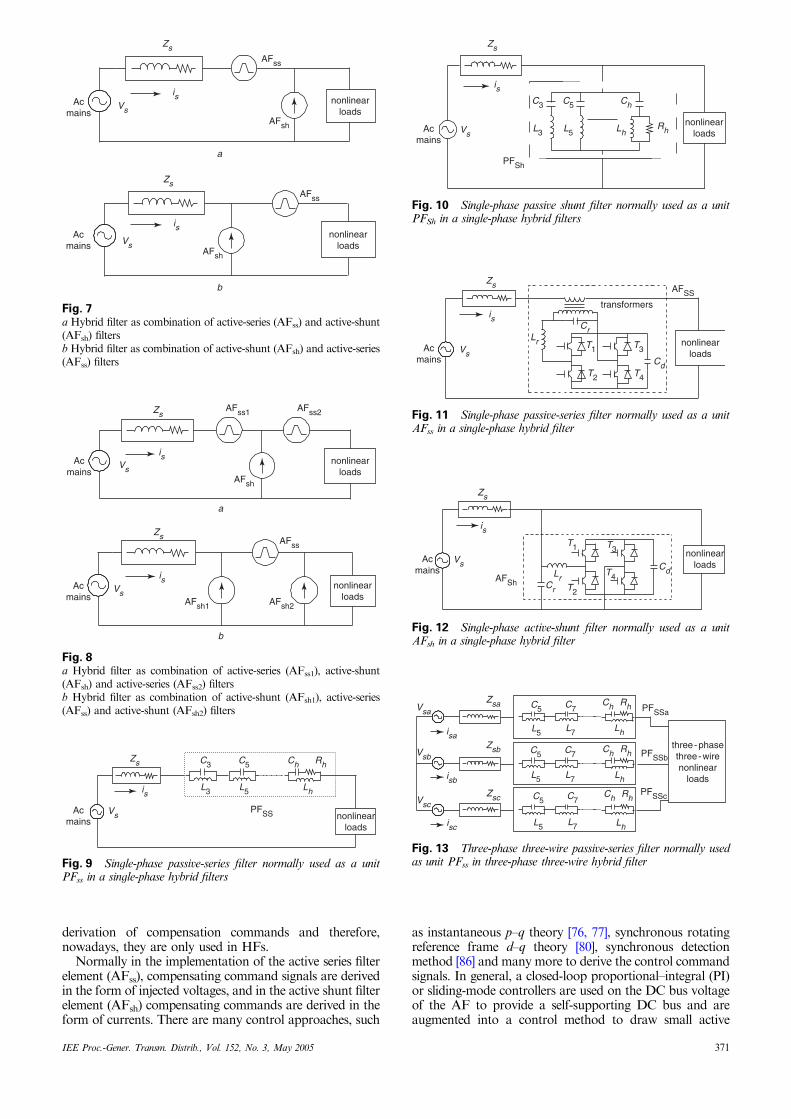
derivation of compensation commands and therefore,nowadays, they are only used in HFs.
Normally in the implementation of the active series filterelement (AFss), compensating command signals are derivedin the form of injected voltages, and in the active shunt filterelement (AFsh) compensating commands are derived in theform of currents. There are many control approaches, such
as instantaneous p–q theory [76, 77], synchronous rotatingreference frame d–q theory [80], synchronous detectionmethod [86] and many more to derive the control commandsignals. In general, a closed-loop proportional–integral (PI)or sliding-mode controllers are used on the DC bus voltageof the AF to provide a self-supporting DC bus and areaugmented into a control method to draw small active
Zs
Zs
is
is
Vs
VsAFsh
AFss
AFsh
AFss
Acmains
Acmains
nonlinearloads
nonlinearloads
a
b
Fig. 7a Hybrid filter as combination of active-series (AFss) and active-shunt(AFsh) filtersb Hybrid filter as combination of active-shunt (AFsh) and active-series(AFss) filters
nonlinearloads
nonlinearloads
Zs
Zs
is
is
Vs
Vs
AFsh
AFsh1 AFsh2
AFss1 AFss2
AFss
Acmains
Acmains
a
b
Fig. 8a Hybrid filter as combination of active-series (AFss1), active-shunt(AFsh) and active-series (AFss2) filtersb Hybrid filter as combination of active-shunt (AFsh1), active-series(AFss) and active-shunt (AFsh2) filters
nonlinearloads
C3
L3
C5
L5
Ch Rh
Lh
Zs
is
VsPFSSAc
mains
Fig. 9 Single-phase passive-series filter normally used as a unitPFss in a single-phase hybrid filters
nonlinearloads
C3
L3
C5
L5 Lh
Ch
Rh
Zs
is
Vs
PFSh
Acmains
Fig. 10 Single-phase passive shunt filter normally used as a unitPFSh in a single-phase hybrid filters
nonlinearloads
T3
T4T2
T1
Cd
CrLr
Zs
is
Vs
AFSS
Acmains
transformers
Fig. 11 Single-phase passive-series filter normally used as a unitAFss in a single-phase hybrid filter
nonlinearloads
T1 T3
T4T2
Cr
CdLr
Zs
is
Vs
AFSh
Acmains
Fig. 12 Single-phase active-shunt filter normally used as a unitAFsh in a single-phase hybrid filter
isa
isb
isc
Rh
Lh
Ch
Rh
Lh
Ch
Rh
Lh
Ch
L5
C5
L7
C7
L5
C5
L7
C7
L5
C5
L7
C7
Vsa
Vsb
Vsc
Zsb
Zsa
Zsc
PFSSa
PFSSb
PFSSc
three - phasethree - wirenonlinear
loads
Fig. 13 Three-phase three-wire passive-series filter normally usedas unit PFss in three-phase three-wire hybrid filter
IEE Proc.-Gener. Transm. Distrib., Vol. 152, No. 3, May 2005 371

Vsa
isa
Zsa
Ch
Lh RhL7
C7
L5
C5 Ch
Lh RhL7
C7
L5
C5 Ch
Lh RhL7
C7
L5
C5
Vsb
isb
Zsb
Vsc
isc
Zsc
PFSha PFShb PFShc
three - phasethree - wirenonlinear
loads
Fig. 14 Three-phase three-wire passive-shunt filter normally used as a unit PFsh in a three-phase three-wire hybrid filter
three - phasethree - wirenonlinear
loads
Vsa
Vsb
Vsc
isc
Zsc
Zsb
Tr
Tr
Tr
CrLr
Cd
Lr
LrCr
Cr
Zsa
isa
isb
AFss
Fig. 15 Three-phase three-wire active-series filter normally used asa unit AFss in a three-phase three-wire hybrid filter
isa
ZsaVsa
Vsb
Vsc
Zsb
Zscisb
Cr
CrCr
Lr Lr Lr
Cd
isc
AFSh
three - phasethree - wirenonlinear
loads
Fig. 16 Three-phase three-wire active-shunt filter normally used asa unit AFsh in a three-phase three-wire hybrid filter
n
n
a
b
c
Vsa
isa
Ch Rh
Lh
Ch Rh
Lh
Ch Rh
Lh
C5C3
L5L3
C5C3
L5L3
C5C3
L5L3
isb
isc
Vsb
Vsc
Zsa
Zsb
Zsc
PFssa
PFssb
PFssc
three - phasefour - wirenonlinear
loads
Fig. 17 Three-phase four-wire passive-series filter normally used as a unit PFss in a three-phase four-wire hybrid filter
n
a
b
cn
Vsa
isa
Zsa
Zsb
Zsc
Ch
LhRh
Ch
Lh LhRh
Ch
Rh
C3
L3
C5
L5
C3
L3
C5
L5
C3
L3
C5
L5
isb
isc
Vsb
Vsc
three - phasefour - wirenonlinear
loads
PFsha PFshb PFshc
Fig. 18 Three-phase four-wire passive-shunt filter normally used as a unit PFsh in a three-phase four-wire hybrid filter
372 IEE Proc.-Gener. Transm. Distrib., Vol. 152, No. 3, May 2005

power from the system for feeding losses in the AF system.These compensating commands, either in the form ofinjected voltage for active series filter (AFss) or in the formof compensating reference currents for a active shunt filterelement (AFsh) of HFs, are used in PWM control togenerate the gating signals for the solid-state switchingdevices of the VSI of the AF of HFs.
4.3 Generation of gating signalsIn the third or final stage of control of the AF in HFs,different closed-loop PWM controllers are used to generategating signals. The PWM controllers are implementedeither in the processor through optimised software andassociated hardware of the processor or in analoguehardware. Nowadays implementation of these PWMcontrollers is preferred in the software of the processor,which reduces the cost of the system and enhances thereliability due to a reduction in component count. Thederived compensating command signals are compared withsensed feedback signals and any error is processed in thePWM controller and generates digital gating signals. Thereare a number of closed-loop PWM controllers such ascarrier-less PWM controllers (hysteresis, on/off etc.),carrier-based PWM controller such as PI, dead beat,sliding-mode controller (SMC), and many more implemen-ted through software in the processor already used forderiving compensating commands. These digital (low/high)gating signals are buffered, isolated and amplified to feedthe gate of the solid-state switching devices of the AF usedin HFs.
5 Selection of components and designconsiderations
The selection of components of the hybrid filters is animportant aspect to attain a high-level performance. Thereare a number of components in HFs, such as passive filterelements, active filter elements, control scheme employingsensors, processor, isolation amplifier circuits, interfacingcircuits, injection transformers etc.
A passive filter (PF) element consists of several ACcapacitors and inductors, and a small resistor to be usedin the damped highpass filter, as shown in Figs. 9, 10, 13,14, 17 and 18. These inductors must have a quality factor ashigh as possible to reduce the losses in the system andthey must be designed in such a way that they must notsaturate in whole current operating range. In passive filters,the value of the capacitor is decided by the required reactivepower in the system, and then the value of the inductoris calculated by tuning it for a particular harmonicfrequency. The quality factor for calculating the value ofthe resistance is decided by the desired sharpness in thecharacteristics of the filter. Similarly the resistance in thehighpass filter is also calculated based on the sharpness or
n
a
b
c
n
a
b
c
a b c
LrCd
Cd
Cd1
Cd2
three - phasefour - wirenonlinear
loads
three - phasefour - wirenonlinear
loads
LrLr
Lr LrLrLr
LrLr Lr
n
isc
isb
isa
Vsa
Zsb
Zsc
Zsa
Vsb
Vsc
n
isc
isb
isa
Vsa
Zsb
Zsc
Zsa
Vsb
Vsc
n
isc
isb
isa
Vsa
Zsb
Zsc
Zsa
Vsb
Vsc
Tr
Tr
Tr
Tr
Tr
Tr
Cr
Cr
Cr
Tr
Tr
Tr
AFSS
AFSS
AFSS
three - phasefour - wirenonlinear
loads
a
b
c
Fig. 19a Three-phase four-wire active-series filter with capacitor mid pointnormally used as a unit AFss in a three-phase four-wire hybrid filterb Three-phase four-wire active-series filter with four-pole topologynormally used as unit AFss in three-phase four-wire hybrid filterc Three-phase four-wire active-series filter with three-single-phase-bridge used as a unit AFss in a three-phase four-wire hybrid filter
n
a
b
c
n
Tr
Tr
Tr
Tr
Tr
Tr
CrCr
Vsa
isa
Zsa
Zsb
Zscisb
isc
Vsb
Vsc
Lr Lr LrCr
three - phasefour - wirenonlinear
loads
Cd 2
Cd 1
AFsh
Fig. 20 Three-phase four-wire active-shunt filter as a unit AFsh ina three-phase four-wire hybrid filter
IEE Proc.-Gener. Transm. Distrib., Vol. 152, No. 3, May 2005 373

attenuation of the higher-order harmonics on one side andreducing the losses on the other side to achieve optimumvalue of the quality factor. Another important componentin the hybrid filter is the active filter element (AF), which isnormally realised using a VSI with ripple filter on the ACside and an electrolytic capacitor to provide a self-supporting DC bus. The ripple filter consists of essentialcomponents such as a capacitor (Cr) and an inductor (Lr) toimprove voltage profile. However, a major component ofthe AF is the solid state switching device, which is aMOSFET for small ratings, an IGBT medium powerratings and a GTO (gate-turn-of thyristor) for exceptionallyhigh power rating to build the VSI of the AFs. These solid-state switching devices are used in modular form, especiallyin low and medium power ratings, as power modules (PMs)or intelligent power modules (IPMs) consisting of severaldevices in one module with gating, protection andinterfacing elements to reduce size, cost and weight of theAF to be used as an element in HFs. One of the majorcomponents is a control scheme, which is implemented intothe processor. First, the voltage and current signals aresensed using PT, CT, Hall-effect sensors and isolationamplifiers. Many manufacturers are developing thesesensors at reasonably low cost. The main and importantcomponent is the processor, which executes an online wholecontrol algorithm after receiving input signals throughADC channels, PLL and synchronised interrupt signals. Italso implements PWM control optimally. All three tasks ofinputting data, computation of algorithm and optimisedPWM generation are carried out concurrently in themodern-day specially designed processors for powerelectronics applications. Many manufacturers are offeringthese processors at give away prices, e.g. Texas Instrumentsseries TMS320F24X, Analog Devices ADMC401, Intel80196 etc. and ASICs for easy and cost-effective imple-mentation of HFs.
6 Comparative features and other options forpower quality improvement
The classified HFs of nine major categories and 156 circuitconfigurations are capable of improving power quality fromthe low-cost HF as a combination of two passive elementsto UPQC (unified power quality conditioner) as perfectcompensation for nonlinear loads as well as providing aclean power supply. Unfortunately, in practice sometimes,most critical loads, such as UPS (uninterruptibte powersupply), behave as nonlinear loads and need clean power. Insuch situations, UPQC is the only right HF to provideperfect compensation. However, it is the costliest HF.
In many situations, active shunt filters can alsocompensate nonlinear loads but their rating and cost aremuch higher compared to an HF of a combination of oneactive and one passive element. In many cases, the rating ofthe AF element in the HF can be reduced to less than 5% ofthe load, resulting in drastic reduction in its cost [76].
Similarly, in some applications, an active series filteralone can provide effective compensation in voltage-fedtypes of loads [33], but its rating can be reduced to less thanone-fifth by adding a passive series filter to it [30]. Therefore,a low rating series AF along with a passive series filter ashybrid filter provides cost-effective compensation. However,there are many methods of power quality improvements insome applications, but HF is one of best alternativemethods of improving power quality. For example, inplace of the three-phase diode rectifier with capacitive filter,one may choose a multipulse AC–DC converter [8], oractive series filter alone [33], but it can easily be observed
that the hybrid filter, as a combination of active series withpassive series filter, is a most appropriate method of powerquality improvement for such a voltage-fed nonlinear load.
In some applications, one can also use a unity powerfactor rectifier for improving power quality. However, inretrofit applications, the replacement of an existing rectifier(AC–DC converter) may be a costly option and may needinterruption of process or plant for a longer period withhigher investment. In such cases, a hybrid filter of propertopology may be the right option and may be brought intoservice within no time. However, with HFs, there may bemany options to the users, but one has to select the mostsuitable HF for a specific application depending on the cost,size, level of performance etc. After, taking into accountthese considerations carefully, one can easily select the bestoption of HF for a particular application.
7 Selection criteria and potential applications
Selection of HFs for a particular application is an importantdecision for users. The following are the some of the factorsfor the selection and design of the right HF configurationfor a specific situation:
� type of supply system (single-phase, three-phase three-wire, three-phase four-wire)
� nature of load (voltage fed, convert fed or mixed)
� rating of load
� compensation required in currents (harmonics, reactivepower, balancing, neutral current)
� compensation required in voltages (harmonics, flicker,unbalance, regulation, sag, swell, surge, spikes, notches etc.)
� pattern of load (fixed, variable, fluctuating)
� level of compensation required (THD, individualharmonic reduction meeting specific standard etc.)
� cost (low cost of passive filters to UPQC)
� size� weight� efficiency� reliability (component counts)
� environmental factors (ambient temperature, altitude,pollution level, humidity, types of cooling etc.).
These are only some of the factors that provide someguidelines for the selection and design of a specific hybridfilter. However, the following are the some additionalcriteria for the selection of HFs.
The selection of HF configuration also depends on thenature of the load. Nonlinear loads can be classified in tothree major categories. The first category is voltage fed orvoltage source or voltage stiff loads, such as dioderectifier with capacitive filter at the DC-link feedingvariable-frequency VSI-based AC motor drive (ASDs),power supplies with front-end diode rectifier with capacitivefilters used in computers and other appliances,battery charger etc. These voltage stiff loads drawdiscontinuous and nonsinusoidal currents from the ACmains resulting in very high THD of the AC current,poor power factor and distortions of the AC terminalvoltage at the PCC. They behave as uncontrolled current-sink-type nonlinear loads. One of the best topologies of HFfor such loads is a combination of active series filter (AFss)with passive series filter (PFss) (Fig. 4a) if there is noproblem of pollution of the supply system. It creates a dam
374 IEE Proc.-Gener. Transm. Distrib., Vol. 152, No. 3, May 2005
for current harmonics and provides an adjustable solutionfor varying loads. It also avoids the resonance problem ofpassive filters.
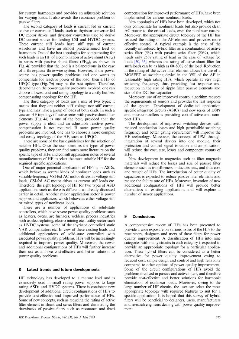
The second category of loads is current fed or currentsource or current stiff loads, such as thyristor-converter-fedDC motor drives, and thyristor converters used to deriveDC current source for feeding CSI and HVDC systems.These current stiff loads have stiff type of currentwaveforms and have an almost predetermined level ofharmonics. One of the best topologies for compensating forsuch loads is an HF of a combination of active shunt (AFsh)in series with passive shunt filters (PFsh), as shown inFig. 4f, provided that the load is a balanced one in the caseof a three-phase three-wire system. However, if the powersource has power quality problems and one wants tocompensate for reactive power of the load, then a HF ofUPQC type (Fig. 7a) may be the best option. Therefore,depending on the power quality problems involved, one canchoose a lowest cost and rating topology to a costly but bestcompensating topology for the HF.
The third category of loads are a mix of two types; itmeans that they are neither stiff voltage nor stiff currenttype and may have a group of loads of both kinds. In such acase an HF topology of active series with passive shunt filterelements (Fig. 4h) is one of the best, provided that thepower supply is ideal and an adjustable reactive powercompensation is not required. If more power qualityproblems are involved, one has to choose a more complexand costly topology of the HF, such as UPQCs.
These are some of the basic guidelines for the selection ofsuitable HFs. Once the user identifies the types of powerquality problems, they can find much more literature on thespecific type of HFs and consult application notes of severalmanufacturers of HF to select the most suitable HF for therequired specific applications.
One of major potential application of HFs is in ASDs,which behave as several kinds of nonlinear loads such asvariable-frequency VSI-fed AC motor drives as voltage stiffloads, CSI-fed AC motor drives as current stiff loads etc.Therefore, the right topology of HF for two types of ASDapplications such as these is different, as already discussedearlier in detail. Another major application sector is powersupplies and appliances, which behave as either voltage stiffor mixed types of nonlinear loads.
There are a number of applications of solid-statecontrollers, which have severe power quality problems suchas heaters, ovens, arc furnaces, welders, process industriessuch as electroplating, electro mining etc., utility sector suchas HVDC systems, some of the thyristor controlled staticVAR compensators etc. In view of these existing loads andadditional applications of solid-state controllers withassociated power quality problems, HFs will be increasinglyrequired to improve power quality. Moreover, the newerand additional configurations of HFs will further increasetheir use as a more cost-effective and better solution topower quality problems.
8 Latest trends and future developments
HF technology has developed to a mature level and isextensively used in small rating power supplies to largerating ASDs and HVDC systems. There is consistent newdevelopment of additional circuit configurations of HFs toprovide cost-effective and improved performance of HFs.Some of new concepts, such as reducing the rating of activefilter element in shunt and series filters and eliminating thedrawbacks of passive filters such as resonance and fixed
compensation for improved performance of HFs, have beenimplemented for various nonlinear loads.
New topologies of HFs have been developed, which notonly compensate for nonlinear loads but also provide cleanAC power to the critical loads, even the nonlinear nature.Moreover, the appropriate circuit topology of the HF hasreduced the rating of the AF element and provides moreeffective control. A typical example is the case of therecently introduced hybrid filter as a combination of activeseries filter (5%) with passive series filter (20%), whichneeds only 25% rating of load in the case of voltage fedloads [30, 33], whereas the rating of active shunt filter forsuch loads can be as high as 60–80% of the load. Reductionin the rating of the active filter element allows the use of aMOSFET as switching device in the VSI of the AF inreasonably high rating HFs, which operate at very highswitching frequency, thus providing fast response andreduction in the size of ripple filter passive elements andsize of the DC bus capacitor.
Moreover, use of an improved control algorithm reducesthe requirements of sensors and provides the fast responseof the system. Development of dedicated applicationspecific integrated circuits (ASICs) and new series of DSPsand microcontrollers is providing cost-effective and com-pact HFs.
The development of improved switching devices withreduced conduction losses and high permissible switchingfrequency and better gating requirement will improve theHF technology. Moreover, the concept of IPM throughintegration of several devices into one module, theirprotection and control signal isolation and amplification,will reduce the cost, size, losses and component counts ofHFs.
New development in magnetics such as filter magneticmaterials will reduce the losses and size of passive filterelements such as transformers, inductors, etc., and thus costand weight of HFs. The introduction of better quality ofcapacitors is expected to reduce passive filter elements andreduce the failure rate of HFs. Moreover, invention of newadditional configurations of HFs will provide betteralternatives to existing applications and will explore anumber of newer applications.
9 Conclusions
A comprehensive review of HFs has been presented toprovide a wide exposure on various issues of the HFs to theresearchers, designers and users of these filters for powerquality improvement. A classification of HFs into ninecategories with many circuits in each category is expected toprovide an appropriate topology for a particular applica-tion. These hybrid filters can be considered as a betteralternative for power quality improvement owing toreduced cost, simple design and control and high reliabilitycompared to other options of power quality improvement.Some of the circuit configurations of HFs avoid theproblems involved in passive and active filters, and thereforeprovide cost-effective and better solutions for harmonicelimination of nonlinear loads. Moreover, owing to thelarge number of HF circuits, the user can select the mostappropriate topology with required features to suit for aspecific application. It is hoped that this survey of hybridfilters will be beneficial to designers, users, manufacturersand research engineers dealing with power quality improve-ment.
IEE Proc.-Gener. Transm. Distrib., Vol. 152, No. 3, May 2005 375
10 References
1 Draft-Revision of Publication IEC 555-2 ‘Harmonics, Equipment forconnection to the public low voltage supply system’ IEC SC 77A,1990
2 IEEE Recommended Practices and Requirements for ‘Harmonicscontrol in electric power systems’ IEEE Std. 519, 1992
3 Electromagnetic compatibility (EMC)-Partt 3: ‘Limits- Section 2:Limits for harmonic current emissions (equipment input current o16A per phase)’ IEC1000-3-2 Document, First Edition, 1995
4 Reid, W.E.: ‘Power quality issues-standards and guidelines’, IEEETrans. Ind. Appl., 1996, 32, (3), pp. 625–632
5 Arrillaga, J., Bradley, D., and Bodger, P.: ‘Power system harmonics’(John Wiley & Sons, New York, 1985)
6 Clark, J.W.: ‘AC power conditioners-design, applications’ (Academic,San Diego, CA, 1990)
7 Heydt, G.T.: ‘Electric power quality’ (Stars in a Circle, WestLafayette, IN, 1994, 2nd edn.)
8 Paice, D.A.: ‘Power electronic converter harmonics-multi-pulsemethods for clean power’ (IEEE Press, New York, 1996)
9 Dugan, R.C., McGranaghan, M.F., and Beaty, H.W.: ‘Electric powersystems quality’ (McGraw Hill, New York, 1996)
10 Bollen, M.H.J.: ‘Understanding power quality problems: voltage sagsand interruptions’ (IEEE Press Series on Power Engineering, NewYork, 2000)
11 Schlabbach, J., Blume, D., and Stephanblome, T.: ‘Voltage quality inelectrical power systems’ (IEE Press, Power Engineering and EnergySeries, Hertz, 2001)
12 Sankaran, C.: ‘Power quality’ (CRC Press, New York, 2001)13 ‘Power system harmonics: an overview’, IEEE Trans. Power Appar.
Syst., 1983, 102, (8), pp. 2455–246014 Emanuel, A.E., Orr, J.A., Cyganski, D., and Gulchenski, E.M.: ‘A
survey of harmonics voltages, currents at the customer’s bus’, IEEETrans. Power Deliv., 1993, 8, (1), pp. 411–421
15 Arseneau, R. et al.: ‘A survey of North American electric utilityconcerns regarding nonsinusoidal waveforms’, IEEE Trans. PowerDeliv, 1996, 11, (1), pp. 73–78
16 Arseneau, R. et al.: ‘Practical definitions for powers in systems withnonsinusoidal waveforms, unbalanced loads: a discussion’, IEEETrans. Power Deliv., 1996, 11, (1), pp. 79–101
17 Mohan, N., Peterson, H.A., Long, W.F., Dreifuerst, G.R., andVithayathil, J.J.: ‘Active filters for AC harmonic suppression’. Proc.IEEE PES Winter Meeting, 1977, pp. 168–174
18 Hammond, P.W.: ‘A harmonic filter installation to reduce voltagedistortion from static power converter’, IEEE Trans. Ind. Appl., 1998,24, (1), pp. 53–58
19 Grady, W.M., Samotyj, M.J., and Noyola, A.H.: ‘Survey of activepower line conditioning methodologies’, IEEE Trans. Power Deliv.,1990, 5, pp. 1536–1542
20 Bou-rabee, M., Chang, C.S., Sutanto, D., and Tam, K.S.: ‘Passiveand active harmonic filters for industrial power systems’. Proc. IEEETENCON, 1991, pp. 222–226
21 VanWyk, J.D.: ‘Power quality, power electronics and control’. Proc.EPE, 1993, pp. 17–32
22 Emanuel, A.E., and Yang, M.: ‘On the harmonic compensation innonsinusoidal systems’, IEEE Trans. Power Deliv., 1993, 8, (1), pp.393–399
23 Akagi, H.: ‘Trends in active power line conditioners’, IEEE Trans.Power Electron., 1994, 9, (3), pp. 263–268
24 Rastogi, M., Naik, R., and Mohan, N.: ‘A comparative evaluationof harmonic reduction techniques in three-phase utility interfaceof power electronic loads’, IEEE Trans. Ind. Appl., 1994, 30, (5),pp. 1149–1155
25 Peeran, S.M., and Cascadden, C.W.P.: ‘Application, design andspecification of harmonic filters for variable frequency drives’, IEEETrans. Ind. Appl., 1995, 31, (4), pp. 841–847
26 Akagi, H.: ‘New trends in active filters for power conditioning’, IEEETrans. Ind. Appl., 1996, 32, pp. 1312–1322
27 Pittorino, L.A., du Toit, J.A., and Enslin, J.H.R.: ‘Evaluationof converter topologies and controllers for power quality compensa-tors under unbalanced conditions’. Proc. IEEE PESC, 1997, pp.1127–1133
28 Fang Zheng Peng, McKeever, J.W., and Adams, D.J.: ‘A powerline conditioner using cascade multilevel inverters for distribu-tion systems’, IEEE Trans. Ind. Appl., 1998, 34, (6),pp. 1293–1298
29 Chen, G., Li, M., Zhongming, Y., and Zhaoming, Q.: ‘A hybridsolution to active power filter for the purpose of harmonicsuppression and resonance damping’. Proc. IEEE POWERCON,1998, pp. 1542–1546
30 Fang Zheng Peng, .: ‘Application issues of active power filters’, IEEEInd. Appl. Mag., 1998, 4, (5), pp. 21–30
31 Singh, B., Haddad, K. AL., and Chandra, A.: ‘A review of activefilters for power quality improvement’, IEEE Trans. Ind. Electron.,1999, 46, pp. 960–971
32 El-Habrouk, M., Darwish, M.K., and Mehta, P.: ‘Activepower filters: A review’, IEE Proc., Electr. Power Appl., 2000, 147,pp. 493–413
33 Peng, F.Z.: ‘Harmonic sources and filtering approaches’, IEEE Ind.Appl. Mag., 2001, 7, (4), pp. 18–25
34 Senini, S.T., and Wolfs, P.J.: ‘Systematic identification and review ofhybrid active filter topologies’. Proc. IEEE PESC, 2002, pp. 394–399
35 Sannino, A., Stevenson, J., and Larsson, T.: ‘Power-electronicsolutions to power quality problems’, J. Electr. Power Syst. Res.,2003, 66, pp. 71–82
36 Strycula, E.C., Paice, D.A., and Gyugyi, L.: ‘High power resonancefilters’, U.S. Patent 4,406,991, Sept, 1983
37 Prasad, A.R., Ziogas, P.D., and Manias, S.: ‘A novel passivewaveshaping method for single-phase diode rectifiers’, IEEE Trans.Ind. Electron., 1990, 37, (6), pp. 521–530
38 Vlatkovic, V., Borojevic, D., and Lee, F.C.: ‘Input filter design forpower factor correction circuits’, IEEE Trans. Power Electron., 1996,11, (1), pp. 199–205
39 Maset, E., Sanchis, E., Sebastian, J., and de la Cruz, E.: ‘Improvedpassive solutions to meet IEC 1000-3-2 regulation in low-cost powersupplies’. Proc. IEEE INTELEC, 1996, pp. 99–106
40 Moo, C.S., Cheng, H.L., and Guo, S.J.: ‘Designing passive LC filterswith contour maps for diode bridge rectifiers’. Proc. IEEE Int. Con.on Power Electronics and Drive Systems, 1997, Vol. 2, pp. 834–838
41 Ji, Y., and Wang, F.: ‘Single-phase diode rectifier with novelpassive filter’, IEE Proc. Circuits Devices Syst., 1998, 145, (4), pp.493–413
42 El-Saadany, E.F., Salama, M.M.A., and Chikhani, A.Y.: ‘Passivefilter design for harmonic reactive power compensation in single-phase circuits supplying nonlinear loads’, IEE Proc. Gen. Transm.and Distrib., 2000, 147, pp. 373–380
43 Yaow-Ming, Chen: ‘Passive filter design using genetic algorithms’,IEEE Trans. Ind. Electron., 2003, 50, pp. 202–207
44 Ryckaert, W.R.A., Ghijselen, J.A.L., and Melkebeek, J.A.A.:‘Harmonic mitigation potential of shunt harmonic impedances’, JElectr. Power Syst. Res., 2003, 65, pp. 63–69
45 Gyugyi, L., and Strycula, E.: ‘Active AC power filters’. Proc. IEEE-IAS Annual Meeting, 1976, pp. 529–535
46 Uceda, J., Aldana, F., and Martinez, P.: ‘Active filters for staticpower converters’, IEE Proc., B, Elector, Power Appli., 1983, 130, (5),pp. 347–354
47 Rajagopalan, V., Jacob, A., S!evigny, A., Nguy, T.N., and Andy, L.:‘Harmonic currents compensation-scheme for electrical distributionsystems’. Proc. of IFAC Control in Power Electronics, ElectricDrives, Lausanne, Switzerland, 1983, pp. 683–690
48 Nastran, J., Cajhen, R., Seliger, M., and Jereb, P.: ‘Active powerfilter for non-linear AC loads’, IEEE Trans. Power Electron., 1994, 9,(1), pp. 92–96
49 Rastogi, M., Mohan, N., and Edris, A.A.: ‘Hybrid-Active Filteringof Harmonic Currents in Power Systems,’, IEEE Trans. Power Deliv.,1995, 10, (4), pp. 1994–2000
50 Maeda, T., Watanabe, T., Mechi, A., Shiota, T., and Iida, K.: ‘Ahybrid single-phase power active filter for high order harmonicscompensation in converter-fed high speed trains’. Proc. PowerConversion Conf. – Nagaoka, 1997, pp. 711–717
51 Liu, J., Yang, J., and Wang, Z.: ‘A new approach for single-phaseharmonic current detecting and its application in a hybrid activepower filter’. Proc. IEEE IECON, 1999, pp. 849–854
52 Lin, B.R., and Yang, B.R.: ‘Current harmonics elimination witha series hybrid active filter’. Proc. IEEE Int. Symp. ISIE, 2001,pp. 566–570
53 Ribeiro, E.R., and Barbi, I.: ‘A series active power filter forharmonic voltage suppression’. Proc. IEEE INTELEC, 2001, pp.514–519
54 Zhao, C., Li, G., Chen, Z., and Li, G.: ‘Design and realization of anew hybrid power filter system used in single-phase circuit’. Proc.IEEE IECON, 2001, pp. 1067–1071
55 Bor-Ren, LIN, Bor-Ren, YANG, and Hui-Ru, TSAI: ‘Analysis andoperation of hybrid active filter for harmonic elimination’, J. Electr.Power Syst. Res., 2002, 62, (3), pp. 191–200
56 Bakhshai, A.R., Karimi, H., and Saeedifard, M.: ‘A new adaptiveharmonic extraction scheme for single-phase active power filters’.Proc. IEEE Int. Symp. Circuits and Systems ISCAS, 2003, pp. 268–271
57 Moran, S.: ‘Line Voltage Regulator’, US Patent 4,950,916, Aug. 21,1990
58 Mochinaga, Y., Hisamizu, Y., Takeda, M., Miyashita, T., andHasuike, K.: ‘Static power conditioner using GTO converters for ACelectric railway’. Proc. IEEE-Power Conversion Conf., Yokohama,1993, pp. 641–646
59 Brennen, M.A.: ‘Series-parallel active power line conditioner utilizingreduced-turns-ratio transformer for enhanced peak voltage regula-tion capability’, U.S. Patent 5,319,534, June 7, 1994
60 Brennen, M.A., Moran, S.A., and Gyugyi, L.: ‘Low cost activepower line conditioner’, US Patent 5,351,181, Sept. 27
61 Valouch, V.: ‘Compensation of harmonic voltage source by usingparallel and series active filters’. Proc. EPE-PEMC, Ko$sice, 2000,pp. 4.20–4.25
62 le Roux, A.D., and Mouton, H.D.T.: ‘A series-shunt compensatorwith combined UPS operation’. Proc. IEEE Int. Symp. on IndustrialElectronics ISIE, 2001, pp. 2038–2043
63 Basu, M., Das, S.P., and Dubey, G.K.: ‘Experimental investigationof performance of a single phase UPQC for voltage sensitive andnonlinear loads’. Proc. IEEE PEDS, 2001, pp. 218–222
64 Steeper, D.E., and Stratford, R.P.: ‘Reactive compensation, harmo-nic suppression for industrial power systems using thyristorconverters’, IEEE Trans. Ind. Appl., 1976, 12, (3), pp. 232–254
65 Gonalez, D.A., and Maccall, J.C.: ‘Design of filters to reduceharmonic distortion in industrial power systems’, IEEE Trans. Ind.Appl., 1987, IA-23, (3), pp. 504–511
376 IEE Proc.-Gener. Transm. Distrib., Vol. 152, No. 3, May 2005

66 Hammond, P.W.: ‘A harmonic filter installation to reduce voltagedistortion from static power converters’, IEEE Trans Ind. Appl.,1988, 24, (1), pp. 53–58
67 Ludbrook, A.: ‘Harmonic filters for notch reduction’, IEEE Trans.Ind. Appl., 1988, 24, pp. 947–954
68 Sharaf, A.M., and Fisher, M.E.: ‘An optimization based techniquefor power system harmonic filter design’, J. Electr. Power Syst. Res.,1994, 30, pp. 63–67
69 Phipps, J.K.: ‘A transfer function approach to harmonic filterdesign,’, IEEE Ind. Appl. Mag., 1997, 3, pp. 68–82
70 El-Saadany, E.F., Salama, M.M.A., and Chikhani, A.Y.: ‘Reductionof voltage and current distortion in distribution systems withnonlinear loads using hybrid passive filters’, IEE Proc., Gener.Transm. Distrib., 1998, 145, (3), pp. 320–328
71 Xiao, Y.: ‘Algorithm for the parameters of double tuned filter’. Proc.IEEE ICHQP, 1998, pp. 154–157
72 Mattavelli, P.: ‘Design aspects of harmonic filters for high-powerAC/DC converters’. Proc. IEEE PES Meeting, 2000, Vol. 2,pp. 795–799
73 Bartzsch, C., Huang, H., Roessel, R., and Sadek, K.: ‘Triple tunedharmonic filters-design principle and operating experience’. Proc.IEEE PowerCon, 2002, pp. 542–546
74 Takeda, M., Ikeda, K., and Tominaga, Y.: ‘Harmonic currentcompensation with active filter’. Proc. IEEE IAS Annual MeetingRecord, 1987, pp. 808–815
75 Peng, F.Z., Akagi, H., and Nabae, A.: ‘A novel harmonic powerfilter,’. Proc. IEEE PESC, 1988, pp. 1151–1159
76 Peng, F.Z., Akagi, H., and Nabae, A.: ‘A new approach toharmonic compensation in power systems-A combined system ofshunt passive, series active filters’, IEEE Trans. Ind. Appl., 1990, 26,(6), pp. 983–990
77 Fujita, H., and Akagi, H.: ‘Design strategy for the combined systemof shunt passive and series active filters’. Proc. IEEE PESC, 1991,pp. 898–903
78 Fujita, H., and Akagi, H.: ‘A practical approach to harmoniccompensation in power systems–series connection of passive, activefilters’, IEEE Trans. Ind. Appl., 1991, 27, (6), pp. 1020–1025
79 Peng, F.Z., Akagi, H., and Nabae, A.: ‘Compensation characteristicsof the combined system of shunt passive, series active filters’, IEEETrans. Ind. Appl., 1993, 29, (1), pp. 144–152
80 Bhattacharya, S., Divan, D.M., and Banerjee, B.B.: ‘Control,reduction of terminal voltage total harmonic distortion (THD) in ahybrid series active, parallel passive filter system’. Proc. IEEE PESC,1993, pp. 779–786
81 Balbo, N., Sella, D., Penzo, R., Bisiach, G., Cappellieri, D.,Malesani, L., and Zuccato, A.: ‘Hybrid active filter for parallelharmonic compensation’. Proc. EPE, 1993, pp. 133–138
82 Moran, S.A., and Brennen, M.B.: ‘Active power line conditionerwith fundamental negative sequence compensation’, U.S. Patent384,696, Jan. 1995
83 Bhattacharya, S., Divan, D.M., and Banerjee, B.: ‘Active filtersolutions for utility interface’. Proc. IEEE ISIE, 1995, pp. 53–63
84 Bhattacharya, S., and Divan, D.: ‘Design, implementation of ahybrid series active filter system’. Proc. IEEE PESC, 1995, pp. 189–195
85 Rastogi, M., Mohan, N., and Edris, A.A.: ‘Filtering of harmoniccurrents, damping of resonances in power systems with a hybrid-active filter’. Proc. IEEE APEC, 1995, pp. 607–612
86 Lin, C.E., Su, W.F., Lu, S.L., Chen, C.L., and Huang, C.L.:‘Operation strategy of hybrid harmonic filter in demand-side system’.Proc. IEEE IAS Annual Meeting, 1995, pp. 1862–1866
87 Bhattacharya, S., and Divan, D.: ‘Synchronous frame basedcontroller implementation for a hybrid series active filter system’.Proc. IEEE-IAS Annual Meeting, 1995, pp. 2531–2540
88 Cheng, P.T., Bhattacharya, S., and Divan, D.M.: ‘Hybrid solutionsfor improving passive filter performance in high power applications’.Proc. IEEE APEC, 1996, pp. 911–917
89 Mohan, N., and Rastogi, M.: ‘Hybrid Filter for reducing distortionin power system’ US Patent 5,548,165, Aug. 20, 1996
90 Libano, F.B., Simonetti, D.S.L., and Uceda, J.: ‘Frequencycharacteristics of hybrid filter systems’. Proc. IEEE PESC, 1996,pp. 1142–1148
91 Kurowski, T., Strzelecki, R., and Supronowicz, H.: ‘A new methodof alternating current harmonic compensation in parallel systems ofhybrid filters’. Proc. IEEE ISIE, 1996, Vol. 2, pp. 596–601
92 Bhattacharya, S., Cheng, P.T., and Divan, D.M.: ‘Hybrid solutionsfor improving passive filter performance in high power applications’,IEEE Trans. Ind. Appl., 1997, 33, (3), pp. 732–747
93 Libano, F., Cobos, J., and Uceda, J.: ‘Simplified control strategyfor hybrid active filters’. Proc. IEEE PESC, 1997, Vol. 2, pp. 1102–1108
94 Dixon, J., Venegas, G., and Moran, L.: ‘A series active power filterbased on a sinusoidal current-controlled voltage-source inverter’,IEEE Trans. Ind. Electron., 1997, 44, (5), pp. 612–620
95 Cheng, P.T., Bhattacharya, S., and Divan, D.M.: ‘Hybrid parallelactive/passive filter system with dynamically variable inductance’, USPatent 5757099, May 26, 1998
96 Cheng, P.T., Bhattacharya, S., and Diwan, D.M.: ‘Control ofsquare-wave inverters in high-power hybrid active filter systems’,IEEE Trans. Ind. Appl., 1998, 34, (3), pp. 458–472
97 Fujita, H., Yamasaki, T., and Akagi, H.: ‘A hybrid active filter fordamping of harmonic resonance in industrial power systems’. Proc.IEEE PESC, 1998, Vol. 1, pp. 209–216
98 Basic, D., Ramsden, V.S., and Muttick, P.K.: ‘Performance of
combined power filters in harmonic compensation of high-power
cycloconverter drives’. Proc. IEE Power Electronics and Variable
Speed Drives Conf. Publ., 1998, Vol. 456, pp. 674–67999 Alexa, D.: ‘Combined filtering system consisting of passive filter with
capacitors in parallel with diodes and low-power inverter’, IEE Proc.
Elect. Power Appl., 1999, 146, (1), pp. 88–94100 Cheng, P.T., Bhattacharya, S., and Divan, D.D.: ‘Line harmonics
reduction in high power using square wave inverters based dominantharmonic active filters’, IEEE Trans Power Election., 1999, 14, (2),pp. 265–272
101 Singh, B.N., Singh, B., Chandra, A., and Haddad, K.A.: ‘Digitalimplementation of a new type of hybrid filter with simplified controlstrategy’. Proc. IEEE APEC, 1999, Vol. 1, pp. 642–648
102 Al-Zamel, A.M., and Torrey, D.A.: ‘A three-phase hybrid seriespassive/shunt active filter system’. Proc. IEEE APEC, 1999, pp. 875–881
103 Singh, B.N., Singh, B., Chandra, A., and Haddad, K.A.: ‘A newcontrol scheme of series hybrid active filter’. Proc. IEEE PESC, 1999,Vol. 1, pp. 249–154
104 Fujita, H., Yamasaki, T., and Akagi, H.: ‘A hybrid active filter fordamping of harmonic resonance in industrial power systems’, IEEETrans. Power Electron., 2000, 15, (2), pp. 215–222
105 Sung, J.H., Park, S., and Nam, K.: ‘New hybrid parallel active filterconfiguration minimising active filter size’, IEE Proc. Electr. PowerAppl., 2000, 147, pp. 93–98
106 Guozhu, C., Lu, Z., and Zhaoming, Q.: ‘The design and implementof series hybrid active power filter for variable nonlinear loads’. Proc.Third Int. Conf. on Power Electronics and Motion Control(PIEMC), 2000, pp. 1041–1044
107 Karthik, K., and Quaicoe, J.E.: ‘Voltage compensation andharmonic suppression using series active and shunt passive filters’.Proc. IEEE Canadian Conf. on Electrical and Computer Engineer-ing, 2000, pp. 582–586
108 Basic, D., Ramsden, V.S., and Muttik, P.K.: ‘Selective compensationof cycloconverter harmonics and interharmonics by using a hybridpower filter system’. Proc. IEEE PESC, 2000, Vol. 3, pp. 1137–1142
109 Akagi, H.: ‘Active and hybrid filters for power conditioning’. Proc.IEEE ISIE, 2000, Vol. 1, p. TU TU 36
110 Jou, H.-L., Wu, J.C., and Wu, K.D.: ‘Parallel operation of passivepower filter and hybrid power filter for harmonic suppression’, IEEProc. Gener. Transm. Distrib., 2001, 148, pp. 8–14
111 Al-Zamil, A.M., and Torrey, D.A.: ‘A passive series, active shuntfilter for high power applications’, IEEE Trans. Power Electron.,2001, 16, (1), pp. 101–109
112 Chen, L., and von Jouanne, A.: ‘A comparison and assessment ofhybrid filter topologies and control algorithms’. Proc. IEEE PESC,2001, Vol. 2, pp. 565–570
113 Guozhu, C., Zhengyu, L., and Zhaoming, Q.: ‘A novel hybrid activepower filter with two passive channels for high power application’.Proc. IEEE PESC, 2001, pp. 1889–1892
114 Lee, G.M., and Lee, D.C.: ‘Control of series active power filterscompensating for source voltage unbalance and current harmonics’.Proc. IEEE IECON, 2001, pp. 1144–1149
115 Detjen, D., Jacobs, J., De Doncker, R.W., and Mall, H.G.: ‘A newhybrid filter to dampen resonances and compensate harmoniccurrents in industrial power systems with power factor correctionequipment’, IEEE Trans. Power Electron., 2001, 16, (6), pp. 821–827
116 Lin, B.R., Yang, B.R., and Tsai, H.R.: ‘Analysis and operation ofhybrid active filter for harmonic elimination’, Electr. Power Syst.Res., 2002, 62, pp. 191–200
117 Rahmani, S., Al-Haddad, K., and Fnaiech, F.: ‘A hybrid structure ofseries active and passive filters to achieving power quality criteria’.Proc. IEEE Int. Conf. on Systems, Man and Cybernetics, 2002,pp. 1–6
118 Akagi, H., Nabae, A., and Atoh, S.: ‘Control strategy of activepower filters using multiple voltage-source PWM converters’, IEEETrans. Ind. Appl., 1986, 22, (3), pp. 460–465
119 Blajszczak, G.: ‘Non-active power compensation using time-window method’, Eur. Trans. Electr. Power Eng., 1992, 2, (5),pp. 285–290
120 Moran, L., Godoy, P., Wallace, R., and Dixon, J.: ‘A new currentcontrol strategy for active power filters using three PWM voltagesource inverters’. Proc. IEEE PESC, 1993, pp. 3–9
121 Bhavaraju, V.B., and Enjeti, P.: ‘A novel active line conditioner for athree-phase system’. Proc. IEEE IAS Annual Meeting, 1993,pp. 979–985
122 Ledwich, G., and Doulai, P.: ‘Multiple converter performance, activefiltering’, IEEE Trans. Power Electron., 1995, 10, (3), pp. 273–279
123 Raju, N.R., Venkata, S.S., Kagalwala, R.A., and Sastry, V.V.: ‘Anactive power quality conditioner for reactive power, harmonicscompensation’. Proc. IEEE PESC, 1995, pp. 209–214
124 Kamran, F., and Habetler, T.G.: ‘A novel on-line UPS with universalfiltering capabilities’. Proc. IEEE PESC, 1995, pp. 500–506
125 Fujita, H., and Akagi, H.: ‘The unified power quality conditioner: theintegration of series- and shunt-active filters’, IEEE Trans. PowerElectron., 1998, 13, (2), pp. 315–322
126 Singh, B.N., Chandra, A., Al-Haddad, K., and Singh, B.: ‘Fuzzycontrol algorithm for universal active filter’. Proc. IEEE PowerQuality, 1998, pp. 73–80
127 Huang, S.J., and Wu, J.C.: ‘Design and operation of cascaded activepower filters for the reduction of harmonic distortions in power
IEE Proc.-Gener. Transm. Distrib., Vol. 152, No. 3, May 2005 377

system’, IEE Proc. Gener. Transm. Distrib, 1999, 146, (2), pp. 193–199
128 Li, R., Johns, A.T., and Elkateb, M.M.: ‘Control concept of unifiedpower line conditioner’. Proc. IEEE PES Meeting, 2000, pp. 2594–2599
129 Tolbert, L.M., Peng, F.Z., and Habetler, T.G.: ‘A multilevelconverter-based universal power conditioner’, IEEE Trans. Ind.Appl., 2000, pp. 596–603
130 Chen, Y., Zha, X., Wang, J., Liu, H., Sun, J., and Tang, H.: ‘Unifiedpower quality conditioner (UPQC): the theory, modeling andapplication’. Proc. IEEE Power System Technology Conf., 2000,pp. 1329–1333
131 Graovac, D., Katic, V., and Rufer, A.: ‘Power quality compensationusing universal power quality conditioning system’, IEEE Power Eng.Rev., 2000, 20, (12), pp. 58–60
132 Cao, R., Zhao, J., Shi, W., Jiang, P., and Tang, G.: ‘Series powerquality compensator for voltage sags, swells, harmonics andunbalance’. Proc. IEEE PES Conf. and Exp. on Transmission andDistribution, 2001, pp. 543–547
133 Singh, P., Pacas, J.M., and Bhatia, C.M.: ‘An improved unifiedpower quality conditioner’. Proc. EPE, 2001
134 Singh, P., Pacas, J.M., and Bhatia, C.M.: ‘A novel 3-phase hybridharmonic and reactive power compensator’, EPE J., 2001, 11, (4),pp. 14–19
135 Kim, S., and Enjeti, P.: ‘A new hybrid active power filter (APF)topology’, IEEE Trans. Power Electron., 2002, 17, (1), pp. 48–54
136 Basu, M., Das, S.P., and Dubey, G.K.: ‘Performance study ofUPQC-Q for load compensation and voltage sag mitigation’. Proc.IEEE IECON, 2002, pp. 698–703
137 Newman, M.J., and Holmes, D.G.: ‘A universal custom powerconditioner (UCPC) with selective harmonic voltage compensation’.Proc. IEEE IECON, 2002, pp. 1261–1266
138 Jintakosonwit, P., Fujita, H., Akagi, H., and Ogasawara, S.:‘Implementation and performance of cooperative control of shuntactive filters for harmonic damping throughout a power distributionsystem’, IEEE Trans. Ind. Appl., 2003, 39, (2), pp. 556–564
139 Mielczarski, W., Szczepanik, J., and Lawrance, W.: ‘Reduction ofharmonic currents in fluorescent lighting systems: design andrealisation’, IEE Proc. Gener., Transm. Distrib., 1998, 145, (4),pp. 363–368
140 Syafrudin, M., Hadzer, C.M., and Sutanto, J.: ‘Zero-sequenceharmonics current minimization using zero-blocking transformer andshunt LC passive filters’. Proc. IEEE Int. Conf. on Power SystemTechnology, POWERCON, 2002, Vol. 1, pp. 116–120
141 Moran, L., Pastorini, I., Dixon, J., and Wallace, R.: ‘Series activepower filter compensates current harmonics and voltage unbalance
simultaneously’, IEE Proc. Gener. Transm. Distrib., 2000, 147, (1),pp. 31–36
142 Kandil, T.A., and Quaicoe, J.E.: ‘A new approach to voltage andharmonic compensation’. Proc. IEEE-Canadian Conf. on Electricaland Computer Engineering, 2001, pp. 747–752
143 Rodriguez, P., Pindado, R., and Bergas, J.: ‘Alternative topology forthree-phase four-wire pwm converters applied to a shunt activepower filter’. Proc. IEEE IECON, 2002, pp. 2939–2944
144 Deng, Z.F., Jiang, X.J., and Zhu, D.Q.: ‘A novel hybrid filter tocancel the neutral harmonic current’. Proc. IEEE IASMeeting, 2002,Vol. 1, pp. 59–63
145 Stacy, E.J., and Brennen, M.A.: ‘Active power conditioner system’,US Patent 4,651,265, March 17, 1987
146 Aredes, M., Heumann, K., andWatanabe, E.H.: ‘An universal activepower line conditioner’, IEEE Trans. Power Deliv., 1998, 13, (2),pp. 545–551
147 Peng, F.Z.: ‘Power line conditioner using cascade multilevel invertersfor voltage regulation, reactive power correction, and harmonicfiltering’, US Patent 6,075,350, June 13, 2000
148 S!ergio, A., da Silva, O., Donso-Garcia, P., Cortizo, P.C., and Seixas,P.F.: ‘Three-phase line-interactive ups systems with series-parallelactive power line conditioning for high power quality’. Proc. EPE-PEMC, Ko$sice,, 2000, pp. 3.130–3.135
149 Ghosh, A., and Ledwich, G.: ‘A unified power quality conditioner(UPQC) for simultaneous voltage and current compensation’, J.Elect. Power Syst. Res., 2001, 59, pp. 55–63
150 Prieto, J., Saimeron, P., Vazquez, J.R., and Alcantara, J.: ‘A series-parallel configuration of active power filters for var and harmoniccompensation’. Proc. IEEE IECON, 2002, pp. 2945–2950
151 Elnady, A., El-Khattam, W., and Salama, M.M.A.: ‘Mitigationof AC are furnace voltage flicker using the unified powerquality conditioner’. Proc. IEEE PES Winter Meeting, 2002,pp. 735–739
152 Faranda, R., and Valade, I.: ‘UPQC compensation strategyand design aimed at reducing losses’. Proc. IEEE-ISIE, 2002,pp. 1264–1270
153 Chiang, S.J., Ai, W.J., and Lin, F.J.: ‘Parallel operation of capacity-limited three-phase four-wire active power filters’, IEE Proc., Electr.Power Appl., 2002, 149, (5), pp. 329–336
154 Barrero, F., Martinez, S., Yeves, F., Mur, F., and Martinez, P.M.:‘Universal and reconfigurable to UPS active power filter forline conditioning’, IEEE Trans. Power Deliv., 2003, 18, (1),pp. 283–290
155 Chiang, S.J.: ‘A three-phase four-wire power conditioner with load-dependent voltage regulation for energy saving’. Proc. IEEE APEC,2003, pp. 159–164
378 IEE Proc.-Gener. Transm. Distrib., Vol. 152, No. 3, May 2005