Coils・ Transform ers・ Filters & A ntennas
66
2013 Balun Transformers バルントランス DC-DC Converter Transformers DC-DCコンバータトランス Inverter Transformers インバータトランス Dielectric Filters/Duplexers 誘電体フィルタ/デュプレクサ Diplexers/Triplexers ダイプレクサ/トリプレクサ Transponder Coils トランスポンダコイル Dielectric Antennas 誘電体アンテナ Coils ・ Transformers ・ Filters & Antennas COILS ・ TRANSFORMERS ・ FILTERS & ANTENNAS コイル・トランス・フィルタ&アンテナ
-
Upload
khangminh22 -
Category
Documents
-
view
0 -
download
0
Transcript of Coils・ Transform ers・ Filters & A ntennas

2013
Balun Transformersバルントランス
DC-DC Converter TransformersDC-DCコンバータトランス
Inverter Transformersインバータトランス
Dielectric Filters/Duplexers誘電体フィルタ/デュプレクサ
Diplexers/Triplexersダイプレクサ/トリプレクサ
Transponder Coilsトランスポンダコイル
Dielectric Antennas誘電体アンテナ
Coils・Transform
ers・Filters &
Antennas
Design A 改-明朝
Headquarters / 本 社
18, Ohaza, Gomigaya, Tsurugashima-shi, Saitama-ken, 350-2281, Japan〒350-2281 埼玉県鶴ヶ島市大字五味ヶ谷18番地Tel : 049-285-2511 Fax : 049-286-7381http://www.toko.co.jp/
営 業 拠 点
● 営業センター 〒350-2281 埼玉県鶴ヶ島市大字五味ヶ谷18 Tel 049-250-2291 Fax 049-279-1811
● 東京オフィス 〒170-0013 東京都豊島区東池袋1-17-8 NBF池袋シティビル3F Tel 03-5960-0350 Fax 03-5960-0348
● 大阪営業所 〒532-0003 大阪市淀川区宮原2-14-10 中尾ロイヤルビル6F Tel 06-6395-6411 Fax 06-6395-6416
● 名古屋営業所 〒465-0093 名古屋市名東区一社2-87 プラザ・タマ2F Tel 052-703-2247 Fax 052-703-2009
東光株式会社
CATALOG No. C-052002 Printed in Japan '12.09 2K (HK)
墨DIC128
COILS・TRANSFORMERS・FILTERS & ANTENNAS
コイル・トランス・フィルタ&アンテナ
この印刷物は、適切に管理された森林からの原料を含むFSC®認証紙と植物油インキを使用しています。
背幅3mm

背幅3mm
コイル・トランス
表3表2
ご注意1. このカタログに記載の製品について、極めて高い信頼性が要求される以下の用途でのご使用をご検討の場合、またはこのカタログに記載された用途以外でのご使用をご検討の場合は、必ず事前に当社営業窓口までご相談ください。
¡自動車、船舶、航空機などの交通輸送システムにおける動力駆動系・操舵航法系・非常信号通信系および上記以外の系であってもその誤動作や機能停止が人命・身体・財産に重大な損害をもたらす恐れのある電子的手段による検出・計測・制御・表示などの機能を含む系。
¡血圧や心拍数などの医用計測装置、心臓ペースメーカや温熱療法などの治療装置、人工臓器や人工義足手システムなどの生体機能補助装置。
¡防災または防犯用電気機器・設備・システム。
2. このカタログの記載内容は 現在のものです。記載内容を予告なく変更あるいは製造を中止することがあります。ご注文に際しては仕様・納入仕様書などの取り交わしをお願いします。
3. このカタログに記載された製品の使用法および回路を適用したり使用したことから生じる諸問題および第三者の特許権その他の知的財産権の侵害に対して、当社はその責任を負いません。また、当社の特許権その他の知的財産権の黙示その他による実施許諾は致しません。
4. 当社の製造工程では、モントリオール議定書で規制されているオゾン層破壊物質(ODS)は一切使用しておりません。
1. Please be sure that you carefully discuss your planned purchase with our sales division ifyou intend to use the products in this catalog under conditions where particularly extremestandards of reliability are required, or if you intend to use products for applications otherthan those listed in this catalog.¡Power drive products for automobile, ship or aircraft transport systems; steering and
navigation systems, emergency signal communications systems, and any system otherthan those mentioned above which include electronic sensors, measuring, or displaydevices, and which could cause major damage to life, limb or property if misused orfailure to function.
¡Medical devices for measuring blood pressure, pulse, etc., treatment units such ascoronary pacemakers and heat treatment units, and devices such as artificial organsand artificial limb systems which augment physiological functions.
¡Electrical instruments, equipment or systems used in disaster or crime prevention.2. This catalog is effective from Note that the contents are subject to change or
discontinuation without notice. When placing orders, please confirm specifications anddelivery conditions in writing.
3. TOKO is not responsible for any problems nor for any infringement of third party patentsor any other intellectual property rights that may arise from the use or method of use ofthe products listed in this catalog. Moreover, this catalog does not signify that TOKOagrees implicitly or explicitly to license any patent rights or other intellectual propertyrights which it holds.
4. None of ozone depleting substances(ODS) under the Montreal Protocol is used inmanufacturing process of us.
NOTICE
2012年9月
Sep. 2012.

i
1
2
3
4
5
6
7
8
Coils, Transformers, filters & Antennas
Contents
Balun Transformers / EMC Components
DC-DC Converter Transformers
CCFL Driving Inverter Transformers
Dielectric Filters
Diplexers / Triplexers
Transponder Coils
Dielectric Antenna Elements

ii
CONTENTS
Balun Transformers & EMC Components
Balun Transformers / Transformers for Frequency Mixer / Distributors / Splitters / Directional Couplers
/ / / /
B4F............................................................ 2~4 B5F............................................................ 5~6 B5FL.......................................................... 7~8
Common-mode Chokes for IEEE1394
B4W .............................................................. 9 B5W ............................................................ 10
Common-mode Chokes for USB1.1 / USB2.0 / IEEE1394 / LVDS / DVI / HDM USB1.1/USB2.0/IEEE1394/LVDS/DVI/HDM
NT2012 ....................................................... 11
Common-mode Chokes for Smart Entry System
BH8S........................................................... 12
DC-DC Converter Transformers SMT DC-DC Converter Transformers
DC-DC 5CA ............................................................. 14 6CA ............................................................. 14 8CA ............................................................. 15 10CA ........................................................... 15 R10F ........................................................... 16 R12F ........................................................... 16 R15F ........................................................... 16
CCFL Driving Inverter Transformers CCFL Driving Inverter Transformer
BLC4115 .................................................... 18 BLC4115L .................................................. 18 CLT4123 .................................................... 18 BLC4204 .................................................... 19 BLC4204B.................................................. 19 BLC4206 .................................................... 19 BLC4206B.................................................. 19
GHz-Filters Chip Dielectric Filters (TDF Series)
TDF Part numbering system Dimensions ....................................22 TDF series for Wireless Broadband Communication
............................................. 23, 26 TDF series for Mobile & Cordless Phone
........................................... 24, 26 TDF Series for Automotive & Satelite Radio
......................... 25, 26 Dielectric Filters 700~2500MHz
#4DFA..........................................................28 #4DFB..........................................................28 #AF3B..........................................................30 #AF3C..........................................................30 #AF5D..........................................................30 #6DFA..........................................................31 #6DFB..........................................................31 #6DFC .........................................................32 #6DFSC .......................................................32 #6DFSD .......................................................33
Antenna Duplexers
#6DPF..........................................................34 #6DPH .........................................................34
Precautions for using Dielectric Filters surface mount type
.....................35 Recommended soldering conditions
.............................................35 Dielectric Waveguide Filters
WDFM..........................................................38
Diplexers & Triplexers Diplexers for Digital CATV Set Top Box and Cable Modem
DIP1A ...........................................................40 DIP2A ...........................................................40 DIP1S ...........................................................40 DIP1H...........................................................40 DIP1K ...........................................................40
Triplexer for MoCA Set
TRP1A..........................................................41
Coils, Transformers, Filters & Antennas

iii
1
2
3
4
5
6
7
8
9
Con
tent
s
Transponder Coils Transponder Coils for Surface Mounting
SA3M12 ...................................................... 44 SA3M08 ...................................................... 45 SA3D14....................................................... 46
Dielectric Antenna Element Dielectric Antenna Element for GPS
DAKC .......................................................... 48 DAM ............................................................ 48 DAG ............................................................ 48 DAXC .......................................................... 48 DAS............................................................. 48 DAU............................................................. 48
Dielectric Antenna Element for GLONASS
DAKC .......................................................... 49 DAG ............................................................ 49
Dielectric Antenna Element for GPS & GLONASS
DAKC .......................................................... 49 DAXC .......................................................... 49
Dielectric Antenna Element for SDARS
DAA............................................................. 50 DAV............................................................. 50 DAH............................................................. 50
Dielectric Antenna Element for ETC / DSRC
DAT ............................................................. 51
Packaging, Sample order sheet, Type code Packaging of Coils, Transformers & Filters
Reel Packaging
............................................54 Surface Mounting Type, Reel / Tape List
/ ......... 54 Sample Order Sheets
..............................55 List of TOKO Type Code
.......................................... 57
Coils, Transformers, Filters & Antennas

iv
Situation of TOKO products for RoHS Directive* Please see our company home-page about an approach for RoHS Directive and the latest situation. TOKO home-page http://www.toko.co.jp/
RoHS * RoHS
http://www.toko.co.jp/ *RoHS (Restriction of the use of certain Hazardous Substances in electrical and electronic equipment)
Coils, Transformers, Filters & Antennas

1
1
2
3
4
5
6
7
8
9
Balu
n Tr
ansf
orm
ers
& EM
C C
ompo
nent
s
Balun Transformers & EMC Components EMC
CONTENTS
Balun Transformers / Transformers for Frequency Mixer / Distributors / Splitters / Directional couplers
Transformers for Frequency Mixers Winding Turns Internal
ConnectionsType iac
2 ½T 4 3 ½T 4 4 ½T 4 5 ½T 4 Page
B4F
300 #617DB-1673 #617DB-1674 #617DB-1675 #617DB-1714 2B5F
300 #458DB-1614 #458DB-1615 #458DB-1616
5
B5FL
300 #616DB-1196 #616DB-1197 #616DB-1198 7
4T(CT):2T 6T(CT):3T 8T(CT):4T 10T(CT):5T B4F
300 #617PT-1667 #617PT-1669 #617PT-1699 #617PT-1664 2
300 #458PT-1619 B5F 230 #458PT-1586 #458PT-1587 #458PT-1565
5
B5FL
300 #616PT-1201 #616PT-1202 #616PT-1203 7
Balun Transformers 2 ½T 2 3 ½T 2 4 ½T 2 5 ½T 2
300 #617DB-1653 #617DB-1654 #617DB-1655 #617DB-1724B4F 1500 #617DB-1643 #617DB-1644 #617DB-1645 #617DB-1646
3
B5FL
300 #616DB-1191 #616DB-1192 #616DB-1193 #616DB-1194 8
Distributors - =1T, - =3T, - = - =2T - =1T, - =4T, - = - =3T
300 #617DS-1676 #617DS-1711 B4F 1500 #617DS-1727 #617DS-1710
4
Splitters/Directional Couplers / - , - =½T
- , - =2½T- , - =½T- , - =3½T
- , - =½T - , - =4½T
- , - =½T- , - =5½T
B4F
300 #617PS-1660 #617PS-1661 #617PS-1662 #617PS-1663 4
B5F
300
#458PS-1623 #458PS-1624 #458PS-1625 6
#; RoHS Compliant Common-mode Choke-Coils for Signal Processing
B4W ........................................................................................................................9 B5W ......................................................................................................................10 NT2012 .................................................................................................................11
Common-mode Choke-Coils for Smart Entry System
BH8S.....................................................................................................................12

2
TYPE B4F
(Unit: mm)
(Unit: mm)
RoHS compliant RoHS
Transformers for Frequency Mixer
TOKO Part No. Winding Turns 1-6=2-4=2-6=3-4 iac
#617DB-1673 2 1/2 T 300 #617DB-1674 3 1/2 T 300 #617DB-1675 4 1/2 T 300 #617DB-1714 5 1/2 T 300
Typical Characteristics 1) #617DB-1673 (Impedance Ratio=50 :200 ) 2) #617DB-1714 (Impedance Ratio=50 :200 )
Transformers for Frequency Mixer
TOKO Part No. Winding Turns 1-2=2-3=4-6 iac
#617PT-1667 2T 300 #617PT-1669 3T 300 #617PT-1699 4T 300 #617PT-1664 5T 300
Typical Characteristics 1) #617PT-1667 (Impedance Ratio=50 :200 ) 2) #617PT-1664 (Impedance Ratio=50 :200 )
Transformers for Frequency Mixer
Recommended patterns
Test Circuit
Test Circuit
5-0.
45

3
1
2
3
4
5
6
7
8
9
Balu
n Tr
ansf
orm
ers
& EM
C C
ompo
nent
s
TYPE B4F Balun Transformers
TOKO Part No. Winding Turns iac
#617DB-1653 2 1/2 T 300 #617DB-1654 3 1/2 T 300 #617DB-1655 4 1/2 T 300 #617DB-1724 5 1/2 T 300
Typical Characteristics 1) #617DB-1653 50 :50 2) #617DB-1654 50 :50
3) #617DB-1655 50 :50 4) #617DB-1724 50 :50
Balun Transformers
TOKO Part No. Winding Turns iac
#617DB-1643 2 1/2 T 1500 #617DB-1644 3 1/2 T 1500 #617DB-1645 4 1/2 T 1500 #617DB-1646 5 1/2 T 1500
Typical Characteristics 1) #617DB-1643 50 :50 2) #617DB-1644 50 :50
3) #617DB-1645 50 :50 4) #617DB-1646 50 :50
Balun Transformers
Test Circuit
Test Circuit

4
TYPE B4F Distributors
Winding Turns TOKO Part No. 1-2 2-3 4-5=5-6 iac
#617DS-1676 1T 3T 2T 300 #617DS-1711 1T 4T 3T 300 #617DS-1727 1T 3T 2T 1500 #617DS-1710 1T 4T 3T 1500
Typical Characteristics 1) #617DS-1676 50 2) #617DS-1711 50
3) #617DS-1727 50 4) #617DS-1710 50
Splitters/Directional Couplers /
Winding Turns TOKO Part No. 1-6=3-4 2-4=2-6 BR I.L.(dB)at 100MHz iac
#617PS-1660 1/2 T 2 1/2 T 10.7 300 #617PS-1661 1/2 T 3 1/2 T 13.0 300 #617PS-1662 1/2 T 4 1/2 T 14.7 300 #617PS-1663 1/2 T 5 1/2 T 16.2 300
Typical Characteristics 1) #617PS-1660 50 2) #617PS-1661 50
3) #617PS-1662 50 4) #617PS-1663 50
Test Circuit
Distributors / Splitters / Couplers
Test Circuit

5
1
2
3
4
5
6
7
8
9
Balu
n Tr
ansf
orm
ers
& EM
C C
ompo
nent
s
TYPE B5F
(Unit: mm)
(Unit: mm)
RoHS compliant RoHS Transformers for Frequency Mixer
TOKO Part No. Winding Turns 1-6=2-4=2-6=3-4 iac
#458DB-1614 2 1/2 T 300 #458DB-1615 3 1/2 T 300 #458DB-1616 4 1/2 T 300
Typical Characteristics 1) #458DB-1614 (Impedance Ratio=50 :200 ) 2) #458DB-1615 (Impedance Ratio=50 :200 )
3) #458DB-1616 (Impedance Ratio=50 :200 )
Transformers for Frequency Mixer
TOKO Part No. Winding Turns 1-2=2-3=4-6 iac
#458PT-1619 2 T 300 #458PT-1586 3 T 230 #458PT-1587 4 T 230 #458PT-1565 5 T 230
Typical Characteristics 1) #458PT-1619 (Impedance Ratio=50 :200 ) 2) #458PT-1586 (Impedance Ratio=50 :200 )
3) #458PT-1587 (Impedance Ratio=50 :200 ) 4) #458PT-1565 (Impedance Ratio=50 :200 )
Transformers for Frequency Mixer
Recommended patterns
Test Circuit
Test Circuit

6
TYPE B5F Splitters/Directional Couplers /
Winding Turns TOKO Part No. 1-6=3-4 2-4=2-6 BR I.L.(dB)at 100MHz iac
#458PS-1623 1/2 T 3 1/2 T 12.5 300 #458PS-1624 1/2 T 4 1/2 T 14.0 300 #458PS-1625 1/2 T 5 1/2 T 16.0 300
Typical Characteristics 1) #458PS-1623 50 2) #458PS-1624 50
3) #458PS-1625 50
Splitters / Directional Couplers
Test Circuit
7
1
2
3
4
5
6
7
8
9
Balu
n Tr
ansf
orm
ers
& EM
C C
ompo
nent
s
TYPE B5FL
(Unit: mm)
(Unit: mm)
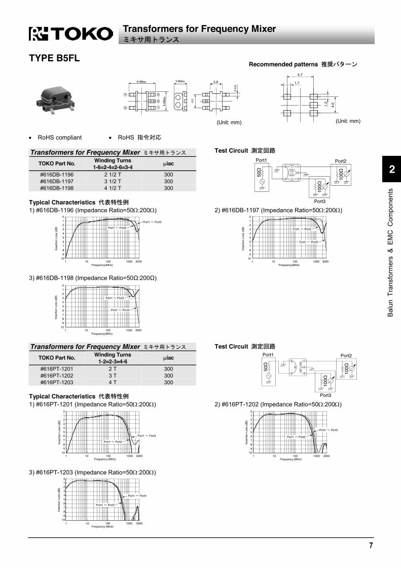
RoHS compliant RoHS Transformers for Frequency Mixer
TOKO Part No. Winding Turns 1-6=2-4=2-6=3-4 iac
#616DB-1196 2 1/2 T 300 #616DB-1197 3 1/2 T 300 #616DB-1198 4 1/2 T 300
Typical Characteristics 1) #616DB-1196 (Impedance Ratio=50 :200 ) 2) #616DB-1197 (Impedance Ratio=50 :200 )
3) #616DB-1198 (Impedance Ratio=50 :200 )
Transformers for Frequency Mixer
TOKO Part No. Winding Turns 1-2=2-3=4-6 iac
#616PT-1201 2 T 300 #616PT-1202 3 T 300 #616PT-1203 4 T 300
Typical Characteristics 1) #616PT-1201 (Impedance Ratio=50 :200 ) 2) #616PT-1202 (Impedance Ratio=50 :200 )
3) #616PT-1203 (Impedance Ratio=50 :200 )
Recommended patterns
Test Circuit
Transformers for Frequency Mixer
Test Circuit
3.8

8
TYPE B5FL Balun Transformers
TOKO Part No. Winding Turns iac
#616DB-1191 2 1/2 T 300 #616DB-1192 3 1/2 T 300 #616DB-1193 4 1/2 T 300 #616DB-1194 5 1/2 T 300
Typical Characteristics 1) #616DB-1191 50 :50 2) #616DB-1192 50 :50
3) #616DB-1193 50 :50 4) #616DB-1194 50 :50
Test Circuit
Balun Transformers

9
1
2
3
4
5
6
7
8
9
Balu
n Tr
ansf
orm
ers
& EM
C C
ompo
nent
s
TYPE B4W
(Unit: mm)
(Unit: mm)
Features Common mode chokes for IEEE1394/LVDS 100/200/400 Mbps 2 chokes in one (for TPA, TPB) RoHS compliant
IEEE1394/LVDS 100/200/400 Mbps 2 1 RoHS
Electrical Characteristics Pin Connections
Insertion Loss (dB) TOKO
Part Number 50MHz 100MHz 300MHz 500MHz #944CM-0051 5.0 2.0 8.0 2.5 12.8 3.0 15.0 3.0
Typical Characteristics
Insertion Loss Characteristics of B4W Impedance Characteristics of B4W
Test circuit
Common mode Normal mode
Applications
Ideal for use as common-mode chokes for IEEE1394 interface.
Common-mode Chokes for IEEE1394/LVDS IEEE1394/LVDS
Recommended patterns
TPA(TPB)
#1(#3)
#2(#4)
#8(#6)
#7(#5)R=50
R=50
IN
OUT

10
TYPE B5W
(Unit: mm)
(Unit: mm)
Features Common mode chokes for IEEE1394/LVDS 100/200/400 Mbps 2 chokes in one (for TPA, TPB) RoHS compliant
IEEE1394/LVDS 100/200/400 Mbps 2 1 RoHS
Electrical Characteristics Pin Connections
Insertion Loss (dB) TOKO
Part Number 50MHz 100MHz 300MHz 500MHz #857CM-0052 3.6 2.0 8.0 2.5 12.0 3.0 14.0 3.0
Typical Characteristics
Insertion Loss Characteristics of B5W Impedance Characteristics of B5W
Test circuit
Common mode Normal mode
Applications
Ideal for use as common-mode chokes for IEEE1394 interface.
Common-mode Chokes for IEEE1394/LVDS IEEE1394/LVDS
Recommended patterns
TPA(TPB)
#1(#3)
#2(#4)
#8(#6)
#7(#5)R=50
R=50
IN
OUT

11
1
2
3
4
5
6
7
8
9
Balu
n Tr
ansf
orm
ers
& EM
C C
ompo
nent
s
TYPE NT2012
(Unit: mm)
(Unit: mm)
Features Wire-wound miniature common mode choke. 2 Line use (for Data Line ). 985AH-1001 and 985BH-1007 passed USB-IF
Compliance Program (HS/FS signal quality test) Surface mount / Reflow soldering. RoHS compliant
2 USB-IF Compliance Program RoHS
Electrical Characteristics Pin Connections
/ Common Mode Impedance Common Mode Insertion Loss DC Resistance
10MHz 100MHz 10MHz 100MHz 500MHz /Line Symbol TOKO Part Number
( ) Typ. ( ) Typ. (dB) Max. (dB) Min. (dB) Min. ( ) Max.
DC Current (mA) Max.
A 985AH-1001 18 165 1.2 4.0 11.0 0.26 330 B 985BH-1007 10 90 1.0 1.5 8.0 0.26 330 C 985DH-1022 7 67 1.0 5.0(Max.) 5.0 0.16 420 D 985DH-1023 14 120 1.0 2.0 7.0 0.21 370 E 985DH-1025 28 260 1.5 6.0 14.0 0.31 310 F 985DH-1026 38 370 2.0 6.5 15.0 0.36 280
Typical Characteristics
Impedance Characteristics of NT2012 Impedance Characteristics of NT2012
Insertion Loss Characteristics of NT2012 Insertion Loss Characteristics of NT2012
Applications Test circuit
Ideal for use as common-mode chokes for USB1.1 / USB2.0 / IEEE1394 interface.
USB1.1/USB2.0 Application IEEE1394 Application
Common-mode Chokes for USB1.1/USB2.0/IEEE1394/LVDS/DVI/HDMI USB1.1/USB2.0/IEEE1394/LVDS/DVI/HDMI
Recommended patterns

12
TYPE BH8S
(Unit: mm)
(Unit: mm)
Features Most suitable common mode chokes for suppressing AM
band radiation noise. Rated DC Current 1.5A Max. (1.995A Typ./ 40°C) 2 line Operating temperature ; –40°C~+105°C
(Including self-temperature rise) RoHS compliant
AM 1.5A Max. (1.995A Typ./ 40°C) 2 40°C 105°C RoHS
Typical Characteristics
Insertion Loss Characteristics of 1065CM-1002 Impedance Characteristics of 1065CM-1002
Typical Applications Pin Connections
Recommended patterns
T vs DC (1065CM-1002)
Common Mode Choke for Smart Entry System

13
1
2
3
4
5
6
7
8
9
DC
-DC
Con
verte
r Tr
ansf
orm
ers
SMT DC-DC Converter Transformers DC-DC
CONTENTS
SMT DC-DC Converter Transformers DC-DC
5CA ......................................................................................................14
6CA ......................................................................................................14
8CA ......................................................................................................15
10CA ....................................................................................................15
R10F.....................................................................................................16
R12F.....................................................................................................16
R15F.....................................................................................................16

14
TYPE 5CA Frequency Range: 10~500kHz Maximum Conversion Power: 0.5~0.7W
*Available in heights 3.2mm, 4.2mm and 5.2mm (Unit: mm)
(Unit: mm)
Features 6.2 × 6.8 Max. square and 3.2mm, 4.2mm and 5.2mm
Max. height. Package design is ideal for automatic assembly. Available
on 12mm embossed tape. Available with up to 7 terminals to provide secondary
winding or taps or function as DC-DC transformer. Output power depends on the height.
H=3.2mm : 0.5W Max. H=4.2mm : 0.6W Max. H=5.2mm: 0.7W Max. (Rated power by each specification)
DC-DC converter transformer for Flyback system. RoHS compliant.
6.2 6.8 Max. 3.2mm 4.2mm 5.2mm Max.
DC-DC
H 3.2mm 0.5W Max. H 4.2mm 0.6W Max. H 5.2mm 0.7W Max.
DC-DC RoHS
TYPE 6CA Frequency Range: 10~500kHz Maximum conversion power: 0.4~0.7W
*Available in heights 2.6mm, 3.0mm and 4.0mm (Unit: mm)
(Unit: mm)
Features 7.04 × 6.5mm Max. square and 2.6mm, 3.0mm and
4.0mm Max. height. Suitable for reflow soldering. Available on tape and reel for automatic insertion. DC converter transformer with 8 terminals for a maximum
of 4 outputs. Output power depends on the height.
H=2.6mm : 0.4W Max. H=3.0mm : 0.6W Max. H=4.0mm: 0.7W Max. (Rated power by each specification)
DC-DC converter transformer for Flyback system. RoHS compliant.
7.04 6.5mm Max. 2.6 3.0 4.0mm Max.
8 4 DC-DC
H 2.6mm 0.4W Max. H 3.0mm 0.6W Max. H 4.0mm 0.7W Max.
DC-DC RoHS
SELECTION GUIDE FOR STANDARD TRANSFORMERS
Recommended patterns
SMT DC-DC Converter Transformers DC-DC
Recommended patterns
Please inquire for detailed specifications for Transformers.

15
1
2
3
4
5
6
7
8
9
DC
-DC
Con
verte
r Tr
ansf
orm
ers
TYPE 8CA Frequency Range: 10~500kHz Maximum conversion power: 0.8W
*:Height 2.9Max.
(Unit: mm)
(Unit: mm)
Features 8.5 × 8.8mm Max. square and 2.9mm Max. height. Suitable for reflow soldering. Available on tape and reel for automatic insertion. DC converter transformer with 8 terminals for a maximum
of 4 outputs. Output power : 0.8W Max.
(Rated power by each specification) DC-DC converter transformer for Flyback system. RoHS compliant.
8.5 8.8mm Max. 2.9mm Max. 8 4 DC-DC
0.8W Max.
DC-DC RoHS
TYPE 10CA Frequency Range: 10~500kHz Maximum conversion power: 1.0~2.0W
*Available in heights 3.5mm and 4.5mm (Unit: mm)
(Unit: mm)
Features 10.3 × 10.8mm Max. square and 3.5, 4.5mm Max. height. Suitable for reflow soldering. Available on tape and reel for automatic insertion. DC converter transformer with 10 terminals for a
maximum of 5 outputs. Output power depends on the height.
H=3.5mm : 1.0W Max. H=4.5mm : 2.0W Max. (Rated power by each specification)
DC-DC converter transformer for Flyback system. RoHS compliant.
10.3 10.8mm Max. 3.5, 4.5mm Max. 10 5 DC-DC
H 3.5mm 1.0W Max. H 4.5mm 2.0W Max.
DC-DC RoHS
SELECTION GUIDE FOR STANDARD TRANSFORMERS
Recommended patterns
SMT DC-DC Converter Transformers DC-DC
Recommended patterns
Please inquire for detailed specifications for Transformers.

16
TYPE R10F Frequency Range: 1~500kHz Inductance Range: 0.01~350mH Maximum conversion power: 1.5W (Flyback system)
(Unit: mm)
(Unit: mm)
TYPE R12F Frequency Range: 8~200kHz Inductance Range: 1~450mH Maximum conversion power: 2.0W (Flyback system)
(Unit: mm)
(Unit: mm)
TYPE R15F Frequency Range: 8~200kHz Inductance Range: 1~600mH Maximum conversion power: 4.0W (Flyback system)
(Unit: mm)
(Unit: mm)
Features R10F: 13.0 × 11.5mm Max. square and 6.2mm Max. height.
R12F: 14.5 × 13mm Max. square and 6.0mm Max. height.R15F: 16.5 × 16mm Max. square and 7.0mm Max. height.
Suitable for reflow soldering. Available on tape and reel for automatic insertion. Multi-output DC-DC converter transformers for low-output
power supplies. Rated power by each specification. RoHS compliant.
R10F 13.0 11.5mm Max. 6.2mm Max.
R12F 14.5 13mm Max. 6.0mm Max. R15F 16.5 16mm Max. 7.0mm Max.
DC-DC
RoHS
SELECTION GUIDE FOR STANDARD TRANSFORMERS
SMT DC-DC Converter Transformers DC-DC
Recommended patterns
Recommended patterns
Recommended patterns
Please inquire for detailed specifications for Transformers.
PITC
H=2
.5

17
1
2
3
4
5
6
7
8
9
CC
FL D
rivin
g In
verte
r Tr
ansf
orm
ers
CCFL Driving Inverter Transformers
PRECAUTIONS The inverter transformer generates high voltage and should not be touched during operation.
CONTENTS
CCFL Driving Inverter Transformers
BLC4115/BLC4115L...........................................................................18 CLT4123 .............................................................................................18 BLC4204/BLC4204B...........................................................................19 BLC4206/BLC4206B...........................................................................19

18
Max. 6.5 & 5.5W, Medium & Large size LCD Monitors and vehicle applications
14 6.5 & 5.5W
TYPE BLC4115/BLC4115L
(Unit: mm)
(Unit: mm) Description The BLC4115/4115L are a CCFL driving surface mount inverter transformers which height are Max. 6.7/6.0mm and formed by EIR ferrite cores. It is suitable for Hand held personal computer and LCD monitors for 14 inch size or more and LCD monitor for automotive monitors.
BLC4115/BLC4115L EIR 6.7/6.0mm Max.
14
Features Small and low-profile h= 6.7/6.0mm Max. height. Suitable for reflow soldering. Tandem structure of unit without the ballast capacitor. Available for mounting machine due to sipply in form of tray. Universal out-put terminals for high-voltage. RoHS compliant.
h=6.7/6.0mm Max. RoHS
STANDARD PARTS SELECTION GUIDE
BLC4115/BLC4115L TOKO Part
Number
Input Voltage
Range (V)
Output Open Voltage
(Vrms)
Power Consumption of CCFL (W)
Oscillation Frequency
(kHz)
Operating Temperature Range ( C)
BLC4115/BLC4115L 5~27 1500 Max. (2550Vo-p Max. 2sec.)
6.5/5.5 Max. 40~100 20 ~ +70*(+85)
Characteristics are different depending on operating conditions. / (85°C) Without ballast capacitance./
Max. 8W, Medium & Large size LCD Monitors and vehicle applications
14 8W
TYPE CLT4123
(Unit: mm)
(Unit: mm) Description Surface mount inverter transformer for CCFL driving. Suitable as an inverter transformer for LCD backlight. (14inch or larger LCD monitor or LCD monitor for automotive application.) The pin type is parts number CLTP4123.
14
CLTP4123
Features Original vertical structure. Low heat and high efficiency are achieved by using ferrite core of high Bs
and low los. Available for mounting machine due to supply in a form of tray. Ballast capacitor free system. Suitable for reflow soldering. RoHS compliant.
Bs RoHS
STANDARD PARTS SELECTION GUIDE CTL4123
TOKO Part
Number
Input Voltage
Range (V)
Output Open Voltage
(Vrms)
Power Consumption of CCFL (W)
Oscillation Frequency
(kHz)
Operating Temperature Range ( C)
CLT4123 DC36V Max. 1800 Max. 3200Vo-p/3sec
8 Max./ch. 35kHz/IC
30~70 20 ~ +70
Characteristics are different depending on operating conditions. / (+85°C) ; Without ballast capacitance. /
CCFL Driving Inverter Transformers

19
1
2
3
4
5
6
7
8
9
CC
FL D
rivin
g In
verte
r Tr
ansf
orm
ers
2 in1 type, Max.3.5W/ch, LCD Monitors for 14 inch size or more and vehicle applications
14 3.5W/ch
TYPE BLC4204/BLC4204B
(Unit: mm)
(Unit: mm)
Description The BLC4204/BLC4204B is a CCFL driving surface mount inverter transformers which height is Max. 5.6mm and formed by EIR ferrite cores. Ideal for 14 inch or more LCD display and automotive monitors (Car navigation).
BLC4204/BLC4204B EIR 5.6mm Max.
14
Features Small and low-profile h=5.6mm Max. height. Tandem structure of the unit without the ballast capacitior. Transformer of two in one construction type.(1 input, 2 outputs/1 input, 1 output.) Suitable for reflow soldering. RoHS compliant.
h=5.6mm Max. 1 2 /1 1 RoHS
STANDARD PARTS SELECTION GUIDE BLC4204/BLC4204B
TOKO Part
Number
Input Voltage
Range (V)
Output Open Voltage
(Vrms)
Power Consumption of CCFL (W)
Oscillation Frequency
(kHz)
Operating Temperature Range ( C)
BLC4204 5~27 1500 Max./ch (2550Vo-p Max. 2sec./ch)
3.5 Max./2ch 40~100 20 ~ +70*(+85)
BLC4204B 5~27 *2000 Max. (1000 Max./ch)
(1750Vo-p Max. 2sec./ch)
7.0 Max. 40~100 20 ~ +70*(+85)
Characteristics are different depending on operating conditions. Use a floating-lamp topology. (85°C); Without ballast capacitance
2 in 1 type, Max. 6.5W/ch, LCD Monitors for 14 inch size or more and vehicle applications
14 6.5W/ch
TYPE BLC4206/BLC4206B
(Unit: mm)
(Unit: mm) Description The BLC4206/BLC4206B is a CCFL driving surface mount inverter transformers which height is Max. 7.0mm and formed by EIR ferrite cores. It is suitable for inverter transformers for 14 inch size or more LCD monitor for automotive monitors.
BLC4206/BLC4206B EIR Max. 7.0mm
14
Features Small and low-profile h=7.0mm Max. height. Tandem structure of the unit without the ballast capacitor. Transformer of two in one construction type.(1 input, 2 outputs./1 input, 1 output.) Suitable for reflow soldering. RoHS compliant.
h=7.0mm Max. 1 2 /1 1 RoHS
STANDARD PARTS SELECTION GUIDE BLC4206/BLC4206B
TOKO Part
Number
Input Voltage
Range (V)
Output Open Voltage
(Vrms)
Power Consumption of CCFL (W)
Oscillation Frequency
(kHz)
Operating Temperature Range ( C)
BLC4206 5~27 1500 Max./ch (2550Vo-p Max. 2sec./ch)
6.5 Max./2ch 40~100 20 ~ +70*(+85)
BLC4206B 5~27 *2000 Max. (1000 Max./ch)
(1750Vo-p Max. 2sec./ch)
13.0 Max. 40~100 20 ~ +70*(+85)
Characteristics are different depending on operating conditions. Use a floating-lamp topology. (85°C); Without ballast capacitance
CCFL Driving Inverter Transformers

20

21
1
2
3
4
5
6
7
8
9
Die
lect
ric F
ilter
s
Chip Dielectric Filters
CONTENTS
Chip Dielectric Filters (TDF Series) TDF
Part numbering system ............................................................ 22 Dimensions .............................................................................. 22 TDF series for Wireless Broadband Communication.......................... 23, 26 TDF series for Mobile & Cordless Phone ........................................... 24, 26 TDF series for Automotive & Satellite Radio ...................................... 25, 26

22
TDF Series
Part numbering system /
Dimensions /
TDFS Type TDFM Type TDF Type TDFH Type
2 Poles 3 Poles 4 Poles
Unit: mm
T1 T2 T3 T4 2.25 Max. 2.0 Max. 1.8 Max.
2.8 Max. 2.25 Max. 2.0 Max.
3.0 Max. 2.25 Max. 2.0 Max.
5.5 Max. 4.0 Max.
The length, L, is different depending on the part number. Refer to the separate table.
(L)
For the details of shapes regarding individual part numbers, contact us separately.
The packing quantity /
The taping quantity per reel in Part Number tables is the quantity of standard packing. Please consult our sales or representative office when you hope for a different amount.
Chip Dielectric Filters

23
1
2
3
4
5
6
7
8
9
Die
lect
ric F
ilter
s
TDF series for Wireless Broadband Communication
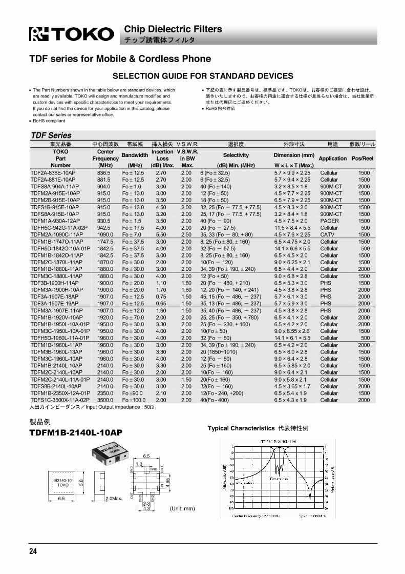
SELECTION GUIDE FOR STANDARD DEVICES The Part Numbers shown in the table below are standard devices, which are readily available. TOKO will design and manufacture modified and custom devices with specific characteristics to meet your requirements. If you do not find the device for your application in this catalog, please contact our sales or representative office.
RoHS compliant
TOKO
RoHS
TDF Series
V.S.W.R. /TOKO Part
Number
Center Frequency
(MHz)
Bandwidth
(MHz)
InsertionLoss
(dB) Max.
V.S.W.R.in BWMax.
Selectivity
(dB) Min. (MHz)
Dimension (mm)
W × L × T (Max.) Application Pcs/Reel
TDF2A-2450T-10AP 2450.0 Fo 50.0 2.00 2.00 20, 16 (Fo 280, + 280) 5.7 × 5.1 × 2.25 2.4G-LAN 2000 TDFM1A-2450T-10AP 2450.0 Fo 50.0 2.00 2.00 20, 16 (Fo 280, + 280) 4.5 × 5.2 × 2.0 2.4G-LAN 2000 TDFM1B-2450T-10AP 2450.0 Fo 50.0 2.30 2.00 35, 30 (Fo 430, + 350) 6.5 × 5.1 × 2.0 2.4G-LAN 1500 TDFM1C-2450T-10AP 2450.0 Fo 50.0 3.00 2.00 21, 32 (Fo 150, 200) 9.0 × 5.15 × 2.0 2.4G-LAN 1500 TDFS8A-2450T-13AP 2450.0 Fo 50.0 2.00 2.00 40 (Fo 500) 3.2 × 3.0 × 1.8 2.4G-LAN 2000 TDF2A-2484E-11AP 2484.0 Fo 13.0 3.00 1.60 35, 30 (Fo 350, 700) 5.7 × 5.1 × 2.25 2.4G-LAN 2000 TDF2A-2484E-12AP 2484.0 Fo 13.0 2.00 1.60 25, 30 (Fo 350, 700) 5.7 × 5.1 × 2.25 2.4G-LAN 2000 TDFM1A-2484E-10AP 2484.0 Fo 13.0 2.00 2.00 25, 30 (Fo 350, 700) 4.5 × 5.1 × 2.0 2.4G-LAN 2000 TDFM1A-2484E-11AP 2484.0 Fo 13.0 3.00 2.00 35, 30 (Fo 350, 700) 4.5 × 5.2 × 2.0 2.4G-LAN 2000 TDFM1B-2350T-11AP 2350.0 Fo 50 2.30 2.00 35,30(1920,2700) 6.5 × 5.35 × 2.0 WiMAX 1500 TDFM1B-2546S-10AP 2546.0 Fo 46.5 1.80 2.00 44, 40 (Fo 412.5, 868.5) 6.5 × 4.05 × 1.90 WiMAX 2000 TDFM1B-2639S-10AP 2639.5 Fo 46.5 1.50 2.00 33, 35 (Fo 410.5, 866.5) 6.5 × 4.75 × 1.90 WIMAX 2000 TDFM3B-2593X-10A-01P 2593.0 Fo 97 2.00 2.00 25(2275) 6.5 × 4.5 × 2.5 WiMAX 1500 TDFH4C-2593X-10AP 2593.0 Fo 97 2.00 2.00 55,40, 30 (1393,2041,2377) 11.5 × 5.9 × 3.8 WiMAX 500 TDFM3B-2596X-10AP 2596.0 Fo 96 2.00 2.00 24,20(2200,3200) 6.5 × 4.5 × 2.5 WiMAX 1500 TDFM1B-2639S-10AP 2639.5 Fo 46.5 1.50 2.00 33, 35 (Fo 410.5, 866.5) 6.5 × 4.75 × 1.90 WiMAX 2000 TDFS1C-3449T-10AP 3449.75 Fo 50.25 1.50 2.00 40, 45 (Fo 862, 406) 6.5 × 4.4 × 2.0 Wi MAX 2000 TDFM2A-3549T-10AP 3549.75 Fo 50.25 1.40 2.00 31, 33 (Fo 882, 406) 4.5 × 4.5 × 2.25 Wi MAX 2000 TDFM2A-4995X-10A-01P 4995.0 Fo 95.5 1.50 2.00 20 (Fo 795) 4.5 × 3.3 × 2.25 5G-LAN 2000 TDFM2C-4995X-10AP 4995.0 Fo 95.5 3.10 2.00 35, 50 (Fo 560, Fo + 560) 9.0 × 3.3 × 2.25 5G-LAN 2000 TDFS8A-5075Z-10AP 5075.0 Fo 175.0 1.25 2.00 20 (4200) 3.2 × 3.25 × 1.8 5G-LAN 2000 TDFM2C-5250X-10AP 5250.0 Fo 100.0 3.00 2.00 35 (Fo 400) 9.0 × 3.1 × 2.25 5G-LAN 2000 TDFS8A-5250X-10AP 5250.0 Fo 100.0 1.50 2.00 20 (Fo 800) 3.2 × 3.2 × 1.8 5G-LAN 2000 TDFS8A-5437Z-10AP 5437.5 Fo 287.5 1.20 2.00 25 (Fo 1937.5) 3.2 × 3.05 × 1.87 5G-LAN 2000 TDFS8A-5500Z-10AP 5500.0 Fo 350.0 1.00 2.00 25 (3500) 3.2 × 3.05 × 1.8 5G-LAN 2000 TDFM2A-5775T-10A-01P 5775.0 Fo 50.0 3.30 2.70 28 (5225.0~5325.0) 4.5 × 2.9 × 2.25 5G-LAN 2000 TDFM2A-5775V-11AP 5775.0 Fo 75.0 1.50 2.00 7,8 (Fo 425, + 515) 4.5 × 2.9 × 2.25 5G-LAN 2000
TDFH4C-2593X-10AP
(Unit: mm)
Chip Dielectric Filters
Typical Characteristics
GND
OU
T
IN
24
TDF series for Mobile & Cordless Phone
SELECTION GUIDE FOR STANDARD DEVICES The Part Numbers shown in the table below are standard devices, which are readily available. TOKO will design and manufacture modified and custom devices with specific characteristics to meet your requirements. If you do not find the device for your application in this catalog, please contact our sales or representative office.
RoHS compliant
TOKO
RoHS
TDF Series
V.S.W.R. /TOKO Part
Number
Center Frequency
(MHz)
Bandwidth
(MHz)
InsertionLoss
(dB) Max.
V.S.W.R.in BWMax.
Selectivity
(dB) Min. (MHz)
Dimension (mm)
W × L × T (Max.) Application Pcs/Reel
TDF2A-836E-10AP 836.5 Fo 12.5 2.70 2.00 6 (Fo 32.5) 5.7 × 9.9 × 2.25 Cellular 1500 TDF2A-881E-10AP 881.5 Fo 12.5 2.70 2.00 6 (Fo 32.5) 5.7 × 9.4 × 2.25 Cellular 1500 TDFS8A-904A-11AP 904.0 Fo 1.0 3.00 2.00 40 (Fo 140) 3.2 × 8.5 × 1.8 900M-CT 2000 TDFM2A-915E-10AP 915.0 Fo 13.0 3.00 2.00 12 (Fo 50) 4.5 × 7.7 × 2.25 900M-CT 1500 TDFM2B-915E-10AP 915.0 Fo 13.0 3.50 2.00 18 (Fo 50) 6.5 × 7.9 × 2.25 900M-CT 1500 TDFS1B-915E-10AP 915.0 Fo 13.0 4.50 2.00 32, 25 (Fo 77.5, + 77.5) 4.5 × 8.3 × 2.0 900M-CT 1500 TDFS8A-915E-10AP 915.0 Fo 13.0 3.20 2.00 25, 17 (Fo 77.5, + 77.5) 3.2 × 8.4 × 1.8 900M-CT 1500 TDFM1A-930A-12AP 930.5 Fo 1.5 3.50 2.00 40 (Fo 90) 4.5 × 7.5 × 2.0 PAGER 1500 TDFH5C-942G-11A-02P 942.5 Fo 17.5 4.00 2.00 20 (Fo 27.5) 11.5 × 8.4 × 5.5 Cellular 500 TDFM2A-1090C-11AP 1090.0 Fo 7.0 5.50 2.50 35, 33 (Fo 80, + 80) 4.5 × 7.6 × 2.25 CATV 1500 TDFM1B-1747O-11AP 1747.5 Fo 37.5 3.00 2.00 8, 25 (Fo 80, 160) 6.5 × 4.75 × 2.0 Cellular 1500 TDFH5D-1842O-10A-01P 1842.5 Fo 37.5 4.00 2.00 32 (Fo 57.5) 14.1 × 6.6 × 5.5 Cellular 500 TDFM1B-1842O-11AP 1842.5 Fo 37.5 3.00 2.00 8, 25 (Fo 80, 160) 6.5 × 4.5 × 2.0 Cellular 1500 TDFM2C-1870L-11AP 1870.0 Fo 30.0 2.00 2.00 10(Fo 120) 9.0 × 6.25 × 2.1 Cellular 1500 TDFM1B-1880L-11AP 1880.0 Fo 30.0 3.00 2.00 34, 39 (Fo 190, 240) 6.5 × 4.4 × 2.0 Cellular 2000 TDFM3C-1880L-11AP 1880.0 Fo 30.0 4.00 2.00 12 (Fo + 50) 9.0 × 6.8 × 2.8 Cellular 1500 TDF3B-1900H-11AP 1900.0 Fo 20.0 1.10 1.80 20 (Fo 480, + 210) 6.5 × 5.3 × 3.0 PHS 1500 TDFM3A-1900H-10AP 1900.0 Fo 20.0 1.70 1.60 12, 20 (Fo 140, + 241) 4.5 × 3.8 × 2.8 PHS 2000 TDF3A-1907E-18AP 1907.0 Fo 12.5 0.75 1.50 45, 15 (Fo 486, 237) 5.7 × 6.1 × 3.0 PHS 2000 TDF3A-1907E-19AP 1907.0 Fo 12.5 0.65 1.50 35, 13 (Fo 486, 237) 5.7 × 5.9 × 3.0 PHS 2000 TDFM3A-1907E-11AP 1907.0 Fo 12.0 1.60 1.50 35, 40 (Fo 486, 237) 4.5 × 3.8 × 2.8 PHS 2000 TDFM1B-1920V-10AP 1920.0 Fo 70.0 2.00 2.00 25, 25 (Fo 350, + 780) 6.5 × 4.1 × 2.0 Cellular 2000 TDFM1B-1950L-10A-01P 1950.0 Fo 30.0 3.30 2.00 25 (Fo 230, + 160) 6.5 × 4.2 × 2.0 Cellular 2000 TDFM3C-1950L-10A-01P 1950.0 Fo 30.0 4.00 2.00 10(Fo 50) 9.0 x 6.55 x 2.6 Cellular 1500 TDFH5D-1960L-11A-01P 1960.0 Fo 30.0 4.00 2.00 32 (Fo 50) 14.1 × 6.1 × 5.5 Cellular 500 TDFM1B-1960L-11AP 1960.0 Fo 30.0 3.00 2.00 34, 39 (Fo 190, 240) 6.5 × 4.2 × 2.0 Cellular 2000 TDFM3B-1960L-13AP 1960.0 Fo 30.0 3.30 2.00 20 (1850~1910) 6.5 × 6.0 × 2.8 Cellular 1500 TDFM3C-1960L-10AP 1960.0 Fo 30.0 4.00 2.00 12 (Fo 50) 9.0 × 6.4 × 2.8 Cellular 1500 TDFM1B-2140L-10AP 2140.0 Fo 30.0 3.30 2.00 25 (Fo 160) 6.5 × 5.85 × 2.0 Cellular 1500 TDFM2C-2140L-10AP 2140.0 Fo 30.0 2.00 2.00 10(Fo 160) 9.0 × 6.4 × 2.1 Cellular 1500 TDFM2C-2140L-11A-01P 2140.0 Fo 30.0 3.00 1.50 20(Fo 160) 9.0 x 5.8 x 2.1 Cellular 1500 TDFS8B-2140L-10AP 2140.0 Fo 30.0 3.00 2.00 32(Fo 160) 4.5 × 3.65 × 1.7 Cellular 2000 TDFM1B-2350X-12A-01P 2350.0 Fo 90.0 2.10 2.00 12(Fo - 240, +200) 6.5 x 5.4 x 1.9 Cellular 1500 TDFS1C-3500X-11A-02P 3500.0 Fo 100.0 2.00 2.00 40(Fo - 400) 6.5 x 4.3 x 1.9 Cellular 2000
Input Output impedance : 50
TDFM1B-2140L-10AP
(Unit: mm)
Chip Dielectric Filters
Typical Characteristics

25
1
2
3
4
5
6
7
8
9
Die
lect
ric F
ilter
s
TDF series for Automotive & Satellite Radio
SELECTION GUIDE FOR STANDARD DEVICES The Part Numbers shown in the table below are standard devices, which are readily available. TOKO will design and manufacture modified and custom devices with specific characteristics to meet your requirements. If you do not find the device for your application in this catalog, please contact our sales or representative office.
RoHS compliant
TOKO
RoHS
TDF Series
V.S.W.R. /TOKO Part
Number
Center Freq. (MHz)
Bandwidth
(MHz)
InsertionLoss
(dB) Max.
V.S.W.R.in BW
Selectivity
(dB) Min. (MHz)
Dimension (mm)
W × L × T (Max.) Application Pcs/Reel
TDFS8A-1472H-10AP 1472.0 Fo 20.0 1.50 2.00 30,19(Fo - 567,Fo + 248) 3.2 x 5.6 x 1.7 DAB 2000 TDFM2B-1472H-10AP 1472.0 Fo 20.0 3.00 2.00 34, 36 (Fo 215, 450) 6.5 × 5.55 × 2.25 DAB 1500 TDFM3A-1472H-10AP 1472.0 Fo 20.0 1.80 2.00 38 (Fo 422) 4.5 × 5.3 × 2.8 DAB 2000 TDFM3A-1472H-14AP 1472.0 Fo 20.0 1.50 2.00 42 (Fo 230) 4.5 × 5.25 × 2.8 DAB 2000 TDFM3A-1238I-10AP 1238.5 Fo 21.5 1.80 2.00 10 (Fo 140) 4.5 × 6.6 × 2.8 GPS+GLONASS 2000 TDFM3A-1590J-10AP 1590.0 Fo 25.0 2.00 2.00 10 (Fo 140) 4.5 × 5.1 × 2.8 GPS+GLONASS 2000 TDFM3C-1590H-10AP 1590.0 Fo 16.0 3.20 2.00 25(Fo 50) 9.0 x 6.8 x 2.5 GPS+GLONASS 1500 TDF3A-1227B-10AP 1227.0 Fo 5.0 1.20 2.00 20 (Fo 140) 5.7 ×7.5 × 3.0 GPS(L2) 1500 TDF2A-1575B-11AP 1575.4 Fo 5.0 5.50 2.30 22 (Fo 50) 5.7 × 5.4 × 2.25 GPS(L1) 2000 TDF2A-1575B-12AP 1575.4 Fo 5.0 2.70 2.00 30, 28 (Fo 140, + 140) 5.7 × 5.2 × 2.25 GPS(L1) 2000 TDF2A-1575B-13AP 1575.4 Fo 5.0 1.00 2.00 7 (Fo 140) 5.7 × 5.2 × 2.25 GPS(L1) 2000 TDF3A-1575B-10AP 1575.4 Fo 5.0 2.70 2.00 30, 28 (Fo 140, + 140) 5.7 × 5.4 × 3.0 GPS(L1) 2000 TDFM1A-1575A-13AP 1575.4 Fo 1.0 4.00 2.00 18 (Fo 50) 4.5 × 5.4 × 1.9 GPS(L1) 2000 TDFM1B-1575A-10AP 1575.4 Fo 1.0 5.50 2.00 30.5 (Fo 50) 6.5 × 5.1 × 1.9 GPS(L1) 1500 TDFM2A-1575A-10AP 1575.4 Fo 1.0 3.20 2.00 30, 28 (Fo 140, + 140) 4.5 × 5.25 × 2.25 GPS(L1) 2000 TDFM2A-1575A-11AP 1575.4 Fo 1.0 5.50 2.30 22 (Fo 50) 4.5 × 5.2 × 2.25 GPS(L1) 2000 TDFS8A-1575A-10AP 1575.4 Fo 1.0 1.00 2.00 25, 5 (Fo 726.5, + 275) 3.2 × 5.3 × 1.8 GPS(L1) 2000 TDFS1C-2326C-10AP 2326.0 Fo 7.0 2.00 2.00 10, 6 (Fo 100, + 100) 5.0 × 4.6 × 2.0 SDARS 2000 TDFS1C-2326C-11AP 2326.0 Fo 7.0 3.00 2.00 30, 25 (Fo 100, + 100) 5.0 × 4.6 × 2.0 SDARS 2000 TDFS8A-2326C-10AP 2326.0 Fo 7.0 2.80 2.00 20 (Fo 200, + 200) 3.2 × 3.5 × 1.8 SDARS 2000 TDFS8B-2326C-10A-01P 2326.0 Fo 7.0 4.50 2.00 24, 19 (Fo 100, + 100) 4.5 × 3.4 × 1.8 SDARS 2000 TDFM1B-2332E-10AP 2332.5 Fo 12.5 2.80 2.00 32, 32 (Fo 226, + 239) 6.5 × 5.35 × 2.0 SDARS 1500 TDFS1C-2332E-10AP 2332.5 Fo 13.0 2.00 2.00 37, 37 (Fo 222.5, + 227.5) 6.5 × 5.1 × 2.0 SDARS 1500 TDFS8A-2338B-11AP 2338.5 Fo 6.25 3.80 2.00 30 (Fo 200) 3.2 × 3.55 × 1.8 SDARS 2000 TDFS8A-2338E-10AP 2338.5 Fo 12.5 3.40 2.00 37, 25 (Fo 200, + 200) 3.2 × 3.3 × 1.8 SDARS 2000 TDFS8A-2338C-12AP 2338.5 Fo 7.0 3.00 2.00 28 (Fo 230) 3.2 × 3.5 × 1.8 SDARS 2000 TDFS1C-2338B-11AP 2338.75 Fo 6.25 3.50 2.00 20 (Fo 56.5) 5.9 × 4.4 × 2.0 SDARS 2000 TDF2A-2500A-12AP 2500.0 Fo 2.0 5.00 2.00 20, 25 (Fo 60, 90) 5.7 × 5.2 × 2.25 VICS 2000 TDFM2A-5800B-11AP 5800.0 Fo 5.0 3.00 2.00 20 (Fo 400) 4.5 × 2.9 × 2.25 ETC/DSRC 2000 TDFS8A-5810P-10AP 5810.0 Fo 40.0 2.50 2.00 20 (5400) 3.2 × 2.9 × 1.8 ETC/DSRC 2000
Input Output impedance : 50
TDFS1C-2332E-10AP
(Unit: mm)
Chip Dielectric Filters
Typical Characteristics
IN
OU
T
GND
26
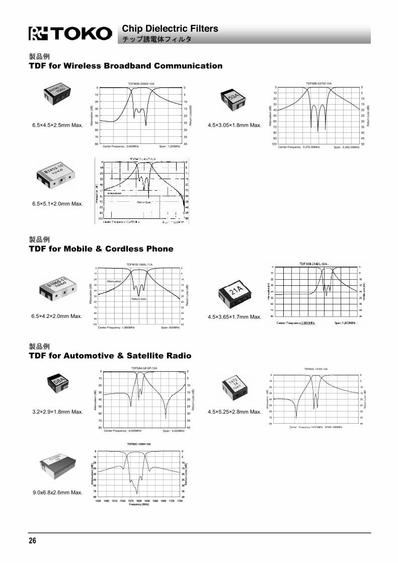
TDF for Wireless Broadband Communication
TDF for Mobile & Cordless Phone
TDF for Automotive & Satellite Radio
TDFM3C-1590H-10A
0
10
20
30
40
50
60
70
801450 1480 1510 1540 1570 1600 1630 1660 1690 1720 1750
Frequency [MHz]
Atte
nuat
ion
[dB
]
0
5
10
15
20
25
30
35
40
Retru
n Lo
ss [d
B]
Chip Dielectric Filters
6.5×4.5×2.5mm Max. 4.5×3.05×1.8mm Max.
6.5×5.1×2.0mm Max.
6.5×4.2×2.0mm Max. 4.5×3.65×1.7mm Max.
3.2×2.9×1.8mm Max. 4.5×5.25×2.8mm Max.
9.0x6.8x2.6mm Max.

27
1
2
3
4
5
6
7
8
9
Die
lect
ric F
ilter
s
Dielectric Filters
2-pole 3-pole 4-pole 5-pole
PIN #6DFA #6DFB #6DFC #6DFSC #6DFSD
#4DFA #4DFB - - FILTERS
SMD #AF3A #AF4A -
#AF3B #AF4B #AF5B
#AF3C #AF4C #AF5C
#AF3D #AF4D #AF5D
TYPE #6DPD #6DPF #6DPH #6DPK
Rx (Receiving) 2-pole 3-pole 4-pole 5-poleDUPLEXERSTx (Transmitting) 2-pole 3-pole 3-pole 4-pole
CONTENTS
Dielectric Filters
#4DFA ....................................................................................................28 #4DFB ....................................................................................................28 #AF.........................................................................................................30 #6DFA ....................................................................................................31 #6DFB ....................................................................................................31 #6DFC....................................................................................................32 #6DFSC .................................................................................................32 #6DFSD .................................................................................................33
Antenna Duplexers
#6DPF ....................................................................................................34 #6DPH....................................................................................................34
Precautions in using dielectric filters suface mount type ..........................35
Recommended soldering conditions.........................................................35

28
TYPE #4DFA (2 Pole SMD Type) / #4DFB (3 Pole SMD Type) Frequency Range: 700~2500MHz Temperature Range: - 40°C~+ 85°C #4DFA
(Unit: mm) *: Depends on Center Frequency. *:
#4DFB
(Unit: mm) *: Depends on Center Frequency. *:
SELECTION GUIDE FOR STANDARD DEVICES
The Part Number shown in the table below are standard devices, which are readily available. TOKO will design and manufacture modified and custom devices with specific characteristics to meet your requirements. If you do not find the devices for your application in this catalog, please contact our sales or representative office.
RoHS compliant
TOKO
RoHS
TYPE #4DFA: SMD 2 Pole Designs
V.S.W.R. TOKO Part
Number
Center Frequency
(MHz)
Bandwidth
(fo MHz)
Insertion Loss
(dB) Max.
Ripple in BW
(dB) Max.
V.S.W.R.in BW Max.
Selectivity
(dB) Min. (MHz) Application
#4DFA-836E-10 836.5 12.5 2.0 1.0 2.0 18 (fo 77.5) AMPS #4DFA-881E-10 881.5 12.5 2.0 1.0 2.0 18 (fo 77.5) AMPS #4DFA-902E-10 902.5 12.5 2.0 1.0 2.0 18 (fo 77.5) NMT/GSM #4DFA-947E-10 947.5 12.5 2.0 1.0 2.0 18 (fo 77.5) NMT/GSM #4DFA-866A-10 866.0 2.0 3.0 1.0 1.43 30 (fo 105) CT2 #4DFA-886A-10 886.0 1.0 3.0 1.0 2.0 22 (fo 45) Cordless Phone #4DFA-808C-11 808.0 8.0 2.0 1.0 2.0 22 (fo 64) Wireless Microphone#4DFA-849C-10 849.0 8.0 2.0 1.0 2.0 22 (fo 64) Wireless Microphone#4DFA-915E-10 915.0 13.0 2.2 1.0 2.0 18 (fo 77.5) Spread Spectrum #4DFA-1227B-10 1227.0 5.0 2.0 0.8 2.0 7, 30 (fo 35, 140) GPS #4DFA-1227B-11 1227.0 5.0 1.2: 0.7 Typ. 0.5 2.0 15, 20 (fo + 140, 140) GPS #4DFA-1227D-12 1227.0 10.0 1.2: 0.7 Typ. 0.7 2.0 16, 20 (fo + 140, 140) GPS #4DFA-1237L-10 1237.0 30.0 1.7 1.0 2.0 10, 15 (fo + 140, 140) GPS+GLONASS #4DFA-1248B-10 1248.0 5.0 2.0: 1.4 Typ. 0.8 2.0 7, 30 (fo 35, 140) GPS #4DFA-1575B-10 1575.4 5.0 2.0: 1.4 Typ. 0.8 2.0 7, 30 (fo 35, 140) GPS #4DFA-1575B-12 1575.4 5.0 1.2: 0.7 Typ. 0.5 2.0 17, 20 (fo + 140, 140) GPS #4DFA-1575B-14 1575.4 5.0 2.5: 1.8 Typ. 0.8 2.0 17 (fo 50) GPS #4DFA-1591L-10 1591.0 30.0 1.5 0.7 2.0 10, 15 (fo + 140, 140) GPS+GLONASS #4DFA-2442P-10 2442.0 40.0 2.5 1.0 2.0 15 (fo 250) Spread Spectrum Input Output impedance : 50
Dielectric Filters for Surface Mounting
Typical Characteristics

29
1
2
3
4
5
6
7
8
9
Die
lect
ric F
ilter
s
TYPE #4DFB: SMD 3 Pole Designs
V.S.W.R. TOKO Part
Number
Center Frequency
(MHz)
Bandwidth
(fo MHz)
Insertion Loss
(dB) Max.
Ripple in BW
(dB) Max.
V.S.W.R.in BW Max.
Selectivity
(dB) Min. (MHz) Application
#4DFB-591F-10 591.0 15.0 3.0 1.2 2.2 40 (fo 110) Wireless Microphone#4DFB-621F-10 621.0 15.0 3.0 1.2 2.2 40 (fo 110) Wireless Microphone#4DFB-704E-10 704.0 12.0 3.0 1.0 2.0 40,43 (fo 100, + 100) Wireless Microphone#4DFB-790H-10 790.0 20.0 2.7 1.1 2.5 35 (fo 100) Wireless Microphone#4DFB-796F-10 796.0 14.0 3.0 1.0 2.0 40,43 (fo 100, + 100) Wireless Microphone#4DFB-836E-10 836.5 12.5 2.5 1.0 2.0 12 (fo 32.5) AMPS #4DFB-881E-10 881.5 12.5 2.5 1.0 2.0 12 (fo 32.5) AMPS #4DFB-886A-10 886.0 1.0 4.5 1.0 2.0 41 (fo 45) Cordless Phone #4DFB-953A-10 953.5 1.5 6.0 1.5 2.0 30 (fo 30) RFID #4DFB-915E-10 915.0 13.0 2.7 1.0 2.0 12 (fo 32.5) Spread Spectrum #4DFB-1030C-10 1030.0 7.5 3.2 1.0 1.6 20, 50 (fo 35, 140) TCAS #4DFB-1227D-10 1227.0 10.0 3.2 1.0 2.0 12, 40 (fo 35, 140) GPS #4DFB-1575D-10 1575.0 10.0 3.2 1.0 2.0 12, 40 (fo 35, 140) GPS #4DFB-1542G-10 1542.0 17.0 2.0 1.0 2.0 17 (fo 84.5) MCSS/INMARSAT #4DFB-1643G-10 1643.5 17.0 1.6 0.5 1.5 18, 28 (fo 67, + 108) MCSS/INMARSAT #4DFB-1747N-10 1747.5 35.0 2.0 1.2 2.0 12, 38 (fo 100, 350) PCN #4DFB-1842N-10 1842.5 35.0 2.0 1.2 2.0 24, 38 (fo 157, 350) PCN #4DFB-1950L-10 1950.0 30.0 3.0 1.0 2.0 25, 25 (fo 230, + 160) W-CDMA #4DFB-2140L-10 2140.0 30.0 3.0 1.0 2.0 30, 22 (fo 340, 160) W-CDMA #4DFB-2442P-10 2442.0 40.0 2.5 1.2 2.0 5, 32 (fo 80, 250) Spread Spectrum #4DFB-920A-11 920.0 2.5 5.0 1.0 2.0 50, 18 (fo 88, 20) Digital TV #4DFB-860D-10 860.0 10.0 2.5 0.8 2.0 15, 35 (fo 35, 80) LMR #4DFB-938A-13 938.0 3.0 2.0 1.0 2.0 18, 13 (fo 36, + 36) LMR Input Output impedance : 50
Dielectric Filters for Surface Mounting

30
#AF Series Frequency Range: 700~2800MHz Temperature Range: 40°C~+ 85°C Package
#AF3B 10 x 13.5 x 4.0 mm
#AF3C 13 x 12 x 4.0 mm
#AF5D 26 x 14 x 6.2 mm
Descriptions Surface mounting dielectric filter . The resonator have 2-5 pole and the size is 3-5mm. TOKO will comply with your demand characteristics. RoHS compliant
3 5mm 2 5
RoHS Applicable range Frequency Range: 700~2800MHz Temperature Range: 40°C~+ 85°C Resonator size: 3mm, 4mm, 5mm Resonator array:2,3,4,5 Input Output impedance : 50ohm
700 2800MHz -40 +85°C 3mm 4mm 5mm 2 3 4 5 50
Example Specifications Typical Characteristics
TOKO Part Number #AF5D-2140L-10
Center frequency 2140 MHz
Bandwidth Fo 30 MHz
Insertion loss 3.0 dB Max.
Ripple 1.0 dB Max.
VSWR 2.0 Max.
Attenuation 43 dB Min. at 1980 MHz
50 dB Min. at 2300 MHz Custom device TOKO will comply with your demand characteristics. Please contact our sales office or representative office.
0
10
20
30
40
50
60
70
801700 1800 1900 2000 2100 2200 2300 2400 2500 2600
Frequency [MHz]
Atte
nuat
ion
[dB]
0
5
10
15
20
25
30
35
40
Ret
urn
Loss
[dB
]
Dielectric Filters for Surface Mounting

31
1
2
3
4
5
6
7
8
9
Die
lect
ric F
ilter
s
TYPE #6DFA (2 Pole Type) / #6DFB (3 Pole Type) Frequency Range: 700~1900MHz Temperature Range: 40°C~+ 85°C #6DFA
(Unit: mm) *: Depends on Center Frequency. *:
#6DFB
(Unit: mm) *: Depends on Center Frequency. *:
SELECTION GUIDE FOR STANDARD DEVICES The Part Number shown in the table below are standard devices, which are readily available. TOKO will design and manufacture modified and custom devices with specific characteristics to meet your requirements. If you do not find the devices for your application in this catalog, please contact our sales or representative office.
RoHS compliant
TOKO
RoHS
TYPE #6DFA: 2 Pole Designs
V.S.W.R. TOKO Part
Number
Center Frequency
(MHz)
Bandwidth (fo MHz)
Insertion Loss
(dB) Max.
Ripple in BW
(dB) Max.
V.S.W.R.in BW Max.
Selectivity (dB) Min. (MHz) Application
#6DFA-836E-10 836.5 12.5 1.8 0.8 2.0 20 (fo 77.5) Cellular-AMPS #6DFA-881E-10 881.5 12.5 1.8 0.8 2.0 20 (fo 77.5) Cellular-AMPS #6DFA-933G-10 933.5 16.5 2.5 1.2 2.2 20 (fo 77.5) Cellular-TACS #6DFA-902E-10 902.5 12.5 1.8 0.8 2.0 20 (fo 77.5) Cellular-NMT/GSM #6DFA-947E-10 947.5 12.5 1.8 0.8 2.0 20 (fo 77.5) Cellular-NMT/GSM #6DFA-915E-10 915.0 13.0 1.8 0.8 2.0 20 (fo 77.5) Spread Spectrum #6DFA-886A-10 886.0 1.0 2.2 0.5 1.8 24 (fo 45) Cordless Phone #6DFA-914A-10 914.5 0.5 2.2 0.5 1.8 24 (fo 45) Cordless Phone #6DFA-959A-10 959.5 0.5 2.2 0.5 1.8 24 (fo 45) Cordless Phone #6DFA-808B-11 808.0 4.0 2.5 1.0 2.0 15, 33 (fo 25, 111) Wireless Microphone#6DFA-849B-11 849.0 6.0 1.8 0.8 2.0 18 (fo 50) Wireless Microphone#6DFA-1227B-12 1227.0 5.0 1.8 0.8 2.0 12 (fo 50) GPS Receiver #6DFA-1575B-12 1575.4 5.0 1.8 0.8 2.0 12 (fo 50) GPS Receiver #6DFA-860D-10 860.0 10.0 1.8 0.8 2.0 10 (fo 35) LMR TYPE #6DFB: 3 Pole Designs
V.S.W.R. TOKO Part
Number
Center Frequency
(MHz)
Bandwidth (fo MHz)
Insertion Loss
(dB) Max.
Ripple in BW
(dB) Max.
V.S.W.R.in BW Max.
Selectivity (dB) Min. (MHz) Application
#6DFB-836E-10 836.5 12.5 2.0 0.8 2.0 12 (fo 32.5) Cellular-AMPS #6DFB-881E-10 881.5 12.5 2.0 0.8 2.0 12 (fo 32.5) Cellular-AMPS #6DFB-933G-10 933.5 16.5 2.5 0.8 2.0 6 (fo 28.5) Cellular-TACS #6DFB-902E-10 902.5 12.5 2.0 0.8 2.0 12 (fo 32.5) Cellular-NMT/GSM #6DFB-947E-10 947.5 12.5 2.0 0.8 2.0 12 (fo 32.5) Cellular-NMT/GSM #6DFB-915E-10 915.0 13.0 2.0 0.8 2.0 12 (fo 32.5) Spread Spectrum #6DFB-886A-10 886.0 1.0 4.0 0.5 2.0 40,50 (fo 45, + 45) Cordless Phone #6DFB-914A-10 914.5 0.5 4.0 0.5 2.0 40,50 (fo 45, + 45) Cordless Phone #6DFB-959A-10 959.5 0.5 4.0 0.5 2.0 40,50 (fo 45, + 45) Cordless Phone #6DFB-1575B-10 1575.4 5.0 3.0 1.0 2.0 18 (fo 50) GPS Receiver #6DFB-1544F-10 1544.5 14.5 3.0 1.0 2.0 20,30 (fo 64.5, + 82) INMARSAT #6DFB-1643G-11 1643.5 17.0 3.0 1.0 2.0 23,37 (fo 67, + 108) INMARSAT Input Output impedance : 50
Dielectric Filters
Typical Characteristics

32
TYPE #6DFC / #6DFSC (4 Pole Type) Frequency Range: 700~1900MHz Temperature Range: 40°C~+ 85°C #6DFC
(Unit: mm) *: Depends on Center Frequency. *:
#6DFSC
(Unit: mm) *: Depends on Center Frequency. *:
SELECTION GUIDE FOR STANDARD DEVICES The Part Number shown in the table below are standard devices, which are readily available. TOKO will design and manufacture modified and custom devices with specific characteristics to meet your requirements. If you do not find the devices for your application in this catalog, please contact our sales or representative office.
RoHS compliant
TOKO
RoHS
TYPE #6DFC: 4 Pole Designs
V.S.W.R. TOKO Part
Number
Center Frequency
(MHz)
Bandwidth (fo MHz)
Insertion Loss
(dB) Max.
Ripple in BW
(dB) Max.
V.S.W.R.in BW Max.
Selectivity (dB) Min. (MHz) Application
#6DFC-836E-10 836.5 12.5 2.7 1.0 2.0 23 (fo 32.5) Cellular-AMPS #6DFC-881E-10 881.5 12.5 2.7 1.0 2.0 23 (fo 32.5) Cellular-AMPS #6DFC-902E-10 902.5 12.5 2.7 1.0 2.0 23 (fo 32.5) Cellular-NMT/GSM #6DFC-947E-10 947.5 12.5 2.7 1.0 2.0 23 (fo 32.5) Cellular-NMT/GSM #6DFC-897G-10 897.5 17.5 3.0 1.1 2.0 4, 16 (fo 27.5, 37.5) Cellular-EGSM #6DFC-942G-10 942.5 17.5 3.0 1.1 2.0 4, 16 (fo 27.5, 37.5) Cellular-EGSM #6DFC-1030C-10 1030.0 7.5 3.0 1.0 2.0 40, 60 (fo 60, 120) TACS #6DFC-1090C-10 1090.0 7.5 3.0 1.0 2.0 40, 60 (fo 60, 120) TACS #6DFC-1229B-12TW 1229.0 5.0 4.0 0.6 2.0 35, 33 (fo 36, + 36) CATV #6DFC-1747O-11 1747.5 37.5 2.5 1.1 2.4 8, 21 (fo 57.5, 80) Cellular-PCN/DSC1800#6DFC-1842O-12 1842.5 37.5 2.5 1.1 2.4 8, 21 (fo 57.5, 80) Cellular-PCN/DSC1800#6DFC-1542G-10 1542.0 17.0 3.5 1.5 2.0 42, 50 (fo 84.5, + 112) INMARSAT TYPE #6DFSC: 4 Pole Designs
V.S.W.R. TOKO Part
Number
Center Frequency
(MHz)
Bandwidth (fo MHz)
Insertion Loss
(dB) Max.
Ripple in BW
(dB) Max.
V.S.W.R.in BW Max.
Selectivity (dB) Min. (MHz) Application
#6DFSC-836E-12T 836.5 12.5 2.5 0.9 1.7 43 (864~894) Cellular-AMPS #6DFSC-920C-10 920.0 7.0 4.0 1.2 2.0 40 (fo 53) Digital TV Input Output impedance : 50
Dielectric Filters
Typical Characteristics

33
1
2
3
4
5
6
7
8
9
Die
lect
ric F
ilter
s
TYPE #6DFSD (5 Pole Type) Frequency Range: 700~1900MHz Temperature Range: 40°C~+ 85°C
(Unit: mm) *: Depends on Center Frequency. *:
SELECTION GUIDE FOR STANDARD DEVICES The Part Number shown in the table below are standard devices, which are readily available. TOKO will design and manufacture modified and custom devices with specific characteristics to meet your requirements. If you do not find the devices for your application in this catalog, please contact our sales or representative office.
RoHS compliant
TOKO
RoHS
TYPE #6DFSD: 5 Pole Designs
V.S.W.R. TOKO Part
Number
Center Frequency
(MHz)
Bandwidth (fo MHz)
Insertion Loss
(dB) Max.
Ripple in BW
(dB) Max.
V.S.W.R.in BW Max.
Selectivity (dB) Min. (MHz) Application
#6DFSD-881E-10 881.5 12.5 3.5 1.2 2.0 24 (fo 32.5) Cellular-EAMPS #6DFSD-881E-12T 881.5 12.5 3.5 1.2 1.7 52 (824~849) Cellular-EAMPS #6DFSD-902E-10 902.0 12.5 3.5 1.2 1.7 25 (fo 32.5) Cellular-NMT/GSM #6DFSD-947E-11 947.5 12.5 3.5 1.2 1.7 25 (fo 32.5) Cellular-NMT/GSM #6DFSD-947E-10T 947.5 12.5 3.5 1.2 1.9 53 (890~915) Cellular-NMT/GSM #6DFSD-1030C-10 1030.0 7.5 3.0 0.7 2.0 60 (fo + 60) TACS #6DFSD-1090C-10 1090.0 7.5 3.5 1.0 2.0 60 (fo 60) TACS Input Output impedance : 50
Dielectric Filters
Typical Characteristics

34
TYPE #6DPF Frequency Range: 700~1500MHz Temperature Range: 40°C~+ 85°C
(Unit: mm) *: Depends on Center Frequency. *:
SELECTION GUIDE FOR STANDARD DEVICES The Part Number shown in the table below are standard devices, which are readily available. TOKO will design and manufacture modified and custom devices with specific characteristics to meet your requirements. If you do not find the devices for your application in this catalog, please contact our sales or representative office.
RoHS compliant
TOKO
RoHS
TYPE #6DPF
V.S.W.R. TOKO Part
Number Tx or Rx
Center Frequency
(MHz)
Bandwidth(fo MHz)
InsertionLoss
(dB) Max.
Ripple in BW
(dB) Max.
V.S.W.R.in BW Max.
Attenuation (dB) Min. (MHz)
Maximum Input Power
(W) Tx 1216.5 2.5 2.7 0.5 2.0 28 (1250) 1.0 #6DPF-1216A1252A-11 Rx 1252.5 2.5 2.7 0.5 2.0 28 (1219) Tx 1643.5 17.0 2.5 1.0 2.0 40, 28 (1480,1559) 1.0 #6DPF-1643G1553J-13 Rx 1553.25 23.25 2.5 1.0 2.0 7, 20 (1600,1626.5)
TYPE #6DPH Frequency Range: 700~1500MHz Temperature Range: 40°C~+ 85°C
(Unit: mm) *: Depends on Center Frequency. *:
SELECTION GUIDE FOR STANDARD DEVICES The Part Number shown in the table below are standard devices, which are readily available. TOKO will design and manufacture modified and custom devices with specific characteristics to meet your requirements. If you do not find the devices for your application in this catalog, please contact our sales or representative office.
RoHS compliant
TOKO
RoHS
TYPE #6DPH
V.S.W.R. TOKO Part
Number Tx or Rx
Center Frequency
(MHz)
Bandwidth(fo MHz)
InsertionLoss
(dB) Max.
Ripple in BW
(dB) Max.
V.S.W.R.in BW Max.
Attenuation (dB) Min. (MHz)
Maximum Input Power
(W) Tx 914.5 12.5 2.0 1.0 2.0 30 (935~960) 4.0 #6DPH-902E947E-14 Rx 959.5 12.5 2.5 1.0 2.0 25 (890~915) Tx 815.5 9.5 1.8 0.5 2.0 43 (851~870) 5.0 Rx 860.5 9.5 2.7 1.0 2.0 58 (806~825) 1.0 #6DPH-815D860D-10
30 (941~960)
Antenna Duplexers
Typical Characteristics
Typical Characteristics

35
1
2
3
4
5
6
7
8
9
Die
lect
ric F
ilter
s
Precautions and recommended soldering conditions for using dielectric filters surface mount type.
1. Reflow solder conditions Solderability When flux-mounted terminals are immersed in solder at following conditions, at least 95% of thesurface should be covered by solder. Conditions leaded process : 215 5°C for 3 0.5 seconds lead free process : 245 5°C for 3 0.5 seconds
Solder heat resistance No abnomalities under solder conditions of leaded process : 230±5°C for 5 seconds lead free process : 255 5°C for 5 seconds
2. Rinsing After Soldering, you should rinsing away the excess flux. Any commercially available rinsing agent may be used.
3. Other Precautions Perform soldering at temperature as low as possible and for time as short as possible. Make sure that the silver electrode of resonators is not covered by solder. Avoid applying external forces to terminals such as by bending or cutting them.
4. Iron Soldering Perform iron soldering with iron at following conditions. Conditions leaded process : 350°C for 5s. Max. lead free process : 390 5°C for 5s. Max.
1.
95
215 5°C 3 0.5245 5°C 3 0.5
230 5°C 5 255 5°C 5
2.
3.
4.
350°C 5 1
390 5°C 5 1
Dielectric Filters for Surface Mounting
Temperature profile (land surface temperature)

36

37
1
2
3
4
5
6
7
8
9
Die
lect
ric F
ilter
s
Dielectric Waveguide Filters
CONTENTS
Dielectric Waveguide Filters
WDFM....................................................................................................38
38
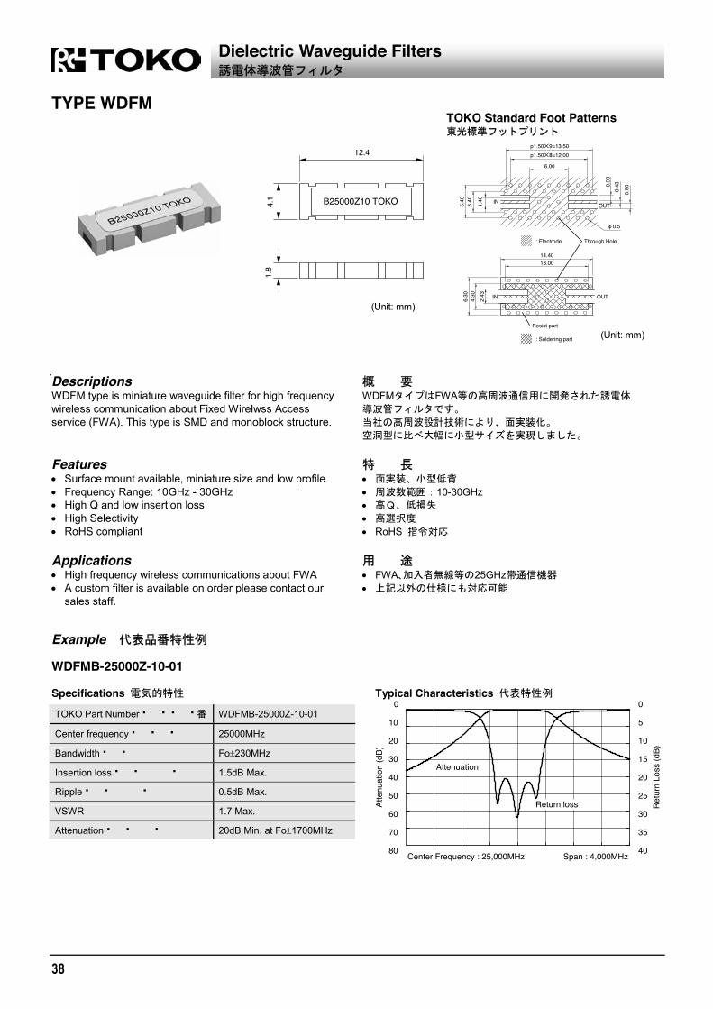
TYPE WDFM
(Unit: mm)
(Unit: mm)
Descriptions WDFM type is miniature waveguide filter for high frequencywireless communication about Fixed Wirelwss Access service (FWA). This type is SMD and monoblock structure.
WDFM FWA
Features Surface mount available, miniature size and low profile Frequency Range: 10GHz - 30GHz High Q and low insertion loss High Selectivity RoHS compliant
10-30GHz RoHS
Applications High frequency wireless communications about FWA A custom filter is available on order please contact our
sales staff.
FWA 25GHz
Example WDFMB-25000Z-10-01 Specifications Typical Characteristics
TOKO Part Number WDFMB-25000Z-10-01
Center frequency 25000MHz
Bandwidth Fo 230MHz
Insertion loss 1.5dB Max.
Ripple 0.5dB Max.
VSWR 1.7 Max.
Attenuation 20dB Min. at Fo 1700MHz
Dielectric Waveguide Filters
TOKO Standard Foot Patterns

39
1
2
3
4
5
6
7
8
9
Dip
lexe
rs /
Trip
lexe
rs
Diplexers for Digital CATV Set Top
Box and Cable Modem
Triplexers for MoCA Set
CATV , MoCA Set
CONTENTS
Diplexers for Digital CATV Set Top Box ,Cable Modem. CATV ,
DIP1A............................................................................................. 40 42 DIP2A............................................................................................. 40 42 DIP1S............................................................................................. 40 42 DIP1H ............................................................................................ 40 42 DIP1K............................................................................................. 40 42
Triplexers for MoCA set. MoCA set TRP1A ........................................................................................... 41 42

40
TYPE DIP1A and DIP2A
(Unit: mm)
TYPE DIP1S
(Unit: mm)
TYPE DIP1H and DIP1K
(Unit: mm)
The distributor is built into DIP1H The distributors and LNA are built into DIP1K LNA
Diplexers and Triplexers

41
1
2
3
4
5
6
7
8
9
Dip
lexe
rs /
Trip
lexe
rs
TYPE TRP1A
(Unit: mm)
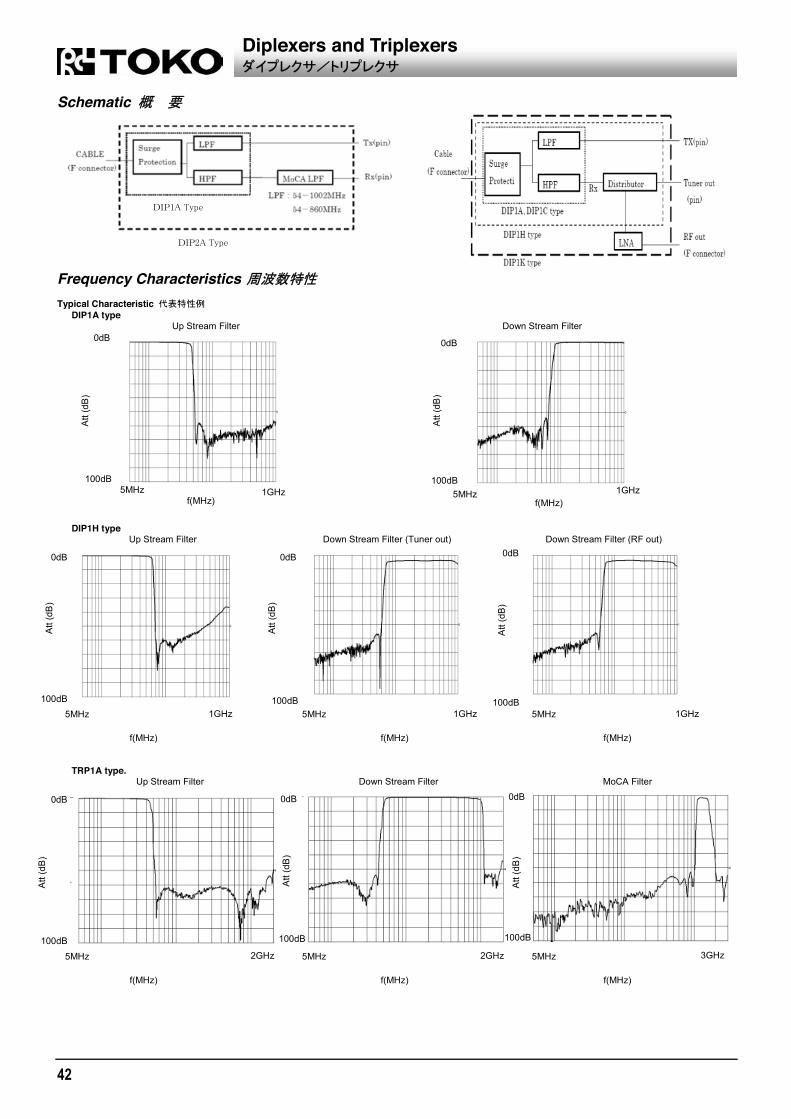
Features Diplexer/Triplexer for digital CATV set top box and cable
modem. Integrated type of Tx and Rx in the shield body with F
connector. Low-profile : DIP1A and DIP1S, Narrow bottom area :
DIP1H and DIP1K Connecting F type connector to cable and mounting TX
and RX terminals on PCB ensure high performance diplexer.
DIP1A with IEC61000-4-5 Level 4, UL60950-1 section 7 Lightning surge protection circuit.
DIP1H has a surge protection circuit of IEC61000-4-5 level 4, and built-in distributor.
DIP1K is LNA add to DIP1H. Designed to meet DOCSIS2.0, DOCSIS3.0,ANSI/SCTE. TRP1A for MoCA Set. RoHS compliant
CATV
/ F Tx Rx DIP1A DIP1S DIP1H
DIP1K F TX RX
DIP1A IEC61000-4-5 4, UL60950-1 section 7
DIP1H IEC61000-4-5 4 DIP1K DIP1H LNA DOCSIS2.0,DOCSIS3.0, ANSI/SCTE MoCA Set TRP1A RoHS
Applications Suitable for designing Open-cable set top box and Cable-
Modem for Europe, USA and Asia Suitable for designing MoCA set top box
MoCA
Specifications
Pass-band Location TOKO Parts.No. Region of
Applications Down Stream Filter Up Stream Filter Lightning Surge
Protection DOCSIS
USA
#R975ABISN-1220 R1246ABIRN-1002 R1257ABNZN-1005 R1190ACVZN-1010 R1190ACVZN-1021
DIP1A DIP1S DIP2A TRP1A
TRP1A
5-42(MHz) 5-42(MHz) 5-42(MHz) 5-42(MHz)
5-42(MHz)
54-1002(MHz) 54-1002(MHz) BPF 54-1002(MHz) BPF 54-1002(MHz) Add MoCA BPF 1125-1525(MHz) BPF 54-1002(MHz) Add MoCA BPF 1125-1675(MHz)
IEC61000-4-5 Level4 IEC61000-4-5 Level4 IEC61000-4-5 Level4 IEC61000-4-5 Level4 IEC61000-4-5 Level4
DOCSIS3.0 DOCSIS3.0 DOCSIS3.0, MoCA Rejection DOCSIS3.0, MoCA1.1 DOCSIS3.0, MoCA2.0
Euro China
#R975ABJUN-1221 R1246ABJTN-1001A R1190ACVZN-1019
DIP1A DIP1S TRP1A
5-65(MHz) 5-65(MHz) 5-65(MHz)
88-1002(MHz) 88-1002(MHz) BPF 88-1002(MHz) Add MoCA BPF 1125-1525(MHz)
IEC61000-4-5 Level4 IEC61000-4-5 Level4 IEC61000-4-5 Level4
DOCSIS3.0 DOCSIS3.0 DOCSIS3.0, MoCA1.1
Japan
#R975ABISN-1222 #R975ABISN-1204 R1086ACITN-1001 R1182ACIZN-1003
DIP1A DIP1A DIP1H DIP1K
5-55(MHz) 5-65(MHz) 5-55(MHz) 5-55(MHz)
90-1002(MHz) 76-1002(MHz) 90-860(MHz) 90-860(MHz)
IEC61000-4-5 Level4 IEC61000-4-5 Level4 IEC61000-4-5 Level4 IEC61000-4-5 Level4
DOCSIS3.0 DOCSIS3.0 DOCSIS2.0, Distributor DOCSIS2.0, Distributor, LNA
KOREA
#R975ABJUN-1223 R1190ACVZN-1017
DIP1A TRP1A
5-85(MHz) 5-85(MHz)
108-1002(MHz) BPF 108-1002(MHz)Add MoCA BPF 1125-1525(MHz)
IEC61000-4-5 Level4 IEC61000-4-5 Level4
DOCSIS3.0 DOCSIS3.0, MoCA1.1
Diplexers and Triplexers
42
Schematic Frequency Characteristics Typical Characteristic
DIP1A type Up Stream Filter Down Stream Filter
DIP1H type
Up Stream Filter Down Stream Filter (Tuner out) Down Stream Filter (RF out)
TRP1A type.
Up Stream Filter Down Stream Filter MoCA Filter
Diplexers and Triplexers
5MHz 1GHz 5MHz
1GHz
5MHz 5MHz 5MHz 1GHz 1GHz 1GHz
0dB
100dB
0dB
0dB
0dB
0dB
100dB
100dB
100dB
100dB
f(MHz) f(MHz)
f(MHz)
f(MHz)
f(MHz)
Att
(dB
)
Att
(dB
)
Att
(dB
)
Att
(dB
)
5MHz 5MHz 5MHz 2GHz 2GHz 3GHz
0dB
0dB
0dB
100dB
f(MHz)
f(MHz)
f(MHz)
Att
(dB
)
Att
(dB
)
100dB
100dB
Att
(dB
) A
tt (d
B)

43
1
2
3
4
5
6
7
8
9
Tran
spon
der C
oils
Transponder Coils for Surface Mounting
CONTENTS
Transponder Coils for Surface Mounting
SA3M12 .................................................................................................44 SA3M08 .................................................................................................45 SA3D14..................................................................................................46

44
TYPE SA3M12
(Unit: mm)
(Unit: mm)
Features High reliability conforms to automotive applications. Encapsulated core and winding for anti-shock proof. High Q and high sensivility due to optimaized magnetic
material and electrode structure. Wide inductance range for design flexibility. Applicable to reflow soldering. RoHS compliant.
Q RoHS
Applications Suitable as a Transponder Antenna Coil for TPMS and
Keyless Entry System. (Vehicle application) Wide operating temperature range ( 40°C~+125°C)
TPMS
40 125°C
SELECTION GUIDE FOR STANDARD TRANSFORMERS TYPE SA3M12
Q TOKO
Part Number Inductance
L (mH) Test Frequency
(kHz) Tolerance
(%) Unloaded Q
Min. 1144AA-102J 1.0 125 5 35 1144AA-122J 1.2 125 5 35 1144AA-152J 1.5 125 5 35 1144AA-182J 1.8 125 5 35 1144AA-222J 2.2 125 5 35 1144AA-272J 2.7 125 5 35 1144AA-332J 3.3 125 5 35 1144AA-392J 3.9 125 5 35 1144AA-472J 4.7 125 5 35 1144AA-562J 5.6 125 5 35 1144AA-682J 6.8 125 5 35 1144AA-752J 7.5 125 5 35 1144AA-822J 8.2 125 5 35
If you are looking for inductance other than the above, please contact us.
Transponder Coils for Surface Mounting
Recommended patterns

45
1
2
3
4
5
6
7
8
9
Tran
spon
der C
oils
TYPE SA3M08
(Unit: mm)
(Unit: mm)
Features High reliability conforms to automotive applications. Encapsulated core and winding for anti-shock proof. High Q and high sensivility due to optimaized magnetic
material and electrode structure. Wide inductance range for desigh flexibility. Applicable to reflow soldering. RoHS compliant.
Q RoHS
Applications Suitable as a Transponder Antenna Coil for TPMS and
Keyless Entry System. (Vehicle application) Wide operating temperature range ( 40°C~+125°C)
TPMS
40 125°C
SELECTION GUIDE FOR STANDARD TRANSFORMERS TYPE SA3M08
Q TOKO
Part Number Inductance
L (mH) Test Frequency
(kHz) Tolerance
(%) Unloaded Q
Min. 1143AA-102J 1.0 125 5 25 1143AA-122J 1.2 125 5 25 1143AA-152J 1.5 125 5 25 1143AA-182J 1.8 125 5 25 1143AA-222J 2.2 125 5 30 1143AA-272J 2.7 125 5 30 1143AA-332J 3.3 125 5 35 1143AA-392J 3.9 125 5 35 1143AA-472J 4.7 125 5 30 1143AA-562J 5.6 125 5 30 1143AA-682J 6.8 125 5 35 1143AA-822J 8.2 125 5 30 1143AA-103J 10.0 125 5 30 1143AA-123J 12.0 125 5 35 1143AA-153J 15.0 125 5 35 1143AA-183J 18.0 125 5 35
If you are looking for inductance other than the above, please contact us.
Transponder Coils for Surface Mounting
Recommended patterns

46
TYPE SA3D14
(Unit: mm)
(Unit: mm)
Features High reliability conforms to automotive applications. Encapsulated core and winding for anti-shock proof. High Q and high sensivility due to optimaized magnetic
material and electrode structure. Wide inductance range for desigh flexibility. Triaxial LF antenna coil. Applicable to reflow soldering. RoHS compliant.
Q 3 RoHS
Applications Suitable as a Transponder Antenna Coil for TPMS and
Keyless Entry System. (Vehicle application) Wide operating temperature range ( 40°C~+85°C)
40 85°C
SELECTION GUIDE FOR STANDARD TRANSFORMERS TYPE SA3D14
Q Inductance
L (mH) Test Frequency
(kHz) Tolerance
(%) Unloaded Q
Min. X: 1.0 6.3 125 5 20 30 Y: 1.0 6.3 125 5 20 30 Z: 1.0 9.0 125 5 20 30
SA3D14 type is custamized item. Please feel free to contact us for details. SA3D14
Transponder Coils for Surface Mounting
Recommended patterns

47
1
2
3
4
5
6
7
8
9
Die
lect
ric A
nten
na E
lem
ents
Dielectric Antenna Element
CONTENTS
Dielectric Antenna Element for GPS GPS
DAKC .....................................................................................................48 DAM .......................................................................................................48 DAG .......................................................................................................48 DAXC .....................................................................................................48 DAS........................................................................................................48 DAU .......................................................................................................48
Dielectric Antenna Element for GLONASS GLONASS
DAKC .....................................................................................................49 DAG .......................................................................................................49
Dielectric Antenna Element for GPS & GLONASS GPS & GLONASS
DAKC .....................................................................................................49 DAXC .....................................................................................................49
Dielectric Antenna Element for SDARS
DAA........................................................................................................50 DAV........................................................................................................50 DAH .......................................................................................................50
Dielectric Antenna Element for ETC and DSRC ETC/DSRC
DAT........................................................................................................51

48
TYPE DAKC, DAM, DAG, DAXC, DAS, DAU DAKC DAM DAG DAXC DAS DAU Features High-spec 25mm H4mm Compact 20mm/ 18mm/ 13mm/ 12mm H4mm Low-profile 25mm/ 20mm/ 12mm H2mm Microstrip structure, offset single feed through ground
plane and substrate. RoHS compliant
25mm H4mm 20mm/ 18mm/ 13mm/ 12mm H4mm 25mm/ 20mm/ 12mm H2mm RoHS
SELECTION GUIDE FOR STANDARD DEVICES TYPE DAKC/DAM/DAG/DAXC/DAS/DAU
( ) GND
TOKO Part
Number
Antenna size (mm)
Range of Receiving Frequency
(MHz)
Center Frequency
(MHz)
Bandwidth(MHz) Typ.
RHCP Gain (Zenith90 ) (dBi)Typ.
GND plane size (mm)
Impedance ( )
#DAKC1575MS74T 25 25 4 1575.42 1.023 1580.5 *1 25.0*2 5.0 70 50.0
DAM1575CR25T 25 25 2 1575.42 1.023 1580.5 *1 15.0*2 4.0 70 50.0
DAG1575CR3T 20 20 4 1575.42 1.023 1582.5 *1 10.0*2 2.0 40 50.0
DAG1575CR30T 20 20 2 1575.42 1.023 1582.5 *1 8.0*2 -1.0 40 50.0
DAXC1575CR76T 18 18 4 1575.42 1.023 1582.5 *1 9.0*2 0.0 40 50.0
DAS1575CR23T 13 13 4 1575.42 1.023 1582.5 *1 7.5*2 -1.0 40 50.0
DAU1575CR53T 12 12 4 1575.42 1.023 1582.5 *1 7.0*2 -2.0 40 50.0
DAU1575CR85T 12 12 2 1575.42 1.023 1582.5 *1 6.5*2 -4.0 40 50.0 *1 When covered with the radome, then in general the shift in the center frequency is set so that it will be lower.
*2 Return Loss –10dB *3 Fixing the Antenna: Use of a double-faced adhesive tape on the grounding plate is recommended.
(unit:mm)
DAG1575CR3T t=4.0 DAG1575CR30T t=2.0
Dielectric Antenna Element for GPS GPS
DAU1575CR53T t=4.0 DAU1575CR85T t=2.0

49
1
2
3
4
5
6
7
8
9
Die
lect
ric A
nten
na E
lem
ents
TYPE DAKC, DAG DAKC DAG Features Right-hand circular polarization specifically developed for
reception of GLONASS. Microstrip structure, offset single feed through ground
plane and substrate. RoHS compliant
GLONASS RoHS
SELECTION GUIDE FOR STANDARD DEVICES TYPE DAKC/DAG
( ) GND
TOKO Part
Number
Antenna size (mm)
Range of Receiving Frequency
(MHz)
Center Frequency
(MHz)
Bandwidth(MHz) Typ.
RHCP Gain (Zenith90 ) (dBi)Typ.
GND plane size (mm)
Impedance ( )
DAKC1602CR86T 25 25 4 1602+3.375/-3.9375 1602 *1 25.0*2 5.0 70 50.0 DAG1602CR87T 20 20 5 1602+3.375/-3.9375 1602 *1 14.0*2 3.0 40 50.0
*1 When covered with the radome, then in general the shift in the center frequency is set so that it will be lower.
*2 Return Loss –10dB *3 Fixing the Antenna: Use of a double-faced adhesive tape on the grounding plate is recommended.
TYPE DAKC, DAXC DAKC DAXC Features A dual frequency antenna capable of receiving GPS and
GLONASS. Microstrip structure, offset single feed through ground
plane and substrate. RoHS compliant
GPS GLONASS RoHS
SELECTION GUIDE FOR STANDARD DEVICES TYPE DAKC/DAXC
( ) GND
TOKO Part
Number
Antenna size (mm)
Range of Receiving Frequency
(MHz)
Center Frequency
(MHz)
Bandwidth(MHz) Typ.
RHCP Gain (Zenith90 ) (dBi)Typ.
GND plane size (mm)
Impedance ( )
DAKC1590CT23T 25 25 4 1575.42 1.023
1602+3.375/-3.9375- -
- -
3.0 3.0
70 50.0
DAXC1590CT24T 18 18 4 1575.42 1.023
1602+3.375/-3.9375- -
- -
-2.0 -2.0
40 50.0
* Fixing the Antenna: Use of a double-faced adhesive tape on the grounding plate is recommended.
Dielectric Antenna Element for GPS & GLONASS GPS & GLONASS
Dielectric Antenna Element for GLONASS GLONASS
t=5.0 (unit:mm)

50
TYPE DAA, DAV, DAH DAA DAV DAH Features Left-hand circular polarization specifically developed for
reception of satellite digital audio radio systems. Microstrip structure, offset single feed through ground
plane and substrate. RoHS compliant
Satellite radio RoHS
SELECTION GUIDE FOR STANDARD DEVICES TYPE DAA/DAV/DAH
( ) GND
TOKO Part
Number
Antenna size (mm)
Range of Receiving Frequency
(MHz)
Center Frequency
(MHz)
Bandwidth(MHz) Typ.
LHCP Gain (Zenith90 ) (dBi)Typ.
GND plane size (mm)
Impedance ( )
DAA2332CL52T 28 28 6 2332.5 12.5 2400.0 *1 150.0 *2 5.5 40 50.0
#DAV2338CL10T 25 25 4 2338.75 6.25 2348.0 *1 55.0 *2 6.0 70 50.0
DAH2338CL42T 20 20 4 2338.75 6.25 2352.0 *1 50.0 *2 5.0 40 50.0 *1 When covered with the radome, then in general the shift in the center frequency is set so that it will be lower.
*2 Return Loss –10dB *3 Fixing the Antenna: Use of a double-faced adhesive tape on the grounding plate is recommended.
Dielectric Antenna Element for SDARS
unit:mm
DAA is Dual type Antenna for SiriusXM.
DAV is Antenna for XM. DAH is Antenna for XM.

51
1
2
3
4
5
6
7
8
9
Die
lect
ric A
nten
na E
lem
ents
TYPE DAT
(Unit: mm) Features 5.8GHz circular polarized dielectric antenna element. Broad-band and low-ripple. Good reception by excellence axial ratio The optimum directivity for DSRC and ETC RoHS compliant
5.8GHz ETC/DSRC RoHS
SELECTION GUIDE FOR STANDARD DEVICES
TYPE DAT ( ) GND
TOKO Part
Number
Antenna size (mm)
Range of Receiving Frequency
(MHz)
Center Frequency
(MHz)
Bandwidth(MHz) Typ.
RHCP Gain (Zenith90 ) (dBi)Typ.
GND plane size (mm)
Impedance ( )
DAT5810CR28T 13 13 3 5810.0 40.0 5810.0 500.0*1 5.0 40 50.0 *1 Return Loss –10dB *2 Fixing the Antenna: Use of a double-faced adhesive tape on the grounding plate is recommended.
Dielectric Antenna Element for ETC and DSRC ETC/DSRC

52
53
Packaging of Coils, Transformers & Filters Inverter Transformer Sample Order Sheets List of TOKO Type Code
CONTENTS
Packaging of Coils · Transformers & Filters
Reel Packaging ......................................................................................54
Surface Mounting Type, Reel / Tape List. ..............................................54 /
Inverter Transformer Sample Order Sheets .............................................55
List of TOKO Type List .............................................................................57

54
Reel Packaging Taping for automatic insertion of SMT Coils ·Transformers & Filters Surface mount devices/adjustable & fixedThis ever expanding assortment of product and unsurpassed quality control, not only give you a component that functionally performs, but just as importantly, allows the use of a variety of placement and soldering equipment necessary for the FLEXIBLE MANUFACTURING PLANT required in today’s competitive world. Various packaging schemes are available. In addition to bulk, tape and reel and magazine, methods are offered for high volume insertion equipment. The following chart lists the packaging details for TOKO's SMD coils: Tape and reel dimensions Notes: (1) There are at least 10 blank spaces (80mm each) at
both ends of the tape which do not include the coils. (2) The protective tape should not cover the holes nor
be shifted to the sides. Further, the tape should not be removed during transportation.
(3) The deficiency per reel is within 0.5%. (4) The coils are positioned with the bonding surface
facing bottom of the pocket. (5) Dimensional tolerances conform to the standards of
Electronic Industries Association of Japan (EIAJ). RC-1009B, for Taping Dimensions (Chip Form) of Electronic components.
SMD
SMD
10 (80mm)
1 0.5 RC-1009B
Surface Mounting Type, Reel/Tape List /
Reel Size (mm) Tape Size (mm) Q'ty Type A B1 B2 C D E F G H I 1 Reel
B5FL 330 17.5 0.5 21.5 1 16.0 0.3 7.5 0.1 6.9 0.1 6.4 0.1 3.95 0.1 0.4 0.05 12.0 0.1 1500 B5F 330 17.5 0.5 21.5 1 16.0 0.3 7.5 0.1 6.9 0.1 6.4 0.1 4.6 0.1 0.4 0.05 12.0 0.1 1000 B4FL 330 13.5 0.5 17.5 1 12.0 0.2 5.5 0.05 5.4 0.1 4.4 0.1 3.2 0.1 0.4 0.05 8.0 0.1 2000 B4F 330 13.5 0.5 17.5 1 12.0 0.3 5.5 0.05 5.4 0.1 4.4 0.1 3.5 0.1 0.4 0.05 8.0 0.1 2000 B4W 330 13.5 0.5 17.5 1 12.0 0.3 5.5 0.1 5.3 0.1 5.3 0.1 2.4 0.1 0.4 0.05 8.0 0.1 2000 6CA 330 17.5 0.5 21.5 1 16.0 0.3 7.5 0.1 6.6 0.1 6.9 0.1 3.3 0.1 0.4 0.05 12.0 0.1 1500 8CA 330 17.5 0.5 21.5 1 16.0 0.3 7.5 0.1 8.6 0.1 8.9 0.1 3.2 0.1 0.4 0.05 12.0 0.1 1000 10CA 330 25.5 0.5 29.5 1 24.0 0.3 11.5 0.1 10.8 0.1 10.4 0.1 3.6 0.1 0.4 0.05 16.0 0.1 1000 R10F 330 25.5 0.5 29.5 1 24.0 0.3 11.5 0.1 10.0 0.1 11.5 0.1 5.8 0.1 0.4 0.05 12.0 0.1 1000 R12F 330 25.5 0.5 29.5 1 24.0 0.3 11.5 0.1 12.9 0.1 14.4 0.1 6.8 0.1 0.5 0.05 20.0 0.1 500 R15F 330 25.5 0.5 29.5 1 24.0 0.3 11.5 0.1 15.9 0.1 16.4 0.1 7.5 0.1 0.5 0.05 20.0 0.1 250
Packaging of Coils · Transformers & Filters

55
5
-
- FAX -
E-mail 1. ················································ 2. ···························································· 3. ····················································· °C °C °C °C 4. 1 ············
Max= mm Max mm Max mm
5.
(Vin)·········································· DC V V V
. ·················································· V rms Vp-p Vin= V
CCFL ···················································· ·······················································
······················································· kHz kHz kHz
······················································· mA rms Vin= V mArms
······························································ V rms Vin= V
...................
PWM FET...........................
IC..............................................................
....................................................
FL FL 6. 2 ····································· No. 7. ·····························································(RoHS ) 8. ······························································· 1
2
CCFL Driving Inverter Transformer Sample Order Sheet

56
Please fill in following points, especially number 5.
Your information Company: Date:
Section: Your name:
Telephone No: Fax No: ( ) —
E-mail 1. Application, set ··············································· 2. Place of use ······················································ In house Out side In car Misc ( ) 3. Operating temperature ····································Guarantee of set ( °C °C) Guarantee of transformer ( °C °C) 4. Toko type name, Dimension 1·······················
Without the ballast capacitor With the ballast capacitor Dimension H Max mm W, Max mm, L Max mm
5. Electrical characteristics Input voltage range (Vin)·································· DC V V (Average V)
Output open voltage. ······································· V rms or Vp-p Input voltage Vin=at V)
Kind of CCFL tube ··········································· Name: Maker: Lamp Q’ty:
Kind of Panel ··················································· Name: Maker: Inch Size:
Impedance at dummy load :
Oscillating frequency ······································· kHz kHz Average kHz)
Setting tube current ········································· mA rms Input voltage Vin=at V) (Panel recommendation = mArms)
Setting tube voltage. ········································ V rms Input voltage Vin=at V)
Dimming (Reference)...................................... Current dimming (Analog dimming) mA Max mA Min
PWM dimming (Duty dimming) % Max % Min
Kind of Transistor or FET................................ Non Yes ( Name Maker ) (Please give us several samples.)
Driving IC........................................................ Non Yes ( Name Maker ) (Please give us several samples.)
Driving circuit .................................................. Royer circuit Full-bridge circuit Half-bridge circuit Push-pull circuit Misc ( )
(Note) In occasion of inverter circuit design, we absolutely need to have a FL tube sample and a copy of it's specification sheet.
6. Safety standard 2 ·········································· Non Yes (Name and No. ) 7. Necessary Environmental standard ············· (Cope RoHS) Misc (Name and No. ) 8. Misc·································································· 1 After we evaluated trans with panel or CCFL , “Transformer-type” may change to other type.
2 Safety standard is only conformity, we will not acquire “safety standard”.
CCFL DRIVING INVERTER TRANSFORMER SAMPLE ORDER SHEET
CCFL Driving Inverter Transformer Sample Order Sheet

57
TYPE CODE vs. TYPE NAME (Reference) vs. ( )
We don’t show type which includes type name in part number. A code is a number of three-digit or four-digit included in the first part of TOKO part number. 3 4
Code Type Code Type Code Type Code Type 181 10RB 892 D124C 1009 DSH126C 1217 DEM8045C
187 8RB 898 8CA 1010 DH124C 1224 DEM2810C
262 8RBS 914 D52LC 1020 DIP1C 1225 DEM2812C
395 5CA 915 D53LC 1032 DH10F 1226 DEM2815C
458 B5F 916 D63CB 1044 DIP1D 1227 DEM2818C
494 8RBH 918 D62LCB 1047 DS75LC 1229 DEM3512C
558 MC152 919 D104C 1065 BH8S 1231 DEM3518C
616 B5FL 920 D62CB 1068 DB3015C 1234 DEM4514C
617 B4F 921 D63LCB 1069 DB3018C 1235 DEM4518C
636 D73F 931 D128C 1070 DB3020C 1239 DFE252012C
638 5CCE 940 BLC4204 1077 DS74LC 1245 DHCP6144
646 D75CE 944 B4W 1079 DS73LC 1246 DIP1S
646 D75F 952 DS104C2 1082 CLT4123 1248 DEM8040C
648 D78C 953 DS126C2 1083 CLTP4123 1255 DG6045C
665 R10F 957 BLC4204B 1085 SA3D14 1256 DEM2612C
687 D76UP 960 D518LC 1086 DIP1H 1257 DIP2A
814 D10F 962 D106C 1109 DB315C 1258 DIP2F
816 10CA 964 ECM85 1120 SA517 1259 UCMH0907
822 8RHB2 966 DS106C2 1131 DIP1F 1264 DG6050C
823 8RHT2 969 BLC4206 1134 DS84LCB 1267 DG8040C
824 10RHB2 970 BLC4206B 1135 DS85LCB 1269 DFE252010C
830 10RHT2 975 DIP1A 1143 SA3M08 1273 DEM8030C
836 FSDV 985 NT2012 1144 SA3M12 1274 DEM10050C
838 6CA 989 D126CT 1156 D2810CB 1276 DFE322510C
844 B4FL 990 BLC4115 1164 D104LC 1277 DFE322512C
857 B5W 991 BLC4115L 1179 DS104LC 1278 DEM4520C
873 R12F 992 DS86C 1182 DIP1K 1285 DFE201610C
875 D52FU 993 DB320C 1190 TRP1A 1286 DFE201612C
876 R15F 997 DB318C 1198 D2815CB 7502 13RHBP
887 D32FU 1006 DH63LCB 1200 D2808CB 7503 11RHBP
888 D31FU 1007 DH75C 1205 BPW10040
889 D53FU 1008 DSH104C 1212 DIP1N
List of TOKO Type Code

58

背幅3mm
コイル・トランス
表3表2
ご注意1. このカタログに記載の製品について、極めて高い信頼性が要求される以下の用途でのご使用をご検討の場合、またはこのカタログに記載された用途以外でのご使用をご検討の場合は、必ず事前に当社営業窓口までご相談ください。
¡自動車、船舶、航空機などの交通輸送システムにおける動力駆動系・操舵航法系・非常信号通信系および上記以外の系であってもその誤動作や機能停止が人命・身体・財産に重大な損害をもたらす恐れのある電子的手段による検出・計測・制御・表示などの機能を含む系。
¡血圧や心拍数などの医用計測装置、心臓ペースメーカや温熱療法などの治療装置、人工臓器や人工義足手システムなどの生体機能補助装置。
¡防災または防犯用電気機器・設備・システム。
2. このカタログの記載内容は 現在のものです。記載内容を予告なく変更あるいは製造を中止することがあります。ご注文に際しては仕様・納入仕様書などの取り交わしをお願いします。
3. このカタログに記載された製品の使用法および回路を適用したり使用したことから生じる諸問題および第三者の特許権その他の知的財産権の侵害に対して、当社はその責任を負いません。また、当社の特許権その他の知的財産権の黙示その他による実施許諾は致しません。
4. 当社の製造工程では、モントリオール議定書で規制されているオゾン層破壊物質(ODS)は一切使用しておりません。
1. Please be sure that you carefully discuss your planned purchase with our sales division ifyou intend to use the products in this catalog under conditions where particularly extremestandards of reliability are required, or if you intend to use products for applications otherthan those listed in this catalog.¡Power drive products for automobile, ship or aircraft transport systems; steering and
navigation systems, emergency signal communications systems, and any system otherthan those mentioned above which include electronic sensors, measuring, or displaydevices, and which could cause major damage to life, limb or property if misused orfailure to function.
¡Medical devices for measuring blood pressure, pulse, etc., treatment units such ascoronary pacemakers and heat treatment units, and devices such as artificial organsand artificial limb systems which augment physiological functions.
¡Electrical instruments, equipment or systems used in disaster or crime prevention.2. This catalog is effective from Note that the contents are subject to change or
discontinuation without notice. When placing orders, please confirm specifications anddelivery conditions in writing.
3. TOKO is not responsible for any problems nor for any infringement of third party patentsor any other intellectual property rights that may arise from the use or method of use ofthe products listed in this catalog. Moreover, this catalog does not signify that TOKOagrees implicitly or explicitly to license any patent rights or other intellectual propertyrights which it holds.
4. None of ozone depleting substances(ODS) under the Montreal Protocol is used inmanufacturing process of us.
NOTICE
2012年9月
Sep. 2012.

2013
Balun Transformersバルントランス
DC-DC Converter TransformersDC-DCコンバータトランス
Inverter Transformersインバータトランス
Dielectric Filters/Duplexers誘電体フィルタ/デュプレクサ
Diplexers/Triplexersダイプレクサ/トリプレクサ
Transponder Coilsトランスポンダコイル
Dielectric Antennas誘電体アンテナ
Coils・Transform
ers・Filters &
Antennas
Design A 改-明朝
Headquarters / 本 社
18, Ohaza, Gomigaya, Tsurugashima-shi, Saitama-ken, 350-2281, Japan〒350-2281 埼玉県鶴ヶ島市大字五味ヶ谷18番地Tel : 049-285-2511 Fax : 049-286-7381http://www.toko.co.jp/
営 業 拠 点
● 営業センター 〒350-2281 埼玉県鶴ヶ島市大字五味ヶ谷18 Tel 049-250-2291 Fax 049-279-1811
● 東京オフィス 〒170-0013 東京都豊島区東池袋1-17-8 NBF池袋シティビル3F Tel 03-5960-0350 Fax 03-5960-0348
● 大阪営業所 〒532-0003 大阪市淀川区宮原2-14-10 中尾ロイヤルビル6F Tel 06-6395-6411 Fax 06-6395-6416
● 名古屋営業所 〒465-0093 名古屋市名東区一社2-87 プラザ・タマ2F Tel 052-703-2247 Fax 052-703-2009
東光株式会社
CATALOG No. C-052002 Printed in Japan '12.09 2K (HK)
墨DIC128
COILS・TRANSFORMERS・FILTERS & ANTENNAS
コイル・トランス・フィルタ&アンテナ
この印刷物は、適切に管理された森林からの原料を含むFSC®認証紙と植物油インキを使用しています。
背幅3mm