UNIT 3 SECONDARY STORAGE TECHNIQUES - Master Of ...
16
Basic Computer Organisation UNIT 3 SECONDARY STORAGE TECHNIQUES Structure Page No. 3.0 Introduction 64 3.1 Objectives 64 3.2 Secondary Storage Systems 65 3.3 Hard Drives 65 3.3.1 Characteristics: Drive Speed, Access Time, Rotation Speed 3.3.2 Partitioning & Formatting: FAT, Inode 3.3.3 Drive Cache 3.3.4 Hard Drive Interface: IDE, SCSI, EIDE, Ultra DMA & ATA/66 3.4 Removable Drives 72 3.4.1 Floppy Drives 3.4.2 CD-ROM & DVD-ROM 3.5 Removable Storage Options 75 3.5.1 Zip, Jaz & Other Cartridge Drives 3.5.2 Recordable CDs & DVDs 3.5.3 CD-R vs CD-RW 3.5.4 Tape Backup 3.6 Summary 78 3.7 Solutions /Answers 78 3.0 INTRODUCTION In the previous units of this block, we have discussed the primary memory system, high speed memories, the memory system of microcomputer, and the input/output interfaces and techniques for a computer. In this unit we will discuss the secondary storage devices such as magnetic tapes, magnetic disks and optical disks, also known as backing storage devices. The main purpose of such a device is that it provides a means of retaining information on a permanent basis. The main discussion provides the characteristics of hard-drives, formatting, drive cache, interfaces, etc. The detailed discussion on storage devices is being presented in the Unit. The storage technologies have moved a dimension from very small storage devices to Huge Giga byte memories. Let us also discuss some of the technological achievements that made such a technology possible. 3.1 OBJECTIVES Storage is the collection of places where long-term information is kept. At the end of the unit you will be able to: • describe the characteristics of the different secondary storage drives, i.e., their drive speed, access time, rotation speed, density etc.; • describe the low-level and high level formatting of a blank disk and also the use of disk partitioning; • distinguish among the various types of drives, i.e., hard drives , optical drives removable drives and cartridge drive; and • define different type of disk formats. 64
-
Upload
khangminh22 -
Category
Documents
-
view
6 -
download
0
Transcript of UNIT 3 SECONDARY STORAGE TECHNIQUES - Master Of ...

Basic Computer Organisation UNIT 3 SECONDARY STORAGE
TECHNIQUES Structure Page No.
3.0 Introduction 64 3.1 Objectives 64 3.2 Secondary Storage Systems 65 3.3 Hard Drives 65
3.3.1 Characteristics: Drive Speed, Access Time, Rotation Speed 3.3.2 Partitioning & Formatting: FAT, Inode 3.3.3 Drive Cache
3.3.4 Hard Drive Interface: IDE, SCSI, EIDE, Ultra DMA & ATA/66 3.4 Removable Drives 72
3.4.1 Floppy Drives 3.4.2 CD-ROM & DVD-ROM
3.5 Removable Storage Options 75 3.5.1 Zip, Jaz & Other Cartridge Drives 3.5.2 Recordable CDs & DVDs 3.5.3 CD-R vs CD-RW 3.5.4 Tape Backup
3.6 Summary 78 3.7 Solutions /Answers 78
3.0 INTRODUCTION
In the previous units of this block, we have discussed the primary memory system, high speed memories, the memory system of microcomputer, and the input/output interfaces and techniques for a computer. In this unit we will discuss the secondary storage devices such as magnetic tapes, magnetic disks and optical disks, also known as backing storage devices. The main purpose of such a device is that it provides a means of retaining information on a permanent basis. The main discussion provides the characteristics of hard-drives, formatting, drive cache, interfaces, etc. The detailed discussion on storage devices is being presented in the Unit. The storage technologies have moved a dimension from very small storage devices to Huge Giga byte memories. Let us also discuss some of the technological achievements that made such a technology possible.
3.1 OBJECTIVES
Storage is the collection of places where long-term information is kept. At the end of the unit you will be able to: • describe the characteristics of the different secondary storage drives, i.e., their
drive speed, access time, rotation speed, density etc.;
• describe the low-level and high level formatting of a blank disk and also the use of disk partitioning;
• distinguish among the various types of drives, i.e., hard drives , optical drives removable drives and cartridge drive; and
• define different type of disk formats.
64

Secondary Storage
Techniques 3.2 SECONDARY STORAGE SYSTEMS
As discussed in Block 2 Unit 1, there are several limitations of primary memory such as limited capacity, that is, it is not sufficient to store a very large volume of data; and volatility, that is, when the power is turned off the data stored is lost. Thus, the secondary storage system must offer large storage capacities, low cost per bit and medium access times. Magnetic media have been used for such purposes for a long time. Current magnetic data storage devices take the form of floppy disks and hard disks and are used as secondary storage devices. But audio and video media, either in compressed form or uncompressed form, require higher storage capacity than the other media forms and the storage cost for such media is significantly higher. Optical storage devices offer a higher storage density at a lower cost. CD-ROM can be used as an optical storage device. Many software companies offer both operating system and application software on CD-ROM today. This technology has been the main catalyst for the development of multimedia in computing because it is used in the multimedia external devices such as video recorders and digital recorders (Digital Audio Tape) which can be used for the multimedia systems. Removable disk, tape cartridges are other forms of secondary storage devices are used for back-up purposes having higher storage density and higher transfer rate.
3.3 HARD DRIVES
The Disks are normally mounted on a disk drive that consists of an arm and a shaft along with the electronic circuitry for read-write of data. The disk rotates along with the shaft. A non-removable disk is permanently mounted on the disk drive. One of the most important examples of a non-removable disk is the hard disk of the PC. The disk is a platter coated with magnetic particles. Early drives were large. Later on, smaller hard (rigid) disk drivers were developed with fixed and removable pack. Each pack held about 30MB of data and became known as the Winchester drive. The storage capacity of today’s Winchester disks is usually of the order of a few tens of Megabytes to a few Gigabytes. Most Winchester drives have the following common features: • the disk and read/write heads are enclosed in a sealed airtight unit;
• the disk(s) spin at a high speed, one such speed may be 7200 revolutions per minute;
• the read/write head do not actually touch the disk surface;
• the disk surface contains a magnetic coating;
• the data on disk surface (platter) are arranged in the series of concentric rings. Each ring is called a track, is subdivided into a number of sectors, each sector holding a specific number of data elements called bytes or characters.
• The smallest unit that can be written to or read from the disk is a sector. The storage capacity of the disk can be determined as the number of tracks, number of sectors, byte per sector and number of read/write heads.
65

Basic Computer Organisation
(a) An Open Disk Casing (b) Tracks and Cylinders
Figure 1: The Hard Disk 3.3.1 Characteristics: Drive Speed, Access Time, Rotation Speed
Tracks and Sectors: The disk is divided into concentric rings called tracks. A track is thus one complete rotation of the disk underneath the read/write head. Each track is subdivided into a number of sectors. Each sector contains a specific number of bytes or characters. Typical sector capacities are 128, 256, 512, 1024 and 4096 bytes. Bad Blocks: The drive maintains an internal table which holds the sectors or tracks which cannot be read or written to because of surface imperfections. This table is called the bad block table and is created when the disk surface is initially scanned during a low-level format. Sector Interleave: This refers to the numbering of the sectors located in a track. A one to one interleave has sectors numbered sequentially 0,1,2,3,4 etc. The disk drive rotates at a fixed speed 7200 RPM, which means that there is a fixed time interval between sectors. A slow computer can issue a command to read sector 0, storing it in an internal buffer. While it is doing this, the drive makes available sector 1 but the computer is still busy storing sector 0. Thus the computer will now have to wait one full revolution till sector 1 becomes available again. Renumbering the sectors like 0,8,1,9,2,10,3,11 etc., gives a 2:1 interleave. This means that the sectors are alternated, giving the computer slightly more time to store sectors internally than previously. Drive Speed: The amount of information that can be transferred in or out of the memory in a second is termed as disk drive speed or data transfer rate. The speed of the disk drive depends on two aspects, bandwidth and latency. • Bandwidth: The bandwidth can be measured in bytes per second. The sustained
bandwidth is the average data rate during a large transfer, i.e., the number of bytes divided by the transfer time. The effective bandwidth is the overall data rate provided by the drive. The disk drive bandwidth ranges from less than 0.25 megabytes per second to more than 30 megabytes per second.
• Access latency: A disk access simply moves the arm to the selected cylinder and waits for the rotational latency, which may take less than 36ms. The latency
66

Secondary Storage
Techniques depends upon the rotation speed of the disk which may be anywhere from 300 RPM to 7200 RPM. An average latency of a disk system is equal to half the time taken by the disk to rotate once. Hence, the average latency of a disk system whose rotation speed is 7200 RPM will be 0.5 / 7200 minutes = 4.1 ms. Rotation Speed: This refers to the speed of rotation of the disk. Most hard disks rotate at 7200 RPM (Revolution per Minute). To increase data transfer rates, higher rotation speeds, or multiple read/write heads arranged in parallel or disk arrays are required. Access Time: The access time is the time required between the requests made for a read or write operation till the time the data are made available or written at the requested location. Normally it is measured for read operation. The access time depends on physical characteristics and access mode used for that device. The disk access time has two major components:
• Seek Time: The seek time is the time for the disk arm to move the heads to the cylinder containing the desired sector.
• Latency Time: The latency time is the additional time waiting for the disk to rotate the desired sector to the disk head.
The sums of average seek and latency time is known as the average access time. 3.3.2 Partitioning and Formatting: FAT, Inode
Today the modern PC contains total capacity of approximately 40GB for storage of program and data. Because of this huge capacity, instead of having only one operating system in our PC, partitions are used to provide several separate areas within one disk, each treated as a separate storage device. That is, a disk partition is a sub-division of the disk into one or more areas. Each partition can be used to hold a different operating system. The computer system boots from the active partition and software provided allows the user to select which partition is the active one. For example, we can run both Windows and Linux operating systems from the same storage of the PC. A new magnetic disk is just platters of a magnetic recording material. Before a disk can store data, it must be divided into sectors that the disk controller can read and write. This is called low level formatting. Low level formatting fills the disk with a special data structure for each sector, which consists of a header, a data area, and a trailer. The low level formatting is placing track and sector information plus bad block tables and other timing information on the disks. Sector interleave can also be specified at this time. In any disk system, space at some time in use will become unwanted and hence will be ‘free’ for another application. The operating system allocates disk space on demand by user programs. Generally, space is allocated in units of fixed size called an allocation unit or a cluster, which is a simple multiple of the disk physical sector size, usually 512 bytes. The DOS operating system forms a cluster by combining two or more sectors so that the smallest unit of data access from a disk becomes a cluster, not a sector. Normally, the size of the cluster can range from 2 to 64 sectors per cluster. High level formatting involves writing directory structures and a map of free and allocated space (FAT or INODE) to the disk. Often this also means transferring the boot file for the operating system onto the hard disks.
67

Basic Computer Organisation
FAT and Inode The FAT maps the usage of data space of the disk. It contains information about the space used by each individual file, the unused disk space and the space that is unusable due to defects in the disk. Since FAT contains vital information, two copies of FAT are stored on the disk, so that in case one gets destroyed, the other can be used. A FAT entry can contain any of the following: • unused cluster • reserved cluster • bad cluster • last cluster in file • next cluster number in the file. The DOS file system maintains a table of pointers called FAT (File allocation table) which consists of an array of 16-bit values. There is one entry in the FAT for each cluster in the file area, i.e., each entry of the FAT (except the two) corresponds to one cluster of disk space. If the value in the FAT entry doesn’t mark an unused, reserved or defective cluster, then the cluster corresponding to the FAT entry is part of a file and the value in the FAT entry would indicate the next cluster in the file. The first two entries (0 & 1) in FAT are reserved for use by the operating system. Therefore, the cluster number 2 corresponds to the first cluster in the data space of the disk. Prior to any data being written on to the disk, the FAT entries are all set to zero indicating a ‘free’ cluster .The FAT chain for a file ends with the hexadecimal value, i.e., FFFF. The FAT structure can be shown as in Figure 2 below.
Figure 2: FAT structure
Limitation of FAT16: The DOS designers decided to use clusters with at least four sectors in them (thus a cluster size of at least 2KB) for all FAT16 hard disks. That size suffices for any hard disk with less than a 128MB total capacity. The largest logical disk drives that DOS can handle comfortably have capacities up to 2GB. For such a large volume, the cluster size is 32KB. This means that even if a file contains only a single byte of data, writing it to the disk uses one entire 32KB region of the disk, making that area unavailable for any other file’s data storage. The most recent solution to these large-disk problems was introduced by Microsoft in its OSR2 release of Windows 95 and it was named FAT32. The cluster entry for FAT32 uses 32-bit numbers. The minimum size for a FAT32 volume is 512MB. Microsoft has reserved the top four bits of every cluster number in a FAT32 file
68

Secondary Storage
Techniques allocation table. That means there are only 28-bits for the cluster number, so the maximum cluster number possible is 268,435,456. In the UNIX system, the information related to all these fields is stored in an Inode table on the disk. For each file, there is an inode entry in the table. Each entry is made up of 64 bytes and contains the relevant details for that file. These details are: a) Owner of the file b) Group to which the Owner belongs c) File type d) File access permissions e) Date & time of last access f) Date & time of last modification g) Size of the file h) No. of links i) Addresses of blocks where the file is physically present.
3.3.3 Drive Cache
Disk cache may be a portion of RAM, sometimes called soft disk cache that is used to speed up the access time on a disk. In the latest technologies such memory can be a part of disk drive itself. Such memory is sometimes called hard disk cache or buffer.
These hard disk caches are more effective, particularly applicable in multiprogramming machines or in disk file servers, but they are expensive, and therefore are smaller. Almost all-modern disk drives include a small amount of internal cache. The cycle time of cache would be about a tenth of the main memory cycle time and its cost about 10 times the cost per byte of main memory. The disk caching technique can be used to speed up the performance of the disk drive system. A set (cache) of buffers is allocated to hold a number of disk blocks which have been recently accessed. In effect, the cached blocks are in memory copies of the disk blocks. If the data in a cache buffer memory is modified, only the local copy is updated at that time. Hence processing of the data takes place using the cached data avoiding the need to frequently access the disk itself. The main disadvantage of the system using disk caching is risking loss of updated information in the event of machine failures such as loss of power. For this reason, the system may periodically flush the cache buffer in order to minimize the amount of loss. The disk drive cache is essentially two-dimensional-all the bits are out in the open. 3.3.4 Hard Drive Interface: IDE, SCSI, EIDE, Ultra DMA and
ATA/66
Secondary storage devices need a controller to act as an intermediary between the device and the rest of the computer system. On some computers, the controller is an integral part of the computer’s main motherboard. On others, the controller is an expansion board that connects to the system bus by plugging into one of the computer’s expansion slots. In order that devices manufactured by independent vendors can be used with different computer manufacturers, it is important that the controllers follow some drive interfacing standard. Following are the commonly used drive interface standards: • IDE (Integrated Disk Electronics) Devices
69
IDE devices are connected to the PC motherboard via a 34-wire ribbon cable. The common drive used today for workstations has capacities of 40MB to
Basic Computer Organisation
1000MB and rotation speed 7200RPM. The controller is embedded on the disk drive itself. It is an interface between the disk controller and an adopter located on the motherboard. It has good access time of 20ms and data transfer rates of about 1Mbps under ideal conditions. Drives are reasonably cheap. The latest version of the IDE specification enables four IDE channels; each one is capable of supporting two IDE devices.
• SCSI (Small Computer Systems Interface)
The other popular way is to attach a disk drive to a PC via a SCSI interface. The common drive choice for servers or high-end workstations with drive capacities ranges from 100MB to 20GB and rotation speed 7200RPM. It is a common I/O interface between the adapter and disk drives or any other peripheral, i.e., CD-ROMs drives, tape drives, printers etc.
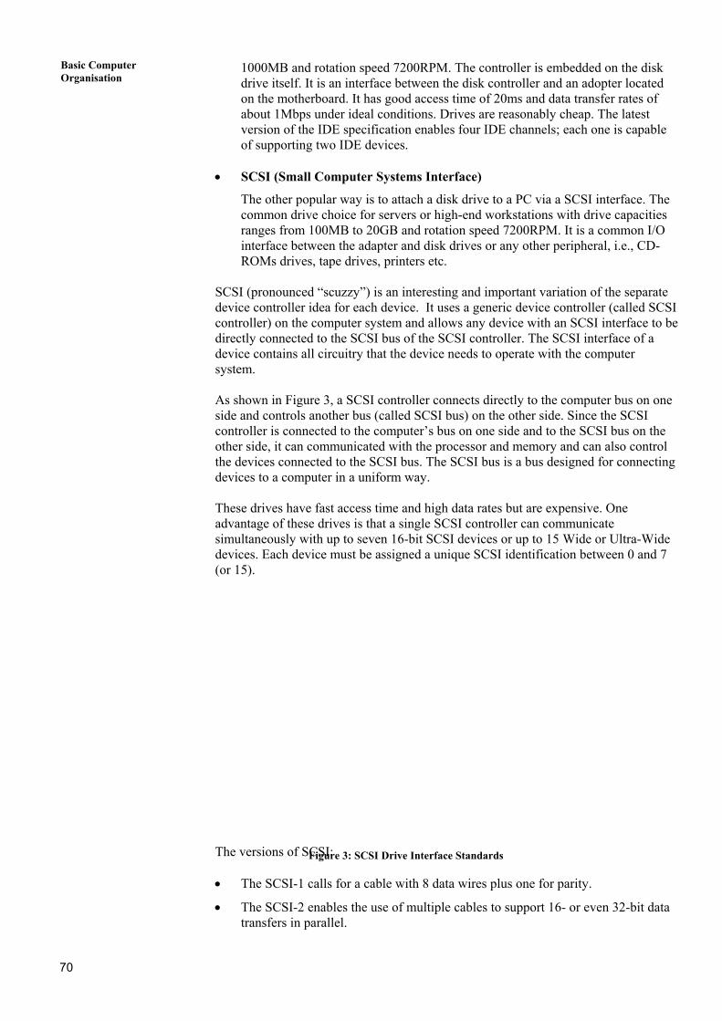
SCSI (pronounced “scuzzy”) is an interesting and important variation of the separate device controller idea for each device. It uses a generic device controller (called SCSI controller) on the computer system and allows any device with an SCSI interface to be directly connected to the SCSI bus of the SCSI controller. The SCSI interface of a device contains all circuitry that the device needs to operate with the computer system. As shown in Figure 3, a SCSI controller connects directly to the computer bus on one side and controls another bus (called SCSI bus) on the other side. Since the SCSI controller is connected to the computer’s bus on one side and to the SCSI bus on the other side, it can communicated with the processor and memory and can also control the devices connected to the SCSI bus. The SCSI bus is a bus designed for connecting devices to a computer in a uniform way. These drives have fast access time and high data rates but are expensive. One advantage of these drives is that a single SCSI controller can communicate simultaneously with up to seven 16-bit SCSI devices or up to 15 Wide or Ultra-Wide devices. Each device must be assigned a unique SCSI identification between 0 and 7 (or 15).
The ver • The
• Thetran
70
sions of
SCSI-1
SCSI-2sfers in
SCSI: Figure 3: SCSI Drive Interface Standards
calls for a cable with 8 data wires plus one for parity.
enables the use of multiple cables to support 16- or even 32-bit data parallel.

Secondary Storage
Techniques • The SCSI-3 enables the use of multiple cables to support 32- or even 64-bit data
transfers in parallel.
• With fast SCSI, it is possible to transfer 40MB of data per second on a single SCSI cable.
• EIDE (Enhanced IDE)
The principle behind the EIDE interface is the same as in the IDE interface but this drive has capacities ranging from 10.2GB to 20.5GB. The rotation speed is 7200RPM. Its feature include 9.5ms access time, a 2MB buffer and support for the Ultra ATA/66 interface for high speed data throughput and greater data integrity.
Modern EIDE interfaces enable much faster communication. The speed increases due to improvements in the protocol that describes how the clock cycles will be used to address devices and transfer data. The modern EIDE hard drives are Ultra DMA and ATA/66.
• Ultra DMA or ATA/33 (AT Attachment): The ATA standard is the formal
specification for how IDE and EIDE interfaces are supposed to work with hard drives. The ATA33 enables up to 33.3 million bytes of data to be transferred each second, hence the name ATA33.
• ATA/66: The ATA66 enables up to 66.7 millions bytes of data to be transferred
each second, hence the name ATA66 doubles the ATA33.
Check Your Progress 1 1. The seek time of a disk is 30ms. It rotates at the rate of 30 rotations per sec. Each
track has 300 sectors. What is the access time of the disk?
……………………………………………………………………………………
……………………………………………………………………………………
……………………………………………………………………………………
2. Calculate the number of entries required in the FAT table using the following parameters for an MS-DOS system:
Disk capacity 30MB Block size 512 bytes Blocks/cluster 4
……………………………………………………………………………………
……………………………………………………………………………………
……………………………………………………………………………………
3. What are the purposes of using SCSI, EISA, ATA, IDE?
……………………………………………………………………………………
……………………………………………………………………………………
……………………………………………………………………………………
3.4 REMOVABLE DRIVES
71
A disk drive with removable disks is called a removable drive. A removable disk can be replaced by another similar disk on the same or different computer, thus providing enormous data storage that is not limited by the size of the disk. Examples of removable disks are floppy disks, CDROM, DVDROM, etc.

Basic Computer Organisation
3.4.1 Floppy Drives
The disks used with a floppy disk drive are small removable disks made up of plastic coated with magnetic recording material. The disk rotates at 360RPM. Floppies can be accessed from both the sides of the disk. Floppy diskette drives are attached to the motherboard via a 34-wire ribbon cable. You can attach zero, one or two floppy drives and how you connect each one determines whether a drive become either A: or B: A typical floppy drive and floppy is as shown in Figure 4.
(a) Floppy Disk (b) Floppy Drive
Figure 4: The Floppy Disk and Drive
A floppy is about 0.64 mm thick and is available in diameters 5.25 inch and 3.5 inch. The data are organized in the form of tracks and sectors. The tracks are numbered sequentially inwards, with the outermost being 0. The utility of index hole is that when it comes under a photosenser, the system comes to know that the read/write head is now positioned on the first sector of the current track. The write-protect notch is used to protect the floppy against deletion of recorded data by mistake. The data in a sector are stored as a series of bits. Once the required sector is found, the average data transfer rate in bytes per second can be computed by the formula:
Average data transfer rate = 60
rpmin speed *ck sector/tra *or bytes/sect
Typical values for IBM/PC compatibles are given in the following table:
72
Size Capacity
Tracks
Sectors
5.25 360KB 40 9 5.25 1.2MB 80 15 3.5 720KB 40 18

Secondary Storage
Techniques 3.5 1.44MB 80 18
3.4.2 CD-ROM and DVD-ROM
Optical disks use Laser Disk Technology, which is the latest, and the most promising technology for high capacity secondary storage. The advent of the compact disk digital audio system, a non-erasable optical disk, paved the way for the development of a new low-cost storage technology. In optical storage devices the information is written using a laser beam. We will discuss here the use of some optical disks such as CD-ROM and DVD-ROM devices that are now becoming increasingly popular in various computer applications.
Figure 5: CD-ROM and DVD-ROM
1. CD-ROM (Compact Disk Read Only Memory): This technology has evolved out of the entertainment electronics market where cassette tapes and long playing records are being replaced by CDs. The term CD used for audio records stands for Compact Disk. The disks used for data storage in digital computers are known as CD-ROM, whose diameter is 5.25 inches. It can store around 650MB. Information in CD-ROM is written by creating pits on the disk surface by shining a laser beam. As the disk rotates the laser beam traces out a continuous spiral. The focused beam creates a circular pit of around 0.8-micrometer diameter wherever a 1 is to be written and no pits (also called a land) if a 0 is to be written. Figure 5 shows the CD-ROM & DVD-ROM.
73

Basic Computer Organisation
The CD-ROM with pre-recorded information is read by a CD-ROM reader which uses a laser beam for reading. It is rotated by a motor at a speed of 360 RPM. A laser head moves in and out to the specified position. As the disk rotates the head senses pits and land. This is converted to 1s and 0s by the electronic interface and sent to the computer. The disk speed of CD-ROM is indicated by the notation nx, where n is an integer indicating the factor by which the original speed of 150KB/s is to be multiplied. It is connected to a computer by SCSI and IDE interfaces. The major application of CD-ROM is in distributing large text, audio and video. For example, the entire Encyclopedia could be stored in one CD-ROM. A 640MB CD-ROM can store 74 min. of music.
The main advantages of CD-ROMs are: • large storage capacity
• mass replication is inexpensive and fast
• these are removable disks, thus they are suitable for archival storage. The main disadvantages of CD-ROMs are: • it is read only, therefore, cannot be updated
• access time is longer than that of a magnetic disks.
• very slow as compared to hard disks, i.e., the normal transfer rate is 300 Mbps for double speed drives and 600 Mbps for quadruple speed drives.
2. DVD-ROM (Digital Versatile Disk Read Only Memory): DVD-ROM uses the
same principle as a CD-ROM for reading and writing. However, a smaller wavelength laser beam is used. The total capacity of DVD-ROM is 8.5GB. In double-sided DVD-ROM two such disks are stuck back to back which allows recording on both sides. This requires the disk to be reversed to read the reverse side. With both side recording and with each side storing 8.5GB the total capacity is 17GB.
In both CD-ROMs and DVD-ROMs, the density of data stored is constant throughout the spiral track. In order to obtain a constant readout rate the disk must rotate faster, near the center and slower at the outer tracks to maintain a constant linear velocity (CLV) between the head and the CD-ROM/DVD-ROM platter. Thus CLV disks are rotated at variable speed. Compare it with the mechamism of constant angular velocity (CAV) in which disk is rotated at a constant speed. Thus, in CAV the density of information storage on outside sectors is low. The main advantage of having CAV is that individual blocks of data can be accessed at semi-random mode. Thus the head can be moved from its current location to a desired track and one waits for the specific sector to spin under it. The main disadvantage of CAV disk is that a lot of storage space is wasted, since the longer outer tracks are storing the data only equal to that of the shorter innermost track. Because of this disadvantage, the CAV method is not recommended for use on CD ROMs and DVD-ROMs.
Comparison of CD-ROM and DVD-ROM Characteristics CD-ROM DVD-ROM
Pit length(micron) 0.834 0.4 Track pitch(micron) 1.6 0.74 Laser beam wave- length(nanometer) 635 780
74

Secondary Storage
Techniques Capacity 1 layer/1 side 650MB 4.7GB 2 layers/1 side NO 8.5GB 1 layer/2sides NO 9.4GB 2 layers/2 sides NO 17GB Speed 1x 150KB/s 1.38MB/s
Check Your Progress 2 1. Compare and contrast the difference between CD-ROM and DVD-ROM.
……………………………………………………………………………………
……………………………………………………………………………………
……………………………………………………………………………………
2. List the advantage and disadvantage of CD-ROM.
……………………………………………………………………………………
……………………………………………………………………………………
3.5 REMOVABLE STORAGE OPTIONS
3.5.1 Zip, Jaz and Other Cartridge Drives
Zip Drive: Volumes of data, loads of files have definitely increased the onus on today’s computer user, and the protection of this data is what bugs each one of us. The Zip drive is a special high-capacity disk drive that uses a 3.5-inch Zip disk which can store 100MB of data. It allows an easy and rapid shift of the data from desktop to laptop. The user can also connect to notebooks running Windows 95/Windows 98/Windows ME via a Zip cable. The latest addition of Zip drive is Iomega’s Zip 250MB drive that can store 250MB of data. Jaz Drive: The Jaz drive is a popular drive with 2GB and unleashes the creativity of professionals in the graphic design and publishing, software development, 3D CAD/CAM, enterprise management systems and entertainment authorizing markets by giving them unlimited space for dynamic digital content. It has an impressive sustained transfer rate of 8.0 MB/s - fast enough to run applications or deliver full-screen, full-motion video. It is compatible with both Windows (95/98/NT 4.0 & 2000) & MAC OS 8.1 through 9.x. Cartridge Drive: A cartridge is a protective case or covering, used to hold a disk, magnetic tape, a printer ribbon or toner. The contents are sealed inside a plastic container so that they cannot be damaged.
Disk Cartridges: Removable disk cartridges are an alternative to hard disk units as a form of secondary storage. The cartridge normally contains one or two platters enclosed in a hard plastic case that is inserted into the disk drive much like a music tape cassette. The capacity of these cartridges ranges from 5MB to more than 60MB, somewhat lower than hard disk units but still substantially superior to diskettes. They are handy because they give microcomputer users access to amounts of data limited only by the number of cartridges used.
75

Basic Computer Organisation
Quarter Inch Cartridge Tapes (QIC Standard): These tape cartridges record information serially in a track with one head. When the end of the tape is reached the tape is rewound and data is recorder on the next track. There are 9 to 30 tracks. Data bits are serial on a track and blocks of around 6000 bytes are written followed by error-correction code to enable correction of data on reading if any error occurs. The density of data is around 16000 bits per inch in modern tapes. The tapes store around 500 MB. The cassette size is 5.25 inch just like a floppy and mounted in a slot provided on the front panel of a computer. The tape read/write speed is around 120 inch/second and data are transferred at the rate of 240KB/s. These tapes are normally interfaced to a computer using the SCSI standard. The data formats used in these tapes are called QIC standard.
Tape drive
Capacity MB
Transfer rate(KB/S)
read/write speed(KB/S)
Main application
QIC DEC TZK 10
525 240 120 Backup, archiving
QIC DEC TK50
95 62.5 75 -do-
QIC TS/1000
1000 300 66 -do-
DAI DELTLZ06
4000 366 1GB/Hour -do-
3.5.2 Recordable CDs and DVDs
The optical disk becomes an attractive alternative for backing up information from hard disk drives, and uses large text, audio and video data. The advent of CD-ROM-R and DVD-ROM-R has broken the monopoly of tapes for backing up files from hard disks with enormous storage capacities in GB range. 3.5.3 CD-R vs CD RW
A CD-R disc looks like a CD. Although all pressed CDs are silver, CD-R discs are gold or silver on their label side and a deep green or cyan on the recordable side. The silver/cyan CD-Rs were created because the green dye used in the original CD-R does not reflect the shorter-wavelength red lasers used in new DVD drives. The cyan dye used in the CD-R will allow complete compatibility with DVD drives. The CD-R disc has four layers instead of three for a CD. At the lowest level, the laser light suffices to detect the presence or absence of pits or marks on the recording surface to read the disc. At the higher level, it can actually burn marks into the surface. CD-RW is relatively new technology, but it has been gaining market share quite rapidly. The drives cost little more than CD-R drives because they can be used to play audio CDs and CD-ROMs as well as playing and recording CD-RW discs. A CD-RW disc contains two more layers than a CD-R. The difference is that the recordable layer is made of a special material, an alloy of several metals. Iomega Corporation has announced a CD-RW drive, the Iomega 48*24*48 USB 2.0 external CD-RW drive. These drive features buffers under run protection, which list user’s record safely, even while multitasking. It offers plug-&-play capability with Microsoft Windows & Mac OS operating systems and its digital audio extraction rate (DAE) of 48x allows users to rep or burn a 60-min CD in under 3 min., while maximum drive speed is attainable only with hi-speed USB 2.0 connections. 3.5.4 Tape Backup
76

Secondary Storage
Techniques Magnetic tapes are used nowadays in computers for the following purposes: • Backing up data stored in disks. It is necessary to regularly save data stored on
disk in another medium so that if accidentally the data on disk are overwritten or if data get corrupted due to hardware failure, the saved data may be written back on the disk.
• Storing processed data for future use. This is called archiving.
• Program and data interchange between organizations.
Comparative Characteristics of Secondary Memories (Please note that this may change with technology advancements /time)
Memory Type
Average Capacity in byte
Technology
Average time to access a bye
Pemanence of storage
Access mode
Purpose in computer system
Relative cost per byte in units
Hard disk
50 GB
Magnetic surgaces on hard disks
10 msec
Non-volatile
Direct
Large data files and program overflow from main memory
1/100
Floppy disk
10 MB
Magnetic surgaces on hard disks
500 msec
Non-volatile
Direct
Data entry. As input unit
1/1000
Main memory
50 MB
Integrated circuits
20 nsec
Volatile
Random
Program and data
1
Cache memory
0.5 MB
High speed integrated circuits
2 nsec
Non-volatile
Direct
Instructions and data to be immediately used
10
CD-ROM
650 MB
Laser Disk
500 msec
Non-volatile
Direct
Store large text, pictures and audio. Software distribution
1/10000
DVD-ROM
8.5 GB
Laser Disk
500 msec
Non-volatile
Direct
Video files
1/100000
Magnetic tape
5 GB
Long ¼ “
25 sec
Non-volatile
Sequential
Historical files. Backup for disk
1/1000
Digital Audio Tape (DAT): The most appropriate tape for backing up data from a disk today is Digital Audio Tape (DAT). It uses a 4mm tape enclosed in a cartridge. It uses a helical scan, read after write recording technique, which provides reliable data recording. The head spins at a high speed while the tape moves. Very high recording densities are obtained. It uses a recording format called Digital Data Storage (DDS), which provides three levels of error correcting code to ensure excellent data integrity. The capacity is up to 4GB with a data transfer speed of 366KB/sec. This tape uses SCSI interface. Check Your Progress 3 1. What is the difference between CD-R and CD-RW?
77

Basic Computer Organisation
……………………………………………………………………………………
……………………………………………………………………………………
……………………………………………………………………………………
2. State True or False:
(a) Zip drive can be used for storing 10 MB data. T/F
(b) QIC standard Cartridges have 40 tracks T/F
(c) DAT is a useful backing store technology T/F
(d) DVD-ROMs are preferred for data storage over CD-ROMs T/F
(e) Magnetic tape is faster that CD-ROM. T/F
3.6 SUMMARY
In this unit, we have discussed the characteristics of different secondary storage drives, their drive speed, access time, rotation speed, density, etc. We also describe the low-level and high-level formatting of a blank disk and also the use of disk partitioning. We have also learnt to distinguish among the various types of drives, i.e., hard drives, optical drives, removable drives and cartridge drive, the hard drive interfaces, removable drives and non-removable drives. This unit also described the different types of disk formats. The advanced technologies of optical memories such as CD-ROM, DVD-ROM, CD-R, CD-RW, etc., and backups for storage such as DAT are also discussed in this unit.
3.7 SOLUTIONS /ANSWERS
Check Your Progress 1
1. Access time is ‘seek time’ plus ‘latency time’. Seek time is the time taken by read-write head to get into the right track. Latency time is the time taken by read-write head to position itself in the right sector. Here a track has 300 sectors. So on an average to position in the right word the read-write head should traverse 150 words. Time taken for this will be 150 / (30 × 300) second = 17 ms (approximately). So the access time will be 30 + 17 = 47 ms.
2. Cluster size is 4 ×512 = 2048 bytes Number of clusters = 30 ×1,000,000/2048 = 14648 approx.
3. SCSI is a port or rather an I/O Bus that is used for interfacing many devices like disk drives, printers, etc to computer. SCSI interfaces provide data transmission rates up to 80 MBits per second. It is an ANSI standard also. EISA (Extended Industry Standard Architecture) is used for connecting peripherals such as mouse etc. ATA (Advanced Technology Attachment) is a disk drive that integrates the controller on the disk drive itself. IDE (Integrated Drive Electronics) is an interface for mass storage devices that integrates the controller into the disk or CD-ROM drive.
Check Your Progress 2 1. A CD-ROM is a non-erasable disk used for storing computer data. The standard
uses 12 cm disk and can hold more than 650 MB. A DVD-ROM is used for providing digitized compressed representation of video as well as the large volume of digital data. Both 8 and 12 cm diameters are used with a double sided capacity of up to 17GB.
2. The advantages of CD-ROM are: 78

79
Secondary Storage Techniques
• Large storage capacity.
• Mass replication is inexpensive and fast.
• These are removable disks, thus they are suitable for archival storage Check Your Progress 3 1. A CD-R is similar to a CD-ROM but the user can write to the disk only once. A
CD-RW is also similar to a CD-ROM but the user can erase and rewrite to the disk multiple times.
2. (a) False (b) False (c) True (d) False (e) False.