Acharya 1985(master)
12
Inr. .i. Heat Mas Trm.s,&. Vol. 29, No. 11, pp. 1711~172’2,1986 Printed in Great Britain Laminar mixed convection in a partially blocked, vertical channel S. HABCHI and S. ACHARYA Mechanical Engineering Department, Louisiana State University, Baton Rouge, LA 70803, U.S.A. (Received 9 October 1985 and i~~~Qiform 7 March 1986) Abstract-A numerical investigation is made of laminar mixed convection of air in a vertical channel containing a partial rectangular blockage on one channel wall. The wall containing the blockage is assumed to be heated while the other wall is assumed to be either adiabatic (asymmetric heating) or heated (symmetric heating). Results indicate that at low values of Gr/Re’ the maximum velocity occurs near the adiabatic wall in the asymmetrically heated channel. As Gr/Re2 increases, this peak shifts towards the hot wall. Reverse flow is predicted beyond the blockage. In this reverse flow region temperature variations are small. The average Nusselt number in the blockage and the pre-blockage regions increases with decreasing Gr/Re2 values. Beyond the blockage, the average Nusselt number decreases with Gr/Re’ at high Rayleigh numbers. For the symmetrically heated channel, the velocity profiles are depressed at the center. For both thermal conditions (symmetric and asymmetric), the Nusselt numbers are smaller than the corresponding smooth duct Nusselt numbers. INTRODUCTION DURING the last decade, the trend in the electronic industry has been towards smaller computer com- ponents. This trend has been associated with increas- ing efforts for improved understanding of heat trans- fer cooling in electronic components. Typically, the simplest situations have received the primary atten- tion. Natural convection in vertical heated channels has been studied extensively [l-6] to assess the mag- nitude of the self-induced cooling. Since fans are com- monly employed in cooling electronic components, mixed convection in smooth ducts has also been studied [7-l@ Heat transfer correlations in smooth vertical ducts do not incorporate the effects of the finite disturbance introduced by the presence of the electronic com- ponents in the channel. So far, this effect does not appear to have received much attention in the litera- ture. The objective of this paper is to study the heat transfer behavior of mixed convection in a partially blocked, vertical channel. A schematic of the problem considered is shown in Fig. 1. The rectangular blockage on the right channel wall represents an electronic module on a vertical circuit board. Thus, the right wall is assumed to be at an elevated temperature T,,. Two thermal conditions are considered for the left wall. In one, the left wall is assumed to be adiabatic (representing a plate that does not contain any components). This defines the asymmetrically heated configuration. The other ther- mal condition corresponds to a heated left plate (that represents a plate containing electronic components on the exterior surface). This situation is referred to as the symmetrically heated configuration in this paper. GOVERNING EQUATIONS AND SOLUTION PROCEDURE The governing equations of the fluid are those that express the conservation of mass, momentum and energy. Because of the presence of the blockage, the flow is elliptic in nature. The flow is assumed to be steady, laminar and two-dimensional. These assump- tions, for limited ranges of the governing parameter values, have been assumed in the literature to be valid for smooth ducts [7-9]. Radiation has been neglected in this study and therefore the results are applicable for moderate temperature differences. The iluid is assumed to satisfy the Boussinesq approximation which relates the temperature to the Hot Plate Hot or ------._ Adiobotic Plate FIG. 1. Schematic of the physical situation. 1711
Transcript of Acharya 1985(master)

Inr. .i. Heat Mas Trm.s,&. Vol. 29, No. 11, pp. 1711~172’2,1986
Printed in Great Britain
Laminar mixed convection in a partially blocked, vertical channel
S. HABCHI and S. ACHARYA
Mechanical Engineering Department, Louisiana State University, Baton Rouge, LA 70803, U.S.A.
(Received 9 October 1985 and i~~~Qiform 7 March 1986)
Abstract-A numerical investigation is made of laminar mixed convection of air in a vertical channel containing a partial rectangular blockage on one channel wall. The wall containing the blockage is assumed to be heated while the other wall is assumed to be either adiabatic (asymmetric heating) or heated (symmetric heating). Results indicate that at low values of Gr/Re’ the maximum velocity occurs near the adiabatic wall in the asymmetrically heated channel. As Gr/Re2 increases, this peak shifts towards the hot wall. Reverse flow is predicted beyond the blockage. In this reverse flow region temperature variations are small. The average Nusselt number in the blockage and the pre-blockage regions increases with decreasing Gr/Re2 values. Beyond the blockage, the average Nusselt number decreases with Gr/Re’ at high Rayleigh numbers. For the symmetrically heated channel, the velocity profiles are depressed at the center. For both thermal conditions (symmetric and asymmetric), the Nusselt numbers are smaller than the corresponding
smooth duct Nusselt numbers.
INTRODUCTION
DURING the last decade, the trend in the electronic industry has been towards smaller computer com- ponents. This trend has been associated with increas- ing efforts for improved understanding of heat trans- fer cooling in electronic components. Typically, the simplest situations have received the primary atten- tion. Natural convection in vertical heated channels has been studied extensively [l-6] to assess the mag- nitude of the self-induced cooling. Since fans are com- monly employed in cooling electronic components, mixed convection in smooth ducts has also been studied [7-l@
Heat transfer correlations in smooth vertical ducts do not incorporate the effects of the finite disturbance introduced by the presence of the electronic com- ponents in the channel. So far, this effect does not appear to have received much attention in the litera- ture. The objective of this paper is to study the heat transfer behavior of mixed convection in a partially blocked, vertical channel.
A schematic of the problem considered is shown in Fig. 1. The rectangular blockage on the right channel wall represents an electronic module on a vertical circuit board. Thus, the right wall is assumed to be at an elevated temperature T,,. Two thermal conditions are considered for the left wall. In one, the left wall is assumed to be adiabatic (representing a plate that does not contain any components). This defines the asymmetrically heated configuration. The other ther- mal condition corresponds to a heated left plate (that represents a plate containing electronic components on the exterior surface). This situation is referred to as the symmetrically heated configuration in this paper.
GOVERNING EQUATIONS AND
SOLUTION PROCEDURE
The governing equations of the fluid are those that express the conservation of mass, momentum and energy. Because of the presence of the blockage, the flow is elliptic in nature. The flow is assumed to be steady, laminar and two-dimensional. These assump- tions, for limited ranges of the governing parameter values, have been assumed in the literature to be valid for smooth ducts [7-9]. Radiation has been neglected in this study and therefore the results are applicable for moderate temperature differences.
The iluid is assumed to satisfy the Boussinesq approximation which relates the temperature to the
Hot Plate Hot or ------._ Adiobotic Plate
FIG. 1. Schematic of the physical situation.
1711

r N~MENC~TUR~
b charmel width
5 specific heat at constant pressure
P a~~ierat~on due to gravity N height of the blockage k thermal conductivity of fluid L, Lf , L2 lengtk of the blockage, distance
before the blockage, distance after the blockage
Nu,, NM, Nusselt number in tbe x and y directions
temp~ratnre temperature of hot surfaces temperature of inlet air dimensio~iess velocities velocity components dimensional inlet velocity dimensionless coordinate, s/t dimensionless coordinate, y/L coordinates.
Nu average Nusseh number Greek symbols p, P dimensional and d~rne~si~~Iess pressme 8 coefficient of the~al expansion Pr Prandtl comber 0 ~mensionl~s temperature PC? P&let number v kinematic viscosity & Rayleigh number P density Re Reynolds number Pn density of inlet air.
1
density through the foXlawing equation
P = Pot1 -B(T- T,)l (1)
where p. and Ta are the corresponding density and temperature of the ~~~o~liRg flow. Also, a modified pressure is defined as fotlows
P* = PfPlj@. 0)
Using this de~~it~o~ and the ~o~ss~nes~ approxi- mation, the term -@/a~--pg in the x-momentum equation ‘becomes - ~~*~~~~ i- ~~~~(~- To).
The dimensio~iess variables chosen are
X=x&, Y= _v].L u = U/JUQ, I/= t!/flo @a)
P = P*/pu;;, 0 = (T- T,)/(l;-- T,), (3b)
The ~orrespond~~~ dimensionless governing equa- tions are
au;iax+ W/a Y = 0 (4)
~~~~~~+ KW/ja Y = -a&z-l- f /Re? * V”U
+ Gr/Re2 m 6 (5)
ui?F+W-+- YZ$W = -~P~~~~I]~~~V~~~ (6)
~l~~~~~+ ~‘~~~~Y = l/PeqV% (7)
where
Gr = pgfl(T)) - T,)L”]v2, Re = u&/v,
Pr = pz,/k, Pe = &Pi+, (8)
The boundary ~on~ti~~s can be expresseal as
atX==O
at Y= h/L
u= V=Q, f3= 1 or a&W==0 (11)
at x = 1+ (Ll “l- L2)lL
s L@;Y = a v/ax = a@]ax = 0, (12)
An examination of the dimensionless governing equations reveals three pa~meters : the Prandtl num- ber (Pr), the Rayleigh number f&J), and the Gr/Re’ ratio, The Prandtl number is assigned the vatue of 0.7 corresponding to air. The Rayleigh number takes on values of to”, IO’ and 10’ while the GP/&’ ratio is vatied between 0. f and 5.0.
In addition to the aforementioned parameters, there are faur geometrical parameters: LI/L, L2/L, b/L and H/L. The parameters LIIL and 6/L have been assumed to be unity while the dimensionless blockage height HJL is assigned the values of 0.1 and 0.2. L&t is chosen to be su~~ie~tiy far downstream so that the zero streamwise gradient condition is satisfied,
The differential equations are solved using an implicit, elliptic finite difference procedure called SIMPLER (semi ~mplicif Eetbod fm @essure &inked equations, Revised). This method has been developed by Patankar, and has been aeeorded a book length description in Ill], and therefore, only a brief description is given here. In this method, the domain is subdivided into a number of control volumes, each associated with a grid point, and the governing differ- ential equation is integrated over each contra1 volume resulting in a system of algebraic equations that can be solved by an iterative technique. in the integration process, profiie approxjmations arc required in each coordinate direction and, for the results presented in this paper, an exponential profile apprax~mation has been employed. Compared to the hybrid ur the

Laminar mixed convection 1713
upwind profile approximations, the assumption of the exponential profile is associated with lower numerical diffusion and, is therefore, more accurate. To avoid checkerboard fields, the velocities are stored at staggered locations. The pressure-velocity linkage is resolved by a predictor-corrector technique.
To determine the appropriate grid size with which grid independent solutions can be obtained, the cal- culations were done on increasingly finer grid size distributions. A 56 x46 non-uniform grid with a denser clustering near the walls was considered to give grid-independent results. To corroborate this, the 56 x 46 grid results were compared with the solution on an 80 x 80 non-uniform grid. The two results compare very well with each other with a maximum local difference of 4% in the two solutions. In addition,
ADIABATIC PLATE /
overall conservation of momentum and energy is satisfied to within 1% with the 56 x 46 grid.
RESULTS AND DISCUSSION
Results presented include streamline and isotherm patterns, dimensionless temperature and velocity pro- files, and average and local Nusselt number dis- tributions. In the discussion that follows, results are presented first for the asymmetrically heated channel followed by those of the symmetrically heated channel.
Asymmetrically heated channel (adiabatic left plate) Streamline and isotherm patterns. Figures 2 and 3
show the streamline and the isotherm patterns for
ADIABATIC PLATE I
HOT P/LATE HOT /PLATE ISOTHERMS
Gr/Re*= 0. I Gr/ Re* = I
ADIABATIC F’LATE STREAMLINES ADIABATIC PLATE
HOT PCATE /
-0.003
(a) (b)
FIG. 2. Isotherms and streamlines for Re = 1195, H/L = 0.1 : (a) Gr/Re2 = 0.1; (b) Gr/Re’ = 1.
ADIABATIC PLATE ADIABATIC PLATE
ISOTHERMS
Ra=106, Re = 1195
ADIABATIC PLATE /
STREAMLINES
Ro = 103, Re’37.8
ADlAs/ATlC PLATE
(0) Lb)
FIG. 3. Isotherms and streamlines for Gr/Re’ = 1.0, H/L = 0.1 : (a) Re = 1195; (b) Re = 37.8.
1714
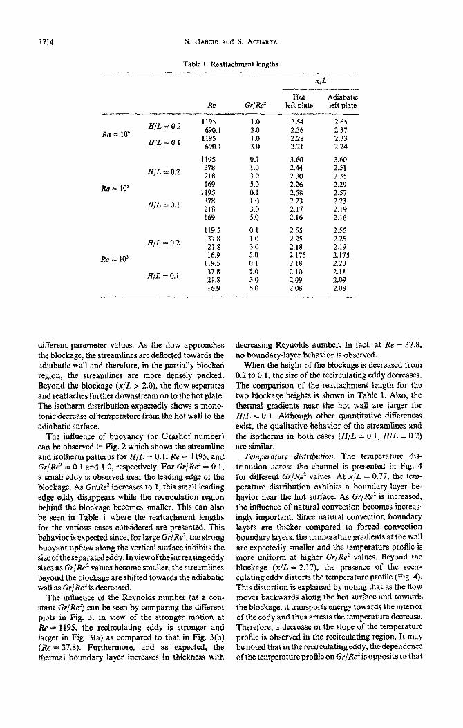
Table I. Reattachment lengths
1195 690.1
1195 690.1
I195 378 218 169
1195 378 218 169
119.5 37.8 21.8 16.9
119.5 37.g 21.8 $6.9
2.54 2.65 2.36 2.37 2.28 2.33 2.21 2.24
3.60 3.60 2.44 2.51 2.30 2.35 2.26 2.29 2.58 2.57 2.23 2.23 2.17 2,19 X16 2.16
255 2.55 x25 2.25 2.18 2.19 2.175 2.175 2.18 2.20 2.10 2.if
2.09 2.08
different parameter values~ As the Aow approaches the blockage, the streamlines are defiected towards the adiabatic wall and therefore, in the partially biocked region, the streamlines are more densely packed. Beyond the blockage (x]C > 2.0), the flow separates and reattaches further downstream on to the hot @ate. The isot~~ d~st~but~on ex~t~y shows a mono- tonic decrease of tern~mtu~ from the hot wall to the adiabatic surface.
The influence of buoyancy (or Grashof number) can be observed in Fig. 2 which shows the streamline and isotherm patterns for NIL = 0.1, & = 1195, and GrjW = 0. I and f .(1, respectively. For GrjXe2 = 0.1, a small eddy is observed near the bztding edge of the blocknge, As GrjRe’ increases to 1, this smaH leading edge eddy disappears while the recirculation region behind the blockage becomes smaller. This can also be seen in TabIe 1 where the reattachment lengths for the various eases considers are presented. This behavior is expected since, for large GP/.R$~ the strong b~oy~t upBow along the vertical surface inhibits the si~o~theseparatededdy.In~ewofthei~c~~sing~dy sizes 8s Gr/Re* values become smaller, the streamlines beyond the blockage are shifted towards the adiabatic wall as GrjRe’is decreased.
The itiuerze of the Reynolds number {at a con- stant GrjRe”) can be stxn by ~ornpa~~~ the dif&rent plots in Fig. 3. In view of the stronger motion at Re w 1195, the recirculating eddy is stronger and larger in Fig. 3(a) as compared to that in Fig. 3(b) (R$ = 37.8). Furth~~ore, and as expected, the thermal boundary layer increases in th~~k~~s with
decreasing Rey~oi~s number. In fact, at Re = 37.8, no boundary-layer b&vior is observed.
When the height of the blockage is decreased fram 0.2 to 0.1, the size of the recirculating eddy decreases. The comparison of the reattachment fength for the two blockage heights is shown in Table 1. AIso, the therm& gradients near the hot waft are larger for H/L = 0. ?t _ A~~~~g~ other ~uan~t~t~ve digerenees exist, the ~ua~ita~ve behavior of the streamfines and the isotherms in both cases (H/L = 0.1, H/L = 0.2) are similar.
Temperature distrJ&ion. The temperature dis- tribution across the channel is presented in Fig. 4 for different Gr/ReZ values. At x/L = 0.77, the tem- perature distribution exhibits a boundary-layer be= havior near the hot surface. As Gr/Re’ is increased, the influence of natural convection becomes increas- ingly important. Since natural convection boundary layers are thicker compared tea forced convection bonds Iayers, the ~ern~~at~e gradients at the wall are expec&edfy smaller and the ~rn~eratu~ profile is more uniform at higher Gr/Re” values. Beyond the blockage (x/L = 2.17), the presence of the recir- culating eddy distorts the temperature profile (Fig. 4). This distortion is explplained by noting that as the flow moves backwards along the hot surface and towards the blockage, it transports energy towards the interior of the eddy and thu$ arrests the temperature decrease. Therefore, a decrea.se in the slope of the temperature prafile is observed in the recirculating region. It may be noted that in the recircuIating eddy, the dependence of the temperature profile on C&-j&? is opposite to that

Laminar mixed convection 1715
0.8
0.7
0.6
8 0.5
0.4
0.3
0.2
0.1
L
0.0 L 0.0 0. I 0.2 0.3 0.4 0.5 0.6 0.7 0.8 0.9 1.0
Y/L
FIG. 4. Temperature distribution across the asymmetrically heated channel : Re = IO’, H/L = 0.2.
observed outside the eddy, i.e. temperatures decrease adiabatic plate while at Gr/Re’ = 5.0, the maximum with increasing Gr/Re*. This trend reverses around velocity occurs near the hot plate. At low values of y/L = 0.25. Gr/Re’, the forced convection effects are dominant
Velocity distribution. The U-velocity profile across and the presence of the blockage causes the flow to the channel for different Gr/Re’ values is plotted in be diverted towards the adiabatic wall resulting in a Fig. 5 for Ra = 10’ and H/L = 0.2. At x/L = 0.77, velocity maximum near the adiabatic plate. As Gr/Re’ the maximum velocity at Gr/Re’ = 0.1 occurs near the is increased, the natural convection effect becomes
2.0
1.8
1.6
0.8
0.6
Gr/Fd=5
FIG. 5. Velocity distribution across the asymmetrically heated channel for Ra = IO’, H/L = 0.2 (main figure) and H/L = 0.1 (inset).

1716 S. HAWXI and S. AC~.ARYA
FIG. 6. Velocity distribution across the ~y~metricaliy heated channel for different GriXe* values and Rayleigh numbers.
increasingly important and therefore, the peak vel- oeity shifts closer to the hot surface. In the blockage region (x/E = 1.45) the velocity levels are generally higher due to the smaller flow area. At x/L = 2.17 (beyond the blockage), negative velocities are observed due to the recirculating eddy (Fig. 6). The magnitude of the negative velocity increases as Gr,/Re’ increases. However, as noted eariier, the recirculation region is smaller at higher Gr!W values.
If the blockage height is decreased from 0.2 to 0.1, the qualitative behavior of the velocity profiles remains the same. However, there are quantitative differences. The inset of Fig. 5 presents the U-velocity profiles at xjL = 0.71 for H/L = 0.1‘ As H/L decreases, the bounce-Iayer behavior near tbe hot surface becomes more pronounced.
The effect of changing the Rayleigh number and Reynolds number, and keeping GrlReZ constant is shown in the inset of Fig. 6. As the Rayleigh number is increased, velocity boundary layers develop near the hot side of the channel. At Ra = 103, the natural convection effects are small and the velocity profiie is almost symmetrical. At Ra = 106, the effects of buoyancy and the presence of the blockage result in local peaks near the two walls with a depression in- between.
~~~e~~ ~~~~~. To present the heat transfer data, the Nusselt number is calculated along the heated surfaces using the following definition.
where MA L == hL/k (13)
is the heat transfer coefficient based on the wail to the inlet temperature difference.
Locut NW& number. Plots for the local Nusselt numbers (Nu,) along the hot plate and the blockage surface parallel to it are presented in Fig. 7. In general, the Nusselt number values decrease with Rayleigh number. The Nusselt number attains a maximum value near the channel inlet and decreases as x/L increases towards the blockage. This is expected because the surface near the entrance is washed by the cold fluid (zero dimensionless temperature). As the fluid flows along the hot surface, its temperature increases and the heat transfer coefficient corre- scoldingly decreases. Along the vertical surface of the blockage (parallel to the x-axis) the same behavior is observed. Beyond the blockage, the Nusselt number behavior is noticeably different due to the recir- culating eddy in that region. The Nusselt number increases up to the point of reattachment and then decreases gradually towards the exit of the channel. At the point of reatta~hment~ the heat flux and there- fore, the Nusselt number values peak. On either side of this point of reattachment, the fiow is directed outwards and, therefore, the Nusselt number (Nu,) values expectedly decrease. For Ra =L: 103, the recir- culation eddy is very small and weak. Therefore, unlike the other Rayleigh numbers, a monotonic increase towards the channel exit is observed.
The influence of Gr/Re’ should also be noted. For the higher Rayleigh rmmbers, as Gr/Re2 increases, the strength of the recirculating eddy increases leading to higher Nu, values (Fig. 7). Since the size of the eddy is reduced at higher Gr/Re”, Nu, peaks at a smaller x/f,

Laminar mixed convection 1717
60
40
N”x t
30 0 00 0.4 06 1.2 16 20 2.4 26 3.2 36 40
X/L
0.0 0.4 0.6 1.2 1.6 2.0 2.4 2.6 3.2 3.6 4.0
FIG. 7 Nusselt number distribution along the hot wall for the unsymmetrically heated channel, H/L = 0.2.
X/L
value. Between x/L = 0 and x/L = 2, Nu, decreases as Gr/Re* increases. This is because the temperature profiles are more uniform at higher Gr/Re2 values resulting in lower heat transfer coefficients.
The Nusselt number along the horizontal surfaces of the blockage (Nu,) is presented in Fig. 8. It should be noted that Nu, at x/L = 1 (inset of Fig. 8), is of the same order of magnitude as Nu, while Nu, at x/L = 2 is much smaller than Nu, at x/L = 1 due, in part, to the fluid being warmer at x/L = 2 and there- fore less amenable to heat transfer.
(Fig. 8), due to the increase in the recirculating eddy strength with Gr/Re’. At the lower Rayleigh number (Ra = 103), the recirculating eddy beyond the block- age is very small and weak and the values of Nu, decrease as Gr/Re2 increases.
Average Nusselt number. The average Nusselt number along a length AS is defined as
- ‘S s+As
N”=rs s
Nu(s) ds (15)
At a higher Rayleigh number, Nu,, along the upper where s represents either x or y. The average Nusselt surface of the blockage increases as Gr/Re’ increases number along the vertical surfaces and along the
IO
9
6
7
6
N”Y 5
4
3
2
I
s LI
I.0
45
40
35
30
25
N"Y 20
15
IO
5
0 006 012 0.16
Y/L
H/L=0.2 x/L=2.0
0 0.03 0.06 0.06 0.12 0.15 0.16
FIG. 8. Local Nusselt number along the lower (x/L = 1.0) and upper (x/L = 2.0) surface of the blockage.

1718 S. J&mm and S. ACRARVA
Ra
to3 104 IO5 106
Rc. 9. Average NnsseIt number distributions along the wtical surfaces (s&d lines) and along the horizontal surfaces of the blockage (dotted lines), H/L = 0.2.
upper and lower s~r%xs of the blockage are pre- sented in Fig. 9 for ff/L ‘= 0.2. With increasing Ray Ieigh number, the strength of the &XV fiefd and, there- fore, the average Nusselt number, atong the vertical surfaces increases. Between X/L = 0 and x/t = 2, the average Nussclt nur&r increases a5 @/Be’ decreases. However, above the blockage ⅈ > 2) and at high Rayleigh numbers, the average Nusseft number increases with increasing Gr{Re2, 70 explain this, it should be noted that at the high Rayleigh nttmhers, as &r/8&’ decreases the size oE the recirculation beyond the blockage increases (Fig. 2) and, since the recirculation region is associated with low heat trans- fer rates, the average heat transfer or Nussett number from the: $ate is therefore expected to deerease with
decreasing Gr/&‘. At iow Ra and Re, the recirculation zone is very small and its effects are not significant,
utemx, the HK @ends fcdfow &me aiong 0 G xJL G 2, i.6 decreasing Nrc with increasing C&+/I@.
The average Nusselt number along the upper and lower surfaces of the blockage is shown by dotted tines in Fig. 9. At the lower stIrface (X/L = 1 j, the average Nusselt number increases with increasing Rayleigh number and decreasing Er/Re’. On the other hand, at the upper surface (x/L = 2), the dependence of the average Nusselt number on GrjRe’ reverses at higher Rayleigh numbers due to the effect of recir- culating eddy beyond the blockage.
Table 2 shows the overall average Nusselt rmmber values for a blocked vertical channel (H/L = 0.2) and a smooth. vertical channel (H!L if Oj at J&2 = 103. Results for the smooth channel were obtained using a parabolic finite-difference procedure of Patankar and Spafding 1121. It is noted that the average Nusseit
This result is s~nle~h~~ u~~~~t~ and is due, in part, tr, the near-isothermal recircularion region behind the blockage which, as noted earlieer, is characterized by low heat transfer rates.
in describing the results for the syrnrnet~~a~~~ heated channel, the discussion is limited primarily to the observed similarities and diReren@% witi the results of the asymmet~~ally heated channel.
Te~pern~slre distribution. The texnperature pr~Eiles across the channel for Ra = IO’, E$/L = 0.2, and the various Gr/Re’ values are shown in Fig. 10. At x/t “- 0.77, it is observed t&t the t~~perat~~ exhibits a botmdary-layer hehatior near both plates. How- ever, the temperature values are generally higher near y/L = 0, due to the higher heat transfer area. Beyond the bto&kage (at x/L = 2, I?), the ~rn~ra~~ pro&e is distorted, as for the asymmet&a& heated charmel, due to the recirculating eddy.
Y&ci?y &sirthution. The U-wlocity profifes across
the channel are pre=ted in Fig. f 1 far Rra = IF, HjL = 02, and the various GqRe” values. At x/L = 0.77, it is observed that the velocity peaks Itear l3ofh plates with the maximum occurring near @me i&t
number values are higher for the smooth channel. -..-.l.” __-_elllil

Laminar mixed convection
I.0
0.9
0.8
0.7
1719
FIG. IO. Temperature distribution in the symmetrically heated channel.
plate (y/L = 1 .O). The presence of the blockage causes observed in the ~y~et~~al~y heated channel. Nega- the flow to be deflected towards the left plate causing tive velocities are once again observed (Fig. 12) beyond the velocity to attain its maximum in that region. With the blockage due to the recirculating eddy. increasing x/L the velocity near both walls increase The effect of the Rayleigh number can be seen in and since the channel flow rate is constant, this results Fig. 12. As expected, at a high Rayleigh number inaconcavityintheprofileinthecenter.Themagnitude (Ra = 106), natural convection effects near the wall of this concavity increases as the flow moves down- are dominant and a large depression in the velocity stream as seen in the inset of Fig. 12 (x/L = 2.17). This profile is observed around the center line. On the significant depression in the velocity profile is not other hand, at a low Rayleigh number (Ra = 103), the
U/U,
1.0
0.9
0.8
0.7
0.6
0.5
0.4 0.3
0.2
0. I no I I _._
0.0 0.1 0.2 0.3 0.4 0.5 0.6 0.1 0.6 0.9 Y/L
FIG. 11. Velocity distribution across the symmetrically heated channel, Ra = to*.

1720
Fro. 12. Velocity distribution across the symmetrically heated channel at x/L = 2.17.
v&&y profile is more uniform and no concavity is
observed. NW& tzupnbers. Tbe general behavior, as well as
the effect of the governing parameters on the local Nusselt number distribution along the right side of the channel are the same as observed in the asym- metrically heated charm&i, but the magnitudes of Nu, are lower by about 10%. The local Nusselt number profiles atong the left plate of the heated channel are presented in Fig. 13 far H/L = 0.2. Expectedly, the local Nusselt number attains a maximum value near
the entrance of the channel and decreases as the Aow approaches the exit. As Cr/Re2 increases, the Nusselt numbers decrease. The inset of Fig. 13 shows the local Nusselt number aiong the kft plate for both the blocked channel (H/L = 0.2) and the smooth channel (H/L = 0). As for the asymmetrically heated channel, the values of Nu, are higher for the smooth channel.
Figure 14 shows that the average Nusselt number along the right plate is slightly tower for the sym- metrically heated channel case. This is expected because the thermal boundary layer along the left
FIG. IS. Nusselt number distribution afonp the smooth plate of the s~~et~ca~ly heated channel.

Laminar mixed convection 1721
- Asymmetric Healinq
- - - Symmetric Haatinq
FIG. 14. Overall average Nusselt number along the hot wall containing the blockage (H/L = 0.2)
16
15
14
13
I2
6
plate, causes the core temperature to increase which results in lower temperature gradients along the right plate boundary layer which reduces the heat transfer.
CONCLUDING REMARKS
Mixed convection in a partially blocked, vertical
channel has been investigated by a numerical procedure. As Gr/Re* increases, the recirculation region above the blockage becomes stronger and smaller. In the recirculation region the temperature profile exhibits a smaller rate of decrease. The local and average Nusselt numbers increase with decreasing
Gr/Re’ in the blockage and the pre-blockage areas while, in the recirculation region, the local and average Nusselt numbers increase with Gr/Re2 at high Ray- leigh numbers. A local maximum in the Nusselt num- ber distribution is obtained at the point where the separated flow beyond the blockage reattaches. The average Nusselt number along the lower horizontal surface of the blockage is comparable to the Nusselt numbers along the vertical walls but significantly larger than the NusseIt number along the upper hori- zontal face of the blockage. Decreasing the dimen- sionless blockage thickness from 0.2 to 0.1 does not change the qualitative behavior although quantitative differences are noted. For the symmetrically heated channels, the velocity profiles are depressed in the center and become increasingly depressed as Gr/Re’
increases. For both symmetric and asymmetric heat- ing cases, the Nusselt numbers are smaller than the corresponding smooth duct Nusselt numbers.
1.
2.
3.
4.
5.
6.
7.
8.
9.
10.
11.
12.
REFERENCES
J. R. Bodia and J. F. Osterle, The development of free convection between heated vertical plates, J. Heat Trans- fer 84C, 4&44 (1962). W. Elenbass, Heat dissipation of parallel plates by free convection, Physica 9, l-28 (1942). W. Aung, Fully developed laminar free convection between vertical parallel plates heated asymmetrically, Int. J. Heat Mass Transfer 15, 1577-1580 (1972). H. Nakamura, Y. Asoko and T. Naitou, Heat transfer by free convection between two parallel flat plates, Numer. Heat Transfer 5, 39-58 (1982). W. Aung, L. S. Fletcher and V. Sernas, Developing laminar free convection between vertical flat plates with asymmetric heating, Znt. J. Heat Mass Transfer 15,2293- 2308 (1972). C. F. Kettleborough, Transient laminar free convection between heated vertical plates including entrance effects, Int. J. Heat Mass Transfer 15, 883-896 (1972). S. Ostrach, Combined natural and forced convection laminar flow and heat transfer of fluid with and without heat sources in channels with linearly varying wall tem- perature, NACA TN, 3141 (1954). T. Cebeci, A. A. Khattab and R. Lemont, Combined natural and forced convection in vertical ducts, Proc. Seventh Int. Heat Transfer Conferenre. Munich. F.R.G..
” ” Vol. 1 (1982). A. M. Dalbert, Natural, mixed and forced convection in a vertical channel with asymmetric uniform heating, Proc. Seventh Znt. Heat Transfer Conference, Munich, F.R.G., Vol. 1 (1982). J. Quintiere and W. K. Muller, An analysis of laminar free and forced convection between parallel plates, J. Heat Transfer 95,53-59 (1973). S. V. Patankar, Numerical Heat Transfer and Fluid Flow. Hemisphere, New York (1980). S. V. Patankar and D. B. Spalding, Heat and Mass Transfer in Boundary Layers. Intertext, London (1970).

1722 S. HABCHI and S. ACHARYA
CONVECTION MIXTE LAMINAIRE DANS UN CANAL VERTICAL PARTIELLEMENT BLOQUE
R&sum&-On etudie numeriquement la convection mixte laminaire d’air dans un canal vertical contenant un blocage partiel rectangulaire sur une paroi d’un canal; cette paroi est supposie chauffee tandis que l’autre est soit adiabatique (chauffage asymetrique) ou chauffee (chauffage symetrique). Les resultats indiquent qu’aux faibles valeurs de Gr/Re*, le maximum de vitesse se produit pres de la paroi adiabatique dans le cas de chauffage asymetrique. Lorsque Gr/Re’ augmente ce pit se d&place vers la paroi chaude. Un Ccoulement de retour est derriere le blocage. Dans cette region les variations de temperature sont petites. Les nombres de Nusselt moyen dans le blocage et avant le blocage augmentent quand diminue Gr/Re*. Au-dessus du blocage, le nombre de Nusselt moyen diminue avec Gr/Re’ aux grands nombres de Rayleigh. Pour le canal chat& symetriquement, les profils de vitesse sont deprimes au centre. Pour les deux conditions thermiques (symttrique et asymitrique), les nombres de Nusselt sont plus petits que ceux relatifs au canal
lisse correspondant.
LAMINARE GEMISCHTE KONVEKTION IN EINEM TEILWEISE VERSPERRTEN VERTIKALEN KANAL
Zusammenfassung-Es wurde eine numerische Untersuchung der laminaren gemischten Konvektion von Luft in einem vertikalen Kanal, der durch ein rechteckiges Hindernis auf einer Kanalwand teilweise versperrt ist, durchgefiihrt. Es wurde angenommen, daBdie Wand mit dem Hindernis beheizt wird, wahrend die andere Wand entweder adiabat (asymmetrische Beheizung) oder beheizt (symmetrische Beheizung) sein ~011. Die Ergebnisse zeigen, da13 fur kleine Werte von Gr/Re2 die maximale Geschwindigkeit im asym- metrisch beheizten Kanal nahe der adiabaten Wand auftritt. Fur zunehmende Gr/Re*-Werte verschiebt sich das Maximum in Richtung auf die beige Wand. Jenseits des Hindernisses ergibt sich eine Umkehrung der Striimung. In dem Gebiet der Rdckwartsstromung sind die Temperaturunterschiede sehr gering. Die mittlere Nusselt-Zahl in den Gebieten vor und innerhalb des Hindernisses steigt mit abnehmenden Gr/Re’- Werten. Jenseits des Hindernisses nimmt die mittlere Nusselt-Zahl mit Gr/Re* fur groDe Rayleigh-Zahlen ab. Beim symmetrisch beheizten Kanal sind die Geschwindigkeitsprofle in der Mitte abgeflacht. Fiir beide thermischen Bedingungen (symmetrisch und asymmetrisch) sind die Nusselt-Zahlen kleiner als die fiir
einen entsprechenden glatten Kanal.
JIAMMHAPHAII CMEIIIAHHAJI KOHBEKHMJI B ‘IACTH9HO 3AFPOMOxAEHHOM BEPTHKAJILHOM KAHAJIE
A~OTa~-~pO~eAeHOq~~AeHHoe~ccneAoaaH~e JIaMuHapHoii cMe~aHHo~KoH~xu~~BO3AyXaB~ep- T5iKanbHoMKaHaAe,K 0~~0SicTeH~e~0~0p0f0np~K~nAe~binp~~oyronb~b~eneperopoAK~.~peA~oAa-
raeTcr, '~TO cTeHKa c neperoponrtawf isarpesaeTcn, B TO Bpehfir KaK Apyrar C'fBTaeTcK ~1~460 aA~a6aT~qeCKO~ (ac~MMeTp~YH~~ Harpen), na60 narperoii (cuMMerpesnbtii narpee). Pesynbrarbi noza- 3btBa~T,qTO~p~MaA~X3HaqeH~KX Gr/Pe'MaKCEfMyMCKOpOCfB BMeeTMeCTO B611B3H aA5ia6aTwszcKo2i
cTeHKU ac~MMeTp~~H0 xarpeeaebforo KaHaAa. C ysena~emfek4 Gr/Pe’ 3~oT ,waKceMyM cMewaeTcK 3
Ha~paB~eH~~ ropnqel crerimf. Ilpencxa3ano cy.mecraonanwe o6pareoro re~erinx 38 neperoponxoir. B 3oHe o6parnoro Te'teHWK B3MeHeHHK TeMnepaTypbi hianbI.CpeAHee wicno HyCC%?nbTa Ha neperopoAKe
B B 30Hax nepen Hei? pacTeT c yMeHbLUeHHeM 3HaveHaii Gr/Pe’. 3a neperopoAKoii CpeAHee SWCJIO
HyCCeJIbTa yMeHbmaercn c Gr/Pe2 npn 6onbnmx rncnax P3nea. Ana cnyran ceMhfeTpa%roro narpe- BaeMoro Kanana npo@inn CKO~~CT~ CxoiMarorca B uearpe. Ana 06oax rennoabrx ~~~HMOB (CNhiMe-
TpE,YHO$-0 H H~~MMeTp~qHOrO) 9HCAa HyCCeAbTa MeHbLUe COOTBeTCTBy~~~X 98CeA AAIi rAaAKOf0
rcaiiana.