
UNIT - 1 UML DIAGRAMS 1101 AMSCE - DEPARTMENT OF IT
306
PART - A 1. What is UML? ( MAY/JUNE 2012) Unified Modeling Language is a visual language for specifying, con- structing and documenting the artifacts of system. UML is the standard diagrammatic notation for drawing picture related to software. UML defines UML profiles that specialize subsets of the notation for common subject areas. 2. List the Relationships used in Use cases. Generalization Extend Include 3. What is Object Oriented Analysis and Design? (APRIL/MAY-2011)( APRIL/MAY-2017) During object-oriented analysis, there is an emphasis on finding and describing the objects—or concepts—in the problem domain. For example, in the case of the library information system, some of the concepts include Book, Library, and Patron. During object-oriented design, there is an emphasis on defining software objects and how they collaborate to fulfill the requirements For example, in the library system, a Book software object may have a title attribute and a get Chapter method 4. Define the inception step. Inception is the initial short step to establish a common vision and basic scope for the project. UNIT - 1 UML DIAGRAMS 1101 AMSCE - DEPARTMENT OF IT
-
Upload
khangminh22 -
Category
Documents
-
view
2 -
download
0
Transcript of UNIT - 1 UML DIAGRAMS 1101 AMSCE - DEPARTMENT OF IT

PART - A1. What is UML? ( MAY/JUNE 2012)
Unified Modeling Language is a visual language for specifying, con-structing and documenting the artifacts of system.
UML is the standard diagrammatic notation for drawing picture related to software.
UML defines UML profiles that specialize subsets of the notation for common subject areas.
2. List the Relationships used in Use cases. � Generalization
� Extend
� Include
3. What is Object Oriented Analysis and Design? (APRIL/MAY-2011)( APRIL/MAY-2017)
� During object-oriented analysis, there is an emphasis on finding and describing the objects—or concepts—in the problem domain.
� For example, in the case of the library information system, some of the concepts include Book, Library, and Patron.
� During object-oriented design, there is an emphasis on defining software objects and how they collaborate to fulfill the requirements
� For example, in the library system, a Book software object may have a title attribute and a get Chapter method
4. Define the inception step. � Inception is the initial short step to establish a common vision and basic scope for the project.
UNIT - 1
UML DIAGRAMS
1101 AMSCE - DEPARTMENT OF IT

2 Unit Wise solved QUestion PaPers
� It will include analysis of perhaps 10% of the use cases, analysis of the critical non-functional requirement, creation of a business case, and preparation of the development environment.
� Most requirement analysis occurs during the elaboration phase ,in parallel with early production quality programming and testing.
� It is a approximate vision, business case, scope, vague estimates.
5. List out any four reasons for the complexity of software.i). Nature of the problem domain
- requirements,
- decay of systems
ii). Complexity of process
- management problems,
- need for simplicity
iii).Dangerous potential for flexibility in software systems
“Software is flexible and expressive and thus encourages highly de-manding requirements, which in turn lead to complex implementations which are difficult to assess”
iv).Characterizing behavior of discrete systems
“The task of the software development team is to engineer the illusion of simplicity”
6. Define a) Actors b) Scenario c) Use cases. (NOV/DEC 2011) � Definition: An actor is something with behavior, such as a person (identified by role), computer system, or organization; for example, a cashier.
� A scenario is a specific sequence of actions and interactions between actors and the system; it is also called a use case instance.
� It is one particular story of using a system, or one path through the use case; for example, the scenario of successfully purchasing items with cash, or the scenario of failing to purchase items because of a credit payment denial.
1101 AMSCE - DEPARTMENT OF IT

object oriented analysis and design 3 � A use case is a collection of related success and failure scenarios
that describe an actor using a system to support a goal
� Definition of a use case provided by the RUP:
� A set of use-case instances, where each instance is a sequence of actions a system performs that yields an observable result of value to a particular actor [RUP].
7. Define object. (NOV/DEC 2009)An object is a combination of data and logic; the representation of some real-world entity.
8. What is the main advantage of object-oriented development? � High level of abstraction
� Seamless transition among different phases of software development
� Encouragement of good programming techniques.
� Promotion of reusability.
9. Define Class Diagram.The main static structure analysis diagram for the system, it represents the class structure of a system including the relationships between class and the inheritance structure.
10. Define Activity Diagram.A variation or special case of a state machine in which the states are activities representing the performance of operations and the transi-tions are triggered by the completion of the operations.
11. What is interaction diagram? Mention the types of interaction diagram.
� Interaction diagrams are diagrams that describe how groups of objects collaborate to get the job done interaction diagrams capture the behavior of the single use case, showing the pattern of interaction among objects.
� There are two kinds of interaction models
� Sequence Diagram
� Collaboration Diagram.
1101 AMSCE - DEPARTMENT OF IT

4 Unit Wise solved QUestion PaPers
12. What is Sequence Diagram? (NOV/DEC 2011)Sequence diagram is an easy and intuitive way of describing the be-haviors of a system by viewing the interaction between the system and its environment.
13. What is Collaboration Diagram?Collaboration diagram represents a collaboration, which is a set of objects related in a particular context, and interaction, which is a set of messages exchanged among the objects with in collaboration to achieve a desired outcome.
14. Define Start chart Diagram. � Start chart diagram shows a sequence of states that an object goes through during its life in response to events.
� A state is represented as a round box, which may contain one or more compartments. The compartments are all optional.
15. What is meant by implementation diagram?Implementation Diagrams show the implementation phase of systems development such as the source code structure and the run- time im-plementation structure.
There are two types of implementation diagrams:
� Component Diagrams
� Development Diagrams.
16. Define Component Diagram? � A Component diagrams shows the organization and dependencies among a set of components.
� A component diagrams are used to model the static implementation view of a system.
� This involves modeling the physical things that reside on a mode, such as executable, libraries, tables, files and documents.
17. Define Deployment Diagram. � Deployment Diagram shows the configuration of run-time processing elements and the software components, processes, and objects that live in them.
1101 AMSCE - DEPARTMENT OF IT
object oriented analysis and design 5 � Deployment diagrams are used to model the static deployment view
of a system.
� A deployment diagram is a graph of modes connected by communication association.
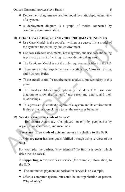
18. Define Use-case Diagram.(NOV/DEC 2011)(MAY/JUNE 2012) � Use-Case Model is the set of all written use cases; it is a model of the system’s functionality and environment.
� Use cases are text documents, not diagrams, and use-case modeling is primarily an act of writing text, not drawing diagrams.
� The Use-Case Model is not the only requirement artifact in the UP.
� There are also the Supplementary Specification, Glossary, Vision, and Business Rules.
� These are all useful for requirements analysis, but secondary at this point.
� The Use-Case Model may optionally include a UML use case diagram to show the names of use cases and actors, and their relationships.
� This gives a nice context diagram of a system and its environment. It also provides a quick way to list the use cases by name.
19. What are the three kinds of Actors? Definition: Actors are roles played not only by people, but by organizations, software, and machines.
There are three kinds of external actors in relation to the SuD:
1. Primary actor has user goals fulfilled through using services of the SuD.
For example, the cashier. Why identify? To find user goals, which drive the use cases?
2. Supporting actor provides a service (for example, information) to the SuD.
� The automated payment authorization service is an example.
� Often a computer system, but could be an organization or person. Why identify?
1101 AMSCE - DEPARTMENT OF IT

6 Unit Wise solved QUestion PaPers
� To clarify external interfaces and protocols.
3. Offstage actor has an interest in the behavior of the use case, but is not primary or supporting; for example, a government tax agency.
20. What are three common use case formats? � brief
� casual
� fully dressed
21. What are the artifacts in inception phase? i).Vision and business case
ii).Supplementary specification
iii).Glossary
iv).Risk list
v).Prototypes
vi).Iteration plan
vii).Phase plan
viii).Development case
22. What are the steps to find use case? i ) Choose the system boundary.
ii) Identify the primary actors
iii) Identify the goals for each primary actor.
iv) Define use cases that satisfy user goals.
23. What Tests Can Help Find Useful Use Cases? � The Boss Test
� The EBP Test
� The Size Test
1101 AMSCE - DEPARTMENT OF IT

object oriented analysis and design 7 24. What are the three ways and perspectives to Apply UML?
(APRIL/MAY-2017)Ways-
� UML as sketch,
� UML as blueprint,
� UML as programming language Perspectives-
� Conceptual perspective,
� Specification (software) perspective,
� Implementation(Software) perspective.
25. What is the use of Component Diagram? � The Component Diagram helps to model the physical aspect of an Object-Oriented software system.
� It illustrates the architectures of the software components and the dependencies between them.
� Those software components including run-time components, executable components also the source code components.
26. Give the meaning of Event, State, Transition. (APRIL/MAY 2011) � An event is a significant or noteworthy occurrence. For example:A telephone receiver is taken off the hook.
� A state is the condition of an object at a moment in time—the time between events. For example:A telephone is in the state of being “idle” after the receiver is placed on the hook and until it is taken off the hook.
� A transition is a relationship between two states that indicates that when an event occurs, the object moves from the prior state to the subsequent state. For example:When the event “off hook” occurs, transition the telephone from the “idle” to “active” state.
27. Define component with an example. � A component represents a modular part of a system that encapsulates its contents and whose manifestation is replaceable within its environment.
1101 AMSCE - DEPARTMENT OF IT

8 Unit Wise solved QUestion PaPers
� A component defines its behavior in terms of provided and required interfaces.
� As such, a component serves as a type, whose conformance is defined by these provided and required interfaces
Figure 1.1 : UML COMPONENTS
28. How will you reflect the version control information in UML diagram?Version Control provides two key facilities:
� ·Coordinating sharing of packages between users
� ·Saving a history of changes to Enterprise Architect packages, including the ability to retrieve previous versions.
29. Define UML state machine diagram? UML state machine diagram illustrates the interesting events and states of an object, and the behavior of an object in reaction to an event.
30. Define state dependent object. It reacts differently to events depending on their state or mode.
31. What are the steps involved in modeling protocols and legal sequences?
� Communication protocols
� UI page / Window flow or Navigation
� UI flow controllers or sessions
� Use case system operations
� Individual UI window event handling
1101 AMSCE - DEPARTMENT OF IT

object oriented analysis and design 9 32. Define transition action.
� A transition can cause an action to fire.
� In a software implementation, this may represent the invocation of a method of the class of the state machine diagram.
33. Define guard condition. � A transition may also have a conditional guard or Boolean test.
� The transition only occurs if the test passes.
34. What do you meant by Nested state? A state allows nesting to contain substates; a substate inherits the tran-sitions of its upper state.
35. What is deployment Diagrams? � A deployment diagram shows the assignment of concrete software artifacts (such as executable files) to computational nodes (something with processing services).
� It shows the deployment of software elements to the physical architecture and the communication (usually on a network) between physical elements
36. What is State-Independent and State-Dependent Objects? � If an object always responds the same way to an event, then it is considered as state
� independent (or modeless) with respect to that event.
� State-dependent objects react differently to events depending on their state or mode.
37. What are the basic elements of deployment diagrams? � The basic element of a deployment diagram is a node, of two types: device node (or device) A physical (e.g., digital electronic) computing resource with processing and memory services to execute software, such as a typical computer or a mobile phone.
� Execution environment node (EEN) This is a software computing resource that runs within an outer node (such as a computer) and which itself provides a service to host and execute other executable software elements.
1101 AMSCE - DEPARTMENT OF IT

10 Unit Wise solved QUestion PaPers
� For example: an operating system (OS) is software that hosts and executes programs a virtual machine (VM, such as the Java or .NET VM) hosts and executes programs a database engine (such as PostgenSQL) receives SQL program requests and executes them, and hosts/executes internal stored procedures.
38. What are the three ways and perspectives to Apply UML? (NOV/DEC 2016) Ways - UML as sketch, UML as blueprint, UML as programming lan-guage Perspectives-Conceptual perspective, Specification (software) perspective, Implementation (Software) perspective.
39. Distinguish between method and message in object. Method Message (NOV/DEC 2016) i) Methods are similar to functions, procedures or subroutines in more traditional programming languages. Message essentially is non-specific function calls.
ii) Method is the implementation. Message is the instruction.
iii) In an object-oriented system, a method is invoked by sending an object a message. An object understands a mes-sage when it can match the message to a method that has the same name as the message.
40. Differentiate coupling and cohesion. (NOV/DEC 2015) � Coupling deals with interactions between objects or software components while cohesion deals with the interactions within a single object or software component.
� Highly cohesive components can lower coupling because only minimum of essential information need to be passed between components
1101 AMSCE - DEPARTMENT OF IT

object oriented analysis and design 11 PART - B
1. Explain about Unified Process Phases. (APRIL/MAY 2011)(MAY/JUNE 2012) (NOV/DEC 2011) (NOV/DEC 2015) (NOV/DEC 2016).( APRIL/MAY-2017)
� A software development process describes an approach to building, deploying, and possibly maintaining software.
� The Unified Process has emerged as a popular software development process for building object-oriented systems.
� In particular, the Rational Unified Process or RUP [KruchtenOO], a detailed refinement of the Unified Process, has been widely adopted.
� The Unified Process (UP) combines commonly accepted best practices, such as an iterative lifecycle and risk-driven development, into a cohesive and well-documented description
This starts with an introduction to the UP for two reasons:1. The UP is an iterative process. Iterative development is a valuable practice that influences how this book introduces OOA/D, and how it is best practiced.
2. UP practices provide an example structure to talk about how to do—and how to learn—OOA/D.
The Most Important UP Idea: Iterative Development � The UP promotes several best practices, but one stands above the others: iterative development. In this approach, development is organized into a series of short, fixed-length (for example, four week) mini-projects called iterations; the outcome of each is a tested, integrated, and executable system.
� Each iteration includes its own requirements analysis, design, implementation, and testing activities.
� The iterative lifecycle is based on the successive enlargement and refinement of a system through multiple iterations, with cyclic feedback and adaptation as core drivers to converge upon a suitable system.
1101 AMSCE - DEPARTMENT OF IT

12 Unit Wise solved QUestion PaPers
� The system grows incrementally over time, iteration by iteration, and thus this approach is also known as iterative and incremental development
Iteration Length and Timeboxing � The UP (and experienced iterative developers) recommends an iteration length between two and six weeks.
� Small steps, rapid feedback, and adaptation are central ideas in iterative development; long iterations subvert the core motivation for iterative development and increase project risk.
� Much less than two weeks, and it is difficult to complete sufficient work to get meaningful throughput and feedback; much more than six or eight weeks, and the complexity becomes rather overwhelming, and feedback is delayed.
� A very long iteration misses the point of iterative development. Short is good. A key idea is that iterations are time boxed, or fixed in length.
� For example, if the next iteration is chosen to be four weeks long, then the partial system should be integrated, tested, and stabilized by the scheduled date—date slippage is discouraged.
� If it seems that it will be difficult to meet the deadline, the recommended response is to remove tasks or requirements from the iteration, and include them in a future iteration, rather than slip the completion date.
Additional UP Best Practices and ConceptsThe central idea to appreciate and practice in the UP is short timeboxed iterative, adaptive development.
Another implicit, but core, UP idea is the use of object technologies, including OOA/D and object-oriented programming.
Some additional best practices and key concepts in the UP include: � tackle high-risk and high-value issues in early iterations
� continuously engage users for evaluation, feedback, and requirements
� build a cohesive, core architecture in early iterations
1101 AMSCE - DEPARTMENT OF IT

object oriented analysis and design 13 � continuously verify quality; test early, often, and realistically
� apply use cases
� model software visually (with the UML)
� carefully manage requirements
� practice change request and configuration management
The UP Phases and Schedule-Oriented TermsA UP project organizes the work and iterations across four major phases:
1. Inception— approximate vision, business case, scope, vague estimates.
2. Elaboration—refined vision, iterative implementation of the core architecture, resolution of high risks, identification of most requirements and scope, more realistic estimates.
3. Construction—iterative implementation of the remaining lower risk and easier elements, and preparation for deployment.
4. Transition—beta tests, deployment.
These phases are more fully defined in subsequent chapters. � This is not the old “waterfall” or sequential lifecycle of first defining all the requirements, and then doing all or most of the design.
� Inception is not a requirements phase; rather, it is a kind of feasibility phase, where just enough investigation is done to support a decision to continue or stop.
� Similarly, elaboration is not the requirements or design phase; rather, it is a phase where the core architecture is iteratively implemented, and high risk issues are mitigated.
Figure 1.2 : Schedule –oriented terms in UP
1101 AMSCE - DEPARTMENT OF IT

14 Unit Wise solved QUestion PaPers
The UP Disciplines (was Workflows) � The UP describes work activities, such as writing a use case, within disciplines (originally called workflows).
� Informally, a discipline is a set of activities (and related artifacts) in one subject area, such as the activities within requirements analysis.
� In the UP, an artifact is the general term for any work product: code,Web graphics, database schema, text documents, diagrams, models, and so on.
� There are several disciplines in the UP; this book focuses on some artifacts in the following three:
Business Modeling—When developing a single application, this includes domain object modeling. When engaged in large-scale business analysis or business process reengineering, this includes dynamic modeling of the business processes across the entire enterprise.
Requirements—Requirements analysis for an application, such as writing uses cases and identifying non-functional requirements.
Design—All aspects of design, including the overall architecture, objects, databases, networking, and the like.
Figure 1.3 :UP DisciplinesIn the UP, Implementation means programming and building
the system, not deployment.
1101 AMSCE - DEPARTMENT OF IT

object oriented analysis and design 15 The Environment discipline refers to establishing the tools and
customizing the process for the project—that is, setting up the tool and process environment.
Disciplines and PhasesDuring one iteration work goes on in most or all disciplines.However, the relative effort across these disciplines changes
over time.Early iterations naturally tend to apply greater relative
emphasis to requirements and design, and later ones less so, as the requirements and core design stabilize through a process of feedback and adaptation.
Relating this to the UP phases (inception, elaboration, ),
Figure 1.4 : Disciplines and Phases
Book Structure and UP Phases and DisciplinesWith respect to the phases and disciplines, what is the focus of the case study?
Answer: � The case study emphasizes the inception and elaboration phase.
� It focuses on some artifacts in the Business Modeling, Requirements, and Design disciplines, as this is where requirements analysis, OOA/D, patterns, and the UML are primarily applied.
The earlier chapters introduce activities in inception; later chapters explore several iterations in elaboration.
The following list and describe the organization with respect to the UP phases.
1101 AMSCE - DEPARTMENT OF IT
16 Unit Wise solved QUestion PaPers
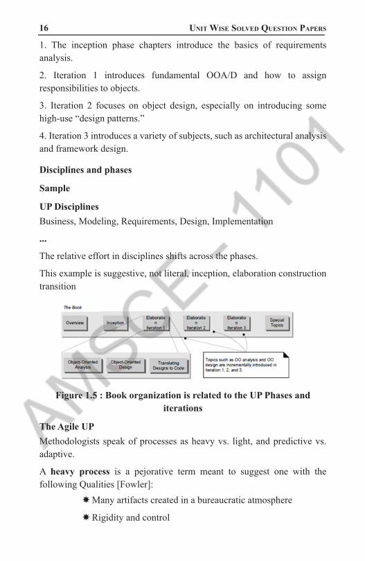
1. The inception phase chapters introduce the basics of requirements analysis.
2. Iteration 1 introduces fundamental OOA/D and how to assign responsibilities to objects.
3. Iteration 2 focuses on object design, especially on introducing some high-use “design patterns.”
4. Iteration 3 introduces a variety of subjects, such as architectural analysis and framework design.
Disciplines and phases
Sample
UP DisciplinesBusiness, Modeling, Requirements, Design, Implementation
...
The relative effort in disciplines shifts across the phases.
This example is suggestive, not literal, inception, elaboration construction transition
Figure 1.5 : Book organization is related to the UP Phases and iterations
The Agile UPMethodologists speak of processes as heavy vs. light, and predictive vs. adaptive.
A heavy process is a pejorative term meant to suggest one with the following Qualities [Fowler]:
�Many artifacts created in a bureaucratic atmosphere
�Rigidity and control
1101 AMSCE - DEPARTMENT OF IT

object oriented analysis and design 17 �Elaborate, long-term, detailed planning
� Predictive rather than adaptive
� A predictive process is one that attempts to plan and predict the activities and resource (people) allocations in detail over a relatively long time span, such as the majority of a project.
� Predictive processes usually have a “waterfall” or sequential lifecycle—first, defining all the requirements; second, defining a detailed design; and third, implementing.
� In contrast, an adaptive process is one that accepts change as an inevitable driver and encourages flexible adaptation; they usually have an iterative lifecycle.
� An agile process implies a light and adaptive process, nimble in response to changing needs.
� The UP was not meant by its authors to be either heavy or predictive, although its large optional set of activities and artifacts has understandably led to that impression in some.
� Rather, it was meant to be adopted and applied in the spirit of an agile process—agile UP. Some examples of how this applies:
� Prefer a small set of UP activities and artifacts. Some projects will benefit from more than others benefit, but, in general, keep it simple.
� Since the UP is iterative, requirements and designs are not completed before implementation. They adaptively emerge through a series of iterations, based on feedback.
� There is not a detailed plan for the entire project.
� There is a high-level plan (called the Phase Plan) that estimates the project end date and other major milestones, but it does not detail the fine-grained steps to those milestones.
� A detailed plan (called the Iteration Plan) only plans with detail one iteration in advance. Detailed planning is done adaptively from iteration to iteration.
1101 AMSCE - DEPARTMENT OF IT

18 Unit Wise solved QUestion PaPers
2. Explain about Use case modeling (NOV/DEC 2015).
Figure 1.6: Hotel Information System � Writing use cases—stories of using a system—is an excellent technique to understand and describe requirements
� The UP defines the Use-Case Model within the Requirements discipline.
� Essentially, this is the set of all use cases; it is a model of the system’s functionality and environment.
Goals and StoriesCustomers and end users have goals (also known as needs in the UP) and want computer systems to help meet them, ranging from recording sales to estimating the flow of oil from future wells.
There are several ways to capture these goals and system requirements; the better ones are simple and familiar because this makes it easier—especially for customers and end users—to contribute to their definition or evaluation.
That lowers the risk of missing the mark.
Use cases are a mechanism to help keep it simple and understandable for all stakeholders.
Informally, they are stories of using a system to meet goals. Here is an example brief format use case:
1101 AMSCE - DEPARTMENT OF IT

object oriented analysis and design 19 Process Sale:
� A customer arrives at a checkout with items to purchase.
� The cashier uses the POS system to record each purchased item.
� The system presents a running total and line-item details.
� The customer enters payment information, which the system validates and records.
� The system updates inventory.
� The customer receives a receipt from the system and then leaves with the items.
� Use cases often need to be more elaborate than this, but the essence is discovering and recording functional requirements by writing stories of using a system to help fulfill various stakeholder goals; that is, cases of use.
� It isn’t supposed to be a difficult idea, although it may indeed be difficult to discover or decide what is needed, and write it coherently at a useful level of detail.
� Much has been written about use cases, and while worthwhile,
Use Cases and Adding ValueFirst, some informal definitions: an actor is something with
behavior, such as a person (identified by role), computer system, or organization; for example, a cashier.
A scenario is a specific sequence of actions and interactions between actors and the system under discussion; it is also called a use case instance.
It is one particular story of using a system, or one path through the use case; for example, the scenario of successfully purchasing items with cash, or the scenario of failing to purchase items because of a credit card transaction denial.
Informally then, a use case is a collection of related success and failure scenarios that describe actors using a system to support a goal.
For example, here is a casual format use case that includes some alternate scenarios:
1101 AMSCE - DEPARTMENT OF IT

20 Unit Wise solved QUestion PaPers
Handle Returns � Main Success Scenario: A customer arrives at a checkout with items to return. The cashier uses the POS system to record each returned item ...
� Alternate Scenarios:
� If the credit authorization is reject, inform the customer and ask for an alternate payment method.
� If the item identifier is not found in the system, notify the Cashier and suggest manual entry of the identifier code (perhaps it is corrupted).
� If the system detects failure to communicate with the external tax calculator system, ...
� An alternate, but similar definition of a use case is provided by the RUP:
� A set of use-case instances, where each instance is a sequence of actions a system performs that yields an observable result of value to a particular actor
Use Cases and Functional RequirementsUse cases are requirements; primarily they are functional
requirements that indicate what the system will do. In terms of the FURPS+ requirements types, they emphasize
the “F” (functional or behavioral), but can also be used for other types, especially when those other types strongly relate to a use case.
In the UP—and most modern methods—use cases are the central mechanism that is recommended for their discovery and definition.
Use cases define a promise or contract of how a system will behave.
To be clear: Use cases are requirements (although not all requirements).
Some think of requirements only as “the system shall do...” function or feature lists.
Not so, and a key idea of use cases is to (usually) reduce the importance or use of detailed older-style feature lists and rather,
1101 AMSCE - DEPARTMENT OF IT

object oriented analysis and design 21 write use cases for the functional requirements. More on this point
in a later section.Use cases are text documents, not diagrams, and use-case modeling
is primarily an act of writing text, not drawing However, the UML defines a use case diagram to illustrate the
names of use cases and actors, and their relationships.
Use Case Types and Formats
Black-Box Use Cases and System Responsibilities � Black-box use cases are the most common and recommended kind; they do not describe the internal workings of the system, its components, or design. Rather, the system is described as having responsibilities, which is a common unifying metaphorical theme in object-oriented thinking—software elements have responsibilities and collaborate with other elements that have responsibilities.
� By defining system responsibilities with black-box use cases, it is possible to specify what the system must do (the functional requirements) without deciding how it will do it (the design). Indeed, the definition of “analysis” versus “design” is sometimes summarized as “what” versus “how.”
� This is an important theme in good software development: During requirements analysis avoid making “how” decisions, and specify the external behavior for the system, as a black box. Later, during design, create a solution that meets the specification.
� Black –Box Style: The System Record the sale
� Not : The system writes the sale to a database..or(even worse):the system generates a SQL INSERT statement for the sale.
Formality TypesUse cases are written in different formats, depending on need. In addition to the black-box versus white-box visibility type, use cases are written in varying degrees of formality:
brief—terse one-paragraph summary, usually of the main success scenario.
The prior Process Sale example was brief.
casual—informal paragraph format. Multiple paragraphs that cover various scenarios. The prior Handle Returns example was casual.
1101 AMSCE - DEPARTMENT OF IT

22 Unit Wise solved QUestion PaPers
fully dressed—the most elaborate. All steps and variations are written in detail, and there are supporting sections, such as preconditions and success guarantees.
Fully Dressed Example: Process SaleFully dressed use cases show more detail and are structured; they are useful in order to obtain a deep understanding of the goals, tasks, and requirements. In the NextGen POS case study, they would be created during one of the early requirements workshops in a collaboration of the system analyst, subject matter experts, and developers.
Use Case UC1: Process Sale
Primary Actor: Cashier
Stakeholders and Interests:Cashier: Wants accurate, fast entry, and no payment errors, as cash drawer short ages are deducted from his/her salary.
Salesperson: Wants sales commissions updated.
Customer: Wants purchase and fast service with minimal effort. Wants proof of purchase to support returns.
Company: Wants to accurately record transactions and satisfy customer interests.
Wants to ensure that Payment Authorization Service payment receivables are recorded. Wants some fault tolerance to allow sales capture even if server components (e.g., remote credit validation) are unavailable. Wants automatic and fast update of accounting and inventory.
Government Tax Agencies: Want to collect tax from every sale. May be multiple agencies, such as national, state, and county.
Payment Authorization Service: Wants to receive digital authorization requests in the correct format and protocol. Wants to accurately account for their payables to the store.
Preconditions: Cashier is identified and authenticated.
Success Guarantee (Postconditions): Sale is saved. Tax is correctly calculated.
Accounting and Inventory are updated. Commissions recorded. Receipt is generated. Payment authorization approvals are recorded.
1101 AMSCE - DEPARTMENT OF IT

object oriented analysis and design 23 Main Success Scenario (or Basic Flow):
1.Customer arrives at POS checkout with goods and/or services to purchase.
2.Cashier starts a new sale.
3.Cashier enters item identifier.
4.System records sale line item and presents item description, price, and running total.
5.Price calculated from a set of price rules.
Cashier repeats steps 3-4 until indicates done.
6. Cashier tells Customer the total, and asks for payment.
7. Customer pays and System handles payment.
8. System logs completed sale and sends sale and payment information to the external Accounting system (for accounting and commissions) and Inventory system (to update inventory).
9. System presents receipt.
10.Customer leaves with receipt and goods (if any).
Extensions (or Alternative Flows):*a. At any time, System fails:
To support recovery and correct accounting, ensure all transaction sensitive state and events can be recovered from any step of the scenario.
1. Cashier restarts System, logs in, and requests recovery of prior state.
2. System reconstructs prior state.
2a. System detects anomalies preventing recovery:
1. System signals error to the Cashier, records the error, and enters a clean state.
2. Cashier starts a new sale.
3a. Invalid identifier:
System signals error and rejects entry.
3b. There are multiple of same item category and tracking unique item identity not important (e.g., 5 packages of veggie-burgers):
1. Cashier can enter item category identifier and the quantity.
1101 AMSCE - DEPARTMENT OF IT
24 Unit Wise solved QUestion PaPers
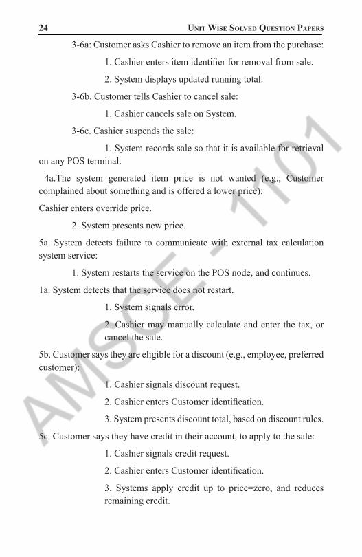
3-6a: Customer asks Cashier to remove an item from the purchase:
1. Cashier enters item identifier for removal from sale.
2. System displays updated running total.
3-6b. Customer tells Cashier to cancel sale:
1. Cashier cancels sale on System.
3-6c. Cashier suspends the sale:
1. System records sale so that it is available for retrieval on any POS terminal.
4a.The system generated item price is not wanted (e.g., Customer complained about something and is offered a lower price):
Cashier enters override price.
2. System presents new price.
5a. System detects failure to communicate with external tax calculation system service:
1. System restarts the service on the POS node, and continues.
1a. System detects that the service does not restart.
1. System signals error.
2. Cashier may manually calculate and enter the tax, or cancel the sale.
5b. Customer says they are eligible for a discount (e.g., employee, preferred customer):
1. Cashier signals discount request.
2. Cashier enters Customer identification.
3. System presents discount total, based on discount rules.
5c. Customer says they have credit in their account, to apply to the sale:
1. Cashier signals credit request.
2. Cashier enters Customer identification.
3. Systems apply credit up to price=zero, and reduces remaining credit.
1101 AMSCE - DEPARTMENT OF IT

object oriented analysis and design 25 6a. Customer says they intended to pay by cash but do not have enough
cash:
1a. Customer uses an alternate payment method.
1b. Customer tells Cashier to cancel sale. Cashier cancels sale on System.
7a. Paying by cash:
1. Cashier enters the cash amount tendered.
2. System presents the balance due, and releases the cash drawer.
3. Cashier deposits cash tendered and returns balance in cash to Customer.
4. System records the cash payment.
7b. Paying by credit:
1. Customer enters their credit account information.
2. System sends payment authorization request to an external Payment Authorization Service System, and requests payment approval.
2a. System detects failure to collaborate with external system:
1. System signals error to Cashier.
2. Cashier asks Customer for alternate payment.
3. System receives payment approval and signals approval to Cashier.
3a. System receives payment denial:
1. System signals denial to Cashier.
2. Cashier asks Customer for alternate payment.
4. System records the credit payment, which includes the payment approval.
5. System presents credit payment signature input mechanism.
6. Cashier asks Customer for a credit payment signature. Customer enters signature.
7c. Paying by check...
1101 AMSCE - DEPARTMENT OF IT

26 Unit Wise solved QUestion PaPers
7d. Paying by debit...
7e. Customer presents coupons:
1. Before handling payment, Cashier records each coupon and System reduces price as appropriate. System records the used coupons for accounting reasons.
1a. Coupon entered is not for any purchased item:
System signals error to Cashier.
9a.There are product rebates:
1. System presents the rebate forms and rebate receipts for each item with a rebate.
9b. Customer requests gift receipt (no prices visible):
1.Cashier requests gift receipt and System presents it.
Special Requirements:Touch screen Ul on a large flat panel monitor. Text must be visible from 1 meter.
Credit authorization response within 30 seconds 90% of the time.
Somehow, we want robust recovery when access to remote services such the inventory system is failing.
Language internationalization on the text displayed.
Pluggable business rules to be insertable at steps 3 and 7.
Technology and Data Variations List:3a. Item identifier entered by bar code laser scanner (if bar code is present) or keyboard.
3b. Item identifier may be any UPC, EAN, JAN, or SKU coding scheme.
7a. Credit account information entered by card reader or keyboard.
7b. Credit payment signature captured on paper receipt
Frequency of Occurrence: Could be nearly continuous.
Open Issues: - What are the tax law variations?
- Explore the remote service recovery issue.
1101 AMSCE - DEPARTMENT OF IT

object oriented analysis and design 27 - What customization is needed for different businesses?
- Must a cashier take their cash drawer when they log out?
- Can the customer directly use the card reader, or does the cashier have to do it?
The Two-Column VariationSome prefer the two-column or conversational format, which emphasizes the fact that there is an interaction going on between the actors and the system.
Figure 1.7: Use Case UC1: Process SaleThe [system] operates a contract between stakeholders, with the use cases detailing the behavioral parts of that contract...The use case, as the contract for behavior, captures all and only the behaviors related to satisfying the stakeholders’ interests
Preconditions and Success Guarantees (Postconditions) � Preconditions state what must always be true before beginning a scenario in the use case.
� Preconditions are not tested within the use case; rather, they are conditions that are assumed to be true.
� Typically, a precondition implies a scenario of another use case that has successfully completed, such as logging in, or the more general “cashier is identified and authenticated.
� “ Note that there are conditions that must be true, but are not of practical value to write, such as “the system has power.”
1101 AMSCE - DEPARTMENT OF IT

28 Unit Wise solved QUestion PaPers
� Preconditions communicate noteworthy assumptions that the use case writer thinks readers should be alerted to.
� Success guarantees (or postconditions) state what must be true on successful completion of the use case.either the main success scenario or some alternate path.
� The guarantee should meet the needs of all stakeholders.
Main Success Scenario and Steps (or Basic Flow) � This has also been called the “happy path” scenario, or the more prosaic “Basic Flow.”
� It describes the typical success path that satisfies the interests of the stakeholders.
� Note that it often does not include any conditions or branching.
The scenario records the steps, of which there are three kinds:
1. An interaction between actors.3
2. A validation (usually by the system).
3. A state change by the system
(for example, recording or modifying something).
Extensions (or Alternate Flows) � Extensions are very important. They indicate all the other scenarios or branches, both success and failure.
� Observe in the fully dressed example that the Extensions section was considerably longer and more complex than the Main Success Scenario section; this is common and to be expected.
� They are also known as “Alternative Flows.”
In thorough use case writing, the combination of the happy path and extension scenarios should satisfy nearly” all the interests of the stakeholders.
This point is qualified, because some interests may best be captured as non-functional requirements expressed in the Supplementary Specification rather than the use cases.
Guideline: Write the condition as something that can be detected by the system or an actor. To contrast:
1101 AMSCE - DEPARTMENT OF IT

object oriented analysis and design 29 5a. System detects failure to communicate with external tax calculation
system service:
5a. External tax calculation system not working:
The former style is preferred because this is something the system can detect; the latter is an inference.
Extension handling can be summarized in one step, or include a sequence, as in this example, which also illustrates notation to indicate that a condition can arise within a range of steps:
3-6a: Customer asks Cashier to remove an item from the purchase:
1. Cashier enters the item identifier for removal from the sale.
2. System displays updated running total.
Goals and Scope of a Use CaseHow should use cases be discovered? It is common to be unsure if something is a valid (or more practically, a useful) use case. Tasks can be grouped at many levels of granularity, from one or a few small steps, up to enterprise-level activities. At what level and scope should use cases be expressed.
Use Cases for Elementary Business ProcessesWhich of these is a valid use case?
. Negotiate a Supplier Contract
. Handle Returns
. Log In
Use Cases and GoalsActors have goals (or needs) and use applications to help satisfy
them. Consequently, an EBP-level use case is called a user goal-level
user case, to emphasize that it serves (or should serve) to fulfill a goal of a user of the system, or the primary actor.
And it leads to a recommended procedure:
1. Find the user goals.
2. Define a use case for each.
1101 AMSCE - DEPARTMENT OF IT

30 Unit Wise solved QUestion PaPers
Subfunction Goals and Use Cases � Although “identify myself and be validated” (or “log in”) has been eliminated as a user goal, it is a goal at a lower level, called a sub function goal.subgoals that support a user goal.
� Use cases should only occasionally be written for these sub function goals, although it is a common problem that use case experts observe when asked to evaluate and improve (usually simplify) a set of use cases.
Goals and Use Cases Can Be CompositeGoals are usually composite, from the level of an enterprise (“be
profitable”), to many supporting intermediate goals while using applications (“sales are captured”), to supporting sub function goals within applications (“input is valid”).
Similarly, use cases can be written at different levels to satisfy these goals, and can be composed of lower level use cases.
Finding Primary Actors, Goals, and Use CasesUse cases are defined to satisfy the user goals of the primary actors. Hence, the basic procedure is:
1. Choose the system boundary. Is it just a software application, the hardware and application as a unit, that plus a person using it, or an entire organization?
2. Identify the primary actors.those that have user goals fulfilled through using services of the system.
3. For each, identify their user goals. Raise them to the highest user goal level that satisfies the EBP guideline.
4. Define use cases that satisfy user goals; name them according to their goal. Usually, user goal-level use cases will be one-to-one with user goals, but there is at least one exception, as will be examined.
Step 1: Choosing the System Boundary � For this case study, the POS system itself is the system under design; everything outside of it is outside the system boundary, including the cashier, payment authorization service, and so on.
� If it is not clear, defining the boundary of the system under design can be clarified by defining what is outside.
1101 AMSCE - DEPARTMENT OF IT

object oriented analysis and design 31 � The external primary and supporting actors.
� Once the external actors are identified, the boundary becomes clearer.
� For example, is the complete responsibility for payment authorization within the system boundary? No, there is an external payment authorization service actor.
Steps 2 and 3: Finding Primary Actors and Goals � It is artificial to strictly linearize the identification of primary actors before user goals; in a requirements workshop, people brainstorm and generate a mixture of both. Sometimes, goals reveal the actors, or vice versa.
� Guideline: Emphasize brainstorming the primary actors first, as this sets up the framework for further investigation.
Primary and Supporting Actors � Recall that primary actors have user goals fulfilled through using services of the system.
� They call upon the system to help them.
� This is in contrast to supporting actors, which provide services to the system under design.
� For now, the focus is on finding the primary actors, not the supporting ones.
The Actor-Goal ListRecord the primary actors and their user goals in an actor-goal list
Figure 1.8: Actor-Goal List
1101 AMSCE - DEPARTMENT OF IT

32 Unit Wise solved QUestion PaPers
Primary Actor and User Goals Depend on System BoundaryWhy is the cashier, and not the customer, the primary actor in the use case Process Sale? Why doesn’t the customer appear in the actor-goal list? If viewing the enterprise or checkout service as an aggregate system, the customer is a primary actor, with the goal of getting goods or services and leaving. However, from the viewpoint of just the POS system (which is the choice of system boundary for this case study), it services the goal of the cashier (and the store) to process the customer’s sale.
Figure 1.9: Primary actor and Goal at different system boundaries
Actors and Goals via Event AnalysisAnother approach to aid in finding actors, goals, and use cases is to identify external events. What are they, where from, and why? Often, a group of events belongs to the same EBP-level goal or use case. For example:
Figure 1.10: Actors and Goals via Event Analysis
1101 AMSCE - DEPARTMENT OF IT

object oriented analysis and design 33 Step 4: Define Use Cases
In general, define one EBP-level use case for each user goal. Name the use case similar to the user goal. For example, Goal: process a sale; Use Case: Process Sale.
Also, name use cases starting with a verb. A common exception to one use case per goal is to collapse CRUD (create, retrieve, update, delete) separate goals into one CRUD use case, idiomatically called Manage <X>. For example, the goals “edit user,” “delete user,” and so forth are all satisfy ed by the Manage Users use case.
USE-CASE MODEL: WRITING REQUIREMENTS IN CONTEXT1. Administrator enters ID and password in dialog box (see Picture 3).
2. System authenticates Administrator.
3. System displays the “edit users” window (see Picture 4).
4. . . . � These concrete use cases may be useful as an aid to concrete or detailed GUI design work during a later step, but they are not suitable during the early requirements analysis work.
� During early requirements work, “keep the user interface out.focus on intent.” An actor is anything with behavior, including the system under discussion (SuD) itself when it calls upon the services of other systems.
� Primary and supporting actors will appear in the action steps of the use case text. Actors are not only roles played by people, but organizations, software, and machines. There are three kinds of external actors in relation to the SuD:
Primary actor.has user goals fulfilled through using services of the SuD.
For example, the cashier. Why identify? To find user goals, which drive the use cases?
Supporting actor.provides a service (for example, information) to the SuD. The automated payment authorization service is an example. Often a computer system, but could be an organization or person.
Why identify? To clarify external interfaces and protocols.
1101 AMSCE - DEPARTMENT OF IT

34 Unit Wise solved QUestion PaPers
Offstage actor.has an interest in the behavior of the use case, but is not primary or supporting; for example, a government tax agency.
Why identify? To ensure that all necessary interests are identified and satisfied. Offstage actor interests are sometimes subtle or easy to miss unless these actors are explicitly named.
Use Case DiagramsThe UML provides use case diagram notation to illustrate the names of use cases can actors, and the relationships between them
Figure 1.11: Partial use case Context Diagram
Use Cases Are Not Object-Oriented � There is nothing object-oriented about use cases; one is not doing object-oriented analysis if writing use cases.
� This is not a defect, but a point of clarification. Indeed, use cases are a broadly applicable requirements analysis tool that can be applied to non-object-oriented projects, which increases their usefulness as a requirements method. However, as will be explored, use cases are a pivotal input into classic OOA/D activities.
Use Cases within the UPUse cases are vital and central to the UP, which encourages use-case driven development. This implies:
� Requirements are primarily recorded in use cases (the Use-Case Model); other requirements techniques (such as functions lists) are secondary, if used at all.
1101 AMSCE - DEPARTMENT OF IT

object oriented analysis and design 35 � Use cases are an important part of iterative planning.
� The work of iteration is in part.
� Defined by choosing some use case scenarios, or entire use cases. And use cases are a key input to estimation.
� Use-case realizations drive the design. That is, the team designs collaborating objects and subsystems in order to perform or realize the use cases. . Use cases often influence the organization of user manuals.
� The UP distinguishes between system and business use cases. System use cases are what have been examined in this chapter, such as Process Sale. They are created in the Requirements discipline, and are part of the Use-Case Model.
Structuring Use-cases with Relationships � In the process of developing a use case model, we may discover that some use cases share common behaviors
� There are also situations where some use cases are very similar but they have some additional behaviors
� For example, Withdraw Money and Deposit Money both require the user to log-on to an ATM system
� In the process of developing a use case model, we may discover that some use cases share common behaviors
� There are also situations where some use cases are very similar but they have some additional behaviors
� For example, Withdraw Money and Deposit Money both require the user to log-on to an ATM system
The <<include>> Relationship � Include relationships are used when two or more use cases share some common portion in a flow of events
� This common portion is then grouped and extracted to form an inclusion use case for sharing among two or more use cases
� Most use cases in the ATM system example, such as Withdraw Money, Deposit Money or Check Balance, share the inclusion use-case Login Account
1101 AMSCE - DEPARTMENT OF IT

36 Unit Wise solved QUestion PaPers
When to use include relationship: � The behavior of the inclusion use case is common to two or more use cases
� The result of the behavior that the inclusion use case specifies, not the behavior itself, is important to the base use case
Figure 1.12: The <<include>> Relationship for use case
Figure 1.13: The <<include>> Relationship for Bank
The <<extend>> Relationship � In UML modeling, you can use an extend relationship to specify that one use case (extension) extends the behavior of another use case (base)
� This type of relationship reveals details about a system or application that are typically hidden in a use case
� The extend relationship specifies that the incorporation of the extension use case is dependent on what happens when the base use case executes
� The extension use case owns the extend relationship. You can specify several extend relationships for a single base use case
1101 AMSCE - DEPARTMENT OF IT

object oriented analysis and design 37 � While the base use case is defined independently and is meaningful
by itself, the extension use case is not meaningful on its own
� The extension use case consists of one or several behavior sequences (segments) that describe additional behavior that can incrementally augment the behavior of the base use-case
� Each segment can be inserted into the base use case at a different point, called an extension point
� The extension use case can access and modify the attributes of the base use case; however, the base use case is not aware of the extension use case and, therefore, cannot access or modify the attributes and operations of the extension use case
� You can add extend relationships to a model to show the following situations:
� A part of a use case that is optional system behavior
� A sub flow is executed only under certain conditions
� A set of behavior segments that may be inserted in a base use case
Figure 1.14: Use Case diagram for Base and Extension
Figure 1.15 : Use Case Diagram for Bank with Extend Relationship
1101 AMSCE - DEPARTMENT OF IT

38 Unit Wise solved QUestion PaPers
Figure 1.16 Use Case Diagram for Bank with Extend point
The Generalization Relationship � A child use-case can inherit the behaviors, relationships and communication links of a parent use-case (like Actor generalization)
� In other words, it is valid to put the child use-case at a place wherever a parent use-case appears
� The relationship between the child use-case and the parent use-case is the generalization relationship
� For example: suppose the ATM system can be used to pay bills. Pay Bill has two child use cases: Pay Credit Card Bill and Pay Utility Bill
Figure 1.17: Use Case Diagram For Bill Payment
3. By considering the Library Management system, perform the Object Oriented System Development and give the use case model (use include, extend and generalization). (8 mark)
Library Management System: � Library management system is the new approach in the management system which is able to transfer the facilities like login user, register of new user, adding/removing of books in the library, searching, issuing & returning of the books etc.
1101 AMSCE - DEPARTMENT OF IT

object oriented analysis and design 39 � Management system also helps in promoting, improving and also
managing of the regular procedure and policy.
� This system is especially designed for the students of the college/university etc.
� In this library system there are certain rules & regulation for the proper functioning i.e. new students can get library card directly, due most be charged to those students for late submission of books etc.
� In this system, user or the students first request the book to the librarian in the library then the librarian check the availability of the books and ask for student’s library card. Initially s/he verifies or validates the library card and again s/he records the date of issue & dates the books to be return along with student’s details.
� Then the librarian issue the books to the students. For the case of new students librarian register the students to the database and provide library card to them. Likewise, penalty must charged for the late submission of books if the deadline is already over.
Object: � In object oriented analysis design, objects are the entities through which we perceive the world around us.
� We normally see our system as being composed of things, which have recognizable identities & behaviour.
� Those entities are then represented as object in the program.
� They may represent a person, a place, a bank account, or any item that the program must handle.
� For a simple examples, vehicles are objects as they have size, weight, colour, etc as attributes and starting, pressing the brake, turning the wheel, pressing the accelerator etc as the operation(that is function).
Following are the most important class for the library management system: � Library: It is the place where books, newspapers, magazine etc are placed for users. It provides the card to its regular user with or without cost.
1101 AMSCE - DEPARTMENT OF IT

40 Unit Wise solved QUestion PaPers
� Library Card: It is a normal identity card containing the basic information of the user.
� Books: The library most contains books or it is the main resources of the library.
� Students: They are the primary user of the library
� Bar code reader: It is an electronic device which is used to read the coded information for the validation.
� Librarian: The persons who handle the overall operation of the library.
Figure 1.18 : Use Case Diagram For Library System
4. Explain about interaction diagrams with example. (MAY/JUNE 2011, 2015)(NOV/DEC 2012)
Interaction Diagram � From the name Interaction it is clear that the diagram is used to describe some type of interactions among the different elements in the model.
� Interaction diagrams are models that describe how a group of objects interact / collaborate in some behavior - typically a single use-case.
1101 AMSCE - DEPARTMENT OF IT

object oriented analysis and design 41 Purpose
� To capture dynamic behavior of a system.
� To describe the message flow in the system.
� To describe structural organization of the objects.
� To describe interaction among objects.
Forms of Interaction DiagramThis interactive behaviour is represented in UML by two diagrams known as
� Sequence diagram and
� Collaboration diagram
Drawing the interaction diagram � The purpose of interaction diagrams are to capture the dynamic aspect of a system.
� Dynamic aspect can be defined as the snap shot of the running system at a particular moment.
� So the following things are to identified clearly before drawing the interaction diagram:
– Objects taking part in the interaction.
– Message flows among the objects.
– The sequence in which the messages are flowing.
– Object organization.
Sequence Diagram � Describe the flow of messages, events, actions between objects .
� An important characteristic of a sequence diagram is that time passes from top to bottom and model important runtime interactions between the parts that make up the system.
� Typically used to document and understand the logical flow of the system .
� A Sequence diagram is an interaction diagram that shows
1101 AMSCE - DEPARTMENT OF IT

42 Unit Wise solved QUestion PaPers
-- how the objects and classes involved in the scenario operate with one another.
-- the sequence of messages exchanged .
Its Significance � An organization’s technical staff can find sequence diagrams useful in documenting how a future system should behave.
� During the design phase, architects and developers can use the diagram to force out the system’s object interactions, thus fleshing out overall system design.
Its Use � One of the primary uses of sequence diagrams is in the transition from requirements expressed as use cases to the next level of refinement.
� Use cases are often refined into one or more sequence diagrams.
� In addition to their use in designing new systems, sequence diagrams can be used to document how objects in an existing system currently interact.
� This documentation is very useful when transitioning a system to another person or organization.
Sequence Diagram Key Parts � participant: object or entity that acts in the diagram
� message: communication between participant objects
� the axes in a sequence diagram:
� –horizontal: which object/participant is acting
� –vertical: time (down -> forward in time)
� Time. The vertical axis represents time proceedings (or progressing) down the page. Note that Time in a sequence diagram is all a about ordering, not duration. The vertical space in an interaction diagram is not relevant for the duration of the interaction.
� Objects. The horizontal axis shows the elements that are involved in the interaction. Conventionally, the objects involved in the operation are listed from left to right according to when they take part in the
1101 AMSCE - DEPARTMENT OF IT

object oriented analysis and design 43 message sequence. However, the elements on the horizontal axis
may appear in any order.
Figure 1.19: Sequence Diagram for Phone
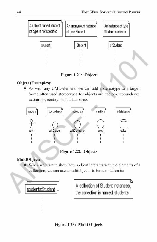
Object � Objects as well as classes can be targets on a sequence diagram, which means that messages can be sent to them.
� A target is displayed as a rectangle with some text in it. Below the target, its lifeline extends for as long as the target exists. The lifeline is displayed as a vertical dashed line.
� The basic notation for an object is where ‘name’ is the name of the object in the context of the diagram and ‘Type’ indicates the type of which the object is an instance.
� Both name and type are optional, but at least one of them should be present.
Figure 1.20: Target and Lifeline
1101 AMSCE - DEPARTMENT OF IT
44 Unit Wise solved QUestion PaPers
Figure 1.21: Object
Object (Examples): � As with any UML-element, we can add a stereotype to a target. Some often used stereotypes for objects are «actor», «boundary», «control», «entity» and «database».
Figure 1.22: Objects
MultiObject: � When we want to show how a client interacts with the elements of a collection, we can use a multiobject. Its basic notation is:
Figure 1.23: Multi Objects
1101 AMSCE - DEPARTMENT OF IT

object oriented analysis and design 45 Lifelines in UML diagrams
� In UML diagrams, such as sequence or communication diagrams, lifelines represent the objects that participate in an interaction.
� Lifeline is a named element which represents an individual participant in the interaction.
� For example, in a banking scenario, lifelines can represent objects such as a bank system or customer.
� Each instance in an interaction is represented by a lifeline.
� Lifeline in a sequence diagram is displayed with its name and type in a rectangle, which is called the head. The head is located on top of a vertical dashed line, called the stem, which represents the timeline for the instance of the object.
Figure 1.24: Lifelines in UML diagrams
Messages � Messages (or signals) on a sequence diagram are specified using an arrow from the participant (message caller) that wants to pass the message to the participant (message receiver) that is to receive the message.
� A Message (or stimulus) is represented as an arrow going from the sender to the top of the focus of control (i.e., execution occurrence) of the message on the receiver’s lifeline.
� Near the arrow, the name and parameters of the message are shown.
1101 AMSCE - DEPARTMENT OF IT

46 Unit Wise solved QUestion PaPers
Synchronous message � A synchronous message is used when the sender waits until the receiver has finished processing the message, only then does the caller continue.
� A closed and filled arrowhead signifies that the message is sent synchronously.
Figure 1.25: Synchronous message with actual parametersIf you want to show that the receiver has finished processing the message and returns control to the sender, draw a dashed arrow from receiver to sender. Optionally, a value that the receiver returns to the sender can be placed near the return arrow.
Figure 1.26: Synchronous message with parameters
and return valueIf you want your diagrams to be easy to read, only show the return arrow if a value is returned. Otherwise, hide it.
1101 AMSCE - DEPARTMENT OF IT

object oriented analysis and design 47
Figure 1.27: Synchronous message for Teacher
Asynchronous messages � With an asynchronous message, the sender does not wait for the receiver to finish processing the message, it continues immediately.
� Messages sent to a receiver in another process or calls that start a new thread are examples of asynchronous messages.
� An open arrowhead is used to indicate that a message is sent asynchronously.
Figure 1.28: Asynchronous message with actual parameters
1101 AMSCE - DEPARTMENT OF IT

48 Unit Wise solved QUestion PaPers
Figure 1.29: Asynchronous message for Hotel Order
Instantaneous message � Messages are often considered to be instantaneous, i.e. the time it takes to arrive at the receiver is negligible.
� Such messages are drawn as a horizontal arrow.
Figure 1.30: Instantaneous message
Non-instantaneous message � Sometimes the message takes a considerable amount of time to reach the receiver.
� For example, a message across a network.
� Such a non-instantaneous message is drawn as a slanted arrow.
Figure 1.31: Instantaneous message
1101 AMSCE - DEPARTMENT OF IT
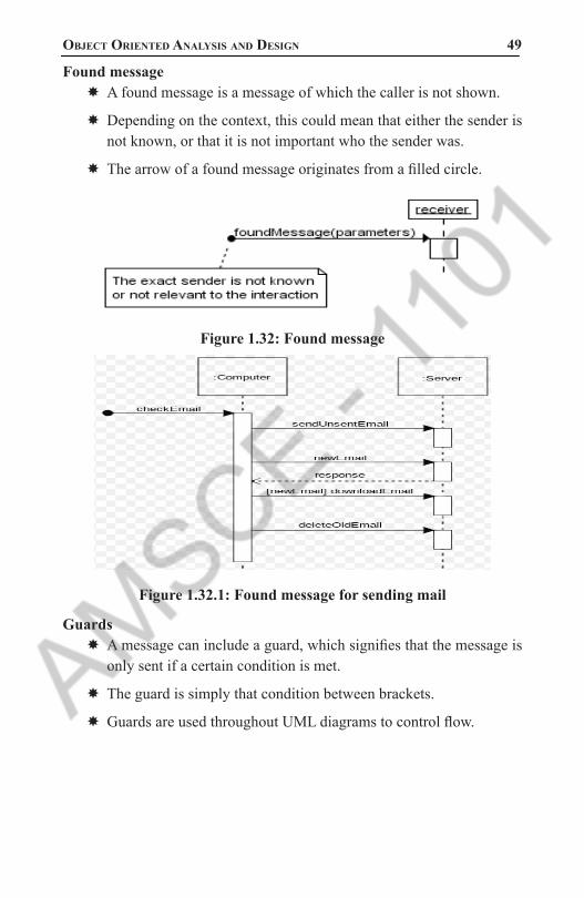
object oriented analysis and design 49 Found message
� A found message is a message of which the caller is not shown.
� Depending on the context, this could mean that either the sender is not known, or that it is not important who the sender was.
� The arrow of a found message originates from a filled circle.
Figure 1.32: Found message
Figure 1.32.1: Found message for sending mail
Guards � A message can include a guard, which signifies that the message is only sent if a certain condition is met.
� The guard is simply that condition between brackets.
� Guards are used throughout UML diagrams to control flow.
1101 AMSCE - DEPARTMENT OF IT

50 Unit Wise solved QUestion PaPers
Figure 1.33 : Guard Message
Figure 1.34: Guard Message
Combined fragments (alternatives, options, and loops) � If you want to show that several messages are conditionally sent under the same guard, you’ll have to use an ‘opt’ combined fragment.
� The combined fragment is shown as a large rectangle with an ‘opt’ operator plus a guard, and contains all the conditional messages under that guard.
1101 AMSCE - DEPARTMENT OF IT

object oriented analysis and design 51
Figure 1.35: Combined fragment Message
Alt � If you want to show several alternative interactions, use an ‘alt’ combined fragment.
� The combined fragment contains an operand for each alternative. Each alternative has a guard and contains the interaction that occurs when the condition for that guard is met.
1101 AMSCE - DEPARTMENT OF IT

52 Unit Wise solved QUestion PaPers
Figure 1.36: Alt Message
Repeated interaction � When a message is prefixed with an asterisk (the ‘*’-symbol), it means that the message is sent repeatedly.
� A guard indicates the condition that determines whether or not the message should be sent (again). As long as the condition holds, the message is repeated.
1101 AMSCE - DEPARTMENT OF IT

object oriented analysis and design 53
Figure 1.37: Repeated Interaction Message
Create and Destroy message � A create message represents the creation of an instance in an interaction. The target lifeline begins at the point of the create message.
� A destroy message represents the destruction of an instance in an interaction. The target lifeline ends at the point of the destroy message, and is denoted by an X.
Figure 1.38: Create and Destroy Message
1101 AMSCE - DEPARTMENT OF IT

54 Unit Wise solved QUestion PaPers
Basic Collaboration Diagram Notation
LinksA link is a connection path between two objects; it indicates some form of navigation and visibility between the objects is possible
Figure 1.39: Link, Lines
MessagesEach message between objects is represented with a message expression and small arrow indicating the direction of the message.
Figure 1.40 : Message
Messages to “self” or “this”A message can be sent from an object to itself
1101 AMSCE - DEPARTMENT OF IT

object oriented analysis and design 55
Figure 1.41: Message to “this”
Creation of InstancesAny message can be used to create an instance, but there is a convention in the UML to use a message named create for this purpose. If another (perhaps less obvious) message name is used, the message may be annotated with a special feature called a UML stereotype, like so: «create».
Figure 1.42: Creation of Instances
Message Number SequencingThe order of messages is illustrated with sequence numbers
1101 AMSCE - DEPARTMENT OF IT

56 Unit Wise solved QUestion PaPers
Figure 1.43: Message Number Sequencing
Conditional MessagesA conditional message is shown by following a sequence number with a conditional clause in square brackets, similar to an iteration clause. The message is only sent if the clause evaluates to true.
Figure 1.44: Conditional Message
Mutually Exclusive Conditional PathsThe example illustrates the sequence numbers with mutually exclusive conditional paths.
Figure 1.45: Mutually Exclusive Message
1101 AMSCE - DEPARTMENT OF IT

object oriented analysis and design 57 Iteration or Looping
If the details of the iteration clause are not important to the modeler, a simple ’*’ can be used.
Figure 1.46: Iteration or Looping
Iteration Over a Collection (Multiobject)map), sending a message to each. Often, some kind of iterator object is ultimately used, such as an implementation of java.util.Iterator or a C++ standard library iterator. In the UML, the term multiobject is used to denote a set of instances.a collection.
Figure 1.47: Iteration Over a CollectionThe “*” multiplicity marker at the end of the link is used to indicate that the message is being sent to each element of the collection.
Messages to a Class ObjectMessages may be sent to a class itself, rather than an instance, to invoke class or static methods. A message is shown to a class box whose name is not underlined, indicating the message is being sent to a class rather than an instance.
1101 AMSCE - DEPARTMENT OF IT

58 Unit Wise solved QUestion PaPers
Figure 1.48: Messages to a Class Object
5. Explain Types of UML Diagrams with example. (MAY/JUNE 2014, 2016) (APRIL/MAY-2017)
Types of UML DiagramsEach UML diagram is designed to let developers and customers view a software system from a different perspective and in varying degrees of abstraction. UML diagrams commonly created in visual modeling tools include:
Use Case Diagram displays the relationship among actors and use cases.
Class Diagram models class structure and contents using design elements such as classes, packages and objects. It also displays relationships such as containment, inheritance, associations and others.
Interaction Diagrams is an important sequence of interactions between objects.
� Sequence Diagram displays the time sequence of the objects participating in the interaction.
� This consists of the vertical dimension (time) and horizontal dimension (different objects).
� Collaboration Diagram displays an interaction organized around the objects and their links to one another. Numbers are used to show the sequence of messages.
� State Diagram displays the sequences of states that an object of an interaction goes through during its life in response to received stimuli, together with its responses and actions.
� Activity Diagram displays a special state diagram where most of the states are action states most of the transitions are triggered by
1101 AMSCE - DEPARTMENT OF IT

object oriented analysis and design 59 completion of the actions in the source states. This diagram focuses
on flows driven by internal processing.
Physical Diagrams � Component Diagram displays the high level packaged structure of the code itself.
� Dependencies among components are shown, including source code components, binary code components, and executable components. Some components exist at compile time, at link time,at run times well as at more than one time.
� Deployment Diagram displays the configuration of run-time processing elements and the software components, processes, and objects that live on them. Software component instances represent run-time manifestations of code units. Use Case Diagrams
� A use case is a set of scenarios that describing an interaction between a user and a system. A use case diagram displays the relationship among actors and use cases. The two main components of a use case diagram are use cases and actors.
Figure 1.49: Use Case DiagramsAn actor is represents a user or another system that will interact with the system you are modeling. A use case is an external view of the system that represents some action the user might perform in order to complete a task.
When to Use: Use Cases Diagrams � Use cases are used in almost every project.
� They are helpful in exposing requirements and planning the project.
� During the initial stage of a project most use cases should be defined, but as the project continues more might become visible.
1101 AMSCE - DEPARTMENT OF IT

60 Unit Wise solved QUestion PaPers
How to Draw: Use Cases DiagramsUse cases are a relatively easy UML diagram to draw, but this is a very simplified
example. � This example is only meant as an introduction to the UML and use cases.
� If you would like to learn more see the Resources page for more detailed resources on UML.
Start by listing a sequence of steps a user might take in order to complete an action. For
Example, a user placing an order with a sales company might follow these steps.
1. Browse catalog and select items.
2. Call sales representative.
3. Supply shipping information.
4. Supply payment information.
5. Receive conformation number from salesperson.
These steps would generate this simple use case diagram:
Figure 1.50: UML Diagram
1101 AMSCE - DEPARTMENT OF IT

object oriented analysis and design 61 Class Diagrams
Class diagrams are widely used to describe the types of objects in a system and their relationships. Class diagrams model class structure and contents using design elements such as classes, packages and objects. Class diagrams describe three different perspectives when designing a system, conceptual, specification, and implementation. These perspectives become evident as the diagram is created and help solidify the design. This example is only meant as an introduction to the UML and class diagrams. If you would like to learn more see the Resources page for more detailed resources on UML. Classes are composed of three things: a name, attributes, and operations.
Figure 1.51: Class DiagramsThe association relationship is the most common relationship in a class diagram. The association shows the relationship between instances of classes. For example, the class Order is associated with the class Customer. The multiplicity of the association denotes the number of objects that can participate in then relationship. For example, an Order object can be associated to only one customer, but a customer can be associated to many orders. Another common relationship in class diagrams is a generalization. A generalization is used when two classes are similar, but have some differences.
1101 AMSCE - DEPARTMENT OF IT

62 Unit Wise solved QUestion PaPers
Figure 1.52: Class Diagrams for generalization
When to Use: Class DiagramsClass diagrams are used in nearly all Object Oriented software designs. Use them to describe the Classes of the system and their relationships to each other.
How to Draw: Class DiagramsClass diagrams are some of the most difficult UML diagrams to draw. To draw detailed and useful diagrams a person would have to study UML and Object Oriented principles for a long time. Therefore, this page will give a very high level overview of the process.
Figure 1.53: Class Diagrams for bank
Interaction DiagramsInteraction diagrams model the behavior of use cases by describing the way groups of objects interact to complete the task. The two kinds of interaction
1101 AMSCE - DEPARTMENT OF IT

object oriented analysis and design 63 diagrams are sequence and collaboration diagrams. This example is only
meant as an introduction to the UML and interaction diagrams. If you would like to learn more see the Resources page for a list of more detailed resources on UML.
When to Use: Interaction DiagramsInteraction diagrams are used when you want to model the behavior of several objects in a use case. They demonstrate how the objects collaborate for the behavior.
Interaction diagrams do not give a in depth representation of the behavior. If you want to see what a specific object is doing for several use cases use a state diagram. To see a particular behavior over many use cases or threads use an activity diagrams.
How to Draw: Interaction DiagramsSequence diagrams, collaboration diagrams, or both diagrams can be used to demonstrate the interaction of objects in a use case. Sequence diagrams generally show the sequence of
events that occur. Collaboration diagrams demonstrate how objects are statically connected. Both diagrams are relatively simple to draw and contain similar elements.
Sequence diagrams:Sequence diagrams demonstrate the behavior of objects in a use case by describing the objects and the messages they pass. the diagrams are read left to right and descending. The example below shows an object of class 1 start the behavior by sending a message to an object of class 2. Messages pass between the different objects until the object of class 1 receives the final message.
Figure 1.54: Sequence Diagrams
1101 AMSCE - DEPARTMENT OF IT

64 Unit Wise solved QUestion PaPers
Below is a slightly more complex example. The light blue vertical rectangles the objects activation while the green vertical dashed lines represent the life of the object. The green vertical rectangles represent when a particular object has control. The represents when the object is destroyed. This diagrams also shows conditions for messages to be sent to other object. The condition is listed between brackets next to the message. For example, a [condition] has to be met before the object of class 2 can send a message() to the object of class 3.
Collaboration diagrams:Collaboration diagrams are also relatively easy to draw. They show the relationship between objects and the order of messages passed between them. The objects are listed as icons and arrows indicate the messages being passed between them. The numbers next to the messages are called sequence numbers. As the name suggests, they show the sequence of the messages as they are passed between the objects. There are many acceptable sequence numbering schemes in UML. A simple 1, 2, 3... format can be used, as the example below shows, or for more detailed and complex diagrams a 1, 1.1 ,1.2, 1.2.1... scheme can be used.
Figure 1.55: Collaboration diagrams
State DiagramsState diagrams are used to describe the behavior of a system. State diagrams describe all of the possible states of an object as events occur. Each diagram usually represents objects of a single class and track the different states of its objects through the system.
When to Use: State DiagramsUse state diagrams to demonstrate the behavior of an object through many use cases of the system. Only use state diagrams for classes where it is necessary to understand the behavior of the object through the entire
1101 AMSCE - DEPARTMENT OF IT

object oriented analysis and design 65 system. Not all classes will require a state diagram and state diagrams
are not useful for describing the collaboration of all objects in a use case. State diagrams are other combined with other diagrams such as interaction diagrams and activity diagrams.
How to Draw: State Diagrams
State diagrams have very few elements. The basic elements are rounded boxes representing the state of the object and arrows indicting the transition to the next state. The activity section of the state symbol depicts what activities the object will be doing while it is in that state.
Figure 1.56: State DiagramsAll state diagrams being with an initial state of the object. This is the state of the object when it is created. After the initial state the object begins changing states. Conditions based on the activities can determine what the next state the object transitions to.
Figure 1.57: Condition based State Diagrams
1101 AMSCE - DEPARTMENT OF IT

66 Unit Wise solved QUestion PaPers
Activity DiagramsActivity diagrams describe the workflow behavior of a system. Activity diagrams are similar to state diagrams because activities are the state of doing something. The diagrams describe the state of activities by showing the sequence of activities performed. Activity diagrams can show activities that are conditional or parallel.
When to Use: Activity DiagramsActivity diagrams should be used in conjunction with other modeling techniques such as interaction diagrams and state diagrams. The main reason to use activity diagrams is to model the workflow behind the system being designed. Activity Diagrams are also useful for: analyzing a use case by describing what actions need to take place and when they should occur; describing a complicated sequential algorithm; and modeling applications with parallel processes. However, activity diagrams should not take the place of interaction diagrams and state diagrams. Activity diagrams do not give detail about how objects behave or how objects collaborate.
How to Draw: Activity Diagrams
Activity diagrams show the flow of activities through the system. Diagrams are read from top to bottom and have branches and forks to describe conditions and parallel activities. A fork is used when multiple activities are occurring at the same time. The diagram below shows a
fork after activity1. This indicates that both activity2 and activity3 are occurring at the same time. After activity2 there is a branch. The branch describes what activities will take place based on a set of conditions. All branches at some point are followed by a merge to indicate the end of the conditional behavior started by that branch. After the merge all of the parallel activities must be combined by a join before transitioning into the final activity state.
1101 AMSCE - DEPARTMENT OF IT

object oriented analysis and design 67
Figure 1.58: Activity Diagrams
Figure 1.59: Activity Diagrams for Hotel
Physical DiagramsThere are two types of physical diagrams: deployment diagrams and component diagrams. Deployment diagrams show the physical relationship between hardware and software in a system. Component diagrams show the software components of a system and how they are related to each other. These relationships are called dependencies.
1101 AMSCE - DEPARTMENT OF IT

68 Unit Wise solved QUestion PaPers
COMPONENT DIAGRAM:Component diagrams consist of physical components like libraries, files, folders etc.
Component diagrams describe the organization of the components in a system.
A component in UML is shown as below with a name inside. Additional elements can be added wherever required.
Figure 1.60: COMPONENT DIAGRAM
DEPLOYMENT DIAGRAM:A deployment diagram consists of nodes. Nodes are nothing but physical hardwares used to deploy the application.
Node Notation:A node in UML is represented by a square box as shown below with a name. A node represents a physical component of the system.
Figure 1.61: DEPLOYMENT DIAGRAMNode is used to represent physical part of a system like server, network etc.
1101 AMSCE - DEPARTMENT OF IT

object oriented analysis and design 69
Figure 1.62: Deployment Diagram For order Management System
6. Explain in detail about UML State diagram.
UML State Machine Diagrams and Modeling � A UML state machine diagram illustrates the events and states of an object and the behavior of an object in reaction to an event.
� Transitions are shown as arrows and it is labeled with their events.
� States are shown in rounded rectangle.
� In state diagram , it is common to include initial pseudostate which automatically make transition to another state.
Figure 1.63 : State Diagram for Telephone
1101 AMSCE - DEPARTMENT OF IT

70 Unit Wise solved QUestion PaPers
� The state diagram shows the lifecycle of an object.
� It shows what events it is experiences, its transitions and its states in between the events.
� It is nor necessary to represent all events in state machine diagram.
� A state machine diagram can be created that describes the lifecycle of object at simple or complex level of detail.
Definitions:1. Event: An event is a significant occurrence.
Example -> A telephone receiver is taken off the hook.
2. State: A state is the condition of an object at a moment of time.
Example -> A telephone is in the state of being “idle” after the receiver is placed on the hook.
3. Transitions: A transitions is a relationship between two states that indicates when an event occur , the object moves from prior state to subsequent state.
Example -> When an event “off hook” occurs, the state of telephone moves from “idle” to “active” state.
How to apply State Machine Diagram ?(i) State - Independent and State –Dependent Objects:
� For all events , if an object always react in the same way , it is state-independent objects.
� State dependent objects react differently to events depending on their state or mode.
� State machine diagram should be drawn to state-dependent objects not for state-independent objects.
� Example -> a telephone is state-dependent object.
� (ii) Modeling State-dependent Objects:
� State machine diagram are applied in two ways
i. To model the behavior of complex objects in response to events.ii. To model legal sequence of operations –protocol or language
specification.
1101 AMSCE - DEPARTMENT OF IT

object oriented analysis and design 71 The following is a list of common objects which are state-dependent . So
it is useful to create state machine diagram for these objects.
(i) Complex Reactive objectsPhysical Devices controlled by software.
->Phone,car etc.Their complex reaction depends upontheir current mode.
Transactions and related Business objects.
-> Reaction of business objects like Sale, payment, order etc. Understanding events and objects states it is useful for design and process improvement.
Role Mutators -> These are the objects that change their role.
(ii) Protocols and Legal Sequences
Communication Protocols-> TCP protocols can be easily understand with state machine diagram.
UI Page /Window Flow or Navigation-> A state diagram is used to understand the legal sequence between
the Web Pages or Windows.
UI Flow Controller or Sessions-> This is related to UI navigation modeling, but for server-side objects
that control the page flow.
UseCase System Operations->The usecase enterItem, makeNewSlae,endSale etc should come in
legal order.
-> Example: endSale must come after one or more enterItem operations.
Individual UI Window Event Handling
-> Understanding the events and legal sequence for one window or form .
1101 AMSCE - DEPARTMENT OF IT
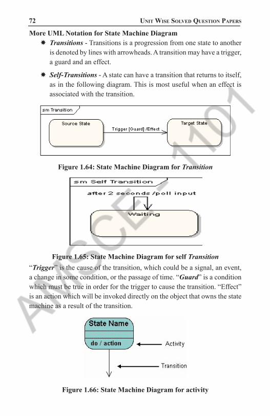
72 Unit Wise solved QUestion PaPers
More UML Notation for State Machine Diagram � Transitions - Transitions is a progression from one state to another is denoted by lines with arrowheads. A transition may have a trigger, a guard and an effect.
� Self-Transitions - A state can have a transition that returns to itself, as in the following diagram. This is most useful when an effect is associated with the transition.
Figure 1.64: State Machine Diagram for Transition
Figure 1.65: State Machine Diagram for self Transition“Trigger” is the cause of the transition, which could be a signal, an event, a change in some condition, or the passage of time. “Guard” is a condition which must be true in order for the trigger to cause the transition. “Effect” is an action which will be invoked directly on the object that owns the state machine as a result of the transition.
Figure 1.66: State Machine Diagram for activity
1101 AMSCE - DEPARTMENT OF IT

object oriented analysis and design 73
Figure 1.67: State Machine Diagram for delivery
Super stateA super-state is used when many transitions lead to the a certain state. Instead of showing all of the transitions from each state to the redundant state a super-state can be used to show that all of the states inside of the super-state can transition to the redundant state.
Compound States - A state machine diagram may include sub-machine diagrams, as in the example below.
1101 AMSCE - DEPARTMENT OF IT

74 Unit Wise solved QUestion PaPers
Figure 1.68: State Machine Diagram for Super state
Figure 1.69: State Machine Diagram for Compound stateThe ∞ symbol indicates that details of the Check PIN sub-machine are shown in a separate diagram
1101 AMSCE - DEPARTMENT OF IT

object oriented analysis and design 75 Choice Pseudo-State - A choice pseudo-state is shown as a diamond with
one transition arriving and two or more transitions leaving. The following diagram shows that whichever state is arrived at, after the choice pseudo-state, is dependent on the message format selected during execution of the previous state.
Figure 1.70: State Machine Diagram for Choice Pseudo-StateConcurrent Regions - A state may be divided into regions containing sub-states that exist and execute concurrently. The example below shows that within the state “Applying Brakes”, the front and rear brakes will be operating simultaneously and independently. Notice the use of fork and join pseudo-states, rather than choice and merge pseudo-states. These symbols are used to synchronize the concurrent threads.
Figure 1.71: State Machine Diagram for Concurrent Regions
1101 AMSCE - DEPARTMENT OF IT

76 Unit Wise solved QUestion PaPers
7. Explain UML Deployment diagrams (Implementation diagram) (MAY/JUNE 2011,2012,2014,2015)
Deployment DiagramUsed to model the static deployment view of a system.
It is important for visualizing , specifying, and documenting embedded, client/server, & distributed systems.
It is a diagram that shows the configuration of run time processing nodes & the artifacts that live on them.
Graphically, a deployment diagram is a collection of vertices and arcs.
Purpose of deployment Diagrams: � Visualize hardware topology of a system
� Describe the H/W components used to deploy software components.
� Describe runtime processing nodes.
Elements of Deployment Diagram
Nodes
Communication between Nodes/Connections �Association
�Dependency
�Generalization
�Realization
�Nodes and Artifacts
Common Modeling Techniques of nodes � Modeling Processors and Devices
� Modeling the Distribution of Artifacts
Elements of Deployment Diagram � Artifacts
� Kinds of Artifacts
� Deployment artifacts
� Work product artifacts
1101 AMSCE - DEPARTMENT OF IT

object oriented analysis and design 77 � Execution Artifacts
� Common Modeling Techniques of Artifacts
� Modeling Execution and Libraries
� Modeling Tables, Files , and Documents
� Modeling Source Code
Nodes: � Just like artifacts, is an important building block in modeling the physical aspects of a system.
� It is a physical elements that exists at run time & represents a computational resource.
� Graphical representation of node is cube.
Types of node
Processor: � It is a piece of hardware capable of executing programs.
� A Processor can have list of processes on it.
� Represented as shaded cube with name of the object.
Device: � A piece of hardware incapable of executing program is called as device.
� Device will also have on a cube.
Communication between Nodes/ Connections:
Association: � It refers to a physical connection or link between the nodes.
� It is shown as a solid-line between nodes.
Communication between Nodes/ Connections:
Dependency � It is a relationship that indicates that a model element is in some way dependent of another model element.
� Dependency of a node on components is depicted using dashed lines.
1101 AMSCE - DEPARTMENT OF IT

78 Unit Wise solved QUestion PaPers
Communication between Nodes/ Connections:
Generalization � It is a relationship between a parent node and child node
� It is shown as a solid-line with triangle between nodes.
Communication between Nodes/ Connections:
Realization � It is a relationship between interface and classes or components that realize them
� It shows as a dashed line with hollow triangle.
� Example the relationship between a interface and a class that realizes or execute that interface
Common Modeling Techniques of Nodes � Modeling Processors and devices
� Modeling the Distribution of Artifacts
� Artifacts
� Artifacts are physical entities that are deployed on nodes, devices and executable environments.
� It is a physical replaceable part of a system.
� Executables, libraries, tables files and documents.
� Standard stereotypes for artifacts
� <<file>>, <<document>>, <<source>>, <<library>>, <<executable>>, <<script>>.
� Artifact must have a unique name
Elements of Deployment Diagram
Artifacts � Kinds of Artifacts
� Deployment artifacts
� Work product artifacts
� Execution Artifacts
1101 AMSCE - DEPARTMENT OF IT
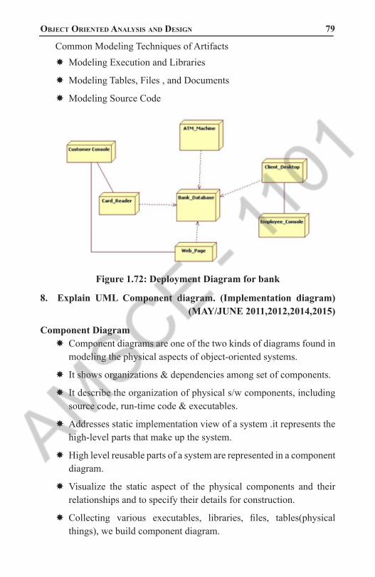
object oriented analysis and design 79 Common Modeling Techniques of Artifacts
� Modeling Execution and Libraries
� Modeling Tables, Files , and Documents
� Modeling Source Code
Figure 1.72: Deployment Diagram for bank
8. Explain UML Component diagram. (Implementation diagram) (MAY/JUNE 2011,2012,2014,2015)
Component Diagram � Component diagrams are one of the two kinds of diagrams found in modeling the physical aspects of object-oriented systems.
� It shows organizations & dependencies among set of components.
� It describe the organization of physical s/w components, including source code, run-time code & executables.
� Addresses static implementation view of a system .it represents the high-level parts that make up the system.
� High level reusable parts of a system are represented in a component diagram.
� Visualize the static aspect of the physical components and their relationships and to specify their details for construction.
� Collecting various executables, libraries, files, tables(physical things), we build component diagram.
1101 AMSCE - DEPARTMENT OF IT

80 Unit Wise solved QUestion PaPers
Elements Of a Component Diagram � Components
� Interfaces
� Ports
� Connectors
Components � Components are made up of one or more classes & describe parts of an application that can be assembled and reused.
� Defined as “a physical replaceable part that conforms to and provides the realization of a set of interfaces”.
� Graphically ,a component is rendered as a rectangle with tabs, with the name of the object in it, preceded by a colon and underlined.
Interface � It is a collection of operations that are used to specify a service of class or components.
� Graphically it is displayed as a circle or as a typical class with stereotype of <<interface>>
Types of interfaceProvided Interface
� An interface that the component provides as a service to other component.
Required Interface � An interface that the component conforms to when requesting services from other components.
� Relationships between component & its interface
Elided, iconic form. � A provided interface is shown as a circle attached to the component by a line and a “lollipop”. A required interface is shown as a semicircle attached to the component by a line and a “socket”. In both cases, the name of the interface is placed next to the symbol.
1101 AMSCE - DEPARTMENT OF IT

object oriented analysis and design 81 Ports
� Ports are used to control the implementation of all the operations in all of the provided interfaces in the component.
� It is an explicit window into an encapsulated component.
� All of the interactions into and out of the component pass through ports.
� It has identity.
� Component can communicate with the component through a specific port.
� It is shown as a small square straddling the border of a component Both provided and required interfaces may be attached to the port symbol.
� A provided interface represents a service that can be requested through that port. A required interface represents a service that the port needs to obtain from some other component.
Connectors � A wire between two port is called connector.
� It represents a link or a transient link. Instance of an ordinary association.
� A transient link represents a usage relationship between two components.
� If two components are explicitly wired together, either directly or through ports, just draw a line between them or their ports.
� If two components are connected because they have compatible interface, you can use a ball-and-socket notation to show that there is no inherent relationship between the components, although they are connected inside this component.
Types of Connector � Direct connector
� Delegation connector
1101 AMSCE - DEPARTMENT OF IT

82 Unit Wise solved QUestion PaPers
Figure 1.73: Component Diagram for Student
Figure 1.74: Component Diagram for Bank
9. Consider the Hospital Management System application with the following requirements Domain model for a hospital to show and explain hospital structure, staff, relationships with patients, and patient treatment terminology. (NOV/DEC 2015)
Purpose: Domain model describing various types of health insurance policies.
Summary: This example shows several subtypes of Health Insurance Policy using UML generalization sets. One generalization set is Coverage Type - Job Based Coverage, Self Coverage, and Benefits Coverage, and another set is based on Insurance Plan - HMO, POS, PPO, FFS.
1101 AMSCE - DEPARTMENT OF IT

object oriented analysis and design 83
Figure 1.75: Use case diagram example for Hospital ManagementPurpose: Describe major services (functionality) provided by a hospital’s reception.
Summary: Hospital Management System is a large system including several subsystems or modules providing variety of functions. Hospital Reception subsystem or module supports some of the many job duties of hospital receptionist. Receptionist schedules patient’s appointments and admission to the hospital, collects information from patient upon patient’s arrival and/or by phone.
For the patient that will stay in the hospital (“inpatient”) she or he should have a bed allotted in a ward. Receptionists might also receive patient’s payments, record them in a database and provide receipts, file insurance claims and medical reports.
1101 AMSCE - DEPARTMENT OF IT

84 Unit Wise solved QUestion PaPers
Figure 1.76: Radiology diagnostic reporting UML use case diagram example
Purpose: Radiology diagnostic reporting UML use case diagram example for Simple Image and Numeric Report (SINR) IHE Radiology Integration Profile.
Summary: In the initial stage of diagnostic reporting, a reading physician records a diagnosis by generating a draft DICOM Structured Report (SR) object. Report Creator actor transmits that DICOM SR object to the Report Manager. External Report Repository Access actor is a gateway to obtain other enterprise department reports, such as Laboratory and Pathology, from within the Imaging department.
Figure1.77: UML information flow diagram example for the Scheduled Workflow
1101 AMSCE - DEPARTMENT OF IT

object oriented analysis and design 85 10. Explain UML activity diagram with example.
(MAY/JUNE 2011,2015, NOV/DEC 2011)
Activity Diagram � Activity is a particular operation of the system.
� An Activity diagram is a dynamic diagram that shows the activity and the event that causes the object to be in the particular state.
� The diagrams describe the state of activities by showing the sequence of activities performed.
� Activity diagrams can show activities that are conditional or parallel.
� The purposes of Activity diagram can be described as:
�Draw the activity flow of a system.
�Describe the sequence from one activity to another.
�Describe the parallel, branched and concurrent flow of the system.
Elements in Activity Diagram
Fork and Join NodesForks and joins have the same notation: either a horizontal or vertical bar (the orientation is dependent on whether the control flow is running left to right or top to bottom). They indicate the start and end of concurrent threads of control. The following diagram shows an example of their use.
Figure 1.78: Fork and Join Nodes
Decision and Merge NodesDecision nodes and merge nodes have the same notation: a diamond shape. They can both be named. The control flows coming away from a decision node will have guard conditions which will allow control to flow if the
1101 AMSCE - DEPARTMENT OF IT

86 Unit Wise solved QUestion PaPers
guard condition is met. The following diagram shows use of a decision node and a merge node.
Figure 1.79: Decision and Merge Nodes
Join node vs Merge nodeA join is different from a merge in that the join synchronizes two inflows and produces a single outflow. The outflow from a join cannot execute until all inflows have been received. A merge passes any control flows straight through it.
Figure 1.80 : Join and Merge Nodes
1101 AMSCE - DEPARTMENT OF IT

object oriented analysis and design 87
Figure 1.81: Activity Diagram for Hotel
•The following diagram is drawn with the four main activities:
•Send order by the customer
•Receipt of the order
•Confirm order
•Dispatch order
•After receiving the order request condition checks are performed to check if it is normal or special order. After the type of order is identified dispatch activity is performed and that is marked as the termination of the process.
Figure 1.82: Activity Diagram for Hotel with check conditions
1101 AMSCE - DEPARTMENT OF IT

88 Unit Wise solved QUestion PaPers
UNIT II
DESIGN PATTERNS
PART - A
1. Define Modular Design? (APRIL/MAY-2017)Modular design, or “modularity in design”, is a design approach that subdivides a system into smaller parts called modules or skids, that can be independently created and then used in different systems.
2. When to use Patterns? (NOV/DEC 2015)The purpose of the pattern is, then, the re-use of the knowledge encap-sulated in it in order to solve a particular problem.
3. Define Coupling. (APRIL/MAY-2017)Coupling is a measure of the strength of association established by a connection from one object or software component to another. Cou-pling is a binary relationship. For example A is coupled with B. Cou-pling is important when evaluating a design because it helps us focus on an important issue in design.
4. What is Design Pattern? (NOV/DEC 2016)It is a description or template for how to solve a problem that can be used in many different situations. Design pattern is instructive infor-mation for that captures the essential structure and insight of a success-ful family of proven design solutions to a recurring problem that arises within a certain context.
Characteristics of Design Patterns:
1. It solves the problem – Design patterns are not just abstract repre-sentations of theoretical research. To be accepted as a pattern it should have some proves practical experiences.
2. It’s a proven concept – Patterns must have a successful history.
3. It describes a relationship – Patterns do not specify a single class instead it specifies more than one classes and their relationship.
4. It has a human component - Good patterns make the job of the pro-grammer easy and time saving.
1101 AMSCE - DEPARTMENT OF IT

object oriented analysis and design 89 5. Distinguish between coupling and cohesion. ?(NOV/DEC 2016)
(APRIL/MAY-2017)Coupling deals with interactions between objects or software components while cohesion deals with the interactions within a single object or software component. Highly cohesive components can lower coupling because only a minimum of essential information need to be passed between components.
6. Write a note on Patterns. ? (NOV/DEC 2016)In Object Oriented Design, a pattern is a named description of a Problem and Solutions that can be applied to new contexts. Many patterns, given a category of problem, guide the assignment of r esponsibilities to objects.
7. What is GRASP? GRASP stands for General Responsibility Assignment Software Patterns. There are 9
GRASP patterns
� Creator
� Controller
� Pure fabrication
� Information expert
� High cohesion
� Indirection
� Low coupling
� Polymorphism
� Protected variations
8. What is a creator pattern? To identify who is responsible for creating a new instance of class. This design will support low coupling, increased clarity, encapsulation and reusability
1101 AMSCE - DEPARTMENT OF IT

90 Unit Wise solved QUestion PaPers
9. Define information expert .The information expert is analyzed to find what is the general principle of assigning responsibilities to object. This will support information encapsulation.
10. Define controller. Controller is to identify which class is having more control over the overall system. This is the first object beyond the UI layer that is responsible for receiving or handling a system operation message.
11. Define bloated controller.When the controllers are poorly designed a controller class will have low cohesion-unfocused and handling too many areas of responsibil-ity; this is called a bloated controller
12. Define use case controller.When placing responsibilities in a façade controller it lead to design with low cohesion or high coupling, typically when the façade control-ler is becoming bloated with more responsibility a use case controller is the best choice to solve this problem.
13. Define adapter.The adapter design pattern is a kind of pattern that is adapting between classes and objects. It act as a interface between objects
14. What is a factory? This is also called simple factory or concrete factory. This pattern is not a GOF design pattern, but extremely widespread. It deals with the problem of creating objects without specifying the exact class of ob-ject that will be created.
15. What is a concrete factory? This is also called simple factory or concrete factory, this pattern is not a GOF design pattern, but extremely widespread.
16. What is Observer pattern? The observer pattern (a subset of the publish/subscribe pattern) is a software design pattern in which an object, called the subject, main-tains a list of its dependents, called observers, and notifies them auto-
1101 AMSCE - DEPARTMENT OF IT

object oriented analysis and design 91 matically of any state changes, usually by calling one of their methods.
It is mainly used to implement distributed event handling systems.
17. What is Responsibility-Driven Design? A popular way of thinking about the design of software objects and also larger scale. Components 3 are in terms of responsibilities, roles, and collaborations. This is part of a larger approach called responsibil-ity-driven design or RDD.
18. What is Facade Pattern? A facade is an object that provides a simplified interface to a larger body of code, such as a class library.
A facade can:
� make a software library easier to use, understand and test, since the facade has convenient methods for common tasks;
� make code that uses the library more readable, for the same reason;
� reduce dependencies of outside code on the inner workings of a library, since most code uses the facade, thus allowing more flexibility in developing the system;
� Wrap a poorly-designed collection of APIs with a single well-designed API (as per task needs).
1101 AMSCE - DEPARTMENT OF IT

92 Unit Wise solved QUestion PaPers
PART - B
1. Write short notes on Adapter, Singleton, Factory and Observer Patterns. (NOV/DEC 2015, MAY/JUNE 2016, NOV/DEC2016) (APRIL/MAY-2017)
Gof Patterns
Table 2.1 : GOF Classification PatternGof patterns are design patterns.
Used to resolve design related issues.
Patterns simplify but proliferation of patterns adds complexity.
Adapter
Factory
Singleton
Observer
Adapter PatternsProblem:
How to resolve incompatible interfaces.
How to provide stable interface to similar components with different interfaces.
Solution:
Hide the incompatible/ unstable interfaces behind the adapter’s interface.
1101 AMSCE - DEPARTMENT OF IT

object oriented analysis and design 93 Client collaborate with stable adapter.
Adapter relay message to unstable interface
Uses protected variations, polymorphism, indirection.
Figure 2.1: The Adapter Pattern
Register post the sale to an adapter.
Adapter communicates with SAP accounting system.
SAP accounting system exposes functionality as a web server
Figure 2.2: The Adapter Pattern for client
1101 AMSCE - DEPARTMENT OF IT

94 Unit Wise solved QUestion PaPers
GRASP as generalization of other patterns
Patterns overload:
100’s of documented patterns.
Too many to comprehend and use.
Perhaps 50+ are common.
GRASP patterns helpful to categorize the patterns using few basic principles.
GRASP is the alphabet of patterns language.
Very important conceptual model.
PV is the most fundamental principle.
Specific gof patterns are concrete applications of grasp
Figure 2.3: Adapter and GRASP
1101 AMSCE - DEPARTMENT OF IT

object oriented analysis and design 95 Updated partial domain model
Design modeling discover new domain concept
FactoryThis is also called Simple Factory or Concrete Factory.
Problem:
Who should be the creator when creation causes incohesiveness or it involves complex creation logic.
Solution (advice)
Assign creation responsibility to pure fabrication factory object
Commonly implemented via singleton pattern
ServicesFactory
accountingAdapter : IAccountingAdapterinventoryAdapter : IInventoryAdaptertaxCalculatorAdapter : ITaxCalculatorAdapter
getAccountingAdapter() : IAccountingAdaptergetInventoryAdapter() : IInventoryAdaptergetTaxCalculatorAdapter() : ITaxCalculatorAdapter...
note that the factory methods return objects typed to an interface rather than a class, so that the factory can return any implementation of the interface
if ( taxCalculatorAdapter == null ) { // a reflective or data-driven approach to finding the right class: read it from an // external property
String className = System.getProperty( "taxcalculator.class.name" ); taxCalculatorAdapter = (ITaxCalculatorAdapter) Class.forName( className ).newInstance();
} return taxCalculatorAdapter;
Figure 2.4: Factory object advantages
Separate the responsibility of complex creation in to cohesive objects.
Hide potentially complex creation logic.
Allow introduction of performance enhancing memory management strategy such as object caching.
SingletonProblem:
Exactly only one instance of a class is neede or allowed.
1101 AMSCE - DEPARTMENT OF IT

96 Unit Wise solved QUestion PaPers
Others objects need single , global point of access to it.
Solution (advice):
Define a static method of a class that return the singleton
The static method can only create one instance.
Who should create factory? Singleton !
Provides global visibility via static method
Avoid passing factory reference to many clients.
Singleton pattern in ServicesFactory class
1ServicesFactory
instance : ServicesFactory
accountingAdapter : IAccountingAdapterinventoryAdapter : IInventoryAdaptertaxCalculatorAdapter : ITaxCalculatorAdapter
getInstance() : ServicesFactory
getAccountingAdapter() : IAccountingAdaptergetInventoryAdapter() : IInventoryAdaptergetTaxCalculatorAdapter() : ITaxCalculatorAdapter...
singleton static attribute
singleton static method
// static methodpublic static synchronized ServicesFactory getInstance(){if ( instance == null ) instance = new ServicesFactory()return instance}
UML notation: in a class box, an underlined attribute or method indicates a static (class level) member, rather than an instance member
UML notation: this '1' can optionally be used to indicate that only one instance will be created (a singleton)
Figure 2.5: Singleton
Accessing Singleton instance
To obtain visibility of singleton instance use following
Singleton Class . get Instance(); � To send message using singleton instance use the following
� Singleton Class . get Instance(). do Foo();
� Example : Service Factory. get Instance(). Get Accounting Adapter();
� Implementation and Design issue
1101 AMSCE - DEPARTMENT OF IT
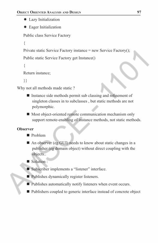
object oriented analysis and design 97 � Lazy Initialization
� Eager Initialization
Public class Service Factory
{
Private static Service Factory instance = new Service Factory();
Public static Service Factory get Instance()
{
Return instance;
}}
Why not all methods made static ?
Instance side methods permit sub classing and refinement of singleton classes in to subclasses , but static methods are not polymorphic.
Most object-oriented remote communication mechanism only support remote-enabling of instance methods, not static methods.
ObserverProblem
An observer (eg GUI) needs to know about static changes in a publisher (eg domain object) without direct coupling with the objects..
Solution :
Subscriber implements a “listener” interface.
Publishes dynamically register listeners.
Publishes automatically notify listeners when event occurs.
Publishers coupled to generic interface instead of concrete object
1101 AMSCE - DEPARTMENT OF IT

98 Unit Wise solved QUestion PaPers
«interface»PropertyListener
onPropertyEvent( source, name, value )
SaleFrame1
onPropertyEvent( source, name, value )
initialize( Sale sale )...
javax.swing.JFrame
...setTitle()setVisible()...
{ if ( name.equals("sale.total") ) saleTextField.setText( value.toString() );}
Sale
addPropertyListener( PropertyListener lis )publishPropertyEvent( name, value )
setTotal( Money newTotal )...
*propertyListeners
{ total = newTotal; publishPropertyEvent( "sale.total", total ); }
{ propertyListeners.add( lis );}
{ for each PropertyListener pl in propertyListeners pl.onPropertyEvent( this, name, value ); }
{ sale.addPropertyListener( this ) ... }
Figure 2.6: Observer
Updating interface � Updating interface when sale total changes
Figure 2.7 : Concrete Observer
1101 AMSCE - DEPARTMENT OF IT

object oriented analysis and design 99
Figure 2.8: The Observer SaleFrame1 Subscribes to the
publisher Sale
Figure 2.9: The sale publishes a property event
to all its subscriber
2. What is GRASP? Explain the design patterns and the principles used in it. (APRIL/MAY 2011) ( MAY/JUNE 2015,2016) (APRIL/MAY-2017)
GRASP: Designing Objects with Responsibilities
Objectives: � OOD is sometimes taught as “ Identifying requirements, creating domain model and then adding methods and define messaging between objects to fulfill the requirements.
� Mastering OOD involves a large set of principles.
UML versus Design Principles � UML is a standard visual modeling language.
� UML sometimes described as “design tool”.
1101 AMSCE - DEPARTMENT OF IT
100 Unit Wise solved QUestion PaPers
� The right thing is “ the critical design tool for software development is a mind well educated in design principles”.
Object DesignHow artifacts relate to object design?
Inputs to object designActivities of object designOutputs
� Inputs : Domain model, use case text, operation contracts, SSD, glossary and supplementary specification.
� Now developers start coding, UML modeling.
� During modeling (ID,CD), they apply GRASP principles.
� Outputs : UML ID, CD and PD for difficult parts of design
� Responsibilities & RDD
� Designing software objects involve responsibilities, roles and collaborations.
� This approach called Responsibility-Driven Design (RDD).
� UML defines responsibilities as a contract of classifier.
� Responsibilities are two types : doing & knowing.
Responsibility types � Doing responsibility
� Doing something itself
� Initiating action in other objects.
� Controlling activities in another objects.
Knowing responsibility � Knowing about encapsulated data.
� About related data
� Things that it calculate
1101 AMSCE - DEPARTMENT OF IT

object oriented analysis and design 101 Connection between Responsibilities, GRASP and UML diagrams
� In UML drawing interaction diagram consider the responsibility of objects.
� Example : Sale objects invoke Payment object and it is assigned to make Payment method
Pattern Definitions and names � Alexander: “A pattern is a recurring solution to a standard problem, in a context.”
� Larman: “In OO design, a pattern is a named description of a problem and solution that can be applied in new contexts; ideally, a pattern advises us on how to apply the solution in varying circumstances and considers the forces and trade-offs.”
Naming Patterns—important! � Why is naming a pattern or principle helpful?
� It supports chunking and incorporating that concept into our understanding and memory
� It facilitates communication
GRASP � Acronym for General Responsibility Assignment Software Patterns
� Describe fundamental principles of object design and responsibility
� Expressed as patterns
Five GRASP patterns:
Creator
Information Expert
Low Coupling
Controller
High Cohesion
Creator patternName: Creator
Problem: Who creates an instance of A?
1101 AMSCE - DEPARTMENT OF IT

102 Unit Wise solved QUestion PaPers
Solution: Assign class B the responsibility to create an instance of class A if one of these is true (the more the better):
B contains or aggregates A (in a collection)
B records A
B closely uses A
B has the initializing data for A
Who creates the SalesLineItem?Since Sale contains many SalesLineItem objects, the creator pattern suggests that Sale is a good candidate to have the responsibility of creating SalesLineItem.
Figure 2.10: Who creates the SalesLineItem
Design Of Object interactions � The context of assigning responsibilities is considered while drawing interaction diagram
1101 AMSCE - DEPARTMENT OF IT

object oriented analysis and design 103
Figure 2.11: Design of Creator
Discussion about creator pattern � Creator guides the assigning of responsibilities related to the creation of objects.
� The basic intent of creator pattern is to find a creator that needs to be connected to connected object in any event.
� Composite aggregates Part, Container contains Content and Recorder records.
� Creator suggests enclosing container or recorder is a good candidate for creating objects
� Responsibilities for object creation are common
� Connect an object to its creator when:
� Aggregator aggregates Part
� Container contains Content
� Recorder records
� Initializing data passed in during creation
Contraindications or caveats � Creation may require significant complexity:
� recycling instances for performance reasons
� conditionally creating instances from a family of similar classes.
1101 AMSCE - DEPARTMENT OF IT

104 Unit Wise solved QUestion PaPers
� In this cases, delegate creation to a helper class called Concrete Factory or Abstract Factory rather than using creator class.
� In these instances, other patterns are available…
Benefits � Low coupling is supported because created class is visible to the creator class by the existing associations.
Related patterns � Low coupling
� Concrete Factory or Abstract Factory
Information Expert (Expert) pattern or principleName: Information Expert
Problem: How to assign responsibilities to objects?
Solution: Assign responsibility to the class that has the information needed to fulfill it?
Example : In Next Gen POS application, some class needs to know the grand total of sale.
“Start assigning responsibilities by clearly stating the responsibility”
By Information Expert, look at class of objects that has the information needed to determine the total
� To identify the class look at design model first.
� If design model is not started, then use domain model to model software classes.
� We add a software class to Design model called Sale
� This supports lower representational gap between real world concepts and software objects
1101 AMSCE - DEPARTMENT OF IT

object oriented analysis and design 105
Figure 2.12: Design of Information Expert pattern or principle
Information to find determine SalesLineItem � SalesLineItem is information expert for finding subtotal
Figure 2.13: Design of Information Expert for finding Subtotal
Product Description is the information expert on answering product price
Figure 2.14: Design of Information Expert for answering product price
Benefits and Contraindications � Facilitates information encapsulation: why?
i. Classes use their own info to fulfill tasks
1101 AMSCE - DEPARTMENT OF IT

106 Unit Wise solved QUestion PaPers
� Encourages cohesive, lightweight class definitions
� Information expert may contradict patterns of Low Coupling and High Cohesion
� Remember separation of concerns principle for large sub-systems
� I.e., keep “business” or application logic in one place, user interface in other place, database access in another place, etc.
Low Coupling PatternName: Low Coupling
Problem: How to reduce the impact of change and encourage reuse?
Solution: Assign a responsibility so that coupling (linking classes) remains low.
Why does the following design violate Low Coupling?
Create Payment instance associated with sale class. By real-world domain, Register records payment, so according to creator pattern “Register” is creator for payment.
Partial interaction diagram reflecting this is follow
: Register p : Payment
:Sale
makePayment() 1: create()
2: addPayment(p)
Figure 2.15: Design of Low Coupling Pattern � In previous diagram, Register creates payment, adds coupling of Register to Payment . It increases coupling.
� So, use Sale class to create payment which does not increase the coupling
: Register :Sale
:Payment
makePayment() 1: makePayment()
1.1. create()
Figure 2.15.1: Design of Low Coupling Pattern for sales
1101 AMSCE - DEPARTMENT OF IT

object oriented analysis and design 107 Benefits & Contraindications
� Understandability: Classes are easier to understand in isolation
� Maintainability: Classes aren’t affected by changes in other components
� Reusability: easier to grab hold of classes But:
� Don’t sweat coupling to stable classes (in libraries or pervasive, well-tested classes)
Controller patternName: Controller
(see Model-View-Controller architecture)
Problem: Who should be responsible for UI events?
Solution: Assign responsibility for receiving or handling a system event in one of two ways:
Represent the overall system (façade pattern)
Represent a use case scenario within which the system event occurs (a session controller)
“Controller if the first object beyond UI layer that is responsible for receiving or handling system operation message.”
The Next Gen Pos application contains several system operations.
During analysis system operations may be assigned to the class System, but it does not mean that software class System fulfill that responsibility
System
endSale()enterItem()makeNewSale()makePayment(). . .
Figure 2.16 : Design of Controller Pattern � Controller class is assigned the responsibility for system operations.
1101 AMSCE - DEPARTMENT OF IT

108 Unit Wise solved QUestion PaPers
Figure 2.16.1: Domain Layer Controller Register
...
endSale()enterItem()makeNewSale()makePayment()
makeNewReturn()enterReturnItem(). . .
System
endSale()enterItem()makeNewSale()makePayment()
makeNewReturn()enterReturnItem(). . .
system operations discovered during system behavior analysis
allocation of system operations during design, using one facade controller
ProcessSaleHandler
...
endSale()enterItem()makeNewSale()makePayment()
System
endSale()enterItem()makeNewSale()makePayment()
enterReturnItem()makeNewReturn(). . .
allocation of system operations during design, using several use case controllers
HandleReturnsHandler
...
enterReturnItem()makeNewReturn(). . .
Figure 2.16.2: Allocation of system operations to two kinds of controllers
By controller pattern there are some choices � Represent overall “system”
� Represent a receiver or handler of system events of use case scenario.
1101 AMSCE - DEPARTMENT OF IT

object oriented analysis and design 109
:RegisterenterItem(id, quantity)
:ProcessSaleHandlerenterItem(id, quantity)
Figure 2.16.2: Design of Controller choices � During design , the system operations identified are assigned to one or more controller classes
How to choose controllers ? � Facade controllers are suitable when there are not “too many” system events.
� Choose use case controller when there are multiple system events to be controlled by multiple controller.
Benefits � Increased potential for reuse and pluggable interface.
� Opportunity to reason about the state of the use case.
High Cohesion patternCohesion measures how strongly related and focused are the responsibilities of an element
Name: High Cohesion
Problem: How to keep classes focused and manageable?
Solution: Assign responsibility so that cohesion remains high.
Example
Register records payment in real world domain
: Register p : Payment
:Sale
makePayment() 1: create()
2: addPayment(p)
Figure 2.17: High Cohesion pattern for payment
1101 AMSCE - DEPARTMENT OF IT

110 Unit Wise solved QUestion PaPers
: Register :Sale
:Payment
makePayment() 1: makePayment()
1.1. create()
Figure 2.17.1: High Cohesion pattern for Sale
Benefits & Contraindications � Understandability, maintainability
� Complements Low Coupling
� But:
� Avoid grouping of responsibilities or code into one class or component to simplify maintenance by one person. Why?
� Sometimes desirable to create less cohesive server objects that provide an interface for many operations, due to performance needs associated with remote objects and remote communication
Designing for Visibility � Visibility is the ability of one object to see or have reference to another object.
Visibility Between Objects � For a sender object to send a message to a receiver object , the sender must be visible to the receiver- “the sender must have some kind of reference or pointer to the receiver.”
1101 AMSCE - DEPARTMENT OF IT

object oriented analysis and design 111
Figure 2.18: the getProductDesc message imply about object visibility
Kinds of Visibility � There are four common ways that visibility can be achieved from object A to object B.
� Attribute visibility – B is an attribute of A
� Parameter visibility – B is a parameter of a method of A.
� Local visibility – B is a (non-parameter) local object in a method of A.
� Global visibility – B is in some way globally visible
Attribute Visibility � Attribute visibility from A to B exists when B is an attribute of A.
� It is relatively permanent visibility because it persists as long as A and B exists.
� This is a common form of visibility in object- oriented system.
1101 AMSCE - DEPARTMENT OF IT

112 Unit Wise solved QUestion PaPers
Figure 2.19 : Attribute Visibility
Parameter visibility � Parameter visibility from A to B exists when B is passed as a parameter to a method of A.
� It is relatively temporary visibility because it persists only within the scope of the method.
� This is the second common form of visibility in object – oriented system.
Figure 2.20 : Parameter Visibility
Transforming parameter visibility to attribute visibility � Within the initializing method , the parameter is assigned to an attribute, thus establishing attribute visibility.
1101 AMSCE - DEPARTMENT OF IT

object oriented analysis and design 113
Figure 2.21 : Parameter to Attribute Visibility
Local visibility � Local visibility from A to B exists when B is declared as a local object within the method.
� This is relatively temporary visibility because it persists only within the scope of the method.
There are two common means by which local visibility is achieved are: � Create a new local instance & assign it to a local variable.
� Assign returning object from method invocation to a local variable
Local visibility diagram:
Figure 2.22: Local Visiblity
1101 AMSCE - DEPARTMENT OF IT

114 Unit Wise solved QUestion PaPers
Global visibility � Global visibility from A to B exists when b is global to A.
� It is relatively permanent visibility because it persists as long as A & B exists.
� It is the least common form of visibility in object - oriented system.
� One way to achieve global visibility is to assign an instance to a global variable.
� Preferred method to achieve this is to use Singleton pattern
3. Explain Creator and Controller design pattern with examples (NOV/DEC2016)
Refer: question No:2
4. Explain design principles in object Modeling. Explain in detail GRASP method for designing objects with examples (NOV/ DEC 2016)
Refer: question No:2
5. Describe the concept of Information Expert
Refer: question No:2
6. Design the use case Realization with GoF Patterns.(APRIL/MAY 2011)
Refer: Question No.1
7. Compare Cohesion and coupling with suitable example (NOV /DEC 2015)
Key to good design is functional independence and key to software quality is design.
Functional independence is evaluated using two criteria:
1. Cohesion
2. Coupling
1101 AMSCE - DEPARTMENT OF IT

object oriented analysis and design 115
Cohesion CouplingCohesion is the indication of the relationship within module.
Coupling is the indication of the relationships between modules.
Cohesion shows the module’s relative functionalstrength.
Coupling shows the relative independence among the modules.
Cohesion is a degree (quality) to which a component / module focuses on the single thing.
Coupling is a degree to which a component / module is connected to the other modules.
While designing you should strive for high cohesion i.e. a cohesive component/ module focus on a single task (i.e., single-mindedness) with little interaction with other modules of the system.
While designing you should strive for low coupling i.e. dependency between modules should be less.
Cohesion is the kind of natural extension of data hiding for example, class having all members visible with a package having default visibility.
Making private fields, private methods and non public classes provides loose coupling.
Cohesion is Intra – Module Concept.
Coupling is Inter -Module Concept.
1101 AMSCE - DEPARTMENT OF IT

116 Unit Wise solved QUestion PaPers
8. State the role and patterns while developing System Design (NOV/DEC 2015)
In software development, a pattern (or design pattern) is a written document that describes a general solution to a design problem that recurs repeatedly in many projects. Software designers adapt the pattern solution to their specific project. Patterns use a formal approach to describing a design problem, its proposed solution, and any other factors that might affect the problem or the solution. A successful pattern should have established itself as leading to a good solution in three previous projects or situations.
In object-oriented programming, a pattern can contain the description of certain objects and object classes to be used, along with their attributes and dependencies, and the general approach to how to solve the problem. Often, programmers can use more than one pattern to address a specific problem. A collection of patterns is called a pattern framework.
Design patterns include the following types of information: � Name that describes the pattern
� Problem to be solved by the pattern
� Context, or settings, in which the problem occurs
� Forces that could influence the problem or its solution
� Solution proposed to the problem
� Context for the solution
� Rationale behind the solution (examples and stories of past successes or failures often go here)
� Known uses and related patterns
� Author and date information
� References and keywords used or searching
� Sample code related to the solution, if it helps
9. Explain about Behavioral pattern (NOV/DEC 2016)In software engineering, behavioral design patterns are design patterns that identify common communication patterns between objects and realize these patterns. By doing so, these patterns increase flexibility in carrying out this communication.
1101 AMSCE - DEPARTMENT OF IT
object oriented analysis and design 117 Chain of responsibility
A way of passing a request between a chain of objects
CommandEncapsulate a command request as an object
InterpreterA way to include language elements in a program
IteratorSequentially access the elements of a collection
MediatorDefines simplified communication between classes
MementoCapture and restore an object’s internal state
Null ObjectDesigned to act as a default value of an object
ObserverA way of notifying change to a number of classes
StateAlter an object’s behavior when its state changes
StrategyEncapsulates an algorithm inside a class
Template methodDefer the exact steps of an algorithm to a subclass
VisitorDefines a new operation to a class without change
1101 AMSCE - DEPARTMENT OF IT

118 Unit Wise solved QUestion PaPers
UNIT III CASE STUDY
PART - A
1. What is Elaboration? What are the tasks in elaboration? (NOV/DEC 2015)
Elaboration is the initial series of interactions during which, on a normal project:
� The core, risky software architecture is programmed and tested
� The majority of requirements are discovered and stabilized
� The major risks are mitigated or retired
Elaboration is the initial series of iterations during which the team does serious investigation, implements (program and tests) the core architecture, clarifies most requirements, and tackles the high-risk issues. It Build the core architecture, resolve the high-risk elements, define most requirements, and estimate the overall schedule and resources
2. List the relationships used in Usecases. (MAY/JUNE 2012)
Include
Extend
Generalize
Association
3. Define Aggregation and Composition. (APRIL /MAY 2011)Aggregation is a vague kind of association in the UML that loosely suggests whole-part relationships (as do many ordinary associations). It has no meaningful distinct semantics in the UML versus a plain as-sociation, but the term is defined in the UML.
Composition, also known as composite aggregation, is a strong kind of whole-part aggregation and is useful to show in some models. A composition relationship implies that 1) an instance of the part belongs to only one composite instance at a time, 2) the part must always be-long to a composite and 3) the composite is responsible for the creation
1101 AMSCE - DEPARTMENT OF IT

object oriented analysis and design 119 and deletion of its parts either by itself creating/deleting the parts, or
by collaborating with other objects.
4. What is a Domain Model? (APRIL/MAY 2011)A domain model is a visual representation of conceptual classes or re-al-situation objects in a domain. Domain models have also been called conceptual models, domain object models and analysis object models. Domain model means a representation of real-situation or conceptual classes, not of software objects. The term does not mean a set of dia-grams describing software classes, the domain layer of a software ar-chitecture, or software objects with responsibilities.
5. Define swim lane.A swimlane shows the actions and activities being executed by a unit, an object or a class, mostly concurrent to other actions/activities
6. Is a domain model a Picture of Software Business Objects? A UP Domain Model is a visualization of things in a real-situation domain of interest, not of software objects such as Java or C# classes, or software objects with responsibilities.
Therefore, the following elements are not suitable in a domain model:
� Software artifacts
� Responsibilities or methods.
7. What are Conceptual Classes? A conceptual class is an idea, thing, or object. A conceptual class may be considered in terms of its symbol, intension, and extension.
Symbol: words or images representing a conceptual class.
Intension: the definition of a conceptual class.
Extension: the set of examples to which the conceptual class applies.
8. Are Domain and Data Models the Same Thing? Data Model: It shows the persistent data to be stored somewhere else. It has relation database design. It has some attributes and methods.
Domain Model: Domain model is not a data model because it does not have attributes and methods for a class.
1101 AMSCE - DEPARTMENT OF IT

120 Unit Wise solved QUestion PaPers
9. How to create a Domain Model? (NOV/DEC 2015) (NOV/DEC 2016)Bounded by the current iteration requirements under design:
1. Find the conceptual classes.
2. Draw them as classes in a UML class diagram.
3. Add associations and attributes
10. What are Three Strategies to Find Conceptual Classes? There are three strategies.
1. Reuse or modify existing models
2. Use a category list
3. Identify noun phrases.
11. When will you Model with “Description‟ Classes? A description class contains information that describes something else. For example, a product description that records the price, picture, and text description of an item.
12. When Are Description Classes Useful? Add a Description Class when: There needs to be a description about an item or service, independent of the current existence of any ex-amples of those items or services. Deleting instances of things they describe results in a loss of information that needs to be maintained. It reduces redundant or duplicated information.
13. Why Should We Avoid Adding Many Associations? We need to avoid adding too many associations to a domain model. Too many creates “visual noise” in a domain model.
14. How do you name an association in UML? Association names should start with a capital letter, since an associa-tion represents a classifier of links between instances; in the UML, classifiers should start with a capital letter. Two common and equally legal formats for a compound association name are: current
1101 AMSCE - DEPARTMENT OF IT

object oriented analysis and design 121 15. What is role of association?
Each end of an association is called a role. Roles may optionally have:
Register Sale
16. Define Multiplicity. Multiplicity defines how many instances of a class A can be associated with oneinstance of a class B. For example, a single instance of a Store can be associated with many” Item instances.
17. Define attributes with example. An attribute is a logical data value of an object. It is useful to identify those conceptual classes that are needed to satisfy the information re-quirements of the current scenarios under development.
For example, a receipt in the Process Sale use case normally includes a date and time, the store name and address, and the cashier ID, among many other things.
18. When do you show attributes? Include attributes that the requirements suggest or imply a need to re-member information. Therefore, Time attribute.
19. What is the syntax for an attribute? The full syntax for an attribute in the UML is:
Visibility name: type multiplicity = default {property-string}.
20. What is derived attribute? The total attribute in the Sale can be calculated or derived from the information in the Sales Line Item. It is derivable attribute, we use convention: a / symbol before the attribute name.
21. What is data type attribute in the domain model? It is a primitive data type such as numbers, character, Boolean, string and Saledate Time / total : Money enumerations.
Example: Here, current Register is not a data type.
1101 AMSCE - DEPARTMENT OF IT

122 Unit Wise solved QUestion PaPers
22. When do you define new data type classes? In the Next Gen POS system an item ID attribute is needed; it is prob-ably an attribute of an Item or Product Description. For example, item ID : Integer or item ID : String. If item ID will be a class in the domain model then use the attribute of the item as Item Identifier in software designing.
23. What is an association? Give one example.An association is the relationship between the classes.
Example: person and company are the classes, works-for is the as-sociation name: Works_for
24. Why call a domain model a visual dictionary? (NOV/DEC 2016)A domain model is a visual dictionary of
the noteworthy abstractions
domain vocabulary, and
information contentA domain model visualizes and relates words or concepts in the do-main. It also shows an abstraction of the conceptual classes and shows how they relate to each other.
25. Explain Association using UML notation.UML Definition:
Associations are defined as semantic relationship between two or more classifiers that involve connections among their instances
Records-current
Register Sale
26. What is Generalization? (APRIL/MAY 2017)Generalization is the activity of identifying commonality among con-cepts and defining superclass (general concept) and subclass (special-ized concept) relationships.
1101 AMSCE - DEPARTMENT OF IT
object oriented analysis and design 123 27. What is UML Activity Diagrams?
A UML activity diagram shows sequential and parallel activities in a process. They are useful for modeling business processes, workflows, data flows, and complex algorithms.
28. How to Apply Activity Diagrams?A UML activity diagram offers rich notation to show a sequence of activities, including parallel activities. It may be applied to any per-spective or purpose, but is popular for visualizing business workflows and processes, and use cases.
29. What is Inception? (APRIL/MAY-2011)Inception is the initial short step to establish a common vision and ba-sic scope for the Project. It will include analysis of perhaps 10% of the use cases, analysis of the critical non-Functional requirement, creation of a business case, and preparation of the development Environment so that programming can start in the elaboration phase. Inception in one Sentence: Envision the product scope, vision, and business case.
30. What Artifacts May Start in Inception?Some sample artifacts are Vision and Business Case, Use-Case Model, Supplementary Specification, Glossary, Risk List & Risk Management Plan, Prototypes and proof-of-concepts etc.
31. What are the task performed in elaboration? (NOV/DEC2015) � The core risky software architecture is programmed and tested.
� The majority of requirement are discovered and stabilized
� The major risk are mitigated or retired
32. What is the purpose of extends and include relationship in use dia-gram (APRIL/MAY 2017)
� Extend is used when a use case adds steps to another first class use case.
� For example, imagine “Withdraw Cash” is a use case of an ATM machine. “Access Fee” would extend Withdraw Cash and describe the conditional “extension point” that is instantiated when the ATM user doesn’t bank at the ATM’s owning institution.
1101 AMSCE - DEPARTMENT OF IT

124 Unit Wise solved QUestion PaPers
� Notice that the basic “Withdraw Cash” use case stands on its own, without the extension.
� Include is used to extract use case fragments that are duplicated in multiple use cases. The included use case cannot stand alone and the original use case is not complete without the included one. This should be used sparingly and only in cases where the duplication is significant and exists by design (rather than by coincidence).
� For example, the flow of events that occurs at the beginning of every ATM use case (when the user puts in their ATM card, enters their PIN, and is shown the main menu) would be a good candidate for an include.
1101 AMSCE - DEPARTMENT OF IT

object oriented analysis and design 125 PART - B
1. Explain Case Study For NextGen POS System.
The NextGen POS System � The case study is the NextGen point-of-sale (POS) system.
� In this apparently straightforward problem domain, we shall see that there are very interesting requirement and design problems to solve.
� In addition, it is a realistic problem; organizations really do write POS systems using object technologies.
� A POS system is a computerized application used (in part) to record sales and handle payments; it is typically used in a retail store.
� It includes hardware components such as a computer and bar code scanner, and software to run the system.
� It interfaces to various service applications, such as a third-party tax calculator and inventory control.
� These systems must be relatively fault-tolerant; that is, even if remote services are temporarily unavailable (such as the inventory system), they must still be capable of capturing sales and handling at least cash payments (so that the business is not crippled).
� A POS system increasingly must support multiple and varied client-side terminals and interfaces.
� These include a thin-client Web browser terminal, a regular personal computer with something like a Java Swing graphical user interface, touch screen input, wireless PDAs, and so forth.
� Furthermore, we are creating a commercial POS system that we will sell to different clients with disparate needs in terms of business rule processing.
� Each client will desire a unique set of logic to execute at certain predictable points in scenarios of using the system, such as when a new sale is initiated or when a new line item is added.
Case study – the Next Gen POS system, Inception :
USECASE MODELING: � The Use Case Model describes the proposed functionality of the new system.
1101 AMSCE - DEPARTMENT OF IT

126 Unit Wise solved QUestion PaPers
� A Use Case represents a discrete unit of interaction between a user (human or machine) and the system.
� A Use Case is a single unit of meaningful work; for example login to system, register with system and create order are all Use Cases.
� Each Use Case has a description which describes the functionality that will be built in the proposed system.
� A Use Case may ‘include’ another Use Case’s functionality or ‘extend’ another Use Case with its own behavior.
� Use Cases are typically related to ‘actors’.
� An actor is a human or machine entity that interacts with the system to perform meaningful work.
� Actors An Actor is a user of the system.
� This includes both human users and other computer systems.
� An Actor uses a Use Case to perform some piece of work which is of value to the business.
� The set of Use Cases an actor has access to defines their overall role in the system and the scope of their action.
Constraints, Requirements and Scenarios
The formal specification of a Use Case includes:
1. Requirements: These are the formal functional requirements that a Use Case
must provide to the end user.
They correspond to the functional specifications found in structured methodologies.
A requirement is a contract that the Use Case will perform some action or provide some value to the system.
2. Constraints: These are the formal rules and limitations that a Use Case
operates under, and includes prepost- and invariant conditions.
A pre-condition specifies what must have already occurred or be in place before the Use Case may start.
1101 AMSCE - DEPARTMENT OF IT

object oriented analysis and design 127 A post-condition documents what will be true once the Use Case
is complete.
An invariant specifies what will be true throughout the time the Use Case operates.
3.Scenarios: Scenarios are formal descriptions of the flow of events that
occurs during a Use Case instance.
These are usually described in text and correspond to a textual representation of the Sequence Diagram.
USE CASE RELATIONSHIPSUse case relationships is divided into three types
1. Include relationship
2. Extend relationship
3. Generalization
1. Include relationship: � It is common to have some practical behavior that is common across several use cases.
� It is simply to underline it or highlight it in some fashion
� Example: Paying by credit: Include Handle Credit Payment
2. Extend relationship: � Extending the use case or adding new use case to the process Extending use case is triggered by some conditions called extension point.
3. Generalization: � Complicated work and unproductive time is spending in this use case relationship.
� Use case experts are successfully doing use case work without this relationship.
Includes and Extends relationships between Use Cases One Use Case may include the functionality of another as part of
its normal processing.
1101 AMSCE - DEPARTMENT OF IT

128 Unit Wise solved QUestion PaPers
Generally, it is assumed that the included Use Case will be called every time the basic path is run.
An example may be to list a set of customer orders to choose from before modifying a selected order in this case the Use Case may be included every time the Use Case is run.
A Use Case may be included by one or more Use Cases, so it helps to reduce duplication of functionality by factoring out common behavior into Use Cases that are re-used many times.
One Use Case may extend the behavior of another - typically when exceptional circumstances are encountered.
Relationships Between Use Cases :Use cases could be organized using following relationships:
Generalization
Association
Extend
Include
Generalization Between Use Cases
Generalization between use cases is similar to generalization between classes; child use case inherits properties and behavior of the parent use case and may override the behavior of the parent.
NOTATION: Generalization is rendered as a solid directed line with a large open arrowhead (same as generalization between classes).
Generalization between use casesAssociation between Use Cases Use cases can only be involved
in binary Associations.
Two use cases specifying the same subject cannot be associated since each of them individually describes a complete usage of the system.
Extend Relationship � Extend is a directed relationship from an extending use case to an extended use case that specifies how and when the behavior defined
1101 AMSCE - DEPARTMENT OF IT

object oriented analysis and design 129 in usually supplementary (optional) extending use case can be
inserted into the behavior defined in the use case to be extended
� The extension takes place at one or more extension points defined in the extended use case. The extend relationship is owned by the extending use case.
� The same extending use case can extend more than one use case, and extending use case may itself be extended.
� Extend relationship between use cases is shown by a dashed arrow with an open arrowhead from the extending use case to the extended (base) use case.
� The arrow is labeled with the keyword Registration use case is meaningful on its own, and it could be extended with optional Get Help On Registration use case.
� The condition of the extend relationship as well as the references to the extension points are optionally shown in a Note attached to the corresponding extend relationship.
Registration use case is conditionally extended by Get Help On Registration use case in extension point Registration Help
Include Relationship � An include relationship is a directed relationship between two use cases, implying that the behavior of the required (not optional) included use case is inserted into the behavior of the including (base) use case.
� Including use case depends on the addition of the included use case.
� The include relationship is intended to be used when there are common parts of the behavior of two or more use cases.
� This common part is extracted into a separate use case to be included by all the base use cases having this part in common.
� As the primary use of the include relationship is to reuse common parts, including use cases are usually not complete by themselves but dependent on the included use cases.
� Include relationship between use cases is shown by a dashed arrow with an open arrowhead from the including (base) use case to the included (common part) use case.
1101 AMSCE - DEPARTMENT OF IT

130 Unit Wise solved QUestion PaPers
2. Explain in detail about Domain Model. (APRIL/MAY 2011)(MAY/JUNE 2016).
Define a Domain Model � Object-oriented analysis is concerned with creating a description of the domain from the perspective of classification by objects.
� A decomposition of the domain involves an identification of the concepts, attributes, and associations that are considered noteworthy.
� The result can be expressed in a domain model, which is illustrated in a set of diagrams that show domain concepts or objects.
Figure 3.1 : Partial Domain Model of the Dice Game � A domain model is a visual representation of conceptual classes or real-world objects in a domain of interest
� They have also been called conceptual models, domain object models, and analysis object models.
� The UP defines a Domain Model as one of the artifacts that may be created in the Business Modeling discipline.
� Using UML notation, a domain model is illustrated with a set of class diagrams in which no operations are defined.
� It may show:
� domain objects or conceptual classes
� associations between conceptual classes
� attributes of conceptual classes
1101 AMSCE - DEPARTMENT OF IT

object oriented analysis and design 131
Figure 3.2: Partial Domain Model- a visual dictionary .The numbers at each end of the line indicate multiplicity
Domain Model- a Visual DictionaryA Visual Dictionary of Abstractions It visualizes and relates some words or conceptual classes in the domain. It also depicts an abstraction of the conceptual classes, because there are many things one could communicate about registers, sales, and so forth. The model displays a partial view, or abstraction, and ignores uninteresting (to the modelers) details. But it is easy to comprehend the discrete elements and their relationships in this visual language, since a significant percentage of the brain participates in visual processing— it is a human strength.
Thus, the domain model may be considered a visual dictionary of the noteworthy abstractions, domain vocabulary, and information content of the domain.
Domain Models Are not Models of Software Components A domain model, as shown in, is a visualization of things in the realworld domain of interest, not of software components such as a Java or C++ class or software objects with responsibilities. Therefore, the following elements are not suitable in a domain model:
Software artifacts, such as a window or a database, unless the domain being modeled is of software concepts, such as a model of graphical user interfaces.
Responsibilities or methods.
1101 AMSCE - DEPARTMENT OF IT

132 Unit Wise solved QUestion PaPers
Figure 3.3: A Domain model does not show artifacts or classes
Conceptual ClassesThe domain model illustrates conceptual classes or vocabulary in the domain.
Informally, a conceptual class is an idea, thing, or object. More formally, a conceptual class may be considered in terms of its symbol, intension, and extension
� Symbol—words or images representing a conceptual class.
� Intension—the definition of a conceptual class.
� Extension—the set of examples to which the conceptual class applies.
For example, consider the conceptual class for the event of a purchase transaction.
I may choose to name it by the symbol Sale. The intension of a Sale may state that it “represents the event of a purchase transaction, and has a date and time.” The extension of Sale is all the examples of sales; in other words, the set of all sales.
1101 AMSCE - DEPARTMENT OF IT
object oriented analysis and design 133
Figure 3.4 A Conceptual Class has a symbol, intension and extension
Domain Models and Decomposition � Software problems can be complex decomposition - divide - and - conquer - is a common strategy to deal with this complexity by division of the problem space into comprehensible units.
� In structured analysis, the dimension of decomposition is by processes or functions
� However, in object-oriented analysis, the dimension of decomposition is fundamentally by things or entities in the domain.
Conceptual Classes in the Sale Domain � For example, in the real-world domain of sales in a store, there are the conceptual classes of Store, Register, and Sale.
� Therefore, our domain model, shown in Figure, may include Store, Register, and Sale.
Store Register Sale
Figure 3.5 Partial Domain Model in the domain of the store
Conceptual Class Identification � Our goal is to create a domain model of interesting or meaningful conceptual classes in the domain of interest (sales).
1101 AMSCE - DEPARTMENT OF IT
134 Unit Wise solved QUestion PaPers
� In this case, that means concepts related to the use case Process Sale.
� In iterative development, one incrementally builds a domain model over several iterations in the elaboration phase.
� In each, the domain model is limited to the prior and current scenarios under consideration, rather than a “big bang” model which early on attempts to capture all possible conceptual classes and relationships.
For example, this iteration is limited to a simplified cash-only Process Sale scenario; therefore, a partial domain model will be created to reflect just that—not more.
The central task is therefore to identify conceptual classes
related to the scenarios under design.
Domain Modeling Guidelines
How to Make a Domain ModelApply the following steps to create a domain model:
1.List the candidate conceptual classes using the Conceptual Class Category List and noun phrase identification techniques related to the current requirements under consideration.
2.Draw them in a domain model.
3.Add the associations necessary to record relationships for which there is a need to preserve some memory (discussed in a subsequent chapter).
4.Add the attributes necessary to fulfill the information requirements
3. Explain the guidelines for finding Conceptual classes with neat diagrams. (MAY/JUNE 2016) (APRIL/MAY 2017)
Conceptual ClassesThe domain model illustrates conceptual classes or vocabulary in the domain.
Informally, a conceptual class is an idea, thing, or object. More formally, a conceptual class may be considered in terms of its symbol, intension, and extension
� Symbol—words or images representing a conceptual class.
1101 AMSCE - DEPARTMENT OF IT

object oriented analysis and design 135 � Intension—the definition of a conceptual class.
� Extension—the set of examples to which the conceptual class applies.
For example, consider the conceptual class for the event of a purchase transaction.
Name it by the symbol Sale. The intension of a Sale may state that it “represents the event of a purchase transaction, and has a date and time.” The extension of Sale is all the examples of sales; in other words, the set of all sales.
Figure 3.4 A Conceptual Class has a symbol, intension and extension
Conceptual Class Identification � Our goal is to create a domain model of interesting or meaningful conceptual classes in the domain of interest (sales).
� In this case, that means concepts related to the use case Process Sale.
� In iterative development, one incrementally builds a domain model over several iterations in the elaboration phase.
� In each, the domain model is limited to the prior and current scenarios under consideration, rather than a “big bang” model
1101 AMSCE - DEPARTMENT OF IT

136 Unit Wise solved QUestion PaPers
which early on attempts to capture all possible conceptual classes and relationships.
� For example, this iteration is limited to a simplified cash-only Process Sale scenario; therefore, a partial domain model will be created to reflect just that—not more.
� The central task is therefore to identify conceptual classes related to the scenarios under design.
The following is a useful guideline in identifying conceptual classes: � It is better to over specify a domain model with lots of fine-grained conceptual classes than to underspecify it.
� Do not think that a domain model is better if it has fewer conceptual classes; quite the opposite tends to be true.
� It is common to miss conceptual classes during the initial identification step, and to discover them later during the consideration of attributes or associations, or during design work.
� When found, they may be added to the domain model. Do not exclude a conceptual class simply because the requirements do not indicate any obvious need to remember information about it (a criterion common in data modeling for relational database design, but not relevant to domain modeling), or because the conceptual class has no attributes.
� It is valid to have attribute less conceptual classes, or conceptual classes which have a purely behavioral role in the domain instead of an information role.
Strategies to Identify Conceptual ClassesTwo techniques are presented in the following sections:
1. Use a conceptual class category list.
2. Identify noun phrases.
Another excellent technique for domain modeling is the use of analysis patterns, which are existing partial domain models created by experts, using published resources such as Analysis Patterns and Data Model Patterns.
1101 AMSCE - DEPARTMENT OF IT

object oriented analysis and design 137 Use a Conceptual Class Category List
� Start the creation of a domain model by making a list of candidate conceptual classes. The following table contains many common categories that are usually worth considering, though not in any particular order of importance.
� Examples are drawn from the store and airline reservation domains.
Conceptual Class Category Examples
Physical or tangible objects Register, Airplane
Specifications, deigns or descriptions of things
ProductSpecificationFlightDescription
Places Store AirportTransactions Sale PaymentReservation
Transaction line items SalesLineItem
Roles of people CashierPilot
Containers of other thingsStoreBinAirplane
Things in a containerItemPassenger
Other computer or electro-mechanical systems external to the system
Credit Payment Authorization SystemAirTrafficControl
OrganizationsSalesDepartmentObjectAirline
Events
SalePaymentMeetingFlightCrashLanding
Rules and policiesRefundPolicyCancellationPolicy
CatalogsProductCatalogPartsCatalog
1101 AMSCE - DEPARTMENT OF IT

138 Unit Wise solved QUestion PaPers
Records of finance, work, contracts, legal matters
ReceiptLedgerEmploymentContractMaintenanceLog
Financial instruments and services
LineOfCreditStock
Manuals, documents, reference papers, books
DailyPriceChangeListRepairManual
Table 3.1: Use a Conceptual Class Category List
Finding Conceptual Classes with Noun Phrase Identification � Another useful technique (because of its simplicity) is linguistic analysis: identify the nouns and noun phrases in textual descriptions of a domain, and consider them as candidate conceptual classes or attributes.
� Care must be applied with this method; a mechanical noun-to-class mapping isn’t possible, and words in natural languages are ambiguous.
� Nevertheless, it is another source of inspiration. The fully dressed use cases are an excellent description to draw from for this analysis.
� For example, the current scenario of the Process Sale use case can be used.
Main Success Scenario (or Basic Flow):1. Customer arrives at a POS checkout with goods and/or services to purchase.
2. Cashier starts a new sale.
3. Cashier enters item identifier.
4. System records sale line item and presents item description, price, and running total. Price calculated from a set of price rules.
Cashier repeats steps 2-3 until indicates done.
5. System presents total with taxes calculated.
6. Cashier tells Customer the total, and asks for payment.
7. Customer pays and System handles payment.
1101 AMSCE - DEPARTMENT OF IT

object oriented analysis and design 139 8. System logs the completed sale and sends sale and payment information
to the external Accounting (for accounting and commissions) and Inventory systems (to update inventory).
9. System presents receipt.
10.Customer leaves with receipt and goods (if any).
Extensions (or Alternative Flows):7a. Paying by cash:
1. Cashier enters the cash amount tendered.
2. System presents the balance due, and releases the cash drawer.
3. Cashier deposits cash tendered and returns balance in cash to Customer.
4. System records the cash payment.
Candidate Conceptual Classes for the Sales Domain � From the Conceptual Class Category List and noun phrase analysis, a list is generated of candidate conceptual classes for the domain.
� The list is constrained to the requirements and simplifications currently under consideration—the simplified scenario of Process Sale.
I. Register
II. Item
III. Store
IV. Sale
V. Payment
VI. ProductCatalog
VII. ProductSpecification
VIII. SalesLineItem
IX. Cashier
X. Customer
XI. Manager
1101 AMSCE - DEPARTMENT OF IT

140 Unit Wise solved QUestion PaPers
Resolving Similar Conceptual Classes—Register vs. “POST” � POST stands for point-of-sale terminal. In computerese, a terminal is any end-point device in a system, such as a client PC, a wireless networked PDA, and so forth.
� In earlier times, long before POSTs, a store maintained a register—a book that logged sales and payments.
� Eventually, this was automated in a mechanical “cash register.” Today, a POST fulfills the role of the register .
� A register is a thing that records sales and payments, but so is a POST.
� However, the term register seems somewhat more abstract and less implementation oriented than POST.
� First, as a rule of thumb, a domain model is not absolutely correct or wrong, but more or less useful; it is a tool of communication.
Figure 3.5 : Post and Register are similar conceptual Classes
Specification or Description Conceptual Classes � The following discussion may at first seem related to a rare, highly specialized issue.
� However, it turns out that the need for specification conceptual classes (as will be defined) is common in many domain models. Thus, it is emphasized.
The Need for Specification or Description Conceptual Classes � The preceding problem illustrates the need for a concept of objects that are specifications or descriptions of other things.
1101 AMSCE - DEPARTMENT OF IT

object oriented analysis and design 141 � To solve the Item problem, what is needed is a ProductSpecification
(or ItemSpecification, ProductDescription, ...) conceptual class that records information about items.
� A ProductSpecification does not represent an Item, it represents a description of information about items.
� Note that even if all inventoried items are sold and their corresponding Item software instances are deleted, the ProductSpecifications still remain.
� Description or specification objects are strongly related to the things they describe.
� In a domain model, it is common to state that an XSpecification Describes an X .
� The need for specification conceptual classes is common in sales and product domains.
� It is also common in manufacturing, where a description of a manufactured thing is required that is distinct from the thing itself.
� Time and space have been taken in motivating specification conceptual classes because they are very common; it is not a rare modeling concept.
Figure 3.6: Specifications or descriptions about other things.
The “*” means a multiplicity of many .It indicates that one ProductSpecification may describe many(*) Items
When Are Specification Conceptual Classes Required?The following guideline suggests when to use specifications:
1101 AMSCE - DEPARTMENT OF IT

142 Unit Wise solved QUestion PaPers
� Add a specification or description conceptual class (for example, ProductSpecification)when:
� There needs to be a description about an item or service, independent of the current existence of any examples of those items or services.
� Deleting instances of things they describe (for example, Item) results in a loss of information that needs to be maintained, due to the incorrect association of information with the deleted thing.
� It reduces redundant or duplicated information.
4. Explain in detail about Association. � An association is a relationship between types (or more specifically, instances of those types) that indicates some meaningful and interesting connection.
� In the UML associations are defined as “the semantic relationship between two or more classifiers that involve connections among their instances.”
Figure 3.7: Association.
Criteria for Useful Associations � On a domain model with n different conceptual classes, there can be n-(n-l) associations to other conceptual classes—a potentially large number.
� Many lines on the diagram will add “visual noise” and make it less comprehensible.
� Therefore, be parsimonious about adding association lines.
The UML Association Notation � An association is represented as a line between classes with an association name.
1101 AMSCE - DEPARTMENT OF IT

object oriented analysis and design 143 � The association is inherently bidirectional, meaning that from
instances of either class, logical traversal to the other is possible.
� This traversal is purely abstract; it is not a statement about connections between software entities.
Figure 3.8: The UML notations for Association.The ends of an association may contain a multiplicity expression
indicating the numerical relationship between instances of the classes.
An optional “reading direction arrow” indicates the direction to read the association name; it does not indicate direction of visibility or navigation.
If not present, it is conventional to read the association from left to right or top to bottom, although the UML does not make this
a rule.
Finding Associations—Common Associations List � Start the addition of associations by using the list in Table .
� It contains common categories that are usually worth considering.
� Examples are drawn from the store and airline reservation domains
1101 AMSCE - DEPARTMENT OF IT

144 Unit Wise solved QUestion PaPers
Table 3.2 Common Association List I
Table 3.3 Common Association List II
High-Priority AssociationsHere are some high-priority association categories that are invariably useful to include in a domain model:
� A is a physical or logical part of B.
� A is physically or logically contained in/on B.
� A is recorded in B.
Association Guidelines � Focus on those associations for which knowledge of the relationship needs to be preserved for some duration (“need-to-know” associations).
1101 AMSCE - DEPARTMENT OF IT

object oriented analysis and design 145 � It is more important to identify conceptual classes than to identify
associations.
� Too many associations tend to confuse a domain model rather than illuminate it. Their discovery can be time-consuming, with marginal benefit.
� Avoid showing redundant or derivable associations.
RolesEach end of an association is called a role. Roles may optionally have:
� name
� multiplicity expression
� navigability
MultiplicityMultiplicity defines how many instances of a class A can be associated with one instance of a class B
For example, a single instance of a store can be associated with “many” (zero or more, indicated by the *) Item instances.
Some example of multiplicity expressions are shown in figure 11. 4.
Figure 3.9: Multiplicity Values
1101 AMSCE - DEPARTMENT OF IT

146 Unit Wise solved QUestion PaPers
� The multiplicity value communicates how many instances can be validly associated with another, at a particular moment, rather than over a span of time.
� For example, it is possible that a used car could be repeatedly sold back to used car dealers over time.
� But at any particular moment, the car is only Stocked-by one dealer.
� The car is not Stocked-by many dealers at any particular moment. Similarly, in countries with monogamy laws, a person can be Married-to only one other person at any particular moment, even though over a span of time, they may be married to many persons.
� The multiplicity value is dependent on our interest as a modeler and software developer, because it communicates a domain constraint that will be (or could be) reflected in software.
Figure 3.10 :Dependency of Multiplicity Values
How Detailed Should Associations Be?Associations are important, but a common pitfall in creating domain models is to spend too much time during investigation trying to discover them.
Naming Associations � Name an association based on a TypeName-VerbPhrase-TypeName format where the verb phrase creates a sequence that is readable and meaningful in the model context.
� Association names should start with a capital letter, since an association represents a classifier of links between instances; in the UML, classifiers should start with a capital letter. Two common and equally legal formats for a compound association name are:
� Paid-by
� PaidBy
1101 AMSCE - DEPARTMENT OF IT

object oriented analysis and design 147 In this Figure , the default direction to read an association name is left to
right or top to bottom. This is not a UML default, but a common convention.
Figure 3.11 :Association Names
Multiple Associations Between Two TypesTwo types may have multiple associations between them; this is not uncommon. There is no outstanding example in our POS case study, but an example from the domain of the airline is the relationships between a Flight (or perhaps more precisely, a FlightLeg) and an Airport . the flying-to and flyingfrom associations are distinctly different relationships, which should be shown separately.
Figure 3.12 : Multiple Associations
Associations and Implementation � During domain modeling, an association is not a statement about data flows, instance variables, or object connections in a software solution; it is a statement that a relationship is meaningful in a purely conceptual sense—in the real world.
� Practically speaking, many of these relationships will typically be implemented in software as paths of navigation and visibility
1101 AMSCE - DEPARTMENT OF IT

148 Unit Wise solved QUestion PaPers
(both in the Design Model and Data Model), but their presence in a conceptual (or essential) view of a domain model does not require their implementation.
� When creating a domain model, we may define associations that are not necessary during implementation.
� Conversely, we may discover associations that need to be implemented but were missed during domain modeling.
Association
Class Logical View
Class A
Class B
Association
Class Logical View
Class A
* Foo(Class B): void
Class B
Figure 3.13 : Associations and Implementation
5. Explain about Aggregation and Composition (APRIL/MAY 2017)Aggregation is a kind of association used to model whole-part relationships between things. The whole is called the composite.
For instance, physical assemblies are organized in aggregation relationships,such as a Hand aggregates Fingers.
Aggregation in the UML � Aggregation is shown in the UML with a hollow or filled diamond symbol at the composite end of a whole-part association
1 0.7
Hand Finger
Aggregation diamond
Figure 3.14: Aggregation notation
1101 AMSCE - DEPARTMENT OF IT

object oriented analysis and design 149 Aggregation is a property of an association role.1
The association name is often excluded in aggregation relationships since it is typically thought of as Has-part. However, one may be used to provide more semantic detail.
Composite Aggregation—Filled Diamond � Composite aggregation, or composition, means that the part is a member of only one composite object, and that there is an existence and disposition dependency of the part on the composite.
� For example, a hand is in a composition relationship to a finger.
� In the Design Model, composition and its existence dependency implication indicates that composite software objects create (or caused the creation of) the part software objects (for example, Sale creates SalesLineItem).
� But in the Domain Model, since it does not represent software objects, the notion of the whole creating the part is seldom relevant (a real sale does not create a real sales line item). However, there is still an analogy.
� For example, in a “human body” domain model, one thinks of the hand as including the fingers, so if one says, “A hand has come into existence,” we understand this to also mean that fingers have come into existence as well.
� Composition is signified with a filled diamond
� It implies that the composite solely owns the part, and that they are in a tree structure parts hierarchy; it is the most common form of aggregation shown in models.
� For example, a finger is a part of at most one hand (we hope!), thus the aggregation diamond is filled to indicate composite aggregation
1 0.7 Hand Finger
Composite aggregation
Figure 3.15: Composite Aggregation notation
1101 AMSCE - DEPARTMENT OF IT

150 Unit Wise solved QUestion PaPers
� If the multiplicity at the composite end is exactly one, the part may not exist separate from some composite.
� For example, if the finger is removed from one hand, it must be immediately attached to another composite object (another hand, a foot, ...); at least, that is what the model is declaring, regardless of the medical merits of this idea!
� If the multiplicity at the composite end is 0..1, then the part may be removed from the composite, and still exist apart from membership in any composite.
� So, if you want fingers floating around by themselves, use 0..1.
Shared Aggregation—Hollow DiamondShared aggregation means that the multiplicity at the composite
end may be more than one, and is signified with a hollow diamond.
It implies that the part may be simultaneously in many composite instances
. Shared aggregation seldom (if ever) exists in physical aggregates, but rather in nonphysical concepts.
For instance, a UML package may be considered to aggregate its elements.
But an element may be referenced in more than one package (it is owned by one, and referenced in others), which is an example of shared aggregation
* References *
UML Package UMLElement
Shared aggregation
Figure 3.16: Shared Aggregation notation
1101 AMSCE - DEPARTMENT OF IT

object oriented analysis and design 151 How to Identify Aggregation
In some cases, the presence of aggregation is obvious—usually in physical assemblies. But sometimes, it is not clear.
On aggregation: If in doubt, leave it out. Here are some guidelines that suggest when to show aggregation:
Consider showing aggregation when: � The lifetime of the part is bound within the lifetime of the composite — there is a create-delete dependency of the part on the whole.
� There is an obvious whole-part physical or logical assembly.
� Some properties of the composite propagate to the parts, such as the location.
� Operations applied to the composite propagate to the parts, such as destruction, movement, recording.
Other than something being an obvious assembly of parts, the next most useful clue is the presence of a create-delete
dependency of the part on the whole.
A Benefit of Showing Aggregation � Identifying and illustrating aggregation is not profoundly important; it is quite feasible to exclude it from a domain model.
� Most—if not all—experienced domain modelers have seen unproductive time wasted debating the fine points of these associations.
� Discover and show aggregation because it has the following benefits, most of which relate to the design rather than the analysis, which is why its exclusion from the domain model is not very significant.
� It clarifies the domain constraints regarding the eligible existence of the part independent of the whole. In composite aggregation, the part may not exist outside of the lifetime of the whole.
� During design work, this has an impact on the create-delete dependencies between the whole and part software classes and database elements (in terms of referential integrity and cascading delete paths).
1101 AMSCE - DEPARTMENT OF IT

152 Unit Wise solved QUestion PaPers
� It assists in the identification of a creator (the composite) using the GRASP Creator pattern.
� Operations—such as copy and delete—applied to the whole often propagate to the parts.
Aggregation in the POS Domain ModelIn the POS domain, the SalesLineItems may be considered a part of a composite Sale; in general, transaction line items are viewed as parts of an aggregate transaction (see Figure In addition to conformance to that pattern, there is a create-delete dependency of the line items on the Sale—their lifetime is bound within the lifetime of the Sale.
By similar justification, ProductCatalog is an aggregate of Product-Specifications.
1 1..*
Sale Sales line item
1 1..*
Product catalog Product specification
Figure 3.17: ProductCatalog is an aggregate of Product-Specifications.
No other relationship is a compelling combination that suggests whole-part semantics, a create-delete dependency, and “If in doubt, leave it out.”
Time Intervals and Product Prices—Fixing an Iteration 1 “Error” � In the first iteration, SalesLineltems were associated with Product-Specifications, that recorded the price of an item.
� This was a reasonable simplification for early iterations, but needs to be amended. It raises the interesting— and widely applicable—issue of time intervals associated with information, contracts, and the like.
� If a SalesLineItem always retrieved the current price recorded in a Product-Specification, then when the price was changed in the object, old sales would refer to new prices, which is incorrect.
� What is needed is a distinction between the historical price when the sale was made, and the current price.
1101 AMSCE - DEPARTMENT OF IT

object oriented analysis and design 153 � Depending on the information requirements, there are at least
two ways to model this. One is to simply copy the product price into the SalesLineltem, and maintain the current price in the ProductSpecification.
* Child
2
Parent
* Files to destination 1 Flight City
Role name
Describes the role of a city in the Files – to association
Person
Creates
Figure 3.18: Time Intervals and Product Prices—Fixing an Iteration 1 “Error”
6. Write about elaboration and discuss the difference between elaboration and Inception (NOV/DEC 2015, 2013) (APRIL/MAY 2017)
Elaboration is the initial series of iterations during which:
. the majority of requirements are discovered and stabilized
. the major risks are mitigated or retired
. the core architectural elements are implemented and proven � Rarely, the architecture is not a risk.for example, if building a website like others the team has successfully built, with the same tools and similar requirements .
� In which case, it does not have to be a focus of these early iterations. In that case, critical but non-architecturally significant features or use cases may be implemented.
1101 AMSCE - DEPARTMENT OF IT

154 Unit Wise solved QUestion PaPers
� It is in this phase that the book emphasizes an introduction to OOA/D, applying the UML, patterns, and architecture.
Checkpoint: What Happened in Inception? � The inception step of the NextGen POS project may last only one week
� The artifacts created should be brief and incomplete, the phase quick, and the investigation light.
� It is not the requirements phase of the project, but a short step to determine basic feasibility, risk, and scope, and decide if the project is worth more serious investigation, which occurs in elaboration.
� Not all activities that could reasonably occur in inception have been covered; this exploration emphasizes requirements-oriented artifacts.
� Some likely activities and artifacts in inception include:
I. a short requirements workshop
II. most actors, goals, and use cases named
III. most use cases written in brief format; 10-20% of the use cases are written in fully dressed detail to improve understanding of the scope and complexity
IV. most influential and risky quality requirements identified
V. version one of the Vision and Supplementary Specification written
VI. risk list � For example, leadership really wants a demo at the POSWorld trade show in Hamburg, in 18 months.
� But the effort for a demo cannot yet be even roughly estimated until deeper investigation.
i. technical proof-of-concept prototypes and other investigations to explore the technical feasibility of special requirements (“Does Java Swing work properly on touch-screen displays?”)
ii. user interface-oriented prototypes to clarify the vision of functional requirements
1101 AMSCE - DEPARTMENT OF IT

object oriented analysis and design 155 iii. recommendations on what components to buy/build/
reuse, to be refined in elaborationiv. For example, a recommendation to buy a tax calculation
package.v. high-level candidate architecture and components
proposed ) � This is not a detailed architectural description, and it is not meant to be final or correct.
� Rather, it is brief speculation to use as a starting point of investigation in elaboration.
� For example, “A Java client-side application, no application server, Oracle for the database, ...” In elaboration, it may be proven worthy, or discovered to be a poor idea and rejected.
. plan for the first iteration
. candidate tools list
On to Elaboration � Elaboration is the initial series of iterations during which the team does serious investigation, implements (programs and tests) the core architecture, clarifies most requirements, and tackles the high-risk issues.
� In the UP, “risk” includes business value. Therefore, early work may include implementing scenarios that are deemed important, but are not especially technically risky.
� Elaboration often consists of between two and four iterations; each iteration is recommended to be between two and six weeks, unless the team size is massive.
� Each iteration is timeboxed, meaning its end date is fixed; if the team is not likely to meet the date, requirements are placed back on the future tasks list, so that the iteration can end on time with a stable and tested release.
� Elaboration is not a design phase or a phase when the models are fully developed in preparation for implementation in the construction step. that would be an example of superimposing waterfall ideas on to iterative development and the UP.
1101 AMSCE - DEPARTMENT OF IT

156 Unit Wise solved QUestion PaPers
� During this phase, one is not creating throw-away prototypes; rather, the code and design are production-quality portions of the final system.
� In some UP descriptions, the potentially misunderstood term “architectural prototype” is used to describe the partial system.
� This is not meant to be a prototype in the sense of a discard able experiment; in the UP, it means a production subset of the final system. More commonly it is called the executable architecture or architectural baseline.
Elaboration in one sentence:Build the core architecture, resolve the high-risk elements, define most requirements, and estimate the overall schedule and resources.
Some key ideas and best practices that will manifest in elaboration include:
i. do short timeboxed risk-driven iterationsii. start programming early
iii. adaptively design, implement, and test the core and risky parts of the architecture
iv. test early, often, realisticallyv. adapt based on feedback from tests, users, developers
vi. write most of the use cases and other requirements in detail, through a series of workshops, once per elaboration iteration
What Is Architecturally Significant in Elaboration? � Early iterations build and prove the core architecture. For the NextGen POS project.indeed, most.this will include:
� .Employing “wide and shallow” design and implementation; or “designing at the seams” as Grady Booch has called it.
� That is, identifying the separate processes, layers, packages, and subsystems, and their high-level responsibilities and interfaces.Partially implement these in order to connect them and clarify the interfaces.
� Modules may contain mostly “stubbed” code.
� Refining the inter-module local and remote interfaces (this includes the fin est details of the parameters and return values).
1101 AMSCE - DEPARTMENT OF IT

object oriented analysis and design 157 � For example, the interface to the object which will wrap access to
third-party accounting systems.
� Version one of an interface is seldom perfect. Early attention to stress testing, “breaking,” and refining the interfaces supports later multi-team parallel work relying on stable interfaces.
� Integrating existing components.
� For example, a tax calculator.
� Implementing simplified end-to-end scenarios that force design, implementation, and test across many major components.
� For example, the main success scenario of Process Sale, using the credit payment extension scenario.
� Elaboration phase testing is important, to obtain feedback, adapt, and prove that the core is robust. Early testing for the NextGen project will include:
� Usability testing of the user interface for Process Sale.
� Testing of recovery when remote services, such as the credit authorizer, fail.
� Testing of high load to remote services, such as load on the remote tax calculator.
Planning the Next IterationOrganize requirements and iterations by risk, coverage, and criticality.
� Risk includes both technical complexity and other factors, such as uncertainty of effort or usability.
� Coverage implies that all major parts of the system are at least touched on in early iterations.perhaps a “wide and shallow” implementation across many components.
� Criticality refers to functions of high business value.
� These criteria are used to rank work across iterations.
� Use cases or use case scenarios are ranked for implementation.early iterations implement high ranking scenarios.
� In addition, some requirements are expressed as high-level features unrelated to a particular use case, such as a logging service.
1101 AMSCE - DEPARTMENT OF IT

158 Unit Wise solved QUestion PaPers
� These are also ranked.
The ranking is done before Iteration 1, but then again before Iteration 2, and so forth, as new requirements and new insights influence the order.
That is, the plan is adaptive, rather than speculatively frozen at the beginning of the project.
� Usually based on some small-group collaborative ranking technique, a fuzzy grouping of requirements will emerge. For example:
Figure 3.19: Planning the Next Iteration � Based on this ranking, we see that some key architecturally significant scenarios of the Process Sale use case should be tackled in early iterations.
� This list is not exhaustive; other requirements will also be tacked. In addition, an implicit or explicit Start Up use case will be worked on in each iteration, to meet its initialization
NeedsIn terms of UP artifacts, a few comments on this planning information:
� The chosen requirements for the next iteration are briefly listed in an Iteration Plan. This is not a plan of all the iterations, only a plan of the next.
� If the short description in the Iteration Plan is insufficient, a task or requirement for the iteration may be written in greater detail in a separate Change Request, and given to the responsible party.
� .The overall requirements ranking is recorded in the Software Development Plan.
1101 AMSCE - DEPARTMENT OF IT

object oriented analysis and design 159 Iteration 1 Requirements and Emphasis: Fundamental OOA/D Skills
� In this case study, Iteration 1 of the elaboration phase emphasizes a range of fundamental and common OOA/D skills used in building object systems, such as assigning responsibilities to objects.
� Of course, many other skills and steps. such as database design, usability engineering, and UI design.are needed to build software, but they are out of scope in this introduction to OOA/D and the UP.
Iteration 1 RequirementsThe requirements for the first iteration of the NextGen POS application follow:
� .Implement a basic, key scenario of the Process Sale use case: entering items and receiving a cash payment.
� .Implement a Start Up use case as necessary to support the initialization needs of the iteration.
� Nothing fancy or complex is handled, just a simple happy path scenario, and the design and implementation to support it.
� There is no collaboration with external services, such as a tax calculator or product database.
� No complex pricing rules are applied.
The design and implementation of the supporting UI would also be done, but is not covered.
Subsequent iterations will grow on this foundation.
Incremental Development for the Same Use Case Across Iterations � Note that not all requirements in the Process Sale use case are being handled in iteration 1.
� It is common to work on varying scenarios or features of the same use case over several iterations and gradually extend the system to ultimately handle all the functionality required .On the other hand, short, simple use cases may be completed within one iteration
1101 AMSCE - DEPARTMENT OF IT

160 Unit Wise solved QUestion PaPers
Figure 3.20 : Usecase implementation may be
spread across iterations
What Artifacts May Start in Elaboration?Table lists sample artifacts that may be started in elaboration, and indicates the issues they address. Subsequent chapters will examine some of these in greater detail, especially the Domain Model and Design Model.
� It introduces artifacts that are more likely to start in elaboration.
Note these will not be completed in one iteration; rather, they will be refined over a series of iterations.
Aircraft Comment
Domain Model This is a visualization of the domain concept; it is similar to a static information model of the domain entitties
Design model
This is the set of the diagrams that describes the logical dedsign This includes software class diagramsobject intraction diagrams, package diagrams and so forth.
1101 AMSCE - DEPARTMENT OF IT

object oriented analysis and design 161
Software architecture document
A learning aid that summarizes the key architectural issues and the resolution in the design. It is a summary of the out stand-ing design ideas and their motivation in the system
Data Model This includes the database schemas, and the mapping strategies between object and non - object representations.
Test Model A describtion of what will be tested , and how
Implementation Model This is the actual implementation - the source code, executables, data base, and so on
Use case story boards, UI proto types
A description of the user interface, paths of navigation, useability models, and so forth
Table 3.4: Artifact and its Comment
You Know You Didn’t Understand Elaboration When... � It is more than “a few” months long for most projects.
� It only has one iteration (with rare exceptions for well-understood problems)
� Most requirements were defined before elaboration.
� The risky elements and core architecture are not being tackled.
� It does not result in an executable architecture; there is no production-code programming.
� It is considered primarily a requirements phase, preceding an implementation phase in construction.
� There is an attempt to do a full and careful design before programming.
� There is minimal feedback and adaptation; users are not continually engaged in evaluation and feedback
� There is no early and realistic testing.
� The architecture is speculatively finalized before programming.
� It is considered a step to do the proof-of-concept programming, rather
1101 AMSCE - DEPARTMENT OF IT

162 Unit Wise solved QUestion PaPers
than programming the production core executable architecture.
� There are not multiple short requirements workshops that adapt and refine the requirements based on feedback from the prior and current iterations.
If a project exhibits these symptoms, the elaboration phase was not understood.
� SSDs Within the UP
� SSDs are part of the Use-Case Model—a visualization of the interactions implied in the use cases. SSDs were not explicitly mentioned in the original UP description, although the UP creators are aware of and understand the usefulness of such diagrams. SSDs are an example of the many possible skillful analysis and design artifacts or activities that the UP or RUP documents do not mention.
PhasesInception—SSDs are not usually motivated in inception.
Elaboration—Most SSDs are created during elaboration, when it is useful to identify the details of the system events to clarify what major operations the system must be designed to handle, write system operation contracts and possibly support estimation (for example, macroestimation with unadjusted function points and COCOMO II).
Note that it is not necessary to create SSDs for all scenarios of all use cases—at least not at the same time. Rather, create them only for some chosen scenarios of the current iteration.
Finally, it should only take a few minutes or an half hour to create the SSDs.
1101 AMSCE - DEPARTMENT OF IT

object oriented analysis and design 163
Figure 3.21: PhasesUP Artifacts
Figure 3.22: UP Artifacts
1101 AMSCE - DEPARTMENT OF IT

164 Unit Wise solved QUestion PaPers
7. Construct design for Library Information System which comprises and following notations (i)Aggregations,(ii)Composition,(iii)Associations (NOV/DEC 2015)
Library:Library is a common place for the people especially for students
from where they borrow books, CDs, study without any cost and disturbance.
In other word library is the peaceful place or environment for those who want to study.
Normally, it is located in the educational institutions such as university, school, and college and so on.
Likewise, there are various kinds of library like public library which is for the local citizens, private library which is not open for outsiders, community library it is little bit similar to public library and especially design for the specific community and lastly there is also a library for school, college etc called a academic library.
Apart from them there are some special library like sports, medical, film, music, law library in the world.
Library Management System:Library management system is the new approach in the
management system which is able to transfer the facilities like login user, register of new user, adding/removing of books in the library, searching, issuing & returning of the books etc.
Management system also helps in promoting, improving and also managing of the regular procedure and policy.
This system is especially designed for the students of the college/university etc.
In this library system there are certain rules & regulation for the proper functioning i.e. new students can get library card directly, due most be charged to those students for late submission of books etc.
In this system, user or the students first request the book to the librarian in the library then the librarian check the availability of the books and ask for student’s library card. Initially s/he verifies or validates the library card and again s/he records the date of issue & dates the books to be return along with student’s details.
1101 AMSCE - DEPARTMENT OF IT

object oriented analysis and design 165 Then the librarian issue the books to the students.
For the case of new students librarian register the students to the database and provide library card to them.
Likewise, penalty must charged for the late submission of books if the deadline is already over.
Object: � In object oriented analysis design, objects are the entities through which we perceive the world around us.
� We normally see our system as being composed of things which have recognizable identities & behaviour.
� Those entities are then represented as object in the program.
� They may represent a person, a place, a bank account, or any item that the program must handle.
� For a simple examples, vehicles are objects as they have size, weight, colour, etc as attributes and starting, pressing the brake, turning the wheel, pressing the accelerator etc as the operation(that
is function).
Class of library system with Attributes
Examples Of Objects
1. Library Card:
Card No
Faculty
Expiry Date
27827, 72932,29882 etc.
BBA, BIT, BIM, BBS etc.
30/04/2011,30/05/2011 etc.
2. Student
Name
Address
Phone
Rahul, Sachin, Sourav etc.
Sukedhara, Lalitpur, Balaju etc.
9841227799, 9849054113, 9849205934 etc.
3. Librarian :
Name
Address
Deepika, Sneha, Sonali etc.
Mumbai, Delhi, Tamilnadu etc.
Table 3.5 : Examples of class object
1101 AMSCE - DEPARTMENT OF IT
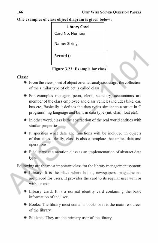
166 Unit Wise solved QUestion PaPers
One examples of class object diagram is given below : Library Card
Card No: Number
Name: String
Expiry Date: Date Record ()
Figure 3.23 :Example for class
Class: � From the view point of object oriented analysis design, the collection of the similar type of object is called class.
� For examples manager, peon, clerk, secretary, accountants are member of the class employee and class vehicles includes bike, car, bus etc. Basically it defines the data types similar to a struct in C programming language and built in data type (int, char, float etc).
� In other word, class is the abstraction of the real world entities with similar properties.
� It specifies what data and functions will be included in objects of that class. Ideally, class is also a template that unites data and operations.
� Finally we can mention class as an implementation of abstract data type.
Following are the most important class for the library management system: � Library: It is the place where books, newspapers, magazine etc are placed for users. It provides the card to its regular user with or without cost.
� Library Card: It is a normal identity card containing the basic information of the user.
� Books: The library most contains books or it is the main resources of the library.
� Students: They are the primary user of the library
1101 AMSCE - DEPARTMENT OF IT

object oriented analysis and design 167 � Bar code reader: It is an electronic device which is used to read the
coded information for the validation.
� Librarian: The persons who handle the overall operation of the library.
Attributes: � According to the basic concepts of object oriented analysis design, attributes is the general properties of an object of the same class.
� It is noun. It is basically implemented while defining the software entity as the variables in the class.
� In the library system following are the possible attributes.
Classes of Library System Related Attributes
Library name, phone, etc.
Library card card no, issue date, expiry date etc.
Book name, author, faculty etc.Student name, address, phone, id etc.
Bar Code Reader version, model, colour etc.Table 3.6: Classes of Library System
with Related Attributes
Methods:Normally, each and every object contains certain types of behaviours which are included as methods in class. In other words, Methods are the services which are provided by class. It is a verb. For verification in the library system the following are the methods of their relative class.
Classes of Library System Related Methods
Library study(), searc_book() etc.
Library Card borrow(), check_status() etc.
Book issue(), study() etc.
Bar Code Reader Check_validity(),
Students Study(), gain_information() etc.Table 3.7: Classes of Library System with Related Methods
1101 AMSCE - DEPARTMENT OF IT

168 Unit Wise solved QUestion PaPers
For examples in general we can display class, attributes & methods as:
Class _ name Attributes – 1
Attributes – 2
---------------
Attributes – n
Methods () 1
Methods () 2
---------------
Methods () n
Students
ID No: Integer
Name: String
Address: String
Study ()
ask book ()
Figure 3.24 : display class, attributes & methods
Use Case: � It is the normal diagram of UML model where UML stands for Unified Modelling Language.
� It is the common language for specifying, visualising, and constructing during the system development process.
� Among the different UML diagram model use case is one of the important once which explain the functional requirement of the system.
� Use case diagram reflects the aims of the system in the graphical way, by the proper implementation of step by step process with the interaction between users and the clients.
Actor:Actor is the aspects of the system in the use case diagram.
It reflects the duties of the person or the system needed for interacting or communicating with the primary use case in the system.
In library system there are two main actors such as librarian and students who communicate directly with the system.
1101 AMSCE - DEPARTMENT OF IT

object oriented analysis and design 169 The stepwise processes are given below:
Students LibrarianStep1:
A student enters and request for book in the library.
Step2:
Librarian initially checks the presence of book or not.
Step3:
Librarian asks for library card of the students.
Step4:
Students show his/her library card and in case for new students he asks for membership.
Step5:
The librarian verifies the library card and for new students s/he records the personal information & provide new library card.
Step6:
The librarian check the previous withdraw or clearance if earlier withdraw is not cleared & the deadline was over then s/he ask for the renewal and charge some penalty.
Step7:
Students pay the penalty & renew the book.
Step8:
Again the librarian records the student’s information along with the book details & the deadline for the book to return.
Step9:
Lastly the students ask library card back.
Step10:
Finally the librarian return the library card & issue the book to the.
Table 3.8 : Actor
1101 AMSCE - DEPARTMENT OF IT

170 Unit Wise solved QUestion PaPers
Students
Librarian
Old New
Figure 3.25 : Use case diagram for Library Management System.
Library System
Request for book
Check availability
Ask for library card
Show his/her library card
Verify library card
Ask for membership
Provide membership
Check for previous withdraw
Pay penalty
Book renew
Records card no & return date
Ask library card back
Issue book
1101 AMSCE - DEPARTMENT OF IT

object oriented analysis and design 171
1
1
* 1 1 *
** 1
* 1 1 1
Inheritance
1 * *
* *
Super
class
Generalization
Figure 3.26 :Class-diagram for library Management System
Library
Name: string
Type: string (College)
Issue_book ()
Library Card
Card no: int
Faculty: string
Expiry date:
Borrow_books()
Students
name: string
id: alphanumeric
address: string
study ()
Book
Name: string
Author: string
Issue ()
Card Reader
Model: string
Version: string
Check_validity ()
OLD
Name: string
Id: alphanumeric
Read_book()
NEW
Name: string
Id: alphanumeric
Add_book () Librarian
Name: string
phone: int
udate_record ()
Magazine
name: string
type: string
price:int
gain_khowledge ()
Weekly
Name: string
Price: int
Read ()
Monthly
Name: string
Price: int
Borrow_magazine ()
Some definition:
Association: � Association is the simplest type of class relationship diagram.
� The single line joining the two different classes is known as association.
� In library system, the relationship between students & library card is denoted as association.
� In above diagram the single straight line shows the process of association.
1101 AMSCE - DEPARTMENT OF IT

172 Unit Wise solved QUestion PaPers
Aggregation: � According to the class diagram, when one class is partially dependent on other classes then the relationship diagram is called aggregation.
� In case of library system, the open relation between library & magazine is aggregation because library can be run without any magazine.
� From the figure aggregation is displayed by the white colour diamond.
Composition: � In class diagram, when one class is fully or completely dependent on the other classes then the relationship diagram is known as composition.
� For library system, the relation between books & library is composition because library cannot run without books.
� Likewise the relationship between library card & card reader, students & library are also composition.
� In the diagram mention above the composition is reflects by the black diamond joining the two different class.
Generalization: � During the process of inheritance that is transforming of characteristics from the ancestors class to the derived class is called inheritance, generalization & specialization takes place.
� Generalization is the process of creating new super class from the initial parent class by taking the common attributes and methods.
� Similarly specialization is the process of creating the sub class from the reference class.
� For simple examples in the above class diagram the class magazine can be both weekly and monthly.
8. What is the purpose of Use Case Model .Identify the actor, Scenarios and use case for library management System (NOV/DEC 2016)
Refer: Question No:6
1101 AMSCE - DEPARTMENT OF IT

object oriented analysis and design 173 9. Explain association, aggregation, and composition relationship in
detail (NOV/DEC 2016)Refer: Question No:6
10. Discuss in detail three strategies to find conceptual classes. (NOV/DEC 2016)
The domain model illustrates conceptual classes or vocabulary in the domain.
Informally, a conceptual class is an idea, thing, or object. More formally, a conceptual class may be considered in terms of its symbol, intension, and extension
� Symbol—words or images representing a conceptual class.
� Intension—the definition of a conceptual class.
� Extension—the set of examples to which the conceptual class applies. For example, consider the conceptual class for the event of a purchase transaction. I may choose to name it by the symbol Sale. The intension of a Sale may state that it “represents the event of a purchase transaction, and has a date and time.” The extension of Sale is all the examples of sales; in other words, the set of all sales.
Figure 3.27: conceptual classesWhen creating a domain model, it is usually the symbol and intentional view of a conceptual class that are of most practical interest
1101 AMSCE - DEPARTMENT OF IT

174 Unit Wise solved QUestion PaPers
Strategies to Identify Conceptual ClassesTwo techniques are presented in the following sections:
1. Use a conceptual class category list.
2. Identify noun phrases.
Another excellent technique for domain modeling is the use of analysis patterns,which are existing partial domain models created by experts, using published resources such as Analysis Patterns [Fowler96] and Data Model Patterns [Hay96].
Use a Conceptual Class Category ListStart the creation of a domain model by making a list of candidate conceptual classes. Table 10.1 contains many common categories that are usually worth considering, though not in any particular order of importance. Examples are drawn from the store and airline reservation domains.
Conceptual Class Category Examples
Physical or tangible objects Register, Airplane
Specifications, deigns or descriptions of things
ProductSpecificationFlightDescription
PlacesStoreAirport
TransactionsSalePaymentReservation
Transaction line items SalesLineItem
Roles of peopleCashierPilot
Containers of other thingsStoreBinAirplane
Things in a containerItemPassenger
1101 AMSCE - DEPARTMENT OF IT

object oriented analysis and design 175
Other computer or electro-mechanical systems external to the system
Credit Payment Authorization SystemAirTrafficControl
OrganizationsSalesDepartmentObjectAirline
Events
SalePaymentMeetingFlightCrashLanding
Rules and policiesRefundPolicyCancellationPolicy
CatalogsProductCatalog PartsCatalog
Records of finance, work, contracts, legal matters
ReceiptLedgerEmploymentContract MaintenanceLog
Financial instruments and services
LineOfCreditStock
Manuals, documents, reference papers, books
DailyPriceChangeListRepairManual
Table 3.9: Use a Conceptual Class Category List
Finding Conceptual Classes with Noun Phrase Identification � Another useful technique (because of its simplicity) suggested in [Abbot83] is linguistic analysis: identify the nouns and noun phrases in textual descriptions of a domain, and consider them as candidate conceptual classes or attributes.
� Care must be applied with this method; a mechanical noun-to-class mapping isn’t possible, and words in natural languages are ambiguous.
1101 AMSCE - DEPARTMENT OF IT

176 Unit Wise solved QUestion PaPers
� Nevertheless, it is another source of inspiration. The fully dressed use cases are an excellent description to draw from for this analysis.
� For example, the current scenario of the Process Sale use case can be used.
Main Success Scenario (or Basic Flow):1. Customer arrives at a POS checkout with goods and/or services to purchase.
2. Cashier starts a new sale.
3. Cashier enters item identifier.
4. System records sale line item and presents item description, price, and running total. Price calculated from a set of price rules.
Cashier repeats steps 2-3 until indicates done.
5. System presents total with taxes calculated.
6. Cashier tells Customer the total, and asks for payment.
7. Customer pays and System handles payment.
8. System logs the completed sale and sends sale and payment information to the external Accounting (for accounting and commissions) and Inventory systems (to update inventory).
9. System presents receipt.
10.Customer leaves with receipt and goods (if any).Extensions (or Alternative Flows):
7a. Paying by cash:
1. Cashier enters the cash amount tendered.
2. System presents the balance due, and releases the cash drawer.
3. Cashier deposits cash tendered and returns balance in cash to Customer.
4. System records the cash payment. � The domain model is a visualization of noteworthy domain concepts and vocabulary.Where are those terms found? In the use cases.
� Thus, they are a rich source to mine via noun phrase identification. Some of these noun phrases are candidate conceptual classes, some may refer to conceptual classes that are ignored in this iteration
1101 AMSCE - DEPARTMENT OF IT
object oriented analysis and design 177 (for example, “Accounting” and “commissions”), and some may be
attributes of conceptual classes.
� Please see the subsequent section and chapter on attributes for advice on distinguishing between the two.
� A weakness of this approach is the imprecision of natural language; different noun phrases may represent the same conceptual class or attribute, among other ambiguities. Nevertheless, it is recommended in combination with the Conceptual Class Category List technique.
Candidate Conceptual Classes for the Sales DomainFrom the Conceptual Class Category List and noun phrase analysis,
a list is generated of candidate conceptual classes for the domain.
The list is constrained to the requirements and simplifications currently under consideration—the simplified
scenario of Process Sale.
Register ProductSpecification
Item SalesLineItemCustomer
Payment Manager
Store Cashier
Sale Customer
ProductCatalogThere is no such thing as a “correct” list. It is a somewhat arbitrary
collection of abstractions and domain vocabulary that the modelers consider noteworthy.
Nevertheless, by following the identification strategies, similar lists will be produced by different modelers
Report Objects—Include Receipt in the Model?A receipt is a record of a sale and payment and a relatively
prominent conceptual class in the domain, so should it be shown
in the model? � Here are some factors to consider:
� A receipt is a report of a sale. In general, showing a report of other information in a domain model is not useful since all its information
1101 AMSCE - DEPARTMENT OF IT

178 Unit Wise solved QUestion PaPers
is derived from other sources; it duplicates information found elsewhere. This is one reason to exclude it.
� A receipt has a special role in terms of the business rules: it usually confers the right to the bearer of the receipt to return bought items. This is a reason to show it in the model.
Since item returns are not being considered in this iteration, Receipt will be excluded. During the iteration that tackles the Handle Returns use case, it would be justified to include it.
A Common Mistake in Identifying Conceptual ClassesPerhaps the most common mistake when creating a domain model is to represent something as an attribute when it should have been a concept. A rule of thumb to help prevent this mistake is:
If we do not think of some conceptual class X as a number or text in the real world, X is probably a conceptual class, not an attribute.
As an example, should store be an attribute of Sale, or a separate conceptual class Store?
Sale
Store
Sale
Store
Phone number or.......?
Figure 3.28 : Identifying conceptual classesIn the real world, a store is not considered a number or text—
the term suggests a legal entity, an organization, and something occupies space.
Therefore, Store should be a concept.
As another example, consider the domain of airline reservations. Should destination be an attribute of Flight, or a separate conceptual class Airport?
Flight
Destination
Flight
Airport
Name or.......?
Figure 3.29 : Airline Reservation conceptual classes
1101 AMSCE - DEPARTMENT OF IT

object oriented analysis and design 179 In the real world, a destination airport is not considered a number
or text—it is a massive thing that occupies space.
Therefore, Airport should be a concept. If in doubt, make it a separate concept. Attributes should be fairly rare in a domain model
Resolving Similar Conceptual Classes—Register vs.”POST”POST stands for point-of-sale terminal. In computer, a terminal is
any end-point device in a system, such as a client PC, a wireless networked PDA, and so forth
In earlier times, long before POSTs, a store maintained a register—a book that logged sales and payments.
Eventually, this was automated in a mechanical “cash register.” Today, a POST fulfills the role of the register
A register is a thing that records sales and payments, but so is a POST.
However, the term register seems somewhat more abstract and less implementation oriented than POST.
So, in the domain model, should the symbol Register be used instead of POST?
� First, as a rule of thumb, a domain model is not absolutely correct or wrong, but more or less useful; it is a tool of communication.
� By the mapmaker principle, “POST” is a term familiar in the territory, so it is a useful symbol from the point of view of familiarity and communication.
� By the goal of creating models that represent abstractions and are implementation independent, Register is appealing and useful.
� Register may be fairly considered to represent both the conceptual class of a place to register sales, and/or an abstraction of various kinds of terminals, such as a POST.
� Both choices have merit; Register has been chosen in this case study somewhat arbitrarily, but POST would also have been understandable to the stakeholders
1101 AMSCE - DEPARTMENT OF IT
180 Unit Wise solved QUestion PaPers
Modeling the Unreal World � Some software systems are for domains that find very little analogy in natural or business domains; software for telecommunications is an example.
� It is still possible to create a domain model in these domains, but it requires a high degree of abstraction and stepping back from familiar designs.
For example, here are some candidate conceptual classes related to a telecommunication switch: Message, Connection, Port, Dialog, Route, and Protocol.
Specification or Description Conceptual ClassesThe following discussion may at first seem related to a rare, highly
specialized issue.
However, it turns out that the need for specification conceptual classes (as will be defined) is common in many domain models.
Thus, it is emphasized.
Note that in earlier times a register was just one possible implementation of how to record sales. The term has acquired a generalized meaning over time.
Assume the following: � An Item instance represents a physical item in a store; as such, it may even have a serial number.
� An Item has a description, price, and itemID, which are not recorded anywhere else.
� Everyone working in the store has amnesia.
� Every time a real physical item is sold, a corresponding software instance of Item is deleted from “software land.”
With these assumptions, what happens in the following scenario?
There is strong demand for the popular new vegetarian burger—ObjectBurger. The store sells out, implying that all Item instances of ObjectBurgers are deleted from computer memory.
Now, here is the heart of the problem: If someone asks, “How much do Object- Burgers cost?”, no one can answer, because the
1101 AMSCE - DEPARTMENT OF IT

object oriented analysis and design 181 memory of their price was attached to inventoried instances, which
were deleted as they were sold.
Notice also that the current model, if implemented in software as described, has duplicate data and is space-inefficient because the description, price, and itemID are duplicated for every Item instance of the same product.
The Need for Specification or Description Conceptual ClassesThe preceding problem illustrates the need for a concept of objects
that are specifications or descriptions of other things.
To solve the Item problem, what is needed is a Product Specification (or Item Specification, Product Description, ...) conceptual class that records information about items.
A Product Specification does not represent an Item, it represents a description of information about items.
Note that even if all inventoried items are sold and their corresponding Item software instances are deleted, the Product Specifications still remain.
Description or specification objects are strongly related to the things they describe. In a domain model, it is common to state that an XSpecification
The need for specification conceptual classes is common in sales and product domains. It is also common in manufacturing, where a description of a manufactured thing is required that is distinct from the thing itself.
Time and space have been taken in motivating specification conceptual classes because they are very common; it is not a rare modeling concept.
1101 AMSCE - DEPARTMENT OF IT

182 Unit Wise solved QUestion PaPers
Describes 1 *
Item
Description price serialnumber itemID
Product specification
Description price itemID
Item
Serial number
Worse
Better
Figure 3.29: Specification or Description of conceptual classes
When Are Specification Conceptual Classes Required?The following guideline suggests when to use specifications:
Add a specification or description conceptual class (for example, ProductSpecification)when:
There needs to be a description about an item or service, independent of the current existence of any examples of those items or services.
Deleting instances of things they describe (for example, Item) results in a loss of information that needs to be maintained, due to the incorrect association of information with the deleted thing.
It reduces redundant or duplicated information.
Another Specification ExampleAs another example, consider an airline company that suffers a
fatal crash of one of its planes. Assume that all the flights are cancelled for six months pending
completion of an investigation. Also assume that when flights are cancelled, their corresponding Flight software objects are deleted from computer memory. Therefore, after the crash, all Flight software objects are deleted.
If the only record of what airport a flight goes to is in the Flight software instances, which represent specific flights for a particular date and time, then there is no longer a record of what flight routes the airline has.
1101 AMSCE - DEPARTMENT OF IT

object oriented analysis and design 183 To solve this problem, a FlightDescription (or FlightSpecification)
is required that describes a flight and its route, even when a
particular flight is not scheduled
Figure 3.30 : Example of Another Specification
Descriptions of ServicesNote that the prior example is about a service (a flight) rather than a good (such as a veggieburger). Descriptions of services or service plans are commonly needed.
1101 AMSCE - DEPARTMENT OF IT

184 Unit Wise solved QUestion PaPers
UNIT IV APPLYING DESIGN PATTERNS
PART - A1. What are the strength and weakness of sequence and Collaboration
diagram (APRIL/MAY 2017)Type Strengths Weekness
Sequence clearly shows sequence or time ordering of messages simple notation
forced to extend to the right when adding new objects consumes horizontal space
collaboration
space economical flexibil-ity to add new object in two dimensions better to illustrate comblex branching iteration and concurrent behavior
difficult to see se-quence of messages more complex notation
2. Difference between logical architecture and layers (APRIL/MAY 2017)
� The logical architectureis the large - scale organization of the software classes into packages (or namespaces), subsystems, and layers.
� It’s called the logical architecture because there’s no decision about how these elements are deployed across different operating system processes or across physical computers in a network (these latter decisions are part of the deployment architecture).
� A layer is a very coarse - grained grouping of classes, packages, or subsystems that has cohesive responsibility for a major aspect of the system
� Also, layers are organized such that “higher” layers (such as the UI layer) call upon services of “lower” layers, but not normally vice versa. Typically layers in an 00 system include:
3. How to Naming System Events and Operations. (NOV/DEC- 2016)System events (and their associated system operations) should be
expressed at the level of intent rather than in terms of the physical input medium or interface widget level.
1101 AMSCE - DEPARTMENT OF IT

object oriented analysis and design 185 It also improves clarity to start the name of a system event with
a verb Thus “enter item” is better than “scan” (that is, laser scan) because it captures the intent of the operation while remaining abstract and noncommittal with respect to design choices about what interface is used to capture the system event.
4. Define System Events and the System Boundary. (NOV/DEC- 2016)To identify system events, it is necessary to be clear on the choice
of system boundary, as discussed in the prior chapter on use cases.For the purposes of software development, the system boundary
is usually chosen to be the software system itself; in this context, a system event is an external event that directly stimulates the software.
5. What is meant by System Behavior?. (NOV/DEC- 2015) � System behavior is a description of what a system does, without explaining how it does it. One Part of that description is a system sequence diagram.
� Other parts include the Use cases, and system contracts.
6. What is the use of System Sequence Diagram?The SSD is fast and easily created artifact which illustrates input
and output events related to the system under discussion. They are input to operation contracts and most importantly – Object Design.
A system sequence diagram (SSD) is a picture that shows, for a particular scenario of a use case, the events that external actors generate, their order, and inter-system events. All systems are treated as a black box; the emphasis of the diagram is events that
cross the system boundary from actors to systems.
7. Define Package and draw the UML notation for Package. � Package is a namespace used to group together elements that are semantically related and might change together.
� It is a general purpose mechanism to organize elements into groups to provide better structure for system model
� A UML package diagram provides a way to group elements.
1101 AMSCE - DEPARTMENT OF IT

186 Unit Wise solved QUestion PaPers
� The elements are classes, use cases and other packages.
� Use a tabbed folder to illustrate packages.
� Write the name of the package on the tab or inside the folder.
� Similar to classes, you can also list the attributes of a package.
Package Name
Package Name
+ Attribute 1 + Attribute 2 + Attribute 3
Figure 4.1 : Packages
8. List the relationships used in class diagram. (NOV/DEC 2015) (APRIL/MAY 2011)There are five key relationships between classes in a UML class dia-gram : dependency, aggregation, composition, inheritance and realiza-tion. These five relationships are depicted in the following diagram:
Figure 4.2: Relationships used in class diagramUML Class Relationships
The above relationships are read as follows:
� Dependency : class A uses class B
� Aggregation : class A has a class B
1101 AMSCE - DEPARTMENT OF IT

object oriented analysis and design 187 � Composition : class A owns a class B
� Inheritance : class B is a Class A (or class A is extended by class B)
� Realization : class B realizes Class A (or class A is realized by class B)
9. What do you mean by sequence number in UML? Where and for what it is used?Message numbering on sequence diagrams allows you to see how messages interact and relate to one another. Numbering messages can be done in one of two ways:
Top-level numbering, where each message is given a single number (in a 1, 2, 3, ... pattern)
Hierarchical numbering, where a message’s number is based on the previous message’s number (in a 1.1, 1.1.2, 1.1.3, ... pattern)
Figure 4.3 : Sequence Diagram
10. Define Logical Architecture and Layers? � The logical architecture is the large-scale organization of the software classes into packages, subsystems, and layers.
� A layer is a very coarse-grained grouping of classes, packages, or subsystems that has cohesive responsibility for a major aspect of the system.
11. Define Software Architecture and Layers? The selection of the structural elements and there interfaces by which the system is composed together with their behavior as specified in the collaborations among those elements. These composition become larger subsystem and architectural style called software architecture
1101 AMSCE - DEPARTMENT OF IT
188 Unit Wise solved QUestion PaPers
12. Define about Reverse Engineering? Reverse Engineering is a UML CASE tool where the source code is converting in to UML package diagram.
13. What are the benefits of using layers? � This reduces coupling and dependencies, improves cohesion, increases reuse potential, increases clarity.
� Related complexity is encapsulated and decomposable.
� Some layers can be replaced with new implementations.
� Lower layers contain reusable functions.
� Some layers can be distributed.
� Development by teams is aided because of the logical segmentation.
14. What are the relationship between domain layer and domain model? The domain layer is part of the software and the domain model is part of the conceptual- perspective analysis. Creating a domain layer with inspiration from the domain model, we achieve a lower representa-tional gap, between the real-world domain , and our software design.
15. Define facade? Facade is a “front end” object that is the single point of entry for the services of a subsystem. The façade object to this subsystem will be called POS Rule Engine Facade.
16. Define UML interaction diagram? The term interaction diagram is a generalization of two more special-ized UML diagram types:
� Sequence diagrams
� Communication diagrams
17. Define interaction overview diagram? It provides a big-picture overview of how a set of interaction diagrams are related in terms of logic and process-flow.
1101 AMSCE - DEPARTMENT OF IT

object oriented analysis and design 189 18. Define synchronous and asynchronous call?
� Asynchronous message call does not wait for response, it doesn‟t block.
� They are used in multi-threaded environments such as .NET and java
� Notation for asynchronous calls is a stick arrow message
� Notation for synchronous calls is a filled arrow message.
19. Define active object? � In active object each instance runs on and controls its own thread of execution.
� In UML it may be shown with double vertical lines on the left and right sides of the lifeline box. The same notation is used for active class whose instance are active object. :Clock
20. What is class diagram and design class diagram? � Class diagram is to illustrate classes, interfaces, and their associations.
� They are used for static object modeling. DCD‟s are the part of the design model.
� Class name
� Attribute name
� Methods
21. Define classifiers. � Classifier is “a model element that describes behavioral and structure features”.
� Classifiers can also be specialized.
22. Define Keywords, Tag, Profile, Stereotypes. Keyword:
� UML Keyword is a text represented to categorize a model element
� For example, the keyword <<interface>> is used in the class box to show the particular class is having link with other class.
1101 AMSCE - DEPARTMENT OF IT

190 Unit Wise solved QUestion PaPers
Tags:
� The stereotypes declare the set of tags, using the attribute syntax.
Profiles:
� A profile is a collection of related stereotypes, tags and constraints.
Stereotypes:
� Stereotypes represent an existing modeling concept
� Stereotype is defined with in a profile.
23. Define notes, constraints, and methods.Notes: A note symbol is displayed as a dog-eared rectangle with the dashed line to the annotated element.
Constraints: A constraint is enclosed inside a brace „{……}‟
Method: It is an implementation of UML operation.
24. Define qualified association? A qualified association has a qualifier that is used to select an object from a larger set of related objects, based upon the qualifier key.
25. What are the user defined compartments in class diagram? In addition to common predefined compartments class compartment such as name, attributes and operations (methods), user defined com-partment can be added to a class box.
Class name
Attribute name
Methods
User defined
26. What is meant by Inter-System SSDs?SSDs can also be used to illustrate collaborations between systems, such as between the NextGen POS and the external credit payment au-thorizer. However, this is deferred until a later iteration in the case study, since this iteration does not include remote systems collaboration.
1101 AMSCE - DEPARTMENT OF IT

object oriented analysis and design 191 27. What is the purpose of glossary?
The terms shown in SSDs (operations, parameters, return data) are terse. These may need proper explanation so that during design work it is clear what is coming in and going out. If this was not explicated in the use cases, the Glossary could be used.
28. What are the typical layers in an Object Oriented System?Layers in an Object Oriented system include :
User Interface
Application logic and domain objects
Technical services
Figure 4.4: Layered Architecture
29. What are the ways to show UML attributes?Attributes of a classifier (also called structural properties in the UML[1]) are shown several ways:
� attribute text notation, such as currentSale : Sale.
� association line notation
� both together
1101 AMSCE - DEPARTMENT OF IT

192 Unit Wise solved QUestion PaPers
Figure 4.5 : UML Attributes
30. What are the advantages of communication diagram? � Communication diagrams have advantages when applying “UMLas sketch” to draw on walls (an Agile Modeling practice) because they are much more space-efficient.
� This is because the boxes can be easily placed or erased anywhere—horizontal or vertical. Consequently as well, modifying wall sketches is easier with communication diagrams—it is simple (during creative high-change OO design work) to erase a box at one location, draw a new one elsewhere, and sketch a line to it.
� In contrast, new objects in a sequence diagrams must always be added to the right edge, which is limiting as it quickly consumes and exhausts right-edge space on a page (or wall); free space in the vertical dimension is not efficiently used.
� Developers doing sequence diagrams on walls rapidly feel the drawing pain when contrasted with communication diagrams.
31. What is an association class? � An association class allows you treat an association itself as a class, and model it with attributes, operations, and other features.
1101 AMSCE - DEPARTMENT OF IT

object oriented analysis and design 193 � For example, if a Company employs many Persons, modeled with
an Employs association, you can model the association itself as the Employment class, with attributes such as start Date.
32. What is a Communication diagram?Communication diagrams illustrate object interactions in a graph or network format, in which objects can be placed anywhere on the diagram
33. Define adapter. � The adapter design pattern is a kind of pattern that is adapting between classes and objects.
� It act as a interface between objects
34. What is an factory? � This is also called simple factory or concrete factory.This pattern is not a GOF design pattern, but extremely widespread.
� It deals with the problem of creating objects without specifying the exact class of object that will be created.
35. What is an concrete factory? This is also called simple factory or concrete factory, this pattern is not a GOF design pattern, but extremely widespread.
36. What is an observable pattern? � It is an interface or abstract class defining the operations for attaching and de-attaching observers to the client.
� In GOF the interface is called as subject.
37. Define singleton class. � There is only one instance of a class then it is called as singleton class
� It is represented with a number “1” at the right corner of the class box.
38. What is meant by link? � A link is a connection path between two objects; it indicates some form of navigation And visibility between the objects is possible .
1101 AMSCE - DEPARTMENT OF IT

194 Unit Wise solved QUestion PaPers
� More formally, a link is an instance of an association.
� For example, there is a link or path of navigation from a Register to a Sale, along which messages may flow, such as to make the Payment message.
39. What is meant by Messages? Each message between objects is represented with a message expres-sion and small arrow indicating the direction of the message. Many messages may flow along this link. A sequence number is added to show the sequential order of messages in the current thread of control.
1101 AMSCE - DEPARTMENT OF IT

object oriented analysis and design 195 PART - B
1. What are system sequence diagrams? What is the relationship be-tween Sequence Diagram and Usecases. Explain with an example. (NOV/DEC 2016).
System Sequence Diagrams � Use cases describe how external actors interact with the software system we are interested in creating.
� During this interaction an actor generates events to a system, usually requesting some operation in response.
� For example, when a cashier enters an item’s ID, the cashier is requesting the POS system to record that item’s sale.
� That request event initiates an operation upon the system.
� It is desirable to isolate and illustrate the operations that an external actor requests of a system, because they are an important part of understanding system behavior.
� The UML includes sequence diagrams as a notation that can illustrate actor interactions and the operations initiated by them.
� A system sequence diagram (SSD) is a picture that shows, for a particular scenario of a use case, the events that external actors generate, their order, and inter-system events.
� All systems are treated as a black box; the emphasis of the diagram is events that cross the system boundary from actors to systems.
Example of an SSD
An SSD shows, for a particular course of events within a use case, the external actors that interact directly with the system, the system (as a black box), and the system events that the actors generate .
Time proceeds downward, and the ordering of events should follow their order in the use case. System events may include parameters.
This example is for the main success scenario of the Process Sale use case.
It indicates that the cashier generates makeNewSale, enteritem, endSale, and makePayment system events.
1101 AMSCE - DEPARTMENT OF IT

196 Unit Wise solved QUestion PaPers
Figure 4.6 : SSD for a Process Sale Scenario
Inter-System SSDs � SSDs can also be used to illustrate collaborations between systems, such as between the NextGen POS and the external credit payment authorizer.
� However, this is deferred until a later iteration in the case study, since this iteration does not include remote systems collaboration.
SSDs and Use Cases � An SSD shows system events for a scenario of a use case, therefore it is generated from inspection of a use case
Figure 4.7: SSDs are derived from use cases
1101 AMSCE - DEPARTMENT OF IT

object oriented analysis and design 197 System Events and the System Boundary
� To identify system events, it is necessary to be clear on the choice of system boundary, as discussed in the prior chapter on use cases.
� For the purposes of software development, the system boundary is usually chosen to be the software(and possibly hardware) system itself; in this context, a system event is an external event that directly stimulates the software .
� Consider the Process Sale use case to identify system events.
� First, we must determine the actors that directly interact with the software system.
� The customer interacts with the cashier, but for this simple cash-only scenario, does not directly interact with the POS system—only the cashier does. Therefore, the customer is not a generator of system events; only the cashier is.
Figure 4.8: Defining the system boundary
Naming System Events and Operations
System events (and their associated system operations) should be expressed at the level of intent rather than in terms of the physical input medium or interface widget level.
1101 AMSCE - DEPARTMENT OF IT

198 Unit Wise solved QUestion PaPers
It also improves clarity to start the name of a system event with a verb (add..., enter..., end..., make...), since it emphasizes the command orientation of these events.
Thus “enteritem” is better than “scan” (that is, laser scan) because it captures the intent of the operation while remaining abstract and noncommittal with respect to design choices about what interface is used to capture the system event.
Figure 4.9 Choose event and operation names at an abstract level
2. Draw a neat sketch of Logical architecture of NextGen application and explain the components in detail. (NOV/DEC 2016)
Architectural Pattern: Layers
Solution The essential ideas of the Layers pattern [BMRSS96] are simple: „
� Organize the large-scale logical structure of a system into discrete layers of distinct, related responsibilities, with a clean, cohesive separation of concerns such that the “lower” layers are low-level and general services, and the higher layers are more application specific. „
� Collaboration and coupling is from higher to lower layers; lower-to-higher layer coupling is avoided.
� A layer is a large-scale element, often composed of several packages or subsystems.
� The Layers pattern relates to the logical architecture; that is, it describes the conceptual organization of the design elements into groups, independent of their physical packaging or deployment.
1101 AMSCE - DEPARTMENT OF IT

object oriented analysis and design 199 � Layers defines a general N-tier model for the logical architecture; it
produces a layered architecture.
� Example The purpose and number of layers varies across applications and application domains (information systems, operating systems, and so forth.
Figure 4.10 : Architectural Pattern: Layers
1101 AMSCE - DEPARTMENT OF IT

200 Unit Wise solved QUestion PaPers
Figure 4.11: Partial Logical View of layers in the NextGen application
UML notation—Package diagrams are used to illustrate the layers. In the UML, a layer is simply a package.
Inter-Layer and Inter-Package Interaction Scenarios
UML notation: Observe that dependency lines can be used to communicate coupling between packages or types in packages. Plain dependency lines are excellent when the communicator does not care to be more specific on the exact dependency (attribute visibility, subclassing, ...), but just wants to highlight general dependencies.
UML notation: „ The package of a type can optionally be shown by qualifying the type with the UML path name expression .example, Domain::Sales::Register.
1101 AMSCE - DEPARTMENT OF IT

object oriented analysis and design 201
3. How to add new SSDs and contracts to design diagram? What are the concepts involved in Domain refinement. (NOV/DEC 2015).
New System Sequence DiagramsIn the current iteration, the new payment handling requirements
involve new collaborations with external systems. To review, SSDs use sequence diagram notation to illustrate
inter-system collaborations, treating each system as a black-box. It is useful to illustrate the new system events in SSDs in order to
clarify: � new system operations that the NextGen POS system will need to support
� calls to other systems, and the responses to expect from these calls
Common Beginning of Process Sale ScenarioThe SSD for the beginning portion of a basic scenario includes makeNewSale, enterItem and endSale system events; it is common regardless of the payment method.
Figure 4.12: SSD Common Beginning
1101 AMSCE - DEPARTMENT OF IT

202 Unit Wise solved QUestion PaPers
Credit PaymentThis credit payment scenario SSD starts after the common beginning
Figure 4.13: Credit Payment SSDIn both cases of credit and check payments, a simplifying assumption is made (for this iteration) that the payment is exactly equal to the sale total, and thus a different “tendered” amount does not have be an input parameter.
Check PaymentThe SSD for the check payment scenario is shown in Figure
Figure 4.14: Check Payment SSD
1101 AMSCE - DEPARTMENT OF IT

object oriented analysis and design 203 New System Operations
In this iteration, the new system operations that our system must handle are:
� makeCreditPayment
� makeCheckPayment
In the first iteration, the system event and operation for the cash payment was simply makePayment. Now that the payments are of different types, it is renamed to makeCashPaymerit.
To review, system operation contracts are an optional requirements artifact (part of the Use-Case Model) that adds fine detail regarding the results of a system operation.
Sometimes, the use case text is itself sufficient, and these contracts are not necessary. Here are contracts for the new system operations:
Contract CO5: makeCreditPaymentOperation: Cross makeCreditPayment( creditAccountNumber, expiryDate)
References: Use Cases: Process Sale
Preconditions: An underway sale exists and all items have been entered.
Postconditions:
- a CreditPayment pmt was created
- pmt was associated with the current Sale sale
- a CreditCard cc was created; cc.number =
creditAccountNumber, cc.expiryDate = expiryDate
- cc was associated with pmt
- a CreditPaymentRequest cpr was created
- pmt was associated with cpr
- a ReceivableEntry re was created
- re was associated with the external AccountsReceivable
- sale was associated with the Store as a completed sale
1101 AMSCE - DEPARTMENT OF IT

204 Unit Wise solved QUestion PaPers
Contract CO6: makeCheckPaymentOperation: Cross makeCheckPayment( driversLicenceNumber)
References: Use Cases: Process Sale
Preconditions: An underway sale exists and all items have been entered.
Postconditions:
- a CheckPayment pmt was created
- pmt was associated with the current Sale sale
- a DriversLicense dl was created; dl.number =driversLicenseNumber
- dl was associated with pmt
- a CheckPaymentRequest cpr was created.
- pmt was associated with cpr
- sale was associated with the Store as a completed sale
4. Explain about interaction diagram notation for inventory management system. (NOV/DEC 2015).(8mark)
Figure 4.15: UML sequence diagram for inventory management system
1101 AMSCE - DEPARTMENT OF IT

object oriented analysis and design 205
Figure 4.16: UML Collaboration diagram for inventory management system
5. Explain about interaction diagram Notation. (NOV/DEC 2011, 2015, MAY/JUNE 2015)
Common Interaction Diagram Notation
Illustrating Classes and InstancesFor any kind of UML element (class, actor), an instance uses the same graphic symbol as the type, but the designator string is underlined.
Sale
Class
:Sale
Instance
s1:Sale
Named instance
Figure 4.17: Classes and instances
Basic Collaboration Diagram Notation
LinksA link is a connection path between two objects; it indicates some form of navigation and visibility between the objects is possible
1101 AMSCE - DEPARTMENT OF IT

206 Unit Wise solved QUestion PaPers
1: make payment (cash Tendered)→
2: foo()→ 2.1: bar() ←
: Register
Link line
: sale
Figure 4.18 : Link Lines
MessagesEach message between objects is represented with a message expression and small arrow indicating the direction of the message.
msg1() ↓ 1: msg2 () →
2: msg3 () → 3:msg4 () → ← 3.1: msg5 ()
: Register
All messages flow on the same link
: sale
Figure 4.19 : Messages
Messages to “self” or “this”A message can be sent from an object to itself
1101 AMSCE - DEPARTMENT OF IT

object oriented analysis and design 207
1: clear () ↑
msg1() ↓
: Register
Figure 4.19.1: Messages of this
Creation of InstancesAny message can be used to create an instance, but there is a
convention in the UML to use a message named create for this purpose.
If another (perhaps less obvious) message name is used, the message may be annotated with a special feature called a UML stereotype, like so: «create».
Figure 4.20 : Instance Creation
1101 AMSCE - DEPARTMENT OF IT

208 Unit Wise solved QUestion PaPers
Message Number SequencingThe order of messages is illustrated with sequence numbers
Figure 4.21 : Message Number Sequencing
Conditional MessagesA conditional message is shown by following a sequence number with a conditional clause in square brackets, similar to an iteration clause. The message is only sent if the clause evaluates to true.
Figure 4.22: Conditional Message
Mutually Exclusive Conditional PathsThe example illustrates the sequence numbers with mutually exclusive conditional paths.
1101 AMSCE - DEPARTMENT OF IT

object oriented analysis and design 209
Figure 4.23 : Mutually Exclusive Message
Iteration or LoopingIf the details of the iteration clause are not important to the modeler, a simple ’*’ can be used.
Figure 4.24 : Iteration
Iteration Over a Collection (Multiobject)Often, some kind of iterator object is ultimately used, such as an implementation of java.util.Iterator or a C++ standard library iterator. In the UML, the term multiobject is used to denote a set of instances.a collection.
1101 AMSCE - DEPARTMENT OF IT

210 Unit Wise solved QUestion PaPers
Figure 4.25 : Iteration Over a Collection (Multiobject)The “*” multiplicity marker at the end of the link is used to indicate that the message is being sent to each element of the collection.
Messages to a Class ObjectMessages may be sent to a class itself, rather than an instance, to
invoke class or static methods.
A message is shown to a class box whose name is not underlined, indicating the message is being sent to a class rather than an instance.
Figure 4.26: Messages to a Class Object
Basic Sequence Diagram Notation
LinksUnlike collaboration diagrams, sequence diagrams do not show links.
1101 AMSCE - DEPARTMENT OF IT

object oriented analysis and design 211 Messages
Each message between objects is represented with a message expression on an arrowed line between the objects. The time ordering is organized from top to bottom.
Figure 4.27 : Messages and focus of control with activation boxes
Focus of Control and Activation Boxes sequence diagrams may also show the focus of control (that is, in a regular blocking call, the operation is on the call stack) using an activation box. The box is optional, but commonly used by UML practitioners.
Illustrating ReturnsA sequence diagram may optionally show the return from a message as a dashed open-arrowed line at the end of an activation box. Some annotate the return line to describe what is being returned (if anything) from the message.
1101 AMSCE - DEPARTMENT OF IT

212 Unit Wise solved QUestion PaPers
Figure 4.28 : Showing Messages
Messages to “self” or “this”A message can be illustrated as being sent from an object to itself by using a nested activation box.
clear ()
msg1()
: Register
Figure 4.29 : Messages to “self” or “this”
1101 AMSCE - DEPARTMENT OF IT

object oriented analysis and design 213 Creation of Instances
Figure 4.30: Instance creation and object lifelines
Object Lifelines and Object DestructionObject lifelines. Represent the vertical dashed lines underneath the objects. these indicate the extent of the life of the object in the diagram. In some circumstances it is desirable to show explicit destruction of an object . the UML lifeline notation provides a way to express this destruction
Figure 4.31: Object Destruction
Conditional Messages
Figure 4.32: Conditional Messages
1101 AMSCE - DEPARTMENT OF IT
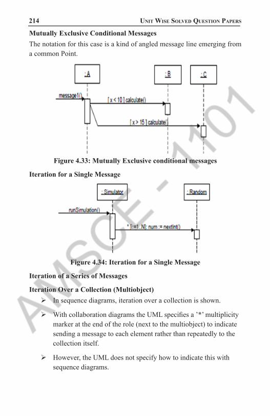
214 Unit Wise solved QUestion PaPers
Mutually Exclusive Conditional MessagesThe notation for this case is a kind of angled message line emerging from a common Point.
Figure 4.33: Mutually Exclusive conditional messages
Iteration for a Single Message
Figure 4.34: Iteration for a Single Message
Iteration of a Series of Messages
Iteration Over a Collection (Multiobject)In sequence diagrams, iteration over a collection is shown.
With collaboration diagrams the UML specifies a ’*’ multiplicity marker at the end of the role (next to the multiobject) to indicate sending a message to each element rather than repeatedly to the collection itself.
However, the UML does not specify how to indicate this with sequence diagrams.
1101 AMSCE - DEPARTMENT OF IT

object oriented analysis and design 215 Messages to Class Objects
As in a collaboration diagram, class or static method calls are shown by not underlining the name of the classifier, which signifies a class object rather than an instance
Figure 4.35: Messages to Class Objects
Figure 4.36: Invoking class or static methods
1101 AMSCE - DEPARTMENT OF IT
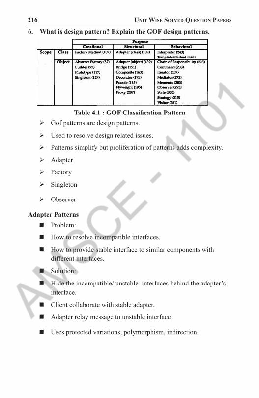
216 Unit Wise solved QUestion PaPers
6. What is design pattern? Explain the GOF design patterns.
Table 4.1 : GOF Classification PatternGof patterns are design patterns.
Used to resolve design related issues.
Patterns simplify but proliferation of patterns adds complexity.
Adapter
Factory
Singleton
Observer
Adapter PatternsProblem:
How to resolve incompatible interfaces.
How to provide stable interface to similar components with different interfaces.
Solution:
Hide the incompatible/ unstable interfaces behind the adapter’s interface.
Client collaborate with stable adapter.
Adapter relay message to unstable interface
Uses protected variations, polymorphism, indirection.
1101 AMSCE - DEPARTMENT OF IT

object oriented analysis and design 217
Figure 4.37: The Adapter Pattern � Register post the sale to an adapter.
� Adapter communicates with SAP accounting system.
� SAP accounting system exposes functionality as a web server
Figure 4.38: The Adapter Pattern for clientGRASP as generalization of other patterns
� Patterns overload:
� 100’s of documented patterns.
� Too many to comprehend and use.
1101 AMSCE - DEPARTMENT OF IT

218 Unit Wise solved QUestion PaPers
� Perhaps 50+ are common.
� GRASP patterns helpful to categorize the patterns using few basic principles.
� GRASP is the alphabet of patterns language.
� Very important conceptual model.
� PV is the most fundamental principle.
� Specific gof patterns are concrete applications of grasp
Figure 4.39 : Adapter and GRASPUpdated partial domain model
Design modeling discover new domain concept
Factory � This is also called Simple Factory or Concrete Factory. Problem:
� Who should be the creator when creation causes incohesiveness or it involves complex creation logic.
� Solution (advice)
1101 AMSCE - DEPARTMENT OF IT

object oriented analysis and design 219 � Assign creation responsibility to pure fabrication factory object
� Commonly implemented via singleton pattern
ServicesFactory
accountingAdapter : IAccountingAdapterinventoryAdapter : IInventoryAdaptertaxCalculatorAdapter : ITaxCalculatorAdapter
getAccountingAdapter() : IAccountingAdaptergetInventoryAdapter() : IInventoryAdaptergetTaxCalculatorAdapter() : ITaxCalculatorAdapter...
note that the factory methods return objects typed to an interface rather than a class, so that the factory can return any implementation of the interface
if ( taxCalculatorAdapter == null ) { // a reflective or data-driven approach to finding the right class: read it from an // external property
String className = System.getProperty( "taxcalculator.class.name" ); taxCalculatorAdapter = (ITaxCalculatorAdapter) Class.forName( className ).newInstance();
} return taxCalculatorAdapter;
Figure 4.40 : Factory object advantages � Separate the responsibility of complex creation in to cohesive objects.
� Hide potentially complex creation logic.
� Allow introduction of performance enhancing memory management strategy such as object caching.
� Singleton
� Problem:
� Exactly only one instance of a class is neede or allowed.
� Others objects need single , global point of access to it.
� Solution (advice):
� Define a static method of a class that return the singleton
� The static method can only create one instance.
� Who should create factory? Singleton !
� Provides global visibility via static method
� Avoid passing factory reference to many clients.
� Singleton pattern in ServicesFactory class
1101 AMSCE - DEPARTMENT OF IT
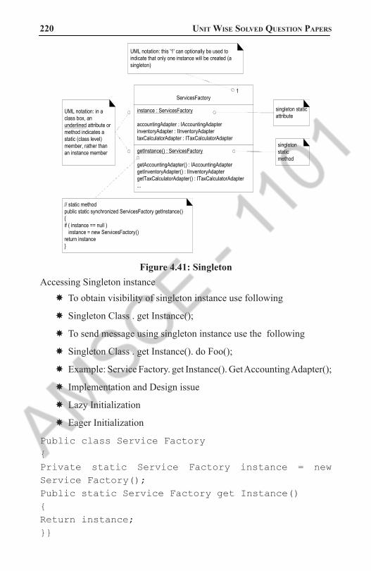
220 Unit Wise solved QUestion PaPers
1ServicesFactory
instance : ServicesFactory
accountingAdapter : IAccountingAdapterinventoryAdapter : IInventoryAdaptertaxCalculatorAdapter : ITaxCalculatorAdapter
getInstance() : ServicesFactory
getAccountingAdapter() : IAccountingAdaptergetInventoryAdapter() : IInventoryAdaptergetTaxCalculatorAdapter() : ITaxCalculatorAdapter...
singleton static attribute
singleton static method
// static methodpublic static synchronized ServicesFactory getInstance(){if ( instance == null ) instance = new ServicesFactory()return instance}
UML notation: in a class box, an underlined attribute or method indicates a static (class level) member, rather than an instance member
UML notation: this '1' can optionally be used to indicate that only one instance will be created (a singleton)
Figure 4.41: SingletonAccessing Singleton instance
� To obtain visibility of singleton instance use following
� Singleton Class . get Instance();
� To send message using singleton instance use the following
� Singleton Class . get Instance(). do Foo();
� Example: Service Factory. get Instance(). Get Accounting Adapter();
� Implementation and Design issue
� Lazy Initialization
� Eager Initialization
Public class Service Factory{Private static Service Factory instance = new Service Factory();Public static Service Factory get Instance(){Return instance;}}
1101 AMSCE - DEPARTMENT OF IT

object oriented analysis and design 221 Why not all methods made static ?
� Instance side methods permit sub classing and refinement of singleton classes in to subclasses , but static methods are not polymorphic.
� Most object-oriented remote communication mechanism only support remote-enabling of instance methods, not static methods.
Observer � Problem � An observer (eg GUI) needs to know about static changes in a publisher (eg domain object) without direct coupling with the objects..
� Solution : � Subscriber implements a “listener” interface. � Publishes dynamically register listeners. � Publishes automatically notify listeners when event occurs. � Publishers coupled to generic interface instead of concrete object
1101 AMSCE - DEPARTMENT OF IT

222 Unit Wise solved QUestion PaPers
«interface»PropertyListener
onPropertyEvent( source, name, value )
SaleFrame1
onPropertyEvent( source, name, value )
initialize( Sale sale )...
javax.swing.JFrame
...setTitle()setVisible()...
{ if ( name.equals("sale.total") ) saleTextField.setText( value.toString() );}
Sale
addPropertyListener( PropertyListener lis )publishPropertyEvent( name, value )
setTotal( Money newTotal )...
*propertyListeners
{ total = newTotal; publishPropertyEvent( "sale.total", total ); }
{ propertyListeners.add( lis );}
{ for each PropertyListener pl in propertyListeners pl.onPropertyEvent( this, name, value ); }
{ sale.addPropertyListener( this ) ... }
Figure 4.42: Observer
Updating interfaceUpdating interface when sale total changes
Figure 4.43 : Concrete Observer
1101 AMSCE - DEPARTMENT OF IT

object oriented analysis and design 223
Figure 4.44 : The Observer SaleFrame1 Subscribes to the publisher Sale
Figure 4.45 : The sale publishes a property event to all its subscriber
7. Explain about Logical Architecture and UML Package Diagram. (NOV/DEC 2011)
Using Packages to Organize the Domain Model � A domain model can easily grow large enough that it is desirable to factor it into packages of strongly related concepts, as an aid to comprehension and parallel analysis work in which different people do domain analysis within different sub-domains
UML Package NotationTo review, a UML package is shown as a tabbed folder
.Subordinate packages may be shown within it.
The package name is within the tab if the package depicts its elements; otherwise, it is centered within the folder itself.
1101 AMSCE - DEPARTMENT OF IT

224 Unit Wise solved QUestion PaPers
Core elements
sales
Figure 4.46 : UML Package
Ownership and References � An element is owned by the package within which it is defined, but may be referenced in other packages.
� In that case, the element name is qualified by the package name using the pathname format PackageName::ElementName
Figure 4.47 : A referenced class in a package
Package Dependencies � If a model element is in some way dependent on another, the dependency may be shown with a dependency relationship, depicted with an arrowed line.
� A package dependency indicates that elements of the dependent package in some way know about or are coupled to elements in the target package.
� For example, if a package references an element owned by another, a dependency exists
� Thus, the Sales package has a dependency on the Core Elements package.
1101 AMSCE - DEPARTMENT OF IT
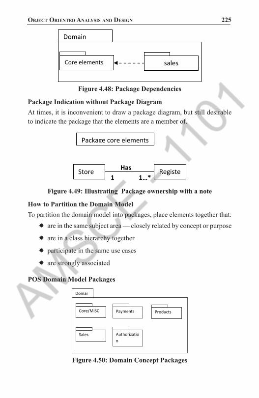
object oriented analysis and design 225
Domain
Core elements
sales
Figure 4.48: Package Dependencies
Package Indication without Package DiagramAt times, it is inconvenient to draw a package diagram, but still desirable to indicate the package that the elements are a member of.
Has 1 1…*
Package core elements
Store Register
Figure 4.49: Illustrating Package ownership with a note
How to Partition the Domain ModelTo partition the domain model into packages, place elements together that:
� are in the same subject area — closely related by concept or purpose
� are in a class hierarchy together
� participate in the same use cases
� are strongly associated
POS Domain Model Packages
Core/MISC
Domain
Payments
Products
Authorization Transactions
Sales
Figure 4.50: Domain Concept Packages
1101 AMSCE - DEPARTMENT OF IT

226 Unit Wise solved QUestion PaPers
Payments
Figure 4.51: Payments package
8. Compare Sequence vs collaboration diagram with suitable example.
Type Strengths Weekness
Sequence clearly shows sequence or time ordering of messages simple notation
forced to extend to the right when adding new objects consumes horizontal space
collaboration
space economical flexibil-ity to add new object in two dimensions better to illustrate comblex branching iteration and concurrent behavior
difficult to see se-quence of messages more complex notation
Table 4.2: Compare Sequence vs collaboration diagram
The Sequence Diagram:The sequence diagram is having four objects (Customer, Order,
SpecialOrder and NormalOrder).
The following diagram has shown the message sequence for SpecialOrder object and the same can be used in case of NormalOrder object.
Now it is important to understand the time sequence of message flows.
1101 AMSCE - DEPARTMENT OF IT

object oriented analysis and design 227 The message flow is nothing but a method call of an object.
The first call is sendOrder () which is a method of Order object.
The next call is confirm () which is a method of SpecialOrder object and the last call is Dispatch () which is a method of SpecialOrder object.
So here the diagram is mainly describing the method calls from one object to another and this is also the actual scenario when the system is running.
Figure 4.52 : The Sequence Diagram
The Collaboration Diagram:The second interaction diagram is collaboration diagram. It shows the object organization as shown below. Here in collaboration diagram the method call sequence is indicated by some numbering technique as shown below. The number indicates how the methods are called one after another. We have taken the same order management system to describe the collaboration diagram.
The method calls are similar to that of a sequence diagram. But the difference is that the sequence diagram does not describe the object organization where as the collaboration diagram shows the object organization.
Now to choose between these two diagrams the main emphasis is given on the type of requirement. If the time sequence is important then sequence diagram is used and if organization is required then collaboration diagram is used.
1101 AMSCE - DEPARTMENT OF IT

228 Unit Wise solved QUestion PaPers
Figure 4.53 : The Collaboration Diagram
9. Describe the UML notations for Class Diagram with an example. (8)
The UML Class Diagram NotationA UML class box used to illustrate software classes often shows three compartments; the third illustrates the methods of the class,
Class name
attributes
methods
Third section is for methods
Figure 4.54 :Software Classes illustrate method namespurpose of the class diagram can be summarized as:
� Analysis and design of the static view of an application.
� Describe responsibilities of a system.
� Base for component and deployment diagrams.
� Forward and reverse engineering.
� he following table represents notations that are used on the UML Class Diagrams:
1101 AMSCE - DEPARTMENT OF IT

object oriented analysis and design 229
Diagram element
Graphical presentation Description
Class
Class represents a set of objects that have the same structure, behavior, and relationships with objects of other classes.
Attribute
Attribute is a typed value that defines the properties and behavior of the object.
Operation
Operation is a function that can be applied to the objects of a given class.
Responsibility
Responsibility is a contract which the class must conform.
1101 AMSCE - DEPARTMENT OF IT

230 Unit Wise solved QUestion PaPers
Interface
Interface is an abstract class that defines a set of operations that the object of the class associated with this interface provides to other objects.
Association
Association is a relationship that connect two classes.
Aggregation
Aggregation is an association with the relation between the whole and its parts, the relation when one class is a certain entity that includes the other entities as components.
N-ary
Association
N-ary association represents two or more aggregations.
1101 AMSCE - DEPARTMENT OF IT

object oriented analysis and design 231
Composition
Composition is a strong variant of aggregation when parts cannot be separately of the whole.
Generalization
Generalization ia an association between the more general classifier and the more special classifier.
Inheritance
Inheritance is a relationship when a child object or class assumes all properties of his parent object or class.
Realization
Realization is a relationship between interfaces and classes or components that realize them.
1101 AMSCE - DEPARTMENT OF IT

232 Unit Wise solved QUestion PaPers
Dependency
Dependency is a relationship when some changes of one element of the model can need the change of another dependent element.
<< >>
Allows to define the properties of the dependency relationship between classes or classes and packages.
{ }
Allows to indicate the additional properties of association.
Multiplicity
Multiplicity shows the quantity of instances of one class that are linked to one instance of the other class.
1101 AMSCE - DEPARTMENT OF IT

object oriented analysis and design 233
PackagePackage groups the classes and other packages.
NoteNote is a textual explication.
Note
connector
Note connector is a connection between the note and elements.
Table 4.3 UML Notations
10. Explain the concept of Link, Association and Inheritance.(8) � An association is a relationship between types (or more specifically, instances of those types) that indicates some meaningful and interesting connection.
� In the UML associations are defined as “the semantic relationship between two or more classifiers that involve connections among their instances.”
Figure 3.7: Association.
1101 AMSCE - DEPARTMENT OF IT

234 Unit Wise solved QUestion PaPers
Criteria for Useful Associations � On a domain model with n different conceptual classes, there can be n-(n-l) associations to other conceptual classes—a potentially large number.
� Many lines on the diagram will add “visual noise” and make it less comprehensible.
� Therefore, be parsimonious about adding association lines.
The UML Association Notation � An association is represented as a line between classes with an association name.
� The association is inherently bidirectional, meaning that from instances of either class, logical traversal to the other is possible.
� This traversal is purely abstract; it is not a statement about connections between software entities.
Figure 3.8: The UML notations for Association.The ends of an association may contain a multiplicity expression
indicating the numerical relationship between instances of the classes.
An optional “reading direction arrow” indicates the direction to read the association name; it does not indicate direction of visibility or navigation.
If not present, it is conventional to read the association from left to right or top to bottom, although the UML does not make this a rule.
Finding Associations—Common Associations List � Start the addition of associations by using the list in Table .
1101 AMSCE - DEPARTMENT OF IT

object oriented analysis and design 235 � It contains common categories that are usually worth considering.
� Examples are drawn from the store and airline reservation domains
Table 3.2 Common Association List I
Table 3.3 Common Association List II
High-Priority AssociationsHere are some high-priority association categories that are invariably useful to include in a domain model:
� A is a physical or logical part of B.
� A is physically or logically contained in/on B.
� A is recorded in B.
1101 AMSCE - DEPARTMENT OF IT

236 Unit Wise solved QUestion PaPers
Association Guidelines � Focus on those associations for which knowledge of the relationship needs to be preserved for some duration (“need-to-know” associations).
� It is more important to identify conceptual classes than to identify associations.
� Too many associations tend to confuse a domain model rather than illuminate it. Their discovery can be time-consuming, with marginal benefit.
� Avoid showing redundant or derivable associations.
RolesEach end of an association is called a role. Roles may optionally have:
� name
� multiplicity expression
� navigability
MultiplicityMultiplicity defines how many instances of a class A can be associated with one instance of a class B
For example, a single instance of a store can be associated with “many” (zero or more, indicated by the *) Item instances.
Some example of multiplicity expressions are shown in figure 11. 4.
1101 AMSCE - DEPARTMENT OF IT

object oriented analysis and design 237
Figure 3.9: Multiplicity Values � The multiplicity value communicates how many instances can be validly associated with another, at a particular moment, rather than over a span of time.
� For example, it is possible that a used car could be repeatedly sold back to used car dealers over time.
� But at any particular moment, the car is only Stocked-by one dealer.
� The car is not Stocked-by many dealers at any particular moment. Similarly, in countries with monogamy laws, a person can be Married-to only one other person at any particular moment, even though over a span of time, they may be married to many persons.
� The multiplicity value is dependent on our interest as a modeler and software developer, because it communicates a domain constraint that will be (or could be) reflected in software.
Figure 3.10 :Dependency of Multiplicity Values
How Detailed Should Associations Be?Associations are important, but a common pitfall in creating domain models is to spend too much time during investigation trying to discover them.
1101 AMSCE - DEPARTMENT OF IT
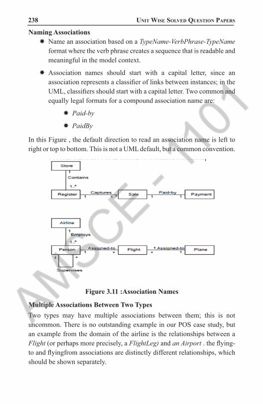
238 Unit Wise solved QUestion PaPers
Naming Associations � Name an association based on a TypeName-VerbPhrase-TypeName format where the verb phrase creates a sequence that is readable and meaningful in the model context.
� Association names should start with a capital letter, since an association represents a classifier of links between instances; in the UML, classifiers should start with a capital letter. Two common and equally legal formats for a compound association name are:
� Paid-by
� PaidBy
In this Figure , the default direction to read an association name is left to right or top to bottom. This is not a UML default, but a common convention.
Figure 3.11 :Association Names
Multiple Associations Between Two TypesTwo types may have multiple associations between them; this is not uncommon. There is no outstanding example in our POS case study, but an example from the domain of the airline is the relationships between a Flight (or perhaps more precisely, a FlightLeg) and an Airport . the flying-to and flyingfrom associations are distinctly different relationships, which should be shown separately.
1101 AMSCE - DEPARTMENT OF IT

object oriented analysis and design 239
Figure 3.12 : Multiple Associations
Associations and Implementation � During domain modeling, an association is not a statement about data flows, instance variables, or object connections in a software solution; it is a statement that a relationship is meaningful in a purely conceptual sense—in the real world.
� Practically speaking, many of these relationships will typically be implemented in software as paths of navigation and visibility (both in the Design Model and Data Model), but their presence in a conceptual (or essential) view of a domain model does not require their implementation.
� When creating a domain model, we may define associations that are not necessary during implementation.
� Conversely, we may discover associations that need to be implemented but were missed during domain modeling.
Association
Class Logical View
Class A
Class B
Association
Class Logical View
Class A
* Foo(Class B): void
Class B
Figure 4.62 : Associations and Implementation
Inheritance It is a software mechanism to make super class things applicable to subclasses. It supports refactoring code from subclasses and pushing it up class hierarchies. Therefore, inheritance has no real part to play in the discussion of the domain model, although it most definitely does when we transition to the design and implementation view.
1101 AMSCE - DEPARTMENT OF IT

240 Unit Wise solved QUestion PaPers
Figure 4.63 : Abstract superclasses ,abstract methods and inheritance in the UML
11. Explain the UML Class, Sequence and Interaction diagram for Li-brary Management (APRIL/MAY 2017)
Library:Library is a common place for the people especially for students
from where they borrow books, CDs, study without any cost and disturbance.
In other word library is the peaceful place or environment for those who want to study.
Normally, it is located in the educational institutions such as university, school, and college and so on.
Likewise, there are various kinds of library like public library which is for the local citizens, private library which is not open for outsiders, community library it is little bit similar to public library and especially design for the specific community and lastly there is also a library for school, college etc called a academic library.
Apart from them there are some special library like sports, medical, film, music, law library in the world.
Library Management System:Library management system is the new approach in the
management system which is able to transfer the facilities like login user, register of new user, adding/removing of books in the library, searching, issuing & returning of the books etc.
1101 AMSCE - DEPARTMENT OF IT
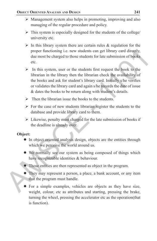
object oriented analysis and design 241 Management system also helps in promoting, improving and also
managing of the regular procedure and policy.
This system is especially designed for the students of the college/university etc.
In this library system there are certain rules & regulation for the proper functioning i.e. new students can get library card directly, due most be charged to those students for late submission of books etc.
In this system, user or the students first request the book to the librarian in the library then the librarian check the availability of the books and ask for student’s library card. Initially s/he verifies or validates the library card and again s/he records the date of issue & dates the books to be return along with student’s details.
Then the librarian issue the books to the students.
For the case of new students librarian register the students to the database and provide library card to them.
Likewise, penalty must charged for the late submission of books if the deadline is already over.
Object: � In object oriented analysis design, objects are the entities through which we perceive the world around us.
� We normally see our system as being composed of things which have recognizable identities & behaviour.
� Those entities are then represented as object in the program.
� They may represent a person, a place, a bank account, or any item that the program must handle.
� For a simple examples, vehicles are objects as they have size, weight, colour, etc as attributes and starting, pressing the brake, turning the wheel, pressing the accelerator etc as the operation(that is function).
1101 AMSCE - DEPARTMENT OF IT
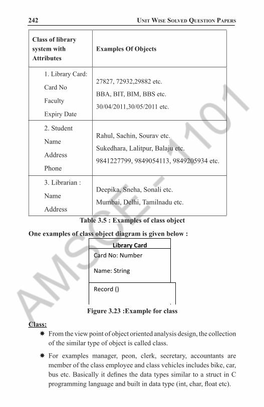
242 Unit Wise solved QUestion PaPers
Class of library system with Attributes
Examples Of Objects
1. Library Card:
Card No
Faculty
Expiry Date
27827, 72932,29882 etc.
BBA, BIT, BIM, BBS etc.
30/04/2011,30/05/2011 etc.
2. Student
Name
Address
Phone
Rahul, Sachin, Sourav etc.
Sukedhara, Lalitpur, Balaju etc.
9841227799, 9849054113, 9849205934 etc.
3. Librarian :
Name
Address
Deepika, Sneha, Sonali etc.
Mumbai, Delhi, Tamilnadu etc.
Table 3.5 : Examples of class object
One examples of class object diagram is given below : Library Card
Card No: Number
Name: String
Expiry Date: Date Record ()
Figure 3.23 :Example for class
Class: � From the view point of object oriented analysis design, the collection of the similar type of object is called class.
� For examples manager, peon, clerk, secretary, accountants are member of the class employee and class vehicles includes bike, car, bus etc. Basically it defines the data types similar to a struct in C programming language and built in data type (int, char, float etc).
1101 AMSCE - DEPARTMENT OF IT

object oriented analysis and design 243 � In other word, class is the abstraction of the real world entities with
similar properties.
� It specifies what data and functions will be included in objects of that class. Ideally, class is also a template that unites data and operations.
� Finally we can mention class as an implementation of abstract data type.
Following are the most important class for the library management system: � Library: It is the place where books, newspapers, magazine etc are placed for users. It provides the card to its regular user with or without cost.
� Library Card: It is a normal identity card containing the basic information of the user.
� Books: The library most contains books or it is the main resources of the library.
� Students: They are the primary user of the library
� Bar code reader: It is an electronic device which is used to read the coded information for the validation.
� Librarian: The persons who handle the overall operation of the library.
Attributes: � According to the basic concepts of object oriented analysis design, attributes is the general properties of an object of the same class.
� It is noun. It is basically implemented while defining the software entity as the variables in the class.
� In the library system following are the possible attributes.
Classes of Library System
Related Attributes
Library name, phone, etc.
Library cardcard no, issue date, expiry date etc.
Book name, author, faculty etc.
1101 AMSCE - DEPARTMENT OF IT

244 Unit Wise solved QUestion PaPers
Student name, address, phone, id etc.
Bar Code Reader version, model, colour etc.Table 3.6: Classes of Library System
with Related Attributes
Methods:Normally, each and every object contains certain types of behaviours which are included as methods in class. In other words, Methods are the services which are provided by class. It is a verb. For verification in the library system the following are the methods of their relative class.
Classes of Library System
Related Methods
Library study(), searc_book() etc.
Library Card borrow(), check_status() etc.
Book issue(), study() etc.
Bar Code Reader Check_validity(),
Students Study(), gain_information() etc.Table 3.7: Classes of Library System with Related Methods
For examples in general we can display class, attributes & methods as:
Class _ name Attributes – 1
Attributes – 2
---------------
Attributes – n
Methods () 1
Methods () 2
---------------
Methods () n
Students
ID No: Integer
Name: String
Address: String
Study ()
ask book ()
Figure 3.24 : display class, attributes & methods
1101 AMSCE - DEPARTMENT OF IT

object oriented analysis and design 245 Use Case:
� It is the normal diagram of UML model where UML stands for Unified Modelling Language.
� It is the common language for specifying, visualising, and constructing during the system development process.
� Among the different UML diagram model use case is one of the important once which explain the functional requirement of the system.
� Use case diagram reflects the aims of the system in the graphical way, by the proper implementation of step by step process with the interaction between users and the clients.
Actor:Actor is the aspects of the system in the use case diagram.
It reflects the duties of the person or the system needed for interacting or communicating with the primary use case in the system.
In library system there are two main actors such as librarian and students who communicate directly with the system.
The stepwise processes are given below:
Students LibrarianStep1:
A student enters and request for book in the library.
Step2:
Librarian initially checks the presence of book or not.Step3:
Librarian asks for library card of the students.
Step4:
Students show his/her library card and in case for new students he asks for membership.
Step5:
The librarian verifies the library card and for new students s/he records the personal information & provide new library card.
1101 AMSCE - DEPARTMENT OF IT

246 Unit Wise solved QUestion PaPers
Step6:
The librarian check the previous withdraw or clearance if earlier withdraw is not cleared & the deadline was over then s/he ask for the renewal and charge some penalty.
Step7:
Students pay the penalty & renew the book.
Step8:
Again the librarian records the student’s information along with the book details & the deadline for the book to return.
Step9:
Lastly the students ask library card back.
Step10:
Finally the librarian return the library card & issue the book to the.
Table 3.8 : Actor
1101 AMSCE - DEPARTMENT OF IT

object oriented analysis and design 247
1
1
* 1 1 *
** 1
* 1 1 1
Inheritance
1 * *
* *
Super
class
Generalization
Figure 3.26 :Class-diagram for library Management System
Library
Name: string
Type: string (College)
Issue_book ()
Library Card
Card no: int
Faculty: string
Expiry date:
Borrow_books()
Students
name: string
id: alphanumeric
address: string
study ()
Book
Name: string
Author: string
Issue ()
Card Reader
Model: string
Version: string
Check_validity ()
OLD
Name: string
Id: alphanumeric
Read_book()
NEW
Name: string
Id: alphanumeric
Add_book () Librarian
Name: string
phone: int
udate_record ()
Magazine
name: string
type: string
price:int
gain_khowledge ()
Weekly
Name: string
Price: int
Read ()
Monthly
Name: string
Price: int
Borrow_magazine ()
Figure .4.66 :Class-diagram for library Management System
1101 AMSCE - DEPARTMENT OF IT
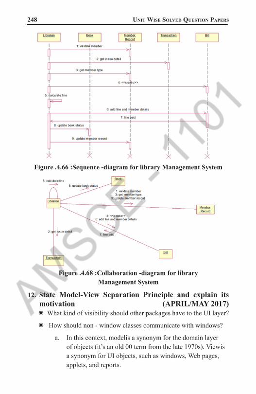
248 Unit Wise solved QUestion PaPers
Figure .4.66 :Sequence -diagram for library Management System
Figure .4.68 :Collaboration -diagram for library Management System
12. State Model-View Separation Principle and explain its motivation (APRIL/MAY 2017)
� What kind of visibility should other packages have to the UI layer?
� How should non - window classes communicate with windows?
a. In this context, modelis a synonym for the domain layer of objects (it’s an old 00 term from the late 1970s). Viewis a synonym for UI objects, such as windows, Web pages, applets, and reports.
1101 AMSCE - DEPARTMENT OF IT

object oriented analysis and design 249 b. The Model - View Separationprinciple2 states that model
(domain) objects should not have direct knowledge of view (UI) objects, at least as view objects
c. So, for example, a Register or Saleobject should not directly send a message to a GUI window object ProcessSaleFrame, asking it to display something, change color, close, and so forth.
� A legitimate relaxation of this principle is the Observer pattern, where the domain objects send messages to UI objects viewed only in terms of an interface such as PropertyListener (a common Java interface for this situation).
� Then, the domain object doesn’t know that the UI object is a UI object - it doesn’t know its concrete window clasj.
� It only knows the object as something that implements the PropertyListener interface.
� A further part of this principle is that the domain classes encapsulate the information and behavior related to application logic.
� The window classes are relatively thin; they are responsible for input and output, and catching GUI events, but do not maintain application data or directly provide application logic.
� For example, a Java JFrame window should not have a method that does a tax calculation.
� A Web JSP page should not contain logic to calculate the tax.
� These UI elements should delegate to non - UI elements for such responsibilities.
The motivation for Model - View Separation includes:To support cohesive model definitions that focus on the domain
processes, rather than on user interfaces.To allow separate development of the model and user interface layers.
To minimize the impact of requirements changes in the interface upon the domain layer.
To allow new views to be easily connected to an existing domain layer, without affecting the domain layer.
1101 AMSCE - DEPARTMENT OF IT

250 Unit Wise solved QUestion PaPers
To allow multiple simultaneous views on the same model object, such as both a tabular and business chart view of sales information
To allow execution of the model layer independent of the user interface layer, such as in a message - processing or batch - mode system.
To allow easy porting of the model layer to another user interface framework.
What’s the Connection Between SSDs, System Operations, and Layers?
� During analysis work, we sketched some SSDs for use case scenarios.
� We identified input events from external actors into the system, calling upon system operations such as makeNewSale and enterltem.
� The SSDs illustrate these system operations, but hide the specific UI objects.
� Nevertheless, normally it will be objects in the UI layer of the system that capture these system operation requests, usually with a rich client GUI or Web page.
� In a well - designed layered architecture that supports high cohesion and a separation of concerns, the UI layer objects will then forward - or delegate - the request from the UI layer onto the domain layer for handling.
1101 AMSCE - DEPARTMENT OF IT

object oriented analysis and design 251 UNIT V
CODING AND TESTING
PART - A1. Explain about oo Integration Testing (APRIL/MAY 2017)
� upon completion of unit testing, the units or modules are to be integrated which gives raise to integration testing.
� The purpose of integration testing is to verify the functional, performance, and reliability between the modules that are integrated.
Integration Strategies:
� Big-Bang Integration
� Top Down Integration
� Bottom Up Integration
� Hybrid Integration
2. What are the steps involved in mapping design to code? (NOV/DEC 2015)(APRIL/MAY 2017)Implementation in an object-oriented language requires writing source code for:
� class and interface definitions
� method definitions
3. Define regression testing. (NOV/DEC 2016) � All passed tests should be repeated with the revised program, called regression testing, which can discover errors introduced during the debugging process.
� When sufficient testing is believed to have been conducted, this fact should be reported and testing for this specific product is complete.
4. What is refactoring? (NOV/DEC 2016) � Refactoring is “the process of changing a software system in such a way that it does not alter the external behavior of the code yet improves its internal structure.
� It is a kind of reorganization.
1101 AMSCE - DEPARTMENT OF IT

252 Unit Wise solved QUestion PaPers
5. List out the issues in OO testing. (NOV/DEC 2015) � basic unit for unit testing
� implications of encapsulation
� implications of inheritance
� implications of genericity
� implications of polymorphism/dynamic binding
� implications for testing processes
6. What is the purpose of debugging?Debugging is the process of finding out where something went wrong in the application, what we develop and correcting the code to elimi-nate the errors or bugs that cause unexpected results.
7. What are the types of errors that you could find in your program?◊ Language (syntax) errors
◊ Run-time errors
◊ Logic errors
These are the various types of errors that would occur in the program that we develop.
8. Discuss Error-based testing?This technique search a given class’s method for particular clues of interests, then describe how these clues should be tested.
9. Discuss Scenario-based testing/usage-based testing? It concentrates on what the user does, not what the product does. This means capturing use cases and the tasks users perform, then perform-ing them and their variants as tests. They often are more complex and realistic than error-based tests. Scenario-based tests tend to exercise multiple subsystems in a single test, because that is what users do.
10. Name some testing strategies◊ Black- Box Testing
o Path Testing
◊ Top-Down Testing
◊ Bottom-Up Testing
1101 AMSCE - DEPARTMENT OF IT

object oriented analysis and design 253 11. What is the Impact of Object orientation on Testing?
� Some types of errors could become less reasonable (not worth testing for)
� Some types of errors could become more reasonable (worth testing for)
� Some new types of errors might appear.
12. Discuss Black-Box testing? In a Black box testing, the test item is treated as “black,” since its logic is unknown; all that is known is what goes in and what comes out or input and output. It may be used for Scenario- based testing.
13. Discuss White- Box testing?It assumes that the specific logic is important and must be tested to guarantee the system’s proper functioning. It is used mainly in the error based testing.
14. What do you mean by Top- down Testing?It assumes that the main logic or object interactions and systems mes-sages of the application need more testing than an individual object’s methods or supporting logic. It can detect the serious design flaws early in the implementation.
15. Discuss about the Statement testing coverage and Branch testing coverage?The main idea of statement testing coverage is to test every statement in the object‘s method by executing it at least once. The main idea behind branch testing coverage is to perform enough tests to ensure that every branch alternative has been executed at least once under some test.
16. What is Path testing?Path testing is one form of white box testing. It makes that each path in a object’s method is executed at least once during testing. Two types of Path testing are:
◊ Statement testing coverage
◊ Branch testing coverage
1101 AMSCE - DEPARTMENT OF IT

254 Unit Wise solved QUestion PaPers
17. What is Bottom - Up Testing? It starts with the details of the system and proceeds to higher levels by a progressive aggregation of details until they collectively fit the requirements for the system. This approach is more appropriate for testing the individual objects in a system.
18. What is the objective of testing? ◊ Testing is the process of executing a program with the intent of find-ing errors.
◊ A successful test case is the one that detects an as-yet undiscovered error.
19. What is the necessary of a test plan?A test plan is developed to detect and identify potential problems be-fore delivering the software to its users. A test plan offers a road map for testing activities, whether usability, user satisfaction, or quality as-surance tests. It should state the test objectives and how to meet them.
20. List the steps needed for a test plan?◊ Objectives of the test
◊ Development of a test case
◊ Test analysis
21. Define Beta testing and Alpha testing?Beta testing, a popular, inexpensive and effective way to test software on a select group of the actual users of the system. Alpha testing is done by in-house testers, such as programmers, software engineers, and internal users.
22. What is the purpose of configuration control system?It provides a way of tracking the changes to the code. At a minimum, every time the code changes, a record should be kept that tracks which module has been changed, who changed it, and when it was altered, with a comment about why the change was made.
1101 AMSCE - DEPARTMENT OF IT

object oriented analysis and design 255 23. When is testing said to be successful?
Testing becomes successful when the steps below are followed;
◊ Understand and communicate the business case for improved testing.
◊ Develop an internal infrastructure to support continuous testing.
◊ Look for leaders who will commit to and own the process.
◊ Measure and document your findings in a defect recording system.
◊ Publicize improvements as they are made and let people know what they are doing better.
24. Define Usability?ISO defines Usability as the effectiveness, efficiency, and satisfaction with which a specified set of users can achieve a specified set of tasks in particular environments. It requires
◊ Defining tasks.
◊ Defining users
◊ A means for measuring effectiveness, efficiency, and satisfaction.
25. What are the issues in software quality? Validation – user satisfaction
◊ Verification – Quality assurance
26. What is Usability testing?It measures the ease of use as well as the degree of comfort and satis-faction users have with the software.
27. What are the guidelines for developing usability testing?◊ The usability testing should include all of software’s components.
◊ Usability testing need not be very expensive, such as including trained specialists working in a soundproof lab with sophisticated re-cording equipment.
◊ All tests need not involve many subjects.
◊ Consider the user’s experience as part of your software usability.
◊ Apply usability testing early and often.
1101 AMSCE - DEPARTMENT OF IT

256 Unit Wise solved QUestion PaPers
28. Explain user satisfaction testing?It is the process of quantifying the usability test with some measurable attributes of the test, such as functionality, cost, or ease of use.
29. Explain COTS and USTS?Commercial off –the –shelf (COTS) software tools are already written and a few are available for analyzing and conducting user satisfac-tion tests. User satisfaction test spreadsheet (USTS) automates many bookkeeping tasks and can assist in analyzing the user satisfaction test results.
30. Mention the purpose of user satisfaction test. (APRIL/MAY 2011) � Create a user satisfaction test for your own project
� Conduct test regularly and frequently
� Read the comments very carefully, especially if they express a strong feeling.
� Use the information from user satisfaction test, usability test, reactions to
� Prototypes, interviews recorded, and other comments to improve the product.
� Important benefit of user satisfaction testing is you can continue using it even after the product is delivered.
1101 AMSCE - DEPARTMENT OF IT

object oriented analysis and design 257 PART - B
1. Explain in detail about mapping design to code implementation in object oriented language.(Elucidate the operation of mapping design to code).(MAY/JUNE 2015,2016)(NOV/DEC 2016) (NOV/DEC 2015)
MAPPING DESIGN TO CODE � After completion of design work- interaction diagram and Design Class diagram, there is a need to generate code for the design.
� These diagrams act as input to the code generation process.
� Source code , database definition and HTML pages etc are the parts of implementation model.
� Thus the code created is the part of implementation model.
Language Samples:The programming language Java is used for code generation because of its widespread use and familiarity.
Programming and Iterative ,Evolutionary Development � The modern development tools provide excellent environment to design – while programming.
� The creation of code in OO language like Java is an end goal.
Creativity and Change during implementation � During programming and testing, myriad changes will be made and detailed problems will be resolved.
� The ideas and understanding during OO design provide great base to meet new problems encountered during programming.
Mapping Designs To CodeImplementation in an object-oriented language requires writing source code for:
Class and interface definitions
Method definitions
1101 AMSCE - DEPARTMENT OF IT

258 Unit Wise solved QUestion PaPers
(i) Creating Class Definition from DCDs: � DCDs depict the class or interface , superclasses , operation signature and attributes of a class.
� If the DCD was drawn in UML tool, it can generate basic class definition from the diagrams.
Defining Class with Method signature and Attribute
public class SalesLineItem{private int quantity;
private ProductDescription description;
public SalesLineItem(ProductDescription desc, int qty) { ... }
public Money getSubtotal() { ... }
}
SalesLineItem
quantity : Integer
getSubtotal() : Money
ProductDescription
description : Textprice : MoneyitemID : ItemID
...
1
description
Figure 5.1: Creating Class Definition from DCDs
(ii) Creating Methods from Interaction Diagrams � The sequence of the messages in an interaction diagram translates to a series of statements in the method definition.
� The enterItem interaction gives Java definition of enterItem method and Register class. enterItem Iteraction Diagram
2: makeLineItem(desc, qty)enterItem(id, qty)
1: desc := getProductDescription(id)
:Register :Sale
:ProductCatalog
{ ProductDescription desc = catalog.ProductDescription(id); currentSale.makeLineItem(desc, qty);}
Figure 5.2: Creating Methods from Interaction Diagrams
1101 AMSCE - DEPARTMENT OF IT

object oriented analysis and design 259 Collection Classes in Code
� One to many relationships are common.
� A Sale must maintain group of SalesLineItem instances.
� This relationship usually implemented with a collection of object such as List or Map, or even a simple array.
� Java libraries contains collection classes such as ArrayList and HashMap, which implement the List and Map interfaces.
� Using ArrayList , the Sale class maintain ordered list of SalesLineItem.
Adding a Collection
SalesLineItem
quantity : Integer
getSubtotal()1..*
Sale
isComplete : Booleantime : DateTime
becomeComplete()makeLineItem()makePayment()getTtotal()
public class Sale{...
private List lineItems = new ArrayList();}
A collection class is necessary to maintain attribute visibility to all the SalesLineItems.
lineItems
Figure 5.3 : Collection Classes in Code
Exceptions and Error Handling � In application development, it is wise to consider the large-scale exception handling strategies during design modeling and certainly during implementation.
� In UML, exceptions can be indicated in the property strings of messages and operations declarations.
Order Of Implementation � Classes need to be implemented from least-coupled to most-coupled.
� In the Example, first classes to implement are either Payment or ProductDescription.
� The next classes to implement are ProductCatalog or SalesLineItem.
1101 AMSCE - DEPARTMENT OF IT

260 Unit Wise solved QUestion PaPers
SalesLineItem
quantity : Integer
getSubtotal()
ProductCatalog
...
getProductDesc(...)
ProductDescription
description : Textprice : MoneyitemID : ItemID
...
Store
address : Addressname : Text
addSale(...)
Payment
amount : Money
...
1..*
1..*
Register
...
endSale()enterItem(...)makeNewSale()makePayment(...)
Sale
isComplete : Booleantime : DateTime
becomeComplete()makeLineItem(...)makePayment(...)getTotal()...
1
1
1
1
1
1
* 1
23
4
56
7
Figure 5.4 : Order Of Implementation
Test-Driven or Test-First Development � A n excellent Practice promoted by Extreme Programming(XP) method is test-driven development(TDD) or test-first development.
� In this practice, unit testing code is written before code to be tested .
� The basic rhythm is to write a little test code, then write a little production code , make it pass the test , then write some more test code etc.
2. Discuss in detail about OO Integration testing and OO system testing. (NOV/DEC 2016). (APRIL/MAY 2017)
Three distinct levels of software testing—unit, integration, and system
Decomposition-Based Integration � four integration strategies based on the functional decomposition tree of the procedural software: top–down, bottom–up.
� The functional decomposition tree is the basis for integration testing because it is the main representation, usually derived from final source code, which shows the structural relationship of the system with respect to its units.
� All these integration orders presume that the units have been separately tested; thus, the goal of decomposition-based integration is to test the interfaces among separately tested units.
1101 AMSCE - DEPARTMENT OF IT

object oriented analysis and design 261 � A functional decomposition tree reflects the lexicological inclusion
of units, in terms of the order in which they need to be compiled, to assure the correct referential scope of variables and unit names.
The Calendar program sketched here in pseudocode acquires a date in the form mm, dd, yyyy, and provides the following functional capabilities:
� The date of the next day (our old friend, NextDate
� The day of the week corresponding to the date (i.e., Monday, Tuesday, …)
� The zodiac sign of the date
� The most recent year in which Memorial Day was celebrated on May 27
� The most recent Friday the 13th
Figure 5.5 : Functional Decomposition of Calendar Program
Top–Down Integration � Top–down integration begins with the main program (the root of the tree). Any lower-level unit that is called by the main program appears as a “stub,” where stubs are pieces of throwaway code that emulate a called unit.
� If we performed top–down integration testing for the Calendar program, the first step would be to develop stubs for all the units called by the main program— isLeap, weekDay, getDate, zodiac, nextDate, friday13th, and memorialDay.
� In a stub for any unit, the tester hard codes in a correct response to the request from the calling/invoking unit.
1101 AMSCE - DEPARTMENT OF IT

262 Unit Wise solved QUestion PaPers
� In the stub for zodiac, for example, if the main program calls zodiac with 05, 27, 2012, zodiacStub would return “Gemini.”
� In extreme practice, the response might be “pretend zodiac returned Gemini.”
Figure 5.6 : Functional Decomposition of Calendar Program
� Once the main program has been tested, we replace one stub at a time, leaving the others as stubs.
� The stub replacement process proceeds in a breadth-first traversal of the decomposition tree until all the stubs have been replaced.
The “theory” of top–down integration is that, as stubs are replaced one at a time, if there is a problem, it must be with the interface to the most recently replaced stub.
Figure 5.7: Next three steps in top-down integration
1101 AMSCE - DEPARTMENT OF IT

object oriented analysis and design 263 Bottom–Up Integration
� Bottom–up integration is a “mirror image” to the top–down order, with the difference that stubs are replaced by driver modules that emulate units at the next level up in the tree.
� Bottom–up integration begins with the leaves of the decomposition tree, and use a driver version of the unit that would normally call it to provide it with test cases.
� As units are tested, the drivers are gradually replaced, until the full decomposition tree has been traversed.
Figure 5.8 : Bottom–Up Integration
Sandwich Integration � Sandwich integration is a combination of top–down and bottom–up integration.
� If we think about it in terms of the decomposition tree, we are really only doing big bang integration on a sub tree.
� There will be less stub and driver development effort, but this will be offset to some extent by the added difficulty of fault isolation that is a consequence of big bang integration.
� (We could probably discuss the size of a sandwich, from dainty finger sandwiches to Dagwood-style sandwiches, but not now.)
� A sandwich is a full path from the root to leaves of the functional decomposition tree.
1101 AMSCE - DEPARTMENT OF IT

264 Unit Wise solved QUestion PaPers
� The set of units is almost semantically coherent, except that isLeap is missing.
� This set of units could be meaningfully integrated, but test cases at the end of February would not be covered.
� Also note that the fault isolation capability of the top–down and bottom–up approaches is sacrificed. No stubs nor drivers are needed in sandwich integration.
Pros and Cons � With the exception of big bang integration, the decomposition-based approaches are all intuitively clear.
� Build with tested components.
� Whenever a failure is observed, the most recently added unit is suspected. Integration testing progress is easily tracked against the decomposition tree.
� One of the most frequent objections to functional decomposition and waterfall development is that both are artificial, and both serve the needs of project management more than the needs of software developers.
� This holds true also for decomposition-based testing.
� The whole mechanism is that units are integrated with respect to structure; this presumes that correct behavior follows from individually correct units and correct interfaces.
� The development effort for stubs or drivers is another drawback to these approaches, and this is compounded by the retesting effort.
Figure 5.9 : Sample Sandwich Integration
1101 AMSCE - DEPARTMENT OF IT

object oriented analysis and design 265 Call Graph–Based Integration
� One of the drawbacks of decomposition-based integration is that the basis is the functional decomposition tree.
� If we use the call graph instead, we resolve this deficiency; we also move in the direction of structural testing.
� The call graph is developed by considering units to be nodes, and if unit A calls (or uses) unit B, there is an edge from node A to node B.
� The call graph for the Calendar program is shown in Figure .
� Since edges in the call graph refer to actual execution–time connections, the call graph avoids all the problems we saw in the decomposition tree–based versions of integration.
� The stubs in the first session could operate as follows.
� When the Calendar main program calls getDateStub, the stub might return May 27, 2013. The zodiacStub would return “Gemini,” and so on.
� Once the main program logic is tested, the stubs would be replaced.
Figure 5.10 : Call Graph–Based Integration
1101 AMSCE - DEPARTMENT OF IT
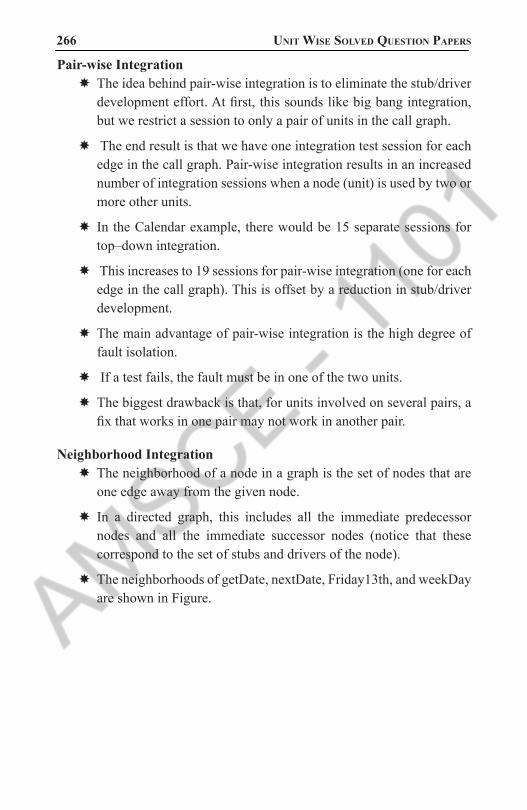
266 Unit Wise solved QUestion PaPers
Pair-wise Integration � The idea behind pair-wise integration is to eliminate the stub/driver development effort. At first, this sounds like big bang integration, but we restrict a session to only a pair of units in the call graph.
� The end result is that we have one integration test session for each edge in the call graph. Pair-wise integration results in an increased number of integration sessions when a node (unit) is used by two or more other units.
� In the Calendar example, there would be 15 separate sessions for top–down integration.
� This increases to 19 sessions for pair-wise integration (one for each edge in the call graph). This is offset by a reduction in stub/driver development.
� The main advantage of pair-wise integration is the high degree of fault isolation.
� If a test fails, the fault must be in one of the two units.
� The biggest drawback is that, for units involved on several pairs, a fix that works in one pair may not work in another pair.
Neighborhood Integration � The neighborhood of a node in a graph is the set of nodes that are one edge away from the given node.
� In a directed graph, this includes all the immediate predecessor nodes and all the immediate successor nodes (notice that these correspond to the set of stubs and drivers of the node).
� The neighborhoods of getDate, nextDate, Friday13th, and weekDay are shown in Figure.
1101 AMSCE - DEPARTMENT OF IT

object oriented analysis and design 267
Figure 5.11: Three pairs for pairwise integration
Figure 5.12: Three neighbourhood for neighbourhood integration
1101 AMSCE - DEPARTMENT OF IT

268 Unit Wise solved QUestion PaPers
Table 5.1 : Neighbourhood of Radius 1 in Calendar Call GraphWhen a unit executes, some path of source statements is traversed.
Suppose that a call goes to another unit along such a path.
At that point, control is passed from the calling unit to the called unit, where some other path of source statements is traversed.
SYSTEM TESTING � Impact of requirements on system testing:
� Quality of use cases determines the ease of functional testing
� Quality of subsystem decomposition determines the ease of structure testing
� Quality of nonfunctional requirements and constraints determines the ease of performance tests
� Functional Testing
� Structure Testing
� Performance Testing
� Acceptance Testing
� Installation Testing
1101 AMSCE - DEPARTMENT OF IT
object oriented analysis and design 269 Functional Testing
Goal: Test functionality of system � Test cases are designed from the requirements analysis document (better: user manual) and centered around requirements and key functions (use cases)
� The system is treated as black box.
� Unit test cases can be reused, but new test cases have to be developed as well.
Structure Testing Goal: Cover all paths in the system design
� Exercise all input and output parameters of each component.
� Exercise all components and all calls (each component is called at least once and every component is called by all possible callers.)
� Use conditional and iteration testing as in unit testing.
Performance Testing Goal: Try to break the subsystems
� Test how the system behaves when overloaded.
� Can bottlenecks be identified? (First candidates for redesign in the next iteration)
� Try unusual orders of execution
� Call a receive() before send()
� Check the system’s response to large volumes of data
� If the system is supposed to handle 1000 items, try it with 1001 items.
� What is the amount of time spent in different use cases?
� Are typical cases executed in a timely fashion?
Types of Performance Testing � Stress Testing
� - Stress limits of system
1101 AMSCE - DEPARTMENT OF IT

270 Unit Wise solved QUestion PaPers
� Volume testing
� -Test what happens if large amounts of data are handled
� Configuration testing
� - Test the various software and hardware configurations
� Compatibility test
� - Test backward compatibility with existing systems
� Timing testing
� - Evaluate response times and time to perform a function
� Security testing
� - Try to violate security requirements
� Environmental test
� - Test tolerances for heat, humidity, motion
� Quality testing
� - Test reliability, maintainability & availability
� Recovery testing
� -Test system’s response to presence of errors or loss of data.
� Human factors testing
� -Test with end users
Acceptance Testing � Goal: Demonstrate system is ready for operational use
� Choice of tests is made by client
� Many tests can be taken from integration testing
� Acceptance test is performed by the client, not by the developer.
Alpha test: Sponsor uses the software at the developer’s site.
Software used in a controlled setting, with the developer always ready to fix bugs.
1101 AMSCE - DEPARTMENT OF IT

object oriented analysis and design 271 Beta test:
Conducted at sponsor’s site (developer is not present)
Software gets a realistic workout in target environment
3. What is OO testing? Explain in detail about concepts of OO testing in OOAD. (NOV/DEC 2015) (APRIL/MAY 2017)
Object-Oriented Testing Activities � Review OOA and OOD models
� Class testing after code is written
� Integration testing within subsystems
� Integration testing as subsystems are added to the system
� Validation testing based on OOA use-cases
Testing OOA and OOD Models � OOA and OOD cannot be tested but can review the correctness and consistency.
� Correctness of OOA and OOD models
Semantic Syntactic
Judged by ensuring that proper modeling conventions and symbolism have been used
Based on the model's conformance to the real world problem domain
Figure 5.13: Testing OOA and OOD Models
Consistency of OOA and OOD Models � Assess the class-responsibility-collaborator (CRC) model and object-relationship diagram
� Review system design (examine the object-behavior model to check mapping of system behavior to subsystems, review concurrency and task allocation, use use-case scenarios to exercise user interface design)
� Test object model against the object relationship network to ensure that all design object contain necessary attributes and operations needed to implement the collaborations defined for each CRC card
1101 AMSCE - DEPARTMENT OF IT

272 Unit Wise solved QUestion PaPers
� Review detailed specifications of algorithms used to implement operations using conventional inspection techniques
Object-Oriented Testing Strategies
Unit testing in the OO context � Smallest testable unit is the encapsulated class or object
� Similar to system testing of conventional software
� Do not test operations in isolation from one another
� Driven by class operations and state behavior, not algorithmic detail and data flow across module interface
� Complete test coverage of a class involves
� Testing all operations associated with an object
� Setting and interrogating all object attributes
� Exercising the object in all possible states
� Design of test for a class uses a verity of methods:
� fault-based testing
� random testing
� partition testing
� each of these methods exercises the operations encapsulated by the class
� test sequences are designed to ensure that relevant operations are exercised
� state of the class (the values of its attributes) is examined to determine if errors exist
Integration testing in the OO context � focuses on groups of classes that collaborate or communicate in some manner
� integration of operations one at a time into classes is often meaningless
� thread-based testing (testing all classes required to respond to one system input or event)
1101 AMSCE - DEPARTMENT OF IT

object oriented analysis and design 273 � use-based testing (begins by testing independent classes first and
the dependent classes that make use of them)
� cluster testing (groups of collaborating classes are tested for interaction errors)
� regression testing is important as each thread, cluster, or subsystem is added to the system
� Levels of integration are less distinct in object-oriented systems
Validation testing in the OO context � focuses on visible user actions and user recognizable outputs from the system
� validation tests are based on the use-case scenarios, the object-behavior model, and the event flow diagram created in the OOA model
� conventional black-box testing methods can be used to drive the validation tests
Test Case Design for OO Software � Each test case should be uniquely identified and be explicitly associated with a class to be tested
� State the purpose of each test
� List the testing steps for each test including:
� list of states to test for each object involved in the test
� list of messages and operations to exercised as a consequence of the test
� list of exceptions that may occur as the object is tested
� list of external conditions needed to be changed for the test
� supplementary information required to understand or implement the test
� Testing Surface Structure and Deep Structure
� Testing surface structure (exercising the structure observable by end-user, this often involves observing and interviewing users as they manipulate system objects)
1101 AMSCE - DEPARTMENT OF IT

274 Unit Wise solved QUestion PaPers
� Testing deep structure (exercising internal program structure - the dependencies, behaviors, and communications mechanisms established as part of the system and object design)
Testing Methods Applicable at The Class Level � Random testing - requires large numbers data permutations and combinations, and can be inefficient
� Identify operations applicable to a class
� Define constraints on their use
� Identify a minimum test sequence
� Generate a variety of random test sequences.
Partition testing - reduces the number of test cases required to test a class � state-based partitioning - tests designed in way so that operations that cause state changes are tested separately from those that do not.
� attribute-based partitioning - for each class attribute, operations are classified according to those that use the attribute, those that modify the attribute, and those that do not use or modify the attribute
� category-based partitioning - operations are categorized according to the function they perform: initialization, computation, query, termination
Fault-based testing � best reserved for operations and the class level
� uses the inheritance structure
� tester examines the OOA model and hypothesizes a set of plausible defects that may be encountered in operation calls and message connections and builds appropriate test cases
� misses incorrect specification and errors in subsystem interactions
Inter-Class Test Case Design � Test case design becomes more complicated as integration of the OO system begins – testing of collaboration between classes
� Multiple class testing
� for each client class use the list of class operators to generate random test sequences that send messages to other server classes
1101 AMSCE - DEPARTMENT OF IT

object oriented analysis and design 275 � for each message generated determine the collaborator class and the
corresponding server object operator
� for each server class operator (invoked by a client object message) determine the message it transmits
� for each message, determine the next level of operators that are invoked and incorporate them into the test sequence
Tests derived from behavior models � Use the state transition diagram (STD) as a model that represent the dynamic behavior of a class.
� test cases must cover all states in the STD
� breadth first traversal of the state model can be used (test one transition at a time and only make use of previously tested transitions when testing a new transition)
� test cases can also be derived to ensure that all behaviors for the class have been adequately exercised
Testing Methods Applicable at Inter-Class Level
Cluster Testing � Is concerned with integrating and testing clusters of cooperating objects
� Identify clusters using knowledge of the operation of objects and the system features that are implemented by these clusters
� Approaches to Cluster Testing
� Use-case or scenario testing
� Testing is based on a user interactions with the system
� Has the advantage that it tests system features as experienced by users
� Thread testing – tests the systems response to events as processing threads through the system
� Object interaction testing – tests sequences of object interactions that stop when an object operation does not call on services from another object
1101 AMSCE - DEPARTMENT OF IT

276 Unit Wise solved QUestion PaPers
Use Case/
Scenario-based Testing � Based on
� use cases
� corresponding sequence diagrams
� Identify scenarios from use-cases and supplement these with interaction diagrams that show the objects involved in the scenario
� Concentrates on (functional) requirements
� Every use case
� Every fully expanded extension (<<extend>>) combination
� Every fully expanded uses (<<uses>>) combination
� Tests normal as well as exceptional behavior
� A scenario is a path through sequence diagram
� using the user tasks described in the use-cases and building the test cases from the tasks and their variants
� uncovers errors that occur when any actor interacts with the OO software
� concentrates on what the use does, not what the product does
� you can get a higher return on your effort by spending more time on reviewing the use-cases as they are created, than spending more time on use-case testing
OO Test Design Issues � White-box testing methods can be applied to testing the code used to implement class operations, but not much else
� Black-box testing methods are appropriate for testing OO systems
� Object-oriented programming brings additional testing concerns
� classes may contain operations that are inherited from super classes
� subclasses may contain operations that were redefined rather than inherited
� all classes derived from an previously tested base class need to be thoroughly tested
1101 AMSCE - DEPARTMENT OF IT

object oriented analysis and design 277 4. Write a short note on “OO test design issues”.
Issues in O-O testing � basic unit for unit testing
� implications of encapsulation
� implications of inheritance
� implications of genericity
� implications of polymorphism/dynamic binding
� implications for testing processes
Unit Testing Object-Oriented Systems � procedural programming
� basic component: subroutine
� results: output data and out parameters
� object-oriented programming
� basic component: class = owned data structures + set of operations
� objects are instances of classes
� Results: output data, out parameters and state
� data structures define the state of the object
� state is not directly accessible, but can only be accessed using the access methods (encapsulation)
Basic Unit for Testing � the class is the natural unit for unit test case design
� methods are meaningless apart from their class
� testing a class instance (an ob ject) can validate a class in isolation
� when individually validated classes are used to create more complex classes in an application system, the entire subsystem must be tested as a whole before it can be considered to be validated (integration testing)
1101 AMSCE - DEPARTMENT OF IT

278 Unit Wise solved QUestion PaPers
Implication of Encapsulation. � Encapsulation of attributes and methods in class may create obstacles while testing. As methods are invoked through the object of corresponding class, testing cannot be accomplished without object.
� In addition, the state of object at the time of invocation of method affects its behavior. Hence, testing depends not only on the object but on the state of object also, which is very difficult to acquire.
Implication of Inheritance. � Inheritance introduce problems that are not found in traditional software.
� Test cases designed for base class are not applicable to derived class always (especially, when derived class is used in different context). Thus, most testing methods require some kind of adaptation in order to function properly in an OO environment.
Implication of Genericity. � Genericity is basically change in underlying structure.
� We need to apply white box testing techniques that exercise this change.
� i.)Parameterization may or may not affect the functionality of access methods.
� ii.)In Tableclass, elemType may have little impact on implementations of the access methods of the Table. Example: generic (parameterized class) class Tableclass(elemType) int numberelements; create(); insert(elemType entry); delete(elemType entry); isEmpty() returns boolean; isentered(elemType entry) returns boolean; endclass;
� But UniqueTable class would need to evaluate the equivalence of elements and this could vary depending on the representation of elemType. Example: class UniqueTable extends Table insert(elemType entry); endclass;
Implications of Polymorphism � Each possible binding of polymorphic component requires a seperate set of test cases.
1101 AMSCE - DEPARTMENT OF IT

object oriented analysis and design 279 � Many server classes may need to be integrated before a client class
can be tested.
� It is difficult to determine such bindings.
� It complicates the integration planning and testing.
Implications for testing processes � Here we need to re-examine all testing techniques and processes.
� White-box vs. Black-box Testing of O-O
� In OO systems, inheritance can change both the implementation and specification
� UniqueTable example
� Black box testing should focus on how the spec has changed
� White box testing should focus on how the insert implementation has changed these techniques can be adapted to method testing, but are not sufficient for class testing
� Conventional flow-graph approaches
� What about flow between methods?
� Do methods in a class have a special relationship that deserves special consideration or are standard interprocedural techniques adequate?
� Must deal with instance variables
� Black-box O-O Testing
� conventional black-box methods are useful for object-oriented systems
� Additional techniques
� Utilize assertions specifications integrated wit h the implementation
� C++ and Java assertions, Eiffel pre/postconditions offer self-checking
� Utilize method (event) sequence information
� Usually don’t have history of method invocations so can’t do this with assertions
1101 AMSCE - DEPARTMENT OF IT

280 Unit Wise solved QUestion PaPers
5. Describe test cases and the impacts of object orientation on testing. Test case—A test case has an identity and is associated with a program behavior. It also has a set of inputs and expected outputs
Test Cases: - � Myers describes the object of testing as follows:
� Testing is process of executing a program with the intent of finding errors
� A good test case is one that has a high probability of detecting an as–yet undiscovered error
� A successful test case is one that detects as as–yet undiscovered error
Guidelines for developing Quality Assurance Test Cases: Freedman & Thomas have developed guidelines that have been adapted for the Unified Approach
◊ Describe which feature or service (external of internal), test attempts to cover
◊ If test case is based on use case it must refer to use–case name and write test plan for that piece
◊ Specify what to test on which method along with test feature and expected action
◊ Test normal use of the object’s methods
◊ Test abnormal but reasonable use of the object’s methods
◊ Test abnormal and unreasonable use of object’s methods
◊ Test boundary conditions of number of parameters or input set of objects
Example: Testing a File Open feature, we specify the result as follows:
1. Drop down the File menu and select Open
2. Try opening following type of files � A file that is there (should work)
� A file that is not there(should get an error message)
1101 AMSCE - DEPARTMENT OF IT

object oriented analysis and design 281 � A file name with international characters (should work)
� A file type that the program does not open (should get a message or conversion dialog box)
Test Cases � The essence of software testing is to determine a set of test cases for the item to be tested. A test case is (or should be) a recognized work product.
� A complete test case will contain a test case identifier, a brief statement of purpose (e.g., a business rule), a description of preconditions, the actual test case inputs, the expected outputs, a description of expected postconditions, and an execution history.
� The execution history is primarily for test management use—it may contain the date when the test was run, the person who ran it, the version on which it was run, and the pass/fail result.
� The output portion of a test case is frequently overlooked, which is unfortunate because this is often the hard part.
� Suppose, for example, you were testing software that determines an optimal route for an aircraft, given certain Federal Aviation Administration air corridor constraints and the weather data for a flight day.
� How would you know what the optimal route really is? Various responses can address this problem.
� The academic response is to postulate the existence of an oracle who “knows all the answers.”
� One industrial response to this problem is known as reference testing, where the system is tested in the presence of expert users.
� These experts make judgments as to whether outputs of an executed set of test case inputs are acceptable.
� Test case execution entails establishing the necessary preconditions, providing the test case inputs, observing the outputs, comparing these with the expected outputs, and then ensuring that the expected postconditions exist to determine whether the test passed.
1101 AMSCE - DEPARTMENT OF IT
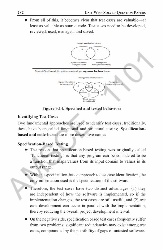
282 Unit Wise solved QUestion PaPers
� From all of this, it becomes clear that test cases are valuable—at least as valuable as source code. Test cases need to be developed, reviewed, used, managed, and saved.
Figure 5.14: Specified and tested behaviors
Identifying Test Cases Two fundamental approaches are used to identify test cases; traditionally, these have been called functional and structural testing. Specification-based and code-based are more descriptive names
Specification-Based Testing � The reason that specification-based testing was originally called “functional testing” is that any program can be considered to be a function that maps values from its input domain to values in its output range.
� With the specification-based approach to test case identification, the only information used is the specification of the software.
� Therefore, the test cases have two distinct advantages: (1) they are independent of how the software is implemented, so if the implementation changes, the test cases are still useful; and (2) test case development can occur in parallel with the implementation, thereby reducing the overall project development interval.
� On the negative side, specification based test cases frequently suffer from two problems: significant redundancies may exist among test cases, compounded by the possibility of gaps of untested software.
1101 AMSCE - DEPARTMENT OF IT

object oriented analysis and design 283 � Figure shows the results of test cases identified by two specification-
based methods. Method A identifies a larger set of test cases than does method B.
� Notice that, for both methods, the set of test cases is completely contained within the set of specified behavior.
� Because specification based methods are based on the specified behavior, it is hard to imagine these methods identifying behaviors that are not specified.
Figure 5.15 : Specification-Based Testing
Code-Based Testing � Code-based testing is the other fundamental approach to test case identification. To contrast it with black box testing, it is sometimes called white box (or even clear box) testing.
� The clear box metaphor is probably more appropriate because the essential difference is that the implementation (of the black box) is known and used to identify test cases.
� The ability to “see inside” the black box allows the tester to identify test cases on the basis of how the function is actually implemented.
� Figure shows the results of test cases identified by two code-based methods. As before, method A identifies a larger set of test cases than does method B.
1101 AMSCE - DEPARTMENT OF IT

284 Unit Wise solved QUestion PaPers
� Is a larger set of test cases necessarily better? for both methods, the set of test cases is completely contained within the set of programmed behavior.
Specification-Based versus Code-Based Debate � Recall that the goal of both approaches is to identify test cases .
� Specification-based testing uses only the specification to identify test cases, while code-based testing uses the program source code (implementation) as the basis of test case identification. Later chapters will establish that
Figure 5.16 : Specification-Based versus Code-Based Debate
Figure 5.17 :Source of test cases
Impacts of Object orientation on testing: � basic unit for unit testing
� implications of encapsulation
� implications of inheritance
� implications of genericity
� implications of polymorphism/dynamic binding
� implications for testing processes
1101 AMSCE - DEPARTMENT OF IT

object oriented analysis and design 285 Unit Testing Object-Oriented Systems
� procedural programming
� basic component: subroutine
� results: output data and out parameters
� object-oriented programming
� basic component: class = owned data structures + set of operations
� objects are instances of classes
� Results: output data, out parameters and state
� data structures define the state of the object
� state is not directly accessible, but can only be accessed using the access methods (encapsulation)
Basic Unit for Testing � the class is the natural unit for unit test case design
� methods are meaningless apart from their class
� testing a class instance (an ob ject) can validate a class in isolation
� when individually validated classes are used to create more complex classes in an application system, the entire subsystem must be tested as a whole before it can be considered to be validated (integration testing)
Implication of Encapsulation. � Encapsulation of attributes and methods in class may create obstacles while testing. As methods are invoked through the object of corresponding class, testing cannot be accomplished without object.
� In addition, the state of object at the time of invocation of method affects its behavior. Hence, testing depends not only on the object but on the state of object also, which is very difficult to acquire.
Implication of Inheritance. � Inheritance introduce problems that are not found in traditional software.
1101 AMSCE - DEPARTMENT OF IT

286 Unit Wise solved QUestion PaPers
� Test cases designed for base class are not applicable to derived class always (especially, when derived class is used in different context). Thus, most testing methods require some kind of adaptation in order to function properly in an OO environment.
Implication of Genericity. � Genericity is basically change in underlying structure.
� We need to apply white box testing techniques that exercise this change.
� i.)Parameterization may or may not affect the functionality of access methods.
� ii.)In Tableclass, elemType may have little impact on implementations of the access methods of the Table. Example: generic (parameterized class) class Tableclass(elemType) int numberelements; create(); insert(elemType entry); delete(elemType entry); isEmpty() returns boolean; isentered(elemType entry) returns boolean; endclass;
� But UniqueTable class would need to evaluate the equivalence of elements and this could vary depending on the representation of elemType. Example: class UniqueTable extends Table insert(elemType entry); endclass;
Implications of Polymorphism � Each possible binding of polymorphic component requires a seperate set of test cases.
� Many server classes may need to be integrated before a client class can be tested.
� It is difficult to determine such bindings.
� It complicates the integration planning and testing.
Implications for testing processes � Here we need to re-examine all testing techniques and processes.
� White-box vs. Black-box Testing of O-O
� In OO systems, inheritance can change both the implementation and specification
� Unique Table example
1101 AMSCE - DEPARTMENT OF IT

object oriented analysis and design 287 � Black box testing should focus on how the spec has changed
� White box testing should focus on how the insert implementation has changed these techniques can be adapted to method testing, but are not sufficient for class testing
� Conventional flow-graph approaches
� What about flow between methods?
� Do methods in a class have a special relationship that deserves special consideration or are standard interprocedural techniques adequate?
� Must deal with instance variables
Black-box O-O Testing � conventional black-box methods are useful for object-oriented systems
� Additional techniques
� Utilize assertions specifications integrated with the implementation
� C++ and Java assertions, Eiffel pre/postconditions offer self-checking
� Utilize method (event) sequence information
� Usually don’t have history of method invocations so can’t do this with assertions
6. Explain in detail how usability of software is tested. Give an example.(8)
A usability test makes sure that the interface of an AUT is built in a way that fits the user’s expectations with respect to meeting requirements (effectiveness) easily (efficiently) in a simplistic satisfying manner.
Usability Testing: - � ISO defines usability as effectiveness, efficiency and satisfaction with which a specified set of users can achieve a specified set of tasks in particular environments. It requires
� i. Defining tasks. What are the tasks?
� ii. Defining users. Who are the users?
1101 AMSCE - DEPARTMENT OF IT

288 Unit Wise solved QUestion PaPers
� iii. A means for measuring effectiveness, efficiency and satisfaction. How do we measure usability?
� Usability testing measures the ease of use as well as degree of comfort and satisfaction users have with the s/w. Usability test cases begin with identification of use cases that can specify the target audience, tasks and test goals. When designing test, focus on use cases or tasks
� The main advantage is that all design traces directly back to user requirements. Use cases and usage scenarios can become test scenarios; and therefore, the use case will drive usability, user satisfaction & quality assurance test cases
Guidelines for developing usability testing◊ Usability testing should include all of a s/w’s components
◊ Usability testing need not be very expensive or elaborate
◊ All tests need not involve many subjects. Typically, quick, iterative tests with small, well –
targeted sample of 6 – 10 participants can identify 80 – 90 percent of most design problems
◊ User’s experience also as part of s/w usability. 80 – 90 percent of most design problems can be studied with target few users of single skill level of users, such as novices or intermediate level
◊ Apply usability testing early and often.
Recording the Usability Test: A quiet location, free from distractions environment is best for conducting test and intervention yields better results. It is done with test data along with guides or hints around a problem. Always records techniques & search patterns users employ when attempting to work though a difficulty & number and type of hints provided to them
The primary focus is on: � Ease of use
� Ease of Learning or familiarizing with the system
� Satisfaction of the user with the entire experience
1101 AMSCE - DEPARTMENT OF IT

object oriented analysis and design 289 Usability has many dimensions to it. It is all about the user’s ‘experience’
during their interaction with an application and their ‘feeling’ towards it. A structured Usability Test translates this experience/feeling into a Validation Process.
Why is usability testing performed?Web and mobile applications rule the business world in recent times. These apps being efficient, effective, easy, simple, appealing, engaging etc. is very critical for them to be embraced by the customers. Usability testing is all about determining if a site is what the user would want to use and come back to or not.
This not only applies to software systems. Any machine/interface that has a human interaction has got to satisfy these rules. How, you ask? Democracy would suffer if the voting machines were not usable. I wouldn’t vote if I had to click more than one button to choose my candidate, would you? Exactly!
For a more software specific example, check out this 300 million dollar article by Jared Spool that will clearly explain how the placement of a button has caused the business to be impacted.
When is Usability Testing conducted? � As testers we know that the earlier a defect is found in the SDLC the cheaper it is to fix it. The same concept holds true for Usability Testing also.
� Usability testing results effect the design of the product
� So, ideally, usability testing should start at the design level. But that is not all; software undergoes many changes/interpretations/implementations throughout the SDLC process.
� To make sure that we do not make usability related mistakes at any of these steps – usability testing should be conducted often and continuously for maximum results.
Who performs usability testing?It can be done as an internal process, when the designers, developers and anyone else can sit down and analyze their system and get the results. Based on these results, the design and/or code can be modified to be in accordance with the changes they all agree on.
1101 AMSCE - DEPARTMENT OF IT

290 Unit Wise solved QUestion PaPers
A more advanced approach is to hire real time users and give them particular tasks. A facilitator/s can devise these tasks and get the results from the users.
The users can then provide information, on whether: � the task was successful or not
� the task could be performed easily
� Was the experience interesting, engaging or annoying – their feeling towards the software
How is usability Testing conducted?Testing is validation of software against its requirements. Usability testing is not different – The only requirement in this case is to validate if the software is as per a mental map of how a user would want the software to be like, what makes it comfortable for them to use, what kind of holistic experience is the user going to take away from the interaction etc.
These are just a few of the ways in which usability testing is carried out.Method #1) During the design phase, you could just take draw your website/application design on a piece of paper and evaluate whether it is going to work or not.
Method #2) An exploratory method would be to build the site and perform some random tests (by the development/design/QA- any or all internal teams) to determine usability factors.
Method #3) Hire a set of real time users to work on the site and report results
Method #4) Use a tool that would provide statistics based on the input wireframes and designs submitted
Method #5) Hire a third-party usability team that specialize in this field
Method #6) Submit your site design and wireframes to an external evaluator and get results from them
The structured Usability testing process contains the following steps:Step #1) Identifying the users to perform the usability test – it helps to choose the set of users that is close to how the real time users are going to be. Care has to be taken not to pick experts or complete newbies . The
1101 AMSCE - DEPARTMENT OF IT

object oriented analysis and design 291 experts are going to simply run through the entire process and the novices
need lots of background training to even get started- neither situation is optimum.
Step #2)Designing the tasks that the users are going to perform on the application–A list of situations that the users are going to use the application for are to be made prior to starting the test. This can include something like: ‘Search for an X-box and buy it” or ‘submit a customer care question” etc. on an eCommerce site. The tasks should closely represent the real transactions the users would use the site for.
Step #3)Facilitating the testing – The usability team will have the users perform the tasks on the site and are going to gather information regarding the test progress and results. It gives them a better picture about how the app was used and where it did not deliver what the user wanted etc, firsthand.
Step #4) Analyze results – At the end of the test, we might end up with the time it took to perform tasks, whether the task was successful or not etc, so basically raw data. The results have to be presented to all the stakeholders and analyzed for identification of potential problem areas.
Usability Testing ToolsThere are also many tools that help this process along. All these tools can be roughly categorized as follows:
Category 1: Create tasks/tests and give them to users (finding the users and giving them tasks is a manual activity, outside of the tool). While they are performing these tasks, the facilitator could watch their screen and interact with them. This could be in the lines of how you would “Skype”.
Category 2: Tool provides users or you can pick your own users. You can submit your page/design and the tasks to be performed. The tool in turn will provide you the videos of the user interaction plus the user’s comments. You can make your own analysis.
Category 3: Tools that use eye tracking and heat map methods to determine which part of the page the user has spent most time on. Some of the tools in this category also record the users clicks, scrolls, mouse moves etc.
Category 4: Tools that provide you with a feedback based on the website, page or wireframe that you submit as input. Some tools of this type also provide surveys that help in giving conclusive evidence regarding usability issues.
1101 AMSCE - DEPARTMENT OF IT

292 Unit Wise solved QUestion PaPers
Category 5: Tools that recruit users for your usability test.
The above is a very broad classification. There are many other tools. And also, the division into a certain category is not always so clean. Sometimes the tools employ multiple methods at the same time.
7. Describe the process of how quality of software is assured.(8)
Quality Assurance Tests: -Debugging is a process of finding out where something went wrong and correcting the code to eliminate the errors or bugs that cause unexpected results. A software debugging system can provide tools for finding errors in programs and correcting them.
Kinds of errors: In general, a software has three types of errors such as below
1. Language (syntax) errors are result of incorrectly constructed code, such as an incorrectly typed keyword or punctuations. They are easiest error to be detected on simple running system
2. Run–time errors are detected on running, when a statement attempts an operation that is impossible to carry out. Eg.: if program tries to access a non-exist file or object, it occurs
3. Logic errors occur when expected output is not formed. They can detected only by testing the code and analyzing the results performed by intended codes
� The elimination of syntactical bug is the process of debugging, whereas detection and elimination of logical bug is the process of testing. Quality assurance testing can be divided into two major categories: error–based testing and scenario–based testing
� Error–based testing techniques search a given class’s method for particular clues of interests, then describe how these clues should be tested. E.g: Boundary condition testing
� Scenario–based testing also called usage–based testing, concentrates on capturing use –cases.
� Then it traces user’s task, performing them with their variants as tests. It can identify interaction bugs. These are more complex tests tend to exercise multiple subsystems in a single test covering higher visibility system interaction bugs
1101 AMSCE - DEPARTMENT OF IT

object oriented analysis and design 293 � S/w testing is one element of a broader topic that is often referred
to as verification and validation (V&V). Verification refers to set of activities that ensure that software correctly implements a specific function. Validation refers to different set of activities that ensure that s/w that has been built is traceable to customer requirements
8. Develop a detailed case study for developing usability test plans and test cases for the ATM System of any bank.
Usability Testing
Planning a Usability Test � One of the first steps in each round of usability testing is to develop a plan for the test.
� The purpose of the plan is to document what you are going to do, how you are going to conduct the test, what metrics you are going to capture, number of participants you are going to test, and what scenarios you will use.
� Typically, the usability specialist meets with the site or product owner and members of the development team to decide on the major elements of the plan.
� Often, the usability specialist then drafts the plan, which circulates to management and the rest of the team. Once everyone has commented and a final plan agreed upon, the usability specialist revises the written plan to reflect the final decisions.
Elements of a Test PlanYou will need to include these elements in the usability test plan.
� Scope: Indicate what you are testing: Give the name of the Web site, Web application, or other product. Specify how much of the product the test will cover (e.g. the prototype as of a specific date; the navigation; navigation and content).
� Purpose: Identify the concerns, questions, and goals for this test. These can be quite broad; for example, “Can users navigate to important information from the prototype’s home page?” They can be quite specific; for example, “Will users easily find the search box in its present location?” In each round of testing, you will probably have several general and several specific concerns to focus on.
1101 AMSCE - DEPARTMENT OF IT

294 Unit Wise solved QUestion PaPers
� Your concerns should drive the scenarios you choose for the usability test.
� Schedule & Location: Indicate when and where you will do the test. If you have the schedule set, you may want to be specific about how many sessions you will hold in a day and exactly what times the sessions will be.
� Sessions: You will want to describe the sessions, the length of the sessions (typically one hour to 90 minutes). When scheduling participants, remember to leave time, usually 30 minutes, between session to reset the environment, to briefly review the session with observer(s) and to allow a cushion for sessions that might end a little late or participants who might arrive a little late
� Equipment:Indicate the type of equipment you will be using in the test; desktop, laptop, mobile/Smartphone. Also indicate if you are planning on recording or audio taping the test sessions or using any special usability testing and/or accessibility tools.
� Participants: Indicate the number and types of participants to be tested you will be recruiting. Describe how these participants were or will be recruited and consider including the screener as part of the appendix.
� Scenarios: Indicate the number and types of tasks included in testing. Typically, for a 60 min. test, you should end up with approximately 10 (+/-2) scenarios for desktop or laptop testing and 8 (+/- 2) scenarios for a mobile/smartphone test. You may want to include more in the test plan so the team can choose the appropriate tasks.
� Metrics:Subjective metrics: Include the questions you are going to ask the participants prior to the sessions (e.g., background questionnaire), after each task scenario is completed (ease and satisfaction questions about the task), and overall ease, satisfaction and likelihood to use/recommend questions when the sessions is completed.
� Quantitative metrics: Indicate the quantitative data you will be measuring in your test (e.g., successful completion rates, error rates, time on task).
1101 AMSCE - DEPARTMENT OF IT

object oriented analysis and design 295 � Roles: Include a list of the staff who will participate in the usability
testing and what role each will play. The usability specialist should be the facilitator of the sessions. The usability team may also provide the primary note-taker. Other team members should be expected to participate as observers and, perhaps, as note-takers.
Identifying Test MetricsThere are several metrics that you may want to collect during the course of testing.
Successful Task Completion: Each scenario requires the participant to obtain specific data that would be used in a typical task. The scenario is successfully completed when the participant indicates they have found the answer or completed the task goal. In some cases, you may want give participants multiple-choice questions. Remember to include the questions and answers in the test plan and provide them to note-takers and observers.
Critical Errors: Critical errors are deviations at completion from the targets of the scenario. For example, reporting the wrong data value due to the participant’s workflow. Essentially the participant will not be able to finish the task. Participant may or may not be aware that the task goal is incorrect or incomplete.
Non-Critical Errors: Non-critical errors are errors that are recovered by the participant and do not result in the participant’s ability to successfully complete the task. These errors result in the task being completed less efficiently. For example, exploratory behaviors such as opening the wrong navigation menu item or using a control incorrectly are non-critical errors.
Error-Free Rate: Error-free rate is the percentage of test participants who complete the task without any errors (critical or non-critical errors).
Time On Task: The amount of time it takes the participant to complete the task.
Subjective Measures: These evaluations are self-reported participant ratings for satisfaction, ease of use, ease of finding information, etc where participants rate the measure on a 5 to 7-point Likert scale.
1101 AMSCE - DEPARTMENT OF IT

296 Unit Wise solved QUestion PaPers
Test Cases for the ATM System of any bank
Figure 5.18: Test Cases for the ATM System of any bankATM Test cases may vary from one bank to another due to the way these terminals are designed. Also each bank has it’s own way to handle the sequence in which cash is being taken out. For example, some banks require additional PIN entry before the cash is taken out for extra layer of security. Some banks don’t allow free withdrawal from other banks ATM etc. However, the functionality for some of the ATM machine can be visualized in general.
Positive Test Cases � Machine accepts card and PIN detail.
� Machine successfully takes out the money.
� Machine takes out the balance printout after the withdrawal.
� Machine logs out of the client session immediately after withdrawal successfully.
� Machine prints out balance inquiry standalone as part of menu operation.
� Machine generates invalid money error due to money asked larger than the savings account balance.
� Machine checks for the idle time in between the client session and wait period while active in account.
� Machine accepts both Visa and Mastercard credit and debit cards.
Negative Test Cases � Machine does not accept card and PIN.
1101 AMSCE - DEPARTMENT OF IT
object oriented analysis and design 297 � Machine finds wrong PIN.
� Machine finds card insertion in wrong way.
� Machine takes 3 invalid PIN attempt.
� Invalid account type selected in the menu.
� Lack of money in the savings account.
� Expired card inserted in the machine.
� Money amount less than 100 entered in the machine.
� Machine does not take out the money.
� Machine can’t take out the balance after withdrawal.
� Machine can’t log out of client session after withdrawal.
� Machine doesn’t print the withdrawal amount.
� Machine does not accept either Visa or master card or both debit/credit cards.
9. (a) Describe user satisfaction (12)
(b) How do you measure the user satisfaction in your project (4)
User Satisfaction Test: -User satisfaction testing is process of quantifying usability test with some measurable attributes of test, such as functionality, cost, intuitive UI, reliability or ease of use. Usability can be accessed by defining measurable goals such as
◊ 95% of users should be able to find how to withdraw money from ATM machine without error
and no formal training
◊ 70% of all users should experience new function as “clear improve-ment over the previous one”
◊ 90% of consumers should be able to operate VCR within 30 minutes
The principle objectives of user satisfaction test are◊ Act as communication vehicle between designers as well as between users & designers
◊ To detect and evaluate changes during the design process
1101 AMSCE - DEPARTMENT OF IT

298 Unit Wise solved QUestion PaPers
◊ To provide a periodic indication of divergence of opinion about cur-rent design
◊ To enable pinpointing specific areas of dissatisfaction for remedy
◊ To provide a clear understanding of just how the completed design is to be evaluated
Guidelines for developing user satisfaction test: The format of every user satisfaction test isbasically same with contents different for each project.
Ask users to select limited number (5 to 10) of attributes by which final product can be evaluated.
User might select following attributes for customer tracking system: ease of use, functionality, cost, intuitiveness of user interface and reliability. User must his/her judgment to answer each question by selecting number between 1 – 10 with 10 as most favorable & 1 as least
An interesting side effect of developing user satisfaction tests is that we benefit from it even if test is never administered to anyone; it still provides useful information. Performing test regularly user actively involved in system development. It also helps us stay focused on user’s wishes
10. (a) Describe Usability Testing (12)
(b) Describe about Quality Assurance (4)
Refer Answer 6 a b
11. Illustrate test plan and continuous testing.
Test Plan : A test is developed to detect and identify potential problems before delivering the s/w to its users.
The test plan need not be very large; in fact, devoting too much time to the plan can be counter productive. The following steps are needed to create a plan
1. Objectives of test: Create objectives of test and describe how to achieve them
2. Development of test case: Develop test data, I/O based on domain of data & expected behavior
1101 AMSCE - DEPARTMENT OF IT

object oriented analysis and design 299 3. Test analysis: It involves examination of test O/p and documentation of
test results
All passed tests should be repeated with revised program called regression testing. Most s/w companies use beta testing, a popular inexpensive, effective way to test s/w and alpha testing
Guidelines for developing Test Plans:
Thomas stated following guidelines for writing test plans◊ Specific appearance or format of test plan must include more details about test
◊ It should contain a schedule and a list of required resources including number of peoples &time
◊ Document every type of test planned with level of detail driven by several factors
◊ A configuration control system provides a way of tracking changes to code should exist
◊ Try to develop a habit of routinely bring test plan sync with product or product specification
◊ At end of each moth or as reach each milestone, take time to com-plete routine updates
Continuous Testing: - � A common practice among developers is to turn over applications to a quality assurance (QA) group for testing only after development is completed. As it is not initial plan, it is time consuming and on identification of design weakness whole process must be repeated.
� In order to overcome time constraint, testing must take place on a continuous basis & refining cycle must continue throughout the development process until fully satisfied with results
� The use cases and usage scenarios can become test scenarios & will drive test plans.
The steps to successful testing are � Understand & communicate the business case for improved testing
� Develop an internal infrastructure to support continuous testing
1101 AMSCE - DEPARTMENT OF IT
300 Unit Wise solved QUestion PaPers
� Look for leaders who will commit to and own the process
� Measure & document the findings in a defect recording system
� Publicize improvements as they are made and let people know what they are doing better
12. Explain in detail about Class Testing.
CLASS TESTING: � Class testing is testing that ensures a class and its instances (objects) perform as defined.
� (Source: Object Testing Patterns).
� When designing a society of classes, an excellent goal is to structure classes so they can be tested with a minimum of fuss.
� After all, a class that requires compiling the application, starting the application, logging into the application, navigating to a particular point in the application ...will likely not get rigorously tested.
� In computer programming, unit testing is a software testing method by which individual units of source code, sets of one or more computer program modules together with associated control data, usage procedures, and operating procedures, are tested to determine whether they are fit for use.
� Intuitively, one can view a unit as the smallest testable part of an application.
� In procedural programming, a unit could be an entire module, but it is more commonly an individual function or procedure.
� In object-oriented programming, a unit is often an entire interface, such as a class, but could be an individual method.
� Unit tests are short code fragments created by programmers or occasionally by white box testers during the development process.
� It forms the basis for component testing. Ideally, each test case is independent from the others. Substitutes such as method stubs, mock objects, fakes, and test harnesses can be used to assist testing a module in isolation.
� Unit tests are typically written and run by software developers to ensure that code meets its design and behaves as intended.
1101 AMSCE - DEPARTMENT OF IT

object oriented analysis and design 301 13. Explain in detail about GUI testing.
GUI stands for : Graphic User Interface - GUI software testing is the process of testing a product that uses a graphical user interface, to ensure that the end product is satisfying the requirement specified by the client and how easy it is to understand by a common user.
GUI testing means testing the user interface by considering parameters like consistency, usability, visibility, compatibility, Alignment, Spell Check.
Why is GUI Testing Important � To find out if all functions work correctly on various platforms.
� To find out if all functions are user friendly.
� To find out all displays are user understandable.
� To find out all wording makes sense and is consistent.
� To have new releases tested and be sure nothing is broken.
What to look for when performing GUI Testing for a website � For any testing there should be some set of standards to be followed.
� We should follow the requirements specification documents for GUI testing. There should be some screen shots (given by client) which we should follow as it is.
There are several factors to consider:Look and Feel – You must validate that all designed and expected functionality is present and correct and verify that the information that the GUI supplies to the user is correct.
Ease of use – Does the presentation make the software simple and straightforward to use?
Clarity – Are all graphics and text visible and unambiguous?
Functionality – All menus, buttons, icons, etc. should respond as expected. Uniformity – All graphics and text, button shape and effects, fonts, colors, etc. must be uniform.
General Guidelines for GUI Testing � All the dialog boxes should have a consistent look through out the Application system. For e.g.- If the heading within a dialog box is blue then for each dialog box the heading should be of this color.
1101 AMSCE - DEPARTMENT OF IT

302 Unit Wise solved QUestion PaPers
� Every field on the screen should have an associated Label.
� Every screen should have an equivalent OK and cancel button. The color combination used should be appealing.
� Tab order should be normally set horizontally for the fields. In some case as per the case the Tab Order can be set vertically.
� Mandatory fields should have * (RED ASTERIK) marked to indicate that they are mandatory fields.
� Test Functionality of control objects like buttons, textbox, list box etc
� Default key <Enter> should be set as OK for the dialog box.
� Default key <Esc> should be set as Cancel for the dialog box.
� Test User Friendly labels and Messages, related message content, understandability of the message.
� Test use of colors, fonts, alignment, tab orders.
� Test Ease of Navigation.
A List of GUI Errors � A list of GUI Errors
� GUI errors include
� Data validation
� Incorrect field defaults
� Mandatory fields, not mandatory
� Incorrect search criteria
� Currency of data on screens.
� Field order.
� Wrong fields retrieved by queries
� Focus on objects needing it.
What is GUI TestingGraphical User Interface (GUI) Testing is the Methods used to identify and conduct GUI tests, including the use of automated tools.
1101 AMSCE - DEPARTMENT OF IT

object oriented analysis and design 303 Elements of GUI Testing
� A Process
� A GUI Test Plan
� A Set of Supporting Tools
� Old Approach Example (TRUMP)
� Was Done by manually stepping through thousands of pages of test procedures.
� Labour intensive, highly error prone.
� Needed to be redone each time regression testing was required.
� Very expensive.
Scripting � Another Programming Language.
� Needs to be subjected to some form of formal verification.
� Eliminates human error during execution of the test.
� Can be used (sometimes with modifications) for regression testing
Capture/Replay ToolsA capture replay tool is a set of software programs that capture user inputs and stores it into a format (a script) suitable to be used at a later time to replay the user inputs.
Available Capture replay tools � QA Partner [Segue Software, Inc)
� Xrunner & WinRunner (Mercury Interactive)
� QC/Replay (CenterLine Sftware)
� Evaluator (Eastern Systems)
� CAPBAK (Software Research, Inc)
� Vermont High Test Plus (Vermont Creative Software)
� WITT (IBM)
� ATS/X-Tester (Automated Testing Solutions Inc.)
1101 AMSCE - DEPARTMENT OF IT

304 Unit Wise solved QUestion PaPers
Figure 5.19 : Capture replay tools
Full Test Integration � Major drawback in Capture/Playback tool is that when the GUI changes, input sequences previously recorded may no longer be valid.
� A test system which makes the maintenance of Capture/Playback generated test scripts easy and fast is a must for such a tool to be of any use.
� A capture/playback tool that support the following capabilities could be used in a more capable and fully integrated test development environment:
� record scripts of user/system interactions
� user access to scripts for editing/maintenance
� user ability to insert validation commands in the script
� allows replay of the recorded script.
� A fully integrated GUI test development environment would also require the following additional characteristics:
� Script editing using higher level abstractions such as icons etc.
� High level view of what functionality is being tested.
� The ability to generate many variations of a recorded script without having to manually edit the script itself.
� A product called TDE under development by Siemens is to provide exactly this kind of functionality (currently only at the prototype level)
1101 AMSCE - DEPARTMENT OF IT

object oriented analysis and design 305 TDE capabilities:
� uses higher level scenario language instead of scripting. This allows graphical editing of the test sequence and easy creation of variations.
� Has a test designer, which through user interactions with the system, builds an internal model of the system’s GUI to produce a high level test design representing many executable scripts.
� Test design library.
� Test generator engine to convert high level scenario into tests scripts.
Figure 5.20: GUITest Integration
Figure 5.21: Test Scenario Screen
1101 AMSCE - DEPARTMENT OF IT

306 Unit Wise solved QUestion PaPers
TDE SUT Representation
Figure 5.22 :TDE SUT Representation
1101 AMSCE - DEPARTMENT OF IT