
Doctoral Thesis Creating and validating UML class diagrams ...
290
Faculty of Computer Science and Management Doctoral Thesis Creating and validating UML class diagrams with the use of domain ontologies expressed in OWL 2 Małgorzata Sadowska Supervisor: prof. dr hab. inż. Zbigniew Huzar Auxiliary Supervisor: dr inż. Bogumiła Hnatkowska Wrocław 2020
-
Upload
khangminh22 -
Category
Documents
-
view
0 -
download
0
Transcript of Doctoral Thesis Creating and validating UML class diagrams ...
Faculty of Computer Science and Management
Doctoral Thesis
Creating and validating UML class diagrams
with the use of domain ontologies
expressed in OWL 2
Małgorzata Sadowska
Supervisor:
prof. dr hab. inż. Zbigniew Huzar
Auxiliary Supervisor:
dr inż. Bogumiła Hnatkowska
Wrocław 2020

1
2
Abstract
The business models aim to present complex business reality in a simplified manner. They
support communication between system shareholders and thus provide the important
information required to create software, as well as play a key role in that software‟s further
development. An important element of business models is the UML class diagrams which are
the subject of this dissertation. UML class diagrams are used to present important notions in a
specific domain.
The ontology is a representation of a selected field of knowledge, and describes domain
concepts and relationships. The ontologies are increasingly used to support modelling in the
software development process, e.g. in the business modelling phase. Using ontologies allows
creating business models without the need for specialized knowledge or the support of domain
specialists. This dissertation selected domain ontologies expressed in the OWL 2 language
due to the fact that currently there are many ontologies already created in this language and
this number is constantly increasing.
The subject of this doctoral dissertation is the process of creating UML class diagrams using
domain ontologies in OWL 2 and their validation against the ontologies.
The thesis of this doctoral dissertation is that the use of domain ontologies favours the faster
creation of business models and increases their semantic quality.
The aim of this research was to propose methods for creating and validating UML class
diagrams based on domain ontologies expressed in OWL 2, as well as the implementation of
the methods in the tool.
Two methods of creating UML class diagrams were proposed, the so-called direct and
extended extraction. The methods required, among others, the proposition of transformation
rules between the elements of UML class diagrams and OWL 2 constructs. The rules were
established based on a systematic review of the literature, as well as extended by new
proposals by the author of this research.
The method of the direct extraction of UML elements uses only the defined transformation
rules. The method of the extended extraction of UML elements allows extracting such UML
elements which are not fully defined in the ontology. It is especially applicable in the case of
the incomplete ontologies and justified by practical modelling needs and the form of real
ontologies. The extended extraction is the original proposal of the author.
The validation process is designed to state whether the created UML class diagrams are
compliant with the indicated domain ontologies that serve as the knowledge base. The
validation of the diagram consists of two stages: the formal verification, which is carried out
automatically in the proposed tool, and optionally the acceptance of the results by the
modeller who finally decides on the result of validation. The process uses the verification
rules proposed by the author is aimed at checking if the UML class diagram being created is
3
complaint with the indicated domain ontology. The method additionally proposes the
automatically generated suggestions of corrections for UML class diagrams.
The methods of creating and validating UML class diagrams based on ontologies have been
implemented as an extension of Visual Paradigm program. The implementation uses on the
original proposition of the OWL 2 ontology transformations which is called normalization.
The normalized ontologies have a unified axiom structure what makes them easier to compare
algorithmically.
The developed tool was checked with the use of test cases and was empirically assessed
through an experiment with students of the Wrocław University of Science and Technology.
The practical potential and usefulness of the proposed methods was confirmed, and thus the
thesis that the use of domain ontologies promotes faster creation of business models and
increases their semantic quality is proved.
4
Streszczenie
Modele biznesowe mają na celu przedstawienie złożonej rzeczywistości biznesowej w sposób
uproszczony. Służą wsparciu komunikacji pomiędzy udziałowcami systemu, a tym samym
dostarczają ważnych informacji wymaganych do utworzenia oprogramowania i odgrywają
kluczową rolę w jego dalszym rozwoju. Istotnym elementem modeli biznesowych są
diagramy klas UML, które są przedmiotem niniejszej rozprawy. Diagramy klas UML służą do
przedstawiania ważnych pojęć w konkretnym obszarze dziedzinowym.
Ontologia stanowi reprezentację wybranej dziedziny wiedzy, na którą składa się zapis pojęć i
relacji między nimi. Ontologie są coraz częściej wykorzystywane do wspierania modelowania
w procesie tworzenia oprogramowania, m.in. w fazie modelowania biznesowego. Korzystanie
z ontologii pozwala na tworzenie modeli biznesowych bez konieczności posiadania wiedzy
specjalistycznej lub wsparcia ekspertów dziedzinowych. W rozprawie są wykorzystywane
ontologie dziedzinowe wyrażone w języku OWL 2, ponieważ obecnie istnieje bardzo wiele
już utworzonych ontologii w tym języku i ta liczba stale rośnie.
Przedmiotem rozprawy doktorskiej jest proces tworzenia diagramów klas UML z
wykorzystaniem ontologii dziedzinowych w OWL 2 oraz ich późniejszej walidacji względem
tych ontologii.
W pracy postawiono tezę, iż zastosowanie ontologii dziedzinowych sprzyja szybszemu
tworzeniu modeli biznesowych i podnosi ich jakość semantyczną.
Celem pracy jest zaproponowanie metod tworzenia oraz walidacji diagramów klas UML w
oparciu o ontologie dziedzinowe, wyrażone w języku OWL 2, a także implementacja metod w
narzędziu.
Zaproponowano dwie metody tworzenia diagramów klas: bezpośrednią i rozszerzoną.
Opracowanie tych metod wymagało między innymi zdefiniowania reguł transformacji między
elementami diagramów klas UML, a konstrukcjami OWL 2. Reguły te zostały opracowane w
oparciu o systematyczny przegląd literatury, a także rozszerzone o nowe autorskie
propozycje.
Metoda bezpośredniego wydobycia elementów UML wykorzystuje jedynie zdefiniowane
reguły transformacji. Natomiast metoda rozszerzonego wydobycia elementów UML, mająca
zastosowanie w przypadku niekompletnych ontologii, umożliwia na wydobycie również
takich elementów UML, które nie są w pełni zdefiniowane w ontologii. Podejście rozszerzone
jest oryginalną propozycją autorki i uzasadnione praktycznymi potrzebami w zakresie
modelowania oraz postacią rzeczywistych ontologii.
Proces walidacji ma za zadanie jednoznacznie stwierdzić, czy otrzymane diagramy klas UML
są zgodne ze wskazanymi ontologiami dziedzinowymi, które służą jako baza wiedzy.
Walidacja diagramu składa się z dwóch etapów: weryfikacji formalnej, która jest
przeprowadzana automatycznie w proponowanym narzędziu, oraz opcjonalnie, akceptacji

5
wyników przez osobę modelującą, która finalnie decyduje o wyniku walidacji. Proces
wykorzystuje zaproponowane przez autorkę reguły weryfikacji, służące do sprawdzania, czy
tworzony diagram klas UML jest zgodny ze wskazaną ontologią dziedzinową. W pracy
zaproponowano również automatycznie generowane sugestie korekt diagramów klas UML.
Metody tworzenia i walidacji diagramów klas na podstawie ontologii zaimplementowano jako
rozszerzenie programu Visual Paradigm. Implementacja bazuje na oryginalnym
przekształcaniu ontologii OWL 2 nazwanym normalizacją. Znormalizowane ontologie mają
zunifikowaną strukturę aksjomatów, dzięki czemu łatwiej je porównywać w sposób
algorytmiczny.
Narzędzie zostało sprawdzone przypadkami testowymi oraz poddane ocenie empirycznej
poprzez eksperyment ze studentami Politechniki Wrocławskiej. Przeprowadzone badania
potwierdziły praktyczny potencjał i użyteczność proponowanych metod, a tym samym
udowodniły postawioną tezę, iż zastosowanie ontologii dziedzinowych sprzyja szybszemu
tworzeniu modeli biznesowych i podnosi ich jakość semantyczną.
6
Table of Contents
List of Figures .............................................................................................. 12
List of Tables................................................................................................ 16
Conventions and Symbols ............................................................................ 20
List of Abbreviations ................................................................................... 21
Part I: Fundamentals
1. Introduction ......................................................................................... 24
1.1. Thesis of the Doctoral Dissertation ....................................................................... 25
1.2. Objectives .............................................................................................................. 26
1.3. Approach ............................................................................................................... 26
1.4. Structure of the Thesis ........................................................................................... 27
1.5. Publications ........................................................................................................... 28
2. UML Class Diagrams in Business and Conceptual Modelling............. 30
2.1. Introduction ........................................................................................................... 30
2.2. Business and Conceptual Modelling ..................................................................... 31
2.3. UML Class Diagrams in Business and Conceptual Modelling ............................. 31
2.4. BPMN as a language to model business processes ............................................... 33
2.5. The Compound Model of a Process ...................................................................... 35
2.6. Conclusions ........................................................................................................... 36
3. Domain Ontologies and OWL 2 Web Ontology Language .................. 38
3.1. Introduction ........................................................................................................... 38
3.2. Domain Ontologies in Relation to Other Types of Ontologies ............................. 39
3.3. OWL 2 Ontology as a Set of Axioms ................................................................... 41
3.4. Syntactically Different but Semantically Equivalent OWL Axioms ................... 42
3.5. Reasoning in OWL Ontologies ............................................................................. 43
3.6. Querying the OWL ontologies with the SPARQL Language ............................... 44
3.7. Online Databases and Libraries with OWL ontologies ......................................... 45
3.8. Validation and Evaluation of OWL Domain Ontologies ...................................... 46
3.9. Similarities and Differences of UML and OWL 2 Notations................................ 47
7
3.9.1. Major Similarities Between UML and OWL 2 Notations .................................... 47
3.9.2. Major Differences Between UML and OWL 2 Notations .................................... 48
3.10. Conclusions ........................................................................................................... 49
Part II: Creation and Validation of UML Class Diagrams
Suported by OWL 2 Ontologies
4. The Problem of Validation and Verification of UML Class Diagrams . 52
4.1. Introduction ........................................................................................................... 52
4.2. Verification and Validation in this Research ........................................................ 53
4.3. The Literature Approaches to Verification of UML Class Diagrams ................... 54
4.4. The Literature Approaches to Validation of UML Class Diagrams ..................... 55
4.4.1. The Manual Approaches to Validation of UML Class Diagrams ......................... 55
4.4.2. The Tool-Supported Approaches to Validation of UML Class Diagrams ............ 56
4.5. Conclusions ........................................................................................................... 57
5. Outline of the Process of Validation of UML Class Diagrams ............. 58
5.1. Introduction ........................................................................................................... 58
5.2. Requirements for the Method of Validation .......................................................... 59
5.3. Description of the Method of Validation............................................................... 59
5.3.1. Outline of the Method of Validation ..................................................................... 59
5.3.2. Transformation Rules ............................................................................................ 65
5.3.3. Verification Rules ................................................................................................. 66
5.4. Result of the Verification ...................................................................................... 70
5.5. Limitations of the Validation Method .................................................................. 72
5.6. Conclusions ........................................................................................................... 72
6. Outline of The Process of the Creation of UML Class Diagrams ........ 74
6.1. Introduction ........................................................................................................... 74
6.2. Creation of the UML Class Diagram Supported by the OWL Domain Ontology ..... 75
6.2.1. Need for the Modification of the Extracted UML Class Diagram ........................ 77
6.2.2. Need for the Verification of the Modified UML Class Diagram .......................... 78
6.3. Extraction of UML Elements from the OWL Domain Ontology ............................. 79
6.3.1. The Direct Extraction ............................................................................................ 80
6.3.2. The Extended Extraction ....................................................................................... 87
6.4. Conclusions ........................................................................................................... 94
Part III: Details of the Proposed Method of Creation and
Validation of UML Class Diagrams
7. The Method of Normalizing OWL 2 DL Ontologies ............................ 98
8
7.1. Introduction ........................................................................................................... 98
7.2. Related Works ..................................................................................................... 101
7.3. OWL 2 Construct Replacements ......................................................................... 102
7.3.1. Class Expression Axioms .................................................................................... 102
7.3.2. Object Property Axioms ...................................................................................... 103
7.3.3. Data Property Axioms ......................................................................................... 104
7.3.4. Assertion Axioms ................................................................................................ 104
7.3.5. Data Ranges ......................................................................................................... 105
7.3.6. Class Expressions ................................................................................................ 105
7.3.7. Object Property Expressions ............................................................................... 108
7.4. Remarks Regarding the Normalization of OWL Ontologies .............................. 108
7.5. Proofs of the Correctness of the OWL 2 Construct Replacements ..................... 109
7.6. Outline of the Ontology Normalization Algorithm ............................................. 112
7.7. The Example of a Normalization of a Single Axiom .......................................... 113
7.8. Conclusions ......................................................................................................... 114
8. Representation of UML Class Diagrams in OWL 2 .......................... 116
8.1. Introduction ......................................................................................................... 116
8.2. Review Process .................................................................................................... 117
8.2.1. Research Question ............................................................................................... 117
8.2.2. Data Sources and Search Queries ........................................................................ 118
8.2.3. Inclusion and Exclusion Criteria ......................................................................... 118
8.2.4. Study Quality Assessment ................................................................................... 118
8.2.5. Study Selection .................................................................................................... 119
8.2.6. Threats to Validity ............................................................................................... 119
8.2.7. Search Results ..................................................................................................... 120
8.2.8. Summary of the Identified Literature .................................................................. 121
8.3. Representation of Elements of the UML Class Diagram in OWL 2 ................... 122
8.3.1. Transformation of UML Classes with Attributes ................................................ 123
8.3.2. Transformation of UML Associations ................................................................ 129
8.3.3. Transformation of UML Generalization Relationship ........................................ 139
8.3.4. Transformation of UML Data Types ................................................................... 144
8.3.5. Transformation of UML Comments .................................................................... 149
8.4. Influence of UML-OWL Differences on Transformation ................................... 150
8.4.1. Instances .............................................................................................................. 150
8.4.2. Disjointness in OWL 2 and UML ....................................................................... 151
8.4.3. Concepts of Class and DataType in UML and OWL .......................................... 152
8.5. Examples of UML-OWL Transformations ......................................................... 153
8.6. Conclusions ......................................................................................................... 160
Part IV: Tool Support
9. Description of the Tool ....................................................................... 164
9.1. Introduction ......................................................................................................... 164
9
9.2. Architecture of the Tool ...................................................................................... 165
9.3. A Summary of Features of the Server Part .......................................................... 165
9.4. A Summary of Features of the Client Part .......................................................... 166
9.5. Installation ........................................................................................................... 166
9.6. The User Interface ............................................................................................... 167
9.6.1. The Settings Form ............................................................................................... 167
9.6.2. The Normalization Form ..................................................................................... 168
9.6.3. The Complementary Tool Functions ................................................................... 170
9.7. Conclusions ......................................................................................................... 172
10. Tool Features for Verification of UML Class Diagrams .................... 173
10.1. Introduction ......................................................................................................... 173
10.2. Tool Features for Diagram Verification .............................................................. 173
10.3. Types of Ontology-based Suggestions for Diagram Corrections ........................ 174
10.4. The Example Verification of the UML Class Diagram....................................... 180
10.5. Limitations of the Tool in the Context of Diagram Verification......................... 185
10.6. Conclusions ......................................................................................................... 186
11. Tool Features for Creation of UML Class Diagrams ......................... 188
11.1. Introduction ......................................................................................................... 188
11.2. Tool Features for the Creation of UML Class Diagrams .................................... 189
11.2.1. Tab 1: UML Classes ............................................................................................ 190
11.2.2. Tab 2: UML Attributes......................................................................................... 192
11.2.3. Tab 3: UML Binary Associations and UML AssociationClasses ......................... 192
11.2.4. Tab 4: UML Generalizations Between the Classes or Between the Associations . 194
11.2.5. Tab 5: UML GeneralizationSets with Constraints ................................................ 194
11.2.6. Tab 6: UML Enumerations .................................................................................. 195
11.2.7. Tab 7: UML Structured DataTypes ...................................................................... 196
11.3. The Example Creation of the UML Class Diagram ............................................ 196
11.4. Limitations of the Tool in the Context of Diagram Creation .............................. 201
11.5. Conclusions ......................................................................................................... 202
Part V: Empirical Evaluation
12. Description of the Experiment ........................................................... 206
12.1. Introduction ......................................................................................................... 206
12.2. Subjects ............................................................................................................... 206
12.3. Objects ................................................................................................................. 207
12.4. Domain Ontologies .............................................................................................. 207
12.5. Variables .............................................................................................................. 208
12.6. Hypotheses .......................................................................................................... 208
12.7. Description of Tasks in the Experiment .............................................................. 209
12.8. Operation of the Experiment ............................................................................... 209
10
12.8.1. Instrumentation .................................................................................................... 209
12.8.2. Preparation of the Laboratory Room ................................................................... 210
12.8.3. Time Frame for the Experiment .......................................................................... 210
12.8.4. Date of the Experiment and Number of Subjects ................................................ 210
13. Analysis of the Results of the Experiment .......................................... 212
13.1. Measures and Scores of Tasks ............................................................................. 212
13.2. Descriptive Statistics ........................................................................................... 212
13.3. Wilcoxon Signed Ranks Test for the Median Difference ................................... 215
13.3.1. Assumptions of Wilcoxon Signed-Ranks Test .................................................... 216
13.3.2. Computations in Wilcoxon Signed-Ranks Test .................................................. 217
13.4. Evaluation of Validity ......................................................................................... 224
13.5. Conclusions ......................................................................................................... 226
Part VI: Final
14. Conclusions ........................................................................................ 230
14.1. Thesis Contributions ............................................................................................ 230
14.1.1. Thesis Contributions in the Context of Validation of UML Class Diagrams ..... 231
14.1.2. Thesis Contributions in the Context of the Creation of UML Class Diagrams .. 232
14.1.3. Additional Thesis Contributions ......................................................................... 232
14.2. Future Works ....................................................................................................... 233
Appendix A. Test Cases ........................................................................... 236
Appendix A.1. Test Cases for Normalization................................................................... 236
Appendix A.2. Test Cases for Transformation Rules ....................................................... 249
Appendix A.3. Test Cases for Verification Rules ............................................................ 258
Appendix B. Materials for the Experiment ............................................. 264
Appendix B.1. Selected Domain Ontologies .................................................................... 264
Appendix B.2. Textual Descriptions of the Domain Ontologies ...................................... 270
Appendix B.3. The Full Text of the Experiment Forms ................................................... 273
References .................................................................................................. 282

11
12
List of Figures
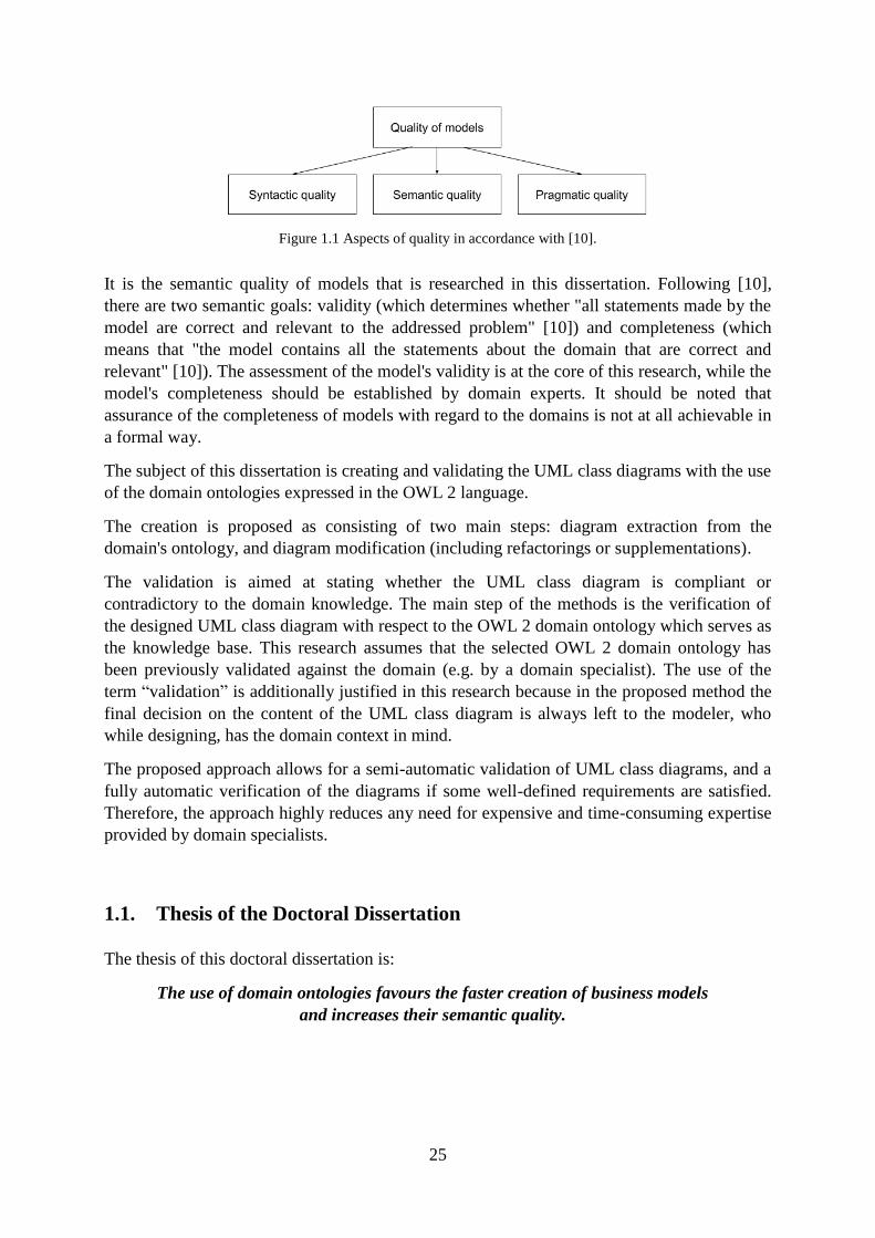
Figure 1.1 Aspects of quality in accordance with [10]............................................................. 25
Figure 2.1 The structure of the compound model of a process. ............................................... 36
Figure 3.1 Ontology classification based on domain scope from [59] (figure on page 26 from
[59]). ......................................................................................................................................... 40
Figure 3.2 A relation between OWL 2 ontology and axioms (extract from Figure 1 in OWL 2
specification [1]). ..................................................................................................................... 41
Figure 3.3 The example relation between the selected class axiom, relevant expressions and
entities on the basis of DisjointClasses axiom (in accordance with OWL 2 specification [1]).
.................................................................................................................................................. 42
Figure 4.1 The schema of understanding accepted in this dissertation for the terms validation
and verification in the context of UML class diagram, OWL domain ontology and the domain.
.................................................................................................................................................. 53
Figure 5.1 The flow diagram for validation of UML class diagrams....................................... 60
Figure 5.2 The simplified diagram for the generation of the result of verification for a single
UML element. .......................................................................................................................... 63
Figure 5.3 A situation when the UML class diagram is compliant with the domain ontology.
.................................................................................................................................................. 71
Figure 5.4 Situation when the UML class diagram is not contradictory with the domain
ontology. ................................................................................................................................... 71
Figure 5.5 Two situations when the UML class diagram is contradictory with the domain
ontology. ................................................................................................................................... 71
Figure 6.1 Illustration of the proposed process of creation of UML class diagram ................. 76
Figure 6.2 The manual and the tool-supported elements of the proposed method of diagram
creation. .................................................................................................................................... 77
Figure 6.3 The extraction, modification and verification steps of the proposed process of
diagram creation. ...................................................................................................................... 78
Figure 6.4 The direct extraction bases fully on the selected ontology. .................................... 80
Figure 6.5 The example attributes of the UML class named Student. ..................................... 84
Figure 6.6 The example generalization between UML classes: Employee and Manager. ...... 86
Figure 6.7 The extended extraction; the OWL-UML transformation should be not
contradictory with the ontology. ............................................................................................. 88
Figure 6.8 The example classes with association between them. ............................................ 91
Figure 6.9 The two binary associations based on the extended extraction. ............................. 92
Figure 6.10 The two binary associations based on the extended extraction. ........................... 92
Figure 6.11 The two binary associations based on the extended extraction ............................ 92
Figure 6.12 The example UML generalization set with {complete, disjoint} constraints. ...... 93
Figure 7.1 The axioms of OWL 2 [1] and the tables which specify the proposed replacement
rules. ....................................................................................................................................... 100
Figure 8.1 Example 1 of UML class diagram ........................................................................ 153
Figure 8.2 Example 2 of UML class diagram ........................................................................ 157
Figure 8.3 Example 3 of UML class diagram ........................................................................ 159
Figure 9.1 The toolbar of the designed plugin. ...................................................................... 167
13
Figure 9.2 The running server icon. ....................................................................................... 167
Figure 9.3 The "Settings" form. ............................................................................................. 168
Figure 9.4 The example of the server message – here: the normalization is conducted. ....... 168
Figure 9.5 The example of ontology before the normalization. ............................................. 169
Figure 9.6 The example of ontology after the normalization. ................................................ 169
Figure 9.7 The example simple UML class diagram consisting of only 5 UML classes. ...... 170
Figure 9.8 The OWL 2 representation of the simple UML class diagram from Figure 9.7. .. 171
Figure 9.9 Example of running server from CMD with the purpose to confirm the port. ..... 172
Figure 10.1 The example of an auto-generated suggestion on the basis of the example of ID
V1 from Table A.13. .............................................................................................................. 174
Figure 10.2 The example of an auto-generated suggestion on the basis of the example of ID
V2 from Table A.13. .............................................................................................................. 175
Figure 10.3 The example of an auto-generated suggestion on the basis of the example of ID
V3 from Table A.13. .............................................................................................................. 175
Figure 10.4 The example of an auto-generated suggestion on the basis of the example of ID
V4 from Table A.13. .............................................................................................................. 175
Figure 10.5 The example of an auto-generated suggestion on the basis of the example of ID
V5 from Table A.13. .............................................................................................................. 175
Figure 10.6 The example of an auto-generated suggestion on the basis of the example of ID
V6 from Table A.13. .............................................................................................................. 175
Figure 10.7 The example of an auto-generated suggestion on the basis of the example of ID
V7 from Table A.13. .............................................................................................................. 176
Figure 10.8 The example of an auto-generated suggestion on the basis of the example of ID
V8 from Table A.13. .............................................................................................................. 176
Figure 10.9 The example of an auto-generated suggestion on the basis of the example of ID
V9 from Table A.13. .............................................................................................................. 176
Figure 10.10 The example of an auto-generated suggestion on the basis of the example of ID
V10 from Table A.13. ........................................................................................................... 176
Figure 10.11 The example of an auto-generated suggestion on the basis of the example of ID
V11 from Table A.13. ........................................................................................................... 177
Figure 10.12 The example of an auto-generated suggestion on the basis of the example of ID
V12 from Table A.13. ........................................................................................................... 177
Figure 10.13 The example of an auto-generated suggestion on the basis of the example of ID
V13 from Table A.13. ........................................................................................................... 177
Figure 10.14 The example of an auto-generated suggestion on the basis of the example of ID
V14 from Table A.13. ........................................................................................................... 177
Figure 10.15 The example of an auto-generated suggestion on the basis of the example of ID
V15 from Table A.13. ........................................................................................................... 178
Figure 10.16 The example of an auto-generated suggestion on the basis of the example of ID
V16 from Table A.13. ........................................................................................................... 178
Figure 10.17 The example of an auto-generated suggestion on the basis of the example of ID
V17 from Table A.13. ........................................................................................................... 178
Figure 10.18 The example of an auto-generated suggestion on the basis of the example of ID
V18 from Table A.13. ........................................................................................................... 178
Figure 10.19 The example of an auto-generated suggestion on the basis of the example of ID
V19 from Table A.13. ........................................................................................................... 179
14
Figure 10.20 The example of an auto-generated suggestion on the basis of the example of ID
V20 from Table A.13. ........................................................................................................... 179
Figure 10.21 The example of an auto-generated suggestion on the basis of the example of ID
V21 from Table A.13. ........................................................................................................... 179
Figure 10.22 The example of an auto-generated suggestion on the basis of the example of ID
V22 from Table A.13. ........................................................................................................... 179
Figure 10.23 The example of an auto-generated suggestion on the basis of the example of ID
V23 from Table A.13. ........................................................................................................... 180
Figure 10.24 The example UML class diagram which needs to be verified. ......................... 180
Figure 10.25 The "contradictory" result of verification including ontology-based suggestions
for diagram correction. ........................................................................................................... 181
Figure 10.26 The detailed information regarding the verification rules which have detected the
incorrectness. .......................................................................................................................... 182
Figure 10.27 The example UML class diagram from Figure 10.24 after correction. ............ 183
Figure 10.28 The "compliant" result of verification. .............................................................. 183
Figure 10.29 The example UML class diagram from Figure 10.24 after additional
modification. .......................................................................................................................... 184
Figure 10.30 The "not contradictory" result of verification. .................................................. 184
Figure 10.31 The "not contradictory" result of verification with a list of not contradictory
normalized transformation axioms. ........................................................................................ 185
Figure 10.32 The error message shown if the selected ontology has a type not from the OWL
2 datatype map. ...................................................................................................................... 186
Figure 11.1 All tabs in the "Create Diagram" form. .............................................................. 189
Figure 11.2 The example of the first tab content based on the selected domain ontology. .... 191
Figure 11.3 The example of the selected rows in the first tab. .............................................. 191
Figure 11.4 The example direct extraction of UML classes based on the selected rows from
Figure 11.3. ............................................................................................................................ 191
Figure 11.5 The example of the appearance of the first tab after extraction of elements from
Figure 11.4. ............................................................................................................................ 191
Figure 11.6 The example of the second tab content based on the selected domain ontology. 192
Figure 11.7 The example direct extraction of the UML attributes based on content from
Figure 11.6. ............................................................................................................................ 192
Figure 11.8 The example of the third tab content based on the selected domain ontology. ... 193
Figure 11.9 The example of direct extraction of UML Associations, and UML
AssociationClass based on content from Figure 11.8. .......................................................... 193
Figure 11.10 The example of the extended extraction of the UML Association based on
content from Figure 11.8. ...................................................................................................... 193
Figure 11.11 The example of the fourth tab content based on the selected domain ontology.194
Figure 11.12 The example direct extraction of UML generalizations between the classes, and
UML generalizations between the associations based on content from Figure 11.11. ............ 194
Figure 11.13 The example of the fifth tab content based on the selected domain ontology. .. 195
Figure 11.14 The example direct extraction of UML generalization sets based on content from
Figure 11.13. .......................................................................................................................... 195
Figure 11.15 The example of the extended extraction of the UML generalization between the
associations based on content from Figure 11.13.................................................................. 195
Figure 11.16 The example of the six tab content based on the selected domain ontology. .... 195
15
Figure 11.17 The example extracted UML Enumeration based on the selected row from
Figure 11.16. .......................................................................................................................... 196
Figure 11.18 The example of the last tab content based on the selected domain ontology. ... 196
Figure 11.19 The example extracted UML structured DataType based on the selected row
from Figure 11.18. .................................................................................................................. 196
Figure 11.20 The UML classes selected from the monetary ontology based on the assumed
glossary. .................................................................................................................................. 197
Figure 11.21 The UML classes extracted from the monetary ontology based on Figure 11.20.
................................................................................................................................................ 197
Figure 11.22 The list of attributes for the classes from Figure 11.21 is empty on the basis of
the selected ontology. ............................................................................................................. 198
Figure 11.23 The UML associations described in the monetary ontology based on selected
classes. .................................................................................................................................... 198
Figure 11.24 All UML associations which follow the direct extraction are selected by the
modeller. ................................................................................................................................. 199
Figure 11.25 All UML associations extracted from the ontology based on Figure 11.24. .... 199
Figure 11.26 The UML generalization described in the monetary ontology based on selected
classes. .................................................................................................................................... 200
Figure 11.27 All UML generalizations extracted from the ontology based on Figure 11.26. 200
Figure 11.28 The UML association which follow the extended extraction is now selected by
the modeller. ........................................................................................................................... 201
Figure 11.29 The complete UML class diagram based on the extended extraction. ............. 201
Figure 13.1 Number of correct, missing, incorrect and excessive UML elements in tasks of
diagram creation. .................................................................................................................... 214
Figure 13.2 Number of correct, missing, incorrect and excessive UML elements in tasks of
diagram validation. ................................................................................................................. 214
Figure 13.3 Histograms for the distribution of the population of difference scores .............. 217
16
List of Tables
Table 3.1 Examples of semantically equivalent axioms. ......................................................... 42
Table 3.2 The overview of important characteristics and features of HermiT reasoner (based
on the article [64] from 2011 and the article [65] from 2014, as well as the website of the
producer). ................................................................................................................................. 44
Table 3.3 The example online databases and libraries with OWL ontologies. ........................ 46
Table 4.1 The selected literature definitions of verification and validation. ............................ 52
Table 5.1 The example of a transformation rule. ..................................................................... 66
Table 5.2 Motivating example presenting the need for verification rules. .............................. 66
Table 5.3 The example of verification rule defining standard OWL verification axiom. ........ 68
Table 5.4 The example of verification rule defining pattern of OWL verification axiom. ...... 69
Table 5.5 The example of verification query. .......................................................................... 70
Table 6.1 The important categories of UML elements which cannot be derived from any
OWL ontology. ......................................................................................................................... 80
Table 6.2 The checking rules for extraction of categories of UML elements from OWL
domain ontology. ...................................................................................................................... 83
Table 6.3 The set of the OWL transformation axioms for the UML elements from Figure 6.5.
.................................................................................................................................................. 84
Table 6.4 The set of the OWL verification axioms for the UML elements from Figure 6.5. .. 85
Table 6.5 The set of the OWL checking axioms for the UML elements from Figure 6.5. ...... 85
Table 6.6 The set of the OWL transformation axioms for the UML elements from Figure 6.6.
.................................................................................................................................................. 86
Table 6.7 The set of the OWL verification axioms for the UML elements from Figure 6.6. .. 86
Table 6.8 The set of the OWL checking axioms for the UML elements from Figure 6.6. ...... 87
Table 6.9 All cases of the incomplete sets of OWL axioms which constitute a premise about
the possibility of being translated into a specific UML elements. ........................................... 89
Table 6.10 The full set of the OWL transformation axioms for the UML elements from Figure
6.8 (based on the direct extraction). ........................................................................................ 91
Table 6.11 The transformation axioms reduced by declaration axioms................................... 91
Table 6.12 The transformation axioms reduced by declaration and inverse object properties
axioms. ..................................................................................................................................... 92
Table 6.13 The maximally reduced transformation axioms, resulting in Figure 6.10. ............ 92
Table 6.14 The maximally reduced transformation axioms, resulting in Figure 6.11. ............ 93
Table 6.15 The full set of the OWL transformation axioms for the UML elements from Figure
6.12 (based on the direct extraction). ...................................................................................... 93
Table 6.16 The transformation axioms reduced by declaration axioms................................... 94
Table 6.17 The maximally reduced transformation axioms, which constitutes a premise of
possibility to translate axioms to UML diagram from Figure 6.12. ........................................ 94
Table 7.1 Replaced and replacing class expression axioms. .................................................. 102
Table 7.2 The replaced and replacing object property axioms............................................... 103
Table 7.3 The replaced and replacing data properties axioms. .............................................. 104
Table 7.4 The replaced and replacing assertion axioms. ........................................................ 104
Table 7.5 The replaced and replacing data ranges. ................................................................ 105
17
Table 7.6 The replaced and replacing class expressions. ....................................................... 106
Table 7.7 The replaced and replacing object property expressions. ...................................... 108
Table 8.1 Search results versus years of publication. ............................................................ 120
Table 8.2 The transformation and verification rules for the category of UML Class. ........... 123
Table 8.3 The transformation and verification rules for the category of UML abstract Class.
................................................................................................................................................ 124
Table 8.4 The transformation and verification rules for the category of UML attribute. ...... 125
Table 8.5 The transformation and verification rules for the category of UML multiplicity of
attribute. .................................................................................................................................. 127
Table 8.6 The transformation and verification rules for the category of UML binary
Association between different Classes. ................................................................................. 129
Table 8.7 The transformation and verification rules for the category of UML binary
Association from the Class to itself. ...................................................................................... 131
Table 8.8 The transformation and verification rules for the category of UML n-ary
Association. ............................................................................................................................ 132
Table 8.9 The transformation and verification rules for the category of UML multiplicity of
Association end. ..................................................................................................................... 134
Table 8.10 The transformation and verification rules for the category of UML
AssociationClass (the Association is between two different Classes). ................................. 136
Table 8.11 The transformation and verification rules for the category of UML
AssociationClass (the Association is from a UML Class to itself). ...................................... 138
Table 8.12 The transformation and verification rules for the category of UML Generalization
between Classes. ..................................................................................................................... 139
Table 8.13 The transformation and verification rules for the category of UML Generalization
between Associations. ............................................................................................................ 140
Table 8.14 The transformation and verification rules for the category of {incomplete, disjoint}
UML GeneralizationSet. ........................................................................................................ 141
Table 8.15 The transformation and verification rules for the category of {complete, disjoint}
UML GeneralizationSet. ........................................................................................................ 142
Table 8.16 The transformation and verification rules for the category of {incomplete,
overlapping} UML GeneralizationSet. ................................................................................. 143
Table 8.17 The transformation and verification rules for the category of {complete,
overlapping} UML GeneralizationSet. ................................................................................. 143
Table 8.18 The transformation and verification rules for the category of UML PrimitiveType.
................................................................................................................................................ 144
Table 8.19 The transformation and verification rules for the category of UML structured
DataType. ............................................................................................................................... 146
Table 8.20 The transformation and verification rules for the category of UML Enumeration.
................................................................................................................................................ 148
Table 8.21 The transformation and verification rules for the category of UML Comment to the
Class. ...................................................................................................................................... 149
Table 8.22 Transformational part of UML class diagram from Example 1. .......................... 153
Table 8.23 Verificational part of UML class diagram from Example 1. ............................... 154
Table 8.24 Transformational part of UML class diagram from Example 2. .......................... 157
Table 8.25 Verificational part of UML class diagram from Example 2. ............................... 158
Table 8.26 Transformational part of UML class diagram from Example 3. .......................... 159
Table 8.27 Verificational part of UML class diagram from Example 3. ............................... 160
18
Table 12.1 Types of tasks in the experiment. ......................................................................... 209
Table 12.2 Domain Ontologies for Group A and Group B. ................................................... 209
Table 13.1 Descriptive statistics for diagram creation with the use of the tool (Task 1). ...... 213
Table 13.2 Descriptive statistics for diagram creation without the use of the tool (Task 3). . 213
Table 13.3 Descriptive statistics for diagram validation with the use of the tool (Task 2). ... 213
Table 13.4 Descriptive statistics for diagram validation without the use of the tool (Task 4).
................................................................................................................................................ 213
Table 13.5 The summary of task execution time in minutes for diagram creation tasks. ...... 215
Table 13.6 The summary of task execution time in minutes for diagram validation tasks. ... 215
Table 13.7 Ranking data in the Wilcoxon signed-rank test for GROUP A with the purpose of
comparing correctness of UML Class Diagram creation with versus without the use of the
tool. ......................................................................................................................................... 219
Table 13.8 Ranking data in the Wilcoxon signed-rank test for GROUP B with the purpose of
comparing correctness of UML Class Diagram creation with versus without the use of the
tool. ......................................................................................................................................... 220
Table 13.9 Results of Wilcoxon signed-rank test for diagram creation in GROUP A and
GROUP B. .............................................................................................................................. 221
Table 13.10 Ranking data in the Wilcoxon signed-rank test for GROUP A with the purpose of
comparing correctness of UML Class Diagram validation with versus without the use of the
tool. ......................................................................................................................................... 221
Table 13.11 Ranking data in the Wilcoxon signed-rank test for GROUP B with the purpose of
comparing correctness of UML Class Diagram validation with versus without the use of the
tool. ......................................................................................................................................... 222
Table 13.12 Results of Wilcoxon signed-rank test for diagram validation in GROUP A and
GROUP B. .............................................................................................................................. 223
Table A.1 The manually verified axioms with result "0" from "COUNTIF" formula. ......... 237
Table A.2 Test cases for class expression axioms. ................................................................ 237
Table A.3. Test cases for object property axioms .................................................................. 239
Table A.4. Test cases for data property axioms. .................................................................... 240
Table A.5. Test cases for assertion axioms. ........................................................................... 241
Table A.6. Test cases for data ranges. .................................................................................... 242
Table A.7. Test cases for class expressions. .......................................................................... 243
Table A.8. Test cases for object property expressions. .......................................................... 246
Table A.9. Additional test cases: axioms with equal normalized and not-normalized form. 247
Table A.10. Additional test cases: more complex axioms or more axioms. .......................... 247
Table A.11 The manually verified axiom with result "0" from "COUNTIF" formula. ......... 249
Table A.12 Test Cases for Transformation Rules. ................................................................. 249
Table A.13 Test Cases for Verification Rules. ....................................................................... 258
Table B.1 The Monetary Ontology ........................................................................................ 265
Table B.2 The Air Travel Booking Ontology ........................................................................ 265
Table B.3 The Smart City Ontology ...................................................................................... 265
Table B.4 The Finance Ontology ........................................................................................... 265
Table B.5 Rules for writing a textual description of UML class with attributes. .................. 271
Table B.6 Rules for writing a textual description of UML generalizations and generalization
sets .......................................................................................................................................... 271
Table B.7 Rules for writing a textual description of UML associations ................................ 272

19
20
Conventions and Symbols
All constructs of OWL 2 Web Ontology Language (OWL 2) are written with the use of
Functional-Style Syntax [1]. In this dissertation OWL always means OWL 2 DL if not stated
differently. Additionally, the following convention is used:
C − indicates a class,
CE (possibly with an index) − indicates a class expression,
OP − indicates an object property,
OPE (possibly with an index) − indicates an object property expression,
DP − indicates a data property,
DPE (possibly with an index) − indicates a data property expression,
DR − indicates a data range,
a − indicates an individual,
lt − indicates a literal,
α = β – means textual identity of α and β OWL 2 constructs,
α ≠ β – means textual difference of α and β OWL 2 constructs.
If not stated otherwise, all SPARQL queries presented in this research use the following
prefixes:
PREFIX rdf: <http://www.w3.org/1999/02/22-rdf-syntax-ns#>
PREFIX owl: <http://www.w3.org/2002/07/owl#>
PREFIX xsd: <http://www.w3.org/2001/XMLSchema#>
PREFIX rdfs: <http://www.w3.org/2000/01/rdf-schema#>
PREFIX : <http://... selected ontology >
21
List of Abbreviations
The following list of abbreviations is used in the dissertation:
BPMN Business Process Model and Notation
CIM Computation Independent Model
CSP Constraint Satisfaction Problem
CWA Closed-world assumption
DL Description Logic
DSL Domain-Specific Language
ERD Entity Relationship Diagram
FOL Frst-Order Logic
HOL Higher-Order Logic
IRI Internationalized Resource Identifier
MDE Model Driven Engineering
MOF Meta-Object Facility
OCL Object Constraint Language
OMG Object Management Group
OUP Ontology UML Profile
OWA Open-world assumption
OWL 2 OWL 2 Web Ontology Language
RAD Rapid application development
SLR Systematic literature review
SRS System (software) requirements specification
SUMO The Suggested Upper Merged Ontology
TR Transformation rule (in the context of mapping UML and OWL)
UML Unified Modeling Language
UNA Unique Name Assumption
W3C World Wide Web Consortium
VOWL Visual Notation for OWL Ontologies
V&V Verification and Validation
VR Verification rule (in the context of mapping UML and OWL)
XMI XML Metadata Interchange
XP Extreme programming
22
Part I
Fundamentals
Part I: Fundamentals

23
24
1. Introduction
Business models are aimed to present complex business realities in a simplified manner [2].
The models support the communication between different stakeholders of the software
development process (e.g. owners, business analysts, IT specialists, organization or company
managers and customers) and provide important information required to develop and maintain
software systems [2]. Due to the fact that business models particularly strongly affect the
quality of the final software, it is expected that the created models adequately represent the
fragment of reality that they describe.
This dissertation deals with models and more precisely their creation and validation in relation
to reality. The validation of models currently requires the involvement of domain specialists
(experts). The domain knowledge can be provided not only by domain specialists but can also
be obtained from other sources of information, e.g. it can be found in various documents or
included in domain ontologies.
In computer and information science, ontology encompasses a representation of a selected
domain of knowledge, which consists of sets of concepts and the relationships between them.
This research will use domain ontologies which reflex and organize information in selected
fields. There are different criteria for classifying ontologies, e.g. based on their degree of
generalization, their formalization or their expressiveness [3]. This classification includes
formal ontologies that are defined in languages with a strict syntax and precisely expressed
semantics. This dissertation is focused only on the formal ontologies expressed with the use of
the OWL 2 Web Ontology Language [4].
There are many online databases and libraries with OWL 2 domain ontologies. This research
uses the existing ontologies, developed for various fields of application. The legitimacy of
reusing the existing ontologies as well as benefits related to them is one of the postulates of
this research.
Currently, ontologies are more and more frequently used as a means of support for modelling
in software development (e.g. [5], [6]), including business [7] and conceptual modelling [8].
A popular and widely used language for modelling the fragments of a domain's reality is
Unified Modeling Language (UML) [9]. The UML standard introduces various types of
diagrams, among which the UML class diagrams are the subject of this dissertation's research.
The UML class diagrams are used in the business modelling phase [2], and their aim is to
present important concepts, their internal structure and the relationships between the concepts,
in a specific domain area. The UML class diagrams describe the static aspect of the system,
and therefore, this research is focused mainly on the static aspect as well.
The assessment of the correctness of models is a key issue to ensure the quality of the final
software system. In accordance with the widely accepted framework for model quality [10]
(see Figure 1.1), the quality of models consists of syntactic quality (adhering to the rules in
the language), semantic quality (describing whether all elements of the model and their
relationships are correct with respect to the problem being described) and pragmatic quality
(comprehensibility for the intended users).
25
Figure 1.1 Aspects of quality in accordance with [10].
It is the semantic quality of models that is researched in this dissertation. Following [10],
there are two semantic goals: validity (which determines whether "all statements made by the
model are correct and relevant to the addressed problem" [10]) and completeness (which
means that "the model contains all the statements about the domain that are correct and
relevant" [10]). The assessment of the model's validity is at the core of this research, while the
model's completeness should be established by domain experts. It should be noted that
assurance of the completeness of models with regard to the domains is not at all achievable in
a formal way.
The subject of this dissertation is creating and validating the UML class diagrams with the use
of the domain ontologies expressed in the OWL 2 language.
The creation is proposed as consisting of two main steps: diagram extraction from the
domain's ontology, and diagram modification (including refactorings or supplementations).
The validation is aimed at stating whether the UML class diagram is compliant or
contradictory to the domain knowledge. The main step of the methods is the verification of
the designed UML class diagram with respect to the OWL 2 domain ontology which serves as
the knowledge base. This research assumes that the selected OWL 2 domain ontology has
been previously validated against the domain (e.g. by a domain specialist). The use of the
term “validation” is additionally justified in this research because in the proposed method the
final decision on the content of the UML class diagram is always left to the modeler, who
while designing, has the domain context in mind.
The proposed approach allows for a semi-automatic validation of UML class diagrams, and a
fully automatic verification of the diagrams if some well-defined requirements are satisfied.
Therefore, the approach highly reduces any need for expensive and time-consuming expertise
provided by domain specialists.
1.1. Thesis of the Doctoral Dissertation
The thesis of this doctoral dissertation is:
The use of domain ontologies favours the faster creation of business models
and increases their semantic quality.
26
1.2. Objectives
Following the posted thesis, the primary objectives of this dissertation are:
1) to develop a method for extracting (selected fragments of) UML class diagrams from
ontologies expressed in OWL 2,
2) to develop a method for automatic verification of the UML class diagrams against
domain ontologies expressed in OWL, which streamlines validation of the diagrams
with respect to the needed domain,
3) to develop and implement a tool which enables
a) the creation of UML class diagrams semantically compatible with selected
domain ontologies in OWL 2, and
b) the automatic verification of the UML class diagrams against domain
ontologies expressed in OWL 2.
1.3. Approach
The presented thesis and objectives are intended to address a practical problem of software
engineering relating to how a modeller can be sure that the developed UML class diagram
being a domain model is semantically correct.
The approach to achieve the first two objectives was the following:
At first, the author proposed a method for the creation and validation of UML class diagrams
with respect to the needed domain. The most important step of the validation method is the
automatic verification of the UML class diagram against the domain ontology expressed in
OWL 2.
The key aspect of the method is the translation of the UML class diagrams into their OWL 2
representation. For this purpose, the author conducted a systematic literature review on the
topic of transformation rules between elements of UML class diagrams and OWL 2
constructs. Next, the author analysed, revised and extended the transformation rules identified
in the literature.
An important and fully original proposition of this research was the proposition of the
verification rules. The verification rules are necessary to check if a UML class diagram is
compliant with the OWL 2 domain's ontology.
Having the transformation and verification rules identified, the author proposed another
original element of this research: the ontology-based suggestions for the correction of the
UML class diagram.
The next step was a more technical aspect. The author proposed a method of normalizing
OWL 2 ontologies, because the intention was to develop a tool to automate the verification of
27
UML class diagrams with respect to the ontologies. The method introduced rules aimed at
refactoring OWL 2 constructs, which enables to present any input OWL 2 ontology in a new
but semantically equivalent form. The need for the method was motivated by the fact that
normalized OWL 2 ontologies have a unified structure of axioms, and thus they can be easily
compared in an algorithmic way.
The approach used to achieve the last objective was the following:
First, the author developed and implemented a tool for the creation and validation of UML
class diagrams. One of the main features of the tool is a possibility to verify the designed
UML class diagram with respect to the selected domain ontology expressed in OWL 2. The
tool was implemented as proof of the concept of the proposed method in order to demonstrate
its feasibility. Additionally, the tool was aimed at verifying the practical potential of the
proposed method.
The final step was to state that the set of objectives meet the posted thesis. For this purpose,
the author conducted an experiment aimed at empirically evaluating the developed tool for the
creation and validation of UML class diagrams. The purpose of the experiment was to check
the practical usefulness of the developed tool for modellers who are not domain experts. After
the experiment was conducted, the experiment data were analysed with the use of statistical
analysis.
1.4. Structure of the Thesis
This dissertation is divided into six interrelated parts, each of which contains a few chapters
built of sections.
Part I presents the fundamentals. Except for the introductory chapter, Chapter 2 clarifies the
basics behind the UML notation with a special focus put on the UML class diagrams used in
business and conceptual modelling. The chapter describes also a wider context of the
considerations, including BPMN language to model business processes and the concept of
compound models of processes. Chapter 3 concentrates on domain ontologies and the
OWL 2, Web Ontology Language, as well as on the most important similarities and
differences between UML and OWL notations.
Part II is devoted to the creation and validation of UML class diagrams supported by OWL 2
ontologies. Chapter 4 presents definitions of validation and verification in the context of
modelling and the understanding of the terms adopted in this dissertation. Chapter 5 outlines
the fully original proposition of this research the method of diagram validation with its
important step of diagram verification against the selected OWL 2 domain ontology. Chapter 6
proposes the ontological-aided process of the creation of UML class diagrams, described in
comparison to other existing approaches which use ontologies for the creation of diagrams.
Part III allows for a closer look at the details of the proposed methods of the creation and
validation of UML class diagrams. Chapter 7 introduces the method of normalizing OWL 2
ontologies, which is also an original proposition of this research. Chapter 8 presents the
28
details of transformation rules of UML class diagrams to their OWL 2 representation
including the analysis of the results of systematic literature review. The identified
state-of-the-art transformation rules were extended and supplemented with some new
propositions. Additionally, the chapter presents the next original proposition of this research
verification rules used to check if a UML class diagram is compliant with the OWL 2 domain
ontology. Appendix A is associated with Part III and presents the conducted test cases for
the normalization, transformation and verification rules.
Part IV describes the developed tool which implements the proposed methods. Chapter 9
presents the architecture of the developed tool. Chapter 10 illustrates tool features for
verifying and Chapter 11 for creating the UML class diagrams. Additionally, Chapter 10
presents another original element of this research the automatically generated
ontology-based suggestions for correction of the UML class diagram based on the detailed
result of the verification.
Part V describes the conducted empirical evaluation of the developed tool. Chapter 12
presents the definition, the design, as well as the conducting of the experiment and
Chapter 13 shows the analysis of the results of the experiment. Appendix B is associated
with Part V and includes the materials used during the experiment, such as selected domain
ontologies and the full text of the experiment forms.
Part VI consists of only one chapter Chapter 14 which constitutes the summary
including the contribution of the dissertation, and it presents some final conclusions.
1.5. Publications
Selected parts of this dissertation have been published as journal articles, a book chapter, a
monograph chapter or a conference paper. Below, the publications are listed with the chapters
covering the respective contributions. In addition, the research work presented in this
dissertation extends and improves the content of the listed publications. It should be noted that
the publications are located between the fields of research on model driven engineering and
ontology engineering.
The context of UML class diagrams in business modelling and the concept of the compound
models of processes has been published as a book chapter in [11]:
Z. Huzar and M. Sadowska, „Towards Creating Complete Business Process Models‟, in
Chapter 5 In: From Requirements to Software: Research and Practice, 2015,
pp. 77–86.
The revised and extended fragments of the publication are described in Sections 2.2, 2.4
and 2.5.
The outline of the proposed method of the semantic validation of UML class diagrams with
the use of OWL 2 domain ontologies has been published as a conference paper [12]:
M. Sadowska and Z. Huzar, „Semantic Validation of UML Class Diagrams with the Use
of Domain Ontologies Expressed in OWL 2‟, Software Engineering: Challenges and
Solutions. Springer International Publishing, pp. 47–59, 2017.
29
The revised and extended version of the paper has been described in Chapter 5.
The proposed method of normalizing OWL 2 DL ontologies has been published as a journal
article [13]:
M. Sadowska and Z. Huzar, „The method of normalizing OWL 2 DL ontologies‟, Global
Journal of Computer Science and Technology, vol. 18, no. 2, pp. 1–13, 2018.
The revised and extended version of the paper has been described in Chapter 7.
Additionally, the revised and extended fragment of the publication is described in
Section 3.3.
The transformation and verification rules of UML class diagrams to their OWL 2
representation have been published as a journal article [14]:
M. Sadowska and Z. Huzar, „Representation of UML class diagrams in OWL 2 on the
background of domain ontologies‟, e-Informatica Software Engineering Journal,
vol. 13, no. 1, pp. 63–103, 2019.
The revised and extended version of the paper has been described in Chapter 8.
Additionally, the revised fragments of the paper are presented in Section 2.3 and
Section 5.3.3.
The prototype version of the developed tool for the semantic validation of UML class
diagrams with the use of OWL 2 domain ontologies has been published as a monograph
chapter [15]:
M. Sadowska, „A Prototype Tool for Semantic Validation of UML Class Diagrams with
the Use of Domain Ontologies Expressed in OWL 2‟, In Towards a Synergistic
Combination of Research and Practice in Software Engineering. Springer, Cham,
pp. 49–62, 2018.
The revised and extended fragments of the paper have been described in Chapter 9,
Chapter 10 and Chapter 11. The article [15] presented the functionality of the
prototype version of the tool, while the chapters describe the current version of the tool
with a much wider functionality. Additionally, some revised and extended fragments of
the paper are presented in Section 3.4 and Section 5.5.
30
2. UML Class Diagrams in Business and Conceptual Modelling
Summary. This chapter shortly explains the importance of Unified Modeling Language
in Model Driven Engineering with a special focus put on the role of UML class diagrams
in business and conceptual modelling. The chapter describes also a wider context of the
considerations presented in this dissertation and places UML class diagrams as part of full
business process models. 1
2.1. Introduction
Model Driven Engineering (MDE) advocates the use of models to represent the most relevant
design decisions in a software development project. Each model is described using a selected
modelling language, for example, the Unified Modeling Language (UML) [9], which is
currently a popular and commonly used modelling standard. UML is a general-purpose
modelling language and currently [5] is the basic modelling paradigm in model-driven
software development. UML has been developed by Object Management Group (OMG)
consortium. This research uses the most current version UML 2.5 [9].
The term “models” can be defined as [16] “simplifications in order to bring clarity and
understanding to some aspect of a problem where there is complexity, uncertainty, change or
assumptions”. Other researchers [17] describe a model as “a description or representation of a
software system or its environment for a certain purpose, developed using modelling language
and thus conforming to a metamodel”. Despite the selected definition, models can be
considered as primary artefacts in software development process.
In graphical modelling in terms of UML, a single model can be built of several “diagrams”,
each of which provides a different view on the described system. In addition, a software
design is typically modelled (e.g. [18], [19]) as a collection of UML diagrams which cover
different aspects of the software system.
The standard of UML in version 2.5 defines 14 not abstract2 types of diagrams (page 683 of
[9]), among which the so-called “class diagrams” are in the main focus of this research. The
context of their use is well-explained in [20]: “UML class diagrams allow for modelling, in a
declarative way, the static structure of an application domain in terms of concepts and
relations between them”3. The UML class diagrams are structure diagrams [9], which are used
to show the specification of objects in a system. The elements of the class diagram represent
the meaningful concepts of an application.
1 Sections 2.2, 2.4 and 2.5 contain the revised and extended fragments of the paper: "Towards creating
complete business process models" [11]. Additionally, Section 2.3 contains the revised and extended fragment
of Section 2 from the paper: "Representation of UML class diagrams in OWL 2 on the background of domain
ontologies" [14]. 2 The standard of UML in version 2.5 defines also three abstract types of diagrams: Structure Diagram,
Behavior Diagram and Interaction Diagram. 3 This citation would be more accurate if the word “between” would be changed into “among”.
31
2.2. Business and Conceptual Modelling
Modelling is a process of extracting knowledge from a selected field, leading to the creation
of a model. In modelling, processes related with the domain are analysed.
Following [21], the process can be defined as a sequence or flow of activities in an
organization with the objective of carrying out work, and is depicted as a graph of flow
elements, which are a set of activities, events, gateways, and sequence flows that adhere to
finite execution semantics. The notion of the process is the most important. The term
“business process” refers to the function (service) performed within the organization and is
related to [22] “a network of graphical objects, which are activities (...) and the flow controls
that define their order of performance”.
There is no single comprehensive and formal definition of the terms of business and
conceptual models. A conceptual model is an abstraction of the concepts and relationships in
a domain. The term conceptual model emphasises the fact that this is a model of the concepts,
and does not reflect a software design. Following [23], the conceptual models are “a high
level abstraction of the represented reality, they constitute a vehicle for communication, provide
a comprehensive documentation, and are the basis for the implementation and evolution of the
developed system”. According to [23], the “business process models are conceptual models
supposed to provide a complete description of the underlying business processes”. The
business models are aimed to present a model of an organization or a company being the
domain of application of a future information system. In [7], the aim of business modelling is
explained as creating “semantically faithful and pragmatically usable representations of
business domain artifacts (e.g. transactions, processes, value chains)”. A business model is
supposed to express intuitive ideas, thus supporting communication among users, and thus
delivering information necessary to specify the requirements for the future software system.
Therefore, a modelling language should have sufficient expression power enabling the
presentation of all interesting structural and behavioural features from the domain of interest.
Additionally, the language should have a satisfactory level of formality that will allow
checking consistency and completeness of a model expressed in this language.
2.3. UML Class Diagrams in Business and Conceptual Modelling
The UML specification [9] does not strictly specify which elements of UML class diagrams
should be included in the diagrams, and this decision is left to modellers. Generally, the
boundaries between various kinds of diagram types are not strictly enforced by the
specification (page 683 of [9]).
What is important, not all model elements are equally useful in the practice of business and
conceptual modelling with UML class diagrams. From the practical point of view, in order to
identify the relevant elements, this research uses the term “category” the category is a set of
32
selected elements of UML class diagram which are of the same type. The type is related to
selected elements from UML metamodel4.
Each category contains the elements which are commonly used in business and conceptual
modelling and are important from the point of view of pragmatics. Following the above
understanding, the most important category of elements of UML class diagrams are “classes”
(some other example categories are: attributes, binary associations, n-ary associations, etc.). A
class in UML specifies a set of objects with the common features [24]. The description of a
class includes the name of the class (unique in the whole diagram) and can contain attributes
or operations of the class. The classes can be interrelated by different relationships. Below are
presented some literature recommendations on the elements which are commonly used in
business and conceptual modelling with UML class diagrams, full list of selected categories
can be found in Section 8.3.
In [25], it is suggested that a full variety of UML constructs is not needed until the
implementation phase and it is practiced that a subset of diagram elements useful for
conceptual modelling in the business context is selected. The following categories of static
elements of UML class diagrams are suggested in literature as the most important in business
and conceptual modelling [2], [26]:
named classes,
attributes of classes with types (either primitive or structured datatypes),
associations between the classes (including aggregation) with the specified
multiplicity of the association ends,
generalization relationships.
The article [26] proposes modelling business processes with UML class, activity and state
machine diagrams. The examples in [26] present a business process at the level of the UML
class diagram as consisting of classes with attributes, class generalizations, associations
between the classes (including aggregation) with a specified multiplicity of the association
ends. The class attributes are typed with either primitive or structured datatypes.
Modelling a complex business requires using several views, each of which focuses on a
particular aspect of business. Following [2], there are four commonly used Business Views:
Business Vision View (presenting the overall vision of the business),
Business Process View (presenting the interaction between different processes),
Business Structure View (presenting the structure among the resources in the
business) and
Business Behaviour View (presenting the individual behaviour of important resources
and processes).
The UML class diagrams are identified as useful [2] in Business Vision View and Business
Structure View. Section 2.4 presents some types of diagrams which can be used in Business
Process View and Business Behaviour View.
The UML class diagrams in a Business Vision View [2] are used to create conceptual
models which establish a common vocabulary and demonstrate relationships among different
4 A model always conforms to a unique metamodel. The MOF-based metamodel specifies the abstract syntax
of the UML (some more information can be found in Section 3.9.1.2).
33
concepts used in business. The important elements of UML class diagrams in the conceptual
modelling are named classes and associations between the classes as they define concepts.
The classes can have attributes as well as a textual explanation which together constitute a
catalogue of terms. The textual descriptions may not be necessarily visible on the UML
diagram but should be retrievable with the help of modelling tools. In the conceptual
modelling with UML, attributes and operations of classes are not so much important [2] (can
be defined only if needed) but relationships among the classes should be already correctly
captured in models.
The UML class diagrams in a Business Structure View [2] are focused on presenting a
structure of resources, products, services and information regarding the business including the
organization of the company. The class diagrams in this view often include classes containing
attributes with types and operations, as well as generalizations and associations with the
specified multiplicity.
The author has not found any further recommendations for using additional static UML class
diagram elements in the context of business or conceptual modelling in other reviewed
literature positions. Obviously, if the selected UML class diagram is compliant with the
domain, it is reasonable to examine the diagram further. For example, the question outside the
scope of this research is about the role of Object Constraint Language (OCL) [27] in business
and conceptual modelling with UML class diagrams. Some other works investigate this
aspect, e.g. [28] proposes an approach to translate OCL invariants into OWL 2 DL axioms.
2.4. BPMN as a language to model business processes
There are different languages which can be used to describe behaviour but all of them refer to
the structure. Business Process Model and Notation (BPMN) is one of numerous modelling
standards among e.g. UML Activity Diagrams, XPDL, EPC or others developed in last
two decades with the purpose to model business processes. BPMN seems to be one of the
most popular business modelling languages, which does not mean that it is not the object of
numerous critics and polemics [29], [30], [31]. It seems that the primary cause of disputes is
the lack of a common or, at least, a widely accepted approach for modelling business
processes. There are some currently prepared proposals, e.g. [32], [33], [34], [35], [36], [37],
but they all base on specific assumptions regarding a field of application or modelling
languages.
Considering BPMN as a process modelling language, one should take into account the related
issues such as “Whether it is a good enough modelling language?” and “Do the existing tools
provide an adequate support for the modelling using BPMN?”, etc. In further, some aspects
regarding the first issue are outlined, however, it should be noted that the assessment of
BPMN is out of scope of this research and can be found in other publications, e.g. [29], [30],
[38].
Development of BPMN [21] lies on one of the branches of the Unified Modeling Language
(UML) [9] evolution. Similarly as the UML, the BPMN is a semi-formal language. BPMN is
basically concerned on the behaviour of a system. BPMN models describe private (internal)
business processes in an organization (e.g. a company, a company division), and their
34
collaboration with public (external) business processes in the environment of the organization
(e.g. a consumer, a seller). The models are presented in a graphical notation, easily
understandable by all business stakeholders, i.a. business analysts, IT specialists, and
organization or company managers [21]. The notation is based on a flowcharting technique
similar to the activity diagrams from the UML. A process determines a partially ordered set of
business activities that represent the steps required to achieve a business objective. The order
results from the flow of control and the flow of data among the activities.
Although BPMN is not declared as a data flow language, in fact, there are two forms of data
exchanged between processes and activities: a message flow that depicts the contents of
communication and an object flow that depicts a data object reference with its state. BPMN
does not itself provide a built-in model for describing the structure of data or a querying
language for that data but allows for the co-existence of multiple data structure and querying
languages within the same model. Additionally, tool vendors are encouraged to include such
languages to their products with commitment to keep compliance with the data modelling
defined in the BPMN specification.
BPMN is constrained to support only the concepts of modelling that are applicable to business
processes. Therefore, the following aspects are out of the scope of the BPMN specification
[21]:
definition of organizational models and resources,
modelling of functional breakdowns,
data and information models,
modelling of strategy,
business rules models.
Has the BPMN enough expression power? At the beginning, it should be noted that BPMN
enables only partial description of the domain of interest. Namely, BPMN concentrates on a
specification of business participants and the types of processes performed, i.e. the types of
mutually offered services. The BPMN puts stress on the description the structures of
processes with skipping details of the processed data objects.
It should be noted that a very important aspect concerning data and its structure is omitted
from BPMN specification. In spite of BPMN transition from BPMN 1.0 to 2.0, this claim is
still valid [39]. For example, elaboration of the conceptual database model requires
information about data types and their relationships. This observation gives rise to the natural
idea of integration of BPMN diagrams with these UML diagrams that describe the data
structures and methods of their processing. The precise and complete business model plays
the fundamental role for the further system development. Especially, it strongly influences on
a quality of the final software product.
The question: “How to build a good model of a business process?” can be used to properly
define the context of all considerations presented in this dissertation (similar questions were
stated in [17] and [40]). This question entails two more detailed questions: “What is a good
model?” and “Which methodology would be recommended for effective model
construction?”. Unfortunately, up to now, there have been no satisfying answers to these
questions. The conclusion of the paper [41] from 2006 is still valid: there is no
well-established modelling standard in this area. A similar conclusion emerges from the
comprehensive overview of the literature on the quality of business modelling [42] which was
35
published in 2015: there is a lack of an encompassing and generally accepted definition of
business process modelling quality.
2.5. The Compound Model of a Process
The main focuses of this research are UML class diagrams in business and conceptual
modelling. In this context, UML class diagrams play a crucial role. This section shortly
introduces a broader aspect of business modelling, initially proposed in [11], which is based
on the integration of UML class diagrams with BPMN process diagrams and UML state
machine diagrams.
BPMN excludes from its scope precise treatment of data and information models which are
the important aspects in software system development, therefore a compound model of a
process is aimed to integrate BPMN process diagrams with UML class diagrams and UML
state machine diagrams, which describe the behaviour of the system. The three types of
diagrams are interrelated and together constitute the compound model of a process. The added
value of using the compound model approach is a result of linking the well-known standards
of BPMN and UML.
As stated in [43], modelling business processes without modelling the processed objects
would be rather poor. Therefore, it seems to be beneficial to create compound models of
processes that would take into account all the details regarding processed data. To fulfil this
postulate, UML class diagrams can be incorporated into the compound model. In this way
some data objects represented on a process diagram will have references in the class diagram.
More precisely, more information is carried if a data object on the process diagram has an
instance of a respective class on the class diagram. Moreover, data objects may change their
states during the execution of a process. Usually, these changes are subjected to some
constraints. These constraints can be clearly presented by UML state machine diagrams.
The proposed compound model of a BPMN process CMBPMN consists of a set of three types
of diagrams: a process diagram, a class diagram, and a state machine diagram:
CMBPMN = <PDBPMN, CDUML, SMDUML>
where:
PDBPMN is a set of BPMN 2.0 process diagrams which illustrate a needed business
process.
CDUML is a set of UML class diagrams whose role is to describe the structure of data
contained in the BPMN diagrams. The diagrams show relevant classes with attributes
as well as relationships between the classes.
SMDUML is a set of UML state machine diagrams which are aimed at presenting
possible processing of data occurring on UML class diagrams. The diagrams describe
for the given classes transitions between the states of their objects together with the
events that trigger transitions between the states.
The Figure 2.1 presenting relationships between process diagrams, class and state machine
diagrams, components of the compound model, looks like a metamodel of the compound
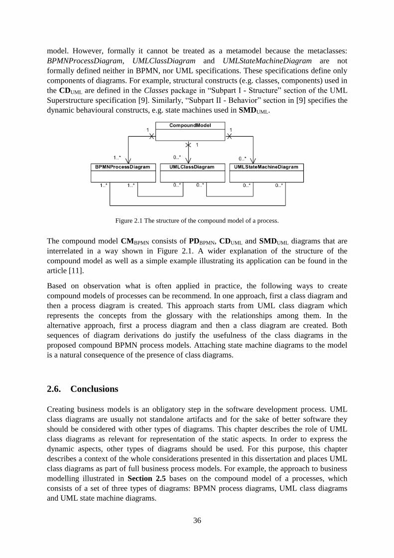
36
model. However, formally it cannot be treated as a metamodel because the metaclasses:
BPMNProcessDiagram, UMLClassDiagram and UMLStateMachineDiagram are not
formally defined neither in BPMN, nor UML specifications. These specifications define only
components of diagrams. For example, structural constructs (e.g. classes, components) used in
the CDUML are defined in the Classes package in “Subpart I - Structure” section of the UML
Superstructure specification [9]. Similarly, “Subpart II - Behavior” section in [9] specifies the
dynamic behavioural constructs, e.g. state machines used in SMDUML.
Figure 2.1 The structure of the compound model of a process.
The compound model CMBPMN consists of PDBPMN, CDUML and SMDUML diagrams that are
interrelated in a way shown in Figure 2.1. A wider explanation of the structure of the
compound model as well as a simple example illustrating its application can be found in the
article [11].
Based on observation what is often applied in practice, the following ways to create
compound models of processes can be recommend. In one approach, first a class diagram and
then a process diagram is created. This approach starts from UML class diagram which
represents the concepts from the glossary with the relationships among them. In the
alternative approach, first a process diagram and then a class diagram are created. Both
sequences of diagram derivations do justify the usefulness of the class diagrams in the
proposed compound BPMN process models. Attaching state machine diagrams to the model
is a natural consequence of the presence of class diagrams.
2.6. Conclusions
Creating business models is an obligatory step in the software development process. UML
class diagrams are usually not standalone artifacts and for the sake of better software they
should be considered with other types of diagrams. This chapter describes the role of UML
class diagrams as relevant for representation of the static aspects. In order to express the
dynamic aspects, other types of diagrams should be used. For this purpose, this chapter
describes a context of the whole considerations presented in this dissertation and places UML
class diagrams as part of full business process models. For example, the approach to business
modelling illustrated in Section 2.5 bases on the compound model of a processes, which
consists of a set of three types of diagrams: BPMN process diagrams, UML class diagrams
and UML state machine diagrams.
37
The next chapter begins the considerations on creating UML class diagrams based on
ontologies. All ontologies always represent the static aspect and only very few refer to the
behaviour. Taking this argument into account, creation of a UML class diagram at the
beginning of business modelling is strongly justified.
38
3. Domain Ontologies and OWL 2 Web Ontology Language
Summary. This chapter presents the definitions of ontologies with a special focus put on
domain ontologies in accordance with the classification of ontologies based on the
domain scope. The chapter introduces OWL 2 Web Ontology Language, includes some
basic information about reasoning and querying from ontologies, and presents selected
existing online databases and libraries with OWL ontologies. The chapter also
summarises the main similarities and differences of UML and OWL 2 notations.
3.1. Introduction
The term “ontology” originates from philosophy and denotes the philosophical study on the
nature of existence. In computer science, the most well-accepted definition of an “ontology”
is proposed in [44] as: “an explicit specification of a conceptualization”. As described in [44],
an ontology is a knowledge specification of conceptualization, where the objects, concepts
and other entities including the relationships between them are presumed to exist in some area
of interest.
In [45], this definition is further specified: “an ontology is a formal, explicit specification of a
shared conceptualisation”. As explained in [45], in the definition, “formal” refers to the fact
that the ontology should be machine readable, “explicit” means that the type of concepts used
and the constraints on their use are explicitly defined, “shared” reflects the notion that an
ontology captures commonly accepted consensual knowledge, and finally “conceptualisation”
refers to an abstract model of some phenomenon in the world.
Ontologies define a common set of concepts and terms that are used to describe and represent
a domain knowledge [46]. Following [5], ontologies provide shared-domain
conceptualizations representing knowledge through vocabulary and typically logical
definitions. The idea behind working with ontologies is to allow for automatic processing of
information in such a way that it is possible to identify the precise meaning [47].
There are many languages for defining ontologies which allow users to write explicit, formal
conceptualizations of domain models. The main requirements for the ontology languages are
[48]: a well-defined syntax and semantics, efficient reasoning support, sufficient expressive
power and convenience of expression.
Taking the above postulates into account, this research selected OWL 2 Web Ontology
Language (OWL 2) [4]. OWL 2 is a description logic knowledge representation language for
defining ontologies developed by World Wide Web Consortium (W3C) and was launched in
October 2009. The OWL 2 language is an extension of OWL language which was first
published in 2004. In comparison with UML which has been evolving since the second half of
the 1990s, the OWL 2 is a much younger formalism and its initial purpose was to represent
knowledge in the Semantic Internet. Nowadays, OWL is frequently used also in researches
related with modelling (e.g. [19], [49], [50], [51], and many others).
39
In this research the choice of OWL 2 is justified by the fact that there is a wide number of
already developed OWL 2 domain ontologies and this number is still increasing (Section 3.7
presents selected currently available online databases and libraries with the ontologies).
In order to store and exchange OWL 2 ontologies a concrete syntax is needed. OWL 2 offers
several different syntaxes [4]: RDF/XML, OWL/XML, Functional-Style Syntax, Turtle and
Manchester Syntax. In this dissertation, all constructs of OWL 2 are written with the use of
Functional-Style Syntax [1]. This syntax style was selected because it is succinct and human-
readable.
There are two alternative ways of assigning meaning to ontologies in OWL 2 called the Direct
Semantics [52] and the RDF-Based Semantics [53]. The Direct Semantics provides a meaning
for OWL 2 in a Description Logic (DL), while the RDF-Based Semantics is based on viewing
OWL 2 ontologies as RDF graphs.
There are two semantic views of OWL 2 called OWL 2 DL and OWL 2 Full. The OWL 2
ontologies which satisfy syntactic conditions listed in the specification (see Section 3 of [1])
are called OWL 2 DL ontologies. In accordance with OWL 2 Primer [54]: "The Direct
Semantics can be applied to ontologies that are in the OWL 2 DL subset of OWL 2 (...).
Ontologies that are not in OWL 2 DL are often said to belong to OWL 2 Full, and can only be
interpreted under RDF-Based Semantics.". One can see OWL 2 DL as a syntactically
restricted version of OWL 2 Full.
What is very important from practicability of reasoning, following [54], OWL 2 Full (under
the RDF-Based Semantics) is undecidable while for OWL 2 DL there are currently several
different reasoners that cover the entire OWL 2 DL language under the Direct Semantics.
Following [55], the Direct Semantics assigns meaning directly to ontology structures,
resulting in a semantics compatible with the model theoretic semantics of the SROIQ
description logic [4]. The description logic SROIQ is a fragment of first order logic with
useful computational properties. SROIQ offers a satisfactory complexity and what is
important for practicability to guarantee decidability in reasoning (e.g. [56], [57]).
Therefore, OWL 2 DL ontologies are in the main focus of this research. In the rest of this
dissertation OWL always means OWL 2 DL if not stated differently.
The description logic languages allow for capturing the schema in the “terminological box”
(TBox) and the objects and their relationships in the “assertional box” (ABox). Together
ABox and TBox make up a knowledge base. The files with OWL ontologies do not have a
clear division into TBox and ABox parts. In practice, the majority of OWL ontologies contain
either both TBox and ABox parts, or only TBox part. However, it is also possible to create an
ontology containing only the ABox.
3.2. Domain Ontologies in Relation to Other Types of Ontologies
Ontologies are developed in the world of philosophy and computer science. Therefore,
various ontology classifications are proposed - by philosophers and by computer scientists.
Ontologies can be classified in accordance with different criteria such as their degree of
generalization, formalization or expressiveness (e.g. [3], [58], [59], [60]).
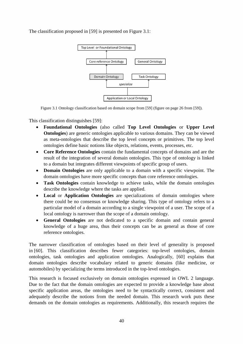
40
The classification proposed in [59] is presented on Figure 3.1:
Figure 3.1 Ontology classification based on domain scope from [59] (figure on page 26 from [59]).
This classification distinguishes [59]:
Foundational Ontologies (also called Top Level Ontologies or Upper Level
Ontologies) are generic ontologies applicable to various domains. They can be viewed
as meta-ontologies that describe the top level concepts or primitives. The top level
ontologies define basic notions like objects, relations, events, processes, etc.
Core Reference Ontologies contain the fundamental concepts of domains and are the
result of the integration of several domain ontologies. This type of ontology is linked
to a domain but integrates different viewpoints of specific group of users.
Domain Ontologies are only applicable to a domain with a specific viewpoint. The
domain ontologies have more specific concepts than core reference ontologies.
Task Ontologies contain knowledge to achieve tasks, while the domain ontologies
describe the knowledge where the tasks are applied.
Local or Application Ontologies are specializations of domain ontologies where
there could be no consensus or knowledge sharing. This type of ontology refers to a
particular model of a domain according to a single viewpoint of a user. The scope of a
local ontology is narrower than the scope of a domain ontology.
General Ontologies are not dedicated to a specific domain and contain general
knowledge of a huge area, thus their concepts can be as general as those of core
reference ontologies.
The narrower classification of ontologies based on their level of generality is proposed
in [60]. This classification describes fewer categories: top-level ontologies, domain
ontologies, task ontologies and application ontologies. Analogically, [60] explains that
domain ontologies describe vocabulary related to generic domains (like medicine, or
automobiles) by specializing the terms introduced in the top-level ontologies.
This research is focused exclusively on domain ontologies expressed in OWL 2 language.
Due to the fact that the domain ontologies are expected to provide a knowledge base about
specific application areas, the ontologies need to be syntactically correct, consistent and
adequately describe the notions from the needed domain. This research work puts these
demands on the domain ontologies as requirements. Additionally, this research requires the
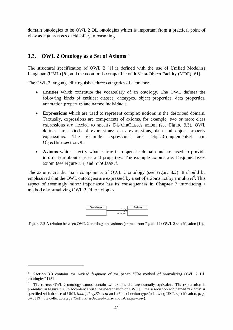
41
domain ontologies to be OWL 2 DL ontologies which is important from a practical point of
view as it guarantees decidability in reasoning.
3.3. OWL 2 Ontology as a Set of Axioms 5
The structural specification of OWL 2 [1] is defined with the use of Unified Modeling
Language (UML) [9], and the notation is compatible with Meta-Object Facility (MOF) [61].
The OWL 2 language distinguishes three categories of elements:
Entities which constitute the vocabulary of an ontology. The OWL defines the
following kinds of entities: classes, datatypes, object properties, data properties,
annotation properties and named individuals.
Expressions which are used to represent complex notions in the described domain.
Textually, expressions are components of axioms, for example, two or more class
expressions are needed to specify DisjointClasses axiom (see Figure 3.3). OWL
defines three kinds of expressions: class expressions, data and object property
expressions. The example expressions are: ObjectComplementOf and
ObjectIntersectionOf.
Axioms which specify what is true in a specific domain and are used to provide
information about classes and properties. The example axioms are: DisjointClasses
axiom (see Figure 3.3) and SubClassOf.
The axioms are the main components of OWL 2 ontology (see Figure 3.2). It should be
emphasized that the OWL ontologies are expressed by a set of axioms not by a multiset6. This
aspect of seemingly minor importance has its consequences in Chapter 7 introducing a
method of normalizing OWL 2 DL ontologies.
Figure 3.2 A relation between OWL 2 ontology and axioms (extract from Figure 1 in OWL 2 specification [1]).
5 Section 3.3 contains the revised fragment of the paper: "The method of normalizing OWL 2 DL
ontologies" [13]. 6 The correct OWL 2 ontology cannot contain two axioms that are textually equivalent. The explanation is
presented in Figure 3.2. In accordance with the specification of OWL [1] the association end named "axioms" is
specified with the use of UML MultiplicityElement and a Set collection type (following UML specification, page
34 of [9], the collection type "Set" has isOrdered=false and isUnique=true).
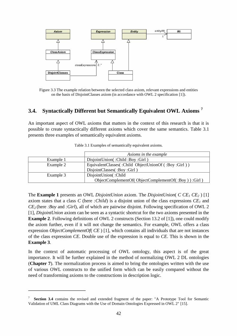
42
Figure 3.3 The example relation between the selected class axiom, relevant expressions and entities
on the basis of DisjointClasses axiom (in accordance with OWL 2 specification [1]).
3.4. Syntactically Different but Semantically Equivalent OWL Axioms 7
An important aspect of OWL axioms that matters in the context of this research is that it is
possible to create syntactically different axioms which cover the same semantics. Table 3.1
presents three examples of semantically equivalent axioms.
Table 3.1 Examples of semantically equivalent axioms.
Axioms in the example
Example 1 DisjointUnion( :Child :Boy :Girl )
Example 2 EquivalentClasses( :Child ObjectUnionOf ( :Boy :Girl ) )
DisjointClasses( :Boy :Girl )
Example 3 DisjointUnion( :Child
ObjectComplementOf( ObjectComplementOf( :Boy ) ) :Girl )
The Example 1 presents an OWL DisjointUnion axiom. The DisjointUnion( C CE1 CE2 ) [1]
axiom states that a class C (here :Child) is a disjoint union of the class expressions CE1 and
CE2 (here :Boy and :Girl), all of which are pairwise disjoint. Following specification of OWL 2
[1], DisjointUnion axiom can be seen as a syntactic shortcut for the two axioms presented in the
Example 2. Following definitions of OWL 2 constructs (Section 13.2 of [1]), one could modify
the axiom further, even if it will not change the semantics. For example, OWL offers a class
expression ObjectComplementOf( CE ) [1], which contains all individuals that are not instances
of the class expression CE. Double use of the expression is equal to CE. This is shown in the
Example 3.
In the context of automatic processing of OWL ontology, this aspect is of the great
importance. It will be further explained in the method of normalizing OWL 2 DL ontologies
(Chapter 7). The normalization process is aimed to bring the ontologies written with the use
of various OWL constructs to the unified form which can be easily compared without the
need of transforming axioms to the constructions in description logic.
7 Section 3.4 contains the revised and extended fragment of the paper: "A Prototype Tool for Semantic
Validation of UML Class Diagrams with the Use of Domain Ontologies Expressed in OWL 2" [15].
43
3.5. Reasoning in OWL Ontologies
According to [48], using formal semantics allows humans to reason about the knowledge. As
described in [19]: "a reasoner is a utility that automatically infers the logical consequences
from a set of logical facts".
The reasoners provide services [62]. The standard reasoning services for TBox are [63]:
satisfiability and subsumption, and for ABox are [63]: instance checking, consistency,
realization and retrieval:
consistency check verifies if every individual is an instance of only satisfiable classes,
satisfiability checking is useful for verifying if an ontology is meaningful (i.e., if all
classes are instantable),
subsumption is useful to hierarchically organize classes according to their generality,
instance checking is used to check if a given individual belongs to the set described
by the given class,
realization identifies the most specific class a given individual belongs to,
retrieval identifies individuals that belong to a given concept.
The above mentioned reasoning services are conducted by OWL reasoners (reasoning
engines) [4]. There are different semantic reasoners designed to work with OWL ontologies.
The detailed comparison of eight popular OWL 2 EL and tableau-based reasoners: CB8,
CEL9, FaCT++
10, HermiT
11, Pellet
12, RacerPro
13, Snorocket
14 and TrOWL
15 can be found in
the article [64] from 2011. This link: http://owl.cs.manchester.ac.uk/tools/list-of-reasoners/
presents a wide list of other currently available OWL reasoners, including the less popular one
(the webpage has been last updated in June 2018).
This research has selected HermiT reasoner due to the fact that it has many benefits important
from the perspective of this research (the overview of its main characteristics is presented in
Table 3.2).
8 CB website: https://www.cs.ox.ac.uk/isg/tools/CB/.
9 CEL website: https://github.com/julianmendez/cel.
10 FaCT++ website: https://code.google.com/archive/p/factplusplus/.
11 HermiT OWL Reasoner website: http://www.hermit-reasoner.com/.
12 Pellet website: https://github.com/Complexible/pellet.
13 RacerPro website: http://www.ifis.uni-luebeck.de/~moeller/racer/.
14 Snorocket website: https://aehrc.com/snorocket/.
15 TrOWL website: http://trowl.org/.
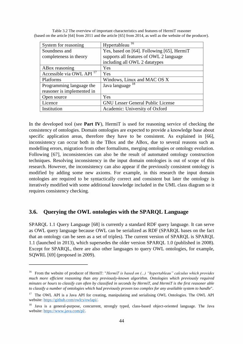
44
Table 3.2 The overview of important characteristics and features of HermiT reasoner
(based on the article [64] from 2011 and the article [65] from 2014, as well as the website of the producer).
System for reasoning Hypertableau 16
Soundness and
completeness in theory
Yes, based on [64]. Following [65], HermiT
supports all features of OWL 2 language
including all OWL 2 datatypes
ABox reasoning Yes
Accessible via OWL API 17
Yes
Platforms Windows, Linux and MAC OS X
Programming language the
reasoner is implemented in
Java language 18
Open source Yes
Licence GNU Lesser General Public License
Institution Academic: University of Oxford
In the developed tool (see Part IV), HermiT is used for reasoning service of checking the
consistency of ontologies. Domain ontologies are expected to provide a knowledge base about
specific application areas, therefore they have to be consistent. As explained in [66],
inconsistency can occur both in the TBox and the ABox, due to several reasons such as
modelling errors, migration from other formalisms, merging ontologies or ontology evolution.
Following [67], inconsistencies can also be the result of automated ontology construction
techniques. Resolving inconsistency in the input domain ontologies is out of scope of this
research. However, the inconsistency can also appear if the previously consistent ontology is
modified by adding some new axioms. For example, in this research the input domain
ontologies are required to be syntactically correct and consistent but later the ontology is
iteratively modified with some additional knowledge included in the UML class diagram so it
requires consistency checking.
3.6. Querying the OWL ontologies with the SPARQL Language
SPARQL 1.1 Query Language [68] is currently a standard RDF query language. It can serve
as OWL query language because OWL can be serialized as RDF (SPARQL bases on the fact
that an ontology can be seen as a set of triples). The current version of SPARQL is SPARQL
1.1 (launched in 2013), which supersedes the older version SPARQL 1.0 (published in 2008).
Except for SPARQL, there are also other languages to query OWL ontologies, for example,
SQWRL [69] (proposed in 2009).
16 From the website of producer of HermiT: "HermiT is based on (...) “hypertableau” calculus which provides
much more efficient reasoning than any previously-known algorithm. Ontologies which previously required
minutes or hours to classify can often by classified in seconds by HermiT, and HermiT is the first reasoner able
to classify a number of ontologies which had previously proven too complex for any available system to handle". 17
The OWL API is a Java API for creating, manipulating and serialising OWL Ontologies. The OWL API
website: https://github.com/owlcs/owlapi/. 18
Java is a general-purpose, concurrent, strongly typed, class-based object-oriented language. The Java
website: https://www.java.com/pl/.
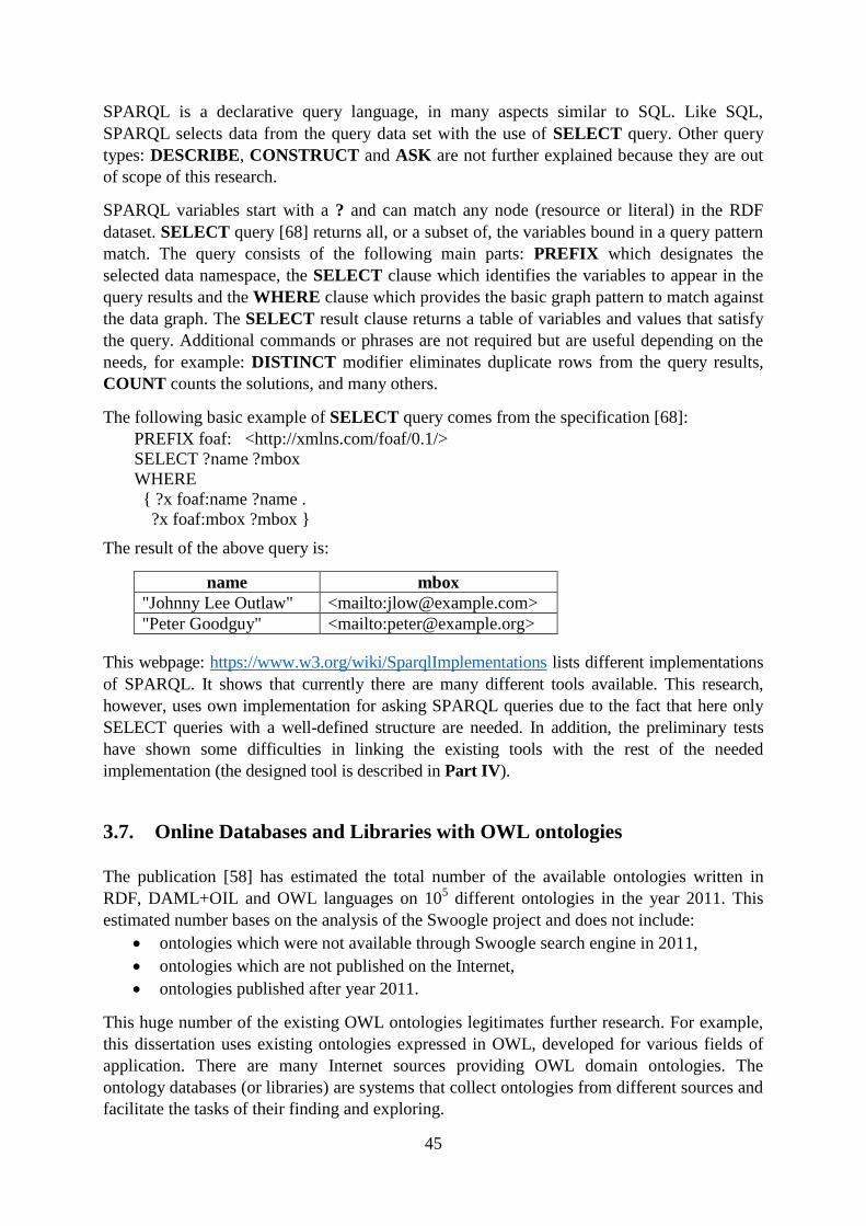
45
SPARQL is a declarative query language, in many aspects similar to SQL. Like SQL,
SPARQL selects data from the query data set with the use of SELECT query. Other query
types: DESCRIBE, CONSTRUCT and ASK are not further explained because they are out
of scope of this research.
SPARQL variables start with a ? and can match any node (resource or literal) in the RDF
dataset. SELECT query [68] returns all, or a subset of, the variables bound in a query pattern
match. The query consists of the following main parts: PREFIX which designates the
selected data namespace, the SELECT clause which identifies the variables to appear in the
query results and the WHERE clause which provides the basic graph pattern to match against
the data graph. The SELECT result clause returns a table of variables and values that satisfy
the query. Additional commands or phrases are not required but are useful depending on the
needs, for example: DISTINCT modifier eliminates duplicate rows from the query results,
COUNT counts the solutions, and many others.
The following basic example of SELECT query comes from the specification [68]:
PREFIX foaf: <http://xmlns.com/foaf/0.1/>
SELECT ?name ?mbox
WHERE
{ ?x foaf:name ?name .
?x foaf:mbox ?mbox }
The result of the above query is:
name mbox
"Johnny Lee Outlaw" <mailto:[email protected]>
"Peter Goodguy" <mailto:[email protected]>
This webpage: https://www.w3.org/wiki/SparqlImplementations lists different implementations
of SPARQL. It shows that currently there are many different tools available. This research,
however, uses own implementation for asking SPARQL queries due to the fact that here only
SELECT queries with a well-defined structure are needed. In addition, the preliminary tests
have shown some difficulties in linking the existing tools with the rest of the needed
implementation (the designed tool is described in Part IV).
3.7. Online Databases and Libraries with OWL ontologies
The publication [58] has estimated the total number of the available ontologies written in
RDF, DAML+OIL and OWL languages on 105 different ontologies in the year 2011. This
estimated number bases on the analysis of the Swoogle project and does not include:
ontologies which were not available through Swoogle search engine in 2011,
ontologies which are not published on the Internet,
ontologies published after year 2011.
This huge number of the existing OWL ontologies legitimates further research. For example,
this dissertation uses existing ontologies expressed in OWL, developed for various fields of
application. There are many Internet sources providing OWL domain ontologies. The
ontology databases (or libraries) are systems that collect ontologies from different sources and
facilitate the tasks of their finding and exploring.
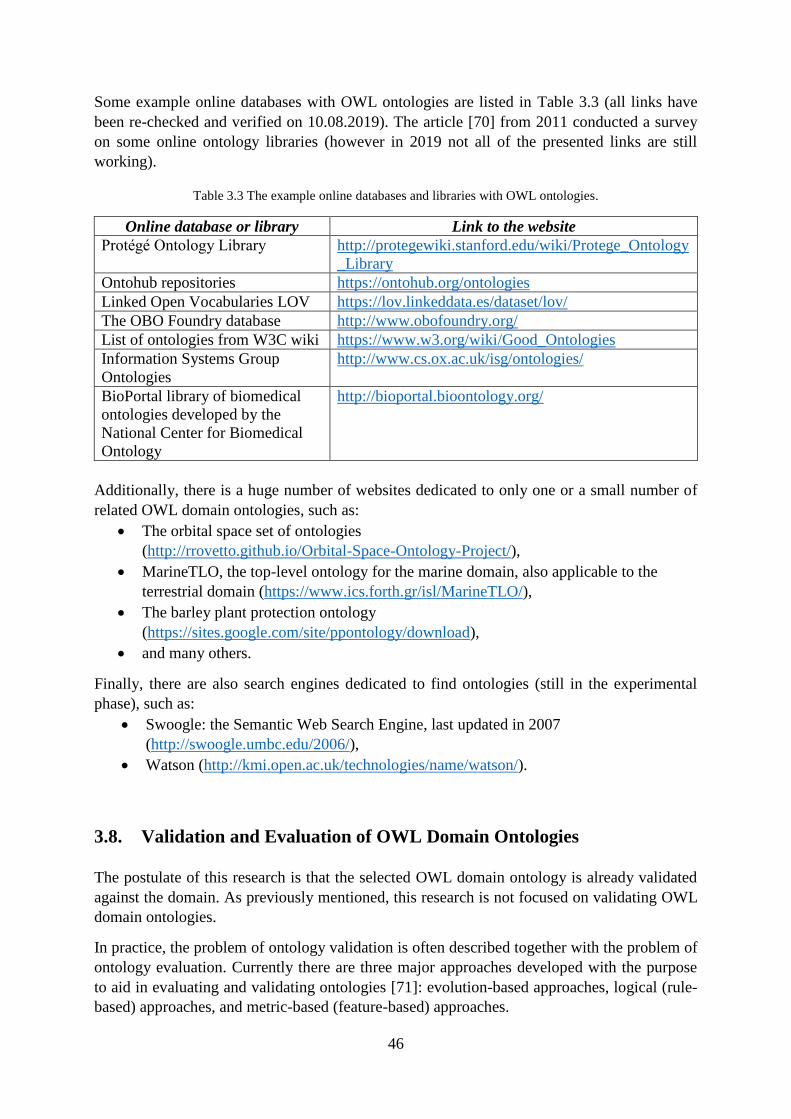
46
Some example online databases with OWL ontologies are listed in Table 3.3 (all links have
been re-checked and verified on 10.08.2019). The article [70] from 2011 conducted a survey
on some online ontology libraries (however in 2019 not all of the presented links are still
working).
Table 3.3 The example online databases and libraries with OWL ontologies.
Online database or library Link to the website
Protégé Ontology Library http://protegewiki.stanford.edu/wiki/Protege_Ontology
_Library
Ontohub repositories https://ontohub.org/ontologies
Linked Open Vocabularies LOV https://lov.linkeddata.es/dataset/lov/
The OBO Foundry database http://www.obofoundry.org/
List of ontologies from W3C wiki https://www.w3.org/wiki/Good_Ontologies
Information Systems Group
Ontologies
http://www.cs.ox.ac.uk/isg/ontologies/
BioPortal library of biomedical
ontologies developed by the
National Center for Biomedical
Ontology
http://bioportal.bioontology.org/
Additionally, there is a huge number of websites dedicated to only one or a small number of
related OWL domain ontologies, such as:
The orbital space set of ontologies
(http://rrovetto.github.io/Orbital-Space-Ontology-Project/),
MarineTLO, the top-level ontology for the marine domain, also applicable to the
terrestrial domain (https://www.ics.forth.gr/isl/MarineTLO/),
The barley plant protection ontology
(https://sites.google.com/site/ppontology/download),
and many others.
Finally, there are also search engines dedicated to find ontologies (still in the experimental
phase), such as:
Swoogle: the Semantic Web Search Engine, last updated in 2007
(http://swoogle.umbc.edu/2006/),
Watson (http://kmi.open.ac.uk/technologies/name/watson/).
3.8. Validation and Evaluation of OWL Domain Ontologies
The postulate of this research is that the selected OWL domain ontology is already validated
against the domain. As previously mentioned, this research is not focused on validating OWL
domain ontologies.
In practice, the problem of ontology validation is often described together with the problem of
ontology evaluation. Currently there are three major approaches developed with the purpose
to aid in evaluating and validating ontologies [71]: evolution-based approaches, logical (rule-
based) approaches, and metric-based (feature-based) approaches.
47
The evolution-based approaches [71] track changes in characteristics of ontologies. The
ontologies change over time mainly due to changes in the domain, changes in
conceptualization (which can result from changing a usage perspective) or changes in the
explicit specification (which can occur when an ontology is translated from one knowledge
representation language to another). The approaches from this group detect and possibly
recover any invalid changes which may appear in the ontologies.
The logical (rule-based) approaches [71] use rules which are built in the ontology languages
and rules users provided to detect conflicts in ontologies. In case of OWL language the
example of such a rule is specifying both DifferentIndividuals axiom and SameIndividual
axiom for the same individuals.
The metric-based (feature-based) approaches [71] offer a quantitative perspective of ontology
quality achieved through scanning the ontology with the purpose to gather different types of
statistics about the knowledge presented in the ontology. The metric-based approaches are
widely researched and there exist many tools offering different options.
Validation and evaluation of OWL domain ontologies is not trivial and should be conducted
by domain specialists. The need for ontology evaluation appears e.g. if there exist several
ontologies with similar area of interest. For example, many ontologies have been created for
biomedical field. If more than one ontology covers a similar content it may be difficult to find
one most suitable ontology without making time-consuming insight into the ontologies.
A good practice is to always read the additional information attached to the selected ontology
(such as included annotations, webpages or included files) with the purpose to find
information about its validation. The information may help to assess if the ontology is suitable
for the user's needs or to select the ontology among different ontologies which best fit to a
certain application.
3.9. Similarities and Differences of UML and OWL 2 Notations
In spite of existing differences, many similar or equivalent elements between UML 2.5 and
OWL 2 notations justify the research focused on creating transformation between the
notations. Following [72], the similarities allow for translating UML class diagrams into
description logic, which gives UML modelling a model-theoretic semantic. The below
summary presents major similarities and differences which have significant impact on the
research presented in this dissertation.
3.9.1. Major Similarities Between UML and OWL 2 Notations
3.9.1.1. Similarities in Semantics
UML [9] modelling language is semi-formal because it has a formally defined syntax using a
subset of UML and informally defined semantics in natural language. The semantics in UML
class diagrams have a reference to a selected reality and describes meaning of the used terms
48
(classes and their relationships). OWL 2 [1] is a formal language with a model-theoretic
semantics. The semantics of ontologies expressed in OWL 2 have a relation to the entities in
the specific domain, similarly as it is in case of UML class diagrams.
In this research, the concept of semantics refers to the elements from both descriptions
(UML class diagram and OWL 2 ontology) with respect to the same domain of application.
3.9.1.2. Compatibility with MOF
The Meta-Object Facility (MOF) [61] is an OMG standard for model-driven engineering.
MOF defines a four-layer structure. The top level (M3 layer) defines meta-meta model, which
is used to build metamodels (M2 layer), the model level (M1) contains concrete models and
(M0) describes real-world objects.
The current version of the MOF specification is 2.5.1 and this version of the specification is
aligned with the UML 2.5 specification [9]. Also, the structural specification of OWL 2 [1] is
defined using UML, and the notation used is compatible with MOF.
The article [51] expounds that both UML and OWL 2 language definitions refer to
comparable meta-models laid down in terms of MOF, but in contrast to UML, OWL 2 is fully
built upon formal logic which allows logical reasoning on OWL 2 ontologies.
3.9.1.3. Similar Constructs in OWL 2 and UML
Many researchers (e.g. [5], [73], [74], [75]) point out that UML and OWL share similar
constructs. What is the most important, and was highlighted e.g. in [76], both UML and OWL
make an equal distinction between “Classes” and “Instances” (or “Individuals” respectively).
Both languages use many other similar or equivalent terms, e.g.
OWL “SubClassOf” class axiom has the reflection in UML “Generalization” between
the classes,
OWL “Cardinality” has the correspondence in UML “Multiplicity”,
the concept of “Enumeration” in UML, and “DatatypeDefinition” axiom and
enumeration of literals with the use of DataOneOf data range in OWL,
and many others - please refer to Chapter 3.9 which analyses the similar constructs
of OWL and UML in great detail.
3.9.2. Major Differences Between UML and OWL 2 Notations
3.9.2.1. The Word Assumptions
UML and OWL languages operate on the opposite assumptions (e.g. [5], [51], [77]). The
UML models follow the so-called “closed-world assumption” and OWL 2 ontologies the
“open-world assumption”.
The closed-world assumption (CWA) requires the complete knowledge to be provided and
what is not known is assumed false, or in other words, all statements that have not been
mentioned explicitly are false (e.g. [5], [51], [77]).
49
The open-world assumption (OWA) does not consider to provide complete knowledge [77],
and it does not assume falsity for the unknown [5]. In this assumption, the missing
information is treated as undeclared [51]. This assumption is used in OWL 2 (e.g. [51], [77]).
As it is reminded in [51], these different semantics require us to add various restrictions
during the transformation process from UML models to OWL 2 ontologies in order to
preserve the semantics of the models.
3.9.2.2. Name Assumption
UML follows a Unique Name Assumption (UNA), which states that two elements with
different names are treated as different (e.g. [74]). OWL 2 follows No Unique Name
Assumption, which means that in OWL 2 one have to explicitly mark elements as being
different (e.g. [74], [78]). For example, OWL 2 does not assume unique names for
individuals.
Additionally, OWL 2 uses Internationalized Resource Identifier (IRI) to name elements of an
ontology. What is important, all assigned names have global scope, regardless of the context
in which they are used.
3.9.2.3. Different Constructs in OWL 2 and UML
Some researchers point out that there are UML elements which do not have the equivalence in
OWL 2 constructs, for example: ordering (e.g. [19]), non-unique properties (e.g. [19]), OCL
constructs (e.g. [19]), abstract class (e.g. [51]), visibility of model elements (e.g. [51]),
operations (e.g. [51], [62]), and others. These elements, however, appeared to be not
frequently used in business and conceptual modelling with UML class diagrams
(Section 2.3).
On the other hand, there are many OWL 2 constructs which do not have the equivalence in
UML elements, for example, EquivalentClasses axiom, ObjectHasSelf class expressions, and
many others. Another example of different constructs is presented in [51]: OWL 2 allows to
use the complement of classes and datatypes, in UML this is not generally possible. What is
more, OWL 2 provides a wide list of primitive datatypes in comparison with only five
predefined in UML (see Section 8.3.4).
3.10. Conclusions
Using OWL 2 ontologies in the phase of business and conceptual modelling with UML class
diagrams is justified in terms of improving the quality of UML class diagrams and by the
aspect of reduction of costs associated with the required assessments of diagrams by domain
specialists. In order to benefit from these advantages, a precise mapping between the UML
and OWL notation taking into account the semantics of both languages is first required. The
differences between OWL 2 and UML 2.5 languages presented in this chapter have their
impact on the form of transformation between UML class diagrams and OWL 2
representation of the diagrams. It is further explained in Section 8.4.

50
Part II
Creation and Validation of UML Class
Diagrams Supported by OWL 2 Ontologies
Part II: Creation and Validation of UML Class
Diagrams Suported by OWL 2 Ontologies

51
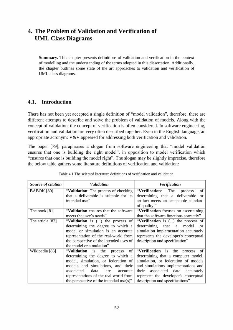
52
4. The Problem of Validation and Verification of
UML Class Diagrams
Summary. This chapter presents definitions of validation and verification in the context
of modelling and the understanding of the terms adopted in this dissertation. Additionally,
the chapter outlines some state of the art approaches to validation and verification of
UML class diagrams.
4.1. Introduction
There has not been yet accepted a single definition of “model validation”, therefore, there are
different attempts to describe and solve the problem of validation of models. Along with the
concept of validation, the concept of verification is often considered. In software engineering,
verification and validation are very often described together. Even in the English language, an
appropriate acronym: V&V appeared for addressing both verification and validation.
The paper [79], paraphrases a slogan from software engineering that “model validation
ensures that one is building the right model”, in opposition to model verification which
“ensures that one is building the model right”. The slogan may be slightly imprecise, therefore
the below table gathers some literature definitions of verification and validation:
Table 4.1 The selected literature definitions of verification and validation.
Source of citation Validation Verification
BABOK [80] “Validation: The process of checking
that a deliverable is suitable for its
intended use”
“Verification: The process of
determining that a deliverable or
artifact meets an acceptable standard
of quality.”
The book [81] “Validation ensures that the software
meets the user‟s needs”
“Verification focuses on ascertaining
that the software functions correctly”
The article [82] “Validation is (...) the process of
determining the degree to which a
model or simulation is an accurate
representation of the real-world from
the perspective of the intended uses of
the model or simulation”
“Verification is (...) the process of
determining that a model or
simulation implementation accurately
represents the developer's conceptual
description and specification”
Wikipedia [83] “Validation is the process of
determining the degree to which a
model, simulation, or federation of
models and simulations, and their
associated data are accurate
representations of the real world from
the perspective of the intended use(s)”
“Verification is the process of
determining that a computer model,
simulation, or federation of models
and simulations implementations and
their associated data accurately
represent the developer's conceptual
description and specifications”
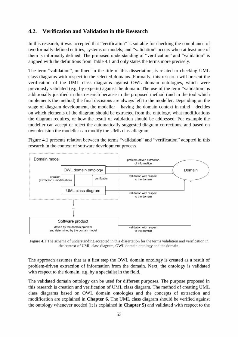
53
4.2. Verification and Validation in this Research
In this research, it was accepted that “verification” is suitable for checking the compliance of
two formally defined entities, systems or models; and “validation” occurs when at least one of
them is informally defined. The proposed understanding of “verification” and “validation” is
aligned with the definitions from Table 4.1 and only states the terms more precisely.
The term “validation”, outlined in the title of this dissertation, is related to checking UML
class diagrams with respect to the selected domains. Formally, this research will present the
verification of the UML class diagrams against OWL domain ontologies, which were
previously validated (e.g. by experts) against the domain. The use of the term “validation” is
additionally justified in this research because in the proposed method (and in the tool which
implements the method) the final decisions are always left to the modeller. Depending on the
stage of diagram development, the modeller having the domain context in mind decides
on which elements of the diagram should be extracted from the ontology, what modifications
the diagram requires, or how the result of validation should be addressed. For example the
modeller can accept or reject the automatically suggested diagram corrections, and based on
own decision the modeller can modify the UML class diagram.
Figure 4.1 presents relation between the terms “validation” and “verification” adopted in this
research in the context of software development process.
Figure 4.1 The schema of understanding accepted in this dissertation for the terms validation and verification in
the context of UML class diagram, OWL domain ontology and the domain.
The approach assumes that as a first step the OWL domain ontology is created as a result of
problem-driven extraction of information from the domain. Next, the ontology is validated
with respect to the domain, e.g. by a specialist in the field.
The validated domain ontology can be used for different purposes. The purpose proposed in
this research is creation and verification of UML class diagram. The method of creating UML
class diagrams based on OWL domain ontologies and the concepts of extraction and
modification are explained in Chapter 6. The UML class diagram should be verified against
the ontology whenever needed (it is explained in Chapter 5) and validated with respect to the
54
domain. As already mentioned the aspect of validation of UML class diagrams their relation
to user requirements specification is out of scope of this research.
4.3. The Literature Approaches to Verification of UML Class Diagrams
This section presents selected literature approaches to verification of UML class diagrams.
The existing methods for verification of UML class diagrams can be divided into two main
groups: the methods of complete verification and the methods of partial verification:
The complete verification methods rely on logical proving whether one model satisfies
all properties expressed by another model. The method of verification proposed in this
dissertation belongs to this group the designed UML class diagrams are verified against
OWL domain ontologies.
The partial verification methods are practical approaches which involve testing, for
example by generating UML object diagrams that are test cases for a selected UML class
diagram.
There are many publications which formalize UML class diagrams with the use of
mathematical approaches and the works are often a starting point for methods of verification
of UML class diagrams. Just to provide an example: the paper [84] formalizes UML class
diagrams with the use of description logics, the paper [85] mathematically defines UML class
diagram and its semantics, and many others. The paper [86] from 2014, lists 48 resources as a
result of systematic literature review on topic of formal verification of static models, and it
draws a conclusion that the most typical formal methods employed in the model verification
approaches are:
a) formalization by means of logical representation such as First-Order Logic (FOL),
Description Logic (DL), Higher-Order Logic (HOL) or others,
b) the use of specialization languages like B or Object-Z,
c) encode the problem of model verification as Constraint Satisfaction Problem (CSP),
d) by means of other mathematical notations.
A wide group of literature approaches on verification of UML class diagrams is focused on
techniques examining the diagrams with OCL constraints. The article [87] presents guidelines
for future UML and OCL models verification methods (the proposed guidelines may be
considered as functional requirements for new verification methods and tools). The paper [88]
proposes a method for verification of UML class diagrams with OCL. In the method the class
diagram is first transformed into the OWL ontology and OCL constraints are transformed into
the SPARQL ASK19
. The translation of the diagram includes UML classes with attributes of
primitive type and binary associations between the classes. In the next step, the correctness of
the diagram is verified against the constraints and the feedback is returned to the user. The
method has been implemented in a prototype tool, planned for further development. Similar
approach is proposed in the article [89], which describes a tool called MOVA for drawing
UML class and object diagrams with OCL invariants, queries and operations. The tool offers
features for checking OCL constraints over instances of UML class diagrams. Another
19 SPARQL ASK query is used to test if a query pattern has a solution:
https://www.w3.org/TR/rdf-sparql-query/#ask.
55
approach is presented in the article [90], which describes an automatic method for formal
verification of UML class diagrams extended with OCL constraints, which uses the paradigm
of constraint programming. In the prototype tool, both class diagrams and OCL constraints are
translated into a constraint satisfaction problem. Then, compliance of the diagram with
respect to several correctness properties such as weak and strong satisfiability or absence of
constraint redundancies is verified.
The article [88] from 2018, proposes an OWL ontology-based verification method for UML
class diagram with OCL invariants. The method proposes transformation of three selected
types of UML elements: UML classes, attributes and associations into OWL. The verification
analysis is based on running the reasoner after creating a large number of instances of the
classes from the UML class diagram. What has to be noted, the UML-OWL transformation
proposed in [88] is not wider explained and may be not fully clear.
4.4. The Literature Approaches to Validation of UML Class Diagrams
This section presents selected literature approaches to validation of UML class diagrams,
divided into two groups: manual and supported by tool. The commonly used approaches for
model validation are manual. Much fewer propositions can be found for the tool-based model
validation but please note that they also require expert's analysis and decision.
4.4.1. The Manual Approaches to Validation of UML Class Diagrams
Three traditional quality techniques used for validation of UML models are [81]:
walkthroughs, inspections and reviews, each of which requires judgement of domain
experts. As is suggested in [91], the quality techniques help users to carry out checks from
elements of diagrams (e.g. single classes) to complete models. More than one quality
technique can be used in combination, in order to accomplish the quality goals of the models.
Following [91], a walkthrough is a relatively informal technique as it is a simple look
through a UML diagram. A modeller can do a walkthrough himself, however, it is important
to treat the walkthrough as a separate activity from the activity of modelling. In accordance
with [91], the intention with walkthrough is not to locate errors formally, but to simply ensure
that no major gaps have been left in the model. In [81], a walkthrough is assessed as more
helpful to detect syntax rather than semantic errors.
In [91], an inspection is described as more formal and more robust in ensuring the quality of
a particular artefact than a walkthrough. It is advisable that the inspection is done by someone
other than the one who has produced the model. In [81], an inspection is explained as a
method that can be used to identify both syntax and semantic errors. Also [10] and [92],
indicate that validation if the model correctly captures the intended domain knowledge mostly
entails its manual inspection.
In accordance with [91] and [81], a review is a technique that ensures that a particular
deliverable is meeting its syntax, semantics, and aesthetics criteria. In a UML-based project, a
review can be carried out on an entire model. It especially makes sense at the level of a model
or a collection of diagrams, because the inconsistencies or incompleteness are not apparent
56
when only a single artefact is inspected. Each review should end with a follow-up task list,
including brief meetings to ensure that all errors and criticisms have been addressed by the
modellers.
4.4.2. The Tool-Supported Approaches to Validation of UML Class Diagrams
The tool-supported approaches to validation of UML class diagrams vary a lot on their scope
of possibilities. The following are some selected literature approaches.
The article [92] presents a method and a tool called MOTHIA for model validation. The tool
generates a set of yes/no questions to the model and for each question the automatically
generated answer is produced. The approach requires judgement of the domain expert in
every case but the validation process is partially automated.
Some literature approaches assume that the static aspect is correct, and aim at constructing a
prototype with the purpose of researching its behaviour. These approaches focus mainly on
validation of behaviour of the diagrams. For example, the paper [93] proposes a method of
validation of UML classes through animation and presents a tool supporting the method
through generating a prototype from the conceptual model and executing scenarios obtained
from stakeholders (in this approach the stakeholders express their requirements as scenarios,
the analyst builds the conceptual model and by means of an animation environment a
prototype is generated automatically). When the prototype is started the behaviour of objects
may be examined by observing the occurring actions and the reached states. As a result, the
expected behaviour from the scenarios is compared with the obtained result and the initial
model is corrected if needed.
The paper [79], proposes a framework for validation and execution of UML diagrams such as
class, object or interaction diagrams. With the use of the framework the modeller can map
UML diagrams into programs in a modelling object language called MOL (the authors present
syntax and semantics for MOL). Thus obtained MOL programs can be executed and
debugged in an integrated development environment called iMOL.
The article [94] introduces a grammar-based approach to validation of UML class diagrams.
The approach involves representing the diagram with the use of Domain-Specific Language
(DSL), which is a language designed specifically for a particular domain. The authors propose
to conduct an XSLT transformation in order to convert an XML representation of a UML
class diagram to its DSL representation. The class diagram is validated by using use case
scenarios to test whether the current class diagram can generate the particular scenario. For
this purpose, the modeller should introduce some positive and negative use cases in the form
of strings. Finally, a string similarity measure is employed in order to provide feedback to the
user regarding validation.
The literature also describes a more narrow understanding of validation as checking the
consistency between the versions of UML class diagrams or checking the consistency
between different diagrams. For example, the paper [19] transforms the selected elements of
UML models containing multiple UML class, object and statechart diagrams into OWL in
order to analyze consistency of the models. A similar approach is presented in [95], which is
focused on detecting inconsistency in models containing UML class diagrams and UML
statechart diagrams. The article [18] proposes an approach to detect and resolve
57
inconsistencies between different versions of a UML model, specified as a collection of UML
class diagrams, UML sequence diagrams and UML statechart diagrams.
4.5. Conclusions
The literature describes different approaches to V&V of UML class diagrams which base on
different understanding of terms: validation and verification. By the term “validation”, this
dissertation understands checking the designed UML class diagram with respect to the
selected domain. The essential step of the checking bases on automatic verification of the
diagram against selected OWL domain ontology.
58
5. Outline of the Process of Validation of UML Class Diagrams
Summary. This chapter outlines a method for semantic validation of UML class
diagrams with respect to the selected domains. The method checks the semantic
compliance of the diagrams with respect to the domains they describe. An important step
in the method is the manual analysis of the automatically generated results of verification
of the designed UML class diagram against the selected domain ontology expressed in
OWL. In more detail, the automatic verification checks if all diagram elements and their
relationships are contained or at least are not contradictory with the domain knowledge
extracted from the selected ontology. With the use of the method, providing that some
well-defined requirements are satisfied, verification of UML class diagrams can be
conducted without involving domain experts in the process, therefore validation is also
semi-automated. 20
5.1. Introduction
The aim of this chapter is to present an outline of the method for validation of UML class
diagrams. In this dissertation, the term “validation” is related to checking UML class diagram
with respect to the selected domain (Section 4.2). The important step in the method is an
automatic verification of the designed UML class diagram against the domain ontology
expressed in OWL, which has been previously validated against the domain (see Section 3.8).
In the proposed method the final validation decision is always left to the modeller. At any
time of diagram creation, the modeller decides on the diagram content keeping in mind its
intended use (see Chapter 6). Additionally, on the basis of the automatically generated result
of verification the modeller decides if he or she accepts or rejects the suggested diagram
corrections and how he or she would like to modify the UML class diagram.
The proposed approach is concerned on verifying if all diagram elements and relationships
among the elements are contained (or not) in the field described by an OWL domain ontology
selected by the modeller. In other words, the method is designed to automatically verify the
semantics of a designed diagram and it states whether the diagram is correct in accordance
with the domain.
The proposed method has the advantage that it allows to check UML class diagrams
whenever needed, in any stage of development, even if the diagrams are not yet complete.
However, it should be underlined that the relevance of the diagram with respect to the user
needs is left to the modeller and is out of scope of this research.
This chapter is organized as follows: Section 5.2 lists requirements for the proposed method
of semantic validation of UML class diagrams, Section 5.3 introduces necessary definitions
and gives the outline of the method, Section 5.4 presents possible results of verification,
20 Chapter 5 contains the revised and extended version of the paper: "Semantic validation of UML class
diagrams with the use of domain ontologies expressed in OWL 2" [12].
59
Section 5.5 discusses limitations of the method and final Section 5.6 concludes the chapter.
The details of the validation method are presented in the following Part III.
5.2. Requirements for the Method of Validation
The method assumes that the following three requirements are satisfied:
Requirement 1: The UML class diagram and the OWL domain ontology must follow one
agreed domain vocabulary. This requirement will be automatically satisfied if the
UML class diagram is directly extracted from the ontology (as further explained in
Chapter 6). Alternatively, if the designed diagram is not based on any ontology, the
requirement can be assured by a domain expert.
Requirement 2: The designed UML class diagram is expected to be syntactically correct,
in accordance with the UML specification21
. Additionally, All class attributes and all
association ends in one UML class diagram need to be uniquely named. If there were
the same names e.g. for attributes in one diagram, they would be mapped to one OWL
element which would cause loss of information (semantics) after the transformation. If
such a situation happens, the modeller can be dealt with it by renaming names of
attributes or association ends in the diagram.
Requirement 3: The method requires the OWL domain ontology selected by the
modeller to be syntactically correct and consistent. Moreover, the ontology has to be
validated (e.g. by domain specialist), due to the fact that it has to adequately describe
the selected domain as it will serve as knowledge base for the application area.
5.3. Description of the Method of Validation
5.3.1. Outline of the Method of Validation
The proposed method of semantic validation of UML class diagrams, at first requires a
translation of the diagram to its OWL representation. Both the domain ontology and the class
diagram need to be presented in the same notation – in the form of a set of OWL axioms.
There are two input elements to the method: the OWL 2 domain ontology selected by the
modeller ( ) and the UML class diagram ( ).
The validation method is graphically illustrated in Figure 5.1 in the flow diagram. The figure
at the top shows inputs to the validation method and at the bottom presents an output. The
rectangles symbolize artefacts and the rounded rectangles stand for transition procedures
supported by the developed tool described in Chapter 9.
21 The proposed method and the developed tool do not verify syntactic correctness of the UML class diagrams. It is
assumed that the diagrams are syntactically correct before they are semantically verified with respect to their
compliance with the OWL domain ontologies. The assessment of the syntactic correctness should be fully carried
out automatically in the tools used for drawing UML class diagrams, such as Visual Paradigm for UML.
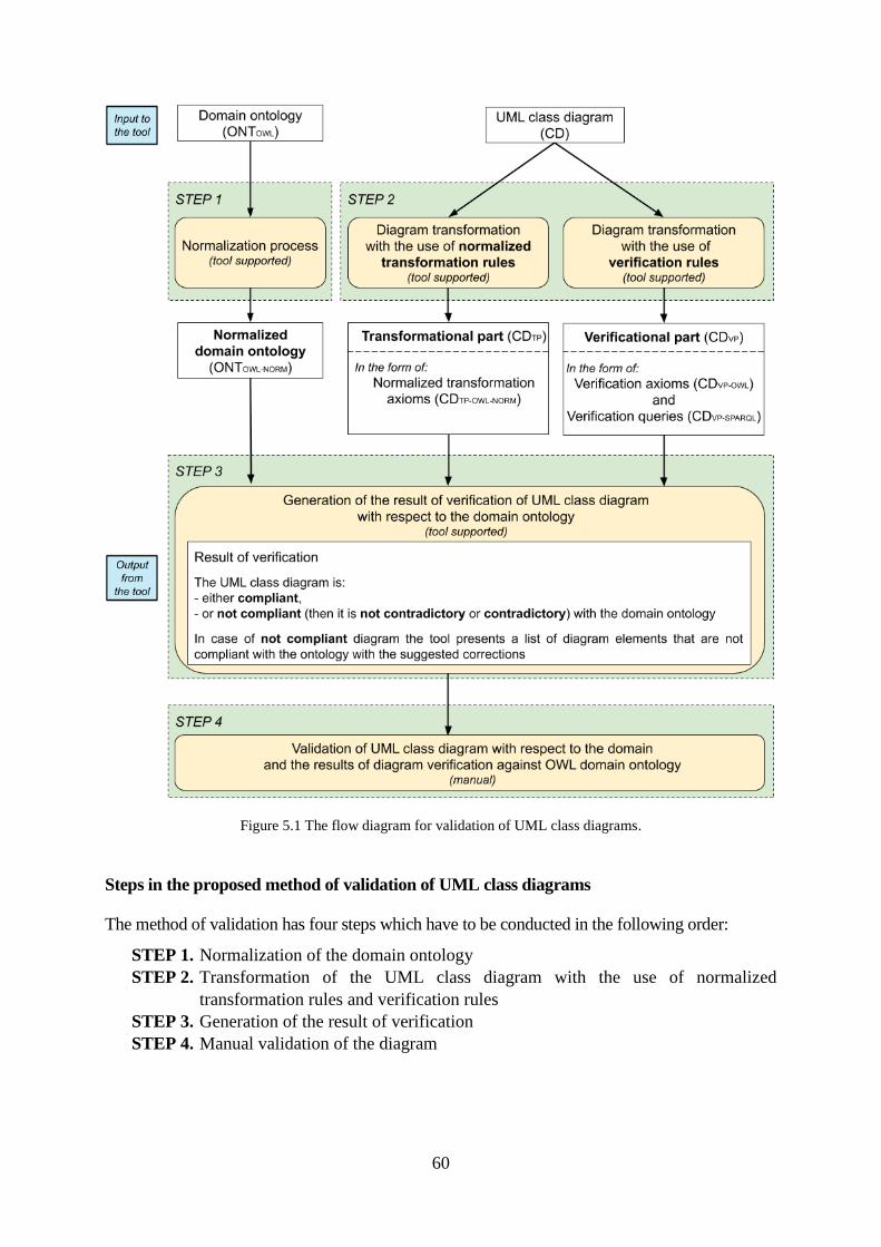
60
Figure 5.1 The flow diagram for validation of UML class diagrams.
Steps in the proposed method of validation of UML class diagrams
The method of validation has four steps which have to be conducted in the following order:
STEP 1. Normalization of the domain ontology
STEP 2. Transformation of the UML class diagram with the use of normalized
transformation rules and verification rules
STEP 3. Generation of the result of verification
STEP 4. Manual validation of the diagram
61
STEP 1. Normalization of the domain ontology
The first step in the process is bringing the OWL 2 domain ontology ( ) to its
normalized form ( ). The process of normalization is an original element of
this research. With the use of the normalization it is much easier to algorithmically compare
ontologies with the unified vocabulary (see Requirement 1 from Section 5.2).
The normalization is necessary to be conducted not only for the domain ontology ( )
but also for the OWL representation of the UML class diagram.
The details of the process of normalization are introduced in Chapter 7.
STEP 2: Transformation of the UML class diagram with the use of normalized
transformation rules and verification rules
The transformation of the UML class diagram ( ) is double track and is conducted with the
use of normalized transformation rules, as well as verification rules. Therefore, the OWL
representation of UML class diagram consists of two parts: transformational part ( )
and verificational part ( ).
The transformational part ( ) consists of sets of normalized transformation axioms
( ), which preserve semantics of elements of the UML class diagram.
The normalized transformation axioms result from transformation of the UML class
diagram with the use of normalized transformation rules. The goal of using the
transformation rules is to compare the information from the UML class diagram with the
information from the domain ontology.
The state of the art transformation rules for elements of UML class diagrams are presented
in Chapter 8.3, where they are not in the normalized form. However, for the purpose of the
proposed method, in the process all transformation axioms are always normalized. The
normalized form is the internal language of the tool implementing the method.
The verificational part ( ) is the result of transformation of UML class diagram ( )
conducted with the use of verification rules. It contains the verification axioms ( )
and verification SPARQL queries ( ).
Every element of UML class diagram has the assigned set of normalized transformation
axioms ( ) and the assigned set of verification axioms and queries.
The verification axioms and verification queries play two interrelated roles. The first role is
to detect if the semantics of the transformed diagram is compliant with the axioms included in
the domain ontology. The second role relates to the assurance of the correctness of the
transformation itself. Considering the inverse transformation (from the ontology to the
diagram), the presence of verification axioms in the domain ontology means that the
reengineering transformation would remain in conflict with the semantics of the UML class
diagram. Therefore, the verification axioms assure that the diagram obtained as a result of
62
reengineering from the modified domain ontology still preserves the semantics of the original
UML class diagram. Therefore, the verificational part is crucial for a correct assessment of the
diagram's compliance with the ontology.
The verification rules are the original element of this research. The verification rules have
two forms: the verification axioms and the verification queries.
The verification axioms used in the process are always normalized.
The verification queries are complementing to the results of comparison of UML class
diagram against the domain ontology conducted with the use of verification axioms. The
necessity to use verification queries results from the need to check the relationship between
classes and instances on the side of the ontology and if the relationship is
compliant with the information in the diagram. Technically, the queries are defined with the
use of SPARQL language. The verification queries are run if the diagram element has not
been evaluated as contradictory on the basis of comparison conducted with the use of
verification axioms. In the method, the verification queries are used for:
a) checking if the classes denoted as abstract in the UML class diagram do not have any
individuals assigned in the OWL domain ontology,
b) verifying if the multiplicity of the attributes is not violated on the side of the OWL
domain ontology,
c) verifying if the multiplicity of the association ends is not violated on the side of the OWL
domain ontology, and
d) checking if the user-defined list of literals of the specified enumerations on the UML
class diagram is compliant with those defined in the OWL domain ontology.
The next subsections (5.3.2 and 5.3.3) present definitions of transformation and verification
rules with some simple examples. All transformation and verification rules are listed and
explained in Chapter 8.3.
STEP 3. Generation of the result of verification
Now, the process of verification is outlined.
The process of verification operates on a working artefact called modified normalized
domain ontology ( ). Initially, the modified normalized domain ontology
is equal to the normalized domain ontology ( ). Later, the
is modified and becomes a union of the axioms from
and the axioms from the transformational part of UML class diagram, provided that it does
not make the inconsistant. The modified normalized domain ontology is used
to check the compliance of the model with the original ontology. In particular, the finding that
the modified domain ontology is not consistent means that the element of UML class
diagram is not compliant with the domain ontology.
The Figure 5.2 outlines the simplified process of generating the result of verification for a
single UML element (a single UML element is an input to the process). The process is
iteratively repeated for all elements from UML class diagram.
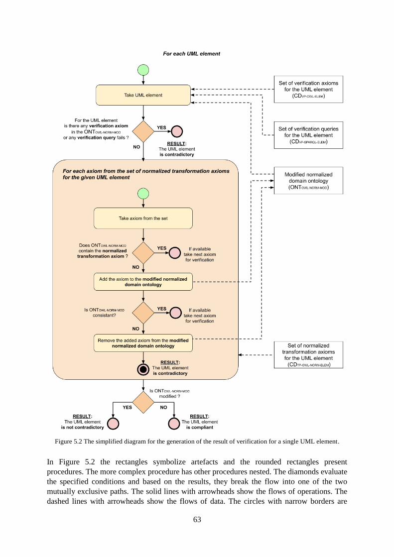
63
Figure 5.2 The simplified diagram for the generation of the result of verification for a single UML element.
In Figure 5.2 the rectangles symbolize artefacts and the rounded rectangles present
procedures. The more complex procedure has other procedures nested. The diamonds evaluate
the specified conditions and based on the results, they break the flow into one of the two
mutually exclusive paths. The solid lines with arrowheads show the flows of operations. The
dashed lines with arrowheads show the flows of data. The circles with narrow borders are
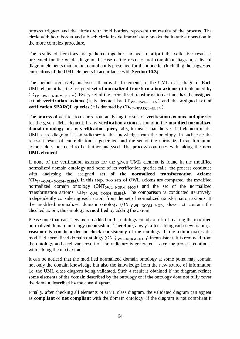
64
process triggers and the circles with bold borders represent the results of the process. The
circle with bold border and a black circle inside immediately breaks the iterative operation in
the more complex procedure.
The results of iterations are gathered together and as an output the collective result is
presented for the whole diagram. In case of the result of not compliant diagram, a list of
diagram elements that are not compliant is presented for the modeller (including the suggested
corrections of the UML elements in accordance with Section 10.3).
The method iteratively analyses all individual elements of the UML class diagram. Each
UML element has the assigned set of normalized transformation axioms (it is denoted by
). Every set of the normalized transformation axioms has the assigned
set of verification axioms (it is denoted by ) and the assigned set of
verification SPARQL queries (it is denoted by ).
The process of verification starts from analysing the sets of verification axioms and queries
for the given UML element. If any verification axiom is found in the modified normalized
domain ontology or any verification query fails, it means that the verified element of the
UML class diagram is contradictory to the knowledge from the ontology. In such case the
relevant result of contradiction is generated and the set of the normalized transformation
axioms does not need to be further analysed. The process continues with taking the next
UML element.
If none of the verification axioms for the given UML element is found in the modified
normalized domain ontology and none of its verification queries fails, the process continues
with analysing the assigned set of the normalized transformation axioms
( ). In this step, two sets of OWL axioms are compared: the modified
normalized domain ontology ( ) and the set of the normalized
transformation axioms ( ). The comparison is conducted iteratively,
independently considering each axiom from the set of normalized transformation axioms. If
the modified normalized domain ontology ( ) does not contain the
checked axiom, the ontology is modified by adding the axiom.
Please note that each new axiom added to the ontology entails a risk of making the modified
normalized domain ontology inconsistent. Therefore, always after adding each new axiom, a
reasoner is run in order to check consistency of the ontology. If the axiom makes the
modified normalized domain ontology ( ) inconsistent, it is removed from
the ontology and a relevant result of contradictory is generated. Later, the process continues
with adding the next axioms.
It can be noticed that the modified normalized domain ontology at some point may contain
not only the domain knowledge but also the knowledge from the new source of information
i.e. the UML class diagram being validated. Such a result is obtained if the diagram refines
some elements of the domain described by the ontology or if the ontology does not fully cover
the domain described by the class diagram.
Finally, after checking all elements of UML class diagram, the validated diagram can appear
as compliant or not compliant with the domain ontology. If the diagram is not compliant it
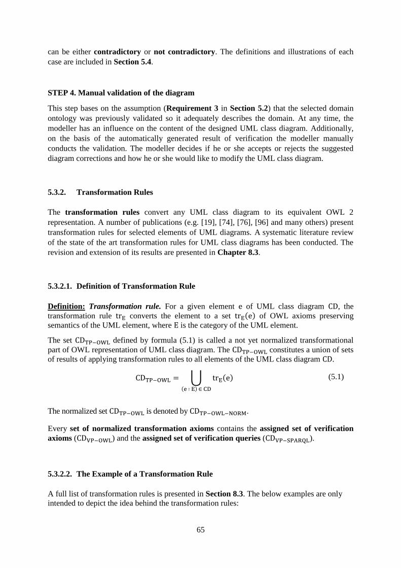
65
can be either contradictory or not contradictory. The definitions and illustrations of each
case are included in Section 5.4.
STEP 4. Manual validation of the diagram
This step bases on the assumption (Requirement 3 in Section 5.2) that the selected domain
ontology was previously validated so it adequately describes the domain. At any time, the
modeller has an influence on the content of the designed UML class diagram. Additionally,
on the basis of the automatically generated result of verification the modeller manually
conducts the validation. The modeller decides if he or she accepts or rejects the suggested
diagram corrections and how he or she would like to modify the UML class diagram.
5.3.2. Transformation Rules
The transformation rules convert any UML class diagram to its equivalent OWL 2
representation. A number of publications (e.g. [19], [74], [76], [96] and many others) present
transformation rules for selected elements of UML diagrams. A systematic literature review
of the state of the art transformation rules for UML class diagrams has been conducted. The
revision and extension of its results are presented in Chapter 8.3.
5.3.2.1. Definition of Transformation Rule
Definition: Transformation rule. For a given element of UML class diagram , the
transformation rule converts the element to a set ( ) of OWL axioms preserving
semantics of the UML element, where is the category of the UML element.
The set defined by formula (5.1) is called a not yet normalized transformational
part of OWL representation of UML class diagram. The constitutes a union of sets
of results of applying transformation rules to all elements of the UML class diagram .
⋃ ( )
( )
(5.1)
The normalized set is denoted by .
Every set of normalized transformation axioms contains the assigned set of verification
axioms ( ) and the assigned set of verification queries ( ).
5.3.2.2. The Example of a Transformation Rule
A full list of transformation rules is presented in Section 8.3. The below examples are only
intended to depict the idea behind the transformation rules:
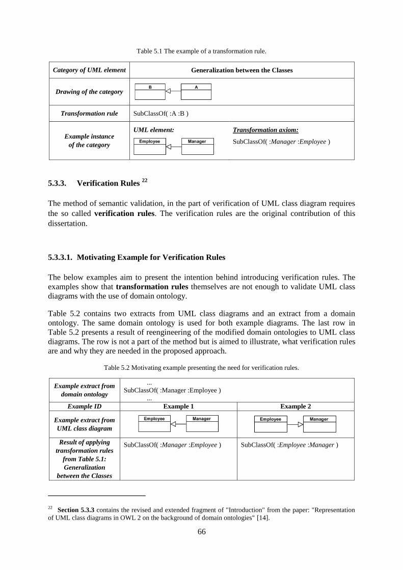
66
Table 5.1 The example of a transformation rule.
Category of UML element Generalization between the Classes
Drawing of the category
Transformation rule SubClassOf( :A :B )
Example instance
of the category
UML element:
Transformation axiom:
SubClassOf( :Manager :Employee )
5.3.3. Verification Rules 22
The method of semantic validation, in the part of verification of UML class diagram requires
the so called verification rules. The verification rules are the original contribution of this
dissertation.
5.3.3.1. Motivating Example for Verification Rules
The below examples aim to present the intention behind introducing verification rules. The
examples show that transformation rules themselves are not enough to validate UML class
diagrams with the use of domain ontology.
Table 5.2 contains two extracts from UML class diagrams and an extract from a domain
ontology. The same domain ontology is used for both example diagrams. The last row in
Table 5.2 presents a result of reengineering of the modified domain ontologies to UML class
diagrams. The row is not a part of the method but is aimed to illustrate, what verification rules
are and why they are needed in the proposed approach.
Table 5.2 Motivating example presenting the need for verification rules.
Example extract from
domain ontology
...
SubClassOf( :Manager :Employee )
...
Example ID Example 1 Example 2
Example extract from
UML class diagram
Result of applying
transformation rules
from Table 5.1:
Generalization
between the Classes
SubClassOf( :Manager :Employee ) SubClassOf( :Employee :Manager )
22 Section 5.3.3 contains the revised and extended fragment of "Introduction" from the paper: "Representation
of UML class diagrams in OWL 2 on the background of domain ontologies" [14].
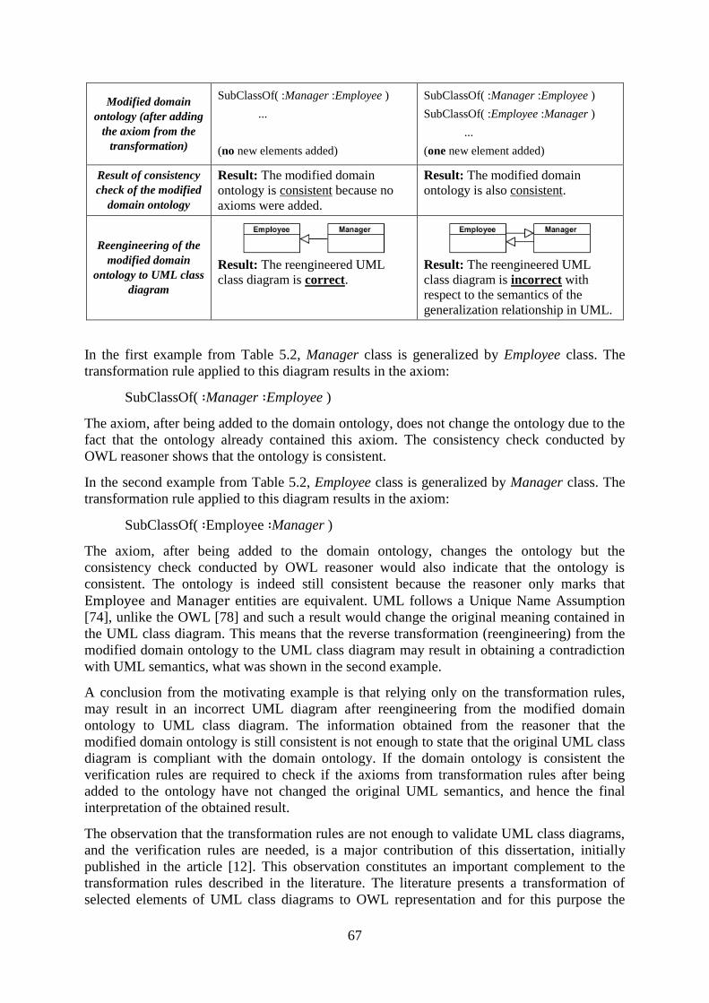
67
Modified domain
ontology (after adding
the axiom from the
transformation)
SubClassOf( :Manager :Employee )
...
(no new elements added)
SubClassOf( :Manager :Employee )
SubClassOf( :Employee :Manager )
...
(one new element added)
Result of consistency
check of the modified
domain ontology
Result: The modified domain
ontology is consistent because no
axioms were added.
Result: The modified domain
ontology is also consistent.
Reengineering of the
modified domain
ontology to UML class
diagram
Result: The reengineered UML
class diagram is correct.
Result: The reengineered UML
class diagram is incorrect with
respect to the semantics of the
generalization relationship in UML.
In the first example from Table 5.2, Manager class is generalized by Employee class. The
transformation rule applied to this diagram results in the axiom:
SubClassOf( Manager Employee )
The axiom, after being added to the domain ontology, does not change the ontology due to the
fact that the ontology already contained this axiom. The consistency check conducted by
OWL reasoner shows that the ontology is consistent.
In the second example from Table 5.2, Employee class is generalized by Manager class. The
transformation rule applied to this diagram results in the axiom:
SubClassOf( Employee Manager )
The axiom, after being added to the domain ontology, changes the ontology but the
consistency check conducted by OWL reasoner would also indicate that the ontology is
consistent. The ontology is indeed still consistent because the reasoner only marks that
and entities are equivalent. UML follows a Unique Name Assumption
[74], unlike the OWL [78] and such a result would change the original meaning contained in
the UML class diagram. This means that the reverse transformation (reengineering) from the
modified domain ontology to the UML class diagram may result in obtaining a contradiction
with UML semantics, what was shown in the second example.
A conclusion from the motivating example is that relying only on the transformation rules,
may result in an incorrect UML diagram after reengineering from the modified domain
ontology to UML class diagram. The information obtained from the reasoner that the
modified domain ontology is still consistent is not enough to state that the original UML class
diagram is compliant with the domain ontology. If the domain ontology is consistent the
verification rules are required to check if the axioms from transformation rules after being
added to the ontology have not changed the original UML semantics, and hence the final
interpretation of the obtained result.
The observation that the transformation rules are not enough to validate UML class diagrams,
and the verification rules are needed, is a major contribution of this dissertation, initially
published in the article [12]. This observation constitutes an important complement to the
transformation rules described in the literature. The literature presents a transformation of
selected elements of UML class diagrams to OWL representation and for this purpose the
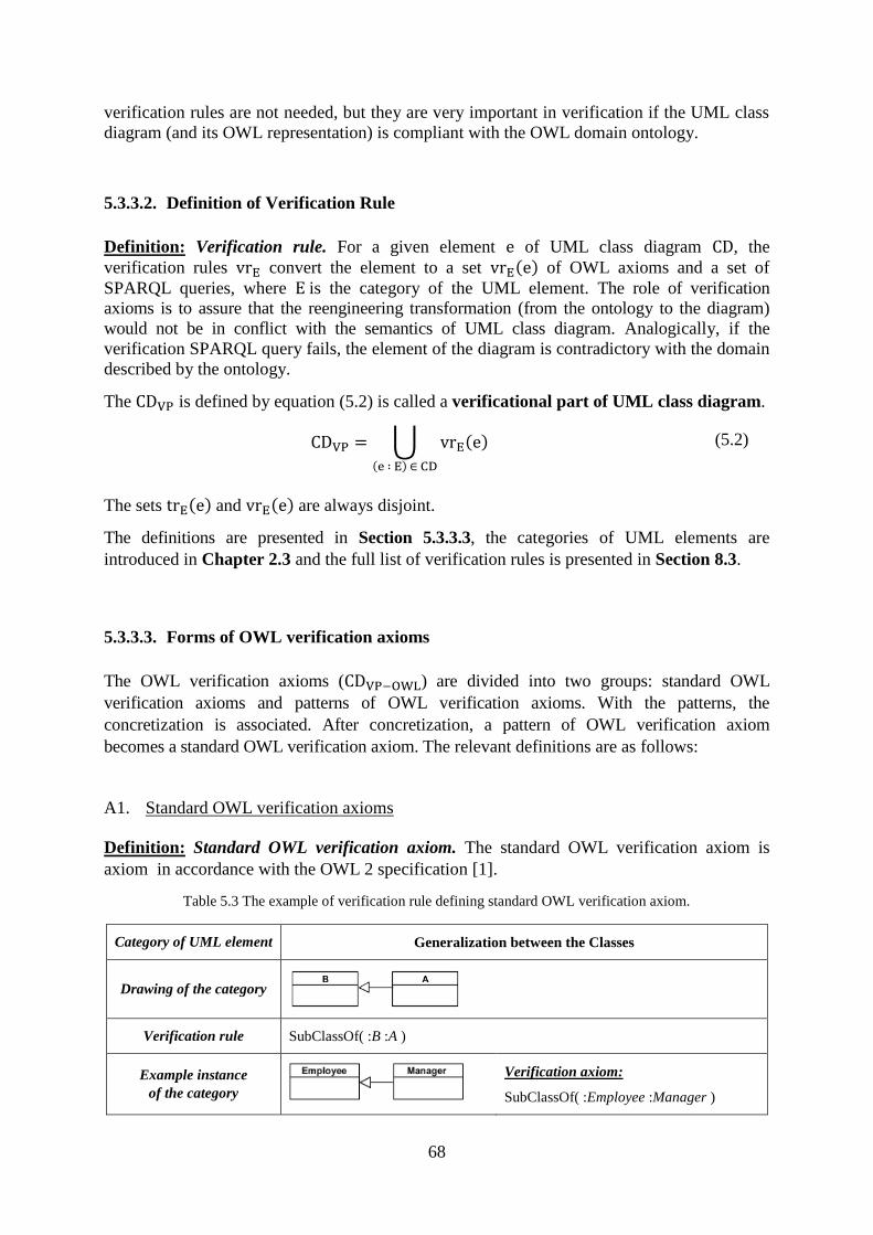
68
verification rules are not needed, but they are very important in verification if the UML class
diagram (and its OWL representation) is compliant with the OWL domain ontology.
5.3.3.2. Definition of Verification Rule
Definition: Verification rule. For a given element of UML class diagram , the
verification rules convert the element to a set ( ) of OWL axioms and a set of
SPARQL queries, where is the category of the UML element. The role of verification
axioms is to assure that the reengineering transformation (from the ontology to the diagram)
would not be in conflict with the semantics of UML class diagram. Analogically, if the
verification SPARQL query fails, the element of the diagram is contradictory with the domain
described by the ontology.
The is defined by equation (5.2) is called a verificational part of UML class diagram.
⋃ ( ) ( )
(5.2)
The sets ( ) and ( ) are always disjoint.
The definitions are presented in Section 5.3.3.3, the categories of UML elements are
introduced in Chapter 2.3 and the full list of verification rules is presented in Section 8.3.
5.3.3.3. Forms of OWL verification axioms
The OWL verification axioms ( ) are divided into two groups: standard OWL
verification axioms and patterns of OWL verification axioms. With the patterns, the
concretization is associated. After concretization, a pattern of OWL verification axiom
becomes a standard OWL verification axiom. The relevant definitions are as follows:
A1. Standard OWL verification axioms
Definition: Standard OWL verification axiom. The standard OWL verification axiom is
axiom in accordance with the OWL 2 specification [1].
Table 5.3 The example of verification rule defining standard OWL verification axiom.
Category of UML element Generalization between the Classes
Drawing of the category
Verification rule SubClassOf( :B :A )
Example instance
of the category
Verification axiom:
SubClassOf( :Employee :Manager )
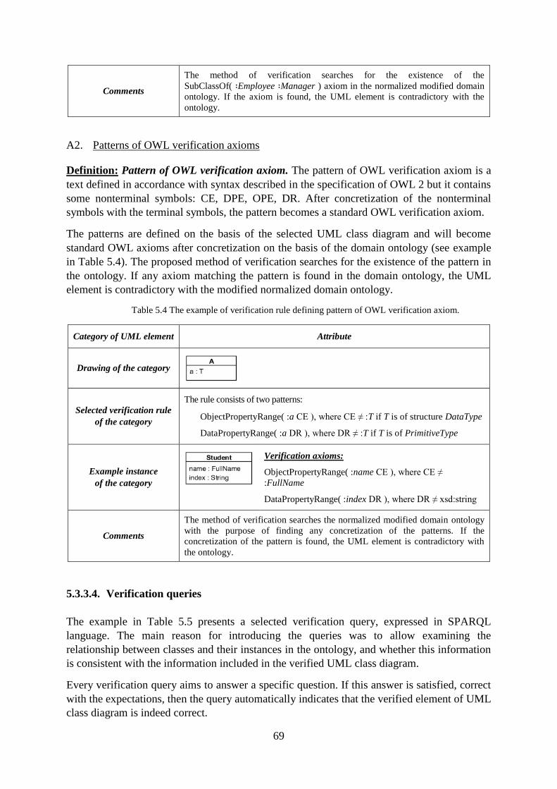
69
Comments
The method of verification searches for the existence of the
SubClassOf( Employee Manager ) axiom in the normalized modified domain
ontology. If the axiom is found, the UML element is contradictory with the
ontology.
A2. Patterns of OWL verification axioms
Definition: Pattern of OWL verification axiom. The pattern of OWL verification axiom is a
text defined in accordance with syntax described in the specification of OWL 2 but it contains
some nonterminal symbols: CE, DPE, OPE, DR. After concretization of the nonterminal
symbols with the terminal symbols, the pattern becomes a standard OWL verification axiom.
The patterns are defined on the basis of the selected UML class diagram and will become
standard OWL axioms after concretization on the basis of the domain ontology (see example
in Table 5.4). The proposed method of verification searches for the existence of the pattern in
the ontology. If any axiom matching the pattern is found in the domain ontology, the UML
element is contradictory with the modified normalized domain ontology.
Table 5.4 The example of verification rule defining pattern of OWL verification axiom.
Category of UML element Attribute
Drawing of the category
Selected verification rule
of the category
The rule consists of two patterns:
ObjectPropertyRange( :a CE ), where CE ≠ :T if T is of structure DataType
DataPropertyRange( :a DR ), where DR ≠ :T if T is of PrimitiveType
Example instance
of the category
Verification axioms:
ObjectPropertyRange( :name CE ), where CE ≠
:FullName
DataPropertyRange( :index DR ), where DR ≠ xsd:string
Comments
The method of verification searches the normalized modified domain ontology
with the purpose of finding any concretization of the patterns. If the
concretization of the pattern is found, the UML element is contradictory with
the ontology.
5.3.3.4. Verification queries
The example in Table 5.5 presents a selected verification query, expressed in SPARQL
language. The main reason for introducing the queries was to allow examining the
relationship between classes and their instances in the ontology, and whether this information
is consistent with the information included in the verified UML class diagram.
Every verification query aims to answer a specific question. If this answer is satisfied, correct
with the expectations, then the query automatically indicates that the verified element of UML
class diagram is indeed correct.
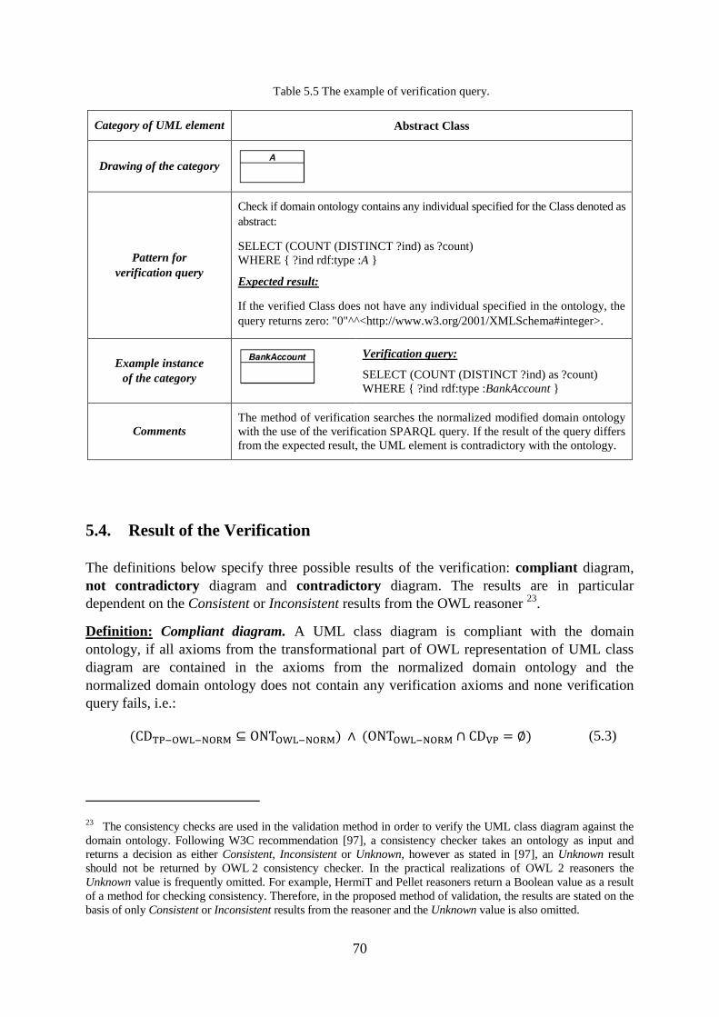
70
Table 5.5 The example of verification query.
Category of UML element Abstract Class
Drawing of the category
Pattern for
verification query
Check if domain ontology contains any individual specified for the Class denoted as
abstract:
SELECT (COUNT (DISTINCT ?ind) as ?count)
WHERE { ?ind rdf:type :A }
Expected result:
If the verified Class does not have any individual specified in the ontology, the
query returns zero: "0"^^<http://www.w3.org/2001/XMLSchema#integer>.
Example instance
of the category
Verification query:
SELECT (COUNT (DISTINCT ?ind) as ?count)
WHERE { ?ind rdf:type :BankAccount }
Comments
The method of verification searches the normalized modified domain ontology
with the use of the verification SPARQL query. If the result of the query differs
from the expected result, the UML element is contradictory with the ontology.
5.4. Result of the Verification
The definitions below specify three possible results of the verification: compliant diagram,
not contradictory diagram and contradictory diagram. The results are in particular
dependent on the Consistent or Inconsistent results from the OWL reasoner 23
.
Definition: Compliant diagram. A UML class diagram is compliant with the domain
ontology, if all axioms from the transformational part of OWL representation of UML class
diagram are contained in the axioms from the normalized domain ontology and the
normalized domain ontology does not contain any verification axioms and none verification
query fails, i.e.:
( ) ( ) (5.3)
23 The consistency checks are used in the validation method in order to verify the UML class diagram against the
domain ontology. Following W3C recommendation [97], a consistency checker takes an ontology as input and
returns a decision as either Consistent, Inconsistent or Unknown, however as stated in [97], an Unknown result
should not be returned by OWL 2 consistency checker. In the practical realizations of OWL 2 reasoners the
Unknown value is frequently omitted. For example, HermiT and Pellet reasoners return a Boolean value as a result
of a method for checking consistency. Therefore, in the proposed method of validation, the results are stated on the
basis of only Consistent or Inconsistent results from the reasoner and the Unknown value is also omitted.
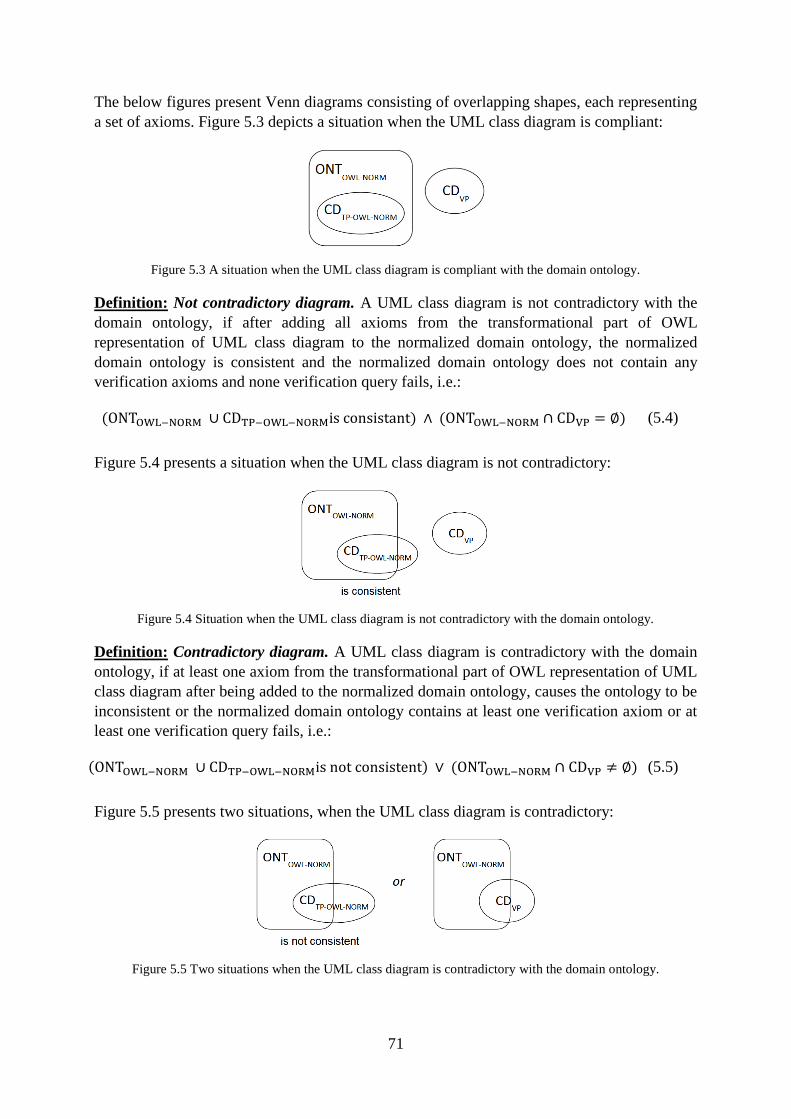
71
The below figures present Venn diagrams consisting of overlapping shapes, each representing
a set of axioms. Figure 5.3 depicts a situation when the UML class diagram is compliant:
Figure 5.3 A situation when the UML class diagram is compliant with the domain ontology.
Definition: Not contradictory diagram. A UML class diagram is not contradictory with the
domain ontology, if after adding all axioms from the transformational part of OWL
representation of UML class diagram to the normalized domain ontology, the normalized
domain ontology is consistent and the normalized domain ontology does not contain any
verification axioms and none verification query fails, i.e.:
( ) ( ) (5.4)
Figure 5.4 presents a situation when the UML class diagram is not contradictory:
Figure 5.4 Situation when the UML class diagram is not contradictory with the domain ontology.
Definition: Contradictory diagram. A UML class diagram is contradictory with the domain
ontology, if at least one axiom from the transformational part of OWL representation of UML
class diagram after being added to the normalized domain ontology, causes the ontology to be
inconsistent or the normalized domain ontology contains at least one verification axiom or at
least one verification query fails, i.e.:
( ) ( ) (5.5)
Figure 5.5 presents two situations, when the UML class diagram is contradictory:
Figure 5.5 Two situations when the UML class diagram is contradictory with the domain ontology.
72
UML class diagram is always contradictory with the ontology if the diagram and the ontology
describe two different realities or the vocabulary between the ontology and the model has not
been initially agreed, what is a preliminary requirement to the method.
5.5. Limitations of the Validation Method 24
The method is aimed to validate the UML class diagrams in accordance with the domain
knowledge included in the domain ontologies. The method does not validate domain
ontologies. In general, the problem of validating ontologies requires a comparison of the
ontologies with an expert knowledge, either provided by domain experts, or included in
another source of domain knowledge.
The proposed method of semantic validation of UML class diagrams has some limitations:
The method is limited to validate only static aspects of UML class diagrams, and the
behavioural features, such as class operations, are omitted. This limitation is motivated
by the fact that the OWL 2 ontologies contain classes, properties, individuals, data
values, etc. but does not allow to define any operations that may be directly invoked
e.g. on the individuals.
Some elements of UML class diagrams are not fully translatable into OWL 2, for
example n-ary associations, compositions (the full list is presented in Chapter 8.3).
This limitation is caused by the fact that UML and OWL standards differ from each
other and e.g. the properties in OWL 2 are only binary relations, or OWL 2 does not
offer some semantically equivalent axioms. However, the partial translation is still
justified for the purpose of diagram verification (e.g. transformation of composition as
simple associations).
The method has a limitation which requires all class attributes and all association ends
in one UML class diagram to be uniquely named. This limitation is also caused by the
fact that the notations have differences and for example two different UML attributes
of the same name would be mapped to one OWL property, which should change the
UML semantics (analogically with association ends). This limitation can be mitigated
by renaming names of some attributes and/or association ends in the UML class
diagram by domain expert.
5.6. Conclusions
This chapter is introductory to Part III which presents the details of the proposed method of
validation of semantic correctness of UML class diagrams with respect to the relevant
domains. The crucial step in the proposed method is an automatic verification of the designed
24 Section 5.5 contains the revised and extended "Limitations of the Validation Method" section from the
paper: "A Prototype Tool for Semantic Validation of UML Class Diagrams with the Use of Domain Ontologies
Expressed in OWL 2" [15].
73
UML class diagram against the selected domain ontology expressed in OWL. In the method,
at any time the modeller decides on the diagram content as well as how to incorporate the
changes in the diagram based on the automatically generated result of diagram verification.
A major contribution of this chapter is an observation that the transformation rules are not
enough to validate UML class diagrams, and the additional rules (here called verification
rules) are needed. The verification rules as well as the process of normalization are the
original elements of this research.
The verification rules are used to check if specific axioms (here called verification axioms)
exist in the domain ontology. The existence of any axiom indicated by the verification rules in
the ontology means that the reengineering transformation (from the ontology to the diagram)
would remain in conflict with the semantics of UML class diagram. The example of such a
conflict is presented in Example 2 from Table 5.2, where a reengineered transformation
resulted in an incorrect cross generalization between the UML classes. For a more complete
verification of diagrams in addition to verification rules the verification queries have been
introduced.
The proposed verification method bases on changing the domain ontology by adding new
axioms – one by one from the transformational part of OWL representation of UML class
diagram − and on subsequent verification if the modified domain ontology is still consistent. A
revision and extension of the state of the art transformation rules and a full list of verification
rules and queries for UML class diagrams are presented in Chapter 8.3. The proposed method
of verification of UML class diagrams is implemented in the developed tool, described in
Part IV.
74
6. Outline of The Process of the Creation of UML Class Diagrams
Summary. This chapter describes the ontology driven process of creation of UML class
diagrams. The proposed process consists of four steps: normalization of the selected
OWL domain ontology, extraction of UML class diagram from the ontology,
modification of the extracted diagram, and verification of the diagram against the
ontology. This chapter proposes checking rules which assure that the elements of UML
class diagram are correctly extracted from the selected OWL domain ontology.
6.1. Introduction
The initial step in business modelling is getting acquaintance with the needed business
domain and understanding the needs (the requirements) of different stakeholders of future
software system. As explained in [98], a system (software) requirements specification
(SRS) is a document or set of documentation that describes the features and behaviour of a
system or software application. The needs on the future software can be expressed in a
various ways and formats. The level of formality of SRS highly depends on the methodology
selected for developing the software system. Not describing the possible graphical or
mathematical specifications, some methods of expressing the user needs are as follows:
The requirements can be described in the natural language in the form of a textual
description (e.g. [99], [100], [101]). The example is presented in page 10 of [100].
The requirements can be described with the use of the so called structured natural
language (e.g. [99], [101]). Structured natural language requirements are written in a
template; the example is presented in page 124 of [99].
The requirements can be described in the form of a more lightweight documentation
by means of user stories and acceptance tests. Following [98] and [102], such a
form of SRS is more preferred in some agile methodologies such as extreme
programming (XP), SCRUM or Kanban. A popular approach to write user stories is
to use the template: “As a (type of user), I want (some function) so that (some
reason)”. The example of the use of this template is presented in page 80 of [103].
Following [98], the detailed requirements can be embodied in prototypes and
mock-ups of the planned system. The prototypes are a visual way to represent the
requirements and help the customer more easily comprehend what is planned to be
implemented. Such a form of SRS is more used in rapid application development
(RAD) methodologies such as DSDM or Unified Process (RUP, AUP).
After system requirements are better understand, the business analyst alone, or together with
domain expert, analyses business processes within the domain. There is a variety of ways to
present the domain information, which could be the basis for business modelling with UML.
Usually the domain information is provided in the form of written or electronic documents in a
variety of formats associated with the described area. On the one hand, the documents may
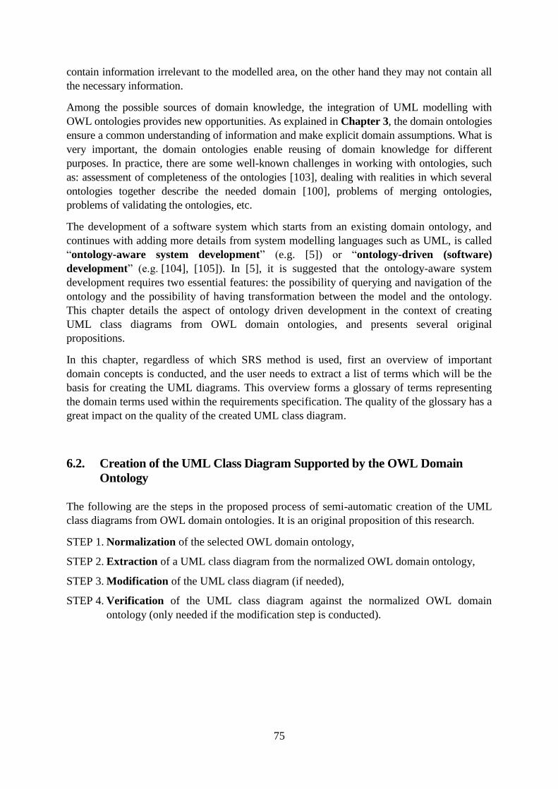
75
contain information irrelevant to the modelled area, on the other hand they may not contain all
the necessary information.
Among the possible sources of domain knowledge, the integration of UML modelling with
OWL ontologies provides new opportunities. As explained in Chapter 3, the domain ontologies
ensure a common understanding of information and make explicit domain assumptions. What is
very important, the domain ontologies enable reusing of domain knowledge for different
purposes. In practice, there are some well-known challenges in working with ontologies, such
as: assessment of completeness of the ontologies [103], dealing with realities in which several
ontologies together describe the needed domain [100], problems of merging ontologies,
problems of validating the ontologies, etc.
The development of a software system which starts from an existing domain ontology, and
continues with adding more details from system modelling languages such as UML, is called
“ontology-aware system development” (e.g. [5]) or “ontology-driven (software)
development” (e.g. [104], [105]). In [5], it is suggested that the ontology-aware system
development requires two essential features: the possibility of querying and navigation of the
ontology and the possibility of having transformation between the model and the ontology.
This chapter details the aspect of ontology driven development in the context of creating
UML class diagrams from OWL domain ontologies, and presents several original
propositions.
In this chapter, regardless of which SRS method is used, first an overview of important
domain concepts is conducted, and the user needs to extract a list of terms which will be the
basis for creating the UML diagrams. This overview forms a glossary of terms representing
the domain terms used within the requirements specification. The quality of the glossary has a
great impact on the quality of the created UML class diagram.
6.2. Creation of the UML Class Diagram Supported by the OWL Domain
Ontology
The following are the steps in the proposed process of semi-automatic creation of the UML
class diagrams from OWL domain ontologies. It is an original proposition of this research.
STEP 1. Normalization of the selected OWL domain ontology,
STEP 2. Extraction of a UML class diagram from the normalized OWL domain ontology,
STEP 3. Modification of the UML class diagram (if needed),
STEP 4. Verification of the UML class diagram against the normalized OWL domain
ontology (only needed if the modification step is conducted).
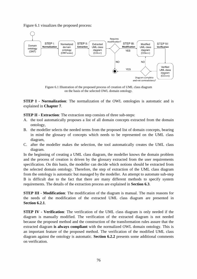
76
Figure 6.1 visualizes the proposed process:
Figure 6.1 Illustration of the proposed process of creation of UML class diagram
on the basis of the selected OWL domain ontology.
STEP I - Normalization: The normalization of the OWL ontologies is automatic and is
explained in Chapter 7.
STEP II - Extraction: The extraction step consists of three sub-steps:
A. the tool automatically proposes a list of all domain concepts extracted from the domain
ontology,
B. the modeller selects the needed terms from the proposed list of domain concepts, bearing
in mind the glossary of concepts which needs to be represented on the UML class
diagram,
C. after the modeller makes the selection, the tool automatically creates the UML class
diagram.
In the beginning of creating a UML class diagram, the modeller knows the domain problem
and the process of creation is driven by the glossary extracted from the user requirements
specification. On this basis, the modeller can decide which notions should be extracted from
the selected domain ontology. Therefore, the step of extraction of the UML class diagram
from the ontology is automatic but managed by the modeller. An attempt to automate sub-step
B is difficult due to the fact that there are many different methods to specify system
requirements. The details of the extraction process are explained in Section 6.3.
STEP III - Modification: The modification of the diagram is manual. The main reasons for
the needs of the modification of the extracted UML class diagram are presented in
Section 6.2.1.
STEP IV - Verification: The verification of the UML class diagram is only needed if the
diagram is manually modified. The verification of the extracted diagram is not needed
because the proposed method and the construction of the transformation rules assure that the
extracted diagram is always compliant with the normalized OWL domain ontology. This is
an important feature of the proposed method. The verification of the modified UML class
diagram against the ontology is automatic. Section 6.2.2 presents some additional comments
on verification.
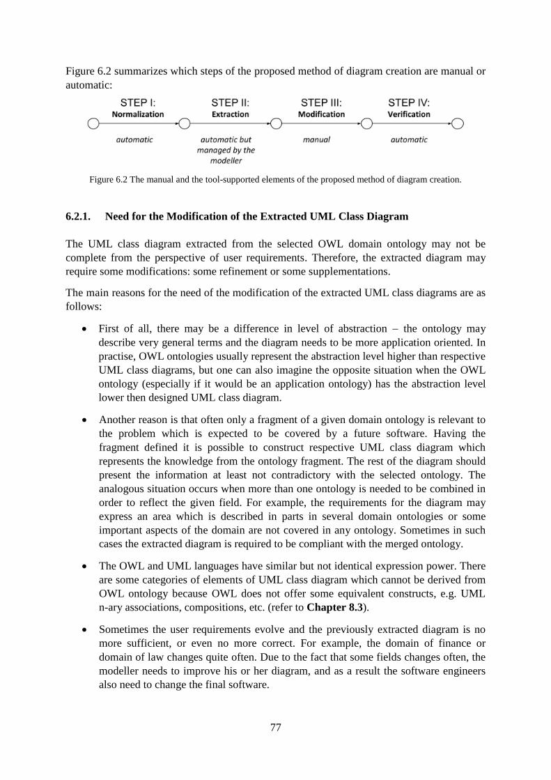
77
Figure 6.2 summarizes which steps of the proposed method of diagram creation are manual or
automatic:
Figure 6.2 The manual and the tool-supported elements of the proposed method of diagram creation.
6.2.1. Need for the Modification of the Extracted UML Class Diagram
The UML class diagram extracted from the selected OWL domain ontology may not be
complete from the perspective of user requirements. Therefore, the extracted diagram may
require some modifications: some refinement or some supplementations.
The main reasons for the need of the modification of the extracted UML class diagrams are as
follows:
First of all, there may be a difference in level of abstraction the ontology may
describe very general terms and the diagram needs to be more application oriented. In
practise, OWL ontologies usually represent the abstraction level higher than respective
UML class diagrams, but one can also imagine the opposite situation when the OWL
ontology (especially if it would be an application ontology) has the abstraction level
lower then designed UML class diagram.
Another reason is that often only a fragment of a given domain ontology is relevant to
the problem which is expected to be covered by a future software. Having the
fragment defined it is possible to construct respective UML class diagram which
represents the knowledge from the ontology fragment. The rest of the diagram should
present the information at least not contradictory with the selected ontology. The
analogous situation occurs when more than one ontology is needed to be combined in
order to reflect the given field. For example, the requirements for the diagram may
express an area which is described in parts in several domain ontologies or some
important aspects of the domain are not covered in any ontology. Sometimes in such
cases the extracted diagram is required to be compliant with the merged ontology.
The OWL and UML languages have similar but not identical expression power. There
are some categories of elements of UML class diagram which cannot be derived from
OWL ontology because OWL does not offer some equivalent constructs, e.g. UML
n-ary associations, compositions, etc. (refer to Chapter 8.3).
Sometimes the user requirements evolve and the previously extracted diagram is no
more sufficient, or even no more correct. For example, the domain of finance or
domain of law changes quite often. Due to the fact that some fields changes often, the
modeller needs to improve his or her diagram, and as a result the software engineers
also need to change the final software.
78
Summarizing, the typical modifications of the extracted UML class diagram are:
refining the diagram (e.g. by changing "*" multiplicity of the association end into
multiplicity of at least M but no more than N instances),
supplementing the diagram with some new UML elements (e.g. by adding additional
classes or attributes not described in the selected domain ontology),
removing some UML elements from the diagram (e.g. removing UML Thing class
extracted on the basis of owl:Thing which represents a set of all individuals in OWL).
6.2.2. Need for the Verification of the Modified UML Class Diagram
As explained, the manual modifications of the extracted UML class diagram are often needed,
but they always involve a risk of introducing some semantic errors. Especially, the modified
diagram may have elements which are not included in the OWL domain ontology, and may
appear as contradictory with the OWL domain ontology. Therefore, the verification is always
needed if the diagram is manually modified. This is illustrated in Figure 6.3:
Figure 6.3 The extraction, modification and verification steps of the proposed process of diagram creation.
The normalized domain sub-ontology ONTNORM-SUB is a subset of the normalized domain
ontology ONTNORM, consisting of axioms which can be transformed into UML elements. All
other OWL axioms do not take part in the extraction step because their semantics cannot be
expressed in the form of elements of UML class diagram. After the extracted diagram is
manually modified, it is verified against full normalized domain ontology (ONTNORM).
It is important to observe that the whole process of creation requires two directed
OWL-UML transformation:
The extraction step requires OWL to UML transformation. The transformation
takes axioms from the normalized OWL domain sub-ontology ONTNORM-SUB, and
transforms them into UML class diagram.
The verification step requires UML to OWL transformation for the purpose of
analysis of the compliance of the diagram with the ontology ONTNORM, and for the
purpose of identifying any potential violations of the UML elements with the
semantics from the selected ontology. The transformation maps all UML elements into
a set of OWL axioms. It is described in Section 5.
79
In this research the two-directed OWL-UML transformation is narrowed only to the OWL
axioms which can be expressed in UML without changing semantics. This chapter does not
discuss any OWL axioms which have no counterparts in the elements of UML class diagrams.
6.3. Extraction of UML Elements from the OWL Domain Ontology
This section is specific because it has several references to Section 8.3 which describes all
transformation rules used to translate single elements of UML class diagram into sets of OWL
axioms. The transformation rules are two-directed what means that they are also applied in the
transformation from OWL to UML. Each rule has a form such that it transforms a UML
element of category into a set of OWL axioms , and vice versa it transforms a set of
OWL axioms into a UML element of category (see Figure 6.4).
The transformations may be presented in the forms (6.1), in which there are premises in the
numerators and conclusions in the denominators. The forms (6.1) are not complete, because the
UML to OWL transformation requires the verification rules and OWL to UML transformation
requires the checking rules which are specified further in the following section.
where is the category of the UML element
(6.1)
The below two subsections present the details of the process of extraction of UML elements
from the selected OWL domain ontology:
Section 6.3.1 presents details of the direct extraction. The direct extraction bases
fully on the selected domain ontology, and extracts all sets of axioms which can be
translated into the elements of UML class diagram with the equivalent semantics. The
proposed method and the construction of the transformation rules assure that the direct
extraction of UML class diagram is always compliant with the normalized OWL
domain ontology.
Section 6.3.2 presents another original proposition of this research: the extended
extraction. It is a proposition to extract some additional UML elements which are only
partly based on the selected domain ontology. This proposal is justified based on
observing the practical modelling needs and real OWL ontologies. The extended
extraction always requires verification. The diagram which bases on the extended
extraction is at most not contradictory with the OWL domain ontology.
For a better clarity, tables in this section follow the following convention:
the elements of UML meta-model are written with the use of italic font,
the OWL 2 constructs are written in bold font.
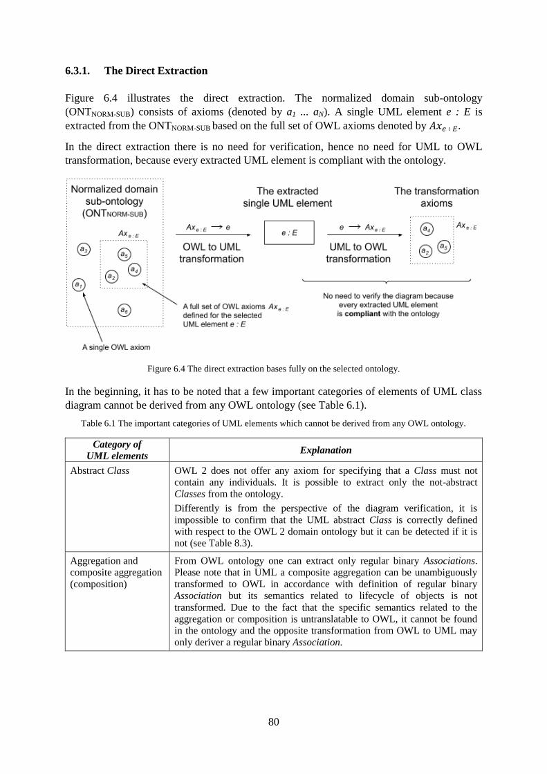
80
6.3.1. The Direct Extraction
Figure 6.4 illustrates the direct extraction. The normalized domain sub-ontology
(ONTNORM-SUB) consists of axioms (denoted by a1 ... aN). A single UML element e : E is
extracted from the ONTNORM-SUB based on the full set of OWL axioms denoted by .
In the direct extraction there is no need for verification, hence no need for UML to OWL
transformation, because every extracted UML element is compliant with the ontology.
Figure 6.4 The direct extraction bases fully on the selected ontology.
In the beginning, it has to be noted that a few important categories of elements of UML class
diagram cannot be derived from any OWL ontology (see Table 6.1).
Table 6.1 The important categories of UML elements which cannot be derived from any OWL ontology.
Category of
UML elements Explanation
Abstract Class
OWL 2 does not offer any axiom for specifying that a Class must not
contain any individuals. It is possible to extract only the not-abstract
Classes from the ontology.
Differently is from the perspective of the diagram verification, it is
impossible to confirm that the UML abstract Class is correctly defined
with respect to the OWL 2 domain ontology but it can be detected if it is
not (see Table 8.3).
Aggregation and
composite aggregation
(composition)
From OWL ontology one can extract only regular binary Associations.
Please note that in UML a composite aggregation can be unambiguously
transformed to OWL in accordance with definition of regular binary
Association but its semantics related to lifecycle of objects is not
transformed. Due to the fact that the specific semantics related to the
aggregation or composition is untranslatable to OWL, it cannot be found
in the ontology and the opposite transformation from OWL to UML may
only deriver a regular binary Association.
81
N-ary Association The current version of OWL 2 offers only binary relations.
Table 8.8 presents a pattern to transform UML n-ary Association to OWL,
however, it is only a partial solution. The pattern allows transforming the
Association unambiguously, however, at the end the semantics in OWL is
not exact to UML in case of n-ary Association. Therefore it is not a
suggested approach to extract UML n-ary Associations from OWL.
GeneralizationSet with
{incomplete, disjoint}
or with {incomplete,
overlapping}
constraints
OWL 2 does not offer any axiom for specifying incompleteness as the
incompleteness in ontology is assumed by default (open world
assumption). Table 8.14 only presents axioms which assure disjointness of
more specific Classes in the Generalization.
Table 8.16 presents no transformation rules.
Regarding the possibilities, the following categories of UML elements can be extracted from
OWL ontologies:
Class,
attributes of the Class,
multiplicity of the attributes,
binary Associations,
multiplicity of the Association ends,
Generalization between Classes,
Generalization between Associations,
GeneralizationSet with {complete, disjoint} or {complete, overlapping} constraints,
Integer and Boolean primitive types (Please note that: UML String and Real primitive
types have similar but not equivalent corresponding OWL 2 types. If a modeller
chooses either xsd:float, or xsd:double for UML Real, and accepts xsd:string for
UML String and differs, the UML-OWL transformation will also be unambiguous and
equivalent.)
structured DataTypes,
Enumerations,
Comments to the Class (UML Comments add no semantics, nevertheless the UML-
OWL transformation of UML Comments is technically possible and two-directed).
As mentioned before, the transformation rules for the categories of UML elements are
presented in Section 8.3.
The transformation rules are two-directed, so they are needed in the transformation from
UML to OWL, as well as in the transformation from OWL to UML.
In UML to OWL transformation, the transformation rules are accompanied with the
verification rules, denoted by (see Section 8.3). As explained in Section 5.3.3, the role
of verification rules is to detect if the semantics of a diagram is not in conflict with the
knowledge included in the domain ontology. The UML to OWL transformation can be
described by (6.2):
82
where is the category of the UML element
(6.2)
Interpretation:
Each element of the UML class diagram is of one category of UML elements
(see Section 2.3).
For each category of UML elements , Section 8.3 defines a set of transformation
rules and a set of verification rules .
In the context of the transformation from UML to OWL, each UML element is
transformed into a set of OWL axioms , providing that the assigned set of
verification rules is checked.
A single verification rule in the context of the transformation from UML to OWL have
the form of either OWL axiom (either standard OWL verification axiom, or pattern of
OWL verification axiom, see Section 5.3.3.3), or verification query (see Section 5.3.3.4).
The set of verification axioms and patterns, denoted by , cannot be found in the
ontology (this is ), because if they are found, the selected UML
element is contradictory with the ontology (see Section 5.3.3.1).
Each verification query has the form of predicates, and consists of the SPARQL query
and the expected result. The expected result is compared to the actual result, which is a
result of applying the query to the ontology. If the result of comparison is not equal,
the selected UML element is contradictory with the ontology. In such cases the result
of verification of UML class diagram against the OWL domain ontology is shown as
contradictory.
Analogically, the rules here called checking rules need to accompany the transformation
rules for the purpose of correct OWL to UML transformation.
The checking rules, denoted by , in the context of the transformation from OWL to
UML have only the form of OWL axioms, so-called checking axioms. For each category of
UML elements . The OWL to UML transformation can be can be described by (6.3):
where is the category of the UML element
(6.3)
Interpretation:
For each category of UML elements , this section defines a set of checking rules
. For many categories of UML elements this set is empty.
In the context of the transformation from OWL to UML, a set of OWL axioms
is transformed into an element of the UML class diagram, providing that the
assigned set of checking axioms is checked.
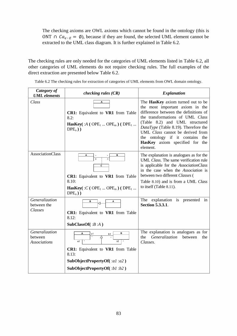
83
The checking axioms are OWL axioms which cannot be found in the ontology (this is
), because if they are found, the selected UML element cannot be
extracted to the UML class diagram. It is further explained in Table 6.2.
The checking rules are only needed for the categories of UML elements listed in Table 6.2, all
other categories of UML elements do not require checking rules. The full examples of the
direct extraction are presented below Table 6.2.
Table 6.2 The checking rules for extraction of categories of UML elements from OWL domain ontology.
Category of
UML elements checking rules (CR) Explanation
Class
CR1: Equivalent to VR1 from Table
8.2:
HasKey( :A ( OPE1 ... OPEm ) ( DPE1 ...
DPEn ) )
The HasKey axiom turned out to be
the most important axiom in the
difference between the definitions of
the transformations of UML Class
(Table 8.2) and UML structured
DataType (Table 8.19). Therefore the
UML Class cannot be derived from
the ontology if it contains the
HasKey axiom specified for the
element.
AssociationClass
CR1: Equivalent to VR1 from Table
8.10:
HasKey( :C ( OPE1 ... OPEm ) ( DPE1 ...
DPEn ) )
The explanation is analogues as for the
UML Class. The same verification rule
is applicable for the AssociationClass
in the case when the Association is
between two different Classes (
Table 8.10) and is from a UML Class
to itself (Table 8.11).
Generalization
between the
Classes
CR1: Equivalent to VR1 from Table
8.12:
SubClassOf( :B :A )
The explanation is presented in
Section 5.3.3.1.
Generalization
between
Associations
CR1: Equivalent to VR1 from Table
8.13:
SubObjectPropertyOf( :a1 :a2 )
SubObjectPropertyOf( :b1 :b2 )
The explanation is analogues as for
the Generalization between the
Classes.
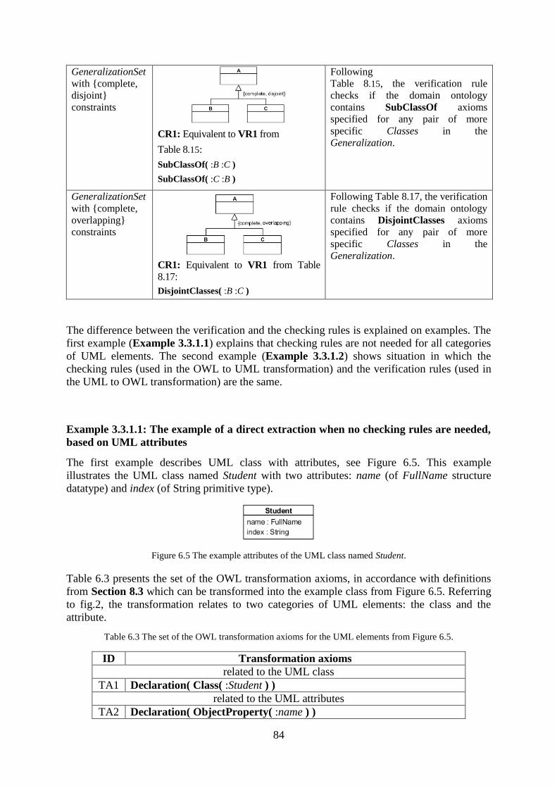
84
GeneralizationSet
with {complete,
disjoint}
constraints
CR1: Equivalent to VR1 from
Table 8.15:
SubClassOf( :B :C )
SubClassOf( :C :B )
Following
Table 8.15, the verification rule
checks if the domain ontology
contains SubClassOf axioms
specified for any pair of more
specific Classes in the
Generalization.
GeneralizationSet
with {complete,
overlapping}
constraints
CR1: Equivalent to VR1 from Table
8.17:
DisjointClasses( :B :C )
Following Table 8.17, the verification
rule checks if the domain ontology
contains DisjointClasses axioms
specified for any pair of more
specific Classes in the
Generalization.
The difference between the verification and the checking rules is explained on examples. The
first example (Example 3.3.1.1) explains that checking rules are not needed for all categories
of UML elements. The second example (Example 3.3.1.2) shows situation in which the
checking rules (used in the OWL to UML transformation) and the verification rules (used in
the UML to OWL transformation) are the same.
Example 3.3.1.1: The example of a direct extraction when no checking rules are needed,
based on UML attributes
The first example describes UML class with attributes, see Figure 6.5. This example
illustrates the UML class named Student with two attributes: name (of FullName structure
datatype) and index (of String primitive type).
Figure 6.5 The example attributes of the UML class named Student.
Table 6.3 presents the set of the OWL transformation axioms, in accordance with definitions
from Section 8.3 which can be transformed into the example class from Figure 6.5. Referring
to fig.2, the transformation relates to two categories of UML elements: the class and the
attribute.
Table 6.3 The set of the OWL transformation axioms for the UML elements from Figure 6.5.
ID Transformation axioms
related to the UML class
TA1 Declaration( Class( :Student ) )
related to the UML attributes
TA2 Declaration( ObjectProperty( :name ) )
85
TA3 Declaration( DataProperty( :index ) )
TA4 ObjectPropertyDomain( :name :Student )
TA5 DataPropertyDomain( :index :Student )
TA6 ObjectPropertyRange( :name :FullName )
TA7 DataPropertyRange( :index xsd:string )
Table 6.4 presents the set of the OWL verification axioms (in accordance with Section 8.3).
Table 6.4 The set of the OWL verification axioms for the UML elements from Figure 6.5.
ID Verification axioms
related to the UML class
VA1 HasKey( :Student ( OPE1 ... OPEm ) ( DPE1 ... DPEn ) )
related to the UML attributes
VA2 ObjectPropertyDomain( :name CE ), where CE ≠ :Student
VA3 DataPropertyDomain( :index CE ), where CE ≠ :Student
VA4 ObjectPropertyRange( :name CE ), where CE ≠ :FullName
VA5 DataPropertyRange( :index DR ), where DR ≠ xsd:string
In the context of only the UML class, there is one verification rule VA1. The HasKey axiom
turned out to be the most important axiom in the difference between the definitions of the
transformations of UML Class and UML structured DataType (see Table 8.2 and Table 8.19).
The UML Class cannot be derived from the ontology if it contains the HasKey axiom
specified for the element. Therefore, the checking rule is the same as the verification rule
because in the extraction process it is important to know if the element is indeed the UML
class.
The main focus of this example are UML attributes. In the context of only the UML
attributes, there are four verification rules VA2-VA5 for the UML to OWL transformation:
two rules VA2-VA3 which check if the ontology defines for the attributes a domain
different that it is defined on the UML class diagram,
two rules VA4-VA5 which check if the ontology defines for the attributes a range
different that it is defined on the UML class diagram.
There are no checking rules for OWL to UML transformation of UML attribute. From the
perspective of ontology we do not need to check if the ontology defines something differently
that it is defined on the UML class diagram, because there is no diagram yet. Therefore, such
rules are not applicable in the transformation from OWL to UML.
To summarize the above elaboration, Table 6.5 presents all checking axioms for the UML
diagram from Figure 6.5.
Table 6.5 The set of the OWL checking axioms for the UML elements from Figure 6.5.
ID Checking axioms
related to the UML class
CA1 HasKey( :Student ( OPE1 ... OPEm ) ( DPE1 ... DPEn ) )
related to the UML attributes
No checking axioms
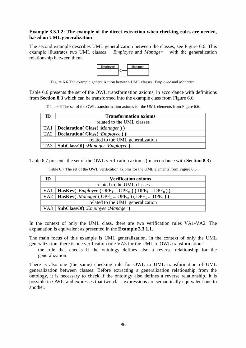
86
Example 3.3.1.2: The example of the direct extraction when checking rules are needed,
based on UML generalization
The second example describes UML generalization between the classes, see Figure 6.6. This
example illustrates two UML classes − Employee and Manager − with the generalization
relationship between them.
Figure 6.6 The example generalization between UML classes: Employee and Manager.
Table 6.6 presents the set of the OWL transformation axioms, in accordance with definitions
from Section 8.3 which can be transformed into the example class from Figure 6.6.
Table 6.6 The set of the OWL transformation axioms for the UML elements from Figure 6.6.
ID Transformation axioms
related to the UML classes
TA1 Declaration( Class( :Manager ) )
TA2 Declaration( Class( :Employee ) )
related to the UML generalization
TA3 SubClassOf( :Manager :Employee )
Table 6.7 presents the set of the OWL verification axioms (in accordance with Section 8.3).
Table 6.7 The set of the OWL verification axioms for the UML elements from Figure 6.6.
ID Verification axioms
related to the UML classes
VA1 HasKey( :Employee ( OPE1 ... OPEm ) ( DPE1 ... DPEn ) )
VA2 HasKey( :Manager ( OPE1 ... OPEm ) ( DPE1 ... DPEn ) )
related to the UML generalization
VA3 SubClassOf( :Employee :Manager )
In the context of only the UML class, there are two verification rules VA1-VA2. The
explanation is equivalent as presented in the Example 3.3.1.1.
The main focus of this example is UML generalization. In the context of only the UML
generalization, there is one verification rule VA3 for the UML to OWL transformation:
the rule that checks if the ontology defines also a reverse relationship for the
generalization.
There is also one (the same) checking rule for OWL to UML transformation of UML
generalization between classes. Before extracting a generalization relationship from the
ontology, it is necessary to check if the ontology also defines a reverse relationship. It is
possible in OWL, and expresses that two class expressions are semantically equivalent one to
another.
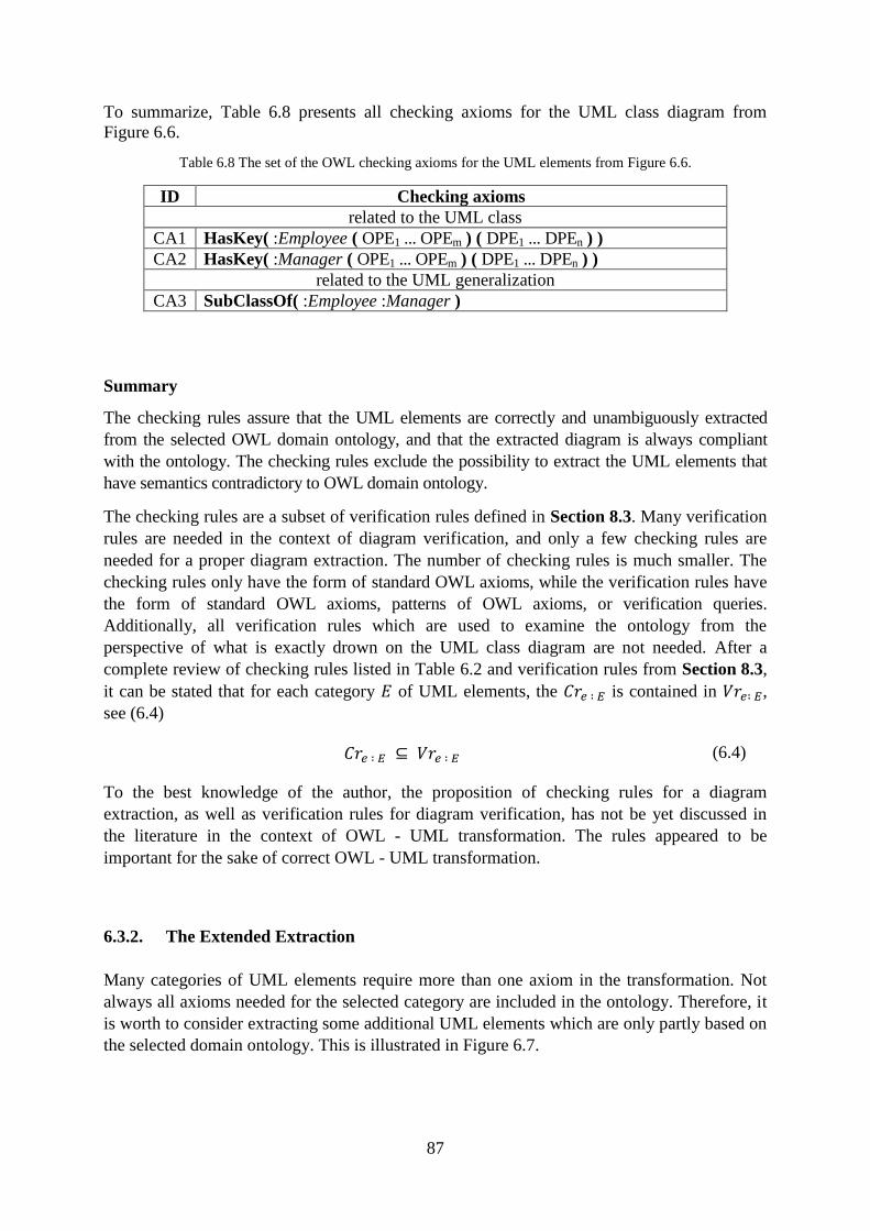
87
To summarize, Table 6.8 presents all checking axioms for the UML class diagram from
Figure 6.6.
Table 6.8 The set of the OWL checking axioms for the UML elements from Figure 6.6.
ID Checking axioms
related to the UML class
CA1 HasKey( :Employee ( OPE1 ... OPEm ) ( DPE1 ... DPEn ) )
CA2 HasKey( :Manager ( OPE1 ... OPEm ) ( DPE1 ... DPEn ) )
related to the UML generalization
CA3 SubClassOf( :Employee :Manager )
Summary
The checking rules assure that the UML elements are correctly and unambiguously extracted
from the selected OWL domain ontology, and that the extracted diagram is always compliant
with the ontology. The checking rules exclude the possibility to extract the UML elements that
have semantics contradictory to OWL domain ontology.
The checking rules are a subset of verification rules defined in Section 8.3. Many verification
rules are needed in the context of diagram verification, and only a few checking rules are
needed for a proper diagram extraction. The number of checking rules is much smaller. The
checking rules only have the form of standard OWL axioms, while the verification rules have
the form of standard OWL axioms, patterns of OWL axioms, or verification queries.
Additionally, all verification rules which are used to examine the ontology from the
perspective of what is exactly drown on the UML class diagram are not needed. After a
complete review of checking rules listed in Table 6.2 and verification rules from Section 8.3,
it can be stated that for each category of UML elements, the is contained in ,
see (6.4)
(6.4)
To the best knowledge of the author, the proposition of checking rules for a diagram
extraction, as well as verification rules for diagram verification, has not be yet discussed in
the literature in the context of OWL - UML transformation. The rules appeared to be
important for the sake of correct OWL - UML transformation.
6.3.2. The Extended Extraction
Many categories of UML elements require more than one axiom in the transformation. Not
always all axioms needed for the selected category are included in the ontology. Therefore, it
is worth to consider extracting some additional UML elements which are only partly based on
the selected domain ontology. This is illustrated in Figure 6.7.
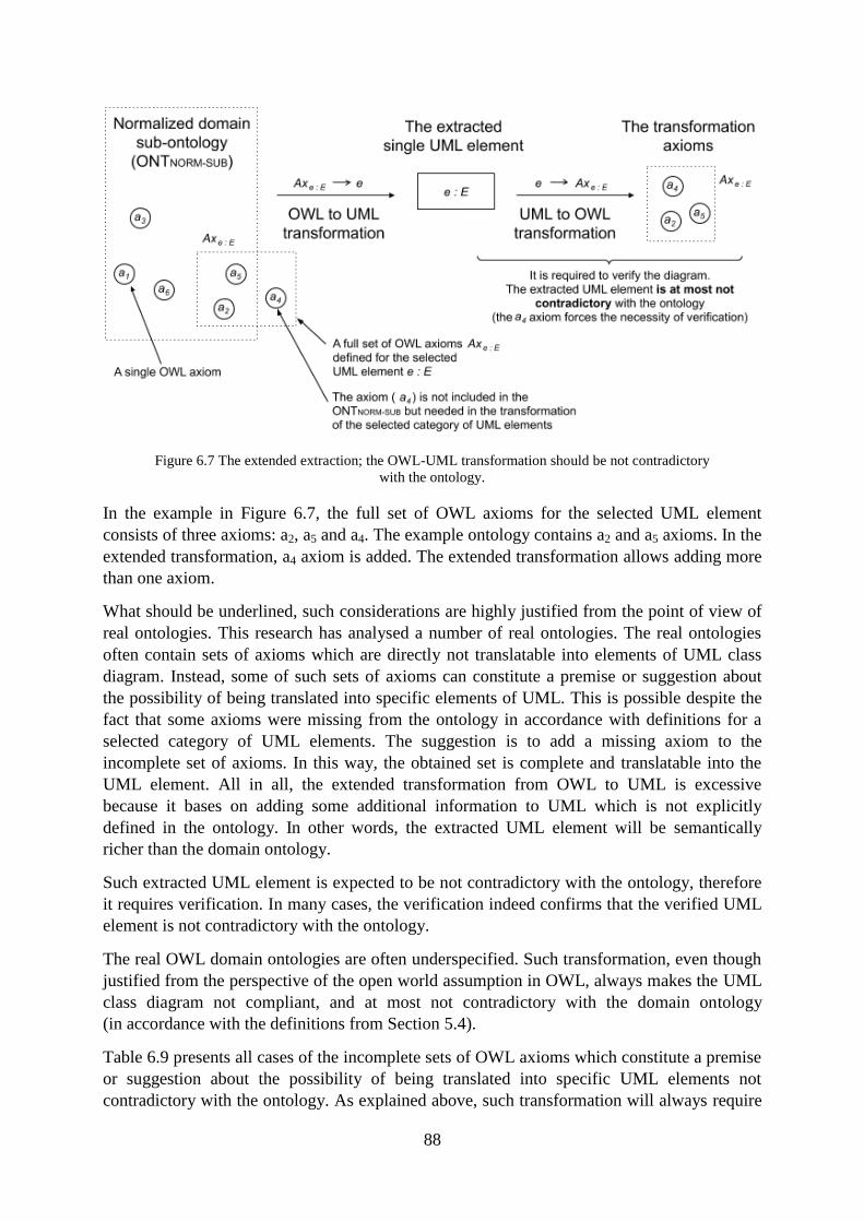
88
Figure 6.7 The extended extraction; the OWL-UML transformation should be not contradictory
with the ontology.
In the example in Figure 6.7, the full set of OWL axioms for the selected UML element
consists of three axioms: a2, a5 and a4. The example ontology contains a2 and a5 axioms. In the
extended transformation, a4 axiom is added. The extended transformation allows adding more
than one axiom.
What should be underlined, such considerations are highly justified from the point of view of
real ontologies. This research has analysed a number of real ontologies. The real ontologies
often contain sets of axioms which are directly not translatable into elements of UML class
diagram. Instead, some of such sets of axioms can constitute a premise or suggestion about
the possibility of being translated into specific elements of UML. This is possible despite the
fact that some axioms were missing from the ontology in accordance with definitions for a
selected category of UML elements. The suggestion is to add a missing axiom to the
incomplete set of axioms. In this way, the obtained set is complete and translatable into the
UML element. All in all, the extended transformation from OWL to UML is excessive
because it bases on adding some additional information to UML which is not explicitly
defined in the ontology. In other words, the extracted UML element will be semantically
richer than the domain ontology.
Such extracted UML element is expected to be not contradictory with the ontology, therefore
it requires verification. In many cases, the verification indeed confirms that the verified UML
element is not contradictory with the ontology.
The real OWL domain ontologies are often underspecified. Such transformation, even though
justified from the perspective of the open world assumption in OWL, always makes the UML
class diagram not compliant, and at most not contradictory with the domain ontology
(in accordance with the definitions from Section 5.4).
Table 6.9 presents all cases of the incomplete sets of OWL axioms which constitute a premise
or suggestion about the possibility of being translated into specific UML elements not
contradictory with the ontology. As explained above, such transformation will always require
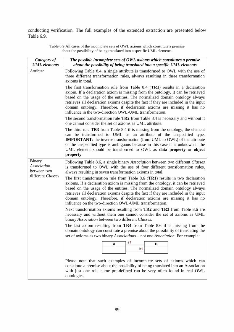
89
conducting verification. The full examples of the extended extraction are presented below
Table 6.9.
Table 6.9 All cases of the incomplete sets of OWL axioms which constitute a premise
about the possibility of being translated into a specific UML elements.
Category of
UML elements
The possible incomplete sets of OWL axioms which constitutes a premise
about the possibility of being translated into a specific UML elements
Attribute Following Table 8.4, a single attribute is transformed to OWL with the use of
three different transformation rules, always resulting in three transformation
axioms in total.
The first transformation rule from Table 8.4 (TR1) results in a declaration
axiom. If a declaration axiom is missing from the ontology, it can be retrieved
based on the usage of the entities. The normalized domain ontology always
retrieves all declaration axioms despite the fact if they are included in the input
domain ontology. Therefore, if declaration axioms are missing it has no
influence in the two-direction OWL-UML transformation.
The second transformation rule TR2 from Table 8.4 is necessary and without it
one cannot consider the set of axioms as UML attribute.
The third rule TR3 from Table 8.4 if is missing from the ontology, the element
can be transformed to UML as an attribute of the unspecified type.
IMPORTANT: the inverse transformation (from UML to OWL) of the attribute
of the unspecified type is ambiguous because in this case it is unknown if the
UML element should be transformed to OWL as data property or object
property.
Binary
Association
between two
different Classes
Following Table 8.6, a single binary Association between two different Classes
is transformed to OWL with the use of four different transformation rules,
always resulting in seven transformation axioms in total.
The first transformation rule from Table 8.6 (TR1) results in two declaration
axioms. If a declaration axiom is missing from the ontology, it can be retrieved
based on the usage of the entities. The normalized domain ontology always
retrieves all declaration axioms despite the fact if they are included in the input
domain ontology. Therefore, if declaration axioms are missing it has no
influence on the two-direction OWL-UML transformation.
Next transformation axioms resulting from TR2 and TR3 from Table 8.6 are
necessary and without them one cannot consider the set of axioms as UML
binary Association between two different Classes.
The last axiom resulting from TR4 from Table 8.6 if is missing from the
domain ontology can constitute a premise about the possibility of translating the
set of axioms as two binary Associations not one Association. For example:
Please note that such examples of incomplete sets of axioms which can
constitute a premise about the possibility of being translated into an Association
with just one role name pre-defined can be very often found in real OWL
ontologies.
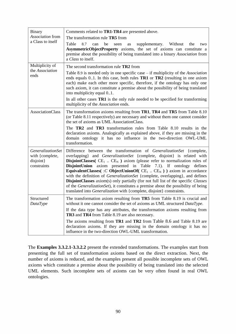
90
Binary
Association from
a Class to itself
Comments related to TR1-TR4 are presented above.
The transformation rule TR5 from
Table 8.7 can be seen as supplementary. Without the two
AsymmetricObjectProperty axioms, the set of axioms can constitute a
premise about the possibility of being translated into a binary Association from
a Class to itself.
Multiplicity of
the Association
ends
The second transformation rule TR2 from
Table 8.9 is needed only in one specific case – if multiplicity of the Association
ends equals 0..1. In this case, both rules TR1 or TR2 (resulting in one axiom
each) make each other more specific, therefore, if the ontology has only one
such axiom, it can constitute a premise about the possibility of being translated
into multiplicity equal 0..1.
In all other cases TR1 is the only rule needed to be specified for transforming
multiplicity of the Association ends.
AssociationClass The transformation axioms resulting from TR1, TR4 and TR5 from Table 8.10
(or Table 8.11 respectively) are necessary and without them one cannot consider
the set of axioms as UML AssociationClass.
The TR2 and TR3 transformation rules from Table 8.10 results in the
declaration axioms. Analogically as explained above, if they are missing in the
domain ontology it has no influence in the two-direction OWL-UML
transformation.
GeneralizationSet
with {complete,
disjoint}
constraints
Difference between the transformation of GeneralizationSet {complete,
overlapping} and GeneralizationSet {complete, disjoint} is related with
DisjointClasses( CE1 .. CEN ) axiom (please refer to normalization rules of
DisjointUnion axiom presented in Table 7.1). If ontology defines
EquivalentClasses( :C ObjectUnionOf( CE1 .. CEN ) ) axiom in accordance
with the definition of GeneralizationSet {complete, overlapping}, and defines
DisjointClasses axiom(s) only partially (for not full list of the specific Classes
of the GeneralizationSet), it constitutes a premise about the possibility of being
translated into Generalization with {complete, disjoint} constraints.
Structured
DataType
The transformation axiom resulting from TR5 from Table 8.19 is crucial and
without it one cannot consider the set of axioms as UML structured DataType.
If the data type has any attributes, the transformation axioms resulting from
TR3 and TR4 from Table 8.19 are also necessary.
The axioms resulting from TR1 and TR2 from Table 8.6 and Table 8.19 are
declaration axioms. If they are missing in the domain ontology it has no
influence in the two-direction OWL-UML transformation.
The Examples 3.3.2.1-3.3.2.2 present the extended transformations. The examples start from
presenting the full set of transformation axioms based on the direct extraction. Next, the
number of axioms is reduced, and the examples present all possible incomplete sets of OWL
axioms which constitute a premise about the possibility of being translated into the selected
UML elements. Such incomplete sets of axioms can be very often found in real OWL
ontologies.
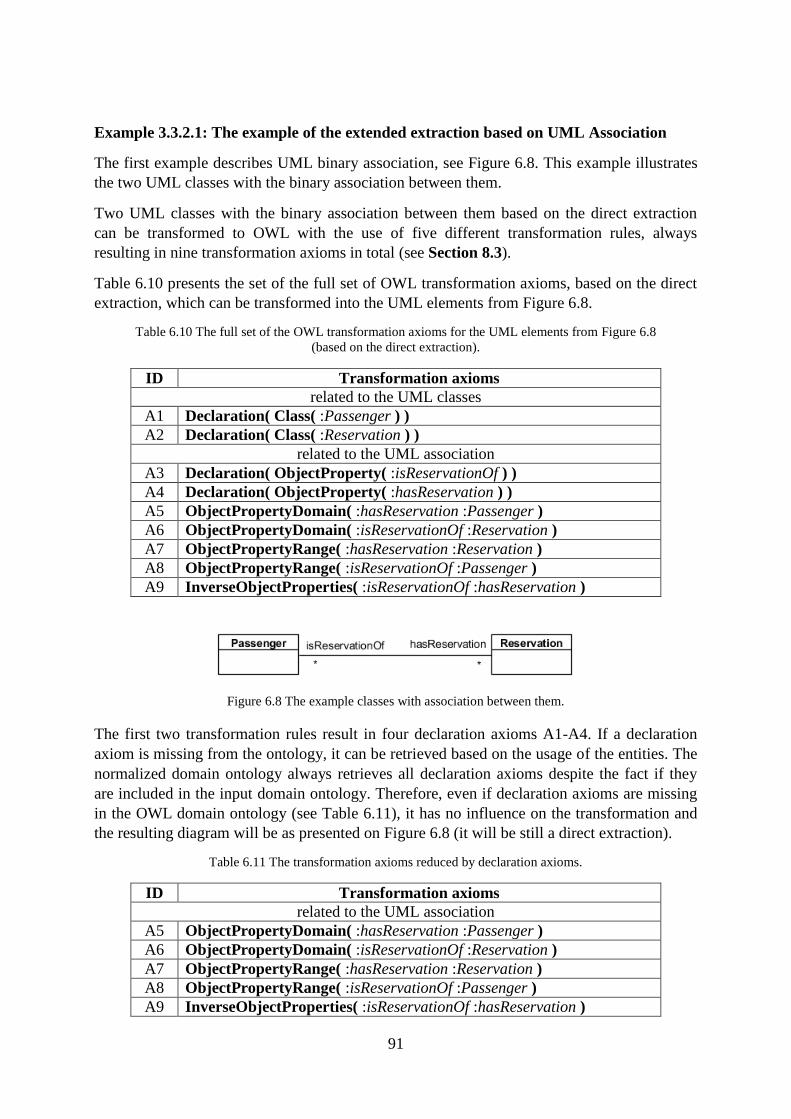
91
Example 3.3.2.1: The example of the extended extraction based on UML Association
The first example describes UML binary association, see Figure 6.8. This example illustrates
the two UML classes with the binary association between them.
Two UML classes with the binary association between them based on the direct extraction
can be transformed to OWL with the use of five different transformation rules, always
resulting in nine transformation axioms in total (see Section 8.3).
Table 6.10 presents the set of the full set of OWL transformation axioms, based on the direct
extraction, which can be transformed into the UML elements from Figure 6.8.
Table 6.10 The full set of the OWL transformation axioms for the UML elements from Figure 6.8
(based on the direct extraction).
ID Transformation axioms
related to the UML classes
A1 Declaration( Class( :Passenger ) )
A2 Declaration( Class( :Reservation ) )
related to the UML association
A3 Declaration( ObjectProperty( :isReservationOf ) )
A4 Declaration( ObjectProperty( :hasReservation ) )
A5 ObjectPropertyDomain( :hasReservation :Passenger )
A6 ObjectPropertyDomain( :isReservationOf :Reservation )
A7 ObjectPropertyRange( :hasReservation :Reservation )
A8 ObjectPropertyRange( :isReservationOf :Passenger )
A9 InverseObjectProperties( :isReservationOf :hasReservation )
Figure 6.8 The example classes with association between them.
The first two transformation rules result in four declaration axioms A1-A4. If a declaration
axiom is missing from the ontology, it can be retrieved based on the usage of the entities. The
normalized domain ontology always retrieves all declaration axioms despite the fact if they
are included in the input domain ontology. Therefore, even if declaration axioms are missing
in the OWL domain ontology (see Table 6.11), it has no influence on the transformation and
the resulting diagram will be as presented on Figure 6.8 (it will be still a direct extraction).
Table 6.11 The transformation axioms reduced by declaration axioms.
ID Transformation axioms
related to the UML association
A5 ObjectPropertyDomain( :hasReservation :Passenger )
A6 ObjectPropertyDomain( :isReservationOf :Reservation )
A7 ObjectPropertyRange( :hasReservation :Reservation )
A8 ObjectPropertyRange( :isReservationOf :Passenger )
A9 InverseObjectProperties( :isReservationOf :hasReservation )
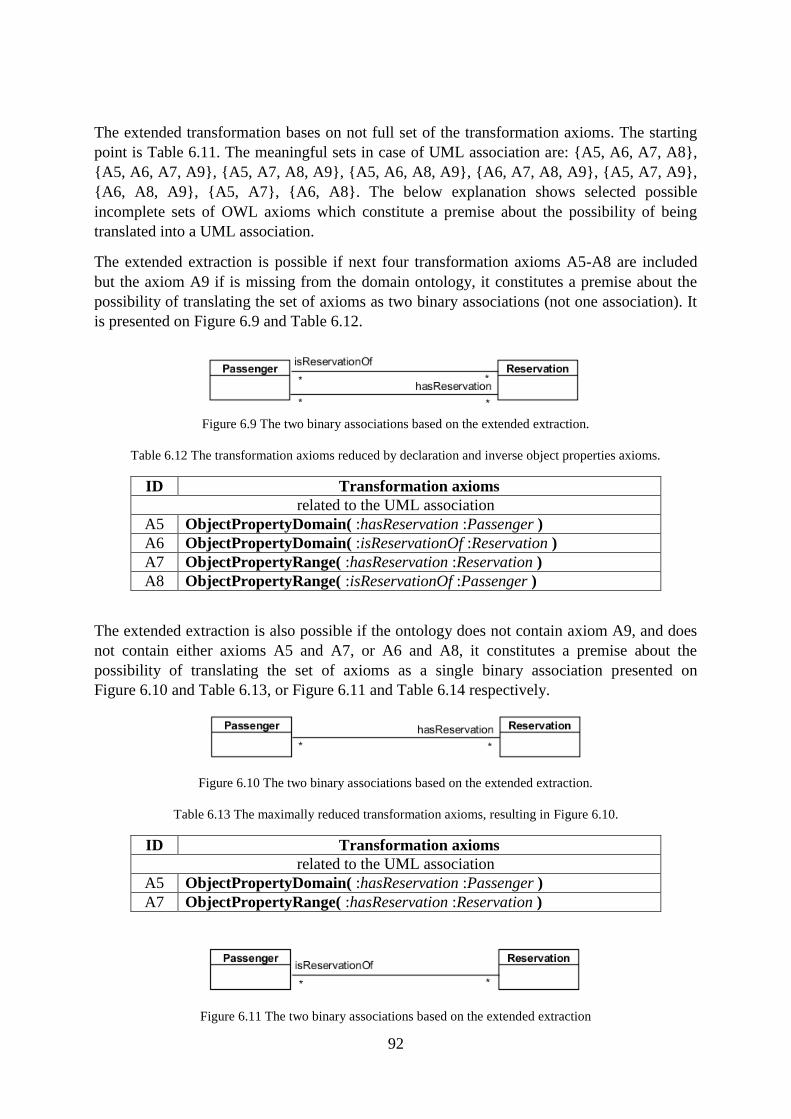
92
The extended transformation bases on not full set of the transformation axioms. The starting
point is Table 6.11. The meaningful sets in case of UML association are: {A5, A6, A7, A8},
{A5, A6, A7, A9}, {A5, A7, A8, A9}, {A5, A6, A8, A9}, {A6, A7, A8, A9}, {A5, A7, A9},
{A6, A8, A9}, {A5, A7}, {A6, A8}. The below explanation shows selected possible
incomplete sets of OWL axioms which constitute a premise about the possibility of being
translated into a UML association.
The extended extraction is possible if next four transformation axioms A5-A8 are included
but the axiom A9 if is missing from the domain ontology, it constitutes a premise about the
possibility of translating the set of axioms as two binary associations (not one association). It
is presented on Figure 6.9 and Table 6.12.
Figure 6.9 The two binary associations based on the extended extraction.
Table 6.12 The transformation axioms reduced by declaration and inverse object properties axioms.
ID Transformation axioms
related to the UML association
A5 ObjectPropertyDomain( :hasReservation :Passenger )
A6 ObjectPropertyDomain( :isReservationOf :Reservation )
A7 ObjectPropertyRange( :hasReservation :Reservation )
A8 ObjectPropertyRange( :isReservationOf :Passenger )
The extended extraction is also possible if the ontology does not contain axiom A9, and does
not contain either axioms A5 and A7, or A6 and A8, it constitutes a premise about the
possibility of translating the set of axioms as a single binary association presented on
Figure 6.10 and Table 6.13, or Figure 6.11 and Table 6.14 respectively.
Figure 6.10 The two binary associations based on the extended extraction.
Table 6.13 The maximally reduced transformation axioms, resulting in Figure 6.10.
ID Transformation axioms
related to the UML association
A5 ObjectPropertyDomain( :hasReservation :Passenger )
A7 ObjectPropertyRange( :hasReservation :Reservation )
Figure 6.11 The two binary associations based on the extended extraction
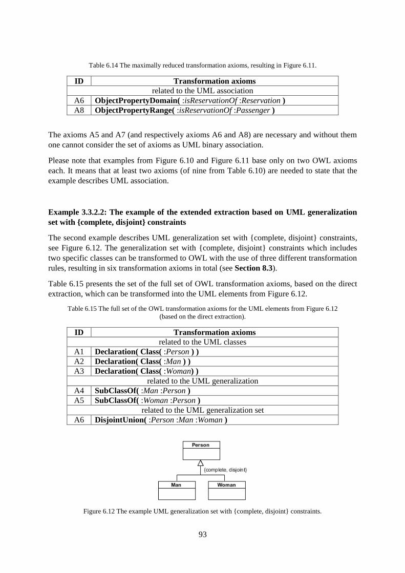
93
Table 6.14 The maximally reduced transformation axioms, resulting in Figure 6.11.
ID Transformation axioms
related to the UML association
A6 ObjectPropertyDomain( :isReservationOf :Reservation )
A8 ObjectPropertyRange( :isReservationOf :Passenger )
The axioms A5 and A7 (and respectively axioms A6 and A8) are necessary and without them
one cannot consider the set of axioms as UML binary association.
Please note that examples from Figure 6.10 and Figure 6.11 base only on two OWL axioms
each. It means that at least two axioms (of nine from Table 6.10) are needed to state that the
example describes UML association.
Example 3.3.2.2: The example of the extended extraction based on UML generalization
set with {complete, disjoint} constraints
The second example describes UML generalization set with {complete, disjoint} constraints,
see Figure 6.12. The generalization set with {complete, disjoint} constraints which includes
two specific classes can be transformed to OWL with the use of three different transformation
rules, resulting in six transformation axioms in total (see Section 8.3).
Table 6.15 presents the set of the full set of OWL transformation axioms, based on the direct
extraction, which can be transformed into the UML elements from Figure 6.12.
Table 6.15 The full set of the OWL transformation axioms for the UML elements from Figure 6.12
(based on the direct extraction).
ID Transformation axioms
related to the UML classes
A1 Declaration( Class( :Person ) )
A2 Declaration( Class( :Man ) )
A3 Declaration( Class( :Woman) )
related to the UML generalization
A4 SubClassOf( :Man :Person )
A5 SubClassOf( :Woman :Person )
related to the UML generalization set
A6 DisjointUnion( :Person :Man :Woman )
Figure 6.12 The example UML generalization set with {complete, disjoint} constraints.
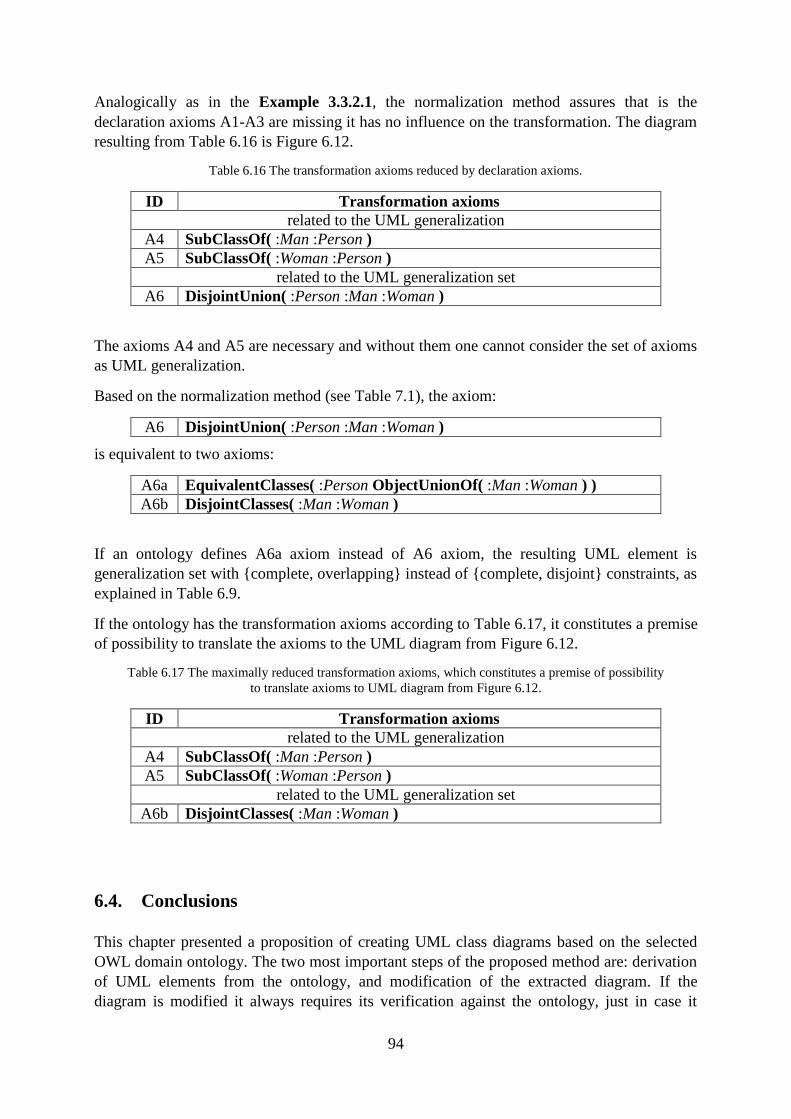
94
Analogically as in the Example 3.3.2.1, the normalization method assures that is the
declaration axioms A1-A3 are missing it has no influence on the transformation. The diagram
resulting from Table 6.16 is Figure 6.12.
Table 6.16 The transformation axioms reduced by declaration axioms.
ID Transformation axioms
related to the UML generalization
A4 SubClassOf( :Man :Person )
A5 SubClassOf( :Woman :Person )
related to the UML generalization set
A6 DisjointUnion( :Person :Man :Woman )
The axioms A4 and A5 are necessary and without them one cannot consider the set of axioms
as UML generalization.
Based on the normalization method (see Table 7.1), the axiom:
A6 DisjointUnion( :Person :Man :Woman )
is equivalent to two axioms:
A6a EquivalentClasses( :Person ObjectUnionOf( :Man :Woman ) )
A6b DisjointClasses( :Man :Woman )
If an ontology defines A6a axiom instead of A6 axiom, the resulting UML element is
generalization set with {complete, overlapping} instead of {complete, disjoint} constraints, as
explained in Table 6.9.
If the ontology has the transformation axioms according to Table 6.17, it constitutes a premise
of possibility to translate the axioms to the UML diagram from Figure 6.12.
Table 6.17 The maximally reduced transformation axioms, which constitutes a premise of possibility
to translate axioms to UML diagram from Figure 6.12.
ID Transformation axioms
related to the UML generalization
A4 SubClassOf( :Man :Person )
A5 SubClassOf( :Woman :Person )
related to the UML generalization set
A6b DisjointClasses( :Man :Woman )
6.4. Conclusions
This chapter presented a proposition of creating UML class diagrams based on the selected
OWL domain ontology. The two most important steps of the proposed method are: derivation
of UML elements from the ontology, and modification of the extracted diagram. If the
diagram is modified it always requires its verification against the ontology, just in case it
95
contains any elements contradictory with the ontology. The method assures that the extracted
UML class diagram if it is based only on the complete sets of axioms is always compliant
with the normalized OWL domain ontology.
In addition to the refinement of the process of diagram creation, this chapter presented two
original elements of this research. The first one is the proposition of the checking rules which
assure that the OWL-UML transformation is correct with respect to other axioms from the
selected OWL domain ontology. The checking rules are required to be applied before any
UML element is derived from the ontology. The second one is related to allow extracting
some UML elements which are only partly based on the ontology, which is justified from the
point of view of the practical modelling needs and real OWL ontologies.

96
Part III
Details of the Proposed Method of the Creation
and Validation of UML Class Diagrams
Part III: Details of the Proposed Method of
Creation and Validation of UML Class Diagrams

97
98
7. The Method of Normalizing OWL 2 DL Ontologies
Summary. In this chapter a method of normalizing OWL 2 DL ontologies is proposed.
The normalization method introduces rules aimed at refactoring OWL 2 constructs what
enables to present any input OWL 2 ontology in a new but semantically equivalent form.
The need for normalization is motivated by the fact that normalized OWL 2 DL
ontologies have a unified structure of axioms, therefore, they can be easily compared in
an algorithmic way. 25
7.1. Introduction
In this approach it is assumed that the selected OWL 2 DL domain ontology is syntactically
correct, consistent and adequately describes the notions from the needed domain.
It is not obvious or conclusive how to effectively process useful operations on the ontology,
for example, how to compare it with another one. The problem of comparing two ontologies
with the agreed vocabulary was already mentioned in Chapter 5 which describes the method
of semantic validation of UML class diagrams. In the verification step of the method, the
UML class diagram is transformed into an ontology expressed in OWL 2. Next, the two
ontologies − the domain ontology and the ontological representation of the UML diagram −
need to be compared against each other.
The question arises:
How to correctly and automatically find out whether one ontology
is compliant or contradictory concerning another one?
For the purpose of answering the question, such a form of normalization is introduced that
allows for unifying the structure of axioms in the ontologies so that it is possible to
automatically compare them.
The ontology normalization is defined as a process of transforming the input ontology into
the ontology in its refactored form. The process is defined through a group of OWL 2
construct replacements. Section 7.3 presents all replacing and replaced OWL 2 constructs
used in the process of normalizing OWL 2 DL ontologies. The details of the ontology
normalization algorithm are presented in Section 7.6. The normalization method has been
implemented in the tool (described in Chapter 9).
The output ontology obtained as a result of conducting the algorithm is considered as
normalized. Due to the fact that all transformations (of the replaced OWL 2 constructs to the
replacing OWL 2 constructs) preserve semantics, the semantics of the normalized ontology is
the same as the semantics of the input ontology.
25 Chapter 7 contains the revised and extended version of the paper: "The method of normalizing OWL 2 DL
ontologies" [13].
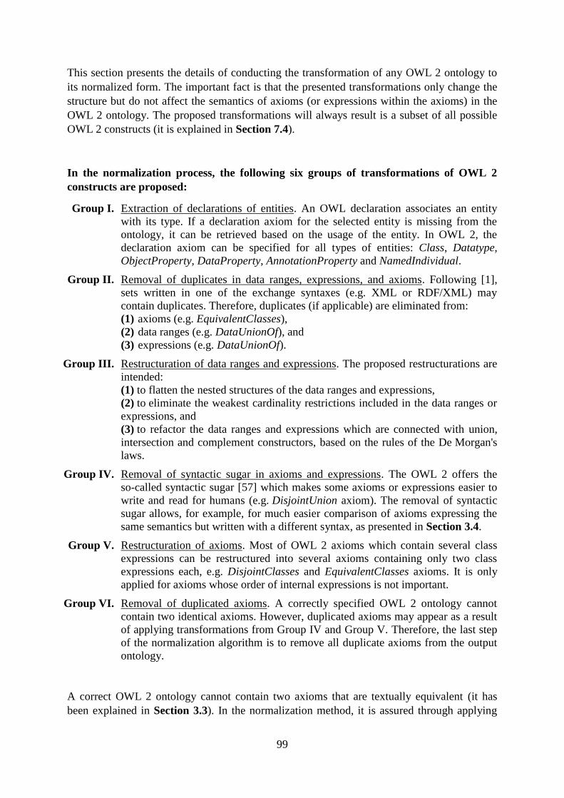
99
This section presents the details of conducting the transformation of any OWL 2 ontology to
its normalized form. The important fact is that the presented transformations only change the
structure but do not affect the semantics of axioms (or expressions within the axioms) in the
OWL 2 ontology. The proposed transformations will always result is a subset of all possible
OWL 2 constructs (it is explained in Section 7.4).
In the normalization process, the following six groups of transformations of OWL 2
constructs are proposed:
Group I. Extraction of declarations of entities. An OWL declaration associates an entity
with its type. If a declaration axiom for the selected entity is missing from the
ontology, it can be retrieved based on the usage of the entity. In OWL 2, the
declaration axiom can be specified for all types of entities: Class, Datatype,
ObjectProperty, DataProperty, AnnotationProperty and NamedIndividual.
Group II. Removal of duplicates in data ranges, expressions, and axioms. Following [1],
sets written in one of the exchange syntaxes (e.g. XML or RDF/XML) may
contain duplicates. Therefore, duplicates (if applicable) are eliminated from:
(1) axioms (e.g. EquivalentClasses),
(2) data ranges (e.g. DataUnionOf), and
(3) expressions (e.g. DataUnionOf).
Group III. Restructuration of data ranges and expressions. The proposed restructurations are
intended:
(1) to flatten the nested structures of the data ranges and expressions,
(2) to eliminate the weakest cardinality restrictions included in the data ranges or
expressions, and
(3) to refactor the data ranges and expressions which are connected with union,
intersection and complement constructors, based on the rules of the De Morgan's
laws.
Group IV. Removal of syntactic sugar in axioms and expressions. The OWL 2 offers the
so-called syntactic sugar [57] which makes some axioms or expressions easier to
write and read for humans (e.g. DisjointUnion axiom). The removal of syntactic
sugar allows, for example, for much easier comparison of axioms expressing the
same semantics but written with a different syntax, as presented in Section 3.4.
Group V. Restructuration of axioms. Most of OWL 2 axioms which contain several class
expressions can be restructured into several axioms containing only two class
expressions each, e.g. DisjointClasses and EquivalentClasses axioms. It is only
applied for axioms whose order of internal expressions is not important.
Group VI. Removal of duplicated axioms. A correctly specified OWL 2 ontology cannot
contain two identical axioms. However, duplicated axioms may appear as a result
of applying transformations from Group IV and Group V. Therefore, the last step
of the normalization algorithm is to remove all duplicate axioms from the output
ontology.
A correct OWL 2 ontology cannot contain two axioms that are textually equivalent (it has
been explained in Section 3.3). In the normalization method, it is assured through applying
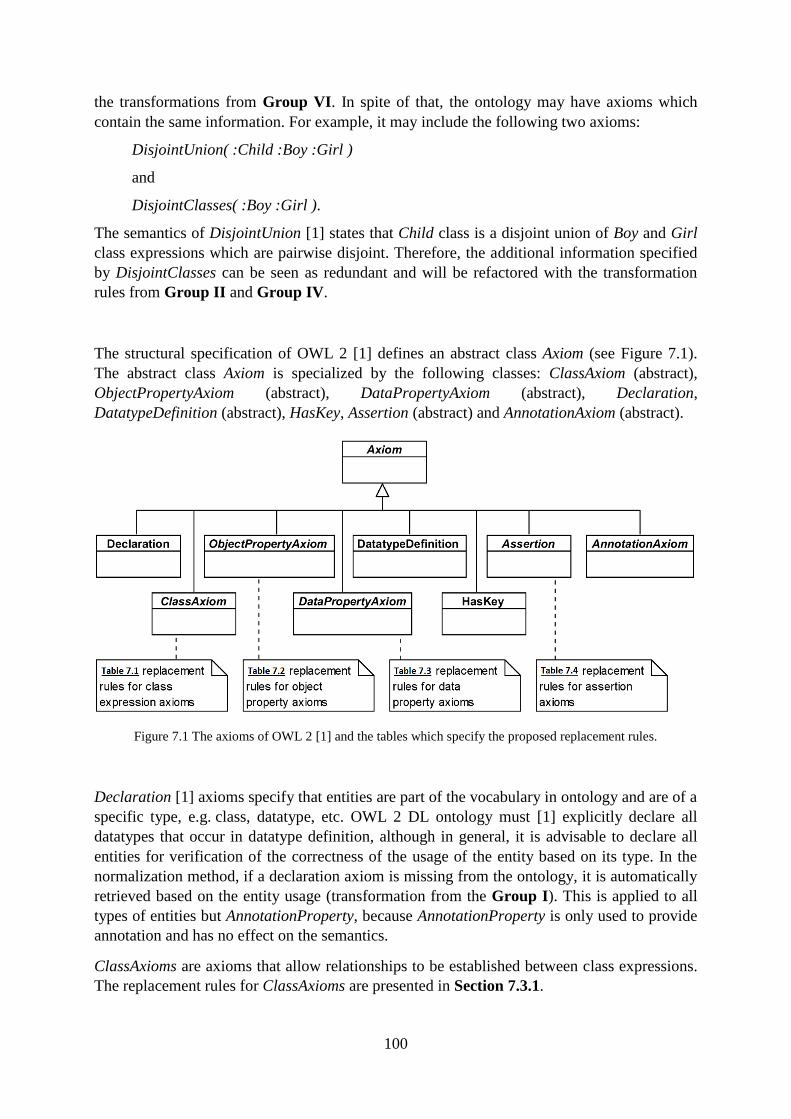
100
the transformations from Group VI. In spite of that, the ontology may have axioms which
contain the same information. For example, it may include the following two axioms:
DisjointUnion( :Child :Boy :Girl )
and
DisjointClasses( :Boy :Girl ).
The semantics of DisjointUnion [1] states that Child class is a disjoint union of Boy and Girl
class expressions which are pairwise disjoint. Therefore, the additional information specified
by DisjointClasses can be seen as redundant and will be refactored with the transformation
rules from Group II and Group IV.
The structural specification of OWL 2 [1] defines an abstract class Axiom (see Figure 7.1).
The abstract class Axiom is specialized by the following classes: ClassAxiom (abstract),
ObjectPropertyAxiom (abstract), DataPropertyAxiom (abstract), Declaration,
DatatypeDefinition (abstract), HasKey, Assertion (abstract) and AnnotationAxiom (abstract).
Figure 7.1 The axioms of OWL 2 [1] and the tables which specify the proposed replacement rules.
Declaration [1] axioms specify that entities are part of the vocabulary in ontology and are of a
specific type, e.g. class, datatype, etc. OWL 2 DL ontology must [1] explicitly declare all
datatypes that occur in datatype definition, although in general, it is advisable to declare all
entities for verification of the correctness of the usage of the entity based on its type. In the
normalization method, if a declaration axiom is missing from the ontology, it is automatically
retrieved based on the entity usage (transformation from the Group I). This is applied to all
types of entities but AnnotationProperty, because AnnotationProperty is only used to provide
annotation and has no effect on the semantics.
ClassAxioms are axioms that allow relationships to be established between class expressions.
The replacement rules for ClassAxioms are presented in Section 7.3.1.
101
DataPropertyAxioms [1] and ObjectPropertyAxioms [1] are axioms that can be used to
characterize and establish relationships between data and object property expressions. The
replacement rules for ObjectPropertyAxioms are presented in Section 7.3.2, and for
DataPropertyAxioms in Section 7.3.3.
HasKey [1] axiom states that each named instance of the specified class expression is
uniquely identified by the specified object property and/or data property expressions. It is
useful in querying about individuals which are uniquely identified. The HasKey axiom itself
is defined in the form that does not need to be restructured, but the internal structure of the
axiom is restructured with the use of transformations from Group II, Group III and Group IV
presented in Section 7.3.6 (for class expression) and Section 7.3.7 (for object property
expressions).
Assertion [1] are axioms about individuals that are often also called facts. The replacement
rules for Assertion axioms are presented in Section 7.3.4.
DatatypeDefinition [1] axiom defines a new datatype as being semantically equivalent to a
unary data range. The DatatypeDefinition axiom is defined in the form that does not need to
be restructured. Nonetheless, the data ranges included in other axioms or expressions may
require refactoring (see transformations from Group II and Group III).
AnnotationAxiom [1] axioms do not affect the semantics and are mainly used to improve
readability for humans. Therefore, they are not further restructured in the normalization
process.
Besides axioms, the replacement rules for data ranges are presented in Section 7.3.5, for class
expression in Section 7.3.6 and for object property expressions Section 7.3.7.
To sum up, the process of normalization consists of the following phases:
1. extraction of declarations (Group I),
2. refactorization of expressions and data ranges through applying transformations from
Group II and Group IV, and restructuration of expressions and data ranges through
applying transformations from Group III,
3. refactorization of axioms through applying transformations from Group II, Group IV,
Group V and Group VI.
7.2. Related Works
To the best knowledge of the author, a similar concept of normalization of OWL ontologies
has not yet been proposed. Here, the normalization is aimed at unifying the structure of
axioms in the ontologies allowing for automatic processing of the ontologies. A different
purpose as well as a different kind of ontology normalization has been proposed in [107],
[108] and [109].
In [107], the notion of ontology normalization is suggested to be a pre-processing step that
aligns structural metrics with intended semantic measures. The goal of the article is to present
guidelines for creating ontology metrics allowing assessment of the ontologies and tracking
their subsequent evolution.
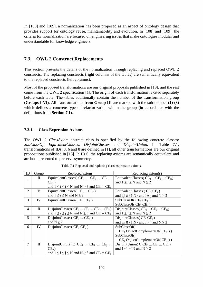
102
In [108] and [109], a normalization has been proposed as an aspect of ontology design that
provides support for ontology reuse, maintainability and evolution. In [108] and [109], the
criteria for normalization are focused on engineering issues that make ontologies modular and
understandable for knowledge engineers.
7.3. OWL 2 Construct Replacements
This section presents the details of the normalization through replacing and replaced OWL 2
constructs. The replacing constructs (right columns of the tables) are semantically equivalent
to the replaced constructs (left columns).
Most of the proposed transformations are our original proposals published in [13], and the rest
come from the OWL 2 specification [1]. The origin of each transformation is cited separately
before each table. The tables additionally contain the number of the transformation group
(Groups I-VI). All transformations from Group III are marked with the sub-number (1)-(3)
which defines a concrete type of refactorization within the group (in accordance with the
definitions from Section 7.1).
7.3.1. Class Expression Axioms
The OWL 2 ClassAxiom abstract class is specified by the following concrete classes:
SubClassOf, EquivalentClasses, DisjointClasses and DisjointUnion. In Table 7.1,
transformations of IDs: 3, 6 and 8 are defined in [1], all other transformations are our original
propositions published in [13]. In ID 6, the replacing axioms are semantically equivalent and
are both presented to preserve symmetry.
Table 7.1 Replaced and replacing class expression axioms.
ID Group Replaced axiom Replacing axiom(s)
1 II EquivalentClasses( CE1 ... CEi ... CEj ...
CEN)
and 1 ≤ i ≤ j ≤ N and N ≥ 3 and CEi = CEj
EquivalentClasses( CE1 ... CEi ... CEN)
and 1 ≤ i ≤ N and N ≥ 2
2 V EquivalentClasses( CE1 ... CEN)
and 1 ≤ i ≤ N and N ≥ 2
EquivalentClasses ( CEi CEj )
and i,j {1,N} and i j and N ≥ 2
3 IV EquivalentClasses( CE1 CE2 ) SubClassOf( CE1 CE2 )
SubClassOf( CE2 CE1 )
4 II DisjointClasses( CE1 ... CEi ... CEj ... CEN)
and 1 ≤ i ≤ j ≤ N and N ≥ 3 and CEi = CEj
DisjointClasses( CE1 ... CEi ... CEN)
and 1 ≤ i ≤ N and N ≥ 2
5 V DisjointClasses( CE1 ... CEN )
and N ≥ 2
DisjointClasses( CEi CEj )
and i,j {1,N} and i j and N ≥ 2
6 IV DisjointClasses( CE1 CE2 ) SubClassOf(
CE1 ObjectComplementOf( CE2 ) )
SubClassOf(
CE2 ObjectComplementOf( CE1 ) )
7 II DisjointUnion( C CE1 ... CEi ... CEj ...
CEN)
and 1 ≤ i ≤ j ≤ N and N ≥ 3 and CEi = CEj
DisjointUnion( C CE1 ... CEi ... CEN)
and 1 ≤ i ≤ N and N ≥ 2
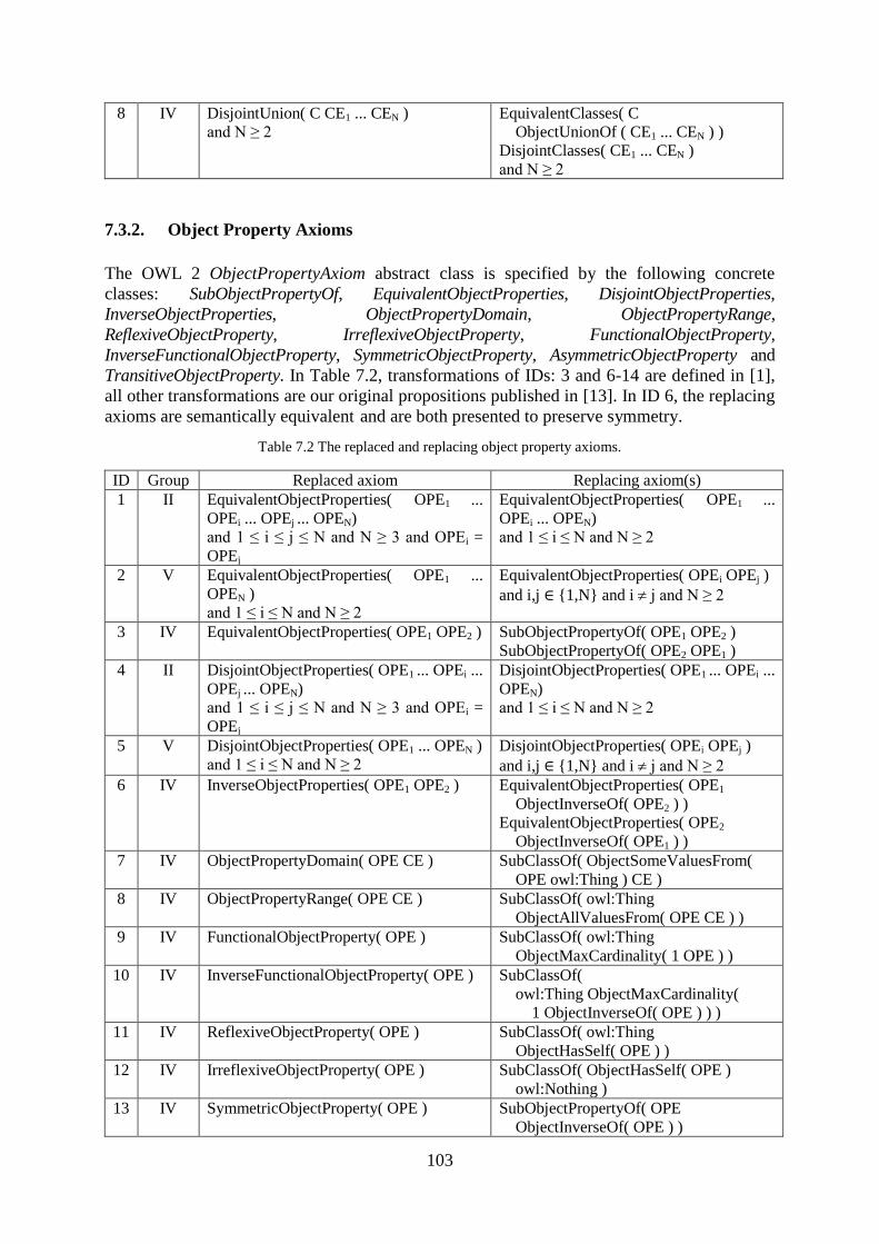
103
8 IV DisjointUnion( C CE1 ... CEN )
and N ≥ 2
EquivalentClasses( C
ObjectUnionOf ( CE1 ... CEN ) )
DisjointClasses( CE1 ... CEN )
and N ≥ 2
7.3.2. Object Property Axioms
The OWL 2 ObjectPropertyAxiom abstract class is specified by the following concrete
classes: SubObjectPropertyOf, EquivalentObjectProperties, DisjointObjectProperties,
InverseObjectProperties, ObjectPropertyDomain, ObjectPropertyRange,
ReflexiveObjectProperty, IrreflexiveObjectProperty, FunctionalObjectProperty,
InverseFunctionalObjectProperty, SymmetricObjectProperty, AsymmetricObjectProperty and
TransitiveObjectProperty. In Table 7.2, transformations of IDs: 3 and 6-14 are defined in [1],
all other transformations are our original propositions published in [13]. In ID 6, the replacing
axioms are semantically equivalent and are both presented to preserve symmetry.
Table 7.2 The replaced and replacing object property axioms.
ID Group Replaced axiom Replacing axiom(s)
1 II EquivalentObjectProperties( OPE1 ...
OPEi ... OPEj ... OPEN)
and 1 ≤ i ≤ j ≤ N and N ≥ 3 and OPEi =
OPEj
EquivalentObjectProperties( OPE1 ...
OPEi ... OPEN)
and 1 ≤ i ≤ N and N ≥ 2
2 V EquivalentObjectProperties( OPE1 ...
OPEN )
and 1 ≤ i ≤ N and N ≥ 2
EquivalentObjectProperties( OPEi OPEj )
and i,j {1,N} and i j and N ≥ 2
3 IV EquivalentObjectProperties( OPE1 OPE2 )
SubObjectPropertyOf( OPE1 OPE2 )
SubObjectPropertyOf( OPE2 OPE1 )
4 II DisjointObjectProperties( OPE1 ... OPEi ...
OPEj ... OPEN)
and 1 ≤ i ≤ j ≤ N and N ≥ 3 and OPEi =
OPEj
DisjointObjectProperties( OPE1 ... OPEi ...
OPEN)
and 1 ≤ i ≤ N and N ≥ 2
5 V DisjointObjectProperties( OPE1 ... OPEN )
and 1 ≤ i ≤ N and N ≥ 2
DisjointObjectProperties( OPEi OPEj )
and i,j {1,N} and i j and N ≥ 2
6 IV InverseObjectProperties( OPE1 OPE2 )
EquivalentObjectProperties( OPE1
ObjectInverseOf( OPE2 ) )
EquivalentObjectProperties( OPE2
ObjectInverseOf( OPE1 ) )
7 IV ObjectPropertyDomain( OPE CE ) SubClassOf( ObjectSomeValuesFrom(
OPE owl:Thing ) CE )
8 IV ObjectPropertyRange( OPE CE ) SubClassOf( owl:Thing
ObjectAllValuesFrom( OPE CE ) )
9 IV FunctionalObjectProperty( OPE ) SubClassOf( owl:Thing
ObjectMaxCardinality( 1 OPE ) )
10 IV InverseFunctionalObjectProperty( OPE ) SubClassOf(
owl:Thing ObjectMaxCardinality(
1 ObjectInverseOf( OPE ) ) )
11 IV ReflexiveObjectProperty( OPE ) SubClassOf( owl:Thing
ObjectHasSelf( OPE ) )
12 IV IrreflexiveObjectProperty( OPE ) SubClassOf( ObjectHasSelf( OPE )
owl:Nothing )
13 IV SymmetricObjectProperty( OPE ) SubObjectPropertyOf( OPE
ObjectInverseOf( OPE ) )
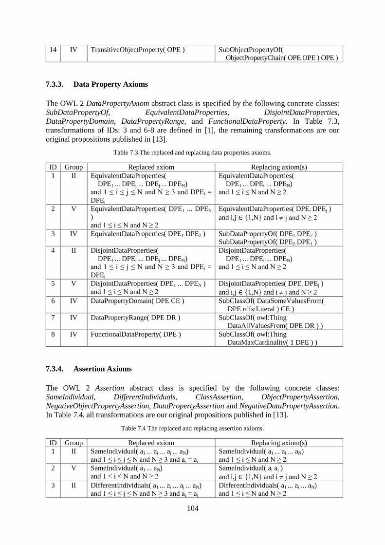
104
14 IV TransitiveObjectProperty( OPE ) SubObjectPropertyOf(
ObjectPropertyChain( OPE OPE ) OPE )
7.3.3. Data Property Axioms
The OWL 2 DataPropertyAxiom abstract class is specified by the following concrete classes:
SubDataPropertyOf, EquivalentDataProperties, DisjointDataProperties,
DataPropertyDomain, DataPropertyRange, and FunctionalDataProperty. In Table 7.3,
transformations of IDs: 3 and 6-8 are defined in [1], the remaining transformations are our
original propositions published in [13].
Table 7.3 The replaced and replacing data properties axioms.
ID Group Replaced axiom Replacing axiom(s)
1 II EquivalentDataProperties(
DPE1 ... DPEi ... DPEj ... DPEN)
and 1 ≤ i ≤ j ≤ N and N ≥ 3 and DPEi =
DPEj
EquivalentDataProperties(
DPE1 ... DPEi ... DPEN)
and 1 ≤ i ≤ N and N ≥ 2
2 V EquivalentDataProperties( DPE1 ... DPEN
)
and 1 ≤ i ≤ N and N ≥ 2
EquivalentDataProperties( DPEi DPEj )
and i,j {1,N} and i j and N ≥ 2
3 IV EquivalentDataProperties( DPE1 DPE2 ) SubDataPropertyOf( DPE1 DPE2 )
SubDataPropertyOf( DPE2 DPE1 )
4 II DisjointDataProperties(
DPE1 ... DPEi ... DPEj ... DPEN)
and 1 ≤ i ≤ j ≤ N and N ≥ 3 and DPEi =
DPEj
DisjointDataProperties(
DPE1 ... DPEi ... DPEN)
and 1 ≤ i ≤ N and N ≥ 2
5 V DisjointDataProperties( DPE1 ... DPEN )
and 1 ≤ i ≤ N and N ≥ 2
DisjointDataProperties( DPEi DPEj )
and i,j {1,N} and i j and N ≥ 2
6 IV DataPropertyDomain( DPE CE ) SubClassOf( DataSomeValuesFrom(
DPE rdfs:Literal ) CE )
7 IV DataPropertyRange( DPE DR ) SubClassOf( owl:Thing
DataAllValuesFrom( DPE DR ) )
8 IV FunctionalDataProperty( DPE ) SubClassOf( owl:Thing
DataMaxCardinality( 1 DPE ) )
7.3.4. Assertion Axioms
The OWL 2 Assertion abstract class is specified by the following concrete classes:
SameIndividual, DifferentIndividuals, ClassAssertion, ObjectPropertyAssertion,
NegativeObjectPropertyAssertion, DataPropertyAssertion and NegativeDataPropertyAssertion.
In Table 7.4, all transformations are our original propositions published in [13].
Table 7.4 The replaced and replacing assertion axioms.
ID Group Replaced axiom Replacing axiom(s)
1 II SameIndividual( a1 ... ai ... aj ... aN)
and 1 ≤ i ≤ j ≤ N and N ≥ 3 and ai = aj
SameIndividual( a1 ... ai ... aN)
and 1 ≤ i ≤ N and N ≥ 2
2 V SameIndividual( a1 ... aN)
and 1 ≤ i ≤ N and N ≥ 2
SameIndividual( ai aj )
and i,j {1,N} and i j and N ≥ 2
3 II DifferentIndividuals( a1 ... ai ... aj ... aN)
and 1 ≤ i ≤ j ≤ N and N ≥ 3 and ai = aj
DifferentIndividuals( a1 ... ai ... aN)
and 1 ≤ i ≤ N and N ≥ 2
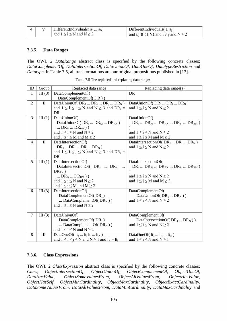
105
4 V DifferentIndividuals( a1 ... aN)
and 1 ≤ i ≤ N and N ≥ 2
DifferentIndividuals( ai aj )
and i,j {1,N} and i j and N ≥ 2
7.3.5. Data Ranges
The OWL 2 DataRange abstract class is specified by the following concrete classes:
DataComplementOf, DataIntersectionOf, DataUnionOf, DataOneOf, DatatypeRestriction and
Datatype. In Table 7.5, all transformations are our original propositions published in [13].
Table 7.5 The replaced and replacing data ranges.
ID Group Replaced data range Replacing data range(s)
1 III (3) DataComplementOf (
DataComplementOf( DR ) )
DR
2 II DataUnionOf( DR1 ... DRi ... DRj ... DRN )
and 1 ≤ i ≤ j ≤ N and N ≥ 3 and DRi =
DRj
DataUnionOf( DR1 ... DRi ... DRN )
and 1 ≤ i ≤ N and N ≥ 2
3 III (1) DataUnionOf(
DataUnionOf( DR1 ... DRAi ... DRAN )
... DRBj ... DRBM ) )
and 1 ≤ i ≤ N and N ≥ 2
and 1 ≤ j ≤ M and M ≥ 2
DataUnionOf(
DR1 ... DRAi ... DRAN ... DRBj ... DRBM )
)
and 1 ≤ i ≤ N and N ≥ 2
and 1 ≤ j ≤ M and M ≥ 2
4 II DataIntersectionOf(
DR1 ... DRi ... DRj ... DRN )
and 1 ≤ i ≤ j ≤ N and N ≥ 3 and DRi =
DRj
DataIntersectionOf( DR1 ... DRi ... DRN )
and 1 ≤ i ≤ N and N ≥ 2
5 III (1) DataIntersectionOf(
DataIntersectionOf( DR1 ... DRAi ...
DRAN )
... DRBj ... DRBM ) )
and 1 ≤ i ≤ N and N ≥ 2
and 1 ≤ j ≤ M and M ≥ 2
DataIntersectionOf(
DR1 ... DRAi ... DRAN ... DRBj ... DRBM )
)
and 1 ≤ i ≤ N and N ≥ 2
and 1 ≤ j ≤ M and M ≥ 2
6 III (3) DataIntersectionOf(
DataComplementOf( DR1 )
... DataComplementOf( DRN ) )
and 1 ≤ i ≤ N and N ≥ 2
DataComplementOf(
DataUnionOf( DR1 ... DRN ) )
and 1 ≤ i ≤ N and N ≥ 2
7 III (3) DataUnionOf(
DataComplementOf( DR1 )
... DataComplementOf( DRN ) )
and 1 ≤ i ≤ N and N ≥ 2
DataComplementOf(
DataIntersectionOf( DR1 ... DRN ) )
and 1 ≤ i ≤ N and N ≥ 2
8 II DataOneOf( lt1 ... lti ltj ... ltN )
and 1 ≤ i ≤ j ≤ N and N ≥ 1 and lti = ltj
DataOneOf( lt1 ... lti ... ltN )
and 1 ≤ i ≤ N and N ≥ 1
7.3.6. Class Expressions
The OWL 2 ClassExpression abstract class is specified by the following concrete classes:
Class, ObjectIntersectionOf, ObjectUnionOf, ObjectComplementOf, ObjectOneOf,
DataHasValue, ObjectSomeValuesFrom, ObjectAllValuesFrom, ObjectHasValue,
ObjectHasSelf, ObjectMinCardinality, ObjectMaxCardinality, ObjectExactCardinality,
DataSomeValuesFrom, DataAllValuesFrom, DataMinCardinality, DataMaxCardinality and
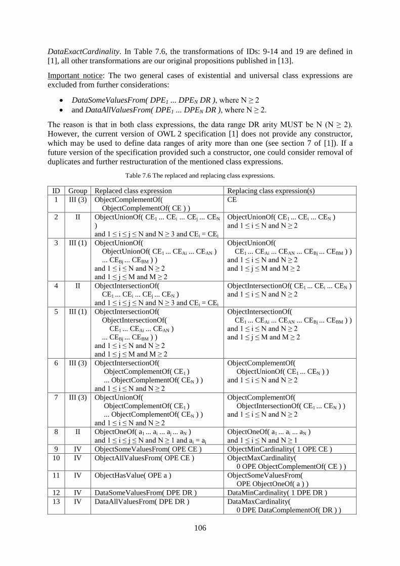
106
DataExactCardinality. In Table 7.6, the transformations of IDs: 9-14 and 19 are defined in
[1], all other transformations are our original propositions published in [13].
Important notice: The two general cases of existential and universal class expressions are
excluded from further considerations:
DataSomeValuesFrom( DPE1 ... DPEN DR ), where N ≥ 2
and DataAllValuesFrom( DPE1 ... DPEN DR ), where N ≥ 2.
The reason is that in both class expressions, the data range DR arity MUST be N (N ≥ 2).
However, the current version of OWL 2 specification [1] does not provide any constructor,
which may be used to define data ranges of arity more than one (see section 7 of [1]). If a
future version of the specification provided such a constructor, one could consider removal of
duplicates and further restructuration of the mentioned class expressions.
Table 7.6 The replaced and replacing class expressions.
ID Group Replaced class expression Replacing class expression(s)
1 III (3) ObjectComplementOf(
ObjectComplementOf( CE ) )
CE
2 II ObjectUnionOf( CE1 ... CEi ... CEj ... CEN
)
and 1 ≤ i ≤ j ≤ N and N ≥ 3 and CEi = CEj
ObjectUnionOf( CE1 ... CEi ... CEN )
and 1 ≤ i ≤ N and N ≥ 2
3 III (1) ObjectUnionOf(
ObjectUnionOf( CE1 ... CEAi ... CEAN )
... CEBj ... CEBM ) )
and 1 ≤ i ≤ N and N ≥ 2
and 1 ≤ j ≤ M and M ≥ 2
ObjectUnionOf(
CE1 ... CEAi ... CEAN ... CEBj ... CEBM ) )
and 1 ≤ i ≤ N and N ≥ 2
and 1 ≤ j ≤ M and M ≥ 2
4 II ObjectIntersectionOf(
CE1 ... CEi ... CEj ... CEN )
and 1 ≤ i ≤ j ≤ N and N ≥ 3 and CEi = CEj
ObjectIntersectionOf( CE1 ... CEi ... CEN )
and 1 ≤ i ≤ N and N ≥ 2
5 III (1) ObjectIntersectionOf(
ObjectIntersectionOf(
CE1 ... CEAi ... CEAN )
... CEBj ... CEBM ) )
and 1 ≤ i ≤ N and N ≥ 2
and 1 ≤ j ≤ M and M ≥ 2
ObjectIntersectionOf(
CE1 ... CEAi ... CEAN ... CEBj ... CEBM ) )
and 1 ≤ i ≤ N and N ≥ 2
and 1 ≤ j ≤ M and M ≥ 2
6 III (3) ObjectIntersectionOf(
ObjectComplementOf( CE1 )
... ObjectComplementOf( CEN ) )
and 1 ≤ i ≤ N and N ≥ 2
ObjectComplementOf(
ObjectUnionOf( CE1 ... CEN ) )
and 1 ≤ i ≤ N and N ≥ 2
7 III (3) ObjectUnionOf(
ObjectComplementOf( CE1 )
... ObjectComplementOf( CEN ) )
and 1 ≤ i ≤ N and N ≥ 2
ObjectComplementOf(
ObjectIntersectionOf( CE1 ... CEN ) )
and 1 ≤ i ≤ N and N ≥ 2
8 II ObjectOneOf( a1 ... ai ... aj ... aN )
and 1 ≤ i ≤ j ≤ N and N ≥ 1 and ai = aj
ObjectOneOf( a1 ... ai ... aN )
and 1 ≤ i ≤ N and N ≥ 1
9 IV ObjectSomeValuesFrom( OPE CE ) ObjectMinCardinality( 1 OPE CE )
10 IV ObjectAllValuesFrom( OPE CE ) ObjectMaxCardinality(
0 OPE ObjectComplementOf( CE ) )
11 IV ObjectHasValue( OPE a ) ObjectSomeValuesFrom(
OPE ObjectOneOf( a ) )
12 IV DataSomeValuesFrom( DPE DR ) DataMinCardinality( 1 DPE DR )
13 IV DataAllValuesFrom( DPE DR ) DataMaxCardinality(
0 DPE DataComplementOf( DR ) )
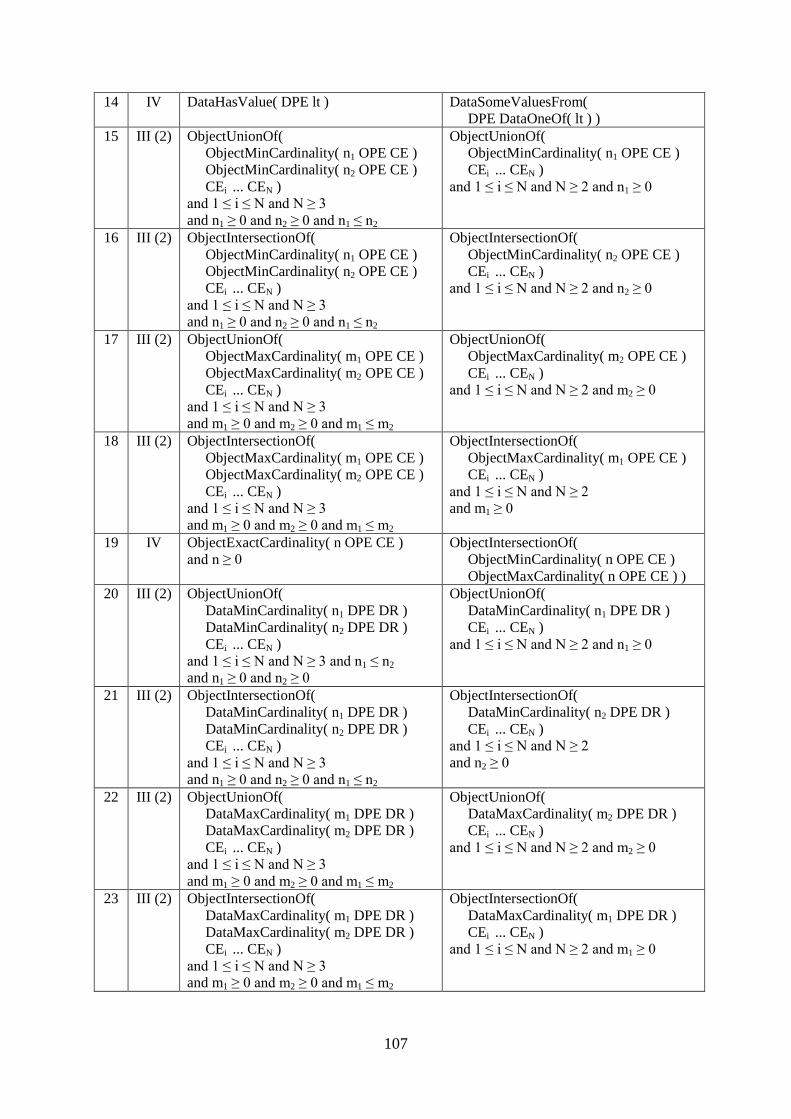
107
14 IV DataHasValue( DPE lt ) DataSomeValuesFrom(
DPE DataOneOf( lt ) )
15 III (2) ObjectUnionOf(
ObjectMinCardinality( n1 OPE CE )
ObjectMinCardinality( n2 OPE CE )
CEi ... CEN )
and 1 ≤ i ≤ N and N ≥ 3
and n1 ≥ 0 and n2 ≥ 0 and n1 ≤ n2
ObjectUnionOf(
ObjectMinCardinality( n1 OPE CE )
CEi ... CEN )
and 1 ≤ i ≤ N and N ≥ 2 and n1 ≥ 0
16 III (2) ObjectIntersectionOf(
ObjectMinCardinality( n1 OPE CE )
ObjectMinCardinality( n2 OPE CE )
CEi ... CEN )
and 1 ≤ i ≤ N and N ≥ 3
and n1 ≥ 0 and n2 ≥ 0 and n1 ≤ n2
ObjectIntersectionOf(
ObjectMinCardinality( n2 OPE CE )
CEi ... CEN )
and 1 ≤ i ≤ N and N ≥ 2 and n2 ≥ 0
17 III (2) ObjectUnionOf(
ObjectMaxCardinality( m1 OPE CE )
ObjectMaxCardinality( m2 OPE CE )
CEi ... CEN )
and 1 ≤ i ≤ N and N ≥ 3
and m1 ≥ 0 and m2 ≥ 0 and m1 ≤ m2
ObjectUnionOf(
ObjectMaxCardinality( m2 OPE CE )
CEi ... CEN )
and 1 ≤ i ≤ N and N ≥ 2 and m2 ≥ 0
18 III (2) ObjectIntersectionOf(
ObjectMaxCardinality( m1 OPE CE )
ObjectMaxCardinality( m2 OPE CE )
CEi ... CEN )
and 1 ≤ i ≤ N and N ≥ 3
and m1 ≥ 0 and m2 ≥ 0 and m1 ≤ m2
ObjectIntersectionOf(
ObjectMaxCardinality( m1 OPE CE )
CEi ... CEN )
and 1 ≤ i ≤ N and N ≥ 2
and m1 ≥ 0
19 IV ObjectExactCardinality( n OPE CE )
and n ≥ 0
ObjectIntersectionOf(
ObjectMinCardinality( n OPE CE )
ObjectMaxCardinality( n OPE CE ) )
20 III (2) ObjectUnionOf(
DataMinCardinality( n1 DPE DR )
DataMinCardinality( n2 DPE DR )
CEi ... CEN )
and 1 ≤ i ≤ N and N ≥ 3 and n1 ≤ n2
and n1 ≥ 0 and n2 ≥ 0
ObjectUnionOf(
DataMinCardinality( n1 DPE DR )
CEi ... CEN )
and 1 ≤ i ≤ N and N ≥ 2 and n1 ≥ 0
21 III (2) ObjectIntersectionOf(
DataMinCardinality( n1 DPE DR )
DataMinCardinality( n2 DPE DR )
CEi ... CEN )
and 1 ≤ i ≤ N and N ≥ 3
and n1 ≥ 0 and n2 ≥ 0 and n1 ≤ n2
ObjectIntersectionOf(
DataMinCardinality( n2 DPE DR )
CEi ... CEN )
and 1 ≤ i ≤ N and N ≥ 2
and n2 ≥ 0
22 III (2) ObjectUnionOf(
DataMaxCardinality( m1 DPE DR )
DataMaxCardinality( m2 DPE DR )
CEi ... CEN )
and 1 ≤ i ≤ N and N ≥ 3
and m1 ≥ 0 and m2 ≥ 0 and m1 ≤ m2
ObjectUnionOf(
DataMaxCardinality( m2 DPE DR )
CEi ... CEN )
and 1 ≤ i ≤ N and N ≥ 2 and m2 ≥ 0
23 III (2) ObjectIntersectionOf(
DataMaxCardinality( m1 DPE DR )
DataMaxCardinality( m2 DPE DR )
CEi ... CEN )
and 1 ≤ i ≤ N and N ≥ 3
and m1 ≥ 0 and m2 ≥ 0 and m1 ≤ m2
ObjectIntersectionOf(
DataMaxCardinality( m1 DPE DR )
CEi ... CEN )
and 1 ≤ i ≤ N and N ≥ 2 and m1 ≥ 0
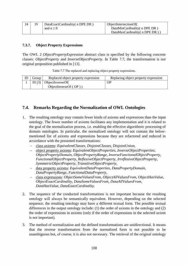
108
24 IV DataExactCardinality( n DPE DR )
and n ≥ 0
ObjectIntersectionOf(
DataMinCardinality( n DPE DR )
DataMaxCardinality( n DPE DR ) )
7.3.7. Object Property Expressions
The OWL 2 ObjectPropertyExpression abstract class is specified by the following concrete
classes: ObjectProperty and InverseObjectProperty. In Table 7.7, the transformation is our
original proposition published in [13].
Table 7.7 The replaced and replacing object property expressions.
ID Group Replaced object property expression Replacing object property expression
1 III (3) ObjectInverseOf(
ObjectInverseOf ( OP ) )
OP
7.4. Remarks Regarding the Normalization of OWL Ontologies
1. The resulting ontology may contain fewer kinds of axioms and expressions than the input
ontology. The fewer number of axioms facilitates any implementation and it is related to
the goal of the normalization process, i.e. enabling the effective algorithmic processing of
domain ontologies. In particular, the normalized ontology will not contain the below-
mentioned list of axioms and expressions because they are refactored and reduced in
accordance with the presented transformations:
class axioms: EquivalentClasses, DisjointClasses, DisjointUnion,
object property axioms: EquivalentObjectProperties, InverseObjectProperties,
ObjectPropertyDomain, ObjectPropertyRange, InverseFunctionalObjectProperty,
FunctionalObjectProperty, ReflexiveObjectProperty, IrreflexiveObjectProperty,
SymmetricObjectProperty, TransitiveObjectProperty,
data property axioms: EquivalentDataProperties, DataPropertyDomain,
DataPropertyRange, FunctionalDataProperty,
class expressions: ObjectSomeValuesFrom, ObjectAllValuesFrom, ObjectHasValue,
ObjectExactCardinality, DataSomeValuesFrom, DataAllValuesFrom,
DataHasValue, DataExactCardinality.
2. The sequence of the conducted transformations is not important because the resulting
ontology will always be semantically equivalent. However, depending on the selected
sequence, the resulting ontology may have a different textual form. The possible textual
differences in the output ontology include: (1) the order of axioms in the ontology and (2)
the order of expressions in axioms (only if the order of expressions in the selected axiom
is not important).
3. The method of normalization and the defined transformations are unidirectional. It means
that the inverse transformation from the normalized form is not possible to be
unambiguous but, of course, it is also not necessary. The retrieval of the original ontology
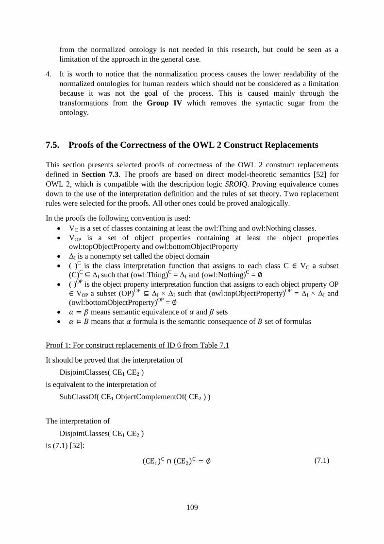
109
from the normalized ontology is not needed in this research, but could be seen as a
limitation of the approach in the general case.
4. It is worth to notice that the normalization process causes the lower readability of the
normalized ontologies for human readers which should not be considered as a limitation
because it was not the goal of the process. This is caused mainly through the
transformations from the Group IV which removes the syntactic sugar from the
ontology.
7.5. Proofs of the Correctness of the OWL 2 Construct Replacements
This section presents selected proofs of correctness of the OWL 2 construct replacements
defined in Section 7.3. The proofs are based on direct model-theoretic semantics [52] for
OWL 2, which is compatible with the description logic SROIQ. Proving equivalence comes
down to the use of the interpretation definition and the rules of set theory. Two replacement
rules were selected for the proofs. All other ones could be proved analogically.
In the proofs the following convention is used:
VC is a set of classes containing at least the owl:Thing and owl:Nothing classes.
VOP is a set of object properties containing at least the object properties
owl:topObjectProperty and owl:bottomObjectProperty
ΔI is a nonempty set called the object domain
( )C is the class interpretation function that assigns to each class C VC a subset
(C)C ΔI such that (owl:Thing)
C = ΔI and (owl:Nothing)
C =
( )OP
is the object property interpretation function that assigns to each object property OP
VOP a subset (OP)OP
ΔI × ΔI such that (owl:topObjectProperty)OP
= ΔI × ΔI and
(owl:bottomObjectProperty)OP
=
means semantic equivalence of and sets
means that formula is the semantic consequence of set of formulas
Proof 1: For construct replacements of ID 6 from Table 7.1
It should be proved that the interpretation of
DisjointClasses( CE1 CE2 )
is equivalent to the interpretation of
SubClassOf( CE1 ObjectComplementOf( CE2 ) )
The interpretation of
DisjointClasses( CE1 CE2 )
is (7.1) [52]:
( ) ( )
(7.1)
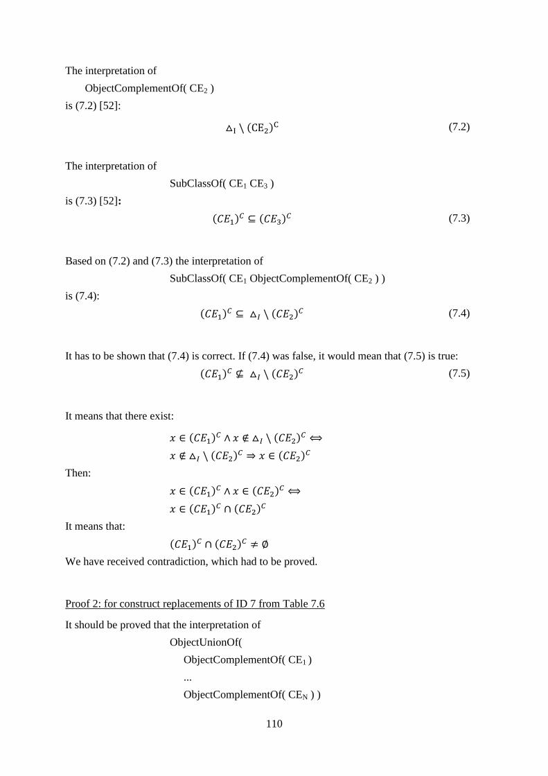
110
The interpretation of
ObjectComplementOf( CE2 )
is (7.2) [52]:
( ) (7.2)
The interpretation of
SubClassOf( CE1 CE3 )
is (7.3) [52]:
( ) ( )
(7.3)
Based on (7.2) and (7.3) the interpretation of
SubClassOf( CE1 ObjectComplementOf( CE2 ) )
is (7.4):
( ) ( )
(7.4)
It has to be shown that (7.4) is correct. If (7.4) was false, it would mean that (7.5) is true:
( ) ( )
(7.5)
It means that there exist:
( ) ( )
( ) ( )
Then:
( ) ( )
( ) ( )
It means that:
( ) ( )
We have received contradiction, which had to be proved.
Proof 2: for construct replacements of ID 7 from Table 7.6
It should be proved that the interpretation of
ObjectUnionOf(
ObjectComplementOf( CE1 )
...
ObjectComplementOf( CEN ) )
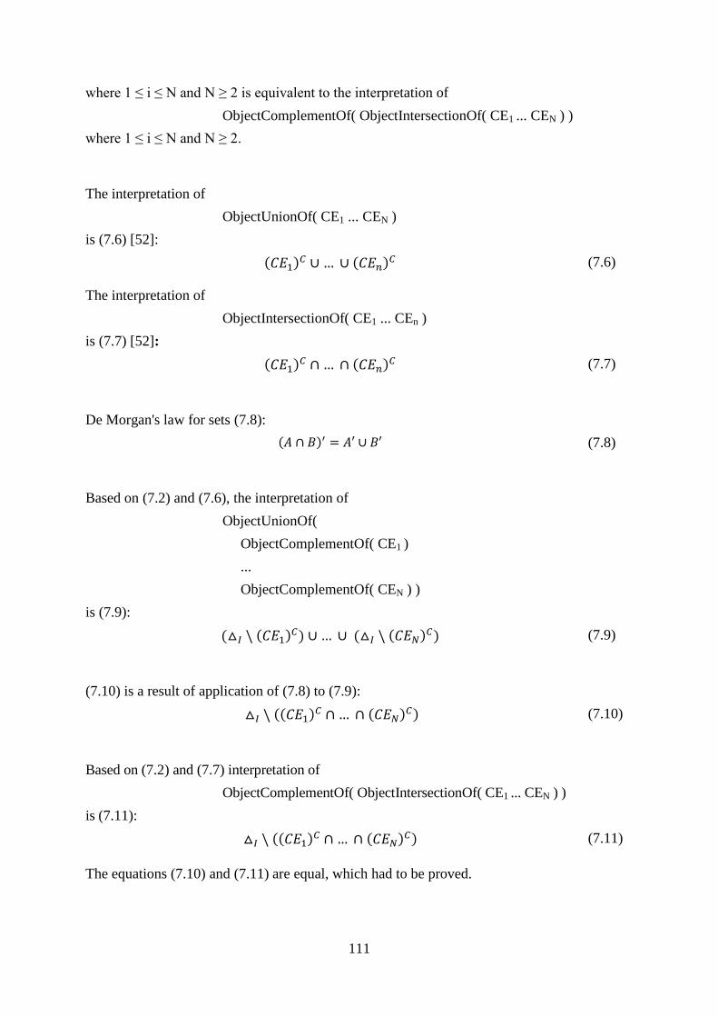
111
where 1 ≤ i ≤ N and N ≥ 2 is equivalent to the interpretation of
ObjectComplementOf( ObjectIntersectionOf( CE1 ... CEN ) )
where 1 ≤ i ≤ N and N ≥ 2.
The interpretation of
ObjectUnionOf( CE1 ... CEN )
is (7.6) [52]:
( ) ( ) (7.6)
The interpretation of
ObjectIntersectionOf( CE1 ... CEn )
is (7.7) [52]:
( ) ( ) (7.7)
De Morgan's law for sets (7.8):
( ) (7.8)
Based on (7.2) and (7.6), the interpretation of
ObjectUnionOf(
ObjectComplementOf( CE1 )
...
ObjectComplementOf( CEN ) )
is (7.9):
( ( ) ) ( ( ) ) (7.9)
(7.10) is a result of application of (7.8) to (7.9):
(( ) ( ) ) (7.10)
Based on (7.2) and (7.7) interpretation of
ObjectComplementOf( ObjectIntersectionOf( CE1 ... CEN ) )
is (7.11):
(( ) ( ) ) (7.11)
The equations (7.10) and (7.11) are equal, which had to be proved.
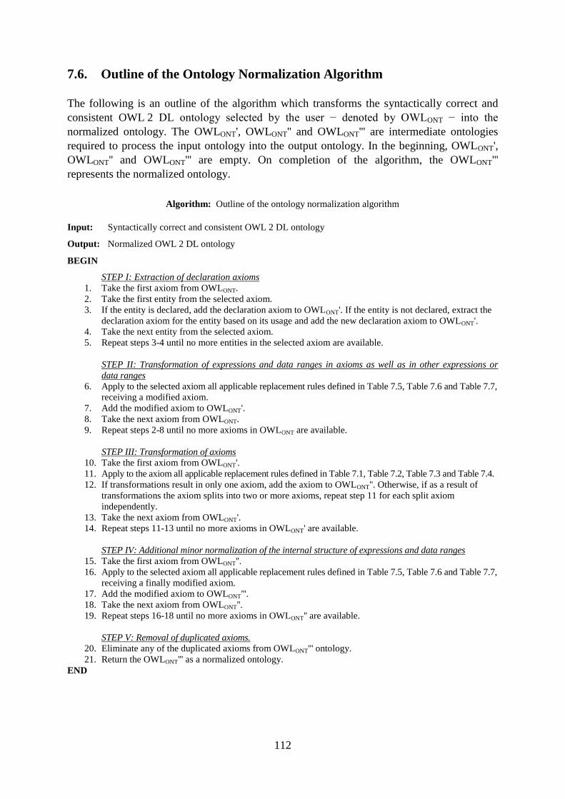
112
7.6. Outline of the Ontology Normalization Algorithm
The following is an outline of the algorithm which transforms the syntactically correct and
consistent OWL 2 DL ontology selected by the user − denoted by OWLONT − into the
normalized ontology. The OWLONT', OWLONT'' and OWLONT''' are intermediate ontologies
required to process the input ontology into the output ontology. In the beginning, OWLONT',
OWLONT'' and OWLONT''' are empty. On completion of the algorithm, the OWLONT'''
represents the normalized ontology.
Algorithm: Outline of the ontology normalization algorithm
Input: Syntactically correct and consistent OWL 2 DL ontology
Output: Normalized OWL 2 DL ontology
BEGIN
STEP I: Extraction of declaration axioms
1. Take the first axiom from OWLONT.
2. Take the first entity from the selected axiom.
3. If the entity is declared, add the declaration axiom to OWLONT'. If the entity is not declared, extract the
declaration axiom for the entity based on its usage and add the new declaration axiom to OWLONT'.
4. Take the next entity from the selected axiom.
5. Repeat steps 3-4 until no more entities in the selected axiom are available.
STEP II: Transformation of expressions and data ranges in axioms as well as in other expressions or
data ranges
6. Apply to the selected axiom all applicable replacement rules defined in Table 7.5, Table 7.6 and Table 7.7,
receiving a modified axiom.
7. Add the modified axiom to OWLONT'.
8. Take the next axiom from OWLONT.
9. Repeat steps 2-8 until no more axioms in OWLONT are available.
STEP III: Transformation of axioms
10. Take the first axiom from OWLONT'.
11. Apply to the axiom all applicable replacement rules defined in Table 7.1, Table 7.2, Table 7.3 and Table 7.4.
12. If transformations result in only one axiom, add the axiom to OWLONT''. Otherwise, if as a result of
transformations the axiom splits into two or more axioms, repeat step 11 for each split axiom
independently.
13. Take the next axiom from OWLONT'.
14. Repeat steps 11-13 until no more axioms in OWLONT' are available.
STEP IV: Additional minor normalization of the internal structure of expressions and data ranges
15. Take the first axiom from OWLONT''.
16. Apply to the selected axiom all applicable replacement rules defined in Table 7.5, Table 7.6 and Table 7.7,
receiving a finally modified axiom.
17. Add the modified axiom to OWLONT'''.
18. Take the next axiom from OWLONT''.
19. Repeat steps 16-18 until no more axioms in OWLONT'' are available.
STEP V: Removal of duplicated axioms.
20. Eliminate any of the duplicated axioms from OWLONT''' ontology.
21. Return the OWLONT''' as a normalized ontology.
END
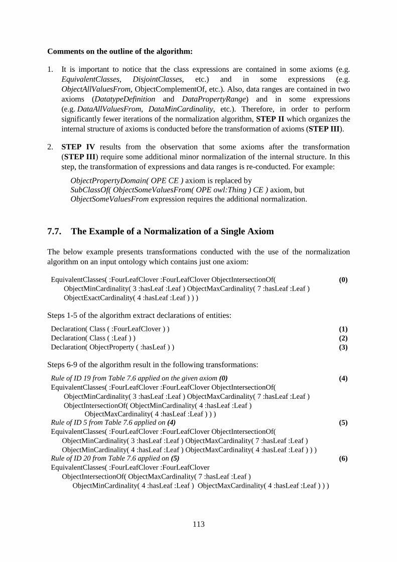
113
Comments on the outline of the algorithm:
1. It is important to notice that the class expressions are contained in some axioms (e.g.
EquivalentClasses, DisjointClasses, etc.) and in some expressions (e.g.
ObjectAllValuesFrom, ObjectComplementOf, etc.). Also, data ranges are contained in two
axioms (DatatypeDefinition and DataPropertyRange) and in some expressions
(e.g. DataAllValuesFrom, DataMinCardinality, etc.). Therefore, in order to perform
significantly fewer iterations of the normalization algorithm, STEP II which organizes the
internal structure of axioms is conducted before the transformation of axioms (STEP III).
2. STEP IV results from the observation that some axioms after the transformation
(STEP III) require some additional minor normalization of the internal structure. In this
step, the transformation of expressions and data ranges is re-conducted. For example:
ObjectPropertyDomain( OPE CE ) axiom is replaced by
SubClassOf( ObjectSomeValuesFrom( OPE owl:Thing ) CE ) axiom, but
ObjectSomeValuesFrom expression requires the additional normalization.
7.7. The Example of a Normalization of a Single Axiom
The below example presents transformations conducted with the use of the normalization
algorithm on an input ontology which contains just one axiom:
EquivalentClasses( :FourLeafClover :FourLeafClover ObjectIntersectionOf(
ObjectMinCardinality( 3 :hasLeaf :Leaf ) ObjectMaxCardinality( 7 :hasLeaf :Leaf )
ObjectExactCardinality( 4 :hasLeaf :Leaf ) ) )
(0)
Steps 1-5 of the algorithm extract declarations of entities:
Declaration( Class ( :FourLeafClover ) ) (1)
Declaration( Class ( :Leaf ) ) (2)
Declaration( ObjectProperty ( :hasLeaf ) ) (3)
Steps 6-9 of the algorithm result in the following transformations:
Rule of ID 19 from Table 7.6 applied on the given axiom (0)
EquivalentClasses( :FourLeafClover :FourLeafClover ObjectIntersectionOf(
ObjectMinCardinality( 3 :hasLeaf :Leaf ) ObjectMaxCardinality( 7 :hasLeaf :Leaf )
ObjectIntersectionOf( ObjectMinCardinality( 4 :hasLeaf :Leaf )
ObjectMaxCardinality( 4 :hasLeaf :Leaf ) ) )
(4)
Rule of ID 5 from Table 7.6 applied on (4)
EquivalentClasses( :FourLeafClover :FourLeafClover ObjectIntersectionOf(
ObjectMinCardinality( 3 :hasLeaf :Leaf ) ObjectMaxCardinality( 7 :hasLeaf :Leaf )
ObjectMinCardinality( 4 :hasLeaf :Leaf ) ObjectMaxCardinality( 4 :hasLeaf :Leaf ) ) )
(5)
Rule of ID 20 from Table 7.6 applied on (5)
EquivalentClasses( :FourLeafClover :FourLeafClover
ObjectIntersectionOf( ObjectMaxCardinality( 7 :hasLeaf :Leaf )
ObjectMinCardinality( 4 :hasLeaf :Leaf ) ObjectMaxCardinality( 4 :hasLeaf :Leaf ) ) )
(6)
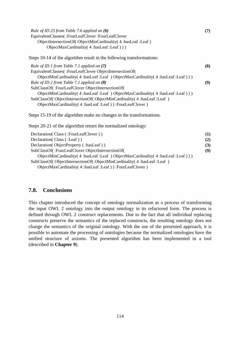
114
Rule of ID 23 from Table 7.6 applied on (6)
EquivalentClasses( :FourLeafClover :FourLeafClover
ObjectIntersectionOf( ObjectMinCardinality( 4 :hasLeaf :Leaf )
ObjectMaxCardinality( 4 :hasLeaf :Leaf ) ) )
(7)
Steps 10-14 of the algorithm result in the following transformations:
Rule of ID 1 from Table 7.1 applied on (7)
EquivalentClasses( :FourLeafClover ObjectIntersectionOf(
ObjectMinCardinality( 4 :hasLeaf :Leaf ) ObjectMaxCardinality( 4 :hasLeaf :Leaf ) ) )
(8)
Rule of ID 2 from Table 7.1 applied on (8)
SubClassOf( :FourLeafClover ObjectIntersectionOf(
ObjectMinCardinality( 4 :hasLeaf :Leaf ) ObjectMaxCardinality( 4 :hasLeaf :Leaf ) ) )
SubClassOf( ObjectIntersectionOf( ObjectMinCardinality( 4 :hasLeaf :Leaf )
ObjectMaxCardinality( 4 :hasLeaf :Leaf ) ) :FourLeafClover )
(9)
Steps 15-19 of the algorithm make no changes in the transformations.
Steps 20-21 of the algorithm return the normalized ontology:
Declaration( Class ( :FourLeafClover ) ) (1)
Declaration( Class ( :Leaf ) ) (2)
Declaration( ObjectProperty ( :hasLeaf ) ) (3)
SubClassOf( :FourLeafClover ObjectIntersectionOf(
ObjectMinCardinality( 4 :hasLeaf :Leaf ) ObjectMaxCardinality( 4 :hasLeaf :Leaf ) ) )
SubClassOf( ObjectIntersectionOf( ObjectMinCardinality( 4 :hasLeaf :Leaf )
ObjectMaxCardinality( 4 :hasLeaf :Leaf ) ) :FourLeafClover )
(9)
7.8. Conclusions
This chapter introduced the concept of ontology normalization as a process of transforming
the input OWL 2 ontology into the output ontology in its refactored form. The process is
defined through OWL 2 construct replacements. Due to the fact that all individual replacing
constructs preserve the semantics of the replaced constructs, the resulting ontology does not
change the semantics of the original ontology. With the use of the presented approach, it is
possible to automate the processing of ontologies because the normalized ontologies have the
unified structure of axioms. The presented algorithm has been implemented in a tool
(described in Chapter 9).

115
116
8. Representation of UML Class Diagrams in OWL 2
Summary. UML class diagrams can be automatically validated if they are compliant with
a domain knowledge specified in a selected OWL 2 domain ontology. The method
requires translation of the UML class diagrams into their OWL 2 representation. The aim
of this chapter is to present transformation and verification rules of UML class diagrams
to their OWL 2 representation. For this purpose, the systematic literature review on the
topic of transformation rules between elements of UML class diagrams and OWL 2
constructs has been conducted and analysed. The purpose of the analysis was to present
the extent to which state-of-the-art transformation rules cover the semantics expressed in
class diagrams. On the basis of the analysis, new transformation rules expressing the
semantics not yet covered but expected from the point of view of domain modelling
pragmatics have been defined. The first result presented in this chapter is the revision and
extension of the transformation rules identified in the literature. The second original result
is a proposition of verification rules necessary to check if a UML class diagram is
compliant with the OWL 2 domain ontology. 26
8.1. Introduction
Chapter 8 is a continuation and extension of Chapter 5 which presented the outline of the
method for semantic validation of UML class diagrams with the use of OWL 2 domain
ontologies. The proposed approach requires a transformation of a UML class diagram
constructed by a modeller into its semantically equivalent OWL 2 representation. In order to
identify which transformation rules of UML class diagrams into OWL constructs have already
been proposed, a systematic review of literature has been performed. The extracted rules have
been analysed, compared and extended. The resulting findings of how to conduct the
transformation of UML class diagram to its OWL 2 representation are described in this
chapter.
Despite the fact that there are many publications which define some UML to OWL 2
transformations, to the best of knowledge of the author, no study has investigated a complete
mapping covering all diagram elements emphasized by pragmatic needs. This chapter seeks to
contribute in this field with a special focus on providing a full transformation of elements of
an UML class diagram which are commonly used in business and conceptual modelling (such
elements are listed in Section 2.3). The presented transformations are limited to static
elements of UML class diagrams − the behavioural aspect represented by class operations is
omitted. This is due to the fact that the semantics of UML operations cannot be effectively
expressed with the use of OWL 2 constructs, which do not represent behaviour.
In the rest of the chapter OWL domain ontology is understood as OWL domain ontology after
normalization. For the purpose of being compliant with the literature and for the potential use
of transformation rules for other purposes, all transformation rules presented in this chapter
26 Chapter 8 contains the revised and extended version of the paper: "Representation of UML class diagrams in
OWL 2 on the background of domain ontologies" [14].
117
are not normalized. On the other hand, due to the fact that the verification rules are the
original proposition of this research, some verification rules are already defined in the
normalized form in order to reduce the number of unnecessary redundant verifications. The
rest verification rules are also not yet normalized for the purpose of clarity for readers. Please
note that in the verification method, before making comparison of axioms, all transformation
and verification axioms are always normalized. This operation is conducted automatically
with the use of the designed tool implementing the method. The tool is described in Part IV,
the process of normalization is explained in Chapter 7.
In practical use of UML to OWL transformation, the initial phase involving modeller's
attention is required. The modeller has to assure that all class attributes and association end
names in one UML class are uniquely named. Otherwise, the transformation rules may
generate repeating OWL axioms which may lead to inconsistencies or may be semantically
incorrect. This is explained in Requirement 2 for the proposed validation method
(Section 5.2, page 59).
The remainder of this chapter is organized as follows. Section 8.2 describes the process and
the results of the conducted systematic literature review which was focused on identifying the
state-of-the-art transformation rules for translating UML class diagrams into their OWL
representation. The section presents in details the review process including research question
for systematic literature review, data sources and search queries, inclusion and exclusion
criteria, study quality assessment, study selection, threats to validity and summary of the
identified literature. Section 8.3 presents the revised and extended transformation rules and
proposes the verification rules. Section 8.4 summarises the important differences between
OWL 2 and UML languages and their impact on the form of transformation. Section 8.5
illustrates application of transformation and verification rules to example UML class
diagrams. Finally, Section 8.6 concludes the chapter.
8.2. Review Process
Kitchenham and Charters in [99] provide guidelines for performing systematic literature
review (SLR) in software engineering. Following [99], a systematic literature review is a
means of evaluating and interpreting all available research relevant to a particular research
question, and aims at presenting a fair evaluation of a research topic by using a rigorous
methodology. This section describes the carried out review aimed at identifying studies
describing mappings of UML class diagrams to their OWL representations.
8.2.1. Research Question
The research question is:
RQ: "What transformation rules between elements of UML class diagrams and OWL
constructs have already been proposed?"
118
8.2.2. Data Sources and Search Queries
In order to make the process repeatable, the details of our search strategy are documented
below. The search was conducted in the following online databases: IEEE Xplore Digital
Library, Springer Link, ACM Digital Library and Science Direct. These electronic databases
were chosen because they are commonly used for searching literature in the field of Software
Engineering. Additional searches with the same queries were conducted through
ResearchGate and Google scholar in order to discover more relevant publications. These
publication channels were searched to find papers published in all the available years until
May 2018. The earliest primary study actually included was published in 2006.
For conducting the search, the following keywords were selected: "transformation",
"transforming", "mapping", "translation", "OWL", "UML" and "class diagram". The
keywords are alternate words and synonyms for the terms used in the research question,
which aimed to minimize the effect of differences in terminologies. Pilot searches showed
that the above keywords were too general and the results were too broad. Therefore, in order
to obtain more relevant results, the search queries were based on the Boolean AND to join
terms:
"transformation" AND "OWL" AND "UML"
"transforming" AND "OWL" AND "UML"
"mapping" AND "OWL" AND "UML"
"translation" AND "OWL" AND "UML"
"transformation" AND "OWL" AND "class diagram"
"transforming" AND "OWL" AND "class diagram"
"mapping" AND "OWL" AND "class diagram"
"translation" AND "OWL" AND "class diagram"
8.2.3. Inclusion and Exclusion Criteria
The main inclusion criterion was that a paper provides some transformation rules between
UML class diagrams and OWL constructs. Additionally, the study had to be written in
English and be fully accessible through the selected online libraries. Additionally, there was a
criterion for excluding a paper from the review results if the study described transformation
rules between other types of UML diagrams to OWL representation or described
transformation rules to other ontological languages.
8.2.4. Study Quality Assessment
The final acceptance of the literature was done by applying the quality criteria. The criteria
were assigned a binary "yes"/"no" answer. In order for a work to be selected, it needed to
provide "yes" answer to both questions from the checklist:
1. Are the transformation rules explicitly defined? For example, a paper could be excluded
if it only reported on a possibility of specifying transformation rules for the selected UML
elements, but such transformations were not provided.
2. Do the proposed transformation rules preserve the semantics of the UML elements? For
example, a paper (or some selected transformation rules within the paper) could be excluded
119
if the proposed rules in the transformation to OWL 2 did not preserve the semantics of the
UML elements.
8.2.5. Study Selection
During the search, the candidate papers for full text reading were identified by evaluating
their titles and abstracts. The literature was included or excluded based on the selection
criteria. The goal was to obtain the literature that answered the research question. The
candidate papers, after eliminating duplicates, were fully read. After positive assessment of
the quality of the literature items, they were added to the results of the systematic literature
review.
Next, if the paper was included, its reference list was additionally scanned in order to identify
potential other relevant papers (backward search). Later, the paper selection has additionally
been extended by forward search related to works citing the included papers. In both
backward search and forward search the papers for full text reading were identified based on
reading title and abstract.
8.2.6. Threats to Validity
The conducted SLR has some threats to its validity, described in categories defined in [110].
Wherever applicable, some mitigating factors corresponding to the identified threats were
applied.
Construct Validity: The specified search queries may not be able to completely cover all
adequate search terms related to the research topic. As a mitigating factor, the alternate words
and synonyms for the terms were used in the research question.
Internal Validity: The identified treats to internal validity relate to search strategy and further
steps of conducting the SLR, such as selection strategy and quality assessment:
1. A threat to validity was caused by lack of assurance that all papers relevant to answering
the research question were actually found. A mitigating factor to this threat was conducting a
search with several search queries and analyzing the references of the primary studies with the
aim of identifying further relevant studies.
2. Another threat was posed by the selected research databases. The threat was reduced by
conducting the search with the use of six different electronic databases.
3. A threat was caused by the fact that one researcher conducted SLR. A mitigating factor to
the search process and the study selection process was that the whole search process was
twice reconducted in April 2018 and May 2018. The additional procedures did not change the
identified studies.
External Validity: External validity concentrates on the generalization of findings derived
from the primary studies. The carried search was aimed at identifying transformation rules of
elements of UML class diagram to their OWL 2 representation. Some transformation rules
could be formulated analogically in some other ontological languages, e.g. DAML+OIL, etc.
Similarly, some transformation rules could be formulated analogically in some modelling
languages or notations different then UML class diagrams, e.g. in Entity Relationship
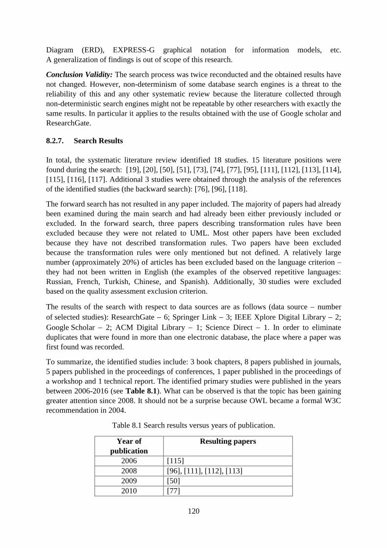
120
Diagram (ERD), EXPRESS-G graphical notation for information models, etc.
A generalization of findings is out of scope of this research.
Conclusion Validity: The search process was twice reconducted and the obtained results have
not changed. However, non-determinism of some database search engines is a threat to the
reliability of this and any other systematic review because the literature collected through
non-deterministic search engines might not be repeatable by other researchers with exactly the
same results. In particular it applies to the results obtained with the use of Google scholar and
ResearchGate.
8.2.7. Search Results
In total, the systematic literature review identified 18 studies. 15 literature positions were
found during the search: [19], [20], [50], [51], [73], [74], [77], [95], [111], [112], [113], [114],
[115], [116], [117]. Additional 3 studies were obtained through the analysis of the references
of the identified studies (the backward search): [76], [96], [118].
The forward search has not resulted in any paper included. The majority of papers had already
been examined during the main search and had already been either previously included or
excluded. In the forward search, three papers describing transformation rules have been
excluded because they were not related to UML. Most other papers have been excluded
because they have not described transformation rules. Two papers have been excluded
because the transformation rules were only mentioned but not defined. A relatively large
number (approximately 20%) of articles has been excluded based on the language criterion –
they had not been written in English (the examples of the observed repetitive languages:
Russian, French, Turkish, Chinese, and Spanish). Additionally, 30 studies were excluded
based on the quality assessment exclusion criterion.
The results of the search with respect to data sources are as follows (data source number
of selected studies): ResearchGate 6; Springer Link 3; IEEE Xplore Digital Library 2;
Google Scholar 2; ACM Digital Library 1; Science Direct 1. In order to eliminate
duplicates that were found in more than one electronic database, the place where a paper was
first found was recorded.
To summarize, the identified studies include: 3 book chapters, 8 papers published in journals,
5 papers published in the proceedings of conferences, 1 paper published in the proceedings of
a workshop and 1 technical report. The identified primary studies were published in the years
between 2006-2016 (see Table 8.1). What can be observed is that the topic has been gaining
greater attention since 2008. It should not be a surprise because OWL became a formal W3C
recommendation in 2004.
Table 8.1 Search results versus years of publication.
Year of
publication
Resulting papers
2006 [115]
2008 [96], [111], [112], [113]
2009 [50]
2010 [77]
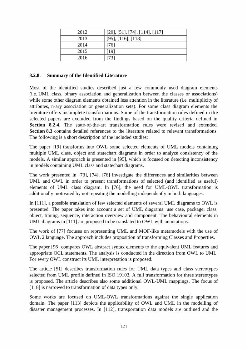
121
2012 [20], [51], [74], [114], [117]
2013 [95], [116], [118]
2014 [76]
2015 [19]
2016 [73]
8.2.8. Summary of the Identified Literature
Most of the identified studies described just a few commonly used diagram elements
(i.e. UML class, binary association and generalization between the classes or associations)
while some other diagram elements obtained less attention in the literature (i.e. multiplicity of
attributes, n-ary association or generalization sets). For some class diagram elements the
literature offers incomplete transformations. Some of the transformation rules defined in the
selected papers are excluded from the findings based on the quality criteria defined in
Section 8.2.4. The state-of-the-art transformation rules were revised and extended.
Section 8.3 contains detailed references to the literature related to relevant transformations.
The following is a short description of the included studies:
The paper [19] transforms into OWL some selected elements of UML models containing
multiple UML class, object and statechart diagrams in order to analyze consistency of the
models. A similar approach is presented in [95], which is focused on detecting inconsistency
in models containing UML class and statechart diagrams.
The work presented in [73], [74], [76] investigate the differences and similarities between
UML and OWL in order to present transformations of selected (and identified as useful)
elements of UML class diagram. In [76], the need for UML-OWL transformation is
additionally motivated by not repeating the modelling independently in both languages.
In [111], a possible translation of few selected elements of several UML diagrams to OWL is
presented. The paper takes into account a set of UML diagrams: use case, package, class,
object, timing, sequence, interaction overview and component. The behavioural elements in
UML diagrams in [111] are proposed to be translated to OWL with annotations.
The work of [77] focuses on representing UML and MOF-like metamodels with the use of
OWL 2 language. The approach includes proposition of transforming Classes and Properties.
The paper [96] compares OWL abstract syntax elements to the equivalent UML features and
appropriate OCL statements. The analysis is conducted in the direction from OWL to UML.
For every OWL construct its UML interpretation is proposed.
The article [51] describes transformation rules for UML data types and class stereotypes
selected from UML profile defined in ISO 19103. A full transformation for three stereotypes
is proposed. The article describes also some additional OWL-UML mappings. The focus of
[118] is narrowed to transformation of data types only.
Some works are focused on UML-OWL transformations against the single application
domain. The paper [113] depicts the applicability of OWL and UML in the modelling of
disaster management processes. In [112], transportation data models are outlined and the
122
translation of UML model into its OWL representation is conducted for the purpose of
reasoning.
The works presented in [20], [50], [115] are focused on extracting ontological knowledge
from UML class diagrams and describe some UML-OWL mappings with the aim to reuse the
existing UML models and stream the building of OWL domain ontologies. The paper [20]
from 2012 extends and enhances the conference paper [50] from 2009. Both papers were
analysed during the process of collecting the data in case of detection of any significant
differences in the description of transformation rules.
In [114], UML classes are translated into OWL. Finally, [116] and [117] present a few
transformations of class diagram elements to OWL.
8.3. Representation of Elements of the UML Class Diagram in OWL 2
This section presents transformation rules (TR) which seek to transform the elements of UML
class diagrams to their equivalent representations expressed in OWL 2 (for more information
about TR please refer to Section 5.3.2). Some of the transformation rules come from the
literature identified in the review (e.g. TR1 in Table 8.2). Another group of rules have their
archetypes in the state-of-the-art transformation rules but the author has refined them in order to
clarify their contexts of use (e.g. TRA, TRC in Section 8.4), or extend their application to a
broader scope (e.g. TR1 in Table 8.5). The remaining transformation rules are new propositions
(e.g. TR5 in Table 8.7).
In contrast to the approaches available in the literature, together with the transformation rules
the verification rules (VR) are defined for all elements of a UML class diagram wherever
applicable. The need for specifying verification rules implies from the need to check the
compliance of the OWL representation of UML class diagram with the OWL domain
ontology. The role of verification rules is to detect if the semantics of a diagram is not in
conflict with the knowledge included in the domain ontology, as explained in Section 5.3.3.
All the static elements of UML class diagrams, which are important from the point of view of
pragmatics (see Section 2.3) were considered. To summarize the results, most of the
categories of the UML elements which are recommended (e.g. [2], [26]) for business or
conceptual modelling with UML class diagrams are fully transformable to OWL 2 constructs:
Class (Table 8.2),
attributes of the Class (Table 8.4),
multiplicity of the attributes (Table 8.5),
binary Association – both between two different Classes (Table 8.6) as well as from a
Class to itself (Table 8.7),
multiplicity of the Association ends (Table 8.9),
Generalization between Classes (Table 8.12)
Integer, Boolean and UnlimitedNatural primitive types (Table 8.18),
structured DataType (Table 8.19),
Enumeration (Table 8.20),
Comments to the Class (Table 8.21).
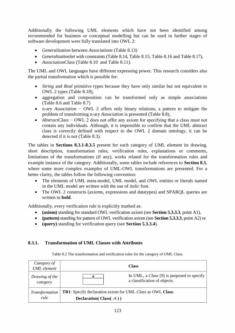
123
Additionally the following UML elements which have not been identified among
recommended for business or conceptual modelling but can be used in further stages of
software development were fully translated into OWL 2:
Generalization between Associations (Table 8.13)
GeneralizationSet with constraints (Table 8.14, Table 8.15, Table 8.16 and Table 8.17),
AssociationClass (Table 8.10 and Table 8.11).
The UML and OWL languages have different expressing power. This research considers also
the partial transformation which is possible for:
String and Real primitive types because they have only similar but not equivalent to
OWL 2 types (Table 8.18),
aggregation and composition can be transformed only as simple associations
(Table 8.6 and Table 8.7)
n-ary Association − OWL 2 offers only binary relations, a pattern to mitigate the
problem of transforming n-ary Association is presented (Table 8.8),
AbstractClass − OWL 2 does not offer any axiom for specifying that a class must not
contain any individuals. Although, it is impossible to confirm that the UML abstract
class is correctly defined with respect to the OWL 2 domain ontology, it can be
detected if it is not (Table 8.3).
The tables in Sections 8.3.1-8.3.5 present for each category of UML element its drawing,
short description, transformation rules, verification rules, explanations or comments,
limitations of the transformations (if any), works related for the transformation rules and
example instance of the category. Additionally, some tables include references to Section 8.5,
where some more complex examples of UML-OWL transformations are presented. For a
better clarity, the tables follow the following convention:
The elements of UML meta-model, UML model, and OWL entities or literals named
in the UML model are written with the use of italic font.
The OWL 2 constructs (axioms, expressions and datatypes) and SPARQL queries are
written in bold.
Additionally, every verification rule is explicitly marked as:
(axiom) standing for standard OWL verification axiom (see Section 5.3.3.3, point A1),
(pattern) standing for pattern of OWL verification axiom (see Section 5.3.3.3, point A2) or
(query) standing for verification query (see Section 5.3.3.4).
8.3.1. Transformation of UML Classes with Attributes
Table 8.2 The transformation and verification rules for the category of UML Class.
Category of
UML element Class
Drawing of the
category
In UML, a Class [9] is purposed to specify
a classification of objects.
Transformation
rule
TR1: Specify declaration axiom for UML Class as OWL Class:
Declaration( Class( :A ) )
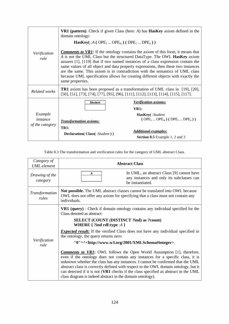
124
Verification
rule
VR1 (pattern): Check if given Class (here: A) has HasKey axiom defined in the
domain ontology:
HasKey( :A ( OPE1 ... OPEm ) ( DPE1 ... DPEn ) )
Comments to VR1: If the ontology contains the axiom of this form, it means that
A is not the UML Class but the structured DataType. The OWL HasKey axiom
assures [1], [119] that if two named instances of a class expression contain the
same values of all object and data property expressions, then these two instances
are the same. This axiom is in contradiction with the semantics of UML class
because UML specification allows for creating different objects with exactly the
same properties.
Related works TR1 axiom has been proposed as a transformation of UML class in [19], [20],
[50], [51], [73], [74], [77], [95], [96], [111], [112], [113], [114], [115], [117].
Example
instance
of the category
Transformation axioms:
TR1:
Declaration( Class( :Student ) )
Verification axioms:
VR1:
HasKey( :Student
( OPE1 ... OPEm ) ( DPE1 ... DPEn ) )
Additional examples:
Section 8.5 Example 1, 2 and 3
Table 8.3 The transformation and verification rules for the category of UML abstract Class.
Category of
UML element Abstract Class
Drawing of the
category
In UML, an abstract Class [9] cannot have
any instances and only its subclasses can
be instantiated.
Transformation
rules
Not possible. The UML abstract classes cannot be translated into OWL because
OWL does not offer any axiom for specifying that a class must not contain any
individuals.
Verification
rule
VR1 (query) : Check if domain ontology contains any individual specified for the
Class denoted as abstract:
SELECT (COUNT (DISTINCT ?ind) as ?count)
WHERE { ?ind rdf:type :A }
Expected result: If the verified Class does not have any individual specified in
the ontology, the query returns zero:
"0"^^<http://www.w3.org/2001/XMLSchema#integer>.
Comments to VR1: OWL follows the Open World Assumption [1], therefore,
even if the ontology does not contain any instances for a specific class, it is
unknown whether the class has any instances. I cannot be confirmed that the UML
abstract class is correctly defined with respect to the OWL domain ontology, but it
can detected if it is not (VR1 checks if the class specified as abstract in the UML
class diagram is indeed abstract in the domain ontology).
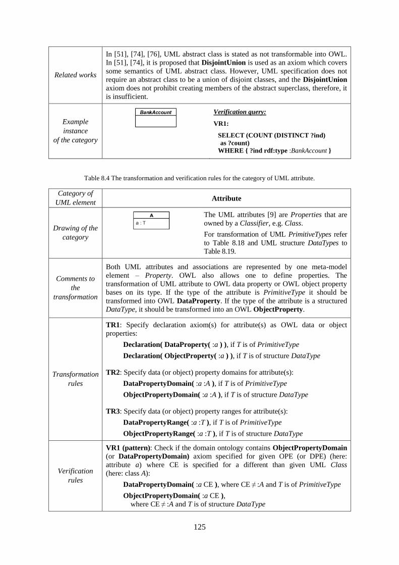
125
Related works
In [51], [74], [76], UML abstract class is stated as not transformable into OWL.
In [51], [74], it is proposed that DisjointUnion is used as an axiom which covers
some semantics of UML abstract class. However, UML specification does not
require an abstract class to be a union of disjoint classes, and the DisjointUnion
axiom does not prohibit creating members of the abstract superclass, therefore, it
is insufficient.
Example
instance
of the category
Verification query:
VR1:
SELECT (COUNT (DISTINCT ?ind)
as ?count)
WHERE { ?ind rdf:type :BankAccount }
Table 8.4 The transformation and verification rules for the category of UML attribute.
Category of
UML element Attribute
Drawing of the
category
The UML attributes [9] are Properties that are
owned by a Classifier, e.g. Class.
For transformation of UML PrimitiveTypes refer
to Table 8.18 and UML structure DataTypes to
Table 8.19.
Comments to
the
transformation
Both UML attributes and associations are represented by one meta-model
element – Property. OWL also allows one to define properties. The
transformation of UML attribute to OWL data property or OWL object property
bases on its type. If the type of the attribute is PrimitiveType it should be
transformed into OWL DataProperty. If the type of the attribute is a structured
DataType, it should be transformed into an OWL ObjectProperty.
Transformation
rules
TR1: Specify declaration axiom(s) for attribute(s) as OWL data or object
properties:
Declaration( DataProperty( :a ) ), if T is of PrimitiveType
Declaration( ObjectProperty( :a ) ), if T is of structure DataType
TR2: Specify data (or object) property domains for attribute(s):
DataPropertyDomain( :a :A ), if T is of PrimitiveType
ObjectPropertyDomain( :a :A ), if T is of structure DataType
TR3: Specify data (or object) property ranges for attribute(s):
DataPropertyRange( :a :T ), if T is of PrimitiveType
ObjectPropertyRange( :a :T ), if T is of structure DataType
Verification
rules
VR1 (pattern): Check if the domain ontology contains ObjectPropertyDomain
(or DataPropertyDomain) axiom specified for given OPE (or DPE) (here:
attribute a) where CE is specified for a different than given UML Class
(here: class A):
DataPropertyDomain( :a CE ), where CE ≠ :A and T is of PrimitiveType
ObjectPropertyDomain( :a CE ),
where CE ≠ :A and T is of structure DataType
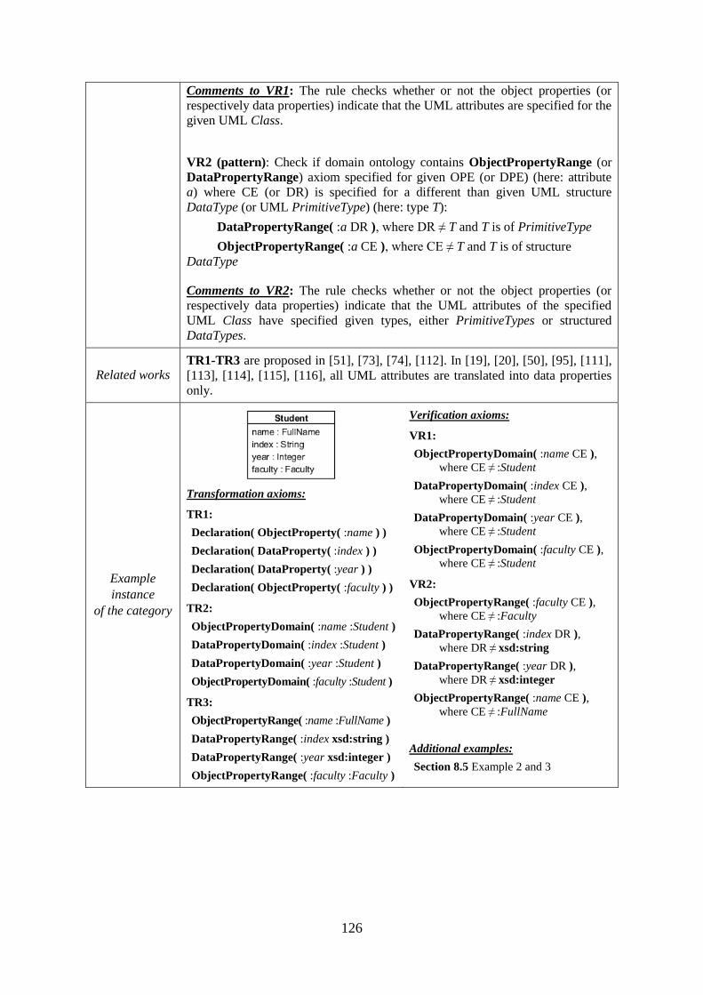
126
Comments to VR1: The rule checks whether or not the object properties (or
respectively data properties) indicate that the UML attributes are specified for the
given UML Class.
VR2 (pattern): Check if domain ontology contains ObjectPropertyRange (or
DataPropertyRange) axiom specified for given OPE (or DPE) (here: attribute
a) where CE (or DR) is specified for a different than given UML structure
DataType (or UML PrimitiveType) (here: type T):
DataPropertyRange( :a DR ), where DR ≠ T and T is of PrimitiveType
ObjectPropertyRange( :a CE ), where CE ≠ T and T is of structure
DataType
Comments to VR2: The rule checks whether or not the object properties (or
respectively data properties) indicate that the UML attributes of the specified
UML Class have specified given types, either PrimitiveTypes or structured
DataTypes.
Related works TR1-TR3 are proposed in [51], [73], [74], [112]. In [19], [20], [50], [95], [111],
[113], [114], [115], [116], all UML attributes are translated into data properties
only.
Example
instance
of the category
Transformation axioms:
TR1:
Declaration( ObjectProperty( :name ) )
Declaration( DataProperty( :index ) )
Declaration( DataProperty( :year ) )
Declaration( ObjectProperty( :faculty ) )
TR2:
ObjectPropertyDomain( :name :Student )
DataPropertyDomain( :index :Student )
DataPropertyDomain( :year :Student )
ObjectPropertyDomain( :faculty :Student )
TR3:
ObjectPropertyRange( :name :FullName )
DataPropertyRange( :index xsd:string )
DataPropertyRange( :year xsd:integer )
ObjectPropertyRange( :faculty :Faculty )
Verification axioms:
VR1:
ObjectPropertyDomain( :name CE ),
where CE ≠ :Student
DataPropertyDomain( :index CE ),
where CE ≠ :Student
DataPropertyDomain( :year CE ),
where CE ≠ :Student
ObjectPropertyDomain( :faculty CE ),
where CE ≠ :Student
VR2:
ObjectPropertyRange( :faculty CE ),
where CE ≠ :Faculty
DataPropertyRange( :index DR ),
where DR ≠ xsd:string
DataPropertyRange( :year DR ),
where DR ≠ xsd:integer
ObjectPropertyRange( :name CE ),
where CE ≠ :FullName
Additional examples:
Section 8.5 Example 2 and 3
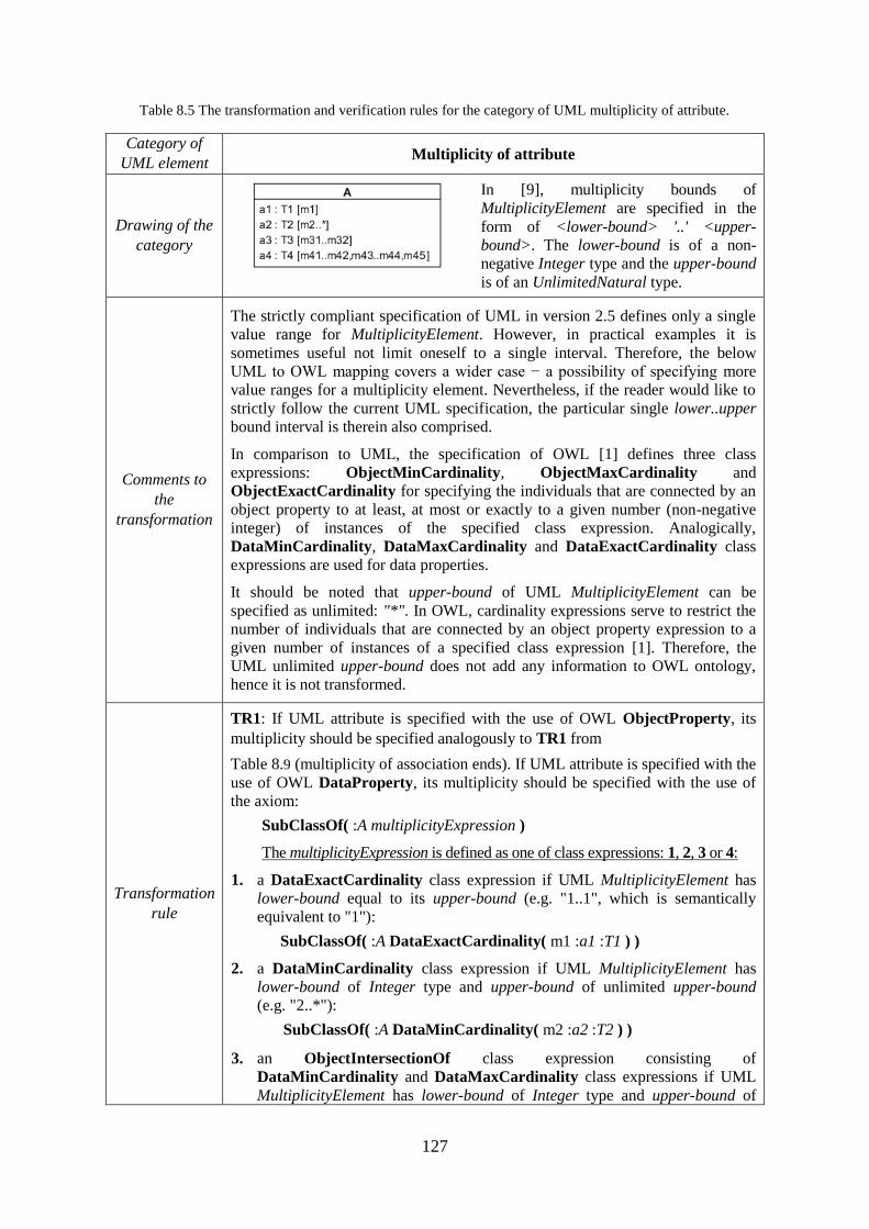
127
Table 8.5 The transformation and verification rules for the category of UML multiplicity of attribute.
Category of
UML element Multiplicity of attribute
Drawing of the
category
In [9], multiplicity bounds of
MultiplicityElement are specified in the
form of <lower-bound> '..' <upper-
bound>. The lower-bound is of a non-
negative Integer type and the upper-bound
is of an UnlimitedNatural type.
Comments to
the
transformation
The strictly compliant specification of UML in version 2.5 defines only a single
value range for MultiplicityElement. However, in practical examples it is
sometimes useful not limit oneself to a single interval. Therefore, the below
UML to OWL mapping covers a wider case − a possibility of specifying more
value ranges for a multiplicity element. Nevertheless, if the reader would like to
strictly follow the current UML specification, the particular single lower..upper
bound interval is therein also comprised.
In comparison to UML, the specification of OWL [1] defines three class
expressions: ObjectMinCardinality, ObjectMaxCardinality and
ObjectExactCardinality for specifying the individuals that are connected by an
object property to at least, at most or exactly to a given number (non-negative
integer) of instances of the specified class expression. Analogically,
DataMinCardinality, DataMaxCardinality and DataExactCardinality class
expressions are used for data properties.
It should be noted that upper-bound of UML MultiplicityElement can be
specified as unlimited: "*". In OWL, cardinality expressions serve to restrict the
number of individuals that are connected by an object property expression to a
given number of instances of a specified class expression [1]. Therefore, the
UML unlimited upper-bound does not add any information to OWL ontology,
hence it is not transformed.
Transformation
rule
TR1: If UML attribute is specified with the use of OWL ObjectProperty, its
multiplicity should be specified analogously to TR1 from
Table 8.9 (multiplicity of association ends). If UML attribute is specified with the
use of OWL DataProperty, its multiplicity should be specified with the use of
the axiom:
SubClassOf( :A multiplicityExpression )
The multiplicityExpression is defined as one of class expressions: 1, 2, 3 or 4:
1. a DataExactCardinality class expression if UML MultiplicityElement has
lower-bound equal to its upper-bound (e.g. "1..1", which is semantically
equivalent to "1"):
SubClassOf( :A DataExactCardinality( m1 :a1 :T1 ) )
2. a DataMinCardinality class expression if UML MultiplicityElement has
lower-bound of Integer type and upper-bound of unlimited upper-bound
(e.g. "2..*"):
SubClassOf( :A DataMinCardinality( m2 :a2 :T2 ) )
3. an ObjectIntersectionOf class expression consisting of
DataMinCardinality and DataMaxCardinality class expressions if UML
MultiplicityElement has lower-bound of Integer type and upper-bound of
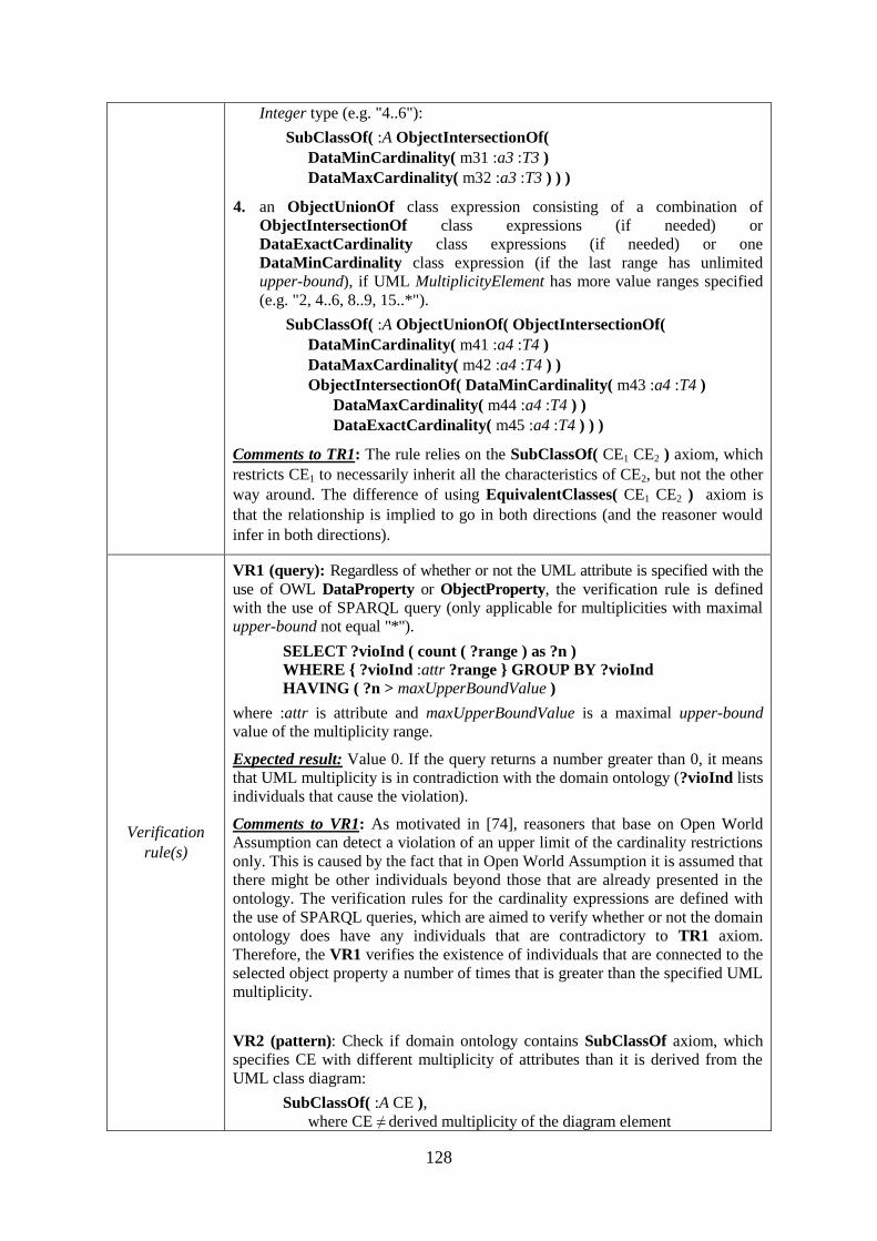
128
Integer type (e.g. "4..6"):
SubClassOf( :A ObjectIntersectionOf(
DataMinCardinality( m31 :a3 :T3 )
DataMaxCardinality( m32 :a3 :T3 ) ) )
4. an ObjectUnionOf class expression consisting of a combination of
ObjectIntersectionOf class expressions (if needed) or
DataExactCardinality class expressions (if needed) or one
DataMinCardinality class expression (if the last range has unlimited
upper-bound), if UML MultiplicityElement has more value ranges specified
(e.g. "2, 4..6, 8..9, 15..*").
SubClassOf( :A ObjectUnionOf( ObjectIntersectionOf(
DataMinCardinality( m41 :a4 :T4 )
DataMaxCardinality( m42 :a4 :T4 ) )
ObjectIntersectionOf( DataMinCardinality( m43 :a4 :T4 )
DataMaxCardinality( m44 :a4 :T4 ) )
DataExactCardinality( m45 :a4 :T4 ) ) )
Comments to TR1: The rule relies on the SubClassOf( CE1 CE2 ) axiom, which
restricts CE1 to necessarily inherit all the characteristics of CE2, but not the other
way around. The difference of using EquivalentClasses( CE1 CE2 ) axiom is
that the relationship is implied to go in both directions (and the reasoner would
infer in both directions).
Verification
rule(s)
VR1 (query): Regardless of whether or not the UML attribute is specified with the
use of OWL DataProperty or ObjectProperty, the verification rule is defined
with the use of SPARQL query (only applicable for multiplicities with maximal
upper-bound not equal "*").
SELECT ?vioInd ( count ( ?range ) as ?n )
WHERE { ?vioInd :attr ?range } GROUP BY ?vioInd
HAVING ( ?n > maxUpperBoundValue )
where :attr is attribute and maxUpperBoundValue is a maximal upper-bound
value of the multiplicity range.
Expected result: Value 0. If the query returns a number greater than 0, it means
that UML multiplicity is in contradiction with the domain ontology (?vioInd lists
individuals that cause the violation).
Comments to VR1: As motivated in [74], reasoners that base on Open World
Assumption can detect a violation of an upper limit of the cardinality restrictions
only. This is caused by the fact that in Open World Assumption it is assumed that
there might be other individuals beyond those that are already presented in the
ontology. The verification rules for the cardinality expressions are defined with
the use of SPARQL queries, which are aimed to verify whether or not the domain
ontology does have any individuals that are contradictory to TR1 axiom.
Therefore, the VR1 verifies the existence of individuals that are connected to the
selected object property a number of times that is greater than the specified UML
multiplicity.
VR2 (pattern): Check if domain ontology contains SubClassOf axiom, which
specifies CE with different multiplicity of attributes than it is derived from the
UML class diagram:
SubClassOf( :A CE ),
where CE ≠ derived multiplicity of the diagram element
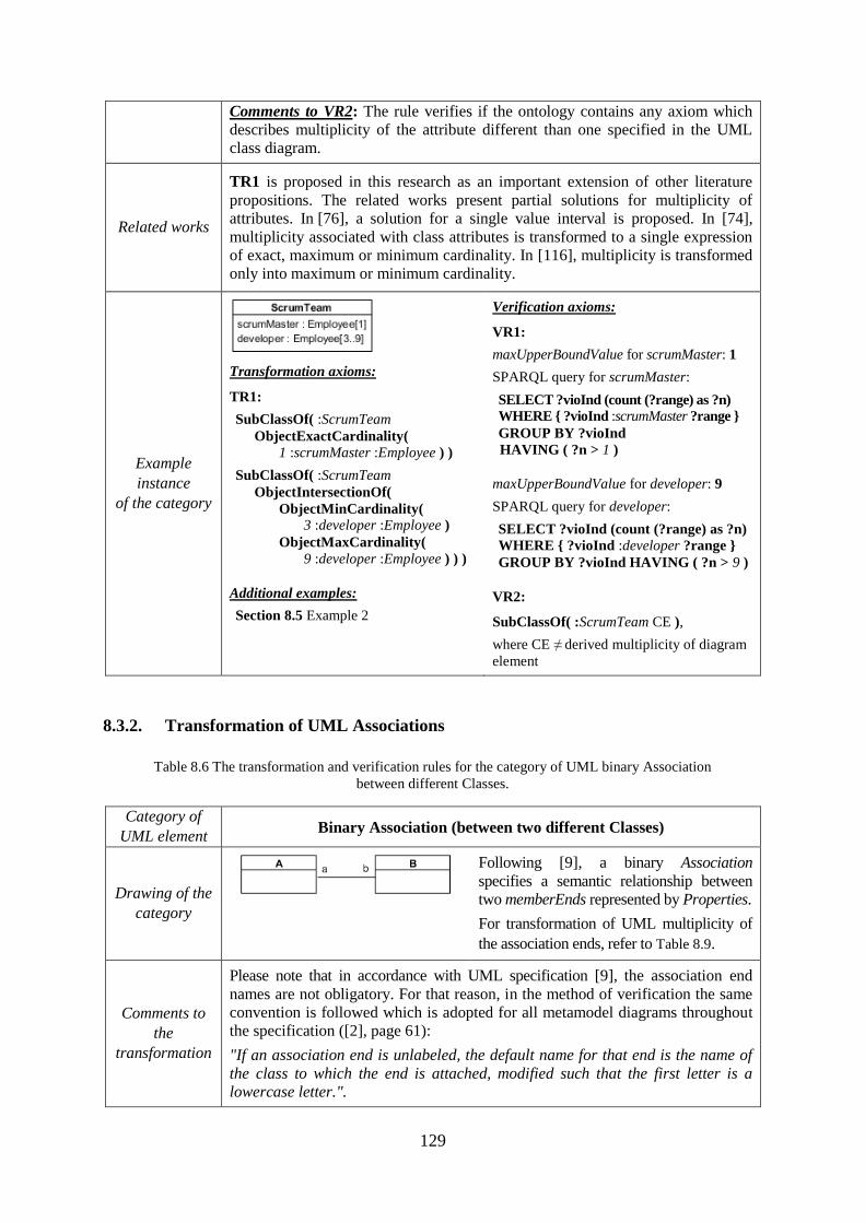
129
Comments to VR2: The rule verifies if the ontology contains any axiom which
describes multiplicity of the attribute different than one specified in the UML
class diagram.
Related works
TR1 is proposed in this research as an important extension of other literature
propositions. The related works present partial solutions for multiplicity of
attributes. In [76], a solution for a single value interval is proposed. In [74],
multiplicity associated with class attributes is transformed to a single expression
of exact, maximum or minimum cardinality. In [116], multiplicity is transformed
only into maximum or minimum cardinality.
Example
instance
of the category
Transformation axioms:
TR1:
SubClassOf( :ScrumTeam
ObjectExactCardinality(
1 :scrumMaster :Employee ) )
SubClassOf( :ScrumTeam
ObjectIntersectionOf(
ObjectMinCardinality(
3 :developer :Employee )
ObjectMaxCardinality(
9 :developer :Employee ) ) )
Additional examples:
Section 8.5 Example 2
Verification axioms:
VR1:
maxUpperBoundValue for scrumMaster: 1
SPARQL query for scrumMaster:
SELECT ?vioInd (count (?range) as ?n) WHERE { ?vioInd :scrumMaster ?range }
GROUP BY ?vioInd
HAVING ( ?n > 1 )
maxUpperBoundValue for developer: 9
SPARQL query for developer:
SELECT ?vioInd (count (?range) as ?n)
WHERE { ?vioInd :developer ?range }
GROUP BY ?vioInd HAVING ( ?n > 9 )
VR2:
SubClassOf( :ScrumTeam CE ),
where CE ≠ derived multiplicity of diagram
element
8.3.2. Transformation of UML Associations
Table 8.6 The transformation and verification rules for the category of UML binary Association
between different Classes.
Category of
UML element Binary Association (between two different Classes)
Drawing of the
category
Following [9], a binary Association
specifies a semantic relationship between
two memberEnds represented by Properties.
For transformation of UML multiplicity of
the association ends, refer to Table 8.9.
Comments to
the
transformation
Please note that in accordance with UML specification [9], the association end
names are not obligatory. For that reason, in the method of verification the same
convention is followed which is adopted for all metamodel diagrams throughout
the specification ([2], page 61):
"If an association end is unlabeled, the default name for that end is the name of
the class to which the end is attached, modified such that the first letter is a
lowercase letter.".
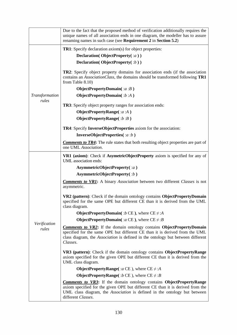
130
Due to the fact that the proposed method of verification additionally requires the
unique names of all association ends in one diagram, the modeller has to assure
renaming names in such case (see Requirement 2 in Section 5.2)
Transformation
rules
TR1: Specify declaration axiom(s) for object properties:
Declaration( ObjectProperty( :a ) )
Declaration( ObjectProperty( :b ) )
TR2: Specify object property domains for association ends (if the association
contains an AssociationClass, the domains should be transformed following TR1
from Table 8.10)
ObjectPropertyDomain( :a :B )
ObjectPropertyDomain( :b :A )
TR3: Specify object property ranges for association ends:
ObjectPropertyRange( :a :A )
ObjectPropertyRange( :b :B )
TR4: Specify InverseObjectProperties axiom for the association:
InverseObjectProperties( :a :b )
Comments to TR4: The rule states that both resulting object properties are part of
one UML Association.
Verification
rules
VR1 (axiom): Check if AsymetricObjectProperty axiom is specified for any of
UML association ends:
AsymmetricObjectProperty( :a )
AsymmetricObjectProperty( :b )
Comments to VR1: A binary Association between two different Classes is not
asymmetric.
VR2 (pattern): Check if the domain ontology contains ObjectPropertyDomain
specified for the same OPE but different CE than it is derived from the UML
class diagram.
ObjectPropertyDomain( :b CE ), where CE ≠ :A
ObjectPropertyDomain( :a CE ), where CE ≠ :B
Comments to VR2: If the domain ontology contains ObjectPropertyDomain
specified for the same OPE but different CE than it is derived from the UML
class diagram, the Association is defined in the ontology but between different
Classes.
VR3 (pattern): Check if the domain ontology contains ObjectPropertyRange
axiom specified for the given OPE but different CE than it is derived from the
UML class diagram.
ObjectPropertyRange( :a CE ), where CE ≠ :A
ObjectPropertyRange( :b CE ), where CE ≠ :B
Comments to VR3: If the domain ontology contains ObjectPropertyRange
axiom specified for the given OPE but different CE than it is derived from the
UML class diagram, the Association is defined in the ontology but between
different Classes.
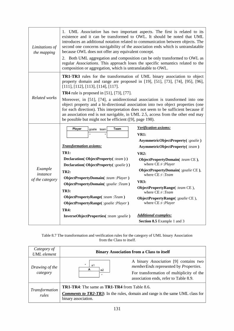
131
Limitations of
the mapping
1. UML Association has two important aspects. The first is related to its
existence and it can be transformed to OWL. It should be noted that UML
introduces an additional notation related to communication between objects. The
second one concerns navigability of the association ends which is untranslatable
because OWL does not offer any equivalent concept.
2. Both UML aggregation and composition can be only transformed to OWL as
regular Associations. This approach loses the specific semantics related to the
composition or aggregation, which is untranslatable to OWL.
Related works
TR1-TR3 rules for the transformation of UML binary association to object
property domain and range are proposed in [19], [51], [73], [74], [95], [96],
[111], [112], [113], [114], [117].
TR4 rule is proposed in [51], [73], [77].
Moreover, in [51], [74], a unidirectional association is transformed into one
object property and a bi-directional association into two object properties (one
for each direction). This interpretation does not seem to be sufficient because if
an association end is not navigable, in UML 2.5, access from the other end may
be possible but might not be efficient ([9], page 198).
Example
instance
of the category
Transformation axioms:
TR1:
Declaration( ObjectProperty( :team ) )
Declaration( ObjectProperty( :goalie ) )
TR2:
ObjectPropertyDomain( :team :Player )
ObjectPropertyDomain( :goalie :Team )
TR3:
ObjectPropertyRange( :team :Team )
ObjectPropertyRange( :goalie :Player )
TR4:
InverseObjectProperties( :team :goalie )
Verification axioms:
VR1:
AsymmetricObjectProperty( :goalie )
AsymmetricObjectProperty( :team )
VR2:
ObjectPropertyDomain( :team CE ),
where CE ≠ :Player
ObjectPropertyDomain( :goalie CE ),
where CE ≠ :Team
VR3:
ObjectPropertyRange( :team CE ),
where CE ≠ :Team
ObjectPropertyRange( :goalie CE ),
where CE ≠ :Player
Additional examples:
Section 8.5 Example 1 and 3
Table 8.7 The transformation and verification rules for the category of UML binary Association
from the Class to itself.
Category of
UML element Binary Association from a Class to itself
Drawing of the
category
A binary Association [9] contains two
memberEnds represented by Properties.
For transformation of multiplicity of the
association ends, refer to Table 8.9.
Transformation
rules
TR1-TR4: The same as TR1-TR4 from Table 8.6.
Comments to TR2-TR3: In the rules, domain and range is the same UML class for
binary association.
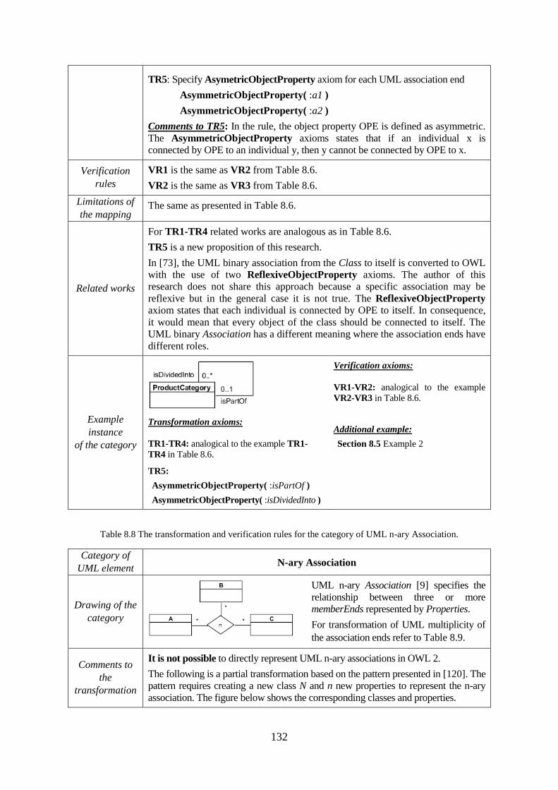
132
TR5: Specify AsymetricObjectProperty axiom for each UML association end
AsymmetricObjectProperty( :a1 )
AsymmetricObjectProperty( :a2 )
Comments to TR5: In the rule, the object property OPE is defined as asymmetric.
The AsymmetricObjectProperty axioms states that if an individual x is
connected by OPE to an individual y, then y cannot be connected by OPE to x.
Verification
rules
VR1 is the same as VR2 from Table 8.6.
VR2 is the same as VR3 from Table 8.6.
Limitations of
the mapping The same as presented in Table 8.6.
Related works
For TR1-TR4 related works are analogous as in Table 8.6.
TR5 is a new proposition of this research.
In [73], the UML binary association from the Class to itself is converted to OWL
with the use of two ReflexiveObjectProperty axioms. The author of this
research does not share this approach because a specific association may be
reflexive but in the general case it is not true. The ReflexiveObjectProperty
axiom states that each individual is connected by OPE to itself. In consequence,
it would mean that every object of the class should be connected to itself. The
UML binary Association has a different meaning where the association ends have
different roles.
Example
instance
of the category
Transformation axioms:
TR1-TR4: analogical to the example TR1-
TR4 in Table 8.6.
TR5:
AsymmetricObjectProperty( :isPartOf )
AsymmetricObjectProperty( :isDividedInto )
Verification axioms:
VR1-VR2: analogical to the example
VR2-VR3 in Table 8.6.
Additional example:
Section 8.5 Example 2
Table 8.8 The transformation and verification rules for the category of UML n-ary Association.
Category of
UML element N-ary Association
Drawing of the
category
UML n-ary Association [9] specifies the
relationship between three or more
memberEnds represented by Properties.
For transformation of UML multiplicity of
the association ends refer to Table 8.9.
Comments to
the
transformation
It is not possible to directly represent UML n-ary associations in OWL 2.
The following is a partial transformation based on the pattern presented in [120]. The
pattern requires creating a new class N and n new properties to represent the n-ary
association. The figure below shows the corresponding classes and properties.
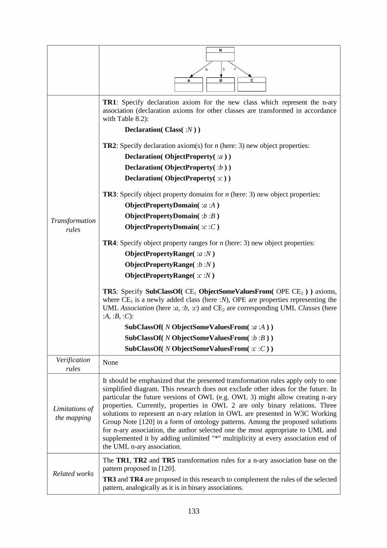
133
Transformation
rules
TR1: Specify declaration axiom for the new class which represent the n-ary
association (declaration axioms for other classes are transformed in accordance
with Table 8.2):
Declaration( Class( :N ) )
TR2: Specify declaration axiom(s) for n (here: 3) new object properties:
Declaration( ObjectProperty( :a ) )
Declaration( ObjectProperty( :b ) )
Declaration( ObjectProperty( :c ) )
TR3: Specify object property domains for n (here: 3) new object properties:
ObjectPropertyDomain( :a :A )
ObjectPropertyDomain( :b :B )
ObjectPropertyDomain( :c :C )
TR4: Specify object property ranges for n (here: 3) new object properties:
ObjectPropertyRange( :a :N )
ObjectPropertyRange( :b :N )
ObjectPropertyRange( :c :N )
TR5: Specify SubClassOf( CE1 ObjectSomeValuesFrom( OPE CE2 ) ) axioms,
where CE1 is a newly added class (here :N), OPE are properties representing the
UML Association (here :a, :b, :c) and CE2 are corresponding UML Classes (here
:A, :B, :C):
SubClassOf( N ObjectSomeValuesFrom( :a :A ) )
SubClassOf( N ObjectSomeValuesFrom( :b :B ) )
SubClassOf( N ObjectSomeValuesFrom( :c :C ) )
Verification
rules None
Limitations of
the mapping
It should be emphasized that the presented transformation rules apply only to one
simplified diagram. This research does not exclude other ideas for the future. In
particular the future versions of OWL (e.g. OWL 3) might allow creating n-ary
properties. Currently, properties in OWL 2 are only binary relations. Three
solutions to represent an n-ary relation in OWL are presented in W3C Working
Group Note [120] in a form of ontology patterns. Among the proposed solutions
for n-ary association, the author selected one the most appropriate to UML and
supplemented it by adding unlimited "*" multiplicity at every association end of
the UML n-ary association.
Related works
The TR1, TR2 and TR5 transformation rules for a n-ary association base on the
pattern proposed in [120].
TR3 and TR4 are proposed in this research to complement the rules of the selected
pattern, analogically as it is in binary associations.
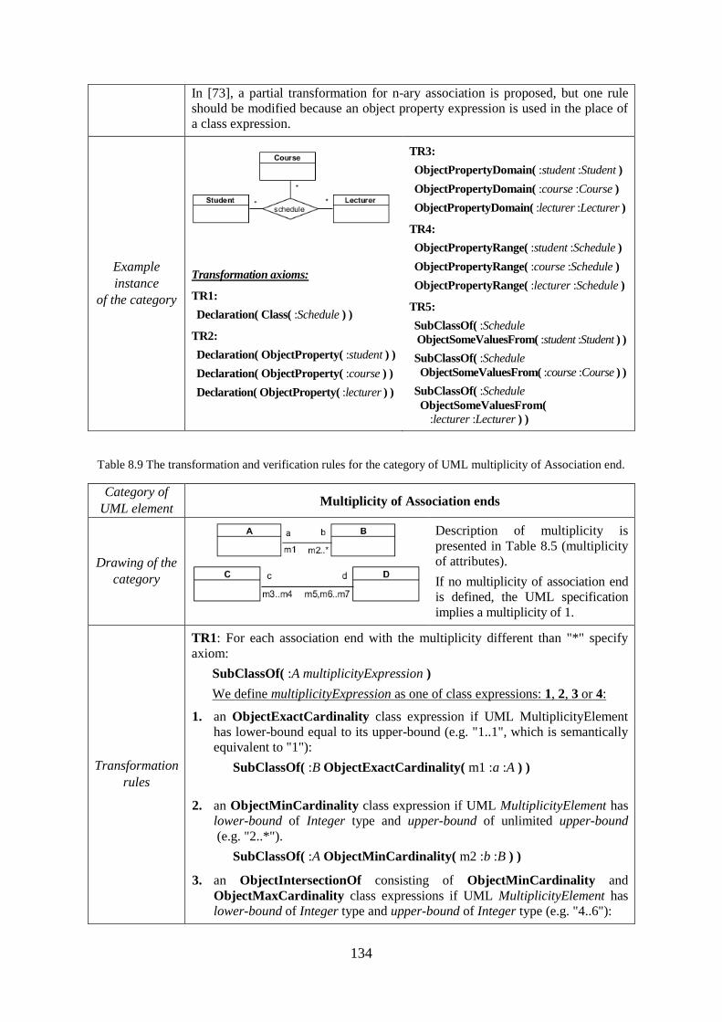
134
In [73], a partial transformation for n-ary association is proposed, but one rule
should be modified because an object property expression is used in the place of
a class expression.
Example
instance
of the category
Transformation axioms:
TR1:
Declaration( Class( :Schedule ) )
TR2:
Declaration( ObjectProperty( :student ) )
Declaration( ObjectProperty( :course ) )
Declaration( ObjectProperty( :lecturer ) )
TR3:
ObjectPropertyDomain( :student :Student )
ObjectPropertyDomain( :course :Course )
ObjectPropertyDomain( :lecturer :Lecturer )
TR4:
ObjectPropertyRange( :student :Schedule )
ObjectPropertyRange( :course :Schedule )
ObjectPropertyRange( :lecturer :Schedule )
TR5:
SubClassOf( :Schedule
ObjectSomeValuesFrom( :student :Student ) )
SubClassOf( :Schedule
ObjectSomeValuesFrom( :course :Course ) )
SubClassOf( :Schedule
ObjectSomeValuesFrom(
:lecturer :Lecturer ) )
Table 8.9 The transformation and verification rules for the category of UML multiplicity of Association end.
Category of
UML element Multiplicity of Association ends
Drawing of the
category
Description of multiplicity is
presented in Table 8.5 (multiplicity
of attributes).
If no multiplicity of association end
is defined, the UML specification
implies a multiplicity of 1.
Transformation
rules
TR1: For each association end with the multiplicity different than "*" specify
axiom:
SubClassOf( :A multiplicityExpression )
We define multiplicityExpression as one of class expressions: 1, 2, 3 or 4:
1. an ObjectExactCardinality class expression if UML MultiplicityElement
has lower-bound equal to its upper-bound (e.g. "1..1", which is semantically
equivalent to "1"):
SubClassOf( :B ObjectExactCardinality( m1 :a :A ) )
2. an ObjectMinCardinality class expression if UML MultiplicityElement has
lower-bound of Integer type and upper-bound of unlimited upper-bound
(e.g. "2..*").
SubClassOf( :A ObjectMinCardinality( m2 :b :B ) )
3. an ObjectIntersectionOf consisting of ObjectMinCardinality and
ObjectMaxCardinality class expressions if UML MultiplicityElement has
lower-bound of Integer type and upper-bound of Integer type (e.g. "4..6"):
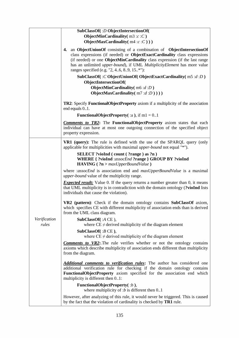
135
SubClassOf( :D ObjectIntersectionOf(
ObjectMinCardinality( m3 :c :C )
ObjectMaxCardinality( m4 :c :C ) ) )
4. an ObjectUnionOf consisting of a combination of ObjectIntersectionOf
class expressions (if needed) or ObjectExactCardinality class expressions
(if needed) or one ObjectMinCardinality class expression (if the last range
has an unlimited upper-bound), if UML MultiplicityElement has more value
ranges specified (e.g. "2, 4..6, 8..9, 15..*"):
SubClassOf( :C ObjectUnionOf( ObjectExactCardinality( m5 :d :D )
ObjectIntersectionOf(
ObjectMinCardinality( m6 :d :D )
ObjectMaxCardinality( m7 :d :D ) ) ) )
TR2: Specify FunctionalObjectProperty axiom if a multiplicity of the association
end equals 0..1.
FunctionalObjectProperty( :a ), if m1 = 0..1
Comments to TR2: The FunctionalObjectProperty axiom states that each
individual can have at most one outgoing connection of the specified object
property expression.
Verification
rules
VR1 (query): The rule is defined with the use of the SPARQL query (only
applicable for multiplicities with maximal upper-bound not equal "*").
SELECT ?vioInd ( count ( ?range ) as ?n )
WHERE { ?vioInd :assocEnd ?range } GROUP BY ?vioInd
HAVING ( ?n > maxUpperBoundValue )
where :assocEnd is association end and maxUpperBoundValue is a maximal
upper-bound value of the multiplicity range.
Expected result: Value 0. If the query returns a number greater than 0, it means
that UML multiplicity is in contradiction with the domain ontology (?vioInd lists
individuals that cause the violation).
VR2 (pattern): Check if the domain ontology contains SubClassOf axiom,
which specifies CE with different multiplicity of association ends than is derived
from the UML class diagram.
SubClassOf( :A CE ),
where CE ≠ derived multiplicity of the diagram element
SubClassOf( :B CE ),
where CE ≠ derived multiplicity of the diagram element
Comments to VR2:.The rule verifies whether or not the ontology contains
axioms which describe multiplicity of association ends different than multiplicity
from the diagram.
Additional comments to verification rules: The author has considered one
additional verification rule for checking if the domain ontology contains
FunctionalObjectProperty axiom specified for the association end which
multiplicity is different then 0..1:
FunctionalObjectProperty( :b ),
where multiplicity of :b is different then 0..1
However, after analyzing of this rule, it would never be triggered. This is caused
by the fact that the violation of cardinality is checked by TR1 rule.
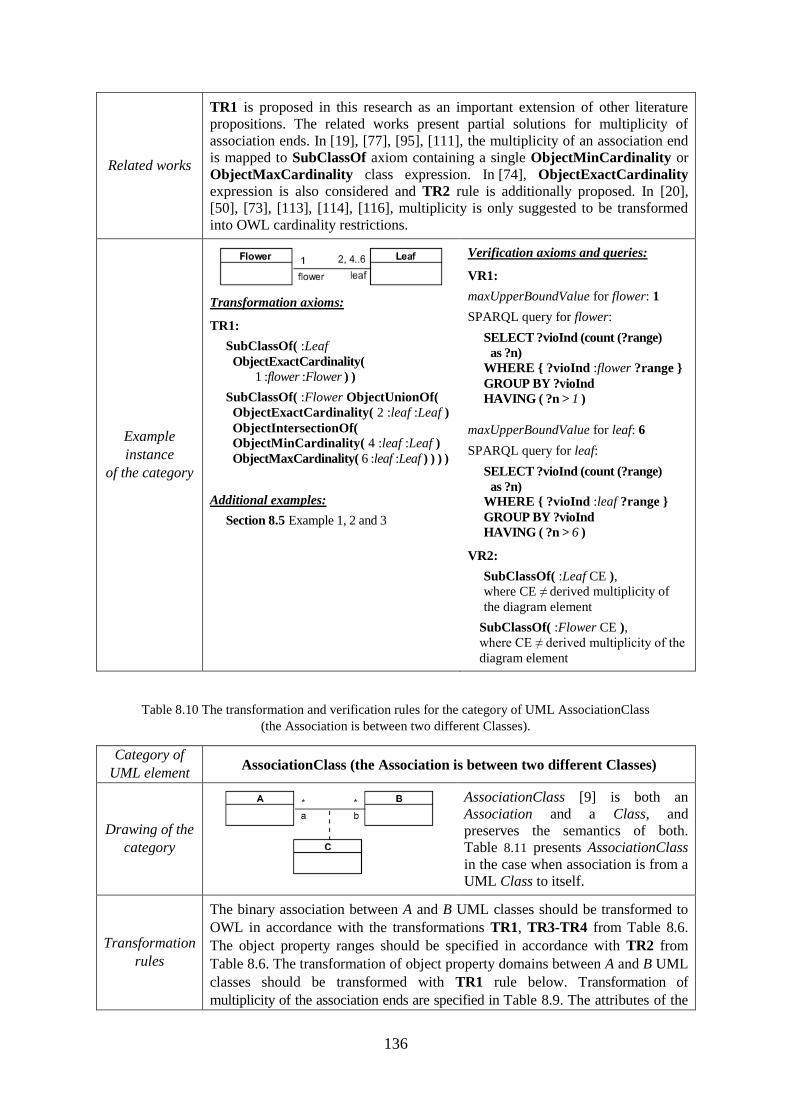
136
Related works
TR1 is proposed in this research as an important extension of other literature
propositions. The related works present partial solutions for multiplicity of
association ends. In [19], [77], [95], [111], the multiplicity of an association end
is mapped to SubClassOf axiom containing a single ObjectMinCardinality or
ObjectMaxCardinality class expression. In [74], ObjectExactCardinality
expression is also considered and TR2 rule is additionally proposed. In [20],
[50], [73], [113], [114], [116], multiplicity is only suggested to be transformed
into OWL cardinality restrictions.
Example
instance
of the category
Transformation axioms:
TR1:
SubClassOf( :Leaf
ObjectExactCardinality(
1 :flower :Flower ) )
SubClassOf( :Flower ObjectUnionOf(
ObjectExactCardinality( 2 :leaf :Leaf )
ObjectIntersectionOf(
ObjectMinCardinality( 4 :leaf :Leaf )
ObjectMaxCardinality( 6 :leaf :Leaf ) ) ) )
Additional examples:
Section 8.5 Example 1, 2 and 3
Verification axioms and queries:
VR1:
maxUpperBoundValue for flower: 1
SPARQL query for flower:
SELECT ?vioInd (count (?range)
as ?n) WHERE { ?vioInd :flower ?range }
GROUP BY ?vioInd
HAVING ( ?n > 1 )
maxUpperBoundValue for leaf: 6
SPARQL query for leaf:
SELECT ?vioInd (count (?range)
as ?n)
WHERE { ?vioInd :leaf ?range }
GROUP BY ?vioInd
HAVING ( ?n > 6 )
VR2:
SubClassOf( :Leaf CE ),
where CE ≠ derived multiplicity of
the diagram element
SubClassOf( :Flower CE ),
where CE ≠ derived multiplicity of the
diagram element
Table 8.10 The transformation and verification rules for the category of UML AssociationClass
(the Association is between two different Classes).
Category of
UML element AssociationClass (the Association is between two different Classes)
Drawing of the
category
AssociationClass [9] is both an
Association and a Class, and
preserves the semantics of both.
Table 8.11 presents AssociationClass
in the case when association is from a
UML Class to itself.
Transformation
rules
The binary association between A and B UML classes should be transformed to
OWL in accordance with the transformations TR1, TR3-TR4 from Table 8.6.
The object property ranges should be specified in accordance with TR2 from
Table 8.6. The transformation of object property domains between A and B UML
classes should be transformed with TR1 rule below. Transformation of
multiplicity of the association ends are specified in Table 8.9. The attributes of the
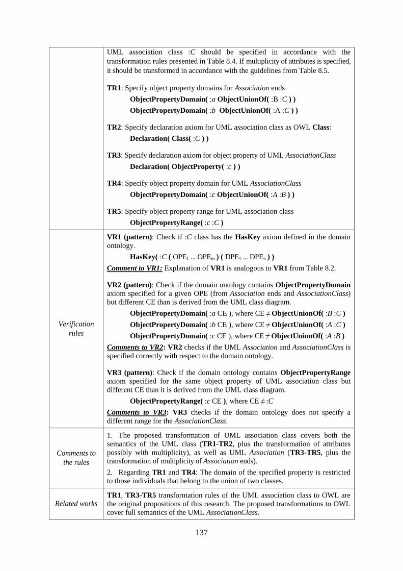
137
UML association class :C should be specified in accordance with the
transformation rules presented in Table 8.4. If multiplicity of attributes is specified,
it should be transformed in accordance with the guidelines from Table 8.5.
TR1: Specify object property domains for Association ends
ObjectPropertyDomain( :a ObjectUnionOf( :B :C ) )
ObjectPropertyDomain( :b ObjectUnionOf( :A :C ) )
TR2: Specify declaration axiom for UML association class as OWL Class:
Declaration( Class( :C ) )
TR3: Specify declaration axiom for object property of UML AssociationClass
Declaration( ObjectProperty( :c ) )
TR4: Specify object property domain for UML AssociationClass
ObjectPropertyDomain( :c ObjectUnionOf( :A :B ) )
TR5: Specify object property range for UML association class
ObjectPropertyRange( :c :C )
Verification
rules
VR1 (pattern): Check if :C class has the HasKey axiom defined in the domain
ontology.
HasKey( :C ( OPE1 ... OPEm ) ( DPE1 ... DPEn ) )
Comment to VR1: Explanation of VR1 is analogous to VR1 from Table 8.2.
VR2 (pattern): Check if the domain ontology contains ObjectPropertyDomain
axiom specified for a given OPE (from Association ends and AssociationClass)
but different CE than is derived from the UML class diagram.
ObjectPropertyDomain( :a CE ), where CE ≠ ObjectUnionOf( :B :C )
ObjectPropertyDomain( :b CE ), where CE ≠ ObjectUnionOf( :A :C )
ObjectPropertyDomain( :c CE ), where CE ≠ ObjectUnionOf( :A :B )
Comments to VR2: VR2 checks if the UML Association and AssociationClass is
specified correctly with respect to the domain ontology.
VR3 (pattern): Check if the domain ontology contains ObjectPropertyRange
axiom specified for the same object property of UML association class but
different CE than it is derived from the UML class diagram.
ObjectPropertyRange( :c CE ), where CE ≠ :C
Comments to VR3: VR3 checks if the domain ontology does not specify a
different range for the AssociationClass.
Comments to
the rules
1. The proposed transformation of UML association class covers both the
semantics of the UML class (TR1-TR2, plus the transformation of attributes
possibly with multiplicity), as well as UML Association (TR3-TR5, plus the
transformation of multiplicity of Association ends).
2. Regarding TR1 and TR4: The domain of the specified property is restricted
to those individuals that belong to the union of two classes.
Related works TR1, TR3-TR5 transformation rules of the UML association class to OWL are
the original propositions of this research. The proposed transformations to OWL
cover full semantics of the UML AssociationClass.
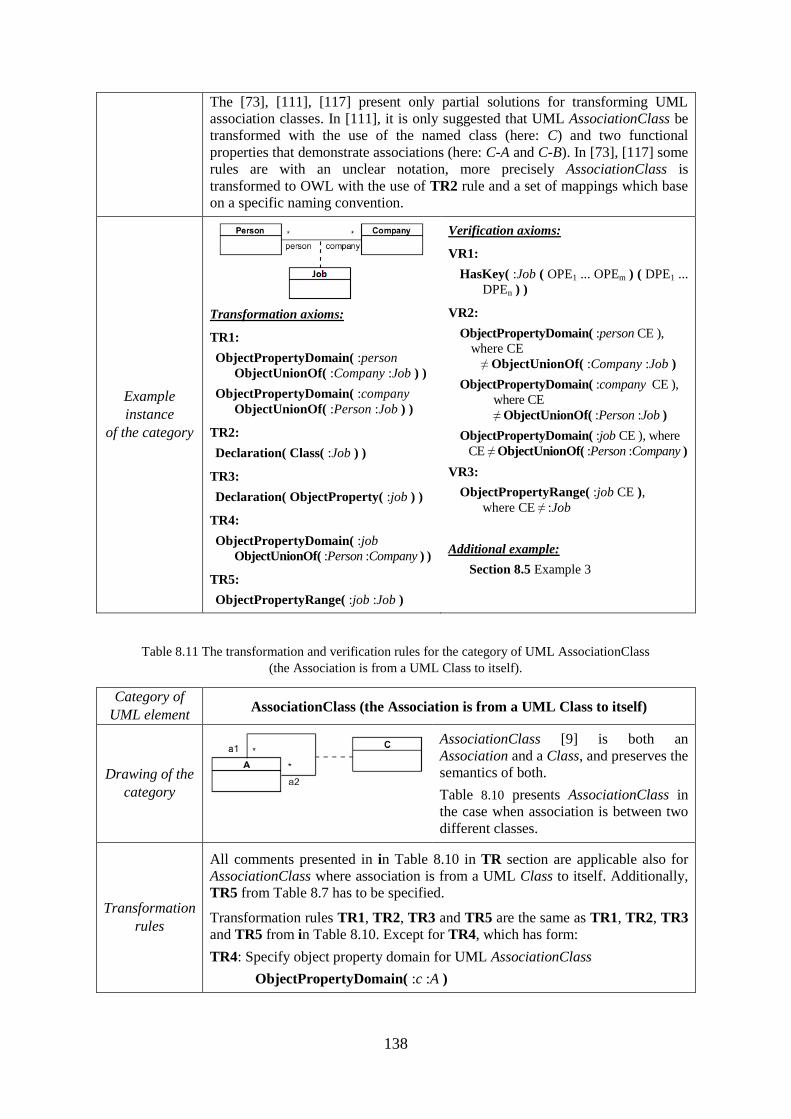
138
The [73], [111], [117] present only partial solutions for transforming UML
association classes. In [111], it is only suggested that UML AssociationClass be
transformed with the use of the named class (here: C) and two functional
properties that demonstrate associations (here: C-A and C-B). In [73], [117] some
rules are with an unclear notation, more precisely AssociationClass is
transformed to OWL with the use of TR2 rule and a set of mappings which base
on a specific naming convention.
Example
instance
of the category
Transformation axioms:
TR1:
ObjectPropertyDomain( :person
ObjectUnionOf( :Company :Job ) )
ObjectPropertyDomain( :company
ObjectUnionOf( :Person :Job ) )
TR2:
Declaration( Class( :Job ) )
TR3:
Declaration( ObjectProperty( :job ) )
TR4:
ObjectPropertyDomain( :job
ObjectUnionOf( :Person :Company ) )
TR5:
ObjectPropertyRange( :job :Job )
Verification axioms:
VR1:
HasKey( :Job ( OPE1 ... OPEm ) ( DPE1 ...
DPEn ) )
VR2:
ObjectPropertyDomain( :person CE ),
where CE
≠ ObjectUnionOf( :Company :Job )
ObjectPropertyDomain( :company CE ),
where CE
≠ ObjectUnionOf( :Person :Job )
ObjectPropertyDomain( :job CE ), where
CE ≠ ObjectUnionOf( :Person :Company )
VR3:
ObjectPropertyRange( :job CE ),
where CE ≠ :Job
Additional example:
Section 8.5 Example 3
Table 8.11 The transformation and verification rules for the category of UML AssociationClass
(the Association is from a UML Class to itself).
Category of
UML element AssociationClass (the Association is from a UML Class to itself)
Drawing of the
category
AssociationClass [9] is both an
Association and a Class, and preserves the
semantics of both.
Table 8.10 presents AssociationClass in
the case when association is between two
different classes.
Transformation
rules
All comments presented in in Table 8.10 in TR section are applicable also for
AssociationClass where association is from a UML Class to itself. Additionally,
TR5 from Table 8.7 has to be specified.
Transformation rules TR1, TR2, TR3 and TR5 are the same as TR1, TR2, TR3
and TR5 from in Table 8.10. Except for TR4, which has form:
TR4: Specify object property domain for UML AssociationClass
ObjectPropertyDomain( :c :A )
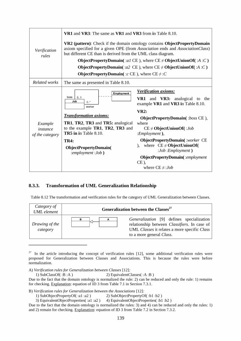
139
Verification
rules
VR1 and VR3: The same as VR1 and VR3 from in Table 8.10.
VR2 (pattern): Check if the domain ontology contains ObjectPropertyDomain
axiom specified for a given OPE (from Association ends and AssociationClass)
but different CE than is derived from the UML class diagram.
ObjectPropertyDomain( :a1 CE ), where CE ≠ ObjectUnionOf( :A :C )
ObjectPropertyDomain( :a2 CE ), where CE ≠ ObjectUnionOf( :A :C )
ObjectPropertyDomain( :c CE ), where CE ≠ :C
Related works The same as presented in Table 8.10.
Example
instance
of the category
Transformation axioms:
TR1, TR2, TR3 and TR5: analogical
to the example TR1, TR2, TR3 and
TR5 in in Table 8.10.
TR4:
ObjectPropertyDomain(
:employment :Job )
Verification axioms:
VR1 and VR3: analogical to the
example VR1 and VR3 in Table 8.10.
VR2:
ObjectPropertyDomain( :boss CE ),
where
CE ≠ ObjectUnionOf( :Job
:Employment ),
ObjectPropertyDomain( :worker CE
), where CE ≠ ObjectUnionOf(
:Job :Employment )
ObjectPropertyDomain( :employment
CE ),
where CE ≠ :Job
8.3.3. Transformation of UML Generalization Relationship
Table 8.12 The transformation and verification rules for the category of UML Generalization between Classes.
Category of
UML element Generalization between the Classes
27
Drawing of the
category
Generalization [9] defines specialization
relationship between Classifiers. In case of
UML Classes it relates a more specific Class
to a more general Class.
27 In the article introducing the concept of verification rules [12], some additional verification rules were
proposed for Generalization between Classes and Associations. This is because the rules were before
normalization.
A) Verification rules for Generalization between Classes [12]:
1) SubClassOf( :B :A ) 2) EquivalentClasses( :A :B )
Due to the fact that the domain ontology is normalized the rule: 2) can be reduced and only the rule: 1) remains
for checking. Explanation: equation of ID 3 from Table 7.1 in Section 7.3.1.
B) Verification rules for Generalization between the Associations [12]:
1) SubObjectPropertyOf( :a1 :a2 ) 2) SubObjectPropertyOf( :b1 :b2 )
3) EquivalentObjectProperties( :a1 :a2 ) 4) EquivalentObjectProperties( :b1 :b2 )
Due to the fact that the domain ontology is normalized the rules: 3) and 4) can be reduced and only the rules: 1)
and 2) remain for checking. Explanation: equation of ID 3 from Table 7.2 in Section 7.3.2.
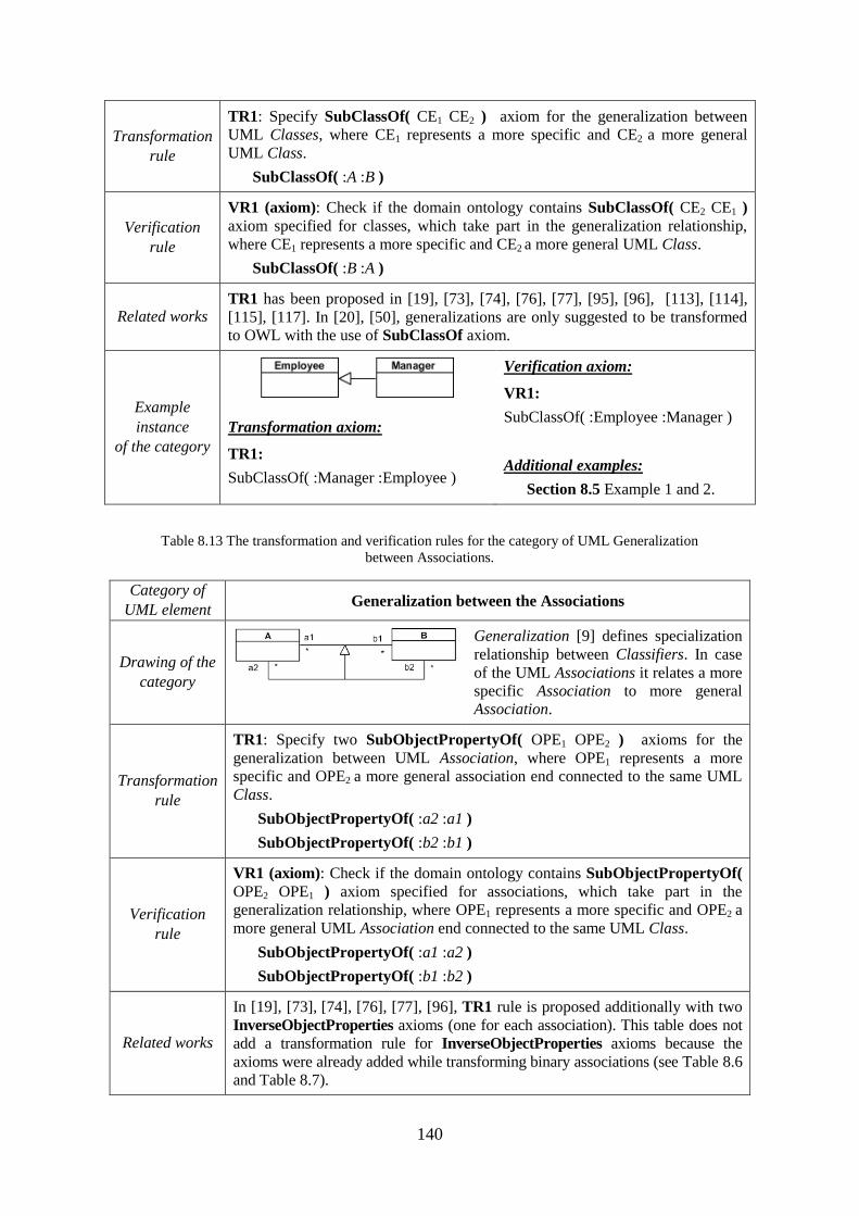
140
Transformation
rule
TR1: Specify SubClassOf( CE1 CE2 ) axiom for the generalization between
UML Classes, where CE1 represents a more specific and CE2 a more general
UML Class.
SubClassOf( :A :B )
Verification
rule
VR1 (axiom): Check if the domain ontology contains SubClassOf( CE2 CE1 )
axiom specified for classes, which take part in the generalization relationship,
where CE1 represents a more specific and CE2 a more general UML Class.
SubClassOf( :B :A )
Related works TR1 has been proposed in [19], [73], [74], [76], [77], [95], [96], [113], [114],
[115], [117]. In [20], [50], generalizations are only suggested to be transformed
to OWL with the use of SubClassOf axiom.
Example
instance
of the category
Transformation axiom:
TR1:
SubClassOf( :Manager :Employee )
Verification axiom:
VR1:
SubClassOf( :Employee :Manager )
Additional examples:
Section 8.5 Example 1 and 2.
Table 8.13 The transformation and verification rules for the category of UML Generalization
between Associations.
Category of
UML element Generalization between the Associations
Drawing of the
category
Generalization [9] defines specialization
relationship between Classifiers. In case
of the UML Associations it relates a more
specific Association to more general
Association.
Transformation
rule
TR1: Specify two SubObjectPropertyOf( OPE1 OPE2 ) axioms for the
generalization between UML Association, where OPE1 represents a more
specific and OPE2 a more general association end connected to the same UML
Class.
SubObjectPropertyOf( :a2 :a1 )
SubObjectPropertyOf( :b2 :b1 )
Verification
rule
VR1 (axiom): Check if the domain ontology contains SubObjectPropertyOf(
OPE2 OPE1 ) axiom specified for associations, which take part in the
generalization relationship, where OPE1 represents a more specific and OPE2 a
more general UML Association end connected to the same UML Class.
SubObjectPropertyOf( :a1 :a2 )
SubObjectPropertyOf( :b1 :b2 )
Related works
In [19], [73], [74], [76], [77], [96], TR1 rule is proposed additionally with two
InverseObjectProperties axioms (one for each association). This table does not
add a transformation rule for InverseObjectProperties axioms because the
axioms were already added while transforming binary associations (see Table 8.6
and Table 8.7).
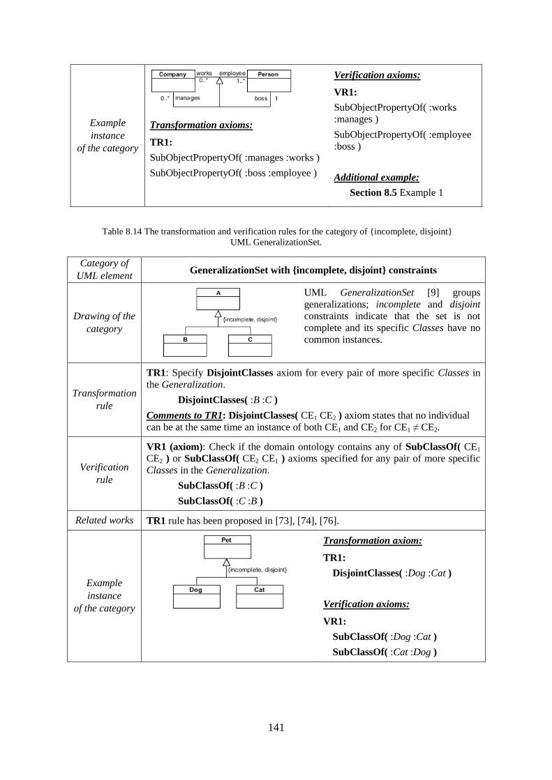
141
Example
instance
of the category
Transformation axioms:
TR1:
SubObjectPropertyOf( :manages :works )
SubObjectPropertyOf( :boss :employee )
Verification axioms:
VR1:
SubObjectPropertyOf( :works
:manages )
SubObjectPropertyOf( :employee
:boss )
Additional example:
Section 8.5 Example 1
Table 8.14 The transformation and verification rules for the category of {incomplete, disjoint}
UML GeneralizationSet.
Category of
UML element GeneralizationSet with {incomplete, disjoint} constraints
Drawing of the
category
UML GeneralizationSet [9] groups
generalizations; incomplete and disjoint
constraints indicate that the set is not
complete and its specific Classes have no
common instances.
Transformation
rule
TR1: Specify DisjointClasses axiom for every pair of more specific Classes in
the Generalization.
DisjointClasses( :B :C )
Comments to TR1: DisjointClasses( CE1 CE2 ) axiom states that no individual
can be at the same time an instance of both CE1 and CE2 for CE1 ≠ CE2.
Verification
rule
VR1 (axiom): Check if the domain ontology contains any of SubClassOf( CE1
CE2 ) or SubClassOf( CE2 CE1 ) axioms specified for any pair of more specific
Classes in the Generalization.
SubClassOf( :B :C )
SubClassOf( :C :B )
Related works TR1 rule has been proposed in [73], [74], [76].
Example
instance
of the category
Transformation axiom:
TR1:
DisjointClasses( :Dog :Cat )
Verification axioms:
VR1:
SubClassOf( :Dog :Cat )
SubClassOf( :Cat :Dog )
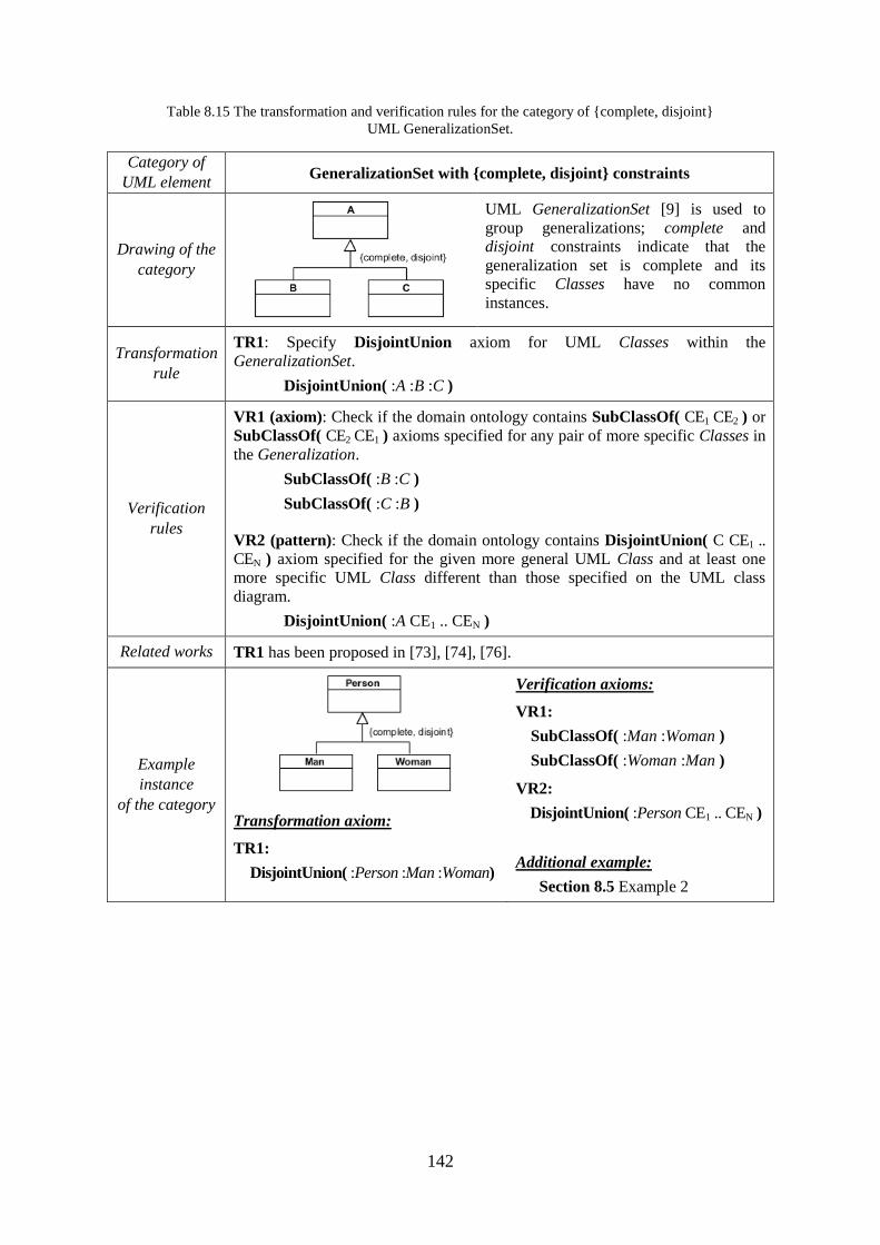
142
Table 8.15 The transformation and verification rules for the category of {complete, disjoint}
UML GeneralizationSet.
Category of
UML element GeneralizationSet with {complete, disjoint} constraints
Drawing of the
category
UML GeneralizationSet [9] is used to
group generalizations; complete and
disjoint constraints indicate that the
generalization set is complete and its
specific Classes have no common
instances.
Transformation
rule
TR1: Specify DisjointUnion axiom for UML Classes within the
GeneralizationSet.
DisjointUnion( :A :B :C )
Verification
rules
VR1 (axiom): Check if the domain ontology contains SubClassOf( CE1 CE2 ) or
SubClassOf( CE2 CE1 ) axioms specified for any pair of more specific Classes in
the Generalization.
SubClassOf( :B :C )
SubClassOf( :C :B )
VR2 (pattern): Check if the domain ontology contains DisjointUnion( C CE1 ..
CEN ) axiom specified for the given more general UML Class and at least one
more specific UML Class different than those specified on the UML class
diagram.
DisjointUnion( :A CE1 .. CEN )
Related works TR1 has been proposed in [73], [74], [76].
Example
instance
of the category
Transformation axiom:
TR1:
DisjointUnion( :Person :Man :Woman)
Verification axioms:
VR1:
SubClassOf( :Man :Woman )
SubClassOf( :Woman :Man )
VR2:
DisjointUnion( :Person CE1 .. CEN )
Additional example:
Section 8.5 Example 2
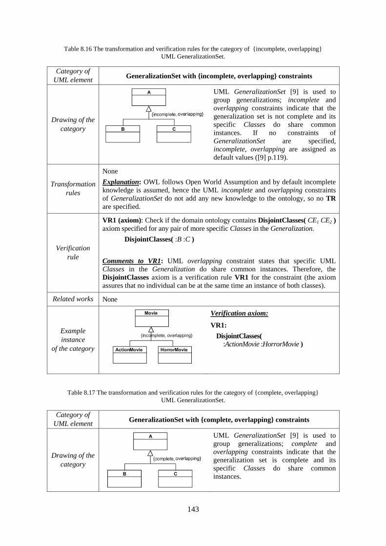
143
Table 8.16 The transformation and verification rules for the category of {incomplete, overlapping}
UML GeneralizationSet.
Category of
UML element GeneralizationSet with {incomplete, overlapping} constraints
Drawing of the
category
UML GeneralizationSet [9] is used to
group generalizations; incomplete and
overlapping constraints indicate that the
generalization set is not complete and its
specific Classes do share common
instances. If no constraints of
GeneralizationSet are specified,
incomplete, overlapping are assigned as
default values ([9] p.119).
Transformation
rules
None
Explanation: OWL follows Open World Assumption and by default incomplete
knowledge is assumed, hence the UML incomplete and overlapping constraints
of GeneralizationSet do not add any new knowledge to the ontology, so no TR
are specified.
Verification
rule
VR1 (axiom): Check if the domain ontology contains DisjointClasses( CE1 CE2 )
axiom specified for any pair of more specific Classes in the Generalization.
DisjointClasses( :B :C )
Comments to VR1: UML overlapping constraint states that specific UML
Classes in the Generalization do share common instances. Therefore, the
DisjointClasses axiom is a verification rule VR1 for the constraint (the axiom
assures that no individual can be at the same time an instance of both classes).
Related works None
Example
instance
of the category
Verification axiom:
VR1:
DisjointClasses(
:ActionMovie :HorrorMovie )
Table 8.17 The transformation and verification rules for the category of {complete, overlapping}
UML GeneralizationSet.
Category of
UML element GeneralizationSet with {complete, overlapping} constraints
Drawing of the
category
UML GeneralizationSet [9] is used to
group generalizations; complete and
overlapping constraints indicate that the
generalization set is complete and its
specific Classes do share common
instances.
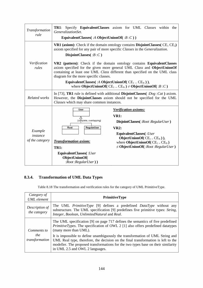
144
Transformation
rule
TR1: Specify EquivalentClasses axiom for UML Classes within the
GeneralizationSet.
EquivalentClasses( :A ObjectUnionOf( :B :C ) )
Verification
rules
VR1 (axiom): Check if the domain ontology contains DisjointClasses( CE1 CE2)
axiom specified for any pair of more specific Classes in the Generalization.
DisjointClasses( :B :C )
VR2 (pattern): Check if the domain ontology contains EquivalentClasses
axiom specified for the given more general UML Class and ObjectUnionOf
containing at least one UML Class different than specified on the UML class
diagram for the more specific classes.
EquivalentClasses( :A ObjectUnionOf( CE1 .. CEN ) ),
where ObjectUnionOf( CE1 .. CEN ) ≠ ObjectUnionOf( :B :C )
Related works In [73], TR1 rule is defined with additional DisjointClasses( :Dog :Cat ) axiom.
However, the DisjointClasses axiom should not be specified for the UML
Classes which may share common instances.
Example
instance
of the category
Transformation axiom:
TR1:
EquivalentClasses( :User
ObjectUnionOf( :Root :RegularUser ) )
Verification axioms:
VR1:
DisjointClasses( :Root :RegularUser )
VR2:
EquivalentClasses( :User
ObjectUnionOf( CE1 .. CEN ) ),
where ObjectUnionOf( CE1 .. CEN )
≠ ObjectUnionOf( :Root :RegularUser )
8.3.4. Transformation of UML Data Types
Table 8.18 The transformation and verification rules for the category of UML PrimitiveType.
Category of
UML element PrimitiveType
Description of
the category
The UML PrimitiveType [9] defines a predefined DataType without any
substructure. The UML specification [9] predefines five primitive types: String,
Integer, Boolean, UnlimitedNatural and Real.
Comments to
the
transformation
The UML specification [9] on page 717 defines the semantics of five predefined
PrimitiveTypes. The specification of OWL 2 [1] also offers predefined datatypes
(many more than UML).
It is impossible to define unambiguously the transformation of UML String and
UML Real type, therefore, the decision on the final transformation is left to the
modeller. The proposed transformations for the two types base on their similarity
in UML 2.5 and OWL 2 languages.
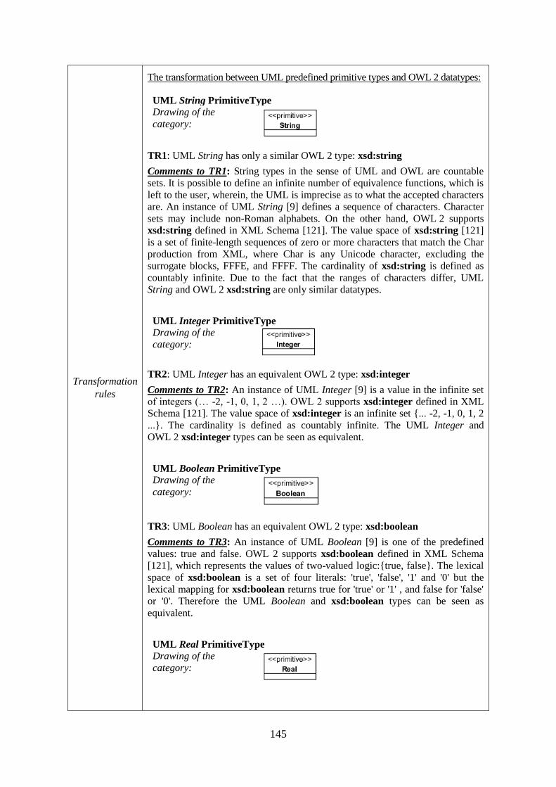
145
Transformation
rules
The transformation between UML predefined primitive types and OWL 2 datatypes:
UML String PrimitiveType
Drawing of the
category:
TR1: UML String has only a similar OWL 2 type: xsd:string
Comments to TR1: String types in the sense of UML and OWL are countable
sets. It is possible to define an infinite number of equivalence functions, which is
left to the user, wherein, the UML is imprecise as to what the accepted characters
are. An instance of UML String [9] defines a sequence of characters. Character
sets may include non-Roman alphabets. On the other hand, OWL 2 supports
xsd:string defined in XML Schema [121]. The value space of xsd:string [121]
is a set of finite-length sequences of zero or more characters that match the Char
production from XML, where Char is any Unicode character, excluding the
surrogate blocks, FFFE, and FFFF. The cardinality of xsd:string is defined as
countably infinite. Due to the fact that the ranges of characters differ, UML
String and OWL 2 xsd:string are only similar datatypes.
UML Integer PrimitiveType
Drawing of the
category:
TR2: UML Integer has an equivalent OWL 2 type: xsd:integer
Comments to TR2: An instance of UML Integer [9] is a value in the infinite set
of integers (… -2, -1, 0, 1, 2 …). OWL 2 supports xsd:integer defined in XML
Schema [121]. The value space of xsd:integer is an infinite set {... -2, -1, 0, 1, 2
...}. The cardinality is defined as countably infinite. The UML Integer and
OWL 2 xsd:integer types can be seen as equivalent.
UML Boolean PrimitiveType
Drawing of the
category:
TR3: UML Boolean has an equivalent OWL 2 type: xsd:boolean
Comments to TR3: An instance of UML Boolean [9] is one of the predefined
values: true and false. OWL 2 supports xsd:boolean defined in XML Schema
[121], which represents the values of two-valued logic:{true, false}. The lexical
space of xsd:boolean is a set of four literals: 'true', 'false', '1' and '0' but the
lexical mapping for xsd:boolean returns true for 'true' or '1' , and false for 'false'
or '0'. Therefore the UML Boolean and xsd:boolean types can be seen as
equivalent.
UML Real PrimitiveType
Drawing of the
category:
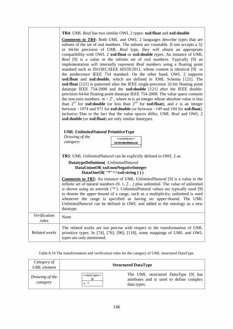
146
TR4: UML Real has two similar OWL 2 types: xsd:float and xsd:double
Comments to TR4: Both UML and OWL 2 languages describe types that are
subsets of the set of real numbers. The subsets are countable. If one accepts a 32
or 64-bit precision of UML Real type, they will obtain an appropriate
compatibility with OWL 2 xsd:float or xsd:double types. An instance of UML
Real [9] is a value in the infinite set of real numbers. Typically [9] an
implementation will internally represent Real numbers using a floating point
standard such as ISO/IEC/IEEE 60559:2011, whose content is identical [9] to
the predecessor IEEE 754 standard. On the other hand, OWL 2 supports
xsd:float and xsd:double, which are defined in XML Schema [121]. The
xsd:float [121] is patterned after the IEEE single-precision 32-bit floating point
datatype IEEE 754-2008 and the xsd:double [121] after the IEEE double-
precision 64-bit floating point datatype IEEE 754-2008. The value space contains
the non-zero numbers m × 2e , where m is an integer whose absolute value is less
than 253
for xsd:double (or less than 224
for xsd:float), and e is an integer
between −1074 and 971 for xsd:double (or between −149 and 104 for xsd:float),
inclusive. Due to the fact that the value spaces differ, UML Real and OWL 2
xsd:double (or xsd:float) are only similar datatypes.
UML UnlimitedNatural PrimitiveType
Drawing of the
category:
TR5: UML UnlimitedNatural can be explicitly defined in OWL 2 as:
DatatypeDefinition( :UnlimitedNatural
DataUnionOf( xsd:nonNegativeInteger
DataOneOf( "*"^^xsd:string ) ) )
Comments to TR5: An instance of UML UnlimitedNatural [9] is a value in the
infinite set of natural numbers (0, 1, 2…) plus unlimited. The value of unlimited
is shown using an asterisk („*‟). UnlimitedNatural values are typically used [9]
to denote the upper-bound of a range, such as a multiplicity; unlimited is used
whenever the range is specified as having no upper-bound. The UML
UnlimitedNatural can be defined in OWL and added to the ontology as a new
datatype.
Verification
rules None
Related works The related works are not precise with respect to the transformation of UML
primitive types. In [74], [76], [96], [118], some mappings of UML and OWL
types are only mentioned.
Table 8.19 The transformation and verification rules for the category of UML structured DataType.
Category of
UML element Structured DataType
Drawing of the
category
The UML structured DataType [9] has
attributes and is used to define complex
data types.
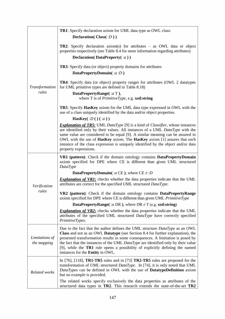
147
Transformation
rules
TR1: Specify declaration axiom for UML data type as OWL class:
Declaration( Class( :D ) )
TR2: Specify declaration axiom(s) for attributes – as OWL data or object
properties respectively (see Table 8.4 for more information regarding attributes)
Declaration( DataProperty( :a ) )
TR3: Specify data (or object) property domains for attributes
DataPropertyDomain( :a :D )
TR4: Specify data (or object) property ranges for attributes (OWL 2 datatypes
for UML primitive types are defined in Table 8.18)
DataPropertyRange( :a T ),
where T is of PrimitiveType, e.g. xsd:string
TR5: Specify HasKey axiom for the UML data type expressed in OWL with the
use of a class uniquely identified by the data and/or object properties.
HasKey( :D ( ) ( :a ) )
Explanation of TR5: UML DataType [9] is a kind of Classifier, whose instances
are identified only by their values. All instances of a UML DataType with the
same value are considered to be equal [9]. A similar meaning can be assured in
OWL with the use of HasKey axiom. The HasKey axiom [1] assures that each
instance of the class expression is uniquely identified by the object and/or data
property expressions.
Verification
rules
VR1 (pattern): Check if the domain ontology contains DataPropertyDomain
axiom specified for DPE where CE is different than given UML structured
DataType
DataPropertyDomain( :a CE ), where CE ≠ :D
Explanation of VR1: checks whether the data properties indicate that the UML
attributes are correct for the specified UML structured DataType.
VR2 (pattern): Check if the domain ontology contains DataPropertyRange
axiom specified for DPE where CE is different than given UML PrimitiveType
DataPropertyRange( :a DR ), where DR ≠ T (e.g. xsd:string)
Explanation of VR2: checks whether the data properties indicate that the UML
attributes of the specified UML structured DataType have correctly specified
PrimitiveTypes.
Limitations of
the mapping
Due to the fact that the author defines the UML structure DataType as an OWL
Class and not as an OWL Datatype (see Section 8.4 for further explanation), the
presented transformation results in some consequences. A limitation is posed by
the fact that the instances of the UML DataType are identified only by their value
[9], while the TR1 rule opens a possibility of explicitly defining the named
instances for the Entity in OWL.
Related works
In [76], [118], TR1-TR5 rules and in [73] TR2-TR5 rules are proposed for the
transformation of UML structured DataType. In [74], it is only noted that UML
DataTypes can be defined in OWL with the use of DatatypeDefinition axiom
but no example is provided.
The related works specify exclusively the data properties as attributes of the
structured data types in TR2. This research extends the state-of-the-art TR2
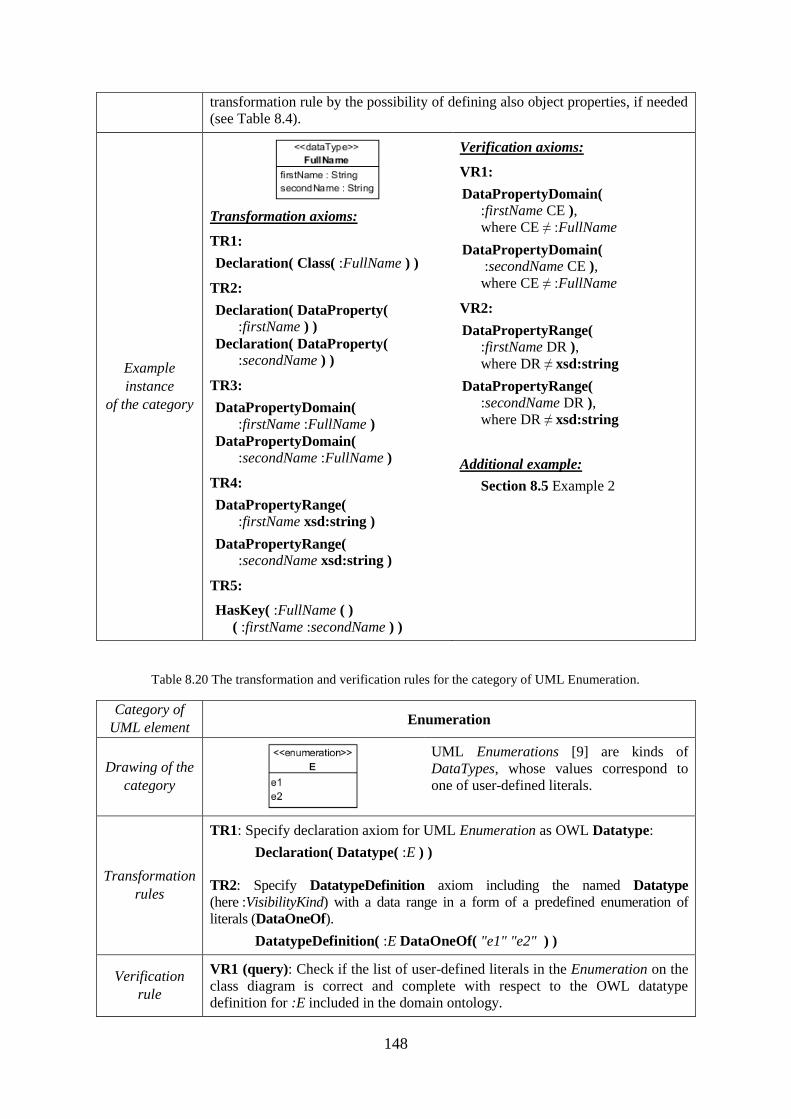
148
transformation rule by the possibility of defining also object properties, if needed
(see Table 8.4).
Example
instance
of the category
Transformation axioms:
TR1:
Declaration( Class( :FullName ) )
TR2:
Declaration( DataProperty(
:firstName ) )
Declaration( DataProperty(
:secondName ) )
TR3:
DataPropertyDomain(
:firstName :FullName )
DataPropertyDomain(
:secondName :FullName )
TR4:
DataPropertyRange(
:firstName xsd:string )
DataPropertyRange(
:secondName xsd:string )
TR5:
HasKey( :FullName ( )
( :firstName :secondName ) )
Verification axioms:
VR1:
DataPropertyDomain(
:firstName CE ),
where CE ≠ :FullName
DataPropertyDomain(
:secondName CE ),
where CE ≠ :FullName
VR2:
DataPropertyRange(
:firstName DR ),
where DR ≠ xsd:string
DataPropertyRange(
:secondName DR ),
where DR ≠ xsd:string
Additional example:
Section 8.5 Example 2
Table 8.20 The transformation and verification rules for the category of UML Enumeration.
Category of
UML element Enumeration
Drawing of the
category
UML Enumerations [9] are kinds of
DataTypes, whose values correspond to
one of user-defined literals.
Transformation
rules
TR1: Specify declaration axiom for UML Enumeration as OWL Datatype:
Declaration( Datatype( :E ) )
TR2: Specify DatatypeDefinition axiom including the named Datatype
(here :VisibilityKind) with a data range in a form of a predefined enumeration of
literals (DataOneOf).
DatatypeDefinition( :E DataOneOf( "e1" "e2" ) )
Verification
rule
VR1 (query): Check if the list of user-defined literals in the Enumeration on the
class diagram is correct and complete with respect to the OWL datatype
definition for :E included in the domain ontology.
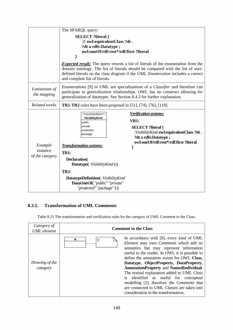
149
The SPARQL query:
SELECT ?literal {
:E owl:equivalentClass ?dt .
?dt a rdfs:Datatype ;
owl:oneOf/rdf:rest*/rdf:first ?literal
}
Expected result: The query returns a list of literals of the enumeration from the
domain ontology. The list of literals should be compared with the list of user-
defined literals on the class diagram if the UML Enumeration includes a correct
and complete list of literals.
Limitations of
the mapping
Enumerations [9] in UML are specializations of a Classifier and therefore can
participate in generalization relationships. OWL has no construct allowing for
generalization of datatypes. See Section 8.4.3 for further explanation.
Related works TR1-TR2 rules have been proposed in [51], [74], [76], [118].
Example
instance
of the category
Transformation axioms:
TR1:
Declaration(
Datatype( :VisibilityKind ) )
TR2:
DatatypeDefinition( :VisibilityKind
DataOneOf( "public" "private"
"protected" "package" ) )
Verification axioms:
VR1:
SELECT ?literal {
:VisibilityKind owl:equivalentClass ?dt .
?dt a rdfs:Datatype ;
owl:oneOf/rdf:rest*/rdf:first ?literal
}
8.3.5. Transformation of UML Comments
Table 8.21 The transformation and verification rules for the category of UML Comment to the Class.
Category of
UML element Comment to the Class
Drawing of the
category
In accordance with [9], every kind of UML
Element may own Comments which add no
semantics but may represent information
useful to the reader. In OWL it is possible to
define the annotation axiom for OWL Class,
Datatype, ObjectProperty, DataProperty,
AnnotationProperty and NamedIndividual.
The textual explanation added to UML Class
is identified as useful for conceptual
modelling [2], therefore the Comments that
are connected to UML Classes are taken into
consideration in the transformation.
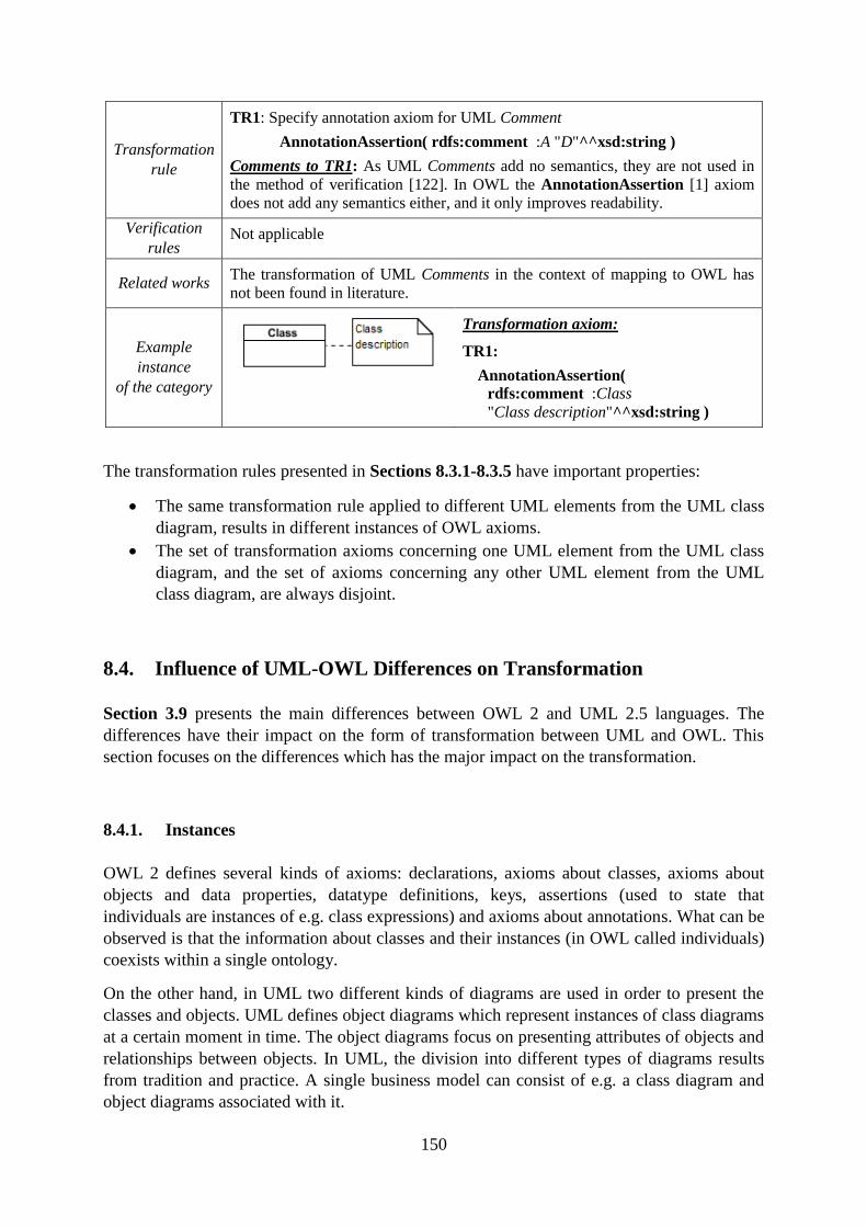
150
Transformation
rule
TR1: Specify annotation axiom for UML Comment
AnnotationAssertion( rdfs:comment :A "D"^^xsd:string )
Comments to TR1: As UML Comments add no semantics, they are not used in
the method of verification [122]. In OWL the AnnotationAssertion [1] axiom
does not add any semantics either, and it only improves readability.
Verification
rules Not applicable
Related works The transformation of UML Comments in the context of mapping to OWL has
not been found in literature.
Example
instance
of the category
Transformation axiom:
TR1:
AnnotationAssertion(
rdfs:comment :Class
"Class description"^^xsd:string )
The transformation rules presented in Sections 8.3.1-8.3.5 have important properties:
The same transformation rule applied to different UML elements from the UML class
diagram, results in different instances of OWL axioms.
The set of transformation axioms concerning one UML element from the UML class
diagram, and the set of axioms concerning any other UML element from the UML
class diagram, are always disjoint.
8.4. Influence of UML-OWL Differences on Transformation
Section 3.9 presents the main differences between OWL 2 and UML 2.5 languages. The
differences have their impact on the form of transformation between UML and OWL. This
section focuses on the differences which has the major impact on the transformation.
8.4.1. Instances
OWL 2 defines several kinds of axioms: declarations, axioms about classes, axioms about
objects and data properties, datatype definitions, keys, assertions (used to state that
individuals are instances of e.g. class expressions) and axioms about annotations. What can be
observed is that the information about classes and their instances (in OWL called individuals)
coexists within a single ontology.
On the other hand, in UML two different kinds of diagrams are used in order to present the
classes and objects. UML defines object diagrams which represent instances of class diagrams
at a certain moment in time. The object diagrams focus on presenting attributes of objects and
relationships between objects. In UML, the division into different types of diagrams results
from tradition and practice. A single business model can consist of e.g. a class diagram and
object diagrams associated with it.
151
Despite the fact that information about the objects is not present in UML class diagrams,
verification rules in the form of SPARQL queries take advantage of the knowledge about
individuals in the domain ontology. The rules are useful in verification of class diagrams
against the selected domain ontologies as they can check, for example, if an abstract class is
indeed abstract (does not have any direct instances in ontology) or if multiplicity restrictions
are specified correctly.
8.4.2. Disjointness in OWL 2 and UML
In OWL 2 an individual can be an instance of several classes [54]. It is also possible to state
that no individual can be an instance of selected classes, which is called class disjointness.
The information that some specific classes are disjoint is part of domain knowledge which
serves a purpose of reasoning.
OWL specification emphasises [54]: "In practice, disjointness statements are often forgotten
or neglected. The arguable reason for this could be that intuitively, classes are considered
disjoint unless there is other evidence. By omitting disjointness statements, many potentially
useful consequences can get lost.".
What can be observed in typical existing OWL ontologies, axioms of disjointness
(DisjointClasses, DisjointObjectProperties and DisjointDataProperties) are stated for
classes, object properties or data properties only for the most evident situations. If disjointness
is not specified, the semantics of OWL states that the ontology does not contain enough
information that disjointness takes place. For example, it is possible that the information is
actually true but it has not been included in the ontology.
On the other hand, in a UML class diagram every pair of UML classes (which are not within
one generalization set with an overlapping constraint) is disjoint, where disjointness is
understood in the way that the classes have no common instances. This aspect of UML
semantics could be mapped to OWL with the use of an extensive set of additional
transformations. The transformations would not be intuitive from the perspective of OWL and
should add a lot of unnecessary information which might never be useful due to the fact that
e.g. one should consider every pair of classes on the diagram and add additional axioms for it.
For the purpose of completeness of the presented revision, the following are the
transformation rules also for disjointness:
a) Transformation rule for disjointness of UML classes (TRA): Specify DisjointClasses
axiom for every pair of UML Classes: CE1, CE2 where CE1 ≠ CE2 and the pair is not
in the generalization relation or within one generalization set with an overlapping constraint.
Comment: The TRA rule for classes within a generalization relationship was originally
proposed in [19], [51], [74]. In this research, this rule has been refined in order to cover only
the pairs of classes which are not only in a direct generalization relation but also not within
one GeneralizationSet with an overlapping constraint. This is caused by the fact that the
GeneralizationSet with the overlapping constraint (see Table 8.16 and Table 8.17) defines
specific Classes, which do share common instances. Please note that UML GeneralizationSet
with disjoint constraint adds DisjointClasses axioms – either directly or indirectly through
DisjointUnion axiom (see Table 8.14 and Table 8.15).
152
b) Transformation rule for disjointness of UML attributes (TRB): Specify
DisjointObjectProperties axiom for every pair OPE1, OPE2 where OPE1 ≠ OPE2 of object
properties within the same UML Class (domain of both OPE1 and OPE2 is the same
OWL Class) and specify DisjointDataProperties axiom for every pair DPE1, DPE2
where DPE1 ≠ DPE2 of object properties within the same UML Class (domain of both
DPE1 and DPE2 is the same OWL Class)
Comment: The TRB rule is an original proposition of this research.
c) Transformation rule for disjointness of UML associations (TRC): Specify
DisjointObjectProperties axiom for every pair of association ends OPE1 and OPE2
where OPE1 ≠ OPE2 and OPE1 is not generalized by OPE2 and OPE2 is not generalized
by OPE1 and domain and range of OPE1 and OPE2 are the same classes.
Comment: In [51], [74], it is suggested that DisjointObjectProperties and
DisjointDataProperties axioms for all properties that are not in a generalization
relationship should be specified. In a general case this suggestion is not clear,
therefore in this research the rule is modified to be applicable for UML associations
which are not in generalization relationship.
Even though the TRA, TRB and TRC rules are reasonable from the point of view of covering
semantics of a class diagram to OWL, they have not been implemented in the proposed tool
for validation of UML class diagram due to their questionable usefulness from the perspective
of pragmatics. This is caused by the fact that including these rules would lead to a large
increase in the number of axioms in the ontology, which would increase the computational
complexity.
8.4.3. Concepts of Class and DataType in UML and OWL
OWL 2 allows specifying declaration axioms for datatypes:
Declaration( Datatype( :DatatypeName ) )
However, the current specification of OWL 2 [1] does not offer any constructs neither to
specify the internal structure of the datatypes, nor the possibility to define generalization
relationships between the datatypes. Both are available in UML 2.5.
Please note that the OWL HasKey, DataPropertyDomain and ObjectPropertyDomain
axioms can only be defined for the class expressions (not for the data ranges). Therefore the
TR2-TR5 rules in Table 8.19 can only be specified if the UML structured DataType is
declared as an OWL Class. This transformation has its consequences, which are presented in
Table 8.19.
If future extensions of the OWL language allow one to precisely define the internal structure
of datatypes, by analogy, as it is possible in UML, the proposed transformation of UML
structured DataType presented in Table 8.19 should then be modified. Additionally, if future
extensions of the OWL language allow one to define generalization relationships between
datatypes, the currently valid limitation of the transformation of UML Enumeration presented
in Table 8.20 will no longer be applicable.
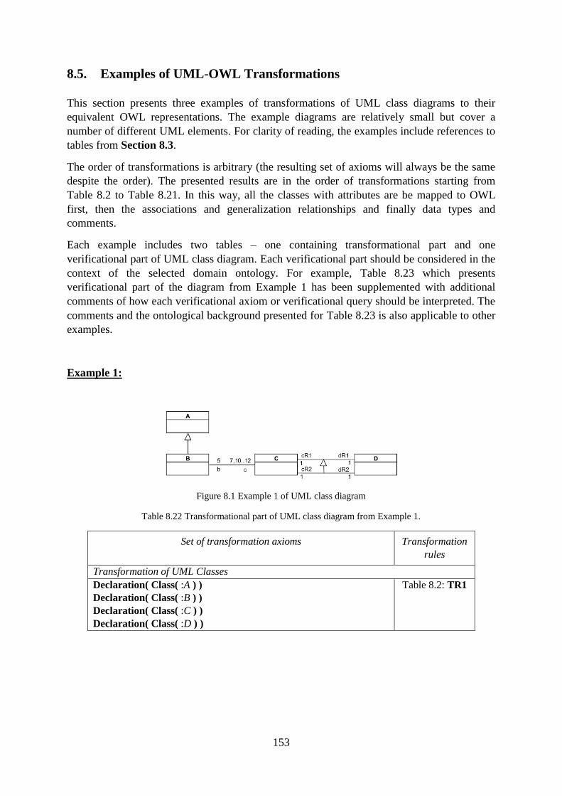
153
8.5. Examples of UML-OWL Transformations
This section presents three examples of transformations of UML class diagrams to their
equivalent OWL representations. The example diagrams are relatively small but cover a
number of different UML elements. For clarity of reading, the examples include references to
tables from Section 8.3.
The order of transformations is arbitrary (the resulting set of axioms will always be the same
despite the order). The presented results are in the order of transformations starting from
Table 8.2 to Table 8.21. In this way, all the classes with attributes are be mapped to OWL
first, then the associations and generalization relationships and finally data types and
comments.
Each example includes two tables – one containing transformational part and one
verificational part of UML class diagram. Each verificational part should be considered in the
context of the selected domain ontology. For example, Table 8.23 which presents
verificational part of the diagram from Example 1 has been supplemented with additional
comments of how each verificational axiom or verificational query should be interpreted. The
comments and the ontological background presented for Table 8.23 is also applicable to other
examples.
Example 1:
Figure 8.1 Example 1 of UML class diagram
Table 8.22 Transformational part of UML class diagram from Example 1.
Set of transformation axioms Transformation
rules
Transformation of UML Classes
Declaration( Class( :A ) )
Declaration( Class( :B ) )
Declaration( Class( :C ) )
Declaration( Class( :D ) )
Table 8.2: TR1
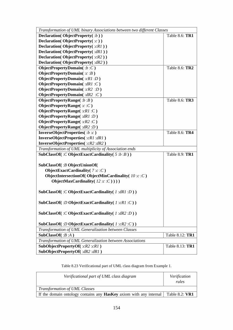
154
Transformation of UML binary Associations between two different Classes
Declaration( ObjectProperty( :b ) )
Declaration( ObjectProperty( :c ) )
Declaration( ObjectProperty( :cR1 ) )
Declaration( ObjectProperty( :dR1 ) )
Declaration( ObjectProperty( :cR2 ) )
Declaration( ObjectProperty( :dR2 ) )
Table 8.6: TR1
ObjectPropertyDomain( :b :C )
ObjectPropertyDomain( :c :B )
ObjectPropertyDomain( :cR1 :D )
ObjectPropertyDomain( :dR1 :C )
ObjectPropertyDomain( :cR2 :D )
ObjectPropertyDomain( :dR2 :C )
Table 8.6: TR2
ObjectPropertyRange( :b :B )
ObjectPropertyRange( :c :C )
ObjectPropertyRange( :cR1 :C )
ObjectPropertyRange( :dR1 :D )
ObjectPropertyRange( :cR2 :C )
ObjectPropertyRange( :dR2 :D )
Table 8.6: TR3
InverseObjectProperties( :b :c )
InverseObjectProperties( :cR1 :dR1 )
InverseObjectProperties( :cR2 :dR2 )
Table 8.6: TR4
Transformation of UML multiplicity of Association ends
SubClassOf( :C ObjectExactCardinality( 5 :b :B ) )
SubClassOf( :B ObjectUnionOf(
ObjectExactCardinality( 7 :c :C )
ObjectIntersectionOf( ObjectMinCardinality( 10 :c :C )
ObjectMaxCardinality( 12 :c :C ) ) ) )
SubClassOf( :C ObjectExactCardinality( 1 :dR1 :D ) )
SubClassOf( :D ObjectExactCardinality( 1 :cR1 :C ) )
SubClassOf( :C ObjectExactCardinality( 1 :dR2 :D ) )
SubClassOf( :D ObjectExactCardinality( 1 :cR2 :C ) )
Table 8.9: TR1
Transformation of UML Generalization between Classes
SubClassOf( :B :A ) Table 8.12: TR1
Transformation of UML Generalization between Associations
SubObjectPropertyOf( :cR2 :cR1 )
SubObjectPropertyOf( :dR2 :dR1 )
Table 8.13: TR1
Table 8.23 Verificational part of UML class diagram from Example 1.
Verificational part of UML class diagram Verification
rules
Transformation of UML Classes
If the domain ontology contains any HasKey axiom with any internal Table 8.2: VR1
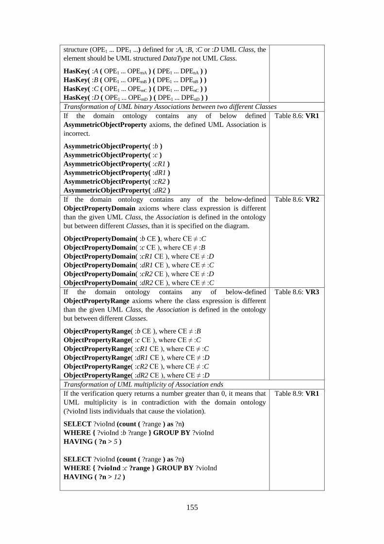
155
structure (OPE1 ... DPE1 ...) defined for :A, :B, :C or :D UML Class, the
element should be UML structured DataType not UML Class.
HasKey( :A ( OPE1 ... OPEmA ) ( DPE1 ... DPEnA ) )
HasKey( :B ( OPE1 ... OPEmB ) ( DPE1 ... DPEnB ) )
HasKey( :C ( OPE1 ... OPEmC ) ( DPE1 ... DPEnC ) )
HasKey( :D ( OPE1 ... OPEmD ) ( DPE1 ... DPEnD ) )
Transformation of UML binary Associations between two different Classes
If the domain ontology contains any of below defined
AsymmetricObjectProperty axioms, the defined UML Association is
incorrect.
AsymmetricObjectProperty( :b )
AsymmetricObjectProperty( :c )
AsymmetricObjectProperty( :cR1 )
AsymmetricObjectProperty( :dR1 )
AsymmetricObjectProperty( :cR2 )
AsymmetricObjectProperty( :dR2 )
Table 8.6: VR1
If the domain ontology contains any of the below-defined
ObjectPropertyDomain axioms where class expression is different
than the given UML Class, the Association is defined in the ontology
but between different Classes, than it is specified on the diagram.
ObjectPropertyDomain( :b CE ), where CE ≠ :C
ObjectPropertyDomain( :c CE ), where CE ≠ :B
ObjectPropertyDomain( :cR1 CE ), where CE ≠ :D
ObjectPropertyDomain( :dR1 CE ), where CE ≠ :C
ObjectPropertyDomain( :cR2 CE ), where CE ≠ :D
ObjectPropertyDomain( :dR2 CE ), where CE ≠ :C
Table 8.6: VR2
If the domain ontology contains any of below-defined
ObjectPropertyRange axioms where the class expression is different
than the given UML Class, the Association is defined in the ontology
but between different Classes.
ObjectPropertyRange( :b CE ), where CE ≠ :B
ObjectPropertyRange( :c CE ), where CE ≠ :C
ObjectPropertyRange( :cR1 CE ), where CE ≠ :C
ObjectPropertyRange( :dR1 CE ), where CE ≠ :D
ObjectPropertyRange( :cR2 CE ), where CE ≠ :C
ObjectPropertyRange( :dR2 CE ), where CE ≠ :D
Table 8.6: VR3
Transformation of UML multiplicity of Association ends
If the verification query returns a number greater than 0, it means that
UML multiplicity is in contradiction with the domain ontology
(?vioInd lists individuals that cause the violation).
SELECT ?vioInd (count ( ?range ) as ?n)
WHERE { ?vioInd :b ?range } GROUP BY ?vioInd
HAVING ( ?n > 5 )
SELECT ?vioInd (count ( ?range ) as ?n)
WHERE { ?vioInd :c ?range } GROUP BY ?vioInd
HAVING ( ?n > 12 )
Table 8.9: VR1
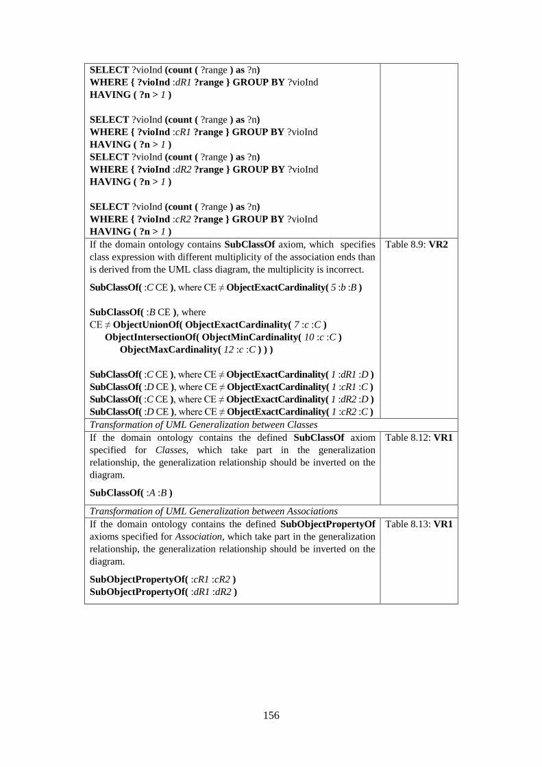
156
SELECT ?vioInd (count ( ?range ) as ?n)
WHERE { ?vioInd :dR1 ?range } GROUP BY ?vioInd
HAVING ( ?n > 1 )
SELECT ?vioInd (count ( ?range ) as ?n)
WHERE { ?vioInd :cR1 ?range } GROUP BY ?vioInd
HAVING ( ?n > 1 )
SELECT ?vioInd (count ( ?range ) as ?n)
WHERE { ?vioInd :dR2 ?range } GROUP BY ?vioInd
HAVING ( ?n > 1 )
SELECT ?vioInd (count ( ?range ) as ?n)
WHERE { ?vioInd :cR2 ?range } GROUP BY ?vioInd
HAVING ( ?n > 1 )
If the domain ontology contains SubClassOf axiom, which specifies
class expression with different multiplicity of the association ends than
is derived from the UML class diagram, the multiplicity is incorrect.
SubClassOf( :C CE ), where CE ≠ ObjectExactCardinality( 5 :b :B )
SubClassOf( :B CE ), where
CE ≠ ObjectUnionOf( ObjectExactCardinality( 7 :c :C )
ObjectIntersectionOf( ObjectMinCardinality( 10 :c :C )
ObjectMaxCardinality( 12 :c :C ) ) )
SubClassOf( :C CE ), where CE ≠ ObjectExactCardinality( 1 :dR1 :D )
SubClassOf( :D CE ), where CE ≠ ObjectExactCardinality( 1 :cR1 :C )
SubClassOf( :C CE ), where CE ≠ ObjectExactCardinality( 1 :dR2 :D )
SubClassOf( :D CE ), where CE ≠ ObjectExactCardinality( 1 :cR2 :C )
Table 8.9: VR2
Transformation of UML Generalization between Classes
If the domain ontology contains the defined SubClassOf axiom
specified for Classes, which take part in the generalization
relationship, the generalization relationship should be inverted on the
diagram.
SubClassOf( :A :B )
Table 8.12: VR1
Transformation of UML Generalization between Associations
If the domain ontology contains the defined SubObjectPropertyOf
axioms specified for Association, which take part in the generalization
relationship, the generalization relationship should be inverted on the
diagram.
SubObjectPropertyOf( :cR1 :cR2 )
SubObjectPropertyOf( :dR1 :dR2 )
Table 8.13: VR1
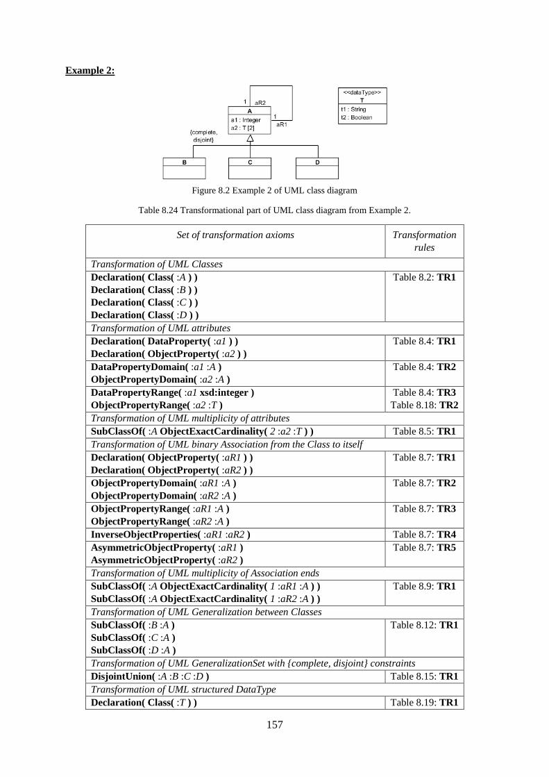
157
Example 2:
Figure 8.2 Example 2 of UML class diagram
Table 8.24 Transformational part of UML class diagram from Example 2.
Set of transformation axioms Transformation
rules
Transformation of UML Classes
Declaration( Class( :A ) )
Declaration( Class( :B ) )
Declaration( Class( :C ) )
Declaration( Class( :D ) )
Table 8.2: TR1
Transformation of UML attributes
Declaration( DataProperty( :a1 ) )
Declaration( ObjectProperty( :a2 ) )
Table 8.4: TR1
DataPropertyDomain( :a1 :A )
ObjectPropertyDomain( :a2 :A )
Table 8.4: TR2
DataPropertyRange( :a1 xsd:integer )
ObjectPropertyRange( :a2 :T )
Table 8.4: TR3
Table 8.18: TR2
Transformation of UML multiplicity of attributes
SubClassOf( :A ObjectExactCardinality( 2 :a2 :T ) ) Table 8.5: TR1
Transformation of UML binary Association from the Class to itself
Declaration( ObjectProperty( :aR1 ) )
Declaration( ObjectProperty( :aR2 ) )
Table 8.7: TR1
ObjectPropertyDomain( :aR1 :A )
ObjectPropertyDomain( :aR2 :A )
Table 8.7: TR2
ObjectPropertyRange( :aR1 :A )
ObjectPropertyRange( :aR2 :A )
Table 8.7: TR3
InverseObjectProperties( :aR1 :aR2 ) Table 8.7: TR4
AsymmetricObjectProperty( :aR1 )
AsymmetricObjectProperty( :aR2 )
Table 8.7: TR5
Transformation of UML multiplicity of Association ends
SubClassOf( :A ObjectExactCardinality( 1 :aR1 :A ) )
SubClassOf( :A ObjectExactCardinality( 1 :aR2 :A ) )
Table 8.9: TR1
Transformation of UML Generalization between Classes
SubClassOf( :B :A )
SubClassOf( :C :A )
SubClassOf( :D :A )
Table 8.12: TR1
Transformation of UML GeneralizationSet with {complete, disjoint} constraints
DisjointUnion( :A :B :C :D ) Table 8.15: TR1
Transformation of UML structured DataType
Declaration( Class( :T ) ) Table 8.19: TR1
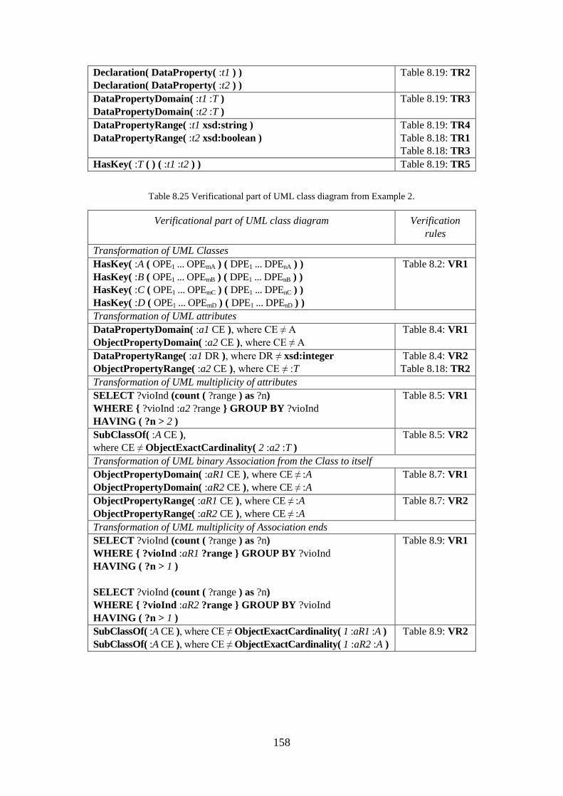
158
Declaration( DataProperty( :t1 ) )
Declaration( DataProperty( :t2 ) )
Table 8.19: TR2
DataPropertyDomain( :t1 :T )
DataPropertyDomain( :t2 :T )
Table 8.19: TR3
DataPropertyRange( :t1 xsd:string )
DataPropertyRange( :t2 xsd:boolean )
Table 8.19: TR4
Table 8.18: TR1
Table 8.18: TR3
HasKey( :T ( ) ( :t1 :t2 ) ) Table 8.19: TR5
Table 8.25 Verificational part of UML class diagram from Example 2.
Verificational part of UML class diagram Verification
rules
Transformation of UML Classes
HasKey( :A ( OPE1 ... OPEmA ) ( DPE1 ... DPEnA ) )
HasKey( :B ( OPE1 ... OPEmB ) ( DPE1 ... DPEnB ) )
HasKey( :C ( OPE1 ... OPEmC ) ( DPE1 ... DPEnC ) )
HasKey( :D ( OPE1 ... OPEmD ) ( DPE1 ... DPEnD ) )
Table 8.2: VR1
Transformation of UML attributes
DataPropertyDomain( :a1 CE ), where CE ≠ A
ObjectPropertyDomain( :a2 CE ), where CE ≠ A
Table 8.4: VR1
DataPropertyRange( :a1 DR ), where DR ≠ xsd:integer
ObjectPropertyRange( :a2 CE ), where CE ≠ :T
Table 8.4: VR2
Table 8.18: TR2
Transformation of UML multiplicity of attributes
SELECT ?vioInd (count ( ?range ) as ?n)
WHERE { ?vioInd :a2 ?range } GROUP BY ?vioInd
HAVING ( ?n > 2 )
Table 8.5: VR1
SubClassOf( :A CE ),
where CE ≠ ObjectExactCardinality( 2 :a2 :T )
Table 8.5: VR2
Transformation of UML binary Association from the Class to itself
ObjectPropertyDomain( :aR1 CE ), where CE ≠ :A
ObjectPropertyDomain( :aR2 CE ), where CE ≠ :A
Table 8.7: VR1
ObjectPropertyRange( :aR1 CE ), where CE ≠ :A
ObjectPropertyRange( :aR2 CE ), where CE ≠ :A
Table 8.7: VR2
Transformation of UML multiplicity of Association ends
SELECT ?vioInd (count ( ?range ) as ?n)
WHERE { ?vioInd :aR1 ?range } GROUP BY ?vioInd
HAVING ( ?n > 1 )
SELECT ?vioInd (count ( ?range ) as ?n)
WHERE { ?vioInd :aR2 ?range } GROUP BY ?vioInd
HAVING ( ?n > 1 )
Table 8.9: VR1
SubClassOf( :A CE ), where CE ≠ ObjectExactCardinality( 1 :aR1 :A )
SubClassOf( :A CE ), where CE ≠ ObjectExactCardinality( 1 :aR2 :A )
Table 8.9: VR2
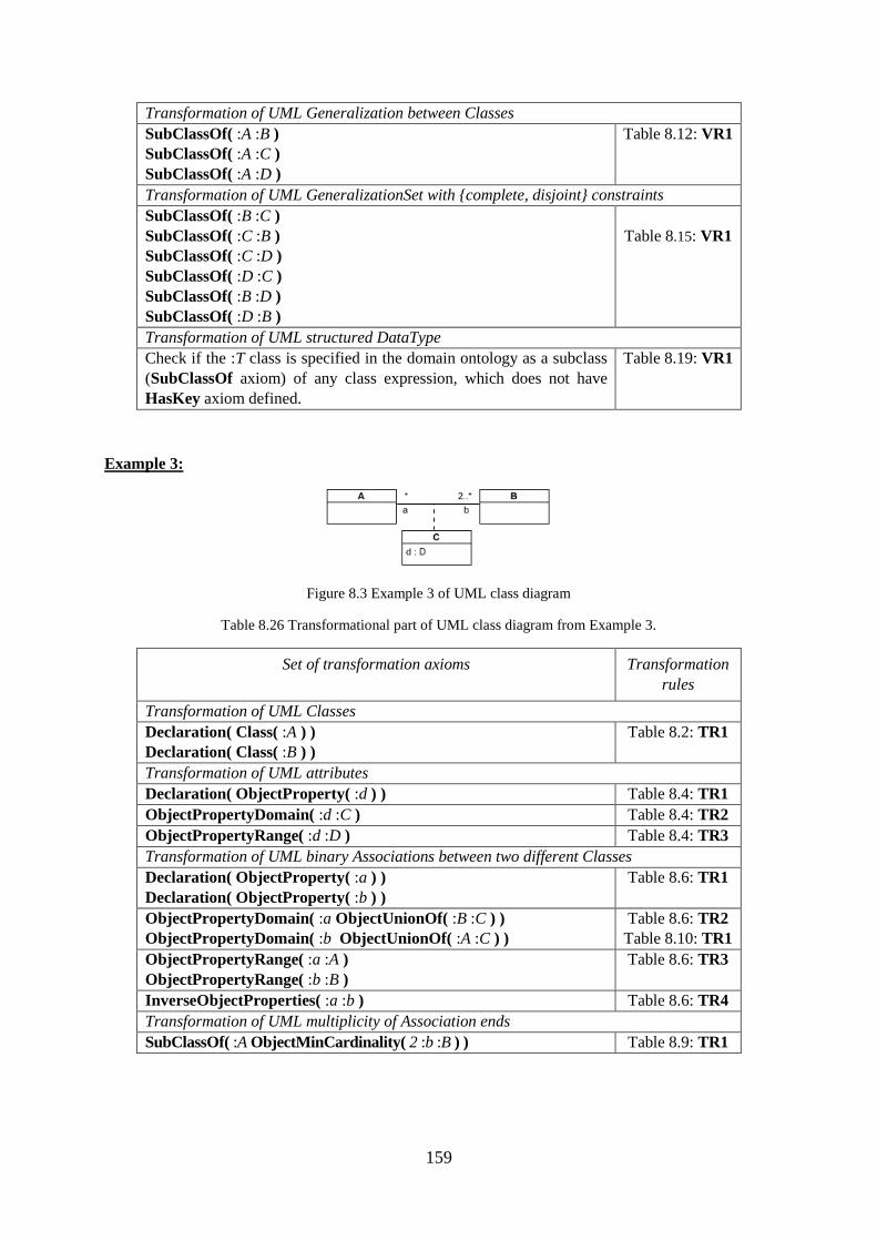
159
Transformation of UML Generalization between Classes
SubClassOf( :A :B )
SubClassOf( :A :C )
SubClassOf( :A :D )
Table 8.12: VR1
Transformation of UML GeneralizationSet with {complete, disjoint} constraints
SubClassOf( :B :C )
SubClassOf( :C :B )
SubClassOf( :C :D )
SubClassOf( :D :C )
SubClassOf( :B :D )
SubClassOf( :D :B )
Table 8.15: VR1
Transformation of UML structured DataType
Check if the :T class is specified in the domain ontology as a subclass
(SubClassOf axiom) of any class expression, which does not have
HasKey axiom defined.
Table 8.19: VR1
Example 3:
Figure 8.3 Example 3 of UML class diagram
Table 8.26 Transformational part of UML class diagram from Example 3.
Set of transformation axioms Transformation
rules
Transformation of UML Classes
Declaration( Class( :A ) )
Declaration( Class( :B ) )
Table 8.2: TR1
Transformation of UML attributes
Declaration( ObjectProperty( :d ) ) Table 8.4: TR1
ObjectPropertyDomain( :d :C ) Table 8.4: TR2
ObjectPropertyRange( :d :D ) Table 8.4: TR3
Transformation of UML binary Associations between two different Classes
Declaration( ObjectProperty( :a ) )
Declaration( ObjectProperty( :b ) )
Table 8.6: TR1
ObjectPropertyDomain( :a ObjectUnionOf( :B :C ) )
ObjectPropertyDomain( :b ObjectUnionOf( :A :C ) )
Table 8.6: TR2
Table 8.10: TR1
ObjectPropertyRange( :a :A )
ObjectPropertyRange( :b :B )
Table 8.6: TR3
InverseObjectProperties( :a :b ) Table 8.6: TR4
Transformation of UML multiplicity of Association ends
SubClassOf( :A ObjectMinCardinality( 2 :b :B ) ) Table 8.9: TR1
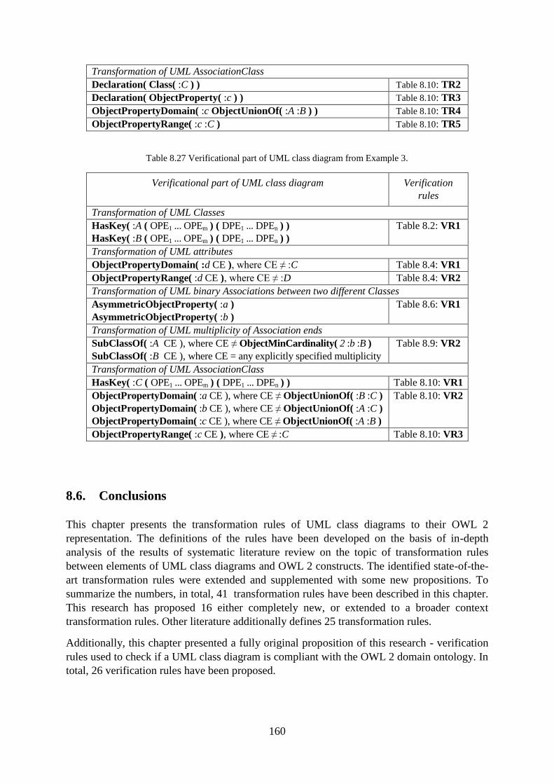
160
Transformation of UML AssociationClass
Declaration( Class( :C ) ) Table 8.10: TR2
Declaration( ObjectProperty( :c ) ) Table 8.10: TR3
ObjectPropertyDomain( :c ObjectUnionOf( :A :B ) ) Table 8.10: TR4
ObjectPropertyRange( :c :C ) Table 8.10: TR5
Table 8.27 Verificational part of UML class diagram from Example 3.
Verificational part of UML class diagram Verification
rules
Transformation of UML Classes
HasKey( :A ( OPE1 ... OPEm ) ( DPE1 ... DPEn ) )
HasKey( :B ( OPE1 ... OPEm ) ( DPE1 ... DPEn ) )
Table 8.2: VR1
Transformation of UML attributes
ObjectPropertyDomain( :d CE ), where CE ≠ :C Table 8.4: VR1
ObjectPropertyRange( :d CE ), where CE ≠ :D Table 8.4: VR2
Transformation of UML binary Associations between two different Classes
AsymmetricObjectProperty( :a )
AsymmetricObjectProperty( :b )
Table 8.6: VR1
Transformation of UML multiplicity of Association ends
SubClassOf( :A CE ), where CE ≠ ObjectMinCardinality( 2 :b :B )
SubClassOf( :B CE ), where CE = any explicitly specified multiplicity
Table 8.9: VR2
Transformation of UML AssociationClass
HasKey( :C ( OPE1 ... OPEm ) ( DPE1 ... DPEn ) ) Table 8.10: VR1
ObjectPropertyDomain( :a CE ), where CE ≠ ObjectUnionOf( :B :C )
ObjectPropertyDomain( :b CE ), where CE ≠ ObjectUnionOf( :A :C )
ObjectPropertyDomain( :c CE ), where CE ≠ ObjectUnionOf( :A :B )
Table 8.10: VR2
ObjectPropertyRange( :c CE ), where CE ≠ :C Table 8.10: VR3
8.6. Conclusions
This chapter presents the transformation rules of UML class diagrams to their OWL 2
representation. The definitions of the rules have been developed on the basis of in-depth
analysis of the results of systematic literature review on the topic of transformation rules
between elements of UML class diagrams and OWL 2 constructs. The identified state-of-the-
art transformation rules were extended and supplemented with some new propositions. To
summarize the numbers, in total, 41 transformation rules have been described in this chapter.
This research has proposed 16 either completely new, or extended to a broader context
transformation rules. Other literature additionally defines 25 transformation rules.
Additionally, this chapter presented a fully original proposition of this research - verification
rules used to check if a UML class diagram is compliant with the OWL 2 domain ontology. In
total, 26 verification rules have been proposed.

161
The transformation and verification rules are used for automatic verification of compliance of
UML class diagrams with respect to OWL 2 domain ontologies. All rules described in this
chapter have been implemented in a tool presented in Part IV.

162
Part IV
Tool Support
Part IV: Tool Support

163
164
9. Description of the Tool
Summary. This chapter presents the developed tool allowing for creating UML class
diagrams from selected OWL domain ontologies, and verifying if the diagrams are
compliant with the ontologies. The tool was implemented as a proof of concept of the
proposed method in order to demonstrate its usability. Additionally, the tool was aimed at
verifying that the proposed method has its practical application. 28
9.1. Introduction
The methods proposed in Chapter 5 and 6 have been implemented in the tool. The tool has
features for semi-automatic creation of UML class diagrams semantically compatible with
selected domain ontologies in OWL 2, and automatic verification of UML class diagrams
against domain ontologies expressed in OWL 2. Furthermore, on the basis of the result of
verification, the tool automatically generates ontology-based suggestions for corrections of
diagrams so it streamlines their validation.
For the best knowledge of the author, currently no other tool allows for automatic verification
of UML class diagrams with the use of domain ontologies expressed in OWL 2. The
developed tool is aimed to contribute to this field.
This chapter describes the architecture of the developed tool and summarizes its features. It
explains the installation procedure, the user interface, and initial tool functions, i.e. the
settings form and the normalization form. In addition, it presents the complementary tool
functions: possibility of calculating on-fly the OWL 2 representation of any designed UML
class diagram, and possibility to change the default port of client-server configuration. The
main tool features are described in the following Chapters 10 and 11.
All transformation and verification rules defined in Chapter 8 have been implemented in the
tool. Therefore, all defined rules are proved to be fully implementable.
The tool has been tested with a number of test cases aimed to determine whether it fully and
correctly implemented the normalization, transformation and verification rules. At least one test
case has been prepared for every normalization, transformation and verification rule.
Additionally, a number of test cases have been prepared to cover popular assemblies of UML
elements, e.g. an association from a class to itself, an association between two classes, two
associations between two classes, two associations between three classes, etc. Each rule has
been independently checked if it returns the expected result.
28 Chapter 9 contains the revised and extended fragments of the paper: "A prototype tool for semantic
validation of UML class diagrams with the use of domain ontologies expressed in OWL 2" [15]. The article [15]
presented the functionality of the prototype version of the tool while this chapter describes the current version of
the tool with a wider functionallity.
165
In total, the number of test cases was as follows (see Appendix A):
d) 80 test cases for ontology normalization rules,
e) 40 test cases for transformation rules and
f) 23 test cases for verification rules.
The tool passed all test cases.
9.2. Architecture of the Tool
The developed tool has been implemented in Java language and consists of two parts, the
server and the client, which communicate through a socket. The tool is designed for Windows
operating system.
The first part of the tool is the server which is a runnable JAR file. The server performs
operations on demand which are called by the client part. The implementation of the server
includes two external libraries: OWL API29
and HermiT OWL reasoner (see Section 3.5). The
OWL API is a Java API for creating and modifying OWL 2 ontologies. HermiT reasoner is
used to determine whether or not the modified OWL ontology is consistent in every iteration
of the verification algorithm.
The second part of the tool is the client which has been developed as a plugin to Visual
Paradigm for UML30
. The plugin has been developed and tested on Visual Paradigm
Community Edition in the version 14.1. With the use of the plugin the user can perform
operations on demand from the server.
9.3. A Summary of Features of the Server Part
The server part of the tool is aimed to perform the operations on the OWL 2 domain ontology,
selected by the modeller, and on the designed UML class diagram. The server has the following
features:
a) the possibility of normalizing any input OWL 2 domain ontology
(as explained in Chapter 7),
b) the possibility of normalizing the OWL 2 representation of UML class diagram
(conducted also in accordance with Chapter 7),
c) the possibility of comparing two sets of axioms: the normalized domain ontology and
the normalized OWL 2 representation of UML class diagram
(It is a necessary part of the verification feature, as explained in Chapter 5.
Additionally, the comparison is used for the purpose of generating some helpful hints of
which diagram elements are already extracted from the ontology to the diagram, while
29 The OWL API website: http://owlapi.sourceforge.net/.
30 The website of the producer of Visual Paradigm for UML: https://www.visual-paradigm.com/features/.
166
UML class diagrams are created with the use of the domain ontologies, as described in
Chapter 6),
d) the possibility of checking the consistency of the OWL domain ontology
(It is a necessary part of the verification feature, as explained in Chapter 5. Moreover,
the detected axioms that have caused inconsistency in the modified domain ontology
are used for the purpose of generating the suggested corrections in the diagram,
following Chapter 10.3),
e) the possibility of calculating the result of the verification of UML class diagram
(It is a crucial part of the proposed method, as explained in Chapter 5),
f) the possibility of generating the suggested corrections of UML class diagram on the
basis of the selected OWL 2 domain ontology
(If the UML class diagram appears to be not compliant, i.e. it is a not contradictory or
contradictory diagram, the feature is used for the purpose of generating the suggested
corrections in the diagram, as explained in Chapter 10.3).
9.4. A Summary of Features of the Client Part
The client part of the tool is aimed to process the designed UML class diagram, to pass the
data to the tool server and to display the results calculated by the server.
The plugin has the following two main features:
a) the possibility of conducting the verification of the designed UML class diagram on
the basis of the OWL 2 domain ontology selected by the user. The verification is
conducted on demand, at any stage of the diagram development, even if the diagram is
not yet complete (the option is presented in Chapter 10).
b) the possibility of creating UML class diagrams on the basis of the OWL 2 domain
ontology selected by the user (the option is presented in Chapter 11),
9.5. Installation
The developed tool is included on the CD enclosed to this dissertation.
Additionally, the tool is available online:
https://sourceforge.net/projects/uml-class-diagrams-validation/
The following is the installation procedure of the tool plugin to Visual Paradigm Community
Edition in the version 14.1:
1. Enter in "C:\Users\UserName\AppData\Roaming\VisualParadigm"
2. Create "plugins" folder (it does not exist by default)
Please note that some older versions of Visual Paradigm may have a different place
for setting the "plugins" folder.
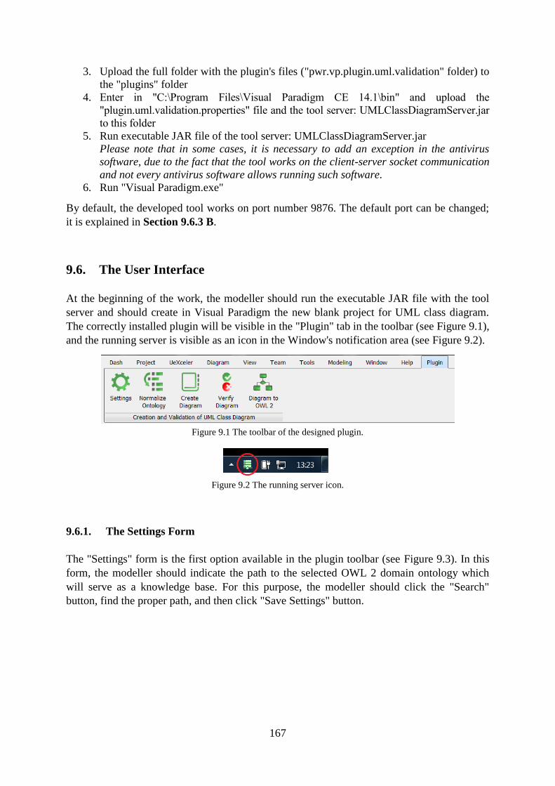
167
3. Upload the full folder with the plugin's files ("pwr.vp.plugin.uml.validation" folder) to
the "plugins" folder
4. Enter in "C:\Program Files\Visual Paradigm CE 14.1\bin" and upload the
"plugin.uml.validation.properties" file and the tool server: UMLClassDiagramServer.jar
to this folder
5. Run executable JAR file of the tool server: UMLClassDiagramServer.jar
Please note that in some cases, it is necessary to add an exception in the antivirus
software, due to the fact that the tool works on the client-server socket communication
and not every antivirus software allows running such software.
6. Run "Visual Paradigm.exe"
By default, the developed tool works on port number 9876. The default port can be changed;
it is explained in Section 9.6.3 B.
9.6. The User Interface
At the beginning of the work, the modeller should run the executable JAR file with the tool
server and should create in Visual Paradigm the new blank project for UML class diagram.
The correctly installed plugin will be visible in the "Plugin" tab in the toolbar (see Figure 9.1),
and the running server is visible as an icon in the Window's notification area (see Figure 9.2).
Figure 9.1 The toolbar of the designed plugin.
Figure 9.2 The running server icon.
9.6.1. The Settings Form
The "Settings" form is the first option available in the plugin toolbar (see Figure 9.3). In this
form, the modeller should indicate the path to the selected OWL 2 domain ontology which
will serve as a knowledge base. For this purpose, the modeller should click the "Search"
button, find the proper path, and then click "Save Settings" button.
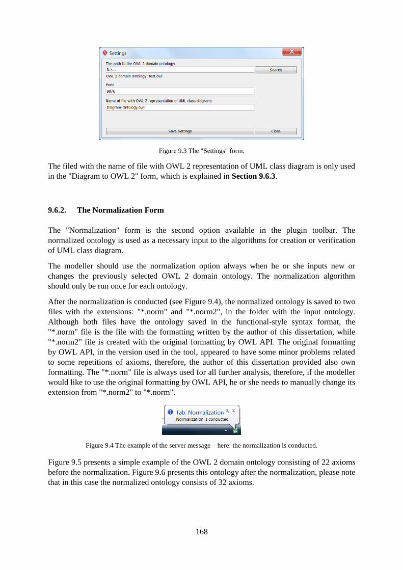
168
Figure 9.3 The "Settings" form.
The filed with the name of file with OWL 2 representation of UML class diagram is only used
in the "Diagram to OWL 2" form, which is explained in Section 9.6.3.
9.6.2. The Normalization Form
The "Normalization" form is the second option available in the plugin toolbar. The
normalized ontology is used as a necessary input to the algorithms for creation or verification
of UML class diagram.
The modeller should use the normalization option always when he or she inputs new or
changes the previously selected OWL 2 domain ontology. The normalization algorithm
should only be run once for each ontology.
After the normalization is conducted (see Figure 9.4), the normalized ontology is saved to two
files with the extensions: "*.norm" and "*.norm2", in the folder with the input ontology.
Although both files have the ontology saved in the functional-style syntax format, the
"*.norm" file is the file with the formatting written by the author of this dissertation, while
"*.norm2" file is created with the original formatting by OWL API. The original formatting
by OWL API, in the version used in the tool, appeared to have some minor problems related
to some repetitions of axioms, therefore, the author of this dissertation provided also own
formatting. The "*.norm" file is always used for all further analysis, therefore, if the modeller
would like to use the original formatting by OWL API, he or she needs to manually change its
extension from "*.norm2" to "*.norm".
Figure 9.4 The example of the server message – here: the normalization is conducted.
Figure 9.5 presents a simple example of the OWL 2 domain ontology consisting of 22 axioms
before the normalization. Figure 9.6 presents this ontology after the normalization, please note
that in this case the normalized ontology consists of 32 axioms.
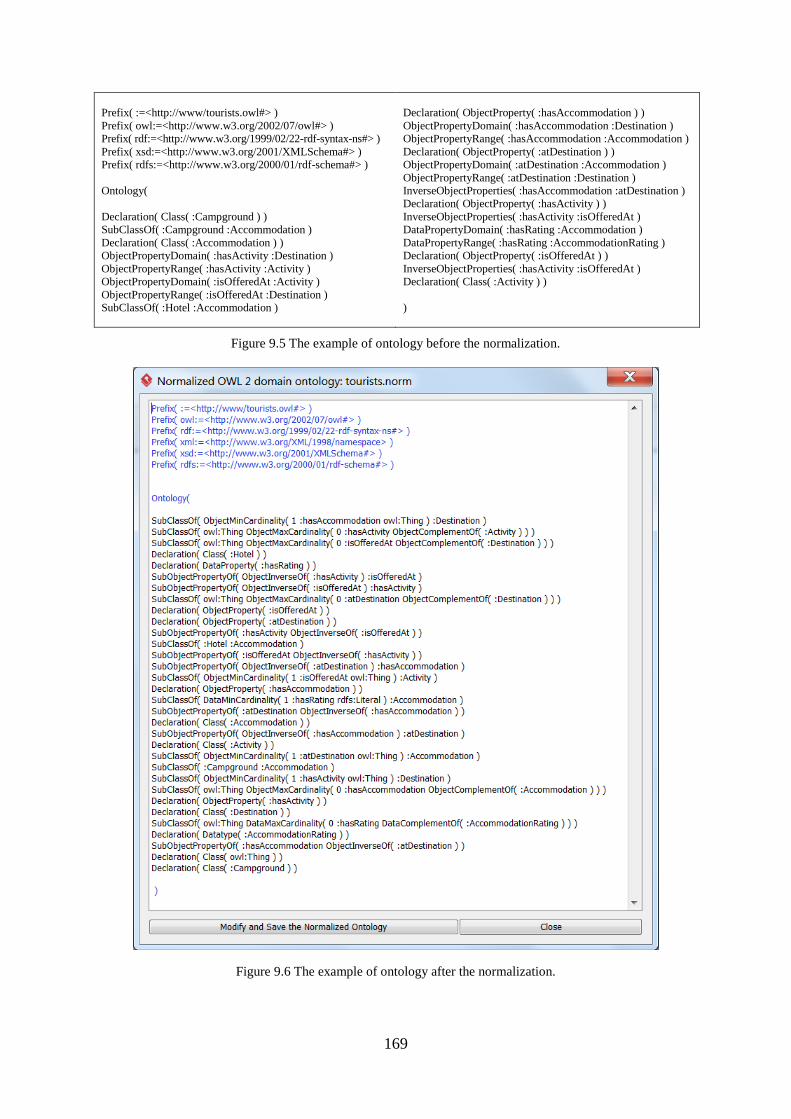
169
Prefix( :=<http://www/tourists.owl#> )
Prefix( owl:=<http://www.w3.org/2002/07/owl#> )
Prefix( rdf:=<http://www.w3.org/1999/02/22-rdf-syntax-ns#> )
Prefix( xsd:=<http://www.w3.org/2001/XMLSchema#> )
Prefix( rdfs:=<http://www.w3.org/2000/01/rdf-schema#> )
Ontology(
Declaration( Class( :Campground ) )
SubClassOf( :Campground :Accommodation )
Declaration( Class( :Accommodation ) )
ObjectPropertyDomain( :hasActivity :Destination )
ObjectPropertyRange( :hasActivity :Activity )
ObjectPropertyDomain( :isOfferedAt :Activity )
ObjectPropertyRange( :isOfferedAt :Destination )
SubClassOf( :Hotel :Accommodation )
Declaration( ObjectProperty( :hasAccommodation ) )
ObjectPropertyDomain( :hasAccommodation :Destination )
ObjectPropertyRange( :hasAccommodation :Accommodation )
Declaration( ObjectProperty( :atDestination ) )
ObjectPropertyDomain( :atDestination :Accommodation )
ObjectPropertyRange( :atDestination :Destination )
InverseObjectProperties( :hasAccommodation :atDestination )
Declaration( ObjectProperty( :hasActivity ) )
InverseObjectProperties( :hasActivity :isOfferedAt )
DataPropertyDomain( :hasRating :Accommodation )
DataPropertyRange( :hasRating :AccommodationRating )
Declaration( ObjectProperty( :isOfferedAt ) )
InverseObjectProperties( :hasActivity :isOfferedAt )
Declaration( Class( :Activity ) )
)
Figure 9.5 The example of ontology before the normalization.
Figure 9.6 The example of ontology after the normalization.
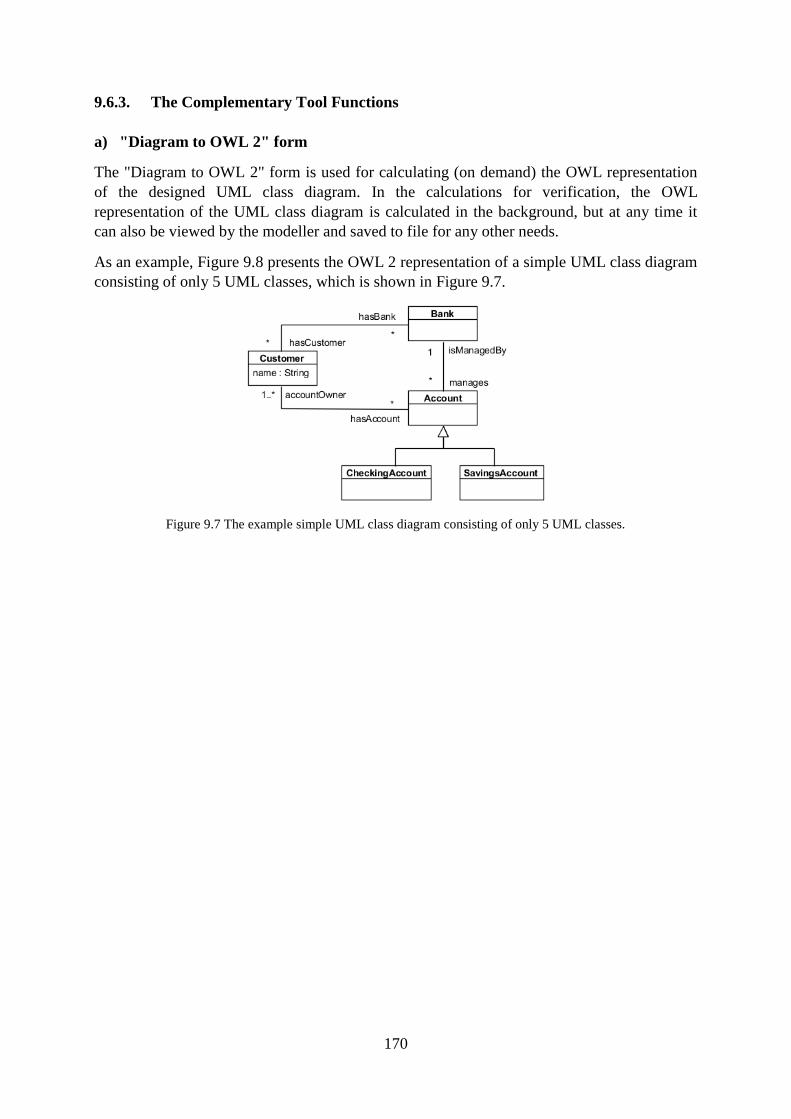
170
9.6.3. The Complementary Tool Functions
a) "Diagram to OWL 2" form
The "Diagram to OWL 2" form is used for calculating (on demand) the OWL representation
of the designed UML class diagram. In the calculations for verification, the OWL
representation of the UML class diagram is calculated in the background, but at any time it
can also be viewed by the modeller and saved to file for any other needs.
As an example, Figure 9.8 presents the OWL 2 representation of a simple UML class diagram
consisting of only 5 UML classes, which is shown in Figure 9.7.
Figure 9.7 The example simple UML class diagram consisting of only 5 UML classes.
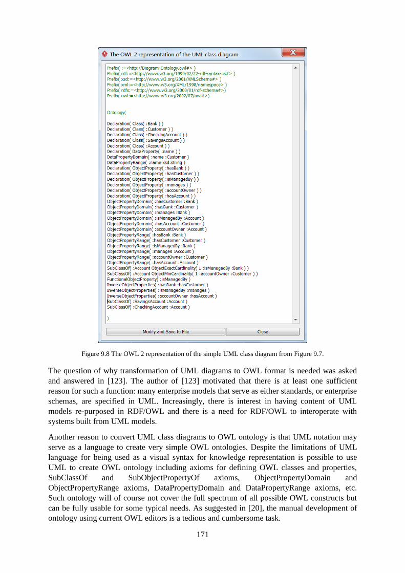
171
Figure 9.8 The OWL 2 representation of the simple UML class diagram from Figure 9.7.
The question of why transformation of UML diagrams to OWL format is needed was asked
and answered in [123]. The author of [123] motivated that there is at least one sufficient
reason for such a function: many enterprise models that serve as either standards, or enterprise
schemas, are specified in UML. Increasingly, there is interest in having content of UML
models re-purposed in RDF/OWL and there is a need for RDF/OWL to interoperate with
systems built from UML models.
Another reason to convert UML class diagrams to OWL ontology is that UML notation may
serve as a language to create very simple OWL ontologies. Despite the limitations of UML
language for being used as a visual syntax for knowledge representation is possible to use
UML to create OWL ontology including axioms for defining OWL classes and properties,
SubClassOf and SubObjectPropertyOf axioms, ObjectPropertyDomain and
ObjectPropertyRange axioms, DataPropertyDomain and DataPropertyRange axioms, etc.
Such ontology will of course not cover the full spectrum of all possible OWL constructs but
can be fully usable for some typical needs. As suggested in [20], the manual development of
ontology using current OWL editors is a tedious and cumbersome task.
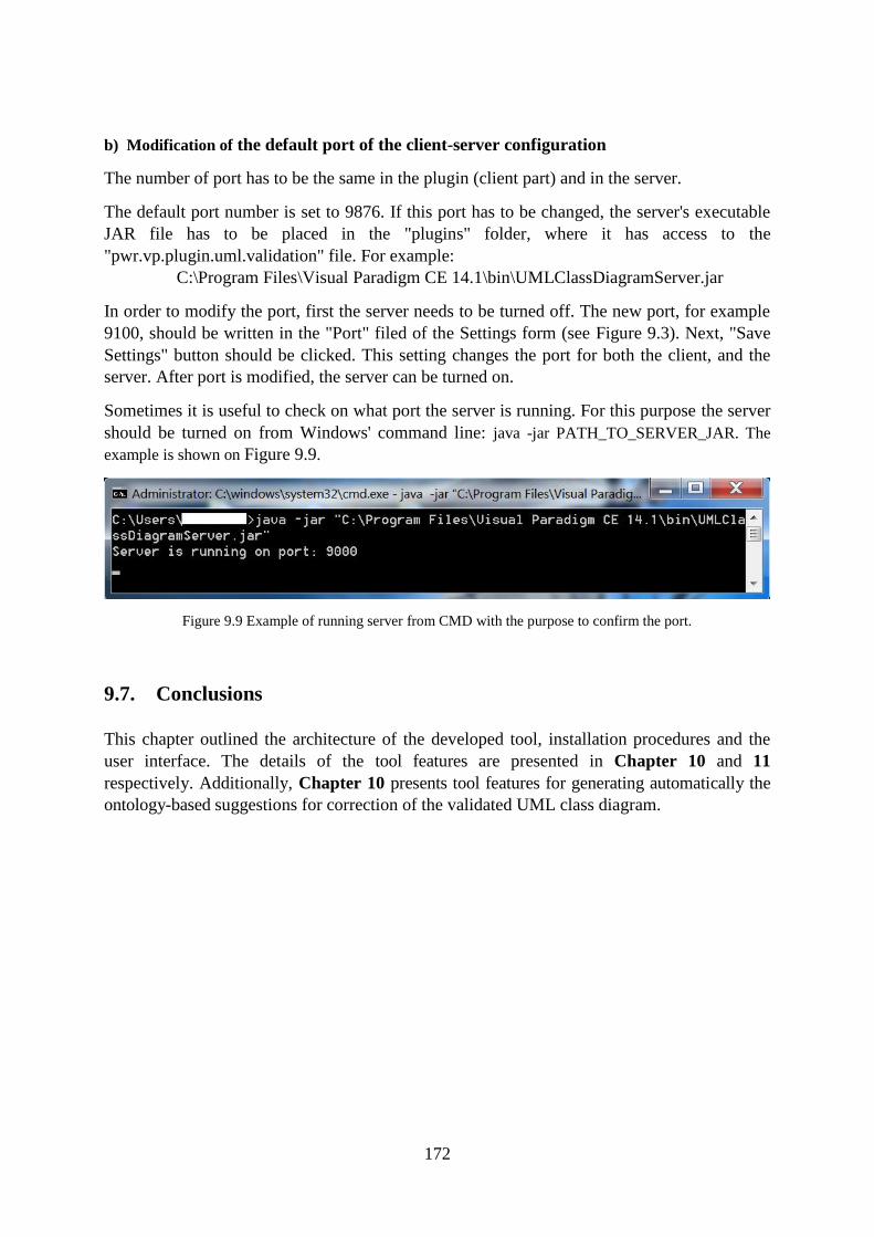
172
b) Modification of the default port of the client-server configuration
The number of port has to be the same in the plugin (client part) and in the server.
The default port number is set to 9876. If this port has to be changed, the server's executable
JAR file has to be placed in the "plugins" folder, where it has access to the
"pwr.vp.plugin.uml.validation" file. For example:
C:\Program Files\Visual Paradigm CE 14.1\bin\UMLClassDiagramServer.jar
In order to modify the port, first the server needs to be turned off. The new port, for example
9100, should be written in the "Port" filed of the Settings form (see Figure 9.3). Next, "Save
Settings" button should be clicked. This setting changes the port for both the client, and the
server. After port is modified, the server can be turned on.
Sometimes it is useful to check on what port the server is running. For this purpose the server
should be turned on from Windows' command line: java -jar PATH_TO_SERVER_JAR. The
example is shown on Figure 9.9.
Figure 9.9 Example of running server from CMD with the purpose to confirm the port.
9.7. Conclusions
This chapter outlined the architecture of the developed tool, installation procedures and the
user interface. The details of the tool features are presented in Chapter 10 and 11
respectively. Additionally, Chapter 10 presents tool features for generating automatically the
ontology-based suggestions for correction of the validated UML class diagram.
173
10. Tool Features for Verification of UML Class Diagrams
Summary. This chapter presents the tool features for an automatic verification of the
designed UML class diagram against the OWL domain ontology selected by the
modeller. On the basis of the result of verification, the tool automatically generates
ontology-based suggestions for making corrections of the diagram. The suggestions are
automatically reported to the modeller always after the verification is conducted with
the aim to help him make the necessary improvements on the diagram, and to
streamline the validation of the diagram. The use of the verification feature is illustrated
on an example. 31
10.1. Introduction
Sections 4.3 and 4.4 present selected existing approaches for verification and validation of
UML class diagrams with different purposes and scopes of possibilities. For the best
knowledge of the author, currently no tool allows for automatic verification of UML class
diagrams with the use of domain ontologies expressed in OWL 2. The developed tool is
aimed to contribute to this field.
In the proposed tool the choice of the UML class diagram which needs to be verified and the
OWL 2 domain ontology which serves as a knowledge base is made by the modeller.
For the purpose of verifying the UML class diagram, the tool analyses the elements of the
diagram, such as attributes of classes (with the multiplicity), associations (with the multiplicity
of the association ends), and generalizations between classes and between associations,
generalization sets, structured datatypes and enumerations. As a result of verification, the tool
automatically recognises if the diagram is compliant, not contradictory or contradictory to the
selected domain ontology. The result of the validation is communicated to the modeller.
Additionally, the tool presents a set of suggestions what and how should be corrected in the
UML class diagram.
10.2. Tool Features for Diagram Verification
The "Verify Diagram" form is the fourth option available in the plugin toolbar
(see Figure 9.1).
The result of verification is visible in the bottom of the form (see example in Section 10.4), and
can be stated as "compliant", "not contradictory", or "contradictory".
31 Chapter 10 contains the revised and extended fragments of the paper: "A prototype tool for semantic
validation of UML class diagrams with the use of domain ontologies expressed in OWL 2" [15]. The article [15]
presented the functionality of the prototype version of the tool while this chapter describes the current version of
the tool with a wider functionallity.
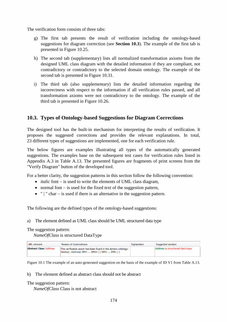
174
The verification form consists of three tabs:
g) The first tab presents the result of verification including the ontology-based
suggestions for diagram correction (see Section 10.3). The example of the first tab is
presented in Figure 10.25.
h) The second tab (supplementary) lists all normalized transformation axioms from the
designed UML class diagram with the detailed information if they are compliant, not
contradictory or contradictory to the selected domain ontology. The example of the
second tab is presented in Figure 10.31.
i) The third tab (also supplementary) lists the detailed information regarding the
incorrectness with respect to the information if all verification rules passed, and all
transformation axioms were not contradictory to the ontology. The example of the
third tab is presented in Figure 10.26.
10.3. Types of Ontology-based Suggestions for Diagram Corrections
The designed tool has the built-in mechanism for interpreting the results of verification. It
proposes the suggested corrections and provides the relevant explanations. In total,
23 different types of suggestions are implemented, one for each verification rule.
The below figures are examples illustrating all types of the automatically generated
suggestions. The examples base on the subsequent test cases for verification rules listed in
Appendix A.3 in Table A.13. The presented figures are fragments of print screens from the
"Verify Diagram" button of the developed tool.
For a better clarity, the suggestion patterns in this section follow the following convention:
italic font is used to write the elements of UML class diagram,
normal font is used for the fixed text of the suggestion pattern,
" | " char is used if there is an alternative in the suggestion pattern.
The following are the defined types of the ontology-based suggestions:
a) The element defined as UML class should be UML structured data type
The suggestion pattern:
NameOfClass is structured DataType
Figure 10.1 The example of an auto-generated suggestion on the basis of the example of ID V1 from Table A.13.
b) The element defined as abstract class should not be abstract
The suggestion pattern:
NameOfClass Class is not abstract
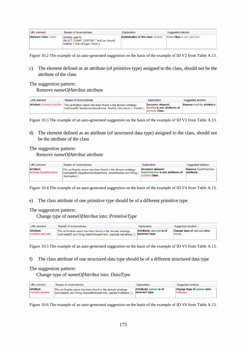
175
Figure 10.2 The example of an auto-generated suggestion on the basis of the example of ID V2 from Table A.13.
c) The element defined as an attribute (of primitive type) assigned to the class, should not be the
attribute of the class
The suggestion pattern:
Remove nameOfAttribut attribute
Figure 10.3 The example of an auto-generated suggestion on the basis of the example of ID V3 from Table A.13.
d) The element defined as an attribute (of structured data type) assigned to the class, should not
be the attribute of the class
The suggestion pattern:
Remove nameOfAttribut attribute
Figure 10.4 The example of an auto-generated suggestion on the basis of the example of ID V4 from Table A.13.
e) The class attribute of one primitive type should be of a different primitive type
The suggestion pattern:
Change type of nameOfAttribut into: PrimitiveType
Figure 10.5 The example of an auto-generated suggestion on the basis of the example of ID V5 from Table A.13.
f) The class attribute of one structured data type should be of a different structured data type
The suggestion pattern:
Change type of nameOfAttribut into: DataType
Figure 10.6 The example of an auto-generated suggestion on the basis of the example of ID V6 from Table A.13.
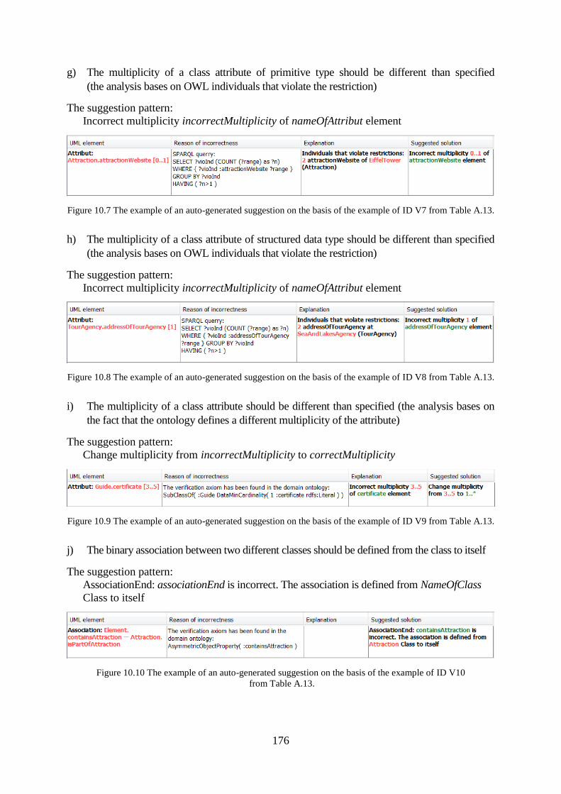
176
g) The multiplicity of a class attribute of primitive type should be different than specified
(the analysis bases on OWL individuals that violate the restriction)
The suggestion pattern:
Incorrect multiplicity incorrectMultiplicity of nameOfAttribut element
Figure 10.7 The example of an auto-generated suggestion on the basis of the example of ID V7 from Table A.13.
h) The multiplicity of a class attribute of structured data type should be different than specified
(the analysis bases on OWL individuals that violate the restriction)
The suggestion pattern:
Incorrect multiplicity incorrectMultiplicity of nameOfAttribut element
Figure 10.8 The example of an auto-generated suggestion on the basis of the example of ID V8 from Table A.13.
i) The multiplicity of a class attribute should be different than specified (the analysis bases on
the fact that the ontology defines a different multiplicity of the attribute)
The suggestion pattern:
Change multiplicity from incorrectMultiplicity to correctMultiplicity
Figure 10.9 The example of an auto-generated suggestion on the basis of the example of ID V9 from Table A.13.
j) The binary association between two different classes should be defined from the class to itself
The suggestion pattern:
AssociationEnd: associationEnd is incorrect. The association is defined from NameOfClass
Class to itself
Figure 10.10 The example of an auto-generated suggestion on the basis of the example of ID V10
from Table A.13.
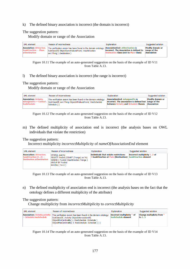
177
k) The defined binary association is incorrect (the domain is incorrect)
The suggestion pattern:
Modify domain or range of the Association
Figure 10.11 The example of an auto-generated suggestion on the basis of the example of ID V11
from Table A.13.
l) The defined binary association is incorrect (the range is incorrect)
The suggestion pattern:
Modify domain or range of the Association
Figure 10.12 The example of an auto-generated suggestion on the basis of the example of ID V12
from Table A.13.
m) The defined multiplicity of association end is incorrect (the analysis bases on OWL
individuals that violate the restriction)
The suggestion pattern:
Incorrect multiplicity incorrectMultiplicity of nameOfAssociationEnd element
Figure 10.13 The example of an auto-generated suggestion on the basis of the example of ID V13
from Table A.13.
n) The defined multiplicity of association end is incorrect (the analysis bases on the fact that the
ontology defines a different multiplicity of the attribute)
The suggestion pattern:
Change multiplicity from incorrectMultiplicity to correctMultiplicity
Figure 10.14 The example of an auto-generated suggestion on the basis of the example of ID V14
from Table A.13.
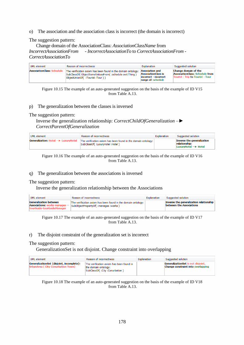
178
o) The association and the association class is incorrect (the domain is incorrect)
The suggestion pattern:
Change domain of the AssociationClass: AssociationClassName from
IncorrectAssociationFrom - IncorrectAssociationTo to CorrectAssociationFrom -
CorrectAssociationTo
Figure 10.15 The example of an auto-generated suggestion on the basis of the example of ID V15
from Table A.13.
p) The generalization between the classes is inversed
The suggestion pattern:
Inverse the generalization relationship: CorrectChildOfGeneralization ►
CorrectParentOfGeneralization
Figure 10.16 The example of an auto-generated suggestion on the basis of the example of ID V16
from Table A.13.
q) The generalization between the associations is inversed
The suggestion pattern:
Inverse the generalization relationship between the Associations
Figure 10.17 The example of an auto-generated suggestion on the basis of the example of ID V17
from Table A.13.
r) The disjoint constraint of the generalization set is incorrect
The suggestion pattern:
GeneralizationSet is not disjoint. Change constraint into overlapping
Figure 10.18 The example of an auto-generated suggestion on the basis of the example of ID V18
from Table A.13.
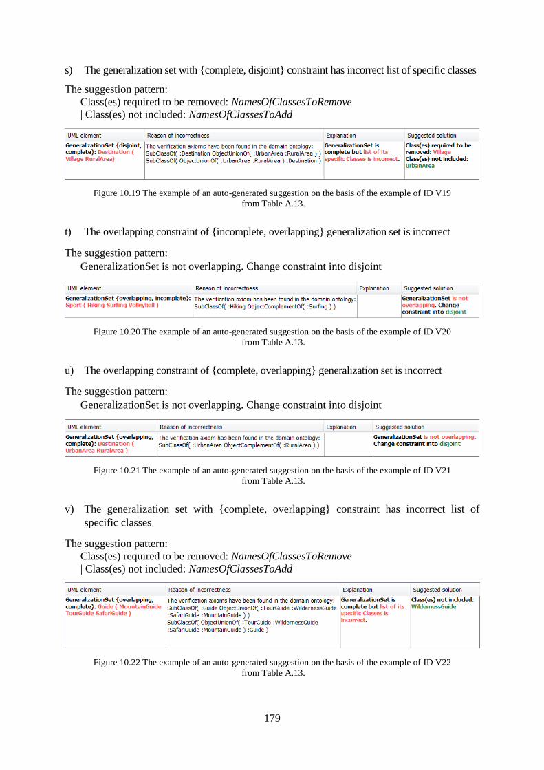
179
s) The generalization set with {complete, disjoint} constraint has incorrect list of specific classes
The suggestion pattern:
Class(es) required to be removed: NamesOfClassesToRemove
| Class(es) not included: NamesOfClassesToAdd
Figure 10.19 The example of an auto-generated suggestion on the basis of the example of ID V19
from Table A.13.
t) The overlapping constraint of {incomplete, overlapping} generalization set is incorrect
The suggestion pattern:
GeneralizationSet is not overlapping. Change constraint into disjoint
Figure 10.20 The example of an auto-generated suggestion on the basis of the example of ID V20
from Table A.13.
u) The overlapping constraint of {complete, overlapping} generalization set is incorrect
The suggestion pattern:
GeneralizationSet is not overlapping. Change constraint into disjoint
Figure 10.21 The example of an auto-generated suggestion on the basis of the example of ID V21
from Table A.13.
v) The generalization set with {complete, overlapping} constraint has incorrect list of
specific classes
The suggestion pattern:
Class(es) required to be removed: NamesOfClassesToRemove
| Class(es) not included: NamesOfClassesToAdd
Figure 10.22 The example of an auto-generated suggestion on the basis of the example of ID V22
from Table A.13.
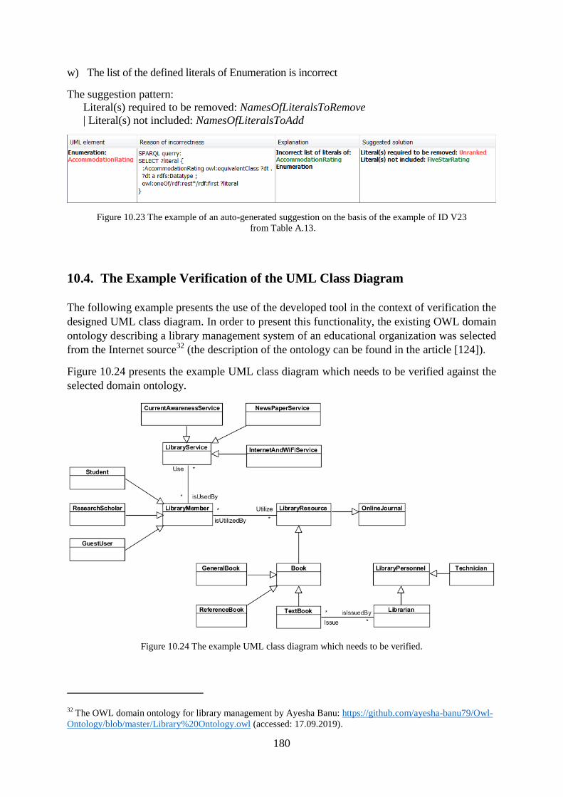
180
w) The list of the defined literals of Enumeration is incorrect
The suggestion pattern:
Literal(s) required to be removed: NamesOfLiteralsToRemove
| Literal(s) not included: NamesOfLiteralsToAdd
Figure 10.23 The example of an auto-generated suggestion on the basis of the example of ID V23
from Table A.13.
10.4. The Example Verification of the UML Class Diagram
The following example presents the use of the developed tool in the context of verification the
designed UML class diagram. In order to present this functionality, the existing OWL domain
ontology describing a library management system of an educational organization was selected
from the Internet source32
(the description of the ontology can be found in the article [124]).
Figure 10.24 presents the example UML class diagram which needs to be verified against the
selected domain ontology.
Figure 10.24 The example UML class diagram which needs to be verified.
32 The OWL domain ontology for library management by Ayesha Banu: https://github.com/ayesha-banu79/Owl-
Ontology/blob/master/Library%20Ontology.owl (accessed: 17.09.2019).
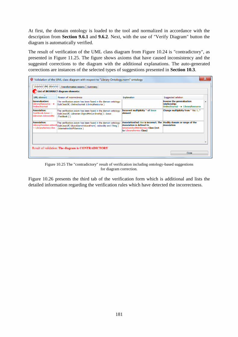
181
At first, the domain ontology is loaded to the tool and normalized in accordance with the
description from Section 9.6.1 and 9.6.2. Next, with the use of "Verify Diagram" button the
diagram is automatically verified.
The result of verification of the UML class diagram from Figure 10.24 is "contradictory", as
presented in Figure 11.25. The figure shows axioms that have caused inconsistency and the
suggested corrections to the diagram with the additional explanations. The auto-generated
corrections are instances of the selected types of suggestions presented in Section 10.3.
Figure 10.25 The "contradictory" result of verification including ontology-based suggestions
for diagram correction.
Figure 10.26 presents the third tab of the verification form which is additional and lists the
detailed information regarding the verification rules which have detected the incorrectness.
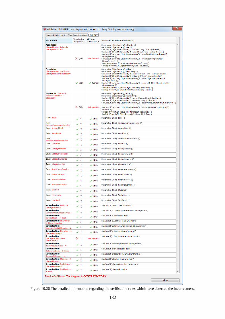
182
Figure 10.26 The detailed information regarding the verification rules which have detected the incorrectness.
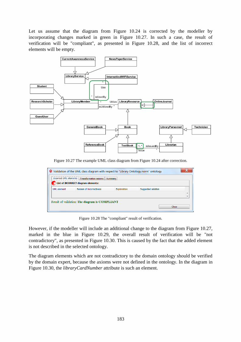
183
Let us assume that the diagram from Figure 10.24 is corrected by the modeller by
incorporating changes marked in green in Figure 10.27. In such a case, the result of
verification will be "compliant", as presented in Figure 10.28, and the list of incorrect
elements will be empty.
Figure 10.27 The example UML class diagram from Figure 10.24 after correction.
Figure 10.28 The "compliant" result of verification.
However, if the modeller will include an additional change to the diagram from Figure 10.27,
marked in the blue in Figure 10.29, the overall result of verification will be "not
contradictory", as presented in Figure 10.30. This is caused by the fact that the added element
is not described in the selected ontology.
The diagram elements which are not contradictory to the domain ontology should be verified
by the domain expert, because the axioms were not defined in the ontology. In the diagram in
Figure 10.30, the libraryCardNumber attribute is such an element.
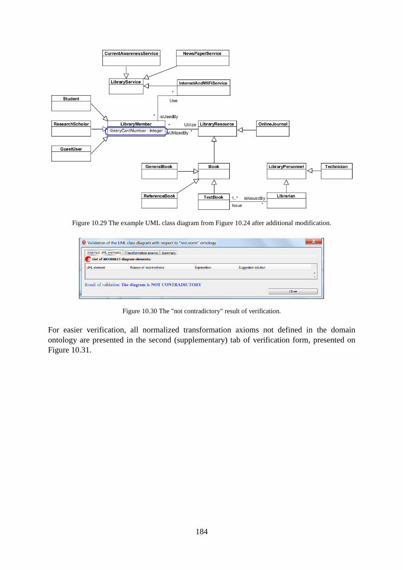
184
Figure 10.29 The example UML class diagram from Figure 10.24 after additional modification.
Figure 10.30 The "not contradictory" result of verification.
For easier verification, all normalized transformation axioms not defined in the domain
ontology are presented in the second (supplementary) tab of verification form, presented on
Figure 10.31.
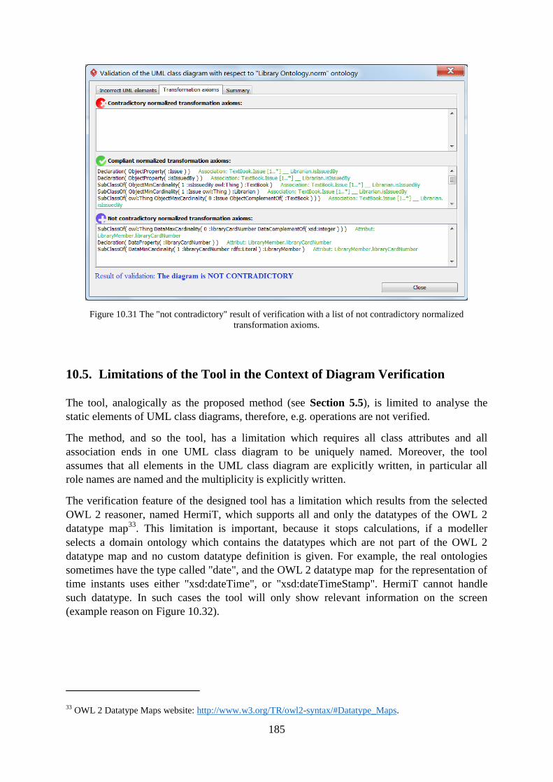
185
Figure 10.31 The "not contradictory" result of verification with a list of not contradictory normalized
transformation axioms.
10.5. Limitations of the Tool in the Context of Diagram Verification
The tool, analogically as the proposed method (see Section 5.5), is limited to analyse the
static elements of UML class diagrams, therefore, e.g. operations are not verified.
The method, and so the tool, has a limitation which requires all class attributes and all
association ends in one UML class diagram to be uniquely named. Moreover, the tool
assumes that all elements in the UML class diagram are explicitly written, in particular all
role names are named and the multiplicity is explicitly written.
The verification feature of the designed tool has a limitation which results from the selected
OWL 2 reasoner, named HermiT, which supports all and only the datatypes of the OWL 2
datatype map33
. This limitation is important, because it stops calculations, if a modeller
selects a domain ontology which contains the datatypes which are not part of the OWL 2
datatype map and no custom datatype definition is given. For example, the real ontologies
sometimes have the type called "date", and the OWL 2 datatype map for the representation of
time instants uses either "xsd:dateTime", or "xsd:dateTimeStamp". HermiT cannot handle
such datatype. In such cases the tool will only show relevant information on the screen
(example reason on Figure 10.32).
33 OWL 2 Datatype Maps website: http://www.w3.org/TR/owl2-syntax/#Datatype_Maps.
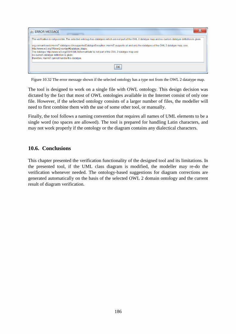
186
Figure 10.32 The error message shown if the selected ontology has a type not from the OWL 2 datatype map.
The tool is designed to work on a single file with OWL ontology. This design decision was
dictated by the fact that most of OWL ontologies available in the Internet consist of only one
file. However, if the selected ontology consists of a larger number of files, the modeller will
need to first combine them with the use of some other tool, or manually.
Finally, the tool follows a naming convention that requires all names of UML elements to be a
single word (no spaces are allowed). The tool is prepared for handling Latin characters, and
may not work properly if the ontology or the diagram contains any dialectical characters.
10.6. Conclusions
This chapter presented the verification functionality of the designed tool and its limitations. In
the presented tool, if the UML class diagram is modified, the modeller may re-do the
verification whenever needed. The ontology-based suggestions for diagram corrections are
generated automatically on the basis of the selected OWL 2 domain ontology and the current
result of diagram verification.

187
188
11. Tool Features for Creation of UML Class Diagrams
Summary. This chapter presents the tool features for a semi-automatic creation of the
UML class diagram on the basis of the OWL domain ontology selected by the modeller.
The use of the creation feature is illustrated on an example. 34
11.1. Introduction
This chapter presents tool features which support creation of UML class diagrams. The main
intention behind this functionality is to guarantee the semantic correctness of UML class
diagrams.
The developed tool in the context of diagram creation allows extracting the categories of
elements of UML class diagrams presented in Section 10.
The developed tool, analogically as other available tools, support visualization of (a selected
part of) OWL ontology in the form of UML class diagram. There are several related works in
this context. The visual modelling of OWL ontologies with UML has been proposed for
example in: [20], [46], [62], [125], [126]. The literature presents some tools designed with the
purpose of visualizing OWL ontologies. For example, OWL2UML35
is a Protégé plugin
which automatically generates UML diagram for an active OWL ontology with the use of
OMG's Ontology Definition Metamodel. The paper [126], describes tool called AToM3
which makes a transformation of selected elements of UML class diagrams to the OWL
representations based on graph transformation. ProtégéVOWL36
is a plugin for Protégé tool
for visualization of OWL ontologies based on Visual Notation for OWL Ontologies (VOWL)
[127]. OWLGrEd37
, wider described in [125], is a UML style graphical editor for OWL, in
which the UML class diagram notation is extend with Manchester-like syntax for the missing
OWL features. The UMLtoOWL tool38
converts extended Ontology UML Profile (OUP)
models in XML Metadata Interchange (XMI) format to OWL ontologies. There are also tools
for visualizing other ontology languages, e.g. the paper [128] proposes a tool for creating
UML class diagrams from SUMO ontology.
In comparison to other available tools, the proposed tool in the context of creation of UML
class diagram has the following functionalities:
34 Chapter 11 contains the revised and extended fragments of the paper: "A prototype tool for semantic
validation of UML class diagrams with the use of domain ontologies expressed in OWL 2" [15]. The article [15]
presented the functionality of the prototype version of the tool while this chapter describes the current version of
the tool with a wider functionallity. 35
OWL2UML tool website: http://apps.lumii.lv/owl2uml/. 36
ProtégéVOWL tool website: http://vowl.visualdataweb.org/protegevowl.html.
37 OWLGrEd tool website: http://OWLGrEd.lumii.lv.
38 UMLtoOWL tool website: http://www.sfu.ca/~dgasevic/projects/UMLtoOWL/.
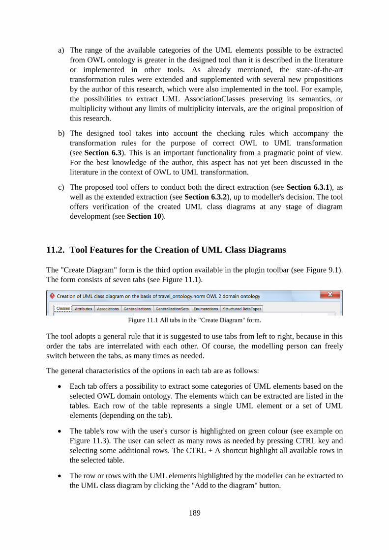
189
a) The range of the available categories of the UML elements possible to be extracted
from OWL ontology is greater in the designed tool than it is described in the literature
or implemented in other tools. As already mentioned, the state-of-the-art
transformation rules were extended and supplemented with several new propositions
by the author of this research, which were also implemented in the tool. For example,
the possibilities to extract UML AssociationClasses preserving its semantics, or
multiplicity without any limits of multiplicity intervals, are the original proposition of
this research.
b) The designed tool takes into account the checking rules which accompany the
transformation rules for the purpose of correct OWL to UML transformation
(see Section 6.3). This is an important functionality from a pragmatic point of view.
For the best knowledge of the author, this aspect has not yet been discussed in the
literature in the context of OWL to UML transformation.
c) The proposed tool offers to conduct both the direct extraction (see Section 6.3.1), as
well as the extended extraction (see Section 6.3.2), up to modeller's decision. The tool
offers verification of the created UML class diagrams at any stage of diagram
development (see Section 10).
11.2. Tool Features for the Creation of UML Class Diagrams
The "Create Diagram" form is the third option available in the plugin toolbar (see Figure 9.1).
The form consists of seven tabs (see Figure 11.1).
Figure 11.1 All tabs in the "Create Diagram" form.
The tool adopts a general rule that it is suggested to use tabs from left to right, because in this
order the tabs are interrelated with each other. Of course, the modelling person can freely
switch between the tabs, as many times as needed.
The general characteristics of the options in each tab are as follows:
Each tab offers a possibility to extract some categories of UML elements based on the
selected OWL domain ontology. The elements which can be extracted are listed in the
tables. Each row of the table represents a single UML element or a set of UML
elements (depending on the tab).
The table's row with the user's cursor is highlighted on green colour (see example on
Figure 11.3). The user can select as many rows as needed by pressing CTRL key and
selecting some additional rows. The CTRL + A shortcut highlight all available rows in
the selected table.
The row or rows with the UML elements highlighted by the modeller can be extracted to
the UML class diagram by clicking the "Add to the diagram" button.
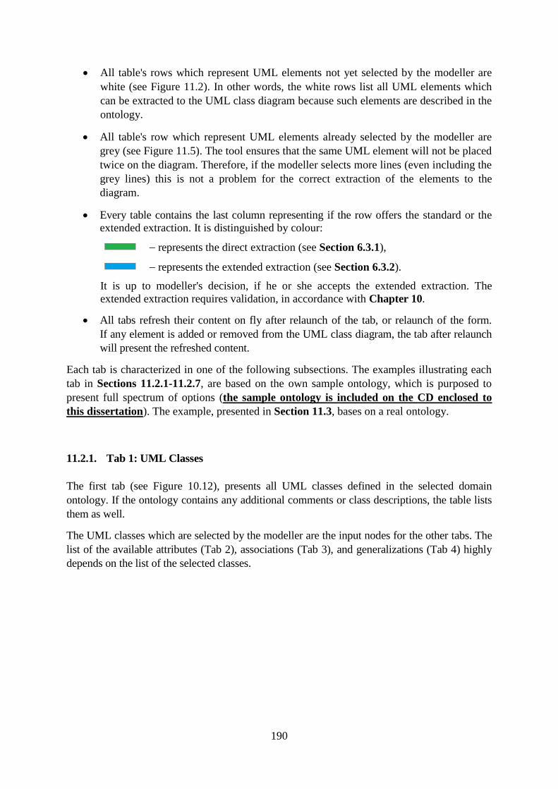
190
All table's rows which represent UML elements not yet selected by the modeller are
white (see Figure 11.2). In other words, the white rows list all UML elements which
can be extracted to the UML class diagram because such elements are described in the
ontology.
All table's row which represent UML elements already selected by the modeller are
grey (see Figure 11.5). The tool ensures that the same UML element will not be placed
twice on the diagram. Therefore, if the modeller selects more lines (even including the
grey lines) this is not a problem for the correct extraction of the elements to the
diagram.
Every table contains the last column representing if the row offers the standard or the
extended extraction. It is distinguished by colour:
represents the direct extraction (see Section 6.3.1),
represents the extended extraction (see Section 6.3.2).
It is up to modeller's decision, if he or she accepts the extended extraction. The
extended extraction requires validation, in accordance with Chapter 10.
All tabs refresh their content on fly after relaunch of the tab, or relaunch of the form.
If any element is added or removed from the UML class diagram, the tab after relaunch
will present the refreshed content.
Each tab is characterized in one of the following subsections. The examples illustrating each
tab in Sections 11.2.1-11.2.7, are based on the own sample ontology, which is purposed to
present full spectrum of options (the sample ontology is included on the CD enclosed to
this dissertation). The example, presented in Section 11.3, bases on a real ontology.
11.2.1. Tab 1: UML Classes
The first tab (see Figure 10.12), presents all UML classes defined in the selected domain
ontology. If the ontology contains any additional comments or class descriptions, the table lists
them as well.
The UML classes which are selected by the modeller are the input nodes for the other tabs. The
list of the available attributes (Tab 2), associations (Tab 3), and generalizations (Tab 4) highly
depends on the list of the selected classes.
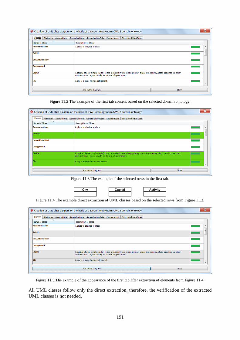
191
Figure 11.2 The example of the first tab content based on the selected domain ontology.
Figure 11.3 The example of the selected rows in the first tab.
Figure 11.4 The example direct extraction of UML classes based on the selected rows from Figure 11.3.
Figure 11.5 The example of the appearance of the first tab after extraction of elements from Figure 11.4.
All UML classes follow only the direct extraction, therefore, the verification of the extracted
UML classes is not needed.
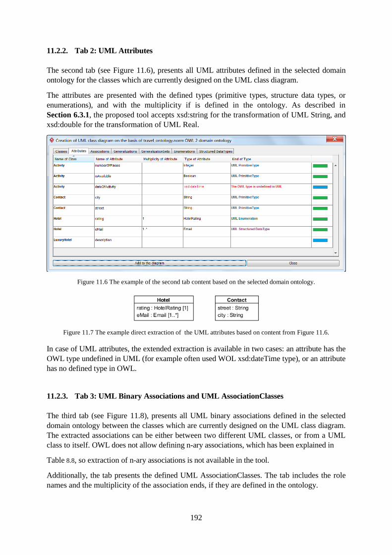
192
11.2.2. Tab 2: UML Attributes
The second tab (see Figure 11.6), presents all UML attributes defined in the selected domain
ontology for the classes which are currently designed on the UML class diagram.
The attributes are presented with the defined types (primitive types, structure data types, or
enumerations), and with the multiplicity if is defined in the ontology. As described in
Section 6.3.1, the proposed tool accepts xsd:string for the transformation of UML String, and
xsd:double for the transformation of UML Real.
Figure 11.6 The example of the second tab content based on the selected domain ontology.
Figure 11.7 The example direct extraction of the UML attributes based on content from Figure 11.6.
In case of UML attributes, the extended extraction is available in two cases: an attribute has the
OWL type undefined in UML (for example often used WOL xsd:dateTime type), or an attribute
has no defined type in OWL.
11.2.3. Tab 3: UML Binary Associations and UML AssociationClasses
The third tab (see Figure 11.8), presents all UML binary associations defined in the selected
domain ontology between the classes which are currently designed on the UML class diagram.
The extracted associations can be either between two different UML classes, or from a UML
class to itself. OWL does not allow defining n-ary associations, which has been explained in
Table 8.8, so extraction of n-ary associations is not available in the tool.
Additionally, the tab presents the defined UML AssociationClasses. The tab includes the role
names and the multiplicity of the association ends, if they are defined in the ontology.
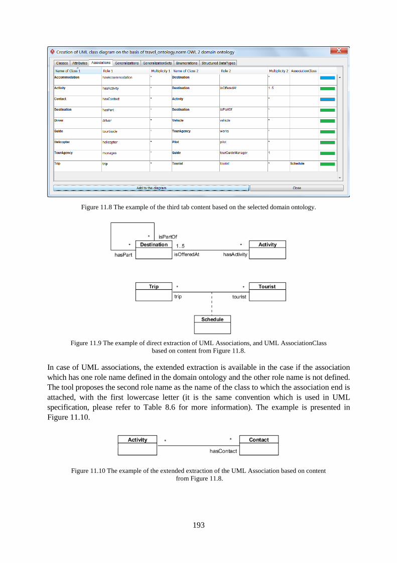
193
Figure 11.8 The example of the third tab content based on the selected domain ontology.
Figure 11.9 The example of direct extraction of UML Associations, and UML AssociationClass
based on content from Figure 11.8.
In case of UML associations, the extended extraction is available in the case if the association
which has one role name defined in the domain ontology and the other role name is not defined.
The tool proposes the second role name as the name of the class to which the association end is
attached, with the first lowercase letter (it is the same convention which is used in UML
specification, please refer to Table 8.6 for more information). The example is presented in
Figure 11.10.
Figure 11.10 The example of the extended extraction of the UML Association based on content
from Figure 11.8.
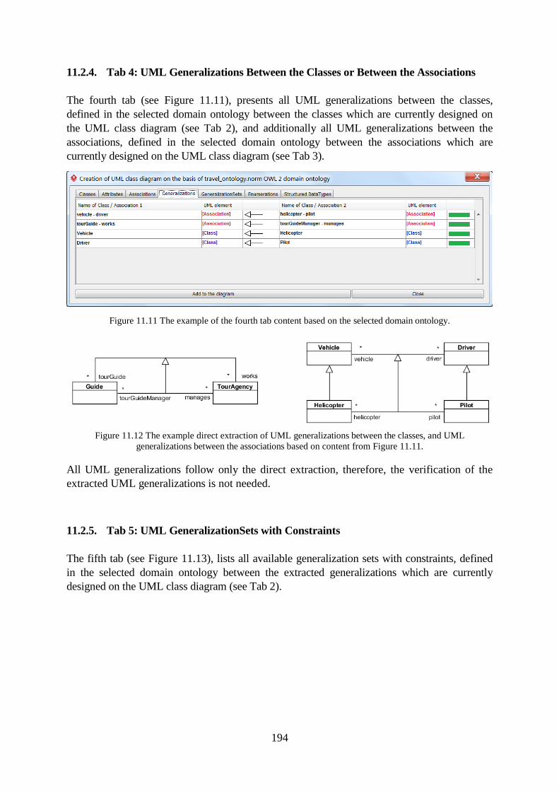
194
11.2.4. Tab 4: UML Generalizations Between the Classes or Between the Associations
The fourth tab (see Figure 11.11), presents all UML generalizations between the classes,
defined in the selected domain ontology between the classes which are currently designed on
the UML class diagram (see Tab 2), and additionally all UML generalizations between the
associations, defined in the selected domain ontology between the associations which are
currently designed on the UML class diagram (see Tab 3).
Figure 11.11 The example of the fourth tab content based on the selected domain ontology.
Figure 11.12 The example direct extraction of UML generalizations between the classes, and UML
generalizations between the associations based on content from Figure 11.11.
All UML generalizations follow only the direct extraction, therefore, the verification of the
extracted UML generalizations is not needed.
11.2.5. Tab 5: UML GeneralizationSets with Constraints
The fifth tab (see Figure 11.13), lists all available generalization sets with constraints, defined
in the selected domain ontology between the extracted generalizations which are currently
designed on the UML class diagram (see Tab 2).
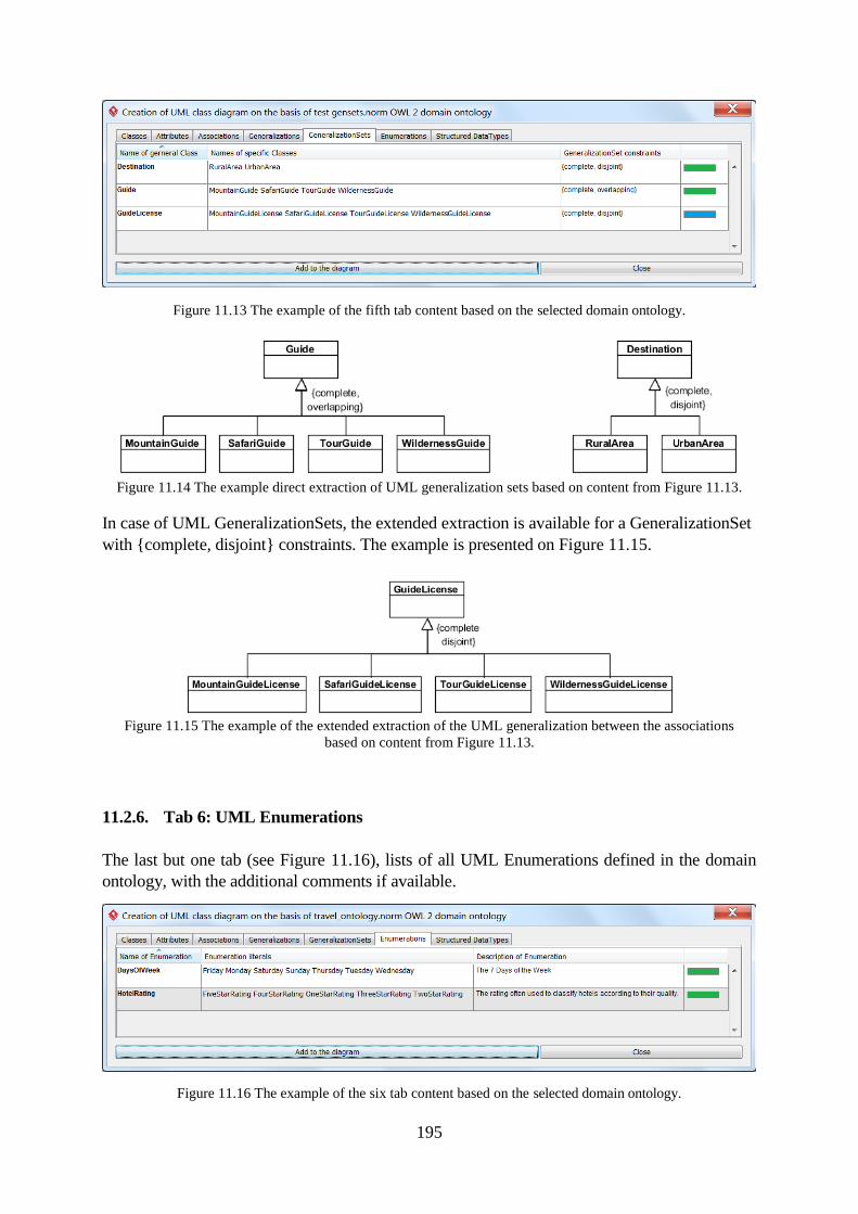
195
Figure 11.13 The example of the fifth tab content based on the selected domain ontology.
Figure 11.14 The example direct extraction of UML generalization sets based on content from Figure 11.13.
In case of UML GeneralizationSets, the extended extraction is available for a GeneralizationSet
with {complete, disjoint} constraints. The example is presented on Figure 11.15.
Figure 11.15 The example of the extended extraction of the UML generalization between the associations
based on content from Figure 11.13.
11.2.6. Tab 6: UML Enumerations
The last but one tab (see Figure 11.16), lists of all UML Enumerations defined in the domain
ontology, with the additional comments if available.
Figure 11.16 The example of the six tab content based on the selected domain ontology.
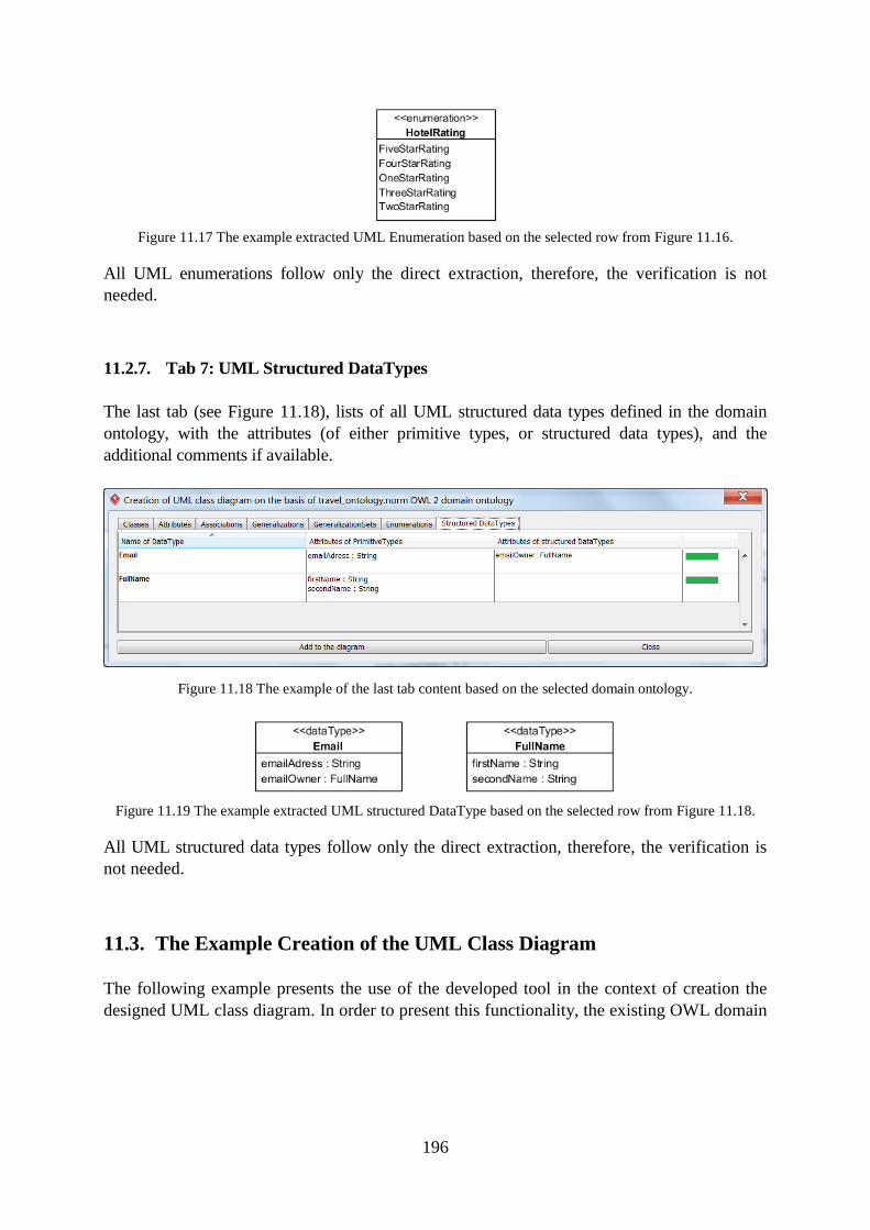
196
Figure 11.17 The example extracted UML Enumeration based on the selected row from Figure 11.16.
All UML enumerations follow only the direct extraction, therefore, the verification is not
needed.
11.2.7. Tab 7: UML Structured DataTypes
The last tab (see Figure 11.18), lists of all UML structured data types defined in the domain
ontology, with the attributes (of either primitive types, or structured data types), and the
additional comments if available.
Figure 11.18 The example of the last tab content based on the selected domain ontology.
Figure 11.19 The example extracted UML structured DataType based on the selected row from Figure 11.18.
All UML structured data types follow only the direct extraction, therefore, the verification is
not needed.
11.3. The Example Creation of the UML Class Diagram
The following example presents the use of the developed tool in the context of creation the
designed UML class diagram. In order to present this functionality, the existing OWL domain
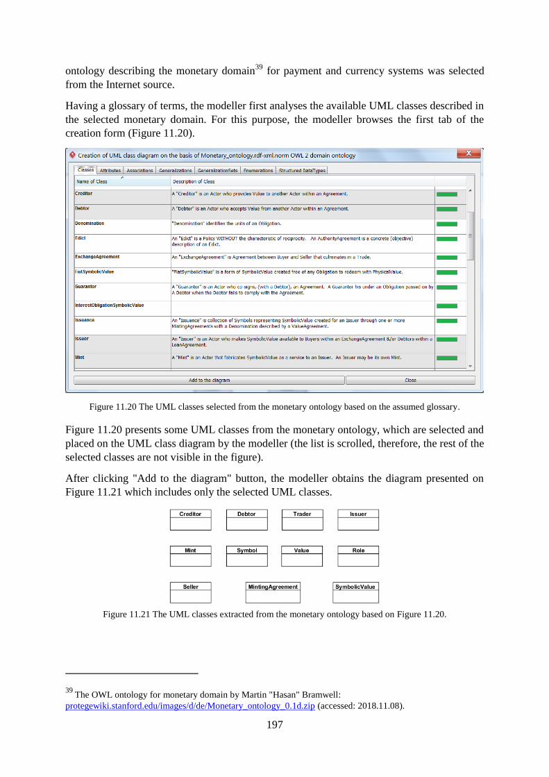
197
ontology describing the monetary domain39
for payment and currency systems was selected
from the Internet source.
Having a glossary of terms, the modeller first analyses the available UML classes described in
the selected monetary domain. For this purpose, the modeller browses the first tab of the
creation form (Figure 11.20).
Figure 11.20 The UML classes selected from the monetary ontology based on the assumed glossary.
Figure 11.20 presents some UML classes from the monetary ontology, which are selected and
placed on the UML class diagram by the modeller (the list is scrolled, therefore, the rest of the
selected classes are not visible in the figure).
After clicking "Add to the diagram" button, the modeller obtains the diagram presented on
Figure 11.21 which includes only the selected UML classes.
Figure 11.21 The UML classes extracted from the monetary ontology based on Figure 11.20.
39 The OWL ontology for monetary domain by Martin "Hasan" Bramwell:
protegewiki.stanford.edu/images/d/de/Monetary_ontology_0.1d.zip (accessed: 2018.11.08).
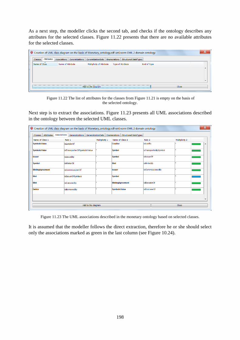
198
As a next step, the modeller clicks the second tab, and checks if the ontology describes any
attributes for the selected classes. Figure 11.22 presents that there are no available attributes
for the selected classes.
Figure 11.22 The list of attributes for the classes from Figure 11.21 is empty on the basis of
the selected ontology.
Next step is to extract the associations. Figure 11.23 presents all UML associations described
in the ontology between the selected UML classes.
Figure 11.23 The UML associations described in the monetary ontology based on selected classes.
It is assumed that the modeller follows the direct extraction, therefore he or she should select
only the associations marked as green in the last column (see Figure 10.24).
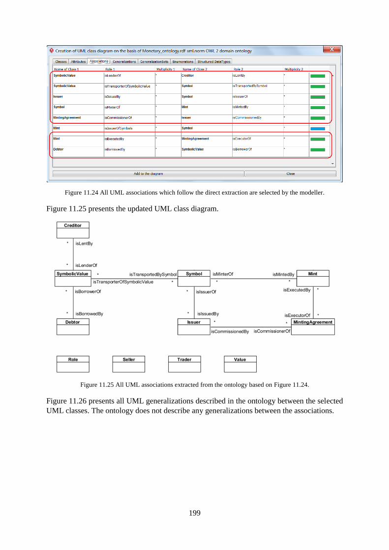
199
Figure 11.24 All UML associations which follow the direct extraction are selected by the modeller.
Figure 11.25 presents the updated UML class diagram.
Figure 11.25 All UML associations extracted from the ontology based on Figure 11.24.
Figure 11.26 presents all UML generalizations described in the ontology between the selected
UML classes. The ontology does not describe any generalizations between the associations.
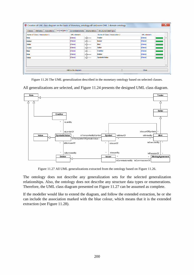
200
Figure 11.26 The UML generalization described in the monetary ontology based on selected classes.
All generalizations are selected, and Figure 11.24 presents the designed UML class diagram.
Figure 11.27 All UML generalizations extracted from the ontology based on Figure 11.26.
The ontology does not describe any generalization sets for the selected generalization
relationships. Also, the ontology does not describe any structure data types or enumerations.
Therefore, the UML class diagram presented on Figure 11.27 can be assumed as complete.
If the modeller would like to extend the diagram, and follow the extended extraction, he or she
can include the association marked with the blue colour, which means that it is the extended
extraction (see Figure 11.28).
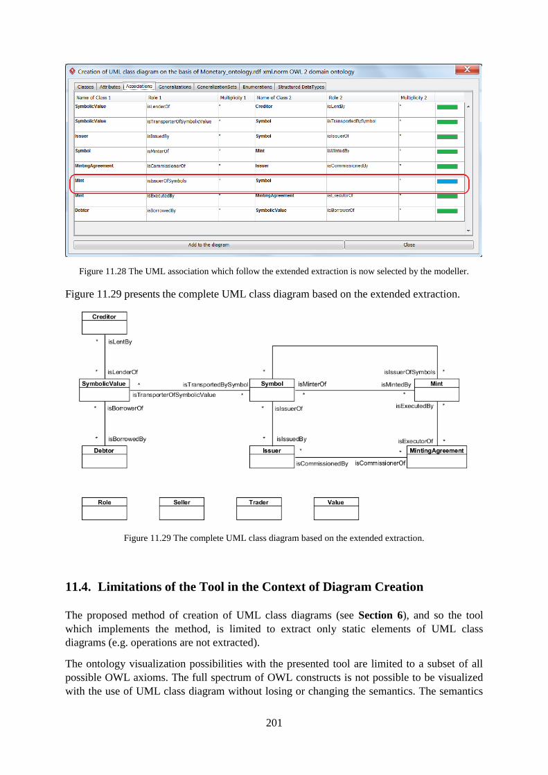
201
Figure 11.28 The UML association which follow the extended extraction is now selected by the modeller.
Figure 11.29 presents the complete UML class diagram based on the extended extraction.
Figure 11.29 The complete UML class diagram based on the extended extraction.
11.4. Limitations of the Tool in the Context of Diagram Creation
The proposed method of creation of UML class diagrams (see Section 6), and so the tool
which implements the method, is limited to extract only static elements of UML class
diagrams (e.g. operations are not extracted).
The ontology visualization possibilities with the presented tool are limited to a subset of all
possible OWL axioms. The full spectrum of OWL constructs is not possible to be visualized
with the use of UML class diagram without losing or changing the semantics. The semantics
202
of UML and OWL notations differ one from another (some examples are presented in
Section 3.9). Therefore, if the modeller's purpose is to visualize all types of constructs from
OWL ontology, it is worth not to use UML but other language dedicated for this purpose, for
example the previously mentioned VOWL. However, if the goal is to create the correct UML
class diagram for the software development purposes, the proposed tool will be a preferable
solution.
The tool is designed to work on a single file with OWL ontology. This design decision was
dictated by the fact that most of OWL ontologies available in the Internet consist of only one
file. However, if the selected ontology consists of a larger number of files, the modeller will
need to first combine them with the use of some other tool, or manually.
The tool is prepared for handling Latin characters, and may not work properly if the ontology
contains any dialectical characters.
11.5. Conclusions
This chapter presented the functionalities of the designed tool for creation of UML class
diagrams on the basis of OWL ontologies. The tool offers to conduct both the direct
extraction, and the extended extraction, depending on the needs of the modeller. The
functionality allows extracting all important categories of elements of UML class diagrams
from OWL domain ontologies (see Section 8.3).
The creating form allows the modeller to browse what is already drawn on the UML class
diagram, and what elements are not yet included in the diagram but worth considering. Based
on the specific requirements, the additional elements may be incorporated in the diagram.
Depending on the context, sometimes it might be useful not to present unnecessary details in
the UML class diagram. Some UML elements such as attributes or associations are sometimes
purposely omitted from the diagram, because the modeller may not want to present some
unneeded details.

203

204
Part V
Empirical Evaluation
Part V: Empirical Evaluation

205
206
12. Description of the Experiment
Summary. This chapter describes the definition, the design, as well as the conduction of
the experiment aimed to empirically evaluate the developed tool.
12.1. Introduction
The designed experiment aimed to answer the following research question:
Is the developed tool for creation and validation of UML class diagrams useful for
modellers?
The purpose of the experiment was to check the practical usefulness of the developed tool for
modellers who are not domain experts. The goal of the experiment was defined in accordance
with the goal template [110]:
Analyse the created and validated UML class diagrams
for the purpose of evaluation of the practical usefulness of the developed tool
with respect to correctness of created or validated UML class diagrams
from the point of view of the researcher
in the context of Bachelor's and Master's students involved in creating and validating
UML class diagrams with and without the use of the developed tool.
12.2. Subjects
The subjects of the experiment were students who study computer science and took courses in
UML modelling for software engineering. The minimum assumption of the experiment was
that its participants had knowledge of UML notation at least in the context of drawing and
reading of UML class diagrams. The second assumption was that participants of experiment
must know how to use Visual Paradigm for UML. Students were not expected to have any
knowledge of ontologies.
In fact, four groups of students from Wrocław University of Science and Technology took
part in the experiment: two groups of software engineering students of bachelor's studies (31
students) and two of master's studies (26 students). In total, 57 students took part in the
experiment. Each group had already had at least two courses on modelling with the use of
UML notation and during the courses had some practice on Visual Paradigm for UML.
207
12.3. Objects
The objects of the study were UML class diagrams. During the experiment, the diagrams were
created and validated by subjects with and without the use of the developed tool (the tasks are
described in section 12.7).
Due to the short time frame assumed for the experiment (for more details please refer to
section 12.8.3), the UML class diagrams were of limited size. More precisely:
the UML class diagrams that students were asked to create, consisted of 4-7 UML
classes,
the UML class diagrams that students were asked to validate, consisted of 7-11 UML
classes.
Each diagram in the task for validation had 5-6 semantic errors, intentionally made by the
experimenter, which students were supposed to mark and correct.
The difficulty level of the diagrams had been balanced. The diagrams with a fewer number of
classes had more connections between them (associations, generalizations), or more complex
internal structure (more attributes). In this way, the complexity of the diagrams was similar in
all tasks for creation, and accordingly, for validation.
12.4. Domain Ontologies
The developed tool uses given OWL 2 domain ontologies as a knowledge base. The tool
automatically processes the input domain ontology and allows the modeller to extract the
needed elements of a UML class diagram directly from the ontology, or to validate the whole
diagram with respect to the selected ontology.
The OWL domain ontologies selected for the purpose of the experiment were rather complex
and intentionally were not related to software engineering, computer science or common
knowledge in order to minimize the risk of knowing the relationships within the domains by
IT students. The selected OWL domain ontologies came from the Internet sources. Due to the
assumed time needed for conducting the experiment (described in section 12.8.3) and a
significant number of axioms in some of the selected ontologies, the number of axioms in the
ontologies had been reduced so that the sub-ontologies had no more than 350 axioms
(including no less than 40 and no more than 45 axioms for class declarations). More
information about the selected domain ontologies and the detailed information about the
conducted modifications including especially reduction of selected axioms can be found in
Appendix B.1.
The diagrams created without the tool were modelled on the basis of the textual description of
the domains written in natural language. Both OWL 2 domain ontologies processed by the
tool and the textual descriptions of the domains in natural language were semantically
equivalent. The textual descriptions were created by the author of the dissertation but the
correctness and equivalence of both formats was expertly verified by dr inż. Bogumiła
Hnatkowska. More information about the textual descriptions of the domains can be found in
Appendix B.2.
208
12.5. Variables
Independent variables of the experiment:
There was one independent variable in the experiment, the UML class diagram was created or
validated with the use of the designed tool (with the tool) or was created or validated without
the use of the designed tool (no tool).
Dependent variables of the experiment:
Usefulness of the developed tool for the purpose of supporting creation and validation of
UML class diagrams was measured by two dependent variables:
I. Correctness – the correctness of the created or validated UML class diagrams,
II. Time – the time needed to fill in each task, measured in minutes (each subject was
asked to write starting time and ending time of each task).
The main measure was correctness of the diagrams. The details of how correctness was
calculated are presented in section 13.1. The measure of time was a supportive measure which
would be particularly useful if the results of correctness would appear similar, despite the fact
if the tool was or was not used.
12.6. Hypotheses
Having in mind that:
the UML class diagrams created and validated with the support of the tool were based on
the OWL domain ontologies processed by the tool, and
the UML class diagrams created and validated without the support of the tool were based
on the textual descriptions of the domains written in natural language,
the following hypotheses are to be tested:
a) For diagram creation:
Null hypotheses (H0DC): The correctness of UML class diagrams created with the use of the
tool is lower or equal to the correctness of diagrams created without the use of the tool.
Alternative hypotheses (H1DC): The correctness of UML class diagrams created with the use
of the tool is higher than the correctness of diagrams created without the use of the tool.
b) For diagram validation:
Null hypotheses (H0DV): The correctness of UML class diagrams validated with the use of
the tool is lower or equal to the correctness of diagrams validated without the use of the tool.
Alternative hypotheses (H1DV): The correctness of UML class diagrams validated with the use
of the tool is higher than the correctness of diagrams validated without the use of the tool.
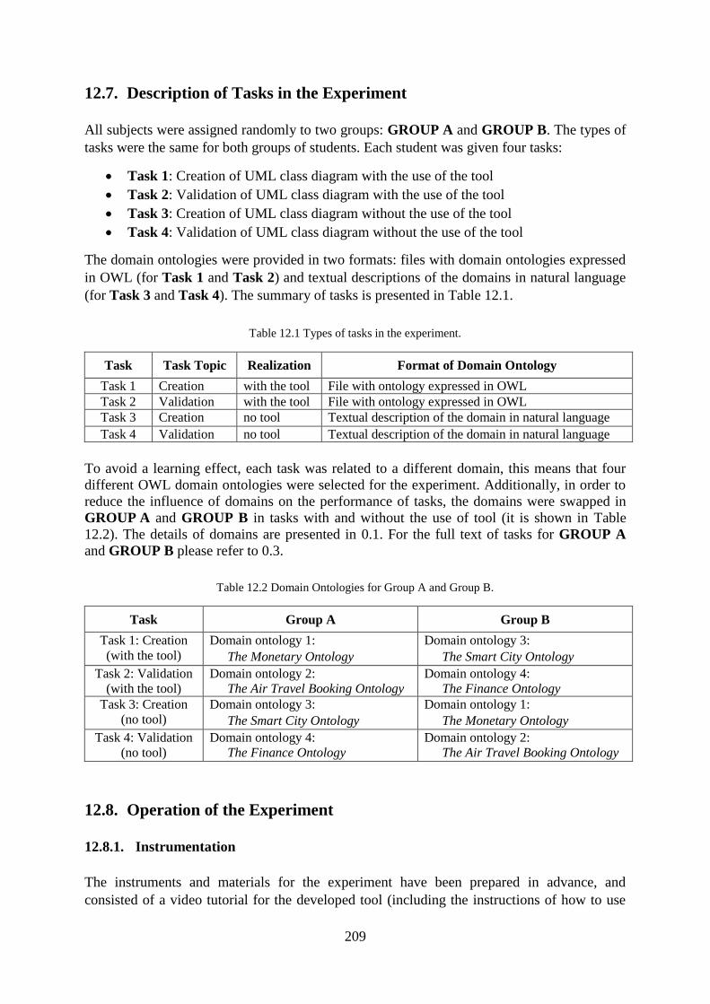
209
12.7. Description of Tasks in the Experiment
All subjects were assigned randomly to two groups: GROUP A and GROUP B. The types of
tasks were the same for both groups of students. Each student was given four tasks:
Task 1: Creation of UML class diagram with the use of the tool
Task 2: Validation of UML class diagram with the use of the tool
Task 3: Creation of UML class diagram without the use of the tool
Task 4: Validation of UML class diagram without the use of the tool
The domain ontologies were provided in two formats: files with domain ontologies expressed
in OWL (for Task 1 and Task 2) and textual descriptions of the domains in natural language
(for Task 3 and Task 4). The summary of tasks is presented in Table 12.1.
Table 12.1 Types of tasks in the experiment.
Task Task Topic Realization Format of Domain Ontology
Task 1 Creation with the tool File with ontology expressed in OWL
Task 2 Validation with the tool File with ontology expressed in OWL
Task 3 Creation no tool Textual description of the domain in natural language
Task 4 Validation no tool Textual description of the domain in natural language
To avoid a learning effect, each task was related to a different domain, this means that four
different OWL domain ontologies were selected for the experiment. Additionally, in order to
reduce the influence of domains on the performance of tasks, the domains were swapped in
GROUP A and GROUP B in tasks with and without the use of tool (it is shown in Table
12.2). The details of domains are presented in 0.1. For the full text of tasks for GROUP A
and GROUP B please refer to 0.3.
Table 12.2 Domain Ontologies for Group A and Group B.
Task Group A Group B
Task 1: Creation
(with the tool)
Domain ontology 1:
The Monetary Ontology
Domain ontology 3:
The Smart City Ontology
Task 2: Validation
(with the tool)
Domain ontology 2:
The Air Travel Booking Ontology
Domain ontology 4:
The Finance Ontology
Task 3: Creation
(no tool)
Domain ontology 3:
The Smart City Ontology
Domain ontology 1:
The Monetary Ontology
Task 4: Validation
(no tool)
Domain ontology 4:
The Finance Ontology
Domain ontology 2:
The Air Travel Booking Ontology
12.8. Operation of the Experiment
12.8.1. Instrumentation
The instruments and materials for the experiment have been prepared in advance, and
consisted of a video tutorial for the developed tool (including the instructions of how to use
210
the experiment infrastructure, etc.) and artefacts: UML class diagrams for the tasks of diagram
validation (in the file format for Visual Paradigm for UML), four domain ontologies in the
format of OWL files, as well as four textual descriptions of the domains written in natural
language.
Due to the fact that the OWL domain ontologies were rather complex (what has been
motivated in section 12.4) and students participating in the experiment were Polish-speaking
students, in order for the language not to influence the results, all materials for the experiment
had been prepared in the Polish language. In particular, the experiment tasks, the domain
ontologies (both in the format of OWL files and textual descriptions) and video tutorial were
prepared in Polish. Only the interface of the tool was in English.
12.8.2. Preparation of the Laboratory Room
The laboratory room has been prepared in advance for conducting the experiment. The
experimenter herself installed on all computers the virtual machines with Visual Paradigm for
UML and the developed tool (the installation procedure is explained in Chapter 9.5).
12.8.3. Time Frame for the Experiment
The time frame for the experiment was rather narrow. The experiment took place during
90 minutes laboratory courses. The experiment was preceded with a short introduction in
which in particular the developed tool was discussed.
The total time has been divided into the following parts:
10 minutes for a short introduction to the experiment, including presentation of the
purpose of the experiment and the types of tasks.
5 minutes for watching a video tutorial of the tool. The students came across the
proposed tool for the first time while watching this tutorial.
15 minutes for performing a simple exercise task with the use of the tool under the
supervision of the experimenter. The exercise included extracting a few UML classes
with associations and generalizations directly from example OWL domain ontology.
Next, students were asked to introduce one-two semantic errors to the diagram
(e.g. modify the type of attribute into incorrect one) and validate the diagram with the
support of the tool.
60 minutes for conducting the experiment. Each experiment task was estimated for 15
minutes.
12.8.4. Date of the Experiment and Number of Subjects
The experiment was carried out in Wrocław University of Science and Technology in 14 and
16 January 2019.

211
In total, 57 students participated in the experiment, 31 of bachelor's studies and 26 of master's
studies. 29 students were assigned to GROUP A and 28 students to GROUP B. Students
were assigned to groups alternately.
The next section presents the results of the experiment.
212
13. Analysis of the Results of the Experiment
Summary. This chapter presents the results of analysis of the experiment data. The data
were first analysed with the use of descriptive analysis (section 13.2) and next with the
use of Wilcoxon signed ranks test for the median difference (section 13.3).
13.1. Measures and Scores of Tasks
As mentioned in section 12.5, two aspects of tasks were measured: the main measure was the
correctness of the created or validated UML class diagrams, and the supportive measure was
the time needed to fill in each task.
How the correctness of tasks was calculated:
a) In tasks for creating of UML class diagrams: for each correctly drawn element of the
diagram (e.g. UML class, attribute of class, multiplicity, role name, etc.) one point was
awarded, regardless of the type of the UML element.
b) In tasks for validating of UML class diagrams: one point was awarded for each
correctly marked semantic error and additional point for its correcting.
This measure of correctness takes into account only the elements correctly drawn (or correctly
validated) on the diagrams.
The calculated results have been normalized to values in the range between 0 and 1. The
normalized values of the answers allow to easily comparing the data obtained by each subject
in each task.
13.2. Descriptive Statistics
The descriptive statistics of measures in tasks with the use of the tool are summarized in
Table 13.1 (for diagram creation) and Table 13.3 (for diagram validation). In comparison,
Table 13.2 presents the measures for diagram creation and Table 13.4 for diagram validation
in tasks without the use of the tool.
The first impression is that the differences between the results obtained by students in
GROUP A and students in GROUP B are not large. Moreover, the results obtained by
students of bachelor studies and students of master studies are rather similar.
However, rather large difference can be observed in correctness of created and validated
diagrams with the use of the tool in comparison with much worse results obtained without the
use of the tool. Particularly high is the value of median equal 1 for all groups of students in
both tasks for diagram creation and diagram validation with the use of the tool (Table 13.1
and Table 13.3).
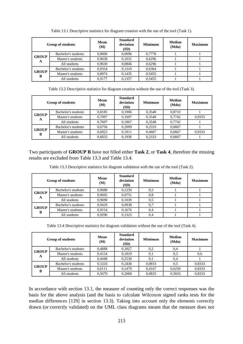
213
Table 13.1 Descriptive statistics for diagram creation with the use of the tool (Task 1).
Group of students Mean
(M)
Standard
deviation
(SD)
Minimum Median
(Mdn) Maximum
GROUP
A
Bachelor's students 0,9606 0,0696 0,7778 1 1
Master's students 0,9658 0,1031 0,6296 1 1
All students 0,9630 0,0846 0,6296 1 1
GROUP
B
Bachelor's students 0,9354 0,1310 0,6364 1 1
Master's students 0,8974 0,1435 0,5455 1 1
All students 0,9177 0,1357 0,5455 1 1
Table 13.2 Descriptive statistics for diagram creation without the use of the tool (Task 3).
Group of students Mean
(M)
Standard
deviation
(SD)
Minimum Median
(Mdn) Maximum
GROUP
A
Bachelor's students 0,8185 0,1906 0,3548 0,8710 1
Master's students 0,7097 0,1697 0,3548 0,7742 0,9355
All students 0,7697 0,1867 0,3548 0,7742 1
GROUP
B
Bachelor's students 0,6756 0,2099 0,2333 0,6667 1
Master's students 0,6923 0,1811 0,4667 0,6667 0,9333
All students 0,6833 0,1936 0,2333 0,6667 1
Two participants of GROUP B have not filled either Task 2, or Task 4, therefore the missing
results are excluded from Table 13.3 and Table 13.4.
Table 13.3 Descriptive statistics for diagram validation with the use of the tool (Task 2).
Group of students Mean
(M)
Standard
deviation
(SD)
Minimum Median
(Mdn) Maximum
GROUP
A
Bachelor's students 0,9688 0,1250 0,5 1 1
Master's students 0,9692 0,0751 0,8 1 1
All students 0,9690 0,1039 0,5 1 1
GROUP
B
Bachelor's students 0,9429 0,0938 0,7 1 1
Master's students 0,9154 0,1676 0,4 1 1
All students 0,9296 0,1325 0,4 1 1
Table 13.4 Descriptive statistics for diagram validation without the use of the tool (Task 4).
Group of students Mean
(M)
Standard
deviation
(SD)
Minimum Median
(Mdn) Maximum
GROUP
A
Bachelor's students 0,4688 0,3027 0,2 0,4 1
Master's students 0,4154 0,1819 0,1 0,5 0,6
All students 0,4448 0,2530 0,1 0,4 1
GROUP
B
Bachelor's students 0,5333 0,2436 0,0833 0,5 0,8333
Master's students 0,6111 0,1479 0,4167 0,6250 0,8333
All students 0,5679 0,2068 0,0833 0,5833 0,8333
In accordance with section 13.1, the measure of counting only the correct responses was the
basis for the above analysis (and the basis to calculate Wilcoxon signed ranks tests for the
median differences [129] in section 13.3). Taking into account only the elements correctly
drawn (or correctly validated) on the UML class diagrams means that the measure does not
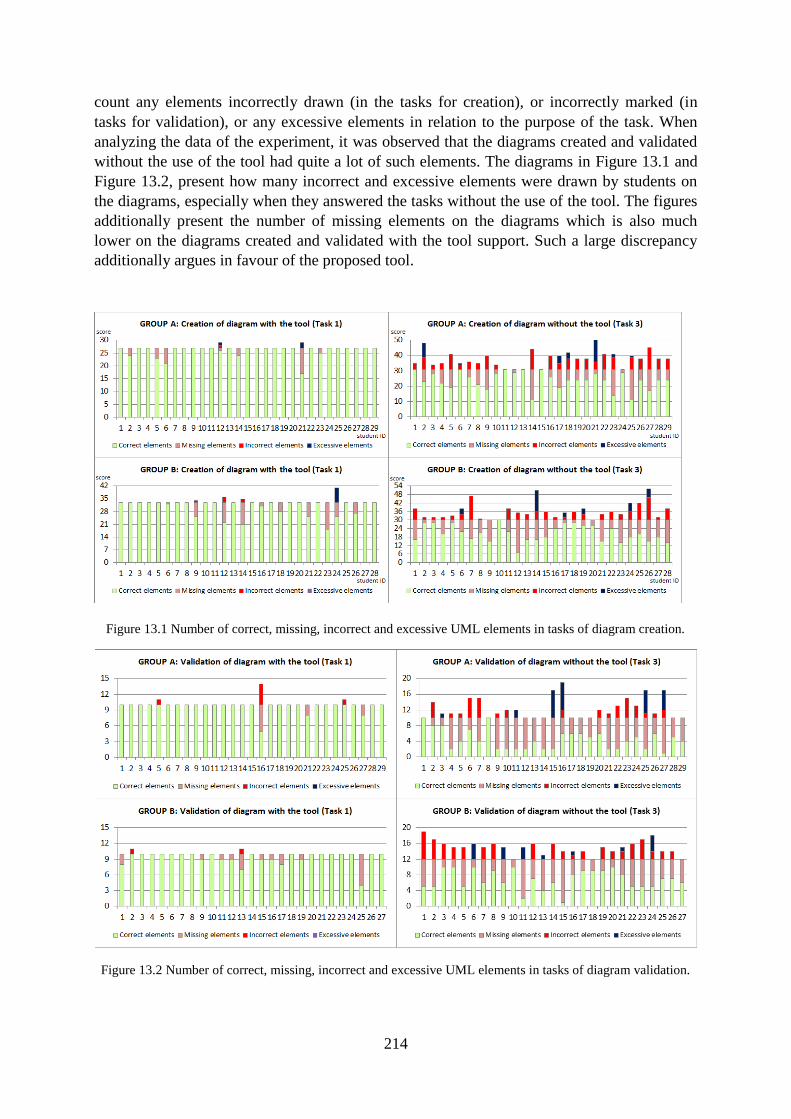
214
count any elements incorrectly drawn (in the tasks for creation), or incorrectly marked (in
tasks for validation), or any excessive elements in relation to the purpose of the task. When
analyzing the data of the experiment, it was observed that the diagrams created and validated
without the use of the tool had quite a lot of such elements. The diagrams in Figure 13.1 and
Figure 13.2, present how many incorrect and excessive elements were drawn by students on
the diagrams, especially when they answered the tasks without the use of the tool. The figures
additionally present the number of missing elements on the diagrams which is also much
lower on the diagrams created and validated with the tool support. Such a large discrepancy
additionally argues in favour of the proposed tool.
Figure 13.1 Number of correct, missing, incorrect and excessive UML elements in tasks of diagram creation.
Figure 13.2 Number of correct, missing, incorrect and excessive UML elements in tasks of diagram validation.
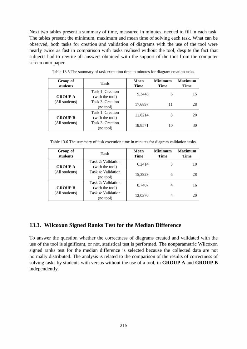
215
Next two tables present a summary of time, measured in minutes, needed to fill in each task.
The tables present the minimum, maximum and mean time of solving each task. What can be
observed, both tasks for creation and validation of diagrams with the use of the tool were
nearly twice as fast in comparison with tasks realised without the tool, despite the fact that
subjects had to rewrite all answers obtained with the support of the tool from the computer
screen onto paper.
Table 13.5 The summary of task execution time in minutes for diagram creation tasks.
Group of
students Task
Mean
Time
Minimum
Time
Maximum
Time
GROUP A
(All students)
Task 1: Creation
(with the tool) 9,3448 6 15
Task 3: Creation
(no tool) 17,6897 11 28
GROUP B
(All students)
Task 1: Creation
(with the tool) 11,8214 8 20
Task 3: Creation
(no tool) 18,8571 10 30
Table 13.6 The summary of task execution time in minutes for diagram validation tasks.
Group of
students Task
Mean
Time
Minimum
Time
Maximum
Time
GROUP A
(All students)
Task 2: Validation
(with the tool) 6,2414 3 10
Task 4: Validation
(no tool) 15,3929 6 28
GROUP B
(All students)
Task 2: Validation
(with the tool) 8,7407 4 16
Task 4: Validation
(no tool) 12,0370 4 20
13.3. Wilcoxon Signed Ranks Test for the Median Difference
To answer the question whether the correctness of diagrams created and validated with the
use of the tool is significant, or not, statistical test is performed. The nonparametric Wilcoxon
signed ranks test for the median difference is selected because the collected data are not
normally distributed. The analysis is related to the comparison of the results of correctness of
solving tasks by students with versus without the use of a tool, in GROUP A and GROUP B
independently.
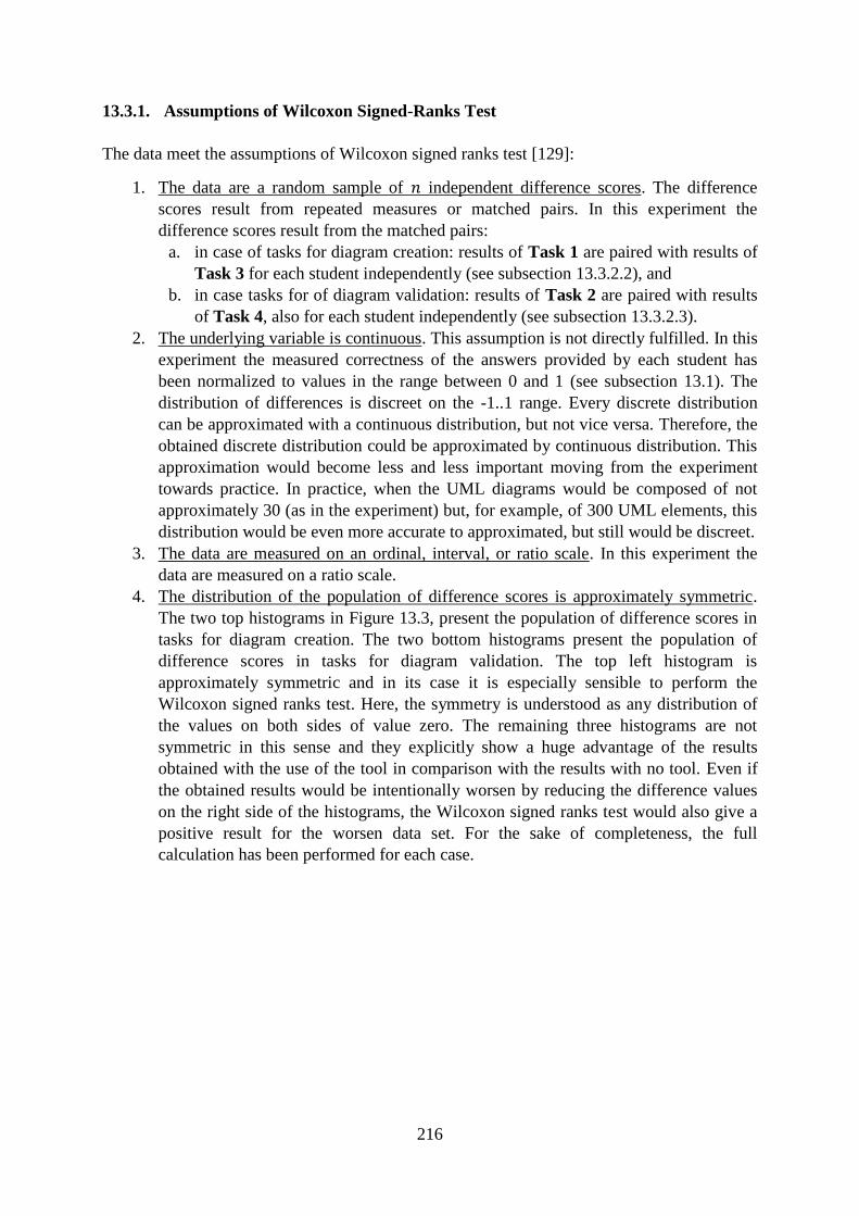
216
13.3.1. Assumptions of Wilcoxon Signed-Ranks Test
The data meet the assumptions of Wilcoxon signed ranks test [129]:
1. The data are a random sample of independent difference scores. The difference
scores result from repeated measures or matched pairs. In this experiment the
difference scores result from the matched pairs:
a. in case of tasks for diagram creation: results of Task 1 are paired with results of
Task 3 for each student independently (see subsection 13.3.2.2), and
b. in case tasks for of diagram validation: results of Task 2 are paired with results
of Task 4, also for each student independently (see subsection 13.3.2.3).
2. The underlying variable is continuous. This assumption is not directly fulfilled. In this
experiment the measured correctness of the answers provided by each student has
been normalized to values in the range between 0 and 1 (see subsection 13.1). The
distribution of differences is discreet on the -1..1 range. Every discrete distribution
can be approximated with a continuous distribution, but not vice versa. Therefore, the
obtained discrete distribution could be approximated by continuous distribution. This
approximation would become less and less important moving from the experiment
towards practice. In practice, when the UML diagrams would be composed of not
approximately 30 (as in the experiment) but, for example, of 300 UML elements, this
distribution would be even more accurate to approximated, but still would be discreet.
3. The data are measured on an ordinal, interval, or ratio scale. In this experiment the
data are measured on a ratio scale.
4. The distribution of the population of difference scores is approximately symmetric.
The two top histograms in Figure 13.3, present the population of difference scores in
tasks for diagram creation. The two bottom histograms present the population of
difference scores in tasks for diagram validation. The top left histogram is
approximately symmetric and in its case it is especially sensible to perform the
Wilcoxon signed ranks test. Here, the symmetry is understood as any distribution of
the values on both sides of value zero. The remaining three histograms are not
symmetric in this sense and they explicitly show a huge advantage of the results
obtained with the use of the tool in comparison with the results with no tool. Even if
the obtained results would be intentionally worsen by reducing the difference values
on the right side of the histograms, the Wilcoxon signed ranks test would also give a
positive result for the worsen data set. For the sake of completeness, the full
calculation has been performed for each case.
217
Figure 13.3 Histograms for the distribution of the population of difference scores
13.3.2. Computations in Wilcoxon Signed-Ranks Test
The Wilcoxon Signed-Ranks Test uses the test statistic which is calculated as follows
[129]:
1. For each item in a sample of items, compute a difference score | |, between the two
paired values.
2. Neglect the and signs and list the set of absolute differences | |. 3. Omit any absolute difference score of zero from further analysis, thereby yielding a set
of nonzero absolute difference scores, where . After removal values with
absolute difference scores of zero, becomes the actual sample size.
4. Assign ranks , from 1 to to each of the | | such that the smallest absolute
difference score gets rank 1 and the largest gets rank . If two or more | | are equal,
assign each of them the mean of the ranks they would have been assigned individually
had ties in the data not occurred.
5. Reassign the symbol and to each of the ranks, depending on whether was
originally positive or negative.
6. Compute the Wilcoxon test statistic as the sum of the positive ranks in accordance
with formula (13.1):
∑ ( )
(13.1)
For samples of , the test statistic is approximatelly normally distributed with mean
and standard deviation .
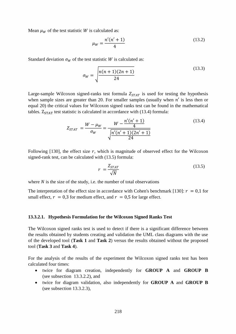
218
Mean of the test statistic is calculated as:
( )
(13.2)
Standard deviation of the test statistic is calculated as:
√ ( )( )
(13.3)
Large-sample Wilcoxon signed-ranks test formula is used for testing the hypothesis
when sample sizes are greater than 20. For smaller samples (usually when is less then or
equal 20) the critical values for Wilcoxon signed ranks test can be found in the mathematical
tables. test statistic is calculated in accordance with (13.4) formula:
( )
√ ( )( )
(13.4)
Following [130], the effect size , which is magnitude of observed effect for the Wilcoxon
signed-rank test, can be calculated with (13.5) formula:
√
(13.5)
where is the size of the study, i.e. the number of total observations
The interpretation of the effect size in accordance with Cohen's benchmark [130]: for
small effect, for medium effect, and for large effect.
13.3.2.1. Hypothesis Formulation for the Wilcoxon Signed Ranks Test
The Wilcoxon signed ranks test is used to detect if there is a significant difference between
the results obtained by students creating and validation the UML class diagrams with the use
of the developed tool (Task 1 and Task 2) versus the results obtained without the proposed
tool (Task 3 and Task 4).
For the analysis of the results of the experiment the Wilcoxon signed ranks test has been
calculated four times:
twice for diagram creation, independently for GROUP A and GROUP B
(see subsection 13.3.2.2), and
twice for diagram validation, also independently for GROUP A and GROUP B
(see subsection 13.3.2.3),
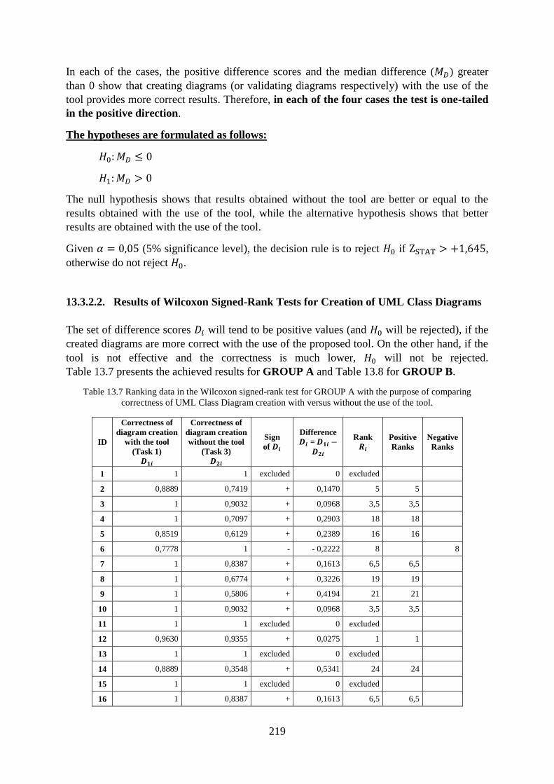
219
In each of the cases, the positive difference scores and the median difference ( ) greater
than 0 show that creating diagrams (or validating diagrams respectively) with the use of the
tool provides more correct results. Therefore, in each of the four cases the test is one-tailed
in the positive direction.
The hypotheses are formulated as follows:
The null hypothesis shows that results obtained without the tool are better or equal to the
results obtained with the use of the tool, while the alternative hypothesis shows that better
results are obtained with the use of the tool.
Given (5% significance level), the decision rule is to reject if ,
otherwise do not reject .
13.3.2.2. Results of Wilcoxon Signed-Rank Tests for Creation of UML Class Diagrams
The set of difference scores will tend to be positive values (and will be rejected), if the
created diagrams are more correct with the use of the proposed tool. On the other hand, if the
tool is not effective and the correctness is much lower, will not be rejected.
Table 13.7 presents the achieved results for GROUP A and Table 13.8 for GROUP B.
Table 13.7 Ranking data in the Wilcoxon signed-rank test for GROUP A with the purpose of comparing
correctness of UML Class Diagram creation with versus without the use of the tool.
ID
Correctness of
diagram creation
with the tool
(Task 1)
Correctness of
diagram creation
without the tool
(Task 3)
Sign
of
Difference
=
Rank
Positive
Ranks
Negative
Ranks
1 1 1 excluded 0 excluded
2 0,8889 0,7419 + 0,1470 5 5
3 1 0,9032 + 0,0968 3,5 3,5
4 1 0,7097 + 0,2903 18 18
5 0,8519 0,6129 + 0,2389 16 16
6 0,7778 1 - - 0,2222 8 8
7 1 0,8387 + 0,1613 6,5 6,5
8 1 0,6774 + 0,3226 19 19
9 1 0,5806 + 0,4194 21 21
10 1 0,9032 + 0,0968 3,5 3,5
11 1 1 excluded 0 excluded
12 0,9630 0,9355 + 0,0275 1 1
13 1 1 excluded 0 excluded
14 0,8889 0,3548 + 0,5341 24 24
15 1 1 excluded 0 excluded
16 1 0,8387 + 0,1613 6,5 6,5
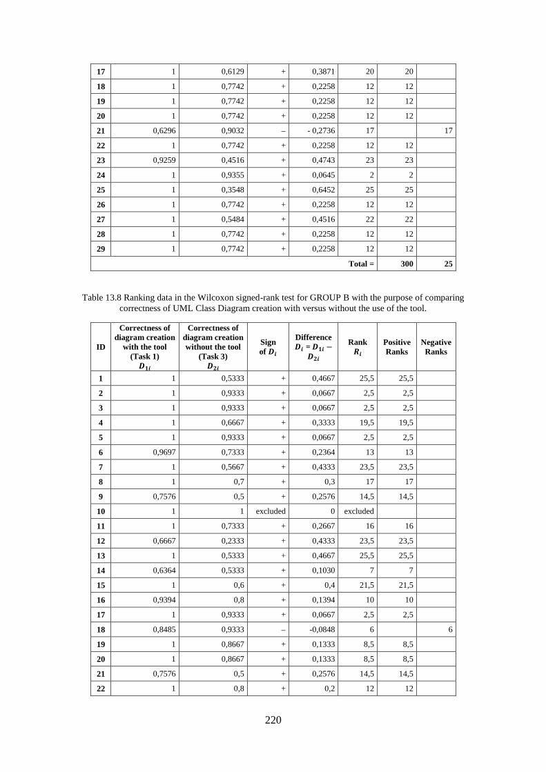
220
17 1 0,6129 + 0,3871 20 20
18 1 0,7742 + 0,2258 12 12
19 1 0,7742 + 0,2258 12 12
20 1 0,7742 + 0,2258 12 12
21 0,6296 0,9032 - 0,2736 17 17
22 1 0,7742 + 0,2258 12 12
23 0,9259 0,4516 + 0,4743 23 23
24 1 0,9355 + 0,0645 2 2
25 1 0,3548 + 0,6452 25 25
26 1 0,7742 + 0,2258 12 12
27 1 0,5484 + 0,4516 22 22
28 1 0,7742 + 0,2258 12 12
29 1 0,7742 + 0,2258 12 12
Total = 300 25
Table 13.8 Ranking data in the Wilcoxon signed-rank test for GROUP B with the purpose of comparing
correctness of UML Class Diagram creation with versus without the use of the tool.
ID
Correctness of
diagram creation
with the tool
(Task 1)
Correctness of
diagram creation
without the tool
(Task 3)
Sign
of
Difference
=
Rank
Positive
Ranks
Negative
Ranks
1 1 0,5333 + 0,4667 25,5 25,5
2 1 0,9333 + 0,0667 2,5 2,5
3 1 0,9333 + 0,0667 2,5 2,5
4 1 0,6667 + 0,3333 19,5 19,5
5 1 0,9333 + 0,0667 2,5 2,5
6 0,9697 0,7333 + 0,2364 13 13
7 1 0,5667 + 0,4333 23,5 23,5
8 1 0,7 + 0,3 17 17
9 0,7576 0,5 + 0,2576 14,5 14,5
10 1 1 excluded 0 excluded
11 1 0,7333 + 0,2667 16 16
12 0,6667 0,2333 + 0,4333 23,5 23,5
13 1 0,5333 + 0,4667 25,5 25,5
14 0,6364 0,5333 + 0,1030 7 7
15 1 0,6 + 0,4 21,5 21,5
16 0,9394 0,8 + 0,1394 10 10
17 1 0,9333 + 0,0667 2,5 2,5
18 0,8485 0,9333 -0,0848 6 6
19 1 0,8667 + 0,1333 8,5 8,5
20 1 0,8667 + 0,1333 8,5 8,5
21 0,7576 0,5 + 0,2576 14,5 14,5
22 1 0,8 + 0,2 12 12
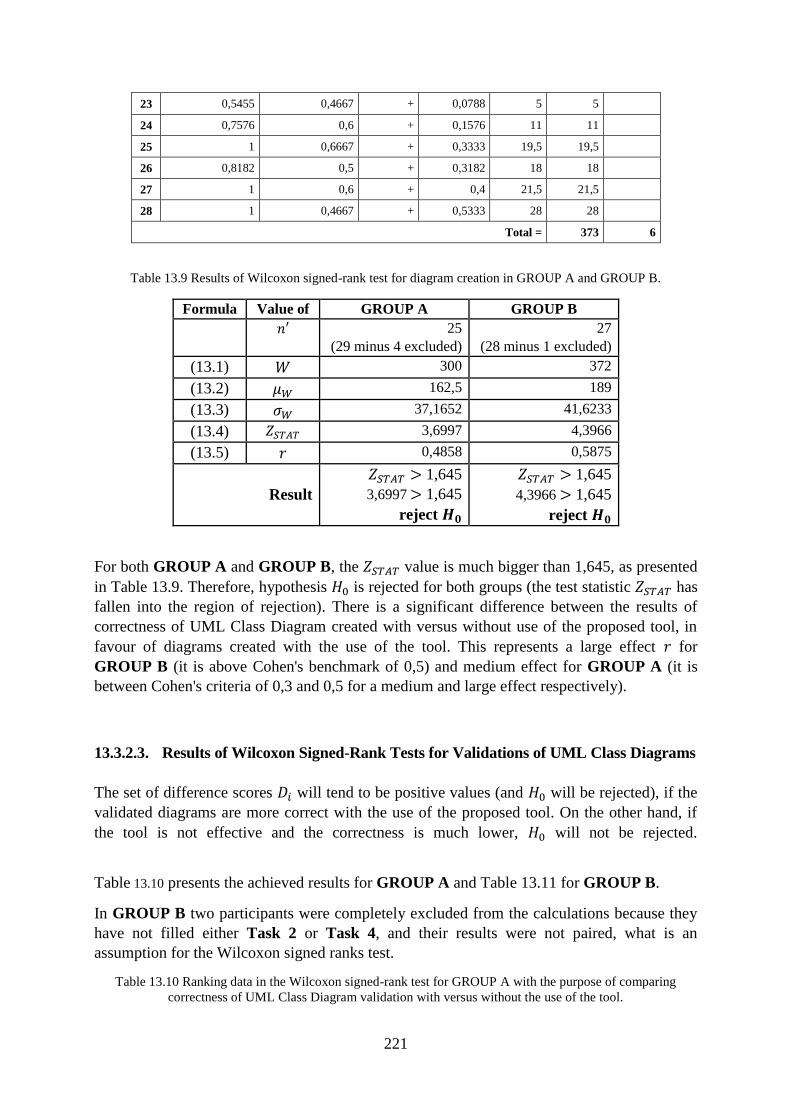
221
23 0,5455 0,4667 + 0,0788 5 5
24 0,7576 0,6 + 0,1576 11 11
25 1 0,6667 + 0,3333 19,5 19,5
26 0,8182 0,5 + 0,3182 18 18
27 1 0,6 + 0,4 21,5 21,5
28 1 0,4667 + 0,5333 28 28
Total = 373 6
Table 13.9 Results of Wilcoxon signed-rank test for diagram creation in GROUP A and GROUP B.
Formula Value of GROUP A GROUP B
25
(29 minus 4 excluded)
27
(28 minus 1 excluded)
(13.1) 300 372
(13.2) 162,5 189
(13.3) 37,1652 41,6233
(13.4) 3,6997 4,3966
(13.5) 0,4858 0,5875
Result
1,645
3,6997 1,645
reject
1,645
4,3966 1,645
reject
For both GROUP A and GROUP B, the value is much bigger than 1,645, as presented
in Table 13.9. Therefore, hypothesis is rejected for both groups (the test statistic has
fallen into the region of rejection). There is a significant difference between the results of
correctness of UML Class Diagram created with versus without use of the proposed tool, in
favour of diagrams created with the use of the tool. This represents a large effect for
GROUP B (it is above Cohen's benchmark of 0,5) and medium effect for GROUP A (it is
between Cohen's criteria of 0,3 and 0,5 for a medium and large effect respectively).
13.3.2.3. Results of Wilcoxon Signed-Rank Tests for Validations of UML Class Diagrams
The set of difference scores will tend to be positive values (and will be rejected), if the
validated diagrams are more correct with the use of the proposed tool. On the other hand, if
the tool is not effective and the correctness is much lower, will not be rejected.
Table 13.10 presents the achieved results for GROUP A and Table 13.11 for GROUP B.
In GROUP B two participants were completely excluded from the calculations because they
have not filled either Task 2 or Task 4, and their results were not paired, what is an
assumption for the Wilcoxon signed ranks test.
Table 13.10 Ranking data in the Wilcoxon signed-rank test for GROUP A with the purpose of comparing
correctness of UML Class Diagram validation with versus without the use of the tool.
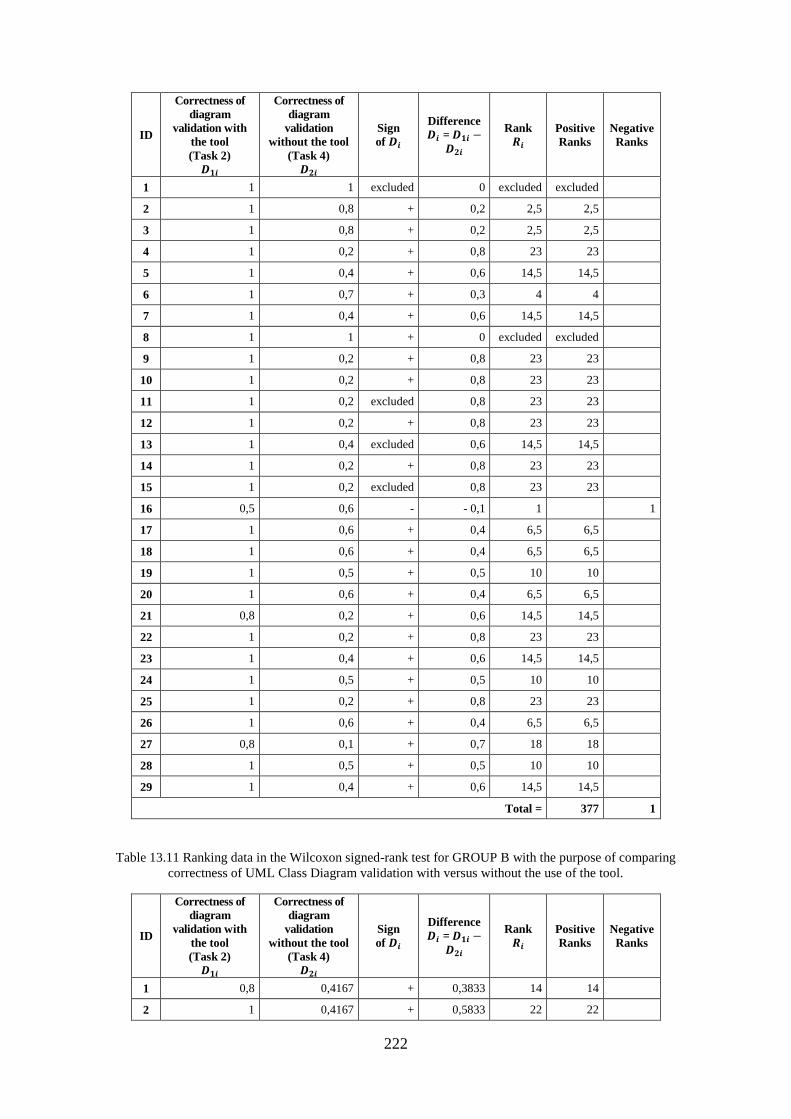
222
ID
Correctness of
diagram
validation with
the tool
(Task 2)
Correctness of
diagram
validation
without the tool
(Task 4)
Sign
of
Difference
=
Rank
Positive
Ranks
Negative
Ranks
1 1 1 excluded 0 excluded excluded
2 1 0,8 + 0,2 2,5 2,5
3 1 0,8 + 0,2 2,5 2,5
4 1 0,2 + 0,8 23 23
5 1 0,4 + 0,6 14,5 14,5
6 1 0,7 + 0,3 4 4
7 1 0,4 + 0,6 14,5 14,5
8 1 1 + 0 excluded excluded
9 1 0,2 + 0,8 23 23
10 1 0,2 + 0,8 23 23
11 1 0,2 excluded 0,8 23 23
12 1 0,2 + 0,8 23 23
13 1 0,4 excluded 0,6 14,5 14,5
14 1 0,2 + 0,8 23 23
15 1 0,2 excluded 0,8 23 23
16 0,5 0,6 - - 0,1 1 1
17 1 0,6 + 0,4 6,5 6,5
18 1 0,6 + 0,4 6,5 6,5
19 1 0,5 + 0,5 10 10
20 1 0,6 + 0,4 6,5 6,5
21 0,8 0,2 + 0,6 14,5 14,5
22 1 0,2 + 0,8 23 23
23 1 0,4 + 0,6 14,5 14,5
24 1 0,5 + 0,5 10 10
25 1 0,2 + 0,8 23 23
26 1 0,6 + 0,4 6,5 6,5
27 0,8 0,1 + 0,7 18 18
28 1 0,5 + 0,5 10 10
29 1 0,4 + 0,6 14,5 14,5
Total = 377 1
Table 13.11 Ranking data in the Wilcoxon signed-rank test for GROUP B with the purpose of comparing
correctness of UML Class Diagram validation with versus without the use of the tool.
ID
Correctness of
diagram
validation with
the tool
(Task 2)
Correctness of
diagram
validation
without the tool
(Task 4)
Sign
of
Difference
=
Rank
Positive
Ranks
Negative
Ranks
1 0,8 0,4167 + 0,3833 14 14
2 1 0,4167 + 0,5833 22 22
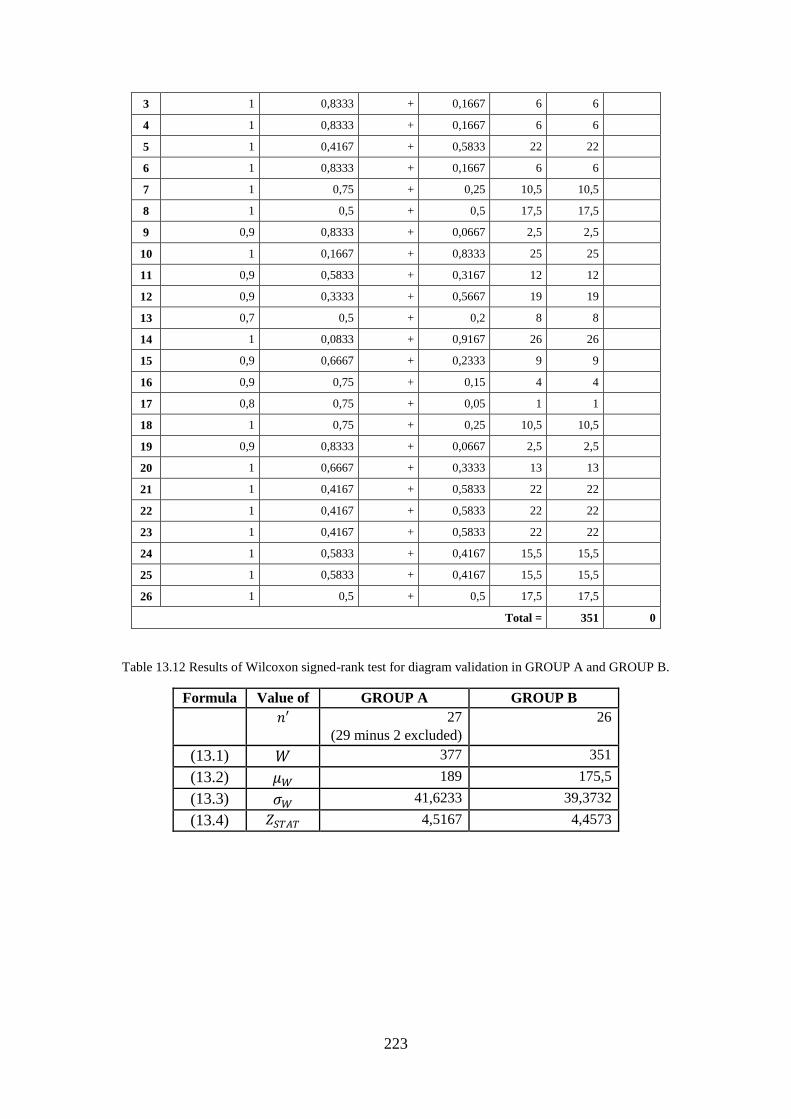
223
3 1 0,8333 + 0,1667 6 6
4 1 0,8333 + 0,1667 6 6
5 1 0,4167 + 0,5833 22 22
6 1 0,8333 + 0,1667 6 6
7 1 0,75 + 0,25 10,5 10,5
8 1 0,5 + 0,5 17,5 17,5
9 0,9 0,8333 + 0,0667 2,5 2,5
10 1 0,1667 + 0,8333 25 25
11 0,9 0,5833 + 0,3167 12 12
12 0,9 0,3333 + 0,5667 19 19
13 0,7 0,5 + 0,2 8 8
14 1 0,0833 + 0,9167 26 26
15 0,9 0,6667 + 0,2333 9 9
16 0,9 0,75 + 0,15 4 4
17 0,8 0,75 + 0,05 1 1
18 1 0,75 + 0,25 10,5 10,5
19 0,9 0,8333 + 0,0667 2,5 2,5
20 1 0,6667 + 0,3333 13 13
21 1 0,4167 + 0,5833 22 22
22 1 0,4167 + 0,5833 22 22
23 1 0,4167 + 0,5833 22 22
24 1 0,5833 + 0,4167 15,5 15,5
25 1 0,5833 + 0,4167 15,5 15,5
26 1 0,5 + 0,5 17,5 17,5
Total = 351 0
Table 13.12 Results of Wilcoxon signed-rank test for diagram validation in GROUP A and GROUP B.
Formula Value of GROUP A GROUP B
27
(29 minus 2 excluded)
26
(13.1) 377 351
(13.2) 189 175,5
(13.3) 41,6233 39,3732
(13.4) 4,5167 4,4573
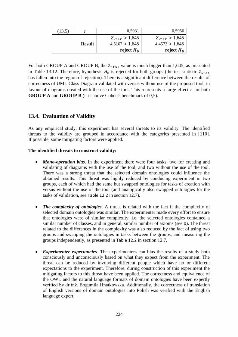
224
(13.5) 0,5931 0,5956
Result
1,645
4,5167 1,645
reject
1,645
4,4573 1,645
reject
For both GROUP A and GROUP B, the value is much bigger than 1,645, as presented
in Table 13.12. Therefore, hypothesis is rejected for both groups (the test statistic
has fallen into the region of rejection). There is a significant difference between the results of
correctness of UML Class Diagram validated with versus without use of the proposed tool, in
favour of diagrams created with the use of the tool. This represents a large effect for both
GROUP A and GROUP B (it is above Cohen's benchmark of 0,5).
13.4. Evaluation of Validity
As any empirical study, this experiment has several threats to its validity. The identified
threats to the validity are grouped in accordance with the categories presented in [110].
If possible, some mitigating factors were applied.
The identified threats to construct validity:
Mono-operation bias. In the experiment there were four tasks, two for creating and
validating of diagrams with the use of the tool, and two without the use of the tool.
There was a strong threat that the selected domain ontologies could influence the
obtained results. This threat was highly reduced by conducing experiment in two
groups, each of which had the same but swapped ontologies for tasks of creation with
versus without the use of the tool (and analogically also swapped ontologies for the
tasks of validation, see Table 12.2 in section 12.7).
The complexity of ontologies. A threat is related with the fact if the complexity of
selected domain ontologies was similar. The experimenter made every effort to ensure
that ontologies were of similar complexity, i.e. the selected ontologies contained a
similar number of classes, and in general, similar number of axioms (see 0). The threat
related to the differences in the complexity was also reduced by the fact of using two
groups and swapping the ontologies in tasks between the groups, and measuring the
groups independently, as presented in Table 12.2 in section 12.7.
Experimenter expectancies. The experimenters can bias the results of a study both
consciously and unconsciously based on what they expect from the experiment. The
threat can be reduced by involving different people which have no or different
expectations to the experiment. Therefore, during construction of this experiment the
mitigating factors to this threat have been applied. The correctness and equivalence of
the OWL and the natural language formats of domain ontologies have been expertly
verified by dr inż. Bogumiła Hnatkowska. Additionally, the correctness of translation
of English versions of domain ontologies into Polish was verified with the English
language expert.
225
The identified threats to internal validity:
Positive and negative effect of maturation. This is the effect of related to the
observation that the subjects may react differently as time passes. Due to the fact that
there were four tasks in the experiment which had to be filled within one hour, there is
a threat that the subjects might have been more tired with each subsequent task.
Therefore, the subjects could be affected negatively (could get tired or bored) and
answer the later tasks (without the use of the tool) with less focus. However, the
subjects could also be affected positively during the course of the experiment, and
could learn how to solve tasks of creation or validation of UML class diagrams on the
basis of previous tasks (with the use of the tool) and provide better answers on the
later tasks (without the use of the tool).
Too short training. There was a strong threat that the subjects had too short training
on the new tool, and almost immediately they had to use it during the experiment. Just
after seeing a short video tutorial, students did only one short and simple warm-up
exercise during which they had the first and only opportunity to familiarize themselves
with the new tool before the experiment started. A longer training on the use of the
tool could significantly improve the results. Despite this strong threat, as a result of the
experiment, it turned out that working with the tool was not problematic for most of
students.
Rewriting UML class diagrams. In order not to favour tasks solved with the use of the
tool in comparison with the tasks solved without the use of the tool, subjects were
expected to write all answers manually in paper (on the experiment form). There was a
threat for tasks solved with the use of the tool that they had to be rewritten from the
computer screen onto paper. This entails some additional time and the possibility of
making a mistake when rewriting the data. Indeed, during the experiment, the
experimenter observed two situations when subjects made errors while rewriting the
data, even though they had correct answers on the screen. In the two observed cases,
the students were asked to check the provided answers on paper.
Knowledge of selected domains by students. Because the students' knowledge of
domains selected for the experiment may influence the results of the experiment, the
selected domain ontologies were not related to IT studies, i.e. software engineering or
computer science, or common knowledge. The selected ontologies were rather
difficult in order to minimize the risk of knowing the relationships within the domains
by IT students.
The knowledge of UML and/or knowledge of Visual Paradigm for UML. This threat
was related to the fact that the subjects were students, most of whose experience in
UML modelling was rather theoretical supported with some practice during the
university courses. Each group of students had at least two courses on UML.
Nevertheless, during the experiment it turned out that a few students had some basic
problems with the UML notation or with Visual Paradigm for UML tool.
The identified threat to conclusion validity:
Heterogeneity of subjects. Subjects were software engineering students of bachelor's
studies (two groups of students) and of master's studies (also two groups of students).
226
Therefore, subjects were heterogeneous as they had slightly different background and
experience.
The identified threat to external validity:
Generalizing the findings. The experiment was designed to check the practical
usefulness of the tool for modellers who are not experts in specific domains. It was not
assumed that the modellers have to be professional. Due to the fact that the results of
the experiment carried out with students proved to be promising, it can be assumed
that the tool could be useful also for professional modellers.
13.5. Conclusions
This section summarized the results of the conducted experiment aimed to check the practical
usefulness of the developed tool, which proved to be promising. Following the results of
statistical analysis, there is a significant difference between the correctness of created and
validated UML class diagrams in favour of the diagrams created and validated with the
support of the proposed tool. While observing the course of the experiment, it turned out that
working with the tool was not problematic for most of students. In spite of very short training,
the participants were able to use the tool quite fluently.

227

228
Part VI
Final
Part VI: Final

229
230
14. Conclusions
14.1. Thesis Contributions
Nowadays, UML class diagrams are the indispensable elements of business models. The
modellers require domain information when designing the diagrams. For this purpose, the
domain ontologies can be used because their purpose is to reflex and organize information in
different domains. This research has selected OWL for defining ontologies, which is justified
by the growing number of the already created domain ontologies in this language. The
selection of domain ontologies has a practical justification but the presented approaches are
applicable not only to domain ontologies but also to top level ontologies or even application
ontologies expressed in OWL.
Using ontologies allows creating models without the necessity of having the expertise
provided by domain experts. The ontology driven development of a software system starts
from an existing domain ontology, and continues with creating a model in a selected
modelling language (Chapter 6.1). This dissertation details the aspect of ontology driven
development in the context of creating UML class diagrams from OWL domain ontologies.
The scope of this research includes both the creation and the validation of UML class
diagrams. In this research, validation is used to check the UML class diagrams with respect to
the given OWL domain ontologies representing the needed domains (Chapter 4.2). There are
two stages in diagram validation: the formal verification which is conducted automatically in
the proposed tool, and the formal acceptance of the results by the modeller who ultimately
decides about the validation.
Developing semantically correct UML class diagrams is a practical problem of software
engineering. This dissertation proposes:
a method for the semi-automatic extraction of UML class diagrams from OWL domain
ontologies (Chapter 6), and
a method for automatic verification of the UML class diagrams against ontologies
expressed in OWL (Chapter 5).
The proposed methods, as a proof of concept, have been implemented in the tool (Part IV).
The tool has been tested with the test cases (Appendix A), and empirically evaluated (Part V,
Appendix B) through conducting an experiment with the students from Wrocław University
of Science and Technology (Chapter 12). As a result, the proposed methods have proven
their practical potential and demonstrated their usability (Chapter 13).
The posed objectives were achieved, and hence, the thesis of this dissertation: "the use of
domain ontologies favours the faster creation of business models and increases their semantic
quality" can be accepted as proven.
231
14.1.1. Thesis Contributions in the Context of Validation of UML Class Diagrams
The method of the semantic validation of UML class diagrams with respect to the selected
domains is the original proposition of this research (Section 5). A key step in the method of
validation, is the automatic generation of the result of verification (Section 10). To the best
knowledge of the author, currently no other method or tool allows for the automatic
verification of UML class diagrams against the domain ontologies expressed in OWL.
The proposed method of validation checks the semantic compliance of the diagrams with
respect to the domains described by the underlying ontology. The method uses the automatic
verification if all diagram elements and their relationships are compliant (or not) with the
selected ontology. The verification of UML class diagrams can be conducted without
involving domain experts in the process. The validation is semi-automated because the
modeller receives the automatically generated results of verification with the suggested
corrections to the designed diagram.
The verification inference bases on the axiomatic system, which uses the so-called
transformation and verification rules:
The transformation rules (Section 5.3.2) convert any UML class diagram to its
equivalent OWL representation. The author of this research has conducted a systematic
literature review on the topic of the transformation rules between elements of UML class
diagrams and OWL constructs, which is also a contribution of this research (Section 8).
The identified state-of-the-art transformation rules were extended with several new
propositions. Summarizing the numbers, 41 transformation rules were identified: 25 came
directly from the literature, and 16 rules were either completely new propositions or were
extended to a broader context by the author of this dissertation.
The verification rules (Section 5.3.3) are a fully original contribution of this research.
The verification rules are aimed at checking the compliance of the OWL representation of
the UML class diagram with the given OWL domain ontology.
The OWL language allows to define different axioms which are semantically equivalent, as
well as to define the axioms of the same type which have a different internal structure and the
same semantic meaning. For the purpose of implementing the intended functionality of the tool
in the context of both creation, as well as validation this dissertation proposes a method of
normalizing OWL ontologies (Section 7). The normalization enables to present any input
OWL ontology in a new but semantically equivalent form; in a unified structure of axioms. The
normalized ontologies have a unified structure of axioms, therefore, they can be easily
compared in an algorithmic way. The tool allows normalizing on-demand any syntactically
correct and consistent ontology expressed in OWL. The normalization method is a
contribution of this research which can be used also in other future projects. For example, it
can be used in the context of merging ontologies. Nevertheless, it has to be noted that the
normalized ontologies are intended to be analysed by tool (not human) readers.
232
14.1.2. Thesis Contributions in the Context of the Creation of UML Class Diagrams
The topic of extracting UML elements from OWL ontologies is not new, and has already been
described in the literature. There are several tools, with different range of possibilities, which
offer a transformation from OWL ontologies to UML class diagrams (Section 9.1).
The original proposition of this research is the process of the semi-automatic creation of UML
class diagrams from OWL domain ontologies (Section 6.2). The process defines the direct
extraction and the extended extraction:
The direct extraction (Section 6.3.1) bases fully on the selected domain ontology. The
proposed method assures that the direct extraction of the UML class diagram is always
compliant with the ontology.
The extended extraction (Section 6.3.2) is another original proposition of this research. It
allows extracting additional UML elements which are only partly based on the selected
domain ontology. Such a transformation from OWL to UML adds some additional
information to the UML elements, which is not explicitly defined in the ontology, but is
also not contradictory with the ontology. This proposal was formulated after observing a
number of real ontologies which often contain incomplete sets of axioms in accordance
with the definitions for the subsequent categories of UML elements. This approach is
justified based on observing the practical modelling needs.
To summarize, the developed method (and the tool) in the context of diagram creation has
three original features:
1. The method assures the compliance of the extracted UML class diagram with the
underlying OWL ontology. The OWL to UML extraction takes into account the checking
rules (Section 6.3.1) for the purpose of correct OWL to UML transformation.
2. The method allows extracting from OWL ontologies all categories of elements of UML
class diagrams which are important from the point of view of pragmatics (Section 2.3).
The proposed extraction is more complex in comparison with the related works.
3. The method offers to conduct both the direct extraction and the extended extraction, as
left up to the modeller's decision.
14.1.3. Additional Thesis Contributions
A) Development of OWL ontologies:
The literature describes approaches focused on reusing the knowledge from (existing) UML
class diagrams in order to develop new OWL ontologies (e.g. [20], [115], [126], [131]). The
works argue that developing OWL ontologies is a difficult and time-consuming task, and the
visual notation, such as well-known UML, may highly accelerate the process of building
ontologies.
The complementary function of the developed tool presents all the axioms which are
described by the semantics of the UML class diagram but are not included in the OWL
233
domain ontology. The listed axioms can be manually added to the OWL domain ontology
with the purpose of extending the ontology with the new knowledge described by the
diagram.
The complementary function of the developed tool allows converting the designed UML class
diagrams into OWL ontologies of a simple structure (simple in terms of the number of
different OWL constructs). What has to be noted, the tool presents the axioms in a standard
form (not in the normalized form), which means that they are easy to be read by human
readers.
OWL and UML languages differ with respect to their expression power. Not every type of
OWL axiom has its equivalence in an element of the UML class diagram. On the other hand,
the majority of elements of the UML class diagram have their equivalence in OWL axioms.
Despite the limitations of UML language for being used as a visual syntax for knowledge
representation, this approach can be used to enhance writing some fragments of ontologies.
Such ontologies will of course not cover the full spectrum of all possible OWL constructs, but
will be fully usable for some typical needs.
B) Visualization of OWL ontologies:
The literature describes approaches aimed at addressing a problem of providing a visual
method for OWL ontologies. Some approaches (e.g. [46], [132]) propose UML as a visual
method for OWL ontologies with the purpose of accelerating the process of human
familiarization with the ontologies, as well as to accelerate the maintenance of the ontologies.
The developed tool allows the modeller to also visualize the whole OWL ontology, with the
restriction that the visualization will include only those OWL axioms which have semantic
equivalents in the elements of the UML class diagrams. However, for the purpose of a
comprehensive visualization of OWL ontologies, it is better not to use UML, but a language
dedicated for this purpose, such as VOWL.
14.2. Future Works
The works presented in this dissertation can be the subject of further research. There are
several directions of future research worth considering, for example:
One area of possible future works is to focus on the role of OCL language in business and
conceptual modelling with UML class diagrams. The OCL is a complement of the UML
notation with the goal to overcome the limitations of UML in terms of precisely specifying
detailed aspects of a system design. It is possible to transform at least some OCL constructs
into OWL axioms.
The possible future works can also develop a method to extract UML object diagrams based
on the extracted UML class diagrams and the OWL individuals defined in the OWL ontology.
During the business analysis phase, the UML object diagrams are used to show a structure of
a modelled system at a specific time. The UML object diagrams depict instances of the
classes and can be also used to confirm the accuracy and completeness of the UML class
diagram.
234
Another area of possible future works concerns the analysis of the natural language in the
context of the OWL domain ontologies, and the selected formats of system requirements
specification. The analysis can result in the automatization of extracting the relevant glossary
of terms representing the domain terms used within the requirements specification. The
quality of the glossary has a great impact on the quality of the final UML class diagrams. For
example, the use of a large lexical database such as WordNet [133] may result in a network of
meaningfully related words and concepts.

235
236
Appendix A. Test Cases
This appendix presents the test cases used to determine whether the developed tool satisfies
the intended requirements. The aim of the test cases is to check if the expected results
(manually created on the basis of the provided definitions) and the actual results
(automatically obtained with the use of the developed tool) are equal, which would confirm
the correctness of the implementation.
The next subsections present test cases for:
normalization (80 test cases, Appendix A.1), in accordance with definitions of
normalization from Section 7.3,
transformation rules (40 test cases, Appendix A.2), according to definitions of
transformation rules from Section 8.3,
verification rules (23 test cases, Appendix A.3), following definitions of verification
rules also from Section 8.3.
The designed test cases cover all situations at least once. All test cases resulted in "Pass".
Please note that the order of axioms in the expected and the actual results is in some cases
different, but the order of the axioms in OWL 2 DL ontology is not important, therefore the
order of axioms does not influence the status (Pass or Fail).
All test cases uses the standard prefix names and IRIs for rdf:, owl:, xsd: and rdfs:, as well as
the declared default ontology prefix:
Prefix(:=<http://www.test.cases/normalization.owl#>)
Prefix(rdf:=<http://www.w3.org/1999/02/22-rdf-syntax-ns#>)
Prefix(owl:=<http://www.w3.org/2002/07/owl#>)
Prefix(xsd:=<http://www.w3.org/2001/XMLSchema#>)
Prefix(rdfs:=<http://www.w3.org/2000/01/rdf-schema#>)
Ontology(<http://www.test.cases/normalization.owl>
Tested axiom(s)
)
Appendix A.1. Test Cases for Normalization
This appendix presents the conducted test cases for OWL 2 DL ontology normalization rules
(defined in Section 7.3).
RESULTS:
All test cases for normalization resulted in "Pass".
ANALYSIS OF RESULTS:
The expected and the actual results were first compared manually and next were compared
automatically with the use of Microsoft Excel and the "COUNTIF" formula, which was used
to count the number of cells that meet a criterion of the number of times a particular axiom
from "Actual result" appeared in a list with "Expected result" for each axiom in each test case
independently. The result "1" means that the selected axiom from "Actual result" was
237
textually identical to one another axiom from "Expected result" in test case of selected ID.
The result "1" was obtained for the majority of axioms. In some cases, all listed in Table A.1,
the obtained result was "0" which means that the selected axiom from "Actual result" was not
textually identical to any other axiom from "Expected result" in test case of selected ID. The
axioms with results "0" were manually verified if they are semantically equivalent
(see Table A.1).
Table A.1 The manually verified axioms with result "0" from "COUNTIF" formula.
Test case ID Explanation of semantic identity of axioms
(in accordance with the OWL 2 specification)
N13 The order of object properties expressions OPEi, 1 ≤ i ≤ n in DisjointObjectProperties( OPE1
... OPEn ) is not important
N17 and N18
and N79
In ObjectMaxCardinality( n OPE CE ) if CE is not present, it is taken to be owl:Thing.
N30 In DataMaxCardinality( n DPE DR ) if DR is not present, it is taken to be rdfs:Literal.
N39 The order of data ranges DRi, 1 ≤ i ≤ n in DataIntersectionOf( DR1 ... DRn ) is not important
N45 and N76 The order of class expressions CEi, 1 ≤ i ≤ n in ObjectUnionOf( CE1 ... CEn ) is not
important
N47 The order of class expressions CEi, 1 ≤ i ≤ n in ObjectIntersectionOf( CE1 ... CEn ) is not
important
TEST CASES:
The below tables contain columns: IDs of test cases, short description of the tested OWL
construct, tested rule(s) in accordance with Section 7.3, tested OWL axiom(s) with respect to
selected tested rule(s), expected result (created manually), actual result (generated
automatically by the tool), and status (Pass, Fail).
Table A.2 Test cases for class expression axioms.
ID Tested OWL
construct(s)
Tested rule(s) Tested axiom(s) Expected result Actual result Status
N1 EquivalentClass
es axiom with
duplicated class expressions
Tested rule:
Table 7.1: ID 1
Other rule called:
Table 7.1: ID 3
EquivalentClasses( :A
:A :B )
Declaration( Class( :A ) )
Declaration( Class( :B ) )
SubClassOf( :A :B ) SubClassOf( :B :A )
SubClassOf( :A :B )
Declaration( Class( :A ) )
SubClassOf( :B :A ) Declaration( Class( :B ) )
Pass
N2 EquivalentClasses axiom with
three class
expressions
Tested rule: Table 7.1: ID 2
Other rule
called: Table 7.1: ID 3
EquivalentClasses( :A :B :C )
Declaration( Class( :A ) ) Declaration( Class( :B ) )
Declaration( Class( :C ) )
SubClassOf( :A :B ) SubClassOf( :B :A )
SubClassOf( :A :C )
SubClassOf( :C :A ) SubClassOf( :C :B )
SubClassOf( :B :C )
SubClassOf( :A :B ) SubClassOf( :B :C )
SubClassOf( :A :C )
Declaration( Class( :A ) ) SubClassOf( :B :A )
SubClassOf( :C :B )
Declaration( Class( :B ) ) SubClassOf( :C :A )
Declaration( Class( :C ) )
Pass
N3 EquivalentClasses axiom with
two class
expressions
Tested rule: Table 7.1: ID 3
EquivalentClasses( :A :B )
Declaration( Class( :A ) ) Declaration( Class( :B ) )
SubClassOf( :A :B )
SubClassOf( :B :A )
SubClassOf( :A :B ) Declaration( Class( :A ) )
SubClassOf( :B :A )
Declaration( Class( :B ) )
Pass
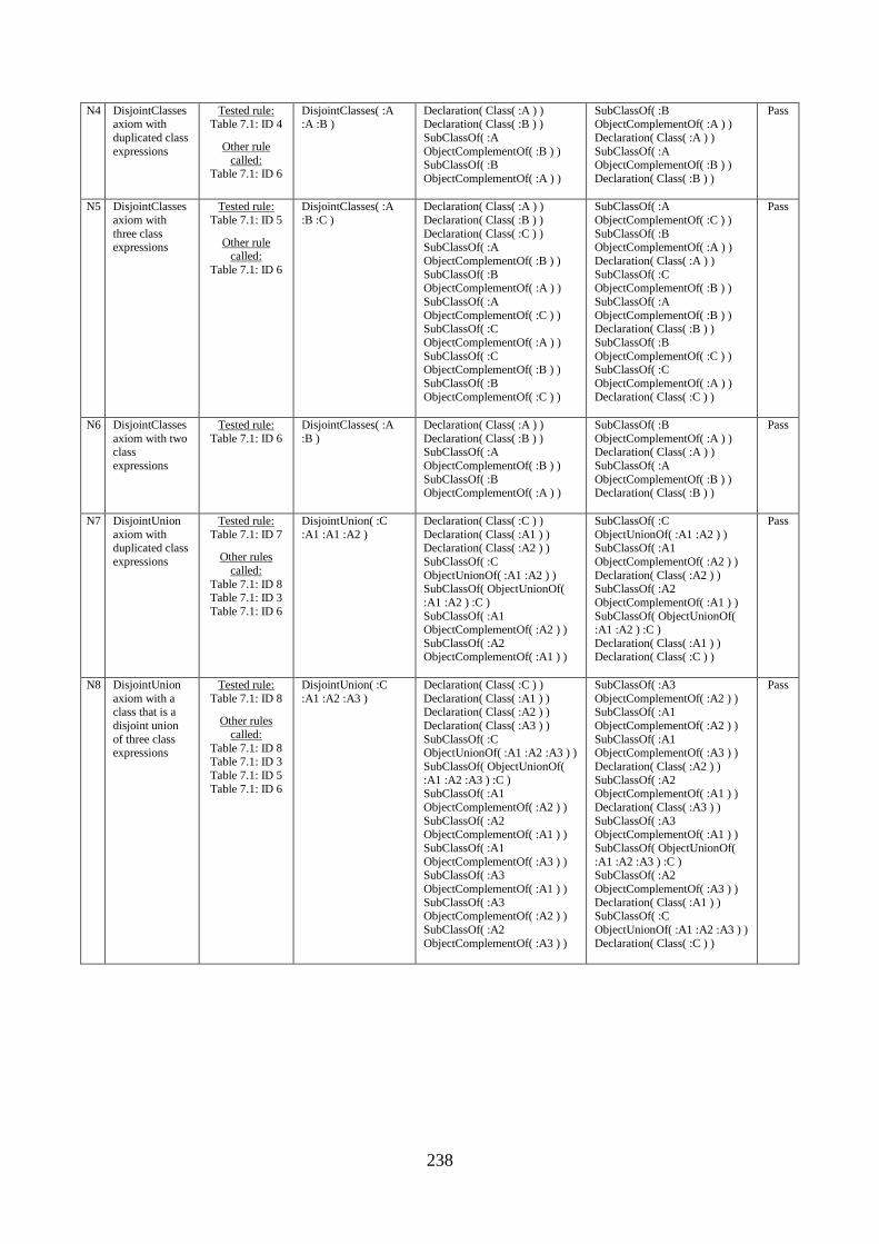
238
N4 DisjointClasses axiom with
duplicated class
expressions
Tested rule: Table 7.1: ID 4
Other rule
called: Table 7.1: ID 6
DisjointClasses( :A :A :B )
Declaration( Class( :A ) ) Declaration( Class( :B ) )
SubClassOf( :A
ObjectComplementOf( :B ) ) SubClassOf( :B
ObjectComplementOf( :A ) )
SubClassOf( :B ObjectComplementOf( :A ) )
Declaration( Class( :A ) )
SubClassOf( :A ObjectComplementOf( :B ) )
Declaration( Class( :B ) )
Pass
N5 DisjointClasses
axiom with
three class expressions
Tested rule:
Table 7.1: ID 5
Other rule called:
Table 7.1: ID 6
DisjointClasses( :A
:B :C )
Declaration( Class( :A ) )
Declaration( Class( :B ) )
Declaration( Class( :C ) ) SubClassOf( :A
ObjectComplementOf( :B ) )
SubClassOf( :B ObjectComplementOf( :A ) )
SubClassOf( :A
ObjectComplementOf( :C ) ) SubClassOf( :C
ObjectComplementOf( :A ) )
SubClassOf( :C ObjectComplementOf( :B ) )
SubClassOf( :B
ObjectComplementOf( :C ) )
SubClassOf( :A
ObjectComplementOf( :C ) )
SubClassOf( :B ObjectComplementOf( :A ) )
Declaration( Class( :A ) )
SubClassOf( :C ObjectComplementOf( :B ) )
SubClassOf( :A
ObjectComplementOf( :B ) ) Declaration( Class( :B ) )
SubClassOf( :B
ObjectComplementOf( :C ) ) SubClassOf( :C
ObjectComplementOf( :A ) )
Declaration( Class( :C ) )
Pass
N6 DisjointClasses
axiom with two class
expressions
Tested rule:
Table 7.1: ID 6
DisjointClasses( :A
:B )
Declaration( Class( :A ) )
Declaration( Class( :B ) ) SubClassOf( :A
ObjectComplementOf( :B ) )
SubClassOf( :B ObjectComplementOf( :A ) )
SubClassOf( :B
ObjectComplementOf( :A ) ) Declaration( Class( :A ) )
SubClassOf( :A
ObjectComplementOf( :B ) ) Declaration( Class( :B ) )
Pass
N7 DisjointUnion
axiom with duplicated class
expressions
Tested rule:
Table 7.1: ID 7
Other rules
called:
Table 7.1: ID 8 Table 7.1: ID 3
Table 7.1: ID 6
DisjointUnion( :C
:A1 :A1 :A2 )
Declaration( Class( :C ) )
Declaration( Class( :A1 ) ) Declaration( Class( :A2 ) )
SubClassOf( :C
ObjectUnionOf( :A1 :A2 ) ) SubClassOf( ObjectUnionOf(
:A1 :A2 ) :C )
SubClassOf( :A1 ObjectComplementOf( :A2 ) )
SubClassOf( :A2 ObjectComplementOf( :A1 ) )
SubClassOf( :C
ObjectUnionOf( :A1 :A2 ) ) SubClassOf( :A1
ObjectComplementOf( :A2 ) )
Declaration( Class( :A2 ) ) SubClassOf( :A2
ObjectComplementOf( :A1 ) )
SubClassOf( ObjectUnionOf( :A1 :A2 ) :C )
Declaration( Class( :A1 ) ) Declaration( Class( :C ) )
Pass
N8 DisjointUnion
axiom with a class that is a
disjoint union
of three class expressions
Tested rule:
Table 7.1: ID 8
Other rules
called:
Table 7.1: ID 8 Table 7.1: ID 3
Table 7.1: ID 5
Table 7.1: ID 6
DisjointUnion( :C
:A1 :A2 :A3 )
Declaration( Class( :C ) )
Declaration( Class( :A1 ) ) Declaration( Class( :A2 ) )
Declaration( Class( :A3 ) )
SubClassOf( :C ObjectUnionOf( :A1 :A2 :A3 ) )
SubClassOf( ObjectUnionOf(
:A1 :A2 :A3 ) :C ) SubClassOf( :A1
ObjectComplementOf( :A2 ) )
SubClassOf( :A2 ObjectComplementOf( :A1 ) )
SubClassOf( :A1
ObjectComplementOf( :A3 ) ) SubClassOf( :A3
ObjectComplementOf( :A1 ) )
SubClassOf( :A3 ObjectComplementOf( :A2 ) )
SubClassOf( :A2
ObjectComplementOf( :A3 ) )
SubClassOf( :A3
ObjectComplementOf( :A2 ) ) SubClassOf( :A1
ObjectComplementOf( :A2 ) )
SubClassOf( :A1 ObjectComplementOf( :A3 ) )
Declaration( Class( :A2 ) )
SubClassOf( :A2 ObjectComplementOf( :A1 ) )
Declaration( Class( :A3 ) )
SubClassOf( :A3 ObjectComplementOf( :A1 ) )
SubClassOf( ObjectUnionOf(
:A1 :A2 :A3 ) :C ) SubClassOf( :A2
ObjectComplementOf( :A3 ) )
Declaration( Class( :A1 ) ) SubClassOf( :C
ObjectUnionOf( :A1 :A2 :A3 ) )
Declaration( Class( :C ) )
Pass
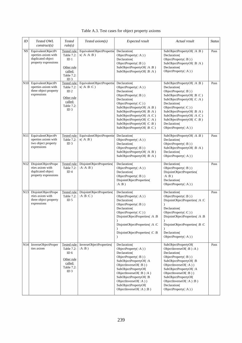
239
Table A.3. Test cases for object property axioms
ID Tested OWL
construct(s)
Tested
rule(s)
Tested axiom(s) Expected result Actual result Status
N9 EquivalentObjectPr
operties axiom with duplicated object
property expressions
Tested rule:
Table 7.2:
ID 1
Other rule
called:
Table 7.2:
ID 3
EquivalentObjectPropertie
s( :A :A :B )
Declaration(
ObjectProperty( :A ) )
Declaration(
ObjectProperty( :B ) )
SubObjectPropertyOf( :A :B )
SubObjectPropertyOf( :B :A )
SubObjectPropertyOf( :A :B )
Declaration(
ObjectProperty( :B ) )
SubObjectPropertyOf( :B :A )
Declaration(
ObjectProperty( :A ) )
Pass
N10 EquivalentObjectPr
operties axiom with three object property
expressions
Tested rule:
Table 7.2:
ID 2
Other rule
called:
Table 7.2: ID 3
EquivalentObjectPropertie
s( :A :B :C )
Declaration(
ObjectProperty( :A ) )
Declaration(
ObjectProperty( :B ) )
Declaration(
ObjectProperty( :C ) )
SubObjectPropertyOf( :A :B )
SubObjectPropertyOf( :B :A )
SubObjectPropertyOf( :A :C )
SubObjectPropertyOf( :C :A )
SubObjectPropertyOf( :C :B )
SubObjectPropertyOf( :B :C )
SubObjectPropertyOf( :A :B )
Declaration(
ObjectProperty( :B ) )
SubObjectPropertyOf( :B :C )
SubObjectPropertyOf( :C :A )
Declaration(
ObjectProperty( :C ) )
SubObjectPropertyOf( :B :A )
SubObjectPropertyOf( :A :C )
SubObjectPropertyOf( :C :B )
Declaration(
ObjectProperty( :A ) )
Pass
N11 EquivalentObjectPr
operties axiom with
two object property expressions
Tested rule:
Table 7.2:
ID 3
EquivalentObjectPropertie
s( :A :B )
Declaration(
ObjectProperty( :A ) )
Declaration(
ObjectProperty( :B ) )
SubObjectPropertyOf( :A :B )
SubObjectPropertyOf( :B :A )
SubObjectPropertyOf( :A :B )
Declaration(
ObjectProperty( :B ) )
SubObjectPropertyOf( :B :A )
Declaration(
ObjectProperty( :A ) )
Pass
N12 DisjointObjectProperties axiom with
duplicated object
property expressions
Tested rule:
Table 7.2:
ID 4
DisjointObjectProperties( :A :A :B )
Declaration(
ObjectProperty( :A ) )
Declaration(
ObjectProperty( :B ) )
DisjointObjectProperties(
:A :B )
Declaration(
ObjectProperty( :B ) )
DisjointObjectProperties(
:A :B )
Declaration(
ObjectProperty( :A ) )
Pass
N13 DisjointObjectPrope
rties axiom with three object property
expressions
Tested rule:
Table 7.2: ID 5
DisjointObjectProperties(
:A :B :C )
Declaration(
ObjectProperty( :A ) )
Declaration(
ObjectProperty( :B ) )
Declaration(
ObjectProperty( :C ) )
DisjointObjectProperties( :A :B
)
DisjointObjectProperties( :A :C
)
DisjointObjectProperties( :C :B
)
Declaration(
ObjectProperty( :B ) )
DisjointObjectProperties( :A :C
)
Declaration(
ObjectProperty( :C ) )
DisjointObjectProperties( :A :B
)
DisjointObjectProperties( :B :C
)
Declaration(
ObjectProperty( :A ) )
Pass
N14 InverseObjectProper
ties axiom
Tested rule:
Table 7.2:
ID 6
Other rule
called:
Table 7.2:
ID 3
InverseObjectProperties(
:A :B )
Declaration(
ObjectProperty( :A ) )
Declaration(
ObjectProperty( :B ) )
SubObjectPropertyOf( :A
ObjectInverseOf( :B ) )
SubObjectPropertyOf(
ObjectInverseOf( :B ) :A )
SubObjectPropertyOf( :B
ObjectInverseOf( :A ) )
SubObjectPropertyOf(
ObjectInverseOf( :A ) :B )
SubObjectPropertyOf(
ObjectInverseOf( :B ) :A )
Declaration(
ObjectProperty( :B ) )
SubObjectPropertyOf( :B
ObjectInverseOf( :A ) )
SubObjectPropertyOf( :A
ObjectInverseOf( :B ) )
SubObjectPropertyOf(
ObjectInverseOf( :A ) :B )
Declaration(
ObjectProperty( :A ) )
Pass
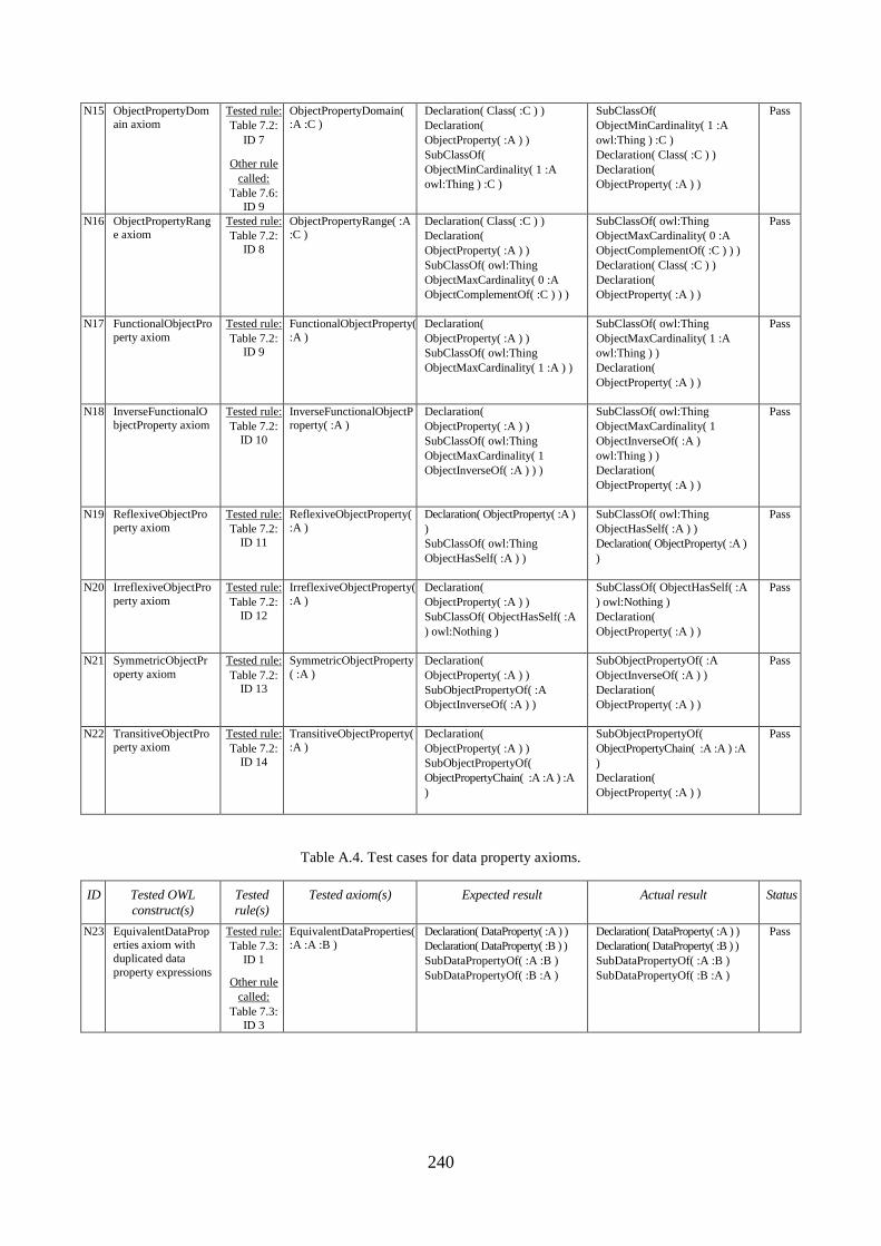
240
N15 ObjectPropertyDomain axiom
Tested rule:
Table 7.2:
ID 7
Other rule
called:
Table 7.6:
ID 9
ObjectPropertyDomain( :A :C )
Declaration( Class( :C ) )
Declaration(
ObjectProperty( :A ) )
SubClassOf(
ObjectMinCardinality( 1 :A
owl:Thing ) :C )
SubClassOf(
ObjectMinCardinality( 1 :A
owl:Thing ) :C )
Declaration( Class( :C ) )
Declaration(
ObjectProperty( :A ) )
Pass
N16 ObjectPropertyRange axiom
Tested rule:
Table 7.2:
ID 8
ObjectPropertyRange( :A :C )
Declaration( Class( :C ) )
Declaration(
ObjectProperty( :A ) )
SubClassOf( owl:Thing
ObjectMaxCardinality( 0 :A
ObjectComplementOf( :C ) ) )
SubClassOf( owl:Thing
ObjectMaxCardinality( 0 :A
ObjectComplementOf( :C ) ) )
Declaration( Class( :C ) )
Declaration(
ObjectProperty( :A ) )
Pass
N17 FunctionalObjectPro
perty axiom
Tested rule:
Table 7.2: ID 9
FunctionalObjectProperty(
:A )
Declaration(
ObjectProperty( :A ) )
SubClassOf( owl:Thing
ObjectMaxCardinality( 1 :A ) )
SubClassOf( owl:Thing
ObjectMaxCardinality( 1 :A
owl:Thing ) )
Declaration(
ObjectProperty( :A ) )
Pass
N18 InverseFunctionalO
bjectProperty axiom
Tested rule:
Table 7.2:
ID 10
InverseFunctionalObjectP
roperty( :A )
Declaration(
ObjectProperty( :A ) )
SubClassOf( owl:Thing
ObjectMaxCardinality( 1
ObjectInverseOf( :A ) ) )
SubClassOf( owl:Thing
ObjectMaxCardinality( 1
ObjectInverseOf( :A )
owl:Thing ) )
Declaration(
ObjectProperty( :A ) )
Pass
N19 ReflexiveObjectProperty axiom
Tested rule:
Table 7.2:
ID 11
ReflexiveObjectProperty( :A )
Declaration( ObjectProperty( :A )
)
SubClassOf( owl:Thing
ObjectHasSelf( :A ) )
SubClassOf( owl:Thing
ObjectHasSelf( :A ) )
Declaration( ObjectProperty( :A )
)
Pass
N20 IrreflexiveObjectPro
perty axiom
Tested rule:
Table 7.2:
ID 12
IrreflexiveObjectProperty(
:A )
Declaration(
ObjectProperty( :A ) )
SubClassOf( ObjectHasSelf( :A
) owl:Nothing )
SubClassOf( ObjectHasSelf( :A
) owl:Nothing )
Declaration(
ObjectProperty( :A ) )
Pass
N21 SymmetricObjectPr
operty axiom
Tested rule:
Table 7.2:
ID 13
SymmetricObjectProperty
( :A )
Declaration(
ObjectProperty( :A ) )
SubObjectPropertyOf( :A
ObjectInverseOf( :A ) )
SubObjectPropertyOf( :A
ObjectInverseOf( :A ) )
Declaration(
ObjectProperty( :A ) )
Pass
N22 TransitiveObjectProperty axiom
Tested rule:
Table 7.2: ID 14
TransitiveObjectProperty( :A )
Declaration(
ObjectProperty( :A ) )
SubObjectPropertyOf(
ObjectPropertyChain( :A :A ) :A
)
SubObjectPropertyOf(
ObjectPropertyChain( :A :A ) :A
)
Declaration(
ObjectProperty( :A ) )
Pass
Table A.4. Test cases for data property axioms.
ID Tested OWL
construct(s)
Tested
rule(s)
Tested axiom(s) Expected result Actual result Status
N23 EquivalentDataProperties axiom with
duplicated data
property expressions
Tested rule:
Table 7.3:
ID 1
Other rule
called:
Table 7.3:
ID 3
EquivalentDataProperties( :A :A :B )
Declaration( DataProperty( :A ) )
Declaration( DataProperty( :B ) )
SubDataPropertyOf( :A :B )
SubDataPropertyOf( :B :A )
Declaration( DataProperty( :A ) )
Declaration( DataProperty( :B ) )
SubDataPropertyOf( :A :B )
SubDataPropertyOf( :B :A )
Pass
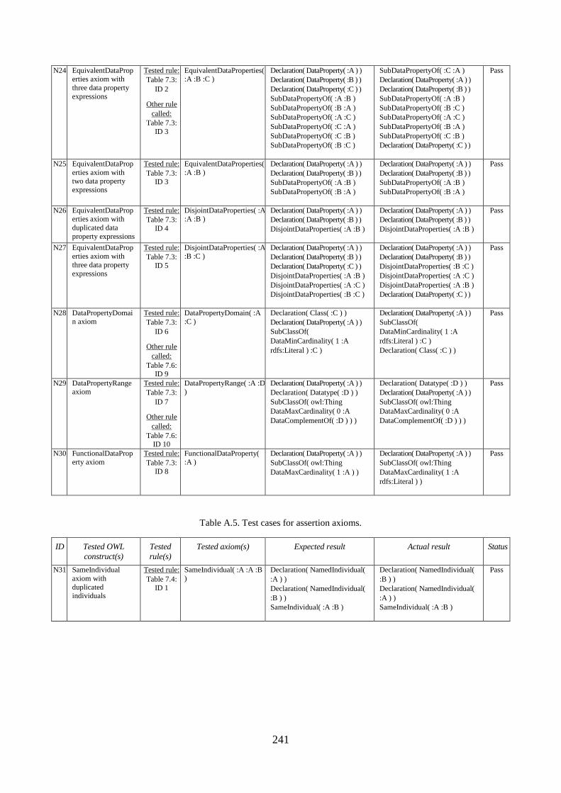
241
N24 EquivalentDataProperties axiom with
three data property
expressions
Tested rule:
Table 7.3:
ID 2
Other rule
called:
Table 7.3:
ID 3
EquivalentDataProperties( :A :B :C )
Declaration( DataProperty( :A ) )
Declaration( DataProperty( :B ) )
Declaration( DataProperty( :C ) )
SubDataPropertyOf( :A :B )
SubDataPropertyOf( :B :A )
SubDataPropertyOf( :A :C )
SubDataPropertyOf( :C :A )
SubDataPropertyOf( :C :B )
SubDataPropertyOf( :B :C )
SubDataPropertyOf( :C :A )
Declaration( DataProperty( :A ) )
Declaration( DataProperty( :B ) )
SubDataPropertyOf( :A :B )
SubDataPropertyOf( :B :C )
SubDataPropertyOf( :A :C )
SubDataPropertyOf( :B :A )
SubDataPropertyOf( :C :B )
Declaration( DataProperty( :C ) )
Pass
N25 EquivalentDataProp
erties axiom with two data property
expressions
Tested rule:
Table 7.3: ID 3
EquivalentDataProperties(
:A :B )
Declaration( DataProperty( :A ) )
Declaration( DataProperty( :B ) )
SubDataPropertyOf( :A :B )
SubDataPropertyOf( :B :A )
Declaration( DataProperty( :A ) )
Declaration( DataProperty( :B ) )
SubDataPropertyOf( :A :B )
SubDataPropertyOf( :B :A )
Pass
N26 EquivalentDataProperties axiom with
duplicated data
property expressions
Tested rule:
Table 7.3:
ID 4
DisjointDataProperties( :A :A :B )
Declaration( DataProperty( :A ) )
Declaration( DataProperty( :B ) )
DisjointDataProperties( :A :B )
Declaration( DataProperty( :A ) )
Declaration( DataProperty( :B ) )
DisjointDataProperties( :A :B )
Pass
N27 EquivalentDataProperties axiom with
three data property
expressions
Tested rule:
Table 7.3:
ID 5
DisjointDataProperties( :A :B :C )
Declaration( DataProperty( :A ) )
Declaration( DataProperty( :B ) )
Declaration( DataProperty( :C ) )
DisjointDataProperties( :A :B )
DisjointDataProperties( :A :C )
DisjointDataProperties( :B :C )
Declaration( DataProperty( :A ) )
Declaration( DataProperty( :B ) )
DisjointDataProperties( :B :C )
DisjointDataProperties( :A :C )
DisjointDataProperties( :A :B )
Declaration( DataProperty( :C ) )
Pass
N28 DataPropertyDomai
n axiom
Tested rule:
Table 7.3:
ID 6
Other rule
called:
Table 7.6: ID 9
DataPropertyDomain( :A
:C )
Declaration( Class( :C ) )
Declaration( DataProperty( :A ) )
SubClassOf(
DataMinCardinality( 1 :A
rdfs:Literal ) :C )
Declaration( DataProperty( :A ) )
SubClassOf(
DataMinCardinality( 1 :A
rdfs:Literal ) :C )
Declaration( Class( :C ) )
Pass
N29 DataPropertyRange
axiom
Tested rule:
Table 7.3:
ID 7
Other rule
called:
Table 7.6: ID 10
DataPropertyRange( :A :D
)
Declaration( DataProperty( :A ) )
Declaration( Datatype( :D ) )
SubClassOf( owl:Thing
DataMaxCardinality( 0 :A
DataComplementOf( :D ) ) )
Declaration( Datatype( :D ) )
Declaration( DataProperty( :A ) )
SubClassOf( owl:Thing
DataMaxCardinality( 0 :A
DataComplementOf( :D ) ) )
Pass
N30 FunctionalDataProp
erty axiom
Tested rule:
Table 7.3:
ID 8
FunctionalDataProperty(
:A )
Declaration( DataProperty( :A ) )
SubClassOf( owl:Thing
DataMaxCardinality( 1 :A ) )
Declaration( DataProperty( :A ) )
SubClassOf( owl:Thing
DataMaxCardinality( 1 :A
rdfs:Literal ) )
Pass
Table A.5. Test cases for assertion axioms.
ID Tested OWL
construct(s)
Tested
rule(s)
Tested axiom(s) Expected result Actual result Status
N31 SameIndividual
axiom with
duplicated individuals
Tested rule:
Table 7.4:
ID 1
SameIndividual( :A :A :B
)
Declaration( NamedIndividual(
:A ) )
Declaration( NamedIndividual(
:B ) )
SameIndividual( :A :B )
Declaration( NamedIndividual(
:B ) )
Declaration( NamedIndividual(
:A ) )
SameIndividual( :A :B )
Pass
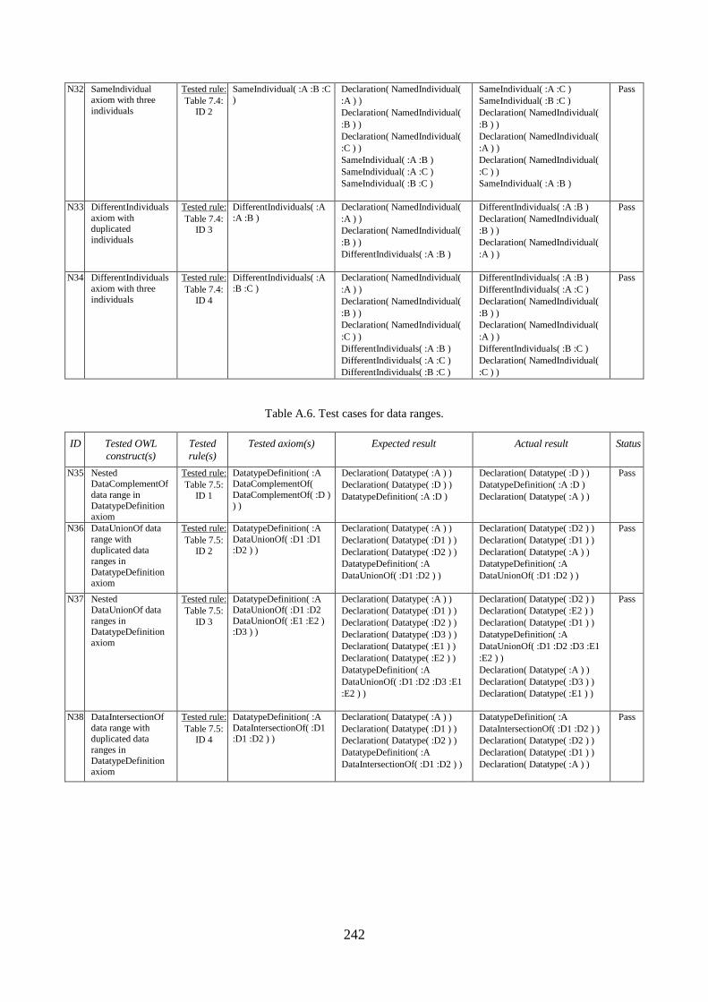
242
N32 SameIndividual axiom with three
individuals
Tested rule:
Table 7.4:
ID 2
SameIndividual( :A :B :C )
Declaration( NamedIndividual(
:A ) )
Declaration( NamedIndividual(
:B ) )
Declaration( NamedIndividual(
:C ) )
SameIndividual( :A :B )
SameIndividual( :A :C )
SameIndividual( :B :C )
SameIndividual( :A :C )
SameIndividual( :B :C )
Declaration( NamedIndividual(
:B ) )
Declaration( NamedIndividual(
:A ) )
Declaration( NamedIndividual(
:C ) )
SameIndividual( :A :B )
Pass
N33 DifferentIndividuals
axiom with duplicated
individuals
Tested rule:
Table 7.4: ID 3
DifferentIndividuals( :A
:A :B )
Declaration( NamedIndividual(
:A ) )
Declaration( NamedIndividual(
:B ) )
DifferentIndividuals( :A :B )
DifferentIndividuals( :A :B )
Declaration( NamedIndividual(
:B ) )
Declaration( NamedIndividual(
:A ) )
Pass
N34 DifferentIndividuals
axiom with three
individuals
Tested rule:
Table 7.4:
ID 4
DifferentIndividuals( :A
:B :C )
Declaration( NamedIndividual(
:A ) )
Declaration( NamedIndividual(
:B ) )
Declaration( NamedIndividual(
:C ) )
DifferentIndividuals( :A :B )
DifferentIndividuals( :A :C )
DifferentIndividuals( :B :C )
DifferentIndividuals( :A :B )
DifferentIndividuals( :A :C )
Declaration( NamedIndividual(
:B ) )
Declaration( NamedIndividual(
:A ) )
DifferentIndividuals( :B :C )
Declaration( NamedIndividual(
:C ) )
Pass
Table A.6. Test cases for data ranges.
ID Tested OWL
construct(s)
Tested
rule(s)
Tested axiom(s) Expected result Actual result Status
N35 Nested DataComplementOf
data range in
DatatypeDefinition axiom
Tested rule:
Table 7.5:
ID 1
DatatypeDefinition( :A DataComplementOf(
DataComplementOf( :D )
) )
Declaration( Datatype( :A ) )
Declaration( Datatype( :D ) )
DatatypeDefinition( :A :D )
Declaration( Datatype( :D ) )
DatatypeDefinition( :A :D )
Declaration( Datatype( :A ) )
Pass
N36 DataUnionOf data
range with
duplicated data
ranges in
DatatypeDefinition axiom
Tested rule:
Table 7.5:
ID 2
DatatypeDefinition( :A
DataUnionOf( :D1 :D1
:D2 ) )
Declaration( Datatype( :A ) )
Declaration( Datatype( :D1 ) )
Declaration( Datatype( :D2 ) )
DatatypeDefinition( :A
DataUnionOf( :D1 :D2 ) )
Declaration( Datatype( :D2 ) )
Declaration( Datatype( :D1 ) )
Declaration( Datatype( :A ) )
DatatypeDefinition( :A
DataUnionOf( :D1 :D2 ) )
Pass
N37 Nested DataUnionOf data
ranges in DatatypeDefinition
axiom
Tested rule:
Table 7.5:
ID 3
DatatypeDefinition( :A DataUnionOf( :D1 :D2
DataUnionOf( :E1 :E2 ) :D3 ) )
Declaration( Datatype( :A ) )
Declaration( Datatype( :D1 ) )
Declaration( Datatype( :D2 ) )
Declaration( Datatype( :D3 ) )
Declaration( Datatype( :E1 ) )
Declaration( Datatype( :E2 ) )
DatatypeDefinition( :A
DataUnionOf( :D1 :D2 :D3 :E1
:E2 ) )
Declaration( Datatype( :D2 ) )
Declaration( Datatype( :E2 ) )
Declaration( Datatype( :D1 ) )
DatatypeDefinition( :A
DataUnionOf( :D1 :D2 :D3 :E1
:E2 ) )
Declaration( Datatype( :A ) )
Declaration( Datatype( :D3 ) )
Declaration( Datatype( :E1 ) )
Pass
N38 DataIntersectionOf
data range with duplicated data
ranges in
DatatypeDefinition axiom
Tested rule:
Table 7.5: ID 4
DatatypeDefinition( :A
DataIntersectionOf( :D1 :D1 :D2 ) )
Declaration( Datatype( :A ) )
Declaration( Datatype( :D1 ) )
Declaration( Datatype( :D2 ) )
DatatypeDefinition( :A
DataIntersectionOf( :D1 :D2 ) )
DatatypeDefinition( :A
DataIntersectionOf( :D1 :D2 ) )
Declaration( Datatype( :D2 ) )
Declaration( Datatype( :D1 ) )
Declaration( Datatype( :A ) )
Pass
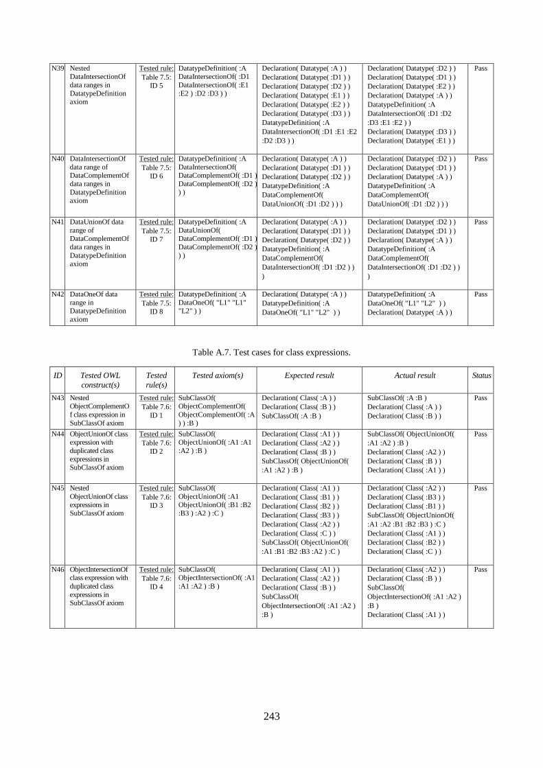
243
N39 Nested DataIntersectionOf
data ranges in
DatatypeDefinition axiom
Tested rule:
Table 7.5:
ID 5
DatatypeDefinition( :A DataIntersectionOf( :D1
DataIntersectionOf( :E1
:E2 ) :D2 :D3 ) )
Declaration( Datatype( :A ) )
Declaration( Datatype( :D1 ) )
Declaration( Datatype( :D2 ) )
Declaration( Datatype( :E1 ) )
Declaration( Datatype( :E2 ) )
Declaration( Datatype( :D3 ) )
DatatypeDefinition( :A
DataIntersectionOf( :D1 :E1 :E2
:D2 :D3 ) )
Declaration( Datatype( :D2 ) )
Declaration( Datatype( :D1 ) )
Declaration( Datatype( :E2 ) )
Declaration( Datatype( :A ) )
DatatypeDefinition( :A
DataIntersectionOf( :D1 :D2
:D3 :E1 :E2 ) )
Declaration( Datatype( :D3 ) )
Declaration( Datatype( :E1 ) )
Pass
N40 DataIntersectionOf
data range of DataComplementOf
data ranges in
DatatypeDefinition axiom
Tested rule:
Table 7.5: ID 6
DatatypeDefinition( :A
DataIntersectionOf( DataComplementOf( :D1 )
DataComplementOf( :D2 )
) )
Declaration( Datatype( :A ) )
Declaration( Datatype( :D1 ) )
Declaration( Datatype( :D2 ) )
DatatypeDefinition( :A
DataComplementOf(
DataUnionOf( :D1 :D2 ) ) )
Declaration( Datatype( :D2 ) )
Declaration( Datatype( :D1 ) )
Declaration( Datatype( :A ) )
DatatypeDefinition( :A
DataComplementOf(
DataUnionOf( :D1 :D2 ) ) )
Pass
N41 DataUnionOf data
range of DataComplementOf
data ranges in
DatatypeDefinition axiom
Tested rule:
Table 7.5:
ID 7
DatatypeDefinition( :A
DataUnionOf( DataComplementOf( :D1 )
DataComplementOf( :D2 )
) )
Declaration( Datatype( :A ) )
Declaration( Datatype( :D1 ) )
Declaration( Datatype( :D2 ) )
DatatypeDefinition( :A
DataComplementOf(
DataIntersectionOf( :D1 :D2 ) )
)
Declaration( Datatype( :D2 ) )
Declaration( Datatype( :D1 ) )
Declaration( Datatype( :A ) )
DatatypeDefinition( :A
DataComplementOf(
DataIntersectionOf( :D1 :D2 ) )
)
Pass
N42 DataOneOf data
range in DatatypeDefinition
axiom
Tested rule:
Table 7.5: ID 8
DatatypeDefinition( :A
DataOneOf( "L1" "L1" "L2" ) )
Declaration( Datatype( :A ) )
DatatypeDefinition( :A
DataOneOf( "L1" "L2" ) )
DatatypeDefinition( :A
DataOneOf( "L1" "L2" ) )
Declaration( Datatype( :A ) )
Pass
Table A.7. Test cases for class expressions.
ID Tested OWL
construct(s)
Tested
rule(s)
Tested axiom(s) Expected result Actual result Status
N43 Nested ObjectComplementO
f class expression in
SubClassOf axiom
Tested rule:
Table 7.6:
ID 1
SubClassOf( ObjectComplementOf(
ObjectComplementOf( :A
) ) :B )
Declaration( Class( :A ) )
Declaration( Class( :B ) )
SubClassOf( :A :B )
SubClassOf( :A :B )
Declaration( Class( :A ) )
Declaration( Class( :B ) )
Pass
N44 ObjectUnionOf class expression with
duplicated class
expressions in SubClassOf axiom
Tested rule:
Table 7.6:
ID 2
SubClassOf( ObjectUnionOf( :A1 :A1
:A2 ) :B )
Declaration( Class( :A1 ) )
Declaration( Class( :A2 ) )
Declaration( Class( :B ) )
SubClassOf( ObjectUnionOf(
:A1 :A2 ) :B )
SubClassOf( ObjectUnionOf(
:A1 :A2 ) :B )
Declaration( Class( :A2 ) )
Declaration( Class( :B ) )
Declaration( Class( :A1 ) )
Pass
N45 Nested
ObjectUnionOf class expressions in
SubClassOf axiom
Tested rule:
Table 7.6: ID 3
SubClassOf(
ObjectUnionOf( :A1 ObjectUnionOf( :B1 :B2
:B3 ) :A2 ) :C )
Declaration( Class( :A1 ) )
Declaration( Class( :B1 ) )
Declaration( Class( :B2 ) )
Declaration( Class( :B3 ) )
Declaration( Class( :A2 ) )
Declaration( Class( :C ) )
SubClassOf( ObjectUnionOf(
:A1 :B1 :B2 :B3 :A2 ) :C )
Declaration( Class( :A2 ) )
Declaration( Class( :B3 ) )
Declaration( Class( :B1 ) )
SubClassOf( ObjectUnionOf(
:A1 :A2 :B1 :B2 :B3 ) :C )
Declaration( Class( :A1 ) )
Declaration( Class( :B2 ) )
Declaration( Class( :C ) )
Pass
N46 ObjectIntersectionOf class expression with
duplicated class
expressions in SubClassOf axiom
Tested rule:
Table 7.6:
ID 4
SubClassOf( ObjectIntersectionOf( :A1
:A1 :A2 ) :B )
Declaration( Class( :A1 ) )
Declaration( Class( :A2 ) )
Declaration( Class( :B ) )
SubClassOf(
ObjectIntersectionOf( :A1 :A2 )
:B )
Declaration( Class( :A2 ) )
Declaration( Class( :B ) )
SubClassOf(
ObjectIntersectionOf( :A1 :A2 )
:B )
Declaration( Class( :A1 ) )
Pass
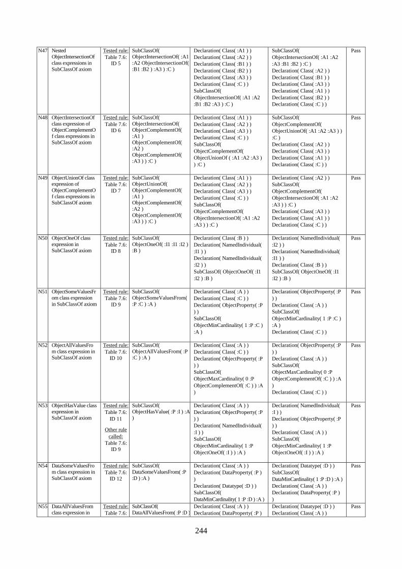
244
N47 Nested ObjectIntersectionOf
class expressions in
SubClassOf axiom
Tested rule:
Table 7.6:
ID 5
SubClassOf( ObjectIntersectionOf( :A1
:A2 ObjectIntersectionOf(
:B1 :B2 ) :A3 ) :C )
Declaration( Class( :A1 ) )
Declaration( Class( :A2 ) )
Declaration( Class( :B1 ) )
Declaration( Class( :B2 ) )
Declaration( Class( :A3 ) )
Declaration( Class( :C ) )
SubClassOf(
ObjectIntersectionOf( :A1 :A2
:B1 :B2 :A3 ) :C )
SubClassOf(
ObjectIntersectionOf( :A1 :A2
:A3 :B1 :B2 ) :C )
Declaration( Class( :A2 ) )
Declaration( Class( :B1 ) )
Declaration( Class( :A3 ) )
Declaration( Class( :A1 ) )
Declaration( Class( :B2 ) )
Declaration( Class( :C ) )
Pass
N48 ObjectIntersectionOf
class expression of ObjectComplementO
f class expressions in
SubClassOf axiom
Tested rule:
Table 7.6: ID 6
SubClassOf(
ObjectIntersectionOf( ObjectComplementOf(
:A1 )
ObjectComplementOf( :A2 )
ObjectComplementOf(
:A3 ) ) :C )
Declaration( Class( :A1 ) )
Declaration( Class( :A2 ) )
Declaration( Class( :A3 ) )
Declaration( Class( :C ) )
SubClassOf(
ObjectComplementOf(
ObjectUnionOf ( :A1 :A2 :A3 )
) :C )
SubClassOf(
ObjectComplementOf(
ObjectUnionOf( :A1 :A2 :A3 ) )
:C )
Declaration( Class( :A2 ) )
Declaration( Class( :A3 ) )
Declaration( Class( :A1 ) )
Declaration( Class( :C ) )
Pass
N49 ObjectUnionOf class expression of
ObjectComplementO
f class expressions in SubClassOf axiom
Tested rule:
Table 7.6:
ID 7
SubClassOf( ObjectUnionOf(
ObjectComplementOf(
:A1 ) ObjectComplementOf(
:A2 )
ObjectComplementOf( :A3 ) ) :C )
Declaration( Class( :A1 ) )
Declaration( Class( :A2 ) )
Declaration( Class( :A3 ) )
Declaration( Class( :C ) )
SubClassOf(
ObjectComplementOf(
ObjectIntersectionOf( :A1 :A2
:A3 ) ) :C )
Declaration( Class( :A2 ) )
SubClassOf(
ObjectComplementOf(
ObjectIntersectionOf( :A1 :A2
:A3 ) ) :C )
Declaration( Class( :A3 ) )
Declaration( Class( :A1 ) )
Declaration( Class( :C ) )
Pass
N50 ObjectOneOf class
expression in
SubClassOf axiom
Tested rule:
Table 7.6:
ID 8
SubClassOf(
ObjectOneOf( :I1 :I1 :I2 )
:B )
Declaration( Class( :B ) )
Declaration( NamedIndividual(
:I1 ) )
Declaration( NamedIndividual(
:I2 ) )
SubClassOf( ObjectOneOf( :I1
:I2 ) :B )
Declaration( NamedIndividual(
:I2 ) )
Declaration( NamedIndividual(
:I1 ) )
Declaration( Class( :B ) )
SubClassOf( ObjectOneOf( :I1
:I2 ) :B )
Pass
N51 ObjectSomeValuesFr
om class expression
in SubClassOf axiom
Tested rule:
Table 7.6:
ID 9
SubClassOf(
ObjectSomeValuesFrom(
:P :C ) :A )
Declaration( Class( :A ) )
Declaration( Class( :C ) )
Declaration( ObjectProperty( :P
) )
SubClassOf(
ObjectMinCardinality( 1 :P :C )
:A )
Declaration( ObjectProperty( :P
) )
Declaration( Class( :A ) )
SubClassOf(
ObjectMinCardinality( 1 :P :C )
:A )
Declaration( Class( :C ) )
Pass
N52 ObjectAllValuesFro
m class expression in SubClassOf axiom
Tested rule:
Table 7.6:
ID 10
SubClassOf(
ObjectAllValuesFrom( :P :C ) :A )
Declaration( Class( :A ) )
Declaration( Class( :C ) )
Declaration( ObjectProperty( :P
) )
SubClassOf(
ObjectMaxCardinality( 0 :P
ObjectComplementOf( :C ) ) :A
)
Declaration( ObjectProperty( :P
) )
Declaration( Class( :A ) )
SubClassOf(
ObjectMaxCardinality( 0 :P
ObjectComplementOf( :C ) ) :A
)
Declaration( Class( :C ) )
Pass
N53 ObjectHasValue class expression in
SubClassOf axiom
Tested rule:
Table 7.6:
ID 11
Other rule
called:
Table 7.6:
ID 9
SubClassOf( ObjectHasValue( :P :I ) :A
)
Declaration( Class( :A ) )
Declaration( ObjectProperty( :P
) )
Declaration( NamedIndividual(
:I ) )
SubClassOf(
ObjectMinCardinality( 1 :P
ObjectOneOf( :I ) ) :A )
Declaration( NamedIndividual(
:I ) )
Declaration( ObjectProperty( :P
) )
Declaration( Class( :A ) )
SubClassOf(
ObjectMinCardinality( 1 :P
ObjectOneOf( :I ) ) :A )
Pass
N54 DataSomeValuesFro
m class expression in
SubClassOf axiom
Tested rule:
Table 7.6:
ID 12
SubClassOf(
DataSomeValuesFrom( :P
:D ) :A )
Declaration( Class( :A ) )
Declaration( DataProperty( :P )
)
Declaration( Datatype( :D ) )
SubClassOf(
DataMinCardinality( 1 :P :D ) :A )
Declaration( Datatype( :D ) )
SubClassOf(
DataMinCardinality( 1 :P :D ) :A )
Declaration( Class( :A ) )
Declaration( DataProperty( :P )
)
Pass
N55 DataAllValuesFrom
class expression in
Tested rule:
Table 7.6:
SubClassOf(
DataAllValuesFrom( :P :D )
Declaration( Class( :A ) )
Declaration( DataProperty( :P )
Declaration( Datatype( :D ) )
Declaration( Class( :A ) )
Pass
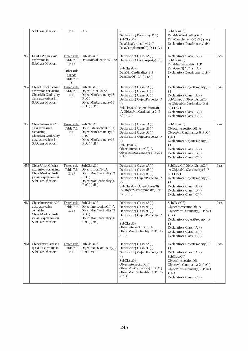
245
SubClassOf axiom ID 13 :A ) )
Declaration( Datatype( :D ) )
SubClassOf(
DataMaxCardinality( 0 :P
DataComplementOf( :D ) ) :A )
SubClassOf(
DataMaxCardinality( 0 :P
DataComplementOf( :D ) ) :A )
Declaration( DataProperty( :P )
)
N56 DataHasValue class
expression in SubClassOf axiom
Tested rule:
Table 7.6:
ID 14
Other rule
called:
Table 7.6: ID 9
SubClassOf(
DataHasValue( :P "L" ) :A )
Declaration( Class( :A ) )
Declaration( DataProperty( :P )
)
SubClassOf(
DataMinCardinality( 1 :P
DataOneOf( "L" ) ) :A )
Declaration( Class( :A ) )
SubClassOf(
DataMinCardinality( 1 :P
DataOneOf( "L" ) ) :A )
Declaration( DataProperty( :P )
)
Pass
N57 ObjectUnionOf class
expression containing
ObjectMinCardinality class expressions in
SubClassOf axiom
Tested rule:
Table 7.6:
ID 15
SubClassOf(
ObjectUnionOf( :A
ObjectMinCardinality( 3 :P :C )
ObjectMinCardinality( 6 :P :C ) ) :B )
Declaration( Class( :A ) )
Declaration( Class( :B ) )
Declaration( Class( :C ) )
Declaration( ObjectProperty( :P
) )
SubClassOf( ObjectUnionOf( :A ObjectMinCardinality( 3 :P
:C ) ) :B )
Declaration( ObjectProperty( :P
) )
Declaration( Class( :A ) )
SubClassOf( ObjectUnionOf(
:A ObjectMinCardinality( 3 :P
:C ) ) :B )
Declaration( Class( :B ) )
Declaration( Class( :C ) )
Pass
N58 ObjectIntersectionOf
class expression containing
ObjectMinCardinality class expressions in
SubClassOf axiom
Tested rule:
Table 7.6: ID 16
SubClassOf(
ObjectIntersectionOf( :A ObjectMinCardinality( 3
:P :C ) ObjectMinCardinality( 6
:P :C ) ) :B )
Declaration( Class( :A ) )
Declaration( Class( :B ) )
Declaration( Class( :C ) )
Declaration( ObjectProperty( :P
) )
SubClassOf(
ObjectIntersectionOf( :A
ObjectMinCardinality( 6 :P :C ) ) :B )
SubClassOf(
ObjectIntersectionOf( :A
ObjectMinCardinality( 6 :P :C )
) :B )
Declaration( ObjectProperty( :P
) )
Declaration( Class( :A ) )
Declaration( Class( :B ) )
Declaration( Class( :C ) )
Pass
N59 ObjectUnionOf class
expression containing
ObjectMaxCardinality class expressions in
SubClassOf axiom
Tested rule:
Table 7.6:
ID 17
SubClassOf(
ObjectUnionOf( :A
ObjectMaxCardinality( 3 :P :C )
ObjectMaxCardinality( 6
:P :C ) ) :B )
Declaration( Class( :A ) )
Declaration( Class( :B ) )
Declaration( Class( :C ) )
Declaration( ObjectProperty( :P
) )
SubClassOf( ObjectUnionOf(
:A ObjectMaxCardinality( 6 :P
:C ) ) :B )
SubClassOf( ObjectUnionOf(
:A ObjectMaxCardinality( 6 :P
:C ) ) :B )
Declaration( ObjectProperty( :P
) )
Declaration( Class( :A ) )
Declaration( Class( :B ) )
Declaration( Class( :C ) )
Pass
N60 ObjectIntersectionOf
class expression containing
ObjectMaxCardinalit
y class expressions in SubClassOf axiom
Tested rule:
Table 7.6: ID 18
SubClassOf(
ObjectIntersectionOf( :A ObjectMaxCardinality( 3
:P :C )
ObjectMaxCardinality( 6 :P :C ) ) :B )
Declaration( Class( :A ) )
Declaration( Class( :B ) )
Declaration( Class( :C ) )
Declaration( ObjectProperty( :P
) )
SubClassOf( ObjectIntersectionOf( :A
ObjectMaxCardinality( 3 :P :C )
) :B )
SubClassOf(
ObjectIntersectionOf( :A
ObjectMaxCardinality( 3 :P :C )
) :B )
Declaration( ObjectProperty( :P
) )
Declaration( Class( :A ) )
Declaration( Class( :B ) )
Declaration( Class( :C ) )
Pass
N61 ObjectExactCardinali
ty class expression in
SubClassOf axiom
Tested rule:
Table 7.6:
ID 19
SubClassOf(
ObjectExactCardinality( 2
:P :C ) :A )
Declaration( Class( :A ) )
Declaration( Class( :C ) )
Declaration( ObjectProperty( :P
) )
SubClassOf(
ObjectIntersectionOf(
ObjectMinCardinality( 2 :P :C )
ObjectMaxCardinality( 2 :P :C )
) :A )
Declaration( ObjectProperty( :P
) )
Declaration( Class( :A ) )
SubClassOf(
ObjectIntersectionOf(
ObjectMinCardinality( 2 :P :C )
ObjectMaxCardinality( 2 :P :C )
) :A )
Declaration( Class( :C ) )
Pass
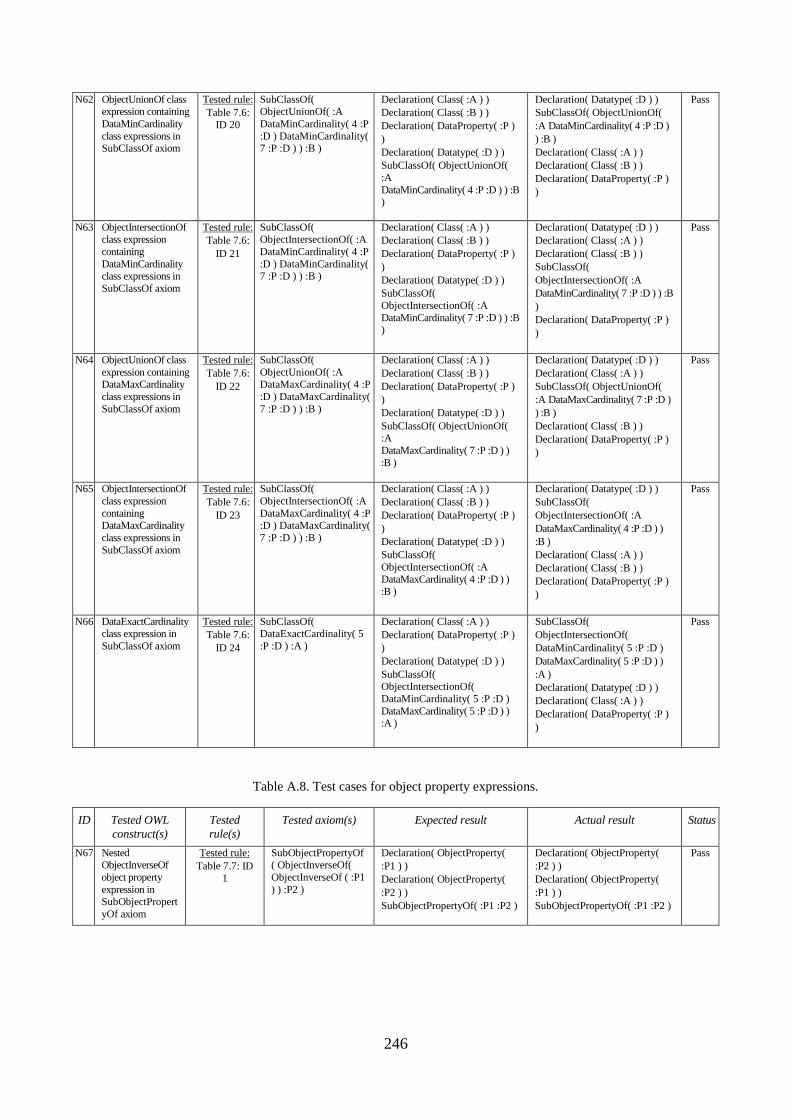
246
N62 ObjectUnionOf class expression containing
DataMinCardinality
class expressions in SubClassOf axiom
Tested rule:
Table 7.6:
ID 20
SubClassOf( ObjectUnionOf( :A
DataMinCardinality( 4 :P
:D ) DataMinCardinality( 7 :P :D ) ) :B )
Declaration( Class( :A ) )
Declaration( Class( :B ) )
Declaration( DataProperty( :P )
)
Declaration( Datatype( :D ) )
SubClassOf( ObjectUnionOf(
:A
DataMinCardinality( 4 :P :D ) ) :B )
Declaration( Datatype( :D ) )
SubClassOf( ObjectUnionOf(
:A DataMinCardinality( 4 :P :D )
) :B )
Declaration( Class( :A ) )
Declaration( Class( :B ) )
Declaration( DataProperty( :P )
)
Pass
N63 ObjectIntersectionOf class expression
containing
DataMinCardinality class expressions in
SubClassOf axiom
Tested rule:
Table 7.6:
ID 21
SubClassOf( ObjectIntersectionOf( :A
DataMinCardinality( 4 :P
:D ) DataMinCardinality( 7 :P :D ) ) :B )
Declaration( Class( :A ) )
Declaration( Class( :B ) )
Declaration( DataProperty( :P )
)
Declaration( Datatype( :D ) )
SubClassOf(
ObjectIntersectionOf( :A
DataMinCardinality( 7 :P :D ) ) :B )
Declaration( Datatype( :D ) )
Declaration( Class( :A ) )
Declaration( Class( :B ) )
SubClassOf(
ObjectIntersectionOf( :A
DataMinCardinality( 7 :P :D ) ) :B
)
Declaration( DataProperty( :P )
)
Pass
N64 ObjectUnionOf class
expression containing DataMaxCardinality
class expressions in
SubClassOf axiom
Tested rule:
Table 7.6:
ID 22
SubClassOf(
ObjectUnionOf( :A DataMaxCardinality( 4 :P
:D ) DataMaxCardinality(
7 :P :D ) ) :B )
Declaration( Class( :A ) )
Declaration( Class( :B ) )
Declaration( DataProperty( :P )
)
Declaration( Datatype( :D ) )
SubClassOf( ObjectUnionOf( :A
DataMaxCardinality( 7 :P :D ) )
:B )
Declaration( Datatype( :D ) )
Declaration( Class( :A ) )
SubClassOf( ObjectUnionOf(
:A DataMaxCardinality( 7 :P :D )
) :B )
Declaration( Class( :B ) )
Declaration( DataProperty( :P )
)
Pass
N65 ObjectIntersectionOf
class expression
containing DataMaxCardinality
class expressions in
SubClassOf axiom
Tested rule:
Table 7.6:
ID 23
SubClassOf(
ObjectIntersectionOf( :A
DataMaxCardinality( 4 :P :D ) DataMaxCardinality(
7 :P :D ) ) :B )
Declaration( Class( :A ) )
Declaration( Class( :B ) )
Declaration( DataProperty( :P )
)
Declaration( Datatype( :D ) )
SubClassOf(
ObjectIntersectionOf( :A DataMaxCardinality( 4 :P :D ) )
:B )
Declaration( Datatype( :D ) )
SubClassOf(
ObjectIntersectionOf( :A
DataMaxCardinality( 4 :P :D ) )
:B )
Declaration( Class( :A ) )
Declaration( Class( :B ) )
Declaration( DataProperty( :P )
)
Pass
N66 DataExactCardinality class expression in
SubClassOf axiom
Tested rule:
Table 7.6:
ID 24
SubClassOf( DataExactCardinality( 5
:P :D ) :A )
Declaration( Class( :A ) )
Declaration( DataProperty( :P )
)
Declaration( Datatype( :D ) )
SubClassOf( ObjectIntersectionOf(
DataMinCardinality( 5 :P :D )
DataMaxCardinality( 5 :P :D ) ) :A )
SubClassOf(
ObjectIntersectionOf(
DataMinCardinality( 5 :P :D )
DataMaxCardinality( 5 :P :D ) )
:A )
Declaration( Datatype( :D ) )
Declaration( Class( :A ) )
Declaration( DataProperty( :P )
)
Pass
Table A.8. Test cases for object property expressions.
ID Tested OWL
construct(s)
Tested
rule(s)
Tested axiom(s) Expected result Actual result Status
N67 Nested ObjectInverseOf
object property
expression in SubObjectPropert
yOf axiom
Tested rule:
Table 7.7: ID
1
SubObjectPropertyOf( ObjectInverseOf(
ObjectInverseOf ( :P1
) ) :P2 )
Declaration( ObjectProperty(
:P1 ) )
Declaration( ObjectProperty(
:P2 ) )
SubObjectPropertyOf( :P1 :P2 )
Declaration( ObjectProperty(
:P2 ) )
Declaration( ObjectProperty(
:P1 ) )
SubObjectPropertyOf( :P1 :P2 )
Pass

247
Table A.9. Additional test cases: axioms with equal normalized and not-normalized form.
ID Tested OWL
construct(s)
Tested axiom(s) Expected result Actual result Status
N68 SubClassOf axiom SubClassOf( :A :B ) Declaration( Class( :A ) )
Declaration( Class( :B ) )
SubClassOf( :A :B )
SubClassOf( :A :B )
Declaration( Class( :A ) )
Declaration( Class( :B ) )
Pass
N69 SubObjectPropertyOf
axiom
SubObjectPropertyOf( :A :B ) Declaration( ObjectProperty( :B ) )
Declaration( ObjectProperty( :A ) )
SubObjectPropertyOf( :A :B )
SubObjectPropertyOf( :A :B )
Declaration( ObjectProperty( :B ) )
Declaration( ObjectProperty( :A ) )
Pass
N70 DisjointObjectPropert
ies axiom with two
object properties
DisjointObjectProperties( :A :B
)
Declaration( ObjectProperty( :A ) )
Declaration( ObjectProperty( :B ) )
DisjointObjectProperties( :A :B )
Declaration( ObjectProperty( :B ) )
DisjointObjectProperties( :A :B )
Declaration( ObjectProperty( :A ) )
Pass
N71 AsymmetricObjectPr
operty axiom
AsymmetricObjectProperty( :A
)
Declaration( ObjectProperty( :A ) )
AsymmetricObjectProperty( :A )
AsymmetricObjectProperty( :A )
Declaration( ObjectProperty( :A ) )
Pass
N72 SubDataPropertyOf
axiom
SubDataPropertyOf( :A :B ) Declaration( DataProperty( :A ) )
Declaration( DataProperty( :B ) )
SubDataPropertyOf( :A :B )
Declaration( DataProperty( :A ) )
Declaration( DataProperty( :B ) )
SubDataPropertyOf( :A :B )
Pass
N73 DisjointDataProperties axiom with two data
properties
DisjointDataProperties( :A :B ) Declaration( DataProperty( :A ) )
Declaration( DataProperty( :B ) )
DisjointDataProperties( :A :B )
Declaration( DataProperty( :A ) )
Declaration( DataProperty( :B ) )
DisjointDataProperties( :A :B )
Pass
N74 SameIndividual axiom with two
individuals
SameIndividual( :A :B ) Declaration( NamedIndividual( :A )
)
Declaration( NamedIndividual( :B )
)
SameIndividual( :A :B )
Declaration( NamedIndividual( :B )
)
Declaration( NamedIndividual( :A )
)
SameIndividual( :A :B )
Pass
N75 DifferentIndividuals
axiom with two
individuals
DifferentIndividuals( :A :B ) Declaration( NamedIndividual( :A )
)
Declaration( NamedIndividual( :B )
)
DifferentIndividuals( :A :B )
DifferentIndividuals( :A :B )
Declaration( NamedIndividual( :B )
)
Declaration( NamedIndividual( :A )
)
Pass
Table A.10. Additional test cases: more complex axioms or more axioms.
ID Tested axiom(s) Expected result Actual result Status
N76 DisjointUnion( :A
ObjectUnionOf( :C1ObjectUnionOf( :B1 :B1 :B2 )
:C2 ) :E1 ObjectComplementOf(
ObjectComplementOf( :D1 ) ) :E2 )
Declaration( Class( :A ) )
Declaration( Class( :B1 ) )
Declaration( Class( :B2 ) )
Declaration( Class( :C1 ) )
Declaration( Class( :C2 ) )
Declaration( Class( :D1 ) )
Declaration( Class( :E1 ) )
Declaration( Class( :E2 ) )
SubClassOf( :A ObjectUnionOf( :C1 :B1 :B2
:C2 :E1 :D1 :E2 ) )
SubClassOf( ObjectUnionOf ( :C1 :B1 :B2
:C2 :E1 :D1 :E2 ) :A )
SubClassOf( ObjectUnionOf( :C1 :B1 :B2 :C2
) ObjectComplementOf( :E1) )
SubClassOf( :E1 ObjectComplementOf(
ObjectUnionOf( :C1 :B1 :B2 :C2 ) ) )
SubClassOf( ObjectUnionOf( :C1 :B1 :B2 :C2
) ObjectComplementOf( :D1 ) )
SubClassOf( :D1 ObjectComplementOf(
ObjectUnionOf( :C1 :B1 :B2 :C2 ) ) )
SubClassOf( ObjectUnionOf( :C1 :B1 :B2 :C2
) ObjectComplementOf( :E2 ) )
SubClassOf( :E2 ObjectComplementOf(
ObjectUnionOf( :C1 :B1 :B2 :C2 ) ) )
SubClassOf( :E1 ObjectComplementOf( :D1 )
SubClassOf( ObjectUnionOf( :B1 :B2 :C1 :C2
) ObjectComplementOf( :D1 ) )
SubClassOf( ObjectUnionOf( :B1 :B2 :C1 :C2
) ObjectComplementOf( :E2 ) )
SubClassOf( ObjectUnionOf( :B1 :B2 :C1 :C2
) ObjectComplementOf( :E1 ) )
SubClassOf( :E2 ObjectComplementOf( :E1 )
)
SubClassOf( :D1 ObjectComplementOf( :E1 )
)
Declaration( Class( :E1 ) )
SubClassOf( :E1 ObjectComplementOf(
ObjectUnionOf( :B1 :B2 :C1 :C2 ) ) )
Declaration( Class( :E2 ) )
Declaration( Class( :D1 ) )
Declaration( Class( :A ) )
SubClassOf( :D1 ObjectComplementOf( :E2 )
)
SubClassOf( :E2 ObjectComplementOf( :D1 )
)
Declaration( Class( :C1 ) )
SubClassOf( ObjectUnionOf( :B1 :B2 :C1 :C2
:D1 :E1 :E2 ) :A )
Declaration( Class( :C2 ) )
Declaration( Class( :B1 ) )
Pass
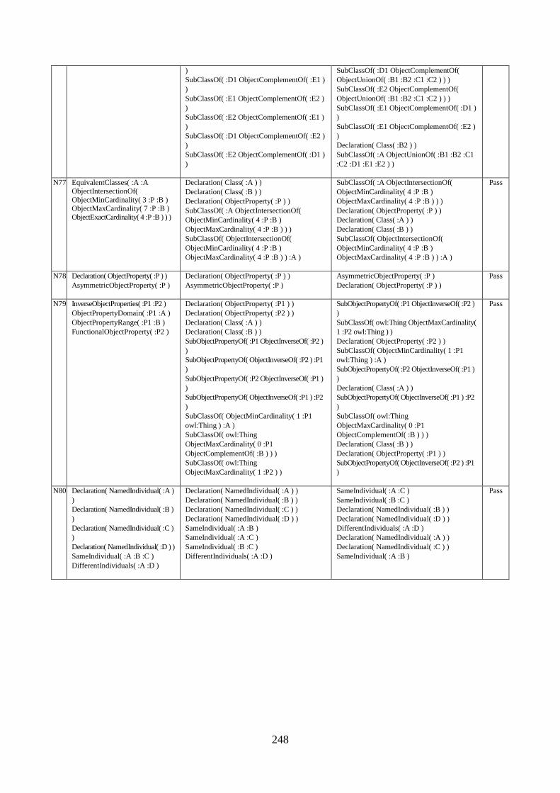
248
)
SubClassOf( :D1 ObjectComplementOf( :E1 )
)
SubClassOf( :E1 ObjectComplementOf( :E2 )
)
SubClassOf( :E2 ObjectComplementOf( :E1 )
)
SubClassOf( :D1 ObjectComplementOf( :E2 )
)
SubClassOf( :E2 ObjectComplementOf( :D1 )
)
SubClassOf( :D1 ObjectComplementOf(
ObjectUnionOf( :B1 :B2 :C1 :C2 ) ) )
SubClassOf( :E2 ObjectComplementOf(
ObjectUnionOf( :B1 :B2 :C1 :C2 ) ) )
SubClassOf( :E1 ObjectComplementOf( :D1 )
)
SubClassOf( :E1 ObjectComplementOf( :E2 )
)
Declaration( Class( :B2 ) )
SubClassOf( :A ObjectUnionOf( :B1 :B2 :C1
:C2 :D1 :E1 :E2 ) )
N77 EquivalentClasses( :A :A
ObjectIntersectionOf(
ObjectMinCardinality( 3 :P :B ) ObjectMaxCardinality( 7 :P :B )
ObjectExactCardinality( 4 :P :B ) ) )
Declaration( Class( :A ) )
Declaration( Class( :B ) )
Declaration( ObjectProperty( :P ) )
SubClassOf( :A ObjectIntersectionOf(
ObjectMinCardinality( 4 :P :B )
ObjectMaxCardinality( 4 :P :B ) ) )
SubClassOf( ObjectIntersectionOf(
ObjectMinCardinality( 4 :P :B )
ObjectMaxCardinality( 4 :P :B ) ) :A )
SubClassOf( :A ObjectIntersectionOf(
ObjectMinCardinality( 4 :P :B )
ObjectMaxCardinality( 4 :P :B ) ) )
Declaration( ObjectProperty( :P ) )
Declaration( Class( :A ) )
Declaration( Class( :B ) )
SubClassOf( ObjectIntersectionOf(
ObjectMinCardinality( 4 :P :B )
ObjectMaxCardinality( 4 :P :B ) ) :A )
Pass
N78 Declaration( ObjectProperty( :P ) )
AsymmetricObjectProperty( :P )
Declaration( ObjectProperty( :P ) )
AsymmetricObjectProperty( :P )
AsymmetricObjectProperty( :P )
Declaration( ObjectProperty( :P ) )
Pass
N79 InverseObjectProperties( :P1 :P2 )
ObjectPropertyDomain( :P1 :A )
ObjectPropertyRange( :P1 :B )
FunctionalObjectProperty( :P2 )
Declaration( ObjectProperty( :P1 ) )
Declaration( ObjectProperty( :P2 ) )
Declaration( Class( :A ) )
Declaration( Class( :B ) )
SubObjectPropertyOf( :P1 ObjectInverseOf( :P2 )
)
SubObjectPropertyOf( ObjectInverseOf( :P2 ) :P1
)
SubObjectPropertyOf( :P2 ObjectInverseOf( :P1 )
)
SubObjectPropertyOf( ObjectInverseOf( :P1 ) :P2
)
SubClassOf( ObjectMinCardinality( 1 :P1
owl:Thing ) :A )
SubClassOf( owl:Thing
ObjectMaxCardinality( 0 :P1
ObjectComplementOf( :B ) ) )
SubClassOf( owl:Thing
ObjectMaxCardinality( 1 :P2 ) )
SubObjectPropertyOf( :P1 ObjectInverseOf( :P2 )
)
SubClassOf( owl:Thing ObjectMaxCardinality(
1 :P2 owl:Thing ) )
Declaration( ObjectProperty( :P2 ) )
SubClassOf( ObjectMinCardinality( 1 :P1
owl:Thing ) :A )
SubObjectPropertyOf( :P2 ObjectInverseOf( :P1 )
)
Declaration( Class( :A ) )
SubObjectPropertyOf( ObjectInverseOf( :P1 ) :P2
)
SubClassOf( owl:Thing
ObjectMaxCardinality( 0 :P1
ObjectComplementOf( :B ) ) )
Declaration( Class( :B ) )
Declaration( ObjectProperty( :P1 ) )
SubObjectPropertyOf( ObjectInverseOf( :P2 ) :P1
)
Pass
N80 Declaration( NamedIndividual( :A )
)
Declaration( NamedIndividual( :B )
)
Declaration( NamedIndividual( :C )
)
Declaration( NamedIndividual( :D ) )
SameIndividual( :A :B :C )
DifferentIndividuals( :A :D )
Declaration( NamedIndividual( :A ) )
Declaration( NamedIndividual( :B ) )
Declaration( NamedIndividual( :C ) )
Declaration( NamedIndividual( :D ) )
SameIndividual( :A :B )
SameIndividual( :A :C )
SameIndividual( :B :C )
DifferentIndividuals( :A :D )
SameIndividual( :A :C )
SameIndividual( :B :C )
Declaration( NamedIndividual( :B ) )
Declaration( NamedIndividual( :D ) )
DifferentIndividuals( :A :D )
Declaration( NamedIndividual( :A ) )
Declaration( NamedIndividual( :C ) )
SameIndividual( :A :B )
Pass
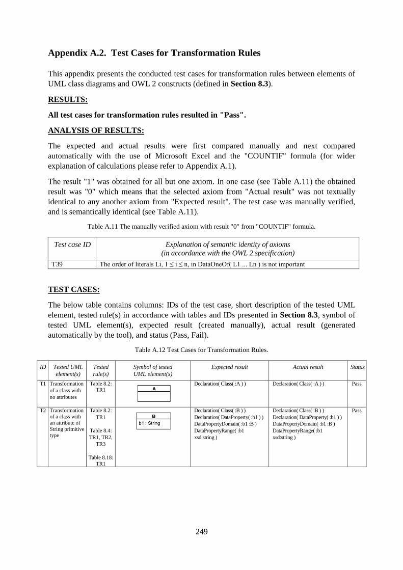
249
Appendix A.2. Test Cases for Transformation Rules
This appendix presents the conducted test cases for transformation rules between elements of
UML class diagrams and OWL 2 constructs (defined in Section 8.3).
RESULTS:
All test cases for transformation rules resulted in "Pass".
ANALYSIS OF RESULTS:
The expected and actual results were first compared manually and next compared
automatically with the use of Microsoft Excel and the "COUNTIF" formula (for wider
explanation of calculations please refer to Appendix A.1).
The result "1" was obtained for all but one axiom. In one case (see Table A.11) the obtained
result was "0" which means that the selected axiom from "Actual result" was not textually
identical to any another axiom from "Expected result". The test case was manually verified,
and is semantically identical (see Table A.11).
Table A.11 The manually verified axiom with result "0" from "COUNTIF" formula.
Test case ID Explanation of semantic identity of axioms
(in accordance with the OWL 2 specification)
T39 The order of literals Li, 1 ≤ i ≤ n, in DataOneOf( L1 ... Ln ) is not important
TEST CASES:
The below table contains columns: IDs of the test case, short description of the tested UML
element, tested rule(s) in accordance with tables and IDs presented in Section 8.3, symbol of
tested UML element(s), expected result (created manually), actual result (generated
automatically by the tool), and status (Pass, Fail).
Table A.12 Test Cases for Transformation Rules.
ID Tested UML
element(s)
Tested
rule(s)
Symbol of tested
UML element(s)
Expected result Actual result Status
T1 Transformation
of a class with
no attributes
Table 8.2: TR1
Declaration( Class( :A ) ) Declaration( Class( :A ) ) Pass
T2 Transformation of a class with
an attribute of
String primitive type
Table 8.2:
TR1
Table 8.4:
TR1, TR2,
TR3
Table 8.18:
TR1
Declaration( Class( :B ) )
Declaration( DataProperty( :b1 ) )
DataPropertyDomain( :b1 :B )
DataPropertyRange( :b1
xsd:string )
Declaration( Class( :B ) )
Declaration( DataProperty( :b1 ) )
DataPropertyDomain( :b1 :B )
DataPropertyRange( :b1
xsd:string )
Pass
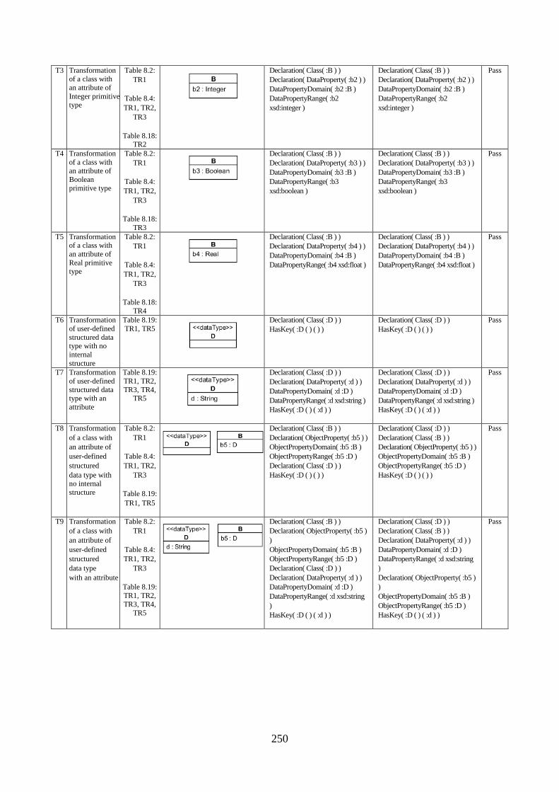
250
T3 Transformation of a class with
an attribute of
Integer primitive type
Table 8.2:
TR1
Table 8.4:
TR1, TR2,
TR3
Table 8.18: TR2
Declaration( Class( :B ) )
Declaration( DataProperty( :b2 ) )
DataPropertyDomain( :b2 :B )
DataPropertyRange( :b2
xsd:integer )
Declaration( Class( :B ) )
Declaration( DataProperty( :b2 ) )
DataPropertyDomain( :b2 :B )
DataPropertyRange( :b2
xsd:integer )
Pass
T4 Transformation
of a class with an attribute of
Boolean
primitive type
Table 8.2:
TR1
Table 8.4:
TR1, TR2,
TR3
Table 8.18:
TR3
Declaration( Class( :B ) )
Declaration( DataProperty( :b3 ) )
DataPropertyDomain( :b3 :B )
DataPropertyRange( :b3
xsd:boolean )
Declaration( Class( :B ) )
Declaration( DataProperty( :b3 ) )
DataPropertyDomain( :b3 :B )
DataPropertyRange( :b3
xsd:boolean )
Pass
T5 Transformation of a class with
an attribute of
Real primitive type
Table 8.2:
TR1
Table 8.4:
TR1, TR2,
TR3
Table 8.18:
TR4
Declaration( Class( :B ) )
Declaration( DataProperty( :b4 ) )
DataPropertyDomain( :b4 :B )
DataPropertyRange( :b4 xsd:float )
Declaration( Class( :B ) )
Declaration( DataProperty( :b4 ) )
DataPropertyDomain( :b4 :B )
DataPropertyRange( :b4 xsd:float )
Pass
T6 Transformation
of user-defined
structured data type with no
internal
structure
Table 8.19:
TR1, TR5
Declaration( Class( :D ) )
HasKey( :D ( ) ( ) )
Declaration( Class( :D ) )
HasKey( :D ( ) ( ) )
Pass
T7 Transformation
of user-defined
structured data type with an
attribute
Table 8.19:
TR1, TR2,
TR3, TR4, TR5
Declaration( Class( :D ) )
Declaration( DataProperty( :d ) )
DataPropertyDomain( :d :D )
DataPropertyRange( :d xsd:string )
HasKey( :D ( ) ( :d ) )
Declaration( Class( :D ) )
Declaration( DataProperty( :d ) )
DataPropertyDomain( :d :D )
DataPropertyRange( :d xsd:string )
HasKey( :D ( ) ( :d ) )
Pass
T8 Transformation
of a class with
an attribute of
user-defined
structured
data type with no internal
structure
Table 8.2:
TR1
Table 8.4:
TR1, TR2,
TR3
Table 8.19:
TR1, TR5
Declaration( Class( :B ) )
Declaration( ObjectProperty( :b5 ) )
ObjectPropertyDomain( :b5 :B )
ObjectPropertyRange( :b5 :D )
Declaration( Class( :D ) )
HasKey( :D ( ) ( ) )
Declaration( Class( :D ) )
Declaration( Class( :B ) )
Declaration( ObjectProperty( :b5 ) )
ObjectPropertyDomain( :b5 :B )
ObjectPropertyRange( :b5 :D )
HasKey( :D ( ) ( ) )
Pass
T9 Transformation
of a class with
an attribute of
user-defined
structured
data type
with an attribute
Table 8.2:
TR1
Table 8.4:
TR1, TR2,
TR3
Table 8.19:
TR1, TR2,
TR3, TR4,
TR5
Declaration( Class( :B ) )
Declaration( ObjectProperty( :b5 )
)
ObjectPropertyDomain( :b5 :B )
ObjectPropertyRange( :b5 :D )
Declaration( Class( :D ) )
Declaration( DataProperty( :d ) )
DataPropertyDomain( :d :D )
DataPropertyRange( :d xsd:string
)
HasKey( :D ( ) ( :d ) )
Declaration( Class( :D ) )
Declaration( Class( :B ) )
Declaration( DataProperty( :d ) )
DataPropertyDomain( :d :D )
DataPropertyRange( :d xsd:string
)
Declaration( ObjectProperty( :b5 )
)
ObjectPropertyDomain( :b5 :B )
ObjectPropertyRange( :b5 :D )
HasKey( :D ( ) ( :d ) )
Pass
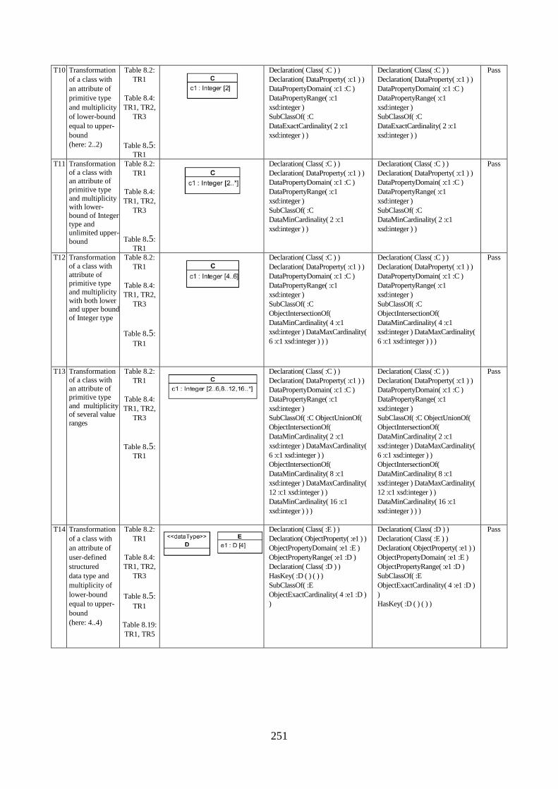
251
T10 Transformation
of a class with
an attribute of
primitive type
and multiplicity
of lower-bound
equal to upper-
bound
(here: 2..2)
Table 8.2:
TR1
Table 8.4:
TR1, TR2,
TR3
Table 8.5:
TR1
Declaration( Class( :C ) )
Declaration( DataProperty( :c1 ) )
DataPropertyDomain( :c1 :C )
DataPropertyRange( :c1
xsd:integer )
SubClassOf( :C
DataExactCardinality( 2 :c1
xsd:integer ) )
Declaration( Class( :C ) )
Declaration( DataProperty( :c1 ) )
DataPropertyDomain( :c1 :C )
DataPropertyRange( :c1
xsd:integer )
SubClassOf( :C
DataExactCardinality( 2 :c1
xsd:integer ) )
Pass
T11 Transformation
of a class with an attribute of
primitive type
and multiplicity with lower-
bound of Integer
type and unlimited upper-
bound
Table 8.2:
TR1
Table 8.4:
TR1, TR2,
TR3
Table 8.5:
TR1
Declaration( Class( :C ) )
Declaration( DataProperty( :c1 ) )
DataPropertyDomain( :c1 :C )
DataPropertyRange( :c1
xsd:integer )
SubClassOf( :C
DataMinCardinality( 2 :c1
xsd:integer ) )
Declaration( Class( :C ) )
Declaration( DataProperty( :c1 ) )
DataPropertyDomain( :c1 :C )
DataPropertyRange( :c1
xsd:integer )
SubClassOf( :C
DataMinCardinality( 2 :c1
xsd:integer ) )
Pass
T12 Transformation
of a class with
attribute of primitive type
and multiplicity
with both lower and upper bound
of Integer type
Table 8.2:
TR1
Table 8.4:
TR1, TR2,
TR3
Table 8.5:
TR1
Declaration( Class( :C ) )
Declaration( DataProperty( :c1 ) )
DataPropertyDomain( :c1 :C )
DataPropertyRange( :c1
xsd:integer )
SubClassOf( :C
ObjectIntersectionOf(
DataMinCardinality( 4 :c1
xsd:integer ) DataMaxCardinality(
6 :c1 xsd:integer ) ) )
Declaration( Class( :C ) )
Declaration( DataProperty( :c1 ) )
DataPropertyDomain( :c1 :C )
DataPropertyRange( :c1
xsd:integer )
SubClassOf( :C
ObjectIntersectionOf(
DataMinCardinality( 4 :c1
xsd:integer ) DataMaxCardinality(
6 :c1 xsd:integer ) ) )
Pass
T13 Transformation
of a class with an attribute of
primitive type
and multiplicity of several value
ranges
Table 8.2:
TR1
Table 8.4:
TR1, TR2,
TR3
Table 8.5:
TR1
Declaration( Class( :C ) )
Declaration( DataProperty( :c1 ) )
DataPropertyDomain( :c1 :C )
DataPropertyRange( :c1
xsd:integer )
SubClassOf( :C ObjectUnionOf(
ObjectIntersectionOf(
DataMinCardinality( 2 :c1
xsd:integer ) DataMaxCardinality(
6 :c1 xsd:integer ) )
ObjectIntersectionOf(
DataMinCardinality( 8 :c1
xsd:integer ) DataMaxCardinality(
12 :c1 xsd:integer ) )
DataMinCardinality( 16 :c1
xsd:integer ) ) )
Pass
T14 Transformation
of a class with
an attribute of
user-defined
structured
data type and
multiplicity of
lower-bound
equal to upper-
bound
(here: 4..4)
Table 8.2:
TR1
Table 8.4:
TR1, TR2,
TR3
Table 8.5:
TR1
Table 8.19:
TR1, TR5
Declaration( Class( :E ) )
Declaration( ObjectProperty( :e1 ) )
ObjectPropertyDomain( :e1 :E )
ObjectPropertyRange( :e1 :D )
Declaration( Class( :D ) )
HasKey( :D ( ) ( ) )
SubClassOf( :E
ObjectExactCardinality( 4 :e1 :D )
)
Declaration( Class( :D ) )
Declaration( Class( :E ) )
Declaration( ObjectProperty( :e1 ) )
ObjectPropertyDomain( :e1 :E )
ObjectPropertyRange( :e1 :D )
SubClassOf( :E
ObjectExactCardinality( 4 :e1 :D )
)
HasKey( :D ( ) ( ) )
Pass
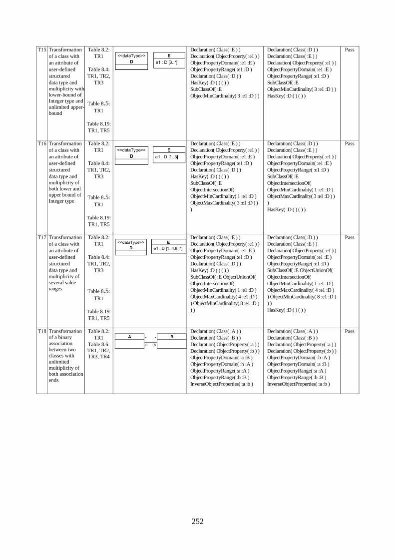
252
T15 Transformation
of a class with
an attribute of
user-defined
structured
data type and
multiplicity with
lower-bound of Integer type and
unlimited upper-
bound
Table 8.2:
TR1
Table 8.4:
TR1, TR2,
TR3
Table 8.5:
TR1
Table 8.19:
TR1, TR5
Declaration( Class( :E ) )
Declaration( ObjectProperty( :e1 ) )
ObjectPropertyDomain( :e1 :E )
ObjectPropertyRange( :e1 :D )
Declaration( Class( :D ) )
HasKey( :D ( ) ( ) )
SubClassOf( :E
ObjectMinCardinality( 3 :e1 :D ) )
Declaration( Class( :D ) )
Declaration( Class( :E ) )
Declaration( ObjectProperty( :e1 ) )
ObjectPropertyDomain( :e1 :E )
ObjectPropertyRange( :e1 :D )
SubClassOf( :E
ObjectMinCardinality( 3 :e1 :D ) )
HasKey( :D ( ) ( ) )
Pass
T16 Transformation
of a class with
an attribute of
user-defined
structured
data type and
multiplicity of
both lower and upper bound of
Integer type
Table 8.2:
TR1
Table 8.4:
TR1, TR2,
TR3
Table 8.5:
TR1
Table 8.19:
TR1, TR5
Declaration( Class( :E ) )
Declaration( ObjectProperty( :e1 ) )
ObjectPropertyDomain( :e1 :E )
ObjectPropertyRange( :e1 :D )
Declaration( Class( :D ) )
HasKey( :D ( ) ( ) )
SubClassOf( :E
ObjectIntersectionOf(
ObjectMinCardinality( 1 :e1 :D )
ObjectMaxCardinality( 3 :e1 :D ) )
)
Declaration( Class( :D ) )
Declaration( Class( :E ) )
Declaration( ObjectProperty( :e1 ) )
ObjectPropertyDomain( :e1 :E )
ObjectPropertyRange( :e1 :D )
SubClassOf( :E
ObjectIntersectionOf(
ObjectMinCardinality( 1 :e1 :D )
ObjectMaxCardinality( 3 :e1 :D ) )
)
HasKey( :D ( ) ( ) )
Pass
T17 Transformation
of a class with
an attribute of
user-defined
structured
data type and
multiplicity of
several value ranges
Table 8.2:
TR1
Table 8.4:
TR1, TR2,
TR3
Table 8.5:
TR1
Table 8.19:
TR1, TR5
Declaration( Class( :E ) )
Declaration( ObjectProperty( :e1 ) )
ObjectPropertyDomain( :e1 :E )
ObjectPropertyRange( :e1 :D )
Declaration( Class( :D ) )
HasKey( :D ( ) ( ) )
SubClassOf( :E ObjectUnionOf(
ObjectIntersectionOf(
ObjectMinCardinality( 1 :e1 :D )
ObjectMaxCardinality( 4 :e1 :D )
) ObjectMinCardinality( 8 :e1 :D )
) )
Declaration( Class( :D ) )
Declaration( Class( :E ) )
Declaration( ObjectProperty( :e1 ) )
ObjectPropertyDomain( :e1 :E )
ObjectPropertyRange( :e1 :D )
SubClassOf( :E ObjectUnionOf(
ObjectIntersectionOf(
ObjectMinCardinality( 1 :e1 :D )
ObjectMaxCardinality( 4 :e1 :D )
) ObjectMinCardinality( 8 :e1 :D )
) )
HasKey( :D ( ) ( ) )
Pass
T18 Transformation of a binary
association
between two classes with
unlimited
multiplicity of both association
ends
Table 8.2:
TR1
Table 8.6:
TR1, TR2, TR3, TR4
Declaration( Class( :A ) )
Declaration( Class( :B ) )
Declaration( ObjectProperty( :a ) )
Declaration( ObjectProperty( :b ) )
ObjectPropertyDomain( :a :B )
ObjectPropertyDomain( :b :A )
ObjectPropertyRange( :a :A )
ObjectPropertyRange( :b :B )
InverseObjectProperties( :a :b )
Declaration( Class( :A ) )
Declaration( Class( :B ) )
Declaration( ObjectProperty( :a ) )
Declaration( ObjectProperty( :b ) )
ObjectPropertyDomain( :b :A )
ObjectPropertyDomain( :a :B )
ObjectPropertyRange( :a :A )
ObjectPropertyRange( :b :B )
InverseObjectProperties( :a :b )
Pass
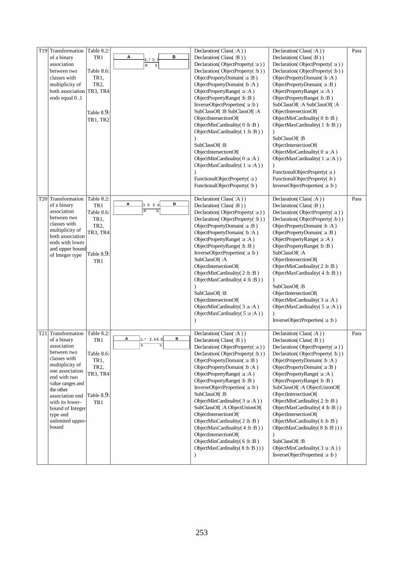
253
T19 Transformation
of a binary
association
between two
classes with
multiplicity of
both association
ends equal 0..1
Table 8.2:
TR1
Table 8.6:
TR1,
TR2,
TR3, TR4
Table 8.9:
TR1, TR2
Declaration( Class( :A ) )
Declaration( Class( :B ) )
Declaration( ObjectProperty( :a ) )
Declaration( ObjectProperty( :b ) )
ObjectPropertyDomain( :a :B )
ObjectPropertyDomain( :b :A )
ObjectPropertyRange( :a :A )
ObjectPropertyRange( :b :B )
InverseObjectProperties( :a :b )
SubClassOf( :B SubClassOf( :A
ObjectIntersectionOf(
ObjectMinCardinality( 0 :b :B )
ObjectMaxCardinality( 1 :b :B ) )
)
SubClassOf( :B
ObjectIntersectionOf(
ObjectMinCardinality( 0 :a :A )
ObjectMaxCardinality( 1 :a :A ) )
)
FunctionalObjectProperty( :a )
FunctionalObjectProperty( :b )
Declaration( Class( :A ) )
Declaration( Class( :B ) )
Declaration( ObjectProperty( :a ) )
Declaration( ObjectProperty( :b ) )
ObjectPropertyDomain( :b :A )
ObjectPropertyDomain( :a :B )
ObjectPropertyRange( :a :A )
ObjectPropertyRange( :b :B )
SubClassOf( :A SubClassOf( :A
ObjectIntersectionOf(
ObjectMinCardinality( 0 :b :B )
ObjectMaxCardinality( 1 :b :B ) )
)
SubClassOf( :B
ObjectIntersectionOf(
ObjectMinCardinality( 0 :a :A )
ObjectMaxCardinality( 1 :a :A ) )
)
FunctionalObjectProperty( :a )
FunctionalObjectProperty( :b )
InverseObjectProperties( :a :b )
Pass
T20 Transformation of a binary
association
between two classes with
multiplicity of
both association ends with lower
and upper bound
of Integer type
Table 8.2:
TR1
Table 8.6:
TR1,
TR2,
TR3, TR4
Table 8.9:
TR1
Declaration( Class( :A ) )
Declaration( Class( :B ) )
Declaration( ObjectProperty( :a ) )
Declaration( ObjectProperty( :b ) )
ObjectPropertyDomain( :a :B )
ObjectPropertyDomain( :b :A )
ObjectPropertyRange( :a :A )
ObjectPropertyRange( :b :B )
InverseObjectProperties( :a :b )
SubClassOf( :A
ObjectIntersectionOf(
ObjectMinCardinality( 2 :b :B )
ObjectMaxCardinality( 4 :b :B ) )
)
SubClassOf( :B
ObjectIntersectionOf(
ObjectMinCardinality( 3 :a :A )
ObjectMaxCardinality( 5 :a :A ) )
)
Declaration( Class( :A ) )
Declaration( Class( :B ) )
Declaration( ObjectProperty( :a ) )
Declaration( ObjectProperty( :b ) )
ObjectPropertyDomain( :b :A )
ObjectPropertyDomain( :a :B )
ObjectPropertyRange( :a :A )
ObjectPropertyRange( :b :B )
SubClassOf( :A
ObjectIntersectionOf(
ObjectMinCardinality( 2 :b :B )
ObjectMaxCardinality( 4 :b :B ) )
)
SubClassOf( :B
ObjectIntersectionOf(
ObjectMinCardinality( 3 :a :A )
ObjectMaxCardinality( 5 :a :A ) )
)
InverseObjectProperties( :a :b )
Pass
T21 Transformation
of a binary
association between two
classes with
multiplicity of one association
end with two
value ranges and the other
association end
with its lower-bound of Integer
type and
unlimited upper-bound
Table 8.2:
TR1
Table 8.6:
TR1,
TR2,
TR3, TR4
Table 8.9:
TR1
Declaration( Class( :A ) )
Declaration( Class( :B ) )
Declaration( ObjectProperty( :a ) )
Declaration( ObjectProperty( :b ) )
ObjectPropertyDomain( :a :B )
ObjectPropertyDomain( :b :A )
ObjectPropertyRange( :a :A )
ObjectPropertyRange( :b :B )
InverseObjectProperties( :a :b )
SubClassOf( :B
ObjectMinCardinality( 3 :a :A ) )
SubClassOf( :A ObjectUnionOf(
ObjectIntersectionOf(
ObjectMinCardinality( 2 :b :B )
ObjectMaxCardinality( 4 :b :B ) )
ObjectIntersectionOf(
ObjectMinCardinality( 6 :b :B )
ObjectMaxCardinality( 8 :b :B ) ) )
)
Declaration( Class( :A ) )
Declaration( Class( :B ) )
Declaration( ObjectProperty( :a ) )
Declaration( ObjectProperty( :b ) )
ObjectPropertyDomain( :b :A )
ObjectPropertyDomain( :a :B )
ObjectPropertyRange( :a :A )
ObjectPropertyRange( :b :B )
SubClassOf( :A ObjectUnionOf(
ObjectIntersectionOf(
ObjectMinCardinality( 2 :b :B )
ObjectMaxCardinality( 4 :b :B ) )
ObjectIntersectionOf(
ObjectMinCardinality( 6 :b :B )
ObjectMaxCardinality( 8 :b :B ) ) )
)
SubClassOf( :B
ObjectMinCardinality( 3 :a :A ) )
InverseObjectProperties( :a :b )
Pass
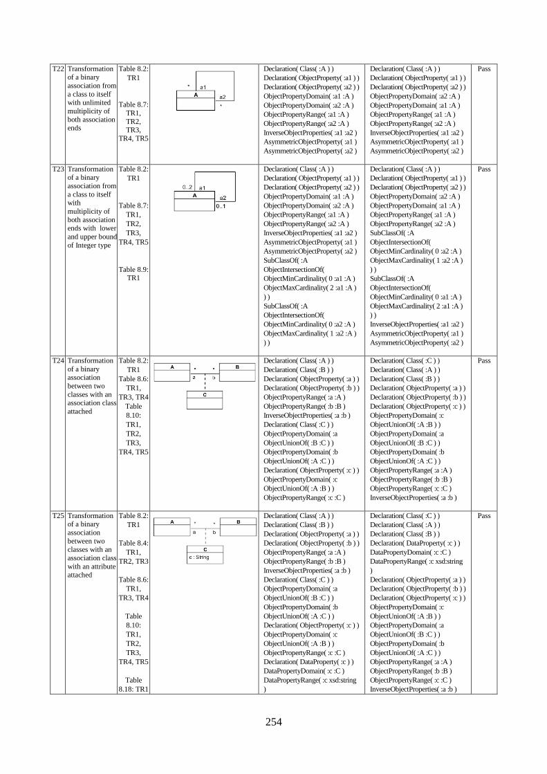
254
T22 Transformation of a binary
association from
a class to itself with unlimited
multiplicity of
both association ends
Table 8.2:
TR1
Table 8.7:
TR1,
TR2, TR3,
TR4, TR5
Declaration( Class( :A ) )
Declaration( ObjectProperty( :a1 ) )
Declaration( ObjectProperty( :a2 ) )
ObjectPropertyDomain( :a1 :A )
ObjectPropertyDomain( :a2 :A )
ObjectPropertyRange( :a1 :A )
ObjectPropertyRange( :a2 :A )
InverseObjectProperties( :a1 :a2 )
AsymmetricObjectProperty( :a1 )
AsymmetricObjectProperty( :a2 )
Declaration( Class( :A ) )
Declaration( ObjectProperty( :a1 ) )
Declaration( ObjectProperty( :a2 ) )
ObjectPropertyDomain( :a2 :A )
ObjectPropertyDomain( :a1 :A )
ObjectPropertyRange( :a1 :A )
ObjectPropertyRange( :a2 :A )
InverseObjectProperties( :a1 :a2 )
AsymmetricObjectProperty( :a1 )
AsymmetricObjectProperty( :a2 )
Pass
T23 Transformation of a binary
association from
a class to itself with
multiplicity of
both association ends with lower
and upper bound
of Integer type
Table 8.2:
TR1
Table 8.7:
TR1,
TR2,
TR3,
TR4, TR5
Table 8.9: TR1
Declaration( Class( :A ) )
Declaration( ObjectProperty( :a1 ) )
Declaration( ObjectProperty( :a2 ) )
ObjectPropertyDomain( :a1 :A )
ObjectPropertyDomain( :a2 :A )
ObjectPropertyRange( :a1 :A )
ObjectPropertyRange( :a2 :A )
InverseObjectProperties( :a1 :a2 )
AsymmetricObjectProperty( :a1 )
AsymmetricObjectProperty( :a2 )
SubClassOf( :A
ObjectIntersectionOf(
ObjectMinCardinality( 0 :a1 :A )
ObjectMaxCardinality( 2 :a1 :A )
) )
SubClassOf( :A
ObjectIntersectionOf(
ObjectMinCardinality( 0 :a2 :A )
ObjectMaxCardinality( 1 :a2 :A )
) )
Declaration( Class( :A ) )
Declaration( ObjectProperty( :a1 ) )
Declaration( ObjectProperty( :a2 ) )
ObjectPropertyDomain( :a2 :A )
ObjectPropertyDomain( :a1 :A )
ObjectPropertyRange( :a1 :A )
ObjectPropertyRange( :a2 :A )
SubClassOf( :A
ObjectIntersectionOf(
ObjectMinCardinality( 0 :a2 :A )
ObjectMaxCardinality( 1 :a2 :A )
) )
SubClassOf( :A
ObjectIntersectionOf(
ObjectMinCardinality( 0 :a1 :A )
ObjectMaxCardinality( 2 :a1 :A )
) )
InverseObjectProperties( :a1 :a2 )
AsymmetricObjectProperty( :a1 )
AsymmetricObjectProperty( :a2 )
Pass
T24 Transformation
of a binary association
between two
classes with an association class
attached
Table 8.2:
TR1
Table 8.6:
TR1,
TR3, TR4
Table
8.10:
TR1,
TR2,
TR3,
TR4, TR5
Declaration( Class( :A ) )
Declaration( Class( :B ) )
Declaration( ObjectProperty( :a ) )
Declaration( ObjectProperty( :b ) )
ObjectPropertyRange( :a :A )
ObjectPropertyRange( :b :B )
InverseObjectProperties( :a :b )
Declaration( Class( :C ) )
ObjectPropertyDomain( :a
ObjectUnionOf( :B :C ) )
ObjectPropertyDomain( :b
ObjectUnionOf( :A :C ) )
Declaration( ObjectProperty( :c ) )
ObjectPropertyDomain( :c
ObjectUnionOf( :A :B ) )
ObjectPropertyRange( :c :C )
Declaration( Class( :C ) )
Declaration( Class( :A ) )
Declaration( Class( :B ) )
Declaration( ObjectProperty( :a ) )
Declaration( ObjectProperty( :b ) )
Declaration( ObjectProperty( :c ) )
ObjectPropertyDomain( :c
ObjectUnionOf( :A :B ) )
ObjectPropertyDomain( :a
ObjectUnionOf( :B :C ) )
ObjectPropertyDomain( :b
ObjectUnionOf( :A :C ) )
ObjectPropertyRange( :a :A )
ObjectPropertyRange( :b :B )
ObjectPropertyRange( :c :C )
InverseObjectProperties( :a :b )
Pass
T25 Transformation of a binary
association
between two classes with an
association class
with an attribute attached
Table 8.2:
TR1
Table 8.4:
TR1,
TR2, TR3
Table 8.6:
TR1,
TR3, TR4
Table
8.10:
TR1,
TR2,
TR3,
TR4, TR5
Table
8.18: TR1
Declaration( Class( :A ) )
Declaration( Class( :B ) )
Declaration( ObjectProperty( :a ) )
Declaration( ObjectProperty( :b ) )
ObjectPropertyRange( :a :A )
ObjectPropertyRange( :b :B )
InverseObjectProperties( :a :b )
Declaration( Class( :C ) )
ObjectPropertyDomain( :a
ObjectUnionOf( :B :C ) )
ObjectPropertyDomain( :b
ObjectUnionOf( :A :C ) )
Declaration( ObjectProperty( :c ) )
ObjectPropertyDomain( :c
ObjectUnionOf( :A :B ) )
ObjectPropertyRange( :c :C )
Declaration( DataProperty( :c ) )
DataPropertyDomain( :c :C )
DataPropertyRange( :c xsd:string
)
Declaration( Class( :C ) )
Declaration( Class( :A ) )
Declaration( Class( :B ) )
Declaration( DataProperty( :c ) )
DataPropertyDomain( :c :C )
DataPropertyRange( :c xsd:string
)
Declaration( ObjectProperty( :a ) )
Declaration( ObjectProperty( :b ) )
Declaration( ObjectProperty( :c ) )
ObjectPropertyDomain( :c
ObjectUnionOf( :A :B ) )
ObjectPropertyDomain( :a
ObjectUnionOf( :B :C ) )
ObjectPropertyDomain( :b
ObjectUnionOf( :A :C ) )
ObjectPropertyRange( :a :A )
ObjectPropertyRange( :b :B )
ObjectPropertyRange( :c :C )
InverseObjectProperties( :a :b )
Pass
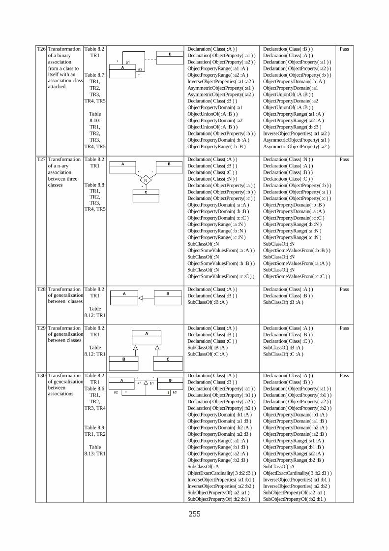
255
T26 Transformation
of a binary
association
from a class to itself with an
association class
attached
Table 8.2:
TR1
Table 8.7:
TR1,
TR2,
TR3,
TR4, TR5
Table
8.10:
TR1,
TR2,
TR3,
TR4, TR5
Declaration( Class( :A ) )
Declaration( ObjectProperty( :a1 ) )
Declaration( ObjectProperty( :a2 ) )
ObjectPropertyRange( :a1 :A )
ObjectPropertyRange( :a2 :A )
InverseObjectProperties( :a1 :a2 )
AsymmetricObjectProperty( :a1 )
AsymmetricObjectProperty( :a2 )
Declaration( Class( :B ) )
ObjectPropertyDomain( :a1
ObjectUnionOf( :A :B ) )
ObjectPropertyDomain( :a2
ObjectUnionOf( :A :B ) )
Declaration( ObjectProperty( :b ) )
ObjectPropertyDomain( :b :A )
ObjectPropertyRange( :b :B )
Declaration( Class( :B ) )
Declaration( Class( :A ) )
Declaration( ObjectProperty( :a1 ) )
Declaration( ObjectProperty( :a2 ) )
Declaration( ObjectProperty( :b ) )
ObjectPropertyDomain( :b :A )
ObjectPropertyDomain( :a1
ObjectUnionOf( :A :B ) )
ObjectPropertyDomain( :a2
ObjectUnionOf( :A :B ) )
ObjectPropertyRange( :a1 :A )
ObjectPropertyRange( :a2 :A )
ObjectPropertyRange( :b :B )
InverseObjectProperties( :a1 :a2 )
AsymmetricObjectProperty( :a1 )
AsymmetricObjectProperty( :a2 )
Pass
T27 Transformation
of a n-ary
association
between three
classes
Table 8.2:
TR1
Table 8.8:
TR1, TR2,
TR3,
TR4, TR5
Declaration( Class( :A ) )
Declaration( Class( :B ) )
Declaration( Class( :C ) )
Declaration( Class( :N ) )
Declaration( ObjectProperty( :a ) )
Declaration( ObjectProperty( :b ) )
Declaration( ObjectProperty( :c ) )
ObjectPropertyDomain( :a :A )
ObjectPropertyDomain( :b :B )
ObjectPropertyDomain( :c :C )
ObjectPropertyRange( :a :N )
ObjectPropertyRange( :b :N )
ObjectPropertyRange( :c :N )
SubClassOf( :N
ObjectSomeValuesFrom( :a :A ) )
SubClassOf( :N
ObjectSomeValuesFrom( :b :B ) )
SubClassOf( :N
ObjectSomeValuesFrom( :c :C ) )
Declaration( Class( :N ) )
Declaration( Class( :A ) )
Declaration( Class( :B ) )
Declaration( Class( :C ) )
Declaration( ObjectProperty( :b ) )
Declaration( ObjectProperty( :a ) )
Declaration( ObjectProperty( :c ) )
ObjectPropertyDomain( :b :B )
ObjectPropertyDomain( :a :A )
ObjectPropertyDomain( :c :C )
ObjectPropertyRange( :b :N )
ObjectPropertyRange( :a :N )
ObjectPropertyRange( :c :N )
SubClassOf( :N
ObjectSomeValuesFrom( :b :B ) )
SubClassOf( :N
ObjectSomeValuesFrom( :a :A ) )
SubClassOf( :N
ObjectSomeValuesFrom( :c :C ) )
Pass
T28 Transformation of generalization
between classes
Table 8.2:
TR1
Table
8.12: TR1
Declaration( Class( :A ) )
Declaration( Class( :B ) )
SubClassOf( :B :A )
Declaration( Class( :A ) )
Declaration( Class( :B ) )
SubClassOf( :B :A )
Pass
T29 Transformation
of generalization
between classes
Table 8.2:
TR1
Table
8.12: TR1
Declaration( Class( :A ) )
Declaration( Class( :B ) )
Declaration( Class( :C ) )
SubClassOf( :B :A )
SubClassOf( :C :A )
Declaration( Class( :A ) )
Declaration( Class( :B ) )
Declaration( Class( :C ) )
SubClassOf( :B :A )
SubClassOf( :C :A )
Pass
T30 Transformation
of generalization
between associations
Table 8.2:
TR1
Table 8.6:
TR1,
TR2,
TR3, TR4
Table 8.9:
TR1, TR2
Table
8.13: TR1
Declaration( Class( :A ) )
Declaration( Class( :B ) )
Declaration( ObjectProperty( :a1 ) )
Declaration( ObjectProperty( :b1 ) )
Declaration( ObjectProperty( :a2 ) )
Declaration( ObjectProperty( :b2 ) )
ObjectPropertyDomain( :b1 :A )
ObjectPropertyDomain( :a1 :B )
ObjectPropertyDomain( :b2 :A )
ObjectPropertyDomain( :a2 :B )
ObjectPropertyRange( :a1 :A )
ObjectPropertyRange( :b1 :B )
ObjectPropertyRange( :a2 :A )
ObjectPropertyRange( :b2 :B )
SubClassOf( :A
ObjectExactCardinality( 3 :b2 :B ) )
InverseObjectProperties( :a1 :b1 )
InverseObjectProperties( :a2 :b2 )
SubObjectPropertyOf( :a2 :a1 )
SubObjectPropertyOf( :b2 :b1 )
Pass
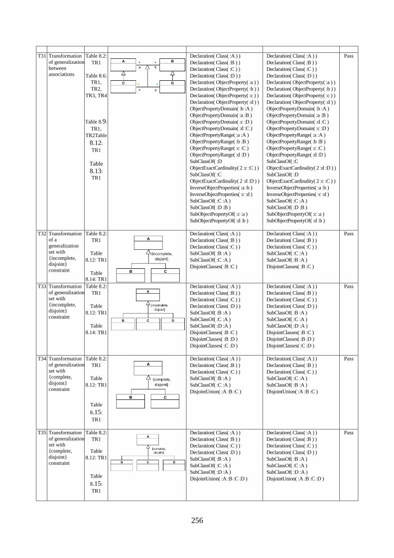
256
T31 Transformation
of generalization
between associations
Table 8.2:
TR1
Table 8.6:
TR1,
TR2,
TR3, TR4
Table 8.9:
TR1,
TR2Table
8.12:
TR1
Table 8.13:
TR1
Declaration( Class( :A ) )
Declaration( Class( :B ) )
Declaration( Class( :C ) )
Declaration( Class( :D ) )
Declaration( ObjectProperty( :a ) )
Declaration( ObjectProperty( :b ) )
Declaration( ObjectProperty( :c ) )
Declaration( ObjectProperty( :d ) )
ObjectPropertyDomain( :b :A )
ObjectPropertyDomain( :a :B )
ObjectPropertyDomain( :c :D )
ObjectPropertyDomain( :d :C )
ObjectPropertyRange( :a :A )
ObjectPropertyRange( :b :B )
ObjectPropertyRange( :c :C )
ObjectPropertyRange( :d :D )
SubClassOf( :D
ObjectExactCardinality( 2 :c :C ) )
SubClassOf( :C
ObjectExactCardinality( 2 :d :D ) )
InverseObjectProperties( :a :b )
InverseObjectProperties( :c :d )
SubClassOf( :C :A )
SubClassOf( :D :B )
SubObjectPropertyOf( :c :a )
SubObjectPropertyOf( :d :b )
Declaration( Class( :A ) )
Declaration( Class( :B ) )
Declaration( Class( :C ) )
Declaration( Class( :D ) )
Declaration( ObjectProperty( :a ) )
Declaration( ObjectProperty( :b ) )
Declaration( ObjectProperty( :c ) )
Declaration( ObjectProperty( :d ) )
ObjectPropertyDomain( :b :A )
ObjectPropertyDomain( :a :B )
ObjectPropertyDomain( :d :C )
ObjectPropertyDomain( :c :D )
ObjectPropertyRange( :a :A )
ObjectPropertyRange( :b :B )
ObjectPropertyRange( :c :C )
ObjectPropertyRange( :d :D )
SubClassOf( :C
ObjectExactCardinality( 2 :d :D ) )
SubClassOf( :D
ObjectExactCardinality( 2 :c :C ) )
InverseObjectProperties( :a :b )
InverseObjectProperties( :c :d )
SubClassOf( :C :A )
SubClassOf( :D :B )
SubObjectPropertyOf( :c :a )
SubObjectPropertyOf( :d :b )
Pass
T32 Transformation
of a
generalization set with
{incomplete, disjoint}
constraint
Table 8.2:
TR1
Table
8.12: TR1
Table 8.14: TR1
Declaration( Class( :A ) )
Declaration( Class( :B ) )
Declaration( Class( :C ) )
SubClassOf( :B :A )
SubClassOf( :C :A )
DisjointClasses( :B :C )
Declaration( Class( :A ) )
Declaration( Class( :B ) )
Declaration( Class( :C ) )
SubClassOf( :C :A )
SubClassOf( :B :A )
DisjointClasses( :B :C )
Pass
T33 Transformation
of generalization set with
{incomplete,
disjoint} constraint
Table 8.2:
TR1
Table
8.12: TR1
Table
8.14: TR1
Declaration( Class( :A ) )
Declaration( Class( :B ) )
Declaration( Class( :C ) )
Declaration( Class( :D ) )
SubClassOf( :B :A )
SubClassOf( :C :A )
SubClassOf( :D :A )
DisjointClasses( :B :C )
DisjointClasses( :B :D )
DisjointClasses( :C :D )
Declaration( Class( :A ) )
Declaration( Class( :B ) )
Declaration( Class( :C ) )
Declaration( Class( :D ) )
SubClassOf( :B :A )
SubClassOf( :C :A )
SubClassOf( :D :A )
DisjointClasses( :B :C )
DisjointClasses( :B :D )
DisjointClasses( :C :D )
Pass
T34 Transformation
of generalization
set with {complete,
disjoint}
constraint
Table 8.2:
TR1
Table
8.12: TR1
Table
8.15:
TR1
Declaration( Class( :A ) )
Declaration( Class( :B ) )
Declaration( Class( :C ) )
SubClassOf( :B :A )
SubClassOf( :C :A )
DisjointUnion( :A :B :C )
Declaration( Class( :A ) )
Declaration( Class( :B ) )
Declaration( Class( :C ) )
SubClassOf( :C :A )
SubClassOf( :B :A )
DisjointUnion( :A :B :C )
Pass
T35 Transformation
of generalization set with
{complete,
disjoint} constraint
Table 8.2:
TR1
Table
8.12: TR1
Table
8.15:
TR1
Declaration( Class( :A ) )
Declaration( Class( :B ) )
Declaration( Class( :C ) )
Declaration( Class( :D ) )
SubClassOf( :B :A )
SubClassOf( :C :A )
SubClassOf( :D :A )
DisjointUnion( :A :B :C :D )
Declaration( Class( :A ) )
Declaration( Class( :B ) )
Declaration( Class( :C ) )
Declaration( Class( :D ) )
SubClassOf( :B :A )
SubClassOf( :C :A )
SubClassOf( :D :A )
DisjointUnion( :A :B :C :D )
Pass
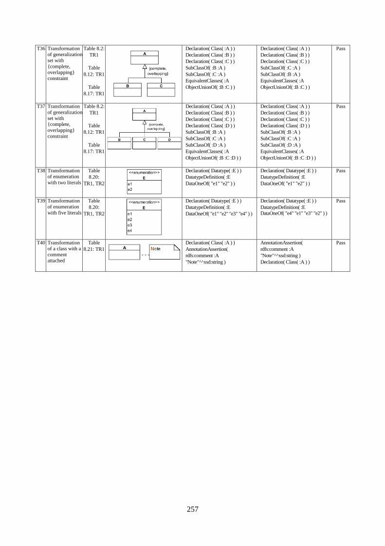
257
T36 Transformation of generalization
set with
{complete, overlapping}
constraint
Table 8.2:
TR1
Table
8.12: TR1
Table
8.17: TR1
Declaration( Class( :A ) )
Declaration( Class( :B ) )
Declaration( Class( :C ) )
SubClassOf( :B :A )
SubClassOf( :C :A )
EquivalentClasses( :A
ObjectUnionOf( :B :C ) )
Declaration( Class( :A ) )
Declaration( Class( :B ) )
Declaration( Class( :C ) )
SubClassOf( :C :A )
SubClassOf( :B :A )
EquivalentClasses( :A
ObjectUnionOf( :B :C ) )
Pass
T37 Transformation
of generalization
set with {complete,
overlapping}
constraint
Table 8.2:
TR1
Table
8.12: TR1
Table
8.17: TR1
Declaration( Class( :A ) )
Declaration( Class( :B ) )
Declaration( Class( :C ) )
Declaration( Class( :D ) )
SubClassOf( :B :A )
SubClassOf( :C :A )
SubClassOf( :D :A )
EquivalentClasses( :A
ObjectUnionOf( :B :C :D ) )
Declaration( Class( :A ) )
Declaration( Class( :B ) )
Declaration( Class( :C ) )
Declaration( Class( :D ) )
SubClassOf( :B :A )
SubClassOf( :C :A )
SubClassOf( :D :A )
EquivalentClasses( :A
ObjectUnionOf( :B :C :D ) )
Pass
T38 Transformation of enumeration
with two literals
Table
8.20:
TR1, TR2
Declaration( Datatype( :E ) )
DatatypeDefinition( :E
DataOneOf( "e1" "e2" ) )
Declaration( Datatype( :E ) )
DatatypeDefinition( :E
DataOneOf( "e1" "e2" ) )
Pass
T39 Transformation
of enumeration
with five literals
Table
8.20:
TR1, TR2
Declaration( Datatype( :E ) )
DatatypeDefinition( :E
DataOneOf( "e1" "e2" "e3" "e4" ) )
Declaration( Datatype( :E ) )
DatatypeDefinition( :E
DataOneOf( "e4" "e1" "e3" "e2" ) )
Pass
T40 Transformation of a class with a
comment
attached
Table
8.21: TR1
Declaration( Class( :A ) )
AnnotationAssertion(
rdfs:comment :A
"Note"^^xsd:string )
AnnotationAssertion(
rdfs:comment :A
"Note"^^xsd:string )
Declaration( Class( :A ) )
Pass
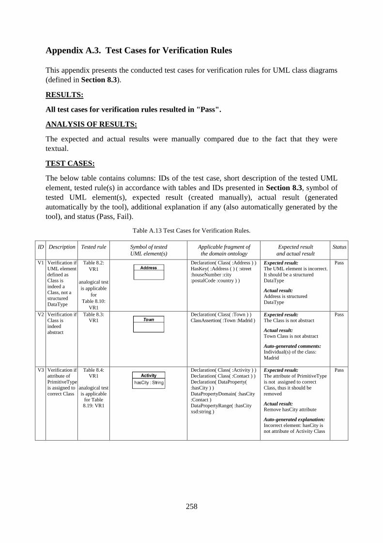
258
Appendix A.3. Test Cases for Verification Rules
This appendix presents the conducted test cases for verification rules for UML class diagrams
(defined in Section 8.3).
RESULTS:
All test cases for verification rules resulted in "Pass".
ANALYSIS OF RESULTS:
The expected and actual results were manually compared due to the fact that they were
textual.
TEST CASES:
The below table contains columns: IDs of the test case, short description of the tested UML
element, tested rule(s) in accordance with tables and IDs presented in Section 8.3, symbol of
tested UML element(s), expected result (created manually), actual result (generated
automatically by the tool), additional explanation if any (also automatically generated by the
tool), and status (Pass, Fail).
Table A.13 Test Cases for Verification Rules.
ID Description Tested rule Symbol of tested
UML element(s)
Applicable fragment of
the domain ontology
Expected result
and actual result
Status
V1 Verification if
UML element
defined as Class is
indeed a
Class, not a
structured
DataType
Table 8.2:
VR1
analogical test
is applicable
for
Table 8.10:
VR1
Declaration( Class( :Address ) )
HasKey( :Address ( ) ( :street
:houseNumber :city :postalCode :country ) )
Expected result: The UML element is incorrect.
It should be a structured DataType
Actual result:
Address is structured
DataType
Pass
V2 Verification if
Class is indeed
abstract
Table 8.3:
VR1
Declaration( Class( :Town ) )
ClassAssertion( :Town :Madrid ) Expected result: The Class is not abstract
Actual result:
Town Class is not abstract
Auto-generated comments: Individual(s) of the class:
Madrid
Pass
V3 Verification if
attribute of
PrimitiveType is assigned to
correct Class
Table 8.4:
VR1
analogical test
is applicable
for Table 8.19: VR1
Declaration( Class( :Activity ) )
Declaration( Class( :Contact ) )
Declaration( DataProperty( :hasCity ) )
DataPropertyDomain( :hasCity
:Contact ) DataPropertyRange( :hasCity
xsd:string )
Expected result: The attribute of PrimitiveType
is not assigned to correct Class, thus it should be
removed
Actual result: Remove hasCity attribute
Auto-generated explanation:
Incorrect element: hasCity is not attribute of Activity Class
Pass
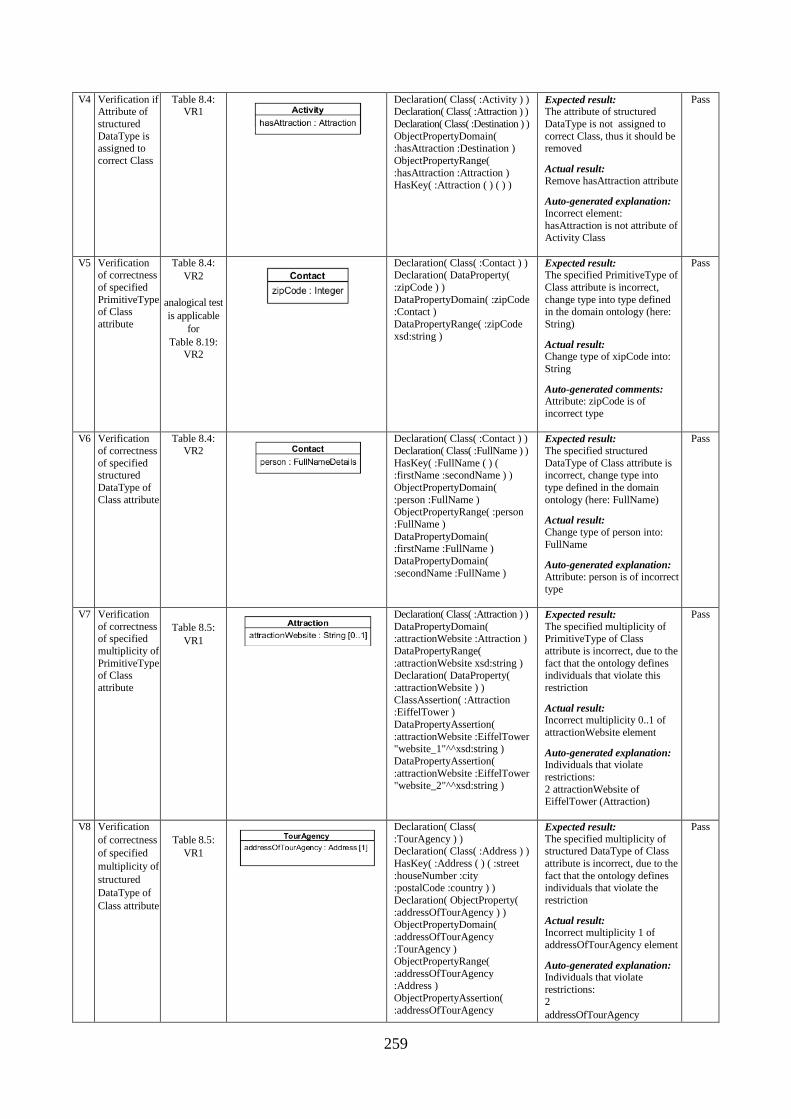
259
V4 Verification if Attribute of
structured
DataType is assigned to
correct Class
Table 8.4: VR1
Declaration( Class( :Activity ) ) Declaration( Class( :Attraction ) )
Declaration( Class( :Destination ) )
ObjectPropertyDomain( :hasAttraction :Destination )
ObjectPropertyRange(
:hasAttraction :Attraction ) HasKey( :Attraction ( ) ( ) )
Expected result: The attribute of structured
DataType is not assigned to
correct Class, thus it should be removed
Actual result:
Remove hasAttraction attribute
Auto-generated explanation:
Incorrect element:
hasAttraction is not attribute of Activity Class
Pass
V5 Verification of correctness
of specified
PrimitiveType of Class
attribute
Table 8.4:
VR2
analogical test
is applicable
for
Table 8.19:
VR2
Declaration( Class( :Contact ) ) Declaration( DataProperty(
:zipCode ) )
DataPropertyDomain( :zipCode :Contact )
DataPropertyRange( :zipCode
xsd:string )
Expected result: The specified PrimitiveType of
Class attribute is incorrect,
change type into type defined in the domain ontology (here:
String)
Actual result: Change type of xipCode into:
String
Auto-generated comments: Attribute: zipCode is of
incorrect type
Pass
V6 Verification
of correctness
of specified structured
DataType of
Class attribute
Table 8.4:
VR2
Declaration( Class( :Contact ) )
Declaration( Class( :FullName ) )
HasKey( :FullName ( ) ( :firstName :secondName ) )
ObjectPropertyDomain(
:person :FullName ) ObjectPropertyRange( :person
:FullName )
DataPropertyDomain( :firstName :FullName )
DataPropertyDomain(
:secondName :FullName )
Expected result:
The specified structured
DataType of Class attribute is incorrect, change type into
type defined in the domain
ontology (here: FullName)
Actual result:
Change type of person into:
FullName
Auto-generated explanation:
Attribute: person is of incorrect
type
Pass
V7 Verification
of correctness of specified
multiplicity of
PrimitiveType of Class
attribute
Table 8.5:
VR1
Declaration( Class( :Attraction ) )
DataPropertyDomain( :attractionWebsite :Attraction )
DataPropertyRange(
:attractionWebsite xsd:string ) Declaration( DataProperty(
:attractionWebsite ) )
ClassAssertion( :Attraction :EiffelTower )
DataPropertyAssertion(
:attractionWebsite :EiffelTower "website_1"^^xsd:string )
DataPropertyAssertion(
:attractionWebsite :EiffelTower "website_2"^^xsd:string )
Expected result:
The specified multiplicity of PrimitiveType of Class
attribute is incorrect, due to the
fact that the ontology defines individuals that violate this
restriction
Actual result: Incorrect multiplicity 0..1 of
attractionWebsite element
Auto-generated explanation: Individuals that violate
restrictions:
2 attractionWebsite of EiffelTower (Attraction)
Pass
V8 Verification
of correctness
of specified
multiplicity of
structured
DataType of
Class attribute
Table 8.5:
VR1
Declaration( Class(
:TourAgency ) ) Declaration( Class( :Address ) )
HasKey( :Address ( ) ( :street
:houseNumber :city :postalCode :country ) )
Declaration( ObjectProperty(
:addressOfTourAgency ) ) ObjectPropertyDomain(
:addressOfTourAgency
:TourAgency ) ObjectPropertyRange(
:addressOfTourAgency :Address )
ObjectPropertyAssertion(
:addressOfTourAgency
Expected result:
The specified multiplicity of structured DataType of Class
attribute is incorrect, due to the
fact that the ontology defines individuals that violate the
restriction
Actual result: Incorrect multiplicity 1 of
addressOfTourAgency element
Auto-generated explanation: Individuals that violate
restrictions: 2
addressOfTourAgency
Pass
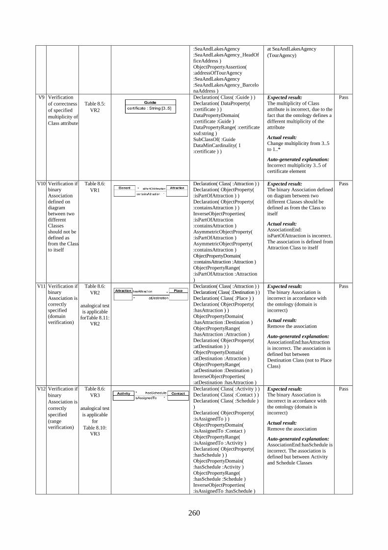
260
:SeaAndLakesAgency :SeaAndLakesAgency_HeadOf
ficeAddress )
ObjectPropertyAssertion( :addressOfTourAgency
:SeaAndLakesAgency
:SeaAndLakesAgency_BarcelonaAddress )
at SeaAndLakesAgency
(TourAgency)
V9 Verification
of correctness
of specified
multiplicity of
Class attribute
Table 8.5:
VR2
Declaration( Class( :Guide ) )
Declaration( DataProperty( :certificate ) )
DataPropertyDomain(
:certificate :Guide ) DataPropertyRange( :certificate
xsd:string )
SubClassOf( :Guide DataMinCardinality( 1
:certificate ) )
Expected result:
The multiplicity of Class attribute is incorrect, due to the
fact that the ontology defines a
different multiplicity of the attribute
Actual result:
Change multiplicity from 3..5 to 1..*
Auto-generated explanation:
Incorrect multiplicity 3..5 of certificate element
Pass
V10 Verification if binary
Association
defined on diagram
between two
different Classes
should not be
defined as from the Class
to itself
Table 8.6:
VR1
Declaration( Class( :Attraction ) ) Declaration( ObjectProperty(
:isPartOfAttraction ) )
Declaration( ObjectProperty( :containsAttraction ) )
InverseObjectProperties(
:isPartOfAttraction :containsAttraction )
AsymmetricObjectProperty(
:isPartOfAttraction ) AsymmetricObjectProperty(
:containsAttraction )
ObjectPropertyDomain( :containsAttraction :Attraction )
ObjectPropertyRange(
:isPartOfAttraction :Attraction )
Expected result: The binary Association defined
on diagram between two
different Classes should be defined as from the Class to
itself
Actual result: AssociationEnd:
isPartOfAttraction is incorrect.
The association is defined from Attraction Class to itself
Pass
V11 Verification if
binary Association is
correctly
specified (domain
verification)
Table 8.6:
VR2
analogical test
is applicable
forTable 8.11: VR2
Declaration( Class( :Attraction ) )
Declaration( Class( :Destination ) ) Declaration( Class( :Place ) )
Declaration( ObjectProperty(
:hasAttraction ) ) ObjectPropertyDomain(
:hasAttraction :Destination )
ObjectPropertyRange( :hasAttraction :Attraction )
Declaration( ObjectProperty(
:atDestination ) ) ObjectPropertyDomain(
:atDestination :Attraction )
ObjectPropertyRange( :atDestination :Destination )
InverseObjectProperties(
:atDestination :hasAttraction )
Expected result:
The binary Association is incorrect in accordance with
the ontology (domain is
incorrect)
Actual result:
Remove the association
Auto-generated explanation: AssociationEnd:hasAttraction
is incorrect. The association is
defined but between Destination Class (not to Place
Class)
Pass
V12 Verification if
binary
Association is
correctly
specified
(range
verification)
Table 8.6:
VR3
analogical test
is applicable
for
Table 8.10:
VR3
Declaration( Class( :Activity ) ) Declaration( Class( :Contact ) )
Declaration( Class( :Schedule )
) Declaration( ObjectProperty(
:isAssignedTo ) )
ObjectPropertyDomain(
:isAssignedTo :Contact )
ObjectPropertyRange(
:isAssignedTo :Activity ) Declaration( ObjectProperty(
:hasSchedule ) ) ObjectPropertyDomain(
:hasSchedule :Activity )
ObjectPropertyRange( :hasSchedule :Schedule )
InverseObjectProperties(
:isAssignedTo :hasSchedule )
Expected result: The binary Association is
incorrect in accordance with
the ontology (domain is incorrect)
Actual result:
Remove the association
Auto-generated explanation:
AssociationEnd:hasSchedule is
incorrect. The association is defined but between Activity
and Schedule Classes
Pass
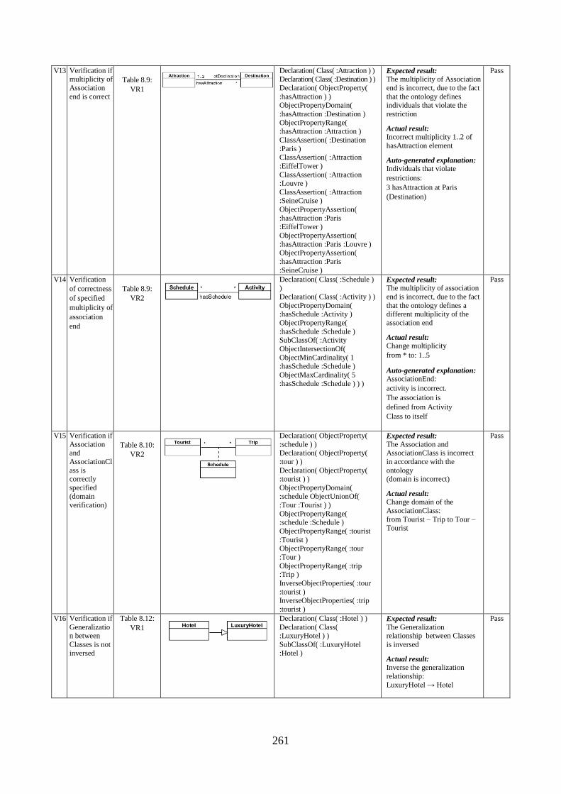
261
V13 Verification if multiplicity of
Association
end is correct
Table 8.9:
VR1
Declaration( Class( :Attraction ) ) Declaration( Class( :Destination ) )
Declaration( ObjectProperty(
:hasAttraction ) ) ObjectPropertyDomain(
:hasAttraction :Destination )
ObjectPropertyRange( :hasAttraction :Attraction )
ClassAssertion( :Destination
:Paris ) ClassAssertion( :Attraction
:EiffelTower )
ClassAssertion( :Attraction :Louvre )
ClassAssertion( :Attraction :SeineCruise )
ObjectPropertyAssertion(
:hasAttraction :Paris :EiffelTower )
ObjectPropertyAssertion(
:hasAttraction :Paris :Louvre ) ObjectPropertyAssertion(
:hasAttraction :Paris
:SeineCruise )
Expected result: The multiplicity of Association
end is incorrect, due to the fact
that the ontology defines individuals that violate the
restriction
Actual result: Incorrect multiplicity 1..2 of
hasAttraction element
Auto-generated explanation: Individuals that violate
restrictions:
3 hasAttraction at Paris
(Destination)
Pass
V14 Verification
of correctness
of specified
multiplicity of
association
end
Table 8.9:
VR2
Declaration( Class( :Schedule ) )
Declaration( Class( :Activity ) )
ObjectPropertyDomain( :hasSchedule :Activity )
ObjectPropertyRange(
:hasSchedule :Schedule ) SubClassOf( :Activity
ObjectIntersectionOf(
ObjectMinCardinality( 1 :hasSchedule :Schedule )
ObjectMaxCardinality( 5
:hasSchedule :Schedule ) ) )
Expected result: The multiplicity of association
end is incorrect, due to the fact
that the ontology defines a different multiplicity of the
association end
Actual result: Change multiplicity
from * to: 1..5
Auto-generated explanation: AssociationEnd:
activity is incorrect.
The association is
defined from Activity
Class to itself
Pass
V15 Verification if
Association and
AssociationCl
ass is correctly
specified (domain
verification)
Table 8.10:
VR2
Declaration( ObjectProperty(
:schedule ) ) Declaration( ObjectProperty(
:tour ) )
Declaration( ObjectProperty( :tourist ) )
ObjectPropertyDomain( :schedule ObjectUnionOf(
:Tour :Tourist ) )
ObjectPropertyRange( :schedule :Schedule )
ObjectPropertyRange( :tourist
:Tourist ) ObjectPropertyRange( :tour
:Tour )
ObjectPropertyRange( :trip :Trip )
InverseObjectProperties( :tour
:tourist ) InverseObjectProperties( :trip
:tourist )
Expected result:
The Association and AssociationClass is incorrect
in accordance with the
ontology (domain is incorrect)
Actual result: Change domain of the
AssociationClass:
from Tourist – Trip to Tour – Tourist
Pass
V16 Verification if
Generalization between
Classes is not
inversed
Table 8.12:
VR1
Declaration( Class( :Hotel ) )
Declaration( Class( :LuxuryHotel ) )
SubClassOf( :LuxuryHotel
:Hotel )
Expected result:
The Generalization relationship between Classes
is inversed
Actual result: Inverse the generalization
relationship:
LuxuryHotel → Hotel
Pass
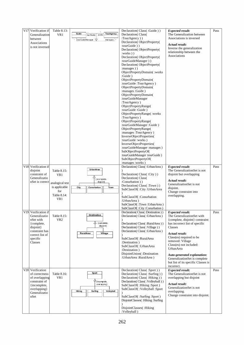
262
V17 Verification if
Generalization
between
Associations
is not inversed
Table 8.13:
VR1
Declaration( Class( :Guide ) ) Declaration( Class(
:TourAgency ) )
Declaration( ObjectProperty( :tourGuide ) )
Declaration( ObjectProperty(
:works ) ) Declaration( ObjectProperty(
:tourGuideManager ) )
Declaration( ObjectProperty( :manages ) )
ObjectPropertyDomain( :works
:Guide ) ObjectPropertyDomain(
:tourGuide :TourAgency ) ObjectPropertyDomain(
:manages :Guide )
ObjectPropertyDomain( :tourGuideManager
:TourAgency )
ObjectPropertyRange( :tourGuide :Guide )
ObjectPropertyRange( :works
:TourAgency ) ObjectPropertyRange(
:tourGuideManager :Guide )
ObjectPropertyRange( :manages :TourAgency )
InverseObjectProperties(
:tourGuide :works ) InverseObjectProperties(
:tourGuideManager :manages )
SubObjectPropertyOf( :tourGuideManager :tourGuide )
SubObjectPropertyOf(
:manages :works )
Expected result: The Generalization between
Associations is inversed
Actual result: Inverse the generalization
relationship between the
Associations
Pass
V18 Verification if disjoint
constraint of Generalizatio
nSet is correct
Table 8.15:
VR1
analogical test
is applicable
for
Table 8.14: VR1
Declaration( Class( :UrbanArea ) )
Declaration( Class( :City ) ) Declaration( Class(
:Conurbation ) )
Declaration( Class( :Town ) ) SubClassOf( :City :UrbanArea
)
SubClassOf( :Conurbation :UrbanArea )
SubClassOf( :Town :UrbanArea )
SubClassOf( :City :Conurbation )
Expected result: The GeneralizationSet is not
disjoint but overlapping
Actual result:
GeneralizationSet is not
disjoint.
Change constraint into
overlapping.
Pass
V19 Verification if Generalizatio
nSet with
{complete, disjoint}
constraint has
correct list of specific
Classes
Table 8.15:
VR2
Declaration( Class( :Destination ) ) Declaration( Class( :UrbanArea )
)
Declaration( Class( :RuralArea ) ) Declaration( Class( :Village ) )
Declaration( Class( :UrbanArea )
) SubClassOf( :RuralArea
:Destination )
SubClassOf( :UrbanArea :Destination )
DisjointUnion( :Destination
:UrbanArea :RuralArea )
Expected result: The GeneralizationSet with
{complete, disjoint} constraint
has incorrect list of specific Classes
Actual result:
Class(es) required to be removed: Village
Class(es) not included:
UrbanArea
Auto-generated explanation:
GeneralizationSet is complete
but list of its specific Classes is incorrect.
Pass
V20 Verification
of correctness of overlapping
constraint of
{incomplete, overlapping}
Generalizatio
nSet
Table 8.16: VR1
Declaration( Class( :Sport ) )
Declaration( Class( :Surfing ) ) Declaration( Class( :Hiking ) )
Declaration( Class( :Volleyball ) )
SubClassOf( :Hiking :Sport ) SubClassOf( :Volleyball :Sport
)
SubClassOf( :Surfing :Sport ) DisjointClasses( :Hiking :Surfing
)
DisjointClasses( :Hiking :Volleyball )
Expected result:
The GeneralizationSet is not overlapping but disjoint
Actual result:
GeneralizationSet is not overlapping.
Change constraint into disjoint.
Pass
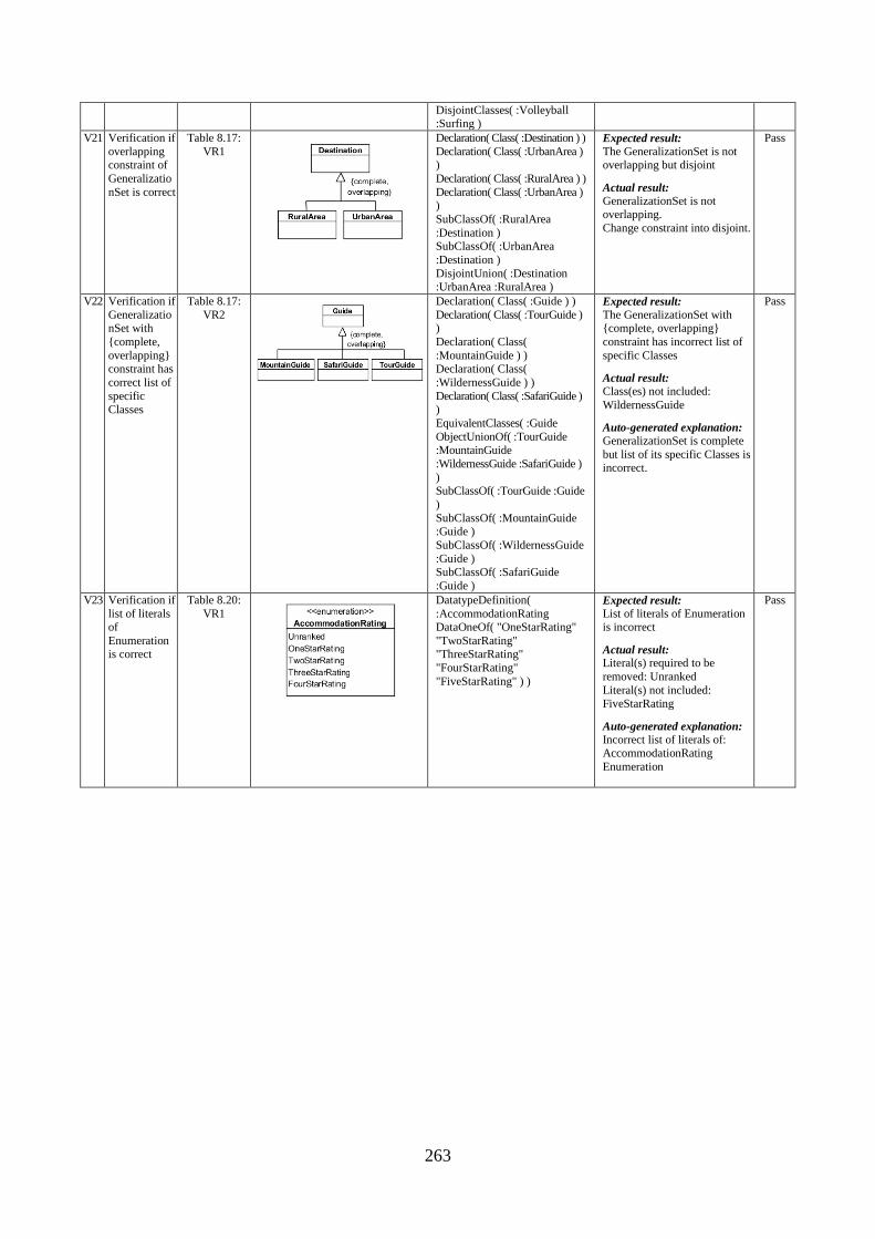
263
DisjointClasses( :Volleyball :Surfing )
V21 Verification if
overlapping constraint of
Generalizatio
nSet is correct
Table 8.17:
VR1
Declaration( Class( :Destination ) )
Declaration( Class( :UrbanArea ) )
Declaration( Class( :RuralArea ) )
Declaration( Class( :UrbanArea ) )
SubClassOf( :RuralArea
:Destination ) SubClassOf( :UrbanArea
:Destination )
DisjointUnion( :Destination :UrbanArea :RuralArea )
Expected result:
The GeneralizationSet is not overlapping but disjoint
Actual result:
GeneralizationSet is not overlapping.
Change constraint into disjoint.
Pass
V22 Verification if
GeneralizationSet with
{complete,
overlapping} constraint has
correct list of
specific
Classes
Table 8.17:
VR2
Declaration( Class( :Guide ) )
Declaration( Class( :TourGuide ) )
Declaration( Class(
:MountainGuide ) ) Declaration( Class(
:WildernessGuide ) )
Declaration( Class( :SafariGuide )
)
EquivalentClasses( :Guide
ObjectUnionOf( :TourGuide :MountainGuide
:WildernessGuide :SafariGuide )
) SubClassOf( :TourGuide :Guide
)
SubClassOf( :MountainGuide :Guide )
SubClassOf( :WildernessGuide
:Guide ) SubClassOf( :SafariGuide
:Guide )
Expected result:
The GeneralizationSet with {complete, overlapping}
constraint has incorrect list of
specific Classes
Actual result:
Class(es) not included:
WildernessGuide
Auto-generated explanation:
GeneralizationSet is complete
but list of its specific Classes is incorrect.
Pass
V23 Verification if
list of literals of
Enumeration is correct
Table 8.20:
VR1
DatatypeDefinition(
:AccommodationRating DataOneOf( "OneStarRating"
"TwoStarRating" "ThreeStarRating"
"FourStarRating"
"FiveStarRating" ) )
Expected result:
List of literals of Enumeration is incorrect
Actual result: Literal(s) required to be
removed: Unranked
Literal(s) not included: FiveStarRating
Auto-generated explanation:
Incorrect list of literals of: AccommodationRating
Enumeration
Pass
264
Appendix B. Materials for the Experiment
Appendix B.1. Selected Domain Ontologies
This appendix describes the method of selecting and preparing domain ontologies for the
purpose of the experiment.
Appendix B.1.1. Postulates for Selection of Domain Ontologies
Taking into account the goal of the experiment, the experimenter posed several postulates for
domain ontology so that it could be considered as being relevant to the experiment:
The ontology is expressed in OWL notation.
The ontology is syntactically correct.
The ontology is NOT related to common knowledge, as well as IT studies including
software engineering or computer science. The matter of semantic completeness of the
ontology was left open. However, the experimenter made efforts to ensure that the
selected ontologies depicted the relevant aspects of the reality in a clear way and as
complete as possible.
Each selected ontology should describe a different domain.
The ontology is consistent. The consistence was checked by experimenter with the use
of Protégé tool.
The ontology contains no less than 40 OWL classes and includes axioms describing
relationships between the classes which could be translated into UML as
generalizations and associations, in accordance with Chapter 8. The final versions of
domain ontologies after modifications (described in Appendix B.1.3) were of
approximately 40-45 OWL classes. This number of classes was chosen in purpose,
because on the one hand the ontology should be expressive and complex enough to be
useful for the purpose of the experiment, but on the other hand the equivalent textual
description of the domain ontology should fit into the length of maximally 1-1.5 page
of A4 size so that it is easy to read during the experiment.
The ontology is written in English.
The license of the ontology allows for its free usage for scientific purposes.
Appendix B.1.2. Internet Sources of the Selected Domain Ontologies
Four different domain ontologies have been selected from Internet sources. The original files
with the OWL ontologies and the modified versions explained in Appendix B.1.3 are
included on the CD enclosed to this dissertation.
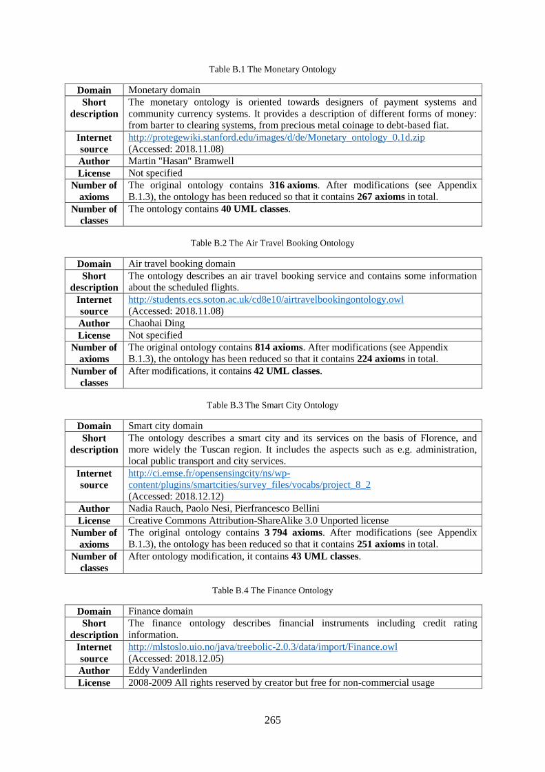
265
Table B.1 The Monetary Ontology
Domain Monetary domain
Short
description
The monetary ontology is oriented towards designers of payment systems and
community currency systems. It provides a description of different forms of money:
from barter to clearing systems, from precious metal coinage to debt-based fiat.
Internet
source
http://protegewiki.stanford.edu/images/d/de/Monetary_ontology_0.1d.zip
(Accessed: 2018.11.08)
Author Martin "Hasan" Bramwell
License Not specified
Number of
axioms
The original ontology contains 316 axioms. After modifications (see Appendix
B.1.3), the ontology has been reduced so that it contains 267 axioms in total.
Number of
classes
The ontology contains 40 UML classes.
Table B.2 The Air Travel Booking Ontology
Domain Air travel booking domain
Short
description
The ontology describes an air travel booking service and contains some information
about the scheduled flights.
Internet
source
http://students.ecs.soton.ac.uk/cd8e10/airtravelbookingontology.owl
(Accessed: 2018.11.08)
Author Chaohai Ding
License Not specified
Number of
axioms
The original ontology contains 814 axioms. After modifications (see Appendix
B.1.3), the ontology has been reduced so that it contains 224 axioms in total.
Number of
classes
After modifications, it contains 42 UML classes.
Table B.3 The Smart City Ontology
Domain Smart city domain
Short
description
The ontology describes a smart city and its services on the basis of Florence, and
more widely the Tuscan region. It includes the aspects such as e.g. administration,
local public transport and city services.
Internet
source
http://ci.emse.fr/opensensingcity/ns/wp-
content/plugins/smartcities/survey_files/vocabs/project_8_2
(Accessed: 2018.12.12)
Author Nadia Rauch, Paolo Nesi, Pierfrancesco Bellini
License Creative Commons Attribution-ShareAlike 3.0 Unported license
Number of
axioms
The original ontology contains 3 794 axioms. After modifications (see Appendix
B.1.3), the ontology has been reduced so that it contains 251 axioms in total.
Number of
classes
After ontology modification, it contains 43 UML classes.
Table B.4 The Finance Ontology
Domain Finance domain
Short
description
The finance ontology describes financial instruments including credit rating
information.
Internet
source
http://mlstoslo.uio.no/java/treebolic-2.0.3/data/import/Finance.owl
(Accessed: 2018.12.05)
Author Eddy Vanderlinden
License 2008-2009 All rights reserved by creator but free for non-commercial usage
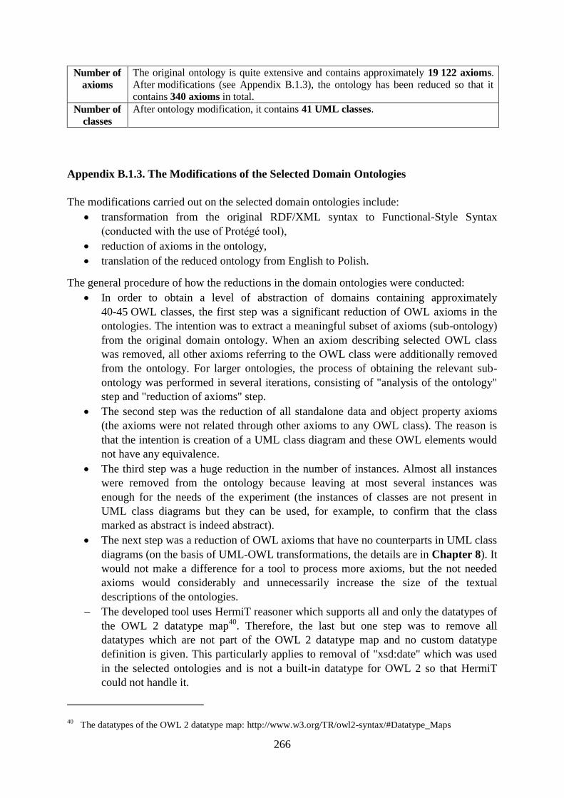
266
Number of
axioms
The original ontology is quite extensive and contains approximately 19 122 axioms.
After modifications (see Appendix B.1.3), the ontology has been reduced so that it
contains 340 axioms in total.
Number of
classes
After ontology modification, it contains 41 UML classes.
Appendix B.1.3. The Modifications of the Selected Domain Ontologies
The modifications carried out on the selected domain ontologies include:
transformation from the original RDF/XML syntax to Functional-Style Syntax
(conducted with the use of Protégé tool),
reduction of axioms in the ontology,
translation of the reduced ontology from English to Polish.
The general procedure of how the reductions in the domain ontologies were conducted:
In order to obtain a level of abstraction of domains containing approximately
40-45 OWL classes, the first step was a significant reduction of OWL axioms in the
ontologies. The intention was to extract a meaningful subset of axioms (sub-ontology)
from the original domain ontology. When an axiom describing selected OWL class
was removed, all other axioms referring to the OWL class were additionally removed
from the ontology. For larger ontologies, the process of obtaining the relevant sub-
ontology was performed in several iterations, consisting of "analysis of the ontology"
step and "reduction of axioms" step.
The second step was the reduction of all standalone data and object property axioms
(the axioms were not related through other axioms to any OWL class). The reason is
that the intention is creation of a UML class diagram and these OWL elements would
not have any equivalence.
The third step was a huge reduction in the number of instances. Almost all instances
were removed from the ontology because leaving at most several instances was
enough for the needs of the experiment (the instances of classes are not present in
UML class diagrams but they can be used, for example, to confirm that the class
marked as abstract is indeed abstract).
The next step was a reduction of OWL axioms that have no counterparts in UML class
diagrams (on the basis of UML-OWL transformations, the details are in Chapter 8). It
would not make a difference for a tool to process more axioms, but the not needed
axioms would considerably and unnecessarily increase the size of the textual
descriptions of the ontologies.
The developed tool uses HermiT reasoner which supports all and only the datatypes of
the OWL 2 datatype map40
. Therefore, the last but one step was to remove all
datatypes which are not part of the OWL 2 datatype map and no custom datatype
definition is given. This particularly applies to removal of "xsd:date" which was used
in the selected ontologies and is not a built-in datatype for OWL 2 so that HermiT
could not handle it.
40 The datatypes of the OWL 2 datatype map: http://www.w3.org/TR/owl2-syntax/#Datatype_Maps
267
The final step was removal or shortening of a significant number of
AnnotationAssertion axioms which are human-readable comments. For the purpose of
the experiment, there were too many comments in the original domain ontologies and
the comments were too long.
The full list of executed reductions in the monetary ontology:
1. Removal of FunctionalObjectProperty or InverseFunctionalObjectProperty axioms related to:
hasRepute, hasReciprocity, isADescriptionOf, isBorrowedBy, isBorrowerOf, isCommissionedBy, isCommissionerOf,
isDescribedBy, isExecutedBy, isExecutorOf, isGiverOfObligationValue, isGiverOfPhysicalValue, isIssuedBy,
isIssuerOf, isIssuerOfSymbols, isLenderOf, isLentBy, isMintedBy, isMinterOf, isReceiverOfObligationValue,
isReputeOf, isReceiverOfPhysicalValue, isReciprocityOf, isTransportedBySymbol, isTransporterOfSymbolicValue
2. Removal of a number of AnnotationAssertion axioms
The full list of executed reductions in the air travel booking ontology:
1. All axioms related to the following OWL classes have been removed from the ontology:
AirlineDirectFlightBetweenLHRAndJFK, AirlineFromOrToSouthamptonInternational, AirlineOperateA380-800,
AirportServedByA380-800, AmericanAirlinesFlight, BritishAirwaysFlight, EmiratesFlight, FlybeFlight, GulfAirFlight,
QantasAirwaysFlight, SwissInternationalAirlinesFlight, Country, BusinessClassSeat, EconomyClassSeat,
FirstClassSeat, PremiumEconomyClassSeat, BusinessReservation, EconomyReservation,
BusinessClassReservationPassenger, AirBooking, PassengerHaveFirstReservationBA0117_20110401,
FirstClassReservation, PremiumEconomyReservation, FirstClassReservationPassenger,
PremiumEconomyClassReservationPassenger, EconomyClassReservationPassenger, DomainConcept, ValuePartition,
CodesharingFlight, OperatingFlight
2. All instances related to the following OWL classes have been removed from the ontology:
Airline, Airport, Manufacturer, Flight, AA1514, AA6138, BE880, EK003, QF4795, BA0003, BA0117, EK003,
QF4795, BA0003_1, BA0003_2, LX22, LX359, GF671, LX359ConnectLX22, Passenger, Reservation, FirstClassSeat
3. All axioms related to the following OWL object properties have been removed from the
ontology:
hasSegment, hasNextSegment, hasPreviousSegment, isCodesharing, isCodesharedBy, isCodesharedBy, isCodesharing,
isConnectedAt, hasCountry, isCountryOf, isPartSegmentOf, hasSameSegment
4. Reduction of some additional axioms:
a) Removal of FunctionalObjectProperty and/or InverseFunctionalObjectProperty axioms related
to: isICAOCodeOf, isOperatedBy, isManufacturedBy, isSeatOf, hasSeat, isManufacturerOf, isReservating,
isReservatedBy, isDepaturedFrom, isArrivedAt, hasReservation, isReservationOf
b) Removal of FunctionalDataProperty axioms related to: hasSeatNumber, isDeparturedOn
5. Removal of a number of AnnotationAssertion axioms
The full list of executed reductions in the smart city ontology:
1. All axioms related to the following OWL classes have been removed from the ontology:
FinancialService (and all its subclasses), MiningAndQuarrying (and all its subclasses), Event, WineAndFood (and all
its subclasses), Wholesale (and all its subclasses), Observation (and all its subclasses), StreetNumber, StatisticalData,
Lot, Entertainment, Maneuver, Feature, Organization, Geometry, Line, Place, Instant, Route, RouteSection, Ride,
RouteJunction, RouteLink, SensorSiteTable, BusinessEntity, GoodsYard, Entry, Path, BeaconObservation,
AVMRecord, SensorSiteTable, BusStopForecast
268
2. All axioms related only to the subclasses of the following OWL classes and the asserted
descendent classes have been removed from the ontology:
Emergency, GovernmentOffice, TransferServiceAndRenting, CulturalActivity, Face, TourismService,
Accommodation, AgricultureAndLivestock, HealthCare, EducationAndResearch, IndustryAndManufacturing,
ShoppingAndService, UtilitiesAndSupply, SpatialThing, CivilAndEdilEngineering, Environment, Advertising
3. All axioms related to the following OWL object properties have been removed from the
ontology:
atBusStop, belongToRoad, hasInternalAccess, hasFirstStop, hasGeometry, hasFirstSection, hasForecast, hasFirstElem,
hasRoute, arrangedOnRoad, beginsAtJunction, concerningNode, concernLine, correspondToJunction, endsAtStop,
finishesAtJunction, formsTable, hasAccess, hasAVMRecord, hasBObservation, hasExpectedTime, hasExternalAccess,
hasLastStop, hasLastStopTime, hasManeuver, hasObservation, hasRouteLink, hasSecondElem, hasSection, location,
hasStatistic, hasStreetNumber, hasThirdElem, includeForecast, instantAVM, updateTime, instantBObserv, lastStop,
instantForecast, instantObserv, instantParking, instantWReport, isInMunicipality, isInRoad, isPartOfLot, startsAtStop,
measuredByBeacon, measuredBySensor, measuredDate, measuredTime, observationTime, onRoute, refersToRide,
placedInElement, placedOnRoad, scheduledOnLine, correspondsTo, coincideWith
4. All axioms related to the following OWL data properties have been removed from the
ontology:
adminClass, alterCode, atecoCode, automaticity, averageDistance, averageSpeed, averageTime, perTemp, axialMass,
capacity, classCode, day, elementClass, elementType, elemLocation, entryType, eventCategory, eventTime, exitRate,
expectedTime, exponent, fillRate, firenzeCard, free, freeEvent, gauge, lat, long, heightHour, hour, humidity, juncType,
lastStopTime, lastTriples, lastUpdate, length, lineNumber, lunarPhase, major, managingAuth, managingBy,
maneuverType, maxTemp, minor, minTemp, moonrise, moonset, multimediaResource, period, number, numTrack,
occupied, overtime, owner, parkOccupancy, porteCochere, power, primaryType, processType, public, railDepartment,
railwaySiding, recTemp, rideState, text, routeLength, routePosition, snow, speedLimit, speedPercentile, sunHeight,
sunrise, sunset, supply, thresholdPerc, composition, time, timestamp, trackType, trafficDir, type, typeLabel,
typeOfResale, underpass, uuid, uv, validityStatus, value, vehicle, vehicleFlow, width, wind, yardType, year,
extendName, restrictionType, restrictionValue, abbreviation, accessType, areaCode, areaName, automaticity, state,
combinedTraffic, concentration, direction, distance, districtCode, elemLocation, entryType, extendNumber,
houseNumber, occupancy, operatingStatus, placeName, routeCode, stopNumber
7. Removal of a number of AnnotationAssertion axioms
The full list of executed reductions in the finance ontology:
1. All axioms related to the following OWL classes and the asserted descendent classes have been
removed from the ontology (including all assigned instances):
ISO10962-ClassificationOfFinancialInstruments, YearlyAccount, ISICCode, RiskProfile, ImpactOfRiskOccurence,
RiskSymptom, Account, Risk, PartyType, XNStatus, PartyValues, Temporal
2. All axioms related to the following OWL classes have been removed from the ontology
(including all assigned instances):
ISO10383-MarketIdentifierCodes, ISO3166-CountryCode, ISO4217-Currencycodes, ValuePartition, InstrumentStatus,
ISOCodes
3. All instances related to the following OWL classes have been removed from the ontology:
ValidPeriod, ValidInstant, Granularity, Party (and all its subclasses), FinancialInstrument, Moodys (and all its
subclasses), StandardAndPoors (and all its subclasses), TargetOfLoan, NationalBank, InstrumentlNature,
CapitalizationType, MonitoringStatus, PostingUnit
4. All axioms related to the following OWL object properties have been removed from the
ontology:
269
isRelatedSeriesOf, hasAsRelatedSeries, isRestrictedVersionOf, hasAsRestrictedVersion, isStripForEntitlement,
hasStripForEntitlement, isBondConvertibleTo, hasPostingUnit, hasCFIGroupCode, hasAsBondConvertibleFrom,
hasAMutualRelationWithInstrument, hasFINature, hasPartyRange, hasCFICategoryCode, hasValuePartitionRelation,
isMutuallyRelatedToInstrument, isOldISINVersionOf, hasPartyRelation, hasInstrumentXNStatus,
hasAsOldISINVersion, hasISOClassificationOfFinancialInstrumentsRelation, isNationalBankFor, hasXNStatus,
isBrokerOnMarket, isFractionOf, isPartOfIndex, hasCFIAttribute1Code, hasCFIAttribute2Code,
hasCFIAttribute3Code, hasCFIAttribute4Code, hasAsNationalCurrency, hasAsFacialCurrency, hasCFIGroupAttribute1
(and all its subproperties), hasCFINature, hasCFIGroupAttribute2 (and all its subproperties), hasCFIGroupAttribute3
(and all its subproperties), hasAsFraction, hasCFIGroupAttribute4 (and all its subproperties),
isReferencedAsAttribute1 (and all its subproperties), isReferencedAsAttribute2 (and all its subproperties),
isReferencedAsAttribute3 (and all its subproperties), isEntitlementFor, isReferencedAsAttribute4 (and all its
subproperties), isReferencedByCFICategory (and all its subproperties), refersToCFIGroupCode (and all its
subproperties), hasQuotationOnMarket, hasBroker, hasRiskRole (and all its subproperties), hasAsNationalBank,
hasAsEntitlement, isLegalSalesEntityFor, hasAsLegalSalesEntity, isPartyCustodianForFinancialInstrument,
hasPartyCustodian, hasTemporalDomainRelation (and all its subproperties), hasTemporalRangeRelation (and all its
subproperties), isPartySubCustodianOf, hasAsUnderyingValue, isUnderlyingValueFor, hasAsIndexPart,
isRenamedInstrumentFrom, hasBeenRenamedTo, hasAsFiscalResidence, hasAsFiscalResident, hasAsLegalResidence,
hasAsLegalResident, hasFinancialInstrumentRelation
5. All axioms related to the following OWL data properties have been removed from the
ontology:
ISICDescription, ISICCode, hasRiskSymptomSource, hasCouponDomain, hasFinancialInstrumentDomain,
isDematerializedFromDate, isMaterializedTillDate, ISO3166-CountryCodes (and all its subproperties), ISOCurrency
(and all its subproperties), ISO10383-MICcodes (and all its subproperties), hasTemporalDomain (and all its
subproperties), hasExCouponDate, asPartOfTotalIssueAmounting, hasProcentualIssuePrice, hasAsDenomination,
isSubjectToSafekeepingFeesMarketSide, hasDateOfBeneficiary, isSubjectToSafekeepingFeesStreetSide,
isExemptedFromTaxesInCountryOfEmittor, hasCreationDateInInformationSystems, hasCouponCapitalizationRate,
hasCouponDate, hasIssueDate
6. Reduction of some additional axioms:
a) Removal of SubObjectPropertyOf axioms related to: hasFinancialInstrumentRelation,
isInvolvedPartyForFinancialInstrument
b) Removal of FunctionalObjectProperty axioms related to: hasMonitoringStatus,
hasCapitalizationType
c) Removal of FunctionalDataProperty axioms related to: hasISINcode, hasNominalValue,
isAllowedForSecuritiesHandling, hasNominalIssuePrice, hasDateOfBeneficiary,
hasCreationDateInInformationSystems, isAFungibleInstrument
7. Removal of a number of AnnotationAssertion axioms
270
Appendix B.2. Textual Descriptions of the Domain Ontologies
The full textual descriptions of the four domain ontologies selected for the experiment
are recorded on the CD enclosed to this doctoral dissertation.
This section is aimed to explain the applied procedure of preparing the textual descriptions of
the domain ontologies in natural language. Both OWL 2 domain ontologies and descriptions
of the domains in natural language had to be semantically equivalent. Therefore, both formats
have been expertly verified by dr inż. Bogumiła Hnatkowska.
Due to the fact that all materials for the experiment were prepared in the Polish language,
which is explained in section 12.8.1, the procedure of preparing textual descriptions of the
domain ontologies with the examples is explained below with the Polish examples (the
relevant English translation is also included).
For better readability of resulting descriptions, the following naming convention was applied:
Names of UML classes: every word with a capital letter, combined into one word
without spaces, written in bold. For example:
InstrumentFinansowy (eng.: FinancialInstrument)
WartośćFizyczna (eng.: PhysicalValue)
Names of UML attributes: the first word with a lowercase letter, every other word
with a capital letter, combined into one word without spaces, written in bold. For
example:
statusParkingu (eng.: carParkStatus)
typWęzła (eng.: nodeType)
Names of UML association ends: the first word with a lowercase letter, every other
word with a capital letter, combined into one word without spaces, written in bold. For
example:
maRatingStandardAndPoors (eng.: hasStandardAndPoorsRating)
maAgentaTransferowego (eng.: hasPartyTransferAgent)
Names of UML instances: capitalization in accordance with the original naming
convention in the ontology, combined into one word without spaces, written in bold.
For example, the following are few selected instances of the class called KodICAO
(eng.: ICAOCode):
EGHI, EGLL, EGPF, EINN
The general procedure of writing a textual description of the domain ontology in the natural
language (here: Polish) is presented in Table B.5 (for UML class with attributes), Table B.6
(for UML generalizations and generalization sets) and Table B.7 (for UML associations).
In the below tables, the square brackets ("[" and "]") in the translation patterns indicate the not
mandatory elements of the pattern. The slash ("/") indicates the alternative elements used
depending on the context.
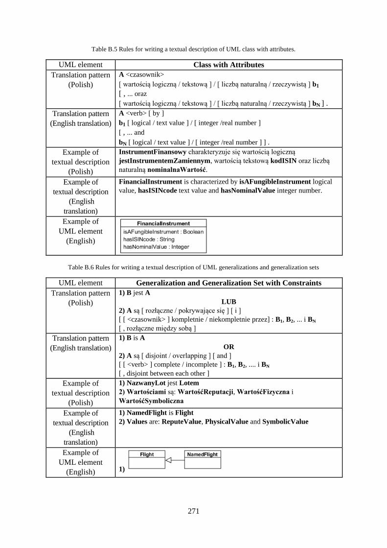
271
Table B.5 Rules for writing a textual description of UML class with attributes.
UML element Class with Attributes
Translation pattern
(Polish)
A <czasownik>
[ wartością logiczną / tekstową ] / [ liczbą naturalną / rzeczywistą ] b1
[ , ... oraz
[ wartością logiczną / tekstową ] / [ liczbą naturalną / rzeczywistą ] bN ] .
Translation pattern
(English translation)
A <verb> [ by ]
b1 [ logical / text value ] / [ integer /real number ]
[ , ... and
bN [ logical / text value ] / [ integer /real number ] ] .
Example of
textual description
(Polish)
InstrumentFinansowy charakteryzuje się wartością logiczną
jestInstrumentemZamiennym, wartością tekstową kodISIN oraz liczbą
naturalną nominalnaWartość.
Example of
textual description
(English
translation)
FinancialInstrument is characterized by isAFungibleInstrument logical
value, hasISINcode text value and hasNominalValue integer number.
Example of
UML element
(English)
Table B.6 Rules for writing a textual description of UML generalizations and generalization sets
UML element Generalization and Generalization Set with Constraints
Translation pattern
(Polish)
1) B jest A
LUB
2) A są [ rozłączne / pokrywające się ] [ i ]
[ [ <czasownik> ] kompletnie / niekompletnie przez] : B1, B2, ... i BN
[ , rozłączne między sobą ]
Translation pattern
(English translation)
1) B is A
OR
2) A są [ disjoint / overlapping ] [ and ]
[ [ <verb> ] complete / incomplete ] : B1, B2, .... i BN
[ , disjoint between each other ]
Example of
textual description
(Polish)
1) NazwanyLot jest Lotem
2) Wartościami są: WartośćReputacji, WartośćFizyczna i
WartośćSymboliczna
Example of
textual description
(English
translation)
1) NamedFlight is Flight
2) Values are: ReputeValue, PhysicalValue and SymbolicValue
Example of
UML element
(English) 1)
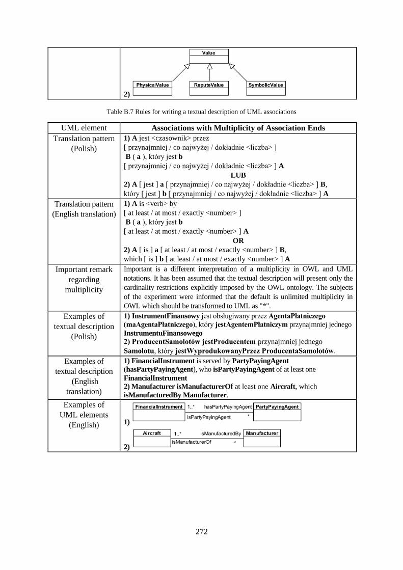
272
2)
Table B.7 Rules for writing a textual description of UML associations
UML element Associations with Multiplicity of Association Ends
Translation pattern
(Polish)
1) A jest <czasownik> przez
[ przynajmniej / co najwyżej / dokładnie <liczba> ]
B ( a ), który jest b
[ przynajmniej / co najwyżej / dokładnie <liczba> ] A
LUB
2) A [ jest ] a [ przynajmniej / co najwyżej / dokładnie <liczba> ] B,
który [ jest ] b [ przynajmniej / co najwyżej / dokładnie <liczba> ] A
Translation pattern
(English translation)
1) A is <verb> by
[ at least / at most / exactly <number> ]
B ( a ), który jest b
[ at least / at most / exactly <number> ] A
OR
2) A [ is ] a [ at least / at most / exactly <number> ] B,
which [ is ] b [ at least / at most / exactly <number> ] A
Important remark
regarding
multiplicity
Important is a different interpretation of a multiplicity in OWL and UML
notations. It has been assumed that the textual description will present only the
cardinality restrictions explicitly imposed by the OWL ontology. The subjects
of the experiment were informed that the default is unlimited multiplicity in
OWL which should be transformed to UML as "*".
Examples of
textual description
(Polish)
1) InstrumentFinansowy jest obsługiwany przez AgentaPłatniczego
(maAgentaPłatniczego), który jestAgentemPłatniczym przynajmniej jednego
InstrumentuFinansowego
2) ProducentSamolotów jestProducentem przynajmniej jednego
Samolotu, który jestWyprodukowanyPrzez ProducentaSamolotów.
Examples of
textual description
(English
translation)
1) FinancialInstrument is served by PartyPayingAgent
(hasPartyPayingAgent), who isPartyPayingAgent of at least one
FinancialInstrument 2) Manufacturer isManufacturerOf at least one Aircraft, which
isManufacturedBy Manufacturer.
Examples of
UML elements
(English) 1)
2)
273
Appendix B.3. The Full Text of the Experiment Forms
The next pages present the experiment forms for GROUP A and GROUP B. The experiment
was conducted in the Polish language but for better readability in this Appendix the English
translation of the forms is enclosed. The full text of the experiment tasks in the original
Polish version are recorded on the CD enclosed to this doctoral dissertation.
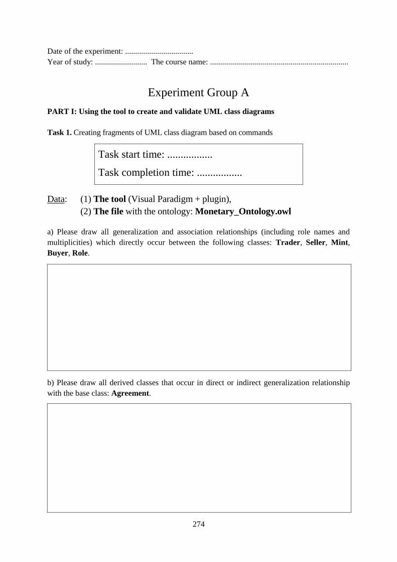
274
Date of the experiment: ..................................
Year of study: .......................... The course name: .....................................................................
Experiment Group A
PART I: Using the tool to create and validate UML class diagrams
Task 1. Creating fragments of UML class diagram based on commands
Task start time: .................
Task completion time: .................
Data: (1) The tool (Visual Paradigm + plugin),
(2) The file with the ontology: Monetary_Ontology.owl
a) Please draw all generalization and association relationships (including role names and
multiplicities) which directly occur between the following classes: Trader, Seller, Mint,
Buyer, Role.
b) Please draw all derived classes that occur in direct or indirect generalization relationship
with the base class: Agreement.
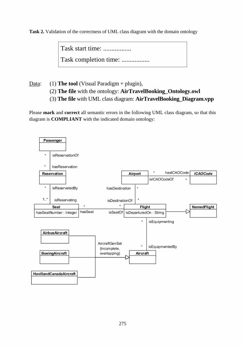
275
Task 2. Validation of the correctness of UML class diagram with the domain ontology
Task start time: .................
Task completion time: .................
Data: (1) The tool (Visual Paradigm + plugin),
(2) The file with the ontology: AirTravelBooking_Ontology.owl
(3) The file with UML class diagram: AirTravelBooking_Diagram.vpp
Please mark and correct all semantic errors in the following UML class diagram, so that this
diagram is COMPLIANT with the indicated domain ontology:
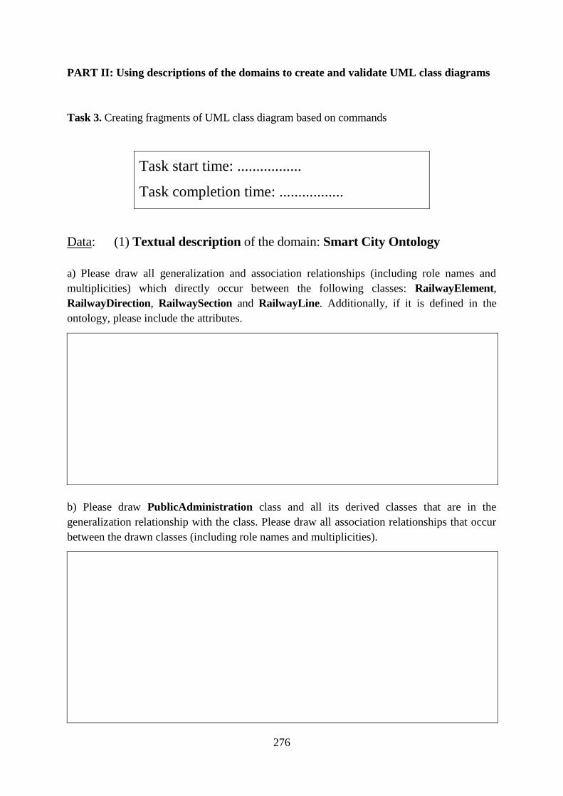
276
PART II: Using descriptions of the domains to create and validate UML class diagrams
Task 3. Creating fragments of UML class diagram based on commands
Task start time: .................
Task completion time: .................
Data: (1) Textual description of the domain: Smart City Ontology
a) Please draw all generalization and association relationships (including role names and
multiplicities) which directly occur between the following classes: RailwayElement,
RailwayDirection, RailwaySection and RailwayLine. Additionally, if it is defined in the
ontology, please include the attributes.
b) Please draw PublicAdministration class and all its derived classes that are in the
generalization relationship with the class. Please draw all association relationships that occur
between the drawn classes (including role names and multiplicities).
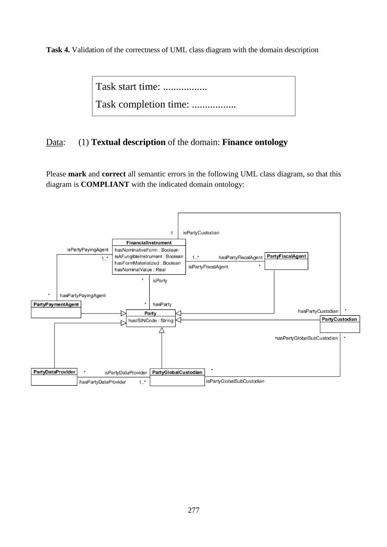
277
Task 4. Validation of the correctness of UML class diagram with the domain description
Task start time: .................
Task completion time: .................
Data: (1) Textual description of the domain: Finance ontology
Please mark and correct all semantic errors in the following UML class diagram, so that this
diagram is COMPLIANT with the indicated domain ontology:
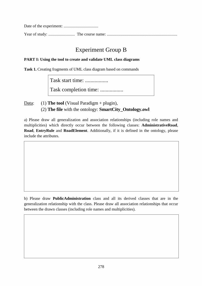
278
Date of the experiment: ..................................
Year of study: .......................... The course name: .....................................................................
Experiment Group B
PART I: Using the tool to create and validate UML class diagrams
Task 1. Creating fragments of UML class diagram based on commands
Task start time: .................
Task completion time: .................
Data: (1) The tool (Visual Paradigm + plugin),
(2) The file with the ontology: SmartCity_Ontology.owl
a) Please draw all generalization and association relationships (including role names and
multiplicities) which directly occur between the following classes: AdministrativeRoad,
Road, EntryRule and RoadElement. Additionally, if it is defined in the ontology, please
include the attributes.
b) Please draw PublicAdministration class and all its derived classes that are in the
generalization relationship with the class. Please draw all association relationships that occur
between the drawn classes (including role names and multiplicities).
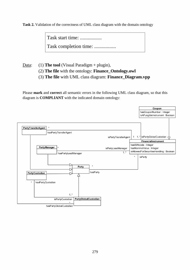
279
Task 2. Validation of the correctness of UML class diagram with the domain ontology
Task start time: .................
Task completion time: .................
Data: (1) The tool (Visual Paradigm + plugin),
(2) The file with the ontology: Finance_Ontology.owl
(3) The file with UML class diagram: Finance_Diagram.vpp
Please mark and correct all semantic errors in the following UML class diagram, so that this
diagram is COMPLIANT with the indicated domain ontology:
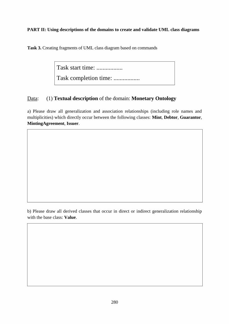
280
PART II: Using descriptions of the domains to create and validate UML class diagrams
Task 3. Creating fragments of UML class diagram based on commands
Task start time: .................
Task completion time: .................
Data: (1) Textual description of the domain: Monetary Ontology
a) Please draw all generalization and association relationships (including role names and
multiplicities) which directly occur between the following classes: Mint, Debtor, Guarantor,
MintingAgreement, Issuer.
b) Please draw all derived classes that occur in direct or indirect generalization relationship
with the base class: Value.
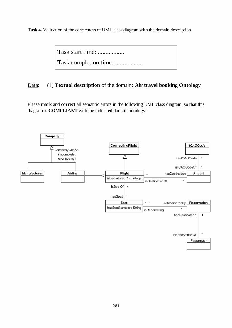
281
Task 4. Validation of the correctness of UML class diagram with the domain description
Task start time: .................
Task completion time: .................
Data: (1) Textual description of the domain: Air travel booking Ontology
Please mark and correct all semantic errors in the following UML class diagram, so that this
diagram is COMPLIANT with the indicated domain ontology:
282
References
[1] OWL 2 Web Ontology Language. Structural Specification and Functional-Style Syntax (Second Edition). W3C Recommendation 11 December 2012, http://www.w3.org/TR/owl2-syntax/. 2012.
[2] H.-E. Eriksson and M. Penker, Business modeling with UML. Business Patterns at Work. New York, USA: John Wiley & Sons, 2000.
[3] K. Goczyła, Ontologie w systemach informatycznych. Warszawa: Akademicka Oficyna Wydawnicza EXIT, 2011.
[4] OWL 2 Web Ontology Language Document Overview (Second Edition). W3C Recommendation 11 December 2012. https://www.w3.org/TR/owl2-overview/.
[5] Parreiras et al., ‘Semantics of Software Modeling’, in Semantic Computing, 2010, pp. 229–247.
[6] D. Ga, D. Djuric, and V. Deved, Model driven architecture and ontology development. Springer Science & Business Media, 2006.
[7] F. Gailly and G. Poels, ‘Ontology-driven business modelling: improving the conceptual representation of the REA ontology’, in Conceptual Modeling-ER 2007, Springer Berlin Heidelberg, 2007, pp. 407–422.
[8] B. Hnatkowska, Z. Huzar, I. Dubielewicz, and L. Tuzinkiewicz, ‘Problems of SUMO-like ontology usage in domain modelling’, in Intelligent Information and Database Systems, Springer International Publishing., 2014, pp. 352–363.
[9] OMG, Unified Modeling Language,Version 2.5, Doc. No.: ptc/2013-09-05, http://www.omg.org/spec/UML/2.5. 2015.
[10] O. I. Lindland, G. Sindre, and A. Solvberg, ‘Understanding quality in conceptual modeling’, Software IEEE, vol. 11, no. 2, pp. 42–49, 1994.
[11] Z. Huzar and M. Sadowska, ‘Towards Creating Complete Business Process Models’, From Requirements to Software: Research and Practice, pp. 77–86, 2015.
[12] M. Sadowska and Z. Huzar, ‘Semantic Validation of UML Class Diagrams with the Use of Domain Ontologies Expressed in OWL 2’, Software Engineering: Challenges and Solutions. Springer International Publishing, pp. 47–59, 2017.
[13] M. Sadowska and Z. Huzar, ‘The method of normalizing OWL 2 DL ontologies’, Global Journal of Computer Science and Technology, vol. 18, no. 2, pp. 1–13, 2018.
[14] M. Sadowska and Z. Huzar, ‘Representation of UML class diagrams in OWL 2 on the background of domain ontologies’, e-Informatica Software Engineering Journal, vol. 13, no. 1, pp. 63–103, 2019.
[15] M. Sadowska, ‘A Prototype Tool for Semantic Validation of UML Class Diagrams with the Use of Domain Ontologies Expressed in OWL 2’, In Towards a Synergistic Combination of Research and Practice in Software Engineering. Springer, Cham, pp. 49–62, 2018.
[16] A. Lindsay, D. Downs, and K. Lunn, ‘Business processes – attempts to find a definition’, Information and Software Technology, vol. 45, no. 15, pp. 1015–1019, 2003.
[17] P. Mohagheghi, V. Dehlen, and T. Neple, ‘Definitions and approaches to model quality in model-based software development – A review of literature’, Information and Software Technology, pp. 1646–1669, 2009.
283
[18] R. Van Der Straeten, T. Mens, J. Simmonds, and V. Jonckers, ‘Using description logic to maintain consistency between UML models’, International Conference on the Unified Modeling Language, pp. 326–340, 2003.
[19] A. H. Khan and I. Porres, ‘Consistency of UML class, object and statechart diagrams using ontology reasoners’, Journal of Visual Languages & Computing 26, pp. 42–65, 2015.
[20] Z. Xu, Y. Ni, W. He, L. Lin, and Q. Yan, ‘Automatic extraction of OWL ontologies from UML class diagrams: a semantics-preserving approach’, World Wide Web 15.5-6, pp. 517–545, 2012.
[21] Business Process Model and Notation (BPMN), Version 2.0, OMG. 2011. [22] S. A. White, ‘Introduction to BPMN’. Ibm Cooperation,
http://www.omg.org/bpmn/Documents/Introduction_to_BPMN.pdf (Accessed: 27.07.2019), 2004.
[23] S. S.-S. Cherfi, S. Ayad, and I. Comyn-Wattiau, ‘Improving business process model quality using domain ontologies’, Journal on Data Semantics 2, vol. 2, no. 3, pp. 75–87, 2013.
[24] A. Calì, D. Calvanese, G. De Giacomo, and M. Lenzerini, ‘A formal framework for reasoning on UML class diagrams’, International Symposium on Methodologies for Intelligent Systems, Springer, Berlin, Heidelberg, pp. 503–513, 2002.
[25] A. Korthaus, ‘Using UML for business object based systems modeling’, in In The Unified Modeling Language, Physica-Verlag HD, 1998, pp. 220–237.
[26] E. D. Nitto, L. Lavazza, M. Schiavoni, E. Tracanella, and M. Trombetta, ‘Deriving executable process descriptions from UML’, In Software Engineering, 2002. ICSE 2002. Proceedings of the 24rd International Conference on. IEEE, pp. 155-165., 2002.
[27] Object Constraint Language, Version 2.4, https://www.omg.org/spec/OCL/2.4/PDF. 2014.
[28] C. Fu, D. Yang, X. Zhang, and H. Hu, ‘An approach to translating OCL invariants into OWL 2 DL axioms for checking inconsistency’, Automated Software Engineering, vol. 24, no. 2, pp. 295–339, 2017.
[29] E. Börger, ‘Approaches to model business processes: a critical analysis of BPMN, workflow patterns and YAWL’, Software Systems Modeling, vol. 11, pp. 305–318, 2012.
[30] W. Reisig, ‘Remarks on Egon Börger: Approaches to model business processes: a critical analysis of BPMN, workflow patterns and YAWL’, Software Systems Modeling, vol. 12, pp. 5–9, 2013.
[31] D. Gagné, ‘Addressing some BPMN 2.0 misconceptions, fallacies, errors, or simply bad practices’, in BPMN 2.0 Handbook. Methods, Concepts, Case Studies and Standards in Business Process Modeling Notation, Future Strategies Inc., 2012, pp. 113–124.
[32] T. Allweyer, ‘Human-Readable BPMN Diagrams’, in BPMN 2.0 Handbook. Methods, Concepts, Case Studies and Standards in Business Process Modeling Notation, Future Strategies Inc., 2012, pp. 217–232.
[33] M. Cortes-Cornax, A. Matei, S. Dupuy-Chessa, D. Rieu, N. Mandran, and E. Letier, ‘Using intensional fragments to bridge the gap between organizational and intensional levels’, Information and Software Technology, vol. 58, pp. 1–19, 2015.
[34] F. Heidari and P. Loucopoulos, ‘Quality evaluation framework (QEF): Modeling and evaluating quality of business processes’, International Journal of Accounting Information Systems, vol. 15, pp. 193–223, 2014.
284
[35] J. Kotremba, S. Raβ, and R. Singer, ‘Distributed Business Process – A Framework for Modeling and Execution’, arXiv:1309.312v2 [csMA], 18 May 2014.
[36] G. Navarro-Suarez, J. Freund, and M. Schrepfer, ‘Best Practice Guidelines for BPMN 2.0.’, in BPMN 2.0 Handbook First Edition, Future Strategies Inc., 2010, pp. 151–165.
[37] Pillat R. M., T. C. Oliveira, P. S. Alencar, and D. D. Cowan, ‘BPMNt: A BPMN extension for specifying software process tailoring’, Information and Software Technology, vol. 57, pp. 95–115, 2015.
[38] G. Aagesen and J. Krogstie, ‘Analysis and design of business processes using BPMN’, Handbook on Business Process Management 1. Springer Berlin Heidelberg, pp. 213–235, 2010.
[39] L. Fischer (ed.), BPMN 2.0 Handbook. Methods, Concepts, Case Studies and Standards in Business Process Modeling Notation. Future Strategies Inc., 2012.
[40] J. Pitschke, ‘Business Vocabulary, Business Rules and Business Process – How to Develop an Integrated Business Model?’, Presentation at the Business Rules Forum 2010, Washington, DC.
[41] W. Wang, ‘A Comparison of Business Process Modeling Methods’, 2006 IEEE International Conference on Service Operations and Logistics, and Informatics, IEEE, pp. 1136–1141, 2006.
[42] I. M.-M. de Oca, M. Snoeck, H. A. Reijers, and A. Rodríguez-Morffi, ‘A systematic literature review of studies on business process modeling quality’, Information and Software Technology, vol. 58, pp. 187–205, 2015.
[43] S. Drejewicz, Zrozumied BPMN modelowanie procesów biznesowych. Wydawnictwo Helion, 2012.
[44] T. R. Gruber, ‘A translation approach to portable ontology specifications’, Knowledge acquisition, vol. 5, no. 2, pp. 199–220, 1993.
[45] R. Studer, V. R. Benjamins, and D. Fensel, ‘Knowledge engineering: Principles and methods’, Data & Knowledge Engineering, vol. 25, no. 1–2, pp. 161–197, Mar. 1998.
[46] S. Brockmans, R. Volz, A. Eberhart, and P. Löffler, ‘Visual modeling of OWL DL ontologies using UML’, International Semantic Web Conference. Springer Berlin Heidelberg, pp. 198–213, 2004.
[47] K. X. S. de Souza and J. Davis, ‘Expanding Queries in Knowledge Management Systems’, in Radoslaw Piotr Katarzyniak (Eds.), Ontologies and Soft Methods in Knowledge Management, Australia: Advanced Knowledge International Pty Ltd., 2005, pp. 3–18.
[48] G. Antoniou and F. van Harmelen, ‘Web Ontology Language: OWL’, in Staab S., Studer R. (eds), Handbook on ontologies. International Handbooks on Information Systems., Springer, Berlin, Heidelberg, 2004.
[49] D. de Almeida Ferreira and A. M. R. da Silva, ‘UML to OWL Mapping Overview An analysis of the translation process and supporting tools’, 2007.
[50] Z. Xu, Y. Ni, L. Lin, and H. Gu, ‘A Semantics-Preserving Approach for Extracting OWL Ontologies from UML Class Diagrams’, Database Theory and Application. Springer Berlin Heidelberg, pp. 122–136, 2009.
[51] J. Zedlitz and N. Luttenberger, ‘Transforming Between UML Conceptual Models And OWL 2 Ontologies’, Terra Cognita 2012 Workshop, vol. 6, 2012.
[52] OWL 2 Web Ontology Language Direct Semantics (Second Edition) W3C Recommendation 11 December 2012, https://www.w3.org/TR/2012/REC-owl2-direct-semantics-20121211/. 2012.
285
[53] OWL 2 Web Ontology Language RDF-Based Semantics (Second Edition). W3C Recommendation 11 December 2012, https://www.w3.org/TR/2012/REC-owl2-rdf-based-semantics-20121211/. 2012.
[54] OWL 2 Web Ontology Language Primer (Second Edition) W3C Recommendation 11 December 2012. https://www.w3.org/TR/owl2-primer/. 2012.
[55] OWL 2 Web Ontology Language Document Overview (Second Edition). W3C Recommendation 11 December 2012. https://www.w3.org/TR/owl2-overview/. 2012.
[56] I. Horrocks, O. Kutz, and U. Sattler, ‘The Even More Irresistible SROIQ’, Proc. of the 10th Int. Conf. on Principles of Knowledge Representation and Reasoning (KR 2006). AAAI Press, pp. 57–67, 2006.
[57] OWL 2 Web Ontology Language New Features and Rationale (Second Edition) W3C Recommendation 11 December 2012, https://www.w3.org/TR/owl2-new-features/. 2012.
[58] P. Garbacz and R. Trypus, ‘Ontologie poza filozofią. Studium metafilozoficzne u podstaw informatyki’, 2011. [Online]. Available: http://trypuz.pl/wp-content/papercite-data/pdf/opf-ver10.pdf. [Accessed: 12-Nov-2019].
[59] C. Roussey, F. Pinet, M. A. Kang, and O. Corcho, ‘An Introduction to Ontologies and Ontology Engineering’, in Ontologies in Urban Development Projects, vol. 1, London: Springer London, 2011, pp. 9–38.
[60] N. Guarino, ‘Formal Ontology in Information Systems.’, Proceedings of FOIS’98, Trento, Italy, 6-8 June 1998. Amsterdam, IOS Press, pp. 3–15.
[61] Meta Object Facility (MOF) Core Specification, Version 2.0. Object Management Group, OMG, http://www.omg.org/spec/MOF/2.0/PDF/. 2006.
[62] F. S. Parreiras and S. Staab, ‘Using ontologies with UML class-based modeling: The TwoUse approach’, Data & Knowledge Engineering, vol. 69, no. 11, pp. 1194–1207, 2010.
[63] F. S. Parreiras, Marrying model-driven engineering and ontology technologies: the TwoUse approach. Ph. Degree Thesis. Koblenz-Landau University. 2011.
[64] D. Kathrin, C. Ronald, ten T. Annette, and de K. Nicolette, ‘Comparison of reasoners for large ontologies in the OWL 2 EL profile’, Semantic Web, no. 2, pp. 71–87, 2011.
[65] B. Glimm, I. Horrocks, B. Motik, G. Stoilos, and Z. Wang, ‘HermiT: An OWL 2 Reasoner’, Journal of Automated Reasoning, vol. 53, no. 3, pp. 245–269, 2014.
[66] P. Haase and G. Qi, ‘An analysis of approaches to resolving inconsistencies in DL-based ontologies’, In Proceedings of the International Workshop on Ontology Dynamics (IWOD-07), pp. 97–109, 2007.
[67] M. Horridge, B. Parsia, and U. Sattler, ‘Explaining inconsistencies in OWL ontologies’, Scalable Uncertainty Management. Springer Berlin Heidelberg, pp. 124–137, 2009.
[68] SPARQL 1.1 Query Language, W3C Recommendation 21 March 2013, https://www.w3.org/TR/sparql11-query/. 2013.
[69] M. J. O’Connor and A. K. Das, ‘SQWRL: A Query Language for OWL’, OWLED, vol. 529, 2009.
[70] M. d’Aquin and N. F. Noy, ‘Where to publish and find ontologies? A survey of ontology libraries’, Journal of Web Semantics, vol. 11, pp. 96–111, Mar. 2012.
[71] S. Tartir, I. B. Arpinar, and A. P. Sheth, ‘Ontological Evaluation and Validation’, in Theory and Applications of Ontology: Computer Applications, Dordrecht: Springer Netherlands, 2010, pp. 115–130.
286
[72] F. Silva Parreiras, S. Staab, and A. Winter, ‘On marrying ontological and metamodeling technical spaces’, Proceedings of the the 6th joint meeting of the European software engineering conference and the ACM SIGSOFT symposium on The foundations of software engineering. ACM, 2007.
[73] O. El Hajjamy, K. Alaoui, L. Alaoui, and M. Bahaj, ‘Mapping UML To OWL2 Ontology’, Journal of Theoretical and Applied Information Technology, 90(1), 126., 2016.
[74] J. Zedlitz, J. Jörke, and N. Luttenberger, ‘From UML to OWL 2’, Knowledge Technology, Springer Berlin Heidelberg, pp. 154–163, 2012.
[75] J. Zedlitz and N. Luttenberger, ‘Transforming Between UML Conceptual Models And OWL 2 Ontologies’, Terra Cognita 2012 Workshop, vol. 6, 2012.
[76] Z. Jesper and N. Luttenberger, ‘Conceptual Modelling in UML and OWL-2’, International Journal on Advances in Software, vol. 7, no. 1 & 2, 2014.
[77] S. Höglund, A. H. Khan, Y. Liu, and I. Porres, ‘Representing and Validating Metamodels using OWL 2 and SWRL’, In Proceedings of the 9th Joint Conference on Knowledge-Based Software Engineering JCKBSE, 2010.
[78] OWL 2 Web Ontology Language Profiles (Second Edition). W3C Recommendation 11 December 2012. https://www.w3.org/TR/owl2-profiles/.
[79] F. Steimann and H. Vollmer, ‘Exploiting practical limitations of UML diagrams for model validation and execution’, Software & Systems Modeling, vol. 5, no. 1, pp. 26–47, 2006.
[80] BABOK v3 A Guide To The Business Analysis Body Of Knowledge. Toronto, Ontario, Canada: International Institute of Business Analysis, 2015.
[81] B. Unhelkar, Verification and validation for quality of UML 2.0 models, vol. 42. John Wiley & Sons, 2005.
[82] V. Lima, C. Talhi, D. Mouheb, M. Debbabi, L. Wang, and M. Pourzandi, ‘Formal Verification and Validation of UML 2.0 Sequence Diagrams using Source and Destination of Messages’, Electronic Notes in Theoretical Computer Science, vol. 254, pp. 143–160, 2009.
[83] ‘Software verification and validation’, Wikipedia, 2019. [Online]. Available: https://en.wikipedia.org/wiki/Software_verification_and_validation. [Accessed: 23-Oct-2019].
[84] D. Berardi, D. Calvanese, and G. De Giacomo, ‘Reasoning on UML class diagrams’, Artificial Intelligence, vol. 168, no. 1, pp. 70–118, 2005.
[85] M. Szlenk, ‘Formal Semantics and Reasoning about UML Class Diagram’, presented at the 2006 International Conference on Dependability of Computer Systems, Szklarska Poreba, 2006, pp. 51–59.
[86] C. A. González and J. Cabot, ‘Formal verification of static software models in MDE: A systematic review’, Information and Software Technology, vol. 56, no. 8, pp. 821–838, 2014.
[87] M. Gogolla, F. Büttner, and J. Cabot, ‘Initiating a benchmark for UML and OCL analysis tools’, In International Conference on Tests and Proofs, pp. 115–132, 2013.
[88] A. Hafeez, S. H. A. Musavi, and A. U. Rehman, ‘Ontology-based verification of UML class/OCL model’, Mehran University Research Journal of Engineering and Technology, vol. 37, no. 4, pp. 521–534, 2018.
[89] M. Clavel, M. Egea, and V. T. Silva, ‘MOVA: A Tool for Modeling, Measuring and Validating UML Class Diagrams’. Academic Posters and Demonstrations Session of MODELS 2007, 2007.
287
[90] J. Cabot, R. Claris, and D. Riera, ‘Verification of UML/OCL class diagrams using constraint programming’, In 2008 IEEE International Conference on Software Testing Verification and Validation Workshop, pp. 73–80, 2008.
[91] B. Unhelkar, Process Quality Assurance for UML-Based Projects. Addison-Wesley Longman Publishing Co., Inc., 2002.
[92] A. Bertolino, G. De Angelis, A. Di Sandro, and A. Sabetta, ‘Is my model right? Let me ask the expert’, Journal of Systems and Software, vol. 84, no. 7, pp. 1089–1099, 2011.
[93] P. Letelier and P. Sánchez, ‘Validation of UML classes through animation’, in Advanced Conceptual Modeling Techniques, Springer Berlin Heidelberg, 2002, pp. 300–311.
[94] J. Faizan, M. Mernik, B. R. Bryant, and J. Gray, ‘A Grammar-Based Approach to Class Diagram Validation’, In Fourth International Workshop on Scenarios and State Machines: Models, Algorithms and Tools (SCESM), St. Louis, MO, 2005.
[95] A. H. Khan, I. Rauf, and I. Porres, ‘Consistency of UML Class and Statechart Diagrams with State Invariants’, Modelsward, pp. 14–24, 2013.
[96] C. Atkinson and K. Kiko, A detailed comparison of UML and OWL. Technischer Bericht 4, Dep. for Mathematics and C.S., University of Mannheim, 2008.
[97] OWL Web Ontology Language. Test Cases. W3C Recommendation 10 February 2004. https://www.w3.org/TR/owl-test/#consistencyChecker.
[98] Inflectra, ‘What are System Requirements Specifications/Software (SRS)?’, 2018. [Online]. Available: https://www.inflectra.com/ideas/topic/requirements-definition.aspx. [Accessed: 16-Oct-2019].
[99] B. Kitchenham and S. Charters, ‘Guidelines for performing Systematic Literature Reviews in Software Engineering, v2.3’, EBSE Technical Report EBSE-2007-01, pp. 1–65, 2007.
[100] I. Dubielewicz, B. Hnatkowska, Z. Huzar, and L. Tuzinkiewicz, ‘Domain modeling in the context of ontology’, Foundations of Computing and Decision Sciences, vol. 40, no. 1, pp. 3–15, 2015.
[101] V. Sládeková, ‘Methods used for requirements engineering’, 2007. [Online]. Available: http://www.dcs.fmph.uniba.sk/diplomovky/obhajene/getfile.php/diplomovka.pdf?id=166&fid=271&type=application%2Fpdf. [Accessed: 16-Oct-2019].
[102] M. Rouse, ‘Definition: user story’, 2019. *Online+. Available: https://searchsoftwarequality.techtarget.com/definition/user-story. [Accessed: 16-Oct-2019].
[103] B. Hnatkowska, Z. Huzar, L. Tuzinkiewicz, and I. Dubielewicz, ‘A New Ontology-Based Approach for Construction of Domain Model’, Asian Conference on Intelligent Information and Database Systems, Springer, Cham, pp. 75–85, 2017.
[104] H. Bogumiła, H. Zbigniew, T. Lech, and I. Dubielewicz, ‘Conceptual Modeling Using Knowledge of Domain Ontology’, in Intelligent Information and Database Systems, vol. 9622, Berlin, Heidelberg: Springer Berlin Heidelberg, 2016, pp. 554–564.
[105] H. Knublauch, ‘Ontology-driven software development in the context of the semantic web: an example scenario with with Protege/OWL’, Annex XVII (7), 2004.
[106] OMG, Unified Modeling Language,Version 2.5, Doc. No.: ptc/2013-09-05, http://www.omg.org/spec/UML/2.5. 2015.
[107] V. Denny and Y. Sure, ‘How to design better ontology metrics’, The Semantic Web: Research and Applications, pp. 311–325, 2007.
[108] A. L. Rector, ‘Normalisation of ontology implementations: Towards modularity, re-use, and maintainability’, Proceedings Workshop on Ontologies for Multiagent Systems
288
(OMAS) in conjunction with European Knowledge Acquisition Workshop, pp. 1–16, 2002.
[109] A. L. Rector, ‘Modularisation of domain ontologies implemented in description logics and related formalisms including OWL’, Proceedings of the 2nd international conference on Knowledge capture. ACM, pp. 121–128, 2003.
[110] C. Wohlin, P. Runeson, M. Höst, M. C. Ohlsson, B. Regnell, and A. Wesslén, Experimentation in Software Engineering. Springer, 2012.
[111] M. Mehrolhassani and E. Atilla, ‘Developing Ontology Based Applications of Semantic Web Using UML to OWL Conversion’, World Summit on Knowledge Society. Springer Berlin Heidelberg, pp. 566–577, 2008.
[112] C. Zhang, Z.-R. Peng, T. Zhao, and W. Li, ‘Transformation of transportation data models from unified modeling language to web ontology language’, Transportation Research Record: Journal of the Transportation Research Board, vol. 2064, pp. 81–89, 2008.
[113] X. Wei, A. Dilo, S. Zlatanova, and P. van Oosterom, ‘Modelling emergency response processes: comparative study on OWL and UML’, Information systems for crisis response and management, Harbin Engineering University, pp. 493–504, 2008.
[114] N. Gherabi and M. Bahaj, ‘A New Method for Mapping UML Class into OWL Ontology’, Special Issue of International Journal of Computer Applications (0975 – 8887) on Software Engineering, Databases and Expert Systems – SEDEXS, pp. 5–9, 2012.
[115] H.-S. Na, O.-H. Choi, and J.-E. Lim, ‘A method for building domain ontologies based on the transformation of UML models’, In Software Engineering Research, Management and Applications, 2006. Fourth International Conference on. IEEE, pp. 332–338, 2006.
[116] M. Bahaj and J. Bakkas, ‘Automatic Conversion Method of Class Diagrams to Ontologies Maintaining Their Semantic Features’, International Journal of Soft Computing and Engineering (IJSCE) 2, p. 2013.
[117] A. Belghiat and M. Bourahla, ‘Transformation of UML models towards OWL ontologies’, Sciences of Electronics, Technologies of Information and Telecommunications (SETIT), 2012 6th International Conference on, IEEE, pp. 840–846, 2012.
[118] J. Zedlitz and N. Luttenberger, ‘Data Types in UML and OWL-2’, presented at the SEMAPRO 2013: The Seventh International Conference on Advances in Semantic Processing, 2013.
[119] OWL 2 Web Ontology Language New Features and Rationale (Second Edition) W3C Recommendation 11 December 2012, https://www.w3.org/TR/owl2-new-features/. 2012.
[120] N. Noy and A. Rector, Defining N-ary Relations on the Semantic Web, W3C Working Group Note 12 April 2006, http://www.w3.org/TR/swbp-n-aryRelations/. 2006.
[121] W3C XML Schema Definition Language (XSD) 1.1 Part 2: Datatypes. W3C Recommendation 5 April 2012. 2012.
[122] M. Sadowska and Z. Huzar, ‘Semantic Validation of UML Class Diagrams with the Use of Domain Ontologies Expressed in OWL 2’, Software Engineering: Challenges and Solutions. Springer International Publishing, pp. 47–59, 2017.
[123] R. Hodgson, ‘Converting UML Models to OWL – Part 1: The Approach’, 2011. *Online+. Available: https://www.topquadrant.com/2011/02/04/converting-uml-models-to-owl-part-1-the-approach/. [Accessed: 21-Sep-2019].
289
[124] A. Banu, S. S. Fatima, and K. U. R. Khan, ‘Building OWL Ontology: LMSO-Library Management System Ontology’, Advances in Computing and Information Technology, pp. 521-530. Springer, Berlin, Heidelberg, 2013.
[125] J. Bārzdiņš, G. Bārzdiņš, K. Čerāns, R. Liepiņš, and A. Sproģis, ‘OWLGrEd: a UML Style Graphical Editor for OWL’, Proceedings of ORES-2010, CEUR Workshop Proceedings, vol. 596, 2010.
[126] A. Belghiat and M. Bourahla, ‘Automatic generation of OWL ontologies from UML class diagrams based on meta-modelling and graph grammars’, World Academy of Science, Engineering and Technology, International Journal of Computer and Information Engineering, vol. 6, no. 8, pp. 967–972, 2012.
[127] VOWL: Visual Notation for OWL Ontologies. Specification of Version 2.0. http://vowl.visualdataweb.org/v2/. 2014.
[128] H. Bogumiła, ‘Towards automatic SUMO to UML translation’, From Requirements to Software, Research and Practice, pp. 87–100, 2015.
[129] M. L. Berenson, D. M. Levine, and T. C. Krehbiel, ‘“Wilcoxon Signed Ranks Test: Nonparametric Analysis for Two Related Populations” online topic for the book’, in Basic Business Statistics: Concepts and Applications, Twelfth Edition., Prentice Hall, 2012.
[130] A. Field, Discopering Statistics Using SPSS, Thrid Edition. SAGE, 2009. [131] S. Cranefield and M. Purvis, ‘UML as an Ontology Modelling Language’, IJCAI-99
Workshop on Intelligent Information Integration, 1999. [132] J. Bārzdiņš, G. Bārzdiņš, K. Čerāns, R. Liepiņš, and A. Sproģis, ‘UML Style Graphical
Notation and Editor for OWL 2’, in Perspectives in Business Informatics Research, vol. 64, Berlin, Heidelberg: Springer Berlin Heidelberg, 2010, pp. 102–114.
[133] G. A. Miller, ‘WordNet: A Lexical Database for English’, Communications of the ACM, vol. 38, no. 11, pp. 39–41, 1995.