The Use of UML Diagrams as External Representations in ...
320
http://researchspace.auckland.ac.nz ResearchSpace@Auckland Copyright Statement The digital copy of this thesis is protected by the Copyright Act 1994 (New Zealand). This thesis may be consulted by you, provided you comply with the provisions of the Act and the following conditions of use: • Any use you make of these documents or images must be for research or private study purposes only, and you may not make them available to any other person. • Authors control the copyright of their thesis. You will recognise the author's right to be identified as the author of this thesis, and due acknowledgement will be made to the author where appropriate. • You will obtain the author's permission before publishing any material from their thesis. To request permissions please use the Feedback form on our webpage. http://researchspace.auckland.ac.nz/feedback General copyright and disclaimer In addition to the above conditions, authors give their consent for the digital copy of their work to be used subject to the conditions specified on the Library Thesis Consent Form.
-
Upload
khangminh22 -
Category
Documents
-
view
1 -
download
0
Transcript of The Use of UML Diagrams as External Representations in ...

http://researchspace.auckland.ac.nz
ResearchSpace@Auckland
Copyright Statement The digital copy of this thesis is protected by the Copyright Act 1994 (New Zealand). This thesis may be consulted by you, provided you comply with the provisions of the Act and the following conditions of use:
• Any use you make of these documents or images must be for research or private study purposes only, and you may not make them available to any other person.
• Authors control the copyright of their thesis. You will recognise the author's right to be identified as the author of this thesis, and due acknowledgement will be made to the author where appropriate.
• You will obtain the author's permission before publishing any material from their thesis.
To request permissions please use the Feedback form on our webpage. http://researchspace.auckland.ac.nz/feedback
General copyright and disclaimer In addition to the above conditions, authors give their consent for the digital copy of their work to be used subject to the conditions specified on the Library Thesis Consent Form.

Cognitive Support during Object-Oriented Software Development: The Case of UML
Diagrams
Gay Florence Costain
A thesis submitted in partial fulfillment of the requirements for the Degree of Doctor of Philosophy in the
Department of Information Systems and Operations Management, The University of Auckland, 2007.

iii
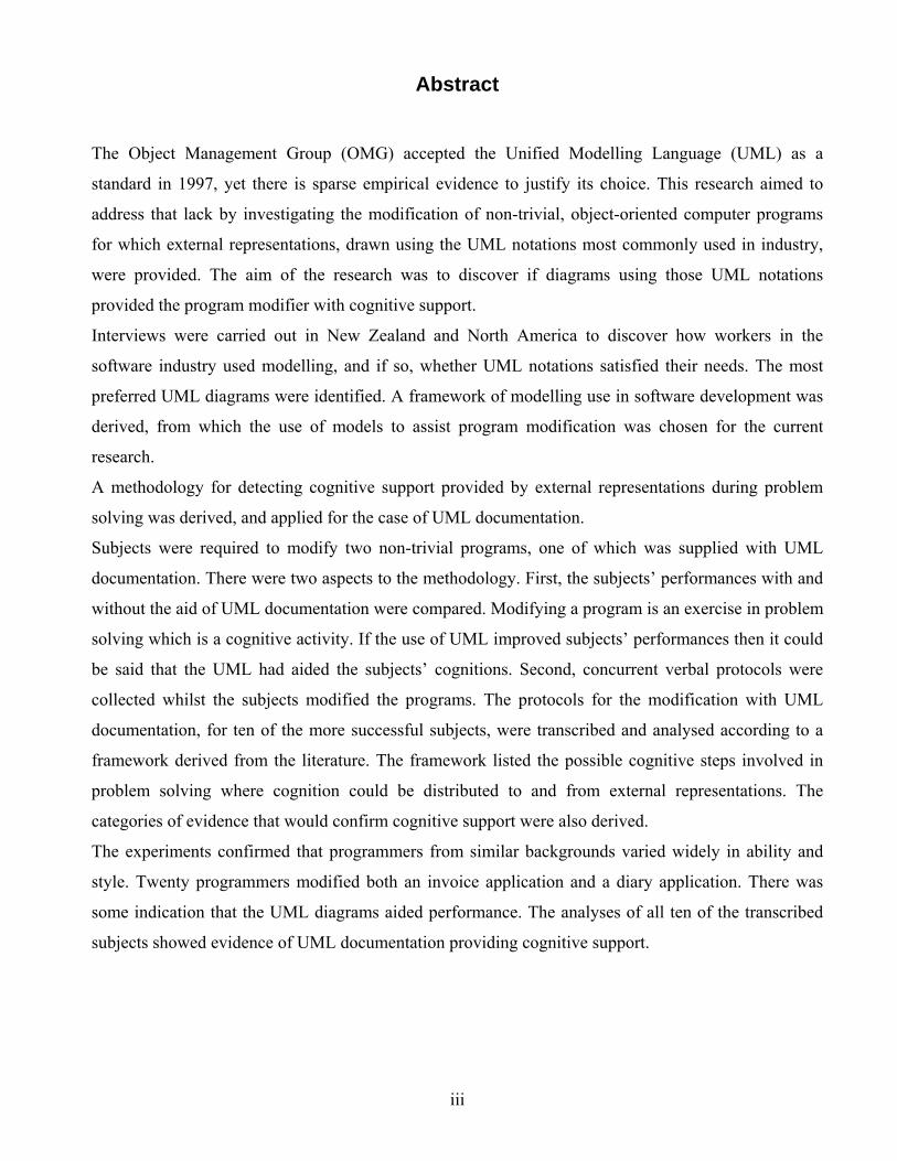
Abstract
The Object Management Group (OMG) accepted the Unified Modelling Language (UML) as a
standard in 1997, yet there is sparse empirical evidence to justify its choice. This research aimed to
address that lack by investigating the modification of non-trivial, object-oriented computer programs
for which external representations, drawn using the UML notations most commonly used in industry,
were provided. The aim of the research was to discover if diagrams using those UML notations
provided the program modifier with cognitive support.
Interviews were carried out in New Zealand and North America to discover how workers in the
software industry used modelling, and if so, whether UML notations satisfied their needs. The most
preferred UML diagrams were identified. A framework of modelling use in software development was
derived, from which the use of models to assist program modification was chosen for the current
research.
A methodology for detecting cognitive support provided by external representations during problem
solving was derived, and applied for the case of UML documentation.
Subjects were required to modify two non-trivial programs, one of which was supplied with UML
documentation. There were two aspects to the methodology. First, the subjects’ performances with and
without the aid of UML documentation were compared. Modifying a program is an exercise in problem
solving which is a cognitive activity. If the use of UML improved subjects’ performances then it could
be said that the UML had aided the subjects’ cognitions. Second, concurrent verbal protocols were
collected whilst the subjects modified the programs. The protocols for the modification with UML
documentation, for ten of the more successful subjects, were transcribed and analysed according to a
framework derived from the literature. The framework listed the possible cognitive steps involved in
problem solving where cognition could be distributed to and from external representations. The
categories of evidence that would confirm cognitive support were also derived.
The experiments confirmed that programmers from similar backgrounds varied widely in ability and
style. Twenty programmers modified both an invoice application and a diary application. There was
some indication that the UML diagrams aided performance. The analyses of all ten of the transcribed
subjects showed evidence of UML documentation providing cognitive support.

iv
Acknowledgments
I have so many to thank for their valued support for this research – I could not have done it alone.
My heartfelt thanks must go to:
Dr. Ananth Srinivasan – for his very patient leadership over the years of research.
Dr. Jairo Gutierrez – for his constructive comments.
Dr. Tiru Arthanari – for his advice on statistics.
Dr. Beryl Plimmer – for being an excellent VB.NET lecturer, for supplying the idea for the
initial diary application, and for her moral support.
Katherine Costain – for arranging and project managing the interviews at Company A, and for
her ongoing love and support.
Laurie Fenkner – for arranging and project managing the interviews at Company B, and for her
ongoing love and support.
Heather Moodie – for a very thorough and skilled proof reading of the paper.
Helen Braddock – for her expert advice on the idiosyncrasies of MS Word and for handling the
printing.
I must also thank the interviewees and subjects who willingly gave up their time to contribute to this
research, and without whom there would be no research.
I should also thank my rowing buddies for keeping me sane over this last intense year.
Last – but certainly not least – I must thank my beloved husband Chris for his tolerance and great
patience in waiting for all this to end.
Gay Costain
v
Table of Contents
Chapter Description Page1 INTRODUCTION . . . . . . . . . . . . . . . . . . . . . . . . . . . . . . . . . . . . . . . . . . . . . 1 1.0 Introduction to research . . . . . . . . . . . . . . . . . . . . . . . . . . . . . . . . . . . . . . 1 1.1 Background . . . . . . . . . . . . . . . . . . . . . . . . . . . . . . . . . . . . . . . . . . . . . . . 2 1.2 Aim of this research . . . . . . . . . . . . . . . . . . . . . . . . . . . . . . . . . . . . . . . . . 4 1.3 Research process . . . . . . . . . . . . . . . . . . . . . . . . . . . . . . . . . . . . . . . . . . . 5 1.4 Thesis organisation . . . . . . . . . . . . . . . . . . . . . . . . . . . . . . . . . . . . . . . . . 6 1.5 Contribution of the research . . . . . . . . . . . . . . . . . . . . . . . . . . . . . . . . . . . 7 1.6 Conclusion . . . . . . . . . . . . . . . . . . . . . . . . . . . . . . . . . . . . . . . . . . . . . . . 82 LITERATURE REVIEW . . . . . . . . . . . . . . . . . . . . . . . . . . . . . . . . . . . . . . . 9 2.0 Introduction . . . . . . . . . . . . . . . . . . . . . . . . . . . . . . . . . . . . . . . . . . . . . . 9 2.1 Human problem solving . . . . . . . . . . . . . . . . . . . . . . . . . . . . . . . . . . . . . . 11 2.1.1 General problem solving . . . . . . . . . . . . . . . . . . . . . . . . . . . . . . . 11 2.1.2 Software design as an ill-structured problem . . . . . . . . . . . . . . . . . 12 2.2 Human cognition . . . . . . . . . . . . . . . . . . . . . . . . . . . . . . . . . . . . . . . . . . . 13 2.2.1 Generic cognitive theory . . . . . . . . . . . . . . . . . . . . . . . . . . . . . . . 13 2.2.2 Applying cognitive theory to software development . . . . . . . . . . . . 15 2.2.3 Rule induction in problem solving and software development . . . . . 16 2.2.3.1 Rule induction in problem solving . . . . . . . . . . . . . . . . . . 16 2.2.3.2 Rule induction and computational co-evolutionary design
for OO software development . . . . . . . . . . . . . . . . . . . . . .
17 2.3 Cognitive differences between experts and novices in software development 19 2.4 Distributed cognition and external representations . . . . . . . . . . . . . . . . . . . . . 20 2.4.1 Distributed cognition . . . . . . . . . . . . . . . . . . . . . . . . . . . . . . . . . . 20 2.4.2 External representations . . . . . . . . . . . . . . . . . . . . . . . . . . . . . . . . 21 2.4.2.1 Introduction . . . . . . . . . . . . . . . . . . . . . . . . . . . . . . . . . 21 2.4.2.2 Computational offloading . . . . . . . . . . . . . . . . . . . . . . . 22 2.4.2.3 Representation . . . . . . . . . . . . . . . . . . . . . . . . . . . . . . . 23 2.4.2.4 Graphical constraining . . . . . . . . . . . . . . . . . . . . . . . . . 23 2.4.2.5 Summary . . . . . . . . . . . . . . . . . . . . . . . . . . . . . . . . . . . 24 2.4.3 Secondary notation . . . . . . . . . . . . . . . . . . . . . . . . . . . . . . . . . . . 24 2.4.4 Benefits of ‘learned’ notations . . . . . . . . . . . . . . . . . . . . . . . . . . . 25 2.4.5 External representations as an aid to program comprehension . . . . . 26 2.4.6 External representations as part of the memory set for solving a
problem . . . . . . . . . . . . . . . . . . . . . . . . . . . . . . . . . . . . . . . . . . .
27 2.4.7 The UML notation for external representations in OO software
development . . . . . . . . . . . . . . . . . . . . . . . . . . . . . . . . . . . . . . . .
30 2.5 Framework for cognitive steps in problem solution using external
representations . . . . . . . . . . . . . . . . . . . . . . . . . . . . . . . . . . . . . . . . . . . .
33 2.6 Conclusion . . . . . . . . . . . . . . . . . . . . . . . . . . . . . . . . . . . . . . . . . . . . . . . 37
Chapter Description Page 3 EXPLORATORY INTERVIEWS . . . . . . . . . . . . . . . . . . . . . . . . . . . . . . . . . . . 39 3.0 Introduction . . . . . . . . . . . . . . . . . . . . . . . . . . . . . . . . . . . . . . . . . . . . . . . . . . . 39 3.1 The interviewees . . . . . . . . . . . . . . . . . . . . . . . . . . . . . . . . . . . . . . . . . . . . . . . 40 3.2 The interviews . . . . . . . . . . . . . . . . . . . . . . . . . . . . . . . . . . . . . . . . . . . . . . . . . 40 3.3 What was discovered from the interviews . . . . . . . . . . . . . . . . . . . . . . . . . . . 42 3.3.1 Company A . . . . . . . . . . . . . . . . . . . . . . . . . . . . . . . . . . . . . . . . . . . . 42 3.3.1.1 Company software development philosophy . . . . . . . . . . . 42 3.3.1.2 Visual Studio Department. Interviewee 1 (I1):
Development Manager . . . . . . . . . . . . . . . . . . . . . . . . . . . .
43 3.3.1.3 Visual Studio Department. Interviewee 2 (I2): Program
Manager . . . . . . . . . . . . . . . . . . . . . . . . . . . . . . . . . . . . . . .
44 3.3.1.4 Handwriting Recognition Department: Interviewee 3 (I3):
Software Architect . . . . . . . . . . . . . . . . . . . . . . . . . . . . . . .
45 3.3.1.5 Office division. Interviewee 4 (I4): Lead Marketing
Research Manager . . . . . . . . . . . . . . . . . . . . . . . . . . . . . . .
46 3.3.2 Company B: Longitudinal study of modelling . . . . . . . . . . . . . . . . . 47 3.3.2.1 Introduction. Interviewee 5 (I5): Product Manager . . . . . . 47 3.3.2.2 Software development environment . . . . . . . . . . . . . . . . . 47 3.3.2.3 Modelling in 2001 . . . . . . . . . . . . . . . . . . . . . . . . . . . . . . . 48 3.3.2.4 2002: What developers were doing one year later . . . . . . . 51 3.3.2.5 2003: What developers were doing eighteen months later 54 3.3.3 Interviewee 10 (I10): Software development methodology designer 61 3.3.4 New Zealand: Interviewee 11 (I11): Software Development Team
Leader . . . . . . . . . . . . . . . . . . . . . . . . . . . . . . . . . . . . . . . . . . . . . . . .
61 3.3.5 New Zealand: Interviewee 12 (I12): Data Administrator . . . . . . . . . 63 3.3.6 Non-modeller: Interviewee 9 (I9): Computer Scientist . . . . . . . . . . . 65 3.4 How the interviewees used modelling . . . . . . . . . . . . . . . . . . . . . . . . . . . . . . 67 3.4.1 Discussion about the exploratory interviews . . . . . . . . . . . . . . . . . . . 67 3.4.2 Categorisation of interviewees’ use of modelling . . . . . . . . . . . . . . . 68 3.4.3 Translationists . . . . . . . . . . . . . . . . . . . . . . . . . . . . . . . . . . . . . . . . . . 68 3.4.4 Non-translationists . . . . . . . . . . . . . . . . . . . . . . . . . . . . . . . . . . . . . . . 69 3.4.4.1 Introduction . . . . . . . . . . . . . . . . . . . . . . . . . . . . . . . . . . . . 69 3.4.4.2 Offloading ideas from working memory . . . . . . . . . . . . . . 69 3.4.4.3 Modelling to communicate, share and develop ideas with
others . . . . . . . . . . . . . . . . . . . . . . . . . . . . . . . . . . . . . . . . .
71 3.4.5 Most popular diagrams . . . . . . . . . . . . . . . . . . . . . . . . . . . . . . . . . . . 73 3.4.6 Problems with UML as perceived by interviewees . . . . . . . . . . . . . . 74 3.5 How the modelling use discoveries impact future research . . . . . . . . . . . . . . 75 3.6 Conclusion . . . . . . . . . . . . . . . . . . . . . . . . . . . . . . . . . . . . . . . . . . . . . . . . . . . 77
vi

Chapter Description Page 4 METHODOLOGY 78 4.0 Introduction . . . . . . . . . . . . . . . . . . . . . . . . . . . . . . . . . . . . . . . . . . . . . . . . . . . 78 4.1 Research questions . . . . . . . . . . . . . . . . . . . . . . . . . . . . . . . . . . . . . . . . . . . . . 81 4.1.1 Research question related to programmer performance . . . . . . . . . . 81 4.1.2 Research questions related to programmers’ cognitive behaviours 81 4.1.2.1 Introduction: the framework . . . . . . . . . . . . . . . . . . . . . . 81 4.1.2.2 Cognitive behaviour questions: UML usage and
cognitive support . . . . . . . . . . . . . . . . . . . . . . . . . . . . . . .
84 4.2 Verbal protocol collection . . . . . . . . . . . . . . . . . . . . . . . . . . . . . . . . . . . . . . . . 86 4.2.1 Introduction . . . . . . . . . . . . . . . . . . . . . . . . . . . . . . . . . . . . . . . . . . . 86 4.2.2 ‘Thinking aloud’ – concurrent verbal reports . . . . . . . . . . . . . . . . . 87 4.2.3 Concurrent verbal protocol collection of data – some concerns . . . 89 4.2.3.1 Verbalisation slows thought processes . . . . . . . . . . . . . . . 89 4.2.3.2 Variation in subject ability to verbalise whilst doing a
task . . . . . . . . . . . . . . . . . . . . . . . . . . . . . . . . . . . . . . . . . .
89 4.2.3.3 Monitor interference . . . . . . . . . . . . . . . . . . . . . . . . . . . . . 90 4.2.3.4 Sample sizes . . . . . . . . . . . . . . . . . . . . . . . . . . . . . . . . . . . 91 4.2.3.5 Effects of session times . . . . . . . . . . . . . . . . . . . . . . . . . . . 93 4.2.3.6 Encoding of transcriptions . . . . . . . . . . . . . . . . . . . . . . . . 94 4.3 Challenges for empirical work with programmers . . . . . . . . . . . . . . . . . . . . . 96 4.3.1 Programmer variability, novices and experts . . . . . . . . . . . . . . . . . . 96 4.3.2 Concerns for program modification use in an experiment . . . . . . . . 97 4.3.3 Program presentation for comprehension and modification . . . . . . 97 4.4 Method procedures . . . . . . . . . . . . . . . . . . . . . . . . . . . . . . . . . . . . . . . . . . . . . 98 4.4.1 Introduction . . . . . . . . . . . . . . . . . . . . . . . . . . . . . . . . . . . . . . . . . . . 98 4.4.2 The applications . . . . . . . . . . . . . . . . . . . . . . . . . . . . . . . . . . . . . . . . 99 4.4.3 The subjects . . . . . . . . . . . . . . . . . . . . . . . . . . . . . . . . . . . . . . . . . . . 100 4.4.4 The venue . . . . . . . . . . . . . . . . . . . . . . . . . . . . . . . . . . . . . . . . . . . . . 100 4.4.5 Session timing . . . . . . . . . . . . . . . . . . . . . . . . . . . . . . . . . . . . . . . . . 100 4.4.6 Pre-session practice . . . . . . . . . . . . . . . . . . . . . . . . . . . . . . . . . . . . . 100 4.4.7 Monitor intervention . . . . . . . . . . . . . . . . . . . . . . . . . . . . . . . . . . . . 100 4.4.8 Pre- and post-session questions . . . . . . . . . . . . . . . . . . . . . . . . . . . . 101 4.4.9 Pilot run . . . . . . . . . . . . . . . . . . . . . . . . . . . . . . . . . . . . . . . . . . . . . . 101 4.4.10 Transcription . . . . . . . . . . . . . . . . . . . . . . . . . . . . . . . . . . . . . . . . . . 101 4.5 Conclusion . . . . . . . . . . . . . . . . . . . . . . . . . . . . . . . . . . . . . . . . . . . . . . . . . . . 1015 THE EXPERIMENTS AND HOW THE PARTICIPANTS
PERFORMED . . . . . . . . . . . . . . . . . . . . . . . . . . . . . . . . . . . . . . . . . . . . . . . . . . . . .
103 5.0 Introduction . . . . . . . . . . . . . . . . . . . . . . . . . . . . . . . . . . . . . . . . . . . . . . . . . . . 103 5.1 The applications . . . . . . . . . . . . . . . . . . . . . . . . . . . . . . . . . . . . . . . . . . . . . . . 104 5.2 The modifications . . . . . . . . . . . . . . . . . . . . . . . . . . . . . . . . . . . . . . . . . . . . . . 106 5.3 The UML documentation . . . . . . . . . . . . . . . . . . . . . . . . . . . . . . . . . . . . . . . . 107 5.4 The subjects . . . . . . . . . . . . . . . . . . . . . . . . . . . . . . . . . . . . . . . . . . . . . . . . . . . 109 5.5 The experiments . . . . . . . . . . . . . . . . . . . . . . . . . . . . . . . . . . . . . . . . . . . . . . . 109 5.6 Performance results for participants . . . . . . . . . . . . . . . . . . . . . . . . . . . . . . . . 110 5.7 Research question discussion . . . . . . . . . . . . . . . . . . . . . . . . . . . . . . . . . . . . . 121 5.8 Conclusion . . . . . . . . . . . . . . . . . . . . . . . . . . . . . . . . . . . . . . . . . . . . . . . . . . . 123
vii
Chapter Description Page 6 RESULTS: BEHAVIOUR . . . . . . . . . . . . . . . . . . . . . . . . . . . . . . . . . . . . . . . . . . 124 6.0 Introduction . . . . . . . . . . . . . . . . . . . . . . . . . . . . . . . . . . . . . . . . . . . . . . . . . . . 124 6.1 Verbal protocol performance . . . . . . . . . . . . . . . . . . . . . . . . . . . . . . . . . . . . . . 127 6.2 Explanation of notation used in the narrative summaries . . . . . . . . . . . . . . . . 127 6.3 Explanation of notation used in behaviour graphs . . . . . . . . . . . . . . . . . . . . . 128 6.4 Industry-experienced subjects’ results . . . . . . . . . . . . . . . . . . . . . . . . . . . . . . . 130 6.4.1 Introduction . . . . . . . . . . . . . . . . . . . . . . . . . . . . . . . . . . . . . . . . . . . . . 130 6.4.2 Summaries and behaviour graphs . . . . . . . . . . . . . . . . . . . . . . . . . . . . 131 Subject 04 . . . . . . . . . . . . . . . . . . . . . . . . . . . . . . . . . . . . . . . . . . . . . . 132 Subject 09 . . . . . . . . . . . . . . . . . . . . . . . . . . . . . . . . . . . . . . . . . . . . . . 140 Subject 15 . . . . . . . . . . . . . . . . . . . . . . . . . . . . . . . . . . . . . . . . . . . . . . 142 Subject 16 . . . . . . . . . . . . . . . . . . . . . . . . . . . . . . . . . . . . . . . . . . . . . . 152 Subject 17 . . . . . . . . . . . . . . . . . . . . . . . . . . . . . . . . . . . . . . . . . . . . . . 167 Subject 18 . . . . . . . . . . . . . . . . . . . . . . . . . . . . . . . . . . . . . . . . . . . . . . 178 Subject 20 . . . . . . . . . . . . . . . . . . . . . . . . . . . . . . . . . . . . . . . . . . . . . . 180 6.4.3 Collation of results from industry-experienced subjects . . . . . . . . . . 194 6.4.3.1 Introduction . . . . . . . . . . . . . . . . . . . . . . . . . . . . . . . . . . . . 194 6.4.3.2 Using UML documentation to assist with comprehension 194 6.4.3.3 Using UML documentation in a set with the problem
space . . . . . . . . . . . . . . . . . . . . . . . . . . . . . . . . . . . . . . . . . .
195 6.4.3.4 Using UML documentation for offloading from working
memory . . . . . . . . . . . . . . . . . . . . . . . . . . . . . . . . . . . . . . .
195 6.4.4 Conclusion for industry-experienced group . . . . . . . . . . . . . . . . . . . . 198 6.5 Student subjects without industry experience . . . . . . . . . . . . . . . . . . . . . . . . . 198 6.5.1 Introduction . . . . . . . . . . . . . . . . . . . . . . . . . . . . . . . . . . . . . . . . . . . . . 198 6.5.2 Summaries and behaviour graphs . . . . . . . . . . . . . . . . . . . . . . . . . . . . 199 Subject 01 . . . . . . . . . . . . . . . . . . . . . . . . . . . . . . . . . . . . . . . . . . . . . . 200 Subject 02 . . . . . . . . . . . . . . . . . . . . . . . . . . . . . . . . . . . . . . . . . . . . . . 202 Subject 03 . . . . . . . . . . . . . . . . . . . . . . . . . . . . . . . . . . . . . . . . . . . . . . 210 Subject 05 . . . . . . . . . . . . . . . . . . . . . . . . . . . . . . . . . . . . . . . . . . . . . . 216 Subject 07 . . . . . . . . . . . . . . . . . . . . . . . . . . . . . . . . . . . . . . . . . . . . . . 225 Subject 13 . . . . . . . . . . . . . . . . . . . . . . . . . . . . . . . . . . . . . . . . . . . . . . 232 Subject 21 . . . . . . . . . . . . . . . . . . . . . . . . . . . . . . . . . . . . . . . . . . . . . . 243 6.5.3 Collation of results from non-industry-experienced subjects . . . . . . . 246 6.5.3.1 Introduction . . . . . . . . . . . . . . . . . . . . . . . . . . . . . . . . . . . . 246 6.5.3.2 Using UML documentation to assist with comprehension 246 6.5.3.3 Using UML documentation in a set with the problem
space . . . . . . . . . . . . . . . . . . . . . . . . . . . . . . . . . . . . . . . . . .
247 6.5.3.4 Using UML documentation for offloading from working
memory . . . . . . . . . . . . . . . . . . . . . . . . . . . . . . . . . . . . . . .
247 6.5.4 Conclusion for non-industry-experienced group . . . . . . . . . . . . . . . . 249 6.6 Using the results to answer the research questions . . . . . . . . . . . . . . . . . . . . . 250 6.7 Conclusion . . . . . . . . . . . . . . . . . . . . . . . . . . . . . . . . . . . . . . . . . . . . . . . . . . . . 252
viii
Chapter Description Page 7 DISCUSSING THE FINDINGS . . . . . . . . . . . . . . . . . . . . . . . . . . . . . . . . . . . . . . 254 7.0 Introduction . . . . . . . . . . . . . . . . . . . . . . . . . . . . . . . . . . . . . . . . . . . . . . . . . . . 254 7.1 The interviews . . . . . . . . . . . . . . . . . . . . . . . . . . . . . . . . . . . . . . . . . . . . . . . . . 255 7.1.1 Introduction . . . . . . . . . . . . . . . . . . . . . . . . . . . . . . . . . . . . . . . . . . . . 255 7.1.2 Challenges and limitations . . . . . . . . . . . . . . . . . . . . . . . . . . . . . . . . . 255 7.1.3 What was found out from the interviews . . . . . . . . . . . . . . . . . . . . . . 255 7.1.4 Conclusion . . . . . . . . . . . . . . . . . . . . . . . . . . . . . . . . . . . . . . . . . . . . . 257 7.2 Performance results . . . . . . . . . . . . . . . . . . . . . . . . . . . . . . . . . . . . . . . . . . . . . 258 7.2.1 Introduction . . . . . . . . . . . . . . . . . . . . . . . . . . . . . . . . . . . . . . . . . . . . . 258 7.2.2 Challenges and limitations . . . . . . . . . . . . . . . . . . . . . . . . . . . . . . . . . 259 7.2.3 Performance results . . . . . . . . . . . . . . . . . . . . . . . . . . . . . . . . . . . . . . 260 7.3 Results of cognitive behaviour experiments . . . . . . . . . . . . . . . . . . . . . . . . . . 261 7.3.1 Introduction . . . . . . . . . . . . . . . . . . . . . . . . . . . . . . . . . . . . . . . . . . . . . 261 7.3.2 Concurrent verbal protocol collection . . . . . . . . . . . . . . . . . . . . . . . . 261 7.3.3 Results of analysis . . . . . . . . . . . . . . . . . . . . . . . . . . . . . . . . . . . . . . . 263 7.3.3.1 General discussion . . . . . . . . . . . . . . . . . . . . . . . . . . . . . . . 263 7.3.3.2 The framework . . . . . . . . . . . . . . . . . . . . . . . . . . . . . . . . . . 266 7.3.3.3 Evidence of UML providing cognitive support . . . . . . . . . 268 7.3.4 Conclusions for cognitive behaviour analysis . . . . . . . . . . . . . . . . . . 271 7.4 Conclusion . . . . . . . . . . . . . . . . . . . . . . . . . . . . . . . . . . . . . . . . . . . . . . . . . . . . 2718 CONCLUSION . . . . . . . . . . . . . . . . . . . . . . . . . . . . . . . . . . . . . . . . . . . . . . . . . . . . . . 272
APPENDICES . . . . . . . . . . . . . . . . . . . . . . . . . . . . . . . . . . . . . . . . . . . . . . . . . . . . . . . . . 276A Interview plan . . . . . . . . . . . . . . . . . . . . . . . . . . . . . . . . . . . . . . . . . . . . . . . . . . . . . . . . 277B Invoice application: Invoice form screen dump . . . . . . . . . . . . . . . . . . . . . . . . . . . . . . 279C Diary application: Diary form screen dump . . . . . . . . . . . . . . . . . . . . . . . . . . . . . . . . . 280D Invoice application documentation . . . . . . . . . . . . . . . . . . . . . . . . . . . . . . . . . . . . . . . . 281 Modification requirements . . . . . . . . . . . . . . . . . . . . . . . . . . . . . . . . . . . . . . . 282 Use case model . . . . . . . . . . . . . . . . . . . . . . . . . . . . . . . . . . . . . . . . . . . . . . . . 283 Use case description for ‘Create invoice’ . . . . . . . . . . . . . . . . . . . . . . . . . . . . 284 Use case description for ‘Add customer’ . . . . . . . . . . . . . . . . . . . . . . . . . . . . 285 Use case description for ‘Add product’ . . . . . . . . . . . . . . . . . . . . . . . . . . . . . . 286 Class diagram for invoice application . . . . . . . . . . . . . . . . . . . . . . . . . . . . . . . 287 Sequence diagram for ‘Create invoice’ . . . . . . . . . . . . . . . . . . . . . . . . . . . . . . 288 Sequence diagram for ‘Print invoice’ . . . . . . . . . . . . . . . . . . . . . . . . . . . . . . . 289E Diary application documentation . . . . . . . . . . . . . . . . . . . . . . . . . . . . . . . . . . . . . . . . . 290 Modification requirements . . . . . . . . . . . . . . . . . . . . . . . . . . . . . . . . . . . . . . . 291 Use case model . . . . . . . . . . . . . . . . . . . . . . . . . . . . . . . . . . . . . . . . . . . . . . . . 292 Use case description for ‘Add appointment’ . . . . . . . . . . . . . . . . . . . . . . . . . . 293 Use case description for ‘Change appointment’ . . . . . . . . . . . . . . . . . . . . . . . 294 Use case description for ‘Delete appointment’ . . . . . . . . . . . . . . . . . . . . . . . . 295 Class diagram for diary application . . . . . . . . . . . . . . . . . . . . . . . . . . . . . . . . . 296 Sequence diagram for ‘Add appointment’ . . . . . . . . . . . . . . . . . . . . . . . . . . . 297LIST OF REFERENCES . . . . . . . . . . . . . . . . . . . . . . . . . . . . . . . . . . . . . . . . . . . . . . . . . . 298
ix

List of Tables
No. Description Page 2.1 Framework for categorising cognitive steps in problem solving with the assistance
of system models as external representations
353.1 Profiles of interviewees 413.2 Categories of modelling use in software development 693.3 How models were used to communicate ideas to others 713.4 Interviewees’ subjective perceptions of problems with UML 744.1 (copy of 2.1) Framework for categorising cognitive steps in problem solving with
the assistance of system models as external representations
834.2 Table showing number of subjects used for verbal protocol collection in software
engineering research.
924.3 Verbal protocol cognitive episode categories for solving a problem with the
assistance of external representations (extracted from Table 4.1)
955.1 Subject profiles 1055.2 Post-session comments from participants 1085.3 Sub-goals to be achieved to complete the invoice modification 1115.4 Sub-goals to be achieved to complete the diary modification 1125.5 Non-formatting sub-goals achieved by subjects in invoice modification 1135.6 Sub-goals achieved by subjects in diary modification 1145.7 Subjects’ percentage success at achieving sub-goals in invoice and diary
modifications
1155.8 Previous experience of subjects in coding invoice and diary applications 1165.9 Subjects grouped as to which modification they attempted first, and diagram
distribution
1175.10 Subjects grouped with modification with UML documentation listed first 1195.11 Subjects grouped according to which application they modified, and sequence 1205.12 Sub-goal achievement for subjects with at least one modification % achievement
>=50%
1216.1 (copy of 4.3) Verbal protocol cognitive episode categories for solving a problem
with the assistance of external representations
1286.2 Legend for cue/destination codes for behaviour graph episodes 1296.3 How the episodes that involved UML documentation were applied; for six subjects
with industry experience
1966.4 Episodes that demonstrate cognitive support supplied by UML documentation for
industry-experienced subjects
1976.5 How the episodes that involved UML documentation were applied; for five non-
industry-experienced subjects
2486.6 Cognitive support supplied by UML documentation for non-industry-experienced
subjects
2497.1 (copy of 6.5) How the episodes that involved UML documentation were applied;
for five non-industry-experienced subjects
2647.2 (copy of 6.3) How the episodes that involved UML documentation were applied;
for six subjects with industry experience
2647.3 (copy of 6.6) Cognitive support supplied by UML documentation for non-industry-
experienced subjects
2677.4 (copy of 6.4) Episodes that demonstrate cognitive support supplied by UML
documentation for industry-experienced subjects
2677.5 Episodes where plan and design schemas were formed by subjects 2687.6 Number of episodes providing evidence of UML cognitive support 270
x
List of Figures
No Description Page 2.1 An information processing model (Mayer, 1989) 142.2 A model of co-evolutionary design (Maher & Tang, 2003) 172.3 Cognitive framework for the rule development process in Object-oriented design
(Kim et al., 1995)
182.4 The theoretical framework of distributed representations (Zhang & Norman, 1994) 282.5 Representational system showing knowledge flow for a distributed cognitive task
for an individual problem solver
302.6 General organisation of a problem solver (Newell & Simon, 1972, p.89) 344.1 Chart of number of participants versus average transcribed session time in minutes
per participant for verbal protocol collection in software engineering research.
934.2 Template for documentation of a categorised episode in behaviour graph 966.1 (copy of 4.2) Template for cognitive activity episode in behaviour graph 1286.2 Sample section of behaviour graph 1306.3 Behaviour graph for Subject 04: 1st modification: invoice app. with documentation 1376.4 Subject 09’s offloading onto paper during modification of the diary application
without the aid of UML documentation
1416.5 The diary form as modified by Subject 15 1436.6 Behaviour graph for Subject 15: 1st modification: diary app. with documentation 1486.7 Diary form as modified by Subject 16 1556.8 Subject 16’s offloading to a structure diagram during his first modification of the
diary application with UML documentation.
1596.9 Some of Subject 16’s offloading to paper whilst modifying the invoice application
without UML documentation – his second modification
1606.10 Behaviour graph for Subject 16: 1st modification: diary app. with documentation 1616.11 Copy of Subject 17’s sketch of the DateTimeBody inheritance hierarchy 1726.12 Behaviour graph for Subject 17: 1st modification: invoice app. with documentation 1746.13 Behaviour graph for Subject 20: 2nd modification: invoice app. with
documentation
1876.14 What Subject 01 offloaded to A3 paper whilst modifying the invoice application
without UML documentation
2016.15 Behaviour graph for Subject 02: 2nd modification: invoice app. with
documentation
2076.16 Behaviour graph for Subject 03: 1st modification: diary app. with documentation 2146.17 Diary form as modified by Subject 05 2176.18 Subject 05’s offloadings during modification of the diary application with the
assistance of UML documentation
2216.19 Behaviour graph for Subject 05: 1st modification: diary app. with documentation 2226.20 Behaviour graph for Subject 07: 2nd modification: invoice app. with
documentation
2296.21 Diary form as modified by Subject 13 2336.22 Form for data entry of the reminder for the appointment, for Subject 13 2336.23 Behavior graph for Subject 13: 2nd modification: diary app. with documentation 2406.24 Subject 21’s offloading whilst modifying the invoice application with supplied
UML documentation
2446.25 Subject 21’s offloading whilst modifying the diary application with no UML
documentation
2447.1 Chart of number of subjects versus average transcribed session time in minutes per
subject for verbal protocol collection in software engineering research.
263
xi

xii
Introduction 1
Chapter 1: Introduction 1.0 Introduction to research
Does the Unified Modelling Language (UML) support the cognitive efforts of software developers?
UML was made a standard by the Object Management Group (OMG) in November 1997 (Johnson,
2002, Kobryn, 1999), yet little empirical research has justified that choice. This research aims to address
that omission.
The authors of UML intended it to be a modelling language to support object-oriented (OO) analysis
and design (Booch et al., 1999, p.xix). OO developers in the U.S.A. were found by survey (Fedorowicz
& Villeneuve, 1999; Johnson, 2000; Johnson & Hardgrave, 1999) to strongly believe in the advantages
of OO Software Development (OOSD) and even non-OO developers were found to have fairly positive
perceptions. If users believe that OOSD is the most advantageous method for software development, it
is important that a standard modelling language, devised to aid that development, fulfils its promise.
The authors of the UML, Booch, Rumbaugh and Jacobson (1999), believed that modelling is central to
all activities leading up to the deployment of good software. A UML diagram may represent an
abstraction of a program’s source code solution, and the source code forms a text-based model for the
executable program.
It can be useful to model something prior to construction in order to clarify thinking with regards to the
appropriateness of the solution. Models are more likely to be used if they are easier to work with and/or
more economical to refactor than the full version. Programming languages are used because they are
more easily understood and manipulated than machine code. When source code is compiled into
machine code there is usually no necessity to extend the machine instructions. At the time of writing,
UML models can not be translated into a fully coded program solution. Class diagrams can be
transformed into limited code. The programmer is required to have some knowledge of the target
programming language in order to complete the exercise.
UML graphical models, constructed to represent a computer solution, are not a miniaturised replica of a
final solution (as is, say, a model yacht); they simply provide an abstraction of what is being modelled.
By using UML notation a programmer cannot completely avoid the writing of code.
An external representation of a problem may be stored on any medium external to the problem solver,
such as paper, whiteboard, drawing tool, CASE tool, reference textbook, notes, or a combination. The
UML is currently a notation that is used in external representations, but may provide limited code
generation if an appropriate translator tool is available.
Introduction 2
In the context of software engineering, the usefulness of tools is ultimately dependent upon their utility
relating to cognition: i.e., to thinking, reasoning, and creating (Walenstein, 2002). Robbins (1999)
claims that “cognitive tasks include decision making, decision ordering, and task-specific design
understanding”. The cognitive tasks of the software designer are to understand the problem, design a
solution, program that solution, debug and test (Walenstein, 2002). Tools that assist the problem-
solver’s cognitive information processing system are said to provide cognitive support, which is
described by Walenstein (2002) as providing ‘computational advantage’.
In order to discover cognitive support it must be possible to detect evidence of the problem-solver’s
cognitive processes and any distribution of cognition between the problem-solver’s internal problem
space and the tool under investigation. This thesis will identify cognitive steps that may be detected
through the collection of concurrent verbal protocols whilst a software developer modifies a program
written in an OO programming language, and for which UML documentation has been supplied, and
will derive the criteria that will demonstrate that cognitive support has occurred. Those criteria will
define potential cognitive support that external representations may supply during problem-solving.
The main question to be addressed in this research is: can external representations that use UML
notation provide cognitive support to the programmer who modifies a program written in an object-
oriented programming language?
The research will investigate if external representations that are drawn using the most popular of the
UML notations can aid a programmer’s comprehension of an existing program, or be used in
conjunction with the writing of code to form a solution for modifying that program.
Even if it is demonstrated that UML can support the programmer’s cognitive activities for program
modification there remains the possibility that a programmer would prefer not to switch back and forth
between diagrams and text-based code, but would rather concentrate on the programming source
language which cannot be avoided.
This chapter is organised as follows: Section 1.1 provides the background of how the UML emerged as
a standard language. Some of the aims behind its creation will be recalled. This will lead to Section 1.2
in which the main aim for this current research is stated. The chosen research methodology is
introduced in Section 1.3. Section 1.4 describes the organisation of the thesis. Section 1.5 highlights the
gaps in previous research that the current research aims to fill. The chapter is concluded in Section 1.6.
1.1 Background
During the 1990’s a plethora of object-oriented (OO) software development tools and methodologies
were published (Beck, 1993; Booch, 1991, 1994; Coad & Yourdon, 1991; Jacobson et al.,1993;
Introduction 3
Rumbaugh et al., 1991). Johnson (2002) claimed that there was an increase from fewer than ten to more
than 50 published methods between 1989 and 1994.
The results from the Johnson and Hardgrave (1999) survey found that the most familiar analysis and
design methods for OO developers were Object Modelling Technique (OMT) (Rumbaugh et al., 1991),
Object-oriented Design (OOD) (Booch, 1991, 1994), and Object-Oriented Software Engineering
(OOSE) (Jacobson et al., 1993) - in that sequence.
At the Ninth Annual Conference on Object-oriented Programming Systems, Languages, and
Applications (OOPSLA), a panel that included the prime authors of the three most popular OO
methods in the Johnson and Hardgrave (1999) survey, discussed whether the methods should be
standardised (Monarchi, 1994). A justification given for standardisation was “the more rapid
acceptance of OOAD methodologies by industry if they can see that there is something solid to adopt,
something that is widely accepted and widely supported.” A reason given for not standardising was
“standardization and/or agreement include the possible stultification of the field before it’s sufficiently
mature”. Booch proposed that the “most obvious target of opportunity is a common object-oriented
analysis and design notation” (Monarchi, 1994).
Booch and Rumbaugh came together at Rational Corporation in 1994 to address the overabundance of
choice of OO analysis and design notations. They were joined in 1996 by Jacobson. UML version 1.1
was approved as a standard in November 1997 by the OMG (Johnson, 2002; Kobryn, 1999). The UML
is a tool that provides graphical diagramming support for OO system and software modelling. Kobryn
(2002), when co-chair of the UML Revision Task force, claimed that UML was the de facto standard
for specifying at least part of software architectures.
UML version 1.4 was current at the time of this research, with the OMG requesting voting on
submissions for the infrastructure for version 2.0. The software development industry was canvassed
for input into the composition of the standard (Johnson, 2002; Kobryn, 2002), but little empirical
research supported UML’s creation.
Rumbaugh (1996a) described the factors that were taken into consideration by himself, Booch and
Jacobson when leveraging their separate methodologies (Booch, 1991, 1994; Jacobson et al., 1993;
Rumbaugh et al., 1991) into the UML. Their aim had been to standardise the software artifacts that
people exchange, and allow users to choose their own processes. Amongst their good notation
principles were: ‘Clear mapping of concepts to symbols’; ‘No overloading of symbols’; and ‘uniform
mapping of concepts to symbols’. The diagrams were to be easy to draw by hand and look good when
printed, especially in monochrome. The authors’ aim was for the notation to be consistent with past
practice and for users to be able to remember it (Rumbaugh, 1996a). Rumbaugh (1996, 1996a)
Introduction 4
admitted that the UML notation was greatly influenced by the three authors’ individual methods. As the
source methods for the UML had been familiar to industry (Johnson & Hardgrave, 1999) it is likely
that the derived modelling language would be more easily assimilated.
However, industry can be offered a standard notation, but practitioners cannot be forced to apply it.
Cockburn (1994) believed that “there are experts who can turn any tool or technique to effective use”.
Studies had found that development teams disliked spending time in design activities that did not
directly lead to the final product, and did not like manually updating design documents. A group’s
ability to change work habits would also impact upon tool acceptance (Cockburn, 1994).
It was Davis (1989) who emphasised that perceived usefulness and perceived ease of use are people’s
subjective appraisals of performance and may not reflect reality. Perception may affect inclinations to
use a modelling language. Davis found that although users’ perceptions of ease of use of a product
influenced their perceptions of usefulness, it was the users’ perceptions of a product’s usefulness that
most strongly predicted the user’s usage of that product. If it can be demonstrated that UML does
support software developers in their tasks, then perceptions may be favourably influenced.
There are other influences at play on software developers. Software development productivity for users
of OO modelling tools may be affected by the user’s previous experiences in the problem domain
(Agarwal et al., 2000; Andriole & Adelman, 1995; Nielsen, 1993; Scaife & Rogers, 1996; Tabachneck-
Schijf et al., 1997); the type of user (Agarwal et al., 2000; Scaife & Rogers, 1996; Tabachneck-Schijf et
al., 1997); the user’s experience of the OO paradigm (Agarwal et al., 2000; Détienne, 1995; Pennington
et al., 1995); modelling notation and its use for abstracting models (Nielsen, 1993), and programming
environment (Détienne, 1995; Kim et al., 1995).
As highlighted by ISO 9241, Part 11 (ISO, 1998), usability must be judged in context. A standard
language should be beneficial for a wide variety of users and contexts.
Hahn and Kim (1999) express the challenges for modelling: Representing knowledge via diagrams is not a trivial task, especially when the target we want to represent is
inherently invisible and dynamic ... The diagram can be regarded as a means of representing knowledge to
facilitate problem solving by making the solution transparent. A diagram is well represented when the
diagrammatic representation supports the cognitive processes effectively in reasoning with the diagram.
(Hahn & Kim, 1999).
From all the influences on software developers’ productivity with modelling tools that are listed in this
Section, it is the latter that we have chosen to investigate for this thesis: do UML diagrams support a
developer’s cognitive processes in reasoning?
1.2 Aim of this research
Introduction 5
The research aim is to discover if UML notation can supply cognitive support to programmers.
If UML is found to provide that cognitive support, then this research may influence the opinions of
software developers and encourage them to use the UML notation. Some justification will have been
found for UML’s selection as a standard language.
A secondary aim is to discover if UML notation, when used in external representations, can improve
the performance of programmers.
1.3 Research process
In order to investigate whether the UML could supply cognitive support during software development
it was necessary to select an application of software development that was feasible to research and
manageable within the time restrictions of study requirements. To identify how developers applied
modelling within the software industry, exploratory interviews were carried out in North America and
New Zealand. The interviews in one Seattle-based company extended over three years to form a brief
longitudinal study. From the modelling uses – or non-use as the case may be – discovered from the
interviews, a framework was derived to categorise modelling usage. An example of modelling use that
was encountered in the longitudinal study triggered the choice of program modification as the
application of software development to research in depth.
Both the interviews and the literature were reviewed to identify the most popular UML notations. UML
has been accused of complexity due to the number of diagrammatic notations it offers (Siau & Cao,
2001). To avoid that complexity, the UML notations selected for this research reflected popular
industry usage. Use case, class and sequence diagrams were used.
A two-pronged study was chosen to investigate if UML documentation of a program supplied cognitive
support to programmers who were occupied in the task of modifying that program. In the first study,
the programmers’ performances whilst modifying a program with the aid of UML documentation were
compared with their performances in modifying an application that lacked UML documentation. For
the second study, concurrent verbal protocols were collected whilst the programmers carried out their
modifications. A framework was derived from the literature to categorise the cognitive steps that a
person could undertake during programming with the aid of external representations such as UML
documentation. The protocols were transcribed and analysed according to that framework. To aid the
discovery of cognitive support supplied by the UML documentation, criteria were derived. If evidence
of the criteria was found in the analysed protocols, the presence of cognitive support could be
confirmed.
Introduction 6
Performance was measured as the number of sub-goals a programmer achieved towards the completion
of his/her modification. As software development involves problem solving, and problem solving is a
cognitive activity (Newell & Simon, 1972), if a programmer achieved more sub-goals with the aid of
UML documentation then it could be assumed that the documentation contributed cognitive support. It
was also possible that UML documentation offered cognitive support, but did not improve
performance. The support could simply replace alternative sources of support, such as program code or
the integrated development environment (IDE).
Concurrent verbal protocol collection was chosen as the method most likely to provide ‘honest’
evidence of the results of the cognitive processes of the person who was ‘thinking aloud’ (Ericsson &
Simon, 1993). The results of the processes are relatively stable and can be verbalised and reported
orally (Ericsson & Simon, 1993, p.xiii; Miller, 1962, p. 56; Neisser, 1967, p.301). Russo et al. (1989)
found empirically that substantial forgetting or fabrication occurred in retrospective interviews. A
survey could only collect responders’ perceptions; it could not demonstrate the actual distribution of
cognition between a problem solver and external representations during program modification.
During the research, the use of the UML by both industry-experienced programmers and student
programmers who lacked industry experience, was examined.
The choice of OO programming language was influenced by a third-year tertiary course that covered
both UML modelling and VB.NET implementation, and was a potential source of subjects.
1.4 Thesis organisation
This thesis is constructed as follows: Chapter 1 introduces the overall research programme. Chapter 2
reviews the literature related to human problem solving and cognition, and the distribution of that
cognition to and from external representations. The cognitive performance of novices and experts are
compared. The UML is a notation in which external representations may be established. The literature
is reviewed to establish common industry usage of UML diagrams. From the findings in Chapter 2, a
framework is derived to categorise the cognitive steps in programming with the aid of external
representations. The criteria to be used for detecting evidence of external representations contributing
cognitive support are also derived.
In Chapter 3, the results from the preliminary interviews in North America and New Zealand are
reported and collated to advise how software developers use models within the IT industry. A
modelling usage framework is derived. Based on content obtained in the longitudinal study, the
common practice of program modification was selected for the in-depth investigation.
Introduction 7
The research methodology that was introduced in Section 1.3 is fully explained in Chapter 4. The
cognitive support provided by UML was planned to be investigated from two different perspectives:
first, the programmers’ performances when UML documentation was provided were to be compared
with the performances when no UML was supplied; and secondly, the cognitive activities were to be
directly detected from transcribed concurrent verbal protocols collected whilst the programmers
modified existing, non-trivial applications that were documented in UML notation. The reasons behind
the methodology selection are elaborated.
Chapter 5 describes the experiments, and presents and discusses the findings for programmer
performance with UML. The results of the investigation into cognitive behaviour that are obtained
from the verbal protocols are presented in Chapter 6. The experiments, their results and limitations are
fully discussed in Chapter 7. The thesis is concluded in Chapter 8, and some suggestions for future
research are presented.
1.5 Contribution of the research
The paucity of empirical research on the effectiveness of UML modelling techniques has been noted in
the literature [e.g. (Dobing & Parsons, 2000)].
Previous research into cognitive activities in OO software design and programming concentrated on
specific topics:
• modelling (Agarwal et al., 1996 [Coad & Yourdon OOA]; Hahn & Kim, 1999 [various, include
some UML]; McCracken, 2002 [Booch & UML]; Pennington et al., 1995 [OMT]; Siau & Lee,
2004 [UML])
• pseudocode (Kim & Lerch, 1992; Kim et al., 1995; Kim et al., 1997)
• coding (Détienne, 1995 [CO2]; Kim & Lerch, 1992 [C++]; Kim et al., 1997 [C++])
Robbins and Redmiles (2000) researched cognitive support features that could be built into design tools
to assist the user in interacting with the tool, and applied their findings in Argo/UML, their UML
CASE tool.
The interaction of a programmer’s reasoning with UML graphical models during the OO programming
activity has not been empirically tested. This research aims to fill that gap.
During the research two frameworks are developed, one for modelling usage, and one for categorising
the cognitive steps in programming when interacting with external representations. The application of
the cognitive framework to analyse the transcribed concurrent verbal protocols of the subjects for this
research, will test if the framework is comprehensive, and therefore potentially able to be applied by
future researchers.
Introduction 8
Criteria for identifying cognitive support within the transcribed protocols are also derived. Again, this
set of criteria could be applied by future researchers to investigate the effect of various external
representations on various programming activities.
The research will be verifying if UML has a positive effect on programmer’s cognitive activities. It will
test one application of UML use to verify UML’s suitability as a standard modelling language for that
activity. If positive results are obtained it may influence software developers’ perceptions of UML use
and encourage them to use it to their benefit.
1.6 Conclusion
Business requires information technology to quickly produce high quality solutions. OO software
development methods are perceived as advantageous in the IT environment. A standard set of tools, the
UML, has been devised and promoted as a global standard for modelling in the OO software
development environment. UML may improve the software development effort but will not be used
unless practitioners perceive its usefulness.
In this thesis we research whether the most commonly used UML models enhance the cognitive
processes required to implement an OO solution for program modification. It is important for
organisations to be informed as to the effectiveness of UML graphical diagrams in order to make
appropriate policy decisions with respect to their use, and for investment in both UML training for their
staff, and CASE tools to facilitate diagram recording.
Two frameworks, and a set of criteria, are developed during the research process, all of which could
potentially be leveraged by future researchers.
This research will add to our understanding of software developers’ cognitive activities whilst writing
program code with the aid of UML diagrams.

Literature Review 9
Chapter 2: Literature Review 2.0 Introduction
The research described in this thesis investigates a software developer’s distribution of his/her
cognition to commonly used Unified Modelling Language (UML) diagrams and program code during a
typical software development activity – that of modifying an existing application. We are seeking
evidence that the UML documentation provides cognitive support for the programmer. Differences in
UML usage between student programmers and programmers with industry experience will also be
noted. However, even if evidence is obtained as to the UML’s efficacy, programmers may still choose
to avoid and/or distrust models external to program code (Davis, 1989).
In this review it will be assumed that the reader is familiar with object-oriented (OO) concepts and the
UML notation. The latter modelling notation has been selected for the research due to its wide
acceptance since being chosen as a standard by the Object Management Group (OMG) in November
1997 (Kobryn, 2002).
The task of this chapter is to review the literature related to the cognitive steps involved in solving
software development problems, which include program modification. The possible effects of the use
of external representations during the problem-solving activity will be explored.
A number of researchers have investigated human problem solving (e.g. Kahney, 1993; Newell &
Simon, 1972; Simon & Lea, 1974) and the human cognitive activities (e.g. Anderson, 1983, 1993;
Wǽrn, 1989) that support it, yet despite all efforts there is no exact knowledge as to how human
cognition works. This chapter will discuss known and theorised facts about human cognition and how it
is applied in problem solving, and specifically how it is applied in solving software development
problems.
From the review a framework will be derived categorising a programmer’s cognitive steps whilst
involved in programming activity where external representations are provided.
Software development challenges people to problem-solve. Our review will start by looking at general
human problem solving as perceived in the literature, and specifically at software development as an
example. Problem solving is a cognitive activity (Newell & Simon, 1972). The explanations provided
in the literature for human cognitive activity in problem solution, and specifically for its application in
software development, will be explored.
Problems may be solved by inducing rules (Simon & Lea, 1974). Rule induction will be reviewed next
as a likely candidate to be included in a framework of cognitive steps that are undertaken during the
Literature Review 10
software design and development activities. A report on cognitive frameworks that include rule
induction as applied by previous researchers will follow. The differences in cognitive performance
between novice and expert problem solvers, as perceived in the literature, will be summarised.
Cognition may be distributed to external representations (Herbsled et al., 1995; Hollan et al., 2000;
Preece et al., 2002). UML documentation may act as an external representation during computer
programming. The possible cognitive support from external representations, especially from
diagrammatic models, will be explored. For example: a problem solver may not be able, nor choose, to
keep track of his/her progress in achieving a solution within his/her internal memory. In this latter case
external representations such as written notes or diagrams may play a role.
According to Booch et al. (1999) a diagram is: ‘the graphical presentation of a set of elements, most
often rendered as a connected graph of vertices (things) and arcs (relationships)’. The authors provide
nine different diagrams in their UML, each of which can be used to model a specific abstraction of a
problem. The UML has been accused of complexity caused by this large number of diagrams (Siau &
Cao, 2001). Common usage of UML diagrams as external representations, as described in the literature,
will be summarised to identify the most popular representations. The literature will also be used to find
guidelines for constructing diagrams to enhance usability.
A framework will be derived from the reviewed literature to categorise the major cognitive steps that a
programmer may undertake after receiving a program modification request until that exercise is
complete. Possible interactions with external representations such as UML documentation that may
occur during the problem-solving activity will be incorporated into the framework.
A complementary aim of this chapter is to specify the evidence exhibited in the problem-solving steps
that would indicate that UML documentation cognitively supports the programming effort.
This chapter is organised as follows: Section 2.1 explores human problem solving, especially as
evidenced in software development. Human cognition and the cognitive activities believed to aid
problem solution are discussed in Section 2.2 and their application to OO software design and coding
and, in particular, rule induction, described. Section 2.3 compares the cognitive activities in problem
solving of novice and expert practitioners, especially with regard to their respective abilities to retain
information within memory. Distributed cognition and external representations will be introduced in
Section 2.4, where distribution of problem representations between internal and external media is
discussed, both from the perspective of aiding program comprehension, and from the perspective of the
external representation becoming part of the memory set utilised by the solver during problem solution.
Aspects of useful diagramming notation will be reviewed. The section will conclude with a summary of
Literature Review 11
the UML diagrams that may be utilised by programmers during programming problem solving, with
the most popular UML diagrams as evidenced in the literature being identified.
In Section 2.5 the final framework of steps in the cognitive problem-solving activity is derived. The
chapter will be summarised in Section 2.6.
2.1 Human problem solving
2.1.1 General problem solving
Newell and Simon’s (1972) theory of human problem solving defines the cognitive system involved in
solution as an information processing system. The authors theorise that a major invariant of all human
problem-solving behaviour is that problem solution takes place by search in a cognitively based
problem space (p.59). They assert that, in general problem solving, each problem must be recognised,
understood, and an internal problem space constructed for it, or, if one already exists in long-term
memory (LTM), that problem space must be evoked to become active. The problem space “contains
partial knowledge about a problem and its solution (the current state)” (Kant & Newell, 1984) and “is
characterised in terms of states, operators, evaluation functions, and search strategies” (Goel 1995).
The problem space “may be constructed gradually as the need for the component pieces arises”
(Newell & Simon, 1972, p.860).
Initially, the potential problem solver is presented with a set of instructions and stimuli. For example,
for our research using a program modification exercise, the instructions provide a description of what
program changes are required, and stimuli would include the existing program code and, if available,
UML documentation.
A problem occurs when the recipient wants to achieve the solution but does not immediately know how
to perform to get it (Newell & Simon, 1972, p.72). Problem solvers attempt to understand a problem,
establishing all that they know about it in an internal representation within the problem space.
Problem components such as goals, rules, constraints, and other aspects, which represent the initial
situation, must be encoded in the space (p.59). Methods may be applied to decompose the problem into
the goals and sub-goals to be achieved in order to reach a final solution, and further methods be
selected to achieve those goals (Newell & Simon, 1972). Thus we may consider problem solving as a
series of activities that transform the sub-goal states (p.76). Solutions may be evoked directly from
memory (the recognition method) (p.94), may be found as a result of searching through prospective
solution paths in memory (p.100), or may be inferred from a ‘generate-and-test’ technique (pp.95-6).
Solution occurs when goal objectives are achieved. The problem-solver’s knowledge of the problem
domain, and problem solving aptitude, affect the problem-solving process (p.82).

Literature Review 12
The means available to the problem-solver for problem solution are dictated by the original internal
representation (Newell & Simon, 1972). Because humans form individual mental representations of a
problem, people differ in the way they solve problems (Kahney, 1993; Newell & Simon, 1972).
From the kinds of problems they had studied, Newell and Simon (1972, p. 90) found that human
subjects do not change their representations of problems appreciably during the course of their
problem-solving activity. For problem solving involving design, evidence is offered by Goel (1995)
and Guindon (1990) that designers rapidly select one solution to a sub-problem. Rejections of
alternative solutions were made rapidly without developing them in depth.
Goel (1995) describes the problem-solving challenges for a designer: Design problem solving can be further subcategorised into problem-structuring and –solving phases with
problem-solving further decomposed into preliminary design, refinement, and detail design. … Interim
design ideas are nurtured and developed incrementally until they are appropriate for the task. They are rarely
discarded and replaced with new ideas. The principal reasons for this are the size and complexity of
problems, the sequential nature of information processing, and the fact that there are no right or wrong
answers (Goel, 1995). We will now look at the solving of software design problems involving computer programming.
2.1.2 Software design as an ill-structured problem
Software development generally will involve problems for which some end goal is specified, but the
requirements may be incompletely specified. Usually there is no predefined solution path (Guindon,
1990). Where the methods for attaining the goal are ill-defined they must be evoked by the software
designer.
Goel (1995) contrasted design and non-design problems: design problems are a type of ill-structured
problem, and non-design problems belong to the class of well-structured problems. The designer is
required to provide the unspecified functions whereby the initial problem state is transformed into the
goal state. Goel (1995) also believed that design problems do not have right or wrong answers, only
better and worse ones. This can apply to the software development situation where the methods
whereby an end goal is achieved can vary considerably depending upon the developer and his/her
previous experience (Newell, 1969). The number of possible designs is very large (Guindon, 1990). We
may thus assume that much of software development deals with ill-structured problems.
The first step for writing a computer program to solve a problem is to determine what is required (the
final state). To transform the initial state into that final state, in other words to solve the computing
problem, general problem-solving techniques and strategies (Grogono & Nelson, 1982) such as those
postulated by Newell and Simon (1972) (see Section 2.1.1) may be used. The problem may be

Literature Review 13
decomposed into simpler sub-problems (Jefferies et al., 1981, p.262; Grogono & Nelson, 1982, p.37).
Iterative decomposition may occur until a level is reached where a solution is apparent or may be easily
found (Grogono & Nelson, 1982; Newell & Simon, 1972, p.95). A solution becomes apparent if it is
recognised, such as when the problem-solver has previously solved a similar problem and stored the
method in memory.
According to Newell and Simon (1972), the problem solver’s information processing system is a
cognitive system. The next section will briefly discuss some of the theories that have been constructed
to explain human cognition.
2.2 Human cognition
2.2.1 Generic cognitive theory
Despite the fact that human cognitive activities are not yet fully understood, many efforts have been
made to explain their phenomena. Ormerod (1990) describes and contrasts a number of explanations
for human cognitive abilities and how they are utilised in computer programming. This section will not
replicate that discussion. Some common properties among suggested explanations for human cognition
will be identified.
Many researchers believe that as users gain experience in a specific activity they form mental models
or schemas in long-term memory (LTM). A schema is a knowledge structure – the stored
representation of common aspects between similar situations; that is to say, it incorporates generic
concepts (Agarwal et al., 2000; Andriole & Adelman, 1995; Détienne, 1990, 1995; Guindon & Curtis,
1988; Larkin & Simon, 1987; Wǽrn, 1989; Zhang, 1997). The schema whose conditions are a best fit
for an understood problem statement is retrieved (Détienne, 1995; Guindon & Curtis, 1988; Larkin &
Simon, 1987; Rist, 1989). Trial solutions may be tested using instance simulations (Andriole &
Adelman, 1995; Kant & Newell, 1984; Kim et al., 1995; Kim et al., 1997; Newell & Simon, 1972).
In the cognitive processing research literature there is a proliferation of terminology. Détienne’s (1995)
program is a set of plans that are merged to achieve the problem goal. A plan refers to the
representations of solutions constructed to achieve given goals within the problem-solving activity
(Détienne, 1995; Rist, 1989). When a plan is memorised into LTM it becomes a plan schema (Rist,
1989).
Anderson’s (1983, 1993) concept differs from that of the schemata fraternity in that he proposes both
declarative memory (factual knowledge) and procedural memory (knowledge manifested in
performance). He uses chunk as the basic unit of knowledge in declarative memory and production as
the basic unit in procedural memory. Koedinger and Anderson (1990) relate the previous concepts by
Literature Review 14
stating that schemata could be represented as production rules. In the following narrative, ‘schema’ will
refer to any cognitive representation held in LTM.
A popular theory emerges that when a problem is encountered, a solver extracts cues from the problem
domain and tries to match them to cues from memories of past events stored in LTM. Solvers search
cognitively for a pattern of cue values from which a partial or full solution may be evoked (Agarwal et
al., 2000; Andriole & Adelman, 1995; Détienne, 1995; Larkin & Simon, 1987; Rist, 1989; Tabachneck-
Schijf et al., 1997). Thus pattern matching is the mechanism that decides which productions to apply to
achieve a particular goal.
It is believed that people economise on LTM by forming ‘chunks’ of knowledge (Anderson, 1983,
1993; McKeithen et al., 1981; Wǽrn, 1989). Schemas may be stored in LTM, but there is an
acceptance that a constrained short-term memory, called working memory (WM), is used cognitively to
temporarily store schemas whilst they are active (Anderson, 1983).
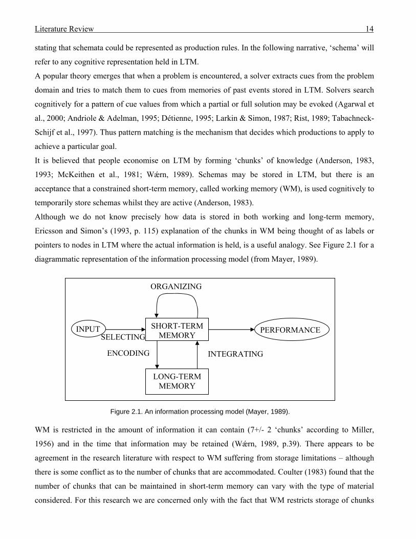
Although we do not know precisely how data is stored in both working and long-term memory,
Ericsson and Simon’s (1993, p. 115) explanation of the chunks in WM being thought of as labels or
pointers to nodes in LTM where the actual information is held, is a useful analogy. See Figure 2.1 for a
diagrammatic representation of the information processing model (from Mayer, 1989).
Figure 2.1. An information processing model (Mayer, 1989). WM is restricted in the amount of information it can contain (7+/- 2 ‘chunks’ according to Miller,
1956) and in the time that information may be retained (Wǽrn, 1989, p.39). There appears to be
agreement in the research literature with respect to WM suffering from storage limitations – although
there is some conflict as to the number of chunks that are accommodated. Coulter (1983) found that the
number of chunks that can be maintained in short-term memory can vary with the type of material
considered. For this research we are concerned only with the fact that WM restricts storage of chunks
SHORT-TERM
MEM
ORYINPUT PERFORMANCE
ENCODING INTEGRATING
SELECTING
ORGANIZING
LONG-TERM MEMORY
Literature Review 15
to a small number; we are not interested in quantifying that number. As a result of this storage
restriction WM can become the ‘bottleneck’ of the human processing system (Siau, 1999).
The extent to which information is retained in LTM depends upon how well it has been attended to and
processed (Anderson, 1983; Gardiner et al., 2006; Preece, 1993).
Recognising information is easier than recalling it from LTM (Anderson, 1983; Preece, 1993; Preece et
al., 2002). Meaningful material is easier to use in working memory because what is meaningful has
only to be activated in long-term memory, whereas nonsense material has no representation in LTM
and must be rehearsed or elaborated in order to be remembered (Andriole & Adelman, 1995; Wǽrn,
1989). An example would be a meaningless numeric code used to uniquely identify a debtor to a
business, where the individual number shapes can be immediately recognised from LTM but the code
itself must be well exercised in order to be established in LTM. This need to exercise meaningless
material is supported by Anderson’s (1983) contention that semantic connections are important and
suggests that a diagrammatic notation will be easier to learn if its symbols could be semantically linked
to existing schemas in LTM. However, it also suggests that it is possible for software developers to use
any notation to represent artefacts in program development, providing that the notation is used
consistently and is thoroughly exercised in order to form internal schemas in LTM.
The merging of each of the individual, popular modelling notations of Booch, Rumbaugh, and
Jacobson into the UML should make the UML easier to learn, as was the authors’ intention
(Rumbaugh, 1996, 1996a). This does not confirm the ‘rightness’ of their previous methods – it simply
makes the new notation quicker to assimilate. A familiar notation can cue appropriate schemas and
require less effort to establish in LTM, regardless of whether it is the most appropriate for the job at
hand.
2.2.2 Applying cognitive theory to software development
Law (1998) noted the popular belief that coding, comprehension and debugging of computer programs
were facilitated through cognitive plan retrieval and recognition (as described in section 2.2.1).
Anderson (1993, p.35) asserts that “cognitive skills are realized by production rules”. For the software
development environment Jefferies et al. (1981, p.262) defined a design schema as “the abstract
knowledge about design and design processes, along with a set of procedures that implement these
processes”. The authors believed that a goal of software design was to break down a problem into sub-
problems and that the design schema was composed of both declarative and procedural knowledge that
assisted to this end. During the design process a decision must be made as to which sub-problem to
solve next, and then find a solution for it. Thus a goal must be identified for the sub-problem whose
Literature Review 16
attainment may be achieved by pattern matching with internal representations. A solution may be
evoked from LTM, may be derived from information acquired from the problem space, or inferred
from the use of mental simulations (Jefferies et al., 1981) [cf. Newell & Simon’s (1972) ‘generate and
test’ method in Section 2.1.1].
For OO development, experts require internal schemas representing information on a specific problem
domain plus schemas dependent upon the targeted programming domain (Détienne, 1995; Kim et al.,
1995). In fact “system design involves the integration of multiple knowledge domains - knowledge of
the application domain, of software system architecture, of computer science, of software design
methods, and so on” (Guindon 1990).
Pennington et al. (1995) found that for their few subjects who modelled in OMT, the differing OO
programming language implementation intentions had only a weak influence on designs. This suggests
that the OMT diagrams were sufficiently generic to accommodate any of the intended implementation
languages. It may be assumed that a software designer requires internal schemas for a modelling
language notation in order to leverage those diagrams.
The next section will discuss how rules are created by the software developer in order to implement a
software solution.
2.2.3 Rule induction in problem solving and software development
2.2.3.1 Rule induction in problem solving
Simon and Lea (1974) coined the phrase ‘rule induction’ to collectively refer to the group of activities
that includes ‘concept attainment’, ‘pattern induction’ and ‘rule discovery’, which are information
processes involved in problem solving. The authors argued that since the process of problem solving
for well-structured problems involves solution discovery, the processes involved must be inductive.
They describe those processes as searches through a problem space guided by information accumulated
during the search. They went on to demonstrate that for problem solving, cognitive rule induction
involves an alternation of activity between two distinct problem spaces: rule space and instance space.
Goel (1995, Chapter 5) demonstrated empirically that professional designers, when confronted with an
architectural design problem, decomposed the problem into sparsely connected modules. Most of the
designers’ decisions for achieving an end result came from memory retrieval and non-deductive
inference.
Haverty et al. (2000) accepted the definition of inductive reasoning in problem solving as “the process
of inferring a general rule by observation and analysis of specific instances”. The authors instantiated
their ideas concerning induction rules in a model for Anderson’s (1983, 1993) ACT-based theory, thus

Literature Review 17
demonstrating that their inductive reasoning theories were compatible with Anderson’s cognitive
theories incorporating production rules. The fact that a computer program authored by a human is
found to support a concept does not confirm that concept, but in the case just quoted there was a
demonstration of compatibility with an anecdotally popular premise.
Hayes et al. (1989) suggested that the collection of verbal protocols was useful for the study of rule
generation. The following sub-section describes research into rule induction that leverages the analysis
of concurrent verbal protocols. The validity of concurrent verbal protocol collection as a method for
investigating cognition will be fully discussed in Chapter 4.
2.2.3.2 Rule induction and computational co-evolutionary design for OO software development
Before discussing rule induction for OO computer programming it will be necessary to set the context
by discussing the concept of two parallel search spaces that may be used by problem solvers: the
problem space and the solution space. Computational co-evolutionary design is characterised by having
one search space of problem requirements and another search space of problem solutions (Maher &
Tang, 2003). The authors define co-evolution as the “term used to identify the process in nature in
which two or more species interact so intimately that their evolutionary fitness depends on each other”.
Thus co-evolutionary design is an approach to design problem solving in which the requirements and
solutions of design evolve separately and affect each other (Maher, 1994). From Maher and Tang’s
(2003) two protocol studies, one for kettle design, one for architectural design, where the subjects were
videoed carrying out their design activities, the authors found evidence of the transitions between the
problem space and the solution space. Maher and Tang (2003) suggest the model in Figure 2.2 for co-
evolutionary design:
Requirements P Interactions Solutions S
Figure 2.2. A model of co-evolutionary design (Maher & Tang, 2003)
For software development the problem domain is defined by Guindon (1990) as “a subset of the real
world with which a computer system is concerned (but not the design solution describing the computer
solution itself)”.
P1 P2 P3
S1 S2 S3
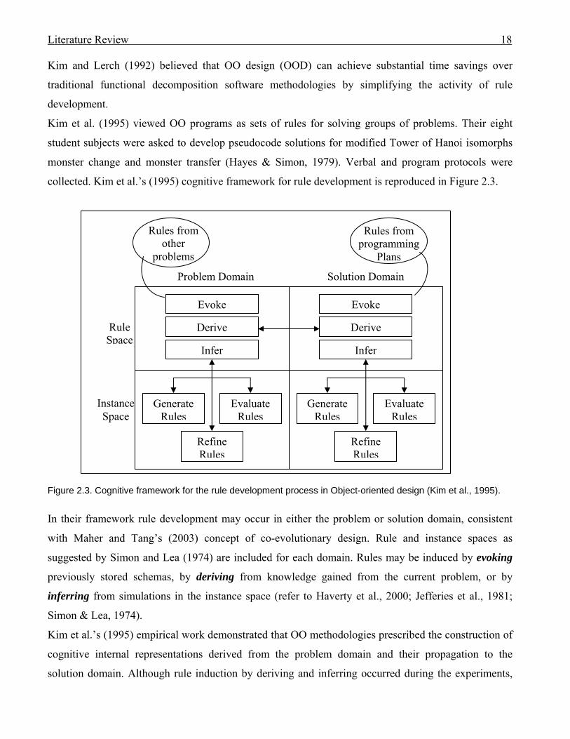
Literature Review 18
Kim and Lerch (1992) believed that OO design (OOD) can achieve substantial time savings over
traditional functional decomposition software methodologies by simplifying the activity of rule
development.
Kim et al. (1995) viewed OO programs as sets of rules for solving groups of problems. Their eight
student subjects were asked to develop pseudocode solutions for modified Tower of Hanoi isomorphs
monster change and monster transfer (Hayes & Simon, 1979). Verbal and program protocols were
collected. Kim et al.’s (1995) cognitive framework for rule development is reproduced in Figure 2.3.
Evoke
Derive
Infer
Generate Rules
Evaluate Rules
Refine Rules
Evoke
Derive
Infer
Generate Rules
Evaluate Rules
Refine Rules
Problem Domain Solution Domain
Rules from other
problems
Rules from programming
Plans
Rule Space
Instance Space
Figure 2.3. Cognitive framework for the rule development process in Object-oriented design (Kim et al., 1995).
In their framework rule development may occur in either the problem or solution domain, consistent
with Maher and Tang’s (2003) concept of co-evolutionary design. Rule and instance spaces as
suggested by Simon and Lea (1974) are included for each domain. Rules may be induced by evoking
previously stored schemas, by deriving from knowledge gained from the current problem, or by
inferring from simulations in the instance space (refer to Haverty et al., 2000; Jefferies et al., 1981;
Simon & Lea, 1974).
Kim et al.’s (1995) empirical work demonstrated that OO methodologies prescribed the construction of
cognitive internal representations derived from the problem domain and their propagation to the
solution domain. Although rule induction by deriving and inferring occurred during the experiments,
Literature Review 19
no evoking of knowledge from LTM was encountered. The authors attributed the lack of evoking to the
fact that the problems were new for the students and thus no previous solution schemas had been
established in LTM.
In Kim and Lerch’s (1997) theoretical framework another space is added. The authors viewed
programming as a search in three problem spaces: rule, instance and representation. Programmers
could change their representation of a problem if an alternative arose, or if rule development became
too difficult. Hypotheses were generated in the rule space and tested in the instance space. The authors
presented three studies, each using two Tower of Hanoi problem isomorphs. The first study involved
the writing of new programs in the OO programming language C++, the second involved
understanding existing programs written to solve the problems, and the third involved using an existing
program to solve a new problem. Verbal and program protocols were collected. Kim and Lerch (1997)
found that programming became more difficult when representation change is required. The authors
state that the two main operators in the rule space are derive and infer. It is conjecture that the lack of
discovery of the evoke operator in the Kim et al. (1995) research influenced this omission.
Kim et al. (1997) use a framework for categorising their collection of verbal protocols from six subjects
designing a solution in pseudocode for a Tower of Hanoi problem isomorph. The framework views
programming as a search in four internal problem spaces: representation (schema), rule (hypotheses
developed for solving or understanding the related phenomena), instance (solvers design and conduct
experiments to test a hypothesis), and paradigm (way of thinking for solving a problem). In the 1991
Webster’s New World Dictionary a paradigm is defined as: “an overall concept accepted by most
people in an intellectual community, as a science, because of its effectiveness in explaining a complex
process, idea, or set of data”. The current research is concerned with one specific paradigm for software
development, that of object orientation.
Newell and Simon (1972) support the concept of solutions evoked directly from memory (the
recognition method) (p.94), or evoked from searching through prospective solution paths in memory
(p.100). Thus for the current research the evoke category of rule induction will not be ignored.
Incidences of the three categorised methods of rule induction (evoke, derive, infer), during problem
solution, may differ between experienced and non-experienced problem solvers. The following section
discusses the differences based upon cognitive theory.
2.3 Cognitive differences between experts and novices in software development One significant aspect of the transformation from novice to expert in any domain of learning is the acquisition
of problem-solving schemas. Problem-solving schemas are memory representations which embody
Literature Review 20
knowledge based on past experiences with a particular type of problem. The process of constructing such a
representation is also called schema learning (Kahney, 1993, p. 75).
Experts in software development can recognise and recall meaningful patterns when they see them,
whereas the novice, lacking appropriate internal representations, cannot (Adelson, 1981; Andriole &
Adelman, 1995; Guindon & Curtis, 1988; McKeithen et al., 1981; Rosson & Alpert, 1990; Wǽrn,
1989). However, experts are no better than novices when unfamiliar patterns are encountered (Andriole
& Adelman, 1995; Chase & Simon, 1973).
The learning of the UML should therefore be more demanding for novices than OO programming
experts as the experts should be able to semantically relate notation to established programming
schemas not possessed by novices. However, if experts have well-established and satisfactory internal
schemas for solving problems using programming code, there may be little motivation to extend those
schemas to incorporate steps involving diagrammatic notation.
Software development experts try to understand a problem, whereas novices plunge immediately into
applying a formula. Experts are able to reach detailed levels of design more quickly than novices. The
experts show plan-based strategies, whereas novices do not. Novices spend little time on defining the
kernel concept and evaluating the design (Jefferies et al., 1981; Pennington et al., 1995). Novices tend
to use more instance space for solution simulation as they have fewer internally stored representations
(Andriole & Adelman, 1995; McKeithen et al., 1981; Wǽrn, 1989) and thus trial several mental
simulations in order to develop a potential solution.
In the Pennington et al. (1995) experiment, OO experts, modelling in OMT, defined methods with
associated classes whereas novices defined classes first and then the methods, probably a reflection of
their having been instructed to do so in their introductory OO course (Pennington et al., 1995).
Anderson (1983) believes that choice of a particular production set is influenced by the learning
mechanisms that give rise to it.
Expert problem solvers often collapse multiple problem-solving steps into a single step (Adelson, 1981;
Anderson, 1983, 1993; Koedinger & Anderson, 1990; McKeithen et al., 1981; Rosson & Alpert, 1990).
Thus experts can utilise working memory more efficiently than novices.
Even for experts some problems may appear to be large and complex. Possible external support to aid
an individual’s problem solving and program comprehension is discussed in the next section.
2.4 Distributed cognition and external representations
2.4.1 Distributed cognition

Literature Review 21
Goel (1995) defines a problem space as a computational modelling space created by the interaction of
the cognitive information processing system with the task environment. In fact “every aspect of the task
environment is a relevant external factor” (Goel, 1995). This would certainly be the case for computer
programming where a problem may be based upon the external real world, and the solution is
implemented utilising an external programming language and requiring an external computing
environment to support execution. Manuals may be referenced by the programmer to source
information about programming syntax or patterns, or operating environment features and constraints.
Program code written to solve prior problems may be copied to the new program. External diagrams in
the form of UML models or entity relationship diagrams may be used as stimuli (refer to Section 2.1.1).
Goel (1995) acknowledges that designers use many distinct external symbol systems for the
construction and manipulation of external models that represent the real world, as it is not possible to
manipulate the real world. The act of testing a non-production version of a program is an example of an
act of manipulation of an external model. The usefulness of diagrammatic representations for
generating and testing hypotheses was also noted by Kim et al. (2000). We can conclude that a designer
may use more than his/her cognitive problem space in order to solve a problem.
A theory of distributed cognition extends what is considered cognitive for the individual in problem
solving, as described in the previous sections, to include interactions between a problem solver and
other people, and/or between the problem solver and external representations such as resources and
materials in the environment (Herbsled et al., 1995; Hollan et al., 2000; Preece et al., 2002).
This research will be investigating the interaction between an individual programmer and external
representations so we will limit our review to that aspect of distributed cognition.
2.4.2 External representations
2.4.2.1 Introduction
External representations of problems and guide solutions may be stored on any external medium such
as paper, whiteboard, drawing tool, CASE tool, reference textbook, notes, or a combination. As Zhang
(1997) points out, external representations are used in many cognitive tasks; for example: arithmetic
with paper and pencil, geometrical problem solving, grocery shopping with a written list, as well as
diagrammatic reasoning.
Internal representations, in contrast, are “the knowledge and structure in memory, as propositions,
productions, schemas, neural networks, or other forms” (Zhang 1997).
External representations are not limited to stimuli provided in the task environment. For complex
problems, external representations may be used to offload partial solution knowledge in order to free
Literature Review 22
WM (Grogono & Nelson, 1982 p.7; Kim & Lerch, 1992; Kotovsky et al., 1985; Newell & Simon,
1972; Scaife & Rogers, 1996) which has limited capacity (Coulter, 1983; Miller, 1956). “An evolving
solution can easily become so complex that issues are lost or misremembered” … “Place keeping, the
ability to keep track of the elements in solution management, is challenging” (Rosson & Alpert, 1990).
Both diagrams and text have their uses as external representations. Larkin and Simon (1987) believed
that diagrammatic representations typically and explicitly display information that is only implicit in
text and in the latter case requires considerable effort to be computed. An example of this would be a
diagrammatic UML class diagram which explicitly displays relationship lines with multiplicity noted.
It would require greater effort to search through programming code to detect multiplicity in programs
written in an OO language such as VB.NET.
From their empirical research Carroll et al. (1980) deduced that graphic representations would be suited
to both well-structured and ill-structured problems such as design. The authors carried out two
experimental studies of design problem solving involving a temporal isomorph (designing a
manufacturing process for widgets), and a spatial isomorph (designing a business office layout). The
performance of subjects provided with a graphic means of representing their solutions was compared to
that of subjects not so provided. There was a highly significant tendency for subjects provided with a
means for representation to take more time in solving the design problem, independent of the isomorph
presentation, and a highly significant tendency for those same subjects to obtain higher performance
scores.
Although computer programmers do not normally use graphical representations for their final solutions
which are typically (but not always) produced in textural code, the findings of Carroll et al. (1980)
suggest that the possession of the ability to represent a problem graphically could produce higher
performance. Part of this research will be looking to verify if the Carroll et al. (1980) findings also
apply in software development where it is possible to abstract the solution in an external graphical
representation prior to coding.
Scaife and Rogers (1996) claim that little is known about the cognitive value of any graphical
representation - it could not be assessed adequately from intuitions. The authors suggest an analytical
framework from which to explain aspects of external cognition: computational offloading,
representation and graphical constraining.
These aspects will be elaborated in the following sub-sections.
2.4.2.2 Computational offloading

Literature Review 23
Scaife and Rogers (1996) define computational offloading as: ‘the extent to which differential external
representations reduce the amount of cognitive effort required to solve informationally equivalent
problems’. The authors use the Larkin and Simon (1987) example of how much easier it is to solve
geometrical problems with the aid of a diagram compared to using a written format, through the
diagram’s “ability to provide direct perceptual recognition of geometric relations”.
Stenning and Oberlander (1995) explained the more efficient processing during problem solving that
occurred when external graphical representations were used, as being dependent upon the ability of the
representation to limit abstraction.
Computational offloading is a commonly observed activity. The use of ‘To Do’ lists provides an
example. Annotation of the external representation may be used, such as crossing off the items on the
‘To Do’ list as they are no longer relevant (Preece et al., 2002).
2.4.2.3 Representation
“This refers to how different external representations, that have the same abstract structure, make
problem solving easier or more difficult” (Scaife & Rogers, 1996). The authors use the Zhang and
Norman (1994) example of the difference between multiplying in arabic numerals compared to roman,
where the former is easier for people used to working in the decimal system.
The choice of the modelling notation in which reality is abstracted constrains how one can learn about
that reality (Siau, 1999). We can record information on paper at the rate of several symbols per second,
which is much faster than we can store information in LTM. If we wish to offload chunks from WM
onto paper, a suitable notation is required. The availability of a suitable notation will determine
whether subjects find paper useful as a problem-solving aid (Grogono & Nelson, 1982, p.7).
2.4.2.4 Graphical constraining
“This refers to the way graphical elements in a graphical representation are able to constrain the kinds
of inferences that can be made about the underlying represented world” . .. “The closer the coupling
between the elements in the visual display and the represented world, the more tractable the
inferencing” (Scaife & Rogers, 1996).
However, as noted by Blackwell et al. (2001) “software diagrams are not constrained by the need for
graphical correspondence to the physical shape of any designed artefact”. The graphical constraining
for software diagrams must be promoted by a notation different from a two-dimensional representation
of a physical shape.
Literature Review 24
2.4.2.5 Summary
We have discussed possible perspectives from which to evaluate a graphical external representation.
Scaife and Rogers (1996) perceive the three aspects in their framework for explaining external
cognition as complementary. Computational offloading highlights cognitive benefits of graphical
representations, representation relates to the representation’s structural properties, and graphical
constraining refers to possible processing mechanisms.
Petre (1995) believes that effective use of an external representation requires purposeful perusal.
Thus an external graphical representation may only support the problem solver if the notation
(representation) is conducive to modelling the real world of the problem; the model constrains what
may be inferenced to prime essentials; the content provides a suitable abstraction of the problem for
computational offloading; and the layout aids perusal.
From this we may conclude that much of the responsibility for the success of an external representation
can lie with the author. A formal notation must be sufficient to represent the essential abstraction of the
real world or the solution to a problem. However, the author may exert much control over content and
layout.
The next section explores an alternative aspect of an external representation which may influence its
usability.
2.4.3 Secondary notation
As noted in the previous Section 2.4.2.5, Petre (1995) highlighted the fact that effective use of a
graphical, external representation requires purposeful perusal, not “the unfettered, wandering eye of the
casual art viewer”. However, it is possible to construct a diagram to aid that perusal.
Kim et al. (2000) suggest that the grouping of relevant information in an external representation aids
the user to identify and recognise relevant items, avoiding a prolonged search.
The initial search in diagrams is guided perceptually (Winn, 1993). It is perceptual skill that enables the
discrimination of relevant features and their synthesis into a meaningful whole (Petre & Green, 1993).
Diagrams can aid that acquisition of information by grouping information used together (Larkin &
Simon, 1987). Much of what contributes to the comprehensibility of a graphical representation isn’t part of the formal
programming notation but a ‘secondary notation’ of layout, typographic clues and graphical enhancements
that is subject to individual skill (Petre, 1995).
Hahn and Kim (1999) confirm in their experiment comparing the effects of four process-oriented
diagrammatic notations - sequence diagram, activity diagram, collaboration diagram and activity flow
Literature Review 25
diagram - that diagrams that captured both decomposition and layout notation (such as sequence
diagrams) resulted in higher design performance than those without. The average number of analysis
and design errors was reduced when diagrams supported decomposition. Design errors were reduced
when an organised layout was presented. However, Hahn and Kim (1999) did not investigate data or
static information diagrams in their experiments (for example, a class diagram) thus omitting a major
representation of OO structure.
The secondary notation of layout is especially important for decreasing information access cost as
spatial proximity of related information in perceptual space reduces eye and head movements (Lohse,
1997; Wickens & Carswell, 1995).
Whilst layout is explicit for a sequence diagram, the modeller has the option of choosing the sequence
in which the object symbols are drawn. It is the author who has the responsibility to ensure appropriate
secondary notation is used.
In addition to layout, secondary notation could include choice of naming conventions, and grouping of
related statements and colour (Blackwell et al., 2001).
In conclusion, a diagram prepared to assist a software developer must be drawn with care to ensure that
related information is clustered, suggesting that it is less important to avoid the crossing of lines and
more important to keep related information together.
The UML was designed to avoid dependency on the secondary notation of colour: it “must fax and
copy well in monochrome images” (Rumbaugh, 1996a).
The next section looks at how a graphical notation for an external representation can become useful if it
is well-exercised into memory.
2.4.4 Benefits of ‘learned’ notations
Petre and Green (1993) concluded from their two sets of empirical studies into graphical program
notation that “what a reader ‘sees’ is largely a matter of what he or she has learned to look for”,
emphasising the importance of training and experience. They believed a graphical programmer was an
‘active reader’, goal-directed and hypothesis driven, and making great use of typographic and semantic
cues in the graphical representation. The skills of readership, both perceptual and interpretive, are
learned skills.
The empirical results of Gardiner, Gregg and Karayianni (2006) confirmed that the remembering, or
the knowing of pictures that appeared on a screen depends upon the conscious resources used for the
encoding of that information, rather than the resources used for retrieving that information from
memory.
Literature Review 26
From this it may be surmised that users will gain more advantage from diagrams whose notation they
have learned. Yet experts may retain schemas in LTM related to their programming plans and program
language syntax, making an external representation redundant for their task. However, if the expert has
originally learned to use the external representation in conjunction with program comprehension and
solution then that behaviour would establish plan schemas in LTM that may be retrieved and activated
at a later date. It is likely that what is practised is exercised into memory.
Although a notation must be learned, it is still possible that certain implementations of a notation
produce more favourable results.
The following two sub-sections look at possible steps in the problem-solving activity that could
demonstrate the cognitive support of an external model.
2.4.5 External representations as an aid to program comprehension
There is consensus in the literature that comprehension of a problem is an important step towards
solving that problem. For example, Newell and Simon (1972) claim that comprehension is the first step
in solving a problem. Tegarden and Sheetz (2001) declare that for successful software development the
‘understanding activity’ is essential. The authors designate the ‘problem decomposition’ activity as a
separate cognitive activity. A programmer’s ‘understanding’ behaviour includes the attempt to obtain
knowledge about the problem domain (Brooks, 1977) and the organising of that knowledge (Rosson &
Alpert, 1990, p. 348). For program modification, the understanding of applicable sections of the
original program will be necessary before a programmer can modify that code. In this sub-section the
features of external representations that may assist a programmer to both problem and program
comprehension, will be discussed.
In her first study, Pennington (1987) tested 40 professional COBOL programmers and 40 professional
Fortran programmers on recognition and comprehension of 15 line texts written in the programmers’
respective programming languages. After limited study time the subjects were asked questions to test
comprehension. “Questions about program operations and control flow relations were answered more
correctly than questions about data flow relations and program states”. The results were interpreted as
providing evidence that the dominant memory representation of the texts was organised by a small set
of abstract program units related to the control structure of the program. Pennington (1987) asserted
that control flow corresponded to the basic programming building blocks of sequence, conditional
selection, and iteration favoured by advocates of structured programming.
For her second study, Pennington invited half of the subjects from the first study to comprehend and
modify a program of a moderate length of 200 lines. After 45 minutes of study time had elapsed the
Literature Review 27
subjects were asked comprehension questions. The results resembled those for the first study, with the
fewest comprehension errors occurring in control flow questions, closely followed by questions on data
flow. In both studies comprehension of function produced more errors than did control flow and data
flow questions.
Although the results for the two studies were consistent, a 200-line program is brief compared to many
active programs used today. For the current research it is planned to investigate the modification of
programs with over 3500 lines of code, which in themselves are brief compared to many popular
program suites (for example, Microsoft Office). There is no surety that comprehension of larger
programs would produce the same results. Not only will the programs for this research be larger than
those used by Pennington (1987), they will be programmed in a language from a different paradigm,
that of object-orientation. In Pennington’s (1987) research, programmers’ comprehension differed as to
which procedural language they used. Control flow and function information were easier to extract
from FORTRAN than from COBOL text, and COBOL programmers were consistently better at
responding to questions about data flow. It is likely that OO language performances will differ from
those of the procedural languages due to the program structure differences where only the coded
methods potentially implement classic control flow.
According to Pennington (1987) comprehension proceeds by the recognition of patterns that implement
known (cognitive) programming plans; plans are activated by partial pattern matches, and confirming
details are either sought or assumed. Newell and Simon’s (1972) internal representation for the
program is thus constructed in the problem space by the exercising of programming plan schemas.
Problem solution may proceed once the programmer has comprehended the problem. The following
section discusses steps in problem solving in which an external representation may be of assistance.
2.4.6 External representations as part of the memory set for solving a problem
A wide variety of cognitive tasks require the processing of information distributed across the internal
mind and the external environment (Zhang & Norman, 1994). Thus in problem solving there are three
distinct memories: a LTM, a short-term memory and an external memory (Goel, 1995). Anderson
(1983, 1993) sub-divides LTM further into declarative and procedural memory (refer to Section 2.2.1). Unlike information in long-term memory, information in short-term memory decays quite rapidly unless it is
constantly updated. This is not a serious problem because while we are actively thinking about a problem we
are constantly examining the seven or so chunks in short-term memory; a particular chunk is recalled
sufficiently often to ensure it does not decay or it is replaced by another chunk that seems to be more
immediately useful. (Grogono & Nelson, 1982, p.6).
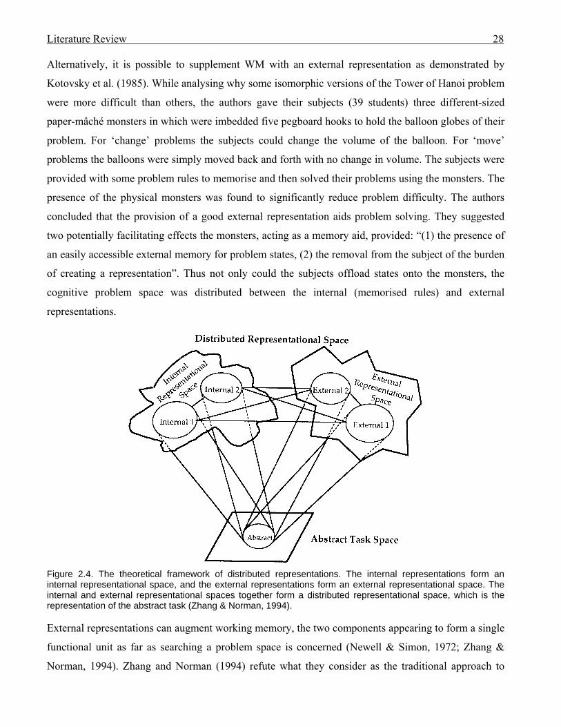
Literature Review 28
Alternatively, it is possible to supplement WM with an external representation as demonstrated by
Kotovsky et al. (1985). While analysing why some isomorphic versions of the Tower of Hanoi problem
were more difficult than others, the authors gave their subjects (39 students) three different-sized
paper-mâché monsters in which were imbedded five pegboard hooks to hold the balloon globes of their
problem. For ‘change’ problems the subjects could change the volume of the balloon. For ‘move’
problems the balloons were simply moved back and forth with no change in volume. The subjects were
provided with some problem rules to memorise and then solved their problems using the monsters. The
presence of the physical monsters was found to significantly reduce problem difficulty. The authors
concluded that the provision of a good external representation aids problem solving. They suggested
two potentially facilitating effects the monsters, acting as a memory aid, provided: “(1) the presence of
an easily accessible external memory for problem states, (2) the removal from the subject of the burden
of creating a representation”. Thus not only could the subjects offload states onto the monsters, the
cognitive problem space was distributed between the internal (memorised rules) and external
representations.
Figure 2.4. The theoretical framework of distributed representations. The internal representations form an internal representational space, and the external representations form an external representational space. The internal and external representational spaces together form a distributed representational space, which is the representation of the abstract task (Zhang & Norman, 1994). External representations can augment working memory, the two components appearing to form a single
functional unit as far as searching a problem space is concerned (Newell & Simon, 1972; Zhang &
Norman, 1994). Zhang and Norman (1994) refute what they consider as the traditional approach to

Literature Review 29
cognition because it considers external representations as mere peripheral aids to cognition and often
mixes external representations with internal representations. The authors consider internal rules
(constraints) as memorised rules and argue that the distributed cognitive task can be considered as a
set with some members internal and some external. Thus the number of chunks that WM can handle
will be increased. Figure 2.4 illustrates this theory.
Hollan et al.’s (2000) claim that distributed cognition involves “cognitive processes, wherever they
may occur, on the basis of the functional relationships of elements that participate together in the
process”, sits comfortably with Zhang and Norman’s (1994) framework (see Figure 2.4).
While acknowledging Zhang and Norman’s (1994) concept of external representations being part of the
distributed representational space that do not need to be fully memorised, if there is no link formed in
the internal cognitive problem space to the external representation, then a search would need to be
repeated every time information from the external representation was required. Olson and Chun (2002)
deduced from their experiments using subjects to search through a display of rotated Ts and Ls to
locate a target as quickly as possible, that the visual system of subjects picks up on invariant spatial
relationships and uses this information, or context, to locate a target item. The authors go on to state
that their results indicated that implicit learning of visual context information is robust enough to
overcome random, uninformative noise in the visual input. In a UML diagram, drawn to represent a
system, the symbols and layout are static. From Olson and Chun’s (2002) results it may be deduced
that readers of the UML diagram experience implicit learning whilst studying the diagram, that enables
them to rapidly locate a specific object at a later viewing. It is now suggested that the problem solver
forms cues, whether visual or otherwise, in the problem space, that refer to the external representation
so that external details may be rapidly found on the external representation and utilised.
From previous discussions a framework can now be derived for the representational system of a
distributed cognitive task for solving a problem by an individual problem solver (see Figure 2.5).
In Figure 2.5 the assigned problem cues the formation within a problem space in WM of an internal
representation of the problem to be solved (Newell & Simon, 1972). A plan/design schema may be
retrieved from LTM to act as an executive structure for selecting and applying methods (Détienne,
1995; Jefferies et al., 1981, p. 262; Law, 1998; Newell & Simon, 1972, p.92; Rist, 1989).
Rules may be derived, evoked or inferred in WM to aid comprehension of the problem, or to achieve
sub-goals towards solution (Kim et al., 1995). External representations (ER) may also be utilised by the
problem space (Newell & Simon, 1972; Zhang and Norman, 1994). Knowledge retrieved from an ER
may help establish the internal representation (Scaife & Rogers, 1996), may ‘cue’ some schema from
LTM (Pennington, 1987), or may be a recipient for the offloading of chunks of data when short-term
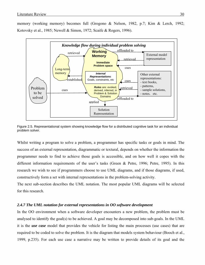
Literature Review 30
memory (working memory) becomes full (Grogono & Nelson, 1982, p.7; Kim & Lerch, 1992;
Kotovsky et al., 1985; Newell & Simon, 1972; Scaife & Rogers, 1996).
Figure 2.5. Representational system showing knowledge flow for a distributed cognitive task for an individual problem solver.
Whilst writing a program to solve a problem, a programmer has specific tasks or goals in mind. The
success of an external representation, diagrammatic or textural, depends on whether the information the
programmer needs to find to achieve those goals is accessible, and on how well it copes with the
different information requirements of the user’s tasks (Green & Petre, 1996; Petre, 1995). In this
research we wish to see if programmers choose to use UML diagrams, and if those diagrams, if used,
constructively form a set with internal representations in the problem-solving activity.
The next sub-section describes the UML notation. The most popular UML diagrams will be selected
for this research.
2.4.7 The UML notation for external representations in OO software development
In the OO environment when a software developer encounters a new problem, the problem must be
analysed to identify the goal(s) to be achieved. A goal may be decomposed into sub-goals. In the UML
it is the use case model that provides the vehicle for listing the main processes (use cases) that are
required to be coded to solve the problem. It is the diagram that models system behaviour (Booch et al.,
1999, p.235). For each use case a narrative may be written to provide details of its goal and the
Working Memory
Immediate Problem space
retrieved
Problem to be
solved
cues
External model representation
Other external representations: - text books, - patterns, - sample solutions, - notes, etc.
offloaded to
retrieved
retrieved
applied
Knowledge flow during individual problem solving
offloaded to
Long-term memory
cues
Solution Representation
established cues
Internal
Representations: Goals, constraints, etc
Rules are: evoked, derived, inferred, in Problem & Solution
Domains
Literature Review 31
expected program behaviour to attain that goal (Cockburn, 1997). Use case narratives typically provide
no advice as to how the results may be achieved, although they are open to customisation.
When designing a solution for an OO programming problem, the programmer must identify the static
classes and dynamic behaviour required by the collaborating objects to achieve the goals stated in the
use case narratives. The UML’s class diagram provides notation for abstracting the detail of classes,
their associations and structure. It models the static design view of an OO system (Booch et al., 1999,
p.105). According to Booch, Rumbaugh and Jacobson (1999, p.5) the UML class diagram is the most
common diagram used for modelling OO systems. The attributes belonging to classes may occur on the
diagram along with the methods those classes apply to their data. However, the sequencing of those
processes is not explicit in the class diagram.
Sequencing of methods is documented in the UML in interaction diagrams, both sequence and
collaboration. These interaction diagrams are isomorphic views of the same information (Booch et al.,
1999). Many believe that there is a representational effect – that is, there is a phenomenon that
isomorphic representations of a common formal structure can cause different cognitive behaviours
(Hahn & Kim, 1999; Larkin & Simon, 1987; Zhang & Norman, 1994). Thus different diagram
notations may trigger different internal representations. The sequence diagram emphasises the time
ordering of messages whereas the collaboration diagram emphasises the structural organisation of
objects that send and receive messages (Booch et al., 1999, p.243). “Sequence diagrams do a better job
of visualising simple iteration and branching than do collaboration diagrams” (Booch et al., 1999,
p.250). Thus the sequence diagram emphasises Pennington’s (1987) control-flow and decision making
requirements. However, the finer details as to how the operations execute their tasks are omitted. Those
processes may be mapped in UML activity diagrams.
UML statechart diagrams capture the event-ordered behaviour of an object as it changes its states. An
object’s structure and associations can be captured in an object diagram. Larger problems may be
decomposed in differing ways, including by the packaging of related classes. Program components and
their associations may be recorded in a component diagram and the deployment diagram shows the
configuration of run-time processing nodes and their relationships (Booch et al., 1999, p.460).
In Smith (2000), Scott Ambler was reported as describing a workshop he had co-conducted where all
groups used use cases, some used sequence diagrams and class diagrams, and only one group
eventually sketched an activity diagram. Martin Fowler proposed a UML kernel around use case, class
and interaction diagrams. He added that “the really useful part of use cases is the textural description”
(Smith, 2000). Henderson-Sellers et al. (1997) included class diagrams, state transition diagrams,
Literature Review 32
interaction, and use case diagrams for their COMN light, suggesting that the authors perceived those to
be the necessary core diagrams.
Multiple diagrams increase the problem space (Hungerford, 2004). The UML has been criticised for the
complexity caused by the number of diagrams (nine) it provides (Siau & Cao, 2001), but that
proliferation of diagrams does attempt to view what is being represented from various perspectives,
giving, in some cases, isomorphic representations, for example: sequence and collaboration diagrams.
For their research into integrating multiple diagrams for developing an OO business system, Kim et al.
(2000) selected diagrams that represented the static, dynamic and functional aspects of the system.
They concluded that use of more than one type of diagram does not necessarily increase an analyst’s
understanding of the target system unless the diagram representations aid problem solution.
Booch et al. (1999, p.431) claim that “You can model 80 per cent of most problems by using about 20
per cent of the UML”. For this research, to avoid complexity, a sub-set of popular UML diagrams will
be investigated. UML use cases with template-based descriptions (narratives) will document system
requirements and UML class and sequence diagrams will abstract the program artefacts that feature in
OO design. Despite official UML documentation providing no guidance for formatting use case
narratives and because of their wide acceptance in the software development industry (confirmed by
Dobing & Parsons, 2008), use case narratives will be included in the current research. Class diagrams
exhibit the abstractions of static information deemed appropriate for OO business systems by Kim et al.
(2000), and are anecdotally the diagrams of choice for most OO designers (Booch et al., 1999, p.105).
Sequence diagrams capture control flow that was deemed important for memory representation by
Pennington (1987), and were the most successful of the process modelling diagrams in the Hahn and
Kim (1999) research.
In a recent OMG-endorsed survey of analysts who were familiar with both OO techniques and UML,
Dobing and Parsons (2006, 2008) excluded component and deployment diagrams, and included the
text-based use case narrative as a ‘diagram’. The authors found that for overall diagram use on projects,
the most used diagrams were: class, use case, sequence, and use case narrative, in that sequence. The
same sequence was retained for most used UML diagrams for ‘Enhancement of System’ (Dobing &
Parsons, 2008). Statecharts were infrequently used, yet ranked second to class diagrams in ‘providing
new information’, suggesting that they could be very useful in specific situations (Dobing & Parsons,
2006). These recent survey findings support the original UML diagram choices made for the current
research.
23 percent of respondents in the Dobing and Parsons survey (2008) used three types of UML diagrams
on more than two thirds of their projects, whereas 16 percent used four UML diagrams, the second
Literature Review 33
most popular combination. For this research, three UML diagram types plus use case narratives are
selected. Dobing and Parsons (2006, 2008) include use case narratives as a fourth ‘diagram’. A use
case model provides an overview of a system, and is decomposed into narratives to provide details. For
this research both model and narratives are included due to their close relationship, the model setting
the context for the narratives.
In summary, the Martin Fowler UML kernel was comprised of use case, class and sequence diagrams.
Those were the most popular UML diagrams to be used spontaneously by participants in the Scott
Ambler workshop (Smith, 2000), and were the most popular in the Dobing and Parsons (2008) survey,
indicating that the selection of those diagrams’ for the current research is appropriate. Component and
deployment diagrams are not necessary for a small program designed to run on one computer.
Scott Ambler also commented on the lack of support for user interface design in UML (Smith, 2000).
2.5 Framework for cognitive steps in problem solution using external representations
This research assumes the paradigm of humans as information processors as theorised by Newell and
Simon (1972). The authors contend that, when humans are presented with a problem, an initial process
- the input translation - produces an internal representation of the external environment in a cognitive
problem space. This internal representation is the context for the problem. Once an internal
representation is established, a problem solving method must be chosen (p.88).
Newell and Simon (1972, p. 89) summarise their understanding of the general organisation of a
problem solver in Figure 2.6 which demonstrates that representations may change as more information
is acquired and the problem becomes reformulated (p.88).
This section aims to establish a framework of cognitive steps that a problem solver may undertake on
receipt of a problem. The cognitive mechanisms whereby the steps are achieved are not currently fully
understood, but the results of those mechanisms may be observed (Ericsson & Simon, 1984, 1993). The
framework will provide a conceptual structure for conducting the research reported in this thesis.
For the first step in problem solving, the schemata fraternity suggests that a schema may be evoked
from LTM to act as an executive structure to manage the problem-solving activity (Jefferies et al.,
1981, p.262; Newell & Simon, 1972, p.92; Pennington, 1987). This will be established in the problem
space and would manage the input acquisition and translation (refer to Figure 2.6).
The translated input is established as internal representations of the problem in the solver’s problem
space (Newell & Simon, 1972).
An external representation may provide assistance for establishing that internal representation. For
example: use case descriptions could communicate the main goals for a program plus the expected

Literature Review 34
steps executed by the program; a class diagram may contribute static information about the structure of
an existing program that is to be modified. These external representations may cue information from
LTM, or may act as recipients for offloading information to free WM (refer to discussion in Section
2.4.6). The problem space may be distributed across both internal and external representations.
External representations can act as a set with the programmer’s cognitive internal representation to
assist in solving a programming problem (Zhang & Norman, 1994). Appropriate external
representations can aid program comprehension (Pennington, 1987), the quality of the assistance being
evidenced in the accuracy of the internal representation.
Affect environment
Translate input
Apply method
Change representation
Select method
Method store
TASK ENVIRONMENT
Internal Representation
Problem Statement
PROBLEM SOLVER
Internal general
knowledge
Note: the eye indicates that input representation is not under control of inputting process
Figure 2.6. General organisation of a problem solver (Newell & Simon, 1972, p.89)
Design schemas may be evoked from LTM to manage solution design (Détienne, 1995; Jefferies et al.,
1981, p.262; Rist, 1989) and rule induction may be used to solve the problems. Rules may be induced
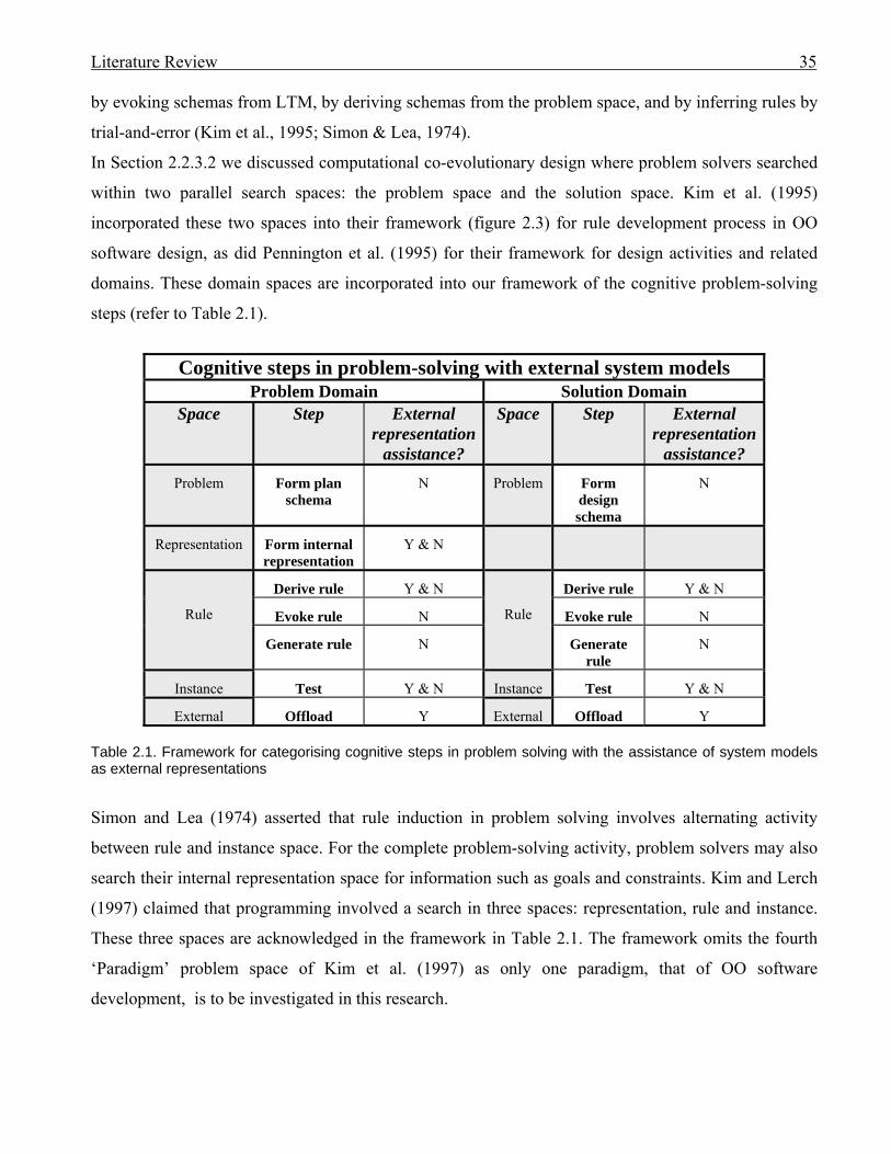
Literature Review 35
by evoking schemas from LTM, by deriving schemas from the problem space, and by inferring rules by
trial-and-error (Kim et al., 1995; Simon & Lea, 1974).
In Section 2.2.3.2 we discussed computational co-evolutionary design where problem solvers searched
within two parallel search spaces: the problem space and the solution space. Kim et al. (1995)
incorporated these two spaces into their framework (figure 2.3) for rule development process in OO
software design, as did Pennington et al. (1995) for their framework for design activities and related
domains. These domain spaces are incorporated into our framework of the cognitive problem-solving
steps (refer to Table 2.1).
Cognitive steps in problem-solving with external system models
Problem Domain Solution Domain Space Step External
representation assistance?
Space Step External representation
assistance? Problem Form plan
schema N Problem Form
design schema
N
Representation Form internal representation
Y & N
Rule
Derive rule Y & N
Rule
Derive rule Y & N
Evoke rule N Evoke rule N
Generate rule N Generate rule
N
Instance Test Y & N Instance Test Y & N
External Offload Y External Offload Y Table 2.1. Framework for categorising cognitive steps in problem solving with the assistance of system models as external representations
Simon and Lea (1974) asserted that rule induction in problem solving involves alternating activity
between rule and instance space. For the complete problem-solving activity, problem solvers may also
search their internal representation space for information such as goals and constraints. Kim and Lerch
(1997) claimed that programming involved a search in three spaces: representation, rule and instance.
These three spaces are acknowledged in the framework in Table 2.1. The framework omits the fourth
‘Paradigm’ problem space of Kim et al. (1997) as only one paradigm, that of OO software
development, is to be investigated in this research.
Literature Review 36
From the previous discussion, the steps in the cognitive problem-solving activity, the respective
domains in which they occur, and the problem spaces in which they are carried out, have been derived,
and are recorded in Table 2.1.
A derived rule exploits knowledge existing in the current problem (Kim et al., 1995).
For our research this includes deriving rules about the problem domain. The subject may ‘derive’
information for the solution – including the copying and modifying of sections of existing code.
An evoked rule directly exploits knowledge gained from solving prior problems (Newell & Simon,
1972; Kim et al., 1995). That is, an evoked rule exploits knowledge from LTM.
Rules may be derived or evoked utilising external representations or internal representations, or both
representations may act together as a set.
According to Kim and Lerch (1992): “in software design a mental simulation is defined as the internal
execution of the task or the software solution”. A generated rule is an internally formulated plan,
representation, or sub-goal solution. It does not involve external representations.
Test is carried out in the instance space (Newell & Simon, 1972). It involves validating and refining a
rule that is derived, evoked or generated. During program modification the ‘testing’ of a solution may
be simulated mentally, but is more likely to involve sample instances being applied to external
representations such as documentation or program code.
Offload can include the creation or modification of external documentation to relieve WM (Grogono &
Nelson, 1982, p.7; Kim & Lerch, 1992; Kotovsky et al., 1985; Newell & Simon, 1972; Scaife &
Rogers, 1996) and can occur in both the problem and solution domains.
In Figure 2.6, for each step, the possibility of external representation (ER) assistance is acknowledged.
To summarise what an external diagrammatic representation should support for OO problem solving:
An external representation will be said to support a programmer’s cognitive processes during
software development if it does any of the following:
1. aids comprehension of the problem by contributing to the internal representation of the problem
in the problem space (Goel, 1995; Hungerford, 2004; Pennington, 1987; Petre, 1995)
2. forms a set with the programmer’s internal problem space to facilitate:
a. evoking of schemas in LTM (Jefferies et al., 1981; Kim et al., 1995, 1997; Newell &
Simon, 1972)
b. deriving of rules from the problem space (Jefferies et al., 1981; Kim & Lerch, 1997;
Kim et al., 1995, 1997)

Literature Review 37
c. application of instances to simulate a solution (Guindon & Curtis, 1988; Haverty et al.,
2000; Jefferies et al.; 1981; Kim & Lerch, 1997; Kim et al., 1995, 1997; Newell &
Simon, 1972; Simon & Lea, 1974)
3. provides a notation for offloading of chunks to free WM (Grogono & Nelson, 1982, p.7; Kim &
Lerch, 1992; Kotovsky et al., 1985; Newell & Simon, 1972; Scaife & Rogers, 1996).
It is suggested here that for the purposes of program modification the affected parts of the existing
program code constitute part of the problem domain, whereas new program code to be written will be
part of the solution domain.
If UML external representations assist in the creation of internal representations of a problem, such as
abstracting program source code, then those representations could aid problem comprehension.
Evidence is required that the representations are an accurate reflection of reality. If UML external
representations act as a set with internal representations to induce rules in the solution domain then they
will be deemed to assist cognitively in problem solution by supplementing WM.
If the construction or modification of UML diagrams is observed it will be assumed that the action has
been carried out in order to free WM, and will be designated to occur in an ‘offload’ step.
2.6 Conclusion
The aim of the current research is to discover whether UML models can be utilised to support cognitive
activities in the OO software modification environment, whether by assisting with problem
comprehension or by working in a cognitive set in conjunction with the programmer’s internal problem
space in order to form a solution.
If, as Goel (1995) believed, design problems must be structured prior to pursuance of design activities
in the solution domain, then problem comprehension is important. The programmer must be able to
recognise information in the problem domain which can act as the source for establishing the internal
representation of the problem. If commonly used UML diagrams are found to assist in application
comprehension, they may be perceived as beneficial for creating internal representations. The modifier
must identify goals and decompose them into sub-goals for completion of the modification. A useful
external representation would support goal formulation, and/or the achieving of those goals.
If programming problems are solved by rule induction, and if programmers use UML diagrams in a set
in conjunction with the internal problem space to induce rules for solution, whether by evoking from
LTM, deriving from the problem space, or inferring from simulations in the instance space, those
diagrams will be deemed to support the cognitive activities involved.

Literature Review 38
Based on the cognitive theories, it is predicted that the more expert programmers would complete an
exercise faster, with fewer mental simulations, and more efficient WM management. The internal
representations of experts may be more condensed than those of novices, suggesting that an expert may
be able to hold more useful ‘chunks’ in WM than do novices. The novices are more likely to use ‘trial
and error’ methods, whereas experts should be able to access their greater selection of internal schemas
in order to evoke rules from LTM or derive rules from the problem domain. Experts may have
advanced schemas for program development plans and programming language syntax that have been
exercised into LTM, and may choose to use program code as their preferred external representation.
However, if the expert had learned to solve programming problems in conjunction with diagrammatic
representations then that is the behaviour that the expert is likely to persist.
Research has found that many experienced users of software work with ‘conceptual blinders’ in that
they are unable or unwilling to fully exploit the software’s capabilities (Rosson & Alpert, 1990). This
could also apply to the use of a modelling language. The modeller may never feel the urge to explore
all features, and thus never take advantage of potential external support. Davis (1989) stated that it was
the users’ perceptions of a product’s usefulness that most strongly predicted the user’s usage of that
product. If software developers perceive the UML notation as useful, there should be evidence of their
preference in how they go about modifying a program for which UML documentation is supplied.
The UML is accused of increasing complexity by having too many diagrams (Siau & Cao, 2001). To
reduce complexity, a subset will be used for this research. The most popular UML diagrams will be
used: use case with template-based descriptions, class and sequence, with the class diagram
documenting the static OO structure. Diagrams will be constructed with an awareness of the
importance of secondary notation such as layout.
A framework has been derived for the cognitive steps that may be involved in problem solving which is
carried out with the assistance of external representations. It is left to the following chapters to describe
how that framework will be applied.
The next chapter summarises the exploratory interviews which were carried out in order to identify a
common usage of diagrams that could be investigated, and which influenced the decision to use
program modification for the current research.
Exploratory Interviews 39
Chapter 3: Exploratory Interviews 3.0 Introduction
The initial aim of this research was to investigate the efficacy of the Unified Modelling Language
(UML). The UML was accepted as a standard by the Object Management Group (OMG) in November
1997 (Johnson, 2002; Kobryn, 1999), yet no research had been carried out to justify its choice. This
knowledge gap needed addressing.
The question needs to be asked: does the UML cognitively support its targeted use? The OMG states
that its modelling standards “enable powerful visual design, execution and maintenance of software and
other processes” (OMG, 2007). It claims that the UML “is OMG’s most-used specification, and the
way the world models not only application structure, behavior, and architecture, but also business
process and data structure” (UML, 2007). Thus the OMG promotes a broad variety of uses for the
UML, too many to investigate in a single research project. It was necessary to target one aspect of
UML use. Evidence was needed to confirm that software developers desired the investigated use, in
order to make the research relevant.
As well as the models promoted by the OMG, methodologies incorporating UML notation have been
promoted, such as that suggested by Costain (2000a) for educational purposes. Although these
methodologies may have merit the question arises: do software developers apply them in industry?
To narrow the scope of the research it was decided to find out not only how UML was actually being
used in the software development industry but how developers would like it to be used. A number of
exploratory interviews were carried out to discover individual software developers’ preferences with
diagrammatic documentation. Interviewees’ attitudes to modelling and their perceptions of UML were
solicited. It was anticipated that an aspect of software development that was suitable for in-depth
investigation would be revealed by the interviews.
An open-ended questionnaire was developed that included questions asking if interviewees had formal
education in modelling, if they had used modelling methods in industry, and what was their notation of
choice. A copy of this interview plan appears in Appendix A.
Several interviewees were sourced from two companies based in Seattle. Those companies are referred
to as Company A and Company B in this chapter. Company A developed or acquired a wide variety of
software for a global market whereas Company B specialised in digital marketing software for an
international market. A longitudinal study of Company B was carried out over three years to track the
software developers’ maturing awareness of modelling. At the time of writing this chapter, Company A

Exploratory Interviews 40
is in the process of acquiring Company B, demonstrating that B’s software varied from but was
complementary to that of Company A’s portfolio. The acquisition was not foreseen at the time the
interviews were carried out.
This chapter describes the interviewees and reports the findings from the individual interviews. The
longitudinal study and emerging use of modelling at Seattle-based Company B will be discussed. From
the interview findings some categories of UML and modelling use will be derived. One category will
be chosen for further investigation.
This chapter proceeds as follows: the interviewees are profiled in Section 3.1, and a general description
of the interviews is given in Section 3.2. The information obtained from the interviews is précised in
Section 3.3, starting with the two companies from which several subjects were sourced. It must be
noted that the findings are not confirmed by observation. The findings are based upon the declared
practices and opinions of the interviewees and simply point to possible research considerations. Section
3.4 analyses the results into categories of use from which the final research topic will be selected.
Section 3.5 names the choice, justifies its selection, and discusses what impact the discoveries will have
on future research for this project. The chapter will be concluded in Section 3.6.
3.1 The interviewees
As this was exploratory research carried out as a precursor to the main investigation, a small
convenience-based cross section of software developers and people involved in the IT industry were
selected, and, with their permission, interviewed. A brief profile of those interviewed appears in Table
3.1. One intention was to interview members of different departments within an organisation in order to
detect any organisational bias.
All interviewees were based in the United States of America, except for Interviewees 11 and 12 who
were based in New Zealand. All were involved in developing software applications except for
Interviewee 4, a Senior Marketing Research Manager who identified application requirements as part
of her job, and Interviewee 5, a Product Manager for Company B’s software application. Most of the
interviewees perceived themselves to be involved in developing medium-sized systems.
3.2 The interviews
Most interviews were carried out during 2001. A copy of the original interview plan is found in
Appendix A. Questions were included to collect as much information as possible about the
interviewee’s modelling practices and exposure to UML.

Exploratory interviews 41
Co.
ID Applications on which interviewees worked
Interviewee’s job title Sex Age No. of staff managed by interviewee
Development environment 2001
Diagram use
A
I1 Visual Studio
Development Manager M 36-45 16 C++ - soon to be C# & Visual Studio. Generates some C++ code from Visio diagrams.
Uses UML to gain clarity, reduce errors.
Use case, class, sequence, deployment diagrams for software design. ORM for database design.
Uses for himself and on W/B at team meetings.
I2 Program Manager M 36-45 (39)
8 C++ - soon to be C# & Visual Studio. Generates some C++ code from Visio diagrams.
Simple W/B sketches and CASE tool on laptop at meetings. Pass as documents to each other.
Class diagram only.I3 Voice recognition
software Software Architect M 26-35
(29) Impacts on 400-500 staff
C++ - soon to be C#, using Visual Studio
Uses block diagrams for himself and on W/B for teams at meetings.
I4 Office suite Lead Marketing Research Manager
F 26-35 (28)
4 Obtains requirements Uses own notation in reports, and presentations at meetings
B
I5 Digital Marketing Suite
Product Manager M Suite product. I6 General Manager for Software
Planning & Client Applications M 36-45 11 including
next 2 staff C++, Visual Basic Hand written UML class, sequence diagrams
I7 Development Manager User Interfaces
M 26-35 4 C++, Visual Basic Uses models for self. CRUD matrixes.
Rectangle & line type on W/B. Occasionally use sequence diagrams on W/B to convey how something works at meetings.
I8 Development Manager for Middle Tier
M 36-45 (42)
4 C++, Visual Basic Hand written DFDs, usually top level – believes they make sense to non-technical people. ERDs maintained by others. Model on W/B at meetings
C
I9 AI programs. At time of interview this was to control the Mars Rover
Computer scientist
M 36-45 Junior member in team of 4
C++ Text documentation
D I10 Software development methodologies
Smalltalk guru, software development methodology designer, author and consultant.
M Draws diagrams informally using boxes and lines, by hand, to model concepts.
E
I11 Real-time software to control sorting equipment
Software Development Team Leader
M 26-35 XP coach. C++ Uses Class diagrams on W/B at team meetings to see how objects work together.
F
I12 Banking Data Administration Specialist
F 46-55 1 PowerDesigner to generate scripts.
Conceptual, logical & physical ERDs Star schema. Uses CASE tool for communication at meetings.
Table 3.1. Profiles of interviewees.
Exploratory Interviews 42
A brief longitudinal study was taken of the Digital Marketing Suite organisation’s software
development department where follow-up interviews were carried out with three of the developers
(interviewees 6, 7 and 8) in June 2002, and two of those (interviewees 6 and 8) were interviewed again
in December 2003. Interviewee 4 was interviewed in 2004 and Interviewee 12, the data modelling
specialist who was interviewed first in June 2001, also had a follow-up interview in 2004 to detect any
change in modelling practice.
Interviews varied in duration from 30 minutes to just over 60 minutes each. One exception occurred for
Interviewee 10 with whom the discussion lasted about 10 minutes due to his lack of availability.
Although the interview was brief, his clearly stated opinion on modelling needs to be included. All
other interviews were audio taped and transcribed by the interviewer (the author). It was intentional to
interview not only those who used graphical modelling for software development, but developers who
did not, in order to identify what conditions were likely to support the use of modelling.
3.3 What was discovered from the interviews
3.3.1 Company A.
3.3.1.1 Company software development philosophy
Four interviewees were sourced from Company A which used a small team approach to product
development. Their style of software development was described as the synch-and-stabilise approach
by Cusumano and Selby (1997). Small parallel teams typically had three to eight developers. The essence is simple: Continually synchronize what people are doing as individuals and as members of
parallel teams, and periodically stabilize the product in increments as a project proceeds, rather than once at
the end of a project. … projects may need to iterate while concurrently managing many design, build, and
testing cycles to move forward toward completing a product. … During product development, the team
members revise the feature set and feature details as they learn more about what should be in the product. …
projects use vision statements and outline specifications rather than detailed designs and complete product
specifications before coding, because teams realize they cannot determine in advance everything developers
need to do to build a good product. ... the synch-and-stabilize process does not guarantee ontime or bug-free
products (Cusumano & Selby, 1997).
This method also accommodates rapid changes in technology. There is room for creative input from
team members as the project progresses.
Project managers divided the product into features, the project into small feature teams, and the project
schedule into three or four sequential subprojects, each requiring a complete cycle of development,
feature integration, testing, and problem fixing (Cusumano & Selby, 1997).

Exploratory Interviews 43
Two interviewees (I1 and I2 – refer to Table 3.1) from Company A, worked on the same application
but belonged to different teams. The beta version of the product that they were working on (Visual
Studio) was released at the time of the interviews. Visual Studio was described as a new language with
a new infrastructure to support it. It was a new programming paradigm. One of its features is that
various languages can work together seamlessly. Different applications will be able to talk to each
other across platforms. Diagrams that generate code are a small part of the whole product. It has two
categories of modelling tools: software modelling tools such as UML and data flow diagrams (DFDs),
and database tools such as entity relationship diagrams (ERDs). ORM (object role model), which
competes with ERDs but is more rigorous and formal, is also supported.
The first three interviewees were developing in a C++ environment, but were moving towards using
Visual Studio and C#.
3.3.1.2 Visual Studio Department. Interviewee 1 (I1): Development Manager
I1 managed a team of 16 members who were involved in software development for their medium-sized
system of about half a million lines of code.
Use cases were occasionally used to capture requirements. The determining of requirements was a
collaborative exercise between the market researchers and the members of the development team who
were close to the product, knew what it did, and were aware of what was wrong with it. Other UML
diagrams were used in the design phase to gain clarity and reduce errors, ultimately saving time. Teams
met to discuss ideas, using the whiteboard to experiment. The design was costed and trade-offs made.
I1 confirmed that his team used the synchronise, stabilise, and iterate, software development method as
described by Cusumano and Selby (1997). The stabilisation periods may be lengthy, with new versions
under way prior to the shipment of the current version. Typically for Visual Studio, a version took
about one year to develop due to the complexity of the product, with 1-2 month milestones for
synchronising and stabilising. There were mini-milestones weekly; the first four days were spent
developing and the fifth was spent testing and stabilising to make sure all the functions were correct.
Teams could take their code away and work on their area, then reintegrate their work, perhaps after a
couple of weeks, when they were ready to do so.
The 16 members of I1’s team each worked on different sections of code but did daily ‘check-ins’ to
integrate the sections into the main application. It was relatively rare for a conflict to occur where two
members modified the same code. ‘Check-in’ did not finish until all tests were passed.
As well as the small utilisation of use case documentation for requirements and ORM for database
design, developers used UML diagrams when working on the whiteboard (W/B) to explore ideas in

Exploratory Interviews 44
developing a design. Class diagrams were most frequently used, deployment diagrams were sometimes
sketched, and sequence diagrams were used especially around the user interface. There was some
exploration of the use of state charts for user interface design but they had not been tried at the time of
interview. I1 believed models should be used on an ad hoc basis as required. There was no compulsion
to use UML diagrams in his section so their use was according to preference.
I1 found UML harder to learn than the ERDs and ORM modelling that he learned at university. He
claimed that UML had strange subtleties around the meta-model. The fact that the model was a set of
points seemed a “weird idea” as points did not coincide with a language. He also criticised the lack of a
concept of a pointer in the UML.
UML notation was easy to remember because it was fairly common. Class diagrams were broadly
similar to ERDs. However, he found UML diagrams were only flexible and adaptable because the team
often broke the UML rules. Few models were 100% pure UML as the developers mostly invented,
modified and coloured things.
I1’s time spent modelling had increased, especially as they used their own product (Visio Enterprise) in
their design. Existing patterns were leveraged. As experience had increased so had the size of the
chunks in which they worked.
I1 believed that it was important to design before building the code. Models were used predominantly
to communicate with his team, although he occasionally modelled for his own purposes. Team models
were kept up-to-date for a release cycle but were not maintained after that unless they were very
special. The roles in the team were usually equal, but one person usually owned the model and was
responsible for making changes. Visio Enterprise was the tool of choice.
3.3.1.3 Visual Studio Department. Interviewee 2 (I2): Program Manager
I2 had received no tuition in modelling whilst studying for his computer science degree, but had used
UML at his previous job. He believed that ERDs were a commonsense way of describing database
data.
He managed a team of eight of whom four were developers and three were testers. His team used their
own tool (Visio Enterprise) extensively for UML modelling, starting from simple sketches that they
discussed at meetings. Whiteboard, and CASE tool on laptop, were used for recording the models
which were published on the web with other documents.
When the team started to design the tool they wanted to build, they constructed a bootstrapping process
– a meta-model that they augmented in UML. The core meta-model recorded the type of classes and
type of relationships among the classes and was used across applications. Although the modelling tool

Exploratory Interviews 45
they used supported other diagrams, only the class diagram was used to produce the initial design.
Class definitions were automatically generated by the tool and developers added to the resulting
skeleton code. Models were maintained as the class diagram was part of the specification. They used
and checked their own tool at the same time.
He believed the UML targeted the building of software applications and was designed with a heavy
influence from OO languages such as C++. A small selection of the UML models was easy to
remember. As it was used it became natural. UML’s use was increasing among the developers,
becoming more pervasive as the staff grew more modelling literate. There was no need to advocate its
use.
He commented on what he perceived as limitations of the UML:
1. interaction diagrams targeted the design stage and were very limited in expressing the execution
environment of an application.
2. deployment diagrams were very ‘thin’ – and conveyed little about the environment.
3. no data type for arrays or lists.
4. pointers were not supported.
5. component diagram support was very weak and would require a major revision to produce
something viable. There were no component models that could execute.
6. UML was not difficult to learn but was obscured by massive documentation.
On the positive side, I2 believed that the use of UML helped to prevent errors and left the users with
more confidence that they had the right design. Productivity was improved, and better quality software
was achieved. He was convinced that there was no alternative but to use modelling as a means of
communication on large projects because it was easier and faster to extract the essentials from a model
than from reading code.
The modelling tool with which his team was involved was only a small fraction of the overall Visual
Studio product. They claimed to be more confident in the accuracy of what was generated than in non-
generated code. This could be attributed to their need to defend their own product. However, other
diagram translationists had gained benefits from generating code, albeit from a different tool. Air New
Zealand had found that the automatic generation of COBOL code through the use of Information
Engineering Facility (IEF) was quicker for development and required less maintenance than code
written in PL/1 used on the same application (Costain, 1996).
3.3.1.4 Hand writing Recognition Department: Interviewee 3 (I3): Software Architect.
Exploratory Interviews 46
I3 was to change his job to Development Manager on the day following the interview. He had received
no tuition in modelling during his computer science degree. He used his own notation for his
architecture diagrams and hierarchical models.
His team looked for a sensible class hierarchy where low level functionality was encapsulated in easier
to use higher level objects. At team meetings they looked for repeating patterns that they could share.
To aid his understanding he drew architecture diagrams on note paper for himself, and drew them on a
whiteboard when talking to others at a meeting to get an idea of how to formally describe what the
product was and how it was going to work. He worked more often on the whiteboard than on note
paper. There were usually five to ten people at a meeting but the overall impact of what he did affected
400 to 500 people. Others wrote the details down. A number of these architectural diagrams became
part of a formal specification. Some of his diagrams were maintained, especially those that turned into
a specification document. PowerPoint or Visio was used for reference diagrams. His simplest model
was drawn as a block diagram.
He understood he had a reputation for drawing diagrams and charts. He believed they improved
productivity and reduced errors. Charts were handy to roughly display how two complex variables (e.g.
performance versus memory) were related.
I3’s idea of good practice in software development was to decide the requirements then design the
code. He found that the simpler the design the more effective it was for communication. There was too
much detail in UML and you could get lost in the details.
3.3.1.5 Office Division. Interviewee 4 (I4): Lead Marketing Research Manager.
I4 managed four people. She had learned formal system modelling, including DFDs and ERDs, whilst
studying information systems courses during her undergraduate degree.
Both I1 and I3 had mentioned that some product requirements were sourced from the marketing
research departments. I4 explained that for the most part product planners initially defined what was
required for a software product. Part of her role was to assist in that activity. Most of her
responsibilities lay after the product had been defined when she helped determine how to sell, price,
position and advertise a product.
Most people could not articulate what they wanted in a product. I4 researched what people were trying
to accomplish in their jobs to ascertain which of the office products would be of assistance. Company
A’s office products had such a wide range of users globally that the profiling of a target customer was
challenging. It was not just the users that influenced the business decision to install the products – the

Exploratory Interviews 47
IT department that did the installation, deployed the software and managed it, also participated in the
decision making.
I4 worked with research vendors who put together her presentations and diagrams to interpret her
findings. Sometimes she did it herself, including graphs and block diagrams in reports and
presentations. She drew her diagrams in Visio. The diagrams were used to communicate her points, or
were flow diagrams of how a process worked.
The presentations took place in front of various constituents, including stakeholders in the research.
Sometimes developers were present, product managers, marketing managers, executives. A prediction
had to be made as to how long a new feature would take to create and how many customers would want
it. Company A’s software developers often participated in the decision making. There were tradeoffs.
They looked at how satisfied customers were with the current product. What did the customers really
want that they couldn’t do today?
3.3.2 Company B: Longitudinal study of modelling
3.3.2.1 Introduction. Interviewee 5 (I5): Product Manager
The first interview at Company B was with I5, the Product Manager, who provided background
information on the digital marketing suite software product that Company B had marketed since 1997.
The company had developed the software package and services for businesses wishing to advertise
their wares via digital media such as existing web pages. I5 described their product as including
“campaign planning, media buying, creative management, message delivery and data collection,
analysis and optimization”. The product was designed for ‘buy-side’ digital marketers. According to
Company B’s brochure, “Buy-side digital marketers are those who buy across a whole spectrum of
digital media based solely on what works, rather than on affiliations with certain publishers or
publisher networks”. One of the tasks performed by the product was to collect visit statistics from
cookies at ad sites. This data was continually being added to the large databases maintained by
Company B. The company produced statistical reports from the stored data to provide their customers,
the buy-side digital marketers, with analysis of the performance of the customers’ digital ads.
Company B’s databases were continuously on-line to provide ads when called and to collect statistics.
A system of redundancy was implemented that ensured that storage facilities were always functioning.
3.3.2.2 Software development environment
All developers who were interviewed believed the digital marketing system to be of medium size yet
complex. It consisted of a web front end, a middle tier, distributed databases, plus extra databases. All
Exploratory Interviews 48
software was developed in a Microsoft environment. Coding was carried out in C++, Visual Basic and
Java script, except for the User Interface (UI) section which predominantly used HTML and XML.
In 2001, ERDs were drawn using the CASE tool ERwin. The diagrams modelled SQL-Server
databases. They were constructed by database staff, not by people from software development. Logical
and physical ERDs were always recorded, and occasionally a conceptual model. ERDs were not
maintained as they could be reverse engineered.
There were plans to go ahead with UML with a 2-day UML course planned for the near future. A
company had evaluated Company B’s internal process about two months prior to the 2001 interviews,
identifying weaknesses in the entire development process. The evaluating company was hired to give a
general group of people, including product managers, a use case modelling class. The evaluating
company had found that program and product managers relied on reams of functional specifications to
convey business objective, when it could be done with a simple diagram or chart.
3.3.2.3 Modelling in 2001 3.3.2.3.1 Software Development Department. Interviewee 6 (I6): General Manager Software Planning and Client
Applications
Eleven people reported to I6, including interviewees 7 and 8. He had been at Company B for 1.5 years
and had previously worked for some time at Company A.
In his tertiary studies he had attended classes that included aspects of modelling but had done no
assignments. He described himself as “self-taught”. He had constructed many ERDs over 15 years, and
had done some semi-formal requirements using use case on his own, looking for greater formality with
regards to the requirements process. He had read a lot about UML, had used Visio and Rational Rose,
and had informally used class diagramming and sequence diagrams, but not extensively. He believed
he had become more efficient and effective as a modeller as he had gained experience.
I6 found sequence diagrams to be easy to use on the whiteboard for experimenting with different types
of software architecture. The initial model might be done individually and reviewed in a group design
session, but more often was derived in the group session. Five or six of his staff were familiar with
gang-of-four patterns. Visio Enterprise was owned but had not been used.
I6 believed that a complex system needed more sophisticated modelling techniques to aid
communication compared to a small system. His team might require state transition diagrams in the
future as the business system had a complicated state transition problem.
I6 was convinced that modelling ERDs prevented errors. He was sure of the level of detail for ERDs,
but was unsure about the level of abstraction for use cases and sequence diagrams, suggesting that this
Exploratory Interviews 49
might be caused by his lack of experience with UML compared to data modelling. He wondered if the
UML modelling should be made superficially simple.
I6 believed the use of UML would improve productivity. It was easier to remember than a structured
Word document which doesn’t give an overall view of a system. Modelling would provide a road map.
He foresaw that the formalising of requirements would reduce software development costs as the
biggest cost in development was incurred when the requirements were found to be wrong.
3.3.2.3.2 Software Development Department. Interviewee 7 (I7): Development Manager User Interfaces
Four people reported to I7. He had been employed by Company B for 1.5 years.
He was mostly self-taught, never having been formally taught what he did in his job whilst in school.
Any modelling he had picked up had been on the job, having had exposure to UML as a modelling
approach two jobs prior to his current position, where they had used mainly use cases to convey
business understanding between their clients and internal development staff. He modelled on an ad hoc
basis for his own personal advantage, using a Rational product that shipped Visual Basic 6 with a
Visual modeller that allowed you to map the user interface elements to middle tier classes which map
to back end database entities. He found it helpful to see the relationships across the tiers. The Rational
product could also be used for sequence, class and use case diagrams. There was little use for state
transition diagrams.
Occasionally he tried to put a CRUD (create, read, update, delete) matrix together to make sense of
things. He believed he was the only person at Company B using CRUD. He just picked it up and saw a
couple of samples that made sense to him.
I7 was a proponent of using diagrams for documentation when communicating between business
stakeholders and software developers, but feared that without some formal training it would not be
easily adopted. Yet his impression was that use cases were easy to take up. He claimed that the
software development staff were more interested in the application of use case documentation than the
business stakeholders, and blamed that on a lack of exposure. If you put a use case together with the
screen you could just follow the flow/path on the diagram without having to read screeds of
requirements where it is hard to detect if anything has been left out.
I7 believed that the use of modelling could speed up decision making and prevent errors. However he
felt that more detail should be added on the technical side. He believed modelling’s big advantage was
to provide a shared understanding – without big gaps in understanding that you might get from volumes
of objectives.

Exploratory Interviews 50
Modelling was used on an ad hoc basis in his area. Very few people used it at all. He would use
simplified models for customers who lacked understanding.
3.3.2.3.3 Software Development Department. Interviewee 8 (I8): Development Manager Middle Tier
Four staff reported to I8. He had been employed by Company B for 1.5 years. The middle tier, for
which he was the development manager, was straightforward in his estimation.
I8 was a self-taught modeller, reading many books on the topic and extracting useful concepts to
include in his own models. He was learning about what other people were trying to represent visually –
the same sorts of things he does – but the authors had thought more deeply about it. When his friend
showed him sequence diagrams for the first time he thought: “That’s clever!” He had been trying to
capture the same information for a long time but never thought of the sequence diagram technique. Yet
he tried sequence diagrams and state transition diagrams and did not like the ones he had seen.
I8 believes that use cases can be understood and leveraged by different groups in the software process
such as the business people, the software developers, the database people, and quality assurance (QA).
He categorised the software development methodology used by his team as a series of iterative
waterfall developments. No formalised modelling was used, but they modelled on the whiteboard at
group meetings. He had never worked with a full UML model for the whole system, believing a piece
of paper as big as a whiteboard would be required to enable the viewer to “get a grip on how the system
fits together”. Their class hierarchies were complex and would require a big representation to be
understandable.
His big criticism of the formalised models was that they did not easily represent things that he was
trying to describe, and secondly, you need the right tools to draw the ‘pretty diagrams’. Despite no
formal requirement for models in the department’s software development philosophy, and after reading
Software Requirements by Karl Wiegers, which introduced him to DFDs, I8 had incorporated a high
level DFD in his overview architecture diagrams. He was enthusiastic about DFDs because he could
choose the granularity of the model and fit a model on one piece of paper. He believed DFDs would
make sense to non-technical customers such as the business sponsors of the project. He had some
problems with DFD modelling, such as when a single user interacted with a single system in many
ways, or when you had two blocks with many errors going between them – it was more illuminating
when many actors did different things. Apart from using DFDs, he modelled in whatever form in which
he could express what he wanted, such as using a non-standard notation block and arrow diagram to
model their system.
Exploratory Interviews 51
He had found it easy to learn modelling, but claimed to have acquired only a surface understanding,
reading the ‘thin’ books such as UML Distilled. He could relate to sections of what he had read: “that
would have been handy to represent this” but did not know if that representation would have made
things any clearer.
I8 acknowledged that the good point about UML was that everybody learned the same language so
things could be described on the whiteboard in a common language. He believed that some sort of
modelling technique, used appropriately, would be of assistance to improve productivity. He described
a meeting he had attended the morning prior to the interviews where the members attending had sat
around discussing: “Can we move this object from this state to that state, or this state to that state”.
They were asking themselves: “how does this work again?” He had had that conversation a dozen times
in the last six months. If they had a state transition diagram up on the whiteboard they could have
referred to that. There were many development meetings where they spent the first part of the meeting
re-conjuring up the same image of the system in everybody’s mind. He believed if they spent the time
up front to do the permanent record of the model then subsequent changes would have been easier.
Hours had been spent at meetings while they were trying to get the same visual page of what the model
looked like.
He did not want to do UML diagrams for his entire architecture design, believing that the idea of
modelling was to convey an idea or design so that someone else could understand and use it. The
model could be stored away and revisited at the next meeting so that you could very quickly remember
what had been discussed previously.
He could not find a direct correspondence between the use of modelling and prevention of errors,
believing that modelling was more about communicating ideas and speeding up the process. A complex
system would require greater efforts at communication. When a modelling language was formalised, if
you could not remember it, it was easy to look up references to discover what the notation represented.
He, as an individual, was likely to write less code for a large complex system with several developers,
than for a small system for which he had the sole responsibility.
They built their code every day, with database updates maybe twice per week. Once a week the build
was moved to QA where a week was spent proving it. The bugs detected by QA had to be rectified.
3.3.2.4 2002: What developers were doing one year later 3.3.2.4.1 Introduction
The activities of the software development department had changed over one year. They were no
longer undertaking large new projects; they were usually adding medium sized chunks of functionality

Exploratory Interviews 52
to their existing product. Each new feature would have approximately 8 to 15 use cases. The software
developers were still not using modelling. They had not attended the UML course, but their business
analysts had. The outcome was that the business analysts developed a customised, text-based, use case
template for recording both functional and performance requirements. The developers received these
use case template-based requirements and were delighted with the new recording method as it was a
vast improvement on previous non-structured methods where it was difficult to predict where specific
information would be located. The template ensured that the developers always knew where to find
specific information. Use cases provided a decomposition of the business problem. All three developers
interviewed were positively disposed to the use of the use case template. Use case models were
omitted. The use case templates provided the functionality and they were not used by the software
developers to extract classes. The software product was tested against these requirements.
There had been little staff turnover during the year since the previous interviews. It was possible that
this could be partly attributed to the tightening of the IT employment market at the time. As a
consequence, the composition of the teams was constant and somebody always had knowledge of
specific development areas.
3.3.2.4.2 Interviewee 6 (I6)
In 2002, for I6, modelling was not a top priority. His perceived ‘hot points’ were estimation, quality
assurance and automatic testing. They had a tool for automatic testing but had not used it at the time of
the interview.
3.3.2.4.3 Interviewee 7 (I7)
I7 had not increased his use of modelling since 2001. He believed that attitudes were changing and
there was general consensus that modelling would be productive.
His team used the occasional workflow-oriented Visio Enterprise diagram – but nothing formal and
there was no continuity. The developers were more the ‘rectangle and line’ type of modellers.
Occasionally as a group they developed informal models using rectangles and lines on the whiteboard,
usually to communicate how something worked. Sometimes class and sequence diagrams were used.
They had no group cohesion to agree upon a simple standard for conveying certain ideas. Individually
they had all looked at UML and occasionally sequence diagrams were used on the whiteboard to
describe a new feature that had been requested. The user interface was very class based. He believed
that their interface system was insufficiently complex to warrant modelling and they had, for the most
part, been able to convey ideas without modelling.
Exploratory Interviews 53
He had looked a lot at eXtreme programming (XP) and wondered if they should go agile?
He thought that modelling would benefit them if they all learned to do it as a group. His was a
relatively small group – an intimate environment developing a not very complex structure – and might
not justify the use of modelling, in the way that a large complex project could.
A usability firm had been hired to take a look at what they had. The aim was to improve their
performance compared to their competitors. They took the approach of developing primarily in
response to their customers’ requirements. Most features were added in response to customer needs
rather than developer driven, although occasionally they had some good ideas from the developers’
perspective.
3.3.2.4.4 Interviewee 8 (I8)
I8’s group occasionally used class and sequence diagrams, and he had retained his affinity with DFDs.
Their build was complicated, involving at least half a dozen databases, with data moving between
databases in which statistics were collected. There was almost a one-for-one correspondence between
classes in the middle tier and entities in the database. It helped to have a record of the data flows so that
when something changed you could find where the dependencies were.
They were still coding in C++ and Visual Basic. Automatic documentation was now being used and
developers had to learn a new syntax for their code comments. A parser went through the source code
and extracted the documentation.
Modelling was carried out mostly on the whiteboard at meetings. They diagrammed informally when
necessary and sometimes wished they had more. They had hundreds of classes “and where is the time
to do that” (model the classes). If you did have the time where would you print it and look at it? He
would love to have had their whole application modelled on the wall. Every once in a while they
needed to add more business rules.
They still occasionally had a situation where they did not remember at meetings how things fit
together: “I just don’t remember what all those pieces are and how they relate and what state they are
in”. It was not so much of an issue as it was at the time of the first interview, but he didn’t know why.
Possibly it was because now all those bits and pieces of business logic had a place to live and most of
them worked and so the subject did not come up. They were more familiar with their system. They did
not have to start a conversation with: “Who’s going to handle this?” Now it had a place to live and
somebody had worked on it.
UI was often planned on the whiteboard as the use case specifications did not include UI details.
At the time of the interview I8 was reading a book on XP.
Exploratory Interviews 54
3.3.2.5 2003: What developers were doing eighteen months later 3.3.2.5.1 Introduction
Following the 2002 interviews and about one year prior to the 2003 interviews, the company
downsized and a few staff members were lost. When the new CTO was appointed she restructured the
Software Group to merge with IT engineering, the department that operated the software created by the
software developers.
3.3.2.5.2 Interviewee 6 (I6): Senior Software Manager
I6 believed there had been at the most two who left his group since September 2002, and one or two
people had been hired during 2003. He described the staff as “pretty stable”.
I6’s group was carrying out modifications that were not too divergent from the original product so the
lack of documentation was not a large problem. They did mine their existing documentation
periodically; otherwise it was in the group knowledgebase. Use case templates were still used when
they did not understand something.
I6’s highest priority at the time of interview was to make it possible for the teams to work as efficiently
as possible – to deliver customer value at the most rapid speed possible. Value implied that the feature
was useful and exhibited quality such that it did not continually break down.
I8 had sparked an interest in agile software development. They had taken on Scrum, a project
management method for agile software development, which required a monthly inspection point for
customers and a daily inspection point for the developers. The team met for 15 minutes daily, and met
monthly with the customers to show them what had been done. At each one of those points there was
the chance to adapt. The person who led the Scrum meetings was the Scrum master and the person who
owned the list of prioritised features required for the project was the product owner. The list of features
was maintained outside the team who must discover what features were at the top of the list at the end
of the month and work on them in the following month. There was an insistence that what was built in
the monthly time frame was essentially complete. Scrum was not very heavy in terms of the software
development processes to be used, leaving the developers to decide how they wanted to develop. I6
believed the ideal was delivering 80% of the value with 20% of the features, as many features were
unused by the typical user (gave examples of Word and Excel having features few would use). He
hoped that with the customer instructing them every month they would build what the customers
wanted.
I6 described himself as being in his position of responsibility partially because it was easy for him to
come up with an idea, and for people to come to him to make decisions. However, he was now trying

Exploratory Interviews 55
to encourage the developers and QA team to make their own decisions. He had set the boundaries of
meeting daily, having review and planning meetings, using automated testing, involving the customer.
At the time of interview his team wrote a unit test with any unit of software that was checked in. That
unit test had to be inspected by two other people, one of them from QA and one other developer. That
was mainly because the QA team was made up of black box testers and had no experience with
automated testing. He was trying to educate the QA team.
I6 was considering XP but did not know if he would mandate it. He was investigating test driven
development. He was going to encourage the senior staff to try test driven development and pair
programming. He would suggest pair programming in the future when knowledge transfer was required
and his developers didn’t know something and feared changing things. He planned to say: “Have you
thought about pair programming with the person who does know – would that work out for you?”
He had bought the members of his team all the books that he believed were great such as Refactoring
by Martin Fowler; test-driven development, design patterns. He had done refactoring intuitively but
had never had it called out so clearly as in the book.
I6 encouraged his staff to sign up for courses in OO design. The recommended courses would involve
UML modelling – class diagrams, and CRC cards. He believed the learning of an OO language and the
UML should go in tandem. When his staff read OO books they encountered UML diagrams. Thus if
staff read design patterns, or refactoring, there was some UML learning as well. He wanted “people to
be facile with that”. He believed that people to be effective “need to be able to communicate in
abstract, rapid ways”.
They had had a design problem that they were working on and I6 had instructed one of his staff to go to
the Internet and read about sequence diagrams and construct one for the problem. He ruefully admitted
he should have asked: “How could we do this?” instead of instructing. The staff member constructed a
sequence diagram that unlocked the ability for everyone to understand what was going on. The
sequence diagram was a great communication mechanism. I6 believed his staff was picking it up in
“fits and starts”.
I6 perceived the middle tier as a means to abstract and scale the database. He would have liked to see
as much logic as possible live in the middle tier with the business rules.
He was pushing for generic type code. Their development environment was moving to DOT.NET with
C#. At the time of interview his team coded about one eighth in C++, one eighth was generating SQL
Server instructions, about half of the development was in ASP or Java script, and the remaining
components were in Visual Basic. They had started to migrate to .NET and ASP.NET to produce about
one tenth of the code. It was a slow migration. They had had a high priority feature to get out to the
Exploratory Interviews 56
customers which was largely repackaging existing systems and, given the Scrum mandate to deliver the
customer value as rapidly as possible, they chose not to migrate it to .NET. However, they were mostly
all working in the Visual Studio environment.
He could see that what Kent Beck was promoting in XP would work: take small steps, write a test for
it, then when it breaks find the code and refactor out the duplication; do that in pairs until you have
clean code that works. If the code was inflexible then it wasn’t “done”. He was reading a test-driven
development book where it said you hard code to pass the test but you are not done until the
functionality delivers what was necessary.
He believed their software had a good reputation. (The company had gone into profit.) He wanted
people to consider their software as great – he didn’t want it to be mediocre, but did not believe it
necessary to get involved with “some big, hairy, complicated methodology”. They had used a fairly
involved process-oriented method for a few years and he believed it yielded only mediocre results.
Scrum seemed like the common sense approach.
For testing they had written unit tests in .NET that tested their UI, thus using the environment with
which they wanted their staff to become familiar. They had to develop their unit testing software by
themselves because the US$30,000 tool they had purchased did not get past the first page of the UI.
The unit testing software needed some improvement but he had thought of making it public domain.
He had just been interviewing new staff. To familiarise new staff with the existing product he would introduce them to the team and find a place in the current project for them to work, and either have
them do some pair programming, .. or give them a task that is accomplishable but will allow them to get
exposure. .. Then I’d also send them to do a training class on how our application is used because we have a
trainer and they periodically do classes. I’d give them the overview of how things work. And then I’d buy
them every book that I think is interesting ۥcause I’ve done that for everybody on the team, and tell them if
you think that there’s some other book that is interesting then let me know and I’d get it for you. And then I’d
have them start working on one small thing in the code to find out what they are capable of. Like the last
person that came in, in the middle of a project, prior to the Scrum thing – he came in and we had a couple of
areas of features that were kind of broad – touched many parts of the code base. We just had conversations
with him to find out if he had the right kind of technical skills to do it and he seemed to, so it was a small
change but across every part of the code and allowed him to essentially be successful and get that done. It
didn’t really require somebody who had specific knowledge of how the system worked. He really didn’t have
that. It was essentially - it was a localisation step - he had to turn all the dates in to be localisable on the
browser. Taking the localisation string that the browser provides so people can change it. If they’ve got a
French browser, then they are going to show the dates in French format. At the very least that was a simple
localisation step. And he made that possible within the boundaries of our technology throughout the whole
system. That gave him a pretty good overview of all aspects of the system at least from that perspective.
Exploratory Interviews 57
They had used Visio to create sequence diagrams and he had used it to create class diagrams. He
believed that class diagrams would be the ones most commonly used in the software development area.
Sequence diagrams had come up when there were multiple objects interacting, especially over time,
and it wasn’t clear to everyone how that was occurring. They still used the use case templates a lot –
but rarely used a use case model.
The UI people used paper prototypes - or they modelled in Visio, or even mocked it up in HTML. They
had done all three in combination.
Because they were not creating many new databases it was less necessary to do a lot of new data
modelling in ERwin. The script for generating the database was created manually. The database
developers chose to work that way in order to be in complete control of the script.
His top priority now was to get a fully automated regression of their application – he expected it to take
a year and a half to do. Secondly he wanted the team to embrace agile techniques so that they could
deliver 20% of the features that provided 80% of the value. Third was to ensure the team became
educated in OO design, design patterns and refactoring.
3.3.2.5.3 Interviewee 7 (I7)
I7 did not intend to use UML modelling and decided that a third interview would not be productive.
3.3.2.5.4 Interviewee 8 (I8)
I8’s job had changed. He had moved from Middle Tier to become Manager of the Back End Ad serving
system. His team was predominantly developing in C++.
There was not a lot of documentation about how the back end systems were put together. In order to
familiarise himself with the Back End systems he had one and two hour sessions with the developers to
figure out where all the programs were, what kind of servers they lived on, how the servers talked to
each other – “just basically how the whole thing fit together”.
The Ad serving system sat on three data centres and each of those data centres were clones. Databases
fed those data centres and the data centres wrote to the databases. They had binary log files that came
from the data centres and were sorted and put together in an enormous “sort of” pseudo database –
terabytes of data. The system itself was a collection of about 35 or more separate applications, of which
some were big, high volume applications, such as the Ad serving code and the scheduler code. The
remaining applications were utilities to manage data.
He was inventorying the utilities. Prior to his shift to the Back End its staff had written utilities to fix
the odd item that went wrong. He believed that the process of familiarisation would have been speeded

Exploratory Interviews 58
up if documentation was provided, but the savings would not have affected the overall time and
expense.
He started documenting the details about a year prior to the 2003 interview. He still liked DFDs and
their process lent itself to being modeled in a DFD, typically at a high level.
The Back End section had lost a couple of staff in the reshuffle and was suffering from not enough
programmers on the team. Another developer in the team left in March so three new people were hired.
It was hard to get the new staff up to speed. Fortunately they had hired senior people. Boxes and lines
were used to provide an overview of the system for the new staff. He had to sort out how to illustrate
their entire system on an 11- by 17-inch piece of paper, and ended by using his own notation
incorporating cylindrical disc-shaped symbols for the databases rather than data stores, and files were
shown using a UML note symbol. The data flows were simplified to avoid clutter. The diagram was
drawn in Visio. What he found necessary to put in the model were the logical groupings of data and
data flows, so that a name could be placed on a group of technologies. He wanted to find out where all
their most important programs were running – then show how the different processes talked to each
other – that is, the data that goes back and forth between processes. He tried to find a home for each of
their major databases in one of the different systems. If, in future, they worked, say, on the log file
processing piece, he would decompose that section of his original diagram into one of a similar size.
One of the staff that I8 now managed was the database coordinator who used ERwin to document the
data modelling. They had very big data hierarchies. The relationships in the Back End were not so
complicated and I8 knew them so he did not need a diagram. However, the new staff did not know
them. I8 drew the class hierarchy on the whiteboard for them and copied it down. He had not seen an
ERwin diagram for a very long time. At the Back End they were still using VB6.
The system did get additional functionality but nothing major. They were working more on improving
the speed and scale of the system. Unused code was removed. As new customers came online, the
volume of data increased. Their goal was to make sure they could handle all their volume from one
data centre and if one went down there were another two clones available.
Use case templates were still being used infrequently in Back End – as Back End was mostly dealing
with bugs or scaling – tweaking the system rather than acquiring new functionality.
I8 had attended the Software Development Expo the previous March and enjoyed the Scott Ambler
presentation. He had read Scott’s book Agile modelling. He commented that Scott was very pragmatic,
advising his audience to “make your diagrams only as good as they need to be and then move on”.
Software Development was using Ken Schwaber’s Scrum agile methodology and I8 was enthusiastic.
You can have some defined processes in Scrum such as the waterfall method. Scrum talked about using
Exploratory Interviews 59
the best practices for the job. Software is developed in one-month iterations and the team has only that
one month to complete whatever they needed in order to meet their goals.
At the beginning of the month the team in the SPRINT planning meeting looked at a prioritised list of
required features and decided how many of those items from the top they could attack. Then the
features were broken down into tasks and the team attacked all those tasks on the list from the top
down. At the end of the month some more defined processes that emerged from the SPRINT review
meeting bound what they did. At that meeting you demonstrated your functionality to the product
owner, and the customers if that was applicable. It was like shipping the code at the end of the month.
All QA must be done within the month.
I8 had attended a Scrum masters class taught by Ken Schwaber and the choice of one month iterations
was justified by claiming that anything shorter would mean the product backlog needed to have items
which were too small and that encouraged the customer to micro-manage. A one month iteration meant
that the features were the right size so that the product owner doesn’t have to think about the details too
much – he can hand out the details to the team to “figger” out. Anything longer than a month and the
product owner and customers lost interest and started thinking of other things that could be done. What
Scrum did was let the product owner and the customers say what the important things were and before
they changed their minds you were done. If change was requested then it could be placed in next
month’s schedule.
He had heard that the front end people were looking at a tool to automatically generate code for a
component that could retrieve, add, delete, and modify records in the middle tier.
All the business logic – the constraints - had to be in the database for efficiency reasons. The web page
would have data validation, but when you submit something the database knew that information, the
middle tier was just the middle man. The data validation was shared between the database, the middle
tier and the web page. In books they describe the business logic as being in the middle tier – but I8
asks: “had they written anything?” For example, many users were allowed to edit the same items so
that there was no blocking. They had to make sure that the data had not changed since the last update.
99.9% of the time it had not, but when it had, it was the database that knew it and could ask for the
access to try again.
He did use sequence diagrams occasionally. He had drawn one on the whiteboard the other day. He
rarely used a class diagram. He got more from reading a class definition than he did from a class
diagram. He did not need a box around it.
3.3.2.5.5 2003: Company B, Software Development Department, Summary
Exploratory Interviews 60
In 2001, Company B’s product was still undergoing some major developmental work. The Digital
Marketing Suite staff did not formally use UML and did not, at the time of the interviews, have use of a
tool to support it. It was anticipated that some UML courses to be held one week following the
interviews would increase the knowledge of modelling within the company. I8 felt that much time had
been lost at meetings whilst attendees reminded themselves about the architecture that had been
previously decided. If a model was established it could, perhaps, be used to quickly bring them up to
speed at meetings with a common understanding of the architecture, and should improve their
productivity. UML would provide a common language. There was no wish to implement a full
selection of UML diagrams and have to maintain them.
By 2002 some staff including business analysts, but not the developers, had attended a course which
got them started on using use case templates for recording and communicating the requirements to the
software developers. The use of the templates was enthusiastically endorsed by the developers as the
formal layout simplified their locating of information.
Between the 2001 and 2002 interviews the software development staff had been stable. They were no
longer doing major development work. Projects undertaken tended to involve the addition of medium
sized chunks of functionality. I6 and I7 had no urge to incorporate modelling into their development
methodology. I8 reported less of a need to sort out how things worked at meetings due to somebody
already owning the code and the information of how things worked was current in their
knowledgebase.
These interviews suggest that modelling is of greatest benefit when new, complex projects are
undertaken and the diagrams are used to aid communication. Modelling was perceived as time-
consuming – producing a conflict when there is urgency to get a product out the door. As the products
matured, the need for models reduced, as knowledge was established and distributed within the team.
The question does emerge: What happens when there are staff changes?
Following the interviews in 2002, Company B had downsized, and in 2003 additional staff was
recruited. I6 encouraged his staff to read about topical subjects such as refactoring, patterns, test-driven
development. As a by-product he expected the readers to become accustomed to the UML notation
used in many of those books. One of the methods I8 used to help his understanding of the Back End
system, and to familiarise his new staff with the system, was to draw a high level diagram using his
own notation.
All three developers who had been interviewed were enthusiastic about receiving requirements
recorded in use case templates. Diagrams were seen as a useful method of communication and were
used on the whiteboard at meetings to communicate ideas. In 2001, I6 had used sequence diagrams on

Exploratory Interviews 61
the whiteboard at meetings. I7 used CRUD diagrams. I8 had found high level DFDs useful for
documenting his middle tier systems. By 2002, I7 admitted that sometimes class and sequence
diagrams were used on the whiteboard in addition to their ‘block-and-line’ diagrams. He believed his
system was insufficiently complex to warrant modelling. I8 still preferred DFDs but admitted his group
occasionally used class and sequence diagrams to communicate ideas. The system for which he was
responsible used hundreds of classes and he believed it would be too time consuming and too large to
model. However, eighteen months later, after the downsizing and the recruitment of new staff, an
awareness of the usefulness of UML as a standard notation for communication grew stronger for I6. He
believed class diagrams would be the UML diagram most often used by his team, but sequence
diagrams were also used. I8’s responsibility had shifted from the middle tier to the back end and he had
to familiarise himself with the new tier. He used a self developed notation to illustrate how the back
end fitted together. He occasionally used sequence diagrams and less often used class diagrams,
claiming to get more from reading a class definition.
3.3.3 Interviewee 10 (I10): Software development methodology designer
The discussion with I10 was brief (approximately ten minutes), but it did elicit strong feelings about
modelling. He did not believe that a formal notation was necessary. Although his published
development methodology did not formally include modelling, he did admit to occasionally using
rectangles and arrows to assist him when trying to sort out problems. During the discussion he sketched
these on a piece of paper, signed it, and handed it to the interviewer as evidence of his preferences.
3.3.4 New Zealand: Interviewee 11 (I11): Software Development Team Leader
I11 first became aware of modelling tools when he was studying his Diploma of Software and
Electronic Engineering. He taught himself to model using Jackson diagrams – a good way, he believed,
of looking at software – real functional breakdown – much as he had originally been taught to program
before he learned OO. He used ERDs to model for a relational database – which was a small part of his
target product at the time of the interview in 2001.
I11 was a self-taught modeller. He had played around with Booch and Object Modelling Technique
(OMT) methods and had used CRC (class, responsibility, collaborator) cards. He had obtained the
appropriate books and started learning OO by using their modelling techniques to work out how to do
things. That was his first experience of OO. He had wondered how he could apply those principles to
the product that he was working on at the time. The language in which he was working was C++. He
had wanted better design techniques, was sold on the OO hype, and wanted to get into it.
Exploratory Interviews 62
Three years prior to the interview he had attended a one week course on UML. The course was held
internally at the company he was working at, which used the Shaelor-Mellor method to carry out a full
modelling translationist approach, with automatic merge generation.
I11 had worked developing real time products such as underground tank gauging to monitor
underground levels of fuel, and job dispatch systems – global positioning system (GPS) tracking over
radio networks. His job at the time of the interview was Software Development Team Leader for a
company that produced software to manage sorting equipment that could be applied, for example, to
sizing apples, and they were researching how to detect blemishes. There was one large system and
several small to medium ones.
The company used XP which I11 described as semi-formal. He acted as XP Coach. It was left up to the
individual developer to use the smartest method for developing. Some of the developers used UML on
the whiteboard. Some used MagicDraw to show the overall structure or various aspects of what they
were doing. MagicDraw was chosen because some of the developers had used it and it was cheap
compared to Rational Rose. They did not want to buy into Rose’s development philosophy. It depended
upon the person – some had a modelling background and thought in the modelling way. They would
generate a model and play with it. They would use it to work out the design and then express it in code.
The models were not maintained.
As the product had only required smaller modifications about the time of the interview, I11 had been
using code to work out what there was to change. He only modelled when the complexity of the
problem demanded it. I11’s modelling was whiteboard-based. He found it an easy way and a higher
level from which to discuss how to structure classes. He looked at class diagrams to work out how
classes worked together, and did not look much at interaction diagrams. He tended to work out a lot of
ideas with a model first. He often used UML to come up with a metaphor for what was in a solution for
a problem.
Use cases were not used; instead they used the storyboards required by XP. According to I11, in XP
you bullet point the basic requirements and do not go into details. The customer is used to provide
specific details. I11’s experience with use cases was that people found it difficult to write them: “How
much detail do I put into here? Have I got everything? Have I covered everything including
exceptions?” With an on-site customer you know your goal and get feedback immediately. The more
the developers knew the problem domain the better.
He did not find learning UML difficult as it was similar to OMT. He described the UML notation as
relatively simple. That belief may have arisen because he only used a sub-set of it. The UML class
diagram was used only in design. The three things he believed were important in UML were class,
Exploratory Interviews 63
inheritance, and association. The notation was easy to remember. UML was a good notation to use
when interviewing people as more people knew UML and it was easy to use it to talk about design.
Thus UML was a good tool to aid communication. Usually modelling was done when two or more
people were talking to each other.
I11 believed the key to software success was good OO design and thus it was not UML itself that
improved productivity. He did not believe it prevented errors, although he thought that it supported
maintainability by assisting the change and modify activities. Although he had a subjective view that
modelling could reduce bugs, most of his current bugs tended to be found in the interaction between
new and old modules.
I11 had used UML when he was using the Rational Unified Process (RUP), but he tended to work
faster and more efficiently in XP. He believed you could spend a lot of time trying to get a model right
rather than getting things done. A more sophisticated model than was necessary could result. As he was
now experienced in many problems he did not bother to model. Experience assisted his approach to
problems, guided how to break a problem down, and had given him a better grasp of granularity. The
key abstractions were easier to identify. Part of the challenge was in identifying the classes. He
believed the hardest thing was to abstract a system into a design. However, analysis and design patterns
did help. The knowledge of the pattern is what you incorporated into your design.
He used stories to illustrate requirements with non-computer literate customers, and discussed code
with an internal technical customer. Algorithms were not well supported in UML.
The team carried out a lot of regression testing.
3.3.5 New Zealand: Interviewee 12 (I12): Data Administrator
I12 had originally been exposed to modelling whilst studying Information Systems for her
undergraduate degree. Information Engineering (IE) had been introduced in a systems analysis course.
Sixteen years prior to the interview she had also attended an in-house IE training course at a previous
job. The in-house course was conducted in the form of workshops and included data modelling.
Everybody in her department had attended the course.
In her job as a data analyst she modelled all the time. If she was working with another person the model
would usually be drawn using a CASE tool. Some of her time in her job was spent talking to people
and doing research, but the result of that would go into a model.
At the beginning of an exercise she would start off with a conceptual high level business model and by
applying refinement processes would drop that level of detail down to a physical ERD. She did
Exploratory Interviews 64
consciously go from conceptual to logical to physical models in the CASE tool (PowerDesigner).
However, if she was familiar with the databases to be used, the conceptual model would be omitted.
I12 used conceptual models when consulting with business users, and physical models when discussing
physical design with database administrators. The physical model was used constantly by the
programmers who were always asking for the latest data model to put up on their wall.
The logical model would be used during the analysis stage when meeting with analysts and business
users – and also after an event to explain a system to people. She may use freehand modelling when
talking with people, but mostly used the CASE tool.
She used models to experiment with different software development architectures. If the access speed
was unacceptable that would be discovered while the project was in the quality testing stage, in which
case the database would be changed.
I12 believed the CASE tool supplied for her job at the bank had been chosen on the basis of the
database platforms it supported, its usability, and – importantly – its price. As a result of the increasing
preference for purchasing pre-written packages, a site could end up with a mixture of database types.
She preferred to use a CASE tool from which you could reverse engineer a database model. You could
be continually asking the CASE tool to view the different databases to keep a model up-to-date. The
output from reverse engineering was a physical model so the reader still had to interpret the results.
The CASE tool itself was not used to generate the database. The tool was used to generate scripts and
these were retained in a repository so that they could be referenced when changing the database. She
believed it was unrealistic to expect to maintain the model and database in sync. Regular audits were
carried out to compare the physical model with the database and ensure correspondence. However, it
was a struggle to keep their conceptual models backwards up-to-date. I12 wondered if it was worth the
effort to constantly keep the conceptual models up-to-date unless there was a lot more going to be done
on it.
She described their application development process as a sort of communication chain. They did not
use group sessions to extract requirements. Members of staff were not prepared to invest the time in
meetings. However, I12 did call meetings when a data design impacted on more than one project. Only
a small section would be reviewed at the meeting. The group could comprise a systems analyst, a
project leader, I12, and sometimes a programmer. She would usually start the meeting with an
overview and then perhaps use a high level logical model. They did not own a corporate data model.
Nobody wished to invest the time to construct one.
I12 found data modelling to be intuitive as she had programmed at one time and had used file
structures. In the IE workshops she had discovered that if you had little knowledge of the business
Exploratory Interviews 65
being used in an exercise the workshop was of little use to you. In the IE course no CASE tool was
used – they drew on large sheets of paper using pencils and rubbers.
Ease with data modelling could depend upon the context in which you were working. When she had
been working in her previous job as a data administrator in the telecommunications industry she had
found the modelling of physical circuitry and cables to be difficult. The challenge was to decide how to
model it in the business sense of the customer, supplier, and invoice. Modelling could also be difficult
as it was two-dimensional and it was not easy in a data model to link process and data.
I12 tested her models using simulation, especially when explaining them to analysts or business users
to make a model meaningful to them. Simulation could have the effect of extracting missed information
from the viewers.
I12 liked the formality of the ERD, believing that it prevented errors, and it stopped you from revisiting
things. She had done some object models and believed she would remember how to think that OO way,
but she would need to be reminded of the notation. Even CASE tools could use different notations for
data modelling but as the underlying concepts did not leave you it did not take long to change to a new
notation.
She added information to a diagram by shading or colouring sections, or adding a graphical note such
as ‘this is permanent’, ‘this is temporary’, or using different areas for different types of data.
She modelled to future-proof the system – so that changes in the future would be easy to handle – but
found the hardest challenge was to decide how far to take future-proofing. They were always looking
for opportunities to use existing generic structures when implementing a system. I12 did not use data
modelling patterns.
By 2004, I12 had changed her job to work in the debt recording industry. Although the data content
differed from that of her job at the bank, and the CASE tool changed to ERwin, I12’s modelling
methods did not alter.
3.3.6 Non-modeller: Interviewee 9 (I9): Computer Scientist
I9 worked for a company that contracted him to work full-time at a NASA Research Centre. He had
started writing Basic programs at high school, but had studied primarily physics at university with an
emphasis on astronomy. His real interest was planetary astronomy such as celestial mechanics,
planetary orbits, etc. He became interested in computing whilst studying at university where he worked
in a lab assisting other students, faculty and staff with their use of computers. However, he claimed to
have studied no computing courses at university and did no modelling. I9 had taken a two-quarter
Pascal course but had read the text book in one week. It had seemed very natural to him. Pascal’s
Exploratory Interviews 66
structure compared to Basic’s lack of structure may have helped. He recognised very early the
advantages of a structured language – and a strongly typed language too. He had also used Lisp at
university before Lisp was standardised.
After leaving university he worked at the college as a system administrator to manage the computers.
That was where he gained his in-depth knowledge of UNIX. He primarily programmed small scripts in
C to make the systems more useful. He believed he understood most of the OO concepts whilst
working at the university.
Syntax was now second nature to him – he had been using it so long. He had played with graphical
modelling for Java but the modelling seemed to get in the way of the code. However, he did know of
people who liked graphical models.
He had learned about artificial intelligence (AI) in his current job, and now programmed entirely in
C++. The code he was currently writing was for the Mars F3 Rover for 2003. They had four people
working close to full time on the project, with I9 the junior member of the team. The four could interact
directly, working fairly closely in the same building, with one office adjoining I9’s. They did not have
anything to agree on to cause them to have big meetings. The four of them had worked out good ways
to communicate with email. They met as a group, at most not more than once per week. The four of
them had got used to each other’s styles of doing things and got to know each other well enough that
they could almost predict what kind of interface made sense to that other person. Working together that
smoothly was productive.
Their class hierarchy was very flat with almost no direct inheritance. It was a fairly sizeable program
but the C++ concept was very straightforward. They had written their own library for lists and vectors
and similar basic structures. Most of those had been prototyped by their Project Leader a couple of
years prior – when the leader was at university and the team had adapted them fairly quickly, extending
them for use on the project, and formalising them so that other people outside the project could easily
use them. The library had been created so that there were no bugs if the compiler changed. The
standard template library seemed to vary between compilers and needed to be avoided to prevent bugs.
Also, C++ exceptions behaved differently with different compilers, so the team did their own error
handling, mostly using a scheme modified from one I9 had developed for an earlier project for NASA.
Each class had a design document that described the interface and usually not the implementation so
that nobody using the interface made assumptions about what the implementation looked like. That had
helped. Some of their C++ classes were so complex internally that they had distinct internal design
documents for them. I9 believed that the behaviour if an error occurred should be formally
documented.
Exploratory Interviews 67
One of I9’s tasks was to maintain the test suite and make sure all the tests were passed before a version
was released. They did regression testing. All programmers had copies of all the code, modifying their
own copy so that they did not have to wait for somebody else’s changes. They used software to assist
them to synchronise the code periodically. It warned if there were conflicts in the merge. I9 believed it
was essential to have software to coordinate changes contributed by more than two or three people on
any sizeable project.
I9 was the only developer who had been interviewed who had never used graphical modelling. He had
tried it for aiding in developing Java programs but had found that it “got in the way of the code”. He
categorised his work as ‘research’. He had a long history in programming prior to encountering
modelling and had found programming very easy to pick up. There may be two explanations for his
lack of enthusiasm for modelling:
1. He was a very experienced programmer before encountering modelling and the new graphical
technique intruded into his already well established practice (and memory schemas).
2. Some people are more disposed to think in textural code than in graphical symbols.
Certainly the type of development in which he was involved falls within the area of ‘new’ problems for
which previous schemas in long term memory would not have been developed. He did justify the lack
of need for architecture diagrams by the fact that he used code with very flat inheritance hierarchies;
the programming in C++ was easy – the concepts to be solved were not.
3.4 How the interviewees used modelling
3.4.1 Discussion about the exploratory interviews
The purpose of the interviews was to identify a use of modelling in software development to which
UML could be applied, and that could be investigated for the cognitive support provided. The uses for
UML as suggested by the OMG (UML, 2007) were too numerous to target in one research project. It
became necessary to select one specific use for investigation.
The exploratory interviews were tools to discover if software developers were using modelling to assist
in their tasks and if so – how was modelling applied?
The number of interviews carried out was small: seventeen individual interviews in total with twelve
interviewees. Subjects were selected on an opportunistic basis depending upon who was available to
the researcher. Thus no assumptions may be made that results from the interviews are common to
global users.
Exploratory Interviews 68
However, the interviewees who were involved in software development typically were eager to
enhance their methods and were analytical of their processes. Some had chosen to use agile
methodologies. The interviewees were not novices - all had more than five years’ industry experience.
All the software developers were employed by companies that successfully marketed the software they
produced, except for the data modeller who in 2001 was employed in the banking area where the
software was used internally. Company B was so successful that Company A, at the time of writing, is
in the process of acquiring it, offering the highest premium it has paid for an acquisition.
The statements of the interviewees have been used to elicit their use of modelling. Those statements
represent subjective opinions of the interviewees.
In the remainder of this section the interviewees’ use of modelling for software development will be
summarised. From those uses one will be selected that is practical for a time-limited project to research
the cognitive support offered by UML. Instances where UML provides the notation for interviewees’
modelling will be collated and will contribute to the decision as to which UML diagrams will be
included in the research. Interviewees’ perceptions of deficiencies in UML and modelling will also be
collated.
3.4.2 Categorisation of interviewees’ use of modelling
The software developer interviewees may be categorised as to whether they are modellers or non-
modellers. The developer who did not use models found that modelling got in the way of code (refer to
Section 3.3.6).
From the interviews, two sub-categories for modeller emerge:
Translationists: those who used the graphical diagrams to generate code/tables
Non-translationists: those who used the models to
a. Assist in understanding a problem not encountered before, either to sort out logic or for
documentation as knowledge is gained (offloading knowledge to an external representation)
b. Assist in communicating software architecture and ideas to others.
The modelling usage categories are documented in Table 3.2. Modelling tended to be used primarily
where an application or part of an application was complex.
The following sub-sections will give examples from the interviews where the listed use categories were
exercised.
3.4.3 Translationists
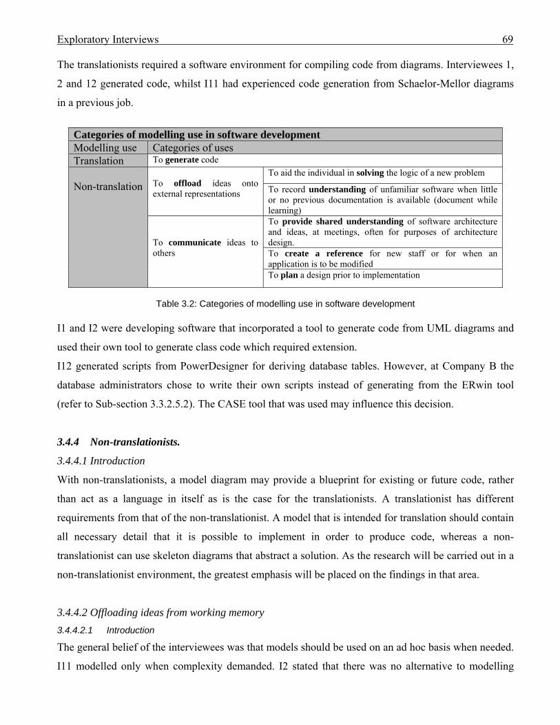
Exploratory Interviews 69
The translationists required a software environment for compiling code from diagrams. Interviewees 1,
2 and 12 generated code, whilst I11 had experienced code generation from Schaelor-Mellor diagrams
in a previous job.
Categories of modelling use in software development Modelling use Categories of uses Translation To generate code Non-translation
To offload ideas onto external representations
To aid the individual in solving the logic of a new problem
To record understanding of unfamiliar software when little or no previous documentation is available (document while learning)
To communicate ideas to others
To provide shared understanding of software architecture and ideas, at meetings, often for purposes of architecture design. To create a reference for new staff or for when an application is to be modified To plan a design prior to implementation
Table 3.2: Categories of modelling use in software development
I1 and I2 were developing software that incorporated a tool to generate code from UML diagrams and
used their own tool to generate class code which required extension.
I12 generated scripts from PowerDesigner for deriving database tables. However, at Company B the
database administrators chose to write their own scripts instead of generating from the ERwin tool
(refer to Sub-section 3.3.2.5.2). The CASE tool that was used may influence this decision.
3.4.4 Non-translationists.
3.4.4.1 Introduction
With non-translationists, a model diagram may provide a blueprint for existing or future code, rather
than act as a language in itself as is the case for the translationists. A translationist has different
requirements from that of the non-translationist. A model that is intended for translation should contain
all necessary detail that it is possible to implement in order to produce code, whereas a non-
translationist can use skeleton diagrams that abstract a solution. As the research will be carried out in a
non-translationist environment, the greatest emphasis will be placed on the findings in that area.
3.4.4.2 Offloading ideas from working memory 3.4.4.2.1 Introduction
The general belief of the interviewees was that models should be used on an ad hoc basis when needed.
I11 modelled only when complexity demanded. I2 stated that there was no alternative to modelling
Exploratory Interviews 70
when developing large, complex projects because it was easier and faster to extract essentials from a
model than reading code. I6 believed that more complex systems needed more sophisticated modelling
techniques.
In Chapter 2 we discussed the use of external representations to capture chunks of data that were too
numerous for working memory’s capacity: For complex problems, external representations may be used to offload partial solution knowledge in order to
free working memory (Grogono & Nelson, 1982, p.7; Kim & Lerch, 1992; Kotovsky et al., 1985; Newell &
Simon, 1972; Scaife & Rogers, 1996) which has limited capacity (Coulter, 1983; Miller, 1956). An evolving
solution can easily become so complex that issues are lost or misremembered … Place keeping, the ability to
keep track of the elements in solution management, is challenging (Rosson & Alpert, 1990).
An external representation such as a UML diagram can be used by the developer to place keep
knowledge about an OO application. The interviewees’ belief that modelling should be applied to
complex problems suggests that offloading from working memory occurs when complexity was
encountered.
The following two modelling usage subcategories of ‘offloading’ describe situations where offloading
onto an external representation has occurred, the first involving an individual trying to sort out a
solution to a problem not previously encountered, and the second involving an individual trying to
understand existing, complex software.
3.4.4.2.2 Modelling individually to solve a logic problem.
Several of those interviewed claimed to occasionally use a diagram to help sort out a solution for a
challenging problem. Blackwell et al. (2001) describe the used diagram as “an external representation
employed as a private aid to thought”.
Developers form solution schemas in their long-term memory that may be applied to assist in solving
future similar problems (Andriole & Adelman, 1995; Détienne, 1995; Guindon & Curtis, 1988; Wǽrn,
1989). These schemas are apparently exercised in many cases. When a matching ‘schema’ cannot be
found, then some developers, to find an answer, use the shorthand method of graphical models to
abstract the problem, perhaps testing alternative solutions through simulation (Andriole & Adelman,
1995; Kim et al., 1995; Kim et al., 1997). This use of an ‘external representation’ could also reflect the
‘offloading’ of information onto paper in order to free up space in working memory (Scaife & Rogers,
1996) which would be unable to contain all of the details.
I8 had commented that the advantage of a modelling language would be in providing a common
language in which developers could discuss design on the whiteboard. For individual modellers, who
are using a diagram for their own purposes, any notation preferred by the modeller would suffice. Thus

Exploratory Interviews 71
if UML is chosen it indicates that the notation is satisfactory for individual purposes. I3, I8 and I10 did
not find it so. I7 used CRUD to make sense of things. However, I6 had used use case techniques to
record some semi-formal requirements and I11 tended to work out ideas with a model first, often with
UML diagrams such as class and, rarely, interaction diagrams.
The reasons for choice of notation could depend upon the type of application, whether the developer
was UML literate, and his/her preference for textural versus graphical documentation.
3.4.4.2.3 Modelling to understand complex inter-relationships
In 2003, when confronted with the responsibility of a new job managing a section of the Company B
product he had not managed previously, I8 used his own notation to document the complex Back End
systems as he learned them. He was able to leverage that same diagram for another use, that of showing
to new staff so they could familiarise themselves with the applications (refer to Section 3.3.2.5.4).
3.4.4.3 Modelling to communicate, share and develop ideas with others 3.4.4.3.1 Modelling to share ideas with others
Nine of the twelve interviewees explicitly mentioned using diagrams to aid communication when
meeting with others. Eight had used sketches on the white board. Three mentioned the use of a CASE
tool to display models for others to share, and three described the use of a drawing tool to display
sketches. Table 3.3 charts the interviewees’ usage of modelling to share ideas with others.
Models used to communicate ideas to others Subject On
W/B Via CASE tool
Via Drawing tool
Notation UML diagrams Other Block
and line class sequence deployment
I1 √ √ √ √ √ I2 √ √ √ I3 √ √ I4 √ √ I5 I6 √ √ √ I7 √ √ √ √ I8 √ √ √ √ DFD √ I9 I10 √ I11 √ √ √ I12 √ √ ERD
Table 3.3. How models were used to communicate ideas to others
Exploratory Interviews 72
The use of diagrams as a communication medium between members of a software team was also noted
by Blackwell et al. (2001). The authors referred to the “informal and ephemeral diagrams” as “talking
sketches”.
Typically the developers were team organised and met to discuss progress, to expand designs, and
discuss how sections of development interfaced. Models were used for sharing ideas whilst designing
the architecture, or for reminding participants about architecture so that time was not wasted conveying
the same view of the software to everybody. I8 had mentioned the difficulty his team experienced in
remembering a software design from one meeting to the next and how a model would have provided a
useful reference for them to share, thus saving time. One of the objections to creating a model was the
time it took.
In many cases the model evolved on the whiteboard at a team meeting. Occasionally, one person was
responsible for the initial model, which was brought to the meeting for modification according to team
consensus.
Some individual modellers eschewed formal notations to utilize only rectangles and lines to record
their models. It was claimed that the simpler the diagram the easier it was to understand. Block and line
can be sufficient to represent both the necessary decomposition and layout recommended by the
research of Hahn and Kim (1999). However, Hahn and Kim (1999) investigated models of dynamics
only, and did not include static models such as a class diagram.
The Mars Rover control system developer (I9) worked in a team of four who had grown to know each
other very well over the years and who could frequently predict what another’s code interface would
be. His team usually met once per week unless there was an emergency. They documented class
interfaces in text, but usually did not document implementation to prevent any dependence upon it.
They had developed an efficient method of email communication. I9 suggested that the reason
modelling was not required was because their class hierarchies were very flat.
I8 viewed the UML as supplying a useful common language for communicating on the whiteboard. He
found that the complexity of his class hierarchies had prevented him from using class diagrams,
believing that the diagrams would be too large. I8 had stated that he got more from a class definition
than he would from a class diagram.
Both I8 and I9 were very experienced programmers and could have developed sound schemas in long-
term memory with respect to coding, such that extra representation in the form of a class model was
unnecessary, regardless of the depth of their hierarchies.
3.4.4.3.2 Modelling to create a reference
Exploratory Interviews 73
As mentioned in Section 3.3.2.5.4, in 2003, I8 was using his own-notation diagram to familiarise his
new staff with the Back End system. He had produced the diagram to record his own understanding of
the system which, for him, was a new responsibility. An added bonus was that the diagram provided
documentation that could be used as a reference, such as to familiarise new staff with the systems.
Although ERDs were used for reference, they were not maintained, the database administrators
preferring to backwards re-engineer them.
In fact few diagrams were maintained for reference, the exception occurring if the diagram was special
and was retained as documentation. For I1, team models were kept up-to-date for a release cycle, but
some which were very special were maintained after that. For I2, class diagrams were maintained as
they became part of the specification, as were I3’s own notation architecture diagrams.
3.4.4.3.3 Modelling to create a design for implementation
Formalising the modelling of a design prior to implementation was not high in the priorities of the non-
translationist developers, although some, such as I11 liked to design on the whiteboard prior to
implementation.
Company B’s developers were enthusiastic about the use of use case templates passed to them by their
business analysts. The templates simplified the location of information. However, the use case
templates used were not graphical models – no use case model was included. In fact their use case
templates were not part of the UML notation.
There are other examples of users avoiding the UML use case model, preferring templates instead. In
an interview with the Auckland Healthcare Services Ltd (AHSL) Applications Development Manager
(Costain, 2000) it was revealed that their customers did not care for the use case diagrammatic models,
but were happy with the templates used to record the steps for each action. The customers could
understand the narrative steps.
3.4.5 Most popular diagrams
Most interviewees confirmed that models such as entity relationship diagrams (ERDs) or object role
models (ORMs) were used to communicate database details. This reflects the findings from Davies et
al. (2006) where the results of a survey promoted through the Australian Computer Society found that
the modelling technique most frequently used was entity-relationship (ER) diagrams. Relational
database tables were generated from scripts. The diagrams were not maintained as the source. If the
diagrams were required at a later date they were re-engineered from the current version of the tables in
order to ensure consistency.
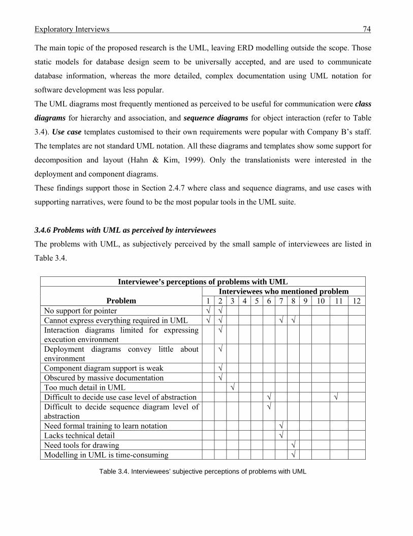
Exploratory Interviews 74
The main topic of the proposed research is the UML, leaving ERD modelling outside the scope. Those
static models for database design seem to be universally accepted, and are used to communicate
database information, whereas the more detailed, complex documentation using UML notation for
software development was less popular.
The UML diagrams most frequently mentioned as perceived to be useful for communication were class
diagrams for hierarchy and association, and sequence diagrams for object interaction (refer to Table
3.4). Use case templates customised to their own requirements were popular with Company B’s staff.
The templates are not standard UML notation. All these diagrams and templates show some support for
decomposition and layout (Hahn & Kim, 1999). Only the translationists were interested in the
deployment and component diagrams.
These findings support those in Section 2.4.7 where class and sequence diagrams, and use cases with
supporting narratives, were found to be the most popular tools in the UML suite.
3.4.6 Problems with UML as perceived by interviewees
The problems with UML, as subjectively perceived by the small sample of interviewees are listed in
Table 3.4.
Interviewee’s perceptions of problems with UML
Problem
Interviewees who mentioned problem 1 2 3 4 5 6 7 8 9 10 11 12
No support for pointer √ √ Cannot express everything required in UML √ √ √ √ Interaction diagrams limited for expressing execution environment
√
Deployment diagrams convey little about environment
√
Component diagram support is weak √ Obscured by massive documentation √ Too much detail in UML √ Difficult to decide use case level of abstraction √ √ Difficult to decide sequence diagram level of abstraction
√
Need formal training to learn notation √ Lacks technical detail √ Need tools for drawing √ Modelling in UML is time-consuming √
Table 3.4. Interviewees’ subjective perceptions of problems with UML
Exploratory Interviews 75
The perceptions tend to be coloured by the context in which the UML was being used. Those
interviewees (I1 and I2) who were involved in developing tools to support the drawing of UML
diagrams and generation of code cited more specific problems with UML than did the remainder who
typically abstracted diagrams at a higher level with no thought of code generation. I1 had found UML
harder to learn than ERDs and ORM modelling. He claimed that UML had strange subtleties around
the meta-model. The fact that the model was a set of points seemed a “weird idea” as points did not
coincide with a language.
Several subjects complained that they could not express everything they wanted in the UML notation,
yet others, such as I3 and I10, found simple block and line diagrams quite adequate. There appears to
be conflict as to the level of abstraction used when modelling, with those involved with implementing
code for translation requiring fine detail and those using UML to communicate ideas typically
modelling at a higher level.
One of the criticisms of UML was that it was difficult for modellers to decide how much detail to
include, especially in use cases and sequence diagrams. However, the modelling of the popular ERDs
did not incur the same difficulty – perhaps because entities in a physical ERD typically had a one-for-
one relationship with a database table and captured only static data. Use case documentation and
sequence diagrams model dynamic data. Thus the possibility is that the nature of what the modeller is
trying to capture in the UML diagrams creates the challenge rather than the notation itself. The initial
concepts for the models must be provided by the modeller.
At least six who were interviewed had used software tools for creating diagrams. Some CASE tools
were considered expensive and were consequently avoided.
3.5 How the modelling use discoveries impact future research
Despite the small number of interviews, the findings have produced a variety of factors that influence
modelling. The plan is to investigate if the UML supports the cognitive activities involved in software
design and implementation. Due to time limitations only one use of UML can be investigated for the
current research. From the uses categorised in Table 3.2 one will be chosen for the in-depth research.
We will not research translationist use due to no tool being available to generate full code.
Many of the non-translationist interviewees claimed that modelling should be carried out on an ad hoc
basis when needed – typically when the problem was complex. It will be necessary to ensure that a
problem set for observation or experiment is one that is new to the subjects, otherwise a solution
schema may already be established in long-term memory and the problem will not be sufficiently
complex to trigger the use of modelling. A problem well-exercised in research such as a conference

Exploratory Interviews 76
registration system, or the tic-tac-toe problem, will not be used. To ensure that the chosen problem is
unfamiliar to the subjects, new applications will be developed for the current research.
As reported in Section 3.4.4.3.1, nine of the interviewees claimed to use models to aid communication
at meetings. How well team members know each other, especially if they have a common history in
software development, can influence the success of a project.
One category of modelling use from Table 3.2 is ‘To communicate ideas’ and ‘to provide shared
understanding’ at meetings. However, to capture the cognitive processes of participants during a
meeting would be challenging. Much cognitive research uses concurrent verbal protocol collection to
capture evidence of subjects’ cognitive processes. It would be very challenging to try to record the
thought processes of individual subjects whilst interacting at a meeting. Thus it has been decided to
investigate individual developers. This is viable provided subjects are selected who have been tutored
in and exercised both UML modelling and programming in the OO environment, and the problem to be
solved is new and sufficiently challenging. It is possible that in-depth experience in writing program
code may establish that method of problem solution at the expense of graphical modelling.
An individual subject may be investigated whilst writing a new program during which activity the
subject may ‘plan a design prior to implementation’ (refer Table 3.2) or offload ‘to aid the individual in
solving the logic’ (Table 3.2). If student subjects were to talk aloud whilst they wrote a new program, it
would be difficult to provide a non-trivial problem that could be accomplished within a practical time
frame, yet be sufficiently complex to trigger a need for external representations. In order to provide
complexity whilst keeping the amount of code to be written to a manageable amount, subjects can be
investigated whilst modifying a program. In order to modify a program a programmer must understand
the parts of that program that will be altered. UML documentation may provide a reference (refer
Table 3.2) to aid that understanding. It is also possible that whilst modifying an application the subject
needs to ‘offload ideas onto external representations’ (Table 3.2).
In the longitudinal study of Company B, I8 used diagrams to familiarise new staff with systems
whereas I6 did not. I6 planned to use good management techniques to bring his staff up to speed but
did not include a model as part of that activity. The question arises: would the use of a UML diagram
be of benefit to developers who were required to modify an application they had not previously
encountered? Would UML diagrams support the cognitive activities of the developers whilst modifying
that application? This question will be targeted for the final investigation. Subjects will be asked to
modify applications with and without reference to UML diagrams, and the performances will be
compared. It is possible that during the experiments, application complexity will persuade subjects to
offload partial solutions to a model, thus adding that modelling usage to the research.

Exploratory Interviews 77
3.6 Conclusion
In 2001, 12 workers involved in the software development industry were interviewed. Three workers
from Company B were interviewed in the following year, and two of those were revisited in 2003. The
purpose of the interviews was to discover if modelling, including the UML notation, was used, and, if
so, how was it used? Table 3.2 lists the discovered uses.
In all examples of use (see Table 3.2) the UML diagrams act as external representations of software
artifacts that have been or will be created in OO code. The program code, in itself, is a text-based
external representation of the problem solution. A UML external representation provides an abstraction
of the text-based code. The code is essential to the solution, the models are not, yet may be desirable.
This research is looking to find whether the availability of the higher abstraction in UML notation is
advantageous to the programmer. Does the UML abstraction assist the programmer cognitively when
solving software application problems?
For our in-depth research, the problem chosen for the subjects must provide sufficient challenge, yet fit
within a manageable timeframe. The choice of problem was influenced by the 2003 interviews in
Company B where new staff needed to become familiar with their software product so that they could
modify it.
Thus the practice of program modification was chosen as the activity to investigate in order to answer
the question: can UML diagrams cognitively assist a programmer in the act of modifying an OO
software application? The applications to be modified, which the subjects will not have seen prior to
the experiments, will be documented in UML notation to provide the programmers with a reference.
The current research project will be new for the subjects so there should be no interference from
previously established solution knowledge. Only class, sequence and use case diagrams will be
provided, as these were found to be the most popular. Use case templates, which contain descriptions
of the use cases on the model, will support the most important use cases.
The exploratory interviews have highlighted the need to be aware of a subject’s background in
modelling, programming, and application domains, as these could affect performance.
It is planned to avoid CASE tools as their usability could impact the usability of the diagrams, as can
size and resolution of screen.
There was some agreement amongst the interviewees who were experienced programmers, that coding
was not the difficult component of software development; the understanding of the problem domain
provided the biggest challenge.
The full and final methodology will be discussed in the next chapter.
Methodology 78
Chapter 4: Methodology 4.0 Introduction
In this chapter we describe the experimental methodology to be used for our research into whether the
Unified Modelling Language (UML) provides cognitive support for programmers who are modifying
object-oriented (OO) programming code.
Several software developers whose interviews were reported in Chapter 3 claimed to use diagrams for
communicating content of software applications. In the situation where the original authors of an
application are no longer available, the provision of documentation in the form of UML diagrams may
be beneficial for future modifiers. It is this latter aspect of UML use that the current research addresses.
Both the performance and cognitive behaviour of programmers who are provided with UML
documentation to assist with their modification of OO software applications will be investigated.
Participants will modify two non-trivial OO programs, only one of which will be accompanied by
UML documentation. Performance with UML assistance will be compared to that which occurs when
no UML documentation is available. When Carroll et al. (1980) gave their subjects a graphic means for
presenting solutions, there was a highly significant tendency for solutions to take longer, but greater
accuracy was achieved. This research will be looking to detect greater accuracy occurring when UML
documentation is used. The main focus of the work will be to detect evidence of cognitive support from
the diagrams being effectively used during the application modifications.
As well as comparing programming performance, this research will study programmers’ cognitive
behaviour during software modification. The aim will be to ascertain whether UML documentation is
incorporated into the problem-solving cognitive activities.
Modifying a software application involves both the comprehension of the problem (Brooks, 1980;
Pennington, 1987) and the induction of rules to achieve the sub-goals that contribute to the main
solution (Kim et al., 1995). In Section 2.5 we discussed that, in order to solve the program modification
problem, programmers may evoke rules from schemas stored in long-term memory (LTM), may derive
rules from information found in the problem domain, or evolve rules through mental simulation. The
programmer may resort to external representations such as UML documentation (if available) to assist
their comprehension of the application to be modified, or may offload information onto external
documentation in order to free space in a busy working memory (WM).
In Section 2.5 a framework was derived to categorise the cognitive steps in problem solution. The
framework appeared in Table 2.1 and is reproduced in this chapter as Table 4.1. It will be applied to
encode the transcriptions of verbal protocols collected from participants during their OO program
Methodology 79
modifications. As noted by Todd and Benbasat (1987), verbal protocol analysis is a controversial
technique. A common criticism is that all mental processes are not captured. When used with care,
concurrent verbal protocol collection can provide data on the end results of subjects’ cognitive
processes (Ericsson & Simon, 1993; Miller, 1962; Neisser, 1967) that are not otherwise obtainable. It
would be difficult for a subject to accurately reiterate every cognitive step in sequence during a
retrospective interview due to the limitations of human memory. Substantial forgetting or fabrication
has been demonstrated empirically (Russo et al., 1989). Ericsson and Simon (1993) believe that
concurrent verbal protocols give more honest data. We wish to capture the end products of individual
subject’s cognitive steps to detect evidence of the cognitive support provided by the UML during the
subject’s modification of an application. Thus concurrent verbal protocol collection has been chosen as
the most appropriate method for collecting honest data for the current research.
Encoded protocols will be collated into behaviour graphs. Behaviour graphs are particularly suited to
record individual behaviour, rather than group behaviour. The graphs will provide the means of
identifying the category of cognitive step dominant for each episode of a subject’s program
modification. An episode is defined by Newell and Simon (1972, p.84) as a succinctly describable
segment of behaviour associated with attaining a goal. Thus the graphs will provide a diagrammatic
record of internal representation formation and rule induction during problem comprehension and
solution. They will also include a record of any cognitive offloading onto external documentation. It
will be possible to quickly reference the sequence of cognitive episodes used to achieve sub-goals
during the modification from the graph’s diagrammatic presentation.
If it can be demonstrated that UML documentation assists the programmer to form more satisfactory
internal representations of the problem then it will be concluded that the programmer’s comprehension
of the application has been supported. The cognitive support of UML documentation would be
evidenced by a participant correcting an inaccurate internal representation after reading the
documentation.
If UML documentation can be used in conjunction with the programmer’s cognitive processes – indeed
forming a set with the programmer’s internal problem space in order to induce rules - then it may be
claimed that UML provides cognitive support for the programmer.
Despite the UML being accepted by the Object Management Group (OMG) as a standard language for
modelling computer applications (Johnson, 2002; Kobryn, 1999) we know of no research into its use
during software problem solution. This lack was commented upon by Blackwell et al. (2001, p.109).
This research attempts to address that omission.
Methodology 80
According to Booch, Rumbaugh and Jacobson (1999, p.xvi) the “UML is applicable to anyone
involved in the production, deployment, and maintenance of software”. The authors define the UML as
“a language for visualizing, specifying, constructing, and documenting the artifacts of a software-
intensive system”. There is no software available at the time of writing that can be used to generate a
fully coded solution from UML models. In fact, UML documentation does not provide program syntax
assistance, ensuring that the writing of program code cannot be fully replicated by UML diagrams
which provide generic information with little implementation language detail. Thus, at present, UML
diagrams are supplementary to the activity of programming software solutions. In fact, they may be
omitted from the activity altogether. If, however, they are perceived to be a useful addition, they will be
leveraged by programmers.
Where the programmer is knowledgeable in both a software application’s problem and solution
domains it is possible that UML documentation is not necessary. From the Company B interviews
(refer to Chapter 3) it was found that as the group of developers became familiar with the source code
for their specific product, the need diminished for an alternative method of representing that code, such
as a system model. This suggests that as developers establish schemas in long-term memory (LTM)
that relate to the source code, it becomes less necessary to leverage partial understandings derived from
external representations such as UML diagrams.
However, there is no opportunity for participants in this research to familiarise themselves over a long
period of time with the source code. Subjects will be exposed to the source code only during the
restricted time of the experiment. Participants will be free to choose to use the external diagrammatic
representations, where they are supplied, to assist in problem comprehension and solution.
The ‘concurrent verbal protocol collection’ method that will be used in this research is also known as
‘talk aloud, or ‘think aloud’, or ‘thought-listing technique’. It will be referred to in this thesis as either
‘think aloud’ or ‘verbal protocol’ method.
This chapter discusses and elaborates upon the methodology chosen for the research. It is organised as
follows:
Section 4.1 covers the research questions concerning performance and cognitive behaviour. The
framework for categorising the programmers’ major steps in their cognitive problem-solving activities
will be reproduced from Chapter 2 for immediate reference.
To provide evidence of the participants’ cognitive behaviour, concurrent verbal protocols will be
collected whilst subjects modify the non-trivial applications. The reasons for selecting the verbal
protocol collection method, and some concerns identified in the literature related to its use, will be
discussed in Section 4.2. That discussion, combined with concerns expressed in the literature related to
Methodology 81
empirical investigation into programmer performance, as reported in Section 4.3, will guide how the
experiments are carried out. A full description of the methodology will be found in Section 4.4. Section
4.5 concludes this chapter.
4.1 Research questions.
4.1.1 Research question related to programmer performance
Participants will modify two different, though similar in size, OO software applications written in
VB.NET, on two different occasions. One application will be supplied with UML documentation
recorded in the most popular UML diagrams as discussed in Section 2.4.7 and confirmed in the
explorative interviews (refer to Section 3.4.5). Those diagrams include use case with written
descriptions of use cases, class, and sequence. The subjects will have knowledge of the UML notation,
but the content that is modelled will be new.
The question to be answered is as follows:
A1. When a programmer solves a program modification problem does the provision of UML
documentation improve performance?
The goal of completing each modification will be decomposed into its sub-goals. Performance will be
measured by the percentage of sub-goals achieved during a two-hour program modification session.
4.1.2. Research questions related to programmers’ cognitive behaviours.
4.1.2.1 Introduction: the framework
The aim of this research is to investigate whether UML documentation cognitively supports the OO
software modification problem-solving activity. UML diagrams and narrative that document the
original programs will act as external representations for the problem solving.
A framework was developed in Chapter 2 (reproduced in this chapter as Table 4.1) to categorise the
cognitive steps that may be taken by a problem solver whilst solving a problem with the aid of system
models as external representations. This framework will be applied to encode the cognitive steps
undertaken by the programmers whilst modifying the programs.
The unit of analysis for categorisation will be the episode - a succinctly describable segment of
behaviour associated with attaining a goal (Newell & Simon, 1972, p.84). The episode was chosen due
to the large volume of data an experiment of this nature will generate.
Methodology 82
The main goal for a problem may be decomposed into sub-goals (Newell & Simon, 1972). A rule may
be induced to attain a specific sub-goal. For our purposes, achievement of a sub-goal occurs as the end
result of an episode where the problem solver has taken a cognitive step in the problem-solving
exercise. The framework can be applied to categorise the episodes performed by the problem solver.
Each assigned category will represent the prime cognitive step required to achieve the episode’s sub-
goal.
An external representation may aid problem solving by assisting in the establishment of the internal
representation of a problem (for example, a class diagram may contribute static information about an
existing program that is to be modified); may cue information from LTM; or may act as a recipient for
offloading information to free working memory (WM) (Grogono & Nelson, 1982, p.7; Kim & Lerch,
1992; Kotovsky et al., 1985; Newell & Simon, 1972; Preece et al., 2002; Scaife & Rogers, 1996).
It is necessary to understand a problem before it can be solved (Newell & Simon, 1972). Appropriate
external representations can aid program comprehension (Pennington, 1987). As we wish to discover if
the UML documentation assists modifiers to comprehend a problem, that aspect of the exercise will be
included for categorisation, not excluded as was the case in Kim et al. (1995) where the subjects read
the problem requirements prior to verbal protocol collection. The formation of an internal
representation does not verify comprehension but can be an initial step in comprehending a problem.
Evidence is required as to the validity of the representation. An internal representation may be changed
as the exercise progresses. If the reading of a UML diagram causes a valid correction to an internal
representation then the documentation will be assumed to assist in the comprehension of the problem.
Internal representations will be established for the problem domain.
OO programs may be viewed as sets of rules for transforming inputs into desirable outputs (Kim et al.,
1995, p.358). The programming solution process involves rule induction, either by evoking schemas
from LTM, deriving schemas from the problem space, or inferring rules from trial-and-error (Kim et
al., 1995; Simon & Lea, 1974).
Appropriate external representations can act as a set with the programmer’s internal problem space to
assist in solving a programming problem (Zhang & Norman, 1994), such as inducing rules. A rule is
variously described as either an hypothesis developed for solving or understanding the related
phenomena (Kim et al., 1997), or: any systematic piece of problem-solving knowledge that allows entities to constrain search. Any knowledge
that allows the entities to compute the next move of a series of moves, rather than just retrieve it from
memory, is regarded as a rule (Ruiz, 1986). In order to be regarded as a rule, the knowledge should be able to
compute the next move or at least constrain search (Kim et al., 1995, p.372).
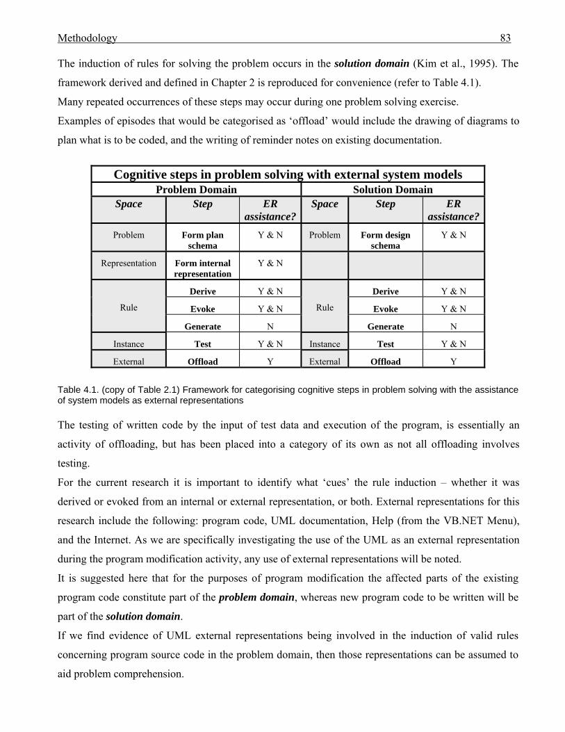
Methodology 83
The induction of rules for solving the problem occurs in the solution domain (Kim et al., 1995). The
framework derived and defined in Chapter 2 is reproduced for convenience (refer to Table 4.1).
Many repeated occurrences of these steps may occur during one problem solving exercise.
Examples of episodes that would be categorised as ‘offload’ would include the drawing of diagrams to
plan what is to be coded, and the writing of reminder notes on existing documentation.
Cognitive steps in problem solving with external system models
Problem Domain Solution Domain Space Step ER
assistance?Space Step ER
assistance?Problem Form plan
schema Y & N Problem Form design
schema Y & N
Representation Form internal representation
Y & N
Rule
Derive Y & N
Rule
Derive Y & N
Evoke Y & N Evoke Y & N
Generate N Generate N
Instance Test Y & N Instance Test Y & N
External Offload Y External Offload Y
Table 4.1. (copy of Table 2.1) Framework for categorising cognitive steps in problem solving with the assistance of system models as external representations The testing of written code by the input of test data and execution of the program, is essentially an
activity of offloading, but has been placed into a category of its own as not all offloading involves
testing.
For the current research it is important to identify what ‘cues’ the rule induction – whether it was
derived or evoked from an internal or external representation, or both. External representations for this
research include the following: program code, UML documentation, Help (from the VB.NET Menu),
and the Internet. As we are specifically investigating the use of the UML as an external representation
during the program modification activity, any use of external representations will be noted.
It is suggested here that for the purposes of program modification the affected parts of the existing
program code constitute part of the problem domain, whereas new program code to be written will be
part of the solution domain.
If we find evidence of UML external representations being involved in the induction of valid rules
concerning program source code in the problem domain, then those representations can be assumed to
aid problem comprehension.
Methodology 84
If we find evidence that UML external representations act as a set with internal representations to
induce rules in the solution domain then they will be deemed to assist in problem solution by
supplementing WM. If the construction or modification of UML diagrams is observed it will be
assumed that the action has been carried out in order to free WM.
The framework may be applied to discover the answers to the following research questions related to a
programmer’s cognitive behaviour.
4.1.2.2 Cognitive behaviour questions: UML usage and cognitive support
The aim for this research is to investigate the following questions for non-trivial programs:
B1. Can the use of UML documentation facilitate a programmer’s comprehension of a non-trivial
program by assisting in the formation of valid internal representations of a problem?
B2. (i) Can the use of UML documentation facilitate a programmer in modifying a non-trivial
program by forming a set with the programmer’s internal problem space?
(ii) Can the use of UML documentation facilitate a programmer’s writing of code to solve a non-
trivial problem by acting in a set with the problem space to induce rules for solution?
B3. Can the use of UML documentation facilitate a programmer’s modifying a non-trivial program by
providing a vehicle for offloading from working memory?
In order to answer these questions an appropriate methodology must be chosen. The methodology will
not address generalisation, instead it will specifically examine the cognitive processes employed for
modifying non-trivial OO programs where cognition may be distributed to UML documentation.
Cognitive mapping techniques have been widely used in management research to depict the cognitive
structures of members of organisations (Swan, 1997; Swan & Newell 1994), and have been more
recently applied in software engineering (e.g. Siau & Tan, 2006, 2006a). In Siau and Tan (2006) the
models produced from cognitive mapping supplement the UML diagrams recommended for
documenting elicited requirements in the Unified Software Development Process (UP) (Jacobson et al.,
1999). In Siau and Tan (2006a) the cognitive mapping techniques are used to elicit interviewees’ belief
systems with respect to a problem domain. In neither example where cognitive mapping techniques are
used in software engineering are the cognitive processes of the subjects identified or tracked.
The term ‘cognitive’ in cognitive mapping is a misnomer, as cognitive mapping technologies focus on
cognitive structure rather than cognitive process (Eden, 1992; Swan, 1997). The outcome of a cognitive
Methodology 85
mapping technique is not the same as an internally represented mental model. It is a reconstruction of
subjective beliefs that have been revealed to the researcher (Eden, 1992). Unconscious processes are not easily accessible for study so the focus here is on ways of exploring cognitions
that are conscious and reflected in peoples’ uses of concepts … A distinction needs to be drawn between
internal psychological schema and cognitive maps, and the output of cognitive mapping techniques. … In
psychology, ‘cognitive map’ was a term that was developed to describe an individual’s internal mental
representation of the concepts and relations among concepts that the individual uses to understand their
environment (Tolman, 1948). Cognitive maps are thus seen as internally represented schemas or mental
models for particular problem-solving domains that are learned and encoded as a result of an individual’s
interaction with their environment. … Cognitive mapping describes a set of techniques that are used to try and
identify subjective beliefs and to portray these externally (Fiol and Huff, 1992). (Swan, 1997).
Swan’s (1997) list of techniques for eliciting cognitive maps includes analysis of documents and
interviews. The outcome of the mapping techniques is shaped by the method used to elicit it: “The very
process of eliciting the revealed map (e.g. by face-to-face interviews) may alter its composition because
the interaction between the researcher and the interviewee involves articulation which can change the
cognitions of both researcher and interviewee” (Swan, 1997).
Eden et al. (1992) claim that it is difficult to detect a link between a theory of cognition and the coding
method of cognitive maps. For this research we require that analysis be linked to theory. We wish to
investigate the distribution of cognition between a subject’s internal problem space and external
representations in the form of UML diagrams. In order to do so it will be necessary to use a method to
detect and categorise the stable outcome of cognitive processes used in problem-solving which may
involve UML documentation. We also require a method of data collection that least influences the
cognitive processes themselves. As concurrent verbal protocol collection can satisfy all these
requirements it has been chosen as the method for investigating these phenomena during program
modification. Transcribed protocols will be divided into episodes which will be encoded according to
the framework in Table 4.1. Behaviour graphs will be constructed from the encoded episodes.
Narrative summaries of the episodes in conjunction with the behaviour graphs will be analysed to
detect
a. a participant’s formation of internal representations of the problem and program.
b. UML documentation being used in a set with the programmer’s problem space
c. rules induced in the problem or solution domain that reflect a participant’s usage of external
UML documentation in a set with his/her internal problem space, and
d. the freeing of WM by offloading to UML documentation in both problem and solution domains.
Methodology 86
It is hypothesised that a programmer with industry experience accumulates more schemas stored in
LTM to assist the program modification activity than does a non-industry experienced student. In
Section 2.3 it was noted that “experts in software development can recognise and recall meaningful
patterns when they see them, whereas the novice, lacking appropriate internal representations, cannot,”
and “expert problem-solvers often collapse multiple problem-solving steps into a single step”. The
industry-experienced programmer’s use of UML models should thus be more efficient. This leads to
the last research question:
C1. Will a student who has no industry experience use UML documentation more often than a
programmer with industry experience?
To answer this question the number of episodes in which a programmer uses UML models will be
counted.
What is concurrent verbal protocol collection, why it has been chosen for this research, and concerns
about its usage will be discussed in the next sections.
4.2 Verbal protocol collection
4.2.1 Introduction
Verbal protocol collection and analysis has been the method used for detecting the cognitive activities
of subjects in many software engineering experiments (Arunachalam & Sasso, 1996; Guindon, 1990;
Guindon & Curtis, 1988; Hahn & Kim, 1999; Hale et al., 1999; Herbsled et al., 1995; Herbsled &
Kuwana, 1993; Hungerford, 2004; Irwin, 2002; Kim & Lerch, 1992; Kim et al., 1995, 1997, 2000;
McCracken, 2002; O’Brien et al., 2001; Owen et al., 2006; Pennington et al., 1995; Rist, 1989; Shaft,
1997; Siau & Lee, 2004; Siau & Tian, 2001; Srinivasan & Irwin, 2006; Srinivasan & Te’eni, 1995).
Owen et al. (2006) collected concurrent verbal protocols when studying which documentation was used
and why it was used by software designers, when designing systems from components. No modelling
diagrams were included in the documentation. The authors adopted verbal protocol analysis as the only
means by which they could capture patterns of information use and user intentions.
In their experiment to test veridicality of retrospective protocols, Russo et al. (1989) found that the
latter “yielded substantial forgetting or fabrication in all tasks, supporting the non-veridicality of these
methods”. Concurrent verbal protocols are likely to provide more honest data (Ericsson & Simon,
1984, p.8).
Methodology 87
As we are investigating the cognitive support supplied by UML diagrams the chosen methodology is to
collect verbal protocols from the subjects whilst they are modifying the programs. Analysis of the
protocols will supply data for constructing graphs of the rules induced to achieve sub-goals in the
problem-solving process.
4.2.2 ‘Thinking aloud’ – concurrent verbal reports
Ericsson and Simon (1984) popularised the method of detecting human cognitive activities by asking
subjects to ‘think aloud’, where the subjects give a running commentary of their thought processes
whilst undertaking a task (Ericsson & Simon, 1984, 1993; Rubin, 1994). To give the closest reflection
of those cognitive processes the thoughts must be verbalised directly (Ericsson & Simon, 1984, p. 16). When subjects verbalize directly only the thoughts entering their attention as part of performing the task, the
sequence of thoughts is not changed by the added instruction to think aloud (Ericsson & Simon, 1993, p.xiii).
The authors concluded from their review of published studies that for ‘think alouds’ from subjects
instructed to verbalise thoughts (categorised as Type 11 and Type 22 verbalisations) the sequence of
cognitive processes can reflect that of the silent task (Ericsson & Simon, 1993, p.xxxii). However, if
the ‘think alouds’ belonged to a Type 3 category, that is, verbalisation where subjects were instructed
to give explanations and reasons, then the cognitive processes were changed (Ericsson & Simon, 1993,
pp.xviii-xix).
From their review of the cognitive processes literature Nisbett and Wilson (1977) deduced there was
almost no conscious awareness of perceptual and memorial processes. They argued that human beings
have no direct access to mental processes and can’t provide an accurate report about them. The authors
did, however, conclude that people have access to a large number of facts, but may have no access at
all to the mental processes that manipulate those facts. Smith and Miller (1978), in their reply to
Nisbett and Wilson (1977), asserted that access to mental processes is possible in certain cases. For this
research we are interested in the products of those mental processes, rather than the processes
themselves.
Ericsson and Simon (1993, p.xiii) theorised that some thought processes could be recognised as a sequence of states, each state containing the end products of cognitive processes, such as information
retrieved from long-term memory, information perceived and recognized, and information generated by
inference. (1993, p.xiii).
1 Type 1: Verbalisations that need not be transformed before being verbalised, for example, the verbalising of numbers (Boren & Ramey, 2000, p.262). That is, content is in verbal form before it is reported (Ransdell, 1995). 2 Type 2: Verbalisations that require additional cognitive processing beyond what is required for task performance, for example: images or abstract concepts that must be transformed into words (Boren & Ramey, 2000, p.262). Content is in verbal form before it is reported (Ransdell, 1995).
Methodology 88
Their theory was based on the following assumptions (1993, p. 221): 1. The verbalisable cognitions can be described as states that correspond to the contents of STM (i.e. to the
information that is in the focus of attention).
2. The information vocalized is a verbal recording of the information in short-term memory.
As reported in Nisbett and Wilson (1977), this theory is supported by Miller (1962, p. 56): “It is the
result of thinking, that appears spontaneously in consciousness”, and by Neisser (1967, p.301):
“Although the constructive processes themselves never appear in consciousness, their products do”.
Because the information in a state is relatively stable it can be verbalised and reported orally, but “the
retrieval and recognition processes delivering the end products, the information, to attention cannot be
reported” (Ericsson & Simon, 1993, p.xiii).
For this research we are investigating those stable states that the authors believed could be verbalised.
We are looking for evidence of the formation of internal representations of problems and the induction
of rules that have been induced to comprehend and solve a problem, either by evoking memories from
LTM, deriving from what is recognised in the problem space, or inferring by trial and error (see
Section 4.1.2.1). The representations and induced rules are stable states which can be verbalised.
If the verbalisation changes the primary process then the verbal protocol is said to be ‘reactive’ (Russo
et al., 1989). Russo et al. (1989) found that a pictorial task showed no reactivity, suggesting that the use
of external diagrams by subjects during verbal protocol collection could fit comfortably within
Ericsson and Simon’s (1993) Type 2 categorisation.
Hughes and Parkes (2003) described verbal protocol collection as a “bias-free method of revealing
what a person is thinking when performing a task”. Information externalised in verbal responses can
provide the experimenter with data that eliminate the need for trust in the subject (Ericsson & Simon,
1984, p.8). This appears to be a case of ‘believe what I say as I do rather than what I say afterwards’. It
implies that concurrent verbal protocols provide more honest information than would be obtained from
an interview or retrospective interrogation. In this research we wish to identify the induced rules
formed during the task performance. These rules may be lost over time due to insufficient cognitive
exercising and thus may not be available after the exercise is concluded. As mentioned in Section 4.0,
Russo et al. (1989) found evidence of “substantial forgetting or fabrication” in their testing of
retrospective protocols. Thus the collection of concurrent verbal protocols will be used as the data are
captured as they occur and should honestly reflect actual states.
As reported at the beginning of this section, only when the verbalisation required the subject to explain
his thought processes was there “evidence that verbalisation changes the course or structure of the
Methodology 89
thought processes” (Ericsson & Simon, 1984, p.106). Other concerns about the use of verbal protocols,
including prompting to avoid reactivity, are reviewed in the next sections.
4.2.3 Concurrent verbal protocol collection of cognitive data – some concerns
4.2.3.1 Verbalisation slows thought processes
Verbalisation whilst doing a task requires more time than would be required to do that task silently
(Anderson, 1985; Ericsson & Simon, 1993, p.xx; Rubin, 1994). When Nielsen et al. (2002, 2002a)
asked students, who had been taught to think aloud, to reflect on their experience, the students claimed
that they thought faster than they could speak, that their thought processes were much more complex
than they could verbalise, and that thinking aloud interfered with the task.
In an exercise that required college students to write letters with (a) thinking aloud protocols, (b)
retrospective replay protocols and (c) no protocols, the thinking aloud protocol had a slower writing
rate than did the other protocols (Ransdell, 1995).
If the ‘think aloud’ method prolongs the elapsed time for problem solving then no reliable deductions
may be made as to time taken by the thought processes that are being investigated.
4.2.3.2 Variation in subject ability to verbalise whilst doing a task
People with poor verbal skills may forget to think aloud (Boren & Ramey, 2000). “Users may not be
especially proficient at verbalizing their thoughts, even after they have been trained in speaking as they
concurrently perform tasks” (Cooke & Cuddihy, 2005). Evidence was found in Cotton and Grestry’s
(2006, p.51) verbal protocol collection study that evaluated an online biological resource for student
nurses, that some students found think aloud easier than others.
A possible explanation suggested by Branch (2001) and Stratman and Hamp-Lyons (1994, p.95) is that
some subjects have limited WM capacity for talking and attending at the same time. From evidence
obtained in early experiences with verbal protocol collection, Ericsson and Simon (1993, p.91)
concluded that subjects may stop verbalising in conditions where they are under a high cognitive load
or they are feeling difficulty.
Branch (2000, 2001) believes that learners are unique and bring their own skills, experience and
vocabulary to a task. When she collected the verbal protocols of junior high students whilst searching
CD-ROM encyclopedias she found that some participants had very brief ‘think alouds’. For her first
session one subject had 278 statements compared to another who gave only 27. The latter subject was
an experienced searcher and found the answers quickly and easily. The process had become automatic,
one that needed little thought or talk.
Methodology 90
Branch used Biemiller and Meichenbaum’s (1992) work on self-directed learning to explain why some
searchers found difficulty with thinking aloud. Biemiller and Meichenbaum (1992) observed that
children whose level of cognitive development exceeded their task had surplus mental capacity to think
aloud whilst doing the task whereas children less advanced needed their full attention to finish the task
leaving little or no capacity for verbal thought processes (p.76).
Anderson (1985) recorded verbal protocols for subjects determining an offer price for firms going
public on the equity markets. He found that verbalisations tended to increase with the experience of the
subject in solving a particular problem or doing a particular task.
Thus there are two extremes which may reduce verbalising – the situation where the participant finds
the task too hard (Anderson, 1985; Biemiller & Meichenbaum, 1992; Ericsson & Simon, 1993) and the
situation where the participant finds it too easy (Branch, 2000, 2001). Both conditions were found to
restrict verbal protocols. This has implications for expert-novice performance for a specific task, where
greater divergence in behaviour may be observed than actually exists.
To get the best result from verbal protocols the task should be sufficiently familiar that participants can
freely talk aloud about it, yet not so easy that it becomes automatic. In the current research, non-trivial
programs will be used to provide complexity. However, the exercise should not be so difficult that no
participant could succeed.
Stratmann and Hamp-Lyons (1994) suggest that monitor influence could cause reactivity in concurrent
verbal protocols. This reactivity may be caused by poor directions from the monitor, by verbal or non-
verbal cues, or from having the subject’s learning increase due to the greater exercising of data. The
question arises: how should the subjects be instructed and prompted to avoid interference with the
thought processes? These concerns are addressed in the next section.
4.2.3.3 Monitor interference
‘Think aloud’ procedures may vary widely among practitioners due to a lack of rules for the practice
for thinking aloud (Boren & Ramey, 2000; Cabello & O’Hora, 2002).
Cabello and O’Hora (2002) cite the example of instructions provided prior to sessions as a point of
difference. Ericsson and Simon (1993, p.xiii) were also concerned with how a subject was advised to
‘think aloud’. If a subject was instructed to explain his/her thoughts (categorised as Type 3
verbalisations) then the sequence of thoughts could be altered. With the verbalising of the explanation
the information is given greater attention, and alters the process (p.xix). Only when the subject is
completely focused on completing the task can the sequence of thoughts resemble that of the silent
condition (Ericsson & Simon, 1993, p.xiv).
Methodology 91
Boren and Ramey (2000) concluded from field observations and reviews of usability guidebooks and
literature that practice often did not reflect that recommended by Ericsson and Simon (1993),
particularly with respect to reminders to keep verbalising.
Ericsson and Simon (1984) deplored using data whose flow was interrupted by comments and prompts
from the monitor. According to the authors an interval of about 15-60 seconds’ silence should be
allowed to elapse before prompting for continuation. The authors obtained from Russo et al. (1989)
their instructions to their participants when the latter were silent during verbalisation (Ericsson &
Simon, 1993, p.xxviii). The participants were asked: “Please tell me what you are thinking?” (Russo et
al, 1989, p. 761). Ericsson and Simon (1993, p.xxviii) believe that is more disruptive than a simple
instruction to “keep talking”, as the former requires descriptive information that could disrupt thought
sequence. “Keep talking” is short and as non-directive as possible (Boren & Ramey, 2000, p.263). A
reminder is successful when thinking aloud immediately resumes.
From their review of previous studies Cabello and O’Hora (2002) deduced that the presence of the
experimenter can affect the verbal behaviour of the participants. Indeed, Rubin (1994) considered his
section on ‘Guidelines for Monitoring the Test’ to be the most important in his book Handbook of
Usability Testing as the monitor can very easily affect the participant. He advises to present the test
neutrally, to not react to mistakes, to not indicate by body language or tone of voice any agreement or
disagreement, and not ‘rescue’ participants when they struggle. Moving closer to someone indicates acceptance of what that person is saying, moving further away indicates
rejection. Raising the pitch of your voice usually signals agreement, while lowering it communicates the
opposite (Rubin, 1994).
However, in practice, “participants regularly say things that are difficult to understand” (Boren &
Ramey, 2000). Despite recommending minimal interaction with the participant, Rubin (1994) does
suggest the careful use of ‘probing’ to gather information that the participant has not imparted.
During this research, interaction will be kept to a minimum, but when a participant’s words require
clarification the monitor will request more detail. The prompts will adhere to Boren and Ramey’s
(2000) recommendation that prompts do not influence the participant’s response, and voice pitch and
body language are neutral (Rubin, 1994). This may produce Type 3 data, but is preferable to having
data that is unclear and thus useless.
4.2.3.4 Sample sizes
Review of verbal protocols is a time-consuming activity (Cabello & O’Hora, 2002; Hughes & Parkes,
2003; Irwin, 2002; Todd & Benbasat, 1987).
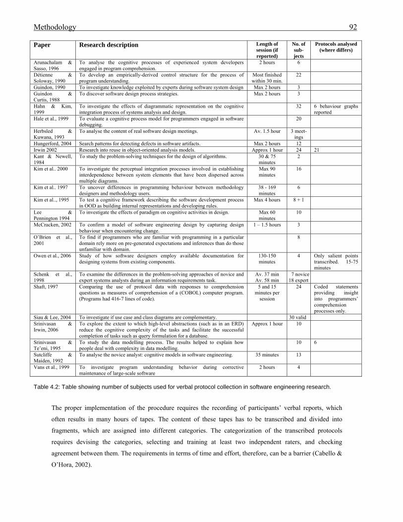
Methodology 92
Paper Research description Length of session (if reported)
No. of sub-jects
Protocols analysed (where differs)
Arunachalam & Sasso, 1996
To analyse the cognitive processes of experienced system developers engaged in program comprehension.
2 hours 6
Détienne & Soloway, 1990
To develop an empirically-derived control structure for the process of program understanding.
Most finished within 30 min.
22
Guindon, 1990 To investigate knowledge exploited by experts during software system design Max 2 hours 3 Guindon & Curtis, 1988
To discover software design process strategies. Max 2 hours 3
Hahn & Kim, 1999
To investigate the effects of diagrammatic representation on the cognitive integration process of systems analysis and design.
32 6 behaviour graphs reported
Hale et al., 1999 To evaluate a cognitive process model for programmers engaged in software debugging.
20
Herbsled & Kuwana, 1993
To analyse the content of real software design meetings. Av. 1.5 hour 3 meet-ings
Hungerford, 2004 Search patterns for detecting defects in software artifacts. Max 2 hours 12 Irwin 2002 Research into reuse in object-oriented analysis models. Approx 1 hour 24 21 Kant & Newell, 1984
To study the problem-solving techniques for the design of algorithms. 30 & 75 minutes
2
Kim et al.. 2000 To investigate the perceptual integration processes involved in establishing interdependence between system elements that have been dispersed across multiple diagrams.
Max 90 minutes
16
Kim et al.. 1997 To uncover differences in programming behaviour between methodology designers and methodology users.
38 - 169 minutes
6
Kim et al.., 1995 To test a cognitive framework describing the software development process in OOD as building internal representations and developing rules.
Max 4 hours 8 + 1
Lee & Pennington 1994
To investigate the effects of paradigm on cognitive activities in design. Max 60 minutes
10
McCracken, 2002 To confirm a model of software engineering design by capturing design behaviour when encountering change.
1 – 1.5 hours 3
O’Brien et al., 2001
To find if programmers who are familiar with programming in a particular domain rely more on pre-generated expectations and inferences than do those unfamiliar with domain.
8
Owen et al., 2006 Study of how software designers employ available documentation for designing systems from existing components.
130-150 minutes
4 Only salient points transcribed. 15-75 minutes
Schenk et al., 1998
To examine the differences in the problem-solving approaches of novice and expert systems analysts during an information requirements task.
Av. 37 min Av. 58 min
7 novice 18 expert
Shaft, 1997 Comparing the use of protocol data with responses to comprehension questions as measures of comprehension of a (COBOL) computer program. (Programs had 416-7 lines of code).
5 and 15 minutes per
session
24 Coded statements providing insight into programmers’ comprehension processes only.
Siau & Lee, 2004 To investigate if use case and class diagrams are complementary. 30 valid Srinivasan & Irwin, 2006
To explore the extent to which high-level abstractions (such as in an ERD) reduce the cognitive complexity of the tasks and facilitate the successful completion of tasks such as query formulation for a database.
Approx 1 hour 10
Srinivasan & Te’eni, 1995
To study the data modelling process. The results helped to explain how people deal with complexity in data modelling.
10 6
Sutcliffe & Maiden, 1992
To analyse the novice analyst: cognitive models in software engineering. 35 minutes 13
Vans et al., 1999 To investigate program understanding behavior during corrective maintenance of large-scale software
2 hours 4
Table 4.2: Table showing number of subjects used for verbal protocol collection in software engineering research.
The proper implementation of the procedure requires the recording of participants’ verbal reports, which
often results in many hours of tapes. The content of these tapes has to be transcribed and divided into
fragments, which are assigned into different categories. The categorization of the transcribed protocols
requires devising the categories, selecting and training at least two independent raters, and checking
agreement between them. The requirements in terms of time and effort, therefore, can be a barrier (Cabello &
O’Hora, 2002).
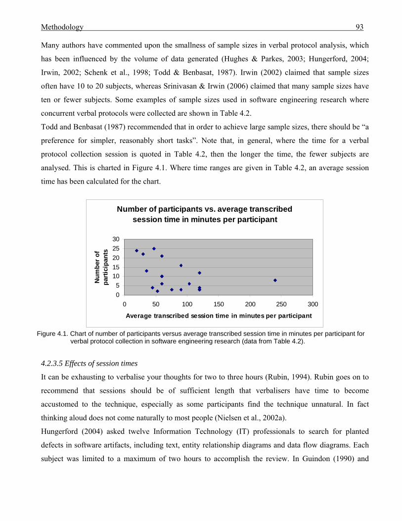
Methodology 93
Many authors have commented upon the smallness of sample sizes in verbal protocol analysis, which
has been influenced by the volume of data generated (Hughes & Parkes, 2003; Hungerford, 2004;
Irwin, 2002; Schenk et al., 1998; Todd & Benbasat, 1987). Irwin (2002) claimed that sample sizes
often have 10 to 20 subjects, whereas Srinivasan & Irwin (2006) claimed that many sample sizes have
ten or fewer subjects. Some examples of sample sizes used in software engineering research where
concurrent verbal protocols were collected are shown in Table 4.2.
Todd and Benbasat (1987) recommended that in order to achieve large sample sizes, there should be “a
preference for simpler, reasonably short tasks”. Note that, in general, where the time for a verbal
protocol collection session is quoted in Table 4.2, then the longer the time, the fewer subjects are
analysed. This is charted in Figure 4.1. Where time ranges are given in Table 4.2, an average session
time has been calculated for the chart.
Number of participants vs. average transcribed session time in minutes per participant
05
1015202530
0 50 100 150 200 250 300
Average transcribed session time in minutes per participant
Num
ber
of
parti
cipa
nts
Figure 4.1. Chart of number of participants versus average transcribed session time in minutes per participant for
verbal protocol collection in software engineering research (data from Table 4.2).
4.2.3.5 Effects of session times
It can be exhausting to verbalise your thoughts for two to three hours (Rubin, 1994). Rubin goes on to
recommend that sessions should be of sufficient length that verbalisers have time to become
accustomed to the technique, especially as some participants find the technique unnatural. In fact
thinking aloud does not come naturally to most people (Nielsen et al., 2002a).
Hungerford (2004) asked twelve Information Technology (IT) professionals to search for planted
defects in software artifacts, including text, entity relationship diagrams and data flow diagrams. Each
subject was limited to a maximum of two hours to accomplish the review. In Guindon (1990) and
Methodology 94
Guindon and Curtis (1988) the protocols collected for investigating software design were limited to two
hours.
Participants in this research will also have their sessions halted after two hours if they have not
completed the exercise, in order to prevent exhaustion.
4.2.3.6 Encoding of transcriptions
Although Ericsson and Simon (1984) believed that transcriptions of verbal protocols provide a good
record of subjects’ intentions, they were concerned that “Coding categories are derived from theories,
hence infect the encoded data with theoretical presuppositions” (Ericsson & Simon, 1993, p. 170).
Valid data needs to be analysed according to valid criteria.
To reduce the possibility of contamination, Ericsson and Simon (1993, p.276) recommend that the
encoding categories should be clear and explicit, and they should be defined prior to accepting input for
encoding. Todd and Benbasat (1987) also recommended that coding schemes be identified a priori in
order “to facilitate the efficient analysis of data”. The authors claimed that verbal protocol data tends to
be overwhelming and may be difficult to interpret without a coding scheme.
Bracewell and Breuleux (1994) addressed the research community involved with analysing concurrent
verbal protocols collected whilst people write, but the authors’ concerns could apply to many domains
for verbal protocol research. They ask: why get excited or have confidence in yet another coding scheme when (a) each scheme is complex, difficult
to master, and laborious to apply; (b) coding categories arise largely in an ad hoc manner from consideration
of the protocol rather than from a rational analysis of the cognitive processes required for the task; and (c) the
relationship among different schemes is unclear, and therefore a choice of one over another must be made as
much on intuition as principle? (Bracewell & Breuleux, 1994, p.56).
Task independent coding is recommended (Bracewell & Breuleux, 1994; Cabello & O’Hora, 2002) so
that the task does not dictate the coding scheme, and comparison among studies is eased. For the
current research the coding scheme to be applied to the protocols has been derived from cognitive
theories and empirical research, and is defined prior to protocol collection, ensuring its independence.
The main goal of subjects should be to modify the application. In order to achieve this, a number of
sub-goals must be achieved. Sub-goals for this experiment could include the acquiring of information
related to the problem or solution, or the creating of a strategy to investigate or solve the problem. A
goal may be achieved with the assistance of external representations such as UML diagrams, written
text, online Help or the Internet. The external representation may be read by a subject or created by the
subject during an episode (e.g. drawing a diagram or writing something on paper).
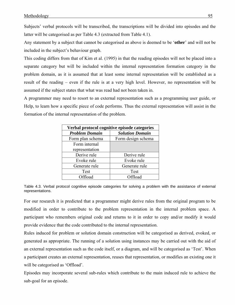
Methodology 95
Subjects’ verbal protocols will be transcribed, the transcriptions will be divided into episodes and the
latter will be categorised as per Table 4.3 (extracted from Table 4.1).
Any statement by a subject that cannot be categorised as above is deemed to be ‘other’ and will not be
included in the subject’s behaviour graph.
This coding differs from that of Kim et al. (1995) in that the reading episodes will not be placed into a
separate category but will be included within the internal representation formation category in the
problem domain, as it is assumed that at least some internal representation will be established as a
result of the reading – even if the rule is at a very high level. However, no representation will be
assumed if the subject states that what was read had not been taken in.
A programmer may need to resort to an external representation such as a programming user guide, or
Help, to learn how a specific piece of code performs. Thus the external representation will assist in the
formation of the internal representation of the problem.
Verbal protocol cognitive episode categories
Problem Domain Solution Domain Form plan schema Form design schema
Form internal representation
Derive rule Derive rule Evoke rule Evoke rule
Generate rule Generate rule Test Test
Offload Offload Table 4.3. Verbal protocol cognitive episode categories for solving a problem with the assistance of external representations. For our research it is predicted that a programmer might derive rules from the original program to be
modified in order to contribute to the problem representation in the internal problem space. A
participant who remembers original code and returns to it in order to copy and/or modify it would
provide evidence that the code contributed to the internal representation.
Rules induced for problem or solution domain construction will be categorised as derived, evoked, or
generated as appropriate. The running of a solution using instances may be carried out with the aid of
an external representation such as the code itself, or a diagram, and will be categorised as ‘Test’. When
a participant creates an external representation, reuses that representation, or modifies an existing one it
will be categorised as ‘Offload’.
Episodes may incorporate several sub-rules which contribute to the main induced rule to achieve the
sub-goal for an episode.
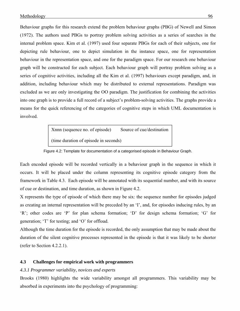
Methodology 96
Behaviour graphs for this research extend the problem behaviour graphs (PBG) of Newell and Simon
(1972). The authors used PBGs to portray problem solving activities as a series of searches in the
internal problem space. Kim et al. (1997) used four separate PBGs for each of their subjects, one for
depicting rule behaviour, one to depict simulation in the instance space, one for representation
behaviour in the representation space, and one for the paradigm space. For our research one behaviour
graph will be constructed for each subject. Each behaviour graph will portray problem solving as a
series of cognitive activities, including all the Kim et al. (1997) behaviours except paradigm, and, in
addition, including behaviour which may be distributed to external representations. Paradigm was
excluded as we are only investigating the OO paradigm. The justification for combining the activities
into one graph is to provide a full record of a subject’s problem-solving activities. The graphs provide a
means for the quick referencing of the categories of cognitive steps in which UML documentation is
involved. Xnnn (sequence no. of episode) Source of cue/destination
(time duration of episode in seconds)
Figure 4.2: Template for documentation of a categorised episode in Behaviour Graph.
Each encoded episode will be recorded vertically in a behaviour graph in the sequence in which it
occurs. It will be placed under the column representing its cognitive episode category from the
framework in Table 4.3. Each episode will be annotated with its sequential number, and with its source
of cue or destination, and time duration, as shown in Figure 4.2.
X represents the type of episode of which there may be six: the sequence number for episodes judged
as creating an internal representation will be preceded by an ‘I’, and, for episodes inducing rules, by an
‘R’; other codes are ‘P’ for plan schema formation; ‘D’ for design schema formation; ‘G’ for
generation; ‘T’ for testing; and ‘O’ for offload.
Although the time duration for the episode is recorded, the only assumption that may be made about the
duration of the silent cognitive processes represented in the episode is that it was likely to be shorter
(refer to Section 4.2.2.1).
4.3 Challenges for empirical work with programmers
4.3.1 Programmer variability, novices and experts
Brooks (1980) highlights the wide variability amongst all programmers. This variability may be
absorbed in experiments into the psychology of programming:
Methodology 97
Individual differences between the subjects are not analysed in detail; instead the experimenter compares the
differences between groups of subjects, looking for statistically significant variations in performance that were
expected to result from the treatment assigned to each group. (Blackwell et al., 2001).
However, the high degree of variability amongst programmers of similar background caused Sheil
(1981) to question experimental studies that used different participants for each condition, producing
large within-condition variations. The wide variation in programmer ability extends across experienced
programmers with equivalent backgrounds (Brooks, 1980). It was emphasised by Brooks (1980) that
programmers employed in industry are likely to gain greater experience than student programmers
whose studies extend for the same length of time. For our experiments we will be comparing the
performance of those with industry experience in OO programming with that of student programmers.
4.3.2 Concerns for program modification use in an experiment
For modification tasks, the specification of the modification can give information about the program
(Brooks, 1980) which aids comprehension.
In order to modify a program, it is assumed that the programmer must first understand it (Brooks
1980). However, for a modification it is not always necessary to understand the whole program. Only
the section(s) being changed need be understood. Brooks (1980) suggests that the use of multiple
modifications requires knowledge of a greater portion of the program.
Sheppard et al. (1979) found that adding new lines of code was more time-consuming for their subjects
who were asked to modify programs, than were deletions or substitutions.
For this research subjects will be required to carry out multiple modifications incorporating the writing
of new code. It is believed that many student programmers would lack the ability to write a non-trivial
program in two hours; thus the use of a modification introduces complexity without the high overhead
of time.
4.3.3 Program presentation for comprehension and modification
In their program comprehension experiment that required subjects to study small (26 to 57 statements)
Fortran programs then recall the code from memory, Sheppard et al. (1979) found that subjects
favoured mnemonic names (although Newsted, 1979, believed that a mnemonic name’s value may
depend on subjective differences among programmers). However, there was no evidence that the use of
mnemonic names helped the professional programmers to memorise the code. Although a common
method for testing comprehension (Pennington, 1987; Sheppard et al., 1979), recall for a short program
could be influenced by memorising rather than comprehension. With sufficient exercising any
Methodology 98
meaningless data may be remembered (Andriole & Adelman, 1995; Wǽrn, 1989). Although working
program code is not meaningless it may be memorised without comprehension.
Shaft (1997) modified the variable and paragraph names in her operational payroll program to make
them more meaningful for her subjects in her study to compare protocol data with responses to
comprehension questions as measures of comprehension of a computer program. Meaningful
mnemonic names will be used in the program code for this research.
Sheppard et al. (1979) found that the presence of a consistent structured layout in the code assisted
program modification. The applications for this research will be written in VB.NET which imposes its
own standard layout structure. The code will be commented where appropriate.
The challenge for empirical work is to provide a program vehicle that is of sufficient complexity to test
the questions being asked, and that could also be completed within manageable time and space for
experimental purposes. Brooks (1980) admonishes that: “At a time when several systems with more
than a million lines of source code exist, programs of less than 500 lines will usually turn out to be toy
or student programs”. Brooks (1980) goes on to mention that 50- to 100-line programs could be
equated with modules of larger systems, but acknowledges that the factors which affect success for
large programs differ from those for small programs, and suggests that all empirical work done up until
his paper was written was in need of replication using larger programs.
The current experiments will use non-trivial programs which require multiple modifications, including
the writing of new code. Applications will be chosen from a problem domain that it is anticipated will
be familiar to the subjects, and the number of lines of code will exceed 3500. Although these
applications will not contain millions of lines of code, they exceed the number of lines mentioned by
Brooks (1980) by at least a factor of seven and will thus be deemed non-trivial.
Brooks (1980) suggests that when investigating a new programming tool or technique the obvious
approach is to have subjects write code with and without the new technique. This is the approach
chosen for our investigation of performance. Each subject will be asked to modify two applications,
one with the aid of UML documentation, and one without.
4.4 Method procedures
4.4.1 Introduction
The researcher will act as monitor for a series of experiments to collect participants’ concurrent verbal
protocols whilst they modify two applications. One application will be provided with UML
documentation including a use case model and detailed templates for the main use cases, class diagram,
and sequence diagram(s) covering the main sections of the code to be modified. The documentation
Methodology 99
will consist of the most popular UML diagrams as discussed in Section 2.4.7 and confirmed in the
interviews (refer to Section 3.4.5).
For Owen et al.’s (2006) study of how software designers employ available documentation for
designing systems from existing components, the effects of knowledge transfer were limited by pairs of
subjects performing their tasks in the opposite order. In Anderson’s (1985) experiment the processing
order of silent and verbalisation conditions was randomised.
In the current study subjects may encounter for their first modification anyone of the following:
Application 1 with documents, Application 1 without documents, Application 2 with documents,
Application 2 without documents. The processing order will be cycled to ensure that all conditions are
experienced. However, the sequence in which the subjects carry out their work will be dependent upon
their availability.
Two types of data will be collected: performance data (the percentage of sub-goals achieved) from the
participants’ programming solutions, and cognitive behaviour data from their verbal protocols.
In Chapter 2 we found that a problem solver’s understanding of graphical models was influenced by
what that person had learned and experienced (Petre & Green, 1993). Thus if an experienced
programmer has learned to use UML documentation to aid in program comprehension and
development then that learned behaviour would be established as schemas in long-term memory (LTM)
that may be reactivated at a later date. However, the more experienced industry programmers should
also have more advanced program solution schemas established in LTM, thus reducing the need for
external stimulus. If both the students and participants with industry experience have learned to
program whilst using UML documentation, we can compare the subjects’ usage of UML
documentation to ascertain whether students make more use of the diagrams than those with greater
experience. The behaviour graphs will indicate how the diagrams are used.
4.4.2 The applications
The applications will be non-trivial, and exceed 3500 lines of code. They will, of necessity, be
different. If this was not so, subjects would be expected to solve the same problem twice. Once the
subject has solved a specific problem, internal schemas related to the problem should be established in
the subject’s LTM and thus the solving of the problem should be simplified with each attempt,
reducing the need for external representations.
The applications will be new for the subjects, will address problem domains familiar to the subjects,
and be written in the VB.NET OO programming language. An independent assessor will validate the
code.

Methodology 100
A series of sub-goals that must be achieved to complete each modification will be identified.
Performances will be compared according to the percentage of sub-goals achieved during a program
modification session.
UML documentation of use case models with supporting use case templates, class diagram and
sequence diagram(s) will be constructed for each application. As with all language the quality of the
writing is dependent upon the author. Any UML documentation used during this research was
previously validated by an independent assessor for accuracy and layout.
4.4.3 The subjects
Students will be recruited who attended the same third-year undergraduate course which covers
VB.NET programming and the UML. The performance of the student subjects will be compared with
that of programmers with more than two month’s industry experience in programming and who know
both UML and VB.NET.
Subjects will be given NZ$40 worth of gift vouchers of their choice for participating in each
modification.
4.4.4 The venue
All subjects will carry out the program modifications in the same office, chosen for its isolation from
noise and disturbance.
4.4.5 Session timing
The subjects will carry out each of the two modifications on different days. Each modification will
terminate either when the subject believes it is finished, or if two hours have elapsed.
4.4.6 Pre-session practice
Subjects should practice verbalising before the experiment begins (Boren & Ramey, 2000; Ericsson &
Simon, 1984; Rubin 1994).
Before starting their first modification, each subject will be asked to do a simple exercise to write a
program whilst practising ‘thinking aloud’. This exercise will be terminated when the monitor judges
that the subject is talking fluently whilst carrying out the task.
4.4.7 Monitor intervention

Methodology 101
If a subject fails to verbalise within a reasonable time (no more than 15-60 seconds [Ericsson & Simon,
1984]) the subject will be asked to “keep talking”. If, however, what the subject says is unclear, the
subject will be prompted, as described in Section 4.2.2.2.
4.4.8 Pre- and post-session questions
Participants will answer a pre-session questionnaire to collect gender, age, nationality, industry
experience, and performance details in courses in VB.NET and UML.
A post-session questionnaire will be recorded to gain insight into participants’ preferences for coding
and UML, and their impressions as to the complexity of the applications, and whether the first
modification influenced the second.
4.4.9 Pilot run
A pilot run will be carried out with student programmers recruited from the third-year undergraduate
course from which the student subjects will be sourced, to verify that the exercises can be completed
within the two hour time frame.
4.4.10 Transcription
The transcribed protocols will be divided into discrete episodes which will be categorised according to
the framework in Table 4.3. Both the monitor and an independent researcher will carry out this task so
that comparisons may be made and consensus obtained.
4.5 Conclusion
In order to investigate whether UML diagrams provide useful support for OO software programming,
data on programmer performance and cognitive behaviour will be collected from students and
programmers from industry whilst modifying two applications, one with UML documentation and one
without. The collection of both the verbal and program protocols should provide a more complete trace
of problem-solving behaviour (Rist, 1989).
The subjects’ performances in modifying an application with UML documentation will be compared
with their performance without the documentation. The criteria for comparison will be the percentage
of sub-goals achieved for the solution during a session.
To study programmers’ cognitive activities whilst modifying the programs, concurrent verbal protocols
will be collected for analysis. The aim is to discover if, for a non-trivial program, the UML diagrams
aid the subject

Methodology 102
1. in comprehending the program
2. (i) by forming a set with the programmer’s internal problem space
(ii) by forming a set with the programmer’s internal problem space to induce rules for
solving the problem
3. by providing a vehicle for offloading to free WM.
It is Neisser (1967, p.304) who reminds us that a satisfactory theory of higher mental processes can
only exist if we also have theories of motivation, personality and social interaction. Thus cognitive
processing alone does not fully explain a subject’s actions. Subjects for the current research will be
rewarded for participation, not for successful completion of each exercise. It is possible that individual
motivation could vary. There will be no social interaction once an experiment is underway, except for
possible probing from the monitor, which will be constrained to a minimum.
Individual preferences for UML will be solicited in the post-experiment questionnaire.
The results for performances will be reported in the next chapter, and the cognitive behaviour results
will follow in Chapter 6.
The Experiments and how the participants performed 103
Chapter 5: The Experiments and how the participants performed 5.0 Introduction
The aim of this research is to discover whether Unified Modelling Language (UML) documentation
can support the cognitive activities of software developers who are modifying a computer application
written in an object-oriented (OO) programming language. There is a continual demand for better,
more reliable methods of software development. If evidence is obtained of beneficial cognitive support
it could encourage more developers to use the modelling language to their advantage. It was Davis
(1989) who emphasised that perceived usefulness was a person’s subjective appraisal of performance
and may not reflect reality. Perceptions may affect inclinations to use a modelling language. Davis
found that although users’ perceptions of ease of use of a product influenced their perceptions of
usefulness, it was the users’ perceptions of a product’s usefulness that most strongly predicted a user’s
usage of that product. If this research demonstrates that UML aids cognition, it may act as a tool to
alter perceptions.
This chapter describes how the research was carried out in order to answer the research questions posed
in Chapter 4. Subjects were required to modify two non-trivial applications written in VB.NET, one of
which was supplied with UML documentation. This chapter describes the applications that were
modified, the modification requirements, the UML documentation that was provided, the subjects, and
the procedures.
The chapter will also apply the subjects’ modification achievements to answer the first research
question from Chapter 4 concerning participant performance (Section 4.1.1):
A1. When a programmer solves a program modification problem does the provision of UML
documentation improve performance?
Performance will be measured as the percentage of sub-goals a subject achieves during a modification
session.
Concurrent verbal protocols were collected whilst the subjects modified the applications. The protocols
were transcribed and encoded to document the cognitive steps undertaken by the participants. The
research questions related to that cognitive behaviour will be answered in the next chapter.
The justification for including performance data in research into cognitive support is that when a
programmer modifies a non-trivial application a problem is being solved. Problem solution is a
The Experiments and how the participants performed 104
cognitive activity (Newell & Simon, 1972). If a subject is more successful in performance when
assisted by UML documentation then that documentation can be assumed to provide cognitive support.
It is possible that UML documentation does supply cognitive support but does not improve
performance. This would occur if the use of UML was equally as time-consuming as alternative
sources of assistance for solving a software development problem. Possible alternative external
representation sources include program code, integrated development environments (IDE), Help, or the
Internet. The aim for investigating performance is to test the extent of support that UML may provide.
It is also possible that use of UML may affect the quality of a programmer’s solution. Quality is an
aspect of software development that could be researched in the future.
This chapter is composed as follows:
Section 5.1 describes the applications, with Section 5.2 describing the requested modifications.
Descriptions of the UML diagrams, the subjects and the experiments follow in the next three sections.
The performance results are presented in Section 5.6, followed in Section 5.7 by a discussion relating
the results to the research question. The chapter will be concluded in Section 5.8.
5.1 The applications
One of the purposes of the UML is to document OO systems (Booch et al., 1999, p.11), and thus it was
necessary to select an appropriate OO language in which to develop the applications for the research.
Two computer applications were developed by the researcher using the OO programming language
VB.NET, which provides well-structured, text-based code. The choice of language was influenced by
the fact that there was a local third-year business faculty undergraduate course in systems analysis and
design which incorporated UML diagramming and VB.NET programming, and which provided a
potential source for subjects.
The two applications were written by the author and checked by an independent research assistant to
ensure there were no errors. To ensure that the coding conventions and programming structures used
for the applications were familiar to the subjects, the author, who had not previously used VB.NET,
attended the same second-year tertiary course in VB.NET that had been passed by all but three of the
subjects (05, 16 and 21), prior to coding the applications. That VB.NET course did not include
diagrammatic modelling. Subjects 05 and 21 had attended alternative classes in OO programming in
the same tertiary department, and Subject 16 had two years industry experience using VB.NET.
All but two subjects had studied and passed the third-year undergraduate course in VB.NET and UML,
mentioned previously as a prospective source for participants. The two exceptions (Subjects 16 and 20)
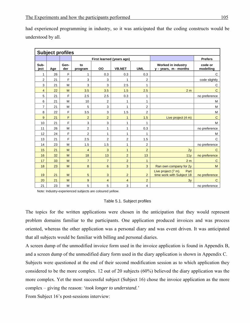
The Experiments and how the participants performed 105
had experienced programming in industry, so it was anticipated that the coding constructs would be
understood by all.
Subject profiles
First learned (years ago) Prefers
Sub-ject Age
Gen-der
to program OO VB.NET UML
Worked in industry y – years, m - months
code or modelling
1 26 F 1 0.3 0.3 0.3 C 2 21 F 3 3 1 2 code slightly 3 21 M 3 3 2.5 1 C 4 22 M 3.5 3.5 1.5 2.5 2 m C 5 21 F 2.5 2.5 0.3 1 no preference 6 21 M 10 2 1 1 M 7 21 M 5 3 1 2 M 8 22 F 3.5 3 1.5 2 M 9 21 F 2 2 1 1.5 Live project (4 m) C
10 21 F 3 3 1 1 M 11 26 M 2 1 1 0.3 no preference 12 24 F 2 1 1 1 M 13 21 F 2.5 2 2 1.5 C 14 23 M 1.5 1.5 1 2 no preference 15 21 M 4 3 1 2 2y C 16 32 M 18 13 2 13 11y no preference 17 33 M 7 7 2 1 2 m C 18 23 M 8 6 3 3 Ran own company for 2y M
19 21 M 5 3 2 2 Live project (7 m). Part time work with Subject 18 no preference
20 21 M 9 4 4 2 3y C 21 23 M 5 5 3 4 no preference
Note: Industry-experienced subjects are coloured yellow.
Table 5.1. Subject profiles The topics for the written applications were chosen in the anticipation that they would represent
problem domains familiar to the participants. One application produced invoices and was process
oriented, whereas the other application was a personal diary and was event driven. It was anticipated
that all subjects would be familiar with billing and personal diaries.
A screen dump of the unmodified invoice form used in the invoice application is found in Appendix B,
and a screen dump of the unmodified diary form used in the diary application is shown in Appendix C.
Subjects were questioned at the end of their second modification session as to which application they
considered to be the more complex. 12 out of 20 subjects (60%) believed the diary application was the
more complex. Yet the most successful subject (Subject 16) chose the invoice application as the more
complex – giving the reason: ‘took longer to understand.’
From Subject 16’s post-sessions interview:

The Experiments and how the participants performed 106
Monitor: ‘The diary was easier to find your way around?’
Subject 16: ‘Yep. Then that might be because we had the UML to give me an entry point into it.’
Subjects 06 and 19 believed that the diary application had more classes. In fact the invoice application
had two more classes and slightly more code.
During the pilot test run, two of the three volunteers completed their modifications of both applications.
As the pilot run modifiers were sourced from the same third-year course as the students who would
participate in the experiments, it was assumed that the applications would not be too difficult for the
student subjects.
5.2 The modifications
The invoice modification required the addition of Goods and Services Tax (GST) calculations, the
display of the calculated GST on the invoice form for invoice item and totals, and the inclusion of GST
in the printed invoice. Not only was the gst calculation done for new products added to the invoice, but
adjustments had to be made to the gst totals when an invoice item was deleted, and to the invoice item
gst value when a product was added that already appeared on the invoice. All the existing steps
required to create an invoice were fully documented in the use case narrative ‘Create Invoice’ which
could be used by a subject to learn about those functions of the application. To solve the problem it was
necessary for the modifier to identify a GST class which existed in the application and discover how it
was related to the customer for the invoice. This information was obtainable directly from the class
diagram. The placement of the changes could be identified in the use case narratives and sequence
diagrams. The use case narratives for ‘Add Customer’ and ‘Add Product’ were provided in case a
subject wished to create new test data.
The diary application enabled users to record appointments with details. Subjects could learn how to
add, change or delete an appointment by reading the use case narratives. The application was required
to be modified so that a set of one to three reminders could be added to an appointment, if desired.
Whilst the application was running, on the day an appointment was due, and prior to the time of that
appointment, reminder messages for the imminent appointments were to be triggered. A class of
reminder sets existed in the application. The modifier had to discover that existing ReminderSet class
and relate that to the Appointment class. The Appointment and ReminderSet classes were clearly
documented on the class diagram. Use case narratives were supplied for ‘Add Appointment’, ‘Change
Appointment’, and ‘Delete appointments’, and a sequence diagram for ‘Add Appointment’ so that
subjects could plan where to insert their changes.

The Experiments and how the participants performed 107
For both applications the use case model provided an introductory high level overview of the functions
of the applications, and set the context for their use case descriptions (narratives).
Copies of the documented modification requirements and UML documentation may be found in the
Appendices. The invoice application documentation is found in Appendix D, and the diary application
documentation in Appendix E.
Subjects were questioned at the end of their second modification session as to which modification they
considered to be the more complex. 13 out of 20 subjects (65%) believed the diary modification was
the more complex, giving reasons of: ‘Because relationship between classes was not visible.’ ‘More
classes, methods, had more features.’ ‘Harder to work out.’ ‘Required modification of objects.’ In fact
both applications required modification of objects.
17 out of 20 subjects (85%) believed that doing the first modification assisted them with doing the
second. Reasons given included: there was similarity of coding constructs and application layout, and
knowledge of how to program in VB.NET was refreshed whilst completing the first modification.
Coding constructs encountered in the first application that were specifically mentioned as assisting in
the second, were xml files and collection classes. Both those topics were included in the second-year
tertiary course in VB.NET that all but three subjects had passed. All coding constructs used within the
applications were covered during that course. A summary of subjects’ comments is found in Table 5.2.
5.3 The UML documentation
As described in Section 4.1.1 the UML notation selected for the experiments was based upon industry
usage. The supplied diagrams documented the unmodified applications. According to industry custom
only the most important use case descriptions and sequence diagrams were included. Within the
documentation for each application was a use case model accompanied by supporting use case
descriptions written in the format specified by Cockburn (1997). Only descriptions that supported the
main use cases, including those affected by the modifications, were provided. Class and sequence
diagrams were also supplied. The sequence diagrams documented the interactions for the main use
cases that were affected by the modifications.
The UML version 1.X diagrams were drawn using Visio Enterprise Architect. The use case
descriptions were written in MS Word. Copies of the UML diagrams and use case descriptions for the
unmodified invoice application may be found with the invoice application documentation in Appendix
D. The UML diagrams and use case descriptions for the unmodified diary application may be found
with the diary application documentation in Appendix E.
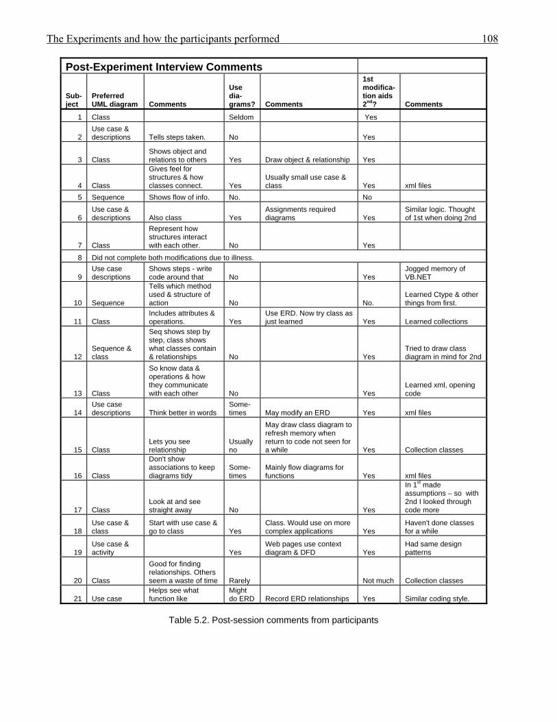
The Experiments and how the participants performed 108
Post-Experiment Interview Comments
Sub- ject
Preferred UML diagram Comments
Use dia-grams? Comments
1st modifica-tion aids 2nd? Comments
1 Class Seldom Yes
2 Use case & descriptions Tells steps taken. No Yes
3 Class Shows object and relations to others Yes Draw object & relationship Yes
4 Class
Gives feel for structures & how classes connect. Yes
Usually small use case & class Yes xml files
5 Sequence Shows flow of info. No. No
6 Use case & descriptions Also class Yes
Assignments required diagrams Yes
Similar logic. Thought of 1st when doing 2nd
7 Class
Represent how structures interact with each other. No Yes
8 Did not complete both modifications due to illness.
9 Use case descriptions
Shows steps - write code around that No Yes
Jogged memory of VB.NET
10 Sequence
Tells which method used & structure of action No No.
Learned Ctype & other things from first.
11 Class Includes attributes & operations. Yes
Use ERD. Now try class as just learned Yes Learned collections
12 Sequence & class
Seq shows step by step, class shows what classes contain & relationships No Yes
Tried to draw class diagram in mind for 2nd
13 Class
So know data & operations & how they communicate with each other No Yes
Learned xml, opening code
14 Use case descriptions Think better in words
Some-times May modify an ERD Yes xml files
15 Class Lets you see relationship
Usually no
May draw class diagram to refresh memory when return to code not seen for a while Yes Collection classes
16 Class
Don't show associations to keep diagrams tidy
Some-times
Mainly flow diagrams for functions Yes xml files
17 Class Look at and see straight away No Yes
In 1st made assumptions – so with 2nd I looked through code more
18 Use case & class
Start with use case & go to class Yes
Class. Would use on more complex applications Yes
Haven't done classes for a while
19 Use case & activity Yes
Web pages use context diagram & DFD Yes
Had same design patterns
20 Class
Good for finding relationships. Others seem a waste of time Rarely Not much Collection classes
21 Use case Helps see what function like
Might do ERD Record ERD relationships Yes Similar coding style.
Table 5.2. Post-session comments from participants
The Experiments and how the participants performed 109
It is common practice to exclude the collection classes from a class diagram. However, the collection
classes’ inheritance hierarchies and relationships were included in the applications’ class diagrams to
provide full information for the participants.
5.4 The subjects
All subjects were students recruited within the University of Auckland, with the exception of Subjects
16, 17, 18, and 19, who worked in software development related jobs at the University and thus were
assigned to the industry-experienced group. Subjects participated on a voluntary basis and were
rewarded with gift vouchers of their choice to the value of $80 when both modifications had been
attempted.
The participants’ profiles are recorded in Table 5.1. The eight subjects with industry-related experience
in programming are coloured yellow in that table. All non-industry-experienced subjects had passed the
third-year tertiary course in systems analysis and design that included UML modelling and VB.NET. In
fact all but Subjects 16 and 20 had passed that course, although not all during the same semester.
Subjects 1 through 15 attended and passed the same occurrence of the third-year course and gave
permission for their course marks to be viewed. The aim was to use student subjects with similar
learning experiences in VB.NET and UML. However, Subjects 04, 09, and 15 were found to have had
industry experience which implied that they had more frequently exercised their OO programming
skills than their non-industry-experienced peers and thus they were placed with the industry-
experienced group.
Twenty subjects modified one application without descriptive UML documents. The same 20 subjects
plus one extra subject (Subject 08) modified one application for which UML documents had been
supplied. Subject 08 did not complete her second modification due to illness.
5.5 The experiments.
Subjects were requested to modify each of the two computer applications written in the OO
programming language VB.NET, one application being accompanied by Unified Modeling Language
(UML) diagrams and supporting use case descriptions, the latter based on the template from Cockburn,
(1997).
The sequence in which subjects carried out the modifications was rotated to ensure an even distribution
of which application was encountered first and which was accompanied by UML documents. The
sequence of attendance at sessions depended upon the availability of the subjects.
The Experiments and how the participants performed 110
A3 paper, pencils and rubber were supplied so that any ‘offloading’ of information could be recorded.
Subjects were advised that they could write on any supplied documentation.
All experiments were conducted at a desk in an office situated on a floor that required key access, so
that unexpected interruptions and noise were avoided.
Concurrent verbal protocols were collected for both modifications for each participant. Ericsson and
Simon (1984) had concluded that simultaneous verbal protocols should not change the sequence or
structure of problem solving, provided that subjects were not required to explain their actions as they
performed. The protocols were collected and analysed to find the sequence and category of cognitive
steps applied by the participants whilst modifying the applications. Cognitive steps included the
formation of internal representations and induced rules (productions) for modifying the applications,
and the distributed cognition between a participant’s internal problem space and UML documentation.
Each modification ended when either the subject believed it was finished, or after two hours had
elapsed, whichever came first.
All participants were given a small exercise for practice in ‘thinking aloud’ prior to attempting their
first experiment, as recommended by Rubin (1994). The details of their experience in VB.NET and OO
development, pass rates in their courses incorporating those topics, their age, and gender, were
collected prior to the start of the experiment. Their perceptions of the applications, modifications, and
use of UML were recorded following completion of both modifications.
A pilot run was conducted, sourcing subjects who had passed the third-year undergraduate course in
systems analysis and design which included UML and VB.NET one semester prior to the occurrence of
that course from which the bulk of the main experiment subjects were sourced. The number of pilot
subjects depended upon the number of volunteers. Each of three pilot subjects modified the two
applications. Two of the pilot subjects completed both the modifications in less than two hours,
indicating that the time limit was reasonable.
The next section reports on the performances of the participants in the experiments.
5.6 Performance results for participants.
A set of sub-goals which must be achieved to successfully complete each modification was established
for each application so that a participant’s success could be quantified as to the number of sub-goals
achieved. Sub-goals related to simple layout and formatting were excluded as they were deemed to be
unaffected by the use of UML documentation.
Subjects 04, 07, 15, 16, and 20, all industry-experienced except for 07, claimed to have completed the
exercise involving UML diagrams in less than the allocated two hours. Despite their claims of success,

The Experiments and how the participants performed 111
further testing by the researcher identified errors which generally were easily corrected. Subject 16 was
the only subject to successfully complete the diary modification. He had a small error in that he had
assumed that there would always be a person/organisation for each appointment. This was not the case,
but had not been explicit in the instructions so was not included as an error.
In his post-sessions comments Subject 16 had stated: ‘if I had sort of a question on what I was actually
doing I’d probably more stop what I was doing and then go ask the user straight away.’ Subject 16 did
not verify requirements with the monitor.
Invoice Application – sub-goals Goal Description
1 derive customer's gst type to use
2 load gst values in invoice form or equivalent
3 extract gst percentage from gst class
4 correctly calc gst for 1st invoice
5 correctly calc gst, totals for successive invoices
6 add new gst column
7 display gst in new column
8 add gst value to total invoice gst & display
9 add gst to total amount owing & display
10 calc revised gst total, ext total after delete
11 add gst to value when adding extra qty & display
12 gst total correct after add qty to existing qty
13 total amount owing is correct after add to qty
14 add gst% attribute or equivalent to invoice
15 store gst % or equivalent in invoice object
16 add headings for new printed values
17 add gst total to printed invoice
18 add gst total to total amount owing & print
Table 5.3. Sub-goals to be achieved to complete the invoice modification.
No participant provided a completely correct solution to the invoice modification, although Subject 16
had only layout and formatting errors which were not included in the percentage-sub-goals-achieved
calculation.
The sub-goals identified for the invoice application are listed in Table 5.3, and those for the diary
application in Table 5.4.
Subjects had the choice of sourcing details and assistance from the Visual Studio integrated
development environment (IDE) or the VB.NET programming code, or from the UML diagrams, when
supplied. They could search the Internet for help, if necessary.
Evidence of ‘offloading’, either onto the printed documentation, or onto the A3 pad, was collected, and
will be commented on in the next chapter.

The Experiments and how the participants performed 112
Diary Application – sub-goals Goal Description
1 add reminder type attribute to appointment
2 load reminders xml file into memory
3 add means of selecting reminder on screen
4 store reminder with appointment when create
5 display reminder when created
6 clear reminder when clear appointment
7 store reminder with appointment when change
8 display reminder when change
9 display reminder on appointment when reload
10 delete reminder type from appointment
11 create reminder message to be displayed
12 check appointment & display reminder at start
13 at start only check today's appointments
14 check & display reminder at end
15 at end check today's appointments only
16 check & display reminder every 30/60 min
17 only today's appointments checked by timer
18 message activates if <= appointment time
Table 5.4. Sub-goals to be achieved to complete the diary modification. Each subject’s solution was tested to find which sub-goals were achieved. Table 5.5 records the sub-
goals achieved by the subjects in the invoice modification. Table 5.6 records the sub-goals achieved by
the subjects in the diary modification.
For example: Subject 09 in the diary application (Table 5.6) successfully achieved one sub-goal – that
of loading the reminders collection into memory (sub-goal 2), and created half of the message (sub-
goal 11), to give her a total of 1.5 sub-goals achieved. The totals from the two tables (5.5 and 5.6) are
displayed in Table 5.7 to illustrate the subjects’ percentage success in achieving sub-goals in both
modifications. Subject 09’s total of 1.5 for the diary application transforms into 8.3% of the possible 18
sub-goals.
In Table 5.7, nine subjects achieved 40% or more of the sub-goals for the invoice application, while for
the diary application seven achieved 40% or higher. This could indicate that for a number of the
subjects the diary modification was more difficult. It corresponds to the 65% of subjects’ perceptions
that the diary modification was more complex, as reported in Section 5.2.
Subjects who modified the invoice application by hard-coding the gst percentage into the program code
instead of deriving the gst percentage (which they had been advised could change over time) from the
GST object, are indicated in Table 5.5. By using the hard-coded percentage in their calculations they
were able to progress and attain further sub-goals, whereas some subjects were held up by attempting
to derive the gst percentage correctly.
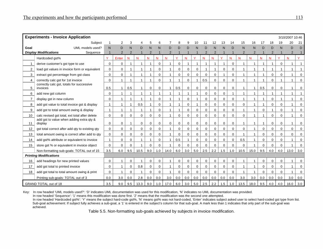
The experiments and how the participants performed 113
Experiments - Invoice Application 3/10/2007 10:46 Subject 1 2 3 4 5 6 7 8 9 10 11 12 13 14 15 16 17 18 19 20 21 Goal UML models used? N D N D N N D D D N D N N D N N D D N D D Display Modifications Sequence 1 2 2 1 2 1 2 1 1 1 2 2 1 1 2 2 1 2 1 2 1
Hardcoded gst% Y Enter N N N N N Y N Y N N Y N N N N N Y N Y
1 derive customer's gst type to use 0 0 1 1 1 0 1 0 1 1 1 1 1 0 1 1 1 1 0 1 1
2 load gst values in invoice form or equivalent 0 0 1 1 1 0 1 0 0 0 1 1 0 0 1 1 1 1 1 1 1
3 extract gst percentage from gst class 0 0 1 1 1 0 1 0 0 0 0 0 1 0 1 1 1 0 0 1 0
4 correctly calc gst for 1st invoice 0 1 1 1 1 0 1 1 0 1 0.5 0 0 0 1 1 1 0 1 1 0
5 correctly calc gst, totals for successive invoices 0.5 1 0.5 1 0 0 1 0.5 0 0 0 0 0 0 1 1 0.5 0 0 1 0
6 add new gst column 0 1 1 1 1 1 1 1 1 1 0 0 0 1 1 1 1 1 1 1 1
7 display gst in new column 0 1 1 1 1 0 1 1 0 1 0 0 0 0 1 1 1 0 1 1 0
8 add gst value to total invoice gst & display 1 1 1 0.5 1 0 1 1 0 1 0 0 0 0 0 1 1 0 0 1 0
9 add gst to total amount owing & display 1 1 1 1 1 0 1 1 0 0 0 0 0 0 1 1 0 1 0 1 0
10 calc revised gst total, ext total after delete 0 0 0 0 0 0 1 0 0 0 0 0 0 0 0 1 1 0 0 1 0
11 add gst to value when adding extra qty & display 0 0 1 0 0 0 0 0 0 0 0 0 0 0 1 1 1 0 0 1 0
12 gst total correct after add qty to existing qty 0 0 0 0 0 0 1 0 0 0 0 0 0 0 0 1 0 0 0 0 0
13 total amount owing is correct after add to qty 0 0 0 0 0 0 1 0 0 0 0 0 0 0 1 1 0 0 0 0 0
14 add gst% attribute or equivalent to invoice 1 0 0 1 1 0 1 0.5 1 0 0 0 0 0 0.5 1 0 0 0 1 0
15 store gst % or equivalent in invoice object 0 0 0 1 0 0 1 0 0 0 0 0 0 0 0 1 0 0 0 1 0
Non-formatting sub-goals: TOTAL out of 15 3.5 6.0 9.5 10.5 9.0 1.0 14.0 6.0 3.0 5.0 2.5 2.2 1.5 1.0 10.5 15.0 9.5 4.0 4.0 13.0 3.0 Printing Modifications
16 add headings for new printed values 0 1 0 1 0 0 1 0 0 0 0 0 0 0 1 1 0 0 0 1 0
17 add gst total to printed invoice 0 1 0 0.8 0 0 1 0 0 0 0 0 0 0 1 1 0 0 0 1 0
18 add gst total to total amount owing & print 0 1 0 1 0 0 1 0 0 0 0 0 0 0 1 1 0 0 0 1 0
Printing sub-goals: TOTAL out of 3 0.0 3.0 0.0 2.8 0.0 0.0 3.0 0.0 0.0 0.0 0.0 0.0 0.0 0.0 3.0 3.0 0.0 0.0 0.0 3.0 0.0
GRAND TOTAL out of 18 3.5 9.0 9.5 13.3 9.0 1.0 17.0 6.0 3.0 5.0 2.5 2.2 1.5 1.0 13.5 18.0 9.5 4.0 4.0 16.0 3.0 Key: In row headed ‘UML models used?’: ‘D’ indicates UML documentation was used for this modification, ‘N’ indicates no UML documentation was provided.
In row headed ‘Sequence’: ‘1’ means this modification was done first. ‘2’ means that the modification was the second one attempted. In row headed ‘Hardcoded gst%’: ‘Y’ means the subject hard-code gst%, ‘N’ means gst% was not hard-coded, ‘Enter’ indicates subject asked user to select hard-coded gst type from list. Sub-goal achievement: If subject fully achieves a sub-goal, a ‘1’ is entered in the subject’s column for that sub-goal. A mark less than 1 indicates that only part of the sub-goal was achieved.
Table 5.5. Non-formatting sub-goals achieved by subjects in invoice modification.
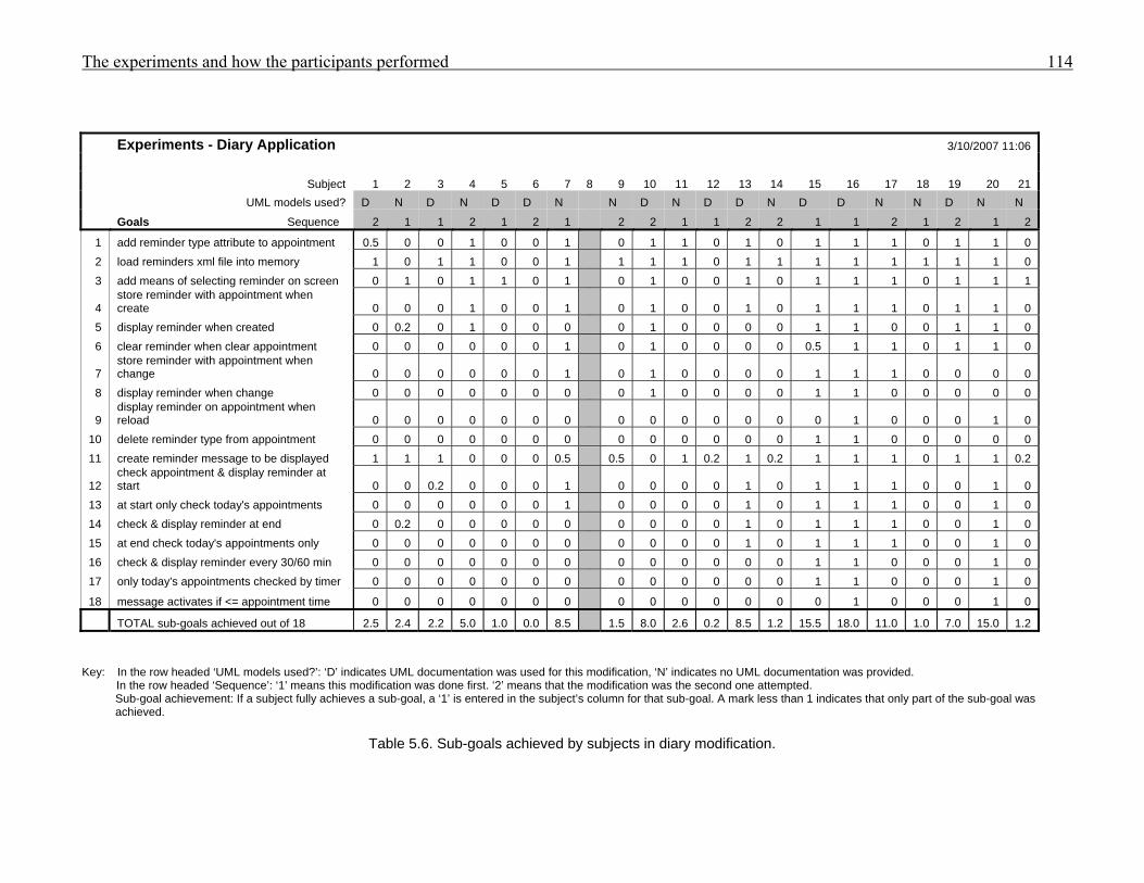
The experiments and how the participants performed 114
Experiments - Diary Application 3/10/2007 11:06
Subject 1 2 3 4 5 6 7 8 9 10 11 12 13 14 15 16 17 18 19 20 21 UML models used? D N D N D D N N D N D D N D D N N D N N
Goals Sequence 2 1 1 2 1 2 1 2 2 1 1 2 2 1 1 2 1 2 1 2
1 add reminder type attribute to appointment 0.5 0 0 1 0 0 1 0 1 1 0 1 0 1 1 1 0 1 1 0 2 load reminders xml file into memory 1 0 1 1 0 0 1 1 1 1 0 1 1 1 1 1 1 1 1 0 3 add means of selecting reminder on screen 0 1 0 1 1 0 1 0 1 0 0 1 0 1 1 1 0 1 1 1
4 store reminder with appointment when create 0 0 0 1 0 0 1 0 1 0 0 1 0 1 1 1 0 1 1 0
5 display reminder when created 0 0.2 0 1 0 0 0 0 1 0 0 0 0 1 1 0 0 1 1 0 6 clear reminder when clear appointment 0 0 0 0 0 0 1 0 1 0 0 0 0 0.5 1 1 0 1 1 0
7 store reminder with appointment when change 0 0 0 0 0 0 1 0 1 0 0 0 0 1 1 1 0 0 0 0
8 display reminder when change 0 0 0 0 0 0 0 0 1 0 0 0 0 1 1 0 0 0 0 0
9 display reminder on appointment when reload 0 0 0 0 0 0 0 0 0 0 0 0 0 0 1 0 0 0 1 0
10 delete reminder type from appointment 0 0 0 0 0 0 0 0 0 0 0 0 0 1 1 0 0 0 0 0 11 create reminder message to be displayed 1 1 1 0 0 0 0.5 0.5 0 1 0.2 1 0.2 1 1 1 0 1 1 0.2
12 check appointment & display reminder at start 0 0 0.2 0 0 0 1 0 0 0 0 1 0 1 1 1 0 0 1 0
13 at start only check today's appointments 0 0 0 0 0 0 1 0 0 0 0 1 0 1 1 1 0 0 1 0 14 check & display reminder at end 0 0.2 0 0 0 0 0 0 0 0 0 1 0 1 1 1 0 0 1 0 15 at end check today's appointments only 0 0 0 0 0 0 0 0 0 0 0 1 0 1 1 1 0 0 1 0 16 check & display reminder every 30/60 min 0 0 0 0 0 0 0 0 0 0 0 0 0 1 1 0 0 0 1 0 17 only today's appointments checked by timer 0 0 0 0 0 0 0 0 0 0 0 0 0 1 1 0 0 0 1 0
18 message activates if <= appointment time 0 0 0 0 0 0 0 0 0 0 0 0 0 0 1 0 0 0 1 0
TOTAL sub-goals achieved out of 18 2.5 2.4 2.2 5.0 1.0 0.0 8.5 1.5 8.0 2.6 0.2 8.5 1.2 15.5 18.0 11.0 1.0 7.0 15.0 1.2 Key: In the row headed ‘UML models used?’: ‘D’ indicates UML documentation was used for this modification, ‘N’ indicates no UML documentation was provided.
In the row headed ‘Sequence’: ‘1’ means this modification was done first. ‘2’ means that the modification was the second one attempted. Sub-goal achievement: If a subject fully achieves a sub-goal, a ‘1’ is entered in the subject’s column for that sub-goal. A mark less than 1 indicates that only part of the sub-goal was achieved.
Table 5.6. Sub-goals achieved by subjects in diary modification.
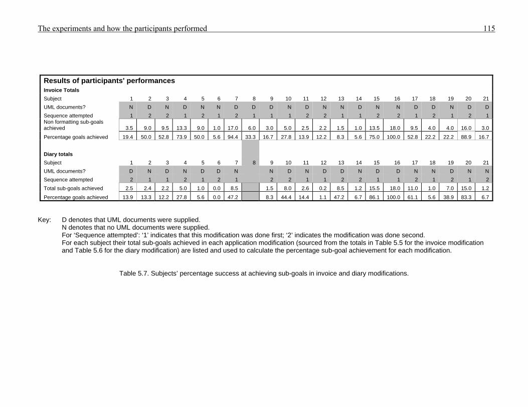
The experiments and how the participants performed 115
Results of participants' performances
Invoice Totals Subject 1 2 3 4 5 6 7 8 9 10 11 12 13 14 15 16 17 18 19 20 21 UML documents? N D N D N N D D D N D N N D N N D D N D D Sequence attempted 1 2 2 1 2 1 2 1 1 1 2 2 1 1 2 2 1 2 1 2 1 Non formatting sub-goals achieved 3.5 9.0 9.5 13.3 9.0 1.0 17.0 6.0 3.0 5.0 2.5 2.2 1.5 1.0 13.5 18.0 9.5 4.0 4.0 16.0 3.0
Percentage goals achieved 19.4 50.0 52.8 73.9 50.0 5.6 94.4 33.3 16.7 27.8 13.9 12.2 8.3 5.6 75.0 100.0 52.8 22.2 22.2 88.9 16.7 Diary totals Subject 1 2 3 4 5 6 7 8 9 10 11 12 13 14 15 16 17 18 19 20 21 UML documents? D N D N D D N N D N D D N D D N N D N N Sequence attempted 2 1 1 2 1 2 1 2 2 1 1 2 2 1 1 2 1 2 1 2 Total sub-goals achieved 2.5 2.4 2.2 5.0 1.0 0.0 8.5 1.5 8.0 2.6 0.2 8.5 1.2 15.5 18.0 11.0 1.0 7.0 15.0 1.2
Percentage goals achieved 13.9 13.3 12.2 27.8 5.6 0.0 47.2 8.3 44.4 14.4 1.1 47.2 6.7 86.1 100.0 61.1 5.6 38.9 83.3 6.7 Key: D denotes that UML documents were supplied.
N denotes that no UML documents were supplied. For ‘Sequence attempted’: ‘1’ indicates that this modification was done first; ‘2’ indicates the modification was done second. For each subject their total sub-goals achieved in each application modification (sourced from the totals in Table 5.5 for the invoice modification and Table 5.6 for the diary modification) are listed and used to calculate the percentage sub-goal achievement for each modification.
Table 5.7. Subjects’ percentage success at achieving sub-goals in invoice and diary modifications.
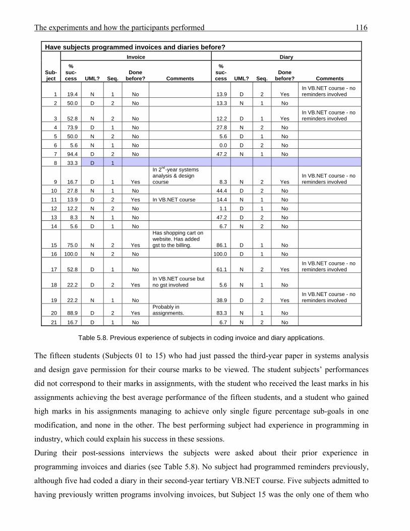
The experiments and how the participants performed 116
Have subjects programmed invoices and diaries before?
Sub-ject
Invoice Diary %
suc-cess UML? Seq.
Done before? Comments
% suc-cess UML? Seq.
Done before? Comments
1 19.4 N 1 No 13.9 D 2 Yes In VB.NET course - no reminders involved
2 50.0 D 2 No 13.3 N 1 No
3 52.8 N 2 No 12.2 D 1 Yes In VB.NET course - no reminders involved
4 73.9 D 1 No 27.8 N 2 No 5 50.0 N 2 No 5.6 D 1 No 6 5.6 N 1 No 0.0 D 2 No 7 94.4 D 2 No 47.2 N 1 No 8 33.3 D 1
9 16.7 D 1 Yes
In 2nd-year systems analysis & design course 8.3 N 2 Yes
In VB.NET course - no reminders involved
10 27.8 N 1 No 44.4 D 2 No 11 13.9 D 2 Yes In VB.NET course 14.4 N 1 No 12 12.2 N 2 No 1.1 D 1 No 13 8.3 N 1 No 47.2 D 2 No 14 5.6 D 1 No 6.7 N 2 No
15 75.0 N 2 Yes
Has shopping cart on website. Has added gst to the billing. 86.1 D 1 No
16 100.0 N 2 No 100.0 D 1 No
17 52.8 D 1 No 61.1 N 2 Yes In VB.NET course - no reminders involved
18 22.2 D 2 Yes In VB.NET course but no gst involved 5.6 N 1 No
19 22.2 N 1 No 38.9 D 2 Yes In VB.NET course - no reminders involved
20 88.9 D 2 Yes Probably in assignments. 83.3 N 1 No
21 16.7 D 1 No 6.7 N 2 No
Table 5.8. Previous experience of subjects in coding invoice and diary applications. The fifteen students (Subjects 01 to 15) who had just passed the third-year paper in systems analysis
and design gave permission for their course marks to be viewed. The student subjects’ performances
did not correspond to their marks in assignments, with the student who received the least marks in his
assignments achieving the best average performance of the fifteen students, and a student who gained
high marks in his assignments managing to achieve only single figure percentage sub-goals in one
modification, and none in the other. The best performing subject had experience in programming in
industry, which could explain his success in these sessions.
During their post-sessions interviews the subjects were asked about their prior experience in
programming invoices and diaries (see Table 5.8). No subject had programmed reminders previously,
although five had coded a diary in their second-year tertiary VB.NET course. Five subjects admitted to
having previously written programs involving invoices, but Subject 15 was the only one of them who
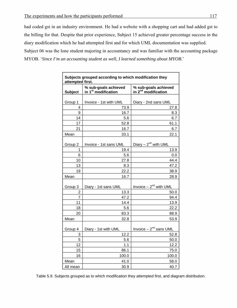
The experiments and how the participants performed 117
had coded gst in an industry environment. He had a website with a shopping cart and had added gst to
the billing for that. Despite that prior experience, Subject 15 achieved greater percentage success in the
diary modification which he had attempted first and for which UML documentation was supplied.
Subject 06 was the lone student majoring in accountancy and was familiar with the accounting package
MYOB. ‘Since I’m an accounting student as well, I learned something about MYOB.’
Subjects grouped according to which modification they attempted first.
Subject % sub-goals achieved in 1st modification
% sub-goals achieved in 2nd modification
Group 1 Invoice - 1st with UML Diary - 2nd sans UML 4 73.9 27.8 9 16.7 8.3
14 5.6 6.7 17 52.8 61.1 21 16.7 6.7
Mean 33.1 22.1
Group 2 Invoice - 1st sans UML Diary – 2nd with UML 1 19.4 13.9 6 5.6 0.0
10 27.8 44.4 13 8.3 47.2 19 22.2 38.9
Mean 16.7 28.9
Group 3 Diary - 1st sans UML Invoice – 2nd with UML 2 13.3 50.0 7 47.2 94.4
11 14.4 13.9 18 5.6 22.2 20 83.3 88.9
Mean 32.8 53.9
Group 4 Diary - 1st with UML Invoice – 2nd sans UML 3 12.2 52.8 5 5.6 50.0
12 1.1 12.2 15 86.1 75.0 16 100.0 100.0
Mean 41.0 58.0 All mean 30.9 40.7
Table 5.9. Subjects grouped as to which modification they attempted first, and diagram distribution.

The experiments and how the participants performed 118
During his modifications he clearly and accurately described his understanding of the requirements for
both modifications, but was unable to translate that understanding into VB.NET code.
It seems that participants’ prior experiences differed sufficiently from the modification problems so as
not to affect the performances.
Tables 5.9, 5.10 and 5.11 group the subjects as to which modification they did and in which sequence.
The results are presented using three different perspectives:
5.9 which modification was done first
5.10 which modification had UML documentation supplied
5.11 which application (invoice or diary) was modified.
In Table 5.9 the performance data is presented with the modification the subjects attempted first
recorded first. The arithmetic mean for all subjects in their first modification was 30.9, with 40.7 for
the second. In all but Group 1, the second modification arithmetic mean was higher than for the first
modification. The results indicate that doing the first modification may have assisted with the
performance in the second, reflecting the subjects’ perceptions where 85% believed that doing the first
assisted in doing the second (refer to Section 5.2).
In Table 5.10 the data is presented with the modification that had UML documentation supplied listed
first. The arithmetic mean for the performance of all subjects when using UML documentation was
39.2, and was 32.4 in the modification without UML. Three groups (1, 2 and 3) had higher means for
the modification they attempted with the assistance of UML documentation, than for the modification
with no UML. The results suggest that the UML documentation did assist the performance of some of
the subjects; however, other factors could be at play which will be addressed later in this section.
In Table 5.11 the data is presented according to which application was modified. The invoice
modification results are listed in the first result column, followed by the diary modification results in
the second. Group 4, whose members modified the diary first with UML documentation, had the
highest average percentage sub-goals achieved in both modifications.
Group 3 were the next most successful group, having the next highest average percentage success in
each of their modifications. Group 3 started with the diary modification without UML documentation.
The results from those two groups suggest that programmer competence was a dominant feature in
dictating the results.
In Table 5.11 the arithmetic mean for the performances of all of the subjects modifying the invoice
application was 40.4, with a mean of 31.2 for the diary modification. For three of the groups in Table
5.11, greater success was achieved in the invoice modification than in the diary modification,
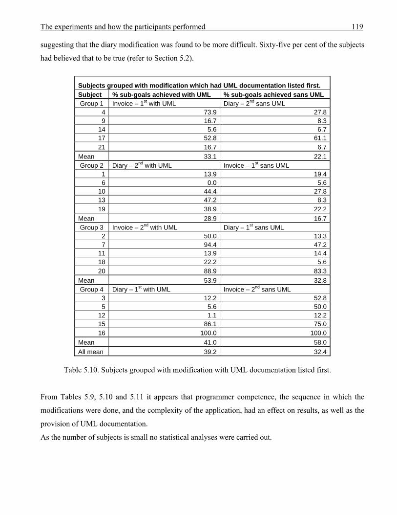
The experiments and how the participants performed 119
suggesting that the diary modification was found to be more difficult. Sixty-five per cent of the subjects
had believed that to be true (refer to Section 5.2).
Subjects grouped with modification which had UML documentation listed first. Subject % sub-goals achieved with UML % sub-goals achieved sans UML Group 1 Invoice – 1st with UML Diary – 2nd sans UML
4 73.9 27.89 16.7 8.3
14 5.6 6.717 52.8 61.121 16.7 6.7
Mean 33.1 22.1 Group 2 Diary – 2nd with UML Invoice – 1st sans UML
1 13.9 19.46 0.0 5.6
10 44.4 27.813 47.2 8.319 38.9 22.2
Mean 28.9 16.7 Group 3 Invoice – 2nd with UML Diary – 1st sans UML
2 50.0 13.37 94.4 47.2
11 13.9 14.418 22.2 5.620 88.9 83.3
Mean 53.9 32.8 Group 4 Diary – 1st with UML Invoice – 2nd sans UML
3 12.2 52.85 5.6 50.0
12 1.1 12.215 86.1 75.016 100.0 100.0
Mean 41.0 58.0All mean 39.2 32.4
Table 5.10. Subjects grouped with modification with UML documentation listed first.
From Tables 5.9, 5.10 and 5.11 it appears that programmer competence, the sequence in which the
modifications were done, and the complexity of the application, had an effect on results, as well as the
provision of UML documentation.
As the number of subjects is small no statistical analyses were carried out.
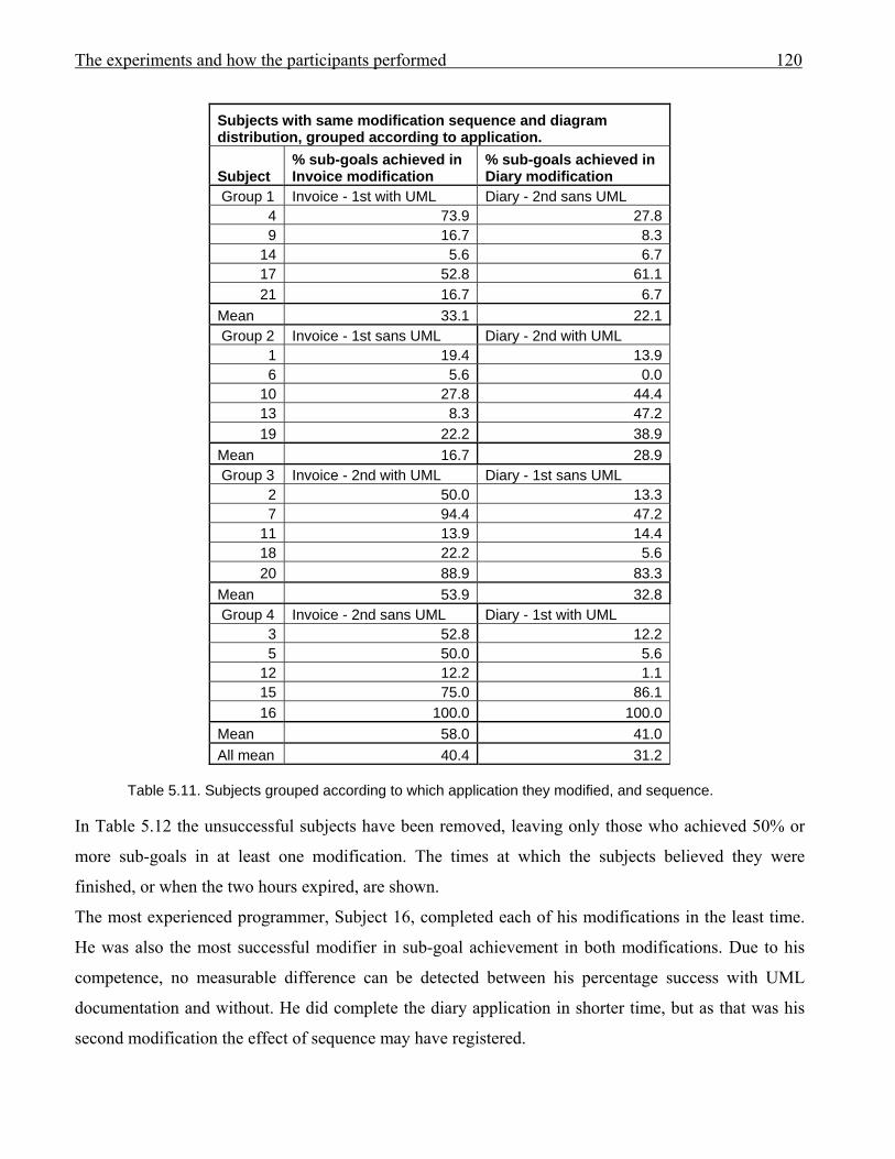
The experiments and how the participants performed 120
Subjects with same modification sequence and diagram distribution, grouped according to application.
Subject % sub-goals achieved in Invoice modification
% sub-goals achieved in Diary modification
Group 1 Invoice - 1st with UML Diary - 2nd sans UML 4 73.9 27.8 9 16.7 8.3
14 5.6 6.7 17 52.8 61.1 21 16.7 6.7
Mean 33.1 22.1 Group 2 Invoice - 1st sans UML Diary - 2nd with UML
1 19.4 13.9 6 5.6 0.0
10 27.8 44.4 13 8.3 47.2 19 22.2 38.9
Mean 16.7 28.9 Group 3 Invoice - 2nd with UML Diary - 1st sans UML
2 50.0 13.3 7 94.4 47.2
11 13.9 14.4 18 22.2 5.6 20 88.9 83.3
Mean 53.9 32.8 Group 4 Invoice - 2nd sans UML Diary - 1st with UML
3 52.8 12.2 5 50.0 5.6
12 12.2 1.1 15 75.0 86.1 16 100.0 100.0
Mean 58.0 41.0 All mean 40.4 31.2
Table 5.11. Subjects grouped according to which application they modified, and sequence.
In Table 5.12 the unsuccessful subjects have been removed, leaving only those who achieved 50% or
more sub-goals in at least one modification. The times at which the subjects believed they were
finished, or when the two hours expired, are shown.
The most experienced programmer, Subject 16, completed each of his modifications in the least time.
He was also the most successful modifier in sub-goal achievement in both modifications. Due to his
competence, no measurable difference can be detected between his percentage success with UML
documentation and without. He did complete the diary application in shorter time, but as that was his
second modification the effect of sequence may have registered.
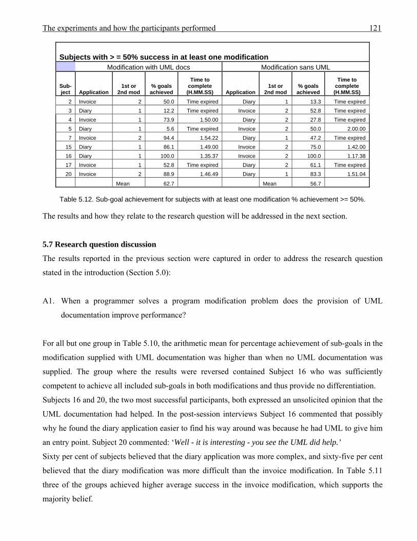
The experiments and how the participants performed 121
Subjects with > = 50% success in at least one modification Modification with UML docs Modification sans UML
Sub-ject Application
1st or 2nd mod
% goals achieved
Time to complete
(H.MM.SS) Application 1st or
2nd mod % goals achieved
Time to complete
(H.MM.SS) 2 Invoice 2 50.0 Time expired Diary 1 13.3 Time expired 3 Diary 1 12.2 Time expired Invoice 2 52.8 Time expired 4 Invoice 1 73.9 1.50.00 Diary 2 27.8 Time expired 5 Diary 1 5.6 Time expired Invoice 2 50.0 2.00.00 7 Invoice 2 94.4 1.54.22 Diary 1 47.2 Time expired
15 Diary 1 86.1 1.49.00 Invoice 2 75.0 1.42.00 16 Diary 1 100.0 1.35.37 Invoice 2 100.0 1.17.38 17 Invoice 1 52.8 Time expired Diary 2 61.1 Time expired 20 Invoice 2 88.9 1.46.49 Diary 1 83.3 1.51.04
Mean 62.7 Mean 56.7
Table 5.12. Sub-goal achievement for subjects with at least one modification % achievement >= 50%. The results and how they relate to the research question will be addressed in the next section.
5.7 Research question discussion
The results reported in the previous section were captured in order to address the research question
stated in the introduction (Section 5.0):
A1. When a programmer solves a program modification problem does the provision of UML
documentation improve performance?
For all but one group in Table 5.10, the arithmetic mean for percentage achievement of sub-goals in the
modification supplied with UML documentation was higher than when no UML documentation was
supplied. The group where the results were reversed contained Subject 16 who was sufficiently
competent to achieve all included sub-goals in both modifications and thus provide no differentiation.
Subjects 16 and 20, the two most successful participants, both expressed an unsolicited opinion that the
UML documentation had helped. In the post-session interviews Subject 16 commented that possibly
why he found the diary application easier to find his way around was because he had UML to give him
an entry point. Subject 20 commented: ‘Well - it is interesting - you see the UML did help.’
Sixty per cent of subjects believed that the diary application was more complex, and sixty-five per cent
believed that the diary modification was more difficult than the invoice modification. In Table 5.11
three of the groups achieved higher average success in the invoice modification, which supports the
majority belief.
The experiments and how the participants performed 122
Eighty-five per cent of subjects who attempted both modifications believed that doing the first
modification assisted with doing the second. In all but one group in Table 5.9 the arithmetic mean for
success in the second modification exceeded that for the first, confirming the majority of subject
perceptions.
As can be seen in Table 5.11, Group 4 members achieved the highest mean percentage success in both
of the modifications, with members of Group 3 having the second highest means in both, suggesting
that programmer competence was a factor in subjects’ successes. Competence was not easy to predict
for the student programmers who passed the same occurrence of the third-year course in systems
analysis and design (Subjects 01 through 15). The most successful of those subjects in the sessions was
the least successful in assignments within his course, and the least successful of those subjects in the
sessions had performed successfully in the course.
Chinn et al. (2007) similarly found no correlation between their five subjects’ course grades and their
ability to solve data structure problems that reflected course material, whilst talking aloud. The authors’
explanation was that the kinds of activities that students gained credit for in the data structures course
depended upon both design and implementation skills and their research did not include
implementation. A similar mismatch may have occurred in the current research. The third-year systems
analysis and design course attended by many of the current subjects required the students to work in
groups to document their projects in UML, and then implement a solution. The students, in their post-
session interviews, admitted to distributing the work among the group members so that some members
modelled and some did the programming. The UML diagrams were frequently drawn to reflect the
implementation, rather than as a plan for the implementation. In this research the subjects were
expected to perform both the modelling and the implementation, and lacked group support.
The percentage successes varied widely for subjects 01 through 15, despite their common course. The
variability of programmers with common backgrounds has been noted in previous research (Brooks,
1980; Sheil, 1981) (refer to Section 4.3.1).
In summary, there appear to be five factors that we have identified that could affect performance:
1. the sequence in which the applications were attempted
2. the provision of UML documentation
3. programmer’s competence
4. the application
5. the modification.
The challenge for research into subjects’ programming performances with and without a specific
treatment is that a programmer cannot be asked to solve the same problem twice without some memory
The experiments and how the participants performed 123
of details from the first attempt being retained to assist with the second. The challenge is to obtain two
completely different applications with equal complexity. As can be seen from the variations in the
participants’ results from the sessions, experiences of complexity can be subjective. Some subjects had
succeeded more slowly than others and appeared to be heading for a successful conclusion when their
two hours expired. A number of participants believed, and previous research has verified, that the
activity of ‘thinking aloud’ can slow progress. Subject 16 commented in his post-sessions interview:
‘I’m thinking speaking all the time I probably haven’t done what I would have done normally.’ … ‘I
did find by talking out loud I kinda wasn’t doing things quite as fast.’ Subject 02 commented on her
experience: ‘Um - because in the first modification I’m not used to – like - speaking aloud and –
speaking aloud and thinking at the same time. And then after doing the first – um - modification and
getting used to – like - talking aloud – and thinking and speaking at the same time - it helps.’
All subjects volunteered their participation. With the small number of self-selected subjects,
performance results can not be assumed to apply to the full population of programmers. However, there
is indication that UML documentation was helpful, despite the fact that the results cannot be supported
statistically due to the small size of the sample.
5.8 Conclusion
The sessions were carried out to find out if the use of UML documentation improved performance
during software modification. If performance was improved then it was implied that the documentation
had assisted the cognitive activities of solving programming problems.
Some evidence of positive support from UML documentation has been obtained. The performance
results from the sessions have highlighted limitations and challenges for this type of research, as
discussed in Section 5.7.
It is possible that the attitude of the subjects to UML documentation could affect their usage, regardless
of whether UML provides cognitive support. The two most successful subjects believed that UML had
helped. Their respective places of work regularly used class diagrams, so the subjects could have
established a pattern of work that incorporated the documentation.
This was one part of a two-pronged approach to discovering if UML cognitively supports software
development. It is possible that UML documentation may simply provide an alternative source of
cognitive support without improving performance. The research questions related to cognitive
behaviour will be addressed in the next chapter, Chapter 6, where the verbal protocols will be analysed.
A full discussion about the experiments, their limitations, and results related to performance and
cognitive behaviour, will be covered in Chapter 7.

Results: Behaviour. 123
Results: Behaviour. 124
Chapter 6: Results: Behaviour 6.0 Introduction
The experiments described in the previous chapter were carried out to test whether Unified Modelling
Language (UML) diagrams supported the cognitive processing of developers whilst modifying a
computer application written in an object-oriented (OO) programming language. The aim was to
discover cognitive support for the OO environment that would suggest that the diagrams are useful
external representations. If it could be demonstrated that successful developers benefited cognitively
from reading or writing appropriate UML diagrams then UML use can be justified for this type of
activity, although the benefits must be weighed against the effort required to establish the
documentation in the first place.
It was concluded in Chapter 2 that an external representation can be said to support a programmer’s
cognitive processes during software development if it aids the programmer’s comprehension by
contributing to the internal representation of the problem in the problem space (Goel, 1995;
Hungerford, 2004; Pennington, 1987; Petre, 1995); forms a set with the programmer’s internal problem
space (Zhang & Norman, 1994); or provides a notation for offloading of chunks to free working
memory (WM) (Grogono & Nelson, 1982, p.7; Kim & Lerch, 1992; Kotovsky et al., 1985; Newell &
Simon, 1972; Scaife & Rogers, 1996). If these claims for cognitive support can be substantiated by
UML documentation, then it may be deduced that documentation using UML notation may be
cognitively beneficial for prospective program modifiers if they choose to use it.
This chapter is concerned with reporting the results from the experiments that address the research
questions related to the cognitive behaviour claims reported above, that were asked in Section 4.1.2.2:
B1. Can the use of UML documentation facilitate a programmer’s comprehension of a non-trivial
program by assisting in the formation of valid internal representations of a problem?
B2. (i) Can the use of UML documentation facilitate a programmer in modifying a non-trivial
program by forming a set with the programmer’s internal problem space?
(ii) Can the use of UML documentation facilitate a programmer’s writing of code to solve a non-
trivial problem by acting in a set with the problem space to induce rules for solution?
B3. Can the use of UML documentation facilitate a programmer’s modifying a non-trivial program by
providing a vehicle for offloading from working memory?
C1. Will a student who has no industry experience use UML documentation more often than a
programmer with industry experience?
Results: Behaviour. 125
In order to detect cognitive support this research required subjects to modify an application that was
written in VB.NET, and which had UML documentation. Participants were assigned either to modify
an application that produced invoices, or an application that recorded appointments in a diary. All
subjects had learned VB.NET programming and UML modelling prior to the modification sessions.
Concurrent verbal protocols were collected during the two-hour maximum modification sessions.
Participants were assigned to one of two groups: a group of industry-experienced subjects, and a group
of non-industry-experienced students. Participants were assigned to the industry-experienced group if
they had participated for a minimum of two months in programming in a commercial environment. The
second group comprised students with no industry-related programming experience, who had all passed
a third year tertiary course that included UML modelling and VB.NET programming. From each of the
groups five of the more successful modifiers were chosen to have their protocols transcribed and coded
according to the framework illustrated in Table 4.3 (and reproduced in Table 6.1), and the results were
used to construct behaviour graphs. Success was measured by the percentage of sub-goals achieved by
each subject during the modification session (refer to Table 5.7). The lists of sub-goals for each
application are presented in the previous chapter, with the sub-goals to be achieved in the invoice
application appearing in Table 5.3 and the list for the diary application in Table 5.4. The more
successful participants were chosen for transcription as the research was investigating the possibility of
successful cognitive support supplied by the UML documentation. Where a subject was unable to
achieve any sub-goals there could be no evidence of UML notation support for solving that problem.
In order to address the research questions, this chapter presents the narrative summaries of the
analysed, transcribed, verbal protocols. These provide the detailed evidence which may, or may not,
support the premise that episodes where UML documentation was used can successfully influence
following episodes, thus demonstrating that the documentation was effective. The summaries are
analysed for evidence of the UML documentation being used
1. to assist in the formation of the subject’s internal representation of the problem
2. in a set with the subject’s problem space
3. in a set with the subject’s problem space to aid the induction of rules, and
4. as an external representation in the offloading of information from working memory.
Summaries are cross-referenced to their related behaviour graphs in which the episodes are encoded
according to the framework derived in Chapter 4. Table 4.3 which documents that framework is
reproduced as Table 6.1 in this chapter for convenience. For the two groups of participants the graphs
will provide a quick reference to the episodes affected by UML documentation. Each episode will be

Results: Behaviour. 126
positioned within the graph to indicate to which cognitive step it belongs. Cognitive steps include those
of rule induction. Episodes will be assigned to either the problem or solution domain.
Due to the slowing effect on progress caused by ‘talking aloud’ (Anderson, 1983; Ericsson & Simon,
1993, p.xx; Nielsen et al., 2000, 2000a; Rubin 1994), no conclusions may be made with respect to time
taken for cognitive activities. However, large differences in episode timings recorded on the behaviour
graphs may indicate relative cognitive time taken.
The extent to which information is retained in long term memory (LTM) depends upon how well it has
been attended to and processed (Anderson, 1983; Gardiner et al., 2006; Preece, 1993). It is possible that
the act of offloading assists the offloader by exercising data sufficiently to establish its retention in
memory.
Ericsson and Simon (1984) believed that transcriptions of concurrent verbal protocols provide a good
record of the verbaliser’s intentions. That was confirmed in the current research as what a participant
said could be verified against the related programming activities. Each transcription was checked and
rechecked twice to verify content and despite a few small changes detected upon a second or third
listening, which clarified understanding, no major differences occurred. The transcriptions were also
matched to the documentation provided in the sessions and the coded solutions produced by the
subjects. Any evidence of offloading onto paper or onto the supplied documentation was collected. The
identification and encoding of the transcribed episodes were checked by an independent researcher as
further validation.
The UML documentation provided for both the invoice and diary applications included use case
models with text-based descriptions for principal use cases, a class diagram, and sequence diagram(s)
for the major use case(s). The choice of these diagrams was justified in Section 4.1.1.
This chapter proceeds as follows: Section 6.1 contains brief comments on the performance of the
subjects in ‘talking aloud’. A description is given in Section 6.2 of how the narrative summaries of
participants’ modification sessions are presented. An explanation of the coding and presentation of the
behaviour graphs is found in Section 6.3.
Sequence numbers are assigned to uniquely identify episodes within a session, and are used to cross-
reference an episode in a narrative session summary to its equivalent episode within the related
behaviour graph. The behaviour graphs provide a reference from which the category of cognitive step
for an episode may be quickly obtained.
The summary for each subject immediately precedes the related behaviour graph. Section 6.4 contains
the summaries and behaviour graphs for each transcribed industry-experienced participant. Summaries
and behaviour graphs for the non-industry-experienced students appear in Section 6.5. A few
Results: Behaviour. 127
unsuccessful subjects are also briefly reported in order to record variation in behaviour amongst
developers.
The research questions are addressed in Section 6.6. All results from this research will be discussed in
Chapter 7.
The subject profiles, the descriptions of the applications and required modifications, the UML diagrams
documenting the applications, the pilot test, and experimental procedures were described in the
previous chapter (Chapter 5) and will not be duplicated here.
This chapter is concluded in Section 6.7.
6.1 Verbal protocol performance
All subjects succeeded in talking meaningfully whilst carrying out the practice modification, yet during
the main experiment some subjects became increasingly silent, especially when they could not find a
way to proceed to solve the problem. Prompting would be answered by ‘I’m still thinking of how to do
….’.
Preece, Rogers and Sharp (2002) suggest that the subject will have difficulty in speaking when the task
becomes demanding. Apart from Subject 04 who required much prompting, subjects did endeavour to
satisfy ‘think aloud’ requirements. It is possible that Subject 04 had little capacity left for verbal
thought processes whilst conducting the task (Biemiller & Meichenbaum, 1992).
Subjects had the choice of sourcing details either from the VB.NET code or from the UML diagrams, if
supplied. The aim of the experiments was to identify whether the diagrams provided cognitive support
for solving the problems, either in the form of contributing to the participant’s understanding of the
problem or as external representations for cuing or offloading information. The following sections
present narrative summaries of the subjects’ behaviours as evidence.
It was possible that although the UML diagrams offered cognitive support, the participants would
prefer the VB.NET environment instead.
To assist in the interpretation of the summaries and behaviour graphs, explanations and keys to their
presentation follow in the next two sections.
6.2 Explanation of notation used in the narrative summaries
For each transcribed subject a narrative summary of the cognitive episodes that occurred during their
modification is provided, and is cross-referenced to the related behaviour graph. The elapsed time from
the start of a session is shown in square brackets for episodes involving UML documentation. For
example: [1.02.34] represents an elapsed time of one hour, two minutes, and thirty-four seconds.
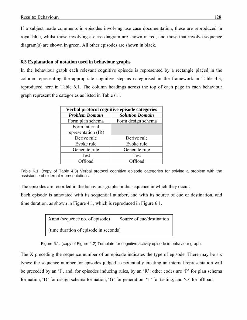
Results: Behaviour. 128
If a subject made comments in episodes involving use case documentation, these are reproduced in
royal blue, whilst those involving a class diagram are shown in red, and those that involve sequence
diagram(s) are shown in green. All other episodes are shown in black.
6.3 Explanation of notation used in behaviour graphs
In the behaviour graph each relevant cognitive episode is represented by a rectangle placed in the
column representing the appropriate cognitive step as categorised in the framework in Table 4.3,
reproduced here in Table 6.1. The column headings across the top of each page in each behaviour
graph represent the categories as listed in Table 6.1.
Verbal protocol cognitive episode categories
Problem Domain Solution Domain Form plan schema Form design schema
Form internal representation (IR)
Derive rule Derive rule Evoke rule Evoke rule
Generate rule Generate rule Test Test
Offload Offload Table 6.1. (copy of Table 4.3) Verbal protocol cognitive episode categories for solving a problem with the assistance of external representations. The episodes are recorded in the behaviour graphs in the sequence in which they occur.
Each episode is annotated with its sequential number, and with its source of cue or destination, and
time duration, as shown in Figure 4.1, which is reproduced in Figure 6.1.
Figure 6.1. (copy of Figure 4.2) Template for cognitive activity episode in behaviour graph.
The X preceding the sequence number of an episode indicates the type of episode. There may be six
types: the sequence number for episodes judged as potentially creating an internal representation will
be preceded by an ‘I’, and, for episodes inducing rules, by an ‘R’; other codes are ‘P’ for plan schema
formation, ‘D’ for design schema formation, ‘G’ for generation, ‘T’ for testing, and ‘O’ for offload.
Xnnn (sequence no. of episode) Source of cue/destination (time duration of episode in seconds)
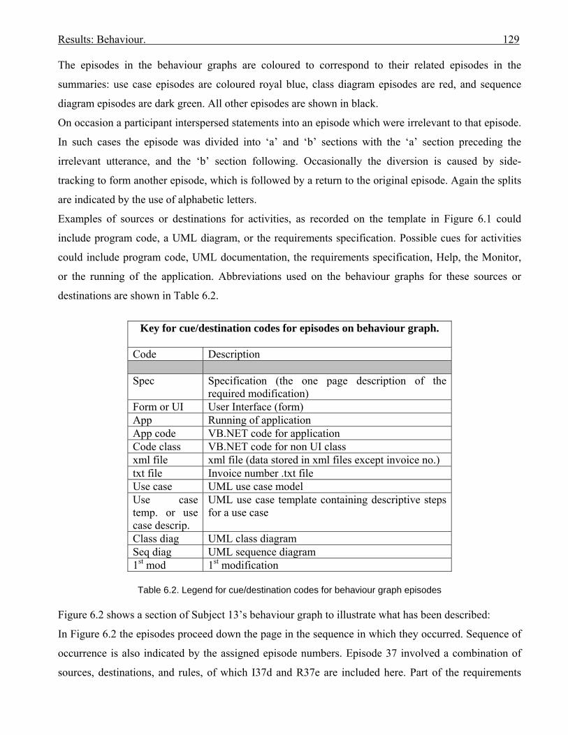
Results: Behaviour. 129
The episodes in the behaviour graphs are coloured to correspond to their related episodes in the
summaries: use case episodes are coloured royal blue, class diagram episodes are red, and sequence
diagram episodes are dark green. All other episodes are shown in black.
On occasion a participant interspersed statements into an episode which were irrelevant to that episode.
In such cases the episode was divided into ‘a’ and ‘b’ sections with the ‘a’ section preceding the
irrelevant utterance, and the ‘b’ section following. Occasionally the diversion is caused by side-
tracking to form another episode, which is followed by a return to the original episode. Again the splits
are indicated by the use of alphabetic letters.
Examples of sources or destinations for activities, as recorded on the template in Figure 6.1 could
include program code, a UML diagram, or the requirements specification. Possible cues for activities
could include program code, UML documentation, the requirements specification, Help, the Monitor,
or the running of the application. Abbreviations used on the behaviour graphs for these sources or
destinations are shown in Table 6.2.
Key for cue/destination codes for episodes on behaviour graph.
Code Description Spec Specification (the one page description of the
required modification) Form or UI User Interface (form) App Running of application App code VB.NET code for application Code class VB.NET code for non UI class xml file xml file (data stored in xml files except invoice no.) txt file Invoice number .txt file Use case UML use case model Use case temp. or use case descrip.
UML use case template containing descriptive steps for a use case
Class diag UML class diagram Seq diag UML sequence diagram 1st mod 1st modification
Table 6.2. Legend for cue/destination codes for behaviour graph episodes
Figure 6.2 shows a section of Subject 13’s behaviour graph to illustrate what has been described:
In Figure 6.2 the episodes proceed down the page in the sequence in which they occurred. Sequence of
occurrence is also indicated by the assigned episode numbers. Episode 37 involved a combination of
sources, destinations, and rules, of which I37d and R37e are included here. Part of the requirements
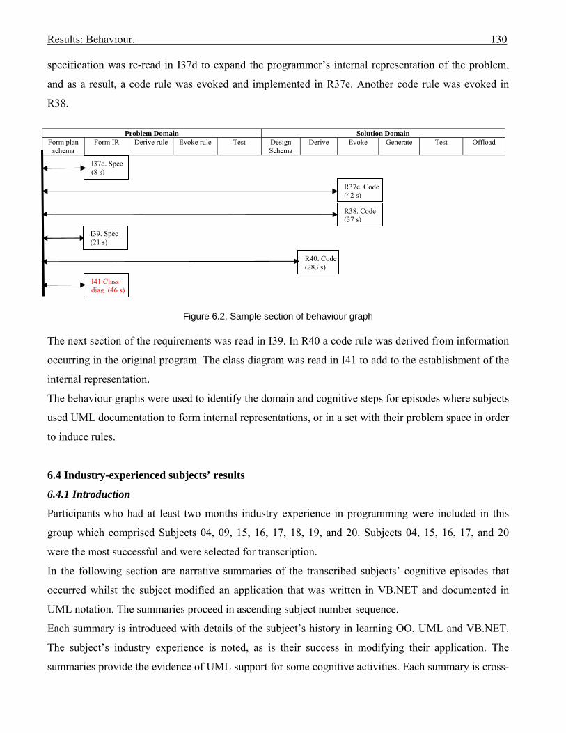
Results: Behaviour. 130
specification was re-read in I37d to expand the programmer’s internal representation of the problem,
and as a result, a code rule was evoked and implemented in R37e. Another code rule was evoked in
R38.
Problem Domain Solution Domain
Form plan schema
Form IR Derive rule Evoke rule Test Design Schema
Derive Evoke Generate Test Offload
Figure 6.2. Sample section of behaviour graph The next section of the requirements was read in I39. In R40 a code rule was derived from information
occurring in the original program. The class diagram was read in I41 to add to the establishment of the
internal representation.
The behaviour graphs were used to identify the domain and cognitive steps for episodes where subjects
used UML documentation to form internal representations, or in a set with their problem space in order
to induce rules.
6.4 Industry-experienced subjects’ results
6.4.1 Introduction
Participants who had at least two months industry experience in programming were included in this
group which comprised Subjects 04, 09, 15, 16, 17, 18, 19, and 20. Subjects 04, 15, 16, 17, and 20
were the most successful and were selected for transcription.
In the following section are narrative summaries of the transcribed subjects’ cognitive episodes that
occurred whilst the subject modified an application that was written in VB.NET and documented in
UML notation. The summaries proceed in ascending subject number sequence.
Each summary is introduced with details of the subject’s history in learning OO, UML and VB.NET.
The subject’s industry experience is noted, as is their success in modifying their application. The
summaries provide the evidence of UML support for some cognitive activities. Each summary is cross-
I37d. Spec (8 s)
R37e. Code (42 s)
R38. Code (37 s)
R40. Code(283 s)
I41.Class diag. (46 s)
I39. Spec (21 s)
Results: Behaviour. 131
referenced to the subject’s behaviour graph, in which the cognitive steps are categorised. Each
summary immediately precedes its related behaviour graph.
At the end of a summary the episodes which demonstrate cognitive support by UML for forming
internal representations of the problem, for forming a set with the modifier’s problem space, or for
offloading from WM, are discussed.
This section concludes with a brief summary of the findings for the group.
The summaries and behaviour graphs for the non-industry-experienced group are to be found in Section
6.5.
6.4.2 Summaries and behaviour graphs
These commence on the following page.
Subjects 09 and 18 are included although they were not transcribed due to their lack of success, and
thus have no summaries, nor behaviour graphs. Subject 09 is included to retain details of his
offloading. Subject 18’s details are recorded as he was the only subject to ignore the UML
documentation.
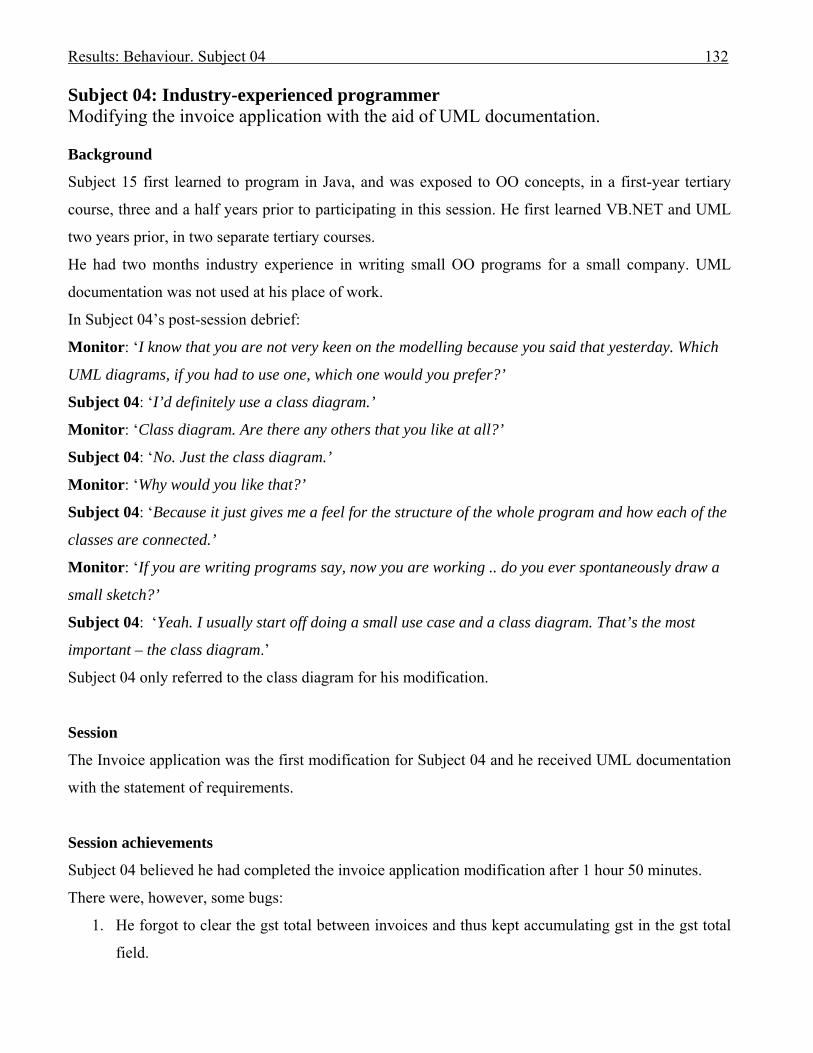
Results: Behaviour. Subject 04 132
Subject 04: Industry-experienced programmer Modifying the invoice application with the aid of UML documentation. Background
Subject 15 first learned to program in Java, and was exposed to OO concepts, in a first-year tertiary
course, three and a half years prior to participating in this session. He first learned VB.NET and UML
two years prior, in two separate tertiary courses.
He had two months industry experience in writing small OO programs for a small company. UML
documentation was not used at his place of work.
In Subject 04’s post-session debrief:
Monitor: ‘I know that you are not very keen on the modelling because you said that yesterday. Which
UML diagrams, if you had to use one, which one would you prefer?’
Subject 04: ‘I’d definitely use a class diagram.’
Monitor: ‘Class diagram. Are there any others that you like at all?’
Subject 04: ‘No. Just the class diagram.’
Monitor: ‘Why would you like that?’
Subject 04: ‘Because it just gives me a feel for the structure of the whole program and how each of the
classes are connected.’
Monitor: ‘If you are writing programs say, now you are working .. do you ever spontaneously draw a
small sketch?’
Subject 04: ‘Yeah. I usually start off doing a small use case and a class diagram. That’s the most
important – the class diagram.’
Subject 04 only referred to the class diagram for his modification.
Session
The Invoice application was the first modification for Subject 04 and he received UML documentation
with the statement of requirements.
Session achievements
Subject 04 believed he had completed the invoice application modification after 1 hour 50 minutes.
There were, however, some bugs:
1. He forgot to clear the gst total between invoices and thus kept accumulating gst in the gst total
field.

Results: Behaviour. Subject 04 133
2. He forgot to change gst value, gst total and amount owing after adding a new quantity to the
existing quantity for a product that had already appeared on the invoice.
3. He forgot to update the program to accommodate the gst when deleting an invoice item.
4. He stored the gst value in the invoice item – he did NOT store gst percentage in the invoice as
requested – but this does not cause a bug.
5. Decimal places for gst total printed on invoice are lost – otherwise OK.
Cognitive episodes during modification
Subject 04 initially read the requirements specification (I1) to set up his first internal representation,
and then leafed through the UML use case documentation. He looked at the GST class code (I2a),
followed by the class diagram for which he had no comment, then returned to the requirements (I3).
He returned to the GST class to try to locate a connection between the invoice and GST classes but did
not find it (I2b). He returned again to the requirements (I4).
Subject 04 looked at the GST form (I5) then ran the program (I6) – he was discovering how the invoice
form compared to what was required.
He then glanced at the xml files with no evidence of gaining any knowledge, then generated the idea to
add a gst total label to the invoice form (G7). He returned to the specification and found that a label
was also required for the amount total (I8). His next episode was to add those two labels to the form
(R9).
Back to the modification (I10) and Subject 04 then decided to look at the properties of the datagrid
(I11), and finally added a new column for gst to the datagrid (R12).
Next, Subject 04 read the requirements for the gst calculation (I13).
He then [13.28] looked at the class diagram to discover how to connect GST and a product on the
invoice [13.54] (I14). From there he searched for the customer class in the code, finally looking at the
xml file to find the gst type in the customer file (I15a). The monitor reminded Subject 04 that a party
became a customer when it received an invoice (I15b). Subject 04 searched the Party class and found
the gst type (I15c). Then he found the code in the main invoice form for accessing the customer by an
index to get its gst code (I16).
Subject 04 searched the gst class to find if gst was calculated (I17). He returned to the invoice form and
wrote code to calculate the gst by hard coding the gst type values (R18), then tested his changes (T19a).
It was not working.
He looked [27.17] at the Party class in the class diagram [27.41] (I19b), and what he found caused him
to insert break points inside the Party class code and continue testing (T19c), only to get an error again.

Results: Behaviour. Subject 04 134
He returned [30.24] to look at the class diagram to find how to connect gst and customer, and found
the customer’s gst type [31.10] (I20).
He glanced at the class diagram again but made no comments [32.16].
He next investigated the loading of customers (I21).
He spent a lot of time flipping from the requirements, the invoice form, customers.xml file, then back
again to the invoice form – but did not articulate any rules.
Subject 04 finally [37.53] returned to the class diagram [37.54] (I22) to identify the customer’s gst
attribute that he then used for generating the plan to create a new variable for gst type in the invoice
form and fill it from the customer’s gst type (G23).
The Monitor reminded him about storing the gst percentage (I24a).
He wrote code in the Party class (R25), glanced at the class diagram [40.30], then generated the idea to
add a new property to the Party class for gst percentage (G26). The Monitor reiterated that the gst
percentage was required to be stored in the invoice (I24b). Subject 04 wrote code to store the
percentage inside the invoice form (R27), and then checked the requirements for what was requested
for the gst percentage (I28a). He coded a new attribute in the invoice class for gst percentage (R28b).
On testing his code he found it did not work (T29).
In I30a he looked through the code for the invoice form to find where the customers were stored (in
order to get their gst types), then added a customer class variable inside the function
CreateNewItemRow() (R30b). Next he set about debugging (T31), changing the style of the gst column
so he could see it, then continuing with the debugging until he believed it worked.
He next added code to fill the totals he had previously added to the invoice form (R32a). However, he
needed to look at the code for the extension total to find how it was done in the original application
(I32b), writing the derived code and modifying it for the new totals (R32c). Next he looked for the
layout of the totals on the requirements (I32d), then ran a test (T32e) where he found some formatting
errors, and finally believed it worked.
Subject 04 believed he had the invoice form section of the requirements working (he had omitted to
look for all variations such as deletions and adding quantity to an existing invoice item). He moved
onto the next section – the Print Preview, looking at the requirements to find the layout (I33). From
there he followed the code in the invoice form to see how it was printing (I34). He ran the program to
learn how the code was written for the printing (T35).
He found the routine that he wrote to add gst to the invoice lines – then immediately evoked the fact
that he was not meant to add GST (R36).

Results: Behaviour. Subject 04 135
At last he discovered how the invoice total is calculated in the invoice class (I37), so he used similar
methods to calculate gst and amount totals (R38). They worked when he tested them (T39).
The Monitor reiterated the need to store gst percentage in the invoice (I40).
Subject 04 generated the idea of saving the gst percentage inside the invoice class (G41).
He looked at the class diagram with no comments [1.25.53], then found his routine for calculating the
gst that he used in the invoice form and inserted it into the invoice item class so that each item stores its
own gst (R42). He then calculated the gst total by inserting the function in the GST class (R43). He
started debugging but his class changes produced warning messages which were explained by the
Monitor (I44).
After that he continued to run and debug the code until he believed it was working. He had trouble with
the formatting primarily (T45).
Comments on cognitive interactions
The only UML documentation used by Subject 04 was the class diagram. However, he was a reluctant
talker, despite performing well in the practice exercise. After first reading the requirements he leafed
through the use case documentation, and then looked at the class diagram without commenting. It is
possible that he obtained information from the diagrams that he did not vocalise.
In his post-session interview:
Subject 04: ‘The class diagram was OK, but, I mean, it didn’t have most of the stuff in it. … I’m not
very good with UML diagrams.’
Monitor: ‘Do you think it was better having the class diagram?’
Subject 04: ‘It definitely helps. But it was a bit too complicated, actually – but I’m no good with UML
diagrams. … ‘It just got the overall structure of the program. Yeah. But it didn’t help me too much.’
Forming an internal representation
Subject 04 spent episodes one through to six forming his internal representation of the problem before
generating an idea as to what he had to do with respect to the new totals that had to be added to the
invoice form. He rechecked the new totals in the requirements (I8), and then placed new labels on the
form (R9) for the required new totals.
He next looked at the requirements for the required gst column on the invoice followed by the study of
the existing datagrid code, deriving from that code the rule to add the column to the datagrid (R12).
The UML documentation was of little apparent assistance at this stage.

Results: Behaviour. Subject 04 136
Subject 04 spent some episodes looking and learning with the aim of writing a routine to calculate the
gst, using the class diagram to look for connections between gst and a product in an invoice (I14)
(there were none). There was no protocol evidence that what he read on the class diagram contributed
to the episodes that followed. This was Subject 04’s first commented reference to UML documentation,
In I20 he looked at the class diagram to see how to make a connection between customer and gst.
Again there was no evidence of his modification being progressed as a result of what he read.
Using UML documentation in a set with the problem space
When Subject 04 wrote his first code to calculate gst (R18) he tested the code (T19a), found errors and
decided to look at the class diagram where he found the Party class (I19b). This discovery guided his
choice of break points to insert within the Party class code and he continued his testing. He finally
decided his errors were caused by the customer instance not being present in the code.
This was an example of the class diagram and testing being used together in a set to satisfy Subject
04’s purpose. No rules were induced during that set.
He later referred to the class diagram (I22) to find the appropriate gst type attribute to eventually use
in his code in the evoked rule R27 in the solution domain. That was the last time he referred to any
UML diagram.
Offloading to UML documentation
There was no evidence of offloading.
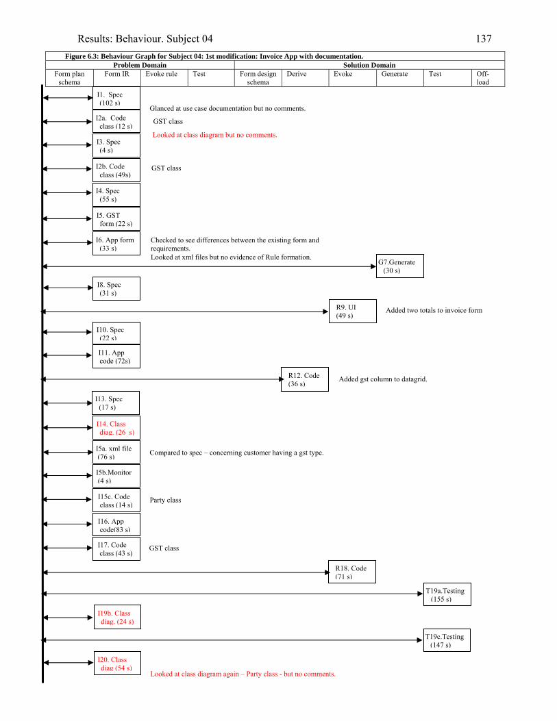
Results: Behaviour. Subject 04 137
Figure 6.3: Behaviour Graph for Subject 04: 1st modification: Invoice App with documentation. Problem Domain Solution Domain
Form plan schema
Form IR Evoke rule Test Form design schema
Derive Evoke Generate Test Off-load
I1. Spec (102 s)
I3. Spec (4 s)
I4. Spec (55 s)
I6. App form (33 s)
G7.Generate (30 s)
I8. Spec (31 s)
I11. App code (72s)
I10. Spec (22 s)
R9. UI (49 s)
I13. Spec (17 s)
I15c. Code class (14 s)
T19a.Testing (155 s)
I20. Class diag (54 s)
I2b. Code class (49s)
R12. Code (36 s)
I16. App code(83 s)
R18. Code (71 s)
Looked at class diagram again – Party class - but no comments.
I2a. Code class (12 s)
Looked at class diagram but no comments.
Glanced at use case documentation but no comments.
GST class
GST class
I5. GST form (22 s)
Checked to see differences between the existing form and requirements. Looked at xml files but no evidence of Rule formation.
Added two totals to invoice form
Added gst column to datagrid.
I14. Class diag. (26 s)
I5a. xml file (76 s)
Party class
I19b. Class diag. (24 s)
T19c.Testing (147 s)
Compared to spec – concerning customer having a gst type.
I5b.Monitor (4 s)
I17. Code class (43 s)
GST class

Results: Behaviour. Subject 04 138
Problem Domain Solution Domain
Form plan schema
Form IR Evoke rule Test Form design schema
Derive Evoke Generate Test Off-load
R25. Code class (48 s)
T29.Testing (47 s)
R27. Code (19 s)
I30a. App code (31 s)
R32a. Code (95 s)
T31.Testing (214 s)
I33. Spec (67 s)
T35. App (284 s)
R38. Code class (61 s)
T32e.Testing (199 s)
I32b. App code (29 s)
T39.Testing (23 s)
I40. Monitor (44 s)
R30b. Code (120 s)
I34. App code(115s)
R32c. UI & Code (172 s)
I37. Code class(70s)
G23.Generate (39 s)
I24b. Monitor (23 s)
Looked at class diagram but no comments.
I21. Code class (107s)
I22. Class diag (30 s)
G26.Generate (7 s)
I28a. Spec (23 s)
R28b. Code class (17 s)
I24a. Monitor (21 s)
I32d. Spec (80 s) Looked at layout of totals.
Episode 32 involved with replicating the new invoice totals.
R36. Spec & monitor (7 s)
Found invoice total function in invoice class.
Remembered what he had read and what the Monitor had advised.
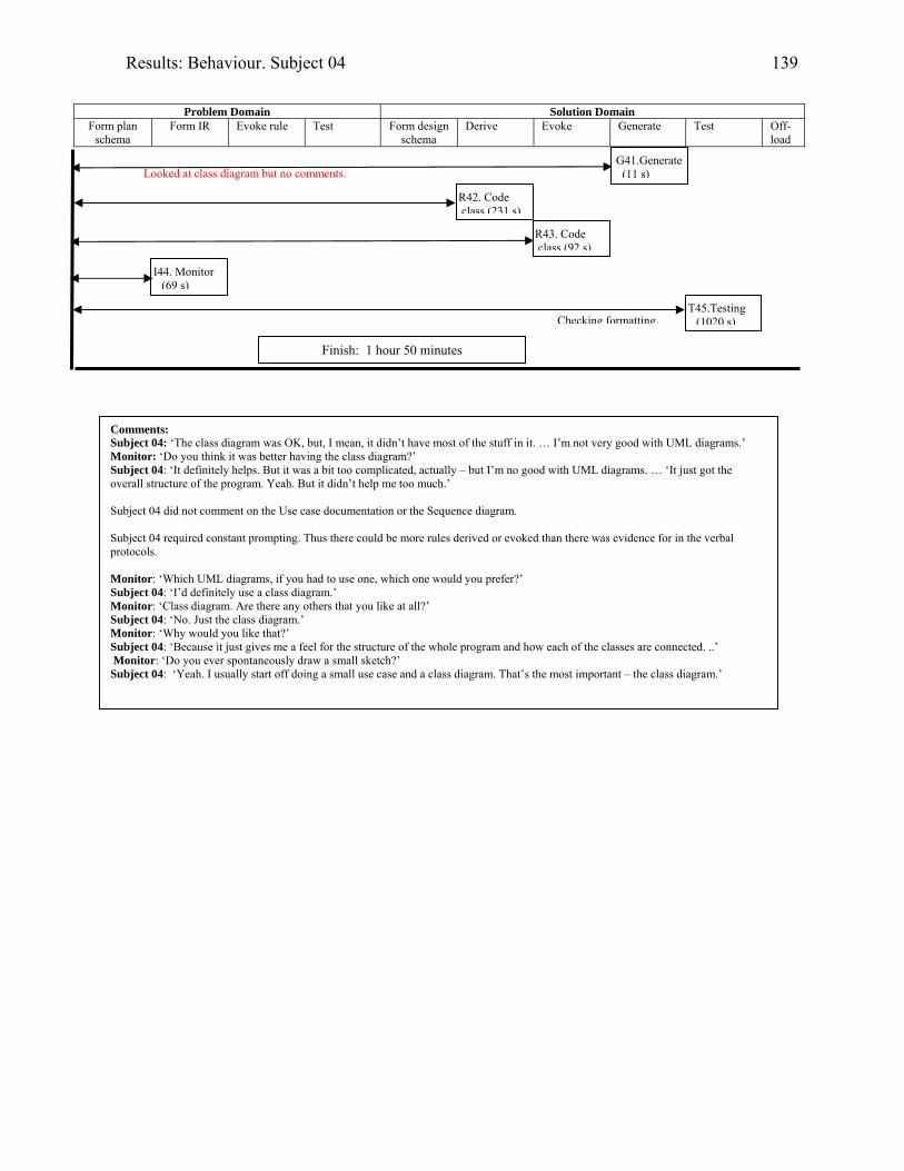
Results: Behaviour. Subject 04 139
Problem Domain Solution Domain
Form plan schema
Form IR Evoke rule Test Form design schema
Derive Evoke Generate Test Off-load
G41.Generate (11 s)
T45.Testing (1020 s)
Finish: 1 hour 50 minutes
Comments: Subject 04: ‘The class diagram was OK, but, I mean, it didn’t have most of the stuff in it. … I’m not very good with UML diagrams.’ Monitor: ‘Do you think it was better having the class diagram?’ Subject 04: ‘It definitely helps. But it was a bit too complicated, actually – but I’m no good with UML diagrams. … ‘It just got the overall structure of the program. Yeah. But it didn’t help me too much.’ Subject 04 did not comment on the Use case documentation or the Sequence diagram. Subject 04 required constant prompting. Thus there could be more rules derived or evoked than there was evidence for in the verbal protocols. Monitor: ‘Which UML diagrams, if you had to use one, which one would you prefer?’ Subject 04: ‘I’d definitely use a class diagram.’ Monitor: ‘Class diagram. Are there any others that you like at all?’ Subject 04: ‘No. Just the class diagram.’ Monitor: ‘Why would you like that?’ Subject 04: ‘Because it just gives me a feel for the structure of the whole program and how each of the classes are connected. ..’ Monitor: ‘Do you ever spontaneously draw a small sketch?’ Subject 04: ‘Yeah. I usually start off doing a small use case and a class diagram. That’s the most important – the class diagram.’
Checking formatting.
R43. Code class (92 s)
I44. Monitor (69 s)
R42. Code class (231 s)
Looked at class diagram but no comments.
Results: Behaviour. Subject 09 140
Subject 09: Industry-experienced programmer
Modifying the invoice application with the aid of UML documentation.
Modifying the diary application without the aid of UML documentation.
Background
Subject 09 had learned to program in Java two and a half years prior to completing her sessions for this
research, in a first year tertiary course. She had learned UML eighteen months prior, and VB.NET one
year prior.
Her industry experience was gained in a student third year course that involved her having worked on
an industry-sponsored project for four months at the time of the session.
Session
The invoice application was the first modification for Subject 09 and she received UML documentation
with the statement of requirements.
Session achievements
Subject 09 did not complete either of her two modifications within the two hours.
For her first modification with the aid of UML documentation she successfully added a new gst column
and correctly added the new totals on the invoice but did not obtain the customer’s gst type, nor did she
load the gst types into memory, and thus was unsuccessful in calculating gst.
For her second modification, that of modifying the diary application without UML assistance, she
managed to load reminders into memory and check for appointments with reminders at application
start-up to display a crude message, but had omitted to check for only the messages for after ‘time now’
for today.
Cognitive episodes in modification
Because Subject 09 was not amongst the five most successful modifiers in her group, her protocols
were not transcribed.
In her post-session debriefing, when she was asked which UML diagrams she preferred, Subject 09
answered that she preferred the use case descriptions because they ‘show the steps a user goes through
and you can write code around that’.
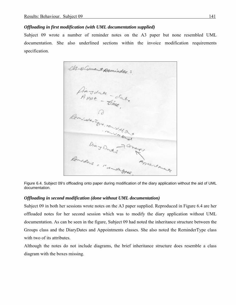
Results: Behaviour. Subject 09 141
Offloading in first modification (with UML documentation supplied)
Subject 09 wrote a number of reminder notes on the A3 paper but none resembled UML
documentation. She also underlined sections within the invoice modification requirements
specification.
Figure 6.4. Subject 09’s offloading onto paper during modification of the diary application without the aid of UML documentation. Offloading in second modification (done without UML documentation)
Subject 09 in both her sessions wrote notes on the A3 paper supplied. Reproduced in Figure 6.4 are her
offloaded notes for her second session which was to modify the diary application without UML
documentation. As can be seen in the figure, Subject 09 had noted the inheritance structure between the
Groups class and the DiaryDates and Appointments classes. She also noted the ReminderType class
with two of its attributes.
Although the notes do not include diagrams, the brief inheritance structure does resemble a class
diagram with the boxes missing.

Results: Behaviour: Subject 15 142
Subject 15: Industry-experienced programmer Modifying the diary application with the aid of UML documentation. Background
Subject 15 learned to program in Java in a tertiary first year course three years prior to his session, but
had a general interest in QuickBasic and Pascal prior to that. He first learned OO concepts three years
prior, learned UML two years prior, and learned VB.NET one year prior to his session.
He had two years industry-level programming experience on hobby sites of interest – but claimed to
not have been employed in industry.
Subject 15 claimed to have never really used use case, sequence, or activity diagrams, despite passing
the third-year tertiary course in VB.NET and UML just prior to his first session.
From his post sessions interview:
Monitor: ‘Do you ever spontaneously, when you are coding, use a diagram?’
Subject 15: ‘.. Um – not while I’m programming. It would generally be a case if I’ve stepped away
from a program for a while then I might try to generate some diagrams, generally just some class
diagram just so I could remember what were the relationships between the classes are, but much
beyond that, no.’
Session
The diary application was the first modification for Subject 15 and he received UML documentation
with the statement of requirements.
Session achievements
Subject 15 believed he had completed the diary application modification after 1 hour 49 minutes had
elapsed. When tested after the session it was found that he had overlooked the fact that it could not be
ensured that today's date was active (in dtmPicker) when exiting the application. As a result he was not
checking today’s appointments for reminders as required, as he was using the list box, into which the
appointments for the selected date were loaded, for searching for appointments that required reminders.
This problem also occurred when checking for reminders dependent upon the timer.
He also had some logic errors in detecting which reminder to display.
The appointment’s reminder was not displayed when the appointment was reloaded, although it was
successfully stored with the appointment.
From his post sessions interview:

Results: Behaviour: Subject 15 143
Monitor: ‘So you didn’t find having the documentation yesterday helped you at all?’
Subject 15: ‘Beyond the class diagram – probably not – no’.
Figure 6.5. The Diary form as modified by Subject 15. Cognitive episodes during modification
Subject 15 spent a long time setting up his internal representation for the problem. He read the
requirements first (I1), followed by running the application. After 2 minutes and 24 seconds he used the
use case description for creating an appointment to guide his progress through the application [3.51]
(I2). He glanced at the class diagram but made no comment. He then looked at the xml file (I3). Then
he looked at the reminder form (I4). He glanced at the class diagram again but made no comment. He
briefly read the requirements (I5) – then commented that there was no button on the form to add a
reminder – only the option within the Edit menu to ‘Add reminders’ (I6).
He studied the code for loading the form to add ReminderSets, then the code behind that form (I7).
He returned to the diary form to study the form load routines where the files are read into memory (I8).
He then ran the application, experimenting with the form used to add ReminderSets form (I9), then
looked at the reminders xml file that was used on that form (I10).
Results: Behaviour: Subject 15 144
He next studied the class diagram, noting all the inheritance structures, and repeating the fact that there
was no link between the Appointment class and the Reminders class, although the ReminderSets were
well defined and had their own form (I11).
[15.44] ‘Ohh - following inheritance of objects. The model’s saying that Appointments, DiaryDates,
Contacts and Reminders are inherited groups which are inherited from SortedList a predefined library
class.
Both Organisations and People are regarded as children or inherit from a Body.
And both DiaryDate and Appointment are inherited from DateTimeBody. .. There’s currently no direct
relationship between a Reminder and an Appointment. …….
In fact ReminderTypes are well defined and have an appropriate form’ [17.53]. (I11).
He next studied the format on the requirements for the pop-up reminder message (I12a) which led into
his coding a new form for this message (R12b), then resized it as appropriate (R12c). He then copied
the existing control from the form to add ReminderSets and renamed it (R12d). He finally added an OK
button to this new form (I12e).
He next investigated the attributes for a ReminderSet class (I13), cross checking with the class diagram
and mistakenly concluded that there were no classes for reminders or contacts as illustrated on the class
diagram1 [25.13] (R14).
He searched for those classes and did find them under their parent Groups class (I15).
He studied the Appointment class next (I16), then moved to the diary form to view how appointment
details for the selected day were displayed in the list (I17). From there he looked at the class diagram:
[33.52] ‘OK. So a diary date may can contain many appointments. Appointments is a List. There is a 1
to1 relationship between DiaryDate and Appointments [34.08]. … [typing]..’ (I18).
He returned to the diary form to study where the Appointments file was being loaded into memory
(I19), then looked through the code to detect consistency in how the xml files were referenced (I20).
He used what he had learned from the previous episodes to insert code for loading the reminders into
the memory for the diary form (R21a).
[42.10] ‘Still examining class diagram for association between appointment and reminder - where it is
appropriate to link [42.20]. …….…’ (I22).
He returned to requirements specification to find that one appointment could have one reminder set
(I23a), but each reminder set contained three possible types of reminder (I23b).
Subject 15 then tested his changes (T21b).
1 In fact all classes on the class diagram were present in the application.
Results: Behaviour: Subject 15 145
He next wrote code for detecting a reminder that fires when the application is loaded (remindAtStart)
and causes the pop-up message to fire (R24a) which he tested, only to get a cast error (T24b). As a
result he checked the reminders code inherited from Group class (I25).
He checked the class diagram for the reminders methods:
[51.35] ‘Examining other classes in similar positions in class diagram such as Appointments … which
otherwise they fillListBox() .. option [51.57]. ..…’ (I26)
He found the methods were used to fill list boxes on the diary form (I27). As the Group classes were
children of the SortedList library routine, he resorted to Help to find out about it (O28).
He next investigated how the xml files were used to store data (I29). Then in I30 he compared the
reminders.xml file data to the data in the class diagram [58.45]. He modified the For-Each in the
loading reminders routine to match the myReminders class (R31).
He ran the application and six pop-up messages appeared as was expected (T32).
Next he looked for where the application closed in order to position a check for reminders on closing
(RemindAtEnd) (R33).
He inserted code at the end for checking for reminders (R34a) and planned ahead for using the code for
other reminder checks (G35). He completed the ‘AtEnd’ code (R34b) then tested it (T34c).
He looked at the contents of the Diary.xml file (I36).
He added a Timer object to the main diary form and set it up for firing at 30-minute-intervals, with a
toggle for firing at 60-minute intervals (R37). He tested the program to check if he had caused any
errors (T38).
Now he added a reminder attribute to Appointment (R39), with a display Reminder method (R40).
Next he wrote a loop to iterate through today’s appointments (R40b). He desk-checked his logic (T41).
In R42a he coded a new constructor for his pop-up form which required parameters to populate the
message for the reminder. He checked the class diagram to find what they were:
[1.20.03] ‘Yeah, I’m - looking at the attributes for an Appointment which do need to be imported and
displayed. … Appointment class doesn't seem to … list the – um - start time’ [1.20.33]. (I42b).
(It did have a start time).
He then generated what he would do for passing the values to the message (G42c) and in 42d he
populated the message. He went back to the diary form to locate the appointment date/time (I42e) and
added that to the message (R42f), then tested all in T42g.
He discovered from the testing that he needed to add the reminder to the appointment.
He deleted his Add Reminder button and replaced it with a combo box (R43a). He modified the load
contacts code to populate the combo box (R43b), then tested (T43c).
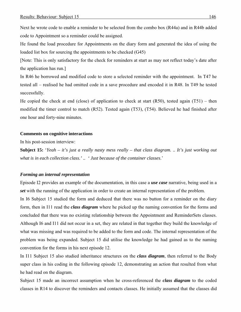
Results: Behaviour: Subject 15 146
Next he wrote code to enable a reminder to be selected from the combo box (R44a) and in R44b added
code to Appointment so a reminder could be assigned.
He found the load procedure for Appointments on the diary form and generated the idea of using the
loaded list box for sourcing the appointments to be checked (G45)
[Note: This is only satisfactory for the check for reminders at start as may not reflect today’s date after
the application has run.]
In R46 he borrowed and modified code to store a selected reminder with the appointment. In T47 he
tested all – realised he had omitted code in a save procedure and encoded it in R48. In T49 he tested
successfully.
He copied the check at end (close) of application to check at start (R50), tested again (T51) – then
modified the timer control to match (R52). Tested again (T53), (T54). Believed he had finished after
one hour and forty-nine minutes.
Comments on cognitive interactions
In his post-session interview:
Subject 15: ‘Yeah – it’s just a really nasty mess really – that class diagram. .. It’s just working out
what is in each collection class.’ .. ‘ Just because of the container classes.’
Forming an internal representation
Episode I2 provides an example of the documentation, in this case a use case narrative, being used in a
set with the running of the application in order to create an internal representation of the problem.
In I6 Subject 15 studied the form and deduced that there was no button for a reminder on the diary
form, then in I11 read the class diagram where he picked up the naming convention for the forms and
concluded that there was no existing relationship between the Appointment and ReminderSets classes.
Although I6 and I11 did not occur in a set, they are related in that together they build the knowledge of
what was missing and was required to be added to the form and code. The internal representation of the
problem was being expanded. Subject 15 did utilise the knowledge he had gained as to the naming
convention for the forms in his next episode 12.
In I11 Subject 15 also studied inheritance structures on the class diagram, then referred to the Body
super class in his coding in the following episode 12, demonstrating an action that resulted from what
he had read on the diagram.
Subject 15 made an incorrect assumption when he cross-referenced the class diagram to the coded
classes in R14 to discover the reminders and contacts classes. He initially assumed that the classes did

Results: Behaviour: Subject 15 147
not exist in the code. However, he persevered, looked within the code, and did discover them, realising
that they were collection classes. Thus it may be assumed that the appearance of those classes on the
diagram did initiate Subject 15’s search for their code.
In I16 and I17 Subject 15 was looking at how an appointment was structured and loaded into the list
box. He found on the class diagram (I18) the specific relationship between the date and its
appointments, adding necessary information to his internal representation which he continued to
expand in the following episodes.
In I22 he was studying the class diagram to find where to link a reminder to an appointment, and
commented on the ReminderSet class in his next episode which he had not mentioned previously,
providing evidence that he had obtained the information concerning the reminderSet class during the
reading of the diagram.
Subject 15 looked at the class diagram in I26 to find the inherited methods for the collection classes.
What he found caused him to look up Help to find out more about what methods could be inherited
from the SortedList library class. This led Subject 15 to seek information about how the collection
classes were written to the xml files.
Using UML documentation in a set with problem space
Subject 15 used the use case narratives for adding and changing an appointment to guide his interaction
with the diary form on screen (I2). This was an example of using the UML documentation in a set with
his problem space to form internal representations.
He next used the class diagram in a set with the class code to derive a rule in R14, in the problem
domain. His behaviour graph supplied the cognitive step category and domain.
In I42, Subject 15 used the class diagram in a set with his coding to find the attributes from
Appointment that needed to be passed to his method for displaying the reminder. The code rule in this
instance was evoked in that he was creating a new routine that was not based upon existing code within
the application.
Following that, he successively coded and tested to achieve his final result.
Offloading to UML documentation.
There was no evidence of offloading.
Subject 15 did use Help (O28) as an external representation from which to discover details about the
SortedList library class.
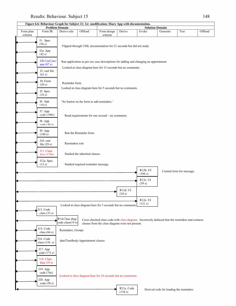
Results: Behaviour. Subject 15 148
Figure 6.6: Behaviour Graph for Subject 15: 1st modification: Diary App with documentation. Problem Domain Solution Domain
Form plan schema
Form IR Derive rule Offload Form design schema
Derive Evoke Generate Test Offload
I1. Spec (56 s)
I2a. App (42 s)
I3. xml file (61 s)
I4. Form (20 s)
I5. Spec (18 s)
I6. App (10 s)
I9. App (180 s)
I8. App code (36 s)
I7. App code (190s)
I10. xml file (29 s)
I11. Class diag (129s)
R12b. UI (106 s)
R12c. UI (39 s)
R12d. UI (24 s)
R12e. UI (131 s)
I13. Code class (33 s)
I15. Code class (66 s)
I16. Code class (156 s)
I19. App code (74s)
I20. App code (58 s)
R21a. Code (154 s)
I18. Class diag (19 s)
Looked at class diagram here for 5 seconds but no comments.
Looked at class diagram here for 3 seconds but no comments.
I2b.UseCase/app (87 s)
Created form for message.
Looked at class diagram here for 15 seconds but no comments.
Looked at class diagram here for 24 seconds but no comments.
I17. App code (173 s)
Ran application as per use case descriptions for adding and changing an appointment.
I12a. Spec (13 s)
Cross checked class code with class diagram. Incorrectly deduced that the reminders and contacts classes from the class diagram were not present.
Reminders, Groups
dateTimeBody/Appointment classes
Flipped through UML documentation for 21 seconds but did not study
Reminder form.
Read requirements for one second – no comments.
Ran the Reminder form.
Reminders.xml
Studied the inherited classes.
Studied required reminder message.
R14.Class diag/ code class(19 s)
Derived code for loading the reminders
‘No button on the form to add reminders.’

Results: Behaviour. Subject 15 149
Problem Domain Solution Domain
Form plan schema
Form IR Derive rule Offload Form design schema
Derive Evoke Generate Test Offload
T21b.Testing (142 s)
I22 Class diag (10s)
R24a.Code (53 s)
I23a. Spec (26 s)
I25. Code class (18 s)
O28. Help (175 s)
I29. Code class (68s)
T32.Testing (92 s)
T34c.Testing (40 s)
T24b.Testing (23 s)
R39. Code class (104s)
R37. Code (253 s)
T38.Testing (50 s)
R40a. Code class (254s)
Used class diagram to assist reading Reminders.xml file, no spoken rule.
I36 xml file (85 s)
R31.Code (15 s)
R34a.Code (9s)
R34b.Code (11s)
I23b. Code class(16 s)
Reminders inherited from Group class.
SortedList()
I27 App code (35 s)
xmlData.vb
R33 App code (18 s)
G35.Plan (9 s)
R40b. Code class (96 s)
Appointment class method to display reminder
Looked at specification for 2 seconds but no comments. Looked at class diagram for association between appointment and reminder to see where to link them.
Looked at how many reminders an appointment may have.
I26.Class diag. (22 s)
Inherited methods from Groups collection class.
I30.Class diag & xml (39 s)
Adds Timer.
Loop for iterating through reminders when triggered.
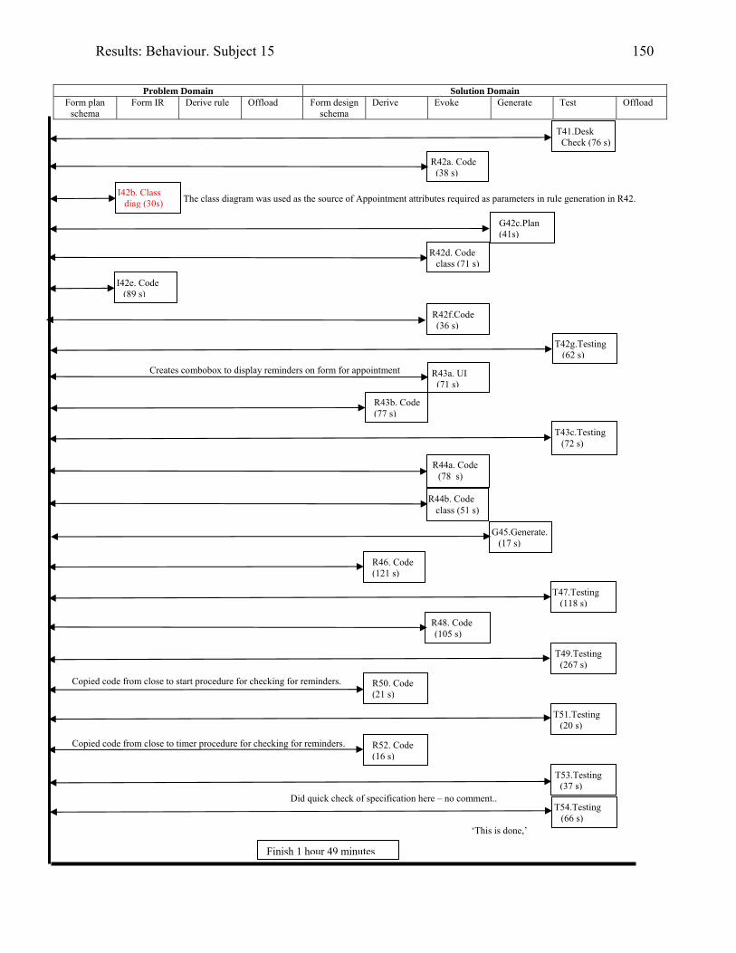
Results: Behaviour. Subject 15 150
Problem Domain Solution Domain
Form plan schema
Form IR Derive rule Offload Form design schema
Derive Evoke Generate Test Offload
T41.Desk Check (76 s)
G42c.Plan (41s)
I42b. Class diag (30s)
I42e. Code (89 s)
T42g.Testing (62 s)
R43a. UI (71 s)
R43b. Code (77 s)
T43c.Testing (72 s)
G45.Generate. (17 s)
T47.Testing (118 s)
R46. Code (121 s)
R44b. Code class (51 s)
T49.Testing (267 s)
The class diagram was used as the source of Appointment attributes required as parameters in rule generation in R42.
Did quick check of specification here – no comment..
R48. Code (105 s)
R42f.Code (36 s)
R50. Code (21 s)
T54.Testing (66 s)
T51.Testing (20 s)
Finish 1 hour 49 minutes
R52. Code (16 s)
T53.Testing (37 s)
R42a. Code (38 s)
R42d. Code class (71 s)
R44a. Code (78 s)
Creates combobox to display reminders on form for appointment
Copied code from close to start procedure for checking for reminders.
Copied code from close to timer procedure for checking for reminders.
‘This is done,’
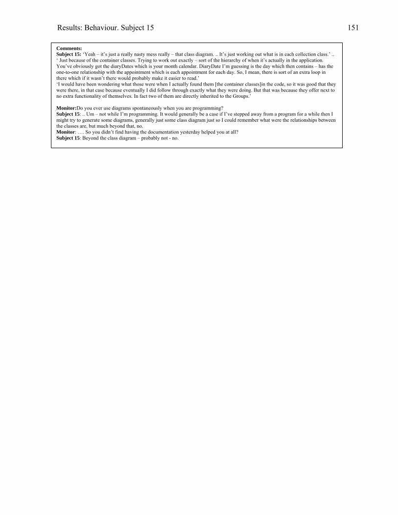
Results: Behaviour. Subject 15 151
Comments: Subject 15: ‘Yeah – it’s just a really nasty mess really – that class diagram. .. It’s just working out what is in each collection class.’ .. ‘ Just because of the container classes. Trying to work out exactly – sort of the hierarchy of when it’s actually in the application. You’ve obviously got the diaryDates which is your month calendar. DiaryDate I’m guessing is the day which then contains – has the one-to-one relationship with the appointment which is each appointment for each day. So, I mean, there is sort of an extra loop in there which if it wasn’t there would probably make it easier to read.’ ‘I would have been wondering what those were when I actually found them [the container classes]in the code, so it was good that they were there, in that case because eventually I did follow through exactly what they were doing. But that was because they offer next to no extra functionality of themselves. In fact two of them are directly inherited to the Groups.’ Monitor:Do you ever use diagrams spontaneously when you are programming? Subject 15: .. Um – not while I’m programming. It would generally be a case if I’ve stepped away from a program for a while then I might try to generate some diagrams, generally just some class diagram just so I could remember what were the relationships between the classes are, but much beyond that, no. Monitor: …. So you didn’t find having the documentation yesterday helped you at all? Subject 15: Beyond the class diagram – probably not - no.

Results: Behaviour. Subject 16 152
Subject 16: Industry-experienced programmer
Modifying the diary application with the aid of UML documentation.
Background
Subject 16 was the most experienced subject. He had taught himself Basic 18 years prior to
participating in this research. Four years later, as a tertiary student, he was exposed to OO
programming and Booch OO Design.
His first job in industry entailed programming in COBOL, starting 12 years prior to participating in this
research. Three years after starting in industry he switched to VB4 which he used for five years until he
returned to the tertiary sector as a student in an unrelated field. He continued to program for a job
whilst he studied, changing to C#.
In his most recent job in a tertiary institute computing department, class diagrams showing hierarchies
but no associations were used. Subject 16 believed that association links cluttered the diagram and if
changes were made much time was spent rearranging a diagram that contained links. He claimed to
occasionally use flow diagrams to document functions when he was programming.
Session
The diary application was the first modification for Subject 16 and he received UML documentation
with the statement of requirements.
Session achievements
Subject 16 believed he had completed the diary application modification after 1 hour 35 minutes 37
seconds had elapsed.
When tested after the session it was found that he had a small bug in his reminder message in that he
had omitted to check for appointments where there was no contact person, assuming that a contact was
always present.
He checked all appointments for program start and finish reminders, including in the latter case any
appointments added in the current session. However, the appointments that were checked for reminders
that occurred at frequency of 30 or 60 minutes included only appointments made prior to the current
session.
Subject 16 was the most successful subject, achieving more sub-goals for this modification than any
other participant. He believed that talking aloud had slowed his progress.

Results: Behaviour. Subject 16 153
Cognitive episodes in modification
Subject 16 read the requirements first (I1), followed by the UML documentation (I2). As he made a
number of comments about the diagrams it is assumed that he was able to create some internal
representation of the problem.
For example, in I2 he read the use case documentation:
[2.45] ‘OK. Reading the documentation. Looking at first page. The use case for Diary Application. And
seeing the user actions. Checking through those. [Reads names of use cases].
Checking the next page, use case template, Diary Application. USE CASE # Add Appointment. [Reads
the template]. …… And finally, I read <Clear Appointment>.
[At the end of reading the DESCRIPTION steps he made the comment:]
So, assuming that they are things that can be done at the same time.
[reading:] EXTENSIONS …. rejected.’
[Comment] That’s assuming they have been already set up in the current activity and you don’t need to
change them.
OK. Next Use Case Diary Application Change Appointment.
Appears to be very similar to previous one.
With main differences are: selecting from the appointments list, and making changes. And the
extensions are: [reads Extensions] If no appointments changes.… rejected.
[Comment] Checking with the previous one – appointments are selected so they are slightly different
categories.
OK Checking next Use Case: Delete Appointments (belonging to one day).
[Reads use case] ‘To delete unwanted appointment on a single day’ So scope level is one day’s
appointments. ‘Preconditions: is looking at ‘appointments have been saved for the previous [Note: he
said ‘previous’ but ‘required’ was actually printed] day. ……. So again Actions: Selecting …wanted’.
So looking at you only want to delete some appointments, not all for a day. So - [Reading] ‘Extensions:
… ‘There’s no selections …I’ve checked the Delete – and checked the appointment’ [6.22] (I2)
Subject 16’s comments in I2 indicate that he did understand much of the documentation. He next
planned in P3 to check that the functionality was not specified in the documentation.
He searched the class diagram to find a place to put a reminder set, only to discover a ReminderSet
class existed (I4):
[6.27] OK. Looking at class diagram – has the different forms on the class diagram. And there’s the
Appointment, together with the Body.
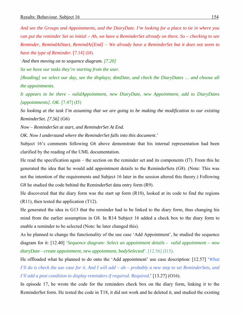
Results: Behaviour. Subject 16 154
And see the Groups and Appointments, and the DiaryDate. I’m looking for a place to tie in where you
can put the reminder Set so initial – Ah, we have a ReminderSet already on there. So – checking to see
Reminder, RemindAtStart, RemindAt[End] – We already have a ReminderSet but it does not seem to
have the type of Reminder. [7.14] (I4).
‘And then moving on to sequence diagram. [7.20]
So we have our tasks they’re starting from the user.
[Reading] we select our day, see the displays; dtmDate, and check the DiaryDates … and choose all
the appointments.
It appears to be there - validAppointment, new DiaryDate, new Appointment, add to DiaryDates
[appointments]. OK. [7.47] (I5)
So looking at the task I’m assuming that we are going to be making the modification to our existing
ReminderSet. [7.56] (G6)
Now – ReminderSet at start, and ReminderSet At End.
OK. Now I understand where the ReminderSet falls into this document.’
Subject 16’s comments following G6 above demonstrate that his internal representation had been
clarified by the reading of the UML documentation.
He read the specification again – the section on the reminder set and its components (I7). From this he
generated the idea that he would add appointment details to the ReminderSets (G8). (Note: This was
not the intention of the requirements and Subject 16 later in the session altered this theory.) Following
G8 he studied the code behind the ReminderSet data entry form (R9).
He discovered that the diary form was the start up form (R10), looked at its code to find the regions
(R11), then tested the application (T12).
He generated the idea in G13 that the reminder had to be linked to the diary form, thus changing his
mind from the earlier assumption in G8. In R14 Subject 16 added a check box to the diary form to
enable a reminder to be selected (Note: he later changed this).
As he planned to change the functionality of the use case ‘Add Appointment’, he studied the sequence
diagram for it: [12.40] ‘Sequence diagram: Select an appointment details - valid appointment – new
diaryDate - create appointment, new appointment, bodySelected’. [12.56] (I15).
He offloaded what he planned to do onto the ‘Add appointment’ use case description: [12.57] ‘What
I’ll do is check the use case for it. And I will add – ah – probably a new step to set ReminderSets, and
I’ll add a post condition to display reminders if required. Required.’ [13.27] (O16).
In episode 17, he wrote the code for the reminders check box on the diary form, linking it to the
ReminderSet form. He tested the code in T18, it did not work and he deleted it, and studied the existing
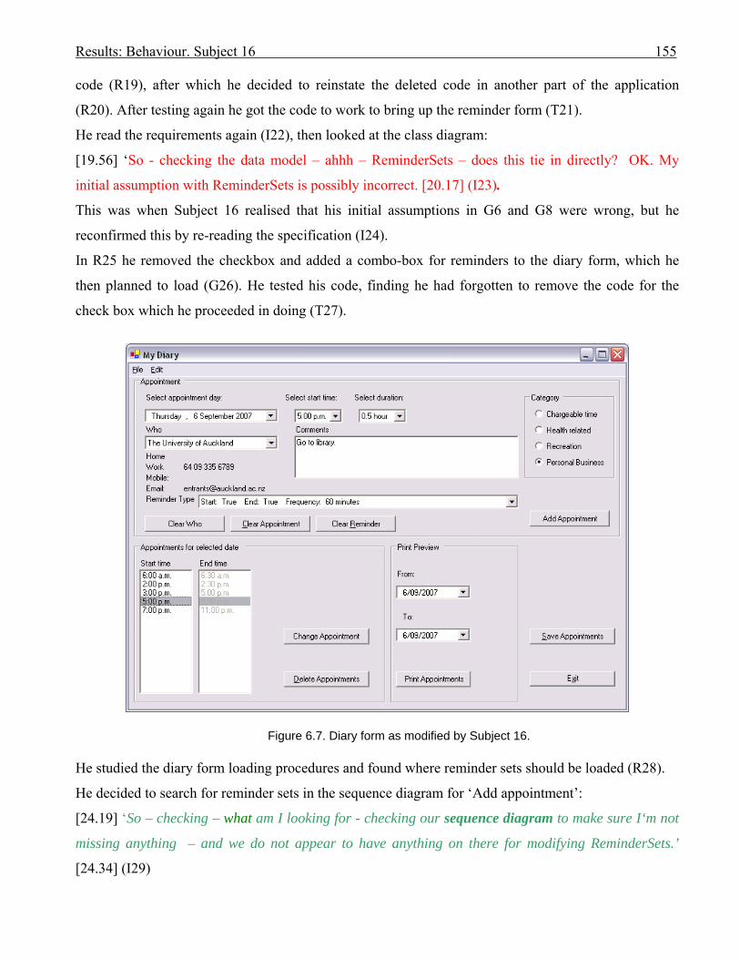
Results: Behaviour. Subject 16 155
code (R19), after which he decided to reinstate the deleted code in another part of the application
(R20). After testing again he got the code to work to bring up the reminder form (T21).
He read the requirements again (I22), then looked at the class diagram:
[19.56] ‘So - checking the data model – ahhh – ReminderSets – does this tie in directly? OK. My
initial assumption with ReminderSets is possibly incorrect. [20.17] (I23).
This was when Subject 16 realised that his initial assumptions in G6 and G8 were wrong, but he
reconfirmed this by re-reading the specification (I24).
In R25 he removed the checkbox and added a combo-box for reminders to the diary form, which he
then planned to load (G26). He tested his code, finding he had forgotten to remove the code for the
check box which he proceeded in doing (T27).
Figure 6.7. Diary form as modified by Subject 16. He studied the diary form loading procedures and found where reminder sets should be loaded (R28).
He decided to search for reminder sets in the sequence diagram for ‘Add appointment’:
[24.19] ‘So – checking – what am I looking for - checking our sequence diagram to make sure I‘m not
missing anything – and we do not appear to have anything on there for modifying ReminderSets.’
[24.34] (I29)

Results: Behaviour. Subject 16 156
He copied the code for loading the reminder sets from the reminder set form into the diary form (R30).
With the testing in T31 he got the application to run with his changes.
The other example of offloading occurred when Subject 16 drew on the class diagram:
[28.10] ‘So checking our class diagram. Come here class diagram – it doesn’t have a direct link - the
data – there is no direct link - so I will add a link between our Appointment and our ReminderSet.
Slightly different notation but close enough. I think what I will need is a joining class. So adding a new
class and I will call it AppointmentReminder. Appointment – AppointmentReminder.’ [28.50] (O32).
He reread the requirements again and changed his drawing:
[29.06] ‘OK. Reading our specification again: Possible three make up one ReminderSet.
It is possible to enable a reminder set to be assigned to an appointment. So we can have two
conditions: either with reminder or not reminder.’ [29.25] (I33).
He reconsidered what he had drawn in light of his interpretation of the requirements specification and
changed what he had added to the class diagram:
[29.26] ‘So instead of adding a joining class I will add in a direct field to Appointment.’ [29.35] (O34).
He studied the code to find how an appointment was handled (R35), then studied the XMLData class to
see how Appointments were loaded (R36), which led him to find the collection class for the
appointments (R37).
‘This file seems to be doing just the static data around it, and the static data is not what I want.’
[31.15] ‘So - let’s find out first and foremost – by looking at the sequence diagram: Are they saving
these? It appears that for DiaryDate not found. DiaryDate not found either - no, no DiaryDate. It
maybe an issue of saving.’ [31.37] (R38).
In R39 Subject 16 found how the diary file was being saved, finally discovering the diary file was
called DiaryDates (R40). In I41 Subject 16 found and studied the DiaryDates and Appointment classes,
so he was now able to add a reminder attribute to the Appointment class (R42).
His next plan was to find the location in which the diary file was being saved (G43). He returned to the
diary form code to find that the file was being saved to the default directory (R44). He planned to
utilise the file name for a search, assuming that the serialisation automatically set the ReminderSet
(G45). He discovered the method where the appointment was created (R46), and wrote the code to set
the ReminderSet attribute in Appointment (R47). He needed to find out how he had loaded the
ReminderSets in the diary form in order to be able to connect them to the new combo box (G48).
However, before that he tested his code (T50), with advice on an error message from the Monitor (I49).
In I52 he studied the xml schema. Through testing in T53 he got the ReminderSet to be added to the
Appointment, and then decided to offload his test data onto the A3 paper (O54), although he discovered

Results: Behaviour. Subject 16 157
later that this was unnecessary. He then continued testing (T55) to check that data was successfully
saved.
After successfully coding the requirements for adding a ReminderSet to an Appointment, clearing that
ReminderSet, and changing the Appointment – and saving the Appointment with its ReminderSet (R56
– T71), Subject 16 needed to address when reminders popped up, so checked the sequence diagram for
‘Add Appointment’ to find:
[57.29] ‘So – looking at our Sequence diagram. We do not have anything on here about selecting our
dates to start with.’ [57.40] (I72).
Following that discovery he searched for the relevant date information in the requirements. Although
there is no evidence in the verbal protocols to support this, it would be predicted that reading the
sequence diagram would have been quicker than reading code to make the same discovery, due to the
number of lines involved.
Once he had discovered the date details for his reminder display implementation, at 57.58 elapsed
minutes, Subject 16 offloaded what he wanted to do by drawing a structure diagram on the A3 paper.
This diagram was process-oriented – there was no OO detail in it - and he used it to plan how he would
check a reminder to see if or when it needed firing. As can be seen on the behaviour graph from O74
onwards, Subject 16 created this diagram and referred to it a number of times to discover what to do
next, or to check if what he had done conformed to his plan. He also crossed off symbols in the
structure diagram as he completed the code for them.
Later, after he inserted a Timer onto his screen in R101a at one hour 18 minutes elapsed time, Subject
16 used the online calculator to calculate the number of milliseconds for the interval for the timer. In
R101c he accessed Help at one hour 20 minutes and 42 seconds to derive the fact that his Timer needed
to be enabled. He wrote some code for the Timer, and then offloaded the number of seconds by writing
them on the requirements page (O103).
There was no further reference to UML diagrams. When he finished he read back the number of
seconds from the requirements sheet to reset the Timer to fire every 30 and 60 minutes (these times
having been reduced in order to be able to test the code).
Comments on cognitive interactions
Subject 16 did comment that he would have been faster if he was not required to talk aloud.
There was only one short example of Subject 16 forming a plan schema in the problem domain, and no
examples of design schemas. He had 12 years of industry programming experience and it is likely that

Results: Behaviour. Subject 16 158
his approach to discovering the problem or solution had become automated and thus not articulated in
his verbal protocols.
Subject 16 primarily used the UML documentation to assist in forming his internal representations, but
also used it for offloading his proposed changes.
From his post-session debriefing:
Subject 16: ‘I’m thinking speaking all the time I probably haven’t done what I would have done
normally.’
Monitor: ‘I noticed that initially you checked with the class diagram quite a bit – but there were other
things that you could have, perhaps, checked later on the class diagram but you went through the code
instead.’
Subject 16: ‘Yeah. Um - more from the point of view that once I’ve kinda got an overview of what’s in
it I tend to find it easier just to go through the code to find it rather than that. Um - I tend to use more
the class diagram to clear kinda an initial idea of what everything is and so forth. Yeah. Yeah - I find it
easier to keep focusing on the screen rather than jumping back to the class diagram. … If I’d had it like
the same sort of layout as I had [in his job] – I probably would have drawn more over the surface -
rather than this – I was kind of – you know - lines all over the place.’
Forming an internal representation
The UML documentation appeared to assist in the creation of internal representations, starting with the
use cases (I2), as Subject 16 made relevant comments on his readings.
There is evidence that an internal representation was clarified as a result of his reading the class
diagram (I4), when Subject 16 discovered the ReminderSet class already existed. His subsequent
comments following G6 indicated that reading the UML documentation (I2, I4, and I5) had clarified
his understanding of the application and its modification.
Subject 16’s original idea to add appointment details to a reminder was rejected after reading the class
diagram in I23 and he changed his plan to adding reminder details to the Appointment.
Subject 16 also used the sequence diagram to ascertain the functionality of the ‘Add appointment’ use
case on several occasions: I5, I15, I29, R38, I72. There is evidence that I29, R38, I72 contributed to his
internal representation of the problem primarily by revealing that what he was looking for was not in
the activity that was modelled.
Using UML documentation in a set with the problem space
Subject 16 did not use the UML documentation in a set.

Results: Behaviour. Subject 16 159
Offloading to UML documentation in first modification (with UML documentation supplied).
In episode 14, Subject 16 decided to add a check box for adding a reminder onto the diary form, and
looked at the sequence diagram in episode 15 to find a place to add his code to control the check box,
but found the use case more useful as he was able to select where his code should perform and
offloaded that information onto the use case description for ‘Create Appointment’ in episode 16.
Subject 16 offloaded his changes onto both the use case description (O16) and the class diagram (O32,
O34). In the latter case Subject 16 initially drew one version of a link of a joining class between the
Appointment and ReminderSet classes on the class diagram (O32), then reread the requirements,
changed his mind as a result, and modified the link by removing the joining class and adding an
attribute to Appointment in O34. This was the only evidence of offloading to UML documentation.
Subject 16 did later draw a structure diagram which he used to plan his progress and cross off parts as
he completed them (refer Figure 6.8).
Figure 6.8. Subject 16’s offloading to a structure diagram during his first modification of the diary application with
UML documentation.
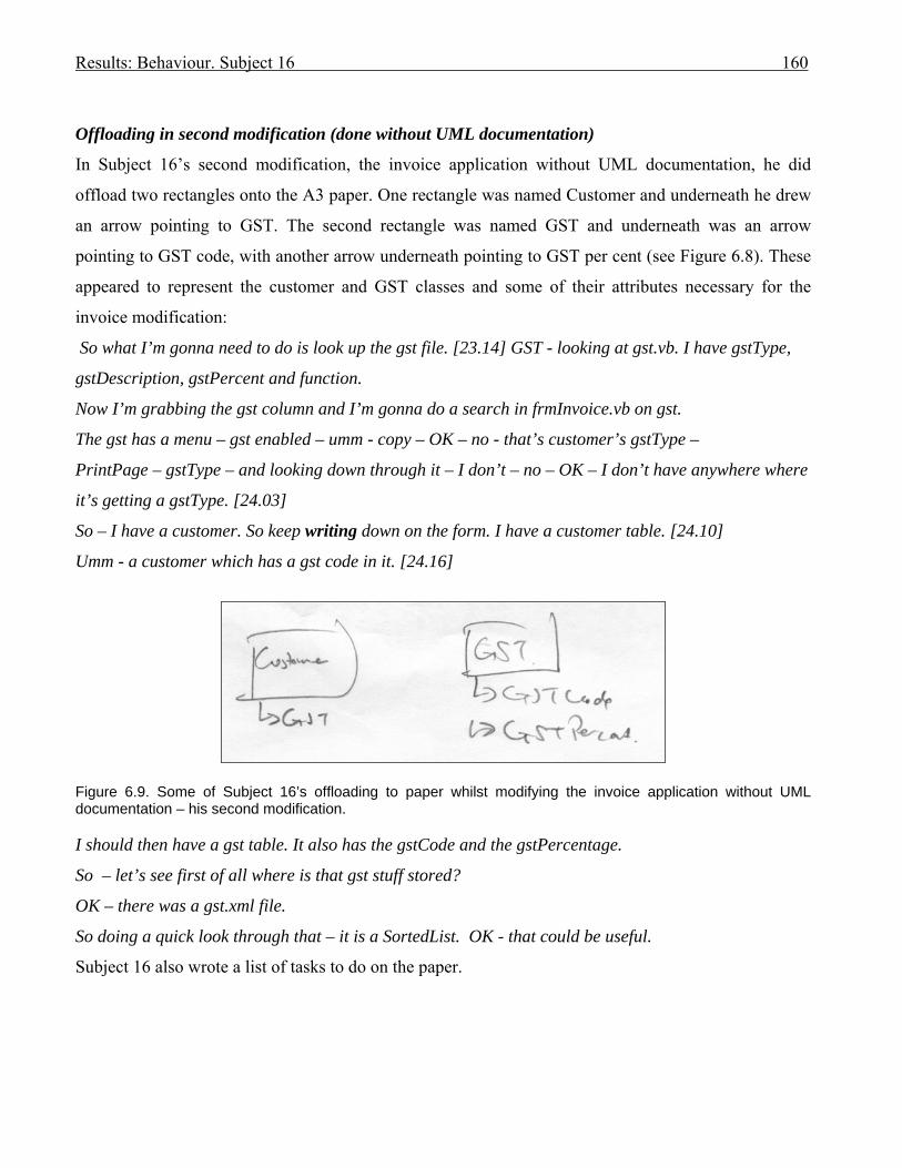
Results: Behaviour. Subject 16 160
Offloading in second modification (done without UML documentation)
In Subject 16’s second modification, the invoice application without UML documentation, he did
offload two rectangles onto the A3 paper. One rectangle was named Customer and underneath he drew
an arrow pointing to GST. The second rectangle was named GST and underneath was an arrow
pointing to GST code, with another arrow underneath pointing to GST per cent (see Figure 6.8). These
appeared to represent the customer and GST classes and some of their attributes necessary for the
invoice modification:
So what I’m gonna need to do is look up the gst file. [23.14] GST - looking at gst.vb. I have gstType,
gstDescription, gstPercent and function.
Now I’m grabbing the gst column and I’m gonna do a search in frmInvoice.vb on gst.
The gst has a menu – gst enabled – umm - copy – OK – no - that’s customer’s gstType –
PrintPage – gstType – and looking down through it – I don’t – no – OK – I don’t have anywhere where
it’s getting a gstType. [24.03]
So – I have a customer. So keep writing down on the form. I have a customer table. [24.10]
Umm - a customer which has a gst code in it. [24.16]
Figure 6.9. Some of Subject 16’s offloading to paper whilst modifying the invoice application without UML documentation – his second modification. I should then have a gst table. It also has the gstCode and the gstPercentage.
So – let’s see first of all where is that gst stuff stored?
OK – there was a gst.xml file.
So doing a quick look through that – it is a SortedList. OK - that could be useful.
Subject 16 also wrote a list of tasks to do on the paper.

Results: Behaviour. Subject 16 161
Figure 6.10: Behaviour Graph for Subject 16: 1st modification: Diary App with documentation. Problem Domain Solution Domain
Form plan schema
Form IR Derive rule Test Form design schema
Derive Evoke Generate Test Offload
I2a.Use case/ temp (186 s)
I4. Class diag.(45s)
I5 Seq. diag.(26s)
I7. Spec (38 s)
G8.Plan (28 s)
G13.Plan (18s)
T12. App (48 s)
R9. App code (58 s)
I15.Seq. dia (16 s)
R17b.Code (46 s)
R17c. Code (32 s)
R14. UI (31s)
O16.Add to use case (30s)
I2b. Use case temp (10 s)
R10. UI (12 s)
I23. Class diag (21s)
I24. Spec (34 s)
I22. Spec (12 s)
T21.Testing (74 s)
R17a App code (19s)
R19 App code (26s)
T18.Testing (102 s)
R20. Code (19 s)
P3.Plan (5 s)
G6.Plan (9 s)
R11 App code (8 s)
I1. Spec (158 s)
Looked at Help but no rule formed
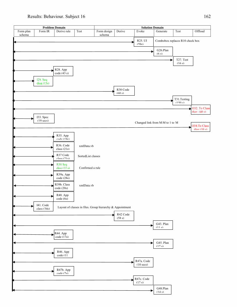
Results: Behaviour. Subject 16 162
Problem Domain Solution Domain
Form plan schema
Form IR Derive rule Test Form design schema
Derive Evoke Generate Test Offload
I41. Code class (34s)
R38 Seq diag (22 s)
R39a. App code (28s)
R42 Code (58 s)
R47a. Code (10 secs)
R46. App code (11
O32. To Class diag. (40 s)
I33. Spec (19 secs)
O34.To Class diag (10 s)
T31.Testing. (150 s)
R36. Code class (21s)
R37 Code class (21s)
R25. UI (59s)
R30 Code (60 s)
T27. Test (16 s)
I29. Seq diag.(15s)
R28. App code (43 s)
R35. App code (19s)
R44. App code (17s)
R47c. Code (17 s)
G26.Plan (6 s)
R40. App code (6s)
G43. Plan (11 s)
G45. Plan (17 s)
R47b. App code (7s)
G48.Plan (14 s)
xmlData.vb
SortedList classes
Layout of classes in files. Group hierarchy & Appointment
Combobox replaces R10 check box
Changed link from M:M to 1 to M
Confirmed a rule
R39b. Class code (20s)
xmlData.vb
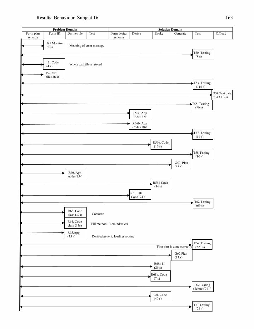
Results: Behaviour. Subject 16 163
Problem Domain Solution Domain
Form plan schema
Form IR Derive rule Test Form design schema
Derive Evoke Generate Test Offload
R65.App (35 s)
T66. Testing (223 s)
G67.Plan (13 s)
R68a UI (26 s)
T69.Testing (debug)(91 s)
R68b. Code (7 s)
T71.Testing (22 s)
O54.Test data to A3 (19s)
T55. Testing (20 s)
R56a. App Code (72s)
R63. Code class (37s)
T57. Testing. (14 s)
R56d Code (54 s)
T62.Testing (69 s)
R61. UI/ Code (24 s)
R60. App code (15s)
I52. xml file (36 s)
T53. Testing (116 s)
R64. Code class (13s)
I49 Monitor (8 s)
T50. Testing (8 s)
R56b. App Code (10s)
R56c. Code (16 s)
T58.Testing (10 s)
G59. Plan (14 s)
R70. Code (40 s)
Contact/s
Fill method - ReminderSets
I51 Code (4 s)
Meaning of error message
Where xml file is stored
Derived generic loading routine
‘First part is done correctly’
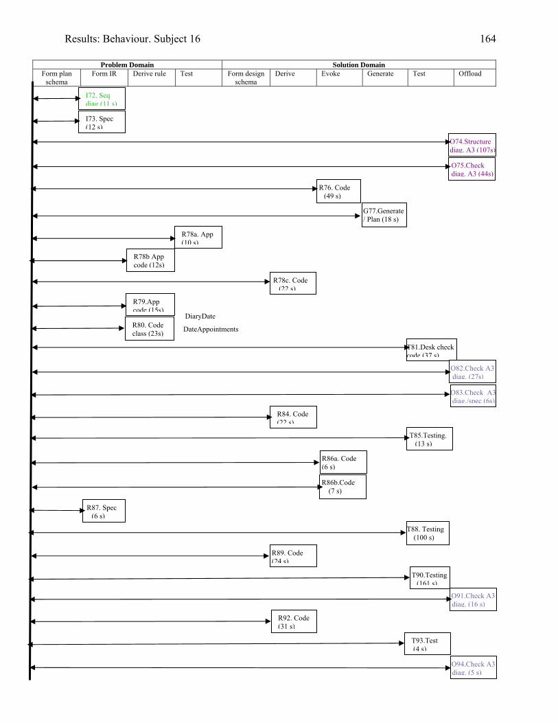
Results: Behaviour. Subject 16 164
Problem Domain Solution Domain
Form plan schema
Form IR Derive rule Test Form design schema
Derive Evoke Generate Test Offload
T88. Testing (100 s)
O91.Check A3 diag. (16 s)
T93.Test (4 s)
R92. Code (31 s)
T81.Desk check code (37 s)
R84. Code (22 s)
T85.Testing. (13 s)
R86a. Code (6 s)
R86b.Code (7 s)
R87. Spec (6 s)
I73. Spec (12 s)
O74.Structure diag. A3 (107s)
R78a. App (10 s)
R78b App code (12s)
R78c. Code (22 s)
I72. Seq diag (11 s)
R79.App code (15s)
R76. Code (49 s)
G77.Generate/ Plan (18 s)
O82.Check A3 diag. (27s)
T90.Testing (161 s)
O75.Check diag. A3 (44s)
R80. Code class (23s)
O83.Check A3diag./spec (6s)
R89. Code (24 s)
O94.Check A3 diag. (5 s)
DiaryDate
DateAppointments
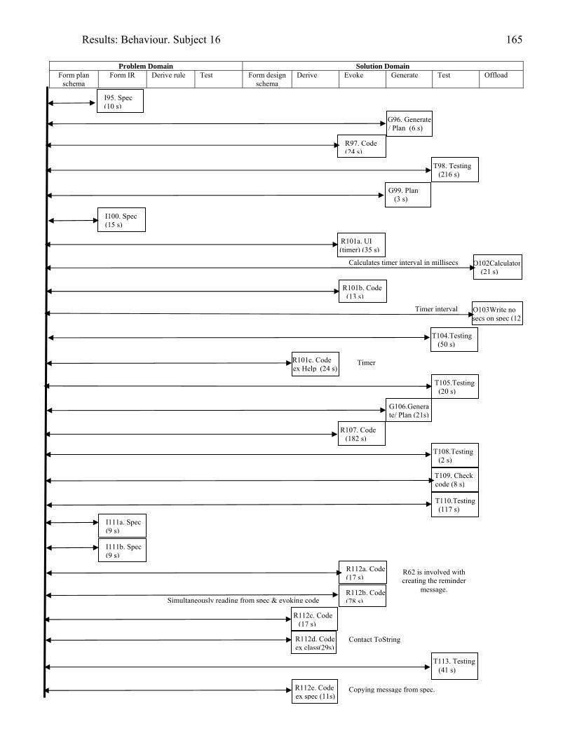
Results: Behaviour. Subject 16 165
Problem Domain Solution Domain
Form plan schema
Form IR Derive rule Test Form design schema
Derive Evoke Generate Test Offload
I111a. Spec (9 s)
I111b. Spec (9 s)
R112a. Code(17 s)
R112b. Code(78 s)
R112c. Code (17 s)
R112d. Code ex class(29s)
T113. Testing(41 s)
Simultaneously reading from spec & evoking code
T98. Testing (216 s)
I100. Spec (15 s)
R101a. UI (timer) (35 s)
O102Calculator(21 s)
R101b. Code (13 s)
O103Write no secs on spec (12
T104.Testing (50 s)
R107. Code (182 s)
T108.Testing (2 s)
I95. Spec (10 s)
R97. Code (24 s)
G96. Generate / Plan (6 s)
G99. Plan (3 s)
R101c. Code ex Help (24 s)
T105.Testing (20 s)
G106.Generate/ Plan (21s)
T109. Check code (8 s)
T110.Testing(117 s)
R62 is involved with creating the reminder
message.
R112e. Code ex spec (11s)
Copying message from spec.
Contact ToString
Timer
Timer interval
Calculates timer interval in millisecs
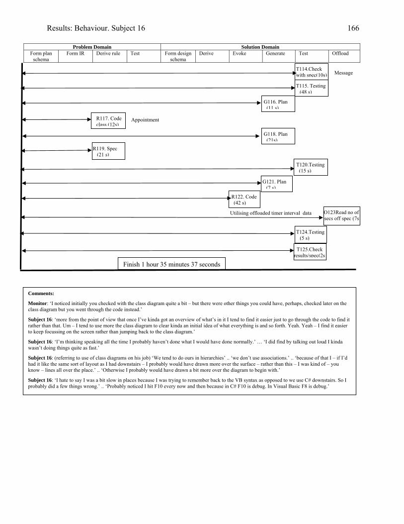
Results: Behaviour. Subject 16 166
Problem Domain Solution Domain
Form plan schema
Form IR Derive rule Test Form design schema
Derive Evoke Generate Test Offload
G116. Plan (11 s)
R119. Spec (21 s)
T120.Testing (15 s)
R122. Code (42 s)
O123Read no of secs off spec (7s
T125.Check results/spec(2s
Comments:
Monitor: ‘I noticed initially you checked with the class diagram quite a bit – but there were other things you could have, perhaps, checked later on the class diagram but you went through the code instead.’
Subject 16: ‘more from the point of view that once I’ve kinda got an overview of what’s in it I tend to find it easier just to go through the code to find it rather than that. Um – I tend to use more the class diagram to clear kinda an initial idea of what everything is and so forth. Yeah. Yeah – I find it easier to keep focussing on the screen rather than jumping back to the class diagram.’
Subject 16: ‘I’m thinking speaking all the time I probably haven’t done what I would have done normally.’ … ‘I did find by talking out loud I kinda wasn’t doing things quite as fast.’
Subject 16: (referring to use of class diagrams on his job) ‘We tend to do ours in hierarchies’ .. ‘we don’t use associations.’ .. ‘because of that I – if I’d had it like the same sort of layout as I had downstairs – I probably would have drawn more over the surface – rather than this – I was kind of – you know – lines all over the place.’ .. ‘Otherwise I probably would have drawn a bit more over the diagram to begin with.’
Subject 16: ‘I hate to say I was a bit slow in places because I was trying to remember back to the VB syntax as opposed to we use C# downstairs. So I probably did a few things wrong.’ .. ‘Probably noticed I hit F10 every now and then because in C# F10 is debug. In Visual Basic F8 is debug.’
Finish 1 hour 35 minutes 37 seconds
T115. Testing(48 s)
T114.Check with spec(10s)
R117. Code class (12s)
G118. Plan (21s)
G121. Plan (7 s)
T124.Testing (5 s)
Appointment
Message
Utilising offloaded timer interval data
Results: Behaviour. Subject 17 167
Subject 17: Industry-experienced programmer
Modifying the invoice application with the aid of UML documentation.
Background
Subject 17 taught himself programming seven years prior to participating in this research. He learned
VB.NET in a second-year tertiary course two years prior, and learned UML modelling one year prior in
third-year tertiary courses. He had two months industry coding experience at the same place of work as
Subject 16, but claimed to not use UML at work.
Subject 17, despite studying courses which covered UML modelling, was not comfortable using it: ‘I
think for me – ah - it’s a lot easier for me to just look at the code than perhaps look at the UML
because I’m not very good at – you know - UML stuff.’
Session
The invoice application was the first modification for Subject 17 and he received UML documentation
with the statement of requirements.
Session achievements
Subject 17 did not complete the exercise within the two hour limit.
He did not clear the new totals, required on the invoice to accommodate the gst, when the invoice was
cleared. Thus successive invoices had invalid gst totals.
He did not have time to add the final invoice total that included the gst.
Apart from that, and some layout and formatting errors, he accurately accomplished all he attempted.
The printing section was not attempted.
Cognitive episodes in modification
Subject 17 read the UML documentation first, starting with the use case model where he concluded:
‘So this is Print invoices for a toy company’, and followed by reading the use case descriptions [1.40]
(I1). This initial internal representation of the problem domain did not change over the time of the
modification, possibly because of the continued exercising of this information, thus ensuring that it
became established in long term memory.
The reading of the use cases was followed by reading the class diagram where he commented:
‘Now I’m looking at the class diagram. [1.52] .. And there appears to be 5 forms.

Results: Behaviour. Subject 17 168
Um. Lot of stuff! [laughs]
OK. Well - Parties and Persons, Organisations. [2.12] (I2).
He glanced at the sequence diagram but vocalised no rule nor representation.
He then read the requirements (I3) followed by another look at the class diagram where he noted the
GST class:
[3.30] ‘I’ll go back to the – um - class diagram and – I can see a GST type. And a GST .. class. [3.44]
(I4)
OK - I’m going to have a look at the – ah - Solution [Explorer] to see what’s there. [3.51] .. Um. OK I
can see a gst.vb class. I’m gonna have a look at this – see what’s about this. OK. Types are stored as
chars – the gstType - and a description as well, and a percentage, which is a decimal.’ [4.18]. (I5).
Thus when Subject discovered the gst class in the class diagram it guided his next activity to look at the
code of the gst class.
He then continued reading the specification from where he stopped in I3 [4.53] (I6).
He marked the sections to be modified on the requirements documentation, placing a line after the gst
formula calculation, and a second line separating off the printing requirements [5.33] (O7).
Subject 17 reread the specification, commenting on its diagram of how the gst should look on the
screen (I8). He ran the program to see how the screen looked and how the application performed (I9,
I10). He continued to run the program (I11) to investigate the Clear Invoice and delete buttons (I11),
then returned to reread the requirements for the Print Preview (I12).
He wanted to start coding so looked carefully at what was showing on the screen, and then at the code
of the data grid that needed modification (I13). In I14 he spent more time studying the code for adding
a column to the data grid. He searched the invoice form code to see where the data grid was mentioned
(I15).
Subject 17 had continued to form his internal representation of the problem domain until R16 [15.36]
when he added the new gst column to the datagrid on the invoice. He then made plans to calculate the
gst and display it (G17), so reviewed the code to discover the methods he needed to modify to this end
(R18), confirming those deductions by running the application (I19). He next chose to study in detail
the code of the first method to be modified (I20), added the heading for the new gst column on the data
grid (I21) and his next steps involved getting the new column to display gst correctly – which he tested
by hard coding a gst value [23.53] (T22).
Once Subject 17 found that his code worked, his attention shifted to calculating the gst instead of using
the hard coding, so he read the requirements to obtain the formula (R23). He generated a plan for
inserting a routine into his first method requiring modification, realising that he needed to get the

Results: Behaviour. Subject 17 169
invoice customer’s gst details (G24), and then he offloaded a note to himself in the method to that
effect (O25).
He returned to study how the customer was loaded into memory (R26), formulating a plan as to what
he had to do the find those details (G27), and checking the class diagram:
[28.56] ‘Um - I’m looking at the class diagram - trying to see if the customer has – um - a gst class.
[29.11] So well - I can’t see it [29.14] (R28).
‘So I’m going to look at the code, which I can probably read better – understand better.’ [29.24]
He looked at the Party class and discovered it had a gst type attribute (R29), so ran the application to
detect the existing customers’ gst types (R30).
He discovered the global variable for mycustomer (R31) and looked at the code to find where it was
accessed (R32), studying the code in R33 to find where it was set.
He created a global variable for gst as a string in R34, generated a plan for its use (G35), but tested his
changes first (T36).
Subject 17 reread the requirements to refresh his memory of the formula to calculate gst (I37), then
planned to extract the gst percentage from the gst type (G38). The gst class was studied (I39), another
plan for handling gst formulated (G40), and the gst form code was studied (I41).
The class diagram was studied in R42:
‘Um - I’m looking for the diagram that has the .. forms.’ [40.46] ‘Ah – it’s the class diagram and - OK.
So it appears that there are – there’s the gst form where they set the gst. [40.59] (R42)
Consequently Subject 17 studied the gst form he had discovered in the class diagram (I43), studied its
code to discover how the gst file was loaded (R44), then tested it to discover that the gst types and
percentages were set (T45). He finally concluded from T45: [44.14] ‘So it appears that for me to get
access to the gst values on my invoice form I need to load them from the xmlfile as is done by the gst
form’. [44.29]
The gst form code was studied further with respect to how the xml file was handled (I46), as he realised
he needed to load the gst file into the invoice form if he wished to extract the gst percentage. He
checked to see if the xml file was already being loaded into the invoice form to prevent duplicating
code (I47). However, he found in his search the invoice form load method for where a number of files
were loaded into memory. He theorised that he should do something similar with the gst file – but
checked the class diagram first to see if the gst class was stored with the customer (he had already
checked this in R28):
Results: Behaviour. Subject 17 170
[47.34] ‘Looking at the customer’s class to see if the gst’s ….. if the gst class is stored with the
customer. ..… There is a class for - called customers, which stores the customer’s and the invoices.
[48.09] (I48)
He glanced through the use case descriptions to see if the gst types were loaded anywhere:
[49.19] ‘Yeah – I’m looking at the use case model. Ah - there’s a use case there for adding gst which is
probably be using the – I’m probably going to find one for ...
OK – there’s Create Invoice, which extends Clear Invoice. OK - I’m looking at the use case to Create
Invoice. ……. OK. It shows that the – um – when the invoice is created it’s saved to the customers.xml
– saved to the customers.xml file’. [50.16] (I49)
Subject 17 did not look at a UML diagram again for the session.
He continued to search for a way to get the customer’s gst percentage from the customer’s gst type:
‘I’m gonna go back to the frmInvoice and I’m looking at the – ah - customer’s combo box. OK. OK - so
yeah - I’ve got the current customer’s gstType, now I’m gonna look .. to see what else I can get from
the customer object’. [51.18]
Um – it’s got addresses, got a PartyCode, and a PostCode .. (I50a)
I’m not entirely sure what PartyCode is. (Other)
I’ll just have a look. It’s an Integer. … OK. [51.43] (I50b).
Subject 17 proceeded to successfully copy the routine for loading the gst types from the gst form into
the loading region of the invoice form. His aim was to derive the gst percent for the current customer’s
gst type. However, he then forgot what gstTypes was:
[57.15] ‘I’ve absolutely forgotten what myGSTTypes does. There is - it is a variable of type gstTypes so
I need to look at that class gstTypes, which is a type – it’s a SortedList. [57.30] (R53).
He took a long time to discover that gst type was stored as a Char in the gst class and as a String in the
Party class, but once this problem was overcome he continued to successfully complete the
modification to the screen invoice until he ran out of time.
Comments on cognitive interactions
On being asked if the UML documentation was helpful, Subject 17 replied:
‘- it’s just that rather than having to read everything I could look at some things and see some stuff
straight away. Um - probably more - I looked at the class diagram a bit. Um I didn’t pay much
attention to the – um - other diagrams – the use cases and stuff like that.’
From Subject 17’s post-session debriefing:
Monitor: ‘The class diagram for you was the most helpful?’

Results: Behaviour. Subject 17 171
Subject 17: ‘Yeah. That’s right.’
Monitor: ‘Do you ever use any diagrams when you are programming - writing code?’
Subject 17: ‘No. I mean - I’m used to ERDs so I guess that – you know - makes me – ah – feel
comfortable with the class diagrams.’
Forming an internal representation
Subject 17 used the use case model (I1) and class diagram (I2, I4) to initially form some internal
representations. The text based use case descriptions and sequence diagram he registered as being
present but no information was gleaned from them. His comment in I1: ‘So this is Print invoices for a
toy company’ demonstrates his initial understanding. In I2 he commented upon the form classes and the
fact that this had registered in his problem space was confirmed later when he made the comment: ‘Um
- I’m looking for the diagram that has the .. forms.’ [40.46]. This comment was made when he was
looking to find where the gst was set, and he followed the comment by looking in the class diagram
(R42) where he discovered the relevant gst form class. This discovery guided his subsequent actions to
search that form’s code.
In I4 he discovered the gst class on the class diagram which led him to search that class’s code.
He twice looked at the class diagram (I28, I48) to see if a customer had a gst class (it does not – this
was a design decision to ensure that historical invoices for customers were not inadvertently
recalculated with a new gst percentage, if the gst had changed over time). The information had not been
exercised in Subject 16’s problem space and needed refreshing.
Subject 17 read the class diagram in I28 to ascertain the absence of a gst class in customer, followed
by reading the code which he claimed he would probably understand better. In fact he did expand his
understanding after seeing the code in R29, to find that the abstract Party class held the gst type (this
was also illustrated on the class diagram).
In I48 Subject 17 did discover that the customers class stored customers with their invoices, but his
next actions were not influenced by this.
He looked briefly at the use case description for Create Invoice in I49 where he discovered that the
customers and their invoices were saved to the customers.xml file, but again there was no evidence in
his following actions to indicate that this influenced his progress.
Using UML documentation in a set with the problem space
There was no evidence of the UML documentation being used in a set.
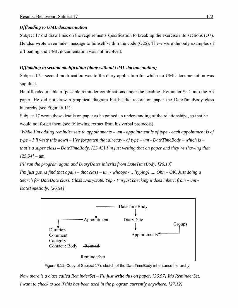
Results: Behaviour. Subject 17 172
Offloading to UML documentation
Subject 17 did draw lines on the requirements specification to break up the exercise into sections (O7).
He also wrote a reminder message to himself within the code (O25). These were the only examples of
offloading and UML documentation was not involved.
Offloading in second modification (done without UML documentation)
Subject 17’s second modification was to the diary application for which no UML documentation was
supplied.
He offloaded a table of possible reminder combinations under the heading ‘Reminder Set’ onto the A3
paper. He did not draw a graphical diagram but he did record on paper the DateTimeBody class
hierarchy (see Figure 6.11):
Subject 17 wrote these details on paper as he gained an understanding of the relationships, so that he
would not forget them (see following extract from his verbal protocols).
‘While I’m adding reminder sets to appointments – um - appointment is of type - each appointment is of
type – I’ll write this down – I’ve forgotten that already - of type – um - DateTimeBody – which is –
that’s a super class – DateTimeBody. [25.45] I’m just writing that on paper and they’re showing that
[25.54] – um.
I’ll run the program again and DiaryDates inherits from DateTimeBody. [26.10]
I’m just gonna find that again – that class – um - whoops - .. [typing] .... Ohh – OK. Just doing a
Search for DateDate class. Class DiaryDate. Yep - I’m just checking it does inherit from – um -
DateTimeBody. [26.51]
Figure 6.11. Copy of Subject 17’s sketch of the DateTimeBody inheritance hierarchy Now there is a class called ReminderSet – I’ll just write this on paper. [26.57] It’s ReminderSet.
I want to check to see if this has been used in the program currently anywhere. [27.12]
Groups Duration Comment Category Contact : Body Remind ReminderSet
DateTimeBody
Appointment DiaryDate
Appointments

Results: Behaviour. Subject 17 173
So I’m doing a search for ReminderSet. [27.16] To see if it occurs anywhere outside the ReminderSet
file. [27.23] OK. And it occurs in the frmReminderSet column. OK. That’s all. So.
Um. I feel I should be adding a ReminderSet variable – or something like that - to the – um - DiaryDate
class. [27.54] OK. [27.55]
Ah – [reading from modification] ‘enable a reminder set to be Assigned to Appointment.’ [27.59] OK.
So that DiaryDate – ah - must have a - um – where is it – there’s appointments. OK. [28.12]
There’s a - DiaryDate has a – ah – a variable called – a class variable – called – um -
myDateAppointments of type appointments. [28.24] OK. I’m just writing that on my paper about where
I should be adding myReminderSets to. [28.34]
Um - Appointments class – um - have a look at that – it – ah - inherits from the Group – Groups class.
[28.46]
OK – um - Appointments class – and there is a – ah - appointment class. [29.02] So I assume that
appointments must be full of appointment. [29.07]
Looking at the Appointment class, which also inherits from DateTimeBody. [29.20]. ..…
OK. Um – looking at the properties. [29.40] There’s one called – ah - appointCat which is a – ah - an
integer. [29.48] Ah – OK. I’m just trying to work out what each of these properties are for. [29.56] OK
- Duration, Comment, the Contact, and a Cat. [30.02]
And this is probably where I want to add my – my – um – what is it? - myReminderSet. [30.12] So
Duration which is a decimal and Comment, Cat. [30.21] Oh - OK – that’s Category, I remember from
the form, now – Category, and Contact which is of type Body, which I’m not really interested in.’
[30.36]
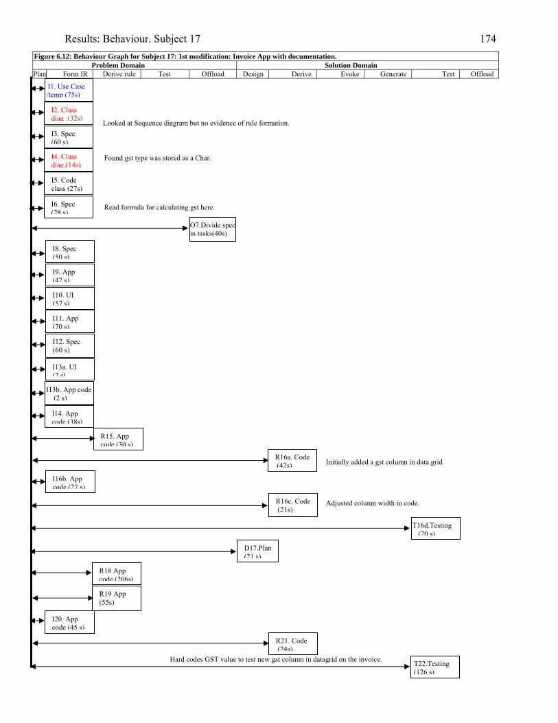
Results: Behaviour. Subject 17 174
Figure 6.12: Behaviour Graph for Subject 17: 1st modification: Invoice App with documentation. Problem Domain Solution Domain
Plan Form IR Derive rule Test Offload Design Derive Evoke Generate Test Offload
I1. Use Case /temp (75s)
I2. Class diag .(32s)
I3. Spec (60 s)
I4. Class diag.(14s)
I5. Code class (27s)
I6. Spec (28 s)
I9. App (47 s)
I8. Spec (50 s)
O7.Divide specin tasks(40s)
I10. UI (57 s)
I11. App (70 s)
I12. Spec (60 s)
I13a. UI (7 s)
I13b. App code (2 s)
I14. App code (38s)
R15. App code (30 s)
T16d.Testing (20 s)
R18 App code (206s)
T22.Testing (126 s)
R19 App (55s)
I20. App code (45 s)
R16c. Code (21s)
Looked at Sequence diagram but no evidence of rule formation.
R16a. Code (42s)
I16b. App code (27 s)
D17.Plan (21 s)
R21. Code (24s)
Hard codes GST value to test new gst column in datagrid on the invoice.
Read formula for calculating gst here.
Found gst type was stored as a Char.
Initially added a gst column in data grid
Adjusted column width in code.
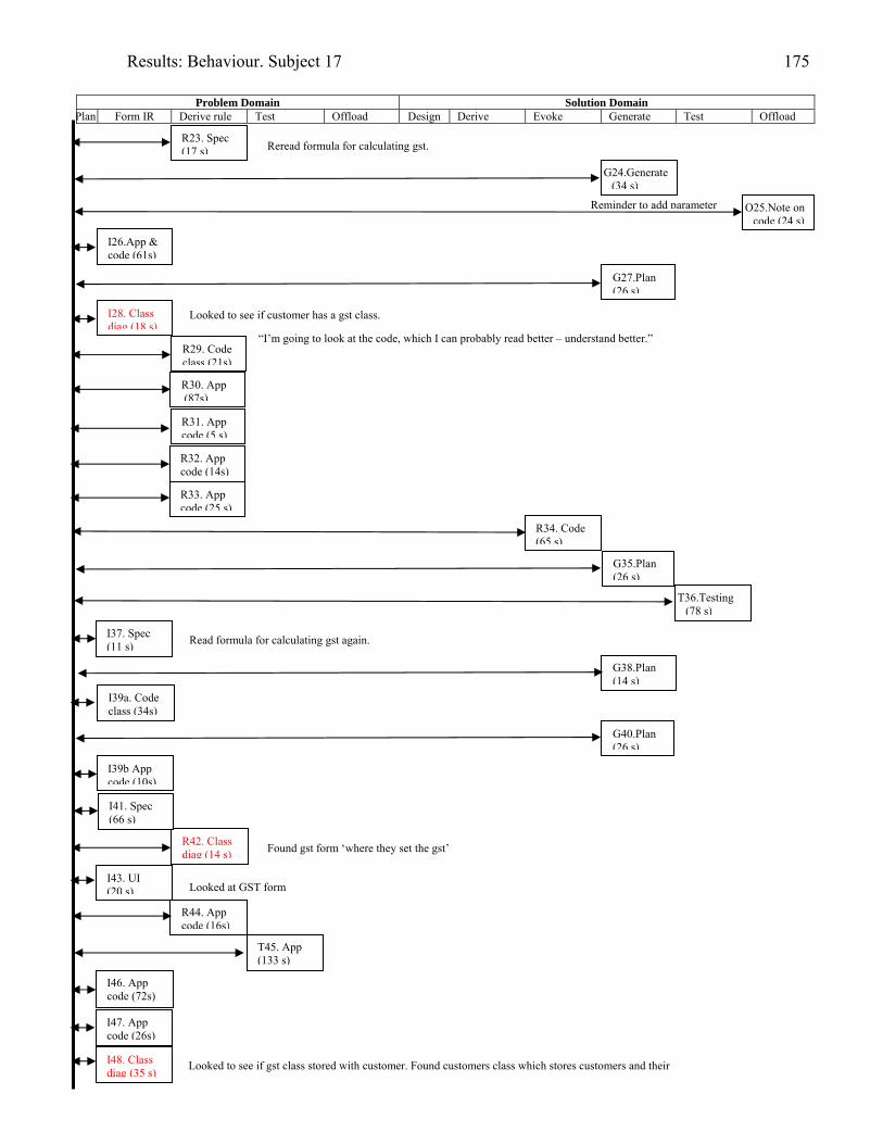
Results: Behaviour. Subject 17 175
Problem Domain Solution Domain
Plan Form IR Derive rule Test Offload Design Derive Evoke Generate Test Offload
R23. Spec (17 s)
I26.App & code (61s)
I28. Class diag (18 s)
R29. Code class (21s)
R31. App code (5 s)
O25.Note on code (24 s)
G24.Generate (34 s)
R32. App code (14s)
R34. Code (65 s)
I39a. Code class (34s)
T36.Testing (78 s)
I37. Spec (11 s)
I39b App code (10s)
I43. UI (20 s)
R42. Class diag (14 s)
I41. Spec (66 s)
R44. App code (16s)
T45. App (133 s)
I46. App code (72s)
I48. Class diag (35 s)
“I’m going to look at the code, which I can probably read better – understand better.”
Reminder to add parameter
G27.Plan (26 s)
R30. App (87s)
R33. App code (25 s)
G38.Plan (14 s)
G40.Plan (26 s)
I47. App code (26s)
G35.Plan (26 s)
Looked at GST form
Looked to see if customer has a gst class.
Read formula for calculating gst again.
Found gst form ‘where they set the gst’
Looked to see if gst class stored with customer. Found customers class which stores customers and their
Reread formula for calculating gst.
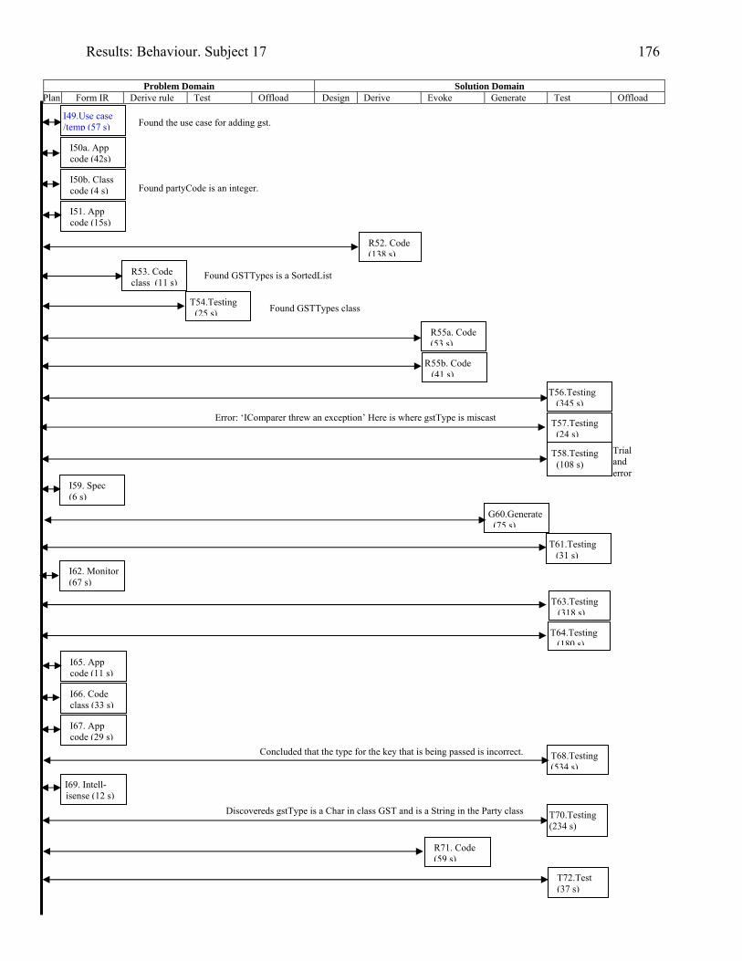
Results: Behaviour. Subject 17 176
Problem Domain Solution Domain
Plan Form IR Derive rule Test Offload Design Derive Evoke Generate Test Offload
I49.Use case /temp (57 s)
T56.Testing (345 s)
I50a. App code (42s)
T58.Testing (108 s)
T61.Testing (31 s)
T63.Testing (318 s)
T64.Testing (180 s)
T68.Testing (534 s)
T70.Testing (234 s)
T72.Test (37 s)
R71. Code (59 s)
I65. App code (11 s)
T57.Testing (24 s)
I50b. Class code (4 s)
I51. App code (15s)
R53. Code class (11 s)
R55b. Code (41 s)
Trial and error
I59. Spec (6 s)
G60.Generate (75 s)
I66. Code class (33 s)
I67. App code (29 s)
I69. Intell-isense (12 s)
T54.Testing (25 s) Found GSTTypes class
R55a. Code (53 s)
Error: ‘IComparer threw an exception’ Here is where gstType is miscast
I62. Monitor (67 s)
Concluded that the type for the key that is being passed is incorrect.
Discovereds gstType is a Char in class GST and is a String in the Party class
Found partyCode is an integer.
R52. Code (138 s)
Found GSTTypes is a SortedList
Found the use case for adding gst.
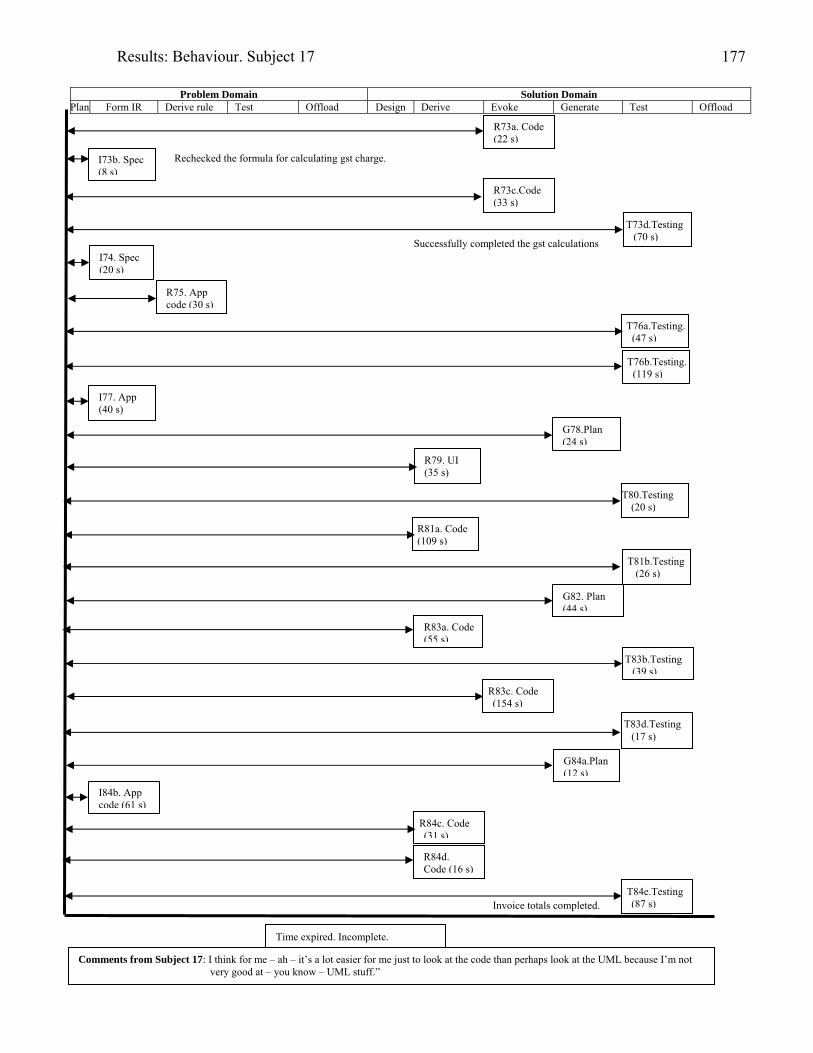
Results: Behaviour. Subject 17 177
Problem Domain Solution Domain
Plan Form IR Derive rule Test Offload Design Derive Evoke Generate Test Offload
R73a. Code (22 s)
R73c.Code (33 s)
I73b. Spec (8 s)
T73d.Testing (70 s)
I74. Spec (20 s)
R75. App code (30 s)
T76a.Testing. (47 s)
R79. UI (35 s)
T80.Testing (20 s)
T81b.Testing (26 s)
T83b.Testing (39 s)
R83c. Code (154 s)
T83d.Testing (17 s)
Time expired. Incomplete.
Comments from Subject 17: I think for me – ah – it’s a lot easier for me just to look at the code than perhaps look at the UML because I’m not very good at – you know – UML stuff.”
I77. App (40 s)
R83a. Code (55 s)
R84c. Code (31 s)
I84b. App code (61 s)
R84d. Code (16 s)
T84e.Testing (87 s)
G78.Plan (24 s)
R81a. Code (109 s)
G82. Plan (44 s)
G84a.Plan (12 s)
Rechecked the formula for calculating gst charge.
Successfully completed the gst calculations
Invoice totals completed.
T76b.Testing. (119 s)
Results: Behaviour. Subject 18 178
Subject 18: Industry-experienced programmer
Modifying the invoice application with the aid of UML documentation.
Background
Subject 18 was a self-taught programmer, having taught himself to program in HTML eight years prior
to his session. He also taught himself OO concepts six years prior – then learned OO programming in a
first-year tertiary course in Java, about five years prior. His UML knowledge was gained in a second-
year course, about three years prior, and, at about the same time, in a different course, he was
introduced to VB.NET.
Subject 18 had run his own company, in which he used a variety of programming languages, including
VB6, for two years.
Session
The Invoice application was the second modification for Subject 18 and he received UML
documentation with the statement of requirements.
Session achievements
Subject 18 did not complete the modification within the two hours.
He correctly added a new gst column and obtained a customer’s gst type, but that was all. He did not
load the gst class values into the memory for the invoice form and thus could not obtain the gst
percentage for calculating the gst to be paid on an invoice item.
Cognitive episodes in modification
Because Subject 18 was not amongst the five most successful modifiers in his group, and did not look
at the UML documentation for his task, his protocols have not been transcribed.
He was the only subject in both groups to not look at the UML documentation, and for this difference is
reported here.
In his post-session debriefing, when he was asked which UML diagrams he preferred, Subject 18
answered that if he had the time he would start with a use case then derive a class diagram. He would
be more likely to use modelling on more complex projects ‘such as transactions with more than three
actors’. He believed the use case model to be very useful, yet stated that you had to know the actual

Results: Behaviour. Subject 18 179
application to know what to do with it, so considered the use case descriptions to be not very important.
He did consider the class diagram to be important as it gave the relationships between the classes.
He admitted that he did not look at the UML documentation for the invoice modification as he had to
go straight to the code. He was in a hurry to do the task. ‘When it comes to a product you want to see
the code as soon as possible.’
Results: Behaviour. Subject 20 180
Subject 20: Industry-experienced programmer
Modifying the invoice application with the aid of UML documentation.
Background
Subject 20 taught himself programming at the age of 12, and VB at age 15, moved to VB.NET at 17,
and industry programming employment in C# at 18. As Subject 20 was 21 at the time of participation
in this research, he had four years industry experience. He was employed as a Senior Developer at
Company A (refer to Chapter 3) in Auckland, New Zealand at the time of participation, and was
studying third year courses at University.
Class diagrams were extensively used where Subject 20 worked, and occasionally use cases, but those
were the only UML diagrams. Company A’s own CASE tool was used for drawing the models. When
the Monitor inquired as to whether it was required that class diagrams be used at Company A, Subject
20 replied: ‘It’s not required – um – it’s - they’re usually included in the specs. But - um - quite often
aren’t updated. So – they’ll be included to – sort of - when we’re designing things up front. Um -
usually very closely linked to the ERDs that we do. Um – in fact sometimes we’ll do away with the class
diagram and just use the ERD if the application mirrors it, which it often does.’
Subject 20 believed that the use case model was superfluous. He found text-based description more
useful.
He drew diagrams quite often when programming in Java because he believed its integrated
development environment (IDE) wasn’t very good. He found that Visual Studio, especially version 5,
was easier to use as it could generate diagrams – a feature which he utilised ‘quite often .. to have a
look how it’s – how it’s going about doing things.’ In Visual Studio a class can be collapsed down, or
expanded to display the properties and the methods.
Subject 20 often added extra information to a class diagram – such as indicating primary key attributes
if the class related directly to an entity.
Session
The Invoice application was the second modification for Subject 20 and he received UML
documentation with the statement of requirements.
Session achievements
Results: Behaviour. Subject 20 181
Subject 20 believed he had completed the diary application modification after 1 hour 46 minutes and 49
seconds had elapsed. When tested after the session it was found that he had a bug in the routine that
added a new quantity to an old quantity for a product already on an invoice. He was adding the old
quantity in twice to the gst total for the invoice. He also had some formatting errors in that he did not
solve how to restrict the screen display to two decimal places.
Cognitive episodes in modification
Subject 20 read the specification for the modification first (I1), then studied the screen form (I2), then
ran the application to learn what it did (I3). He checked the class diagram to find the invoice class, its
attributes and methods (I4):
[3.42] ..Right – so invoice has – invoice number, invoice date, items and then totalItemsCount, and –
oh - right - they’re methods. [3.59] (I4).
He continued to run the program, selecting a product for an invoice line item (I5), then looked at the
class diagram to find the invoice items collection class (I6);
[4.56] It doesn’t - no – there’s a collection of invoiceItems or invoiceItem but it doesn’t tell me
anything about deleting them. [5.14] (I6).
He briefly looked at a use case template but derived nothing, then continued to run the program until he
exited (I7). He checked the class code for invoice and invoice items (I8), and found that the Product
class referenced in invoice item – after which he looked Product up on the class diagram (I9) –
commenting: ‘It’s easier than opening up the – um – the Product class and trying to switch back and
forth between them.’:
[7.42] And so Product has a ProductNo, a description, a Price and ToString which I don’t care about.
OK. There’s nothing in here about being able to override prices so I’m assuming that’s not in the
scope. And then there’s an invoiceProductPrice. Oh – OK maybe there is. [8.10] (I9).
He continued to study the code for the data grid columns (I10), followed by planning to find and study
where the data grid was populated (P11). Then Subject 20 reread the requirements specification (I12).
He ran the program discovering its ability to add quantity to an invoice item product that already
existed in the data grid (I13). He studied the code for the invoice form and discovered where the data
grid was populated and the data saved (I14 & 15).
At I16 he looked at the class diagram again: [12.53] ‘So it doesn’t seem to do anything along the lines
of looking at the invoice item which I’m just looking at on the class diagram again. It doesn’t seem to
actually use it in there. [13.04] (I16).
He derived the fact that data was being stored in a datagrid – not in objects (R17).
Results: Behaviour. Subject 20 182
He explained his plan for finding out how to reference the gst (G18). He followed through the code for
storing the items (I19 & I 20), checked with the requirements that a customer had a gst type (I21), then
planned to add a gst type to each customer (G22).
However, he then checked the class diagram for the Party class where he discovered that a Party
already had a gst type code as an attribute: [14.30] ‘And there’s a – ah – yes - Party. Parties store all
the parties without their invoices. Customers store parties with invoices. Mmm. OK. But a customer is
still a party so I can pretty much ignore that. Have a look at it.
And there’s already an attribute on here called mPartyGSTType.’ [14.56] (I23a).
He cross checked the Party class code to verify this (R23b). He then reread the part of the specification:
‘Each customer of Tuff Toys has a gst type’ (I24), then checked the xml file to discover values of gst
types already stored there [15.48] (I25). He offloaded some of these customer details found in the xml
file to A3 as potential test data (O26) [17.45].
He generated a plan to discover where the ‘customer using thing’ was (P27), so continued looking at
the code, discovered the menu for ‘Edit Customer’, but it was not active within the program at that time
(it became active when an invoice was cleared) (I28a). He checked both the class diagram (I28b) and
use case model (I29) to find it was not mentioned there.
He formed the plan to get the customer’s gst type to enable the gst calculations (P30), rereading the
requirements section on customer gst (I31).
In D32, Subject 20 formulated the plan to create a subroutine to calculate the gst [19.57]. So he looked
at the class diagram (I33) where he verified that the invoice item was not related to gst: [19.59] ‘So
invoice item doesn’t have anything to do with gst at the moment. The - Oh – hang on – there’s this - I
haven’t seen this before. This gst entity and the collection of it is gstTypes. and it hooks up to frmGST
– I wonder what that does? [20.20] (I33).
Subject 20 executed the gst form for maintaining gst (I34), then verified by reading the specification
that the activities of the form gst were outside the scope of the present changes (I35).
He then decided to add the new column to the datagrid to accommodate the gst values for the invoice
line items (D36a), checked the columns illustrated on the requirements (I36b), read the code to find
where this should be done (I36c), then added a new column (I36d) and completed this by [24.27]
(T36g). His next step was to calculate the gst values (D37) [24.46]. He checked again that a customer
had a gst type on the class diagram (I38a) [24.55], then cross-checked with the class code (I38b)
[25.05]. Subject 20 decided to not hard code the gst (G39) and searched for all references to gst to look
at its code (G40). Whilst looking at the code he discovered methods for updating a Party to a Customer
(I41). He looked at the class diagram but formed no rule, so returned to the code to discover the gst
Results: Behaviour. Subject 20 183
class (I42). He studied the xmlData class (I43) to see how the xml files were handled. He remembered
the first modification where he had a stub loading class to complete (I44) – but decided to load
customers and gst types instead in the loading region (R45a). It is here that he tended to use the class
diagram in a set while coding the load gst types file:
‘So I’m going to call this myGSTTypes and I’ll do a clear on that as well. [29.48]. So that variable
doesn’t exist yet but I’ll do it in a second.
myGSTTypes = CType(myGSTFile.Load[xml]File(“cust …
Ah – now I have to look at the file name –OK – so it’s: gst.xml” (R45a)
I saw that in the bin folder [30.04].
And its arguments ??? – and so its type is – ah – GST I think.
Yes it is – GST – I looked at the class diagram to find that out’ (R45b) [30.15]
After some coding Subject 20 decided to test:
‘OK – I’ll just make sure it compiles – and it doesn’t. [31.13] ‘Value of type InvoiceApp.gst cannot be
converted to an InvoiceApp.gstTypes’ [31.18] [T45e].
‘OK – so just looking back at the diagram’. [31.21] ‘Oh – OK. So there’s GST and then gstTypes. So
gstTypes is the collection of gst’ [31.29].
‘I’m not sure whether it’s not called gstType. But – anyway’ [31.33]. [I45f]
‘Um – so it’s a gst Types’ [31.37].
Subject 20 changed his code to gstTypes and the loading routine worked after this.
Subject 20 decided to code the calculate gst method and by R49 started the coding for it. During the
development of the code to achieve the sub-goal of creating the calculate gst routine the class diagram
is again used in a set with coding:
‘So I’ll create this Private Function CalculateGST [34.46] and it’s gonna pass in a – and it’s a
Decimal. There it is – I’ll just hold it over the – um - Price on there. Um - a Decimal as a price. And
the other argument was PartygstType which is a String. Decimal PartyGSTType As a String - and it’s
going to return a Decimal as well. [35.16] (R49b).
OK. So the first thing I need do is work out what the gst rate is based on that GSTType. [35.26] (G49c)
So I’ll look at the class diagram:
So there’s this gstTypes. [35.30] That doesn’t look like there’s a method on the gstTypes collection to
find a particular gstType based on the string representation of the ID. [35.40] (I49d).
So I’ll – Um - I’ll just have a look at that actually.
So I created a variable called myGSTTypes. [35.51] (R49e)
Subject 20 continued to code the routine until he needed to find the name of the class again:
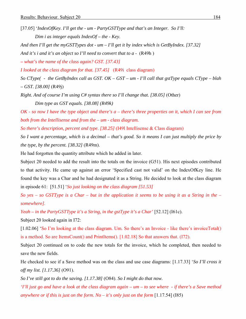
Results: Behaviour. Subject 20 184
[37.05] ‘IndexOfKey. I’ll get the - um - PartyGSTType and that’s an Integer. So I’ll:
Dim i as integer equals IndexOf – the - Key.
And then I’ll get the myGSTTypes dot - um – I’ll get it by index which is GetByIndex. [37.32]
And it’s i and it’s an object so I’ll need to convert that to a - (R49h )
– what’s the name of the class again? GST. [37.43]
I looked at the class diagram for that. [37.45] (R49i class diagram)
So CType( - the GetByIndex call as GST. OK – GST – um - I’ll call that gstType equals CType – blah
– GST. [38.00] (R49j)
Right. And of course I’m using C# syntax there so I’ll change that. [38.05] (Other)
Dim type as GST equals. [38.08] (R49k)
OK - so now I have the type object and there’s a – there’s three properties on it, which I can see from
both from the Intellisense and from the – um - class diagram.
So there’s description, percent and type. [38.25] (I49l Intellisense & Class diagram)
So I want a percentage, which is a decimal – that’s good. So it means I can just multiply the price by
the type, by the percent. [38.32] (R49m).
He had forgotten the quantity attribute which he added in later.
Subject 20 needed to add the result into the totals on the invoice (G51). His next episodes contributed
to that activity. He came up against an error ‘Specified cast not valid’ on the IndexOfKey line. He
found the key was a Char and he had designated it as a String. He decided to look at the class diagram
in episode 61: [51.51] ‘So just looking on the class diagram [51.53]
So yes – so GSTType is a Char – but in the application it seems to be using it as a String in the –
somewhere].
Yeah – in the PartyGSTType it’s a String, in the gstType it’s a Char’ [52.12] (I61c).
Subject 20 looked again in I72:
[1.02.06] ‘So I’m looking at the class diagram. Um. So there’s an Invoice - like there’s invoiceTotal()
is a method. So are ItemsCount() and PrintItems(). [1.02.18] So that answers that. (I72).
Subject 20 continued on to code the new totals for the invoice, which he completed, then needed to
save the new fields.
He checked to see if a Save method was on the class and use case diagrams: [1.17.33] ‘So I’ll cross it
off my list. [1.17.36] (O91).
So I’ve still got to do the saving. [1.17.38] (O84). So I might do that now.
‘I’ll just go and have a look at the class diagram again – um – to see where - if there’s a Save method
anywhere or if this is just on the form. No – it’s only just on the form [1.17.54] (I85)

Results: Behaviour. Subject 20 185
I’ll just have a look at the use case too. [1.17.56]. Um – so that’s the second page. Create invoice
involves to create and save invoice. Description 3 is the save invoice. And there’s a whole lot of
extension things here which don’t look relevant to me. Um – this is for adding customers, adding a
product. OK. So none of these are any use really’ [1.18.26] (I86).
Subject 20 completed the coding related to the invoice on screen, including the new totals and saving
the new results. His next task was to complete the printing routine to include the gst totals. He followed
through the printing code until he came to a routine called by the invoice:
‘Oh – OK – so it’s calling this PrintItems method on the Invoice’. [1.27.07] (I97a)
So looking at the class diagram. [1.27.10] ‘Oh yeah – invoice has this PrintItems’ [1.27.12] (I97b).
Subject 20 did not refer to the UML diagrams again as he completed the exercise.
Comments on cognitive interactions
In his post session interview he commented: ‘Well - it is interesting - you see the UML did help. … And
also I tend to rely more on intellisense where I can. But having said that, the UML was good for
finding the relationships between the different things. .. But I only used the class diagram. The other
ones were pretty useless. They’re probably good for understanding how the program works but I could
work that out from the code so I wasn’t terribly concerned.’
Forming an internal representation
Subject 20 used the class diagram to assist in his formation of an internal representation in I4, I6 and
I9. In I8 he looked at the invoice class code to verify the attributes he had already observed in I4, thus
reinforcing his internal representation. The information obtained from I6 was relevant but was not used
for some period of time following its discovery. He commented that it was easier to look at the class
diagram than the code before looking in I9. Although I9 added to his understanding of the application,
it was not useful for the modification.
He later looked at the class diagram to check that the input data did not go directly into the invoice
item (I16), this time confirming what he had discovered from the code. As the exercising of data assists
in establishing its presence in memory it can be said that the class diagram in I4 and I16 was useful.
Subject 20 added to his internal representation with respect to the customers class and the gst type
attribute within the Party class, both of which he found in the class diagram in episode 23, then cross-
checked his findings with respect to the Party class by checking the code. As the gst type in Party is
essential for successfully completing the modification this was an important discovery.

Results: Behaviour. Subject 20 186
In I33 he checked the class diagram to see that there was no existing link between invoice item and gst,
and by chance discovered the gst, gstTypes, and gst form classes of which he had not been aware. As a
result he looked in the gst form code to discover where the gst types were input. In I72 his discovery of
the invoiceTotal() method on the class diagram guided his following coding.
In I85 he searched for a save method in the class diagram and ascertained that it was not used there,
and then checked the use case descriptions in I86 for the same details. That was the third time he
looked at use case documentation during the session, his first view following I6 resulting in no rules
being induced, and his second view (I29) being brief, where he discovered a use case for ‘Add Product’
which did not contribute to the modification. The discovery that there was no Save method in the class
diagram in I85 did guide subject 20 to look in the invoice form code.
In I97 Subject 20 found the PrintItems() method in the class diagram which guided him to look in the
class where it resided. I97 was Subject 20’s last use of UML documentation.
Using UML documentation in a set with the problem space
Subject 20 had used the UML class diagram in a set with his coding effort for episode 45 where he
derived code from the existing application. He extensively used the class diagram in episode 49, but
this time for evoking code (refer to Figure 6.12: Behaviour graph). He again used the class diagram in
a set in episode 61 – but was using it more for a speedy confirmation of type-casting of variables for
evoked rules. All rules were induced in the solution domain.
Offloading to UML documentation
Subject 20 did not offload to UML documentation. In O26 he wrote some customer details on the A3
sheet as possible test data. In O63 he drew circles around the new totals illustrated on the requirements
specification in order to highlight them. He made a further note on the A3 sheet as a reminder of what
to do in O64c. He created a To Do list on-line in O80, crossed off what he had completed in O83, and
then read the next item in his list in O84.
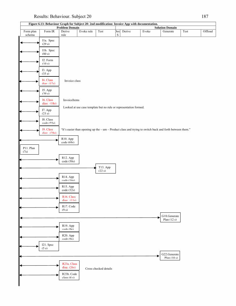
Results: Behaviour. Subject 20 187
Figure 6.13: Behaviour Graph for Subject 20: 2nd modification: Invoice App with documentation. Problem Domain Solution Domain
Form plan schema
Form IR Derive rule
Evoke rule Test DesiS
Derive Evoke Generate Test Offload
I1a. Spec (29 s)
I2. Form (10 s)
“It’s easier than opening up the – um – Product class and trying to switch back and forth between them.”
I3. App (35 s)
I4. Class diag. (17s)
I5. App (39 s)
I6. Class diag. (18s)
I9. Class diag. (28s)
I8. Class code (55s)
I7. App (23 s)
R10. App code (69s)
R12. App code (50s)
T13. App (22 s)
R14. App code (16s)
R15. App code (32s)
R19. App code (9s)
R20. App code (9s)
I21. Spec (5 s)
R23b. Code class (4 s)
R23a. Class diag. (26s)
G22.Generate. Plan (10 s)
I1b. Spec (80 s)
P11. Plan (7s)
R17. Code (9 s)
G18.Generate Plan (12 s)
R16. Class diag. (11s)
Invoice class
InvoiceItems
Cross checked details
Looked at use case template but no rule or representation formed.
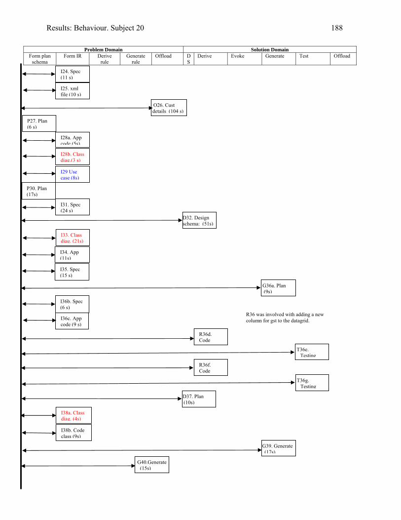
Results: Behaviour. Subject 20 188
Problem Domain Solution Domain
Form plan schema
Form IR Derive rule
Generate rule
Offload DS
Derive Evoke Generate Test Offload
I24. Spec (11 s)
I25. xml file (10 s)
P30. Plan (17s)
O26. Cust details (104 s)
I33. Class diag. (21s)
I28b. Class diag.(3 s)
G36a. Plan (9s)
I36b. Spec (6 s)
I36c. App code (9 s)
R36d. Code
T36e. Testing
I34. App (11s)
R36f. Code
T36g. Testing
I38b. Code class (9s)
D37. Plan (10s)
I38a. Class diag. (4s)
G39. Generate (17s)
G40.Generate (15s)
P27. Plan (6 s)
I28a. App code (5s)
I29 Use case (8s)
I31. Spec (24 s)
D32. Design schema: (51s)
I35. Spec (15 s)
R36 was involved with adding a new column for gst to the datagrid.
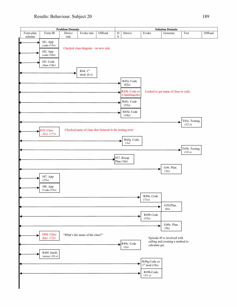
Results: Behaviour. Subject 20 189
Problem Domain Solution Domain
Form plan schema
Form IR Derive rule
Evoke rule Offload DS
Derive Evoke Generate Test Offload
I42. App code (10s)
I41. App code (25s)
R44. 1st mod. (6 s)
R45a. Code (82s)
R45b. Code ex ClassDiag(8s)
R45c. Code (35s)
R45d. Code (10s)
I49d. Class diag. (12s)
T45e. Testing. (12 s)
T45h. Testing.(19 s)
R49a. Code (31s)
I47. App (25s)
I45f. Class diag. (12s)
R49g.Code ex 1st mod (18s)
R49h.Code, (35 s)
I43. Code class (18s)
Checked class diagram – no new rule.
G46. Plan. (3s)
G50.Plan. (6s)
R49b Code (35s)
G49c. Plan. (9s)
R49e. Code (3s)
R49f. Intell- isense (18 s)
Looked to get name of class to code.
R45g. Code (3s)
Checked name of class that featured in the testing error
D37. Recap Plan (10s)
I48. App Code (25s)
“What’s the name of the class?” Episode 49 is involved with calling and creating a method to calculate gst.
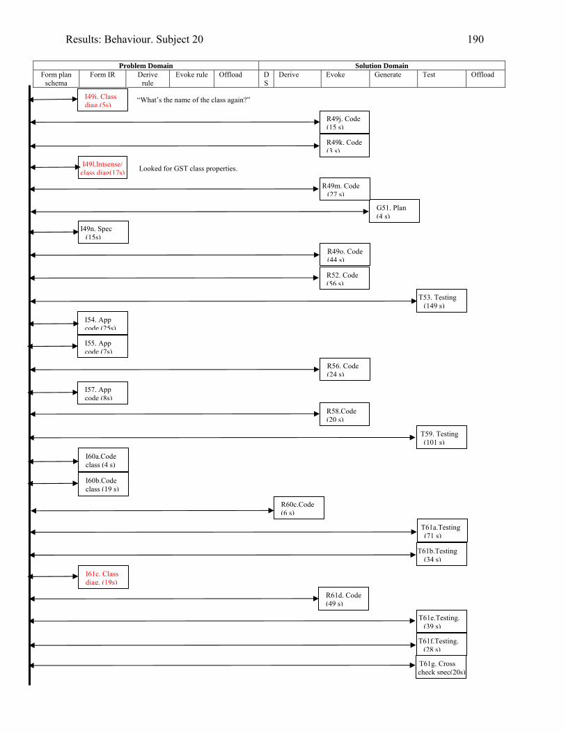
Results: Behaviour. Subject 20 190
Problem Domain Solution Domain
Form plan schema
Form IR Derive rule
Evoke rule Offload DS
Derive Evoke Generate Test Offload
I49i. Class diag.(5s)
R49j. Code (15 s)
I49l.Intsense/ class diag(17s)
G51. Plan (4 s)
I49n. Spec (15s)
R52. Code (56 s)
T53. Testing (149 s)
R56. Code (24 s)
T59. Testing (101 s)
I60a.Code class (4 s)
T61a.Testing (71 s)
I54. App code (25s)
I61c. Class diag. (19s)
R61d. Code (49 s)
T61e.Testing. (39 s)
“What’s the name of the class again?”
R49k. Code (3 s)
R49m. Code (27 s)
Looked for GST class properties.
R49o. Code (44 s)
I55. App code (7s)
I57. App code (8s)
R58.Code (20 s)
I60b.Code class (19 s)
T61b.Testing (34 s)
T61g. Cross check spec(20s)
R60c.Code (6 s)
T61f.Testing. (28 s)
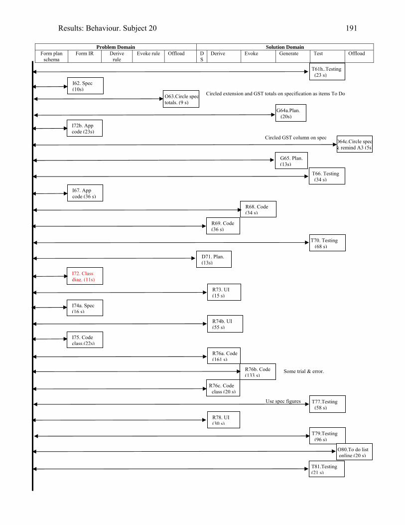
Results: Behaviour. Subject 20 191
Problem Domain Solution Domain
Form plan schema
Form IR Derive rule
Evoke rule Offload DS
Derive Evoke Generate Test Offload
O63.Circle spec totals. (9 s)
I72b. App code (23s)
R69. Code (36 s)
T70. Testing (68 s)
I72. Class diag. (11s)
I74a. Spec (16 s)
T77.Testing (58 s)
T79.Testing (96 s)
R76a. Code (161 s)
O80.To do list online (20 s)
T81.Testing (21 s)
R68. Code (34 s)
I75. Code class (22s)
T61h..Testing (23 s)
I62. Spec (10s)
G64a.Plan. (20s)
O64c.Circle spec & remind A3 (5s)
G65. Plan. (13s)
T66. Testing (34 s)
I67. App code (36 s)
D71. Plan. (13s)
R74b. UI (55 s)
R76b. Code (133 s)
Some trial & error.
R76c. Code class (20 s)
Use spec figures
R78. UI (30 s)
Circled extension and GST totals on specification as items To Do
Circled GST column on spec
R73. UI (15 s)

Results: Behaviour. Subject 20 192
.
Problem Domain Solution Domain lan schema Form IR Derive
rule Evoke rule Offload D
S Derive Evoke Generate Test Offload
T82.Testing (119 s)
O83.Cross off To Do list (3 s)
I85. Class diag.(12s)
I87. App code (21s)
I88. Code class (18s)
I89. Spec (22 s)
R90a.Code class (50 s)
R90b. Code class (41 s)
I91. Spec (18 s)
T93.Testing (60 s)
I97a App code (136s)
I96. Spec (14 s)
I95. App (26 s)
I97b. Class diag. (2s)
I98a.Spec (14 s)
I98b.App (33 s)
I98c. Code class (95s)
R99a.Code class (32 s)
O84.Read next To Do list (2 s)
I86. Use case temp (30s)
I97c Code class (38 s)
R99b.Code class (68 s)
I92. Monitor (34 s)
I94. Spec (1 s)
Found that the next thing to do is printing.

Results: Behaviour. Subject 20 193
. Problem Domain Solution Domain
lan schema Form IR Derive rule
Evoke rule Offload DS
Derive Evoke Generate Test Offload
T100.Testing (90 s)
R101c.Code class (62s)
T102b.Cross check spec(8s
T106.Testing/calculator (48 s)
T105 Cross check spec(10s
Finish 1 hour 46 minutes 49 seconds.
Subject 20’s comments re UML after completion: “Well – it is surprising – you see the UML did help.” “The UML was good for finding the relationships between the different things.” “But I only used the class diagram – the other ones were pretty useless. They’re probably good for understanding how the program works but I could work that out from the code.”
T101dTesting (220s)
T102c.Testing (74s)
I104. Code class (27s)
I101a. Code class (6 s)
G101b Plan (4s)
R102a.Code class (11s)
T102d.Testing (8s)
T102e.Testing (31s)
G103a.Plan (11s)
T103b.Testing (25s)
110 aligned the totals display on the screen.
Planed a testing
Concerned about his inability to print 2 decimal places. Followed this look at the code class with a ‘wander’ through the classes on the off-chance he might find something to assist.
Cross checked results with spec values.

Results: Behaviour 194
6.4.3 Collation of results from industry-experienced subjects
6.4.3.1 Introduction
Evidence was obtained that UML documentation supplied cognitive support to all of the five most
successful subjects with industry experience. However, some, such as Subject 17, appeared
uncomfortable with the documentation. Subject 17 believed the class diagram to be overly busy.
Subject 15 claimed that the class diagram was a mess. Subject 16 commented that he used the
documentation to gain an overview of the scenario, but once under way found it easier to concentrate
on the screen. Subject 20 stated at I9 that he found it easier to look at the class diagram than clicking
‘back and forth’ in the class code, whereas Subject 17 commented after looking at the class diagram in
I28 that he would look at the code as he understood it better. Subject 20 was accustomed to using a
class diagram at his place of work; Subject 17 was not.
Subject 18, who was one of the least successful of the industry-experienced group, did not read the
UML documentation. He expressed the need to get on with the code. He was the only participant
amongst the twenty-one subjects who did not read the documentation.
Table 6.3 summarises which UML documentation was used by the participants. Episodes where UML
documentation was accessed by the subjects but there was no evidence that the episode produced any
further progress, are shown in italics in the Table.
As documented in Table 6.3, all five industry-experienced participants who had been the most
successful, and who had had their verbal protocols transcribed, found the class diagram to be useful.
All used that diagram to discover both the attributes and associations of classes.
All but Subject 04 benefited from the use case documentation, but only Subject 16 made productive use
of the sequence diagram.
An aim of the research was to discover if UML documentation could be used
1. to assist in the formation of a programmer’s internal representation of a coding problem
2. in a set with a programmer’s problem space
3. in a set with the subject’s problem space to aid the induction of rules, and
4. as an external representation in the offloading of information from working memory.
These UML uses by the group are discussed in the next sub-sections, the results of which are
summarised in Table 6.4. The episodes included in Table 6.4 are those for which there was evidence
that they affected further episodes, or where offloading was involved.
6.4.3.2 Using UML documentation to assist with comprehension

Results: Behaviour 195
If the knowledge gained by a subject in reading UML documentation was used in succeeding episodes
it was judged that it had contributed to the establishment of an internal representation, thus aiding
comprehension. There was evidence that UML documentation was used by all transcribed participants
to assist in the formation of internal representations of the problem in the cognitive problem space.
In some cases details were forgotten and reread, due to their not having been sufficiently exercised in
working memory (see Subject 17), but the memory of where it was documented was sometimes
retained (refer to Subject 20’s looking to see the name of the gst class on the class diagram on a couple
of occasions).
As demonstrated in Table 6.4, only Subject 04 lacked assistance from the class diagram to aid his
comprehension, although he did use the class diagram in a set with his problem space.
6.4.3.3 Using UML documentation in a set with the problem space
Subject 15 was the sole participant to use a use case description to guide his usage of an application (in
I2b) in the problem domain.
The behaviour graphs were used to identify the domain and cognitive steps where rules were induced.
Three of the five transcribed subjects, 04, 15 and 20, used the class diagram in a set with their problem
spaces. Subject 04 discovered a relevant class on the class diagram which guided his placement of
breakpoints for discovering how the application was coded, in the problem domain (I19b). He again
used findings from the class diagram from I22 in evoking a rule (R27) in the solution domain.
For Subjects 15 and 20, who used UML in a set to induce rules, all episodes occurred in the solution
domain, except for Subject 15’s R14 where the rule was derived in the problem domain. In Subject
20’s episode 45, a code rule was derived from the existing application in order to load a file into
memory. Subject 15’s episode 42, and Subject 20’s episodes 49 and 61, involved the evoking of rules
in the solution domain.
6.4.3.4 Using UML documentation for offloading from working memory
6.4.3.4.1 Offloading during session with provided UML documentation
Only Subject 16 from the industry-experienced group offloaded to the provided UML documentation.
He offloaded his planned changes onto a use case description for ‘Create Appointment’. He planned to
change an association on the class diagram and, after drawing one version, reread the requirements
specification, changed his mind and created a different link – one between the Appointment and the
ReminderSet - on the diagram.
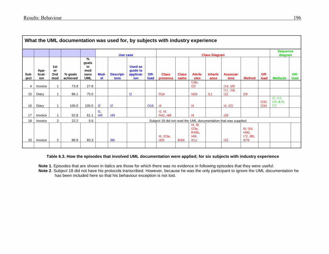
Results: Behaviour 196
What the UML documentation was used for, by subjects with industry experience
Use case Class Diagram Sequence diagram
Sub-ject
App-licat-ion
1st or
2nd mod
% goals achieved
% goals
in mod sans UML
Mod-el
Descript-ions
Used as guide to applicat-
ion Off-load
Class presence
Class name
Attrib-utes
Inherit-ance
Associat-ions Method
Off-load Methods
Off-load
4 Invoice 1 73.9 27.8 I19b, I22 I14, I20
15 Diary 1 86.1 75.0 I2 R14 I42b I11 I11, I18, I22 I26
16 Diary 1 100.0 100.0 I2 I2 O16 I4 I4 I4, I23 O32, O34
I5, I15, I29, R38, I72
17 Invoice 1 52.8 61.1 I1, I49 I49
I2, I4, R42, I48 I4 I28
18 Invoice 2 22.2 5.6 Subject 18 did not read the UML documentation that was supplied.
20 Invoice 2 88.9 83.3 I86 I6, I23a, I45f R49i
I4, I9, I23a, R45b, I49l, I61c I33
I9, I16, I49d, I72, I85, I97b
Table 6.3. How the episodes that involved UML documentation were applied; for six subjects with industry experience
Note 1. Episodes that are shown in italics are those for which there was no evidence in following episodes that they were useful. Note 2. Subject 18 did not have his protocols transcribed. However, because he was the only participant to ignore the UML documentation he
has been included here so that his behaviour exception is not lost.
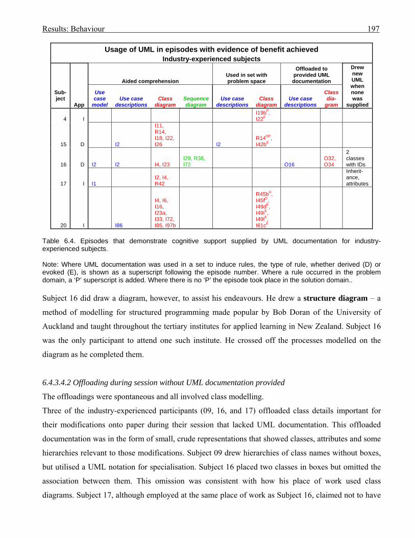
Results: Behaviour 197
Usage of UML in episodes with evidence of benefit achieved Industry-experienced subjects
Sub-ject
App
Aided comprehension Used in set with problem space
Offloaded to provided UML documentation
Drew new UML when none was
supplied
Use case
model Use case
descriptions Class
diagram Sequence diagram
Use case descriptions
Class diagram
Use case descriptions
Class dia-
gram
4 I I19bP, I22E
15 D I2
I11, R14, I18, I22, I26 I2
R14DP, I42bE
16 D I2 I2 I4, I23 I29, R38, I72 O16
O32, O34
2 classes with IDs
17 I I1 I2, I4, R42
Inherit-ance, attributes
20 I I86
I4, I6, I16, I23a, I33, I72, I85, I97b
R45bD, I45fD, I49dE, I49iE, I49lE, I61cE
Table 6.4. Episodes that demonstrate cognitive support supplied by UML documentation for industry-experienced subjects. Note: Where UML documentation was used in a set to induce rules, the type of rule, whether derived (D) or evoked (E), is shown as a superscript following the episode number. Where a rule occurred in the problem domain, a ‘P’ superscript is added. Where there is no ‘P’ the episode took place in the solution domain.. Subject 16 did draw a diagram, however, to assist his endeavours. He drew a structure diagram – a
method of modelling for structured programming made popular by Bob Doran of the University of
Auckland and taught throughout the tertiary institutes for applied learning in New Zealand. Subject 16
was the only participant to attend one such institute. He crossed off the processes modelled on the
diagram as he completed them.
6.4.3.4.2 Offloading during session without UML documentation provided
The offloadings were spontaneous and all involved class modelling.
Three of the industry-experienced participants (09, 16, and 17) offloaded class details important for
their modifications onto paper during their session that lacked UML documentation. This offloaded
documentation was in the form of small, crude representations that showed classes, attributes and some
hierarchies relevant to those modifications. Subject 09 drew hierarchies of class names without boxes,
but utilised a UML notation for specialisation. Subject 16 placed two classes in boxes but omitted the
association between them. This omission was consistent with how his place of work used class
diagrams. Subject 17, although employed at the same place of work as Subject 16, claimed not to have
Results: Behaviour 198
used UML in his job. He recorded class hierarchies but had used relationship arrows pointing in the
opposite direction to standard UML notation.
There was evidence that Subject 17 added to his hierarchy chart as he gained understanding. He
explicitly commented that his purpose was to aid his memory. Although Subject 16 did not explicitly
state that he was offloading for understanding, his comments imply that that was the case. It is possible
that the cognitive exercising of the data as the subjects wrote it down aided its retention in memory
(refer to Section 6.0).
Details of hierarchies were not offloaded when the subjects had UML documentation provided, perhaps
because they were explicit in the provided UML documentation.
Subject 09 was not included in Table 6.4 due to his lack of success.
6.4.4 Conclusion for industry-experienced group
Evidence has been found in these sessions that UML documentation does supply cognitive support to
assist a programmer’s comprehension of a program.
UML documentation was also observed as being used in a set with the programmer’s problem space
1. for creating internal representations of the problem in the problem domain (Subjects 04 and 15)
by deriving rules (Subject 15)
2. for evoking rules in the solution domain (Subjects 04, 15 and 20)
3. for deriving rules in the solution domain (Subject 20).
Offloading onto UML documentation was observed to occur spontaneously, although the offloading
evidence was supplied by only one industry-experienced subject (16) for those sessions where UML
documentation was provided.
Three subjects were found to spontaneously offload class-related details onto paper, using their own
customised versions of UML notation, when no UML documentation was provided. For two of those
subjects the offloaded items recorded inheritance hierarchies. No hierarchies were offloaded where
UML diagrams were provided, possibly because the solutions did not require changes to hierarchies
and the specialisation relationships were explicit on the provided class diagrams.
6.5 Student subjects without industry experience
6.5.1 Introduction
Subjects 01, 02, 03, 05, 06, 07, 08, 10, 11, 12, 13, 14 and 21 were students with no industry experience.
They were graduates of the third-year tertiary course in systems analysis and design that included the
use of UML documentation and VB.NET coding. All but Subject 05 had initially learned VB.NET in a

Results: Behaviour 199
tertiary course that did not include modelling. However, Subject 05 had passed several tertiary
programming courses that used OO programming languages.
The verbal protocols for subjects 02, 03, 05, 07, and 13 were transcribed as representative of the more
successful non-industry-experienced participants. The presentation is in the same format as used for the
industry-experienced group (refer to Section 6.4.1 for a description).
Subjects are presented in ascending subject number sequence.
6.5.2 Summaries and behaviour graphs
These commence on the following page.
Although they were not transcribed due to their lack of success, and have no summaries, nor behaviour
graphs, Subjects 01 and 21 have their individual offloading sketches included in this section.
Results: Behaviour. Subject 01 200
Subject 01: Student programmer
Modifying the invoice application without the aid of UML documentation.
Background
Subject 01 first learned to program in Java in a first-year tertiary course one year prior to participating
in this research, but claimed to have first learned object-oriented (OO) concepts and UML in a second-
year systems analysis and design course one semester prior. She first learned VB.NET in a second-year
tertiary course one semester prior.
Session
The invoice application was the first modification for Subject 01 and she did NOT receive UML
documentation with the statement of requirements.
Session achievements
Subject 01 did not complete either of her modifications. She is included here as she was the only
subject to spontaneously offload a rough flowchart to aid her understanding. This occurred when she
was attempting to modify the invoice application for which no UML documents were supplied. Her
flowchart is shown in Figure 6.13.
Despite her efforts, Subject 01 achieved little in the invoice modification. Although she hard-coded the
gst and was thus able to produce valid new totals on her invoice, she did not add a new column so
could not display the gst. She did add a means of storing gst in the invoice class.
Cognitive episodes in modification
Subject 01 did not have her verbal protocols transcribed as her average percentage success at achieving
sub-goals for both modification sessions was not as high as for those who were transcribed.
Comments
Subject 01 claimed to prefer coding over modelling.
Of the UML notations, Subject 01 stated that she preferred the class diagram. However, she
commented: ‘If you want to examine what the program does, use use case. The use case model gives
the users the general idea with one look.’ She believed the template descriptions were more detailed.
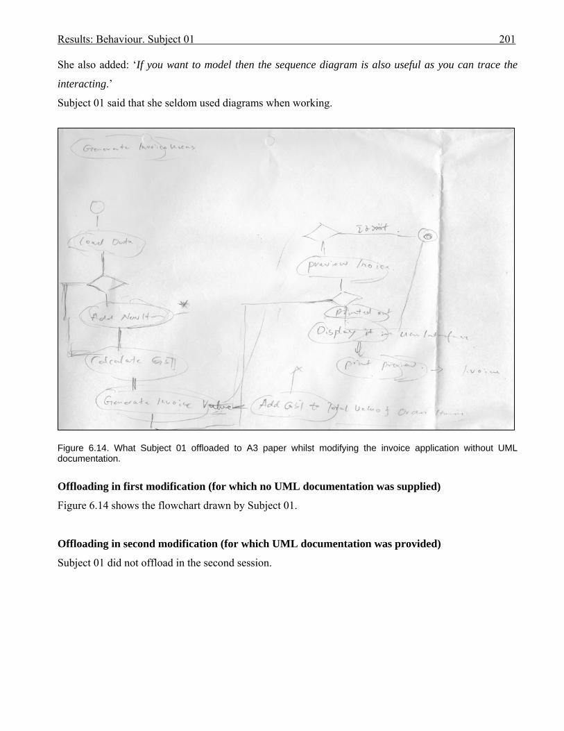
Results: Behaviour. Subject 01 201
She also added: ‘If you want to model then the sequence diagram is also useful as you can trace the
interacting.’
Subject 01 said that she seldom used diagrams when working.
Figure 6.14. What Subject 01 offloaded to A3 paper whilst modifying the invoice application without UML documentation.
Offloading in first modification (for which no UML documentation was supplied)
Figure 6.14 shows the flowchart drawn by Subject 01.
Offloading in second modification (for which UML documentation was provided)
Subject 01 did not offload in the second session.

Results: Behaviour. Subject 02 202
Subject 02: Student programmer
Modifying the invoice application with the aid of UML documentation.
Background
Subject 02 first learned to program in Java in a first year tertiary course three and a half years prior to
participating in this research, but claimed to have first learned object oriented (OO) concepts in a
second-year software engineering course that used Java, two and a half years prior. In that course she
could remember modelling use case and interaction diagrams on paper, but did not remember drawing
class diagrams. She had a brief experience of UML modelling in a second-year course in systems
analysis and design, in the following semester. She first learned VB.NET one and a half years prior to
this research.
Session
The Invoice application was the second modification for Subject 02 and she received UML
documentation with the statement of requirements.
Session achievements
Subject 02 did not extract the gst type from the customer; instead she placed a drop-down list on the
invoice form from which the user could select a gst type of either ‘Standard’ or ‘Export’, the latter
being the default. She hard-coded the gst percentages for each of these types within methods for the
invoice form. As it is possible that there could be more gst codes, and that gst per cent could be
changed in the future, this was not a satisfactory solution. However, it did permit her to progress
through the modification and display the required totals.
As Subject 02 did not remember to clear her new totals, they did not calculate correctly following the
first invoice.
Subject 02 also forgot to adjust the totals when deleting an invoice item from the invoice; she further
did not correctly make adjustments when more quantity was added to an item for a product already
appearing on an invoice.
She did, however, progress to the printing section of the modification and successfully displayed the
extra headings and gst total as required.
She did not add the gst percentage or value to either the invoice or its items.
Subject 02 did make progress through the modification – but at the expense of flexibility.

Results: Behaviour. Subject 02 203
Cognitive episodes in modification
Subject 02 read the use case model first (I1):
‘So now I’m just reading the current – um - function of the application.
So I’m just reading the use case diagram now. So the warehouse clerk can add a - a product, and
change a product or print products – and - it’s not implemented.
And accounts receivable clerk can add customer, change customers, print customers, add gst, clear
invoice and ex - extends create invoice, and create invoice includes – includes - um - print invoice.
OK. Uses print invoice’ [00.54]. (I1)
[00.55] ‘So I’m reading the use case template now. It’s Tuff Toys Company Limited Invoice
Application and the use case is – the purpose of the use case for this is to Create Invoice’ [1.10]. (I2a)
[rustle] ‘So I’m just referring back to the use case diagram now – so.’ [01.17].
She demonstrated an understanding of the notation of the use case diagram in episode 1. However, in
episode 2 she simply read the text of the use case descriptions.
She did comment on the class diagram in episode 3:
[6.40] ‘OK and now I’m – I’m reading the class diagram of the whole application.
Umm – yeah. That’s – um. Just – see. OK. Ah – yeah - reading class diagram for the application and …
this –. OK – InvoiceItem is – um - strongly associated with invoice, and invoiceItems’ [7.31]. (I3).
In episode 4, Subject 02 read the sequence diagram, after which she commented that she would refer to
it when she wanted to She did not refer to the UML documentation again during the session.
Subject 02 thoroughly read the requirements specification in episode 5, and then ran the application
(I6). The appearance of the invoice form in episode 6 triggered her next episode (I7) which was to
study the data grid in which the invoice items were displayed. That led to a study of the code behind
the grid (I8), which in turn led to her inserting code for adding a column for gst into the grid in episode
9. She encountered unresolved errors.
Subject 02 next studied the Invoice class code (I10) to see if there were any solutions to the errors.
However, she ran the application again and it worked, without her changing any code.
From there Subject 02 was able to write code to adjust the column style to improve the view of the gst
column in the grid (episode 11), using the existing column styles as a guide.
From there Subject 02 unsuccessfully searched to find a way to add a scroll bar to the data grid.
She returned to the requirements specification to reread that each customer had one gst type at a time
(I12). This was followed by the placement of a drop-down list on the invoice form from which the user

Results: Behaviour. Subject 02 204
could select a gst type for the customer (episode 13). Subject 02 briefly checked back to the
requirements (I13b), then entered the values ‘E’ and ‘S’ as the selection in the drop-down list (R13c).
Subject 02 returned to re-read the requirements, stating: ‘I’ve done the gst type.’ She read the section
on calculating the gst value for an invoice item (I14), before doing her test for episode 13 (T13d), after
which she wrote code to set a default value (‘E’) in the drop-down list so that there would always be a
gst type present (R13e). After her final test for episode 13 (T13f) Subject 02 stated: ‘Now I have to
calculate the gst.’
She studied the code behind the Add button on the frmInvoice in episode I15, followed by the code of
the gst class (I16). She returned to the frmInvoice code and found that the data row displayed in the
data grid was created in the method ‘CreateNewItemRow()’ (I17). She used the examples for the other
attributes in the data row in that method to add one for gst (R18).
She rechecked the formula for calculating gst in the requirements (I19), then attempted to encode it in
episode 20. She hypothesised in G21 that she wished to create a variable for gst. After searching
without comment through the gst form, she declared a class variable for gst in episode 22, in which she
also coded a method where gst percentages could be retrieved, depending upon which gst type was
selected in the drop-down list. These gst percentages were hard-coded. There was no flexibility for
possible future changes in gst percentage values.
With this routine in place she was able to return to the CreateNewItemRow() method in frmInvoice and
complete code for calculating a gst value for an invoice item (R23).
When Subject 02 tested what she had coded (T24) she commented: ‘I’ll need to make the grid
scrollable because I can’t read the gst column, since I can’t scroll it to the right.’
She tried to gain information about adding a scroll bar by looking up Help (O25), then spent about 17
minutes in trial and error to achieve a readable column (T26). In her final test for gst value for an
invoice line (T27) the value could be read and was correct.
Her next step was to calculate the totals for the invoice. She ran the application to find where to insert
the code to add gst to its total, found the place, and inserted the code, which worked (episode 28).
Through trial and error in T29, Subject 02 succeeded in displaying the gst total for the invoice in a
currency format.
She returned to the requirements (I30) to confirm that she had completed the totals requirements,
except for the overall amount owing, which she then implemented in episode 31.
In episode 32, Subject 02 rechecked the requirements to confirm that she had completed all invoice
totals and now needed to modify the Print Preview for the invoice.
Results: Behaviour. Subject 02 205
She decided to run the application to test the existing Print Preview coding (episode 33), investigated
the code behind the Print Preview in frmInvoice (I34), and then reread the diagram on the requirements
that showed what was required (I35).
Subject 02 proceeded to spend some time searching through the code for printing. She was wondering
how she would code the required printing of the totals and hoped to find some assistance in the existing
code. In I36 she found the PrintItems() method in the Invoice class, and returned to the frmInvoice
code to discover from where it was called (I37), returning to the Invoice class to study the PrintItems()
method’s code (episode 38).
After briefly playing with the idea of placing the required code in the gst class she returned to the
PrintItems() method in the Invoice class to complete her study for episode 38.
In episode 39, Subject 02 studied the printing operations in the frmInvoice and decided to experiment
by coding a temporary print line to see if it displayed; it did not (episode 40).
Subject 02 returned to the requirements to read the section on adding gst percentage to the invoice class
(episode 41). [Note: Subject 02 did not implement this requirement.]
She theorised that the new code be placed within the PrintItems() method in the Invoice class (G42). In
episode 43 she added code to the PrintItems() method, then spent 14 minutes testing, debugging, and
adjusting the layout of the totals and labels on the Print Preview screen for the invoice (T44).
Comments on cognitive interactions
In Subject 02’s post session debriefing:
Monitor: ‘Do you think that doing the first application helped you at all with doing the second?’
Subject 02: ‘Um - yes. I think so.’
Monitor: ‘And why was that?’
Subject 02: ‘Um - because in the first modification I’m not used to – like - speaking aloud and –
speaking aloud and thinking at the same time. And then after doing the first – um - modification and
getting used to – like - talking aloud – and thinking and speaking at the same time - it helps.’…….
Monitor: ‘If you have some unified modelling language – that’s UML diagrams - which ones do you
prefer to use?’
Subject 02: ‘Um - I prefer to use – um - the use case diagram and the documentation – use case
documentation’.
Monitor: ‘And what is the reason for that?’
Subject 02: ‘It tells you – like - how – because the supporting documents tell you how – um - the step is
taken. Like the post-conditions and pre-conditions and the step has taken to - for the application.’

Results: Behaviour. Subject 02 206
Monitor: ‘When you are programming do you ever spontaneously use a diagram at all?’
Subject 02: ‘No.’
Monitor: ‘Do you think that doing the first application helped you at all with doing the second?’
Subject 02: ‘Um - yes. I think so.’
Monitor: ‘And why was that?’
Subject 02: ‘Um - because in the first modification I’m not used to – like - speaking aloud and –
speaking aloud and thinking at the same time. And then after doing the first – um - modification and
getting used to – like - talking aloud – and thinking and speaking at the same time - it helps.’
Subject 02 did not draw any diagrams during her sessions.
Forming an internal representation
Subject 02 read the UML documentation thoroughly then did not refer to it again during the
modification session. She initially read the use case diagram (I1), followed by the use case
description for ‘Create Invoice’, swapping back to the diagram, but making no comments. She
continued to read the use case description (I2). Although she read the text in detail she made no
comments on what she read, except for the class diagram (I3) where she commented that invoiceItem
was strongly associated with invoice, and invoiceItems.
Following the reading of the sequence diagram in I4 she commented: ‘I will refer to it when I want to –
but now I’m going to – um - read the specification.’ She did not, however, refer to the UML
documentation again.
After reading the requirements specification (I5) she did anticipate seeing an ‘invoice item’ but whether
this was the result of reading the UML documentation or the requirements, or a combination of the two,
it is not possible to confirm.
The reading of the UML documentation occurred at the time when Subject 02 would have been
forming her internal representation of the problem.
Using UML documentation in a set with the problem space
Subject 02 did not use the UML documentation in a set.
Offloading to documentation
Subject 02 did not offload onto any documentation or paper during either of her sessions.
She did refer to Help (O25) for advice on adding scroll bars to data grids.
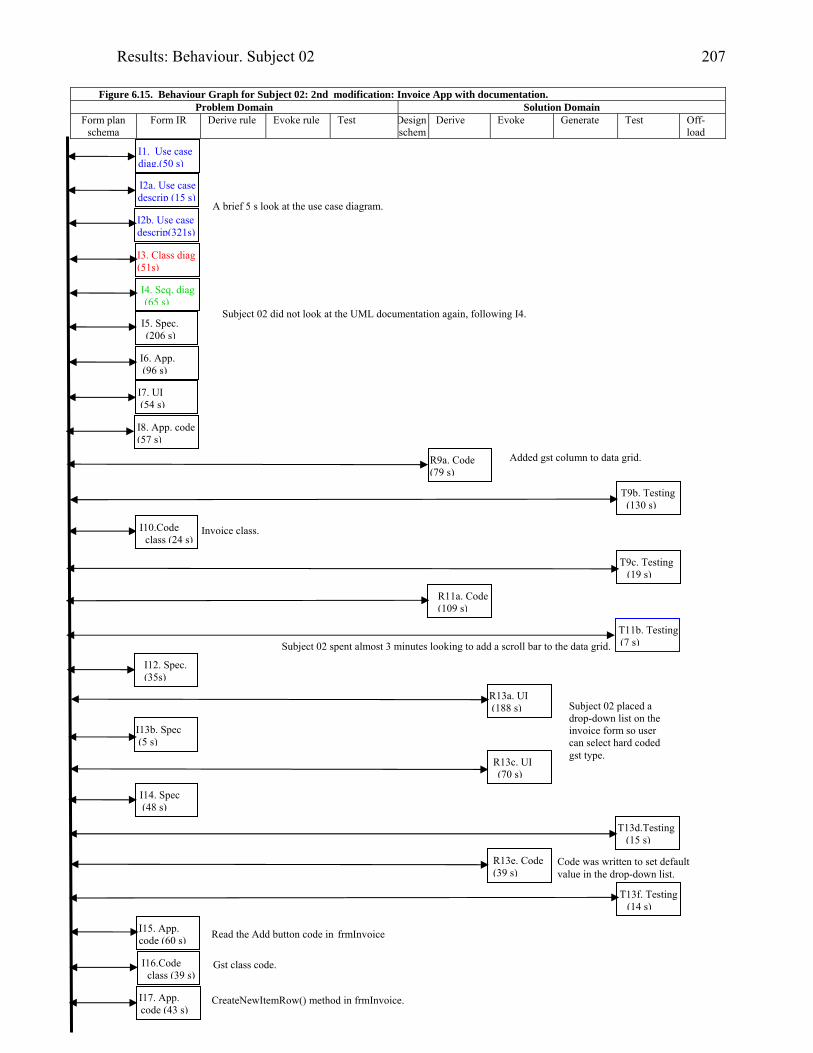
Results: Behaviour. Subject 02 207
Figure 6.15. Behaviour Graph for Subject 02: 2nd modification: Invoice App with documentation.
Problem Domain Solution Domain Form plan
schema Form IR Derive rule Evoke rule Test Design
schemDerive Evoke Generate Test Off-
load
I2a. Use case descrip (15 s)
R13a. UI (188 s)
I3. Class diag (51s)
I4. Seq. diag (65 s)
I5. Spec. (206 s)
T9b. Testing (130 s)
R9a. Code (79 s)
I6. App. (96 s)
R11a. Code (109 s)
T11b. Testing(7 s)
I12. Spec. (35s)
I13b. Spec (5 s)
R13c. UI (70 s)
T13d.Testing (15 s)
T13f. Testing (14 s)
I15. App. code (60 s)
I17. App. code (43 s)
R13e. Code (39 s)
I1. Use case diag.(50 s)
I7. UI (54 s)
T9c. Testing (19 s)
I2b. Use case descrip(321s)
I14. Spec (48 s)
I16.Code class (39 s)
Gst class code.
Read the Add button code in frmInvoice
Code was written to set default value in the drop-down list.
Added gst column to data grid.
A brief 5 s look at the use case diagram.
Subject 02 did not look at the UML documentation again, following I4.
Subject 02 spent almost 3 minutes looking to add a scroll bar to the data grid.
Subject 02 placed a drop-down list on the invoice form so user can select hard coded gst type.
CreateNewItemRow() method in frmInvoice.
I8. App. code (57 s)
I10.Code class (24 s)
Invoice class.
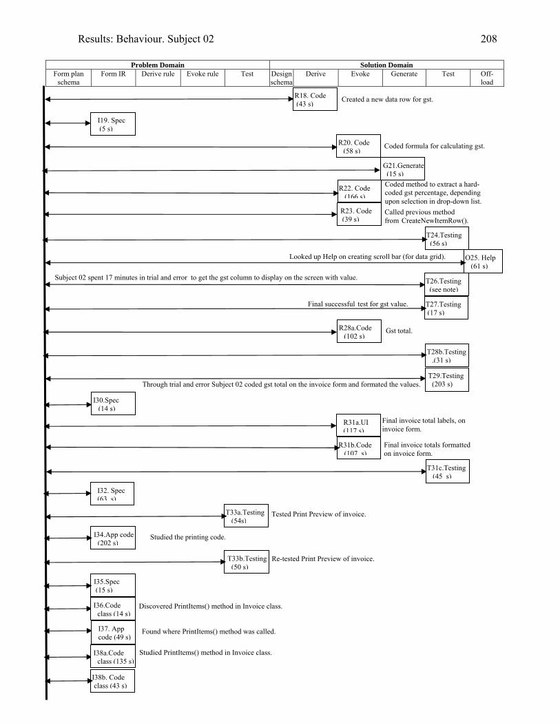
Results: Behaviour. Subject 02 208
Problem Domain Solution Domain
Form plan schema
Form IR Derive rule Evoke rule Test Design schema
Derive Evoke Generate Test Off-load
R20. Code (58 s)
G21.Generate (15 s)
O25. Help (61 s)
R28a.Code (102 s)
I19. Spec (5 s)
T33a.Testing (54s)
I34.App code (202 s)
R31a.UI (117 s)
T29.Testing (203 s)
R22. Code (166 s)
T24.Testing (56 s)
R31b.Code (107 s)
Subject 02 spent 17 minutes in trial and error to get the gst column to display on the screen with value.
R18. Code (43 s)
R23. Code (39 s)
T27.Testing (17 s)
T28b.Testing .(31 s)
I30.Spec (14 s)
I32. Spec (63 s)
T31c.Testing (45 s)
T33b.Testing (50 s)
I38b. Code class (43 s)
Gst total.
Created a new data row for gst.
Coded formula for calculating gst.
Coded method to extract a hard- coded gst percentage, depending upon selection in drop-down list. Called previous method from CreateNewItemRow().
Looked up Help on creating scroll bar (for data grid).
T26.Testing (see note)
Final successful test for gst value.
Through trial and error Subject 02 coded gst total on the invoice form and formated the values.
Final invoice total labels, on invoice form.
Final invoice totals formatted on invoice form.
Tested Print Preview of invoice.
Studied the printing code.
Re-tested Print Preview of invoice.
I35.Spec (15 s)
I36.Code class (14 s)
Discovered PrintItems() method in Invoice class.
I37. App code (49 s)
Found where PrintItems() method was called.
I38a.Code class (135 s)
Studied PrintItems() method in Invoice class.
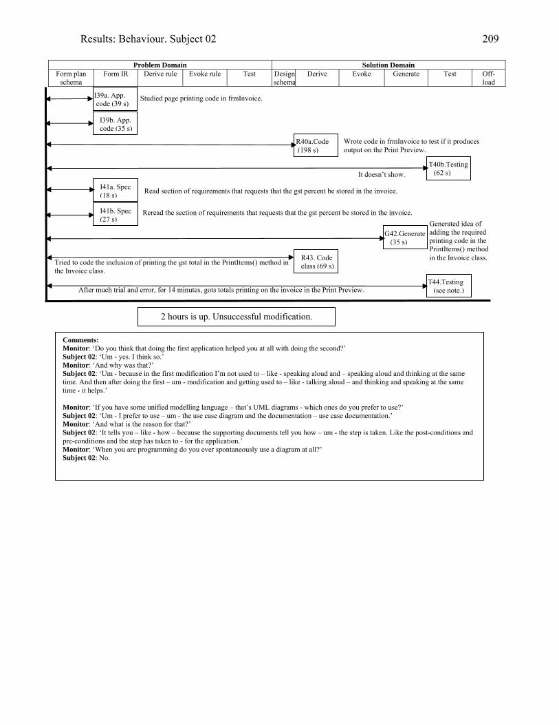
Results: Behaviour. Subject 02 209
Problem Domain Solution Domain
Form plan schema
Form IR Derive rule Evoke rule Test Design schema
Derive Evoke Generate Test Off-load
2 hours is up. Unsuccessful modification.
Comments: Monitor: ‘Do you think that doing the first application helped you at all with doing the second?’ Subject 02: ‘Um - yes. I think so.’ Monitor: ‘And why was that?’ Subject 02: ‘Um - because in the first modification I’m not used to – like - speaking aloud and – speaking aloud and thinking at the same time. And then after doing the first – um - modification and getting used to – like - talking aloud – and thinking and speaking at the same time - it helps.’ Monitor: ‘If you have some unified modelling language – that’s UML diagrams - which ones do you prefer to use?’ Subject 02: ‘Um - I prefer to use – um - the use case diagram and the documentation – use case documentation.’ Monitor: ‘And what is the reason for that?’ Subject 02: ‘It tells you – like - how – because the supporting documents tell you how – um - the step is taken. Like the post-conditions and pre-conditions and the step has taken to - for the application.’ Monitor: ‘When you are programming do you ever spontaneously use a diagram at all?’ Subject 02: No.
I39b. App. code (35 s)
R40a.Code (198 s)
T40b.Testing (62 s)
I41a. Spec (18 s)
I41b. Spec (27 s)
G42.Generate (35 s)
R43. Code class (69 s)
T44.Testing (see note.)After much trial and error, for 14 minutes, gots totals printing on the invoice in the Print Preview.
Tried to code the inclusion of printing the gst total in the PrintItems() method in the Invoice class.
I39a. App. code (39 s)
Studied page printing code in frmInvoice.
Read section of requirements that requests that the gst percent be stored in the invoice.
Reread the section of requirements that requests that the gst percent be stored in the invoice.
Wrote code in frmInvoice to test if it produces output on the Print Preview.
It doesn’t show.
Generated idea of adding the required printing code in the PrintItems() method in the Invoice class.

Results: Behaviour. Subject 03 210
Subject 03: Student programmer
Modifying the diary application with the aid of UML documentation.
Background
Subject 03 learned to program Java in a first-year tertiary course three and a half years prior to
participating in this research. Three years earlier he learned VB.NET and eighteen months earlier he
learned UML.
Session
The diary application was the first modification for Subject 03 and he received UML documentation
with the statement of requirements.
Session achievements
Subject 03 did not complete the diary application modification within the two hours.
When tested after the session it was found that he had successfully loaded the ReminderSets file into
memory, and had created a crude reminder pop-up message. He did not relate a reminder with an
appointment so that his checking of ReminderSets at application start-up was invalid.
Cognitive episodes in modification
Subject 03 read the requirements first (I1), admitting later that he read but did not fully take in what he
was reading. He did spend 24 seconds rereading the requirements specification. Next he looked at the
diary form (I2), comparing it to the requirements in order to find what was missing, and then ran the
application (I3).
He returned to the requirements (I4) ‘to totally understand what shall I do.’
In I5 Subject 03 studied the diary form again to search for the presence of a reminder (it was not there).
He returned to the requirements (I6), only to discover the reference to xml files. When he assumed that
he had only the diary form to deal with, the Monitor advised that there were several forms (I7).
In I8 he discovered the xmlData class in Solution Explorer and opened it for review (I8).
H then chose to read the UML documentation, comparing the use case model to the diary form: [13.12]
‘Reading the use case model. .. I’m now comparing about – I’m comparing the use case diagram and
the form’. [13.36] … [13.53] (I9).
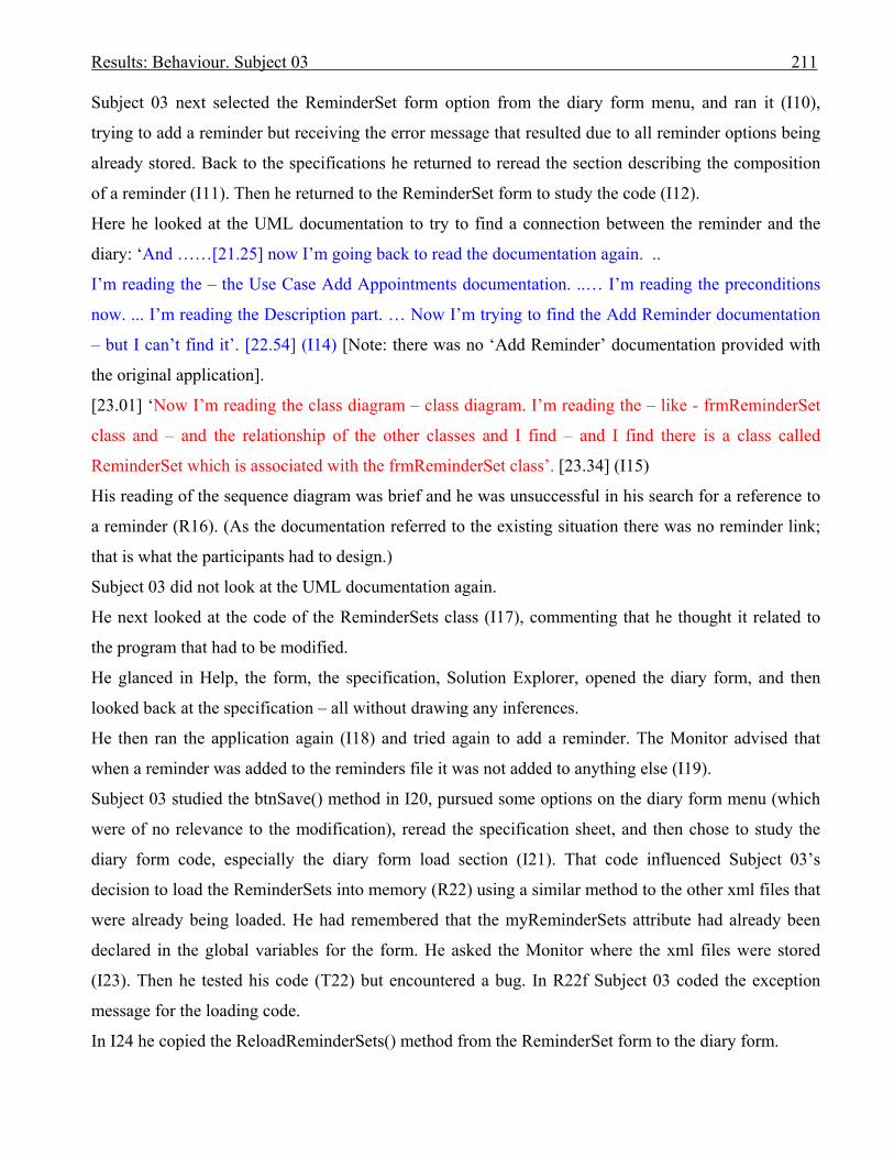
Results: Behaviour. Subject 03 211
Subject 03 next selected the ReminderSet form option from the diary form menu, and ran it (I10),
trying to add a reminder but receiving the error message that resulted due to all reminder options being
already stored. Back to the specifications he returned to reread the section describing the composition
of a reminder (I11). Then he returned to the ReminderSet form to study the code (I12).
Here he looked at the UML documentation to try to find a connection between the reminder and the
diary: ‘And ……[21.25] now I’m going back to read the documentation again. ..
I’m reading the – the Use Case Add Appointments documentation. ..… I’m reading the preconditions
now. ... I’m reading the Description part. … Now I’m trying to find the Add Reminder documentation
– but I can’t find it’. [22.54] (I14) [Note: there was no ‘Add Reminder’ documentation provided with
the original application].
[23.01] ‘Now I’m reading the class diagram – class diagram. I’m reading the – like - frmReminderSet
class and – and the relationship of the other classes and I find – and I find there is a class called
ReminderSet which is associated with the frmReminderSet class’. [23.34] (I15)
His reading of the sequence diagram was brief and he was unsuccessful in his search for a reference to
a reminder (R16). (As the documentation referred to the existing situation there was no reminder link;
that is what the participants had to design.)
Subject 03 did not look at the UML documentation again.
He next looked at the code of the ReminderSets class (I17), commenting that he thought it related to
the program that had to be modified.
He glanced in Help, the form, the specification, Solution Explorer, opened the diary form, and then
looked back at the specification – all without drawing any inferences.
He then ran the application again (I18) and tried again to add a reminder. The Monitor advised that
when a reminder was added to the reminders file it was not added to anything else (I19).
Subject 03 studied the btnSave() method in I20, pursued some options on the diary form menu (which
were of no relevance to the modification), reread the specification sheet, and then chose to study the
diary form code, especially the diary form load section (I21). That code influenced Subject 03’s
decision to load the ReminderSets into memory (R22) using a similar method to the other xml files that
were already being loaded. He had remembered that the myReminderSets attribute had already been
declared in the global variables for the form. He asked the Monitor where the xml files were stored
(I23). Then he tested his code (T22) but encountered a bug. In R22f Subject 03 coded the exception
message for the loading code.
In I24 he copied the ReloadReminderSets() method from the ReminderSet form to the diary form.
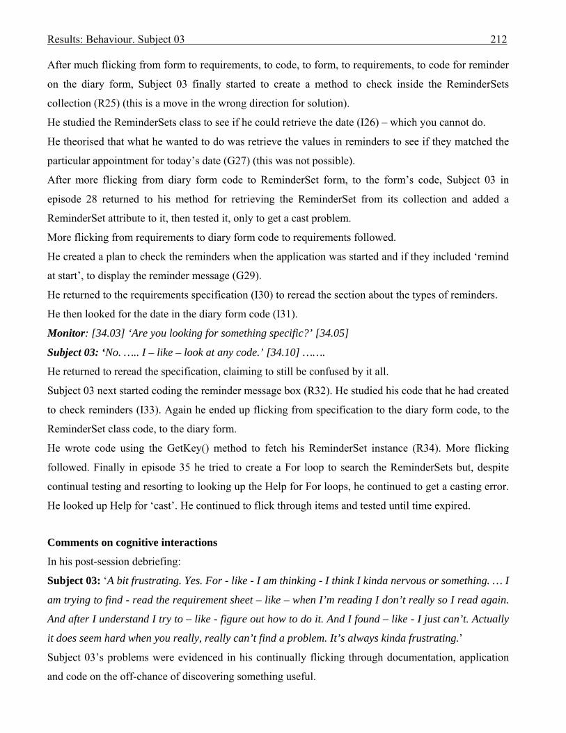
Results: Behaviour. Subject 03 212
After much flicking from form to requirements, to code, to form, to requirements, to code for reminder
on the diary form, Subject 03 finally started to create a method to check inside the ReminderSets
collection (R25) (this is a move in the wrong direction for solution).
He studied the ReminderSets class to see if he could retrieve the date (I26) – which you cannot do.
He theorised that what he wanted to do was retrieve the values in reminders to see if they matched the
particular appointment for today’s date (G27) (this was not possible).
After more flicking from diary form code to ReminderSet form, to the form’s code, Subject 03 in
episode 28 returned to his method for retrieving the ReminderSet from its collection and added a
ReminderSet attribute to it, then tested it, only to get a cast problem.
More flicking from requirements to diary form code to requirements followed.
He created a plan to check the reminders when the application was started and if they included ‘remind
at start’, to display the reminder message (G29).
He returned to the requirements specification (I30) to reread the section about the types of reminders.
He then looked for the date in the diary form code (I31).
Monitor: [34.03] ‘Are you looking for something specific?’ [34.05]
Subject 03: ‘No. ….. I – like – look at any code.’ [34.10] …….
He returned to reread the specification, claiming to still be confused by it all.
Subject 03 next started coding the reminder message box (R32). He studied his code that he had created
to check reminders (I33). Again he ended up flicking from specification to the diary form code, to the
ReminderSet class code, to the diary form.
He wrote code using the GetKey() method to fetch his ReminderSet instance (R34). More flicking
followed. Finally in episode 35 he tried to create a For loop to search the ReminderSets but, despite
continual testing and resorting to looking up the Help for For loops, he continued to get a casting error.
He looked up Help for ‘cast’. He continued to flick through items and tested until time expired.
Comments on cognitive interactions
In his post-session debriefing:
Subject 03: ‘A bit frustrating. Yes. For - like - I am thinking - I think I kinda nervous or something. … I
am trying to find - read the requirement sheet – like – when I’m reading I don’t really so I read again.
And after I understand I try to – like - figure out how to do it. And I found – like - I just can’t. Actually
it does seem hard when you really, really can’t find a problem. It’s always kinda frustrating.’
Subject 03’s problems were evidenced in his continually flicking through documentation, application
and code on the off-chance of discovering something useful.

Results: Behaviour. Subject 03 213
He did not appear to fully understand the problem as it was explicitly stated that the reminder must be
assigned to an appointment.
When being interviewed after both his sessions, Subject 03’s comments were as follows:
Monitor: ‘If you use UML diagrams which ones do you prefer to use?’
Subject 03: ‘Mmm. Which ones do I prefer? … I think probably the class diagram, which shows the
object. .. Yes – correspond - verification even – like - based on – well - object-oriented – like – create
an object. Yes - if I had a class diagram I can know which objects relate to which one.’ …..
Monitor: ‘Now, when you are programming do you ever find where you have got a tricky bit of
programming, you draw something on a piece of paper to help you?’
Subject 03: ‘Oh - yes, yes, yes. I would – like - write the object down, like, probably draw the
relationship.’
Monitor: ‘You haven’t done that here at all, although you’ve got the pad and that. You felt perhaps it
doesn’t need a sketch?’
Subject 03: ‘Because I was – like – I keep thinking the thing – like – I just - because I don’t understand
it then I just keep reading and after I get the relationship then the thing – the first thing is to help with
the variance so I don’t need to draw it out.’
This suggests that he understood the situation and it was not necessary to draw it on the diagram. He
did not add the required relationship between Appointment and ReminderSet on the class diagram.
Forming an internal representation
Subject 03 searched the use case documentation, class and sequence diagrams, to find references to
reminder. He was successful in his search in the class diagram where he discovered the ReminderSet
class related to the ReminderSet form. This latter discovery led him to search for the ReminderSets
class which he studied in I17. As there was no mention of reminder within the use case documentation
for maintaining an appointment, nor the sequence diagram for adding an appointment, that lack could
have highlighted what was required for the modification to succeed.
Using UML documentation in a set with the problem space.
In I9, Subject 03 compared the use case model with the form. That was the only time he used the UML
documentation in a set with the problem space.
Offloading to UML documentation
Subject 03 did not offload in either of his two modification sessions.
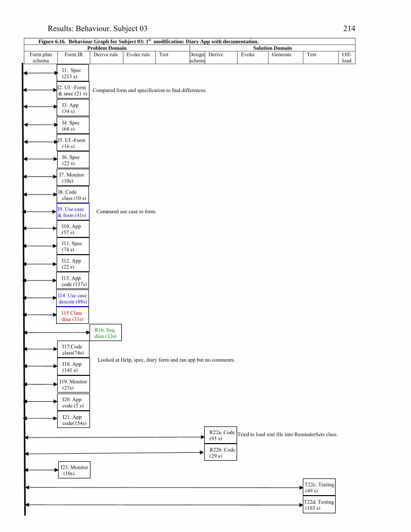
Results: Behaviour. Subject 03 214
Figure 6.16. Behaviour Graph for Subject 03: 1st modification: Diary App with documentation. Problem Domain Solution Domain
Form plan schema
Form IR Derive rule Evoke rule Test Designsschema
Derive Evoke Generate Test Off-load
I2. UI –Form & spec (21 s)
I3. App (34 s)
I4. Spec (68 s)
I5. UI -Form (16 s)
I6. Spec (22 s)
I11. Spec (74 s)
I10. App (57 s)
I7. Monitor (10s)
I13. App code (137s)
I14. Use case descrip (89s)
I15 Class diag (33s)
I17.Code class(74s)
I18. App (141 s)
I20. App code (5 s)
R22a. Code (93 s)
R22b. Code(29 s)
T22c. Testing (49 s)
Compared use case to form.
I21. App code(154s)
I1. Spec (213 s)
Compared form and specification to find differences.
I8. Code class (10 s)
I9. Use case & form (41s)
I12. App (22 s)
R16. Seq. diag (12s)
Looked at Help, spec, diary form and ran app but no comments.
I19. Monitor (27s)
Tried to load xml file into ReminderSets class.
I23. Monitor (10s)
T22d. Testing (103 s)
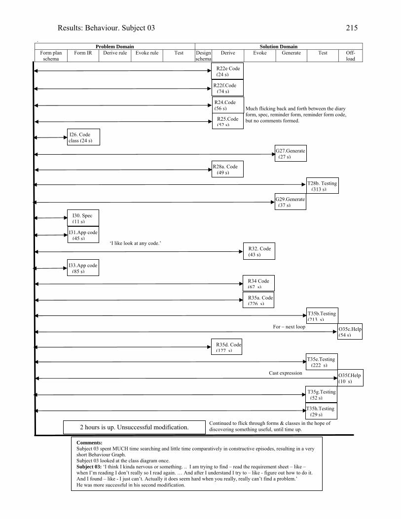
Results: Behaviour. Subject 03 215
. Problem Domain Solution Domain
Form plan schema
Form IR Derive rule Evoke rule Test Design schema
Derive Evoke Generate Test Off-load
R22f.Code (74 s)
R24.Code (56 s)
R28a. Code (49 s)
I30. Spec (11 s)
R22e Code (24 s)
O35c.Help(54 s)
T35e.Testing (222 s)
O35f.Help(10 s)
T35g.Testing(52 s)
R34 Code (67 s)
R32. Code (43 s)
2 hours is up. Unsuccessful modification.
Comments: Subject 03 spent MUCH time searching and little time comparatively in constructive episodes, resulting in a very short Behaviour Graph. Subject 03 looked at the class diagram once. Subject 03: ‘I think I kinda nervous or something. .. I am trying to find – read the requirement sheet – like – when I’m reading I don’t really so I read again. … And after I understand I try to – like - figure out how to do it. And I found – like - I just can’t. Actually it does seem hard when you really, really can’t find a problem.’ He was more successful in his second modification.
R25.Code (52 s)
G27.Generate (27 s)
R35a. Code (226 s)
T35b.Testing(213 s)
T35h.Testing (29 s)
T28b. Testing (313 s)
I26. Code class (24 s)
Much flicking back and forth between the diary form, spec, reminder form, reminder form code, but no comments formed.
G29.Generate (37 s)
I31.App code (45 s)
‘I like look at any code.’
I33.App code (85 s)
R35d. Code (127 s)
For – next loop
Cast expression
Continued to flick through forms & classes in the hope ofdiscovering something useful, until time up.

Results: Behaviour. Subject 05 216
Subject 05: Student programmer
Modifying the diary application with the aid of UML documentation.
Background
Subject 05 learned to program Java in a first year tertiary course three and a half years prior to
participating in this research. One semester prior she learned VB.NET and one year prior she learned
UML. Although she had just learned VB.NET in the previous semester, she had passed a number of
other programming courses and could be described as a reasonably experienced student programmer.
Session
The diary application was the first modification for Subject 05 and she received UML documentation
with the statement of requirements.
Session achievements
Subject 05 did not complete the diary application modification within the two hours.
She created a button on the diary screen with the aim of adding a reminder to an appointment by
clicking on the button to bring up the ReminderSet form after an appointment had been added.
However, she created no reminder attribute within the Appointment class in order to store the reminder
with the appointment. She spent much time trying to discover how to activate the ReminderSet form
after the button was clicked.
Cognitive episodes in modification
Subject 05 read part of the requirements first (I1a), then looked at the use case model and textural
descriptions (I2) [0.42]. She made an incorrect assumption after reading the use case documentation
that the existing application permitted a reminder to be added to an appointment. This could have been
corrected if she had followed by reading the class diagram, but unfortunately she did not do this. There
is no evidence that reading the use case documentation increased Subject 05’s understanding of the
exercise.
Subject 05 continued to finish reading the requirements (I1b & c) specification, making a number of
comments that indicated understanding.
She ran the application to discover that the diary form was the start-up form (I3), and then proceeded to
look at the code behind that form (I4).
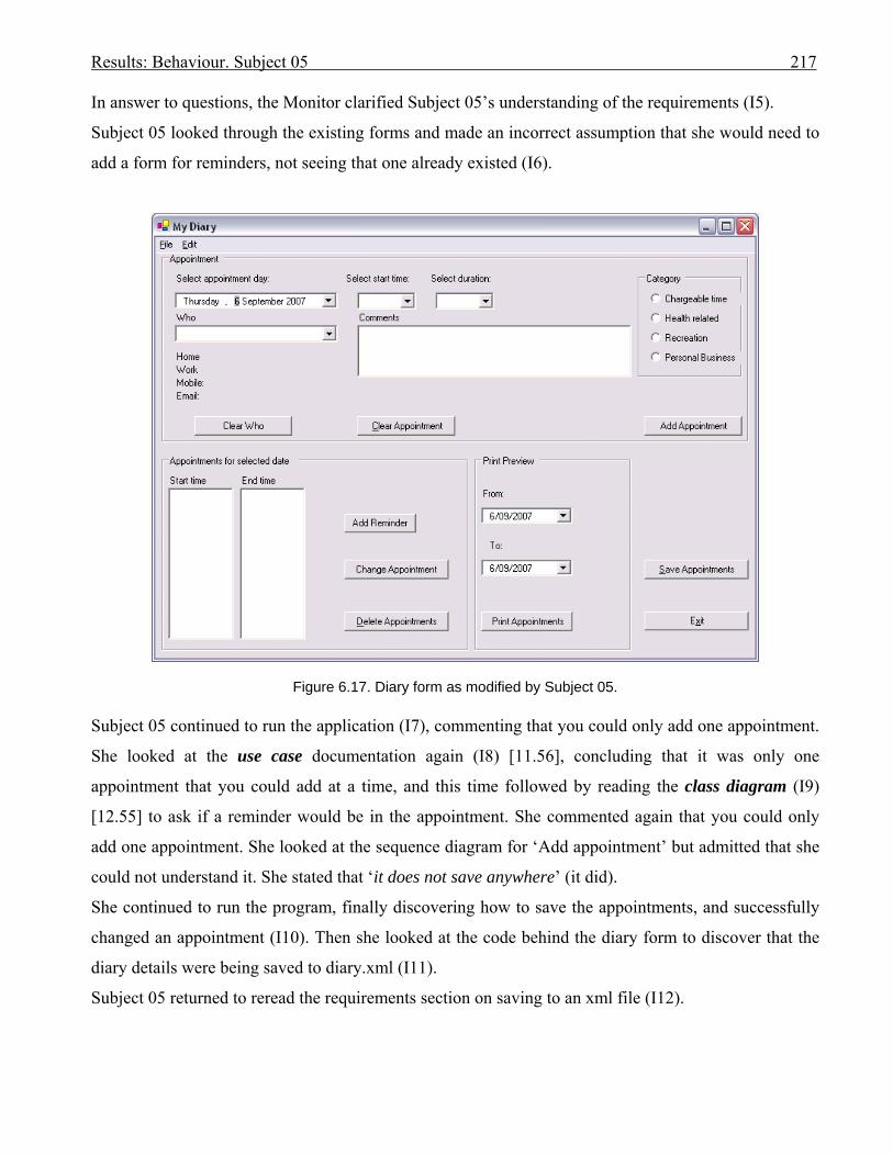
Results: Behaviour. Subject 05 217
In answer to questions, the Monitor clarified Subject 05’s understanding of the requirements (I5).
Subject 05 looked through the existing forms and made an incorrect assumption that she would need to
add a form for reminders, not seeing that one already existed (I6).
Figure 6.17. Diary form as modified by Subject 05. Subject 05 continued to run the application (I7), commenting that you could only add one appointment.
She looked at the use case documentation again (I8) [11.56], concluding that it was only one
appointment that you could add at a time, and this time followed by reading the class diagram (I9)
[12.55] to ask if a reminder would be in the appointment. She commented again that you could only
add one appointment. She looked at the sequence diagram for ‘Add appointment’ but admitted that she
could not understand it. She stated that ‘it does not save anywhere’ (it did).
She continued to run the program, finally discovering how to save the appointments, and successfully
changed an appointment (I10). Then she looked at the code behind the diary form to discover that the
diary details were being saved to diary.xml (I11).
Subject 05 returned to reread the requirements section on saving to an xml file (I12).

Results: Behaviour. Subject 05 218
Back to the code (I13), and Subject 05 looked at the form-loading routines, especially the one where
appointments for today’s date were forced to be displayed. As she could not see the appointments she
had created, she looked at the xml file to see if they were saved (I15), concluding that they were not.
She searched Solution Explorer to find the existing files for the project and discovered that a form
already existed for reminder (frmReminderSet), as did a ReminderSet class (I16). She looked at the
reminder form (I17).
Subject 05 planned ahead to look at the appointments from the diary form, and then follow up by
studying the reminder form (P18).
She ran the program again, confirming how the appointment was stored (R19). It was here that she
decided to place a button on the diary form to allow a user to go from the diary form to the reminder
form (G20a), and followed in R20b with the actual placement of the button for ‘Add Reminder’, and
then searched the diary form loading routines to discover how to load the form (I21).
It was after this that she started experimenting to try to load the reminder form when the ‘Add
Reminder’ button was clicked (episode 22). She did refer to the sequence diagram to conclude that the
add appointment method did not have any other forms associated with it (R23) [27.56]. She resorted to
looking up Help, and experimenting with changing the form name (T24). She finally succeeded in
getting the reminder form to display when the button was clicked after fifty-one and a half minutes of
time had elapsed.
In episode 25 Subject 05 studied the ReminderSets class and form code, running a test to verify that all
the reminder sets were displayed in the combo box when the reminders form loaded.
She next decided to study how the ReminderSets were saved (I26), and then worried as to how the
program would know which appointment owned a ReminderSet. She looked at the code for saving the
ReminderSets to the xml file (I27), returning to reread the requirements (I28) to note that checking for
reminders for appointments would occur only when the program was running.
She repeated the question to herself: ‘How do I add the new reminder to only one appointment?’
Subject 05 verified that all the appointments were loaded for today when the program loaded (I29). She
decided to test the program (T30) and found that if she tried to add a reminder on the diary form she
received the error message that all the reminders already existed. (This was because she was simply
running the reminder form where all the different reminder options had already been loaded.)
She theorised that a user would need to select only one ReminderSet from the list for an appointment
(G31), as all the ReminderSets were already entered.
Subject 05 read the labels and messages on the reminder form (I32).

Results: Behaviour. Subject 05 219
She went back to study the reminder form code (I33) – then ran the program again (I34) to find that she
could not delete a ReminderSet. So she returned to the requirements (I35) to reread the section on types
of reminders, and when the reminder messages should be triggered.
She looked again at the use case documentation:
[1.03.31] ‘I’m looking at the Class diagram – no – no – no – the Use Case diagram.
I’m looking at the use case template. It only has one appointment. It is only how?
[next template] ‘Change Appointment’. Ohhh. I’m looking at the – from the use case diagram. So –
‘Add appointment’. The ‘Add Reminder’ should be included in the ‘Add appointment’. Hang on.
Hmmm. But ‘Change appointment’ extends ‘Clear appointment’.
‘Add appointment’ extends ‘Clear appointment’ [1.05.00] (I36)
Her conclusion with respect to where her modification should be within the use case was correct, but
she did not write it down. She reread the requirements section to verify that a reminder should belong
to an appointment (I37), and then returned to the use case documentation (I38):
[1.05.30] ‘I’m looking at the – from the use case (model) again: ‘Add contact detail’, ‘Change contact
detail’. ‘Add reminder’ is the first use case.
I’m reading the use case template [for Add appointment]: Preconditions: Possible diary appointment
times and durations are entered into the system. Possible people or organisations (contacts) that may
be involved in an application [should read: appointment] are entered into the system. Is that: For each
selected date, for each appointment to be recorded for this date: select appointment start time,
duration, person/organisation, appointment category, write any applicable comments, add
appointment. Extension: If no person and or organisation involved, clear the selection. If appointment
overlaps previous appointment then appointment is rejected. If no appointment category is selected….
[1.07.12] Mmmm. That doesn’t really help.’
So she looked at the class diagram (I39):
[1.07.59] ‘I’m looking at the class diagram. … Add Appointment? Group? SortedList? There is a
connection between appointment and ReminderSets. .... So the ReminderSets is connected to the
ReminderSet, the Groups and xmlData. That’s it. Mmm.
If the reminder? If an appointment have a reminder … they should be in a composite relationship. It
does not have any relationship between the ReminderSets and appointment. [1.09.32] …’. [I39] Again
her conclusion was correct.
She briefly glanced at the sequence diagram [1.09.50] but drew no conclusions.

Results: Behaviour. Subject 05 220
Subject 05 returned to look at the code in the reminder form (I40) with respect to defining a new
ReminderSet, commenting that the class diagram showed what was in the program before it was
modified.
In O41 [1.11.28] she theorised that there should be a link between the appointment and the
ReminderSet in a one-to-one relationship, sketched this in a small diagram (see Figure 6.15), and
suggested that the appointment should have a reminderID. Then she thought that the ReminderSet
should have an appointment ID.
She returned to study the code for saving an appointment (I42), then offloaded (O43) [1.15.57] her
understanding of the link between myDiaryDate and DateAppoinmtents (refer to Figure 6.17) to the A3
paper.
In episodes 44 and 45 Subject 05 read the diary form code to discover how the keys were used for
identifying an appointment for a day, finally concluding that the day was used as the key (R46).
She searched for and studied the Appointment class, finding the class for the day that owned the
appointments (I47). In I48 she looked at the actual code that added an appointment to a date, but then
worried because she could not find its Add method documented (it was inherited from the SortedList
Library class which was noted on the class diagram). She studied the methods that were documented
(R49), concluding that Appointment should not have the Add method, then theorised that the method
must be inherited (R50).
She enabled the AddReminder form (R51), repositioned her AddReminder button (R52) to be placed
where appointments could be changed, and copied a call from the ChangeAppointment method to the
AddReminder method (R53). She finished out her time modifying the change appointment code to
incorporate the ReminderSet and testing it unsuccessfully (episode 54).
Forming an internal representation
Subject 05 initially read the use case model and descriptions in I2 but there was no evidence that she
acquired useful knowledge. She searched the use case documentation (I8), and class (I9) and sequence
diagrams to find references to reminder, but did not act on her findings. She later looked at the use case
documentation (episodes 36 and 38) and class diagram (I39), making some valid deductions. She
discovered that the class diagram showed no link between appointment and any reminder class, and did
act on her findings by eventually sketching a relationship (refer to Figure 6.15) in O41. Her reading of
the class diagram in I39 did assist in her understanding.
Her reading (I36) of the use case descriptions for ‘Add Appointment’ and ‘Change Appointment’ and
her conclusion that adding the reminder should be included in the ‘Add Appointment’ use case did

Results: Behaviour. Subject 05 221
influence her following step (I37) where she reread the requirements specification to verify that
conclusion.
There was no follow-on effect after subject 05 read the sequence diagram in I23.
Using UML documentation in a set with code to solve the problem.
Subject 05 did not use the UML documentation in a set to solve the problem.
Offloading to UML documentation
Diary modification with UML documentation
Subject 05 used a small class diagram to document her suggested link between Appointment and
ReminderSet (O41) (see Figure 6.18).
Figure 6.18. Subject 05’s offloadings during the modification of the diary application with the assistance of UML documentation.
The myDiaryDate – DateAppointments link was added in O43 to document her understanding.
Invoice modification with NO UML documentation
Subject 05 offloaded a small list of the GST class attributes.
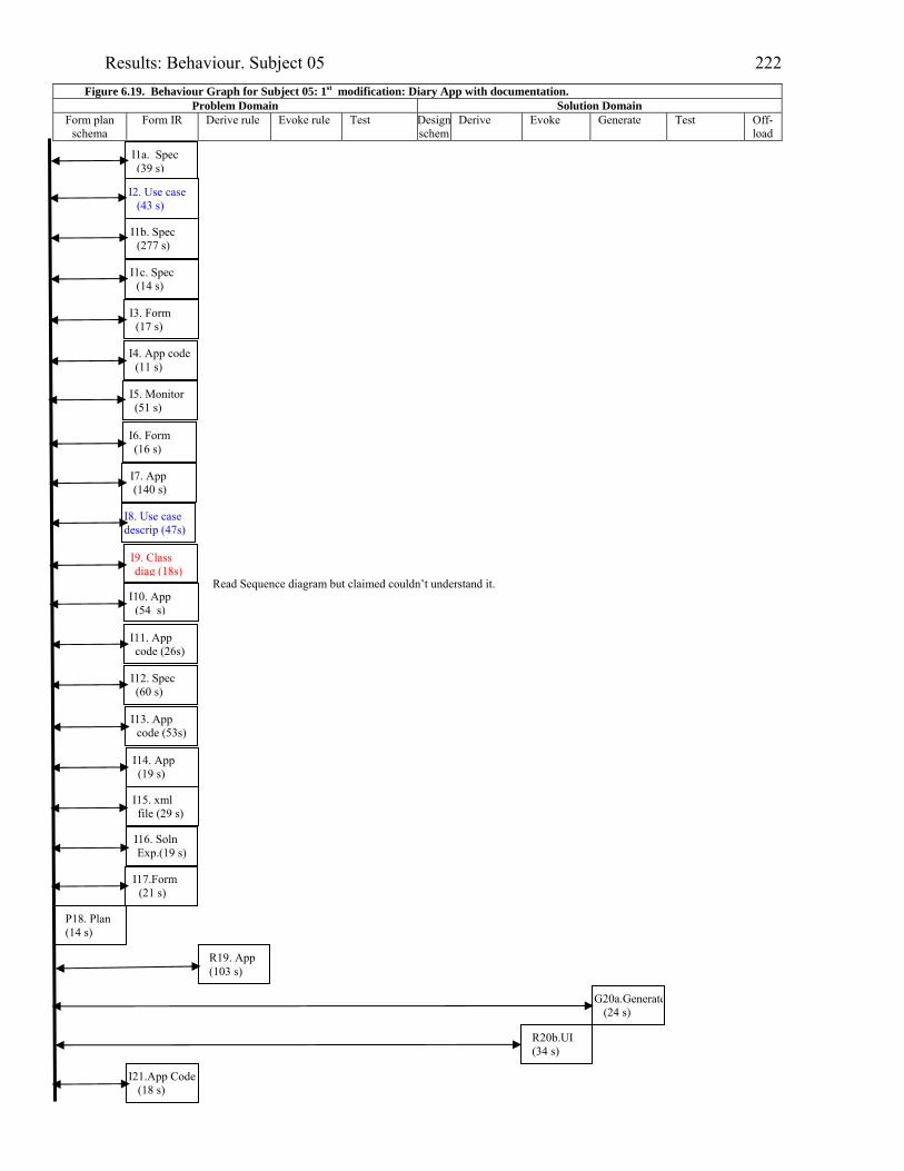
Results: Behaviour. Subject 05 222
Figure 6.19. Behaviour Graph for Subject 05: 1st modification: Diary App with documentation. Problem Domain Solution Domain
Form plan schema
Form IR Derive rule Evoke rule Test Designschem
Derive Evoke Generate Test Off-load
I2. Use case (43 s)
I1b. Spec (277 s)
I3. Form (17 s)
I5. Monitor (51 s)
I7. App (140 s)
Read Sequence diagram but claimed couldn’t understand it.
I9. Class diag (18s)
I8. Use case descrip (47s)
I11. App code (26s)
I12. Spec (60 s)
I13. App code (53s)
I15. xml file (29 s)
I17.Form (21 s)
R19. App (103 s)
P18. Plan (14 s)
R20b.UI (34 s)
I10. App (54 s)
I6. Form (16 s)
G20a.Generate(24 s)
I14. App (19 s)
I21.App Code (18 s)
I1a. Spec (39 s)
I1c. Spec (14 s)
I4. App code (11 s)
I16. Soln Exp.(19 s)

Results: Behaviour. Subject 05 223
Problem Domain Solution Domain
Form plan schema
Form IR Derive rule Evoke rule Test Designschema
Derive Evoke Generate Test Off-load
.
O22c.Help (87 s)
R22i.Code (18 s)
T22j.Testing(98 s)
I25b. App code (83 s)
T22h.Testing (57 s)
T22g.Testing (7 s)
I29.Form (55 s)
I28. Spec (20 s)
Looked at Sequence diagram, said it didn’t help but did derive one rule..
Looked at Help - some understanding indicated.
R23. Seq dia. (26 s)
R22b. Code (80 s)
Derived from Help.
T25c. App (13 s)
I26. App code (30s)
I33. App code (67 s)
R22a.Code (27 s)
R22d. Code (209 s)
O22e.Help (262 s)
R22f. Code (31 s)
T24.Testing (26 s)
I27. App code (14s)
T30.Testing (90 s)
G31.Generate (13 s)
I32.Form (16 s)
I34. App (39 s)
I25a. Code class (22 s)
ReminderSet class
Reminder form code
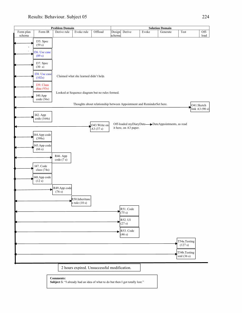
Results: Behaviour. Subject 05 224
Problem Domain Solution Domain
Form plan schema
Form IR Derive rule Evoke rule Offload Designschema
Derive Evoke Generate Test Off-load
. .
Thoughts about relationship between Appointment and ReminderSet here.
I35. Spec (59 s)
I36. Use case (89 s)
I37. Spec (30 s)
I38. Use case (102s)
I39. Class diag (93s)
O41.Sketch link A3 (90 s)
I42. App code (164s)
I40.App code (36s)
O43.Write on A3 (37 s)
I44.App code (398s)
I47. Code class (74s)
R46. App code (7 s)
I45.App code (66 s)
I48.App code (12 s)
T54a.Testing (127 s)
R50.Inheritance rule (10 s)
Claimed what she learned didn’t help.
Looked at Sequence diagram but no rules formed.
2 hours expired. Unsuccessful modification.
Comments: Subject 5: “I already had an idea of what to do but then I got totally lost.”
Off-loaded myDiaryDate DateAppointments, as read it here, on A3 paper.
T54b.Testing xml (36 s)
R51. Code (75 s)
R52. UI (27 s)
R53. Code (46 s)
R49.App code(76 s)
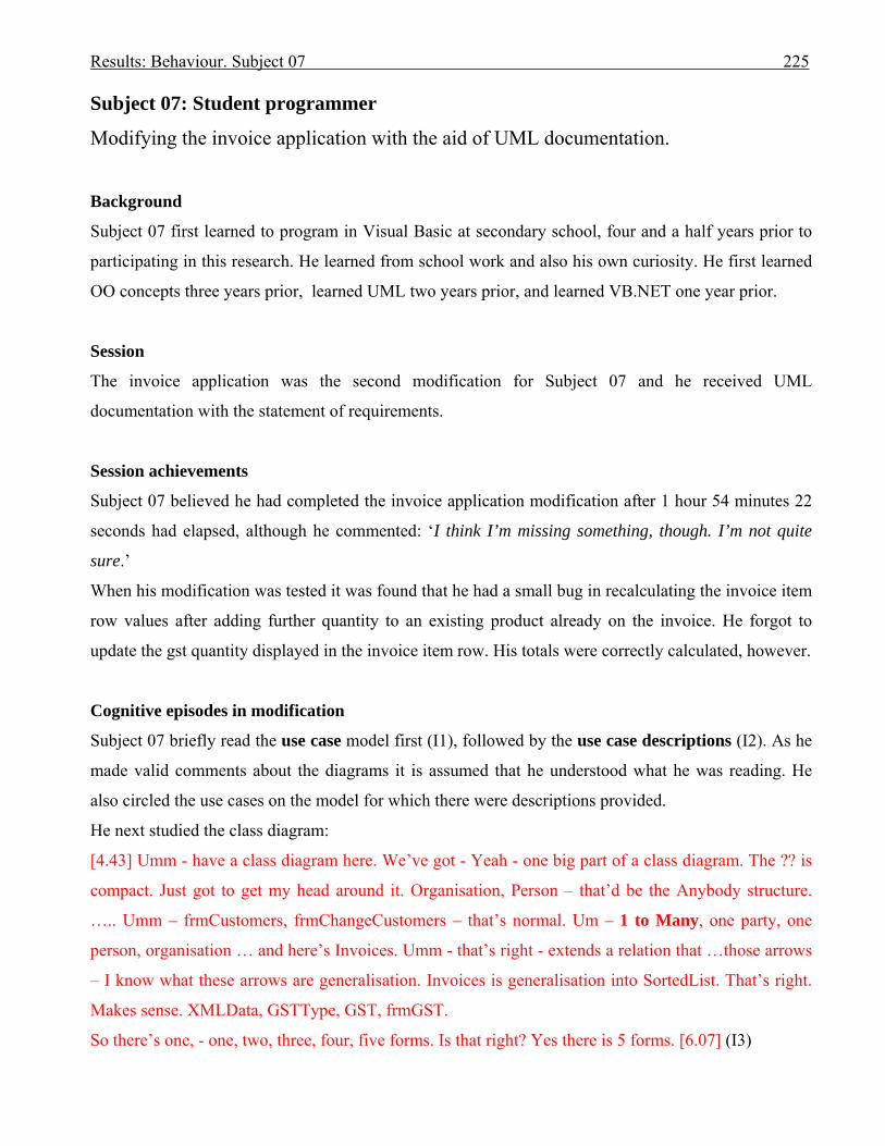
Results: Behaviour. Subject 07 225
Subject 07: Student programmer
Modifying the invoice application with the aid of UML documentation.
Background
Subject 07 first learned to program in Visual Basic at secondary school, four and a half years prior to
participating in this research. He learned from school work and also his own curiosity. He first learned
OO concepts three years prior, learned UML two years prior, and learned VB.NET one year prior.
Session
The invoice application was the second modification for Subject 07 and he received UML
documentation with the statement of requirements.
Session achievements
Subject 07 believed he had completed the invoice application modification after 1 hour 54 minutes 22
seconds had elapsed, although he commented: ‘I think I’m missing something, though. I’m not quite
sure.’
When his modification was tested it was found that he had a small bug in recalculating the invoice item
row values after adding further quantity to an existing product already on the invoice. He forgot to
update the gst quantity displayed in the invoice item row. His totals were correctly calculated, however.
Cognitive episodes in modification
Subject 07 briefly read the use case model first (I1), followed by the use case descriptions (I2). As he
made valid comments about the diagrams it is assumed that he understood what he was reading. He
also circled the use cases on the model for which there were descriptions provided.
He next studied the class diagram:
[4.43] Umm - have a class diagram here. We’ve got - Yeah - one big part of a class diagram. The ?? is
compact. Just got to get my head around it. Organisation, Person – that’d be the Anybody structure.
….. Umm – frmCustomers, frmChangeCustomers – that’s normal. Um – 1 to Many, one party, one
person, organisation … and here’s Invoices. Umm - that’s right - extends a relation that …those arrows
– I know what these arrows are generalisation. Invoices is generalisation into SortedList. That’s right.
Makes sense. XMLData, GSTType, GST, frmGST.
So there’s one, - one, two, three, four, five forms. Is that right? Yes there is 5 forms. [6.07] (I3)

Results: Behaviour. Subject 07 226
As Subject 07 counted the forms he circled the matching symbol on the class diagram. Once he had
finished with the UML documentation he planned how he would further expand his understanding of
the problem (P4).
He read the requirements specification (I5), using the calculator to check that a field was actually a
total. He continued to read the requirements (I6) then did some further planning (P7), but continued to
read the requirements (I8).
Next he looked at the invoice form on screen (I9a) and followed immediately by marking on the use
case description for Create Invoice where the gst needed to be calculated (O9b).
Subject 07 then ran the application (I10 to 13), creating invoices, and pursuing the menu links. He
concluded that he had to calculate the gst once an item was added to an invoice (G14).
He looked at the invoice form code to find the code for adding an invoice item to the data grid (I15).
He remembered having read about the xml file so returned to the requirements to reread it (I16). He
also reread that the gst percentage should be stored in the invoice (this impacts the xml file structure),
then incorrectly assumed that the gst percentage was already stored with the customer.
He asked where to find the customer data structure and the Monitor advised that parties became
customers when they got an invoice (I17). Subject 07 then mused that the way to identify a customer
was to find their invoices (G18).
Next he studied the code for the invoice class (I19).
In episode 20, Subject 07 returned to the requirements to recheck the requirement for storing the gst per
cent with the invoice, and followed by making his first change to the program by adding a gst per cent
attribute to the invoice class.
He reread the invoice line on the invoice screen in episode 21 and looked at the code of the data grid
(which was used to display the invoice items on the screen) to find if the properties were done
programmatically: they were. In episode 22, he looked at how the items were added to the data grid.
From what he learned he was able, in episode 23, to add a column to the data grid for gst, and
successfully test it.
Subject 07 entered the code to declare gst in the invoice form and successfully tested his addition in
episode 24.
He next deduced how the code for editing a customer and editing the input values for the invoice item
functioned (R25). He studied (I26) in more depth, the procedure for validating a selected product and
using a valid product to create a new invoice item line on the data grid.
He noted the option to add to the quantity of an existing product and decided to test it (T27).
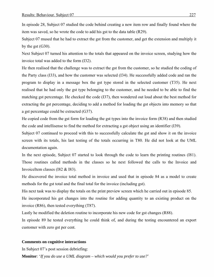
Results: Behaviour. Subject 07 227
In episode 28, Subject 07 studied the code behind creating a new item row and finally found where the
item was saved, so he wrote the code to add his gst to the data table (R29).
Subject 07 mused that he had to extract the gst from the customer, and get the extension and multiply it
by the gst (G30).
Next Subject 07 turned his attention to the totals that appeared on the invoice screen, studying how the
invoice total was added to the form (I32).
He then realised that the challenge was to extract the gst from the customer, so he studied the coding of
the Party class (I33), and how the customer was selected (I34). He successfully added code and ran the
program to display in a message box the gst type stored in the selected customer (T35). He next
realised that he had only the gst type belonging to the customer, and he needed to be able to find the
matching gst percentage. He checked the code (I37), then wondered out loud about the best method for
extracting the gst percentage, deciding to add a method for loading the gst objects into memory so that
a gst percentage could be extracted (G37).
He copied code from the gst form for loading the gst types into the invoice form (R38) and then studied
the code and intellisense to find the method for extracting a gst object using an identifier (I39).
Subject 07 continued to proceed with this to successfully calculate the gst and show it on the invoice
screen with its totals, his last testing of the totals occurring in T80. He did not look at the UML
documentation again.
In the next episode, Subject 07 started to look through the code to learn the printing routines (I81).
Those routines called methods in the classes so he next followed the calls to the Invoice and
InvoiceItem classes (I82 & I83).
He discovered the invoice total method in invoice and used that in episode 84 as a model to create
methods for the gst total and the final total for the invoice (including gst).
His next task was to display the totals on the print preview screen which he carried out in episode 85.
He incorporated his gst changes into the routine for adding quantity to an existing product on the
invoice (R86), then tested everything (T87).
Lastly he modified the deletion routine to incorporate his new code for gst changes (R88).
In episode 89 he tested everything he could think of, and during the testing encountered an export
customer with zero gst per cent.
Comments on cognitive interactions
In Subject 07’s post session debriefing:
Monitor: ‘If you do use a UML diagram – which would you prefer to use?’
Results: Behaviour. Subject 07 228
Subject 07: ‘Of all of those? Looking back, now, the class diagram would have been pretty helpful. But
in terms of what I use – um - probably the use case spec would be the most useful to me.’ …….
Monitor: ‘And why do you like the class diagram best?’
Subject 07: ‘Because – ah – because it represents how the structures are interacting with one another.
… But it’s interesting to see how the correlation between that and that, you know.’
Subject 07 had spent more time studying the use case documentation than the class diagram.
Monitor: ‘Do you ever draw diagrams when you are programming? You know - spontaneously?’
Subject 07: ‘No’.
Subject 07 did not draw any diagrams during his sessions.
Forming an internal representation
Subject 07 must have formed some internal representations from reading the use case documentation in
episodes 1 and 2 as he was able to return and add where the gst needed to be calculated on the ‘Create
Invoice’ use case description.
Although there was evidence that Subject 07 understood what he was reading from the class diagram in
episode 3, it did not trigger follow-up episodes.
Using UML documentation in a set with the problem space
Subject 07 did not use the UML documentation in a set.
Offloading to UML documentation
Subject 07 did offload where to calculate the gst for the invoice onto the use case description for
‘Create Invoice’ in episode 9.
He had ringed the use cases on the use case model for which descriptions were provided (I2) and
circled the form classes on the class diagram as he counted them (I3). He had also underlined some
parts of the requirements specification as he was reading.
Offloading in second modification (done without UML documentation)
Subject 07 had also underlined a few expressions on the diary requirements sheet, plus writing the
multiplicity expression of ‘0: .. 1’ above a sentence describing that an appointment may have no
reminder, or one reminder set which may be a combination of one to three reminder types.
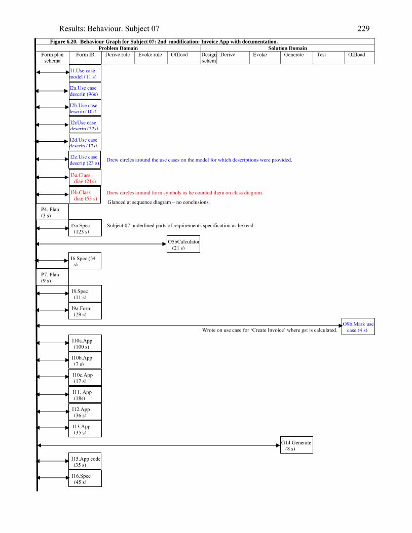
Results: Behaviour. Subject 07 229
Figure 6.20. Behaviour Graph for Subject 07: 2nd modification: Invoice App with documentation. Problem Domain Solution Domain
Form plan schema
Form IR Derive rule Evoke rule Offload Designschem
Derive Evoke Generate Test Offload
I1.Use case model (11 s)
I2a.Use case descrip (96s)
I2d.Use case descrip (12s)
I3a.Class diag (21s)
I2b.Use case descrip (10s)
I2cUse case descrip (32s)
I3b.Class diag (53 s)
I2e.Use case descrip (23 s)
Glanced at sequence diagram – no conclusions. P4. Plan (3 s)
I5a.Spec (123 s)
O5bCalculator(21 s)
I6.Spec (54 s)
P7. Plan (9 s)
I8.Spec (11 s)
I9a.Form (29 s)
I10a.App (100 s)
I10b.App (7 s)
I10c.App (17 s)
I11. App (18s)
I12.App (36 s)
I13.App (35 s)
G14.Generate (8 s)
I15.App code (35 s)
I16.Spec (45 s)
Subject 07 underlined parts of requirements specification as he read.
Drew circles around form symbols as he counted them on class diagram.
Drew circles around the use cases on the model for which descriptions were provided.
O9b.Mark use case (4 s)Wrote on use case for ‘Create Invoice’ where gst is calculated.
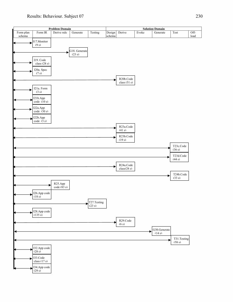
Results: Behaviour. Subject 07 230
Problem Domain Solution Domain
Form plan schema
Form IR Derive rule Generate Testing Designschema
Derive Evoke Generate Test Off-load
I17.Monitor (9 s)
G18. Generate (23 s)
I19. Code class (28 s)
I20a. Spec (7 s)
R20b.Code class (51 s)
I21a. Form (3 s)
I21b.App code (10 s)
I22a.App code (30 s)
I22b.App code (3 s)
R23a.Code (41 s)
R23b.Code (19 s)
T23c.Code (36 s)
R24a.Code class(28 s)
T23d.Code (44 s)
T24b.Code (33 s)
R25.App code (83 s)
I26.App code (18 s)
T27.Testing (23 s)
I28.App code (135 s)
R29.Code (6 s)
G30.Generate (14 s)
T31.Testing (58 s)
I32.App code (28 s)
I33.Code class (17 s)
I34.App code (29 s)
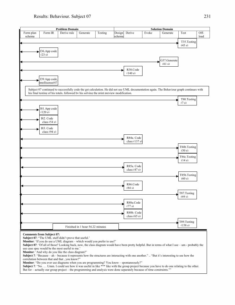
Results: Behaviour. Subject 07 231
Problem Domain Solution Domain
Form plan schema
Form IR Derive rule Generate Testing Designschema
Derive Evoke Generate Test Off-load
Subject 07 continued to successfully code the gst calculation. He did not use UML documentation again. The Behaviour graph continues with his final testing of his totals, followed by his solving the print preview modification.
T35.Testing (45 s)
I36.App code (23 s)
G37.Generate (61 s)
R38.Code (140 s)
I39.App code, intellisense(47
T80.Testing (7 s)
I81.App code (120 s)
I82. Code class (54 s)
I83. Code class (94 s)
R84a. Code class (137 s)
T84b.Testing (50 s)
T84c.Testing (14 s)
R85a. Code class (47 s)
T85b.Testing (60 s)
R86.Code (84 s)
T87.Testing (69 s)
R88a.Code (77 s)
R88b. Code class (65 s)
T89.Testing (158 s)Finished in 1 hour 54.22 minutes
Comments from Subject 07: Subject 07: “The UML stuff didn’t prove that useful.’ Monitor: ‘If you do use a UML diagram – which would you prefer to use?’ Subject 07: ‘Of all of those? Looking back, now, the class diagram would have been pretty helpful. But in terms of what I use – um - probably the use case spec would be the most useful to me.’ Monitor: ‘And why do you like the class diagram?’ Subject 7: “Because – ah – because it represents how the structures are interacting with one another.” .. “But it’s interesting to see how the correlation between that and that , you know?” Monitor: “Do you ever use diagrams when you are programming? You know – spontaneously?” Subject 7: “No. … Umm. I could see how it was useful in like *** like with the group project because you have to do one relating to the other. But for – actually our group project – the programming and analysis were done separately because of time constraints.””

Results: Behaviour. Subject 13 232
Subject 13: Student programmer
Modifying the diary application with the aid of UML documentation.
Background
Subject 13 first learned to program in a first year tertiary course in Java, three years prior to
participating in this research. She learned to program in VB.NET two and a half years prior, and
learned UML two years prior.
Session
The diary application was the second modification for Subject 13 and she received UML
documentation with the statement of requirements.
Session achievements
Subject 13 did not complete the diary application modification within the two hours.
When tested after the session it was found that she had added a button called ‘Create Reminder’ on the
frmDiary screen, but not within the Appointment Group box where it should have been placed. She
successfully achieved the use of that button to enable the user to select a reminder for an appointment,
but failed to store the selected reminder in the attribute she had created for it in the appointment class.
She checked the appointments for reminders at the start and exit of the program but did not have time
to code the timed checks. The method she used of displaying a copy of the frmReminder to enable
reminder selection meant that she did not display the reminder when an appointment was reloaded.
Cognitive episodes in modification
Subject 13 initially glanced at the use case model for about eight seconds and commented: ‘The use
case is involved.’ However, she did follow this by reading the use case descriptions for adding and
changing an appointment (I1). She briefly looked at the class diagram (I2), commenting on the
changeContact form, then moved on to the sequence diagram (I3), interpreting it as follows:
[3.17] I’m looking at the sequence diagram. Um.
So the user selects the day to make an appointment then select the day, date is selected from the
calendar .. .. .. which contains a key, if DiaryDate found get diaryDate appointments. So they’re
looking up - um - appointments for a specific day.
Valid Appointment. If there’s no diarydate, you can create a new diary date.
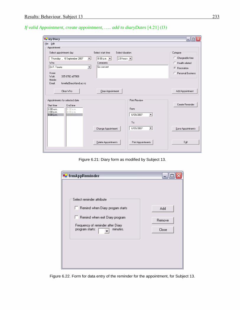
Results: Behaviour. Subject 13 233
If valid Appointment, create appointment, ….. add to diaryDates [4.21] (I3)
Figure 6.21: Diary form as modified by Subject 13.
Figure 6.22. Form for data entry of the reminder for the appointment, for Subject 13.

Results: Behaviour. Subject 13 234
Subject 13 next returned to the class diagram and compared the illustrated Body class with the Body
class as coded (I4), finding that they corresponded.
In I5, Subject 13 read the requirements specification from start to finish.
She returned to the class diagram:
[8.22] [rustle]’ Just looking at the class diagram again. Um.
So a Party has phone number, address, mobile, email,
May be a Person or an Organisation they can make many appointments. Um.
An appointment can be for either zero or one person. Ah – yeah. Um. ..
A party – that is a collection of contacts – so contacts collects all bodies and one body - many bodies
will be with one contact. Um. ..
A contact is a .. sub type of Group? Ah – and as ReminderSets is also collected in ReminderSets class
and appointments is collected in the DiaryDate collection class. Um. …. About 3 main collection
classes, for the diary, the reminders and contacts.’ [10.28] (I6).
She returned to verify the goal of the requirements (I7a), and then returned to the class diagram to
locate the relevant classes:
[10.59] The diaryDate already has all the appointments. Umm – so Appointment needs to be linked to
Reminder …… Um. … AppointDuration, Comment, Category, Contact, [Appoint]Finish(),
PrintAppointment(), Wordwrap() [Note: these are the attributes and methods of the Appointment class]
[11.45] (I7b)
The reading of the specification had guided Subject 13 to locate and study the Appointment class in the
diagram. She was unsure of how the reminder should be linked to the appointment so returned to the
requirement specification to reread the section on what reminder information was required in the
appointment (I8).
Subject 13 returned to the use case description for a brief read of the use case description for adding
an appointment (I9).
She wondered how to link the Appointment and ReminderSet and made an incorrect assumption that
the ReminderSets group class should be linked, offloading her one-to-one link onto the diagram
between the Appointment class and the ReminderSets group class:
[14.32] ‘Um. .. So if I want to add a reminder to an appointment – umm – I have to say which
appointment is stored …
So ….. maybe even the ReminderSets class – yeah, collection class, – um - refer to the appointment,
the reminders as well, so the ReminderSet will have to be linked – the ReminderSets collection class
will have to be linked to the appointment class. ….. mmm. …. Umm …….[drawing on class diagram]

Results: Behaviour. Subject 13 235
If I just link appointment to a reminder - mmm - as one to one. So each ReminderSet in the reminders
collection class will be for a specific appointment’. [15.56] (O10 )
She continued to study the class diagram:
[16.04] ‘Just like – um – each appointment in the appointment class will be for a specific diaryDate.
…… For each appointment, the appointment collection class will be for a specific date. ….
So the reminders collection class will have the ReminderSet and the appointment – as well. … Mm. So
the diaryDate collection class it has a … ValidAppointment() method so I’m just going to have a look
at that and see’. [17.35] (I11)
Thus the study of the classes in the diagram identified an area of code that Subject 13 wished to study
further. In I12 she found the code for the appointment class and reviewed the ValidAppointment
method.
She was still concerned as to how the relationship should perform and returned to look at the class
diagram: [22.57] It’s clearly – ah - an instance of an appointments class - collection class. So I’ve got
to do the appointment class to the reminder class. So it goes the appointment class [44.24] – it’s got
AppointDuration, Comment, Category, Contact [23.34] (I13).
Subject 13 created an attribute for a ReminderSets instance in the appointment class in episode 14.
During that episode she briefly returned to the class diagram, making no comments, then generated
thoughts about what she should code to make the modification work – such as creating ValidReminder
and AddReminder methods (G15).
She returned to the requirements specification (in a continuation of episode 14), rereading that the
reminder should be added to an appointment, after which she coded her AddReminder method –
encountering a problem which caused her to look back at the class diagram:
[29.35] ‘ReminderSet is grouped into ReminderSets class
All instances of the reminders will be in the ReminderSets class. (R14d)
So we add the reminder, we send in the appointment and add …….. [30.33].
She continued to write her code for episode 14, then assumed that the ReminderSets collection class
had a ReminderSet for each appointment – so she decided to look at the ReminderSet class in I16 –
cross-checking between the original code and the class diagram.
Subject 13 looked in Solution Explorer (I17) to see what files were present. In episode 18 she studied
the appointment class code, frequently glancing back at the class diagram. She correctly surmised that
the ReminderSet should go in the Appointment class and successfully changed her code to a new
ReminderSet attribute within the Appointment class (R19), instead of a ReminderSets collection class.

Results: Behaviour. Subject 13 236
She returned to reread the requirements again (I20), clarifying her understanding of how an
appointment could have a selection of reminders, then looked at the code for the ReminderSet form,
deciding that the selection of reminders she required was added via that form (I21).
Subject 13 decided to run the application (T22), adding appointments, and then chose to look at the
form for adding ReminderSets, discovering that all combinations were already present. Her next step
was to place a Create Reminder button on the diary form – but placed it outside the Appointment group
box (R23), writing code in episode 24 to call a frmReminderSet when that button was clicked.
She wished to pass an appointment to this called form so declared an attribute for appointment in the
code for the form in episode 25. Subject 13’s next step in episode 25 was to look at the code for the
Appointment class, and she stated that the appointment could not be accessed by the reminder class.
She continued to code the handling of the appointment variable to be passed to the reminder form by
setting its remindAtSart, remindAtEnd and frequency attributes.
She checked the class diagram – but did not comment, then continued episode 25 by adding further
code for setting a reminder for an appointment within the reminder form.
Subject 13 next offloaded onto the class diagram (O26) the details of the attribute that she set for a
ReminderSet in the appointment class: mReminder:ReminderSet, adding her comment: ‘So you can
add a reminder.’
Subject 13 returned to the requirements to study what to do next, to find the reminding activities (I27).
Before she undertook that code she ran the application to test what she had already done (T28), found
that she was not showing the reminders form when the Create Reminder button was clicked, corrected
that, then glanced back at the code for the diary form where an appointment was already being set
(I29), then ran the program again in T30, where she encountered errors and decided that she should
change the reminder attribute she had placed in the appointment class back to the reminders group
class. She studied the diary form code, finding DateTimeBody class (I31), so studied the
DateTimeBody hierarchy code (I32), finding that the group class had no methods of its own. She then
reflected (G33) that she should make the attribute a ReminderSet, commenting: ‘So now I am back to
where I was before.’
Through further testing (T34), Subject 13 succeeded in setting a reminder attribute in the appointment.
She returned to the requirements to read how and when the reminders were triggered (I35), which
caused her to generate thoughts that the appointments collection class needed to be checked for
appointments with a date that equaled the system date (G36).
She started coding a ValidReminder method for carrying out those checks (episode 37). During the
coding activity she looked at the class diagram but made no comment. She had trouble discovering
Results: Behaviour. Subject 13 237
how to get the system time so looked up Help, and the requirements. She set the ValidReminder
function to True if the appointment date was for today, then shifted the code for ValidReminder into
the form loading section (R38) of the diary form.
Subject 13 checked the requirement specification for the ‘remind at start’ requirements (I39), then
continued to read the requirements for the pop-up reminder message to guide what she coded (R40).
She looked at the class diagram to find the details of the Person class as a possible source for the ‘Who’
section of the message (I41).
She ran the program (T42), added code similar to that for ‘remind at start’ at the program exit, to serve
for ‘remind at end’, coding and testing to discover there were no appointments in the appointment class
(Note: appointments were there but her code was not picking them up).
Subject 13 glanced at the class diagram again with no comment, then made changes to her code (R43),
looked back at the form loading code for the diary form (I44), specifically studying the
LoadAppointments method. She ran the program again (T45), reconfirming there were no
appointments, and blaming their absence for no reminder messages popping up. She read the form
loading comments (I46) with respect to the fact that the appointments were loaded from an xml file, but
then claimed that she had no xml file.
The Monitor advised how to access the xml file (I47), so that Subject 13 could find that the xml file for
appointments did exist. She found the xml file loading code in the diary form (I48) and decided to copy
it (episode 49), tested it and got an error.
Her two hours time expired here.
Comments on cognitive interactions
In her post-session debriefing:
Subject 13: ‘I had more problems thinking about the code rather than the documentation.’
Monitor: ‘If you had to use UML diagrams which ones do you prefer to use?’
Subject 13: ‘Ah - Class diagrams.’
Monitor: ‘Class. And the reason for that?’
Subject 13: ‘Um. So you know where the data is, and – ah - what operations exactly - how they
communicate to each other.’
Monitor: ‘When you are programming normally do you ever spontaneously use a diagram? Draw a
diagram?’
Subject 13: ‘Ah - not really. [laughs] I don’t really worry about the documentation much. I’m more
into involved in the coding. And then if I get really stuck I’ll look in the documentation – just - yeah.’

Results: Behaviour. Subject 13 238
For this session, Subject 13 had read the UML documentation first, prior to reading the requirements,
and had made use of them as reported in the following paragraphs.
Forming an internal representation
Subject 13 looked initially at the UML documentation. There was no evidence that the reading of the
use case documentation (I1), the class diagram (I3), and the sequence diagram (I3) triggered further
steps. She did return to the class diagram to compare it with the code for the Body class (I4) but she did
not make any further use of this knowledge.
In I6 she discovered the collection classes from the class diagram. She checked with the requirements
which guided her to read appropriate classes on the class diagram in episode 7. From this reading she
made the decision that the Appointment class needed to be linked to a reminder and thus this reading of
the class diagram can be claimed to assist in her establishing an internal representation, not only of the
problem, but also of a potential step in its solution.
Subject 13 looked again at the use case documentation in I9. She offloaded her thoughts concerning a
link between the appointment class and the reminders collection class onto the class diagram in O10,
then continued to read the class diagram (I11), targeting the Appointment class, finding its
ValidAppointment method, which guided her next step to look at the code for that method. Again, the
reading of the class diagram had led to a further step in her acquisition of an internal representation.
Using UML documentation in a set with the problem space.
Subject 13 did use the UML documentation in a set to solve the problem. The reading of the class
diagram in I13 guided her to place an attribute for a reminder in the appointment class.
In episode 14, Subject 13 was exploring the use of a ReminderSets collection class attribute in the
Appointment class and she looked at the class diagram to clarify that every ReminderSet was stored in
the ReminderSets collection class. Following I16 she looked at the class diagram again, using it to
cross-check with the ReminderType class code. She continued to look at the class diagram and
explored more code until G14f when she finally confirmed (correctly) that she should place a
ReminderSet attribute in Appointment, instead of the ReminderSets collection class. Here was an
example of the class diagram being used in a set with the reading of code to enable Subject 13 to reach
a decision and evoke a rule in the solution domain.
In I41, Subject 13 looked up the details for a contact on the class diagram whilst she was coding the
reminder pop-up message which required those details; another example of the class diagram being
used in a set with code.

Results: Behaviour. Subject 13 239
Offloading to UML documentation
In the diary application with UML documentation
Subject 13 did offload onto the class diagram on two occasions: in O10, when she drew a link
(incorrectly) between the Appointment class and the ReminderSets collection class, and in O26 when
she added a correct attribute for ReminderSet within the Appointment class.
In I13 she checked her link that was drawn in O10 (evidence of the utility of the offloading) then
started coding the link in the following episode.
In the invoice application with UML documentation
Subject 13 did not offload any item during this session in which she performed less successfully than
she did in the diary application.
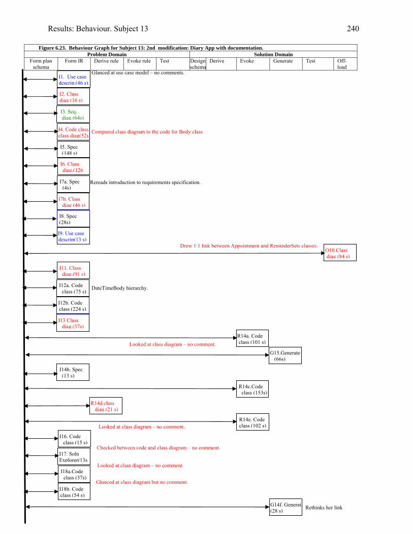
Results: Behaviour. Subject 13 240
Figure 6.23. Behaviour Graph for Subject 13: 2nd modification: Diary App with documentation.
Problem Domain Solution Domain Form plan
schema Form IR Derive rule Evoke rule Test Design
schemaDerive Evoke Generate Test Off-
load
I2. Class diag (16 s)
R14a. Code class (101 s)
I4. Code class class diag(52s
I5. Spec (148 s)
I6. Class diag.(126
O10.Class diag (84 s)
I9. Use case descrip(13 s)
I7a. Spec (4s)
I12a. Code class (75 s)
I12b. Code class (224 s)
I13 Class diag (37s)
G15.Generate (66s)
I14b. Spec (13 s)
R14d.class diag (21 s)
I16. Code class (15 s)
I17. Soln Explorer(13s
I18b. Code class (54 s)
R14e. Code class (102 s)
I1. Use case descrip.(46 s)
I7b. Class diag (46 s)
I8. Spec (28s)
I11. Class diag.(91 s)
I3. Seq. diag (64s)
R14c.Code class (153s)
I18a.Code class (37s)
G14f. Generate(28 s)
Compared class diagram to the code for Body class
Glanced at use case model – no comments.
Rereads introduction to requirements specification.
Drew 1:1 link between Appointment and ReminderSets classes.
DateTimeBody hierarchy.
Glanced at class diagram but no comment.
Rethinks her link
Looked at class diagram – no comment.
Checked between code and class diagram – no comment.
Looked at class diagram – no comment.
Looked at class diagram – no comment.
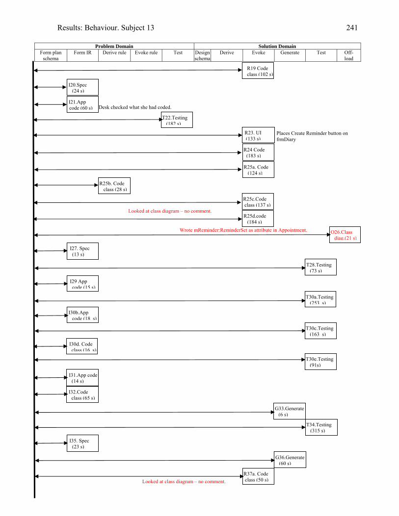
Results: Behaviour. Subject 13 241
Problem Domain Solution Domain
Form plan schema
Form IR Derive rule Evoke rule Test Design schema
Derive Evoke Generate Test Off-load
I20.Spec (24 s)
I21.App code (60 s)
R25a. Code (124 s)
R25d.code (184 s)
R19 Code class (102 s)
T30e.Testing (91s)
I31.App code (14 s)
I29 App code (15 s)
I27. Spec (13 s)
T22.Testing (182 s)
R24 Code (183 s)
T30a.Testing (253 s)
I30b.App code (18 s)
T34.Testing (315 s)
R25b. Code class (28 s)
R23. UI (133 s)
R25c.Code class (137 s)
O26.Class diag.(21 s)
T28.Testing (73 s)
I30d. Code class (16 s)
Desk checked what she had coded.
Places Create Reminder button on frmDiary
Wrote mReminder:ReminderSet as attribute in Appointment.
T30c.Testing (163 s)
I32.Code class (65 s)
G33.Generate (6 s)
I35. Spec (23 s)
G36.Generate (60 s)
R37a. Code class (50 s)Looked at class diagram – no comment.
Looked at class diagram – no comment.
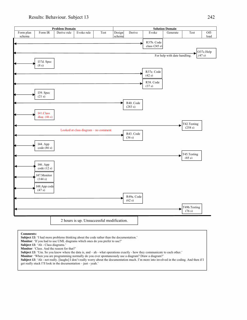
Results: Behaviour. Subject 13 242
Problem Domain Solution Domain
Form plan schema
Form IR Derive rule Evoke rule Test Design schema
Derive Evoke Generate Test Off-load
2 hours is up. Unsuccessful modification.
Comments: Subject 13: ‘I had more problems thinking about the code rather than the documentation.’ Monitor: ‘If you had to use UML diagrams which ones do you prefer to use?’ Subject 13: ‘Ah - Class diagrams.’ Monitor: ‘Class. And the reason for that?’ Subject 13: ‘Um. So you know where the data is, and – ah - what operations exactly - how they communicate to each other.’ Monitor: ‘When you are programming normally do you ever spontaneously use a diagram? Draw a diagram?’ Subject 13: ‘Ah - not really. [laughs] I don’t really worry about the documentation much. I’m more into involved in the coding. And then if I get really stuck I’ll look in the documentation – just - yeah.’
R37b. Code class (245 s)
O37c.Help .(47 s)
I37d. Spec (8 s)
R37e. Code (42 s)
R38. Code (37 s)
I39. Spec (21 s)
R40. Code (283 s)
I41.Class diag. (46 s)
T42.Testing (258 s)
R43. Code (36 s)
I44. App code (86 s)
T45.Testing (85 s)
I46. App code (12 s)
I47.Monitor (144 s)
I48.App code (47 s)
R49a. Code (62 s)
T49b.Testing (76 s)
Looked at class diagram – no comment.
For help with date handling.

Results: Behaviour. Subject 21 243
Subject 21: Student programmer
Modifying the invoice application with the aid of UML documentation.
Modifying the diary application with NO UML documentation provided
Background
Subject 21 first learned to program in a first-year tertiary course in Java, five years prior to
participating in this research. In that course he first encountered OO concepts. He first learned UML
four years prior, and learned to program in VB.NET three years prior, in a third-year programming
course which did not include UML modelling.
Session
The invoice application was the first modification for Subject 21 and he received UML documentation
with the statement of requirements.
Session achievements
Subject 21 did not complete either of his modifications. His lack of success dictated that his protocols
were not transcribed.
For his invoice modification Subject 21 added a gst column to the invoice, but then hard-coded the gst
percentage used in the calculations, despite successfully extracting the customer’s gst type.
Comments on cognitive interactions
Subject 21 claimed that if you knew what you wanted to do then it was preferable to go straight to
code. In Subject 21’s post-session debriefing he claimed to be more of a coder.
Of the UML notation he preferred to use the use case documentation as it ‘helps to get the detail of
what functions you would like to see in a normal run’.
He stated that a class diagram was useful for modelling cohesiveness and coupling, which could
improve design. He thought the sequence diagram initially communicated how a program actually runs,
but became no longer useful once the programmer had played with the program.
When asked if he ever used diagrams when he was programming, Subject 21 said he ‘might do a little
ERD.’ He believed that for a new application UML would help.
Offloading in first modification (with UML documentation provided)

Results: Behaviour. Subject 21 244
Figure 6.24. Subject 21’s offloading whilst modifying the invoice application with supplied UML documentation.
Subject 21 did not offload to the UML documentation. However, as shown in Figure 6.24, he did
offload many notes onto the A3 paper. He placed in the top left-hand corner the composite relationship
between an invoice and its invoice items, despite its inclusion on the supplied class diagram.
Figure 6.25. Subject 21’s offloading whilst modifying the diary application with no UML documentation Offloading in second modification (done without UML documentation)

Results: Behaviour. Subject 21 245
Included in the notes that Subject 21 offloaded during this session was a sketch of part of a class
diagram showing Reminder and Appointment classes and an invalid association linking them (refer to
Figure 6.25). He had drawn a ‘crow’s foot’ relationship between the classes. He had stated that the
diagram he would most likely use whilst he was programming was an ERD, and he had borrowed from
that notation for his diagram. His inclusion of an ‘appointment ID’ attribute in a Reminder did not
satisfy the requirements which explicitly requested that an Appointment be given a ReminderSet.
Results: Behaviour. 246
6.5.3 Collation of results from non-industry-experienced subjects
6.5.3.1 Introduction
The non-industry-experienced group was comprised of subjects who had just passed a third-year
systems analysis and design course which incorporated UML documentation and VB.NET
programming. All but Subject 05 had passed a tertiary course in VB.NET programming (which did
NOT include any modelling). Subject 05 had passed several other courses in OO programming.
Every non-industry-experienced subject, including those who were unsuccessful and did not have their
verbal protocols transcribed, read some of the UML documentation. Table 6.5 documents the episodes
in which the participants who had their verbal protocols transcribed and analysed, used the provided
UML documentation. Table 6.6 documents only the uses for which evidence was obtained that the
reading of the UML documentation had some effect on the subject’s following steps, or offloading was
involved.
The only evidence of effective reading of UML documentation for Subject 02 was in episode 3 where
she read the class diagram. For the remaining participants who were transcribed, benefit was received
from reading more than one part of the documentation. Subject 03 was the only transcribed subject to
read the sequence diagram and provide evidence of its usefulness.
All transcribed subjects benefited from reading the class diagram. Table 6.5, which shows how the
UML documentation was used, supplies evidence that all transcribed subjects benefited from reading
associations on the class diagram.
Although all transcribed subjects read at least some of the use case descriptions, only Subjects 05 and
07 were able to leverage that reading.
As reported in Section 6.4.3.1, and repeated here for convenience, an aim of the research was to
discover if UML documentation could be used
1. to assist in the formation of a programmer’s internal representation of a coding problem
2. in a set with a programmer’s problem space
3. in a set with the subject’s problem space to aid the induction of rules, and
4. as an external representation in the offloading of information from working memory.
The uses listed above are discussed in the next sub-sections and the results are summarised in Table
6.6. The results are to be used to answer the research questions as stated in Section 6.0.
6.5.3.2 Using UML documentation to assist with comprehension

Results: Behaviour. 247
Where there is evidence that the knowledge gained by a subject in reading UML documentation was
used in succeeding episodes it was judged that the reading had contributed to the establishment of an
internal representation.
There was evidence that all non-industry-experienced subjects who had their verbal protocols
transcribed gained understanding as a result of reading a class diagram (refer to Table 6.6). Table 6.5
provides further information in that those subjects all gained benefit from reading associations on the
class diagram. Only Subject 13, who utilised the UML documentation more often than her peers,
gained benefit from reading attributes and methods on the class diagram.
Subjects 03, 05 and 07 leveraged the use case documentation to form internal representations. Subject
03 also used the sequence diagram.
6.5.3.3 Using UML documentation in a set with the problem space
Subjects 03 and 13 demonstrated using the UML documentation in a set with the problem space.
Subject 03 compared the use cases with the form in the problem domain (I9) and Subject 13 compared
the class diagram to class code in I16 in the problem domain.
The behaviour graphs were used to identify the domain and cognitive steps where rules were induced.
Subject 13 accessed the class diagram in her episodes to evoke rules with respect to placement of a new
reminder attribute in the appointment class in the solution domain.
6.5.3.4 Using UML documentation for offloading from working memory
6.5.3.4.1 Offloading during session with UML documentation provided
Only the most successful non-industry-experienced subjects, 07 and 13, offloaded onto the UML
documentation.
Subject 07 offloaded where to calculate gst onto the use case description for ‘Create Invoice’ in episode
9, and Subject 13 drew a link (O10) and wrote a new ReminderSet attribute (O26) in the Appointment
class on the class diagram. As the invoice application was process-oriented it was appropriate that the
use case description was utilised as it described processes. The diary application was event-oriented.
The insertion of the ReminderSet as an attribute in Appointment was essential to the implementation of
that modification.
Subject 05, despite having the UML documentation supplied for her session for modifying the diary
application, offloaded the Appointment – ReminderSet relationship onto the A3 paper (O41). In O43
she replicated the relationship between the date in the diary and its appointments, onto the A3 paper,
replacing the names used on the class diagram with those declared within the code.

Results: Behaviour 248
Table 6.5. How the UML episodes that involved UML documentation were applied; for five non-industry-experienced subjects.
What the UML documentation was used for, by subjects with NO industry experience
Use case Class Diagram Sequence diagram
Sub-ject
App-licat-ion
1st or
2nd mod
% goals achieved
% goals
in mod sans UML
Mod-el
Descript-ions
Used as guide to applicat-
ion Off-load
Class presence
Class name
Attrib-utes
Inherit-ance
Associat-ions Method
Off-load
Meth-ods
Off-load
2 Invoice 2 50.0 13.3 I1 I2 I3 I4 3 Diary 1 12.2 52.8 I14 I9 I15 R16
5 Diary 1 5.6 50.0
I2, I36, I38
I2, I8, I36, I38 I9 I39
O41, O43 R23
7 Invoice 2 94.4 47.2 I1 I2 I2, O9 I3 I3 I3
13 Diary 2 47.2 8.3 I1, I9 I2, I6, I41
I4, I6, I11, I7b, I13, I16 I6
I6, I7b, I11, I13, R14d
I4, I7b, I11
O10, O26 I3
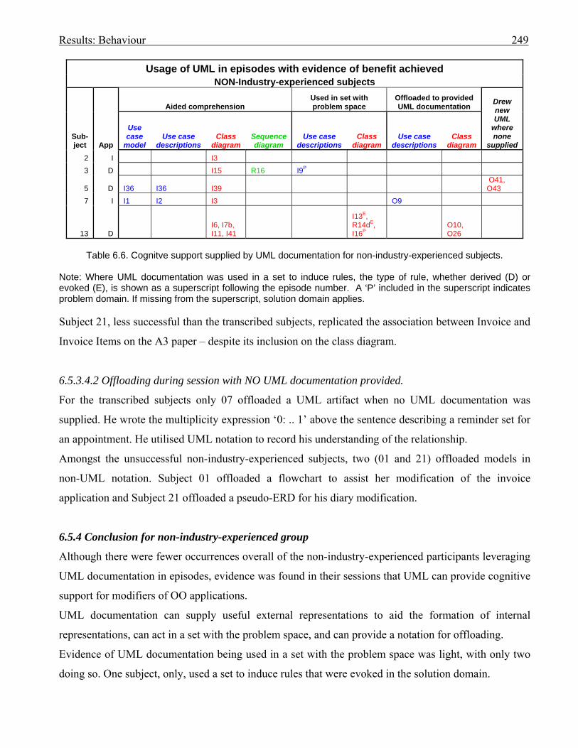
Results: Behaviour 249
Usage of UML in episodes with evidence of benefit achieved NON-Industry-experienced subjects
Sub- ject App
Aided comprehension Used in set with problem space
Offloaded to provided UML documentation Drew
new UML
where none
supplied
Use case
model Use case
descriptions Class
diagram Sequence diagram
Use case descriptions
Class diagram
Use case descriptions
Class diagram
2 I I3 3 D I15 R16 I9P
5 D I36 I36 I39 O41, O43
7 I I1 I2 I3 O9
13 D I6, I7b, I11, I41
I13E, R14dE, I16P
O10, O26
Table 6.6. Cognitve support supplied by UML documentation for non-industry-experienced subjects.
Note: Where UML documentation was used in a set to induce rules, the type of rule, whether derived (D) or evoked (E), is shown as a superscript following the episode number. A ‘P’ included in the superscript indicates problem domain. If missing from the superscript, solution domain applies. Subject 21, less successful than the transcribed subjects, replicated the association between Invoice and
Invoice Items on the A3 paper – despite its inclusion on the class diagram.
6.5.3.4.2 Offloading during session with NO UML documentation provided.
For the transcribed subjects only 07 offloaded a UML artifact when no UML documentation was
supplied. He wrote the multiplicity expression ‘0: .. 1’ above the sentence describing a reminder set for
an appointment. He utilised UML notation to record his understanding of the relationship.
Amongst the unsuccessful non-industry-experienced subjects, two (01 and 21) offloaded models in
non-UML notation. Subject 01 offloaded a flowchart to assist her modification of the invoice
application and Subject 21 offloaded a pseudo-ERD for his diary modification.
6.5.4 Conclusion for non-industry-experienced group
Although there were fewer occurrences overall of the non-industry-experienced participants leveraging
UML documentation in episodes, evidence was found in their sessions that UML can provide cognitive
support for modifiers of OO applications.
UML documentation can supply useful external representations to aid the formation of internal
representations, can act in a set with the problem space, and can provide a notation for offloading.
Evidence of UML documentation being used in a set with the problem space was light, with only two
doing so. One subject, only, used a set to induce rules that were evoked in the solution domain.
Results: Behaviour 250
As was the case for the industry-experienced group the class diagram was used more often than the
other UML documentation.
6.6 Using the results to answer the research questions
The research questions involving cognitive behaviour will be answered in turn.
Question B1. Can the use of UML documentation facilitate a programmer’s comprehension of a non-
trivial program by assisting in the formation of valid internal representations of a
problem?
Answer B1: Tables 6.4 and 6.6 record the episodes where evidence was obtained that UML
documentation supported the programmer in establishing an internal representation of the problem. For
both groups the class diagram was the most often accessed UML external representation. All subjects
except 04 gained cognitive support in forming internal representations from the class diagram. Subject
04 did use the class diagram in a set with his problem space.
Question B2. (i) Can the use of UML documentation facilitate a programmer in modifying a non-trivial
program by forming a set with the programmer’s internal problem space?
Answer B2: There was less evidence of set forming than of internal representation formation. One only
subject in each group formed a set with the use case documentation. Three industry-experienced
subjects formed a set with the class diagram, as did one participant from the student group.
An examination of Tables 6.4 and 6.6 in conjunction with the behaviour graphs shows that episodes
involving UML documentation were more plentiful in the early stages of the modification when initial
internal representations were being formed. The comments of Subject 16 may apply here as he claimed
to like to get an overview from the documentation first, but found it easier to go through the code after
that. He found it easier to focus on the screen than to flip back and forth.
Question B3. (ii) Can the use of UML documentation facilitate a programmer’s writing of code to
solve a non-trivial problem by acting in a set with the problem space to induce rules
for solution?

Results: Behaviour 251
Answer B3: Set formation and induction of rules tended to occur following the setting up of initial
internal representations.
Subject 15 derived a rule in the problem domain (R14) when using the class diagram in a set with his
problem space.
Rule induction in the solution domain occurred when UML class diagrams were used in a set with a
programmer’s problem space to evoke rules for Subjects 04, 13, 15 and 20. In addition, Subject 20
derived a rule in the solution domain in episode 45 (refer to Tables 6.4 and 6.6).
Question B4. Can the use of UML documentation facilitate a programmer’s modifying a non-trivial
program by providing a vehicle for offloading from working memory?
Answer B4: Again, there were few examples. Subjects 07 and 16 offloaded onto use case descriptions.
Subject 07 offloaded the step at which to calculate the gst for the invoice modification (O9), and
Subject 16 offloaded where to set ReminderSets, with a Post Condition to display reminder, for the
diary modification (O16).
Subjects 13 and 16 offloaded to the class diagram. Subject 13 developed her link between the
Appointment and ReminderSet class in O10 and O26, as did Subject 16 in O32 and O34. Although the
two subjects ended up with similar, valid links, their methods of attaining them varied. Subject 16
initially tried to insert an intermediate class between the two classes and Subject 13 initially had the
link joining the collection class for the ReminderSets. They both used the class diagram as the vehicle
for evolving their solutions.
Although it cannot be confirmed with the current research, it is possible that the extra exercising of the
information as it is offloaded helped to establish what was offloaded more firmly in LTM. Both Subject
13 and Subject 16 implemented the final results of what they offloaded.
There were a few examples of subjects offloading, using UML notation, to paper. Subjects 16 and 17
offloaded class artifacts whilst modifying applications for which no UML documentation was
provided, whilst Subject 05 offloaded a small two-class diagram for the Appointment – ReminderSet
link in O41, despite UML documentation being available. She also offloaded the ‘mydiaryDate-
>DateAppointments’ relationship in O43 in the same modification. In the latter she had replicated the
declared variable names for the class names in the hierarchy.
Although not transcribed, Subjects 09 and 21 also offloaded small class artifacts onto paper.
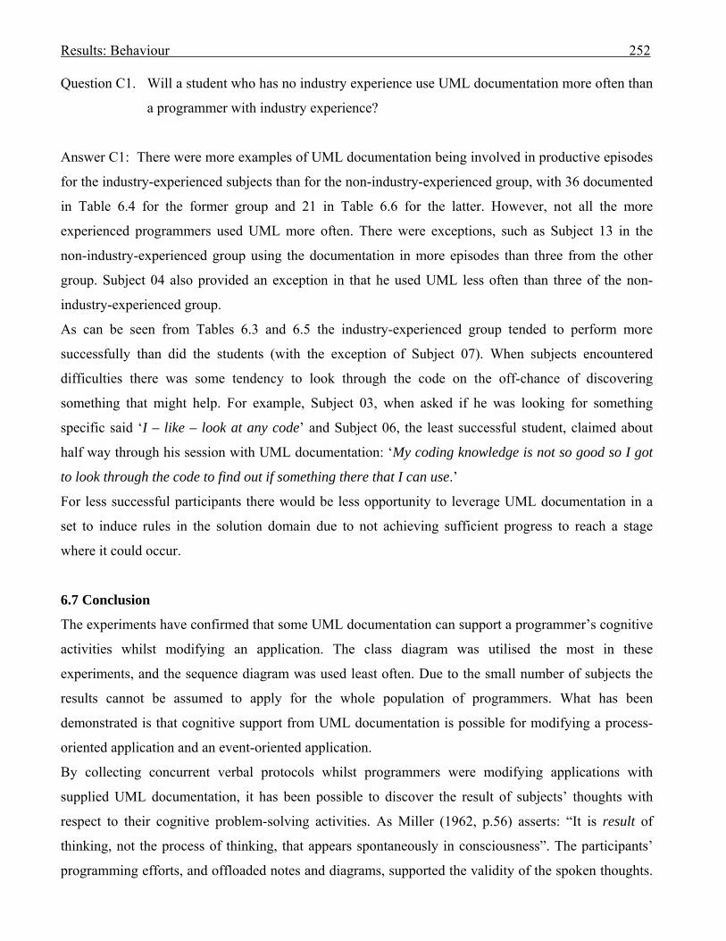
Results: Behaviour 252
Question C1. Will a student who has no industry experience use UML documentation more often than
a programmer with industry experience?
Answer C1: There were more examples of UML documentation being involved in productive episodes
for the industry-experienced subjects than for the non-industry-experienced group, with 36 documented
in Table 6.4 for the former group and 21 in Table 6.6 for the latter. However, not all the more
experienced programmers used UML more often. There were exceptions, such as Subject 13 in the
non-industry-experienced group using the documentation in more episodes than three from the other
group. Subject 04 also provided an exception in that he used UML less often than three of the non-
industry-experienced group.
As can be seen from Tables 6.3 and 6.5 the industry-experienced group tended to perform more
successfully than did the students (with the exception of Subject 07). When subjects encountered
difficulties there was some tendency to look through the code on the off-chance of discovering
something that might help. For example, Subject 03, when asked if he was looking for something
specific said ‘I – like – look at any code’ and Subject 06, the least successful student, claimed about
half way through his session with UML documentation: ‘My coding knowledge is not so good so I got
to look through the code to find out if something there that I can use.’
For less successful participants there would be less opportunity to leverage UML documentation in a
set to induce rules in the solution domain due to not achieving sufficient progress to reach a stage
where it could occur.
6.7 Conclusion
The experiments have confirmed that some UML documentation can support a programmer’s cognitive
activities whilst modifying an application. The class diagram was utilised the most in these
experiments, and the sequence diagram was used least often. Due to the small number of subjects the
results cannot be assumed to apply for the whole population of programmers. What has been
demonstrated is that cognitive support from UML documentation is possible for modifying a process-
oriented application and an event-oriented application.
By collecting concurrent verbal protocols whilst programmers were modifying applications with
supplied UML documentation, it has been possible to discover the result of subjects’ thoughts with
respect to their cognitive problem-solving activities. As Miller (1962, p.56) asserts: “It is result of
thinking, not the process of thinking, that appears spontaneously in consciousness”. The participants’
programming efforts, and offloaded notes and diagrams, supported the validity of the spoken thoughts.

Results: Behaviour 253
Ericsson and Simon (1984, p.8) claimed that verbal responses can provide the experimenter with data
that eliminate the need for trust in people. After the experiments, subjects were asked which UML
diagram they preferred to use. In one case what the subject did during the experiment, and what she
claimed to prefer, did not tally. Subject 05’s stated preference was for the sequence diagram yet she did
not leverage support from the sequence diagram in her session. It is believed that the recorded
protocols give a more accurate record of what people do as opposed to what they may say afterwards.
However, differing types of orientation for an application and its problem may suit different types of
documentation and modelling. For the current research, for both process-oriented and event-oriented
applications, the class diagram was more often accessed in order to gain cognitive support.
The framework (refer to Table 6.1) used to categorise the cognitive steps of the participants was a
comprehensive tool to encode the episodes, with examples of all categories being encountered during
the research. However, few examples of Plan or Design schema formation emerged. An explanation for
the less experienced subjects could be that few schema had been established in their LTM and thus
could not be leveraged (Andriole & Adelman, 1995; McKeithen et al., 1981; Wǽrn 1989). For the very
experienced subjects, the schema could be so well established as to have become automated (Branch,
2000, 2001).
The results will be discussed in the next chapter.

Discussing the findings 253
Discussing the findings 254 Chapter 7: Discussing the findings 7.0 Introduction
In the beginning, the aim of this research was to investigate the Unified Modelling Language (UML) to
discover if evidence was forthcoming as to its benefits. The elevation of the UML to a standard for the
Object Management Group (OMG) in November 1997 (Johnson, 2002; Kobryn, 1999) raised questions
concerning the lack of empirical evidence that UML deserved that recognition. This research aimed to
address that omission.
Modelling languages may be used in many ways. According to Booch et al. (1999, p.449): A process is a set of partially ordered steps intended to reach a goal. In software engineering, your goal is to
efficiently and predictably deliver a software product that meets the needs of your business. … The UML is
largely process-independent, meaning that you can use it with a number of software engineering processes. It was not possible to investigate empirically all applications of UML in the time available. It became
necessary to identify an application of the UML that made the best use of available resources.
Exploratory interviews were carried out, both in New Zealand and North America, to discover whether
software developers used diagrammatic modelling and if they were applying the UML. The aim was to
choose a software development practice that potentially could leverage UML documentation and that
would be appropriate, and manageable, to research.
From the applications of modelling that were described in the interviews (refer to Table 3.2), the one
chosen for further research was that of UML documentation communicating abstractions of an existing,
unfamiliar software product to programmers who were given the job of modifying that product.
The methodology selected to discover whether UML documentation supplied cognitive support to
programmers whilst modifying an application was two-pronged. Both the subjects’ performances and
cognitive behaviours were investigated. Subjects were asked to modify two different software
applications on two different occasions, one of which was supplied with documentation in the notation
of the most popular UML diagrams as identified in Section 2.4.7. The subjects’ performances with and
without UML documentation were to be compared. Program modification involves problem solving
and problem solution is a cognitive activity (Newell & Simon, 1972). If a programmer’s performance
was improved by the use of UML documentation then that documentation must have aided that
programmer’s cognition. However, it was possible that UML documentation could aid cognition, but
not provide any significant improvement in performance compared to alternative methods, such as
reading code, to complete a modification exercise. In order to detect evidence of UML documentation
support that may be difficult to detect in performance, concurrent verbal protocols were collected
Discussing the findings 255 whilst the subjects modified the applications. The ‘thinking aloud’ method for discovering subjects’
intentions was considered the most appropriate for discovering whether the UML documentation
provided cognitive support to the modifiers (refer to Section 4.2.2).
The experiments and subjects’ performances and cognitive behaviour results have been reported in
previous chapters. This chapter will discuss the exploratory interviews and experimental results and
comment on the findings.
The chapter proceeds as follows: The results from the interviews are reviewed in Section 7.1, the
performance results are evaluated in Section 7.2, and the cognitive support findings discussed in
Section 7.3. The chapter is concluded in Section 7.4.
7.1 The interviews
7.1.1 Introduction
To discover how a variety of practitioners used modelling, interviews were carried out with software
development practitioners from two countries. Four interviewees were sourced from each of two
successful Seattle-based companies that produced and sold their own software. An aim was to discover
if modelling evolved from a company culture or was driven subjectively. At both Company A and
Company B (refer to Chapter 3) it was discovered that the use of models and modelling languages was
influenced by team leaders rather than set down as a company directive.
A brief longitudinal study was carried out in the software development area at Company B. The study
charted the growing appreciation of modelling in that company.
From the interviews a framework of modelling uses was derived.
7.1.2 Challenges and limitations
The interviews were used to find out what the interviewees believed were their own practices, and to
elicit the interviewees’ subjective opinions. To validate interview findings with respect to practice it is
necessary to cross-check between interviewees. This was possible only for the interviews held at
Companies A and B. However, with subjective opinions the interviewer must rely upon the
interviewees’ honesty. Some back-up evidence was obtained from the diagrams used by Interviewee 8,
and the signed sample from Interviewee 10.
The sample size was small. It is possible there are alternative modelling practices carried out within the
full programming population.
7.1.3 What was found out from the interviews
Discussing the findings 256 Two of the interviewees from Company A were involved with designing and developing a software
package that acted as a Computer Aided Software Engineering (CASE) tool for drawing UML models,
and could partially translate class diagrams into code. The developers leveraged their own CASE tool
to generate code. Yet two other employees, each a member of different departments at Company A,
chose to use their own customised diagrams. Subject 20, who worked as a programmer for Company A
in New Zealand, claimed that class diagrams were used extensively at his work, and occasionally use
case diagrams, all diagrams being constructed using the company’s CASE tool.
At Company B, the product manager and the general manager for software planning and client
applications, plus two team managers who reported to him, were interviewed. The latter three will be
referred to as ‘developers’. At the time of the first interviews, no formal modelling was carried out.
One team manager enthused about data flow diagrams (DFDs), the other appreciated CRUD diagrams.
The three developers were re-interviewed one year later, and two were interviewed again, a further
eighteen months later, in a longitudinal study. What emerged from the interviews was a growing
awareness of the UML and its ability to provide a common language in which to communicate software
artifacts. All three developers mentioned the use of modelling on the whiteboard to communicate ideas
at meetings. By the time of the second set of interviews at Company B, use case documentation had
been enthusiastically embraced by all who were interviewed. Use case models were not used, the
developers’ preferred the text-based descriptions in their customised format.
The first interviews at Company B took place whilst the company’s product was still being developed.
The second year of interviews occurred after the product was established and the teams were involved
in modifications and enhancements. During the initial interviews a need had been expressed for some
means of modelling the software product so that time was not lost at meetings to refresh memories of
software structures and dynamics. That need had dissipated over the year as a stable staff grew familiar
with the product. By the time of the third set of interviews the company had experienced a period of
staff reduction. Knowledge of the product had been lost. The company expanded again, employing new
staff who needed to acquire that knowledge. The DFD enthusiast, by now managing a different team,
including new-comers, had not lost his interest in DFD modelling which provided a top-down method
for decomposing a system into further detail. He used his customised version of a DFD to document his
growing understanding of his new software responsibility and gave that document to his new staff to
assist their learning. It was the contrast between his approach and that of the senior manager that led to
the choice of program modification for this research. By the third set of interviews the senior manager
was strongly supporting his staff in becoming familiar with OO technologies and UML, believing that
they should be learned in tandem. He purchased reference books and recommended courses for his staff
Discussing the findings 257 to attend. He was interested in the agile methodologies, and SCRUM had been implemented. When
bringing new staff ‘up-to-speed’ he would give them a small task initially, would recommend pair
programming with an experienced team member, and would send the new comers on training courses.
Thus his new staff learned the product from its code, and their partners in programming. No diagram of
the product was provided. It was this contrast in approach to ‘bringing new staff up-to-speed’ between
the managers at Company B that provided the concept of program modification for the current
research.
At both Companies A and B, UML variations were used on the whiteboard at meetings to communicate
ideas for software. UML class and sequence diagrams were favoured.
Of all twelve interviewees five mentioned their use of block and line diagrams. The aim, regardless of
the method, was to communicate concepts in a format that was easy to understand.
The New Zealand software development team leader also found that due to his company’s product
requiring only minor modifications at the time of his interview, models were not necessary. He used
diagrams when complexity demanded. His modelling was also whiteboard-based and he predominantly
modelled class diagrams.
One interviewee, involved in developing software for NASA, never used diagrams. He claimed that his
team of four knew each other well, the inheritance hierarchies in the software were flat, and diagrams
were not needed. The tertiary institute computing department, at which Subject 16 worked, only
documented the hierarchies in class diagrams. Subject 16 believed that the association lines cluttered
the class diagrams. Two of the industry-experienced subjects offloaded class hierarchies for their
sessions without UML documentation, indicating that the understanding of the hierarchies was
important for them.
The data administrator (Interviewee 12), who worked in a bank, worked in an environment where a
strategic decision had been made as to which CASE tool would be used to capture their data modelling.
As she was documenting data for implementation in databases and data warehouses, she used the
CASE tool extensively by choice as well as requirement. Many of the interviewees had commented that
they expected database data to be recorded in entity relationship diagrams (ERDs). It appeared that the
static nature of database data definitions lent itself to be captured in those models.
7.1.4 Conclusion
The interviews were exploratory to discover how UML and modelling were used in industry. A chart
was derived (refer to Table 3.2) to categorise how modelling was found to be used. It is possible that
Discussing the findings 258 other uses could be discovered in the wider population of software developers. A specific use was
selected for the main research project.
As well as satisfying the demands for the final research, the interviews provided a rich source of
information about modelling practices. The interviewees, with the exception of Interviewee 12, worked
in environments where the use of diagrams depended on the preference of the individual. Specific
modelling techniques were used by a developer depending upon past experiences or individual
research. Models, especially class and sequence diagrams, were spontaneously used at meetings to
communicate concepts with respect to software products.
The need for diagrammatic documentation diminished as team members became familiar with their
product and the product became stable. The UML was perceived as a useful standard language to aid
communication, yet four interviewees complained that it did not provide notation to capture everything
they would wish. Five interviewees used block-and-line diagrams and three explicitly mentioned
customising their own diagrams.
In conclusion, all but one of those interviewed used modelling in some form, chiefly on an ad hoc
basis, to communicate software structures and dynamics to others. Although the UML was frequently
mentioned as a useful standard language for this communication, a number of interviewees either used
their own customised notation, or modified the UML notation to meet their individual needs.
The interviews were exploratory, carried out prior to the main research in order to find how modelling
was used in industry so that a use could be chosen for the main experiments. In this task the interviews
were successful.
From these interviews it appears that UML has support as a standard but its notation does not fully
satisfy the needs of all individual practitioners.
7.2 Performance results
7.2.1 Introduction
Twenty subjects modified the two applications, one of which had UML documentation. The
experiment details and performance results were described in Chapter 5. Performance was measured as
percentage sub-goals achieved towards the completion of each modification.
The cognitive support provided by external representations recorded in UML notation was being
investigated. As problem solving is a cognitive activity (Newell & Simon, 1972) it was believed that if
a programmer performed better under one condition, then that condition had aided cognition for
solving the modification problem.
The challenges encountered, and limitations on the research, are reviewed in the next section.
Discussing the findings 259 7.2.2 Challenges and limitations
For experiments of this nature there are many challenges. Where two conditions are being compared, in
this case the modification of a program with the aid of UML documentation compared with modifying
with no documentation, it would be ideal to have each experiment completely equivalent except for the
change in condition. With programming that is not possible. The challenge for comparing the two
conditions is to limit the effect of the differences that can occur between the sessions.
If a subject modifies the same program for each condition, knowledge schemas acquired by the
programmer during the first modification could be applied in the second attempt. Some experiments
have used Tower of Hanoi isomorphs in order to achieve variation, yet retain a common core problem.
However, subjects have been found to respond differently to different isomorphs, some taking much
longer to solve (Kotovsky et al., 1985). Thus isomorphs do not necessarily solve the challenge. An aim
of the current research was to use programs sourced from problem domains familiar to all subjects, yet
the subjects had not previously been required to program them, thus would retain no established
schemas for solving them.
When one person writes both programs, that author’s inherent programming style can pervade each,
despite the content for each program being targeted for quite different purposes. Knowledge of the
writing style gained by the subjects in the first modification can assist for the second. At least three
subjects in the current research commented that the two programs had similarities of style. It is possible
that this problem could be avoided by having two different authors each code one of the programs.
However, the act of programming one application provides cognitive exercising that may re-establish
related knowledge schemas for using the programming syntax, regardless of author.
In this research each participant was expected to modify the two different applications. The subject was
a constant for the two modifications. An alternative method would be to compare the performances of
two different programmers with similar programming histories whilst modifying the same program,
with only one programmer receiving UML documentation. It has been pointed out previously that
programmers with similar backgrounds vary widely in ability (Brooks, 1980; Sheil, 1981). Those
differences have been confirmed during the current experiments where subjects 01 through 15 were all
recent graduates of the same occurrence of a third-year tertiary systems analysis and design course.
Subjects 01 through 15 achieved widely varying successes (refer to Table 5.7). The subjects’
assignment marks for the course did not necessarily predict the subjects’ successes in the experiments.
The subject who had the highest average success for the modifications had earned the lowest marks for
his assignments. Another subject with high assignment marks achieved the lowest success. Thus the
Discussing the findings 260 use of different programmers with similar histories, for each condition, does not solve the problem of
situations differing between conditions.
As pointed out in Section 1.1, there are many influences at play on software developers. Software
development productivity for users of OO modelling tools may be affected by the user’s previous
experiences in the problem domain (Agarwal et al., 2000; Andriole & Adelman, 1995; Nielsen, 1993;
Scaife & Rogers, 1996; Tabachneck-Schijf et al., 1997). The subjects for the current research were
asked in their post-sessions interviews whether they had programmed invoices or diaries prior to the
sessions (refer to Table 5.8). No subject had programmed reminders previously. One subject (15) had
programmed gst for a website that used a shopping cart. In his second session he modified the invoice
application without the aid of UML documentation, yet he performed more successfully in his first
modification of the diary, which many subjects perceived as more complex, and for which he was
supplied with UML documentation. Although Subject 15 had some prior experience it did not favour
the UML condition.
The environment in which the experiments took place was constant for all sessions. Concurrent verbal
protocols were consistently collected for both modifications. A total of 21 subjects volunteered for the
project, with all but one (Subject 08) completing both modifications.
It had been a challenge to produce two applications and modifications of similar complexity, yet
sufficient differences to reduce the effect of the first on the second. The subjects were rotated as to
which modification was done first, and which modification received UML documentation. Assignment
depended upon when a subject was available. This rotation had been used in an attempt to average the
affect of one modification on the other.
7.2.3 The performance results
There were indications in the results, as reported in Chapter 5, that there were potential factors that
affected the performances. Five factors were identified:
1. the sequence in which the applications were attempted
2. the provision of UML documentation
3. the programmer’s competence
4. the application
5. the modification.
In the previous section we discussed what had been done to reduce the affect of sequence of
modification and use of UML documentation. However, programmer competence appeared to also be a
factor (see item 3 above). Due to the variability of programmers with similar histories (Brooks, 1980;
Discussing the findings 261 Sheil, 1981), confirmed in this research, it would be difficult to produce an easily acquired measure of
programming competence. Subject 16 had the most years of industry experience and his performances
were the most successful. However, Subject 18 had run and participated in his own software
development business for two years, yet did not perform as well as Subject 17 who had only two
month’s industry experience; Subject 07 with no industry experience at all, performed better in the
invoice application than either 17 or 18. Subject 15 was the most successful of the students sourced
from the same occurrence of the systems analysis and design course, yet his grades for assignments for
the course were the lowest, and Subject 06 achieved high grades yet achieved little in his modifications
(refer Section 5.7). Although competence may be affected by external matters such as problem domain
knowledge, it does appear to be an intrinsic component that is difficult to predict without prior testing.
The competence of Subject 16 was such that he was able to complete both modifications. He was faster
in achieving his second modification for which no UML documentation was supplied, despite believing
it was a more difficult modification. This suggests that he may have acquired schemas related to style,
syntax and content from the first modification that he was able to leverage in the second, or that the
exercising of VB.NET in the first modification re-established syntax schemas.
Although there was some indication that UML documentation did assist the modifier, it is possible that
some external representations may provide cognitive support but do not improve performance. Whether
UML diagrams can provide cognitive assistance will be addressed in the next section.
7.3 Results of cognitive behaviour experiments
7.3.1 Introduction
As is typical for experiments using concurrent verbal protocol collection, this research chose a small
sample of ten subjects (Srinivasan & Irwin, 2006) for transcription and analysis. As the sample is
small, no assumptions may be made with respect to the whole population of programmers. What is
demonstrated, however, is that it is possible for programmers to leverage UML documentation or
notation when modifying an application as both the industry-experienced and non-industry-experienced
groups of subjects received cognitive support from the UML documentation.
7.3.2 Concurrent verbal protocol collection
Concurrent verbal protocol collection has proven to be a useful tool to capture the results of subjects’
cognitive processes whilst modifying a software application with the assistance of UML
documentation. With the exception of Subject 04, subjects generally produced adequate protocols,
Discussing the findings 262 although the less competent subjects tended to have longer pauses between utterances as they ran out of
ideas as to how to proceed.
All subjects were given a small exercise prior to the experiments in which to practice ‘thinking aloud’.
The practice exercise was brief and less complex than the non-trivial applications used for the main
experiments. All participants succeeded in competently ‘thinking aloud’ in the practice session.
Some subjects commented that they found it easier to ‘think aloud’ in the second modification after
having practiced in the first modification. For example, Subject 02 commented in her post-sessions
interview:
‘Um - because in the first modification I’m not used to – like - speaking aloud and – speaking aloud
and thinking at the same time. And then after doing the first – um - modification and getting used to –
like - talking aloud – and thinking and speaking at the same time - it helps.’ Thus not only the style and
content of the first modification could have assisted performance in the second, but also the protocol
collection activity itself could be a factor.
Variation in subject ability to verbalise whilst doing a task was discussed in Section 4.2.3.2. Two
extremes which may reduce verbalising were identified – the situation where the participant found the
task too hard (Anderson, 1985; Biemiller & Meichenbaum, 1992; Ericsson & Simon, 1993) and the
situation where the participant found it too easy (Branch, 2000, 2001). As the two most successful
subjects (16, and 20) spoke well and provided the most extensive protocols, each producing more than
100 episodes, it is believed that no participant found the modifications too easy.
Subject 04 had talked more freely in his practice than in his sessions. As discussed in Section 4.2.3.2, a
possible explanation is that some subjects have limited WM capacity for talking and attending at the
same time (Branch, 2001; Stratman & Hamp-Lyons, 1994, p.95). Ericsson and Simon (1993, p.91) had
found that subjects may stop verbalising in conditions where they are under a high cognitive load or
they are feeling difficulty. Reduction in verbalising was observed in the less successful subjects when
they encountered difficulty:
Subject 06 spoke fluently as he familiarised himself with the invoice modification. However, pauses
started to intrude. He gave a reason for one of his silences: ‘Yeah – because I was – like – it’s getting to
the programming stage, and, ah – I’m not that into programming. So I guess it’s – it’s my knowledge
block – really don’t make that layer to continue.’ And much later, after another pause: ‘I still think.’
(sighs) …….
Subject 05 also had pauses in her vocalising when she was struggling to discover how to display a form
in the diary modification.
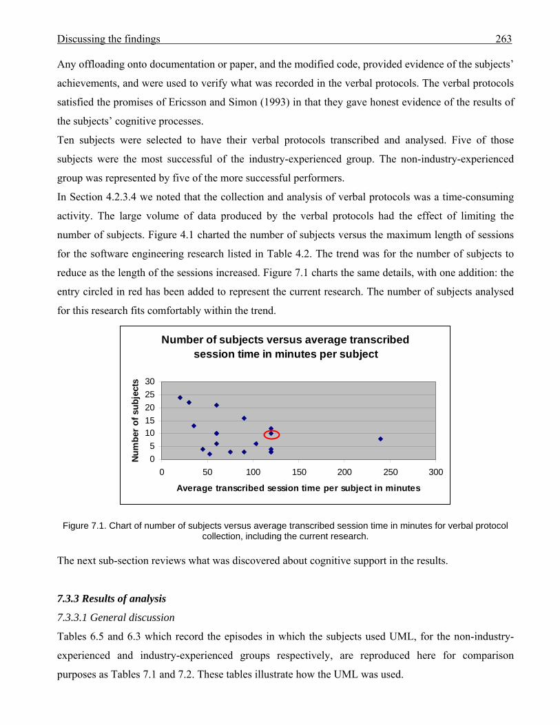
Discussing the findings 263 Any offloading onto documentation or paper, and the modified code, provided evidence of the subjects’
achievements, and were used to verify what was recorded in the verbal protocols. The verbal protocols
satisfied the promises of Ericsson and Simon (1993) in that they gave honest evidence of the results of
the subjects’ cognitive processes.
Ten subjects were selected to have their verbal protocols transcribed and analysed. Five of those
subjects were the most successful of the industry-experienced group. The non-industry-experienced
group was represented by five of the more successful performers.
In Section 4.2.3.4 we noted that the collection and analysis of verbal protocols was a time-consuming
activity. The large volume of data produced by the verbal protocols had the effect of limiting the
number of subjects. Figure 4.1 charted the number of subjects versus the maximum length of sessions
for the software engineering research listed in Table 4.2. The trend was for the number of subjects to
reduce as the length of the sessions increased. Figure 7.1 charts the same details, with one addition: the
entry circled in red has been added to represent the current research. The number of subjects analysed
for this research fits comfortably within the trend.
Number of subjects versus average transcribed session time in minutes per subject
05
1015202530
0 50 100 150 200 250 300
Average transcribed session time per subject in minutes
Num
ber o
f sub
ject
s
Figure 7.1. Chart of number of subjects versus average transcribed session time in minutes for verbal protocol collection, including the current research.
The next sub-section reviews what was discovered about cognitive support in the results.
7.3.3 Results of analysis
7.3.3.1 General discussion
Tables 6.5 and 6.3 which record the episodes in which the subjects used UML, for the non-industry-
experienced and industry-experienced groups respectively, are reproduced here for comparison
purposes as Tables 7.1 and 7.2. These tables illustrate how the UML was used.
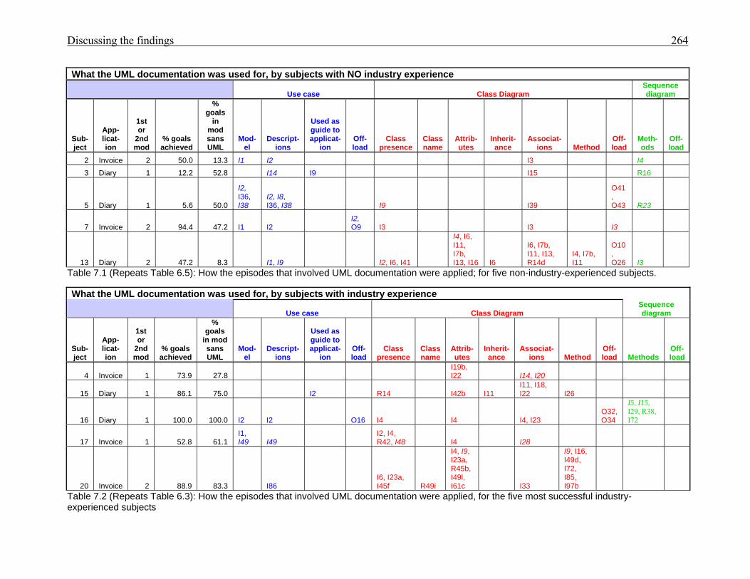
Discussing the findings 264
What the UML documentation was used for, by subjects with NO industry experience
Use case Class Diagram Sequence diagram
Sub-ject
App-licat-ion
1st or
2nd mod
% goals achieved
% goals
in mod sans UML
Mod-el
Descript-ions
Used as guide to applicat-
ion Off-load
Class presence
Class name
Attrib-utes
Inherit-ance
Associat-ions Method
Off-load
Meth-ods
Off-load
2 Invoice 2 50.0 13.3 I1 I2 I3 I4 3 Diary 1 12.2 52.8 I14 I9 I15 R16
5 Diary 1 5.6 50.0
I2, I36, I38
I2, I8, I36, I38 I9 I39
O41, O43 R23
7 Invoice 2 94.4 47.2 I1 I2 I2, O9 I3 I3 I3
13 Diary 2 47.2 8.3 I1, I9 I2, I6, I41
I4, I6, I11, I7b, I13, I16 I6
I6, I7b, I11, I13, R14d
I4, I7b, I11
O10, O26 I3
Table 7.1 (Repeats Table 6.5): How the episodes that involved UML documentation were applied; for five non-industry-experienced subjects. What the UML documentation was used for, by subjects with industry experience
Use case Class Diagram Sequence diagram
Sub-ject
App-licat-ion
1st or
2nd mod
% goals achieved
% goals
in mod sans UML
Mod-el
Descript-ions
Used as guide to applicat-
ion Off-load
Class presence
Class name
Attrib-utes
Inherit-ance
Associat-ions Method
Off-load Methods
Off-load
4 Invoice 1 73.9 27.8 I19b, I22 I14, I20
15 Diary 1 86.1 75.0 I2 R14 I42b I11 I11, I18, I22 I26
16 Diary 1 100.0 100.0 I2 I2 O16 I4 I4 I4, I23 O32, O34
I5, I15, I29, R38, I72
17 Invoice 1 52.8 61.1 I1, I49 I49
I2, I4, R42, I48 I4 I28
20 Invoice 2 88.9 83.3 I86 I6, I23a, I45f R49i
I4, I9, I23a, R45b, I49l, I61c I33
I9, I16, I49d, I72, I85, I97b
Table 7.2 (Repeats Table 6.3): How the episodes that involved UML documentation were applied, for the five most successful industry-experienced subjects
Discussing the findings 265 Individual preferences of participants for UML documentation use were demonstrated. Subject 13,
from the non-industry-experienced group, leveraged UML documentation more often than all but two
of the industry-experienced group. One member of the industry-experienced group, Subject 18, who
claimed two year’s industry experience, ignored the UML documentation for his invoice modification,
and was unsuccessful in his solutions. His lack of UML support cannot necessarily be blamed for his
lack of success as he achieved fewer sub-goals in his modification of the diary application. Subject 18’s
poor performances provided another example to support the contention that programmer competence
was a factor affecting subjects’ performances.
Success was not guaranteed for the industry-experienced group. Subject 07, despite lacking industry
experience, achieved more sub-goals when modifying the invoice application than all but the most
successful (Subject 16) of the industry-experienced group who had eleven years in commercial
programming.
Wide variability amongst programmers with similar backgrounds has been previously acknowledged
(Brooks, 1980; Sheil, 1981) and has been confirmed by the current research. A review of the behaviour
graphs demonstrates the different approaches chosen by the participants. For example: in modifying the
diary application, Subject 03 read the requirements specification first, then compared the form to the
requirements to find the differences. Subject 15, on the other hand, whilst modifying the diary
application, read the requirements specification, ran the application, then used the use case descriptions
to guide his running of the application to add and change an appointment. Subject 02, in modifying the
invoice application, read all the UML documentation before she read the requirements, despite the
requirements sheet being on top of the documentation handed out to subjects. Subject 04 read the
requirements for the diary modification first, read the code for the GST class, reread the requirements
and class code, reread the requirements, and then looked at the GST form. The differing usages of
UML documentation by the subjects is evidenced in Tables 7.1 and 7.2.
In the behaviour graphs the amount of time spent using the UML documentation was small compared
to the overall time taken for each session, yet several of the concepts obtained from the documentation
were essential for the solution, such as the relationship between the Appointment and ReminderSet in
the diary application, and the relationship between GST and Customer in the invoice application, both
of which could be obtained from their respective class diagrams. That information could alternatively
be obtained from the VB.NET documented classes. What cannot be surmised is how quickly a subject
could obtain the essential information gleaned from the UML documentation if the documentation had
not been provided.

Discussing the findings 266 This research has demonstrated that UML documentation can provide cognitive support to
programmers when modifying an existing application. What is yet to be determined is the value of this
support supplied by UML compared to alternative modelling methods and integrated development
environments (IDE).
The benefits of using the documentation must also be weighed against the efforts required to prepare it.
When Interviewee 8’s job at Company B shifted to managing an aspect of the company’s systems new
to him (refer to Chapter 3), he used his own notation for diagrammatic modelling to document the
system as he gained understanding, then used that documentation to assist new staff to familiarise
themselves with the system. In that example, the effort of diagramming was useful to Interviewee 8
prior to its being used by new staff. The effort could be justified.
The fact that successful subjects did benefit from episodes involving class diagrams indicates that class
diagrams do aid users cognitively. However, less successful subjects also utilised the diagrams but
generally failed to generate as many rules, possibly because they were less competent at formulating a
solution, having fewer plan schemas, and thus were less able to leverage the diagrams. The diagrams in
themselves did not trigger a solution; they did, however, provide a quick reference for learning about
the applications via the use case documentation, and viewing the classes, their attributes and methods,
and the relationships between classes (refer to Tables 7.1 and 7.2).
Subject 06 who articulated the solutions yet could not convert that understanding into code was
evidence that a competent knowledge of code and programming conventions are necessary.
Only one subject (18) who achieved little success chose to not look at the UML diagrams at all.
7.3.3.2 The framework
The verbal protocols were analysed to produce behaviour graphs that represented the cognitive steps
undertaken by the subjects in modifying their applications. The framework that supplied the categories
for cognitive steps was derived in Section 2.5 (refer to Table 2.1). An episode was defined as “a
succinctly describable segment of behaviour associated with attaining a goal” (Newell & Simon, 1972,
p.84). The categories were found to be comprehensive for distinguishing episodes of behaviour that
were the results of cognitive processing, and that achieved sub-goals. The sub-goals were frequently at
a lower level of achievement than the sub-goals used for performance estimates. It could take subjects
several episodes to complete the sub-goals listed in Tables 5.3 and 5.4. Random searches by subjects
such as that by Subject 03 that did not achieve a sub-goal for a modification were categorised as
‘other’, as were other utterances that did not relate to the modification, or achieve sub-goals.
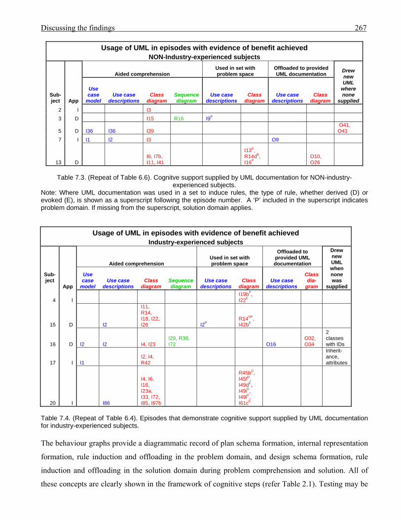
Discussing the findings 267
Usage of UML in episodes with evidence of benefit achieved NON-Industry-experienced subjects
Sub- ject App
Aided comprehension Used in set with problem space
Offloaded to provided UML documentation Drew
new UML
where none
supplied
Use case
model Use case
descriptions Class
diagram Sequence diagram
Use case descriptions
Class diagram
Use case descriptions
Class diagram
2 I I3 3 D I15 R16 I9P
5 D I36 I36 I39 O41, O43
7 I I1 I2 I3 O9
13 D I6, I7b, I11, I41
I13E, R14dE, I16P
O10, O26
Table 7.3. (Repeat of Table 6.6). Cognitve support supplied by UML documentation for NON-industry-
experienced subjects. Note: Where UML documentation was used in a set to induce rules, the type of rule, whether derived (D) or evoked (E), is shown as a superscript following the episode number. A ‘P’ included in the superscript indicates problem domain. If missing from the superscript, solution domain applies.
Usage of UML in episodes with evidence of benefit achieved Industry-experienced subjects
Sub-ject
App
Aided comprehension Used in set with problem space
Offloaded to provided UML documentation
Drew new UML when none was
supplied
Use case
model Use case
descriptions Class
diagram Sequence diagram
Use case descriptions
Class diagram
Use case descriptions
Class dia-
gram
4 I I19bP, I22E
15 D I2
I11, R14, I18, I22, I26 I2P
R14DP, I42bE
16 D I2 I2 I4, I23 I29, R38, I72 O16
O32, O34
2 classes with IDs
17 I I1 I2, I4, R42
Inherit-ance, attributes
20 I I86
I4, I6, I16, I23a, I33, I72, I85, I97b
R45bD, I45fD, I49dE, I49iE, I49lE, I61cE
Table 7.4. (Repeat of Table 6.4). Episodes that demonstrate cognitive support supplied by UML documentation for industry-experienced subjects. The behaviour graphs provide a diagrammatic record of plan schema formation, internal representation
formation, rule induction and offloading in the problem domain, and design schema formation, rule
induction and offloading in the solution domain during problem comprehension and solution. All of
these concepts are clearly shown in the framework of cognitive steps (refer Table 2.1). Testing may be
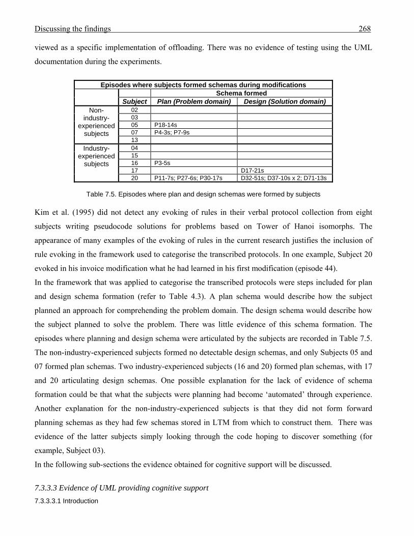
Discussing the findings 268 viewed as a specific implementation of offloading. There was no evidence of testing using the UML
documentation during the experiments.
Episodes where subjects formed schemas during modifications
Schema formed Subject Plan (Problem domain) Design (Solution domain)
Non-industry-
experienced subjects
02 03 05 P18-14s 07 P4-3s; P7-9s 13
Industry-experienced
subjects
04 15 16 P3-5s 17 D17-21s 20 P11-7s; P27-6s; P30-17s D32-51s; D37-10s x 2; D71-13s
Table 7.5. Episodes where plan and design schemas were formed by subjects
Kim et al. (1995) did not detect any evoking of rules in their verbal protocol collection from eight
subjects writing pseudocode solutions for problems based on Tower of Hanoi isomorphs. The
appearance of many examples of the evoking of rules in the current research justifies the inclusion of
rule evoking in the framework used to categorise the transcribed protocols. In one example, Subject 20
evoked in his invoice modification what he had learned in his first modification (episode 44).
In the framework that was applied to categorise the transcribed protocols were steps included for plan
and design schema formation (refer to Table 4.3). A plan schema would describe how the subject
planned an approach for comprehending the problem domain. The design schema would describe how
the subject planned to solve the problem. There was little evidence of this schema formation. The
episodes where planning and design schema were articulated by the subjects are recorded in Table 7.5.
The non-industry-experienced subjects formed no detectable design schemas, and only Subjects 05 and
07 formed plan schemas. Two industry-experienced subjects (16 and 20) formed plan schemas, with 17
and 20 articulating design schemas. One possible explanation for the lack of evidence of schema
formation could be that what the subjects were planning had become ‘automated’ through experience.
Another explanation for the non-industry-experienced subjects is that they did not form forward
planning schemas as they had few schemas stored in LTM from which to construct them. There was
evidence of the latter subjects simply looking through the code hoping to discover something (for
example, Subject 03).
In the following sub-sections the evidence obtained for cognitive support will be discussed.
7.3.3.3 Evidence of UML providing cognitive support 7.3.3.3.1 Introduction
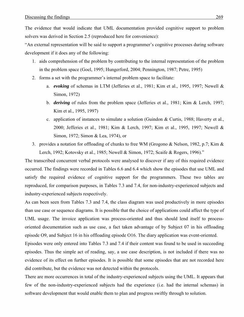
Discussing the findings 269 The evidence that would indicate that UML documentation provided cognitive support to problem
solvers was derived in Section 2.5 (reproduced here for convenience):
“An external representation will be said to support a programmer’s cognitive processes during software
development if it does any of the following:
1. aids comprehension of the problem by contributing to the internal representation of the problem
in the problem space (Goel, 1995; Hungerford, 2004; Pennington, 1987; Petre, 1995)
2. forms a set with the programmer’s internal problem space to facilitate:
a. evoking of schemas in LTM (Jefferies et al., 1981; Kim et al., 1995, 1997; Newell &
Simon, 1972)
b. deriving of rules from the problem space (Jefferies et al., 1981; Kim & Lerch, 1997;
Kim et al., 1995, 1997)
c. application of instances to simulate a solution (Guindon & Curtis, 1988; Haverty et al.,
2000; Jefferies et al., 1981; Kim & Lerch, 1997; Kim et al., 1995, 1997; Newell &
Simon, 1972; Simon & Lea, 1974), or
3. provides a notation for offloading of chunks to free WM (Grogono & Nelson, 1982, p.7; Kim &
Lerch, 1992; Kotovsky et al., 1985; Newell & Simon, 1972; Scaife & Rogers, 1996).”
The transcribed concurrent verbal protocols were analysed to discover if any of this required evidence
occurred. The findings were recorded in Tables 6.6 and 6.4 which show the episodes that use UML and
satisfy the required evidence of cognitive support for the programmers. These two tables are
reproduced, for comparison purposes, in Tables 7.3 and 7.4, for non-industry-experienced subjects and
industry-experienced subjects respectively.
As can been seen from Tables 7.3 and 7.4, the class diagram was used productively in more episodes
than use case or sequence diagrams. It is possible that the choice of applications could affect the type of
UML usage. The invoice application was process-oriented and thus should lend itself to process-
oriented documentation such as use case, a fact taken advantage of by Subject 07 in his offloading
episode O9, and Subject 16 in his offloading episode O16. The diary application was event-oriented.
Episodes were only entered into Tables 7.3 and 7.4 if their content was found to be used in succeeding
episodes. Thus the simple act of reading, say, a use case description, is not included if there was no
evidence of its effect on further episodes. It is possible that some episodes that are not recorded here
did contribute, but the evidence was not detected within the protocols.
There are more occurrences in total of the industry-experienced subjects using the UML. It appears that
few of the non-industry-experienced subjects had the experience (i.e. had the internal schemas) in
software development that would enable them to plan and progress swiftly through to solution.

Discussing the findings 270 7.3.3.3.2 UML aids comprehension by assisting in the formation of internal representations
The most popular use of UML documentation was in the formation of internal representations (refer to
Table 7.6). The UML documentation was used to assist the subjects to familiarise themselves with the
applications to be modified.
Number of episodes providing evidence of cognitive support UML provides assistance to:
Totals
Form internal representations
form sets with problem space off-load from WM
Problem domain Solution domain
Derive
rule Evoke rule Other
Derive rule
Evoke rule
Non-industry-experienced subjects 13 2 2 5 22Industry-experienced subjects 26 1 2 2 6 5 42Totals 39 1 4 2 8 10 64
Table 7.6. Number of episodes providing evidence of UML cognitive support
7.3.3.3.3 UML documentation forming a set with the problem space
There was less evidence of subjects forming sets than there was for subjects forming internal
representations (refer to Tables 7.3, 7.4, 7.6). There can be a number of explanations for this. One
could be that, like Subject 16, subjects preferred to gain an understanding from the UML
documentation, but resisted switching back and forth between screen and forms when coding
commenced. Another explanation for the less successful subjects is that they did not progress far
enough in their modifications to warrant the formation of sets.
Sets were formed with problem spaces to both derive and evoke rules (refer to Table 7.6).
7.3.3.3.4 UML notation used for ‘offloading’
Examples were obtained of subjects using the use case and class diagrams to assist in the development
of what they intended to do. For the use case, a step could be added to a use case description to
accommodate the planned changes (refer to Table 7.3 Subject 07, episode 9; and Table 7.4 Subject 16,
episode 16). For the class diagram the relationship between classes could be developed. Subject 16
offloaded his thoughts for a relationship between the ReminderSet and Appointment classes in episode
32, which he rethought and corrected in episode 34. Subject 13 used the class diagram to the same end,
adding an incorrect link in episode 10, then referring back to her link in episode 13, and finally
correcting it in episode 26.
Discussing the findings 271 These examples demonstrate the usefulness of external documentation in the planning stages for the
modifications.
Offloading that occurred when no UML documentation was provided often included rough sketches of
relevant classes, but the notation was simplified to suit the author. Subjects 05, 09, 16, 17 and 21
offloaded sketches onto paper that communicated relevant class information but did not use formal
UML notation. The sketches were quickly formed and adequate to indicate the subjects’ intentions. It
did appear that the class detail content of those sketches was important to the subjects’ thought
processes. Where programmers created their own diagrams they used any notation suited to their needs.
Two subjects drew non-UML diagrams to help their understanding and to plan what they would do.
Subject 01 drew a flowchart and Subject 16 a structure diagram. Whereas Subject 01 was not a
successful modifier, Subject 16 was the most successful, crossing off each section of his structure
diagram as it was coded. His choice of notation reflected his familiarity with and prior use of structure
diagram notation.
For translationists (refer to Section 3.4.3), formal UML notation is mandatory as code is to be
generated from what is modelled. The notation comes embedded in the tool used to translate the model,
such as a class diagram, into the code.
Four interviewees commented that UML did not supply all that they wanted, and seven interviewees
perceived problems with UML (refer to Table 3.4).
7.3.4 Conclusions for cognitive behaviour analysis
The results obtained for this research are based upon the analysis of collected concurrent verbal
protocols. Analysis of those protocols has demonstrated that UML documentation can assist a
programmer’s comprehension of an application modification problem; can be used in a set with a
programmer’s problem space, in some cases to induce rules for solution; and can be used for offloading
to relieve working memory.
7.4 Conclusion
The interviews, the experiments in modification performances, and the results of the analysis of the
concurrent verbal protocol collections, have all contributed a rich vein of information about the use of
external representations. The UML can supply positive cognitive support to software developers.
It is possible that several notations could do the same job, as software developers have been shown to
use ‘learned’ notations (Petre & Green, 1993) (refer Section 2.4.4). A precise notation may benefit only
translationists. The practitioners appear to customise to their own needs of speed and data capture.
Conclusion 272 Chapter 8: Conclusion This thesis started with a question: ‘Does the Unified Modelling Language (UML) support the
cognitive efforts of software developers?’ To answer the question it was decided to use concurrent
verbal protocol collection in order to receive honest feedback of programmers’ cognitive intentions
whilst involved in software development. However, the UML may be used in a variety of ways. Booch
et al. intended for UML users to provide their own processes (Rumbaugh, 1996a). Due to the time
limitations for the research programme, it was necessary to select one application of modelling to
investigate in-depth. Exploratory interviews were carried out in two countries to discover how
modelling, and especially UML modelling, was being applied in the software development industry.
From the responses obtained from the longitudinal study at Company B, where two different methods
were being used to assist new staff to become familiar with Company B’s systems, it was decided to
investigate programmers who were asked to modify two applications which they had not encountered
previously. External representations in the form of UML documentation, recorded in the most popular
UML notations of use case, class and sequence diagrams, would be provided for the unmodified
programs.
Participants in the research would be investigated from two perspectives:
1. Did programmers perform more successfully when aided by UML documentation? Performance
was measured as the percentage of sub-goals achieved towards a successful modification. As
problem solving is a cognitive activity, if performances were improved then the UML could be
said to assist the programmers’ cognitive activities.
2. Did the UML documentation support the programmers’ cognitive processes during the program
modification?
From the results it was found that the UML documentation did cognitively support programmers: it
was found to assist in the creation of internal representations of the problems, aiding comprehension; it
was found to be used in a set with the programmers’ problem spaces to assist in problem familiarisation
and solution; and the UML provided a notation for offloading from working memory.
Although there were indications that programmers’ performances were improved by the use of UML
notation, the small number of subjects that is typical of concurrent verbal protocol collection
experiments prevented statistical verification.
The number of subjects used in these experiments was small. Twenty participants modified both
applications, and ten of the more successful subjects had their verbal protocols transcribed and
analysed to discover the cognitive support. The small sample size means that results cannot be applied

Conclusion 273 globally to all programmers. However, it has been demonstrated that all transcribed subjects received
cognitive support from the UML documentation. It has been demonstrated that UML can supply
cognitive support. The question at the start of this thesis has been answered.
It is possible that UML supplies cognitive support but does not improve performance. The results
obtained here suggest otherwise. As discussed in Chapter 7, there are many challenges and limitations
in experiments such as that used to compare performances. Other factors such as the program
application, the modification requirements, the sequence in which subjects carried out their
modifications, and programmer competence were also at play.
The industry-experienced subjects, on average, used the UML documentation more than the non-
industry-experienced subjects. There are several possible explanations for this. The industry-
experienced subjects may have ‘learned’ to use the UML notation. The two best performing subjects
both worked in environments where class diagrams were used. Experience thus may have established
schemas for working with the diagrams that the non-industry-experienced subjects lacked. It is also
possible the inexperience of the non-industry-experienced subjects inhibited their progress and reduced
their opportunities to leverage the diagrams.
This research has also confirmed the variability in performance of programmers from common
backgrounds, which contributes to the challenges for research into programming activities.
During the research two frameworks were developed: one to categorise modelling use (Table 3.2); and
one to categorise the cognitive steps that may occur during problem solving where cognition may be
distributed to external representations (Table 2.1). The latter framework incorporates cognitive steps
that are taken to achieve sub-goals, including planning and internal representation formation in the
problem domain, and rule induction and offloading either to external representations or for testing
purposes, both in the problem and solution domains. The framework was found to be comprehensive
for the current research. It could be applied to a variety of problem-solving situations in the future.
This research investigated one category of use from the framework for modelling use (Table 3.2): that
of the use of models as a reference for when an application is to be modified. There was also evidence
during the experiments of other modelling uses, such as offloading to assist in the understanding of
unfamiliar software, and offloading to aid the individual to solve the logic of a new problem. However,
not all modelling uses from the framework could be exercised. This research investigated the activities
of individuals. The use of modelling to communicate ideas and design solutions at meetings has not
been investigated.
The opinions and observations in these experiments applied to individual modellers. The experiments
investigated the cognitive activities of individual programmers. Yet one of the most common uses of

Conclusion 274 modelling that was mentioned during the exploratory interviews was that of modelling providing a
means of communicating ideas at meetings (explicitly mentioned by eight interviewees). Where
communication is concerned the utility of a common language for communicators is important. UML,
as a standard, can provide that common language.
There were strong indications from both the exploratory interviews and the subjects’ offloadings in the
main experiments that UML notation was frequently customised. The UML notation either did not
capture all that the modellers wished to convey or was too complex (refer to Table 3.4). During the
experiments subjects spontaneously offloaded diagrams that were simplified versions of class
diagrams.
For distributed cognition in a team environment, customisation of the diagrams may occur only if all
meeting attendees are privy to the changes in notation, or if the changes represent what is self-evident.
Future research could be applied to investigate the use of modelling as a method of documenting and
communicating ideas at meetings. Such an investigation of distributed cognition among people and
external representations would be a challenging, but illuminating exercise, to discover the aspects of
diagrams that are the most useful for communication purposes and those that would benefit from
modification. Cognitive mapping techniques (refer Section 4.1.2.2) may be applied to discover meeting
participants’ beliefs.
Although not presented as a framework, there were three criteria used for evidence of cognitive support
in this research into the use of external representations in problem solving: support for forming internal
representations, support in the form of acting in a set with the subjects’ problem spaces, and support for
offloading. These were also found to be comprehensive for the research and are recommended to future
researchers.
An aspect of modelling that begs further research is that of the implicit learning of visual context. Hahn
and Kim (1999) concluded from their comparison of the computational efficiency of four methods of
documenting processes that the decomposition of the process components had a positive effect on both
analysis and design activities and that layout organisation had a positive effect on the design activities.
The authors inferred that a layout template, providing visual cues that became external aids for keeping
track of necessary components, was desirable. Blackwell et al. (2001) also concluded that the cost of
locating and indexing information in diagrams affected the performance benefits. In the current
research, four transcribed subjects were found to use the UML documentation in a set with their
problem space in order to induce rules, both in the problem and solution domains. Concurrent verbal
protocol collection does not record eye movements, but the speed with which subjects were able to

Conclusion 275 detect information on the class diagram when working in sets suggested that some implicit learning of
the visual context of the information had occurred.
The class diagram models static data, not dynamic as was investigated by Hahn and Kim (1999).
However, it is likely that layout of data is also important for extracting information from the class
diagrams. Larkin and Simon (1987) commented that it was the ability of diagrams to group information
that was used together that aided the synthesis of a meaningful whole. The authors suggested that it was
not necessarily the graphical notation so much as the secondary notation of “layout, typographic clues
and graphical enhancements” that benefited the users. To support cognition, Robbins and Redmiles
(2000) include layout tools such as their ‘Broom alignment tool’ which enabled symbols to be aligned
in their Argol/UML CASE tool.
This area of visual context has been investigated in psychology research (for example Olson & Chun,
2002). Further research is required in the software development area, especially with respect to the
decomposition of static diagrams. Subject 17 had commented that there was a ‘lot of stuff’ on the class
diagram.
Subject 16 worked in an environment where the only linkages shown on class diagrams were the
inheritance hierarchies. It was believed that the association links cluttered the diagram. If we can learn
more about the effects of visual context on both experts and novices then the practice of modelling can
be improved, with a flow-on benefit for the software development industry as a whole.
This thesis addressed the lack of research into the activity of programming whilst interacting with
external representations using UML notation. For all transcribed subjects, who represented the more
successful at achieving sub-goals for solution, the UML was found to provide cognitive assistance.
There was also an indication that the UML documentation improved performance. While our
understanding of how programmers use UML documentation has been advanced, there have been
several areas suggested in this chapter for further research.
It is hoped that the evidence obtained here will positively influence software developers’ perceptions of
the usefulness of the UML, and convert more software developers to its use. If the UML can assist
software developers to do their jobs, then the software development industry will benefit as a whole.
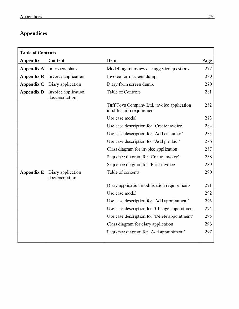
Appendices 276 Appendices
Table of Contents
Appendix Content Item Page
Appendix A Interview plans Modelling interviews – suggested questions. 277
Appendix B Invoice application Invoice form screen dump. 279
Appendix C Diary application Diary form screen dump. 280
Appendix D Invoice application documentation
Table of Contents 281
Tuff Toys Company Ltd. invoice application modification requirement
282
Use case model 283
Use case description for ‘Create invoice’ 284
Use case description for ‘Add customer’ 285
Use case description for ‘Add product’ 286
Class diagram for invoice application 287
Sequence diagram for ‘Create invoice’ 288
Sequence diagram for ‘Print invoice’ 289
Appendix E Diary application documentation
Table of contents 290
Diary application modification requirements 291
Use case model 292
Use case description for ‘Add appointment’ 293
Use case description for ‘Change appointment’ 294
Use case description for ‘Delete appointment’ 295
Class diagram for diary application 296
Sequence diagram for ‘Add appointment’ 297
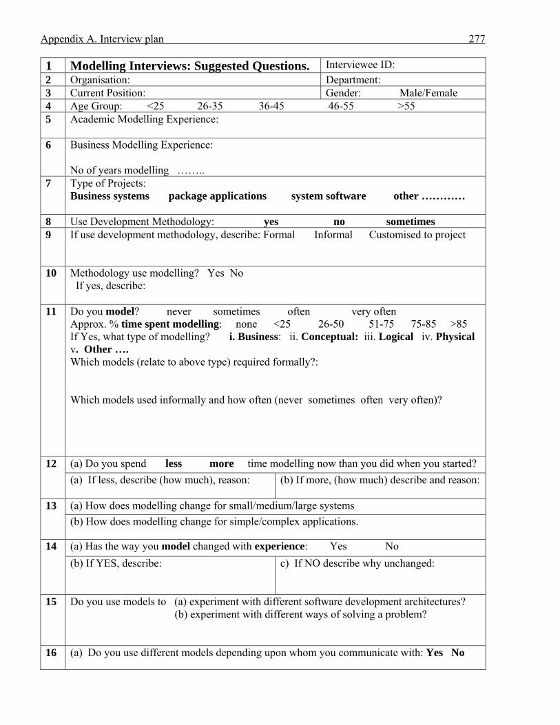
Appendix A. Interview plan 277 1 Modelling Interviews: Suggested Questions. Interviewee ID: 2 Organisation: Department: 3 Current Position: Gender: Male/Female 4 Age Group: <25 26-35 36-45 46-55 >55 5 Academic Modelling Experience:
6 Business Modelling Experience:
No of years modelling ……..
7 Type of Projects: Business systems package applications system software other …………
8 Use Development Methodology: yes no sometimes 9 If use development methodology, describe: Formal Informal Customised to project
10 Methodology use modelling? Yes No If yes, describe:
11 Do you model? never sometimes often very often Approx. % time spent modelling: none <25 26-50 51-75 75-85 >85 If Yes, what type of modelling? i. Business: ii. Conceptual: iii. Logical iv. Physical v. Other …. Which models (relate to above type) required formally?: Which models used informally and how often (never sometimes often very often)?
12 (a) Do you spend less more time modelling now than you did when you started? (a) If less, describe (how much), reason:
(b) If more, (how much) describe and reason:
13 (a) How does modelling change for small/medium/large systems (b) How does modelling change for simple/complex applications.
14 (a) Has the way you model changed with experience: Yes No (b) If YES, describe:
c) If NO describe why unchanged:
15 Do you use models to (a) experiment with different software development architectures? (b) experiment with different ways of solving a problem?
16 (a) Do you use different models depending upon whom you communicate with: Yes No
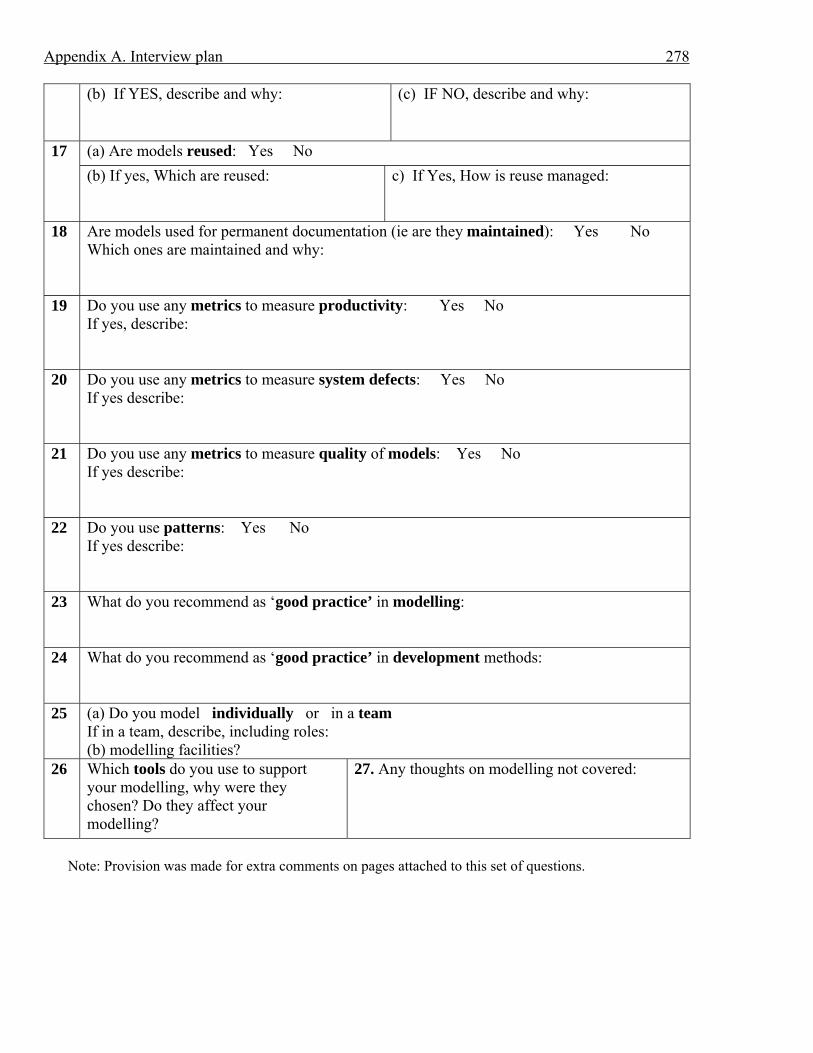
Appendix A. Interview plan 278 (b) If YES, describe and why: (c) IF NO, describe and why:
17 (a) Are models reused: Yes No (b) If yes, Which are reused:
c) If Yes, How is reuse managed:
18 Are models used for permanent documentation (ie are they maintained): Yes No Which ones are maintained and why:
19 Do you use any metrics to measure productivity: Yes No If yes, describe:
20 Do you use any metrics to measure system defects: Yes No If yes describe:
21 Do you use any metrics to measure quality of models: Yes No If yes describe:
22 Do you use patterns: Yes No If yes describe:
23 What do you recommend as ‘good practice’ in modelling:
24 What do you recommend as ‘good practice’ in development methods:
25 (a) Do you model individually or in a team If in a team, describe, including roles: (b) modelling facilities?
26 Which tools do you use to support your modelling, why were they chosen? Do they affect your modelling?
27. Any thoughts on modelling not covered:
Note: Provision was made for extra comments on pages attached to this set of questions.
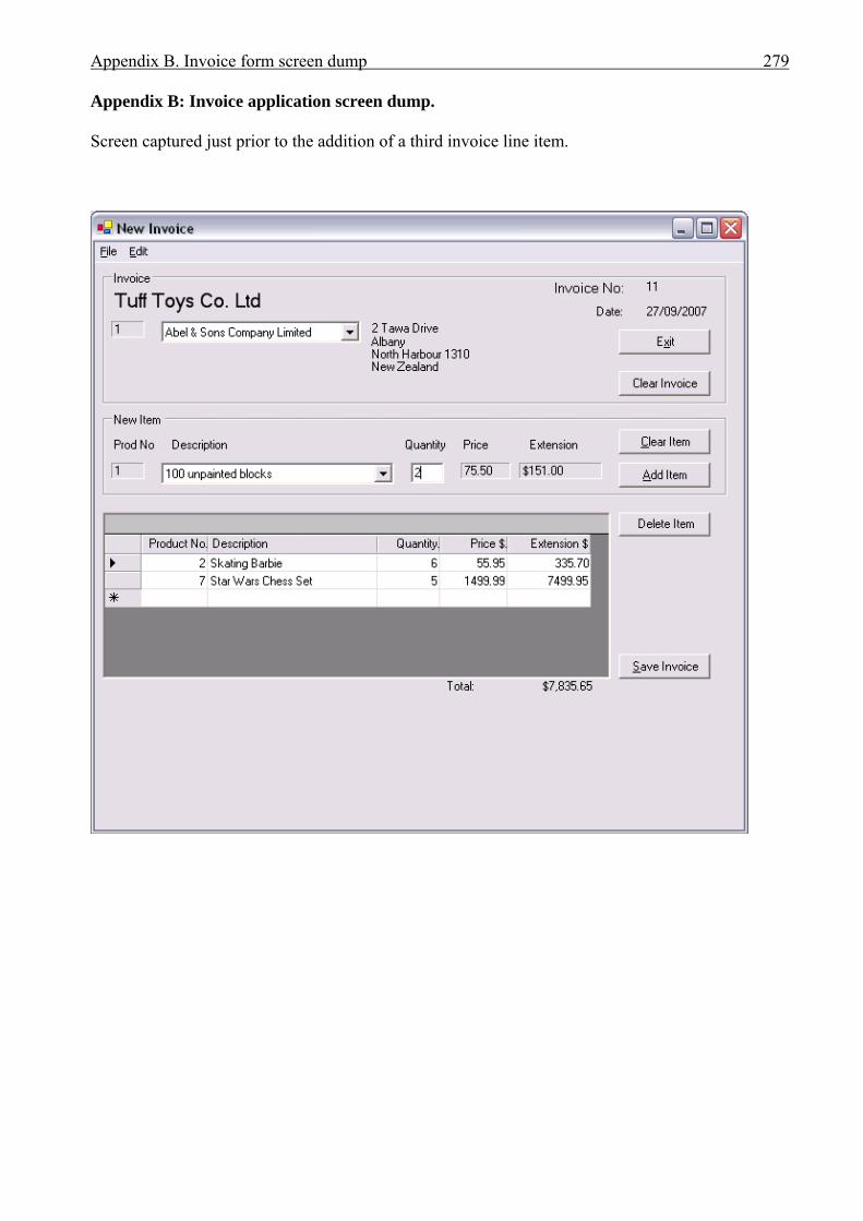
Appendix B. Invoice form screen dump 279 Appendix B: Invoice application screen dump. Screen captured just prior to the addition of a third invoice line item.
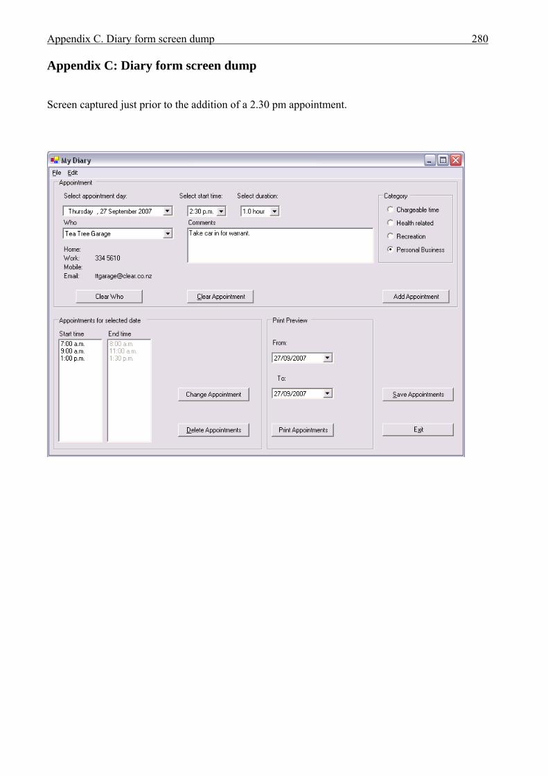
Appendix C. Diary form screen dump 280 Appendix C: Diary form screen dump Screen captured just prior to the addition of a 2.30 pm appointment.
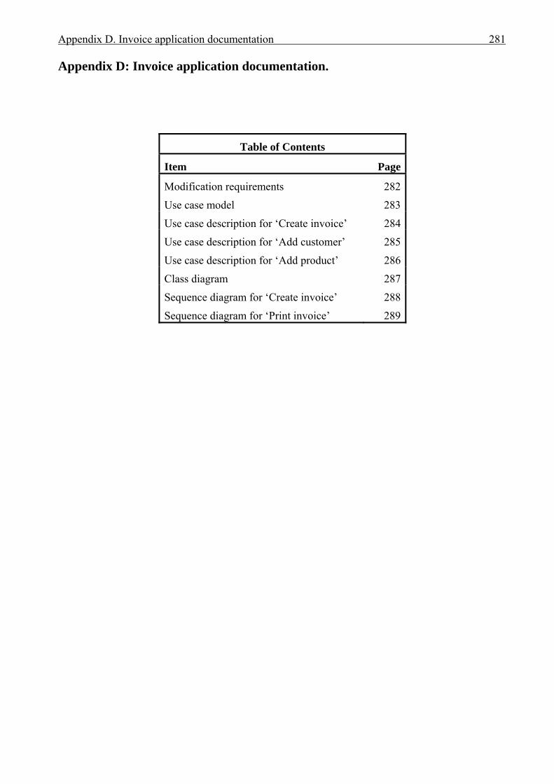
Appendix D. Invoice application documentation 281 Appendix D: Invoice application documentation.
Table of Contents
Item Page
Modification requirements 282
Use case model 283
Use case description for ‘Create invoice’ 284
Use case description for ‘Add customer’ 285
Use case description for ‘Add product’ 286
Class diagram 287
Sequence diagram for ‘Create invoice’ 288
Sequence diagram for ‘Print invoice’ 289
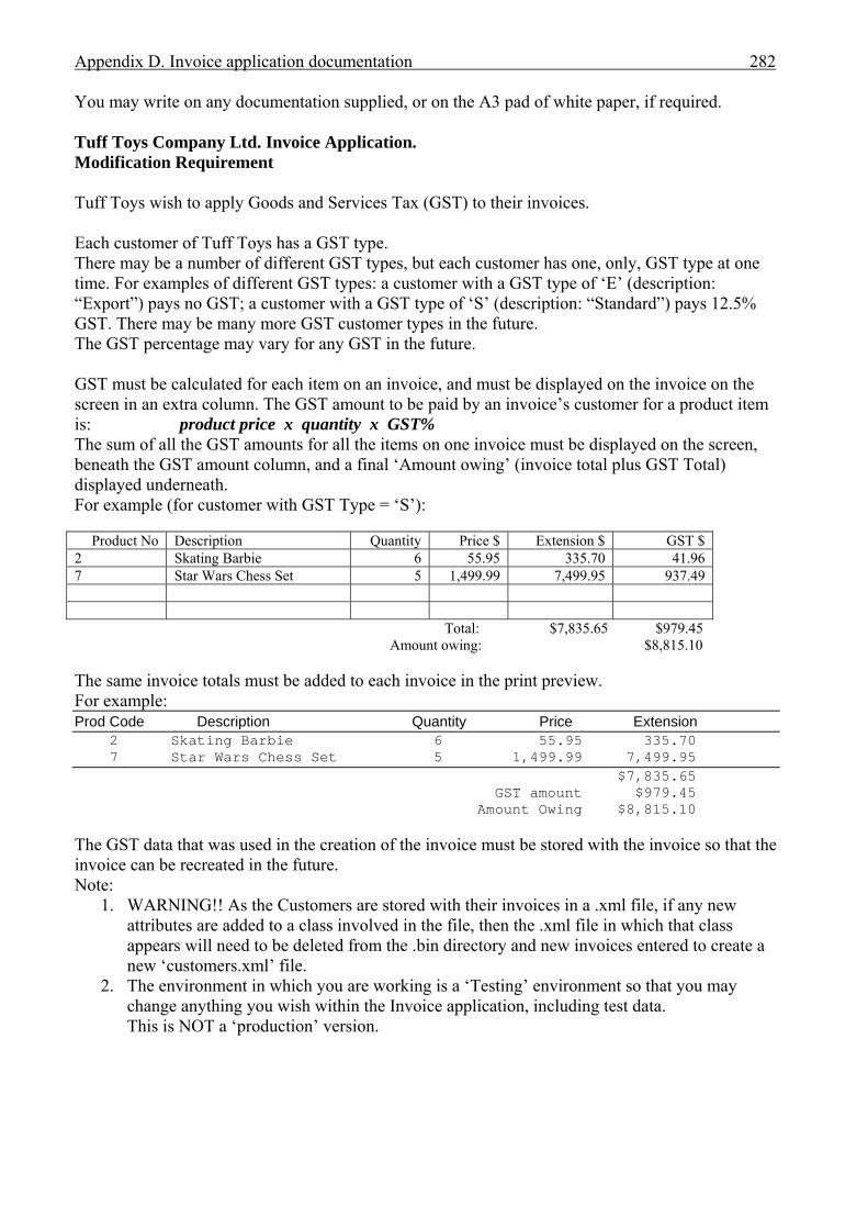
Appendix D. Invoice application documentation 282 You may write on any documentation supplied, or on the A3 pad of white paper, if required. Tuff Toys Company Ltd. Invoice Application. Modification Requirement Tuff Toys wish to apply Goods and Services Tax (GST) to their invoices. Each customer of Tuff Toys has a GST type. There may be a number of different GST types, but each customer has one, only, GST type at one time. For examples of different GST types: a customer with a GST type of ‘E’ (description: “Export”) pays no GST; a customer with a GST type of ‘S’ (description: “Standard”) pays 12.5% GST. There may be many more GST customer types in the future. The GST percentage may vary for any GST in the future. GST must be calculated for each item on an invoice, and must be displayed on the invoice on the screen in an extra column. The GST amount to be paid by an invoice’s customer for a product item is: product price x quantity x GST% The sum of all the GST amounts for all the items on one invoice must be displayed on the screen, beneath the GST amount column, and a final ‘Amount owing’ (invoice total plus GST Total) displayed underneath. For example (for customer with GST Type = ‘S’):
Product No Description Quantity Price $ Extension $ GST $ 2 Skating Barbie 6 55.95 335.70 41.96 7 Star Wars Chess Set 5 1,499.99 7,499.95 937.49
Total: $7,835.65 $979.45 Amount owing: $8,815.10
The same invoice totals must be added to each invoice in the print preview. For example: Prod Code Description Quantity Price Extension 2 Skating Barbie 6 55.95 335.70 7 Star Wars Chess Set 5 1,499.99 7,499.95 $7,835.65 GST amount $979.45 Amount Owing $8,815.10 The GST data that was used in the creation of the invoice must be stored with the invoice so that the invoice can be recreated in the future. Note:
1. WARNING!! As the Customers are stored with their invoices in a .xml file, if any new attributes are added to a class involved in the file, then the .xml file in which that class appears will need to be deleted from the .bin directory and new invoices entered to create a new ‘customers.xml’ file.
2. The environment in which you are working is a ‘Testing’ environment so that you may change anything you wish within the Invoice application, including test data. This is NOT a ‘production’ version.
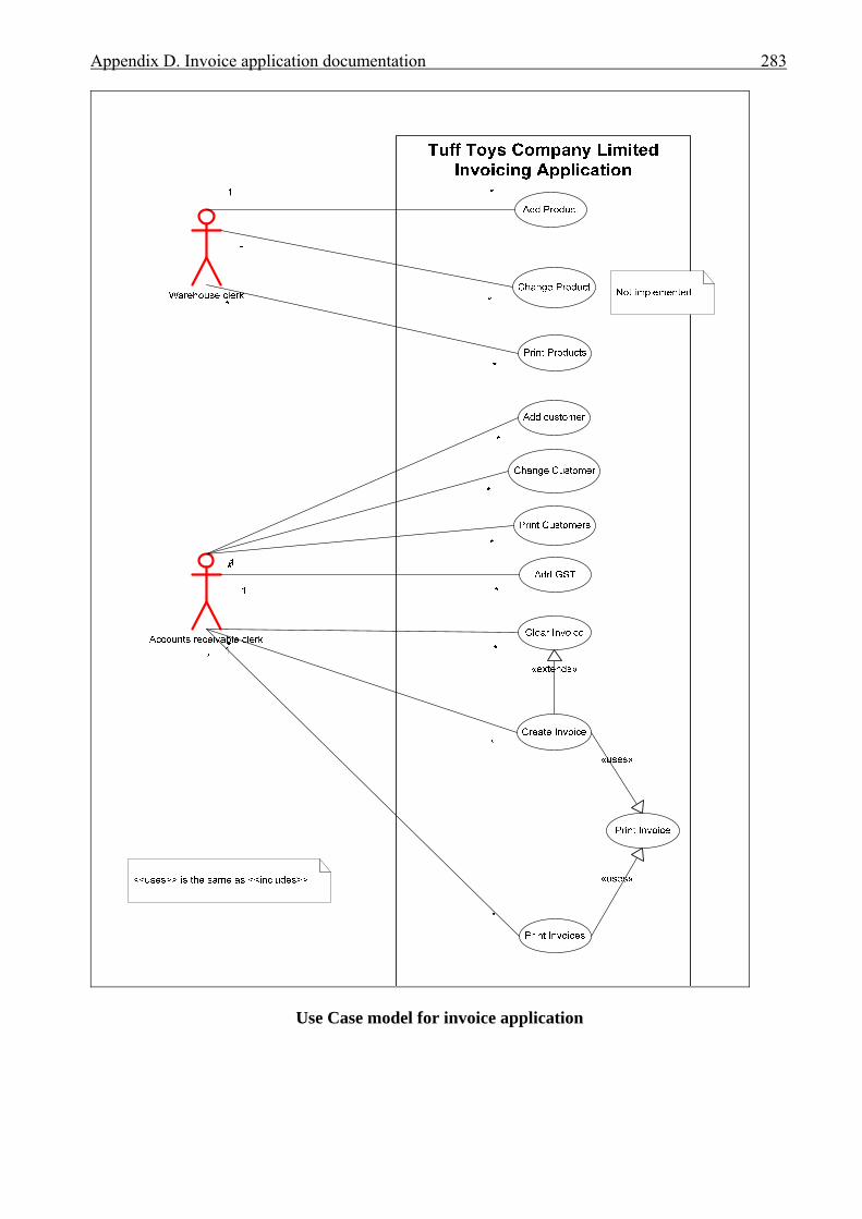
Appendix D. Invoice application documentation 283
Use Case model for invoice application
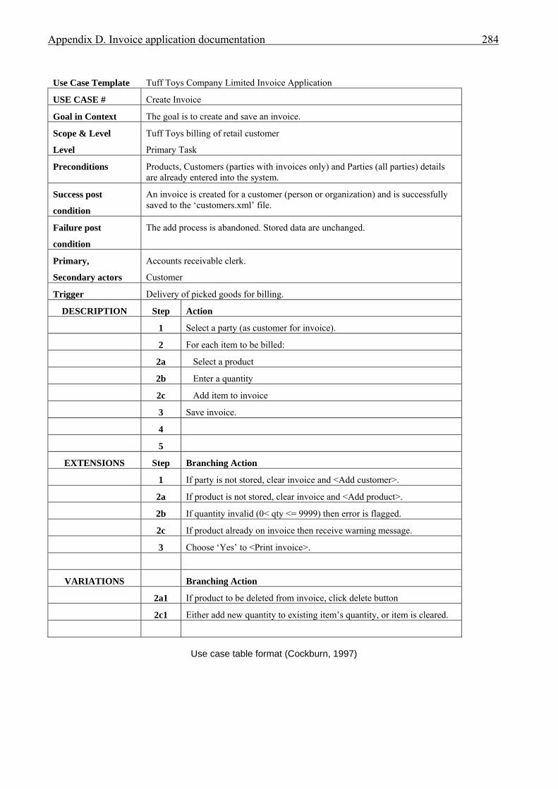
Appendix D. Invoice application documentation 284
Use Case Template Tuff Toys Company Limited Invoice Application
USE CASE # Create Invoice
Goal in Context The goal is to create and save an invoice.
Scope & Level
Level
Tuff Toys billing of retail customer
Primary Task
Preconditions Products, Customers (parties with invoices only) and Parties (all parties) details are already entered into the system.
Success post
condition
An invoice is created for a customer (person or organization) and is successfully saved to the ‘customers.xml’ file.
Failure post
condition
The add process is abandoned. Stored data are unchanged.
Primary,
Secondary actors
Accounts receivable clerk.
Customer
Trigger Delivery of picked goods for billing.
DESCRIPTION Step Action
1 Select a party (as customer for invoice).
2 For each item to be billed:
2a Select a product
2b Enter a quantity
2c Add item to invoice
3 Save invoice.
4
5
EXTENSIONS Step Branching Action
1 If party is not stored, clear invoice and <Add customer>.
2a If product is not stored, clear invoice and <Add product>.
2b If quantity invalid (0< qty <= 9999) then error is flagged.
2c If product already on invoice then receive warning message.
3 Choose ‘Yes’ to <Print invoice>.
VARIATIONS Branching Action
2a1 If product to be deleted from invoice, click delete button
2c1 Either add new quantity to existing item’s quantity, or item is cleared.
Use case table format (Cockburn, 1997)
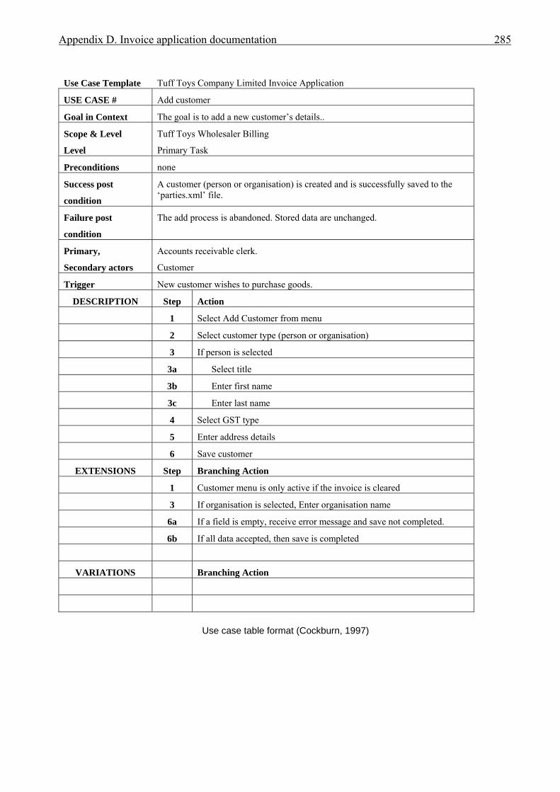
Appendix D. Invoice application documentation 285
Use Case Template Tuff Toys Company Limited Invoice Application
USE CASE # Add customer
Goal in Context The goal is to add a new customer’s details..
Scope & Level
Level
Tuff Toys Wholesaler Billing
Primary Task
Preconditions none
Success post
condition
A customer (person or organisation) is created and is successfully saved to the ‘parties.xml’ file.
Failure post
condition
The add process is abandoned. Stored data are unchanged.
Primary,
Secondary actors
Accounts receivable clerk.
Customer
Trigger New customer wishes to purchase goods.
DESCRIPTION Step Action
1 Select Add Customer from menu
2 Select customer type (person or organisation)
3 If person is selected
3a Select title
3b Enter first name
3c Enter last name
4 Select GST type
5 Enter address details
6 Save customer
EXTENSIONS Step Branching Action
1 Customer menu is only active if the invoice is cleared
3 If organisation is selected, Enter organisation name
6a If a field is empty, receive error message and save not completed.
6b If all data accepted, then save is completed
VARIATIONS Branching Action
Use case table format (Cockburn, 1997)

Appendix D. Invoice application documentation 286
Use Case Template Tuff Toys Company Limited Invoice Application
USE CASE # Add product
Goal in Context The goal is to add a new product’s details.
Scope & Level
Level
Tuff Toys Warehouse
Primary Task
Preconditions none
Success post
condition
A product is created and is successfully saved to the ‘products.xml’ file.
Failure post
condition
The add process is abandoned. Stored data are unchanged.
Primary,
Secondary actors
Warehouse clerk.
Trigger New product is added to warehouse stock.
DESCRIPTION Step Action
1 Select Add product from menu
2 Enter a description
3 Enter a price
4 Save the product
5
EXTENSIONS Step Branching Action
1 Product menu is only active if the invoice is cleared.
2 If description is longer than 30 characters, then receive error message.
3a If price Not (> 0 and <= 9999) then receive error message.
3b If price has more than 3 decimal places receive error
VARIATIONS Branching Action
Use case table format (Cockburn, 1997)
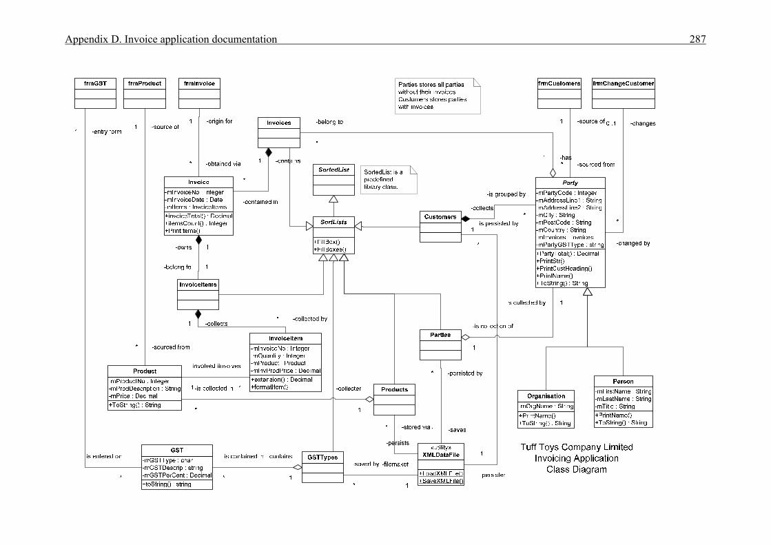
Appendix D. Invoice application documentation 287
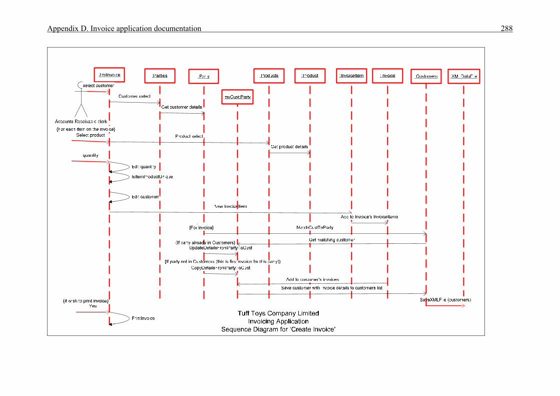
Appendix D. Invoice application documentation 288
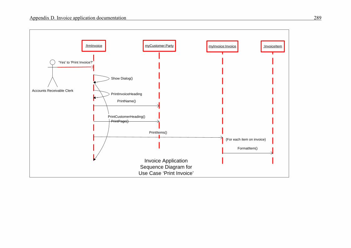
Appendix D. Invoice application documentation 289
Accounts Receivable Clerk
:frmInvoice
Invoice ApplicationSequence Diagram for
Use Case ‘Print Invoice’
'Yes' to 'Print Invoice?'
myCustomer:Party
Show Dialog()
PrintPage()
PrintName()
PrintCustomerHeading()
myInvoice:Invoice
PrintItems()
PrintInvoiceHeading
{For each item on invoice}
:InvoiceItem
FormatItem()

Appendix E. Diary application documentation 290 Appendix E: Diary application documentation
Table of Contents
Item Page
Modification requirements 291
Use case model 292
Use case description for ‘Add appointment’ 293
Use case description for ‘Change appointment’ 294
Use case description for ‘Delete appointment’ 295
Class diagram 296
Sequence diagram for ‘Add appointment’ 297
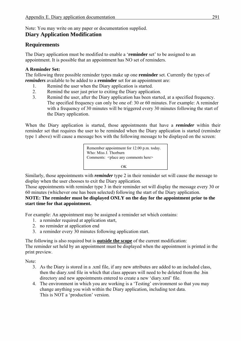
Appendix E. Diary application documentation 291 Note: You may write on any paper or documentation supplied. Diary Application Modification
Requirements The Diary application must be modified to enable a ‘reminder set’ to be assigned to an appointment. It is possible that an appointment has NO set of reminders. A Reminder Set: The following three possible reminder types make up one reminder set. Currently the types of reminders available to be added to a reminder set for an appointment are:
1. Remind the user when the Diary application is started. 2. Remind the user just prior to exiting the Diary application. 3. Remind the user, after the Diary application has been started, at a specified frequency.
The specified frequency can only be one of: 30 or 60 minutes. For example: A reminder with a frequency of 30 minutes will be triggered every 30 minutes following the start of the Diary application.
When the Diary application is started, those appointments that have a reminder within their reminder set that requires the user to be reminded when the Diary application is started (reminder type 1 above) will cause a message box with the following message to be displayed on the screen:
Remember appointment for 12.00 p.m. today. Who: Miss J. Thorburn Comments: <place any comments here>
OK
Similarly, those appointments with reminder type 2 in their reminder set will cause the message to display when the user chooses to exit the Diary application. Those appointments with reminder type 3 in their reminder set will display the message every 30 or 60 minutes (whichever one has been selected) following the start of the Diary application. NOTE: The reminder must be displayed ONLY on the day for the appointment prior to the start time for that appointment. For example: An appointment may be assigned a reminder set which contains:
1. a reminder required at application start, 2. no reminder at application end 3. a reminder every 30 minutes following application start.
The following is also required but is outside the scope of the current modification: The reminder set held by an appointment must be displayed when the appointment is printed in the print preview. Note:
3. As the Diary is stored in a .xml file, if any new attributes are added to an included class, then the diary.xml file in which that class appears will need to be deleted from the .bin directory and new appointments entered to create a new ‘diary.xml’ file.
4. The environment in which you are working is a ‘Testing’ environment so that you may change anything you wish within the Diary application, including test data. This is NOT a ‘production’ version.
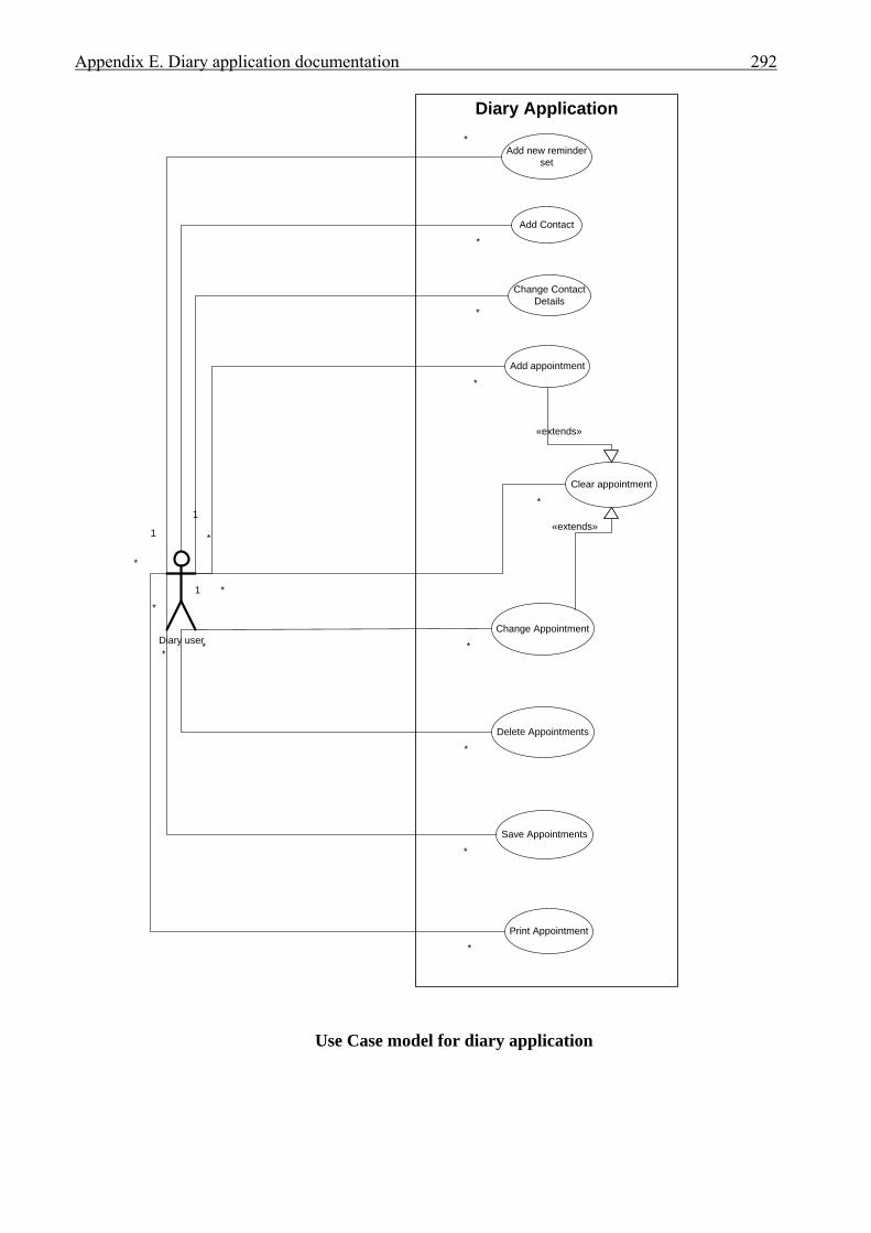
Appendix E. Diary application documentation 292
Diary Application
Diary user
Add Contact
Change ContactDetails
Add appointment
Change Appointment
Delete Appointments
1
*
*
*
1
*
Clear appointment
Save Appointments
*
*
*
*
* *
«extends»
Print Appointment
*
*
«extends»
*
*
Add new reminderset
*
1
Use Case model for diary application
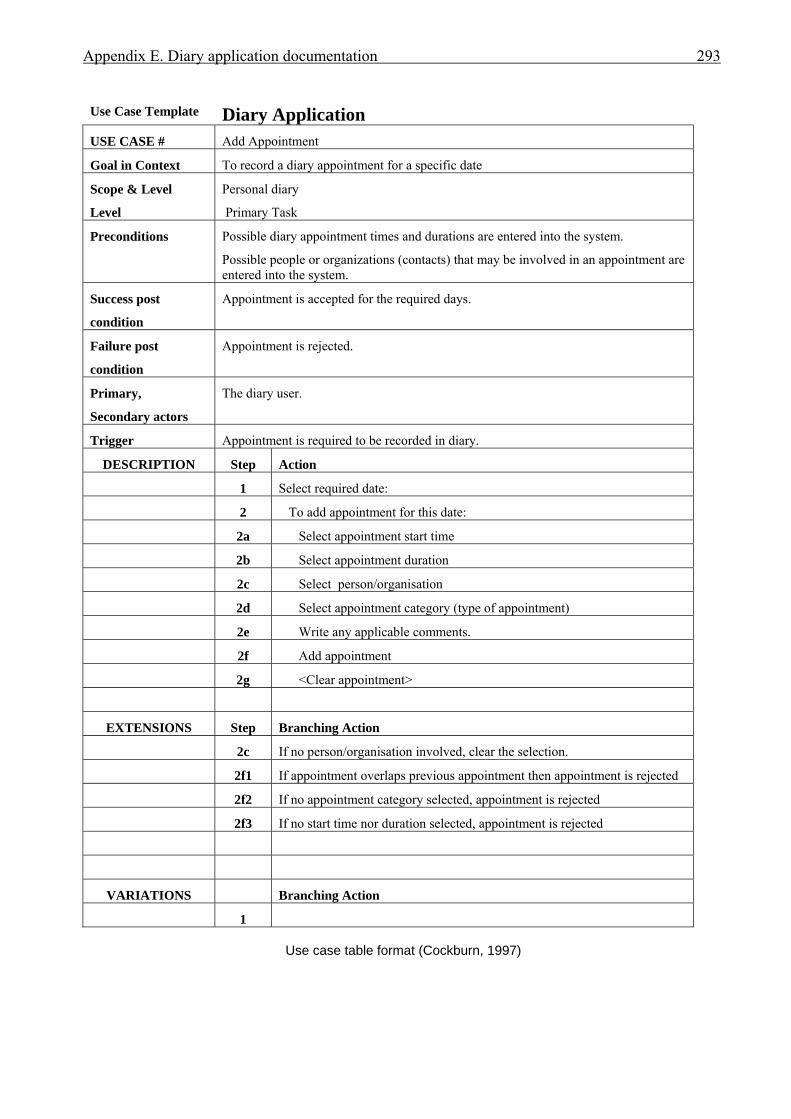
Appendix E. Diary application documentation 293
Use Case Template Diary Application USE CASE # Add Appointment
Goal in Context To record a diary appointment for a specific date
Scope & Level
Level
Personal diary
Primary Task
Preconditions Possible diary appointment times and durations are entered into the system.
Possible people or organizations (contacts) that may be involved in an appointment are entered into the system.
Success post
condition
Appointment is accepted for the required days.
Failure post
condition
Appointment is rejected.
Primary,
Secondary actors
The diary user.
Trigger Appointment is required to be recorded in diary.
DESCRIPTION Step Action
1 Select required date:
2 To add appointment for this date:
2a Select appointment start time
2b Select appointment duration
2c Select person/organisation
2d Select appointment category (type of appointment)
2e Write any applicable comments.
2f Add appointment
2g <Clear appointment>
EXTENSIONS Step Branching Action
2c If no person/organisation involved, clear the selection.
2f1 If appointment overlaps previous appointment then appointment is rejected
2f2 If no appointment category selected, appointment is rejected
2f3 If no start time nor duration selected, appointment is rejected
VARIATIONS Branching Action
1
Use case table format (Cockburn, 1997)
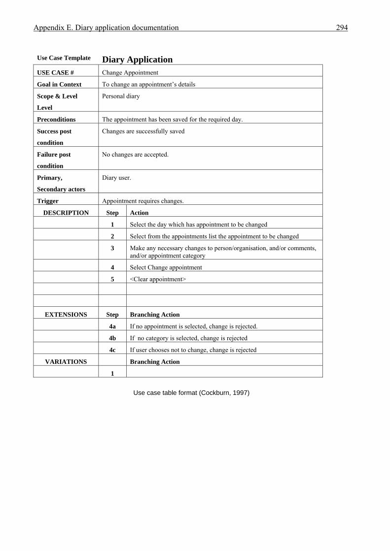
Appendix E. Diary application documentation 294
Use Case Template Diary Application USE CASE # Change Appointment
Goal in Context To change an appointment’s details
Scope & Level
Level
Personal diary
Preconditions The appointment has been saved for the required day.
Success post
condition
Changes are successfully saved
Failure post
condition
No changes are accepted.
Primary,
Secondary actors
Diary user.
Trigger Appointment requires changes.
DESCRIPTION Step Action
1 Select the day which has appointment to be changed
2 Select from the appointments list the appointment to be changed
3 Make any necessary changes to person/organisation, and/or comments, and/or appointment category
4 Select Change appointment
5 <Clear appointment>
EXTENSIONS Step Branching Action
4a If no appointment is selected, change is rejected.
4b If no category is selected, change is rejected
4c If user chooses not to change, change is rejected
VARIATIONS Branching Action
1
Use case table format (Cockburn, 1997)
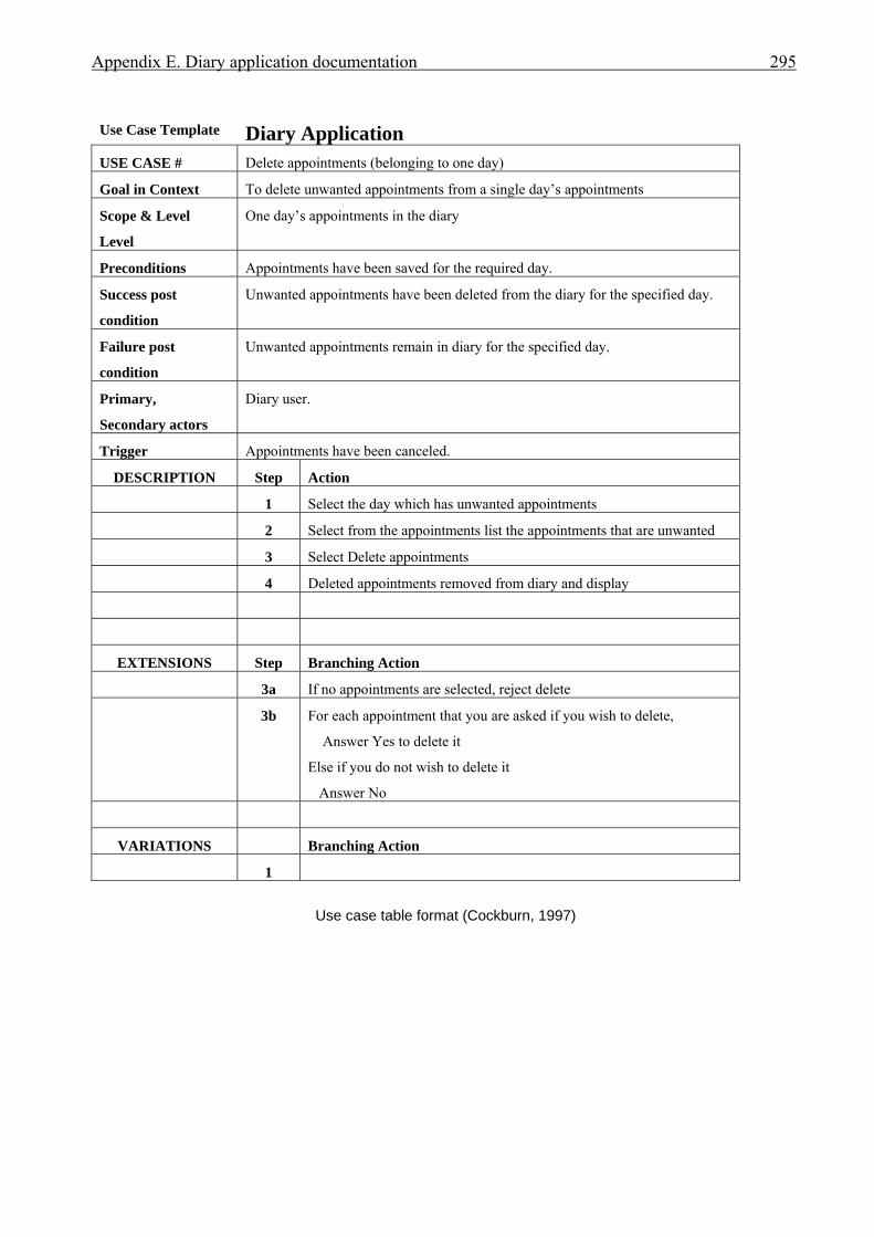
Appendix E. Diary application documentation 295
Use Case Template Diary Application USE CASE # Delete appointments (belonging to one day)
Goal in Context To delete unwanted appointments from a single day’s appointments
Scope & Level
Level
One day’s appointments in the diary
Preconditions Appointments have been saved for the required day.
Success post
condition
Unwanted appointments have been deleted from the diary for the specified day.
Failure post
condition
Unwanted appointments remain in diary for the specified day.
Primary,
Secondary actors
Diary user.
Trigger Appointments have been canceled.
DESCRIPTION Step Action
1 Select the day which has unwanted appointments
2 Select from the appointments list the appointments that are unwanted
3 Select Delete appointments
4 Deleted appointments removed from diary and display
EXTENSIONS Step Branching Action
3a If no appointments are selected, reject delete
3b For each appointment that you are asked if you wish to delete,
Answer Yes to delete it
Else if you do not wish to delete it
Answer No
VARIATIONS Branching Action
1
Use case table format (Cockburn, 1997)
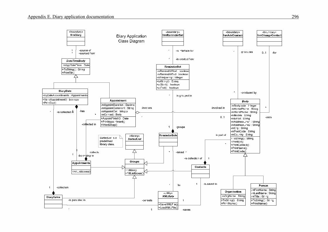
Appendix E. Diary application documentation 296
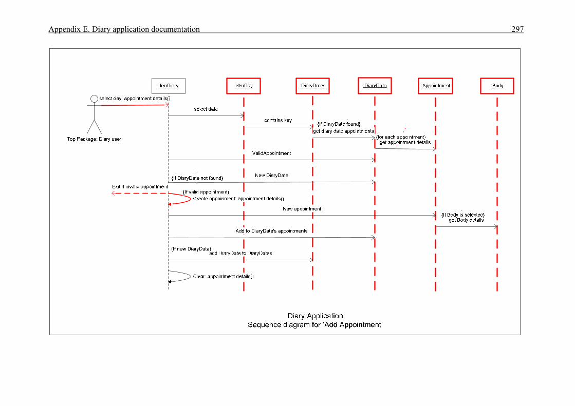
Appendix E. Diary application documentation 297
List of references 298 List of references Adelson, B. (1981). Problem solving and the development of abstract categories in programming
languages. Memory and Cognition, 9, 422-433. Agarwal, R., Sinha, A.P., & Tanniru, M. (1996). Cognitive fit in requirements modeling: A study of
object and process. Journal of Management Information Systems, 13(2), 137-162. Agarwal, R., De, P., Sinha, A.P., & Tanniru, M. (2000). On the usability of OO representations.
Communications of the ACM, 43(10), 83-89. Anderson, J.R. (1983). The architecture of cognition. Cambridge, MA: Harvard University Press. Anderson, J.R. (1993). Rules of the mind. Mahwah, NJ: Lawrence Erlbaum Associates. Anderson, M.J. (1985). Some evidence on the effect of verbalisation on process: A methodological
note. Journal of Accounting Research, 23(2), 843-852. Andriole, S., & Adelman, L. (1995). Cognitive systems engineering for user-computer interface design,
prototyping, and evaluation. Mahwah, NJ: Lawrence Erlbaum Associates. Arunachalam, V., & Sasso, W. (1996). Cognitive processes in program comprehension: An empirical
analysis in the context of software engineering. Journal of Systems and Software, 34(3), 177-189. Beck, K. (1993). CRC: Finding objects the easy way. Object Magazine, 3(4), 42-44. Biemiller, A., & Meichenbaum, D. (1992). The nature and nurture of the self-directed learner.
Educational Leadership, 50(2), 75-80. Blackwell, A.F., Whitley, K.N., Good, J. & Petre, M. (2001). Cognitive factors in programming with
diagrams. Artificial Intelligence Review, 15, 95-114. Booch. G. (1991). Object-oriented design with applications. Redwood City, CA: Benjamin/Cummings. Booch G. (1994).Object-oriented analysis and design with applications (2nd ed.). Redwood City, CA:
Benjamin/Cummings. Booch, G., Rumbaugh, J., & Jacobson, I. (1999). The unified modeling language user guide. Reading,
MA: Addison-Wesley. Boren, M.T., & Ramey, J. (2000). Thinking aloud: Reconciling theory and practice. IEEE Transactions
on Professional Communication, 43(3), 261-278. Bracewell, R., & Breuleux, A. (1994). Substance and romance in analyzing think-aloud protocols. In
Peter Smagorinsky, Editor, Speaking about writing: Reflections on research methodology (pp.55-88). Thousand Oaks, CA: Sage Publications.
Branch, J.L. (2000). The trouble with think alouds: Generating data using concurrent verbal protocols. In Kublik, A., Editor, Dimensions of a global information science, Proceedings of the 28th Conference of the Canadian Association for Information Science (CAIS 2000), Edmonton, Alberta, Canada, retrieved from http://www.slis.ualberta.ca/cais2000/branch.htm 2/03/07
Branch, J.L. (2001). Junior high school students and think alouds: Generating information-seeking process data using concurrent protocols. Library & Information Science Research, 23, 107-122.
Brooks, R. (1977). Towards a theory of the cognitive processes in computer programming. International Journal of Man-Machine Studies, 9, 737-751.
Brooks, R.E. (1980). Studying programmer behavior experimentally: The problems of proper methodology. Communications of the ACM, 23(4), 207-213.
Cabello, F., & O’Hora, D. (2002). Addressing the limitations of protocol analysis in the study of complex human behavior. International Journal of Psychology and Psychological Therapy,
2(2), 115-130. Carroll, J.M., Thomas, J.C., & Malhotra, A. (1980). Presentation and representation in design problem-
solving. British Journal of Psychology, 7, 143-153. Chase, W.C., & Simon, H.A. (1973). Perception in chess. Cognitive Psychology, 4, 55-81.
List of references 299 Chinn, D., Spencer, C., & Martin, K. (2007). Problem solving and student performance in data
structures and algorithms. Proceedings of ITiCSE ’07, June 23-27, Dundee, Scotland, United Kingdom, 241-245.
Coad, P., & Yourdon, E. (1991). Object-oriented analysis (2nd ed.). Englewood Cliffs, N.J: Yourdon Press.
Cockburn, A.A.R. (1994). In search of a methodology. Object Magazine, 4(4), 52-56 Cockburn, A.A.R. (1997). Using goal-based use cases. JOOP (Journal of Object-Oriented
Programming), SIGS Publications, 10(7), 56-62. Cooke, L., & Cuddihy, E (2005). Using eye tracking to address limitations in think-aloud protocol.
Proceedings of the 2005 IEEE International Professional Communication Conference, 653-658. Costain, G. (1996). A framework for post-implementation review of use of CASE methodology.
Unpublished master's thesis. University of Auckland, New Zealand. Costain, G. (2000). Teaching the capturing of functional requirements in use cases. New Zealand Journal of Applied Computing, NACCQ, New Zealand, 4(2), 19-24. Costain, G. (2000a). Selecting an object-oriented process for student analysts. Proceedings of the 7th
Asia-Pacific Software Engineering Conference (APSEC 2000), Singapore, December 5-8, 384-391. Cotton, D., & Grestry, K. (2006). Reflecting on the think-aloud method for evaluating e-learning. British Journal of Educational Technology, 37(1), 45-54. Coulter, N.S. (1983). Software science and cognitive psychology. IEEE Transactions on software
Engineering SE-9(2), 166-171. Cusumano, M.A., & Selby, R.W. (1997). How Microsoft builds software. Communications of the
ACM, 40(6), 53-61. Davies, I., Green, P., Rosemann, M., Indulska, M., & Gallo, S. (2006). How do practitioners use
conceptual modeling in practice? Data & Knowledge Engineering, 58, 358-380. Davis, F.D. (1989). Perceived usefulness, perceived ease of use. MIS Quarterly, 13(3), 319-340 Détienne, F. (1990) Expert programming knowledge: A schema-based approach. In Hoc, J.M., Green,
T.R.G., Samurçay, R., & Gilmore, D.G., Editors. Psychology of programming (pp.205-222). London: Academic Press Ltd.
Détienne, F. (1995). Design strategies and knowledge in object-oriented programming: Effects of experience. Human-Computer Interaction, 10, 129-169.
Détienne, F., & Soloway, E. (1990). An empirically-derived control structure for the process of program understanding. International Journal of Man-Machine Studies, 33(3), 323-342.
Dobing, B., & Parsons, J. (2000). Understanding the role of use cases in UML: A review and research agenda. Journal of Database Management, 11(4), 28-36.
Dobing, B., & Parsons, J. (2006). How UML is used. Communications of the ACM, 49(5), 109-113. Dobing, B., & Parsons, J. (2008). Dimensions of UML use: A survey of practitioners. Journal of
Database Management, 19(1), 1-18. Eden, C. (1992). On the nature of cognitive maps. Journal of Management Studies, 29(3), 261-265. Eden, C., Ackermann, F., & Cropper, S. (1992). The analysis of cause maps. Journal of Management
Studies, 29(3), 309-324. Ericsson, K.A., & Simon, H.A. (1984). Protocol analysis: Verbal reports as data. Cambridge, MA:
MIT Press. Ericsson, K.A., & Simon, H.A. (1993). Protocol analysis: Verbal reports as data. Cambridge, MA:
MIT Press. Fedorowicz, J., & Villeneuve, A. (1999). Surveying object technology usage and benefits: A test of
conventional wisdom. Information & Management, 35, 331-344. Fiol, C.M., & Huff, A.S. (1992). Maps for managers: where are we? Where do we go from here?
Journal of Management Studies, 29(3), 267-285.
List of references 300 Gardiner, J.M., Gregg. V.H., & Karayianni, I. (2006). Recognition memory and awareness: Occurrence
of perceptual effects in remembering or in knowing depends upon conscious resources at encoding, but not at retrieval. Memory and Cognition, 34(2), 227-239.
Goel, V. (1995). Sketches of Thought. A Bradford Book. Cambridge, MA: MIT Press. Green, T.R.G. & Petre, M. (1996). Usability analysis of visual programming environments: A
‘cognitive dimensions’ framework. Journal of Visual Programming Languages and Computing, 7, 131-174.
Grogono, P., & Nelson, S.H. (1982). Problem solving and computer programming. Reading, MA: Addison-Wesley.
Guindon, R. (1990). Knowledge exploited by experts during software system design. International Journal of Man-Machine Studies, 33(3), 279-304.
Guindon, R., & Curtis, B. (1988). Control of cognitive processes during software design: What tools are needed. Proceedings of the CHI’88 Conference on Human Factors in Computer Systems, New York, ACM, 263-268.
Hahn, J., & Kim, J. (1999). Why are some diagrams easier to work with? Effects of diagrammatic representation on the cognitive integration process of systems analysis and design. ACM Transactions on Computer-Human Interaction, 6(3), 181-213.
Hale, J.E., Sharpe, S., & Hale, D.P. (1999). An evaluation of the cognitive processes of programmers engaged in software debugging. Journal of Software Maintenance: Research and Practice, 11, 73-91.
Haverty, L.A., Koedinger, K.R., Klahr, D., & Alibali, M.W. (2000). Solving inductive reasoning problems in mathematics: Not-so-trivial pursuit. Cognitive Science, 24(2), 249-298.
Hayes, J.R., & Simon, H. (1979). The understanding process: Problem isomorphs. In Simon, H.A. Editor, Models of Thought, Vol.1 (pp.477-497). New Haven, CT: Yale University Press.
Hayes, S.C., Zettle, R.D., & Rosenfarb, I. (1989). Rule following. In Hayes, S.C., Editor, Rule-governed behavior: cognition, contingencies, and instructional control, Reno, NV: Context Press.
Henderson-Sellers, H., Firesmith, D., & Graham, M. (1997). The benefits of common object modeling notation. JOOP, 10(5), 28-34.
Herbsled, J.D., Klein, H.I., Olson, G.M., Brunner, H., Olson, J.S., & Harding, J. (1995). Object-oriented analysis and design in software project teams. Human-Computer Interaction, 10, 249-292.
Herbsled, J.D., & Kuwana, E. (1993). Preserving knowledge in design projects: What designers need to know. Proceedings of INTERCHI ’93, New York: ACM, 7-14.
Hollan, J., Hutchins, E., & Kirsh, D. (2000). Distributed cognition: Toward a new foundation for human-computer interaction research. ACM Transactions on Computer-Human Interaction, 7(2), 174-196.
Hughes, J., & Parkes, P. (2003). Trends in the use of verbal protocol analysis in software engineering research. Behaviour & Information Technology, 22(2), 127-140.
Hungerford, B.C. (2004). Reviewing software diagrams: A cognitive study. IEEE Transactions on Software Engineering, 30(2), 82-96.
Irwin, G. (2002). The role of similarity in the reuse of object-oriented analysis models. Journal of Management Information Systems, 19(2), 219-248.
ISO. (1998). Ergonomic requirements for office work with visual display terminals. ISO 9241-11, ISO, Geneva.
Jacobson, I., Booch, G., & Rumbaugh, J. (1999). The unified software development process. Reading, Massachusetts: Addison-Wesley.
Jacobson, I., Christerson, M., Jonsson, P., & Övergaard, G. (1993). Object-oriented software engineering: A use case driven approach (Rev.ed.). New York: Addison-Wesley.
List of references 301 Jefferies, R., Turner, A.A., Polson, P.G., & Atwood, M.E. (1981). The processes involved in designing
software. In Anderson, J.R., Editor, Cognitive Skills and their Acquisition (pp.255-283). Hilldale, NJ: Lawrence Erlbaum Associates.
Johnson, R.A. (2000). The ups and downs of object-oriented systems development. Communications of the ACM, 43(10), 69-73.
Johnson, R.A. (2002). Object-oriented analysis and design – What does the research say? Journal of Computer Information Systems, 42(3), 11-15.
Johnson, R.A., &. Hardgrave, B.C. (1999). Object-oriented methods: Current practices and attitudes. The Journal of Systems and Software, 48, 5-12.
Kahney, H. (1993). Problem solving: Current issues (2nd ed.). Buckingham, PA: Open University Press.
Kant, E., & Newell, A. (1984). Problem solving techniques for the design of algorithms.Information Processing & Management, 20(1/2), 97-118.
Kim, J., Hahn, H., & Hahn, J. (2000). How do we understand a system with (so) many diagrams? Cognitive integration processes in diagrammatic reasoning. Information Systems Research, 2000 INFORMS, 11(3), 284-303.
Kim, J., Hahn, J., & Lerch, F.J. (1997). How is the designer different from the user? Focusing on a software development methodology. Proceedings of the 7th Empirical Studies of Programmers, 69-90.
Kim, J., & Lerch, F.J. (1992). Towards a model of cognitive process in logical design: Comparing object-oriented and traditional functional decomposition software methodologies. In Bauersfield, P., Bennett, J., & Lynch, G., Editors. Proceedings of CHI ’92, ACM Conference on Human Factors in Computing Systems, May 3-7, Monterey, California, 489-498.
Kim, J., & Lerch, F.J. (1997). Why is programming (sometimes) so difficult? Programming as scientific discovery in multiple problem spaces. Information Systems Research, 8(1), 25-50.
Kim, J., Lerch, F.J., & Simon, H.A. (1995). Internal representation and rule development in object-oriented design. ACM Transactions on Computer-Human Interaction, 2(4), 357-390.
Kobryn, C. (1999). UML 2001: A standardization odyssey. Communications of the ACM, 42(10), 29-37.
Kobryn, C. (2002). Will UML 2.0 be agile or awkward? Communications of the ACM, 45(1), 107-110. Koedinger, K.R. & Anderson, J.R. (1990). Abstract planning and perceptual chunks: Elements of
expertise in Geometry. Cognitive Science, 14, 511-550. Kotovsky, K., Hayes, J.R., & Simon., H.A. (1985). Why are some problems hard? Evidence from
Tower of Hanoi. Cognitive Psychology, 17, 248-294. Larkin, J.H. & Simon, H.A. (1987). Why a diagram is (sometimes) worth ten thousand words.
Cognitive Science, 11(1), 65-100. Law, Lai-Chong. (1998). A situated cognition view about the effects of planning and authorship on
computer program debugging. Behaviour & Information Technology, 17(6), 325-337. Lee, A., & Pennington, N. (1994). The effects of paradigm on cognitive activities in design.
International Journal of Human-Computer Studies, 40(4), 577-601. Lohse, G.L. (1997). The role of working memory on graphical information processing. Behaviour &
Information Technology, 16(6), 297-308. Maher, M.L. (1994) Creative design using a generic algorithm. Journal of Computing in Civil
Engineering, ASCE Research Library, 8, 2014-2021 [as reported in Maher & Tang, 2003]. Maher, M.L., & Tang, H. (2003). Co-evolution as a computational and cognitive model of design.
Research in Engineering Design, 14, 47-63. Mayer, R.E. (1989). Models for understanding. Review of Educational Research, 59(1), 43-64.
List of references 302 McCracken, W.M. (2002). Models of designing: Understanding software engineering education from
the bottom up. Proceedings of the 15th Conference on Software Engineering Education and Training (CSEET’02), IEEE.
McKeithen, K.B., Reitman, J., Rueter, H.H., & Hirtle, S.C. (1981). Knowledge organization and skill differences in computer programmers. Cognitive Psychology, 13, 307-325.
Miller, G.A. (1956). The magical number seven, plus or minus two: Some limits on our capacity for processing information. Psychological Review, 63(1), 81-97.
Miller, G.A. (1962). Psychology: The science of mental life, New York, Harper & Row. Monarchi, D., (Moderator), Booch, G., Henderson-Sellers, B., Jacobson, I., Mellor, S., Rumbaugh, J.,
& Brock, R.W. (1994). Methodology standards: Help or hindrance? Proceedings of the Ninth Annual Conference on Object-oriented Programming Systems, Languages, and Applications (OOPSLA), 23-27 October, Portland, Oregon, U.S.A., ACM Press, Panel 4, 223-228.
Neisser, U. (1967). Cognitive psychology. New York: Appleton-Century-Crofts. Newell, A. (1969). Heuristic programming: Ill-structured problems. In J. Aronofsky, Editor, Progress
in Operations Research, Vol. 3, (pp.362-414). New York: J. Wiley & Sons, Inc. Newell, A., & Simon, H.A. (1972). Human problem Solving. Englewood Cliffs, NJ: Prentice-Hall. Newsted, P.R. (1979). Flowchart-free approach to documentation. Journal of Systems Management,
30(4), 18-21. Nielsen, J. (1993). Usability engineering. Boston: Academic Press. Nielsen, J., Clemmensen, T., & Yssing, C. (2002). People’s heads, people's minds? – Theoretical
reflections on thinking aloud. In Dai, G., Editor, Proceedings of the APCHI2002 – User Interaction Technology in the 21st Century, Vol.2, (pp.897-911). Science Press, Beijing.
Nielsen, J., Clemmensen, T., & Yssing, C. (2002a). Getting access to what goes on in people’s heads? – Reflections on the think-aloud technique. NordCHI 2002, Ärhus, Denmark, October 19-23, 101-110.
Nisbett, R.E., and Wilson T.D. (1977). Telling more than we know: Verbal reports on mental processes. Psychological Review, 84(3), 231-241.
O’Brien, M.P., Shaft, T.M., & Buckley, J. (2001). An open-source analysis schema for identifying software comprehension processes. In G. Kadoda, Editor. Proceedings of Psychology of Programming Interest Group (PPIG) (pp. 129-146). 13th Annual Workshop 17-20 April, Bournmouth University, UK.
Olson, I.R., &.Chun, M.M. (2002). Perceptual constraints on implicit learning of spatial context. In Glyn W. Humphreys, Editor, Visual cognition (pp.273-302). Psychology Press Ltd.
OMG. (2007), http://www.omg.org, Home page last viewed 9/5/2007 Ormerod, T. (1990). Human cognition and programming. In Hoc, J.M., Green, T.R.G., Samurcay, R.,
& Gilmore, D.J., Editors, Psychology of Programming (pp.63-82). London: Academic Press Ltd. Owen, S., Budgen, D., & Brereton, P. (2006). Protocol analysis: A neglected practice. Communications
of the ACM, 49(2), 117-122. Pennington, N. (1987). Stimulus structures and mental representations in expert comprehension of
computer programs. Cognitive Psychology, 19, 295-341. Pennington, N., Lee, A.Y., & Rehder, B. (1995). Cognitive activities and levels of abstraction in
procedural and object-oriented design. Human-Computer Interaction, 10, 171-226. Petre, M. (1995). Why looking isn’t always seeing: Readership skills and graph. Communications of
the ACM, 38(6), 33-44. Petre, M., & Green, T.R.G. (1993). Learning to read graphics: Some evidence that ‘seeing’ an
information display is an acquired skill. Journal of Visual Languages and Computing, 4, 55-70. Preece, J. (Ed.). (1993). A guide to usability: Human factors in computing. Wokingham, England:
Addison-Wesley.
List of references 303 Preece, J., Rogers, Y., & Sharp, H. (2002). Interaction design: Beyond human-computer interaction,
Hoboken, NJ: John Wiley & Sons, Inc. Ransdell, S. (1995). Generating thinking-aloud protocols: Impact on the narrative writing of college
students. American Journal of Psychology, 108(1), 89-98 Rist, R.S. (1989). Schema creation in programming. Cognitive Science, 13, 389-414. Robbins, J.E. (1999). Cognitive support features for software development tools. Unpublished PhD
Thesis. University of California, Irvine Robbins, J.E., & Redmiles, D.F. (2000). Cognitive support, UML adherence, and XMI interchange in
Argo/UML. Information and Software Technology, 42, 79-89 Rosson, M.B., & Alpert, S.R. (1990). The cognitive consequences of object-oriented design. Human-
Computer Interaction, 5, 345-379. Rubin, J. (1994). Handbook of usability testing: How to plan, design, and conduct effective tests. New
York: John Wiley & Sons, Inc. Ruiz, D. (1986), Learning and problem solving: What is learned while solving the Towers of Hanoi,
Unpublished doctoral dissertation, Stanford University, Calif. [as reported in Kim et al., 1995]. Rumbaugh, J. (1996). To form a more perfect union: Unifying the OMT and Booch methods. JOOP,
8(8), 14-18. Rumbaugh, J. (1996a). Notation notes: Principles for choosing notation. JOOP, 9(2), 11-14. Rumbaugh, J., Blaha, M., Premerlani, W., Eddy, F., & Lorensen, W. (1991). Object-oriented modeling
and design. Englewood cliffs, NJ: Prentice-Hall. Russo, J.E., Johnson, E.J., & Stephens, D.L. (1989). The validity of verbal protocols. Memory and
Cognition, 17, 759-789. Scaife, M., & Rogers Y. (1996). External cognition: How do graphical representations work?
International Journal of Human-Computer Studies, 45, 185-213. Schenk, K.D., Vitalari, N.P., and Davis, K.S. (1998). Differences between novice and expert systems
analysts: What do we know and what do we do? Journal of Management Information Systems, 15(1), 9-50.
Shaft, T.M. (1997). Responses to comprehension questions and verbal protocols as measures of computer program comprehension processes. Behaviour & Information Technology, 16(6), 320-336.
Sheil, B. A. (1981). The psychological study of programming. Computing Surveys, 13(1), 101-120. Sheppard, S.B., Curtis, B., Milliman, P., & Love, T. (1979). Modern coding practices and programmer
performance. COMPUTER, IEEE, 12(12), 41-49. Siau, K. (1999). Information modeling and method engineering: A psychological perspective. Journal
of Database Management, 10(4), 44. Siau, K, & Cao, Q. (2001). Unified modeling language (UML) – A complexity analysis. Journal of
Database Management, 12(1), 26–34. Siau, K., & Lee, L. (2004). Are use case and class diagrams complementary in requirements analysis?
An experimental study on use case and class diagrams in UML. Requirements Engineering, 9, 229-237.
Siau, K., & Tian, Y. (2001). The complexity of unified modeling language: A GOMS analysis Twenty-Second International Conference on Information Systems, 443-447.
Siau, K., & Tan, X. (2006). Using cognitive mapping techniques to supplement UML and UP in information requirements determination. Journal of Computer Information Systems, Special Issue, 59-66.
Siau, K., & Tan, X. (2006a). Cognitive mapping techniques for user-database interaction, IEEE Transactions on Professional Communication, 49(2), 96-108.
Simon, H.A., & Lea, G. (1974). Problem solving and rule induction. In Simon, H.A, Editor, Models of Thought (pp.329-346) [1979] London University Press.

List of references 304 Smith, E.R., &. Miller, F.D. (1978). Limits on perception of cognitive processes: A reply to Nisbett and
Wilson. Psychological Review, 85, 355-362. Smith, R. (2000). Defining the UML kernel. Software Development Online,
http://www.sdmagazine.com/articles/2000/0010/0010b/0010b.htm last viewed 6/4/2001. Srinivasan, A., & Irwin, G. (2006). Communicating the message: Translating tasks into queries in a
database context. IEEE Transactions on Professional Communication, 49(2), 145-159. Srinivasan, A., & Te’eni, D. (1995). Modeling as constrained problem solving: an empirical study of
the data modeling process. Management Science, 41(3), 419-434. Stenning, K., & Oberlander, J. (1995). A cognitive theory of graphical and linguistic reasoning: Logic
and implementation. Cognitive Science, 19(1), 97-140. Stratman, J.F. & Hamp-Lyons, L. (1994). Reactivity in concurrent think-aloud protocols: Issues for
research. In P. Smagorinsky, Editor, Speaking about writing: Reflections on research methodology, Vol.8, pp. 89-111, Thousand Oaks, CA: Sage.
Sutcliffe, A.G., & Maiden, N.A.M. (1992). Analysing the novice analyst: Cognitive models in software engineering. International Journal of Man-Machine Studies, 36(5), 719-740. Swan, J. (1997). Using cognitive mapping in management research: decisions about technical innovation. British Journal of Management, 8, 183-198.
Swan, J. (1997). Using cognitive mapping in management research: decisions about technical innovation. British Journal of Management, 8, 183-198.
Swan, J.A. & Newell, S. (1994). Managers’ beliefs about factors affecting the adoption of technological innovation: A study using cognitive maps. Journal of Managerial Psychology, 9(2), 3-11.
Tabachneck-Schijf, H.J. M., Leonardo, A.M., & Simon, H.A. (1997). CaMeRa: A computational model of multiple representations. Cognitive Science, 21(3), 305-350.
Tegarden, D.P., & Sheetz, S.D. (2001). Cognitive activities in OO development. International Journal of Human-Computer Studies, 54, 779-798.
Todd, P., & Benbasat, I. (1987). Process tracing methods in decision support systems: Exploring the black box. Management Information Systems (MIS) Quarterly, 11(4), 493-512.
Tolman, E. (1948). Cognitive maps in rats and men. Psychological Review, 55(4), 189-208. UML. (2007), http://www.uml.org , UML Resources link from [OMG 2007], last viewed 9/5/2007. Vans, A.M., von Mayrhauser, A., and Somolo, G. (1999). Program understanding behavior during
corrective maintenance of large-scale software. International Journal of Human-Computer Studies, 51(1), 31-70.
Wǽrn, Y. (1989). Cognitive aspects of computer supported tasks. Chichester, England: John Wiley and Sons.
Walenstein, A. (2002). Cognitive support in software engineering tools. A distributed cognitve framework. Unpublished PhD Thesis. Simon Frazer University
Wickens, C.D., & Carswell, C.M. (1995). The proximity compatibility principle: Its psychological foundation and relevance to display design. Human Factors, 37(3), 473-494.
Winn, W. (1993). An account of how readers search for information in diagrams. Contemporary Educational Psychology, 18, 162-185.
Zhang, J. (1997). The nature of external representations in problem solving. Cognitive Science, 2l(2), 179-217.
Zhang, J., & Norman, D.A. (1994). Representations in distributed cognitive tasks. Cognitive Science, 18, 87-122.

List of references 305