Iterative Formalization of Smallest Workface Boundary for ...
Upload
khangminh22Category
view
0download
0
Formalization of UML Communication Diagrams
using π-Calculus
Aissam Belghiat1,2
1Département d’informatique, Université 20 Août 1955-
Skikda, Algérie
Allaoua Chaoui2
2MISC Laboratory, Department of Computer Science,
University of Constantine2, Algeria
Abstract—UML is a general-purpose modeling language for
object oriented systems. UML suffers from lack of semantics
design due to its semi-formal structure. Formal methods have
been used largely in order to deal with this problem. This paper
presents a formalization of UML communication diagrams
(collaboration diagrams in UML 1.x) semantics using π-calculus
computation model. The formalization provides a formal
theoretical basis as well as formal analysis and checking for UML
communication diagrams. We illustrate our approach by an
example in order to explain the general purpose usability of our
approach for a wide audience. It also illustrates a practical usage
which proved the effectiveness of the translation.
Keywords—UML, communication diagram, π-calculus, formal
method, formalization, MDA.
I. INTRODUCTION
UML (Unified Modeling Language) is a semi-formal language to visualize, specify, build and document all the artifacts and aspects of software systems [1]. UML provides interaction diagrams to represent the communications with and within the software. There are two common variant of interaction diagrams; the sequence diagram and the communication diagram. Whereas the sequence diagram shows temporal representation of the interactions between the objects and the chronology of the exchanged messages between the objects and with the actors, the communication diagram displays a spatial representation of the objects and their interactions.
The formalization of UML diagrams using formal methods has been adopted largely in order to deal with its problem of imprecise semantics. In this paper, we propose to use the π -calculus computation model to compensate the lack of semantics in UML communication diagrams by defining a theoretical formal basis for them. In order to do that, we examine the graphical syntax of such diagrams which is precisely specified and also the semantics that is imprecisely defined. Then we tried to develop an incremental semantic correspondence between UML communication diagrams and the π-calculus using the abilities of this later in capturing the way in which the objects interact.
Little research effort has been devoted at tackling the formalization of UML communication diagrams; due the fact that large numbers of designers claim that the other UML interaction diagram (i.e. the sequence diagram) is more appropriate in the modeling task. Unfortunately, this is not true because the UML specification [1] tells us that each type of the proposed diagrams provides slightly different abilities and capabilities that make it more appropriate and adapted for certain situations. Furthermore, communication diagrams are more suitable [7][18] and often used to provide a glance-view of a collection of collaborating objects, in particular within a real-time environment, offer an alternate view of interaction with sequence diagrams, add functionality to classes by exploring the behavior results from the interaction of its objects, model the implementation logic of a complex operation; in particular when it interacts with several other objects, and to describe the roles taken by objects in a system, and the different relationships involved in those roles.
The main contribution of this paper is the formalization of the execution semantics of UML communication diagrams using the π-calculus computation model and consequently strengthening these diagrams by providing for them a formal semantic foundation. Other outcome is to advance state-of-the-art of the formalization of all UML diagrams by means of process algebras. Furthermore, our work can be seen as a refinement and extension of the study in [15] in which the authors proceed to capture the dynamic behavior of programs using collaboration diagrams. Using our contribution, which maps a communication diagram to the correspond π-calculus specification and by the means of some π-calculus tools like MWB [2][3], we can proceed to model checking and equivalence checking of programs which have the dynamic behavior modeled as collaboration diagrams.
The rest of the paper is structured as follows. In Section 2, we present related works. In Section 3, we present basic notions about UML communication diagrams and the π-calculus. In Section 4, we propose a formalization of communication diagrams using the π-calculus. In Section 5, we illustrate our approach through an example. Section 6 concludes the work by remarks and future works.
Symposium on Complex Systems and Intelligent Computing (CompSIC)University of Souk Ahras - Université Mohamed Chérif Messaadia de Souk-Ahrashttp://www.univ-soukahras.dz/en/publication/article/410

II. RELATED WORK
There is a large body of work attempting to formalize the semantics of UML diagrams, but to the best of our knowledge, a few works have addressed directly the formalization of communication diagrams. Lano et al. [5] have formalized collaboration diagrams using Structured Temporal Theories in an effort to describe semantics for a subset of UML diagrams. Övergaard, in [17], developed a sequence-based formalization of collaboration diagrams in terms of roles and interactions. In [6] a Colored Petri Nets-based approach is proposed to represent collaboration diagrams. In [7] an integrated approach graph transformation rules and graph processes is used to formalize collaboration diagrams. In [8] the authors use Object Petri Net Models to formalize UML statechart and collaboration diagrams for analysis purposes. In [9] the authors propose an approach for integrating UML statechart and collaboration diagrams by their formalization using Hierarchical Predicate Transition Nets (HPrTNs). In [10] a graph transformation based approach is developed for the automatic generation of Coloured Petri Net Models from UML statechart and collaboration diagrams. Merah et al. [16] translate UML2 communication diagrams to Buchi automata using the ATL transformation language. In [11] the authors transform the communication diagrams of Fuzzy UML [12] (which is a modeling language that combines the UML with Fuzzy logic) to Fuzzy Petri nets.
With regard to previous studies, we notice the following concerns:
The works in [20], [6], [8], [9], and [10] have not
addressed directly the formalization of communication
diagrams, but as part of theirs contributions to attain
other objectives.
The informal definition of the semantic mapping in all
previous work, especially in [7], [16]. Which make them
insufficient to fully define the translation.
The authors in [16] propose a non-persistent mapping
which neglects the most essential features those that
reflect the behavioral-semantics of communication
diagrams such as asynchronous communication,
conditional messages, concurrent messages and
concurrent loops. Thus, the approach proposed by [16] is
very limited and does not fully conform to the semantics
of UML.
The authors in [7] provide a formalization which covers
three aspects of models which can be expressed in
collaboration diagrams: structure, interaction and a novel
state transformation proposed-aspect. However, the
examination of the proposed-approach indicates that it is
oriented to the former and later aspects, and the
interaction aspect was ambiguously and badly modeled
and covered. No formalization is provided for example
even to basic interactions such as exchanging messages
which deviates the formalization from the main
semantics-purpose of communication diagrams. An
interested reader can rapidly detect that the novel aspect
proposed in [7] has immediately turned the approach to a
statechart-oriented contribution because the focus in the
formalization is on the lifecycle of each object instead of
communication between objects. In contrast to all these works, our contribution provides
multiple benefits over them:
Our study addresses directly communication diagrams
from the UML2 specification [1] in contrast to the works
in [20], [6], [8], [9], and [10]. It tackles the main
objective of a communication diagram such as defined in
the OMG specification i.e. the underling structure and
interaction of system’s objects unlike in [7].
Our study is a first attempt in regard to the formalization
of UML communication diagrams using the π-calculus.
The target semantic domain chosen in our translation
provides a rich theory and tools, which will allow and
automate formal analysis and verification of
communication diagrams such as model checking and
equivalence checking.
Our study provides a full formal definition of the
semantic mapping between UML communication
diagrams and the π-calculus, especially in contrast to [7],
and [16], which will allow easily the automation of the
translation for rigorous analysis tasks.
We provide an exhaustive approach in our formalization
(Unlike in [16]), so that all systems modeled in such
diagrams can be perfectly described in our process
algebras.
Our approach covered the aspect of using collaboration
diagrams invented in [7], i.e., the specification of
system’s state transformation.
III. BACKGROUND
A. UML Communication Diagrams (CDs)
A communication diagram (collaboration diagrams in UML 1.x) is one of interaction diagrams that display a spatial representation of the objects and their interactions. We present in this section the syntax and semantics of these diagrams.
1) Structural elements of UML CDs. We present below the notational elements of UML
communication diagrams [1, 19] in (Fig. 1) and we show the different combination of these elements which used to build the diagrams.
Other visual stereotypes symbols of the robustness diagram can be considered since they are used to improve the readability of the communication diagrams [18]. (Fig. 2) depicts these symbols.
Symposium on Complex Systems and Intelligent Computing (CompSIC)University of Souk Ahras - Université Mohamed Chérif Messaadia de Souk-Ahrashttp://www.univ-soukahras.dz/en/publication/article/410
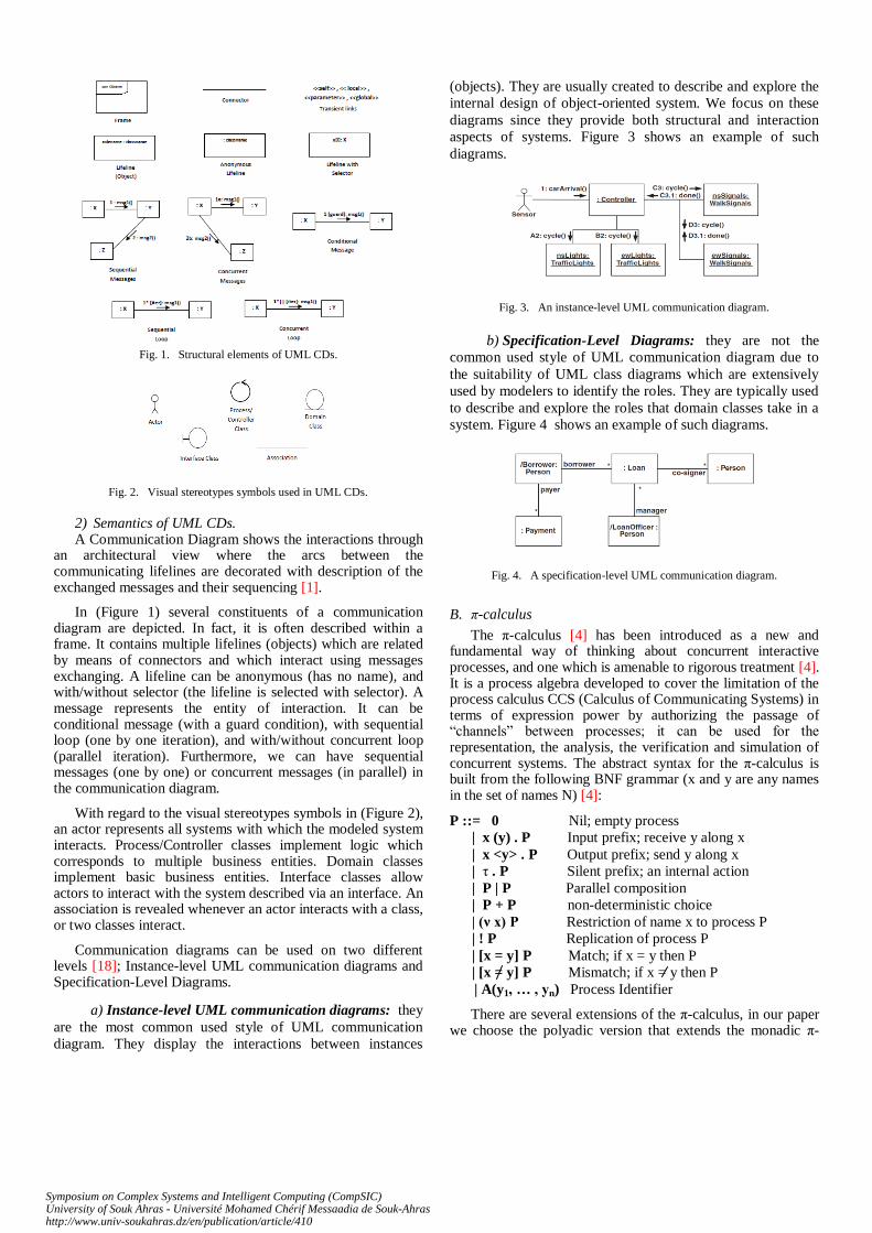
Fig. 1. Structural elements of UML CDs.
Fig. 2. Visual stereotypes symbols used in UML CDs.
2) Semantics of UML CDs. A Communication Diagram shows the interactions through
an architectural view where the arcs between the communicating lifelines are decorated with description of the exchanged messages and their sequencing [1].
In (Figure 1) several constituents of a communication diagram are depicted. In fact, it is often described within a frame. It contains multiple lifelines (objects) which are related by means of connectors and which interact using messages exchanging. A lifeline can be anonymous (has no name), and with/without selector (the lifeline is selected with selector). A message represents the entity of interaction. It can be conditional message (with a guard condition), with sequential loop (one by one iteration), and with/without concurrent loop (parallel iteration). Furthermore, we can have sequential messages (one by one) or concurrent messages (in parallel) in the communication diagram.
With regard to the visual stereotypes symbols in (Figure 2), an actor represents all systems with which the modeled system interacts. Process/Controller classes implement logic which corresponds to multiple business entities. Domain classes implement basic business entities. Interface classes allow actors to interact with the system described via an interface. An association is revealed whenever an actor interacts with a class, or two classes interact.
Communication diagrams can be used on two different levels [18]; Instance-level UML communication diagrams and Specification-Level Diagrams.
a) Instance-level UML communication diagrams: they
are the most common used style of UML communication
diagram. They display the interactions between instances
(objects). They are usually created to describe and explore the
internal design of object-oriented system. We focus on these
diagrams since they provide both structural and interaction
aspects of systems. Figure 3 shows an example of such
diagrams.
Fig. 3. An instance-level UML communication diagram.
b) Specification-Level Diagrams: they are not the
common used style of UML communication diagram due to
the suitability of UML class diagrams which are extensively
used by modelers to identify the roles. They are typically used
to describe and explore the roles that domain classes take in a
system. Figure 4 shows an example of such diagrams.
Fig. 4. A specification-level UML communication diagram.
B. π-calculus
The π-calculus [4] has been introduced as a new and fundamental way of thinking about concurrent interactive processes, and one which is amenable to rigorous treatment [4]. It is a process algebra developed to cover the limitation of the process calculus CCS (Calculus of Communicating Systems) in terms of expression power by authorizing the passage of “channels” between processes; it can be used for the representation, the analysis, the verification and simulation of concurrent systems. The abstract syntax for the π-calculus is built from the following BNF grammar (x and y are any names in the set of names N) [4]:
P ::= 0 Nil; empty process
| x (y) . P Input prefix; receive y along x
| x <y> . P Output prefix; send y along x
| τ . P Silent prefix; an internal action
| P | P Parallel composition
| P + P non-deterministic choice
| (ν x) P Restriction of name x to process P
| ! P Replication of process P
| [x = y] P Match; if x = y then P
| [x = y] P Mismatch; if x = y then P
| A(y1, … , yn) Process Identifier
There are several extensions of the π-calculus, in our paper we choose the polyadic version that extends the monadic π-
Symposium on Complex Systems and Intelligent Computing (CompSIC)University of Souk Ahras - Université Mohamed Chérif Messaadia de Souk-Ahrashttp://www.univ-soukahras.dz/en/publication/article/410

calculus in which a message consists of multiple names rather than one. This is because with this version we can demonstrate and illustrate sufficiently our formalization approach.
For the convenience, we define the following shortcuts: ① to represent the summation of all processes, ② to represent the composition of all processes, ③ to represent a series of channels and ④ the restriction operator for multiple names in a process as follow:
Ii iPdef
P1 + P2 + . . . + Pn … ①
Ii iPdef
P1 | P2 | . . . | Pn … ②
x1 def
x1, x2 ,...., xn … ③
(ν x1, x2 ,...., xn) P def
(ν x1)(ν x2) … (ν xn) P … ④
IV. THE PROPOSED APPROACH
A communication diagram shows the spatial organization of interacting participants. It represents the interactions in a spatial point of view. The π-calculus describes the interaction of linked processes in a virtual space. The reason for using the π-calculus computation model is that it is more suitable for reasoning. In fact, the behavior of a communication diagram can be perfectly modeled using the π-calculus because this computation model provides multiple constructs, which are able to describe the meaning of different interactions in such diagrams. Furthermore, it contains a rich theory and background for the analysis and verification of these systems modeled as process expressions.
We propose in this section inspired by [13, 14] a formal definition of UML communication diagrams; first, we define a communication diagram in terms of sets and functions. Then, we start our formalization by formally defining the translation mapping between the source and target models.
A. Formal definition of UML CDs
Definition 1: (CDs definition)
We suppose the types of notational elements of communication diagrams as:
Elements = Lifelines, Links, Messages, Conds, Msgs, Vals, Prms
A communication diagram is a 8-tuple:
CD = ( CDname, Elements, αcond , αmsg, αval, αprm , αin , αout)
Where:
- CDname is the communication diagram name.
- Lifelines represents the set of lifelines
- Links represents the set of links
- Messages represents the set of messages
- Conds represents the set of conditions.
- Msgs represents the set of messages names.
- Vals represents the set of return values.
- Prms represents the set of parameters.
- αcond : Messages Conds Defines for a
messages its condition.
- αmsg : Messages Msgs Specifies for a
message its name.
- αval : Messages Vals Specifies for a
message its return value.
- αprm : Messages Prms Specifies for a message its parameters.
- αin : Lifelines U Messages Links Relates a lifeline (resp. message) to links (considered as entering links).
- αout : Lifelines U Messages Links Relates a lifeline (resp. message) to links (considered as leaving links).
Definition 2: (Process expression function)
In order to capture the semantics of communication diagrams, we define a function Ω for representing UML communication diagrams as process expressions in the π-calculus. The function Ω is defined as follows:
Ω Elements : Elements Pi-calculus
EElements, P Pi-calculus, where Ω ElementsE (E)
= P. Which means that each elements of the communication diagram has it’s correspond process expression “P” in the pi-calculus.
Using this function, we can map each notational element of the communication diagram into the adequate π-calculus specification as process expressions.
B. Formalization of UML CDs
The technique adopted to formalize UML communication diagrams is to define the appropriate π-calculus representation for each of their notational elements. The task is repeated until no elements are left and a complete π-calculus specification for a communication diagram is generated. The lifelines are modeled as processes, the messages as processes and the links as connectors.
Rule 1: (lifeline “object”)
Suppose O1 Lifelines, αin (O1) = INi, αout (O1) = OUTj, ΩLinks(INi) = inio1 , ΩLinks(OUTj) = outjo1 , for i = 1,…, n. j = 1,…, m. f = n + m is the number of links associated with the lifeline. “seq” is a channel for evaluating the sequence number of the next message that will be sent. ΩLiflines (O1) = O1(inio1, seq, outjo1). We model the semantics of a lifeline by the behavior of the parameterized process O1(inio1, seq, outjo1) as follows (While i and j represent different inputs and outputs respectively of the object):
O1(inio1, seq, outjo1)
def
inio1. τ. (ν x) seq<x>.x(s). !outjo1<s>. O1(inio1, seq, outjo1)
An event that occurs in the process modeling the object is specified using the internal action “τ”. We use the “seq” channel to evaluate the sequence number of the message generated in response to the event produced. The output action seq<x> and the input action x(s) specify the sequence number of the next message. The concerned message process will be
Symposium on Complex Systems and Intelligent Computing (CompSIC)University of Souk Ahras - Université Mohamed Chérif Messaadia de Souk-Ahrashttp://www.univ-soukahras.dz/en/publication/article/410
fired using the output action “outjo1<s>” in the process. The replication operator “!” is used to indicate that the process modeling the object will trigger multiple messages processes (towards different objects), by outputting multiple copies of the “s” channel, if they have letters on messages i.e. different threads concurrently (in parallel). The recurrence of the process O1(inio1, seq, outjo1) in the end of the expression is to deal with sequential messages (one by one).
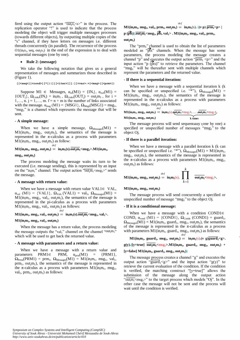
Rule 2: (message)
We take the following notation that gives us a general representation of messages and summarizes those described in (Figure 1).
[[<seq>][<cond>][*[||][[<iter>]]]:][<var>:=]<msg>([<prm>])
Suppose M1 Messages, αin(M1) = INi, αout(M1) =
OUTj, ΩLinks(INi) = inim1 , ΩLinks(OUTj) = outjm1 , for i = 1,…, n. j = 1,…, m. f = n + m is the number of links associated with the message. αmsg (M1) = MSG1, ΩMsgs(MSG1) = msg1, “msg1” is a channel which represents the message that will be sent.
- A simple message:
When we have a simple message, ΩMessages(M1) = M1(inim1, msg1, outjm1), the semantics of the message is represented in the π-calculus as a process with parameters M1(inim1, msg1, outjm1) as follow:
M1(inim1, msg1, outjm1)def
inim1(s).outjm1<msg1>.M1(inim1,
msg1, outjm1)
The process modeling the message waits its turn to be executed (i.e. message sending), this is represented by an input on the “inim1” channel. The output action “outjm1<msg1>” sends the message.
- A message with return value:
When we have a message with return value VAL1 VAL, αval (M1) = VAL1, ΩVals (VAL1) = val1, ΩMessages(M1) = M1(inim1, msg1, val1, outjm1), the semantics of the message is represented in the pi-calculus as a process with parameters M1(inim1, msg1, val1, outjm1) as follows:
M1(inim1, msg1, val1, outjm1)
def
inim1(s).outjm1<msg1, val1>.
M1(inim1, msg1, val1, outim1)
When the message has a return value, the process modeling
the message outputs the “val1” channel on the channel “outim1” which will be used to get back the returned value.
- A message with parameters and a return value:
When we have a message with a return value and parameters PRM1 PRM, αprm(M1) = PRM1, ΩPrms(PRM1) = prm1, ΩMessages(M1) = M1(inim1, msg1, val1, prm1, outjm1), the semantics of the message is represented in the π-calculus as a process with parameters M1(inim1, msg1, val1, prm1, outjm1) as follows:
M1(inim1, msg1, val1, prm1, outjm1)def
inim1(s). ((ν p) prm1<p> |
p (pts)).outjm1<msg1, pts, val1> . M1(inim1, msg1, val1, prm1,
outjm1)
The “prm1” channel is used to obtain the list of parameters modeled as “pts” channels. When the message has some parameters, the process modeling the message creates a channel “p” and executes the output action “prm1 <p>” and the input action “p (pts)” to retrieve the parameters. The channel “msg1” will be thereafter sent with multiple channels which represent the parameters and the returned value.
- If there is a sequential iteration:
When we have a message with a sequential iteration k (k can be specified or unspecified i.e. “*”), ΩMessages(M1) = M1(inim1, msg1, outjm1), the semantics of the message is represented in the π-calculus as a process with parameters M1(inim1, msg1, outjm1) as follows:
M1(inim1, msg1, outjm1)
def
inim1(s).outjm1<msg1>. … .outjm1<msg1>.
M1(inim1, msg1, outjm1)
The message process will send sequentially (one by one) a specified or unspecified number of messages “msg1” to the object Oj.
- If there is a parallel iteration:
When we have a message with a parallel iteration k (k can be specified or unspecified i.e. “*”), ΩMessages(M1) = M1(inim1, msg1, outjm1), the semantics of the message is represented in the π-calculus as a process with parameters M1(inim1, msg1, outjm1) as follows:
M1(inim1, msg1, outjm1)def
inim1(s).
k
k 1
outjm1<msg1>.
M1(inim1, msg1, outjm1)
The message process will send concurrently a specified or unspecified number of message “msg1” to the object Oj.
- If it is a conditional message:
When we have a message with a condition COND1 COND, αcond (M1) = COND1, ΩConds (COND1) = guard1, ΩMessages(M1) = M1(inim1, guard1, msg1, outjm1), the semantics of the message is represented in the π-calculus as a process with parameters M1(inim1, guard1, msg1, outjm1) as follows:
M1(inim1, guard1, msg1, outjm1)def
inim1(s).(ν g)guard1<g>.
g(y).([y=true] outjm1<msg1>.M1(inim1, guard1, msg1, outjm1) +
[y=false] M1(inim1, guard1, msg1, outjm1))
The message process creates a channel “g” and executes the output action “guard1<g>” and the input action “g(y)” to retrieve the current evaluation of the condition. If the condition is verified, the matching construct “[y=true]” allows the submission of the message along the output action “outim1<msg1>” to the target process which models “Oj”. In the other case the message will not be sent and the process will wait until the condition is verified.
k times
Symposium on Complex Systems and Intelligent Computing (CompSIC)University of Souk Ahras - Université Mohamed Chérif Messaadia de Souk-Ahrashttp://www.univ-soukahras.dz/en/publication/article/410
K times
- A full message:
When we have a full message M1, ΩMessages(M1) = M1(inim1, guard1, msg1, val1, prm1, outjm1), the semantics of the message is represented in the π-calculus as a process with parameters M1(inim1, guard1, msg1, val1, prm1, outjm1) as follows:
M1(inim1, guard1, msg1, val1, prm1, outjm1)def
inim1(s).(ν g)
guard1<g>. g(y).([y=true] ((ν p) prm1 <p> | p (pts))
(outjm1<msg1, pts, val1>. … .outjm1<msg1, pts, val1>. … +
Kkoutjm1<msg1, pts, val1> ) .
M1(inim1, guard1, msg1, val1, prm1, outjm1) + [y=false] M1(inim1,
guard1, msg1, val1, prm1, outjm1))
The process modeling the message is executed when the “inim1” channel is fired, after that, the condition will be evaluated using the “guard1” channel. If the condition is not verified, the message will not be sent. If the condition is verified, the message process proceeds to send either one message, multiple messages consequently or multiple messages concurrently.
Definition 3: (Processes communication)
The objects are related using the connectors, which are consequently represented as links between processes representing objects and processes representing messages and vice versa. They relate output ports of source processes with input ports of target processes. Here, we can use the communication reduction rule defined in [4]:
COMM : (…+ x(y).P) | (… + xz.Q) P z / y | Q
This rule represents the communication between two complementary processes (have complementary subjects) and consequently all free occurrence of y in P will be replaced by z using the substitution z / y after the communication. Based on this rule, the author in [4] has introduced a linking operator
relation “ ” on two π-calculus processes as follow:
P Q(t/p, t/q) def
ν t (t/pP | t/qQ)
This relation indicates that port p of the process P is linked with the port q of the process Q and then the channel t will be internalized.
Rule 3: (links)
We aspire from the interesting relation defined in (definition 3) to facilitate the expression of the translation from an object to message and vice versa represented as processes. Furthermore, we define a process called “Connector” that links all object processes “Oi” and message processes “Mj” of a system as bellow:
Connector def
Iji, ν c (c/oiOi | c/mjMj)
Rule 4: (CDs)
Suppose an UML communication diagram CD = (CDname, Elements, αcond , αmsg , αval , αprm , αin , αout). ΩCDname(CD) = CDname. The semantics of this communication diagram is modeled in the π-calculus by the process expression:
CDname def
Ii iO | Jj jM | Connector
Where “Oi” and “Mj” represent respectively the objects and messages processes resulting from applying the function defined in (Definition 2) in (rule 1) and (rule 2) on the communication diagram. Thus the model can be seen as π-calculus concurrent processes which are running in parallel.
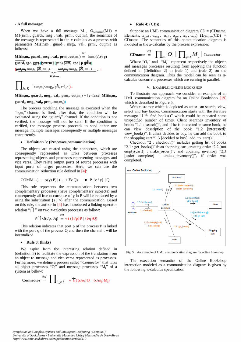
V. EXAMPLE: ONLINE BOOKSHOP
To illustrate our approach, we consider an example of an UML communication diagram for an Online Bookshop [19] which is described in Figure 5.
Web customer which is depicted as actor can search, view, select and buy books. Communication starts with the iterative message “1 *: find_books()” which could be repeated some unspecified number of times. Client searches inventory of books “1.1 : search()”, and if he is interested in some book, he can view description of the book “1.2 [interested]: view_book()”. If client decides to buy, he can add the book to the shopping cart “1.3 [decided to buy]: add_to_cart()”.
Checkout “2 : checkout()” includes getting list of books “2.1 : get_books()” from shopping cart, creating order “2.2 [not empty(cart)] : make_order()”, and updating inventory “2.3 [order complete] : update_inventory()”, if order was completed.
Fig. 5. An example of UML communication diagram for online bookshop.
The execution semantics of the Online Bookshop interaction modeled as a communication diagram is given by the following π-calculus specification
Symposium on Complex Systems and Intelligent Computing (CompSIC)University of Souk Ahras - Université Mohamed Chérif Messaadia de Souk-Ahrashttp://www.univ-soukahras.dz/en/publication/article/410

VI. CONCLUDING REMARKS
In this paper we proposed an intuitive yet systematic formalization of UML communication diagrams using a π-calculus computation model. A major motivation for this work is to provide rigorous execution semantics for UML objects interactions modeled as communication diagram models. An eventual aim of our paper is to make possible model equivalence and model checking of communication diagrams by exploring the rich theory and background of the π-calculus. In our proposition, we provided a full bottom-up formalization of a communication diagram which is defined by a set of concurrent mutual-recursively defined π-calculus processes, each of them corresponds to a lifeline or a message.
The generated specification can be considered as underlying formal basis that strengthens UML communication diagrams and allows analysis, verification and reasoning about the behavior of systems modeled in these diagrams. In order to illustrate the applicability of our approach, we have applied it to an example of an online bookshop system modeled in a communication diagram and we have shown how to generate the π-calculus specification from it. Using our approach, each system modeled as a communication diagram can be analyzed and verified using π-calculus tools, for example, this will allow
analyzing the dynamic behavior of a program modeled as a communication diagram like indicated in the second example.
In our future work, we plan to extend our approach by formalizing others diagrams such as sequence and interaction overview diagrams to give a full formal semantics based π-calculus for all UML diagrams.
REFERENCES
[1] OMG, “OMG Unified Modeling Language, Infrastructure, v2.3”, http://www.omg.org/spec/ UML/2.3/Superstructure, May 2010.
[2] B. Victor. “A Verification Tool for the Polyadic π-Calculus”. Department of Computer Systems, Uppsala University, 1994. Licentiate thesis.
[3] B. Victor and F. Moller, “The Mobility Workbench - A Tool for the π-calculus”. In D. Dill, ed., Proceedings of the Conference on Computer-Aided Verification (CAV'94), volume 818 of LNCS, pages 428- 440. Springer Verlag, 1994.
[4] R. Milner, “Communicating and Mobile Systems: The π-calculus”, Cambridge University Press, 1999.
[5] Lano and J. Bicarregui, “Formalizing the UML in Structured Temporal Theories”. In B. Rumpe H. Kilov, editor, Proc. of Second ECOOP Workshop on Precise Behavioral Semantics, ECOOP'98, Munich, Germany, 1998.
[6] Pettit IV, R.G. and Gomaa, H.: Validation of Dynamic Behavior in UML Using Colored PetriNets. Proc. UML2000.
[7] Heckel R. and Sauer S.: Strengthening UML Collaboration Diagrams by State Transformations. Proc. FASE 2001.
[8] J. Saldhana and S. M. Shatz, "UML Diagrams to Object Petri Net Models: An Approach for Modeling and Analysis," Proc. of the Int. Conference on Software Engineering and Knowledge Engineering (SEKE), Chicago, July 2000, 103-110.
[9] Z. Dong, X. He, "Integrating UML Statechart and Collaboration Diagrams Using Hierarchical Predicate Transition Nets", In Proceedings of pUML, pp. 99-112, 2001.
[10] R. Elmansouri, A. Chaoui, E. Kerkouche, and K. Khalfaoui. “From UML Statechart and Collaboration Diagrams to Coloured Petri Net Models: A Graph Transformation Based Approach for Modeling and Analysis of Business Processes in Virtual Enterprises”. In Proceedings of the Fourth South-East European Workshop on Formal Methods, IEEE, Washington, DC, USA, (2009).
[11] H. Motameni and T. Ghassempouri. Transforming Fuzzy Communication Diagram to Fuzzy Petri Net. American Journal of Scientific Research, 16, (2011).
[12] A. Haroonabadi and M. Teshnehlab. A Novel Method for Behavior Modeling in Uncertain Information Systems. World Academy of Science, Engineering and Technology, 41, (2008).
[13] D. Yang and S. S. Zhang, “Using π-calculus to formalize UML activity diagrams”, in 10th Int. Conf. and Workshop on the Engineering of Computer-based Systems, IEEE Computer Society, 2004, pp. 47-54.
[14] VITUS S. W. LAM, “on π-calculus semantics as a formal basis for UML activity diagrams”, International Journal of Software Engineering and Knowledge Engineering. Vol. 18, No. 4 (2008) 541-567. World Scientific Publishing Company, 2008.
[15] Ralf Kollmann, Martin Gogolla, “Capturing Dynamic program Behaviour with UML Collaboration Diagrams”, In Pedro Sousa and Jurgen Ebert, editors, Proc. 5th European Conference on Software Maintenance and Reengineering. IEEE, Los Alamitos, 2001.
[16] Elkamel Merah, Nabil Messaoudi, Halima Saidi, Allaoua Chaoui, “Design of ATL Rules for Transforming UML 2 Communication Diagrams into Buchi Automata”. International Journal of Software Engineering & Its Applications, Vol. 7, No. 2, p1-15, Mars 2013.
[17] G. ¨Overgaard. A formal approach to collaborations in the Unified Modeling Language. In Proc. UML’99 – Beyond the Standard, pages 99–115, volume 1723 of LNCS. Springer-Verlag, 1999.
[18] Scott W. Ambler, “The Elements of UMLTM2.0 Style”, Cambridge University Press, 2005.
[19] Kirill Fakhroutdinov, http://www.uml-diagrams.org/, 2013.
Symposium on Complex Systems and Intelligent Computing (CompSIC)University of Souk Ahras - Université Mohamed Chérif Messaadia de Souk-Ahrashttp://www.univ-soukahras.dz/en/publication/article/410
Copyright © 2022 FDOKUMEN