UML Activity Diagrams - Department of Computer Science
11
Department of Computer Science COS121 Lecture Notes Chapter 16- UML Activity Diagrams Copyright c 2015 by Linda Marshall and Vreda Pieterse. All rights reserved. Contents 16.1 Introduction ................................. 2 16.2 Notational Elements ............................ 2 16.2.1 Initial and final nodes ............................ 2 16.2.2 Action nodes ................................. 2 16.2.3 Activity edge ................................. 3 16.2.4 Alternate flows ................................ 4 16.2.5 Parallel flows ................................. 4 16.2.6 Composite activities ............................. 4 16.2.7 Swimlanes .................................. 5 16.3 Examples ................................... 5 16.3.1 Finding and drinking a beverage ...................... 5 16.3.2 Implementing code for an activity diagram ................ 8 16.3.3 Activities based on age of the participant ................. 8 References ....................................... 10 1
-
Upload
khangminh22 -
Category
Documents
-
view
1 -
download
0
Transcript of UML Activity Diagrams - Department of Computer Science

Department of Computer ScienceCOS121 Lecture Notes
Chapter 16- UML Activity DiagramsCopyright ccopy2015 by Linda Marshall and Vreda Pieterse All rights reserved
Contents
161 Introduction 2
162 Notational Elements 21621 Initial and final nodes 21622 Action nodes 21623 Activity edge 31624 Alternate flows 41625 Parallel flows 41626 Composite activities 41627 Swimlanes 5
163 Examples 51631 Finding and drinking a beverage 51632 Implementing code for an activity diagram 81633 Activities based on age of the participant 8
References 10
1
161 Introduction
The first structured method for documenting process flow the ldquoflow process chartrdquo wasintroduced by [3] Activity diagrams combine techniques from flow charts event dia-grams [5] and Petri nets [6] Activity diagrams describe the workflow of a system Thediagrams describe activities by showing the sequence of activities performed Activitydiagrams are useful for analysing a use case by describing what actions need to take placeand when they should occur Usually activity diagrams are used to describe a complicatedalgorithm or to model the flow in applications with parallel processes The distinction be-tween state and activity diagrams is only in what they model Where state diagrams areused to model state-dependent behaviour and conditions for transitions between statesactivity diagrams are used to model the flow of actions and the order in which the actionstake place
162 Notational Elements
The notational elements used in state diagrams and activity diagrams are the same exceptfor a few subtle differences The main difference between UML state diagrams and UMLactivity diagrams is in their intent
The basic elements of UML activity diagrams can be classified as activity nodes and edgesActivity nodes can either be action object or control nodes An activity is shown as around-cornered rectangle which encloses all the action and control nodes which make upthe activity Action nodes represent a single step within an activity and are also denotedby a round-cornered rectangle Control nodes model different flows that are controlled byconditions called guards
1621 Initial and final nodes
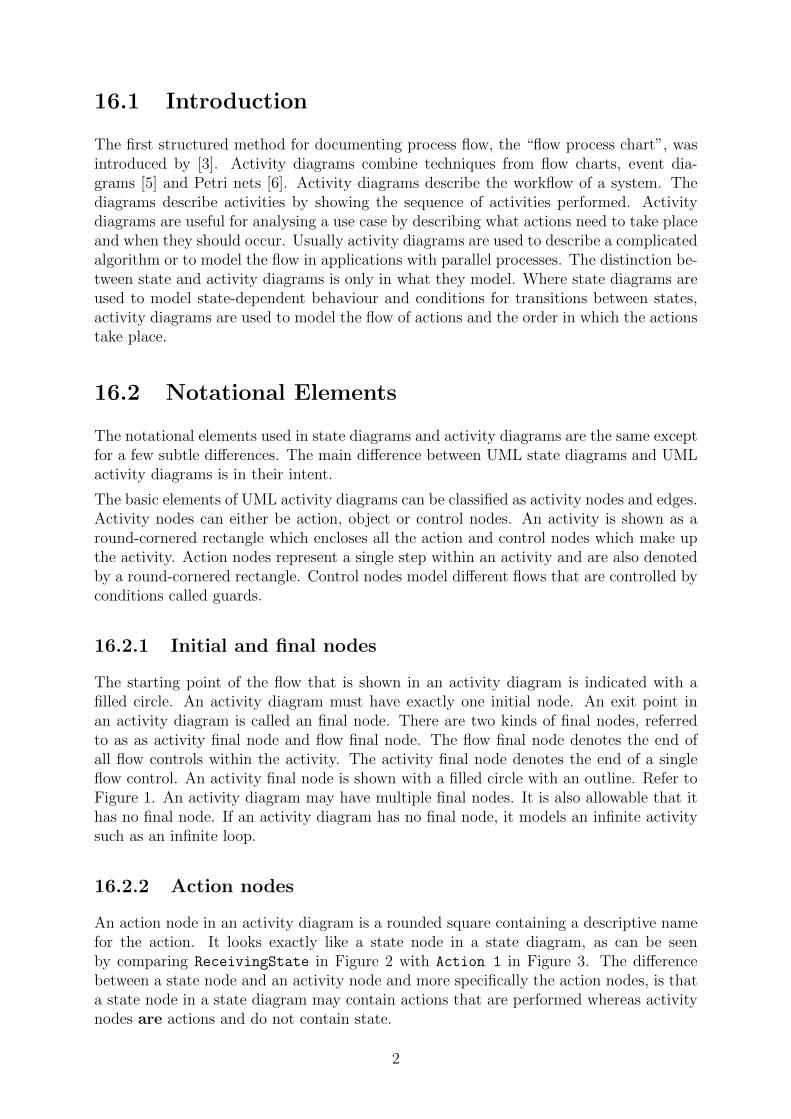
The starting point of the flow that is shown in an activity diagram is indicated with afilled circle An activity diagram must have exactly one initial node An exit point inan activity diagram is called an final node There are two kinds of final nodes referredto as as activity final node and flow final node The flow final node denotes the end ofall flow controls within the activity The activity final node denotes the end of a singleflow control An activity final node is shown with a filled circle with an outline Refer toFigure 1 An activity diagram may have multiple final nodes It is also allowable that ithas no final node If an activity diagram has no final node it models an infinite activitysuch as an infinite loop
1622 Action nodes
An action node in an activity diagram is a rounded square containing a descriptive namefor the action It looks exactly like a state node in a state diagram as can be seenby comparing ReceivingState in Figure 2 with Action 1 in Figure 3 The differencebetween a state node and an activity node and more specifically the action nodes is thata state node in a state diagram may contain actions that are performed whereas activitynodes are actions and do not contain state
2
Figure 1 Start and end nodes
A state van have activities An activity does not have states
Figure 2 The notational difference between states and activities
1623 Activity edge
An activity edge is an arrow indicating the flow between two activities as shown inFigure 3 The arrow points in the direction of the activity that has to execute nextOptionally activity edges may be named using text Usually there is no need to nameactivity edges When decision nodes (Section 1624) are used each activity edge exitingfrom the decision node should have a guard condition shown with text in square bracketsA guard condition indicates that the flow to the next activity may only be executed if thespecified condition is true Activity edges are similar to transition edges found in statediagrams An important difference is that a transition edge in a state diagram my bedecorated with an activity while it is not permissible to indicate an activity on an activityedge in an activity diagram
Figure 3 Activity edge
3
Figure 4 Model of a payment showing the use of decision and merge nodes
1624 Alternate flows
Alternate flows are shown by using decision and merge nodes Both these are shown asa diamond shape If different activity edges leave such shape it is a decision node Ifdifferent activity edges meet at the shape it is a merge node Figure 4 shows a diagramwith alternate flows The guards on the action edges leaving the decision node on theleft side of the figure specifies under what conditions each of these flows should executeIn this example there are three alternate flows depending on the kind of payment Bothcash and cheque payments requires some extra activity while the flow immediately pro-ceed to the clear debt activity if a credit card payment is made In the case of chequepayments the cheque is processed while cash payments require an update of the cashbalance before proceeding to the clear debt action It is important to note that only oneof the alternate flows may execute at any time Therefore the guards should be mutuallyexclusive In programming alternate flows represent conditional actions like in if andwhile statements
1625 Parallel flows
Parallel flows are shown by using fork and join nodes Both these are shown as a heavyvertical or horizontal line If different activity edges leave such line it is a fork nodeIf different activity edges meet at the line it is a join node Figure 5 shows a diagramwith parallel flows When a fork is reached in the flow all the activities to which theactivity edges that leave the fork point are executed at the same time using independentexecution threads This example models a shopping experience by a married coupleThey both enter the shop and then proceed each on a separate mission While the oneperson (probably the wife) picks up fruit then meat and then milk the other personmove directly to the news stand to pick up a news paper After both completed theirrespective actions they join and proceed to the till It is important to note that all theflows leaving a fork are executed in parallel In programming new threads are spawnedfor each parallel flow
1626 Composite activities
A composite activity is an activity that can itself be described in terms of an activitydiagram Sometimes composite activities are shown by drawing the diagram of its activi-
4
Figure 5 Fork and join nodes
ties inside the action node as shown in the right hand diagram in Figure 6 A compositeof which the sub-activities are not shown can be drawn using a rake symbol inside it asshown in the left hand diagram in Figure 6 Such sub-activity is called a called actionA called action is like a subroutine call in a program Called actions are often used toeliminate the need to draw the same sub-activity diagram in more than one place
1627 Swimlanes
Swimlanes are used to convey which class is responsible for a given activity A swimlaneis a vertical or horizontal zone in which the activities which are the responsibility ofa certain class are grouped Swimlanes are indicated using solid vertical or horizontallines to indicate a border between two swimlanes and labeling the zones The diagramin Figure 7 was adapted from [1] It illustrates the use of swimlanes In this diagramthe consultant is responsible for filling in the expense form and correcting it if neededThe accountant is responsible for validating such form and taking the appropriate actionswhile the payroll service is responsible for paying the employer of the consultant
163 Examples
1631 Finding and drinking a beverage
The activity diagram in Figure 8 comes from the UML 10 documentation and was repli-cated from [2] This diagram illustrates the interpretation of an activity diagram on aconceptual level
There parallel activities Put Coffee in Filter Add Water to Reservoir and Get Cups
may be interpreted to mean that these activities may be executed in any order or if pos-sible at the same time by interleaving them The synchronisation point indicated by thejoin node before Turn On Machine should be interpreted that the machine may only beturned on after both the putting the filter with coffee and putting water in the reservoirwas completed
5
Figure 6 Activities with sub-activities
Figure 7 Processing an expense
6
Figure 8 Finding and drinking a beverage
7
Figure 9 An activity diagram containing a loop
1632 Implementing code for an activity diagram
Activity diagrams can be translated into code Each activity node is either a programstatement or a function call If it is a function call it can be indicated using the rakesymbol Decision nodes represent conditional statements like if or switch If there issome transition from a later activity node back to a decision node it represents a loopstructure which can be implemented using a while-loop a for-loop or recursion
The activity diagram in Figure 9 contains a loop because the topmost decision node maybe reached a number of times The following code fragment is an implementation of thediagram in Figure 9 using a while-loop
int value = 22 while ( va lue gt minus5)
i f ( va lue lt 10)
value += 3 else
value minus= 16
1633 Activities based on age of the participant
From an implementation-perspective the activities shown in an activity diagram representmethods in classes To illustrate this we have created code to lsquoimplementrsquo the activities
8
Figure 10 Activities for people of different age groups
in the activity diagram in Figure 10 and came up with the following code
include ltiostreamgtinclude ltboost thread hppgt
using namespace std using namespace boost
void goBowling ( ) void bunjyJump ( ) void stayHome ( ) void study ( )
int main ( ) int age thread stayHomeThread = thread ( stayHome ) thread studyThread = thread ( study ) cout ltlt rdquo Please ente r your age rdquo c in gtgt age i f ( age gt 60)
goBowling ( ) else i f ( age gt 21)
bunjyJump ( ) else
9
stayHomeThread j o i n ( ) studyThread j o i n ( ) cout ltlt rdquo Act ions whi l e threads are running rdquo ltlt endl stayHomeThread detach ( ) studyThread detach ( )
void goBowling ( )
cout ltlt rdquoEnjoy the day p lay ing bowls rdquo ltlt endl
void bunjyJump ( )
cout ltlt rdquo Drive to the p r e c i p i c e rdquo cout ltlt rdquo attach the bunjy cord and jump rdquo ltlt endl
void stayHome ( )
cout ltlt rdquoStay Homerdquo ltlt endl
void study ( )
cout ltlt rdquoStudyrdquo ltlt endl
An article [4] that was written by the author of the BoostThreads library will get youstarted on installing and using this library and writing multi-threaded applications usingthe C++ programming language1
References
[1] SW Ambler Uml 2 activity diagramming guidelines httpwwwagilemodeling
comstyleactivityDiagramhtm 2009 [Online accessed 2011-09-09]
[2] Martin Fowler and Kendall Scott UML Distilled Applying the Standard Object Mod-eling Language Addison-Wesley Reading Mass 1997
1In this module you must be able to understand code using threads However it will not be expectedof you have to write such code yourself
10
[3] F B Gilbreth and L M Gilbreth Process charts first steps in finding the onebest way to do work Presented at the Annual Meeting of The American Society ofMechanical Engineers New York USA 1921
[4] William E Kempf The boostthreads library httpdrdobbscomcpp1844015182002 [Online Accessed 1 Sept 2011]
[5] James Martin and James J Odell Object-Oriented Analysis and Design PrenticeHall Inc Englewood Cliffs NJ 07632 1992
[6] James Lyle Peterson Petri Net Theory and the Modeling of Systems Prentice HallInc Englewood Cliffs NJ 07632 1981
11
- Introduction
- Notational Elements
-
- Initial and final nodes
- Action nodes
- Activity edge
- Alternate flows
- Parallel flows
- Composite activities
- Swimlanes
-
- Examples
-
- Finding and drinking a beverage
- Implementing code for an activity diagram
- Activities based on age of the participant
-
- References
-
161 Introduction
The first structured method for documenting process flow the ldquoflow process chartrdquo wasintroduced by [3] Activity diagrams combine techniques from flow charts event dia-grams [5] and Petri nets [6] Activity diagrams describe the workflow of a system Thediagrams describe activities by showing the sequence of activities performed Activitydiagrams are useful for analysing a use case by describing what actions need to take placeand when they should occur Usually activity diagrams are used to describe a complicatedalgorithm or to model the flow in applications with parallel processes The distinction be-tween state and activity diagrams is only in what they model Where state diagrams areused to model state-dependent behaviour and conditions for transitions between statesactivity diagrams are used to model the flow of actions and the order in which the actionstake place
162 Notational Elements
The notational elements used in state diagrams and activity diagrams are the same exceptfor a few subtle differences The main difference between UML state diagrams and UMLactivity diagrams is in their intent
The basic elements of UML activity diagrams can be classified as activity nodes and edgesActivity nodes can either be action object or control nodes An activity is shown as around-cornered rectangle which encloses all the action and control nodes which make upthe activity Action nodes represent a single step within an activity and are also denotedby a round-cornered rectangle Control nodes model different flows that are controlled byconditions called guards
1621 Initial and final nodes
The starting point of the flow that is shown in an activity diagram is indicated with afilled circle An activity diagram must have exactly one initial node An exit point inan activity diagram is called an final node There are two kinds of final nodes referredto as as activity final node and flow final node The flow final node denotes the end ofall flow controls within the activity The activity final node denotes the end of a singleflow control An activity final node is shown with a filled circle with an outline Refer toFigure 1 An activity diagram may have multiple final nodes It is also allowable that ithas no final node If an activity diagram has no final node it models an infinite activitysuch as an infinite loop
1622 Action nodes
An action node in an activity diagram is a rounded square containing a descriptive namefor the action It looks exactly like a state node in a state diagram as can be seenby comparing ReceivingState in Figure 2 with Action 1 in Figure 3 The differencebetween a state node and an activity node and more specifically the action nodes is thata state node in a state diagram may contain actions that are performed whereas activitynodes are actions and do not contain state
2
Figure 1 Start and end nodes
A state van have activities An activity does not have states
Figure 2 The notational difference between states and activities
1623 Activity edge
An activity edge is an arrow indicating the flow between two activities as shown inFigure 3 The arrow points in the direction of the activity that has to execute nextOptionally activity edges may be named using text Usually there is no need to nameactivity edges When decision nodes (Section 1624) are used each activity edge exitingfrom the decision node should have a guard condition shown with text in square bracketsA guard condition indicates that the flow to the next activity may only be executed if thespecified condition is true Activity edges are similar to transition edges found in statediagrams An important difference is that a transition edge in a state diagram my bedecorated with an activity while it is not permissible to indicate an activity on an activityedge in an activity diagram
Figure 3 Activity edge
3
Figure 4 Model of a payment showing the use of decision and merge nodes
1624 Alternate flows
Alternate flows are shown by using decision and merge nodes Both these are shown asa diamond shape If different activity edges leave such shape it is a decision node Ifdifferent activity edges meet at the shape it is a merge node Figure 4 shows a diagramwith alternate flows The guards on the action edges leaving the decision node on theleft side of the figure specifies under what conditions each of these flows should executeIn this example there are three alternate flows depending on the kind of payment Bothcash and cheque payments requires some extra activity while the flow immediately pro-ceed to the clear debt activity if a credit card payment is made In the case of chequepayments the cheque is processed while cash payments require an update of the cashbalance before proceeding to the clear debt action It is important to note that only oneof the alternate flows may execute at any time Therefore the guards should be mutuallyexclusive In programming alternate flows represent conditional actions like in if andwhile statements
1625 Parallel flows
Parallel flows are shown by using fork and join nodes Both these are shown as a heavyvertical or horizontal line If different activity edges leave such line it is a fork nodeIf different activity edges meet at the line it is a join node Figure 5 shows a diagramwith parallel flows When a fork is reached in the flow all the activities to which theactivity edges that leave the fork point are executed at the same time using independentexecution threads This example models a shopping experience by a married coupleThey both enter the shop and then proceed each on a separate mission While the oneperson (probably the wife) picks up fruit then meat and then milk the other personmove directly to the news stand to pick up a news paper After both completed theirrespective actions they join and proceed to the till It is important to note that all theflows leaving a fork are executed in parallel In programming new threads are spawnedfor each parallel flow
1626 Composite activities
A composite activity is an activity that can itself be described in terms of an activitydiagram Sometimes composite activities are shown by drawing the diagram of its activi-
4
Figure 5 Fork and join nodes
ties inside the action node as shown in the right hand diagram in Figure 6 A compositeof which the sub-activities are not shown can be drawn using a rake symbol inside it asshown in the left hand diagram in Figure 6 Such sub-activity is called a called actionA called action is like a subroutine call in a program Called actions are often used toeliminate the need to draw the same sub-activity diagram in more than one place
1627 Swimlanes
Swimlanes are used to convey which class is responsible for a given activity A swimlaneis a vertical or horizontal zone in which the activities which are the responsibility ofa certain class are grouped Swimlanes are indicated using solid vertical or horizontallines to indicate a border between two swimlanes and labeling the zones The diagramin Figure 7 was adapted from [1] It illustrates the use of swimlanes In this diagramthe consultant is responsible for filling in the expense form and correcting it if neededThe accountant is responsible for validating such form and taking the appropriate actionswhile the payroll service is responsible for paying the employer of the consultant
163 Examples
1631 Finding and drinking a beverage
The activity diagram in Figure 8 comes from the UML 10 documentation and was repli-cated from [2] This diagram illustrates the interpretation of an activity diagram on aconceptual level
There parallel activities Put Coffee in Filter Add Water to Reservoir and Get Cups
may be interpreted to mean that these activities may be executed in any order or if pos-sible at the same time by interleaving them The synchronisation point indicated by thejoin node before Turn On Machine should be interpreted that the machine may only beturned on after both the putting the filter with coffee and putting water in the reservoirwas completed
5
Figure 6 Activities with sub-activities
Figure 7 Processing an expense
6
Figure 8 Finding and drinking a beverage
7
Figure 9 An activity diagram containing a loop
1632 Implementing code for an activity diagram
Activity diagrams can be translated into code Each activity node is either a programstatement or a function call If it is a function call it can be indicated using the rakesymbol Decision nodes represent conditional statements like if or switch If there issome transition from a later activity node back to a decision node it represents a loopstructure which can be implemented using a while-loop a for-loop or recursion
The activity diagram in Figure 9 contains a loop because the topmost decision node maybe reached a number of times The following code fragment is an implementation of thediagram in Figure 9 using a while-loop
int value = 22 while ( va lue gt minus5)
i f ( va lue lt 10)
value += 3 else
value minus= 16
1633 Activities based on age of the participant
From an implementation-perspective the activities shown in an activity diagram representmethods in classes To illustrate this we have created code to lsquoimplementrsquo the activities
8
Figure 10 Activities for people of different age groups
in the activity diagram in Figure 10 and came up with the following code
include ltiostreamgtinclude ltboost thread hppgt
using namespace std using namespace boost
void goBowling ( ) void bunjyJump ( ) void stayHome ( ) void study ( )
int main ( ) int age thread stayHomeThread = thread ( stayHome ) thread studyThread = thread ( study ) cout ltlt rdquo Please ente r your age rdquo c in gtgt age i f ( age gt 60)
goBowling ( ) else i f ( age gt 21)
bunjyJump ( ) else
9
stayHomeThread j o i n ( ) studyThread j o i n ( ) cout ltlt rdquo Act ions whi l e threads are running rdquo ltlt endl stayHomeThread detach ( ) studyThread detach ( )
void goBowling ( )
cout ltlt rdquoEnjoy the day p lay ing bowls rdquo ltlt endl
void bunjyJump ( )
cout ltlt rdquo Drive to the p r e c i p i c e rdquo cout ltlt rdquo attach the bunjy cord and jump rdquo ltlt endl
void stayHome ( )
cout ltlt rdquoStay Homerdquo ltlt endl
void study ( )
cout ltlt rdquoStudyrdquo ltlt endl
An article [4] that was written by the author of the BoostThreads library will get youstarted on installing and using this library and writing multi-threaded applications usingthe C++ programming language1
References
[1] SW Ambler Uml 2 activity diagramming guidelines httpwwwagilemodeling
comstyleactivityDiagramhtm 2009 [Online accessed 2011-09-09]
[2] Martin Fowler and Kendall Scott UML Distilled Applying the Standard Object Mod-eling Language Addison-Wesley Reading Mass 1997
1In this module you must be able to understand code using threads However it will not be expectedof you have to write such code yourself
10
[3] F B Gilbreth and L M Gilbreth Process charts first steps in finding the onebest way to do work Presented at the Annual Meeting of The American Society ofMechanical Engineers New York USA 1921
[4] William E Kempf The boostthreads library httpdrdobbscomcpp1844015182002 [Online Accessed 1 Sept 2011]
[5] James Martin and James J Odell Object-Oriented Analysis and Design PrenticeHall Inc Englewood Cliffs NJ 07632 1992
[6] James Lyle Peterson Petri Net Theory and the Modeling of Systems Prentice HallInc Englewood Cliffs NJ 07632 1981
11
- Introduction
- Notational Elements
-
- Initial and final nodes
- Action nodes
- Activity edge
- Alternate flows
- Parallel flows
- Composite activities
- Swimlanes
-
- Examples
-
- Finding and drinking a beverage
- Implementing code for an activity diagram
- Activities based on age of the participant
-
- References
-
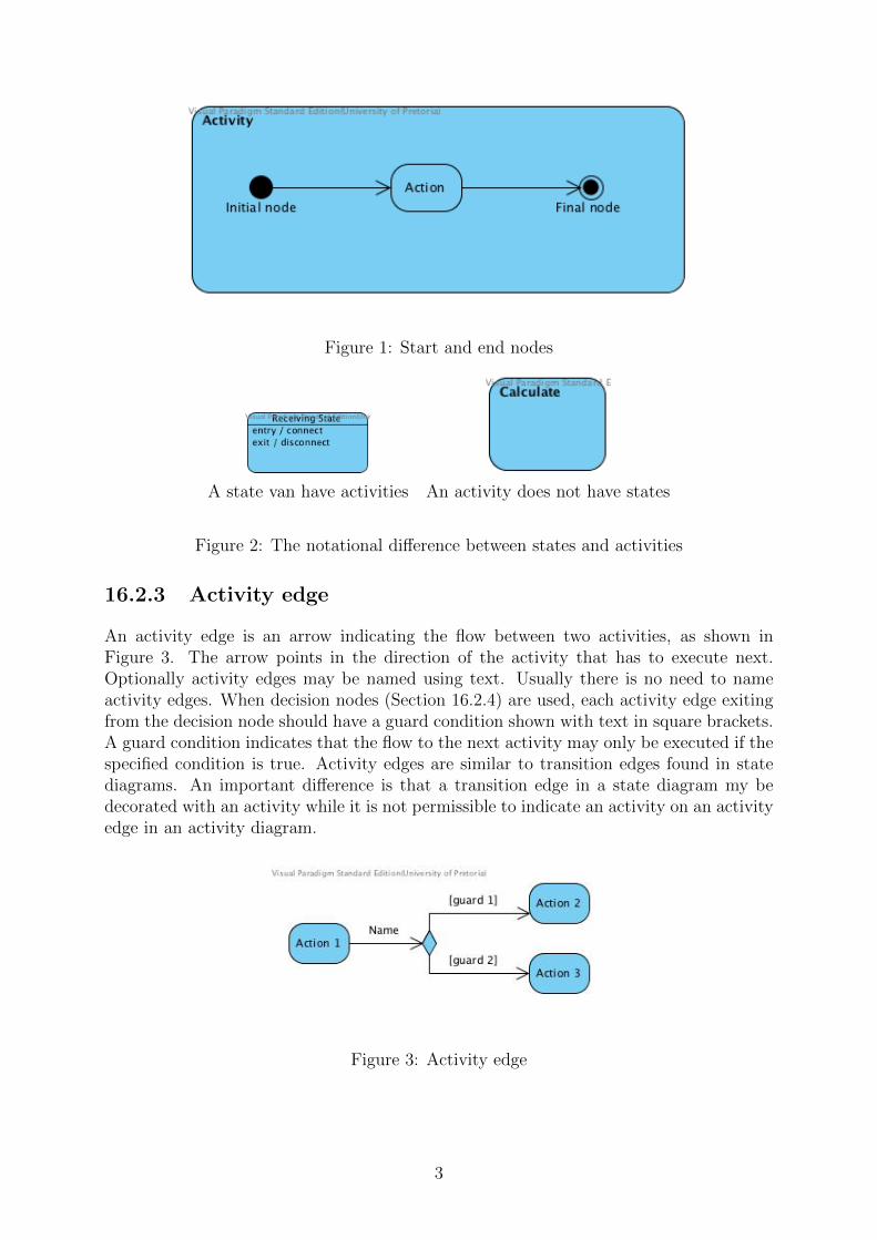
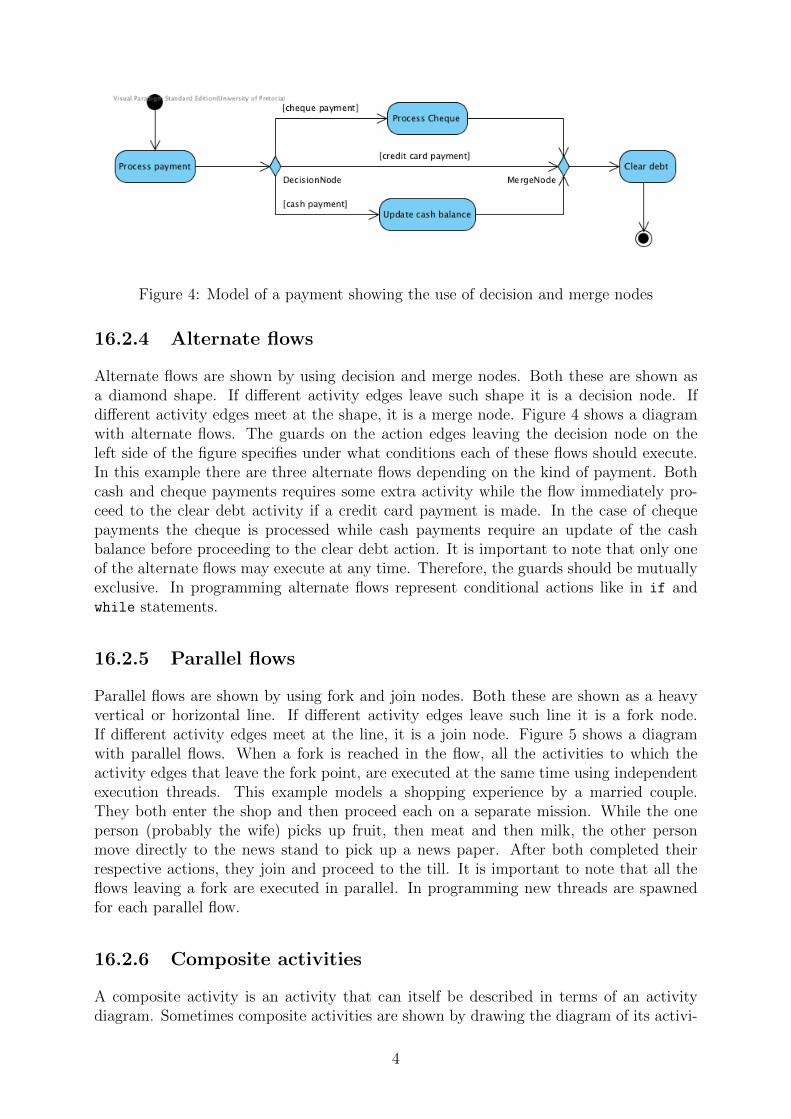
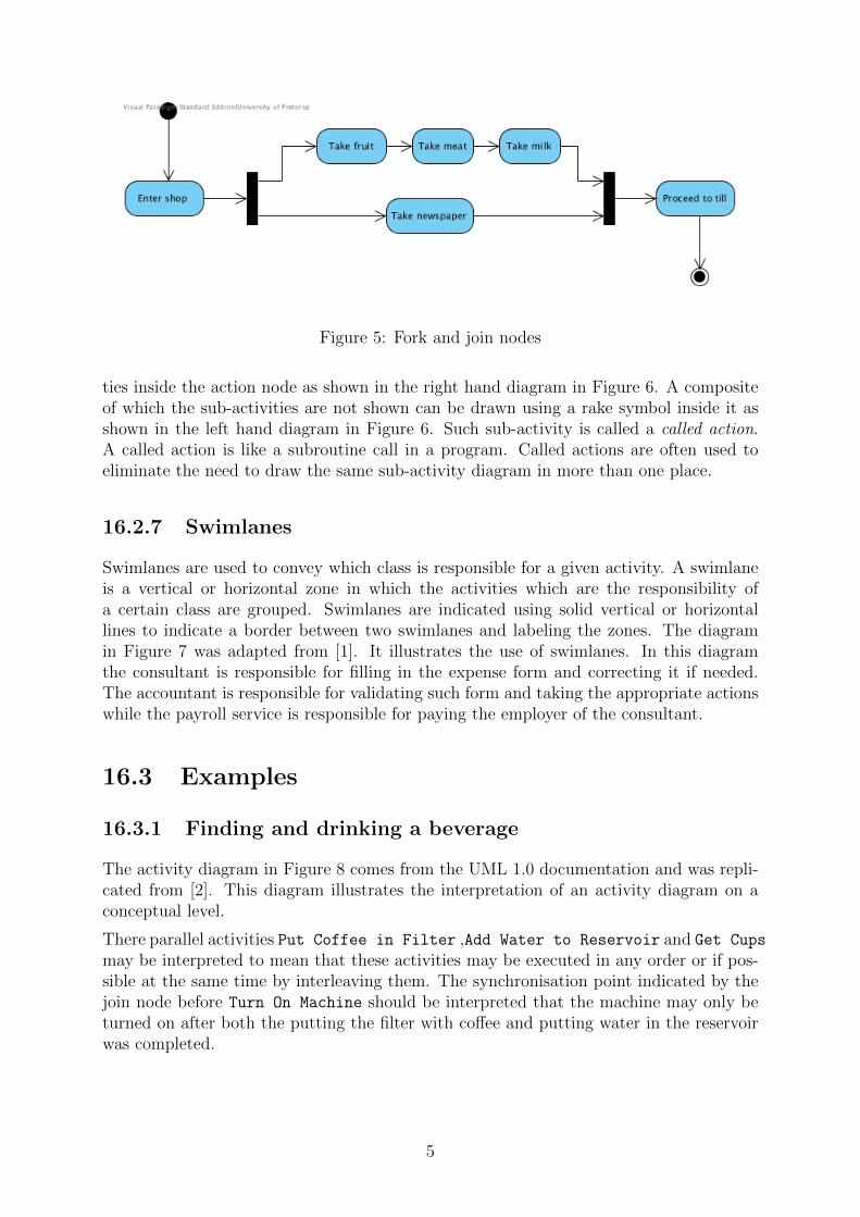
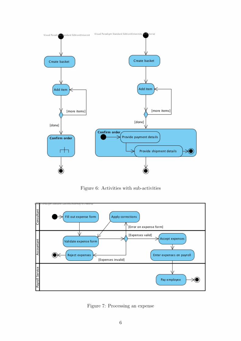
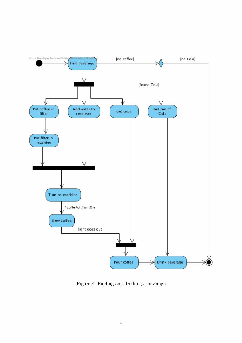
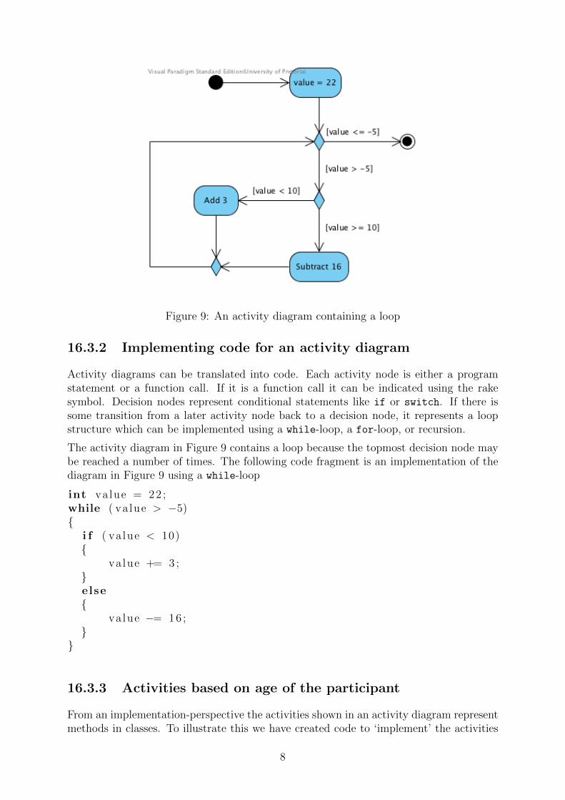
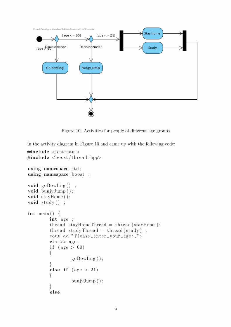