HDL code generation from UML/MARTE sequence diagrams for verification and synthesis
25
1 23 Design Automation for Embedded Systems An International Journal ISSN 0929-5585 Des Autom Embed Syst DOI 10.1007/s10617-014-9158-1 HDL code generation from UML/MARTE sequence diagrams for verification and synthesis Emad Ebeid, Franco Fummi & Davide Quaglia
Transcript of HDL code generation from UML/MARTE sequence diagrams for verification and synthesis

1 23
Design Automation for EmbeddedSystemsAn International Journal ISSN 0929-5585 Des Autom Embed SystDOI 10.1007/s10617-014-9158-1
HDL code generation from UML/MARTEsequence diagrams for verification andsynthesis
Emad Ebeid, Franco Fummi & DavideQuaglia

1 23
Your article is protected by copyright and all
rights are held exclusively by Springer Science
+Business Media New York. This e-offprint is
for personal use only and shall not be self-
archived in electronic repositories. If you wish
to self-archive your article, please use the
accepted manuscript version for posting on
your own website. You may further deposit
the accepted manuscript version in any
repository, provided it is only made publicly
available 12 months after official publication
or later and provided acknowledgement is
given to the original source of publication
and a link is inserted to the published article
on Springer's website. The link must be
accompanied by the following text: "The final
publication is available at link.springer.com”.

Des Autom Embed SystDOI 10.1007/s10617-014-9158-1
HDL code generation from UML/MARTE sequencediagrams for verification and synthesis
Emad Ebeid · Franco Fummi · Davide Quaglia
Received: 13 June 2013 / Accepted: 11 December 2014© Springer Science+Business Media New York 2015
Abstract Design of Embedded Systems is becoming more and more complex in terms ofverify that requirements are fulfilled at different design levels. This requires the simulation ofthe system and the checking of its timing and functional properties. model-driven design andUML give a reasonable solution to cope with such complexity since they have mechanismsto model and verify embedded systems. This paper presents a methodology which starts fromUML/MARTE sequence diagrams with timing constraints and the automatic generation ofexecutable SystemC/TLM and VHDL code with checkers from such diagrams. The simula-tion of the generated model allows to verify the specified sequence of exchanged informationbetween components while checkers allow to verify that properties and timing constraintsare met. Three case studies are used to show the validity of the approach and a less than linearincrease of execution time overhead due to time observation and assertion checkers.
Keywords Unified modeling language (UML) · Sequence diagram · MARTE · VSL ·HDL · Timing constraint
1 Introduction
In the last years, model-driven design and Unified Modeling Language (UML) [17] havegained an increasing interest for electronic system design as a platform independent mod-eling [22]. Several UML profiles have been proposed (e.g., the UML for SoC [24] andUML 2.0 profile for SystemC [20]) to model hardware components at UML level and togenerate code from such level. The most comprehensive effort towards this issue is a UML
E. Ebeid (B)Aarhus University, Aarhus, Denmarke-mail: [email protected]
F. Fummi · D. QuagliaUniversity of Verona, Verona, Italye-mail: [email protected]
D. Quagliae-mail: [email protected]
123
Author's personal copy

E. Ebeid et al.
profile to support all the requirements for real-time, embedded system design (i.e., func-tional and non-functional aspects of embedded systems). This profile is named Modelingand Analysis of Real-time and Embedded Systems (MARTE) [18] and it introduces a way toexpress timing properties in UML diagrams. One of the most commonly used UML diagramin the modeling of real-time embedded systems is named sequence diagram. Sequence dia-gram expresses the application functionality, the interactions between different componentsand allows to specify “time-invariants”.
Code generation from UML diagrams is a growing area of interest due to its benefitsof verifying UML models by simulation. In the same context, there are several works[15,25] and commercial tools [3,9,19,21] to generate source code from UML specifications tomainstream languages, such as C++, SystemC and Java.
Moreover, with UML, it is possible for the designers to specify the structure and function-ality of interacting components which could be implemented as either SW or HW [11]. There-fore, UML approach for “Model-Driven Architecture” fits well with the trends in embeddedsystem design towards a kind of HW-SW codesign [6]. Thus, the system functionality can becaptured separately from, and independently of any possible architectural implementation.Another advantage of UML-based specification is that both HW and SW components can behandled in the same UML description from which platform-optimized code can be generatedand simulated (e.g., within SystemC-based transaction level platform).
What is missing in this context is a design methodology:
– to generate code from sequence diagrams for verification and synthesis;– to express timing observations and to check constraints inside the executable code;– to generate checkers from invariants and time constraint.
The proposed work aims at filling these gaps by:
– showing the rules for the automatic generation of HDL code (i.e, SystemC/TLM andVHDL) from UML sequence diagrams;
– creating new components (e.g. C++ classes and VHDL components) to manage timeobservations and their evaluation;
– finding a strategy to generate checkers from UML invariants and MARTE time constraintsas well as to put them in the right position inside the generated code.
The paper is organized as follows. Section 2 shows the proposed methodology to modeland validate embedded systems. Section 3 explains the previous literature of this topic.Section 4 introduces the modeling languages and UML sequence diagrams which are usedin this work to describe and validate the embedded system design. Section 5 presents theproposed transformation rules to validate by simulation the high level embedded systemmodels functionality and that by generating an executable (SystemC/TLM and VHDL) codefrom such models. Section 6 experimentally validates the methodology by applying it to threecase studies related to building-automation applications. Section 7 draws some conclusions.
2 Proposed methodology
This section shows the proposed methodology which are used to model and validateUML/MARTE diagrams. The whole verification flow derived from this approach is depictedin Fig. 1. The starting point is UML/MARTE sequence diagrams which describe both thebehavior of the system (in terms of data exchanging between components) and the constraintsto satisfy. From this description, both SystemC/TLM and VHDL models are generated. This
123
Author's personal copy

HDL code generation from UML/MARTE sequence diagrams
Fig. 1 Proposed verification andsynthesis flow fromUML/MARTE sequence diagram
contains the assertion calls to check constraints. Nevertheless, the generated code is notenough for simulation since sequence diagrams specify data exchange between entities butnot the processing code inside them; therefore, these entities should be linked to libraryof Intellectual Property (IP) cores available. Simulation takes as input a suitable set of testbenches and generates a trace in which failed constraints are reported. As a result of theverification process, on one hand, new information are obtained from the simulation and ituses to refine the UML models and their constraints. On the other hand, the generated VHDLcode is synthesized into hardware components (e.g. Field-Programmable Gate Array (FPGA)chip) to obtain the actual implementation of UML application.
The motivation of having two paths is two-folds: (1) to have a fast validation of thehigh-level model (i.e., UML) by mapping it into a high level executable language such asSystemC/TLM. (2) to have an accurate implementation of such model on HW platform (e.g.,on FPGA). Direct transformation from UML to VHDL allows to preserve the conceptualseparation between functional code and the checkers. While, converting UML to VHDL viaSystemC does not guarantee the correct mapping between their checkers since it relies ona third-party tool which is unaware about these checker specifications. Moreover, when thedesigner is writing in VHDL and keeping the coding style, VHDL lets the designer to controlthe logic implementation while automatic synthesis tools perform manipulation which leadsto resource wasting (chip area) and the generated code is hard to be modified [12].
3 State of the art
This section presents what has been already achieved in the generation of HDL code fromUML diagrams.
123
Author's personal copy

E. Ebeid et al.
Related to SystemC/TLM; in [25], the code generation problem was firstly investigated;authors presented a bi-directional UML-SystemC translation tool and a set of principlesto model SystemC designs in UML. Authors used UML class diagrams and state chartsfor modeling the structural and behavioral parts of the system, respectively . Similar tothe approach of the previous work, authors in [16] presented a framework for direct codegeneration from UML. They took the UML model as Metadata Interchange file for thetranslation into SystemC/TLM. They mentioned the importance of sequence diagrams inthe design of embedded systems without showing the way to generate code from it. In [20]authors proposed UML 2.0 profile for SystemC which provides a graphical entry to SystemCdesigners, with a special attention to the code generation and back annotation capabilities.They mentioned the usefulness of sequence diagrams in test bench modeling. Habibi et al. [7]presented an approach to design and verify SystemC models at the transaction level. Theyproposed an approach to translate the UML model with Property Specification Languageinto an intermediate representation (e.g. state machine) for model checking. They used UMLsequence diagrams to capture transaction-related system properties. On the contrary, theyhave used very low level details (e.g. clock signals) to model timing expressions at a veryabstract level (i.e. UML).
Related to VHDL; there are very few works addressing the automatic VHDL code gen-eration from UML diagrams. In [13], authors presented the mapping rules between UMLdiagrams and VHDL [10], as a common and structured environment for system documen-tation and specification. They used UML class and state charts diagrams for capturing thestructural and behavioral aspects, respectively. In [14], authors presented a methodology toautomatically generate VHDL code from UML specification. This work is considered as afirst contribution in the generation of a simulatable model of the system from UML. They usedUML state chart for expressing class behavior. However the generation of code describingsystem behavior is not enough for its verification since assertions should be also generated,i.e., code which checks system properties and eventually rises warning messages.
In the same context, HDL verification libraries such as Open Verification Library (OVL) [1]developed to verify properties of embedded system designs. OVL consists of a set of assertioncheckers that verify specific properties of the design and its checkers are instantiated in Verilogand VHDL modules/entities. Actually, OVL library does not cover all kinds of assertion andit lacks support for time and duration constraints (e.g. ovl_time checks the value of anexpression for a specified number of cycles) which are useful in the transformation fromUML sequence diagram.
4 Background
This section provides an overview about UML and MARTE profile, MARTE expressionlanguage, UML sequence diagrams, SystemC/TLM, VHDL and HIF modeling languageswhich are used in this research.
4.1 UML/MARTE and VSL
Common Behavior package [17] is a UML package which defines a Simple Time modeland provides a syntax to represent time and duration expressions as well as a mechanism torepresent event observations with time marks. MARTE [18] is a UML profile intended formodel-based development of real-time and embedded systems. MARTE provides a languagenamed Value Specification Language (VSL) to specify the values of constraints, properties,
123
Author's personal copy

HDL code generation from UML/MARTE sequence diagrams
Fig. 2 Syntax elements of UML sequence diagrams
and stereotype attributes particularly related to non-functional aspects such as time. VSLis based on Tagged Value Language and OCL and provides specification for mathematicalexpressions (arithmetic, logical, etc) and time expressions (delays, periods, trigger conditions,etc). MARTE extends UML and deals with VSL to support specification expressions. In fact,VSL can be used in tagged values, body of constraints, and in any UML element associatedwith value specification.
Time expression package (VSL::TimeExpressions) is one of the VSL sub-packageswhich presents specialized syntax for time value specifications and adds textual capabilitiesto represent time related expressions.
VSL’s Time Expression model improves UML with different capabilities; for instance,the i-th occurrence of a given event can be expressed by an occurrence index; durationobservations and the jitter (i.e., the standard deviation) of a sequence of occurrences of thesame event can be used inside expressions. The idea of using MARTE expression languagewith UML sequence diagrams is to open the way to model timing expressions, observationconcepts and constraint specification.
4.2 Sequence diagrams
It is a UML behavior diagram that shows how data is exchanged between process instancesand in which order [26]. As depicted in Fig. 2 a sequence diagram shows objects interactionsarranged in a time sequence. It depicts the objects involved in the scenario and the sequence ofmessages exchanged between them to carry out the functionality of the scenario. A sequencediagram annotated with constraints expressed in a language like Object Constraint Language(OCL) [8] can be the basis for communication protocol specification.
4.3 SystemC/TLM
Transaction-level modeling (TLM) is a high-level approach to model digital systems wheredetails about the communication among modules are separated from the implementation
123
Author's personal copy

E. Ebeid et al.
details of functional units [23]. Two modeling styles are defined in TLM 2.0, i.e., LooselyTimed and Approximated Timed. The Loosely Timed modeling style is targeted for systemand platform models, where data and timing are loosely connected. TLM2.0 defines twotiming points, the start time and the end time of a transaction. Blocking transport interfaceb_transport is devoted to support this kind of modeling style. Approximated Timed (AT)is used for models where the dependency of data and timing is very strong. The AT modelingstyle defines four timing points for a transaction, i.e., begin request, end request, beginresponse and end response. Non-blocking transport interface nb_transport is devotedto support this kind of modeling style.
4.4 VHDL
It is a design language that has been created and optimized to describe the behavior ofdigital systems which can be synthesized and implemented as hardware components onfield-programmable gate arrays. VHDL is commonly used to write text models that describea logic circuit. Such a model is processed by a synthesis program to generate the actualhardware implementation. Assertions are modeled and tested in VHDL based on Booleanconditions and if the condition is false, a warning message is generated. Moreover, In the lastyears VHDL has become crucial to simplify the hardware design and verify the behavior ofthe modeled systems by simulation.
4.5 HIF
Heterogeneous Intermediate Format (HIF) [4] is a HW/SW description language structuredas XML tree of classes. Each class describes a specific component or functionality that istypically provided by Hardware Description Languages (HDL) like VHDL, Verilog, and Sys-temC. It provides designers with a convenient way for automatically manipulating HW/SWdescriptions.
To make use of that language in embedded system design, a tool named HIFSuite [5]has been created. It allows designers to manipulate and integrate heterogeneous componentsimplemented by using different hardware description languages. Therefore, HIFSuite consistsof a set of tools and an application programming interface that allows a import/export ofmodels into HIF and their manipulation.
5 UML/MARTE code generation
The following subsections introduce the syntax elements of the sequence diagrams anddescribe the transformation rules which are used to generate SystemC/TLM and VHDL code.
5.1 Model and constraint specifications
Figure 2 shows the syntax elements of a sequence diagram; numerical labels are used todenote the items to be explained.
Lifeline objects (label 1 and 2) interact by exchanging messages. Each message (3,4)represents either a message transfer or the corresponding reply. Transfers can be either syn-chronous (3) or asynchronous (4). Execution specification (5) represents the execution of aunit of behavior or action within the lifeline. Combined fragment is a logical grouping (6)which contains the control structures that affect the flow of messages. A combined frag-ment contains interaction operands and it is defined by the interaction operator (i.e., loop,
123
Author's personal copy

HDL code generation from UML/MARTE sequence diagrams
Fig. 3 VSL-based time expressions and constraints in UML sequence diagrams
alternative, sequence, etc.). Furthermore, Lifeline is not allowed to transfer more than onemessage at the same time.
Figure 3 shows the modeling of duration and timing constraints; numerical labels areused to denote the items to be explained. There are two kinds of constraints, local constraintfor single observation point (10) and global constraint for different observation points (8).TimeObservation (7) is the reference to a given time instant during the execution. TimeEx-pression (8) is used to represent a time value. TimeConstraint (9) represents a constraint thatrefers to the range between two time expressions named TimeIntervalMin (10) and TimeIn-tervalMax (11). DurationObservation (12) represents the time spent to transfer the messageto whom it is applied. DurationConstraint can be defined with respect to either a constant(13) or a range between two values named DurationIntervalMin (14) and DurationInterval-Max (15). StateInvariant (16) is a constraint placed on a lifeline that must be true at thegiven point. Timing expression package of VSL introduces the basis to write time-relatedexpressions. For example, InstantExpression is a time expression that denotes a time instantvalue, DurationExpression is a time expression that refers to a duration value, JitterExpres-sion denotes the time variation in a sequence of event occurrences. Section 6 describes anexample which shows the practical use of this package.
5.2 Generation rules
Based on the semantics of UML sequence diagrams [17], VSL [18], SystemC/TLM [23]and VHDL [10], we propose a set of mapping rules between UML sequence diagrams withMARTE expression language and the corresponding SystemC/TLM and VHDL modelinglanguages. These rules are described below and numerical labels in Figs. 2, 3 are used todenote the item to be explained.
5.2.1 UML to SystemC/TLM
The following rules have been set to generate SystemC/TLM code from UML/MARTEsequence diagrams;
123
Author's personal copy
E. Ebeid et al.
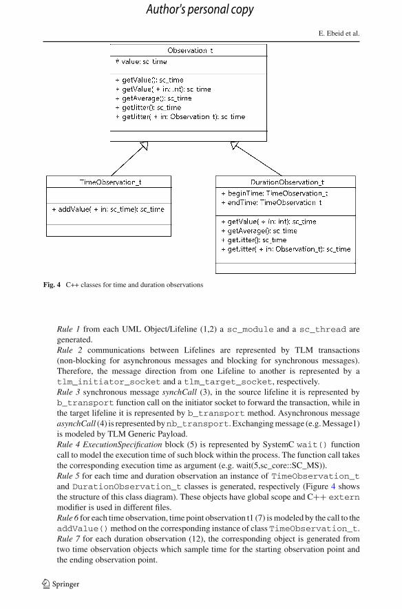
Fig. 4 C++ classes for time and duration observations
Rule 1 from each UML Object/Lifeline (1,2) a sc_module and a sc_thread aregenerated.Rule 2 communications between Lifelines are represented by TLM transactions(non-blocking for asynchronous messages and blocking for synchronous messages).Therefore, the message direction from one Lifeline to another is represented by atlm_initiator_socket and a tlm_target_socket, respectively.Rule 3 synchronous message synchCall (3), in the source lifeline it is represented byb_transport function call on the initiator socket to forward the transaction, while inthe target lifeline it is represented by b_transport method. Asynchronous messageasynchCall (4) is represented bynb_transport. Exchanging message (e.g. Message1)is modeled by TLM Generic Payload.Rule 4 ExecutionSpecification block (5) is represented by SystemC wait() functioncall to model the execution time of such block within the process. The function call takesthe corresponding execution time as argument (e.g. wait(5,sc_core::SC_MS)).Rule 5 for each time and duration observation an instance of TimeObservation_tand DurationObservation_t classes is generated, respectively (Figure 4 showsthe structure of this class diagram). These objects have global scope and C++ externmodifier is used in different files.Rule 6 for each time observation, time point observation t1 (7) is modeled by the call to theaddValue()method on the corresponding instance of class TimeObservation_t.Rule 7 for each duration observation (12), the corresponding object is generated fromtwo time observation objects which sample time for the starting observation point andthe ending observation point.
123
Author's personal copy

HDL code generation from UML/MARTE sequence diagrams
Table 1 Mapping betweenUML/MARTE sequence diagramand SystemC/TLM elements
UML/MARTE SystemC/TLM
Lifeline sc_thread()
Object sc_module()
Message tlm_initiator_socket<> /
tlm_target_socket<>
SynchCall b_transport()
AsynchCall nb_transport()
ExecutionSpecification wait(rand())
Combined fragment C++ statement
Constraints sc_assert()
TimeObservation TimeObservation_t t1
DurationObservation DurationObservation_t d1
Event observation (t1) t1.getValue()
Instant time observation (t1[i]) t1.getValue(int i)
Jitter (t1) t1.getJitter()
Jitter (t2-t1) t1.getJitter(t2)
Duration time (d1) d1.getValue()
Global constraint global_constraints1 gc;
gc.check_validity()
StateInvariant sc_assert(p==2)
Rule 8 SystemC assert statement sc_assert() is also used to check the constraintvalidity (e.g. sc_assert (d1.getValue()≤ sc_time(1,SC_MS)) and it gen-erates a log message when the condition is false. Furthermore, sc_assert() is usedto model UML StateInvariant (16).Rule 9 constraints are checked after the observations of all the input variables (e.g., t1,t2, d1, etc.) have been performed.Rule 10 a global object is created to model global constraints (e.g. the constraint labeledby (8)). For each global constraint, this object has a function which is called after lasttiming or duration observation is performed to assure the constraint consistency.Rule 11 combined fragment such as optional, alternative, parallel, and loop are repre-sented by pure C++ statements such as if...else, for...loop, etc..
These rules allow a complete transformation of the main sequence diagram elements withtime constraints to SystemC/TLM code. Table 1 summarizes these transformation rules.
5.2.2 UML to VHDL
Direct mapping from sequence diagram elements to VHDL code is not a sufficient way asit was in TLM case since there are some corner cases which can not be converted directly.Figure 5a shows a case which has a discontinuity between the sequence of messages andFig. 5b shows the generation of the corresponding EFSM.
Therefore, Extended Finite-State Machine (EFSM) is used as an intermediate componentto achieve a consolidate transformation of sequence diagram. EFSM is a finite state machinewith enabling and update functions associated to its transitions [2]. Figure 6 shows the position
123
Author's personal copy

E. Ebeid et al.
Fig. 5 Formalization of UML sequence diagram by using EFSM. a UML sequence diagram of a case studyand b The corresponding EFSM
of EFSM in the structure of VHDL description. EFSM models the flow of messages betweendesign components (later explain in detail).
Figure 6 gives an overview of the main transformation rules. Each sequence diagramobject is transformed into a VHDL entity and interactions between lifelines with constraintsare represented by the evolution of an EFSM implemented in the controller while jitterconstraint is modeled as a separate component. Moreover, EFSM mechanism fits the samemechanism of the sequence diagram interactions and Sect. 6 describes this point by usingactual case study. The internal device functionality, has been modeled by using UML classdiagrams and in [14] shows the rules of generating VHDL description from correspondingUML diagrams.
The following rules have been set to generate VHDL code from UML/MARTE sequencediagrams and Figs. 2, 3 show UML/MARTE elements to be converted;
Rule 1 each UML lifeline object is represented by VHDL COMPONENT consisting ofENTITY for object (1) and ARCHITECTURE for lifeline (2).Rule 2 communication flows (i.e., asynchronous and synchronous messages) betweenlifelines are represented by EFSM transitions. Therefore, the message direction from
123
Author's personal copy

HDL code generation from UML/MARTE sequence diagrams
Fig
.6M
ain
map
ping
rule
sbe
twee
nU
ML
sequ
ence
diag
ram
san
dV
HD
Lel
emen
ts
123
Author's personal copy

E. Ebeid et al.
one lifeline to another is represented by two VHDL signals one named SIGNALcurrent_state for the source lifeline and the other named SIGNAL next_statefor the destination lifeline.Rule 3 synchronous message synchCall (3) is represented by 2 transitions one fromSIGNAL current_state to SIGNAL next_state and the other from SIGNALnext_state to SIGNAL current_state while asynchronous message asynch-Call (4) is represented by one transition from SIGNAL current_state to SIGNALnext_state.Rule 4 ExecutionSpecification (5) is represented by a PROCESS() function and it takesthe corresponding execution time and models it as a delay component of this process(e.g. preset counter).
For constraint modeling, VHDL control path component (efsm_controller) has been cre-ated for observation and constraints checking.
Rule 5 for time observation, time point observation t1 (7) is modeled by EFSM SIGNAL.Each observation point represented as a signal or bus of EFSM ENTITY with countersignal to count the observation time.Rule 6 in UML, duration observation (12), is defined by using two points i.e., Message-Send and MessageRecv. In VHDL it is represented by two internal signals of EFSMarchitecture, one for the starting observation point and the other for the ending obser-vation point. Therefore, MessageSend is modeled as signal t1_0: unsigned ofEFSM architecture and MessageRecv is modeled as signal t1_1: unsigned ofEFSM architecture and the duration observation is the difference between those signals.The structure of EFSM will be explained in details in the next paragraph.Rule 7 assertions are used to model constraints, VHDL assert statement assert()severity ; is used to check the constraint validity (e.g. assert Not(delay-SPI>5) severity failure;) and it triggers when the condition is false. Further-more, assert() is used to model UML StateInvariant (16).Rule 8 UML time and duration global constraints (8) are modeled as VHDL global actionstatements.Rule 9 each time unit is normalized by the system clock signal which has the highestfrequency of the whole system; for instance, if the frequency of system clock signal is1 MHz and the constraint time is (10,us) then this constraint will be normalized as 10.Rule 10 jitter is computed by a separate component which takes data from jitter observa-tion point inside controller, counts the number of iterations and it provides the controllerwith jitter value for this observation point.Rule 11 combined fragment such as optional, alternative, parallel, and loop are repre-sented by pure VHDL statements such as if...else, for...loop, etc..
The generation of EFSM is shown in Fig. 5b which consists of the following cases:
– Each lifeline object is represented by a state as shown under label (r1).– Each message call from X object to Y object is represented by two transition, one from
X state to Y state and the other from Y state to the source of the next message call. Label(r2) shows this step.
– Each message will have a unique ID which will be generated by a counter and the ID isattached in EFSM transition condition as shown in Fig. 5 under label (r3).
– Observation points are bound with message IDs in EFSM for achieving its requirementsas shown under label (r4).
123
Author's personal copy

HDL code generation from UML/MARTE sequence diagrams
Table 2 Mapping betweenUML/MARTE sequence diagramand VHDL elements
UML/MARTE VHDL
Object Component structure
Lifeline ARCHITECTURE
ExecutionSpecification PROCESS()
Message EFSM states / transitions
Combined fragment VHDL statement
TimeObservation EFSM SIGNAL t1 with counter SIGNAL
DurationObservation (t1_1–t1_0)
Jitter Jitter COMPONENT
Constraints assert()
Global constraint assert() at global action statement
StateInvariant assert(p=2)
– For constraints transformation, a new state is added to depict the behavior of constraintcheck as state (w) in Fig. 5. The constraint statement is translated into a transition con-dition. Label (r5) shows the transformation between them.
– Loop is modeled as a new transition condition as shown under label (r6).
These rules allow a complete transformation of the main sequence diagram elements withtime constraints into VHDL code. Table 2 summarizes the mapping between the mainUML/MARTE sequence diagram elements and VHDL elements.
5.2.3 UML2HIF
For automatic code generation, UML2HIF front-end tool has been developed. It parses XMLdescription of UML sequences diagram and generates a corresponding components in theintermediates description (HIF) (see Sect. 4.5 ). Then, HIFSuite [5] back-end tools are usedto translate HIF description to the target HDL code. HIF2SC back-end tool for generatingSystemC/TLM code and HIF2VHDL back-end tool for generating VHDL code.
6 Experimental validation
The approach has been validated on three case studies, the first two cases are related tothe model of a Wireless Sensor Node (WSN) while the third case study is about buildingautomation application. The first and second cases show the generation of SystemC modelsfrom the UML description of the software part of WSN and VHDL models from the UMLdescription of the hardware part of WSN, respectively. Third case shows the generation ofVHDL code from a complex UML scenario of building automation application which has adiscontinuity between the sequence of messages.
Among different tools for UML modeling, Papyrus [21] has been used in this work for itssupport of the latest MARTE sub-profiles and the exporting mechanism to XML.
6.1 SystemC/TLM code generation of WSN application (Case study #1):
WSN is implemented by connecting the Radio Frequency (RF) module to the CPU through theSerial Peripheral Interface (SPI). RF model implements the IEEE 802.15.4 stack and provides
123
Author's personal copy

E. Ebeid et al.
Fig. 7 UML sequence diagram of the SW part of WSN case study with VSL constraints
an application programming interface through the SPI interface to let CPU send/receive datato/from other wireless sensor nodes. The wireless protocol has an over-the-air data rate of250 kb/s and the maximum payload is 104 byte. To model a realistic scenario, a further objectnamed NW NODE has been introduced to reproduce 802.15.4 network traffic.
As depicted in Fig. 7, a sequence diagram with MARTE VSL is used to model the spec-ification and time constraints of the SW part of the WSN application. At the beginning,CPU sends data to SPI with a non-blocking transfer whose maximum duration is constrainedto 5 ms (1). SPI receives data and processes it in a time interval which is constrained tobe between 1 and 3 times the duration of the data transfer (2). The RF module receives asequence of bits from SPI with at least 0.33 µs between them (3) and then it collects bitsinto bytes and bytes into frames to be sent over the network with a blocking transfer. There-fore, RF sends frames to the network and the max duration of data transfer is constrainedto 3.328 ms (4). The duration between sending data by the RF module and the completehandling of the reply is constrained to a maximum time of 4 µs (5). Intervals with squaredbrackets for bound specification are used to write this constraint. A jitter constraint is alsoattached to the duration of this data transfer, limiting its deviation to a value shorter than10 µs (6).
SystemC/TLM code is generated from the UML sequence diagram; some portions of thegenerated code are reported as follows:
//Specification part:tlm::tlm_initiator_socket<> initiatorRF; //send message.tlm::tlm_target_socket<> targetRF; //receive message.RF::RF(sc_module_name RF) : sc_module(RF) //RF object.SC_THREAD(send); //RF Lifeline.tlm::tlm_sync_enum RF::nb_transport_fw //Asynchronous call.tlm::tlm_sync_enum RF::nb_transport_bw //Asynchronous call.void NW_NODE::b_transport(tlm:: tlm_generic_payload & trans, sc_time &t) //Synchronous call.
123
Author's personal copy

HDL code generation from UML/MARTE sequence diagrams
1
10
100
1000
0 10 20 30 40 50
Exec
utio
n tim
e (s
)
# of constraints
experimental datalinear trend
Fig. 8 SystemC execution time of WSN case study as a function of the number of checked constraints
//Constraints part:sc_assert(d1.getValue() >= (sc_time(0,SC_MS)) && d1.getValue() <
(sc_time(5,SC_MS)); //Constraint #1.sc_assert (sc_time_stamp() >= d1.getValue() && sc_time_stamp() <=3*d1.getValue()); //Constraint #2.sc_assert((t1.getValue(t1.getSize())− t1.getValue(t1.getSize()−1)) >
(sc_time(0.33,SC_US))); //Constraint #3.sc_assert(d2.getValue() <= (sc_time(3.328,SC_MS))); //DurationConstraint #4.sc_assert((sc_time_stamp() > t0.getValue()) && sc_time_stamp() <=(t0.getValue()+(sc_time(0.024,SC_SEC)))); //Constraint #5.sc_assert(t2.getJitter() <= (sc_time (10,SC_US))); //Constraint #6.
6.1.1 Constraint checking
Experiments have been performed on Intel core i5-2520M CPU @ 2.50GHz and VMware vir-tual machine running the Linux Ubuntu 11.04 with 2.6.38-8 kernel. The testing environmentconsists of gcc 4.5.2, SystemC 2.2.0 and TLM-2009-07-15. To evaluate the overhead broughtby constraint checking, the execution time of the generated SystemC model was evaluatedwithout constraint checking and with an increasing number of constraints (through duplica-tion of the Constraint1 assertion and the corresponding time observations). Results areshown in Fig. 8; the execution of the SystemC model without constraint checking takes about2.4 s while the there is an overhead due to time observations and assertion checking whichdepends on the number of constraints and on the number of observation variables for eachof them; in the experiment the execution time trend which is less than linear.
6.2 VHDL code generation of WSN application (Case study #2):
As depicted in Fig. 9, a sequence diagram with MARTE VSL is used to model the specifi-cation and time constraints of he HW part of the WSN application, respectively; numericallabels are used to denote the item to be explained. At the beginning, Data Source sends datato SPI with a non-blocking transfer whose maximum duration is constrained to 50 ms (1).
123
Author's personal copy

E. Ebeid et al.
Fig. 9 UML sequence diagram of the HW part of WSN case study with VSL constraints
SPI receives data and sends bits to RF with a blocking transfer in a time interval which isconstrained to be between 1 and 3 times the duration of the data transfer (2). The RF modulereceives a sequence of bits from SPI with at least 33 µs between them (3). In addition, jitterconstraint is also attached to the RF unit limiting the deviation of bit arrival time to a value≤10 µs (4). VHDL code has been generated from UML sequence diagram which describesthe interactions between application components. Figure 10 shows the generated structuralVHDL block diagram with constraints. It consists of two parts, one for data path and theother for control path with checkers. Jitter computation is modeled as a separate componentwhich takes inputs from fsm_controller component and provides the jitter value as an out-put to the fsm_controller. Numbers are used to show the mapping of each constraint fromUML to VHDL as depicted in Figs. 9, 11. Each state inside fsm_controller controls deviceunit and checks the validity of its constraint as shown in Fig. 11. Counters are added toeach state for counting the delay time of corresponding observation point, (e.g. delayDS<= delayDS+ 1; as shown in Fig. 11).
Some portions of the generated code with comments labeled by item number are reportedas follows:
– Data path part.ENTITY SPI IS –SPI object.ARCHITECTURE rtl OF SPI IS – SPI Lifeline.PROCESS(clk,rst)BEGIN – SPI Specification.END PROCESS;
– Control path part:SIGNAL current_state : STATE_TYPE ; – Message.SIGNAL next_state : STATE_TYPE ; – Message.SIGNAL t1,t2:unsigned (9 downto 0); – Time Observation (@t1).SIGNAL t1_0,t1_1:unsigned (9 downto 0); – Duration observation (&d1).SIGNAL count: unsigned (9 downto 0); – Counter for observation point.
123
Author's personal copy

HDL code generation from UML/MARTE sequence diagrams
Fig
.10
Blo
ckdi
agra
mof
WSN
case
stud
yin
VH
DL
123
Author's personal copy
E. Ebeid et al.
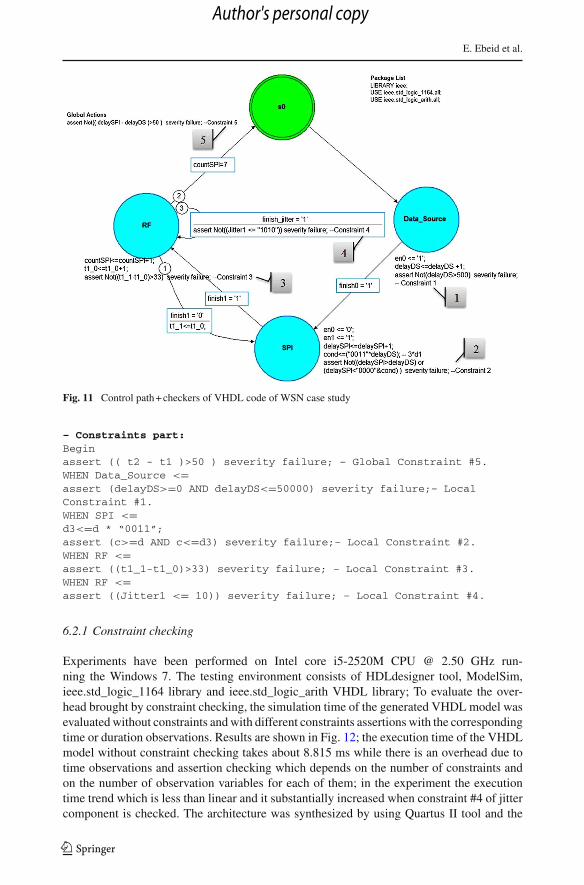
Fig. 11 Control path + checkers of VHDL code of WSN case study
– Constraints part:Beginassert (( t2 - t1 )>50 ) severity failure; – Global Constraint #5.WHEN Data_Source <=assert (delayDS>=0 AND delayDS<=50000) severity failure;– LocalConstraint #1.WHEN SPI <=d3<=d * “0011”;assert (c>=d AND c<=d3) severity failure;– Local Constraint #2.WHEN RF <=assert ((t1_1-t1_0)>33) severity failure; – Local Constraint #3.WHEN RF <=assert ((Jitter1 <= 10)) severity failure; – Local Constraint #4.
6.2.1 Constraint checking
Experiments have been performed on Intel core i5-2520M CPU @ 2.50 GHz run-ning the Windows 7. The testing environment consists of HDLdesigner tool, ModelSim,ieee.std_logic_1164 library and ieee.std_logic_arith VHDL library; To evaluate the over-head brought by constraint checking, the simulation time of the generated VHDL model wasevaluated without constraints and with different constraints assertions with the correspondingtime or duration observations. Results are shown in Fig. 12; the execution time of the VHDLmodel without constraint checking takes about 8.815 ms while there is an overhead due totime observations and assertion checking which depends on the number of constraints andon the number of observation variables for each of them; in the experiment the executiontime trend which is less than linear and it substantially increased when constraint #4 of jittercomponent is checked. The architecture was synthesized by using Quartus II tool and the
123
Author's personal copy

HDL code generation from UML/MARTE sequence diagrams
Fig. 12 Execution time of the VHDL simulator of WSN case study as a function of the number of checkedconstraints
Fig. 13 UML sequence diagram of the building automation application case study with VSL constraints
design used 5,262 cells of cyclone EPIC6Q240C8 FPGA chip which corresponds to 88 % ofits chip area.
6.3 VHDL code generation of building automation application (Case study #3):
The building automation application consists of five devices for monitoring and controllingthe building. The strict interaction between these devices is depicted by using sequencediagram with VSL constraints as shown in Fig. 13. Sensor_0 starts the process by sendingasynchronous call of measured data to the controller. After that, sensor_1 sends synchronouscall of measured data to the controller. Controller processing time is constrained by time t andthen the controller sends parallel asynchronous actions (a0, a1) to actuator_0 and actuator_1.Global constraint is set over time observation points t0 and t1 for actuator_0 and actuator_1.
123
Author's personal copy

E. Ebeid et al.
Fig
.14
Blo
ckdi
agra
mof
build
ing
auto
mat
ion
appl
icat
ion
case
stud
yin
VH
DL
123
Author's personal copy

HDL code generation from UML/MARTE sequence diagrams
Fig. 15 Control path + checkers of VHDL code of building automation application case study
Design steps are similar to the previous case study. The block diagram of this case study isshown in Fig. 14 which consists of data path and control path + checkers. In this case study, wewant to focus on the modeling of the parallel combination fragment in VHDL with assertions.As shown in Fig. 15 that each device has his own state but there is an extra state at the middlenamed Actuator_0_1 which represents the parallel actions for both devices (Actuator_0 andActuator_1). Moreover, we use a new signal named “seq” for tracing the message sequencewhich makes the code more solid. Therefore, each message is represented by two transitionswith fixed “seq” number in the transition condition, one for representing the direction of themessage and the other for connecting the current state with the next state in the sequence.For example, sensor_0 sends message to the collector and then sensor_1 starts to send a newmessage as shown in Fig. 13. Therefore, we need two transition for representing that. Oneto connect sensor_0 with the collector and the other for connecting collector with sensor_1.The architecture was synthesized by using Quartus II tool and the design used 5,620 cells ofcyclone EPIC6Q240C8 FPGA chip which corresponds to 94 % of its chip area.
123
Author's personal copy

E. Ebeid et al.
7 Conclusions
We presented a methodology to automatically generates SystemC and VHDL models fromUML/MARTE sequence diagrams with timing constraints for design verification by simula-tion. Set of rules are presented to show the transformations between UML/MARTE elementsand HDL primitives. A UML2HIF tool has been developed upon HIFSuite framework toautomatize the code generation flow. The checking mechanism is done according to the orig-inal UML/MARTE expressions. The methodology has been validated on three cases studiesto show the checking overhead. For VHDL code generation cases, the generated code hasbeen synthesized into an FPGA chip to achieve the complete implementation of the UMLmodels.
References
1. Accellera Standard OVL V2 Library Reference Manual (2011) OVL 2.6. http://www.accellera.org2. Alagar VS, Periyasamy K (2011) Extended Finite State Machine. In: Gries D, Schneider FB (eds) Spec-
ification of Software Systems. Texts in Computer Science, Springer London, pp 105–128. http://link.springer.com/book/10.1007%2F978-0-85729-277-3
3. Atego (2013) Artisan Studio. http://www.atego.com4. Bombieri N, Di Guglielmo G, Ferrari M, Fummi F, Pravadelli G, Stefanni F, Venturelli A (2010) HIFSuite:
Tools for HDL Code Conversion and Manipulation. EURASIP Journal on Embedded Systems 1:436,3285. EDALAB (2012) HIFSuite: Tools and APIs for HDL Code Conversion and Manipulation- version
2012.12. http://www.hifsuite.com6. Balarin F et al.(1997) Hardware–Software Co-design of embedded systems: the polis approach. Kluwer
Academic Press, Norwell7. Habibi A, Tahar S (2006) Design and verification of SystemC Transaction-Level Models. Very Large
Scale Integr (VLSI) Syst, IEEE Trans 14(1):57–688. Heng D, Ping G, Xiao-mei Y, Lin-li Z (2010) A research of object constraint language used in PIM
accurate modeling. In: International conference on information management and engineering (ICIME),pp 629–632
9. IBM (2012) IBM Rational. http://www-01.ibm.com/software/rational/10. Manual R (2000) IEEE Standard VHDL Language. IEEE Std 1076–2000, pp i–290. doi:10.1109/
IEEESTD.2000.9229711. Martin G, Muller W (2005) UML for SoC design. Springer, New York12. Martin G, Smith G (2009) High-level synthesis: past, present, and future. Des Test Comput, IEEE
26(4):18–2513. McUmber W, Cheng B (1999) UML-based analysis of embedded systems using a mapping to VHDL. In:
International symposium on high-assurance systems engineering, 1999, pp. 56–6314. Moreira T, Wehrmeister M, Pereira C, Petin JF, Levrat E (2010) Automatic code generation for embedded
systems: from UML specifications to VHDL code. In: International conference on industrial informatics(INDIN), 2010, pp 1085–1090
15. Mueller W, Villar E, Carballeda, M (2010) The SATURN approach to SysML-Based HW/SW Codesign.In: Computer society annual symposium on VLSI (ISVLSI), 2010, pp 506–511
16. Nguyen K, Sun Z, Thiagarajan P, Wong WF (2004) Model-driven SoC design via executable UML toSystemC. In: Real-Time systems symposium, pp 459–468
17. Object Management Group (2009) OMG Unified Modeling LanguageTM (OMG UML), superstruc-ture(version 2.2). In: OMG document number: formal/2009-02-02. http://www.omgmarte.org
18. Object Management Group (2011) A UML Profile for MARTE (version 1.1). In: OMG document number:formal/2011-06-02. http://www.omgmarte.org
19. Object Management Group (2013) Acceleo. http://www.eclipse.org/acceleo/20. Riccobene E, Scandurra P, Rosti A, Bocchio S (2005) A SoC design methodology involving a UML 2.0
profile for SystemC. In: Design, Automation and test in Europe, pp 704–709 Vol. 221. Sébastien Gérard et al. (2012) Papyrus UML, http://www.papyrusuml.org22. Technical report (2005) Survey of system design trends. Technical report, Electronics Weekly & Celoxica23. Transaction Level Modeling Working Group (2006) OSCI TLM 2.0. http://www.systemc.org
123
Author's personal copy

HDL code generation from UML/MARTE sequence diagrams
24. Vanderperren Y, Mueller W, Dehaene W (2008) UML for electronic systems design: a comprehensiveoverview, vol 12. Springer, Berlin
25. Xi C, Hua LJ, ZuCheng Z, YaoHui S (2005) Modeling SystemC design in UML and automatic codegeneration. In: Design automation conference, 2005. Proceedings of the ASP-DAC 2005. Asia and SouthPacific, vol 2, pp 932–935
26. Yu J, Li T, Tan Q (2006) The use of UML sequence diagram for System-on-Chip system level transaction-based functional verification. in: the sixth world congress on intelligent control and automation, 2006,vol 2, pp 6173–6177
123
Author's personal copy