New Diagrams in UML 2.x, Model Driven Architecture (MDA), Executable UML (MDA), Executable UML
Upload
mundusphd-interzonesCategory
view
0download
0
Integrating UML Static and Dynamic Views and
Formalizing the Interaction Mechanism of UMLState Machines
Alessandra Cavarra1 Elvinia Riccobene2 Patrizia Scandurra2
1 Oxford University Computing LaboratoryWolfson Building Parks Road, - OX1 3QD - Oxford, U.K.
[email protected] Dipartimento di Matematica e Informatica, Universita di Catania -
V.le A. Doria, 6 - 95125 Catania, [email protected]
Abstract. In this paper we address the problem of integrating UMLstatic and dynamic views, and different behavioral views. We tackle theseproblems by providing (a) a mapping of UML metamodel static andbehavioral elements into ASMs and (b) a precise compositional semanticsfor state machines.Structural model elements are translated into an ASM vocabulary ascollections of domains and functions. The dynamic view is captured bymulti-agent ASMs reflecting the behavior modeled by UML state ma-chines.The interaction among UML state machines is achieved by providingthe semantics for actions and events and refining the ASM model in [4]to formalize objects communication, i.e. signals exchange and operationcalls mechanism.
1 Introduction
Although UML is nowadays considered the new standard for model specification,visualization, construction and documentation, practitioners from industry stilldo not find it easy to use because of the lack of a well defined model designprocess and of a clear semantics of the different kinds of diagrams UML allowsto draw.
UML is a bunch of notations without an effective integration and with loosesemantics. This leads to a more apparent than real understanding of models, dif-ficulty to perform rigorous analysis, validation, verification, integrity of models,and difficulty to develop tools supporting mechanical validation and verification.
This work comes as part of a formalization effort necessary to build a simula-tion tool [7] for a subset of the UML, namely class, object, state and interactiondiagrams. In fact, although in [4] we provide a formal semantics for UML statemachines, this proved to be not enough when one wants to reason about statemachines in a more general context, or integrating state machines with otherUML structural and behavioral diagrams.

UML is a graphical notation used to describe the structure and the dynam-ics of a software system. The language is constituted of two different types ofdiagrams, representing the two views of a system: the static view, modelinginformation that does not evolve with time and the dynamic view, where theevolution of the components of the system is shown.
Even if many approaches exist in literature to define a precise semantics ofstatic and behavioral diagrams [10], the problem of the integration between thestatic and the semantic views of UML is still an open problem, as well as theintegration among behavioral views is still missing.
In this paper we address this problem by providing (a) a mapping of UMLmetamodel static and behavioral elements into ASMs and (b) a precise compo-sitional semantics for state machines.
The “static” semantics of a given UML model represents the structural as-pects of the model and essentially includes classes, relationships, attributed andoperations. Moreover, this view encompasses the “static dependencies” capturedby the metamodel and regarding only those meta-classes (including data types)and their relationships that directly represent the types of the entities specifiedby the given UML model at run-time. Such concepts concerning the static viewof a system are translated into an ASM vocabulary as collections of domainsand functions.
The “dynamic” semantics of a UML model describes the behavioral aspect ofthe model. The dynamic of a system can imply two different typologies of changesin the symbolic instance of the model: changes in the states of individual objects,caused by the triggering of events and the consequent execution of actions; andchanges in the overall state of the system (due to e.g. creation and destructionof objects, the system clock, etc.).
In UML the behavior of an object is modeled by a state diagram; in ourASM model, objects will be formalized as ASM agents and their state diagramsas ASM modules associated to those agents. All the agents of the same “type”(i.e. formalizing objects of the same class) execute the same module, but eachwith its own execution space (the memory of the object itself) and event queue.
In order to handle the problem of the interaction among UML state machines,we provide a semantics for actions and events and refine the multi-agent ASMmodel in [4] in order to formalize objects communication, i.e. signals exchangeand operation calls mechanism.
2 A subset of the UML
Although UML provides a wide range of notations, to fully describe the func-tionalities of a system it is sufficient to use class diagrams and state diagrams.Class diagrams show collections of declarative elements in the system, and theirrelationships. State diagrams specify the life-cycle of objects of a class, describ-ing the possible sequences of states and actions through which an object can goduring its lifetime as a result of reacting to discrete events. Interactions among
2

objects are modeled by means of interaction diagrams which specify how andwhen messages are sent between objects to perform a task.
2.1 UML Class and Object Diagrams
A class diagram (see Fig. 2) describes the static structure of a system, consist-ing of a number of classes and their relationships. The application concepts aremodeled in UML as classes each of which describes a set of objects that hold in-formation and communicate to implement a behavior. The information they holdis modeled as attributes; the behavior they perform is modeled as operations.Structural relationships between objects of different classes are represented byassociations. The definition of associations may be enhanced by a name, rolenames and cardinality (multiplicity).
An object diagram (see Fig. 3) is a graph of instances of the entities rep-resented in a class diagram, namely objects and links. They model the actualconfiguration of the system at a certain time.
2.2 UML State Diagrams: Basic concepts
State diagrams focus on the event-ordered behavior of an object, a feature whichis specially useful in modeling reactive systems. A state diagram shows the eventtriggered flow of control due to transitions which lead from state to state, i.e.it describes the possible sequences of states and actions through which a modelelement can go during its lifetime as a result of reacting to discrete events. Astate reflects a situation in the life of an object during which this object satisfiessome condition, performs some action, or waits for some event. According tothe UML meta-model [3], states can belong to one of the following categories:simple states, composite states (sequential, concurrent, submachine), final, andpseudostates (initial, history, stub, junction, synch).
Transitions are viewed in UML as relationships between two states indicatingthat an object in the first state will enter the second state and perform specificactions when a specified event occurs provided that certain conditions are satis-fied [2]. UML statecharts include internal, external and completion transitions.
The semantics of event processing in UML state machines is based on therun to completion (rtc) assumption: events are processed one at a time and whenthe machine is in a stable configuration, i.e. a new event is processed only whenall the consequences of the previous event have been terminated. Therefore, anevent is never processed when the state machine is in some intermediate, unstablesituation.
Events may be specified by a state as being possibly deferred. They areactually deferred if, when occurring, they do not trigger any transition. Thiswill last until a state is reached where they are no more deferred or where theytrigger a transition. Fig. 4 shows an example of state diagram.
3

3 Mapping UML models into ASM
The basic idea here consists on mapping every UML model into a multi-agentASM model. Fig. 1 shows the schema adopted to map UML (meta) model ele-ments into ASMs.
Fig. 1. UML to ASM mapping schema
The architecture of the UML is based on a four-layer metamodel structure,which consists of the following layers [3]:
– meta-metamodel: This layer forms the foundation for the metamodelingarchitecture. The primary responsibility of this layer is to define the languagefor specifying a metamodel.
– metamodel: A metamodel is an instance of a meta-metamodel. The pri-mary responsibility of the metamodel layer is to define a language for speci-fying models. Examples of metaobjects in the metamodeling layer are: Class,Attribute, Operation.
– model: A model is an instance of a metamodel. The primary responsibilityof the model layer is to define a language that describes an informationdomain. Examples of objects in the modeling layer are: Stack, buffer, pop.
4

– user objects: User objects (a.k.a. user data) are an instance of a model.The primary responsibility of the user objects layer is to describe a specificinformation domain.
This mapping addresses the metamodel, model, and user objects layers. TheUML notation defined at the metamodel level has been manually translatedonce for all into a corresponding ASM signature, i.e. universes, functions, andpredicates.
This mapping scheme has been implemented in our tool in order to automat-ically initialize the ASM signature from the input UML “model”. In particular,class diagrams provide information regarding declarative UML elements (classes,operations, relationships,. . . ). Object diagrams are used to define the multi-agentASM model initial states.
The ASM signature formalizing the state diagram elements (state, transi-tions, etc.) in the metamodel is automatically instantiated according to the statediagrams provided in the input model. An ASM model formalizing the semanticsof UML state diagrams has been defined (again once for all) according to theformal ASM model presented in [5, 4].
Observe that we assume input models to be notationally well defined.
3.1 Mapping UML structural elements into ASMs
We present here the translation process adopted to map basic UML structuralelements, such as classes, relationships, attributes and operations into ASM.
As example of static mapping we consider the UML model of the followingstack-printer case study. A stack structure, of limited size, is an active objectwhich is used by the environment to push and pop integer elements. The stacksignals its state of underflow or overflow by sending a message of stackEmptyor stackFull to a printer. The printer is always ready to print all messages ona terminal. The terminal has a buffer windowbuffer of type String in whichmessages from the printer are showed.
Figures 2, 3, 4, 5 respectively show the class diagram, the object diagram,the state machine of the stack component, and the state machine of the printercomponent of the UML model of the stack-printer example, developed using theCASE tool Poseidon [9].
UML metamodel. Each UML metaclass is mapped into a corresponding ab-stract set with the typewriting convention that a MetaClass is mapped into theASM universe MetaClass, i.e. the metaclass StateMachine is mapped into theabstract set StateMachine of state machines, the metaclass State is mappedinto the set State, Transition into Transition, Event into Event, Action intoAction, etc.
A composition relation between metaclasses is mapped into a composition re-lation between the corresponding abstract sets. Therefore, the set State is parti-tioned into the sets SimpleState, SequentialState, ConcurrentState, PseudoState;the set Event is partitioned into the sets SignalEvent, CallEvent, TimeEvent,
5

Fig. 2. Stack-Printer Class Diagram
Fig. 3. Stack-Printer Object Diagram
Fig. 4. Stack State Machine
6

Fig. 5. Printer State Machine
ChangeEvent ; Action is partitioned into CallAction, SendAction, CreateAction,DestroyAction, UninterpretedAction; etc.
According to the UML Meta-Model for state machines, the ASM domainStateMachine has elements are of type
statemachine(name,init,state,transition,event)where name ∈ String is the state diagram name, init ∈ State is the initial state ofthe diagram, state ∈ P(State) denotes the set of states in the diagram, transition∈ P(Transition) represents the set of (both internal and external) transitions inthe diagram, and event ∈ P(Event) is the set of events labeling the transitionsin the diagram.
UML models. Information provided by the diagrams at the Model level, areused to initialize the abstract sets corresponding to the meta-classes at the Meta-Model level.
Let Class1,...,Classn the set given by the classes defined in all the classdiagrams. For each Classi, we define a dynamic domain Classi in the ASMmodel, whose elements are the instances of the corresponding class in the objectdiagrams (and will be initialized at User Model level).
Attributes are formalized as ASM functions, whose domain is the ASM uni-verse corresponding to the class whom the attribute belongs to, and the co-domain is the attribute’s type itself. Operations are represented by ASM rulesparameterized on the universe corresponding to the class encompassing the op-eration and on the universes corresponding to the types of the operation param-eters1.
Each association navigable from Classi to Classj is represented as an ASMfunction having the universe Classi as domain and Classj as co-domain. If theassociation is navigable in both directions, then the inverse function is defined aswell. A generalization between Classk and Classh is mapped into an inclusionrelation between Classk and Classh. Basic data types, such as Integer, String,Boolean, etc, are mapped into the corresponding ASM types. Enumerations willbe translated as static ASM universes.
From class diagram in Fig.2, universes Stack, Printer, Terminal, Integer,String are defined (as elements of the abstract set Class) together with thefunctions:1 We assume that operation parameters include possible return types.
7

buffer, size, limit : Stack → Integer*printer : Stack → Printerterm : Printer → Terminalwindowbuffer : Terminal → String
Rules for operations of the class Stack are the following:
push(self,e) ≡ do insert(e,buffer(self))size(self) := size(self) + 1
pop(self) ≡ do send(printer(self),sgnprint,head(buffer(self)))buffer(self) := tail(buffer(self))size(self) := size(self) − 1
where assignments are actions viewed as specializations of the metaclass Uninter-pretedAction. The operation of the class Terminal is defined by the rule:
print(self,s) ≡ windowbuffer(self,s) :=s
Statecharts at Model level allow to initialize the abstract set StateMachine andthe derived universes. From the state machines in Fig. 4 and 5, the universeStateMachine is initialized with the elements:
st1 = statemachine(StackMachine, initState1, {empty,intermediate, full},{tr1, tr2, tr3, tr4, tr5, tr8, tr9} ∪ {tr6,tr7}, {push(e:Integer), pop()})
st2 = statemachine(PrinterMachine, initState2, {active}, {tr11} ∪{tr22, tr33, tr44}, {print(s:String), stackEmpty(), stackFull()})
UML user model. Diagrams developed at User Model level (Object Diagrams)allow to initialize the signature defined at Model level.
Each dynamic domain Classi in the ASM model takes as elements all the in-stances of the corresponding class in the object diagrams. For instance, from theobject diagram in Fig. 3, sets Stack, Printer, Terminal are initialized as {s}, {p},{t}, respectively. And functions on Classi are suitably initialized (buffer(s) = [];size(s) = 0; limit(s) = 3 ; . . . ; term(p) = t, windowbuffer(p) =“”, etc.).
Let Object be the union of all sets Classi defined as above. If the behav-ior of a class is described by a state diagram2, the function classifier : Object→ {Class1,. . . ,Classn} associates to each object the class it belongs to, whilethe function context : StateMachine → {Class1,. . . ,Classn} associates to a statemachine its context, i.e. the set of objects behaving according to it;behavior isthe inverse function of context. Each element in StateMachine is associated to aclass instance which constitutes the context of the machine by the function stMa-chine : Object → StateMachine where stMachine(a) = behavior(classifier(a)).According to our example, stMachine(s) = st1 and stMachine(p) = st2.
2 It is possible to have classes without an associated state diagram.
8

3.2 Mapping UML models behavior into ASMs
In the UML models under consideration here, the behavior of class instances isdescribed by a state diagram attached to the class. In our ASM model, objectswith state machine are modeled as ASM agents (therefore, AGENT ⊆ Object)3
and their state diagrams are formalized as ASM modules of such agents. Allthe agents (objects) of the same type (class) execute the same module (statediagram). However, each agent runs on its own execution space and handles itsown event queue. The overall system behavior is represented by the multi-agentASM whose initial states are given by the object diagrams.
According to our model of the Stack-Printer, AGENT = {s, p}, while t isa location on Terminal. The behavior of each agent is described by the statemachine given by the function stMachine.
The ASM model for the behavioral meaning of state diagrams is definedin [5, 4]. This model (a) rigorously defines the UML event handling scheme ina way which makes all its “semantic variation points” explicit, including theevent deferring and the event completion mechanism; (b) encapsulates the runto completion step in two simple rules (Transition Selection and GenerateCompletion Events) where the peculiarities relative to entry/exit or transitionactions and sequential, concurrent or history states are dealt with in a modularway; (c) integrates smoothly the state machine control structure with the dataflow; (d) clarifies various difficulties concerning the scheduling scheme for internalongoing (really concurrent) activities; (e) describes all the UML state machinefeatures that break the thread-of-control; (f) provides a precise computationalcontent to the UML terms of atomic and durative actions/activities, withoutloosing the intended generality of these concepts, and allows one to clarify somedark but semantically relevant points in the UML documents on state machines.
For each UML state machine in the model, the set of objects defined inthe context of the diagram move through the diagram each executing what isrequired by their current state (see [5] for more details).
To fully understand the content of the following sections, a knowledge of theASM state machines model in [4, 5] is strongly recommended. We report relevantparts of such a model in Appendix.
3.3 ASM semantics of UML events
An event represents a specification of a noteworthy occurrence. In the UMLmetamodel four different kinds of event are defined: SignalEvent, CallEvent,ChangeEvent, and TimeEvent [3]. Currently, we allow only signal events andcall events. A signal event represents the reception of a particular asynchronoussignal. A call event represents the reception of a request to synchronously invokea specific operation. The expected result is the execution of a sequence of actionswhich characterize the operation behavior at a particular state. We define the3 Since we do not distinguish between protocol and state machines, we associate to
passive objects agents which are active only when stimulated by external events.
9

abstract sets SignalEvent and CallEvent to model the corresponding classes inthe metamodel.
In UML it is assumed that a state machine processes one event at a time andfinishes all the consequences of that event before processing another event. “Anevent is received when it is placed on the event queue of its target. An event isdispatched when it is dequeued from the event queue and delivered to the statemachine for processing. At this point, it is referred as the current event. Finally,it is consumed when event processing is complete. A consumed event is no longeravailable for processing” [3].
Our model is fully compliant with the rtc assumption. The event handlingmechanism is formalized by a number of queues, one per each agent (i.e. ob-ject with behavior) in the model. In such a way, we guarantee that each agentconsumes an instance of an event at a time and also that distinct agents cansimultaneously consume distinct instances of events. The function eventQueue :AGENT → Event∗ formalizes the association between an agent and its eventqueue.
According to the UML classification of events, the eventQueue of an agentmay be updated at run-time by (a) the environment by means of time events(i.e. time expiration, calendar/clock, etc.), time signal events (i.e. stimuli fromphysical entities), (b) change in value of some agent entity by means of changeevents, (c) requests of services from other objects by means of call events (i.e.synchronous or asynchronous object operation invocations) and signal events(i.e. asynchronous signal reception). Therefore, we can imagine the eventQueueof an agent as partitioned into a part ExtEventQueue monitored by the en-vironment and a part IntEventQueue updated as result of actions of otheragents (controlled by shared functions). Thus, for each agent a, eventQueue(a) =ExtEventQueue(a) ∪ IntEventQueue(a). The mechanism of updating of the In-tEventQueue is explained in section 3.5 because related to the semantics ofactions.
The ASM models for state machine in [5] and [4] have to be slightly re-fined in order to guarantee the concurrent computation of more than one ma-chine at the same time. The monitored function dispatched(e), indicating whichevent instance is dequeued to be processed, is refined with the predicate dis-patched(e, a), monitored on eventQueue(a), a ∈ AGENT. In such a way, weallow different agents (even running the same type of machine) to process simul-taneously instances of different events. An eventQueue is inherited by a subagentwhen created.
For each agent a, a transition is enabled to fire if it satisfies the following con-dition enabled(t, e, a) ≡ event(t) = e & guard(t)(a) & source(t) ∈ currState(a) .
Let enabled(e, a) = {t ∈ transitions(stMachine(a)) | enabled(t, e, a)} be the setof all transitions (simultaneously) enabled by an event e for an agent a.
Even if we allow more than one event globally, i.e. with respect to all theagents, dispatched at the same time, a single agent process an event per time.However, more than one transition can be enabled by a same event in the state
10

machine of the agent4. We skip here the mathematical definition of the setFirableTrans(e, a) which consists of all triggering transitions taking into accountthe UML requirement that among all the transitions enabled by the same eventand with different source states, priority is given to an innermost one and tocompletion transitions. The choice among those triggering transitions is left openas semantic variation point (see choose in the Transition Selection rule).
Deferred Events. Events may be specified in a state as being possibly deferred.They are actually deferred if, when occurring, they do not trigger any transition.This will last until a state is reached where they are no more deferred or wherethey trigger a transition. According to [3], an event that is deferred in a compositestate is automatically deferred in all its directly or transitively nested substates.For reasons of simplicity, but without loss of generality, we assume that the deferset of each state explicitly contains all the inherited events to be deferred.
If a dispatched event does not trigger any transition in the current state ofan agent, it is lost unless it occurs in the deferred set of the deepest active state.This is formalized by the following predicate deferrable on Event × AGENT :deferrable(e, a) = true ⇔ enabled(e, a) = ∅ & e ∈ defer(deepest(a)).
As suggested in [3], to store deferred events we associate to each agent a listof events deferQueue that is dynamically updated during the computation (seerule Transition Selection). We can therefore define deferred(e, a) to mean e ∈deferQueue(a).
We call a deferred event releasable when it becomes ready to be consumed, i.e.when it can trigger a transition in the current state configuration: releasable(e, a) =true ⇔ deferred(e, a) & enabled(e, a) = ∅ .
3.4 The Run To Completion Step.
A run-to-completion-step of a state machine consists in choosing an event withan enabled transition, and in firing the enabled transition. Apparently, UMLleaves it unspecified how to choose between dispatched and releasable events. Wereflect this by using a selection function which, at any moment, chooses eithera dispatched event triggering a transition, or an event that has been deferred.A dispatched event, if deferrable, has to be inserted into the deferQueue. Areleasable event, when chosen for execution, has to be deleted from deferQueue.This implies that when choosing an event which is simultaneously dispatchedand releasable, that event will be deleted from the deferred events.
The main rule for selecting the machine transition to be executed next canthus be states as follows. For each a ∈ AGENT :
Rule Transition Selection(Self)choose e : dispatched(e,Self) ∨ releasable(e,Self)
choose trans in FirableTrans(e, Self)stateMachineExecution(trans)
4 We refer the reader to [4] for a complete and exhaustive discussion on conflictingtransitions.
11
if deferrable(e,Self) then insert(e,deferQueue(Self))if releasable(e,Self) then delete(e,deferQueue(Self))
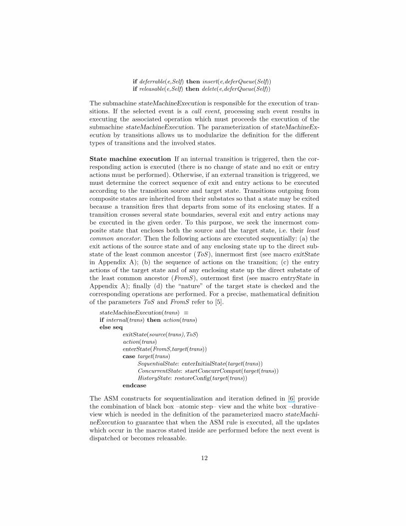
The submachine stateMachineExecution is responsible for the execution of tran-sitions. If the selected event is a call event, processing such event results inexecuting the associated operation which must proceeds the execution of thesubmachine stateMachineExecution. The parameterization of stateMachineEx-ecution by transitions allows us to modularize the definition for the differenttypes of transitions and the involved states.
State machine execution If an internal transition is triggered, then the cor-responding action is executed (there is no change of state and no exit or entryactions must be performed). Otherwise, if an external transition is triggered, wemust determine the correct sequence of exit and entry actions to be executedaccording to the transition source and target state. Transitions outgoing fromcomposite states are inherited from their substates so that a state may be exitedbecause a transition fires that departs from some of its enclosing states. If atransition crosses several state boundaries, several exit and entry actions maybe executed in the given order. To this purpose, we seek the innermost com-posite state that encloses both the source and the target state, i.e. their leastcommon ancestor. Then the following actions are executed sequentially: (a) theexit actions of the source state and of any enclosing state up to the direct sub-state of the least common ancestor (ToS ), innermost first (see macro exitStatein Appendix A); (b) the sequence of actions on the transition; (c) the entryactions of the target state and of any enclosing state up the direct substate ofthe least common ancestor (FromS ), outermost first (see macro entryState inAppendix A); finally (d) the “nature” of the target state is checked and thecorresponding operations are performed. For a precise, mathematical definitionof the parameters ToS and FromS refer to [5].
stateMachineExecution(trans) ≡if internal(trans) then action(trans)else seq
exitState(source(trans),ToS)action(trans)enterState(FromS,target(trans))case target(trans)
SequentialState: enterInitialState(target(trans))ConcurrentState: startConcurrComput(target(trans))HistoryState: restoreConfig(target(trans))
endcase
The ASM constructs for sequentialization and iteration defined in [6] providethe combination of black box –atomic step– view and the white box –durative–view which is needed in the definition of the parameterized macro stateMachi-neExecution to guarantee that when the ASM rule is executed, all the updateswhich occur in the macros stated inside are performed before the next event isdispatched or becomes releasable.
12

3.5 ASM semantics of UML actions
An action is a specification of an executable statement that forms an abstractionof a computational procedure that results in a change in the state of the model,and can be realized by sending a message to an object or modifying a valueof an attribute. In UML, the language of actions and events is left partiallyundefined: its final form is dictated by the target language of model –usually theprogramming language chosen for implementation. Currently, an OMG requestfor proposal for a “precise, software-independent action specification” has beenissued. In our framework, we decided to adopt an ASM dialect as action languagefor our models.
In the UML metamodel, Action is modeled as an abstract class from whichseven types of actions are defined by specialization: SendAction, CallAction,CreateAction, TerminateAction, DestroyAction, ReturnAction, Uninterpr-etedAction. A send action is an action that results in the (asynchronous) send-ing of a signal. A call action is an action resulting in an invocation of an opera-tion on an instance, i.e. a call event. A call action can be synchronous or asyn-chronous, indicating whether the operation is invoked synchronously or asyn-chronously. This is modeled by the boolean attribute isAsynchronous attributein Action. A create action is an action resulting in the creation of an instanceof some classifier. A destroy action is an action results in the destruction of anobject specified in the action. A terminate action results in self-destruction of anobject. A return action is an action that results in returning a value to a caller.
The class Action is mapped into the abstract set Action, partitioned intoSendAction, CallAction, CreateAction, TerminateAction, DestroyAction, Retur-nAction5. The elements of each partition are identified respectively by the fol-lowing characteristic functions: isSend, isCall, isCreate, isDestroy, isReturn andisAssignment. The predicate isAsynchronous : CallAction −→ BOOLEAN de-termines whether a call action is synchronous or not.
According to the UML metamodel, each action is identified by a name anda body instance of the metaclass ActionExpression which is left abstract andwithout semantics. As with operations, we give semantics to actions by meansof ASM rules. We refine action(trans) in the stateMachineExecution as follows:
action(trans) ≡ loop through act ∈ action(trans)case act
isSend : send(obj,op(parList))isCall : call(obj,op(parList))isCreate : create(obj,parList)isDestroy : destroy(obj)isReturn : return(obj,parList)isAssignment : act
endcase
where act is an ASM function update if the action is an assignment, or has theform op(obj,parList) (i.e. obj.op(parList) in object oriented notation) otherwise.5 The metaclass UninterpretedAction will be represented by its specialized classes,
e.g. in our example we have the set AssignmentAction.
13

The special macros formalizing the action execution are given below. Due tolack of space, we present here only those for call and send actions.
send(obj,sig) ≡ insert(sig,IntEvQueue(obj))
call(obj,op) ≡ if isAgent(obj)then insert(op,IntEvQueue(obj))else op(obj)
Remark. Currently our model only deals with asynchronous call events. Thisis due to a limitation of ASM sub-machine semantics which does not allow tointerrupt a sub-machine execution. This feature is required to model the block-ing effect when synchronous calls are invoked: the caller sub-machine needs tosuspend until the control is returned by the callee machine.
Fig. 6. UML to ASM Toolkit Architecture
4 A framework to simulate UML models
Figure 6 shows the architecture of the toolkit we have developed to simulate in-teractive UML state machines. Input UML models can be drawn using any UMLCASE Tool able to produce the XMI format for diagrams (i.e. Poseidon [9]) andcan include class diagrams (to define model entities), object diagrams (to providean initial configuration of the system), state diagrams (to show objects behav-ior in response to events received), and sequence diagrams (to depict possibleinteraction scenarios).
The simulator for state diagrams has been built upon the ASM semanticsdescribed in [5, 4], refined with events and actions semantics, and developed usingAsmGofer [11], an advanced Abstract State Machine programming system.
The UMLtoASM Converter is a Java program that automatically initializesASMGofer core scripts from the XMI representations, according to the formalmapping schema presented in section 3. The conversion consists of the following
14

steps: (a) the component XMI API constructs a DOM (Document Object Model)tree-like representation of the XMI document; (b) the Visitor traverses the treeand initializes a Java representation of the ASM Vocabulary; (c) the ASMGoferscript generator initializes the signature of the ASMGofer script.
5 Conclusion and related work
We have presented a rigorous schema to map UML metamodel elements intoASMs. Given a UML model consisting of class, object and state diagrams, ourmapping provides the vocabulary and the rules of a multi-agent ASM formaliz-ing the given model. In such a way, we integrate UML static and dynamic views,and propose a compositional semantics for UML state machines through a for-malization of the interaction mechanism among different machines via actionsand events.
This work comes as part of a formalization effort necessary to build a simu-lator for UML models. The toolkit framework has been briefly presented.
An approach to map UML metamodel elements into ASMs has been pre-sented in [8]. However, this work only takes into account model elements froma static view, neglecting any relation to their actual, dynamic semantics. Ourwork comes from a different perspective. In fact, although in [4] we provide aformal semantics for UML state machines, this proved to be not enough whenone wants to integrate UML structural and behavioral diagrams, and formalizethe state machines interaction mechanism.
References
1. OMG Unified Modeling Languages Specification, version 1.4, 2001.2. UML 1.4 Notation, 2001. (Published as part of [1]).3. UML 1.4 Semantics, 2001. (Published as part of [1]).4. E. Borger, A. Cavarra, and E. Riccobene. A precise semantics of UML State
Machines: making semantic variation points and ambiguities explicit. In Proc. Se-mantic Foundations of Engineering Design Languages (SFEDL02) - ETAPS 2002.
5. E. Borger, A. Cavarra, and E. Riccobene. Modeling the Dynamics of UML StateMachines. In Y. Gurevich et al., editor, Abstract State Machines. Theory andApplications, volume 1912 of LNCS 1912, pages 223–241. Springer, 2000.
6. E. Borger and J. Schmid. Composition and Submachine Concepts for Sequen-tial ASMs. In P. Clote and H. Schwichtenberg, editors, Computer Science Logic(Gurevich Festschrift), number 1862 in LNCS, pages 41–60, 2000.
7. A. Cavarra and E. Riccobene. Simulating uml statecharts. In R. Moreno-Diaz andA. Quesada-Arencibia, editors, EUROCAST 2001, pages 224–227. February 2001.
8. I. Ober. More meaningful UML Models. In TOOLS - 37 Pacific 2000. IEEEComputer Society Press, 2000.
9. Poseidon UML Tool. http://www.gentleware.com.10. The precise UML group. http://www.cs.york.ac.uk/puml/.11. J. Schmid. Executing ASM specifications with AsmGofer.
http://www.tydo.de/AsmGofer.
15

Appendix
Handling State Diagrams Control
To formalize the control in a state machine, we introduce a set of AGENT s whichmove through the diagram, each executing what is required for its currentlyactive state. A state becomes active when it is entered as result of some transition,and becomes inactive if it is exited as result of a transition. “When dealing withcomposite and concurrent states, the simple term current state can be quiteconfusing. In a hierarchical state machine more then one state can be active atonce. If the control is on a simple state that is contained in a composite state,then all the composite states that either directly or transitively contain thesimple state are also active” [3]. To maintain the current configuration of activestates, we introduce a dynamic function currState : AGENT −→ P(STATE)whose updates follow the control flow of the given state machine. The functiondeepest : AGENT → STATE yields the last (innermost) state reached by anagent.
The agents execute UML state machines, i.e. all use the same ASM rule(though initialized by one program instance for each agent). When a new agentis created to perform a concurrent subcomputation (defined by one of the sub-states in a concurrent composite state), it is linked to the parent agent bythe dynamic function parent : AGENT −→ AGENT ∪ {undef}. We assumethat this function yields undef for the main agent who is not part of anyconcurrent flow. The active subagents of an agent a are collected in the setSubAgent(a) = {a′ ∈AGENT | parent(a′) = a}. The function descendents :AGENT → P(AGENT) yields the set of all the active subagents of an agent aat any depth of concurrency.
Exiting states
If a transition that crosses the boundary of a composite state fires, we mustdistinguish two cases to perform the exits from nested states in an order whichrespects the hierarchical structure (see macro exitState below):
1. The agent is not parent of concurrent subagents. In this case for each statefrom the agent’s deepest state6 up to, but excluding, the source/target leastcommon ancestor state (see the stateMachineExecution rule above), inner-most first, it sequentially (a) stops the internal ongoing activities, (b) per-forms the exit actions, and (c) removes those states from the agent’s currentstate and, when sequential states are exited, their enclosed final state (ifany). Moreover, it (d) updates the history (if defined and provided that thefinal state has not been reached), memorizing in it all the states it is exitingin case of deep history, or only its direct active substate in case of shallowhistory (see macro sequentialExit).
6 This is to ensure that if the source of the fired transition is a state encompassing theagent’s deepest state, all the exits from the deepest to the source state are performed.
16

2. The agent is parent of concurrent subagents. In this case the parent agentsequentially forces all its subagents ai to perform their exits from their deep-est state up to, but excluding, its deepest state (by recursively calling themacro exitState). Then each ai deactivates itself (by the macro deactivate).This is performed by the macro exitSubAgents defined below. Afterwards,the parent agent updates its deferQueue to retain all deferred events of itsown but none of those processed by its subagents, disconnects all its deac-tivated subagents (see the corresponding macro defined below), and finallyperforms its sequential exits as in case 1.
exitState(s,t) ≡ if SubAgent(Self) = ∅then sequentialExit(s,t)else seq exitSubAgents
deferQueue(Self) := defer(deepest(Self)) ∩⋂ai∈SubAgent(Self)
deferQueue(ai)
disconnectSubAgentssequentialExit(s,t)
sequentialExit(s,t) ≡ loop through S ∈ UpChain(s′,t)seq
abortInternalActivity(S)exit(S)if SequentialState(S) &
final(S) ∈ currStatethen currState := remove({final(S),S},currState)else currState := remove(S,currState)
endseqif history(S) �= undef &
final(S) �∈ currStatethen memory(history(S)) := hist(s, S)
endloopwhere s′ = deepest(Self)
hist(s, S) = UpChain(s,S) for deep historydirectSubState(S,UpChain(s,S)) for shallow history
The macro abortInternalActivity [5, 4] stops the internal state activity.exitSubAgents ≡ do forall ai ∈ SubAgent(Self)
seq exitState(s1 s2)deactivate(ai)
where s1 = deepest(ai)s2 = directSubState(deepest(self),
UpChain(deepest (ai),deepest (Self)))
deactivate(a) ≡ Rule(a) := undefcurrState(a) := ∅
disconnectSubAgents ≡ do forall ai ∈ SubAgent(Self)parent(ai) = undef
17

Entering states
A transition may have a target state nested at any depth in a composite state.Therefore, any state enclosing the target one up to, but excluding, the leastcommon ancestor will be entered in sequence, outermost first. Entering a statemeans that (a) the state is activated, i.e. inserted in currState, (b) its entryaction is performed, and (c) the state internal activity (if any) is started. Thisis realized by the macro enterState for which we use the macro startActivity[5, 4] to create a new worker agent whose job is to execute the activity of itsassociated state. The agent’s deferQueue is updated by deleting all those eventswhich are no more deferred in the target state, and finally if the entered state isa sequential state encompassing a history state that is not the target state, thenthe memory of the history is reset.
enterState(s,t) ≡ loop through S ∈ DownChain(s,t)seq
currState := insert(S,currState)entry(S)startActivity(S)
endseqdeferQueue := deferQueue ∩ defer(S)if SequentialState(S) & history(S) �= undefthen if history(S) �= t
then memory(S) := []endloop
Observe that when a state is entered for the first time or its most recentlyactive state prior to its exit was the final state, its history (if any) must beempty [3]. This is guaranteed in our model since we initialize each history statememory to the empty sequence, delete it after using it (see macro restoreConfigin Appendix), and store nothing in it when its enclosing state is exited by a finalstate.
Sequential composite states A transition drawn to the boundary of a se-quential composite state is equivalent to a transition to its initial pseudostate[3]. Therefore, when a composite sequential state is the target state of a triggeredtransition, the control passes to its initial state that is inserted in currState.
enterInitialState(S) ≡ currState := insert(init(S),currState)
Concurrent composite states If a transition incoming to a concurrent com-posite state fires, the flow of control is split into two or more flows of control.The currently active agent creates a new agent ai for each concurrent componentSi. All the subagents inherit their parent’s program to execute state machinesand its list of active deferred events. As a transition drawn to the boundary of aconcurrent composite state is equivalent to a transition to any of its concurrentcomponents and consequently to the component initial state, the currState ofeach agent ai contains the component Si and its associated initial state.
startConcurrComput(S) ≡let S1, . . . , Sn = concurrentComp(S)
18

extend AGENT with a1, . . . , an
do forall 1 ≤ i ≤ nparent(ai) := SelfdeferQueue(ai) := deferQueue(Self)Rule(ai) := Rule(Self)currState(ai) := {Si,init(Si)}
The parent agent will stand idle waiting for the termination of its subagents’computation. This is enforced by the definition of when a concurrent state iscompleted to trigger the completion event which may enable the transition ex-iting the concurrent state. The running subagents can finish their job eitherbecause of a completion event generated by their parent7 or by the firing of anexplicit event labeling a transition outgoing their enclosing state.
7 In this case they all must have reached their final state.
19
Copyright © 2022 FDOKUMEN