Simple Machines
56
44 Machines are an integral part of our day-to-day life. We use machines for many activities. For example, a grinder is used to grind spices, a washing machine is used to wash clothes, a sewing machine is used to stitch clothes and a vacuum cleaner is used to dust, clean and mop. Similarly, machines are used in factories for manufacturing things in large quantities. Machines are devices that make our work easier and save us time and effort. All the machines mentioned above have a large number of parts and a complex design. However, there are some tools that have simple design and very few moving parts. We will learn about such tools in this chapter. SIMPLE MACHINES In our everyday life, we use tools such as a knife (to chop vegetables), a hammer (to fix a nail in the wall), a bottle opener (to open the metal caps of cold drink bottles) and a pair of scissors (to cut paper or cloth). These tools have a simple design and very few or no moving parts. They allow us to do a task with a lesser effort. So, the work gets done easily. Such simple tools that make our work easier are called simple machines. An axe, a knife, a needle, a pair of scissors and a hand pump are a few other examples of simple machines. A simple machine cannot do any work on its own. It requires some energy that is usually provided by the person using it. Let us understand how a simple machine makes work easier. 4 Learning Objectives • Define a machine • Describe six simple machines with examples from daily life • Describe different types of levers • Define mechanical advantage of a lever • Solve problems based on mechanical advantage of a lever Simple Machines Chapter 04_Simple Machines.indd 44 2/10/2017 4:24:37 PM © Pearson India Education Services Pvt. Ltd.
-
Upload
khangminh22 -
Category
Documents
-
view
2 -
download
0
Transcript of Simple Machines

44
Machines are an integral part of our day-to-day life. We use machines for many activities. For example, a grinder is used to grind spices, a washing machine is used to wash clothes, a sewing machine is used to stitch clothes and a vacuum cleaner is used to dust, clean and mop. Similarly, machines are used in factories for manufacturing things in large quantities. Machines are devices that make our work easier and save us time and effort. All the machines mentioned above have a large number of parts and a complex design. However, there are some tools that have simple design and very few moving parts. We will learn about such tools in this chapter.
SIMPLE MACHINESIn our everyday life, we use tools such as a knife (to chop vegetables), a hammer (to fix a nail in the wall), a bottle opener (to open the metal caps of cold drink bottles) and a pair of scissors (to cut paper or cloth). These tools have a simple design and very few or no moving parts. They allow us to do a task with a lesser effort. So, the work gets done easily. Such simple tools that make our work easier are called simple machines. An axe, a knife, a needle, a pair of scissors and a hand pump are a few other examples of simple machines.
A simple machine cannot do any work on its own. It requires some energy that is usually provided by the person using it. Let us understand how a simple machine makes work easier.
4
Learning Objectives
• Define a machine• Describe six simple machines with examples from
daily life• Describe different types of levers
• Define mechanical advantage of a lever• Solve problems based on mechanical advantage
of a lever
Simple Machines
Chapter 04_Simple Machines.indd 44 2/10/2017 4:24:37 PM
© Pearso
n Ind
ia Edu
catio
n Serv
ices P
vt. Lt
d.

45
Simple machines make our work easier in the following ways.
By applying the force at a convenient point: It is quite difficult to cut a paper as smoothly as cut by a pair of scissors. The force applied at the handle of the scissors appears at the other end between the blades and helps in cutting the paper.
By changing the magnitude of the applied force: In many situations, the applied force is not enough to complete a task. For example, pulling out a nail from a wall with one’s hand is a difficult task. However, it can be easily done with the help of a claw hammer, by applying only a small force. The claw hammer increases the magnitude of the applied force. The machines that are used to increase the magnitude of applied force are called force-multiplier machines.
By changing the direction of the applied force: Sometimes, changing the direction of the applied force makes performing a task easier. We can draw water from a well by pulling the rope tied to the bucket vertically upwards. However, pulling a rope attached to a bucket full of water in a vertical upward direction is very inconvenient. Using a fixed pulley, the direction of the applied force is changed. The rope is now pulled in the downward direction, which is much easier.
By changing the speed of a body: In some situations, the applied force is utilised to change the speed of a body. For example, in a bicycle, the applied force is used to rotate the pedals, which in turn move the wheels of the bicycle with greater speed. Such machines that are used to change the speed of a body are called speed multiplier machines.
Simple machines are considered basic machines, which can be used to make a complicated machine. Such complicated machines are called compound machines.
TYPES OF SIMPLE MACHINESSimple machines are divided into six types—lever, pulley, inclined plane, screw, wedge and wheel-and-axle.
LeverA lever is a straight rigid rod that can move freely about a fixed point. It is used to lift or move an object by changing the magnitude and direction of the force applied (Fig. 4.1). The object that has to be lifted is called the load (L). The force applied on the lever is called the effort (E). The fixed point at which the lever rests is called the fulcrum (F). The length of the lever between the fulcrum and the point at which the load acts is called load arm. The length of the lever between the fulcrum and the point at which the effort is applied is called effort arm. A see-saw, a nutcracker and a crowbar are some examples of levers.
Load Fulcrum
Effort
Fig. 4.1 A lever
Chapter 04_Simple Machines.indd 45 2/10/2017 4:24:37 PM
© Pearso
n Ind
ia Edu
catio
n Serv
ices P
vt. Lt
d.
46
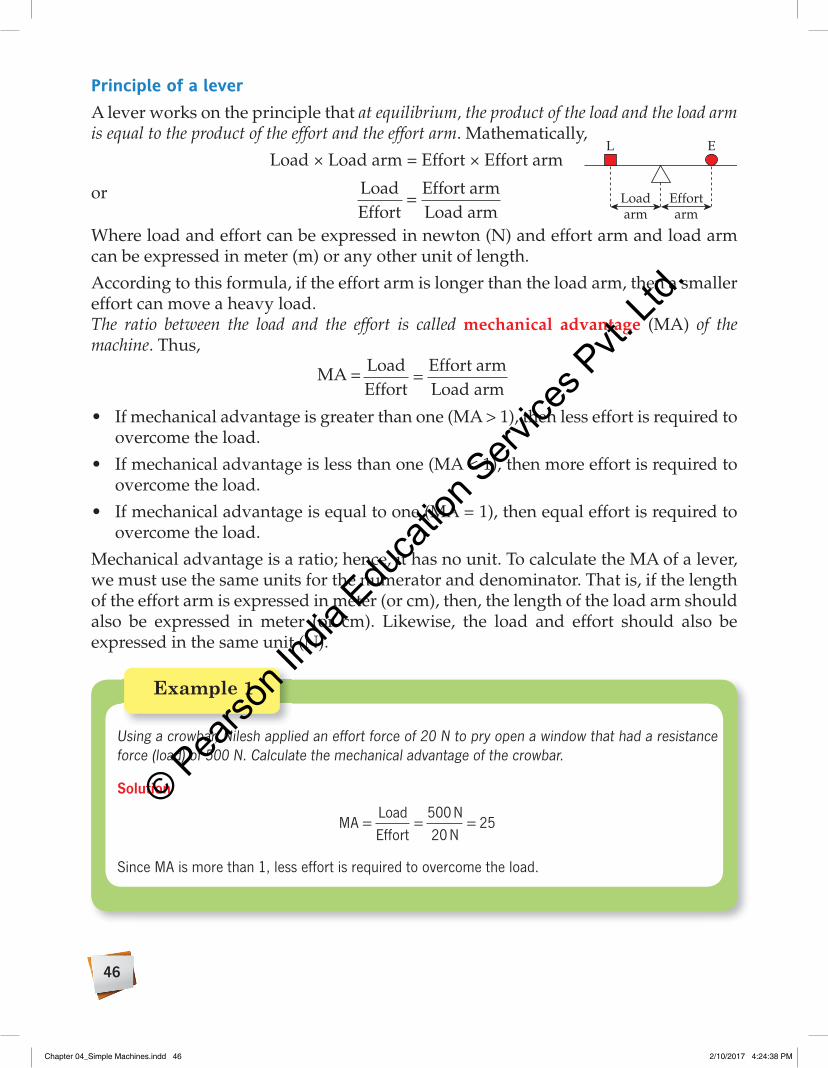
Principle of a leverA lever works on the principle that at equilibrium, the product of the load and the load arm is equal to the product of the effort and the effort arm. Mathematically,
Load × Load arm = Effort × Effort arm
or LoadEffort
Effort armLoad arm
=
Where load and effort can be expressed in newton (N) and effort arm and load arm can be expressed in meter (m) or any other unit of length.
According to this formula, if the effort arm is longer than the load arm, then a smaller effort can move a heavy load.The ratio between the load and the effort is called mechanical advantage (MA) of the machine. Thus,
MA = LoadEffort
Effort armLoad arm
=
• Ifmechanicaladvantageisgreaterthanone(MA>1),thenlesseffortisrequiredtoovercome the load.
• Ifmechanicaladvantageislessthanone(MA<1),thenmoreeffortisrequiredtoovercome the load.
• Ifmechanicaladvantageisequaltoone(MA=1),thenequaleffortisrequiredtoovercome the load.
Mechanical advantage is a ratio; hence, it has no unit. To calculate the MA of a lever, we must use the same units for the numerator and denominator. That is, if the length of the effort arm is expressed in meter (or cm), then, the length of the load arm should also be expressed in meter (or cm). Likewise, the load and effort should also be expressed in the same unit (N).
L
Loadarm
Effortarm
E
Example 1
Using a crowbar, Nilesh applied an effort force of 20 N to pry open a window that had a resistance force (load) of 500 N. Calculate the mechanical advantage of the crowbar.
Solution
MALoadEffort
500 N20 N
25= = =
Since MA is more than 1, less effort is required to overcome the load.
Chapter 04_Simple Machines.indd 46 2/10/2017 4:24:38 PM
© Pearso
n Ind
ia Edu
catio
n Serv
ices P
vt. Lt
d.

47
Example 2
Rohil used a lever to move a bale of hay that weighed 500 N. If the effort arm and load arm were 50 cm and 10 cm long, respectively, calculate the mechanical advantage of the lever.
Solution
MAEffort armLoad arm
50 cm10 cm
5= = =
Since MA is greater than 1, less effort is required to overcome the load.
A lever with an input arm of 2 m has a mechanical advantage of 4. What is the load arm’s length?
Solution
MAEffort armLoad arm
=
⇒ 4
2 mLoad arm
=
⇒
Load arm2 m4
0.5 m= =
The length of load arm is 0.5 m.
Example 3
Types of leversThere are three types of levers, based on the relative positions of fulcrum, load and effort—Class I levers, Class II levers and Class III levers. The structures of these are defined in table 4.1.
Table 4.1 Types of levers
Class StructureClass I Fulcrum between the load and the effortClass II Load between the fulcrum and the effortClass III Effort between the load and the fulcrum
Chapter 04_Simple Machines.indd 47 2/10/2017 4:24:39 PM
© Pearso
n Ind
ia Edu
catio
n Serv
ices P
vt. Lt
d.

48
Class I lever: In a Class I lever, the fulcrum is between the load and the effort (Fig. 4.2). A see-saw, beam balance, crowbar, claw hammer, nail cutter, pliers, wire cutter, hand pump and pair of scissors are examples of Class I levers (Fig. 4.3).
If the effort arm is longer than the load arm, a smaller effort will be required to lift a load, as in case of a crowbar.
If the effort arm is smaller than the load arm, a large effort will be required to lift the load, as in case of a hand pump.
If the effort and the load arms are equal in length, an equal effort will be required to lift a load, as in case of a beam balance or a see-saw.
Load
Effort
Fulcrum
Fulcrum
LoadEffort
Fulcrum
(a) A pair of scissors (b) See-saw (c) Claw hammer
Load
Fulcrum
Effort
Fulcrum
Fulcrum
(d) Pliers (e) Beam balance (f) Hand pump
Fig. 4.3 Class I levers—examples
F
EL
Fig. 4.2 Class I lever—structure
A construction worker uses a board and a small stone (used as fulcrum) as a Class I lever to lift a heavy rock. If the effort arm is 3 m long and the load arm is 0.75 m long, what is the mechanical advantage of the lever?
Solution
MAEffort armLoad arm
3 m
0.75 m4= = =
Since MA is greater than 1, less effort is required to overcome the load.
Pivot pointLoad
Force
Pivot
Example 4
Chapter 04_Simple Machines.indd 48 2/10/2017 4:24:44 PM
© Pearso
n Ind
ia Edu
catio
n Serv
ices P
vt. Lt
d.

49
Class II lever: In a Class II lever, the load lies between the effort and the fulcrum (Fig. 4.4). In Class II levers, the effort arm is always longer than the load arm. So, a small force is required to get the work done. A nutcracker, bottle opener, wheelbarrow and lemon crusher are examples of Class II levers (Fig. 4.5). F
L E
Fig. 4.4 Class II lever—structure
Fulcrum
Load
Effort
Fulcrum
Load
Effort
Effort Load
Fulcrum
(a) Nutcracker (b) Bottle opener (c) Wheelbarrow
Fig. 4.5 Class II levers—examples
Class III lever: In a Class III lever, the effort lies between the fulcrum and the load (Fig. 4.6). In this case, the effort arm is always smaller than the load arm. Thus, a large amount of effort is required to lift a small load. A broom, sugar tong, tweezers and fishing rod are some examples of Class III levers (Fig. 4.7).
Example 5
Yogendra held the handles of a wheelbarrow 2.4 m from where they were attached to the wheel. The heavy stone placed in the wheelbarrow was 1.2 m from the wheel. Calculate mechanical advantage of the wheelbarrow.
Solution
MAEffort armLoad arm
2.4 m1.2 m
2= = =
Since MA is greater than 1, less effort is required to overcome the load.
F
E
L
Fig. 4.6 Class III lever—structure
Chapter 04_Simple Machines.indd 49 2/10/2017 4:24:46 PM
© Pearso
n Ind
ia Edu
catio
n Serv
ices P
vt. Lt
d.

50
1. Identify the type of lever and label the load, effort and fulcrum in the given picture.
2. Fill in the blanks. a. The devices that make our work easier are called ________. b. A ________ machine is a device that has few or no moving parts. c. When the fulcrum is situated near the load, a ________ effort will be required to lift the
load. d. In a ________ lever, the effort and the fulcrum are situated at the ends of the lever. e. In a ________ lever, the effort arm is always smaller than load arm.
Quick Check
Example 6
Anjila was raking leaves in her garden. She held the rake so that its input arm was 0.4 m and its output arm was 1.0 m. What is the mechanical advantage of the rake?
Solution
MAEffort armLoad arm
mm
= = = .
.0 41
0 4
Since MA is less than 1, more effort is required to overcome the load.
Think Through
On a door, the handle is situated at one end of the door and the hinges at the other end. Identify the class of lever the door represents.
F
E
L F
EL
L
E
F
F
E
L
(a) Broom (b) Sugar tong (c) Tweezers (d) Fishing rod
Fig. 4.7 Class III levers—examples
Chapter 04_Simple Machines.indd 50 2/10/2017 4:24:48 PM
© Pearso
n Ind
ia Edu
catio
n Serv
ices P
vt. Lt
d.

51
PulleyA pulley consists of a grooved wheel and a rope that runs through the groove (Fig. 4.8). The wheel rotates on a rod (called axle) that passes through its centre. A pulley is used to lift heavy objects. When the free end of the rope is pulled, the load gets lifted.
A pulley either changes the direction of the applied force or reduces the effort required.
Pulleys are used to draw water from a well, to lift heavy loads, move elevators, etc. In cranes, pulleys and levers work together to lift heavy loads.
There are two types of pulleys—fixed pulley and movable pulley.
Fixed pulleyIn a fixed pulley, the axle is attached to a rigid support. So, the wheel rotates at a fixed place. The load that needs to be lifted is attached to one end of the rope. The effort is applied at the free end of the rope (Fig. 4.9). The length of the rope pulled is equal to the distance moved by the load. So, the magnitude of the effort is equal to that of the load. This means that to lift a load of 60 N, we need to apply an effort of 60 N. However, a fixed pulley changes the direction of effort. So, to lift a load up, we pull the rope down. A fixed pulley is used to draw water from a well or to hoist a flag.
How does the change of direction help? Let us consider the example of drawing water from a well. It is much easier to pull the rope down than to pull it up. However, the effort applied in both the cases is the same. Hence, although the change of direction makes it easy to apply the force (effort), it does not reduce the effort required to lift the load in any way.
Movable pulleyIn a movable pulley, the axle is not fixed to any rigid support. So, the pulley can move up and down. The load is attached to the pulley by a hook. The effort is applied in the same direction in which the load is lifted (Fig. 4.10).
In a movable pulley, we need to pull twice the length of the rope. It reduces the effort needed to lift a weight by half. This means that to lift a load of 60 N, we need to apply an effort of 30 N. However, a movable pulley does not change the direction of the force applied (effort). This means that if the load is to be lifted upwards, we need to pull the rope upwards too. A pulley used to lift heavy engines and fit them into vehicles is an example of a movable pulley (Fig. 4.11).
Wheel
Axle
Rope
Fig. 4.8 Pulley
Load
Effort
Fig. 4.9 Single fixed pulley
Load
E
Fig. 4.10 Single movable pulley
Chapter 04_Simple Machines.indd 51 2/10/2017 4:24:52 PM
© Pearso
n Ind
ia Edu
catio
n Serv
ices P
vt. Lt
d.

52
(a) Lifting bucket from water well (b) Lifting heavy weight (c) Cranes
Fig. 4.11 Usage of pulleys
A combination of fixed and movable pulleys can be used to form a compound pulley.
Inclined PlaneAn inclined plane is a plane surface raised at an angle (Fig. 4.12). You may have seen people use a sloping surface to load things like furniture onto trucks. Sloping surfaces are also built in hospitals and shopping malls for wheelchair-bound people to be able to enter easily. All these are examples of inclined planes.
An inclined plane reduces the effort required to lift a load. It makes the work easier. It is easier to push, pull, roll or slide an object on an inclined plane than lifting it straight up. Although an inclined plane reduces effort, it increases the distance the load has to travel. By increasing the length of an inclined plane, the effort required can be reduced further. Some examples of the usages of inclined planes are given below.
• When goods and luggage are loaded onto ships, boats, trucks or aircrafts, awooden plank or large metal plate is often placed along the vehicle in a slanted manner to make the loading easier (Fig. 4.13).
• Housesareoftenprovidedwithrampsintheshapeofaninclinedplaneinfrontof the garage, to make it easier for a car or motorcycle to enter the garage.
(a) Loading goods in a truck (b) Loading cars in a truck
Fig. 4.13 Inclined planes—examples
Fig. 4.12 An inclined plane
Chapter 04_Simple Machines.indd 52 2/10/2017 4:24:58 PM
© Pearso
n Ind
ia Edu
catio
n Serv
ices P
vt. Lt
d.

53
ScrewA screw is an inclined plane wrapped spirally around a cylinder (Fig. 4.14). The spiral ridges are called threads. One end of the screw is pointed while the other end has a groove. The groove helps in rotating the screw. Let us perform an activity to understand the shape of a screw.
Materials required: Pencil (or a nail), a pair of scissors and a sheet of paper
Procedure and observation: Take the paper and cut it with the help of a pair of scissors into the shape of a right angle triangle. Hold the pencil in an upright position. Now, wrap that triangle-shaped piece of paper around the pencil.
This is the model of a screw. The inclined edge of the paper (hypotenuse of the right triangle) represents the threads of the screw.
ACTIVITY 1 Aim: To understand the shape of a screw
A screw as an inclined plane, wrapped around a cylinder
A screw converts rotational motion to linear motion. For instance, when a screw is rotated on a wooden block with the help of a screw driver, the pointed end of the screw moves downwards into the wooden block. The effort needed for the rotational motion of the screw to produce a downward motion into the wooden block is very less as compared to hammering a nail into it. However, the effort has to be applied for a longer duration of time to drive the screw deeper into the block.
Screws can be used to hold things together or to lift heavy objects. Some real-life examples of screws are given here (Fig. 4.15).
• Fasteningdevices:Screwsareoftenusedtojoinpiecesofmetalorwoodtogether.
A screw holds more firmly than a nail. This is because the threads in a screw interlock with the surrounding materials, resulting in a firm hold.
• Bottlecaps
• Lift heavy objects: Screw jacks are used to lift heavy objects such as cars [Fig. 4.15(c)].
• Spiralstaircases,whichhelpustoclimbupabuildingwithlesseffort[Fig.4.15(d)].
Threads
Fig. 4.14 A screw
Chapter 04_Simple Machines.indd 53 2/10/2017 4:25:01 PM
© Pearso
n Ind
ia Edu
catio
n Serv
ices P
vt. Lt
d.

54
(a) Nut and bolt (b) Cork screw (c) Jack (d) Spiral staircase
Fig. 4.15 Screws—examples
(a) Axe (b) Knife (c) Chisel (d) Nail
Fig. 4.17 Some examples of wedges
WedgeA wedge is a pair of inclined planes put together to form a sharp edge [Fig. 4.16(a)]. Wedges are mainly used to cut things into pieces or to push things apart [Fig. 4.16(b)]. An axe is an example of a wedge. It is used to cut logs of wood into smaller pieces. A knife, a razor, a chisel and a saw are other examples of wedges (Fig. 4.17).
Wheel
Axle
Fig. 4.18 Wheel-and-axle
Fig. 4.16 Wedge
(a) A combination of two inclined planes
(b) Direction of input and output forces by a wedge
Input force
Outputforce
Outputforce
Wheel-and-AxleA wheel-and-axle arrangement consists of a circular disc (wheel) connected to a thin cylindrical rod (axle). The wheel, along with the axle, acts like a simple machine (Fig. 4.18). They rotate each other when a force is applied on any one of them. Wheel and axle help us to turn and move things. For example, when wheels of a handcart move, they turn the axle that carries forward the load mounted over it.
Chapter 04_Simple Machines.indd 54 2/10/2017 4:25:14 PM
© Pearso
n Ind
ia Edu
catio
n Serv
ices P
vt. Lt
d.

55
3. Fill in the blanks.a. A single __________ pulley halves the effort that has to be applied to lift the load.b. Inclined plane __________ the effort required to lift a load.c. A screw is used to convert __________ motion into __________ motion.d. __________ are mainly used to divide or break things apart.e. The cylinder of smaller diameter is called the __________, whereas the cylinder with bigger
diameter is called the __________.
Quick Check
There are two types of wheel-and-axle arrangements.
• When the force is applied on the wheel:Theforce applied (effort) turns the wheel that, in turn, rotates the axle. Such arrangement of wheel and axle is used in doorknobs, screwdrivers, windmills, taps, etc. [Fig. 4.19(a)–(b)].
• When the force is applied on the axle:Theforceapplied(effort)turnstheaxlethat,in turn, rotates the wheel. Such arrangement of wheel and axle is used in a merry-go-round, steering of a vehicle, pedals of a bicycle, fan, etc. [Fig. 4.19(c)–(d)].
By increasing the diameter of the wheel or decreasing the diameter of the axle, the effort required can be reduced.
(a) Doorknob (b) Screw driver (c) Merry-go-round (d) Skating board
Fig. 4.19 Wheel-and-axle—examples
did You Know?
Movement of the hands of a clock is possible because of the gears (toothed wheels) connected to them, which are a form of wheel and axle.
TAKING CArE OF MACHINESMachines play an integral part in our lives. They help us to do tedious tasks with minimum effort. That is why it is important to maintain these machines in proper working conditions. The following methods can be used to enhance the life of different machines. 1. The moving parts of machines should be oiled or greased from time to time.
Proper lubrication reduces wear and tear, and ensures that machines last longer. 2. The parts of the machines which are not moving must be painted or oiled to
prevent rusting. 3. Machines should be covered with cloth or plastic sheets when not in use.
Chapter 04_Simple Machines.indd 55 2/10/2017 4:25:23 PM
© Pearso
n Ind
ia Edu
catio
n Serv
ices P
vt. Lt
d.

56
A. Choose the correct answer.
1. Hockey stick is an example of __________.
a. Class I lever b. Class II lever
c. Class III lever d. All of the above
2. A ramp is an example of __________.
a. a screw b. an inclined plane
c. a wedge d. none of the above
ASSESSMENT TIME
Connecting the Dots
Class II lever
Class III lever
Pulley
Inclined plane
Screw
Wedge
Wheel-and-axle
Class I lever
Simple machines
Lever
Single fixed pulley
Single movable pulley
3. A single fixed pulley is used to __________.
a. change the direction of effort to a convenient direction
b. reduce the effort
c. increase the effort
d. none of the above
KEYWOrdS
• Machine: a device that assists in performing a task
• Lever: a rigid bar or rod which is capable of turning about a fixed point
• Fulcrum: a fixed point about which a lever moves
• Mechanicaladvantage: the ratio between the load and the effort
• Pulley: a circular disc with grooves along its rim
• Axle: a cylindrical rod on which a wheel revolves or which revolves with a wheel
• Inclinedplane: a sloped or slanted plane at an angle with the ground
• Plank: a thick, broad and long piece of timber
• Screw: a nail with a thin strip of metal wrapped in a spiral fashion
• Wedge: a double inclined plane
Chapter 04_Simple Machines.indd 56 2/10/2017 4:25:24 PM
© Pearso
n Ind
ia Edu
catio
n Serv
ices P
vt. Lt
d.

57
3. The force that is applied to overcome the load
c. Single fixed pulley
4. A lever where more effort is required to overcome a load
d. Effort
5. A pulley that moves with the load
e. Class III lever
E. Look at the pictures below and answer the following questions.
1. 2.
3.
a. In figure 1, mark the positions of load, effort and fulcrum.
b. Identify the class of lever displayed in figure 2.
c. Which type of simple machine is shown in figure 3?
F. Answer in brief.
1. List the various types of simple machines.
2. What is a lever? List the various types of levers.
3. Write three uses of pulleys.
4. Give three examples where we use inclined planes.
5. When do we use wedges?
6. List some examples of wheel-and-axle arrangement.
4. An axe is an example of __________.
a. an inclined plane b. a screw
c. a wedge d. a lever
5. Which of the following is the best way to hoist a flag?
a. Using a fixed pulley
b. Using a single movable pulley
c. Using a staircase
d. None of the above
B. Fill in the blanks.
1. __________ is the point about which a lever can rotate.
2. The unit of effort is __________.
3. In Class __________ lever, effort is in between the fulcrum and load.
4. A __________ pulley reduces the effort while lifting a load.
5. A combined pair of inclined planes is called a __________.
C. State whether the following are true or false.
1. In Class III levers, less effort is required to overcome a large force.
2. The wedge converts rotational motion to linear motion.
3. Screws are used to break things apart.
4. The wheel and axle essentially consists of two cylinders of same diameters.
5. In single fixed pulley, the effort is applied in the upward direction.
D. Match the following:
1. A simple machine used to change the direction of effort in a convenient direction
a. Class II lever
2. A lever in which less effort is applied to overcome heavier loads
b. Single movable pulley
Chapter 04_Simple Machines.indd 57 2/10/2017 4:25:31 PM
© Pearso
n Ind
ia Edu
catio
n Serv
ices P
vt. Lt
d.

58
7. Definetheterms:
a. Fulcrum b. Load c. Effort
d. Load arm e. Effort arm
G. Answer in detail.
1. Write the purpose of simple machines.
2. State the principle of a lever and list its uses.
3. Compare Class I and Class II levers.
4. Distinguish between a single fixed pulley and a single movable pulley.
5. A single fixed pulley does not reduce the effort we apply to pull an object, so why do we use it?
6. What is a screw? Write its uses.
7. Explain the wheel-and-axle arrangement with its types.
H. Solve the following numerical problems.
1. A lever used to lift a heavy box has an effort arm of 4 m and a load arm of 0.8 m. What is the mechanical advantage of the lever?
2. A worker uses a crowbar to lift a manhole cover weighing 65 N. The effort arm of the lever is 60 cm long and the load arm is 10 cm long. What is the mechanical advantage of the bar?
3. What is the mechanical advantage of a lever that has an effort arm of 3 m and a load arm of 2 m?
4. If an output force is five times larger than the input force, what is the mechanical advantage?
5. The MA of a lever is 0.5. If the load is 1 N, calculate the effort needed.
APPLICATION-BASEd QUESTIONS 1. Identify the type of pulley in each case. In which case is effort required to pull the bucket filled
with water greater?
a. b. 2. Where would you place object B so that the two objects are balanced?
Chapter 04_Simple Machines.indd 58 2/10/2017 4:25:33 PM
© Pearso
n Ind
ia Edu
catio
n Serv
ices P
vt. Lt
d.

59
3. With reference to Class III levers, answer the following questions.
a. The mechanical advantage will always be less than 1. Explain why.
b. If there is no advantage to Class III levers, why are they considered useful?
CrOSS-CONNECTIONHistory: Compare the tools used by the early humans to the ones you have just read about. Are there any similarities? How are they different?Mathematics: Three of your friends are all sitting on one end of a see-saw. Their weights are 350 N, 400 N and 450 N. If the length from the fulcrum to your friends is 2.5 m and from the fulcrum to you is 4.5 m, what is the MA? What effort force is needed to lift your friends?
LET US EXPLOrE1. Visit a car or motorbike repair shop with your parents. Observe various simple as well as
compound machines at the shop. Make a list of these machines and try to categorise them according to their types.
2. Cooperation and working together: Make groups of five students each and create a collage depicting the different types of simple machines found around you.
3. Problem solving: Yashwant is shifting his home from the ground floor to the first floor. Which machine should he use to bring the heavy boxes out of his old house and which to lift them upto first floor?
Chapter 04_Simple Machines.indd 59 2/10/2017 4:25:33 PM
© Pearso
n Ind
ia Edu
catio
n Serv
ices P
vt. Lt
d.

60
LiGHtYou cannot see anything in a dark room, but when a bulb is switched, on everything becomes visible. Similarly, you can see things clearly during the day, but not at night.
So, what is it that enables you to see things around you?
The magic word is ‘light’. During the day, the sun gives us light. This light enables us to see everything around us. In a dark room, the electric bulb produces light that enables us to see things. So, we are able to see things because of light. We see an object only when the light from it reaches our eyes.
WHAt iS LiGHt?How do devices such as mobile phones, microwave oven, remote control and scanning machines function? These gadgets use electromagnetic radiations such as radiowaves, microwaves, infrared waves and X-rays. We cannot see any of these radiations. Light is also an electromagnetic wave that we can detect. Do you know that sound waves need a medium like air to travel? That is why we cannot hear the sound of a ringing bell in vacuum.
5
Learning Objectives
• Give examples of evidence that light travels in straight lines
• Explain the formation of shadows• Explain the occurrence of lunar and solar eclipse• Explain the terms umbra and penumbra
• Describe principle, construction and working of pinhole camera
• Explain the factors on which the size of the image in a pinhole camera depends upon
Light and Shadows
Chapter 05_Light and Shadows.indd 60 2/10/2017 4:21:09 PM
© Pearso
n Ind
ia Edu
catio
n Serv
ices P
vt. Lt
d.

61
Light does not need any material medium. It can even travel through vacuum. The vast space between the sun and the earth is mostly a vacuum. Still the light from the sun is able to travel through space before entering earth’s atmosphere.
Light travels at a speed of 30,00,00,000 m/s. This is the ultimate speed known. Even at this enormous speed, light takes about 500 s to reach the earth.
Since there is no matter to reflect light rays, the space beyond earth’s atmosphere appears black. Inside the earth’s atmosphere, the air particles deflect light from its path. Light undergoes multiple deflections like these in earth’s atmosphere. It is due to these multiple deflections that our sky appears illuminated during the day.
more About LightWhy is light important to us? Light is a form of energy that is essential for the existence of life. The natural warmth of the sunlight creates conditions conducive for the growth and development of life. It is the main source of energy for animals and plants. All green plants depend on the energy of light to prepare their food during the process of photosynthesis. Without sunlight, the process of photosynthesis will not take place and most plant species will cease to exist. This would disturb all food chains, as plants are the first element in any food chain. In the absence of photosynthesis, the supply of oxygen in air would also be disturbed. There would not be enough oxygen for animals and humans to breathe. Without natural light, our dependence for energy on fossil fuels will increase. This would lead to faster depletion of the fossil fuel reserves. Thus, without natural light, the existence of all living beings will be in danger.
How does light help us to see things? Some objects have their own light. When this light reaches our eyes, we are able to see them. Others do not emit their own light. When such objects receive light from a light-emitting object, some part or whole of the light is reflected back. When this reflected light reaches our eyes, it forms an inverted image of the object on the retina. The retina sends the signal to the brain through the optic nerve. The brain interprets this signal or image and sees the erect image of the object.
SOUrCeS OF LiGHtAnything that gives out light is a source of light. The sun is theprimary source of light on earth. The various sources of light can be broadly categorised into two types: natural sources and artificial (or man-made) sources.
Know your ScientistIn 1865, a Scottish scientist named James Clerk Maxwell (1831–1879) proposed that light is an electromagnetic wave.
(a) Natural
Chapter 05_Light and Shadows.indd 61 2/10/2017 4:21:12 PM
© Pearso
n Ind
ia Edu
catio
n Serv
ices P
vt. Lt
d.
62
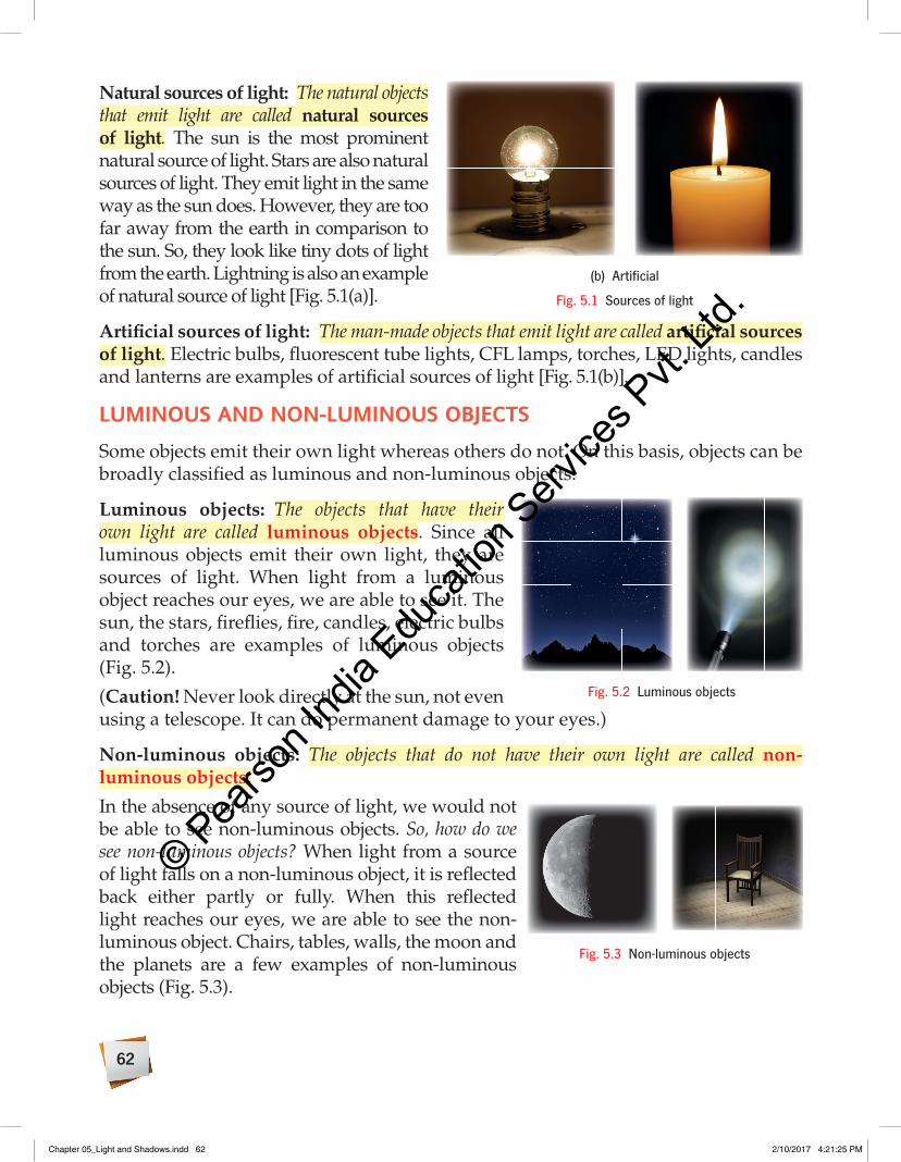
Natural sources of light: The natural objects that emit light are called natural sources of light. The sun is the most prominent natural source of light. Stars are also natural sources of light. They emit light in the same way as the sun does. However, they are too far away from the earth in comparison to the sun. So, they look like tiny dots of light from the earth. Lightning is also an example of natural source of light [Fig. 5.1(a)].
Artificial sources of light: The man-made objects that emit light are called artificial sources of light. Electric bulbs, fluorescent tube lights, CFL lamps, torches, LED lights, candles and lanterns are examples of artificial sources of light [Fig. 5.1(b)].
LUmiNOUS AND NON-LUmiNOUS OBJeCtSSome objects emit their own light whereas others do not. On this basis, objects can be broadly classified as luminous and non-luminous objects.
Luminous objects: The objects that have their own light are called luminous objects. Since all luminous objects emit their own light, they are sources of light. When light from a luminous object reaches our eyes, we are able to see it. The sun, the stars, fireflies, fire, candles, electric bulbs and torches are examples of luminous objects (Fig. 5.2).
(Caution! Never look directly at the sun, not even using a telescope. It can do permanent damage to your eyes.)
Non-luminous objects: The objects that do not have their own light are called non-luminous objects.
In the absence of any source of light, we would not be able to see non-luminous objects. So, how do we see non-luminous objects? When light from a source of light falls on a non-luminous object, it is reflected back either partly or fully. When this reflected light reaches our eyes, we are able to see the non-luminous object. Chairs, tables, walls, the moon and the planets are a few examples of non-luminous objects (Fig. 5.3).
Fig. 5.2 Luminous objects
(b) Artificial
Fig. 5.1 Sources of light
Fig. 5.3 Non-luminous objects
Chapter 05_Light and Shadows.indd 62 2/10/2017 4:21:25 PM
© Pearso
n Ind
ia Edu
catio
n Serv
ices P
vt. Lt
d.

63
Can a non-luminous object be converted into a luminous object? Yes—when some non-luminous objects are heated to a high temperature, they start emitting light. For example, when a metal is heated to a very high temperature, it becomes luminous and emits red light. If the heating is continued, then it turns yellow and eventually white.
Why are the moon and other planets considered non-luminous objects? It is because they do not emit light of their own. The planets in the solar system and their moons reflect the light of the sun falling on them. Figure 5.4 shows the moon reflecting the light emitted by the sun.
Bioluminescence: A natural phenomenon in which living organisms are seen to emit light from their body is known as bioluminescence. Fireflies, glow-worms, certain aquatic animals, algae, jellyfish and a few species of phytoplankton are known to exhibit bioluminescence (Fig. 5.5). This phenomenon occurs due to a chemical reaction in their bodies in which chemical energy is converted into light energy. Since this process gives off very little heat, the light emitted in this process is also called cold light.
trANSPAreNt, trANSLUCeNt AND OPAQUe mAteriALSYou may have observed that some objects allow light to pass through them whereas some objects block it completely. On this basis, different materials can be broadly categorised into three types—transparent, translucent and opaque materials.
Transparent materials: Materials through which light can pass completely are called transparent materials. Glass, alcohol, water and air are examples of transparent materials. We can see clearly through transparent materials or objects. For example, we can see through glass windows and view things across them (Fig. 5.6).
Translucent materials: Materials through which light can pass only partially are called translucent materials. Frosted glass and butter paper are examples of translucent materials. We cannot see clearly through translucent materials or objects. For example, objects seen through the frosted glass of a bathroom window look hazy (Fig. 5.7).
Opaque materials: Materials through which no light can pass are called opaque materials. Wood, metals, brick walls, rubber and books are examples of opaque materials.
Fig. 5.4 Moon reflects the sunlight
Did you Know
Humans are bioluminescent. The metabolic reactions in the human body emit light. The glow of this light is very feeble to eyes.
Fig. 5.5 A firefly emitting light from its body
Chapter 05_Light and Shadows.indd 63 2/10/2017 4:21:30 PM
© Pearso
n Ind
ia Edu
catio
n Serv
ices P
vt. Lt
d.

64
We cannot see through opaque materials or objects. For example, we cannot see through a wooden board (Fig. 5.8).
Fig. 5.6 Transparent material Fig. 5.7 Translucent material Fig. 5.8 Opaque material
1. Fill in the blanks.
a. The speed of light in air is __________.
b. The __________ is the primary source of light on earth.
c. An object that emits light on its own is called __________.
d. Materials through which light can pass only partially are called __________.
e. __________ materials do not allow any light to pass through them.
Quick Check
reCtiLiNeAr PrOPAGAtiON OF LiGHtWhen a bulb is switched on in a dark room, it spreads light across the room. As a result, we can see the objects in the room. However, some places in the room still appear dark. What could be the reason for this? It happens because light travels in a straight line. If an opaque object comes in the path of light, the light ceases to continue on its straight-line path. So, some regions in the room do not receive any light. Such regions appear dark.
The property that light travels in a straight line is called rectilinear propagation of light.
At night, the light from the headlight of a car or bike seems to go straight-forward. This is due to rectilinear propagation of light. It can also be observed when a straight-narrow beam of sunlight enters a dark room.
Let us perform the following activities to verify this property.
Chapter 05_Light and Shadows.indd 64 2/10/2017 4:21:32 PM
© Pearso
n Ind
ia Edu
catio
n Serv
ices P
vt. Lt
d.

65
Materials required: Candle and rubber pipeProcedure and observation: Place a lit candle on the table. Keep the rubber pipe straight and look at the flame of candle through one end of the pipe. You will observe that the flame of the candle is visible. Now, bend the pipe and try to observe the candle flame through it. You will observe that the flame is not visible through the bent pipe.Conclusion: The above observation shows that light travels in a straight line.
ACTIVITY 1 Aim: To understand the propagation of light
(a) When the pipe is straight (b) When the pipe is bent
Observing the flame of a candle through a rubber pipe
ACTIVITY 2 Aim: To verify that light travels in a straight line
Rectilinear propagation of light
Materials required: Three cardboards of equal size, needle, flat table and candleProcedure and observation: Stack three cardboards. Make small holes at the centre of each cardboard with the help of a needle. Place them on the flat table so that they are all upright and at the same distance from each other. Ensure that the holes are in a straight line. Take a lit candle of the same height as that of the holes from the table and place it directly in front of the first cardboard’s hole as shown in the figure. Make sure that the cardboard does not catch fire. Look through the hole of the third the cardboard. You will observe that the flame of the candle is visible. Now, shift any one of the pieces of cardboard out of line. You will observe that the flame is no longer visible.Conclusion: When the holes are in a straight line, light passes through that straight line. When the alignment of holes is disturbed, light does not get a straight-line path to reach the observer’s eye. This verifies rectilinear propagation of light.
The above activities show that light travels in a straight line. The path travelled by light in a straight line is represented with the help of ray of light (Fig. 5.9). The arrowhead indicates the direction in which light travels.
Fig. 5.9 A ray of light
Chapter 05_Light and Shadows.indd 65 2/10/2017 4:21:37 PM
© Pearso
n Ind
ia Edu
catio
n Serv
ices P
vt. Lt
d.

66
Let us learn about some other terms associated with light.
Beam of light: A bunch of rays of light is called a beam of light. Depending upon the size of the source of light, a beam of light can be parallel, divergent or convergent.
Parallel beam of light: A beam of light is said to be parallel if the rays of the beam are parallel to one another. A parallel beam of light does not spread in all directions. A beam of light emitted by a laser light is an example of a parallel beam of light. Also, the beam of light originating from any distant object like the sun or from a large object such as a flashlight and searchlight is considered as a parallel beam (Fig. 5.10). The source of light that emits parallel beam of light is called an extended source of light. An extended source of light casts light rays which originate from an area larger than a point.
Divergent beam of light: A beam of light is said to be divergent if the rays of the beam spread out from a point. Some of the common sources of light that generate divergent beams include LEDs, bulbs and candles. The source of light that emits divergent beam of light is called point source of light. A point source of light casts light rays originating from a single point (Fig. 5.11).
Convergent beam of light: A beam is said to be convergent if the rays of the beam approach towards a common point. For instance, when a beam of light is passed through a magnifying glass, the rays are bent and eventually converge or meet at a point. Figure 5.12 depicts the nature of a convergent beam.
Pinhole CameraWe have learnt that light emitted from an object travels in a straight line. By making the beams of light fall on a screen without blocking their path along a straight line, we can get the image of an object on that screen.
A pinhole camera is one of the simplest imaging devices that projects the image of an object on a screen. A pinhole camera works on the principle of rectilinear propagation of light. Interestingly, before the advancements in the design of camera, the pinhole camera was used to take photographs of stationary objects. The pinhole camera can also be used to photograph the movement of the sun over a long period of time. This type of photography is called solargraphy and can also be used to observe and record solar eclipses.
Extended source of light
Fig. 5.10 A parallel beam of light
Point source of light
Fig. 5.11 A divergent beam of light
Fig. 5.12 A convergent beam of light
Chapter 05_Light and Shadows.indd 66 2/10/2017 4:21:38 PM
© Pearso
n Ind
ia Edu
catio
n Serv
ices P
vt. Lt
d.

67
A pinhole camera forms real and inverted image of an object.
Construction: A pinhole camera consists of a cuboidal box with a pin-sized hole on one face and a translucent screen on the opposite face. The remaining walls of the box are coloured black or covered with black paper.
Let us perform an activity to construct a pinhole camera and to observe the images of various objects.
Materials required: Empty shoebox, black paint or water colour, a pair of scissors, butter paper, adhesive tape, pin and candleProcedure:• Take the shoebox, remove its
cover and paint it black from inside. Also, paint the inside surface of the cover of the box.
• Make a small hole by pricking with a pin at the centre of one of the faces of the box.• Cut and remove the face opposite to the pinhole. Cover this opening with a sheet of butter
paper. Fix it firmly to the box with the help of adhesive tape. This modified face acts as the screen of the pinhole camera.
• Put the cover back on the box and seal the gaps with the help of opaque adhesive tape so that light cannot enter through these gaps. The pinhole camera is now ready.
• Place a lit candle at some distance in front of the pinhole. Adjust the position of the pinhole and the screen with respect to the candle. Do you observe anything on the screen?
Observation: You will observe the inverted image of the lit candle on the screen. You may need to adjust the position of the pinhole camera around the candle to observe a clear image.
ACTIVITY 3 Aim: To construct a pinhole camera
Pinhole camera
Formation of image by a pinhole camera
B′O
A(a) Image formation by a pinhole camera
Pinhole
(b) Ray diagram
BA′S
Fig. 5.13 A pinhole camera
Observe the images of various other brightly lit objects through the pinhole camera you have created.
Working of a pinhole camera: The rays of light from the candle spread out in all directions. Some of them enter the box through the pinhole [Fig. 5.13(a)]. Let us consider two light rays as illustrated in a simple ray diagram shown in figure 5.13(b). One ray starting from A and passing along the straight line AO
Chapter 05_Light and Shadows.indd 67 2/10/2017 4:21:45 PM
© Pearso
n Ind
ia Edu
catio
n Serv
ices P
vt. Lt
d.

68
strikes the screen at A′. In a similar way, another ray starting from B and passing along BO strikes the screen at B′. All other rays in between A and B fall on the screen between A′ and B′. Thus, A′B′ becomes the image of AB, which appears on the screen S of the pinhole camera.
The image produced is temporary if a simple piece of paper is used. The image can be made permanent by placing a photographic plate in place of the screen.
Variations caused by changing the distance between the screen and the pinhole:
• When the distance between the screen and thepinhole is increased, the size of the image formed on the screen will increase, as illustrated in figure 5.14(a). However, the image will be less bright and blurred. This happens because the light entering from the pinhole travels a longer distance to reach the screen and spreads over a larger area.
• When the distance between the screen and thepinhole is decreased, the size of the image formed on the screen will decrease, as illustrated in figure 5.14(b). In this case, the image will be brighter and clearer as the light entering from pinhole travels a shorter distance to reach the screen and concentrates over a very small area.
Variation caused by size of the pinhole: In case a bigger hole is used instead of a pin-sized hole, the image generated will be blurred. To understand this, let us consider a large hole to be made of a bunch of smaller pinholes. In this case, each pinhole will create a separate image on the same screen. All these images will overlap each other, thus forming a single blurred image. This is the reason why a small pin-sized hole is necessary to make a pinhole camera.
2. Fill in the blanks.
a. __________ travels in a straight line.
b. The __________ along which light travels is called a ray of light.
c. An extended source of light emits a __________ beam of light.
d. When a beam of light is passed through a magnifying glass, it produces a __________ beam of light.
e. When the distance between the screen and pinhole is __________, the image will be less bright and blurred.
Quick Check
(a) Distance between the screen and the pinhole is increased
(b) Distance between the screen and the pinhole is decreased
Fig. 5.14 Variation in the size of image
Chapter 05_Light and Shadows.indd 68 2/10/2017 4:21:47 PM
© Pearso
n Ind
ia Edu
catio
n Serv
ices P
vt. Lt
d.
69
SHADOWSWe know that an opaque object does not allow light to pass through it. When an opaque object is placed between a luminous object and a screen, a part of light is blocked by the opaque object. This blocked light does not reach the screen. A dark patch is observed on the screen in its place. The dark patch formed due to obstruction of light by an opaque object is called the shadow of the opaque object.
Different objects cast different kinds of shadows. Opaque objects, such as wooden boards or steel utensils, cast dark shadows. Translucent objects, such as a frosted glass or thick plastic sheet, cast weak shadows. However, transparent objects, such as glass or clear water, do not cast a shadow.
Conditions for the Formation of a ShadowThere are three basic conditions for the formation of a shadow:
• Theremustbeasourceoflight.
• Theremustbeanopaqueobjecttoobstructthelight.
• Theremustbeanopaquescreenonwhichtheshadowappears.
If any of these conditions is not fulfilled, a shadow will not form. For example, we cannot see the shadow in a dark room as there is no source of light. As soon as we turn on the light, the shadows of different opaque objects begin to appear on the floor or the wall, which acts as an opaque screen.
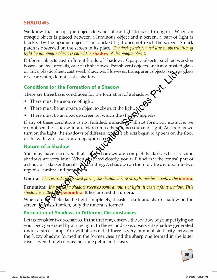
Nature of a ShadowYou may have observed that some shadows are completely dark, whereas some shadows are very faint. When observed closely, you will find that the central part of a shadow is darker than its surrounding. A shadow can therefore be divided into two regions—umbra and penumbra.
Umbra: The central and darkest part of the shadow where no light reaches is called the umbra.
Penumbra: If a part of a shadow receives some amount of light, it casts a faint shadow. This shadow is called the penumbra. It lies around the umbra.
When an object blocks the light completely, it casts a dark and sharp shadow on the screen. In this situation, only the umbra is formed.
Formation of Shadows in Different CircumstancesLet us consider two scenarios. In the first one, observe the shadow of your pet lying on your bed, generated by a tube light. In the second case, observe its shadow generated under a street lamp. You will observe that there is very minimal similarity between the fuzzy shadow formed in the former case and the sharp one formed in the latter case—even though it was the same pet in both cases.
Chapter 05_Light and Shadows.indd 69 2/10/2017 4:21:47 PM
© Pearso
n Ind
ia Edu
catio
n Serv
ices P
vt. Lt
d.

70
This is because the nature of the shadow formed in a certain situation depends on much more than just the object. The size, shape and brightness of any shadow depend on:
• The nature of the source of light: The source of light may be either a point source or an extended source.
• The size of the object (if an extended source of light is used): The object might be bigger or smaller than the source.
• The relative positions of the source, object and screen.
Also, if the screen is shifted away from the object, the shadow will become bigger and fainter. If the object is brought towards the source, the shadow will become larger. Let us discuss some of the possible cases of formation of shadows.
Shadow formed by a point source of lightLet us perform an activity to observe the shadow of an opaque object formed by a point source of light.
Materials required: Torch, black paper, pin, tennis ball and white boardProcedure: Cover the front of the torch by pasting black paper on it. Make a small hole with the help of a pin. This point-sized hole acts as a point source of light. Take a tennis ball and place it in front of the torch. Place a white board behind the ball as shown in the figure. This white board acts as a screen. Now, switch on the torch and observe the shadow of ball formed on the white board. What will happen when the white board (screen) is moved away or towards the ball (opaque object)?Observation and conclusion:• A dark shadow forms on the white board. This area of dark shadow is the umbra.• The shape of the umbra is similar to that of the object, but its size is larger than the object.• When the screen is moved away from the object, the size of the umbra increases but the
darkness of the umbra decreases. Thus, the size of the shadow increases with increase in distance between the object and the screen.
• When the screen is moved towards the object, the size of the umbra decreases but the darkness of the umbra increases. Thus, the size of the shadow decreases with decrease in distance between the object and the screen.
ACTIVITY 4 Aim: To observe the shadow formed by a point source of light
White board
Umbra
Tennisball
Pointsourceof light
Shadow formed by a point sourceof light
Did you Know
Ancient people used sundials to determine the time of a day. It was done by tracking the shadow cast by gnomon (a flat triangular blade) on the dial. As the sun appears to move across the sky, the shadow of the gnomon also moves on the dial. Its shadow is aligned with different hour lines marked on the dial to indicate the time of a day.
Chapter 05_Light and Shadows.indd 70 2/10/2017 4:21:51 PM
© Pearso
n Ind
ia Edu
catio
n Serv
ices P
vt. Lt
d.

71
From the above activity, we conclude that an opaque object, placed in front of the beam of light from a point source of light, casts a dark shadow (umbra) on the screen. The two rays of light (divergent beam) from the point source pass by the two extremities of the opaque object and strike the screen. The area enclosed by these rays on the screen will not receive any light from the source and forms only umbra on the screen.
Shadow formed by an extended source of lightWhen the source is smaller than the objectLet us perform an activity to observe the shadow of an opaque object (larger size) formed by an extended source (smaller size) of light.
Materials required: Torch, black paper, pencil, stationery knife, tennis ball and white boardProcedure: Paste a black paper on the front of a torch. Mark a circle of about 1 cm diameter, on the black paper by a pencil. Cut this portion with the help of the stationery knife and remove it. This circular portion acts as an extended source of light. Take a tennis ball and place it in front of the torch. Place a white board (screen) behind the ball as shown in the figure. Now, switch on the torch and observe the shadow of the ball formed on the white board. What will happen when the white board (screen) is moved away or towards the ball (opaque object)?Observation and conclusion:• A dark shadow surrounded by a faint shadow forms on the white board. A small region
outside the dark shadow receives partial amount of light from the extended source of light. That is why a faint shadow forms around the dark shadow. These areas of dark and faint shadows are umbra and penumbra.
• The size of umbra is larger than the object.• When the screen is moved away from the object, the size of the umbra and penumbra
increases. Thus, the size of the shadow increases with an increase in the distance between the object and the screen.
• When the screen is moved towards the object, the size of the umbra and penumbra decreases. Thus, the size of the shadow decreases with a decrease in the distance between the object and the screen.
ACTIVITY 5Aim: To observe the shadow formed by an extended source of light (smaller than the size of object)
Tennisball
Extendedsource of
light
White boardPenumbra
Umbra
Shadow formed when the source is smaller than the object
Chapter 05_Light and Shadows.indd 71 2/10/2017 4:21:56 PM
© Pearso
n Ind
ia Edu
catio
n Serv
ices P
vt. Lt
d.

72
When an opaque object is placed in front of the beam of light from an extended source of light, having size smaller than the object as shown in figure of activity 5, it casts a shadow that has two distinct regions—a dark shadow (umbra) and a faint shadow (penumbra).
When the source is larger than the object
Let us perform an activity to observe the shadow of an opaque object (smaller size) formed by an extended source (larger size) of light.
Materials required: Torch, table tennis ball and white boardProcedure: Take a table tennis ball and place it in front of the torch. Place a white board (screen) behind the ball as shown in the figure. Switch on the torch and observe the shadow of the ball formed on the white board. What will happen when the white board (screen) is moved away or towards the ball (opaque object)?Observation and conclusion:• A small and dark shadow (umbra) surrounded by a
faint shadow (penumbra) forms on the white board. A large region outside the dark shadow receives partial amount of light from the extended source of light. That is why a faint shadow forms around the dark shadow.
• The size of umbra is smaller than the object. In fact, the umbra is also smaller than the penumbra.
ACTIVITY 6Aim: To observe the shadow formed by an extended source of light (larger than the size of object)
Tennisball
Extendedsource of
light
White boardPenumbra
Umbra
Shadow formed when the source is larger than the object
Thus, when the source is larger than the object, the size of the umbra is smaller than the object. In fact, the size of umbra is smaller than that of the penumbra. However, when the screen is moved away from the object, the size of the umbra further decreases but the size of the penumbra increases. If the screen continues to move away from the object, then a stage will be reached when the umbra will become a point and will vanish completely if moved further. The shadow will consist of the penumbra only.
think through
Why do birds not cast shadows on the ground when flying at a great height?
Chapter 05_Light and Shadows.indd 72 2/10/2017 4:22:00 PM
© Pearso
n Ind
ia Edu
catio
n Serv
ices P
vt. Lt
d.

73
eCLiPSeEclipses are examples of formation of shadows in nature. In the solar system, the sun is the source of light. An eclipse occurs when a heavenly body (such as a planet or a moon) comes in the way of the light emitted by the sun and casts a shadow on another heavenly body.
We know that the earth revolves around the sun while the moon revolves around the earth. During their motion, there are times when the moon comes between the sun and the earth. At times, the moon blocks the sunlight from reaching the earth. Sometimes the earth blocks the sunlight from reaching the moon. Thus, on the earth, we commonly see two kinds of eclipses—lunar eclipse and solar eclipse.
Let us perform an activity to understand the formation of an eclipse.
Materials required: Torch, globe and one small ballProcedure and observation: Place the globe on a table. Switch on the torch at some distance from the globe as shown in figure (a). You will observe that half the portion of the globe is illuminated by the torch’s light. Switch off the torch. Now, suspend the ball between the torch and the globe. Switch on the torch. You will observe that the ball casts a shadow on the globe as shown in figure (b). This is how an eclipse occurs.
ACTIVITY 7 Aim: To understand the formation of an eclipse
(a) No shadow on the globe
(b) A shadow cast by the ball on the globeFormation of an eclipse
In activity 7, we can consider the torch as the sun, the ball as the moon and the globe as the earth.
Lunar eclipseOn a full moon night, the sun and the moon are on the opposite sides of the earth. However, they are not aligned in a straight line. So, we see the full illuminated face of the moon. On certain full moon nights, the sun, the earth and the moon align in a perfect straight line. The earth, being in the middle, blocks the light from the sun and casts its shadow on the moon. The moon becomes either fully or partially invisible during the time it is in the shadow. This natural phenomenon in which the
Chapter 05_Light and Shadows.indd 73 2/10/2017 4:22:03 PM
© Pearso
n Ind
ia Edu
catio
n Serv
ices P
vt. Lt
d.

74
moon hides in the shadow of the earth is called lunar eclipse. There are three types of lunar eclipses—penumbral, partial and total.
Penumbral lunar eclipse: Penumbral lunar eclipse occurs when the entire moon is in the penumbra of the earth’s shadow [Fig. 5.15(a)]. In this position, the moon is visible from the earth, but appears pale.
Partial lunar eclipse: Partial lunar eclipse occurs when a part of the moon is in the umbra while the remaining part is in the penumbra [Fig. 5.15(b)]. In this position, the moon is only partially visible from the earth.
Total lunar eclipse: Total lunar eclipse occurs when the moon is completely in the umbra region of earth’s shadow [Fig. 5.15(c)]. In this position, the moon is not visible from the earth.
Umbra
Moon’s orbit
Penumbra
(a) Penumbral lunar eclipse (b) Partial lunar eclipse (c) Total lunar eclipse
Fig. 5.15 Various forms of lunar eclipses
When the moon emerges out of the shadow of the earth, it becomes visible again and appears as bright as it was before entering the shadow.
Solar eclipseDuring its motion around the earth, the moon often comes in between the sun and the earth. In this position, the dark face of the moon is towards the earth. This phase of the moon is called the new moon phase. On a new moon day, when the sun, the moon and the earth align in a perfect straight line, the moon casts its shadow on the earth. As a result, the sun may become invisible, partly or fully, from regions of the earth that fall in the shadow of the moon. This natural phenomenon in which the moon hides the sun by casting a shadow on the surface of the earth is called solar eclipse. The solar eclipse occurs only on a new moon day, when the sun, moon and earth are in a perfect straight line. The sun appears again when the moon moves away from this position.
To experience the solar eclipse, one has to be on sunny side of the earth. Even on this side, not everyone will be able to experience solar eclipse. This is because the moon is very small as compared to the earth. So, its shadow on the earth will be formed on a very small region. The solar eclipse will be observed only in the areas falling in this region.
Chapter 05_Light and Shadows.indd 74 2/10/2017 4:22:09 PM
© Pearso
n Ind
ia Edu
catio
n Serv
ices P
vt. Lt
d.

75
There are four types of solar eclipses—total, partial, annular and hybrid.
Total solar eclipse: Total solar eclipse occurs when the moon completely hides the sun. It occurs in the region that falls in the umbra of the moon’s shadow [Fig. 5.16(a)]. The sun is not at all visible in this region.
Partial solar eclipse: Partial solar eclipse occurs when the moon hides only a part of the sun. It occurs in the region that falls in the penumbra of the moon’s shadow [Fig. 5.16(a)]. The sun is only partially visible in this region.
Annular solar eclipse: Annular solar eclipse occurs when only the circumference of the sun is visible as a bright circular ring (Fig. 5.17). The central portion of the sun is completely blocked by the moon. This occurs when only the tip of the moon’s umbra touches the earth [Fig. 5.16(b)].
Hybrid solar eclipse: A hybrid solar eclipse occurs when a total solar eclipse is visible on some part of the earth but an annular solar eclipse is visible on another part of the earth at the same time.
The size of the moon is very small compared to the size of the earth, so the earth easily passes through the shadow cast by the moon. This is also why, most of the time, the shadow of the moon does not reach the earth, making solar eclipses a rare event.
Fig. 5.17 A bright circular ring during annular solar eclipse
Penumbraenumbraenumbra Earth’sorbit
MoonMoon
Sun Total eclipseotal eclipseTotal eclipseT EarEarthMoon’Moon’Moon’s
orbitPartial eclipsetial eclipse
UmbraUmbraUmbraUmbra
(a) Total solar eclipse and partial solar eclipse
Earth
(b) Annular solar eclipse
Fig. 5.16 Solar eclipse
Chapter 05_Light and Shadows.indd 75 2/10/2017 4:22:17 PM
© Pearso
n Ind
ia Edu
catio
n Serv
ices P
vt. Lt
d.

76
3. Fill in the blanks.
a. __________ are formed due to the obstruction of light.
b. The central and darkest part of the shadow where no light reaches is called the __________.
c. An __________ is an astronomical event.
d. There are __________ types of lunar eclipses.
e. In an annular solar eclipse, only __________ of the sun is visible.
Quick Check
Connecting the Dots
Facts aboutlight
Speed of light Has the fastest possible speed inthe universe
Sources of lightNatural sources of light
Artificial sources of light
Rectilinear propagationof light Light travels in a straight line
Luminous
Non-luminous
Formed when opaque objects blockthe path of light
Eclipses:Formation of shadows in
nature
Solar eclipse
Lunar eclipse
Transparent
Translucent
Opaque
Shadows
Can be used to classifymaterials
Can be used to classifyobjects
Chapter 05_Light and Shadows.indd 76 2/10/2017 4:22:18 PM
© Pearso
n Ind
ia Edu
catio
n Serv
ices P
vt. Lt
d.

77
KeyWOrDS
• Light: a form of energy that creates the sensation of vision
• Electromagneticwave: a type of wave which transports energy through vacuum
• Luminousobjects: objects that have their own light
• Non-luminousobjects: objects that do not have their own light
• Bioluminescence: a natural phenomenon in which living organisms are seen to emit light from their body
• Transparentmaterials: materials through which light can pass completely
• Translucentmaterials: materials through which light can pass only partially
• Opaquematerials: materials through which no light can pass
• Rectilinear: moving in a straight line• Shadow: dark patch formed due to
obstruction of light by an opaque object • Umbra: a dark shadow• Penumbra: a faint shadow• Eclipse: a natural phenomenon of
obstruction of light by a heavenly body that casts a shadow on another heavenly body
• Lunareclipse: a natural phenomenon in which the moon hides in the shadow of the earth
• Solareclipse: a natural phenomenon in which the moon hides the sun by casting a shadow on the surface of the earth
A. Choose the correct answer.
1. Which of the following is an example of a natural source of light?
a. Lighted spirit lamp b. Star
c. Torch d. Oil lamp
2. Which of the following is a non-luminous body?
a. Red-hot iron ball b. Moon
c. Firefly d. Tube light
3. Which kind of beam of light is emitted from a flashlight?
a. Parallel beam of light
b. Convergent beam of light
c. Divergent beam of light
d. Both (b) and (c)
4. If the distance between the pinhole and the screen is reduced, the image will become
a. smaller and brighter.
b. larger and fainter.
c. smaller and fainter.
d. larger and brighter.
5. If the size of an extended source is bigger than the object, then
a. the umbra of the shadow is spread over a larger area than the penumbra.
b. the penumbra of the shadow is spread over a larger area than the umbra.
c. the umbra and penumbra of the shadow have equal areas.
d. both (b) and (c) are correct
ASSeSSmeNt time
Chapter 05_Light and Shadows.indd 77 2/10/2017 4:22:20 PM
© Pearso
n Ind
ia Edu
catio
n Serv
ices P
vt. Lt
d.

78
B. Fill in the blanks.
1. Light is a form of __________.
2. The medium through which light can pass easily is called __________.
3. A bunch of rays is called __________.
4. Lunar eclipse occurs only on __________ nights.
5. In a solar eclipse, the __________ comes in between the earth and the sun.
C. State whether the following are true or false.
1. The sunlight takes about 8 minutes 20 seconds to reach the earth from the sun.
2. Planets are luminous objects.
3. There must be a source of light for the formation of a shadow.
4. Penumbra is the darkest part of the shadow.
5. Hybrid solar eclipse is a combination of total and partial solar eclipses.
D. Match the following:
1. A shadow of complete darkness
a. Full moon night
2. Solar eclipse b. Umbra3. A shadow of partial
darknessc. Inverted image
4. Image formed by a pinhole camera
d. Penumbra
5. Lunar eclipse e. New moon day
E. In the given picture, identify the umbra and penumbra of the shadow shown on the screen.
F. Answer in brief.
1. Why are the moon and planets considered to be non-luminous?
2. Which kind of beam of light is emitted by a laser light?
3. What are the two parts of a shadow?
4. State the principle of the pinhole camera.
5. When does a partial solar eclipse occur?
G. Answer in detail.
1. What is bioluminescence? Give some examples.
2. What is a shadow? Write the three conditions necessary for the formation of a shadow.
3. Why does a pinhole camera have a small pin-sized hole? What will happen if the size of the hole is very big?
4. State the factors on which size, shape and brightness of a shadow depend.
5. Distinguish between the umbra and penumbra regions of a shadow. Explain with a ray diagram.
6. Distinguish between solar eclipse and lunar eclipse.
7. Distinguish between total solar eclipse and annular solar eclipse.
8. How does an annular solar eclipse occur?
H. Draw the ray diagrams for the following:
1. Divergent beam of light from an LED
2. Convergent beam of light through a magnifying glass
3. Parallel beam of light from a tube light
4. Shadow formed by a point source of light on a screen
5. Partial lunar eclipse
Chapter 05_Light and Shadows.indd 78 2/10/2017 4:22:20 PM
© Pearso
n Ind
ia Edu
catio
n Serv
ices P
vt. Lt
d.

79
APPLiCAtiON-BASeD QUeStiONS1. A student has two different objects—a wax paper and a wooden board. Describe the nature of
shadow cast by each object.
CrOSS-CONNeCtiONArt: Illuminate the wall of a dark room with a torch. Hold your hands between the torch and the wall, about a feet away from the wall. Make different shapes with your hands and see the shadows on the wall. Try to from the animal shadows shown here.
Let US eXPLOre1. Construction: Make a portable pinhole camera with the help of disposable paper cups and use it
to observe the images of different objects around us.
2. Cooperation and working together: Working in pairs, make a model to show the total lunar eclipse. You can use a football as the earth, a cricket ball as the moon and a flashlight as the sun.
3. Problem solving: A boy covered a bulb with blue cellophane sheet to obtain a shadow of an opaque object. He repeats this activity again with red and green light. Will the colour of the light affect the shadow?
Chapter 05_Light and Shadows.indd 79 2/10/2017 4:22:21 PM
© Pearso
n Ind
ia Edu
catio
n Serv
ices P
vt. Lt
d.

80
You may have noticed that the door of a refrigerator gets closed automatically when the door is left slightly open. Do you know why? It is the magnet on the edges of the refrigerator door that causes it to close automatically. Magnets are familiar objects that nevertheless continue to fascinate us. In this chapter, we shall study the properties of magnets and look at their applications in our everyday life.
DISCoVERy oF MAGNETAbout a few thousand years ago, a shepherd Magnes was grazing his sheep in an area called Magnesia in Ancient Greece. The metal staff he was carrying got stuck to a large black stone on the ground. He was somewhat surprised and tried to pull the staff away from the mysterious black stone, but it held firm. After a lot of exertion, he finally managed to free his staff. He returned home puzzled. Later, it was found that the rock had the interesting property of attracting objects made of iron. The rock was named magnetite, after either Magnes or Magnesia. This simple shepherd’s encounter with an odd stone was perhaps the first time man had come across something that we know today as magnet. The rock had another interesting property. If it was shaped like a thin strip and suspended freely, it always aligned
6
Learning objectives
• State characteristics of a magnet• Distinguish magnetic and non-magnetic
substances• State the properties of magnets• Recognise the magnetic field around a magnet• Recognise the earth’s magnetic field
• Describe different ways to make a magnet• Distinguish permanent and temporary magnets• Make a simple electromagnet• List care and storage of magnets• Discuss loss of magnetic property due to heating,
hammering and electricity
Magnetism
Did you Know?
Magnetite is an ore. It is an oxide of iron with the formula Fe O3 4. Magnetite is the most magnetic of all the naturally occurring minerals on earth.
Chapter 06_Magnetism.indd 80 2/10/2017 4:22:47 PM
© Pearso
n Ind
ia Edu
catio
n Serv
ices P
vt. Lt
d.

81
along the north–south direction. This property of the rock helped people to keep track of directions and find their way if they were lost. Due to this property, the rock was also known as the lodestone, meaning the stone that could show the way.
MAGNETA magnet is an object that can attract objects made of substances such as iron, nickel and cobalt. This property of a magnet to attract substances like iron is called magnetism. The force of attraction exerted by the magnet on these substances is called magnetic force.
You may have noticed that we do not have to touch an iron nail to a magnet to cause attraction. An iron nail moves towards a magnet on its own when brought close to it. The magnet seems to have some sort of invisible influence all around it that exerts a magnetic force on the iron nail. The region around the magnet where the influence of its magnetic force can be felt is called its magnetic field. This field gets weaker as we move away from the magnet.
Magnetic and Non-magnetic SubstancesThe substances that are attracted by a magnet are known as magnetic substances. Iron, nickel and cobalt are some familiar examples of magnetic substances.
The substances that are not attracted by a magnet are known as non-magnetic substances. Copper, brass and wood are some examples of non-magnetic substances.
Let us perform an activity to classify magnetic and non-magnetic things around us.
Materials required: Bar magnet, iron pins, eraser, pieces of paper and stapler pinsProcedure and observation: Scatter some irons pins, stapler pins, pieces of paper and eraser on a table. Hold the bar magnet in your hand and take it close to each object on the table.You will observe that iron pins and stapler pins stick to the magnet, but the eraser and pieces of paper remain on the table.Conclusion: Iron pins and stapler pins are magnetic substances. Erasers and pieces of paper are non-magnetic substances.
ACTIVITY 1 Aim: To separate magnetic and non-magnetic materials
NATURAL AND ARTIFICIAL MAGNETSThere are two types of magnets—natural magnets and artificial magnets.
Objects that are found in nature and exhibit the properties of a magnet like attracting magnetic substances are known as natural magnets. There are certain rocks that are obtained from the earth, such as magnetite, which show the properties of a magnet. They are examples of natural magnets (Fig. 6.1).
Chapter 06_Magnetism.indd 81 2/10/2017 4:22:50 PM
© Pearso
n Ind
ia Edu
catio
n Serv
ices P
vt. Lt
d.

82
However, a magnet can also be made from the magnetic substances by using artificial methods. Magnets created artificially by man are called artificial magnets. Artificial magnets are available in various shapes and sizes. Bar magnets, U-shaped magnets, horseshoe mag nets, cylindrical magnets and the highly useful electromagnets are some examples of artificial magnets (Fig. 6.2). Needles of magnetic com passes are also examples of artificial magnets. Artificial magnets are usually made of iron, cobalt, nickel or steel.
There are some properties that clearly distinguish natural and artificial magnets. Some of them are listed below.
Natural Magnets Artificial Magnets
These are found in nature and have irregular shapes and sizes.
These are man-made and can be made in different shapes and sizes.
The strength of a natural magnet is fixed and cannot be altered.
Artificial magnets can be given any specified strength.
Fig. 6.1 Natural magnets
Horseshoemagnets
Barmagnets
Ball-endedmagnet
Cylindricalmagnet
Fig. 6.2 Artificial magnets
TyPES oF ARTIFICIAL MAGNETSOn the basis of the ability to retain magnetism, artificial magnets are classified into two types—temporary magnets and permanent magnets.
Temporary magnets are those artificial magnets that lose their magnetism as soon as the cause that produces the magnetism is removed. They are made from soft iron. Soft iron behaves as a magnet under the influence of electricity. But, it loses the magnetic properties as soon as the electricity is switched off. Magnets used in electric bells, junkyard cranes, transformers and electric motors are some examples of temporary magnets.
Permanent magnets are those artificial magnets that retain their magnetism even after the removal of the cause of its magnetism. The most commonly used permanent magnets are made of ALNICO, an alloy of aluminium, nickel and cobalt. Magnets used in refrigerators, bar magnets, speakers, fridge magnets and magnetic compasses are some familiar examples of permanent magnets.
Chapter 06_Magnetism.indd 82 2/10/2017 4:22:52 PM
© Pearso
n Ind
ia Edu
catio
n Serv
ices P
vt. Lt
d.

83
1. Fill in the blanks.a. The property of a magnet to attract substances like iron is called __________.b. Magnetic substances are __________ by a magnet.c. __________ was used for navigation because of its magnetic property.d. __________ magnets can be given any specified strength.e. Magnets that can retain their magnetism are called __________.
Quick Check
PRoPERTIES oF A MAGNETMagnets exhibit many interesting properties. Let us learn about them.
The Attractive PropertyWe have learnt that magnets attract objects made of magnetic substances. This property of magnets is called the attractive property.
The attractive property of magnets can act through non-magnetic substances such as wood and paper. For example, a magnet can move an iron nail placed on the wooden table from underneath the table.
Magnetic polesThe two ends of a magnet are called magnetic poles. The attractive force of a magnet is maximum at the poles. Let us perform an activity to verify this.
Materials required: Horseshoe magnet and iron nailsProcedure and observation: Put some iron nails on a table. Take a horseshoe magnet and place it on the table. What will happen? The nails will stick to the magnet. Observe how they are spread over the magnet. Are they clustered uniformly on the magnet? No, the distribution of nails is not uniform. The nails are clustered towards the ends of the magnet and there are few nails near the middle.Result: This shows that magnetic force is not uniform everywhere. It is maximum at two ends of the magnet (poles of the magnet).
ACTIVITY 2 Aim: To find out where magnetic force is maximum
Nails attracted by a magnet
can move an iron nail placed on the wooden table from underneath the table.
Did you Know?
The most powerful magnet in the universe is actually a star called magnetar (magnetic neutron star). Its magnetic field is so enormous (and lethal) that it can absorb all the iron atoms from our blood stream (haemoglobin) at a distance of 1000 km.
Activity 2 shows that the force of attraction of a magnet is greater at the poles than in the middle.
Chapter 06_Magnetism.indd 83 2/10/2017 4:22:56 PM
© Pearso
n Ind
ia Edu
catio
n Serv
ices P
vt. Lt
d.

84
The Directive PropertyThe poles of a freely suspended bar magnet always align in the geographic north–south direction. Let us perform an activity to verify this.
Materials required: Bar magnet, support and piece of stringProcedure and observation: Hang a bar magnet freely from a support using a piece of string. Ensure that there is no magnetic substance or another magnet placed near it. Disturb the magnet by slightly tilting it. Wait for the suspended magnet to come to rest.In which direction does the north pole point? It points towards the geographic north direction. Also, the south pole of the magnet is directed towards the geographic south direction. You might think that this is a coincidence. So, repeat the experiment a few more times. What do you observe? The magnet always comes to rest with one end pointing towards north and the other towards the south.Result: A freely suspended bar magnet always aligns itself in the north–south direction.
Aim: To verify that a freely suspended magnet points in the north–south direction ACTIVITY 3
NS
A freely suspended magnet
The property of a magnet by which it aligns along the north–south direction when freely suspended is known as directive property.
The pole of the magnet that points towards the geographic north direction is called the north pole. The pole of the magnet that points towards the geographic south direction is called the south pole.
Magnetic axis: The imaginary line joining the two poles of a magnet is called its magnetic axis. The axis of a freely suspended magnet always aligns in the north–south direction.
The directive property of a magnet is very useful in finding directions. A magnetic compass is built on this property of magnets. A magnetic compass consists of a magnetic needle with pointed ends mounted on a pivot about which it can freely rotate (Fig. 6.3). The north pole of the magnetic needle (red-coloured needle) always points
Fig. 6.3 A magnetic compass
Did you Know?
Pigeons have extraordinary navigational abilities. It enables them to find their way back home even if we take them to a place they have never been before. The presence of magnetite in their beak enables them to sense the magnetic field of the earth. Such magnetic sense is called magnetoception.
Chapter 06_Magnetism.indd 84 2/10/2017 4:23:01 PM
© Pearso
n Ind
ia Edu
catio
n Serv
ices P
vt. Lt
d.
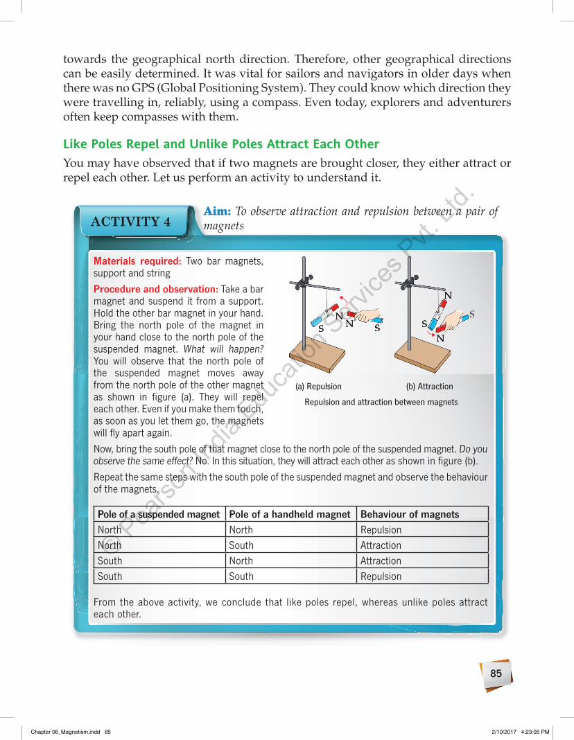
85
towards the geographical north direction. Therefore, other geographical directions can be easily determined. It was vital for sailors and navigators in older days when there was no GPS (Global Positioning System). They could know which direction they were travelling in, reliably, using a compass. Even today, explorers and adventurers often keep compasses with them.
Like Poles Repel and Unlike Poles Attract Each otherYou may have observed that if two magnets are brought closer, they either attract or repel each other. Let us perform an activity to understand it.
Materials required: Two bar magnets, support and stringProcedure and observation: Take a bar magnet and suspend it from a support. Hold the other bar magnet in your hand. Bring the north pole of the magnet in your hand close to the north pole of the suspended magnet. What will happen? You will observe that the north pole of the suspended magnet moves away from the north pole of the other magnet as shown in figure (a). They will repel each other. Even if you make them touch, as soon as you let them go, the magnets will fly apart again.Now, bring the south pole of that magnet close to the north pole of the suspended magnet. Do you observe the same effect? No. In this situation, they will attract each other as shown in figure (b).Repeat the same steps with the south pole of the suspended magnet and observe the behaviour of the magnets.
Pole of a suspended magnet Pole of a handheld magnet Behaviour of magnetsNorth North RepulsionNorth South AttractionSouth North AttractionSouth South Repulsion
From the above activity, we conclude that like poles repel, whereas unlike poles attract each other.
Aim: To observe attraction and repulsion between a pair of magnetsACTIVITY 4
SN
N SSN
N S
N
S
N
S
N
N
S
(a) Repulsion (b) Attraction
Repulsion and attraction between magnets
Chapter 06_Magnetism.indd 85 2/10/2017 4:23:05 PM
© Pearso
n Ind
ia Edu
catio
n Serv
ices P
vt. Lt
d.
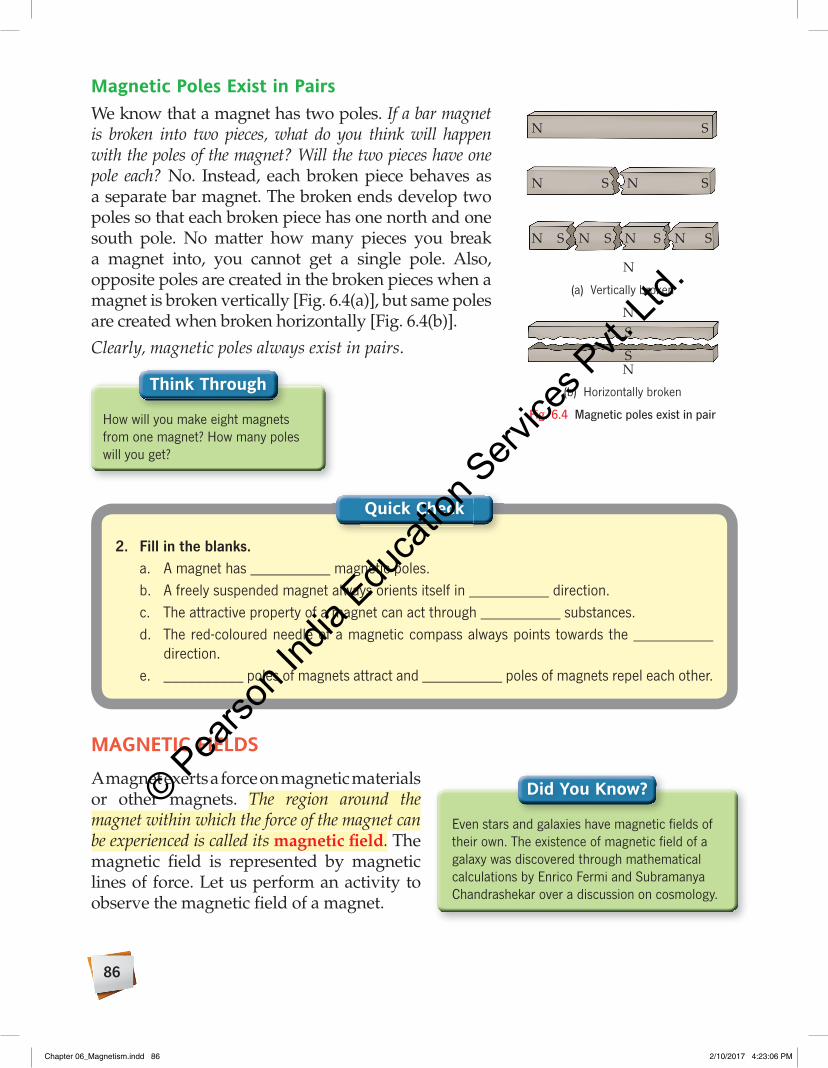
86
Magnetic Poles Exist in PairsWe know that a magnet has two poles. If a bar magnet is broken into two pieces, what do you think will happen with the poles of the magnet? Will the two pieces have one pole each? No. Instead, each broken piece behaves as a separate bar magnet. The broken ends develop two poles so that each broken piece has one north and one south pole. No matter how many pieces you break a magnet into, you cannot get a single pole. Also, opposite poles are created in the broken pieces when a magnet is broken vertically [Fig. 6.4(a)], but same poles are created when broken horizontally [Fig. 6.4(b)].
Clearly, magnetic poles always exist in pairs.
Think Through
How will you make eight magnets from one magnet? How many poles will you get?
2. Fill in the blanks.a. A magnet has __________ magnetic poles.b. A freely suspended magnet always orients itself in __________ direction.c. The attractive property of a magnet can act through __________ substances.d. The red-coloured needle of a magnetic compass always points towards the __________
direction.e. __________ poles of magnets attract and __________ poles of magnets repel each other.
Quick Check
MAGNETIC FIELDSA magnet exerts a force on magnetic materials or other magnets. The region around the magnet within which the force of the magnet can be experienced is called its magnetic field. The magnetic field is represented by magnetic lines of force. Let us perform an activity to observe the magnetic field of a magnet.
N S
N N SS
N N S N S N
N
N
S
S
SS
(a) Vertically broken
N S
N N SS
N N S N S N
N
N
S
S
SS
(b) Horizontally broken
Fig. 6.4 Magnetic poles exist in pair
Did you Know?
Even stars and galaxies have magnetic fields of their own. The existence of magnetic field of a galaxy was discovered through mathematical calculations by Enrico Fermi and Subramanya Chandrashekar over a discussion on cosmology.
Chapter 06_Magnetism.indd 86 2/10/2017 4:23:06 PM
© Pearso
n Ind
ia Edu
catio
n Serv
ices P
vt. Lt
d.

87
Materials required: Bar magnet, white sheet of paper and iron filingsProcedure: Place the white sheet of paper over a bar magnet. Sprinkle some iron filings evenly across the paper. Gently tap the paper.Observation: The iron filings closer to the magnet arrange themselves in a particular pattern. The pattern appears to be curved lines connecting one pole of the magnet to the other around the magnet.
ACTIVITY 5 Aim: To observe the magnetic field around a bar magnet
The lines along which the iron filings arrange themselves are called magnetic lines of force or magnetic field lines.
The magnetic field lines always extend from the north pole of a magnet to its south pole. Let us verify this with the help of the following activity.
Materials required: Magnetic compass, a sheet of paper and bar magnetProcedure:1. Place the magnet on the sheet of paper.2. Place the compass at a point near the north pole of the magnet.3. Mark the end point and the direction towards which the north
pole of the compass points.4. Move the compass such that its south pole points towards the
mark you previously made.5. Repeat steps 3 and 4 until you have a set of points in a curve,
extending from the north pole to the south pole.6. Join the points to get a closed continuous curve.7. Repeat this process starting at a few other points near the
north pole on both edges of the magnet.8. You will now have a complete set of lines all around the
magnet. This is the magnetic field of the magnet, as shown in figure (b).
Observation: Magnetic field lines as shown in the figure would be obtained.Conclusion: The magnetic field lines of a bar magnet are continuous curved lines that originate from the north pole and end at the south pole.
(a)
(b)
ACTIVITY 6 Aim: To plot the field lines around a magnet using a magnetic compass
S N
Chapter 06_Magnetism.indd 87 2/10/2017 4:23:12 PM
© Pearso
n Ind
ia Edu
catio
n Serv
ices P
vt. Lt
d.

88
Thus, the magnetic field lines are the paths around a magnet along which the north pole of a magnetic compass tends to move.
Let us now observe the magnetic lines of force of a horseshoe magnet with the help of the following activity.
The magnetic field lines of a magnet are affected by the presence of another magnet’s magnetic field. Let us study the effect of presence of another magnet on the magnetic lines of force of a bar magnet with the help of the following activity.
Materials required: Horseshoe magnet, white cardboard and iron filingsProcedure: Put the horseshoe magnet flat on the top of a table. Place a white sheet of paper over it and sprinkle iron filings uniformly across it. Tap the sheet of paper gently.Observation: The iron filings will align themselves along the field lines of the magnet, as shown.
ACTIVITY 7 Aim: To observe the field lines of a horseshoe magnet
N S
Materials required: Two bar magnets, white cardboard and iron filings Procedure:1. Take two identical magnets.2. Place them on the cardboard Kept on a flat surface such
that their north poles face each other.3. Take some iron filings and uniformly sprinkle them over
the cardboard.4. Lightly tap the cardboard. Now trace the patterns made
by the filings. 5. Repeat your experiment by placing the magnets such that their opposite poles are facing
each other.
ACTIVITY 8 Aim: To observe the effect of a magnet on the magnetic field of another magnet
N N
Like poles facing each other
Chapter 06_Magnetism.indd 88 2/10/2017 4:23:17 PM
© Pearso
n Ind
ia Edu
catio
n Serv
ices P
vt. Lt
d.

89
Observation: Magnetic field lines as shown in the figures would be obtained.
• When like poles face each other, the lines of force from one magnet repel the lines of force from the other magnet. Thus, there will be a region between the two magnets in which there will be no lines of force.
• When unlike poles face each other, the lines of force from the two magnets join to form continuous lines.
N S
Unlike poles facing each other
The magnetic lines of force are characterised by the following properties:
• They are closed, continuous curves.
• They start from the north pole of the magnet and end at the south pole. Within the magnet, their direction is from the south pole to the north pole.
• They never intersect with each other.
• They mutually repel each other.
• The lines of force are closer at the poles. The more closely packed lines indicate a stronger magnetic field. Thus, the maximum strength of a magnet lies at its pole.
EARTH—A HUGE MAGNETWe have learnt that north and south poles of freely suspended magnets always align in geographical north and south directions. Why does this happen?
3. State whether the following are true or false.a. Magnetic lines of force intersect with each other. ________b. Magnetic lines of force are more concentrated around
the middle region of the magnet. ________c. Magnetic lines of force are closed, continuous lines. ________d. Magnetic field lines extend from north pole to south pole inside the magnet. ________e. A magnetic compass can be used to plot the magnetic field lines. ________
Quick Check
Chapter 06_Magnetism.indd 89 2/10/2017 4:23:18 PM
© Pearso
n Ind
ia Edu
catio
n Serv
ices P
vt. Lt
d.

90
It is because our earth behaves as a huge magnet. You can imagine a huge bar magnet buried inside earth. The magnetic south pole of this imaginary magnet is located near the earth’s geographic north pole. The magnetic north pole of the imaginary magnet is located near the earth’s geographic south pole. We know that unlike poles attract. So the magnetic north pole of the imaginary magnet inside the earth will attract the magnetic south pole of a freely suspended magnet. Similarly, the magnetic south pole of the imaginary magnet will attract the north pole of a freely suspended magnet. Thus, the magnetic field of earth causes a freely suspended magnet to orient itself in the north–south direction.
[Note: The geographic and magnetic axes of earth do not overlap (Fig. 6.5). They are separated by an angle of about 10°.]
MAKING MAGNETSWe have mentioned earlier that an artificial magnet can be made from magnetic materials. It can be made by creating a magnetic property in a magnetic substance. The process of making a magnetic substance into a magnet is known as magnetisation. There are several methods of making a magnet. Let us study about some of these methods.
Magnetic Induction MethodIn this method, we use a bar magnet to magnetise a magnetic substance by the method of magnetic induction. This method is used to make a temporary magnet.
Let us perform an activity to understand how to make a magnet using this method.
Magneticsouth pole
Magneticnorth pole
Geographicnorth pole
Geographicsouth pole
Fig. 6.5 Geographic and magnetic poles of earth
Materials required: Bar magnet, stand, iron nail and some iron paper clips Procedure:1. Take an iron nail and fix it vertically on
the stand.2. Spread some iron paper clips below the nail.3. Hold a bar magnet and bring either of its
poles close to the top end of the nail.4. Place the bar magnet away from the iron nail.
ACTIVITY 9Aim: To make a magnet by magnetic induction method
Magnetic induction method
Chapter 06_Magnetism.indd 90 2/10/2017 4:23:21 PM
© Pearso
n Ind
ia Edu
catio
n Serv
ices P
vt. Lt
d.

91
Observation: The iron paper clips get attracted towards the iron nail when the bar magnet is brought closer to the nail. As soon as the magnet is taken away from the nail, it stops attracting the clips. So, the clips fall off.Conclusion: The iron nail gets magnetised by this method and behaves as a temporary magnet.
Single-touch MethodIn this method, we use a bar magnet to make a permanent magnet from a magnetic material.
Let us perform an activity to make a magnet using this method.
Materials required: Bar magnet, stand, iron nail and some iron paper clipsProcedure:1. Place the iron bar (AB) on a non-magnetic surface such as wood.2. Pick the bar magnet. Place any pole of the magnet (say, the
north pole) over one end of the iron bar (say, end A).3. Drag the magnet slowly on the iron bar till the other end (here,
end B), without lifting the magnet. Make sure that there is no backward movement of the magnet on the iron bar.
4. Now, lift the magnet and move it through air to reach end A of the iron bar again.5. Repeat steps 3 and 4 about 30–40 times.Observation: When the magnetised iron bar is brought closer to small iron clips, the clips get attracted to it.Conclusion: The above observation shows that the iron bar has been magnetised. The end A will acquire magnetic north pole and the end B will acquire magnetic south pole.
ACTIVITY 10 Aim: To make a magnet by single-touch method
A B
N
S
A B
NN
S
Single-touch method
Double-touch MethodIn this method, we use two bar magnets of equal strength to make a permanent magnet from a magnetic material—for example, an iron bar.
Let us perform the following activity to make a magnet using this method.
Chapter 06_Magnetism.indd 91 2/10/2017 4:23:24 PM
© Pearso
n Ind
ia Edu
catio
n Serv
ices P
vt. Lt
d.

92
Materials required: Bar magnet, stand, iron nail and some iron paper clips
ACTIVITY 11 Aim: To make a magnet by double-touch method
Procedure:1. Place the iron bar AB on a non-magnetic
surface such as wood.2. Place the opposite poles of the two bar magnets
at the centre of the iron bar.3. Slowly drag the two bar magnets on the iron
bar in opposite directions till the ends of the iron bar. Lift the magnets and move them through air to the centre of the iron bar again. Repeat this process a few times.
Observation: When the magnetised iron bar is brought closer to small iron clips, the clips get attracted to it.Conclusion: The above observation shows that the iron bar has been magnetised. The end A will acquire magnetic north pole and the end B will acquire magnetic south pole.
S
N S
A B
NS N
N S
Double-touch method
Electrical MethodIn this method, we use electricity to make a temporary magnet from a magnetic material. An insulated copper wire is wound around an iron bar several times as shown in figure 6.6. When current is made to pass through the wire by connecting it to a battery, the iron bar behaves like a magnet. The strength of the magnetic force can be controlled by varying the amount of current through the wire. It can also be controlled by increasing or decreasing the number of turns of the wire wound around the iron bar.
What will happen when the current is switched off? When the current is switched off, the iron bar loses its magnetism. It no longer behaves like a magnet.
Such kind of behaviour of gaining and losing magnetism by allowing or blocking the passage of electric current is quite amazing. It has found many applications in industries as well as for household purposes.
ELECTRoMAGNETA type of magnet in which the magnetic properties are produced by using electricity is called an electromagnet.
An electromagnet is made by using the electrical method. The magnetic substance used to make an electromagnet is soft iron. Let us perform an activity to make an electromagnet.
To battery
Fig. 6.6 Electrical method
Chapter 06_Magnetism.indd 92 2/10/2017 4:23:28 PM
© Pearso
n Ind
ia Edu
catio
n Serv
ices P
vt. Lt
d.

93
Materials required: Battery, iron nail, insulated copper wire and some paper clips.
Procedure and observation:• Wind the wire around the nail.• Connect the two free ends of the wire to the two ends of the battery.• Take this arrangement close to the paper clips. What do you see?
The paper clips are attracted to the end of the nail as shown in figure (a).• Disconnect any side of the wire from the battery. What do you see?
The paper clips will fall down as shown in figure (b).• Join the wire back. What happens?
The paper clips are attracted towards the nail again.• Now, replace the battery with a larger battery that can provide a large amount of current.
What do you observe? More paper clips will be attracted to the electromagnet as shown in figure (c).
(a) Magnetism due to electric current (b) No current, no magnetism
(c) Large current, stronger magnetism
Making an electromagnet
Conclusion: The nail turns into an electromagnet when current is passed through it. It shows magnetic properties as long as the current flows through the wire. The nail loses its magnetism when the current stops flowing. The nail becomes a stronger magnet when a large amount of current passes through it.
ACTIVITY 12 Aim: To make an electromagnet
The above activity shows that an electromagnet is a temporary magnet.
Electromagnets can be made extremely powerful by supplying them with a high current. That is why they are mainly used in electrically operated cranes that can lift very heavy loads, such as girders and rails. Also, the poles of electromagnets can be interchanged by reversing the direction of flow of electric current.
Chapter 06_Magnetism.indd 93 2/10/2017 4:23:32 PM
© Pearso
n Ind
ia Edu
catio
n Serv
ices P
vt. Lt
d.

94
[Note: Steel does not lose its magnetism once it is magnetised by the electrical method. So, if we use steel to make an electromagnet, it will become a permanent magnet.]
DEMAGNETISATIoNIf a magnet loses its magnetism, it is said to be demagnetised. The phenomenon in which a permanent magnet loses its magnetism is known as demagnetisation. A magnet can get demagnetised in various ways:
• by prolonged hammering of the magnet
• by frequently dropping the magnet from a height
• by heating it to high temperatures
• by passing an alternating current around the magnet
• when they are placed side by side with like poles facing each other
• by improper storage
SToRING MAGNETSTo prevent magnets from getting demagnetised, we should handle and store them carefully.
A magnet left lying around slowly loses its magnetic properties. The phenomenon in which a permanent magnet loses its magnetic properties when not used for a period of time is known as self-demagnetisation. To prevent self-demagnetisation, ‘magnetic keepers’ are used. Amagnetic keeper is a soft iron bar or steel strip placed across the poles of a permanent magnet to prevent self-demagnetisation. As illustrated in figure 6.7, magnetic keepers enable the magnets to form an imaginary magnetic chain from magnetic north to south poles of the magnet. This helps the magnets to retain their magnetism. They are used specially for those magnets whose magnetic strength is weak. They also prevent other magnetic substances from being attracted to the magnet.
Magnets can also lose their magnetism when they are placed side by side with like poles facing each other. To prevent this, bar magnets should be arranged side by side with their unlike poles facing each other. Also, the two magnetic keepers can
Magnetic keepers
Woodenblock
Fig. 6.7 Storing magnets
Know your Scientist
Michael Faraday (1791–1867), an English scientist, was one of the most influential scientists of his time. He introduced the concept of magnetic field produced by a current carrying conductor (a type of electromagnet). He invented the first rotatory device with the help of electricity and magnetism, which laid the foundation for electric motor technology which is in use today.
Chapter 06_Magnetism.indd 94 2/10/2017 4:23:34 PM
© Pearso
n Ind
ia Edu
catio
n Serv
ices P
vt. Lt
d.

95
be placed on either end of the pair of magnets which further protects them from self-demagnetisation.
USES oF MAGNETSIn ancient times, the most important task for which magnets were used was finding the direction. Nowadays, the most important task for which magnets are used is generating electricity. Without magnets, a dynamo cannot generate electricity.
Without electricity, it is highly improbable to imagine our modern lifestyle. We can say that magnets are extremely useful in our daily life.
Magnets, especially electromagnets, have countless uses. Some of their uses are given below.
• Magnets are used to make electric bells, electric motors and generators.
• They are used in televisions, computers and tape recorders.
• They are used in loudspeakers and microphones.
• In banks, magnets enable the computers to read the cheque numbers printed on a cheque.
• An extremely fast moving train, the Maglev train, uses extremely powerful electromagnets to float above the tracks.
• In industries, magnetic conveyor belts are used to sort out magnetic substances from scrap mixed with non-magnetic substances.
• The tips of screwdrivers are made slightly magnetic so that the screws remain attached to its tip.
• At hospitals, extremely strong electromagnets are used in MRI (Magnetic Resonance Imaging) machines.
• A very feeble magnetic substance is used to prepare the black strip of debit and credit cards.
• Magnets are widely used in making storage devices such as hard disks.
4. Fill in the blanks.a. __________ is a process of making a magnet from a magnetic substance.b. In __________ method, two bar magnets are used to make a magnet.c. Soft iron is used for making __________.d. To prevent self-demagnetisation, __________ are used.e. __________ are used in making hard disks of computer.
Quick Check
Chapter 06_Magnetism.indd 95 2/10/2017 4:23:34 PM
© Pearso
n Ind
ia Edu
catio
n Serv
ices P
vt. Lt
d.

96
Connecting the Dots
Directive property
Magnetic poles exist in pair
Like poles repel
Unlike poles attract
Magnetic induction method
Single-touch method
Double-touch method
Electrical method
Attractive property
Types of magnetsNatural magnet
Artificial magnetPermanent magnet
Temporary magnet
Never intersect
Closer at poles
Mutually repel
Start from north pole outside the magnet
Closed continuous curves
Electromagnets
Magnet
Properties of magnets
How to make magnets
Storing magnets
Properties of magneticlines of force
Properties of magnetic fields
Magnetic lines of force are closed, continuous lines
They start from north pole and end at the south pole
They never intersect with each other
They mutually repel each other
The lines of force are closer at the poles
Magnetic keepers
Chapter 06_Magnetism.indd 96 2/10/2017 4:23:35 PM
© Pearso
n Ind
ia Edu
catio
n Serv
ices P
vt. Lt
d.

97
KEyWoRDS
• Magnet: a type of object that can attract other objects such as iron or steel
• Magnetite: a type of rock containing oxide of iron, which behaves as a magnet
• Lodestone: a type of rock, found in nature, which was used for navigational purpose because of its magnetic property
• Magnetism: ability of a magnet to attract objects such as iron
• Magneticforce: force of attraction (or repulsion) exerted by a magnet
• Magneticfield: an invisible field around the magnet where the influence of its magnetic force can be felt
• Magneticsubstances: substances that are attracted by a magnet
• Non-magneticsubstances: substances that are not attracted by a magnet
• Naturalmagnets: objects that are found in nature and exhibit magnetism
• Artificialmagnets: objects that have been made into magnets by artificial man-made methods
• Magneticpoles: two ends of a magnet where magnetic force of the magnet is maximum
• Magneticfield:the region around a magnet within which the force of a magnet can be experienced
• Magnetisation: a process of making a magnet from a magnetic substance
• Electromagnet: a type of magnet in which magnetism is produced by electricity
• Demagnetisation: the phenomenon in which a permanent magnet loses its magnetism
• Magnetickeeper: a piece or strip made of soft iron or steel which is placed across the poles of permanent magnets
ASSESSMENT TIME
A. Choose the correct answer.
1. The north pole of a bar magnet and the south pole of a U-shaped magnet will __________.
a. attract each other
b. repel each other
c. neither attract nor repel each other
d. none of these
2. Which of these is a kind of artificial magnet used in navigation?
a. Horseshoe magnet
b. Compass
c. Electromagnet
d. All of these
3. Magnetisation can be made more effective by __________.
a. using a weaker magnet
b. rubbing for a longer time
c. using a stronger magnet
d. both (b) and (c)
4. A magnet is cut into two pieces. The broken sides are repelling each other. They are cut __________.
a. along the length
b. along the breadth
c. both (a) and (b)
d. none of these
Chapter 06_Magnetism.indd 97 2/10/2017 4:23:35 PM
© Pearso
n Ind
ia Edu
catio
n Serv
ices P
vt. Lt
d.

98
5. Which of these is a non-magnetic substance?
a. Iron b. Aluminium
c. Copper d. Both (a) and (b)
B. Fill in the blanks.
1. __________ is the sure test of magnetism.
2. Electromagnets are made of __________.
3. The first discovered magnetic material was called __________.
4. Iron is a __________ substance.
5. The magnetic strength is __________ at poles.
C. State whether the following are true or false.
1. Two magnets always attract each other.
2. Strength of natural magnets can be altered.
3. Magnetic field lines never intersect.
4. The magnetic axis of a freely suspended magnet always align in east–west direction.
5. Hammering a magnet increases its magnetic strength.
D. Look at the picture below and answer the following questions.
1.
2.
a. In figure 1, which pair of magnets will attract each other?
b. In figure 2, mark the geographic directions (east, west, north, south) around the freely suspended magnet.
E. Answer in brief.
1. Define a magnet.
2. Classify magnets based on:
a. how long the magnetism lasts
b. how they are made
3. You are at a job where you need a magnet. What kind of magnet will you choose if
a. no electricity is available.
b. electricity is available and a very strong magnet is required.
4. What is self-demagnetisation?
5. A bar B of some material is attracted to a magnet. Is the bar B magnetised?
F. Answer in detail.
1. Why do we use electromagnets, when they have to be magnetised every time they are used?
2. Why do we make artificial magnets?
3. What is a magnetic keeper? Why it is used?
4. Discuss the properties of magnetic field.
5. State any two advantages of artificial magnets over natural magnets.
G. Match the following:
1. Directive property
a. Used to make permanent magnets
2. Soft iron b. Used in electrical cranes to lift heavy loads
3. Attractive property
c. Not a sure test for a magnet
4. Electromagnet d. Used to make temporary magnets
5. Steel e. Used in magnetic compass
Chapter 06_Magnetism.indd 98 2/10/2017 4:23:36 PM
© Pearso
n Ind
ia Edu
catio
n Serv
ices P
vt. Lt
d.

99
LET US EXPLoRE1. Cooperation and working together: Make a simple device—magnetic compass—to know the
direction. Work in groups of three to make the compass.
Take a steel needle or pin and convert it into a magnet with the help of a bar magnet (single-touch method) so that the pointed end of the needle becomes magnetic north pole. Take an empty refill of pen and cut it exactly equal to the length of needle. Insert that magnetised needle in it and seal both its ends. Paint it red colour on one half of the refill containing the tip of the needle. Take a bowl filled with water and gently place that half painted refill on the water at the centre of the bowl.
2. Critical thinking: You are given two identical looking metallic pieces, out of which one is a magnet. Using another magnet with its pole marked, how can you identify which one of the two pieces is a magnet?
APPLICATIoN-BASED QUESTIoNSThe needle of a magnetic compass always points towards the north–south direction. When the compass is brought closer to the speaker of a television or a mobile phone, its needle begins to flicker. Why does this happen?
CRoSS-CoNNECTIoN Geography:
1. Collect information on the magnetic pole flip of the earth.
2. Near the magnetic poles of the earth, the sky glows with a spectacular display of green and pink lights. Why does this happen?
Technology in daily life:
1. Hard drives use discs of magnetic material, called platters, to store information. Magnetism is a useful way to store information on hard drives because it continues to store the information even when the computer is switched off.
2. The National Football League is looking at the idea of using the principle of magnetic repulsion (like poles repel) in football helmets. If two helmets get close enough to each other, the two will repel each other and at least lessen the force of the impact. This is being done to address the issue of brain injury that aging players are showing.
Chapter 06_Magnetism.indd 99 2/10/2017 4:23:36 PM
© Pearso
n Ind
ia Edu
catio
n Serv
ices P
vt. Lt
d.