A Survey of Recent MARTe Based Systems
8
1482 IEEE TRANSACTIONS ON NUCLEAR SCIENCE, VOL. 58, NO. 4, AUGUST 2011 A Survey of Recent MARTe Based Systems André C. Neto, Diogo Alves, Luca Boncagni, Pedro J. Carvalho, Daniel F. Valcárcel, Antonio Barbalace, Gianmaria De Tommasi, Horácio Fernandes, Filippo Sartori, Enzo Vitale, Riccardo Vitelli, Luca Zabeo, and JET EFDA CONTRIBUTORS Abstract—The Multithreaded Application Real-Time executor (MARTe) is a data driven framework environment for the devel- opment and deployment of real-time control algorithms. The main ideas which led to the present version of the framework were to standardize the development of real-time control systems, while providing a set of strictly bounded standard interfaces to the out- side world and also accommodating a collection of facilities which promote the speed and ease of development, commissioning and deployment of such systems. At the core of every MARTe based application, is a set of independent inter-communicating software blocks, named Generic Application Modules (GAM), orchestrated by a real-time scheduler. The platform independence of its core library provides MARTe the necessary robustness and flexibility for conveniently testing applications in different environments including non-real-time operating systems. MARTe is already being used in several machines, each with its own peculiarities regarding hardware interfacing, supervisory control configura- tion, operating system and target control application. This paper presents and compares the most recent results of systems using MARTe: the JET Vertical Stabilization system, which uses the Real Time Application Interface (RTAI) operating system on Intel multi-core processors; the COMPASS plasma control system, driven by Linux RT also on Intel multi-core processors; ISTTOK real-time tomography equilibrium reconstruction which shares the same support configuration of COMPASS; JET error field correction coils based on VME, PowerPC and VxWorks; FTU LH reflected power system running on VME, Intel with RTAI. Index Terms—Multithreaded Application Real-Time executor (MARTe), nuclear fusion control, real-time, tokamak. Manuscript received June 14, 2010; revised November 17, 2010; accepted February 17, 2011. Date of publication April 05, 2011; date of current version August 17, 2011. This work was supported by the European Communities under the Contract of Association between EURATOM/IST and was carried out within the framework of the European Fusion Development Agreement. Portions of this work were presented at the IAEA 22nd Fusion Energy Conference (FEC), Geneva, Oct. 13-18, 2008. A. C. Neto, D. Alves, P. J. Carvalho, D. F. Valcárcel, and H. Fernandes are with Associação EURATOM/IST, Instituto de Plasmas e Fusão Nuclear-Lab- oratório Associado, 1049-001 Lisboa, Portugal (e-mail: andre.neto@ipfn. ist.utl.pt; [email protected]; [email protected]; daniel.val- [email protected]; [email protected]). L. Boncagni and E. Vitale are with Associazione EURATOM/ENEA, 00040 Frascati, Italy (e-mail: [email protected]). A. Barbalace is with the Associazione EURATOM/ENEA, Consorzio RFX, 35127 Padova, Italy (e-mail: [email protected]). G. DeTommasi is with Associazione EURATOM/ENEA/CREATE, Univer- sità di Napoli Federico II, 80138 Napoli, Italy (e-mail: [email protected]). F. Sartori is with Fusion for Energy, 08019 Barcelona, Spain (e-mail: Filippo. [email protected]). R. Vitelli is with the Dipartimento di Informatica, Sistemi e Pro- duzione, Università di Roma “Tor Vergata,” 00133 Rome, Italy (e-mail: [email protected]). L. Zabeo is with ITER-IO, St. Paul-Lez-Durance 13108, France (e-mail: [email protected]). Color versions of one or more of the figures in this paper are available online at http://ieeexplore.ieee.org. Digital Object Identifier 10.1109/TNS.2011.2120622 I. INTRODUCTION M ultithreaded Application Real-Time executor (MARTe) is a C++ multi-platform framework for the development and execution of real-time control systems [1]. Its main goals are to provide a clear boundary between algorithms, hardware interaction and system configuration, leveraging reusability and maintainability. This functional division also enables control systems simulation [2] and phased commissioning, by replacing some of its components by models and synthetic data producers. Being multi-platform it minimizes the constraints with the operational environments, so that the target application can be easily run on a different operating system. A feature which al- lows the development and execution of code in non real-time environments and to proceed to the final deployment on the real-time target, only when the overall functionality of the con- trol system is asserted. MARTe was already ported and tested in the following operating systems: Wind River VxWorks, Linux, Linux/RTAI, Solaris, and MS Windows. MARTe and its components are data driven using a textual language with a specific format and syntax, validated during the configuration phase. The framework does not impose a way on how the configuration data should be produced, but it does pro- vide a mechanism for updating its components configuration, allowing its integration in different experiments and human ma- chine interfaces. This interface is provided by a framework com- ponent which acts as a proxy, so that when a new component configuration is requested, it automatically forwards the config- uration data to the selected framework objects. The core component of a MARTe is the Generic Application Module (GAM). A MARTe application is built by connecting a collection of specialized GAMs, using a memory data bus named Dynamic Data Buffer (DDB). Each GAM can produce and receive data using DDB named channels. These are re- quested by the GAM upon configuration and the framework guarantees that all the required sources are present on the system. Usually each GAM is associated with a functional re- quirement of the control system (e.g., PID or data conversion), enabling the reusage of the component itself, or the replacement of part of the control system, particularly useful for simulation purposes. The interface with the hardware and synchronization is performed using a special module named IOGAM. It provides a standard hardware interface to MARTe, which expects the real hardware interaction to be implemented at the driver level (e.g., configuration and data transferring). MARTe supports two types of synchronization mechanisms, one based on continuous polling of a resource and the other as a response to an external interrupt. The framework can also have asynchronously, event 0018-9499/$26.00 © 2011 IEEE
-
Upload
independent -
Category
Documents
-
view
0 -
download
0
Transcript of A Survey of Recent MARTe Based Systems

1482 IEEE TRANSACTIONS ON NUCLEAR SCIENCE, VOL. 58, NO. 4, AUGUST 2011
A Survey of Recent MARTe Based SystemsAndré C. Neto, Diogo Alves, Luca Boncagni, Pedro J. Carvalho, Daniel F. Valcárcel, Antonio Barbalace,
Gianmaria De Tommasi, Horácio Fernandes, Filippo Sartori, Enzo Vitale, Riccardo Vitelli, Luca Zabeo, andJET EFDA CONTRIBUTORS
Abstract—The Multithreaded Application Real-Time executor(MARTe) is a data driven framework environment for the devel-opment and deployment of real-time control algorithms. The mainideas which led to the present version of the framework were tostandardize the development of real-time control systems, whileproviding a set of strictly bounded standard interfaces to the out-side world and also accommodating a collection of facilities whichpromote the speed and ease of development, commissioning anddeployment of such systems. At the core of every MARTe basedapplication, is a set of independent inter-communicating softwareblocks, named Generic Application Modules (GAM), orchestratedby a real-time scheduler. The platform independence of its corelibrary provides MARTe the necessary robustness and flexibilityfor conveniently testing applications in different environmentsincluding non-real-time operating systems. MARTe is alreadybeing used in several machines, each with its own peculiaritiesregarding hardware interfacing, supervisory control configura-tion, operating system and target control application. This paperpresents and compares the most recent results of systems usingMARTe: the JET Vertical Stabilization system, which uses theReal Time Application Interface (RTAI) operating system on Intelmulti-core processors; the COMPASS plasma control system,driven by Linux RT also on Intel multi-core processors; ISTTOKreal-time tomography equilibrium reconstruction which sharesthe same support configuration of COMPASS; JET error fieldcorrection coils based on VME, PowerPC and VxWorks; FTU LHreflected power system running on VME, Intel with RTAI.
Index Terms—Multithreaded Application Real-Time executor(MARTe), nuclear fusion control, real-time, tokamak.
Manuscript received June 14, 2010; revised November 17, 2010; acceptedFebruary 17, 2011. Date of publication April 05, 2011; date of current versionAugust 17, 2011. This work was supported by the European Communities underthe Contract of Association between EURATOM/IST and was carried out withinthe framework of the European Fusion Development Agreement. Portions ofthis work were presented at the IAEA 22nd Fusion Energy Conference (FEC),Geneva, Oct. 13-18, 2008.
A. C. Neto, D. Alves, P. J. Carvalho, D. F. Valcárcel, and H. Fernandes arewith Associação EURATOM/IST, Instituto de Plasmas e Fusão Nuclear-Lab-oratório Associado, 1049-001 Lisboa, Portugal (e-mail: [email protected]; [email protected]; [email protected]; [email protected]; [email protected]).
L. Boncagni and E. Vitale are with Associazione EURATOM/ENEA, 00040Frascati, Italy (e-mail: [email protected]).
A. Barbalace is with the Associazione EURATOM/ENEA, Consorzio RFX,35127 Padova, Italy (e-mail: [email protected]).
G. De Tommasi is with Associazione EURATOM/ENEA/CREATE, Univer-sità di Napoli Federico II, 80138 Napoli, Italy (e-mail: [email protected]).
F. Sartori is with Fusion for Energy, 08019 Barcelona, Spain (e-mail: [email protected]).
R. Vitelli is with the Dipartimento di Informatica, Sistemi e Pro-duzione, Università di Roma “Tor Vergata,” 00133 Rome, Italy (e-mail:[email protected]).
L. Zabeo is with ITER-IO, St. Paul-Lez-Durance 13108, France (e-mail:[email protected]).
Color versions of one or more of the figures in this paper are available onlineat http://ieeexplore.ieee.org.
Digital Object Identifier 10.1109/TNS.2011.2120622
I. INTRODUCTION
M ultithreaded Application Real-Time executor (MARTe)is a C++ multi-platform framework for the development
and execution of real-time control systems [1]. Its main goalsare to provide a clear boundary between algorithms, hardwareinteraction and system configuration, leveraging reusability andmaintainability. This functional division also enables controlsystems simulation [2] and phased commissioning, by replacingsome of its components by models and synthetic data producers.
Being multi-platform it minimizes the constraints with theoperational environments, so that the target application can beeasily run on a different operating system. A feature which al-lows the development and execution of code in non real-timeenvironments and to proceed to the final deployment on thereal-time target, only when the overall functionality of the con-trol system is asserted. MARTe was already ported and tested inthe following operating systems: Wind River VxWorks, Linux,Linux/RTAI, Solaris, and MS Windows.
MARTe and its components are data driven using a textuallanguage with a specific format and syntax, validated during theconfiguration phase. The framework does not impose a way onhow the configuration data should be produced, but it does pro-vide a mechanism for updating its components configuration,allowing its integration in different experiments and human ma-chine interfaces. This interface is provided by a framework com-ponent which acts as a proxy, so that when a new componentconfiguration is requested, it automatically forwards the config-uration data to the selected framework objects.
The core component of a MARTe is the Generic ApplicationModule (GAM). A MARTe application is built by connectinga collection of specialized GAMs, using a memory data busnamed Dynamic Data Buffer (DDB). Each GAM can produceand receive data using DDB named channels. These are re-quested by the GAM upon configuration and the frameworkguarantees that all the required sources are present on thesystem. Usually each GAM is associated with a functional re-quirement of the control system (e.g., PID or data conversion),enabling the reusage of the component itself, or the replacementof part of the control system, particularly useful for simulationpurposes.
The interface with the hardware and synchronization isperformed using a special module named IOGAM. It providesa standard hardware interface to MARTe, which expects thereal hardware interaction to be implemented at the driver level(e.g., configuration and data transferring). MARTe supports twotypes of synchronization mechanisms, one based on continuouspolling of a resource and the other as a response to an externalinterrupt. The framework can also have asynchronously, event
0018-9499/$26.00 © 2011 IEEE
NETO et al.: A SURVEY OF RECENT MARTe BASED SYSTEMS 1483
based, triggered elements on the control chain, which collectthe latest data available and verify if the latency is acceptable.
Each control loop is executed by an entity named real-timethread. A MARTe application can have one or more real-timethreads, running at different frequencies and with different pri-orities. If the underlying hardware and operating system sup-ports it, the threads can run in different CPU sets. These threadscan also be connected and share data between their DDBs, usinga special IOGAM provided by the framework, where the outputof the thread producing data is connected to an input acquisitionmodule in the thread consuming the signals. As a real-time ex-ecutor, MARTe measures the execution time of its components,the total overall cycle time and jitter, and is capable of takingprotective actions if problems are found during the control loopcycle. A series of auxiliary components are also built around theframework, enabling among other things: component introspec-tion and browsing using a built-in HTTP server, an advancedreal-time logging mechanism and a data archiver.
MARTe is currently being used in several fusion experiments,to solve different control problems, each with its own particular-ities regarding supervisory control and configuration, data col-lection and hardware. This paper describes some of the systems,comparing architectures and recent results.
II. JET VERTICAL STABILIZATION
A. Description
Tokamak plasmas are confined inside a vessel using strongmagnetic fields. Vertically elongated plasmas experience a ver-tical instability that has to be actively controlled, by means ofa radial magnetic field [3], created by a set of poloidal fieldcoils. The controller tries to maintain the plasma vertical ve-locity and current on the circuit around zero. Erroneous con-trol of the system can have serious consequences, as a suddenloss of thermal and magnetic energy can lead to the inductionof large currents and forces on the machine vessel. Recently atJET [4], the largest tokamak in the world, the Vertical Stabi-lization (VS) system was upgraded [5], in order to enable theexploitation of the machine at high plasma current with ITER[6] relevant plasma shapes.
The power radial field amplifier (RFA) was enhanced toa newer version, ERFA [7] capable of providing 5 kA ofoutput current and 12 kV at maximum rate of change of 800
. The controller hardware was upgraded from a versionrunning on TMS32C40 processors [8] to an ATCA and PCIebased system [9] acquiring 192 ADC channels at 2 MHz, withmicrosecond figure latencies in data transportation to the maincore. Finally, all the modules and controllers were partiallyredesigned and improved to take advantage of the greater flexi-bility of the new control system, in particular the larger numberof inputs and processing power available. Acquired data isfiltered down to 20 kHz in the acquisition cards FPGAs andtransferred at this rate to the central processing unit, providingthe 50 cycle time of the control system. The system runson an IntelCore2 Quad processor and uses the Linux operatingsystem with the real-time extension RTAI.
The VS is also used as an experimental tool. In order to in-crease performance and confinement times, it is required to push
plasma parameters towards high pressure and plasma current.Unfortunately this triggers a set of instabilities which can workagainst the system. Of particular importance is an instabilitynamed Edge Localized Mode (ELM), occurring in the outer partof the radius, which can deliver high heat loads to the plasmafacing components. One of the ideas to mitigate its impact, isto try to generate the ELMs at a predefined frequency, in orderto have some control over the instability size. The VS systemachieves this using a technique called ELM pacing [10], whichconsists in applying for a given period of time a constant voltageto the amplifier (ignoring what was requested by the controller),called vertical kick, and causing an abrupt vertical movement ofthe plasma.
B. Software Architecture
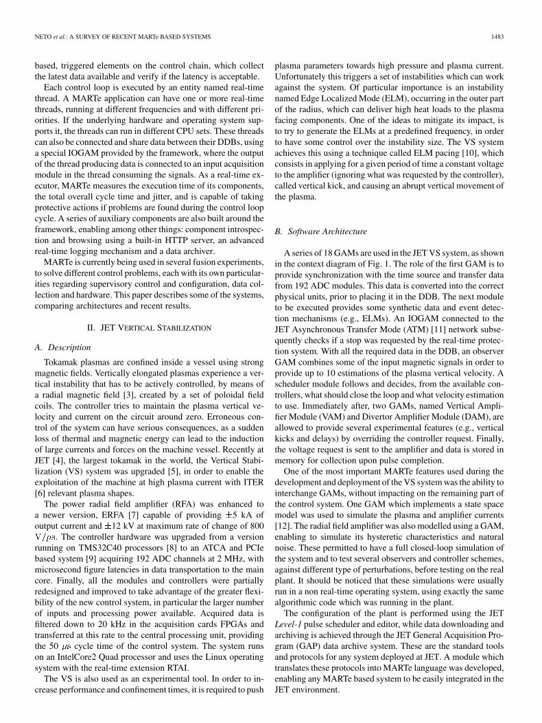
A series of 18 GAMs are used in the JET VS system, as shownin the context diagram of Fig. 1. The role of the first GAM is toprovide synchronization with the time source and transfer datafrom 192 ADC modules. This data is converted into the correctphysical units, prior to placing it in the DDB. The next moduleto be executed provides some synthetic data and event detec-tion mechanisms (e.g., ELMs). An IOGAM connected to theJET Asynchronous Transfer Mode (ATM) [11] network subse-quently checks if a stop was requested by the real-time protec-tion system. With all the required data in the DDB, an observerGAM combines some of the input magnetic signals in order toprovide up to 10 estimations of the plasma vertical velocity. Ascheduler module follows and decides, from the available con-trollers, what should close the loop and what velocity estimationto use. Immediately after, two GAMs, named Vertical Ampli-fier Module (VAM) and Divertor Amplifier Module (DAM), areallowed to provide several experimental features (e.g., verticalkicks and delays) by overriding the controller request. Finally,the voltage request is sent to the amplifier and data is stored inmemory for collection upon pulse completion.
One of the most important MARTe features used during thedevelopment and deployment of the VS system was the ability tointerchange GAMs, without impacting on the remaining part ofthe control system. One GAM which implements a state spacemodel was used to simulate the plasma and amplifier currents[12]. The radial field amplifier was also modelled using a GAM,enabling to simulate its hysteretic characteristics and naturalnoise. These permitted to have a full closed-loop simulation ofthe system and to test several observers and controller schemes,against different type of perturbations, before testing on the realplant. It should be noticed that these simulations were usuallyrun in a non real-time operating system, using exactly the samealgorithmic code which was running in the plant.
The configuration of the plant is performed using the JETLevel-1 pulse scheduler and editor, while data downloading andarchiving is achieved through the JET General Acquisition Pro-gram (GAP) data archive system. These are the standard toolsand protocols for any system deployed at JET. A module whichtranslates these protocols into MARTe language was developed,enabling any MARTe based system to be easily integrated in theJET environment.
1484 IEEE TRANSACTIONS ON NUCLEAR SCIENCE, VOL. 58, NO. 4, AUGUST 2011
Fig. 1. Software context diagram for the VS system. MARTe is being executed inside an IntelCore2 Quad processor and the hardware interface to the plant isbased on the ATCA and PCIe standards.
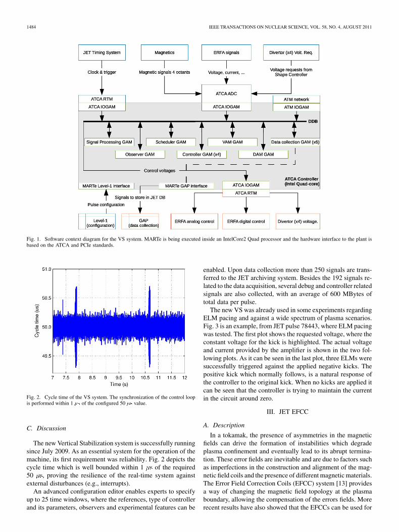
Fig. 2. Cycle time of the VS system. The synchronization of the control loopis performed within 1 �� of the configured 50 �� value.
C. Discussion
The new Vertical Stabilization system is successfully runningsince July 2009. As an essential system for the operation of themachine, its first requirement was reliability. Fig. 2 depicts thecycle time which is well bounded within 1 of the required50 , proving the resilience of the real-time system againstexternal disturbances (e.g., interrupts).
An advanced configuration editor enables experts to specifyup to 25 time windows, where the references, type of controllerand its parameters, observers and experimental features can be
enabled. Upon data collection more than 250 signals are trans-ferred to the JET archiving system. Besides the 192 signals re-lated to the data acquisition, several debug and controller relatedsignals are also collected, with an average of 600 MBytes oftotal data per pulse.
The new VS was already used in some experiments regardingELM pacing and against a wide spectrum of plasma scenarios.Fig. 3 is an example, from JET pulse 78443, where ELM pacingwas tested. The first plot shows the requested voltage, where theconstant voltage for the kick is highlighted. The actual voltageand current provided by the amplifier is shown in the two fol-lowing plots. As it can be seen in the last plot, three ELMs weresuccessfully triggered against the applied negative kicks. Thepositive kick which normally follows, is a natural response ofthe controller to the original kick. When no kicks are applied itcan be seen that the controller is trying to maintain the currentin the circuit around zero.
III. JET EFCC
A. Description
In a tokamak, the presence of asymmetries in the magneticfields can drive the formation of instabilities which degradeplasma confinement and eventually lead to its abrupt termina-tion. These error fields are inevitable and are due to factors suchas imperfections in the construction and alignment of the mag-netic field coils and the presence of different magnetic materials.The Error Field Correction Coils (EFCC) system [13] providesa way of changing the magnetic field topology at the plasmaboundary, allowing the compensation of the errors fields. Morerecent results have also showed that the EFCCs can be used for

NETO et al.: A SURVEY OF RECENT MARTe BASED SYSTEMS 1485
Fig. 3. The first two plots show the requested and applied voltage by the am-plifier, followed by the current on the circuit. On the first plot the negative kicksare highlighted and as it can be seen from the last plot, three ELMs were suc-cessfully triggered.
ELM mitigation [14]. The JET system can drive either one ortwo amplifiers, depending on the required EFCC magnetic con-figuration. In the former case the two amplifier sets are con-trolled by independent feedback controllers.
The JET EFCC controller and power supplies were recentlyupgraded. The new system is based on the VME architecturehosting a MotorolaMVME5100 PowerPC processor module.Analog signals are acquired using the PentlandMPV956 board,which provides up to 32 multiplexed ADC channels with a max-imum sampling rate of 330 kHz and 8 DAC channels, while dig-ital I/O is performed using the PentlandMPV922 board, bothinterfaced to VME. The operating system is the real-time WindRiver VxWorks.
The control algorithm and the synchronization scheme werealso upgraded, in order to add new functionality and to havebetter performances in higher frequency current references. Thenew controller scheme, still to be tested on the plant, containsa contribution from an adaptive feed-forward and a feedbacksystem. The target cycle for the system is set to 200 .
B. Software Architecture
The EFCC system comprises a collection of 13 GAMs. Thefirst module uses a VxWorks timer as its input. As soon as thistime is a multiple of the cycle time, it enables a new controlcycle to start. At this stage, a time correction GAM based onan adaptive algorithm, ensures that the acquired data is cor-rectly time stamped against the JET central time, by estimatingand adjusting the relative skew between the 1 ms time tick pro-vided by JET and the internal 200 cycle time of the system.Data is then acquired from the MPV956 board and transferred tothe DDB. The waveform generator is responsible for providingthe current references previously designed by the expert user.This GAM and the feedback modules are executed before thevoltage requests are written to the DACs. Finally, data is storedin memory for later collection.
The system uses the same JET interfaces of VS, both for con-figuration and data retrieval. The only difference relies on theconfiguration data itself and on the signals that are acquired.
Fig. 4. Cycle time for the EFCC system. The synchronization is achievedwithin the required 200 �� with a worst case jitter of 15 ��.
Fig. 5. The controller successfully follows the reference during the periodwhere the EFCC system was enabled in the experiment.
C. Results
Fig. 4 shows the cycle for the system during JET pulse 78949,where the worst case jitter for the 200 cycle is of 15 , avalue which is still acceptable for the controller.
Fig. 5 depicts the controller successfully following a currentreference previously setup by the expert. One of the key featuresthat greatly enhanced the development process was the ability torun the same software modules both in online and offline envi-ronments. It not only enabled the validation of the control algo-rithms, by allowing the use of data from previous experiments,but also drastically reduced the debugging effort by permittingtesting in non real-time systems. The time adjustment permitsan improved time tagging precision of the acquired samples butis not essential to the system. It can be reused in other JET sys-tems, based on different primary synchronization mechanisms,that also require this extra functionality. As referred before, thesystem can drive one or two amplifiers, each with its own feed-back data. In the later case, a copy of the same set of controlGAMs is used for both amplifiers, although driven by differentdata.
1486 IEEE TRANSACTIONS ON NUCLEAR SCIENCE, VOL. 58, NO. 4, AUGUST 2011
IV. COMPASS CONTROL SYSTEM
A. Description
COMPASS is a compact tokamak that has recently restartedits operation in Prague [15]. It is a machine of particular interestto the fusion community due to its ITER-relevant geometry andthe possibility to perform ITER-edge plasma physics relevantexperiments.
The plasma control system is also being upgraded. The archi-tecture is divided in two control loops, one running at 50 anda second at 500 . The former is responsible for the control ofhorizontal and vertical position, while the later handles equilib-rium, shaping and plasma current.
The hardware data acquisition and processor solution [16] issimilar to the one used for the JET VS. The interface to boththe slow power supplies system and fast amplifiers is performedusing a serial protocol over fiber optics.
B. Software Architecture
As referred before the system is divided in two loops [17].This is accomplished in MARTe using two real-time threads,that in the case of COMPASS are running in two different coresof the CPU. The faster 50 loop, reads the data from the ADCsand synchronizes with the trigger and timing system. An offsetand drift removal GAM is then used to remove the drift causedby the analog integration of the magnetic signals. Before pro-ceeding with its main execution, the thread sends the acquireddata to the 500 loop. The control algorithms for the fast loopare at that point executed and the references sent to the powersupplies. Finally data is collected for later retrieval.
When the slower loop is executed it already has 10 samplesfor each signal transferred from the faster loop. These samplesare filtered before being fed to the DDB. After synchronizingwith the timing source, it runs a GAM that calculates the plasmacurrent, followed by the plasma position and shaping calculatormodules. As on the faster loop, data is sent to the amplifiersusing the serial link and stored in memory for later collection,when the experiment terminates.
The possibility of having the conceptual division of the twocontrol loops directly mapped into MARTe was an advantagefor the design of the system, as it allowed to have one singlesource for data processing and acquisition, before propagatingit to the different algorithms. Since part of the hardware wasalready being used at JET, some of the GAMs did not have tobe developed and could be used without any modifications.
The integration with COMPASS supervisory control and con-figuration system was performed using the framework HTTPserver and introspection system. A series of components thattranslate between an HTTP request and a MARTe internal mes-sage, both for GAM configuration and experimental data col-lection, were also developed.
C. Results
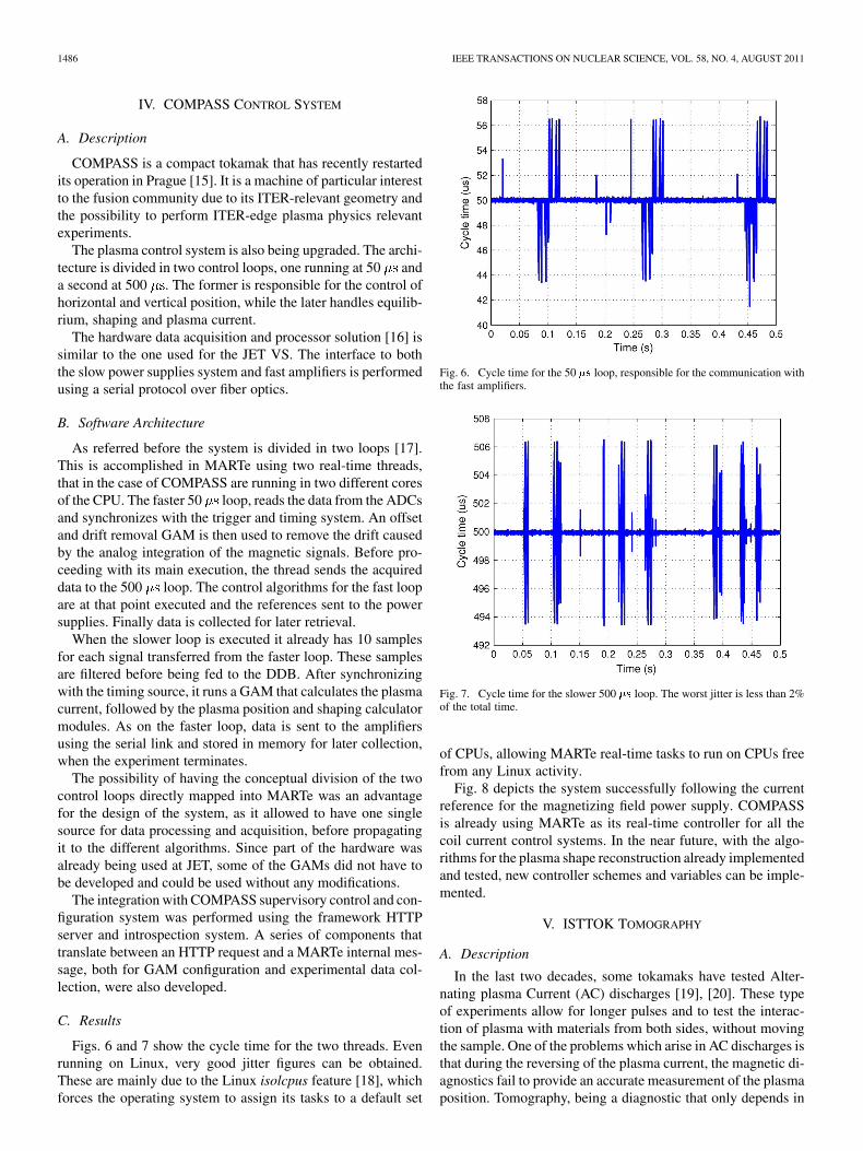
Figs. 6 and 7 show the cycle time for the two threads. Evenrunning on Linux, very good jitter figures can be obtained.These are mainly due to the Linux isolcpus feature [18], whichforces the operating system to assign its tasks to a default set
Fig. 6. Cycle time for the 50 �� loop, responsible for the communication withthe fast amplifiers.
Fig. 7. Cycle time for the slower 500 �� loop. The worst jitter is less than 2%of the total time.
of CPUs, allowing MARTe real-time tasks to run on CPUs freefrom any Linux activity.
Fig. 8 depicts the system successfully following the currentreference for the magnetizing field power supply. COMPASSis already using MARTe as its real-time controller for all thecoil current control systems. In the near future, with the algo-rithms for the plasma shape reconstruction already implementedand tested, new controller schemes and variables can be imple-mented.
V. ISTTOK TOMOGRAPHY
A. Description
In the last two decades, some tokamaks have tested Alter-nating plasma Current (AC) discharges [19], [20]. These typeof experiments allow for longer pulses and to test the interac-tion of plasma with materials from both sides, without movingthe sample. One of the problems which arise in AC discharges isthat during the reversing of the plasma current, the magnetic di-agnostics fail to provide an accurate measurement of the plasmaposition. Tomography, being a diagnostic that only depends in

NETO et al.: A SURVEY OF RECENT MARTe BASED SYSTEMS 1487
Fig. 8. Current control for the magnetizing field. This circuit is responsible forinducing the plasma current.
the emitted radiation from the plasma and that does not rely onmagnetic measurements, is a strong candidate to provide thismeasurement.
A new real-time plasma position controller, based on tomog-raphy, was recently developed at ISTTOK [21] (Lisbon). Thehardware is again based on the same ATCA solution used forthe JET VS and COMPASS. The system uses 30 ADC inputs,from one acquisition board, acquired at 2 MHz and later down-sampled to 20 kHz inside the board FPGAs. The communica-tion with the horizontal and vertical field power supplies is per-formed using a serial link over fiber optics, sharing the sameprotocol used in COMPASS. Due to the amount of calculationswhich have to be performed in the real-time tomography algo-rithm, the cycle time was set to 100 .
B. Software Architecture
A collection of 10 GAMs is executed for each control loop.After acquiring the data from the ATCA IOGAM, the ISTTOKtomography reconstruction and PID algorithms are executedand the system synchronized to the timing system. Subsequentlyto the module which generate the references, the next step is theexecution of the GAMs responsible for the communication withthe power supplies, followed by a set of utility and collectionGAMs.
Sharing the same hardware interface with the JET VS systemand the same power supplies protocol with the COMPASS ar-chitecture, enabled the developer to focus in the development ofthe core tomographic and control algorithms.
C. Results
Fig. 9 shows the plasma position being successfully con-trolled in real-time, using the tomographic reconstruction ofthe plasma emissivity, for ISTTOK pulse number 23330. Asreferred before, this is extremely useful during the inversionstage of AC tokamak discharges (happening at around 27 msin this pulse), where magnetic measurements, are less reliabledue to low plasma current.
Fig. 9. The first two plots show the R and Z plasma position coordinates, ascalculated by the tomographic reconstruction and by the magnetics. In the thirdplot the plasma current is depicted. During the inversion of the plasma current(�27 ms), the magnetics fail to provide an accurate value of the plasma position.
Fig. 10. Cycle time for the real-time position control of the ISTTOK plasma,using tomography. After 32 ms the cycle time worst jitter is larger by 2��, likelydue to a larger latency in the communication with the power supplies.
The cycle time is depicted in Fig. 10 and the target value of100 with a maximum jitter of about 6 , even with a complextomographic algorithm in the control loop.
VI. FTU LOWER HYBRID REFLECTED POWER
A. Description
In a fusion device, additional heating systems provide a wayof complementing the ohmic heating attained through Joule ef-fect. The Lower Hybrid (LH) system provides a way of deliv-ering power to the plasma using electromagnetic waves and canalso work as a current drive system [22]. The system works inthe 1–10 GHz range with high power (several hundreds of kW)RF sources. This source is usually a high vacuum electronic tubeworking as an amplifier, named klystron, or an open resonant

1488 IEEE TRANSACTIONS ON NUCLEAR SCIENCE, VOL. 58, NO. 4, AUGUST 2011
TABLE IMARTe BASED SYSTEMS CYCLE TIME COMPARISON
Fig. 11. Cycle time of the LH system. The jitter is under 1% of the total time.
Fig. 12. Ratio between reflected and transmitted power from the LH antenna.This value is going to be send to the feedback system in order to improve thecoupling.
cavity, named gyrotron. In the case of the FTU tokamak (Fras-cati), the 8 GHz LH system [23] uses gyrotrons with an outputRF power of 1 MW.
The main feedback control system of FTU tokamak is goingto be upgraded to receive the ratio between LH reflected andtransmitted power from the plasma. The controller will use thisvalue to change the plasma position in order to optimize thecoupling with the LH source antenna [24]. The power ratio isgoing to be computed by a MARTe based system, running on aVME crate with a XVME-6200 VMEbus IntelCore2 Duo T7400processor, one acquisition board from CAEN with 16, 12 bits,ADC channels and two Acromag outputs boards with 8 DAC
channels each. The operating system is RTAI and the requestedcycle time for the feedback system is 250 .
B. Software Architecture
MARTe waits for the beginning of a new control cycle usingan IOGAM triggered by the acquisition board. After convertingthe acquired signals from the ADC channels into physicalunits, the module that computes the power ratio is executed.An IOGAM ultimately writes the calculated data to the DACchannels and a collection GAM stores the signals in memoryfor later archiving.
During the commissioning of the system, a waveform gen-eration module was introduced in the control chain, providingsimulated values of the inputs. In order to test the system andthe hardware as accurately as possible, data produced by thewaveform generator is sent through the DACs and digitized backusing the acquisition board. This module will be removed whenthe system is connected to the diagnostic.
C. Discussion
As depicted in Fig. 11, the target 250 cycle time has beenmet with a worst case jitter of less than 2 . Fig. 12 shows thepower ratio for the LH antenna in FTU pulse number 32682.
The LH system required the development of new modulesboth for hardware interaction and algorithm execution. It wasalso the first system to use MARTe and RTAI in a VME basedenvironment.
VII. DISCUSSION
Table I compares the different MARTe systems regardinghardware, operating system and cycle time. All have verygood results in what concerns worst case jitter, proving thatthe operating system is protecting the controllers executionfrom external interrupts and correctly prioritizing the real-timetasks. It should be noticed that the development of MARTeapplications is completely transparent in what concerns lowlevel interactions with the underlying operating system, sincethese are delegated to the framework libraries.
The VS system was the first MARTe based application to bedeployed. It delivered very high performances and allowed partof the system to be modelled and tested offline, taking advan-tage of the GAM structures. The EFCC application proved thatthe framework could also run, delivering high performances, ina completely different hardware and operating system. COM-PASS used for the first time the multi-thread support to run twocontrol loops, each with its own frequency, in the same pro-cessor set. Both COMPASS and ISTTOK took advantage ofsome of the already developed modules for the ATCA basedhardware and focused their effort on the development on new
NETO et al.: A SURVEY OF RECENT MARTe BASED SYSTEMS 1489
algorithmic modules. The FTU LH system was the first to runusing Intel dual core processors on VME.
The most important feature which seems to be transversal toall systems is the ability to easily change GAMs. It is widelyused to simulate the algorithms in an offline system withouthardware (model based design), or to test the hardware usingsimulated data. The modularity provided by the GAMs has alsoallowed the different projects to interchange some modules,without having to rewrite any code. Examples are the IOGAMssharing the same low level hardware and utility GAMs (e.g.,data collection).
Making no assumptions on how data is produced and whatunderlying protocols are used, allowed MARTe to be easily in-tegrated in experiments with their own methodology for config-uration and experimental data retrieval. More important, as theboundary is very well defined, there was no impact on existingcode and allowed to develop and integrate new modules, withoutmaking any assumptions about who were the input data sourcesand output consumers.
The framework proved to be portable enough to be alreadyin use in 4 different experimental devices, running importantcontrollers and diagnostics which are in some cases essential tothe operation of the machine. Although the examples presentedon this paper are all related to the fusion experimental world,there is no reason why MARTe could not be used in differentkinds of experiments.
REFERENCES
[1] A. C. Neto, F. Sartori, F. Piccolo, R. Vitelli, G. De Tommasi, andL. Zabeo et al., “Marte: A multiplatform real-time framework,” IEEETrans. Nucl. Sci., vol. 57, no. 2, pp. 479–486, Apr. 2010.
[2] G. D. Tommasi, F. Piccolo, A. Pironti, and F. Sartori, “A flexiblesoftware for real-time control in nuclear fusion experiments,” Contr.Engrg. Practice, vol. 14, no. 11, pp. 1387–1393, 2006.
[3] R. Albanese, E. Cocorrese, and G. Rubinacci, “Plasma modeling forthe control of vertical instabilities in tokamaks,” Nucl. Fusion, vol. 29,no. 6, pp. 1013–1023, 1989.
[4] F. Romanelli and R. Kamendje, JET-EFDA Contributors, “Overviewof JET results,” Nucl. Fusion, vol. 49, no. 10, p. 104 006, Oct. 2009.
[5] F. Sartori, F. Crisanti, R. Albanese, G. Ambrosino, V. Toigo, and J. Hayet al., “The JET PCU project: An international plasma control project,”Fusion Engrg. Design, vol. 83, no. 2–3, pp. 202–206, 2008.
[6] R. Aymar, P. Barabaschi, and Y. Shimomura, “The iter design,” PlasmaPhys. Control. Fusion vol. 44, no. 5, p. 519, 2002 [Online]. Available:http://stacks.iop.org/0741-3335/44/i=5/a=304
[7] D. Ganuza, D. Rendell, B. Arenal, J. de la Fuente, S. Shaw, and V.Toigo et al., “The design and manufacture of the enhanced radialfield amplifier (erfa) for the jet project,” Fusion Engrg. Design vol.84, no. 2–6, pp. 810–814, 2009 [Online]. Available: http://www.sci-encedirect.com/science/article/B6V3C-4W3P06D-1/2/9104d5bfc786818df2b89b2c45d3f117
[8] F. Sartori, S. Dorling, A. Horton, P. J. Lomas, M. E. U. Smith, andR. C. Stephen, “ � � � compensation and variable gains for jetvertical stabilisation,” Fusion Engrg. Design vol. 66–68, pp. 727–734,2003 [Online]. Available: http://www.sciencedirect.com/science/ar-ticle/B6V3C-48XSGCJ-4/2/23a287e1 10e8a355499d5089dc11a693
[9] A. Batista, A. Neto, M. Correia, A. Fernandes, B. Carvalho, and J. For-tunato et al., “ATCA control system hardware for the plasma verticalstabilization in the jet tokamak,” IEEE Trans. Nucl. Sci., vol. 57, no. 2,pp. 583–588, Apr. 2010.
[10] F. Sartori, P. Lomas, F. Piccolo, and M. Zedda, JET-EFDA Contrib-utors, “Synchronous elm pacing at jet using the vertical stabilisationcontroller,” in Proc. 35th EPS Conf. on Plasma Physics, Jun. 2008, p.P-5.045.
[11] R. Felton, K. Blackler, S. Dorling, A. Goodyear, O. Hemming, and P.Knight et al., “Real-time plasma control at jet using an ATM network,”in Proc. Real Time Conf. 11th IEEE NPSS, 1999, pp. 175–181.
[12] R. Albanese and F. Villone, “The linearized create-l plasma responsemodel for the control of current, position and shape in tokamaks,” Nucl.Fusion vol. 38, no. 5, p. 723, 1998 [Online]. Available: http://stacks.iop.org/0029-5515/38/i=5/a=307
[13] I. Chapman, T. Hender, D. Howell, S. Erents, M. P. Gryaznevich, and S.Shibaev et al., “Perturbation of tokamak magnetic surfaces by appliedtoroidally asymmetric magnetic fields,” Nucl. Fusion vol. 47, no. 11,p. L36, 2007 [Online]. Available: http://stacks.iop.org/0029-5515/47/i=11/a=L02
[14] Y. Liang, H. R. Koslowski, P. R. Thomas, E. Nardon, B. Alper, andP. Andrew et al., “Active control of type-i edge-localized modes with� � � perturbation fields in the jet tokamak,” Phys. Rev. Lett., vol. 98,no. 26, p. 265004, Jun. 2007.
[15] R. Panek, O. Bilykova, V. Fuchs, M. Hron, P. Chraska, and P. Pavloet al., “Reinstallation of the compass-d tokamak in ipp ascr,” Czech. J.Phys., vol. 56, no. 2, pp. B125–B137, 2006.
[16] D. Valcárcel, A. Neto, J. Sousa, B. Carvalho, H. Fernandes, and J.Fortunato et al., “An ATCA embedded data acquisition and controlsystem for the compass tokamak,” Fusion Engrg. Design vol. 84,no. 7–11, pp. 1901–1904, 2009 [Online]. Available: http://www.sci-encedirect.com/science/article/B6V3C-4VDSD1R-N/2/3bc517a94893b910da789966a3e4d4bf
[17] D. Valcárcel, A. Duarte, A. Neto, I. Carvalho, B. Carvalho, and H.Fernandes et al., “Real-time software for the compass tokamak plasmacontrol,” Fusion Engrg. Design [Online]. Available: http://www.sci-encedirect.com/science/article/B6V3C-4YXMP1Y-3/2/b4918a83fec0d894ea31927c51ea1c9b
[18] A. Neto, F. Sartori, F. Piccolo, A. Barbalace, R. Vitelli, and H.Fernandes, “Linux real-time framework for fusion devices,” Fu-sion Engrg. Design vol. 84, no. 7–11, pp. 1408–1411, 2009[Online]. Available: http://www.sciencedirect.com/science/ar-ticle/B6V3C-4VJS6VR-C/2/b34a4ea3 7c455a155dd7a321334227ac
[19] J. Cabral, H. Fernandes, H. Figueiredo, and C. Varandas, “Operation ofthe tokamak ISTTOK in a multicycle alternating flat-top plasma currentregime,” Nucl. Fusion vol. 37, no. 11, pp. 1575–1581, 1997 [Online].Available: http://stacks.iop.org/0029-5515/37/1575
[20] O. Mitarai, C. Xiao, L. Zhang, D. McColl, W. Zhang, and G. Conwayet al., “Alternating current plasma operation in the stor-m tokamak,”Nucl. Fusion vol. 36, no. 10, pp. 1335–1343, 1996 [Online]. Available:http://stacks.iop.org/0029-5515/36/1335
[21] P. Carvalho, H. Thomsen, R. Coelho, P. Duarte, C. Silva, and H. Fer-nandes, “Isttok plasma control with the tomography diagnostic,” Fu-sion Engrg. Design, vol. 85, pp. 266–271, 2010.
[22] G. Hoang, A. Bécoulet, J. Jacquinot, J. Artaud, Y. Bae, and B. Beau-mont et al., “A lower hybrid current drive system for iter,” Nucl. Fu-sion vol. 49, no. 7, p. 075001, 2009 [Online]. Available: http://stacks.iop.org/0029-5515/49/i=7/a=075001
[23] F. Mirizzi, P. Bibet, A. Marra, P. Petrolini, and A. A. Tuc-cillo, “The PAM launcher for FTU: Results of the preliminarytests,” Fusion Engrg. Design vol. 66–68, pp. 621–625, 2003[Online]. Available: http://www.sciencedirect.com/science/ar-ticle/B6V3C-495VKP7-1/2/e66b1d33 e850daeac2cf92fd1d717778
[24] D. Carnevale, A. Astolfi, C. Centioli, S. V. Vitale, and L. Zaccarian, “Anew extremum seeking technique and its application to maximize RFheating on FTU,” Fusion Engrg. Design, vol. 84, no. 2, pp. 554–558,2009.


![Giovanni Virginio Schiaparelli: le «lacrime di San Lorenzo» portano a Marte [I parte]](https://static.fdokumen.com/doc/165x107/633f180803c3a3f0c206a458/giovanni-virginio-schiaparelli-le-lacrime-di-san-lorenzo-portano-a-marte-i.jpg)