
HDL code generation from UML/MARTE sequence diagrams for verification and synthesis
Upload
khangminh22Category
view
1download
0
Date: June 2011
UML Profile for MARTE: Modeling and Analysis of Real-Time Embedded Systems
Version 1.1(with change bars)
OMG Document Number: formal/2011-06-03Standard document URL: http://www.omg.org/spec/MARTE/1.1Associated Files*: http://www.omg.org/spec/MARTE/20100801
http://www.omg.org/spec/MARTE/20100802
Original files: ptc/2010-08-33 (XMI), ptc/2010-08-34 (model library XMI)

Copyright © 2001-2010, Alcatel-LucentCopyright © 2003-2010, ARTISAN Software ToolsCopyright © 2001-2010, International Business Machines CorporationCopyright © 2003-2010, Lockheed Martin CorporationCopyright © 1997-2011, Object Management GroupCopyright © 2001-2010, SOFTEAMCopyright © 2003-2010, THALESCopyright © 2001-2010, Commissariat à l’Energie Atomique
USE OF SPECIFICATION - TERMS, CONDITIONS & NOTICES
The material in this document details an Object Management Group specification in accordance with the terms, conditions and notices set forth below. This document does not represent a commitment to implement any portion of this specification in any company's products. The information contained in this document is subject to change without notice.
LICENSES
The companies listed above have granted to the Object Management Group, Inc. (OMG) a nonexclusive, royalty-free, paid up, worldwide license to copy and distribute this document and to modify this document and distribute copies of the modified version. Each of the copyright holders listed above has agreed that no person shall be deemed to have infringed the copyright in the included material of any such copyright holder by reason of having used the specification set forth herein or having conformed any computer software to the specification.
Subject to all of the terms and conditions below, the owners of the copyright in this specification hereby grant you a fully-paid up, non-exclusive, nontransferable, perpetual, worldwide license (without the right to sublicense), to use this specification to create and distribute software and special purpose specifications that are based upon this specification, and to use, copy, and distribute this specification as provided under the Copyright Act; provided that: (1) both the copyright notice identified above and this permission notice appear on any copies of this specification; (2) the use of the specifications is for informational purposes and will not be copied or posted on any network computer or broadcast in any media and will not be otherwise resold or transferred for commercial purposes; and (3) no modifications are made to this specification. This limited permission automatically terminates without notice if you breach any of these terms or conditions. Upon termination, you will destroy immediately any copies of the specifications in your possession or control.
PATENTS
The attention of adopters is directed to the possibility that compliance with or adoption of OMG specifications may require use of an invention covered by patent rights. OMG shall not be responsible for identifying patents for which a license may be required by any OMG specification, or for conducting legal inquiries into the legal validity or scope of those patents that are brought to its attention. OMG specifications are prospective and advisory only. Prospective users are responsible for protecting themselves against liability for infringement of patents.
GENERAL USE RESTRICTIONS
Any unauthorized use of this specification may violate copyright laws, trademark laws, and communications regulations and statutes. This document contains information which is protected by copyright. All Rights Reserved. No part of this

work covered by copyright herein may be reproduced or used in any form or by any means--graphic, electronic, or mechanical, including photocopying, recording, taping, or information storage and retrieval systems--without permission of the copyright owner.
DISCLAIMER OF WARRANTY
WHILE THIS PUBLICATION IS BELIEVED TO BE ACCURATE, IT IS PROVIDED "AS IS" AND MAY CONTAIN ERRORS OR MISPRINTS. THE OBJECT MANAGEMENT GROUP AND THE COMPANIES LISTED ABOVE MAKE NO WARRANTY OF ANY KIND, EXPRESS OR IMPLIED, WITH REGARD TO THIS PUBLICATION, INCLUDING BUT NOT LIMITED TO ANY WARRANTY OF TITLE OR OWNERSHIP, IMPLIED WARRANTY OF MERCHANTABILITY OR WARRANTY OF FITNESS FOR A PARTICULAR PURPOSE OR USE. IN NO EVENT SHALL THE OBJECT MANAGEMENT GROUP OR ANY OF THE COMPANIES LISTED ABOVE BE LIABLE FOR ERRORS CONTAINED HEREIN OR FOR DIRECT, INDIRECT, INCIDENTAL, SPECIAL, CONSEQUENTIAL, RELIANCE OR COVER DAMAGES, INCLUDING LOSS OF PROFITS, REVENUE, DATA OR USE, INCURRED BY ANY USER OR ANY THIRD PARTY IN CONNECTION WITH THE FURNISHING, PERFORMANCE, OR USE OF THIS MATERIAL, EVEN IF ADVISED OF THE POSSIBILITY OF SUCH DAMAGES.
The entire risk as to the quality and performance of software developed using this specification is borne by you. This disclaimer of warranty constitutes an essential part of the license granted to you to use this specification.
RESTRICTED RIGHTS LEGEND
Use, duplication or disclosure by the U.S. Government is subject to the restrictions set forth in subparagraph (c) (1) (ii) of The Rights in Technical Data and Computer Software Clause at DFARS 252.227-7013 or in subparagraph (c)(1) and (2) of the Commercial Computer Software - Restricted Rights clauses at 48 C.F.R. 52.227-19 or as specified in 48 C.F.R. 227-7202-2 of the DoD F.A.R. Supplement and its successors, or as specified in 48 C.F.R. 12.212 of the Federal Acquisition Regulations and its successors, as applicable. The specification copyright owners are as indicated above and may be contacted through the Object Management Group, 140 Kendrick Street, Needham, MA 02494, U.S.A.
TRADEMARKS
MDA®, Model Driven Architecture®, UML®, UML Cube logo®, OMG Logo®, CORBA® and XMI® are registered trademarks of the Object Management Group, Inc., and Object Management Group™, OMG™ , Unified Modeling Language™, Model Driven Architecture Logo™, Model Driven Architecture Diagram™, CORBA logos™, XMI Logo™, CWM™, CWM Logo™, IIOP™ , IMM™ , MOF™ , OMG Interface Definition Language (IDL)™, and SysML™ are trademarks of the Object Management Group. All other products or company names mentioned are used for identification purposes only, and may be trademarks of their respective owners.
COMPLIANCE
The copyright holders listed above acknowledge that the Object Management Group (acting itself or through its designees) is and shall at all times be the sole entity that may authorize developers, suppliers and sellers of computer software to use certification marks, trademarks or other special designations to indicate compliance with these materials.
Software developed under the terms of this license may claim compliance or conformance with this specification if and only if the software compliance is of a nature fully matching the applicable compliance points as stated in the specification. Software developed only partially matching the applicable compliance points may claim only that the software was based on this specification, but may not claim compliance or conformance with this specification. In the event that testing suites are implemented or approved by Object Management Group, Inc., software developed using this specification may claim compliance or conformance with the specification only if the software satisfactorily completes the testing suites.


OMG’s Issue Reporting Procedure
All OMG specifications are subject to continuous review and improvement. As part of this process we encourage readers to report any ambiguities, inconsistencies, or inaccuracies they may find by completing the Issue Reporting Form listed on the main web page http://www.omg.org, under Documents, Report a Bug/Issue (http://www.omg.org/technology/agreement.htm).


Table of Contents
Preface .....................................................................................................v
1 Scope .................................................................................................. 11.1 Introduction ............................................................................................................... 1
2 Conformance ...................................................................................... 12.1 Overview ................................................................................................................... 12.2 Extension Units and Features ................................................................................... 22.3 Conformance of MARTE with UML ........................................................................... 22.4 Conformance with MARTE ........................................................................................ 3
2.4.1 Compliance Cases .................................................................................................. 3 2.4.2 Extension Units in each Compliance Case ............................................................. 4 2.4.3 Special additional compliance case and extension units ........................................ 4
3 Normative References ........................................................................ 4
4 Terms and Definitions ......................................................................... 4
5 Symbols .............................................................................................. 5
6 Additional Information ......................................................................... 66.1 Scope of OMG RT/E Related Standards .................................................................. 66.2 Rationale and General Principles .............................................................................. 7
6.2.1 Real-time and embedded domain ........................................................................... 7 6.2.2 Guiding principles .................................................................................................... 9 6.2.3 How to use this specification ................................................................................. 10
6.3 Approach and Structure .......................................................................................... 13 6.3.1 Profile Architecture ................................................................................................ 13 6.3.2 A Foundation for Model Driven Techniques .......................................................... 14 6.3.3 Approach to Modeling RT/E Systems ................................................................... 14 6.3.4 Approach to Annotating for Model Analysis .......................................................... 15 6.3.5 MDA and MARTE .................................................................................................. 15
6.4 How to Read this Specification ............................................................................... 16 6.4.1 Structure of the Document .................................................................................... 16 6.4.2 Extension Specification Rationale and Format Convention .................................. 16 6.4.3 Conventions and Typography ............................................................................... 17
6.5 Acknowledgements ................................................................................................. 17
7 Core Elements (CoreElements) ........................................................ 217.1 Overview ................................................................................................................. 217.2 Domain View ........................................................................................................... 22
7.2.1 The Foundations Package .................................................................................... 22 7.2.2 The Causality::CommonBehavior Package .......................................................... 24 7.2.3 The Causality::RunTimeContext Package ............................................................ 27 7.2.4 The Causality::Invocation Package....................................................................... 28 7.2.5 The Causality::Communication Package .............................................................. 29
UML Profile for MARTE, V1.1 i
7.3 UML Representation ............................................................................................... 31 7.3.1 Profile Diagrams .................................................................................................... 32 7.3.2 Profile Elements Description ................................................................................. 32 7.3.3 Examples .............................................................................................................. 34
8 Non-functional Properties Modeling (NFPs) ..................................... 378.1 Overview ................................................................................................................. 378.2 Domain View ........................................................................................................... 38
8.2.1 Overview ............................................................................................................... 38 8.2.2 The NFP_Nature package .................................................................................... 39 8.2.3 The NFP_Annotation Package .............................................................................. 40 8.2.4 The NFP_Declaration Package ............................................................................. 42
8.3 UML Representation ............................................................................................... 43 8.3.1 Profile Diagrams .................................................................................................... 44 8.3.2 Profile elements description .................................................................................. 44 8.3.3 Graphical Syntax of NFP Value Specification ....................................................... 48 8.3.4 Examples .............................................................................................................. 48
9 Time Modeling (Time) ....................................................................... 579.1 Overview ................................................................................................................. 579.2 Domain View ........................................................................................................... 58
9.2.1 The BasicTimeModels Package ............................................................................ 59 9.2.2 The MultipleTimeModels Package ........................................................................ 61 9.2.3 The TimeAccesses Package ................................................................................. 64 9.2.4 The TimeRelatedEntities Package ........................................................................ 68
9.3 UML Representation ................................................................................................ 75 9.3.1 Profile Diagrams .................................................................................................... 75 9.3.2 Profile Elements Description ................................................................................. 78 9.3.3 Examples .............................................................................................................. 87
10 Generic Resource Modeling (GRM) ................................................. 9110.1 Overview ............................................................................................................... 9110.2 Domain View ......................................................................................................... 92
10.2.1 The ResourceCore Package ............................................................................... 92 10.2.2 The ResourceTypes Package ............................................................................. 94 10.2.3 The ResourceManagement Package .................................................................. 97 10.2.4 The Scheduling Package .................................................................................... 98 10.2.5 The ResourceUsage Package .......................................................................... 100
10.3 UML Representation ........................................................................................... 101 10.3.1 Profile Diagrams ................................................................................................ 101 10.3.2 Profile Elements Description ............................................................................. 105 10.3.3 GRM model library elements description .......................................................... 117
10.4 Examples ............................................................................................................ 117
11 Allocation Modeling (Alloc) ............................................................. 12111.1 Overview ............................................................................................................. 12111.2 Domain View ....................................................................................................... 12311.3 UML Representation ........................................................................................... 124
11.3.1 Profile Diagrams ................................................................................................ 125
ii UML Profile for MARTE, V1.1

11.3.2 Profile elements description .............................................................................. 12711.4 Examples ............................................................................................................ 133
11.4.1 Unix process ..................................................................................................... 133 11.4.2 System on Chip ................................................................................................. 134 11.4.3 Allocate activity group ....................................................................................... 135
12 Generic Component Model (GCM) ................................................ 13912.1 Overview ............................................................................................................. 13912.2 Domain View ....................................................................................................... 139
12.2.1 The GenericComponentModel Package........................................................... 139 12.2.2 On the MARTE Causality Model for GCM ......................................................... 143
12.3 UML Representation ........................................................................................... 146 12.3.1 Profile Diagrams ................................................................................................ 146 12.3.2 Profile Elements Description ............................................................................. 147
12.4 Examples ............................................................................................................ 169 12.4.1 Example of Model Patterns Illustrating the Usage of Flow Ports ...................... 169 12.4.2 Automotive Example ......................................................................................... 174 12.4.3 Avionics Example .............................................................................................. 176
13 High-Level Application Modeling (HLAM) ...................................... 17913.1 Overview ............................................................................................................. 17913.2 Domain View ....................................................................................................... 17913.3 UML Representation ........................................................................................... 183
13.3.1 Profile Diagrams ................................................................................................ 183 13.3.2 Profile Elements Description ............................................................................. 185
13.4 Examples ............................................................................................................ 192 13.4.1 Notational Examples ......................................................................................... 192 13.4.2 Avionics Example .............................................................................................. 193
14 Detailed Resource Modeling (DRM) .............................................. 19714.1 Software Resource Modeling (SRM) ................................................................... 197
14.1.1 Overview ........................................................................................................... 197 14.1.2 Domain View ..................................................................................................... 198 14.1.3 UML Representation ......................................................................................... 206 14.1.4 Profile Diagrams ................................................................................................ 207 14.1.5 Profile Elements Descriptions ........................................................................... 211 14.1.6 Examples .......................................................................................................... 229
14.2 Hardware Resource Modeling (HRM) ................................................................. 235 14.2.1 Overview ........................................................................................................... 235 14.2.2 Domain View..................................................................................................... 237 14.2.3 UML Representation ......................................................................................... 247 14.2.4 Examples .......................................................................................................... 275
15 Generic Quantitative Analysis Modeling (GQAM) .......................... 28515.1 Overview ............................................................................................................. 28515.2 Domain View ....................................................................................................... 287
15.2.1 The GQAM package ......................................................................................... 287 15.2.2 The GQAM_Workload Package ........................................................................ 288 15.2.3 GQAM_Observers Package .............................................................................. 291
UML Profile for MARTE, V1.1 iii

15.2.4 The GQAM_Resource Package ........................................................................ 292 15.2.5 Common NFP Attributes for Analysis ................................................................ 294
15.3 UML Representation ........................................................................................... 295 15.3.1 Profile Diagrams ................................................................................................ 295 15.3.2 Profile Elements Description ............................................................................. 299
16 Schedulability Analysis Modeling ................................................... 31116.1 Overview ............................................................................................................. 31116.2 Domain View ....................................................................................................... 311
16.2.1 The SAM Root Package .................................................................................... 312 16.2.2 The SAM Workload package ............................................................................ 313 16.2.3 The SAM Observers Package ........................................................................... 316 16.2.4 The SAM Resources Package .......................................................................... 317
16.3 UML Representation ........................................................................................... 319 16.3.1 Profile Diagrams................................................................................................ 320 16.3.2 Profile Elements Description ............................................................................. 322 16.3.3 Examples .......................................................................................................... 328
17 Performance Analysis Modeling (PAM) ......................................... 33517.1 Overview ............................................................................................................. 33517.2 Domain View ....................................................................................................... 335
17.2.1 The PAM_Workload Package ........................................................................... 335 17.2.2 Outline of Domain Concepts ............................................................................. 338
17.3 UML Representation ........................................................................................... 344 17.3.1 Profile Diagrams ................................................................................................ 344 17.3.2 Profile Elements Description ............................................................................. 346
17.4 Examples for Performance Analysis ................................................................... 352 17.4.1 Example 1: A Simple Web Application .............................................................. 352 17.4.2 Example 2: An Electronic Bookstore Home Page Interaction ........................... 355 17.4.3 Example 3: A building surveillance system ....................................................... 358 17.4.4 Example 4: Communications example, a layer subsystem ............................... 362 17.4.5 Example 5: Services by component subsystems .............................................. 364 17.4.6 Example 6: State machine annotations ............................................................. 368
Annex A - Guidance Example for Use of MARTE................................ 373
Annex B - Value Specification Language (VSL)................................... 433
Annex C - Clock Handling Facilities .................................................... 471
Annex D - Normative MARTE Model Libraries (MARTE_Library)........ 493
Annex E - Repetitive Structure Modeling (RSM).................................. 529
Annex F - Domain Class Descriptions ................................................. 547
Annex G - Bibliography ........................................................................ 725
Annex H - Mapping SPT on MARTE.................................................... 731
Index .................................................................................................... 733
iv UML Profile for MARTE, V1.1

Preface
About the Object Management Group
OMG
Founded in 1989, the Object Management Group, Inc. (OMG) is an open membership, not-for-profit computer industry standards consortium that produces and maintains computer industry specifications for interoperable, portable and reusable enterprise applications in distributed, heterogeneous environments. Membership includes Information Technology vendors, end users, government agencies and academia.
OMG member companies write, adopt, and maintain its specifications following a mature, open process. OMG's specifications implement the Model Driven Architecture® (MDA®), maximizing ROI through a full-lifecycle approach to enterprise integration that covers multiple operating systems, programming languages, middleware and networking infrastructures, and software development environments. OMG's specifications include: UML® (Unified Modeling Language™); CORBA® (Common Object Request Broker Architecture); CWM™ (Common Warehouse Metamodel); and industry-specific standards for dozens of vertical markets.
More information on the OMG is available at http://www.omg.org/.
OMG Specifications
As noted, OMG specifications address middleware, modeling and vertical domain frameworks. A catalog of all OMG Specifications is available from the OMG website at:
http://www.omg.org/technology/documents/spec_catalog.htm
Specifications within the Catalog are organized by the following categories:
OMG Modeling Specifications
• UML
• MOF
• XMI
• CWM
• Profile specifications.
OMG Middleware Specifications
• CORBA/IIOP
• IDL/Language Mappings
• Specialized CORBA specifications
• CORBA Component Model (CCM).
Platform Specific Model and Interface Specifications
• CORBAservices
UML Profile for MARTE, V1.1 v

• CORBAfacilities
• OMG Domain specifications
• OMG Embedded Intelligence specifications
• OMG Security specifications.
All of OMG’s formal specifications may be downloaded without charge from our website. (Products implementing OMG specifications are available from individual suppliers.) Copies of specifications, available in PostScript and PDF format, may be obtained from the Specifications Catalog cited above or by contacting the Object Management Group, Inc. (as of January 16, 2006) at:
OMG Headquarters140 Kendrick StreetBuilding A, Suite 300Needham, MA 02494USATel: +1-781-444-0404Fax: +1-781-444-0320Email: [email protected]
Certain OMG specifications are also available as ISO standards. Please consult http://www.iso.org
Typographical Conventions
The type styles shown below are used in this document to distinguish programming statements from ordinary English. However, these conventions are not used in tables or section headings where no distinction is necessary.
Times/Times New Roman - 10 pt.: Standard body text
Helvetica/Arial - 10 pt. Bold: OMG Interface Definition Language (OMG IDL) and syntax elements.
Courier - 10 pt. Bold: Programming language elements.
Helvetica/Arial - 10 pt: Exceptions
Note – Terms that appear in italics are defined in the glossary. Italic text also represents the name of a document, specification, or other publication.
Issues
The reader is encouraged to report any technical or editing issues/problems with this specification to http://www.omg.org/technology/agreement.htm.
vi UML Profile for MARTE, V1.1

1 Scope
1.1 Introduction
This specification of a UML™ profile adds capabilities to UML for model-driven development of Real Time and Embedded Systems (RTES). This extension, called the UML profile for MARTE (in short MARTE for Modeling and Analysis of Real-Time and Embedded systems), provides support for specification, design, and verification/validation stages. This new profile is intended to replace the existing UML Profile for Schedulability, Performance and Time (formal/03-09-01).
MARTE defines foundations for model-based descriptions of real time and embedded systems. These core concepts are then refined for both modeling and analyzing concerns. Modeling parts provides support required from specification to detailed design of real-time and embedded characteristics of systems. MARTE concerns also model-based analysis. In this sense, the intent is not to define new techniques for analyzing real-time and embedded systems, but to support them. Hence, it provides facilities to annotate models with information required to perform specific analysis. Especially, MARTE focuses on performance and schedulability analysis. But, it defines also a general analysis framework that intends to refine/specialize any other kind of analysis.
Among others, the benefits of using this profile are thus:
• Providing a common way of modeling both hardware and software aspects of an RTES in order to improve communication between developers.
• Enabling interoperability between development tools used for specification, design, verification, code generation, etc.
• Fostering the construction of models that may be used to make quantitative predictions regarding real-time and embedded features of systems taking into account both hardware and software characteristics.
2 Conformance
2.1 Overview
The range of applications and areas of knowledge that are inside the scope of this specification is largely broader than the current usage of traditional tools in the real-time and embedded systems market. Though all of them are related from the system perspective and will benefit from having a common place for notations, vocabulary, and semantics inside MARTE, it is a fact that a number of different specialized actors are involved. Consequently, the tools that are currently in the market, which are those expected to evolve to support this specification, have different users and specific target applications sub-domains. For this reason, and in order to ease its adoption process, this specification defines a modular approach for conformance. This is similar to the UML compliance strategy, but in this case the compliance points are not defined as stratified horizontal layers. Here they are defined as Compliance Cases, whose constitutions depend closely on the expected use cases of the specification.
Though it is recognized that the ability to exchange models between tools is extremely important, this is not compromised in this approach since interchange is only deemed useful between tools for similar and/or complementary purposes. When such purposes are similar, the exchanging tools will likely satisfy the same conformance cases. If they are complementary, model transformations and/or a broader scope of compliance cases will be required at least in one of the tools involved.
UML Profile for MARTE, V1.1 1
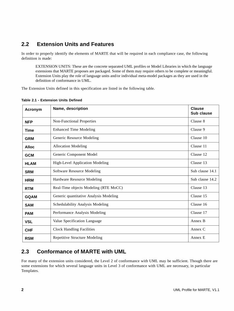
2.2 Extension Units and Features
In order to properly identify the elements of MARTE that will be required in each compliance case, the following definition is made:
EXTENSION UNITS: These are the concrete separated UML profiles or Model Libraries in which the language extensions that MARTE proposes are packaged. Some of them may require others to be complete or meaningful. Extension Units play the role of language units and/or individual meta-model packages as they are used in the definition of conformance in UML.
The Extension Units defined in this specification are listed in the following table.
2.3 Conformance of MARTE with UML
For many of the extension units considered, the Level 2 of conformance with UML may be sufficient. Though there are some extensions for which several language units in Level 3 of conformance with UML are necessary, in particular Templates.
Table 2.1 - Extension Units Defined
Acronym Name, description ClauseSub clause
NFP Non-Functional Properties Clause 8
Time Enhanced Time Modeling Clause 9
GRM Generic Resource Modeling Clause 10
Alloc Allocation Modeling Clause 11
GCM Generic Component Model Clause 12
HLAM High-Level Application Modeling Clause 13
SRM Software Resource Modeling Sub clause 14.1
HRM Hardware Resource Modeling Sub clause 14.2
RTM Real-Time objects Modeling (RTE MoCC) Clause 13
GQAM Generic quantitative Analysis Modeling Clause 15
SAM Schedulability Analysis Modeling Clause 16
PAM Performance Analysis Modeling Clause 17
VSL Value Specification Language Annex B
CHF Clock Handling Facilities Annex C
RSM Repetitive Structure Modeling Annex E
2 UML Profile for MARTE, V1.1
2.4 Conformance with MARTE
Tools vendors and MARTE implementers require a set of conformance definitions that allow them to better target their particular user needs without having to implement the complete MARTE Specification.
The target usages of the profile (its use cases and/or the actors involved) are good conceptual entities to look for groups of Extension Units that may lead to useful compliance definitions.
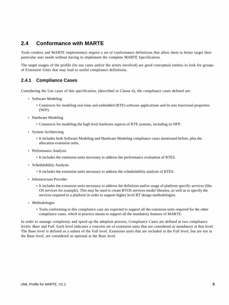
2.4.1 Compliance Cases
Considering the Use cases of this specification, (described in Clause 6), the compliance cases defined are:
• Software Modeling
• Constructs for modeling real-time and embedded (RTE) software applications and its non functional properties (NFP).
• Hardware Modeling
• Constructs for modeling the high level hardware aspects of RTE systems, including its NFP.
• System Architecting
• It includes both Software Modeling and Hardware Modeling compliance cases mentioned before, plus the allocation extension units.
• Performance Analysis
• It includes the extension units necessary to address the performance evaluation of RTES.
• Schedulability Analysis
• It includes the extension units necessary to address the schedulability analysis of RTES.
• Infrastructure Provider
• It includes the extension units necessary to address the definition and/or usage of platform specific services (like OS services for example). This may be used to create RTOS services model libraries, as well as to specify the services required to a platform in order to support higher level RT design methodologies.
• Methodologist
• Tools conforming to this compliance case are expected to support all the extension units required for the other compliance cases, which in practice means to support all the mandatory features of MARTE.
In order to manage complexity and speed up the adoption process, Compliance Cases are defined at two compliance levels: Base and Full. Each level indicates a concrete set of extension units that are considered as mandatory at that level. The Base level is defined as a subset of the Full level. Extension units that are included in the Full level, but are not in the Base level, are considered as optional at the Base level.
UML Profile for MARTE, V1.1 3

2.4.2 Extension Units in each Compliance Case
The Extension Units that must be supported in each Compliance Cases are assigned as depicted in the next table:
2.4.3 Special additional compliance case and extension units
Tools that wish to serve AADL users should implement A.3 in Annex A of this specification.
3 Normative References
The following normative documents contain provisions which, through reference in this text, constitute provisions of this specification. Refer to the OMG site for subsequent amendments to, or revisions of any of these publications:
• UML 2.1.2 Superstructure Specification (OMG document number formal/2007-11-02)
• UML 2.1.2 Infrastructure Specification (OMG document number formal/2007-11-04)
• XMI 2.1 Specification (OMG document number formal/2005-09-01)
4 Terms and Definitions
There are no formal definitions in this specification that are taken from other documents.
Table 2.2 - Extension Units that must be supported in each Compliance Case
CASE Level GRM NFP VSL Time CHF SRM HRM GCM Alloc HLAM GQAM PAM SAM RSM
Software Base X X X X
Full X X X X
Hardware Base X X X X
Full X X X X X
System Base X X X X X
Full X X X X X X
Performance Base X X X X X
Full X X
Schedulability Base X X X X X
Full X X
Infrastructure Base X X X X
Full X X X X
Methodologist Base X X X X X X
Full X X X X X X X X
4 UML Profile for MARTE, V1.1

5 Symbols
Acronym Meaning
AADL Architecture Analysis and Design Language
AHB AMBA High-performance Bus
AMBA Advanced Microcontroller Bus Architecture
ARM Advanced RISC Machines
CAN Controller Area Network
CCM Corba Component Model
CORBA Common Object Request Broker Architecture
CPU Central Processing Unit
DMA Direct Memory Access
DPRAM Double-Port RAM
DRAM Dynamic Random Access Memory
EAST-ADL2 EAST Architecture Description Language 2
EDF Earliest Deadline First
EQN Extended Queueing Network
FIFO First In First Out
GQAM Generic Quantitative Analysis Modeling
GRM Generic Resource Modeling
GUI Graphical User Interface
LQN Layered Queueing Network
Lw-CCM Lightweight CCM
MARTE UML profile for Modeling and Analysis of Real-Time and Embedded systems
MDA Model-Driven Architecture
NFP Non-Functional Properties modeling
OCL Object Constraint Language
OS Operating System
PAM Performance Analysis Modeling
QN Queueing Network
QoS Quality of Service
QoS&FT UML Profile for Quality of Service and Fault Tolerance specification
RISC Reduced Instruction-Set Computer
RMA Rate Monotonic Analysis
RSM Repetitive Structure Modeling
RTOS Real-Time Operating System
UML Profile for MARTE, V1.1 5

6 Additional Information
6.1 Scope of OMG RT/E Related Standards
The MARTE profile, which replaces the current profile for Schedulability, Performance, and Time, is one of a group of related OMG specifications (Figure 6.1). The most obvious of these is the UML 2 Superstructure specification, which is the basis for any UML profile. It also uses the OCL 2.0 specification for all constraints specified in OCL.
Figure 6.1 - Informal description of the MARTE dependencies with other OMG standards
Note that the Superstructure is dependent on UML compliance level 3 (L3), which is the complete UML metamodel.
In addition, MARTE is related to the following other OMG specifications:
• The UML profile for Modeling Quality of Service and Fault Tolerance Characteristics and Mechanisms. This specification provides, among other things, a generic metamodel for defining different qualities of service and is used for specifying any such characteristics defined in the MARTE profile.
• The UML profile for Systems Engineering (SysML), which deals with many of the same areas, such as the modeling of platforms and their constituent elements (hardware resources) and the allocation of software to platforms (i.e.,
SAM Schedulability Analysis Modeling
SI Système International
SPT UML Profile for Schedulability, Performance and Time specification
SysML Systems Modeling Language
TCP Transmission Control Protocol
TPC-W Transaction Processing Council Web benchmark
TVL Tag Value Language
UML Unified Modeling Language
VSL Value Specification Language
WCET Worst Case Execution Time
« profi le »
Marte« profile »
SPT
« replace »
MOF 2.0 QVT« metamodel »
U ML2 Superstru cture (L3)OCL 2
« uses »« uses »
6 UML Profile for MARTE, V1.1
deployment). In areas where there is conceptual overlap, MARTE is either reuses the corresponding SysML stereotypes, or defines elements that are conceptually and terminologically aligned with SysML.
• The Executable UML Foundation specification (currently in progress) defines, among other things, a model of causality for UML that is at the core of various scenario-based analysis methods (such as performance and schedulability analyses). The MARTE causality model must be fully consistent with the model specified in the Executable UML Foundation specification.
• The RTCORBA and CCM specifications address issues related to software execution platforms, real-time constraints, composition mechanisms, etc. (i.e., issues that are all in the scope of the MARTE specification). All these computing platforms may be then considered as specific resources for executing MARTE model-based application.
The following OMG specifications deal with similar subject matter but are not considered relevant to this specification:
• The UML for SoC profile
• The EDOC UML profile
6.2 Rationale and General Principles
Since the adoption of the UML standard and its new advanced release UML2, this modeling language has been used for development of a large number of time-critical and resource-critical systems (a significant number of these can be found in the various books, papers, and reports listed in the bibliography at the end of this specification). Based on this experience, a consensus has emerged that, while a useful tool, UML is lacking in some key areas that are of particular concern to real-time and embedded system designers and developers. In particular, it was noticed that first the lack of a quantifiable notion of time and resources was an impediment to its broader use in the real-time and embedded domain. Second, the need for rigorous semantics definition is also a mandatory requirement for a widespread usage of the UML for RT/E systems development.
Fortunately, and contrary to an often expressed opinion, it was discovered that UML had all the requisite mechanisms for addressing these issues, in particular through its extensibility faculties. This made the job much easier, since it was unnecessary to add new fundamental modeling concepts to UML – so-called “heavyweight” extensions. Rather, the work being done in the specification consisted of defining a standard way of using these capabilities to represent concepts and practices from the real-time and embedded domain.
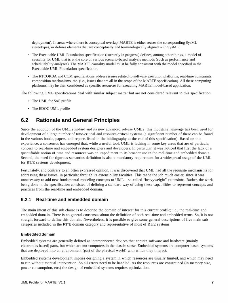
6.2.1 Real-time and embedded domain
The main intent of this sub clause is to describe the domain of interest for this current profile; i.e., the real-time and embedded domain. There is no general consensus about the definition of both real-time and embedded terms. So, it is not straight forward to define this domain. Nevertheless, it is possible to give some general descriptions of five main sub categories included in the RT/E domain category and representative of most of RT/E systems.
Embedded domain
Embedded systems are generally defined as interconnected devices that contain software and hardware (mainly electronics based) parts, but which are not computers in the classic sense. Embedded systems are computer-based systems that are deployed into an environment (part of the physical world) with which they interact.
Embedded systems development implies designing a system in which resources are usually limited, and which may need to run without manual intervention. So all errors need to be handled. As the resources are constrained (in memory size, power consumption, etc.) the design of embedded systems requires optimization.
UML Profile for MARTE, V1.1 7
The designed system will be embedded in a real application, either software or hardware. Therefore, the produced code must be easily interfaced with a software environment such as a real-time operating system (RTOS), middleware, a micro-controller or onto specific hardware (e.g., ASIC, FPGA).
Embedded systems distinguish themselves especially by following specific characteristics: heterogeneity (hardware / software), distribution (on potential multiple and heterogeneous hardware resources), ability to react (supervision, user interfaces modes), criticality, real-time, and consumption constraints.
Reactive domain
Systems are generally tagged as “reactive” to stress the fact that they are meant to react to information inputs coming from some environment. The main goal of such reactive systems is actually to control, supervise, or simply collaborate or interact with this environment. Of course such systems may perform heavy data computation, but this aspect is played down and abstracted somehow in the system description.
The behavior of reactive systems usually consists of reaction cycles: first, input events are gathered from the environment (through sensors); second, a reaction is computed and decided upon; third, the proper outputs are emitted back in a timely manner in response to environment stimuli through actuators for example. The reactions may depend on a local or global state, defining the current mode of operation of the reactive system.
Reactive systems can be found in transportation (automotive, aircrafts), factory automation, in hardware/software controllers, in various embedded electronic appliances, including mobile communications.
Control/Command domain
Applications for control/command domain are usually dedicated to manage the execution of a process or object of the physical world. The command synthesis matches the production of commands toward actuators from a given request.
A request is generated after measures have been done on one or several sensors. A measure is packaged (i.e., processing the signal coming from the sensor) and then managed (i.e., taking into account the process state) in order to build the corresponding request. From a given request, it is possible to distinguish three kinds of command synthesis: (1) the regulating or the request is fixed; (2) serving that means the adaptation of a command following the order variations; (3) the trajectory monitoring in case of variable request.
The command synthesis may be achieved either in open loop or in closed loop mode. The command synthesis in open loop mode consists in designing a function that depends on the request values and parameters of the actuators. The command synthesis in closed loop mode is relying on an additional measure requiring to evaluate the level at which the request is considered and to adjust the command if needed.
Moreover, real case studies demonstrate that, in addition to the usual functions for command synthesis and measuring, it is necessary to have user information functions (via a specific API or network) and trace functions.
Systems dedicated to process control consist of three main activities: measuring, command synthesis, and information output. Three components involved in the development of control/command systems may be also identified: Sensors (buttons, serial input devices, etc.) related to measuring activities; Actuators (motors, printers, etc.) related to command synthesis in open and closed loop; and output devices (e.g., screen, files, networks, etc.) related to information output.
Intensive data flow computation domain
Intensive data flow computation is mainly encountered in signal processing, image processing, and mobile devices. A common scenario is a radio signal tuned by a receiver, filtered, and decoded. These different stages require intensive data computation to be performed, possibly in parallel, with the help of several computation units.
8 UML Profile for MARTE, V1.1

Many signal and image processing applications follow an organization in two high level stages: systematic signal processing and intensive data processing.
The systematic signal processing is the very first part of a signal processing application. It mainly consists of a chain of filters and regular processing applied on the input signals independently of the signal values. It results in a characterization of the input signals with values of interest.
The intensive data processing is the second part of a signal processing application. It applies irregular computations on the values issued by the systematic signal processing. Those computations may depend on the signal values.
Software Defined Radio receiver is a concrete industrial example of such a domain. This emerging application is structured with front end systematic signal processing including signal digitalization, channel selection, and application of filters to eliminate interferences. The data is decoded in a second and more irregular phase (synchronization, signal demodulation, etc.).
Intensive data-flow computation is an important class of embedded applications requiring hardware architectures description. It requires mainly being able to express potential parallel processing of data and parallel hardware architectures, preferably in simple ways that allow for factorization of repeated elements.
Best-effort service domain
Real-time systems sometimes include elements that do not deliver services in a totally safe or time-constrained way (such as web application servers in an IP telephony system). These systems nonetheless have properties (delay distribution, probability of failure of a service) that need to be understood.
Best-effort services supply one or more responses as data, to a request. They often make subsidiary requests to other services, particularly to data services (databases, caches, file servers, disk storage). Best-effort services are not distinguishable from systems that are not primarily designated “real-time” systems.
To a certain extent most computer systems have some aspect of requirements for real-time responses, which are affected by system resources. This profile provides some capabilities for describing and analyzing those real-time aspects of any system.
6.2.2 Guiding principles
This sub clause aims in defining what have been the main guiding principles used to write this specification. The main guiding principles are then as follows:
• The profile should support independent modeling of both software or hardware parts of RT/E systems and the relationships between them.
• The profile has to provide modeling constructs covering the development process of RT/E systems. Such features may be categorized into qualitative (parallelism, synchronization, communication) or quantitative (deadline, periodicity). The profile must provide high-level modeling constructs for specification purposes, for example, but also low-level construct for implementation purposes.
• As much as possible, modelers should not be hindered in the way they use UML to represent their systems just to be able to do model analysis. That is, rather than enforcing a specific approach or modeling style for real-time systems, the profile should allow modelers to choose the style and modeling constructs that they feel are the best fit to their needs of the moment.
• Modelers should be able to take advantage of different types of model analysis techniques without requiring a deep understanding of the inner workings of those techniques. The steep learning curve behind many of the current model
UML Profile for MARTE, V1.1 9

analysis methods has been one of the major impediments to their adoption.
• The profile must support all the current mainstream real-time technologies, design paradigms, and model analysis techniques. However, it should also be fully open to new developments in all of these areas.
• It must foster construction of UML models that can be used to make quantitative and partitioning predictions and analysis regarding hardware and software characteristics of the RT/E system. In particular, it is important to be able to perform such analyses early in the development cycle. For that, it has to be possible to analyze partial models. It should be possible to automatically construct different analysis-specific models directly from a given UML model. Such tools should be able to read the model, process it, and feed the results back to the modeler in terms of the original UML model.
6.2.3 How to use this specification
This sub clause describes which potential actors may use this specification and how they can do it. Of course, neither the actors nor use cases described represent an exclusive set for how this specification can be used, but rather reflect on some of the ways that we expect it to be used or (in most cases) expanded.
Figure 6.2 describes a set of potential actors that may use this specification for designing RT/E systems.
Figure 6.2 - Possible actors using the MARTE specification
• Model Designer: These are modelers that design models dedicated to be applied in the context of the development process of RT/E systems. Models may be used for usual specification, design, or implementation stages. But models may be also used for analyzing in order to determine whether they will meet their performance and schedulability requirements.
• RT/E Systems Architect: These are specific modelers concerned with the overall architecture and they usually make trade-offs between implementing functionality in hardware, software, or both.
Mo d e l De s i g n e r
R T /E S y s te m A rc h i te c t H ar dw a re M o de l e rSo f tw a re M o de l e r
M e tho d o l o gy P ro v id e r
A n a l y si s M e th o d ol o g y P ro v i d er
So f tw are A rc hi te c t H a rd wa re A rc h i tec t
M a rte Us e r
D es i g n M e th od o l o g y Pro v id e r
E xe c u t i o n P l a t fo rm P ro v i de rM o d el A na l y s t
10 UML Profile for MARTE, V1.1

• Hardware Modeler: These are modelers specifically dedicated to hardware aspects of the RT/E systems development.
• Hardware Architect: These are modelers concerned by designing hardware architecture.
• Software Modeler: These are modelers specifically dedicated to software aspects of the RT/E systems development.
• Software Architect: These are modelers concerned with designing software architecture.
• Model Analyst: These are modelers concerned with annotating system models in order to perform specific analysis methodologies.
• Execution Platform Provider: These are developers and vendors of run-time technologies (hardware- or/and software-based platforms) such as Real-Time CORBA, real-time operating systems, and specific hardware components.
• Methodology Provider: These are the individuals and teams who are responsible for defining model-based methodology for RT/E domain. This category includes UML tool providers.
• Design Methodology Provider: These are specialized methodology providers who are responsible for defining model-based methodology for specifying, designing or/and implementing RT/E systems.
• Analysis Methodology Provider: These are specialized methodology providers who are responsible for defining model-based analysis methodology such as RMA or queuing theory, as well as technology provider such as tool vendors providing tools and processes for supporting particular model analysis methods.
Common possible usages of the MARTE profile are specified in the use case diagram depicted in Figure 6.3.
Figure 6.3 - Common use cases of the MARTE specification
Details of the use case “build Model”
• Actor: Modeler
• Description: A modeler builds a model iterating it through several stages defined in an appropriate development process. According to a given methodology (see the “define Methodology” use case), a modeler uses appropriate UML extensions or specific model libraries defined in the MARTE specification in order to describe the RT/E aspects in the model of their system.
• Deliverable: The result of this use case is a model of the user system containing all its RT/E specificities.
Model Designer
build Model
build Execution Platform Model
Methodology Provider
Execution Platform Providerprovide Execution Platform
define Methodology
adapt Marte Specification
« include »
« include »
Marte specification
Model Analyst
annotate Model for Analysis
analyze Model
UML Profile for MARTE, V1.1 11
Details of the use case “adapt MARTE Specification”
• Actor: Methodology Provider and Execution Platform Provider
• Description: This use case consists in defining a specific MARTE sub-profile. The motivations to adapt MARTE may be either to deal with a specific domain not covered by MARTE or to define restrictions on the usage of MARTE modeling constructs. In the former case, the actor may either specialize MARTE modeling constructs in order to adapt them suitably to their needs or introduce new concepts not available in MARTE. The second way to adapt the MARTE specification is to define modeling rules in order to constraint the usage of the specification.
• Deliverable: The outcome of this use case is a definition of MARTE extension that takes the form a UML profile based on the MARTE specification. The dependencies with the MARTE profile may be merge, import or specialization.
Details of the use case “define Methodology”
• Actor: Methodology Provider
• Description: This use case consists in defining how to use the MARTE specification for a given purpose. For example, one may define a specific methodology for the design of electronic automotive systems (cf. the EAST-ADL annex) or for avionics (see AADL annex). One may also define model-based analysis methodology such as schedulability or performance analysis.
• Deliverable: The outcome of this use case is a model-based methodology. This latter may include a process description, a set of constraint rules and a set of required techniques that applies to the methodology. If necessary, this use case may also include the definition of an extension of the MARTE profile (include of the “extend MARTE Specification” use case).
Details of the use case “annotate Model for Analysis”
• Actor: Model Analyst
• Description: The model analyst uses appropriate MARTE extensions, as defined for example in a specific analysis methodology, in order to annotate appropriately models in order to perform a given analysis techniques.
• Deliverable: The outcome of this use case is a model annotated with MARTE extensions and ready for performing specific analysis.
Details of the use case “analyze Model”
• Actor: Model Analyst
• Description: The model analyst perform a given analysis techniques on a model. The purpose of the analysis may be varied depending of the nature of the analysis techniques used. Some examples of analysis are: schedulability or performance analyses.
• Deliverable: The outcomes of this use case are analysis results.
Details of the use case “build Execution Platform Model”
• Actor: Execution Platform Provider
• Description: This use case consists in building model of execution platform for MARTE based developments of RT/E systems.
• Deliverable: The outcome of this use case is a MARTE compatible execution platform model.
12 UML Profile for MARTE, V1.1
Details of the use case “provide Execution Platform”
• Actor: Execution Platform Provider
• Description: This use case consists in providing execution platform conform to a given model of platform.
• Deliverable: The outcome of this use case is an execution platform.
6.3 Approach and Structure
6.3.1 Profile Architecture
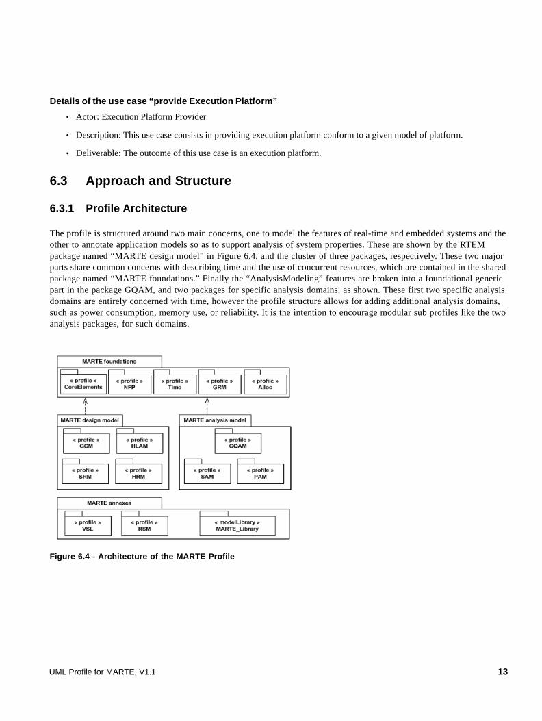
The profile is structured around two main concerns, one to model the features of real-time and embedded systems and the other to annotate application models so as to support analysis of system properties. These are shown by the RTEM package named “MARTE design model” in Figure 6.4, and the cluster of three packages, respectively. These two major parts share common concerns with describing time and the use of concurrent resources, which are contained in the shared package named “MARTE foundations.” Finally the “AnalysisModeling” features are broken into a foundational generic part in the package GQAM, and two packages for specific analysis domains, as shown. These first two specific analysis domains are entirely concerned with time, however the profile structure allows for adding additional analysis domains, such as power consumption, memory use, or reliability. It is the intention to encourage modular sub profiles like the two analysis packages, for such domains.
Figure 6.4 - Architecture of the MARTE Profile
UML Profile for MARTE, V1.1 13

6.3.2 A Foundation for Model Driven Techniques
The profile is intended to provide a foundation for applying transformations from UML models into a wide variety of analysis models. The environment for exploiting the profile would consist of a set of tools, including model transformers, as shown in Figure 6.5. Prototypes of such tool chains have been produced based on SPT.
The forward path shows the way the model is expected to be transformed via the XMI output, to a format readable by an analysis tool. The dashed line indicates a potential feedback path to re-import the analysis results into the UML diagrams.
Another feedback path clearly exists from the analysis to the modeler.
Figure 6.5 - A Tool Chain for Carrying out Analysis of a Model
6.3.3 Approach to Modeling RT/E Systems
Embedded systems are becoming increasingly heterogeneous. This is true of applications, which combine intensive, often heavily pipelined, data computation for signal processing, together with control mode switches and communication protocols. This is true also of execution platforms, which comprise flexible or custom-made hardware, multi-core processors, cache and bus hierarchies, and so on. This is reflected in the design of such systems, which must try to fit best applications onto existing platforms, or even adjust and dimension again execution platforms for pre-existing applications. The main criteria governing this allocation of application functions to HW/SW execution resources are stringent real-time requirements, but power- and area-consumption or cost also play a role. Adequate modeling can of course be of great help with this design activity by providing the support for design and analysis. The modeling support should also encompass early global timing budget and maximal latency requirements, as well as scheduling results display expressing the explicit quality of allocation in a traceable manner.
Application modeling is based on interacting component blocks for structural aspects. As for behavior, data-intensive pipe-lined computations are generally represented with block-diagrams amenable to activity charts, while control-flow parts and communication protocols use hierarchical finite-state machines. This functionality is complemented with timing aspects, based on appropriate time/cycle descriptions (see time model below). Application modeling is further described in Clause 9.
M o d e l D e si g n er
U M L To o l An no ta te d U M L M od el
( XM I)
Ann o ta ted Plat fo rm
M o de l L ibr ar y
T r a n sf o r m a t io n to An a l ys is
M o d e lAna ly sis M o de l
A n a lys is T o o l
M o d e l A n al ys t
An aly sis Re s ults
D ia g n o s tic /F e ed b a c k
b ui ld a n a ly z e
14 UML Profile for MARTE, V1.1
Execution platform modeling comprises the description of both dedicated hardware and (middleware) software layers and interconnects composing the platform. It can be described at the same level of abstraction as the application, and contains timing information along with structural and behavioral aspects. Explicit detailed modeling can be needed in as far as the appropriate match between application and architecture is to be studied (hierarchical cache structure or Instruction Set Simulators for instance). Execution platform modeling is further described in both Clauses 10 and 14.
The allocation model describes the association matching applicative functions onto execution platform resources. It is sometimes mandatory to provide timing information on this allocation link itself, rather than on its constituents, for reasons of modular abstraction (for instance one may indicate that a complex filter function can be realized at a given cost on a given specific processor, without going back to individual statements and instructions). Allocation modeling is further described in Clause 12.
Note: allocation is here reminiscent of the similar notion in the SysML specification.
Regular iterative constructs, that are often encountered in the embedded world to represent signal-processing applications or dedicated DSP operator blocks, or processor arrays, are best modeled using dedicated iterative model representations such as described in Annex E.
6.3.4 Approach to Annotating for Model Analysis
Annotations use stereotypes that permit us to map model elements into the semantics of an analysis domain such as schedulability, and give values for properties that are needed in order to carry out the analysis. We may distinguish “input” properties that are needed to carry out the analysis, and “output” properties that are determined by the analysis. However the modeler may also input required values of output properties, which can be used to determine how well the system meets its requirements (another output property).
Analysis is not always simply “pass/fail,” and the particular goals of analysis are specific to its domain. Output properties to be reported may include details of how and where time and resources are consumed, in order to diagnose problems, and may include sensitivity studies to explore the importance of parameters whose values are uncertain.
6.3.5 MDA and MARTE
The MARTE profile defines precise semantics for time and resource modeling. These precise semantics allow automatic transformations of models to lower abstraction level models such as UML for SoC for hardware / software simulation or into C++ for implementation purposes.
One of the goals of this profile is to support common design flows for RT/E systems. One of these design flows is to define in different views or models the application (including functional and non functional characteristics), the hardware architecture and the allocation of the application onto the hardware architecture. Starting from this allocation model, if the semantics is precise enough, one can automate code generation for simulation at different abstraction levels or synthesis of specific hardware parts.
Another use of MDA (or MDE, “Model Driven Engineering”) with the MARTE profile is the integration of tools. Indeed, some analysis or verification tools can be coupled with the modeling tools if the semantics of the models correspond to the semantics of the analysis or verification tool. Model transformation techniques can then be used to enable this coupling.
UML Profile for MARTE, V1.1 15
6.4 How to Read this Specification
6.4.1 Structure of the Document
The MARTE specification consists of five blocks of clauses:
• Block one gathers the introduction clauses (from Clauses 1 to 6).
• Block two is Part I of the MARTE specification and it is intended to define the MARTE foundations. It conflates clauses 7 to 12 respectively focused on: Clause 7, Core Elements, defines the basic elements for model-based approach and specially for real-time embedded domains such as a causality model; Clause 8, Non-Functional Properties modeling, defines a common framework for annotating models with quantitative and qualitative non-functional information; Clause 9, Time modeling, defines the time as used within MARTE; Clause 10, Generic Resource Modeling, specifies how to describe at system level resource models; finally, Clause 11, Allocation modeling, defines concepts required to describe allocation concerns.
• The third block is Part II of the MARTE specification. It is intended to define the MARTE concepts for model-based design of RTES. It consists of the following clauses: Clause 12, General Component Model, introduces a general component model suitable for RTES. This component model, called GCM, is build on top of the composite structure of the UML, and it is compatible with well-known component models such as the one of SysML, CCM, AADL and EAST-ADL; Clause 13, High-Level Application Modeling, defines high-level concepts for designing qualitative and quantitative concerns of RTES (e.g., concurrency and synchronization); Clause 14, Detailed Resource Modeling, is split into two sub-clauses respectively dedicated to detailed modeling of software (sub clause 14.1, SRM, “Software Resource Modeling”) and hardware (sub clause 14.2, HRM, “Hardware Resource Modeling”) resources.
• The fourth block is Part III and focuses on model-based analysis. It does not intend to define new analysis technologies, but to define the information required for annotation models on which external analysis techniques may be applied. It consists of three clauses: Clause 15, Generic Quantitative Analysis Modeling, defines basis concept for specific analysis technics; Clause 16, Schedulability Analysis Modeling, specializes the generic framework for performing schedulability analysis, whereas Clause 17, Performance Modeling, is the specialization for model-based performance analysis.
• The last block, Part IV, contains all the MARTE annexes. The main information contained within these annexes is about additional useful value specification languages provided by MARTE (Annex B and Annex C): the Value Specification Language (VDL), the Clocked Value Specification Language (CVSL) and the Clock Constraint Specification Language (CCSL). Another important added value contained is a predefined MARTE model library (Annex D). This latter annex described predefined primitive and data types required for defining the UML profile for MARTE itself, but also usefull for user models. The annex part owns also a UML extension definition (Annex E, the Repetitive Structure Modeling MARTE subprofile) intended to support specific system modeling consisting of repetitions of structural elements, interconnected via a regular connection pattern. We call this kind of structure “repetitive structure.” Finally, the annex block of MARTE owns an annex dedicated to describe the detailed semantics of each domain concepts introduced within the specification (see following sub clause which relates on how to use this Annex F).
6.4.2 Extension Specification Rationale and Format Convention
Extensions proposed by MARTE have been conflated around one main concern and detailed in separate clauses: Clause 7 to Clause 17 and Annex F. Such clauses are then organized following the same patterns. The way to define each sub profile contained within MARTE rely on a two stage process: a domain model specification and its underlying UML profile design.
16 UML Profile for MARTE, V1.1

The first stage consists of defining the required concepts (also called domain elements) related to one specific concern (e.g., non-functional properties modeling and time modeling). The output of this stage is then called the domain model, which formalized through the definition of a meta-model and the detailed semantics descriptions of each of its elements. In order to reduce the bulk of this document, we decided to gather all these detailed descriptions within a common place, Annex F.
The second stage of the process we adopted for MARTE aims at designing a UML profile (sub clauses called “UML representations”). Our purpose is then to define UML extensions (i.e., mainly stereotypes, tagged values, specific notations, and OCL rules) for supporting within the UML the specific concepts introduced within each MARTE domain model for supporting RTES model-based engineering.
In order to minimize the impact of the MARTE extensions on the model readability, firstly we try to reduce the size of stereotype names as much as possible, but without scarifying their meaning too much. Secondly, we decided to prefix the stereotypes only when required. A typical example was when we define stereotype that was inherited by other stereotypes.
6.4.3 Conventions and Typography
In the description of this specification, the following conventions have been used:
• While referring to stereotypes, metaclasses, metaassociations, metaattributes, etc. in the text, the exact names as they appear in the model are always used.
• No visibilities are presented in the diagrams, since all elements are public.
• If a sub clause is not applicable, it is not included.
• Stereotype, metaclass and meta-association names: initial embedded capitals are used (e.g., ‘ModelElement,’ ‘ElementReference’).
• Boolean meta-attribute names always start with ‘is’ (e.g., ‘isComposite’).
• Enumeration types always end with “Kind” (e.g., ‘DependencyKind’).
• In diagrams described in the rest of this document, the way of identifying an element external to the package being described will be its name preceded by the hierarchy of containing packages/namespaces; the root element to use for this sequence shall be the closest ancestor in the hierarchy that is common to both the imported element, and the package being described.
6.5 Acknowledgements
The following companies submitted and/or supported parts of this specification:
• Adaptive
• Alcatel
• ARTISAN Software Tools
• Carleton University
• Commissariat à l’Energie Atomique
• ESEO
• ENSIETA
UML Profile for MARTE, V1.1 17

• France Telecom
• International Business Machines
• INRIA
• INSA from Lyon
• Lockheed Martin
• MathWorks
• Mentor Graphics Corporation
• NASA
• No Magic
• Software Engineering Institute (Carnegie Mellon University)
• Softeam
• Telelogic AB
• Thales
• Tri-Pacific Software Inc.
• Universidad de Cantabria
The following persons were members of the core team that originally designed and wrote this specification (sorted in alphabetical order): Charles André, Jean-Philippe Babau, Pierre Boulet, Irv Badr, Arnaud Cuccuru, Gérard Cristau, Jérome Delatour, Cédric Dumoulin, Sébastien Demathieu, Robert De Simone, Huascar Espinoza, Madeleine Faugère, Sébastien Gérard, Mark Gerhardt, Peter Kortmann, Frédéric Mallet, Julio Medina, Alan Moore, Chokri Mraidha, Dorina Petriu, Laurent Rioux, Bran Selic, Safouan Taha, Jean-Pierre Talpin, Frédéric Thomas, Murray Woodside and Ben Watson.
In addition, the following persons contributed valuable ideas and feedback that significantly improved the content and the quality of this specification (sorted in alphabetical order): Jérôme Blanc, Joel Champeau, José María Drake, Thierry Gautier, Michael González Harbour, Jack Low, Benoît Masson, and Yves Sorel.
18 UML Profile for MARTE, V1.1

Subpart I - MARTE Foundations
This subpart contains the following clauses:
• 7 - Core Elements (CoreElements)
• 8 - Non-functional Properties Modeling (NFPs)
• 9 - Time Modeling (Time)
• 10 - Generic Resource Modeling (GRM)
• 11 - Allocation Modeling (Alloc)
UML Profile for MARTE, V1.1 19

20 UML Profile for MARTE, V1.1
7 Core Elements (CoreElements)
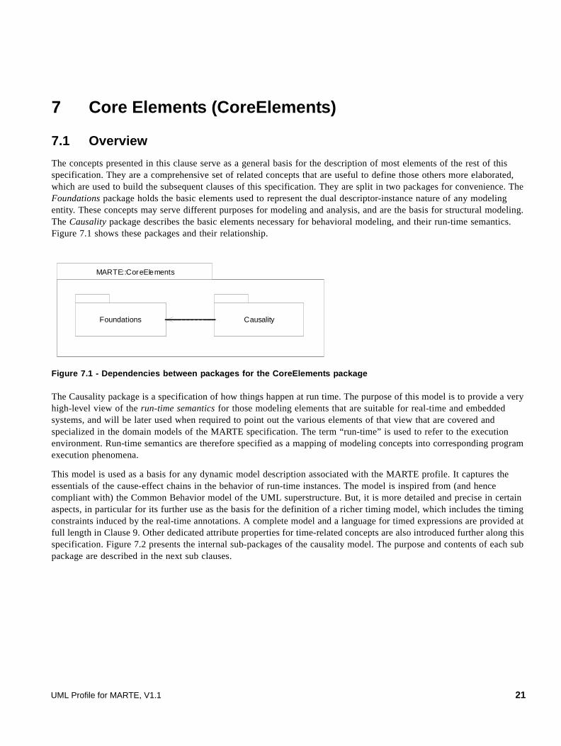
7.1 Overview
The concepts presented in this clause serve as a general basis for the description of most elements of the rest of this specification. They are a comprehensive set of related concepts that are useful to define those others more elaborated, which are used to build the subsequent clauses of this specification. They are split in two packages for convenience. The Foundations package holds the basic elements used to represent the dual descriptor-instance nature of any modeling entity. These concepts may serve different purposes for modeling and analysis, and are the basis for structural modeling. The Causality package describes the basic elements necessary for behavioral modeling, and their run-time semantics. Figure 7.1 shows these packages and their relationship.
Figure 7.1 - Dependencies between packages for the CoreElements package
The Causality package is a specification of how things happen at run time. The purpose of this model is to provide a very high-level view of the run-time semantics for those modeling elements that are suitable for real-time and embedded systems, and will be later used when required to point out the various elements of that view that are covered and specialized in the domain models of the MARTE specification. The term “run-time” is used to refer to the execution environment. Run-time semantics are therefore specified as a mapping of modeling concepts into corresponding program execution phenomena.
This model is used as a basis for any dynamic model description associated with the MARTE profile. It captures the essentials of the cause-effect chains in the behavior of run-time instances. The model is inspired from (and hence compliant with) the Common Behavior model of the UML superstructure. But, it is more detailed and precise in certain aspects, in particular for its further use as the basis for the definition of a richer timing model, which includes the timing constraints induced by the real-time annotations. A complete model and a language for timed expressions are provided at full length in Clause 9. Other dedicated attribute properties for time-related concepts are also introduced further along this specification. Figure 7.2 presents the internal sub-packages of the causality model. The purpose and contents of each sub package are described in the next sub clauses.
MARTE::CoreElements
Foundations Causality
UML Profile for MARTE, V1.1 21

Figure 7.2 - Architecture of the Causality package
7.2 Domain View
7.2.1 The Foundations Package
The domain models presented in this specification will use a consistent set of modeling elements, which in spite of being non-normative, form a large meta-model that covers all the modeling requirements imposed by the RFP.
For modeling and analysis purposes, it is fundamental to distinguish between design-time classifier elements, such as classes and types, and run-time instance elements that are created on the basis of those classifiers. All modeling elements at any level of specification will represent either one or the other of these two fundamental aspects, based on their purpose.
This basic partitioning into classifiers and instance is reflected in the diagram depicted in Figure 7.3. Any number of instances can be created from a given classifier. This latter is referred to as the type of the instance. Notice that an instance may have multiple types (which can be used either to represent different viewpoints of the model element) or a composition of partial descriptions, including multiple inheritance for example).
The concept of Instance may be in practice represented in UML not only as InstanceSpecifications but also by those other elements that are described in terms of role-based models (like UML::ConnectableElement in collaborations or internal structure diagrams, parts, ports, or roles).
C au s a l it y
C o m m o n B e h a v io r
R u n T im e C on t ex t
In v o c a t io n C o m m u n ic a t io n
22 UML Profile for MARTE, V1.1
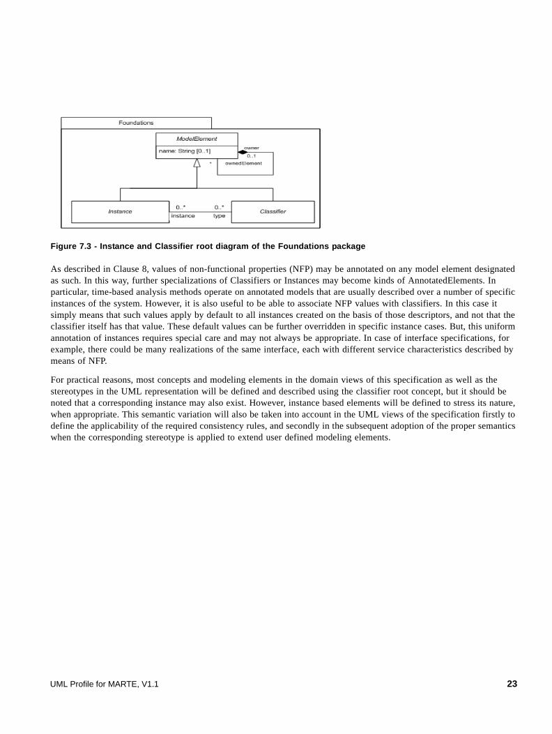
Figure 7.3 - Instance and Classifier root diagram of the Foundations package
As described in Clause 8, values of non-functional properties (NFP) may be annotated on any model element designated as such. In this way, further specializations of Classifiers or Instances may become kinds of AnnotatedElements. In particular, time-based analysis methods operate on annotated models that are usually described over a number of specific instances of the system. However, it is also useful to be able to associate NFP values with classifiers. In this case it simply means that such values apply by default to all instances created on the basis of those descriptors, and not that the classifier itself has that value. These default values can be further overridden in specific instance cases. But, this uniform annotation of instances requires special care and may not always be appropriate. In case of interface specifications, for example, there could be many realizations of the same interface, each with different service characteristics described by means of NFP.
For practical reasons, most concepts and modeling elements in the domain views of this specification as well as the stereotypes in the UML representation will be defined and described using the classifier root concept, but it should be noted that a corresponding instance may also exist. However, instance based elements will be defined to stress its nature, when appropriate. This semantic variation will also be taken into account in the UML views of the specification firstly to define the applicability of the required consistency rules, and secondly in the subsequent adoption of the proper semantics when the corresponding stereotype is applied to extend user defined modeling elements.
UML Profile for MARTE, V1.1 23

Figure 7.4 - Property diagram of the Foundations package
A Property is a MultiplicityElement, so that it can have an upper and lower bound specifying the valid range of cardinalities for this property. Additionally, it has an aggregation kind and a type (as a classifier).
7.2.2 The Causality::CommonBehavior Package
7.2.2.1 Basic Behavior
This model states the relationships between classifier element models and their instances from a behavioral viewpoint. It is aligned to the UML semantics basis, in the sense that there is no disembodied behavior: all behavior emanates from the actions of structural entities. In particular since in UML a behavior is a kind of class, it is possible for a behavior to be its own structural context. For many of the UML behavioral concepts mentioned here you may find the corresponding UML2 semantics description in Clause 13 of the OMG document ptc/06-04-02. For those that reify the UML2 concepts, analogous definitions have been extracted from that OMG document.
24 UML Profile for MARTE, V1.1

Figure 7.5 - The CommonBehavior package
A Behavior defines how some system or entity changes over time. From a modeling point of view, this concept defines the behavior of some classifier, specifically, a Behaviored Classifier. A behavior captures the dynamic of its context classifier. It is a specification of how its context classifier as well as the state of the system that is in the scope of the behavior may change over time. A behavior may have Parameters whose values may be used for evaluating a behavior. A behaviored classifier may have behavior specifications that illustrate specific scenarios of interest associated with that classifier, such as the start-up scenario. In particular, the behavior specification used to represent the behavior that starts executing when instances of that classifier are created and started is called main behavior. For many real-time concurrent systems, this can be, for example, the behavior that initiates the activity of a thread, which continues until the thread is terminated. Two kinds of Behavior may be defined: CompositeBehavior and Action. Action is an atomic behavior, and CompositeBehavior may contain other Behaviors, which in turn may be either composite or atomic.
An Action is the fundamental unit of behavior. An action takes a set of inputs and converts them into a set of outputs, though either or both sets may be empty. Actions are contained in behaviors, which provide their context. Behaviors provide constraints among actions to determine when they execute and what inputs they have.
An Event is the specification of a kind of change of state that may happen in the modeled system. Event occurrences are often generated as a result of some action either within the system or in the environment surrounding the system. Consistently with UML 2, Triggers are specification of what can cause execution of behavior (e.g., the execution of the effect activity of a transition in a state machine).
A Trigger specifies the event that may trigger a behavior execution as well as any constraints on the event to filter out event occurrences not of interest. Indeed, a Trigger is the concept that relates an Event to a Behavior that may affect any instance of the behavioral classifier.
The Timed versions of these concepts are introduced in Clause 9, under the name of TimedProcessing (for Actions) and TimedEvents (for Events and Triggers).
UML Profile for MARTE, V1.1 25

7.2.2.2 Modal Behavior
The previous sub clause described the main concepts to describe basic system behavior. This basic behavior is aligned with UML, and hence, it represents a common conceptual basis for further extensions required in the real-time and embedded systems. There is however, a kind of behavior that is not particularly distinguished in UML and that requires specific consideration when modeling time and safety-critical systems. This behavior is related to the notion of operational mode, and for this reason we call it modal behavior.
An operational mode can represent different things:
• An operational system (or subsystem) state that is managed by reconfiguration mechanisms (e.g., fault-tolerance management middleware) according to fault conditions.
• A state of system operation with a given level of QoS that can be handled by resource management infrastructures (e.g., middleware that assign resources at run time according to load demand, timing constraints, or resource usage).
• A phase of a system operation (e.g., starting, stopping, launching, in a mission-critical aerospace system).
Figure 7.6. Domain model of Modal Behavior
A mode identifies an operational segment within the system execution that is characterized by a given configuration. The system configuration may be defined by a set of active system elements (e.g., application components, platform components, hardware resources), and/or by a set of operation parameters (e.g., QoS parameters or functional parameters).
Working in a given mode may imply that a set of system entities are active during that operational fragment. We factorize such mode-sensitive system entities in BehavioredClassifier. A BehavioredClassifier can be active in zero or more operational modes. Furthermore, a BehavioredClassifier that represents a system, subsystem or any composite entity can have a set of modes modeled as a ModeBehavior.
26 UML Profile for MARTE, V1.1

A ModeBehavior specifies a set of modes mutually exclusive, i.e., only one mode can be active in a given time instant. Particularly, the dynamics of modes is represented by connecting modes by means of ModeTransitions. A mode transition describes the modeled system under mode switching. A mode transition can be produced in response to a Trigger. Thus, as described before in the Basic Behavior sub clause, a Trigger is related to an Event that determines the conditions causing the triggering action.
7.2.3 The Causality::RunTimeContext Package
A BehaviorExecution is a specification of the execution of a unit of behavior or action within the instances of BehavioredClassifiers. Hence, behavior executions are run-time instances of the behavior and action concepts. For this reason, in this domain model, this concept is specialized into both important concepts: CompBehaviorExecution and ActionExecution. Correspondingly, events have instances called EventOccurrences.
Any behavior execution is the direct consequence of the action execution of at least one instance of a classifier. A behavior execution specification describes how the states of these instances change over time. Behavior executions, as such, do not exist by their own, and they do not communicate. If a behavior execution operates on data, that data is obtained from the host instance.
In UML2, there are two kinds of behaviors at run-time, emergent behavior and executing behavior. An executing behavior is performed by an instance (its host) and is the description of the behavior of this instance. Emergent behavior execution results from the interaction of one or more participant instance(s).
MARTE does not highlight this difference on the nature of behaviors. Indeed, it deals only with behavior execution as the general concept to express a behavior instance. Hence, the MARTE BehaviorExecution notion corresponds to the UML2 Behavior Performance concept described in the overview of its Common Behavior clause.
On one hand, a behavior execution is thus directly caused by the invocation of a behavioral feature of an instance or by its creation. In either case, it is a consequence of the execution of an action by some related classifier instance. A behavior has access to the structural features of its host instance.
On the other hand, behavior execution may result from the interaction of various participant instances. If the participating classifier instances are parts of a larger composite classifier instance, a behavior execution can be seen as indirectly describing the behavior of the container instance also. Nevertheless, a behavior execution can result from the executing behaviors of the participant instances.
This latter form of behavior is of interest since the behavior that is to be analyzed and observed at the system level, in order to predict its timing properties, is normally described as an abstract view of the run-time emergent behavior due to the combination of the behavior executions of all its constituent parts.
UML Profile for MARTE, V1.1 27
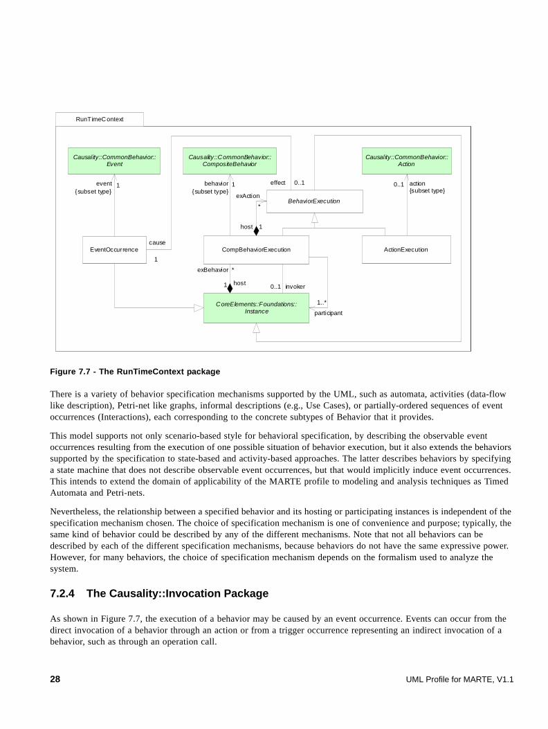
Figure 7.7 - The RunTimeContext package
There is a variety of behavior specification mechanisms supported by the UML, such as automata, activities (data-flow like description), Petri-net like graphs, informal descriptions (e.g., Use Cases), or partially-ordered sequences of event occurrences (Interactions), each corresponding to the concrete subtypes of Behavior that it provides.
This model supports not only scenario-based style for behavioral specification, by describing the observable event occurrences resulting from the execution of one possible situation of behavior execution, but it also extends the behaviors supported by the specification to state-based and activity-based approaches. The latter describes behaviors by specifying a state machine that does not describe observable event occurrences, but that would implicitly induce event occurrences. This intends to extend the domain of applicability of the MARTE profile to modeling and analysis techniques as Timed Automata and Petri-nets.
Nevertheless, the relationship between a specified behavior and its hosting or participating instances is independent of the specification mechanism chosen. The choice of specification mechanism is one of convenience and purpose; typically, the same kind of behavior could be described by any of the different mechanisms. Note that not all behaviors can be described by each of the different specification mechanisms, because behaviors do not have the same expressive power. However, for many behaviors, the choice of specification mechanism depends on the formalism used to analyze the system.
7.2.4 The Causality::Invocation Package
As shown in Figure 7.7, the execution of a behavior may be caused by an event occurrence. Events can occur from the direct invocation of a behavior through an action or from a trigger occurrence representing an indirect invocation of a behavior, such as through an operation call.
RunTimeContext
BehaviorExecution
ActionExecutionCompBehaviorExecution
1behavior{subset type}
Causality::CommonBehavior::CompositeBehavior
Causality::CommonBehavior::Action
0..1 action{subset type}
EventOccurrence
Causality::CommonBehavior::Event
1event{subset type}
effect
cause
1
0..1
exBehavior
1 host
*
participant
1..*CoreElements::Foundations::Instance
invoker0..1
exAction
*
host 1
28 UML Profile for MARTE, V1.1

In a number of analyses, it is also useful to consider the events that occur when a behavior starts and ends its execution. A start occurrence marks the beginning of a behavior execution, while its completion is accompanied by a termination occurrence.
These and further defined concepts specialized from EventOccurrence will be considered eligible to be extended by timing annotations, though for simplicity in the domain model these annotations may be defined in the form of extensions to their common ancestor EventOccurrence.
Figure 7.8 - The Invocation package
7.2.5 The Causality::Communication Package
The Communication sub package of the Causality package adds the infrastructure to communicate between classifier instances and to invoke behaviors. The domain model in Figure 7.8 shows how a communication takes place. This domain model specifies the general semantics of communication between concurrent units.
Invocation
Causality::RunTimeC ontext::EventOccurrence
StartOccurrenceTerminationOccurrence
Causality::RunTimeContext::BehaviorExecution execution
start1
1
finish
execution1
1
Causality::CommonBehavior::Event
1endEvent{subset event} 1
startEvent{subset event}
StartEventTerminationEventCausality::
CommonBehavior::Behavior
11behavior1
1behavior
UML Profile for MARTE, V1.1 29

Figure 7.9 - The Communication package
In real time systems, the basic unit of logical concurrency is commonly known as a thread1. Threads are the root of a special case of instances, usually called active, or real-time or even reactive objects. In fact, the recommended way of adding concurrency into an object model is to identify the desired concurrent units (logical or physical depending on the detail level of the model) through the application of concurrency identification strategies. Once the threads are identified, the developer may create an active object for each. According to the level of specification other forms of expressing concurrency in UML may be used, like the fork in an activity, or a state with orthogonal regions. Other objects, i.e. those that are not identified as concurrent units, are then usually called passive objects. These latter objects are then associated to the active objects via a composition or shared relationships. The role of the active object is to run when appropriate and call or delegate actions to the passive objects that it owns. Passive objects execute usually using the concurrent resource of the caller active object.
Instances respond to messages that are generated by others executing communication actions. When these messages arrive, the receivers eventually respond by executing the behavior that is matched to that message. The dispatching method by which a particular behavior is associated with a given message depends on the higher-level formalism used and is not defined here (hence, it is an open-variation semantics point of UML).
Figure 7.8 shows the general communication model. An action representing the invocation of a behavioral feature is executed by a sender instance resulting in an InvocationOccurrence. The invocation event may represent the sending of a signal or the call to an operation. As a result of the invocation event occurrence a Request is generated.
A Request, which fully corresponds to the Request concept of UML 2, is an instance of a communication in transit between a calling instance and a called one. In fact, a request is an instance capturing the data that was passed to the action causing the invocation event (the arguments that must match the parameters of the invoked behavioral feature);
1. It should be noted here that from the concurrency point of view, there is no distinction between threads, tasks, and processes. They all are variations of the very same concept, though they may differ in some aspects of their detailed properties (such as the context switch time and whether low-cost pointers can be used across the concurrency boundary).
Communication
RequestInvocationOccurrence R eceiveOccurrence
Causality ::R unTimeContext::ActionExecution
Causality ::R unTimeContext::EventOccur rence
effectcause
1 1..*
*
1execution
invocation
C oreElements::F oundations::Instance
C ausali ty ::RunT imeContext::EventOccurrence
CoreElements::Foundations::Instance
1
sender
1
receiver
effect
cause1
1
sender 1 receiver 1
30 UML Profile for MARTE, V1.1

information about the nature of the request (i.e., the behavioral feature that was invoked); the identities of the sender and receiver instances; as well as sufficient information about the behavior execution to enable the return of a reply from the invoked behavior, where appropriate. Eventually the request may include additional information, like a time stamp.
While each request is targeted at exactly one receiver instance and caused by exactly one sending instance, an occurrence of an invocation event may result in a number of requests being generated (as in a signal broadcast). The receiver may be the same instance that is the sender, it may be local (i.e., an instance held inside the currently executing instance, or the currently executing instance itself, or the instance owning the currently executing instance), or it may be remote. The manner of transmitting the request, the amount of time required to transmit it, the order in which the transmissions reach their receiver instances, and the path for reaching the receiver instances are to be defined and annotated by using any of the different communication mechanisms available, like rendezvous, message queuing, interrupts, etc.
Once the generated request arrives at the receiver instances, a ReceiveOccurrence occurs, which according to the triggers expected may subsequently launch the behaviors of the receiver instance or of any of its internal instances. Like in the Common Behaviors Domain Model of UML, two kinds of requests are determined according to the kind of invocation occurrence that caused it: the sending of a signal, and the invocation of an operation. The former is used to trigger a reaction in the receiver in an asynchronous way without a reply. The latter applies an operation to an instance, which may be synchronous or asynchronous and may require a reply from the receiver to the sender.
Observe that modeling elements like invocation occurrence and receive occurrence shown in this domain model are not explicitly represented in the specification of a system, but they are implicit in the dynamic semantics of the constructs used.
7.3 UML Representation
A certain impact on the representation of modeling elements is envisioned according to their classifier/instance dual nature.
The modeling elements defined in this specification may adopt the nature of Classifier or Instance presented here, or both. This quality of being may be of course specifically stated as part of their definition, but it may be also left to the user to be decided according to the purpose of the annotation, and the intended semantics.
In most of the cases the concepts defined in the domain view are proposed to be represented in UML by means of a stereotype extending a concrete UML modeling element. When this is the case, the Classifier or Instance intrinsic nature of the UML annotated element may lead to identify the corresponding nature, semantics, or concrete variations of the MARTE concept that is intended to be represented with the annotation. Hence, the explicit different semantics that may be defined for each MARTE modeling concept, when it is considered as an instance or as a classifier, may be inferred directly from the fundamental nature of the corresponding UML element that is annotated.
When a stereotype is applied on an instance, and provided it can be also applied on classifiers, the value of the attributes not explicitly assigned in the annotation of the instance are taken in principle from the defaults in the profile stereotype definition, but they might be overridden by those in its corresponding classifier, if it happens to be annotated with the same stereotype.
This sub clause describes the UML extensions required to support the concepts defined in the previous domain view. The set of extensions, to support Core Elements modeling with UML, is organized according to the application context of the domain concepts. In particular note that not every domain concept will result directly in a UML stereotype or tagged value. In CoreElements, only the concepts related to the ModalBehavior domain model are concretized as stereotypes.
UML Profile for MARTE, V1.1 31

7.3.1 Profile Diagrams
Figure 7.10 shows the UML extensions for CoreElements. The CoreElements package (stereotyped as profile) defines how the elements of the domain model extend metaclasses of the UML metamodel. These stereotypes are listed in alphabetical order. The semantic descriptions corresponding to these stereotypes and their properties are provided in the following sub clause.
Figure 7.10 - UML profile diagram for CoreElements modeling
7.3.2 Profile Elements Description
7.3.2.1 Configuration
The Configuration stereotype maps the Configuration domain element denoted in Annex F (F.1.10, ’Configuration’).
A system configuration may be defined by a set of active system elements (e.g., application components, platform components, hardware resources), and/or by a set of operation parameters (e.g., QoS parameters or functional parameters).
Extensions
• StructuredClassifier (from UML::CompositeStructure::InternalStructures)
• Package (from UML::Classes::Kernel)
Generalizations
• None
32 UML Profile for MARTE, V1.1

Associations
• mode: CoreElements::Mode [*] The operational modes that are represented by this configuration.
Attributes
• None
Constraints
• None
7.3.2.2 Mode
The Mode stereotype maps the Mode domain element denoted in Annex F.
A Mode identifies an operational segment within the system execution that is characterized by a given configuration. Working in a given mode may imply that a set of system entities are active during that operational fragment. We factorize such mode-sensitive system entities in BehavioredClassifier domain concepts. However, since BehavioredClassifier is an abstract concept (there is not a corresponding stereotype), we add the relationship of the different mode-sensitive system entities to a mode directly in the concrete stereotypes. See for example, Clause 8 - NFP where a mode is associated to the NFPs::NfpConstraint stereotype.
Extensions
• State (from UML::UML::StateMachines::BehaviorStateMachines)
Generalizations
• None
Associations
• None
Attributes
• None
Constraints
[1] Transitions between modes must be stereotyped as ModeTransition.
7.3.2.3 ModeBehavior
The ModeBehavior stereotype maps the ModeBehavior domain element denoted in Annex F (F.1.16, ’ModeBehavior’).
A ModeBehavior specifies a set of modes mutually exclusive (i.e., only one mode can be active in a given time instant). Particularly, the dynamics of modes is represented by connecting modes by means of ModeTransitions.
Extensions
• StateMachine (from UML:: UML::StateMachines::BehaviorStateMachines)
UML Profile for MARTE, V1.1 33
Generalizations
• None
Associations
• None
Attributes
• None
Constraints
[1] Owned States must be stereotyped as Mode, and Owned Transitions must be stereotyped as ModeTransition.
7.3.2.4 ModeTransition
The ModeTransition stereotype maps the ModeTransition domain element denoted in Annex F.
A ModeTransition describes the modeled system under mode switching. A mode transition can be produced in response to a UML::Trigger. Thus, a UML::Trigger is related to a UML::Event that determines the conditions causing the triggering action.
Extensions
• Transition (from UML:: UML::StateMachines::BehaviorStateMachines)
Generalizations
• None
Associations
• None
Attributes
• None
Constraints
[1] Owned States must be stereotyped as Mode, and Owned Transitions must be stereotyped as ModeTransition.
7.3.3 Examples
We illustrate a reconfigurable system that uses the concepts of operational mode and configuration.
34 UML Profile for MARTE, V1.1

Figure 7.11 - Modeling Modes and Configurations
In Figure 7.11 we can see that the software application has two possible modes: a NominalMode and a DegradedMode. We specify the modal behavior by using state machines. For instance, reconfiguration properties, such as mode transitions and causing events are modeled with UML::Transition and guards/actions notation.
Then, the system configuration under DegradedMode is represented by using a composite structure. The composite structure represents an allocation scenario of application components into a set of platform resources (for further details on the allocation, see Clause 11, ’Allocation Modeling (Alloc)’). We say that this configuration is valid for the DegradedMode by using the mode attribute in Configuration.
UML Profile for MARTE, V1.1 35

36 UML Profile for MARTE, V1.1

8 Non-functional Properties Modeling (NFPs)
8.1 Overview
This clause describes both domain model and its UML representation for specifying Non-Functional Properties (NFPs). It also describes how NFPs may be attached to UML modeling elements. This sub package of the MARTE specification provides a general framework for annotating UML models with NFPs. It is especially focused on formalizing a set of modeling constructs in order to specify this kind of property in a detailed way.
The NFP modeling framework deals with the following requirements:
• How NFPs are to be described, and particularly what NFPs should be considered.
• How particular instances of NFPs are to be attached to UML model elements.
• How relationships between different NFPs are to be defined.
• How to express constraints on or between NFPs in order to express requirements on the system model.
• Usability of the annotations should minimize the designer efforts2.
• To provide an open modeling framework, i.e., not tailored towards specifications of a particular modeling concern or a restricted set of NFPs.
Although the UML Profile for “Modeling Quality of Service and Fault Tolerance Characteristics and Mechanisms” (QoS&FT) already defines a framework to express a similar concept to NFP, there are some reasons to define a different one in the context of this specification.
For instance, the QoS&FT profile relies on a two-step annotation process: a) derive a Quality Model for each application model by instantiating template classes from the QoS Catalogs and, b) annotate UML models with QoS Constraints and QoS Values, which implies catalog binding and either the creation of extra objects (instantiated from the Quality Model), or the specification of long OCL expressions. This two-step process requires too much effort for the users and may induce not readable models.
The QoS&FT profile provides a flexible mechanism to store pre-defined QoS Characteristics. It supports declaring the most common QoS characteristics for different application domains by means of QoS Catalogs. A particular QoS Catalog may contain qualifiers of QoS properties including statistical qualifiers and measurement units. At the level of QoS value specifications, however, QoS&FT ignores some important attributes such as measurement sources, precision, and time expressions. These properties are required for the domain of MARTE and are therefore supported by the NFPs introduced in this specification and the Value Specification Language (VSL) defined in Annex B.
In general, the term Quality of Service (QoS) is the aptitude of a service for providing a quality level to the different demands of its clients. In the computer systems domain, the term QoS is frequently associated specifically with network issues, such as throughput and bandwidth (and in conjunction with multimedia applications). But it has more recently begun to be applied to NFPs of more general services. There is still no common consensus about the concepts of NFP and
2. One of the major constraints that drove the definition of this specification has been to minimize the required efforts to apply the profile. But since our purpose was to enrich UML with capacities to describe formally and efficiently the real-time and embedded features of a system, applying the profile hence requires some additional effort with regard to a common usage of the UML.
UML Profile for MARTE, V1.1 37

QoS. Anyhow, the NFPs considered here have a larger extent than only quality levels. NFPs may describe the internals and externals of the system, and some of them directly relate to the users of resource services and their QoS perception and others not.
Besides, the UML profile for “Schedulability, Performance, and Time Specification” (SPT) provides a straightforward annotation mechanism specifying a set of predefined stereotypes and tagged values. Moreover, it supports already some of the requirements for NFP annotations, such as support for symbolic variables and expressions through its specialized Tag Value Language (TVL). However, its approach was not defined formally enough to allow for new user-defined NFP or for different specialized domains. Indeed, SPT defines a grammar for powerful concepts, as for instance “RTtimeValue” expressions, but does not define a mechanism to extend or refine these constructs for more specific needs.
The MARTE NFP modeling framework has reused some useful structural concepts suggested in the UML profile for QoS&FT. However, some considerations to reduce the inherent usage complexity of the UML profile for QoS&FT and to facilitate the modeling process have been taken into account and led to a new proposal. Additionally, as much as possible, features of the SPT profile have been reused. For instance, The Value Specification Language (VSL) introduced in MARTE extends and formalizes (by means of a metamodel and its associated concrete syntax) some concepts supported by TVL to annotate constant, variable, tuple, and expression values. In this manner, we provide a flexible and straightforward framework for supporting a wide variety of NFPs annotations while adopting the best modeling practices of both UML profiles.
The NFP modeling framework provides the capability to describe various kind of values related to physical quantities, such as Time, Mass, Energy. These values are used to describe the non-functional properties of a system. This notion of value is introduced and used in a broader sense in the context of another OMG specification: Systems Modeling Language (SysML) by the means of value properties and value types.
8.2 Domain View
8.2.1 Overview
The model of a computing system describes its architecture and behavior by means of model elements (e.g., resources, resources services, behavior features, logical operations, configurations modes, modeling views), and the properties of those model elements. It is convenient to group application properties into two categories: functional properties, which are primarily concerned with the purpose of an application (i.e., what it does at run-time); and non-functional properties (NFPs), which are more concerned with its fitness for purpose (i.e., how well it does it or it has to do it). Both functional and non-functional property are specialization of a more general concept of value property, related to a quantity.
In the context of model-driven development approaches for real-time and embedded systems, modeling NFPs is of fundamental relevance and implies a number of design decisions. NFPs provide information about different characteristics, as for example throughput, delays, overheads, scheduling policies, deadline, or memory usage.
In this and subsequent sub clauses, we will use metamodels to describe the domain viewpoint. Note that, although the intent of this domain model is to be precise, it is not fully formal since its purpose is primarily to provide profile’s users with the minimal knowledge to understand the concepts and relationships of the domain.
The NFP annotation framework has many facets that are grouped into individual sub-packages. The overall package structure of the NFP framework is shown in Figure 8.1.
38 UML Profile for MARTE, V1.1

Figure 8.1 - Structure and dependencies of the NFPs modeling package
The purpose and contents of each sub package denoted in Figure 8.1 are described in subsequent sub clauses.
8.2.2 The NFP_Nature package
From an abstract viewpoint, an NFP (AbstractNFP) can be either qualitative or quantitative, as shown in Figure 8.2.
QuantitativeNFPs are measurable properties. A given quantitative NFP may be characterized by a set of SampleRealizations and Measures.
SampleRealizations represent a set of values that occur for the QuantitativeNFP under consideration at run-time (for instance, measurements collected from a real system or a simulation experiment). A QuantitativeNFP may be sampled once or repeated multiple times over an extended run. In a cyclic deterministic system, in which each execution cycle has the same value, a single sample is sufficient to characterize completely the QuantitativeNFP.
A Measure is a (statistical) function (e.g., mean, max, min) characterizing the set of sample realizations. Measures may be computed either directly by applying the desired function to the set of realizations values, or by using theoretical functions of the probability distribution given for the respective QuantitativeNFP.
According to measurement theory (JCGM 200:2008, International Vocabulary of Metrology - Basic and General Concepts and Associated Terms (VIM), 3rd edition, 2008, BIPM, Paris, France.), measures are defined as a Quantity expressed in terms of a specific Unit. Quantities can be basic or derived for a given system of quantities. BasicQuantities are for example length, mass, time, current, temperature, or luminous intensity. The units of measure for the basic quantities are organized in systems of measures, such as the universally accepted Système International (SI) or International System of Units. Quantities expressed in the same unit can be compared. DerivedQuantities (e.g., area, volume, force, frequency) may be obtained from basic quantities by explicit formulas known as Dimension relationships. This notion of dimension is useful for dimensional analysis of non-functional properties: for a given system of quantities, a derived quantity can be expressed as a set of base quantities in a dimension equation. Additionally, different units of the same physical quantity may be transformed to, or expressed in terms of, existing base units through a given conversion factor and an offset factor.
NFPs
NFP_AnnotationNFP_Declarat ion
« im port » NFP_Nature
« import »
MART E::VSL
« im por t »
MARTE::CoreElements::Foundatio ns
« import »
UML Profile for MARTE, V1.1 39

Figure 8.2 - Domain Model for NFP Nature
QualitativeNFP refers to inherent or distinctive characteristics that may not be measured directly. In general, a qualitative NFP is denoted by a label (e.g., “bronze,” “silver,” and “gold” level of service) representing a high-level of abstraction characterization that is meaningful to the analyst and the analysis tools. More specifically, a qualitative NFP takes a value from a list of allowed values, where each value identifies a possible alternative.
When looking in more detail at a qualitative NFP, it may be possible to define it in function of a set of criteria, which may be in turn qualitative or quantitative. Some qualitative NFPs have known meanings that can be interpreted by particular domains, for example:
• the choice of a scheduler type for a processor, or
• the choice of a statistical distribution for the latency of a network.
In both examples, the full specification of the property requires not only a qualitative value, but also some quantitative parameters, as for instance: scheduler-type = roundRobin (quantumSize) or latency-value = gamma (mean, variance).
8.2.3 The NFP_Annotation Package
Figure 8.3 shows a domain model for NFP annotations. A model of a system (which is considered in this specification to be expressed in UML) can be extended by annotated models with additional semantic expressing concepts from a given modeling concern or domain viewpoint. An annotated model contains annotated elements, which are model elements extended by standard modeling mechanisms. For example, some typical performance analysis-related annotated elements are: step (a unit of execution), scenario (a sequence of steps), resource (an entity that offers one or more services), service (offered by a resource or by a component of some kind) 3.
40 UML Profile for MARTE, V1.1

An annotated element describes certain of its non-functional aspects (i.e., the ones that are directly related to the annotation concern) by means of NFP value annotations. These annotations are specified by the designer in the models and attached to model elements. Thus, the role nfpValue on ValueSpecification (Figure 8.3) indicates that an annotated model element has a value or values for a specific NFP. ValueSpecification is used to define the value expressions associated with NFPs. The values must conform to the defining NFP in type and multiplicity. Examples of NFPs are: the total delay of a step when executed (including queuing delays), the utilization of a resource, and the response time and throughput of a service.
Figure 8.3 - Domain model for NFP annotations
Due to the abstraction involved in the construction of a model, only some NFPs are relevant to a certain modeling concern. In other words, a given modeling concern uses a set of NFPs, which establishes the ontology of the domain. For instance, specific analysis techniques (e.g., performance or schedulability analysis) deal with distinctive non-functional annotations.
An NFP_Constraint is a condition (a Boolean expression) on the non-functional properties associated with model elements. In general, NFP_Constraints are assertions that indicate restrictions that must be satisfied by a real-time system. The annotated model defines the context of the constraints for interpreting names used in the value specification. Kind of constraints qualifies NFP constraints by either required, offered, or contract nature. When a constraint is defined as required, the values specified in the NFP_Constraint indicate the minimum quantitative or qualitative level that the constrained elements demand (these elements are usually clients of resources). An example of required constraints for a step element is the maximum latency for execution. Offered constraints establish the space of NFP values that can support a model element, as for example the throughput of a CPU (elements in this case are commonly software or hardware resources). Contract constraints define conditional expressions that specify relationships between offered and required non-functional values. For instance, if a given model element (e.g., a computing resource) does not support a condition on
3. The Step and Scenario model elements are defined in GQAM (Clause 15), whilst the Resource and Service model elements are intro-duced in GRM (Clause 10).
UML Profile for MARTE, V1.1 41

one or many of its NFP values (e.g., a processing capacity), other model elements might change one or many of NFP values accordingly (e.g., the delay to execute a piece of code). In 8.3.2.5, ’NfpConstraint’ we give a detailed example of NFP_Contraints usage.
Multiple NFP_Constraints may serve to specify different levels of qualities for the same services. For instance, in a component-based architecture, components can support different operational modes, and these operational modes may provide different non-functional values or qualities for the same component services. This is represented by the association of NFP_Constraint to Mode. A given NFP_Constraint may also represent the quality level in more than one Mode. The level of quality modeled by a given NFP_Constraint depends on the resources available and functional parameters such as state variables that identify the mode configuration. For instance, in a reconfigurable system, resources may offer different quality depending on the load that they have.
8.2.4 The NFP_Declaration Package
NFP declaration is intended to qualify and assign extended data types to NFP values (Figure 8.4).
This package introduces the notion of value property, further specialized by the notion of non-functional property. A value property represents any kind of physical quantity relevant in the design of the system. A non-functional property (NFP) is a kind of value property, which focuses on fitness for purpose aspects. These NFPs are used in other clauses of the specification for design and analysis of RTES.
Value properties have a TupleType (see Annex D for MARTE extended data types), called ValueType. Two attributes define the body of value types: valueAttribute and exprAttribute. ExprAttribute is used to specify expressions associated with value properties. Hence, we are able to assign variables, literals, intervals, and other expressions. The return value of the expression must conform to the associated value attribute of the value type.
ValueType adds the ability to carry a measurement unit (by means of unitAttribute) and additional qualifiers to values (qualifierAttributes).
A ValueType with a measurement unit is associated with physical measures. In sub clause 8.3.3.1, we show some pre-declared units largely used in the domain (e.g., time units, data size units, transmission speed units) that can be used when specifying values.
NFP and NFP_Type are direct specialization of ValueProperty and ValueType to describe non-functional aspect of a system.
Examples of qualifiers are statisticalQualifier, direction, value source, measurement precision, and (see NFP Types Library in sub clause 8.3.2.4). A statisticalQualifier indicates the type of statistical measure of a given property (e.g., maximum, minimum, mean, percentile, distribution). The direction attribute (i.e., increasing or decreasing) defines the type of the quality order relation in the allowed value domain of NFPs. Indeed, this allows multiple instances of NFP values to be compared with the relation “higher-quality-than” in order to identify what value represents the higher quality or importance. Source is a peculiarity of non-functional properties associated with the origin of specifications. Precision is the degree of refinement in the instruments and methods used to obtain a result.
42 UML Profile for MARTE, V1.1

Figure 8.4 - Domain Model of NFP Declaration
Notice that the set of concepts supporting the declaration of NFPs provides means to annotate NFPs in a first phase, but the concrete infrastructure for specifying values is supported by VSL (Annex B). Nevertheless, default measurement units and values may be assigned when declaring NFPs and NFP types.
The ability to specify all the kinds of values supported by VSL is a key concern for NFP annotations. Indeed, NFP specifications need to be composable. That means, it should be possible to specify NFP values at a fine-grained level and compose them into higher-level specifications. Conversely, a high-level NFP specification should be decomposable such that fine-grained NFP specifications can be refined. The refinement relationship between two levels of NFP specification must ensure consistency between both levels. The process of composition and decomposition should be carried out in such a manner as to guarantee this consistency. NFP specifications should be able to be refined so that new NFP specifications can be based on existing ones.
8.3 UML Representation
This clause describes the UML extensions required to support the concepts defined in the previous domain view. The set of extensions to support NFP modeling with UML is organized according to the application context of the domain concepts. In particular, in the NFP modeling framework, note that not every domain concept will result directly in a UML stereotype or tagged value. This is because some domain concepts are abstract, representing generalizations that will not appear directly in any UML model.
For instance, the abstract notion of a “Measure” is very useful as an abstraction in our framework, but will only be manifested in its concrete forms (e.g., delay, throughput, capacity) in MARTE models. While a corresponding stereotype could have been defined for this abstract concept, it would never be used in practice. Therefore, we have chosen to only define stereotypes for concepts that we envisage are actually going to be used in practical modeling situations. This results in a simpler and more compact profile.
Thus, we first describe the extensions concretized in stereotypes. In Annex D, a set of NFP Types is predefined, which is used extensively in MARTE to type and qualify non-functional properties.
UML Profile for MARTE, V1.1 43

In sub clause 8.3.3, we will describe some examples that use the whole extensions for NFP annotations with both tagged values and UML constraints.
8.3.1 Profile Diagrams
Figure 8.5 shows the UML extensions for NFP modeling. The NFP Modeling package (stereotyped as profile) defines how the elements of the domain model extend metaclasses of the UML metamodel. These stereotypes are listed in alphabetical order. The semantic descriptions corresponding to these stereotypes and their properties are provided in the following sub clause.
Figure 8.5 - UML profile diagram for NFPs modeling
8.3.2 Profile elements description
8.3.2.1 ConstraintKind
ConstraintKind is an enumeration type that defines literals used to specify the nature of constraint assertions by either required, offered, or contract nature.
Literals
• required It indicates the minimum quantitative or qualitative level that the constrained elements demand (these elements are usually clients of resources).
• offered It establishes the space of values that can support a model element (elements in this case are commonly software or hardware resources).
• contract It defines conditional expressions that specify relationships between offered and required non-functional values.
44 UML Profile for MARTE, V1.1
8.3.2.2 Dimension
A Dimension is a relationship between a quantity and a set of base quantities in a given system of quantities.
Extensions
• Enumeration (StructuredClasses::Kernel)
Generalizations
• None
Associations
• None
Attributes
• symbol: String [0..1] This attribute represents the symbol used to designate the dimension.
• baseDimension: Dimension [*] {ordered} This attribute represents the base dimensions by which the dimension of a derived quantity unit is created. Basic dimensions do not require this attribute.
• baseExponent: Integer [*] {ordered} This attribute represents the exponents that characterize the base dimensions used to define the dimension of a derived quantity. Basic dimensions do not require this attribute.
Constraints
• None
8.3.2.3 Nfp
The Nfp stereotype maps the NFP domain element denoted in Annex F (F.2.10, ’ModelingConcern (from NFP_Annotation)’).
Non-Functional Properties (NFPs) declares an attribute of one or more instances in terms of a named relationship to a value or values. Nfp is intended to declare, qualify, and assign extended data types to NFP values.
Extensions
• Property (from UML::StructuredClasses::Kernel)
Generalizations
• None
Associations
• None
Attributes
• None
UML Profile for MARTE, V1.1 45

Constraints
• None
8.3.2.4 NfpType
This NfpType stereotype maps the NFP_Type domain element denoted in Annex F (F.2.12, ’NFP_Constraint (from NFP_Annotation)’). Note, however, that the qualifierAttributes role is not implemented in the UML view. In practical terms, the tupleAttribute inherited from TupleType is sufficient to define qualifier attributes.
An Nfp type is a type whose instances are identified only by NFP value specifications. An Nfp Type contains specific attributes to support the modeling of NFP tuple types.
Extensions
• DataType (from UML::StructuredClasses::Kernel)
Generalizations
• TupleType (from VSL::DataTypes) in Annex B, sub clause B.3.2.5.
Associations
• None
Attributes
• valueAttrib: Property [1] both physical and non-physical NFP types have a value attribute, which serves as placeholder to specify a value of NFPs.
• unitAttrib: Property [0..1] measurement unit declaration that apply to all the value specifications of the NFP. Usually, it is an enumeration data type with a list of the valid measurement units.
• exprAttrib: Property [0..1] attributes representing an expression. MARTE uses the VSL language to define expressions.
Constraints
• None
8.3.2.5 NfpConstraint
This NfpConstraint stereotype maps the NFP_Constraint domain concept denoted in Annex F (F.2.11, ’NFP (from NFP_Declaration)’).
NfpConstraint extends the UML mechanism for applying a condition or restriction to modeled elements. Specifically, NFP constraints support textual expressions to specify assertions regarding performance, scheduling, and other embedded systems’ features, and their relationship to other features by means of variables, mathematical, logical, and time expressions.
Extensions
• Constraint (from UML::StructuredClasses::Kernel)
46 UML Profile for MARTE, V1.1

Generalizations
• None
Associations
• mode: Mode [*] The set of modes in which the NFP constraint annotations are valid.
Attributes
• kind: ConstraintKind [0..1] Tagged definition qualifying NFP constraints by either required, offered, or contract nature.
Constraints
• None
8.3.2.6 Unit
This Unit stereotype maps the Unit domain element denoted in Annex F (F.2.18, ’StatisticalQualifierKind’).
Unit is a qualifier of measured values in terms of which the magnitudes of other quantities that have the same physical dimension can be stated. A unit often relies on precise and reproducible ways to measure the unit. For example, a unit of length such as a meter may be specified as a multiple of a particular wavelength of light. A unit may also specify less stable or precise ways to express some value, such as a cost expressed in some currency, or a severity rating measured by a numerical scale.
Unit is defined as a stereotype of EnumerationLiteral. This allows modelers to assign a list of allowed units to a particular physical NFP type by means of a related Enumeration element. In this way, we bound the universe of legal units that apply to a specific kind of NFPs.
Units can be declared with a parameter representing the Conversion Factor that is applied to a Base Unit to determine the value in terms of the specified measurement unit.
Extensions
• EnumerationLiteral (StructuredClasses::Kernel)
Generalizations
• None
Associations
• None
Attributes
• convFactor: Real [0..1] This parameter allows referencing measurement units to other base units by a numerical factor.
• offsetFactor: Real [0..1] This parameter allows referencing measurement units to other base units by applying an offset value to them.
UML Profile for MARTE, V1.1 47

• baseUnit: Unit [0..1] This attribute represent the base unit by which a derived measurement unit is created Basic units do not require this attribute.
Constraints
• None
8.3.3 Graphical Syntax of NFP Value Specification
In this sub clause, we define an alternative graphical syntax for value specifications having NfpType as data type. This syntax consists of a pair of a value and a unit:
<nfp-value> ::= <value-specification> [' ' <unit-enumeration>]
The following are typical examples:
5 ms # a duration value
50 kHz # a frequency value
Note that this notation is for the graphical view of models only. The tuple notation (see sub clause B.3.3.9) is still valid for NFP values (NfpType inherits from VSL::TupleType), both in graphical models and in the repository as well. For instance, the NFP value: '50 kHz' can be specified in the model repository as: '(50, -, kHz, max, -, est, -)' or '(value=50, expr=null, unit=kHz, statQ=max, dir=null, source=est, precision=null)'.
The main rationale of the “value-unit” notation is readability of graphical models. Specific tools could provide more flexibility in the graphical notation. For instance, users may be able to customize the elements of a tuple in an NFP value specification that should be displayed. However, because of its common usage in engineering models in general, the “value-unit” notation is normative (although not mandatory) in MARTE.
8.3.4 Examples
A requirement for NFP annotations is a trade-off between usability and flexibility. Usability suggests the merit of declaring a set of standard NFPs for a given modeling domain, so they can be easily referred to and, consequently, every user of the annotations means the same thing. For NFPs with well-known variants, a set of declarations can be standardized, which cover the important cases with differently-named measures; these can be translated if necessary by domain specialists for the use of a specific tool with different names. However there are some NFPs whose meaning is domain- or even project-dependent. This requires a capability for users to define their own NFPs. Thus flexibility and expressive power requires that the users have the capability to define their own NFPs, but usability requires a set of standard measures that can be used in a straightforward way.
The following sub clauses will describe respectively an example of NFP model library and examples of usage of such library.
8.3.4.1 Example of NFP model library definition
This sub clause provides an example of NFP types model library definitions. This example corresponds to an excerpt of a more complete model library predefined for MARTE and specified in detail in Annex D.1. This MARTE library includes predefined data types supporting NFP annotations commonly used in the real-time and embedded system domain.
48 UML Profile for MARTE, V1.1

NFP Types are implemented in MARTE through UML data types. UML data types (DataType metaclass) are a special kind of classifier, similar to classes. A data type differs from a class in that instances of a data type are identified only by their values. Like a class, data type may have attributes. In VSL, we define four kinds of composite data types (data types allowing attributes): IntervalType, CollectionType, ChoiceType, and TupleType. A data type with attributes of different types is called TupleType (see Annex D for MARTE extended data types). If a tuple type has attributes with different types, then instances of that data type will contain attribute values matching the types of their corresponding attributes. Particularly in MARTE, we define a set of pre-declared NFP types that are useful for the other sub-profiles. However, other domain-specific libraries can be defined either using the NFP profile or specializing the MARTE libraries.
Figure 8.6 shows the package pre-declaring NFP types. Note that we import the MARTE primitive types defined in the VSL annex (Annex B). The list of MARTE primitive types includes Real and DateTime in addition to the pre-declared UML primitive types. However, note that the set of UML primitive types are completely redefined within MARTE in order to allow specifying operators on these types (more rationales on this are provided in Annex D.1).
General MARTE data types that are not NFP types are declared in the MARTE_DataTypes library (Annex D). This library uses stereotypes of the VSL Profile for data types (see Annex B).
General MARTE NFP types are declared in the BasicNFP_Types library (Annex D). A root NFP type called NFP_CommonType is defined to factorize common NFP type attributes.
In addition to value, expression, and unit attributes, NFP types are declared specifying a set of qualifier attributes required to precisely specify and qualify NFP values.
The semantic of the provided qualifier attributes is the following:
• source: SourceKind [0..1] peculiarity of NFPs associated with the origin of specifications. Predefined kind of sources for values are estimated, calculated, required, and measured.
• precision: Real [0..1] degree of refinement in the performance of a measurement operation, or the degree of perfection in the instruments and methods used to obtain a result. Precision is characterized in terms of a Real value, which is the standard deviation of the measurement.
• statQ: StatisticalQualifierKind [0..1] statistical qualifier indicates the type of “statistical” measure of a given property (e.g., maximum, minimum, mean, percentile, distribution).
• dir: DirectionKind [0..1] direction attribute (i.e., increasing or decreasing) defines the type of the quality order relation in the allowed value domain of NFPs. Indeed, this allows multiple instances of NFP values to be compared with the relation “higher-quality-than” in order to identify what value represents the higher quality or importance.
UML Profile for MARTE, V1.1 49

Figure 8.6 - Extract of the model library defining the pre-declared Basic NFP Types and measure units
50 UML Profile for MARTE, V1.1

The NFP_CommonType (parent of all the other NfpTypes) includes a set of probability distribution operations that are defined in Annex D, sub clause D.2.2 (NFP_CommonType). This list of probability distributions is certainly not exhaustive but it includes the more common distributions used in state-of-the-art performance analysis and simulation tools. Further probability distributions can be added in specialized libraries without needing any modification in the MARTE profile or VSL. Probability distribution is a fundamental concept to specify stochastic values. A probability distribution assigns to every interval of the real numbers a probability, so that the probability axioms are satisfied. In technical terms, a probability distribution is a probability measure whose domain is the Borel algebra on the reals. A probability distribution is modeled in MARTE as the name of the function and a set of parameters allowing estimating the function in terms of the standard form of the distribution.
Probability distributions are defined as operations of NFP types, each with particular parameters. The included probability distribution function values are described by the following:
• bernoulli (prob: Real) Bernoulli distribution has one parameter, a probability (a real value no greater than 1).
• binomial (prob: Real, trials: Integer) Binomial distribution has two parameters: a probability and the number of trials (a positive integer).
• exp (mean: Real) Exponential distribution has one parameter, the mean value.
• gamma (k: Integer, mean: Real) Gamma distribution has two parameters (“k” a positive integer and the “mean”).
• normal (mean: Real, standDev: Real) Normal (Gauss) distribution has a mean value and a standard deviation value (greater than 0).
• poisson (mean: Real) Poisson distribution has a mean value.
• geometric (p: Real) The Geometric distribution is a discrete distribution bounded at 0 and unbounded on the high side.
• triangular (min: Real, max: Real, mode: Real) The Triangular distribution is often used when no or little data is available; it is rarely an accurate representation of a data set.
• logarithmic (theta: Real) The Logarithmic distribution is a discrete distribution bounded by [1,...]. Theta is related to the sample size and the mean.
For example, consider a property typed by NFP_CommonType:distribution: NFP_CommonType
The values of this property can be constructed by using a special VSL expression called CallOperationExpression (see the VSL annex, package Expressions, for further details). For instance, the following expression:
distribution= normal (50, 7)
is a CallOperationExpression that calls the probability distribution operation “normal” of the defining NfpType (NFP_CommonType) and provides the arguments for its parameters “mean: Real" and “standDev: Real.”
Two kinds of data types are defined: physical dimension types and dimensionless types. In this latter group, we define all the data types supporting NFP literal values (e.g., NFP_Real, NFP_DateTime, NFP_Boolean). For dimensionless types, the value attribute is typed according to the related primitive type. For dimension types, the value attribute has the
UML Profile for MARTE, V1.1 51

primitive type Real. This has a practical definition intended to allow modelers representing measured NFP values in the domain of real numbers. Note that this set of dimension types is not a complete one, since in Annex D, we include additional time and non-time specific NFP types as predeclared MARTE data types.
The time at which a VSL expression is evaluated depends on different factors. For example, some expressions could be evaluated when a resource allocation at modeling level is done. Other properties may be evaluated when a given “real time situation” is modeled. Analysis tools could also provide evaluation of certain expressions.
Notice that dimension types have measurement units. The BasicMeasurementUnits package (stereotyped «modelLibrary») define a set of measurement units that are useful for the MARTE scope. We apply to this package the «unit» stereotype defined in the NFP profile. As illustrative examples, we show in Figure 8.6 some units used in the MARTE domain (a complete MARTE library for measurement Units is shown in Annex D.1). It holds a set of self-defined units, as for example: “s” denoting the time unit for “seconds.” Other derived units are defined with basis on basic units. For instance, “ms” denotes a time unit obtained with basis on “seconds” by a conversion factor of “0.001.” Modelers are able to define further units in the same way.
8.3.4.2 Usage example of NFP model libraries
We consider three annotation mechanisms: Tagged Values, Constraints, and (Instance Specification) Slots. Tagged values are a kind of value slots associated with attributes of specific UML stereotypes. Hence, one tagged value characterizes just one model element. On the other hand, a constraint is a condition expressed in natural language text or in a machine-readable language (e.g., OCL) for declaring some semantics of one or various model elements. This is useful if we define NFPs that involve more than one element (for instance, a delay between two different events). On the other hand, NFP annotations in instance specification slots are related to classifier-defined NFPs. Thus, while the stereotype attribute mechanism implies the creation of UML profiles, the two latter are mainly aimed at supporting user-defined NFPs.
We explore the capabilities of the NFP modeling framework to annotate NFPs by means of stereotypes and tagged values. In Figure 8.7, we show a generic scheme to define and apply NFPs. The Basic_NFP_Types package (stereotyped modelLibrary) corresponds to that presented in Figure 8.6. It encloses the general NFP types and their default measurement units supporting NFP annotations through all the UML profile for MARTE. Additionally, we depict an extract of the UML sub-profile for GQAM (Generic Quantitative Analysis Modeling) (detailed in Clause 15), which uses the basic NFP Types. To illustrate annotation examples we present a small example of modeling for quantitative analysis.
Figure 8.7 - General Structure for Declaring and Annotating NFPs
In the GQAM “profile” package (Figure 8.8), we illustrate a description of one of the stereotypes defined in Clause 15 and some of its property definitions. The example’s intent is to show some particulars of the extension mechanisms used in the NFP modeling framework. These arise from the fact that we use NFP annotations for defining most of types of the
« profile »GQAM
(Generic Quantitat iveAnalysis Modeling)
« modelLibrary»BasicNFP_Types
« import »
« apply » UserModelForAnalysis
52 UML Profile for MARTE, V1.1
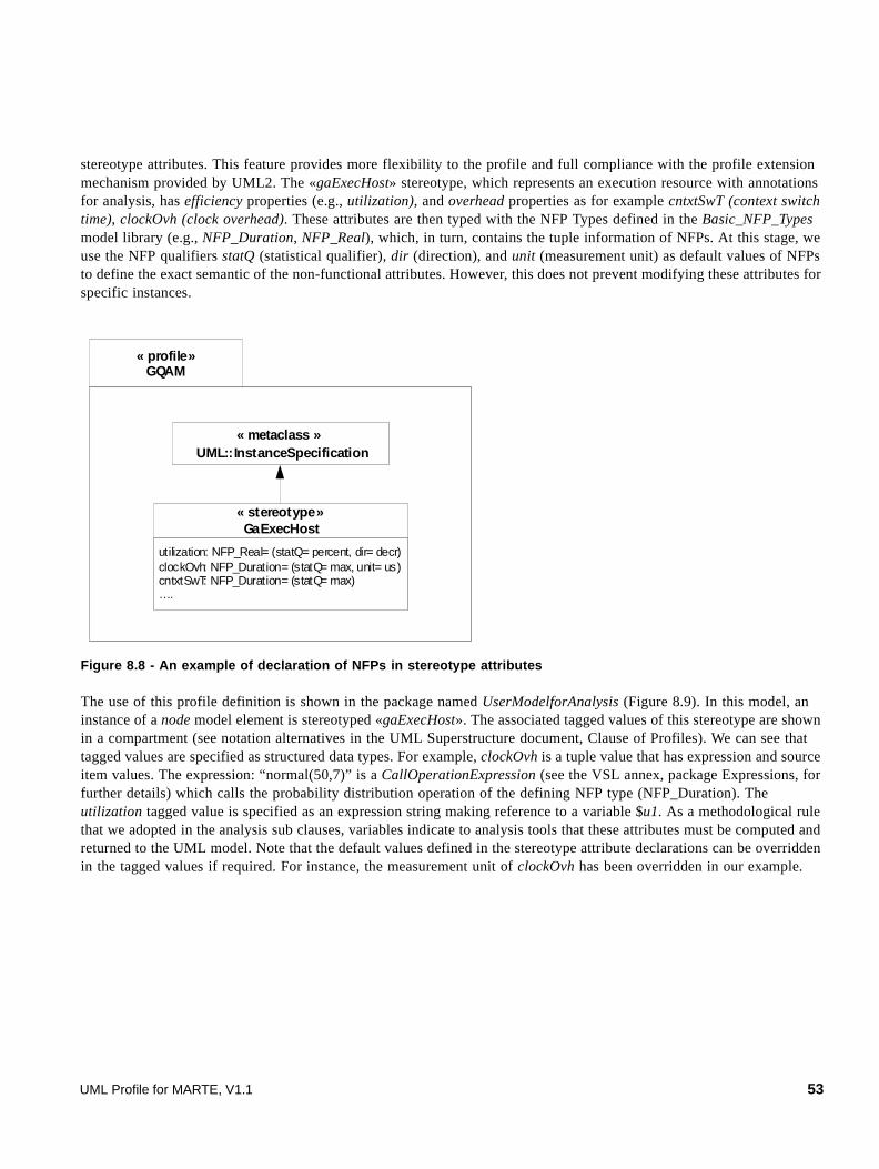
stereotype attributes. This feature provides more flexibility to the profile and full compliance with the profile extension mechanism provided by UML2. The «gaExecHost» stereotype, which represents an execution resource with annotations for analysis, has efficiency properties (e.g., utilization), and overhead properties as for example cntxtSwT (context switch time), clockOvh (clock overhead). These attributes are then typed with the NFP Types defined in the Basic_NFP_Types model library (e.g., NFP_Duration, NFP_Real), which, in turn, contains the tuple information of NFPs. At this stage, we use the NFP qualifiers statQ (statistical qualifier), dir (direction), and unit (measurement unit) as default values of NFPs to define the exact semantic of the non-functional attributes. However, this does not prevent modifying these attributes for specific instances.
Figure 8.8 - An example of declaration of NFPs in stereotype attributes
The use of this profile definition is shown in the package named UserModelforAnalysis (Figure 8.9). In this model, an instance of a node model element is stereotyped «gaExecHost». The associated tagged values of this stereotype are shown in a compartment (see notation alternatives in the UML Superstructure document, Clause of Profiles). We can see that tagged values are specified as structured data types. For example, clockOvh is a tuple value that has expression and source item values. The expression: “normal(50,7)” is a CallOperationExpression (see the VSL annex, package Expressions, for further details) which calls the probability distribution operation of the defining NFP type (NFP_Duration). The utilization tagged value is specified as an expression string making reference to a variable $u1. As a methodological rule that we adopted in the analysis sub clauses, variables indicate to analysis tools that these attributes must be computed and returned to the UML model. Note that the default values defined in the stereotype attribute declarations can be overridden in the tagged values if required. For instance, the measurement unit of clockOvh has been overridden in our example.
« profile»GQAM
utilization: NFP_Real= (statQ= percent, dir= decr)clockOvh: NFP_Duration= (statQ= max, unit= us)cntxtSwT: NFP_Duration= (statQ= max)….
« stereotype»GaExecHost
« metaclass »UML::InstanceSpecification
UML Profile for MARTE, V1.1 53
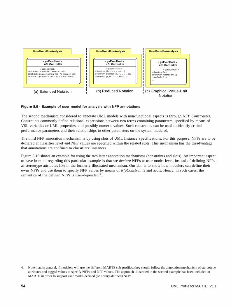
Figure 8.9 - Example of user model for analysis with NFP annotations
The second mechanism considered to annotate UML models with non-functional aspects is through NFP Constraints. Constraints commonly define relational expressions between two terms containing parameters, specified by means of VSL variables or UML properties, and possibly numeric values. Such constraints can be used to identify critical performance parameters and their relationships to other parameters on the system modeled.
The third NFP annotation mechanism is by using slots of UML Instance Specifications. For this purpose, NFPs are to be declared at classifier level and NFP values are specified within the related slots. This mechanism has the disadvantage that annotations are confined to classifiers’ instances.
Figure 8.10 shows an example for using the two latter annotation mechanisms (constraints and slots). An important aspect to have in mind regarding this particular example is that we declare NFPs at user model level, instead of defining NFPs as stereotype attributes like in the formerly illustrated mechanism. Our aim is to show how modelers can define their owns NFPs and use them to specify NFP values by means of NfpConstraints and Slots. Hence, in such cases, the semantics of the defined NFPs is user-dependent4.
4. Note that, in general, if modelers will use the different MARTE sub-profiles, they should follow the annotation mechanism of stereotype attributes and tagged values to specify NFPs and NFP values. The approach illustrated in the second example has been included in MARTE in order to support user model-defined (or library-defined) NFPs.
UserModelForAnalysis
« gaExecHost »utilization= ($u1, -, -, -, calc, -)clockOvh= (normal(50 , 7), -, -, -, est, -)cntxtSwT= (8, us, -, -, -, meas, -)...
« gaExecHost »uC: Controller
UserModelForAnalysis
« gaExecHost »utilization= (value=$u1 , source= calc)clockOvh= ( value= normal (50 , 7), source= est)cntxtSwT= ( value= 8, unit= us, source= meas)...
« gaExecHost »uC: Controller
UserModelForAnalysis
« gaExecHost »utilization= $u1clockOvh= normal (50 , 7)cntxtSwT= 8 us...
« gaExecHost »uC: Controller
(a) Extended Notation (b) Reduced Notation (c) Graphical Value-Unit Notation
54 UML Profile for MARTE, V1.1

Figure 8.10 - Example of user model with NfpConstraint and Slot annotations
We defined a classifier, named Controller, that owns a set of properties stereotyped as «nfp». Note that we have declared similar NFPs as in the previous example, but we intentionally changed their names to emphasize the fact that, in this case, the declared NFPs have user-specific meaning. As for the stereotype annotation mechanism, in this example we use NFP_Types to define the structure of NFP value specifications. We also defined default values for NFPs, which state the predefined value qualifiers: statistical qualifier, direction, and unit.
We created a uC instance of Controller and then specified its internal structure by means of a Composite Structure diagram. These instance-level model elements are stereotyped with high-level modeling constructs, «computingResource», «scheduler», and «clockResource», which are formally introduced in the GRM sub-profile, sub clause 10.3. At this stage, we specify a set of NFP values by means of two NfpConstraints attached to the specific constrained elements. In both cases, the constrainedElement (association end from the UML Constraint metaclass to UML
p roc U ti liz= ($u1 , calc)
« co m p u tin g R eso u rce»u C: C o n tro l ler
« sch eduler »{sc hedPo licy = F ixe dPrio rity}
s 1 / s ysSche d
« clockR esour ce »p1 / pr ocC lo ck
« n fp Co nt raint » {k ind= contract }{ pro cU tiliz > (90 , percent ) ? cloc kFre q==(60, MH z ) : c loc kFre q== (20 , M H z) }
« nf pC ont rain t » {k ind=offered }{ co nte xtS w it ch== (8, u s, m ea s) and s ched U ti liz== (5, perce nt) }
VS L C ondit ional E xpress ion
procU til iz > (90 , percent ) ? c lock F req= =(60 , M Hz) : c lock F req = =(20 , MH z)
C ondit ion If -T r ue Ex press io n If -F alse Expr ession
VSL Pro per tyC a llExp res sion(call t o a p rop ert y of
‘C o ntroller’ )
VSL Tup le Specif ic at ion(re lat ed t o t he
‘N FP_ Fre quen cy’ N FP t ype)
VSL Operat ionC allExpress io n(VSL inf ix n ota tion:
c all to t he ope rat ion ‘> ‘ , ‘great er t han ’ )
In te rn a l C o mp o si te S tr u ctu re o f a sp e ci fi c Co n tro l le r i n sta n c e
«nf p» procU t iliz: N FP _R eal= (p erc ent , dec r)«nf p» sche dU t iliz: N FP_ R eal= (p erc ent , dec r)«nf p» cont ex tSw itc h: NF P_D urat io n = (m ax)«nf p» clockF req: N FP_F req uenc y= (m ax , us)
C o n tro ller
UML Profile for MARTE, V1.1 55

Element metaclass) are the specific model elements to which the non-functional annotations apply, and the context (association end from the UML Contraint metaclass to the UML Namespace metaclass) is the Controller node element, which actuates as a namespace context for VSL expressions.
For instance, one of the NFP_Contraints is attached to the sysScheduler part element. This one defines an “offered” non-functional constraint written in VSL (see Annex B for details on the VSL textual language). The VSL expression is a three-level nested boolean expression. In the first level, an infix CallOperationExpression makes reference to the “and” operation (see the list of operations in Annex D) by specifying two operands. These operands are in turn other CallOperationExpressions making reference to the equalTo (“==”) operation, which has two operands. The first operand in both cases is PropertyCallExpression (calling to the contextSwitch and schedUtiliz properties of Controller) and the second operand in both expressions is a particular value that is conform to the defining property. In simple words, VSL allows for specifying NFP values by using (NFP) properties previously declared in the model.
In order to complement this basic annotation, a more complex NFP_Constraint has been specified for the procClock par (processor clock instance). We illustrate a non-functional contract assertion that is intended to be allowed at run time. When the Controller utilization becomes greater than 90%, the clock’s frequency increase from 20 MHz to 60 MHz. In this example, we do not make any assumption about the run-time mechanisms supporting this assertion. The contract has been specified by using a VSL Conditional Expression, whose structure is detailed in Figure 8.10.
The third proposed annotation mechanism is depicted by defining a procUtiliz slot within the uC instance of Controller. As in the first example (Figure 8.9), the utilization slot is specified by a variable $u1. The methodological rule indicates, again, that this variable should be computed by analysis tools and returned to the UML model.
Additional examples of VSL time expressions and the constraint annotation mechanism are given in Annex B.
56 UML Profile for MARTE, V1.1

9 Time Modeling (Time)
This clause contains both domain and UML viewpoints for time modeling. The clause describes a general framework for representing time and time-related concepts and mechanisms that are appropriate for modeling real-time and embedded systems. These serve as a base for the standard modeling elements defined in subsequent clauses of the MARTE profile.
Since Real-time systems are specifically concerned with the cardinality of time (e.g., delay, duration, clock time), (chrono-) metric time will be considered. Embedded systems may also require logical time models. Thus, both logical and metric times are covered in this specification.
9.1 Overview
The time domain model described in this clause identifies the set of time-related concepts and semantics that are supported by this profile. The model is quite general, and a given application may need to use only a subset of its concepts and semantics.
Time can be differently perceived at the different phases of the development of an embedded real-time system (modeling, design, performance analysis, schedulability analysis, implementation, etc.). The concept of ordering (i.e., something occurring before or after another thing) is common to many Time representations. MARTE adopts models of time that rely on partial ordering of instants. The temporal ordering of behavior activities can be represented in many ways, depending on the level of precision required. There are three main classes of time abstraction used to represent behavioral flows (with minor variations at each level). They are known under different names in different contexts, and these names are also often used with different meanings elsewhere (so there is no general consensus).
• Causal/temporal: in such models, one is only concerned about instruction precedence/dependency. These relations can be partial in presence of concurrency. Cooperation between concurrent entities takes place as communications (i.e., through events). Communications themselves can be fully asynchronous, blocking (with the emitter awaiting a returned reply), or hand-shake synchronization.
• Clocked/synchronous: this class of time abstraction adds a notion of simultaneity, and divides the time scale in a discrete succession of instants. Rich causal dependencies can take place inside an instant, leading to the “instantaneous reaction” abstraction. When the clock(s) is (are) linked to a regular pulse, clock ticks become the unit scale of a discrete-time model (but this need not be the case in any “synchronous” temporal model). This level is used in hardware modeling (at RTL level) where instantaneous propagation corresponds to “combinatorial” behaviors, in
simulation formalisms (as in MATLAB® / SIMULINK®, or in Hardware Description Languages such as SystemC/VHDL/Verilog with δ-cycles representing causal zero-delay dependencies), or in software modeling when relying on synchronous languages semantics (such as Esterel or SCADE or Signal). A generalization of the synchronous domain allows clocked entities to be linked in a looser, asynchronous network where no single-clock domain is defined. It leads to the notion of GALS (Globally-Asynchronous/Locally-Synchronous) domains. These are used in the field of system-level models, for instance for SoC (System-on-Chip) design, where several levels of modeling – either software or hardware – can be combined during the course of the design.
• Physical/real-time: this class of time abstraction demands the precise accurate modeling of real-time duration values, for scheduling issues in critical systems. Physical time models can also be applied to clocked model, for instance to derive the admissible speed of a reaction.
In embedded real-time systems modeling, time should not be considered as an external model: Time and Behavior are strongly coupled. The Time domain model identifies concepts that relate time and behavior. The Causality package in the CoreElements clause of MARTE has provided a high-level view of the run-time semantics of real time and embedded systems. The Time modeling clause enriches this view with explicit references to time-related concepts. The Invocation
UML Profile for MARTE, V1.1 57
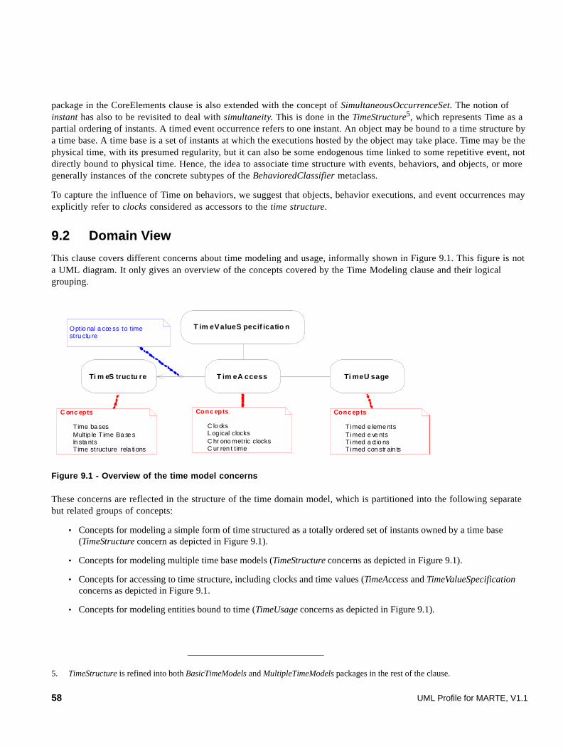
package in the CoreElements clause is also extended with the concept of SimultaneousOccurrenceSet. The notion of instant has also to be revisited to deal with simultaneity. This is done in the TimeStructure5, which represents Time as a partial ordering of instants. A timed event occurrence refers to one instant. An object may be bound to a time structure by a time base. A time base is a set of instants at which the executions hosted by the object may take place. Time may be the physical time, with its presumed regularity, but it can also be some endogenous time linked to some repetitive event, not directly bound to physical time. Hence, the idea to associate time structure with events, behaviors, and objects, or more generally instances of the concrete subtypes of the BehavioredClassifier metaclass.
To capture the influence of Time on behaviors, we suggest that objects, behavior executions, and event occurrences may explicitly refer to clocks considered as accessors to the time structure.
9.2 Domain View
This clause covers different concerns about time modeling and usage, informally shown in Figure 9.1. This figure is not a UML diagram. It only gives an overview of the concepts covered by the Time Modeling clause and their logical grouping.
Figure 9.1 - Overview of the time model concerns
These concerns are reflected in the structure of the time domain model, which is partitioned into the following separate but related groups of concepts:
• Concepts for modeling a simple form of time structured as a totally ordered set of instants owned by a time base (TimeStructure concern as depicted in Figure 9.1).
• Concepts for modeling multiple time base models (TimeStructure concerns as depicted in Figure 9.1).
• Concepts for accessing to time structure, including clocks and time values (TimeAccess and TimeValueSpecification concerns as depicted in Figure 9.1.
• Concepts for modeling entities bound to time (TimeUsage concerns as depicted in Figure 9.1).
5. TimeStructure is refined into both BasicTimeModels and MultipleTimeModels packages in the rest of the clause.
C onc epts
Time ba sesMult ip le T ime Ba se sIn sta ntsTime structure rela ti ons
Conc epts
C lo cksL og ical clocksC hr ono metric clocksC ur ren t t ime
Conc epts
Timed e leme ntsTimed e ve ntsTimed a ct io nsTimed con str ain ts
Optio nal a cce ss to time stru ctu re
T im eValueS pecif icatio n
T im eA ccessTi m eS tructu re Ti meU sage
58 UML Profile for MARTE, V1.1
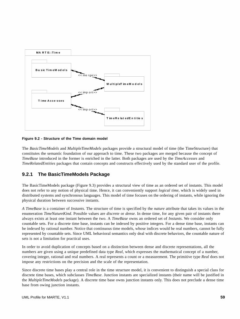
Figure 9.2 - Structure of the Time domain model
The BasicTimeModels and MultipleTimeModels packages provide a structural model of time (the TimeStructure) that constitutes the semantic foundation of our approach to time. These two packages are merged because the concept of TimeBase introduced in the former is enriched in the latter. Both packages are used by the TimeAccesses and TimeRelatedEntities packages that contain concepts and constructs effectively used by the standard user of the profile.
9.2.1 The BasicTimeModels Package
The BasicTimeModels package (Figure 9.3) provides a structural view of time as an ordered set of instants. This model does not refer to any notion of physical time. Hence, it can conveniently support logical time, which is widely used in distributed systems and synchronous languages. This model of time focuses on the ordering of instants, while ignoring the physical duration between successive instants.
A TimeBase is a container of Instants. The structure of time is specified by the nature attribute that takes its values in the enumeration TimeNatureKind. Possible values are discrete or dense. In dense time, for any given pair of instants there always exists at least one instant between the two. A TimeBase owns an ordered set of Instants. We consider only countable sets. For a discrete time base, instants can be indexed by positive integers. For a dense time base, instants can be indexed by rational number. Notice that continuous time models, whose indices would be real numbers, cannot be fully represented by countable sets. Since UML behavioral semantics only deal with discrete behaviors, the countable nature of sets is not a limitation for practical uses.
In order to avoid duplication of concepts based on a distinction between dense and discrete representations, all the numbers are given using a unique predefined data type Real, which expresses the mathematical concept of a number, covering integer, rational and real numbers. A real represents a count or a measurement. The primitive type Real does not impose any restrictions on the precision and the scale of the representation.
Since discrete time bases play a central role in the time structure model, it is convenient to distinguish a special class for discrete time bases, which subclasses TimeBase. Junction instants are specialized instants (their name will be justified in the MultipleTimeModels package). A discrete time base owns junction instants only. This does not preclude a dense time base from owing junction instants.
MA R T E: :Ti m e
T im e R e la t e dE n t i t ie s
B a s ic Ti m e M od e l s
M ul t i pl eT im e M o d e l s
<< imp o r t >>
<< me r ge >>
<< imp o r t >>
T i me A c c e s se s
UML Profile for MARTE, V1.1 59

The association between a discrete time base and a time base optionally enables linking a discrete time base to a dense time base. In this case, the former results from a discretization of the latter.
Figure 9.3 - Basic time diagram of the time model
Physical time is considered as a continuous and unbounded progression of physical instants. Physical time is assumed to progress monotonically (with respect to any particular observer) and only in the forward direction. For a given observer, it can be modeled as a dense time base. A convenient model for Physical Time as perceived in MARTE is the mathematical concept of real line R.
B as icT ime Mo de ls
na tur e:T ime Nat ure Kin d
Tim eB aseDis cre teT im eBa se{na tur e = discrete }
da te: Re al
In sta nt
ins tan ts
1tb
{ ord ere d }1..*
Ju nc tio nIn sta nt
0.. 1 co ve ring TB
cu rre ntIn sta nt{su bsets inst ant s }
1
discre te de nse
<< en um era tion>>T ime Na tureK ind
60 UML Profile for MARTE, V1.1

9.2.2 The MultipleTimeModels Package
Figure 9.4 - Multiple time diagram of the time model
The linear vision of time presented in the BasicTimeModels is not sufficient for most of the applications, especially in the case of distributed systems. Multiple time bases are then used. A time structure contains a tree of multiple time bases. A MultipleTimeBase consists of one or many time bases. A time base is owned by one and only one multiple time base.
Time bases are a priori independent. They become dependent when instants from different time bases are linked by relations (Time Instant Relations). Note that the word relation has been preferred to relationship in order to stress on the mathematical meaning of this word. The instants involved in such relations are special instants called junction instants, previously introduced in the BasicTimeModels package (Figure 9.3). All the instants of a discrete time base are also junction instants, because they are potentially observable instants (see sub clause 9.2.3 about Time Access, page 74).
A multiple time base owns a possibly empty set of time structure relations. These relations specify the time structure. TimeStructureRelation is an abstract class. It is subclassed into TimeBaseRelation and TimeInstantRelation, which are also abstract classes. A time base relation relates 2 or more time bases. A time instant relation relates 0 or more junction instants. Notice that the relatedTBs and relatedJIs properties are derived union (i.e., the effectively related elements are defined in concrete subclasses, as illustrated in the next 2 sub clauses).
Multip leT imeB ase
B as icT imeMod e ls: :Time Ba se
B as ic T imeMod els: :Jun ct io nIn s tan t
T ime Stru ct u reRe la tio ntsRe lat io ns
0. .*
Mu ltip leT imeMo d e ls
T ime Ba se Re la tion T imeIn s tan tR elat io n
2. .*
{ un ion,o rde red}/ re lated T Bs
0..*{u nion ,ord ere d}/re lated JIs0 ..*
o wn ing MT B1
o wn edT Bs
ne ste dMT Bs
0. .1 p are ntMTB
0..*
UML Profile for MARTE, V1.1 61

9.2.2.1 Concrete time instant relations
Figure 9.5 - TimeInstantRelation diagram of the time model
As shown in Figure 9.5, three concrete subclasses of the abstract TimeInstantRelation class are defined: CoincidenceRelation, PrecedenceRelation, and TimeIntervalMembership.
CoincidenceRelation is a strong form of time instant relation: junction instants belonging to different time bases can be coincident (i.e., same time and same place). In modeling, coincidence has not necessarily this strict relativistic meaning. It may represent clock synchronizations or design choices, for instance. The coincidence relation must be symmetric and transitive. Moreover, we assume that any junction instant is coincident with itself, so that the coincidence relation is an equivalence relation over instants. A strong requirement is that adding coincidence does not introduce cyclic dependencies in the temporal ordering. In mathematical words, the set of instants quotiented by the coincidence relation must be a partially ordered set. For convenience, the coincidence relation is often represented in diagrams by linking pairs of coincident instants. The actual relation is obtained by computing the transitive closure of the relation. Figure 9.6 shows an example for a multiple time base made of three time bases. Junction instants a2 and b2 are coincident. So are b2 and c2. Even if not drawn in the picture, a2 and c2 are also coincident junction instants (by transitivity).
Figure 9.6 - Example of multiple time base with coincidences
T im e In s ta nt R e la t i o n
C o in c id e n ce R e la t i o n T im e I n terv alM e m b er sh i p
2. . *
c oin c ide nt J Is{ s u bs et s rela te dJ I s }
low er 1up per 1
P rec ed en c eR el ati o n
B as ic T im eM o d el s: :Ju n c ti o nI n st an t
1{ su bs et s rel at edJ I s }
af t er{ s ubs e ts rel at edJ I s }b ef ore1
is Low er Ope n: B ool ean [1 ] is U pp er Ope n: B ool ean [1 ]
T i m eI n ter va lBa si cT i m eM o d e l s::
T i m e Bas e 1b as e
m e m be rs{ s u bs et s r e la te dJ I s }
0. .*
t im e In te rv al
1
A:TimeBase
B:TimeBase
C:TimeBase
:MultipleTimeBase
a1 a2 a3 a4 a5 a6
b1 b2 b3 b4 b5 b6 b7
c1 c2 c3 c4 c5 c6
Legend: instance of
Instant
Instance of CoincidenceRelation
62 UML Profile for MARTE, V1.1

PrecedenceRelation between junction instants from different time bases is a time instant relation weaker than coincidence. It expresses a directional dependency: a junction instant owned by a time base may precede or follow junction instants owned by other time bases.
A time interval on a time base is a convex set of junction instants owned by this time base. The convexity is the property that ensures that any junction instant between two junction instants of the interval is also in the interval. Two Boolean attributes specify whether the lower and upper bounds of the interval are in the interval or not. By default, the interval is closed on both boundaries. The bounds and the closure attributes must specify a non empty set of instants. The time interval is specified by its two bound junction instants. The TimeIntervalMembership is a relation that characterizes junction instants (members) that are either in the given time interval or are coincident with junction instants in this time interval.
9.2.2.2 Concrete time base relations
As explained in the previous sub clause, time instant relations induce relations on time bases of a multiple time base. Time base relations are a higher level way to impose dependencies between junction instants. A time base relation specifies a set of time instant relations. As shown in Figure 9.7, for any two time bases A and B, one defines a relation A is finer than B (or B is coarser than A) if for each junction instant in B there exists one and only one coincident junction instant in A. This relation can be characterized by a mapping M from the coarser time base B to the finer time base A. This mapping is injective and order-preserving (i.e., if b1 and b2 are two junction instants of B, and b1 is before b2, then a1 = M(b1) and a2 = M(b2) are such that a1 is before a2 in time base A). Notice that the specific association between DiscreteTimeBase and TimeBase (Figure 9.3) represents a coarser/finer relationship: the coarser time base, which is discrete, results from a discretization of its covering time base (i.e., its coveringTB property), which is a dense time base.
Figure 9.7 - Example of time relations between two time bases
When the finer time base is also a discrete time base, more precise relations can be specified. For instance, the k-finer relation is defined as follows. A is k-finer than B for k integer, k ≥ 1, if A is finer than B and for any two consecutive instants in B, there exist k-1 instants between the corresponding coincident instants in A. Figure 9.7 illustrates an example where k=2.
Predefined time base relations are suggested in the TimeStructureRelation Library of MARTE. The semantics of these relations is given in OCL.
a1 a2 a3 a4 a5 a6
b1 b2 b3 b4 b5
A:TimeBase
B:TimeBase
a7 a8
A is finer than BB is coarser than A
a9 a10 a11
More precisely, A is 2-finer than B
UML Profile for MARTE, V1.1 63
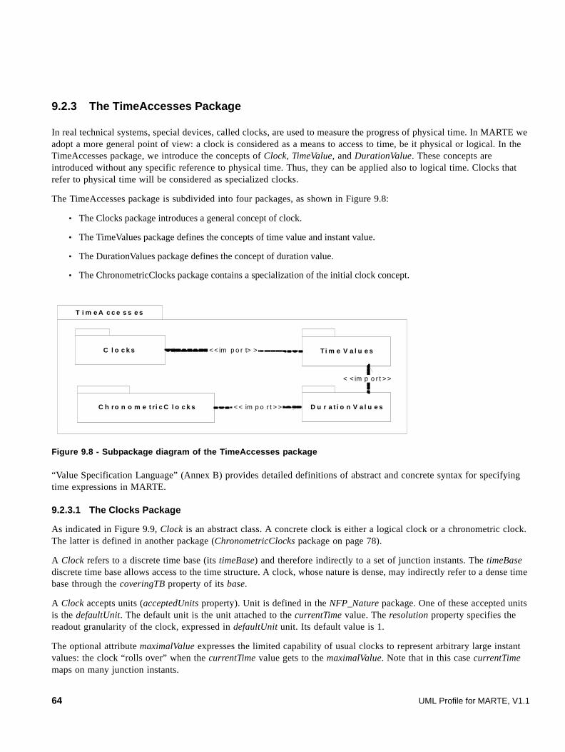
9.2.3 The TimeAccesses Package
In real technical systems, special devices, called clocks, are used to measure the progress of physical time. In MARTE we adopt a more general point of view: a clock is considered as a means to access to time, be it physical or logical. In the TimeAccesses package, we introduce the concepts of Clock, TimeValue, and DurationValue. These concepts are introduced without any specific reference to physical time. Thus, they can be applied also to logical time. Clocks that refer to physical time will be considered as specialized clocks.
The TimeAccesses package is subdivided into four packages, as shown in Figure 9.8:
• The Clocks package introduces a general concept of clock.
• The TimeValues package defines the concepts of time value and instant value.
• The DurationValues package defines the concept of duration value.
• The ChronometricClocks package contains a specialization of the initial clock concept.
Figure 9.8 - Subpackage diagram of the TimeAccesses package
“Value Specification Language” (Annex B) provides detailed definitions of abstract and concrete syntax for specifying time expressions in MARTE.
9.2.3.1 The Clocks Package
As indicated in Figure 9.9, Clock is an abstract class. A concrete clock is either a logical clock or a chronometric clock. The latter is defined in another package (ChronometricClocks package on page 78).
A Clock refers to a discrete time base (its timeBase) and therefore indirectly to a set of junction instants. The timeBase discrete time base allows access to the time structure. A clock, whose nature is dense, may indirectly refer to a dense time base through the coveringTB property of its base.
A Clock accepts units (acceptedUnits property). Unit is defined in the NFP_Nature package. One of these accepted units is the defaultUnit. The default unit is the unit attached to the currentTime value. The resolution property specifies the readout granularity of the clock, expressed in defaultUnit unit. Its default value is 1.
The optional attribute maximalValue expresses the limited capability of usual clocks to represent arbitrary large instant values: the clock “rolls over” when the currentTime value gets to the maximalValue. Note that in this case currentTime maps on many junction instants.
Ti m e V a l u e s
C h ro n o m e t ri c C l o c k s < < im p o r t > >
T i m e A c c e s s e s
C l o c k s < < im p o r t> >
D u r a t i o n V a l u e s
< < im p o r t > >
64 UML Profile for MARTE, V1.1
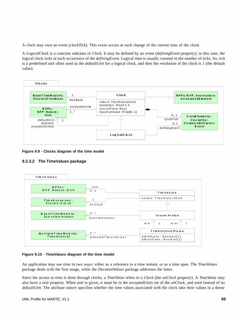
A clock may own an event (clockTick). This event occurs at each change of the current time of the clock.
A LogicalClock is a concrete subclass of Clock. It may be defined by an event (definingEvent property); in this case, the logical clock ticks at each occurrence of the definingEvent. Logical time is usually counted in the number of ticks. So, tick is a predefined unit often used as the defaultUnit for a logical clock, and then the resolution of the clock is 1 (the default value).
Figure 9.9 - Clocks diagram of the time model
9.2.3.2 The TimeValues package
Figure 9.10 - TimeValues diagram of the time model
An application may use time in two ways: either as a reference to a time instant, or as a time span. The TimeValues package deals with the first usage, while the DurationValues package addresses the latter.
Since the access to time is done through clocks, a TimeValue refers to a Clock (the onClock property). A TimeValue may also have a unit property. When unit is given, it must be in the acceptedUnits set of the onClock, and used instead of its defaultUnit. The attribute nature specifies whether the time values associated with the clock take their values in a dense
C lo c k s
B a sic T ime M od e ls: :D is c re t eT im eB a s e
n atu r e: T im e N a tu re K in d re so lu tio n : R e a l=1 .0 cu rr e n tT im e: R e a l ma xi m al Va lu e : R ea l[0 ..1 ]
C loc k1
tim e Ba se
L og ic alC lo c k
C or eE le me n ts: :C a u sa lit y::
C o mm o nB e h av io r:: E v e nt
N FPs ::N FP _N a tu re ::
U nit
N FP s::N FP_ A nn ot a tio n: :A n no ta t e dE le m e nt
0 ..1cl o ckTi ck
0..1
d e fin in g Eve n t
a cce p ted U n i ts
1 ..*
d efa u ltU n i t {su b se ts
a cce p te d U ni ts}
1
T im e A c c e s s e s : :C l o c k s: :C lo c k
B a s ic T i m e M o d e ls: :J u n c t io n I n s t a n t I n s t a n tV a lu e
0 .. *
d e n o te d In s ta n t
M u l t ip le T im e M o d e ls: :T im e In t e r v a l
0 .. *
d e n o te d T im e I n te rv a l
T im e V a lu e s
n a tu r e : T i m e N a tu r e K i n d
T im e V a lu e
is M in O p e n : B o o l e a n [1 ]is M a x O p e n : B o o le a n [ 1 ]
T i m e I n t e r v a lV a lu e
m in 1 m a x 1
N F P s ::N F P_ N a t u r e : :U n i t
u n it
0 . .1
1
o n C l o c k
UML Profile for MARTE, V1.1 65

or discrete domain. Since computers work with finite precision numbers, the distinction between discrete and dense sets is blurred by the limited precision of the representation: ultimately all values are discrete. Since the distinction between dense and discrete sets has a semantic meaning, we retain this distinction in the model, and we use “real” numbers for dense time values and integer numbers for discrete ones.
In the MARTE time model, logical clocks are always discrete, and their time values are integer numbers.
An InstantValue, which is a TimeValue, may refer to 0, 1, or many junction instants of a discrete time base. The multiple denotation of junction instants is due to the bounded nature of the representation of values. There may exist a folding of the time representation due to clock roll-over.
A TimeIntervalValue is defined as a pair of instant values and denotes 0 or many time intervals (many results from possible folding of the time representation). The min InstantValue refers to the lower instant of the time interval; the max InstantValue refers to the upper instant of the time interval. The closure properties of the interval are specified by the two Boolean attributes isMinOpen and isMaxOpen. By default, the interval is closed (i.e., it includes the min and max values).
When used in a time value specification, a time interval value indicates any time value in the interval.
The TimeValue class is abstract. It generalizes InstantValue and DurationValue, which is introduced next.
9.2.3.3 The DurationValues package
Figure 9.11 - DurationValues diagram of the time model
The DurationValues package introduces the concept of duration value (Figure 9.11). Duration is a “distance” between two instants. It characterizes the “extension” of a time interval. From the user’s point of view, a time interval is specified by a TimeIntervalValue. As explained in “The TimeValues package” on page 65, a TimeIntervalValue may denote 0, 1 or many time intervals, due to possible clock roll-over. In the simple case when the clock has no defined maximalValue, the DurationValue of a TimeIntervalValue is defined by the difference between the max and min instant values of this time interval value. When the maximalValue property is defined, the DurationValue is defined as the difference modulo maximalValue between the max and min instant values of this time interval value.
A DurationIntervalValue is defined by a pair of duration values, which specifies an interval of values. When used in specification, a duration interval value indicates any duration value in the interval.
DurationValue
DurationValues
TimeAccesses::TimeValues::TimeValue
isMinDOpen: Boolean[1]isMaxDOpen: Boolean[1]
Durat ionIntervalValue
minD 1 1 maxD
TimeAccesses::TimeValues::
TimeIntervalValue
intervalValue
1
66 UML Profile for MARTE, V1.1

9.2.3.4 The ChronometricClocks Package
Figure 9.12 - ChronometricClocks diagram of the time model
In “The BasicTimeModels Package” on page 59, physical time has been characterized as a continuous and unbounded progression of physical instants. The progression of physical time is perceived through event occurrences. Some events are considered as better candidates to represent the (assumed) uniform progression of physical time. For instance, one may choose the period of the radiation corresponding to the transition between the two hyperfine levels of the ground state of the cesium 133 atom (see the definition of the second time unit). Today, this is the best known reference. More conveniently, one considers cyclic events, whose occurrences are (more or less) periodic. Periodicity should be checked against the above mentioned best reference. Usually, periodic event generators are called clocks. We have already used this term in a broader sense: there is no reference to periodicity in clocks defined in sub clause 9.2.3. Therefore, we name ChronometricClock a clock that implicitly refers to physical time.
The ChronometricClocks package introduces the main concepts related to clocks bound to physical time (Figure 9.12). A chronometric clock provides quantitative information about time. Numerous non functional time-related properties can be defined for chronometric clocks. Only a few are presented below.
Figure 9.13 represents, in an informal way, the dependency of chronometric clocks on physical time. Physical time is modeled as a dense time base (the Real line). The instants of the discrete time base associated with a chronometric clock are coincident with physical instants regularly interspaced on the real line. In a chronometric clock, the resolution property is the duration value of physical time elapsed between two consecutive instants of this clock. Real chronometric clocks do not perfectly reflect evolution of physical time. Possible defects are characterized by non functional properties. For instance, stability is the ability for a clock to report consistent intervals of time. Stability is measured by derivatives of the clock rate, derivation against time or against environmental factors.
When many clocks are present in a system, other non functional time properties are considered. They are time-dependent pair-wise characteristics. Usually, one clock is taken as a reference clock against which the other clock is matched. When omitted, the reference clock is supposed to be an “almost perfect clock.” Two clocks with the same rate may present an offset. This duration value may vary along time. The rate of change of the offset (i.e., its first derivative against time) between two clocks is called the skew. This skew itself may change over time. The derivative of the skew is called the drift.
s ta n d a rd : T im e St a nd a r d K i n d [ 0 .. 1 ] s ta b ilit y : R ea l [0 .. 1 ] o f f se t: D u ra t io n V a l ue [ 0 . . 1 ] s ke w : R e a l [ 0 . .1 ] d r i ft : R e a l [ 0 .. 1 ]
C h ro n o m e t ri c C l o ck
P h y si c a l T im e
T A IU T0U T1U T CT TT D BT C GT C BS i d er e a lL o c a lG P S
< < e n u m e ra t io n> >T im e S ta n d a rd K in d
C h ro n o m e t ri c C lo c k s
0 .. 1
r e f e re nc eC lo c k
T im e A c c e s s e s: :C l o ck s: :C l o c k
UML Profile for MARTE, V1.1 67

\
Figure 9.13 - Dependency example of chronometric clocks on physical time
9.2.4 The TimeRelatedEntities Package
Figure 9.14 - Subpackages of the TimeEntities package
Time can be used for observation or for control. Typical examples of the first usage are observations of event occurrences in interactions diagrams. Time events triggering behaviors are examples of the second usage. MARTE explicitly relates events, actions, messages… to time. The TimeRelatedEntities package is subdivided into the following subpackages (Figure 9.14):
P h y s ic a l t im e
t 1 :D is c r e t e Ti m eB a s e
q
q
q
c 1:C h r o n o m e t r ic C lo c k
b a s e
t 2 : D is c r e te T im eB a se
c 2: C h r o n o m e t r ic C l o c k
b a s e
o f f se t
R : T im e B a se{ d e n s e }
c o v e r in g T B
c o v e r in g T B
T imeR elate d En ti ties
C loc kC o n str ain ts T ime dO b ser va tio n s
T ime d Ele men ts T imed Eve n tM o d els
T imed Pro ce ssin gM o de lsT ime d Co n s tra in t s
<< im po rt>>
< <im p ort>>
< < im po rt> >
< < im po rt> >
<< im p or t>>
68 UML Profile for MARTE, V1.1

• TimedElements package defines the key concept of TimedElement;
• ClockConstraints package introduces constraints on clocks;
• TimedObservations package provides concepts related to observation of timed entities;
• TimedConstraint package specifies constraints on time-related observations;
• TimedEventModels package deals with events whose occurrences are bound to time;
• TimedProcessingModels package addresses executions bound to time.
9.2.4.1 The TimedElements Package
Figure 9.15 - TimedElement diagram of the time model
A timed element, introduced in the TimedElements package (Figure 9.15), is a most general concept. TimedElement is an abstract class generalization of all other timed concepts. It associates a non empty set of clocks with a model element. The semantics of the association with clocks depends on the kind of timed element.
9.2.4.2 The ClockConstraints package
Figure 9.16 - ClockConstraints diagram of the time model
A clock constraint constrains two or more clocks. The specification of the constraint is expressed by a ClockConstraintSpecification. Clock constraint specifications are special value specifications described in Annex C (Clock Constraint Specification Language). An example of clock constraint is that two clocks are harmonic with one twice faster than the other.
TimedElements
TimeA cc ess es::C loc ks::C loc k TimedEl ement
1..*
o n
C oreEle me nts::Founda tions::M odelE lement
ClockConstrai nt
NFPs::NFP_An notation::
NfpCo nstrain t
TimeAccesses::Clocks::Clock
2..*
constra inedClocks{ subsets constrainedElement }
CCS::ClockConstra intSpecification
1
specif ication{ redefines
specifica tion }
Cl ockCo nstrain ts
UML Profile for MARTE, V1.1 69

9.2.4.3 The TimedObservations Package
Figure 9.17 - TimedObservations diagram of the time model
TimedObservation is an abstract superclass of TimedInstantObservation and TimedDurationObservation. A TimedObservation is a TimedElement. As a TimedElement it has associated clocks, used for observing time. A TimedObservation is made in the runtime context of a (sub)system behavior execution (the observationContext property).
The enumeration literals of the EventKind enumeration allow the user to specify the kind of events considered in a TimedObservation. For a behavior, observed events can be either its start event or its finish event. For a Request, the possible events are its sending, its receipt, or the start of its processing by the receiver.
A TimedInstantObservation denotes an instant in time, associated with an event occurrence (eocc property) and observed on a given clock. The obsKind property of the TimedInstantObservation may specify the kind of observed event.
A TimedDurationObservation denotes some interval of time, associated with execution, request, or two event occurrences, and observed on one clock or two clocks. The exc property associates the duration observation with a BehaviorExecution, which is an abstraction of CompBehaviorExecution and ActionExecution. The duration is the time elapsed between the occurrences of the start and the finish events of an execution of this BehaviorExecutionSpecification (i.e., a CompBehaviorExecution or an ActionExecution). The stim property associates the duration observation with a Request. A Message is a kind of Request. The duration can be observed between two of the three events associated with a request (its sending, its receipt or the start of its processing). The precise kind of event can be given by the obsKind attribute. Finally, a duration can be observed between two event occurrences (eocc property), not necessarily observed on the same clock.
TimedObservation
obsKind:EventKind[0..1]
TimedInstantObservation
obsKind:EventKind[0..2]
TimedDurationObservation
eocc1
0..2
eocc
TimedObservations
CoreElements::Causality::
RunTimeContext::EventOccurrence
TimedElements::TimedElement
CoreElements::Causality::
Communication::Request
CoreElements::C ausality::
RunTimeContext::CompBehaviorExecution
observationContext
0..1
0..1exc
CoreElements::C ausality::
RunTimeContext::BehaviorExecution
stim0..1startfinishsendreceiveconsume
<<enumeration>>EventKind
70 UML Profile for MARTE, V1.1
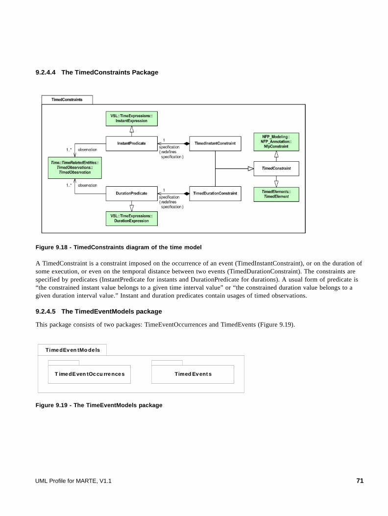
9.2.4.4 The TimedConstraints Package
Figure 9.18 - TimedConstraints diagram of the time model
A TimedConstraint is a constraint imposed on the occurrence of an event (TimedInstantConstraint), or on the duration of some execution, or even on the temporal distance between two events (TimedDurationConstraint). The constraints are specified by predicates (InstantPredicate for instants and DurationPredicate for durations). A usual form of predicate is “the constrained instant value belongs to a given time interval value” or “the constrained duration value belongs to a given duration interval value.” Instant and duration predicates contain usages of timed observations.
9.2.4.5 The TimedEventModels package
This package consists of two packages: TimeEventOccurrences and TimedEvents (Figure 9.19).
Figure 9.19 - The TimeEventModels package
TimedEven tMo de ls
T imedEven tOccu rre nces Timed Event s
UML Profile for MARTE, V1.1 71

9.2.4.5.1 The TimeEventOccurrences package
An event occurrence can be associated with time instants. MARTE introduces the concept of TimedEventOccurrence (Figure 9.20), which is both a TimedElement and an EventOccurrence. The at property specifies the instant value of this timed event occurrence on one of its clocks. Since a timed event occurrence may refer to several clocks (on property), several instant values (at property) are possible. Usually, there is one clock only, but several are allowed at least to cover the case of simultaneous occurrence set, introduced below.
This package also introduces the concept of SimultaneousOccurrenceSet. In the Causality Modeling clause, an execution of a behavior may be caused by an event occurrence. In some situations, several events have to be considered as a whole because their collective effect cannot reduce to the serialization of their individual effects. The concept of SimultaneousOccurrenceSet is introduced to address this issue. A SimultaneousOccurrenceSet is an EventOccurrence, and as such, it can be the cause of a behavior execution. This concept is useful at design-time when different views of a same event, which have been introduced earlier, have to be merged into one event. It is also of common use in reactive synchronous modeling.
Figure 9.20 - TimedEventOccurrences diagram of the time model
9.2.4.5.2 The TimeEvents package
A TimedEvent is an event the occurrences of which are bound to clocks. A TimedEvent may have several occurrences. The when property specifies when the first occurrence occurs. The Boolean attribute isRelative specifies whether the time value is relative (the when property is a time duration value) or absolute (the when property is a time instant value). The every optional property permits repetitive occurrences of the timed event. When every is present, its value is the duration that separates the successive occurrences of the timed event. The number of occurrences can be limited by the repetition attribute. The time values are specified by CVS expressions. CVS (Clocked Value Specification) is defined in Annex C. A CVS::ClockedValueSpecification specifies a TimeValue, a CVS::DurationValueSpecification a DurationValue, and a CVS::InstantValueSpecification an InstantValue.
T imedEventOccurrence
T imeAccesses::TimeValues::InstantValue
at
0..1
1..*
T imedEventModels: :TimedEventOccurrences
SimultaneousOccurrenceSet
T imedElements: :TimedElement
occSet0..*
0..1
CoreElements::Causality::
RunT imeContext::EventOccurrence
72 UML Profile for MARTE, V1.1

Figure 9.21 - TimedEvents diagram of the time model
9.2.4.6 The TimedProcessingModels package
This package consists of two packages: TimedExecutions and TimedProcessings.
Figure 9.22 - The TimedProcessingModels package
9.2.4.6.1 The TimedExecutions package
A TimedExecution is a TimedElement that is a specialization of the CoreElements::Causality::RunTimeContext::BehaviorExecution. As a TimedElement, a timed execution makes explicit reference to clocks.
Two instant values, startInstant and finishInstant, are associated with an execution and they correspond to the occurrence instants of its StartOccurrence and TerminationOccurrence, respectively. A DurationValue may also characterize an execution. Since a timed execution may refer to several clocks (on property), several time values are possible.
isRelat ive : Booleanrepetition: Integer[0..1]
TimedEvent
TimedElements::TimedElement
TimedEventModels::TimedEvents
every0..1when1
CoreElements::Causality: :
CommonBehavior::Event
CVS: :ClockedValueSpecification
CVS: :DurationValueSpecificat ion
T ime d P ro ce ss in g M o d e ls
T ime d E xec u tio n s T imed Pro c ess ing s
UML Profile for MARTE, V1.1 73

In the CoreElements::Causality::RunTimeContext package, CompBehaviorExecution and ActionExecution are concrete subclasses of BehaviorExecution, so that timed behavior executions and timed action executions also make explicit reference to clocks. A message transfer can also be assimilated to a timed execution (the sending instant being the startInstant of the communication and the receipt instant being its finishInstant). In what follows, Behavior, Action, and Message are collectively designated as timed processing, even if this assimilates a Message to its transfer.
Figure 9.23 - TimedBehaviorExecutions diagram of the time model
9.2.4.6.2 The TimedProcessings package
TimedProcessing (Figure 9.24) is a generic concept for modeling activities that have known start and finish times, or a known duration. In fact, two out of the three time values suffice to characterize a particular execution of the processing. For a timed message, start and finish events are respectively named as sending and receipt events.
A delay is a special kind of timed action that represents a null operation lasting for a given duration.
T imed Execut ion
T imeA ccesses: :TimeValues: :In st ant Valu e
1..*startInstant 1..*finishInstant1..*executionDuration
TimeAccesses: :Du rat ionValu es::
Duration Valu e
TimedPro cessin gMod els: :TimedExecu tio ns
T imed Elements: :T imed Elemen t
C oreElemen ts::Cau sality: :
Ru nTimeCo nt ext: :BehaviorExecut ion
74 UML Profile for MARTE, V1.1

Figure 9.24 - TimedProcessings diagram of the time model
9.3 UML Representation
This sub clause describes the UML extensions required to support the concepts defined in the Time Modeling domain view. Some concepts result in new stereotypes, others specialize stereotypes defined for NFPs modeling, and still others need no extensions at all. Most of the time-related stereotypes extend metaclasses from UML::Classes::Kernel, UML::CommonBehaviors, and the SimpleTime package of CommonBehaviors.
9.3.1 Profile Diagrams
The Time profile depends on the NFPs profile as shown in Figure 9.25.
Figure 9.25 - Time profile dependencies diagram
For convenience, the Time profile is represented as a collection of diagrams. Each diagram gathers tightly related model elements. The actual Time profile consists of all these diagrams. The libraries are presented in Annex D.
« profil e »N FPs
« modelLi brary »T ime Type sLib ra ry
« profile »Time
<< imp ort>> <<imp ort>>
« modelL ibrary »TimeL ibrary
<<ap ply>>
<< im po rt>>
« profil e »VSL::D ata Type s
<< imp ort>>
UML Profile for MARTE, V1.1 75

9.3.1.1 TimedElement and Clock stereotypes
In the Time domain view, the concepts related to the time structure have been introduced in the BasicTimeModels and MultipleTimeModels packages. These concepts constitute the semantic domain of the Time model. The corresponding concepts in the UML view are ClockType and TimedDomain. The TimedDomain stereotype of the UML view maps to MultipleTimeBase and the ClockType stereotype maps to TimeBase.
TimedElement is an abstract stereotype that must be used to associate one (or many when dealing with multiple time references) clock(s) to a UML model element. The concrete specializations of TimedElement make it clear which model element can or cannot be associated with clocks. When the property “on” is not specified, it should be understood as being by default, a dense chronometric clock with no flaws that represent the physical time. One possible example of such clock called “idealClk” is available in the library TimeLibrary. (see D.3.2).
Figure 9.26 - UML extensions for Time modeling (1)
9.3.1.2 Timed value specification stereotypes
A TimedValueSpecification is the specification of a set of instances of time values. As a TimedElement, a TimedValueSpecification makes reference to Clocks. The optional interpretation property may force the interpretation of the value as duration or instant specification.
Figure 9.27 - UML extensions for Time modeling (2)
9.3.1.3 Constraint stereotypes
Time Modeling introduces two stereotypes specializing the NfpConstraint stereotype, which is itself an extension to the UML Constraint. TimedConstraint deals with constraints imposed on either instant value or on duration value, according to the value given to the interpretation attribute. ClockConstraint imposes dependency between clocks or between clock types. As TimedElement, both stereotypes refer to clocks. Additional OCL rules specify the constrained elements, the specification, and the context of the constraint. Note that VSL is convenient to express various timed constraints.
standard: TimeStandardKind[0..1]
« stereotype »Clock
« metaclass »UML::Classes::Kernel::InstanceSpecification
<<metaclass>>Class
type1
1..* on
« Stereotype »NFP_Profile::Unit
« Metaclass »UML::CommonBehaviors::Communications::Event
« stereotype »TimedElement
« metaclass »UML::Classes::
Kernel::Property
unit0..1
nature: TimeNatureKind[1]unitType: Enumeration[0..1]isLogical: Boolean[1] = falseresolAttr: Property[0..1]maxValAttr: Property[0..1]offsetAttr: Property[0..1]getTime: Operation[0..1]setTime: Operation[0..1]indexToValue: Operation[0..1]
« stereotype »ClockType
« stereotype »TimedDomain
« metaclass »UML::Classes::Kernel::
Namespace
<<metaclass>>UM L::Classes::Kernel::
ValueSpecification i nterpretation: TimeIn terpr etationKind[0..1]
<<stereotype>>TimedValueSpecification <<stereot ype>>
TimedElement
76 UML Profile for MARTE, V1.1

Figure 9.28 - UML extensions for Time modeling (3)
9.3.1.4 Observation Stereotypes
As specializations of TimedElement, TimedInstantObservation, and TimedDurationObservation refer to clocks. The optional obsKind attribute may specify the kind of the observed event(s). The Enumeration EventKind is part of the TimeTypesLibrary (Annex D.3.1)
1
Figure 9.29 - UML extensions for Time modeling (4)
9.3.1.5 Timed event stereotype
The TimedEvent stereotype represents Event whose occurrences are explicitly bound to clocks.
Figure 9.30 - UML extensions for Time modeling (5)
9.3.1.6 Timed processing stereotype
The TimedProcessing stereotype represents activities that have know start and finish times or a known duration, and whose instants and durations are explicitly bound to clocks.
repet it ion: Integer[0 ..1]
< <stere oty pe>>T imed Even t
<<meta cla ss>>UM L ::C ommo nB eh avior s::
SimpleT ime::TimeEven t
<<meta cla ss>>UM L::Cla sses: :Ke rn el::
ValueSp ecificatio n 0. .1 0. .1
e ver y <<s tereo typ e>>Timed Elemen t
UML Profile for MARTE, V1.1 77

Figure 9.31 - UML extensions for Time modeling (6)
9.3.2 Profile Elements Description
9.3.2.1 Clock
The Clock stereotype maps the Clock domain element denoted in Annex F (sub clause F.3.2). It also relates to the ChronometricClock domain element (sub clause F.3.1).
A Clock is a model element that represents an instance of ClockType. A Clock gives access to time. A Clock exists in a TimedDomain. A Clock maps to a TimeBase in the semantic domain. The stereotype specifies the unit of the Clock. A Clock is also characterized by its resolution, and optionally by its offset (its initial instant value) and its maximal value. The values of these attributes are contained in the slots of the stereotyped InstanceSpecification.
A Clock can also be a stereotyped Property, so that it can be used in composite structure and interactions.
Alternatively, any UML event can be handled as a clock since the stereotype Clock extends the metaclass Event. This extension maps to the domain concept of definingEvent (sub clause F.3.16) and allows for defining clock constraints on any event, not just TimeEvent. When using this choice, the type MUST be logical.
9.3.2.1.1 Extensions
• Event (UML::CommonBehaviors::Communications::Event)
• Property (from UML::Classes::Kernel)
• InstanceSpecification (from UML::Classes::Kernel).
9.3.2.1.2 Generalizations
• None
9.3.2.1.3 Associations
• type: ClockType[1] Specifies the ClockType whose this Clock is an instance.
<< s te reo t y p e> >T i m e dP ro c e s si n g
s t a r t0 .. 1
f in is h
0 .. 1
d u r a t io n
0. .1 0 .. 1
<<m e ta c la s s>>U ML ::C om m o nB e h a v i ors: :
C o mm u n ic a t io n: :Ev e nt
<<m e ta c la s s>>U M L::A ct i o ns : :
A ct i on
<< me t a cl a ss >>U M L: :C o m m o nB e ha v io rs: :
B e ha v io r
<<m e t ac l as s >>U M L: :I n te ra c t io n s: :B a si c I n te ra c t io n s: :
M es s a ge
<< s te reo t y p e> >Ti m e d E le m e n t
<<m e t ac l as s >>U M L: :C l a s se s: :K e r ne l : :
Va lu e S p e ci f ic a t i on
78 UML Profile for MARTE, V1.1
• unit: NFPs::Unit[0..1] Defines the unit used by this Clock. If unit is not defined, then this Clock uses the anonymous tick unit. When defined, this unit must be of the unitType specified in the ClockType.
9.3.2.1.4 Attributes
• standard: TimeStandardKind[0..1] References the system of time adopted by the clock. This property is not defined for a logical clock.
9.3.2.1.5 Constraints
[1] The base_InstanceSpecification of the Clock must be an InstanceSpecification of the base_Class of its type property.
not self.base_InstanceSpecification.oclIsUndefined() implies self.base_InstanceSpecification.classifier->includes(self.type.base_Class)
[2] The base_Property of the Clock must be a Property of the base_Class of its type property.
not self.base_Property.oclIsUndefined() implies self.base_Property.type = self.type.base_Class
[3] The unit must be an ownedLiteral of the unitType enumeration of the ClockType.
self.unit->notEmpty( ) implies self.type.unitType.ownedLiteral->includes(self.unit)
[4] A logical clock does not have a defined standard.
self.type.isLogical implies self.standard->isEmpty( )
[5] When clock extends an event, its type must be logical.
not self.base_Event.oclUndefined() implies self.type.isLogical = true
9.3.2.2 ClockConstraint
The ClockConstraint stereotype maps the ClockConstraint domain element denoted in Annex F (sub clause F.3.3).
A ClockConstraint is a Constraint that imposes dependency between clocks or between clock types. A ClockConstraint refers to a set of clocks or clock types, and possibly to other model elements. The clocks in the constrained elements must belong to the on clock set of this ClockConstraint; the constrained clock types must be types of clocks in the on clock set. The specification of the constraint is usually an opaque expression using a dedicated language: CCSL (Clock Constraint Specification Language) defined in Annex C.
A ClockConstraint may define one or several clock relations and relies on many, often infinitely many, instant relations. When relying on coincidence instant relations, the attribute “isCoincidenceBased” must be set to true. When relying on precedence instant relations, the attribute “isPrecedenceBased” must be set to true. Note that they are not exclusive. However, when only “isCoincidenceBased” is true, the constraint is purely synchronous, when only “isPrecedenceBased” is true, the constraint is purely asynchronous. Apart from these structural distinctions, a ClockConstraint may also define a constraint related to chronometric aspects of the clocks (like stability, skew, offset …). In such cases, the attribute “isChronometricBased” must be set to true.
9.3.2.2.1 Extensions
• None
UML Profile for MARTE, V1.1 79
9.3.2.2.2 Generalizations
• NfpConstraint (from NFPs)
• TimedElement
9.3.2.2.3 Associations
• None
9.3.2.2.4 Attributes
• isCoincidenceBased: Boolean [1] Specifies whether this ClockConstraint relies on coincidence instant relations.
• isPrecedenceBased: Boolean [1] Specifies whether this ClockConstraint relies on precedence instant relations.
• isChronometricBased: Boolean [1] Specifies whether this ClockConstraint relies on chronometric aspects (such as stability, offset, skew) that are not purely structural.
9.3.2.2.5 Constraints
[1] The constrained clocks are members of the on clock set of the ClockConstraint.
self.on->includesAll(self.base_Constraint.constrainedElement->select(c|c.oclIsTypeOf(Clock))
[2] The constrained clock types are types of clock members of the on clock set of the ClockConstraint.
self.on->includesAll(self.base_Constraint.constrainedElement->select(c|c.oclIsTypeOf(ClockType).type)
9.3.2.3 ClockType
The ClockType stereotype maps the TimeBase domain element denoted in Annex F (sub clause F.3.21). It also relates indirectly to Clock (sub clause F.3.2) and ChronometricClock (sub clause F.3.1).
A ClockType is a classifier for Clock. The attributes of the stereotype define the nature of the represented time (discrete or dense), the type of units, and whether its instances are logical clocks or chronometric clocks.
9.3.2.3.1 Extensions
• Class (from UML::Classes::Kernel)
Note: The ClockType stereotype the UML Class. This metaclass goes through several merge increments in the UML specification. Using UML::Classes::Kernel::Class does not preclude usage of Class from UML::StructuredClasses.
9.3.2.3.2 Generalizations
• None
9.3.2.3.3 Associations
• None
80 UML Profile for MARTE, V1.1

9.3.2.3.4 Attributes
• nature: TimeNatureKind [1] Specifies the nature dense or discrete of the time represented by this ClockType.
• unitType: UML::Classes::Kernel::Enumeration [0..1] Is the type of units supported by this ClockType.
• isLogical: Boolean [1] = false Specifies whether this ClockType reads a logical time or not. When isLogical is false, the ClockType reads a chronometric time, i.e., a time bound to physical time.
• maxValAttr: Property [0..1] The maxValAttr property refers to a property of the base class. This property declares a read only attribute which determines the maximalValue of the associated Clock, value at which the clock rolls over. The maximal value is expressed with the clock's unit as a unity.
• offsetAttr: Property [0..1] The offsetAttr property refers to a property of the base class. This property declares a read only attribute which determines the offset (initial instant) of the associated Clock. The offset is expressed with the clock’s unit as a unity.
• resolAttr: Property [0..1] The resolAttrib property refers to a property of the base class. This property declares a read only attribute which determines the resolution of the associated Clock. The resolution is expressed with the clock’s unit as a unity. When resolution is not defined, the granularity is arbitrarily small. This is the case for dense time.
• getTime: UML::Classes::Kernel::Operation [0..1] The getTime property refers to an operation of the base class that returns the current time.
• setTime: UML::Classes::Kernel::Operation [0..1] The setTime property refers to an operation of the base class that sets the current time.
• indexToValue: UML::Classes::Kernel::Operation [0..1] The indexToValue property refers to an operation of the base class that yields the instant value associated with an instant specified by its index.
9.3.2.3.5 Constraints
• None
9.3.2.4 TimedConstraint
The TimedConstraint stereotype maps the TimedConstraint domain element denoted in Annex F (sub clause F.3.25). It also relates indirectly to TimedInstantConstraint (sub clause F.3.32) and TimedDurationConstraint (sub clause F.3.26).
A TimedConstraint imposes constraints on either instant value or duration value associated with model elements bound to clocks. If interpretation is set to the enumeration literal instant, then the constraint is interpreted as a constraint on instant value. If interpretation is set to the enumeration literal duration, then the constraint is interpreted as a constraint on duration value. There is no other case. The specification of the constraint itself can be conveniently expressed in VSL.
9.3.2.4.1 Extensions
• None
UML Profile for MARTE, V1.1 81

9.3.2.4.2 Generalizations
• NfpConstraint (from NFPs)
• TimedElement
9.3.2.4.3 Associations
• None
9.3.2.4.4 Attributes
• interpretation: TimeInterpretationKind [1] Specifies whether the constraint applies to an instant value or to a duration value.
9.3.2.4.5 Constraints
[1] The owner of a constraint stereotyped by TimedConstraint must be a Package stereotyped by TimedDomain
base_Constraint.owner.oclIsTypeOf(TimedDomain)
[2] The interpretation property is either instant or duration
[3] self.interpretation <> TimeInterpretationKind::any
9.3.2.5 TimedDomain
The TimedDomain stereotype maps the MultipleTimeBase domain element denoted in Annex F (sub clause F.3.17).
A TimedDomain is a container of Clocks. Model elements of the TimeDomain may refer to Clocks to express that their behavior depends on time. A TimedDomain is also a context for a ClockConstraint. A TimedDomain may own nested TimedDomains. A TimedDomain maps to a MultipleTimeBase in the semantic domain.
9.3.2.5.1 Extensions
• Namespace (from UML::Classes::Kernel::Namespace)
9.3.2.5.2 Generalizations
• None
9.3.2.5.3 Associations
• None
9.3.2.5.4 Attributes
• None
9.3.2.5.5 Constraints
• None
9.3.2.6 TimedDurationObservation
The TimedDurationObservation stereotype maps the TimedDurationObservation domain element denoted in Annex F (sub clause F.3.27).
82 UML Profile for MARTE, V1.1

A TimedDurationObservation denotes some interval of time, observed on one or two clocks. The duration may be the time elapsed between the occurrences of the start and the finish events of an execution. The duration may also be the time elapsed between two of the three events associated with a message (its sending, its receipt, and the start of its processing by the receiver). More generally, the duration may be the time elapsed between the occurrences of two distinct events.
9.3.2.6.1 Extensions
• DurationObservation (from UML::CommonBehaviors::SimpleTime::DurationObservation).
9.3.2.6.2 Generalizations
• TimedElement
9.3.2.6.3 Associations
• None
9.3.2.6.4 Attributes
• obsKind: EventKind [0..2] Specifies the kind of the observed events.
9.3.2.6.5 Constraints
• None
9.3.2.7 TimedElement (abstract)
The TimedElement stereotype maps the TimedElement domain element denoted in Annex F (sub clause F.3.28).
The TimedElement stereotype is an abstract stereotype that does not extend UML meta classes. It stands for model elements referencing Clocks. Only concrete specializations of TimedElement can be applied.
9.3.2.7.1 Extensions
• None
9.3.2.7.2 Generalizations
• None
9.3.2.7.3 Associations
• on: Clock [1..*] References a set of Clocks. When no clock is explicitly specified, a reference to an implicit dense chronometric clock
(like idealClk, see D.3.2) is intended.
9.3.2.7.4 Attributes
• None
9.3.2.7.5 Constraints
• None
UML Profile for MARTE, V1.1 83
9.3.2.8 TimedEvent
The TimedEvent stereotype maps the TimedEvent domain element denoted in Annex F (sub clause F.3.29). It also relates indirectly to TimedEventOccurrence (sub clause F.3.30).
The TimedEvent stereotype represents events whose occurrences are explicitly bound to a Clock. When this stereotype is applied to an Event, this Event specifies the first occurrence of this Event (isRelative and when properties). The when value is considered read on the on Clock of this TimedEvent, and with the unit of this Clock. The every property specifies the duration between successive occurrences, if any. The number of occurrences can be limited by the repetition property.
9.3.2.8.1 Extensions
• TimeEvent (from CommonBehaviors::SimpleTime)
9.3.2.8.2 Generalizations
• TimedElement
9.3.2.8.3 Associations
• every: UML::Classes::Kernel::ValueSpecification [0..1] Is an optional owned specification of the duration value between two successive occurrences of this TimedEvent. By default this duration is read on the on Clock of this TimedEvent. By applying the TimedValueSpecification stereotype to this ValueSpecification, another Clock can be chosen.
9.3.2.8.4 Attributes
• repetition: Integer[0..1] Is an optional repetition factor. When defined, repetition is the number of successive occurrences of the TimedEvent. Its absence is interpreted as an unbounded repetition.
9.3.2.8.5 Constraints
[1] A TimedEvent is bound to one Clock.
on->size( ) = 1
[2] The optional repetition property of a TimedEvent must be not defined when every is not defined.
every->isEmpty( ) implies repetition->isEmpty( )
9.3.2.9 TimedInstantObservation
The TimedInstantObservation stereotype maps the TimedInstantObservation domain element denoted in Annex F (sub clause F.3.33).
A TimedInstantObservation denotes an instant in time, associated with an event occurrence, and observed on a clock. The obsKind attribute may specify the kind of the observed event.
9.3.2.9.1 Extensions
• TimeObservation (from UML::CommonBehaviors::SimpleTime::TimeObservation)
84 UML Profile for MARTE, V1.1

9.3.2.9.2 Generalizations
• TimedElement
9.3.2.9.3 Associations
• None
9.3.2.9.4 Attributes
• obsKind: EventKind [0..1] specifies the kind of the observed event.
9.3.2.9.5 Constraints
• None
9.3.2.10 TimedProcessing
The TimedProcessing stereotype maps the TimedProcessing domain element denoted in Annex F (sub clause F.3.36). It also relates indirectly to TimedEventOccurrence (sub clause F.3.30), TimedBehavior (sub clause F.3.24), TimedAction (sub clause F.3.23), TimedMessage (sub clause F.3.34), and TimedExecution (sub clause F.3.31).
The TimedProcessing stereotype represents activities that have known start and finish times or a known duration, and whose instants and durations are explicitly bound to Clocks.
9.3.2.10.1 Extensions
• Action (from UML::Actions)
• Behavior (from UML::CommonBehaviors)
• Message (from UML::Interactions::BasicInteractions)
9.3.2.10.2 Generalizations
• TimedElement
9.3.2.10.3 Associations
• duration: UML::Classes::Kernel::ValueSpecification [0..1] Is an optional owned specification of the duration of an execution for Action and Behavior, or the duration of a transmission for a Message. By default this duration is read on the on Clock of this TimedProcessing, if it is unique. By applying the TimedValueSpecification stereotype to this ValueSpecification, another Clock can be chosen.
• finish: UML::CommonBehaviors::Communication::Event [0..1] the event whose occurrence determines the end of execution of the processing, for Action or Behavior; the receipt for a Message.
• start: UML::CommonBehaviors::Communication::Event [0..1] the event whose occurrence determines the start of execution of the processing, for Action or Behavior; the sending for a Message.
9.3.2.10.4 Attributes
• None
UML Profile for MARTE, V1.1 85

9.3.2.10.5 Constraints
[1] Not all three properties are empty.
duration->notEmpty( ) or ( start->notEmpty( ) and finish->notEmpty( ) )
9.3.2.11 TimedValueSpecification
The TimedValueSpecification stereotype maps the TimeValue domain element denoted in Annex F (sub clause F.3.44), InstantValue domain element (sub clause F.3.14), and DurationValue domain element (sub clause F.3.10).
A TimedValueSpecification is the specification of a set of instances of time values. As a TimedElement, a TimedValueSpecification makes reference to Clocks. The optional interpretation property may force the interpretation of the value as duration or instant specification.
9.3.2.11.1 Extensions
• ValueSpecification (from UML::Classes::Kernel::ValueSpecification)
9.3.2.11.2 Generalizations
• TimedElement
9.3.2.11.3 Associations
• None
9.3.2.11.4 Attributes
• interpretation: TimeInterpretationKind[0..1] Specifies whether the time values are instant values or duration values.
9.3.2.11.5 Constraints
• None
9.3.2.12 TimeInterpretationKind (from TimeTypesLibrary)
TimeInterpretationKind is an enumeration type that defines literals used to specify the way to interpret a time expression.
9.3.2.12.1 Literals
• duration Indicates that the typed elements are time spans.
• instant Indicates that the typed elements are instants.
• any Indicates that the typed elements can be durations or instants.
9.3.2.13 TimeNatureKind (from TimeTypesLibrary)
TimeNatureKind is an enumeration type that defines literals used to specify the nature discrete or dense of a time value.
86 UML Profile for MARTE, V1.1
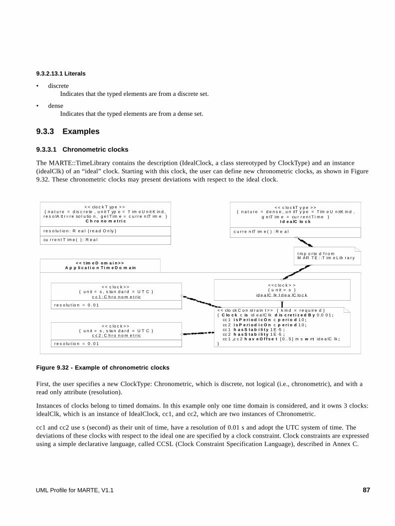
9.3.2.13.1 Literals
• discrete Indicates that the typed elements are from a discrete set.
• dense Indicates that the typed elements are from a dense set.
9.3.3 Examples
9.3.3.1 Chronometric clocks
The MARTE::TimeLibrary contains the description (IdealClock, a class stereotyped by ClockType) and an instance (idealClk) of an “ideal” clock. Starting with this clock, the user can define new chronometric clocks, as shown in Figure 9.32. These chronometric clocks may present deviations with respect to the ideal clock.
Figure 9.32 - Example of chronometric clocks
First, the user specifies a new ClockType: Chronometric, which is discrete, not logical (i.e., chronometric), and with a read only attribute (resolution).
Instances of clocks belong to timed domains. In this example only one time domain is considered, and it owns 3 clocks: idealClk, which is an instance of IdealClock, cc1, and cc2, which are two instances of Chronometric.
cc1 and cc2 use s (second) as their unit of time, have a resolution of 0.01 s and adopt the UTC system of time. The deviations of these clocks with respect to the ideal one are specified by a clock constraint. Clock constraints are expressed using a simple declarative language, called CCSL (Clock Constraint Specification Language), described in Annex C.
cu r r e n t T im e ( ) : R e a l
r e s o lu t io n : R e a l { r e a d O n ly }
< < clo c k T yp e > >{ n a t u r e = d is c r e te , u n it T yp e = T im e U n it K in d ,r e s o lA tt r = r e so l u tio n , g e t T im e = c u r r e n tT im e }
C h ro n o m e t r i c
r e s o lu t io n = 0 . 0 1
< < c lo c k > >{ u n it = s , s ta n d a r d = U T C }
c c 1 : C h r o n o m e t r ic
r e s o lu t io n = 0 . 0 1
< < c lo c k > >{ u n it = s , s ta n d a r d = U T C }
c c 2 : C h r o n o m e t r ic
< < clo ck C o n st r a in t > > { k in d = r e q u ir e d }{ C lo c k c is id e a lC lk d is c re t i z e d B y 0 .0 0 1 ; cc 1 i s P e r i o d i c O n c p e r i o d 1 0 ; cc 2 i s P e r i o d i c O n c p e r i o d 1 0 ; cc 1 h a s S t a b i li t y 1 E -5 ; cc 2 h a s S t a b i li t y 1 E -5 ; cc 1 ,c c 2 h a v e O f f s e t [ 0 .. 5 ] m s w r t id e a lC lk ;}
< < c lo c k > >{ u n it = s }
id e a lC lk :I d e a lC lo c k
c u r r e n tT im e ( ) : R e a l
< < c lo c kT y p e > >{ n a t u r e = d e n s e , u n itT y p e = T im e U n itK in d ,
g e tT im e = cu r r e n t T i m e }I d e a lC lo c k
I m p o r te d f r o m M AR T E : :T im e L ib r a r y
< < t im e D o m a i n > >A p p li c a t i o n T i m e D o m a in
UML Profile for MARTE, V1.1 87

The clock constraint in Figure 9.32 imposes to cc1 and cc2 to be almost periodic (stability=10-5), with a period of 10 ms, and with an offset between the two clocks no greater than 5 ms. Note that the 10 ms period must be consistent with the given resolution (0.01 s = 10 ms). The first line, in the body of the constraint, declares a clock c, local to the constraint and not part of the system. c is defined as an ideal discrete clock whose resolution is 0.001 s = 1 ms. The other lines are constraints. Figure 9.33 represents a time structure that satisfies the given clock constraint.
Figure 9.33 - Instants of clocks cc1 and cc2
9.3.3.2 Logical Clocks
In this simplified example, a processor executes the same code for several controllers (Figure 9.34). The processor is a Voltage Scaling processor: its frequency can be dynamically controlled. For simplicity, only two frequencies are considered: the frequency in the full power mode, and the frequency in the low power mode, which is half the former. The Boolean attribute inLowPower indicates the running mode of the processor. The control must be applied periodically (the period attribute of the Controller) by executing some code (pidCode which is an OpaqueBehavior). The behavior of the controller is specified by a state machine (ctrlBeh).
Figure 9.34 - Example of timed control
pidCode is a behavior that is executed in a fixed and known number of processor cycles. This can be modeled with a logical clock. To this end, the class Processor is stereotyped by ClockType. This mixture of physical time (period of activation) and logical time (execution duration expressed in processor cycles) is usual in control applications. Figure 9.35 represents instances and a clock constraint. The TimedDomain is not explicitly represented. There are two instances of Controller, with periods of activation equal to 1 and 2 ms, respectively. Each execution of pidCode takes 100 cycles of the processor, which is expressed by a TimedProcessing. The dependency between the processor cycle duration and the physical time is specified by a ClockConstraint. The constraint specification indicates that the local Clock c is a discrete clock with a period of 1 us (1E-6 s). Clock pr is derived from c. The period of pr is 20 us when running in the low power mode, and 10 us in the full power mode. The trigger of the transition labeled “after p” in the state machine, implicitly declares a TimeEvent with isRelative = true and when = p. This TimeEvent is stereotyped by TimedEvent with on = idealClk.
(c)cc1cc2
offset of cc1 vs . cc2
cc1.period
idealClk10 ms 1 ms
in Low P ow er: B o ole anre so lut io n: R ea l { re adO nly }
< < c lock T ype >>{ na tu re =dis c re te,
re solA t t r=r es olu ti on,isLo gical }
P ro c ess o r p er iod: NF P _D ura ti on
C o n tro l l er
pro c c tr l
0 .. *1
s tm c tr lB eh ( p: N F P _Du rat io n )
en tr y/ pid Co de
a f te r p
88 UML Profile for MARTE, V1.1

Figure 9.35 - Clocks and TimedProcessing
reso lution = 1
<<clock>>pr:Pr ocessor
<<clock >>{ unit = s }
idea lClk:Idea lClock
<<clockConstrain t>>{ Clock c is idealC lk discretizedBy1E- 6; pr = c filteredBy 0B( 1.0^19) if pr.inLowPower; p r = c filteredBy 0B(1 .0^9) if not pr .inLowPower;}
pe riod = (va lue=1,un it=ms)
c1 : Control ler
per iod = ( va lue=2,unit=ms)
c2: Contro ller
<<timedProcessing>>{ on = pr,
dura tion = 100 }<<opaqueBehavio r>>
pidCode
UML Profile for MARTE, V1.1 89

90 UML Profile for MARTE, V1.1

10 Generic Resource Modeling (GRM)
10.1 Overview
The objective of this package is to offer the concepts that are necessary to model a general platform for executing real-time embedded applications. The generic resource model (GRM) includes the features that are required for dealing with:
• Modeling of executing platforms at different level of details. The level of granularity needed for platform modeling depends on the concern motivating the description of the platform, as for example the type of the platform, the type of the application, or the type of analysis to be carried out on the model.
• Modeling of both “hardware” (e.g., memory units or physical communication channels) and “software” (e.g., real-time operating systems) platform.
• Providing foundational modeling constructs that are later refined to support design (SRM & HRM) as well as analysis (GQAM, SAM & PAM) models.
Both 14.1, ’Software Resource Modeling (SRM)’ and 14.2, ’Hardware Resource Modeling (HRM)’ provide a specialization of this general resource model for software and hardware related platforms respectively.
Figure 10.1 describes the dependencies of the GRM package with other sub-packages of MARTE.
Figure 10.1 - Dependencies of the GeneralResourceModel (GRM) package
The different facets of the GRM are grouped in individual packages, following the structure shown in Figure 10.2:
• The ResourceCore package defines the basic elements and their relationships.
• The ResourceTypes package defines fundamental types of resources as well as the basic services that they provide.
• The ResourceManagement package defines specific management resources and their associated services.
UML Profile for MARTE, V1.1 91

Figure 10.2 - Architecture of the GeneralResourceModel (GRM) package
The purpose and contents of each sub-package are described in the following sub clauses.
10.2 Domain View
10.2.1 The ResourceCore Package
The basic partitioning into classifiers and instances made in the Foundations package is used here to describe the nature of the basic resource elements, depicted in the class diagram in Figure 10.3. The central concept of the GRM is the notion of a Resource. A Resource represents a physically or logically persistent entity that offers one or more ResourceServices. Resources and its services are the available means to perform the expected duties and/or satisfy the requirements for which the system under consideration is aimed.
Figure 10.3 - Instance/Classifier nature of core resource elements
MARTE::CoreElements::Foundations::Classifier
resMu lt: In teger [0..1]
Reso urce
ResourceService
1..*
1co ntext
p Services{subset ownedbeh avior}
MARTE::Core Elements::Foundations::Instance
instance type
1..*0..*Reso urceInstance
Resource ServiceExecution
0..*
1co ntext
exeServices
insta nce
type
1..*
0..*
instance type
1..*0..*
MARTE::CoreElements::Causality ::Common Be havior::Beh avioredClassifier
MARTE::Co reElements::Cau sality::Commo nBehavior
::Behavior
*
context
1
ownedbehavior
MARTE::CoreElements::Causality ::RunTimeContext
::BehaviorExecutio n
92 UML Profile for MARTE, V1.1

As shown in Figure 10.4, Resources and their respective instances are also kinds of AnnotatedElements, hence values of non-functional properties (NFPs) may be annotated on them. In particular, as a type of classifier, Resources may have NFPs declared on it. As it is also shown in Figure 10.4, besides the NFP specifications, a resource has an optional set of referenced clocks, normally only one, but more in general.
Figure 10.4 - NFP annotations and reference Clocks of a Resource
A second orthogonal aspect, which is also very important, is the necessity to differentiate between application and platform elements. The latter are considered either as resources or resource services. Resources are used to model the execution platform from a structural point of view, while the resource services supply the behavioral point of view. A resource may be structurally described in terms of its internal resources - this is represented by the “owner-ownedElement” association in Resource inherited from the ModelElement meta-class. For example, a processing resource may be refined as a processor connected to a memory through a bus, if such level of detail is of interest for the modeler or for the analysis method to be applied to the model.
The reference clock of a resource may be either a chronometric (i.e., “physical”) clock or a logical clock. In any case, a clock is used as the reference unit for time related characteristics of the services provided by the resource. For example, considering chronometric clocks, the “processing time” associated with functions in a computation library may be expressed in terms of processor cycles rather than absolute time values. The reference clock (typically the processor clock) would then allow translating such values into physical times.
The optional attribute resMult (resource multiplicity) is used to express the limited nature of an aggregated multi elementary resource. When used it indicates the maximum number of instances of the elementary units of a particular type of resource that are available through its corresponding services.
Resource and ResourceService, as well as their corresponding instance-based concepts, ResourceInstance and ResourceServiceExecution respectively, may also provide and/or require non-functional properties. A ResourceServiceExecution is a kind of BehaviorExecution that represents a concrete instance of the realization of a service, in the context of the instance of a resource.
re sMu lt: In teger [0..1 ]
Resource
instance type
1..*0..*ResourceInstance
MARTE::NFPs::NFP_An notation::AnnotatedElement
ownedElement
owner
0..1
0..*
MARTE::NFPs::NFP_ declaration::NFP
* provided{subset value }
*
required{sub set value}
MARTE::Time::TimeAccesses ::Clocks::Clock
*
refe renceClocks
UML Profile for MARTE, V1.1 93

Figure 10.5 - Resource Reference, and ResourceAmount of the ResourceCore package
For convenience, as shown in Figure 10.5, two more abstract concepts are defined in this ResourceCore package:
• ResourceReference, to be used when modeling the dynamic creation of resources is required.
• ResourceAmount, representing a generic quantity of the “amount” provided by the resource. This may be mapped to any significant quantification of the resource, like memory units, utilization, power, etc.
A resource can be a “black box,” in which case only the provided services are visible, or a “white box,” in which case its internal structure, in terms of lower level resources, may be visible, and the services provided by the resource may be detailed based on collaborations of these lower level resources.
Note that in the case of the platform provider for example, it is up to the modeler to represent it as:
• One black box resource (e.g., a real-time operating system), which abstracts the hardware hence considered as internal elements.
• A collaboration between a software layer and a hardware layer.
• A collaboration between basically hardware elements. In this case, software features of the execution platform may be represented by overheads on raw hardware performance figure.
• Any combination of these previous approaches depending on the type of development and analysis method applied by the user.
The rationale for deciding if an element in the execution platform should be represented as a resource in the platform model is more related to its criticality in terms of real-time behavior, rather than to its software or hardware nature. Therefore, the interface (i.e., the set of services) provided by the execution platform as a whole may be much simpler than the API (Application Programming Interface) visible to the application software. Of course, a model library describing a given platform may provide several views, corresponding to different anticipated use cases for the platform.
As it occurs with classifiers, the execution platform may be represented as a hierarchical structure of resources.
10.2.2 The ResourceTypes Package
Figure 10.6 presents the basic resource types defined along with their specific attributes. Next a description of each of them is provided, including the interpretation of the resource base clock when necessary. A first characterization of resources can be done using the two additional attributes shown, isProtected and isActive. Each of the specialized kinds may be defined by considering the Boolean values for them. isProtected implies the necessity to arbitrate access to the resource or its services, while isActive means that it has its own course of action.
ResourceReference ResourceAmount
MARTE::CoreElements::Foundations::ModelElement
94 UML Profile for MARTE, V1.1

Figure 10.6 - Types of resources in the ResourceTypes package
• A StorageResource represents memory, and its capacity is expressed in number of elements; the size of an individual element in bits must be given. The reference clock corresponds to the pace at which data is updated in it, and hence it determines the time it takes to access to one individual memory element. The level of granularity in the amount of storage resources represented is up to the model designer. For example, if the storage resource represents a hard disk drive, the element could be a block or a sector, and the speed of the clock to access such element would be directly related to the disk rotation speed. The services provided by a storage resource are intended to move data between memory and a processing unit (which can be a computing resource or a communication endpoint).
• A TimingResource represents a hardware or software entity that is capable of following and evidencing the pace of time. It is defined as a kind of chronometric clock, and may represent a clock itself or a timer, in which case it acts according to the clock that it has as a reference. This concept is used to model the SPT TimingMechanism. According to the concrete kind of resource or timing mechanism that it represents, the referenced clock may be another chronometric clock or a logical clock, as defined in the Time clause. A timing resource may have concrete services for its management and operation. Figure 10.7 shows these services in the form of roles of associations with ResourceService in the model of timing resources.
Figure 10.7 - Timing resources
re sMult: Intege risPro tected : BooleanisActive : Boolean
GRM::ResourceCore::Resource
St orageResourc e
Comput ingResource
TimingRe sourceCommunicat ionResourc e
DeviceResourceConcurrencyResourceSy nchRe source
UML Profile for MARTE, V1.1 95
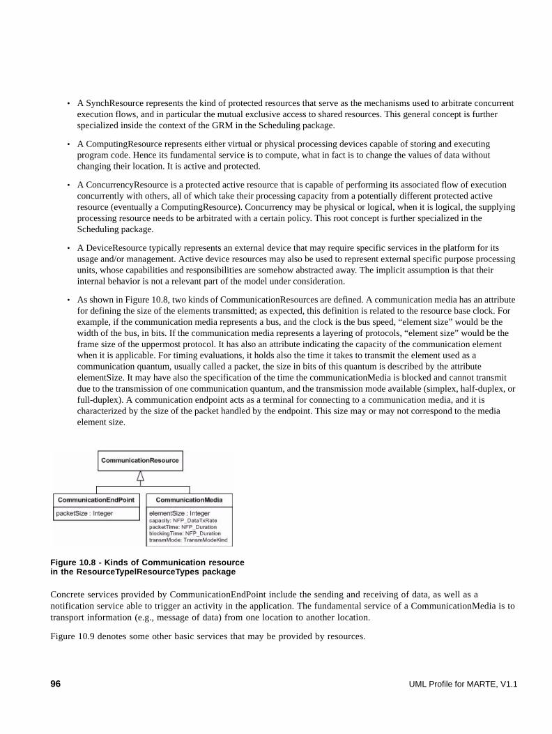
• A SynchResource represents the kind of protected resources that serve as the mechanisms used to arbitrate concurrent execution flows, and in particular the mutual exclusive access to shared resources. This general concept is further specialized inside the context of the GRM in the Scheduling package.
• A ComputingResource represents either virtual or physical processing devices capable of storing and executing program code. Hence its fundamental service is to compute, what in fact is to change the values of data without changing their location. It is active and protected.
• A ConcurrencyResource is a protected active resource that is capable of performing its associated flow of execution concurrently with others, all of which take their processing capacity from a potentially different protected active resource (eventually a ComputingResource). Concurrency may be physical or logical, when it is logical, the supplying processing resource needs to be arbitrated with a certain policy. This root concept is further specialized in the Scheduling package.
• A DeviceResource typically represents an external device that may require specific services in the platform for its usage and/or management. Active device resources may also be used to represent external specific purpose processing units, whose capabilities and responsibilities are somehow abstracted away. The implicit assumption is that their internal behavior is not a relevant part of the model under consideration.
• As shown in Figure 10.8, two kinds of CommunicationResources are defined. A communication media has an attribute for defining the size of the elements transmitted; as expected, this definition is related to the resource base clock. For example, if the communication media represents a bus, and the clock is the bus speed, “element size” would be the width of the bus, in bits. If the communication media represents a layering of protocols, “element size” would be the frame size of the uppermost protocol. It has also an attribute indicating the capacity of the communication element when it is applicable. For timing evaluations, it holds also the time it takes to transmit the element used as a communication quantum, usually called a packet, the size in bits of this quantum is described by the attribute elementSize. It may have also the specification of the time the communicationMedia is blocked and cannot transmit due to the transmission of one communication quantum, and the transmission mode available (simplex, half-duplex, or full-duplex). A communication endpoint acts as a terminal for connecting to a communication media, and it is characterized by the size of the packet handled by the endpoint. This size may or may not correspond to the media element size.
Figure 10.8 - Kinds of Communication resource in the ResourceTypelResourceTypes package
Concrete services provided by CommunicationEndPoint include the sending and receiving of data, as well as a notification service able to trigger an activity in the application. The fundamental service of a CommunicationMedia is to transport information (e.g., message of data) from one location to another location.
Figure 10.9 denotes some other basic services that may be provided by resources.
96 UML Profile for MARTE, V1.1

Figure 10.9 - Basic resource services of the ResourceTypeResourceTypes package
• Both Acquire and Release services correspond respectively to the allocation and de-allocation of some “amount" from the resource. For example, for a resource representing storage, the amount could be the memory size. As another example, a resource could represent a single element (maximum amount available is “1”), and acquire/release would be used to model mutual exclusive access.
• Activate corresponds to the application of a service on a given quantity. For example, activate a communication service with the amount of data to be transferred as a parameter.
• GetAmountAvailable returns the amount of the resource that is currently available.
The behavior shown by each service (acquire, release, activate, etc.) of a concrete resource that offers it, shall be described to the extent needed by the modeling concerns of that specific resource.
10.2.3 The ResourceManagement Package
The elements in this package serve for modeling various resource management services, such as those found in most operating systems. Figure 10.10 shows both types of resources that hold management services.
Figure 10.10 - Resource management
isBlocking: Boolea n
Acquire Relea se GetAmountAvailable Activate
1..*
+service
1..*
+amo unt
1..*
+amou nt
1..*
+ amount
GRM: :ResourceCore::ResourceService
GRM::ResourceCore::Resource Amount
GRM::ResourceCore: :Resource
Resource Broker ResourceManager
brokedResource
broker *
1..*
managedResource
manager0..1
1 ..*
ResourceControlPolicy
resCtrlPolicy
*
1..*
AccessControlPolicy
accCtrlPolicy
*
1..*
UML Profile for MARTE, V1.1 97
The ResourceBroker is a kind of resource that is responsible for allocation and de-allocation of a set of resource instances (or their services) to clients according to a specific access control policy. For example, a memory manager will allocate memory from a heap upon request from a client and also return it back into the heap once the client no longer needs it. The access control policy determines the criteria for determining and making effective the provision of resources, it can impose limitations on the prioritization of competing requests, or on the amount of memory provided to individual clients, etc.
On the other hand, the ResourceManager is responsible for creating, maintaining, and deleting resources according to a resource control policy. For example, a buffer pool manager is responsible for creating a set of buffers from one or more chunks of heap memory. Once created and initialized, the resources are typically handed over to a resource broker. In most practical cases, the resource manager and the resource broker are the same entity. However, since this is not always true the two concepts are modeled separately (they can be easily combined by designating the same entity as serving both purposes).
10.2.4 The Scheduling Package
Scheduling is the way of arranging behavior at run-time. At this level of description a Scheduler is defined as a kind of ResourceBroker that brings access to its brokered ProcessingResource or resources following a certain scheduling policy. The concept of scheduling policy as it is presented here corresponds to the scheduling mechanism described in sub clause 6.1.1 of SPT, since it refers specifically to the order to choose threads for execution. A ProcessingResource generalizes the concepts of CommunicationMedia, ComputingResource, and active DeviceResource. It introduces an element that abstracts the fundamental capability of performing any behavior assigned to the active classifiers of the modeled system. Fractions of this capacity are brought to the SchedulableResources that require it.
A SchedulableResource is defined as a kind of ConcurrencyResource with logical concurrency. This means that it takes the processing capacity from another active protected resource, usually a ProcessingResource, and competes for it with others linked to the same scheduler under the basis of the concrete scheduling parameters that each SchedulableResource has associated. In the case of hierarchical scheduling, schedulers other than the main scheduler are represented by the SecondaryScheduler concept. This kind of schedulers do not receive processing capacity directly from a processing resource, instead they receive it from a SchedulableResource, which is in its turn effectively scheduled by another scheduler. These intermediate SchedulableResource, play the role of a virtual processing resource, conducting the fraction of capacity they receive from their host scheduler to its dependent secondaryScheduler.
Figure 10.11 shows the relationships between all these elements, as well as the various kinds of scheduling policies and the corresponding scheduling parameters.
98 UML Profile for MARTE, V1.1

Figure 10.11 - The Scheduling package
For a scheduler, the description of an offline schedule is expressed either by an opaque expression or by a table with the timeslots corresponding to the different schedulable resources that will represent the partitioned available capacity.
When the executionBehaviors of concurrencyResources need to access common protected resources, the underlying scheduling mechanisms are typically implemented using some form of synchronization resource, (semaphore, mutex, etc.) with a protecting protocol to avoid priority inversions. Other solutions avoid this concurrency issue by creating specific schedules that order the access in advance. Whichever mechanism is used, the pertinent abstraction at this level of specification requires at least the identification of the common resource, its protecting mechanism, and the associated protocol; this is what the MutualExclusionResource defines. Figure 10.12 shows this element. Its associated protocol, represented by MutualExclusiveProtocol, is derived from the policy associated to the scheduler that manages it, and the parameters required by the protocol are represented by the ProtectionParameters element.
Scheduling
GRM::ResourceCore::Resource
GRM::ResourceManagement::ResourceBroker
speedFactor: NFP_Real = {value = 1.0}
ProcessingResource
broker brokedResource
1..**
SchedulableResource
GRM::ResourceManagement::AccessControlPolicy
accCtrlPolicy
*1..*
schedule:ScheduleSpecification
Scheduler
GRM::ResourceTypes::ComputingResource
GRM::ResourceTypes::CommunicationMedia
1..**
processingUnits{subset brokedResource}
1
0..* schedulableResource
host
GRM::ResourceTypes::ConcurrencyResource SchedulingParameters
schedParams
*
1
0..1 mainScheduler
SecondaryScheduler
dependentScheduler
virtualProcessingUnits 1..*
0..1
1host
policy{subset accCtrlPolicy}
*1
policy: SchedPolicyKindotherSchedPolicy: String
SchedulinglPolicy
EarliestDeadlineFirstFIFOFixedPriorityLeastLaxityFirstRoundRobinTimeTableDrivenUndefOther
« enumeration »SchedPolicyKind
GRM::ResourceTypes::DeviceResource
{isActive=True}
UML Profile for MARTE, V1.1 99
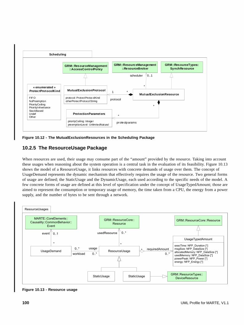
Figure 10.12 - The MutualExclusionResources in the Scheduling Package
10.2.5 The ResourceUsage Package
When resources are used, their usage may consume part of the “amount” provided by the resource. Taking into account these usages when reasoning about the system operation is a central task in the evaluation of its feasibility. Figure 10.13 shows the model of a ResourceUsage, it links resources with concrete demands of usage over them. The concept of UsageDemand represents the dynamic mechanism that effectively requires the usage of the resource. Two general forms of usage are defined; the StaticUsage and the DynamicUsage, each used according to the specific needs of the model. A few concrete forms of usage are defined at this level of specification under the concept of UsageTypedAmount; those are aimed to represent the consumption or temporary usage of memory, the time taken from a CPU, the energy from a power supply, and the number of bytes to be sent through a network.
Figure 10.13 - Resource usage
Scheduling
GRM::ResourceTypes::SynchResource
MutualExclusionResource
GRM::ResourceManagement::AccessControlPolicy
protocol: ProtectProtocolKindotherProtec tProtocol:String
MutualExclusionProtocol
protocol
*1
priorityCeiling: IntegerpreemptionLevel: UnlimitedNatural
ProtectionParameters
protectparams
*
*
GRM::ResourceManagement::ResourceBroker
scheduler
*
0..1
FIF ONoPreemptionPriorityCeilingPriorityInheritanceStackBasedUndefOther
« enumerated »ProtectProtocolKind
ResourceUsages
GRM::ResourceCore::ResourceGRM::ResourceCore::Resource
execTime: NFP_Duration [*]msgSize: NFP_DataSize [*]allocatedMemory: NFP_DataSize [*]usedMemory: NFP_DataSize [*]powerPeak: NFP_Power [*]energy: NFP_Energy [*]
UsageTypedAmount
UsageDemand
MARTE::CoreElements::Causaility::CommonBehavior::
Event
0..** requiredAmount
0..*
0..*
workload
usage
StaticUsage
event
*
0..1
GRM::ResourceTypes::DeviceResource
usedResource
*
0..*
StaticUsage
ResourceUsage
100 UML Profile for MARTE, V1.1

10.3 UML Representation
This sub clause describes the UML extensions provided to support the concepts defined in the presented domain view. The stereotypes here provided are generic and may be used at different levels of specification.
In order to get the maximum flexibility in the ways of applying the proposed stereotypes, most of the UML elements extended, are extended by the generic stereotype Resource. Then, through inheritance the large majority of stereotypes in GRM may extend elements like Property, InstanceSpecification, Classifier, Lifeline, and ConnectableElement. In particular, they might be applied for example to Classifiers, as well as to InstanceSpecifications of those very same Classifiers. In this case it is worth to consider the rules described in Section 7.3 for the usage of a stereotype in such situations. According to this rule when a stereotype is applied on an instance, the value of the attributes not explicitly assigned in the annotation of the instance are taken in principle from the defaults in the profile stereotype definition, but they might have to be taken from the annotation of the same stereotype on its corresponding classifier, which may have overwrote them, making effective with it the classifier nature of the annotation.
10.3.1 Profile Diagrams
The UML extensions for the modeling of resources at this level of specification are provided in the MARTE::GRM profile and the MARTE::MARTE_Library::GRM_BasicTypes model library. They are shown in separate figures for convenience.
Figure 10.14 shows the stereotypes defined for the root concepts defined for the modeling of resources. Figure 10.16 shows the relationships between stereotypes defined for scheduling. Figure 10.17 shows the UML elements that may be extended with the GrService stereotype. And Figure 10.19 shows for convenience the model library that collects all the utilitarian types defined for the GRM profile and which is formally presented in Annex D.
The MARTE::GRM package (stereotyped as profile) defines how the elements of the domain model extend metaclasses of the UML metamodel. All the stereotypes defined in the GRM profile are then listed and described in alphabetical order. The semantic descriptions of the concepts that these stereotypes represent are provided along 10.2 ”Domain View” on page 92. And the detailed descriptions of their corresponding concepts in the domain view are presented in Annex F. Finally the elements in the GRM_Basic_Types model library are also described in alphabetical order.
UML Profile for MARTE, V1.1 101

Figure 10.14 - UML extensions for GeneralResourceModeling
« profile »GRM
« metaclass »UML::Classes::Kernel::
Classifier
resMult: NFP_Integer = 1isProtected: Boolean isActive: Boolean
« stereotype»Resource
« metaclass »UML::Classes::Kernel::InstanceSpecification
« stereotype »ComputingResource
elementSize: NFP_Integer
« stereotype »CommunicationMedia
schedParams: schedParameters[0..*]isActive:Boolean=true{IsReadOnly}
« stereotype »SchedulableResource
protectKind: ProtectProtocolKind=priorityInheritanceceiling: NFP_IntegerotherProtectProtocol: StringisProtected:Boolean=true{IsReadOnly}
« stereotype »MutualExclusionResource
« stereotype »DeviceResource
packetSize: NFP_Integer
« stereotype »CommunicationEndPoint
elementSize: NFP_Integer
« stereotype »StorageResource
isPreemptible: Boolean = trueschedPolicy: SchedPolicyKind = FixedPriorityotherSchedPolicy: Stringschedule: ScheduleSpecification
« stereotype »Scheduler
speedFactor: NFP_Real
« stereotype »ProcessingResource
« stereotype »SecondaryScheduler
« metaclass »UML::Classes::Kernel::
Property
« stereotype »SynchronizationResource
« stereotype »ConcurrencyResource
« metaclass »UML::Interaction::Basic
Interactions::Lifeline
« metaclass »UML::CompositeStructures::
InternalStructures::ConnectableElement
« metaclass »UML::CompositeStructures::
InternalStructures::Connector
102 UML Profile for MARTE, V1.1
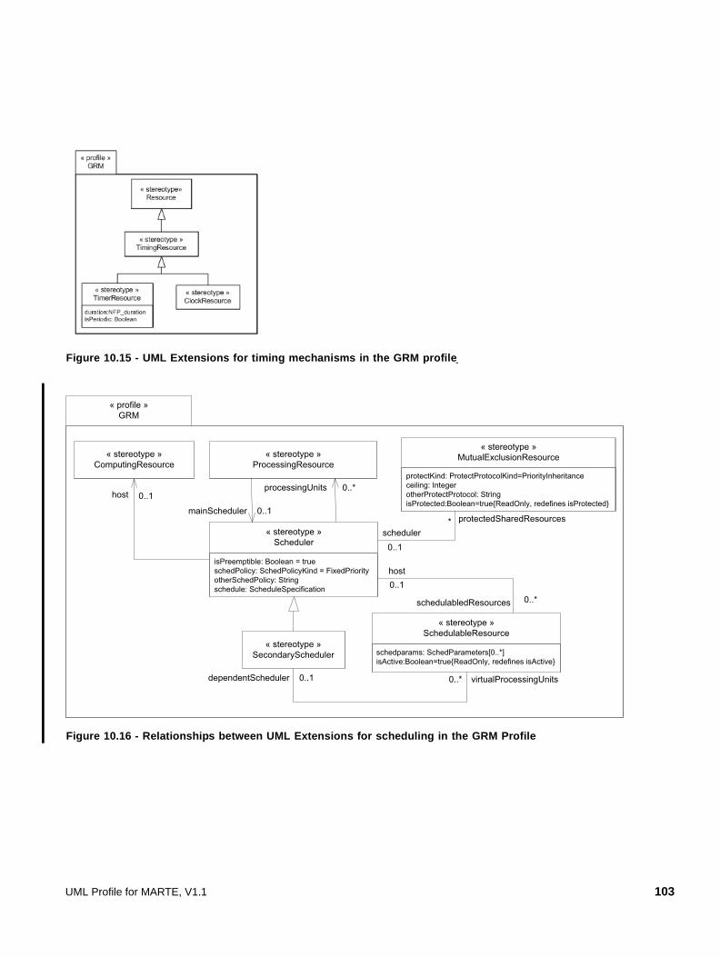
Figure 10.15 - UML Extensions for timing mechanisms in the GRM profile
Figure 10.16 - Relationships between UML Extensions for scheduling in the GRM Profile
« profile »GRM
schedparams: SchedParameters[0..*]isActive:Boolean=true{ReadOnly, redefines isActive}
« stereotype »SchedulableResource
protectKind: ProtectProtocolKind=PriorityInheritanceceiling: IntegerotherProtectProtocol: StringisProtected:Boolean=true{ReadOnly, redefines isProtected}
« stereotype »MutualExclusionResource
isPreemptible: Boolean = trueschedPolicy: SchedPolicyKind = FixedPriorityotherSchedPolicy: Stringschedule: ScheduleSpecification
« stereotype »Scheduler
« stereotype »ProcessingResource
« stereotype »SecondaryScheduler
schedulabledResources
host0..1
0..*
dependentScheduler virtualProcessingUnits0..*0..1
host 0..1processingUnits 0..*
mainScheduler 0..1*
scheduler0..1
protectedSharedResources
« stereotype »ComputingResource
UML Profile for MARTE, V1.1 103

Figure 10.17 - UML Extensions for Services in the GRM Profile
Figure 10.18 - UML Extensions for resource usage in the GRM Profile
« profile »GRM
execTime: NFP_Duration {ordered} [*]msgSize: NFP_DataSize {ordered} [*]allocatedMemory: NFP_DataSize {ordered} [*]usedMemory: NFP_DataSize {ordered} [*]powerPeak:NFP_Power {ordered} [*]enery:NFP_Energy {ordered} [*]
« stereotype»ResourceUsage
« stereotype»Resource
{ordered}usedResources
*
« metaclass »UML::Classes::Kernel::NamedElement
*{ordered}subUsage
104 UML Profile for MARTE, V1.1
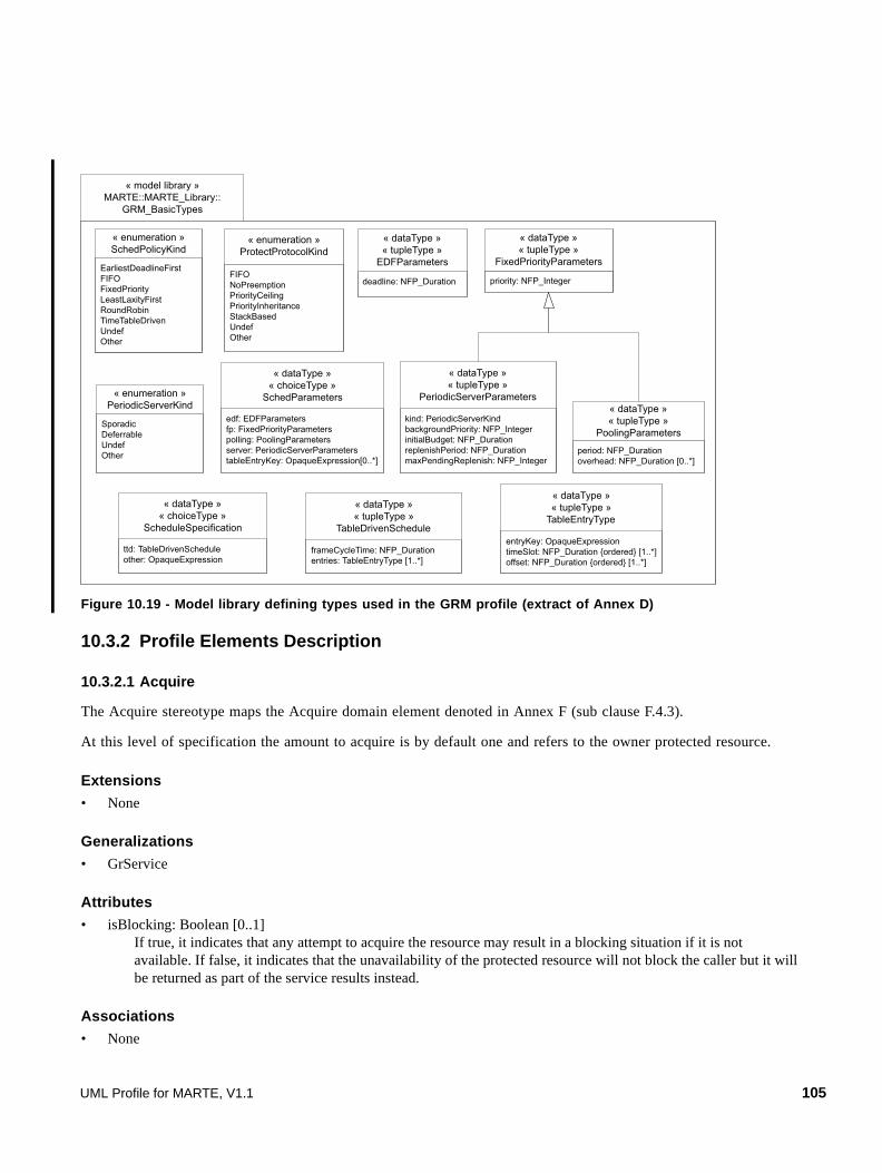
Figure 10.19 - Model library defining types used in the GRM profile (extract of Annex D)
10.3.2 Profile Elements Description
10.3.2.1 Acquire
The Acquire stereotype maps the Acquire domain element denoted in Annex F (sub clause F.4.3).
At this level of specification the amount to acquire is by default one and refers to the owner protected resource.
Extensions
• None
Generalizations
• GrService
Attributes
• isBlocking: Boolean [0..1] If true, it indicates that any attempt to acquire the resource may result in a blocking situation if it is not available. If false, it indicates that the unavailability of the protected resource will not block the caller but it will be returned as part of the service results instead.
Associations
• None
« model library »MARTE::MARTE_Library::
GRM_BasicTypes
EarliestDeadlineFirstFIFOFixedPriorityLeastLaxityFirstRoundRobinTimeTableDrivenUndefOther
« enumeration »SchedPolicyKind
edf: EDFParametersfp: FixedPriorityParameterspolling: PoolingParametersserver: PeriodicServerParameterstableEntryKey: OpaqueExpression[0..*]
« dataType »« choiceType »
SchedParameters
FIFONoPreemptionPriorityCeilingPriorityInheritanceStackBasedUndefOther
« enumeration »ProtectProtocolKind
deadline: NFP_Duration
« dataType »« tupleType »
EDFParameters
priority: NFP_Integer
« dataType »« tupleType »
FixedPriorityParameters
kind: PeriodicServerKindbackgroundPriority: NFP_IntegerinitialBudget: NFP_DurationreplenishPeriod: NFP_DurationmaxPendingReplenish: NFP_Integer
« dataType »« tupleType »
PeriodicServerParameters
period: NFP_Durationoverhead: NFP_Duration [0..*]
« dataType »« tupleType »
PoolingParametersSporadicDeferrableUndefOther
« enumeration »PeriodicServerKind
frameCycleTime: NFP_Durationentries: TableEntryType [1..*]
« dataType »« tupleType »
TableDrivenScheduleentryKey: OpaqueExpressiontimeSlot: NFP_Duration {ordered} [1..*] offset: NFP_Duration {ordered} [1..*]
« dataType »« tupleType »
TableEntryType
ttd: TableDrivenScheduleother: OpaqueExpression
« dataType »« choiceType »
ScheduleSpecification
UML Profile for MARTE, V1.1 105

Constraints
[1] The resource that owns the service must be a protected resource (i.e., its attribute isProtected must be true).
10.3.2.2 ClockResource
The ClockResource stereotype maps the ClockResource domain element denoted in Annex F (sub clause F.4.5).
Extensions
• None
Generalizations
• TimingResource
Attributes
• None
Associations
• None
Constraints
• None
10.3.2.3 CommunicationEndPoint
The CommunicationEndPoint stereotype maps the CommunicationEndPoint domain element denoted in Annex F (sub clause F.4.6).
Extensions
• None
Generalizations
• Resource
Attributes
• packetSize: NFP_Integer[0..1] The size of the packet handled by the endpoint.
Associations
• None
Constraints
• None
10.3.2.4 CommunicationMedia
The CommunicationMedia stereotype maps the CommunicationMedia domain element denoted in Annex F (sub clause F.4.7).
106 UML Profile for MARTE, V1.1

Extensions
• Connector (from UML::CompositeStructures::InternalStructures).
Generalizations
• ProcessingResource
Attributes
• elementSize: NFP_Integer[0..1] Characterizes the size of the elements to be transmitted.
• capacity: NFP_DataTxRate [0..1] Capacity of the communication element when applicable link.
• packetT: NFP_Duration [0..1] Time to transmit the element used as a communication quantum, usually called a packet, the size in bits of this quantum is described by the attribute elementSize.
• blockT: NFP_Duration [0..1] Time the communicationMedia is blocked and cannot transmit due to the transmission of one communication quantum.
• transmMode: MARTE_Library::MARTE_DataTypes::TransmModeKind [0..1] Defines the transmission mode, one of the following values: {simplex, half-duplex, full-duplex}.
Associations
• None
Constraints
• None
10.3.2.5 ComputingResource
The ComputingResource stereotype maps the ComputingResource domain element denoted in Annex F (sub clause F.4.9).
Extensions
• None
Generalizations
• ProcessingResource
Attributes
• None
Associations
• None
Constraints
[1] The attribute isActive inherited from Resource is always true.
UML Profile for MARTE, V1.1 107
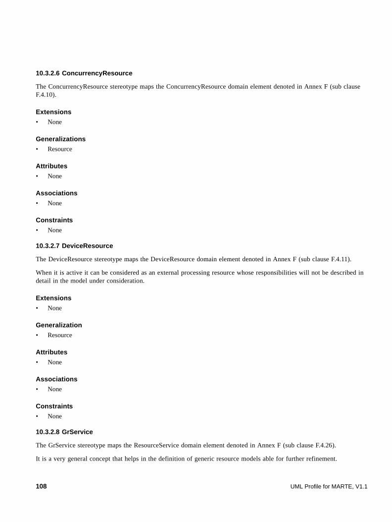
10.3.2.6 ConcurrencyResource
The ConcurrencyResource stereotype maps the ConcurrencyResource domain element denoted in Annex F (sub clause F.4.10).
Extensions
• None
Generalizations
• Resource
Attributes
• None
Associations
• None
Constraints
• None
10.3.2.7 DeviceResource
The DeviceResource stereotype maps the DeviceResource domain element denoted in Annex F (sub clause F.4.11).
When it is active it can be considered as an external processing resource whose responsibilities will not be described in detail in the model under consideration.
Extensions
• None
Generalization
• Resource
Attributes
• None
Associations
• None
Constraints
• None
10.3.2.8 GrService
The GrService stereotype maps the ResourceService domain element denoted in Annex F (sub clause F.4.26).
It is a very general concept that helps in the definition of generic resource models able for further refinement.
108 UML Profile for MARTE, V1.1

Extensions
• Behavior (from UML::CommonBehaviors::BasicBehaviors)
• BehaviorExecutionSpecification (from UML::Interactions::BasicInteractions)
• BehavioralFeature (from UML::Classes::Kernel)
• Collaboration (from UML::CompositeStructures::Collaborations)
• CollaborationUse (from UML::CompositeStructures::Collaborations)
Generalizations
• None
Attributes
• owner: Resource [0..1] Refers to the resource that owns the represented service.
Associations
• None
Constraints
• None
10.3.2.9 MutualExclusionResource
The MutualExclusionResource stereotype maps the MutualExclusionResource domain element denoted in Annex F (sub clause F.4.15).
Extensions
• None
Generalizations
• Resource
Attributes
• ceiling: NFP_Integer [0..1] Determines the concrete parameter used to characterize the protection access protocol, it is used for the PriorityCeiling and the StackBased protocols. For the latter only positive values are to be used. It holds the concept of ProtectionParameters of the domain model.
• otherProtectProtocol: String [0..1] Is used to annotate a protocol that is not included among the values of the ProtectProtocolKind enumerated type.
• protectKind: ProtectProtocolKind [0..1]=PriorityInheritance Determines the type of protection protocol used to access the resource.
• isProtected: Boolean = true {readOnly, redefines isProtected}
UML Profile for MARTE, V1.1 109

Associations
• scheduler: Scheduler [0..1] Refers to the scheduler that will implement the protection protocol.
Constraints
[1] The attribute isProtected inherited from Resource is always true.
[2] The scheduling policy of the scheduler must be compatible to the kind of protectKind given to the MutualExclusionResource.
10.3.2.10 ProcessingResource
The ProcessingResource stereotype maps the ProcessingResource domain element denoted in Annex F (sub clause F.4.16).
It is an active, protected, executing-type resource that is allocated to the execution of schedulable resources, and hence any actions that use those schedulable resources to execute. In general, they abstract the processing capabilities of a computing resource, a communication media, or an active external device.
Extensions
• None
Generalizations
• Resource
Attributes
• speedFactor: Real [0..1] = (value=1.0) Is a relative factor for annotating the processing speed expressed as a ratio to the speed of the reference processingResource for the system under consideration. The amount of resource usages specified for the entities in further usage models (like execution times for schedulability) assume a normative value of 1.0, which means that they have been measured or estimated either in respect to the reference system platform or directly over the platform used if it has speedFactor equal to 1.0.
Associations
• mainScheduler: Scheduler [0..1] Is the scheduler that controls the access to its processing capacity.
Constraints
• None
10.3.2.11 Release
The Release stereotype maps the Release domain element denoted in Annex F (F.4.19).
At this level of specification the amount release is by default one and refers to the owner protected resource.
Extensions
• None
110 UML Profile for MARTE, V1.1
Generalizations
• GrService
Attributes
• None
Associations
• None
Constraints
[1] The resource that owns the service must be a protected resource (i.e., its attribute isProtected must be true).
10.3.2.12 Resource
The Resource stereotype maps both Resource denoted in Annex F (F.4.20) and ResourceInstance domain elements (F.4.23).
It is provided for further refinement and for the representation of generic resources from a holistic system wide perspective. The nature of the concrete element extended defines the domain concept that it represents.
Extensions
• InstanceSpecification (from UML::Classes::Kernel)
• Classifier (from UML::Classes::Kernel)
• Property (from UML::Classes::Kernel)
• Lifeline (from UML::Interactions::BasicInteractions)
• ConnectableElement (from UML::CompositeStructures::InternalStructures)
Generalizations
• None
Attributes
• resMult: NFP_Integer [0..1] = 1 Indicates the multiplicity of a resource. For a classifier it may specify the maximum number of instances of the resource considered as available. By default only one instance is available.
• isProtected: Boolean [0..1] If true, it indicates that the access to the resource is protected by some kind of brokeringResource.
• isActive: Boolean [0..1] If true, it indicates that the resource has an initial behavior associated that allows it to possibly perform its services autonomously or by the triggering and animation of behaviors on others.
Associations
• None
UML Profile for MARTE, V1.1 111

Constraints
• None
10.3.2.13 ResourceUsage
The ResourceUsage stereotype maps both ResourceUsage denoted in Annex F (F.4.27) and UsageTypedAmount (F.4.43) domain elements.
Extensions
• NamedElement (from UML::Classes::Kernel)
Generalizations
• None
Attributes
• execTime: NFP_Duration {ordered} [*] Time that the resource is in use due to the usage.
• msgSize: NFP_DataSize {ordered} [*] Amount of data transmitted by the resource.
• allocatedMemory: NFP_DataSize {ordered} [*] Amount of memory that is demanded from or returned to the resource. It may be a positive or negative value.
• usedMemory: NFP_DataSize {ordered} [*] Amount of memory that will be used from a resource but that will be immediately returned, and hence should be available while the usage is in course. This may be used to specify the required free space in the stack for example.
• powerPeak:NFP_Power {ordered} [*] Power that should be available from the resource for its usage.
• energy:NFP_Energy {ordered} [*] Amount of energy that will be permanently consumed from a resource due to the usage.
Associations
• usedResources: Resource [0..*] {ordered} List of resources that are used.
• subUsages: ResourceUsage {ordered} [0..*] List of resourceUsages used to complement the description of the resourceUsage and generate composite descriptions.
Constraints
[1] To consider the ResourceUsage fully specified, if the list usedResources is empty, the list subUsages should not be empty and vice versa. Further refinements of ResoureUsage may define additional attributes that may bring implicit elements into the usedResources list.
[2] If the list usedResources has only one element, all the optional lists of attributes (execTime, msgSize, allocatedMemory, usedMemory, powerPeak and energy) refer to this unique Resource and at least one of them
must be present.
112 UML Profile for MARTE, V1.1

[3] If the list usedResources has more than one element, all of the optional lists of attributes (execTime, msgSize, allocatedMemory, usedMemory, powerPeak, and energy) that are present, must have that number of elements, and they will be considered to match one to one.
[4] If the list subUsages is not empty, and any of the optional lists of attributes (execTime, packetSize, allocatedMemory, usedMemory, powerPeak, and energy) is present, then more than one annotation for the same resource and kind of usage may be expressed. In this case, if the annotations have also the same source and statistical qualifiers they will be considered in conflict, and hence the ResourceUsage inconsistent.
10.3.2.14 SchedulableResource
The SchedulableResource stereotype maps the SchedulableResource domain element denoted in Annex F (F.4.29).
It is an active resource able to perform actions using the processing capacity brought from a processing resource by the scheduler that manages it.
Extensions
• None
Generalizations
• Resource
Attributes
• schedParams: SchedParameters [0..*] Parameters used to compete for processing capacity.
• isActive: Boolean = true {readOnly, redefines isActive}.
Associations
• dependentScheduler: SecondaryScheduler [0..1] This scheduler takes its capacity from the schedulable resource, and in its turn shares it among its nested served schedulable resources.
• host: Scheduler [0..1] Is the scheduler that controls the processing capacity that will be shared among the demanding schedulable resources.
Constraints
[1] The policy used by the scheduler (host) must be compatible with the scheduling parameters (schedparams) of the schedulable resource. The following table establishes the rules for such compatibility.
SchedulingPolicy choiceAttribute(s) of the SchedulingParameters usedEarliestDeadlineFirst edf
FixedPriority fp, polling, or server
LeastLaxityFirst edf (combined with)/plus server
TimeTableDriven tableEntry
UML Profile for MARTE, V1.1 113

10.3.2.15 Scheduler
The Scheduler stereotype maps the Scheduler domain element denoted in Annex F (F.4.30).
Extensions
• None
Generalizations
• Resource
Attributes
• isPreemptible: Boolean [0..1] = true Qualifies the capacity of the scheduler for preempting schedulable resources once the access to the processing capacity has been granted upon the arrival of a new situation where a different schedulable resource has to execute.
• otherSchedPolicy: String Is used to annotate a scheduling policy that is not included among the values of the schedPolicyKind enumerated type.
• schedPolicy: schedPolicyKind [0..1] = fixedPriority Scheduling policy implemented by the scheduler.
• schedule: OpaqueExpression [0..1] Is the concrete schedule to use in the case of time table driven strategies. The format for expressing the times for activation and suspension, the cycle time as well as the number and identification of schedulable resources is user dependent.
Associations
• host: ComputingResource [0..1] Refers to the computing resource on which the scheduler runs. It may or may not be the same computing resource whose processing capacity it will control and share among the demanding schedulable resources.
• processingUnits: ProcessingResources [0..*] List of ProcessingResources whose processing capacity is shared by the scheduler among the schedulableResources it has associated.
• protectedSharedResources: MutualExclusionResource[0..*] List of the MutualExclusionResources to which access must be protected using the corresponding protocol.
• schedulableResources: SchedulableResource [0..*] List of schedulable resources that demand processing capacity from the scheduler.
Constraints
[1] The scheduling policy of the scheduler must be compatible with the scheduling parameters of all the schedulable resources that it has associated.
[2] The scheduling policy of the scheduler must be compatible with the ProtectProtocolParameters of all the associated MutualExclusionResources.
114 UML Profile for MARTE, V1.1

10.3.2.16 SecondaryScheduler
The SecondaryScheduler stereotype maps the SecondaryScheduler domain element denoted in Annex F (F.4.33).
A scheduler of this kind takes its capacity from the set of schedulable resources collected as virtual processing units, and in its turn shares it among its nested served schedulable resources.
Extensions
• None
Generalizations
• Scheduler
Attributes
• None
Associations
• virtualProcessingUnits: SchedulableResource [0..*] Set of virtual processing resources to whose processing capacity the secondary scheduler controls access.
Constraints
[1] A SecondaryScheduler takes its capacity from the virtualProcessingUnits list of schedulable resources, so it is not possible to have processing resources capacity through the processingUnits list inherited from Scheduler.
10.3.2.17 StorageResource
The StorageResource stereotype maps the StorageResource domain element denoted in Annex F (F.4.36).
Extensions
• None
Generalizations
• Resource
Attributes
• elementSize: NFP_Integer [0..1] Size in bits of the basic storage unit.
Associations
• None
Constraints
• None
UML Profile for MARTE, V1.1 115

10.3.2.18 SynchronizationResource
The SynchronizationResource stereotype maps the SynchResource domain element denoted in Annex F (F.4.37).
Extensions
• None
Generalizations
• Resource
Attributes
• None
Associations
• None
Constraints
• None
10.3.2.19 TimerResource
The TimerResource stereotype maps the TimerResource domain element denoted in Annex F (F.4.40).
Extensions
• None
Generalizations
• TimingResource
Attributes
• duration: NFP_Duration [0..1] Interval after which the timer will make evident the elapsed time.
• isPeriodic: Boolean [0..1] If true, the timer will indicate the arrival of a new finalization of the programmed interval in a periodic repetitive way. If false, it will do it only one time after it is started.
10.3.2.20 TimingResource
The TimingResource stereotype maps the TimingResource domain element denoted in Annex F (F.4.41).
Extensions
• None
Generalizations
• Resource
116 UML Profile for MARTE, V1.1

Attributes
• None
Associations
• None
Constraints
• None
10.3.3 GRM model library elements description
The description of all the elements in the model library for GRM are in Annex D4.
10.4 Examples
The general resource model is planned to be used not only for further extension in the software and hardware platform models, or in the analysis models of this specification, but also as a way to describe resources and platform architectures at a very high level, when design choices and analysis techniques to use for the verification are probably still undecided. The illustration in Figure 10.20 shows a simple example of the platform description for a teleoperated robot using a deployment diagram. This example is further revisited to illustrate the usage of schedulability analysis annotations in Section 16.3.3.
The system platform is composed of two processors interconnected through a CAN bus, and a robot arm whose servo control cards are connected by means of a backpanel VME bus.
Figure 10.20 - Simple example of usage of the GRM Profile at a high architectural level
<< C o mpu tin gR eso urc e>>{sp eed Fa ctor =(1 .0) }
NT _S tat ion
<< Co mp utin gR eso urc e>>{s pee dFa cto r=(0 .6)}
C on tro llerCA N_B us
<< D ev iceR es our ce>>{s pee dFa cto r=(1 .0)}
R obo t A rm
VME _B us
<< C om mu nica tio nM e dia>>{sp eed Fac tor= (1.0 )}
<< Co mm un icat ion M ed ia> >{s pee dF acto r=( 8.5 ) }
<< S tora ge Res our ce> >{el eme ntS ize =10 24 x 102 4 x8 ,
res M u lt=2 56 }
UML Profile for MARTE, V1.1 117
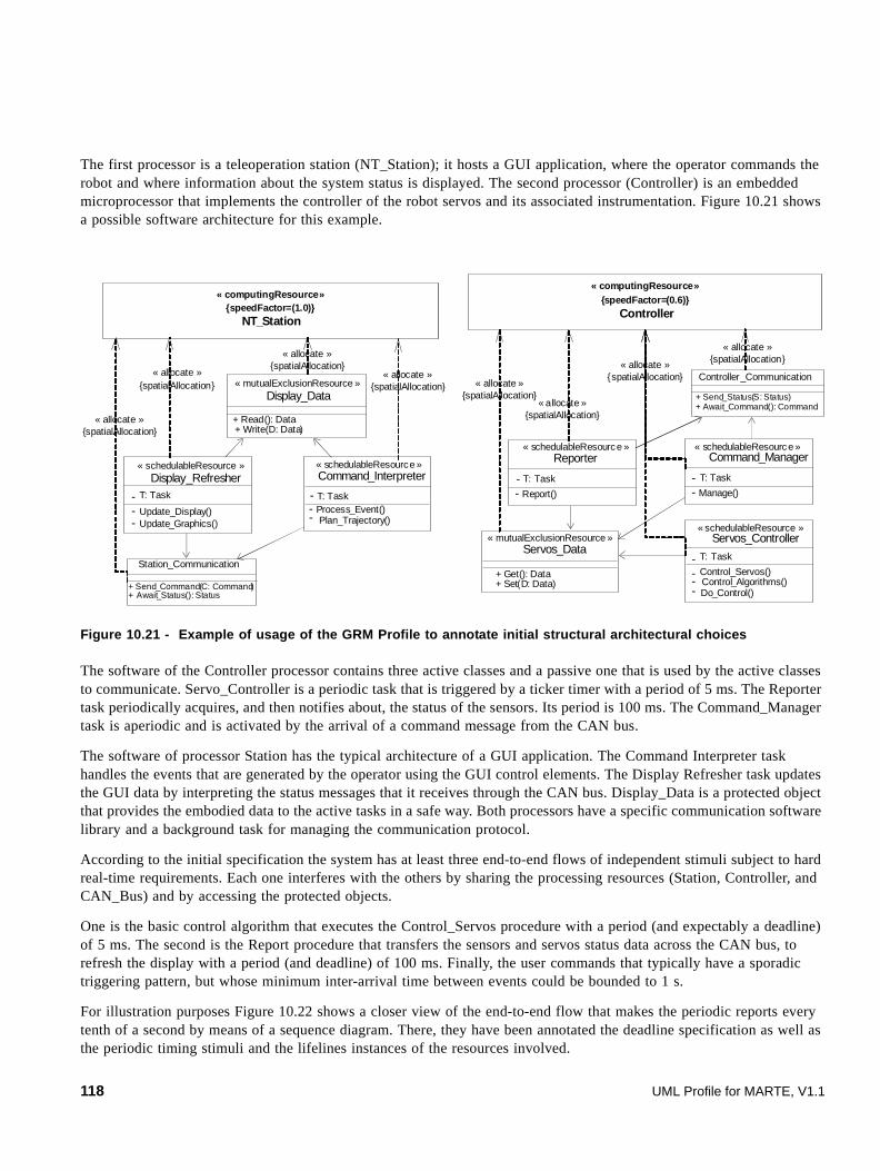
The first processor is a teleoperation station (NT_Station); it hosts a GUI application, where the operator commands the robot and where information about the system status is displayed. The second processor (Controller) is an embedded microprocessor that implements the controller of the robot servos and its associated instrumentation. Figure 10.21 shows a possible software architecture for this example.
Figure 10.21 - Example of usage of the GRM Profile to annotate initial structural architectural choices
The software of the Controller processor contains three active classes and a passive one that is used by the active classes to communicate. Servo_Controller is a periodic task that is triggered by a ticker timer with a period of 5 ms. The Reporter task periodically acquires, and then notifies about, the status of the sensors. Its period is 100 ms. The Command_Manager task is aperiodic and is activated by the arrival of a command message from the CAN bus.
The software of processor Station has the typical architecture of a GUI application. The Command Interpreter task handles the events that are generated by the operator using the GUI control elements. The Display Refresher task updates the GUI data by interpreting the status messages that it receives through the CAN bus. Display_Data is a protected object that provides the embodied data to the active tasks in a safe way. Both processors have a specific communication software library and a background task for managing the communication protocol.
According to the initial specification the system has at least three end-to-end flows of independent stimuli subject to hard real-time requirements. Each one interferes with the others by sharing the processing resources (Station, Controller, and CAN_Bus) and by accessing the protected objects.
One is the basic control algorithm that executes the Control_Servos procedure with a period (and expectably a deadline) of 5 ms. The second is the Report procedure that transfers the sensors and servos status data across the CAN bus, to refresh the display with a period (and deadline) of 100 ms. Finally, the user commands that typically have a sporadic triggering pattern, but whose minimum inter-arrival time between events could be bounded to 1 s.
For illustration purposes Figure 10.22 shows a closer view of the end-to-end flow that makes the periodic reports every tenth of a second by means of a sequence diagram. There, they have been annotated the deadline specification as well as the periodic timing stimuli and the lifelines instances of the resources involved.
« computingResource»{speedFactor=(0.6)}
Controller
« computingResource»{speedFactor=(1.0)}
NT_Station
Command_Interpreter
- T: Task- Process_Event()- Plan_Trajectory()
Display_Refresher
- T: Task
- Update_Display()- Update_Graphics()
« schedulableResource »
Display_Data
+ Read(): Data+ Write(D: Data)
« mutualExclusionResource »
Station_Communication
+ Send_Command(C: Command)+ Await_Status(): Status
« schedulableResource »
Servos_Controller
- T: Task
- Control_Servos()--
Control_Algorithms() Do_Control()
Reporter
- T: Task
- Report()
Command_Manager
- T: Task
- Manage()
Servos_Data
+ Get(): Data+ Set(D: Data)
Controller_Communication
+ Send_Status(S: Status)+ Await_Command(): Command
« schedulableResource »
« schedulableResource »
« schedulableResource »
« mutualExclusionResource »
« allocate »{spatialAllocation}
« allocate »{spatialAllocation}
« allocate »{spatialAllocation}
« allocate »{spatialAllocation} « allocate »
{spatialAllocation}« allocate »
{spatialAllocation}
« allocate »{spatialAllocation}
« allocate »{spatialAllocation}
118 UML Profile for MARTE, V1.1

Figure 10.22 - Use of the GRM Profile to annotate behavioral specification instances
<<TimerResource>>duration=( 0.1 ,s)
Controller_Clock
:ReporterComm
:CAN_Bus :Station_:Controller_Comm
:Display _Refresher
:Servos_Data
:Display_Data
Report
Send_StatusTransmit
Transmit_Command
Transmitted
Update_Display
Await_Status
{Init..Init+(0.1,s)}
Get
Read
Write
Update_Graphics
{return Await_Status}<<SchedulableResource >>
<<MutualExclusionResource>>
<<CommunicationMedia>>elementsize=64
<<MutualExclusionResource>>
<<SchedulableResource>>
<<SchedulableResource >>
<<SchedulableResource>>
<<ResourceUsage>>msgSize=(80,Bytes,max)usedResource=CAN_Bus
@Init
UML Profile for MARTE, V1.1 119

120 UML Profile for MARTE, V1.1

11 Allocation Modeling (Alloc)
11.1 Overview
This clause contains both domain and UML viewpoints for allocation modeling.
Allocation of functional application elements onto the available resources (the execution platform) is the main concern of real-time embedded system design. This comprises both spatial distribution and temporal scheduling aspects, in order to map various algorithmic operations onto available computing and communication resources and services.
The MARTE profile defines relevant application and execution platform models (Clause 13 and Clause 14). A MARTE allocation is an association between a MARTE application and a MARTE execution platform. Application elements may be any UML element suitable for modeling an application, with structural and behavioral aspects. An execution platform is represented as a set of connected resources, where each resource provides services to support the execution of the application. So resources are basically structural elements, while services are rather behavioral elements.
Application and execution platform models are built separately, before their pairing through the allocation process. Often this requires prior adjustment (inside each model) to abstract/refine its components to allow a direct match. Allocation can be viewed as a “horizontal” association, and abstraction/refinement layering as a “vertical” one, with the abstract version relying on constructs introduced in the more refined model. While different in role, allocation and refinement share a lot of formal aspects, and so both will be described here. This dual function was recognized in SPT, where allocation was called realization, while refinement was used as such.
Application and execution platform elements can be annotated with time information based on logical or physical clocks. Allocation and refinement should provide relations between these timing under the form of constraints between the clocks and their ticks. Other similar non-functional properties definable from the NFPs package (such as space requirement, cost, or power consumption) can also be considered.
Note – we do not use here the UML notion of deployment, but rather a SysML-inspired notion of allocation to emphasize the fact that Execution Platform models should themselves be abstract and not seen as concretization models.
In the simplest case application elements are untimed without explicit logical clocks attached. Asynchronous parts can also be attached to fully independent virtual clocks. In this simple case the timed allocation provides a physical duration (and maybe other constraints) to the execution of this given application function on this given execution platform service or resource. In the more general case timed allocations provide constraints between the virtual logical clocks on the application side and the more physical technical clocks on the platform side. Clocks on the application side can be important as they allow the user for visualizing a possible scheduling, maybe computed by subsequent tools and respecting the provided scheduling constraints, rather than being provided by the user himself.
Refinement (or its inverse abstraction) should also relate the more abstract clocks to the mode refined. On the application side, abstraction grouping could amount to performing a number of operations in a single instruction (by parallelization, vectorization, or by replacing a task body by a simple call to it). Atomic instants at some level can be subdivided into many micro-steps at a more refined level. On the execution platform side, abstraction can help define new services built as collaborations between resource elements and lower-level services; these services can be generic, or ad-hoc to help represent simply the allocation of application functions using them. Again here the clocks can be subdivided to represent the division of service calls into more atomic services.
UML Profile for MARTE, V1.1 121

Allocation can be specified in different kinds: Structural, behavioral, or hybrid. Structural allocation is an association between a group of structural elements and a group of resources. Behavioral allocation is an association between a set of behavioral elements and a service provided by the execution platform. When clear from context, hybrid allocations can also be allowed (for instance when an implicit service is uniquely defined for a resource). At the finer level of detail, behavioral allocation deals with the mapping of UML actions to resources and services.
The next sub clause considers how resources can be grouped to collaborate and provide a given service, possibly with a given scenario. The following sub clause describes the principles of the Allocation process (between two previously independent models). The last part deals with NFP annotations.
Grouping process (Abstraction/Refinement)
Allocations concerns groups of elements. Such grouping of resources was already included in the service definition. The intention is as follows: grouping, together with the associations already existing at each side (application or platform), should provide a way to represent a change of atomicity level (abstraction/refinement) inside each model. If a number of application actions (sets of instructions or subprogram) can be realized atomically as a platform service, itself being made of several resources collaborating according to a given scenario, then this scheme allows for linking them by an atomic mapping between the two models. The preliminary process of constructing the entities to be matched is conducted separately, inside each model. This shows a separation of concern between service definition and actual mapping of matching elements.
Groups of services could themselves be viewed as compound services. Keeping the two levels is useful to discriminate between generic services, built on the platform in full isolation, and ad-hoc services, only introduced to cover specific needs of a particular application.
Allocation process
Allocation results in both spatial distribution and temporal scheduling. Spatial distribution is the allocation of computations to processing elements, of data to memories, and of data/control dependencies to communication resources. Scheduling is the temporal/behavioral ordering of the activities (computations, data storage movements or communication) allocated to each resource. Scheduling is represented as a relation between the respective time bases of application and platform elements.
In turn, the potential analysis performed due to allocation mapping may refine “back” the temporal aspects of applications, to reflect the results of constraints (scheduling, resource allocation, and sharing) imposed by the execution platform. It may do so according to a possible refinement of the Time model at the application level.
Structural allocation enforces the corresponding behavioral allocation of encapsulated behaviors, so that contained elements “inherit” the allocation of compound structures unless otherwise stated at their level (and then the proper execution platform communication pattern should be feasible). For example, if a Behavior is executed in the context of a particular object, and this object is allocated to a particular ComputingResource C1 for execution, then any uml::CallBehaviorAction would by default use the “Call” service provided by C1. However, if the called Behavior belongs to an object to which another ComputingResource is allocated, it uses the “RemoteProcedureCall” service provided by C1 to reach C2 - assuming a communication path exists between C1 and C2.
The allocation model could offer different allocation alternatives for a given application element, so that there is an actual choice on how to map application functions and objects to various parts of the execution platform. The mapping can then be refined and made more precise in several ways by model transformations directed by analysis techniques.
Both spatial and temporal allocations have to be mutually and globally consistent to ensure a correct execution of the application by its deployment on the execution platform. This is in general the topic of analysis techniques that the current MARTE profile aims to offer. But the profile itself only describes the means to describe (total or partial)
122 UML Profile for MARTE, V1.1
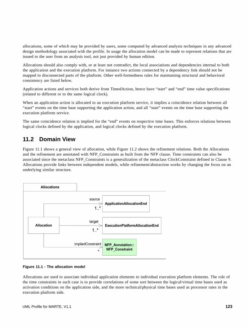
allocations, some of which may be provided by users, some computed by advanced analysis techniques in any advanced design methodology associated with the profile. In usage the allocation model can be made to represent relations that are issued to the user from an analysis tool, not just provided by human edition.
Allocations should also comply with, or at least not contradict, the local associations and dependencies internal to both the application and the execution platform. For instance two actions connected by a dependency link should not be mapped to disconnected parts of the platform. Other well-formedness rules for maintaining structural and behavioral consistency are listed below.
Application actions and services both derive from TimedAction, hence have “start” and “end” time value specifications (related to different or to the same logical clock).
When an application action is allocated to an execution platform service, it implies a coincidence relation between all “start” events on the time base supporting the application action, and all “start” events on the time base supporting the execution platform service.
The same coincidence relation is implied for the “end” events on respective time bases. This enforces relations between logical clocks defined by the application, and logical clocks defined by the execution platform.
11.2 Domain View
Figure 11.1 shows a general view of allocation, while Figure 11.2 shows the refinement relations. Both the Allocations and the refinement are annotated with NFP_Constraints as built from the NFP clause. Time constraints can also be associated since the metaclass NFP_Constraints is a generalization of the metaclass ClockConstraint defined in Clause 9. Allocations provide links between independent models, while refinement/abstraction works by changing the focus on an underlying similar structure.
Figure 11.1 - The allocation model
Allocations are used to associate individual application elements to individual execution platform elements. The role of the time constraints in such case is to provide correlations of some sort between the logical/virtual time bases used as activation conditions on the application side, and the more technical/physical time bases used as processor rates in the execution platform side.
UML Profile for MARTE, V1.1 123

Allocation as from SysML can map structural to structural, and behavioral to behavioral or structural elements. The refinement process generally involves the definition of additional constraints to precise links between the general element and the refined ones. For instance, one may want to specify how the time bases relates, how the bandwidth (or power consumption …) is spread among refined elements. The association with some NFPs::NFP_Annotations::NfpConstraint is a provision for defining such links.
Figure 11.2 - The Refinement model
Refinement can deal with both application models and execution platform model. A single element on the more abstract side can be associated with a number of elements (a group) in the more refined side. In case a group of (structural) resources and (behavioral) services are grouped to form a more abstract behavioral element (a higher-level service), then a collaboration use scenarios or something similar should be introduced to indicate how the cooperation of the more basic entities form the more abstract service is implemented.
For instance on the application side a “task” call can be refined as its body, or arrange of operations can be parallelized (or vectorized) as a single instruction. On the execution platform side a service or transaction can be realized by a sequence of protocol steps.
11.3 UML Representation
The UML view for allocation is strongly inspired from the SysML solution. The SysML solution is satisfactory, but we wanted to emphasize three important points:
1. The allocation is a mechanism aiming at defining a mapping from the logical parts (the application model elements) of the model to some more physical parts (the execution platform).
2. There can be several possible allocations and all of them imply a cost that affects the time budget, the power budget or the budget of any other non functional property.
3. There can be at least two reasons to make an allocation: to perform a spatial distribution of artifacts onto resources or resource services, or to schedule algorithmic parts onto available resources.
The allocation package includes all these three points.
124 UML Profile for MARTE, V1.1

11.3.1 Profile Diagrams
The first step is to identify what can be allocated, the logical view (behavior or structure), and what can serve as a target of an allocation, the physical view (a resource or a service). The stereotype Allocated (Figure 11.3) is used for this matter.
Figure 11.3 - The stereotype "allocated"
The second step is to identify what is allocated onto what and what are the reasons for such an allocation and what are the constraints implied by this allocation, hence the definition of the stereotype Allocate.
Figure 11.4 - The stereotype "allocate"
In addition, we define an alternative UML representation of the Allocation domain view metaclass, via the Assign stereotype. The Assign stereotype extends a UML metaclass: Comment with neutral semantics (instead of leveraging the semantics of Abstraction). It defines “from” / “to” attributes to indicate the ends of the assignment. Like an allocation, an assignment can be characterized by its “nature” (spatial or time distribution) and its “kind” (structural, behavioral, or hybrid). The optional body property of the Comment meta-class can be used to provide the justification of the assignment.
UML Profile for MARTE, V1.1 125

Figure 11.5 - The stereotype Assign
As in SysML, a special attention is given to activities since the notation is natural to allocate a set of actions to a structural element (classifier, instance or part). We define the stereotype AllocateActivityGroup (Figure 11.6), which name is less misleading than AllocateActivityPartition that would suggest an actual partition of activity nodes. We intend to represent possible allocations; we anticipate several cases where activity nodes will be shared by several allocate activity groups. In this case, that means the shared activity nodes can be allocated either to one activity partition (an instance of the classifier, the instance itself, or the instance playing the part represented by the activity partition) or to the other. The isUnique property explicitly prevents an activity node from being allocated to several groups. This does not mean the node cannot be shared by several groups, it only means that once we have made the final decision of the allocation, the node is actually allocated to only one group.
Figure 11.6 - The stereotype AllocateActivityGroup
For the purpose of specifying refinement, the abstraction mechanism offered by UML and the UML keyword refine are enough. Defining abstractions is useful in bottom-up approaches while making refinement is useful in top-down approach.
126 UML Profile for MARTE, V1.1
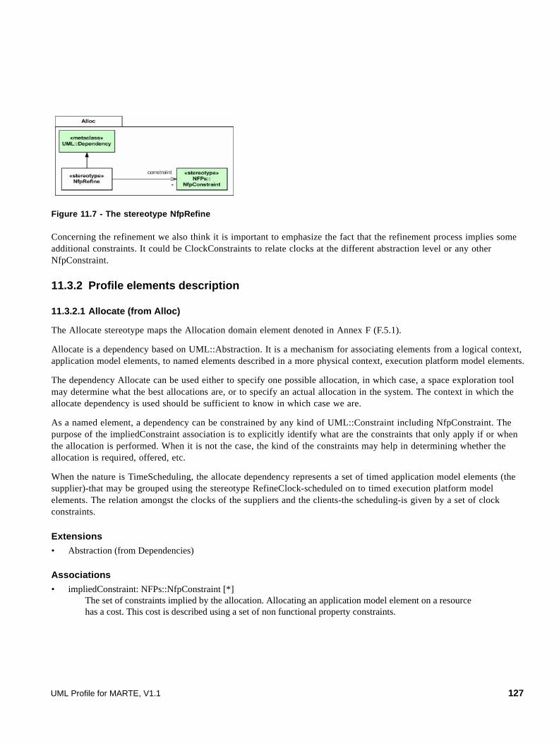
Figure 11.7 - The stereotype NfpRefine
Concerning the refinement we also think it is important to emphasize the fact that the refinement process implies some additional constraints. It could be ClockConstraints to relate clocks at the different abstraction level or any other NfpConstraint.
11.3.2 Profile elements description
11.3.2.1 Allocate (from Alloc)
The Allocate stereotype maps the Allocation domain element denoted in Annex F (F.5.1).
Allocate is a dependency based on UML::Abstraction. It is a mechanism for associating elements from a logical context, application model elements, to named elements described in a more physical context, execution platform model elements.
The dependency Allocate can be used either to specify one possible allocation, in which case, a space exploration tool may determine what the best allocations are, or to specify an actual allocation in the system. The context in which the allocate dependency is used should be sufficient to know in which case we are.
As a named element, a dependency can be constrained by any kind of UML::Constraint including NfpConstraint. The purpose of the impliedConstraint association is to explicitly identify what are the constraints that only apply if or when the allocation is performed. When it is not the case, the kind of the constraints may help in determining whether the allocation is required, offered, etc.
When the nature is TimeScheduling, the allocate dependency represents a set of timed application model elements (the supplier)-that may be grouped using the stereotype RefineClock-scheduled on to timed execution platform model elements. The relation amongst the clocks of the suppliers and the clients-the scheduling-is given by a set of clock constraints.
Extensions
• Abstraction (from Dependencies)
Associations
• impliedConstraint: NFPs::NfpConstraint [*] The set of constraints implied by the allocation. Allocating an application model element on a resource has a cost. This cost is described using a set of non functional property constraints.
UML Profile for MARTE, V1.1 127

Attributes
• kind: AllocationKind [1] This differentiates the kind of allocations, whether both allocated elements on each side are structural, behavioral, or whether this is a hybrid allocation.
• nature: AllocationNature [1] This identifies the purpose of the allocation, whether the allocation is equivalent to a spatial distribution, where several application model elements are distributed to different resources or whether timed elements are scheduled according to a given scheduler.
Constraints
[1] When the kind is structural, suppliers, and clients must all be structural elements: classes, instance specifications, or packages. When the kind is behavioral, suppliers must be UML::Behavior or UML::Action and the clients must be behavioral elements, a UML::BehavioralFeature for example. When the kind is hybrid, suppliers must be behavioral elements while the clients must be structural elements.
[2] When the nature is TimeScheduling, supplier and the clients must be Time::TimedElement and the NFPs::NfpConstraint shall include Time::ClockConstraint.
Notation
The “allocate” relationship is a dashed line with an open arrow head. The arrow points in the direction of the allocation. In other words, the directed line points “from” the elements being allocated “to” the elements that are the targets of the allocation
11.3.2.2 AllocateActivityGroup (from Alloc)
AllocateActivityGroup is used to depict an allocation relationship on an Activity. It is an extension of the metaclass UML::ActivityPartition.
AllocateActivityGroup is a standard UML::ActivityPartition, with modified constraints such that any actions within the partition must result in an “allocate” dependency between the activity used by the action, and the element that the partition represents.
Since we also intend to represent possible allocations, we anticipate several cases where activity nodes will be shared by several allocate activity groups (Figure 11.10). In this case, that means the shared activity nodes can be allocated either to one activity partition (an instance of the classifier, the instance itself or the instance playing the part represented by the activity partition) or to the other. The isUnique property explicitly prevents an activity node from being allocated to several groups. This does not mean the node cannot be shared by several groups, it only means that once we have made the final decision of the allocation, the node is actually allocated to only one group.
Extensions
• ActivityPartition (from IntermediateActivities).
Attributes
• isUnique: Boolean=false This specifies whether or not the actions contained in the partition can actually be allocated to several partitions (the default) or can only be allocated to only one.
128 UML Profile for MARTE, V1.1
Constraints
[1] All Actions appearing in an AllocateActivityGroup will be the /suppliers (from) end of a single Allocate dependency. The element represented by the AllocateActivityGroup will be the /client (to) end of the same Allocate dependency. This allows for defining non functional property constraints applying to all contained actions.
Notation
For brevity, the keyword used on an AllocateActivityGroup is “allocate,” rather than the stereotype name (“allocateActivityGroup”).
11.3.2.3 Allocated (from Alloc)
The Allocated stereotype maps the AllocationEnd domain element denoted in Annex F (F.5.2).
The stereotype Allocated applies to any named element that has at least one allocation relationship with another named element. Allocated named elements may be designated by either the /from or /to end of an “allocate” dependency.
The stereotype Allocated provides a mechanism for a particular model element to conveniently retain and display the element at the opposite end of any allocation. With this stereotype you can allocate anything on anything. To make it clear you want to allocate something logical, from the application model, use the meta-attribute kind (application, executionPlatform).
The attribute kind is not available in SysML.
Extensions
• NamedElement (from Dependencies)
Associations
• None
Atrributes
• /allocatedTo: Allocated [*] Named elements that are suppliers of an “allocate” whose client is extended by this stereotype. This property is the union of all suppliers to which this instance is the client. This association is derived from any “allocate” dependency.
• /allocatedFrom: Allocated [*] Named elements that are clients of an “allocate” whose supplier is extended by this stereotype. The allocatedFrom elements are not necessarily derived from the same “allocate” dependency. A given element can be the supplier of several application model elements, each of which is allocated using a separate “allocate” dependency. The association is derived from any “allocate” dependency.
• kind: AllocationEndKind [1] = undef Specifies the kind of allocation end.
11.3.2.4 AllocationEndKind (from Alloc)
AllocationEndKind is an enumeration type that differentiates the application allocation end from the execution platform allocation end.
UML Profile for MARTE, V1.1 129

Literals
• undef Should be used when no differentiation is to be made on the nature of the allocation end. It could be either an application allocation end or an execution allocation end or something else (as in SysML, where no distinction is made).
• application Identifies an allocation end as being on the application side of the allocation. This allocation end must be the source (the client) of an allocate dependency.
• executionPlatform Identifies an allocation end as being on the execution platform side of the allocation. This allocation end must be the target (the supplier) of an allocate dependency.
• both Identifies an allocation end as being both on the application and the execution platform side of the allocation. This allocation must be the source (the client) of an allocate dependency and the target (the supplier) of an (another) allocate dependency.
11.3.2.5 AllocationNature (from Alloc)
AllocationNature is an enumeration type that defines literals used to specify the purpose of the allocation.
Literals
• spatialDistribution It indicates that the suppliers are distributed on the clients. Spatial distribution is the allocation of computations to processing elements, of data to memories, and of data/control dependencies to communication resources.
• timeScheduling It indicates that the allocation consists in a temporal/behavioral ordering of the suppliers, the order being given by the clients. Scheduling is the temporal/behavioral ordering of the activities (computations, data storage movements or communication) allocated to each resource.
11.3.2.6 AllocationKind (from Alloc)
AllocationKind is an enumeration type that defines literals used to specify the kind of named elements that are used as clients and suppliers.
Literals
• structural Indicates that the suppliers and the clients are all structural named elements.
• behavioral Indicates that the suppliers and the clients are all behavioral named elements.
• hybrid Indicates that the suppliers and the clients are not of the same kind.
11.3.2.7 Assign (from Alloc)
The Assign stereotype maps the Allocation domain element denoted in Annex F (F.5.1).
130 UML Profile for MARTE, V1.1

Assign is an alternative UML representation for the Allocation domain element based on semantically neutral UML::Comment. It is a mechanism for associating elements from a logical context, application model elements, to named elements described in a more physical context, execution platform model elements.
The Assign stereotype can be used either to specify one possible allocation, in which case, a space exploration tool may determine what the best allocations are, or to specify an actual allocation in the system. The context in which the Assign stereotype is used should be sufficient to know in which case we are.
As a named element, an assignment can be constrained by any kind of UML::Constraint including NfpConstraint. The purpose of the impliedConstraint association is to explicitly identify what are the constraints that only apply if or when the allocation is performed. When it is not the case, the kind of the constraints may help in determining whether the allocation is required, offered, etc.
When the nature is timeScheduling, the Assign stereotype represents a set of timed application model elements (the supplier)-that may be grouped using the stereotype RefineClock-scheduled on to timed execution platform model elements. The relation among the clocks of the suppliers and the clients-the scheduling-is given by a set of clock constraints.
Extensions
• Comment
Associations
• impliedConstraint: NFPs::NfpConstraint [*] The set of constraints implied by the assignment. Assigning an application model element on a resource has a cost. This cost is described using a set of non functional property constraints.
Attributes
• kind: AllocationKind [1] This differentiates the kind of assignment, whether both allocated elements on each side are structural, behavioral, or whether this is a hybrid assignment.
• nature: AllocationNature [1] This identifies the purpose of the assignment, whether the assignment is equivalent to a spatial distribution, where several application model elements are distributed to different resources or whether timed elements are scheduled according to a given scheduler.
Associations
• from : Element [*] (from Kernel) The elements that are assigned.
• to : Element [*] (from Kernel) The elements to which the assignment is performed.
Constraints
[1] When the kind is structural, suppliers, and clients must all be structural elements: classes, instance specifications, or packages. When the kind is behavioral, suppliers must be UML::Behavior or UML::Action and the clients must be behavioral elements, a UML::BehavioralFeature for example. When the kind is hybrid, suppliers must be behavioral elements while the clients must be structural elements.
UML Profile for MARTE, V1.1 131

[2] When the nature is TimeScheduling, supplier and the clients must be Time::TimedElement and the NFPs::NfpConstraint shall include Time::ClockConstraint.
Notation
The two allowed notations are presented in the following table.
11.3.2.8 NfpRefine (from Alloc)
The stereotype NfpRefine maps the domain element Refinement denoted in Annex F (F.5.5).
NfpRefine is a dependency based on UML::Dependency. It is a mechanism for associating one abstract model element to refined model elements. It is a provision for grouping elements. The refinement process implies some additional constraints between the abstract element and the refined elements.
When several application model elements are to be collectively allocated to execution platform elements they should first be grouped using the dependency NfpRefine. Some NfpConstraints, like for instance ClockConstraint, should be associated with this dependency to specify relations between the general element and the refined ones.
Extensions
• Dependency (from Dependencies).
Associations
• constraints: NFPs::NfpConstraint [*] The set of constraints implied by the refinement.
Constraints
[1] A singledependency NfpRefine shall have only one client (from), but may have one or many suppliers (to).
context NfpRefine
inv: base_Dependency.from->size()=1 and base_Dependency.to->size()>=1
[2] The client and the suppliers must be Time::TimedElement.
Notation
The relationship NfpRefine is a dashed line with an open arrow head. The arrow points in the direction of the refinement. In other words, the directed line points “from” the element being refined “to” the elements that are the refined elements.
132 UML Profile for MARTE, V1.1

11.4 Examples
11.4.1 Unix process
Figure 11.8 shows an example of allocations with three layers. The first layer describes the application point of view, the second layer represents the operating system internals, and the last layer shows the hardware parts. We use structured classifiers to represent both hardware and software resources.
The example models the design of a given operating system family, not a particular implementation. It represents a typical Unix operating system. A VxWorks model or an embedded Unix model would show a different partition of memory (e.g., no virtual memory). An Arinc653 OS model would show the explicit “partitions” as both space and time partitioning of hardware resources.
A refinement down to Posix threads would show further partitioning of the CPU resources without further partitioning of Memory.
1. Assignment within note and arrow 2. Assignment as a dashed arrow
(The arrow points in the direction of the allocation. In other words, the directed line points “from” the elements being assigned “to” the elements that are the targets of the assignment.)
UML Profile for MARTE, V1.1 133

Figure 11.8 - Allocation of Unix processes
The diagram shows several resources such as computing resources, communication media and storage (using stereotypes defined in GRM), and how these resources can be grouped using a structured classifier and how they can be allocated to more physical resources.
The lower layer in the diagram represents the hardware elements.
The top layer is the view from the application: a (Unix, in this example) process is a group involving a time shared access to a computing resource, and a “spatial” partition in the virtual memory.
The intermediate layer is the implementation internals. The VirtualMemory is the high-level view as seen from the application process. Physically, this virtual memory relies on two types of physical storage (the actual physical memory and a hard disk).
This diagram is for illustration purpose. Often hard real-time application do not need to model the virtual memory and swap space, since a prior analysis based on a simpler model would have verified that the worst case memory requirement does not exceed available RAM memory.
11.4.2 System on Chip
To illustrate the use of the stereotype “clockRefine” we take the example of a system on chip (Figure 11.9). We first decide that we need to have a digital signal processor (e.g., the OAK+) to compute floating point operations and a Risc processor (e.g., an ARM 7) to control the whole application. The two processors are meant to communicate but we do not elaborate on the communication itself at this point (Figure 11.9, upper part).
Application
«allocated»{kind=executionPlatform} «storage»VirtualMemory
«allocate» {nature=spatialDistribution}
«allocated»{kind=application}
«storage»OS_Memory
«allocated»{kind=application}
«storage»Swap
«allocated»{kind=executionPlatform}
«storage»Memory
«allocated»{kind=executionPlatform}
«storage»Disk
OperatingSystem
«allocated»{kind=application}
«storage»RootFs
«allocated»{kind=executionPlatform}«communicationMedia»
Bus
«allocated» {kind=executionPlatform}«computingResource»
CPU
«allocated» {kind=application}
«storage»ReservedMemory
«allocate» {nature=timeScheduling}
«allocated»{kind=application}«computingResource»
CPU
«allocated»{kind=application}«storage»
Memory
«allocate» {nature=spatialDistribution}«allocate» {nature=spatialDistribution}
p : Process [256]
Hardware
134 UML Profile for MARTE, V1.1

Figure 11.9 - Communication refinement
We then decide to refine the communication (Figure 11.9, lower part). We use a double port Ram for the communication. The bus coming from the OAK+ is the GDP bus and the bus coming from the ARM7 conforms to the AMBA High-performance Bus specification. The “clockRefine” dependency specifies that these two connectors (GDP, AHB) and this part (ram : DPRAM) are refinements of the connector comm. Each named element involved in these structured classifiers are typed by a class stereotyped “clockType” (Figure 11.9, right part), which means there is no a priori assumption on relative rates of each part of this diagram. Additionally, the clock constraints associated with the dependency constrain these rates by stating that:
• The clock of the instance that is to be used to conform to the role ram is the same as the macroscopic clock perceived for the global communication between the OAK+ and the ARM7.
• The clock of this instance is finer than the clock of the two busses (b1 : GDP and b2 : AHB). This is probably an over specification and the Time Model (Clause 9) offers several clock relations that allows for more accurate defining of constraints.
Note that using a single dependency rather than three separate ones gives a stronger specification because the dependency identifies a common context that gathers all four constrained elements.
11.4.3 Allocate activity group
To illustrate the use of the stereotype AllocateActivityGroup with take the example of a system described using an activity (Figure 11.10). The activity groups (P1 and P2) represent processors that are the potential clients for the actions of the activity. Because of the nature of the processor (digital signal processor or general purpose processor) and because of the physical localization of sensors (used by actions inpC, outW and outZ) some processing elements cannot be executed by one processor or another. For instance, the operation oper1 requires a hardware coprocessor not included on processor P2. However, the operation oper2 can be allocated to both processors even though the cost of the allocation (not represented here) could be different. An analysis tool could use this information to choose the best allocation regarding, for instance, to a time budget.
UML Profile for MARTE, V1.1 135

Had we wanted to represent the allocation cost, we would have used the non functional property constraints defined in NFP clause. For clarity, we can either draw explicitly dependencies or draw a separate table that would present the cost of each allocation.
Figure 11.10 - Actions shared between two allocate activity groups
The table below illustrates how to complete the allocation information of Figure 11.9 to represent the cost.
We use the standard notation for NFP Constraints, either the simplify version or the full tuple notation. Several constraints can be put in the same cell or a different table can be done for each different constraint. Any kind of NFP constraints can be specified (e.g., time, power consumption).
P1 P2
inpC 4 ms 6 ms
oper1 10 ms
oper2 10 ms 8 ms
outW 4 ms
outZ 6 ms
136 UML Profile for MARTE, V1.1
Subpart II - MARTE Design Model
This Subpart contains the following clauses.
• 12 - Generic Component Model (GCM)
• 13 - High-Level Application Modeling (HLAM)
• 14 - Detailed Resource Modeling (DRM)
UML Profile for MARTE, V1.1 137

138 UML Profile for MARTE, V1.1

12 Generic Component Model (GCM)
12.1 Overview
The MARTE GeneralComponentModel presents additional concepts (with respect to usual component paradigms) that have been identified as necessary to address the modeling of artifacts in the context of real-time and embedded systems component based approaches. Figure 12.1 shows the dependencies of this package.
Figure 12.1 - Dependencies of the GenericComponentModel package
Additionally, the MARTE generic component model defines shortcut notations that help in simplifying the modeling and are useful in the application of component base strategies in the real-time and embedded systems domains.
12.2 Domain View
12.2.1 The GenericComponentModel Package
The domain model introduced in this specification for the MARTE Generic Component model is mainly an abstraction of the UML structured classes. This model provides a common denominator among various component models, which in principle do not target exclusively the real-time and embedded domain. The purpose is to provide in MARTE a model as general as possible, that is not tied to specific execution semantics, on which real-time characteristics can be applied later on. The MARTE generic component model relies mainly on UML structured classes, on top of which a support for SysML blocks has been added. Providing a support for Lightweight-CCM, AADL and EAST-ADL2 have also influenced the definition of some features of the MARTE Generic Component Model.
UML Profile for MARTE, V1.1 139

Figure 12.2 - The bulk of the MARTE GenericComponentModel package
A StructuredComponent defines a self-contained entity of a system, which may encapsulate structured data and behavior. The MARTE structured component specializes the BehavioredClassifier concept (Marte::CoreElements::Foundations::BehavioredClassifier). It owns properties that can be used as AssemblyParts (within an internal component description), attributes, or member ends of an association. When used as an assembly part, a property is indicated in the parts reference. As mentioned in the CoreElements package, Property is similar to the corresponding UML definition, i.e., it has a multiplicity in terms of upper and lower bounds, an aggregation kind and a type (as a Classifier). InteractionPorts are a special kind of properties owned by a structured component. An interaction port defines an explicit interaction point through which components may be connected (linked) through an assembly connector, and through which they can communicate via message passing. Messages can represent operation calls, signals, or simply data (as described below). One may also directly connect structured component with no ports. In any case, related ports need to be compatible regarding their provided/required ClientServerFeatures or flow specifications and directions.
StructuredComponentInteractionPort AssemblyPart
/kind : ConnectorKind [1]
Connector
Marte::CoreElements::Foundations::Property
Marte::CoreElements::Causality::CommonBehavior::BehavioredClassifier
ConnectorEnd
ownedConnectors [*]
[1]
owner [1]
ownedPorts [*] [0..1]
/parts [*]
ends [2..*]
owner [1]
endPort [0..1] endPart [0..1]
Marte::CoreElements::Foundations::MultiplicityElement
delegationassembly
« enumeration »ConnectorKind
140 UML Profile for MARTE, V1.1
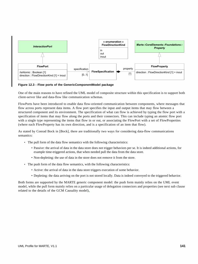
Figure 12.3 - Flow ports of the GenericComponentModel package
One of the main reasons to have refined the UML model of composite structure within this specification is to support both client-server like and data-flow like communication schemas.
FlowPorts have been introduced to enable data flow-oriented communication between components, where messages that flow across ports represent data items. A flow port specifies the input and output items that may flow between a structured component and its environment. The specification of what can flow is achieved by typing the flow port with a specification of items that may flow along the ports and their connectors. This can include typing an atomic flow port with a single type representing the items that flow in or out, or associating the FlowPort with a set of FlowProperties (where each FlowProperty has its own direction, and is a specification of an item that flow).
As stated by Conrad Bock in [Bock], there are traditionally two ways for considering data-flow communications semantics:
• The pull form of the data flow semantics with the following characteristics:
• Passive: the arrival of data in the data store does not trigger behaviors per se. It is indeed additional actions, for example time-triggered actions, that when needed pull the data from the data store.
• Non-depleting: the use of data in the store does not remove it from the store.
• The push form of the data flow semantics, with the following characteristics:
• Active: the arrival of data in the data store triggers execution of some behavior.
• Depleting: the data arriving on the port is not stored locally. Data is indeed conveyed to the triggered behavior.
Both forms are supported by the MARTE generic component model: the push form mainly relies on the UML event model, while the pull form mainly relies on a particular usage of delegation connectors and properties (see next sub clause related to the details of the GCM Causality model).
InteractionPort
/isAtomic : Boolean [1]direction : FlowDirectionKind [1] = inout
FlowPort
Marte::CoreElements::Foundations::Property
direction : FlowDirectionKind [1] = inout
FlowPropertyspecification
[0..1]
inoutinout
« enumeration »FlowDirectionKind
FlowSpecificationproperty
[*]
UML Profile for MARTE, V1.1 141

Figure 12.4 - Message ports of the GeneralComponentModel package
ClientServerPorts support a request/reply communication paradigm (also called client-server model of communication), where messages that flow across ports represent operation calls or signals. A ClientServerPort owns a set of features, called the ClientServerFeature. These features may be provided or required or even they may be in the same time provided and required. When the ClientServerFeature is an Operation, it represents a service that the owning structured component may provide and/or require via this port. In the case of a Reception, it represents a signal that they may publish (in this case, we consider the feature is required) and/or consume (in this case, we consider the feature is provided) via this port. Just like flow ports, a client server port can be atomic (i.e., /isAtomic = true). In this case, the ClientServerPort has no features, and the port is directly typed (via its attribute type inherited from Foundations::Property) by the signal it may produce and/or consume (with respect to its attribute kind).
Figure 12.5 - Possible kinds of InvocationAction in the GenericComponentModel package
InteractionPort
/isAtomic : Boolean [1]kind : ClientServerKind [1] = proreq
ClientServerPort
kind : ClientServerKind [1] = proreq
ClientServerFeaturefeature
[*]
providedrequiredproreq
« enumeration »ClientServerKind
ReceptionOperation
ClientServerSpecificationspecification
[0..1]
InteractionPortInvocationActiononPort
[1]
Causality::CommonBehaviors::Action
SendSignalAction CallOperationAction SendDataAction
FlowProperty
[0..1]targetProperty
BroadcastSignalAction
142 UML Profile for MARTE, V1.1

GCM also defines particular refinements of the Action concept (from Causality::CommonBehaviors) related to communication aspects. For client-server communications, the SendSignalAction (and its BroadcastSignalAction variant) and CallOperationAction are introduced respectively for expressing signal occurrence creations and operation calls. For the dataflow communications, the SendDataAction is introduced for dealing with modeling of data emission.
12.2.2 On the MARTE Causality Model for GCM
This sub clause provides a description of the MARTE causality model in the context for the GCM. This description is based on the concepts introduced in the package MARTE::CoreElements::Causality, and let’s notice that no particular specializations of the concepts defined in this package have been required for GCM. Note that the package Causality uses the concept of Request to denote the run-time manifestation of a communication in transit between an emitting instance and a receiving instance.
The InteractionPorts of a StructuredComponent basically act as relay objects between the internals of the component and its environment (i.e., when the StructuredComponent is used as an AssemblyPart in the context of a particular assembly). When a request is sent by the environment (i.e., it is an incoming request from the perspective of the receiver), the targeted port is in charge of delegating the request to the component internals, which handle the request by processing the appropriate behavior. Similarly, when a request is sent by the structured component internals (i.e., it is an outgoing request from the perspective of the sender), the targeted port is in charge of forwarding the request to the environment, which must properly handle or process it. More generally, it can be said that GCM InteractionPort semantics is driven by a kind of “request propagation process,” just like standard UML ports.
Of course, the way of handling and processing a request is strongly different if the request is related to a client-server like communication (i.e., the request represents an operation call or a signal occurrence, and the client-server communication has been put into action via a GCM CallOperationAction, GCM SendSignalAction, or GCM BroadcastSignalAction on a GCM ClientServerPort) or if the request is related to a data-flow like communication (i.e., the request actually conveys a data value, and the data-flow communication has been put into action via a GCM SendDataAction on a GCM FlowPort). The “message propagation process” described above however remains the same for both kind of communications. Figure 12.6 (which provides an informal description of the way an incoming message is handled) and Figure 12.7 (related to the handling of an outgoing message) are thus valid for both client-server and data-flow communications, as described below.
On the semantics about incoming requests on ports
The semantics related to incoming requests and defined in GCM is sketched in the following activity diagram shown in Figure 12.6.
UML Profile for MARTE, V1.1 143

Figure 12.6 - Schema of the various semantics related to incoming requests on port
When a request is received on a port (Step A.1 in Figure 12.6) owning delegation connectors, it is propagated to the internals of the structured component (In UML, this case typically corresponds to a non-behavioral port). In this case, one processes to an analysis of the possible delegation paths (Step A.2.a). It consists of selecting a delegation connector with a connector end that is able to handle the request. If the delegation scheme is partial (i.e., no compatible connector is found), the message is lost (as depicted by the final node Lost Request shown in Figure 12.6). For the particular case of an operation call on a ClientServerPort, if the StructuredComponent directly realizes the called operation (i.e., in UML, this fact would typically be captured by an InterfaceRealization relationship between the component and the interface that is provided on the port), then the message is not lost and directly triggers the execution of the corresponding StructuredComponent’s operation. In the opposite case where the analysis detects several connector ends that are able to handle the request (i.e., ends are conflicting), the selection of the delegation connector is a semantic variation point (as depicted by the final node Semantics Variation Point). Otherwise (i.e., one and only one delegation connector has been detected), the request is propagated via the selected connector (Step A.3.a), and the handling process is recursively involved (Step A.4.a). The conditions for a connector to be able to handle a request depend on the nature of the port receiving the request:
• ClientServerPort: For a given delegation connector outgoing a ClientServerPort, one of the end (i.e., a ClientServerPort or directly an assembly part) must have a provided or provided/required ClientServerFeature that is compatible with the request. It means that if the request matches to a given signal occurrence, this feature must be a Reception with an associated Signal that is type-compatible with the Signal occurrence of the received request. If the request matches to an operation call, this feature must be an operation that is signature-compatible with the operation associated with the call. The case where multiple ClientServerFeatures are compatible with the received request falls in the case of Semantics Variation Point described above (i.e., the case with conflicting connector ends). Note that in the case where the received request corresponds to a Signal, an alternative and valid delegation scheme concerns the case where the delegation connector targets an atomic ClientServerPort which is type-compatible with the type of the signal.
• FlowPort: For a given delegation connector from this FlowPort, one of the end (that can be a FlowPort or directly an assembly part) must have one of the following characteristics:
• Either it is an in or inout atomic flow port which type is compatible with the type of the received data.
144 UML Profile for MARTE, V1.1

• Or it is a port owning an in or inout flow property which type is compatible with the type of the received data. The case where multiple flow properties are compatible with the message falls in the case of the Semantics Variation Point described above (i.e., conflicting ends of connectors).
• Or it is an assembly part which type is compatible with the type of the received-data (this case matches to the pull form of data-flow semantics considered by Step B.1 as described below).
If a request is received on a port that has no delegation connectors, a ReceiveOccurence (see 7.2.5) on the Causality::Communication Package) is generated (Step A.2.b) and stored in the event pool of the context structured component for further usages (Step A.3.b). Typically, these events can be used as Triggers by Behaviors processed in the context of the receiving object (see description of Behavior, Trigger, Event and BehaviorExecution in 7.2.2 and 7.2.3). Firstly, each ReceiveOccurence is associated with the information related to the received request (i.e., either, both the operation that has been called and the associated parameters in the case of an operation call, or the values of the signal properties in the case of a signal occurrence reception, or simply a value in the case of a data-flow communication). Secondly, each ReceiveOccurence is made available to the Behaviors that use these events as triggers. Note that in the particular case of a FlowPort, such events are used to support the push form of data-flow semantics (i.e., the availability of a data, which is the consequence of a request reception, is manifested by the generation of an event).
The last possible case corresponds to the reception of a request directly on an assembly part (Step B.1). The way the request is processed (Step B.2) varies according to the communication paradigm:
• Client-server paradigm: Depending on the nature of the request (operation call or signal occurrence) and the way the type of the assembly part has been specified (i.e., if the typing classifier is specified as a BehavioredClassifier or not. See 7.2, either the request is stored as a ReceiveOccurence in the event pool of the receiving element for further usage, or the request triggers directly the processing of a Behavior (e.g., in the case of an operation call).
• Data-flow paradigm: Provided what we have described in the previous paragraphs and the fact that the type of the assembly part is necessarily compatible with the type of the received data, the value of the received data is simply held by the assembly part, and it will be persistently available for any behavior that need to use it. This case corresponds to the pull form of data-flow semantics. Indeed, no ReceiveOccurence is generated in this case, and cannot therefore be used to trigger a behavior.
On the semantics about requests outgoing from ports
The semantics related to incoming requests and defined in GCM is sketched in the following activity diagram shown in Figure 12.7.
Figure 12.7 - Schema of the various semantics related to incoming requests on port
UML Profile for MARTE, V1.1 145
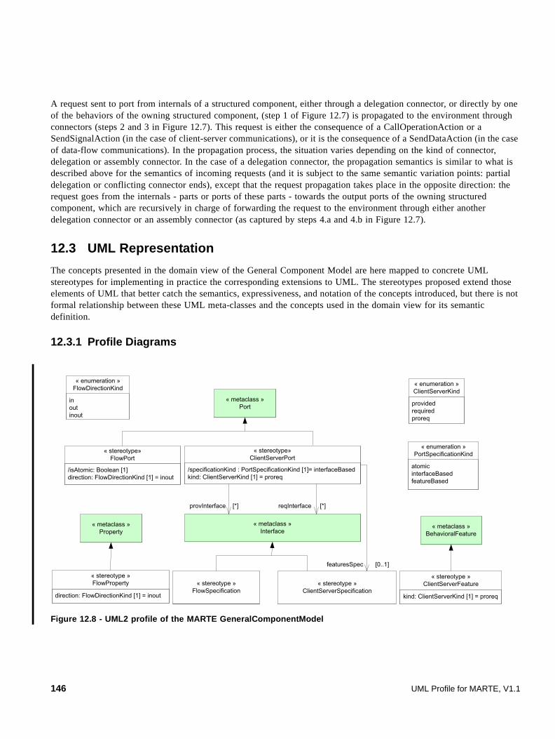
A request sent to port from internals of a structured component, either through a delegation connector, or directly by one of the behaviors of the owning structured component, (step 1 of Figure 12.7) is propagated to the environment through connectors (steps 2 and 3 in Figure 12.7). This request is either the consequence of a CallOperationAction or a SendSignalAction (in the case of client-server communications), or it is the consequence of a SendDataAction (in the case of data-flow communications). In the propagation process, the situation varies depending on the kind of connector, delegation or assembly connector. In the case of a delegation connector, the propagation semantics is similar to what is described above for the semantics of incoming requests (and it is subject to the same semantic variation points: partial delegation or conflicting connector ends), except that the request propagation takes place in the opposite direction: the request goes from the internals - parts or ports of these parts - towards the output ports of the owning structured component, which are recursively in charge of forwarding the request to the environment through either another delegation connector or an assembly connector (as captured by steps 4.a and 4.b in Figure 12.7).
12.3 UML Representation
The concepts presented in the domain view of the General Component Model are here mapped to concrete UML stereotypes for implementing in practice the corresponding extensions to UML. The stereotypes proposed extend those elements of UML that better catch the semantics, expressiveness, and notation of the concepts introduced, but there is not formal relationship between these UML meta-classes and the concepts used in the domain view for its semantic definition.
12.3.1 Profile Diagrams
Figure 12.8 - UML2 profile of the MARTE GeneralComponentModel
« metaclass »Port
inoutinout
« enumeration »FlowDirectionKind
/specificationKind : PortSpecificationKind [1]= interfaceBasedkind: ClientServerKind [1] = proreq
« stereotype»ClientServerPort
« metaclass »Interface
direction: FlowDirectionKind [1] = inout
« stereotype »FlowProperty
« metaclass »Property
« stereotype »FlowSpecification
« stereotype »ClientServerSpecification
/isAtomic: Boolean [1]direction: FlowDirectionKind [1] = inout
« stereotype»FlowPort
kind: ClientServerKind [1] = proreq
« stereotype »ClientServerFeature
« metaclass »BehavioralFeature
providedrequiredproreq
« enumeration »ClientServerKind
provInterface [*] reqInterface [*]
featuresSpec [0..1]
atomicinterfaceBasedfeatureBased
« enumeration »PortSpecificationKind
146 UML Profile for MARTE, V1.1
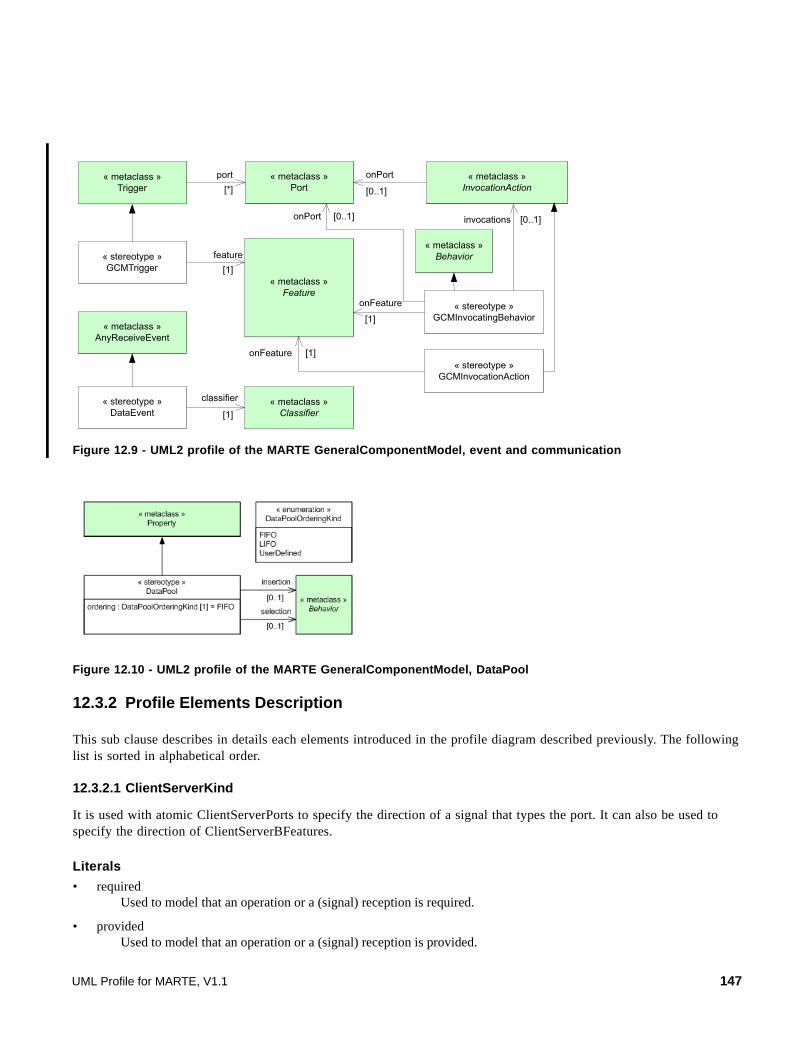
Figure 12.9 - UML2 profile of the MARTE GeneralComponentModel, event and communication
Figure 12.10 - UML2 profile of the MARTE GeneralComponentModel, DataPool
12.3.2 Profile Elements Description
This sub clause describes in details each elements introduced in the profile diagram described previously. The following list is sorted in alphabetical order.
12.3.2.1 ClientServerKind
It is used with atomic ClientServerPorts to specify the direction of a signal that types the port. It can also be used to specify the direction of ClientServerBFeatures.
Literals
• required Used to model that an operation or a (signal) reception is required.
• provided Used to model that an operation or a (signal) reception is provided.
« metaclass »Trigger
« metaclass »Port
« metaclass »Feature
« stereotype »GCMTrigger
port[*]
feature[1]
[0..1]
onPort
« stereotype »DataEvent
« metaclass »AnyReceiveEvent
« metaclass »Classifier
classifier
[1]
« metaclass »InvocationAction
« stereotype »GCMInvocationAction
[1]onFeature
« stereotype »GCMInvocatingBehavior
« metaclass »Behavior
[1]
onFeature
[0..1]onPort [0..1]invocations
UML Profile for MARTE, V1.1 147

• proreq Used to model that an operation or a (signal) reception is both provided and required.
12.3.2.2 ClientServerFeature
This ClientServerFeature stereotype maps both Reception and Operation domain elements as described in F.6.17 and F.6.18.
A ClientServerFeature specifies the nature of a BehavioralFeature owned by interfaces stereotyped as ClientServerSpecification. If kind is required it is expected to be a required operation or signal reception while if kind is provided, it is expected to be a provided operation or signal reception.
Extensions
• BehavioralFeature (from UML::Kernel)
Generalizations
• None
Attributes
• kind: ClientServerKind [1] =proreq Define the nature of the ClientServerFeature.
Associations
• None
Constraints
• None
Notation
When applying the stereotype ClientServerFeature using the iconographical notation, the following icons are used.
12.3.2.3 ClientServerPort
This stereotype maps the ClientServerPort domain concept defined in F.6.6.
The main purpose of the ClientServerPort stereotype is to provide a mechanism for specifying provided and required behavioral features of standard UML ports, which is more intuitive and direct than the standard UML mechanism (which relies on derivation rules based on the port type, and the set of Usage and InterfaceRealization relationships associated
Icon Usage
For a provided behavioral feature (i.e., kind = provided).
For a required behavioral feature (i.e., kind = required).
For a behavioral feature which is both provided and required (i.e., kind = proreq).
148 UML Profile for MARTE, V1.1

with this type). ClientServerPort can be seen as a kind of “syntactic sugar,” and a client-server port is thus semantically equivalent to a standard UML port. It practically means that a GCM model (i.e., a UML model on which the GCM subprofile has been applied) can be defined using standard UML ports, on which the ClientServerPort has not been applied.
We identify three potential usages of ClientServerPort (where a particular usage is technically captured by the specificationKind:PortSpecificationKind derived property):
• Atomic usage: the designer wants to directly associate a signal with the port (i.e., the port is typed by the signal), specifying that the component owning the port is either able to send (i.e., ClientServerPort::kind = required) or receive (i.e., ClientServerPort::kind = provided) the signal via this port.
• Interface-based usage: the designer wants to directly provide and/or require standard UML interfaces on a port. In this case, the port is not typed, and the set of provided and required interfaces are specified via properties of the ClientServerStereotype (i.e., provInterface and reqInterface respectively).
• Feature-based usage: the designer wants to associate a ClientServerSpecification (i.e., a consistent set of behavioral features, some of which may be provided or required) with the port. In this case, the port is not typed, and the ClientServerSpecification is specified via the property specification of the stereotype ClientServerPort.
In the case of Feature-based usage, if the property “isConjugated” (from UML ports) is true, all the directions of the ClientServerFeatures specified by a ClientServerSpecification that characterizes a featureBased ClientServerPort are exposed in the opposite kind (i.e., a provided feature is treated as a required feature by the ClientServerPort). In the case of an atomic or interface-based usage, the value of “isConjugated” is ignored.
Note that in the case of the atomic usage, a ClientServerPort typed by a signal means that emission or reception of the signal can occur over that port (with respect to the kind of the port). It is equivalent to a standard UML port exposing an Interface with a Reception for this signal, and does not introduce any new communication paradigm.
The fact that FlowPort enables the same kind of construction (i.e., an atomic FlowPort which is typed by a signal) may be confusing. It comes from the fact that the FlowPort concept has been defined in the context of SysML, and reused without changes in the definition of MARTE for compatibility purposes. MARTE thus provides two syntactic means for specifying atomic ports. They are however semantically equivalent and they can be used jointly in a same model. Examples of such combined usages of atomics FlowPorts with standard UML ports or ClientServerPorts are illustrated in Figure 12.12, Figure 12.13, Figure 12.14, and Figure 12.15.
UML Profile for MARTE, V1.1 149

Extensions
• Port (from UML::Ports)
Generalizations
• None
Attributes
• /specificationKind : PortSpecificationKind [1] = interfaceBased A derived property describing the way how the set of provided or required functionalities of the port has been specified. Cf. the description or PortSpecificationKind for a description of the different ways of specifying the set of required/provided functionalities (and consequently to derive the value of /specificationKind).
• kind : ClientServerKind [1] In the case where the ClientServerPort is atomic (i.e., specificationKind = atomic), this property enables specifying directly the kind of the port. In the case where the ClientServerPort is interface-based (i.e., specificationKind = interfaceBased), then the value of the kind property must be consistent with the set of interfaces associated with the port (via the provInterface and reqInterface properties). If provInterface is the only property to be used, then kind must be equal to provided. If only reqInterface is used, then kind must be equal to required. If both properties are used, then kind must be equal to proreq. Finally, in the case where the port is feature-based (i.e., specificationKind = featureBased), then the value of the kind property must be consistent with the ClientServerSpecification associated
Delegation Connector Reception Semantics
Beh
avio
ral
Cli
entS
erve
rPor
t NO
A MessageEvent (i.e., a CallEvent or a SignalEvent) is raised and stored in the event pool of the receiving instance.
YESIn MARTE, we consider such model to be ill-formed.
Non
-Beh
avio
ral
Cli
entS
erve
rPor
t
NOIf the classifier of the receiving instance directly realizes the behavioral feature, the reception of the message directly triggers a call to this behavioral feature (and no MessageEvent is generated).If the behavioral feature is not realized by the classifier of the receiving instance, the message is lost.
YES The received message follows one of the available delegation connectors, so that the message is handled by the delegation target.If multiple connectors can be followed (i.e., multiple targeted elements are able to handle the message), the choice of the connector to be followed is a semantic variation point (for more details, let’s see the “Conflicting End” semantic variation point, in 12.2.2 on the causality model of the MARTE GCM).
150 UML Profile for MARTE, V1.1

with the port (via the featuresSpec property) and with the fact that the port is conjugated or not. If the ClientServerSpecification only owns provided features, kind must be equal to provided (required if the port is conjugated). If the ClientServerSpecification only owns required features, kind must be equal to required (provided if the port is conjugated). If it contains provided and required features, kind must be equal to proreq.
Associations
• specification : ClientServerSpecification [0..1] The ClientServerSpecification used to specify the set of ClientServerBFeature provided/required by the port. This case corresponds to what we call a “featureBased” usage of ClientServerPort (i.e., /specificationKind = featureBased).
• provInterface : Interface [0..*] The set of interfaces provided by the ClientServerPort. It is important here to notice that this property is not derived, as opposed to the “provided” property of standard UML ports. “provInterface” can be seen as a shortcut to provide a set of interfaces on a port, without using the standard UML mechanism based on port type. This case corresponds to what we call an “interfaceBased” usage of ClientServerPort (i.e., /specificationKind = interfaceBased). Note that the “provInterface” property can be used jointly with the “reqInterface” property.
• reqInterface : Interface [0..*] The set of interfaces required by the ClientServerPort. Again, it is important to notice that this property is not derived, as opposed to the “required” property of standard UML ports. “reqInterface” just provide a shortcut. This case also corresponds to what we call an “interfaceBase” usage of ClientServerPort (i.e., /specificationKind = interfaceBased). The “reqInterface” property can be used jointly with the “provInterface” property.
Constraints
[1] A conjugated port may be involved in only bidirectional connector, i.e., connector with exactly two connector ends.
[2] Interfaces contained in ClientServerPort.provInterface cannot be FlowSpecification or ClientServerSpecification.
[3] Interfaces contained in ClientServerPort.reqInterface cannot be FlowSpecification or ClientServerSpecification.
[4] If ClientServerPort.specificationKind = atomic, then: NOT(Port::type.isEmpty) and Port::type instanceof Signal and provInterface.isEmpty and reqInterface.isEmpty and specification.isEmpty.
[6] If ClientServerPort.specificationKind = interfaceBased, then: Port::type.isEmpty and NOT(provInterface.isEmpty and reqInterface.isEmpty) and specification.isEmpty.
[7] If ClientServerPort.specificationKind = featureBased, then: Port::type.isEmpty and NOT(specification.isEmpty) and provInterface.isEmpty and reqInterface.isEmpty.
[8] The ClientServerPort.kind property is only applicable to atomic ClientServerPorts.
[9] The ClientServerPort.isConjugated property is only applicable to featureBased ClientServerPorts.
UML Profile for MARTE, V1.1 151
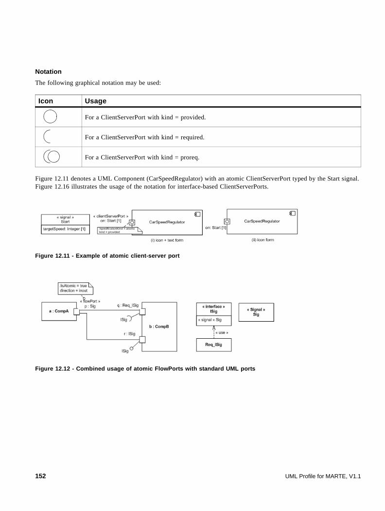
Notation
The following graphical notation may be used:
Figure 12.11 denotes a UML Component (CarSpeedRegulator) with an atomic ClientServerPort typed by the Start signal. Figure 12.16 illustrates the usage of the notation for interface-based ClientServerPorts.
Figure 12.11 - Example of atomic client-server port
Figure 12.12 - Combined usage of atomic FlowPorts with standard UML ports
Icon Usage
For a ClientServerPort with kind = provided.
For a ClientServerPort with kind = required.
For a ClientServerPort with kind = proreq.
152 UML Profile for MARTE, V1.1

Figure 12.13 - Combined usage of atomic FlowPorts with "atomic" ClientServerPorts
Figure 12.14 - Combined usage of atomic FlowPorts with "interfaceBased" ClientServerPorts
Figure 12.15 - Combined usage of atomic FlowPorts with "featureBased" ClientServerPorts
When a message port is non-atomic, the following icon may be used for the stereotype (Example in Figure 12.4): .
UML Profile for MARTE, V1.1 153

Figure 12.16 - Example of interface-based ClientServerPorts
12.3.2.4 ClientServerSpecification
The ClientServerSpecification stereotype is related to ClientServerFeature domain elements as described in F.6.4.
A ClientServerSpecification provides a way to define specialized interface that allows for defining its nature in terms of either its ability to receive and send UML signals, or of its provided and required operations.
Extensions
• Interface
Generalizations
• None
Attributes
• None
Associations
• None
Constraints
[1] A ClientServerSpecification can only own ClientServerBFeatures, i.e., Operations and/or Receptions on which the ClientServerBFeature stereotype has been applied. It cannot own properties.
Notation
When applying the stereotype using its iconographical or shape forms, following icons are used.
Icon Usage
For ClientServerSpecification with kind = required, when all the features contained in the interface are signal receptions.
154 UML Profile for MARTE, V1.1

Figure 12.17 - Examples of ClientServerSpecification
12.3.2.5 DataEvent
DataEvent extends the AnyReceiveEvent metaclass, which is the most generic kind of concrete MessageEvent of UML. DataEvents are raised when messages (which have been created as a consequence of a SendObjectAction) are received on a behavioral FlowPort. They are then stored in the pool of events of the owning object just like any other kind of UML events would be. It implies that the UML semantic variation points related to the management of events in the events pool also applies to event stereotyped with “DataEvent” (see UML2 Superstructure, 13.3.4 BehavioredClassifier for more details about event management in UML). Particular semantic interpretation on the way data-event are handled would thus require a specialization of the MARTE Generic Component Model, such as the one discussed in the HLAM clause. The definition of “DataEvent” mimics the definition of the UML SignalEvent metaclass in the sense that it is possible to attach a classifier to the event in order to characterize it (just as it is possible to attach a Signal to a SignalEvent). DataEvents can then be exploited by triggers of StateMachine transitions or triggers of AcceptEventActions in activity diagrams for example so that it is possible to specify reactions to reception of data of a particular type (i.e., data which are typed by a classifier compatible with the classifier associated with the DataEvent). Note that in UML such triggers can natively be related to the port from which the DataEvent has been raised. In order to avoid overlapping with UML SignalEvent, a constraint imposes that the classifier associated with the DataEvent cannot be a Signal.
Extensions
• AnyReceiveEvent (from UML::Communications)
Generalizations
• None
Attributes
• None
Associations
• classifier : Classifier [1] The specific classifier that is associated with this event.
For ClientServerSpecification with kind = provided, when all the features contained in the interface are signal receptions.
For ClientServerSpecification with kind = required, when all the features contained in the interface are operations.
For ClientServerSpecification with kind = provided, when all the features contained in the interface are operations.
UML Profile for MARTE, V1.1 155

Constraints
[1] classifier can be any UML Classifier that can be used to type an atomic FlowPort or a FlowProperty (i.e., DataType or Class) except a Signal.
12.3.2.6 DataPool
The DataPool stereotype extends the UML Property metaclass. It is used to specify the storing policy of a flow port that semantics is to be a “pull-semantics.” The stereotype has to be applied on a property of the port owner and the property must be linked to the flow-port by a delegation connector. The multiplicity of the property is used to define the size of the store associated to the flow port. Infinite pool may be specified by setting to "*" the upper value of the multiplicity.
When such a DataPool also has a connector targeting an input parameter of a behavior (see 12.3.2.9, ’FlowPort’ about FlowPort, sub-clause concerning the use of connectors between properties and parameters of behavior), the DataPool also specify the policy that determines what are the values that will actually be used as input parameters of the targeted behavior (when this behavior will be called). The property ordering is used to specify the insertion and selection policies. Two default policies are pre-defined: FIFO and LIFO (see 12.3.2.7, ’DataPoolOrderingKind’ on DataPoolOrderingKind). It is a MARTE semantics variation point to define what happen in case of the DataPool is full (i.e., the upper-bound multiplicity associated with the DataPool has been reached). In MARTE, however we define the following default semantics: for both predefined policies (FIFO and LIFO) the reception of a new data while the pool is full will not be blocking. The oldest data contained in the pool is lost to the benefit of the freshest one.
For flexibility purposes, it is possible to specify user-defined policy for managing the data pool. In this case, the property ordering must be set to UserDefined, and properties, insertion and selection, of the stereotype DataPool must be used to reference specific behaviors. These behaviors encapsulate then the explicit user-defined description of how data should be inserted and selected from the pool (see Example 4 in the notation clause below). Finally, as denoted in the following constraint clause, let's notice that two constraints have been defined in order to model the behaviors describing the user-defined insertion and selection policy.
Extensions
• Property (from UML::Kernel)
Generalizations
• None
Attributes
• ordering : OrderingKind [1] = FIFO It denotes how data are to be inserted and selected from the DataPool.
Associations
• insertion : Behavior [0..1] It references a behavior describing the policy for the insertion of data in the DataPool.
• selection : Behavior [0..1] It references a behavior describing the policy for the selection of data from the DataPool.
156 UML Profile for MARTE, V1.1

Constraints
[1] If the Property ordering is set to UserDefined, it implies that both properties insertion and selection have to be specified. self.ordering = UsedDefined implies (self.insertion.size()=1 and self.selection.size()=1)
[2] The Behavior referenced by the property insertion must have one and only one parameter. Its direction must be in or inout and its type that is compatible with the type of the FlowPort connected to the DataPool.
[3] The Behavior referenced by the property selection must have one and only one parameter. Its direction must be return and its type and its multiplicity must be compatible with the type and the multiplicity of the Parameter connected to the DataPool (see example 4 shown on Figure 12.25).
12.3.2.7 DataPoolOrderingKind
The DataPoolOrderingKind is used in the context of a DataPool to specify both insertion/selection policies of data in the pool.
Literals
• FIFO The first element inserted in the DataPool is the first element to be selected.
• LIFO The last element inserted in the DataPool is the first element to be selected.
• UserDefined The insertion and selection policies are user-defined (see 12.3.2.6, ’DataPool’).
12.3.2.8 FlowDirectionKind
This enumeration maps the FlowDirectionKind domain concept defined in Annex F (F.6.8).
It is used with atomic flow (or message) ports to specify the direction of a flow element or a signal that types the port. It can be also used with non-atomic flow (or message) ports to specify the direction of a flow specification (or signal specification), or the direction of its owned properties.
Literals
• in The direction of the information flow is from outside to inside of the owning entity. When related to a signal, it is usual to say that the signal is consumed.
• out The direction of the information flow is from inside to outside of the owning entity. When related to a signal, it is usual to say that the signal is produced or published.
• inout The information flow is bidirectional.
12.3.2.9 FlowPort
This stereotype maps the concept of FlowPort defined in Annex F. A FlowPort may relay incoming, outgoing, or bidirectional flows. The nature of the flow is specified by the type of the port in the case of an atomic flow port. A flow also can be specified in terms of flow specifications and flow properties, in the case of a non-atomic flow port.
UML Profile for MARTE, V1.1 157
In the case where the flow port is not atomic, if the property “isConjugated” (from UML ports) is true, all the directions of the flow properties (FlowProperty) specified by a FlowSpecification that types a port are relayed in the opposite direction (e.g., an incoming flow property is treated as an outgoing flow property by the FlowPort). If the post is atomic the value of “isConjugated” is ignored.
In the case where a FlowPort (or FlowProperty) is typed by a Signal, the UML SendSignalAction is used to create a signal instance and transmit it via the port (or FlowProperty). For other kind of types (i.e., DataType or Classes) and as shown in example 1 of the next notation clause, the designer may use the UML SendObjectAction for sending data on a port. Since SendObjectAction inherits from InvocationAction, it is natively possible to determine the port on which the SendObjectAction is applied, via the property onPort of InvocationAction (see “GCMInvocationAction” for the ability to specify the flow property of a non-atomic flow port that is concerned by SendObjectAction). SendObjectAction is an action that transmits an object to the target object. In our case, the transmitted object is a message encapsulating the data that has been put on its input pin denoted by its metaproperty request.
As stated in the domain view, the MARTE Generic Component Model supports the two following main forms of dataflow communications: the “push” semantics and the “pull” semantics.
For the push semantics, the execution of a SendObjectAction results in the emission of a message encapsulating the sent object. When such a message is received on a target behavioral flow port, a “DataEvent” (see 12.3.2.5, ’DataEvent’ for a deeper description of DataEvent) is raised on the receiving side (In the case of a non-behavioral FlowPort, data are propagated along associated delegation connectors, and no event is raised at all). DataEvents raised consequently to data receptions on behavioral ports are then stored in the event pool of the owning object just like any other kind of UML events would be. It implies that the UML semantic variation points defined in the UML2 specification and related to event management also apply to DataEvent. Additional semantics on how DataEvent are handled would thus require a specialization of the GCM semantics, such as the one discussed in the HLAM sub-profile of MARTE.
DataEvents can be exploited by triggers of transitions within a StateMachine, or by triggers of AcceptEventActions within an Activity (as illustrated in example 2 of the next notation sub clause). Hence, it is possible to specify reactions to reception of data of a particular type (i.e., data which are typed by a classifier compatible with the classifier associated with the DataEvent). Note that such triggers can natively be related to particular ports (i.e., the ports from which the DataEvent have been raised). The “active” characteristic of the “push” semantics is covered because the reception of a data on a behavioral FlowPort raises a DataEvent that can be used as a trigger in a behavior. The “depleting” characteristics of the “push” semantics is covered because, according to the standard UML semantics, once an event has been consumed by a behavior, it is no longer available in the event pool to trigger other behaviors.
Concerning the “pull” semantics of MARTE’s FlowPorts, no particular extensions are required. A simple modeling pattern (as suggested by SysML and by Conrad Bock in [Bock], respectively for the usage of delegation connectors and the usage of properties for persistent data storage and non-depleting data use) is sufficient.
According to the UML 2 superstructure, a non-behavioral port should have delegation connectors, so that incoming requests can be propagated along these connectors to parts of the composite structure owning the port. In other case, the messages arriving on a non-behavioral port without out delegation connectors are considered to be lost. If out delegation connectors exist, the connected parts either delegate the requests to some of their parts, or deal directly with the request triggering the execution of one of their behaviors. At the end of the delegation chain, a non-behavioral input atomic flow port should have at least one delegation connector targeting a part which is type-compatible with the port. When a data is received on such a port and delegated through the connector, no DataEvent is raised (which is in line with the “passive” characteristics of the “pull” form of the data flow semantics). In this case, the semantics says that the data is written in the part targeted by the delegation connector, replacing any existing value. The data stored on the targeted property can then be used when needed by the behavior of the component, typically via a ReadStructuralFeatureAction (which has no depleting effect on the value of the property). This case is illustrated in Example 3 of the next notation sub clause. For more complex storage policies, the stereotype «dataPool» can be applied to the targeted property, in order to describe how
158 UML Profile for MARTE, V1.1

received data are inserted in the property, and how they are selected when they are needed (see 12.3.2.6, ’DataPool’ for a precise description of the DataPool concept). This rule can be extended for non-atomic flow ports, where each flow property should be associated with a delegation connector (by convention and for simplicity, when one of the flow properties is not associated with a delegation connector, the FlowPort should be behavioral, and then the data received on this FlowPort and related to this FlowProperty will raise a DataEvent).
Behavioral Flowport
Delegation Connector Reception Semantics Consumption Semantics
”pus
h” S
eman
tics
True No A Dataevent is raised when data is received on the port. This event is then stored in the event pool of the receiving instance.
Events in the event pool can be used to trigger any behavior executing in the context of the receiving object. Once they have been used as a trigger for one of these behaviors, they are removed from the event pool, and no longer available for other behaviors (see Example 2 shown in Figure 12.23).
True Yes In Marte, this kind of model is considered as ill-formed.
False There exists a delegation connector targeting directly an input parameter (In or Inout) of the classifier behavior.
The data received on the port is made available as a data token on the In or Inout parameter (of the executing classifier behavior) targeted by the delegation connector.
The semantics of token consumption is those of Uml 2 activities (i.e., depleting). See Uml 2 Superstructure, Clause 11 Actions and Clause 12 Activities for more details.For the data passed as a parameter to be accepted by the behavior while it is executing, the parameter must be specified as a streaming parameter (See Example 5 shown in Figure 12.26).
inParam inParam
{streaming}
UML Profile for MARTE, V1.1 159

”pul
l” S
emna
tics
False There exists a delegation connector targeting a property.
Data received on the port will be stored on the property targeted by the delegation connector, and replace any value contained in the property.If the stereotype «datapool» is applied on the targeted property, received data will be inserted in the property with respect to the policy specified by the property 'ordering' of the stereotype «datapool». If ordering is set to user defined, the user-defined insertion behavior (referenced by the property insertion of the stereotype «datapool») determines how received data must be inserted in the property.
Data values held in the property are persistently available to Any behavior that is (or will be) executing in the context of the receiving instance. These data can simply be accessed via a read structural feature action when needed (See Example 3 shown in Figure 12.24).A delegation connector between such a property and an input parameter of a behavior (typically owned by the owner of the property) can be used as an alternative. When this behavior is called (e.g., its execution is triggered by a transition on a Statemachine), values that are passed as input parameters to this call are those contained in the property. If the stereotype «datapool» is applied on the property, then the values to be passed as input parameters are those determined by the ordering policy (see Example 4 shown in Figure 12.25).
False No Incoming data are considered to be lost in this case.
Behavioral Flowport
Delegation Connector Reception Semantics Consumption Semantics
« dataPool »p1: Type1
160 UML Profile for MARTE, V1.1
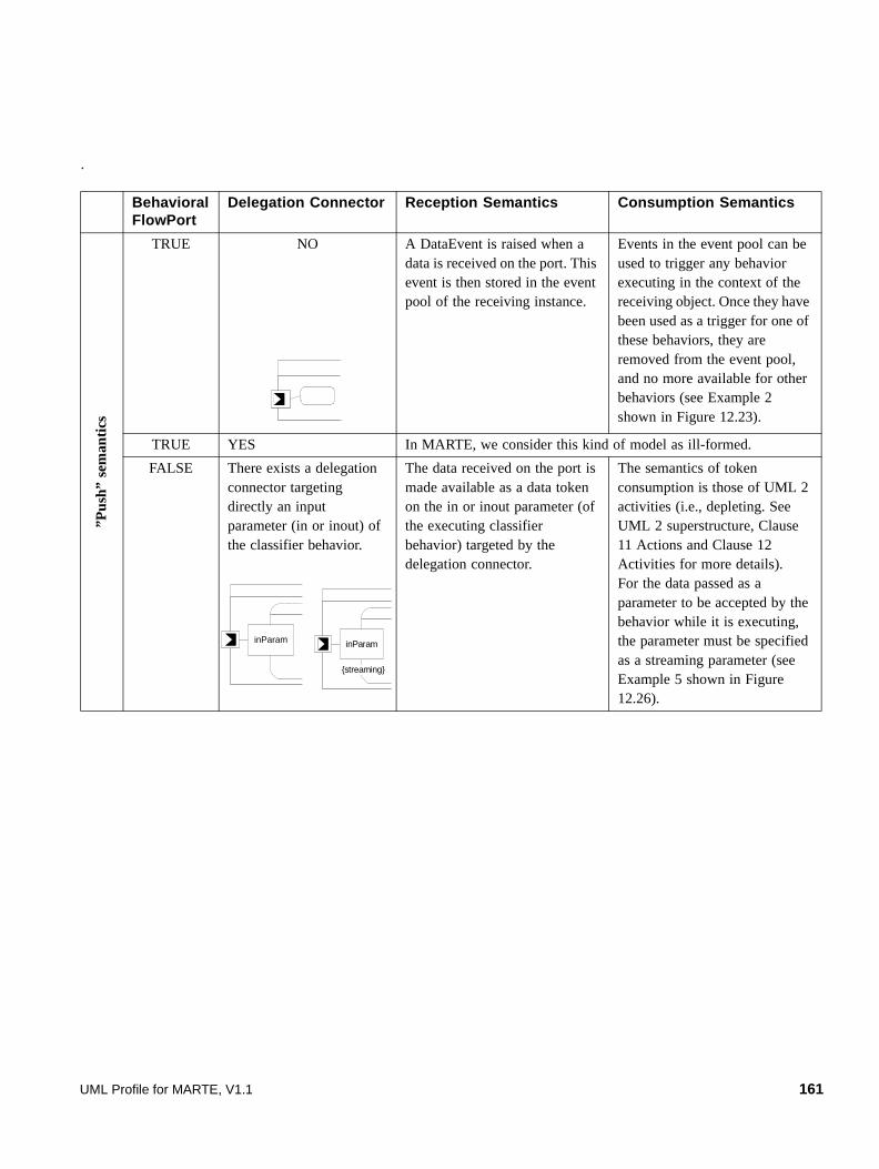
.
Behavioral FlowPort
Delegation Connector Reception Semantics Consumption Semantics
”Pus
h” s
eman
tics
TRUE NO A DataEvent is raised when a data is received on the port. This event is then stored in the event pool of the receiving instance.
Events in the event pool can be used to trigger any behavior executing in the context of the receiving object. Once they have been used as a trigger for one of these behaviors, they are removed from the event pool, and no more available for other behaviors (see Example 2 shown in Figure 12.23).
TRUE YES In MARTE, we consider this kind of model as ill-formed.
FALSE There exists a delegation connector targeting directly an input parameter (in or inout) of the classifier behavior.
The data received on the port is made available as a data token on the in or inout parameter (of the executing classifier behavior) targeted by the delegation connector.
The semantics of token consumption is those of UML 2 activities (i.e., depleting. See UML 2 superstructure, Clause 11 Actions and Clause 12 Activities for more details).For the data passed as a parameter to be accepted by the behavior while it is executing, the parameter must be specified as a streaming parameter (see Example 5 shown in Figure 12.26).
inParam inParam
{streaming}
UML Profile for MARTE, V1.1 161

12.3.2.10 Linking FlowPorts with Activity Parameters
As UML 2 activities naturally behave following a data-flow communication paradigm, we provide modeling patterns to relate non-behavioral flowports to parameters of an Activity. The two forms of data flow semantics defined in MARTE are addressed next:
• “pull” semantics: A standard UML connector is expressed between a property (which used to be the target of a delegation connector, but does not need to be) of the component and an in or inout parameter of a BehaviorFeature (such as an Operation that would typically belong to the owner of the port, but does not need to be) or a Behavior. It means that the values passed to the parameters of the behavior or BehavioralFeature when they are called are actually the values of the connected properties. The connectors just prevent from the usage of an explicit ReadStructuralFeatureAction to get the value associated with the properties. Note that this usage of connectors is compatible with the abstract syntax of UML, as both Property and Parameter are ConnectableElements. In the case where the connected property is stereotyped with “DataPool,” the Behavior referenced by its property selection is used
”Pul
l” s
emna
tics
FALSE There exists a delegation connector targeting a property.
Data received on the port will be stored on the property targeted by the delegation connector, and replace any value contained in the property.If the stereotype «DataPool» is applied on the targeted property, received data will be inserted in the property with respect to the policy specified by the property 'ordering' of the stereotype «DataPool». If ordering is set to UserDefined, the user-defined insertion behavior (referenced by the property insertion of the stereotype «DataPool») determines how received data must be inserted in the property.
Data values held in the property are persistently available to any behavior that is (or will be) executing in the context of the receiving instance. These data can simply be accessed via a ReadStructuralFeatureAction when needed (see example 3 shown in Figure 12.24).A delegation connector between such a property and an input parameter of a behavior (typically owned by the owner of the property) can be used as an alternative. When this behavior is called (e.g., its execution is triggered by a transition on a statemachine), values that are passed as input parameters to this call are those contained in the property. If the stereotype «DataPool» is applied on the property, then the values to be passed as input parameters are those determined by the ordering policy (see example 4 shown in Figure 12.25).
FALSE NO Incoming data are considered to be lost in this case.
Behavioral FlowPort
Delegation Connector Reception Semantics Consumption Semantics
« dataPool »p1: Type1
162 UML Profile for MARTE, V1.1
to determine what are the values to be selected from the property that is the data pool in this case and then that are to be passed to the parameter (as illustrated in example 4 of the notation sub clause).
• “push” semantics: Connectors are directly expressed between input non-behavioral flow ports (respectively the output
flow ports) and input parameters (respectively the output parameters) of the Activity denoting the classifierBehavior6 of the composite structure owning the ports. The idea is that each data received on a flow port will be propagated to a parameter of the classifier behavior. The data associated with the input message will be handled as a token on an ActivityParameterNode corresponding to the parameter. The token will then enter the chain of computation described by the set of object flows and actions of the activity (with respect to the token propagation semantics of UML activities). At the end of the computation chain, tokens will be propagated to ActivityParameterNodes corresponding to output parameters of the Activity. If a delegation connector is expressed between such a parameter and an output flow port of the component, a message containing the produced data will be emitted through the flow port (just as if a SendObjectAction with this value would have been applied on the flow port). The standard semantics of UML activities implies that tokens related to input pins of a CallBehaviorAction must be available for the called activity to start and that tokens corresponding to output parameters the CallBehaviorAction are then available on its output pins only once the invoked activity is finished. The execution of an Activity finishes when one of its final node has been reached by a control token. If final nodes are omitted in the specification of the Activity, the execution finishes when output values have been produced for each of the required output/return parameters of the Activity (with respect to the lower bound of their multiplicity).
Notice that parameters of a behavior may be specified as streamed (see the definition of property isStream in UML 2 Superstructure, clause 12.3.41 Parameter). In that case, the invoked activity may accept tokens on its input parameter and may also produce results on its output parameters while running. Therefore, if the classifier behavior of a structured class (described by an Activity) needs to accept / produce data on its parameters while it is executing (which is probably the most usual case), the usage of streaming parameters on the classifier behavior may be required, as illustrated in Example 5 shown in Figure 12.26.
Extensions
• Port (from UML::Ports)
Generalizations
• None
Attributes
• isAtomic: Boolean [1] = false If true, the port is said to be an atomic port, otherwise it is considered as a non-atomic port. An atomic port is typed by a Classifier, Signal, a DataType, or a PrimitiveType.
• direction: FlowDirectionKind [0..1] = inout If the port is atomic, the direction property specifies the direction of the flow. If the port is non-atomic, the direction property must be consistent with the direction of the FlowProperties owned by the FlowSpecification specifying this non-atomic FlowPort. If the FlowSpecification only owns in FlowProperties, then the direction of the FlowPort must be in (out if the port is conjugated). If the FlowSpecification only owns out FlowProperties, then the direction of the FlowPort must be out (in if the port is conjugated). If it contains both in and out properties, then the direction of the FlowPort must be inout.
6. In UML, when a BehavioredClassifier is instantiated, its classifier-behavior is started. When the execution of the classifier-behavior finishes, the context instance (i.e., the instance of BehavioredClassifier that is hosting the execution of the classifier -behavior) is also terminated.
UML Profile for MARTE, V1.1 163
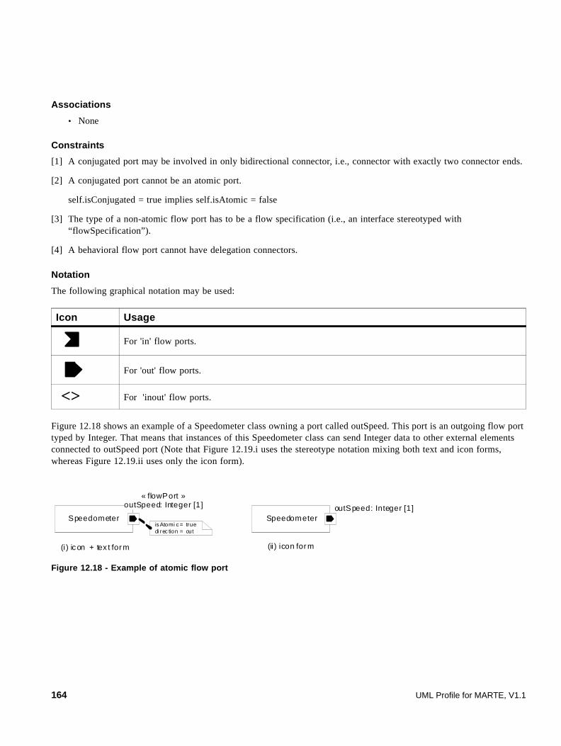
Associations
• None
Constraints
[1] A conjugated port may be involved in only bidirectional connector, i.e., connector with exactly two connector ends.
[2] A conjugated port cannot be an atomic port.
self.isConjugated = true implies self.isAtomic = false
[3] The type of a non-atomic flow port has to be a flow specification (i.e., an interface stereotyped with “flowSpecification”).
[4] A behavioral flow port cannot have delegation connectors.
Notation
The following graphical notation may be used:
Figure 12.18 shows an example of a Speedometer class owning a port called outSpeed. This port is an outgoing flow port typed by Integer. That means that instances of this Speedometer class can send Integer data to other external elements connected to outSpeed port (Note that Figure 12.19.i uses the stereotype notation mixing both text and icon forms, whereas Figure 12.19.ii uses only the icon form).
Figure 12.18 - Example of atomic flow port
Icon Usage
For 'in' flow ports.
For 'out' flow ports.
<> For 'inout' flow ports.
Speedometer
« flowPort »outSpeed: Integer [1]
is Atomi c = truedi rec tion = out
SpeedometeroutSpeed: Integer [1]
(i ) icon + tex t for m (ii ) icon for m
164 UML Profile for MARTE, V1.1

Figure 12.19 - Example of non-atomic flow port
12.3.2.11 FlowProperty
This stereotype maps the FlowProperty domain concept defined in F.6.13. A FlowProperty defines the type and the direction of a single flow element carried through flow ports. It may relate to a Classifier, a Signal, a PrimitiveType or a DataType. A flow property is used by as part of a flow specification to characterize the type of a non-atomic flow port.
Extensions
• Property
Generalizations
• None
Attributes
• direction: FlowDirectionKind [1] = inout Direction of the flow property.
Associations
• None
Constraints
• None
Notation
When applying the stereotype using its iconographical form, following icons are used:
Figure 12.20 describes an example using both textual and iconographical forms of the stereotype.
Icon Usage
For 'in' flow properties.
For 'out' flow properties.
<> For 'inout' flow properties.
UML Profile for MARTE, V1.1 165

Figure 12.20 - Example of flow properties
12.3.2.12 FlowSpecification
This stereotype has been defined to specialize interfaces used to type flow port (domain concept introduced in F.6.14) in order to enable the description of the different data a flow port may relay.
Extensions
• Interface
Generalizations
• None
Attributes
• None
Associations
• None
Constraints
[1] If the direction of flow specification is “in,” all its owned flow property must be conformed to this direction (i.e., only in flow properties).
[2] If the direction of flow specification is “out,” all its owned flow property must be conformed to this direction (i.e., only out flow properties).
[3] A flow specification owns only FlowProperties, i.e., Properties on which the FlowProperty stereotype has been applied. It cannot own operations, or receptions (of signal).
12.3.2.13 GCMInvocatingBehavior
GCMInvocatingBehavior extends the UML Behavior metaclass with the ability to define any number of invocations happening inside it. Each invocation will be defined either by a pair port/feature (i.e., a FlowPort and a FlowProperty, or a ClientServerPort and a ClientServerFeature) or by an invocation action.
Extensions
• Behavior (from UML::BasicBehaviors)
166 UML Profile for MARTE, V1.1

Generalizations
• None
Attributes
• None
Associations
• onPorts: Port[0..*] The set of ports the interactions will occur at.
• onFeatures: Feature[0..*] The set of features, related to the ports, to which the interaction is related.
• invocations: InvocationAction[0..*] The set of invocation actions that define the interactions occurring at this behavior.
Constraints
[1] The ports referenced by the “onPorts” association must be FlowPorts or ClientServerPorts. self.onPorts->forAll(port | port.oclIstypeOf(MARTE::MARTE_DesignModel::GCM::FlowPort) or port.oclIsTypeOf(MARTE::MARTE_DesignModel::GCM::ClientServerPort).
[2] The features referenced by the “onFeatures” association must be FlowProperties or ClientServerFeatures.
self.onFeatures->forAll(feature | feature.oclIstypeOf(MARTE::MARTE_DesignModel::GCM::FlowPorperty) or feature.oclIsTypeOf(MARTE::MARTE_DesignModel::GCM::ClientServerFeature).
[3] If a feature is included in the “onFeatures” list, then its related port must be referenced in the “onPorts” list.
12.3.2.14 GCMInvocationAction
GCMInvocationAction extends UML InvocationAction metaclass with the ability to specify the Feature (i.e., FlowProperty or ClientServerFeature) of a FlowPort or ClientServerPort that is concerned by the invocation.
Extensions
• InvocationAction (from UML::InvocationActions
Generalizations
• None
Attributes
• None
Associations
• onFeature: Feature [1] The Feature (of a FlowPort or ClientServerPort) that is concerned by the InvocationAction.
UML Profile for MARTE, V1.1 167
Constraints
[1] The InvocationAction must reference (via InvocationAction::onPort) exactly one port.
[2] The referenced port must be a non-atomic FlowPort or a feature-based ClientServerPort.
[3] In the case of a FlowPort, ‘onFeature’ must reference a FlowProperty owned by the FlowSpecification specifying the port.
[4] In the case of a ClientServerPort, ‘onFeature’ must reference a ClientServerFeature owned by the ClientServerSpecification specifying the port.
[5] In the case of a FlowPort, the ‘direction’ of the FlowProperty referenced by ‘feature’ must be either out, or inout.
[6] In the case of a ClientServerPort, the ‘kind’ of the ClientServerFeature referenced by ‘feature’ must be either required, or proreq.
12.3.2.15 GCMTrigger
GCMTrigger extends the UML Trigger metaclass. Within UML, triggers can natively be related to a particular port. Additionally, the GCMTrigger can be related to a particular feature of a FlowPort or ClientServerPort. It is thus possible to specify reactions that are, for example, related to the occurrence of a specific event on a given non-atomic port. For example, if we consider a non-atomic flow port proving an interface defining two flow-property (e.g., a time and a speed), the designer may specify individual reaction to whatever received information.
Extensions
• Trigger (from UML::InvocationExtensions)
Generalizations
• None
Attributes
• None
Associations
• feature: Feature [1] The Feature (of a ClientServerSpecification or FlowSpecification) to which the Trigger is related.
Constraints
[1] The Trigger must reference (via Trigger::port) exactly one port.
[2] The referenced port must be a non-atomic FlowPort or a feature-based ClientServerPort.
[3] In the case of FlowPort, feature must reference a FlowProperty owned by the FlowSpecification specifying the port.
[4] In the case of a ClientServerPort, feature must reference a ClientServerFeature owned by the ClientServerSpecification specifying the port.
[5] In the case of a FlowPort, the direction of the FlowProperty referenced by feature must be either in, or inout.
168 UML Profile for MARTE, V1.1
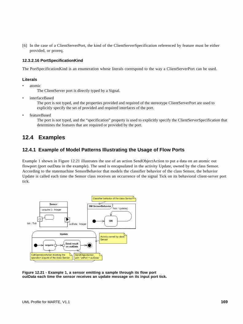
[6] In the case of a ClientServerPort, the kind of the ClientServerSpecification referenced by feature must be either provided, or proreq.
12.3.2.16 PortSpecificationKind
The PortSpecificationKind is an enumeration whose literals correspond to the way a ClientServerPort can be used.
Literals
• atomic The ClientServer port is directly typed by a Signal.
• interfaceBased The port is not typed, and the properties provided and required of the stereotype ClientServerPort are used to explicitly specify the set of provided and required interfaces of the port.
• featureBased The port is not typed, and the “specification” property is used to explicitly specify the ClientServerSpecification that determines the features that are required or provided by the port.
12.4 Examples
12.4.1 Example of Model Patterns Illustrating the Usage of Flow Ports
Example 1 shown in Figure 12.21 illustrates the use of an action SendObjectAction to put a data on an atomic out flowport (port outData in the example). The send is encapsulated in the activity Update, owned by the class Sensor. According to the statemachine SensorBehavior that models the classifier behavior of the class Sensor, the behavior Update is called each time the Sensor class receives an occurrence of the signal Tick on its behavioral client-server port tick.
Figure 12.21 - Example 1, a sensor emitting a sample through its flow port outData each time the sensor receives an update message on its input port tick.
UML Profile for MARTE, V1.1 169

Example 2 shown in Figure 12.22 illustrates the use of the GCMInvocatingBehavior stereotype to show all the interactions taking place inside a behavior. As in Example 1, the sends are encapsulated in the activity Update, owned by Sensor. In this case, the interactions triggered by the execution of Update are available at state machine level, without needing to go deep into the details of the Update activity. The same is also applicable for StateMachines or OpaqueBehaviors.
Figure 12.22 - Example 2, a sensor emitting two samples though different ports and features.
Example 3 shown in Figure 12.23, illustrates the “push” form of the flow port semantics. The port inData is a behavioral input atomic flow port typed as Integer. Thus, each time an integer value is received on this port inData, a DataEvent is raised and stored in the event pool of the context object of the classifier behavior DataDrivenFilterClassifierBehavior (i.e., the instance of the class DataDrivenActuator receiving the integer value). The activity DataDrivenFilterActuatorClassifierBehavior (used as a classifier behavior for the class DataDrivenActuator) specifies a reaction to the occurrence of a DataEvent on its flowport inData, as described by its AcceptEventAction. The output pin of the AcceptEventAction represents the data associated with the DataEvent, which is provided as an input to the next action, the CallOperationAction compute.
Sensor
outAtomic : Integer
SM SensorBehavior
ON
Tick / Update()
«GCMInvocationBehavior»Update
«GCMInvocationAction»Send … on outData
Send…on outAtomic
onPort = outDataonFeature = a onPort = outAtomic
Activity owned by class Sensor
tick : Tick
outData : Integer
«GCMInvocationBehavior»onPort = {outData, outAtomic}onFeature = a
170 UML Profile for MARTE, V1.1

Figure 12.23 - Example 3, on the "push" form of the flow port semantics. Reactions of the actuator are triggered by data receptions, through an AcceptEventAction using a "DataEvent" as a trigger.
Example 4 shown in Figure 12.24 illustrates the “pull” variant of flow port semantics. The input port inData, a non-behavioral port, of the class SamplingActuator has a delegation connector towards the part i_value. This property is typed by the Integer primitive type accordingly to the type of the port. As described in sub clause 12.3.2.9 on the semantics of FlowPort, this modeling pattern means that data received on port inData are held by the property i_value. In this case, as the stereotype «dataPool» is not applied on the property i_value, the data hold by the property is replaced each time a new data is received on port inData. This data is then available for the activity Update (which is owned by the class SamplingActuator). With respect to the classifier behavior SensorBehavior, each time an instance of the class SamplingActuator receives an instance of the signal Tick on its client-server port tick, the outgoing transition from state On is triggered and its effect behavior is ran. In this case, the effect behavior is modeled by the activity Update. This latter reads the value hold on the property i_value and passes the value as input parameter to the CallOperationAction compute.
UML Profile for MARTE, V1.1 171

Figure 12.24 - Example 4, on the "pull" form of the flow port semantics. Reactions of the sampling actuator are triggered by reception of Tick signal instances
In addition to Example 4 shown in Figure 12.24, Example 5 depicted in Figure 12.25 illustrates the use the stereotype «dataPool» applied here on the property buffer of the class SamplingActuator. The activity Replace (see top left corner of Figure 12.25) is used as a specification of how data must be inserted in the property buffer when they are received on the flow port inData. Moreover, this example also illustrates the use of connectors between the input parameter of the activity Update (owned by the class SamplingActuator) and the property buffer, and the use of connectors between the output parameter of the activity updateMethod and the flow port outData of class SamplingActuator. These connectors mean that each time the activity Update is called (here, as a consequence of Tick signal occurrences), the input values to activity Update are read from the data pool buffer, with respect to the ‘selection’ policy specified by the activity LastIsBest (see top right corner in Figure 12.25). When an execution of activity Update finishes, data available on its output parameter are propagated via the delegation connector between its output parameter and the flow port outData of the actuator.
172 UML Profile for MARTE, V1.1

Figure 12.25 - Example 5, on the usage of the stereotype "DataPool" in the context of the "pull" form of the flow port semantics
Example 6 shown in Figure 12.26 illustrates the use of an Activity as a classifier behavior (i.e., DataDrivenFilterBehavior) for putting into action the 'push' form of flow port semantics. Data received on the flow port inData are made available as tokens to the streaming parameter input of the activity DataDrivenFilterBehavior via a delegation connector. As UML activities behave naturally according to the push form of flow port semantics, the tokens available on the parameter input will be proposed to the CallOperationAction filter. This latter will consume incoming token one per one and produce output tokens on its streaming parameter labeled output. The delegation connector
UML Profile for MARTE, V1.1 173

between the parameter output of DataDrivenFilterBehavior and the flow port outData of DataDrivenFilter is used to mean that the data produced by the activity is conveyed to the port outData. Note that the use of streaming parameters is essential so that the execution of DataDrivenFilterBehavior can accept and produce data in a pipeline manner.
Figure 12.26 - Example 6, on the "push" form of the flow port semantics
12.4.2 Automotive Example
The example shown in Figure 12.27 denotes the interface description for the example of a component model depicted previously. The package SpeedRegulatorInterfaces consists of two definitions of interface and one signal declaration. RegInterface is a UML2 interface stereotyped with “clientServerSpecification.” It specifies a provided reception for the Start signal (i.e., a reception stereotyped with “clientServerFeature” with kind = ‘provided.’ It is modeled in this example using the iconographical notation) and a required controlEngine service (i.e., an operation stereotyped as “clientServerFeature,” with kind = ‘required.’ It is also represented using the iconographical notation). The interface ECInterface is a classical UML interface, with a single operation named controlEngine.
174 UML Profile for MARTE, V1.1
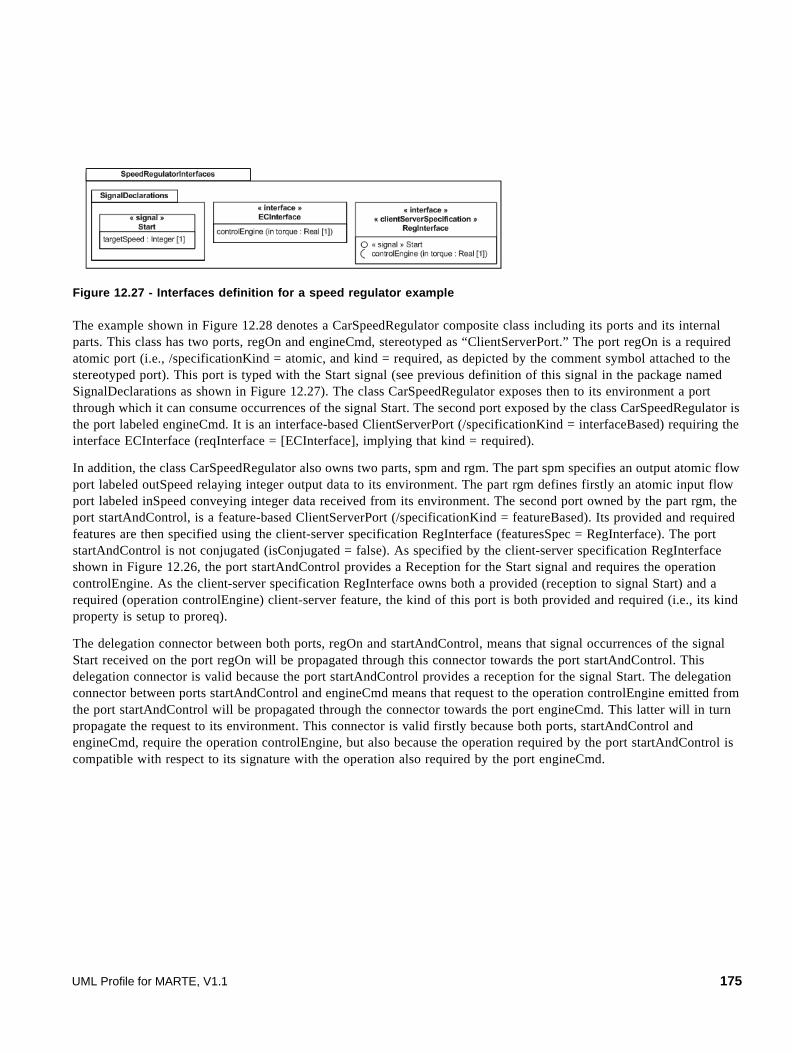
Figure 12.27 - Interfaces definition for a speed regulator example
The example shown in Figure 12.28 denotes a CarSpeedRegulator composite class including its ports and its internal parts. This class has two ports, regOn and engineCmd, stereotyped as “ClientServerPort.” The port regOn is a required atomic port (i.e., /specificationKind = atomic, and kind = required, as depicted by the comment symbol attached to the stereotyped port). This port is typed with the Start signal (see previous definition of this signal in the package named SignalDeclarations as shown in Figure 12.27). The class CarSpeedRegulator exposes then to its environment a port through which it can consume occurrences of the signal Start. The second port exposed by the class CarSpeedRegulator is the port labeled engineCmd. It is an interface-based ClientServerPort (/specificationKind = interfaceBased) requiring the interface ECInterface (reqInterface = [ECInterface], implying that kind = required).
In addition, the class CarSpeedRegulator also owns two parts, spm and rgm. The part spm specifies an output atomic flow port labeled outSpeed relaying integer output data to its environment. The part rgm defines firstly an atomic input flow port labeled inSpeed conveying integer data received from its environment. The second port owned by the part rgm, the port startAndControl, is a feature-based ClientServerPort (/specificationKind = featureBased). Its provided and required features are then specified using the client-server specification RegInterface (featuresSpec = RegInterface). The port startAndControl is not conjugated (isConjugated = false). As specified by the client-server specification RegInterface shown in Figure 12.26, the port startAndControl provides a Reception for the Start signal and requires the operation controlEngine. As the client-server specification RegInterface owns both a provided (reception to signal Start) and a required (operation controlEngine) client-server feature, the kind of this port is both provided and required (i.e., its kind property is setup to proreq).
The delegation connector between both ports, regOn and startAndControl, means that signal occurrences of the signal Start received on the port regOn will be propagated through this connector towards the port startAndControl. This delegation connector is valid because the port startAndControl provides a reception for the signal Start. The delegation connector between ports startAndControl and engineCmd means that request to the operation controlEngine emitted from the port startAndControl will be propagated through the connector towards the port engineCmd. This latter will in turn propagate the request to its environment. This connector is valid firstly because both ports, startAndControl and engineCmd, require the operation controlEngine, but also because the operation required by the port startAndControl is compatible with respect to its signature with the operation also required by the port engineCmd.
UML Profile for MARTE, V1.1 175
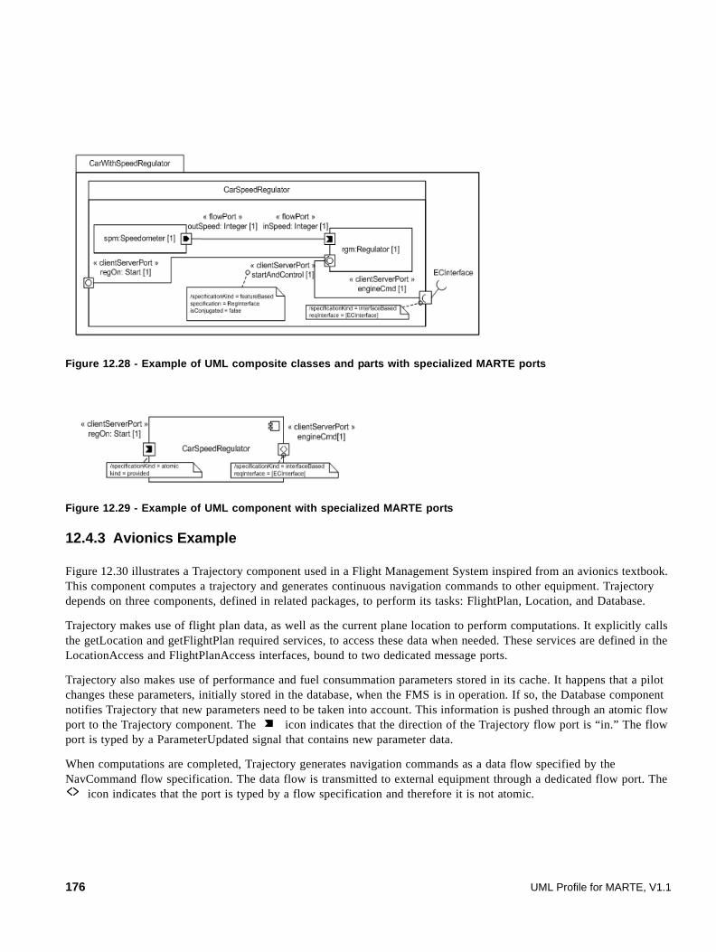
Figure 12.28 - Example of UML composite classes and parts with specialized MARTE ports
Figure 12.29 - Example of UML component with specialized MARTE ports
12.4.3 Avionics Example
Figure 12.30 illustrates a Trajectory component used in a Flight Management System inspired from an avionics textbook. This component computes a trajectory and generates continuous navigation commands to other equipment. Trajectory depends on three components, defined in related packages, to perform its tasks: FlightPlan, Location, and Database.
Trajectory makes use of flight plan data, as well as the current plane location to perform computations. It explicitly calls the getLocation and getFlightPlan required services, to access these data when needed. These services are defined in the LocationAccess and FlightPlanAccess interfaces, bound to two dedicated message ports.
Trajectory also makes use of performance and fuel consummation parameters stored in its cache. It happens that a pilot changes these parameters, initially stored in the database, when the FMS is in operation. If so, the Database component notifies Trajectory that new parameters need to be taken into account. This information is pushed through an atomic flow port to the Trajectory component. The icon indicates that the direction of the Trajectory flow port is “in.” The flow port is typed by a ParameterUpdated signal that contains new parameter data.
When computations are completed, Trajectory generates navigation commands as a data flow specified by the NavCommand flow specification. The data flow is transmitted to external equipment through a dedicated flow port. The
icon indicates that the port is typed by a flow specification and therefore it is not atomic.
176 UML Profile for MARTE, V1.1
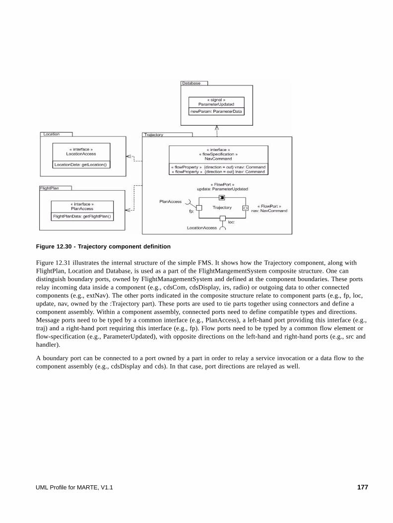
Figure 12.30 - Trajectory component definition
Figure 12.31 illustrates the internal structure of the simple FMS. It shows how the Trajectory component, along with FlightPlan, Location and Database, is used as a part of the FlightMangementSystem composite structure. One can distinguish boundary ports, owned by FlightManagementSystem and defined at the component boundaries. These ports relay incoming data inside a component (e.g., cdsCom, cdsDisplay, irs, radio) or outgoing data to other connected components (e.g., extNav). The other ports indicated in the composite structure relate to component parts (e.g., fp, loc, update, nav, owned by the :Trajectory part). These ports are used to tie parts together using connectors and define a component assembly. Within a component assembly, connected ports need to define compatible types and directions. Message ports need to be typed by a common interface (e.g., PlanAccess), a left-hand port providing this interface (e.g., traj) and a right-hand port requiring this interface (e.g., fp). Flow ports need to be typed by a common flow element or flow-specification (e.g., ParameterUpdated), with opposite directions on the left-hand and right-hand ports (e.g., src and handler).
A boundary port can be connected to a port owned by a part in order to relay a service invocation or a data flow to the component assembly (e.g., cdsDisplay and cds). In that case, port directions are relayed as well.
UML Profile for MARTE, V1.1 177

Figure 12.31 - FlightManagementSystem internal structure
Note – Both Figure 12.30 and Figure 12.31 are compatible with the SysML block definition diagrams and internal block diagrams.
FlightManagementSystem
:Database
:FlightPlan
:Location
:Trajectory
extNav: NavCommand
radio: RadioInterface
irs: IRSInterface
radio: RadioInterface
nav: NavCommand
handler: ParameterUpdated
traj:
src: ParameterUptated
loc:
irs: IRSInterface
cds:
fp:
db:
cds:
LocationAccess
LocationAccess
fp:PlanAccess
PlanAccess
loc:
CDSCommand
CDSCommand
cdsCom:
CDSDisplay
CDSDisplay
cdsDisplay:
DBAccess
DBAccess
178 UML Profile for MARTE, V1.1

13 High-Level Application Modeling (HLAM)
13.1 Overview
Figure 13.1 - Dependencies of the HLAM package
As illustrated by Figure 13.1, the HLAM package of MARTE is depending of both GRM and CoreElements packages. The concern of the HLAM package is to provide high-level modeling concepts to deal with real-time and embedded features modeling. In comparison with usual application domains, RT systems (in short RTS) development requires possibilities of modeling on one hand quantitative features such as deadline and period and, in other the hand, qualitative features that are related to behavior, communication and concurrency. The next sub clause will describe a domain model defining the MARTE concepts for RT/E high-level modeling constructs to support both aspects.
13.2 Domain View
One first important issue to deal with when modeling RTE applications is concurrency. In order to handle that feature, this specification uses the concept of RtUnit as depicted in Figure 13.2. It provides high-level constructs for real-time and embedded application modeling based on the MARTE foundations introduced in Part I (within both CoreElements and GRM packages) and in the Generic Component Model. An RtUnit is similar to the active object of UML but with a more detailed semantics description. It owns one or several schedulable resources (GRM::Scheduling::SchedulableResource). If its dynamic attribute is set to true, the schedulable resources are created dynamically when required. In other case, the real-time unit has a pool of schedulable resources. When no schedulable resource is available , the real-time unit may either wait indefinitely for a resource to be released, wait for only a given amount of time (specified by its poolWaitingTime attribute), and increase its pool thread dynamically to adapt to the demand, or generate an exception.
Hence, a real-time unit may be seen as an autonomous execution resource, able to handle different messages at the same time. It can manage concurrency and real-time constraints attached to incoming messages. An RtUnit is a unit of concurrency that encapsulates in a single entity both the object and the process paradigms, which means that concurrency control is encapsulated within the unit. Any real-time unit can invoke services of other real-time units, send signals or data (see the GCM clause for details on dataflow-oriented communications), without worrying about concurrency issues. Real-time units are some kind of tasks servers that can satisfy several requests from several real-time units at the same time, enabling intra-unit parallelism if necessary. An RtUnit owns also a concurrency and behavior controller for managing message constraints according to its current state and the concurrent execution constraints attached to the messages.
An application owns at least one main RtUnit. Following creation, each real-time unit that has a main (which is indicated by setting the isMain attribute to true) starts invoking a main real-time service, which executes until the real-time unit is terminated. Like any other real-time units, the main service of a main unit may perform explicit receive actions during its execution, in order to accept any received events. A receive action by a real-time unit leads to a direct activation of the
UML Profile for MARTE, V1.1 179
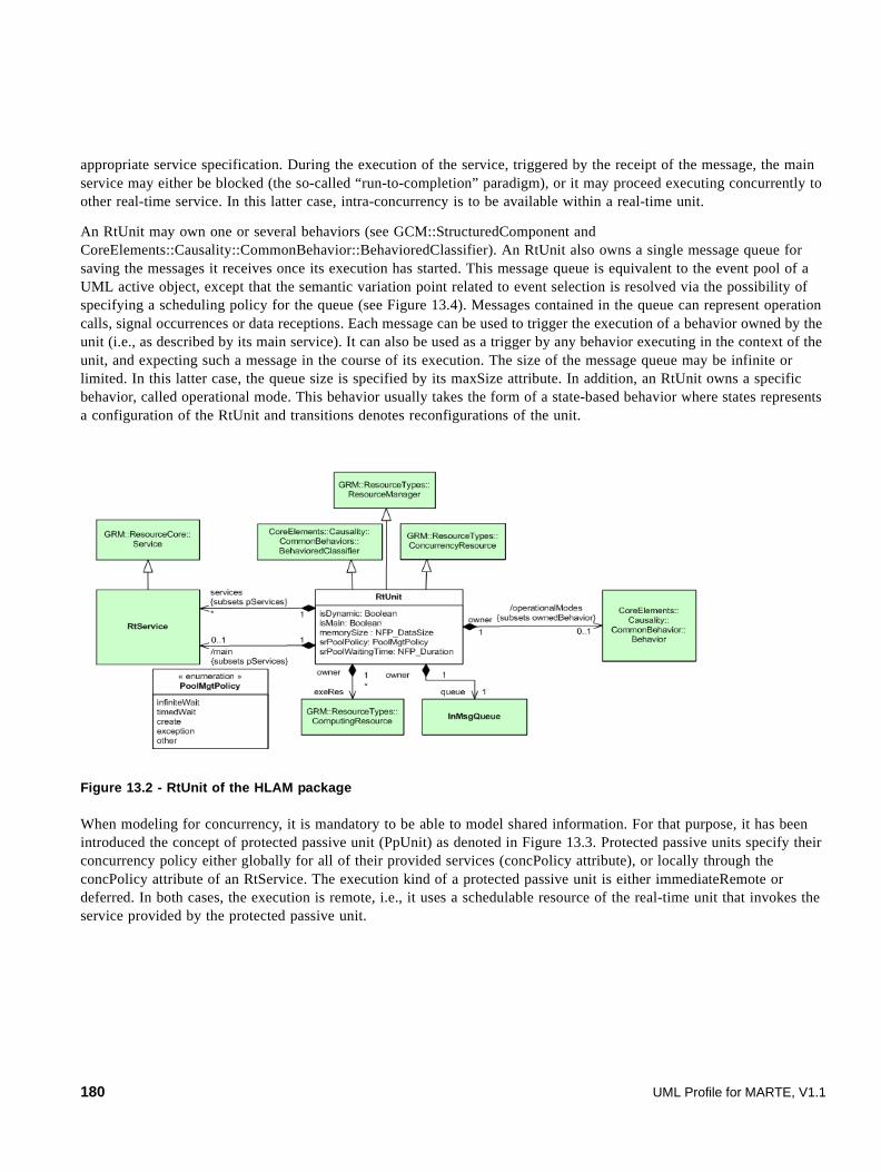
appropriate service specification. During the execution of the service, triggered by the receipt of the message, the main service may either be blocked (the so-called “run-to-completion” paradigm), or it may proceed executing concurrently to other real-time service. In this latter case, intra-concurrency is to be available within a real-time unit.
An RtUnit may own one or several behaviors (see GCM::StructuredComponent and CoreElements::Causality::CommonBehavior::BehavioredClassifier). An RtUnit also owns a single message queue for saving the messages it receives once its execution has started. This message queue is equivalent to the event pool of a UML active object, except that the semantic variation point related to event selection is resolved via the possibility of specifying a scheduling policy for the queue (see Figure 13.4). Messages contained in the queue can represent operation calls, signal occurrences or data receptions. Each message can be used to trigger the execution of a behavior owned by the unit (i.e., as described by its main service). It can also be used as a trigger by any behavior executing in the context of the unit, and expecting such a message in the course of its execution. The size of the message queue may be infinite or limited. In this latter case, the queue size is specified by its maxSize attribute. In addition, an RtUnit owns a specific behavior, called operational mode. This behavior usually takes the form of a state-based behavior where states represents a configuration of the RtUnit and transitions denotes reconfigurations of the unit.
Figure 13.2 - RtUnit of the HLAM package
When modeling for concurrency, it is mandatory to be able to model shared information. For that purpose, it has been introduced the concept of protected passive unit (PpUnit) as denoted in Figure 13.3. Protected passive units specify their concurrency policy either globally for all of their provided services (concPolicy attribute), or locally through the concPolicy attribute of an RtService. The execution kind of a protected passive unit is either immediateRemote or deferred. In both cases, the execution is remote, i.e., it uses a schedulable resource of the real-time unit that invokes the service provided by the protected passive unit.
180 UML Profile for MARTE, V1.1
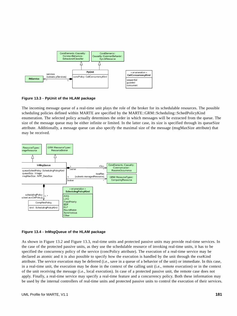
Figure 13.3 - PpUnit of the HLAM package
The incoming message queue of a real-time unit plays the role of the broker for its schedulable resources. The possible scheduling policies defined within MARTE are specified by the MARTE::GRM::Scheduling::SchedPolicyKind enumeration. The selected policy actually determines the order in which messages will be extracted from the queue. The size of the message queue may be either infinite or limited. In the latter case, its size is specified through its queueSize attribute. Additionally, a message queue can also specify the maximal size of the message (msgMaxSize attribute) that may be received.
Figure 13.4 - InMsgQueue of the HLAM package
As shown in Figure 13.2 and Figure 13.3, real-time units and protected passive units may provide real-time services. In the case of the protected passive units, as they use the schedulable resource of invoking real-time units, it has to be specified the concurrency policy of the service (concPolicy attribute). The execution of a real-time service may be declared as atomic and it is also possible to specify how the execution is handled by the unit through the exeKind attribute. The service execution may be deferred (i.e., save in a queue of a behavior of the unit) or immediate. In this case, in a real-time unit, the execution may be done in the context of the calling unit (i.e., remote execution) or in the context of the unit receiving the message (i.e., local execution). In case of a protected passive unit, the remote case does not apply. Finally, a real-time service may specify a real-time feature and a concurrency policy. Both these information may be used by the internal controllers of real-time units and protected passive units to control the execution of their services.
UML Profile for MARTE, V1.1 181
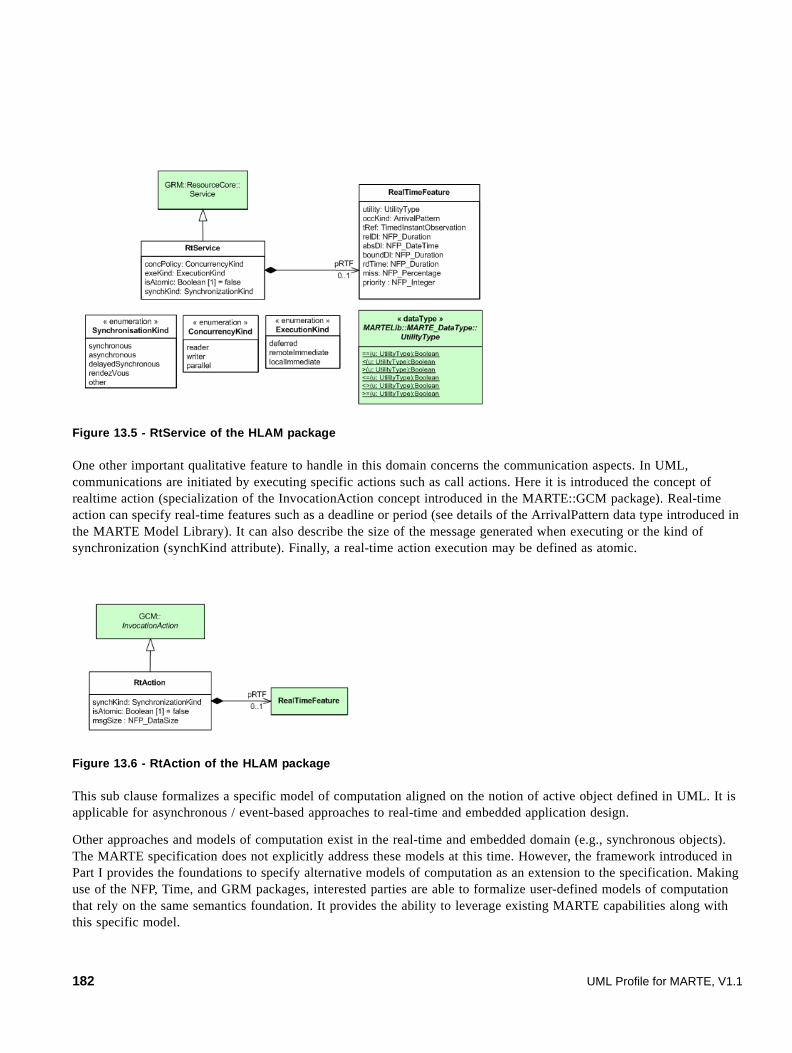
Figure 13.5 - RtService of the HLAM package
One other important qualitative feature to handle in this domain concerns the communication aspects. In UML, communications are initiated by executing specific actions such as call actions. Here it is introduced the concept of realtime action (specialization of the InvocationAction concept introduced in the MARTE::GCM package). Real-time action can specify real-time features such as a deadline or period (see details of the ArrivalPattern data type introduced in the MARTE Model Library). It can also describe the size of the message generated when executing or the kind of synchronization (synchKind attribute). Finally, a real-time action execution may be defined as atomic.
Figure 13.6 - RtAction of the HLAM package
This sub clause formalizes a specific model of computation aligned on the notion of active object defined in UML. It is applicable for asynchronous / event-based approaches to real-time and embedded application design.
Other approaches and models of computation exist in the real-time and embedded domain (e.g., synchronous objects). The MARTE specification does not explicitly address these models at this time. However, the framework introduced in Part I provides the foundations to specify alternative models of computation as an extension to the specification. Making use of the NFP, Time, and GRM packages, interested parties are able to formalize user-defined models of computation that rely on the same semantics foundation. It provides the ability to leverage existing MARTE capabilities along with this specific model.
182 UML Profile for MARTE, V1.1

13.3 UML Representation
This sub clause describes the MARTE HLAM sub-profile. This latter contains all required UML extensions to support the concepts denoted in the previous domain model.
Figure 13.7 - The MARTE HLAM sub-profile
13.3.1 Profile Diagrams
Figure 13.8 - RtUnit and PpUnit stereotype of the MARTE::HLAM sub-profile
« metaclass »CommonBehavior::BasicBehaviors::
BehavioredClassifier
isDynamic: Boolean [1] = trueisMain: BooleansrPoolSize: IntegersrPoolPolicy: PoolMgtPolicyKindsrPoolWaitingTime: NFP_DurationqueueSchedPolicy: SchedPolicyKindqueueSize: IntegermsgMaxSize: NFP_DataSizeoperationalMode: Behaviormain: OperationmemorySize: NFP_DataSize
« stereotype »RtUnit
concPolicy: CallConcurrencyKindmemorySize: NFP_DataSize
« stereotype »PpUnit
infiniteWaittimedWaitdynamicexceptionother
« enumeration »PoolMgtPolicyKind
sequentialguardedconcurrent
« enumeration »CallConcurrencyKind
EarliestDeadlineFirstLIFOFixedPriorityLeastLaxityFirstRoundRobinTimeTableDrivenUndefOther
« enumeration »MARTE_Library::
GRM_BasicTypes::SchedPolicyKind
UML Profile for MARTE, V1.1 183

Figure 13.9 - RtFeature stereotype of the MARTE::HLAM sub-profile
Figure 13.10 - RtAction of the MARTE::HLAM sub-profile
Figure 13.11 - RtService of the MARTE::HLAM sub-profile
184 UML Profile for MARTE, V1.1

13.3.2 Profile Elements Description
13.3.2.1 CallConcurrencyKind
The CallConcurrencyKind enumeration maps the CallConcurrencyKind domain element denoted in Annex F (F.7.1).
This enumeration defines the kind of concurrency policy applied to a protected passive unit.
Literals
• sequential Only one schedulable resource at a time can access a feature of a PpUnit. The PpUnit do not provide in this case access control mechanism; it is up to the client to deal with potential concurrent conflicts.
• guarded A schedulable resource at a time can access a feature of a PpUnit while concurrent ones are suspended.
• concurrent Multiple schedulable resources at a time can access a PpUnit.
13.3.2.2 ConcurrencyKind
The ConcurrencyKind enumeration maps the ConcurrencyKind domain element denoted in Annex F (F.7.3).
This enumeration defines the kinds of concurrency of a behavioral feature.
Literals
• reader The behavioral feature execution has no side effects (i.e., it does not modify the state of the object, or the values of its properties).
• writer The behavioral feature execution may have side effects.
• parallel The behavioral feature execution may be done in parallel of any kind of service.
13.3.2.3 ExecutionKind
The ExecutionKind enumeration maps the ExecutionKind domain element denoted in Annex F (F.7.4).
This enumeration defines the kind of execution of a behavioral feature.
Literals
• deferred Event occurrence matching the service invocation is saved in the queue of behavior attached to the object.
• remoteImmediate The execution is performed immediately with schedulable resource of the calling object.
• localImmediate The execution is performed immediately with a schedulable resource of the called object.
UML Profile for MARTE, V1.1 185

13.3.2.4 PoolMgtPolicyKind
The PoolMgtPolicyKind enumeration maps the PoolMgtPolicy domain element denoted in Annex F (F.7.4).
This enumeration has been introduced in the profile to define the concurrency pool management policy of the real-time units.
Literals
• infiniteWait If the pool is empty, the real-time unit waits indefinitely until a schedulable resource will be released.
• timedWait If the pool is empty, the real-time unit waits for bound time until a schedulable resource will be released. At the end of the waiting time, if no schedulable resource have released, an exception is raised.
• dynamic If the pool is empty, the real-time unit creates a new schedulable resource and adds it to the pool.
• exception If the pool is empty, the real-time unit raise an exception.
• other
13.3.2.5 PpUnit
The PpUnit stereotype maps the PpUnit domain element denoted in Annex F (F.7.7).
Protected passive units specify their concurrency policy either globally for all of their provided services (concPolicy attribute), or locally through the concPolicy attribute of the RtService. The execution kind of a protected passive unit is either immediateRemote or deferred. In this latter case, the execution is also remote, i.e., it uses the schedulable resource of the real-time unit invoking the service to the protected passive unit.
Extensions
• BehavioredClassifier (from UML::CommonBehavior::BasicBehaviors).
Attributes
• concPolicy: CallConurrencyKind [0..1] Kind of concurrency policy applied to the behavioral feature of the PpUnit. CallConcurrencyKind is the enumeration defined in the UML2. Its literal values may be as defined in UML: sequential, guarded, or concurrent.
• memorySize: NFP_DataSize Amount of static memory required for each instance of the protected passive unit to be placed in an application.
13.3.2.6 RtAction
The RtAction stereotype maps the RtAction domain element denoted in Annex F (F.7.8).
InvocationActions and BehavioralFeatures, stereotyped with RtAction, gain the additional following attributes of “real-time” constraints.
Extensions
• InvocationAction (from UML::BasicBehaviors)
186 UML Profile for MARTE, V1.1

• BehavioralFeature (from UML::Kernel)
Attributes
• synchKind: SynchronizationKind Synchronization mechanism associated to the communication action.
• isAtomic: Boolean [1] = false When true, implies that the RtAction executes as one indivisible unit, non-interleaved with other RtActions.
• msgSize: NFP_DataSize Size of a message generated when executing an action.
13.3.2.7 RtFeature
The RtFeature stereotype maps the RealTimeFeature domain element denoted in Annex F (F.7.10).
The RtFeature stereotype is used to annotate model elements with real-time features according to set of RtSpecification associated with this stereotype. This stereotype may be also used in other contexts than RtUnit and PpUnit.
The stereotype «RtFeature» can be applied to multiple kinds of modeling elements (i.e., behavioral features, actions, messages, signals, and ports). Whatever the element on which the stereotype is applied, there is a common run-time interpretation for real-time specifications associated with a real-time feature. The stereotype «RtSpecification» enables capturing information concerning messages in transit between two (or more) communicating instances. This information is used by the receiving instances as constraints on behavior executions triggered by incoming messages.
The run-time moment at which the values for this information are fixed depends on the design-time element on which the stereotype «RtFeature» has been applied. It can be easily understood in terms of priority rules, as described in the following paragraph.
The most basic model elements on which the stereotype «RtFeature» can be applied are instances of InvocationAction. When such action is executed at run-time, a message carrying run-time values (consistent with the corresponding values of the properties of the instance of the stereotype «RtSpecification» applied on the executed action) will be sent. The instance receiving the message will then handle it a priori by launching the execution of a behavior. This execution will then be constrained by the real-time information associated with the message. Applying the stereotype «RtFeature» on a modeling element that is not an instance of InvocationAction can be seen as a means for defining a default real-time constraint specification if an invocation action has no associated real-time specification. In the case where the stereotype «RtFeature» is applied on several modeling elements, the HLAM profile provides priority rules between the different modeling elements on which the stereotype can be applied, as illustrated in Figure 13.12.
For example, if the design-time model is object-oriented (i.e., corresponding run-time instances do not communicate via ports), the stereotype RtFeature can also be applied on a BehavioralFeature of a classifier involved in the model. At run-time, when an instance of this classifier receives a message (i.e., operation call event or signal occurrence) related to an «RtFeature» behavioral feature and in the case where the invocation action (whose execution resulted in the emission of this message) was not stereotyped with «RtFeature», real-time information associated with the «RtFeature» behavioral feature are used to determine the real-time information associated with the message itself. In the case where the stereotype «RtFeature» is applied on both the invocation action and the invoked behavioral feature, the real-time specification associated with the action has priority on the real-time specification associated with the behavioral feature. In Figure 13.12, green circles represent the different places where the stereotype «RtFeature» can be applied within a UML model. The number associated with each circle represents the priority of the modeling element (i.e., real-time information associated with an invocation action has the strongest priority).
UML Profile for MARTE, V1.1 187
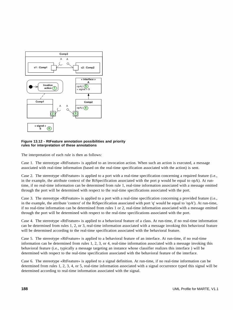
Figure 13.12 - RtFeature annotation possibilities and priority rules for interpretation of these annotations
The interpretation of each rule is then as follows:
Case 1. The stereotype «RtFeature» is applied to an invocation action. When such an action is executed, a message associated with real-time information (based on the real-time specification associated with the action) is sent.
Case 2. The stereotype «RtFeature» is applied to a port with a real-time specification concerning a required feature (i.e., in the example, the attribute context of the RtSpecification associated with the port p would be equal to opA). At run-time, if no real-time information can be determined from rule 1, real-time information associated with a message emitted through the port will be determined with respect to the real-time specifications associated with the port.
Case 3. The stereotype «RtFeature» is applied to a port with a real-time specification concerning a provided feature (i.e., in the example, the attribute 'context' of the RtSpecification associated with port 'q' would be equal to 'opA'). At run-time, if no real-time information can be determined from rules 1 or 2, real-time information associated with a message emitted through the port will be determined with respect to the real-time specifications associated with the port.
Case 4. The stereotype «RtFeature» is applied to a behavioral feature of a class. At run-time, if no real-time information can be determined from rules 1, 2, or 3, real-time information associated with a message invoking this behavioral feature will be determined according to the real-time specification associated with the behavioral feature.
Case 5. The stereotype «RtFeature» is applied to a behavioral feature of an interface. At run-time, if no real-time information can be determined from rules 1, 2, 3, or 4, real-time information associated with a message invoking this behavioral feature (i.e., typically a message targeting an instance whose classifier realizes this interface ) will be determined with respect to the real-time specification associated with the behavioral feature of the interface.
Case 6. The stereotype «RtFeature» is applied to a signal definition. At run-time, if no real-time information can be determined from rules 1, 2, 3, 4, or 5, real-time information associated with a signal occurrence typed this signal will be determined according to real-time information associated with the signal.
188 UML Profile for MARTE, V1.1

Extensions
• Action (from UML::Kernel)
• BehavioralFeature (from UML::Kernel)
• Message (from UML::BasicInteractions)
• Signal (from UML::Communication)
• Behavior (from UML::BasicBehaviors)
Associations
• /specification : RtSpecification [1..*] {subsets ownedComment} This is a derived property. It references the set of comments owned by this “RtFeature” on which the stereotype “RtSpecification” is applied.
Constraints
[1] The set of comments (i.e., property ownedComment) owned by the element on which the stereotype «RtFeature» is applied contains at least one «RtSpecification».
[2] If the stereotype «RtFeature» is not applied to a port, the property specification must reference exactly one «RtSpecification».
13.3.2.8 RtService
The RtService stereotype maps the RtService domain element denoted in Annex F (F.7.12).
BehavioralFeatures, stereotyped with RtService, gain the additional following attributes of “real-time” constraints. The RtService stereotype may be applied on one BehavioralFeature independently of the fact that the containing classifier to be either a RtUnit or a PpUnit.
Extensions
• BehavioralFeature (from UML::Kernel)
Attributes
• concPolicy: ConcurrencyKind [0..1] Concurrency property of the service.
• exeKind: ExecutionKind [0..1] Execution nature property of the service.
• isAtomic: Boolean [1] = false When true, implies that the RtService executes as one indivisible unit, non-interleaved with other RtService.
• synchKind: SynchronizationKind [0..1] Synchronization mechanism of the service.
13.3.2.9 RtSpecification
The stereotype RtSpecification enables capturing information (with real-time concerns) concerning messages in transit between two (or more) communicating instances. This information is used by the receiving instances as constraints on behavior executions triggered by the reception of the message.
UML Profile for MARTE, V1.1 189

Extensions
• Comment (from UML::Kernel)
Attributes
• utility: UtilityType [0..1] Specification of the importance features. This property is typed by the UtilityType data type defined in the MARTE_Library. This type is abstract and it is up to the user to define its own specialized utility type according to its needs.
• occKind: ArrivalPattern [0..1] Specification of the arrival pattern.
• tRef: TimedInstantObservation [0..1] Time reference used for relative timing properties.
• relDl: NFP_Duration [0..1] specification of the relative deadline.
• absDl: NFP_DateTime [0..1] Specification of the absolute deadline.
• boundDl: NFP_Duration [0..1] Specifies the relative deadline.
• rdTime: NFP_Duration [0..1] Specifies the minimal ready time.
• miss: NFP_Percentage [0..1] Specifies the percentage of acceptance for missing the deadline.
• priority : NFP_Integer [0..1] Specification of the priority.
• context : BehavioralFeature [0..1] Specification of the 'context' behavioral feature, in the case where the owning RtFeature is a port.
Associations
• /context: BehavioralFeature [0..1] {subsets annotatedElement} This is a derived property. It references the BehavioralFeature on which the information contained in this «RtSpecification» applies (in the case where the owning “RtFeature” is a port).
Constraints
[1] The element owning this «RtSpecification» must be an element on which the stereotype «RtFeature» is applied.
[2] If the owning «RtFeature» is not a port, the property annotatedElement (from Comment) must contain a reference to exactly one element (i.e., the «RtFeature» owning this «RtSpecification»)
[3] If the owning «RtFeature» is a port, the property annotatedElement (from Comment) must not contain more than two references (i.e., the «RtFeature» owning this «RtSpecification», and the BehavioralFeature that is used as a context for the «RtSpecification»).
[4] If the «RtFeature» owning this «RtSpecification» is a port, the property context of the «RtSpecification» associated with the «RtFeature» must be a feature that is provided or required by the port (see the GCM clause for details about different means of providing/requiring a feature).
190 UML Profile for MARTE, V1.1

[3] If the stereotype «RtFeature» is applied to a port, the property context of the «RtSpecification» associated to the «RtFeature» can be empty only if the port is atomic (see the GCM clause).
13.3.2.10 RtUnit
The RtUnit stereotype maps the RtUnit domain element (F.7.11)
An RtUnit is similar to the active object of UML but with a more detailed semantics description. It owns at least one schedulable resource, but can also have several ones. If its dynamic attribute is set to true, the schedulable resources are created dynamically when required. In other case, the real-time unit has a pool of schedulable resources. When no schedulable resources are available in the possible, the real-time unit may either wait indefinitely for a resource to be released, or wait only a given amount of time (specified by its poolWaitingTime attribute), or increase its pool thread dynamically to adapt to the demand, or generate an exception. An RtUnit may own behaviors that have one message queue for saving the messages received by the unit. The size of this message queue may be infinite or finite. In this latter case, the queue size is specified by its maxSize attribute. In addition, an RtUnit owns a specific behavior, called operational mode. This behavior take usually the form of a state-based behavior where states represents a configuration of the RtUnit and transitions denotes reconfigurations of the unit.
Extensions
• BehavioredClassifier (from UML::CommonBehavior::BasicBehaviors)
Attributes
• isDynamic: Boolean [1] = true If true, it denotes that the real-time unit creates dynamically the schedulable resource required to execute its services. If false, the real-time unit owns a pool of schedulable resources to execute its services.
• isMain: Boolean [0..1] If true, the real-time unit is a main unit of the application.
• srPoolSize: Integer [0..1] Size of the schedulable resource pool of a real-time unit.
• srPoolPolicy: PoolMgtPolicyKind [0..1] Kind of pool policy adopted by a real-time unit.
• srPoolWaitingTime: NFP_Duration [0..1] Maximal time a real-time unit waits for a schedulable resource to be released in case of pool management policy set to timedWait.
• queueSchedPolicy: SchedPolicyKind [0..1] Queue scheduling policy of the RtUnit.
• queueSize: Integer [0..1] queue size
• msgMaxSize: NFP_DataSize [0..1] Maximal size of the messages acceptable in the queue.
• operationalMode: Behavior [0..1] Behavior owned by the real-time unit and denoting the operational modes of the real-time unit.
• main: Operation [0..1] Main operation of the real-time unit.
UML Profile for MARTE, V1.1 191
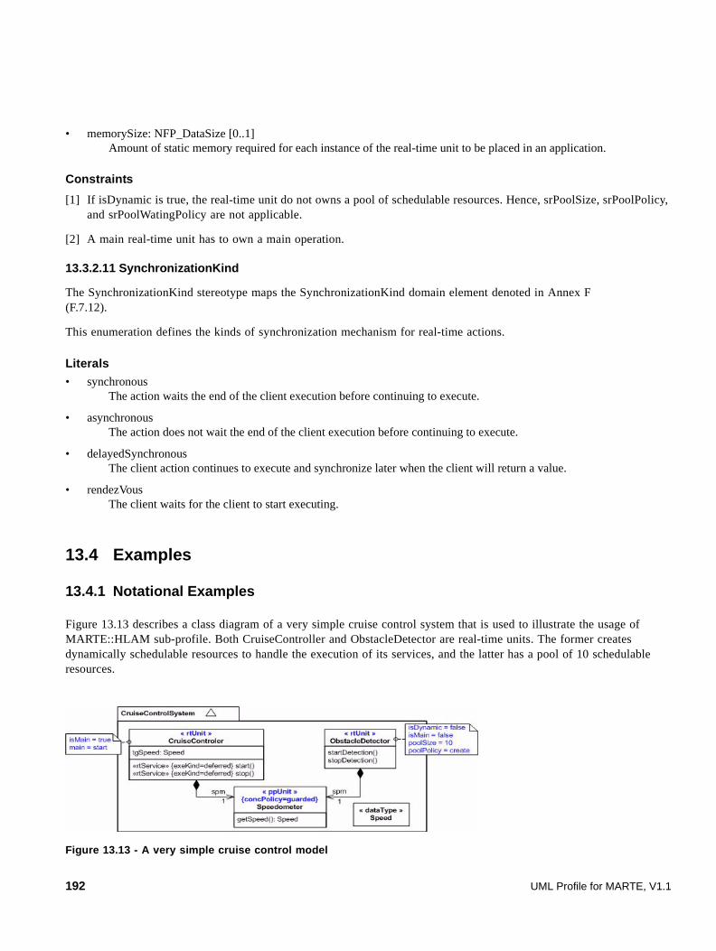
• memorySize: NFP_DataSize [0..1] Amount of static memory required for each instance of the real-time unit to be placed in an application.
Constraints
[1] If isDynamic is true, the real-time unit do not owns a pool of schedulable resources. Hence, srPoolSize, srPoolPolicy, and srPoolWatingPolicy are not applicable.
[2] A main real-time unit has to own a main operation.
13.3.2.11 SynchronizationKind
The SynchronizationKind stereotype maps the SynchronizationKind domain element denoted in Annex F (F.7.12).
This enumeration defines the kinds of synchronization mechanism for real-time actions.
Literals
• synchronous The action waits the end of the client execution before continuing to execute.
• asynchronous The action does not wait the end of the client execution before continuing to execute.
• delayedSynchronous The client action continues to execute and synchronize later when the client will return a value.
• rendezVous The client waits for the client to start executing.
13.4 Examples
13.4.1 Notational Examples
Figure 13.13 describes a class diagram of a very simple cruise control system that is used to illustrate the usage of MARTE::HLAM sub-profile. Both CruiseController and ObstacleDetector are real-time units. The former creates dynamically schedulable resources to handle the execution of its services, and the latter has a pool of 10 schedulable resources.
Figure 13.13 - A very simple cruise control model
192 UML Profile for MARTE, V1.1

Figure 13.14 shows an example of call action with a deadline real-time feature specification. The generated message is aperiodic. Its time reference is denoted by the instant observation to. This latter denotes the start execution time of the action. The specified deadline is 10 ms and the acceptable rate of deadline missing is 1%.
Figure 13.14 - An example of call action with a deadline real-time feature
Figure 13.15 shows an example of call action with a priority real-time feature specification.
Figure 13.15 - An example of call action with a priority real-time feature
Figure 13.16 shows an example of real-time feature specification within a sequence diagram.
Figure 13.16 - Examples of real-time feature within sequence diagrams
13.4.2 Avionics Example
In this example, we make use of components introduced in the avionics example of the General Component Model clause. We refine these components by applying the real-time characteristics introduced in this clause. We consider Trajectory, Location, FlightPlan, and Database as passive components that require to be allocated on execution resources to be set in operation. Figure 13.17 illustrates elements of the Location package used for communicating with Trajectory. Location is a passive component (e.g., Lw-CCM), which provides a real-time service called getLocation through its LocationAccess
UML Profile for MARTE, V1.1 193

interface. The operation carries an “rtService” stereotype that indicates the concurrency kind (reader), the execution kind (deferred), and the synchronization kind (delayedSynchronous). The operation also carries an “rtFeature” stereotype that indicates additional real-time features, such as the priority (P1), the occurrence kind (10 ms period, 2 ms jitter), the relative deadline (3 ms), as well as the acceptable deadline miss ratio (1% i.e., a hard deadline). Defining these features at a service level is used as a contract defined between ports that provide and require the service. The characteristics are applicable whatever the service invocation context or action.
The Location package also introduces a protected passive unit, called LocationData and stereotyped “ppUnit.” It is used to transmit data from the Location to the Trajectory component. When initialized, Location instantiates a LocationData object and keeps it periodically updated, based on the IRS and radio signal received. Trajectory concurrently accesses to the same object as a reader, invoking the getLocation real-time service every 10 ms. LocationData implements a sequential access policy that ensures integrity by preventing readers and writers to concurrently access to the same data.
Figure 13.17 - Real-time characteristics defined on elements of the Location package
Figure 13.18 illustrates the main behavior of the Trajectory component, called computeTrajectory. This activity defines a series of four periodic actions triggered every 10 ms. At the beginning of the period, two actions are concurrently activated: a CallServiceAction invokes the getLocation real-time service, while another CallServiceAction invokes the getFlightPlan real-time service. Real-time features defined on getLocation apply here and there is no need to redefine these. Real-time features can be also defined at an action level, using the “rtAction” and “rtFeature” stereotypes, as illustrated by the getFlightPlan, performComputation, and generateCommand service call actions.
Both getLocation and getFlightPlan service calls are delayed synchronous. Results shall be received and control flows need to be synchronized (with a 3 ms deadline constraint) before the trajectory computation begins with the invocation of the internal performComputation operation (synchronous, with a 4ms deadline constraint). Resulting commands can be generated and relayed through the nav flow port owned by Trajectory, with the invocation of the internal generateCommand operation (synchronous, with a 1ms deadline constraint).
194 UML Profile for MARTE, V1.1
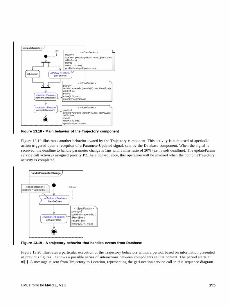
Figure 13.18 - Main behavior of the Trajectory component
Figure 13.19 illustrates another behavior owned by the Trajectory component. This activity is composed of aperiodic action triggered upon a reception of a ParameterUpdated signal, sent by the Database component. When the signal is received, the deadline to handle parameter change is 1ms with a miss ratio of 20% (i.e., a soft deadline). The updateParam service call action is assigned priority P2. As a consequence, this operation will be invoked when the computeTrajectory activity is completed.
Figure 13.19 - A trajectory behavior that handles events from Database
Figure 13.20 illustrates a particular execution of the Trajectory behaviors within a period, based on information presented in previous figures. It shows a possible series of interactions between components in that context. The period starts at t0[i]. A message is sent from Trajectory to Location, representing the getLocation service call in this sequence diagram.
UML Profile for MARTE, V1.1 195

The message is be stereotyped as a real-time feature, indicating information such as period and deadline. Other characteristics (e.g., synchronization kind) are implied from real-time features defined on real-time actions or services. A message is also sent from Trajectory to FlightPlan, representing the getFlightPlan service call.
Trajectory computation begins when both LocationData and FlightPlanData objects are returned (this internal behavior is not shown in this diagram). The sequence of actions used to compute the trajectory and generate the navigation commands shall end by t1[i], 8 ms after the beginning of the period. This allows 2 ms in order to handle aperiodic signals. An aperiodic signal arriving before t1[i] implies that its resulting processing will be delayed. The updateParam service call action has a lower priority than the other actions. In this execution scenario, the signal ParamUpdated is received after the Trajectory component completed its computation. Therefore, the parameter update can be immediately processed.
Figure 13.20 - A Trajectory execution scenario within a period
Note: We assume here that all the components rely on the same global clock.
196 UML Profile for MARTE, V1.1
14 Detailed Resource Modeling (DRM)
The objective of this clause is to provide a set of detailed resources for modeling both software and hardware platforms by specializing the concepts defined within the General Resource Modeling (GRM) clause. This clause is split into two sub clauses:
• The Software Resource Modeling (SRM): focuses on modeling of application programming interfaces of software multi-tasking platform.
• The Hardware Resource Modeling (HRM): focuses on modeling hardware platform through different views and detail levels.
14.1 Software Resource Modeling (SRM)
14.1.1 Overview
There are mainly two approaches to designing software real-time and embedded (RTE) applications: the sequential-based design approach (also called loop-design) and the multitask-based design approach. The former approach consists in designing applications as a set of ordered sequential actions, whose order is pre-calculated in order to satisfy the real-time features. The multitask-based method aims at designing applications as a set of units executing concurrently and interacting (i.e., communicating and synchronizing) via specific mechanisms provided by a specific execution support. That support is in charge of real-time and embedded features (e.g., time constraints, determinism, and memory footprint). It provides a set of resources and services through its application programming interface (API). That API may be either standard or specific (proprietary or commercial).
The widespread approach used to design software RTE applications is the multi-tasking-based approach built upon a real-time operating system (RTOS) as the execution support. Hence, the Software Resource Modeling (SRM) clause specifies a set of modeling artifacts that can be used to describe the structure of such support. More specifically, it is looking to depict software resources and software services described in multi-tasking (API). Thus, it provides:
• Modeling artifacts to design in a unified way RTOS-like software execution support API through the definition of specific UML profile: the SRM (Software Resource Model) sub-profile.
• Examples of specific UML model libraries using the SRM profile to describe parts of standardized RTOS APIs, such as OSEK/VDX (OS 2.2.2) and ARINC (653-1) standards.
The typical use of the SRM UML profile is the description in a unified way of software multi-tasking API in order to integrate explicitly the execution supports in the design flow (e.g., model library description and model transformation description). The SRM profile is not a new multi-tasking API standard. It provides modeling artifacts to describe such API. Moreover, even if this clause focuses on RTOS APIs, it is useful not only to describe such support but also to depict specific multi-tasking libraries and more generally multi-tasking framework API (e.g., RTE middleware and RTE virtual machine).
This clause is structured around a domain model description and its UML representation. The domain model sub clause describes domain concepts. That domain model has been built based on a deep analysis of the main RTOS API standards (SCEPTRE 2, POSIX Issue 6 IEEE std 1003.1, OSEK/VDX 2.2.2, ARINC 653-1), and of some RTOS (e.g., VxWorks 5.5, RTAI 3.1, QNX). The UML representation defines the UML extensions required to manipulate the concepts as defined in the domain model and then be able to describe UML model libraries.
UML Profile for MARTE, V1.1 197

14.1.2 Domain View
This domain view is a specialization of the Generic Resource domain model for the purpose of software modeling. Hence, the SRM model specializes resources and services defined in that previous clause. Commonly, multi-tasking software resources relate to:
• Concurrent execution contexts (i.e., parallel execution).
• Interactions between concurrent context both to communicate and to synchronize themselves.
• Brokering of hardware and software resources (e.g., device management and memory management).
Hence, the domain model is organized in four packages:
1. SW_ResourceCore provides the basic software resource concepts.
2. SW_Concurrency classifies concurrent execution contexts.
3. SW_Interaction sorts communication and synchronization resources.
4. SW_Brokering refers to hardware and software resources management.
Figure 14.1 shows the overall package structure.
Figure 14.1 - Structure of the SRM modeling framework
The purpose and the content of each package is described briefly in subsequent sub clauses. For more formal semantic details, refer to the class description (Annex F).
14.1.2.1 The SW_ResourceCore Package
Figure 14.2 shows the structure of the SW_ResourceCore package.
As a rule, execution supports APIs fulfill real-time and embedded concepts as both a set of types and a set of operations. For example, a kind of concurrency implementation in the POSIX standard is the concept of “thread.” Hence, a type named “pthread_t” and an operation named “pthread_create” (i.e., operation that implements the creation of a thread) fulfill POSIX threads. Users make use of those types and operations to implement their applications on the execution
198 UML Profile for MARTE, V1.1

support. The SW_ResourceCore package supplies the framework to model both those types and those operations. Types are modeled as SwResource. SwResource inherits from the generic resource concept of the GRM::ResourceCore package. Hence, a SwResource provides by inheritance a set of ResourceServices provided by the GRM package (sub clause 10.2).
In this domain model, there is no distinction between services provided by software resources to the application (for example: a mailbox mechanism allows users to communicate messages) and services provided to manage those resources (for example: the creation and the deletion of a mailbox). An SwResource concept gathers both the resource as such and the manager of that resource. Hence, an SwResource inherits not only from the GRM::ResoureCore::Resource, but also from the GRM::ResourceManagement::ResourceManager.
Figure 14.2 - The SW_ResourceCore package overview
A specific software service is the SwAccessService used to access elements. In fact, software resources provide some services to access their characteristics: get and set. Those services may be considered as SwAccessServices. In case of the “set” one, the Boolean attribute “isModifier” may be true.
Figure 14.3 - The SwAccessService
14.1.2.2 The SW_Concurrency Package
Figure 14.5, Figure 14.6, Figure 14.7, Figure 14.8, Figure 14.9, and Figure 14.10 show the structure of the SW_Concurrency package.
The SW_Concurrency package defines SwConcurrentResource that represents entities that compete for computing resources in order to execute sequential part of instructions. They provide an execution context (e.g., stack, interrupts enable/disable and registers) for an execution flow (i.e., sequence of actions). The execution context may be confined to specific memory partition (i.e., virtual address space). Kinds of SwConcurrentResource are interrupt resources and schedulable resources.
UML Profile for MARTE, V1.1 199

An entry point specifies the execution flow associated to a SwConcurrentResource. That entry point is re-entrant whether it can be invoked while it is still executing from a previous invocation.
Figure 14.4 - The SwConcurrentResource overview
Figure 14.5 - The SwConcurrentResource interactions
Interrupt resources match to the physical processing level. In that execution context, the competition for the processing unit is managed at the physical level by a controller and bypasses the scheduler. Many execution supports provide specific services to manage context of interrupt service routine (ISR) execution (i.e., interrupt entry point). The Interrupt resource deals with both hardware interrupts and exceptions (i.e., software interrupts produced by the control processing unit (CPU) while executing instructions). Exceptions can either be “Processor-detected” exceptions when the CPU detects an anomalous condition while executing an instruction or “Programmed” exceptions (also called software interrupts) when they occur at the request of the programmer. Some examples of “Processor-detected” exceptions are faults (divide error, device not ready), traps (breakpoints, debug), and aborts (double fault).
type : ArrivalPattern activationCapacity : IntegerperiodElements : ModelElement [0..*]priorityElements : ModelElement [0..*]stackSizeElements : ModelElement [0..*]
SwConcurrentResource
SRM::SW_Interaction::MessageComResource
SRM::SW_Interaction::SharedDataComResource
SRM::SW_Interaction::SwMutualExclusionResource
SRM::SW_Interaction::NotificationResource
sharedDataResources
0..*
messageResources
0..*
mutualExclusionResources0..*
notificationResources
0..*
200 UML Profile for MARTE, V1.1

Figure 14.6 - The Interrupt Resource
A specific class of interruptResource is the alarm one which allows the interrupt service routines (i.e., the alarm entry points) to be connected to a timer and invoked after a one-shot or periodically. A particular software alarm is the watchdog. If the application doesn’t succeed in resetting the watchdog, that means that the system is not functioning properly and the alarm occurs, forcing application to execute the watchdog entry point or to reset the processor.
Figure 14.7 - The Alarm resource
SwSchedulableResources match to the logical processing context. In that context, the competition for the CPU is brokered at the logical level by a software scheduler. Hence, SwSchedulableResources are linked to an explicit software scheduler that determines the order and the timing (i.e., the “schedule”) in which those should be executed. Typical examples of SwSchedulableResource are the POSIX Thread, the ARINC-653 Process and the OSEK/VDX Task.
Figure 14.8 - The SwSchedulable resource overview
As explained above, software computing resources may be confined in specific MemoryPartitions. A MemoryPartition represents a virtual address space which insures that each concurrent resource associated to a specific memory partition can only access and change its own memory space.
kind:InterruptKindisMaskable : BooleanvectorElements : ModelElement [0..*]maskElements : ModelElement [0..*]
InterruptResourceHardwareInterruptionProcessorDetectedExceptionProgrammedExceptionUndefOther
« enumeration»InterruptKindroutineConnectServices
0..*
SwConcurrentResource
EntryPoint
isrEntryPoints{redefines entryPoint}
0..* routineDisconnectServices
0..*
GRM::ResourceCore::ResourceService
InterruptResource
isWatchdog : Boolean
Alarm
GRM::ResourceType::TimerResource
0..*
timersdurationElements : ModelElement { redefines duration}
SwTimerResource
scheduler scheduledResource
0..*1GRM::Scheduling::Scheduler
isStaticSchedulingFeature : BooleanisPreemptable : BooleandeadlineElements : ModelElement [0..*]deadlineTypeElements : ModelElement [0..*]timeSliceElements : ModelElement [0..*]
SwSchedulableResource
SwConcurrentResource
joinServices0..*
yieldServices0..*
GRM::ResourceCore::ResourceService
delayServices0..*
GRM::Scheduling::SchedulableResource
UML Profile for MARTE, V1.1 201

Figure 14.9 - The MemoryPartition resource
14.1.2.3 The SW_Interaction Package
Figure 14.11, Figure 14.12, Figure 14.13, Figure 14.14, Figure 14.15, Figure 14.16, and Figure 14.17 show the structure of the SW_Interaction package.
In concurrent execution contexts, resources need to interact both to synchronize their actions and to communicate data. Hence, SwSynchronizationResources control execution flows whereas SwCommunicationResources manage data flows.
In any case, resources interact according to a waiting policy. For example, considering a blocked WaitingPolicy, the acquire call part of a mutual exclusion synchronization involves that the caller is blocked in a waiting state (non available for scheduling) until someone release the shared resource. The waiting resources are queued in a waiting queue characterized by a policy and a capacity. Those interactions may be limited to a certain partition of the memory (i.e., isIntraMemoryPartitionInteraction property).
Figure 14.10 - The SW_InteractionResource package overview
To control execution flow, real-time execution supports provide several kinds of synchronization mechanisms: ones to notify event and others to control shared data mutual access. The two corresponding resources are SwMutualExclusionResource and NotificationResource.
MemoryPartitionGRM::ResourceType::
StorageResource
memorySpaces
0..*
SwConcurrentResource
GRM::ResourceCore::ResourceService
forkServices
0..*exitServices
0..*
SRM::SwResource
concur rentResources addressSpace
0..11..*
isIntraMemoryPartitionInteraction : BooleanwaitingQueuePolicy : QueuePolicyKindwaitingQueueCapacity : IntegerwaitingPolicyElements : ModelElement [0..*]
SwInteractionResource
SwCommunicationResource
SRM::SW_ResourceCore::SwResourceGRM::ResourceManagement::
ResourceBroker
SwSynchronizationResource
FIFOLIFOPriorityUndefOther
« enumeration »QueuePolicyKind
GRM::ResourceType::CommunicationEndPoint
202 UML Profile for MARTE, V1.1

Figure 14.11 - The SwSynchronizationResource overview
SwMutualExclusionResource describes resources commonly used to synchronize mutual access to shared data. As examples, Boolean semaphore (one token that anybody can release even if it does not get it), mutex (a Boolean semaphore associated with a concept of ownership : only resource that owns the mutex can release it) and counting semaphore (several token may be got and released) are kind of SwMutualExclusionResource.
Figure 14.12 - The MutualExclusionResource Overview
NotificationResource supports control flow by notifying occurrences of conditions to awaiting concurrent resource. As examples POSIX Signal, OSEK\VDX Event and ARINC-653 Event are NotificationResources. The notified occurrence can be memorized (i.e., memorized in a buffer), bounded (i.e., each occurrence increments a counter) or memoryless (i.e., not memorized in a buffer, hence multiple occurrences are lost).
Figure 14.13 - The NotificationResource overview
SwSynchronizationResource
GRM::ResourceType::SynchronizationResourceSwInteractionResource
SwMutualExclusionResource NotificationResource
concurrentAccessProtocol : ConcurrentAccessProtocolKindaccessTokenElements : ModelElement [0..*]mechanism : MutualExclusionResourceKind
SwMutualExclusionResource
SwSynchronizationResource
PIPPCPNoPreemptionUndefOther
« enumeration »ConcurrentAccessProtocolKind
GRM::ResourceCore::ResourceService
acquireServices
0..*
releaseServices
0..*
BooleanSemaphoreCountSemaphoreMutexUndefOther
MutualExclusionResourceKind
GRM::Scheduling::MutualExclusionResource
policy : OccurencePolicyKindoccurenceCountElements : ModelElement [0..*]maskElements : ModelElement [0..*]mechanism : NotificationResourceKind
NotificationResourceflushServices
0..* MemorizedBoundedMemorylessUndefOther
« enumeration »OccurencePolicyKind
SwSynchronizationResource
GRM::ResourceCore::ResourceService
signalServices0..*
waitServices0..*
clearServices0..*
BarrierEventUndefOther
« enumeration »NotificationResourceKind
UML Profile for MARTE, V1.1 203

Commonly, to manage data flows, users can manipulate both shared data and message.
Figure 14.14 - The MessageComResource overview
MessageComResource are artifacts to communicate messages (i.e., a structure of data characterized by, for example, either a fixed or a dynamic size, a priority, a type of data.) among concurrent resources. Messages may be queued. Common mechanisms are MessageQueue, Blackboard, POSIX Pipe.
Figure 14.15 - The Messaging Communication resource
SharedDataComResource define specific resources used to share the same area of memory among concurrent resources. They allow concurrent resources to exchange safely information by reading and writing the same area in memory.
Figure 14.16 - The shared data communication resource
MessageComReso urce
SwCommunicatio nResource
SwIn teractionResource
SharedDataComResource
GRM::Re sourceTyp e::Co mmunica tionMedia
FIFOLIFOPriorityUndefOther
« enumeration »QueuePolicyKind
isFixedMessageSize : BooleanmessageSizeElements : ModelElement [0..*]mechanism : MessageRessourceKind [0..1]messageQueuePolicy : QueuePolicyKind [0..1]messageQueueCapacityElements : ModelElement [0..*]
MessageComResource
MessageQueuePipeBlackboardUndefOther
« enumeration »MessageRessourceKind
SwCommunicationResource
GRM::ResourceCore::ResourceService
sendServices
0..*
receiveServices
0..*
SwCommunicationResource
SharedDataComResource
readServices
0..*
writeServices
0..*
GRM::ResourceCore::ResourceService
204 UML Profile for MARTE, V1.1
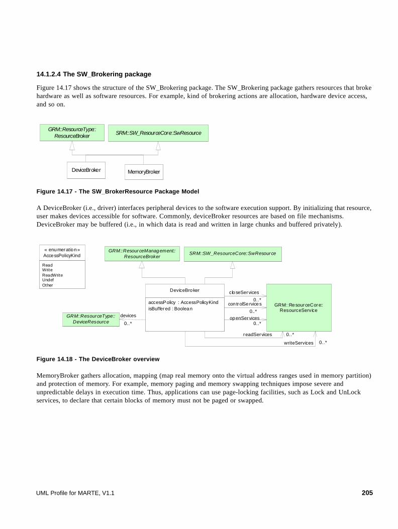
14.1.2.4 The SW_Brokering package
Figure 14.17 shows the structure of the SW_Brokering package. The SW_Brokering package gathers resources that broke hardware as well as software resources. For example, kind of brokering actions are allocation, hardware device access, and so on.
Figure 14.17 - The SW_BrokerResource Package Model
A DeviceBroker (i.e., driver) interfaces peripheral devices to the software execution support. By initializing that resource, user makes devices accessible for software. Commonly, deviceBroker resources are based on file mechanisms. DeviceBroker may be buffered (i.e., in which data is read and written in large chunks and buffered privately).
Figure 14.18 - The DeviceBroker overview
MemoryBroker gathers allocation, mapping (map real memory onto the virtual address ranges used in memory partition) and protection of memory. For example, memory paging and memory swapping techniques impose severe and unpredictable delays in execution time. Thus, applications can use page-locking facilities, such as Lock and UnLock services, to declare that certain blocks of memory must not be paged or swapped.
GRM::ResourceType::ResourceBroker SRM::SW_ResourceCore::SwResource
DeviceBroker MemoryBroker
accessPolicy : AccessPolicyKindisBuffered : Boolean
DeviceBroker
GRM::ResourceType::DeviceResource
devices
0..*
ReadWriteReadWriteUndefOther
« enumeration»AccessPolicyKind
GRM::ResourceCore::ResourceService
closeServices
0..*
GRM::ResourceManagement::ResourceBroker
SRM::SW_ResourceCore::SwResource
controlSe rvices
0..*openServices
0..*
writeServices 0..*
readServices 0..*
UML Profile for MARTE, V1.1 205

Figure 14.19 - The MemoryBroker overview
14.1.3 UML Representation
This sub clause contains a definition of each stereotype that is defined for the software resource modeling profile (SRM). The first sub clause describes rationales for matching domain model concepts to UML profile concepts (i.e., sub-profile, stereotypes, tag, and constraints). Then, the purpose and the content of each sub-profile are briefly described in a second sub clause. Finally, a third sub clause is dedicated to a detailed description of each stereotype.
As the SRM profile is intended to provide modeling artifacts to describe APIs of multi-tasking execution support, rationales have been made to implement domain model concepts in a UML profile:
• The MARTE::CoreElements::ModelElement metaclass is matched to the UML::Kernel::Classes::TypedElement metaclass. This matched rule allows users to reference as well structural features (for example, UML::Kernel::Classes::Property) as behavioral features (for example, UML::Kernel::Classes::Parameter). Figure 14.20 shows one example of the SwResource matching.
Figure 14.20 - SRM Matched rule on ModelElement metaclass
• As Associations between ResourceService and SwResource are navigable in one way, the association ends relative to the SwResource metaclass are matched to SwResource stereotype tags. Moreover, the ResourceService metaclass is matched to the UML::Kernel::Classes::BehavioralFeature. In UML, a behavioral feature specifies that an instance of a classifier will respond to a designated request by invoking a behavior. Hence, services described in APIs are kind of behavioral features (i.e., behavior signature). Figure 14.21 shows one example of the SwResource matching.
accessPolicy : AccessPolicyKind memoryBlockAddressElements : ModelElement [0..*]memoryBlockSizeElements : ModelElement [0..*]
MemoryBroker
GRM::ResourceType::Storage
memories
0..*
GRM::ResourceManagement::ResourceBroker SRM::SW_ResourceCore::SwResource
lockServices0..*
unLockServices0..*
mapServices0..*
unmapServices0..*
GRM::ResourceCore::ResourceService
identifierElem ents : M odelEleme nt [0.. *]
SwR esource
iden tif ier Eleme nts : TypedElem ent [0..* ]
« st ereo t ype »SwR esou rce
(i) domain model (i i) UML profile
« metac lass »C lass if ier
206 UML Profile for MARTE, V1.1
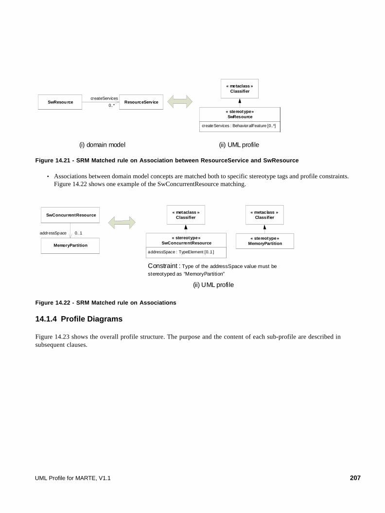
Figure 14.21 - SRM Matched rule on Association between ResourceService and SwResource
• Associations between domain model concepts are matched both to specific stereotype tags and profile constraints. Figure 14.22 shows one example of the SwConcurrentResource matching.
Figure 14.22 - SRM Matched rule on Associations
14.1.4 Profile Diagrams
Figure 14.23 shows the overall profile structure. The purpose and the content of each sub-profile are described in subsequent clauses.
SwResou rce
createServices : BehavioralFeature [0..*]
« stereotype»SwResource
(i) domain model (ii) UML profile
ResourceServicecreateServices
0..*
« metaclass »Classifier
SwConcurrentResource
addressSpace : TypeElement [0..1]
« stereotype»SwConcurrentResourceMemoryPartition
0..1addressSpace« stereotype»
MemoryPartition
(ii) UML profile
« metaclass »Classifier
« metaclass »Classif ier
Constraint : Type of the addressSpace value must be
stereotyped as “MemoryPartition”
UML Profile for MARTE, V1.1 207
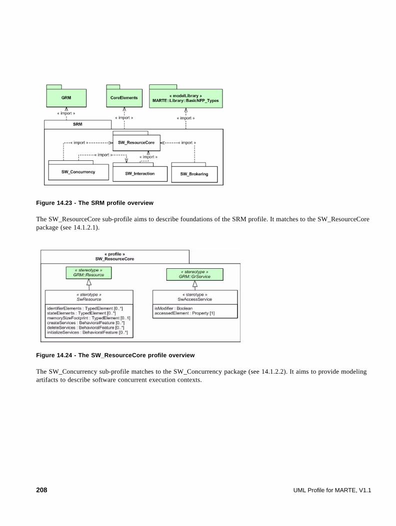
Figure 14.23 - The SRM profile overview
The SW_ResourceCore sub-profile aims to describe foundations of the SRM profile. It matches to the SW_ResourceCore package (see 14.1.2.1).
Figure 14.24 - The SW_ResourceCore profile overview
The SW_Concurrency sub-profile matches to the SW_Concurrency package (see 14.1.2.2). It aims to provide modeling artifacts to describe software concurrent execution contexts.
208 UML Profile for MARTE, V1.1

Figure 14.25 - The SW_Concurrency profile overview
The SW_Interaction sub-profile describes communications and synchronizations among concurrent execution contexts. It matches to the SW_Interaction package (see 14.1.2.3).
« profile »SW_Concurrency
type : ArrivalPattern activationCapacity : IntegerentryPoints : Element [*]addressSpace : TypedElement [*]periodElements : TypedElement [*]priorityElements : TypedElement [*]heapSizeElements : TypedElement [*]stackSizeElements : TypedElement [*]activateServices : BehavioralFeature [*]enableConcurrencyServices : BehavioralFeature [*]resumeServices : BehavioralFeature [*]suspendServices : BehavioralFeature [*]terminateServices : BehavioralFeature [*]disableConcurrencyServices : BehavioralFeature [*]shareDataResources : TypedElement[*]messageResources : TypedElement[*]mutualExclusionResources : TypedElement[*]notificationResources : TypedElement[*]
« stereotype»SwConcurrentResource
isReentrant : Booleanroutine : BehavioralFeature [1]
« stereotype»EntryPoint
kind:InterruptKindisMaskable : Boolean vectorElements : TypedElement [*]maskElements : TypedElement [*]routineConnectServices : BehavioralFeature [*]routineDisconnectServices : BehavioralFeature [*]
« stereotype»InterruptResource
HardwareInterruptionProcessorDetectedExceptionProgrammedExceptionUndefOther
« enumeration »InterruptKind
isWatchdog : Booleantimers : TypedElement [*]
« stereotype»Alarm
concurrentResources : TypedElement [*]memorySpaces : TypedElement [*]fork : BehavioralFeature [*]exit : BehavioralFeature [*]
« stereotype »MemoryPartition
« stereotype »SRM::SW_ResourceCore::SwResource
« stereotype »SRM::SW_ResourceCore::SwResource
« stereotype »Alloc::Allocate
« metaclass »UML2::Classes::Kernel::NameSpace
GRM::TimerResource
durationElements : TypedElement {redefines duration}
SwTimerResource
isStaticSchedulingFeature : BooleanisPreemptable : Booleanschedulers : NamedElement [1]deadlineElements : TypedElement [*]deadlineTypeElements : TypedElement [*]timeSliceElements : TypedElement [*]delayServices : BehavioralFeature [*]joinServices : BehavioralFeature [*]yieldServices : BehavioralFeature [*]
« stereotype»SwSchedulableResource
« stereotype »GRM::SchedulableResource
UML Profile for MARTE, V1.1 209

Figure 14.26 - The SW_Interaction profile overview
The SW_Brokering sub-profile matches to the SW_Brokering package (see 14.1.2.4). The SW_Brokering sub-profile describes stereotypes to annotate hardware and software resource management.
Figure 14.27 - The SW_Brokering profile overview
« profile »SW_Interaction
isIntraMemoryPartitionInteraction : BooleanwaitingQueuePolicy : QueuePolicyKindwaitingQueueCapacity : IntegerwaitingPolicyElements : TypedlElement [*]
« stereotype »SwInteractionResource
FIFOLIFOPriorityUndefOther
« enumeration »QueuePolicyKind
isFixedMessageSize : Booleanmechanism : MessageResourceKindmessageSizeElements :TypedElement [*]messageQueueCapacityElements: TypedlElement [*]messageQueuePolicy : QueuePolicyKind [0..1]sendServices : BehavioralFeature [0..*]receiveServices : BehavioralFeature [0..*]
« stereotype »MessageComResource
MessageQueuePipeBlackboardUndefOther
« enumeration »MessageResourceKind
EventBarrierUndefOther
« enumeration »NotificationResourceKind
occurence : NotificationKindmechanism : NotificationResourceKindoccurenceCountElements : TypedElement [*]maskElements : TypedElement [*]flushServices : BehavioralFeature [*]signalServices : BehavioralFeature [*]waitServices : BehavioralFeature [*]clearServices : BehavioralFeature [*]
« stereotype »NotificationResource
MemorizedBoundedMemorylessUndefOther
« enumeration »NotificationKind
« stereotype»GRM::CommunicationMedia
« stereotype»GRM::SynchronizationResource
« stereotype »SwCommunicationResource
mechanism : MutualExclusionResourceKindconcurrentAccessProtocol : ConcurrentAccessProtocolKindaccessTokenElements : TypedElement [*]releaseServices : BehavioralFeature [*]acquireServices : BehavioralFeature [*]
« stereotype »SwMutualExclusionResource
« stereotype »SwSynchronizationResource
BooleanSemaphoreCountSemaphoreMutexUndefOther
« enumeration »MutualExclusionResourceKind
PIPPCPNoPreemptionUndefOther
« enumeration »ConcurrentAccessProtocolKind
« stereotype»SRM::SW_ResourceCore::SwResource
readServices : BehavioralFeature [0..*]writeServices : BehavioralFeature [0..*]
« stereotype »SharedDataComResource
« stereotype»GRM::MutualExclusionResource
« profile»SW_Brokering
accessPolicy : AccessPolicyKindisBuffered : Booleandevices : TypedElement [0..*]closeServices : BehavioralFeature [*]controlServices : BehavioralFeature [*]openServices : BehavioralFeature [*]readServices : BehavioralFeature [*]writeServices : Behaviora lFeature [*]
« stereotype »DeviceBroker
accessPolicy : AccessPolicyKindmemories : TypedElement [*]memoryBlockAddressElements : TypedElement [*]memoryBlockSizeElements : TypedElement [*]lockServices : BehavioralFeature [*]unlockServices : BehavioralF eature [*]mapServices : BehavioralFeature [*]unMapServices : BehavioralFeature [*]
« stereotype »MemoryBroker
ReadWriteReadWriteUndefOther
« enumeration »AccessPolicyKind
« stereotype»SRM::SW_ResourceCore::SwResource
210 UML Profile for MARTE, V1.1

14.1.5 Profile Elements Descriptions
14.1.5.1 Alarm (from MARTE::SRM::SW_Concurrency)
This stereotype matches to the domain concept Alarm denoted in Annex F (F.8.1).
Alarm resource provides executing context to a user routine, which must be connected to a timer invoked after a one-shot or periodically.
Extensions
• None
Generalizations
• InterruptResource (from SW_Concurrency)
Associations
• None
Attributes
• isWatchdog: Boolean [0..1] Specifies if the alarm is a watchdog.
• timers: TypedElement [0..1] Specifies the timer that raises the signal to execute the entry-point of the alarm resource.
Constraints
[1] Types of timers values must be stereotyped either as “SwTimerResource.”
Notations
The image associated with that stereotype is shown below:
Figure 14.28 - The alarm notation
14.1.5.2 AccessPolicyKind (from MARTE::SRM::SW_Brokering)
The AccessPolicyKind enumerates common policy to access a resource.
Description
• Read Read access only.
• ReadWrite Read and write access are allowed.
UML Profile for MARTE, V1.1 211

• Write Write access only.
• Undef Undefined policy.
• Other Other user's specific policy.
14.1.5.3 ConcurrentAccessProtocolKind (from MARTE::SRM::SW_Interaction)
The ConcurrentAccessProtocolKind enumerates common protocol to access mutually a shared resource.
Description
• NoPreemption Lock the concurrency to avoid preemption when a resource is accessing a shared variable.
• PCP Priority Ceiling protocol.
• PIP Priority Inheritance Protocol.
• Undef Undefined policy.
• Other Other user's specific policy.
14.1.5.4 DeviceBroker (from MARTE::SRM::SW_Brokering)
This stereotype matches the domain concept DeviceBroker denoted in Annex F (F.8.4).
A DeviceBroker (i.e., driver) interfaces peripheral devices to the software execution support.
Extensions
• None
Generalizations
• SwResource (from SRM::SW_ResourceCore) on page 196
Associations
• None
Attributes
• accessPolicy: AccessPolicyKind [0..1] Access policy of the device (read, write).
• closeServices: BehavioralFeature [0..*] Services that make the hardware device unavailable from software resources.
• controlServices: BehavioralFeature [0..*] Services that initialize and broker the device.
212 UML Profile for MARTE, V1.1

• devices: TypedElement [0..*] Hardware device brokered by the driver.
• isBuffered: Boolean[0..1] If true, data is read and written in large chunks and buffered privately.
• openServices: BehavioralFeature [0..*] Services that establish the connection between a device and the resource. This service makes available the device to software resources.
• readServices: BehavioralFeature [0..*] Services which read data from the device.
• writeServices: BehavioralFeature [0..*] Services which write data to the device.
Constraints
[1] Types of device values must be stereotyped either as “DeviceResource” or as “DeviceBroker” sub-Stereotype.
Notations
The icon associated with that stereotype is:
Figure 14.29 - The deviceBroker notation
14.1.5.5 EntryPoint (from MARTE::SRM::SW_Concurrency)
This stereotype matches the domain concept EntryPoint denoted in Annex F (F.8.5).
The EntryPoint supplies the routine (i.e., operations) executed in the context of the Sw ComputingResource.
Extensions
• Allocate (from Alloc)
Generalizations
• None
Associations
• None
Attributes
• isReentrant: Boolean [0..1] Specifies if a single copy of the routine instructions in memory can be shared by multiple concurrent resource. If true, instructions described in the routine could be called from multiple concurrent resource contexts simultaneously without conflict.
UML Profile for MARTE, V1.1 213

• routine: BehavioralFeature [1] Specifies the routine that has to be executed in the context of the software computing resource.
Constraints
• None
14.1.5.6 InterruptResource (from MARTE::SRM::SW_Concurrency)
This stereotype matches the domain concept InterruptResource denoted in Annex F (F.8.6).
InterruptResource defines an executing context to execute user-delivered routines (i.e., entry point) further to hardware or software asynchronous signals.
Extensions
• None
Generalizations
• SwConcurrentResource (from SRM::SW_Concurrency) on page 193
Associations
• None
Attributes
• kind: InterruptKind [0..1] Specifies the kind of interrupt.
• isMaskable: Boolean [0..1] Interrupts can either be maskable or not. Only few critical signals raise non maskable interrupts. The control processor unit (CPU) always recognizes those. Maskable interrupts can be in two states: unmasked (i.e., recognized by the CPU) or masked (i.e., ignored by the control unit). For example, a schedulable resource can explicitly mask maskable interrupts to avoid its pre-emption in some code sub clauses.
• maskElements: TypedElement [0..*] Specifies elements that map the semantics of the interrupt mask.
• routineConnect: BehavioralFeature [0..*] Services that connect the routine to the interrupt vector.
• routineDisConnect: BehavioralFeature [0..*] Identifies services that disconnect the routine to the interrupt vector.
• vectorElements: TypedElement [0..*] Specifies elements that map the semantics of the interrupt vector.
Constraints
• None
Notations
The image associated with that stereotype is:
214 UML Profile for MARTE, V1.1

Figure 14.30 - The interrupt notation
14.1.5.7 InterruptKind (from MARTE::SRM::SW_Concurrency)
The InterruptKind enumerates different kinds of interrupt.
Description
• HardwareInterrupt The interrupt source is a hardware one.
• ProcessorDetectedException Software interrupts produced by the CPU control unit while it detects an anomalous condition in executing an instruction. Some examples of “Processor-detected” exceptions are faults (divide error, device not ready) and aborts (double fault).
• ProgrammedException Software interrupts produced by an explicit request of the programmer. Some examples of “ProgrammedException” exceptions are traps (breakpoints, debug).
• Undef Undefined mechanism.
• Other: Others mechanisms.
MemoryBroker (from MARTE::SRM::SW_Brokering)
This stereotype matches the domain concept MemoryBroker denoted in Annex F (F.8.8).
MemoryBroker resources provide primarily services to manage the memory allocation, the memory protection, and the memory access.
Extensions
• None
Generalizations
• SwResource (from SW_ResourceCore) on page 196
Associations
• None
Attributes
• accessPolicy : AccessPolicyKind [0..1] Defines the access policy to the memory (read, write).
X
UML Profile for MARTE, V1.1 215
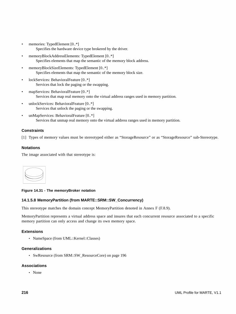
• memories: TypedElement [0..*] Specifies the hardware device type brokered by the driver.
• memoryBlockAddressElements: TypedElement [0..*] Specifies elements that map the semantic of the memory block address.
• memoryBlockSizeElements: TypedElement [0..*] Specifies elements that map the semantic of the memory block size.
• lockServices: BehavioralFeature [0..*] Services that lock the paging or the swapping.
• mapServices: BehavioralFeature [0..*] Services that map real memory onto the virtual address ranges used in memory partition.
• unlockServices: BehavioralFeature [0..*] Services that unlock the paging or the swapping.
• unMapServices: BehavioralFeature [0..*] Services that unmap real memory onto the virtual address ranges used in memory partition.
Constraints
[1] Types of memory values must be stereotyped either as “StorageResource” or as “StorageResource” sub-Stereotype.
Notations
The image associated with that stereotype is:
Figure 14.31 - The memoryBroker notation
14.1.5.8 MemoryPartition (from MARTE::SRM::SW_Concurrency)
This stereotype matches the domain concept MemoryPartition denoted in Annex F (F.8.9).
MemoryPartition represents a virtual address space and insures that each concurrent resource associated to a specific memory partition can only access and change its own memory space.
Extensions
• NameSpace (from UML::Kernel::Classes)
Generalizations
• SwResource (from SRM::SW_ResourceCore) on page 196
Associations
• None
216 UML Profile for MARTE, V1.1
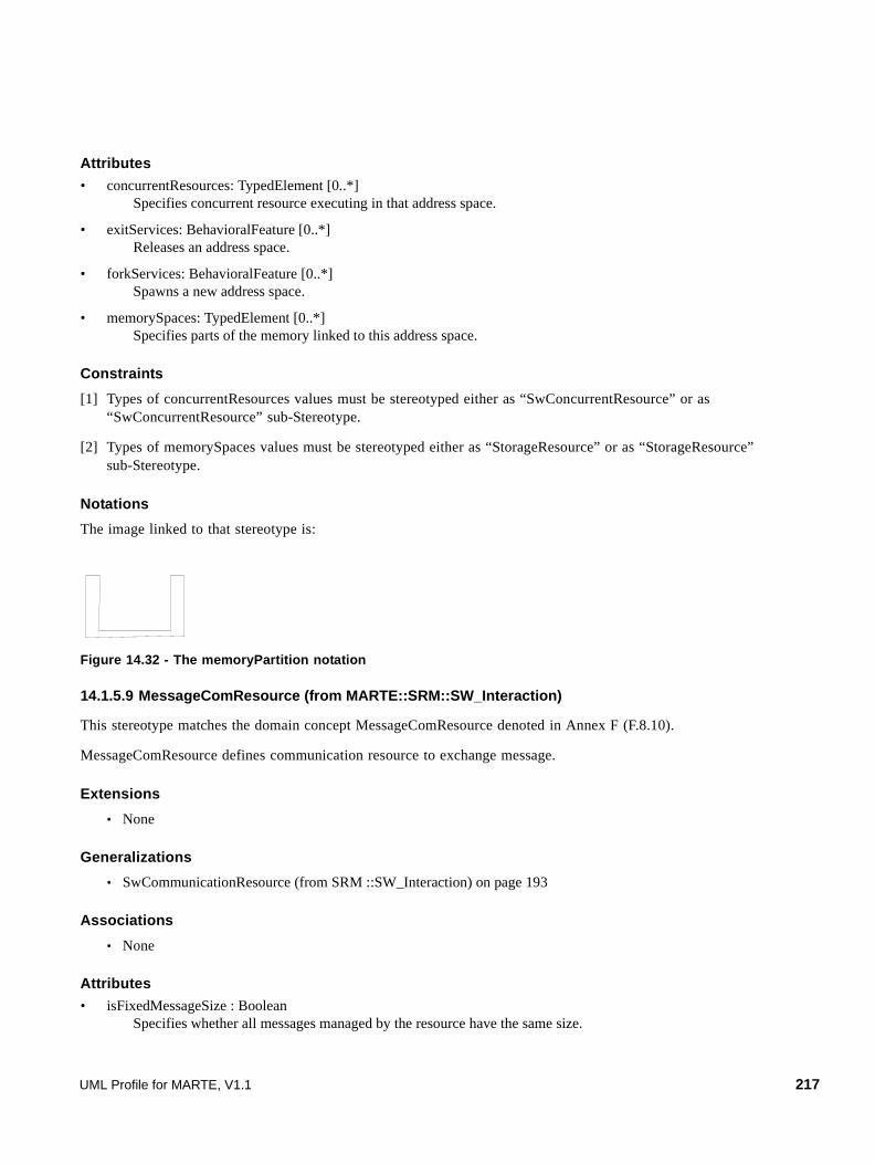
Attributes
• concurrentResources: TypedElement [0..*] Specifies concurrent resource executing in that address space.
• exitServices: BehavioralFeature [0..*] Releases an address space.
• forkServices: BehavioralFeature [0..*] Spawns a new address space.
• memorySpaces: TypedElement [0..*] Specifies parts of the memory linked to this address space.
Constraints
[1] Types of concurrentResources values must be stereotyped either as “SwConcurrentResource” or as “SwConcurrentResource” sub-Stereotype.
[2] Types of memorySpaces values must be stereotyped either as “StorageResource” or as “StorageResource” sub-Stereotype.
Notations
The image linked to that stereotype is:
Figure 14.32 - The memoryPartition notation
14.1.5.9 MessageComResource (from MARTE::SRM::SW_Interaction)
This stereotype matches the domain concept MessageComResource denoted in Annex F (F.8.10).
MessageComResource defines communication resource to exchange message.
Extensions
• None
Generalizations
• SwCommunicationResource (from SRM ::SW_Interaction) on page 193
Associations
• None
Attributes
• isFixedMessageSize : Boolean Specifies whether all messages managed by the resource have the same size.
UML Profile for MARTE, V1.1 217

• mechanism: MessageResourceKind [0..1] Specifies the kind of mechanism used to exchange messages.
• messageQueueCapacityElements: TypedElement [0..1] Specifies the upper limit of message number allowed in a queue.
• messageQueuePolicy: QueuePolicyKind [0..1] Defines the algorithm to manage the outgoing message queue.
• messageSizeElements : TypedElement [0..*] Specifies the parameter used in message exchange services to define the size of the message.
• receiveServices : BehavioralFeature [0..*] Identifies services that get a message.
• sendServices : BehavioralFeature [0..*] Identifies services that set a message.
Constraints
• None
Notations
The image associated with that stereotype is:
Figure 14.33 - The MessageComResource notation
14.1.5.10 MessageResourceKind (from MARTE::SRM::SW_Interaction)
The MessageResourceKind enumerates common mechanisms provided by platform to exchange data.
Literals
• Blackboard Defines a one message buffer.
• MessageQueue Defines a multiple message buffer.
• Pipe Defines POSIX Pipe mechanism, which allows data flow among separate memory partitions.
• Undef Undefined mechanism.
• Other Other mechanisms.
14.1.5.11 MutualExclusionResourceKind (from SW_Interaction)
The MutualExlusionResourceKind enumerates common mechanisms provided by platform to synchronize resource.
218 UML Profile for MARTE, V1.1

Literals
• BooleanSemaphore Defines a binary semaphore. It is a flag available or unavailable. There is no proprietary purpose. Anybody can give the semaphore even if it does not take it.
• CountSemaphore Defines a counting semaphore for which every time the semaphore is given the count is incremented; every time the semaphore is given the count is decremented.
• Mutex Defines a binary semaphore associated with a propriety concept, resource can give the semaphore if and only if the resource takes it.
• Undef Undefined mechanisms.
• Other Other mechanisms.
14.1.5.12 NotificationKind (from MARTE::SRM::SW_Interaction)
The NotificationKind enumerates common policy to access a resource.
Literals
• Bounded Each occurrence increments a counter.
• Memorized Occurrences are memorized in a buffer.
• Memoryless Occurrences are not memorized in a buffer, hence multiple occurrences are lost.
• Undef Undefined.
• Other User’s specific policy.
14.1.5.13 NotificationResourceKind (from MARTE::SRM::SW_Interaction)
The NotificationResourceKind enumerates common mechanisms provide by support to notify occurrence.
Literals
• Barrier barrier mechanism.
• Event event mechanism.
• Undef undefined mechanisms.
• Other other mechanisms.
UML Profile for MARTE, V1.1 219

14.1.5.14 NotificationResource (from MARTE::SRM::SW_Interaction)
This stereotype matches the domain concept NotificationResource denoted in Annex F (F.8.15).
NotificationResource supports control flow by notifying the occurrences of conditions to awaiting concurrent resources.
Extensions
• None
Generalizations
• SwSynchronizationResource on page 198
Associations
• None
Attributes
• clearServices: BehavioralFeature [0..*] Services that erase one or several occurrences.
• flushServices: BehavioralFeature [0..*] Services to release any resource that waits for an occurrence.
• maskElements: TypedElement [0..*] Elements that map the semantic of the mechanism to mask occurrence.
• mechanism : NotificationResourceKind Identifies notification mechanism.
• occurenceCountElements: TypedElement [0..*] Elements that map the semantic of the occurrence number.
• occurenceKind : NotificationKind Specifies the kind of notification.
• signalServices: BehavioralFeature [0..*] Services that send one or several occurrences.
• waitServices: BehavioralFeature [0..*] Services to wait one or several occurrences.
Constraints
• None
Notations
The image associated with that stereotype is:
220 UML Profile for MARTE, V1.1

Figure 14.34 - The NotificationSynchronization notation
14.1.5.15 QueuePolicyKind (from MARTE::SRM::SW_Interaction)
The QueuePolicyKind enumerates algorithms provided by resources to order a queue.
Literals
• FIFO The first element put in the queue is the first outgoing.
• LIFO The last element put in the queue is the first outgoing.
• Priority Each element is annotated with a priority.
• Undef Undefined.
• Other Other algorithms.
14.1.5.16 SharedDataComResource (from MARTE::SRM::SW_Interaction)
This stereotype matches the domain concept SharedDataComResource denoted in Annex F (F.8.17).
SharedDataComResource defines specific resources used to share the same area of memory among concurrent resources.
Extensions
• None
Generalizations
• SwCommunicationResource (from SRM:SW_Interaction) on page 193
Associations
• None
Attributes
• readServices: BehavioralFeature [0..*] Services that read the shared data.
• writeServices: BehavioralFeature [0..*] Services that write the shared data.
UML Profile for MARTE, V1.1 221
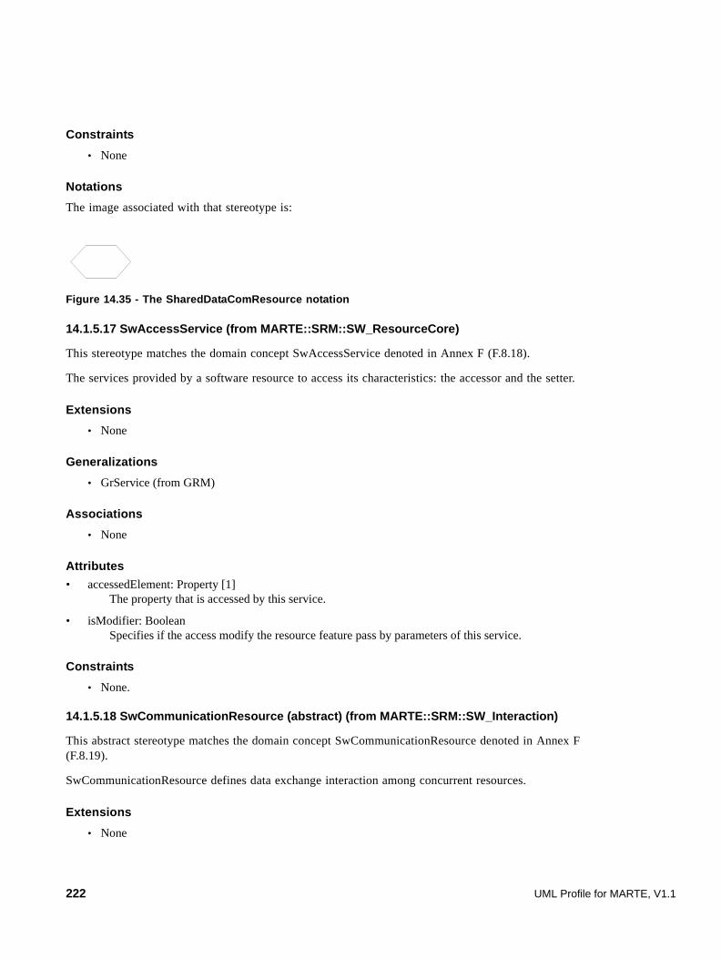
Constraints
• None
Notations
The image associated with that stereotype is:
Figure 14.35 - The SharedDataComResource notation
14.1.5.17 SwAccessService (from MARTE::SRM::SW_ResourceCore)
This stereotype matches the domain concept SwAccessService denoted in Annex F (F.8.18).
The services provided by a software resource to access its characteristics: the accessor and the setter.
Extensions
• None
Generalizations
• GrService (from GRM)
Associations
• None
Attributes
• accessedElement: Property [1] The property that is accessed by this service.
• isModifier: Boolean Specifies if the access modify the resource feature pass by parameters of this service.
Constraints
• None.
14.1.5.18 SwCommunicationResource (abstract) (from MARTE::SRM::SW_Interaction)
This abstract stereotype matches the domain concept SwCommunicationResource denoted in Annex F (F.8.19).
SwCommunicationResource defines data exchange interaction among concurrent resources.
Extensions
• None
222 UML Profile for MARTE, V1.1

Generalizations
• SwInteractionResource (from SRM ::SW_Interaction) on page 195.
• CommunicationMedia (from GRM) on page 102.
Associations
• None
Attributes
• None
Constraints
• None
14.1.5.19 SwConcurrentResource (abstract) (from MARTE::SRM::SW_Concurrency)
This abstract stereotype matches the domain concept SwConcurrentResource denoted in Annex F (F.8.20).
This resource defines entities that may execute concurrently sequential parts of instructions.
Extensions
• None
Generalizations
• SwResource (from SRM::SW_ResourceCore) on page 196
Associations
• None
Attributes
• activateServices: BehavioralFeature [0..*] Services that make available a resource to execute. As a result, activated resources are ready to compete for the computing resource. In case of interruption, it results in explicitly raised the interrupt (i.e., to set of the interrupt).
• activationCapacity: Integer [0..1] Specifies the activation number allowed in the system.
• addressSpace: TypedElement [0..1] Defines the address space in which the flow is executed.
• disableConcurrencyServices : BehavioralFeature [0..*] Services that lock the competition for a computing resource. As a result, any concurrent resource cannot pre-empt the executing resource.
• enableConcurrencyServices: BehavioralFeature [0..*] Services that unlock the competition for a computing resource. As a result, any concurrent resource can preempt the executing resource.
UML Profile for MARTE, V1.1 223

• entryPoints: Elements [0..*] Defines entry points of the resource.
• heapSizeElements : TypedElement [0..*] Elements that map the semantic of the resource heap size in case of dynamic memory allocation.
• periodElements: TypedElement [0..*] Elements that map the semantic of the resource period in case of a periodic concurrent resource.
• priorityElements: TypedElement [0..*] Elements that map the semantic of the resource priority.
• stackSizeElements: TypedElement [0..*] Elements that map the semantic of the resource stack size.
• type : ArrivalPattern (from MARTE_Library::BasicNFP_Types::ArrivalPattern) Identifies the occurrence execution pattern.
• resumeServices: BehavioralFeature [0..*] Services that make available a resource to compete with either ready or pended concurrent resource. Pended resources are blocked due to the unavailability of some other resources. In case of interrupt, resume service is equivalent to an enable service.
• suspendServices: BehavioralFeature [0..*] Services that make unavailable a resource to execute. In case of interrupt, suspend service is equivalent to disable service.
• terminateServices: BehavioralFeature [0..*] Services that stop definitively resource execution.
• sharedDataResources: TypedElement [0..*] Resources used to share data among computing resources. Those resource types must be stereotyped as “SRM::SW_Interaction::SharedDataComResource.”
• messageResources: TypedElement [0..*] Resources used to communicate messages among computing resources. Those resource types must be stereotyped as “SRM::SW_Interaction::MessageComResource.”
• mutualExclusionResources: TypedElement [0..*] Resources used to synchronize mutual accesses. Those resource types must be stereotyped as “SRM::SW_Interaction::SwMutualExclusionResource.”
• notificationResources: TypedElement [0..*] Defines resources used to synchronize computing resources. Those resource types must be stereotyped as “SRM::SW_Interaction::NotificationResource.”
Constraints
[1] Type of the addressSpace value must be stereotyped as “MemoryPartition.”
[2] entryPoints values must be stereotyped as “EntryPoint.”
[3] sharedDataResources values must be stereotyped as “SRM::SW_Interaction::SharedDataComResource.”
[4] messageResources values must be stereotyped as “SRM::SW_Interaction::SwMutualExclusionResource.”
[5] mutualExclusionResources values must be stereotyped as “SRM::SW_Interaction::SwMutualExclusionResource.”
[6] notificationResources values must be stereotyped as “SRM::SW_Interaction::NotificationResource.”
224 UML Profile for MARTE, V1.1

14.1.5.20 SwInteractionResource (abstract) (from MARTE::SRM::SW_Interaction)
This stereotype matches to the domain concept SwInteractionResource denoted in Annex F (F.8.21).
InteractionResource is an abstract concept that denotes generic mechanism to interact among concurrent executing resources. Synchronization and Communication are specific kinds of interaction.
Extensions
• None
Generalizations
• SwResource (from SRM::SW_ResourceCore) on page 196
Associations
• None
Attributes
• isIntraMemoryPartitionInteraction: Boolean [0..1] Specifies if the mechanism can be accessed from different memory partitions (i.e., namespace, address space).
• waitingPolicyElements: TypedElement [0..*] Elements by which the communication waiting policy is specified: waiting, ready, waiting with a time out, conditional waiting.
• waitingQueuePolicy: QueuePolicyKind [0..*] Defines the algorithm to manage the resource waiting queue.
• waitingQueueCapacity: Integer [0..1] The number of resources allowed in the waiting queue.
Constraints
• None
14.1.5.21 SwMutualExclusionResource (from MARTE::SRM::SW_Interaction)
This stereotype matches the domain concept SwMutualExclusionResource denoted in Annex F (F.8.22).
MutualExclusionResource describes resources commonly used for synchronize access to shared variables.
Extensions
• None
Generalizations
• MutualExclusionResource (from GRM) on page 109
• SwSynchronizationResource on page 198
UML Profile for MARTE, V1.1 225

Associations
• None
Attributes
• accessTokenElements : TypedElement [0..*] Elements that map the semantics of the token used to access a shared information.
• acquireServices: BehavioralFeature [0..*] Services that get an access token to a shared information.
• concurrentAccessProtocol : ConcurrentAccessProtocolKind Specifies the protocol applied in concurrent access.
• mechanism : MutualExclusionResourceKind Specifies the kind of mechanism used to mutual exclusion synchronization.
• releaseServices: BehavioralFeature [0..*] Services that release an access token to a shared information.
Constraints
• None
Notations
The image associated with that stereotype is:
Figure 14.36 - The SwMutualExclusionResource notation
14.1.5.22 SwResource (abstract) (from MARTE::SRM::SW_ResourceCore)
This stereotype matches the domain concept SwResource denoted in Annex F (F.8.23).
SwResource model software structural entities provided to the user by execution supports.
Extensions
• None
Generalizations
• Resource (from GRM on page 117)
Associations
• None
226 UML Profile for MARTE, V1.1

Attributes
• createServices: BehavioralFeature [0..*] Services that allocate and declare the resource to the system.
• deleteServices: BehavioralFeature [0..*] Services that free and delete the resource from the system.
• identifierElements: TypedElement [0..*] Elements that map the semantic of a resource identifier.
• initializeServices: BehavioralFeature [0..*] Services that initialize the resource.
• memorySizeFootprintElements: TypedElement [0..1] Elements that map the memory size footprint of the resource.
• stateElements: TypedElement [0..*] Elements that map the semantic of the resource state.
Constraints
• None
14.1.5.23 SwSchedulableResource (from MARTE::SRM::SW_Concurrency)
This stereotype matches the domain concept SwSchedulableResource denoted in Annex F (F.8.24).
SchedulableResource are resources that execute concurrently to other concurrent resource.
Extensions
• None
Generalizations
• SchedulableResource (from GRM) on page 113.
• SwConcurrentResource (from SRM::SW_Concurrency) on page 193.
Associations
• None
Attributes
• deadlineElements: TypedElement [0..*] Elements that map the semantic of the deadline feature.
• deadlineTypeElements : TypedElement [0..*] Elements that map the semantic of the deadline criticality degree (e.g., soft and hard).
• delayServices: BehavioralFeature [0..*] Services that delay for a lapse of time the execution. The resource is in a dormant state during this lapse.
• isPreemptable: Boolean [0..1] Specifies if the scheduler can preempt that kind of resource.
UML Profile for MARTE, V1.1 227

• isStaticSchedulingFeature: Boolean [0..1] Specifies if the scheduling parameters (priority, deadline, timeslice) are static (i.e., constants define off-line).
• joinServices: BehavioralFeature [0..*] Services that suspend the execution of set of concurrent resource until other concurrent resources terminates.
• scheduler: TypedElement [1] Specifies the scheduler that orchestrates the concurrent execution of this kind of resource.
• timeSliceElements: TypedElement [0..*] Elements that map the semantic of the timeSlice in case of round robin scheduling.
• yieldServices: BehavioralFeature [0..*] Services that explicitly relinquish the computing resource. They explicitly ask scheduler to reschedule.
Constraints
[1] The type of scheduler value must be stereotyped either as “Scheduler” or as “Scheduler” sub-Stereotype.
Notations
The image associated with that stereotype is:
Figure 14.37 - The SwSchedulableResource notation
14.1.5.24 SwSynchronizationResource (abstract) (from MARTE::SRM::SW_Interaction)
This stereotype matches the domain concept SwSynchronizationResource denoted in Annex F (F.8.25).
This resource defines interaction mechanisms to synchronize concurrent execution flow.
Extensions
• None
Generalizations
• SwInteractionResource (from SRM::SW_Interaction) on page 195.
• SynchronizationResource (from GRM) on page 102.
Associations
• None
Attributes
• None
Constraints
• None
228 UML Profile for MARTE, V1.1

14.1.5.25 SwTimerResource (from MARTE::SRM::SW_Concurrency)
This stereotype matches to the domain concept SwTimerResource denoted in Annex F (F.8.26).
A SwTimerResource represents an entity that is capable of following and evidencing the pace of time upon demand with a prefixed maximum resolution, at programmable time intervals.
Extensions
• None
Generalizations
• TimerResource (from GRM::ResourceTypes) on page 104
Associations
• None
Attributes
• DurationElements : TypedElement [0..*] {redefines GRM::TimerResource::duration} Elements that map the semantic of the interval after which the timer will make evident the elapsed time.
Constraints
• None
Notations
The image associated with that stereotype is:
Figure 14.38 - The SwTimerResource notation
14.1.6 Examples
The following examples illustrate how the SRM sub-profile stereotypes may be used in practice. Several brief case studies are described for each sub-profile. In a first sub clause, modeling possibilities are exhaustively described. In a second sub clause, some concrete RTOS concepts are modeling. In addition, D.5 provides two examples of RTOS API model library, for OSEK VDX and ARINC-653, build with the SRM profile.
14.1.6.1 Modeling possibilities
The idea of this sub clause is to describe common use of SRM sub-Profile stereotypes. It aims to give an overview of typical modeling possibilities. The list of examples is by no means exhaustive.
UML Profile for MARTE, V1.1 229

Applying SwResource stereotypes on classifiers
All stereotypes of the SRM sub-profile extend the UML::Classes::Kernel::Classifier metaclass. Thus, any UML Classifier sub-metaclass may be extended by those stereotypes (e.g., Class, Interface, Component, and AssociationClass). Figure 14.40 and Figure 14.41 illustrate UML Class and UML Component extension.
Figure 14.39 - Class extension example
Figure 14.40 - Component extension example
Figure 14.41 illustrates the use of an AssociationClass (from UML::CompositesStructures::InternalStructures) to describe interaction between concurrent computing resources. As the SwInteractionResource stereotype extends the UML Classifier metaclass, a UML AssociationClass may be stereotyped as any SwInteractionResource sub-stereotype (for example: NotificationResource, MessageComResource, SwMutualExclusionResource). In this example, the execution support provides concurrent resource to compute instructions: “Alarm” and “Task.” They are described as UML classes and respectively stereotyped as “Alarm” and as “SwSchedulableResource.” In this example, an “Alarm” resource may interact with a “SwSchedulableResource” (i.e., a task) by means of an event mechanism stereotyped “NotificationResource.”
Figure 14.41 - AssociationClass extension example
Applying SwResource stereotypes on properties
All stereotypes of the SRM sub-profile extend the UML::ConnectableElement meta class (from UML::CompositeStructures::InternalStructures). Figure 14.42 illustrates the use of such extension to describe interactions between concurrent computing resources in a memory partition.
+yield()
Deadline : Integer
«swSchedulableResource »Task
« SwSchedulableResource »deadlineElements = Task::DeadlineyieldService = Task::yield()
+yield()
« interface »TaskService
«SwSchedulableResource »deadlineElements = Task::DeadlineyieldService = TaskService::yield()
- Deadline : Integer
«swSchedulableResource »Task
(i) Class (ii) Class and Interface
« swSchedulableResource »Task +yield()
« inter face»TaskService
« SwSchedulableResource »yieldService = TaskService::yield()
task
0..1
« SwSchedulableResource »Task
« Alarm »Alarm
« NotificationResource »Event
230 UML Profile for MARTE, V1.1

Figure 14.42 - ConnectableElement extension example
Applying the EntryPoint stereotype on dependencies
Figure 14.43 denotes a use of the entryPoint stereotype on a UML::Dependency. This example illustrates a robotic application build upon a generic API. This design is a part of a robot controller in charge of the motion control. On the left side, the software designer describes the logical “RobotController” model. On the right side, the SRM profile is used to describe the MemoryPartiton and the SchedulableResource provided by a generic real-time and embedded API. Then, a model is described as instances of the MemoryPartition and Schedulable resources. Hence, the Task instances are bound with their entryPoint by means of UML 2.0 dependency In case of the “t2” instanceSpecification, the stereotype “entryPoint” is used to specify that the “trajectoryControl” operation of a specific MotionController instanceSpecification is the routine that has to be executed in the context of that schedulable resource.
Figure 14.43 - EntryPoints examples
« memoryPartition »Partition
« swSchedulableResource »tasks : Task [1..*]
« interruptResource »its : Interrupt [0..*]
« messageComResource »mbx : MailBox [0..*]
X
« modelLibrary»GenericAPI
« model»RobotControllerTaskModel
p1 : Partition
t2 : Task
« import »
« import »
« Profile »SRM
« apply »
« MemoryPartition »Partition
+tasks+owner
0..1 1..*
« SwSchedulableResource »Task
« model»RobotControllerLogicalModel
trajectoryControl()odometry()
+maxSpeed : Integer
MotionController
: MotionController
« entryPoint »
« entryPoint »isReentrant = trueroutine = trajectoryControl t1 : Task« entryPoint »
« entryPoint »isReentrant = trueroutine = odometry
UML Profile for MARTE, V1.1 231

Applying the SwAccessService stereotype on services
“Get” and “Set” services may be formally clarified with the SwAccessService stereotype. In the example depicted in Figure 14.44, the “sem_getValue” service returns the semaphore value. Hence, it is stereotyped as “SwAccessService.” The tag “accessedElement” specifies that the feature accessed is the property named “value.” Therefore, the boolean tag “isModifier” indicates that this service does not modify the value.
Figure 14.44 - SwAccessService example
Tagged values examples
Stereotype properties allow users to precise semantics of elements. For example, in Figure 14.40, the “Deadline” property is tagged to clarify its semantic. It denotes explicitly in the model that among all attributes of this class, one refers to the task deadline. That is named “Deadline.” Thus, it allows tools to distinguish properties and to permit automatic model transformations (code generation for example).
In the second part of Figure 14.45, the “TaskService” interface owns a “yield” operation. This operation is tagged as a “yieldServices” by the “SwSchedulableResource” stereotype, whereas this stereotype is not applied to the interface. It means that in the context of a “task,” the service to call in order to release the computing resource is the operation “yield” of the interface “TaskService.”
Multiple tagged values for the same tag and multiple tags for the same feature are allowed. On the one hand user can express formally multiple semantics for the same feature through multiple tags. On the other hand, user can express the same semantic for multiple features through the same tag. Figure 14.46 describes a “taskSpawn()” service as both task creating and task activating. In the same way, to activate a task, you can either call the “taskSpawn()” service or the “taskActivate()” one. Figure 14.47 illustrates that user may reference UML properties as well as UML parameters to the same tag.
Figure 14.45 - Multiple tags and multiple tagged services
« swAccessService » +sem_getValue( ) : Integer
-value : Integer
Semaphore « SwAccessService »accessedElement = valueisModifier = fa lse
+taskSpawn()+taskActivate ()
« swSchedulableResource»Task
« SwSchedulableResource »createServices = Task::taskSpawn()activateServices = Task::taskSpawn(),Task::taskActivate ()
232 UML Profile for MARTE, V1.1

Figure 14.46 - Multiple tagged features
14.1.6.2 Specific RTOS API examples
The idea of this sub clause is to describe concrete use of SRM sub-Profile stereotypes. Those stereotypes are applied to specific RTOS concepts. Some explanations are given for each case study. In addition, large examples of specific UML model libraries using the SRM profile are described in Annex D.4. Thus, some parts of OSEK/VDX (OS 2.2.2) and ARINC (653-1) APIs are described as examples.
SwSchedulableResource and MemoryPartition example
To illustrate the use of the “SwSchedulableResource” and “MemoryPartition” stereotypes, Figure 14.47 aims to represent the POSIX Process and Pthread concepts modeled as UML classes. POSIX process is an address space with one or more threads executing within that address space, and the required system resources for those threads. Each process shall be controlled by a priority. Hence, POSIX Process conforms to both a “MemoryPartition” and an “SwSchedulableResource.” The PID attribute is the process identifier. Hence, this attribute is assigned to the “identifierElements” inherited tagged value of the “SwResource” stereotype. That tagged value clarifies the semantic of the PID attribute. It explains explicitly in the model that the attribute named “PID” refers to the process identifier. POSIX thread (i.e., pthread) is a single flow of control within a process. Anything whose address may be determined by a thread is accessible to all threads in the same process. Each thread shall be controlled by an associated priority. Hence, a POSIX Thread is conformed to an “SwSchedulableResource” and associated with the “Process” classifier.
Figure 14.47 - POSIX Process and Pthread example
InterruptResource example
Figure 14.48 illustrates the OSEK/VDX interrupt resource modeled as a UML class. OSEK interrupts are scheduled by hardware while tasks (i.e., OSEK schedulableResource) are scheduled by the scheduler. Interrupts can interrupt tasks (preemptable and non preemptable tasks). OSEK offers fast functions to suspend (i.e., disable) and resume (i.e., enable) interrupts.
+taskSpawn(prio : Integer)+taskActivate()
Priority : Integer
« swSchedulableResource »Task
« SwSchedulableResource »priorityElements = Task::Priority, Task::taskSpawn::prio
UML Profile for MARTE, V1.1 233

Figure 14.48 - OSEK/VDX Interrupt example
Alarm example
Figure 14.49 illustrates the use of the “Alarm” stereotype. The OSEK operating system provides services for processing recurring events. Such events may be for example timers that provide an interrupt at regular intervals, or encoders at axles that generate an interrupt in case of a constant change of a camshaft or crankshaft angle, or other regular application specific triggers. The OSEK operating system provides a two-stage concept to process such events. The recurring events (sources) are registered by implementation specific counters. Based on counters, the OSEK operating system software offers alarm mechanisms to the application software, such as services to activate tasks, set events, or call an alarm-callback routine (i.e., the alarm entry point) when an alarm expires. Note that the SwTimerResource is directly used to stereotype OSEK/VDX Counter.
Figure 14.49 - OSEK/VDX Alarm example
SwMutualExclusionResource example
Figure 14.50 illustrates one use of the “SwMutualExclusionResource” stereotype to clarify the semantic of the POSIX semaphore type, named Sem_t. POSIX semaphore may be used to guard access to any resource accessible by more than one schedulable resource in the system. A concurrent resource that wants access to a critical resource (section) has to wait for (i.e., to acquire) the semaphore that guards that resource. When the semaphore is locked on behalf of a concurrent resource, it knows that it can use the resource without interference by any other cooperating concurrent resource in the system. When the concurrent resource finishes its operation on the critical resource, leaving it in a well-defined state, it releases the semaphore, indicating that some other concurrent resource may now obtain the resource protected by that semaphore.
234 UML Profile for MARTE, V1.1

Figure 14.50 - POSIX semaphore example
MessageComResource example
Figure 14.51 shows a representation of the ARINC-653 Buffer and Event mechanism. ARINC-653 Buffer is stereotyped MessageComResource. That mechanism is a communication object used by schedulable resources (i.e., ARINC-653 process) of a same memory partition (i.e., ARINC-653 partition) to send or receive message.
ARINC-653 Event is a communication object used to notify of a condition to schedulable resources (i.e., ARINC-653 processes) that may wait for it. Hence, it is stereotyped “NotificationResource.”
Figure 14.51 - ARINC-653 Event and Buffer example
14.2 Hardware Resource Modeling (HRM)
14.2.1 Overview
This sub clause provides mechanisms to model the hardware (HW) part of embedded systems, which is essential to fulfill the application specification. When interfacing hardware and software design flows, it is a common practice to specify abstracted and understandable models in order to communicate design intends and to study interdependencies affecting design decisions. At the end, the hardware modeled resources are combined with the software (SW) ones to support the whole application execution.
Hardware has several various architectures and a huge amount of hardware components exist. It is also continuously varying with many new emerging technologies. Therefore, modeling such a domain requires a highly expressive language. The UML mechanisms like generalization, composition, encapsulation, separation of concerns (structure/
+sem_init ()+sem_close()+sem_destroy()+sem_open()+sem_post()+sem_timedWait()+sem_tryWait()+sem_wait()
-value : Integer
« swMutualExclusionResource »Sem_t
« SwResource »createServices = sem_initdeleteServices = sem_destroyinitializeServices = sem_init
« SwMutualExclusionResource »mechanism = CountSemaphoreaccessTokenElements = valueacquireServices = sem_wait, sem_timedWait, sem_tryWaitreleaseServices = sem_post
« SwResource»createServices = sem_initdeleteServices = sem_destroyinitializeServices = sem_init
« SwMutualExclusionResource »mechanism = CountSemaphoreaccessTokenElements = valueacquireServices = sem_wait, sem_timedWait, sem_tryWaitreleaseServices = sem_post
« swMutualExclusionResource »Sem_t
(i) icon + text form (ii) shape form
« SwResource »createServices = createEvent
« SwInteractionResource »isIntraMemoryPartitionInteraction=true
« NotificationResource »occurrence = Memorylessmechanism = EventclearServices = resetEventsignalServices = setEventwaitServices = waitEvent
createEvent(...)resetEvent(...)setEvent(...)waitEvent(...)
« NotificationResource »Event
« SwResource »createServices = createBuffer
« SwInteractionResource »isIntraMemoryPartitionInteraction=true
« SwMessageComResource »isFixedMessageSize = falsemechanism = BufferreceiveServices = receiveBuffersendServices = sendBuffer
createBuffer(...)receiveBuffer(...)sendBuffer(...)
« MessageComResource»Buffer
UML Profile for MARTE, V1.1 235

behavior), abstraction (different views), and refinement, are well adapted for that dilemma. The Deployments package of UML specifies constructs like DeploymentTarget, Node, or Device, which can be used to define roughly a hardware architecture that is to serve as the target of software artifacts. Our scope is larger, we aim to cover many aspects:
• Software design and allocation using a high level hardware description model of the targeted hardware architecture, with some details about available resources, instruction set family, memory size. Such model is a formal alternative to block diagrams.
• Analysis and simulation of a specialized hardware description model:
• The nature of details depends on the analysis focus and the simulated resources. For example, schedulability analysis requires details on the processor throughput, memory organization, and communication bandwidth; whereas, power analysis will focus on power consumption, heat dissipation, and the layout of the hardware components.
• The required level of detail depends on the analysis and simulation accuracy. The performance simulation needs a fine description of the processor microarchitecture and memory timings; whereas, many functional simulators simply require entering the instruction set family.
• Hardware constructors can describe their products with a kind of model-based datasheets. They must provide a detailed hardware design model refined with specific details.
To support all use cases enumerated above, the authors extend UML using a profile based on a detailed Hardware Resource Model. This latter is intended to serve for description of existing and conception of new hardware platforms, through different views and detail levels. In a few words, the Hardware Resource Model is grouping most hardware concepts under a hierarchical taxonomy with several categories depending on their nature, functionality, technology, and form.
Separation of concerns and abstraction are the main qualities of this profile. It eases adaptation to many orthogonal activities. The Hardware Resource Model is composed of two views: a logical view that classifies hardware resources depending on their functional properties, and a physical view that concentrates on their physical properties. Both are specializations of the general model. The logical and physical views are complementary. They provide two different abstractions of hardware and they could be simply merged (example 14.2.4.3). In turn, each view is composed of many models differentiated by other criteria.
Stereotypes introduced within this clause are organized under a tree of successive inheritances from generic stereotypes to specific ones, no stereotype is orphan. This is the main reason behind the ability of the hardware resource profile to cover many detail levels. Optional tagged values and the composite structure of stereotypes are strengthening this ability as well.
Another feature of the Hardware Resource Model is support of most hardware concepts thanks to a big range of stereotypes and once more its layered architecture. If no specific stereotype corresponds to a particular hardware component, a generic stereotype may match. This is also appropriate to support new hardware concepts of new nature or new technologies.
236 UML Profile for MARTE, V1.1

Figure 14.52 - Hardware Resource Model dependencies
Both Hardware Resource Model and Software Resource Model (SRM: 14.1, ’Software Resource Modeling (SRM)’) are specializations of the General Resource Model (GRM: Clause 10). Therefore, hardware/software allocation model (Alloc: Clause 12) benefits from the unified structure of these models.
This sub clause contains all information about Hardware Resource Modeling profile. See sub clause 14.2.2, which describes the domain model that is separated into general, logical, and physical parts. In 14.2.3, the UML representation contains the profile diagrams and the stereotype descriptions. Sub clause 14.2.4 assembles illustrative examples.
14.2.2 Domain View
In this sub clause, the hardware (HW) concepts are introduced category by category through several metamodel diagrams. Each metaclass has a detailed description in the Annex F and modeling examples are given in sub clause 14.2.4.
To ease the use of the Hardware Resource Model (HRM), names of stereotypes and their attributes are rigorously chosen in accord with conventional hardware terminology. In addition, they are prefixed by the “HW_” label to save from ambiguity. For example, HW_Timer denotes the hardware counter device and it is not a software timer.
Each metaclass attribute is chosen only if it verifies many criteria. First, it denotes a characteristic property of the metaclass that is common to all represented hardware resources. Then, it complies with the level of abstraction of the concept and the modeled view. Finally, it must be essential for at least one of the profile use cases enumerated in the introduction.
Last, many OCL rules are specified to ensure the coherency of the hardware platform model.
14.2.2.1 The Hardware General model
The HW_General model defines a typical structure of execution platforms. It is inferred from the GRM and it is a common basis for both logical and physical models.
NonFunctionalPropertyModel TimeModel
GeneralResourceMo del
HardwareResourceModel
HW_Lo gical HW_Physical
« Import »
SoftwareResourceModel
« import »
HW_General
« merge » « merge »
UML Profile for MARTE, V1.1 237

Figure 14.53 - HW_General model details
The concept of HW_Resource is generic; it denotes a generic hardware entity. It may encapsulate other owned hardware resources. This composition mechanism allows successive refinements with different granularities. From a structural point of view the HW_Resource concept is similar to UML Components but semantically an HW_Resource defines a hardware execution entity for which the services can be qualified by one or more quality-of-service characteristics.
One example of composite hardware resources is FPGA, which often contains many embedded processors, some amount of RAM, and it can also be configured into many units with different functions (SMP example 14.2.4.3).
Typically, an HW_Resource provides at least one HW_ResourceService, and may require some services from other resources. Each HW_ResourceService could be detailed by many views to describe its behaviors.
Collaborations of resources by means of their services characterize the execution platform.
Most of the metaclasses introduced below are inheriting from HW_Resource and in consequence from its structure. Thus, they are associated with the HW_ResourceServices that they are offering. In order to lighten metamodels and improve their flexibility, services would not be explicitly specified if they are inherited from the GRM or intuitively deduced from the HW_Resource type (example 14.2.4.1).
14.2.2.2 The Hardware Logical model
The objective of the logical modeling is to provide a functional classification of hardware entities, whether they are computing, storage, communication, timing, or device resources. Such a classification is mainly based on services that each resource offers and optionally influenced by the resources nature (example 14.2.4.1).
The logical taxonomy is common to many previous works. It is not categorical, and the following concepts are not necessarily incompatible. One hardware resource could have many functions within the same hardware platform.
MARTE::GRM ::Res ource
de scrip tio n ; NFP_St ring
HW _Res ource
0..* 0..1o wn ed HW{sub se ts own edElem en t}
MARTE::GRM ::Res ource Servi ce
HW _Res ourceS ervi ce
p_ HW_ Services{su bsets p Services }
1. .*
r_HW _Se rvice s
0..*
M ARTE::Ca usa lity::Co reBeha vior::Beha vior
238 UML Profile for MARTE, V1.1
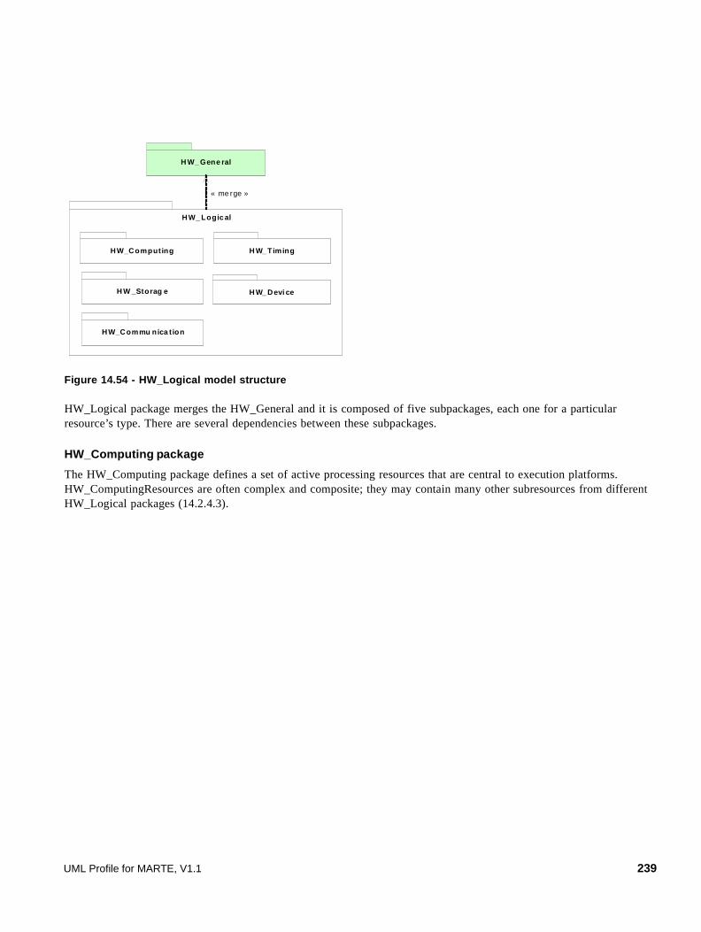
Figure 14.54 - HW_Logical model structure
HW_Logical package merges the HW_General and it is composed of five subpackages, each one for a particular resource’s type. There are several dependencies between these subpackages.
HW_Computing package
The HW_Computing package defines a set of active processing resources that are central to execution platforms. HW_ComputingResources are often complex and composite; they may contain many other subresources from different HW_Logical packages (14.2.4.3).
HW_ Logic al
HW_Computing
H W _Storag e
HW_Commu nica tion
H W_ Timing
H W_ Devi ce
H W_ Gene ral
« me rge »
UML Profile for MARTE, V1.1 239

Figure 14.55 - HW_Computing package details
HW_ComputingResource is a generic resource. It could be specialized (HW_ASIC), such resources are known to be efficient but not flexible. It could be configurable (HW_PLD), there are many technologies that have different capabilities like dynamic reconfiguration (SRAM). And it could be programmable (HW_Processor), which typically implements some instruction sets, owns caches, corresponding memory management units, and adopts branch prediction policies.
HW_Storage package
The metamodel of the HW_Storage package includes two diagrams, one for the HW_Memory resource and the other for the HW_StorageManager resource.
240 UML Profile for MARTE, V1.1

Figure 14.56 - HW_Storage package details (HW_Memory)
HW_Memory denotes a given amount of memory. It could be an HW_ProcessingMemory or HW_StorageMemory. HW_ProcessingMemory is an abstract metaclass that symbolizes a fast and volatile working memory, while HW_StorageMemory is an abstract metaclass for permanent and relatively time consuming storage devices.
In real world, RAM (Random Access Memory) takes many forms, SRAM for Static RAM is often used as cache, SDRAM for Synchronous Dynamic RAM is enough fast to be used as main memory (example 14.2.4.2). But as the logical model focuses on the functionality rather than the technology, we distinguish HW_RAM for main memories and HW_Cache for cache memories.
UML Profile for MARTE, V1.1 241
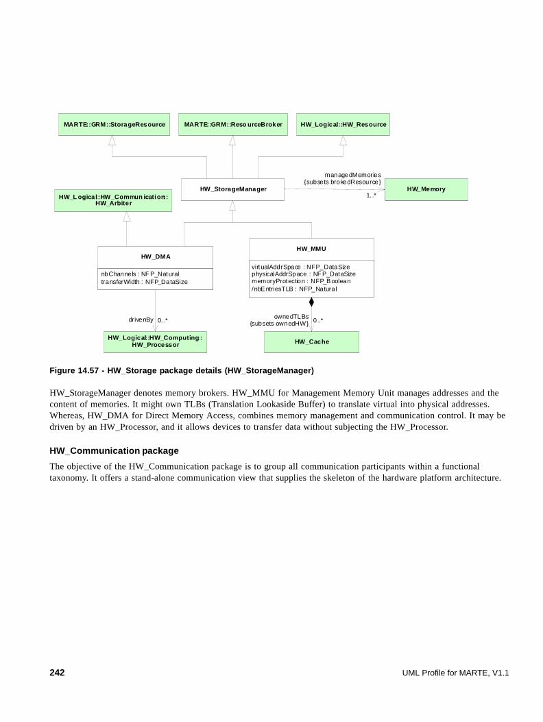
Figure 14.57 - HW_Storage package details (HW_StorageManager)
HW_StorageManager denotes memory brokers. HW_MMU for Management Memory Unit manages addresses and the content of memories. It might own TLBs (Translation Lookaside Buffer) to translate virtual into physical addresses. Whereas, HW_DMA for Direct Memory Access, combines memory management and communication control. It may be driven by an HW_Processor, and it allows devices to transfer data without subjecting the HW_Processor.
HW_Communication package
The objective of the HW_Communication package is to group all communication participants within a functional taxonomy. It offers a stand-alone communication view that supplies the skeleton of the hardware platform architecture.
HW_StorageManager
MARTE::GRM::StorageResource MARTE::GRM::Reso urceBroker HW_Logical::HW_Resource
virtualAddrSpace : NFP_DataSizephysicalAddrSpace : NF P_DataSizememoryProtection : NFP_Boolean/nbEntriesTLB : NFP_Natural
HW_MMU
HW_Cache
ownedTLBs{subsets ownedHW} 0..*
HW_L ogical::HW_Commun ication::HW_Arbiter
HW_Memory
managedMemories{subsets brokedResource}
1. .*
nbChannels : NF P_NaturaltransferWidth : NFP_DataSize
HW_DMA
HW_Logical::HW_Computing::HW_Processor
drivenBy 0. .*
242 UML Profile for MARTE, V1.1

Figure 14.58 - HW_Communication package details
The HW_Media is a central concept that denotes a communication resource able to transfer data with a theoretical bandwidth. It may link many HW_EndPoint(s). It could be controlled by many HW_Arbiters and it may be connected to other HW_Medias by means of HW_Bridges. An HW_EndPoint is an identified connection point of an HW_Resource (e.g., pin, port, or slot).
If HW_Media is generic and symbolizes any kind of connections, HW_Bus is a particular wired channel with specific functional properties (example 14.2.4.3).
UML Profile for MARTE, V1.1 243

HW_Timing package
Figure 14.59 - HW_Timing package details
Figure 14.60 defines timing resources. The HW_Clock is a basic periodic pulse with a definite frequency. Every HW_Resource can be clocked.
HW_Timer is a set of counters. The counter width determines the maximum measurement of time in terms of clock periods (2counterWidth -1). HW_Watchdog is typically a count-down timer, which sends an alarm when the zero count is reached (example 14.2.4.1).
HW_Device package
Figure 14.60 - HW_Device package details
HW_TimingResource
MARTE::GRM::TimingResource
frequency : NFP_Frequency
HW_Clock
nbCounters : NFP_NaturalcounterWidth : NFP_Datasize
HW_Timer
HW_Watchdog
HW_Logical::HW_Resource
0..1clock
inputClock{redefines clock}
1
244 UML Profile for MARTE, V1.1

From a functional point of view, an HW_Device is an auxiliary resource that is not as fundamental as computing, storage, and communication resources are, but it expands the functionality of the hardware platform. It has two subcategories. The HW_IO denotes resources that interact with the environment, like sensors, actuators, peripherals, displays, external port, and so on. Whereas, the HW_Support is a support resource like power suppliers (batteries), power regulators, cooling fans, or miscellaneous electronic devices. Because of their nature, some support devices are detailed in the physical model (example 14.2.4.3).
14.2.2.3 The Hardware Physical model
The HW_Physical model represents hardware resources as physical components with details on their shape, size, position within platform, power consumption, heat dissipation, and many other physical properties.
As most embedded systems have limited area and weight, hard environmental conditions and a predetermined autonomy, this view helps the hardware design and mapping components on the physical platform.
Figure 14.61 - HW_Physical model structure
Same as the functional view introduced above, the HW_Physical package merges the HW_General and contains two subpackages. The HW_Layout package that focuses on the layout architecture and the HW_Power package that provides mechanisms to annotate the model with power properties.
HW_Layout package
The HW_Layout package provides mechanisms to make UML graphical diagrams as close as possible to the real hardware platform layout. It classifies hardware components depending on their forms and offers arrangement constructs using rectilinear grids (example 14.2.4.3).
HW_Physical
HW_Layout
HW_Power
HW_General
« merge »
« merge »
UML Profile for MARTE, V1.1 245

Figure 14.62 - HW_Layout package details
HW_Component denotes a generic physical component that can be refined into a grid of subcomponents. It has dimensions, a resulting area, a particular weight, and optionally a number of pins and a position within a potential container. Each HW_Component requires some environmental conditions whether if it is in use or not.
HW_Power package
The HW_Power package comes with a detailed description of HW_Component power consumption and heat dissipation. It enables advanced power analysis and autonomy optimization that are crucial for embedded systems. Notice that the HW_Layout may also influence the power analysis.
246 UML Profile for MARTE, V1.1

Figure 14.63 - HW_Power package details
HW_PowerDescriptor is a key metaclass that provides instantaneous power descriptions. It annotates each provided service with its corresponding consumption and each HW_Component with a description of its leakage at non-operating time.
HW_PowerSupply and HW_Battery are energy suppliers, whereas HW_CoolingSupply is a heat reducer.
14.2.3 UML Representation
This sub clause depicts the Hardware Resource Model profile. It first groups all hardware stereotypes under several profile diagrams, and then it provides the detailed description of each hardware stereotype. The Hardware Resource Model profile is based on the hardware resource domain model. Therefore most stereotype descriptions refer to the corresponding domain concepts. All cases where stereotypes are different from the mapped domain concepts are justified.
As shown in Figure 14.65, the Hardware Resource Model profile keeps the structure of the domain model. It is composed of logical and physical profiles. Both have a local general model of hardware platforms, in order to ensure their total independency. The logical profile is in turn composed of many other packages representing many functions of hardware, whereas the physical profile is also composed of layout and power packages. Note that these packages are not sub-profiles, they only improve the organization of the HwLogical and HwPhysical profiles.
To leave a large modeling flexibility, HwResource of both HwGeneral packages (Figure 14.66, Figure 14.73) inherits from the Resource stereotype (from the General Resource Model, Clause 10) that extends the Classifier and InstanceSpecification metaclasses from the UML kernel package. This allows using the Hardware Resource Model profile within all structural UML diagrams (Class, Component, Composite Structure - examples 14.2.4.2, 14.2.4.3). The same principle applies to the HwResourceService that extends the Operation metaclass and could be associated with many UML behavior views.
All hardware resource stereotypes have the same extensions. However some of them also are particularly extending other appropriate UML metaclasses (e.g., HwMedia from the HwCommunication package also extends Association).
suppliedPower : NFP_Power
HW_PowerSupply
capacity : NFP_Energy
HW_Battery
HW_Component
coolingPower : NFP_Power
HW_Coolin gSupply
consumption : NF P_Powerdissipation : NFP_Power
HW_PowerDescriptor
HW_Physical::HW_ResourceService
0..1consumption
0..1
leakage
poweredServices{redefines p_HW_Services }
0. .*
UML Profile for MARTE, V1.1 247

Within MARTE, stereotypes tag definitions are optional and they should be specified only if needed. In addition, because of extending both Classifier and InstanceSpecification, they could be fixed either at model or instance level. This variation point enlarges the semantics of tag definitions (battery within example 14.2.4.3).
The Hardware Resource Model profile includes many notations. There is an appropriate icon for each logical stereotype and a shape for each physical one. Also, the HwLayout package from the HwPhysical profile provides arrangement mechanisms with rectilinear grids to make UML graphical diagrams as close as possible to the real hardware platform architecture.
14.2.3.1 Profile diagrams
The Hardware Resource Model profile (HRM profile) has similar structure to the HRM domain model. It is composed of logical and physical sub-profiles that contain a local general model and other different packages.
Figure 14.64 - Hardware Resource Model profile structure
248 UML Profile for MARTE, V1.1
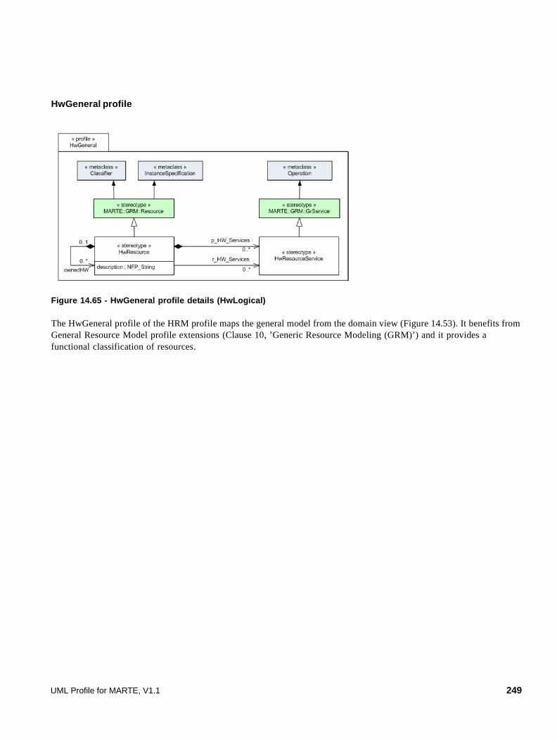
HwGeneral profile
Figure 14.65 - HwGeneral profile details (HwLogical)
The HwGeneral profile of the HRM profile maps the general model from the domain view (Figure 14.53). It benefits from General Resource Model profile extensions (Clause 10, ’Generic Resource Modeling (GRM)’) and it provides a functional classification of resources.
UML Profile for MARTE, V1.1 249

HwComputing profile
Figure 14.66 - HwComputing package details
The HwComputing profile from the HwLogical profile maps the corresponding hardware computing domain model.
250 UML Profile for MARTE, V1.1

HwMemory profile
Figure 14.67 - HwMemory profile details (HwStorage)
The HwMemory profile lightly varies from its corresponding domain model. It removes abstract HW_ProcessingMemory and HW_StorageMemory concepts but it maintains the composition specifying the buffer memory for the HwDrive.
UML Profile for MARTE, V1.1 251
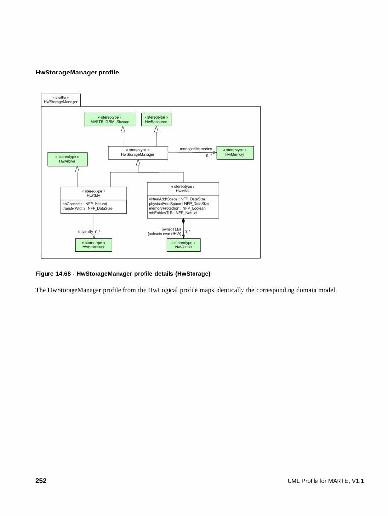
HwStorageManager profile
Figure 14.68 - HwStorageManager profile details (HwStorage)
The HwStorageManager profile from the HwLogical profile maps identically the corresponding domain model.
252 UML Profile for MARTE, V1.1

HwCommunication profile
Figure 14.69 - HwCommunication profile details
The HwCommunication profile maps the corresponding HW_Communication domain model.
Notice that among the inherited extensions, HwMedia extends the UML Connector metaclass.
UML Profile for MARTE, V1.1 253
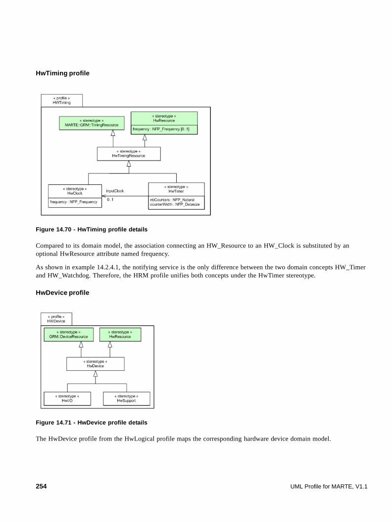
HwTiming profile
Figure 14.70 - HwTiming profile details
Compared to its domain model, the association connecting an HW_Resource to an HW_Clock is substituted by an optional HwResource attribute named frequency.
As shown in example 14.2.4.1, the notifying service is the only difference between the two domain concepts HW_Timer and HW_Watchdog. Therefore, the HRM profile unifies both concepts under the HwTimer stereotype.
HwDevice profile
Figure 14.71 - HwDevice profile details
The HwDevice profile from the HwLogical profile maps the corresponding hardware device domain model.
254 UML Profile for MARTE, V1.1
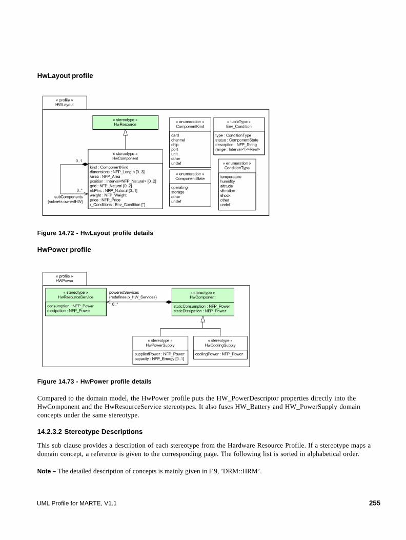
HwLayout profile
Figure 14.72 - HwLayout profile details
HwPower profile
Figure 14.73 - HwPower profile details
Compared to the domain model, the HwPower profile puts the HW_PowerDescriptor properties directly into the HwComponent and the HwResourceService stereotypes. It also fuses HW_Battery and HW_PowerSupply domain concepts under the same stereotype.
14.2.3.2 Stereotype Descriptions
This sub clause provides a description of each stereotype from the Hardware Resource Profile. If a stereotype maps a domain concept, a reference is given to the corresponding page. The following list is sorted in alphabetical order.
Note – The detailed description of concepts is mainly given in F.9, ’DRM::HRM’.
UML Profile for MARTE, V1.1 255

CacheStructure
The CacheStructure tupletype maps the CacheStructure domain element (F.9.1).
Attributes
• nbSets: NFP_Natural Specifies the number of sets.
• blockSize: NFP_DataSize Specifies the width of a cache block.
• associativity: NFP_Natural Specifies the associativity of the cache.
CacheType
The CacheType enumeration maps the CacheType domain element (F.9.2).
Literals
• data
• instruction
• unified for both data and instruction
• other
• undef
ComponentKind
ComponentKind is an enumeration of the following HwComponent kinds:
Description
• card
• channel
• chip
• port
• unit
• other
• undef
ComponentState
The ComponentState enumeration maps the ComponentState domain element (F.9.3).
Description
• operating
• storage non-operating state
256 UML Profile for MARTE, V1.1

• other
• undef
ConditionType
The ConditionType enumeration maps the ConditionType domain element (F.9.4).
Description
• temperature
• humidity
• altitude
• vibration
• shock
• other
• undef
Env_Condition
The Env_Condition tupletype maps the Env_Condition domain element (F.9.5).
Attributes
• type: ConditionType Specifies the condition type.
• status: ComponentState Specifies the required state of the HwComponent.
• description: NFP_String Specifies a short description of the environmental condition.
• range: Interval<T->Real> Specifies the range of possible values.
HwActuator
Actuators are frequently used as mechanisms to introduce motion, or to clamp an object so as to prevent motion. They are devices that transform an input signal (mainly an electrical signal) into motion (F.9.6).
Generalizations
• HwI/O
HwArbiter
The HwArbiter stereotype maps the HW_Arbiter domain element (F.9.7).
Generalizations
• HwCommunicationResource
UML Profile for MARTE, V1.1 257

Associations
• controlledMedias: HwMedia[0..*] Specifies the controlled connections.
Notations
HwASIC
The HwASIC stereotype maps the HW_ASIC domain element (F.9.8).
Generalizations
• HwComputingResource
Constraints
[1] if a clock frequency is specified, it must belong to op_Frequencies.
HwBranchPredictor
The HwBranchPredictor stereotype maps the HW_BranchPredictor domain element (F.9.10).
Generalizations
• HwResource
HwBridge
The HwBridge stereotype maps the HW_Bridge domain element (F.9.11).
Generalizations
• HwMedia
Associations
• sides: HwMedia[0..*] Specifies HwMedias at the ends of the HwBridge.
Notations
HwBus
The HwBus stereotype maps the HW_Bus domain element (F.9.12).
258 UML Profile for MARTE, V1.1

Generalizations
• HwMedia
Attributes
• adressWidth: NFP_DataSize Specifies the supported addressing size. In general, it is a number of bits.
• wordWidth: NFP_DataSize Specifies the transfer word width.
• isSynchronous: NFP_Boolean Specifies whether the bus is clocked or not.
• isSerial: NFP_Boolean Distinguishes serial from parallel buses.
Constraints
[1] Synchronous bus must have a clock frequency.
HwCache
The HwCache stereotype maps the HW_Cache domain element (F.9.13).
Generalizations
• HwMemory
Attributes
• level: NFP_Natural Specifies the cache level. The default value is 1.
• type: CacheType Specifies the type of the cache.
• structure: CacheStructure Specifies the structure of the cache.
Constraints
[1] memorySize is derived from structure attribute.
[2] addressSize is greater than the total cache entries number derived from the structure attribute.
HwClock
The HwClock stereotype maps the HW_Clock domain element (F.9.17).
Generalizations
• HwTimingResource
Attributes
• None
UML Profile for MARTE, V1.1 259

HwCommunicationResource
The HwCommunicationResource stereotype maps the HW_CommunicationResource domain element (F.9.18).
Generalizations
• HwResource
HwComponent
The HwComponent stereotype maps the HW_Component domain element from the HW_Layout package (F.9.19).
Generalizations
• HwResource
Associations
• subComponents: HwComponent[0..*] Specifies the owned physical entities. Subsets HwResource.ownedHW.
Attributes
• dimensions: NFP_Length[0..3] Specifies Cartesian dimensions of the HwComponent. It is an ordered attribute.
• /area: NFP_Area Specifies the area of the HwComponent. Derived from dimensions.
• position: Interval<NFP_Natural>[0..2] Specifies position within the enclosing HwComponent. It is an ordered attribute.
• grid: NFP_Natural[0..2] Specifies a rectilinear grid associated to the HwComponent. It is an ordered attribute.
• nbPins: NFP_Natural[0..1] Specifies the number of pins. It is optional.
• weight: NFP_Weight Specifies the weight of the HwComponent.
• price: NFP_Price Specifies the HwComponent price.
• r_Conditions: Env_Condition[*] Specifies the required environmental conditions.
• kind: ComponentKind Specifies the kind of the HwComponent
• staticConsumption: NFP_Power Specifies the HwComponent static consumption.
• staticDissipation: NFP_Power Specifies the HwComponent static dissipation.
260 UML Profile for MARTE, V1.1

Semantics
The HwComponent stereotype maps its corresponding domain concept but it has three additional attributes kind to specify the kind of the hardware component, staticConsumption, and staticDissipation that are appropriate for power description and substitute the composition between the HW_Component and HW_PowerDescriptor domain concepts.
Constraints
[1] area must derive from dimensions
[2] subComponents positions must not exceed the grid
[3] requiredConditions intervals must be included within the subcomponents corresponding intervals.
Notations
HwComponent has many shapes depending on its kind.
• Card
• Channel
• Chip
• Port
UML Profile for MARTE, V1.1 261
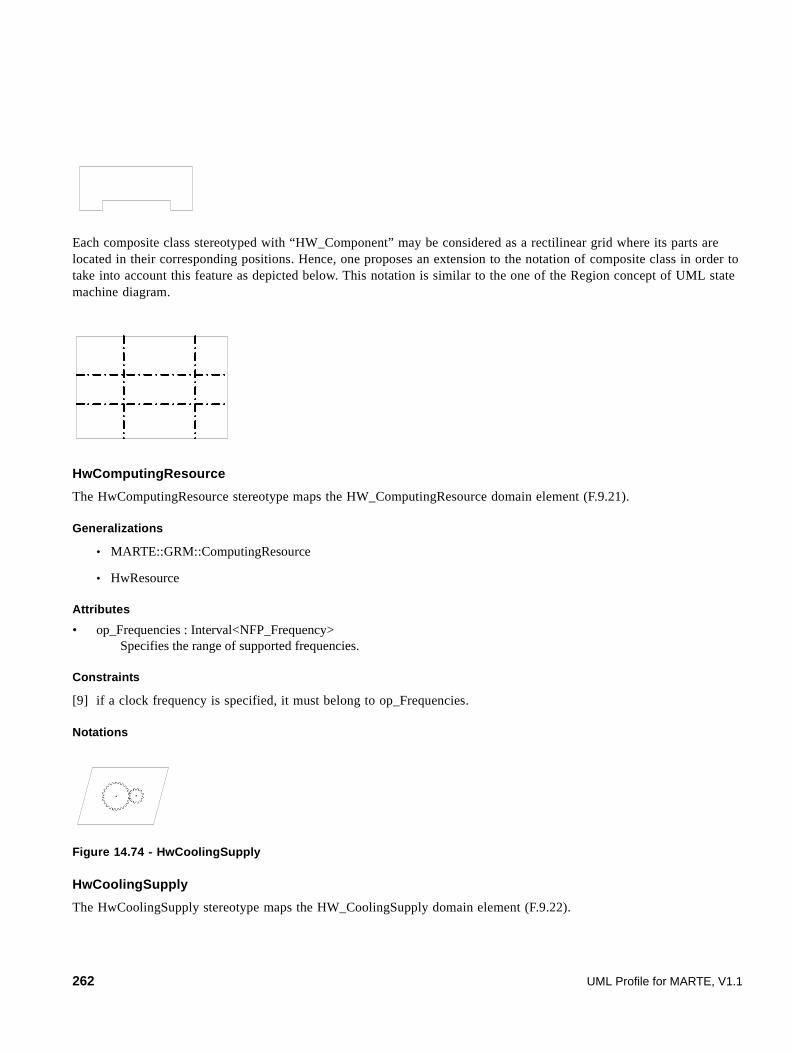
Each composite class stereotyped with “HW_Component” may be considered as a rectilinear grid where its parts are located in their corresponding positions. Hence, one proposes an extension to the notation of composite class in order to take into account this feature as depicted below. This notation is similar to the one of the Region concept of UML state machine diagram.
HwComputingResource
The HwComputingResource stereotype maps the HW_ComputingResource domain element (F.9.21).
Generalizations
• MARTE::GRM::ComputingResource
• HwResource
Attributes
• op_Frequencies : Interval<NFP_Frequency> Specifies the range of supported frequencies.
Constraints
[9] if a clock frequency is specified, it must belong to op_Frequencies.
Notations
Figure 14.74 - HwCoolingSupply
HwCoolingSupply
The HwCoolingSupply stereotype maps the HW_CoolingSupply domain element (F.9.22).
262 UML Profile for MARTE, V1.1

Generalizations
• HwComponent
Attributes
• coolingPower: NFP_Power Specifies the cooling power.
Notations
HwDevice
The HwDevice stereotype maps the HW_Device domain element (F.9.23).
Generalizations
• MARTE::GRM::DeviceResource
• HwResource
Notations
HwDMA
The HwDMA stereotype maps the HW_DMA domain element (F.9.24).
Generalizations
• HwStorageManager
• HwArbiter
Associations
• drivenBy: HwProcessor[0..*] Specifies processors that control the HwDMA.
Attributes
• nbChannels: NFP_Natural Specifies the number of HwDMA channels.
UML Profile for MARTE, V1.1 263
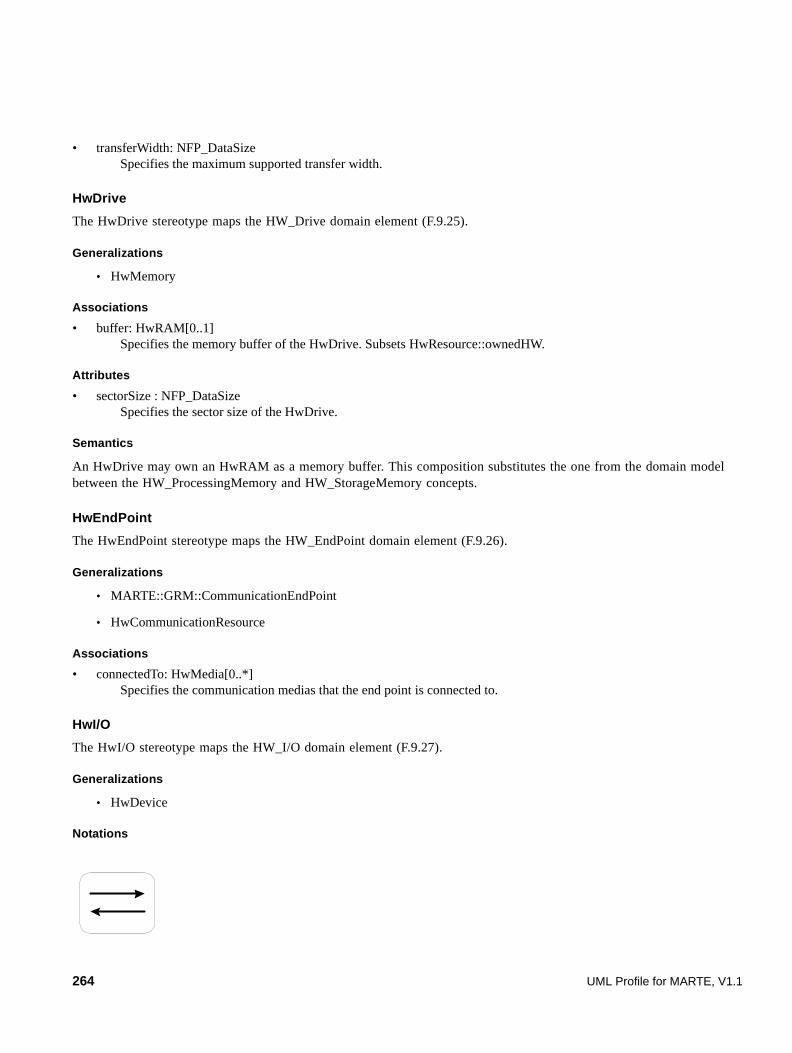
• transferWidth: NFP_DataSize Specifies the maximum supported transfer width.
HwDrive
The HwDrive stereotype maps the HW_Drive domain element (F.9.25).
Generalizations
• HwMemory
Associations
• buffer: HwRAM[0..1] Specifies the memory buffer of the HwDrive. Subsets HwResource::ownedHW.
Attributes
• sectorSize : NFP_DataSize Specifies the sector size of the HwDrive.
Semantics
An HwDrive may own an HwRAM as a memory buffer. This composition substitutes the one from the domain model between the HW_ProcessingMemory and HW_StorageMemory concepts.
HwEndPoint
The HwEndPoint stereotype maps the HW_EndPoint domain element (F.9.26).
Generalizations
• MARTE::GRM::CommunicationEndPoint
• HwCommunicationResource
Associations
• connectedTo: HwMedia[0..*] Specifies the communication medias that the end point is connected to.
HwI/O
The HwI/O stereotype maps the HW_I/O domain element (F.9.27).
Generalizations
• HwDevice
Notations
264 UML Profile for MARTE, V1.1

HwISA
The HwISA stereotype maps the HW_ISA domain element (F.9.28).
Generalizations
· HwResource
Attributes
• family: NFP_String Specifies the ISA family.
• inst_Width: NFP_DataSize Specifies the instruction width.
• type: ISA_Type Specifies the ISA type.
HwMedia
The HwMedia stereotype maps the HW_Media domain element (F.9.29).
Generalizations
• MARTE::GRM::CommunicationMedia
• HwCommunicationResource
Extensions
• None
Associations
• arbiters: HwArbiter[0..*] Specifies the HwMedia controllers.
Attributes
• None
Notations
HwMemory
The HwMemory stereotype maps the HW_Memory domain element (F.9.30).
Generalizations
• MARTE::GRM::StorageResource
• HwResource
UML Profile for MARTE, V1.1 265

Attributes
• memorySize: NFP_DataSize Specifies the storage capacity of the HwMemory.
• addressSize: NFP_DataSize Specifies the address width of the HwMemory.
• timings: Timing[*] Specifies timings of the HwMemory.
• throughput:NFP_DataTxRate Speciifes the throughput in a memory.
Constraints
[10] The value of the inherited attribute isprotected is true.
Notations
HwMMU
The HwMMU stereotype maps the HW_MMU domain element (Section F.9.31).
Generalizations
• HwStorageManager
Associations
• ownedTLBs: HwCache[0..*] Specifies the owned Translation Lookaside Buffers.
Attributes
• virtualAddrSpace: NFP_DataSize Specifies the managed virtual address space.
• physicalAddrSpace: NFP_DataSize Specifies the managed physical address space.
• memoryProtection: NFP_Boolean Specifies if memory protection is supported.
• /nbEntriesTLB: NFP_Natural Specifies the total number of TLBs entries. Derived from the ownedTLBs association.
Constraints
[1] nbEntriesTLB is derived from the ownedTLBs number of entries.
266 UML Profile for MARTE, V1.1

HwPLD
The HwPLD stereotype maps the HW_PLD domain element (F.9.32).
Generalizations
• HwComputingResource
Associations
• blocksComputing: HwComputingResource[0..*] Specifies owned computing blocks. Subsets HwResource.ownedHW.
• blocksRAM : HwRAM[0..*] Specifies the owned HwRAM memories.
Attributes
• technology: PLD_Technology Specifies the HwPLD technology.
• organization: PLD_Organization Specifies the matrix organization of the HwPLD.
• nbLUTs Specifies the number of LUTs within the HwPLD.
• nbLUT_Inputs Specifies the number of inputs of one LUT.
• nbFlipFlops Specifies the number of FlipFlops within the HwPLD.
Constraints
[1] if a clock frequency is specified, it must belong to op_Frequencies.
HwPowerSupply
The HwPowerSupply stereotype maps the HW_PowerSupply domain element (F.9.35).
Generalizations
• HwComponent
Attributes
• suppliedPower: NFP_Power Specifies the instantaneous supplied power.
• capacity: NFP_Energy[0..1] Specifies the capacity of the HwPowerSupply.
Semantics
This stereotype denotes both domain elements HW_PowerSupply and HW_Battery.
Constraints
[1] power consumption is greater than dissipation.
UML Profile for MARTE, V1.1 267

Notations
HwProcessor
The HwProcessor stereotype maps the HW_Processor domain element (F.9.37).
Generalizations
• HwComputingResource
Associations
• predictors: HwBranchPredictor[0..*] Specifies the owned branch prediction units. Subsets HwResource.ownedHW.
• caches: HwCache[0..*] Specifies processor caches. Subsets HwResource.ownedHW.
• ownedMMUs: HwMMU[0..*] Specifies the owned Memory Management Units. Subsets HwResource.ownedHW.
• ownedISAs: HwISA[1..*] Specifies the owned instruction set architectures. Subsets HwResource.ownedHW.
Attributes
• /architecture: NFP_DataSize Specifies the instruction width. Derived from ownedISAs.
• mips: NFP_Natural Specifies the throughput of the processor.
• /ipc: NFP_Real Specifies the number of instructions executed each clock cycle. Derived from mips and clock attributes.
• nbCores: NFP_Natural Specifies the number of cores within the HwProcessor.
• nbPipelines: NFP_Natural Specifies the number of pipelines per core.
• nbStages: NFP_Natural Specifies the number of stages per pipeline.
• nbALUs: NFP_Natural Specifies the number of Arithmetic Logic Units within the HwProcessor.
• nbFPUs: NFP_Natural Specifies the number of Floating Point Units within the HwProcessor.
Constraints
[1] if a clock frequency is specified, it must belong to op_Frequencies.
268 UML Profile for MARTE, V1.1

[2] architecture must derive from the inst_Width of the supportedISAs.
[3] ipc must derive from mips attribute and clock frequeny.
HwRAM
The HwRAM stereotype maps the HW_RAM domain element (F.9.38).
Generalizations
• HwMemory
Attributes
• organization: MemoryOrganization Specifies the organization of the HwRAM.
• isSynchronous: NFP_Boolean Specifies whether the HwAM is clocked or not.
• isStatic: NFP_Boolean Specifies whether the HwRAM is static or not.
• isNonVolatile: NFP_Boolean Specifies whether the HwRAM is volatile or not. Default value is false.
Constraints
[1] memorySize is derived from organization attribute.
[2] addressSize is greater than the number of memory words derived from organization attribute.
[3] synchronous HwRAM must have a clock frequency.
HwResource (from HwLogical)
This HwResource stereotype maps the HW_Resource domain element from the HW_Logical package (F.9.39).
Generalizations
• MARTE::GRM::Resource
Associations
• ownedHW: HwResource[0..*] Specifies the owned sub-HwResources. Subsets Resource.ownedElement.
• p_HW_Services: HwResourceService[0..*] Specifies the provided services. Subsets Resource.pServices.
• r_HW_Services: HwResourceService[0..*] Specifies the required services.
• endPoints: HwEndPoint[0..*] Specifies the connection points of the HwReource. Subsets ownedHW.
UML Profile for MARTE, V1.1 269

Attributes
• description: NFP_String Specifies a textual description of the HwResource.
• frequency: NFP_Frequency[0..1] Specifies the clock frequency of the HwResource.
HwResource (from HwPhysical)
This HwResource stereotype maps the HW_Resource domain element from the HW_General package (F.9.41).
Generalizations
• MARTE::GRM::Resource
Associations
• ownedHW: HwResource[0..*] Specifies the owned sub-HwResources. Subsets Resource.ownedElement.
• p_HW_Services: HwResourceService[0..*] Specifies the provided services. Subsets Resource.pServices.
• r_HW_Services: HwResourceService[0..*] Specifies the required services.
Attributes
• description: NFP_String Specifies a textual description of the HwResource.
HwResourceService (from HwLogical)
The HwResourceService stereotype maps the HW_ResourceService domain element from the HW_General package (F.9.41).
Generalizations
• MARTE::GRM::ResourceService
HwResourceService (from HwPhysical)
The HwResourceService stereotype maps the HW_ResourceService domain element from the HW_Physical package (F.9.42).
Generalizations
• MARTE::GRM::ResourceService
Attributes
• consumption: NFP_Power Specifies the consumption of the HwComponent when powering the HwResourceService.
• dissipation: NFP_Power Specifies the dissipation of the HwComponent when powering the HwResourceService.
270 UML Profile for MARTE, V1.1

Semantics
Compared to its analogous domain concept, the HwResourceService stereotype from the HwPhysical package converts the association with the HW_PowerDescriptor to two appropriate attributes.
Constraints
[1] power consumption is greater than dissipation.
HwROM
The HwROM stereotype maps the HW_ROM domain element (F.9.43).
Generalizations
• HwMemory
Attributes
• type: ROM_Type Specifies the HwROM type.
• organization: MemoryOrganization Specifies the structure of the HwROM.
Constraints
[1] memorySize is derived from organization attribute.
[2] addressSize is greater than the number of memory words derived from organization attribute.
HwSensor
A sensor is a device that measures a physical quantity and converts it into a signal, which can be read by an observer or by an instrument. (F.9.44).
Generalizations
• HwI/O
HwStorageManager
The HwStorageManager stereotype maps the HW_StorageManager domain element (F.9.44).
Generalizations
• MARTE::GRM::StorageResource
• HwResource
Associations
• managedMemories: HwMemory[0..*] Specifies the managed memories.
UML Profile for MARTE, V1.1 271

Notations
HwSupport
The HwSupport stereotype maps the HW_Support domain element (F.9.47).
Generalizations
• HwDevice
HwTimer
The HwTimer stereotype maps the HW_Timer domain element (F.9.48).
Generalizations
• HwTimingResource
Associations
• inputClock: HwClock[0..1] Specifies the input clock of the HwTimer.
Attributes
• nbCounters: NFP_Natural Specifies the number of counters within the HwTimer.
• counterWidth: NFP_DataSize Specifies the width of one counter.
Semantics
This stereotype unifies both domain elements HW_Timer and HW_Watchdog.
HwTimingResource
The HwTimingResource stereotype maps the HW_TimingResource domain element (F.9.49).
Generalizations
• MARTE::GRM::TimingResource
• HwResource
272 UML Profile for MARTE, V1.1

Notations
ISA_Type
The ISA_Type enumeration maps the ISA_Type domain element (F.9.52).
Description
• RISC (Reduced Instruction Set Computer)
• CISC (Complex Instruction Set Computer)
• VLIW (Very Long Instruction Word)
• SIMD (Single Instruction Multiple Data)
• other
• undef
MemoryOrganization
The MemoryOrganization tupletype maps the MemoryOrganization domain element (F.9.53).
Attributes
• nbRows: NFP_Natural Specifies the number of rows.
• nbColumns: NFP_Natural Specifies the number of columns.
• nbBanks: NFP_Natural Specifies the number of banks.
PLD_Class
The PLD_Class enumeration maps the PLD_Class domain element (F.9.54).
Description
• symetricalArray
• rowBased
• seaOfGates
UML Profile for MARTE, V1.1 273

• hierarchicalPLD
• other
• undef
PLD_Organization
The PLD_Organization tupletype maps the PLD_Organization domain element (F.9.55).
Attributes
• nbRows: NFP_Natural Specifies the number of rows.
• nbColumns: NFP_Natural Specifies the number of columns.
• class: PLD_Class Specifies the HW_PLD Class.
PLD_Technology
The PLD_Technology enumeration maps the PLD_Technology domain element (F.9.56).
Description
• SRAM
• Antifuse
• Flash
• other
• undef
Repl_Policy
The Repl_Policy enumeration maps the Repl_Policy domain element (F.9.58).
Description
• LRU Least Recently Used
• NFU Not Frequently Used
• FIFO First In First Out
• Random
• other
• undef
274 UML Profile for MARTE, V1.1
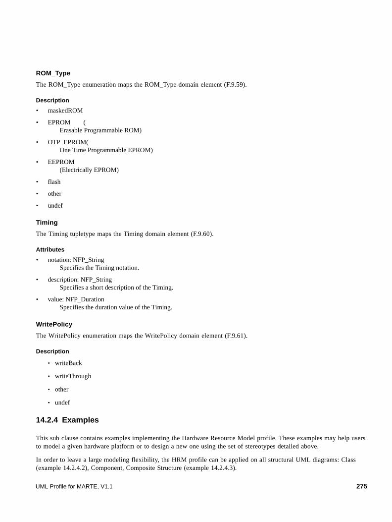
ROM_Type
The ROM_Type enumeration maps the ROM_Type domain element (F.9.59).
Description
• maskedROM
• EPROM ( Erasable Programmable ROM)
• OTP_EPROM( One Time Programmable EPROM)
• EEPROM (Electrically EPROM)
• flash
• other
• undef
Timing
The Timing tupletype maps the Timing domain element (F.9.60).
Attributes
• notation: NFP_String Specifies the Timing notation.
• description: NFP_String Specifies a short description of the Timing.
• value: NFP_Duration Specifies the duration value of the Timing.
WritePolicy
The WritePolicy enumeration maps the WritePolicy domain element (F.9.61).
Description
• writeBack
• writeThrough
• other
• undef
14.2.4 Examples
This sub clause contains examples implementing the Hardware Resource Model profile. These examples may help users to model a given hardware platform or to design a new one using the set of stereotypes detailed above.
In order to leave a large modeling flexibility, the HRM profile can be applied on all structural UML diagrams: Class (example 14.2.4.2), Component, Composite Structure (example 14.2.4.3).
UML Profile for MARTE, V1.1 275
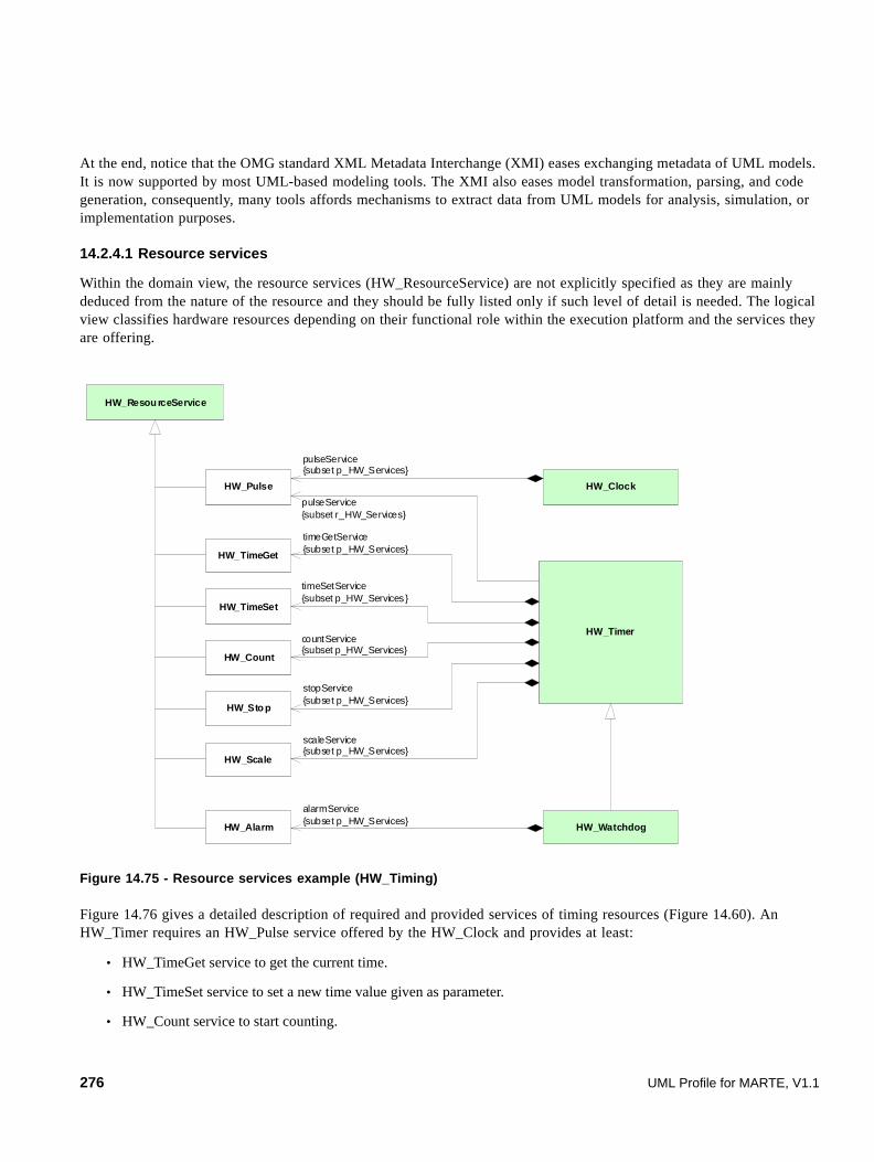
At the end, notice that the OMG standard XML Metadata Interchange (XMI) eases exchanging metadata of UML models. It is now supported by most UML-based modeling tools. The XMI also eases model transformation, parsing, and code generation, consequently, many tools affords mechanisms to extract data from UML models for analysis, simulation, or implementation purposes.
14.2.4.1 Resource services
Within the domain view, the resource services (HW_ResourceService) are not explicitly specified as they are mainly deduced from the nature of the resource and they should be fully listed only if such level of detail is needed. The logical view classifies hardware resources depending on their functional role within the execution platform and the services they are offering.
Figure 14.75 - Resource services example (HW_Timing)
Figure 14.76 gives a detailed description of required and provided services of timing resources (Figure 14.60). An HW_Timer requires an HW_Pulse service offered by the HW_Clock and provides at least:
• HW_TimeGet service to get the current time.
• HW_TimeSet service to set a new time value given as parameter.
• HW_Count service to start counting.
HW_Timer
HW_Watchdog
HW_Pulse HW_Clock
HW_Alarm
HW_Count
HW_TimeSet
HW_TimeGet
HW_Resou rceService
pulseService{subset r_HW_Services}
pulseService{subset p_HW_Services}
countService{subset p_HW_Services}
timeSetService{subset p_HW_Services }
timeGetService{subset p_HW_Services}
alarmService{subset p_HW_Services}
HW_Scale
HW_Sto p
stopService{subset p_HW_Services}
scaleService{subset p_HW_Services}
276 UML Profile for MARTE, V1.1
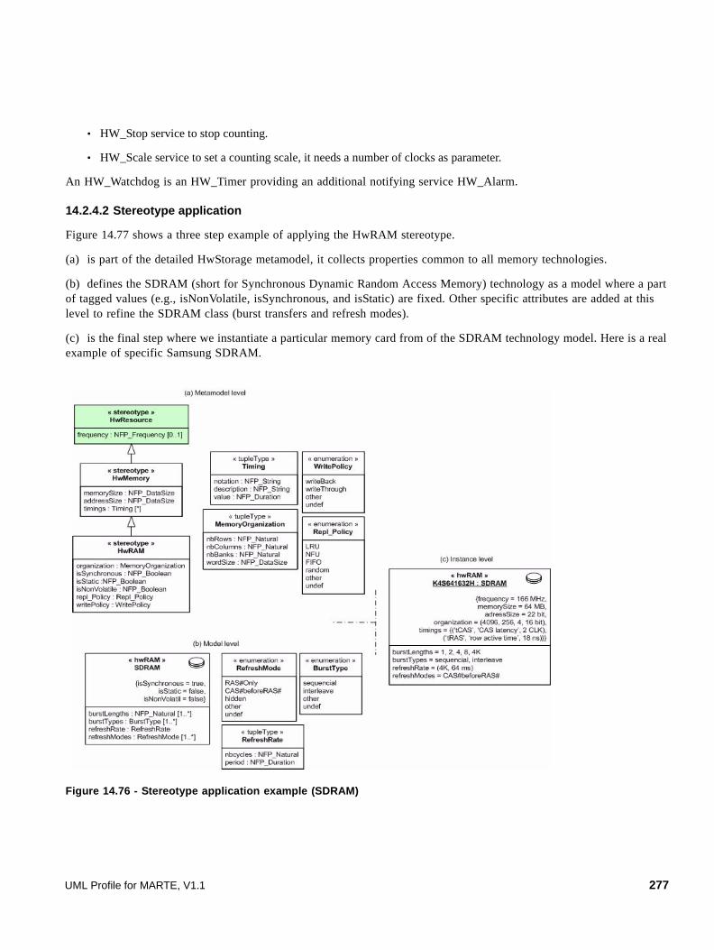
• HW_Stop service to stop counting.
• HW_Scale service to set a counting scale, it needs a number of clocks as parameter.
An HW_Watchdog is an HW_Timer providing an additional notifying service HW_Alarm.
14.2.4.2 Stereotype application
Figure 14.77 shows a three step example of applying the HwRAM stereotype.
(a) is part of the detailed HwStorage metamodel, it collects properties common to all memory technologies.
(b) defines the SDRAM (short for Synchronous Dynamic Random Access Memory) technology as a model where a part of tagged values (e.g., isNonVolatile, isSynchronous, and isStatic) are fixed. Other specific attributes are added at this level to refine the SDRAM class (burst transfers and refresh modes).
(c) is the final step where we instantiate a particular memory card from of the SDRAM technology model. Here is a real example of specific Samsung SDRAM.
Figure 14.76 - Stereotype application example (SDRAM)
UML Profile for MARTE, V1.1 277

14.2.4.3 Logical/Physical modeling
The next example is an SMP (Symmetric MultiProcessing) hardware platform with four processors owning caches and sharing the same main memory, through an FSB bus. This SMP platform also contains a 4-channels DMA (Direct Memory Access) and a battery (Figure 14.78).
Figure 14.77 - SMP description
The next figures depict two refinements of the previous high level model into a logical view on Figure 14.79 and a physical view on Figure 14.80.
Figure 14.78 - SMP logical view
Due to its encapsulation/composition mechanisms, the UML Composite Structure diagram is well adapted to hardware modeling even if the HRM profile can be used with all structural diagrams.
« hwResource»SMP
1
«hwResource»FSB
« hwResource»DMA
«hwResource»SDRAM
1 1
« hwResource»Battery
1
« hwResource»CPU
4
« hwResource»UL2
1
« hwLogical::hwResource »SMP
« hwProcessor »CPU
« hwCache »UL2
{level = 2,type = unified}
« hwBus»FSB
{isSynchronous = true}
« hwRAM »SDRAM
{isSynchronous = true,isStatic = false}
4 1 1 1
« hwSupport»Battery
« hwDMA »DMA{nbChannels = 4}
1
1
1
1
278 UML Profile for MARTE, V1.1

Figure 14.79 - SMP physical view
As UML allows application of many stereotypes on the same element, these two previous views could be merged into a unified view as shown in Figure 14.80.
Figure 14.80 - SMP merged (logical/physical) view
Even if merging logical and physical views is possible, separation of concerns is an adequate way to have specialized and detailed models that are lightened from unused properties. Figure 14.81 and Figure 14.82 depict two detailed logical and physical refinements of the SMP example introduced above.
UML Profile for MARTE, V1.1 279
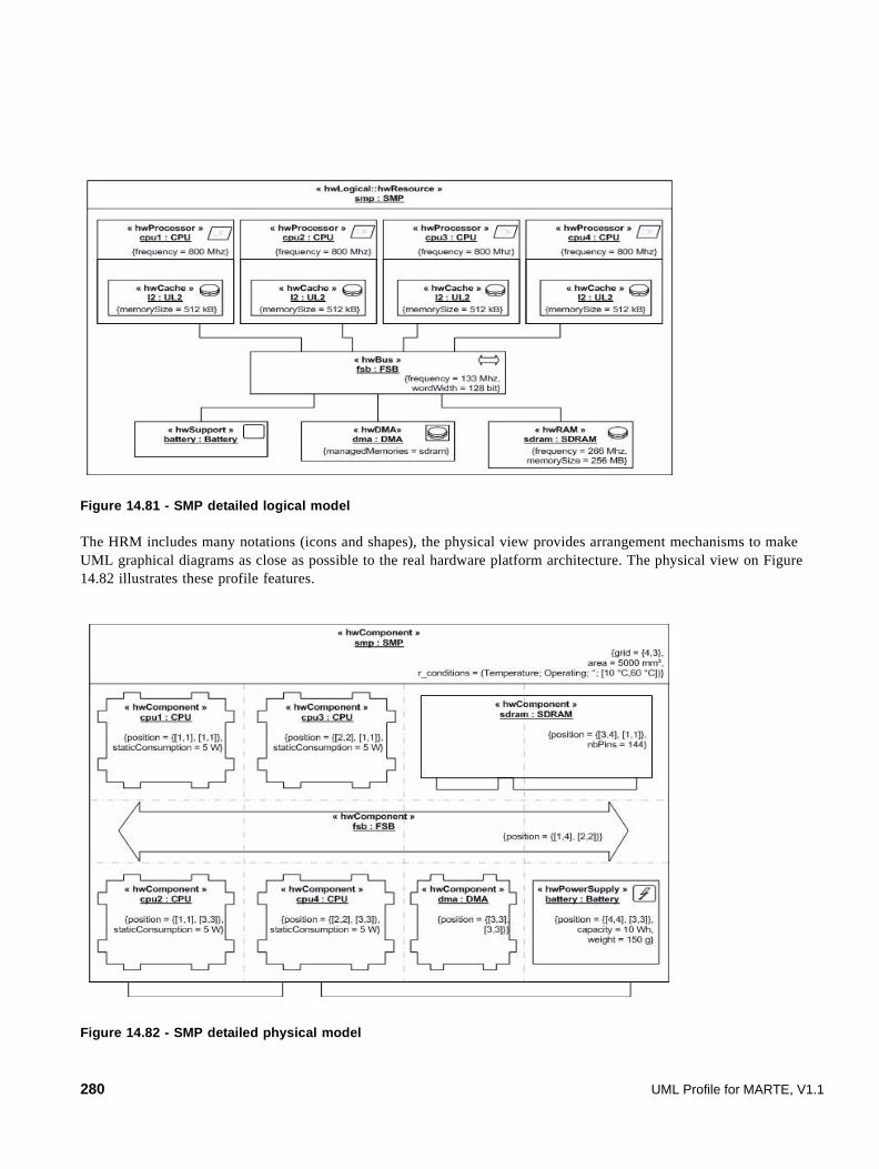
Figure 14.81 - SMP detailed logical model
The HRM includes many notations (icons and shapes), the physical view provides arrangement mechanisms to make UML graphical diagrams as close as possible to the real hardware platform architecture. The physical view on Figure 14.82 illustrates these profile features.
Figure 14.82 - SMP detailed physical model
280 UML Profile for MARTE, V1.1

Because of the nature of hardware resources, the logical and physical views converge on many concepts. Some logical stereotypes have a set of corresponding physical stereotypes like an HwLogical::HwBus that is typically a physical channel or HwLogical::HwProcessor(s) that are chips. Reciprocally, an HwPhysical::HwBattery is considered as an HwLogical::HwSupport device. More accurately, the addressSize and wordSize tag values of an HwLogical::HwMemory must go with the nbPins tag value of the corresponding HwPhysical::HW_Component.
Within MARTE, stereotype tag values can be fixed either at model or instance level. This enlarges the semantics of hardware models. For example, within Figure 14.80, the capacity of the battery at the model level was 40Wh and corresponds to the maximum capacity of such class of batteries, whereas the same tag value becomes 10Wh at instance level (Figure 14.82) and represents the current stored energy.
UML Profile for MARTE, V1.1 281

282 UML Profile for MARTE, V1.1

Subpart III - MARTE Analysis Model
This Subpart contains the following clauses:
• 15 - Generic Quantitative Analysis Modeling (GQAM)
• 16 - Schedulability Analysis Modeling (SAM)
• 17 - Performance Analysis Modeling (PAM)
UML Profile for MARTE, V1.1 283

284 UML Profile for MARTE, V1.1

15 Generic Quantitative Analysis Modeling (GQAM)
The generic analysis domain includes specialized domains in which the analysis is based on the software behavior, such as performance and schedulability (the two next clauses), and also power, memory, reliability, availability, and security. Although analysis domains have different terminology, concepts, and semantics, they also share some foundation concepts that are expressed in this clause, in order to simplify the profile and make it easier to add new analyses. Generic modeling defines basic modeling concepts and NFPs, using the NFP annotation framework depicted in Clause 8.
MARTE analysis is intended to support accurate and trustworthy evaluations using formal quantitative analyses based on sound mathematical models, which may supplement designer intuition and “feel.” Model analysis can detect problems early in the development life cycle and reduce cost and risk.
The two following clauses use GQAM in creating sub-profiles for:
• Schedulability analysis, to predict whether a set of software tasks meets its timing constraints and to verify its temporal correctness, e.g., RMA-based techniques (see, e.g., “Real-Time Systems,” by Jane Liu).
• Performance analysis, to determine if a system with non-deterministic behavior can provide adequate performance, usually defined by some statistical measures (see e.g., The Art of Computer Performance Modeling, by Raj Jain).
Figure 15.1 shows the relationship of these clauses to each other and to the rest of the profile. Analysis of power consumption and the use of memory are also briefly considered here as additional specializations that may be used in future analysis subprofiles.
Figure 15.1 - Dependencies of GenericQuantitativeAnalysisModeling (GQAM) package
15.1 Overview
This sub clause supports generic concepts for types of analysis based on system execution behavior, which may be represented at different levels of detail. Extra annotations needed for analysis are to be attached to an actual design model, rather than requiring a special version of the design model to be created only for the analysis. Even if the specification contains fine detail, the annotations may optionally be applied to aggregates. The same arguments may be applied to modeling software or embedded devices.
UML Profile for MARTE, V1.1 285

The core of the GQAM domain is the description of how the system behavior uses resources.
Quantitative analysis techniques determine the values of “output NFPs” (such as response times, deadline failures, resource utilizations, and queue sizes) based on data provided as “input NFPs” (e.g., request or trigger rates, execution demands, deadlines, QoS targets). The goals of analysis may have varying degrees of generality:
• A point evaluation of the output NFPs gives their values, along with decisions such as pass/fail.
• Sensitivity or scalability analysis is parameterized over variations in the input NFPs. It may seek to find which cases are satisfactory, and which are not; or to find the sensitivity of some measures to parameters that are not well determined.
• Some analysis may search over input NFP values to find feasible or optimal values.
The same NFP may be an input or output, depending on the context. For example a worst-case latency may be an output in WCET analysis, or an input in Schedulability Analysis.
Although NFPs may describe all aspects of a system (including, for example, heat generation and power consumption), this discussion centers on time and resource-related properties.
Time-Related NFPs
The core purpose of real-time analysis is to estimate the capability of a system to provide timely responses to requests for (or initiations of) specified system-level operations, which we will call services, and to handle an adequate frequency of requests, under specified conditions. To enable this analysis, a UML model must specify the system-level operations, the frequency of requests, and the conditions of execution (which we may term its environment).
Timeliness of a response can be defined in several different ways, as a property of the response delay to complete it. A recent survey is given by Sha et al. Some examples of definitions given in this survey are:
• Hard deadline: the response must be complete within this delay.
• Soft deadline: a stated percentage of responses must be complete within this delay. Quality-of-service specifications often are stated in these terms (see e.g., Jin and Nahrstedt, esp. Fig 4.).
• Delay cost function: a function of delay should be within a target value, or should be minimized. This is useful for trading off delays of multiple streams of requests that compete for resources. (see e.g., Franaszek and Nelson).
• Other statistical measures: the average delay, or the average of some function of some measure, must be within a target value, or some other measure must meet some requirement. The following real example is a generalization of soft deadlines: “the probability distribution function of delay must lie above a specified distribution function, so at each delay value the probability is higher than the specification.”
The expression of such measures in service level agreements was discussed and surveyed recently by Skene et al. They point out the value of analysis of the execution path of the software.
Other NFPs
Although this clause is concerned with time, it is instructive to consider others, such as memory and power usage (reliability and security are further examples not considered here).
Memory usage is determined by the size of objects that must be stored. As seen at the level of a system specification, these objects include:
• Executables when loaded.
286 UML Profile for MARTE, V1.1

• Data structures in memory, both static and dynamic. For dynamic data structures, the maximum size seems to be of the greatest interest. However a situation might arise where the program creates one buffer pool at one stage, then destroys it and creates another one at a later stage. A full analysis would then have to look at the memory use over the duration of a response, attaching sizes for a given object to particular operations. An example of a potentially dynamic data structure is a buffer pool.
• Messages sent between entities.
• Files.
Additional objects arise in the environment, including the operating system executable and data, file system cache and other memory objects, and the “heap.”
Power use depends on the system configuration and deployment and on its behavior, in that power is used to operate peripherals and memory, as well as to execute instructions and i/o operations. Power may be managed dynamically by a power control policy of the operating system, which responds to demands and battery status.
Power is related to time to execute a behavior, because the power used by a host processor is controlled through its clock speed, which affects its rate of operation.
Power management also applies to DRAM memories. (see “Memory Controller Policies for DRAM Power Management,” Xiaobo Fan, Carla S. Ellis, Alvin R. Lebeck, Proceedings of the International Symposium on Low Power Electronics and Design (ISLPED), pages 129--134, August 2001).
In wireless networks the power of transmission may be controlled, affecting messaging speed. Optimal policies take into account competition between nodes (see e.g., Cruz and Santhanam).
15.2 Domain View
Figure 15.2 shows the domain model for generic quantitative model-based analysis composed of four packages: GQAM, GQAM_Workload, GQAM_Observers, and GQAM_Resources.
15.2.1 The GQAM package
The top-level GQAM package shown in Figure 15.2, is organized around the concept of AnalysisContext, which represents the root of the domain model. It contains two parts that address different concerns:
• WorkloadBehavior (refined in Figure 15.3) contains a set of related end-to-end system-level operations, each with a defined behavior, triggered over time as defined by a set of workload events.
• ResourcesPlatform (refined in Figure 15.5) is a logical container for the resources used by the system-level behavior represented in the previous model.
AnalysisContext may have parameters of type VSL::Expressions::Variables, which define different cases being considered for analysis, and may affect the parameters of behavior and resources (such as the number of repetitions of a sub-operation, or the size of a list).
UML Profile for MARTE, V1.1 287

Figure 15.2 - Top package of the GQAM domain model
15.2.2 The GQAM_Workload Package
The package GQAM_Workload (Figure 15.3) describes workload and behavior concerns. WorkloadBehavior is a container for one or more end-to-end system operations (behaviors) used for analysis, and one or more streams of request events.
15.2.2.1 Workload concepts
Different workloads may correspond to different situations, such as takeoff, in-flight and landing of an aircraft, or peak-load and average-load of an enterprise application. Each workload is represented by a stream of triggering events, WorkloadEvent. Such a stream may be generated in different ways:
• by a timed event.
• by a stated arrival pattern, which includes a wide range of classic models of event streams.
• from an arrival-generating mechanism represented by a Workload Generator (that may be modeled as a state-machine). There may be multiple independent identical mechanisms generating the stream, the number is called its “population.”
• or from a trace (Event Trace) stored in a file.
In practice, one of these options is used and the others are left undefined. The arrivalPattern alternatives are described in Annex D, but they include the PeriodicPattern, often used for schedulability, the Open and Closed patterns often used for performance analysis, and some less regular patterns. EventTrace has attributes for location (the file location or URL), format (a description of the trace record format) and content (for the trace data itself).
288 UML Profile for MARTE, V1.1

Figure 15.3 - GQAM_Workload package of the GQAM domain model
15.2.2.2 Behavior Scenario concepts
The behavior in response to a trigger event is described by a BehaviorScenario, which is composed of sub-operations called Steps, any one of which can be refined as another BehaviorScenario. A BehaviorScenario captures any system-level behavior description or any operation in UML, and attaches resource usage to it. Resources are used in three different ways:
GQAM_Workload
WorkloadBehavior
pattern: ArrivalPattern
WorkloadEvent
demand1..*
SequenceBranchMergeForkJoin
« enumeration »ConnectorKind
hostDemand: NFP_DurationhostDemandOps: NFP_Real [*]interOccTime: NFP_Duration [*]throughput: NFP_Frequency [*]respTime: NFP_Duration [*]utilization: NFP_Real [*]utilizationOnHost: NFP_Real [*]
BehaviorScenario
population: NFP_Integer
WorkloadGenerator
EventTrace
generator0..1
trace0..1
1
1..*
cause{redefines workload}
effect{redefines
usage}
behavior 1..*
connectorKind: ConnectorKind
PrecedenceRelation outputRel *succes1
inputRel *predec1
connectors *
isAtomic: NFP_BooleanblockingTime: NFP_Duration [*]repetitions: NFP_Real =1probability: NFP_Real = 1priority: NFP_IntegerserviceDemand:RequestedService [*] {ordered}serviceCount:NFP_Real [*]{ordered}
Step
0..1root steps
0..1 scenario
*
GQAM_Resources::ExecutionHost
GRM::Scheduling::SchedulableResource
0..1host
0..1
concurRes
RequestedService
msgSize: NFP_DataSize
CommunicationStep
GQAM_Resources::CommunicationHost
GQAM_Resources::CommunicationChannel
0..1{redefines host}host 0..1
{redefines concurRes}concurRes
resUnits: NFP_Integer
AcquireStep
resUnits: NFP_Integer
ReleaseStep
GRM::ResourceCore::Resource
acqRes0..1relRes 0..1
Time::TimedEventModel::
TimedEvents::TimedEvent
timeEvent{redefines event}
0..1
Time::TimeRelatedEntities::TimedProcessingModels::
TimedProcessing
GRM::ResourceUsages::ResourceUsage
GQAM_Observers::TimingObserver
*timingchildScenario0..1
parentStep0..1
GRM::ResourceUsages::UsageDemand
UML Profile for MARTE, V1.1 289

• Each primitive Step has a host processor used to execute the operation of the step.
• A Step implicitly uses an operating system process, which is a SchedulableResource.
• A Step may be a specialized AcquireStep or ReleaseStep to acquire or release a Resource, particularly a logical Resource representing a software resource.
BehaviorScenarios and Steps may also use other kinds of resources, such as power and memory. For this reason, BehaviorScenario inherits from ResourceUsage (described in Clause 10), which links resources with concrete usage demands. A few concrete forms of usage are defined at this level of specification, such as: memory, CPU execution time, energy from a power supply, and size of messages to be sent through a network.
GQAM models Scenarios that terminate, and assumes that they are triggered repeatedly by the WorkloadEvent stream.
The predecessor-successor relationship between Steps may be a simple sequence, or it may be:
• branch (one predecessor Step, multiple successor Steps, each with a probability of selecting that branch).
• merge (multiple predecessor Steps, one successor triggered by any predecessor).
• fork (one predecessor Step, multiple successor Steps, indicating that all successors are executed logically in parallel.
• join (multiple predecessor Steps, one successor triggered by all predecessors completing).
These are represented in the Figure by the types of connectorKind in PrecedenceRelation.
Steps and BehaviorScenarios have attributes as shown in Figure 15.3. Most of these are defined in Table 15.1 below, which also defines additional result variables which could be included in an extended model, but which are not incorporated in this domain model. In particular, respTime is the end-to-end delay of a BehaviorScenario, and blockingTime is any pure delay which enters the Step in addition to delays related to execution of operations. A BehaviorScenario is a collection of Steps, but also a Step can also be the parent of a refinement as a more detailed BehaviorScenario (its childScenario). Priority is the priority of execution of a Step on the host processor, and the isAtomic property specifies atomicity of execution of the entire Step (the default is false).
A Step has a host association, a process (a SchedulableResource), and a hostDemand for its own execution time, which can be represented either as a time, or a number of operations on the host processor. It also may have optional requests (servDemand, with mean count servCount) for services from system components. To support demands for multiple services, these are expressed as ordered sets of service requests and counts, with the order corresponding one to the other.
A CommunicationStep defines the conveyance of a message between system entities, and has an attribute of the message size. The repetitions attribute of a CommunicationStep Inherited from Step) denotes multiple sendings (event multiplication) if >1, or decimation of sendings (event division) if <1. If repetitions is deterministic and less than 1 it is interpreted as event division by N = 1/repetitions, rounded to the nearest integer. That is, every Nth execution of the sending Step causes on cal to occur. Repetitions may also be a random quantity.
BehaviorScenarios in similar forms are widely used for timing analysis. In schedulability analysis they are called “task sequences” (Jane Liu, “Real Time Systems”), and specifications of timing normally refer to certain scenarios. Performance models are also created from scenarios (see e.g., Smith and Williams, “Performance Solutions”). Early analysis may be deliberately restricted to certain behaviors for certain triggers.
A BehaviorScenario may be represented by a UML interaction, statechart, or activity diagram.
290 UML Profile for MARTE, V1.1
Time Intervals
Time intervals are defined by events that are associated with units of behavior, particularly Steps and BehaviorScenario, or with pairs of events from other sources. The inter-occurrence time interval between two successive initiations of a behavior unit (the “interOccTime” NFP) is one such example.
It is also sometimes necessary to define an interval between two events that are associated with separate units of behavior, such as the interval between corresponding events on two parallel paths, to give the amount by which one parallel path leads or follows another.
Services
Services are provided by resources and by subsystems. A service by a subsystem is identified as a RequestedService, a subtype of Step. It is associated with an operation included in some interface of a system component, and is defined for analysis purposes as a Step refined by the BehaviorScenario for the behavior of that operation.
15.2.3 GQAM_Observers Package
TimedObservers (Figure 15.4) are conceptual entities that define requirements and predictions for measures defined on an interval between a pair of user-defined observed events, named startObs and endObs in the figure. A TimedObserver must be extended to define the measure that it collects. The LatencyObserver makes this extension to collect the duration between the two events, and some properties of that duration. Other extensions can be defined to describe power or energy usage, memory usage, etc., over a partial behavior.
A TimedObserver uses Timed Instant Observations (from the Time subprofile) to define the start and end events in a given behavioral model. It may express constraints on the defined measure, for instance on the duration between the two time observations. It can use predefined and parameterized patterns (e.g., latency, jitter) or more elaborate expressions (e.g., written in OCL or VSL) since TimedObserver inherits all the modeling capabilities from NfpConstraint.
A TimedObserver may be attached to particular start and end observed events, or to a behavior element such as a Step. In the latter case the start and end events are the start and end events for execution of the behavior element.
LatencyObserver specifies a duration observation between startObs and endObs, with a miss ratio assertion (percentage), a utility function that places a value on the duration, and a jitter constraint. Jitter is the difference between the maximum and minimum duration.
UML Profile for MARTE, V1.1 291

Figure 15.4 - The GQAM Observers package
15.2.4 The GQAM_Resource Package
The top class in the GQAM_Resource package (Figure 15.5) is ResourcesPlatform, which represents a logical container for all the resources used to perform the behaviors described in the previous package.
Resources in real-time systems take a variety of forms, including hardware devices, software servers and logical resources like locks. The viewpoint of resources in Figure 15.5 is inherited from the GRM package: an abstract Resource class, with features shared by all resources which include a scheduling discipline, and a multiplicity called “resMult” for “maximum resource instances.” In use it will also have an output NFP of resource utilization (for a multiple resource this is defined as the mean number of busy units), and for throughput (the number of requests handled successfully per unit time). A multiprocessor may be modelled as a single resource with multiple units and one scheduler (for a processor pool), or a collection of single resources each representing one processor, (where tasks are allocated to processors separately).
From an analysis viewpoint, these four types of resources shown in Figure 15.5 are important:
• ExecutionHost: a processor or other device that executes operations specified in the model. It has a host role relative to the processes and the Steps that execute on it.
• CommunicationsHost: hardware links between devices, with the role of host to the conveyance of a message.
• SchedulableResource: a schedulable service like a process or thread pool, which is a software resource managed by the OS.
• CommunicationChannel : a middleware or protocol layer that conveys messages.
There are also other concurrency resources, such as mutual exclusion resources (from the GRM clause), which may be any mechanism that can make a program wait for a condition to be satisfied. Examples include a critical section, semaphores, and locks; a finite buffer pool (a multiple resource, with multiplicity equal to the number of units of memory in the pool), or a pool of admission control tokens.
292 UML Profile for MARTE, V1.1
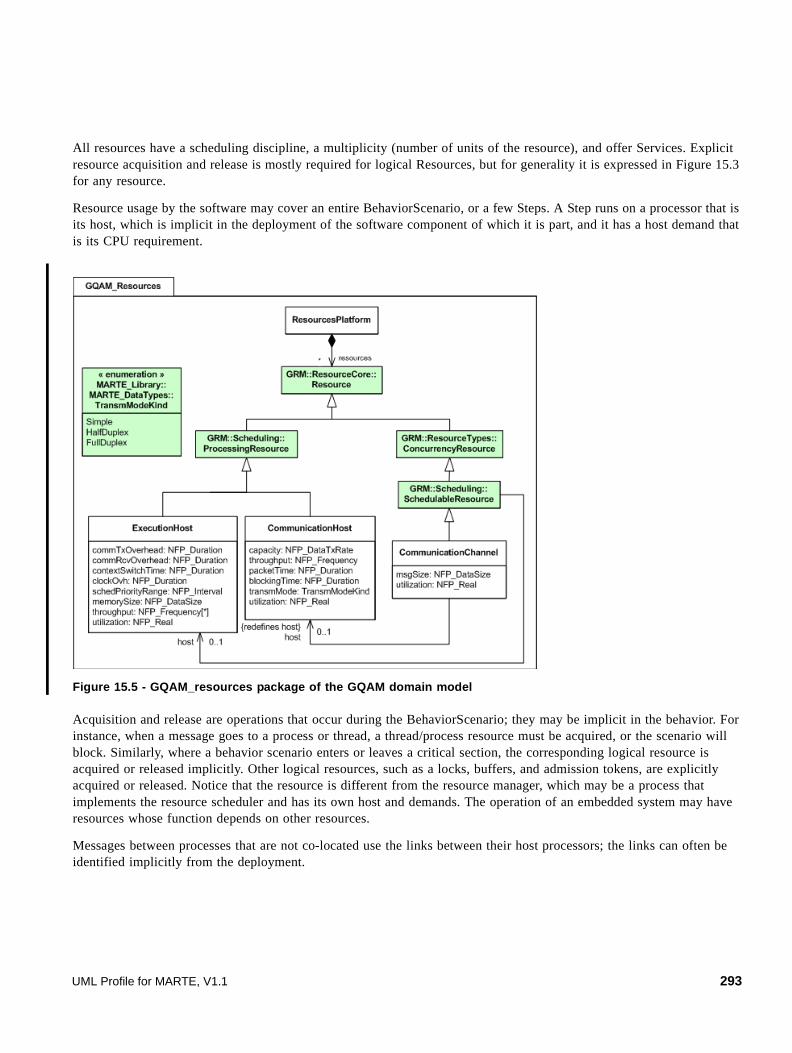
All resources have a scheduling discipline, a multiplicity (number of units of the resource), and offer Services. Explicit resource acquisition and release is mostly required for logical Resources, but for generality it is expressed in Figure 15.3 for any resource.
Resource usage by the software may cover an entire BehaviorScenario, or a few Steps. A Step runs on a processor that is its host, which is implicit in the deployment of the software component of which it is part, and it has a host demand that is its CPU requirement.
Figure 15.5 - GQAM_resources package of the GQAM domain model
Acquisition and release are operations that occur during the BehaviorScenario; they may be implicit in the behavior. For instance, when a message goes to a process or thread, a thread/process resource must be acquired, or the scenario will block. Similarly, where a behavior scenario enters or leaves a critical section, the corresponding logical resource is acquired or released implicitly. Other logical resources, such as a locks, buffers, and admission tokens, are explicitly acquired or released. Notice that the resource is different from the resource manager, which may be a process that implements the resource scheduler and has its own host and demands. The operation of an embedded system may have resources whose function depends on other resources.
Messages between processes that are not co-located use the links between their host processors; the links can often be identified implicitly from the deployment.
UML Profile for MARTE, V1.1 293
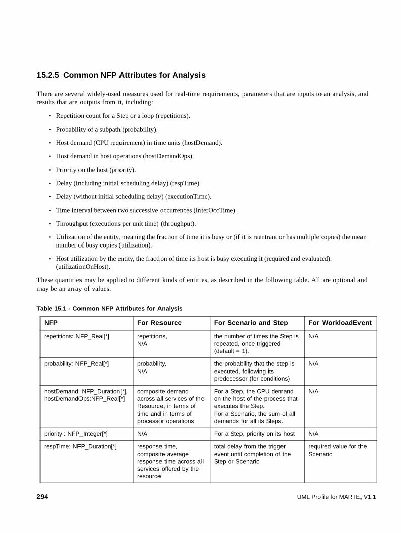
15.2.5 Common NFP Attributes for Analysis
There are several widely-used measures used for real-time requirements, parameters that are inputs to an analysis, and results that are outputs from it, including:
• Repetition count for a Step or a loop (repetitions).
• Probability of a subpath (probability).
• Host demand (CPU requirement) in time units (hostDemand).
• Host demand in host operations (hostDemandOps).
• Priority on the host (priority).
• Delay (including initial scheduling delay) (respTime).
• Delay (without initial scheduling delay) (executionTime).
• Time interval between two successive occurrences (interOccTime).
• Throughput (executions per unit time) (throughput).
• Utilization of the entity, meaning the fraction of time it is busy or (if it is reentrant or has multiple copies) the mean number of busy copies (utilization).
• Host utilization by the entity, the fraction of time its host is busy executing it (required and evaluated). (utilizationOnHost).
These quantities may be applied to different kinds of entities, as described in the following table. All are optional and may be an array of values.
Table 15.1 - Common NFP Attributes for Analysis
NFP For Resource For Scenario and Step For WorkloadEvent
repetitions: NFP_Real[*] repetitions,N/A
the number of times the Step is repeated, once triggered (default = 1).
N/A
probability: NFP_Real[*] probability,N/A
the probability that the step is executed, following its predecessor (for conditions)
N/A
hostDemand: NFP_Duration[*], hostDemandOps:NFP_Real[*]
composite demand across all services of the Resource, in terms of time and in terms of processor operations
For a Step, the CPU demand on the host of the process that executes the Step.For a Scenario, the sum of all demands for all its Steps.
N/A
priority : NFP_Integer[*] N/A For a Step, priority on its host N/A
respTime: NFP_Duration[*] response time,composite average response time across all services offered by the resource
total delay from the trigger event until completion of the Step or Scenario
required value for the Scenario
294 UML Profile for MARTE, V1.1

For a BehaviorScenario, which is a composite entity, some NFPs apply directly (repetitions, probability, response time, inter-occurrence time, and throughput) while others either do not apply or represent sums of the attributes of the Steps that make up the Scenario, weighted by their throughputs relative to that of the BehaviorScenario (execution time, hostDemand, utilizationOnHost).
15.3 UML Representation
15.3.1 Profile Diagrams
The UML extensions for the GQAM sub-profile are presented in this sub clause. The sub-profile is split in four figures related to corresponding domain model packages GQAM, GQAM_Workload, GQAM_Behavior, GQAM_Observers, and GQAM_Resources.
execTime : NFP_Duration[*] execution time, N/A (same as hostDemand)
respT minus any initial scheduling delays
N/A
interOccTime: NFP_Duration[*] inter-occurrence time, interval between successive requests for services
interval between initiations interval between trigger events
throughput : NFP_Frequency[*] frequency of requests for all services
frequency of initiations frequency of the trigger event
utilization : NFP_Real[*] fraction of time the resource is active (has an active service). For a multiple resource, the mean number of busy units.
fraction of time the BehaviorScenario is active (between its trigger event and its completion)
N/A
utilizationOnHost: NFP_Real[*] N/A fraction of time the host is busy executing the BehaviorScenario. If it has multiple hosts, this is a set of values.
N/A
blockingTime: NFP_Duration[*] blocking time,N/A
a pure delay waiting for passive resources to be available or an event controlled from elsewhere (value is an output variable)
N/A
selfDelay: NFP_Duration[*] delay a pure delay controlled or requested by the Step. (value is an input variable)
N/A
Table 15.1 - Common NFP Attributes for Analysis
UML Profile for MARTE, V1.1 295

In general, resource-related stereotypes extend the UML metaclass Classifier. More exactly, the stereotypes GaExecHost, GaCommHost, and GaCommChannel specialize the stereotype GRM::Resource, defined in the GRM clause, which extends in turn Classifier, InstanceSpecification, and Property (the last used for annotating Parts in UML composite structure diagrams). Therefore, resource stereotypes can be applied to all kinds of classes, instances, components, parts, and deployment nodes.
GaScenario and Step stereotypes inherit from TimeModels::TimedProcessing (which extends Behavior, Message, Actions) and GRM::Resource (which extends NamedElement). So, Scenario and Step stereotypes can be applied to a wide set of behavior-related elements covered by the UML2 metaclass NamedElement, such as Operations, Actions, Messages that initiate Operations or Actions, Transitions and States in state machine diagrams, Signals that trigger state machine transitions, Events, ExecutionOccurrenceSpecifications and InteractionFragments in interaction diagrams, InputPins in activity diagrams and UseCases.
Figure 15.6 - UML extensions for top level stereotypes of the GQAM profile
296 UML Profile for MARTE, V1.1

Figure 15.7 - UML extensions for GQAM stereotypes related to behavior
« profile »GQAM
pattern: ArrivalPattern [0..1]generator: GaWorkloadGenerator [0..1]trace: GaEventTrace [0..1]effect: GaScenario [0..1]timeEvent::UML::timeEvent[0..1]
« stereotype »GaWorkloadEvent
« stereotype »MARTE::GRM::ResourceUsage
« metaclass »UML::Classes::Kernel::
NamedElement
content: Stringformat: Stringlocation: String
« stereotype »GaEventTrace
« metaclass »UML::CommonBehavior::BasicBehaviors::Behavior
pop: NFP_Integer = (1)
« stereotype »GaWorkloadGenerator
« stereotype »MARTE::Time::TimeRelatedEntities::
TimedProcessingModels::TimedProcessing
cause: GaWorkloadEventhostDemand: NFP_Duration [*]hostDemandOps: NFP_Real [*]interOccT: NFP_Duration [*]throughput: NFP_Frequency [*]respT: NFP_Duration [*]utilization: NFP_Real [*]utilizationOnHost: NFP_Real [*]root: GaSteptiming: GaTimingObserver [*]
« stereotype »GaScenario
isAtomic: NFP_BooleanblockT: NFP_Duration [*]rep: NFP_Real =(1.0)prob: NFP_Real =(1.0)priority: NFP_IntegerconcurRes: SchedulableResourcehost: GaExecHostservDemand: GaRequestedService [*] {ordered}servCount: NFP_Real [*] {ordered}
« stereotype »GaStep
« metaclass »UML::Classes::
Kernel::Operation
« stereotype »GaRequestedService
« stereotype »GaCommStep
acqRes: ResourceresUnits: NFP_Integer = (1)
« stereotype »GaAcqStep
relRes: ResourceresUnits: NFP_Integer= (1)
« stereotype »GaRelStep
periodic: PeriodicPatternaperiodic: AperiodicPatternsporadic: SporadicPatternburst: BurstPatternirregular: IrregularPatternclosed: ClosedPatternopen: OpenPattern
« dataType »« choiceType »
MARTE_Library::BasicNFP_Types::
ArrivalPattern
« metaclass »UML::CommonBehavior
::SimpleTime::TimeEvent
timedEvent 0..1
scenario0..1
steps*
parentStep0..1
childScenario0..1
UML Profile for MARTE, V1.1 297

Figure 15.8 - GQAM stereotype for observing timing occurrences between two events
Figure 15.9 - UML extensions for GQAM stereotypes related to resources
298 UML Profile for MARTE, V1.1
15.3.2 Profile Elements Description
This sub clause describes the stereotypes of the GQRM profile (listed in alphabetical order).
15.3.2.1 GaAcqStep
The GaAcqStep stereotype maps the AcquireStep domain element denoted in Annex F (F.10.1).
A step that acquires a resource.
Extensions
• None
Generalizations
• GaStep
Associations
• None
Attributes
• acqRes: Resource [0..1] The resource to be acquired within the step execution.
• resUnits : NFP_Integer [0..1]= 1 The number of units of resource acquired within the step execution.
Constraints
• None
15.3.2.2 GaAnalysisContext
The GaAnalysisContext stereotype maps the AnalysisContext domain element denoted in Annex F (F.10.2).
For a given analysis, the context identifies the model elements (diagrams) of interest and specifies global parameters of the analysis.
Extensions
• None
Generalizations
• ExpressionContext (from MARTE::VSL::Expressions)
• Configuration (from CoreElements)
Associations
• None
UML Profile for MARTE, V1.1 299
Attributes
• contextParams: NFP_String [*] Strings giving a set of annotation variables defining global properties of this analysis context. Each string should conform to the concrete syntax for variable calls or declarations as defined in B.3.3.12.
Constraints
• None
15.3.2.3 GaCommChannel
The GaCommChannel stereotype maps the CommunicationChannel domain element denoted in Annex F (F.10.4).
It is used for denoting a logical communications layer connecting SchedulableResources.
Extensions
• None
Generalizations
• SchedulableResource (from MARTE::GRM)
Associations
• None
Attributes
• msgSize: NFP_DataSize [0..1] The size of the data unit handled by the channel.
• utilization: NFP_Real [0..1] The fraction of the Communication Host capacity used by the Channel. This is typically a result of the analysis better than a specification.
Constraints
• None
15.3.2.4 GaCommHost
The GaCommHost stereotype maps the CommunicationHost domain element denoted in Annex F (F.10.5).
It is used for denoting a physical communications link.
Extensions
• None
Generalizations
• CommunicationMedia (from MARTE::GRM)
• Scheduler (from MARTE::GRM)
300 UML Profile for MARTE, V1.1

Associations
• None
Attributes
• throughput: NFP_Frequency [*] actual throughput
• utilization: NFP_Real [*] utilization of this host
Constraints
[1] The associations processingUnits and mainScheduler inherited from Scheduler and ProcessingResource respectively have as default values the very same element that is being annotated with the GaCommHost stereotype.
15.3.2.5 GaCommStep
The GaCommStep stereotype maps the CommunicationStep domain element denoted in Annex F (F.10.6).
A CommStep is an operation that conveys a message from one locale to another.
Extensions
• None
Generalizations
• GaStep
Associations
• None
Attributes
• None
Constraints
• None
15.3.2.6 GaEventTrace
The GaEventTrace stereotype maps the EventTrace domain element denoted in Annex F (F.10.7).
A trace of events that can serve as source for the request event stream.
Extensions
• NamedElement (from UML::Classes::Kernel)
Generalizations
• None
UML Profile for MARTE, V1.1 301

Associations
• None
Attributes
• content: String [0..1] Contains the serialization of the event trace according to the file format.
• format: String [0..1] This indicates the format of the event trace - which is how the string content should be interpreted.
• location: String [0..1] This contains a location that can be used by a tool to locate the file as an alternative to embedding it in the stereotype.
Constraints
• None
15.3.2.7 GaExecHost
The GaExecHost stereotype maps the ExecutionHost domain element denoted in Annex F (F.10.4.
It denotes a processor that executes Steps.
Extensions
Generalizations
• ComputingResource (from MARTE::GRM)
• Scheduler (from MARTE::GRM)
Associations
• None
Attributes
• commTxOvh: NFP_Duration [*] The host demand for sending messages.
• commRcvOvh:NFP_Duration [*] The host demand for receiving messages.
• cntxtSwT: NFP_Duration [*] Context switch time.
• clockOvh: NFP_Duration [*] Clock overhead.
• schedPriRange: NFP_Interval [*] The range of priorities offered by this processor.
• memSize: NFP_DataSize [0..1] The memory size.
302 UML Profile for MARTE, V1.1

• utilization: NFP_Real [*] The processor utilization, expressed as mean busy processors (in the range from 0 to resMult which is the number of processors).
• throughput: NFP_Frequency [*] The throughput of the host in scheduled initiations/sec.
Constraints
[1] The associations processingUnits and mainScheduler inherited from Scheduler and ProcessingResource respectively have as default values the very same element that is being annotated with the GaExecHost stereotype.
15.3.2.8 GaLatencyObs
The GaLatencyObs stereotype maps the LatencyObserver domain element denoted in Annex F (F.10.10).
GaLatencyObs specifies a duration observation between startObs and endObs UML TimeObservations, with a miss ratio assertion (percentage), a utility function, which places a value on the duration, and a jitter constraint. Jitter is the difference between maximum and minimum duration.
Extensions
• None
Generalizations
• GaTimedObs
Attributes
• latency: NFP_Duration [*] Value of the latency.
• miss: NFP_Real [*] For soft timing constraints the miss ratio indicates the admitted or actual percentages of “required” latency missed.
• utility: UtilityType [0..1] Value of importance for required timing constraints.
• maxJitter: NFP_Duration [*] Maximum deviation value - it represents a maximum deviation with which a periodic internal event is generated. The output jitter is calculated as the difference between a worst-case latency time and the best-case latency time for the observed event measured from a reference event.
Constraints
• None
15.3.2.9 GaRelStep
The GaRelStep stereotype maps the ReleaseStep domain element denoted in Annex F (F.10.13).
It denotes a step that releases a resource.
UML Profile for MARTE, V1.1 303

Extensions
• None
Generalizations
• GaStep
Associations
• None
Attributes
• relRes:Resource [0..1] The resource to be released.
• resUnits : NFP_Integer [0..1] = 1 How many units to be released (default = 1).
Constraints
• None
15.3.2.10 GaResourcesPlatform
The GaResourcesPlatform stereotype maps the ResourcesPlatform domain element denoted in Annex F (F.10.16).
A logical container for the resources used in an analysis context.
Extensions
• Classifier (from UML::Classes::Kernel)
Generalizations
• None
Associations
• None
Attributes
• resources: Resource[*] Set of resources contained by this container.
Constraints
• None
15.3.2.11 GaRequestedService
The GaRequestedService stereotype maps the RequestedService domain element denoted in Annex F (F.10.15).
A request for an operation by some system object, for instance a subsystem defined by component notation and interface operations. The operation details may be defined by a Scenario attached by the behavior association inherited from Step.
304 UML Profile for MARTE, V1.1

Extensions
• Operation (from UML::Classes::Kernel)
Generalizations
• GaStep
Associations
• None
Attributes
• None
Constraints
• None
15.3.2.12 GaScenario
The GaScenario stereotype maps the BehaviorScenario domain element denoted in Annex F (F.10.3).
A Scenario captures system-level behavior and attaches allocations and resource usages to it. It is composed of sub-operations called Steps, any one of which can be a composite Step, refined as another Scenario.
Extensions
• None
Generalizations
• ResourceUsage (from MARTE::GRM)
• TimedProcessing (from MARTE::Time::TimeRelatedEntities::TimedProcessingModels)
Associations
• steps: GaStep [1..*] The set of steps that make up the Scenario.
• parentStep: GaStep [1..*] A GaStep of which this scenario is a refinement.
Attributes
• cause: GaWorkloadEvent [1..*] The event stream which triggers the scenario
• hostDemand: NFP_Duration [*] The cpu demand in units of time, if all Steps are on the same host.
• hostDemandOps: NFP_Integer [*] The cpu demand in units of operations, if all Steps are on the same host.
• interOccT: NFP_Duration[*] The interval between successive initiations of the scenario.
UML Profile for MARTE, V1.1 305

• throughput: NFP_Frequency[*] The mean rate of initiation of the scenario.
• respT: NFP_Duration[*] The time duration from initiation to completion, for one execution of the scenario.
• utilization: NFP_Real[*] The occupancy of the scenario, computed as the mean number of scenario instances active at any one time.
• utilizationOnHost: NFP_Real[*] The occupancy of thehost processor, executing Steps of this scenario, if all Steps are on the same host.
• root: GaStep [0..1] The first Step of the scenario.
• timing: GaTimedObs [*] Timing observers associated with this scenario.
Constraints
[1] The hostDemand and hostDemandOps attributes derive their values from the Steps in the Scenario, but only in cases where all the Steps have the same Host.
15.3.2.13 GaStep
The GaStep stereotype maps the Step domain element denoted in Annex F (F.10.17).
A GaStep is a part of a Scenario, defined in sequence with other actions, and may be a composite Step containing a Scenario.
The precedence relations in the domain model are not defined as associations because they do not need to be explicitly defined in the UML behavior, they are given implicitly by the diagram.
Extensions
• None
Generalizations
• GaScenario
Associations
• scenario: GaScenario [0..1] A GaScenario that contains the Step.
• childScenario: GaScenario [0..1] A GaScenario that refines this Step, making it a composite Step.
Attributes
• isAtomic: NFP_Boolean [0..1] = false If true, the step must not be decomposed any further.
306 UML Profile for MARTE, V1.1

• blockT: NFP_Duration [0..1] A delay inserted in the execution of the Step, waiting for an event controlled elsewhere (by another step or scenario), or for a condition such as the availability of passive protected resources nedded by the step but in by preempted (i.e., lower priority schedulableResources) concurrent steps.
• selfDelay: NFP_Duration [0..1] A delay inserted in a Step, whose duration is controlled or requested by the Step (e.g., a sleep time).
• rep: NFP_Real [0..1] = 1 The actual or average number of repetitions of an operation or loop.
• prob: NFP_Real [0..1] = 1 The probability of the step to be executed (for a conditional execution).
• priority: NFP_Integer [0..1] The step priority on its host processor.
• concurRes:GrmSchedulableResource [0..1] The process which executes the Step.
• host: GaExecHost [0..1] The host processor..
• servDemand: GaRequestedService [*] {ordered} A set of operations requested by the Step, such as calls to interface operations. The order corresponds to the order in servCount.
• servCount: NFP_Real [*] {ordered} A set of values for the number of requests to the operations given in the list for GaRequestedService, in the same order.
Constraints
[1] the elements of the ordered lists servDemand and servCount correspond, element to element.
[2] a composite Step (with the behavior association defined) cannot have a host or concur association.
15.3.2.14 GaTimedObs
The GaTimedObs stereotype maps the TimedObserver domain element denoted in Annex F (Section F.10.18).
GaTimedObs is a purely conceptual entity that serves to collect timing requirements and predictions that relates to user-defined observed events. In this sense, GaTimedObs uses UML TimeObservations to define the observed event in a given behavioral model. If there is more than one start/end pair, they are ordered correspondingly along with the laxity property for each pair.
Extensions
• None
Generalizations
• NfpConstraint (from NFPs::NFP_Annotation)
UML Profile for MARTE, V1.1 307

Associations
• endObs: UML::CommonBehaviors::BasicTime::TimeObservation [0..*]{ordered} Observed event to which the timing observer applies.
• startObs: UML::CommonBehaviors::BasicTime::TimeObservation [0..*]{ordered} Reference event
Attributes
• laxity: LaxityKind [0..*]{ordered} Indicates whether required timing constraints are hard or soft.
Constraints
• None
15.3.2.15 GaWorkloadBehavior
The GaWorkloadBehavior stereotype maps the WorkloadBehavior domain element denoted in Annex F (F.10.18).
A logical container for the analyzed behavior and the workload that triggers it, in an analysis context.
Extensions
• NamedElement (from UML::Classes::Kernel)
Generalizations
• None
Associations
• None
Attributes
• behavior: GaScenario [*]
• demand: GaWorkloadEvent [*]
Constraints
• None
15.3.2.16 GaWorkloadEvent
The GaWorkloadEvent stereotype maps the WorkloadEvent domain element denoted in Annex F (F.10.20).
A stream of events that initiate system-level behavior. It may be generated in different ways: by a stated arrival process (such as Poisson or deterministic), by an arrival-generating mechanism modeled by a workload generator class, by a timed event and from a trace.
Extensions
• NamedElement (from UML::Classes::Kernel)
308 UML Profile for MARTE, V1.1

Generalizations
• None
Attributes
• pattern: MARTE::MARTE_Library::BasicNFP_Types::ArrivalPattern [0..1] If defined, this attribute defines a pattern of arrival events.
• generator:GaWorkloadGenerator [0..1] A workload generator that produces the events.
• trace: GaEventTrace [0..1] Indicates an event trace file.
• timeEvent: UML::CommonBehaviors::SimpleTime::TimeEvent [0..1] A time event in the UML specification that triggers the request events.
Associations
• effect:GaScenario [1] The scenario triggered by the GaWorkloadEvent.
Constraint
[1] Only one of the four attributes may be defined.
15.3.2.17 GaWorkloadGenerator
The GaWorkloadGenerator stereotype maps the WorkloadGenerator domain element denoted in Annex F (F.10.21).
A mechanism defined by a UML behavior definition such as a state machine, that generates events to drive the system behavior, for example by invoking a top-level system behavior (scenario). There may be multiple independent and identical instances (population > 1).
Extensions
• Behavior (from UML::CommonBehavior::BasicBehavior)
Generalizations
• None
Associations
• None
Attributes
• pop: NFP_Integer [0..1] = 1
Constraints
• None
UML Profile for MARTE, V1.1 309
15.3.2.18 LaxityKind
The LaxityKind is an Enumeration that includes a list of qualifiers specifying the criticality of a given “required” timing property.
Enumeration literals
• hard The required timing specifications have to be met for system behavior correctness.
• soft If the required timing specifications are not met, the system behavior is still correct. Further specifications, such as the miss ratio, can be used to specify the limit of timing misses.
• other A user-specific laxity.
310 UML Profile for MARTE, V1.1

16 Schedulability Analysis Modeling
16.1 Overview
In this clause, we describe a component of the MARTE profile that is intended specifically for schedulability analysis. As it is known, when dealing with real-time systems, the influence of scheduling on the timing and performance is crucial to calculate guaranteed bounds on response times and resource processing loads. The maturity of scheduling analysis techniques has led to a set of useful mathematical formalisms like the classic and generalized Rate Monotonic Analysis (RMA), holistic techniques, or extended timed automata.
Typical tools for this class of model analysis provide two important functions:
• The first one is to calculate the schedulability of the system or a particular piece of software; that is, the ability of the system to meet certain temporal constraints (e.g., deadlines, miss rations) defined for the entire system or for a group of individual concurrent execution units. Such tools typically indicate which entities are schedulable and which are not.
• Sensitivity analysis assists with determining how the system can be improved. That may mean suggestions for making an entity schedulable or it may mean epitomizing system usage for a more balanced system. A system designer will typically want to analyze the system under several configurations using different parameter values for each scenario, or to explore the variability of different resource allocations and deployment into alternative hardware and software platforms.
Schedulability analysis can be used at different stages. Early analysis of a design model aids developers to detect potentially unfeasible real-time architectures and prevents costly design mistakes, particularly related to timing behavior. On the other hand, a later analysis of an implemented system allows analyzers to discover (with more precise quantitative information of the system) temporal-related faults, or to evaluate the impact of possible platform migrations or modifications on the scheduling strategies.
This clause describes a set of common annotations for model-based schedulability analysis. It allows quantitative annotations to be attached at the level of detail desired by the designer. Indeed, even if the specification might contain extreme detail, the set of annotations may optionally be partially applied. On the other hand, each vendor is encouraged to supply specialized profiles that extend this set in order to perform model analysis that is more extensive.
It was actually stated that the SPT’s sub-profiles for schedulability and performance analysis were too much independently defined, reducing the ability to reuse annotated models for any kind of analysis. To improve this aspect, we introduced a common framework, named Generic Quantitative Analysis Modeling (GQAM), supporting both kinds of timing analysis. The modeling framework described in this sub clause attempts to specialize GQAM into a collection of modeling concepts for model-based schedulability analysis purposes, as well as a set of Non-Functional Properties (NFPs) for these basic concepts. This framework therefore involves the use of the NFP Modeling framework presented in Clause 8.
The structure of this sub clause follows the convention adopted throughout this document: First, a domain viewpoint is described that identifies the basic abstractions used in schedulability analyses. The semantics of these abstractions and their relationships are explained with the aid of metamodels. The second part of the clause describes how these abstractions are expressed in the UML metamodel. This is done through a series of UML extensions (stereotypes, constraints, and tag definitions). Supplementing this description is a set of illustrative examples showing common ways of applying this part of the MARTE profile.
16.2 Domain View
The Schedulability Analysis Modeling (SAM in short) domain model uses similar domain concepts as those presented in the GQAM framework. Since these concepts are already described in a general way, we define here their semantics in the
UML Profile for MARTE, V1.1 311

schedulability analysis domain and add the NFPs used for these purposes. All the NFP data types for schedulability analysis are declared in a model library (the BasicNFP_Types model library is presented in Annex D).
The SAM sub-profile has many facets that are grouped in individual packages. The overall package structure is shown in Figure 16.1.
Figure 16.1 - Structure of the SAM domain model
The purpose and contents of each package are described in the following sub clauses.
16.2.1 The SAM Root Package
As in the GQAM clause, the SAM’s conceptual domain model is organized around the notion of Analysis Context (Figure 16.2). An analysis context is the root concept to collect relevant quantitative information for performing a specific analysis scenario. Starting with the analysis context and its elements, a tool can follow the links of the model to extract the information that it needs to perform the model analysis.
Analysis contexts are also known as real-time situations in the schedulability analysis domain. In particular, an SaAnalysisContext is a kind of AnalysisContext with additional attributes. The isSchedulable attribute indicates whether all the timing constraints defined for the analysis context are respected. The optimalityCriterion attribute denotes a global criterion used to determine a schedule for the context analyzed (e.g., meet all hard deadlines, minimize the number of missed deadlines, minimize the mean tardiness, maximize flow).
Note – Most of specialized SAM-specific concepts have the prefix “Sa,” which stands for “Schedulability Analysis.”
In general, AnalysisContext is associated with the following two modeling concerns:
• WorkloadBehavior: represents a given load of processing flows triggered by external (e.g., environmental events) or internal (e.g., a timer) stimuli. The processing flows are modeled as a set of related steps that contend for use of processing resources and other shared resources.
• ResourcesPlatform: represents a concrete architecture and capacity of hardware and software processing resources used in the context under consideration.
312 UML Profile for MARTE, V1.1

Figure 16.2 - The SAM root domain model: Analysis context
Since analysis models are intended to be integrated with existing design models, or at least to be defined in a separated view with a clear mapping to design views, we are especially interested on collecting modeling elements according to the above mentioned modeling concerns. Indeed, this separation of modeling concerns is essential to support the MDA approach. Splitting an analysis context model into these two aspects allows MDA modelers to keep platform-independent models (models annotated with WorkloadBehavior elements) separated from platform description models (ResourcesPlatform annotations). We illustrate an example supporting this approach in Section 16.3.3. This feature attempts to enhance the modeling practices fostered by MARTE in order to ease retargetability of logical model elements onto execution platforms models possibly stored into reusable libraries (a key requirement).
In the remaining sub clauses, the main concepts related to these modeling concerns are described.
16.2.2 The SAM Workload package
The SAM_Workload package contains concepts related to the processing load on the system. We split this package in two figures (Figure 16.3 and Figure 16.4).
The end-to-end related concepts are gathered in Figure 16.3. This figure shows the constructs required to specify the end-to-end behavior and the associated quantitative information concerning end-to-end stimuli, timing requirements, and responses.
Note – In general, most of the discussed concepts are imported from GQAM and GRM. For explanation purposes, we show here some available attributes of interest for schedulability analysis. For a complete list of attributes of the imported concepts, refer to the respective clauses.
In a given analysis context, a single WorkloadBehavior situation is commonly evaluated. A WorkloadBehavior situation may correspond to a mode of system operation (e.g., starting mode, fault recovering, or normal operation) or a level of intensity of environment events. A specific WorkloadBehavior model is defined by both a workload demand (set of workload events) and the triggered behaviors (set of behavior scenarios). In SAM, these two latter concepts are regrouped in end-to-end processing flows (EndToEndFlow), which represent the analyzed workload.
End-to-end flows describe a unit of processing work in the analyzed system, which contend for use of the processing resources. This is a conceptual entity only, which is represented by its concrete elements: end-to-end stimuli and end-to-end response.
UML Profile for MARTE, V1.1 313

Figure 16.3 - The SAM Workload domain model: EndToEndFlow (partial view)
End-to-end flows refer to a set of stimuli requesting computations. We may refer to an instance of a particular request stimulus as an event occurrence. Since the stimulus can occur repeatedly, we refer to recurrence of events as WorkloadEvent. Workload events can be originated outside the system, inside the system, or because of the passage of time. From a modeling viewpoint, workload events can be modeled by known patterns (see the definition of the ArrivalPattern data type in Annex D), by traces files, by internal timed event models, or by workload generator models (e.g., state machine models). Workload event models are fully defined in the GQAM clause.
A computation that is performed as a consequence of a workload event is referred to as the behavior scenario (BehaviorScenario) that executes in response to its event occurrences. Depending on the implementation nature of behavior scenarios, they could be concretized in a single task executing in one processor or in dependent tasks into single or multiple processors. But ultimately, behavior scenarios serve to describe end-to-end responses of a workload model under analysis.
As a conceptual entity, end-to-end flow allows to define a set of timing requirements and timing predictions. Timing requirements include deadlines, maximum miss ratios and maximum jitters. Timing predictions are typically provided by analysis tools and include latencies, jitters, and other scheduling metrics. These aspects are modeled by the TimedObserver concept. Section 16.2.3 provides details on this.
SAM_Workload
isSchedulable: NFP_BooleanschedulabilitySlack: NFP_RealendToEndTime: NFP_DurationendToEndDeadline: NFP_Duration
EndToEndFlow
GQAM_Workload::WorkloadBehavior
pattern: ArrivalPattern
GQAM_Workload::WorkloadEvent GQAM_Workload::
BehaviorScenarioeffect
1..*
cause
1
1..* endToEndStimuli 1endToEndResponse
SAM_Observers::TimedObserver
timing
1
*
periodic: PeriodicPatternaperiodic: AperiodicPatternsporadic: SporadicPatternburst: BurstPatternirregular: IrregularPatternclosed: ClosedPatternopen: OpenPattern
« dataType »« choiceType »ArrivalPattern
demand 1..*behavior 1..*
314 UML Profile for MARTE, V1.1

Figure 16.4 - The SAM Workload domain model: BehaviorScenario (partial view)
Additionally, end-to-end flows are characterized by a set of NFPs. isSchedulable indicates whether the flow meets all its deadlines. schedulabilitySlack provides a percentage measure by which the (effective) execution time of all the atomic processing units participating in the end-to-end response may be increased while still keeping the end-to-end flow schedulable. EndToEndTime and EndToEndDeadline are respectively the predicted worst completion time and required completion latency of the end-to-end response measured from the arrival of the requested event. This applies if only one input end-to-end stimuli exist and only one finalization Step exists.
Figure 16.4 shows the domain concepts for defining behavior execution modeling aspects. This model is based on the one introduced in the GQAM framework.
Thus, the BehaviorScenario concept serves to collect detailed descriptions of the response behavior. Depending on the implementation nature of BehaviorScenario, they could be concretized in a single step executing in one processor or in a number of flow related steps into single or multiple processors. A step may represent a small segment of code execution as well as the sending of a message through a communication media (ExecutionStep and CommunicationStep). The ordering of steps follows a predecessor-successor pattern, with the possibility of multiple concurrent successors and predecessors, stemming from concurrent thread joins and forks respectively. The granularity of a step is often a modeling choice that depends on the level of detail that is being considered. Hence, a step at one level of abstraction may be decomposed further into a set of finer-grained steps.
Schedulability analysis models commonly restrict steps to processing units that must not change allocation of system resources. Scheduling-based processing steps (SaStep and SaCommunicationStep) begin and end when decisions about the allocation of system resources are made, as for example when changing its priority. As a main concept on schedulability analysis models, step deadlines define the maximal time bounds on the completion of particular segments that must be met. The SaStep concept is enriched with other latency properties such as preempted time and ready time. Notice that the association requiredAmount inherited from ResourceUsage (sub clause 10.2.5) is used to model execution
UML Profile for MARTE, V1.1 315

times. The worst, average, and best execution times are modeled with different instances of the usage attribute by means of the statistical qualifier slot in NFP types. For instance, a pair of worst and best case execution time values is: “execTime= {(5.0, ms, max),(3.0, ms, min)}.” The same case applies for whatever attribute typed with a NFP data type.
In this model, steps use the active resource services for execution by means of schedulable resources (e.g., threads, process in execution resources) and communication channels (e.g., message management units) characterized by concrete scheduling parameters, and synchronize through calls to shared resources (for instance, I/O devices, DMA channels, critical sections or network adapters) identified using the sharedResource association of the SaStep instances.
16.2.3 The SAM Observers Package
Timed Observers (Figure 16.5) are purely conceptual entities that serve to collect timing requirements and predictions that relates to user-defined observed events. In this sense, Timed Observer use Timed Instant Observations (Clause 9) to define the observed event in a given behavioral model. Timed Observers are a powerful mechanism to annotate and compare timing constraints against timing predictions provided by analysis tools. Timed Observers can be used as predefined and parameterized patterns (e.g., latency, jitters) or by means of more elaborated expressions since TimedObserver inherits all the modeling capabilities from NFP_Constraint.
Note that these modeling constructs are mainly useful for complex end-to-end flows with several observation points in order to provide centralized and flexible means to annotate analyzer-defined timing constraints. Most of analysis tools provide a repository to store this kind of global information that is more related with the exploration of constraint cases.
Timed Observers are typically of two kinds in schedulability analysis: required and offered. Required Timed Observers represent timing constraints such as deadlines or required maximum jitters. Offered Timed Observers specify prediction results mostly calculated by analysis tools.
Two kinds of Timed Observer patterns are used in SAM. LatencyObserver specifies a duration observation with its corresponding miss ratio percentage assertion (percentage), a utility value of a latency value, and a maximum jitter with which a periodic internal event is generated. The output jitter is calculated as the difference between a worst-case latency time and the best-case latency time for the observed event measured from a reference event. Required latency values are known as deadlines in real-time systems. SchedulingObserver provides prediction about scheduling metrics such as overlaps, the maximum number of suspensions caused by shared resources or the blocking time caused by the used shared resources. All these metrics are relative to the interval defined by the reference and observed events.
Timed Observers must be attached to behavior elements. When the reference and observed events are not defined, the start and finish events can be deduced from the behavior element annotated.
316 UML Profile for MARTE, V1.1

Figure 16.5 - The SAM Observers domain model
16.2.4 The SAM Resources Package
In the SAM framework, the concept of resourcesPlatform matches the engineering model of resources introduced in the SPT profile. That includes not only hardware resources (CPU, devices, backplane buses, network resources), but also software ones (threads, tasks, buffers). Figure 16.6 shows a framework to describe the platform of resources.
Schedulability models use an abstracted version of a more structured and detailed platform model (see Clause 14 for detailed resources models), which is especially useful for expressing NFPs oriented to quantitative analysis and without distinguishing among different abstraction levels (hardware, RTOS, or middleware).
As defined in GQAM, the resources platform model consists of a set of resources with explicit NFPs. Specifically, throughput properties (e.g., processing rate), efficiency properties (e.g., utilization), and overhead properties as for example blocking times and clock overhead times. This model distinguishes two kinds of processing resources: execution hosts (e.g., processors, coprocessors) and communication hosts (e.g., networks, buses). For each one, the SAM framework adds specialized NFPs. Particularly, schedulability metrics, interrupt overheads, and utilization of scheduling processing.
Two kinds of concurrent resources are used by steps to access processing hosts: schedulable resources and communication channels. SchedulableResource is a kind of active protected resource that is used to execute steps. In an RTOS, this is the mechanism that represents a unit of concurrent execution, such as a task, a process, or a thread. In a communication host, the related element is CommunicationChannel, which may be characterized by concrete scheduling parameters (like the packet size). Schedulable resources are scheduled with a chosen set of scheduling parameters associated to a given scheduling algorithm. The component that implements these algorithms is called the scheduler.
Schedulers can be of two types: system schedulers (typically a RTOS scheduler) that offer the whole processing capacity of its associated base processors to its allocated schedulable resources, and secondary schedulers that only provide the processing capacity offered by its hosting schedulable resource. This hierarchical structure is typically used in real-time systems when users are interested in applying dynamic scheduling on top of commercial RTOS supporting only static scheduling. Likewise, novel algorithms exist that allow to perform real-time analysis of these hierarchical configurations of schedulers.
SAM_Observers
hardsoftundefother
« enumeration »LaxityKind
kind: ConstraintKind
NFP_Modeling::NFP_Annotation::NFP_Constraint
laxity: LaxityKind
GQAM_Observers::TimedObserver
latency: NFP_DurationmissRatio: NFP_Realutility: UtilityTypemaxJitter: NFP_Duration
GQAM_Observers::LatencyObserver
TimeModels::TimedRelatedEntities::TimedObservations::
TimedInstantObservation
*
startObs
*endObs
requiredofferedcontract
« enumeration »ConstraintKind
suspensions: NFP_IntegerblockingTime: NFP_Durationoverlaps: NFP_Integer
SchedulingObserver
UML Profile for MARTE, V1.1 317

Figure 16.6 - The SAM Resources domain model
Execution Hosts own shared resources, as for example I/O devices, DMA channels, critical sections, or network adapters. Shared resources are dynamically allocated to schedulable resources by means of an access policy. Common access policies are FIFO, priority ceiling protocol, highest locker, priority queue, and priority inheritance protocol.
16.2.4.1 Types of Model Analysis Methods
Two major categories of scheduling policies, and therefore two types of analysis, are available. One category is static in nature - i.e., parametric decisions about scheduling importance are all made “up-front” and the entire collection of execution possibilities and contexts is known beforehand. The other category involves dynamic scheduling (i.e., scheduling decisions are made at runtime using information available within the dynamic context of execution). It is the intention of this specification to support both categories.
Depending on the policy, parameters like scheduling priority may be statically determined by the analyst, with or without the aid of model analysis tools, or dynamically by portions of the system that continuously analyze context and adjust internal parameters like priority. Earliest Deadline First scheduling is an example of such a dynamic activity. Deadlines -
318 UML Profile for MARTE, V1.1
the amount of time remaining in which the defined work of a thread must be done - changes continually when that thread is not running. This means that the earliest deadline is a dynamically changing value. Rate Monotonic Analysis, on the other hand, is determined from the complete static set of schedulable threads, their resources, and rates of invocation.
Static scheduling and related model analysis
Rate Monotonic Analysis
Rate Monotonic Analysis assigns scheduling priority to periodic schedulable resources by ordering scheduling priority according to the frequency of repetition of execution (i.e., the rate by which a periodic schedulable resource needs to be scheduled to execute). The name Rate Monotonic means that the priority ordering is a monotonic function of the rate of execution. This model analysis technique can be extended to include both periodic and sporadic scheduling end-to-end flows. Detailed discussion of these topics can be found readily in the literature.
Deadline Monotonic Analysis
Rate Monotonic Analysis is used for analysis of periodic schedulable resources where the deadline coincides with the next required execution to start (i.e., the period and the deadline are the same). Sometimes this is not the case. A slight variation of RMA is deadline monotonic analysis where the deadline for a periodic schedulable resource need not be the same as its period. Detailed discussion of deadline monotonic analysis can be found readily in the literature.
Dynamic Scheduling - value or utility based scheduling
Dynamic Scheduling deals with the condition where the values used to order the scheduling of the CPU are a changing function over time. Therefore, dynamic scheduling uses a scheduler that makes decisions based on importance of each schedulable resource, but the importance is continuously re-examined within the dynamic context of execution of the system containing the scheduler. This class of scheduling policy is often called value based or utility based scheduling; it uses a supplied function (which may be but doesn't have to be a function of time, v(t)) to obtain a value for scheduling importance.
Earliest deadline first is a simple concrete example of a specific value function; it is a widely used scheduling policy implemented in a dynamic scheduling manner in many domains, including the telecommunications community. Although earliest deadline is a popular value function the notion can be generalized to any value function that makes sense for a specific domain.
Value based scheduling is currently receiving significant attention.
16.3 UML Representation
We now examine how the domain concepts previously presented can be represented (mapped) in the UML modeling space. To provide the flexibility required by the RFP for this specification, the same stereotypes may be applied to a number of different kinds of modeling elements.
This sub-profile allows modelers to choose the style and modeling constructs, or to impose constraints, that they feel are the best fits to their needs. From a predictive point of view, most of schedulability analysis models are intrinsically instance-based. Nevertheless, high-level descriptor/type-based models and state-based models can also be annotated with non-functional characteristics, and then concrete analysis models may be instantiated for specific analysis runs. For instance, stereotypes for schedulability analysis modeling apply to both instance concepts as well as generic descriptor concepts. Either form may be used since there are no semantic differences as far as the interpretation of the results is concerned. The choice depends on circumstances (i.e., whichever model is more readily available) or individual preference of the modeler. The tagged values of descriptor elements should be viewed as defaults for derived instances, which can override the defaults.
UML Profile for MARTE, V1.1 319

16.3.1 Profile Diagrams
This sub clause shows the UML extensions for the SAM sub-profile. The SAM package (stereotyped as profile) defines how the elements of the domain model extend metaclasses of the UML metamodel.
An analysis context (real-time situation) for schedulability analysis is modeled as a stereotype SaAnalysisContext (Figure 16.7). It specializes the GQAM::GaAnalysisContext stereotype, and the latter in turn specializes the VSL::ExpressionContext stereotype, which extends UML::NamedElement. Although this could seem too general, common extended elements are UML::Classifier, for more complex models, and whatever UML::Behavior kind, for the simplest cases. This means that these model elements are used as collectors of schedulability analysis sub-views, i.e., workload behavior models and platform resources model. Note that in the simplest cases, an analysis context can be extracted from a behavior model that has explicit allocations (stereotypes from the Allocation profile) to resources elements.
GQAM::GaWorkloadBehavior and GQAM::GaResourcesPlatform (see the GQAM clause) extend UML::NamedElement and UML::Classifier respectively.
An end-to-end flow maps to UML::NamedElement. Although this could seem too general, common extended elements are UML::Behaviors such as UML::Interaction or UML::Activity. The reason by which it extends UML::NamedElement is that it might extend other elements, such as UML::ActivityPartition. An SaEndToEndFlow will make reference implicitly to one or more GQAM::GaWorkloadEvent and to one GQAM::GaScenario commonly by means of a containment relationship (owned elements) or allocation stereotypes.
Figure 16.7 - The SAM Profile: Analysis Context and Workload Behavior elements
A GQAM::GaWorkloadEvent extends UML::NamedElement in GQAM. Nevertheless, more common extended elements are: UML::AcceptEventAction, UML::Event, UML::Trigger, UML::InitialNode, or UML::Message. The relationship between GQAM::GaWorkloadEvent and GQAM::GaScenario is either via collocation of the stereotypes, or by a UML meta-association between the two elements stereotyped (e.g., UML elements: Event-Trigger-Behavior, InitialNode-ControlFlow-Action, Message-ExecutionSpecification-Behavior).
320 UML Profile for MARTE, V1.1

The GQAM::GaScenario, and the SAM::SaStep and SAM::SaCommStep extend Time::TimedProcessing of the MARTE Time profile. The latter extends UML::Actions, UML::Behavior, UML::ExecutionSpecification, and UML::Message. The Allocation stereotypes can be used to associate steps with particular resources. GQAM::GaStep can call GQAM::RequestedServices, which is a kind of GQAM::GaStep (see the GQAM Clause). This is used to make calls from an instance-based behavioral element (e.g., UML::ExecutionSpecification) to descriptor-based behavior elements (e.g., UML::BehavioralFeature).
GQAM::GaTimedObs specializes NFP::NfpConstraint, and the latter extends UML::Constraints (see the NFPs profile). In general, GQAM::GaTimedObs are used to constrain other behavioral elements. For instance, SAM::SaEndToEndFlow has an association (timing) that defines a meta-association between this element and UML constraints stereotyped as GQAM::GaTimedObs, or its children stereotypes.
Figure 16.8 - The SAM Profile: Timed Observers
Resources stereotypes extend UML structural elements (Figure 16.9). These are indicated by stereotyping UML::Classifier or UML::InstanceSpecification (e.g., UML::Class, UML::Node, UML::Component) with the appropriate stereotypes (SAM::SaCommHost, SAM::SaExecHost, SAM::SaSharedResource, GRM::Scheduler, GRM::SchedulableResource, GQAM::GaCommChannel). The relationship between SAM::SaExecHost and the SAM::SaSharedResource, GRM::Scheduler, and GRM::SchedulableResource resources is established using the Alloc::Allocate and Alloc::Allocated stereotypes of the Allocation profile.
« profile »SAM
laxity: LaxityKind [0..1]
« stereotype »GQAM::
GaTimedObs
suspentions: NFP_Integer [*]blockT: NFP_Duration [*]overlaps: NFP_Integer [*]
« stereotype »SaSchedObs
« stereotype »MARTE::NFPs::NfpConstraint
« metaclass »UML::CommonBehaviors::
BasicTime::TimeObservation
*
startEvent
*endEvent hard
softother
« enumeration »LaxityKind
UML Profile for MARTE, V1.1 321

Figure 16.9 - The SAM Profile: Resources
16.3.2 Profile Elements Description
This sub clause describes the SAM stereotypes. These stereotypes are listed in alphabetical order. The detailed semantic descriptions corresponding to these stereotypes and tagged values are provided in sub clause F.11.
16.3.2.1 SaEndToEndFlow
The SaEndToEndFlow stereotype maps the EndToEndFlow domain element (sub clause F.11.1) denoted in Annex F. End-to-end flows describe a unit of processing work in the analyzed system, which contend for use of the processing resources. This is a conceptual entity only, which is represented by its concrete elements: end-to-end stimuli and end-to-end response.
Extensions
• UML::Classes::Kernel::NamedElement
Generalizations
• None
Associations
• None
Attributes
• isSched: NFP_Boolean [0..1] Indicates whether the flow meets all its deadlines.
• schSlack: NFP_Real [0..1] Provides a percentage measure by which the (effective) execution time of all the atomic processing units participating in the end-to-end response may be increased while still keeping the end-to-end flow schedulable.
322 UML Profile for MARTE, V1.1

• EndToEndT: NFP_Duration [0..1] Represents the predicted worst completion time latency of the end-to-end response measured from the arrival of the requested event. This applies if only one input end-to-end stimuli exist.
• EndToEndD: NFP_Duration [0..1] Represents the required worst completion time latency of the end-to-end response measured from the arrival of the requested event. This applies if only one input end-to-end stimuli exist.
• timing: TimedObs [*] Set of timing requirements or preditions that constrain local fragments or the global end-to-end execution flow.
Constraints
• None
16.3.2.2 SaAnalysisContext
The SaAnalysisContext stereotype maps the SaAnalysisContext domain element denoted in Annex F (F.11.2).
An analysis context is the root concept to collect relevant quantitative information for performing a specific analysis scenario. Starting with the analysis context and its elements, a tool can follow the links of the model to extract the information that it needs to perform the model analysis. Analysis contexts are also known as real-time situations in the schedulability analysis domain.
Extensions
• None
Generalizations
• GaAnalysisContext (from GQAM)
Associations
• None
Attributes
• isSched: NFP_Boolean [0..1] It indicates whether all the timing constraints defined for the analysis context are respected.
• optCriterion: optimalityCriterionKind [0..1] The optimalityCriterion attribute denotes a global criterion used to determine a schedule for the context analyzed (e.g., meet all hard deadlines, minimize the number of missed deadlines, minimize the mean tardiness, maximize flow).
Constraints
• None
16.3.2.3 SaStep
The SaStep stereotype maps the SaStep domain element denoted in Annex F (F.11.3).
UML Profile for MARTE, V1.1 323

An SaStep is a kind of GaStep that begin and end when decisions about the allocation of system resources are made, as for example when changing its priority.
Extensions
• None
Generalizations
• GaStep (from GQAM)
Associations
• sharedRes: SaSharedResource [*] {subsets GQAM_Workload::GaStep::usedResources} Set of shared resources that will be locked during the execution of this step.
Attributes
• deadline: NFP_Duration [0..1] Defines the maximal time bound on the completion of this particular execution segment that must be met.
• spareCap: NFP_Duration [0..1] Amount of execution time that can be added to the step without affecting schedulability.
• schSlack: NFP_Real [0..1] Percentage by which the execution time of the step can be increased (positive values) or should be decreased (negative values) in order to reach the schedulability limit.
• preempT: NFP_Duration [0..1] Length of time that the step is preempted, when runnable, to make way for a higher priority step.
• readyT: NFP_Duration [0..1] Effective release time expressed as the length of time since the beginning of a period; in effect a delay between the time an entity is eligible for execution and the actual beginning of execution.
• nonpreemptionBlocking: NFP_Duration [0..1] Maximum length of time within the context of the current SaStep that a ready SaStep is blocked while lower priority schedulable entities are nonpreemptible.
• selfSuspensionBlocking: NFP_Duration [0..1] Maximum length of time within the context of the current SaStep that a ready SaStep voluntarily yields the Processing Resource.
• numberSelfSuspensions: NFP_Integer [0..1] Maximum number of times an SaStep self suspends during its execution. (MUST be provided if
selfSuspensionBlocking is provided.).
Constraints
• None
16.3.2.4 SaCommStep
The SaCommStep stereotype maps the SaCommunicationStep domain element denoted in Annex F (F.11.4).
A SaCommStep is a kind of step that represents a usage of a communication media.
324 UML Profile for MARTE, V1.1
Extensions
• None
Generalizations
• CommStep (from GQAM)
Associations
• None
Attributes
• deadline: NFP_Duration [0..1] Defines the maximal time bound on the completion of this particular transmission that must be met.
• spareCap: NFP_Duration [0..1] Amount of execution time that can be added to the step without affecting schedulability.
• schSlack: NFP_Real [0..1] Percentage by which the execution time of the step can be increased (positive values) or should be decreased (negative values) in order to reach the schedulability limit.
Constraints
• None
16.3.2.5 SaExecHost
The SaExecHost stereotype maps the SaExecutionHost domain element denoted in Annex F (F.11.5).
A CPU or other device which executes functional steps. The SaExecHost stereotype adds schedulability metrics, interrupt overheads, and utilization of scheduling processing.
Extensions
• None
Generalizations
• GaExecHost (from GQAM)
Associations
• None
Attributes
• ISRswitchT: NFP_Duration [0..1] Context switch time of ISR (Interrupt Service Routines) interruptions.
• ISRprioRange: NFP_IntegerInterval [0..1] Range of ISR priorities supporte by the platform.
• isSched: NFP_Boolean [0..1] Indicates whether all the timing constraints defined for the execution host are respected.
UML Profile for MARTE, V1.1 325

• schSlack: NFP_Real [0..1] Percentage by which the execution time of all the steps running in this execution host can be increased (positive values) or should be decreased (negative values) in order to reach the schedulability limit.
• schedUtiliz: NFP_Real [0..1] Total utilization of scheduling services.
Constraints
• None
16.3.2.6 SaCommHost
The SaCommHost stereotype maps the SaCommunicationHost domain element denoted in Annex F (F.11.6).
In a communication host (e.g., networks, buses). the related schedulable resource element is CommunicationChannel, which may be characterized by concrete scheduling parameters (like the packet size).
Extensions
• None
Generalizations
• GaCommHost (from GQAM)
Associations
• None
Attributes
• isSched: NFP_Boolean [0..1] Indicates whether the transmitted message meets all its deadlines.
• schSlack: NFP_Real [0..1] Provides a percentage measure by which the (effective) transmission time of all the communication steps participating in the host may be increased while still keeping the system schedulable.
Contraints
• None
16.3.2.7 SaSchedObs
The SaSchedObs stereotype maps the SchedulingObserver domain element denoted in Annex F (F.11.7).
SaSchedObs provides prediction about scheduling metrics such as overlaps, the maximum number of suspensions caused by shared resources or the blocking time caused by the used shared resources. All these metrics are relative to the interval defined by the reference and observed events.
Extensions
• None
326 UML Profile for MARTE, V1.1

Generalizations
• TimedObs (from GQAM)
Associations
• None
Attributes
• suspensions: NFP_Integer [*] The maximum number of suspensions caused by shared resources.
• blockT: NFP_Duration [*] The blocking time caused by the used shared resources.
• overlaps: NFP_Duration [*] In case of soft timing constraints, this indicates how many instances may overlap their execution because of missed deadlines.
Contraints
• None
16.3.2.8 SaSharedResource
The SaSharedResource stereotype maps the SharedResource domain element denoted in Annex F (F.11.8).
Execution Hosts own shared resources as for example I/O devices, DMA channels, critical sections or network adapters. Shared resources are dynamically allocated to schedulable resources by means of an access policy. Common access policies are FIFO, priority ceiling protocol, highest locker, priority queue, and priority inheritance protocol.
Extensions
• None
Generalizations
• MutualExclusionResource (from GRM)
Associations
• None
Attributes
• capacity: NFP_Integer [0..1] Number of permissible concurrent users, for example using a counting semaphore.
• isPreemp: NFP_Boolean [0..1] If the resource can be preempted while it is being used.
• isConsum: NFP_Boolean [0..1] Indicates that the resource is consumed by use.
UML Profile for MARTE, V1.1 327
• acquisiT: NFP_Duration [0..1] Time delay suffered by an action between being granting access to a resource and the availability of the resource.
• releaseT: NFP_Duration [0..1] Time delay suffered by an action between initiating release of a resource and the action becoming eligible for execution again.
Contraints
• None
16.3.3 Examples
We now examine how the domain concepts and the profile previously presented can be used for modeling schedulability-aware systems.
The annotations have been made over a case study application for the real-time modeling and analysis of a simple distributed system for the teleoperated control of a robotized cell.
The application system (see Figure 16.10) is composed of two processors interconnected through a CAN bus. The first processor is a teleoperation station (Station); it hosts a GUI application, where the operator commands the robot and where information about the system status is displayed. The second processor (Controller) is an embedded microprocessor that implements the controller of the robot servos and its associated instrumentation.
The software architecture is described by means of the class diagram shown in Figure 16.10. The software of the Controller processor contains three active classes (called rtUnits in MARTE, see Clause 13) and a passive one that is used by the active classes to communicate. Servo Controller is a periodic rtUnit that is triggered by a ticker timer with a period of 5 ms. The Reporter rtUnit periodically acquires, and then notifies about, the status of the sensors. Its period is 100 ms. The Command Manager rtUnit is aperiodic and is activated by the arrival of a command message from the CAN bus.
The software of processor Station has the typical architecture of a GUI application. The Command Interpreter rtUnit handles the events that are generated by the operator using the GUI control elements. The Display Refresher rtUnit updates the GUI data by interpreting the status messages that it receives through the CAN bus. Display_Data is a protected object (called ppUnit in MARTE, see Clause 13) that provides the embodied data to the rtUnit in a safe way. Both processors have a specific communication software library and a background task for managing the communication protocol.
328 UML Profile for MARTE, V1.1

Figure 16.10 - Example of the Teleroperated Robot application: Structural View
To organize the UML models annotated for schedulability analysis, we adopt the concept of views, which represent the concern models composing the SAM's real-time situation concept. In this way, we provide separated diagrams for specifying the SAM concepts of workload behavior, and resources platform. Next, we show some examples that illustrate this organization.
16.3.3.1 Example of Workload Behavior model
The workload behavior situation to be analyzed contains three end-to-end flows with hard real-time requirements. They all use the processing resources Station, Controller and CAN_Bus and interact by accessing protected objects.
Additionally, a set of schedulable resources and communication channels instances are modeled as parts that are allocated on processing resources and the communication host respectively. Schedulable resources and communication channels are annotated with a priority parameter.
Figure 16.11 illustrates an UML Activity diagram that represents a workload behavior model consisting of the three above-mentioned end-to-end flows characterized by their workload events and behavior scenarios. These three end-to-end flows explicitly introduce the semantic of concurrency for the modeled activity partitions. Workload events annotating UML AcceptEventActions introduce the semantic of event sequence arrivals for the execution of each callBehaviorAction (Control, Report, and Command). We also annotate non-functional properties for the three kinds of extensions. An end-to-end flow is characterized by an end-to-end deadline and the request event stream by their the arrival patterns. Behavior
ClassesView_TeleoperatedRobot
read (): Datawri te (D : Data)
data: Integer [* ]
« ppUnit »DisplayData
updateDis play ()updateGraphic s ()
« rtUnit »D isplayRefresher
display Data
processEv ent ()p lanTrajectory ()
« rtUnit »CommandInterpreter
dis playData
sendComm and (C: Command)awaitStatus (): Status
StationCommunication
sendStatus (S: Status)awai tCommand (): Command
ControllerCommunication
comm comm
report ()
« rtUnit »Reporter
manage ()
« rtUnit »CommandManager
comm com m
get (): Dataset (D: Data)
Data: Integer [* ]
« ppUnit»ServosData
controlServos ()controlAlgori thms ()doControl ()
« rtUnit »ServosController
servos Datas ervosData
s ervosData
DeploymentView_TeleoperatedRobot
Stat ion
Controller RobotArm
CAN_Bus
VM E_B us
UML Profile for MARTE, V1.1 329

scenarios are annotated with expressions of variables ($r1, $u1, $e1, $wcet1, $pR, etc.). In general, when attributes are annotated with variables, the model indicates to the analysis tools that these attributes must be computed and returned to the UML model.
Figure 16.11 - Example of end-to-end flows situations model
Figure 16.12 presents one of the three scenarios that models the Report behavior scenario. Note that a “GaScenario” stereotype (which is annotating UML CallBehaviorActions) can also annotate the behavior itself. Behaviors can be Interactions, State Machines and Activities. The behavior model elements allow for representing end-to-end behaviors and the precedence between the processing steps involved in the scenario. In our example, we applied it to sequence diagrams (see Figure 16.12). Observe that the stereotypes “SaStep” and “SaCommStep” extend UML messages. In general, steps annotating UML messages represent the execution load of the associated UML ExecutionSpecification at the reception of the message. In this example, “SaSharedResource” elements are UML Lifelines of the sequence diagram. The chain of steps (connected by the successor-predecessor patterns) conform the model of the “GaScenario.” “SaStep” elements include worst and best case execution times, and “SaCommStep,” in turn, the size of the message transmitted or received.
330 UML Profile for MARTE, V1.1
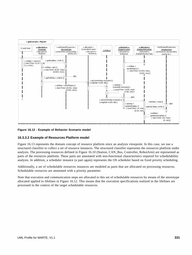
Figure 16.12 - Example of Behavior Scenario model
16.3.3.2 Example of Resources Platform model
Figure 16.13 represents the domain concept of resource platform since an analysis viewpoint. In this case, we use a structured classifier to collect a set of resource instances. The structured classifier represents the resources platform under analysis. The processing resources defined in Figure 16.10 (Station, CAN_Bus, Controller, RobotArm) are represented as parts of the resources platform. These parts are annotated with non-functional characteristics required for schedulability analysis. In addition, a scheduler instance (a part again) represents the OS scheduler based on fixed priority scheduling.
Additionally, a set of schedulable resources instances are modeled as parts that are allocated on processing resources. Schedulable resources are annotated with a priority parameter.
Note that execution and communication steps are allocated to this set of schedulable resources by means of the stereotype allocated applied to lifelines in Figure 16.12. This means that the execution specifications realized in the lifelines are processed in the context of the target schedulable resources.
« gaScenario » Report
« allocated »:Reporter
{ al loc atedTo= Reporter}
« saSharedResource»:ServosData
{ protec tKind= priority Ceiling, priority=16 }
:ContrClock:CANBus
«SaSharedResource»:DisplayData
{ protectKind= priorityCeiling,
priori ty=31 }
« allocated »:ControllerComm
{ alloc atedTo= Ms jStatus}
« allocated »:StationComm{ al loc atedTo=
M sjStatus}
« allocated »:DisplayRefresher
{ allocatedTo= DisplayRefresherTask}
« saStep » report (){ execTime= (1.22, max)(1.1, min) }
« saStep » get (){ execTime= (0.02, max)
(0.004, min) }
« saStep » sendStatus (){ execTime= (0.031, max)
(0.031, min) }
« saCommStep »transmit (){ msgSize=(100, kB) }
« saCommStep»transmit (){ msgSize=(100, kB) }
« saStep »transmitCommand (){ execTime= (2.56, max)
(2.56, min) }
« gaAcqStep » lock ()
« gaRelStep » unlock ()
« saStep »updateDisplay (){ execTime= (4, max)
(0.24, min)}
«saStep » read ()
«saExecStep» write ()
«saStep»updatesGraphics (){ execTime= (10, max)
(5, min )}
« saStep »awaitStatus (){ execTime= (0.022, max),
0.022, min) }
@t1
@t3
@t3
UML Profile for MARTE, V1.1 331
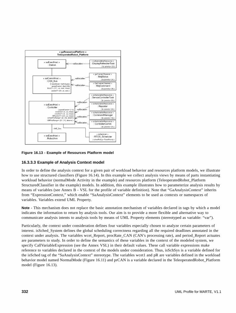
Figure 16.13 - Example of Resources Platform model
16.3.3.3 Example of Analysis Context model
In order to define the analysis context for a given pair of workload behavior and resources platform models, we illustrate how to use structured classifiers (Figure 16.14). In this example we collect analysis views by means of parts instantiating workload behavior (normalMode Activity in the example) and resources platform (TeleoperatedRobot_Platform StructuredClassifier in the example) models. In addition, this example illustrates how to parameterize analysis results by means of variables (see Annex B - VSL for the profile of variable definition). Note that “GaAnalysisContext” inherits from “ExpressionContext,” which enable “SaAnalysisContext” elements to be used as contexts or namespaces of variables. Variables extend UML Property.
Note - This mechanism does not replace the basic annotation mechanism of variables declared in tags by which a model indicates the information to return by analysis tools. Our aim is to provide a more flexible and alternative way to communicate analysis intents to analysis tools by means of UML Property elements (stereotyped as variable: “var”).
Particularly, the context under consideration defines four variables especially chosen to analyze certain parameters of interest. isSched_System defines the global scheduling correctness regarding all the required deadlines annotated in the context under analysis. The variables wcet_Report, procRate_CAN (CAN’s processing rate), and period_Report actuates are parameters to study. In order to define the semantics of these variables in the context of the modeled system, we specify CallVariableExpression (see the Annex VSL) in their default values. These call variable expressions make reference to variables declared in the context of the models under consideration. Thus, isSchSys is a variable defined for the isSched tag of the “SaAnalysisContext” stereotype. The variables wcet1 and pR are variables defined in the workload behavior model named NormalMode (Figure 16.11) and prCAN is a variable declared in the TeleoperatedRobot_Platform model (Figure 16.13).
332 UML Profile for MARTE, V1.1
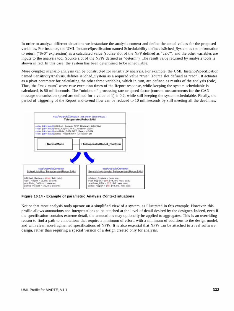
In order to analyze different situations we instantiate the analysis context and define the actual values for the proposed variables. For instance, the UML InstanceSpecification named Schedulability defines isSched_System as the information to return (“$v0” expression) as a calculated value (source slot of the NFP defined as “calc”), and the other variables are inputs to the analysis tool (source slot of the NFPs defined as “determ”). The result value returned by analysis tools is shown in red. In this case, the system has been determined to be schedulable.
More complex scenario analysis can be constructed for sensitivity analysis. For example, the UML InstanceSpecification named SensitivityAnalysis, defines isSched_System as a required value “true” (source slot defined as “req”). It actuates as a pivot parameter for calculating the other three variables, which in turn, are defined as results of the analysis (calc). Thus, the “maximum” worst case execution times of the Report response, while keeping the system schedulable is calculated, is 50 milliseconds. The “minimum” processing rate or speed factor (current measurements for the CAN message transmission speed are defined for a value of 1) is 0.2, while still keeping the system schedulable. Finally, the period of triggering of the Report end-to-end flow can be reduced to 10 milliseconds by still meeting all the deadlines.
Figure 16.14 - Example of parametric Analysis Context situations
Notice that most analysis tools operate on a simplified view of a system, as illustrated in this example. However, this profile allows annotations and interpretations to be attached at the level of detail desired by the designer. Indeed, even if the specification contains extreme detail, the annotations may optionally be applied to aggregates. This is an overriding reason to find a path to annotations that require a minimum of effort, with a minimum of additions to the design model, and with clear, non-fragmented specifications of NFPs. It is also essential that NFPs can be attached to a real software design, rather than requiring a special version of a design created only for analysis.
UML Profile for MARTE, V1.1 333

334 UML Profile for MARTE, V1.1

17 Performance Analysis Modeling (PAM)
17.1 Overview
In MARTE, “performance modeling” describes the analysis of temporal properties of best-effort systems and soft-real-time embedded systems, including systems supplying information, web-based services, enterprise services, multimedia, telecommunications, and networked services. Performance measures (analysis outputs) are statistical, such as mean throughput and delay, or the probability of missing a target response time. Input parameters to the analysis may also be probabilistic, such as a random arrival process, random execution time for a media frame, or a probability of a cache hit. The common performance analysis techniques include simulations, extended queueing models, and discrete-state models such as Stochastic Petri Nets. Behavior is often regarded as non-terminating for the purposes of analysis (steady state behavior, for example for capacity analysis).
Performance analysis includes single-case analysis for a given set of input parameters, or multicase analysis such as:
• sensitivity analysis that explores a parameter space, to find ideal operational parameters or to identify risky workload situations. Sensitivity analysis may also include alternative scenarios, platforms, physical deployments, and configurations.
• Scalability or capacity analysis which explore the capabilities of the design or configuration.
There is explicit support for multicase analysis in the parameters of the AnalysisContext.
The performance domain employs and extends the Generic Quantitative Analysis Modeling (GQAM) domain of Clause 15. It employs features such as the WorkloadEvent description of the stream of arriving events, focusing on some of the workload types (open and closed arrivals, workload generators, and traces), and the behavior-causality model of Scenarios and Steps. It extends the properties of Steps to include more kinds of operation demands during a step, and the possibility of an asynchronous (non-synchronizing) parallel operation. Other extensions: a Step subtype PassResource that identifies the passing of a resource (usually a SharedResource) from one process to another.
The increment to the GQAM domain model is shown in Figure 17.1 and Figure 17.2, broken into two packages, PAM_Workload and PAM_Resources. Some elements are shown in both diagrams where there are associations between resources and behavior elements. For elements from other domains, only the attributes of interest for performance analysis are shown.
17.2 Domain View
17.2.1 The PAM_Workload Package
Performance analysis is determined by how the system behavior uses system resources. Important resources include hardware ExecutionEngines, concurrent process threads (ScheduledResources), and LogicalResources defined by the software. A logical resource can be any entity to which the software requires access, and for which the program may have to wait at some point. Thus a semaphore is in this sense a resource, as is a lock, or a buffer, or a block of memory. A pool of access control tokens can be modeled as a logical resource.
A process resource, or pool of process threads, is also a kind of logical resource that is modeled separately, by the concept of SchedulableResource imported from the General Resource domain model (GRM). Because processes may be identified in behavior specifications by other entities (lifelines and swimlanes in particular), a special concept of RunTimeObjectInstance is introduced to represent an alias for a process resource.
UML Profile for MARTE, V1.1 335

Figure 17.1 - Part of the performance domain model relevant to behavior
Resources that are not modeled within the software design may also have an impact on performance. This domain model identifies “external operations” by such resources by a name (a string), so they can be modeled in the performance environment. An example is the use of a TCP connection, which is not modeled in the software specification, but for which customized simulators exist. The same considerations might apply to database or storage subsystems.
Demands by a Step for external operations are described by the pair of properties externalOpDemand and externalOpCount. The first is an ordered list of operation names (strings), and the second is an ordered list (in the same order) of the number of demands made during one execution of the Step. The number may be an exact number (an integer), an average value (real) or a probability distribution defined in the NFP.
PAM_Workload
GQAM_Workload::WorkloadBehavior
pattern: ArrivalPattern
GQAM_Workload::WorkloadEvent
demand1..*
GeneratorPatternTraceTimed
« enumeration»GQAM_Workload::EventStreamKind
SequenceBranchMergeForkJoin
« enumeration»GQAM_Workload::
ConnectorKind hostDemand: NFP_DurationhostDemandOps: NFP_R eal [*]interOccT : N FP_Duration [*]throughput: NFP_Frequency [*]respT: NFP_Duration [*]utilization : NFP_Real [*]utilizationOnHost : NFP_R eal [*]root: GaStep
GQAM_Workload::BehaviorScenario
population: NFP_Integer
GQAM_Workload::WorkloadGenerator
GQAM_Workload::EventTrace
generator
0..1
trace0..1
behavior 1..*
GQAM_Workload::PrecedenceRelation
connectors
GQAM_Workload::Step
root steps
0..1 behavior
*
noSync: Boolean [0..1] = FalseexternalOpDemands: String [*] {ordered}externalOpCount: NFP_Real [*] {ordered}behaviorDemands: GaScenario [*] {ordered}behaviorCount: NFP_Real [*] {ordered}
PAM_Step
GQAM_Resources::ExecutionHost
GRM::SchedulableResource
0..1host 0..1concurR es
GQAM_Workload::RequestedService
GQAM_Workload::CommunicationStep
GQAM_Resources::CommunicationHost
GQAM_Resources::CommunicationChannel
0..1host
0..1concurRes
GQAM_Workload::AcquireStep
GQAM_Workload::ReleaseStep
resU nits: NFP_Integer
ResourcePassStep
GRM::Resource
acqRes
relRes
passedRes
336 UML Profile for MARTE, V1.1

Figure 17.2 - Part of the performance domain model relevant to resources
Performance properties of different system elements fall into a small number of different measures, as discussed in Clause 15. For instance, the term throughput (in operations/sec) is applied to the system as a whole, for handling of requests, but also to a single process, or component, or processing step. Because of this uniformity, one set of property names is defined in Table 15.1 to be applied at will to different behavior and resource entities. These NFPs are used here also. Typical performance properties include average response time, mean throughput capacity, resource utilization, and the probability of missing a delay target. However more sophisticated properties can be investigated, and in general performance analysis uses input and output properties which may be any statistical measure of five types of quantities:
• Duration (e.g., respT) (e.g., as an operation delay, or as a response time), NFP_Duration.
• also forced duration (e.g., blockT) (a duration which is part of the operation, such as a user think time), NFP_Duration
• Frequency (or throughput. e.g., of events or operations) NFP_Frequency.
• Probability (e.g., of occurrence of some event), NFP_Real.
• Repetitions, for a loop repetition or a repeated operation, NFP_Real. This is represented as Real rather than integer so that mean values can be represented.
• Message size or memory size, NFP_DataSize.
The analysis associates a BehaviorScenario with the concepts of workload, request, service, and response. The workload defines the frequency or intensity of occurrence of requests for the service; the details of the service given to each request are defined by the BehaviorScenario (giving the resources and operations including their demand parameters), and the response is the result, including its properties of delay, frequency, and probabilities. Resources are associated with one or more BehaviorScenarios, constrain their properties, and have their own properties that include holding time and utilization (which is the probability that the resource is busy, or a mean count of the number of busy resource units).
UML Profile for MARTE, V1.1 337

17.2.2 Outline of Domain Concepts
17.2.2.1 Performance AnalysisContext and Workload
The AnalysisContext (from GQAM) corresponds to the scope of a study or evaluation. It combines the system represented by its behavior (BehaviorScenarios) and its resources (from GQAM), with one or more workloads. It has a set of parameters that are used in expressions that define system input parameters, and which define the range of variation of cases that may arise within the study.
A performance context specifies one or more BehaviorScenarios that are used to explore various dynamic situations involving a specific set of resources. For instance, a performance context may describe a “busy hour,” during which the maximum processor load is expected and therefore imposing the greatest likelihood of performance problems, such as missed deadlines. For a given system specification, there may be many performance contexts with overlapping resources, but one BehaviorScenario is specific to one performance context.
One UML specification may give rise to several performance models, due to variations in system usage, workload, allocation/deployment, and configuration. We will call these different models cases; they are supported by parameterizing the specification. Parameterized NFPs are supported by the use of:
• Variables global to the AnalysisContext, defining the variations.
• Variable names in place of numeric values of input properties for model elements.
• Functional dependencies of the input properties on the global variables, to define values.
Variables can then be used to specify:
• Workload intensity, through arrival rates or concurrency (population size).
• System scaling through multiprocessors or replication.
• Data record size (and then various demands, through functions).
Analysis cases are defined outside the UML specification by defining groups of values of variables, with one group of values for each case. These may be expressed in a table with a column for each case and a row for each variable.
Additional sources of variation may arise with different configurations and environments. Some of these variations are independent of the UML model, for example the choice of middleware or operating system. The construction of performance models can incorporate directives to compose the application with a stated environment, using a library of submodels for environments (described above). These also become case parameters.
Figure 17.3 - Analysis over cases
UML Model Configu ration /
Platform C ase Para meters Perfo rmance
Mod el Inpu t NFPs (Parameter
Values) Perfo rmance Model Solver
O utpu t NFPs (Perfo rman ce
Results )
338 UML Profile for MARTE, V1.1

17.2.2.2 Behavior
The unit of description of behavior is the BehaviorScenario, which corresponds to a behavior diagram (interaction, activity, or state-machine diagram). It is a sequence of actions (called Step here for its performance aspects), with predecessor-successor relationships that may include forks, joins, and loops. Steps indicate the demands of the system on its resources, both for execution on the host processor of the step (called its hostDemand attribute) and for other resources.
Other resources can be acquired (and released) explicitly using subtypes of Step called ResourceAcquire and ResourceRelease, in which the resource is identified directly. Still further resources can be utilized through demands by a Step for Services (like calls) that may involve arbitrary resource combinations. One kind of Service, by an ExternalResource, shows the use of resources outside the UML model.
The input attributes of a Step include its probability (following a branch, or in an opt or alt CombinedFragment), a repetition count (for a repeated step, such as a loop CombinedFragment), and a “noSync” attribute (following a fork, or on an asynchronous message or par operand) to explicitly indicate that a parallel branch does not join. Behavior using noSync may provide increased concurrency and increased performance.
A Step may be refined by another BehaviorScenario. In an Interaction Diagram the sub-BehaviorScenario may be the operand of a CombinedInteraction; in an Activity Diagram it may be the contents of a StructuredActivity. A BehaviorScenario that responds directly to requests by a Workload may be termed a “top-level” BehaviorScenario, while others are sub-scenarios.
In a performance model the system behavior is often non-terminating, that is it cycles forever, repeating the top-level scenarios as defined by the workload intensity.
Resource demands by a step include its host execution (CPU) demand, acquisition of a logical resource, and demands for services which are not defined in the same behavior definition, but are provided by some system component, or by the platform or the environment, or by an external system.
17.2.2.3 Workload
A context may have any number of workloads, representing different sources of requests or initiations of operations. Each workload has a distinct mechanism for initiating requests, its own load intensity, and its own QoS requirements. In a performance analysis, a workload corresponds to a class of traffic, with a mechanism that may be either open or closed.
Behavior is initiated by a workload event. An open workload is a WorkloadEvent in which the events arrive at a given rate in some predetermined pattern (such as clocked or Poisson arrivals), or by a trace.
A closed workload defines a stream generated by a fixed number of active or potential users or jobs that cycle between demanding to execute the BehaviorScenario, and spending an external delay period (some times called a Think Time) outside the system, between the end of one response and the next request. A system may have any combination of open and closed workloads. Further, a closed workload may combine requests for different BehaviorScenarios in some sequence; in general a mechanism to describe this is called a WorkloadGenerator, governed by a state machine making requests for operations. ClosedWorkload is a special case.
The same BehaviorScenario concept describes execution of a request for a service by an external resource, which was discussed above. The operation size parameter can be used in such requests to define the service time of the request, when executed. For example a file service request might define the file size; then a performance submodel for the file system could use this parameter to work out the demands on the various resources in the file system, for each request.
UML Profile for MARTE, V1.1 339

17.2.2.4 Service
It is normal in performance analysis to speak of services, with offered and demanded quality of service. An informal expanded view of behavior with ServiceDemands and OfferedServices is shown in Figure 17.4 and used in the following discussion.
A Service is a pivotal concept in performance. Requests queue for service by some resource, and may have a required quality of service. The actual service is defined in general by a BehaviorScenario, with a provided quality of service. It may be incorporated into the modeled behavior in three ways:
• By making a serviceDemand from a Step to a RequestedService, representing an operation offered at some interface, which is in turn defined by a BehaviorScenario.
• By making a behaviorDemand from a Step to directly invoke a BehaviorScenario, which defines a logical service offered in some way by the system.
• By making an extOpDemand from a Step to request an external service, which is defined in the performance environment outside the UML model.
External services vary depending on how much is defined in the UML model. For instance if the network is defined in the deployment then a message transmission is defined within the UML model, but if no network is specified it is an external service.
In the performance model, behavior can be composed flexibly from units defined by scenarios, by service operations embedded in components, and by external operations, as shown in Figure 17.4. This provides a toolkit that suits many different software design structures, and situations in which different kinds of performance information is available.
For component or platform services defined in the UML document, a submodel can be made and composed with the model of the defined services, through service demands. As an abstraction, for systems in which there is no such submodel, the equivalent behavior can be described by a subscenario and composed through behavior demands. For some kinds of platform services the costs can be included as overhead parameters of the host devices.
Figure 17.4 - Informal view of Services and Behavior
PWo rk loa dGenera tor
GQAM_ Workl oad::Be hav iorSce nario
« use »
GQAM_ Work load::Beha vio rS cena rio
PRequ este dServ ice Ex ternalOp eratio n
« use » « use » « use »
GQAM_Wo rkloa d::Beha vio rS cena rio
« use »
PRequ este dServ ice
« use »
Ex ternalOp eratio n
« use »« use »
« use »
« u se »
340 UML Profile for MARTE, V1.1

17.2.2.5 Resources
In performance modeling based on queues, resources may be modeled as servers. An active resource is self-contained (e.g., a CPU) and has a characteristic service time for each class of service it offers. A passive resource may be acquired and released during a BehaviorScenario, and has a holding time that is determined by the behavior (e.g., by the sub-scenario) between acquisition and release, which defines the class of service. An external resource is an active resource that is an abstraction for an external sub-system of any kind.
Software components, like resources, offer services that are defined by sub-scenarios. The steps of the sub-scenario define the use of other components and resources during a service. A component has a set of interfaces, each of which offers one or more of the services of the component. In software terms a single service may be defined as the response to one interface method, or to any one of a set of interface methods (methods may be clustered as a form of abstraction in the performance analysis). A software component may also be a passive resource (a process or thread) if its execution is restricted in some way. If there is no limit in the number of simultaneous concurrent active executions of the component, it optionally may be regarded as a special kind of “infinite resource,” or as not a resource; the two concepts are equivalent.
17.2.2.6 Communications Channels
A message between two objects is conveyed by some mechanism:
1. If the objects are in the same process, it is conveyed by the language runtime.
2. If the objects are in different processes in the same node (ProcessingHost), it is conveyed by the operating system.
3. If they are of different nodes, it is conveyed by a system layer we will term a CommChannel. This may be a middlware layer (a web services connection, a CORBA connection, a Java Remote Method Invocation, an MPI (Message-Passing Interface) connection in a grid, a socket or secure socket connection), or a more complex infrastructure such as a publish-and-subscribe system.
To give the modeler flexibility, these will be modeled in five different ways, of increasing detail and complexity (levels of detail):
1. Within the same node, language runtime costs and operating system costs are ignored by default; they are part of the scenario. If the interprocess communication cost per byte of the ProcessingHost is defined, that is used instead to calculate a hostDemand.
2. Between nodes the default is to determine node hostDemands from the sending and receiving overhead on the nodes (attributes of the two ProcessingHosts) and insert the latency of the link (an attribute of the connecting CommunicationsHost).
3. Between nodes the conveyance of the message may also be modeled as an external operation, invoking a submodel of the communications layer. If this demand is defined it overrides the default. It is an attractive option for modeling the behavior of the internet and the complexities of the TCP protocol.
4. Between nodes a communications layer such as CORBA may be defined as a UML StructuredClass offering send and receive operations to the two end-point processes. This layer is denoted as a CommChannel with a conveyance operation demanded by the CommunicationsStep in the scenario. Its service is defined by a BehaviorScenario defined for the send operation and the combination of the two end-point processes. The scenario may involve directory look-ups, authorization, and redirection of requests. If a serviceDemand for this operation is defined it overrides the default.
UML Profile for MARTE, V1.1 341

5. Between nodes a complex communications protocol can be modeled by a pure BehaviorScenario not associated with a system component, but describing a collaboration of the hosts. For example, in a publish-and-subscribe system a message is transferred by posting it to a repository, which then informs subscribers of the message. They finally access it themselves, at which point the message is delivered. If a serviceDemand for this operation is defined it overrides the default.
Each message with performance significance is defined as a kind of Step called a CommunicationStep, in sequence in the BehaviorScenario. Its annotations determine which level is used to model the cost and delay of communications. Figure 17.5 shows these definitions as dependencies, for both cases.
Notice that if the channel is a CommunicationsEngine with a rate parameter, its transmission demand may define the latency.
(a) Detail Level 2, conveyance modeled at the hardware level
(b) Detail levels 4 and 5: using a communications layer
Figure 17.5 - Roles in modeling the transmission of a message
From the above discussion, the model for levels 4 and 5 defined by a BehaviorScenario for transmission, either associated with CommChannel or invoked explicitly. For level 3 there is an implicit three step scenario of (send overhead on sending host, latency delay, receive overhead on receiving host). The domain model to support communications modeling is shown in Figure 17.5.
SchedulableResource (sender)
CommunicationsHost (link)
-latency
hardware-based conveyance
SchedulableResource (receiver)
Message
ProcessingHost (receiver)
-recvOH
ProcessingHost (sender)
-sendOH
SchedulableResource (sender)
structured conveyance
SchedulableResource (receiver)
Message
system-wide behavior BehaviorScenario
(sender to receiver)
communications layer CommChannel
(sender to receiver)
{one or the other}
342 UML Profile for MARTE, V1.1

Figure 17.6 - Domain model for communications in performance modeling
17.2.2.7 Types of Performance Analysis Methods
A sub-profile for performance analysis should support modeling tools for building different kinds of performance models. Most modeling tools deal with one or more of the following common types of models:
• Queueing models define customer classes (workloads) which execute particular aspects of the software, which are captured in different scenarios. In the simplest queueing models it is only necessary to define the class sizes or arrival rates, and the total average demands placed on each device in the system, during one execution of each scenario. In more complex queueing models the distribution of the demand may be required, there may be passive resources as well as devices, and the detailed scenario sequence may be required (for instance if it has parallel branches).
Queueing models calculate average throughput, utilization and response times for classes overall, and layered or extended queueing models also can calculate these figures for passive resources and for parts of BehaviorScenarios (scenario steps or resource-operations).
1. Simulation models define multiple logical tokens which execute the software, following the detailed BehaviorScenario structure and using execution time distributions for the operations of each step. There may be passive resources and they may have complex scheduling (for instance, LRU management of a cache). Simulation models can calculate a wide range of measures including histograms and percentiles as well as average values.
2. Discrete-state models such as Petri Nets define tokens which execute the software, following the detailed BehaviorScenario structure. As in queueing models there may be open or closed classes of tokens for different scenarios. Where tokens must be differentiated they are said to be colored. Petri Nets use places to define the progress of tokens and transitions to describe decisions, and the passage of time. Resources are described by additional places and tokens, and resource scheduling by transitions which execute scheduling decisions. Other forms of discrete-state models include Markov and Semi-Markov chains, Stochastic Process Algebras, and Stochastic Automata.
UML Profile for MARTE, V1.1 343

Performance Petri Nets and other discrete-state models typically calculate average measures but can provide more detailed measures such as higher moments and distributions.
17.3 UML Representation
17.3.1 Profile Diagrams
The profile is defined in the two diagrams that follow, and in text in the next sub clause. Much of it re-uses extensions defined for Generic Quantitative Analysis Modeling (Section 15.3.1), prefixed Ga, and these extensions are shown again here to show that they are part of this sub-profile, though their definitions are given elsewhere. For the inherited stereotypes, properties (tags) which are important for performance analysis are shown here.
344 UML Profile for MARTE, V1.1
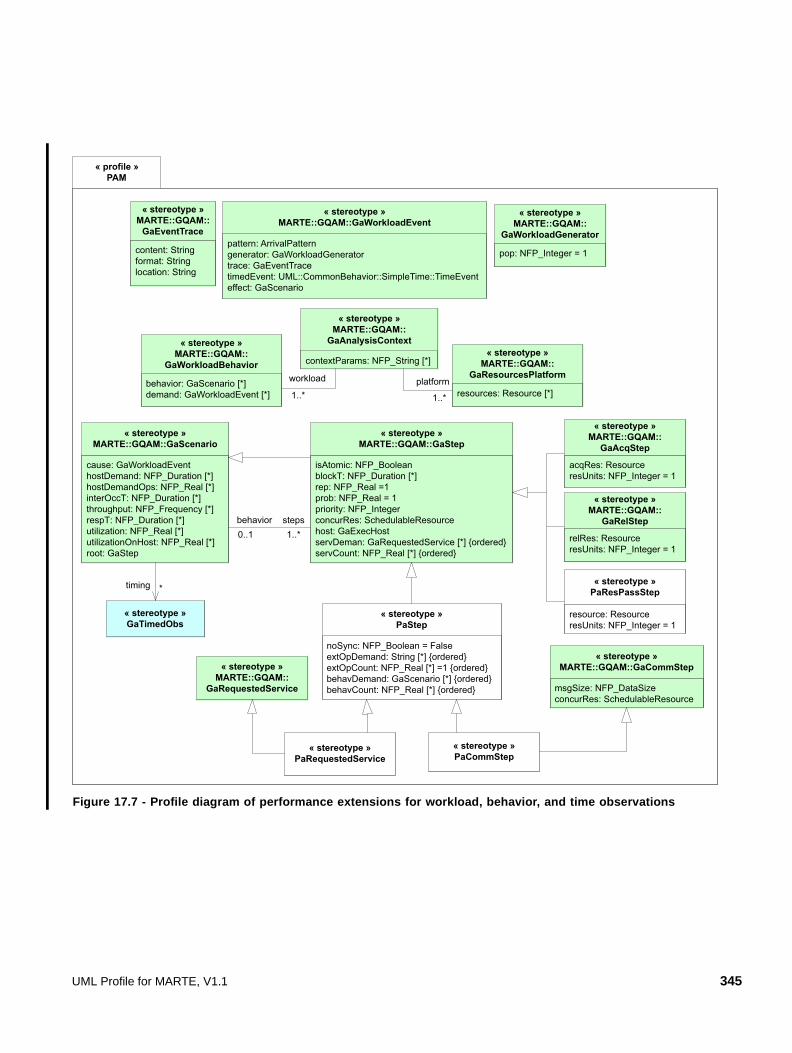
Figure 17.7 - Profile diagram of performance extensions for workload, behavior, and time observations
« profile »PAM
pattern: ArrivalPatterngenerator: GaWorkloadGeneratortrace: GaEventTracetimedEvent: UML::CommonBehavior::SimpleTime::TimeEventeffect: GaScenario
« stereotype »MARTE::GQAM::GaWorkloadEvent
content: Stringformat: Stringlocation: String
« stereotype »MARTE::GQAM::
GaEventTrace
pop: NFP_Integer = 1
« stereotype »MARTE::GQAM::
GaWorkloadGenerator
cause: GaWorkloadEventhostDemand: NFP_Duration [*]hostDemandOps: NFP_Real [*]interOccT: NFP_Duration [*]throughput: NFP_Frequency [*]respT: NFP_Duration [*]utilization: NFP_Real [*]utilizationOnHost: NFP_Real [*]root: GaStep
« stereotype »MARTE::GQAM::GaScenario
isAtomic: NFP_BooleanblockT: NFP_Duration [*]rep: NFP_Real =1prob: NFP_Real = 1priority: NFP_IntegerconcurRes: SchedulableResourcehost: GaExecHostservDeman: GaRequestedService [*] {ordered}servCount: NFP_Real [*] {ordered}
« stereotype »MARTE::GQAM::GaStep
stepsbehavior0..1 1..*
« stereotype »MARTE::GQAM::
GaRequestedService msgSize: NFP_DataSizeconcurRes: SchedulableResource
« stereotype »MARTE::GQAM::GaCommStep
acqRes: ResourceresUnits: NFP_Integer = 1
« stereotype »MARTE::GQAM::
GaAcqStep
relRes: ResourceresUnits: NFP_Integer = 1
« stereotype »MARTE::GQAM::
GaRelStep
« stereotype »PaRequestedService
contextParams: NFP_String [*]
« stereotype »MARTE::GQAM::
GaAnalysisContext
resources: Resource [*]
« stereotype »MARTE::GQAM::
GaResourcesPlatformbehavior: GaScenario [*]demand: GaWorkloadEvent [*]
« stereotype »MARTE::GQAM::
GaWorkloadBehavior
platform
1..*1..*
workload
resource: ResourceresUnits: NFP_Integer = 1
« stereotype »PaResPassStep
noSync: NFP_Boolean = FalseextOpDemand: String [*] {ordered}extOpCount: NFP_Real [*] =1 {ordered}behavDemand: GaScenario [*] {ordered}behavCount: NFP_Real [*] {ordered}
« stereotype »PaStep
« stereotype »PaCommStep
« stereotype »GaTimedObs
timing *
UML Profile for MARTE, V1.1 345

Figure 17.8 - Profile diagram of performance extensions for resources
17.3.2 Profile Elements Description
Imported stereotypes from GRM and GQAM that are part of this subprofile are included in this list, however they are not defined. Where the semantics of the imported stereotype are affected by the performance domain, the semantics are outlined.
17.3.2.1 GaAnalysisContext (from MARTE::GQAM)
17.3.2.2 GaAcqStep (from MARTE::GQAM)
17.3.2.3 GaCommChannel (from MARTE::GQAM)
17.3.2.4 GaCommHost (from MARTE::GQAM)
17.3.2.5 PaCommStep
The semantics is similar to GQAM::GaCommStep, however the inheritance from PaStep incorporates the additional behavior definitions for operations during the step (external operations and behavDemand for a nested Scenario). The message conveyance may be executed by a combination of host middleware and network services.
346 UML Profile for MARTE, V1.1
Extensions
• None
Generalizations
• PaStep
• GaCommStep (from MARTE::GQAM)
Associations
• None
Attributes
• msgSize: NFP_dataSize [*] The size of message to be transmitted by the step.
• concurResource: MARTE::GRM::SchedulableResource [0..1] The logical communications channel by which the message is conveyed.
Constraints
• None
17.3.2.6 GaEventTrace (from MARTE::GQAM)
17.3.2.7 GaExecHost (from MARTE::GQAM)
In performance modeling, an GaExecHost can be any device which executes behavior, including storage and peripheral devices.
17.3.2.8 PaLogicalResource
The PaLogicalResource stereotype maps the LogicalResource domain element denoted in Annex F (F.12.13).
A PaLogicalResource is a resource that can be acquired and released explicitly by AcqStep or RelStep. It may be a single-unit resource, as a mutex or exclusive lock, or have multiple units, as a buffer pool or an access token pool. A logical resource that is embodied as a software process is stereotyped SchedulableResource or PaRunTInstance instead.
Extensions
• Classifier (from UML::Classes::Kernel)
Generalization
• Resource (from MARTE::GRM)
Associations
• None
UML Profile for MARTE, V1.1 347

Attributes
• poolSize: NFP_Integer [0..1] = 1 The number of units of the resource.
• utilization: NFP_Real [*] The occupancy of the resource, expressed as the mean number of busy units of the resource. If poolsize = 1, there is one instance, and the utilization is the probabilty it is busy.
• throughput: NFP_Frequency [*] The rate of requests to the resource.
Constraints
• None
17.3.2.9 GaRelStep (from MARTE::GQAM)
17.3.2.10 PaRequestedService
The PaRequestedService stereotype maps the RequestedService domain element denoted in Annex F.
The semantics are similar to GQAM::GaRequestedService, however the inheritance from PaStep incorporates the additional behavior definitions for operations during the step (external operations and behavDemand for a nested Scenario).
Extensions
• Operation (from UML::Classes::Kernel)
Generalizations
• PaStep
• GaRequestedService (from MARTE::GQAM)
Associations
• None
Attributes
• None
Constraints
• None
17.3.2.11 GaResourcesPlatform (from MARTE::GQAM)
17.3.2.12 PaResPassStep
ResPassStep is applied immediately after a fork to indicate that a resource held before the fork is passed to this branch, and not shared by all the branches of the fork. Resource units that are held before the fork and not passed, are shared by all branches.
348 UML Profile for MARTE, V1.1

Extensions
• None
Generalizations
• GaStep (from MARTE::GQAM)
Associations
• None
Attributes
• resource: Resource [0..1] The identity of the resource of which some units are passed.
• resUnits: NFP_Integer [0..1] = 1 The number of units which are passed.
Constraints
• None
17.3.2.13 PaRunTInstance
A stereotype for a swimlane or lifeline that indicates a run-time instance of a process resource and its properties.
Provides an explicit connection between a locality or role in a behavior definition (a lifeline or swimlane) and a run time instantiation of a process, and optionally defines properties of the process. In some specifications there may be multiple deployment instantiations of the same process class, with different properties, so this stereotype should be used for the properties that are different.
Extensions
• NamedElement (from UML::Classes::Kernel)
Generalizations
• None
Associations
• None
Attributes
• poolSize: NFP_Integer [0..1] = 1 The number of threads for the process.
• unbddPool: Boolean [0..1] = false Indicates effectively infinite threads if true.
• instance: MARTE::GRM::SchedulableResource [0..1] The SchedulableResource that is the actual process resource.
UML Profile for MARTE, V1.1 349

• host: GaExecHost [0..1] The host of the process and thus of all Steps associated with this run-time instance.
• utilization:NFP_Real [*] The occupancy of the thread pool, in terms of the mean busy threads.
• throughput: NFP_Frequency [*] The rate of acceptance of messages by all threads in the process, taken together.
Constraints
• None
17.3.2.14 SchedulableResource (from MARTE::GRM)
In performance modeling, a schedulable resource is a process or thread pool. A named element such as a swimlane or lifeline that represents behavior of a schedulable resource is stereotyped as a PaRunTInstance (see below) with a pointer to the resource, and also may capture the size of the thread pool and the host of the process.
17.3.2.15 PaStep
A step is a unit of a scenario. Some inherited properties of PaStep are given to provide performance interpretations. PaStep without a refining scenario is a basic sequential execution step on a host processor. With a refining scenario it is a larger unit of behavior.
Extensions
• None
Generalizations
• GaStep (from MARTE::GQAM)
Associations (inherited):
• behavior:GaScenario [0..1] A scenario that is a refinement of this Step.
Attributes (inherited)
• blockT: NFP_Duration [*] A pure delay that is part of the execution of a step. Think times for performance models are represented by a blockT value.
• rep: NFP_Real [0..1] = 1 Repetitions, used to represent loops or optional execution.
• prob: NFP_Real [0..1] = 1 Probability of a branch.
• host: GaExecHost [0..1] Host processor (usually implicit in the deployment of the process).
• servDemand: GaRequestedService [*] {ordered} A list of operations that are called during one execution of the Step.
350 UML Profile for MARTE, V1.1

• servCount: NFP_Real [*] {ordered} A list of values for how many calls are made to each operation in the servDemand list, in the same order.
• concurRes: SchedulableResource [0..1] The process or software component which executes the step, usually implicit in the location of execution in the behavior definition (lifeline, swimlane).
Attributes
• noSync: Boolean [0..1] = false Identifying a Step immediately after a fork, for which there will be no corresponding join. An asynchronous branch of a fork.
• extOpDemands : String [*] {ordered} A set of identifiers for operations by external services which are demanded by this Step, in a form understood by the performance environment.
• extOpCount: NFP_Real [*] {ordered} The number of requests made for each external operation during one execution of the Step, in the same order as the demands.
• behavDemands: GaScenario [*] {ordered} A set of scenarios defining operations that are invoked by this Step. This provides another way to insert a Scenario into a Step, in this case with a parameter for multiple, or probabilistic insertion.
• behavCount: NFP_Real [*] {ordered} The number of requests made to execute each scenario operation during one execution of the Step, in the same order as the demands.
Constraints
• None
17.3.2.16 GaTimedObs (from MARTE::GQAM)
This observer stereotypes is an NFP_Constraint associated to two TimingObservations. In performance analysis it is used to identify and compute the duration of the time interval between them.
17.3.2.17 GaWorkloadEvent (from MARTE::GQAM)
Defines a stream of events that make up a workload that drives the system. For performance analysis the events can be taken from a trace (for simulation) from an arrivalPattern, which can be an OpenPattern, or a ClosedPattern; or from a WorkloadGenerator that is a State Machine defining sequences of operations.
17.3.2.18 GaWorkloadBehavior (from MARTE::GQAM)
A container for a set of Scenarios and a set of WorkloadEvents.
17.3.2.19 GaWorkloadGenerator (from MARTE::GQAM)
A State Machine defining sequences of events to drive a system. There may be a population of instances, each representing one user or one source of input.
UML Profile for MARTE, V1.1 351

17.4 Examples for Performance Analysis
17.4.1 Example 1: A Simple Web Application
The basic performance features will be illustrated by describing a web-based application. Example 1 is a simple sequential scenario with basic features of the profile: open arrivals, average processor demands, a repeated operation, multithreaded processes, and communication overheads at the nodes. Example 2 adds more complex behavior patterns and corresponds roughly to a web application benchmark.
Figure 17.9, the blockT attribute of the LAN represents the network latency, and the capacity is the nominal maximum throughput rate. The send and receive overheads on the nodes apply equally to all transmissions. The nodes are stereotyped as ExecHost and each is a multiserver, with 5 and 2 processors respectively indicated by resMult (multiplicity of available instances). The webserver artifact represents a load module for the webserver and its deployment, and similarly for the database.
Figure 17.9 - Deployment of Example 1, with communications overhead annotations
<<GaExecHost>> AppHost
{commRcvOvh = (0.15,ms/KB), commTxOvh = (0.1,ms/KB)}
<<GaExecHost>> DBhost
{commRcvOvh = (0.14,ms/KB), commTxOvh = (0.07,ms/KB)}
<<GaCommHost>> LAN
{blockT = (10,us), capacity = (100,Mb/s)}
: DatabaseSystem : WebServer
<<artifact>> <<SchedulableResource>>
webserver
<<artifact>> database
<<deploy>>
<<deploy>>
<<manifest>> <<manifest>>
352 UML Profile for MARTE, V1.1
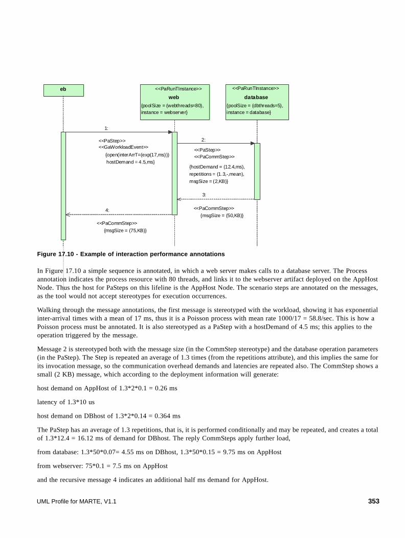
Figure 17.10 - Example of interaction performance annotations
In Figure 17.10 a simple sequence is annotated, in which a web server makes calls to a database server. The Process annotation indicates the process resource with 80 threads, and links it to the webserver artifact deployed on the AppHost Node. Thus the host for PaSteps on this lifeline is the AppHost Node. The scenario steps are annotated on the messages, as the tool would not accept stereotypes for execution occurrences.
Walking through the message annotations, the first message is stereotyped with the workload, showing it has exponential inter-arrival times with a mean of 17 ms, thus it is a Poisson process with mean rate 1000/17 = 58.8/sec. This is how a Poisson process must be annotated. It is also stereotyped as a PaStep with a hostDemand of 4.5 ms; this applies to the operation triggered by the message.
Message 2 is stereotyped both with the message size (in the CommStep stereotype) and the database operation parameters (in the PaStep). The Step is repeated an average of 1.3 times (from the repetitions attribute), and this implies the same for its invocation message, so the communication overhead demands and latencies are repeated also. The CommStep shows a small (2 KB) message, which according to the deployment information will generate:
host demand on AppHost of 1.3*2*0.1 = 0.26 ms
latency of 1.3*10 us
host demand on DBhost of 1.3*2*0.14 = 0.364 ms
The PaStep has an average of 1.3 repetitions, that is, it is performed conditionally and may be repeated, and creates a total of 1.3*12.4 = 16.12 ms of demand for DBhost. The reply CommSteps apply further load,
from database: 1.3*50*0.07= 4.55 ms on DBhost, 1.3*50*0.15 = 9.75 ms on AppHost
from webserver: 75*0.1 = 7.5 ms on AppHost
and the recursive message 4 indicates an additional half ms demand for AppHost.
<<PaRunTInstance>>
web
{poolSize = (webthreads=80), instance = webserver}
<<PaRunTInstance>>
database
{poolSize = (dbthreads=5), instance = database}
eb
<<PaStep>> <<PaCommStep>>
2:
{hostDemand = (12.4,ms),
repetitions = (1.3,-,mean),
msgSize = (2,KB)}
<<PaCommStep>>
4:
{msgSize = (75,KB)}
<<PaCommStep>>
3:
{msgSize = (50,KB)}
<<PaStep>> <<GaWorkloadEvent>>
1:
{open(interArrT=(exp(17,ms)))
hostDemand = 4.5,ms}
UML Profile for MARTE, V1.1 353

Performance Models: Queueing Network (QN)
A queueing model of this system has two servers - AppHost with 5 servers and total demand Dap ms/request, and DBhost with 3 servers and total demand Ddb ms/request - where:
Dap = 4.5 + 0.26 + 9.75 + 7.5 = 22.01 ms/request
Ddb = 0.28 + 16.12 + 4.55 = 20.95 ms/request
The annotations have not specified a message size for the original request from the browser, so it is ignored.
A QN model could be shown as follows:
Figure 17.11 - Queueing Network for Example 1
The two total demand values Dap and Ddb are sufficient to give a solution if this is assumed to be a separable QN, which means assuming processor-sharing scheduling at the two computers (not a very serious assumption for enterprise systems). The demands are assumed to include all operating system overheads, including background workloads. If additional workloads are present they should either be modeled as additional classes (from other scenarios) or some fraction of processor utilization should be allocated to them.
The QN model ignores the performance impact of the process thread pool sizes. To represent this we require an extended queueing network or layered network, that models the simultaneous possession of two resources (threads and processor). (see e.g., Lavenberg, “Performance Modeling Handbook”).
Extended Queueing Network or layered Queueing Network (EQN or LQN)
The ordinary queueing model ignores the thread limits on the webserver and database, which may limit performance. An EQN can model this with logical resources as shown in the Figure. The oval resource pools have resource tokens that are dispatched to requests in a queue (the upright triangle shows the dispatcher, the inverted triangle shows the release point for the thread.
AppHost Arrivals
Departures
DBhost
354 UML Profile for MARTE, V1.1

Figure 17.12 - Extended Queueing Network diagram
The service time of the logical server is the holding time of the thread. Solution of an EQN is approximate, using various strategies (see e.g., Jain, or Menasce and Almeida).
In Figure 17.13 each process is a logical server with a queue and a pool of tokens representing the process threads. The arriving job must first obtain a process token and be processed by the webserver on AppHost, then without releasing the first token (since this is a blocking call) it obtains a database process token and is processed by the database on DBhost. It releases the second token and goes back with the reply to the webserver, cycles an average of 1.3 times to the database, and then releases the webserver token and departs. This resource logic is captured more compactly in the LQN, in which each process is a layered server, illustrated in Figure 17.12.
Figure 17.13 - Layered Queueing version of the same model
The LQN notation has servers that are processes or tasks (represented by the bold rectangles, with threading shown as a multiserver multiplicity) allocated to host processors, the ellipses, also with multiplicity. The classes of service are denoted as entries, the attached rectangles, showing the total hostDemand for each operation. Entries make requests to other entries, shown as arcs labeled with the mean frequency (1.3 here). The solution of the LQN is essentially the same as the solution of the EQN above, it is just a more elegant notation provided the usage of logical resources are nested, lower layers within higher.
17.4.2 Example 2: An Electronic Bookstore Home Page Interaction
This example illustrates additional annotations and their application to additional features of the UML2 Interaction Diagram:
• Parameters global to the AnalysisContext, and their use in expressions for values.
Arrivals f
Departures
webthreads
dbthreads
DBhost
AppHost
webserver process
database process
htmlReq webserver 10 ms [webthreads]
arrivals at 58.8/sec
AppHost[5]
database [dbthreads]
(1.3)
dbReq 12.4 ms
DBhost [3]
UML Profile for MARTE, V1.1 355

• Alt and par CombinedFragments stereotyped as Steps, with probability for alt.
• An external operation for storage.
• A noSync stereotype applied to an asynchronous operation.
• A closed workload.
• Computation of parameters for the reply to getHomePage, using an NFP with expressions to determine the value, depending on the variable $images.
• A repeated action (getHomeImages) and an optional action with a probability.
• A percentile requirement on overall response time.
The example is elaborated from the Transaction Processing Council standard scalable benchmark TPC-W for electronic commerce (see TPC for the specification), by putting two Promotions into an alt combination (Promotion1 on the first pass, then Promotion2 thereafter), and introducing a logging operation in parallel with getHomeImages.
The scenario shows the interactions of a user starting from getting the home page, until the page is completely displayed. It includes checking the site’s data on the user if the user is logged in with a site ID, retrieving a subpage on a promotion, getting page data from the database, and getting a number of embedded images from an image server.
The deployment is based on example 1, with an added image server. It does not specify the number of replicated processors, so the default value of 1 is assumed.
Figure 17.14 - Deployment of a web application representing the TPC-W benchmark
The behavior is shown in Figure 17.15.
<<GaExecHost>>DBhost
{commRcvOvh = (0.14,ms/KB),commTxOvh = (0.07,ms/KB),resMult = 3}
<<GaExecHost>>AppHost
{commRcvOvh = (0.15,ms/KB),commTxOvh = (0.1,ms/KB),resMult = 5}
<<GaExecHost>>ImageServerHost
{commRcvOvh = (0.1,ms/KB),commTxOvh = (0.2,ms/KB)}
<<GaCommHost>>LAN
{blockT = (10,us),capacity = (100,Mb/s)}
: DatabaseSystem : ImageServer
<<artifact>> <<SchedulableResource>>
imageserver
: WebServer
<<artifact>> <<SchedulableResource>>
webserver database
<<deploy>> <<deploy>><<deploy>>
<<manifest>><<manifest>><<manifest>>
<<artifact>> <<SchedulableResource>>
356 UML Profile for MARTE, V1.1
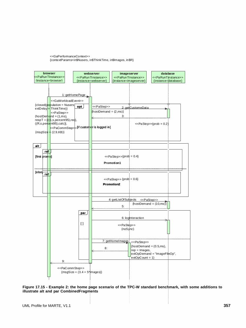
Figure 17.15 - Example 2: the home page scenario of the TPC-W standard benchmark, with some additions to illustrate alt and par CombinedFragments
[f irst promo]
[else]
<<PaStep>>
Promotion2
{prob = 0.6}
ref
alt
[ ]
par
[if customer is logged in]
opt
imageserver <<PaRunTInstance>>
{instance=imageserver}
webserver <<PaRunTInstance>> {instance=webserver}
database <<PaRunTInstance>> {instance=database}
browser <<PaRunTInstance>>
{instance=browser}
<<PaStep>>
Promotion1
{prob = 0.4}
ref
<<GaPerformanceContext>>{contextParams=in$Nusers, in$ThinkTime, in$Images, in$R}
8:
getCustomeData2: <<PaStep>>
{hostDemand = (2,ms)}
getListOfSubjects4: <<PaStep>>{hostDemand = (10,ms)}
<<PaStep>>
logInteraction6:
{noSync}
getHomeImages7: <<PaStep>>{hostDemand = (0.5,ms),rep = Images,extOpDemand = "ImageFileOp",extOpCount = 1}
<<PaCommStep>>
9:
{msgSize = (3.4 + 5*Images)}
3:
5:
<<GaWorkloadEvent>>
<<PaStep>>
<<PaCommStep>>
getHomePage1:
{msgSize = (2.9,KB)}
[f irst promo]
[else]
Promotion2
ref
alt
[ ]
par
<<PaStep>>[if customer is logged in]
{prob = 0.2}
opt
ref
{hostDemand = (1,ms), respT = {((1,s,percent95),req),((R,s,percent95),calc)},
{closed(population = Nusers,extDelay = ThinkTime)}
UML Profile for MARTE, V1.1 357

17.4.3 Example 3: a building surveillance system
17.4.3.1 Overview
This is a soft real-time embedded system with a set of cameras that must be scanned at least once every second (with 95% probability), as described by Xu et al. The scan is free-running, with the next camera being polled as soon as the image-capture of the previous one is complete. The images are polled by an “acquire” thread, placed in a buffer and passed to a “storage” thread, which stores them in a database. Multiple buffers, asynchronous storage, and multithreaded processes ensure concurrency in the handling, to obtain adequate performance.
The profile features that are emphasized in this example are:
• Case parameters attached to the PerformanceContext, giving the number of cameras ($Ncameras), the size of a camera image ($imageSize, in MB), and the number of storage blocks per image ($blocks), with default values.
• Annotation of an activity diagram, with process resources stereotyped on ActivityPartitions (swimlanes).
• Repetition of a complex operation defined by a StructuredActivity. It is stereotyped as a Step with a repetition count and a refinement as the interior activity.
• Use of both a mean and variance in defining a host demand parameter.
• A CommStep stereotype applied to an ActivityEdge.
• A logical resource (the buffer pool) with multiple units, with explicit acquire and release steps.
• Passing a resource from one process to another (passing a buffer to be stored).
• An external Service (a file storage operation) defined by name only in an extOpDemand attribute of the Database operation.
Figure 17.16 and Figure 17.17 show the deployment and activity diagrams for the example. In the deployment diagram the “SchedulableResource” stereotypes are shown only for the Control artifact, but in fact apply to all the artifacts shown (not shown to avoid diagram clutter).
358 UML Profile for MARTE, V1.1

Figure 17.16 - Deployment diagram of the building surveillance system of example 3
Examining the deployment diagram first, the nodes are stereotyped as ExecHost. As the Camera node is only symbolic, and is not represented in the design, it need not be stereotyped. The ProcessingRate attribute of the DataBaseNode is interpreted for performance as a factor, relative to a nominal processor, on which the hostDemand figures are based.
The deployed objects are all artifacts, and it is these artifacts that are referenced by the RunTInstance stereotypes in the activity diagram. The reference to the artifact (rather than to the class or instance) is to resolve the deployment of active objects. The bufferpool artifact stands for a set of buffers at run-time, and the number of buffers $Nbuffers is a significant parameter for performance (remember resMult stands for “multiplicity of resource instances”).
The attachment of the parameter $Nbuffers to the analysis context assists in identifying parameters that may be varied over cases in the analysis. The analysis context should be shared with the behavior diagram(s).
<<GaExe cHos t>>
ControlNode<<GaExe cHost>>
C amera
<<GaExecHos t>>
DataBaseNode
<<R esource>>buf ferpool
{ resM ult = $Nbuffe rs}
acquire : Acquire : CameraControl : Store
<<a rtifact>>BufM gr
: DB
<<art ifact>>DB
<<art ifac t>>S tore
<<artifact>>Control
<<S chedu lab leR esource>>
<<artifac t>>Acquire
<<GaA nalys isContext>> {contextParams=in$Nbu ffe rs = 15}
<<deploy>>
<<deploy>>
<<GaCom m Host>>
B ackend
{capacity = (1000,M b/s )}
<<deploy>>
<<GaCom m Host>>
LA N
{capacity = (100,M b/s )}
<<deploy>><<d eploy>>
<<d eplo y>>
<<manifest>> <<m anifes t>> < <m anifes t> ><<m anifes t>>
UML Profile for MARTE, V1.1 359

Figure 17.17 - Activity diagram for the building surveillance system of example 3
In the activity diagram there are additional global parameters associated with the analysis context. The workload is modeled as a single “user” (think of it as a token) that arrives to initiate a scan, and returns immediately after the scan is done to start the next one. Thus the population is 1 and the external delay is zero. The performance requirement is on the 95th percentile of the time between successive initiations of the scan; thus 95% of scans should take less than 1 second.
The cycleInit Action has a hostDemand. Since it is not shown in a swimlane, its process (SchedulableResource) is given directly on the Step stereotype by the attribute “concurRes” (which determines its deployment and thus its host processor).
<<PaStep>> getOneImage {rep = $Ncameras}
{hostDemand = (1.8,ms)}
<<PaStep>>getBuf
getImage
passImage
{hostDemand = (0.2,ms)}
<<PaStep>>freeBuf
{hostDemand = (2.5,ms),noSync}
<<PaStep>>storeImage
cleanUp
<<PaStep>><<GaAcqStep>>
allocBuffer{hostDemand = (0.5,ms),acqRes = bufferpool,resUnits = 1}
<<PaStep>><<GaRelStep>>
deallocBuffer{hostDemand = (0.5,ms),
relRes = bufferpool}
<<PaStep>>storeDB
{hostDemand ={((blocks*0.9),ms,mean),(blocks*0.2),var)},extOpDemand = writeBlock,extOpCount = blocks}
<<PaRunTInstance>>bufMgr
{resMult = 1,instance = Acquire}
<<PaRunTInstance>>DB
{resMult = DBThreads,instance = DB}
<<PaRunTInstance>>Store
{resMult = storeThreads,instance = Store}
<<PaRunTInstance>>Acquire
{instance = Acquire,resMult = acquireThreads}
cycleInit
<<GaAnalysisContext>>{contexParams={in$Ncameras = 100, in$frameSize = 0.1, in$blocks = 15, in$acquireThreads = 1, in$storeThreads = 2, in$DBThreads = 2},
<<PaCommStep>>{msgSize = ($frameSize,bytes),rep = ($frameSize/1500)}
<<PaResPassStep>>{resource = bufferpool,resUnits = 1}
<<GaWorkloadEvent>>{closed (populat ion = 1, extDelay = 0),
interOccTime = {(1.0,s,percent95,req),
(CycleTime95,s,percent95,calc)}}
<<PaStep>> {hostDemand = (0.2, ms), extDelay = (0, s),
360 UML Profile for MARTE, V1.1

Apart from the scan initialization, the scan is a loop that is described inside a StructuredActivity that is stereotyped as a Step, with a repetition count equal to the number of cameras. Four processes are identified: the component attribute gives the artifact for deployment, and the resMult attribute gives the number of threads. Two comments:
• Since threads are annotated on the PaRunTInstance, two run-time instantiations of the same artifact can have different numbers of threads.
• One artifact may manifest multiple processes.
The StructuredActivity has two ending points, and shows the use of the noSync attribute of the storeImage Step, to enhance concurrency. After the fork node on the left, the main loop ends and this allows the next iteration to begin. The explicit noSync attribute on the storeImage action shows that the main behavior does not wait for this branch to complete, so the right-hand behavior for storing the frame continues in parallel with the next scan. In fact, the concurrency of the storage behavior is only limited by the number of Store threads and the number of buffers. This overlapped storage behavior is illustrated by a Gantt chart, in Figure 17.17. Any number of concurrent storage operations can be continuing while further buffers are filled, up to the point where there are no free buffers to allocate.
Figure 17.18 - An asynchronous pattern of buffer storage operations, indicated by the noSync property (to indicate concurrent continuation of a refinement BehaviorScenario after the return to the outer level of behavior).
The bufferpool logical resource is of importance in this specification, as the system suffers easily from buffer starvation. Notice:
• The number of buffers is declared on the deployment artifact.
• The acquisition and release of the buffers are separate stereotypes on the buffer manager steps that allocate and deallocate them. The single unit of resource is shown explicitly on the allocate (it need not be defined as one is the default), but the deallocate uses the default.
• The explicit passing of the buffer from one process to another is shown by the ResourcePassStep stereotype attached to an ActivityEdge from Acquire to Store. Here the unit is shown (one is again the default). Without an explicit ResourcePassStep, the logical resource is handed on along the flow, including flows that cross from one process to another (as in the return from the Buffer manager). However after a fork in the flow it may be essential to indicate the passing explicitly.
Only one CommStep is annotated here, for the delay to transfer the data over the network. The database communications might also be significant. The annotations give a derived communications latency of (message size)/rate, in the absence of explicit delay and demand attributes in the deployment diagram.
get buffer and fill with first image
get buffer and fill with second image
get buffer and fill with third image
store first image and deallocate buffer
store second image and deallocate buffer
store third image etc...
time
etc.
UML Profile for MARTE, V1.1 361

The use of mean and variance in specifying a random hostDemand, is illustrated for the storeDB action. Notice that the units are not given for the variance (implicitly they are the square of the units for the mean, but they are normally not stated).
An external operation is defined for the storeDB action, defining the storage on disk of one block of image data, with an operation count of $blocks.
17.4.4 Example 4: Communications example, a layer subsystem
Communication is provided by the execution platform of the system, and this may be described in UML by a layering of components and subsystems. The commService stereotype on a message identifies an Operation on an interface of the platform, as conveying the message. This sub clause illustrates the concept with an oversimplified CORBA layer submodel.
Figure 17.19 - Sending of messages by the application, with commService attributes
Figure 17.18 shows a call-reply pair and an asynchronous message. Notice that the reply is stereotyped separately here, so it has its own sub-scenario. It is also possible to aggregate all the latencies and workloads into the request, which provides the correct total workload and delays but does not represent the behavior precisely. Figure 17.19 shows the simplified CORBA system, with a stub component (integrated with the sender), a skeleton component (integrated with the receiver), an ORB component to execute the core functions, and a location server. The last two are separate processes in this assumed system; the deployment will not be shown.
Server Client
<<PaCommStep>> 2: {servDemand = send , servCount = 1}
<<PaCommStep>> 1:
{servDemand = send, servCount = 1}
<<PaCommStep>>
3:
{servDemand = send, servCount = 1}
362 UML Profile for MARTE, V1.1
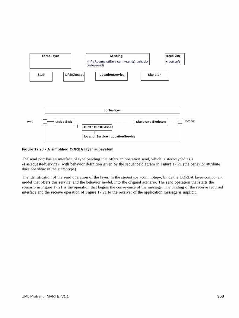
Figure 17.20 - A simplified CORBA layer subsystem
The send port has an interface of type Sending that offers an operation send, which is stereotyped as a «PaRequestedService», with behavior definition given by the sequence diagram in Figure 17.21 (the behavior attribute does not show in the stereotype).
The identification of the send operation of the layer, in the stereotype «commStep», binds the CORBA layer component model that offers this service, and the behavior model, into the original scenario. The send operation that starts the scenario in Figure 17.21 is the operation that begins the conveyance of the message. The binding of the receive required interface and the receive operation of Figure 17.21 to the receiver of the application message is implicit.
locationService : LocationService
skeleton : Skeleton
ORB : ORBClasses
stub : Stub
corba-layer
send receive
Sending
<<PaRequestedService>>+send(){behavior= corba-send}
corba-layer
LocationService SkeletonStub ORBClasses
Receiving
+receive()
UML Profile for MARTE, V1.1 363

Figure 17.21 - Behavior of the operation "send"
17.4.5 Example 5: Services by component subsystems
Operations by components and subsystems may be included in a Step by giving it an attribute servDemand with a parameter servCount. ServDemand is typed on the operation, which itself must be stereotyped as GaRequestedService, and servCount is the average number of invocations. Services may be useful to include platform and environment operations, without modifying the behavior definition provided by the designer.
Figure 17.22 shows a basic behavior that invokes a findRecord operation defined on the class DataManager, three times. The findRecord operation is shown in Figure 17.23 and is annotated with its hostDemand and an external service operation.
<<PaRunTInstance>>locationService
<<PaRunTInstance>>ORB
skeleton receiversender stub
4:
<<PaCommStep>><<PaStep>>
3:
5:
7:
<<PaStep>>
1:
{hostDemand = ((0.01*messageSize),ms)}
<<PaStep>><<PaCommStep>>
6:
{hostDemand = ((0.011*messageSize),ms)}
<<PaStep>>
2:
{hostDemand = (12,ms),prob = 0.3}
SD corbaSend <<GaScenario>> <<GaAnalysisContext>> {contextParams=in$messageSize}
364 UML Profile for MARTE, V1.1

Figure 17.22 - Sequence diagram for an operation findRecord invoked from a Step
Figure 17.23 - The DataManager class with annotated operation findRecord
In both Figure 17.21 and Figure 17.22, the operation findRecord is stereotyped on the DataManager class, not on a run-time instance of DataManager. Because the stereotype extends PaStep, it can also have properties execHost and concurRes which identify the host processor and process, respectively. This is sufficient if there is just one deployment of DataManager. If there is more than one deployed instance of DataManager, there is a problem to identify which instance is invoked and what are the parameters such as hostDemand. A possible solution is to use a different variable name for the servCount in the PaStep stereotypes that make the invocations. Then that variable name can be associated with a deployed instance in a table.
For example if StepA invoked findRecord on dataManager1, its servCount for the operation could be set to the variable $findR1, while StepB invokes the same operation on dataManager2 $findR2 times. Then a table can be set up:
Table 17.1 - Instance Parameters for calls to DataManager findRecord
Instance servCount Variable Value
dataManager1 $findR1 3
dataManager2 $findR2 1.7
<<PaRunTInstance>>
webserver
{poolSize = (webthreads=80),instance = webserver}
<<PaRunTInstance>>
App
browser
<<PaStep>>
appReq2:
{hostDemand = (12.4,ms),servDemand = findRecord,servCount = 3}
4: 3:
<<PaStep>>
<<GaWorkloadEvent>>
htmlReq1:
{open (IntArrTime = exp(17,ms)),
hostDemand = 4.5,ms}
{instance = App}
DataM anager
<< PaReques tedServ ice> >+findRecord(){hostDem and = (7,ms), extOpDem and = readStore, ex tOpC ount = 1500, concurRes = dataManager}
UML Profile for MARTE, V1.1 365

This associates the instances with the Step and a value. The tool would have to determine the deployment of each instance by name, however.
Figure 17.24 - Deployment of the dataManager instance of DataManager
Call Hierarchy
The operation findRecord may be the work of a subsystem rather than a single object, and the subsystem can be annotated to show the invocation hierarchy and to parameterize the calls. The next example shows a call hierarchy and also a number of instances of the same class, with additional parameters. The call hierarchy may be represented schematically in terms of the instances as in Figure 17.25, with a modified data manager DataManagerB.
<<GaExecHost>>
DataMgrhost
{commRcvOvh = (0.14,ms/KB),
commTxOvh = (0.07,ms/KB),
resMult = 3}
<<GaExecHost>>
AppHost
{commRcvOvh = (0.15,ms/KB),
commTxOvh = (0.1,ms/KB),
resMult = 5}
<<GaCommHost>>
LAN
{blockT = (10,us),
capacity = (100,Mb/s)}
<<PaRunTInstance>>
: DataManager
<<artifact>>
dataManager
: Application : WebServer
<<artifact>>
webserver
<<artifact>>
application
<<deploy>><<deploy>> <<deploy>>
<<manifest>> <<manifest>> <<manifest>>
366 UML Profile for MARTE, V1.1
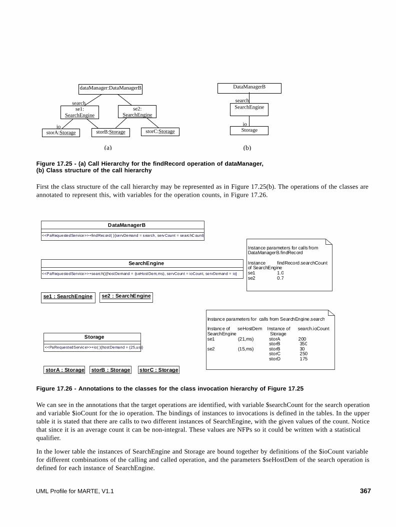
Figure 17.25 - (a) Call Hierarchy for the findRecord operation of dataManager, (b) Class structure of the call hierarchy
First the class structure of the call hierarchy may be represented as in Figure 17.25(b). The operations of the classes are annotated to represent this, with variables for the operation counts, in Figure 17.26.
Figure 17.26 - Annotations to the classes for the class invocation hierarchy of Figure 17.25
We can see in the annotations that the target operations are identified, with variable $searchCount for the search operation and variable $ioCount for the io operation. The bindings of instances to invocations is defined in the tables. In the upper table it is stated that there are calls to two different instances of SearchEngine, with the given values of the count. Notice that since it is an average count it can be non-integral. These values are NFPs so it could be written with a statistical qualifier.
In the lower table the instances of SearchEngine and Storage are bound together by definitions of the $ioCount variable for different combinations of the calling and called operation, and the parameters $seHostDem of the search operation is defined for each instance of SearchEngine.
dataManager:DataManagerB
se1: SearchEngine
se2: SearchEngine
storA:Storage storB:Storage storC:Storage
search
io
DataManagerB
SearchEngine
Storage
search
io
(a) (b)
SearchEngine
<<PaRequestedService>>+search(){hostDemand = (seHostDem,ms), servCount = ioCount, servDemand = io}
DataManagerB
<<PaRequestedService>>+findRecord( ){servDemand = search, servCount = searchC ount}
Storage
<<PaRequestedService>>+io( ){hostDemand = (25,us)}
se1 : SearchEngine se2 : SearchEngine
storC : StoragestorA : Storage storB : Storage
Instance parameters for calls from SearchEngine.search
Instance of seHostDem Instance of search.ioCount SearchEngine Storage se1 (21,ms) storA 200 storB 350se2 (15,ms) storB 30 storC 250 storD 175
Instance parameters for calls from DataManagerB.findRecord
Instance findRecord.searchCountof SearchEnginese1 1.0se2 0.7
UML Profile for MARTE, V1.1 367

17.4.6 Example 6: State machine annotations
We will consider some kinds of behavior described by a state machine. The first kind will be a state machine that governs the generation of requests, called in the profile a “Workload Generator” state machine. The states represent states of the user (or the process that generates the workload) and in each state, there is a reference to a behavior for that state. This behavior represents an action taken on entering the state. The blockingTime attributes represent user-thinking time during that state, before the user enters the request that will take it to a new state.
Figure 17.27 shows a simplified version of the cycle of user states described for the TPC-W benchmark, and references one interaction diagram in each state. The behavior for each state is a single execution and does not itself have repetitive workload attributes. The getHomePage interaction diagram would be the same as the one depicted in Figure 17.15 but its GaWorkloadEvent stereotype would reference the state machine as a WorkloadGenerator.
368 UML Profile for MARTE, V1.1
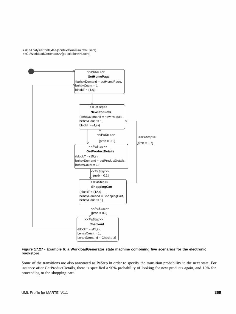
Figure 17.27 - Example 6: a WorkloadGenerator state machine combining five scenarios for the electronic bookstore
Some of the transitions are also annotated as PaStep in order to specify the transition probability to the next state. For instance after GetProductDetails, there is specified a 90% probability of looking for new products again, and 10% for proceeding to the shopping cart.
<<PaStep>>
GetProductDetails
{blockT = (10,s),behavDemand = getProductDetails,behavCount = 1}
<<PaStep>>
GetHomePage
{behavDemand = getHomePage,behavCount = 1,blockT = (4,s)}
<<PaStep>>
ShoppingCart
{blockT = (12,s),behavDemand = ShoppingCart,behavCount = 1}
<<PaStep>>
NewProducts
{behavDemand = newProduct,behavCount = 1,blockT = (4,s)}
<<PaStep>>
Checkout
{blockT = (45,s),behavCount = 1,behavDemand = Checkout}
<<GaAnalysisContext>>{contextParams=in$Nusers}<<GaWorkloadGenerator>>{population=Nusers}
<<PaStep>>
{prob = 0.7}
<<PaStep>>
{prob = 0.9}
<<PaStep>>{prob = 0.3}
<<PaStep>>{prob = 0.1}
UML Profile for MARTE, V1.1 369

A workload generator could more generally be a set of state machines communicating by signals and all generating behavior concurrently.
The analytic performance model will represent the generator as a Markov Chain governing the probabilities of making requests for different behaviors (what is sometimes called the user profile).
The Markov Chain is solved to provide the steady state probabilities of each state, and thus of each behavior in the combined workload.
A second use of a state machine is to define a sequence of operations, like an interaction diagram. This must be a behavior that terminates, and its start point is driven by a WorkloadEvent.
Each state or transition can be a PaStep, and a state can be refined to a subscenario either as a composite state or by an annotation with a behavDemand as above. A composite state with multiple regions is an implicit parallel section, however all the details of composite states (e.g., history) have not been integrated into the profile. This kind of terminating behavior can also be defined with several interacting machines.
A third use of a state machine is similar to the second, but it repeats infinitely, waiting at some well-defined “home state” for input events derived from a WorkloadEvent stream.
370 UML Profile for MARTE, V1.1

Subpart IV - Annexes
This subpart contains the following annexes.
• A - Guidance Example for Use of MARTE
• B - Value Specification Language (VSL)
• C - Clock Handling Facilities
• D - Normative MARTE Model Libraries (MARTE_Library)
• E - Repetitive Structure Modeling (RSM)
• F - Domain Class Descriptions
• G - Bibliography
• H - Mapping SPT on MARTE
UML Profile for MARTE, V1.1 371

372 UML Profile for MARTE, V1.1

Annex AGuidance Example for Use of MARTE
A.1 Open-source Tool Support for MARTE
In the context of different projects - System@tic::UsineLogicielle::OpenDevFactory (http://www.usine-logicielle.org/), RNTL::OpenEmbeDD (http://openembedd.inria.fr/home_html), and CARROLL::Protes/CORTESS(http://www.carroll-research.org/) - the CEA LIST has developed an open-source implementation of the UML profile for MARTE (including a support for the VSL language). This implementation is an eclipse-based project and it is available at this address: www.papyrusuml.org.
A.2 AADL-like Models with MARTE
AADL is an RTES design and analysis language and standard referenced at the SAE (standard number XXX). Version 2 has been voted in XXX. This sub clause presents the correspondence between MARTE 1.0 and AADL 2.0 concepts, with the aim to clarify which subset of MARTE concepts shall be used to explicit AADL concepts. The MARTE profile has been adopted as the UML profile for AADL, so this sub clause presents the MARTE2AADL concepts correspondence.
The sub clause is not a methodology to design AADL applications in UML.
An AADL specification consists of AADL global declarations and AADL declarations. Global declarations essentially describe a hierarchical package structure for the system model.
AADL declarations comprise component types and implementations and port group types.
A component type specifies a functional interface in terms of “features,” flow specifications and properties. These would be considered as communication models in MARTE.
A component implementation describes the internal structure and behavior of that component in terms of subcomponents, connections and flows across them, and behavioral modes.
A system modeled in AADL consists of “application software” components “bound” to “execution platform” components. In MARTE the word “software” is dropped from “application,” since the execution platform can also contain software (middleware, RTOS) as well as hardware parts. AADL “binding” is called “allocation” in MARTE, following the SysML wording, but the concept is the same. It can be hierarchical and compositional.
AADL application ‘software’ components are made of data, threads, and process components. Data are akin to Objects in UML, as they may contain “subprograms,” similar to UML operations. AADL thread components model units of concurrent execution. A scheduler manages the execution of a thread. Threads can be in states such as suspended, ready or running. State transitions occur as a result of dispatch requests […] or if time constraints are exceeded. Dispatch semantics are given by standard dispatch protocols such as periodic, sporadic, and aperiodic threads. Additional dispatch protocols may be defined. This provides various models of computation, including simultaneity of concurrent threads running periodically on the same clock. Different clock domains can be defined; as well as explicit delays on any logical clock. This again is in line with some of MARTE’s requirements. Threads owe behaviorally to UML activity diagrams, which allow distinction between Object (Data) and Control (Event) flows.
UML Profile for MARTE, V1.1 373

AADL execution platform components use processors, memory, busses, and devices. They are connected by “features” such as flows and may be structurally and behaviorally switching modes (in a control-flow fashion). This again is in line with MARTE. Flows can be represented by UML sequence diagrams, and modes by state diagrams.
Operating systems may be represented through properties of the execution platform or, requiring significantly more detail, modeled as software components. These call for various Models of Computation. The ability to model in the RT/E design part the scheduling disciplines considered in the Analysis part is also a goal in MARTE.
An AADL system design contains a set of properties needed to support system generation and/or desired forms of scheduling analysis. This information will be generated from the AADL design model.
To fully address MARTE to AADL mapping, the SysML profile is needed, and shall be imported: the “Block” concept is used to represent the AADL system concept.
A.2.1 MARTE for AADL Summary Table
The following table resumes the mapping defined between AADL and MARTE concepts.
A.2.1.1 AADL Software Components
AADL Concepts MARTE/UML concept AADL definition
Data UML DataType, UML Classifiers, swMutualExclusionResource according the different semantics.
Data component represents data types, static data, data assessors, shared data in source text.
Subprogram UML Operation accessible through subprogram group accesses.
A subprogram component represents sequentially executed source text that is called with parameters.
Subprogram Group UML Operation stored in UML “modelLibrary” element.
A subprogram group represents subprogram libraries accessible through subprogram group features and connections.
Thread MARTE swSchedulableResource stereotype on UML Classifier.
Concurrent schedulable unit of sequential execution through source code.
Thread Group MARTE swSchedulableResource stereotype on abstract UML Classifier.
A thread group represents an organizational component to logically group threads contained in processes.
Process MARTE memoryPartition stereotype on UML Classifier.
Represents a protected address space and contains executable code or data.
374 UML Profile for MARTE, V1.1

A.2.1.2 AADL Hardware Components
A.2.1.3 AADL System
Pre-requisite: to fully address MARTE to AADL mapping, the SysML profile is needed, and shall be imported: the “Block” concept is used to represent the AADL system concept.
A.2.1.4 AADL Features
AADL Concepts MARTE/UML concept AADL definition
Processor hwProcessor stereotype on UML Classifier. Hardware unit responsible for scheduling and executing threads.
Virtual Processor swSchedulingResource and ProcessingResource on UML Classifier
A virtual processor represents a logical resource that is capable of scheduling and executing threads.
Memory hwMemory stereotype on UML Classifier. Abstract representation that is a storage component for data and executable code.
Bus hwBus stereotype on UML Classifier. Hardware unit that enables communication among other execution platform components.
Virtual Bus CommunicationMedia stereotype on UML connection or classifier allocated to the physical HWBus.
A virtual bus component represents logical bus abstraction.
Device hwDevice stereotype on UML Classifier. Represents entities that interface with the external environment of an application system.
AADL Concepts MARTE/UML concept AADL definition
System SysML Block on UML composite structure. Represents a composite software, execution platform, or system components.
AADL Concepts MARTE/UML concept AADL definition
Data Port flowPort typed by a UML Primitive type or Data type.
Represents a composite software, execution platform, or system components.
Event Port ClientServerPort typed by UML signal without data attributes.
MARTE ClientServerPort typed by a UML signal without data attributes.
EventDataPort ClientServerPort typed by UML signal with only ONE data attribute.
AADL Event Data Ports should be represented as MARTE ClientServerPorts typed by a UML signal with only ONE AADL data attribute.
UML Profile for MARTE, V1.1 375

A.2.1.5 AADL Connections and Flows
A.2.1.6 AADL Mode
A.2.1.7 AADL Properties
As MARTE suggests many precise concepts, dedicated to design and analysis, most AADL properties can find their equivalences in MARTE. If not, they will be added through “NFP” and “NFP constraints,” precising the MARTE characteristics. All these properties will be precise in each AADL concepts mapping area.
Contrarily to MARTE, AADL also addresses other aspects, like platform parameterization and code generation aspects. These specific properties have not been considered because of being out of scope of MARTE.
Feature group UML2 port typed by UML interface composed of at least two attributes or operations.
Represents group of component features.
Data access UML2 port typed by UML interface composed of ONE attribute.
Represents modeling of shared access to a common data area or static data.
Subprogram group access
UML2 port typed by UML interface composed of ONE operation.
Represents accesses to subprograms components.
Bus Access UML2 UML interface directly provided by HwBus.
Represents connectivity of execution platform components through buses.
AADL Concepts MARTE/UML concept AADL definition
Connections UML delegation connectors between Ports and Parts on composite diagrams. UML assembly connectors between parts.
A connection declaration binds a port from a component to another one.
Flows specifications See A.2.8. Specifies the detailed description and analysis of an abstract information path throughout a system.
End-To-End Flows See A.2.8. Specifies a flow that starts within one subcomponent and ends within another one.
AADL Concepts MARTE/UML concept AADL definition
Mode See A.2.7. Represents a defined configuration of contained components and connections.
AADL Concepts MARTE/UML concept
AADL property set MARTE stereotypes and associated attributes and user defined Nfp and NFP constraints stereotyped attributes.
AADL Concepts MARTE/UML concept AADL definition
376 UML Profile for MARTE, V1.1

A.2.1.8 AADL Binding
A.2.2 Packages, Components Declaration, and Implementation
A.2.2.1 Packages
AADL packages will be used to organize component modeling, improving model visibility and component reuse. AADL packages will be modelized by the way of UML packages as shown in Figure A.1.
A.2.2.2 Component type and implementation
In AADL, each component is characterized by a component declaration and some component implementation descriptions. Each component type specifies the external behavior of the component, its way of communicating and features that might be provided for other elements. Component implementations allow the definition of subcomponents, mode specific behaviors, or components properties.
Component declarations and implementation could be modelized in different packages named Declaration and Implementation as shown in Figure A.1. A Uml “ComponentRealization” will be used to formalize this implementation relationship (“Gps” component can have two different implementations named “Gps.Basic” and “Gps.Handheld”). Component declaration and implementation could also be extended using a UML Generalization link (“Gps.handled” implementation extends “Gps.Basic” implementation).
Figure A.1 - Component Types and Implementation modeling
AADL Concepts MARTE/UML concept AADL definition
System Binding MARTE Allocate stereotyped UML Dependency, with attribute “nature” set to “SpatialDistribution.”
Binds software components to appropriate execution platform components (i.e., hardware components).
UML Profile for MARTE, V1.1 377

A.2.2.3 Abstract component
The component category abstract represents an abstract component. AADL abstract component category represents a component that can be refined into any concrete component categories.
It will be represented as an abstract UML classifier, refined using “refined” UML abstraction according to AADL constraints (features, access).
A.2.2.4 Prototype
AADL Prototype represents parameterization of component type, component implementation, and feature group type declarations. AADL also provides more specific refinement capabilities as in/out direction, required/provided ports, port kind, and component category.
On the MARTE side, UML will provide “Template” concept specifying how classifiers can be parameterized with Classifier, ValueSpecification, and Feature (Property and Operation) template parameters. TemplateParameters will be typed by TemplateSignatures. A template binding relationship specifies the substitutions of actual parameters for the formal parameters of the template.
Only Classifier Parametrization will be addressed within the MARTE2AADL mapping.
MARTE View AADL View
abstract car end car;
abstract power_train end power_train;
abstract exhaust_system end exhaust_system;
abstract implementation car.generic subcomponents PowerTrain: abstract power_train; ExhaustSystem: abstract exhaust_system; end car.generic;
system carRT extends car end carRT;
system implementation carRT.impl extends car.generic subcomponents PowerTrain : refined to system power_train; ExhaustSystem : refined to system exhaust_system; end carRT.impl;
378 UML Profile for MARTE, V1.1
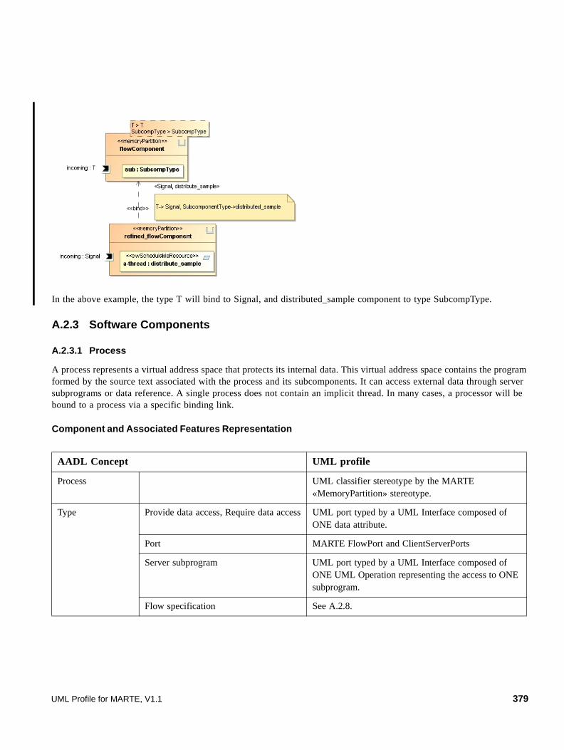
In the above example, the type T will bind to Signal, and distributed_sample component to type SubcompType.
A.2.3 Software Components
A.2.3.1 Process
A process represents a virtual address space that protects its internal data. This virtual address space contains the program formed by the source text associated with the process and its subcomponents. It can access external data through server subprograms or data reference. A single process does not contain an implicit thread. In many cases, a processor will be bound to a process via a specific binding link.
Component and Associated Features Representation
AADL Concept UML profile
Process UML classifier stereotype by the MARTE «MemoryPartition» stereotype.
Type Provide data access, Require data access UML port typed by a UML Interface composed of ONE data attribute.
Port MARTE FlowPort and ClientServerPorts
Server subprogram UML port typed by a UML Interface composed of ONE UML Operation representing the access to ONE subprogram.
Flow specification See A.2.8.
UML Profile for MARTE, V1.1 379

AADL Properties
An AADL process will be represented by a MARTE “partition Memory” stereotyped UML classifier, containing subcomponents as UML parts, communicating with other components or subcomponents through ports. In the following example, the “control_processing.speed_control” process contains four subcomponents.
Figure A.2 - AADL Process example
Implementation Subcomponent (data, thread, thread group)
UML Part of the owner component.
Connections UML Connector and delegation connectors between Ports in composite structure diagram.
Flows See A.2.8.
Properties See A.2.9.
AADL Properties MARTE/Properties
Scheduling_protocol(Ex: EDF, RMS, SporadicServer, SlackServer, ARINC653)
Specified by the “schedPolicy” attribute of Scheduler stereotype.Scheduler and SchedulableResource stereotypes modeled with associated scheduling policy kinds, and scheduling parameters.
load_time and load_deadline • Specific “execTime” and “deadline” attributes from SaStep stereotype, or
• specific added “nfp” attributes types NFP_Duration.
Period and deadline are specified for inheritance Period and deadlines are specified at the thread level on WorkloadEvent and SaSteps.
process implementation control_processing.speed_control
subcomponents
control_input : thread control_in.input_processing;
control_output : thread control_out.output_processing;
control_thread_group : thread group control_threads.control_thread_set;
set_point_data : data set_point_data_type;
end control_processing.speed_control
380 UML Profile for MARTE, V1.1

Figure A.3 - Process and contained subcomponents UML representation
A.2.3.2 Thread
A thread is a concurrent schedulable unit of a sequential execution through source code. A thread models a schedulable unit that transits between various scheduling states. It always executes within the virtual address space of a process, i.e., the binary images making up the virtual address space must be loaded before any thread can execute in that virtual address space.
Component and associated features representation
AADL properties mainly rely on analysis information. As MARTE analysis context and scenarios specification are not in line with AADL approach, this information should be represented on structural component models.
AADL Concept UML Profile
Thread UML class stereotyped «swSchedulableRessource»
Type Provide/require data access UML port typed by a UML Interface owning one or more data attributes and/or operations.
Port MARTE FlowPorts, ClientServerPorts.
Server subprogram UML port typed by a UML Interface composed of ONE operation.
Flow Specification See A.2.8.
Implementation Subcomponents UML Part of the owner component.
Subprogram Call Message call on subprogram provided component.
Connections UML Connector and UML delegation Connectors between Ports in composite structure diagram.
Flows See A.2.8.
Modes See A.2.7.
UML Profile for MARTE, V1.1 381

AADL properties Marte Analysis
Dispatch protocol: enumeration Specified by “occKind” attribute of Schedulable Resource.
Periodic“PeriodicPattern” enumeration literal selected for “ArrivalPattern” attribute.
Sporadic“SporadicPattern” enumeration literal selected for “Pattern” attribute for the WorkloadEvent stereotype.
Aperiodic“AperiodicPattern” enumeration literal selected for “ArrivalPattern” attribute.
Background“OpenPattern” enumeration literal selected for “ArrivalPattern” attribute, with “ArrivalProcess” attribute set to “Background.”
Timed“PeriodicPattern” enumeration literal selected for “ArrivalPattern” attribute with phase attribute set to the period.
Hybrid“IrregularPattern” enumeration literal selected for “ArrivalPattern” attribute with minInterval attribute set to the period.
Period: Time “Period” attribute from the “PeriodicPattern” attribute.
Deadline: Time (inherited from period) At this level, the same as “Period” attribute defined above.
Compute_execution_time
Computed from the different “Steps” concepts supported by the thread; shall be defined in scenarios. Could also be defined as “NFP” attributes by the end-user within the different threads.
Compute_deadline
Computed from the different “SaSteps” supported by the thread; shall be defined in scenarios. Could also be defined as “NFP” attributes by the end-user within the different threads at design time.
Initialize_execution_Time and Initialize_deadline
Specific “execTime” and “deadline” attributes from SaStep stereotype corresponding on mode switch operations defined in the SwPlatform model. Could also be defined as “NFP” attributes by the end-user within the different threads at design time.
Active_execution_time (specific for mode switch) and Active_deadline (specific for mode switch)
Specific “execTime” and “deadline” attributes from SaStep stereotype corresponding on mode switch operations defined in the Swplatform model. Could also be defined as “NFP” attributes by the end-user within the different threads at design time.
382 UML Profile for MARTE, V1.1

The following example illustrates a thread containing a data subcomponent.
Figure A.4 - AADL Thread example
Deactive_execution_time (specific for mode switch) and Deactive_deadline (specific for mode switch)
Specific “execTime” and “deadline” attributes from SaStep stereotype corresponding on mode switch operations defined in the Swplatform model. Could also be defined as “NFP” attributes by the end-user within the different threads at design time.
Recover_execution_time (specific for mode fault handling) and Recover_deadline (specific for mode fault handling)
Specific “execTime” and “deadline” attributes from SaStep stereotype corresponding on mode switch operations defined in the Swplatform model. Could also be defined as “NFP” attributes by the enduser within the different threads at design time.
Finalize_execution_time and Finalize_deadline
Specific “execTime” and “deadline” attributes from SaStep stereotype corresponding on mode switch operations defined in the Swplatform model. Could also be defined as “NFP” attributes by the end-user within the different threads at design time.
Synchronized_component Nfp stereotyped attribute defined by the end-user.
Active_thread_handling_protocol (specific to mode switch): ex abort, complete_one_flush_queue, complete_one_transfer_queue,complete_one_preserve_ queue, complete_all
Nfp stereotyped attribute with associated end-user defined enumeration.
thread control_laws
end control_laws;
data static_data
end static_data;
thread implementation control_laws.control_input
subcomponents
configuration_data : data static_data;
end control_laws.control_input;
UML Profile for MARTE, V1.1 383

Figure A.5 - Thread and data subcomponent UML representation
Two possible representations of the dispatch protocol are given here. The choice between the two depends on the abstraction layer and end-user objectives. Some alternative solutions may also be possible.
A first representation allows mixing application elements and resources by attaching a Dispatch protocol attribute and applying the stereotype “swSchedulableResource.” For instance, a new property (named “dispatch_type”) and stereotyped “rtf” can be defined in the user model view. This dispatch property covers the different AADL dispatch protocols, named periodic, sporadic, aperiodic, timed, hybrid, background.
The following table illustrates the use of this component to create different dispatch protocols.
<<swSchedulableResource>>
my_comp
<<nfp>>-dispatch_type : ArrivalPattern
384 UML Profile for MARTE, V1.1

A second representation is to define a model library for AADL threads. One class can be defined for each dispatch protocol and the classes are used to type parts of a structured classifier. Subprograms can then be represented as actions within an Activity and are allocated to the parts of the structured classifier, which represent the software execution platform.
A periodic thread is periodically dispatched according to the attribute period. The dispatch_Offset is represented by the attribute “phase” defined by the type PeriodicPattern (D.2.3).
An aperiodic task is dispatched when an event occurs or when a subprogram is called. (See type AperiodicPattern in D.2.1.)
A sporadic task is dispatched when an event occurs or when a remote subprogram is called. The time interval between successive dispatch requests can never be less than the associated Period property value (see SporadicPattern in D.2.5).
A timed task is dispatched at event, event data, or remote subprogram arrival, or it is issued a time interval specified by the Period property value since the last dispatch if no event, event data, or remote subprogram call has arrived or is queued since the last dispatch.
A thread whose dispatch protocol is hybrid, combines both aperiodic and periodic dispatch behavior in the same thread. A dispatch request is the result of an event, event data, or remote subprogram call arrival, as well as periodic dispatch requests at a time interval specified by the Period property value.
A background task is dispatched immediately upon completion of its initialization entrypoint execution (see OpenPattern in D.2.17).
<<swSchedulableResource>>periodic_task : my_comp
dispatch_type = "periodic(period=5ms, phase=0,5ms)"
<<swSchedulableResource>>aperiodic_task : my_comp
dispatch_type = "aperiodic()"
<<swSchedulableResource>>sporadic_task : my_comp
dispatch_type = "sporadic(minInterarrival=5ms)"
<<swSchedulableResource>>
timed_task : my_comp
dispatch_type = "periodic(phase=3ms)"
<<swSchedulableResource>>hybride_task : my_comp
dispatch_type = "irregularPattern()"
<<swSchedulableResource>>
background_task : my_comp
dispatch_type = "OpenPattern(arrivalProcess=background)"
UML Profile for MARTE, V1.1 385

This model library is then instanciated:
A.2.3.3 ThreadGroup
A thread group represents an organizational component to logically group threads contained in processes.
Thread group types and implementations specify the features, the required subcomponent accesses, the contained thread connectivity.
A thread group will be represented as an abstract UML classifier stereotyped “swSchedulable Resource” (used to make the distinction with abstract component).
386 UML Profile for MARTE, V1.1
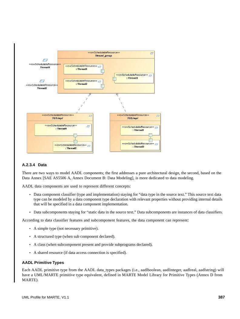
A.2.3.4 Data
There are two ways to model AADL components; the first addresses a pure architectural design, the second, based on the Data Annex [SAE AS5506 A, Annex Document B: Data Modeling], is more dedicated to data modeling.
AADL data components are used to represent different concepts:
• Data component classifier (type and implementation) staying for “data type in the source text.” This source text data type can be modeled by a data component type declaration with relevant properties without providing internal details that will be specified in a data component implementation.
• Data subcomponents staying for “static data in the source text.” Data subcomponents are instances of data classifiers.
According to data classifier features and subcomponent features, the data component can represent:
• A simple type (not necessary primitive).
• A structured type (when sub component declared).
• A class (when subcomponent present and provide subprograms declared).
• A shared resource (if data access connection is specified).
AADL Primitive Types
Each AADL primitive type from the AADL data_types packages (i.e., aadlboolean, aadlinteger, aadlreal, aadlstring) will have a UML/MARTE primitive type equivalent, defined in MARTE Model Library for Primitive Types (Annex D from MARTE).
UML Profile for MARTE, V1.1 387

These primitive types are commonly used in properties specification. To represent them in an architectural view, the data annex based representation style must imperatively be followed.
AADL simple and structured data type
A structured data type will be represented by a UML Data Type with corresponding attributes.
MARTE View AADL View
DATA annex based representationpackage data_types public data integer properties data_model::data_representation => integer; end integer; …end data_types;
388 UML Profile for MARTE, V1.1

A Class
A data type may have associated access functions (called attributes accessors in OO languages) that are represented by providing subprogram access declarations in the features sub clause of the data type declaration.
A Shared Resource
Concurrent access to shared data is coordinated according to the concurrency control protocol specified by the Concurrency_Control_Protocol property value associated with the data component.
A Shared resource on data declaration will be represented by a MARTE concurrency concept.
MARTE View AADL View
Simple type representationdata logs end logs;
Structured type representationdata my_structend my_struct;data implementation my_struct.i subcomponents pA : Integer; pB: float;end my_struct.i;
DATA annex based representationdata my_struct properties data_model::data_repr=>struct; data_model::enumeration=>("pA","pB"); data_model::base_types=>(classifier integer, classifier float); end my_struct;
data logs end logs;
UML Profile for MARTE, V1.1 389

This mapping necessitates a pre-requisite on the AADL side: An AADL property project with MARTE concurrency_protocols (PIP, PCP, No, etc.) shall exist.
A.2.3.5 Subprograms and subprogram calls
Subprogram
A subprogram represents a sequentially executable source text, a callable component, with or without parameters, that operates on data or provides server functions to components that call it.
To stay consistent the MARTE models of subprogram, subprogram calls, and subprogram access, subprograms should be represented as a UML operation, element of a UML Interface, allowing subprogram access representations.
Access to subprogram components are detailed in the subprogram access sub clause.
MARTE View AADL View
process Pend P;
Process implementation P.iSubcomponents T1 : thread my_thread; T2 : thread my_thread; D : data my_data { Concurrency_Control_Protocol => Priority_Ceiling_Protocol; };Connections Data access D -> T1.d; Data access D -> T2.d;End P.i;
MARTE View AADL View
subprogram compute_pressure features raw_data : in parameter; filtered_data : out parameter;end compute_pressure;
390 UML Profile for MARTE, V1.1

Subprogram calls
Subprogram calls should be represented by UML sequence diagrams, illustrating how the calling component requires subprogram access.
Figure A.6 - SubProgram call in UML/MARTE
A.2.3.6 SubprogramGroup
Subprogram groups represent subprogram libraries accessible to other components through subprogram group access features and subprogram group access connections. These libraries will be stored in UML “modelLibrary” stereotyped packages.
A.2.4 Execution Platform Components
Execution platform component UML profile is illustrated in Figure A.9.
A.2.4.1 Processor
A processor is an abstraction of hardware and associated software that is responsible for scheduling and executing threads. Processors can execute threads that are declared in application software system, or threads that reside in components accessible from those processors.
UML Profile for MARTE, V1.1 391

Component and associated features representation
AADL Properties
A.2.4.2 Virtual Processor
A virtual processor represents a logical resource that is capable of scheduling and executing threads and other virtual processors bound to them. It will be represented as a MARTE “swSchedulingResource” AND “ProcessingResource” stereotyped UML Classifier.
A.2.4.3 Bus
A bus represents hardware and associated communication protocols that enable interactions among other execution.
AADL Concept UML Profile
Processor «hwProcessor» stereotyped UML Class
Port MARTE Flow Port and ClientServerPorts
Requires bus access UML Dependency between the Processor and the bus provided Interface.
Flow specifications See A.2.8.
Implementation Subcomponents (Memory) UML Part of Processor
Subprogram Calls None.
Connections None.
Flows See A.2.8.
AADL properties Marte Analysis
Thread_limit AssociationEnd cardinality between “Scheduler” and “swSchedulingResources” concepts modelized in the sw Platform.
Assign_time: Time Nfp stereotyped attribute defined by the end-user.
Assign_byte_Time: Time Nfp stereotyped attribute defined by the end-user.
Assign_fixed_Time: Time Nfp stereotyped attribute defined by the end-user.
Clock_Jitter Nfp stereotyped attribute defined by the end-user.
Clock_period Nfp stereotyped attribute defined by the end-user.
Clock_Period_Range “Op_frequencies” attribute from HwProcessor stereotype.
392 UML Profile for MARTE, V1.1
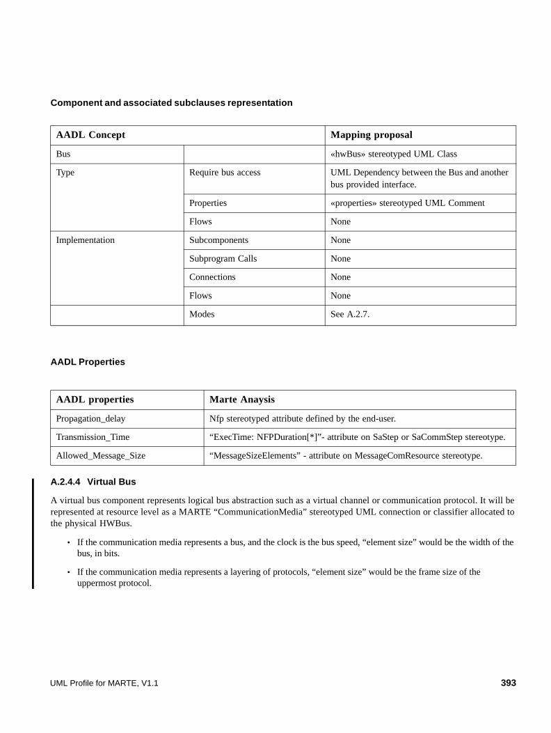
Component and associated subclauses representation
AADL Properties
A.2.4.4 Virtual Bus
A virtual bus component represents logical bus abstraction such as a virtual channel or communication protocol. It will be represented at resource level as a MARTE “CommunicationMedia” stereotyped UML connection or classifier allocated to the physical HWBus.
• If the communication media represents a bus, and the clock is the bus speed, “element size” would be the width of the bus, in bits.
• If the communication media represents a layering of protocols, “element size” would be the frame size of the uppermost protocol.
AADL Concept Mapping proposal
Bus «hwBus» stereotyped UML Class
Type Require bus access UML Dependency between the Bus and another bus provided interface.
Properties «properties» stereotyped UML Comment
Flows None
Implementation Subcomponents None
Subprogram Calls None
Connections None
Flows None
Modes See A.2.7.
AADL properties Marte Anaysis
Propagation_delay Nfp stereotyped attribute defined by the end-user.
Transmission_Time “ExecTime: NFPDuration[*]”- attribute on SaStep or SaCommStep stereotype.
Allowed_Message_Size “MessageSizeElements” - attribute on MessageComResource stereotype.
UML Profile for MARTE, V1.1 393

A.2.4.5 Memory
Memory abstractions represent storage components for data and executable code. Memory components include randomly accessible physical storage (e.g., RAM, ROM) or complex permanent storage such as disks or reflective memory.
Component and associated feature representation
AADL Concept Mapping proposal
Memory «hwMemory» stereotyped UML Class
Type Requires bus access UML Dependency between a UML Class stereotyped «hwMemory» and the bus access provided the needed interface.
Flows specifications None
Implementation Subcomponents UML Part of a UML Class stereotyped «hwMemory».
Subprogram Calls None
Connections None
Flows None
Modes A.2.7.
394 UML Profile for MARTE, V1.1

A.2.4.6 Device
Device abstractions represent entities that interface with the external environment of an application system. Those devices often have complex behaviors. They may have internal processors, memory, and software that are executed on an external processor. Alternatively, they may require driver softwares that are executed on an external processor. A device external driver software may be considered as a part of a processor’s execution overhead, or it may be treated as an explicitly declared thread with its own execution properties.
Component and associated features representation
AADL properties MARTE SW/HW Platform MARTE Anaysis
MemoryProtocol (R,W, RW) Model elements stereotyped “MemoryBroker” allocated on a model element stereotyped “HwMemory.”
Property AccessPolicy of stereotype «MemoryBroker».
Read_Time:Time[] Property ExecTime: NFPDuration[*] of stereotypes «SaStep» or «SaComStep».
Write_Time:Time[] Property ExecTime: NFPDuration[*] of stereotypes «SaStep» or «SaComStep».
AADL Concept UML Profile
Device «hwDevice» stereotyped UML Class
Type Server subprogram «server_subprogram» stereotyped UML Dependency between server components and the called subprogram (UML Operation).
Port MARTE Flow Port and ClientServerPort
Require bus access UML Dependency between the device and the bus provided interface.
Flow Specifications See A.2.8.
Implementation Subcomponents None
Subprogram Calls None
Connections None
Flows See A.2.8.
Modes See A.2.7.
UML Profile for MARTE, V1.1 395

Figure A.7 - Execution platform components UML representation
A.2.5 System
A.2.5.1 System Composition
The system abstraction represents a composite of software, execution platform, or system components. System abstractions can be organized into a hierarchy that can represent complex systems of systems as well as the integrated software and hardware of a dedicated application system.
Component and associated features representation
AADL Concept Mapping proposal
System SysML block concept
Port MARTE Flow Ports
Requires/Provides bus access Dependency/realization link between System Provided/required access Interface
Require/Provides data access Dependency/realization link between System Provided/required access Interface
Flows specifications See Clause 10.
Implementation Subcomponents (data, process, processor, memory, bus, device, system)
UML Part of System
Subprogram calls None
Connections UML Connectors between Ports of the UML Class and Ports of the contained UML Parts.
Flows See A.2.8.
Modes See A.2.7.
396 UML Profile for MARTE, V1.1

A.2.5.2 Binding
For a complete system specification (one that can be instantiated), software components must be bound to appropriate execution platform components. For example, threads must be bound to processing elements and processes must be bound to memory. Similarly, inter processor connections must be bound to buses, and subprogram calls must be bound to their server subprogram. These bindings are defined through property association.
Component and associated features representation
In the following example, the “a_client_process” component is bound to the “a_client_processor” component. Both components are bound by an “allocation” stereotyped MARTE NFPConstraint.
Figure A.8 - System binding representation
AADL Concept Mapping proposal
Binding MARTE Allocate stereotype and NFPConstraint with attribute “nature” set to “SpatialDistribution.”
UML Profile for MARTE, V1.1 397

A.2.6 Features and Shared Access
A.2.6.1 Port and Port connections
A port represents a communication interface for the directional exchange of data, events, or both (event data) between components. Connections are linkages representing the communication of data between components through ports of different threads or between threads and processor or device component. Component and associated features representation.
AADL Data port
• Interfaces for typed state data transmission among components without queuing.
• Connections between data ports are either immediate or delayed.
AADL Concept Mapping proposal
Port MARTE Flow and ClientServer Port.
Port direction (in, out, in/out) In, out, in/out port (event data, data, event)
“direction” attribute on MARTE Flow and ClientServer Port.
Port type Event port MARTE ClientServerPort typed by a UML signal without data attributes.
Data port AADL Data Ports will be represented as MARTE Flow Ports typed by a UML Primitive type or Data Type.
Event/Data Port AADL Event Data Ports will be represented as MARTE ClientServerPorts typed by a UML signal with only ONE AADL data attribute.
Connections Immediate Connections UML Connectors between MARTE ports
Delayed Connections “NfpConstraints” linked to UML Connector between Ports.
398 UML Profile for MARTE, V1.1

AADL Event port
• Interfaces for the communication of events raised by subprograms, threads, processors, and devices (examples: trigger for the dispatch of aperiodic thread, initiator of mode switch, alarm communications).
• Events may be queued. Event such alarms may be queued by the recipient, and the recipient may process the queue content.
MARTE View AADL View
process control features speed: in data port raw_speed; thorttle_command: out data port Command_data;end control;
MARTE View AADL View
data raw_set_speed;end raw_set_speed;
process controlfeatures set_speed: in event data port raw_set_speed; set_speed2: in data port raw_set_speed;end control;
UML Profile for MARTE, V1.1 399
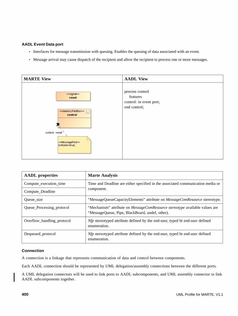
AADL Event Data port
• Interfaces for message transmission with queuing. Enables the queuing of data associated with an event.
• Message arrival may cause dispatch of the recipient and allow the recipient to process one or more messages.
Connection
A connection is a linkage that represents communication of data and control between components.
Each AADL connection should be represented by UML delegation/assembly connections between the different ports.
A UML delegation connectors will be used to link ports to AADL subcomponents, and UML assembly connector to link AADL subcomponents together.
MARTE View AADL View
process control features control: in event port;end control;
AADL properties Marte Analysis
Compute_execution_time Time and Deadline are either specified in the associated communication media or component.
Compute_Deadline
Queue_size “MessageQueueCapacityElements” attribute on MessageComResource stereotype.
Queue_Processing_protocol “Mechanism” attribute on MessageComResource stereotype available values are “MessageQueue, Pipe, BlackBoard, undef, other).
Overflow_handling_protocol Nfp stereotyped attribute defined by the end-user, typed bt end-user defined enumeration.
Dequeued_protocol Nfp stereotyped attribute defined by the end-user, typed bt end-user defined enumeration.
400 UML Profile for MARTE, V1.1

A.2.6.2 Subprogram, data, and bus access
Components such as buses or data might be accessed by the system through an explicit declaration access in component types. Provides indicates that the component provides access to a data or bus component within it. Requires indicates that a component requires access to a data or bus component that is external to it.
Data access
Data access represents modeling of shared access to a common data area or static data.
Data Access connections designate access to shared data components by concurrently executing threads or by subcomponents executing within a thread. Bus access represents communication between processors, memory, and devices by accessing a shared bus.
AADL Data access will be represented by:
• UML 2 ports typed by a UML interface.
• UML Interface composed of a UML attribute representing the access to ONE DATA.
• UML delegation/assembly connection represents AADL data access.
UML Profile for MARTE, V1.1 401
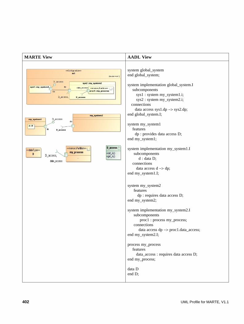
MARTE View AADL View
system global_systemend global_system;
system implementation global_system.I subcomponents sys1 : system my_system1.i; sys2 : system my_system2.i; connections data access sys1.dp −> sys2.dp;end global_system.I;
system my_system1 features dp : provides data access D;end my_system1;
system implementation my_system1.I subcomponents d : data D; connections data access d −> dp;end my_system1.I;
system my_system2 features dp : requires data access D;end my_system2;
system implementation my_system2.I subcomponents proc1 : process my_process; connections data access dp −> proc1.data_access;end my_system2.I;
process my_process features data_access : requires data access D;end my_process;
data Dend D;
402 UML Profile for MARTE, V1.1

Bus access
Bus access represents connectivity of execution platform components through buses whose access they share.
AADL Bus access should be represented by:
• MARTE HwBus provides bus access services through a bus_access interface (without passing through ports).
• UML delegation/assembly connection represents AADL bus access connections.
Subprogram access
Subprogram access represents access to subprogram component in enclosing thread group, process, or system. Execution by calling thread.
AADL Subprogram access will be represented by:
• UML 2 ports typed by a UML interface.
• UML Interface composed of a UML operation representing the access to ONE subprogram.
• UML delegation/assembly connection represents AADL subprogram access.
UML Profile for MARTE, V1.1 403

A.2.6.3 Feature Group
Feature group represents groups of component features, features group can contain feature group, and can be used anywhere features can be used. Inside a component, each feature can be connected individually, outside a component a feature group can be connected as a single unit.
In MARTE, feature groups will be represented as a UML interface composed by at least two attributes (representing more than one data access) or two subprogram access (representing more than one subprogram access).
FeatureGroup composition will be represented by data or operation additions to the interface representing the FeatureGroup, or interface refinement, and FeatureGroup decomposition inside the components by smaller interface (interface subtypes) specifications. By default, the interface is provided. Inside the components, i.e. in threads or processes constituting the system, internal ports will be typed by interfaces representing the FeatureGroup subtypes, providing FeatureGroup subtypes or unitary data/subprogram access.
In MARTE, the FeatureGroup semantical perimenter will be restricted to data and subprogram accesses, providing a homogeneous representation for designers, with data access and subprogram access.
UML delegation/assembly connection represents AADL subprogram access connections and UML provided/required interface concept the AADL provides/requires data access.
MARTE View AADL View
System implementation global_system.I subcomponents sys1 : system my_system1.i; sys2 : system my_system2.i; connections subprogram access sys1.sp −> sys2.sp;end global_system.I;
system my_system2 features sp : requires subprogram access sub_p1;end my_system2;
subprogram sub_p1end sub_p1;
system my_system1 features sp : provides subprogram access sub_p1;end my_system1;
system global_systemend global_system;
404 UML Profile for MARTE, V1.1
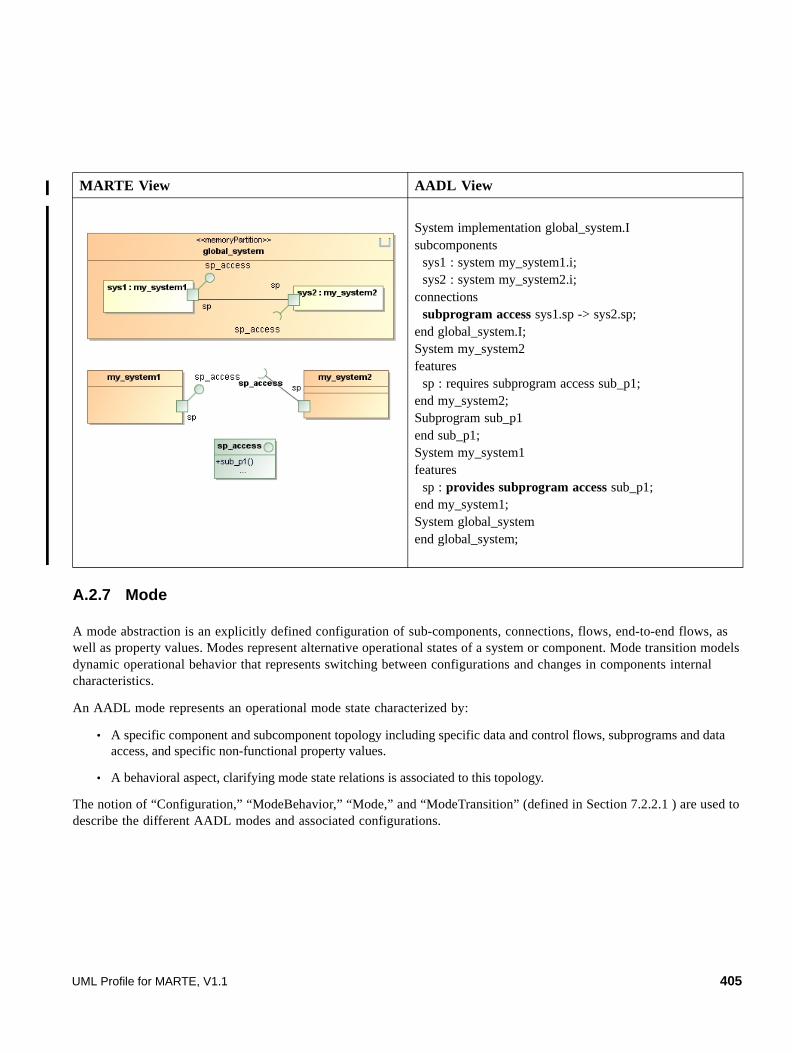
A.2.7 Mode
A mode abstraction is an explicitly defined configuration of sub-components, connections, flows, end-to-end flows, as well as property values. Modes represent alternative operational states of a system or component. Mode transition models dynamic operational behavior that represents switching between configurations and changes in components internal characteristics.
An AADL mode represents an operational mode state characterized by:
• A specific component and subcomponent topology including specific data and control flows, subprograms and data access, and specific non-functional property values.
• A behavioral aspect, clarifying mode state relations is associated to this topology.
The notion of “Configuration,” “ModeBehavior,” “Mode,” and “ModeTransition” (defined in Section 7.2.2.1 ) are used to describe the different AADL modes and associated configurations.
MARTE View AADL View
System implementation global_system.Isubcomponents sys1 : system my_system1.i; sys2 : system my_system2.i;connections subprogram access sys1.sp -> sys2.sp;end global_system.I;System my_system2features sp : requires subprogram access sub_p1;end my_system2;Subprogram sub_p1end sub_p1;System my_system1features sp : provides subprogram access sub_p1;end my_system1; System global_systemend global_system;
UML Profile for MARTE, V1.1 405

A composite structure view presents a global topology view, in a mode independent way as illustrated in the figure below.
Configurations (specific composite structures) will be used to specify component mode specific typology (subcomponents and connections), flows, and property values as illustrated in the figure above.
Mode and associated features representation AADL Concept UML Profile
Mode configuration
Mode specific component topology (subcomponents and connections, flows, and property values) will be represented by a UML Composite structure specialized by the “Configuration” stereotype. The “Mode” attribute will make reference to a specific mode state, declared in a ModeBehavio r defined in the behavioral part of the enclosing component.
Modes and Modes transitions
Modes and Mode transitions will be defined in UML StateMachine diagram, which will be stereotyped “ModeBehavior”. Each mode is represented by an UML State stereotyped “Mode”. UML transitions, describing how modes are linked together, will be represented by UML Transition stereotyped “ModeTransition”. To specify from which port the event triggered the transition arrived, an UML Constraint wil l be attached to the transition.
406 UML Profile for MARTE, V1.1
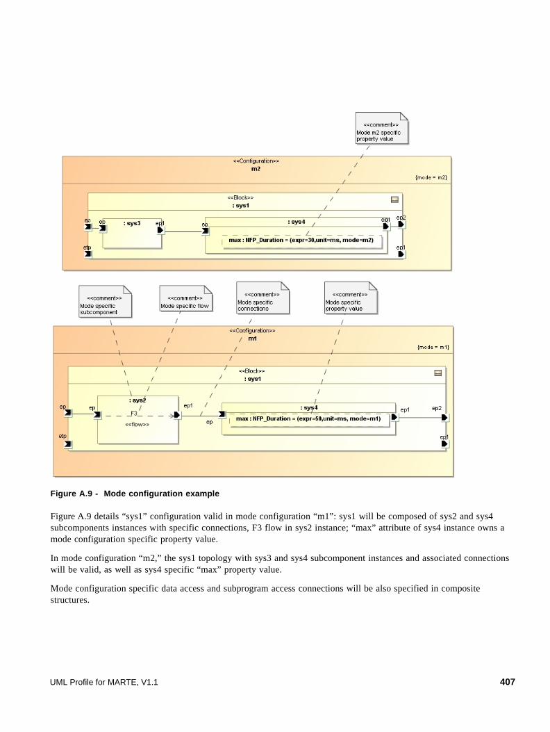
Figure A.9 - Mode configuration example
Figure A.9 details “sys1” configuration valid in mode configuration “m1”: sys1 will be composed of sys2 and sys4 subcomponents instances with specific connections, F3 flow in sys2 instance; “max” attribute of sys4 instance owns a mode configuration specific property value.
In mode configuration “m2,” the sys1 topology with sys3 and sys4 subcomponent instances and associated connections will be valid, as well as sys4 specific “max” property value.
Mode configuration specific data access and subprogram access connections will be also specified in composite structures.
UML Profile for MARTE, V1.1 407

Figure A.10 - Data access mode specific example
Mode configuration dependant data access “D_access” is illustrated in Figure A.10. The connections between sys1, sys2 and proc1 instances are specific to mode configuration “m1.”
Mode and Mode transition will be declared and represented in UML StateMachines stereotyped “ModeBehavior.” AADL modes are declared as UML States stereotyped “Mode,” and state switching by UML Transitions stereotyped “ModeTransition” as illustrated in Figure A.10. The event triggering the transition corresponds to the UML Signal declared in the input event port specification. An additional guard attached to the “ModeTransition,” will precise the port origin of the event triggering the transition.
Figure A.11 - Mode and Mode Transition example
End-to-end flows are also mode specific, activity diagrams and sequence diagrams will be stereotyped “Configuration” precising in which mode the end-to-end latency values are obtained.
state machine sys1 sys1[ ]
<<Mode>>m2
<<Mode>>m1
initia l_mode
guard: from etp
<<ModeTransition>>
et2
<<ModeTransit ion>>
, et
408 UML Profile for MARTE, V1.1
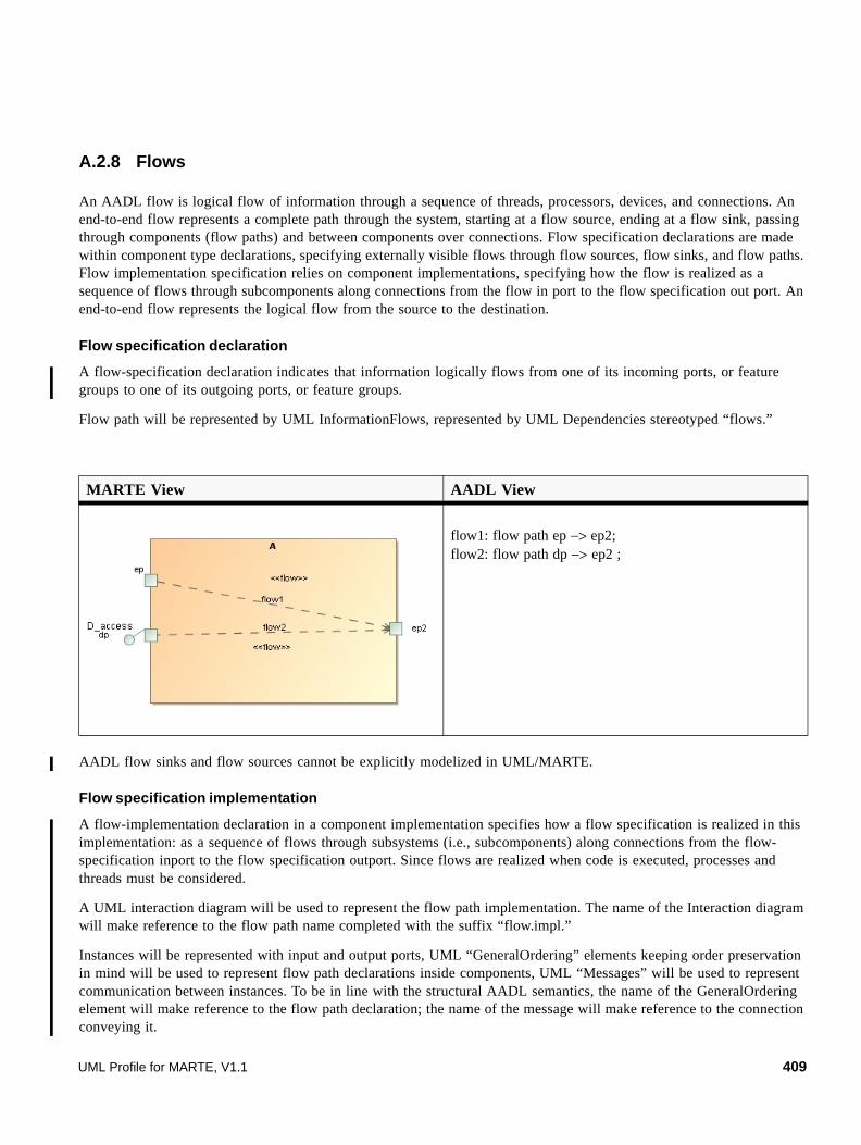
A.2.8 Flows
An AADL flow is logical flow of information through a sequence of threads, processors, devices, and connections. An end-to-end flow represents a complete path through the system, starting at a flow source, ending at a flow sink, passing through components (flow paths) and between components over connections. Flow specification declarations are made within component type declarations, specifying externally visible flows through flow sources, flow sinks, and flow paths. Flow implementation specification relies on component implementations, specifying how the flow is realized as a sequence of flows through subcomponents along connections from the flow in port to the flow specification out port. An end-to-end flow represents the logical flow from the source to the destination.
Flow specification declaration
A flow-specification declaration indicates that information logically flows from one of its incoming ports, or feature groups to one of its outgoing ports, or feature groups.
Flow path will be represented by UML InformationFlows, represented by UML Dependencies stereotyped “flows.”
AADL flow sinks and flow sources cannot be explicitly modelized in UML/MARTE.
Flow specification implementation
A flow-implementation declaration in a component implementation specifies how a flow specification is realized in this implementation: as a sequence of flows through subsystems (i.e., subcomponents) along connections from the flow-specification inport to the flow specification outport. Since flows are realized when code is executed, processes and threads must be considered.
A UML interaction diagram will be used to represent the flow path implementation. The name of the Interaction diagram will make reference to the flow path name completed with the suffix “flow.impl.”
Instances will be represented with input and output ports, UML “GeneralOrdering” elements keeping order preservation in mind will be used to represent flow path declarations inside components, UML “Messages” will be used to represent communication between instances. To be in line with the structural AADL semantics, the name of the GeneralOrdering element will make reference to the flow path declaration; the name of the message will make reference to the connection conveying it.
MARTE View AADL View
flow1: flow path ep −> ep2;flow2: flow path dp −> ep2 ;
UML Profile for MARTE, V1.1 409

AADL flow sinks and flow sources cannot be explicitly modelized in UML/MARTE.
End to end flows
An end-to-end flow represents a logical flow of data and control from a source to a destination through a sequence of threads that process and possibly transform the data. In a complete AADL specification, the source and destination can be threads, data components, devices, and processors. In an incomplete AADL specification, the source and destination are the leaf nodes in the component hierarchy, which may be thread groups, processes, or systems.
Two ways to represent AADL end-to-end flows are possible: The first one as sequence diagrams and the second one as activity graphs. Both diagrams are stereotyped “SaEndToEndFlow.”
Using Interactions diagrams, Flow Path will be represented as UML Messages between components ports, and connections by unnamed Message with connection property set to the connection element.
AADL Expected_Latency and Actual_latency property will be represented respectively by MARTE “EndToEndD” and “EndToEndT” stereotype attribute.
MARTE View AADL View
Process implementation A.impl ….….FlowsFlow1.impl: flow path dp->C2->B.F3->C3->C.F4->C4->ep……
410 UML Profile for MARTE, V1.1

The use of activity diagrams for end-to-end flows representation makes explicit the different objects transmitted between the various actions (allocated one of the threads instances). These object properties intrinsically take into account timing aspects like queueing policies and dequeue protocols, impacting the final end-to-end latency.
In UML, an object node (a special activity node) can contain 0 or many tokens. The number of tokens in an object node can be bound by setting its property upperBound. The order in which the tokens present in the object node are offered to its outgoing edges can be imposed (property ordering). FIFO (First-In First-Out) is a predefined ordering value. So, object nodes can be used to represent both event and event-data AADL communication links. The token flow represents the communication itself. The standard rule is that only a single token can be chosen at a time. This is fully compatible with the AADL dequeue protocol OneItem. The UML representation of the AADL dequeue protocol AllItems is also possible. This needs the advanced activity concept of edge weight, which allows any number of tokens to pass along the edge, in groups at one time. The attribute “weight” specifies the minimum number of tokens that must traverse the edge at the same time. Setting this attribute to the unlimited weight (denoted '*') means that all the tokens at the source are offered to the target.
To model data ports, UML provides “datastore” object nodes. In these nodes, tokens are never consumed thus allowing multiple readings of the same token. Using a data store node with an upper bound equal to one is a good way to represent AADL data port communications.
MARTE View AADL View
ETE1: end to end flow B.F3−>C3−>C.F4;
UML Profile for MARTE, V1.1 411
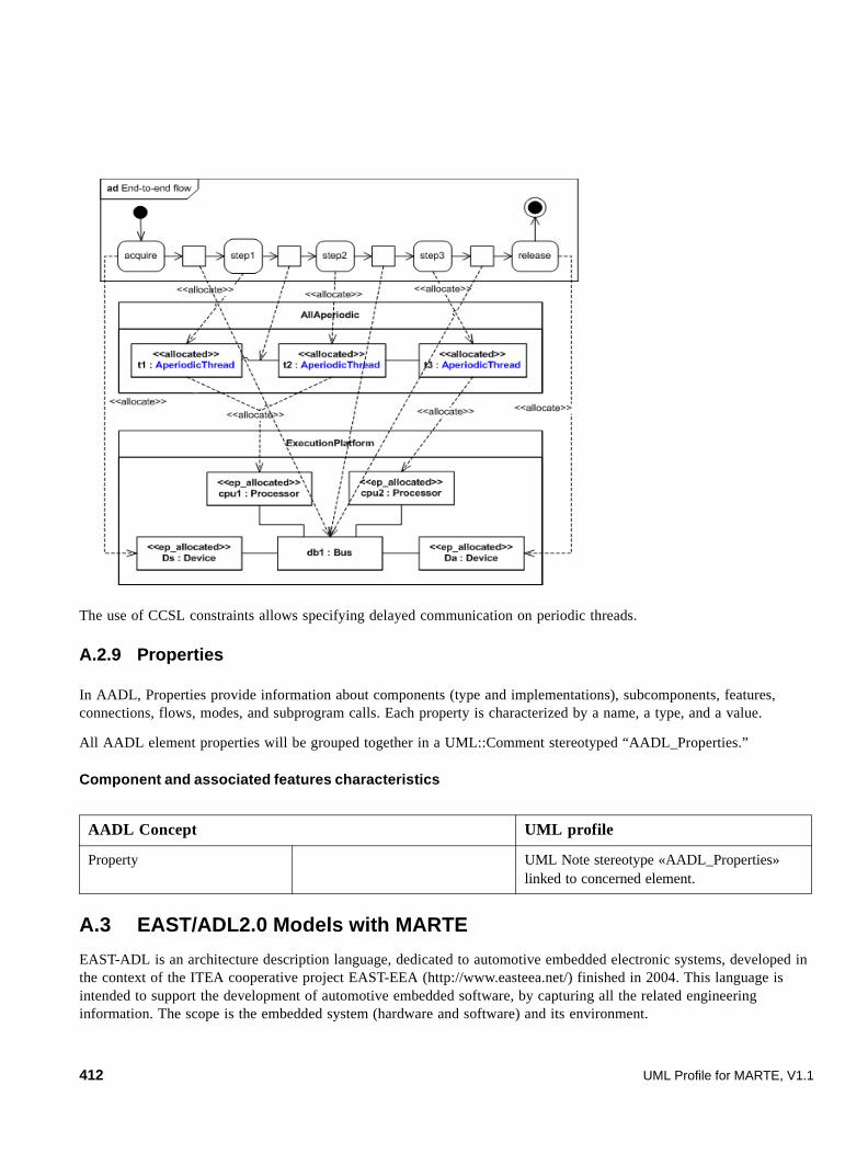
The use of CCSL constraints allows specifying delayed communication on periodic threads.
A.2.9 Properties
In AADL, Properties provide information about components (type and implementations), subcomponents, features, connections, flows, modes, and subprogram calls. Each property is characterized by a name, a type, and a value.
All AADL element properties will be grouped together in a UML::Comment stereotyped “AADL_Properties.”
Component and associated features characteristics
A.3 EAST/ADL2.0 Models with MARTE
EAST-ADL is an architecture description language, dedicated to automotive embedded electronic systems, developed in the context of the ITEA cooperative project EAST-EEA (http://www.easteea.net/) finished in 2004. This language is intended to support the development of automotive embedded software, by capturing all the related engineering information. The scope is the embedded system (hardware and software) and its environment.
AADL Concept UML profile
Property UML Note stereotype «AADL_Properties» linked to concerned element.
412 UML Profile for MARTE, V1.1
The ATESST project (www.atesst.org) is aimed at refining the EAST-ADL language in the context of dependability concerns, aligning with OMG standards and the new automotive domain standardization AUTOSAR (http://www.autosar.org/).
To cover dependable systems, requirement constructs will be enriched to satisfy the needs of different integrity levels and the modeling entities will be refined to support necessary analysis methods, and an engineering process for safety. Transversal to these concepts, with the same consideration for dependability, the variability constructs of EAST-ADL will be improved to support vehicle product lines, the major productivity driver in automotive industry.
The EAST ADL2 abstraction layers are used to allow reasoning of the features on several levels of abstraction. Note, however, that the abstraction levels are only conceptual; the modeling elements are organized according to the artifacts that may span more than one of these layers.
Entities on different abstraction levels are related with a Realization association, where applicable, to allow traceability. Traceability can also be deduced from the requirements structure.
The EAST ADL2 abstraction layers with their corresponding artifacts are:
• Vehicle layer, with the Vehicle Feature Model describing user visible features such as anti-lock braking or windscreen wipers.
• Analysis level with Functional Analysis Architecture capturing the behavior and algorithms of the Vehicle Feature Model functions. There is an n-to-m mapping between Vehicle Feature Model entities and Functional Analysis Architecture entities, i.e., one or several functions may realize one or several features.
• Design level with Functional Design Architecture, representing a decomposition of functionality in the Functional Analysis Architecture. The decomposition has the purpose of making it possible to meet constraints regarding allocation, efficiency, re-use, supplier concerns, etc. Again, there is an n-to-m mapping between entities on Functional Design Architecture and Functional Analysis Architecture. Non-transparent infrastructure functionality of the BasicSWArchitecture, such as mode changes and error handling are also represented on a Design Level.
• Implementation level with the ImplementationArchitecture represented by HardwareArchitecture, BasicSWArchitecture, and ApplicationSWArchitecture based on AUTOSAR concepts.
• Operational level, this describes the binary entities and their related tools.
• The Hardware Architecture and Environment Model span several abstraction levels. The Hardware Architecture contains models Electronic Control Units, ECUs, communication links, sensors and actuators and their connections. The Environment model contains Environment functions that are encapsulations of plant models (i.e., models of the behavior of the vehicle and its non-electronic systems). The environment model is only conceptual and is not an ADL entity.
This part is non-normative. The intent is to describe how MARTE may be used for authoring EAST-ADL2-like models. This annex only focuses on aspects related to functional modeling and end-to-end flows. In the next versions of MARTE, it will be enhanced in order to provide a more complete mapping of EAST-ADL2 concepts.
UML Profile for MARTE, V1.1 413

A.3.1 MARTE for EAST-ADL2 Functional Modeling Summary Table
Table A.1. Comparison table of EAST-ADL2 and MARTE concepts
EAST-ADL2Concept
DescriptionUML
ConceptMARTE Stereotype
ADLClientPort The ADLClientPort denotes a port for clients in a client-server interaction.
Port ClientServerPort with kind set to required.
ADLClientServer Interface
The ADLClientServerInterface is used to specify the operations in ADLClientServerPorts.
Interface ClientServerSpecification
ADLClientServer Port
ADLClientServerPort is an abstract port for client-server interaction, which is subtyped (see ADLClientPort and ADLServerPort) to allow for different notations in an ATESST tool.
Port ClientServerPort
ADLConnector Prototype
The ADLConnectorPrototype connects a pair of flowports or a client and server port.
Connector None: uses the plain UML2 Connector.
ADLFlowPort The ADLFlowPort is an abstract port for data-flow interaction, which is subtyped (see ADLInFlowPort, ADLOutFlowPort and ADLInOutFlowPort) to allow for different notations in an ATESST tool.
Port See concrete mappings for ADLInFlowPort, ADLOutFlowPort and ADLInOutFlowPort.
ADLFunction Prototype
Appear as parts of ADLFunctionTypes and are typed by an ADLFunctionType. This allows for a reference to the occurrence of an ADLFunctionType when it acts as a part.
Part None: uses the plain UML2 part concept. An ADLFunctionPrototype will be represented as a property typed by an ADLFunctionType.
ADLFunctionType ADLFunctionType is the functionality provided by a car on the analysis level.
Class None: The stereotype ADLFunctionType is introduced.
ADLInFlowPort The ADLInFlowPort represents a port that requires data input. The data is specified by the associated datatype, and may be discrete or continuous in value. The value may be continuous or discrete in time, depending on the properties of the sending ADLFunction. ADLInFlowPort owns an attribute isTriggered that indicates whether the owning ADLFunction is triggered by the ADLInFlowPort.
Port FlowPort with direction=in.The attribute isTriggered of and ADLInFlowPort is mapped to the attribute isBehavior of UML ports.FlowPort defines also an RtFeature referring to an RtSpecification to denote the possible inter arrival time between two occurrences of the data conveyed via the port.
414 UML Profile for MARTE, V1.1

As illustrated in Table A.1, most of the concepts defined in EAST-ADL2 for functional modeling have an almost direct counterpart in either UML or MARTE. Therefore, very few extensions are required. They are depicted in Figure A.12.
ADLInOutFlow Port
The ADLInOutFlowPort is a Port that both provides and requires data. The direction attribute has the value INOUT.
Port FlowPort with direction set to inout.FlowPort also defines an RtFeature referring to an RtSpecification to denote the possible inter arrival time between two occurrences of the data conveyed via the port.
ADLOutFlowPort The ADLOutFlowPort is a port that provides data according to the associated datatype.
Port FlowPort with direction set to out.FlowPort defines also an RtFeature refering to an RtSpecification to denote the possible inter arrival time between two occurrences of the data conveyed via the port.
ADLPortGroup The ADLPortGroup is used to collapse several ports to one. All ports that are part of a port group are graphically represented as a single graphically collapsed to a single line.
None None
ADLServerPort The ADLServerPort is a port for servers in a client-server interaction.The interface type of such port specifies the operations that are provided. Its property isTriggered indicates whether the owning ADLFunction is triggered by the ADLServerPort. In case the owner is non-elementary the triggering property refers to the contained ADLFunction connected by delegation connector(s). Only server ports can be triggered.
Port ClientServerPort with kind set to provided.No extension is required.The attribute isTriggered of ADLServerPort is mapped to the attribute isBehavior of UML ports.
Table A.1. Comparison table of EAST-ADL2 and MARTE concepts
EAST-ADL2Concept
DescriptionUML
ConceptMARTE Stereotype
UML Profile for MARTE, V1.1 415
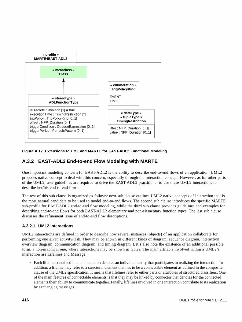
Figure A.12. Extensions to UML and MARTE for EAST-ADL2 Functional Modeling
A.3.2 EAST-ADL2 End-to-end Flow Modeling with MARTE
One important modeling concern for EAST-ADL2 is the ability to describe end-to-end flows of an application. UML2 proposes native concept to deal with this concern, especially through the interaction concept. However, as for other parts of the UML2, user guidelines are required to drive the EAST-ADL2 practitioner to use these UML2 interactions to describe her/his end-to-end flows.
The rest of this sub clause is organized as follows: next sub clause outlines UML2 native concepts of Interaction that is the most natural candidate to be used to model end-to-end flows. The second sub clause introduces the specific MARTE sub-profile for EAST-ADL2 end-to-end flow modeling, while the third sub clause provides guidelines and examples for describing end-to-end flows for both EAST-ADL2 elementary and non-elementary function types. The last sub clause discusses the refinement issue of end-to-end flow descriptions.
A.3.2.1 UML2 Interactions
UML2 interactions are defined in order to describe how several instances (objects) of an application collaborate for performing one given activity/task. They may be shown in different kinds of diagram: sequence diagram, interaction overview diagram, communication diagram, and timing diagram. Let’s also note the existence of an additional possible form, a non-graphical one, where interactions may be shown in tables. The main artifacts involved within a UML2’s interaction are Lifelines and Message:
• Each lifeline contained in one interaction denotes an individual entity that participates in realizing the interaction. In addition, a lifeline may refer to a structural element that has to be a connectable element as defined in the composite clause of the UML2 specification. It means that lifelines refer to either parts or attributes of structured classifiers. One of the main features of connectable elements is that they may be linked by connector that denotes for the connected elements their ability to communicate together. Finally, lifelines involved in one interaction contribute to its realization by exchanging messages.
« profile »MARTE4EAST-ADL2
isDiscrete : Boolean [1] = trueexecutionTime : TimingRestriction [*]trigPolicy : TrigPolicyKind [0..1]offset : NFP_Duration [0..1]triggerCondition : OpaqueExpression [0..1]triggerPeriod : PeriodicPattern [0..1]
« stereotype »ADLFunctionType
« metaclass »Class
EVENTTIME
« enumeration »TrigPolicyKind
jitter : NFP_Duration [0..1]value : NFP_Duration [0..1]
« dataType »« tupleType »
TimingRestriction
416 UML Profile for MARTE, V1.1

• A message defines different ways of communication between lifelines of one interaction, generally involving a pair of sender and receiver. In this latter case, messages are said to be complete. In other cases, messages may be lost (one sender and no specified receiver), found (one receiver and no specified sender), or unknown. Messages may also refer to the connector that conveys them from sender to receiver. Message may also be of the following kinds: synchronous or asynchronous operation call, asynchronous signal post, creation or deletion of an object, or a reply message.
UML2 interactions are then a good candidate for modeling EAST-ADL2 end-to-end flows. Nevertheless, as previously outlined, the main paradigm for communicating within interaction is the message that involved either operation call-based or signal-based communication. This is not sufficient for our purpose, because EAST-ADL2 enables also structural entities (also called ADLFunctionTypes) to communicate by data-passing, similarly to the general component model of the MARTE standard. The purpose of the next sub clause is then to describe the EASL-ADL2 proposed extension to UML2 interactions in order to cope with data-based communications.
A.3.2.2 The UML sub-profile for EAST-ADL2 data-flow based interactions
The focus of this sub clause is to describe the EASL-ADL2 sub-profile dedicated to define its extensions for modeling end-to-end flows on EAST-ADL2 functions (for both elementary and non-elementary functions).
First of all, Figure A.13 denotes the stereotype “ADLE2EFlow” for marking an interaction to show that the latter is denoting an EASL-ADL2 end-to-end flow. Note its attribute called kind enabling to specify that an interaction is either internal or external. An external end-to-end flow focuses only on showing what are the inputs and the outputs of the element the interaction is attached to. Within an external end-to-end flow, one does not want to show the complete interactions. In other words, we consider the modeled element for which an interaction is described as a black box. An internal end-to-end flow will describe all the details of the flow, even what happens inside the described element.
Figure A.13. UML profile diagram for EAST-ADL2 interactions
We also need to extend the message concept as defined within the Interactions clause of the UML2 specification in order to enable UML2 interaction to support data-based communication. As shown in Figure A.13, we then define the stereotype «ADLDataMessage». This latter owns a property value, which models the data value conveyed by the message. The type of this property is a UML OpaqueExpression. An opaque expression consists of a set of body descriptions described in some given language defining how to interpret each text string contained in the bodies. For our purpose, it is expected that users will use VSL to describe the value conveyed by a message. But the user is also free to adopt any kind of other language, such as Java or C++ for example, or even natural language.
« profile »MARTE4EAST-ADL2
« metaclass »UML::Interaction
kind: E2EFlowKind
« stereotype »ADLE2EFlow
internalexternal
« enumeration »E2EFlowKind
UML Profile for MARTE, V1.1 417

Figure A.14 - UML profile diagram for EAST-ADL2 data-based message
In UML2, a message owns generally two message ends: one refers to the event occurrence related to the posting of the message, while the other refers to the event occurrence related to the receipt of the message. Currently, due to its initial intent, the UML2 interactions clause defines only specific events dedicated to either operation-based message or signal-based message. For our concern, i.e., enabling data-based communication within UML2’s interactions, we will then need to also extend the concept of UML2’s Event as defined in the package UML::CommonBehaviors::Communications. Figure A.15 denotes the extensions we define for that concern. It consists of extending the Event concept of UML2 by introducing an abstract stereotype, «ADLDataEvent» and to reify this latter in order to introduce both concepts of event related to posting and reception of data.
Figure A.15 - UML profile diagram for EAST-ADL2 data event
« profile »MARTE4EAST-ADL2
value: OpaqueExpression
« stereotype »ADLDataMessage
« metaclass »Message
« profile »MARTE4EAST-ADL2
« stereotype »ADLDataEvent
« metaclass »UML::CommonBehaviors::
Communications::Event
« stereotype »ADLSendDataEvent
« stereotype »ADLReceiveDataEvent
itemProperty: Property
« stereotype »SysML::ItemFlow
1
data1
data
418 UML Profile for MARTE, V1.1

Firstly, we define an abstract stereotype «EADLDataEvent» and we generalize this latter into both stereotypes, «ADLSendDataEvent» and «ADLReceiveDataEvent». Both stereotypes reference a SysML ItemFlow that is used to denote the data that may be conveyed through the message.
Finally, on the notation point of view, we introduce a new representation of message in order to distinguish clearly data-based communication from signal-based and operation-based communications. A data-based message will then be represented as a line with a hollow triangle as an arrowhead (see examples in next sub clause). The name of the message will consist of the text string contained in the body of data referenced by one of the end events (either ADLSendDataEvent or ADLReceiveDataEvent). In case of complete messages (i.e., messages with two message ends), it is the ADLSendDataEvent that is taken into account.
A.3.3 Examples
This sub clause provides examples illustrating the usage of the previous defined extensions. It consists of two sub clauses that show how to model interaction for respectively EAST-ADL2 elementary and non-elementary functions.
A.3.3.1 The elementary ADLFunctionTypes case
In EAST-ADL2, an elementary function is a function that may not be decomposed in finer sub-functions. It is represented in UML2 using its profile for EAST-ADL2 with a composite class annotated with the stereotype «ADLFunctionType» for which the property isElementary is set to true.
The model described in Figure A.16 denotes an elementary ADLFunctionType, called EFT0, owning both following client/server ports: on the left side of the figure, EFT0 specifies a server port pServ1 typed with the interface Interface1. This latter defines an operation named operation; on the right side of the figure, pCli1 defines a client port typed with the interface named Interface2. This interface defines an operation named operation2. Instances of EFT0 may then receive calls to the operation1 operation and they may also do calls to the operation2 operation.
Figure A.16. Example of elementary ADLFunctionType with GCM client/server ports
The model described in Figure A.17 denotes an elementary ADLFunctionType, called EFT1, owning both following flow ports: on the left side of the figure, EFT1 specifies an input flow port typed as an Integer; on the right side of the figure, pout1 defines an output port also typed as Integer. Instances of EFT1 may then receive integer-typed values through pin1 and it may send integer-typed values via the port pout1.
« ADLFunctionType »
EFT 0pServ1 pCli1
operation2()
« interface »Interface2
« interface »Interface1
Interface1Interface2
operation1()
UML Profile for MARTE, V1.1 419

Figure A.17. Example of an elementary ADLFunctionType with flow ports
Figure A.18 shows an example of an EAST-ADL2 external end-to-end flow for the previous defined elementary ADLFunctionType, EFT1. This figure models that when an instance of EFT1 receives an integer value on its pin1 port, it sends some time later an output integer value (j) on its output port pout1. Let’s note the specific line drawn between the head of the left message and the tail of the right message. This line denotes a general ordering (see UML2 specification on p. 480, sub clause 14.3.12 for more details on this concept) that enables specifying a partial order between OccurrenceSpecifications (i.e., event linked to the ends of a message) that may otherwise not have a specified order. In this case, that means that the j value is sent from pout1 after the value i is received on pin1.
Figure A.18. Example of an EAST- ADL2 external end-to-end flow for an elementary ADLFunctionType
Both Figure A.19 and Figure A.20 denote examples of internal end-to-end flows. The interaction shown in Figure A.19 illustrates the fact that an instance of EFT1 will execute some actions when receiving the value i in order to generate the value j. This is described by the gray rectangle allocated to the life line shown in the middle of the sequence diagram. This rectangle specifies an execution of either a unit of behavior, or action within the life line. Finally, let’s note that in this example, there are no extra delays on both input and output ports.
Figure A.19 - Example 1 of an EAST- ADL2 internal end-to-end flow for an elementary ADLFunctionType
Figure A.20 illustrates the specification of a delay on the input port side.
« ADLFunctionType »EFT1
pin1: Integer pout1: Integer
420 UML Profile for MARTE, V1.1

Figure A.20 - Example 2 of an EAST- ADL2 internal end-to-end flow for an elementary ADLFunctionType
The In flow port of EAST-ADL2 may be triggered meaning that the behavior execution of the ADL function owning the port is triggered by the arrival of the data on the in ports. In the previous example, pin1 is supposed to be an input data triggered port. In other words, the semantics of the EAST-ADL2 function is said to be time-triggered. That means that the function will poll periodically its input ports in order to get the data stored by the ports (Figure A.21).
Figure A.21 - Example of an EAST- ADL2 internal end-to-end flow for an elementary ADLFunctionType owning a non-triggered input port
A.3.3.2 The non-elementary AFLFunctionTypes case
Non-elementary functions are different from elementary functions due mainly to two features: Firstly, one non-elementary function may expose several end-to-end flows; secondly, a non-elementary function may be further described in terms of sub-functions (called in EASL-ADL2 function prototypes).
The first example will consist of denoting two possible end-to-end flows for the non-elementary function type described in Figure A.22. This function type defines two input flow ports, pin1 and pin2 typed as Integer, and one single output flow port, pout1, typed as Integer. Both models describe two possible end-to-end flows for our non-elementary function. This latter may either receive i values on its input port pin1 and consequently send j data values on its output port pout1. Or, if it receives input values on pin2, it outputs also a result value on pout1.
« ADLE2EFlow » {kind = internal}sd E2EF_1OfEFT1
:EFT1
pin1: Integer pout1: Integer
(i)
(j) (j)i
UML Profile for MARTE, V1.1 421

Figure A.22. An example of non-elementary ADLFunctionType
Figure A.23. End-to-end flow 1 for NEFT1
Figure A.24. End-to-end flow 2 for NEFT1
Previous examples were an illustration of external end-to-end flow for non-elementary functions. In the next example, we illustrate the modeling of internal end-to-end flows for non-elementary functions. Firstly, as shown in Figure A.25, we refine the description of the previous non-elementary function type, called NEFT1, by detailing its internal structure (Figure A.25). NETF1 consists of two elementary function prototypes that are denoted by parts, part1, and part2. Both elementary function prototypes are respectively typed by the elementary function types, EFT1, EFT2, and EFT3. EFT1 (resp. EFT3) owns an input port pin1 (resp. pin3) typed as Integer, and an output port pout1 (resp. pout3) also typed as Integer. EFT2 has two input flow ports, pin21 and pin22, typed as Integer and one output port, pout21, typed as Integer.
422 UML Profile for MARTE, V1.1

Figure A.25 - Example of a non-elementary function type owning two elementary function prototypes
Both following figures denote two possible internal end-to-end flows for the previous described non-elementary functions NEFT1. In Figure A.26, we may notice one particular point: the arrow head used to model the data-passing from pout11 to pin21 is tiled downwards showing that the data take sometime to pass along the assembly connector linking both involved ports.
Figure A.26 - Example 1 of an internal end-to-end flow for one non-elementary function
In the following internal end-to-end flow, let’s also notice that we did not detail all internal messages involved in the interaction (i.e., in the end-to-end flow). In particular, we decided for this example to not show the details of the interaction that happen inside both function prototypes denoted by parts, part1 and part3. Hence, we abstracted this part of the model by using the general ordering concepts as previously shown in Figure A.18.
Figure A.27 - Example 2 of an internal end-to-end flow for one non-elementary function
UML Profile for MARTE, V1.1 423
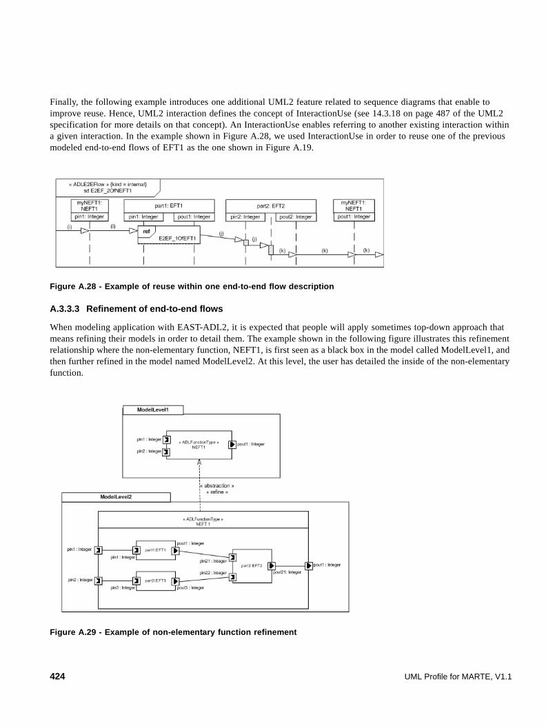
Finally, the following example introduces one additional UML2 feature related to sequence diagrams that enable to improve reuse. Hence, UML2 interaction defines the concept of InteractionUse (see 14.3.18 on page 487 of the UML2 specification for more details on that concept). An InteractionUse enables referring to another existing interaction within a given interaction. In the example shown in Figure A.28, we used InteractionUse in order to reuse one of the previous modeled end-to-end flows of EFT1 as the one shown in Figure A.19.
Figure A.28 - Example of reuse within one end-to-end flow description
A.3.3.3 Refinement of end-to-end flows
When modeling application with EAST-ADL2, it is expected that people will apply sometimes top-down approach that means refining their models in order to detail them. The example shown in the following figure illustrates this refinement relationship where the non-elementary function, NEFT1, is first seen as a black box in the model called ModelLevel1, and then further refined in the model named ModelLevel2. At this level, the user has detailed the inside of the non-elementary function.
Figure A.29 - Example of non-elementary function refinement
424 UML Profile for MARTE, V1.1
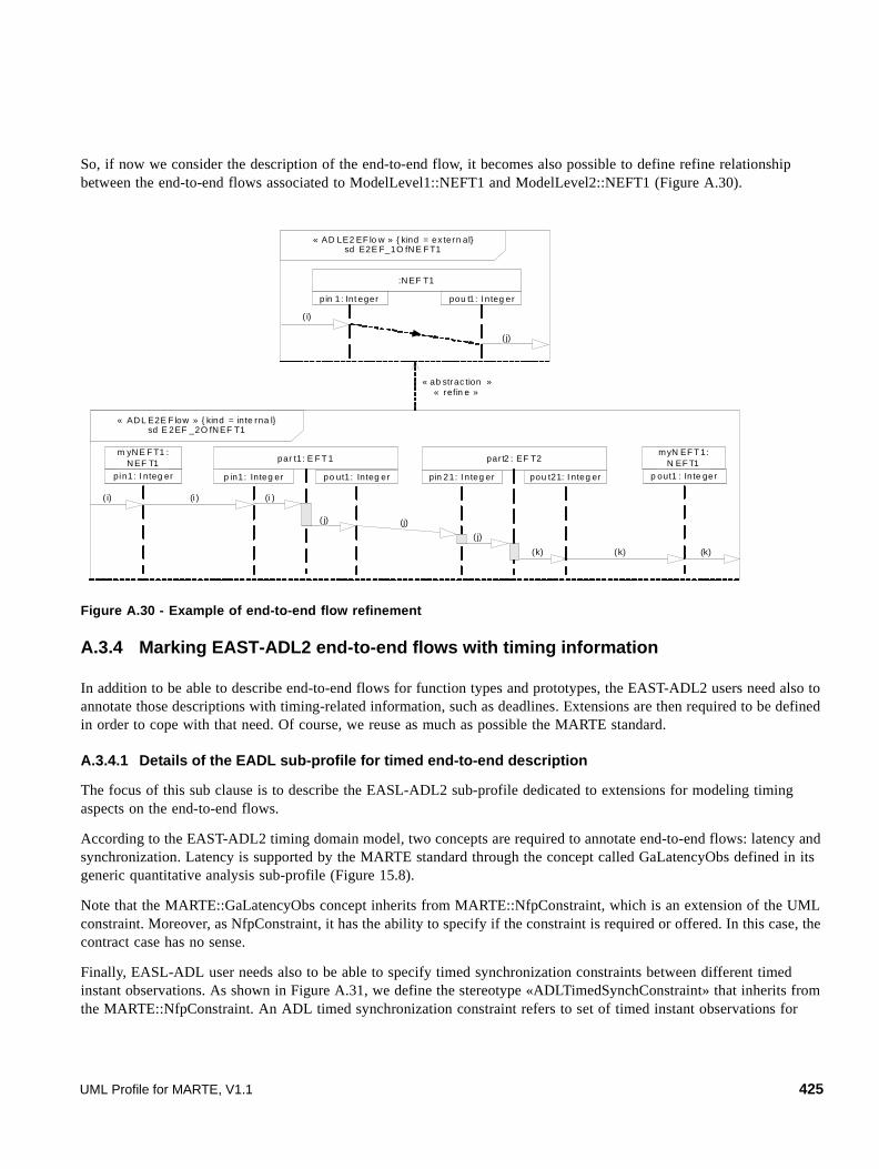
So, if now we consider the description of the end-to-end flow, it becomes also possible to define refine relationship between the end-to-end flows associated to ModelLevel1::NEFT1 and ModelLevel2::NEFT1 (Figure A.30).
Figure A.30 - Example of end-to-end flow refinement
A.3.4 Marking EAST-ADL2 end-to-end flows with timing information
In addition to be able to describe end-to-end flows for function types and prototypes, the EAST-ADL2 users need also to annotate those descriptions with timing-related information, such as deadlines. Extensions are then required to be defined in order to cope with that need. Of course, we reuse as much as possible the MARTE standard.
A.3.4.1 Details of the EADL sub-profile for timed end-to-end description
The focus of this sub clause is to describe the EASL-ADL2 sub-profile dedicated to extensions for modeling timing aspects on the end-to-end flows.
According to the EAST-ADL2 timing domain model, two concepts are required to annotate end-to-end flows: latency and synchronization. Latency is supported by the MARTE standard through the concept called GaLatencyObs defined in its generic quantitative analysis sub-profile (Figure 15.8).
Note that the MARTE::GaLatencyObs concept inherits from MARTE::NfpConstraint, which is an extension of the UML constraint. Moreover, as NfpConstraint, it has the ability to specify if the constraint is required or offered. In this case, the contract case has no sense.
Finally, EASL-ADL user needs also to be able to specify timed synchronization constraints between different timed instant observations. As shown in Figure A.31, we define the stereotype «ADLTimedSynchConstraint» that inherits from the MARTE::NfpConstraint. An ADL timed synchronization constraint refers to set of timed instant observations for
« AD L E2E F low » { kind = in te rna l}sd E 2EF _2O fN EF T1
m yN E F T1 : N EF T1
pin1: I nteg er po ut1: Integ erp in1: Integ er
myN EF T 1: N EF T1
p out1 : In te ger
par t1: E F T 1
pou t21: I nteg erpin 21: I n teg er
par t2 : EF T2
( i)
( j)
(i ) (i )
(j)
( j)
(k) (k) (k)
« AD LE2 EF lo w » { kind = ex tern al}sd E2E F_1O fN E FT1
:N EF T1
pin 1: Int eger pou t1: I n teg er
( i)
( j)
« ab strac tion »« refin e »
UML Profile for MARTE, V1.1 425

which one wants to specify a timed synchronization constraint. It is then possible to specify either an upper, or a lower, or a nominal value for the acceptable delay you accept between the min and the max of the synchronized timed instant observations.
Figure A.31 - UML profile diagram for EAST-ADL2 timed synchronization constraint
A.3.4.2 Examples
The first example presented in this sub clause denotes a flow latency specification for the ADL elementary function type modeled in Figure A.32. In this case, we want to specify a latency between the data values output from pout1 and the data values received on pin1. To do that, we first have to describe the end-to-end flow itself that we want to consider as shown on the left hand side of Figure A.32. The second step is to adorn this end-to-end flow model with the timed instant observations that are needed to express the latency. In our case, we want to specify latency between the instant when values are output from an instance and EFT1 and the instant when values are received on the input port of this instance of EFT1. As shown in Figure A.32, we add both TimedInstantObservation, t1 and t2, that denote respectively, the instant when an integer value is received on pin1 and the instant when an integer value is sent from pout1. Then, we add a UML2 constraint (shown in the rectangle with the upper right corner bent, also called “note symbol”) stereotyped as ADLE2EFlowLatency to specify the latency. The text of the constraint has to be understood that way: in this case, it is an offered latency. When receiving an integer value, i, on its input flow port pin1, an instance of EFT1 will output an integer value j on its output flow port pout1 6,2 ms later in the nominal case. Note also that the output value is never sent before 5,5 ms after receiving the input value, and no later than 6,8 ms. Finally, we accept a jitter of 1 ms for this flow.
« profile »MARTE4EAST-ADL2
value: NFP_Duration
« stereotype »ADLTimedSynchConstraint MARTE::
TimedInstantObservation
synchInstants
2..*
kind: ConstraintKind
« stereotype »MARTE::NfpConstraint
426 UML Profile for MARTE, V1.1

Figure A.32 - Example of flow latency for an elementary function type
In the next example, we consider a second elementary function type owning two input ports, pin1 and pin2 and one output port, pout1. In this example, we would like to specify a latency constraint between the output values and both input values (Figure A.33).
Figure A.33 - An ADL elementary function type with two input ports and one output ports
The interesting point highlighted in this example (Figure A.34) is the specific modeling to take into account the receipt of input values, i and j. In this case, an instance of EFT2 may receive Integer values on both input ports pin1 and pin2. And we want to specify a latency between a pair of values received on the input ports and a value sent on the output port. We first model that i and j may be received in whatever order (i.e., i before j, or j before i). To do that, we used a co-region as shown in Figure A.34. This co-region enables us to model here that the reception order for i and j is not specified, that means they may be interleaved. The specified flow latency can then be read as follows: it is required for any instance of EFT2 to send an output integer value on pout 1 respecting following timing constraints: in the nominal case, 6 ms later the inputs are received, but not before 5 ms and no later than 7 ms. The acceptable jitter is 2 ms.
«ADLFunctionType »EFT1
pin1: Integer pout1: Integer
« ADLE2EFlow » {kind = external}sd E2EF_1OfEFT1
:EFT1
pin1: Integer pout1: Integer
(i)
(j)@t1
@t2«gaLatencyObs»
{ kind=required, startObs=(t1), endObs=(t2), latency=(best=5.5 ms, value=6.2 ms, worst=6.8 ms), maxJitter=1 ms }
« ADLFunctionType »EFT2
« ADLFlowPort »pin1 : Integer
« ADLFlowPort »pin2 : Integer
« ADLFlowPort »pout1 : Integer
UML Profile for MARTE, V1.1 427
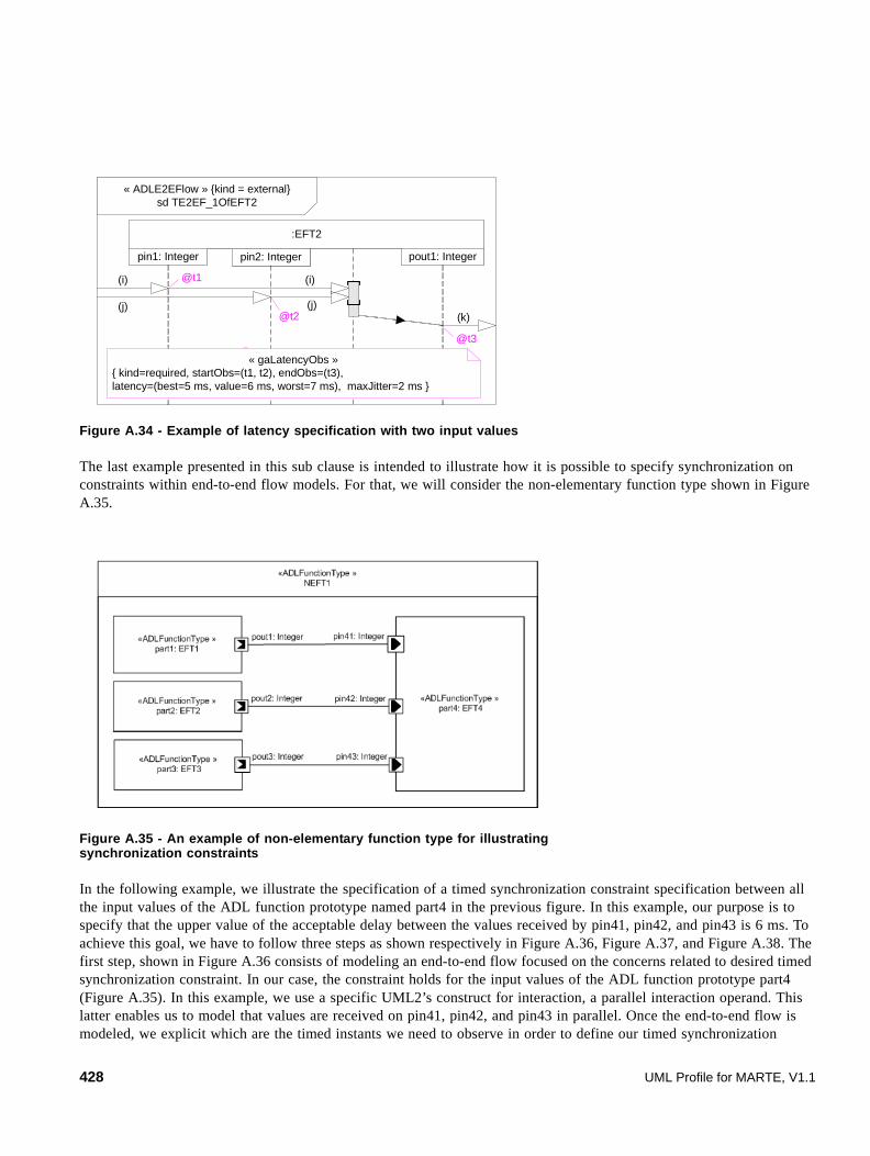
Figure A.34 - Example of latency specification with two input values
The last example presented in this sub clause is intended to illustrate how it is possible to specify synchronization on constraints within end-to-end flow models. For that, we will consider the non-elementary function type shown in Figure A.35.
Figure A.35 - An example of non-elementary function type for illustrating synchronization constraints
In the following example, we illustrate the specification of a timed synchronization constraint specification between all the input values of the ADL function prototype named part4 in the previous figure. In this example, our purpose is to specify that the upper value of the acceptable delay between the values received by pin41, pin42, and pin43 is 6 ms. To achieve this goal, we have to follow three steps as shown respectively in Figure A.36, Figure A.37, and Figure A.38. The first step, shown in Figure A.36 consists of modeling an end-to-end flow focused on the concerns related to desired timed synchronization constraint. In our case, the constraint holds for the input values of the ADL function prototype part4 (Figure A.35). In this example, we use a specific UML2’s construct for interaction, a parallel interaction operand. This latter enables us to model that values are received on pin41, pin42, and pin43 in parallel. Once the end-to-end flow is modeled, we explicit which are the timed instants we need to observe in order to define our timed synchronization
« ADLE2EFlow » {kind = external}sd TE2EF_1OfEFT2
:EFT2
pin1: Integer pout1: Integer
@t3
@t1
pin2: Integer
@t2
« gaLatencyObs »{ kind=required, startObs=(t1, t2), endObs=(t3), latency=(best=5 ms, value=6 ms, worst=7 ms), maxJitter=2 ms }
(i)
(j)
(i)
(j)(k)
428 UML Profile for MARTE, V1.1

constraint. Here, we then introduce tin41, tin 42, and tin43 that enables us to identify the instants when I, j, and k are received by their respective ports (Figure A.37). Finally, we can write the timed synchronization constraint as described in Figure A.38.
Figure A.36 - Step 1 for modeling a timed synchronization constraint
Figure A.37 - Step 2 for modeling a timed synchronization constraint
« ADLE2EFlow » {kind=external}sd InputsSyncroSpecSpec2Of_part4
par
pin41: Integer
part4: EFT4
pin42: Integer pin42: Integer
(i)
(j)
(k)
« ADLE2EFlow » {kind=external}sd InputsSyncroSpecSpec2Of_part4
par
@tin41
pin41: Integer
part4: EFT4
@tin42
pin42: Integer pin42: Integer
@tin42
(i)
(j)
(k)
UML Profile for MARTE, V1.1 429

Figure A.38 - Step 3 for modeling a timed synchronization constraint
« ADLE2EFlow » {kind=external}sd InputsSyncroSpecSpec2Of_part4
par
@tin41
pin41: Integer
part4: EFT4
« ADLTimedSynchConstraint »{ synchInstants = (tin41, tin42, tin43), value = 6 ms}
@tin42
pin42: Integer pin42: Integer
@tin42
(i)
(j)
(k)
430 UML Profile for MARTE, V1.1

UML Profile for MARTE, V1.1 431

432 UML Profile for MARTE, V1.1

Annex B Value Specification Language (VSL)
(normative)
B.1 Overview
This annex provides a detailed definition of the abstract (MOF compliant metamodel) and concrete (textual grammar) syntax for specifying expressions in MARTE. The MARTE expression language is used to specify the values of constraints, properties, and stereotype attributes particularly related to non-functional aspects. In fact, this expression language can be used by profile users in tagged values, body of constraints, and in any UML element associated with value specifications.
In addition, the expression language might be used by any other UML-based specification interested in extending the base expression infrastructure provided by UML. As shown below, the MARTE expression language is an extension to the “Value specification” and “DataType” concepts provided by UML. For this reason, we call it Value Specification Language (VSL).
VSL deals with the following requirements:
• How to specify parameters/variables, constants, and expressions in textual form.
• How relationships between different parameters/variables, or constant values are to be defined with support on arithmetic, logical, relational, and conditional expressions.
• How different time values and assertions are to be defined in UML.
• How to specify composite values such as collection, interval, and tuple values.
VSL expressions can be used to specify non-functional values, parameters, operations, and dependency between different values in a UML model. UML modelers can use VSL to specify non-functional constraints in their models.
Note: This annex is normative in the UML profile for MARTE.
B.2 Domain View
B.2.1 Overview
This sub clause describes the abstract syntax of VSL. In this abstract syntax a number of concepts (metaclasses) from the UML metamodel are reused. These concepts are shown in the models with a gray fill color. Note that, however, we do not formally “import” them from UML, but re-define them with the same semantics in the MARTE namespace. In the UML representation clause, we describe how all these metaclasses are actually mapped to UML.
The abstract syntax is divided into several packages. The overall package structure of VSL is shown in Figure B.1.
• The DataTypes package describes the concepts that define the datatype extensions to UML. In addition to primitive and enumeration datatypes, it includes further specializations for composite datatypes and subtypes.
• The LiteralValues package includes literal constant values of different primitive types. Besides UML literals, this package distinguishes, among others, Real and DateTime literals.
UML Profile for MARTE, V1.1 433

• The Expressions package describes the structure of expressions, including variables and reference values to UML model elements.
• The CompositeValues package defines four kinds of composite values: interval, collection, tuple, and choice.
• The TimeExpressions package presents specialized syntax for time value specifications and expressions.
The purpose and contents of each sub package denoted in Figure B.1 are described in subsequent sub clauses.
Figure B.1 - Structure of the VSL framework
B.2.2 The Datatypes Package
A datatype is a type whose instances are identified only by their value. Instances of a given datatype consist of a set of distinct values, characterized by properties and operations on those values. A value space is the set of values for a datatype. The value space of a given datatype can be defined either by enumeration, axiomatically from fundamental notions, or as a subset of values from some already defined value space.
VSL is a typed language. Each value specification, including expressions, has a type that is either explicitly declared or can be statically derived. Evaluation of an expression yields a value of this type.
The model of datatypes used in this specification is said to be an “abstract computational model.” It is “computational” in the sense that it deals with the manipulation of information by computer systems and makes distinctions in the typing of data units that are appropriate to that kind of manipulation. It is “abstract” in the sense that it deals with the perceived properties of the data units themselves, rather than with the properties of their representations in computer systems.
In this specification, datatypes are categorized, for syntactic convenience, into:
• Enumeration types, whose value space is defined by enumeration.
MARTE::VSL
TimeExpressionsCompositeValues
Expressions
«import »
LiteralValues
« import »
« modelLibrary »MARTE_Library::
MARTE_PrimitiveTypes
« import »
DataTypes « import »
434 UML Profile for MARTE, V1.1

• Primitive types, which are defined axiomatically without reference to other datatypes.
• Subtypes, which are defined in terms of other datatypes.
• Composite types are aggregates of value spaces that can be seen as an organization of specific datatypes.
Figure B.2 - VSL::DataTypes package
Note that the Datatype package preserves the same structure and semantics as in UML, but it extends UML in the following ways:
• Like in UML, DataTypes may contain attributes to support modeling of structured data types. However, dissimilar kinds of structures, with different syntax and semantics, are defined in our language. CompositeType is the metaclass that congregates composite data types. Each kind of composite type (interval, collection, tuple, and choice) has a set of attributes defining particular structures of data types.
• The set of owned operations for a data type comprises those operations on the data type values, possibly yielding values of the owner data type, of the Boolean data type, or, in some cases, of other existing data types. In general, there is no unique collection of operations for a given data type. This specification provides a set of operations for each MARTE data type, which is sufficient for most purposes in this domain. However, this does not limit the capacity of the language to accept new operations in specialized or new data type libraries.
• A Subtype is a data type derived from an existing data type, designated the base data type, by restricting the value space to a subset of that to the base data type while maintaining all operations. Particularly, a Bounded Subtype defines a subtype of any ordered data type by placing new minimum and maximum value bounds on the value space.
VSL::DataTypes
DataType
PrimitiveTypeSubtype CompositeType
CollectionType TupleType
minValue: StringmaxValue: StringisMinOpen: BooleanisMaxOpen: Boolean
BoundedSubtype
EnumerationType
1
baseType
Property
Operat ion
ownedAtt ributedatatype
0..1 *
ownedOperationdatatype
0..1 *
Property
tupleAt tributes{subs ets
ownedAttribute}*
collectionAtt ribute{subsets
ownedAttribute}1
IntervalType
intervalAttribute{subsets
ownedAttribute} 1
Parameter
ownedParameter
operation0. .1
*
ChoiceType
c hoiceAtt ributes{ subsets
ownedAtt ribute}*
defaultAttribute{s ubsets
ownedAttribute}
0..1
EnumerationLiteral
ownedLiteral*
UML Profile for MARTE, V1.1 435
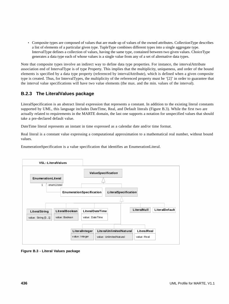
• Composite types are composed of values that are made up of values of the owned attributes. CollectionType describes a list of elements of a particular given type. TupleType combines different types into a single aggregate type. IntervalType defines a collection of values, having the same type, contained between two given values. ChoiceType generates a data type each of whose values is a single value from any of a set of alternative data types.
Note that composite types involve an indirect way to define data type properties. For instance, the intervalAttribute association end of IntervalType is of type Property. This implies that the multiplicity, uniqueness, and order of the bound elements is specified by a data type property (referenced by intervalAttribute), which is defined when a given composite type is created. Thus, for IntervalTypes, the multiplicity of the referenced property must be ‘[2]’ in order to guarantee that the interval value specifications will have two value elements (the max. and the min. values of the interval).
B.2.3 The LiteralValues package
LiteralSpecification is an abstract literal expression that represents a constant. In addition to the existing literal constants supported by UML, this language includes DateTime, Real, and Default literals (Figure B.3). While the first two are actually related to requirements in the MARTE domain, the last one supports a notation for unspecified values that should take a pre-declared default value.
DateTime literal represents an instant in time expressed as a calendar date and/or time format.
Real literal is a constant value expressing a computational approximation to a mathematical real number, without bound values.
EnumerationSpecification is a value specification that identifies an EnumerationLiteral.
Figure B.3 - Literal Values package
VSL::LiteralValues
ValueSpecification
LiteralSpecificat ion
value: String [0..1]
LiteralString
value: Real
LiteralReal
value: Boolean
LiteralBoolean
value: DateTime
LiteralDateTime
value: Integer
LiteralInteger
LiteralNull
value: UnlimitedNatural
LiteralUnlimitedNatural
LiteralDefault
Enumerat ionSpecificat ion
EnumerationLiteral
1 enumLiteral
436 UML Profile for MARTE, V1.1

B.2.4 The Expressions package
An expression represents a node in an expression tree. If there are no operands, it represents a terminal node. If there are operands, it represents an operator applied to those operands. In either case there is a symbol associated with the node. The interpretation of this symbol depends on the context of the expression.
Expressions are used to derive values from other values or expressions. An expression can be a simple literal or variable, or it can be a compound expression (arithmetic, logical, or time expressions) formed by combining operands and Operation Call Expressions.
The basic structure in the package consists of Variable Call/Declaration Expression, Property Call Expression, Operation Call Expression, and Conditional Expression (Figure B.4).
Variables are typed elements for passing data in expressions. The variable can be used in expressions where the variable is in scope. A Variable Call Expression is an expression that consists of a reference to a variable. Variable creates a variable with a given name, data type, and nature (input, output, input/output).
Variables are declared in a given Expression Context. The Expression Context’s name attribute is used for identification of the variable elements. An Expression Context provides a container for variables. It provides a means for resolving conflicting global variables by allowing Variable Call Expressions of the form exprContext1::subContext2::varX. Concrete rules to construct the derived attribute “variable” of Variable Call Expression, are defined in “UML Representation.”
A Property Call Expression is used to refer to Properties in the UML metamodel.
An Operation Call Expression refers to an operation defined in a UML Classifier. The expression may contain a list of argument expressions if the operation is defined to have parameters. In this case, the number and types of the arguments must match the parameters.
A Behavior Call Expression refers to a behavior defined in a UML Namespace. The expression may contain a list of argument expressions if the behavior is defined to have parameters. In this case, the number and types of the arguments must match the parameters.
This metamodel does not define explicitly the context of properties and operations and the namespace that the corresponding call expressions must use. When specifying values making reference to properties and operations of their corresponding data types, the namespace is not taken into account. Further usages of this metamodel may define different namespaces for property and operation.
Conditional Expressions define “if-then-else” statements, which can be used inside an expression. The result of evaluating this expression will be the result of the evaluation of the ifTrueExpr if the conditionExpr is true. Otherwise, the result will be the result of the ifFalseExpr.
An Opaque Expression is an uninterpreted textual statement that denotes a (possibly empty) set of values when evaluated. This allows extending VSL to other specialized expression languages.
UML Profile for MARTE, V1.1 437

Figure B.4 - VSL::Expressions package
B.2.5 The CompositeValues package
In general, a composite value can contain zero, one, or more component values. Three kinds of composite value specifications are defined: interval, collection, and tuple (Figure B.5).
Collection Specifications represent a list of elements of a particular given type. Individual elements of collections are item Value Specifications. Note that there is no restriction on the item value type of a collection type. This means in particular that a collection type may be parameterized with other collection types allowing collections to be nested arbitrarily deep. Size, uniqueness, and order nature of item values are defined by the defining data type.
Interval Specifications describe ordered sets of value specifications represented by two values: the minimum and the maximum value. Additionally, two attributes define whether these two values belong or not to the referred set (isLowerOpen and isUpperOpen).
Tuple Specifications denote structured values of possibly different types. It contains a name, a type, and a value for each item of the tuple value. There is no restriction on the kind of types that can be used to define item values of tuples. In particular, a Tuple Specification may contain other tuple and collection values.
VSL::Expressions
ValueSpecification
/variable: String
VariableCallExpression
symbol: String [0..1]
Expression
* {ordered}operand
name: Stringdirection: VariableDirectionKind [0..1]/datatypeName: String [0..1]
Variable
1definingVariable
ConditionalExpression
/operation: String
OperationCallExpression
Operation0..1
definingOperation
DataType0..1
datatype
inoutinout
« enumeration »VariableDirectionKind
1conditionExpr
*argument {ordered}
1ifTrueExpr
1ifFalseExpr
/property: String
PropertyCallExpression
Property1
definingProperty
0..1
initExpression
body: String [*] {ordered}language: String [*] {ordered}
OpaqueExpression
name: String [1]
ExpressionContext
0..1context
*subContext
0..1
/behavior: String
BehaviorCallExpression
symbol : String [0..1]/isAnOperator : Boolean/arity : Integer
Behavior
1
definingBehavior
*argument {ordered}
438 UML Profile for MARTE, V1.1

Choice Specification denotes a value of a choice data type (ChoiceType). It contains the name of one of the attribute members (chosenAlternative), which determines the chosen data type, and a value that conforms to the chosen data type. The derived attribute “chosenAlternative” can be constructed with basis on an explicitly chosen data type. When the chosen data type is undefined in a given choice value specification, the chosen alternative can be deduced from the default alternative attribute of the corresponding choice type.
Figure B.5 - VSL::CompositeValues package
B.2.6 The TimeExpression package
This package adds textual capabilities to represent time related expressions. UML has defined a Simple Time model in the Common Behavior package, which already provides means to represent time and durations, as well as a mechanism to refer to event observations with time marks. MARTE extends UML to support more expressive time expressions, constraints, as well as observations in different behavior diagrams. Particularly, VSL’s Time Expression model improves UML with the following capabilities:
• One single instant or duration observation can be expressed with an occurrence index. For instance, we can express the “i-th” occurrence of a given event. While the occurrence could be trivial in sequence diagrams (since this diagram is based on occurrence specifications), other diagrams such as state machines and activities may require the explicit identification of the occurrence. In the same way, recurrent interaction fragments represented by a single sequence diagram, such as periodic or loop fragments may require time assertions comparing different instance traces of the sequence diagram. For instance, the duration between the i-th and i+1-th occurrence of an event that triggers a periodic scenario.
• One single instant or duration observation can be expressed with a given condition. For example, the instant time at which a given event occurs (observation) when a specific class’ attribute has a value greater than a given constant (condition).
• The jitter of a nominal periodic event or, in general, the jitter between two causal events that occur in instants separated by a nominal time interval. Typical examples are the jitter of a clock event or the maximum jitter introduced by packet networks so that a continuous playout of audio (or video) transmitted over the network can be ensured.
.
VSL::CompositeValues
ValueSpecif icat ion
* tupleI tem
isLowerOpen: BooleanisUpperOpen: Boolean
IntervalSpecif icat ion
1max
1min
TupleSpecificat ion
/tupleI temName:String
TupleItemValue
1itemValue
CollectionSpecif icat ion
*
itemValue
/chosenAlternative: String
ChoiceSpecification
Property1
tupleAttribute
10..1choiceAttribute
1
value
UML Profile for MARTE, V1.1 439
Observation Call Expressions (ObsCallExpression) refers to a single observation (instant and duration observation). It includes an occurrence index expression (occurIndexExpr) that must evaluate to an integer value. Condition expression defines an operational (run-time) condition that completes the definition of a relative event.
The semantics of the occurrence index depends on the observed events. While the absolute order of a given event occurrence regarding another different event could be useful only when both events are synchronized, it exists certain cases where the relative order of an occurrence may be useful to express constraints from different responses of a recurrent scenario. In many systems, each request for service needs to be met by a separate response, but the two need not happen at the same time. For instance, let us point to data consistency of FIFO queues as a simple example. Also index “i” enables comparisons between different occurrences of the same event that may not be consecutive (e.g., burstiness).
The condition expression of observation call expression allows having a similar construct as the UML ChangeEvent, which defines an expression condition that defines the event occurrence. However, we target to construct textual expressions that do not require the explicit definition of a ChangeEvent element.
TimeExpression is an expression that factorizes different kinds of time related expressions, including instants, durations, and jitters.
The Time Expression is given by “expr” that may contain usage of the observations (obsExpr) given by ObsCallExpression. In the case where there are no “obsExpr,” the “expr” will contain a time constant. In the case where there is no “expr,” there shall be a single “obsExpr” that indicates the instant or duration expression value.
InstantExpression is a time expression that denotes a time instant value.
DurationExpression is a time expression that evaluates to a duration value.
JitterExpression is a duration expression that denotes an unwanted variation (delta) in an event occurrence instant that should occur in periodic intervals.
Instant and DurationIntervalSpecifications are special kinds of interval specifications that have time expressions as upper and lower bounds.
440 UML Profile for MARTE, V1.1

Figure B.6 - VSL::TimeExpressions package
Note that the Time Expressions package only introduces the basis to write time related expressions. For example, this model does not account for the relativistic effects that occur in many distributed systems, or the effects resulting from imperfect clocks with finite resolution, overflows, drift, skew, etc. These capabilities, among others, are defined in the MARTE’s Time clause. In the same way, measurement units and other time value qualifiers are defined in the NFP modeling clause.
B.3 UML Representation
This sub clause describes the UML extensions required to support the concepts defined in the previous domain view. The set of extensions to support VSL with UML is organized according to the extension mechanism used for each part of the metamodel. In particular, note that in VSL not every domain concept will result directly in a UML stereotype or tagged value. This is because some domain concepts are defined to be implemented as a separated metamodel.
For instance, we have chosen to only define stereotypes for concepts that are related to data types definition and variable declaration. The group of domain concepts related to value specifications and expressions yields a separated language, thus providing a new metamodel used in a complementary way to the UML one. Indeed, the latter defines an extended grammar for textual notations.
Thus, we first describe the extensions concretized in stereotypes. Then, we define the extensions related to the specification of value expressions. It covers the definition of the concrete syntax of VSL for annotating model elements with extended value specifications.
In sub clause D.1, we define a model library of primitive DataTypes and its operations, which is intensively used in MARTE, especially to characterize the supported operations in primitive types.
VSL::TimeExpress ions
ValueSpecification
DurationExpressionObservat ion
TimeExpression*
{ordered}obsExpr CompositeValues::
Interva lSpecification
DurationIntervalSpecification
{redef ines min}min
{redef ines max}max
0. .1expr
InstantExpression InstantIntervalSpecif icat ion
{redef ines min}min
{redef ines max}max
Jit terExpression
0..1occurIndexExpr
0..1conditionExpr
ObsCallExpression
1observat ion
UML Profile for MARTE, V1.1 441

B.3.1 Profile Diagrams
Figure B.7 shows the UML extensions for DataTypes definition. The VSL::DataTypes package (stereotyped as profile) defines how the elements of the domain model extend metaclasses of the UML metamodel. These stereotypes are listed in alphabetical order. The semantic descriptions corresponding to these stereotypes and tagged values are provided in sub clause B.3.2.
Figure B.7 - UML Extensions for DataTypes definition
Although variables can be created in VSL expressions, we provide the capability to alternatively declare them by means of extended UML Properties. When using UML properties, variable declaration matches to the concept of Parameters in SysML Constraint Blocks.
Figure B.8 shows the UML extensions for Variable definition. The VSL::Variables package (stereotyped as profile) defines how the elements of the domain model extend metaclasses of the UML metamodel. These stereotypes are listed in alphabetical order. The semantic descriptions corresponding to these stereotypes and tagged values are provided in sub clause B.3.2.
« profi le »VSL: :D at aTypes
« metac lass »UM L::Da taType
c ollec tionA tt rib: Property [1 ]
« st ereot ype »C ollectionType
t upleAt trib : Propert y [ *]
« s tere otype »TupleType
baseTy pe: Da taT ype [1]m inValue : Str ing [1 ]max Value : St ring [1]isMinOpen : Boo lean [1] = Fa ls eisMax Open: B oolean [1] = False
« stereotype »BoundedSubty pe
int ervalAtt rib : Property [1 ]
« st ereot ype »Int ervalType
choiceAt trib: Propert y [ *]defau lt At trib : Property [0 . .1 ]
« st ereot ype »ChoiceType
442 UML Profile for MARTE, V1.1
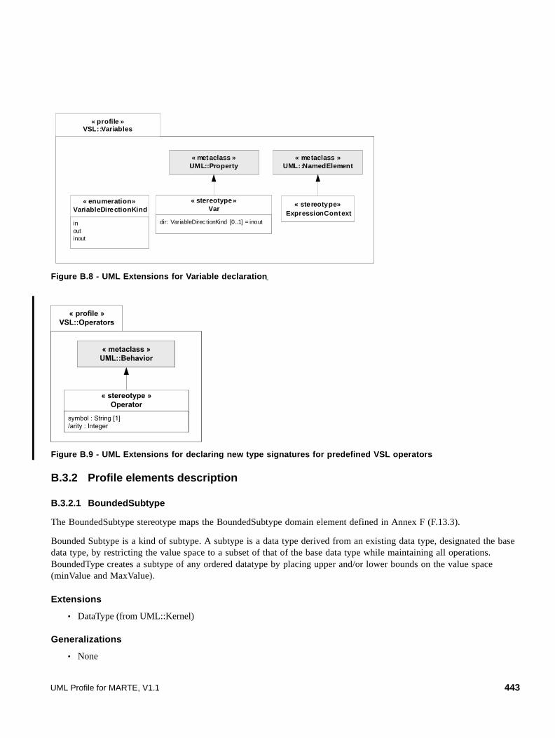
Figure B.8 - UML Extensions for Variable declaration
Figure B.9 - UML Extensions for declaring new type signatures for predefined VSL operators
B.3.2 Profile elements description
B.3.2.1 BoundedSubtype
The BoundedSubtype stereotype maps the BoundedSubtype domain element defined in Annex F (F.13.3).
Bounded Subtype is a kind of subtype. A subtype is a data type derived from an existing data type, designated the base data type, by restricting the value space to a subset of that of the base data type while maintaining all operations. BoundedType creates a subtype of any ordered datatype by placing upper and/or lower bounds on the value space (minValue and MaxValue).
Extensions
• DataType (from UML::Kernel)
Generalizations
• None
« profile »VSL::Variables
« metaclass »UML::Property
dir: VariableDirec tionKind [0..1] = inout
« stereotype»Var
« stereotype»ExpressionContext
« metaclass »UML::NamedElement
inoutinout
« enumeration»VariableDirectionKind
« profile »VSL::Operators
« metaclass »UML::Behavior
symbol : String [1]/arity : Integer
« stereotype »Operator
UML Profile for MARTE, V1.1 443
Associations
• None
Attributes
• baseType: UML::Classes::Kernel::DataType [1] Designates an ordered datatype.
• minValue: String [1] Defines a string that specifies that the value space is limited to this value in his lower bound. When minValue is "*", it indicates that no lower bound is being specified.
• maxValue: String [1] Defines a string that specifies that the value space is limited to this value in his upper bound. When maxValue is "*", it indicates that no upper bound is being specified.
• isMinOpen: Boolean [1] Defines if minValue is excluded in the bounded value space.
• isMaxOpen: Boolean [1] Defines if maxValue is excluded in the bounded value space.
Contraints
• None
B.3.2.2 ChoiceType
This stereotype maps the “ChoiceType” domain element defined on Annex F.
Choice Type generates a data type each of whose values is a single value from any of a set of alternative data types. Choice Type combines different types into a single data type. Instances of choice data types belong to only one of the member types. This type is similar to the C union type and the Ada/Pascal “variant-record.” When all the attributes of the extended data type participate as alternatives of the choice type, choiceAttrib can be left undefined.
Extensions
• DataType (from UML::Kernel)
Generalizations
• None
Associations
• None
Attributes
• choiceAttrib: UML::Classes::Kernel::Property [*] Defines the type, size, uniqueness, and order of the alternative members of the choice data type. When all the attributes of the extended data type participate as alternatives of the choice type, the choiceAttrib’s tagged value can be left undefined.
• defaultAttrib: UML::Classes::Kernel::Property [0..1] Defines the default alternative member of the choice data type.
444 UML Profile for MARTE, V1.1

Constraints
[1]The types of the properties belonging to this DataType are constrained to be UML::DataType or one of its children meta-classes only.
B.3.2.3 CollectionType
This stereotype maps the domain concept “CollectionType” defined in Annex F.
Collection Type describes a list of elements of a particular given type. Part of every collection type is the declaration of the type of its elements by means of the CollectionAttribute (i.e., a collection type is parameterized with an element type). Note that there is no restriction on the element type of a collection type. This means in particular that a collection type may be parameterized with other collection types allowing collections to be nested arbitrarily deep.
Extensions
• DataType (from UML::Kernel)
Generalizations
• None
Associations
• None
Attributes
• collectionAttrib: UML::Classes::Kernel::Property [1] defines the element type, size, uniqueness and order kind of this composite data type.
Constraints
[1]The types of the properties belonging to this DataType are constrained to be UML::DataType or one of its children meta-classes only.
B.3.2.4 IntervalType
This stereotype maps the domain concept “IntervalType.”
Interval type is a composite data type defining a set of values by means of two bound limits. The minAttribute defines a single value, which will designate the lower bound of the Interval. The maxAttribute defines a single value, which defines the upper bound of the Interval.
Extensions
• DataType (from UML::Kernel)
Generalizations
• None
Associations
• None
UML Profile for MARTE, V1.1 445

Attributes
• minAttrib: UML::Classes::Kernel::Property [1] Defines the lower bound part of this composite data type.
• maxAttrib: UML::Classes::Kernel::Property [1] Defines the upper bound part of this composite data type.
Constraints
• None
B.3.2.5 Operator
The stereotype Operator matches the domain concept “Behavior,” defined in Annex F, in the case the property “Behavior.isAnOperator” is true. This stereotype applies to the metaclass Behavior. It is used to specify that a given predefined VSL operator (i.e., unary 'not', unary '-', unary '+', '*', '/', '+', '-', '<', '>', '<=', '>=', '= =', '<>', 'and', 'or', and 'xor') applies on specific data types, an can safely be manipulated in the context of an infix or prefix VSL expression.
Extensions
• Behavior (from UML::BasicBehaviors)
Generalizations
• None
Associations
• None
Attributes
• symbol: String [1] The symbol associated with the corresponding operator.
• /arity: String [1] The arity of the corresponding operator. This is a derived property. The arity of the operator is equal to the
number of input parameters of the stereotyped Behavior.
Constraints
[1] Symbol must represent a predefined VSL operator. It must be equal to one of the following strings: '*', '/', '+', '-', '<', '>', '<=', '>=', '= =', '<>', 'not', 'and', 'or', 'xor'.
[2] The behavior must have only input parameters (no out or inout parameters).
[3] The behavior must have exactly one return parameter.
Semantics
In standard libraries of data types defined in MARTE, predefined operators (manipulated in infix or prefix expressions of VSL) are captured as operations associated with data types. The stereotype Operator provides an alternative solution for specifying that a given predefined VSL operator applies on a standard or user-defined data type. The property “symbol” actually captures the corresponding operator, and the set of input parameters as well as the return parameter of the behavior capture the type signature of the operator.
446 UML Profile for MARTE, V1.1

The usage of behaviors for capturing operator signatures can help to limit the coupling between type definitions and operator signature definitions (since operator signatures are not captured as operations of data types), potentially limiting the need for modifications of existing data types libraries.
The following simple examples illustrates the usage of the stereotype “Operator,” for the definition of operators '+' and '-' applying on the DataType Integer, and how the information provided by the stereotype could be exploited by an implementation of a VSL parser.
Figure B.10 - Defining operators ‘+’ and ‘-’ (for DataType Integer) using stereotype «Operator»
In an implementation of VSL parser, an expression such as “a + b” would be interpreted as an “additive expression,” due to the presence of operator '+'. Then, a generic type checking algorithm (associated with a parser implementation) would typically consist in:
1. Inferring the type of expression “a”
2. Inferring the type of expression “b”
3. Searching in the PrimitiveBehaviors library (or any namespace which is “visible” in the context of the Expression, e.g., by a library import) if there is a behavior such that:
• the stereotype «Operator» is applied, and its property 'symbol' is equal to "+"
• the signature is compatible with typeOf("a") and typeOf("b") (I come back on what “compatible” means in your point about “polymorphic behaviors”).
If typeOf("a") == Integer and typeOf("b") == Integer, then the expression "a + b" would be equivalent to the behavior call expression "VSL.PrimitiveBehaviors.AddInteger(a,b)"
This kind of algorithm necessarily relies on a notion of scope or visibility, to determine what behaviors are actually visible in the context of an expression. Let us consider the following example to show how such a notion of scope could actually be implemented.
VSL
« operator »{symbol = ‘’+’’}
AddInteger
Integer
Integer
Integer
PrimitiveBehaviors
« operator »{symbol = ‘’-’’}
MinusInteger
Integer
Integer
Integer
UML Profile for MARTE, V1.1 447

Figure B.11 - Principles of the Scoping mechanism in VSL
In this example, the model M (in the bottom of the figure) owns a class C, which owns a property p. In order to type C.p by VSL.PrimitiveTypes.Integer, the library VSL.PrimitiveTypes must have been imported, at least by model M. Similarly, in order to write a BehaviorCallExpression which uses a behavior from the library VSL.PrimitiveBehaviors (such as AddInteger(a,b) in our example), this library must be imported, at least at the level of model M. In this case, any behavior defined in the imported library is visible in the context of an expression, so that an expression such as “AddInteger(a,b)” (which would be equivalent to the infix expression "a+b") is valid (i.e., the fully qualified name is not mandatory since the library VSL.PrimitiveBehaviors has been imported), and semantically equivalent to “VSL.PrimitiveBehaviors.AddInteger(a,b).”
To make this principle more general, let’s consider the function scopeOf(n : Namespace), which returns the list of elements that are either directly owned by the namespace n, or directly imported by n. In our example, scopeOf(C) would return: {a, b, p}. Similarly, scopeOf(C') would return : {a, b, p, AddInteger} (i.e., 'AddInteger' is visible due to the "import" relationship between C' and MyCustomBehaviors").
Considering this function, one can write a generic algorithm such that, according to a behavior name expression in a BehaviorCallExpression, the actual “Operator” Behavior can be retrieved. This algorithm could be as follows (pseudo Java statement):
retrieveBehavior (behaviorName : String, context : Namespace) : Behavior {
// the operation ''contains'' makes abstraction of potential nested namespaces
if (scopeOf (context).contains ("a behavior which matches behaviorName…") {
« operator »{symbol = ‘’+’’}
AddInteger
Integer
Inetger
Integer
« library »MyCustomBehaviors
VSL
« operator »{symbol = ‘’+’’}
AddInteger
Integer
Integer
Integer
« library »PrimitiveBehaviors
M
« var » a: Integer« var » b: Integerp: Integer = AddInteger(a, b)
C
« import »
Equivalent to:VSL.PrimitiveBehaviors.AddInteger(a, b)
« var » a: Integer« var » b: Integerp: Integer = AddInteger(a, b)
C’
Equivalent to:MyCustomBehaviors.AddInteger(a, b)
« import »
448 UML Profile for MARTE, V1.1

// return this behavior
else
if (context.getOwner() != null)
// recursively applies the process on the namespace containing context
return retrieveBehavior (behaviorName, context.getOwner()) ;
else
// No behavior matching behaviorName has been found
return null ;
}
In the case where the resolution process described above retrieves multiple behaviors (i.e., there are multiple behaviors whose signature match the expected signature, in the same scoping level), the model is probably ill-formed (i.e., there are probably some problems regarding definitions of behavior libraries, or multiple imports which overlap), and the usage of qualified name is required (which in this case prevents the usage of the infix notation).
In the case where the expected signature does not exactly match available signatures (e.g., we have an expression like “3.5 + b,” i.e., the expected signature is: Real, Integer), an additional notion of type compatibility must also be considered. In UML, what makes a type compatible with another type is a semantic variation point. One possibility would be to following object-oriented type compatibility rules, where a type can be considered as compatible with another type if there is a direct or indirect generalization relationship between the types.
The last example below illustrates how the stereotype operator can be used to specify that the operator '-' applies on the standard primitive type DateTime, and how the operator '<' applies on standard data type NFP_Duration. Please note that the definition of the two operators has no impact on the two data types.
B.3.2.6 TupleType
This stereotype maps the domain concept “TupleType.”
Tuple Type combines different types into a single composite type. The parts of a Tuple Type are described by its attributes, each having a name and a type. There is no restriction on the kind of types that can be used as part of a tuple. In particular, a Tuple Type may contain other tuple types and collection types. Each attribute of a Tuple Type represents a single feature of a TupleType. Each part is uniquely identified by its name. When all the attributes of the extended data type participate in the tuple structure, tupleAttrib can be left undefined.
Extensions
• DataType (from UML::Kernel)
Generalizations
• None
Associations
• None
Attributes
• tupleAttrib: UML::Classes::Kernel::Property [*] Attribute defining the type, size, uniqueness and order kind of the structured elements of this
UML Profile for MARTE, V1.1 449

composite data type. When all the attributes of the extended data type participate in the tuple structure, the tupleAttrib’s tagged value can be left undefined.
Constraints
• None
B.3.2.7 Var
This stereotype maps the domain concept “Variable.”
Variables are typed elements for passing data in expressions. Variable creates a variable with a given name, data type, and nature (input, output, input/output).
Extensions
• Property (from UML::Kernel)
Generalizations
• None
Associations
• None
Attributes
• dir: VariableDirectionKind [0..1] Nature of the created variable: input, output, input/output. The complete semantics of this attribute depends on the context on which the variable is created
Constraints
• None
B.3.2.8 ExpressionContext
This stereotype maps the domain concept “ExpressionContext.”
Variables are declared in a given Expression Context. The Expression Context's name attribute is used for identification of the variable elements. A Expression Context provides a container for variables. It provides a means for resolving conflicting global variables by allowing Variable Call Expressions of the form ExprContext1::SubContext2::varX.
Extensions
• NamedElement (from UML::Kernel)
Generalizations
• None
Associations
• None
450 UML Profile for MARTE, V1.1

Attributes
• None
Constraints
• None
B.3.3 Concrete syntax of value specification
This sub clause defines VSL for specifying value specifications. We base the syntax and semantics of this textual language on the metamodel (abstract syntax) defined in B.2.3 to B.2.6.
Value Specifications are used to specify the textual value parts of UML models. The value specification could be a simple literal, such as a number, or it could be a complex expression that involves variables and operations. Whatever the expression, the desired value is produced when the expression is evaluated.
The use of expressions and variables clearly presumes that there is a pre-processor that evaluates the values before a model can be analyzed. It also requires a mechanism for supplying the values of independent variables, since this language itself does not have an assignment operation. However, these additional mechanisms are necessary for any system that allows values to be expressed through variables and are not a consequence of using VSL.
In the VSL grammar that specifies the concrete syntax, every production rule is denoted using the EBNF formalism and annotated with disambiguating rules.
Disambiguating rules
Some of the production rules are syntactically ambiguous. For such productions disambiguating rules have been defined. Using these rules, each production and thus the complete grammar becomes non ambiguous. For example in parsing a.b(), there are at least two possible parsing solutions:
1. a is a VariableCallExpr (a reference to a variable).
2. a is a PropertyCallExp (self is implicit).
A decision on which grammar production rule to use can only be made when the environment of the expression is taken into account. The disambiguating rules describe these choices based on the environment and allow unambiguous parsing of a.b(). In this case, the rules (in plain English) would be:
• If a is a defined variable in the current scope, a is a VariableCallExpr. We need then to identify the meaning of a.b().
• If not, check self and all variables in scope. The inner-most scope for which as is an UML::Property with the name a, resulting in an PropertyCallExpr. We need then to identify the meaning of a.b().
• If neither of the above is true, the expression is illegal / incorrect and cannot be parsed.
Disambiguating rules may be based on the UML model to which the VSL expression is attached (e.g., does a UML::Property exist or not). Because of this, the UML model must be available when a VSL expression is parsed, otherwise it cannot be validated as a correct expression. The grammar is structured in such a way that at most one of the production rules will fulfill all the disambiguating rules, thus ensuring that the grammar as a whole is unambiguous. The disambiguating rules are written in plain English.
UML Profile for MARTE, V1.1 451

Parsing Implementation
The grammar in this sub clause in VSL might not prove to be the most efficient way to directly construct a tool. Of course, a tool builder is free to use a different parsing mechanism. He/She can, for example, first parse a VSL expression using a special concrete syntax tree, and do the semantic validation against a UML model in a second pass. Also, error correction or syntax directed editing might need hand-optimized grammars. This document does not prescribe any specific parsing approach. The only restriction is that at the end of all processing a tool should be able to produce the same well-formed instance of the abstract syntax tree, as would be produced by this grammar.
Thus, a value in VSL can be specified as a literal value (LiteralSpecification), as a composite value (IntervalSpecification, CollectionSpecification, TupleSpecification), as an expression (Expression), or as a time value or expression (TimeValueSpecification, TimeExpression). The top-level production is defined by:
<value-specification> ::= <literal> | <enum-specification> | <interval> | <collection> | <tuple> | <choice> | <expression> | <time-expression> | <obs-call-expression>
The following are typical examples of the notation for value specification.
In the following sub clauses, we describe the notation supported for the symbol of values.
B.3.3.1 Literals
The ability to describe constants (by means of literals) is a fundamental capability for a language that serves exclusively to specify values.
Literals are defined by the following production rule:
Table B.1 - Examples of Value Specifications
NFP Value Specification Examples of expressions for NFP values
Real Number 1.2E-3 //scientific notation 1234.56 //conventional notation
Variable In$timeout //an input variable declaration timeout+(2, us) //an expression calling a variable
Collection {1, 2, 88, 5, 2} //sequence, bag, ordered set… {{1,2,3}, {3,2}} //collection of collections
Tuple (value=2, unit=ms, clock=ck1) //a duration tuple value (2, -, ms, ck1) //a duration tuple value without names.
Interval [1..251] //interval between integers [A1..A2] //interval between variables
DateTime 06/01/02 12:00:00 //a given calendar time instant
Duration (endEvent - startEvent) //between two observed events
Operations on values deadline < timeout + 5.0 //timing constraint
Conditional Expression V1 == ( (clients<6) ? (exp(6)) : 1 )
452 UML Profile for MARTE, V1.1
<literal> ::= <number-literal> | <string-literal> | <boolean-literal> | <datetime-literal> | <null-literal> | <default-literal>
B.3.3.2 Number Literal
Numbers are represented in decimal, binary, and hexadecimal form only. Integer, unlimited natural and real numbers are allowed, as are positive and negative numbers. No whitespaces or commas are allowed within numbers. Real numbers may be expressed using the scientific notation.
<number-literal> ::= <integer-literal> | <unlimited-natural> | <real-literal>
<integer-literal> ::= ['+' | '-'] ( <decimal-string> | <hexadecimal-string> | <binary-string> )
<unlimited-natural> ::= <unlimited-string>
<real-literal> ::= ['+' | '-'] ( <real-string> | <scientific-real> )
<scientific-real> ::= <real-string> 'E' ['+' | '-'] <decimal-string>
<real-string> ::= <decimal-string> ['.' <decimal-string>)]
<hexadecimal-string> ::= '0x' ( ('0'..'9') | ('A'..'F') | ('a'..'f') )+
<binary-string> ::= '0b' ( '0' | '1' )+
<decimal-string> ::= ('0'..'9')+
<unlimited-string> ::= ( ('0'..'9')+ | '*' )
Expression typing
• The <integer-literal> production rule should be evaluated to the Integer (MARTE_Library::MARTE_ PrimitiveTypes::Integer) primitive type described in D.1.
• The <unlimited-natural> production rule should be evaluated to the UnlimitedNatural (MARTE_Library::MARTE_ PrimitiveTypes::UnlimitedNatural) primitive type described D.1.
• The <real-literal> production rule should be evaluated to the Real (MARTE_Library::MARTE_ PrimitiveTypes::Real) primitive type described in D.1.
Abstract syntax mapping
• The <integer-literal> production rule maps to the LiteralInteger domain element described in Annex F (F.13.26).
• The <unlimited-natural> production rule maps to the LiteralUnlimitedNatural domain element described in Annex F (F.13.30).
• The <real-literal> production rule maps to the LiteralReal domain element described in Annex F (F.13.28).
Disambiguating rules
• None
The following are typical examples:
12345 #positive integer
-123 #negative integer
0xFF #hexadecimal integer
UML Profile for MARTE, V1.1 453
0b00100111 #binary integer
1234.56 #positive real
1.2E3 #real with scientific notation
* #infinite value
B.3.3.3 Enumeration Specification
An enumeration specification identifies a UML enumeration literal. The notation is simply the name of the enumeration literal.
<enum-specification> ::= <enum-id>
<enum-id> ::= <body-text>
Expression typing
• The <enum-specification> should be evaluated to any Enumeration (UML::Enumeration) type.
Abstract syntax mapping
• The <enum-specification> production rule maps to the EnumerationLiteral domain element described in Annex F (F.13.14).
Disambiguating rules
• <enum-id> must be a name of an existing enumeration literal owned by the enumeration type of the Element that is being valuated.
For instance,
EDF #a reference to an enumeration literal named 'EDF'
B.3.3.4 Boolean Literal
We express Boolean values through two predefined literals: true and false.
<boolean-literal> ::= 'true' | 'false'
Expression typing
• The <boolean-literal> production rule should be evaluated to the Boolean (MARTE_Library::MARTE_ PrimitiveTypes::Boolean) primitive type described in D.1.
Abstract syntax mapping
• The <boolean-literal> production rule maps to the LiteralBoolean domain element described in Annex F (F.13.23).
Disambiguating rules
• None
For example:
isPeriodic = true
454 UML Profile for MARTE, V1.1
B.3.3.5 String Literal
Strings are specified by bracketing a stream of printable characters between single quotes ('). Any printable character can be included in a string. To include the single quote character itself, the two-character combination of backslash and quote (\') is used, while a backslash character can be inserted into a string constant using a double backslash combination (\\). There are no predefined upper limits on the size of strings.
<string-literal> ::= ''' ( <body-text> | '\'' | '\\' )* '''
<body-text> ::= (terminal symbol consisting of string of characters defined in one character set encoding)
Expression typing
• The <string-literal> production rule should be evaluated to the String (MARTE_Library::MARTE_ PrimitiveTypes::String) primitive type described in D.1.
Abstract syntax mapping
• The <string-literal> production rule maps to the LiteralString domain element described in Annex F (Section F.13.29).
Disambiguating rules
• None
The following are typical examples:
'A simple string'
'A string with a quote literal (\') included within.'
'The backslash-quote combination (\\\') appearing literally in a string'
B.3.3.6 DateTime Literal
DateTime is a special value expressed described by the following extended BNF:
<datetime-literal> ::= (<date-string> [<daystring>] ) | ( <time-string> [<date-string>] [<day-string>] ) | ( <day-string> )
<time-string> ::= <hr> [':' <min> [':' <sec> [':' <centisec>] ] ]
<hr> ::= '00'..'23'
<min> ::= '00'..'59'
<sec> ::= '00'..'59'
<centisec> ::= '00'..'99'
<date-string> ::= <year> '/' <mon> '/' <day-of-mon>
<year> ::= '0000'..'9999'
<mon> ::= '01'..'12'
<day-of-mon> ::= '01'..'31'
<day-string> ::= 'Mon' | 'Tue' | 'Wed' | 'Thr' | 'Fri' | 'Sat' | 'Sun'
UML Profile for MARTE, V1.1 455

Expression typing
• The <datetime-literal> production rule should be evaluated to the DateTime (MARTE_Library::MARTE_ PrimitiveTypes::DateTime) primitive type described in D.1.
Abstract syntax mapping
• The <datetime-literal> production rule maps to the LiteralDateTime domain element described in Annex F (F.13.24).
Disambiguating rules
• None
The following are typical examples:
12:24:00 #a simple standard time value
12:24:00 2006/02/07 #a simple datetime value
2006/02/07 Tue #a date value
B.3.3.7 Null Literal
A Null Literal allows specifying an undefined value. We use the text “null” to specify a null literal.
<null-literal> ::= 'null'
Expression typing
• The <null-literal> production rule should be evaluated to any DataType that types the Element that is being valuated.
Abstract syntax mapping
• The <null-literal> production rule maps to the LiteralNull domain element described in Annex F (F.13.27).
Disambiguating rules
• None
B.3.3.8 Default Literal
A Default Literal allows specifying a default value. If a default value exists, it is assigned to the value, otherwise the value remains as a Null value. We use the symbol “-” to specify a default value literal.
<default-literal> ::= '-'
Expression typing
• The <default-literal> production rule should be evaluated to any DataType that types the Element that is being valuated.
Abstract syntax mapping
• The <default-literal> production rule maps to the LiteralDefault domain element described in Annex F (F.13.25).
Disambiguating rules
• None
456 UML Profile for MARTE, V1.1

B.3.3.9 Intervals
Values can be specified as intervals (ranges) of values. The min value and max value of an interval as to be conformed to the same data type. The “interval” value returns all the values counting by one from the initial value to the end value. An interval value can specify if it includes or not the initial and end values. For example, [x..y] stands for left and right closed interval or ]x .. x[ stands for left and right open interval.
<interval> ::= ('[' | ']') <interval-bounds> ('[' | ']')
<interval-bounds> ::= <number-interval-bound> '..' <number-interval-bound>
| <datetime-interval-bound> '..' < datetime -interval-bound>
| <tuple-interval-bound> '..' <tuple-interval-bound>
| <choiceinterval-bound> '..' <choice-interval-bound>
| <expression-interval-bound> '..' <expression-interval-bound>
<tuple-interval-bound> ::= <tuple>
<choice-interval-bound> ::= <choice>
<expression-interval-bound> ::= <expression>
Expression typing
• The <interval> production rule should be evaluated to any UML::DataType stereotyped VSL::IntervalType.
• The <interval-bounds> production rules must be evaluated to the corresponding intervalAttrib’s data type of the IntervalType evaluated in the precedent point.
Abstract syntax mapping
• The <interval> production rule maps to the IntervalSpecification domain element described in Annex F (F.13.19).
Disambiguating rules
• None
The following are typical examples:
[1..2] #a simple numerical interval
[start..end[ #a variable interval which does not include the value assigned to the variable "end".
B.3.3.10 Collections
It is possible to combine value specifications into a collection of items between a set of parentheses with individual item values separated by commas. There are no predefined limits on the size of collections.
<collection> ::= '{' <value-specification> (',' < value-specification > )* '}'
Expression typing
• The <collection> production rule should be evaluated to any UML::DataType stereotyped VSL::CollectionType.
• The <value-specification> production rules must be evaluated to the corresponding collectionAttrib’s data type of the
UML Profile for MARTE, V1.1 457

CollectionType evaluated in the precedent point.
Abstract syntax mapping
• The <collection> production rule maps to the CollectionSpecification domain element described in Annex F (F.13.5).
Disambiguating rules
• None
The following are typical examples:
{1, 2, 5, 88} #a simple numerical collection
{'apple', 'orange', 'strawberry'}#a string collection
{1, 3, 45, 2, 3} #a sequence collection
{{1,2,3}, {3,2}} #a collection of collections
B.3.3.11 Tuples
Tuple specification enables describing values that are conformed to tuple data types. The elements of a tuple are named tuple items and consist of a pair of item name and its associated value separated by an equal symbol.
<tuple> ::= '(' [<item-name> '='] <value-specification> (',' [<item-name> '='] <value-specification> )* ')'
<item-name> ::= <body-text>
Expression typing
• The <tuple> production rule should be evaluated to any UML::DataType stereotyped VSL::TupleType.
• The <value-specification> production rules must be evaluated to the corresponding UML::Property’s data types of the TupleType evaluated in the precedent point.
Abstract syntax mapping
• The <tuple> production rule maps to the TupleSpecification domain element described in Annex F (F.13.42).
Disambiguating rules
• <item-name> must be a name of an existing UML::Property owned by the TupleType evaluated for this <tuple>.
The following are typical examples:
(maxValue=10, meanValue=3, minValue=1) #a tuple value specifying three measured magnitudes
(10, 30, 5) #the same tuple value without itemNames
(10, -, 5) #a tuple value with an Undefined value
B.3.3.12 Choice values
458 UML Profile for MARTE, V1.1
Choice value specification denotes a value of a choice data type. It contains the name of one of the attribute members (chosen alternative), which determines the chosen data type, and a value that conforms to the chosen data type. When the chosen alternative name is undefined in a given choice value specification, the chosen alternative can be deduced from the default alternative attribute of the corresponding choice type. In order to avoid double parentheses in value specifications, choice parentheses are optional when the enclosed value is a tuple.
<choice> ::= ( [<chosen-alternative-name>] '(' <value-specification> ')' ) | ( [<chosen-alternative-name>] <tuple>)
<chosen-alternative-name> ::= <body-text>
Expression typing
• The <choice> production rule should be evaluated to any UML::DataType stereotyped VSL::ChoiceType.
• The <value-specification> and/or <tuple> production rules must be evaluated to the corresponding UML::Property’s data types of the ChoiceType evaluated in the precedent point.
Abstract syntax mapping
• The <choice> production rule maps to the ChoiceSpecification domain element described in Annex F (F.13.4).
Disambiguating rules
• <chosen-alternative-name> must be a name of an existing UML::Property owned by the ChoiceType evaluated for this <choice>.
The following are typical examples:
periodic(period=10, jitter=0.1) #a choice value specifying a chosen alternative "periodic" whose data type is a tuple with two items "period" and "jitter".
B.3.3.13 Expressions
An expression can be a simple constant or variable, or it can be a compound expression formed by combining expressions through operator calls. The latter provides a relatively sophisticated capability to express values that are related to each other in possibly very complex ways.
<expression> ::= <variable-call-expr> | <variable-declaration> | <property-call-expr> | <operation-call-expr> | <behavior-call-expr> | <conditional-expr>
For instance, the following somewhat contrived example shows a complex case where the tuple value of a timeout tag (expression plus measurement unit) will depend exponentially on the number of clients configured in the system (clients), unless that number is greater than 6, in which case a single maximum value is used:
timeout = (abs((clients<6)?(0.5*exp(clients)):(0.5*exp(6))), ms)
B.3.3.14 Variables
There are two expressions of variables: call and declaration. A variable call expression is just a name that refers to a variable. Variable declaration creates a variable. In variable declarations, the type and init expression are optional. When these are required, this is defined in the production rule where the variable declaration is used. When the type is not
UML Profile for MARTE, V1.1 459
defined, the type “String” is assumed. Variable declarations begin with the ‘direction’ information, either ‘in,’ ‘out,’ or ‘inout’ (see the Domain Model for further details). The ‘direction’ information is optional, which means that an unspecified direction implies that this information is irrelevant for the usage context. The “$” symbol is a key word for variable declarations, which is placed at the beginning of variable names.
Variables are declared in a given Expression Context (See the UML Profile for Variables in B.3.1, ’Profile Diagrams’) The Expression Context’s name attribute is used for identification of the variable elements. A Expression Context provides a container for variables. It provides a means for resolving conflicting global variables by allowing Variable Call Expressions of the form exprContext1::subContext2::varX. All variable names have a namespace that is defined by the closer UML element stereotyped “ExpressionContext” in which the variables are contained. If no namespace is specified, either the context of the expression is the same as the context of the variable declaration, or there is not exists an ExpressionContext. In the latter case, variables are global to the UML model in which they appear.
<variable-call-expr> ::= <variable-name>
<variable-declaration> ::= [<variable-direction>] '$' <variable-name> [':' <type-name>] ['=' <init-expression>]
<variable-direction> ::= 'in' | 'out' | 'inout'
<variable-name> ::= [<namespace> '.'] <body-text>
<namespace> ::= <body-text>
<type-name> ::= <body-text>
<init-expression> ::= <value-specification>
Expression typing
• The <variable-call-expr> production rule should be evaluated to the same primitive type as the referred <variable-declaration> type (<type-name> production rule).
• The <variable-declaration> production rule should be evaluated to the same primitive type as the referred <type-name>.
Abstract syntax mapping
• The <variable-call-expr> production rule maps to the VariableCallExpression domain element described in Annex F (F.13.46).
• The <variable-declaration> production rule maps to the Variable domain element described in Annex F (F.13.45).
Disambiguating rules
• <variable-name> must be a name of an existing <variable-declaration> (VSL::Variable) in the current ExpressionContext (the closer UML element stereotyped “VSL::ExpressionContext”) in which the variables are contained.
• <type-name> must be a name of an existing primitive type as described in Annex D.1 (MARTE_Library::MARTE_PrimitiveTypes).
For example:
(clock_rate, us) #a tuple value specifying a variable and a unit
460 UML Profile for MARTE, V1.1

in$timeStamp:DateTime #a declaration of an input variable for a DateTime value
RMAanalysis.isSchedulable #a variable call expression which uses the UML element called "RMAanalysis" as context for a variable called "isSchedulable".
B.3.3.15 Property Call Expression
This rule represents property call expressions for an implicit (without namespace) or explicit (with namespace) scoped UML Property metaclass instance.
This metamodel does not define explicitly the context of properties and operations and the namespace that the corresponding call expressions must use. When specifiyng values making reference to properties and operations of their corresponding data types, the namespace is not taken into account. Further usages of this metamodel may define different namespaces for property and operation.
<property-call-expr> ::= <property-name>
<property-name> ::= [<namespace> '.'] <body-text>
<namespace> ::= <body-text> ['.' <namespace>]
Expression typing
• The <property-call-expr> production rule should be evaluated to the type of the UML::Property that is called.
Abstract syntax mapping
• The <property-call-expr> production rule maps to the Property domain element described in Annex F (F.13.38).
Disambiguating rules
• <property-name> should correspond to a name of an existing UML::Property.
For example:
MyPackage.MyTask.priority #a property call expression which makes reference to the UML property called "priority" defined in the Class "MyTask" which in turn is contained in a Package "MyPackage."
B.3.3.16 Operation Call Expressions
Operation calls are particularly used in the MARTE context to call operations of data type values. An operation call expression has two different forms: normal and infix notations. Some operators (e.g., '+,' '-,' '*.' '/,' '<,' '>,' '<>' '<=' '>=') are used as infix operators. If a type defines one of those operators with the correct signature, they will be used as infix operators. The expression:
a + b
is conceptually equal to the expression:
a.+(b)
UML Profile for MARTE, V1.1 461

that is, invoking the “+” operation on a with b as the parameter to the operation.
The infix operators defined for a type must have exactly one parameter. For the infix operators '<,' '>,' '<=,' '>=,' '<>,' 'and,' 'or,' and 'xor' the return type must be Boolean.
<operation-call-expr> ::= (<value-specification> '.' <operation-name> '('[ <argument-value> [','<argument-value>]* ]')') | ( <argument-value> <operation-name> <argument-value> | '('<argument-value> <operation-name> <argument-value> ')' )
<argument-value> ::= <value-specification>
<operation-name> ::= <body-text>
Expression typing
• The <operation-call-expr> production rule should be evaluated to the type of the UML::Operation that is called.
• The <value-specification> production rule must be evaluated to the corresponding to DataType that types the Element that is being evaluated.
• The <argument-value> production rule must be evaluated to the corresponding to UML::Parameter’s type of an existing UML::Parameter owned by the UML::Operation.
Abstract syntax mapping
• The <operation-call-expr> production rule maps to the OperationCallExpression domain element described in Annex F (F.13.34).
Disambiguating rules
• <operation-name> should correspond to an existing UML::Operation name owned by the DataType to which the <value-specification> is evaluated.
B.3.3.17 Behavior Call Expressions
Behavior calls are particularly used in the MARTE context to call behaviors taking data type values as parameters.
<behavior-call-expr> ::= <behavior-name> '('[ <argument-value> [','<argument-value>]* ]')'
<behavior-name> ::= [<namespace> '.'] <body-text>
<namespace> ::= <body-text> [<namespace> '.']
Expression typing
• The <behavior-call-expr> production rule should be evaluated to the type of the UML::Behavior that is called.
• The <argument-value> production rule must be evaluated to the corresponding UML::Parameter’s type of an existing UML::Parameter owned by the UML::Behavior.
Abstract syntax mapping
• The <behavior-call-expr> production rule maps to the BehaviorCallExpression domain element described in Annex F
462 UML Profile for MARTE, V1.1

(F.13.2).
Disambiguating rules
• <behavior-name> should correspond to an existing UML::Behavior name.
B.3.3.18 Conditional Expressions
This expression works like an if-then-else statement.
<conditional-expression> ::= <condition-expr> '?' <if-true-expr> ':' <if-false-exp>
<condition-expr> ::= '(' <variable-declaration> | <variable-call-expr> | <property-call-expr> | <operation-call-expr> ')'
<if-true-expression> ::= <value-specification>
<if-false-expression> ::= < value-specification>
The result of evaluating this expression will be the result of the evaluation of the <if-true-expr> if the <condition-expr> is true. Otherwise, the result will be the result of the <if-false-expr>.
Expression typing
• The <conditional-expression> production rule should be evaluated to the DataType that types the Element that is being valuated.
• The <if-true-expr> and <if-false-expr> production rules should be evaluated to the DataType that types the Element that is being valuated.
• The <condition-expr> production rule should be evaluated to Boolean (MARTE_Library::MARTE_ PrimitiveTypes::Boolean). However, some of the terms (e.g., <variable-declaration>) have an implicit comparative semantics: "==true" not expressed in the syntax.
Abstract syntax mapping
• The <conditional-expression> production rule maps to the OperationCallExpression domain element described in Annex F (F.13.8).
Disambiguating rules
• None
The following are typical examples:
(clock_rate>5)?5:clock_rate returns either the value 5 if the clock_rate value is greater than 5 or the value of variable denoted by clock_rate.
The conditional operator has a precedence that is below the relational operators, but above the Boolean operators.
B.3.3.19 Time Expressions
UML Profile for MARTE, V1.1 463

A time expression can be a simple constant or variable representing a time value or it can be a compound expression formed by combining observation call expressions. The latter provides a relatively sophisticated capability to specify time expressions that are related to specific events or event occurrences declared in UML models. Observation declarations are defined in the UML model space conforming to the Simple Time model of the Common Behavior package (UML Superstructure).
<time-expression> ::= <duration-expr> | <instant-expr> | <jitter-expr>
<instant-expr> ::= ( ( <datetime-literal> | <variable-call-expr> ) ['+' <duration-expr>] ) | ( <instant-obs-expr> [ '+' <duration-expr> ] )
<duration-expr> ::= ( <real-literal> | <variable-call-expr> ) | <duration-obs-expr> | ( '(' <instant-obs-expr> '-' <instant-obs-expr> ')' )
<jitter-expr> ::= ( 'jitter(' <instant-obs-expr> ')' ) | ( 'jitter(' <instant-obs-expr> '-' <instant-obs-expr> ')' )
<instant-interval> ::= ('[' | ']') <instant-expr> '..' <instant-expr> ('[' | ']')
<duration-interval> ::= ('[' | ']') <duration-expr> '..' <duration-expr> ('[' | ']')
<obs-call-expression> ::= <instant-obs-expr> | <duration-obs-expr>
<instant-obs-expr> ::= <instant-obs-name> [ '[' <occur-index-expr> ']' ] [ ' when ' <condition-expr> ']' ]
<duration-obs-expr> ::= <duration-obs-name> [ '[' <occur-index-expr> ']' ] [ ' when ' <condition-expr> ']' ]
<instant-obs-name> ::= [<namespace> '.'] <body-text>
<duration-obs-name> ::= [<namespace> '.'] <body-text>
<occur-index-expr> ::= <value-specification>
<condition-expr> ::= <value-specification>
Expression typing
• The <duration-expr> and <jitter-expr> production rules should be evaluated to the Real (MARTE_Library::MARTE_ PrimitiveTypes:: Real) primitive type.
• The <instant-expr> and <jitter-expr> production rules should be evaluated to the DateTime (MARTE_Library::MARTE_ PrimitiveTypes::DateTime) primitive type.
Abstract syntax mapping
• The <time-expression> production rule maps to the TimeExpression domain element described in Annex F (F.13.40).
• The <duration-expr> production rule maps to the DurationExpression domain element described in Annex F (F.13.10).
• The <instant-expr> production rule maps to the InstantExpression domain element described in Annex F (F.13.17).
464 UML Profile for MARTE, V1.1

• The <jitter-expr> production rule maps to the JitterExpression domain element described in Annex F (F.13.21).
Disambiguating rules
• The <instant-obs-name> and <duration-obs-name> must be names of existing UML::TimeObservation and UML::DurationObservation elements.
Some typical examples of observation-based time expressions are:
t1 #returns the instant time of an event observation "t1" declared in a UML model element "time observation."
d1 #returns the duration time of an action, message or whatever behavior execution observation "d1" declared in a UML model element "duration observation."
t1[i] #returns the instant time of an event observation "t1" declared in a UML model element "time observation". The index "i" is a modifier that indicates that the instant time refers to whatever of the occurrences of the observed event. It is a modifier in the sense that if the observed event is an instance (event occurrence) the expression refers to its type (event).
(t2-t1) #returns the duration between two observed events which their occurrence instants are labeled by "t1" and "t2" and where "t1" occurs before than "t2."
(t1[i+1]-t1[i])#returns the duration between any two successive occurrences of an observed event whose occurrence instants are labeled by "t1."
t1+d1 #returns the instant time which is defined "d1" units of time after "t1," where "d1" is the duration of an observed action, message or other behavior execution and "t1" is the time at which occurs an observed event.
jitter(t1) #returns the occurrence deviation of an specific event, which is defined by a time observation "t1," regarding its nominal occurrence period. The jitter notation is a modifier in the sense that the referred event is nominally periodic and, additionally, is the observed event is an instance (event occurrence) the expression refers to its type (event).
jitter(t2-t1) #returns the jitter between two observed events which their occurrence instants are labeled by "t1" and "t2" and where "t1" occurs before than "t2." The jitter notation is a modifier in the sense that the referred interval between these two events is nominally constant and, additionally, whether the observed events are instances (event occurrences) the expression refers to their types (events).
B.3.4 Examples
UML Profile for MARTE, V1.1 465

In order to illustrate the extensions proposed by VSL, we present a short example of declaration of extended data types and a set of associated value specifications.
In Figure B.12, we define a representative collection of data types.
From an implementation perspective, VSL data type extensions involve an indirect mechanism to define data type features. For instance, the collectionAttrib tag definition of CollectionType is of type Property (UML Property metaclass). This implies that the size, uniqueness, and order of collection elements is specified by a data type property (referenced by collectionAttrib), which is created when the stereotype is applied.
For instance, the Long bounded subtype defines an Integer type whose value space is restricted two the set of integers from -480000 to + 480000.
The IntegerInterval data type defines a data type, which composite values are expressed as a pair of integers denoting the set of integers comprised between them.
IntegerVector and IntegerMatrix declare integer value spaces of collections and collection of collections.
Power data type defines a tuple to express an aggregated value containing a value, an expression, a measurement unit, and a source. Note that we do not define the tupleAttrib’s tagged values. Indeed, this tagged value is optional when all the data type properties participate in the tuple structure (see definition of the TupleType stereotype). This kind of tuple is used in the NFP modeling clause to declare qualified values.
Arrival pattern type defines a choice type. Two alternative attributes are defined: periodic and sporadic. Each attribute is typed by a tuple type containing the parameters of the alternative choice. Note that we do not define the choiceAttrib’s tagged values. Indeed, this tagged value is optional when all the data type attributes are alternatives of the choice type. This kind of type is used to define parameterized values.
Finally, we show a template of Array data type, which is used to create arrays of different item type and elements number.
Figure B.12 - Examples of declarations using the UML stereotypes for Datatypes
In Figure B.13, we use these data types to declare a set of contrived properties and their values with the VSL textual syntax.
MARTE::DataTypesDeclaration
« boundedSubtype»{ baseT ype = Integer ,minValue = -480000 ,
maxValue = +480000 }Long
v ectorElement : Integer [0. .*]
« collect ionType»{ collectionAttr ib = vectorElement }
Inte ge rVector
va lue: Realex pr: VSL_Ex pressionun it : PowerUnitKind source: Sourc eKind
« tupleType »Power
vectorElement: T [0. .k]
« collect ionType»{ collectionAttr ib = vectorElement }
Array
T, k: Str in gExpre ssion = *
« collectionType»MyInt egerArray
« bind » <T- >Integer, k->100>
« collect ionType »Array<T->Real>
matrixElement : IntegerVector [0. .* ]
« c ollectionType»{ collectionAttr ib = matrixElement }
IntegerMat rix
periodic : Period ic Pat ternsporadic: SporadicPat tern
« choiceTy pe »ArrivalPa tte rn
period: Realjit ter: Real
« tupleType»PeriodicPatt ern
minInterarrival: RealmaxInterarrival: Real
« tupleType»Sporadic Patte rn
bound: Integer [2]
« dataType »« interva lType »
{ intervalAttrib = bound }
IntegerInterval
466 UML Profile for MARTE, V1.1

Figure B.13 - Using of the Datatypes created in the example of the previous figure
In order to illustrate some VSL expressions, we should refer to Annex D, where a set of data types and their operations are declared. Operations help to define functions applicable on data types.
From a computer science viewpoint, every function declaration can be expressed as a tuple: <name, parameters/arguments, returning type>. For instance, all the functions supported by Matlab are defined in this way. In Matlab, functions are program routines, usually implemented in M-files that accept input arguments and return output arguments. Every mathematical (or not mathematical) function in Matlab is implemented with this basic principle (integrals, derivatives, matrices, potentials, optimization expressions, etc.).
If we look at VSL, the notion of function matches very well with the UML::Operation concept. Thus, VSL is supported in Operations for the declaration and specification (expression specifications) of functions. More concretely, we use:
• The definition of UML::Operations in DataTypes, for the declaration of functions in data type libraries.
• VSL::OperationCallExpression, for the specification of functions (reference/call to declared UML::Operations) in VSL expressions.
The number of functions that could be added to VSL, and useful in the real-time and embedded system domain, is large. In MARTE, we did not attempt to define all these functions. Instead, we proposed only a basic subset useful for general expressions. The initial intent was that further libraries could extend MARTE libraries to support domain-specific functions.
We provide some examples on how VSL would support different kind of expressions for the functions:
a) Powers
A VSL expression calling to this UML::Operation would be (OperationCallExpr):
a.^(3) or the infix notation: a^3 ' where a is a Real
The same mechanism can be used for exponentials with different basis. For instance, multiple functions (e.g., exp10(), exp2(), expE()) may be created for different basis (base 10, base 2, base e).
b) Derivatives
For instance, if we want to calculate the second order derivative of a variable f, represented by the algebraic expression: (x2 + x - 3), which in other words would be: d2f/dx the corresponding VSL expression is:
(x^2 + x - 3).diff(x, 2) ' where x is a variable defined elsewhere: $x
Ex amples: :Data TypesUsage
length: LongpriorityRange: I ntegerIntervalposition: In tegerVectors hape: In tegerMatrixc onsumption: Powerarray 1: My IntegerArrayarray 2: Array<T->Real>arriv al: ArrivalPat tern
MyClass
length = 212333priorit yRange = [0. .2 ]position= {2,3}s hape = {{2,3 },{1,5}}c onsumption = (-, exp=x*v1, unit= mW, sourc e= calc)a rray 1 = {1, 2, 3}a rray 2 = {0.1, 0.2, 0.3}a rriv al = period ic (period= 10, jitter= 0.1)
m:MyClass
UML Profile for MARTE, V1.1 467
c) Integrals
For example, if we want to express the integral of (x5 + x3) over the interval [0, Π/2], we can do it with VSL as follows:
(x^5 + x^3).intg(x, 0, pi/2) ' where x and pi are variables defined elsewhere: $x and $pi
d) Summations
Consider the summation:
, the VSL expression would be:
(1/k^2).sum(k, 1, 100)' where k is a variable defined elsewhere: $k
e) Indexed Elements
Consider the following schedulability theorem stated by Liu and Layland:
A set of n independent periodic tasks scheduled by the rate monotonic algorithm will always meet its deadlines, for all tasks, if:
Where Ci is the completion time of task i, and Ti is the period of task i.
We can specify this expression in VSL as follows:
(C.at(i)/T.at(i)).sum(i, 1, n) <= n*(2^(1/n)-1)' where i and n are variables defined elsewhere: $i: Integer, $n: Integer, and C and T are variables declared elsewhere: $C: RealVector, $T: RealVector
The “at” operation is defined for the RealVector collection data type in Annex D. It returns the ith element of the Collection.
In order to illustrate the use of time expressions, Figure B.14 depicts a sequence diagram with timing annotations and constraints. Note that for completeness of the example, time constraints have been extended in the MARTE’s Time modeling clause. We focus here in the textual language for expressions.
This sequence diagram shows a periodic gate called “start.” “Constraint1” in the Interaction “DataAcquisition” determines the period of the gate (100 milliseconds). Additionally, a jitter constraint is attached to the gate, confining its deviation (regarding to the period) to a value shorter than 5 milliseconds. Note that we use the tuple notation to write the magnitude and the measurement unit of duration values. The MARTE’s NFP clause defines the Duration tuple type that allows to assign this measurement unit to a duration value.
After receiving “start,” Controller sends a message “acquire” to ask “Sensor” for new data. The duration of the message transmission is constrained to 1 millisecond.
∑=
100
12
1
k k
)12( /1
1
−≤∑=
nn
i i
i nT
C
468 UML Profile for MARTE, V1.1
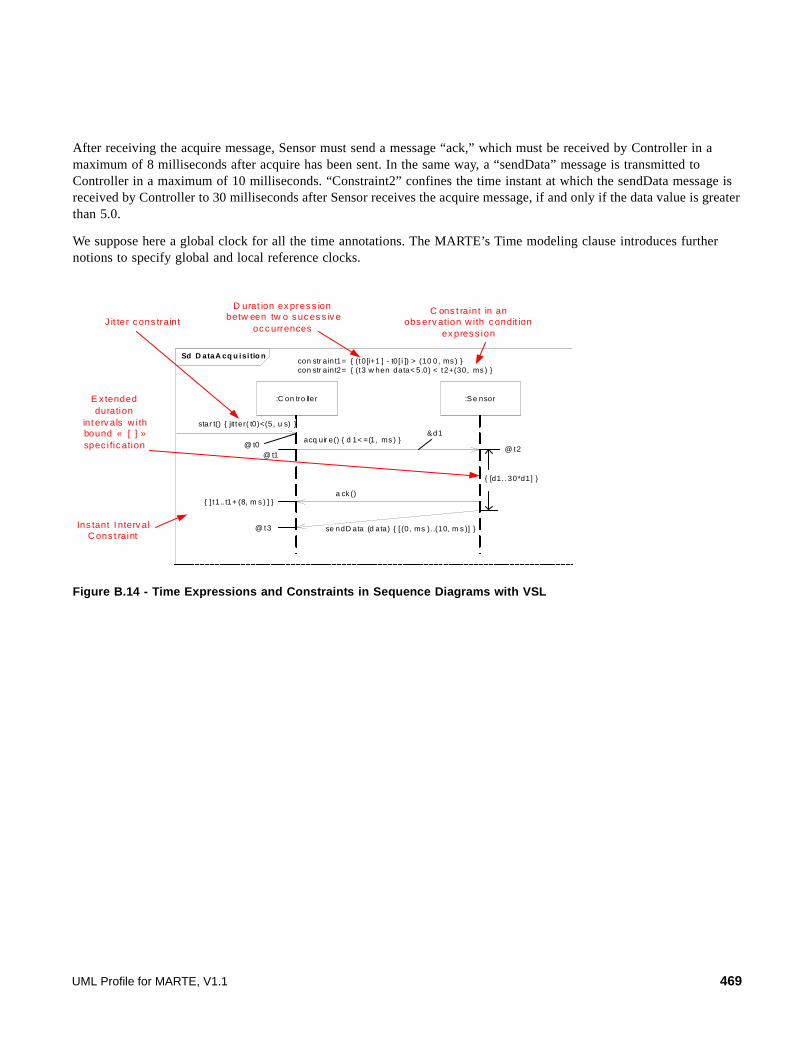
After receiving the acquire message, Sensor must send a message “ack,” which must be received by Controller in a maximum of 8 milliseconds after acquire has been sent. In the same way, a “sendData” message is transmitted to Controller in a maximum of 10 milliseconds. “Constraint2” confines the time instant at which the sendData message is received by Controller to 30 milliseconds after Sensor receives the acquire message, if and only if the data value is greater than 5.0.
We suppose here a global clock for all the time annotations. The MARTE’s Time modeling clause introduces further notions to specify global and local reference clocks.
Figure B.14 - Time Expressions and Constraints in Sequence Diagrams with VSL
Sd D ataA cq u isi tio n
:C on tro ller :Se nsor
acq uir e() { d 1< =(1, ms ) }
se ndD ata (d ata) { [ (0, ms ). .(10, m s )] }
a ck ()
@ t2
{ [d1. .30*d1] }
&d1
con str aint1= { (t0[i+1 ] - t0[ i ]) > (10 0, ms ) }con str aint2= { (t3 w hen data< 5.0) < t2+(30, ms ) }
E x tended duration
int erv als w i th bound « [ ] » spec i fic ation
Ins tant I nterv al C ons t raint
C ons t raint in an obs erv ation w ith c ondit ion
ex pres s ion
D urat ion ex pres s ion betw een tw o s uc es s iv e
oc c urrences
star t() { jit ter( t0)<(5, u s) }
@ t0
{ ] t1.. t1+ (8, m s ) ] }
J it ter c ons traint
@ t3
@ t1
UML Profile for MARTE, V1.1 469

470 UML Profile for MARTE, V1.1

Annex CClock Handling Facilities
C.1 Overview
This annex provides the abstract syntax for specifying clocked values and clock dependencies. Concrete syntax is also described: the Clocked Value Specification Language (CVSL) and the Clock Constraint Specification Language (CCSL). These languages reuse the Value Specification Language (VSL) for general expressions on Boolean, Integer, Real.
C.2 Clocked Value Specification
C.2.1 Domain view
A ClockedValuedSpecification (CVS) is the specification of a set of instances of time values making reference to Clocks. Since the concept of time covers the two concepts of instant and duration, the CVS domain view (Figure C.1) reflects this dichotomy. A ClockedValueSpecification may reference an instance (InstantInstanceValue or DurationInstanceValue) or may be an expression denoting an instance or instances when evaluated. The CVS expressions involve only instants (InstantExpression), only durations (DurationExpression), or both (Span and Translation) in order to combine instants and durations in restricted ways. Interval specifications (InstantIntervalSpecification and DurationIntervalSpecification) are used to specify range of values or uncertainties.
In Figure C.1, InstantValueSpecification and DurationValueSpecification are duplicated to improve legibility.
UML Profile for MARTE, V1.1 471

Figure C.1 - CVS domain view
C.2.1.1 ClockedValueSpecification
A ClockedValueSpecification may reference an instance (InstantInstanceValue or DurationInstanceValue) or may be an expression denoting an instance or instances when evaluated.
Generalizations
• ValueSpecification (from UML::Classes::Kernel)
Associations
• None
Attributes
• None
ValueSpecificat ionClockedValueSpecification
InstantValueSpecification Durat ionValueSpecification
symbol:Str ing[0..1]
InstantExpression
{ ordered } 0..*
0..1
iOperand
InstantInstanceValue
InstantValueSpecification
isLowerOpen: Boolean[1]isUpperOpen: Boolean[1]
InstantIntervalSpecification
10..1
min
1
0..1 max
DurationValueSpecificat ion
isLower Open: Boolean[1]isUpper Open: Boolean[1]
Durat ionIntervalSpecif icat ion
1
0..1min
1 0..1
max
Span
1
0..1
begin end0..1
1
isBackward: Boolean[0..1]
Translation
1
0..1
star t
1
0..1
offset
symbol:String[0..1]
DurationExpression
dOperand
0..1
0..* { or der ed }
DurationInstanceValue
factor: Real[1]
Scaling
1
0..1
dur ation
CVS
472 UML Profile for MARTE, V1.1

Semantics
A ClockedValueSpecification yields zero or more time values bound to Clocks. A ClockedValueSpecification may reference an instance (InstantInstanceValue or DurationInstanceValue) or may be an expression denoting an instance or instances when evaluated. This is an abstract class.
C.2.1.2 DurationExpression
A DurationExpression is a structured tree of symbols that denotes a set of duration values when evaluated in a context.
Generalizations
• DurationValueSpecification (from CVS)
Associations
• dOperand: DurationValueSpecification[0..*] specifies a sequence of operands, which are DurationValueSpecifications.
Attributes
• symbol: String[0..1] the symbol associated with the node in the expression tree.
Semantics
A DurationExpression represents a node in an expression tree. If there are no operands, it represents a terminal node. If there are operands, it represents an operator applied to those operands. In either case there is a symbol associated with the node. The interpretation of this symbol depends on the context of the expression.
C.2.1.3 DurationInstanceValue
A DurationInstanceValue is value that identifies a duration on a Clock.
Generalizations
• DurationValueSpecification (from CVS)
Associations
• None
Attributes
• None
Semantics
A DurationInstanceValue is value that identifies a duration on a Clock.
C.2.1.4 DurationIntervalSpecification
A DurationIntervalSpecification specifies an ordered set of duration value specifications.
UML Profile for MARTE, V1.1 473

Generalizations
• DurationValueSpecification (from CVS)
Associations
• max: DurationValueSpecification [1] Specifies the upper bound of the interval.
• min: DurationValueSpecification [1] Specifies the lower bound of the interval.
Attributes
• isLowerOpen: Boolean [1] = false Specifies whether the lower bound is in the interval (isLowerOpen set to false) or not (isLowerOpen set to true).
• isUpperOpen: Boolean [1] = false Specifies whether the upper bound is in the interval (isUpperOpen set to false) or not (isUpperOpen set to true).
Semantics
A DurationIntervalSpecification specifies an ordered set of duration value specifications.
C.2.1.5 DurationValueSpecification
A DurationValueSpecification may reference an instance (DurationInstanceValue) or may be an expression denoting an instance or instances of durations when evaluated.
Generalizations
• ClockedValueSpecification (from CVS)
Associations
• None
Attributes
• None
Semantics
A DurationValueSpecification yields zero or more duration values bound to Clocks. A DurationValueSpecification may reference an instance (DurationInstanceValue) or may be an expression denoting an instance or instances of durations when evaluated. This is an abstract class.
C.2.1.6 InstantValueSpecification
An InstantValueSpecification may reference an instance (InstantInstanceValue) or may be an expression denoting an instance or instances of instants when evaluated.
474 UML Profile for MARTE, V1.1

Generalizations
• ClockedValueSpecification (from CVS)
Associations
• None
Attributes
• None
Semantics
An InstantValueSpecification yields zero or more instant values bound to Clocks. An InstantValueSpecification may reference an instance (InstantInstanceValue) or may be an expression denoting an instance or instances of instants when evaluated. This is an abstract class.
C.2.1.7 InstantExpression
An InstantExpression is a structured tree of symbols that denotes a set of instant values when evaluated in a context.
Generalizations
• InstantValueSpecification (from CVS)
Associations
• iOperand: InstantValueSpecification [0..*] specifies a sequence of operands, which are InstantValueSpecifications.
Attributes
• symbol: String [0..1] the symbol associated with the node in the expression tree.
Semantics
An InstantExpression represents a node in an expression tree. If there are no operands, it represents a terminal node. If there are operands, it represents an operator applied to those operands. In either case there is a symbol associated with the node. The interpretation of this symbol depends on the context of the expression.
C.2.1.8 InstantInstanceValue
An InstantInstanceValue is value that identifies an instant on a Clock.
Generalizations
• InstantValueSpecification (from CVS)
Associations
• None
UML Profile for MARTE, V1.1 475

Attributes
• None
Semantics
An InstantInstanceValue is value that identifies an instant on a Clock.
C.2.1.9 InstantIntervalSpecification
An InstantIntervalSpecification specifies an ordered set of instant value specifications.
Generalizations
• InstantValueSpecification (from CVS)
Associations
• max: InstantValueSpecification [1] Specifies the upper bound of the interval.
• min: InstantValueSpecification [1] Specifies the lower bound of the interval.
Attributes
• isLowerOpen: Boolean [1] = false Specifies whether the lower bound is in the interval (isLowerOpen set to false) or not (isLowerOpen set to true).
• isUpperOpen: Boolean [1] = false Specifies whether the upper bound is in the interval (isUpperOpen set to false) or not (isUpperOpen set to true).
Semantics
An InstantIntervalSpecification specifies an ordered set of instant value specifications.
C.2.1.10 Scaling
A Scaling is a special expression that denotes duration values obtained from a DurationValueSpecification by applying a multiplicative factor.
Generalizations
• DurationValueSpecification (from CVS)
Associations
• duration: DurationValueSpecification [1] Specifies a duration on a Clock.
Attributes
• factor: Real [1] Specifies the multiplicative factor to apply to duration.
476 UML Profile for MARTE, V1.1
Semantics
A Scaling is a special expression that denotes duration values obtained from a DurationValueSpecification by applying a multiplicative factor.
C.2.1.11 Span
A Span is a special expression that denotes duration values characterized by two instants (begin and end) on a Clock.
Generalizations
• DurationValueSpecification (from CVS)
Associations
• begin: InstantValueSpecification [1] Specifies an instant origin of a time interval on a Clock.
• end: InstantValueSpecification [1] Specifies an instant end of a time interval on a Clock.
Attributes
• None
Semantics
A Span is a special expression that denotes duration values characterized by two instants (begin and end) on a Clock.
C.2.1.12 Translation
A Translation is a special expression that denotes instant values obtained by a forward or backward translation of instants on a Clock.
Generalizations
• InstantValueSpecification (from CVS)
Associations
• offset: DurationValueSpecification [1] Specifies a duration that indicates the delay applied to the start instant on a Clock.
• start: InstantValueSpecification [1] Specifies an instant which is delayed on a Clock.
Attributes
• isBackward: Boolean [0..1] Indicates whether the instant translation is forward (isBackward not defined or defined and set to false) or backward (isBackward set to true).
Semantics
A Translation is a special expression that denotes instant values obtained by a forward or backward translation of instants on a Clock.
UML Profile for MARTE, V1.1 477

C.2.2 Concrete Syntax
CVSL is a simple language for specifying clocked values (instant or duration) in MARTE. The language is not normative. For time expressions on a unique ChronometricClock, VSL::TimeExpressions (Annex B) can be used as well.
A character set encoding is assumed, supporting at least the alpha and the numeric classes, and possibly a miscSymbol class. Classically,
alpha ::= ('A' .. 'Z') | ('a' .. 'z')
numeric ::= '0' .. '9'
alphanumeric ::= alpha | numeric
And for the miscSymbol class, contains a possibly empty set of symbols useful to represent physical units. For instance,
miscSymbol ::= '°' | 'O' | …
The syntax of the language reflects the domain view defined in the CVS package.
C.2.2.1 Literals
CVSL reuses number literals of VSL
number-literal ::= integer-literal | unlimited-natural | real-literal
integer-literal ::= ('+' | '-')? ( decimal-string | hexadecimal-string | binary-string )
unlimited-natural ::= unlimited-string
real-literal ::= ('+' | '-')? nonNegative-real-literal
nonNegative-real-literal ::= ( real-string | scientific-real )
scientific-real ::= real-string 'E' ('+' | '-')? decimal-string
real-string ::= decimal-string ('.' decimal-string)?
hexadecimal-string ::= '0x' ( ('0'..'9') | ('A'..'F') | ('a'..'f') )+
binary-string ::= '0b' ( '0' | '1' )+
decimal-string ::= ('0'..'9')+
unlimited-string ::= ( ('0'..'9')+ | '*' )
C.2.2.2 String literal
string-literal ::= ''' ( body-text | '(\')' | '(\\)')* '''
body-text ::= (terminal symbol consisting of string of characters defined in a character set encoding)
478 UML Profile for MARTE, V1.1
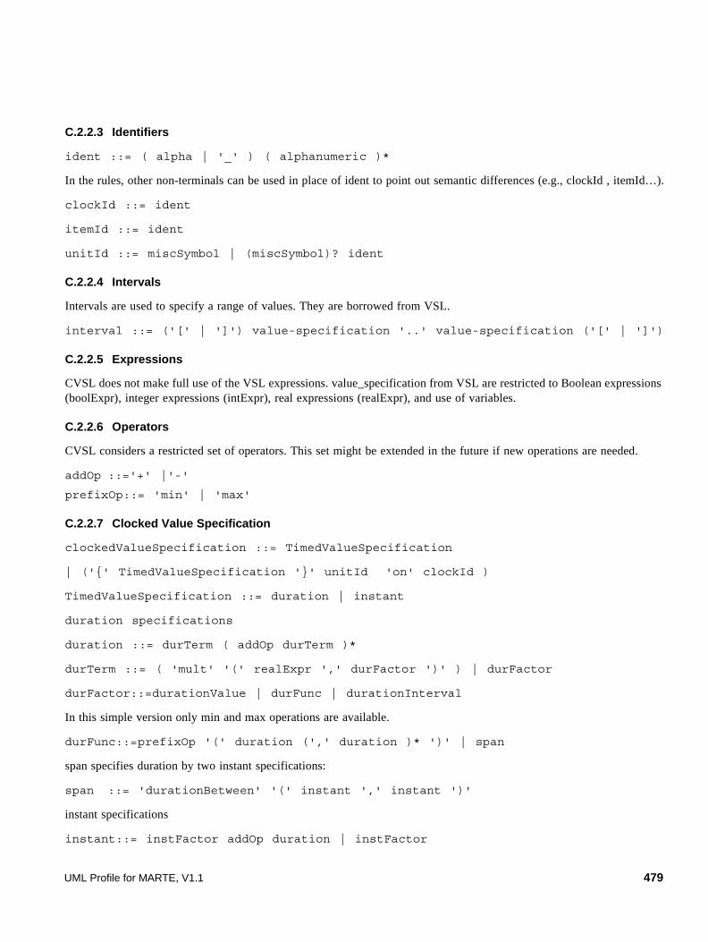
C.2.2.3 Identifiers
ident ::= ( alpha | '_' ) ( alphanumeric )*
In the rules, other non-terminals can be used in place of ident to point out semantic differences (e.g., clockId , itemId…).
clockId ::= ident
itemId ::= ident
unitId ::= miscSymbol | (miscSymbol)? ident
C.2.2.4 Intervals
Intervals are used to specify a range of values. They are borrowed from VSL.
interval ::= ('[' | ']') value-specification '..' value-specification ('[' | ']')
C.2.2.5 Expressions
CVSL does not make full use of the VSL expressions. value_specification from VSL are restricted to Boolean expressions (boolExpr), integer expressions (intExpr), real expressions (realExpr), and use of variables.
C.2.2.6 Operators
CVSL considers a restricted set of operators. This set might be extended in the future if new operations are needed.
addOp ::='+' |'-'
prefixOp::= 'min' | 'max'
C.2.2.7 Clocked Value Specification
clockedValueSpecification ::= TimedValueSpecification
| ('{' TimedValueSpecification '}' unitId 'on' clockId )
TimedValueSpecification ::= duration | instant
duration specifications
duration ::= durTerm ( addOp durTerm )*
durTerm ::= ( 'mult' '(' realExpr ',' durFactor ')' ) | durFactor
durFactor::=durationValue | durFunc | durationInterval
In this simple version only min and max operations are available.
durFunc::=prefixOp '(' duration (',' duration )* ')' | span
span specifies duration by two instant specifications:
span ::= 'durationBetween' '(' instant ',' instant ')'
instant specifications
instant::= instFactor addOp duration | instFactor
UML Profile for MARTE, V1.1 479

instFactor::= instantValue | instantFunc | instantInterval | '(' instant ')'
An instant can be specified as the sum or the difference of an instant specification and a duration specifications. An instant can also be specified by a more general expression. In this simple version only min and max operations are available.
instantFunc ::= prefixOp '(' instant (',' instant )* ')'
C.2.2.8 TimeInstanceValue
Two syntactic forms are available for denoting TimeInstanceValue. This first one uses the tuple notation, as VSL does. The second is closer to a natural language expression.
timeInstanceValue ::= '(' valOrExpr ',' unitSpec (',' clockSpec )? ')'
| realValue unitId 'on' clockId
valOrExpr ::= ('value' '=' realValue ) | ( 'expr' '=' realExpr )
unitSpec ::= 'unit' '=' unitId
clockSpec ::= 'onClock' '=' clockId
realValue ::= nonnegative-real-literal | variable-name
The tuple form denotes either an instance of an NFP_duration (from BasicNFP_Types) or an instance of a TimedValueType (from TimeLibrary). The former can be used only for the idealClk, which is implicit in the notation. variable-name is defined in the VSL grammar.
instantInstanceValue and durationInstanceValue are both timeInstanceValue. The evaluation context determines the interpretation of the value.
instantInstanceValue::= timeInstanceValue
durationInstanceValue ::= timeInstanceValue
C.2.3 Examples of clocked value specifications
C.2.3.1 Single clock time values
The three specifications below denote the same time instance value, on the idealClk clock.
(value = 1.5, unit = ms)
(value = 1.5, unit = ms, onClock = 'idealClk')
1.5 ms on idealClk
The first two specifications use the tuple notation. In the first one (NFP_Duration) the clock is implicitly the idealClk clock. The last one avoids item identifiers, parentheses, commas, and single quotes.
C.2.3.2 Simple expressions on a single clock
(value = 1, unit = ms) + (value = 150, unit = us)
This expression is implicitly on the idealClk clock. Its value is (value = 1.150, unit = ms) or (value = 1150, unit = us), value obtained after applying the conversion factor between ms and us (1 ms = 1000 us). Any clock other than idealClk must be explicitly given.
480 UML Profile for MARTE, V1.1

C.2.3.3 Expressions on multiple clocks
min (15 tick on prClk, 5 ms on idealClk)
This expression is an expression referencing two clocks. It is not always computable. A ClockConstraint binding the two clocks prClk and idealClk must be provided (e.g., the duration of a processor cycle).
{min (15 tick on prClk, 5 ms on idealClk)} ms on idealClk
The same expression placed in a context as above, must return a time value on idealClk and with ms for unit (if it is computable).
C.3 Clock Constraint Specification
C.3.1 Domain View
A ClockConstraintSpecification (CCS) consists of a non empty set of conditional constraints. Conditional means that the constraint is imposed only when the associated guard evaluates to true. In the absence of guard, the constraint is unconditionally applied.
Clock constraints are specialized into ClockRelation, InstantRelation, and ChronoNFP. An InstantRelation imposes an ordering or a coincidence between two instants of different clocks. A ClockRelation is more general and imposes constraints on set of instants of different clocks. A ChronoNFP is a constraint that applies to chronometric clocks only, and specifies time related non functional properties for a chronometric clock or a group of chronometric clocks. A fourth clock constraint is a ClockDefinition. It defines a new clock, local to the ClockConstraintSpecification.
UML Profile for MARTE, V1.1 481

Figure C.2 - CCS domain view
C.3.1.1 AbstractConstraint
AbstractConstraint is an abstract super class of ClockRelation, ChronoNFP, InstantRelation, and ClockDefinition.
Generalizations
• None
Associations
• guard: Predicate [0..1] An owned predicate, which is evaluated in the context of the owning ClockConstraintSpecification. When this property is empty or when it is defined and evaluates to true, the constraint is applied. It is ignored otherwise.
Attributes
• None
Semantics
AbstractConstraint is an abstract super class of ClockRelation, ChronoNFP, InstantRelation, and ClockDefinition. The optional guard attribute indicates whether the constraint is applied or ignored according to the context of the ClockConstraintSpecification.
TimeModels::TimeAccesses::Clocks::Clock
ClockExpression
defBody
0..1
0..1
CoreElements::Causality::CommonBehavior::Event
0..1
definingEvent
ClockRelation
clocks 0..* { ordered } index: Integer
InstantReference
clock1
relation: InstantRelationKind
InstantRelation
{ ordered } 2
0..1
instantRefs
AbstractConstraint
ChronoNFP
Predicate0..1
0..1 guard
TimeModels::TimeAccesses::
ChronometricClocks::ChronometricClock
{ ordered } 1..* chronos
ClockDefinition
localClock0..1
1
ClockConstraintSpecification1..*
constraints
CCS
coincidenceprecedence
<<enumeration>>InstantRelationKind
{ ordered }1..*
clocks
0..*{ ordered }
0..1
anonymousClocks
482 UML Profile for MARTE, V1.1

C.3.1.2 ChronoNFP
A ChronoNFP is a constraint that applies to chronometric clocks only, and specifies time related non functional properties for a chronometric clock or a group of chronometric clocks.
Generalizations
• AbstractConstraint (from CCS)
Associations
• chronos:Time::TimeAccesses::ChronometricClocks::ChronometricClock[1..*] References a set of chronometric clocks whose time related non functional properties are constrained.
Attributes
• None
Semantics
A ChronoNFP is a constraint that applies to chronometric clocks only, and specifies time related non functional properties for a chronometric clock or a group of chronometric clocks.
Examples of ChronoNFP
• StabilityConstraint, which imposes a constraint on the value of the stability attribute of a ChronometricClock. Additional constraint: chronos->size( ) = 1.
• SkewConstraint, which imposes a constraint on the value of the skew attribute of a ChronometricClock, with respect to another ChronometricClock. Additional constraint: chronos->size( ) = 2.
• DriftConstraint, which imposes a constraint on the value of the drift attribute of a ChronometricClock, with respect to another ChronometricClock. Additional constraint: chronos->size( ) = 2.
• OffsetConstraint, which imposes a constraint on the value of the offset attribute of a ChronometricClock, with respect to another ChronometricClock. Additional constraint: chronos->size( ) = 2.
C.3.1.3 ClockDefinition
A ClockDefinition defines a new clock, local to the ClockConstraintSpecification.
Generalizations
• AbstractConstraint (from CCS)
Associations
• defBody: ClockExpression[0..1] Owned ClockExpression that specifies the localClock as derived from other clocks.
• definingEvent: CoreElements::Causality::CommonBehavior::Event[0..1] References the event whose occurrences define the ticks of the localClock.
• localClock: Time::TimeAccesses::Clocks::Clock[1] References the defined clock.
UML Profile for MARTE, V1.1 483

Attributes
• None
Semantics
A ClockDefinition defines a new clock, local to the ClockConstraintSpecification. This clock is defined as derived from other clocks or from occurrences of an event.
Constraints
[2] A (local) clock can be defined either by a ClockExpression or by an Event.
definingEvent->None.mpty( ) = defBody->isEmpty( )
C.3.1.4 ClockExpression
A ClockExpression specifies a clock derived from one or many clocks.
Generalizations
• None
Associations
• clocks: Clock [1..*] { ordered } References the clocks from which the specified clock is derived.
Attributes
• None
Semantics
A ClockExpression specifies a clock derived from one or many clocks.
Examples of ClockExpression
A ClockExpression is a function-like clock relation that returns a Clock derived from other clocks.
• ClockDiscretization, takes a dense ChronometricClock, and returns a discrete Clock. Parameters: a discretizationStep, and an optional discretization interval.
• ClockFiltering, derives a discrete clock from another discrete clock. Each instant of the returned clock is coincident with an instant of the filtered clock. Parameter: a BinaryWord which specifies the filter: the kth instant of the filtered clock is coincident with an instant of the returned clock if and only if the kth bit of the BinaryWord is set to 1.
• ClockDelay, takes a clock and returns a new one. Parameter: a delay. The kth instant of the returned clock is coincident with the (k+delay)th instant of the given clock.
• ClockChaining, takes two clocks and returns a new one. The first argument clock must be finite. The first instants of the returned clock are coincident with the instants of the first clock. The following instants are coincident with the instants of the second clock.
Figure C.3 illustrates clock expressions. Junction instants are represented by small circles, and the coincidence relation by red edges between junction instants.
484 UML Profile for MARTE, V1.1

Figure C.3 - Examples of clock expressions
C.3.1.5 ClockRelation
A ClockRelation specifies a constraint among clocks. This constraint imposes relations between instants of those clocks.
Generalizations
• AbstractConstraint (from CCS)
Associations
• anonymousClocks: ClockExpression [0..*] References clock expressions involved in the relation. They are called anonymous clocks because they are not identified clocks, but clock expressions specifying an unnamed clock. The clock expressions are owned by this ClockRelation.
• clocks: Clock [0..*] References clocks involved in the relation.
Attributes
• None
Semantics
A ClockRelation specifies a constraint among clocks. This constraint imposes relations (coincidence or precedence) between instants of those clocks.
A rg u men t c lo c k{d e n se}
D is cre tized clo ck{d isc ret e}
Discre tiza tio n inte rvalD icre tiza tio n s tep
C lo c k D is c re ti z a ti o n
A rg u men t c lo c k
F i lt ere d c lo ck
C lo c k Fi l te ri n g
bw= 0 11 00(1 0)
A rg u men t c lo c k
D elay ed clo ck
de lay =3
C lo c k D e la y
2n d A rg u me nt c lo ck
1s t A rg u men t c lo c k{f in ite }
C h ain ed clo ck
C lo c k C h a in in g
UML Profile for MARTE, V1.1 485

Constraints
[1] A ClockRelation constrains at least two clocks or anonymous clocks.
clocks->union(anonymousClocks)->size( ) >= 2
Examples of ClockRelation
A ClockRelation is a relational dependency between instants of clocks. This is a more general concept than ClockExpression, which is a functional dependency. A ClockRelation imposes a partial ordering between the instants of the clocks. In what follows, ClockReference denotes either a Clock or a ClockExpression.
The following clock relations constrain a pair of ClockReferences.
• Periodicity imposes that there exists an integer p such that between each pair of successive instants of a ClockReference, there exist p instants of the other ClockReference.
• Sporadicity imposes that there exists an integer g such that between each pair of successive instants of a ClockReference, there exist at least g instants of the other ClockReference.
• Subclocking imposes that there exists an injective mapping from the instants of one ClockReference onto the instants of the other ClockReference, such that this mapping preserves the instant ordering. This relation is a weak form of the ClockFiltering without an imposed filter.
• Equality is a strong relation: there exists a one-to-one mapping between instants of the two ClockReferences, and this mapping is order preserving.
Some clock relations require a third ClockReference. Each constrained ClockReference must be subclock of this third ClockReference.
• RelativeSpeed imposes that for any integer k, the kth instant of the faster ClockReference precedes the kth instant of the slower ClockReference.
• MaximalDrift imposes that there exists an integer m such that for each instant k of the third ClockReference, the absolute difference between the numbers of instants preceding instant k in the two ClockReferences is less than or equal to m.
Figure C.4 illustrates clock relations. Note that junction instants are not necessarily evenly interspaced.
486 UML Profile for MARTE, V1.1

Figure C.4 - Examples of clock relations
C.3.1.6 InstantReference
An InstantReference specifies an instant of a Clock.
Generalizations
• None
Associations
• clock: Clock [1] References the Clock whose instant is referred to.
Attributes
• index: Integer [1] specifies the index of the instant.
Semantics
An InstantReference specifies an instant of a Clock.
C.3.1.7 InstantRelation
An InstantRelation imposes a precedence or a coincidence constraint between two instants of two different clocks.
Generalizations
• AbstractConstraint (from CCS)
a1 a2 a3 a4 a5 a6
b1 b2 b3
b4 b5
a7 a10a8 a9
x y
x y
x ydeno tes (coincidence)
deno tes (w eak p recedence)
deno tes (s t rict precedence)
x y
x y
x y
≡
p
?
a
b periodicw .r .t. a, p =3
Periodic it y
c1 c2 c3 c 4 c5 c 6 c 7 c10c8 c9
a1 a2 a3 a4
b1 b2 b3
R elativeSpeed : a faster than b
c
a subclocking c
b subclocking c
UML Profile for MARTE, V1.1 487
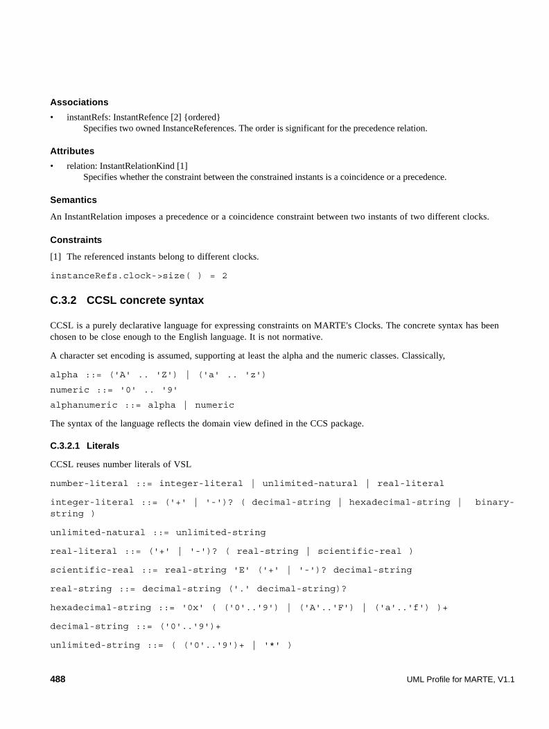
Associations
• instantRefs: InstantRefence [2] {ordered} Specifies two owned InstanceReferences. The order is significant for the precedence relation.
Attributes
• relation: InstantRelationKind [1] Specifies whether the constraint between the constrained instants is a coincidence or a precedence.
Semantics
An InstantRelation imposes a precedence or a coincidence constraint between two instants of two different clocks.
Constraints
[1] The referenced instants belong to different clocks.
instanceRefs.clock->size( ) = 2
C.3.2 CCSL concrete syntax
CCSL is a purely declarative language for expressing constraints on MARTE's Clocks. The concrete syntax has been chosen to be close enough to the English language. It is not normative.
A character set encoding is assumed, supporting at least the alpha and the numeric classes. Classically,
alpha ::= ('A' .. 'Z') | ('a' .. 'z')
numeric ::= '0' .. '9'
alphanumeric ::= alpha | numeric
The syntax of the language reflects the domain view defined in the CCS package.
C.3.2.1 Literals
CCSL reuses number literals of VSL
number-literal ::= integer-literal | unlimited-natural | real-literal
integer-literal ::= ('+' | '-')? ( decimal-string | hexadecimal-string | binary-string )
unlimited-natural ::= unlimited-string
real-literal ::= ('+' | '-')? ( real-string | scientific-real )
scientific-real ::= real-string 'E' ('+' | '-')? decimal-string
real-string ::= decimal-string ('.' decimal-string)?
hexadecimal-string ::= '0x' ( ('0'..'9') | ('A'..'F') | ('a'..'f') )+
decimal-string ::= ('0'..'9')+
unlimited-string ::= ( ('0'..'9')+ | '*' )
488 UML Profile for MARTE, V1.1
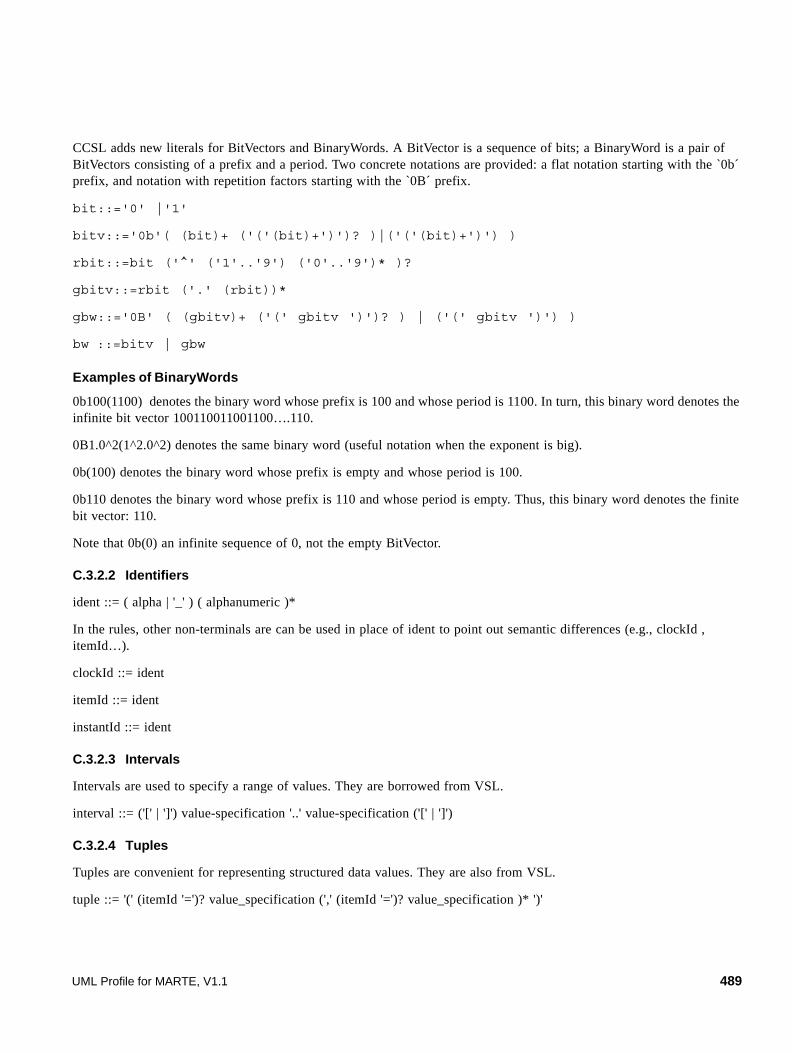
CCSL adds new literals for BitVectors and BinaryWords. A BitVector is a sequence of bits; a BinaryWord is a pair of BitVectors consisting of a prefix and a period. Two concrete notations are provided: a flat notation starting with the `0b´ prefix, and notation with repetition factors starting with the `0B´ prefix.
bit::='0' |'1'
bitv::='0b'( (bit)+ ('('(bit)+')')? )|('('(bit)+')') )
rbit::=bit ('^' ('1'..'9') ('0'..'9')* )?
gbitv::=rbit ('.' (rbit))*
gbw::='0B' ( (gbitv)+ ('(' gbitv ')')? ) | ('(' gbitv ')') )
bw ::=bitv | gbw
Examples of BinaryWords
0b100(1100) denotes the binary word whose prefix is 100 and whose period is 1100. In turn, this binary word denotes the infinite bit vector 100110011001100….110.
0B1.0^2(1^2.0^2) denotes the same binary word (useful notation when the exponent is big).
0b(100) denotes the binary word whose prefix is empty and whose period is 100.
0b110 denotes the binary word whose prefix is 110 and whose period is empty. Thus, this binary word denotes the finite bit vector: 110.
Note that 0b(0) an infinite sequence of 0, not the empty BitVector.
C.3.2.2 Identifiers
ident ::= ( alpha | '_' ) ( alphanumeric )*
In the rules, other non-terminals are can be used in place of ident to point out semantic differences (e.g., clockId , itemId…).
clockId ::= ident
itemId ::= ident
instantId ::= ident
C.3.2.3 Intervals
Intervals are used to specify a range of values. They are borrowed from VSL.
interval ::= ('[' | ']') value-specification '..' value-specification ('[' | ']')
C.3.2.4 Tuples
Tuples are convenient for representing structured data values. They are also from VSL.
tuple ::= '(' (itemId '=')? value_specification (',' (itemId '=')? value_specification )* ')'
UML Profile for MARTE, V1.1 489

C.3.2.5 Expressions
CCSL does not make full use of the VSL expressions. value_specification from VSL are restricted to Boolean expressions (boolExpr), integer expressions (intExpr), real expressions (realExpr).
CCSL adds its own duration expression:
durationExpr::=realExprunitId 'on' clockId
C.3.2.6 Operators
CCSL has relational operators, Boolean operators, and the dot operator used for navigation like OCL.
relOp ::='<' |'<=' |'=' |'>=' |'<' |'<>' |'in'
booleanOp::='and' | 'or' | 'xor' | 'not'
path ::=id ('.' id )*
C.3.2.7 Constraints
A clock constraint consists of a set of conditional statements.
clockConstraint ::= ( conditionalStatement';' )+
conditionalStatement ::= statement (guard)?
statement ::=clockDef | instantRel | clockRel | chronoNFP | instantDef
guard ::='if' boolExpr
clockDef::='Clock' clockId ( 'is' clockExpr )?
clockRef::=clockId | '(' clockExpr ')'
instantDef::='Instant' instantId ( 'is' instantRef )?
instantRef::=instantId | ( clockRef '[' intExpr ']' )
| 'instantOf' clockRef 'suchThat' boolExpr
C.3.2.8 ChronoNFP
Time-related non functional properties of ChronometricClocks have been defined in the CCS domain view. The chosen syntax is self-explanatory.
chronoNFP::=clockRef
( ( 'hasStability' realExpr ) ('wrt' clockId )?
| ( ',' clockRef
( ('haveSkew'|'haveDrift') realExpr )
| ('haveOffset' durationExpr )
) ('wrt' clockId )? ('at' instantExpr )?
)
)
490 UML Profile for MARTE, V1.1

C.3.2.9 Clock expressions
A ClockExpression specifies a clock derived from one or many clock references.
clockExpr::=clockId
| ( 'when' eventExpr )
| clockRef
( ( 'restrictedTo' boolExpr )
| ( 'filteredBy' bwExpr )
| ( 'discretizedBy' realExpr
('from' realExpr )? ('to' realExpr )? )
| ( 'delayedBy' intExpr )
| ( 'followedBy' | 'inter' | 'minus' | 'sampledTo' )
clockRef
)
C.3.2.10 Clock relations
The ClockRelations have been defined in the CCS domain view.
clockRel::=clockRef
(( ('isPeriodicOn' clockRef ('period' realExpr )?)
| ('isSporadicOn' clockRef ('gap' realExpr )?)
| ( ( 'isFinerThan' |'isCoarserThan' ) clockRef )
| ( ( 'isFasterThan' |'isSlowerThan' ) clockRef )
| ( ',' clockRef 'haveMaxDrift' intExpr )
| ( '=' clockRef )
| ( '#' clockRef )
| ( 'alternatesWith' clockRef )
| ( 'hasSameRateThan' clockRef )
)
C.3.2.11 Instant relations
The reference to an instant of a given Clock is made using the at operation.
instant::=clockId '.' 'at' '(' intExpr ')'
instantRel::=instantRef
( 'coincidentWith' | ('strictly')? 'precedes' )
instantRef
Periodicity and Sporadicity are respectively denoted by isPeriodicOn and isSporadicOn. The optional real expression allows the user to specify the period or the minimal gap between successive instants of the first clock with respect to the second.
Subclocking is denoted by isCoarserThan. The converse is also offered if b isCoarserThan a, then a isFinerThan b. (b is a subclock of a, and a is a superclock of b.)
UML Profile for MARTE, V1.1 491

RelativeSpeed is expressed by isFasterThan, with the converse relation isSlowerThan.
Equality is simply denoted by the equality symbol.
The maximalDrift relation being symmetric, the adopted syntax is a pair of clock references followed by haveMaxDrift. This yields an integer value that is constrained.
492 UML Profile for MARTE, V1.1

Annex DNormative MARTE Model Libraries
(MARTE_Library)
D.1 MARTE Model Library for Primitive Types
This sub clause defines a model library of MARTE primitive types (Figure D.1) that includes predefined operations commonly used in the real-time and embedded system domain.
Figure D.1 - MARTE Primitive types and their operators
For each operation the signature and a description of the semantics is given in the following sub-headings. Within the description, the reserved word ‘result’ is used to refer to the value those results from evaluating the operation. Note that all the defined operations are static.
D.1.1 Real
UML Profile for MARTE, V1.1 493

The standard type Real represents an approximation to the mathematical concept of real. Note that Integer is a subclass of Real, so for each parameter of type Real, you can use an integer as the actual parameter.
D.1.2 Integer
The standard type Integer represents the mathematical concept of integer.
+ (r : Real) : Real value of the addition of self and r.
- () : Real negative value of self.
* (r : Real) : Real value of the multiplication of self and r.
/ (r : Real) : Real value of self divided by r.
abs() : Real absolute value of self.
< (r : Real) : Boolean true if self is less than r.
> (r : Real) : Boolean true if self is greater than r.
<= (r : Real) : Boolean true if self is less than or equal to r.
>= (r : Real) : Boolean true if self is greater than or equal to r.
<> (r : Real) : Boolean true if different to r.
== (r : Real) : Boolean true if equal to r.
^(p: Real): Real ^(p: Real): Real.
diff(x: Real, n: Integer) Order n derivative of self regarding the independent variable x.
intg(x: Real, lw: Real, up: Real) Integral of self from the lower limit lw to the upper limit up.
sum(k: Real, lw: Real, up: Real). Summation of self from k equal to a lower value lw to an upper value up.
+ (i : Integer) : Integer value of the addition of self and i
- () : Integer negative value of self
* (i : Integer) : Integer value of the multiplication of self and i.
/ (i : Integer) : Real value of self divided by i
< (i : Integer) : Boolean true if self is less than i.
> (i : Integer) : Boolean true if self is greater than i.
<= (i : Integer) : Boolean true if self is less than or equal to i.
>= (i : Integer) : Boolean true if self is greater than or equal to i
<> (i : Integer) : Boolean true if different to i
== (i : Integer) : Boolean true if equal to i
mod (i : Integer) : Integer true modulo of self and i
^(p: Real): Real ^(p: Real): Real.
diff(x: Real, n: Integer) Order n derivative of self regarding the independent variable x.
intg(x: Real, lw: Real, up: Real) Integral of self from the lower limit lw to the upper limit up.
sum(k: Real, lw: Real, up: Real). Summation of self from k equal to a lower value lw to an upper value up.
494 UML Profile for MARTE, V1.1

D.1.3 UnlimitedNatural
The standard type Unlimited Natural represents the mathematical concept of Natural including the infinite value.
D.1.4 String
The standard type String represents strings, which can be both ASCII and Unicode.
D.1.5 Boolean
+ (un : UnlimitedNatural) : UnlimitedNatural value of the addition of self and un
- () : Integer negative value of self.
* (un : UnlimitedNatural) : UnlimitedNatural value of the multiplication of self and u
/ (un : UnlimitedNatural) : Real value of self divided by un
< (un : UnlimitedNatural) : Boolean true if self is less than un
> (un : UnlimitedNatural) : Boolean true if self is greater than un.
<= (un : UnlimitedNatural) : Boolean true if self is less than or equal to un
>= (un : UnlimitedNatural) : Boolean true if self is greater than or equal to un
<> (un : UnlimitedNatural) : Boolean true if different to un.
== (un : UnlimitedNatural) : Boolean true if equal to un
mod (un : UnlimitedNatural) : Integer true modulo of self and i
^(p: Real): Real ^(p: Real): Real.
diff(x: Real, n: Integer) Order n derivative of self regarding the independent variable x.
intg(x: Real, lw: Real, up: Real) Integral of self from the lower limit lw to the upper limit up.
sum(k: Real, lw: Real, up: Real). Summation of self from k equal to a lower value lw to an upper value up.
concat(s : String) : String concatenation of self and s
<> (s : String) : Boolean true if different to s.
== (s : String) : Boolean true if equal to s.
UML Profile for MARTE, V1.1 495

The standard type Boolean represents the common true/false values.
D.1.6 DateTime
Datetime defines an instant of time in calendar format.
D.1.7 Precedence Rules
The precedence order for the operations, starting with highest precedence, in VSL is defined as follow:
• unary 'not', unary minus '-' and unary plus '+'
• '*' and '/'
• binary '+' and '-'
• '<', '>', '<=', '>='
• '= =', '<>'
• 'and', 'or' and 'xor'
Parentheses '(' and ')' can be used to change precedence.
D.2 MARTE model library for extended datatypes
This sub clause defines the complete set of MARTE datatypes that use the UML profiles for NFP and VSL. In Figure D.2, we show the whole architecture of extended data types and the applied profiles.
or (b : Boolean) : Boolean true if either self or b is true
xor (b : Boolean) : Boolean true if either self or b is true, but not both
and (b : Boolean) : Boolean true if both self and b are true
not () : Boolean true if self is false.
<> (b: Boolean) : Boolean true if different to b
== (b: Boolean) : Boolean true if equal to b
+ (r : Real) : Real value of the addition of self and r, after converting DateTime to real.
- (r : Real) : Real value of the subtraction of r to self, after converting DateTime to real
< (dt : DateTime) : Boolean true if self is less than dt.
> (dt : DateTime) : Boolean true if self is greater than dt.
<= (dt : DateTime) : Boolean true if self is less than or equal to dt
>= (dt : DateTime) : Boolean true if self is greater than or equal to dt.
<> (dt : DateTime) : Boolean true if different to dt.
== (dt : DateTime) : Boolean true if equal to dt
496 UML Profile for MARTE, V1.1
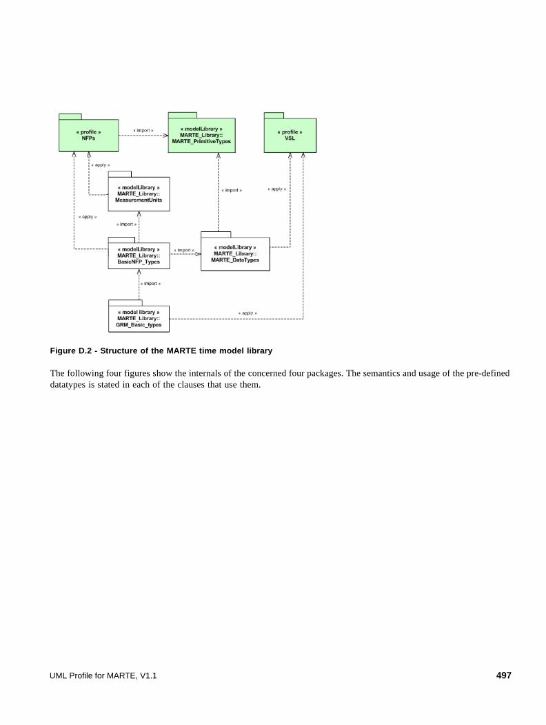
Figure D.2 - Structure of the MARTE time model library
The following four figures show the internals of the concerned four packages. The semantics and usage of the pre-defined datatypes is stated in each of the clauses that use them.
UML Profile for MARTE, V1.1 497
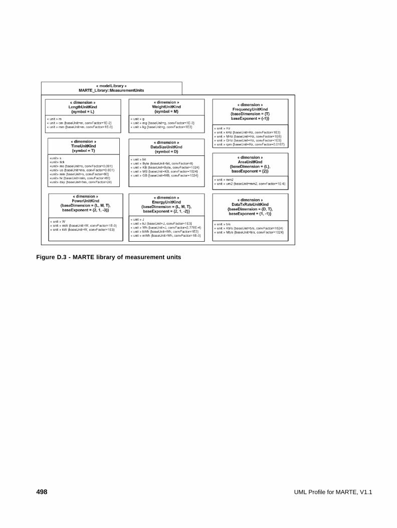
Figure D.3 - MARTE library of measurement units
498 UML Profile for MARTE, V1.1
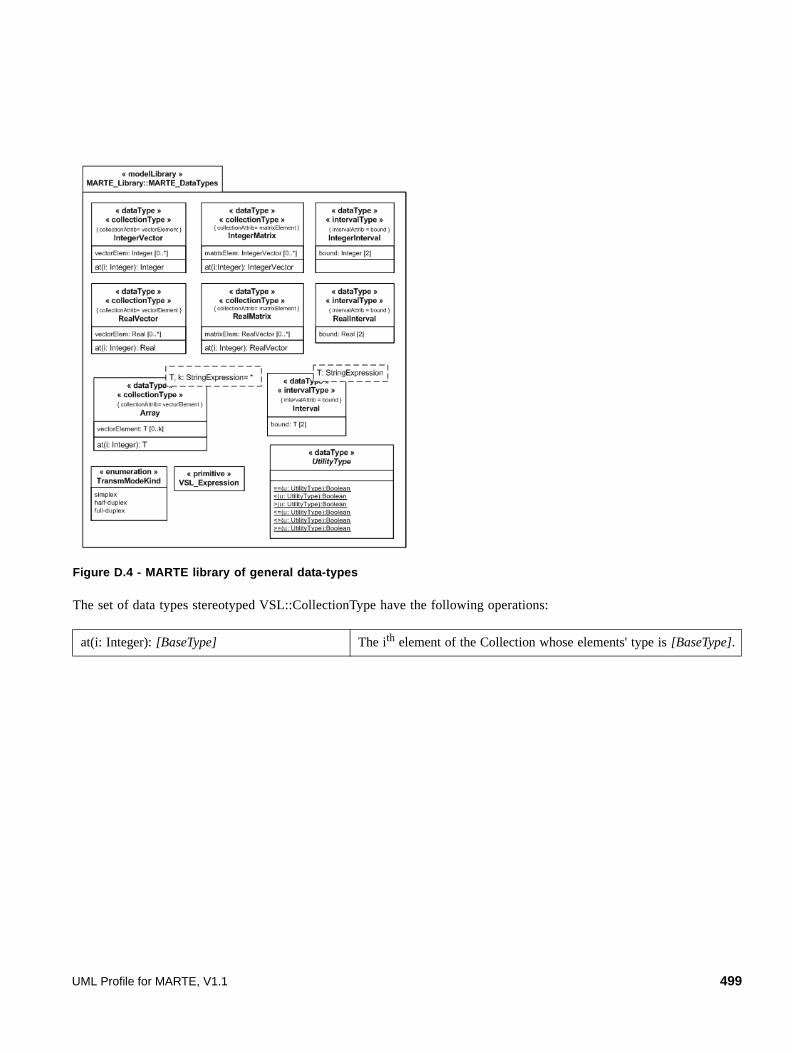
Figure D.4 - MARTE library of general data-types
The set of data types stereotyped VSL::CollectionType have the following operations:
at(i: Integer): [BaseType] The ith element of the Collection whose elements' type is [BaseType].
UML Profile for MARTE, V1.1 499

Figure D.5 - MARTE library of pre-declared NFP types
Figure D.6 describes the set of operations in NFP_CommonType that declare common probability distributions. Note that it represents a partial view of NFP_CommonType. The properties of this NfpType are described in Figure D.5.
500 UML Profile for MARTE, V1.1
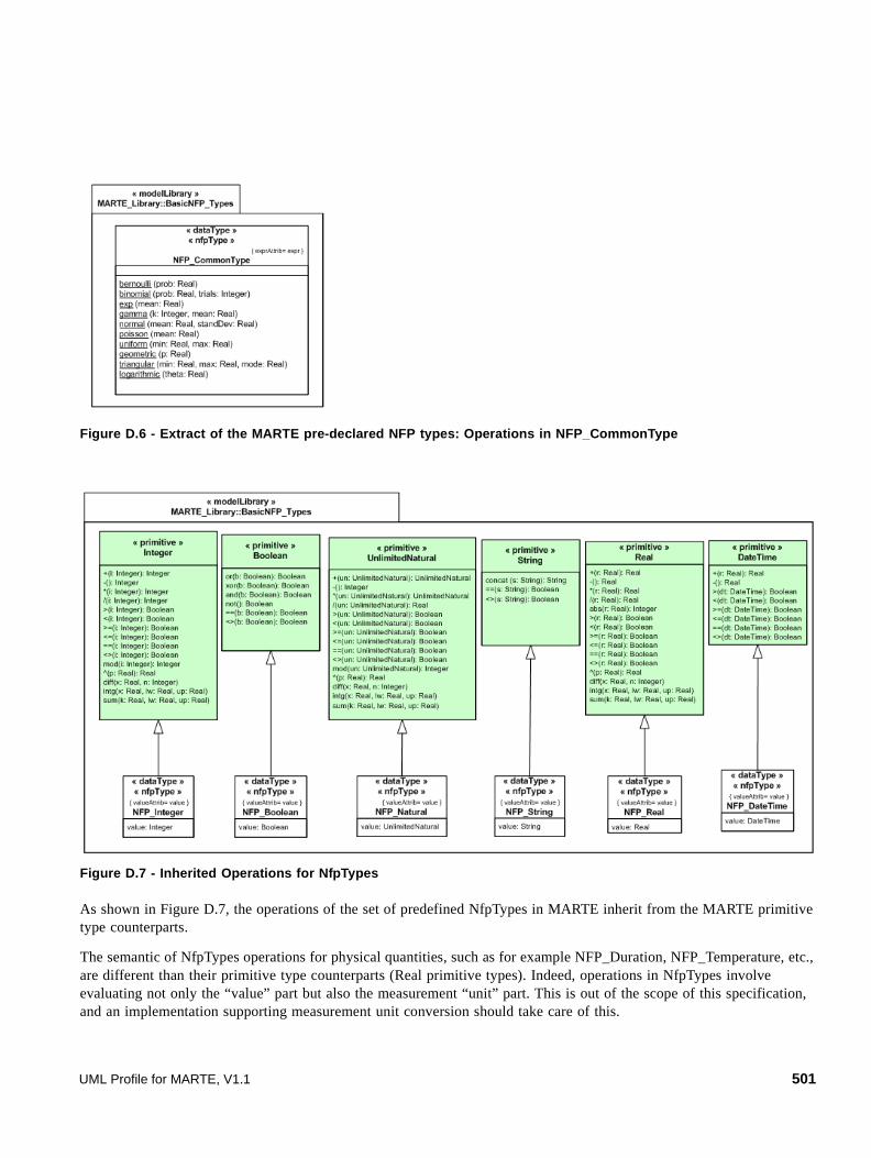
Figure D.6 - Extract of the MARTE pre-declared NFP types: Operations in NFP_CommonType
Figure D.7 - Inherited Operations for NfpTypes
As shown in Figure D.7, the operations of the set of predefined NfpTypes in MARTE inherit from the MARTE primitive type counterparts.
The semantic of NfpTypes operations for physical quantities, such as for example NFP_Duration, NFP_Temperature, etc., are different than their primitive type counterparts (Real primitive types). Indeed, operations in NfpTypes involve evaluating not only the “value” part but also the measurement “unit” part. This is out of the scope of this specification, and an implementation supporting measurement unit conversion should take care of this.
UML Profile for MARTE, V1.1 501
D.2.1 AperiodicPattern
This is a TupleType that contains the parameters that are necessary to specify an aperiodic pattern (unbounded pattern).
Attributes
• distribution: NFP_CommonType [0..1] A distribution of the arrival pattern that could use one of the patterns described in 8.3.3.
D.2.2 ArrivalPattern
This is a ChoiceType that contains the different kinds of parameters that are necessary to specify the most common arrival patterns of events.
Attributes
• periodic: PeriodicPattern [0..1] It describes periodic interarrival patterns, with an optional maximal deviation (jitter).
• aperiodic: AperiodicPattern [0..1] It describes an unbounded pattern that is defined by a distribution function.
• sporadic: SporadicPattern [0..1] It describes a bounded pattern that is defined by a corner case interarrival times and a maximum deviation (jitter).
• burst: BurstPattern [0..1] It describes a bursty interarrival pattern with a number of events that can occur in a bounded period.
• irregular: IrregularPattern [0..1] It describes an aperiodic pattern that is described by a table of successive interarrivals durations measured from a starting phase.
• closed: ClosedPattern [0..1] It describes a workload characterized by a fixed number of active or potential users or jobs that cycle between executing the scenario.
• open: OpenPattern [0..1] It describes a workload that is modeled as a stream of requests that arrive at a given rate in some predetermined pattern (such as Poisson arrivals).
D.2.3 BurstPattern
This is a TupleType that contains the parameters that are necessary to specify a bursty pattern.
Generalizations
• AperiodicPattern.
Attributes
• minInterarrival: NFP_Duration [0..1] The minimum interarrival duration between two successive occurrences of a burst.
• maxInterarrival: NFP_Duration [0..1] The maximum interarrival duration between two successive occurrences of a burst.
502 UML Profile for MARTE, V1.1

• minEventInterval: NFP_Duration [0..1] The minimum interval between two event occurrences within a burst.
• maxEventInterval: NFP_Duration [0..1] The maximum interval between two event occurrences within a burst.
• burstSize: NFP_Integer The number of event occurrences within a burst.
D.2.4 ClosedPattern
This is a TupleType that contains the parameters that are necessary to specify a closed pattern. It is characterized by a fixed number of active or potential users or jobs that cycle between executing the scenario, and spending an external delay period (sometimes called “think time”) outside the system, between the end of one response and the next request.
Attributes
• population: NFP_Integer [0..1] The size of the workload (number of system users).
• extDelay: NFP_Duration [0..1] The delay between the end of one response and the start of the next for each member of the population of system users.
D.2.5 IrregularPattern
This is a TupleType that contains the parameters that are necessary to specify an irregular pattern (list of duration separations between successive event occurrences). This is a fully deterministic arrival pattern.
Generalizations
• AperiodicPattern
Attributes
• phase: NFP_Duration [0..1] A delay for the first occurrence of the event.
• interarrivals: NFP_Duration[*] The set of duration separations between successive event occurrences.
D.2.6 NFP_Boolean
Generalization
• NFP_CommonType
• Boolean
Attributes
• value: MARTE_PrimitiveTypes::Boolean [0..1] Attribute representing the value part of an NfpType.
UML Profile for MARTE, V1.1 503

D.2.7 NFP_CommonType
This is the parent NfpType that contains common parameters (modeled as UML Properties) and common operations of the various NfpTypes defined in MARTE.
Attributes
• expr: VSL_Expression [0..1] Attribute representing an expression. MARTE uses the VSL language to define expressions.
• source: SourceKind [0..1] Peculiarity of NFPs associated with the origin of specifications. Predefined kind of sources for values are estimated, calculated, required and measured.
• statQ: StatisticaQualifierKind [0..1] Statistical qualifier indicates the type of “statistical” measure of a given property (e.g., maximum, minimum, mean, percentile, distribution).
• dir: DirectionKind [0..1] Direction attribute (i.e., increasing or decreasing) defines the type of the quality order relation in the allowed value domain of NFPs. Indeed, this allows multiple instances of NFP values to be compared with the relation “higher- quality-than” in order to identify what value represents the higher quality or importance.
• mode: String [*] Operational mode(s) in which the NFP annotation is valid. The string should contain the name of a existing UML element stereotyped as «MARTE::CoreElements::Mode».
Operations
• bernoulli (prob: Real) Bernoulli distribution has one parameter, a probability (a real value no greater than 1).
• binomial (prob: Real, trials: Integer) Binomial distribution has two parameters: a probability and the number of trials (a positive integer).
• exp (mean: Real) Exponential distribution has one parameter, the mean value.
• gamma (k: Integer, mean: Real) Gamma distribution has two parameters ("k" a positive integer and the "mean").
• normal (mean: Real, standDev: Real) Normal (Gauss) distribution has a mean value and a standard deviation value (greater than 0).
• poisson (mean: Real) Poisson distribution has a mean value.
• uniform (min: Real, max: Real) Uniform distribution has two parameters designating the start and end of the sampling interval.
• geometric (p: Real) The Geometric distribution is a discrete distribution bounded at 0 and unbounded on the high side.
• triangular (min: Real, max: Real, mode: Real) The Triangular distribution is often used when no or little data is available; it is rarely an accurate representation of a data set.
504 UML Profile for MARTE, V1.1
• logarithmic (theta: Real) The Logarithmic distribution is a discrete distribution bounded by [1,...]. Theta is related to the sample size and the mean.
D.2.8 NFP_DataTxRate, NFP_Frequency, NFP_Length, NFP_Area, NFP_Power, NFP_DataSize, NFP_Energy, NFP_Weight
Generalization
• NFP_Real
Attributes
• unit: {MeasurementUnits:: DataTxRateUnitKind, FrequencyUnitKind, LengthUnitKind, AreaUnitKind, PowerUnitKind, DataSizeUnitKind, EnergyUnitKind, WeightUnitKind} [0..1]
Attribute representing the measurement unit.
• precision: Real [0..1] Degree of refinement in the performance of a measurement operation, or the degree of perfection in the instruments and methods used to obtain a result. Precision is characterized in terms of a Real value, which is the standard deviation of the measurement.
D.2.9 NFP_DateTime
Generalization
• NFP_CommonType
• DateTime
Attributes
• value: MARTE_PrimitiveTypes::DateTime [0..1] Attribute representing the value part of an date time NfpType.
D.2.10 NFP_Duration
Generalization
• NFP_Real
Attributes
• unit: MeasurementUnits:: DurationUnitKind [0..1] Attribute representing the measurement unit.
• clock: String [0..1] Attribute representing the reference to a clock.
• precision: Real [0..1] Degree of refinement in the performance of a measurement operation, or the degree of perfection in the instruments and methods used to obtain a result. Precision is characterized in terms of a Real value, which is the standard deviation of the measurement.
UML Profile for MARTE, V1.1 505

• worst: Real [0..1] Attribute representing the worst-case value of a duration.
• best: Real [0..1] Attribute representing the best-case value of a duration.
D.2.11 NFP_Integer
Generalization
• NFP_CommonType
• Integer
Attributes
• value: MARTE_PrimitiveTypes::Integer [0..1] Attribute representing the value part of an integer NfpType.
D.2.12 NFP_Natural
Generalization
• NFP_CommonType
• UnlimitedNatural
Attributes
• value: MARTE_PrimitiveTypes::Natural [0..1] Attribute representing the value part of a natural NfpType.
D.2.13 NFP_Percentage
Generalizations
• NFP_Real
Attributes
• unit: String= "%" [0..1] Attribute representing the measurement unit.
D.2.14 NFP_Price
Generalizations
• NFP_Real
Attributes
• unit: String= "$US" [0..1] Attribute representing the measurement unit.
506 UML Profile for MARTE, V1.1
D.2.15 NFP_Real
Generalization
• NFP_CommonType
• Real
Attributes
• value: MARTE_PrimitiveTypes::Real [0..1] Attribute representing the value part of a real NfpType.
D.2.16 NFP_String
Generalization
• NFP_CommonType
• String
Attributes
• value: MARTE_PrimitiveTypes::String [0..1] Attribute representing the value part of a string NfpType.
D.2.17 OpenPattern
A workload that is modeled as a stream of requests that arrive at a given rate in some predetermined pattern (such as Poisson arrivals).
Attributes
• interArrivalTime: NFP_Duration [0..1] The time between successive arrivals. For a Poisson process this is exponentially distributed with mean = 1/rate.
• arrivalRate: NFP_Frequency [0..1] The average rate of arrivals.
• arrivalProcess: String [0..1] The name of an arrival process, understood by the analysis tool. Examples (not exhaustive) are Poisson, General, Phase-type, Markov-Modulated Poisson, Correlated, Pareto. If arrivalProcess is defined, normally arrivalRate is also defined, and interArrivalTime is not.
D.2.18 PeriodicPattern
This is a TupleType that contains the parameters that are necessary to specify a periodic pattern.
Attributes
• period: NFP_Duration [0..1] The period as a duration.
UML Profile for MARTE, V1.1 507

• jitter: NFP_Duration [0..1] The maximum deviation of the occurrences.
• phase: NFP_Duration [0..1] A delay for the first occurrence of the event.
• occurrences: NFP_Integer [0..1] The maximum number of occurrences of the periodic arrival event.
D.2.19 SporadicPattern
This is a TupleType that contains the parameters that are necessary to specify a sporadic pattern (bounded pattern).
Generalizations
• AperiodicPattern.
Attributes
• minInterarrival: NFP_Duration [0..1] The minimum interarrival duration between two successive occurrences of an event.
• maxInterarrival: NFP_Duration [0..1] The maximum interarrival duration between two successive occurrences of an event.
• jitter: NFP_Duration [0..1] The maximum deviation of the occurrences regarding to the minimum interarrival time.
D.2.20 TransmModeKind
This enumeration defines the kind of transmission mode of messages over a network.
Literals
• simplex It allows for one-way communication of data through the network.
• half-duplex It allows communication in both directions, but only one direction at a time (not simultaneously). Typically, once a party begins receiving a signal, it must wait for the transmitter to stop transmitting, before replying.
• full-duplex It allows communication in both directions, and unlike half-duplex, allows this to happen simultaneously.
D.3 MARTE Model Library for Time
This sub clause provides model elements related to Time, gathered in two model libraries (Figure D.8). The TimeTypesLibrary library is used in the Time profile, the TimeLibrary is for users.
508 UML Profile for MARTE, V1.1

Figure D.8 - Structure of the MARTE time model library
D.3.1 TimeTypesLibrary Library
This package contains enumerations used in the Time profile (Figure D.9). TimeNatureKind is an enumeration type that defines literals used to specify the discrete or dense nature of a time value. TimeInterpretationKind is an enumeration type that defines literals used to specify the way to interpret a time expression: either as a duration or as an instant.
The EventKind enumeration contains literals that may characterize events: events related to a behavior execution (start and finish), and events related to a stimulus (send, receive, and consume).
TimeStandardKind defines literals used to specify the standard “systems of time.” The meaning of the acronyms is given below:
• GPS General Positioning System, not adjusted for leap seconds
• Local Local Time
• Sidereal Sidereal Time
• TAI International Atomic Time scale, a statistical timescale based on a large number of atomic clocks
• TCB Barycentric Coordinate Time
• TCG Geocentric Coordinate Time
• TDB Barycentric Dynamical Time
• TT Terrestrial Time
• UT0 Universal Time 0
• UT1 Universal Time 1
• UTC Coordinated Universal Time
<<modelLibrary>>TimeTypesLibrary
<<profile>>Time
<<modelLibrary>>TimeLibrary
<<import>> <<apply>>
UML Profile for MARTE, V1.1 509

Figure D.9 – TimeTypesLibrary library
D.3.2 TimeLibrary
The TimeLibrary library (Figure D.10) provides enumerations related to time and facilities for using the ideal chronometric time (i.e., the time referenced in physical laws).
TimeUnitKind contains the main chronometric time units. s (second) is an SI unit. Other units are derived units. All the enumeration literals are stereotyped by clockUnit.
LogicalTimeUnitKind is a special enumeration which contains one enumeration literal only. This literal is tick.
The IdealClock and its instance idealClk model the abstract and ideal time which is used in physical laws. It is a dense time. idealClk should be imported in models that refer to chronometric time. TimedValueType is a templated data type. The template parameter is an enumeration which contains time units.
TAIUT0UT1UTCLocalTTTDBTCGTCBSiderealGPS
« enumeration »TimeStandardKind
startfinishsendreceiveconsume
« enumeration »EventKind
discrete dense
« enumeration »TimeNatureKind
« modelLibrary »TimeTypesLibrary
durationinstant
« enumeration »TimeInterpretationKind
510 UML Profile for MARTE, V1.1

Figure D.10 - Detailed model library of TimeLibrary
« modelLibrary»TimeLibrary
currentTime( ): Real
<<clockType>>{ nature = dense, unitType = TimeUnitKind,
getTime = currentTime }IdealClock
« clock »{ unit = s }
idealClk:IdealClock«unit» s«unit» ms {baseUnit=s, convFactor=0.001}«unit» us {baseUnit=ms, convFactor=0.001}«unit» ns {baseUnit=us, convFactor=0.001}«unit» min {baseUnit=s, convFactor=60}«unit» hrs {baseUnit=min, convFactor=60}«unit» dys {baseUnit=hrs, convFactor=24}...
« enumeration »TimeUnitKind
<<unit>> tick
« enumeration »LogicalTimeUnitKind
value: Realexpr: ClockedValueSpecificationunit: TUKonClock: String
« tupleType »TimedValueType
TUK
« primitive »ClockedValueSpecification
UML Profile for MARTE, V1.1 511

D.4 MARTE Model Library for GRM
Figure D.11 - Details of the MARTE model library for GRM
D.4.1 EDF_Parameters
This dataType is a tupleType that defines the parameter used to characterize an EDF schedulable resource.
Attributes
• deadline: NFP_Duration [0..1] Relative deadline used to schedule each activation of the schedulable resource in the context of an EDF scheduler.
D.4.2 FixedPriorityParameters
This dataType is a tupleType that defines the parameter used to characterize a fixed priority schedulable resource.
Attributes
• priority: NFP_Integer [0..1] Priority used to schedule the schedulable resource in a fixed priority scheduler.
« model library »MARTE::MARTE_Library::
GRM_BasicTypes
EarliestDeadlineFirstFIFOFixedPriorityLeastLaxityFirstRoundRobinTimeTableDrivenUndefOther
« enumeration »SchedPolicyKind
edf: EDFParametersfp: FixedPriorityParameterspolling: PoolingParametersserver: PeriodicServerParameterstableEntryKey: OpaqueExpression[0..*]
« dataType »« choiceType »
SchedParameters
FIFONoPreemptionPriorityCeilingPriorityInheritanceStackBasedUndefOther
« enumeration »ProtectProtocolKind
deadline: NFP_Duration
« dataType »« tupleType »
EDFParameters
priority: NFP_Integer
« dataType »« tupleType »
FixedPriorityParameters
kind: PeriodicServerKindbackgroundPriority: NFP_IntegerinitialBudget: NFP_DurationreplenishPeriod: NFP_DurationmaxPendingReplenish: NFP_Integer
« dataType »« tupleType »
PeriodicServerParameters
period: NFP_Durationoverhead: NFP_Duration [0..*]
« dataType »« tupleType »
PoolingParametersSporadicDeferrableUndefOther
« enumeration »PeriodicServerKind
frameCycleTime: NFP_Durationentries: TableEntryType [1..*]
« dataType »« tupleType »
TableDrivenScheduleentryKey: OpaqueExpressiontimeSlot: NFP_Duration {ordered} [1..*] offset: NFP_Duration {ordered} [1..*]
« dataType »« tupleType »
TableEntryType
ttd: TableDrivenScheduleother: OpaqueExpression
« dataType »« choiceType »
ScheduleSpecification
512 UML Profile for MARTE, V1.1

D.4.3 NoParams
This is an empty utility dataType used in choiceTypes to indicate the absence of a value.
D.4.4 PeriodicServerKind
This enumeration defines the kind of periodic server.
Literals
• sporadic Indicates the sporadic server scheduling algorithm.
• deferrable Indicates the deferrable server scheduling algorithm.
• undef Indicates the scheduling algorithm of the server is not defined.
• other The scheduling algorithm of the server is None of the described in this enumerated.
D.4.5 PeriodicServerParameters
This is a TupleType that contains the scheduling parameters that are necessary to schedule the kinds of periodic servers defined.
Generalizations
• FixedPriorityParameters
Attributes
• kind: PeriodicServerKind [0..1] Indicates the type of periodic server.
• backgroundPriority: NFP_Integer [0..1] Is the priority used to run the server when it is in the background.
• initialBudget: NFP_Duration [0..1] Is the full amount of execution time available for a cycle of the server.
• replenishPeriod: NFP_Duration [0..1] Is the replenishment period defined for the server.
• maxPendingReplenish: NFP_Integer [0..1] Is the maximum number of replenishments that can be stored in the queue of pending replenishments, it limits the number of times a schedulable resource may block itself in the time frame of a cycle period.
D.4.6 PoolingParameters
This is a TupleType that contains the scheduling parameters that are necessary to schedule a schedulable resource with the polling policy kind. It represents the scheduling mechanism by which there is a periodic task that polls for the arrival of its input event. Thus, execution of the actions associated to the event may be delayed until the next period.
UML Profile for MARTE, V1.1 513
Generalizations
• FixedPriorityParameters
Attributes
• period: NFP_Duration [0..1] Is the polling period, the time between successive inquiries for the arrival of an activation event.
• overhead: NFP_Duration [0..*] List of duration time values that characterize the polling overhead, it is typically characterized by the minimum, maximum and average values.
D.4.7 ProtectProtocolKind
This is an enumerated type that lists the kinds of protection protocols to use in the access to shared resources. It corresponds to the homonymous concept of the domain view, whose class description is described in Annex F.
Literals
• FIFO This means basically exclusive access with no protection.
• NoPreemption No other concurrent activity may be executed while the resource is in use
• PriorityCeiling Uses the immediate priority ceiling resource protocol. This is equivalent to Ada’s Priority Ceiling, or the POSIX priority protect protocol. It requires the specification of an integer value to indicate the ceiling.
• PriorityInheritance It uses the basic priority inheritance protocol.
• StackBased It uses the Stack Resource Protocol (SRP). This is similar to the priority ceiling protocol but works for non-priority-based policies. It requires the specification of the preemption level.
• Undef The protocol is not specified.
• Other The protocol is not included in this enumerated type, but it is specified using a user-defined string.
D.4.8 SchedParameters
This is a ChoiceType that contains the different kinds of parameters that are necessary to specify the contention privileges of a schedulable resource in comparison to others under the same scheduler. It maps to the SchedulingParameters concept of the domain view, whose class description is described in Annex F.
Attributes
• edf: EDF_Parameters [0..1] Parameters used in the earliest deadline first scheduling policy.
• fp: FixedPriorityParameters [0..1] Parameters used in the fixed priority scheduling policy.
514 UML Profile for MARTE, V1.1

• polling: PollingParameters [0..1] Parameters used when a polling mechanism is used to start schedulable resources running under a fixed priority scheduling policy.
• server: PeriodicServerParameters [0..1] Parameters used when the schedulable resources are scheduled in a periodic server that runs under a fixed priority scheduling policy.
• tableEntryKey: OpaqueExpression [0..*] Identification of the corresponding entry (entries) in the schedule table used for the particular SchedulableResource in a time-triggered, table-based scheduler.
D.4.9 SchedPolicyKind
This enumeration defines the kinds of scheduling policies defined. It maps to the homonymous concept of the domain view, whose class description is described in Annex F.
Literals
• EarliestDeadlineFirst The scheduler applies the earliest deadline first algorithm.
• FIFO The activations of schedulable resources are served in a first come first served basis.
• FixedPriority The scheduler applies the fixed priority policy.
• LeastLaxityFirst The scheduler applies the least laxity first algorithm to do the scheduling.
• RoundRobin The scheduler shares the processing resource in a round robin way.
• TimeTableDriven The scheduler applies a predefined fixed repetitive schedule.
• Undef The scheduling policy in not specified.
• Other The scheduling policy is None. of the included in this enumerated type, but it is specified using a user-defined string.
D.4.9.1 ScheduleSpecification
This is a ChoiceType that contains the two alternative mechanisms to express an offline time trable driven schedule. It maps to the ScheduleSpecification concept of the domain view, whose class description is described in Annex F.
Attributes
• ttd: TableDriveSchedule [0..1] A table with the necessary data.
• other: String [0..1] A String representing the corresponding opaque expression.
UML Profile for MARTE, V1.1 515
D.4.9.2 TableDrivenSchedule
This is a Tuple that contains the specification of the time used for repeating the schedule and the list of partitions in which this time is divided for its assignment to schedulable resources. It maps to the TableDrivenSchedule concept of the domain view, whose class description is described in Annex F.
Attributes
• frameCycleTime: NFP_Duration The time used as frame for repetition of the schedule
• entries: TableEntryType [1..*] List of definitions for the partitions in which the schedule time is divided.
D.4.9.3 TableEntryType
This is a Tuple that contains the identification and description of the capacity reserved in the schedule that shares it in a static way. It maps to the TableEntryType concept of the domain view, whose class description is described in Annex F.
Attributes
• entryKey: OpaqueExpression Id of the table entry. It is used by the SchedParameters to link the SchedulableResources with its corresponding entry in the static table of the schedule.
• timeSlot: NFP_Duration {ordered} [1..*] List of reserved slots that conform this partition specification.
• offset: NFP_Duration {ordered} [1..*] List of offsets relative to the start of the schedule that match the starting of the time slots of the partition that is being specified.
Constraint
[1] the timeslots and offset attributes must be equal in number and are match one to the other in the same order they appear.
D.5 MARTE Model Library for RTOSs
D.5.1 OSEK/VDX OS
D.5.1.1 Overview
OSEK/VDX is the result of an harmonized specification between both a German automotive project named OSEK ("Offene Systeme und deren Schnittstellen für die Elektronik im Kraftfahrzeug" (English: Open Systems and the Corresponding Interfaces for Automotive Electronics)) and a French one named VDX (Vehicle Distributed eXecutive). It aim to provide to the automotive industry a standard for an open-ended architecture for distributed control units in vehicles
The open architecture introduced by OSEK/VDX comprises these three main areas:
• OSEK COM : Communication (data exchange within and between control units)
516 UML Profile for MARTE, V1.1

• OSEK OS : Operating System (real-time execution of ECU software and base for the other OSEK/VDX modules)
• OSEK NM : Network Management (Configuration determination and monitoring)
We mainly focus on OSEK OS 2.2.2 in this sub clause.
The specification of the OSEK operating system is to represent a uniform environment, which supports efficient utilization of resources for automotive control unit application software. The OSEK operating system is a single processor operating system. It describes a static RTOS where all kernel objects are created at compile time.
D.5.1.2 Osek/VDX Model library
Library Overview
Figure D.12 - OSEK/VDX library overview
Generic Data Type package
Figure D.13 - OSEK/VDX generic dataType package
ConcurrencyCore(OSEK/VDX_Platform.Osek/VDXLibrary.Concurrency)
ConcurrencyDataType(OSEK/VDX_Platform.Osek/VDXLibrary.Concurrency)
Concurrency(OSEK/VDX_Platform.Osek/VDXLibrary)
<<modelLibrary>>Osek/VDXLibrary
(OSEK/VDX_Platform)
OsekDataType(OSEK/VDX_Platform.Osek/VDXLibrary)
InteractionCore(OSEK/VDX_Platform.Osek/VDXLibrary.Interaction)
InteractionDataType(OSEK/VDX_Platform.Osek/VDXLibrary.Interaction)
Interaction(OSEK/VDX_Platform.Osek/VDXLibrary) System
(OSEK/VDX_Platform.Osek/VDXLibrary)
<<import>> <<import>><<import>>
<<import>><<import>>
OsekDataType(OSEK/VDX_Platform.Osek/VDXLibrary)
<<dataType>>appModeType
<<primitive>>UINT64
<<primitive>>UINT32
<<primitive>>FLOAT
<<primitive>>INT64
<<dataType>>t ickRefType
<<dataType>>tickType
<<dataType>>statusType
<<primitive>>INT32
UML Profile for MARTE, V1.1 517

Concurrency package
Figure D.14 - OSEK/VDX ConcurrencyDataType package
ConcurrencyDataT ype(OSEK/VDX_Platform.Osek/VDXLibrary.Concurrency)
<<dataType>>
taskType
<<enumeration>>SCHEDULE
FULLNON
<<dataType>>
taskRefType
<<dataType>>alarmType
<<enumeration>>
AlarmActionKind
ALARMC ALLBAC K
ACTIVATETASKSETEVENT
<< dataType>>taskStateRefType
<<dataType>>alarmB aseRefType
518 UML Profile for MARTE, V1.1

Figure D.15 - OSEK/VDX ConcurrencyCore package
AlarmService
+SetRelAlarm( AlarmID : alarmType, Increment : tickType, Cycle : tickType ) : statusType+GetAlarm( AlarmID : alarmType, Tick : tickRefType ) : statusType+DeclareAlarm( AlarmID : alarmType )+CancelAlarm( AlarmID : alarmType ) : statusType+GetAlarmBase( AlarmID : alarmType, Info : alarmBaseRefType ) : statusType+SetAbsAlarm( AlarmID : alarmType, Start : tickType, Cycle : tickType ) : statusType
ConcurrencyCore(OSEK/VDX_Platform.Osek/VDXLibrary.Concurrency)
<<NotificationResource>>Event
(OSEK/VDX_Platform.Osek/VDXLibrary.Interaction.InteractionCore)
<<SwMutualExclusionResource>>Ressource
(OSEK/VDX_Platform.Osek/VDXLibrary.Interaction.InteractionCore)
<<SwMutualExclusionResource>>Ressource
(OSEK/VDX_Platform.Osek/VDXLibrary.Interaction.InteractionCore)
TaskService
+terminateTask() : statusType+getTaskID( TaskID : taskRefType ) : statusType+declareTask( TaskID : taskType )+getTaskState( TaskID : taskType, State : taskStateRefType ) : statusType+chainTask( TaskID : taskType ) : statusType+activateTask( TaskID : taskType ) : statusType+schedule() : statusType
<<SwSchedulableResource>>Task
+activation : UINT32{readOnly}+autostart : boolean{readOnly}+priority : UINT32{readOnly}+schedule : SCHEDULE{readOnly}
<<SwSchedulableResource>>ExtendedTask
<<SwSchedulableResource>>BasicTask
<<Alarm>>Alarm
+Action : AlarmActionKind+Autostart : boolean{readOnly}
Counter
+maxAllowedValue : UINT32+minCycle : UINT32+ticksPerBase : UINT32
<<InterruptResource>>Interrupt
Extended tasks are distinguished from basic tasks by being allowed to use the operating system call WaitEvent, which may result in a waiting state. The waiting state allows the processor to be released and to be reassigned to a lower-priority task without the need to terminate the running extended task.
An ALARM may be used to asynchronously inform or activate a specific task.<<SwComputingResource>>
suspendServices =
UML Profile for MARTE, V1.1 519

Interaction package
Figure D.16 - OSEK/VDX InteractionDataType package
Figure D.17 - OSEK/VDX InteractionCore package
I nte ra c ti onData Ty pe(OS EK /V DX_ P la tf orm .O se k/V DXL ibra ry .In te ract ion )
<< enumeration>>
Res ource PropertyKind
S TA NDA RD
INT ER NALLINK E D <<dataTy pe> >
event MaskRef Type
<< dataT ype>>
even tM askType
<< dataT ype>>event Type
<<dataTy pe> >
resou rceTyp e
InteractionCore(OSEK/VDX_Platform.Osek/VDXLibrary.Interaction)
ResourceService
+releaseResource( ResID : resourceType ) : statusType+declareResource( ResID : resourceType )+getResource( ResID : resourceType ) : statusType
EventService
+SetEvent( TaskID : taskType, Mask : eventMaskType ) : statusType+DeclareEvent( EventID : eventType )+GetEvent( TaskID : taskType, Event : eventMaskRefType ) : statusType+WaitEvent( Mask : eventMaskType ) : statusType+ClearEvent( Mask : eventMaskType ) : statusType
<<SwMutualExclusionResource>>Ressource
+resourceProperty : ResourcePropertyKind [1]
<<NotificationResource>>Event
+mask : UINT64
<<SwMutualExclusionResource>>RES_SCHEDULER : Ressource
The event mechanism• is a means of synchronisation• is only provided for extended tasks• initiates state transitions of tasks to and from the waiting state.
<<NotificationResource>>clearServices =
520 UML Profile for MARTE, V1.1
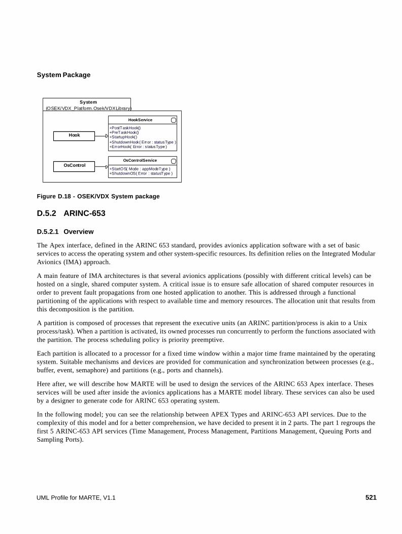
System Package
Figure D.18 - OSEK/VDX System package
D.5.2 ARINC-653
D.5.2.1 Overview
The Apex interface, defined in the ARINC 653 standard, provides avionics application software with a set of basic services to access the operating system and other system-specific resources. Its definition relies on the Integrated Modular Avionics (IMA) approach.
A main feature of IMA architectures is that several avionics applications (possibly with different critical levels) can be hosted on a single, shared computer system. A critical issue is to ensure safe allocation of shared computer resources in order to prevent fault propagations from one hosted application to another. This is addressed through a functional partitioning of the applications with respect to available time and memory resources. The allocation unit that results from this decomposition is the partition.
A partition is composed of processes that represent the executive units (an ARINC partition/process is akin to a Unix process/task). When a partition is activated, its owned processes run concurrently to perform the functions associated with the partition. The process scheduling policy is priority preemptive.
Each partition is allocated to a processor for a fixed time window within a major time frame maintained by the operating system. Suitable mechanisms and devices are provided for communication and synchronization between processes (e.g., buffer, event, semaphore) and partitions (e.g., ports and channels).
Here after, we will describe how MARTE will be used to design the services of the ARINC 653 Apex interface. Theses services will be used after inside the avionics applications has a MARTE model library. These services can also be used by a designer to generate code for ARINC 653 operating system.
In the following model; you can see the relationship between APEX Types and ARINC-653 API services. Due to the complexity of this model and for a better comprehension, we have decided to present it in 2 parts. The part 1 regroups the first 5 ARINC-653 API services (Time Management, Process Management, Partitions Management, Queuing Ports and Sampling Ports).
System(OSEK/VDX_Platform.Osek/VDXLibrary)
HookService
+PostTaskHook()+PreTaskHook()+StartupHook()+ShutdownHook( Error : statusType )+ErrorHook( Error : statusType )
OsControlService
+StartOS( Mode : appModeType )+ShutdownOS( Error : statusType )
Hook
OsControl
UML Profile for MARTE, V1.1 521

Figure D.19 - Relationship between APEX Types and ARINC-653 API services (part 1)
As described above, the following figure describes the relationship between APEX types and the last five ARINC-653 API services (Buffers, Blackboard, Semaphores, Events, and Health Monitoring).
Figure D.20 - Relationship between APEX Types and ARINC-653 API services (part 2)
D.5.2.2 ARINC-653 Model Library
The ARINC standard 653 defines two kinds of types: Generic Types (APEX Types) and Process Types that we can model.
Figure D.21 - ARINC-653 Generic APEX Types package
522 UML Profile for MARTE, V1.1

Figure D.22 - ARINC-653 APEX PROCESS Types package
For the description of all ARINC-653 functions describes here below please refer to the [ARINC-653] ARINC-653-2 Specification (Avionics Application Software Interface, Part 1 - Required Services).
The following model describes the Time Management API defined in the ARINC 653.
Figure D.23 - ARINC-653 Time Management package
The following model describes the Process Management API defined in the ARINC 653.
UML Profile for MARTE, V1.1 523

Figure D.24 - ARINC-653 PROCESS package
The following model describes the Partitions Management API defined in the ARINC 653.
Figure D.25 - ARINC-653 PARTITION package
The following model describes the Sampling Ports API defined in the ARINC 653.
524 UML Profile for MARTE, V1.1
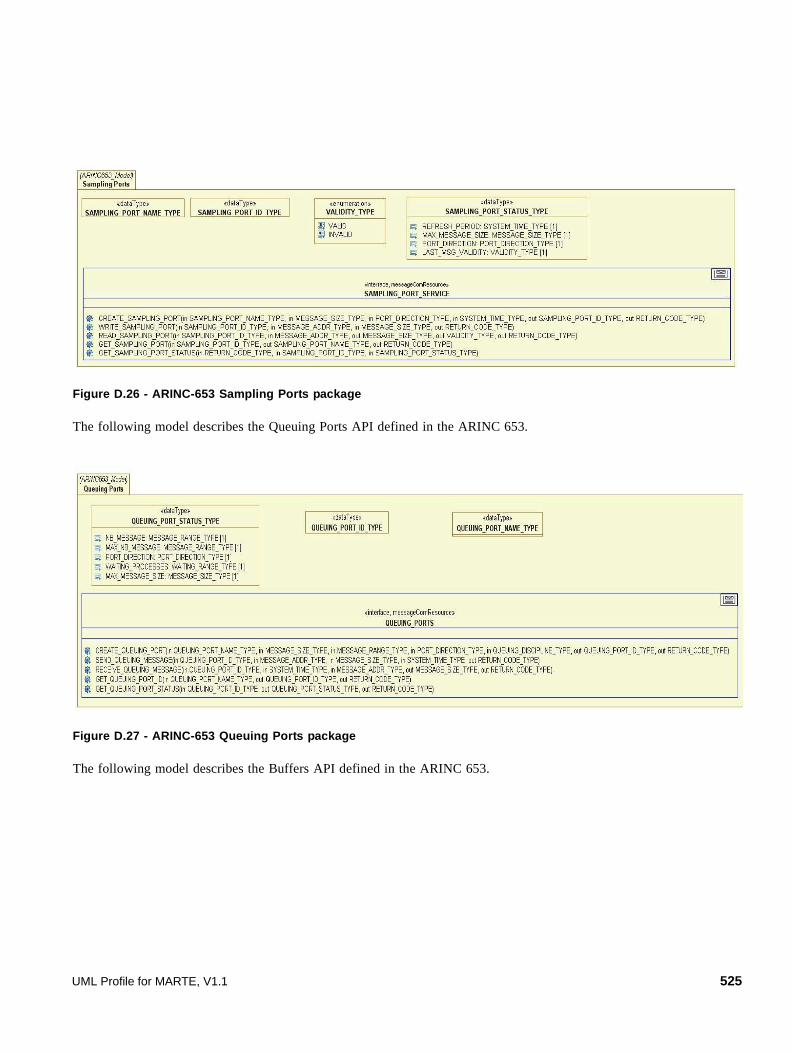
Figure D.26 - ARINC-653 Sampling Ports package
The following model describes the Queuing Ports API defined in the ARINC 653.
Figure D.27 - ARINC-653 Queuing Ports package
The following model describes the Buffers API defined in the ARINC 653.
UML Profile for MARTE, V1.1 525

Figure D.28 - ARINC-653 Buffers package
The following model describes the Blackboard API defined in the ARINC 653.
Figure D.29 - ARINC-653 Blackboard package
The following model describes the Semaphores API defined in the ARINC 653.
Figure D.30 - ARINC-653 Semaphores package
526 UML Profile for MARTE, V1.1

The following model describes the Events API defined in the ARINC 653.
Figure D.31 - ARINC-653 Events package
The Health Monitor is Operating System function for hardware reporting and system monitoring. The following figure describes the UML model of the health monitoring ARINC-653 API service.
Figure D.32 - ARINC-653 Health monitoring package
UML Profile for MARTE, V1.1 527

528 UML Profile for MARTE, V1.1

Annex ERepetitive Structure Modeling (RSM)
E.1 Overview
Application domains such as signal processing, image processing, or mobile devices usually require intensive data computations to be performed, possibly in a parallel way, and with the help of several computation units. In the field of embedded systems, we call this kind of systems “intensive computation embedded systems.” The purpose of this clause is to propose high level modeling constructs that enable to take into account this kind of systems. More precisely, it describes a compact way to express the regularity of such a system's structure or topology. The structures considered are composed of repetitions of structural elements, interconnected via a regular connection pattern. We call this kind of structure “repetitive structure.”
The mechanisms are oriented toward two aspects:
• The first aspect concerns the possibility to specify the shape of a repetition specified by a multiplicity, and basically enables seeing the collection of potential link ends represented by a multiplicity as a multidimensional array. The purpose is twofold: ease the expression of link topologies, and improve the power of expression of the topology description mechanism.
• The second aspect concerns a way to add topological information on relations expressed between design-time entities in order to specify the topologies of links that will exist between run-time entities in the context of these relations.
These mechanisms can be used in a common way for:
• Hardware execution platform modeling: in order to express all the available parallelism of the platform precisely and in a compact way.
• Application modeling: in order to express the potential parallelism (task and data parallelism) of the application.
• Allocation: Regular temporal and spatial mapping of the application onto the hardware execution platform.
E.2 Domain View
E.2.1 Package Overview
The RSM package extends the basic constructs of the MARTE metamodel by providing shaped multiplicities and link topologies. Figure E.1 presents the global structure of this RSM package.
UML Profile for MARTE, V1.1 529

Figure E.1 - Repetitive Structure package
A multiplicity usually enables determining some instantiation directives about the design time element it is attached to. These directives concern the number of elements that can potentially be instantiated at run time. As described in the MARTE foundations via the MultiplicityElement domain class, a multiplicity is defined as an inclusive interval of non-negative integers, beginning with a lower bound, and ending with a possibly infinite upper bound. It defines the range of allowable cardinalities that a set may assume.
Figure E.2 - Shape modeling concepts
A model element and its associated multiplicity can be seen as a mono dimensional collection of elements. We propose to precise this point of view, and to enable specifying a multidimensional shape for this collection: a model element can be seen as a multidimensional array of model elements via the shape associated to its multiplicity. The concepts used for this shape specification are presented in Figure E.2.
In order to take into account the modeling of link topologies, we introduce the abstract concept of LinkTopology. LinkTopology defines an optional set of information that can be associated to a connector. Basically two use cases are identified. In the first case, links are expressed between potential instances playing the same role. In the second case, links
MARTE::Foundat ions
M ARTE::RSM
Shape LinkTopology
M ARTE::VSL
« merge »
M ARTE: :Alloc
« mer ge » MARTE: :M AR TE_Library::M ARTE_Dat aTypes
530 UML Profile for MARTE, V1.1

are expressed between potential instances playing different roles. These two use cases lead to the definition of four refinements of the LinkTopology concept: InterRepetition and DefaultLink for the first case and Tiler and Reshape for the second case. Figure E.3 presents these concepts.
Figure E.3 - Link topology modeling concepts
The design idea is to identify sub-arrays, called patterns, of points inside each array (defined by a shape specification), and then to relate the points (i.e., link ends) contained in these patterns. The considered patterns are multidimensional arrays themselves described by a shape. We call tile a pattern when it is considered as a set of points of an array. The considered tiles are sets of regularly spaced points and the tiles themselves are regularly spaced in the array. The description of the regular spacing of the points of a tile is called fitting and the description of the regular spacing of the tiles in the array is called paving. The complete description of the tiling of an array by tiles necessitates the description of the shape of the pattern, the fitting, the paving, an origin, and a repetition space. The repetition space gives the number of tiles. It is itself characterized by a shape. The fitting describes the coordinates of the points of the tile in the array relatively to a reference point. The paving describes the set of reference points of the tiles relatively to the origin. So the origin is the point of index [0, …, 0] of the tile of index [0, …, 0] in the repetition space. The tiling process is described by a Tiler having the attributes: origin, a Vector of Integers, fitting, a Matrix of Integers and paving, a Matrix of Integers. The points of the tile of index r in the repetition space are enumerated as follows: Given the point of index i in the pattern, the coordinates of the corresponding point of in the array is (origin + paving x r + fitting x i) mod array_shape. This formula ensures that the points of the tile are regularly spaced because they are built from the reference point of the tile by the linear combination of the column vectors of the fitting matrix; that the reference points of the tiles are regularly spaced because they are built by the linear combination of the column vectors of the paving matrix; and that all points of the tiles are points of the array thanks to the computation modulo the shape of the array. This is inspired by the Array-OL language [1,2,3].
L in kT o po lo gy
L in kTo po lo g y
Defau ltL in k
Resha p e
patter nS h ape : Sh ape: :S hapeS pecifica tionrepe titionS pace : Shap e: :S h ap eS pe cifica tion
srcT ile r1
ta rge tT ile r
1
MAT E::Co reE lement s::Gen era lCo mp on ent Mod el::Co nn ect or All oc: :Al lo cat e
to po logy 0 . .1 0.. 1to po logy
Ti ler
or ig in : Lib ra ry::MA RT E_D at aType s::In teg erV ect o rpavin g : Lib ra ry::MA RT E_D ata Types:: In te gerM atrixfitting : Lib ra ry: :MA RT E_D ataTypes:: In teg erMa tr ix
In te rR ep etit io n
repe t it io nSpa ce De penden ce : M AR TE_DataT ypes::I n teger Vecto risM odu lo : Boo lean
UML Profile for MARTE, V1.1 531

E.2.2 Class Description
DefaultLink
The DefaultLink allows specifying a default source or destination for an InterRepetition dependence.
Generalizations
• LinkTopology
Semantics
When some links are not created at run time because of the specification of the InterRepetition topology, a connector with a DefaultLink topology can be specified and connected to one end of the connector having the InterRepetition topology. It defines a link whenever the other one is not present. This allows specifying default values.
Constraints
One connector end must be connected to the same connectable element as a connector having an InterRepetition topology. The connected elements must have the same shape if specified.
InterRepetition
The concerned systems are composed of the repetition of a single element, such as in a grid or cube topology. Each potential instance of this element is connected to other potential instances of the same element. For example, in the case of a cyclic grid, each instance is connected to neighbors located at north, south, east, and west. The InterRepetition topology enables specifying the position of every neighbor of every potential instance of a model element with a multidimensional shape.
Generalizations
• LinkTopology
Attributes
• repetitionSpaceDependence: IntegerVector The repetitionSpaceDependence attribute is a translation vector on the space of the multidimensional array. It identifies the position of a given neighbor.
• modulo: Boolean [0..1] = false The modulo attribute indicates if the translation is applied modulo the size of the multidimensional array defined by the shape of the repeated element or not. If the modulo attribute is equal to false, the translation is not applied if the target is out of the bounds of the array, and the corresponding links won’t be created at run time. This allows to model cyclic grids as well as non cyclic ones.
Semantics
Each potential instance is implicitly associated to one point of the multidimensional array described by the shape associated to the multiplicity of the model element. The coordinates of the neighbor is the addition of the coordinates of the considered point and the repetitionSpaceDependence. The considered point is the source of the topology and the neighbor the destination.
532 UML Profile for MARTE, V1.1

Constraints
If the connector having an InterRepetition topology connects two ports, these two ports must belong to the same part. The repetition space is defined by the multiplicity of that part. If the ports have themselves a multiplicity, the links are established between the sets of instances defined by these multiplicities. The connected elements must have the same shape if specified.
LinkTopology
Each repeated element has a multidimensional shape. Each point of the multidimensional arrays (identified by the multidimensional shapes) corresponds to a potential link end. The mechanism proposed via the LinkTopology concept enables specifying in a compact way all the links existing between potential link ends contained in each of the two arrays. As a consequence, it enables identifying all the links that will exist at run time.
Semantics
This concept is abstract. Its semantics are detailed by its specializations.
MultiplicityElement
The MultiplicityElement defines an interval of number of potential instances. It is extended to support the definition of the shape of the set of the potential instances of the element considered as a multidimensional array of instances.
Attributes
• /upper: UnlimitedNatural [0..1] Upper bound of the multiplicity.
• /lower: Integer [0..1] Lower bound of the multiplicity.
• shape: ShapeSpecification [0..1] Defines the number of dimensions and the size of the dimensions of the multidimensional array of the potential instances of the element.
Constraints
The shape of a collection has a meaning only if the number of elements of this collection is fixed (the upper bound of the multiplicity interval equals its lower bound). Furthermore the isOrdered attribute of the element has to be set to true in order to index the potential instances.
Reshape
This link topology specifies the set of runtime links connecting multidimensional arrays. It defines the tiling of the arrays by an identical pattern. It establishes links between tiles of the arrays.
Generalizations
• LinkTopology
Attributes
• patternShape: ShapeSpecification [1] Specifies the shape of the pattern used to tile all the arrays.
UML Profile for MARTE, V1.1 533

• repetitionSpace: ShapeSpecification [1] Defines how many tiles there are.
• srcTiler: Tiler [1] Specifies the tiling of the source array.
• targetTiler: Tiler [1] Specifies the tiling of the target array.
Semantics
A Reshape topology defines a repetition space shape and the shape of the pattern (the same for all link ends). A Tiler has to be associated to each link end. These Tilers describe how the collection of structural features connected to this end is tiled by the tiles.
ShapeSpecification
A ShapeSpecification is the list of the size of the dimensions of an array.
Attributes
• value: UnlimitedNatural[*] {ordered} Defines the shape of an array.
Constraints
At most one dimension of a shape can be infinite.
Tiler
A tiler is used in the case when complex topologies are modeled between different potential entities playing different roles. It is based on the tiling of arrays by patterns mechanism.
Generalizations
• LinkTopology
Attributes
• origin: IntegerVector [0..1] The origin is the coordinates of the reference point of the reference tile. When not specified, it defaults to the zero vector.
• fitting: IntegerMatrix [0..1] The fitting matrix defines the regular spacing of the tile points in the array from the reference element of the tile. When not specified, it defaults to the identity matrix.
• paving: IntegerMatrix [1] The paving matrix defines the regular spacing of the reference elements of the tiles from the origin.
Semantics
This is used for example to express the data parallel repetition of an application component. Such a repetition is composed of a repetition component having the repeated component as a part and Tilers connecting the ports of the repetition component to those of the repeated part. The number of repetitions (and the shape of the repetition space) is
534 UML Profile for MARTE, V1.1

specified as the multiplicity (and the shape) of the repeated part. As this repetition space is shared by all the Tilers, such a construction establishes links between the tiles of the various ports of the repetition component. Indeed, the tiles of the same repetition index are connected to patterns of the same repeated component part.
E.3 UML Representation
E.3.1 Profile Diagrams
This package stereotyped profile defines the stereotypes and data types needed to model repetitive structures. The possibility to model the shape of multidimensional collection of elements is provided by the shaped stereotype and the specification of the topology of the links between such multidimensional collections is provided by the linkTopology abstract stereotype and its specializations. The distribute stereotype provides a way to specify regular allocations of multidimensional collections of elements to other multidimensional collections of elements, for example a repetition of tasks to a set of processing elements. Figure E.4 presents the Shaped stereotype use to specify the shape of a collection of model elements. Figure E.5 presents the data types needed to specify shapes and tiling parameters. Figure E.6 presents the stereotypes used to specify the various link topologies for composite structures and Figure E.7 presents the link topology provided for repetitive allocations, called distributions.
Figure E.4 - Profile diagram for shape modeling
Figure E.5 - Model library defining the data types used by the RSM profile
« metaclass »UML::MultiplicityElement
« profile »RSM
« stereotype »Shaped
shape : ShapeSpecification [1]
« d a t a T y p e »« t u p le T y p e »
T i le rS p e c if i c at io n
o r ig in : In te g e r V ec t o rp av in g : In te g e r M a tr ix [1 ]fi tt in g : In t eg e r M a t r ix
« m o d e l L i b ra ry »R S _ L i b r ar y
« d a t a T y p e »« c o lle c t i o n T y p e »
{ c o lle c tion A tt r ib = s iz e }S h a p e S p e c if i c at io n
s iz e : U nl im it e dN a tu r a l [0 .. * ]
UML Profile for MARTE, V1.1 535

Figure E.6 - Profile diagram for link topology modeling in composite structures
Figure E.7 - Profile diagram for distribution modeling
E.3.2 Profile Elements Description
DefaultLink
This stereotype maps the DefaultLink domain element defined on page 532.
DefaultLink specifies a default value for an inter-repetition dependence. When such a dependence would refer to a non-existent value, the default value is taken.
« metaclass »UML::ConnectorEnd
« metaclass »UML::Connector
« stereotype »LinkTopology
« stereotype »DefaultLink
« profile »RSM
« stereotype »InterRepetition
repetitionSpaceDependence : IntegerVector [1]isModulo : Boolean = false
« stereotype »Tiler
origin : IntegerVectorpaving : IntegerMatrixfitting : IntegerMatrixtiler : TilerSpecification
patternShape : ShapeSpecification [1]repetitionSpace : ShapeSpecification [1]
« stereotype »Reshape
« s t e r e o t y p e »A ll o c : : A ll o c a t e
« p r o f il e »R S M
« s t e r e o t y p e »D i s t r ib u t e
p a t te r n S h a p e : S h a p e S p e c i f i c a ti o n [ 1 ]r e p e t it io n S p a c e : S h a p e S p e c i f i c a tio n [ 1 ]fr o m T i le r : T i le r S p e c if ic a ti o n [1 ]to T il e r : T il e r S p e c i f i c a tio n [ 1 ]
536 UML Profile for MARTE, V1.1
Extensions
• Connector (fromUML::InternalStructures)
Generalizations
• LinkTopology
Attributes
• None
Associations
• None
Constraints
[1] One end of the connector has to be connected to the same port than the end of a connector stereotyped interRepetition.
Distribute
The Distribute stereotype maps the Reshape domain element defined on page 537 to allocations. It adds support of multidimensional distributions to allocations.
A distribute allocation distributes regularly a multidimensional array of elements on another multidimensional array of elements. The repartition of the elements is done exactly in the same way as in the reshape connector (see below).
Extensions
• Abstraction (from UML::Dependencies)
Generalizations
• Allocate (from MARTE::Alloc)
• LinkTopology
Attributes
• kind: AllocationKind [0..1] Inherited from MARTE::Alloc::Allocate.
• nature: AllocationNature [0..1] Inherited from MARTE::Alloc::Allocate.
• patternShape: ShapeSpecification [1] Specifies the shape of the pattern used to tile both from and to arrays.
• repetitionSpace: ShapeSpecification [1] Specifies the repetition space.
• fromTiler: TilerSpecification [1] Specifies the tiling of the from array.
• toTiler: TilerSpecification [1] Specifies the tiling of the to array.
UML Profile for MARTE, V1.1 537

Associations
• None
Constraints
• None
InterRepetition
The InterRepetition stereotype maps the InterRepetition domain element defined on page 538. It specifies a uniform translation in a repetition space.
If the connected ports are directed, then the direction of the translation is from the output port to the input port, else, the translation is considered in both directions, allowing specifying undirected or duplex links.
If the connector is directed, the coordinates of the destination are those of the source plus the repetitionSpaceDependence vector. This addition is considered modulo the shape of the repetition space if the modulo attribute is true, else some links do not exist. In that case, a defaultLink may be specified.
Extensions
• Connector (fromUML::InternalStructures)
Generalizations
• LinkTopology
Attributes
• repetitionSpaceDependence: MARTE::MARTE_Library::MARTE_DataTypes::IntegerVector [1] Specifies the translation vector in the repetition space.
• isModulo: Boolean [0..1]= false Specifies if the translation is taken modulo the shape of the repetition space or not.
Associations
• None
Constraints
[1] Both ends of the connector must be connected to the same component. This component must have a shape that defines the repetition space.
[2] The size of the repetitionSpaceDependence has to be the same as that shape as it is a vector in the space defined by that shape.
[3] Both connector ends must have the same shape.
LinkTopology (abstract)
The LinkTopology abstract stereotype maps the LinkTopology domain element of page 538.
It allows specifying the topology of the potential link instances linking shaped elements. See the tiler stereotype definition below for a full description of the semantics of a reshape connector.
538 UML Profile for MARTE, V1.1

Extensions
• Connector (fromUML::InternalStructures)
• Abstraction (from UML::Dependencies)
Attributes
• None
Associations
• None
Constraints
• None
Reshape
This stereotype maps the Reshape concept of page 539 to assembly connectors. It allows specifying a set of potential connector instances between multidimensional arrays of potential port instances. If the shapes of these arrays of port instances are identical and the connection topology is a direct point-to-point topology, the Reshape stereotype can be omitted. If the shapes are different and no Reshape stereotype is specified, the link topology is indeterminate.
Extensions
• Connector (fromUML::InternalStructures)
Generalizations
• LinkTopology
Attributes
• patternShape: ShapeSpecification [1] The shape of the pattern used to tile all the arrays.
• repetitionSpace: ShapeSpecification [1] Defines how many tiles there are.
Associations
• None
Constraints
[1] The reshape stereotype can only be applied to assembly connectors.
[2] A tiler stereotype has to be applied to each connector end to specify how each multidimensional array is tiled.
Shaped
The Shaped stereotype maps the MultiplicityElement domain element defined on page 539.
It enables providing a multidimensional view of a collection of elements. We allow profile users to specify a value only for the shape tag of a shaped MultiplicityElement, without specifying a value for the multiplicity property of the MultiplicityElement.
UML Profile for MARTE, V1.1 539

Extensions
• MultiplicityElement (from UML::Kernel)
Generalizations
• None
Attributes
• shape: ShapeSpecification [1] Allows specifying the shape of a collection (i.e., the number of dimensions and the size of each dimension).
Associations
• None
Constraints
[1] If both a multiplicity and its associated shape are specified, then the product of the elements of the sizes of all the dimensions must be equal to the value of the multiplicity property.
[2] A shaped stereotype can only be applied on an element with a fixed multiplicity, not an interval. If the multiplicity of the element is *, then one of the dimensions of the shape has to be infinite.
Notation
Instead of using the shaped stereotype, the user can write the shape in place of the multiplicity. Whenever a multiplicity is between curly brackets, it has to be understood as a shape specification.
To refer to a specific Element that is part of a multidimensional collection specified by a shape, one can use the ElementName[index] notation where index is the index of this element in the collection. The index is a vector of n naturals where n is the number of dimensions of the shape. The indexes are numbered from 0 to the size of the corresponding dimension minus 1. For example if a part is declared as PE: ProcessingElement [{10,10}] one can refer to the specific PE of index {0,6} by PE[{0,6}].
ShapeSpecification
This data type supports the notation of a shape. It is a vector of unlimited naturals. Each element of the collection is the size of one dimension of a multidimensional array.
Attributes
• size: UnlimitedNatural [0..*] size of each dimension
Constraints
[1] At most one element of the collection can be infinite.
Notation
As specified in the Value Specification Language (VSL) annex, the shape is a comma separated collection of unlimited naturals between curly brackets, for example: {10, 5, *}.
540 UML Profile for MARTE, V1.1

Tiler
The Tiler stereotype maps the Tiler domain element of page 541.
It expresses how a multidimensional array is tiled by multidimensional tiles. In the case when the tiler stereotype is applied to a delegation connector, it connects an external port with a port of an internal part. The shape of the array is given by the shape of the external port. The shape of the pattern is given by the shape of the port of the internal part. And the shape of the repetition space is given by the shape of this part.
When it is applied to a ConnectorEnd, it belongs to a reshape connector and connects a port of an internal part. The shapes of the repetition space and of the pattern are given by tags of the reshape stereotype. The shape of the array is the concatenation of the shape of the part and the shape of the port. Indeed, the number of potential instances of the port is the product of the multiplicity of the part by the multiplicity of the port. For example the shape of the array of a connector end connected to a port of shape {10, 4} (multiplicity: 40) of a part of shape {25} (multiplicity: 25) is {25, 10, 4} (multiplicity: 1000).
The points of the tile of index r in the repetition space are enumerated as follows: Given the point of index i in the pattern, the coordinates of the corresponding point in the array is (origin + paving x r + fitting x i) mod array_shape.
Extensions
• Connector (from UML::InternalStructures)
• ConnectorEnd (from UML::InternalStructures)
Generalizations
• LinkTopology
Attributes
• origin: MARTE_Library::MARTE_DataTypes::IntegerVector [0..1] Specifies the origin of the reference tile in the array. If it is absent, the origin is the zero vector of dimension the dimension of the array.
• fitting: MARTE_Library::MARTE_DataTypes::IntegerMatrix [0..1] Specifies how the pattern is mapped to a tile in the array with respect to a reference element. If it is not specified, the fitting matrix is the identity matrix.
• paving: MARTE_Library::MARTE_DataTypes::IntegerMatrix [0..1] Specifies how an index in the repetition space is mapped to the reference point of a tile with respect to the reference tile.
• tiler: TilerSpecification [0..1] Can be used as an alternative to the three previous attributes to specify the origin, fitting, and paving using a Tiler object.
Associations
• None
Constraints
[1] The tiler stereotype can be applied only to delegation connectors.
[2] It can be applied to connector ends only if they belong to a connector with the reshape stereotype.
UML Profile for MARTE, V1.1 541

[3] The tiler attribute can be used only if the origin, fitting, and paving attributes are not specified.
[4] The number of elements of the origin vector, the number of lines of the paving and fitting matrices must be equal to the dimension of the array.
[5] The number of columns of the paving matrix must be equal to the dimension of the repetition space and the number of columns of the fitting matrix must be equal to the dimension of the pattern.
[6] Notation
[7] The vectors of the paving and fitting matrices are column vectors. For example a {{1},{0},{0}} matrix has to be interpreted as the [1 0 0] matrix.
TilerSpecification
This data type supports the notation of a tiler (see the tiler stereotype above for more details on its semantics).
Attributes
• origin: MARTE_Library::MARTE_DataTypes::IntegerVector [0..1] Specifies the origin of the reference tile in the array. If it is absent, the origin is the zero vector of dimension the dimension of the array.
• fitting: MARTE_Library::MARTE_DataTypes::IntegerMatrix [0..1] Specifies how the pattern is mapped to a tile in the array with respect to a reference element. If it is not specified, the fitting matrix is the identity matrix.
• paving: MARTE_Library::MARTE_DataTypes::IntegerMatrix [1] Specifies how an index in the repetition space is mapped to the reference point of a tile with respect to the reference tile.
Associations
• None
Constraints
• See the Tiler stereotype above
Notation
The notation is as specified in the Value Specification Language (VSL) annex. For example, a tiler specifying a paving of a 2D array by blocks of 5 by 10 elements would be specified as {origin = {0,0}, fitting = {{1,0},{0,1}}, paving = {{5, 0}, {0, 10}}}, or even simply by {paving = {{5, 0}, {0, 10}}}.
E.4 Examples
This sub clause is illustrated with the distribution of a repetitive application onto a repetitive hardware architecture.
542 UML Profile for MARTE, V1.1

Figure E.8 - 2D repetition of a FFT component
The application, as described by Figure E.8 is the first task of a sonar application. It consists of the repetition of a fast Fourier transform on samples recorded by hydrophones distributed around a submarine. This repetition is two-dimensional: a sliding window on time (128 samples every 32 time steps) and a basic repetition on the 512 hydrophones. It consumes a 2D array and produces a 3D array.
Figure E.9 - 4x4 cyclic grid of processors example
The hardware architecture, as described by Figure E.9, is an SIMD unit built as a cyclic grid of 4 by 4 processors. Each elementary processor of the grid is connected to its north, east, south, and west neighbors.
FftStage
[{512,*}]f : FFT [{512,*}]
[{512,128,*}]
« tiler »{origin={0,0},fitting={{0,1}},
paving={{1,0},{0,32}}
« tiler »{origin={0,0,0},fitting={{0,1,0}},
paving={{1,0,0},{0,0,1}}}
[{128}]
[{128}]
« HwISA » {type = SIMD}SIMDUnit
« HwComputingResource »p : ElementaryProc [{4,4}]w e
s
n
« interRepetition »{repetitionSpaceDependence ={1,0},
modulo = true}
« interRepetition »{repetitionSpaceDependence ={0,1},
modulo=true}
UML Profile for MARTE, V1.1 543

Figure E.10 - Bloc distribution example
The allocation, as described by Figure E.10, distributes the computations by blocs of 32 FFTs on the 16 processors of the grid.
As a complement to illustrate the other notations described in this clause, we suggest the following example.
Here the two forms of shape specification are shown: the shape of the myMemory part is specified by the way of the shaped stereotype while the shape of the slave port is specified with the shape specification in place of the multiplicity.
A reshape connector links these two parts. As to build the shape of a port of a shaped part one has to concatenate both shapes, the shape of the port of the myMemory part is then understood as {5} because there are {5} parts with each one port of shape {}. The shape of the slave port is understood as {8} because there is one part of shape {} with one port of shape {8}.
The reshape connector indicates that each memory module is connected to one port of the bus in such a way that memory module number i is connected to the slave port of index i+2 of the bus. The way to specify this link topology is to say that there are 5 patterns of shape {} (see the attributes of the reshape stereotype) which are used to tile both port arrays. The definition of the tiles is done by the tiler stereotypes on the connector ends. The tiler on the memory end is noted using the default values. Its complete specification would be {fitting = {{}}, origin = {0}, paving = {{1}}} that means that the tile of index i corresponds to the port of index i. The tiler on the bus end is also noted using the default values. Its
« distribute »{patternShape = {32}, repetitionSpace = {4,4,*}, fromTiler = {origin = {0,0},
fitting = {{1,0}}, paving={{32,0},{128,0},{0,1}}},
toTiler = {origin = {0,0}, fitting = {{0,0}}, paving = {{1,0},{0,1},{0,0}}}}
FftStage::f : FFT [{512,*}]
SimdUnit::p : ElementaryProc [{4,4}]
« tiler »{paving = { {1}}}
« tiler »{origin = {2},
paving = {{1}}}
« reshape »{repetitionSpace = {5},
patternShape = {}}
« shaped »{shape = {5}}
myMemory : RAMModule
myBus : Bus
slave [{8}]
544 UML Profile for MARTE, V1.1

complete specification would be {fitting = {{}}, origin = {2}, paving = {{1}}} that means that the tile of index i corresponds to the port of index i+2. The link between both sets of port tiles is thus maintained by the mean of the repetition space defined by the reshape stereotype on the connector.
UML Profile for MARTE, V1.1 545

546 UML Profile for MARTE, V1.1

Annex FDomain Class Descriptions
F.1 Core Elements
F.1.1 Action (from Causality::CommonBehavior)
An Action is the fundamental unit of behavior specification.
Generalizations
• Behavior (from Causality::CommonBehavior).
Associations
• None
Attributes
• None
Semantics
An Action is the fundamental unit of behavior specification. An action takes a set of inputs and converts them into a set of outputs, though either or both sets may be empty. Actions are contained in compositeBehaviors, which provide their context. CompositeBehaviors provide constraints among actions to determine when they execute and what inputs they have.
F.1.2 ActionExecution (from Causality::RunTimeContext)
An ActionExecution is a kind of behaviorExecution that corresponds to an instance of an Action, and consequently expresses an atomic piece of behaviorExecution.
Generalizations
• BehaviorExecution (from Causality::RunTimeContext).
Associations
• action: Causality::CommonBehavior::Action [0..1] {subset type} Type of behavior of which the CompBehaviorExecution is an instance.
Attributes
• None
UML Profile for MARTE, V1.1 547

Semantics
An ActionExecution is a kind of behaviorExecution that corresponds to an instance of an Action, and consequently expresses an atomic piece of behaviorExecution. The context in which an actionExecution is performed is obtained by means of the host association inherited from behaviorExcecution, which relates the action to its container CompBehaviorExecution, and transitively to the instance of the behavioredClassifier in which it is effectively performed.
F.1.3 AggregationKind (from Foundations)
It is an enumeration type that defines literals used to specify the kind of aggregation between a classifier and its properties.
Literals
• None Indicates that there is no aggregation, the property is defined by itself.
• shared Indicates that the property is defined by itself and it may be used by one or more classifiers as part of their respective specifications.
• composite Indicates that the property is owned by one classifier as part of its definition.
F.1.4 Behavior (from Causality::CommonBehavior)
A Behavior defines how a system, or an entity defining a part of it, changes over time.
Generalizations
• ModelElement (from Foundations)
Associations
• context: Causality::CommonBehavior::BehaviorClassifier [1] Holds the behaviorClassifier that defines the context in which the behavior is defined.
• Parameter: Causality::CommonBehavior::Parameter [0..*] Indicates the optional set of parameters whose values characterize the behavior.
Attributes
• None
Semantics
A Behavior defines how a system or entity changes over time. From a modeling point of view, this concept defines the behavior of some classifier, specifically, a Behaviored Classifier. A behavior captures the dynamic of its context classifier. It is a specification of how its context classifier as well as the state of the system that is in the scope of the behavior may change over time. A behavior may have Parameters whose values may be used for evaluating a behavior. Two kinds of Behavior may be defined: CompositeBehavior and Action.
548 UML Profile for MARTE, V1.1
F.1.5 BehavioredClassifier (from Causality::CommonBehavior)
A behavioredClassifier is a kind of classifier that represents the context in which behaviors may be specified.
Generalizations
• Classifier (from Foundations)
Associations
• ownedTrigger: Causality::CommonBehavior::Trigger [0..*] Specifies the trigger or triggers that filter events that may affect the execution of behaviors of the classifier.
• ownedBehavior: Causality::CommonBehavior::Behavior [0..*] Specifies the different behaviors that may expose and hold the behavioredClassifier.
• mainBehavior: Causality::CommonBehavior::Behavior [0..1] {subset ownedBehaviort} Specifies the behavior that is launched after creation and initialization of any instance of the behavioredClassifier.
• modeBehavior: ModeBehavior [*] {subsets ownedBehavior} The sets of modal behaviors of this behaviored classifier.
• activeIn: Mode [*] The set of modes in which an entity is participating.
Attributes
• None
Semantics
A behavioredClassifier represents the context in which behaviors may be specified. It exposes concrete behavior specifications to illustrate specific scenarios of interest associated with that classifier, such as the start-up scenario. The particular behavior specification used to represent the behavior that starts executing when instances of that classifier are created and started is called main behavior. For many real-time concurrent systems, this can be, for example, the behavior that initiates the activity of a thread, which continues until the thread is terminated.
F.1.6 BehaviorExecution (from Causality::RunTimeContext)
A BehaviorExecution is a specification of the execution of a unit of behavior or action within the instances of BehavioredClassifiers.
Generalizations
• Instance (from Foundations)
Associations
• host: Causality:: RunTimeContext::CompBehaviorExecution [1] Is used to designate the context in which the behavior is being executed.
• cause: Causality::RunTimeContext::EventOccurrence [1] Designates the concrete occurrence of an event that causes the behaviorExecution to take effect.
UML Profile for MARTE, V1.1 549

Attributes
• None
Semantics
A BehaviorExecution is a specification of the execution of a unit of behavior or action within the instances of BehavioredClassifiers. Hence, they are run-time instances of the behavior and action concepts.
Any behavior execution is the direct consequence of the action execution of at least one instance of a classifier. A behavior execution specification describes how the states of these instances change over time. Behavior executions, as such, do not exist by their own, and they do not communicate. If a behavior execution operates on data, that data is obtained from the host instance.
In UML2, there are two kinds of behaviors at run-time, emergent behavior and executing behavior. An executing behavior specification is performed by an instance specification (its host) and is the description of the behavior of this instance. Emergent behavior execution specification results from the interaction of one or more participant instance specifications. MARTE does not highlight this difference on the nature of behaviors. Indeed, it deals only with behavior execution as the general concept to express a behavior instance. Hence, the MARTE BehaviorExecution notion corresponds to the UML2 Behavior Performance concept described in the overview sub clause of its common behavior clause.
On one hand, a behavior execution specification is thus directly caused by the invocation of a behavioral feature of an instance specification or by its creation. In either case, it is a consequence of the execution of an action by some related classifier instance. A behavior has access to the structural features of its host instance specification.
On the other hand, behavior execution may result from the interaction of various participant instances. If the participating classifier instances are parts of a larger composite classifier instance, a behavior execution can be seen as indirectly describing the behavior of the container instance also. Nevertheless, a behavior execution can result from the executing behaviors of the participant instances. This form of behavior is of interest since the behavior that is to be analyzed and observed at the system level, in order to predict its timing properties, is normally described as an abstract view of the run-time emergent behavior due to the combination of the behavior executions of all its constituent parts.
F.1.7 Classifier (from Foundations)
An abstract concept representing some kind of design-time specification. This concept includes all kinds of descriptors such as classifiers, collaborations, data types, etc.
Generalizations
• ModelElement (from Foundations)
Associations
• instance: Instance [0..*] Indicates the set of run-time instances that are incarnated based on this classifier.
• ownedProperties: Property [0..*] Holds the possible execution behaviors of the instance.
Attributes
• None
550 UML Profile for MARTE, V1.1

Semantics
In the context of the duality classifier-instance, a classifier represents a generic pattern that acts as a design-time specification to which any instance made from it must conform. This concept includes all kinds of descriptors such as classifiers, collaborations, data types, etc. It is generally assumed that every instance element in the domain model may have an implicit or explicit classifier. Properties are used to describe particular aspects of a Classifier.
F.1.8 CompBehaviorExecution (from Causality::RunTimeContext)
A CompBehaviorExecution is a kind of behaviorExecution that corresponds to an instance of a compositeBehavior, and consequently is expressed in terms of other behaviorExecutions.
Generalizations
• BehaviorExecution (from Causality::RunTimeContext)
Associations
• behavior: Causality::CommonBehavior::CompositeBehavior [1] {subset type} Type of behavior of which the CompBehaviorExecution is an instance.
• exAction: Causality::RunTimeContext::BehaviorExecution[0..1] Set of internal behaviorExecutions that define the CompBehaviorExecution. They may be ActionExecutions or other CompBehaviorExecutions.
• host: CoreElements::Foundations::Instance [1] Context in which the behavior is being executed. The associated element corresponds to an instance of a BehavioralClassifier to which the descriptive behavior belongs.
• invoker: CoreElements::Foundations::Instance [0..1] Instance responsible for the invocation of the composite behavior execution.
• participant: CoreElements::Foundations::Instance [1..*] Set of instances that are involved in the execution of the composite behavior.
Attributes
• None
Semantics
A CompBehaviorExecution is a kind of behaviorExecution that corresponds to an instance of a compositeBehavior, and consequently may be expressed in terms of other behaviorExecutions.
The set of participants gives access to the instances that interact to make emerge and are involved in the execution of the composite behavior. This set may include the interacting structural features of its host instance specification.
F.1.9 CompositeBehavior (from Causality::CommonBehavior)
A CompositeBehavior is a kind of Behavior that may contain other Behaviors.
Generalizations
• Behavior (from Causality::CommonBehavior)
UML Profile for MARTE, V1.1 551

Associations
• action: Causality::CommonBehavior::Behavior [0..*] Set of atomic or compositeBehaviors used to specify the behavior.
Attributes
• None
Semantics
A CompositeBehavior is a kind of Behavior that may contain other Behaviors, which in turn may be either composite or atomic.
F.1.10 Configuration
A Configuration characterizes a set of participating entities associated to a system, sub-system or whatever composite element. A configuration prescribes the properties that the participating entities exhibit in the configuration context.
Generalizations
• None
Associations
• mode: CoreElements::Mode [*] The operational modes that are represented by this configuration.
Attributes
• None
Semantics
A system configuration may be defined by a set of active system elements (e.g., application components, platform components, hardware resources), and/or by a set of operation parameters (e.g., QoS parameters or functional parameters). A configuration can also represent a particular deployment plan of application components in platform entities.
F.1.11 Event (from Causality::CommonBehavior)
An Event is the specification of a kind of change of state that may happen in the modeled system.
Generalizations
• ModelElement (from Foundations)
Associations
• None
Attributes
• None
552 UML Profile for MARTE, V1.1
Semantics
An Event is the specification of a kind of change of state that may happen in the modeled system. Event occurrences are often generated as a result of some action either within the system or in the environment surrounding the system.
F.1.12 EventOccurrence (from Causality::RunTimeContext)
An EventOccurrence is an instance of an Event, representing a potential change of state in the modeled system.
Generalizations
• Instance (from Foundations)
Associations
• event: Causality::CommonBehavior::Event [1] {subset type} Type of event of which the eventOcurrence is an instance.
• effect: Causality::RunTimeContext::BehaviorExecution [0..1] Concrete instance of a behavior whose execution is an effect of the eventOccurrence.
Attributes
• None
Semantics
An EventOccurrence is an instance of an Event. They are used to represent a change of state in the modeled system. Event occurrences are often generated as a result of some action or combination of them, either within the system or in the environment surrounding the system.
F.1.13 Instance (from Foundations)
An abstract concept representing some kind of run-time instance that is created based on one or more type specifications (descriptors). This concept includes all kinds of instances, including objects, data values, etc.
Generalizations
• ModelElement (from Foundations)
Associations
• type: Classifier [0..*] Set of types to which the instance is conformant. These are design-time descriptors that are used to specify all the aspects necessary to run this instance
• exBehavior: RunTimeContext::CompBehaviorExecution [0..*] Holds the possible execution behaviors of the instance.
Attributes
• None
UML Profile for MARTE, V1.1 553

Semantics
In the context of the duality classifier-instance, an instance represents a concrete reification of a classifier. The classifier is referred to as the type of the instance. An instance may have multiple types, which can be used either to represent different viewpoints of the model element or a composition of partial descriptions, including multiple inheritance for example. An instance may expose a number of concrete behaviors at run time; these are expressed by means of a set of composite behavior executions.
F.1.14 InvocationOccurrence (from Causality::Communication)
An InvocationOccurrence is a run time instance that represents the start of a communication in transit between a sender instance and a receiver instance, through the inquiry of an actionExecution.
Generalizations
• EventOccurrence (from Causality::RunTimeContext)
Associations
• effect: Causality::Communication::Request [1..*] Event that will be considered the descriptor of the instance represented by the terminationOccurrence.
• sender: Foundations::Instance [1] Instance that starts the invocation.
• execution: Causality::RunTimeContext::ActionExecution [1] actionExecution that initiates the invocation.
Attributes
• None
Semantics
An InvocationOccurrence is a run time instance that represents the start of a communication in transit between a sender instance and a receiver instance, through the inquiry of an actionExecution. This actionExecution, representing the invocation of a behavioral feature, is executed by a sender instance resulting in the InvocationOccurrence. The invocation event may represent the sending of a signal or the call to an operation. As a result of the invocationOccurrence a Request is generated. An InvocationOccurrence may result in a number of requests being generated (as in a signal broadcast).
F.1.15 Mode
A Mode identifies an operational segment within the system execution that is characterized by a given configuration.
Generalizations
• None
Associations
• participatingEntity: BehavioredClassifier [*] The set of participant entities that are active in the mode.
554 UML Profile for MARTE, V1.1

• /outgoing: ModeTransition [*] The set of outgoing mode transitions that have this mode as source state.
• /incoming: ModeTransition [*] The set of incoming mode transitions that have this mode as target state.
Attributes
• None
Semantics
Working in a given mode may imply that a set of system entities are active during that operational fragment. We factorize such mode-sensitive system entities in BehavioredClassifier. A BehavioredClassifier can be active in zero or more operational modes. Furthermore, a BehavioredClassifier that represents a system, subsystem, or any composite entity can have a set of modes modeled as a ModeBehavior.
F.1.16 ModeBehavior
A ModeBehavior specifies a set of modes mutually exclusive, i.e., only one mode can be active in a given time instant. Particularly, the dynamics of modes is represented by connecting modes by means of ModeTransitions.
Generalizations
• Behavior (from CommonBehavior)
Associations
• composite: BehavioredClassifier [0..1] {subsets context} The composite element (e.g., a system or subsystem) that owns this ModeBehavior.
• mode: Mode [*] The set of mutually exclusive modes participating in this ModeBehavior.
• Transition: ModeTransition [*] The set of owned mode transitions modeled in this ModeBehavior.
Attributes
• None
Semantics
Working in a given mode may imply that a set of system entities are active during that operational fragment. We factorize such mode-sensitive system entities in BehavioredClassifier. A BehavioredClassifier can be active in zero or more operational modes. Furthermore, a BehavioredClassifier that represents a system, subsystem, or any composite entity can have a set of modes modeled as a ModeBehavior.
F.1.17 ModeTransition
A mode transition describes the modeled system or subsystem under mode switching.
UML Profile for MARTE, V1.1 555

Generalizations
• None
Associations
• trigger: Trigger [*] The set of triggers that produce this mode transition.
• source: Mode [1] The mode that is the initial state of this transition.
• target: Mode [1] The mode that is the final state of this transition.
Attributes
• None
Semantics
The dynamics of modes is represented by connecting modes by means of ModeTransitions. A mode transition describes the modeled system or subsystem under mode switching. A mode transition can be produced in response to a Trigger. A Trigger is related to an Event that determines the conditions causing the triggering action.
F.1.18 ModelElement (from Foundations)
Abstract root modeling element.
Generalizations
• None
Associations
• ownedElement: ModelElement [0..*] Set of other modeling elements that are part of or define the modelElement in which they are inserted.
• owner: ModelElement [0..1] Modeling element to which this belongs.
Attributes
• name: String [0..1] Identifies the element.
Semantics
This abstract class defines a root for most of the concepts defined in this specification. It plays a role similar to the NamedElement concept in the UML metamodel. The ownedElement - owner association is used to bring it containing capabilities, which can be used to define composite model elements.
556 UML Profile for MARTE, V1.1

F.1.19 MultiplicityElement (from Foundations)
A multiplicity is a definition of an inclusive interval of non-negative integers beginning with a lower bound and ending with a (possibly infinite) upper bound, specifying the range of valid cardinalities for instantiation of this element.
Generalizations
• ModelElement (from MARTE::CoreElements::Foundations)
Attributes
• / lower : Integer [0..1] The Integer value derived from the lowerValue specification.
• / upper : UnilimitedNatural [0..1] The UnlimitedNatural value derived from the upperValue specification.
Associations
• lowerValue : ValueSpecification [0..1] Specifies the lower bound of the multiplicity. It can be as simple as a literal or as complex as an expression.
• upperValue : ValueSpecification [0..1] Specifies the upper bound of the multiplicity. It can be as simple as a literal or as complex as an expression.
Semantics
This concept matches the definition of the MultiplicityElement metaclass defined in UML.
F.1.20 Parameter (from Causality::CommonBehavior)
It is a typed element that may be owned by a behavior.
Generalizations
• ModelElement (from Foundations)
Associations
• type: Classifier [0..1] Type of the parameter by means of a classifier.
Attributes
• None
Semantics
A parameter is a typed element that may be owned by a behavior. Values assigned to parameters are to be consistent with its type, and are used to characterize the different scenarios and variations of a behavior.
F.1.21 Property (from Foundations)
It is a typed element that may be owned by a classifier.
UML Profile for MARTE, V1.1 557

Generalizations
• MultiplicityElement (from Foundations)
Associations
• type: Classifier [0..1] Type of the property by means of a classifier.
Attributes
• aggregation: AggregationKind [1] = None. Kind of aggregation used to include the property in a classifier.
Semantics
As the UML homonymous concept a property is a typed element that may be owned by a classifier. It has a multiplicity in terms of upper and lower bounds, an aggregation kind, and a type. It is used to describe particular aspects of a Classifier, by giving to it concrete values at instantiation time. This concept is consistent with the UML::Classes::Kernel::Property element of the UML2 metamodel.
F.1.22 ReceiveOccurrence (from Causality::Communication)
A ReceiveOccurrence is a run time instance that represents the reception of a communication in transit between a sender instance and a receiver instance.
Generalizations
• EventOccurrence (from Causality::RunTimeContext)
Associations
• cause: Causality::Communication::InvocationOccurrence [1] received request
• receiver: Foundations::Instance [1] Instance that receives the request.
Attributes
• None
Semantics
A ReceiveOccurrence is a run time instance that represents the reception of a communication in transit between a sender instance and a receiver instance. Once the generated request arrives at the receiver instances, a ReceiveOccurrence occurs, which according to the triggers expected may subsequently launch the behaviors of the receiver instance or any of its internal instances. Like in the Common Behaviors Domain Model of UML, two kinds of requests are determined according to the kind of invocation occurrence that caused it: the sending of a signal, and the invocation of an operation. The former is used to trigger a reaction in the receiver in an asynchronous way without a reply. The latter applies an operation to an instance, which may be synchronous or asynchronous and may require a reply from the receiver to the sender.
558 UML Profile for MARTE, V1.1

F.1.23 Request (from Causality::Communication)
A Request is an instance of a communication in transit between a calling instance and a called one.
Generalizations
• Instance (from Foundations)
Associations
• effect: Causality::Communication::ReceiveOccurrence [1] receiveOccurrence that will handle the reception of the request.
• cause: Causality::Communication::InvocationOccurrence [1] invocationOccurrence that originates the request.
• sender: Foundations::Instance [1] Instance that starts the invocation.
• receiver: Foundations::Instance [1] Instance that receives the request.
Attributes
• None
Semantics
A Request, which fully corresponds to the Request concept of UML 2, is an instance of a communication in transit between a calling instance and a called one. In fact, a request is an instance capturing the data that was passed to the action causing the invocation event (the arguments that must match the parameters of the invoked behavioral feature); information about the nature of the request (i.e., the behavioral feature that was invoked); the identities of the sender and receiver instances; as well as sufficient information about the behavior execution to enable the return of a reply from the invoked behavior, where appropriate. Eventually the request may include additional information, like a time stamp.
Each request is targeted at exactly one receiver instance and caused by exactly one sending instance, but an occurrence of an invocation event may result in a number of requests being generated (as in a signal broadcast). The receiver may be the same instance that is the sender, it may be local (i.e., an instance held inside the currently executing instance, or the currently executing instance itself, or the instance owning the currently executing instance), or it may be remote. The manner of transmitting the request, the amount of time required to transmit it, the order in which the transmissions reach their receiver instances, and the path for reaching the receiver instances are to be defined and annotated by using any of the different communication mechanisms available, like rendezvous, message queuing, interrupts, etc.
F.1.24 StartEvent (from Causality::Invocation)
A StartEvent represents the start of a Behavior.
Generalizations
• Event (from Causality::CommonBehavior)
UML Profile for MARTE, V1.1 559
Associations
• behavior: Causality::CommonBehavior::BehaviorExecution [1] Behavior whose start is represented by the StartEvent.
Attributes
• None
Semantics
A StartEvent represents the start of a Behavior. The event is tied to the start of the associated behavior.
F.1.25 StartOccurrence (from Causality::Invocation)
A StartOccurrence represents the start of a BehaviorExecution.
Generalizations
• EventOccurrence (from Causality::RunTimeContext).
Associations
• startEvent: Causality::Invocation::StartEvent [1] {subset event} Event that will be considered the descriptor of the instance represented by the startOccurrence.
• execution: Causality::RunTimeContext::BehaviorExecution [1] behaviorExecution whose start is represented by the startOccurrence.
Attributes
• None
Semantics
A StartOccurrence represents the start of a BehaviorExecution. The occurrence is tied to the start of the associated behaviorExecution.
F.1.26 TerminationEvent (from Causality::Invocation)
A TerminationEvent represents the finalization of a Behavior.
Generalizations
• Event (from Causality::CommonBehavior)
Associations
• behavior: Causality:: CommonBehavior::BehaviorExecution [1] Behavior whose termination is represented by the terminationEvent.
Attributes
• None
560 UML Profile for MARTE, V1.1

Semantics
A TerminationEvent represents the finalization of a Behavior. The event is tied to the finalization of the associated behavior.
A TerminationOccurrence represents the finalization of a BehaviorExecution.
Generalizations
• EventOccurrence (from Causality::RunTimeContext)
Associations
• endEvent: Causality::Invocation::TerminationEvent [1] {subset event} Event that will be considered the descriptor of the instance represented by the terminationOccurrence.
• execution: Causality::RunTimeContext::BehaviorExecution [1] behaviorExecution whose termination is represented by the terminationOccurrence.
Attributes
• None
Semantics
A TerminationOccurrence represents the finalization of a BehaviorExecution. The occurrence is tied to the finalization of the associated behaviorExecution.
F.1.27 TerminationOccurrence (from Causality::Invocation)
A TerminationOccurrence represents the finalization of a BehaviorExecution.
Generalizations
• EventOccurrence (from Causality::RunTimeContext)
Associations
• endEvent: Causality::Invocation::TerminationEvent [1] {subset event} Event that will be considered the descriptor of the instance represented by the terminationOccurrence.
• execution: Causality::RunTimeContext::BehaviorExecution [1] behaviorExecution whose termination is represented by the terminationOccurrence.
Attributes
• None
Semantics
A TerminationOccurrence represents the finalization of a BehaviorExecution. The occurrence is tied to the finalization of the associated behaviorExecution.
UML Profile for MARTE, V1.1 561

F.1.28 Trigger (from Causality::CommonBehavior)
A Trigger specifies the event and conditions that may trigger a behavior execution.
Generalizations
• ModelElement (from Foundations)
Associations
• event: Causality::CommonBehavior::Event [1] Event that will be considered to start the associated BehavioredClassifier.
Attributes
• None
Semantics
A Trigger specifies the event and conditions that may trigger a behavior execution. It handles as well any necessary constraints on the event to filter out event occurrences not of interest. Indeed, a Trigger is the concept that relates an Event to a Behavior that may affect instances of the behavioral classifier. Triggers specify what can cause execution of behaviors (e.g., the execution of the effect activity of a transition in a state machine).
F.2 NFP
F.2.1 AbstractNFP (abstract, from NFP_Nature)
AbstractNFP defines the abstract concept of Non-Functional Property (NFP) as quantitative or qualitative information.
Semantics
A non-functional property (NFP) is also called extra-functional property or even quality of service depending on the application domain. It describes how a computing system behaves.
F.2.2 AnnotatedElement (abstract, from NFP_Annotation)
An annotated model element is a model element with additional annotations implemented by standard modeling mechanisms (for instance, the UML profile extension mechanism). An annotated model element describes certain of its non-functional aspects by means of NFP annotations.
Generalizations
· ModelElement (from CoreElements::Foundations)
Associations
• owner: AnnotatedModel [1] Modeling context of the annotated element.
• nfpValue : MARTE::VSL::ValueSpecification [*] Set of value annotations associated with non-functional properties.
562 UML Profile for MARTE, V1.1
• nfpDeclaration: NFP [*] Set of NFP declarations owned by the annotated element.
Semantics
Annotated Elements are model elements extended by standard modeling mechanisms. For example, some typical performance analysis-related annotated elements are: Step (a unit of execution), Scenario (a sequence of Steps), Resource (an entity that offers one or more services), Service (offered by a Resource or by a component of some kind). An annotated element describes certain of its non-functional aspects by means of NFP value annotations.
F.2.3 AnnotatedModel (abstract, from NFP_Annotation)
An annotated model is a model with additional semantic expressing concepts from a given modeling concern or domain viewpoint. An annotated model contains annotated model elements.
Associations
• owns: AnnotatedElement [*] Annotated elements owned by the model.
• annotationConcern: ModelingConcern [1..*] Modeling concerns for which the model is created.
• ownedRule: NFP_Constraint [*] Set of Constraints owned by this model.
Semantics
An annotated model is a model with additional semantic required for a given modeling concern or domain. An annotated model may contain annotated model elements.
F.2.4 BasicQuantity (abstract, from NFP_Nature)
Basic quantities are primitive quantities. Many other quantities can be derived out of the combination of the basic quantities (see Derived Quantity). Example of basic quantities are length, mass, time, current, temperature, and luminous intensity. The units of measure for the basic quantities are organized in systems of measures, such as the universally accepted Système International (SI) or International System of Units.
Generalizations
· Quantity (from NFP_Nature)
Semantics
Basic quantities are primitive quantities. They may be used to obtain derived quantities. Example of basic quantities are length, mass, time, current, temperature, and luminous intensity. The units of measure for the basic quantities are organized in systems of measures, such as the universally accepted Système International (SI) or International System of Units.
UML Profile for MARTE, V1.1 563
F.2.5 ConstraintKind
Kind of constraints qualifies NFP constraints by either required, offered, or contract nature.
Literals
• required
• offered
• contract
F.2.6 DerivedQuantity (abstract, from NFP_Nature)
Derived Quantities (e.g., area, volume, force, frequency) may be obtained from the basic quantities by known formulas.
Generalizations
• Quantity (from NFP_Nature) on page 51.
Associations
• None
Semantics
Derived physical quantities (which are the majority of quantities) are defined by a mathematical expression involving either the fundamental (basic) quantities or other derived quantities.
F.2.7 Dimension
A Dimension is relationship between a quantity and a set of base quantities in a given system of quantities.
Associations
• baseDimension: Dimension [*] {ordered} The base dimensions by which the dimension of a derived quantity unit is created. Basic dimensions do not require this attribute.
Attributes
• symbol: String [0..1] This attribute represents the symbol used to designate the dimension.
• baseExponent: Integer [*] {ordered} This attribute represents the exponents that characterize the base dimensions used to define the dimension of a derived quantity. Basic dimensions do not require this attribute.
Semantics
The dimension of a derived quantity is expressed using the base dimension and base exponents properties. Both properties represent ordered collections. The correspondence between the referenced base dimension and its exponent is done thanks to collection indices.
564 UML Profile for MARTE, V1.1
F.2.8 DirectionKind
The direction kind (i.e., increasing or decreasing) defines the type of the quality order relation in the allowed value domain of NFPs.
Literals
• increasing
• decreasing
F.2.9 Measure (abstract, from NFP_Nature)
A Measure is a (statistical) function (e.g., mean, max, min, mean) characterizing the set of sample realizations.
Associations
• physicalQuantity: Quantity [1] Physical magnitude of a measure.
• measurementUnit: Unit [0..1] Measurement unit associated with the physical quantity used for expressing a measure.
• domain: SampleRealization [1..*] Set of sample realizations used for obtaining a measure.
Semantics
A Measure is a (statistical) function (e.g., mean, max, min, median, variance, standard deviation, histogram, etc.) characterizing a set of samples realizations. Measures may be computed either directly by applying one function to the set of realization values, or by using theoretical functions of the probability distribution given for the respective quantitative NFP.
F.2.10 ModelingConcern (from NFP_Annotation)
Concerns are those interests which pertain to the system’s development, its operation or any other aspects that are critical or otherwise important to one or more stakeholders at a given point of the development process.
Associations
• relevantNfp: NFP [*] Due to the abstraction involved in the construction of a model, only some NFPs are relevant to a certain Modeling Concern. In other words, a given modeling concern uses a set of NFPs which establishes the ontology of the domain.
Attributes
• description : String [0..1] Name of the concern that is expressed by a model. (This name may refer to a profile definition.)
UML Profile for MARTE, V1.1 565

Semantics
Concerns are those interests that pertain to the system’s development, its operation or any other aspects that are critical or otherwise important to one or more stakeholders at a given point of the development process.
F.2.11 NFP (from NFP_Declaration)
Non-Functional Properties (NFPs) declares an attribute of one or more instances in terms of a named relationship to a value or values.
Generalizations
• ValueType
Attributes
• None
Semantics
Functional properties, which are primarily concerned with the purpose of an application (i.e., what it does); and non-functional properties (NFPs), which are more concerned with its fitness for purpose (i.e., how well it does it or it has to do it). NFPs are specified by the designer in the models and attached to different model elements.
F.2.12 NFP_Constraint (from NFP_Annotation)
NFP Constraints are conditions or restrictions to modelled elements providing the ability to define if these are of “required,” “offered,” or “contract” nature.
Associations
• constrainedElement: AnnotatedElement [*] Set of Annotated Elements referenced by this NFP Constraint.
• context: AnnotatedModel [0..1] Namespace that is the context for evaluating this constraint.
• specification: ValueSpecification [1] Condition that must be true when evaluated in order for the constraint to be satisfied.
• mode: Mode [*] The set of modes in which the NFP constraint annotations are valid.
Attributes
• kind: ConstraintKind [0..1] Tagged definition qualifies NFP constraints by either required, offered, or contract nature.
Semantics
NFP Constraints are conditions or restrictions to modeled elements. Specifically, NFP constraints support textual expressions to specify assertions regarding performance, scheduling, and other embedded systems’ features, and their relationship to other features by means of variables, mathematical, logical, and time expressions.
566 UML Profile for MARTE, V1.1
F.2.13 NFP_Type (abstract, from NFP_Declaration)
An NFP type is a type whose instances are identified only by NFP value specifications. An NFP Type contains specific attributes to support the modeling of NFP tuple types.
Generalizations
• TupleType (from VSL::DataTypes) on page 568.
Semantics
An NFP Type constrains the values represented by an NFP. If an NFP type has attributes, then instances of that NFP type will contain attribute values matching the attributes.
F.2.14 QualitativeNFP (abstract, from NFP_Nature)
Qualitative NFP refer to inherent or distinctive characteristics that may not be measured directly. More specifically, a qualitative NFP takes a value from a list of allowed values, where each value identifies a possible alternative.
Generalizations
• AbstractNFP (from NFP_Nature)
Associations
• parameter: AbstractNFP [*] Set of parameters of a qualitative NFP.
Semantics
A Qualitative NFP is a non-functional property that is not a quantitative NFP. Especially, a qualitative NFP is not physically measurable. In general, a qualitative NFP is denoted by a label representing a high-level of abstraction characterization that is meaningful to the analyst and the analysis tools.
F.2.15 QuantitativeNFP (abstract, from NFP_Nature)
Quantitative NFP are measurable, countable, or comparable properties. A given quantitative NFP may be characterized by a set of Sample Realizations and Measures.
Generalizations
• AbstractNFP (from NFP_Nature)
Associations
• measure: Measure [0..*] Set of measures defining a quantitative NFP.
• realizationValues: SampleRealization [0..*] Set of sample values used to define a quantitative NFP.
UML Profile for MARTE, V1.1 567

Semantics
A Quantitative NFP is a non-functional property that is measurable, countable, or comparable, and can be represented by an amount that is a numerical value.
F.2.16 Quantity (abstract, from NFP_Nature)
A physical property characterizing some aspect of nature that can be measured.
Attributes
• allowedUnits: Unit [*] Set of measure units valid for the physical quantity.
• dimension: Dimension [1] The dimension related to this quantity.
Semantics
A physical quantity is either a quantity within physics that can be measured (e.g., mass, volume) or the result of a measurement. Physical quantities are usually associated with a set of valid measure units.
F.2.17 SampleRealization (abstract, from NFP_Nature)
A Sample Realization represents a set of values that occur for the quantitative NFP under consideration at run-time.
Associations
• function: Measure [0..*] Set of functions applied to a set of values to obtain separated measures.
Semantics
Sample Realizations represent a set of values that occur for the Quantitative NFP under consideration at run-time (for instance, measurements collected from a real system or a simulation experiment). A Quantitative NFP may be sampled once or repeated times over an extended run. In a cyclic deterministic system, in which each execution cycle has the same values, a single sample is sufficient to characterize completely the Quantitative NFP.
F.2.18 StatisticalQualifierKind
A statistical qualifier kind lists the type of “statistical” measure of a given property.
Literals
• max
• min
• mean
• range
568 UML Profile for MARTE, V1.1
• percentile
• distribution
• deterministic
F.2.19 Unit (from NFP_Nature)
A unit defines a quantity in terms of which the magnitudes of other quantities that have the same dimension can be stated.
Associations
• baseUnit: Unit [0..1] Base unit by which a measurement unit is derived. Basic units of the International System of Measures do not define this attribute.
Attributes
• convFactor: Real [0..1] Parameter that allows referencing measurement units to other base units by a numerical factor.
• convOffset: Real [0..1] Parameter that allows referencing measurement units to other base units by applying an offset value to them.
Semantics
A unit defines a quantity in terms of which the magnitudes of other quantities that have the same dimension can be stated. A unit often relies on precise and reproducible ways to measure the unit. For example, a unit of length such as meter may be specified as a multiple of a particular wavelength of light. A unit may also specify less stable or precise ways to express some value, such as a cost expressed in some currency, or a severity rating measured by a numerical scale.
F.2.20 ValueProperty (from NFP_Declaration)
Value property declares an attribute of one or more instances in terms of a named relationship to a value or values.
Associations
• type : ValueType [1] ValueType that constraints the space of possible values.
• defaultValue : MARTE::VSL::ValueSpecification [0..1] Value specification that is evaluated to give a default value for the NFP when an instance of the owning Annotated Element is created.
Attributes
• None
Semantics
Value properties declare an attribute of one or more instances in terms of a named relationship to a value or values.
UML Profile for MARTE, V1.1 569

F.2.21 ValueType (abstract, from NFP_Declaration)
A ValueType is a type whose instances are identified only by value specifications. A ValueType contains specific attributes to support the modeling of tuple types representing physical quantities.
Generalizations
• TupleType (from VSL::DataTypes) on page 568.
Associations
• allowedUnit: Unit [*] Set of measure units valid for the Value Types.
• defaultUnit: Unit [0..1] Measure unit valid as a default value for all the value specifications of this Value Type.
• valueAttribute: UML::Classes::Kernel::Property [1] Tuple attribute representing the resulting value after evaluating the expression of the data type.
• exprAttribute: UML::Classes::Kernel::Property [0..1] Tuple attribute representing an expression. MARTE uses the VSL language to define expressions.
• unitAttribute: UML::Classes::Kernel::Property [0..1] Tuple attribute representing a measurement unit of a data type for physical properties.
• qualifierAttributed: UML::Classes::Kernel::Property [*] Attributes offering completeness to the value attribute.
Semantics
A ValueType is a type whose instances are identified only by value specifications. A ValueType contains specific attributes to support the modeling of tuple types representing physical quantities.
F.3 Time
F.3.1 ChronometricClock (from TimeAccesses::ChronometricClocks)
A chronometric clock is a clock bound to physical time. Some properties are specific to a clock; others are related to a pair of clocks.
Generalizations
• Clock (from TimeAccesses::Clocks)
Associations
• referenceClock: ChronometricClock [0..1] References a chronometric clock against which this clock can be compared.
Attributes
Characteristics inherent in a chronometric clock.
570 UML Profile for MARTE, V1.1
• /rate: Real [0..1] The reciprocal of the resolution. This is derived.
• stability: Real [0..1] The derivative of the clock rate either against time or against a physical parameter.
• standard: TimeStandardKind[0..1] The time standard on which this chronometric clock relies.
Pair-wise characteristics of chronometric clocks:
• drift: Real [0..1] The first derivative of the skew.
• offset: DurationValue [0..1] The difference between two clocks at a particular instant in time.
• skew: Real [0..1] The rate of change of the offset (i.e., its first derivative) at a particular instant in time.
Semantics
A chronometric clock is a clock bound to physical time. It can yield a “time reading.” Clock characteristics reflect imperfections of clocks to accurately follow physical time evolutions.
F.3.2 Clock (from TimeAccesses::Clocks)
A clock provides access to time.
Generalizations
• AnnotatedElement (from NFPs::NFP_Annotation)
Associations
• acceptedUnits: NFPs::NFP_Nature::Unit [1..*] Set of units accepted by this clock.
• clockTick: CoreElements::Causality::CommonBehavior::Event [0..1] References an event owned by the clock. This event occurs whenever the clock changes its current time.
• defaultUnit: NFPs::NFP_Nature::Unit [1] Unit attached to the currentTime value of this clock. Subsets Clock::acceptedUnits.
• timeBase: DiscreteTimeBase [1] The discrete time base, whose instants correspond to the clock’s ticks.
Attributes
• currentTime: Real [1] References the current instant value.
• maximalValue: Real [0..1] If defined, the clock rolls over when it gets at maximalValue.
• nature: TimeNatureKind [1] Specifies whether time values are from a discrete or a dense set.
UML Profile for MARTE, V1.1 571
• resolution: Real [1] = 1.0 The duration value expressed in defaultUnit between two consecutive ticks of this clock.
Semantics
A clock provides access to a discrete time base, and possibly to a dense time base, but through a discrete time base. The instants of this time base correspond to “ticks” of the clock. A clock associates time values with instants of the time base. These values may be from a discrete or a dense set of values.
A Clock accepts units (acceptedUnits property). Unit is defined in the NFP_Nature package. One of these accepted units is the defaultUnit, which is attached to the currentTime value.
Clock is an abstract class.
F.3.3 ClockConstraint (from TimeRelatedEntities::ClockConstraints)
A clock constraint constrains two or more clocks.
• Generalizations
• NfpConstraint (from NFPs::NFP_Annotation)
Associations
• constrainedClocks: Clock[2..*] References the clocks on which the constraint applies. Subsets NFPs::NFP_Annotation::NfpConstraint::constrainedElement.
• specification: ClockConstraintSpecification[1] References the specification of the clock constraint. Redefines NFPs::NFP_Annotation::NfpConstraint::specification.
Attributes
• None
Semantics
A clock constraint constrains two or more clocks. The specification of the constraint is expressed by a clock expression.
F.3.4 ClockConstraintSpecification (from TimeRelatedEntities::ClockConstraints)
A value specification that specifies constraints imposed to clocks.
Generalizations
• None
Associations
• None
572 UML Profile for MARTE, V1.1

Attributes
• None
Semantics
A value specification that specifies constraints imposed to clocks. An example of clock constraint specification is that two clocks are harmonic with one twice faster than the other. A dedicated language (CCSL: Clock Constraint Specification Language) is proposed with MARTE (Annex C).
F.3.5 CoincidenceRelation (from MultipleTimeModels)
A coincidence relation relates junction instants that are coincident.
Generalizations
• TimeInstantRelation (from MultipleTimeModels)
Associations
• coincidentJIs: JunctionInstant [2..*] References a set of coincident junction instants. Subsets TimeInstantRelation::relatedJIs.
Attributes
• None
Semantics
A coincidence relation relates junction instants that are coincident. These instants are owned by distinct time bases.
Constraints
[1] All coincident junction instants in a coincidence relation are owned by distinct time bases.
coincidentJIs->forAll( i,j | i<>j implies i.tb <> j.tb )
F.3.6 Delay (from TimeRelatedEntities::TimedProcessingModels::TimedProcessings)
Delay is a special kind of TimedAction that represents a null action lasting for a given duration.
Generalizations
• TimedAction (from TimeRelatedEntities::TimedProcessingModels::TimedProcessings)
Associations
• None
Attributes
• None
UML Profile for MARTE, V1.1 573

Semantics
Delay is a special kind of TimedAction that represents a null action lasting for a given duration.
F.3.7 DiscreteTimeBase (from BasicTimeModels)
A DiscreteTimeBase represents an ordered discrete set of instants.
Generalizations
• TimeBase (from BasicTimeModels)
Associations
• coveringTB: TimeBase[0..1] If present, it references the dense time base of which this discrete time base is a discretization.
Attributes
• None
Semantics
A discrete time base represents an ordered set of discrete instants. A discrete time base can be referred to by a clock, and thus allows access to the time structure.
Constraints
[1] The nature of a discrete time base is discrete.
self.nature = TimeNatureKind::discrete
[2] All instants owned by a discrete time base are junction instants.
self.instants->forAll( j | j.oclIsTypeOf(JunctionInstant) )
F.3.8 DurationIntervalValue (from TimeAccesses::DurationValues)
A duration interval value is defined by a pair of duration values.
Generalizations
• None
Associations
• maxD: DurationValue [1] References the duration value that stands for the maximal value of this duration interval value.
• minD: DurationValue [1] References the duration value that stands for the minimal value of this duration interval value.
574 UML Profile for MARTE, V1.1
Attributes
• isMinDOpen: Boolean [1] = false Specifies whether the minimal instant value is in this duration interval value or not. When this attribute is true, then the minimal duration value is not in the interval. The default value is false.
• isMaxDOpen: Boolean [1] = false Specifies whether the maximal duration value is in the interval or not. When this attribute is true, then the maximal duration value is not in the interval. The default value is false.
Semantics
A duration interval value is defined by a pair of duration values. By default a duration interval value is closed (including the bound values). When used in a time value specification, a duration interval value designates any duration value of the interval (including or not the bound values according to the isMinDOpen and isMaxDOpen attribute values).
Constraints
[1] minD and maxD duration values of this duration interval value have the same onClock clock.
minD.onClock = maxD.onClock
F.3.9 DurationPredicate (from TimeRelatedEntities::TimedConstraints)
DurationPredicate is a predicate on a duration expression.
Generalizations
• DurationExpression (from VSL::TimeExpressions)
Associations
• observation: TimedObservation [1..*] References timed observations used in the expression.
Attributes
• None
Semantics
DurationPredicate is a predicate on a duration expression. Note that the expression may involve two TimedInstantObservation, say t1 and t2, a TimedDurationObservation, say d, and use “(t1-t2)+d,” which effectively denotes a duration.
F.3.10 DurationValue (from TimeAccesses::DurationValues)
A duration value is a time value that characterizes a time span measured on its onClock clock.
Generalizations
• TimeValue (from TimeAccesses::TimeValues)
UML Profile for MARTE, V1.1 575

Associations
• intervalValue: TimeIntervalValue [1] References the time interval value for which the duration value is determined.
Attributes
• None
Semantics
A duration value is a time value that characterizes the time span of a time interval measured on its onClock clock. In the simple case when the clock has no defined maximalValue, the DurationValue of a TimeIntervalValue is defined by the difference between the max and min instant values of this time interval value. When the maximalValue property is defined, the DurationValue is defined as the difference modulo maximalValue between the max and min instant values of this time interval value.
Constraints
[1] The intervalValue is on the same clock as the duration value.
self.onClock = intervalValue.min.onClock
-- note that the same holds for intervalValue.max (constraint [1], page 462)
F.3.11 EventKind (from TimeRelatedEntities::TimedElements::TimeObservations)
EventKind is an enumeration type that defines literals used to specify the kind of event used in a timed observation.
Literals
• start Indicates that the typed elements is the start event of a behavior execution.
• finish Indicates that the typed elements is the finish event of a behavior execution.
• send Indicates that the typed elements is the sending event of a request.
• receive Indicates that the typed elements is the receipt event of a request.
• consume Indicates that the typed elements is the start event of the processing of a received request by the receiver.
F.3.12 Instant (from BasicTimeModels)
An instant represents an element of a time base (a point in time).
Generalizations
• None
576 UML Profile for MARTE, V1.1

Associations
• tb: TimeBase [1] References the owning time base.
Attributes
• ·date:Real [0..1] Specifies a value attached to this instant.
Semantics
An instant represents a point in time. It is owned by a time base in which it occupies a unique position with respect to the other instants of this time base.
F.3.13 InstantPredicate (from TimeRelatedEntities::TimedConstraints)
InstantPredicate is a predicate on an instant expression.
Generalizations
• InstantExpression (from VSL::TimeExpressions)
Associations
• observation: TimedObservation [1..*] References timed observations used in the expression.
Attributes
• None
Semantics
InstantPredicate is a predicate on an instant expression. Note that the expression may involve a TimedInstantObservation, say t, a TimedDurationObservation, say d, and use “t+d,” which effectively denotes an instant.
F.3.14 InstantValue (from TimeAccesses::TimeValues)
An instant value is a time value that denotes instants of the time base associated with its onClock clock.
Generalizations
• TimeValue (from TimeAccesses::TimeValues)
Associations
• denotedInstant: JunctionInstant [0..*] References junction instants denoted by this instant value. These instants are owned by the time base associated with the onClock clock of this instant value.
Attributes
• None
UML Profile for MARTE, V1.1 577
Semantics
An instant value is a time value that denotes junction instants of the time base associated with its onClock clock. When the onClock clock has a maximal value, due to clock roll-over, an instant value may denote many instants.
Constraints
[1] All junction instants denoted by this instant value are owned by the timeBase time base of the onClock clock of this time value.
denotedInstant->forAll( j | j.tb = self.onClock.timeBase )
F.3.15 JunctionInstant (from BasicTimeModels)
A junction instant represents a point in time. All instants owned by a discrete time base are junction instants. Some instants of a dense time base may be junction instants.
Generalizations
• Instant (from BasicTimeModels)
Associations
• None
Attributes
• None
Semantics
A junction instant represents a point in time. A junction instant can be referred to by a time instant relation.
F.3.16 LogicalClock (from TimeAccesses::Clocks)
A logical clock provides access to a logical time, that is, a model of time in which only the ordering of instants is meaningful. There is no implicit reference to the physical time.
Generalizations
• Clock (from TimeAccesses::Clocks)
Associations
• definingEvent: CoreElements::Causality::CommonBehavior::Event [0..1] References an event whose occurrences define the logical instants of this clock: this logical clock ticks at each occurrence of the definingEvent.
Attributes
• None
578 UML Profile for MARTE, V1.1

Semantics
A logical clock provides access to a logical time, that is, a model of time in which only the ordering of instants is meaningful. There is no implicit reference to the physical time. Logical clocks are often used in conjunction with a time structure model accessible through its timeBase property. A logical clock can also be defined by any event (its definingEvent). In this case, the logical clock ticks at each occurrence of this event.
F.3.17 MultipleTimeBase (from MultipleTimeModels)
A multiple time base represents a multiform time. It consists of a set of time bases.
Generalizations
• None
Associations
• nestedMTBs: MultipleTimeBase [0..*] Set of multiple time bases owned by this multiple time base.
• ownedTBs: TimeBase [0..*] Set of time bases owned by this multiple time base.
• parentMTB: MultipleTimeBase [0..1] MultipleTimeBases can be nested. If the parentMTB property is defined, it references the unique owning MultipleTimeBase.
• tsRelations: TimeStructureRelation [0..*] Set of possible relationships that constrain the time bases owned directly or indirectly by this time base.
Attributes
• None
Semantics
A multiple time base represents a multiform time structure. It owns one or many time bases. Multiple time bases can be nested. The set of instants indirectly owned by the top multiple time base is partially ordered. This partial ordering of instants characterizes the time structure.
Additional operations
[1] The operation allIncludedTimeBases results in the set of all the time bases that are directly or indirectly member of a multiple time base.
MultipleTimeBase::allIncludedTimeBases ( ): Set(TimeBase);
allIncludedTimeBases = ownedTBs->union(ownedTBs. allIncludedTimeBases ( ))
[2] The operation allMemberJunctionInstants results in the set of all the junction instants owned by a time bases that are directly or indirectly member of a multiple time base.
MultipleTimeBase::allMemberJunctionInstants ( ): Set(JunctionInstant);
allMemberJunctionInstants = self.allIncludedTimeBases( ).instants
UML Profile for MARTE, V1.1 579

Constraints
[1] All related time bases in a time base relation are directly or indirectly contained in this multiple time base.
self.allIncludedTimesBases( )->includesAll(self.relatedTBs)
[2] All related junction instants in a time instant relation are owned by a time base directly or indirectly contained in this multiple time base.
self.allMemberJunctionInstants( )->includesAll(self.relatedJIs)
F.3.18 PhysicalTime (from TimeAccesses::ChronometricClocks)
Physical time is an abstract concept in MARTE. Physical time does not directly participate in the model.
Semantics
Physical time is considered as a continuous and unbounded progression of physical instants. Physical time is assumed to progress monotonically (with respect to any particular observer) and only in the forward direction. For a given observer, it can be modeled as a dense time base.
F.3.19 PrecedenceRelation (from MultipleTimeModels)
A precedence relation relates two junction instants, from distinct time bases, which are temporally ordered.
Generalizations
• TimeInstantRelation (from MultipleTimeModels)
Associations
• after: JunctionInstant [1] References a junction instant that is (temporally) after the before junction instant. Subsets TimeInstantRelation::relatedJIs.
• before: JunctionInstant [1] References a junction instant that is (temporally) before the after junction instant. Subsets TimeInstantRelation::relatedJIs.
Attributes
• None
Semantics
A precedence relation relates two junction instants, from distinct time bases, which are temporally ordered: the before junction instant precedes the after junction instant.
Constraints
[3] The before and the after junction instants of a precedence relation are owned by distinct time bases.
after.tb <> before.tb
580 UML Profile for MARTE, V1.1

F.3.20 SimultaneousOccurrenceSet (from TimeRelatedEntities::TimedEvent Models::TimedEventOccurrences)
SimultaneousOccurrenceSet represents a set of occurrences considered as a whole.
Generalizations
• EventOccurrence (from CoreElements::Causality::RunTimeContext)
Associations
• occSet: CoreElements::Causality::RunTimeContext::EventOccurrence[0..*] Set of event occurrences considered as a whole.
Attributes
• None
Semantics
SimultaneousOccurrenceSet represents a set of occurrences considered as a whole. Since a SimultaneousOccurrenceSet is also an EventOccurrence, it may cause changes in the system.
F.3.21 TimeBase (from BasicTimeModels and MultipleTimeModels)
A TimeBase represents an ordered set of instants.
Generalizations
• None
Associations
• instants: Instant [0..*] {ordered} References the ordered set of instants owned by this time base.
• currentInstant: Instant [1] It references the current instant of this time base. Subsets TimeBase::instants. (from MultipleTimeModels)
• owningMTB: MultipleTimeBase [1] Specifies the multiple time base that owns this time base
Attributes
• nature: TimeNatureKind [1] Specifies whether the set of owned instants is discrete or dense.
Semantics
A time base represents an ordered set of instants. It is the building block of the time structure.
Constraints
No additional constraints
UML Profile for MARTE, V1.1 581
F.3.22 TimeBaseRelation (from MultipleTimeModels)
A time instant relation states that a set of time bases are temporally dependent in some way.
Generalizations
• TimeStructureRelation (from MultipleTimeModels)
Associations
• /relatedTBs: TimeBase[2..*] {ordered} References the time bases involved in the relation. This is a derived union.
Attributes
• None
Semantics
A time instant relation states that a set of time bases are temporally dependent in some way. More precisely, some instants of the time bases are temporally related. The related time bases must be directly or indirectly owned by the multiple time base owning this time base relation. This constraint is expressed in the MultipleTimeBase description (constraint [1], page 451). This is an abstract class.
F.3.23 TimedAction (from TimeRelatedEntities:: TimedProcessingModels::Timed Processings)
TimedAction is a generic concept for modeling action that have known start and finish times or a known duration, and whose instants and durations are bound to clocks.
Generalizations
• TimedProcessing (from TimeRelatedEntities::TimedProcessingModels::TimedProcessings).
• Action (from CoreElements::Causality::CommonBehavior).
Associations
• None
Attributes
• None
Semantics
TimedAction is a generic concept for modeling actions that have known start and finish times or a known duration, and whose instants and durations are bound to clocks. This is an abstract class.
582 UML Profile for MARTE, V1.1

F.3.24 TimedBehavior (from TimeRelatedEntities::TimedProcessingModels::Timed Processings)
TimedBehavior is a generic concept for modeling behavior that have known start and finish times or a known duration, and whose instants and durations are bound to clocks.
Generalizations
• TimedProcessing (from TimeRelatedEntities::TimedProcessingModels::TimedProcessings)
• Behavior (from CoreElements::Causality::CommonBehavior)
Associations
• None
Attributes
• None
Semantics
TimedBehavior is a generic concept for modeling behaviors that have known start and finish times or a known duration, and whose instants and durations are bound to clocks. This is an abstract class.
F.3.25 TimedConstraint (from TimeRelatedEntities::TimedConstraints)
TimedConstraint is an abstract superclass of TimedInstantConstraint and TimedDurationConstraint. It allows to constraint when an event may occur or constraint the duration of some execution or even constraint the temporal distance between two event occurrences.
Generalizations
• NfpConstraint (from NFPs::NFP_Annotation)
• TimedElement (from TimedElements)
Associations
• None
Attributes
• None
Semantics
TimedConstraint is an abstract superclass of TimedInstantConstraint and TimedDurationConstraint. It allows to constraint when an event may occur or constraint the duration of some execution or event constraint the temporal distance between two event occurrences. Since a timed constraint is a timed element, it refers to clocks.
UML Profile for MARTE, V1.1 583

F.3.26 TimedDurationConstraint (from TimeRelatedEntities::TimedConstraints)
A TimedDurationConstraint defines a constraint on the duration of some execution or the temporal distance between two event occurrences.
Generalizations
• TimedConstraint (from TimedConstraints)
Associations
• specification: DurationPredicate [1] Specification of the constraint. Redefines NFPs::NFP_Annotation::NfpConstraint::specification.
Attributes
• None
Semantics
A TimedDurationConstraint defines a constraint on the duration of some execution or the temporal distance between two event occurrences.
F.3.27 TimedDurationObservation (from TimeRelatedEntities::TimedObservations)
A TimedDurationObservation denotes some interval of time, observed on one clock or two clocks.
Generalizations
• TimedObservation (from TimedObservations)
Associations
• eocc: CoreElements::Causality::RunTimeContext::EventOccurrence [0..2] When defined, specifies the two event occurrences between which the duration is observed.
• exc: CoreElements::Causality::RunTimeContext:: BehaviorExecution [0..1] When defined, specifies an execution. The observed duration is between the occurrences of the start and the finish event of this execution.
• stim: CoreElements::Causality::Communication:: Request [0..1] When defined, specifies a request. The duration is between the sending and the receipt of this message.
Attributes
• obsKind: EventKind [0..2] Specifies the kind of the observed events.
Semantics
A TimedDurationObservation denotes some interval of time, associated with execution, request, or two event occurrences, and observed on one clock or two clocks. The latter case occurs for instance when a message is sent to a distant site, with a receiver clock distinct from the sender clock. The duration may be the time elapsed between the occurrences of the start
584 UML Profile for MARTE, V1.1

and the finish events of an execution. The duration may also be the time elapsed between two of the three events associated with a message (its sending, its receipt, and the start of its processing by the receiver). More generally, the duration may be the time elapsed between the occurrences of two distinct events.
Constraints
[1] A TimedDurationObservation is an observation of one thing and only one among an execution, a request or a pair of event occurrences.
exc->union(stim)->union(eocc)->notEmpty( ) and
exc->notEmpty( ) implies stim->union(eocc)->isEmpty( ) and
stim->notEmpty( ) implies exc->union(eocc)->isEmpty( ) and
eocc->notEmpty( ) implies (exc->union(stim)->isEmpty( ) and
eocc->size( ) = 2)
[2] A TimedDurationObservation of an execution refers to one clock only.
exc->notEmpty( ) implies on->size( ) = 1
[3] A TimedDurationObservation of two event occurrences refers to one or two clocks.
eocc->notEmpty( ) implies on->size( ) = 1 or on->size( ) = 2
F.3.28 TimedElement (from TimeRelatedEntities::TimedElements)
TimedElement is an abstract class, generalization of all other timed concepts. It associates a non empty set of clocks with a model element.
Generalizations
• ModelElement (from NFP_Annotation)
Associations
• on: TimeAccesses::Clocks::Clock [1..*] Set of clocks through which the model element is related to time.
Semantics
TimedElement is an abstract class, generalization of all other timed concepts. It associates a non empty set of clocks with a model element. The semantics of the association with clocks depends on the kind of timed element.
F.3.29 TimedEvent (from TimeRelatedEntities::TimedEventModels::TimedEvents)
A TimedEvent is an event whose occurrences are bound to clocks.
Generalizations
• Event (from CoreElements::Causality::CommonBehavior)
• TimedElement (from TimedElements)
UML Profile for MARTE, V1.1 585
Associations
• every: CVS::DurationValueSpecification [0..1] Optional DurationValueSpecification that specifies the duration value that separates the successive occurrences of this timed event.
• when: CVS::ClockedValueSpecification [1] ClockedValueSpecification that specifies the instant value of the first Occurrence of this timed event. The ClockedValueSpecification is a DurationValueSpecification if the isRelative attribute is true, otherwise it is an InstantValueSpecification.
Attributes
• isRelative: Boolean [1] If true, the time value is relative else it is absolute.
• repetition: Integer [0..1] It is an optional repetition factor. When defined, repetition is the number of successive occurrences of the TimedEvent. Its absence is interpreted as an unbounded repetition.
Semantics
A TimedEvent is an event whose occurrences are bound to clocks. The when property specifies the instant value of the first occurrence of this TimedEvent. The every optional property specifies repetitive occurrences.
Constraints
[1] The isRelative attribute determines the kind of ClockedValueSpecification.
if isRelative, then when.oclIsTypeOf(DurationValueSpecification) else when.oclIsTypeOf(InstantValueSpecification)endif
[2] The optional repetition property of a TimedEvent must be not defined when every is not defined.
every->isEmpty( ) implies repetition->isEmpty( )
F.3.30 TimedEventOccurrence (from TimeRelatedEntities::TimedEventModels::Timed EventOccurrences)
This is a generic concept of an event occurrence that may be assigned an instant value on clocks.
Generalizations
• EventOccurrence (from CoreElements::Causality::RunTimeContext)
• TimedElement (from TimedElements)
Associations
• at: TimeAccesses::TimeValues::InstantValue[1..*] Instant values of this TimedEventOccurrence on one of its on clocks.
Attributes
• None
586 UML Profile for MARTE, V1.1
Semantics
A TimedEventOccurrence is an EventOccurrence and a TimedElement. As a TimedElement, it refers to clocks. The at property specifies the InstantValue of the event occurrence of this TimedEventOccurrence on any of its on clocks.
Constraints
[1] The Clock of an at InstantValue is also an on Clock of this TimedOccurrenceEvent.
on->includesAll(at.onClock)
[2] All the at instant values are specified on different clocks.
at->forAll( iv, jv | iv <> jv implies iv.onClock <> jv.onClock )
F.3.31 TimedExecution (from TimeRelatedEntities::TimedProcessingModels::Timed Executions)
This is a generic concept of an execution that may be assigned start and finish instant values and duration values on clocks.
Generalizations
• ExecutionSpecification (from CoreElements::Causality::RunTimeContext)
• TimedElement (from TimedElements)
Associations
• executionDuration: TimeAccesses::DurationValues::DurationValue [1..*] Duration value of the execution of this TimedExecution on one of its on clocks.
• finishInstant: TimeAccesses::TimeValues::InstantValue [1..*] Instant value of the termination of the execution of this TimedExecution on one of its on clocks.
• startInstant: TimeAccesses::TimeValues::InstantValue [1..*] Instant values of the start of the execution of this TimedExecution on one of its on clocks.
Attributes
• None
Semantics
A TimedExecution is a BehaviorExecutionSpecification and a TimedElement. As a TimedElement, it refers to clocks. The startInstant (finishInstant, respectively) property specifies the InstantValue of the start (finish, respectively) event occurrence of the execution of this TimedExecution on one of its on clocks. The executionDuration property specifies the DurationValue of the execution of this TimedExecution on one of its on clocks.
Constraints
[1] The Clock of a startInstant InstantValue is also a on Clock of this TimedExecution.
on -> includesAll(startInstant.onClock)
UML Profile for MARTE, V1.1 587
[2] The Clock of a finishInstant InstantValue is also a on Clock of this TimedExecution.
on -> includesAll(finishInstant.onClock)
[3] The Clock of an executionDuration InstantValue is also a on Clock of this TimedExecution.
on -> includesAll(executionDuration.onClock)
F.3.32 TimedInstantConstraint (from TimeRelatedEntities::TimedConstraints)
A TimedInstantConstraint defines a constraint on when an event may occur.
Generalizations
• TimedConstraint (from TimedConstraints)
Associations
• specification: InstantPredicate [1] Specification of the constraint. Redefines NFPs::NFP_Annotation::NfpConstraint::specification.
Attributes
• None
Semantics
A TimedInstantConstraint defines a constraint on when an event may occur.
F.3.33 TimedInstantObservation (from TimeRelatedEntities::TimedObservations)
A TimedInstantObservation denotes an instant in time, observed on a given clock.
Generalizations
• TimedObservation (from TimedObservations)
Associations
• eocc: CoreElements::Causality::RunTimeContext::EventOccurrence [1] Observed event occurrence.
Attributes
• obsKind: EventKind [0..1] Specifies the kind of the observed event.
Semantics
A TimedInstantObservation denotes an instant in time, associated with an event occurrence and observed on a given clock. The obsKind attribute may specify the kind of the observed event.
588 UML Profile for MARTE, V1.1
Constraints
[1] A TimedInstantObservation refers to one clock only.
on->size( ) = 1
F.3.34 TimedMessage (from TimeRelatedEntities::TimedProcessingModels::Timed Processings)
TimedMessage is a generic concept for modeling communications that have known start, finish, or consumption times or a known duration, and whose instants and durations are bound to clocks.
Generalizations
• TimedProcessing (from TimeRelatedEntities::TimedProcessingModels::TimedProcessings)
• Request (from CoreElements::Causality::Communication)
Associations
• None
Attributes
• None
Semantics
TimedMessage is a generic concept for modeling communications that have known start, finish, or consumption times or a known duration, and whose instants and durations are bound to clocks. This is an abstract class.
F.3.35 TimedObservation (from TimeRelatedEntities::TimedObservations)
TimedObservation is an abstract superclass of TimedInstantObservation and TimedDurationObservation. It allows time expressions to refer to either in a common way.
Generalizations
• TimedElement (from TimedElements)
Associations
• observationContext
• CoreElements::Causality::RunTimeContextModel::CompBehaviorExecution [0..1] runtime context of the observation.
Attributes
• None
UML Profile for MARTE, V1.1 589

Semantics
TimedObservation is an abstract superclass of TimedInstantObservation and TimedDurationObservation. It allows time expressions to refer to either in a common way. Since a timed observation is a timed element, it refers to clocks. The observation is made in the context of a (sub)system behavior execution. This execution can be represented, for instance, by a sequence diagram. When the observationContext is not defined, the observation is valid for any behavior execution.
F.3.36 TimedProcessing (from TimeRelatedEntities::TimedProcessingModels::Timed-Processings)
TimedProcessing is a generic concept for modeling activities that have known start and finish times or a known duration, and whose instants and durations are bound to clocks.
Generalizations
• TimedElement (from TimedElements)
Associations
• duration: TimedAccesses::DurationValues::DurationValue [0..1] The execution duration of this timed processing (action, behavior, …). Whether it is specified, expected, observed must be made clear by the context.
• finish: CoreElements::Causality::CommonBehavior::Event [0..1] Optional event whose occurrences denote the termination of execution of this TimedProcessing.
• start: CoreElements::Causality::CommonBehavior::Event [0..1] Optional event whose occurrences denote the start of execution of this TimedProcessing.
Attributes
• None
Semantics
TimedProcessing is a generic concept for modeling activities that have known start and finish times or a known duration, and whose instants and durations are bound to clocks.
This is an abstract class.
Constraints
[1] Not all 3 properties duration, start, finish can be absent.
( duration->isEmpty( ) implies start->notEmpty( ) and finish->notEmpty( ) )and
( ( start->isEmpty( ) and finish->isEmpty( ) ) implies duration->notEmpty( ) )
F.3.37 TimeInstantRelation (from MultipleTimeModels)
A time instant relation states that junction instants of a set are temporally related in some way.
590 UML Profile for MARTE, V1.1

Generalizations
• TimeStructureRelation (from MultipleTimeModels)
Associations
• /relatedJIs: JunctionInstant[0..*] {ordered} junction instants involved in the relation. This is a derived union.
Attributes
• None
Semantics
A time instant relation states that junction instants of a set are temporally related in some way. The concrete relation can be coincidence, precedence, or membership of a time interval. The related junction instants must be owned by time bases directly or indirectly included in the multiple time base owing this time instant relation. This constraint is expressed in the MultipleTimeBase description (constraint [2], page 451). This is an abstract class.
F.3.38 TimeInterval (from MultipleTimeModels)
A time interval denotes a set of junction instants belonging to a time base and characterized by its lower and upper bound.
Generalizations
• None
Associations
• lower:JunctionInstant [1] Lower bound of the interval.
• upper:JunctionInstant [1] Upper bound of the interval.
• base:TimeBase [1] Time base on which the interval is defined.
Attributes
• isLowerOpen:Boolean [1] = false Specifies whether the lower bound is in the interval or not. When true, the lower bound is not in the interval. The default value is false.
• isUpperOpen:Boolean [1] = false Specifies whether the upper bound is in the interval or not. When true, the upper bound is not in the interval. The default value is false.
Semantics
A time interval of a time base denotes the set of junction instants belonging to this time base and temporally after the lower junction instant and before the upper junction instants. Two Booleans indicate whether the bounds belong or not to the interval. Note that the bounds and the members are restricted to junction instants because they are the only observable instants.
UML Profile for MARTE, V1.1 591

Constraints
[1] The lower and the upper bounds are owned by the time base of the time interval.
(lower.tb = base) and (upper.tb = base)
F.3.39 TimeIntervalMembership (from MultipleTimeModels)
A time interval membership relation states that junction instants of a set are within a given time interval.
Generalizations
• TimeInstantRelation (from MultipleTimeModels)
Associations
• members:JunctionInstant [0..*] Set of junction instants included in a time interval or coincident with a junction instant in the time interval. Subsets TimeInstantRelation::relatedJIs.
• timeInterval:TimeInterval [1] Specifies the including time interval.
Attributes
• None
Semantics
A time interval membership relation states that junction instants of a set are within a given time interval. Within must be interpreted in a broad sense: A member junction instant can be directly in the given time interval or coincident with a junction instant member of the interval.
F.3.40 TimeIntervalValue (from TimeAccesses::TimeValues)
A time interval value is a set of instants values specified by a pair of instant values, which define the bounds of the interval.
Generalizations
• None
Associations
• denotedTimeInterval: TimeInterval [0..*] Time intervals denoted by this time interval value.
• max: InstantValue [1] Instant value which stands for the upper bound of this time interval value.
• min: InstantValue [1] Instant value which stands for the lower bound of this time interval value.
592 UML Profile for MARTE, V1.1

Attributes
• isMinOpen: Boolean [1] = false Specifies whether the minimal instant value is in this time interval value or not. When this attribute is true, then the minimal instant value is not in the interval. The default value is false.
• isMaxOpen: Boolean[1] = false Specifies whether the maximal instant value is in the interval or not. When this attribute is true, then the maximal instant value is not in the interval. The default value is false.
Semantics
A time interval value is a set of instant values specified by a pair of instant values. A time interval value denotes 0 or many time intervals in the time base associated with the onClock clock of its bounds. When the onClock clock has a maximal value, due to clock roll-over, a time interval value may denote many time intervals.
When used in a time value specification, a time interval value designates any time value of the interval (including or not the bound values according to the isMinOpen and isMaxOpen attribute values).
Constraints
[1] Min and max instant values of this time interval value have the same onClock clock.
min.onClock = max.onClock
F.3.41 TimeNatureKind (from BasicTimeModels)
TimeNatureKind is an enumeration type that defines literals used to specify the nature discrete or dense of a time base or a time value.
Generalizations
• None
Literals
• discrete Indicates that the typed elements are from a discrete set.
• dense Indicates that the typed elements are from a dense set.
F.3.42 TimeStandardKind (from TimeAccesses::ChronometricClocks)
TimeStandardKind is an enumeration type that defines literals used to specify the standard “systems of time” adopted for a chronometric clock.
Generalizations
• None
Literals
• GPS General Positioning System, not adjusted for leap seconds
UML Profile for MARTE, V1.1 593

• Local Local Time
• Sidereal Sidereal Time
• TAI International Atomic Time scale, a statistical timescale based on a large number of atomic clocks
• TCB Barycentric Coordinate Time
• TCG Geocentric Coordinate Time
• TDB Barycentric Dynamical Time
• TT Terrestrial Time
• UT0 Universal Time 0
• UT1 Universal Time 1
• UTC Coordinated Universal Time
F.3.43 TimeStructureRelation (from MultipleTimeModels)
A time structure relation states that junction instants of different time bases are temporally related in some way. The relation applies either to a set of junction instants or to a set of time bases.
Generalizations
• None
Associations
• None
Attributes
• None
Semantics
A time structure relation states that junction instants of different time bases are temporally related in some way. The relation applies either to a set of junction instants or to a set of time bases. The latter case is a convenient way to specify multiple temporal relations between junction instants. This is an abstract class.
F.3.44 TimeValue (from TimeAccesses::TimeValues)
TimeValue is an abstract class for expressing instant values and duration values.
Generalizations
• None
Associations
• onClock: Clock [1] Clock that associating time values to instants.
• unit: NFPs::NFP_Nature::Unit [0..1] Optional unit attached to the time value. When defined, it must be in the acceptedUnits set of the onClock and be used instead of its defaultUnit.
594 UML Profile for MARTE, V1.1
Attributes
• nature: TimeNatureKind [1] Specifies whether the time values associated with the clock take their values in a dense or discrete domain.
Semantics
TimeValue is an abstract class for expressing instant values and duration values. Time values are related to a clock.
F.4 GRM
F.4.1 AccesControlPolicy (from MARTE:GRM::ResourceManagement)
The AccesControlPolicy determines the rules for regulating access to the resources controlled by a broker.
Generalizations
• None
Associations
• None
Attributes
• None
Semantics
The AccesControlPolicy determines the rules for regulating access to the resources controlled by a broker.
F.4.2 AccesControlPolicy (from MARTE:GRM::ResourceManagement)
The ResourceControlPolicy determines the rules for regulating the management of resources.
Generalizations
• None
Associations
• None
Attributes
• None
Semantics
The ResourceControlPolicy determines the rules for regulating the management of resources, what includes creating, maintaining, and deleting resources.
UML Profile for MARTE, V1.1 595
F.4.3 Acquire(from MARTE:GRM::ResourceTypes)
Acquire represents the allocation of or the access to some “amount” from the resource.
Generalizations
• ResourceService (from MARTE:GRM::ResourceCore)
Associations
• amount: MARTE:GRM::ResourceCore::ResourceAmount [1..*] Amount of resource to which access is demanded.
Attributes
• isBlocking: Boolean [0..1] Indicates whether the call to the service is blocking or not.
Semantics
Acquire corresponds to the allocation of some “amount” from the resource. For example, for a resource representing storage, the amount could be the memory size. As another example, a resource could represent a single element (maximum amount available is “1”), and acquire could be used to model the lock in a mutually exclusive access situation. If the attribute isBlocking is true it indicates that the caller waits until the service is able to allocate or provide the access to the resource demanded. If false, the service return indicating the impossibility of providing immediate access to the amount of resource demanded.
F.4.4 Activate (from MARTE:GRM::ResourceTypes)
Enable the activation of a certain amount of a resource.
Generalizations
• ResourceService (from MARTE:GRM::ResourceCore)
Associations
• amount: MARTE:GRM::ResourceCore::ResourceAmount [1..*] Amount of resource that is to be activated.
Attributes
• None
Semantics
Activate allows for the application of an activation service on a given quantity. For example, activate a communication service with the amount of data to be transferred as a parameter.
F.4.5 ClockResource (from MARTE:GRM::ResourceTypes)
A ClockResource represents a hardware or software entity that is capable of following and evidencing the pace of time upon demand with a prefixed resolution.
596 UML Profile for MARTE, V1.1

Generalizations
• TimingResource (from MARTE::GRM::ResourceTypes)
Associations
• None
Attributes
• None
Semantics
A ClockResource represents a hardware or software entity that is capable of following and evidencing the pace of time upon demand with a prefixed resolution. The services and the concrete mechanisms used by a ClockResource to offer them are to be further refined as necessary according to the hardware or software nature of the clock.
F.4.6 CommunicationEndPoint (from MARTE::GRM::ResourceTypes)
A CommunicationEndPoint represents a mechanism for connecting and delivering data to a communication media.
Generalizations
• CommunicationResource (from MARTE:GRM::ResourceTypes)
Associations
• None
Attributes
• packetSize: Integer [0..1] Size in bits of the elementary messages that can be inserted in the CommunicationEndPoint.
Semantics
A CommunicationEndPoint acts as a terminal for connecting to a communication media, and it is characterized by the size of the packet handled by the endpoint. This size may or may not correspond to the media element size. Concrete services provided by a CommunicationEndPoint include the sending and receiving of data, as well as a notification service able to trigger an activity in the application.
F.4.7 CommunicationMedia (from MARTE::GRM::ResourceTypes)
A CommunicationMedia represents the means to transport information from one location to another.
Generalizations
• CommunicationResource (from MARTE:GRM::ResourceTypes)
Associations
• None
UML Profile for MARTE, V1.1 597
Attributes
• elementSize: Integer [0..1] Size in bits of the elementary messages that can be transmitted.
• capacity: NFP_DataTxRate [0..1] Specifies the capacity of the communication element when applicable link.
• packetTine: NFP_Duration [0..1] Specifies the time to transmit the element used as a communication quantum, usually called a packet. The size in bits of this quantum is described by the attribute elementSize.
• blockT: NFP_Duration [0..1] Specifies the time the communicationMedia is blocked and cannot transmit due to the transmission of one communication quantum.
• transmMode: MARTE_Library::MARTE_DataTypes::TransmModeKind [0..1] Specifies the transmission mode, one of the following values: {simplex, halfduplex, full-duplex}.
Semantics
The fundamental service of a CommunicationMedia is to transport information (e.g., message of data) from one location to another. It has as an attribute the size of the elements transmitted; as expected, this definition is related to the resource base clock. For example, if the communication media represents a bus, and the clock is the bus speed, “element size” would be the width of the bus, in bits. If the communication media represents a layering of protocols, “element size” would be the frame size of the uppermost protocol.
F.4.8 CommunicationResource (from MARTE::GRM::ResourceTypes)
A CommunicationResource generalizes the two kinds of communication resources defined. It holds a collection of communication services.
Generalizations
• Resource (from MARTE:GRM::ResourceCore)
Associations
• None
Attributes
• None
Semantics
A CommunicationResource generalizes the two kinds of communication resources defined, communicationMedia and communicationEndpoint. It represents any resource used for communication and may be considered as a collector of communication services.
F.4.9 ComputingResource (from MARTE:GRM::ResourceTypes)
A ComputingResource represents either virtual or physical processing devices capable of storing and executing program code. Hence its fundamental service is to compute.
598 UML Profile for MARTE, V1.1

Generalizations
• Resource (from MARTE:GRM::ResourceCore)
Associations
• None
Attributes
• None
Semantics
A ComputingResource represents either virtual or physical processing devices capable of storing and executing program code. Hence its fundamental service is to compute, which in fact means to change the values of data without changing their location. It is active and protected.
Constraints
[2] isActive is true and isProtected is true.
F.4.10 ConcurrencyResource (from MARTE:GRM::ResourceTypes)
A ConcurrencyResource is a protected active resource that is capable of performing its associated flow of execution concurrently with others, all of which take their processing capacity from a potentially different protected active resource (eventually a ComputingResource). Concurrency may be physical or logical, when it is logical the supplying processing resource needs to be arbitrated with a certain policy.
Generalizations
• Resource (from MARTE:GRM::ResourceCore)
Associations
• None
Attributes
• None
Semantics
A ConcurrencyResource is a protected active resource that is capable of performing its associated flow of execution concurrently with others, all of which take their processing capacity from a potentially different protected active resource (eventually a ComputingResource). Concurrency may be physical or logical, when it is logical the supplying processing resource needs to be arbitrated with a certain policy. This root concept is further specialized in the Scheduling package.
Constraints
[3] isActive is true and isProtected is true.
UML Profile for MARTE, V1.1 599

F.4.11 DeviceResource (from MARTE:GRM::ResourceTypes)
A DeviceResource typically represents an external device that may be manipulated or invoked by the platform, but whose internal behavior is not a relevant part of the model under consideration.
Generalizations
• Resource (from MARTE:GRM::ResourceCore)
Associations
• None
Attributes
• None
Semantics
A DeviceResource typically represents an external device that may require specific services in the platform for its usage and/or management. Active device resources may also be used to represent external specific purpose processing units, whose capabilities and responsibilities are somehow abstracted away. The implicit assumption is that their internal behavior is not a relevant part of the model under consideration.
F.4.12 DynamicUsage (from MARTE::GRM::ResourceUsages)
A DynamicUsage represents the sequence or causal flow of usages that may occur in response to a UsageDemand.
Generalizations
• Behavior (from MARTE::CoreElements::Causality::CommonBehavior).
Associations
• None
Attributes
• None
Semantics
A DynamicUsage represents the sequence or causal flow of usages that may occur in response to a UsageDemand. It is a kind of behavior, whose actions make use of one or more resources along its execution. A few concrete forms of usage are defined at this level of specification; those are aimed to represent the consumption of memory, the time taken from a CPU, the energy from a power supply and the number of bytes to be sent through a network.
F.4.13 GetAmountAvailable (from MARTE:GRM::ResourceTypes)
GetAmountAvailable returns the amount of the resource that is currently available.
600 UML Profile for MARTE, V1.1

Generalizations
• ResourceService (from MARTE:GRM::ResourceCore)
Associations
• None
Attributes
• None
Semantics
• GetAmountAvailable returns the amount of the resource that is currently available.
F.4.14 MutualExclusionProtocol (from MARTE::GRM::Scheduling)
It provides or determines the set of rules necessary to arrange contending access to shared protected resources at run time.
Generalizations
• AccesControlPolicy (from MARTE:GRM::ResourceManagement)
Associations
• None
Attributes
• protocol: MARTE:GRM::Scheduling::ProtectProtocolKind [1] Concrete type of protection protocol used.
• otherProtectProtocol: String [0..1] This string is used by the modeler to specify the protection protocol used when it is None of the included in the ProtectProtocolKind enumerated type.
Semantics
MutualExclusionProtocols are defined in scheduling theory to avoid or minimize the priority inversion problem with the minimum impact on the pessimism of the analysis technique to apply. The protocols are to be implemented by the scheduler and consequently they must be compatible with the scheduling policy implemented by them. To be effectively applied some of them require each resource to be characterized with additional ProtectionParameters, which typically represent the scope of schedulable resources that will make use of the passive mutually exclusive resource.
F.4.15 MutualExclusionResource (from MARTE::GRM::Scheduling)
A MutualExclusiveResource is a kind of synchronization resource that represents the contention in the access to common usually passive resources at run-time.
Generalizations
• SynchResource (from MARTE::GRM::ResourceTypes)
UML Profile for MARTE, V1.1 601

Associations
• protocol: MARTE::GRM::Scheduling::MutualExclusioProtocol [1] Protection protocol used by the scheduler to regulate the access to the MutalExclusionResource.
• protectParams: MARTE::GRM::Scheduling::ProtectionParameters [0..*] Concrete parameters to be passed to the scheduler.
• scheduler: MARTE::GRM::Scheduling::Scheduler [0..1] Scheduler in charged of imposing the protocol rules.
Attributes
• protocol: MARTE:GRM::Scheduling::ProtectProtocolKind [1] Concrete type of protection protocol used.
Semantics
When the executionBehaviors of concurrencyResources need to access common protected resources, the underlying scheduling mechanisms are typically implemented using some form of synchronization resource, (semaphore, mutex, etc.) with a protecting protocol to avoid priority inversions. Other solutions avoid this concurrency issue by creating specific schedules, which order the access in advance. Whichever mechanism is used, the pertinent abstraction at this level of specification requires at least the identification of the common resource, its protecting mechanism, and the associated protocol; this is what the MutualExclusionResource defines. Its associated protocol, represented by MutualExclusiveProtocol, is derived from the policy associated to the scheduler that manages it, and the parameters required by the protocol are represented by the ProtectionParameters element.
F.4.16 ProcessingResource (from MARTE::GRM::Scheduling)
A ProcessingResource generalizes the concepts of CommunicationMedia, ComputingResource, and active DeviceResource.
Generalizations
• Resource (from MARTE::GRM::ResourceCore)
Associations
• mainScheduler: MARTE::GRM::Scheduling::Scheduler [0..1] Scheduler that shares the processing capacity brought in by the processing resource.
Attributes
• speedFactor: NFP_Real [0..1] = (value=1.0) This number gives a linear approximation of the relative speed of the unit as compared to the reference one. The reference processing resource is determined as one with speedFactor equal to 1.0.
Semantics
A ProcessingResource generalizes the concepts of CommunicationMedia, ComputingResource, and active DeviceResource. It introduces an element that abstracts the fundamental capability of performing any behavior assigned to the active classifiers of the modeled system. Fractions of this capacity are brought to the SchedulableResources that require it.
602 UML Profile for MARTE, V1.1
The speedFactor attribute is a linear approximation of the relative speed of the unit as compared to the reference one. The reference processing resource is determined by setting its speedFactor to 1.0.
F.4.17 ProtectParameters (from MARTE::GRM::Scheduling)
This class holds the parameters that are necessary for two of the more typical protocols that need them; the priority ceiling and the stack based protocols.
Generalizations
• None
Associations
• None
Attributes
• priorityCeiling: Integer [0..1] Ceiling of the resource, used in the Priority Ceiling Protocol.
• preemptionLevel: UnlimitedNatural [0..1] Preemption level of the resource, used in the Stack Based Protocol.
Semantics
This is a utility class used to provide the required ceilings for these protocols. The stack based protocol is the EDF compatible version of the priority ceiling protocol, and since both used different nomenclature to hold the required ceiling, both fields have been included: the ceiling and the preemption level.
F.4.18 ProtectProtocolKind (from MARTE::GRM::Scheduling)
This class is an enumerated value with the shared variables protection protocols most widely known.
Literals
• FIFO
• NoPreemption
• PriorityCeiling
• PriorityInheritance
• StackBased
• Undef
• Other
F.4.19 Release (from MARTE:GRM::ResourceTypes)
Release represents the de-allocation or liberation of some “amount” from the resource.
UML Profile for MARTE, V1.1 603

Generalizations
• ResourceService (from MARTE:GRM::ResourceCore)
Associations
• amount: MARTE:GRM::ResourceCore::ResourceAmount [1..*] Amount of resource that is released.
Attributes
• None
Semantics
Release corresponds to the de-allocation of some “amount” from the resource. For example, for a resource representing storage, the amount could be the memory size. As another example, a resource could represent a single element (maximum amount available is “1”), and release could be used to model the unlock in a mutually exclusive access situation.
F.4.20 Resource (from MARTE::GRM::ResourceCore)
A resource represents a physically or logically persistent entity that offers one or more services. Resources and its services are the available means to perform the expected duties and/or satisfy the requirements for which the system under consideration is aimed.
Generalizations
• BehavioredClassifier (from MARTE::CoreElements::Causality::CommonBehavior).
• AnnotatedElement (from MARTE::NFPs::NFP_Annotation).
Associations
• referenceClocks: TimeModel::TimeAccesses::Clocks Clock [0..*] Clocks that serve as time base for the services that the resource may provide.
• pServices: ResourceService [0..*] Set of services provided by the resource.
• instance: ResourceInstance [0..*] Set of Instances provided by the resource. (Inherited from MARTE::CoreElemments::Foundations).
• provided: MARTE::NFP_Modelig::NFP_Declaration::NFP Set of non-functional properties provided. Subsets MARTE::NFPs::NFP_Annotation::AnnotatedElement.nfpDeclaration.
• required: MARTE::NFP_Modelig::NFP_Declaration::NFP Set of non-functional properties required. Subsets MARTE::NFPs::NFP_AnnotationAnnotatedElement.nfpDeclaration.
• manager: ResourceManager [0..1] Link to a manager of the instances of the resource.
• broker: ResourceBroker [0..*] Link to a broker of the instances of the resource.
604 UML Profile for MARTE, V1.1

Attributes
• resMult: Integer[0..1] Resource multiplicity is used to express the limited nature of an aggregated multi elementary resource. When used it indicates the maximum number of instances of the elementary units of a particular type of resource that are available through its corresponding services.
• isProtected: Boolean [0..1] If true, implies the necessity of arbitrating access to the resource or its services.
• isActive: Boolean [0..1] If true, it implies that the resource has its own course of action.
Semantics
A resource can be a “black box,” in which case only the provided services are visible, or a “white box,” in which case its internal structure, in terms of lower level resources, may be visible, and the services provided by the resource may be detailed based on collaborations of these lower level resources.
Note that in the case of the platform provider for example, it is up to the modeler to represent it as:
• A black box resource (e.g., a real-time operating system), which abstracts the hardware hence considered as internal elements.
• A collaboration between a software layer and a hardware layer.
• A collaboration between basically hardware elements. In this case, software features of the execution platform may be represented by overheads on raw hardware performance figure.
• Any combination of these previous approaches depending on the type of development and analysis method applied by the user.
The rationale for deciding if an element in the execution platform should be represented as a resource in the platform model is more related to its criticality in terms of real-time behavior, rather than to its software or hardware nature. Therefore, the interface (i.e., the set of services) provided by the execution platform as a whole may be much simpler than the API (Application Programming Interface) visible to the application software. Of course, a model library describing a given platform may provide several views, corresponding to different anticipated use cases for the platform.
A resource may be structurally described in terms of its internal resources - this is represented by the “owner-ownedElement” association in Resource transitively inherited from ModelElement.
F.4.21 ResourceAmount (from MARTE::GRM::ResourceCore)
A ResourceAmount represents a generic quantity of the “amount” provided by the resource.
Generalizations
• ModelElement (from MARTE::CoreElements::Foundations)
Associations
• None
UML Profile for MARTE, V1.1 605

Attributes
• None
Semantics
A ResourceAmount represents a generic quantity of the “amount” provided by the resource. This may be mapped to any significant quantification of the resource, like memory units, utilization, power, etc. This is an abstract class.
F.4.22 ResourceBroker (from MARTE:GRM::ResourceManagement)
The resourceBroker is a kind of resource that is responsible for allocation and de-allocation of a set of resource instances (or their services) to clients according to a specific access control policy.
Generalizations
• Resource (from MARTE:GRM::ResourceCore)
Associations
• brokedResource: MARTE:GRM::ResourceCore::Resource [1..*] Resources to which the broker controls access.
• accCtrlPolicy: MARTE:GRM::ResourceManagement::AccessControlPolicy [1..*] Policy used to regulate access to the resources controlled by the broker.
Attributes
• None
Semantics
The resourceBroker, is a kind of resource that is responsible for allocation and de-allocation of a set of resource instances (or their services) to clients according to a specific access control policy. For example, a memory manager will allocate memory from a heap upon request from a client and also return it back into the heap once the client no longer needs it. The access control policy determines the criteria for determining and making effective the provision of resources, it can impose limitations on the prioritization of competing requests, or on the amount of memory provided to individual clients, etc. After being created and initialized, the resources are typically handed over to a resource broker. In most practical cases, the resource manager and the resource broker are the same entity. However, since this is not always true the two concepts are modeled separately (they can be easily combined by designating the same entity as serving both purposes).
F.4.23 ResourceInstance (from MARTE::GRM::ResourceCore)
A resource instance represents the realization of a concrete resource. It can be used to describe generic elements of a concrete platform or designated modeling elements at a certain level of specification meaningful to the modeler in order to consider its properties or services as offered to others.
Generalizations
• AnnotatedElement (from MARTE::NFPs::NFP_Annotation)
• Instance (from MARTE::CoreElements::Foundations)
606 UML Profile for MARTE, V1.1

Associations
• type: MARTE::GRM::ResourceCore::Resource [1..*] Set of classifiers to whose specifications the instance is conformant.
Attributes
• exeServices: ResourceServiceExecution [0..*] Set of represented run-time performing services of a resource that are to be considered for one of its particular instances.
Semantics
A ResourceInstance is the concretization of a resource or resources, and is to be conformant with the specification of those resources that it instantiates. It assumes the role of an instance in the classifier-instance modeling pattern, and consequently adopts the corresponding semantics. In general it is used to represent the items of a resource that are modeled at configuration time, instantiated at deployment time, and managed at run time.
F.4.24 ResourceManager (from MARTE:GRM::ResourceManagement)
The ResourceManager, is responsible for creating, maintaining, and deleting resources according to a resource control policy.
Generalizations
• Resource (from MARTE:GRM::ResourceCore)
Associations
• managedResource: MARTE:GRM::ResourceCore::Resource[1..*] Set of resources that are managed.
• resCtrlPolicy: MARTE:GRM::ResourceManagement::ResourceControlPolicy[1..*] Policy used to regulate the management of resources.
Attributes
• None
Semantics
The ResourceManager is responsible for creating, maintaining, and deleting resources according to a resource control policy. For example, a buffer pool manager is responsible for creating a set of buffers from one or more chunks of heap memory. Once created and initialized, the resources are typically handed over to a resource broker. In most practical cases, the resource manager and the resource broker are the same entity. However, since this is not always true the two concepts are modeled separately (they can be easily combined by designating the same entity as serving both purposes).
F.4.25 ResourceReference (from MARTE:GRM::ResourceCore)
A ResourceReference is an abstract class that will be used to create links to concrete instances of resources in order to manage them.
UML Profile for MARTE, V1.1 607

Generalizations
• ModelElement (from MARTE::CoreElements::Foundations)
Associations
• None
Attributes
• None
Semantics
A ResourceReference provides a way to designate instances of a resource that will be created and eliminated at run-time. This is an abstract class.
F.4.26 ResourceService (from MARTE::GRM::ResourceCore)
A ResourceService represents the behaviors of interest for a certain kind of resource.
Generalizations
• Behavior (from MARTE::CoreElements::Causality::CommonBehavior)
Associations
• instance: ResourceServiceExecution [0..*] Set of run-time instances of the service that may be performed in the context of the resource associated (inherited from MARTE::CoreElemments::Foundations).
• context: from MARTE:GRM::ResourceCore::Resource [1] The resource in whose context the service is specified.
Attributes
· None
Semantics
ResourceServices are the available means for a Resource to manifest, and then perform, its expected duties and/or responsibilities, to further satisfy the requirements for which it is in place. ResourceServices are expressed as behaviors associated to the resource, which also provides the structural context for them.
F.4.27 ResourceUsage (from MARTE::GRM::ResourceUsages)
A ResourceUsage represents the run-time mechanism that effectively requires the usage of the resource.
Generalizations
• None
608 UML Profile for MARTE, V1.1

Associations
• requiredAmount: MARTE::GRM:: ResourceUsages::UsageTypedAmount [0..*] List of different types of amounts of resources that are expressed by means of non-Functional properties used to characterize the magnitudes demanded by the usage.
• usedResources: MARTE::GRM::CoreResource::Resource [0..*] List of resource used.
• workload: MARTE::GRM::ResourceUsages::UsageDemand [0..*] The set of events to which the usage responds.
Attributes
• None
Semantics
When resources are used, their usage may consume part of the “amount” provided by the resource. Taking into account these usages when reasoning about the system operation, is a central task in the evaluation of its feasibility. A ResourceUsage links resources with concrete demands of usage over them. The concept of UsageDemand represents the dynamic mechanism that effectively requires the usage of the resource. Two general forms of usage are defined the StaticUsage and the DinamicUsage, each used according to the specific needs of the model. A few concrete forms of usage are defined at this level of specification; those are aimed to represent the consumption of memory, the time taken from a CPU, the energy from a power supply and the number of bytes to be sent through a network.
F.4.28 SchedPolicyKind (from MARTE:GRM::Scheduling)
This class is an enumerated value with the scheduling policies most widely known.
Literals
• EarliestDeadlineFirst
• FIFO
• FixedPriority
• LeastLaxityFirst
• RoundRobin
• TableDriven
• Undef
• Other
F.4.29 SchedulableResource (from MARTE::GRM::Scheduling)
A SchedulableResource is defined as a kind of ConcurrencyResource with logical concurrency.
Generalizations
• ConcurrencyResource (fromMARTE::GRM::ResourceTypes)
UML Profile for MARTE, V1.1 609

Associations
• schedParams: MARTE::GRM::Scheduling::SchedulingParameters [1] Concrete parameters used to compete for the access to the processing capacity brokered by the scheduler.
• dependentScheduler: MARTE::GRM::scheduling::SecondarySceduler [0..1] Secondary scheduler to which the schedulable resource brings its capacity.
• host: MARTE::GRM::Scheduling::Scheduler [1] Scheduler in which the SchedulableResource is being consider for processing.
Attributes
• None
Semantics
A SchedulableResource is defined as a kind of ConcurrencyResource with logical concurrency. This means that it takes the processing capacity from another active protected resource, usually a ProcessingResource, and competes for it with others linked to the same scheduler under the basis of the concrete scheduling parameters that each SchedulableResource has associated. In the case of hierarchical scheduling, schedulers other than the main scheduler are represented by the SecondaryScheduler concept. This kind of scheduler does not receive processing capacity directly from a processing resource, instead it receives it from a schedulableResource, which is in its turn effectively scheduled by another scheduler. These intermediate schedulableResources play the role of a virtual processing resource, conducting the fraction of capacity they receive from their host scheduler to its dependent secondaryScheduler.
Constraints
[1] The policy used by the scheduler (linked by means of host) must be compatible with the scheduling parameters (schedparams) of the schedulable resource, The compatibility required may be expressed according to the following rules:
• EarliestDeadlineFirst is compatible with edf.
• FixedPriority is compatible with fp, polling, or server.
• LeastLaxityFirst is compatible with a combination of one schedulingParameters of type edf and another of type server.
• TimeTableDriven is compatible with tableEntry.
F.4.30 Scheduler (from MARTE:GRM::Scheduling)
A Scheduler is defined as a kind of ResourceBroker that brings access to its brokered ProcessingResource or resources following a certain scheduling policy.
Generalizations
• ResourceBroker (from MARTE:GRM::ResourceManagement)
Associations
• processingUnits: MARTE:GRM::Scheduling::ProcessingResource [1..*] Set of processing resources to which the scheduler controls access. Subsets MARTE:GRM::ResourceManagement:: ResourceBroker .brokedResource.
610 UML Profile for MARTE, V1.1

• schedulableResource: MARTE:GRM::Scheduling::SchedulableResource [0..*] Set of schedulable resources that try to get processing capacity from the ComputingResources controlled by the scheduler.
• policy: MARTE:GRM::Scheduling::SchedulingPolicy [1] Policy used to regulate access to the processing capacity brought in by the ComputingResources controlled by the scheduler. Subsets MARTE:GRM::ResourceManagement::ResourceBroker.accCtrlPolicy.
• host: (from MARTE:GRM::ResourceTypes::ComputingResource [1] The computing resource on which the artifacts that realize the scheduler are deployed and from which it gets computing power to work.
Attributes
• schedule: ScheduleSpecification [0..1] It is the concrete schedule to use in the case of offline static schedulers. The format for expressing the times for activation and suspension, the cycle time as well as the number and identification of schedulable resources is either user dependent or expressed as indicated in the definition of the type.
Semantics
A Scheduler is defined as a kind of ResourceBroker that brings access to its brokered ProcessingResource or resources following a certain scheduling policy. The concept of scheduling policy as it is presented here corresponds to the scheduling mechanism described in 6.1.1 of SPT, since it refers specifically to the order to choose threads for execution.
The attribute host represents the ComputingResource on which the artifacts that realize the scheduler are deployed and from which it gets computing power to work.
The concrete schedule that is to be used by the scheduler may be calculated offline and introduced as an opaque expression or it may be the result of a simulation after applying the scheduling policy and taking traces of the scheduler behavior.
F.4.31 SchedulingParameters (from MARTE::GRM::Scheduling)
Values given to a SchedulableResource to quantify its merits to receive processing capacity in comparison with others scheduled under the same scheduler.
Generalizations
• None
Associations
• None
Attributes
• None
Semantics
Values given to a SchedulableResource to quantify its merits to receive processing capacity in comparison with others scheduled under the same scheduler. A fine characterization is necessary to address the wide range of parameters that correspond to each of the different kinds of policies available.
UML Profile for MARTE, V1.1 611

F.4.32 SchedulingPolicy (from MARTE:GRM::Scheduling)
It provides or determines the set of rules necessary to arrange scheduling at run time.
Generalizations
• AccesControlPolicy (from MARTE:GRM::ResourceManagement)
Associations
• None
Attributes
• policy: MARTE:GRM::Scheduling::SchedulingPolicyKind [1] Concrete type of policy followed.
• otherSchedPolicy: String [0..1] String is used by the modeler to specify the scheduling policy followed when it is None of the included in the SchedPolicyKind enumerated type.
Semantics
It provides or determines the set of rules necessary to arrange scheduling at run time. The concept of scheduling policy as it is presented here corresponds to the scheduling mechanism described in 6.1.1 of SPT, since it refers specifically to the order to choose threads for execution.
F.4.33 SecondaryScheduler (from MARTE:GRM::Scheduling)
A SecondaryScheduler is defined as a kind of Scheduler, for which the processing capacity to share among its schedulable resources is not obtained directly from processing units, but from other schedulable resources instead.
Generalizations
• Scheduler (from MARTE:GRM::Scheduling)
Associations
• virtualprocessingUnits: MARTE:GRM::Scheduling::SchedulableResource [1..*] Set of virtual processing resources to whose processing capacity the secondary scheduler controls access.
Attributes
• None
Semantics
The SecondaryScheduler concept is introduced to support hierarchical scheduling schemes. It is conceived as a kind of Scheduler, for which the processing capacity that will be shared among its schedulable resources is not obtained directly from processing units, but from other schedulable resource instead, which is in its turn effectively scheduled by another scheduler. These intermediate schedulableResource, play the role of a virtual processing resource, conducting the fraction of capacity they receive from their host scheduler to its dependent secondaryScheduler.
612 UML Profile for MARTE, V1.1

Constraints
[1] A SecondaryScheduler takes its capacity from the virtualProcessingUnits list of schedulable resources, so it is not possible to have processing resources capacity through the processingUnits list inherited from Scheduler.
F.4.34 ScheduleSpecification
This is a ChoiceType that contains the two alternative mechanisms to express an offline time table driven schedule. It maps to the ScheduleSpecification concept of the domain view, whose class description is described in Annex F.
Attributes
• ttd: TableDriveSchedule [0..1] A table with the necessary data
• other: String [0..1] A String representing the corresponding opaque expression.
F.4.35 StaticUsage (from MARTE::GRM::ResourceUsages)
A StaticUsage represents a usage with no temporal assumption eventually occurring in response to an UsageDemand.
Generalizations
• Behavior (from MARTE::CoreElements::Causality::CommonBehavior)
Associations
• None
Attributes
• None
Semantics
A StaticUsage represents a usage with no temporal assumption, in such a way that it may represent the usage that occurs inside a simple action as well as the full usage of a set of resources from the platform due to the operation of the whole system. A few concrete forms of usage are defined at this level of specification; those are aimed to represent the consumption of memory, the time taken from a CPU, the energy from a power supply and the number of bytes to be sent through a network.
F.4.36 StorageResource (from MARTE:GRM::ResourceTypes)
A StorageResource represents the different forms of memory.
Generalizations
• Resource (from MARTE::GRM::ResourceCore)
Associations
• None
UML Profile for MARTE, V1.1 613

Attributes
• elementSize: Integer Size in bits of the basic storage unit.
Semantics
A StorageResource represents memory, and its capacity is expressed in number of elements; the size of an individual element in bits must be given. The reference clock in this kind of resource corresponds to the pace at which data is updated in it, and hence it determines the time it takes to access to one individual memory element. The level of granularity in the amount of storage resources represented is up to the model designer. For example, if the storage resource represents a hard disk drive, the element could be a block or a sector, and the speed of the clock to access such element would be directly related to the disk rotation speed. The services provided by a storage resource are intended to move data between memory and a processing unit, which in this case can be a computing resource or a communication endpoint.
F.4.37 SynchResource (from MARTE:GRM::ResourceTypes)
A SynchResource represents the kind of protected resources that serve as the mechanisms used to arbitrate concurrent execution flows, and in particular the mutually exclusive access to shared resources.
Generalizations
• Resource (from MARTE:GRM::ResourceCore)
Associations
• None
Attributes
• None
Semantics
A SynchResource represents the kind of protected resources that serve as the mechanisms used to arbitrate concurrent execution flows, and in particular the mutually exclusive access to shared resources. This general concept is further specialized inside the context of the GRM in the Scheduling package.
Constraints
[1] isProtected is true.
F.4.38 TableDrivenSchedule
This is a Tuple that contains the specification of the time used for repeating the schedule and the list of partitions in which this time is divided for its assignment to schedulable resources. It maps to the TableDrivenSchedule concept of the domain view, whose class description is described in Annex F.
Attributes
• frameCycleTime: NFP_Duration The time used as frame for repetition of the schedule.
614 UML Profile for MARTE, V1.1

• entries: TableEntryType [1..*] List of definitions for the partitions in which the schedule time is divided.
F.4.39 TableEntryType
This is a Tuple that contains the identification and description of the capacity reserved in the schedule that shares it in a static way. It maps to the TableEntryType concept of the domain view, whose class description is described in Annex F.
Attributes
• entryKey: OpaqueExpression Id of the table entry. It is used by the SchedParameters to link the SchedulableResources with its corresponding entry in the static table of the schedule.
• timeSlot: NFP_Duration {ordered} [1..*] List of reserved slots that conform this partition specification.
• offset: NFP_Duration {ordered} [1..*] List of offsets relative to the start of the schedule that match the starting of the time slots of the partition that is being specified.
Constraint
[1] The timeslots and offset attributes must be equal in number and are matched one to the other in the same order they appear.
F.4.40 TimerResource (from MARTE:GRM::ResourceTypes)
A TimerResource represents a hardware or software entity that is capable of following and evidencing the pace of time upon demand with a prefixed maximum resolution, at programmable time intervals.
Generalizations
• TimingResource (from MARTE::GRM::ResourceTypes)
Associations
• None
Attributes
• duration: NFP_Duration Interval after which the timer will make evident the elapsed time.
• isPeriodic: Boolean If true, the timer will indicate the arrival of a new finalization of the programmed interval in a periodic repetitive way. If false, it will do it only one time after it is started.
UML Profile for MARTE, V1.1 615
Semantics
A TimerResource represents a hardware or software entity that is capable of following and evidencing the pace of time upon demand with a prefixed maximum resolution, usually with the usage of its reference clock. The TimerResource will make evident the arrival of the programmed duration time after the instant of its last starting or resetting.
When the attribute is Periodic is set to true the timer will indicate the arrival of a new finalization of the programmed interval in a periodic repetitive way, if set to false it will do it only one time after it is started. As any TimingResource, the services and the concrete mechanisms used by a TimerResource to offer them are to be further refined as necessary according to the hardware or software nature of the timer and its reference clock.
F.4.41 TimingResource (from MARTE:GRM::ResourceTypes)
A TimingResource represents a hardware or software entity that is capable of following and evidencing the pace of time.
Generalizations
• Resource (from MARTE::GRM::ResourceCore)
Associations
• start: GRM::ResourceCore::ResourceService [0..1] Service for starting the operation of the TimingResource.
• set: GRM::ResourceCore::ResourceService [0..1] Service for assigning a time value to the TimingResource.
• get: GRM::ResourceCore::ResourceService [0..1] Service for obtaining the time value from the TimingResource.
• reset: GRM::ResourceCore::ResourceService [0..1] Service for re-starting the operation of the TimingResource.
• pause: GRM::ResourceCore::ResourceService [0..1] Service for pausing the operation of the TimingResource.
Attributes
• None
Semantics
A TimingResource represents a hardware or software entity that is capable of following and evidencing the pace of time. It is defined as a kind of chronometric clock, and may represent a clock itself or a timer, in which case it acts according to the clock that it has as a reference. According to the concrete kind of resource or timing mechanism that it represents, the referenced clock may be another chronometric clock or a logical clock, as defined in the Time clause. A TimingResource has concrete services for its management and operation.
F.4.42 UsageDemand (from MARTE::GRM::ResourceUsages)
A UsageDemand represents the dynamic mechanism that effectively requires the usage of the resource.
616 UML Profile for MARTE, V1.1
Generalizations
• None
Associations
• event: MARTE::CoreElements::Causality::CommonBehavior::Event [0..1] Event that induces the demand.
• usage: MARTE::GRM::ResourceUsages::ResourceUsage [0..*] List of usages demanded by the referenced event.
Attributes
• None
Semantics
The concept of UsageDemand represents the dynamic mechanism that effectively requires the usage of the resource. It links events (that can come from the external environment to concrete usages of the resources described in the model under consideration.
F.4.43 UsageTypedAmount (from MARTE::GRM::ResourceUsages)
A UsageTypedAmount represents the amount and concrete types of magnitudes that characterize what can be used from a Resource.
Generalizations
• ResourceAmount (from MARTE:GRM::ResourceCore)
Associations
• None
Attributes
• execTime: NFP_Duration [*] Processing time used.
• msgSize: NFP_DataSize [*] Number of bytes sent.
• allocatedMemory: NFP_DataSize [*] Amount of memory allocated.
• usedMemory: NFP_DataSize [*] Amount of memory that is required to be available.
• powerPeak:NFP_Power [*] Power capability required as available.
• enery:NFP_Energy [*] Energy consumed.
UML Profile for MARTE, V1.1 617

Semantics
The concept of UsageTypeAmount is used to collect in one structure all the types of usages that are defined in this specification. Some types are demands that imply effectively the consumption of resources like energy, execTime, msgSize, or allocatedMemory; allocatedMemory can in fact be negative since it may be returned to the system. Others like powerPeak, and usedMemory imply the necessity to have the mentioned amount as available; powerPeak is the maximum power that is demanded, while usedMemory is the amount of memory that is typically temporarily allocated (like in the stack for example) to perform an action, but which is promptly returned to the system. The multiplicities allow for different statistical or purpose dependent annotations of the same magnitude.
F.5 Alloc
F.5.1 Allocation (from Allocations)
Allocation is a mechanism for associating elements from a logical context, application model elements, to named elements described in a more physical context, execution platform model elements.
Generalizations
• None
Associations
• impliedConstraint: NFP_Constraint [*] Constraints implied by the allocation.
• source: ApplicationAllocationEnd [1..*] Application model elements being allocated.
• target: ExecutionPlatformAllocationEnd [1..*] Execution platform model elements to which the sources are allocated.
Attributes
• None
Semantics
An Allocation represents either a possible allocation, in which case, a space exploration tool may determine what the best allocations are, or an actual allocation in the system. The context in which the allocate dependency is used should be sufficient to know in which case we are. When it is not the case, the kind of the constraints may help in determining whether the allocation is required, offered, etc.
The purpose of the impliedConstraint association is to explicitly identify what are the constraints that only apply if or when the allocation is performed.
F.5.2 AllocationEnd (from Allocations)
AllocationEnd is an abstract class that identifies elements involved in an allocation.
618 UML Profile for MARTE, V1.1
Generalizations
• None
Associations
• None
Attributes
• None
Semantics
AllocationEnds are elements that have at least one allocation relationship with another element. This is an abstract class, concrete specialized allocation ends are provided to clarify whether the end is a source for the allocation or a target.
F.5.3 ApplicationAllocationEnd (from Allocations)
ApplicationAllocationEnd identifies elements that are sources of an allocation.
Generalizations
• AllocationEnd (from Allocations)
Associations
• /allocatedTo: ExecutionPlatformAllocationEnd[*] ‘ union of all targets of all allocations into which the ApplicationAllocationEnd is involved as a source.
Attributes
• None
Semantics
ApplicationAllocationEnd identifies application model elements that are allocated to resources. Its allocatedTo attribute is derived from any Allocation dependency and allows for tracing the resources on to which this element is allocated.
F.5.4 ExecutionPlatformAllocationEnd (from Allocations)
ExecutionPlatformAllocationEnd identifies elements that are targets of an allocation.
Generalizations
• AllocationEnd (from Allocations)
Associations
• /allocatedFrom: ApplicationAllocationEnd[*] Union of all sources of all allocations into which the ExecutionPlatformAllocationEnd is involved as a target.
UML Profile for MARTE, V1.1 619

Attributes
• None
Semantics
ApplicationAllocationEnd identifies execution platform model elements that are the target of an Allocation. Its allocatedFrom attribute is derived from any Allocation dependency and allows for tracing the model elements that are allocated.
F.5.5 Refinement (from Allocations)
Refinement is a relationship where a general element is refined into more specialized ones. It is the opposite of an abstraction.
Generalizations
• None
Associations
• general: AllocationEnd [1] Element being refined.
• refined: AllocationEnd [1..*] Refined elements.
• constraints: NFPs::NFP_Annotation::NFP_Constraint [*] Set of constraints implied by the refinement.
Attributes
• None
Semantics
Contrary to an allocation that deals with independent models, refinement works by changing the focus on an underlying similar structure. A refinement applies either to application model elements only or to execution platform model elements only.
Constraint
[1] If the general end is an ApplicationAllocationEnd, then the refined ends must be ApplicationAllocationEnd as well.
[2] If the general end is an ExecutionPlatformAllocationEnd, then the refined ends must also be ExecutionPlatformAllocationEnd.
F.6 GCM
F.6.1 AssemblyPart
An AssemblyPart is a property that relates to a StructuredComponent. It is used to reference instances of a StructuredComponents is used in the definition of the structure of another one.
620 UML Profile for MARTE, V1.1

Generalizations
• Property (from MARTE ::Causality::CommonBehavior)
Semantics
The type attribute of an AssemblyPart refers to a StructuredComponent. It means that this specific component is instantiated and used in an assembly to define the structure of another StructuredComponent.
F.6.2 BroadcastSignalAction
A BroadcastSignalAction is an action that broadcasts a signal to its environment.
Generalization
• InvocationAction (from MARTE::CoreElements::GeneralComponent)
Associations
• None
Semantics
This concept matches the BroadcastSignalAction classifier defined in UML.
F.6.3 CallOperationAction
A CallOperationAction is an action that invokes an operation provided by other connected components and may receive a return value.
Generalizations
• InvocationAction (from GenericComponentModel)
Associations
• None
Semantics
This concept mimics the UML concept of CallOperationAction defined in the package UML::BasicActions.
F.6.4 ClientServerFeature (abstract)
A ClientServerFeature is the definition of behavior that a component provides or requires to/from other components.
Associations
• None
UML Profile for MARTE, V1.1 621

Attributes
• kind: ClientServerKind [1] Defines the kind of the behavioral feature.
Semantics
A ClientServerFeature represents an externally visible behavior owned by a component. A ClientServerFeature is used in message-based communication as a contract between components: the owner component provides a ClientServerFeature through one of its ports to other components, which require the service. Using a request/reply communication schema, a component that requires a ClientServerFeature may invoke it through a service call or signal reception.
F.6.5 ClientServerKind
ClientServerKind is an enumeration, which literals specify the kind of behavioral features related to ClientServerPorts.
Literals
• provided The behavioral feature is provided by the port of the owning entity.
• required The behavioral feature is required by the port of the owning entity.
• proreq The behavioral feature is both provided and required.
F.6.6 ClientServerPort
A ClientPort is a concrete kind of InteractionPort used for client-server like communications between structured components. It relays only service calls and/or signals. A ClientServerPort specifies a set of services it provides/requires, as well as the type of signal it produces/consumes.
Generalizations
• Port (from MARTE::CoreElements::GeneralComponent)
Attributes
• /_isAtomic: Boolean [1] = false Indicates whether the port is atomic (i.e., it is typed by a signal).
• kind: ClientServerKind [0..1] The kind of port when the latter is not atomic.
Associations
• None
Semantics
A ClientServerPort supports client-server like communications: it assumes a request/reply communication schema between components. The attribute kind specifies whether the port has provided or required services or signal receptions.
622 UML Profile for MARTE, V1.1

Constraints
• None
F.6.7 ClientServerSpecification
A ClientServerSpecification provides a way to group a set of message signatures, characterizing the messages that can be exchanged over the ClientServerPort exposing this ClientServerSpecification. Message signatures are captured by a set of ClientServerFeatures with their own kind (i.e., the features can be provided to and/or required from the environment).
Generalizations
• None
Associations
• feature : ClientServerFeature [*] Client server features owned by the ClientServerSpecifications.
Semantics
The ClientServerSpecification concept matches to the UML concept of Interface, with the additional capability that the ClientServerFeatures it owns can have their own exposition kind (provided / required / proreq).
F.6.8 Connector
A Connector represents a specific interaction path between ports and/or assembly parts in the context of the definition of a StructuredComponent. A connector defines at least two connector ends, which refers to type-compatible ports, assembly part or a component, depending on which element is connected.
Generalization
• None
Attributes
• /kind : ConnectorKind [1] A derived property specifying if the connector is used as an assembly connector or a delegation connector.
Associations
• ends : ConnectorEnd [2..*] Set of ConnectorEnd that determines the endpoints of the Connector.
Semantics
This concept mimics UML concept of connector defined in the package UML::CompositeStructures::InternalStructures. A Connector specifies a link between components (either through ports or directly), where each of its ends represents an element that is involved in the connection.
Constraints
• None
UML Profile for MARTE, V1.1 623
F.6.9 ConnectorEnd
A ConnectorEnd is an endpoint of a connector enabling to identify the elements of a StructuredComponent that are involved in a connection. Concretely, a ConnectorEnd may reference an InteractionPort (via its endPort property), an AssemblyPart (endPart), or a Port in the context of an AssemblyPart (using both endPort and endPart properties).
Generalizations
• MultiplicityElement (from MARTE::CoreElements::Foundations)
Associations
• endPort: InteractionPort [0..1] References a port involved in the connection.
• endPart: AssemblyPart [0..1] References a part involved in the connection.
• owner: AssemblyConnector [1] References the AssemblyConnector owning this ConnectorEnd.
Semantics
This concept matches the definition of the CompositeStructures::InternalStructures::ConnectorEnd metaclass defined in UML.
F.6.10 ConnectorKind
An enumeration literal used to specify the way a Connector is used.
Literals
• delegation The connector is used to specify a link between a port of a structured component and the internal of this component.
• assembly The connector is used to specify a link between elements in the same hierarchy level.
F.6.11 FlowDirectionKind
FlowDirectionKind is an enumeration, which literals specify the direction of item flows on FlowPorts.
Literals
• in Denotes a direction of the information flow is from outside to inside of the owning entity.
• out Denotes a direction of the information flow is from inside to outside of the owning entity.
• inout Denotes a bidirectional information flow.
624 UML Profile for MARTE, V1.1

F.6.12 FlowPort
A FlowPort is a concrete kind of InteractionPort used for data flow communications between structured components. A FlowPort may relay incoming, outgoing, or bidirectional flows. The type of data that flows across a flow port is determined by the type of the port when the port is atomic. In the case of a non-atomic flow port, the FlowPort is associated with a set of FlowProperties (where each FlowProperty has its own direction, and is a specification of an item that may flow through the port).
Generalization
• InteractionPort (from MARTE::CoreElements::GeneralComponent)
Attributes
• /isAtomic: Boolean [1] = false If true, the port is said to be an atomic port, otherwise it is considered as a non-atomic port. An atomic port is typed by a Classifier or a DataType.
• direction: FlowDirectionKind [1]=inout Direction of the port when the port is atomic. In other case, this property is not applicable.
Associations
• specification: FlowSpecification [0..1] Flow specification used to type a non-atomic flow port.
Semantics
FlowPorts have been introduced to enable dataflow-oriented communications between components, where messages that flow across ports represent data items. A flow port specifies the input and output items that may flow between a structured component and its environment. The specification of what can flow is achieved by typing the flow port with a specification of things that flow. This can include typing an atomic flow port with a single type representing the items that flow in or out, or associating the FlowPort with a set of FlowProperties (where each FlowProperty has its own direction, and is a specification of an item that may flow through the port).
Constraint
[1] If the ClientServer is not atomic and if the attribute “kind” of all the ClientServerFeature of its ClientServerSpecification are set to “provided” (respectively “required”), then the kind must be “provided” (respectively “required”) otherwise the kind is “proreq.” If the ClientServerPort is atomic, the attribute “kind” must be set by the designer.
F.6.13 FlowProperty
A FlowProperty defines the type and the direction of a single flow element carried through flow ports. It may relate to a Class or a DataType.
Generalization
• Property (from MARTE::CoreElements::Foundations)
UML Profile for MARTE, V1.1 625
Attributes
• direction: FlowDirectionKind [1] = in Drection of the flow property: either incoming (in), outgoing (out), or bidirectional (inout).
Semantics
A FlowProperty defines the type and the direction of a single element carried in a dataflow. It can relate either to a Class or a DataType. Depending on its direction attribute, it may represent a flow element entering and/or leaving a component through a flow port. The type and direction of a flow property are used to evaluate whether flow ports are type-compatible.
F.6.14 FlowSpecification
A FlowSpecification provides a way to define structured elements that a non-atomic flow port may relay. It defines a series of flow properties with their own types and flow direction.
Associations
• property: FlowProperty [*] Flow properties owned by the flow specification.
Semantics
A FlowSpecification provides a way to define structured elements that a non-atomic flow port may relay. It defines a series of flow properties with their own types and flow direction. This concept matches the FlowSpecification concept defined in SysML.
Constraints
[1] A flow specification owns only properties, it cannot own operation or reception.
F.6.15 InteractionPort (abstract)
An InteractionPort specifies an interaction point on a structured component. It factorizes the common structural properties of ports used in the Generic Component Model.
Generalizations
• Property (from MARTE::CoreElements::Foundations).
Associations
• owner: Component [1] References the structured component owning the port.
Semantics
An InteractionPort is an abstract class that specifies an interaction point of a structured component. It factorizes the common structural properties of ports used in the Generic Component Model.
626 UML Profile for MARTE, V1.1

F.6.16 InvocationAction (abstract)
An InvocationAction defines common invocation mechanisms used in the Generic Component Model.
Generalizations
• Action (from MARTE::CoreElements::Causality::CommonBehavior)
Attributes
• None.
Associations
• onPort: Port[1] Port on which the invocation action is triggered.
Semantics
An Invocation action is an abstract class that factorizes invocation mechanisms common client-server and dataflow communications. It is very similar to the UML concept of InvocationAction defined in the package UML::BasicActionsNone.
F.6.17 Reception
A provided Reception represents the ability of a port to consume a particular signal. A required Reception represents the fact that signals may be sent from the context port.
Generalizations
• ClientServerFeature
Attributes
• None
Associations
• None
Semantics
This concept mimics the UML metaclass Reception defined in the package UML::Communication.
F.6.18 Operation
An Operation is a behavioral feature that a component provides or requires to/from other components. An operation is used in client-server like communications when a component invokes a behavior through a service call and expects a reply to be provided.
Generalizations
• ClientServerFeature
UML Profile for MARTE, V1.1 627

Associations
• None
Semantics
An Operation represents an externally visible behavior owned by a component. A service is used in client-server like communications as a contract between components: the owner component provides a service through one of its ports to other components, which require the service. Using a request/reply communication schema, a component that requires a service may invoke it through an operation call. The client component expects then a reply to be provided by the service provider.
F.6.19 SendDataAction
A SendDataAction is an action that is used to send a data via a flow port to other connected components. In that case, connected component ports indicate that they accept this type of flow in input.
Generalizations
• InvocationAction (from GenericComponentModel)
Associations
• targetProperty: FlowProperty [0..1] The FlowProperty targeted by the SendDataAction.
Semantics
This action sends a data to other connected components, which accepts this type of data in input. An asynchronous and “send and forget” communication mode is used: the caller does not wait for data transmission to be completed and acknowledged to continue its execution.
F.6.20 SendSignalAction
A SendSignalAction is an action that can be used to send a signal to the environment.
Generalization
• InvocationAction (from MARTE::CoreElements::GeneralComponent)
Associations
• None
Semantics
This concept matches the metaclass SendSignalAction defined in UML.
628 UML Profile for MARTE, V1.1

F.6.21 StructuredComponent
A StructuredComponent is a self-contained entity of a system, which encapsulates structured data and behavior. StructuredComponents may interact directly or through their ports, preventing access to their internal features by other means. The structure of a component is defined in terms of assembly parts, which type refers to external structured components, and connectors. Parts may be linked using connectors provided related components or ports are type-compatible.
Generalizations
• BehavioredClassifier (from MARTE::CoreElements::Causality::CommonBehavior)
Associations
• ownedConnectors: Connector [*] Connectors owned by the component.
• ownedPorts: Port [*] {subsets ownedProperties} Ports owned by the component.
• /parts: Property [*] Parts owned by the component.
Attributes
• None
Semantics
This concept matches the CompositeStructures::InternalStructures::StructuredClassier classifier defined in UML. As in UML, the “parts” association role is derived, based on a selection of properties with an “isComposite” attribute set to true.
F.7 HLAM
F.7.1 CallConcurencyKind
CallConcurencyKind is an enumeration that literals specify the concurrency policy applied to a protected passive unit.
Literals
• sequential A schedulable resource at a time can access a feature of a protected passive unit.
• guarded A schedulable resource at a time can access a feature of a protected passive unit while concurrent ones are suspended.
• concurrent Multiple schedulable resources at a time can access a protected passive unit.
UML Profile for MARTE, V1.1 629

F.7.2 CompResPolicy
CompResPolicy is used to specify the scheduling policy of resources managed by an incoming message queue.
Attributes
• policy: SchedulingPolicyKind [0..1] Scheduling policy of resources managed by a message queue.
Semantics
CompResPolicy reifies a scheduling policy defined as a literal of the SchedulingPolicyKind enumeration in the General Resource Model (GRM). It is used along with the redefined association: schedulingPolicy to specify the scheduling policy of computing resources for an incoming message queue.
F.7.3 ConcurencyKind
ConcurencyKind is an enumeration, which literals specify the kind of concurrency policy of a behavioral feature.
Literals
• reader A behavioral feature execution has no side effects (i.e., it does not modify the state of the object or the values of its properties).
• writer A behavioral feature execution may have side effects.
• parallel A behavioral feature execution may be done in parallel of any kind of service.
F.7.4 ExecutionKind
ExecutionKind is an enumeration, which literals specify the kind of execution of a behavioral feature.
Literals
• deferred The event occurrence matching the service invocation is stored in the queue of the behavior attached to the object.
• remoteImmediate The execution is performed immediately with a computing resource of the calling object.
• localImmediate The execution is performed immediately with a computing resource of the called object.
F.7.5 InMsgQueue
An incoming message queue plays the role of broker for schedulable resources owned by a real-time unit. It stores incoming messages before schedulable resources can process them. A schedulable resource can be assigned to handle a message when its gets available, based on a scheduling policy.
630 UML Profile for MARTE, V1.1

Generalizations
• ResourceBroker (from MARTE::GRM::ResourceTypes)
• StorageResource (from MARTE::GRM::ResourceTypes)
Attributes
• queueSchedPolicy: SchedulingPolicyKind Scheduling policy used to manage a queue.
• queueSize: Integer Size of a queue, in the case of a size-limited queue.
• msgMaxSize: NFP_DataSize Maximum size of a message stored in a queue.
Associations
• exeRes: SchedulableResource [*] {subsets managedResource} Schedulable resources brokered by the queue.
• rOcc: ReceiveOccurence [*] Occurrences of message reception.
• schedulingPolicy: CompResPolicy [1..*] {subset accCtrlPolicy} Scheduling policies used for controlling access to schedulable resources.
Semantics
An incoming message queue stores incoming messages before they can be executed by a schedulable resource owned by a real-time unit. Messages are handled in the queue based on a defined scheduling policy. The size of the message queue may be either infinite or limited.
F.7.6 PoolMgtPolicy
PoolMgtPolicy is an enumeration, which literals specify the kind of pool management policy used for schedulable resources of a real-time unit.
Literals
• infiniteWait If the pool is empty, then the real-time unit waits indefinitely until a computing resource is released.
• timedWait If the pool is empty, then the real-time unit waits for a bounded time until a computing resource is released.
An exception is raised if no computing resource is available by the end of the waiting time.
• create If the pool is empty, then the real-time unit creates a new computing resource and adds it to the pool.
• exception If the pool is empty, then the real-time unit raises an exception.
• Other Other pool management policy.
UML Profile for MARTE, V1.1 631
F.7.7 PpUnit
A protected passive unit is used to represent shared information among real-time units. It does not own any schedulable resource. Meanwhile, it provides protection mechanisms to support concurrent accesses by multiple real-time units.
Generalizations
• BehavioredClassifier (from MARTE::CoreElements::Causality::CommonBehavior)
• SynchResource (from MARTE::CoreElements::Causality::CommonBehavior)
Attributes
• concPolicy: CallConcurencyKind [0..1] Concurrency policy applied to a protected passive unit.
Associations
• services: RtService [*] {subsets pServices} Services owned by a protected passive unit.
Semantics
A protected passive unit is used by real-time units to carry information, while providing protection mechanisms against concurrent accesses. It does not own any computing resource but defines behaviors and services. A protected passive unit may specify its concurrency policy globally, using its concPolicy attribute. It may also specify its concurrency policy locally through the concPolicy attribute of the RtService classifier. The execution kind of a protected passive unit is either immediateRemote or deferred. In both cases, the computing resource of the real-time unit invoking the service of the protected passive unit is used.
Constraints
[1] The execution kind of a protected passive unit is either immediateRemote or deferred.
F.7.8 RtAction
A real-time action is an action that may specify real-time characteristics by the means of a real-time feature. It may also define a synchronization kind and a message size, both related to the execution of the action.
Generalizations
• InvocationAction (from MARTE::GCM::Invocation)
Attributes
• syncKind: SynchronizationKind [0..1] Kind of synchronization used when the action executes.
• isAtomic: Boolean [1] = false When true, implies that the Action executes as one indivisible unit, non-interleaved with other actions.
• msgSize: NFP_DataSize [0..1] Size of a message generated when the action is executed.
632 UML Profile for MARTE, V1.1
Associations
• pRTF: RealTimeFeature [0..1] Real-time feature related to an RtAction.
Semantics
An RtAction is an Action specialized with the additional aforementioned attributes of “real-time” constraints.
F.7.9 RealTimeFeature
A real-time feature defines special characteristics that can be attached to a real-time service, a real-time action, a message, or a signal.
Attributes
• utility: UtilityType [0..1] Specifies an “importance” feature. The UtilityType data type is defined in the MARTE_Library. This type is abstract and it is to the user to define its own specialized utility type according to its needs.
• occKind: ArrivalPattern [0..1] Arrival pattern (e.g., periodic, aperiodic).
• tRef: TimedInstantObservation [0..1] Time reference used by the other relative timing attributes.
• relDl: NFP_Duration [0..1] Relative deadline (with respect to the time reference).
• absDl: NFP_DateTime [0..1] Absolute deadline.
• boundDl: NFP_Duration [0..1] Relative deadline.
• rdTime: NFP_Duration [0..1] Minimal ready-time.
• miss: NFP_Percentage [0..1] Percentage of tolerance for missing the deadline.
• priority: NFP_Integer Priority.
Semantics
A real-time feature is used to define special real-time characteristics: a real-time service, a real-time action, a message, or a signal.
F.7.10 RtService
An RtService can specify the real-time features described by its attributes.
Generalization
• Service (from MARTE::GRM::ResourceCore)
UML Profile for MARTE, V1.1 633
Attributes
• concPolicy: ConcurrencyKind [1] Concurrency policy used for the real-time service.
• exeKind: ExcutionKind [1] Execution policy used for the real-time service.
• isAtomic: Boolean [1] = false When true, implies that the RtService executes as one indivisible unit, non-interleaved with other RtServices.
• syncKind: SynchronizationKind [1] Synchronization policy used for the real-time service.
Associations
• pRTF: RealTimeFeature [0..1] Real-time feature that can be attached to a real-time service.
Semantics
An RtService is a Service specialized with the additional aforementioned attributes of “real-time” constraints. These attributes apply for all the invocations of the RtService.
F.7.11 RtUnit
A real-time unit is similar to the active object of UML but with a more detailed semantics description.
Generalizations
• BehavioredClassifier (from MARTE::CoreElements::Causality::CommonBehavior)
• ConcurrencyResource (from MARTE::CoreElements::Causality::CommonBehavior)
• ResourceManager (from MARTE::GRM::ResourceTypes)
Attributes
• isDynamic: Boolean [0..1] If true, it denotes that the real-time unit creates dynamically the resource required to execute its services. Otherwise, the real-time unit owns a pool of schedulable resources to execute its services.
• isMain: Boolean [0..1] Indicates whether the real-time unit is the main application unit.
• memorySize: NFP_DataSize [0..1] Amount of static memory requires for each instance of the real-time unit to be placed in an application.
• srPoolSize: Integer [0..1] Size of the schedulable resource pool of a real-time unit.
• srPoolPolicy: PoolMgtPolicy [0..1] Pool management policy of an RtUnit.
• srPoolWaitingTime: NFP_Duration [0..1] Maximal time that a real-time unit waits for a schedulable resource to be released. This attribute is applicable in the case of a pool management policy set to “timedWait.”
634 UML Profile for MARTE, V1.1

Associations
• behaviors: RtBehaviror [*] Behaviors owned by an RtUnit.
• exeRes: ComputingResource [*] Computing resources owned by a real-time unit.
• main: RtService [0..1] {subsets pServices} Service used as the application entry point, in case of the main unit.
• operationalModes: RtBehavior [0..1] Behavior used to describe unit configurations.
• services: RtServices [*] {subsets pServices} Services owned by an RtUnit.
• queue: InMsgQueue [1] Incoming message queue owned by the RtUnit.
Semantics
A real-time unit is similar to the active object of UML but with a more detailed semantics description. It owns at least one schedulable resource but can also have several ones. If its dynamic attribute is set to true, the resources are created dynamically when required. In the other case, the real-time unit has a pool of scheduling resources. When no schedulable resources are available in the possible, the real-time unit may either wait indefinitely for a resource to be released, or wait only a given amount of time (specified by its poolWaitingTime attribute), or dynamically increase its pool of thread to adapt to the demand, or generate an exception. A real-time unit may own behaviors. It also owns a message queue used to store incoming messages. The size of this message queue may be infinite or limited. In the latter case, the queue size is specified by its maxSize attribute. In addition, a real-time unit owns a specific behavior, called operational mode. This behavior takes usually the form of a state-based behavior where states represent a configuration of the real-time unit and transition denotes reconfigurations of the unit.
Constraints
[1] A main real-time unit shall specify a main service.
self.isMain=true implies self.main->size() = 1
F.7.12 SynchronizationKind
SynchronizationKind is an enumeration, which literals specify the synchronization mechanism used for real-time actions and services.
Literals
• synchronous The client waits for the end of the invoked behavior before continuing its own execution.
• asynchronous The client does not wait for the end of the invoked behavior to continue its own execution.
• delayedSynchronous The client continues to execute and will synchronize later when the invoked behavior returns a value.
UML Profile for MARTE, V1.1 635

• rendezVous The behavior waits for the client to start executing.
• other Other synchronization policy.
F.8 DRM::SRM
F.8.1 Alarm (from SRM::SW_Concurrency)
Generalizations
• InterruptResource (from SRM::SW_Concurrency).
Associations
• timers: TimerMechanism (from GRM::ResourceType) [0..1] Timer that raises the signal to execute the entry-point of the alarm resource.
Attributes
• isWatchdog: Boolean [0..1] If true, the alarm is a watchdog.
Semantics
Alarm resource provides executing context to a user routine, which must be connected to a timer invoked after a one-shot or periodically. A particular alarm is the watchdog. If the application doesn't succeed in resetting the watchdog, that means that the system is not functioning properly and the alarm occurs, forcing application to execute the watchdog entry point or to reset the processor.
F.8.2 AccessPolicyKind (from SRM::SW_Brokering)
The AccessPolicyKind enumerates common policy to access a resource.
Literals
• Read Read access only.
• ReadWrite Read and write access allowed.
• Write Write access only.
• Undef Undefined policy.
• Other Other user's specific policy.
636 UML Profile for MARTE, V1.1

F.8.3 ConcurrentAccessProtocolKind (from SRM::SW_Interaction)
The ConcurrentAccessProtocolKind enumerates common protocol to access mutually a shared resource.
Literals
• NoPreemption Lock the concurrency to avoid preemption when a resource is accessing a shared variable.
• PCP Priority Ceiling protocol.
• PIP Priority Inheritance Protocol.
• Undef Undefined policy.
• Other Other user’s specific policy.
F.8.4 DeviceBroker (from SRM::SW_Brokering)
Generalizations
• ResourceBroker (from GRM::ResourceManagement)
• SwResource (from SRM::SW_ResourceCore)
Associations
• closeServices: GRM::ResourceCore::ResourceService [0..*] Services that make the hardware device unavailable from software resources.
• controlServices: GRM::ResourceCore::ResourceService [0..*] Services that initialize and broke the device.
• devices: GRM::ResourceType::DeviceResource [0..*] Hardware device brokered by the driver.
• openServices: GRM::ResourceCore::ResourceService [0..*] Services that establish the connection between a device and the resource. This service makes available the device to software resources.
• readServices: GRM::ResourceCore::ResourceService [0..*] Services that read data from the device.
• writeServices: GRM::ResourceCore::ResourceService [0..*] Services that write data to the device.
Attributes
• accessPolicy : AccessPolicyKind [0..1] Access policy to the device (read, write …).
UML Profile for MARTE, V1.1 637

• isBuffered: Boolean[0..1] Specifies if data is read and written in large chunks and buffered privately.
Semantics
A DeviceBroker (i.e., driver) interfaces peripheral devices to the software execution support. It makes devices accessible for software. It initializes the software interface to access the device (i.e., a driver). Commonly, deviceBroker resources are based on file mechanisms.
F.8.5 EntryPoint (from SRM::SW_Concurrency)
Generalizations
• Allocation (from Allocations)
Attributes
• isReentrant: Boolean [0..1] Specifies if a single copy of the routine instructions in memory can be shared by multiple concurrent
resource. If true, instructions described in the routine could be called from multiple concurrent resource contexts simultaneously without conflict.
• routine: Behavior [1] Routine that has to be executed in the context of the software computing resource.
Semantics
The EntryPoint supplies the routine (i.e., operations) executed in the context of the SwConcurrentResource. At creations of concurrent resources, users are usually invited to define as parameter a sequence of actions to be executed in the context provided by the concurrent resource. For example, the POSIX standard provides a computing resource creation service named “pthread_create” where users define the entry point of that resource by the parameter “start_routine.”
F.8.6 InterruptResource (from SRM::SW_Concurrency)
Generalizations
• SwConcurrentResource (from SRM::SW_Concurrency.
Associations
• isr : EntryPoint [0..*] Interrupt service requests (i.e., entryPoint).
• routineConnect: GRM::ResourceCore::ResourceService [0..*] Services that connect the routine to the interrupt vector.
• routineDisConnect: GRM::ResourceCore::ResourceService [0..*] Services that disconnect the routine to the interrupt vector.
Attributes
• kind: InterruptKind [0..1] Kind of interrupt.
638 UML Profile for MARTE, V1.1
• isMaskable: Boolean [0..1] Interrupts may be maskable. Only a few critical signals raise non maskable interrupts. The control processor
unit (CPU) always recognizes those. Maskable interrupts can be in two states: unmasked (i.e., recognized by the CPU) or masked (i.e., ignored by the control unit). For example, a schedulable resource can explicitly mask maskable interrupts to avoid its pre-emption in some code sections.
• maskElements: CoreElements::Foundations::ModelElement [0..*] Elements that map the semantics of the interrupt mask.
• vectorElements: CoreElements::Foundations::ModelElement [0..*] Elements that map the semantics of the interrupt vector.
Semantics
InterruptResource defines an executing context to execute user-delivered routines (i.e., entry point) further to hardware or software asynchronous signals. Exceptions are software asynchronous signals. Exceptions can either be “Processor-detected” exceptions when the CPU detects an anomalous condition while executing an instruction or “Programmed” exceptions (also called software interrupts) when they occur at the request of the programmer. Some example of “Processor-detected” exceptions are faults (divide error, device not ready), traps (breakpoints, debug), and aborts (double fault)).
F.8.7 InterruptKind (from SRM::SW_Concurrency)
The InterruptKind enumerates different kinds of interrupt.
Literals
• HardwareInterrupt The interrupt source is a hardware one.
• ProcessorDetectedException Software interrupts produced by the CPU control unit while it detects an anomalous condition in executing
an instruction. Some examples of “Processor-detected” exceptions are faults (divide error, device not ready) and aborts (double fault).
• ProgrammedException Software interrupts produced by an explicit request of the programmer. Some examples of
“ProgrammedException” exceptions are traps (breakpoints, debug).
• Undef Undefined mechanism.
• Other: Others mechanisms.
F.8.8 MemoryBroker (from SRM::SW_Brokering)
Generalizations
• ResourceBroker (from GRM::ResourceManagement)
• SwResource (from SRM::SW_ResourceCore)
UML Profile for MARTE, V1.1 639
Associations
• memories: GRM::ResourceType::StorageResource [0..*] Hardware devices brokered by the driver.
• lockServices: GRM::ResourceCore::ResourceService [0..*] Services that lock the paging or the swapping.
• mapServices: GRM::ResourceCore::ResourceService [0..*] Services that map real memory onto the virtual address ranges used in memory partition.
• unlockServices: GRM::ResourceCore::ResourceService [0..*] Services that unlock the paging or the swapping.
• unMapServices: GRM::ResourceCore::ResourceService [0..*] Services that unmap real memory onto the virtual address ranges used in memory partition.
Attributes
• accessPolicy : AccessPolicyKind [0..1] Access policy to the memory (read, write …).
• memoryBlockAddressElements: CoreElements::Foundations::ModelElement [0..*] Elements that map the semantic of the memory block address.
• memoryBlockSizeElements: CoreElements::Foundations::ModelElement [0..*] Elements that map the semantic of the a memory block size.
Semantics
MemoryBroker resources provide primarily services to manage the memory allocation, the memory protection and the memory access.
F.8.9 MemoryPartition (from SRM::SW_Concurrency)
Generalizations
• SwResource (from SRM::SW_ResourceCore)
Associations
• concurrentResources: SRM::SW_Concurrency::SwConcurrentResource [0..*] Concurrent resources executing in that address space.
• exitServices: GRM::ResourceCore::ResourceService [0..*] Services that release address spaces.
• forkServices: GRM::ResourceCore::ResourceService [0..*] Services that spawn a new address space.
• memorySpaces: GRM::ResourceType::StorageResource [0..*] Parts of the memory linked to this address space.
Semantics
MemoryPartition represents a virtual address space. It insures that each concurrent resource associated to a specific memory partition can only access its own memory space.
640 UML Profile for MARTE, V1.1

F.8.10 MessageComResource (from SRM::SW_Interaction)
Generalizations
• SwCommunicationResource (from SRM ::SW_Interaction)
Associations
• receiveServices: GRM::ResourceCore::ResourceService [0..*] Services that get a message.
• sendServices: GRM::ResourceCore::ResourceService [0..*] Services that set a message.
Attributes
• isFixedMessageSize : Boolean [0..1] Specifies whether all messages managed by the resource have the same size.
• mechanism: MessageResourceKind [0..1] Specifies the kind of mechanism used to exchange message
• messageQueueCapacityElements: CoreElements::Foundations::ModelElement [0..1] Upper limit of message number allowed in a queue.
• messageQueuePolicy: QueuePolicyKind [0..1] Algorithm to manage the outgoing message queue.
• messageSizeElements: CoreElements::Foundations::ModelElement [0..*] Parameters used in message exchange services to define the size of the message.
Semantics
MessagingComResource defines communication resource to exchange message. Real-time platforms provide several communication mechanisms to exchange data in a concurrent resource context. Commonly, users can manipulate message queues, pipes, blackboards, buffer, etc.
F.8.11 MessageResourceKind (from SRM::SW_Interaction)
The MessageResourceKind enumerates common mechanisms provide by platform to exchange data.
Literals
• Blackboard Defines a one message buffer.
• MessageQueue Defines a multiple message buffer.
• Pipe Defines POSIX Pipe mechanism, which allows data flow among separate memory partition.
• Undef Undefined mechanism.
• Other Other mechanisms.
UML Profile for MARTE, V1.1 641

F.8.12 MutualExclusionResourceKind (from SRM::SW_Interaction)
The MutualExlusionResourceKind enumerates common mechanisms provide by platform to synchronize resource.
Literals
• BooleanSemaphore Binary semaphore. It is a flag available or unavailable. There is no proprietary purpose. Anybody can give the semaphore even if it does not take it.
• CountSemaphore Counting semaphore for which every time the semaphore is given the count is incremented; every time the semaphore is given the count is decremented.
• Mutex Binary semaphore associated with a propriety concept, resource can give the semaphore if and only if the resource takes it.
• Undef Undefined mechanisms.
• Other Other mechanisms.
F.8.13 NotificationKind (from SRM::SW_Interaction)
The NotificationKind enumerates common policy to access a resource.
Literals
• Bounded Each occurrence increments a counter.
• Memorized Occurrences are memorized in a buffer.
• Memoryless Occurrences are not memorized in a buffer, hence multiple occurrences are lost.
• Undef Undefined.
• Other User's specific policy.
F.8.14 NotificationResourceKind (from SRM::SW_Interaction)
The NotificationResourceKind enumerates common mechanisms provide by support to notify occurrence.
Literals
• Barrier Barrier mechanism.
642 UML Profile for MARTE, V1.1

• Event Event mechanism.
• Undef Undefined mechanisms.
• Other Other mechanisms.
F.8.15 NotificationResource (from SRM::SW_Interaction)
Generalizations
• SwSynchronizationResource (from SRM::SW_Interaction)
Associations
• clearServices: GRM::ResourceCore::ResourceService [0..*] Services that erase an or several occurrences.
• flushServices: GRM::ResourceCore::ResourceService [0..*] Services to release any resource that waits for an occurrence.
• signalServices: GRM::ResourceCore::ResourceService [0..*] Services that send one or several occurrences.
• waitServices: GRM::ResourceCore::ResourceService [0..*] Services to wait one or several occurrences.
Attributes
• maskElements: CoreElements::Foundations::ModelElement [0..*] Elements that map the semantic of the mechanism to mask occurrence.
• mechanism: NotificationResourceKind [0..1] Notification mechanism.
• occurenceCountElements: CoreElements::Foundation::ModelElement [0..*] Elements that map the semantic of the occurrence number.
• occurenceKind : NotificationKind [0..1] Kind of notification.
Semantics
NotificationResource supports control flow by notifying the occurrences of conditions to awaiting concurrent resources, such as POSIX Signal, OSEK\VDX Event, ARINC-653 Event… Occurrences can be memorized (i.e., memorized in a buffer), bounded (i.e., each occurrence increments a counter) or memoryless (i.e., not memorized in a buffer, hence multiple occurrences are lost).
F.8.16 QueuePolicyKind (from SRM::SW_Interaction)
The QueuePolicyKind enumerates algorithms provide by resources to order a queue.
UML Profile for MARTE, V1.1 643

Literals
• FIFO The first element put in the queue is the first outgoing.
• LIFO The last element put in the queue is the first outgoing.
• Priority Each element is annotated with a priority.
• Undef Undefined.
• Other Other algorithms.
F.8.17 SharedDataComResource (from SRM::SW_Interaction)
Generalizations
• SwCommunicationResource (from SRM::SW_Interaction)
Associations
• readServices: BehaviroalFeature [0..*] Services that read the shared data.
• writeServices: BehaviroalFeature [0..*] Services that write the shared data.
Semantics
SharedDataComResource defines specific resources used to share the same area of memory among concurrent resources. They allow concurrent resources to exchange safely information by reading and writing the same area in memory.
F.8.18 SwAccessService (from SRM::SW_ResourceCore)
Generalizations
• ResourceService (from GRM::ResourceCore)
Associations
• accessedElement: CoreElements::Foudations::Property [1] Property that is accessed by this service.
Attributes
• isModifier: Boolean Specifies if the access modify the resource feature pass by parameters of this service.
Semantics
The services provided by a software resource to access its characteristics: the accessor and the setter.
644 UML Profile for MARTE, V1.1

F.8.19 SwCommunicationResource (abstract) (from SRM::SW_Interaction)
Generalizations
• SwInteractionResource (from SRM::SW_Interaction)
• CommunicationMedia (from GRM::ResourceType)
Semantics
SwCommunicationResource defines data exchange interaction among concurrent resources.
F.8.20 SwConcurrentResource (abstract) (from SRM::SW_Concurrency)
Generalizations
• SwResource (from SRM::SW_ResourceCore)
• ResourceBroker (from GRM::ResourceManagement)
• ConcurrencyResource (from GRM::ResourceType)
Associations
• activateServices: GRM::ResourceCore::ResourceService [0..*] Services that make available a resource to execute. As a result, activated resource is ready to compete for the computing resource. In case of interruption, it results in explicitly raised the interrupt (i.e., to set of the
interrupt).
• addressSpace: SRM::SW_Concurrency::MemoryPartition [0..1] Address space in which the flow is executed.
• disableConcurrencyServices: GRM::ResourceCore::ResourceService [0..*] Services that lock the competition for a computing resource. As result, any concurrent resource cannot
preempt the executing resource.
• enableConcurrencyServices: GRM::ResourceCore::ResourceService [0..*] Services that unlock the competition for a computing resource. As result, any concurrent resource can preempt the executing resource.
• entryPoints: SRM::SW_Concurrency::EntryPoint [0..*] Entry points of the resource.
• heapSizeElements : ModelElement [0..*] Elements that map the semantic of the resource heap size in case of dynamic memory allocation.
• resumeServices: ResourceService (from GRM::ResourceCore) [0..*] Services that make available a resource to compete with either ready or pended concurrent resource.
Pended resources are blocked due to the unavailability of some other resources. In case of interrupt, resume service is equivalent to an enable service.
• suspendServices: GRM::ResourceCore::ResourceService [0..*] Services that make unavailable a resource to execute. In case of interrupt, suspend service is equivalent to
disable service.
• terminateServices: GRM::ResourceCore::ResourceService [0..*] Services that stop definitively resource execution.
UML Profile for MARTE, V1.1 645

• sharedDataResources: SharedDataComResource [0..*] Resources used to share data among computing resources.
• messageResources: MessageComResource [0..*] Resources used to communicate messages among computing resources.
• mutualExclusionResources: SwMutualExclusionResource [0..*] Resources used to synchronize mutual accesses.
• notificationResources: NotificationResource [0..*] Resources used to synchronize computing resources.
Attributes
• activationCapacity: Integer [0..1] Activation number allowed in the system.
• periodElements: CoreElements::Foundations::ModelElement [0..*] Elements that map the semantic of the resource period in case of a periodic concurrent resource.
• priorityElements: CoreElements::Foundations::ModelElement [0..*] Elements that map the semantic of the resource priority.
• stackSizeElements: CoreElements::Foundations::ModelElement [0..*] Elements that map the semantic of the resource stack size.
• type: MARTE_Library::BasicNFP_Types::ArrivalPattern [0..1] Occurrence execution pattern.
Semantics
This resource defines entities, which may execute concurrently sequential part of instructions. SwConcurrentResource is an abstract concept. It provides an executing context to a routine. Typical SwConcurrentResource are schedulableResources, interruptResources, and alarms.
F.8.21 SwInteractionResource (abstract) (from SRM::SW_Interaction)
Generalizations
• SwResource (from SRM::SW_ResourceCore)
• ResourceBroker (from GRM::ResourceManagement)
• CommunicationEndPoint (from GRM::ResourceType)
Attributes
• isIntraMemoryPartitionInteraction: Boolean [0..1] Specifies if the mechanism can be accessed from different memory partition (i.e., namespace, address space).
• waitingPolicyElements: CoreElements::Foundation::ModelElement (from) [0..*] Elements by which the communication waiting policy is specified: waiting, ready, waiting with a time out,
conditional waiting.
• waitingQueuePolicy: QueuePolicyKind [0..*] Algorithm to manage the resource waiting queue.
646 UML Profile for MARTE, V1.1

• waitingQueueCapacity: Integer [0..1] Number of resources allowed in the waiting queue.
Semantics
InteractionResource is an abstract concept, which denotes generic mechanism to interact among concurrent executing resources. Synchronization and Communication are specific kind of interaction.
F.8.22 SwMutualExclusionResource (from SRM::SW_Interaction)
Generalizations
• SwSynchronizationResource (from SRM::SW_Interaction)
• MutualExclusionResource (from GRM::Scheduling)
Associations
• acquireServices: GRM::ResourceCore::ResourceService [0..*] Services that get an access token to a shared information.
• releaseServices: GRM::ResourceCore::ResourceService [0..*] Services that release an access token to a shared information.
Attributes
• accessTokenElements: CoreElements::Foundations::ModelElement (from) [0..*] Elements that map the semantics of the token used to access a shared information.
• concurrentAccessProtocol: ConcurrentAccessProtocolKind [0..1] Protocol applied in concurrent access.
• mechanism: MutualExclusionResourceKind [0..1] Kind of mechanism use to mutual exclusion synchronization.
Semantics
MutualExclusionResource describe resources commonly used for synchronize access to shared variables. As examples, Boolean semaphore (one token that anybody can release even if it does not get it), mutex (i.e., a Boolean semaphore associated with a propriety concept. Only resource, which gets the mutex, can release it), and counting semaphore (several token may be got and released) are MutualExclusionResource.
F.8.23 SwResource (abstract) (from SRM::SW_ResourceCore)
Generalizations
• Resource (from GRM::ResourceCore)
• ResourceManager (from GRM::ResourceManagement)
Associations
• createServices: GRM::ResourceCore::ResourceService [0..*] Services that allocate and declare the resource to the system.
UML Profile for MARTE, V1.1 647
• deleteServices: GRM::ResourceCore::ResourceService [0..*] Services that free and delete the resource from the system.
• initializeServices: GRM::ResourceCore::ResourceService [0..*] Services that initialize the resource.
Attributes
• identifierElements: CoreElements::Foundations::ModelElement [0..*] Elements that map the semantic of a resource identifier.
• stateElements: CoreElements::Foundations::ModelElement [0..*] Elements that map the semantic of the resource state.
• memorySizeFootprint: CoreElements::Foundations::ModelElement [0..1] Elements that map the memory size footprint of the resource.
Semantics
SwResource model software structural entities provided to the user by execution supports. Commonly, those entities are considered as execution support specific types. By inheritance, SwResource provides to the user a set of ResourceServices and a set of features. Services provided by SwResource gather services provided by software resource to the application (i.e., the work of computing for a ComputingResource for example) and services provided to manage and to broker those resources (i.e., the help to create the software resource for example). A SwResource concept gathers both the resource as such and the manager of that resource.
F.8.24 SwSchedulableResource (from SRM::SW_Concurrency)
Generalizations
• SwConcurrentResource (from SRM::SW_Concurrency)
• SchedulableResource (from GRM::Scheduling)
Associations
• delayServices: GRM::ResourceCore::ResourceService [0..*] Services that delay for a lapse of time the execution. The resource is in a dormant state during this lapse.
• joinServices: GRM::ResourceCore::ResourceService [0..*] Services that suspend the execution of set of concurrent resource until other concurrent resources
terminates.
• scheduler: GRM::Scheduling::Scheduler [1] Scheduler that orchestrates the concurrent execution of this kind of resource.
• yieldServices: GRM::ResourceCore::ResourceService [0..*] Services that explicitly relinquish the computing resource. They explicitly ask scheduler to reschedule.
Attributes
• deadlineElements: CoreElements::Foundation::ModelElement [0..*] Elements that map the semantic of a time by which a schedulable resource must have completed a certain
activity.
648 UML Profile for MARTE, V1.1

• deadlineTypeElements : CoreElements::Foundation::ModelElement [0..*] Elements that map the semantic of the deadline criticality degree (e.g., soft and hard).
• isPreemptable: boolean [0..1] specifies if the scheduler can preempt that kind of resource.
• isStaticSchedulingFeature: boolean [0..1] Specifies if the scheduling parameters (priority, deadline, timeslice …) are static (i.e., constants define off-line).
• timeSliceElements: CoreElements::Foundation::ModelElement [0..*] Elements that map the semantic of the timeSlice in case of round robin scheduling.
Semantics
SchedulableResources are resources, which execute concurrently to other concurrent resources. The competition for execution among the set of schedulable resources is supervised by a scheduler. In fact, a scheduler interleaves their execution based on a scheduling algorithm. Common SchedulableResources are POSIX Thread, ARINC-653 Process, and OSEK/VDX Task. By default, schedulableResources share the same address space but preserve their own contexts (program counter, registers, signal mask, stack, etc.).
F.8.25 SwSynchronizationResource (abstract) (from SRM::SW_Interaction)
Generalizations
• SwInteractionResource (from SRM::SW_Interaction)
• SynchronizationResource (from GRM::ResourceType)
Semantics
This resource defines interaction mechanisms to synchronize concurrent execution flow. Real-time platform provides several basic communication mechanisms to synchronize resources. Two usual specializations are the mutual exclusion synchronization and the event synchronization. In using synchronization mechanisms, concurrent resources want either to notify or to make sure that they are in specified parts of their code at the same time or not (i.e., mutual exclusion).
F.8.26 SwTimerResource (from SRM::SW_Concurrency)
A SwTimerResource represents an entity that is capable of following and evidencing the pace of time upon demand with a prefixed maximum resolution, at programmable time intervals.
Generalizations
• TimerResource (from MARTE::GRM::ResourceTypes)
Associations
• None
Attributes
• durationElements: ModelElement {redefines GRM::TimerResource::duration} Elements that map the semantic of the interval after which the timer will make evident the elapsed time.
UML Profile for MARTE, V1.1 649

Semantics
An SwTimerResource represents an entity that is capable of following and evidencing the pace of time upon demand with a prefixed maximum resolution, usually with the usage of its reference clock. The SwTimerResource will make evident the arrival of the programmed duration time after the instant of its last starting or resetting.
F.9 DRM::HRM
F.9.1 CacheStructure
CacheStructure is a cache structure tupletype from the HW_Storage package.
Attributes
• nbSets: NFP_Natural Specifies the number of sets.
• blockSize: NFP_DataSize Specifies the width of a cache block.
• associativity: NFP_Natural Specifies the associativity of the cache.
Semantics
The cache is organized under sets of blocks. Associativity value is the number of blocks within one set. Consequently, the cache size is the product of these three attributes.
If the associativity value is 1, cache is direct mapped. Otherwise if the nbSets value is 1, the cache is fully associative.
Detailed description of the cache structure is necessary for performance simulation of HW_Processors.
Example: TLB (Transfer Lookaside Buffer) is typically a fully associative cache.
Constraints
• None
F.9.2 CacheType
CacheType is an enumeration defining the possible cache types.
Literals
• data
• instruction
• unified both data and instruction
• other
• undef
650 UML Profile for MARTE, V1.1
F.9.3 ComponentState
ComponentState is an enumeration defining the possible states for HW_Component.
Literals
• operating
• storage non-operating state
• other
• undef
F.9.4 ConditionType
ConditionType is an enumeration defining the various condition types.
Literals
• temperature
• humidity
• altitude
• vibration
• shock
• other
• undef
F.9.5 Env_Condition
Env_Condition is an environmental condition tupletype from the HW_Layout package.
Attributes
• type: ConditionType Specifies the condition type.
• status: ComponentState Specifies the required state of the HW_Component.
• description: NFP_String Specifies a short description of the environmental condition.
• range: Interval<T->Real> Specifies the range of possible values.
Semantics
An Env_Condition is characterized by its type (F.9.4), a given state (F.9.3), a short description, and an interval of supported values. It is a safety condition applied to an HW_Component in a particular state (e.g., SMP card 14.2.4.3).
UML Profile for MARTE, V1.1 651

The value range of an Env_Condition at storage (non-operating) time is generally wide.
Example: embedded systems are often operating in hostile environments.
Constraints
• None
F.9.6 HW_Actuator
Generalizations
• HW_Logical::HW_I/O
Associations
• None
Attributes
• None
Semantics
Actuators are frequently used as mechanisms to introduce motion, or to clamp an object so as to prevent motion. They are devices that transform an input signal (mainly an electrical signal) into motion.
Constraints
• None
F.9.7 HW_Arbiter
HW_Arbiter is a communication broker concept from the HW_Communication package.
Generalizations
• HW_CommunicationResource
• ResourceBroker (from MARTE::GRM)
Associations
• controlledMedias: HW_Media [1..*] Specifies the controlled connections. Subsets ResourceBroker.brokedResource.
Attributes
• None
Semantics
HW_Arbiter is a communication broker resource. It controls at least one HW_Media and performs arbitration among the multiple masters that are connected. It could implement any arbitration strategy as a provided HW_ResourceService.
652 UML Profile for MARTE, V1.1
Note that a bus master is a transient role of an HW_EndPoint during a communication transfer. That is fundamentally different from the HW_Arbiter concept.
Example: an HW_Processor is often arbitrating its system bus and it may temporarily delegate this task to an associated HW_DMA.
Constraints
• None
F.9.8 HW_ASIC
HW_ASIC is a computing resource from the HW_Computing package.
Generalizations
• HW_ComputingResource
Associations
• None
Attributes
• None
Semantics
HW_ASIC (Application Specific Integrated Circuit) is a computing resource, which is customized for a particular use. It offers execution services corresponding to the mapped application.
HW_ASICs are known to be efficient but not flexible. However, notice that many of them are composite and contain processors and memory.
Example: newly video converter ASICs can perform real time compression encoding of a video source image to an optimized format.
Constraints
[1] If a clock frequency is specified, it must belong to op_Frequencies.
F.9.9 HW_Battery
HW_Battery is a power supply resource from the HW_Power package.
Generalizations
• HW_PowerSupply
Associations
• None
UML Profile for MARTE, V1.1 653

Attributes
• capacity: NFP_Energy Quantifies the energy capacity of the HW_Battery.
Semantics
HW_Battery is a non permanent power supply resource. It contains a limited stored energy. Therefore it may restrain the system autonomy.
Example: mobile phones batteries
Constraints
• None
F.9.10 HW_BranchPredictor
HW_BranchPredictor is a branch prediction resource from the HW_Computing package.
Generalizations
• HW_Logical::HW_Resource
Associations
• None
Attributes
• None
Semantics
An HW_BranchPredictor is the HW_Processor part that determines whether a conditional branch is to be taken or not. Almost all pipelined processors need some form of branch prediction. It may be refined with a prediction behavior model.
Branch prediction description is crucial for processor performance simulation.
Example: Intel Pentium processors apply bimodal prediction.
Constraints
• None
F.9.11 HW_Bridge
HW_Bridge is a particular HW_Media from the HW_Communication package.
Generalizations
• HW_Media
654 UML Profile for MARTE, V1.1
Associations
• sides: HW_Media [2..*] specifies HW_Medias at the ends of the HW_Bridge.
Attributes
• None
Semantics
The HW_Bridge typically handles communications between two or more HW_Medias. It may realize complex protocol translations.
Like any HW_Media, HW_Bridge has a maximum bandwidth.
Example: PCI-to-ISA Bridge behaves as a PCI target on a PCI bus and as an ISA master on an ISA bus.
Constraints
• None
F.9.12 HW_Bus
HW_Bus is a particular HW_Media from the HW_Communication package.
Generalizations
• HW_Media
Associations
• None
Attributes
• adressWidth: NFP_DataSize Specifies the supported addressing size. In general, it is a number of bits.
• wordWidth: NFP_DataSize Specifies the transfer word width.
• isSynchronous: NFP_Boolean Specifies whether the bus is clocked or not.
• isSerial: NFP_Boolean Distinguishes serial from parallel buses.
Semantics
HW_Bus denotes a material HW_Media.
It is characterized by its address and word widths, these are functional values, usually different from the wires number of its corresponding HW_Channel seeing that buses may be multiplexed or serial.
Example: ISA (Industry Standard Architecture) is a parallel bus (20-bit address and 8-bit data) operating at 4.77 MHz.
UML Profile for MARTE, V1.1 655

Constraints
[1] Synchronous bus must have a clock frequency.
F.9.13 HW_Cache
HW_Cache is a processing memory from the HW_Storage package.
Generalizations
• HW_ProcessingMemory
Associations
• None
Attributes
• level: NFP_Natural [0..1] = 1 Specifies the cache level. The default value is 1.
• type: CacheType Specifies the type of the cache.
• structure: CacheStructure Specifies the structure of the cache.
Semantics
An HW_Cache is an HW_ProcessingMemory where frequently used data can be stored for rapid access. HW_Caches may vary depending on their level, type (F.9.2) and structure (F.9.1).
Example: PowerPC G4 processor owns 32KB L1 instruction and data caches and 512KB L2 on-chip cache.
Constraints
[1] memorySize is derived from structure attribute.
[2] addressSize is greater than the total cache entries number derived from the structure attribute.
F.9.14 HW_Card
HW_Card is a physical entity from the HW_Layout package.
Generalizations
• HW_Component
Associations
• None
Attributes
• None
656 UML Profile for MARTE, V1.1
Semantics
HW_Card symbolizes a printed circuit board. It is typically a composite HW_Component that comprises other sub components like chips and electrical devices.
Example: A motherboard is an HW_Card.
Constraints
• None
F.9.15 HW_Channel
HW_Channel is a physical entity from the HW_Layout package.
Generalizations
• HW_Component
Associations
• None
Attributes
• nbWires: NFP_Natural Specifies the number of wires within the channel.
Semantics
HW_channel is a physical set of connectors that may transfer data and power between HW_Components.
Example: USB cable is a 4 wires channel.
Constraints
• None
F.9.16 HW_Chip
HW_Chip is a physical entity from the HW_Layout package.
Generalizations
• HW_Component
Associations
• ownedUnits: HW_Unit [0..*] Specifies the sub units of the chip. Subsets HW_Component.subComponents.
Attributes
• technology: NFP_Length Specifies the chip manufacturing process.
UML Profile for MARTE, V1.1 657

Semantics
HW_Chip is a physical entity that denotes an integrated circuit. It may be analog or digital and it could contain numerous sub units.
Example: processors, digital memories and ASICs.
Constraints
• None
F.9.17 HW_Clock
HW_Clock is a timing resource from the HW_Timing package.
Generalizations
• HW_TimingResource
Associations
• None
Attributes
• frequency: NFP_Frequency Specifies the provided clock frequency.
Semantics
HW_Clock is a fundamental concept. It provides a periodical signal triggering.
Example: a quartz crystal that vibrates at a given frequency.
Constraints
• None
F.9.18 HW_CommunicationResource
HW_CommunicationResource is a high level concept from the HW_Communication package.
Generalizations
• CommunicationResource (from MARTE::GRM)
• HW_Logical::HW_Resource
Associations
• None
Attributes
• None
658 UML Profile for MARTE, V1.1

Semantics
HW_CommunicationResource is a high level concept that groups all communication actors. It could be a communication media, an arbiter or an end point.
Example: PCI bus (HW_Bus), DMA (HW_Arbiter), a port or an antenna (HW_EndPoint).
Constraints
• None
F.9.19 HW_Component (from HW_Layout)
HW_Component is the main physical entity of the HW_layout package.
Generalizations
• HW_Resource (from HRM::HW_General)
Associations
• subComponents: HW_Component [0..*] The owned physical entities. Subsets HW_Resource.ownedHW.
Attributes
• dimensions: NFP_Length [0..3] Cartesian dimensions of the HW_Component. It is an ordered attribute.
• /area: NFP_Area Specifies the area of the HW_Component. Derived from dimensions.
• position: Interval<NFP_Natural> [0..2] Position within the enclosing HW_Component. It is an ordered attribute.
• grid: NFP_Natural [0..2] A rectilinear grid associated to the HW_Component. It is an ordered attribute.
• nbPins: NFP_Natural [0..1] The number of pins. It is optional.
• weight: NFP_Weight [0..1] The weight of the HW_Component.
• price: NFP_Price [0..1] HW_Component price.
• r_Conditions: Env_Condition [*] Required environmental conditions.
Semantics
HW_Component is the main metaclass of the hardware physical model. It is an abstraction of any hardware real entity based on its physical properties. It could be basic or composed of many other subcomponents.
The dimensions attribute represents in order, the length, the width and the height of the HW_Component. It should correspond to the smallest cuboid that encloses the HW_Component. This attribute is optional.
UML Profile for MARTE, V1.1 659

The area attribute is the product of the length and the width of the HW_Component dimensions if specified, elsewhere the default value is 0.
Each composite HW_Component may be considered as a rectilinear grid where subcomponents are located in their corresponding positions. A position is a collection of contiguous rectangles within the grid.
Each HW_Component could also be annotated by its weight, its price and many required environmental conditions (F.9.5).
These characteristics detailed above are crucial for layout, cost and power analysis.
Example: chips (HW_Chip), batteries (HW_Battery)…
Constraints
[1] area must derive from dimensions.
[2] subcomponents positions must not exceed the grid.
[3] requiredConditions intervals must be included within the subcomponents corresponding intervals.
F.9.20 HW_Component (from HW_Power)
HW_Component is the main physical entity of the HW_Power package.
Generalizations
• None
Associations
• poweredServices: HW_Physical::HW_ResourceService[0..*] Services of the HW_Component corresponding resource. Redefines HW_Resource.p_HW_Services.
• leakage: HW_PowerDescriptor[0..1] Specifies the component power consumption when it is non-operating.
Attributes
• None
Semantics
HW_Component redefines the same named concept from the merged HW_Layout package. It denotes any hardware physical resource. It may consume power when running provided services and leaks once idle.
Constraints
• None
F.9.21 HW_ComputingResource
HW_ComputingResource is a high level concept from the HW_Computing package.
660 UML Profile for MARTE, V1.1

Generalizations
• ComputingResource (from MARTE::GRM)
• HW_Logical::HW_Resource
Associations
• None
Attributes
• op_Frequencies : Interval<NFP_Frequency> Specifies the range of supported frequencies.
Semantics
HW_ComputingResource is a high level concept that denotes an active execution resource.
Such resources are often clocked and may support a range of operating frequencies.
Example: CPUs (HW_Processor), FPGAs (HW_PLD) are programmable computing resources.
Constraints
[1] If a clock frequency is specified, it must belong to op_Frequencies.
F.9.22 HW_CoolingSupply
HW_CoolingSupply is a cooler component from the HW_Power package.
Generalizations
• HW_Component
Associations
• None
Attributes
• coolingPower: NFP_Power Specifies the cooling power.
Semantics
HW_CoolingSupply is a support HW_Component that dissipates heat in order to keep other components within their safe operating temperatures.
Example: fans, heat sinks
Constraints
• None
UML Profile for MARTE, V1.1 661

F.9.23 HW_Device
HW_Device is a high level concept from the HW_Device package.
Generalizations
• DeviceResource (from MARTE::GRM)
• HW_Logical::HW_Resource
Associations
• None
Attributes
• None
Semantics
HW_Device is a high level metaclass. It denotes any resource attached to the platform in order to expand its functionality.
Example: sensors, displays (HW_I/O), power regulators (HW_Support).
Constraints
• None
F.9.24 HW_DMA
HW_DMA (Direct Memory Access) is a memory manager from the HW_Storage package.
Generalizations
• HW_StorageManager
• HW_Logical::HW_Communication::HW_Arbiter
Associations
• drivenBy: HW_Logical::HW_Computing::HW_Processor [0..*] Processors that control the HW_DMA.
Attributes
• nbChannels: NFP_Natural The number of HW_DMA channels.
• transferWidth: NFP_DataSize Maximum supported transfer width.
Semantics
HW_DMA is mainly a memory manager. It allows access to the controlled HW_Memory for reading and/or writing independently of the HW_Processor by taking the control of the communication media.
662 UML Profile for MARTE, V1.1
The attribute nbChannels corresponds to the number of simultaneous transfers that the HW_DMA can handle.
Example: DMA controller is typically part of the motherboard chipset.
Constraints
• None
F.9.25 HW_Drive
HW_Drive is a mass storage memory from the HW_Storage package.
Generalizations
• HW_StorageMemory
Associations
• None
Attributes
• sectorSize : NFP_DataSize Specifies the sector size of the HW_Drive.
Semantics
HW_Drive is a permanent storage memory. In some HW_Drives, the storage medium is permanently seated inside. In others, the medium can be replaced.
From a functional point of view, sectorSize attribute corresponds to the smallest physical amount of memory that can be allocated.
Example: 0.85-inch hard disk drives with over 4 GB storage space.
Constraints
• None
F.9.26 HW_EndPoint
HW_EndPoint is a communication interface from the HW_Communication package.
Generalizations
• CommunicationEndPoint (from MARTE::GRM)
• HW_CommunicationResource
Associations
• connectedTo: HW_Media[0..*] Specifies the communication medias that the end point is connected to.
UML Profile for MARTE, V1.1 663
Attributes
• None
Semantics
HW_EndPoint is a generic concept that symbolizes the HW_Resource end points. It is a part of an HW_Resource that serves as an interface to communicate with other HW_Resources through HW_Medias.
Example: ports, pins, slots.
Constraints
• None
F.9.27 HW_I/O
HW_I/O is an input/output device from the HW_Device package.
Generalizations
• HW_Device
Associations
No additional associations
Attributes
No additional attributes
Semantics
HW_I/O (Input/Output) is a generic concept. It represents any device that is interacting with its environment.
It may be only an input device like a camera, an output one like a speaker or both like a touch screen.
Example: for embedded systems, HW_I/O is well adapted to symbolize sensors and actuators.
Constraints
• None
F.9.28 HW_ISA
HW_ISA is a part of HW_Processor microarchitecture from the HW_Computing package.
Generalizations
• HW_Logical::HW_Resource
Associations
No associations
664 UML Profile for MARTE, V1.1

Attributes
• family: NFP_String Specifies the ISA family.
• inst_Width: NFP_DataSize Specifies the instruction width.
• type: ISA_Type Specifies the ISA type.
Semantics
ISA (Instruction Set Architecture) is a metaclass that models the HW_Processor implemented instruction set architectures. It has a family (x86, ARM, MIPS), an instruction width and a given type (F.9.50).
The HW_Processor microarchitecture is tightly dependent of the supported ISAs. Therefore HW_ISA metaclass may be refined to a detailed model for HW_Processor simulation or ISS (Instuction Set Simulator) generation.
Example: Intel 386 is a 32-bit CISC architecture from the x86 family.
Constraints
• None
F.9.29 HW_Media
HW_Media is a communication resource from the HW_Communication package.
Generalizations
• CommunicationMedia (from MARTE::GRM)
• HW_CommunicationResource
Associations
• arbiters: HW_Arbiter [0..*] Specifies the HW_Media controllers.
Attributes
• bandwidth: NFP_DataTxRate Specifies the transfer bandwidth of the HW_Media.
Semantics
HW_Media is a generic concept. It represents any resource able to transfer data.
It has a theoretical bandwidth, it may be connected to many HW_EndPoints and it may be controlled by many HW_Arbiters.
Example: wire, bus, wireless connection.
UML Profile for MARTE, V1.1 665
Constraints
• None
F.9.30 HW_Memory
HW_Memory is a high level metaclass from the HW_Storage package.
Generalizations
• StorageResource (from MARTE::GRM)
• HW_Logical::HW_Resource
Associations
• None
Attributes
• memorySize: NFP_DataSize Specifies the storage capacity of the HW_Memory.
• addressSize: NFP_DataSize Specifies the address width of the HW_Memory.
• timings: Timing[*] Specifies timings of the HW_Memory.
• throughput:NFP_DataTxRate Specifies the throughput in a memory.
Semantics
HW_memory is the generic metaclass that denotes any form of data storage during some interval of time. It is a protected HW_Resource that may offer read/write HW_ResourceServices.
The timings attribute (F.9.58) is a simple way to annotate detailed timing durations of some HW_Memory services or behaviors. Such details are necessary for performance analysis or simulation.
Example: SDRAMs, hard drives, their buffers.
Constraints
[1] The value of the inherited attribute isprotected is true.
F.9.31 HW_MMU
HW_MMU is a memory manager from the HW_Storage package.
Generalizations
• HW_StorageManager
666 UML Profile for MARTE, V1.1

Associations
• ownedTLBs: HW_Cache[0..*] Specifies the owned Translation Lookaside Buffers.
Attributes
• virtualAddrSpace: NFP_DataSize Specifies the managed virtual address space.
• physicalAddrSpace: NFP_DataSize Specifies the managed physical address space.
• memoryProtection: NFP_Boolean Specifies if memory protection is supported.
• /nbEntriesTLB: NFP_Natural Specifies the total number of TLBs entries. Derived from the ownedTLBs association.
Semantics
HW_MMU (Memory Management Unit) is an HW_StorageManager It manages and speeds processor accesses to memory by translating virtual addresses to physical ones via associative caches called Translation Lookaside Buffers (TLB).
In general, TLB entry stores the virtual address of a memory page with its corresponding physical address. It also includes information about the page use that is necessary for memory protection if supported.
Example: all today processors have integrated HW_MMUs.
Constraints
[1] nbEntriesTLB is derived from the ownedTLBs number of entries.
F.9.32 HW_PLD
HW_PLD is a programmable computing resource from the HW_Computing package.
Generalizations
• HW_ComputingResource
Associations
• blocksComputing: HW_ComputingResource[0..*] Specifies owned computing blocks. Subsets HW_Resource.ownedHW.
• blocksRAM : HW_Logical::HW_Storage::HW_RAM[0..*] Specifies the owned HW_RAM memories.
Attributes
• technology: PLD_Technology Specifies the HW_PLD technology.
• organization: PLD_Organization Specifies the matrix organization of the HW_PLD.
UML Profile for MARTE, V1.1 667
• nbLUTs Specifies the number of LUTs within the HW_PLD.
• nbLUT_Inputs Specifies the number of inputs of one LUT.
• nbFlipFlops Specifies the number of FlipFlops within the HW_PLD.
Semantics
HW_PLD (Programmable Logic Device) is a computing resource in which functions are hardwired. It has a special organization (F.9.53) and it may own several IPs, hardwired or not, such as processors, memories, analogic devices, and so on.
The functions are represented by bit streams that are injected into the PLD through interfaces.
The HW_PLD can be dynamically reconfigured, depending on the underlying technology (F.9.54).
Example: an FPGA may contain many processors, arithmetic blocks and some amount of RAM.
Constraints
[1] If a clock frequency is specified, it must belong to op_Frequencies.
F.9.33 HW_Port
HW_Port is a physical entity from the HW_Layout package.
Generalizations
• HW_Component
Associations
• None
Attributes
• type: PortType Specifies the type of the HW_Port whether it is male or female.
Semantics
HW_Port is a particular HW_Component where external equipments are plugged.
Conventionally, HW_Port may be male or female.
Example: USB serial port, DIMM memory slot.
Constraints
• None
668 UML Profile for MARTE, V1.1
F.9.34 HW_PowerDescriptor
HW_PowerDescriptor is the main feature of the HW_Power package.
Generalizations
• None
Associations
• None
Attributes
• consumption: NFP_Power Specifies the power consumed.
• dissipation: NFP_Power Specifies the power dissipated.
Semantics
HW_PowerDescriptor is a power description feature. It may be attached to an HW_Component and its HW_ResourceServices.
This feature is composed of two instantaneous measures: the power consumption and the heat dissipation. Such properties are crucial for hardware power analysis.
Example: an Intel Pentium processor clocked at 200MHz consumes about 3W when idle but more than 15W under max load.
Constraints
[1] Power consumption is greater than dissipation.
F.9.35 HW_PowerSupply
HW_PowerSupply is a power supplier from the HW_Power package.
Generalizations
• HW_Component
Associations
• None
Attributes
• suppliedPower: NFP_Power Specifies the instantaneous supplied power.
Semantics
HW_PowerSupply is a particular HW_Component that supplies power for the hardware platform.
UML Profile for MARTE, V1.1 669

Example: batteries.
Constraints
• None
F.9.36 HW_ProcessingMemory
HW_ProcessingMemory is an abstract concept from the HW_Storage package.
Generalizations
• HW_Memory
Associations
• None
Attributes
• repl_Policy: Repl_Policy Specifies the replacement policy.
• writePolicy: WritePolicy Specifies the write policy.
Semantics
HW_ProcessingMemory is an abstract concept that symbolizes fast and volatile working memories. Consequently it has a replacement policy (F.9.56) and a write policy (F.9.59).
Example: caches, RAMs, buffers.
Constraints
• None
F.9.37 HW_Processor
HW_Processor is a computing resource from the HW_Computing package.
Generalizations
• HW_ComputingResource
Associations
• predictors: HW_BranchPredictor [0..*] Specifies the owned branch prediction units. Subsets HW_Resource.ownedHW.
• caches: HW_Logical::HW_Storage::HW_Cache [0..*] Specifies processor caches. Subsets HW_Resource.ownedHW.
• ownedMMUs: HW_Logical::HW_Storage::HW_MMU [0..*] Specifies the owned Memory Management Units. Subsets HW_Resource.ownedHW.
670 UML Profile for MARTE, V1.1

• ownedISAs: HW_ISA [1..*] Specifies the owned instruction set architectures. Subsets HW_Resource.ownedHW.
Attributes
• /architecture: NFP_DataSize Specifies the instruction width. Derived from ownedISAs.
• mips: NFP_Natural Specifies the throughput of the processor.
• /ipc: NFP_Real Specifies the number of instructions executed each clock cycle. Derived from mips and clock attributes.
• nbCores: NFP_Natural Specifies the number of cores within the HW_Processor.
• nbPipelines: NFP_Natural Specifies the number of pipelines per core.
• nbStages: NFP_Natural Specifies the number of stages per pipeline.
• nbALUs: NFP_Natural Specifies the number of Arithmetic Logic Units within the HW_Processor.
• nbFPUs: NFP_Natural Specifies the number of Floating Point Units within the HW_Processor.
Semantics
HW_Processor is a generic computing resource that symbolizes a processor. HW_Processor contains at least one instruction set architecture (F.9.27), caches (F.9.12) organized under categories and levels, memory management units ([1]) to handle its addressing and branch predictors (F.9.9) to speed pipelined computing.
mips (million instructions per second) and ipc (instructions per clock) attributes characterize the throughput of the HW_Processor, while other attributes concern the microarchitecture.
Example: ARM-7 embedded processor, TI-C6000 VLIW DSP… DSPs are specialized repetitive processors, designed specifically for Digital Signal Processing.
Constraints
[1] If a clock frequency is specified, it must belong to op_Frequencies.
[2] Architecture must derive from the inst_Width of the supportedISAs.
[3] ipc must derive from mips attribute and clock frequeny.
F.9.38 HW_RAM
HW_RAM is a processing memory from the HW_Storage package.
Generalizations
• HW_ProcessingMemory
UML Profile for MARTE, V1.1 671

Associations
• None
Attributes
• organization: MemoryOrganization Specifies the organization of the HW_RAM.
• isSynchronous: NFP_Boolean Specifies whether the HW_RAM is clocked or not.
• isStatic: NFP_Boolean Specifies whether the HW_RAM is static or not.
• isNonVolatile: NFP_Boolean Specifies whether the HW_RAM is volatile or not. Default value is false.
Semantics
HW_RAM (Random Access Memory) is a processing memory that provides fast read/write services. Unlike HW_Drives, it allows data accesses in any order with the same timing.
Each HW_RAM have a special memory organization (F.9.51), which implies its size and its behavior. Such properties coupled with memory timings are necessary for performance simulation.
HW_RAM may be static or dynamic. Dynamic ones needs periodical refreshing (example 14.2.4.2).
Typically HW_RAMs are volatile memories, as they lose their stored data once powered off. Hence, non volatile memories have permanent power supply or an associated HW_ROM.
Example: SDRAM (Synchronous Dynamic RAM) main memory card.
Constraints
[1] memorySize is derived from organization attribute.
[2] addressSize is greater than the number of memory words derived from organization attribute.
[3] synchronous HW_RAM must have a clock frequency.
F.9.39 HW_Resource (from HW_General)
HW_Resource is the main concept of the Hardware Resource Model.
Generalizations
• Resource (from MARTE::GRM)
Associations
• ownedHW: HW_Resource [0..*] Specifies the owned sub-HW_Resources. Subsets Resource.ownedElement.
• p_HW_Services: HW_ResourceService [1..*] Specifies the provided services. Subsets Resource.pServices.
672 UML Profile for MARTE, V1.1

• r_HW_Services: HW_ResourceService [0..*] Specifies the required services.
Attributes
• description: NFP_String [0..1] Specifies a textual description of the HW_Resource.
Semantics
HW_Resource is the most abstract concept of the Hardware Resource Model. It denotes an hardware entity that provides one or many services (HW_ResourceService), and may require some services from other resources.
HW_Resource could be basic or composed of ownedHW sub-resources.
Each HW_Resource can be refined to a logical resource and/or a physical component.
As most of other hardware concepts are inheriting from HW_Resource, they benefit from the same structure.
Example: Every hardware entity is an HW_Resource
Constraints
• None
F.9.40 HW_Resource (from HW_Logical)
HW_Resource is the main concept of the Hardware Logical Model.
Generalizations
• None
Associations
• endPoints: HW_Communication::HW_EndPoint [0..*] Specifies the connection points of the HW_Reource. Subsets ownedHW.
• clock: HW_Timing::HW_Clock [0..1] Specifies an optional frequency clock.
Attributes
• None
Semantics
HW_Resource is the most abstract concept of the Hardware Logical Model. It redefines the HW_Resource from the HW_General to denote a logical entity.
It may have a clock and endpoints.
As most other hardware logical concepts are inheriting from HW_Resource, they benefit from the same structure.
UML Profile for MARTE, V1.1 673
Constraints
• None
F.9.41 HW_ResourceService (from HW_General)
HW_ResourceService is the main behavior concept of the Hardware Resource Model.
Generalizations
• ResourceService (from MARTE::GRM)
Associations
• None
Attributes
• None
Semantics
HW_ResourceService denotes a service that one HW_ Resource provides and others require. It is mainly used within the logical model where HW_Resources are classified depending on their functionalities. Collaborations of resources by means of their services characterize the execution platform.
An HW_ResourceService could be detailed by behavior views.
Example: read/write services of an HW_Memory.
Constraints
• None
F.9.42 HW_ResourceService (from HW_Physical)
HW_ResourceService is the main behavior concept from the hardware Physical Model.
Generalizations
• None
Associations
• consumption: HW_PowerDescriptor [0..1] Specifies the power description of the HW_ResourceService execution.
Attributes
• None
674 UML Profile for MARTE, V1.1

Semantics
HW_ResourceService redefines the same named concept of the HW_General and it denotes a powered HW_Component service. It is associated with a power description that corresponds to the instantaneous consumption of the HW_Component when it is running this service.
Constraints
• None
F.9.43 HW_ROM
HW_ROM is a storage memory from the HW_Storage package.
Generalizations
• HW_StorageMemory
Associations
No additional associations
Attributes
• type: ROM_Type Specifies the HW_ROM type.
• organization: MemoryOrganization Specifies the structure of the HW_ROM.
Semantics
HW_ROM for Read-Only Memory is a class of permanent storage memories that provides essentially read services. It can also be rewritable depending of the HW_ROM type (F.9.57).
Each HW_ROM have a special memory organization (F.9.51).
Example: a program ROM of a microcontroller, a mobile phone memory, a BIOS memory.
Constraints
[1] memorySize is derived from organization attribute.
[2] addressSize is greater than the number of memory words derived from organization attribute.
F.9.44 HW_Sensor
Generalizations
• HW_Logical::HW_I/O
Associations
• None
UML Profile for MARTE, V1.1 675

Attributes
• None
Semantics
Sensor is a device that measures a physical quantity and converts it into a signal that can be read by an observer or by an instrument. For example, a mercury thermometer converts the measured temperature into expansion and contraction of a liquid, which can be read on a calibrated glass tube. A thermocouple converts temperature to an output voltage, which can be read by a voltmeter.
Constraints
• None
F.9.45 HW_StorageManager
HW_StorageManager is a storage broker concept from the HW_Storage package.
Generalizations
• StorageResource (from MARTE::GRM)
• ResourceBroker (from MARTE::GRM)
• HW_Logical::HW_Resource
Associations
• managedMemories: HW_Memory[1..*] Specifies the managed memories. Subsets ResourceBroker.brokedResource.
Attributes
• None
Semantics
HW_StorageManager denotes an abstract memory broker that manages the access and/or the content of some controlled memories.
Example: HW_Processor, HW_MMU, HW_DMA.
Constraints
• None
F.9.46 HW_StorageMemory
HW_StorageMemory is an abstract concept from the HW_Storage package.
Generalizations
• HW_Memory
676 UML Profile for MARTE, V1.1

Associations
• buffer: HW_ProcessingMemory [0..1] Specifies an optional buffer of the HW_StorageMemory.
Attributes
• None
Semantics
HW_StorageMemory in opposition to HW_ProcessingMemory symbolizes permanent and relatively time-consuming storage resources. It may be sped up by associating a cache buffer for frequently accessed data.
Example: Flash memory, HW_Drive.
Constraints
• None
F.9.47 HW_Support
HW_Support is a support device from the HW_Device package.
Generalizations
• HW_Device
Associations
• None
Attributes
• None
Semantics
HW_Support is an abstract concept that denotes a non functional resource from a logical point of view. However support resources are necessary to insure the platform execution.
HW_Power package components are typically support resources.
Example: regulators, batteries, heat sinks.
Constraints
• None
F.9.48 HW_Timer
HW_Timer is a timed counter from the HW_Timing package.
UML Profile for MARTE, V1.1 677

Generalizations
• HW_TimingResource
Associations
• inputClock: HW_Clock [1] Specifies the input clock of the HW_Timer. Redefines HW_Resource.clock.
Attributes
• nbCounters: NFP_Natural Specifies the number of counters within the HW_Timer.
• counterWidth: NFP_DataSize Specifies the width of one counter.
Semantics
HW_Timer is a set of independent counters clocked periodically with an inputClock.
Each counter may be loaded with an initial value, and then accessed for current ones (example 14.2.4.1). The counter width determines its maximum measurement of cycles. Some HW_Timers allows merge of counters.
Example: most of microcontrollers embed timers.
Constraints
• None
F.9.49 HW_TimingResource
HW_TimingResource is a high-level concept from the HW_Timing package.
Generalizations
• TimingResource (from MARTE::GRM)
• HW_Logical::HW_Resource
Associations
• None
Attributes
• None
Semantics
HW_TimingResource is an abstract concept that denotes a timing resource.
Example: watchdogs, timers, clocks.
678 UML Profile for MARTE, V1.1
Constraints
• None
F.9.50 HW_Unit
HW_Unit is a physical entity from the HW_Layout package.
Generalizations
• HW_Component
Associations
• subUnits: HW_Unit [0..*] Specifies the HW_Unit subunits. Subsets HW_Component.subComponents.
Attributes
• None
Semantics
HW_Unit is an identified area of an integrated circuit. It is a part of an HW_Chip or an enclosing HW_Unit.
Example: the ALU and the FPU are subunits of the EU (Execution Unit), which is in turn a unit of the processor chip.
Constraints
[1] HW_Unit must belong to an HW_Chip or an enclosing HW_Unit.
F.9.51 HW_Watchdog
HW_Watchdog is a particular timer from the HW_Timing package.
Generalizations
• HW_Timer
Associations
• None
Attributes
• None
Semantics
HW_Watchdog is a particular HW_Timer that triggers the system when it ends counting if it is not reset before (example 14.2.4.1).
The reset period is an equation of the counter width and the clock frequency.
Example: most of microcontrollers embed watchdogs.
UML Profile for MARTE, V1.1 679

Constraints
• None
F.9.52 ISA_Type
ISA_Type is an enumeration.
Literals
• RISC Reduced Instruction Set Computer
• CISC Complex Instruction Set Computer
• VLIW Very Long Instruction Word
• SIMD Single Instruction Multiple Data
• other
• undef
F.9.53 MemoryOrganization
MemoryOrganizaion is a memory organization tupletype from the HW_Storage package.
Generalizations
• None
Associations
• None
Attributes
• nbRows: NFP_Natural Specifies the number of rows.
• nbColumns: NFP_Natural Specifies the number of columns.
• nbBanks: NFP_Natural Specifies the number of banks.
• wordSize: NFP_DataSize Specifies the word width.
Semantics
The memory (HW_RAM and HW_ROM) is organized under banks of rows and columns of words. Consequently, the memory size is the product of all these attributes.
680 UML Profile for MARTE, V1.1

Such detailed description of the memory organization is necessary for performance analysis and HW_Memory simulation.
Example: 64Mo SDRAM could be organized under 4096x256x4x16bit.
Constraints
• None
F.9.54 PLD_Class
PLD_Class is an enumeration.
Literals
• symetricalArray
• rowBased
• seaOfGates
• hierarchicalPLD
• other
• undef
F.9.55 PLD_Organization
PLD_Organization is the HW_PLD organization tupletype from the HW_Computing package.
Generalizations
• None
Associations
• None
Attributes
• nbRows: NFP_Natural Specifies the number of rows.
• nbColumns: NFP_Natural Specifies the number of columns.
• class: PLD_Class Specifies the HW_PLD Class.
Semantics
An HW_PLD (F.9.31) is organized as a class (F.9.31) with rows and columns.
Constraints
• None
UML Profile for MARTE, V1.1 681

F.9.56 PLD_Technology
PLD_Technology is an enumeration.
Literals
• SRAM
• antifuse
• flash
• other
• undef
F.9.57 PortType
PortType is an enumeration.
Literals
• male
• female
• other
• undef
F.9.58 Repl_Policy
Repl_Policy is an enumeration of the following replacement policies:
• LRU Least Recently Used
• NFU Not Frequently Used
• FIFO First In First Out
• random
• other
• undef
F.9.59 ROM_Type
ROM_Type is an enumeration.
Literals
• maskedROM Not erasable ROM
682 UML Profile for MARTE, V1.1

• EPROM Erasable Programmable ROM (only erasable by exposition to strong ultraviolet light).
• OTP_EPROM One Time Programmable EPROM (inerasable once programmed).
• EEPROM Electrically EPROM (electrically erasable).
• Flash
• other
• undef
F.9.60 Timing
Timing is a memory timing tupletype from the HW_Storage package.
Attributes
• notation: NFP_String Specifies the Timing notation.
• description: NFP_String Specifies a short description of the Timing.
• value: NFP_Duration Specifies the duration value of the Timing.
Semantics
Timing is a generic tupletype that annotates a timing measurement. Memory timings are necessary for performance analysis and accurate simulation.
Example: tCAS of an HW_RAM is the CAS (Column Address Strobe) latency. It is often measured in clock cycles.
Constraints
• None
F.9.61 WritePolicy
WritePolicy is an enumeration.
Literals
• writeBack Cache write is not immediately reflected to the backing memory.
• writeThrough Writes are immediately mirrored.
• other
• undef
UML Profile for MARTE, V1.1 683

F.10 GQAM
F.10.1 AcquireStep
Generalizations
• Step
Associations
• acqResource: Resource[0..1] Resource to be acquired within the step.
Attributes
• resUnits: NFP_Integer [0..1] = 1 Units of the resource that are acquired.
Constraints
[1] An AcquireStep may be inserted between execution steps. If an execution step is also an AcquireStep, the resource is acquired at the beginning of the execution step.
F.10.2 AnalysisContext
For each kind of analysis, there is one analysis context in a UML model. This class identifies elements (diagrams) that are of interest for the given analysis. Global parameters of the Context.
Generalizations
• ExpressionContext (from VSL::Expressions).
• Configuration (from CoreElements::Causality::CommonBehavior).
Associations
• resourcesPlatform: ResourcesPlatform [1..*] Logical containers for the resources used in the behavior to be analyzed.
• workloadBehavior: WorkloadBehavior[1..*] Logical container for the workload model and for the system-level behavior triggered by it.
Attributes
• contextParams: NFP [*]
Semantics
The contextParams are a set of annotation variables defining global properties of this analysis context. Properties of the workload, behavior, and resources may be defined as functions of these variables.
684 UML Profile for MARTE, V1.1

F.10.3 BehaviorScenario
A BehaviorScenario defines the behavior in response to a request event, including the sequence of steps and their use of resources.
Generalizations
• TimedProcessing (from MARTE::Time::TimeRelatedEntities::TimedProcessingModels).
• ResourceUsage (from MARTE::GRM::ResourceUsages).
Associations
• root: Step [0..1] Root Step to begin the BehaviorScenario.
• steps: Step [0..1] Set of Steps making up the BehaviorScenario.
• cause: WorkloadEvent [1..*] {redefines workload} The characterization of the events that may initiate this BehaviorScenario.
• parentStep: Step [0..1] Step of which this BehaviorScenario is a refinement (nested behavior).
• connectors: PrecedenceRelation [*] The set of precedence relationships between the steps of the scenario.
Attributes
• hostDemand: NFP_Duration [0..1] CPU demand in time units.
• hostDemandOps: NFP_Real [0..1] CPU demand in operations.
• priority: NFP_Integer [0..1] This is an attribute of Step.
• respTime: NFP_Duration [0..1] End-to-end delay of a part of an operation.
• interOccTime: NFP_Duration [0..1] Interval between successive initiations of an operation.
• throughput: Frequency [0..1] Frequency of initiations of an operation.
• utilization: NFP_Real [0..1] Fraction of time an operation is busy (throughput times delay). For a resource, the fraction of time each unit is busy, times the number of units.
• utilizationOnHost: NFP_Real [0..1] Fraction of time the host is busy executing this operation.
UML Profile for MARTE, V1.1 685

Constraint
[1] The same BehaviorScenario may be associated with one or more WorkloadEvent within the same AnalysisContext.
[2] hostDemand, hostDemandOps, and utilizationOnHost are only defined if all the Steps in the scenario have the same Host.
F.10.4 CommunicationChannel (from GQAM::GQAM_Resources)
A logical communications layer connecting SchedulableResources.
Generalizations
• ConcurrentResource
Associations
• concurrentRes: SchedulableResource [0..1] The SchedulableResources that communicate by this communications layer.
Attribute
• packetSize: NFP_DataSize [0..1] The size of the data unit handled by the channel.
• utilization: NFP_Real [0..1] The fraction of the Communication Host capacity used by the Channel. This is typically a result of the analysis better than a specification.
F.10.5 CommunicationHost (from GQAM::GQAM_Resources)
A physical communications link.
Generalizations
• CommunicationMedia (from MARTE::GRM)
• ProcessingResource
• Scheduler (from MARTE::GRM)
Associations
• steps: CommunicationSteps [0..1] CommunicationStep that use this host.
Attributes
• throughput: NFP_Frequency Actual throughput.
• utilization: NFP_Real Utilization of this host.
686 UML Profile for MARTE, V1.1

F.10.6 CommunicationStep
A CommunicationStep is an operation of sending a message over a CommunicationsResource that connects the host of its predecessor Step, to the host of its successor Step.
Generalizations
• Step
Attributes
• msgSize: NFP_DataSize [0..1] size of the message.
F.10.7 EventTrace
A trace of events that can be the source for the workload event stream.
Generalizations
• None
Associations
• stream: WorkloadEvent [1] Indicates the workload stream driven by the trace.
Attributes
• None
F.10.8 ExecutionHost
A CPU or other device that executes functional steps.
Generalizations
• ComputingResource (from MARTE::GRM)
• ProcessingResource
• Scheduler (fromMARTE::GRM)
Associations
• steps: ExecutionStep [*] Execution steps that use this host.
• concurrentRes: SchedulableResource [0..1] Schedulable resources (e.g., processes, threads) deployed on this host.
Attributes
• commTxOverhead: NFP_Duration [0..1] Host demand for sending messages.
UML Profile for MARTE, V1.1 687

• commRcvOverhead:NFP_Duration [0..1] Host demand for receiving messages.
• contextSwitchTime: NFP_Duration [0..1] Context switch time.
• clockOverhead: NFP_Duration [0..1] Timing overhead affecting scheduling due to system clock interrupt, which is assumed to execute at a priority level higher than the highest interrupt.
• schedPriorityRange: NFP_Interval [0..1]
• memorySize: NFP_Integer [0..1]
• utilization: NFP_Real [0..1]
F.10.9 ExecutionStep
An ExecutionStep is a primitive functional operation, modeling a sequential computation on a ProcessingHost.
Generalizations
• Step
Associations:
• concurrentRes: SchedulableResource [0..1] Concurrent resource (process, task) in which this Step is executed.
• host: ExecutionHost [0..1] Host processor.
Attributes
• None
Constraints
[1] An ExecutionStep cannot be refined to a BehaviorScenario.
[2] The host of an ExecutionStep is the host of its SchedulableResource (process or thread).
F.10.10 LatencyObserver
LatencyObserver specifies a duration observation between startObs and endObs TimedInstantObservations, with a miss ratio assertion (percentage), a utility function, which places a value on the duration, and a jitter constraint. Jitter is the difference between maximum and minimum duration.
Generalizations
• TimedObserver
Associations
• None
688 UML Profile for MARTE, V1.1

Attributes
• latency: NFP_Duration [0..1] Value of the latency.
• missRatio: NFP_Real [0..1] For soft timing constraints the miss ratio indicates the admitted or actual percentages of “required” latency missed.
• utility: UtilityType [0..1] Provides a value of importance for required timing constraints.
• maxJitter: NFP_Duration [*] Maximum deviation value. It represents a maximum deviation with which a periodic internal event is generated. The output jitter is calculated as the difference between a worst-case latency time and the best-case latency time for the observed event measured from a reference event.
Semantics
LatencyObserver specifies a duration observation between startObs and endObs TimedInstantObservations, with a miss ratio assertion (percentage), a utility function, which places a value on the duration, and a jitter constraint. Jitter is the difference between maximum and minimum duration.
F.10.11 LaxityKind
The LaxityKind is an Enumeration that includes a list of qualifiers specifying the criticality of a given required timing property.
Literals
• hard The required timing specifications have to be met for system behavior correctness.
• soft If the required timing specifications are not met the system behavior is still correct. Further specifications, such as the miss ratio, can be used to specify the limit of timing misses.
• other A user-specific laxity.
F.10.12 PrecedenceRelation
Generalizations
• None
Associations
• predec: Step [*] Set of predecessor Steps of the relation
• succes: Step [*] Set of successor Steps of the relation
UML Profile for MARTE, V1.1 689

Attributes
• connectorType: ConnectorKind [0..1] Type of the precedence relation.
Semantics
The relationship between successive Steps. The precedence relations play the role of the connectors.
F.10.13 ReleaseStep
Generalizations
• Step
Associations
• relRes: Resource [0..1] Resource released within the step.
Attributes
• resUnits: NFP_Integer [0..1] = 1 Unit of the resource that are released.
Constraints
[1] A ReleaseStep may be inserted between functional steps. If a functional step is also a ReleaseStep, the resource is released at the end of the functional step.
[2] From Table 15-1. the only meaningful Step attributes are interOccTime and throughput.
F.10.14 RequestedService
A RequestedService is an Operation by some class or interface, which is requested during the execution of a Step. This supports invocation of software services by components that are defined in other models. The RequestedService can in turn have details provided through the attributes it inherits from Step. An ordered list of RequestedServices may be specified, with a correspondingly ordered list servCount of mean numbers of requests made during the step.
Generalizations
• GaStep
Associations
• None
Attributes
• None
Constraints
• None
690 UML Profile for MARTE, V1.1

F.10.15 RequestedService
Generalizations
• Step
Associations
• None
Attributes
• None
Constaints
• None
F.10.16 ResourcesPlatform
A logical container for the resources used in an analysis context.
Generalizations
• None
Associations
• resources: Resource [*] set of resources contained by this container.
Attributes
• None
Constaints
• None
F.10.17 Step
A Step is a part of a BehaviorScenario, defined in sequence with other actions, and may be a complex Step containing a BehaviorScenario. A loop is defined as a Step with a repetition count; the loop body is a nested BehaviorScenario.
Generalizations
• BehaviorScenario
Associations
• outputRel: PrecedenceRelation [*] Successor relation.
UML Profile for MARTE, V1.1 691
• inputRel: Step[*]:PrecedenceRelation [*] Predecessor relation.
• childScenario: Scenario [0..1] An optional refinement of the behavior of this Step.
Attributes
• isAtomic: NFP_Boolean [0..1] If true, the step cannot be decomposed any further.
• blockingTime: NFP_Duration [0..1] Delay inserted into the execution of the Step.
• repetitions: NFP_Real=1 [0..1] Actual or average number of repetitions of an operation or loop.
• probability: NFP_Real=1 [0..1] Probability of the step to be executed (useful for conditional execution).
• priority: NFP_Interval [0..1] Step priority.
Attributes
• None
Constraints
[1] There can be more than one end Step in a BehaviorScenario.
[2] hostDemand, hostDemandOps, executionTime, utilization, and utilizationOnHost are only defined if all the Steps in the scenario have the same Host.
F.10.18 TimedObserver
TimedObservers are conceptual entities that collect timing requirements and predictions related to a pair of user-defined observed events. In this sense, TimedObserver uses TimedInstantObservations (from the Time sub-profile) to define the observed event in a given behavioral model. Normally the observer expresses constraints on the duration between the two time observations, named startObs, and endObs. If there are multiple pairs of events the definitions must be ordered to correspond, each with a value of the attribute laxity, also ordered.
Generalizations
• NFP_Constraint (from NFPs::NFP_Annotation)
Associations
• endObs:Time::TimedRelatedEntities::TimedObservations::TimedInstantObservation [*] {ordered} Observed event to which the timing observers apply.
• startObs:Time::TimedRelatedEntities::TimedObservations::TimedInstantObservation [*] {ordered} Reference event.
692 UML Profile for MARTE, V1.1
Attributes
• laxity: LaxityKind [*] {ordered} Indicates whether required timing constraints are hard or soft.
Semantics
TimedObservers are conceptual entities that collect timing requirements and predictions related to a pair of user-defined observed events. In this sense, TimedObserver uses TimedInstantObservations (from the Time sub-profile) to define the observed event in a given behavioral model. Normally the observer expresses constraints on the duration between the two time observations, named startObs and endObs. Timing observers are a powerful mechanism to annotate and compare timing constraints against timing predictions provided by analysis tools.
F.10.19 WorkloadBehavior
Represents a logical container for the analyzed behavior and the workload that triggers it.
Generalizations
• None
Associations
• demand: WorkloadEvent [*] Indicates the request event streams that are part of this container.
• behavior: BehaviorScenario [1..*] Indicates the set of system behaviors used for analysis.
Attributes
• None
Constraints
• None
F.10.20 WorkloadEvent
A stream of events that initiate system-level behaviour. It may be generated in different ways: by a clock, by a stated arrival process (such as Poisson or deterministic), as the output of another subsystem, from an arrival-generating mechanism modeled by a workload generator class, and from a trace.
Generalizations
• UsageDemand (from MARTE::GRM::ResourceUsages).
Associations
• effect: BehaviorScenario [0..1] {redefines usage} The behaviorScenario that is launched by the workloadEvent.
• generator:WorkloadGenerator [0..1] Optional mechanism (usually defined by a state machine) that generates the request events.
UML Profile for MARTE, V1.1 693

• trace: EventTrace [0..1] Indicates an event trace file.
• timeEvent: TimedEvent [0..1] {redefines event} Indicates a timed event that generates the workloadEvent.
Attributes
• pattern: ArrivalPattern [0..1] If this attribute is present it describes the pattern of events generated.
Constraints
[1] Only one among the three associations: generator trace and timedEvent, and the attribute pattern may be present.
F.10.21 WorkloadGenerator
A mechanism that optionally may serve to create an event stream to trigger a behavior. It may be defined internally by a state machine.
Generalizations
• None
Associations
• behavior: WorkloadEvent [*]
Attributes
• None
Constraints
[1] One generator may trigger several WorkloadEvent, and one Behavior may be triggered by several generators.
F.11 SAM
F.11.1 EndToEndFlow
End-to-end flows describe a unit of processing work in the analyzed system, which contend for use of the processing resources. This is a conceptual entity only, which is represented by its concrete elements: end-to-end stimuli and end-to-end response.
Generalizations
• None
Associations
• endToEndStimuli: WorkloadEvent [1..*] Set of request event streams that trigger the processing flow.
694 UML Profile for MARTE, V1.1

• endToEndResponse: BehaviorScenario [1] End-to-end execution scenario as response to a related set of request event stream.
• Timing: TimedObserver [*] Set of timing requirements or predictions that constrain local fragments or the global end-to-end execution flow.
Attributes
• isSchedulable: NFP_Boolean [0..1] Indicates whether the flow meets all its deadlines.
• schedulabilitySlack: NFP_Real [0..1] Provides a percentage measure by which the (effective) execution time of all the atomic processing units participating in the end-to-end response may be increased while still keeping the end-to-end flow schedulable.
• endToEndTime: NFP_Duration [0..1] Represents the predicted worst completion time latency of the end-to-end response measured from the arrival of the requested event. This applies if only one input end-to-end stimuli exist.
• endToEndDeadline: NFP_Duration [0..1] Represents the required worst completion time latency of the end-to-end response measured from the arrival of the requested event. This applies if only one input end-to-end stimuli exist.
Semantics
End-to-end flows describe a unit of processing work in the analyzed system, which contend for use of the processing resources. As a conceptual entity, end-to-end flow allows to define a set of timing requirements and timing predictions. Timing requirements include deadlines, maximum miss ratios and maximum jitters. Timing predictions are typically provided by analysis tools and include latencies, jitters, and other scheduling metrics.
Constraints
• None
F.11.2 SaAnalysisContext
An analysis context is the root concept to collect relevant quantitative information for performing a specific analysis scenario. Starting with the analysis context and its elements, a tool can follow the links of the model to extract the information that it needs to perform the model analysis. Analysis contexts are also known as real-time situations in the schedulability analysis domain (SaAnalysisContext).
Generalizations
• AnalysisContext (from GQAM)
Associations
• None
Attributes
• isSchedulable: NFP_Boolean
UML Profile for MARTE, V1.1 695

Semantics
In general, SaAnalysisContext is associated with the following two modeling concerns. WorkloadBehavior represents a given load of processing flows triggered by external (e.g., environmental events) or internal (e.g., a timer) stimuli. The processing flows are modeled as a set of related steps that contend for use of processing resources and other shared resources. ResourcesPlatform represents a concrete architecture and capacity of hardware and software processing resources used in the context under consideration.
Constraints
• None
F.11.3 SaStep
An SaStep is a kind of Step that begin and end when decisions about the allocation of system resources are made, as for example when changing its priority.
Generalizations
• Step (from GQAM)
Associations
• sharedRes: SaSharedResource [*] {subsets GRM::ResourceUsage.usedResources} Set of shared resources that will be locked during the execution of this step.
Attributes
• deadline: NFP_Duration [0..1] Maximal time bound on the completion of this particular execution segment that must be met.
• spareCapacity: NFP_Duration [0..1] Amount of execution time that can be added to the step without affecting schedulability.
• schedulabilitySlack: NFP_Real [0..1] Percentage by which the execution time of the step can be increased (positive values) or should be decreased (negative values) in order to reach the schedulability limit.
• preemptedTime: NFP_Duration [0..1] Length of time that the step is preempted, when runnable, to make way for a higher priority step.
• readyTime: NFP_Duration [0..1] Effective release time expressed as the length of time since the beginning of a period; in effect a delay between the time an entity is eligible for execution and the actual beginning of execution.
• nonpreemptionBlocking: NFP_Duration [0..1] Maximum length of time within the context of the current SaStep that a ready SaStep is blocked while lower priority schedulable entities are nonpreemptible.
• selfSuspensionBlocking: NFP_Duration [0..1] Maximum length of time within the context of the current SaStep that a ready SaStep voluntarily yields the Processing Resource.
• numberSelfSuspensions: NFP_Integer [0..1] Maximum number of times an SaStep self suspends during its execution. (MUST be provided if
selfSuspensionBlocking is provided.)
696 UML Profile for MARTE, V1.1

Semantics
The ordering of steps follows a predecessor-successor pattern, with the possibility of multiple concurrent successors and predecessors, stemming from concurrent thread joins and forks respectively. The granularity of a step is often a modeling choice that depends on the level of detail that is being considered. A SaStep at one level of abstraction may be decomposed further into a set of finer-grained steps. In this model, steps use the active resource services for execution by means of schedulable resources (e.g., threads, process in execution resources).
Constraints
• None
F.11.4 SaCommunicationStep
An SaCommunicationStep is a kind of step that represents a usage of a communication channel.
Generalizations:
• CommunicationStep (from GQAM)
Attributes:
• deadline: NFP_Duration [0..1] Maximal time bound on the completion of this particular transmission that must be met.
• spareCapacity: NFP_Duration [0..1] Amount of execution time that can be added to the step without affecting schedulability.
• schedulabilitySlack: NFP_Real [0..1] Percentage by which the execution time of the step can be increased (positive values) or should be decreased (negative values) in order to reach the schedulability limit.
Semantics
An SaCommunicationStep is a kind of step that represents a usage of a communication channel.
Constraints
• None
F.11.5 SaExecutionHost
A CPU or other device that executes functional steps. SaExecutionHost adds schedulability metrics, interrupt overheads, and utilization of scheduling processing.
Generalizations
• ProcessingResource
Associations
• timingRes: GRM::ResourceTypes::TimingResources [0..1] Execution steps that use this host
UML Profile for MARTE, V1.1 697

• schedRes: GRM::Scheduling::SchedulableResource [0..1] Schedulable resources (e.g., processes, threads) deployed on this host.
• sharedResources: SharedResource [0..1] Shared resources owning to this execution host.
Attributes
• ISRswitchTime: NFP_Duration [0..1] Context switch time of ISR (Interrupt Service Routines) interruptions.
• ISRpriorityRange: NFP_IntegerInterval [0..1] Range of ISR priorities supporte by the platform.
• isSchedulable: NFP_Boolean [0..1] Indicates whether all the timing constraints defined for the execution host are respected.
• schedulabilitySlack: NFP_Real [0..1] Percentage by which the execution time of all the steps running in this execution host can be increased (positive values) or should be decreased (negative values) in order to reach the schedulability limit.
• schedUtilization: NFP_Real [0..1] Total utilization of scheduling services.
Semantics
A CPU or other device which executes functional steps. SaExecutionHost adds schedulability metrics, interrupt overheads, and utilization of scheduling processing.
F.11.6 SaCommunicationHost
In a communication host (e.g., network and bus), the related schedulable resource element is CommunicationChannel, which may be characterized by concrete scheduling parameters (like the packet size).
Generalizations
• CommunicationHost
Associations
• commChannels: CommunicationChannels [0..1] The channels that belong to this host.
Attributes
• isSchedulable: NFP_Boolean [0..1] Indicates whether the transmitted messages meets all its deadlines.
• schedulabilitySlack: NFP_Real [0..1] Provides a percentage measure by which the (effective) transmission time of all the communication steps participating in the host may be increased while still keeping the system schedulable.
Semantics
In a communication host (e.g., network, bus), the related schedulable resource element is CommunicationChannel, which may be characterized by concrete scheduling parameters (like the packet size).
698 UML Profile for MARTE, V1.1

F.11.7 SchedulingObserver
SchedulingObserver provides prediction about scheduling metrics such as overlaps, the maximum number of suspensions caused by shared resources or the blocking time caused by the used shared resources. All these metrics are relative to the interval defined by the reference and observed events.
Generalizations
• TimedObserver
Associations
• None
Attributes
• suspensions: NFP_Duration [*] Maximum number of suspensions caused by shared resources.
• blockingTime: NFP_Duration [*] Blocking time caused by the used shared resources.
• overlaps: NFP_Duration [*] In case of soft timing constraints, this indicates how many instances may overlap their execution because of missed deadlines.
Semantics
SchedulingObserver provides prediction about scheduling metrics such as overlaps, the maximum number of suspensions caused by shared resources or the blocking time caused by the used shared resources. All these metrics are relative to the interval defined by the reference and observed events.
F.11.8 SharedResource
Execution Hosts own shared resources as for example I/O devices, DMA channels, critical sections or network adapters. Shared resources are dynamically allocated to schedulable resources by means of an access policy. Common access policies are FIFO, priority ceiling protocol, highest locker, priority queue, and priority inheritance protocol.
Generalizations
• NFP_Constraint (from NFPs::NFP_Annotation)
Associations
• None
Attributes
• capacity: NFP_Integer [0..1] Number of permissible concurrent users, for example using a counting semaphore.
• isPreemptible: NFP_Boolean [0..1] Indicates if the resource can be preempted while it is being used.
UML Profile for MARTE, V1.1 699

• isConsumable: NFP_Boolean [0..1] Indicates that the resource is consumed by use.
• acquisitionTime: NFP_Duration [0..1] Time delay suffered by an action between being granting access to a resource and the availability of the resource.
• releaseTime: NFP_Duration [0..1] Time delay suffered by an action between initiating release of a resource and the action becoming eligible for execution again.
Semantics
Execution Hosts own shared resources as for example I/O devices, DMA channels, critical sections or network adapters. Shared resources are dynamically allocated to schedulable resources by means of an access policy. Common access policies are FIFO, priority ceiling protocol, highest locker, priority queue, and priority inheritance protocol.
F.12 PAM
F.12.1 Perf_Workload_Behavior
A collection of workload and behavior for this AnalysisContext.
Associations
• load:RequestEventStream [1..*] Sources of load.
• behavior:BehaviorScenario [1..*] Behaviors used in the responses.
F.12.2 Perf_ResourcesPlatform
The collection of resources for this AnalysisContext
Associations
• resource: Resource [0..1] Set of resources.
F.12.3 PRequestEventStream
The sequence of initiation events for a behavior.
Generalizations
• RequestEventStream (from GQAM).
Associations
• effect: PBehaviorScenario [*] Behavior triggered by the event stream, specialized for performance analysis.
700 UML Profile for MARTE, V1.1

• generator: PWorkloadGenerator [0..*] Optional mechanism (usually defined by a state machine) that generates the request events, specialized for performance analysis.
Attributes
• workloadKind: PWorkloadKind [1]
• closedPopulation: NFP_Integer [0..1]
• closedExtDelay: NFP_Duration [0..1]
• openIntArrT: NFP_Duration [0..1]
• generator: WorkloadGenerator [0..1]
• traceName: String[0..1]
Constraints
[1] The workloadType attribute governs which other attributes are used to define the workload.
F.12.4 PWorkloadGenerator
A source of system initiation events
Generalization:
• WorkloadGenerator (from GQAM)
Associations
• behavior: RequestEventStream [*]
Attributes
• population: NFP_Integer [0..1] Number of workload sources, each of which can generate one request at any one time, default = 1.
F.12.5 PStep
A step in a scenario.
Generalizations
• Step (from GQAM)
Associations
• outputRel: PStep [*] Set of successor PSteps.
• inputRel: PStep [*] Set of predecessor PSteps.
• ownedStep: PStep [*] Set of steps in a BehaviorScenario that refines the step.
UML Profile for MARTE, V1.1 701

Attributes
• noSync: Boolean [0..1] = false Flag to indicate that a PStep following a fork in the PBehaviorScenario begins a sub-path that does not join with the other parallel paths.
Semantics
PStep establishes the sequence of the BehaviorScenario. It may be refined to a BehaviorScenario with a separate step for each service. A refined PStep is purely a holder for its refinement sub-BehaviorScenario, and does not have a host or demands of its own. The BehaviorScenario for a refined PStep is defined implicitly as the operand of a CombinedFragment or StructuredActivity.
The probability attribute is required for a PStep immediately following a branch (OR-fork) in the BehaviorScenario (default value is equal probabilities for all paths). On other PSteps it indicates an optional execution (default = 1).
The noSync attribute is meaningful only on a PStep immediately following a fork in the flow of the scenario (par CombinedFragment, asynchronous message, or Fork ActivityNode). It indicates that the subpath following this PStep does not join with the parallel subpaths, but continues until it terminates on its own. It may continue after the join of the other paths. In particular, on an asynchronous message within an operand of a CombinedFragment, it shows that the operand terminates without waiting for the subpath from the asynchronous message. The default value is false.
Constraints
[1] there can be more than one end PStep in a BehaviorScenario.
[2] hostDemand, hostDemandOps, executionTime, utilization and utilizationOnHost are only defined if all the Steps in the scenario have the same Host.
F.12.6 PExecutionStep
Generalizations
• PStep (from GQAM).
Associations
• process: PProcess[0..1] Process in which this Step is executed.
• host: ProcessingHost[0..1] Host processor.
• service: RequestedService [*] Set of services requested by this Step.
Attributes
• serviceDemand: ServiceDemand [*] Set of demands for a PRequestedService during the PStep.
• behaviorDemand: PBehaviorDemand [*] Set of demand sfor a behavior described by a scenario, during the PStep.
• extOpDemand: PExtOpDemand [*] Set of demands for an operation defined by an external submodel, during the PStep.
702 UML Profile for MARTE, V1.1

Semantics
A PExecutionStep represents an Operation or an Action. It consists of sequential host execution, possibly interspersed with requests (assumed blocking) to services. At this level of granularity the order of these is unspecified (any order may be assumed). To specify the order, the Step can be refined.
Demands for resources are made in an undetermined order during the PStep. Each demand datatype names its resource and a quantity of demands:
• hostDemand is implicitly for the ExecutionHost, in units of time.
• serviceDemand and behaviorDemand is for an indicated operation defined by a RequestedService or by a BehaviorScenario, with a quantity in units of operations.
• extOpDemand is for a named operation for which the modeling environment has a known submodel, with a quantity in units of operations.
Constraints
• A PExecutionStep cannot be refined to a BehaviorScenario.
• The host of a PExecutionStep is the host of its process (PProcess).
F.12.7 PResourcePassStep
Generalizations
• Pstep
Associations
• resource: Resource [1] Resource that is passed.
Additional Attributes
• resource: Resource [1] Class of resource that is passed.
• resUnits: NFP_Integer [0..1] Unit of resource passed, default value 1.
Semantics
Explicit resource passing is required in certain circumstances only. Implicitly, logical resources held by a PBehaviorScenario are passed into sub-scenarios, and to all of the alternative paths at a branch or alternative combination. At a fork, par combination or asynchronous message however the default is that all forked paths hold all the logical resources, and this may need to be over-ridden by PassResource to define which parallel path has which resource. At a subsequent join, the semantics of resource passing are that the union of resources are held by the subsequent behavior.
Notice that on alternative branches care must be taken in defining the acquiring and releasing resources, to come to the merging of paths with the same set of resources on all branches. Inconsistent resource holdings at a merge are a non-recoverable error in the performance definitions.
UML Profile for MARTE, V1.1 703
Constraints
[1] The units passed cannot exceed those held at that point; if they do, the value is truncated at those held.
F.12.8 PCommunicationStep
Generalizations
• PStep
Associations
• sendHost: ExecutionHost [0..1]
• recvHost: ExecutionHost [0..1]
• process: CommChannel [0..1] Logical channel that carries the message.
• host: CommunicationHost [0..1] Physical channel that carries the message.
Attributes
• commService: RequestedService [0..1]
• commBehavior: PBehaviorScenario [0..1] PBehaviorScenario defining the global system behavior to transmit the message.
• commExtOperation: String [0..1] Name of an external operation to convey the message.
Semantics
A PCommunicationStep defines a subscenario to convey the message between objects on different nodes, in one of four ways:
1. if commService, commBehavior, and extOperation are all null, then the host overhead parameters are used to define a three-Step subscenario (overhead to send, latency across the net, overhead to receive).
2. if commService is non-null, it identifies a layer operation that has behavior to define the conveyance.
3. if commBehavior is non-null, it identifies a subscenario which defines the conveyance.
4. if extOperation is non-null, it identifies an external submodel to be used to determine the delay for conveyance. An example could be a network simulation.
Constraints
[1] Only one of commService, commBehavior, and extOperation may be non-null.
704 UML Profile for MARTE, V1.1
F.12.9 PRequestedService
A “service,” that is an Action of some kind, supplied by an Operation supplied by an Object or Component through its interface. If the Object or Component has a behavior definition for the Operation, the BehaviorScenario for this definition is included in the calling scenario; if not, then a BehaviorScenario can be referenced explicitly. A third shorthand way to define the “service” (as a kind of stub for a full definition) is through its inherited attributes as a PExecutionStep.
Generalizations
• PExecutionStep
Associations
• behaviorDef: BehaviorScenario [0..1] Optionally defines the operation.
• process: PProcess [0..1] Process that executes the component that supplies the service.
• host : ExecutionHost [0..1] Host of the PProcess.
Semantics
The host and process associations are determined through the configuration information in the UML model, such as the process context of the Object or Component, and its deployment.
Constraints
[1] If the behaviorDef association is present, the BehaviorScenario acts as a refinement to a PStep. Only a subset of the inherited attributes are relevant. The relevant subset is the performance measures {delay, executionTime, interval, throughput, utilization, utilizationOnHost, startTime, endTime}.
[2] If the behaviorDef association is absent, the PRequestedService is defined as a stub for the service definition. All the attributes inherited from PExecutionStep may be defined; this includes the demand attributes hostDemand, serviceDemand, behaviorDemand, and extOpDemand.
F.12.10 PBehaviorDemand
A data structure describing a demand for executing a behavior, the type of a behaviorDemand attribute.
Attributes
• requestedBehavior: BehaviorScenario [1] Behavior that is demanded.
• opCount: NFP_Real [1] Number of operations that are demanded.
F.12.11 PExtOpDemand
A data structure for a demand for an operation which is defined only for the performance modeling environment, and is identified by name. It is the type of an extOpDemand attribute.
UML Profile for MARTE, V1.1 705
Attributes
• extOperation: String [1] Name of the external operation, meaningful to the performance modeling environment.
• opCount: NFP_Real [1] Number of operations demands.
F.12.12 PProcess
A designation for a deployed process, a kind of SchedulableResource with performance attributes.
Generalizations
• SchedulableResource (from MARTE::GRM)
Inherited Attributes useful for Performance
• resMult: NFP_Integer [0..1] Size of the thread pool of the process.
Attributes
• task: String [1] String identifier for the deployed process resource.
• component: ConnectableElement [0..1]
• artifact: Artifact[0..1] Deployed artifact for the process that executes this behavior.
Semantics
For performance modeling this represents a process, possibly multithreaded. The capacity gives the level of multithreading, assumed to be static. The component attribute identifies the deployment of the process through the artifact that implements it physically, and thus identifies its host processor.
F.12.13 LogicalResource
Generalizations
• Resource (from MARTE::GRM)
Semantics
A logical resource is any resource that provides the environment for execution, but does not actually execute instructions. Examples include semaphores, mutexes, buffers, and locks.
706 UML Profile for MARTE, V1.1

F.13 VSL
F.13.1 Behavior
Generalizations
• Expression (from Expressions) on page 712.
Associations
• None.
Attributes
• symbol: String [0..1] In the case where the Behavior actually represents an operator, the string symbol represent the symbol associated with this operator.
• /isAnOperator: Boolean A derived property stating if the Behavior represents an operator or not. It is true if symbol is specified. It is false otherwise.
• /arity: Integer, If isAnOperator = true This derived property states the arity of the specified operator. Its value is equal to the number of input parameters of the Behavior. If isAnOperator = false, it is equal to 0.
Semantics
Behavior matches with the UML concept of Behavior, except two additional properties (symbol and isAnOperator). We show only the associations, attributes, and constraints that are relevant for the VSL specification.
If the behavior represents an operator (i.e., isAnOperator = true), the behavior can also be invoked in infix or prefix VSL expressions. In this case, the string captured by the property symbol represents the symbol of the operator (e.g., +, -, <, etc.).
F.13.2 BehaviorCallExpression (from Expressions)
Generalizations
• Expression (from Expressions) on page 712.
Associations
• definingBehavior: Causality::CommonBehavior::Behavior [1] Called Behavior.
• argument: VSL::ValueSpecification [*] {ordered} Arguments of the Operation Call.
UML Profile for MARTE, V1.1 707

Attributes
• /behavior: String [1] String with the qualified name of the called Behavior. This is a derived value obtained from the definingBehavior.
Semantics
A Behavior Call Expression refers to a behavior defined in a UML Namespace. The expression may contain a list of argument expressions if the behavior is defined to have parameters. In this case, the number and types of the arguments must match the parameters.
F.13.3 BoundedSubtype (from DataTypes)
Generalizations
• Subtype (from DataTypes) on page 567
Attributes
• minValue: String [0..1] Defines a string which specifies that the value space is limited to this value in his lower bound.
• maxValue: String [0..1] Defines a string which specifies that the value space is limited to this value in his upper bound.
• isMinOpen: Boolean [0..1] Defines if minValue is excluded in the bounded value space.
• isMaxOpen: Boolean [0..1] Defines if maxValue is excluded in the bounded value space.
Semantics
BoundedSubtype is a kind of Subtype. BoundedType creates a subtype of any ordered datatype by placing upper and/or lower bounds on the value space (minValue and MaxValue).
F.13.4 ChoiceSpecification (from CompositeValues)
Generalizations
• ValueSpecification (from VSL) on page 568
Associations
• choiceAttribute: VSL::DataTypes::Property [1] Chosen data type’s attribute.
Attributes
• /chosenAlternative: String [0..1] Derived String with the name of the chosen data type’s attribute.
• value: VSL::ValueSpecification [1] Value specification whose type must conform to the chosen data type’s attribute.
708 UML Profile for MARTE, V1.1
Semantics
Choice Specification denotes a value of a choice data type (ChoiceType). It contains the name of one of the attribute members (chosenAlternative), which determines the chosen data type, and a value that conforms to the chosen data type. The derived attribute “chosenAlternative” can be constructed with basis on an explicitly chosen data type. When the chosen data type is undefined in a given choice value specification, the chosen alternative can be deduced from the default alternative attribute of the corresponding choice type.
Generalizations
• CompositeType (from DataTypes) on page 558
Associations
• choiceAttributes: VSL::DataTypes::Property [*] Attribute defines the type, size, uniqueness, and order of the alternative members of the choice data type.
• defaultAttribute: VSL::DataTypes::Property [0..1] Attribute defines the default alternative member of the choice data type.
Semantics
Choice Type generates a data type each of whose values is a single value from any of a set of alternative data types. Choice Type combines different types into a single data type. Instances of choice data types belong to only one of the member types. This type is similar to the C union type and the Ada/Pascal “variant-record.”
F.13.5 CollectionSpecification (from CompositeValues)
Generalizations
• ValueSpecification (from VSL) on page 568
Associations
• itemValue : VSL::ValueSpecification [*] Set of values of a collection.
Semantics
Collection Specifications represent a list of elements of a particular given type. Individual elements of collections are item Value Specifications. Note that there is no restriction on the item value type of a collection type. This means in particular that a collection type may be parameterized with other collection types allowing collections to be nested arbitrarily deep. Size, uniqueness, and order nature of item values are specified by the defining data type.
Constraints
[1] All the item values of a collection are of the same data type.
F.13.6 CollectionType (from DataTypes)
Generalizations
• CompositeType (from DataTypes) on page 558
UML Profile for MARTE, V1.1 709
Associations
• collectionAttribute: VSL::DataTypes::Property [1] Attribute that defines the element type, size, uniqueness, and order kind of this composite data type.
Semantics
Collection Type describes a list of elements of a particular given type. Part of every collection type is the declaration of the type of its elements by means of the CollectionAttribute (i.e., a collection type is parameterized with an element type). Note that there is no restriction on the element type of a collection type. This means in particular that a collection type may be parameterized with other collection types allowing collections to be nested arbitrarily deep.
F.13.7 CompositeType (from DataTypes)
Generalizations
• DataType (from DataTypes) on page 558
Semantics
Composite types are composed of values, which are made up of values of the owned attributes.
F.13.8 ConditionalExpression (from Expressions)
Generalizations
• Expression (from Expressions) on page 560
Associations
• conditionExpr: VSL::ValueSpecification [1] Boolean expression to be evaluated.
• ifTrueExpr: VSL::ValueSpecification [1] Result expression if conditionExpr is evaluated to True.
• ifFalseExpr: VSL::ValueSpecification [0..1] Result expression if conditionExpr is evaluated to false.
Semantics
Conditional Expressions define “if-then-else” statements, which can be used inside an expression. The result of evaluating this expression will be the result of the evaluation of the ifTrueExpr if the conditionExpr is true. Otherwise, the result will be the result of the ifFalseExpr.
F.13.9 DataType (from DataTypes)
DateType matches with the UML concept of DataType. We show below only the associations, attributes, and constraints that are relevant for the VSL specification.
Generalizations
• Classifier (from Foundations) on page X.
710 UML Profile for MARTE, V1.1

Associations
• ownedAttribute: VSL::DataTypes::Property [*] Attributes owned by the DataType. This is an ordered collection.
• ownedOperation: VSL::DataTypes::Operation [*] Operations owned by the DataType. This is an ordered collection.
Semantics
A data type is a special kind of classifier, similar to a class. It differs from a class in that instances of a data type are identified only by their value. All copies of an instance of a data type and any instances of that data type with the same value are considered to be the same instance. Instances of a data type that have attributes (i.e., is a structured data type) are considered to be the same if the structure is the same and the values of the corresponding attributes are the same. If a data type has attributes, then instances of that data type will contain attribute values matching the attributes.
F.13.10 DurationExpression (from TimeExpressions)
Generalizations
• TimeExpression (from F.13.40)
Semantics
DurationExpression is a time expression that denotes a duration value.
F.13.11 DurationIntervalSpecification (from TimeExpressions)
Generalizations
• IntervalSpecification (from CompositeValues) on page 561
Associations
• min : VSL::TimeExpressions::DurationExpression [1] Lower duration expression of the Interval.
• max : VSL::TimeExpressions::DurationExpression [1] Upper duration expression of the Interval.
Attributes
No additional attributes
Semantics
Duration Interval Specifications are special kinds of interval specifications that have duration expressions as upper and lower bounds.
F.13.12 EnumerationSpecification (from LiteralValues)
EnumerationSpecification defines the value instance of an enumeration literal.
UML Profile for MARTE, V1.1 711
Generalizations
• ValueSpecification (from VSL) on page 568
Associations
• numLiteral: VSL::DataTypes::EnumerationLiteral [1] Referred enumeration literal
Semantics
EnumerationSpecification defines the value instance of an enumeration literal.
F.13.13 EnumerationType (from DataTypes)
EnumerationType matches with the UML concept of Enumeration. We show below only the associations, attributes, and constraints that are relevant for the VSL specification.
Associations
• ownedLiteral: EnumerationLiteral [*] Set of enumeration literals
Semantics
The run-time instances of an Enumeration data type are data values. Each such value corresponds to exactly one Enumeration Literal.
F.13.14 EnumerationLiteral (from DataTypes)
An EnumerationLiteral defines an element of the run-time extension of an enumeration data type.
Semantics
An EnumerationLiteral defines an element of the run-time extension of an enumeration data type. An EnumerationLiteral has a name that can be used to identify it within its enumeration datatype. The enumeration literal name is scoped within and must be unique within its enumeration. The run-time values corresponding to enumeration literals can be compared for equality.
F.13.15 Expression (from Expressions)
Expression matches with the UML concept of Expression. We show below only the associations, attributes, and constraints that are relevant for the VSL specification.
Generalizations
• ValueSpecification (from F.13.44)
Associations
• operand: VSL::ValueSpecification [*] sequence of operands.
712 UML Profile for MARTE, V1.1

Attributes
• symbol: String [0..1] Symbol associated with the node in the expression tree.
Semantics
An expression represents a node in an expression tree. If there are no operands, it represents a terminal node. If there are operands, it represents an operator applied to those operands. In either case, there is a symbol associated with the node. The interpretation of this symbol depends on the context of the expression.
F.13.16 ExpressionContext (from Expressions)
Associations
• subContext: ExpressionContext [*] Set of sub-contexts that are used to construct a namespace.
Attributes
• name: String [1] Name of the context.
Semantics
Variables are declared in a given Expression Context. The Expression Context’s name attribute is used for identification of the variable elements. An Expression Context provides a container for variables. It provides a means for resolving conflicting global variables by allowing Variable Call Expressions of the form ExprContext1::SubContext2::varX.
F.13.17 InstantExpression (from TimeExpressions)
Generalizations
• TimeExpression (from F.13.40)
Semantics
InstantExpression is a time expression that denotes a time instant value.
F.13.18 InstantIntervalSpecification (from TimeExpressions)
Generalizations
• IntervalSpecification (from CompositeValues) on page 561
Associations
• min : InstantExpression [1] Lower instant expression of the Interval.
• max : InstantExpression [1] Upper instant expression of the Interval.
UML Profile for MARTE, V1.1 713

Attributes
• None
Semantics
Instant Interval Specifications are special kinds of interval specifications that have instant expressions as upper and lower bounds.
F.13.19 IntervalSpecification (from CompositeValues)
Generalizations
• ValueSpecification (from F.13.44).
Associations
• min : VSL::ValueSpecification [1] Lower value of an Interval.
• max : VSL::ValueSpecification [1] Upper value of an Interval.
Attributes
• isLowerOpen: Boolean [0..1] Defines if the Interval includes the lower value.
• isUpperOpen: Boolean [0..1] Defines if the Interval includes the upper value.
Semantics
An Interval defines the range between two value specifications. The semantics of an Interval is always related to Constraints in which it takes part.
F.13.20 IntervalType (from DataTypes)
Generalizations
• CompositeType (from F.13.7)
Associations
• intervalAttribute: VSL::DataTypes::Property [1] Attribute defining the bounds part of this composite data type. We use only one property in order to guarantee that the types of both max. and min. bounds are the same.
Semantics
Interval type is a composite data type defining a set of values by means of two bound limits. The minAttribute defines a single value that will designate the lower bound of the Interval. The maxAttribute defines a single value that defines the upper bound of the Interval.
714 UML Profile for MARTE, V1.1

F.13.21 Jitter (from TimeExpressions)
Generalizations
• DurationExpression (from TimeExpressions) on page 559
Semantics
JitterExpression is a duration expression that denotes an unwanted variation (delta) in an event occurrence instant that should occur in periodic intervals.
F.13.22 LiteralSpecification (abstract, from LiteralValues)
LiteralSpecification matches with the UML concept of LiteralSpecification. We show below only the associations, attributes, and constraints that are relevant for the VSL specification.
Generalizations
• ValueSpecification (from F.13.44)
Semantics
A literal specification is an abstract specialization of ValueSpecification that identifies a literal constant being modeled.
F.13.23 LiteralBoolean (from LiteralValues)
LiteralBoolean matches with the UML concept of LiteralBoolean. We show below only the associations, attributes, and constraints that are relevant for the VSL specification.
Generalizations
• LiteralSpecification (from F.13.22)
Attributes
• value : Boolean [0..1] Specified Boolean value.
Semantics
A LiteralBoolean specifies a constant Boolean value.
F.13.24 LiteralDateTime (from LiteralValues)
Generalizations
• LiteralSpecification (from F.13.22)
Attributes
• value : DateTime [0..1] specified DateTime value.
UML Profile for MARTE, V1.1 715

Semantics
DateTime is a special value used to specify an instant by means of a date and a time in calendar format.
F.13.25 LiteralDefault (from LiteralValues)
Generalizations
• LiteralSpecification (from LiteralValues) on page 562
Semantics
A Default Literal allows specifying a default value. If a default value exists, it is assigned to the value, otherwise the value remains as a Null value.
F.13.26 LiteralInteger (from LiteralValues)
LiteralInteger matches with the UML concept of LiteralInteger. We show below only the associations, attributes, and constraints that are relevant for the VSL specification.
Generalizations
• LiteralSpecification (from F.13.22)
Attributes
• value : Integer [0..1] specified Integer value.
Semantics
A LiteralInteger specifies a constant Integer value.
F.13.27 LiteralNull (from LiteralValues)
LiteralNull matches with the UML concept of LiteralNull. We show below only the associations, attributes, and constraints that are relevant for the VSL specification.
Generalizations
• LiteralSpecification (from F.13.22)
Semantics
LiteralNull is intended to be used to explicitly model the lack of a value.
F.13.28 LiteralReal (from LiteralValues)
Generalizations
• LiteralSpecification (from F.13.22)
716 UML Profile for MARTE, V1.1

Attributes
• value : Real [0..1] specified Real value.
Semantics
A value to represent the mathematical concept of a real number. A Real value may be used to specify approximate values that hold continuous quantities, without committing a specific representation such as a floating point data type with restrictions on precision and scale.
F.13.29 LiteralString (from LiteralValues)
LiteralString matches with the UML concept of LiteralString. We show below only the associations, attributes and constraints that are relevant for the VSL specification.
Generalizations
• LiteralSpecification (from F.13.22)
Attributes
• value: String [0..1] specified String value.
Semantics
A LiteralString specifies a constant String value.
F.13.30 LiteralUnlimitedNatural (from LiteralValues)
LiteralUnlimitedNatural matches with the UML concept of LiteralUnlimitedNatural. We show below only the associations, attributes, and constraints that are relevant for the VSL specification.
Generalizations
• LiteralSpecification (from F.13.22)
Attributes
• value : UnlimitedNatural [0..1] specified Unlimited Natural value.
Semantics
A LiteralUnlimitedNatural specifies a constant UnlimitedNatural value.
F.13.31 ObservationCallExpression (from Expressions)
Generalizations
• ValueSpecification (from F.13.44)
UML Profile for MARTE, V1.1 717

Associations
• observation: VSL::DataTypes::Observation [1] Called Observation.
• conditionExpr: VSL::ValueSpecification [0..1] Condition expression defines an operational (run-time) condition that completes the definition of an observed event.
• occurIndexExpr: VSL::ValueSpecification [0..1] Occurrence index expression that must evaluate to an integer value. The semantic of the occurrence index depends on the observed events. While the absolute order of a given event occurrence regarding another different event could be useful only when both events are synchronized, it exists in certain cases where the relative order of an occurrence may be useful to express constraints from different responses of a recurrent scenario.
Semantics
Observation Call Expression refers to a single observation (instant and duration observation). It includes an occurrence index expression (occurIndexExpr) that must evaluate to an integer value. Condition expression defines an operational (run-time) condition that completes the definition of a relative event.
F.13.32 OpaqueExpression (from Expressions)
OpaqueExpression matches with the UML concept of OpaqueExpression. We show below only the associations, attributes, and constraints that are relevant for the VSL specification.
Attributes
• body: String [0..*] Text of the expression, possibly in multiple languages.
• language: String [0..*] Set of languages in which the expression is stated. The interpretation of the expression body depends on the languages. If the languages are unspecified, they might be implicit from the expression body or the context.
Languages are matched to body strings by order.
Semantics
The expression body may consist of a sequence of text strings - each in a different language - representing alternative representations of the same content. When multiple language strings are provided, the language of each separate string is determined by its corresponding entry in the “language” attribute (by sequence order). The interpretation of the text strings is language specific. Languages are matched to body strings by order. If the languages are unspecified, they might be implicit from the expression bodies or the context.
It is assumed that a linguistic analyzer for the specified languages will evaluate the bodies. The times at which the bodies will be evaluated are not specified.
F.13.33 Operation (from DataTypes)
Operation matches with the UML concept of Operation. We show below only the associations, attributes, and constraints that are relevant for the VSL specification.
718 UML Profile for MARTE, V1.1

Associations
• datatype: DataType [0..1] DataType that owns this Property.
• ownedParameter: Parameter[*] {ordered} Specifies the parameters owned by this Operation.
Semantics
An operation is invoked on an instance of the data type for which the operation is a feature. The list of owned parameters describes the order, type, and direction of arguments that can be given when the Operation is invoked or which are returned when the Operation terminates.
F.13.34 OperationCallExpression (from Expressions)
Generalizations
• Expression (F.13.15)
Associations
• definingOperation: VSL::DataTypes::Operation [0..1] Called Operation.
• argument: VSL::ValueSpecification [*] {ordered} Arguments of the Operation Call.
Attributes
• /operation: String [0..1] String with the name (not qualified name if data types are concerned in the call) of the called Operation. This is a derived value obtained from the defining Operation.
Semantics
An Operation Call Expression refers to an operation defined in a UML Classifier. The expression may contain a list of argument expressions if the operation is defined to have parameters. In this case, the number and types of the arguments must match the parameters.
F.13.35 Parameter (from DataTypes)
Parameter matches with the UML concept of Parameter. We show below only the associations, attributes, and constraints that are relevant for the VSL specification.
Associations
• operation: VSL::DataTypes::Operation[0..1] operation owning this parameter.
Semantics
A parameter specifies how arguments are passed into or out of an invocation of an operation. The type and multiplicity of a parameter restrict what values can be passed, how many, and whether the values are ordered.
UML Profile for MARTE, V1.1 719

A parameter may be given a name, which then identifies the parameter uniquely within the parameters of the same operation. If it is unnamed, it is distinguished only by its position in the ordered list of parameters.
F.13.36 PrimitiveType (from DataTypes)
PrimitiveType matches with the UML concept of PrimitiveType. We show below only the associations, attributes, and constraints that are relevant for the VSL specification.
Generalizations
• DataType (from F.13.9)
Semantics
The run-time instances of a primitive type are data values. The values are in many-to-one correspondence to mathematical elements defined outside of UML (for example, the various integers). Instances of primitive types do not have identity. If two instances have the same representation, then they are indistinguishable.
Additionally, in VSL, a primitive data type may have operations defined through Operation features. The algebra of primitive data types is defined axiomatically outside of UML.
F.13.37 Property (from DataTypes)
Property matches with the UML concept of Property. We show below only the associations, attributes, and constraints that are relevant for the VSL specification.
Associations
• datatype : VSL::DataTypes::DataType [0..1] the DataType that owns this Property.
Semantics
When a property is owned by a data type via ownedAttribute, then it represents an attribute of the data type. When instantiated a property represents a value or collection of values associated with an instance of one (or in the case of a ternary or higher-order association, more than one) type. The value or collection of values instantiated for a property in an instance of its context conforms to the property’s type.
F.13.38 PropertyCallExpression (from Expressions)
Generalizations
• Expression (from F.13.15)
Associations
• definingProperty: VSL::DataTypes::Property [0..1] called Property.
720 UML Profile for MARTE, V1.1
Attributes
• /property: String [0..1] String with the name (qualified name) of the called Property. This is a derived value obtained from the defining Property.
Semantics
A Property Call Expression is used to refer to Properties in the UML metamodel.
F.13.39 Subtype (from DataTypes)
Generalizations
• DataType (from F.13.9)
Associations
• baseType : VSL::DataTypes::DataType [1] Designates an ordered DataType.
Semantics
A Subtype is a data type derived from an existing data type, designated the base data type, by restricting the value space to a subset of that to the base data type while maintaining all operations.
F.13.40 TimeExpression (from TimeExpressions)
Generalizations
• ValueSpecification (from VSL) on page 568
Associations
• expr: VSL::ValueSpecification [0..1] Complete time expression containing the usage of the observations given by “obsExpr,” other expressions, or whatever value specification.
• obsExpr: ObsCallExpression [*] Set of observation call expressions that are used in “expr.”
Semantics
TimeExpression is an expression that factorizes different kinds of time related expressions, including instants, durations, and jitters. The Time Expression is given by “expr” that may contain usage of the observations (obsExpr) given by ObsCallExpression. In the case where there are no “obsExpr,” the “expr” will contain a time constant. In the case where there is no “expr,” there shall be a single “obsExpr” that indicates the instant or duration expression value.
F.13.41 TupleItemValue (from CompositeValues)
Associations
• itemValue: VSL::ValueSpecification [1] Value of the item.
UML Profile for MARTE, V1.1 721

• tupleAttribute: Property [1] Tuple data type's attribute.
Attributes
• /tupleItemName: String {0..1] Derived String with the name of the tuple data type’s attribute.
Semantics
TupleItemValue assigns a value specification to instances of the called attributes of a TupleType.
F.13.42 TupleSpecification (from CompositeValues)
Generalizations
• ValueSpecification (from VSL) on page 568
Associations
• tupleItem : TupleItemValue [*] Set of parts of a tuple specification.
Semantics
Tuple Specifications denotes structured values of possibly different types. It contains a name, a type, and a value for each item of the tuple value. There is no restriction on the kind of types that can be used to define item values of tuples. In particular, a Tuple Specification may contain other tuple and collection values.
F.13.43 TupleType (from DataTypes)
Generalizations
• CompositeType (from F.13.9)
Associations
• tupleAttributes: VSL::DataTypes::Property [*] Attribute defining the type, size, uniqueness, and order kind of the structured elements of this composite data type.
Semantics
Tuple Type combines different types into a single composite type. The parts of a Tuple Type are described by its attributes, each having a name and a type. There is no restriction on the kind of types that can be used as part of a tuple. In particular, a Tuple Type may contain other tuple types and collection types. Each attribute of a TupleType represents a single feature of a TupleType. Each part is uniquely identified by its name.
F.13.44 ValueSpecification (abstract, from VSL)
ValueSpecification matches with the UML concept of ValueSpecification. We show below only the associations, attributes, and constraints that are relevant for the VSL specification.
722 UML Profile for MARTE, V1.1

Semantics
ValueSpecification is an abstract metaclass used to identify a value or values in a model. It may reference an instance or it may be an expression denoting an instance or instances when evaluated. It is required that the type and number of values is suitable for the context where the value specification is used.
F.13.45 Variable (from Expressions)
Generalizations
• Expression (from F.13.15)
Associations
• datatype: VSL::DataTypes::DataType [0..1] Type of the Variable.
• initExpression: VSL::ValueSpecification [0..1] Initial value specification assigned to the variable when created.
• context: ExpressionContext [0..1] Context of the variable declaration. Expressions making reference to this variable use ExpressionContext’s name as namespace.
Attributes
• name: String [0..1] Name of the variable.
• direction: VariableDirectionKind [0..1] Nature of the created variable: input, output, input/output. The complete semantics of this attribute depends on the context on which the variable is created.
• /datatypeName: String [0..1] String with the name of its DataType. This is a derived value obtained from the associated DataType.
Semantics
Variables are typed elements for passing data in expressions. The variable can be used in expressions where the variable is in scope. Variable creates a variable with a given name, data type, and nature (input, output, input/output).
F.13.46 VariableCallExpression (from Expressions)
Generalizations
• Expression (from F.13.15)
Associations
• definingVariable: Variable [1] Called Variable
UML Profile for MARTE, V1.1 723
Attributes
• /variable: String [0..1] String with the name (containing the ExpressionContext’s namespace) of the called Variable. This is a derived value obtained from the defining Variable.
Semantics
Variables are typed elements for passing data in expressions. A variable can be used in expressions where the variable is in scope. A VariableCallExpression is an expression that consists of a reference to a variable.
724 UML Profile for MARTE, V1.1

Annex GBibliography
Agrawal, A., Bakshi, A., Davis, J., Eames, B., Ledeczi, A., Mohanty, S.,,Mathur, V., Neema, S., Nordstrom, G., Prasanna, V., and Raghavendra, C., MILAN: A Model Based Integrated Simulation Framework for Design of Embedded Systems, Workshop on Languages, Compilers, and Tools for Embedded Systems, Snowbird, Utah, June 2001.
Airlines electronic engineering committee. Avionics Application Software Standard Interface, ARINC Specification 653-1, Aeronautical radio, INC., Annapolis, Maryland, USA. October 2003.
Aldea, M., Bernat, G., Broster, I., Burns, A., Dobrin, R., Drake, J.M., Fohler, G., Gai, P., González Harbour, M., Guidi, G., Gutiérrez, J.J., Lennvall, T., Lipari, G., Martínez, J.M., Medina, J.L., Palencia, J.C., and Trimarchi, M., FSF: A Real-Time Scheduling Architecture Framework, Proc. of the 12th Real-Time Systems Technology and Applications Symposium (RTAS'06), pp. 113-124, IEEE Press, April 2006.
Andrade Almeida João Paulo, Model-Driven Design of Distributed Applications. Ph.D. Thesis in Computer Science, CTIT Ph.D.-Thesis Series, No. 06-85, Telematica Instituut Fundamental Research Series, No. 018 (TI/FRS/018), Enschede, The Netherlands, ISBN 90-75176-422, 2006.
André, C., Mallet, F., and De Simone, R., Modeling Time(s) in UML, Research Report I3S Laboratory, ISRN I3S/RR-2007-16-FR, May 2007.
André, C., Mallet, F., and Peraldi-Frati, M-A., A multiform time approach to real-time modeling: Application to an automotive system, IEEE Second International Symposium on Industrial Embedded Systems (SIES'2007), Lisbon, Portugal, 4-6 July 2007.
ARINC-653-2 Specification (Avionics Application Software Interface, Part 1 - Required Services), 1st December 2005.
Atkinson Colin, and Kühne Thomas, A Generalized Notion of Platforms for Model-Driven Development Chapter contribution in "Model-Driven Software Development, Volume II of Research and Practice in Software Engineering", p. 119-136, S. Beydeda and V. Gruhn editors, Springer Verlag, 2005.
AUTomotive Open System ARchitecture (AUTOSAR), http://www.autosar.org
Avionics Architecture Description Language Standards Document (AADL), http://www.aadl.info
Awad, M., Kuusela, and J., Ziegler, J., Object-Oriented Technology for Real-Time Systems, Prentice-Hall Inc., 1996.
Bernardi, S., Petriu, D., Comparing two UML Profiles for Non-functional Requirement Annota-tions: the SPT and QoS Profiles, UML'2004, Lisbon, Portugal, October 2004.
Bock, C., "UML 2 Activity and Action Models Part 4: Object Nodes", in Journal of Object Technology, vol.3, no.1, pp.27-41.
Boulet Pierre, Array-OL revisited, multidimensional signal processing specification. Research Report RR-6113, INRIA, February 2007.
Burns, A., and A. Wellings, Real-Time Systems and Programming Languages (2nd ed.), Addison-Wesley, 1997.
Chen Rong, Sgroi Marco, Lavagno Luciano, Martin Grant, Sangiovanni-Vincentelli Alberto, and Rabaey Jan, UML and platform-based design, in "UML for real: design of embedded real-time systems", Edited by B. Selic, L. Lavagno, G. Martin, ISBN 1-4020-7501-4, pp 107-126, Kluwer Academic Publishers, Norwell, MA, USA, 2003.
UML Profile for MARTE, V1.1 725
Chen, R., Sgroi, M., Martin, G., Lavagno, L., Sangiovanni-Vincentelli, A. L., Rabaey, J., Embedded System Design Using UML and Platforms, in "System Specification and Design Languages", Eugenio Villar and Jean Mermet, eds., CHDL Series, Kluwer Academic Publishers, 2003.
Colbert, E., Overview of the UML Profile for the SAE AADL, (presentation) http://la.sei.cmu.edu/aadlinfosite/AADLPublications&Presentations.html, SAE World Aviation Congress Nov 2004.
Cooling, N., and Moore, A., "Real-Time Perspective - Foundation," Artisan Software White Paper, 1998.
Cortelessa, V. and Mirandola, R., Deriving a Queueing Network based Performance Model from UML Diagrams, Proc. 2nd International Workshop on Soft-ware and Performance (WOSP 2000), ACM, 2000.
Cortelessa, V. and Mirandola, R., UML Based Performance Modeling of Distrib-uted Systems, Proc. <<UML-2000>> Conference, Springer Verlag, 2000
Cruz, R.L. and Arvind V. Santhanam , "Optimal Routing, Link Scheduling and Power Control in Multi-hop Wireless Networks", Infocom 2003.
Cuccuru Arnaud, Dekeyser Jean-Luc, Marquet Philippe, and Boulet Pierre. Towards UML 2 extensions for compact modeling of regular complex topologies - A partial answer to the MARTE RFP. In MoDELS/UML 2005, ACM/IEEE 8th International Conference on Model Driven Engineering Languages and Systems, pages 445-459, Montego Bay, Jamaica, October 2005. Lecture Notes in Computer Science vol. 3713.
Cuccuru Arnaud. Unified Modeling of Repetitive Aspects in Software/Hardware Co-Design of High Performance System-on-Chip. PhD Thesis, Laboratoire d'Informatique Fondamentale de Lille, Université de Lille 1, France, November 2005. (In French).
Cuenot, Ph., Chen, D., Gérard, S., Lönn, H.,. Reiser, M.-O., Servat, D., Tavakoli Kolagari, R., Törngren, M., Weber, M., Towards Improving Dependability of Automotive Systems by Using the EAST-ADL Architecture Description Language, in Architecting Dependable Systems IV, Rogerio de Lemos, Cristina Gacek, Alexander Romanovsky Eds, LNCS Series, Springer, (to be published in 2007).
De Miguel, M. et al., UML Extensions for the Specification and Evaluation of Latency Constraints in Architectural Models, Proc. 2nd International Workshop on Software and Performance (WOSP 2000), ACM, 2000.
Delatour Jérôme, Thomas Frédéric, Savaton Guillaume, and Faucou Sébastien, Modèle de plate-forme pour l'embarqué : première expérimentation sur les noyaux temps réel, Premières journées sur l'Ingénierie Dirigée par les modèles (IDM 2005), France, June 2005.
Demeure Alain and Del Gallo Yannick. An Array Approach for Signal Processing Design. In Sophia-Antipolis conference on Micro-Electronics (SAME 98), France, October 1998.
Douglass, B., Doing Hard Time, Developing Real-Time Systems with UML, Objects, Frameworks, and Patterns, Addison Wesley, 1999.
Douglass, B., Real-Time UML, Developing Efficient Objects for Embedded Sys-tems - Second Edition, Addison Wesley, 2000.
Espinoza H., D. Petriu, C. Mraidha, S. Gérard, An Extended Value Specification Syntax for More Expressive UML Models, submitted to MoDELS 2007, Sep. 2007.
Espinoza Huáscar, Dubois Hubert, Gérard Sébastien, Medina Julio, Petriu Dorina C. and Woodside Murray. Annotating UML Models with Non-functional Properties for Quantitative Analysis. In Lecture Notes in Computer Science No.3844, pp.79-90, Springer-Verlag, ISBN:3-540-31780-5. January 2006.
726 UML Profile for MARTE, V1.1
Espinoza, H., H. Dubois, S. Gerard and J. Medina, A General Structure for the Analysis Framework of the UML MARTE Profile, International Workshop MARTES, MoDELS/UML 2005, Oct. 2005, Montego Bay, Jamaica.
Espinoza, H., J. Medina, H. Dubois, S. Gerard and F. Terrier, Towards a UML-based Modeling Standard for Schedulability Analysis of Real-time Systems, International Workshop MARTES, MoDELS/UML 2006. Oct. 2006. Genova, Italie.
Faugère, M., Bourdeau, T., De Simone, R. and Gérard, S., MARTE: Also an UML Profile for modeling AADL applications, published at the AADL/UML workshop of the "The twelfth IEEE International Conference on Engineering of Complex Computer Systems, July 14 , 2007, Auckland, New Zealand".
Flake, S., Mueller, W., A UML Profile for Real-Time Constraints with the OCL In J. M. Jezequel, H. Hussmann, S. Cook (Eds.) UML'2002, Dresden, Germany LNCS (2460), pp. 179 - 195, Springer Verlag 2002.
Franaszek, P.A. and Nelson, R.D. , "Properties of delay-cost scheduling in time-sharing systems", IBM J. of Research and Development, Volume 39, Number 3, 1995.
Gérard, S., and H. Espinoza, Rationale of the UML Profile for MARTE (Book Chapter). From MDD Concepts to Experiments and Illustrations, ISBN: 1905209592, pp. 43-52, Sep. 2006.
Gomaa, H., Designing Concurrent, Real-Time and Distributed Applications with UML, Addison Wesley, 2000.
González Harbour M., Gutiérrez J.J., Palencia J.C., and Drake J.M., MAST: Modeling and Analysis Suite for Real Time Applications. Proc. of 13th Euromicro Conference on Real-Time Systems, Delft, The Netherlands, IEEE Computer Society Press, pp. 125-134, June 2001.
Graf Susanne, Ober Ileana, and Ober Iulian, A real-time profile for UML, International Journal on Software Tools for Technology Transfer (STTT), Publisher Springer Berlin / Heidelberg, ISSN 1433-2779, Volume 8, Number 2 , April 2006.
Hoeben, F., Using UML Models for Performance Calculation, Proc. 2nd Inter-national Workshop on Software and Performance (WOSP 2000), ACM, 2000
ISO/IEC/ANSI, Ada 95 Reference Manual: Annex D: Real-Time systems ISO/IEC/ANSI 8652:1995.
Jain, Raj, The Art of Computer Performance Modeling, Wiley, 1991.
Jin, Jingwen and Nahrstedt, Klara, : "QoS Specification Languages for Distributed Multimedia Applications: A Survey and Taxonomy", IEEE Multimedia, July/September 2004 (Vol. 11, No. 3) pp. 74-87.
Kabous, L. and Neber, W., Modeling Hard Real Time Systems with UML: The OOHARTS Approach, Proc. 2nd International Conference on the Unified Mod-eling Language ("UML"' 99), Springer (LNCS vol. 1723), 1999 (pp.339-355)
Käkhkipuro, P., UML Based Performance Modeling Framework for Object-Ori-ented Distributed Systems, Proc. 2nd International Conference on the Unified Modeling Language ("UML"' 99), Springer (LNCS vol. 1723), 1999 (pp.356-371).
King, P. and Pooley, R., Using UML to Derive Stochastic Petri Net Models, Proc. 15th UK Performance Engineering Workshop, U. of Bristol, July 1999.
Klein, M., Ralya, T., Pollak, B., Obenza, R., and Gonzalez Harbour, M., A Practitioner's Handbook for Real-Time Analysis: Guide to Rate Monotonic Analysis for Real-Time Systems, Kluwer Academic Publishers, 1993.
Kopetz, H., Real-Time Systems: Design Principles for Distributed Embedded Applications, Kluwer Academic Publishers, 1997.
UML Profile for MARTE, V1.1 727

Kukkala, P., Riihimâki, J., Hämäläinen, M., and Kronlöf, K., UML 2.0 Profile for Embedded System, Proc. of Design, Automation, and Test in Europe Conference (DATE 2005), pp. 710-715, March 2005.
Lanusse, A., Gerard, S., and Terrier, F., Real-Time Modeling with UML: The ACCORD Approach, Proc. 1st International Conference on the Unified Model-ing Language ("UML"' 98), Springer (LNCS vol. 1618), 1998 (pp.319-335).
Lavenberg, S, "Performance Modeling Handbook", Academic Press, 1983).
Liu, J. W. S., Real-Time Systems, Prentice-Hall, Inc., 2000.
López, P., Medina, J.L., and Drake, J.M., Real-Time Modelling of Distributed Component-based Applications, Proc. of the 2006 32nd Euromicro Conference on Software Engineering and Advanced Applications (EUROMICRO-SEAA'06), pp. 92-99, IEEE Computer Society Press, August 2006.
Medina Julio, González Harbour Michael, and Drake José María, MAST Real-Time View: A Graphic UML Tool for Modeling Object-Oriented Real-Time Systems. Proc. 22nd IEEE Real-Time Systems Symposium, pp. 245-256, IEEE Computer Society Press, December 2001.
Medina Julio, González Harbour Michael, and Drake José María, The "UML Profile for Schedulability, Performance and Time" in the schedulability analysis and modeling of real-time distributed systems, Proc. of SIVOES-SPT Workshop on the usage of the UML profile for Scheduling, Performance and Time, hold in conjunction with the 10th IEEE Real-Time and Embedded Technology and Applications Symposium, RTAS 2004, Toronto - Canada, May 2004.
Medina Julio, Gutiérrez José Javier, Drake José María, and González Harbour Michael, Modeling and Schedulability Analysis of Hard Real-Time Distributed Systems based on Ada Components, Lecture Notes in Computer Science No.2361, pp.282-296,Springer, ISBN 3-540-43784-3, June 2002.
Medina Julio, López Patricia, and Drake José María, Towards a UML Profile for Real-Time Modelling of Component-Based Distributed Embedded Systems, Proc. of FDL'06 - Forum on Specification & Design Languages, ISSN: 1636-9874, pp. 381-388, Darmstadt - Germany, September 2006.
Medina Julio, Methodology and UML tools for modelling and analysis of object oriented real-time systems, Phd Thesis (Spanish), Universidad de Cantabria, URN TDR-0209106-103344, ISBN 84-689-6946-X, Santander- Spain, September 2005.
Menasce, Daniel, and Virgilio Almeida, "Capacity Planning for Web Services: metrics, models, and methods", Prentice Hall, 2001.
Object Management Group, Real-Time CORBA (version 1.1), OMG document formal/02-08-02, August 2002.
Object Management Group, Real-Time CORBA (version 1.1), OMG document number formal/02-08-02 (August 2002).
Object Management Group, Real-Time CORBA 2.0: Dynamic Scheduling Specification, OMG document number ptc/01-08-34, September 2001
Object Management Group, Real-Time CORBA 2.0: Dynamic Scheduling Specification, OMG document number ptc/01-08-34 (September 2001).
Object Management Group, The Common Object Request Broker: Architecture and Specification, OMG document number formal/00-10-01 (October 2000)
Object Management Group, UML 2.0 OCL 2nd revised submission, OMG document ad/2003-01-07, 2003.
Object Management Group, UML Profile for Modeling and Analysis of Real-Time and Embedded systems (MARTE), RFP. 2005. OMG document: realtime/05-02-06.
728 UML Profile for MARTE, V1.1

Object Management Group, UML Profile for Modeling Quality of Service and Fault Tolerance Characteristics and Mechanisms. 2004. OMG document ptc/04-09-01.
Object Management Group, UML Profile for Schedulability, Performance, and Time, Version 1.1. 2005. OMG document: formal/05-01-02.
Object Management Group, UML Profile for System on a Chip (SoC), Version 1.0.1. OMG Document, 06-08-01. 2006
OSEK/VDX Group. OSEK/VDX OS specification, Version 2.2.3, 2005. http://portal.osek-vdx.org/files/pdf/specs/os223.pdf.
Palencia, J.C., and González Harbour, M., Exploiting Precedence Relations in the Schedulability Analysis of Distributed Real-Time Systems, Proc. of the 20th IEEE Real-Time Systems Symposium, 1999.
Palencia, J.C., and González Harbour, M., Offset-Based Response Time Analysis of Distributed Systems Scheduled under EDF, Proc. of the 15th Euromicro Conference on Real-Time Systems, ECRTS. ISBN: 0-7695-1936-9, pp. 3-12. Porto, Portugal. July 2003.
Palencia, J.C., and González Harbour, M., Response Time Analysis for Tasks Scheduled under EDF within Fixed Priorities, Proc. of the 24th IEEE Real-Time Systems Symposium, Cancún, México, December 2003.
Palencia, J.C., and González Harbour, M., Response Time Analysis of EDF Distributed Real-Time Systems, Journal of Embedded Computing (JEC), IOS Press, Vol. 1, Issue 2, November, 2005.
Palencia, J.C., and González Harbour, M., Schedulability Analysis for Tasks with Static and Dynamic Offsets, Proc. of the 19th IEEE Real-Time Systems Symposium, Madrid Spain. December 1998.
Petriu, D., and Sun, Y., Consistent Behaviour Representation in Activity and Sequence Diagrams, Proc. <<UML-2000>> Conference, Springer Verlag, 2000.
Petriu, D.C., and Murray, W., Some Requirements for Quantitative Annotations of Software De-signs, in MoDELS 2005, Workshop MARTES.
TPC (Transaction Processing Council), "TPC Benchmark W (Web Commerce) Specification", Version 1.8, Feb 19, 2002.
Riccobene, E., Scandurra, P.,Rosti, A., and Bocchio, S., A UML 2.0 profile for SystemC: toward high-level SoC design, EMSOFT '05: Proceedings of the 5th ACM international conference on Embedded software, pages 138-141, Jersey City, NJ, USA, 2005.
Rumbaugh, J., Jacobson, I., Booch, G., The Unified Modeling Language Reference Manual, Addison Wesley, 1999.
Sangiovanni-Vincentelli Alberto, and Martin Grant, Platform-Based Design and Software Design Methodology for Embedded Systems, IEEE Design and Test of Computers, volume 18 , number 6, 2001, pp. 23-33, IEEE Computer Society, CA, USA, 2001.
Selic, B., A Generic Framework for Modeling Resources with UML, IEEE Computer vol. 33 no.6, pp.64-69, June 2000.
Selic, B., A Systematic Approach to Domain-Specific Language Design Using UML, Proc. of the 10th IEEE International Symposium on Object and Component-Oriented Real-Time Distributed Computing, 2007, ISORC'07, pp. 2-9 ISBN: 0-7695-2765-5, May 2007.
Selic, B., Model-Driven Development: Its Essence and Opportunities, ISORC 2006: pp 313-319, Apr 2006.
Selic, B., Modeling Quality of service with UML: How Quantity changes Quality, in UML for Real: Design of Embedded Real-Time Systems, Edited by B. Selic, L. Lavagno, G. Martin, pp. 189-270, Kluwer Academic Publishers, May 2003.
UML Profile for MARTE, V1.1 729

Selic, B., On Software Platforms, Their Modeling with UML2, and Platform-Independent Design Eighth IEEE International Symposium on Object-Oriented Real-Time Distributed Computing (ISORC 2005), May 2005.
Selic, B., On the Semantic Foundations of Standard UML 2.0, in Bernardo, M., and Corradini, F. (eds.), Formal Methods for the Design of Real-Time Systems, Lecture Notes in Computer Science vol. 3185, Springer-Verlag, 2004.
Sha, L., Abdelzaher, T., Arzen, K., E., Cervin, A., Baker, T., Burns, A., Buttazzo, G., Caccamo, M., Lehoczky, J., Mok, A., K., Real Time Scheduling Theory: A Historical Perspective, Real-Time Systems Journal, Vol. 28, No, 2-3, pp. 101-155, ISSN:0922-6443, November-December 2004.
SimpleScalar Tool Set, http://www.simplescalar.com
Skene, James, Lamanna, David and Wolfgang Emmerich, "Precise Service Level Agreements", Proc 26th International Conference on Software Engineering (ICSE'04), pp. 179-188).
Smith, C.U. and L. Williams, "Performance Solutions", Addison- Wesley 2000.
Taha, S., Radermacher, A., Gerard, S., and Dekeyzer, J.-L., An Open Framework for Detailed Hardware Modeling, Proc. of IEEE Second International Symposium on Industrial Embedded Systems - SIES'2007, Lisbon, Portugal. July 2007.
Thomas Frédéric, Gérard Sébastien, and Delatour Jérôme, Towards an UML 2.0 profile for real-time execution platform modeling, 18th Euromicro Conference on Real-Time Systems (ECRTS 06) Work in progress session, July 2006.
Thomas, F., Espinoza, H., Taha, S., Gérard, S., MARTE : le futur standard OMG pour le développement dirigé par les modèles des systèmes embarqués temps réel, journal Génie Logiciel, n° 80, March 2007.
Tindell, K., Adding Time-Offsets to Schedulability Analysis, Technical Report YCS 221, De-partment of Computer Science, University of York, January 1994.
Woodisde, C., Resource Architectures from Software Design, Chapter 3 in Software Resource Architecture and Performance Oriented Patterns.
Xu, J, M. Woodside, and D. Petriu, "Performance Analysis of a Software Design using the UML Profile for Schedulability, Performance and Time," Proc. 13th Int. Conf. on Modeling Techniques and Tools for Computer Performance Evaluation (TOOLS 03), Urbana, USA, Sept. 2003.
730 UML Profile for MARTE, V1.1

Annex HMapping SPT on MARTE
In order to minimize the impact on users of the SPT profile specification, a precise mapping between the SPT profile and the MARTE metamodels and its defined extensions is provided. Wherever changes have adversely impacted backward compatibility a short rational has been given. The next table presents the concepts in SPT in the left side and the corresponding elements in MARTE in the right side. The three front-end profile definitions for compliance in SPT has been included, SAprofile, PAprofile, and RSAprofile.
SPT stereotype MARTE element(s) that may be used to model it in equivalent contexts
SAaction SaExecStep, SaCommStep, Step
SAengine SaExecHost, SaCommHost, ProcessingResource, ComputingResource
SAowns Allocate. This may be also expressed by aggregation between resources
SAprecedes PrecedenceRelation. These dependencies are now to be made explicit in the End-
ToEndFlow by means of the appropriate control nodes.
SAresource SharedResource, MutualExclusiveResource
SAresponse BehaviorScenario, SaExecStep
SAschedRes SchedulableResource
SAscheduler Scheduler
SAsituation SaAnalysisContext
SAtrigger WorkloadEvent
SAusedHost ExecutionStep.concurrentRes association to SchedulableResource
SAuses SaExecStep.usedResources association to SharedResource
PAclosedLoad GaWorkloadEvent {pattern = closed(population = XXX:NFP_Integer, extDelay =
YYY:NFP_Duration)}
PAcontext GaAnalysisContext
PAhost GaExecHost, GaCommHost
PAopenLoad GaWorkloadEvent {pattern = aperiodic(distribution = XXX)}
e.g., exp(YYY:NFP_Duration )
UML Profile for MARTE, V1.1 731

PAresource Resource (general resource), superclass of these two next:
PaRunTInstance (process resource or thread pool
PaLogicalResource (other logical resource, eg mutex, buffer, lock)
PAscenario GaScenario
PAstep PaStep
PAperfValue NFP, including VSL for values
PAextOpValue extOpDemand, extOpCount pair for service and frequency
RSAchannel SaCommunicationHost
RSAclient This has not a direct mapping, but it can be represented with an RtUnit or a structured
class having the SchedulableResource, the behaviors of the client, the Communication-
Channel to the server, and the ResourceBroker.
RSAconnection This has not a direct mapping, but it can be represented with a SharedResource and a
CommunicationChannel.
RSAmutex MutualExclusiveResource, PpUnit
RSAorb This does not have a direct mapping, but it can be represented using a Secondary-
Scheduler, RtUnit, and MutualExclusiveResources.
RSAserver This does not have a direct mapping, but it can be represented using an RtUnit or a
structured class having the SchedulableResource, the behaviors of the client, and even-
tually the SecondaryScheduler.
732 UML Profile for MARTE, V1.1

INDEX
AAADL Event port 399AADL flow 409AbstractConstraint 482AbstractNFP 39AbstractNFP (abstract, from NFP_Nature) 562AccesControlPolicy (from MARTE
GRM ResourceManagement) 595AccessPolicyKind 211AccessPolicyKind (from SRM SW_Brokering) 636Acquire stereotype 105Acquire(from MARTE
GRM ResourceTypes) 596Action (from Causality CommonBehavior) 547Action 25ActionExecution 27ActionExecution (from Causality RunTimeContext) 547Activate (from MARTE GRM ResourceTypes) 596Actuators 257Additional Information 6Advanced RISC Machines (ARM) 5AggregationKind (from Foundations) 548Alarm 211Alarm (from SRM SW_Concurrency) 636Alarm resource 201Alloc 618Allocate activity group 135Allocate stereotype 127AllocateActivityGroup 128Allocation (from Allocations) 618Allocation process 122AllocationEnd (from Allocations) 618AllocationEndKind 129AllocationKind 130AllocationNature 130Allocations 123AMBA High-performance Bus (AHB) 5AnalysisContext 338, 684Annotated model 40AnnotatedElement (abstract, from NFP_Annotation) 562AnnotatedModel (abstract, from NFP_Annotation) 563AperiodicPattern 502ApplicationAllocationEnd (from Allocations) 619Architecture Analysis and Design Language (AADL) 5ARINC-653 521ArrivalPattern 502AssemblyConnector 620AssemblyPart 620Assign stereotype 130ATESST project 413
BBase 3BasicQuantity (abstract, from NFP_Nature) 563BasicTimeModels 59Behavior 25
Behavior (from Causality CommonBehavior) 548Behaviored Classifier 25BehavioredClassifier 58BehavioredClassifier (from Causality
CommonBehavior) 549BehaviorExecution 27BehaviorExecution (from Causality RunTimeContext) 549BehaviorScenario 339, 685Benefits 1Best-effort service domain 9BFeatureKind 621Binding 397Boolean 496Boolean values 454BoundedSubtype 443BoundedSubtype (from DataTypes) 708BroadcastSignalAction 621BurstPattern 502Bus 392Bus access 403
CCacheStructure 256, 650CacheType 256, 650CallConcurencyKind 185, 629CallOperationAction 621Causality
CommonBehavior Package 24Communication Package 29Invocation Package 28RunTimeContext Package 27
Causality package 21CCSL 488CCSL (Clock Constraint Specification Language) 87Central Processing Unit (CPU) 5Choice Type 444Choice values 459ChoiceSpecification (from CompositeValues) 708Chronometric clocks 87ChronometricClock (from TimeAccesses
ChronometricClocks) 570ChronometricClocks Package 67ChronoNFP 483Classifier (from Foundations) 550ClientServerFeature 148ClientServerFeature (abstract) 621ClientServerKind 147, 622ClientServerPort 142, 148, 622ClientServerSpecification 154Clock (from TimeAccesses Clocks) 571Clock stereotype 78ClockConstraint 76ClockConstraint (from TimeRelatedEntities
ClockConstraints) 572ClockConstraint stereotype 79ClockConstraints package 69ClockConstraintSpecification (CCS) 481ClockConstraintSpecification (from TimeRelatedEntities
ClockConstraints) 572
UML Profile for MARTE, V1.1 733

ClockDefinition 483ClockedValuedSpecification (CVS) 471ClockExpression 484ClockRelation 485ClockResource (from MARTE
GRM ResourceTypes) 596ClockResource stereotype 106Clocks 58Clocks Package 64ClockType 76ClockType stereotype 80ClosedPattern 503CoincidenceRelation 62CoincidenceRelation (from MultipleTimeModels) 573Collection Type 445Collections 457CollectionSpecification (from CompositeValues) 709CollectionType (from DataTypes) 709Common Object Request Broker Architecture (CORBA) 5Common use cases 11Communication package 30CommunicationChannel (from GQAM
GQAM_Resources) 686CommunicationEndPoint 96CommunicationEndPoint (from MARTE
GRM ResourceTypes) 597CommunicationEndPoint stereotype 106CommunicationHost (from GQAM
GQAM_Resources) 686CommunicationMedia (from MARTE
GRM ResourceTypes) 597CommunicationMedia stereotype 106CommunicationResource (from MARTE
GRM ResourceTypes) 598Communications channels 341CommunicationStep 687CompBehaviorExecution 27CompBehaviorExecution (from Causality
RunTimeContext) 551Compliance Cases 1Compliance cases 3ComponentKind 256ComponentState 256, 651CompositeBehavior 25CompositeBehavior (from Causality
CommonBehavior) 551CompositeType (from DataTypes) 710CompositeValues package 438CompResPolicy 630ComputingResource 96ComputingResource (from MARTE
GRM ResourceTypes) 598ComputingResource stereotype 107ConcurencyKind 630ConcurrencyKind 185ConcurrencyResource 96ConcurrencyResource (from MARTE
GRM ResourceTypes) 599ConcurrencyResource stereotype 108ConcurrentAccessProtocolKind 212
ConcurrentAccessProtocolKind (from SRMSW_Interaction) 637
Conditional Expressions 463ConditionalExpression (from Expressions) 710ConditionType 257, 651Configuration 552Conformance 1Conformance definitions 3Conformance with UML 2Connector 623ConnectorEnd 624ConnectorKind 624ConstraintKind 44, 564Constructs 137, 283Control/Command domain 8Controller Area Network (CAN) 5Conventions 17Corba Component Model (CCM) 5Core elements 21
DDataEvent 155DataPool 156DataPoolOrderingKind 157DataType (from DataTypes) 710Datatypes package 434DateTime 455Datetime 496Default Literal 456Definitions 4, 5Delay (from TimeRelatedEntities
TimedProcessingModels TimedProcessings) 573DerivedQuantity (abstract, from NFP_Nature) 564DeviceBroker 205, 212DeviceBroker (from SRM SW_Brokering) 637DeviceResource 96, 108DeviceResource (from MARTE
GRM ResourceTypes) 600DeviceResource stereotype 108Dimension 45, 564Direct Memory Access (DMA) 5DirectionKind 565Disambiguating rules 451DiscreteTimeBase (from BasicTimeModels) 574Double-Port RAM (DPRAM) 5Drift 67DurationExpression 473DurationExpression (from TimeExpressions) 711DurationInstanceValue 473DurationIntervalSpecification 473DurationIntervalSpecification (from TimeExpressions) 711DurationIntervalValue (from TimeAccesses
DurationValues) 574DurationPredicate (from TimeRelatedEntities
TimedConstraints) 575DurationValue (from TimeAccesses
DurationValues) 575DurationValues package 66
DurationValueSpecification 474
734 UML Profile for MARTE, V1.1

GRM ResourceUsages) 600
EEarliest Deadline First (EDF) 5EAST ADL2 413EAST Architecture Description Language 2 (EAST-
ADL2) 5EDF_Parameters 512Embedded domain 7EndToEndFlow 694EntryPoint 213EntryPoint (from SRM SW_Concurrency) 638EnumerationLiteral (from DataTypes) 712EnumerationSpecification (from LiteralValues) 711EnumerationType (from DataTypes) 712Env_Condition 257, 651Event 25Event (from Causality CommonBehavior) 552EventKind (from TimeRelatedEntities
TimedElements TimeObservations) 576EventOccurrence (from Causality RunTimeContext) 553EventOccurrences 27EventTrace 687Execution platform components 391Execution Platform Provider 11ExecutionHost 687ExecutionKind 185, 630ExecutionPlatformAllocationEnd (from Allocations) 619ExecutionStep 688ExprAttribute 42Expression (from Expressions) 712Expression Context 450ExpressionContext (from Expressions) 713Expressions 459Expressions package 437Extension Units 2
FFirst In First Out (FIFO) 5FixedPriorityParameters 512FlowDirectionKind 157, 624FlowPort 157, 625FlowPorts 141FlowProperty 165, 625FlowSpecification 166, 626Foundations Package 22Full 3
GGaAcqStep 299GaAnalysisContext 299GaCommChannel 300GaCommHost 300GaCommStep 301GaEventTrace 301GaExecHost 302GaLatencyObs 303GaRelStep 303GaRequestedService 304
GaResourcesPlatform 304GaScenario 305GaStep 306GaTimedObs 307, 351GaWorkloadBehavior 308, 351GaWorkloadEvent 308, 351GaWorkloadGenerator 309, 351GCM 620GCMInvocationAction 167GCMTrigger 168Generic Quantitative Analysis Modeling (GQAM) 5, 311generic resource model (GRM) 91Generic Resource Modeling (GRM) 5GenericComponentModel Package 139GetAmountAvailable (from MARTE
GRM ResourceTypes) 600GQAM 684GQAM_Resource package 292GQAM_Workload 288Grammar 452Graphical User Interface (GUI) 5GRM 595GRM model library elements 117GrService stereotype 108Guiding principles 9
HHardware Resource Modeling (HRM) 197HLAM 629HW_Actuator 652HW_Arbiter 652HW_ASIC 653HW_Battery 247, 653HW_BranchPredictor 654HW_Bridge 654HW_Bus 655HW_Cache 656HW_Card 656HW_Channel 657HW_Chip 657HW_Clock 244, 658HW_Communication package 242HW_CommunicationResource 658HW_Component 246, 659, 660HW_ComputingResource 660HW_CoolingSupply 247, 661HW_Device 662HW_DMA 662HW_Drive 663HW_EndPoint 663HW_General model 237HW_I/O 664HW_ISA 664HW_Layout package 245HW_Media 243, 665HW_Memory 666HW_MMU 666HW_Physical model 245HW_PLD 667HW_Port 668
UML Profile for MARTE, V1.1 735

HW_Power package 246HW_PowerDescriptor 247, 669HW_PowerSupply 247, 669HW_ProcessingMemory 670HW_Processor 670HW_RAM 671HW_Resource 672HW_Resource (from HW_Logical) 673HW_ResourceService (from HW_General) 674HW_ResourceService (from HW_Physical) 674HW_ROM 675HW_Sensor 675HW_Storage package 240HW_StorageManager 676HW_StorageMemory 676HW_Support 677HW_Timer 244, 677HW_TimingResource 678HW_Unit 679HW_Watchdog 244, 679HwArbiter 257HwASIC 258HwBranchPredictor 258HwBridge 258HwBus 258HwCache 259HwClock 259HwCommunicationResource 260HwComponent 260HwComputingResource 262HwCoolingSupply 262HwDevice 263HwDMA 263HwDrive 264HwEndPoint 264HwI/O 264HwISA 265HwMedia 265HwMemory 265HwMMU 266HwPLD 267HwPowerSupply 267HwProcessor 268HwRAM 269HwResource 269, 270HwResourceService 270HwROM 271HwSensor 271HwStorageManager 271HwSupport 272HwTimer 272HwTimingResource 272
IInMsgQueue 630Instance (from Foundations) 553Instant (from BasicTimeModels) 576InstantExpression 475InstantExpression (from TimeExpressions) 713InstantInstanceValue 475InstantIntervalSpecification 476
InstantIntervalSpecification (from TimeExpressions) 713InstantPredicate (from TimeRelatedEntities
TimedConstraints) 577InstantReference 487InstantRelation 487InstantValue (from TimeAccesses
TimeValues) 577InstantValueSpecification 474Integer 494Intensive data flow computation domain 8InteractionPort 626InterRepetition 538interrupt service routine (ISR) 200InterruptKind 215InterruptKind (from SRM SW_Concurrency) 639InterruptResource 214interruptResource 201InterruptResource (from SRM SW_Concurrency) 638Interval type 445Intervals 457IntervalSpecification (from CompositeValues) 714IntervalType (from DataTypes) 714InvocationAction 627InvocationOccurrence (from Causality
Communication) 554InvocationOcurrence 30IrregularPattern 503ISA_Type 273, 680
JJitter (from TimeExpressions) 715JuctionInstant (from BasicTimeModels) 578
LLatencyObserver 291, 688LaxityKind 310, 689Layered Queueing Network (LQN) 5Lightweight CCM (Lw-CCM) 5LinkTopology 538LiteralBoolean (from LiteralValues) 715LiteralDateTime (from LiteralValues) 715LiteralDefault (from LiteralValues) 716LiteralInteger (from LiteralValues) 716LiteralNull (from LiteralValues) 716LiteralReal (from LiteralValues) 716Literals 452LiteralSpecification (abstract, from LiteralValues) 715LiteralString (from LiteralValues) 717LiteralUnlimitedNatural (from LiteralValues) 717LiteralValues package 436Logical Clocks 88LogicalClock (from TimeAccesses Clocks) 578LogicalResource 706
MMARTE primitive types 493Measure 39Measure (abstract, from NFP_Nature) 565MemoryBroker 205, 215MemoryBroker (from SRM
736 UML Profile for MARTE, V1.1
MemoryOrganizaion 680MemoryOrganization 273MemoryPartition 201, 216MemoryPartition (from SRM SW_Concurrency) 640MessageComResource 204, 217MessageComResource (from SRM SW_Interaction) 641MessageResourceKind 218MessageResourceKind (from SRM SW_Interaction) 641Methodology Provider 11Modal Behavior 26Mode 554ModeBehavior 555Model Analyst 11Model designer 10Model Driven Engineering (MDE) 15Model driven techniques 14Model-Driven Architecture (MDA) 5ModelElement (from Foundations) 556Modeling concern 40Modeling RT/E systems 14ModelingConcern (from NFP_Annotation) 565ModeTransition 34, 555MultipleTimeBase (from MultipleTimeModels) 579MultipleTimeModels 59MultipleTimeModels Package 61MultiplicityElement (from Foundations) 557MutualExclusionProtocol (from MARTE
GRM Scheduling) 601MutualExclusionResource 225MutualExclusionResource (from MARTE
GRM Scheduling) 601MutualExclusionResource stereotype 109MutualExclusionResourceKind (from SRM
SW_Interaction) 642MutualExlusionResourceKind 218
NNFP 42, 562NFP (from NFP_Declaration) 566NFP model libraries 52NFP model library definition 48Nfp stereotype 45NFP_Boolean 503NFP_CommonType 504NFP_Constraint 41NFP_Constraint (from NFP_Annotation) 566NFP_DateTime 505NFP_Declaration Package 42NFP_Duration 505NFP_Integer 506NFP_Nature package 39NFP_Percentage 506NFP_Price 506NFP_Real 505, 507NFP_String 507NFP_Type (abstract, from NFP_Declaration) 567NfpConstraint 76NfpConstraint stereotype 46NfpType stereotype 46
nfpValue 41Non functional properties (NFP) 3Non-Functional Properties (NFPs) 37, 311Non-Functional Properties modeling (NFP) 5NoParams 513Normative References 4Normative references 4NotificationKind 219NotificationKind (from SRM SW_Interaction) 642NotificationResource 203, 220NotificationResource (from SRM SW_Interaction) 643NotificationResourceKind 219NotificationResourceKind (from SRM SW_Interaction) 642Null Literal 456Numbers 453
OObject Constraint Language (OCL) 5ObservationCallExpression (from Expressions) 717OpaqueExpression (from Expressions) 718OpenPattern 507Operating System (OS) 5Operation 627Operation (from DataTypes) 718Operation Call Expressions 461OperationCallExpression (from Expressions) 719OSEK/VDX OS 516
PPaCommStep 346PaLogicalResource 347PAM 700Parameter (from Causality CommonBehavior) 557Parameter (from DataTypes) 719Parameters 25PaRequestedService 348PaRunTInstance 349PaStep 350PBehaviorDemand 705PCommunicationStep 704Perf_ResourcesPlatform 700Perf_Workload_Behavior 700Performance Analysis Modeling (PAM) 5PeriodicPattern 507PeriodicServerKind 513PeriodicServerParameters 513PExecutionStep 702PExtOpDemand 705Physical time 60PhysicalTime (from TimeAccesses
ChronometricClocks) 580PLD_Class 273, 681PLD_Organization 274, 681PLD_Technology 274, 682PoolingParameters 513PoolMgtPolicy 631PoolMgtPolicyKind 186Port 398Port Group 401PortSpecificationKind 169
UML Profile for MARTE, V1.1 737
PortType 682PProcess 706PpUnit 632PpUnit stereotype 186Precedence Rules 496PrecedenceRelation 63PrecedenceRelation (from MultipleTimeModels) 580PRequestedService 705PRequestEventStream 700PResourcePassStep 703PrimitiveType (from DataTypes) 720ProcessingResource (from MARTE
GRM Scheduling) 602ProcessingResource stereotype 110Profile Diagrams 44Profile Elements 32Properties 412Property (from DataTypes) 720Property (from Foundations) 557Property Call Expression 461PropertyCallExpression (from Expressions) 720ProtectParameters (from MARTE
GRM Scheduling) 603ProtectProtocolKind 514ProtectProtocolKind (from MARTE
GRM Scheduling) 603PStep 701PWorkloadGenerator 701
QQoS Catalogs 37QoS Characteristics 37QoS Constraints 37QoS Values 37QualitativeNFP 40QualitativeNFP (abstract, from NFP_Nature) 567Quality Model 37Quality of Service (QoS) 5QuantitativeNFP (abstract, from NFP_Nature) 567QuantitativeNFPs 39Quantities 39Quantity (abstract, from NFP_Nature) 568Queueing Network (QN) 5QueuePolicyKind 221QueuePolicyKind (from SRM SW_Interaction) 643
RRate Monotonic Analysis (RMA) 5, 311Reactive domain 8Real 494Real-time and embedded (RTE) 3Real-time and embedded domain 7Real-Time Operating System (RTOS) 5RealTimeFeature 633ReceiveOccurrence 31ReceiveOccurrence (from Causality
Communication) 558Reception 627Reduced Instruction-Set Computer (RISC) 5References 4Refinement (from Allocations) 620
Release (from MARTEGRM ResourceTypes) 603
ReleaseStep 690Repetitive Structure Modeling (RSM) 5, 529Repl_Policy 274, 682Request (from Causality
Communication) 559RequestedService 691Reshape 539Resource 40Resource (from MARTE
GRM ResourceCore) 604Resource stereotype 111ResourceAmount (from MARTE
GRM ResourceCore) 605ResourceBroker (from MARTE
GRM ResourceManagement) 606ResourceCore Package 92ResourceInstance (from MARTE
GRM ResourceCore) 606ResourceManagement Package 97ResourceManager (from MARTE
GRM ResourceManagement) 607ResourceReference (from MARTE
GRM ResourceCore) 607Resources 341ResourceService (from MARTE
GRM ResourceCore) 608ResourcesPlatform 312, 691ResourceUsage (from MARTE
GRM ResourceUsages) 608ResourceUsage Package 100ResPassStep 348Response time 41ROM_Type 275, 682RT/E Systems Architect 10RtAction 632RtAction stereotype 186RtFeature stereotype 187RtService 633RtService stereotype 189RtSpecification 189RtUnit 634RtUnit stereotype 191Run-time semantics 21RunTimeContext package 28
SSaAnalysisContext 695SaCommunicationHost 698SaCommunicationStep 697SaExecutionHost 697SAM 694SampleRealization (abstract, from NFP_Nature) 568SampleRealizations 39SaStep 696Scaling 476scenario 40SchedParameters 514SchedPolicyKind 515
738 UML Profile for MARTE, V1.1

GRM Scheduling) 609Schedulability Analysis Modeling (SAM) 6Schedulable resource 350SchedulableResource (from MARTE
GRM Scheduling) 609SchedulableResource stereotype 113Scheduler (from MARTE
GRM Scheduling) 610Scheduler stereotype 114Scheduling Package 98SchedulingObserver 699SchedulingParameters (from MARTE
GRM Scheduling) 611SchedulingPolicy (from MARTE
GRM Scheduling) 612Scope 1, 21, 37, 57, 91, 121, 139, 179, 197, 285, 311, 335SecondaryScheduler (from MARTE
GRM Scheduling) 612SecondaryScheduler stereotype 115SendDataAction 628Service 40, 291, 340Shaped 539ShapeSpecification 540SharedDataComResource 204, 221SharedDataComResource (from SRM
SW_Interaction) 644SharedResource 699SimultaneousOccurrenceSet 58SimultaneousOccurrenceSet (from TimeRelatedEntities
TimedEvent ModelsTimedEventOccurrences) 581
Skew 67Software Resource Modeling (SRM) 197SporadicPattern 508StartEvent (from Causality Invocation) 559StartOccurrence (from Causality Invocation) 560StaticUsage (from MARTE
GRM ResourceUsages) 613StatisticalQualifierKind 568Step 40, 691StorageResource 95StorageResource (from MARTE
GRM ResourceTypes) 613String 455, 495Structural Constructs 137, 283StructuredComponent 629Subtype (from DataTypes) 721SW_Brokering 210SW_Brokering package 205SW_Concurrency 208SW_Concurrency package 199SW_Interaction 209SW_Interaction package 202SW_InteractionResource package 202SW_ResourceCore 208SW_ResourceCore package 198SwAccessService 199, 222SwAccessService (from SRM
SW_ResourceCore) 644SwCommunicationResource 222SwCommunicationResource (abstract) (from SRM
SW_Interaction) 645SwConcurrentResource 223SwConcurrentResource (abstract) (from SRM
SW_Concurrency) 645SwInteractionResource 225SwInteractionResource (abstract) (from SRM
SW_Interaction) 646SwMutualExclusionResource 203SwMutualExclusionResource (from SRM
SW_Interaction) 647SwResource 226SwResource (abstract) (from SRM
SW_ResourceCore) 647SwSchedulable resource 201SwSchedulableResource 227SwSchedulableResource (from SRM
SW_Concurrency) 648SwSynchronizationResource 228SwSynchronizationResource (abstract) (from SRM
SW_Interaction) 649SwTimerResource 229SwTimerResource (from SRM
SW_Concurrency) 649SynchResource 96SynchResource (from MARTE
GRM ResourceTypes) 614SynchronizationKind 635SynchronizationKind stereotype 192SynchronizationResource stereotype 116Système International (SI) 6Systems Modeling Language (SysML) 6
TTag Value Language (TVL) 6, 38Templates 2TerminationEvent (from Causality
Invocation) 560TerminationOccurrence (from Causality
Invocation) 561Terms and definitions 4, 5Thread 381Tiler 541TilerSpecification 542Time 570Time base relations 63Time domain view 76Time expression 464Time interval 63, 291Time modeling 57TimeAccesses Package 64TimeBase (from BasicTimeModels and
MultipleTimeModels) 581TimeBaseRelation 61TimeBaseRelation (from MultipleTimeModels) 582TimedAction (from TimeRelatedEntities
TimedProcessingModels Timed Processings) 582
UML Profile for MARTE, V1.1 739

TimedBehavior (from TimeRelatedEntitiesTimedProcessingModels Timed Processings) 583
TimedConstraint 76TimedConstraint (from TimeRelatedEntities
TimedConstraints) 583TimedConstraint stereotype 81TimedConstraints Package 71TimedDomain 76TimedDomain stereotype 82TimedDurationConstraint (from TimeRelatedEntities
TimedConstraints) 584TimedDurationObservation (from TimeRelatedEntities
TimedObservations) 584TimedDurationObservation stereotype 82TimedElement (from TimeRelatedEntities
TimedElements) 585TimedElement stereotype 83TimedElements Package 69TimedEvent (from TimeRelatedEntities
TimedEventModels TimedEvents) 585TimedEvent stereotype 77, 84TimedEventModels package 71TimedEventOccurrence (from TimeRelatedEntities
TimedEventModelsTimed EventOccurrences) 586
TimedExecution (from TimeRelatedEntitiesTimedProcessingModels
Timed Executions) 587TimedExecutions package 73TimedInstantConstraint (from TimeRelatedEntities
TimedConstraints) 588TimedInstantObservation (from TimeRelatedEntities
TimedObservations) 588TimedInstantObservation stereotype 84TimedMessage (from TimeRelatedEntities
TimedProcessingModelsTimed Processings) 589
TimedObservation (from TimeRelatedEntitiesTimedObservations) 589
TimedObservations Package 70TimedObservers 291TimedProcessing (from TimeRelatedEntities
TimedProcessingModelsTimedProcessings) 590
TimedProcessing stereotype 77, 85TimedProcessingModels package 73TimedProcessings package 74TimedValueSpecification 76TimedValueSpecification stereotype 86TimeEventOccurrences package 72TimeEvents package 72TimeExpression (from TimeExpressions) 721TimeExpression package 439TimeInstantRelation 61TimeInstantRelation (from MultipleTimeModels) 590TimeInterpretationKind 86TimeInterval (from MultipleTimeModels) 591TimeIntervalMembership 63TimeIntervalMembership (from MultipleTimeModels) 592
TimeIntervalValue (from TimeAccessesTimeValues) 592
TimeLibrary 510TimeNatureKind 86TimeNatureKind (from BasicTimeModels) 593Time-Related NFPs 286TimeRelatedEntities Package 68TimerResource (from MARTE
GRM ResourceTypes) 615TimerResource stereotype 116TimeStandardKind (from TimeAccesses
ChronometricClocks) 593TimeStructure 58TimeStructureRelation 61TimeStructureRelation (from MultipleTimeModels) 594TimeTypesLibrary 509TimeUsage 58TimeValue (from TimeAccesses
TimeValues) 594TimeValues package 65TimeValueSpecification 58Timing 275, 683TimingResource 95TimingResource (from MARTE
GRM ResourceTypes) 616TimingResource stereotype 116Transaction Processing Council Web benchmark
(TPC-W) 6Translation 477Transmission Control Protocol (TCP) 6TransmModeKind 508Trigger 25Trigger (from Causality CommonBehavior) 562Tuple Type 449TupleItemValue (from CompositeValues) 721Tuples 458TupleSpecification (from CompositeValues) 722TupleType 42TupleType (from DataTypes) 722
UUML 7UML compliance level 3 (L3) 6UML profile for Modeling and Analysis of Real-Time and
Embedded systems (MARTE) 5UML Profile for Quality of Service and Fault Tolerance
specification (Qos&FT) 5UML Profile for Schedulability, Performance and Time 1UML Profile for Schedulability, Performance and Time
specification (SPT) 6Unified Modeling Language (UML) 6Unit 39Unit (from NFP_Nature) 569Unit stereotype 47Unlimited Natural 495UsageDemand (from MARTE
GRM ResourceUsages) 616UsageTypedAmount (from MARTE
GRM ResourceUsages) 617
740 UML Profile for MARTE, V1.1

VValue Specification Language (VSL) 6, 433Value Specifications 451ValueProperty (from NFP_Declaration) 569ValueSpecification 41ValueSpecification (abstract, from VSL) 722ValueType 42ValueType (abstract, from NFP_Declaration) 570Variable (from Expressions) 723VariableCallExpression (from Expressions) 723Variables 450, 460VSL 707
WWorkload 339WorkloadBehavior 312, 693WorkloadEvent 693WorkloadGenerator 694Worst Case Execution Time (WCET) 6WritePolicy 275, 683
UML Profile for MARTE, V1.1 741

742 UML Profile for MARTE, V1.1
Copyright © 2022 FDOKUMEN


![KLV-30MR1 - Error: [object Object]](https://static.fdokumen.com/doc/165x107/631786651e5d335f8d0a6a63/klv-30mr1-error-object-object.jpg)


