
Object Oriented Database Management System: A UML Design Approach

Object Oriented Analysis and Design using UML
A Complete Reference
Dr Jay van Zyl

Copyright 1999, 2007, 2012. All rights reserved.This may not be reproduced without the written permission of
SystemicLogic (Pty) Ltd.

Table of Contents
1.1 Objectives.......................................................11.2 Audience.........................................................11.3 Preparation......................................................11.4 Book Organization................................................12.1 Introduction.....................................................32.2 What is Analysis and Design?.....................................32.2.1 Systems Thinking.............................................32.2.2 The Challenge................................................3
2.3 The Evolution of Analysis and Design Methods.....................42.3.1 Problems with Analysis and Design and Software...............42.3.2 Structured Analysis and Design...............................42.3.3 Information Engineering......................................52.3.4 Object Oriented Software Engineering.........................5
2.4 The Requirements Collection Funnel...............................72.5 Summary..........................................................82.5.1 Why do we do Analysis and Design?............................8
3.1 Introduction....................................................103.2 What is the UML?................................................103.2.1 History of the UML..........................................103.2.2 UML Artifacts...............................................11
3.3 Visual Modeling.................................................113.3.1 Modeling and the UML........................................12
4.1 Introduction....................................................134.1.1 Abstraction and Boundaries..................................134.1.2 Structure...................................................144.1.3 Behavior....................................................14
4.2 The Y-Model and Learning........................................154.2.1 Learning Model as the Hub...................................154.2.2 Software Architecture.......................................164.2.3 People......................................................164.2.4 Projects....................................................164.2.5 Maturity....................................................16
5.1 Introduction....................................................175.2 Notation........................................................175.3 Domain Analysis.................................................175.4 Case Study......................................................185.5 How To..........................................................195.5.1 Steps.......................................................195.5.2 Tips........................................................19
6.1 Introduction....................................................206.2 Use Case Diagrams...............................................206.3 Use Case Usage in Process.......................................216.4 Notation........................................................216.4.1 Use Cases...................................................226.4.2 Actor.......................................................23
6.5 Types of Use Cases..............................................246.6 Use Cases and Project Delivery..................................246.7 Notational Points...............................................24
11 February, 2013 Version: 3.0.0 Page iDocument: document.doc

6.8 Use Case Modeling and Abstraction...............................256.9 Case Study......................................................266.10 How To.........................................................266.10.1 Steps to Identify...........................................276.10.2 Tips........................................................27
7.1 Introduction....................................................287.2 What is an Object?..............................................287.3 Class Diagram...................................................297.3.1 Usage in Process............................................297.3.2 Notation....................................................297.3.2.1Classes..................................................307.3.2.2Actors...................................................307.3.2.3Associations.............................................317.3.2.4Cardinality or Multiplicity..............................31
7.3.3 Association Types...........................................347.3.3.1Simple Association.......................................347.3.3.2Child in Self Association................................347.3.3.3Complex Existence Association............................357.3.3.4Many to Many Association.................................357.3.3.5Derived Associations.....................................357.3.3.6Association Class........................................36
7.4 Generating 1st Cut Class Diagram................................377.5 How To..........................................................377.5.1 Steps to Identify...........................................377.5.2 Tips........................................................37
7.6 Attributes and Operations.......................................377.6.1 Class Element: Attributes...................................387.6.2 Class Element: Operations...................................387.6.3 Usage in Process............................................397.6.4 Case Study..................................................397.6.5 How To......................................................407.6.5.1Steps to Identify........................................407.6.5.2Tips.....................................................40
8.1 Generalizations.................................................418.1.1 Total Inclusion.............................................418.1.2 Type Partitions.............................................428.1.3 Many to Many to Self........................................428.1.4 Relationship Sub-types......................................438.1.5 Bridge Different Domains....................................438.1.6 How To......................................................448.1.6.1Steps to Identify........................................448.1.6.2Tips.....................................................44
8.2 Aggregations....................................................448.2.1 Composition.................................................458.2.2 Derived Objects.............................................468.2.3 How To......................................................478.2.3.1Steps to Identify........................................478.2.3.2Tips.....................................................47
9.1 Introduction....................................................489.2 How To..........................................................499.2.1 Steps to Identify...........................................49
11 February, 2013 Version: 3.0.0 Page iiDocument: document.doc
9.2.2 Tips........................................................4910.1 Notation.......................................................5110.1.1 Objects.....................................................5110.1.2 Messages....................................................52
10.2 System as a Black Box..........................................5410.3 Case Study.....................................................5410.4 How To.........................................................5510.4.1 Steps to Identify...........................................5510.4.2 Tips........................................................55
11.1 Notation.......................................................5711.2 Navigability...................................................5711.3 Case Study.....................................................5812.1 Notation.......................................................6012.1.1 Event.......................................................6012.1.2 State.......................................................6012.1.3 Transition..................................................61
12.2 Case Study.....................................................6212.3 How To.........................................................6212.3.1 Steps to Identify...........................................6212.3.2 Tips........................................................63
13.1 Introduction...................................................6413.2 Deadlines......................................................6413.3 Timebox Delivery...............................................6413.3.1 Timebox Method..............................................6513.3.2 Creeping Functionality......................................6513.3.3 Considerations..............................................66
13.4 Macro Process..................................................6613.4.1 Using Workshops.............................................6713.4.1.1Pre-Workshop Activities.................................6713.4.1.2Workshop Activities.....................................6813.4.1.3Post-Workshop Activities................................68
13.5 Process Phases.................................................6813.5.1 Process Phase: Perform Sales................................6813.5.2 Process Phase: Project Delivery.............................6913.5.2.1Understand the “As-Is” Situation........................6913.5.2.2Building Solution.......................................7013.5.2.2.1......................Define the “To-Be” Situation
7013.5.2.2.2.......................Design and Build the System
70Analyse and Further Define Solution..........................70Design the System............................................71
13.5.2.3User Acceptance.........................................7113.5.2.4Implement System........................................71
13.5.3 Process Phase: Service Management...........................7213.6 Process Management.............................................7214.1 Introduction...................................................7314.2 Initial Process Artifacts......................................7314.3 Expanded Process Artifacts.....................................7415.1 Introduction...................................................7515.2 Quality Requirements...........................................76
11 February, 2013 Version: 3.0.0 Page iiiDocument: document.doc

15.2.1 Functionality...............................................7715.2.2 Reliability.................................................7715.2.3 Usability...................................................7715.2.4 Efficiency..................................................7815.2.5 Maintainability.............................................7815.2.6 Portability.................................................78
16.1 Introduction...................................................7916.1.1 Stereotypes.................................................7916.1.2 Software Products...........................................79
16.2 Class Diagram Considerations...................................7916.2.1 Classes into Rubico Structure System........................7916.2.2 Classes into Rubico Cube Configuration......................7916.2.3 Attributes into Rubico Attribute Management.................7916.2.4 Operations into Rubico Rules and Calcs......................8016.2.5 Associations into Item Code Attributes......................8016.2.6 Aggregations and Transactions into Rubico Generics..........80
16.3 Sequence and Collaboration Diagram Considerations..............8016.4 State Diagram Considerations...................................801.1 Purpose of this chapter.........................................811.2 Scope of the Case Study.........................................811.3 Definitions, acronyms and abbreviations.........................811.4 References......................................................812.1 The Client......................................................822.2 What this Case Study Covers.....................................822.3 The Business Environment........................................833.1 Business Process Overview.......................................843.1.1 Process Package Overview....................................843.1.2 Purchase Order Processing...................................853.1.2.1Place Order..............................................853.1.2.2Maintain Order...........................................853.1.2.2.1.....................Scenario: Create Purchase Order
863.1.2.2.2...................Scenario: Maintain Purchase Order
873.1.2.3Monitor Order............................................873.1.2.3.1...........................Scenario: Monitor Order
883.1.3 Goods Receiving.............................................883.1.3.1Receive Goods............................................893.1.3.1.1...........................Scenario: Receive Goods
893.1.3.2Monitor Deliveries.......................................903.1.3.3Return Goods Advice generated............................903.1.3.3.1..................Scenario: Return Goods To Supplier
903.1.3.4Release Goods............................................913.1.3.4.1...........................Scenario: Release Goods
913.1.3.5GRN Generated............................................91
3.1.4 Class Diagram...............................................923.1.4.1Class Name: Purchase Order...............................93
11 February, 2013 Version: 3.0.0 Page ivDocument: document.doc

3.1.4.2Class Name: Goods Received Voucher.......................933.1.4.2.1............................Attribute Name: GRV No
943.1.4.2.2......................Attribute Name: Supplier Code
943.1.4.2.3.........................Attribute Name: GRV Status
943.1.4.2.4......................Attribute Name: Order Ref. No
943.1.4.2.5................Attribute Name: Order Transaction No.
943.1.4.2.6.......Attribute Name: Suppliers Invoice/Delivery Note
943.1.4.2.7...............................Attribute Name: UOM
943.1.4.2.8......................Attribute Name: Date Received
943.1.4.2.9.........................Attribute Name: Qty On GRA
943.1.4.2.10................Attribute Name: Qty on Delivery Note
943.1.4.2.11.......................Attribute Name: Qty Counted
943.1.4.2.12...................Attribute Name: Qty Inspected OK
943.1.4.2.13......................Attribute Name: Qty Rejected
943.1.4.2.14......................Attribute Name: Qty to Stock
953.1.4.3Class Name: Goods Returned Note..........................953.1.4.3.1............................Attribute Name: GRN No
953.1.4.3.2......................Attribute Name: Supplier Code
953.1.4.3.3.......Attribute Name: Suppliers Invoice/Delivery Note
953.1.4.3.4........................Attribute Name: GRV Ref. No
953.1.4.3.5......................Attribute Name: Order Ref. No
953.1.4.3.6.........................Attribute Name: Qty on GRN
953.1.4.3.7.......................Attribute Name: Qty Returned
953.1.4.3.8..........................Attribute Name: Net Price
953.1.4.3.9............................Attribute Name: Reason
953.1.4.4Class Name: Purchase Order HDR...........................953.1.4.4.1..........................Attribute Name: Supplier
95
11 February, 2013 Version: 3.0.0 Page vDocument: document.doc
3.1.4.4.2.....................Attribute Name: Transaction No.95
3.1.4.4.3.........................Attribute Name: Order Type95
3.1.4.4.4.........................Attribute Name: Created By95
3.1.4.4.5...................Attribute Name: Date Time Created96
3.1.4.4.6.......................Attribute Name: Order Status96
3.1.4.4.7.................Attribute Name: Settlement Discount96
3.1.4.4.8..................Attribute Name: Order Reference No96
3.1.4.5Class Name: Purchase Order DETL..........................963.1.4.5.1..........................Attribute Name: Warehouse
963.1.4.5.2.........................Attribute Name: Request No
963.1.4.5.3...............................Attribute Name: UOM
963.1.4.5.4.......................Attribute Name: Qty Required
963.1.4.5.5......................Attribute Name: Date Required
963.1.4.5.6..................Attribute Name: Quote Reference No
963.1.4.5.7.............................Attribute Name: Price
973.1.4.5.8....................Attribute Name: Trade Discount 1
973.1.4.5.9....................Attribute Name: Trade Discount 2
973.1.4.5.10......................Attribute Name: Requested By
973.1.4.5.11...................Attribute Name: Line Item Status
973.1.4.6Class Name: PO Inquiry...................................97
4.1 Business Process Overview.......................................984.1.1 Process Package Overview....................................984.1.2 Purchase Order Processing...................................994.1.2.1Place Order..............................................994.1.2.2Maintain Order...........................................994.1.2.2.1.....................Scenario: Create Purchase Order
1004.1.2.2.2...................Scenario: Maintain Purchase Order
1014.1.2.2.3...............................Scenario: Close PO
1014.1.2.3Monitor Order...........................................101
11 February, 2013 Version: 3.0.0 Page viDocument: document.doc

4.1.2.3.1...........................Scenario: Monitor Order102
4.1.3 Goods Receiving............................................1034.1.3.1Receive Goods...........................................1034.1.3.1.1...........................Scenario: Receive Goods
1044.1.3.2Monitor Deliveries......................................1044.1.3.3Capture GRA Details.....................................1054.1.3.3.1..................Scenario: Return Goods To Supplier
1054.1.3.4Accept Goods............................................1054.1.3.4.1...........................Scenario: Release Goods
1064.1.3.5GRN Generated...........................................106
4.1.4 Class Diagram..............................................1074.1.4.1Class Name: Purchase Order..............................1084.1.4.2Class Name: Goods Received Voucher......................1084.1.4.3Class Name: Purchase Order HDR..........................1084.1.4.3.1...................Attribute Name: Purchase Order No
1084.1.4.3.2......................Attribute Name: Supplier Code
1084.1.4.3.3................Attribute Name: Supplier Description
1084.1.4.3.4.........................Attribute Name: Order Type
1084.1.4.3.5.............................Attribute Name: Buyer
1084.1.4.3.6....................Attribute Name: DateTime Created
1084.1.4.3.7.......................Attribute Name: Order Status
1084.1.4.3.8.................Attribute Name: Settlement Discount
1094.1.4.3.9.......................Attribute Name: Authority No
1094.1.4.3.10...................Attribute Name: Delivery Address
1094.1.4.3.11........................Attribute Name: Version No
1094.1.4.4Class Name: Purchase Order DETL.........................1094.1.4.4.1..........................Attribute Name: Warehouse
1094.1.4.4.2.........................Attribute Name: Request No
1094.1.4.4.3...............................Attribute Name: UOM
1094.1.4.4.4.......................Attribute Name: Qty Required
1104.1.4.4.5.......................Attribute Name: Qty Received
110
11 February, 2013 Version: 3.0.0 Page viiDocument: document.doc

4.1.4.4.6......................Attribute Name: Date Required110
4.1.4.4.7..................Attribute Name: Quote Reference No110
4.1.4.4.8.............................Attribute Name: Price110
4.1.4.4.9....................Attribute Name: Trade Discount 1110
4.1.4.4.10...................Attribute Name: Trade Discount 2110
4.1.4.4.11......................Attribute Name: Requested By110
4.1.4.4.12...................Attribute Name: Line Item Status110
4.1.4.5Class Name: Stock Items.................................1114.1.4.5.1..........................Attribute Name: Item Code
1114.1.4.5.2....................Attribute Name: Item Description
1114.1.4.5.3.................Attribute Name: Suppliers Item Code
1114.1.4.5.4................Attribute Name: Special Instructions
1114.1.4.6Class Name: Non-Stock Item..............................1114.1.4.6.1...........................Attribute Name: GL Code
1114.1.4.6.2..........................Attribute Name: Item Code
1114.1.4.6.3....................Attribute Name: Item Description
1114.1.4.6.4...........................Attribute Name: GL Type
1114.1.4.6.5................Attribute Name: Quoted Reference No.
1114.1.4.7Class Name: Split line Item.............................1124.1.4.7.1......................Attribute Name: Date Required
1124.1.4.7.2.......................Attribute Name: Qty Required
1124.1.4.7.3...........................Attribute Name: GRA No.
1124.1.4.7.4.......................Attribute Name: Qty Returned
1124.1.4.7.5............................Attribute Name: Reason
1124.1.4.8Class Name: GRV Status..................................1124.1.4.9Class Name: GRV Inquiry.................................1124.1.4.10Class Name: PO Inquiry.................................1124.1.4.11Class Name: PO Status..................................1134.1.4.12Class Name: GRV HDR....................................113
11 February, 2013 Version: 3.0.0 Page viiiDocument: document.doc

4.1.4.12.1...........................Attribute Name: GRV No113
4.1.4.12.2.....................Attribute Name: Supplier Code113
4.1.4.12.3................Attribute Name: Supplier Description113
4.1.4.12.4........................Attribute Name: GRV Status113
4.1.4.12.5......................Attribute Name: Authority No113
4.1.4.12.6.................Attribute Name: Purchase Order No.113
4.1.4.12.7......Attribute Name: Suppliers Invoice/Delivery Note114
4.1.4.12.8.....................Attribute Name: Date Received114
4.1.4.13Class Name: GRV Detail.................................1144.1.4.13.1.........................Attribute Name: Item Code
1144.1.4.13.2...................Attribute Name: Item Description
1144.1.4.13.3.........................Attribute Name: Warehouse
1144.1.4.13.4..............................Attribute Name: UOM
1144.1.4.13.5................Attribute Name: Qty on Delivery Note
1144.1.4.13.6.......................Attribute Name: Qty Counted
1144.1.4.13.7...................Attribute Name: Qty Inspected OK
1144.1.4.13.8......................Attribute Name: Qty Rejected
1144.1.4.13.9......................Attribute Name: Qty Accepted
1144.1.4.13.10....................Attribute Name: Unit Net Price
1154.1.4.13.11.......................Attribute Name: Qty On GRA
1154.1.4.13.12...............Attribute Name: Supplier Invoice No.
1154.1.4.13.13.............Attribute Name: Supplier Invoice Value
1155.1 System Diagram.................................................1165.2 Roles and Security.............................................1175.2.1 Roles and Securities Table.................................118
5.3 Design Processes...............................................1215.3.1 Design: Purchase Order Processing..........................1215.3.1.1Use Case Diagram: Design: Purchase Order Processing.....1235.3.1.2Use Case Breakdown......................................123
11 February, 2013 Version: 3.0.0 Page ixDocument: document.doc

5.3.1.2.1.............................Use Case: Place Order123
5.3.1.2.2..........................Design: Placing an Order124
5.3.1.2.3..........................Use Case: Maintain Order124
5.3.1.2.4.....................Analysis: Create Purchase Order124
5.3.1.2.5.....................Design: Create a Purchase Order125
5.3.1.2.6 Design: Create a Purchase order - HDR Attribute Triggers125
5.3.1.2.7....Design: Create a Stock PO - DETL Attribute Triggers126
5.3.1.2.8...................Analysis: Maintain Purchase Order126
5.3.1.2.9.....................Design: Maintain Purchase Order127
5.3.1.2.10.....................Analysis: Close Purchase Order127
5.3.1.2.11......................Design: Close Purchase Order127
5.3.1.2.12..........................Use Case: Monitor Order128
5.3.1.2.13..........................Analysis: Monitor Order128
5.3.1.2.14.....................Design: Monitor Purchase Order129
5.3.2 Design: Goods Receiving....................................1305.3.2.1Class Diagram: Design: Goods Receiving..................1305.3.2.2Use Case Diagram: Design: Goods Receiving...............1315.3.2.3Use Case Breakdown......................................1325.3.2.3.1...........................Use Case: Receive Goods
1325.3.2.3.2...........................Analysis: Receive Goods
1325.3.2.3.3.............................Design: Receive Goods
1335.3.2.3.4.......................Design: Update W/H Item & QC
1335.3.2.3.5.......................Use Case: Monitor Deliveries
1345.3.2.3.6.............................Design: Monitor GRV's
1345.3.2.3.7......................Use Case: Capture GRA Details
1355.3.2.3.8..................Analysis: Return Goods To Supplier
1355.3.2.3.9............................Use Case: Accept Goods
135
11 February, 2013 Version: 3.0.0 Page xDocument: document.doc

5.3.2.3.10..........................Analysis: Release Goods136
5.3.2.3.11............................Design: Release Goods137
5.4 Object Design Documentation....................................1385.5 Visual Alias Documentation: PO_CAP_MAN.........................1385.5.1 Business Class: Purchase Order.............................1385.5.1.1Purchase Order Header...................................1385.5.1.2Purchase Order Detail...................................140
5.6 Visual Alias Documentation: GRV_Form...........................1435.6.1 Business Class: Goods Received Voucher.....................1435.6.1.1GRV Header..............................................1435.6.1.2GRV Detail..............................................144
Published Books....................................................147Articles and Papers................................................149Standards Bodies...................................................150
11 February, 2013 Version: 3.0.0 Page xiDocument: document.doc

Table of FiguresFigure 1...........................The Business Rule Acquisition Funnel.
7Figure 2.................................Model of the world in software.
8Figure 3.................Y Model to show the dimensions of requirements.
13Figure 4........Organizational Design Models incl. Y-Model and Learning.
15Figure 5................................................Package example.
17Figure 6........................System diagram for the education system.
19Figure 7....................................Y model with Use Case focus.
20Figure 8...........................Use Cases provide services to Actors.
22Figure 9........................................Notation for a Use Case.
22Figure 10.........................................Notation for an Actor.
23Figure 11.......................Analysis at higher level of abstraction.
25Figure 12..............................................Use Case example.
26Figure 13...........................Y model with system structure focus.
28Figure 14..................................Class diagram basic notation.
29Figure 15................................................Class notation.
30Figure 16..........................................Showing associations.
31Figure 17..................................................Multiplicity.
32Figure 18..........................................Reading Accociations.
33Figure 19..............................................Roles as Classes.
33Figure 20...........................Associations with Restrictive Rules.
33Figure 21.............................Associations with Cascading Rules.
33Figure 22............................................Simple association.
34Figure 23.....................................Child in self association.
34Figure 24.................................Complex existence association.
35
11 February, 2013 Version: 3.0.0 Page xiiDocument: document.doc

Figure 25......................................Many to many association.35
Figure 26...........................................Derived association.36
Figure 27.............................................Association class.36
Figure 28.............................Class notation showing attributes.38
Figure 29.............................Class notation showing operations.38
Figure 30........................Using operations in object interaction.39
Figure 31.........................................Class diagram example.40
Figure 32.........................................Using generalizations.41
Figure 33......................................Showing total inclusions.42
Figure 34......................................Showing types of objects.42
Figure 35..................................Showing many to many to self.43
Figure 36.............................Double association to class types.43
Figure 37.....................................Classes to bridge domains.44
Figure 38.................................Class notation for aggregates.45
Figure 39..........................................Transitivity example.46
Figure 40...............................Access path via derived objects.46
Figure 41...................................Y model with behavior focus.48
Figure 42........Messages between objects use operations to communicate.50
Figure 43.............................Notation for the Sequence diagram.51
Figure 44...........................Objects live for a duration in time.52
Figure 45....Different messages are used to communicate between objects.53
Figure 46.............Sequence diagrams are used to “black box” systems.54
Figure 47...Classes are for Use Cases and are used in Sequence diagrams.54
Figure 48........................Notation for the collaboration diagram.57
Figure 49.................................Notation to show navigability.57
11 February, 2013 Version: 3.0.0 Page xiiiDocument: document.doc

Figure 50.................................Example collaboration diagram.58
Figure 51................................Notation for the state diagram.60
Figure 52............................................Notation for state.60
Figure 53......................................Notation for transitions.61
Figure 54..................................Booking-status state diagram.62
Figure 55...........................................The timebox process.66
Figure 56..........................................The workshop process.67
How models become complete............................................72Figure 58....................Initial process artifacts and dependencies.
73Figure 59...Artifacts become more complete as the project moves through
time. 74Figure 60........Objects interact and is sourced from the Use Case view.
76Figure 61..............ISO 9126 as a guideline for quality requirements.
77
11 February, 2013 Version: 3.0.0 Page xivDocument: document.doc

Chapter 1 IntroductionThis manual introduces object oriented analysis and designtechniques and how the life cycles, processes and modelingtechniques can be applied.
1.1 ObjectivesThis book is intended to provide you with the following:
An understanding of object orientation concepts. A guide to solve business problems by using object
orientated concepts. A roadmap to deliver effective requirements
definitions that fit the business. The understanding of how visual models can be used
to document business rules.
This book is aimed at giving credence to the Y-Model and itsimplementations as an international practice. It is essential tobusiness and software consultants that deal with moderate tocomplex problems.
1.2 AudienceThis book is aimed at the following audience:
Practicing software engineers who need exposure oris moving to object orientation.
Business engineering consultants who need anunderstanding of how modeling techniques can be applied tospecify the various facets of a business.
1.3 PreparationThe following basic skills are needed before this book isattempted:An understanding of information management concepts.The correct attitude to learn and deal with different concepts.
The UML Standards and Patterns document is a definite referenceif the concepts discussed here are to be implemented in a CASEtool such as RationalIt is not necessary to have a background in business modeling.This book takes you through the understanding of why modeling isneeded and how it is implemented.
1.4 Book OrganizationThe book is organized in the following sections:
17 October, 2022 Version: 3.0.0 Page: 1Document: document.doc

Chapter 2 introduces object oriented analysis and design andtakes a look at other methods in the domain of visual modelingand methodology.Chapter 3 introduces the UML at a high level and puts the use ofit in perspective.Chapter 4 describes how the Y-Model can be used to understand alldimensions of a business problem or solution. The concept ofabstraction is introduced and the scene is set for the next fewchapters that deal with content of the Y-Model.Chapter 5 describes the use of systems theory in understandingthe high-level picture of a business.Chapter 6 deals with use case diagrams and how they are used todefine the boundaries and identify the stakeholders of anybusiness.Chapter 7 deals with object and class modeling in understandingthe “static” definition of any business.Chapter 8 deals with extended class modeling concepts. Thischapter builds on the previous and focuses on the enhancementsthat can be made to standard class diagrams.Chapter 9 introduces system behavior as a concept. The scene isset for the next few chapters where the different ways to modelbehavior are covered.Chapter 10 deals with sequence diagrams.Chapter 11 deals with collaboration diagrams.Chapter 12 deals with state diagrams.Chapter 13 introduces process and how modeling fits in.Chapter 14 deals with process artifacts.Chapter 15 deals with model balancing concepts and also coversquality characteristics of requirements.Chapter 16 deals with design issues when dealing with thetechnical solution.Appendix A covers a complete real life case study.Appendix B is a glossary of terms relevant to object orientedanalysis and design.Appendix C is a partial bibliography on the many subjects thatare combined in this volume.
How to read this book: You can start reading this book from anywhere to
anywhere if you are already familiar with the UML. The Y-Model is used to guide you into
understanding how complex requirements are systematicallyconstructed.
Each technical section is broken into similar sub-sections:
concept introduction where it is used in the process of system
delivery notational elements relevant to the concept case study that shows the implementation
17 October, 2022 Version: 3.0.0 Page: 2Document: document.doc

a how-to section that explains the steps tofollow when creating the concept and some tips
17 October, 2022 Version: 3.0.0 Page: 3Document: document.doc

Chapter 2 Introducing Object Oriented Analysis and Design
2.1 IntroductionThis chapter will provide an overview of various analysis anddesign methods including how object oriented analysis and designcame about.
Humans cannot comprehend all the dimensions of complex businesssystems. It is beyond our mental capability. [Booch] This iswhy people and machines have been in battle for the last manyyears. We are constantly striving to make a complex worldsimpler.
2.2 What is Analysis and Design?Jeffrey Whitten and Lonnie Bentley define systems analysis as thedissection of a system into its component pieces to study howthose component pieces interact and work. They continue todefine systems synthesis as the re-assembly of a system’scomponent pieces back into a whole system – it is hoped animproved system.
This really means that we need to break a complex system intounderstandable pieces of comprehendible concepts. It is a formof problem solving.
Design is the process whereby the results of the analysis effortare used to produce a physical blue print of what is to bedelivered.
Systems thinking must be understood for an analyst to break downa complex interdependent problem.
2.2.1 Systems ThinkingPeter Senge in his book, The Fifth Discipline describes systemsthinking to be more powerful than a language. Complex issuescannot be described in normal linguistic terms. The subject-verb-object construction of most Western languages make itdifficult to talk about A causes B and B causes A, and bothinterrelate with D when C is true. There must be a mechanism todescribe complex issues in different ways where allinterrelations are shown in simple terms. [Jay van Zyl, Y-Model]
17 October, 2022 Version: 3.0.0 Page: 4Document: document.doc

Using natural language is obviously not effective and a visuallyrich notation is needed. Most common system thinking researcherstoday only focus on process dimensions. [Peter Senge]
A system is a perceived whole whose elements all tie togetherbecause they affect each other. Systems normally have a singlepurpose in mind making all interrelated elements complex. Sincesystems are only perceived whole elements, the observer normallyhas trouble in understanding all the aspects and complexities.
2.2.2 The ChallengeIn Jeffrey Whitten’s definition things seem so easy, but the realworld does not work like that. You cannot just divide the systeminto pieces without looking at the bid picture and understandingcause and effect.
Everything is linked to everything else, there is a dynamiccomponent and a static component to every complex system.
Fundamentally there are three primary items that need attention: Scope; the scope of what needs to be done is the
direction setting medium. Context; everything that is done is there for a
purpose. Context keeps your mind focused on the right issuesas part of the scope.
Content; this is the detail that is needed tocomplete any unit of work including problem solving.
2.3 The Evolution of Analysis and Design MethodsAnalysis and design methods have been evolving slowly since thebeginning of time. People have been analyzing systems anddesigning new ones to make their lives easier. One would thinkthat we got better at it.
The human species is constantly striving to make communicationeasier by using symbols. Written language is a slow and tediousmethod of communication.
This section describes three methods used by business andcomputer professionals. The evolution is shown in three phasesfor clarity even though it did not really happen as cleanly asthis.
To understand why the focus on systems analysis and design let’slook at some problems with computer software.
17 October, 2022 Version: 3.0.0 Page: 5Document: document.doc

2.3.1 Problems with Analysis and Design and SoftwareIEEE Software reported that NASA programmers were nervous duringthe space shuttle Discovery's first mission after the Challengerdisaster. On the September flight of Discovery there was only onevisible problem. Thirty seconds of noncritical real-timetelemetry data was lost. It was discovered later that this errorwas due to a problem in the requirements stage of the softwaredevelopment process. This was the only new software defectdetected on this flight, but surprisingly, the shuttle actuallyflies with many known software errors. The average backlog ofknown errors is about 1,800.
Unisys holds the NASA contract to maintain and support 14 millionlines of ground software for the space shuttle. Each change madeto the actual shuttle requires appropriate software changes inthe shuttle simulators and ground systems. There were 3,800requirement changes made to the software after the loss ofChallenger. These changes resulted in 900 software releases, ofwhich 30 applied to the mission-control centre with 3 of thesebeing major upgrades.
These are just two of the many stories available today thatclearly states that most problems occur at the requirementsdefinition phase of any project. Analysis and design is vital indetermining the correct requirements.
There has been an immense effort by the software industry toaddress the problems with requirements definition.
2.3.2 Structured Analysis and DesignStructured analysis and design techniques have been around sincethe 60’s. It was recognized that a disciplined approach tosoftware delivery was needed.
Concepts such as data modeling and data flow diagrams wereintroduced to assist in the definition of analyzed systems. Manyaspects of the final system were left undocumented and open forinterpretation.
Most documentation work was done in the flow of information andhow the software would cater for it. Storage and data recordingwas not really an issue.
With the advent of the relational database, things startedchanging and database technology become more prominent. Businessrequirements are now also presented in the data model.
17 October, 2022 Version: 3.0.0 Page: 6Document: document.doc

2.3.3 Information EngineeringInformation Engineering started to look at information needs athigher level. It also concentrated on integration of the variousdimensions of business. Business area analysis concepts wereused to understand and define system boundaries.
Business areas group business concepts together in obtaining abetter understanding of the business. Subject area analysis isused to understand lower levels of detail and can either be usedwith Business Area Analysis or Detailed Business Area Analysis.It allows for the management of abstraction using divide andconquer concepts.
Data modeling describes data. It does however also includebusiness rules about the way in which entities relate in thebusiness. It allows for decomposition up to database (technical)definition.
Activity Modeling was used to show a decomposition of all theactivities that took place in a business.
Interaction modeling was used to link various concepts togetherfor example showing which activities are used by which dataelements. This means that linking was done outside of themodeling domain.
2.3.4 Object Oriented Software EngineeringObject Orientation is a reflection of how the world is viewed.Objects are associated to other objects. Objects also haveattributes and show behavior. An example is
Sam is described by his name, address, salary andso on. These are the attributes of the object called Sam.
Sam is employed by Widgets Inc. Sam and WidgetsInc are both objects that are associated.
Sam gets paid. Getting paid is an operation, itshows behavior.
Objects go through a life cycle, from the point of creation tothe point of destruction.
There is some Object Oriented concepts that are important tounderstand:Encapsulation is the grouping together of various propertiesassociated with an identified object. Access to the object isrestricted to a well defined interface. This shows anencapsulation of all data and behavior, to the outside world.Classification is when objects are grouped based on commonbehavior for example Joe and Sam are both people.
17 October, 2022 Version: 3.0.0 Page: 7Document: document.doc

Polymorphism is when an object can behave in different ways. Oneoperation can be achieved in different ways for example Joe “getspaid” electronically and Sam “gets paid” by cheque. Payment isdistributed via “gets paid”, the paying object does not know howit will be done.Inheritance is used when objects share common attributes andbehavior. Joe and Sam have address details. Joe has additionalattributes that are used in the context of employee and Sam hasadditional attributes in the context of supplier. They are bothclassified as people. This commonality is used to store genericinformation like name and address. The advantages of object oriented concepts include (this isobviously only true if software engineers apply the conceptsproperly):
Faster development times. It is achieved by usingconcepts such as re-usability and prototyping.
Maintenance of software becomes easier. It iseasier to determine changes and impact with objects designedin small units and executable software using these objectcomponents. Normal procedural code lines have lengthyprograms that perform various functions where objects havenormally only one function per object.
Linked to the real world. Objects as concepts arelinked to the real world. The dimensions of objectorientation cover all aspects of defining business andsoftware systems. This will be dealt with in detail when wediscuss the Y-model.
17 October, 2022 Version: 3.0.0 Page: 8Document: document.doc
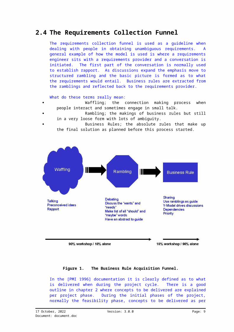
2.4 The Requirements Collection FunnelThe requirements collection funnel is used as a guideline whendealing with people in obtaining unambiguous requirements. Ageneral example of how the model is used is where a requirementsengineer sits with a requirements provider and a conversation isinitiated. The first part of the conversation is normally usedto establish rapport. As discussions expand the emphasis move tostructured rambling and the basic picture is formed as to whatthe requirements would entail. Business rules are extracted fromthe ramblings and reflected back to the requirements provider.
What do these terms really mean: Waffling; the connection making process when
people interact and sometimes engage in small talk. Rambling; the makings of business rules but still
in a very loose form with lots of ambiguity. Business Rules; the absolute rules that make up
the final solution as planned before this process started.
Figure 1. The Business Rule Acquisition Funnel.
In the [PMI 1996] documentation it is clearly defined as to whatis delivered when during the project cycle. There is a goodoutline in chapter 2 where concepts to be delivered are explainedper project phase. During the initial phases of the project,normally the feasibility phase, concepts to be delivered as per
17 October, 2022 Version: 3.0.0 Page: 9Document: document.doc

the scope, is not really clearly understood. As the projectprogresses onto the subsequent stages, concepts are crystallizedand the plans updated. The funnel can be used throughout theproject to clarify scope and technical deliverables.
It must be remembered that the Y-Model as described in this book,forms the primary “information recording and classification”tool. The funnel alone cannot be used, nor can projectmanagement principles be used to overcome all the obstacles ofobtaining user requirements.
2.5 SummaryModels of the world are used to implement models in software.There is a process of systematic “knowledge transfer” into amedium of software. To test the effectiveness of this process,services offered to the world must support the needs as definedby the world.
M odel of the worldM odel of software
systematic implementation
services offered
Figure 2. Model of the world in software.
When a software package evaluation process is done for example,one needs to have both models to see the fit and determine thegaps between business and technology. It is these gaps thatcause grief in building business solutions.
The workings of a system are presented graphically to make thecommunication process easier. People prefer pictures to writtenEnglish. User Requirement and Software Requirement’s documentsare used to group and visualize graphical models.
17 October, 2022 Version: 3.0.0 Page: 10Document: document.doc

2.5.1 Why do we do Analysis and Design?This should be answered by now! I would just like to add anotherfew points on the importance.
It directs you to: Understanding the dimensions of the problem. Knowing what to do and how. Using domains as problem solving areas.
Analysis emphasizes an investigation of the problem but notspecifically for a solution. Analysis effort will bedramatically affected depending on the size and complexity of theproblem.
Design is the practical side of the analysis where concepts arecrystallized into discrete implementation units.
Domains are logical areas of business or functionality. Domainsare used to manage the boundaries of analysis and to keep theproblem of not being able to scope requirements under control.
Analysis is the “what” of the system, where design answers to“how”.
The undeniable conclusion of large business implementationssuccesses have been the clear understanding of what must bedelivered.
17 October, 2022 Version: 3.0.0 Page: 11Document: document.doc

Chapter 3 UML with Analysis and Design
3.1 IntroductionModels have been important in engineering disciplines for a longtime. Before something is built, drawings are made thatrepresent and describe and final product. These drawings areused throughout the process of getting a better understandingwhat must be built and how it must be built.
Essentially there are three dimensions that are described by thedrawings namely; abstract definition, static structure andbehavior. The UML provides a set of models whereby thesedimensions can be described graphically. It is a graphicalmedium where concepts can be communicated to the stakeholders ofa product.
The UML is not revolutionary it is the first official commonobject oriented modeling language that combines the best ofBooch, OMT (Object Modeling Technique), OOSE (Object OrientedSystems Engineering), Fusion (Hewlett Packard Method) andCoad/Yourdon.
3.2 What is the UML?The UML basically combines the best elements of the followingconcepts:
data modeling concepts business process modeling object modeling component modeling
The UML comprises a rich set of graphical notation elements thatcan be used in just about any form of modeling. In the earlierchapters I introduced the principles of graphical systemsdefinition, the UML is a language to document the artifacts of asystem. It also shows all interdependencies.
The UML represents best practices in modeling of large andcomplex systems.
3.2.1 History of the UMLThe following is a brief description of the history of the UML:
In the Late ‘80s and early ‘90 there were many(50+) OO methodologies. Many different people and bodiespromoted these.
Among the first generation methodologies, Boochand OMT (Rumbaugh) stood out as the most complete and usable.
17 October, 2022 Version: 3.0.0 Page: 12Document: document.doc

Around 1993, second generation methodologies cameout - Booch ‘93 and OMT-II. Methodologist borrowed goodconcepts from each other. So many concepts were the sameacross the methodologies but with different notations.
In October 1994 Dr. James Rumbaugh joined Rationalto unify Booch & OMT.
At OOPSLA ‘95, Grady and Jim announced UnifiedMethod 0.8. The beginning of the UML drive.
The Use Case technique developed by Dr. IvarJacobson was adapted by all methodologies by then.
Rational acquires Objectory (Dr. Ivar Jacobson) inthe fall of ‘95 and Dr. Ivar Jaconson joins Rational.
In June of ‘96 Rational submits UML 0.9 to OMG. UML gains industry support from HP, Microsoft,
Oracle + 16 others. UML is the defacto standard for OO and component
technologies. The final submission went in Sep. ’97.
There is already a major move behind the UML. Many organizationsare behind the standardization of modeling techniques. Partnersinclude:
Digital Equipment Corp. HP I-Logix IBM Microsoft Oracle Rational Software TI Unisys Rubico
3.2.2 UML ArtifactsAll the artifacts are discussed in detail in the UML summarydocument.
“UML Semantics - defines the rich semantics and expressive syntax of the Unified Modeling Language. The UML is layered architecturally and organized by package. Within each package, the model elements are defined in terms of their abstract syntax (using the UML class diagram notation), well-formedness rules (using text and Object Constraint Language expressions), and semantics (using precise text). Two appendices are included: UML Glossary and Standard Elements.
17 October, 2022 Version: 3.0.0 Page: 13Document: document.doc

UML Notation Guide - defines notion and provides supporting examples. The UML notation represents the graphic syntax for expressing the semantics described by the UML metamodel.”
Reference: UML Summary Document
3.3 Visual ModelingModeling communicates business rules in a graphical way. It is alanguage of communication, like using the English language.
Visual modeling captures the essential parts of a system. Itdoes not mean that the entire “system” has to be computerized.The scope of the implementation will determine how much softwareis involved.
What is Visual Modeling? It manages complexity through visualisation and
abstraction. It is used as a communication tool between teams,
team members and users. A modeling language must include:
Model elements - modeling concepts and semantics Notation - visual rendering of model elements Guidelines - idioms of usage within trade
It defines software architecture independent ofimplementation technology.
The world is infinitely complex. We need tools to break downthese complexities into manageable concepts or units. Modelingrepresents facts in a graphical way. These facts could reflectthe current situation in a business or in a redesigned view.
Business analysts and domain experts define requirements.Software architects and developers build systems based on theserequirements. Typically, they have communication problems due todifferent use of terminology and different definition ofconcepts. The UML addresses these shortcomings.
For a modeling language to be complete the following items areneeded:Elements with specific meaning. Balancing of various concepts tomake up a “whole” picture.When various graphical elements come together in a “picture”.There must be specific meaning attached to the connections andgraphical notation.A common set of terms is needed to have everybody using the toolunderstand the concepts.
17 October, 2022 Version: 3.0.0 Page: 14Document: document.doc

A Model of a system is essentially software architecture. Thisarchitecture is a representation of the physical architecture.
Reuse at a business level is normally ignored. How many timeshave you been required to complete forms for the same company,with your name and address details? Reusing the person detailsfor medical-aid, pension, customer, supplier, and so on willprovide a much better environment than one where these arerecorded individually i.e. storage consistency, less effort inmaintaining, and so on. Modeling assists you in identifying thecommon areas that can be reused.
Even though computer systems automate business processes thatnormally seem easy to understand, people find it hard to deliversoftware systems correctly.
The people that use software systems do not care how they wereconstructed. It is our (business and software engineeringpeople) responsibility to shield the complexities of technologyfrom its users
3.3.1 Modeling and the UML Scope of the UML: Common language that is widely usable Built on existing methods Standard modeling language and not a process Promoting a process that is: Use-case driven Architecture centric Iterative and incremental
Why is the scope of the UML so important to us? Having a commonlanguage worldwide to describe systems will significantly reducethe effort in learning the different notations. The UML wasbuilt on existing methods by Booch, Rumbaugh and Jacobson.
The UML does not include a delivery process. This means that thenotation can be used in many diverse processes as long as itmakes sense.
The UML supports a process that is Use Case driven, meaning thatthe system is broken down into manageable components.Architecture centric means that the boundaries of the methods canbe set within your own framework. There are components of theUML that must be “balanced” to produce a completely verified setof models. It does not mean that the models have to imposelimitations. Stereotypes can be used to extend the functionalityof the UML.
The UML has the following parts:
17 October, 2022 Version: 3.0.0 Page: 15Document: document.doc

Views show the different aspects of the systemsthat are modeled and are loose standing visualrepresentations.
Diagrams describe the visual elements graphicallyin a view.
Model elements are the concepts that are used todescribe the components of the concept, such as classes,objects and messages.
17 October, 2022 Version: 3.0.0 Page: 16Document: document.doc
Chapter 4 Dimensions of Problem Domain
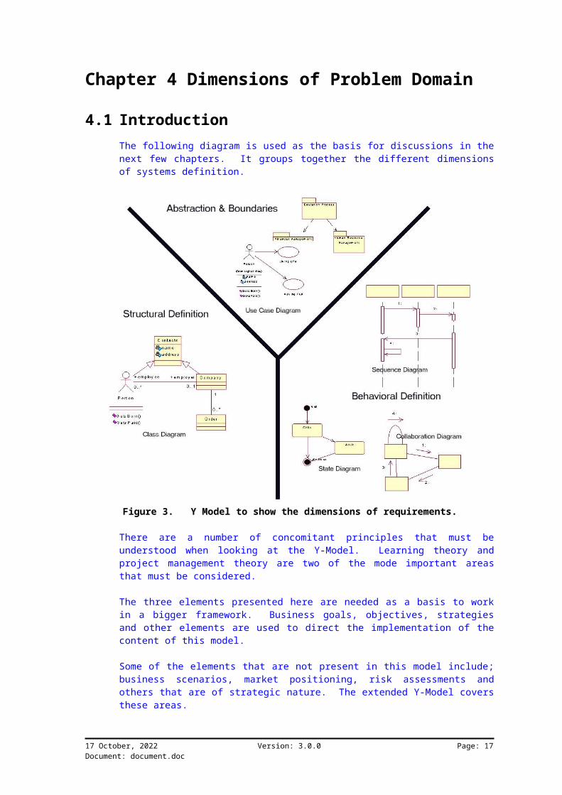
4.1 IntroductionThe following diagram is used as the basis for discussions in thenext few chapters. It groups together the different dimensionsof systems definition.
Figure 3. Y Model to show the dimensions of requirements.
There are a number of concomitant principles that must beunderstood when looking at the Y-Model. Learning theory andproject management theory are two of the mode important areasthat must be considered.
The three elements presented here are needed as a basis to workin a bigger framework. Business goals, objectives, strategiesand other elements are used to direct the implementation of thecontent of this model.
Some of the elements that are not present in this model include;business scenarios, market positioning, risk assessments andothers that are of strategic nature. The extended Y-Model coversthese areas.
17 October, 2022 Version: 3.0.0 Page: 17Document: document.doc

4.1.1 Abstraction and BoundariesThe “bigger picture” is shown in this dimension. This is wherethe boundaries of work are defined. The models in the otherdimensions are focused on the abstract view as defined by UseCase diagrams. The System Diagram sets the boundaries anddependencies.
4.1.2 StructureThis is where the “static” view of the solution is modeled.“Static” means that all the non-behavioral elements are modeled.It represents a business rule at a point in time. This dimensionis responsible for the identification and modeling of all theobjects.
4.1.3 BehaviorBehavior shows the “dynamic” view of objects. All aspects of howobjects interact in the context of the boundaries as defined bythe Use Case view are defined here.
17 October, 2022 Version: 3.0.0 Page: 18Document: document.doc
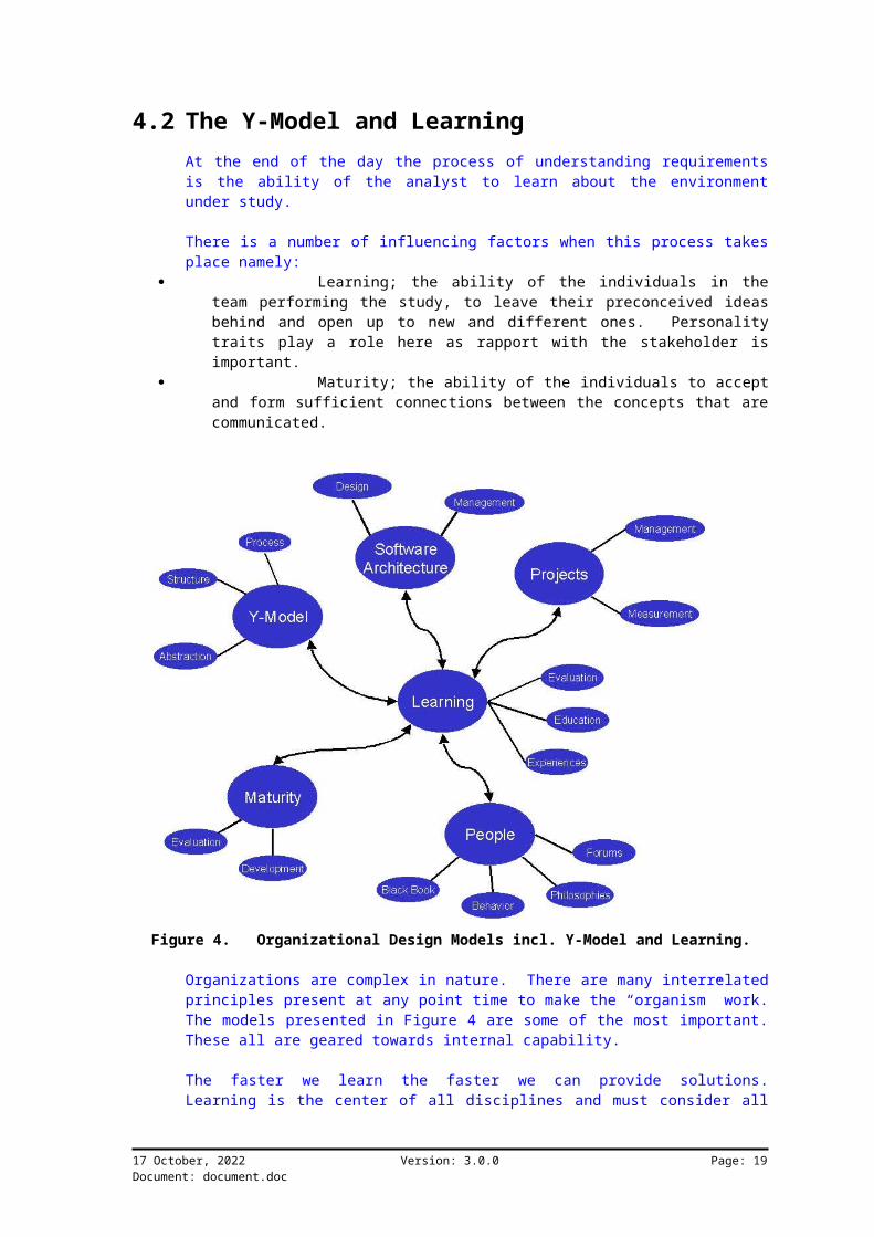
4.2 The Y-Model and LearningAt the end of the day the process of understanding requirementsis the ability of the analyst to learn about the environmentunder study.
There is a number of influencing factors when this process takesplace namely:
Learning; the ability of the individuals in theteam performing the study, to leave their preconceived ideasbehind and open up to new and different ones. Personalitytraits play a role here as rapport with the stakeholder isimportant.
Maturity; the ability of the individuals to acceptand form sufficient connections between the concepts that arecommunicated.
Figure 4. Organizational Design Models incl. Y-Model and Learning.
Organizations are complex in nature. There are many interrelatedprinciples present at any point time to make the “organism” work.The models presented in Figure 4 are some of the most important.These all are geared towards internal capability.
The faster we learn the faster we can provide solutions.Learning is the center of all disciplines and must consider all
17 October, 2022 Version: 3.0.0 Page: 19Document: document.doc
aspects of causality. Everything that happens relates in someway to the principle of causality (cause and effect).
4.2.1 Learning Model as the HubAn organizations ability to learn is possibly their greatestasset. It is fundamental to share knowledge freely tostakeholders in the common purpose.
The biggest challenge I’ve seen for consultants and customersalike, is their ability to part with knowledge and not to letpreconceived ideas overwhelm situations.
4.2.2 Software ArchitectureThis book describes the essence of taking abstract ideas andbusiness concepts into tangible software products. This requiresa solid and stable framework to work from, where the mundane workis already performed.
At the end of the day everything comes down to innovative design.Everything today revolves around design; the cars we drive, thecomputers we use, the clothes we wear. Software architecturecaptures the primary software design principles to make thebusiness implement its concepts properly.
4.2.3 PeoplePeople make Businesses! Buildings, office furniture andcomputers are not what make businesses succeed, it is the drive,attitudes and ability of its people.
4.2.4 ProjectsProjects are used to fulfill business requirements. Throughoutthe next few sections I will show how the particular conceptslink to a delivery process.
4.2.5 MaturityYou will learn things by reading this book that will only makesense once all aspects have been “processes”. There will be anew set of challenges once the concepts are applied as described.Maturity is the ability to understand this now and learn as muchas possible.
If you are really interested in modeling and businessrequirements definition, then this will be the starting point ofa very long journey. There are reference materials available on
17 October, 2022 Version: 3.0.0 Page: 20Document: document.doc

the People Maturity Model that explains the pain an individualgoes through in his/her quest for knowledge.
17 October, 2022 Version: 3.0.0 Page: 21Document: document.doc

Chapter 5 Understanding Systems
5.1 IntroductionThe system diagram is used to show the boundaries of a particularsystem. It groups together semantically related elements. Thisdiagram must only be used when discreetly different areas areidentified. Use Case diagrams can also show boundaries, but willonly be discussed later.
5.2 Notation
Package1 Package2
Figure 5. Package example.
The rectangles are called packages. The line and arrow meansthat one package is dependant on another. The dependency is inthe direction of the arrow. The example in figure 2 explainsthat Package1 is dependent on Package2.
Since the packages are the primary boundaries of the proposedsystem, the project plan with the work breakdown structure shouldbe matched up. This will provide the project plan with adefinite guide as to which requirements are to be fulfilled when.Project priority and package priority is matched up to obtain theoptimum schedule for the business. This is also an easy way todetermine pre-requisites. The concept used here is calledarchitectural priority.
Architectural priority is the process whereby the analyst obtainsall related information as per the Y-Model and links these to thearchitecture.
5.3 Domain AnalysisWhy and how domain analysis is used:Abstraction of business environment:
Learning and communicating Focus on relevant details
How are solutions shaped? Complex system broken down into smaller views Every model expressed at different levels The best models are connected to reality
17 October, 2022 Version: 3.0.0 Page: 22Document: document.doc

A domain is a sphere of activity, it is a grouping of businessconcepts with all related stimuli and behavior. To do “domainanalysis” is to understand the stimuli and processes that make adomain.
Abstraction is the act of separating in thought and concept theparts of a system. We need to abstract to understand a problemand know how to deal with it. One can only focus on problemrelevant details once abstraction has been done.
Solutions are shaped by breaking down concepts in a domain, intosmaller human understandable areas. The process of breaking downthe concepts will explore more detail as time goes by. Levels ofabstraction must be balanced to keep concepts together, forexample; it is not wise to show how a transaction is performed ata level where only system boundaries are indicated.
Domain Analysis facilitates communication to all the relevantstakeholders. Process owners (the people responsible for thedeliverables produced by processes) are normally directlyinvolved in the process.
Domains are affected by business events. These events are usedto further explore the working of the area under study.
Some Considerations when doing analysis: Domain expert’s availability and knowledge Number and complexity of real-world concepts in
domain Semantics of problem Domain operations that include processes
5.4 Case StudyThe case study in this book is for an education system. Theramblings are collected from the system owner and system user.Relevant business rules are extracted from the ramblings andgraphical models are shown.
Rambling:I need a system to manage the education process. The educationprocess cuts across all other process in the organization. Ithink you would need an interface into the financial system sothat all payments can go to the books directly. People’s detailswould be recorded in the human resources system. We also keeptrack of all training and development programs for the employeesonly. Outside consultants are not tracked as detailed, butcourses and other communication with the system need to bestored. We also need to know how many people come through thetraining and what their maturity ratings are.
17 October, 2022 Version: 3.0.0 Page: 23Document: document.doc

Education System
Finance System
Hum an Resource System
Plan, schedule and control the training process.
Figure 6. System diagram for the education system.
Note that the rambling includes many other concepts that are notrelevant at this time. One of the problems with modeling systems
17 October, 2022 Version: 3.0.0 Page: 24Document: document.doc

is that we want to include too many concepts at once. Thiscreates confusion, as the foundations are not built correctly.Understanding boundaries is one of these foundations as the scopeof your project could be affected if these are definedincorrectly.
5.5 How To5.5.1 Steps
Understand boundaries and limitations. Discuss and document system elements. Know the dependencies.
5.5.2 Tips Don’t use dependencies to indicate flow or data
sharing.
17 October, 2022 Version: 3.0.0 Page: 25Document: document.doc

Chapter 6 Use Case Modeling
6.1 IntroductionThere are two types of business models namely internal andexternal models. The external model describes the business andits interactions with the outside world where the internal modelsdescribe the detailed processes.
External models are described in terms of primary businessesincluding the interactions with customers, suppliers andemployees. It involves all processes and their interactions,resources and dependencies.
Internal models describe the business processes and theirdetailed and related tasks. Resources are needed when tasks areperformed.
This chapter describes Use Cases that form the primary medium ofdescribing business and their external relevancy. Use Cases arepart of the Abstraction and System Boundaries dimension as shownin the figure below.
Figure 7. Y model with Use Case focus.
One of the uses of a Use Case diagram is to determine systemboundaries. This means that Use Cases can be used to decomposesystem functionality. The decomposition is done for the levelsof system abstraction. Even though the Use Case diagram in theabove picture is shown in the “abstraction and system boundaries”dimension, system behavior is also depicted using Use Case
17 October, 2022 Version: 3.0.0 Page: 26Document: document.doc
diagrams. “Packages” (see the section on packages) are also usedto show system boundaries.
Use Cases also show how its stakeholders use the system.
6.2 Use Case DiagramsUse case diagrams describe the relevant business processes.Processes normally interact with customers, suppliers and variousresources such as employees.
Use Cases are scenarios that show how external components usebusiness systems.The purpose is to present a kind of context diagram to understandthe system and its workings.Shows relationship among Actors and Use Cases in a system todescribe functional requirements .
The users and any system that may interact with the system arethe Actors.
A Use Case diagram presents a collection of Use Cases and Actorsand is typically used to specify or characterize thefunctionality and behavior of a whole application systeminteracting with one or more external Actors.
Since Actors represent system users, they help delimit the systemand give a clearer picture of what it is supposed to do. UseCases are developed on the basis of the Actors needs. Thisinsures that the system will turn out to be what the userexpected.
Use Case diagrams consist of a number of different drawing objectincluding Actors, association relationships, generalizerelationships, packages, and Use Cases.
You can create a top-level Use Case diagram to visualize thecontext of a system and the boundaries of the system’s behavior.You can also create one or more Use Case diagrams to describe apart of an application. Individual Use Cases can include otherUse Cases to further describe their behavior.
A Use Case Specification enables you to display and modify theproperties and relationships of a Use Case. The information inthe specification is presented textually; some of thisinformation can also be displayed inside the icon representing aUse Case.
17 October, 2022 Version: 3.0.0 Page: 27Document: document.doc

6.3 Use Case Usage in ProcessUse Cases are used throughout the life cycle to manage and trackrequirements. The project scope can be attached to a high-levelUse Case. The analysis phase will reveal the actual workings ofit.During design, Use Cases are expanded to include physicalimplementation design issues included.
Use cases are linked to individual packages as discussed earlier.The challenge now is to transfer these use-cases onto a projectplan to show implementation.
6.4 NotationThe following diagram illustrates Use Cases diagrams.
Use case
Actor
Relationship
Use Case
<<uses>>
Use Case1
<<extends>>
Figure 8. Use Cases provide services to Actors.
17 October, 2022 Version: 3.0.0 Page: 28Document: document.doc

A Use Case diagram is a graph of Actors, a set of Use Casesenclosed by a system boundary, communication (participation)associations between the Actors and the Use Cases, andgeneralizations among the Use Cases.
The solid line with the line arrow represents a “message” orstimuli from the Actor to the Use Case. It shows that the Actoruses the Use Case. The hollow arrow means that the “Use Case:Master” uses “Use Case” to perform its work, for example; UseCase “electronic payment” and “manual payment” both use the“payment” Use Case.
An abstract notation indicates a use case that exists to capturecommon functionality between use cases (uses) and to describeextensions to a use case (extends).
The uses generalization is used to describe common behavior betweentwo or more use cases. It is one of the mechanisms used toidentify reusable behavior for business rules.
The extends generalization is used to express optional behavior fora use case. It provides one of the mechanisms for architectingdependencies in an application.
6.4.1 Use Cases
Use case
Figure 9. Notation for a Use Case.
Description: describes functionality in relation to events of
an Actor these events are to complete a process stories of using the system
Example: Buy Items
buying items from a store recording purchase and collecting payment customer leaves with items
A Use Case is a sequence of transactions performed by a system inresponse to a triggering event initiated by an Actor to thesystem. A full Use Case should provide value to an Actor whenthe Actor is performing the task defined by the Use Case. A UseCase contains all the events that can occur between the Actor andthe Use Casebut , not necessarily the ones that will occur in any
17 October, 2022 Version: 3.0.0 Page: 29Document: document.doc

particular scenario. A Use Case contains a set of scenarios thatexplain various sequences of interaction within the transaction.
A Use Case can also describe the behavior of a set of objects,such as an organization.
Use Cases are normally described using a verb and nouncombination. This indicates work.
A common mistake people make is to define a Use Case as anindividual activity or step as part of a process. It is not thenorm to decompose Use Cases into such detail, but rather todescribe it, or use Sequence diagrams and State diagrams todepict steps.
Use Cases with no Actor interaction should be investigatedclosely, as it is very unlikely that work gets done in a systemwith no stimuli.
6.4.2 Actor
Actor
Figure 10. Notation for an Actor.
Description: external entity to the system participates in the story of a Use Case represented by the role they play
Example: Customer
buying items from a store leaves with items
An Actor is a stereotype1 of a class. It models a kind of objectoutside the domain of the system itself that interacts directlywith the system. The users and any system that may interact withthe system are the Actors. Since Actors represent system users,they help delimit the system and give a clearer picture of whatit is supposed to do.
1 A stereotype represents the subclassification of a model element. It represents a class within the UML metamodel itself (i.e., a type of modeling element).
17 October, 2022 Version: 3.0.0 Page: 30Document: document.doc

Actors can play a role in relation to the situation in the model,for example; “person” plays the role of “employee” in relation tothe Use Case “paying salaries”.
Environments generally have a number of standard actors namely;customers, suppliers, employees, and so on. These actors can bepresented as external entities, the physical or human aspect orthe internal entities namely records in paper format or incomputer storage.
Note:A stereotype is a new class of modeling element introduced atmodeling time. It represents the same characteristics as anexisting element, but with a different intent. For example anActor has attributes that describe it and operations that areperformed. But classes also have attributes and operations.Classes will be discussed later.
6.5 Types of Use CasesPrimary Use Cases:
represent major common processes; “Buy Items” expanded to a lower level of detail could show concrete design
Secondary Use Cases: represent minor or uncommon processes
Optional Use Cases: represent processes outside of the system domain
or scope not modeled to a low level of detail
Use Cases are classified into primary, secondary and optional. Primary Use Cases need constant project focus
because they represent major common processes. These arenormally decomposed to lower levels and can go as far asdesign and implementation.
Secondary Use Cases are needed but not critical tothe deliverables of your system. They support the primary UseCases.
Optional Use Cases are outside of the boundariesof the system, but might be needed to complete yourrequirements. These are normally not modeled at a lowerlevel.
6.6 Use Cases and Project DeliveryUse Cases are used to track how requirements are implementedduring a project. It is done this way because Actors, that couldbe the users of the system, must be satisfied by thefunctionality as provided in the Use Case.
17 October, 2022 Version: 3.0.0 Page: 31Document: document.doc

A grid could be used where all the Use Cases are mapped to itemsin the work breakdown structure. This can function as acompleteness check to make sure that all requirements areconsidered. Detailed elements can also be included such asdetailed process definitions and classes of information.
6.7 Notational PointsNaming Use Cases:
start by describing with a verb; “Buy Items”,“Enter an Order”
Expanded Use Case: <Actor> <initiates an event>; “Customer arrives at
a POST with items to purchase”Notation decision points:describe each decision point by using a reference in the maindescription
Use Cases describe work, so to make it easier to understand use averb as part of the description.
It becomes difficult to see traceability with expanded Use Casesif the description is without the Actor that initiated it and theevent that takes place. This is not practical in some cases.
The standards and patterns documentation on the usage of UMLdescribes all aspects of the notation.
6.8 Use Case Modeling and AbstractionA high level of abstraction should be represented by a smallnumber of Use Cases. In this example the analysis Use Case isdecomposed and shown at a lower level with more detail. Thisdecomposition should not be taken too far. Sequence andcollaboration diagrams are used to show exact behavior.
17 October, 2022 Version: 3.0.0 Page: 32Document: document.doc

Person
Docum ent Concepts
Perform Planning
Understand Concepts
Perform Analysis
Person
Perform Design
Figure 11. Analysis at higher level of abstraction.
Figure 11 indicates that “Perform Analysis” is broken into areasof “Perform Planning” and so on. Details are expanded as theabstraction is reduced.
17 October, 2022 Version: 3.0.0 Page: 33Document: document.doc

6.9 Case StudyRambling by education director:The education process can be divided into three main areasnamely; training scheduling, tracking and execution of training,and booking management. I will initiate the scheduling of newtraining. Lecturers must be considered when doing scheduling assome courses have more than one. The Intranet must be used tocommunicate training schedules. Training co-ordination is done by the training co-ordinator. Itinvolves the tracking of items during the running of the coursesand programs. Stock items, such as personal computers andmanuals are issued to candidates. We also record informationabout the programs and courses. Candidates book themselves on training via the training co-ordinator. They could do it themselves via the intranet, but astatus must show that is was done externally. Once bookings aremade they are published on the Intranet. Candidates can use e-mail or a fax to confirm bookings.
Lecturer
Education Director
Track Training
Schedule Training
gives inputinitiates
Candidate
inform
Training Coordinator
track training components
gives direction
Intranet
publish
M anage Bookingrequest booking
takes booking
publish
Figure 12. Use Case example.
17 October, 2022 Version: 3.0.0 Page: 34Document: document.doc
6.10 How ToUse Case models are normally not completed in one action. Ittakes time with ongoing reviews and system verifications to havea completely clean model.
[*] Various concepts can be used to check completeness of usecases when created in workshops with stakeholders:The first and most important concept is that any business hascustomers, suppliers and products. This means that thestakeholders need to understand their own environment before anyrecording of such concepts can take place. Refer to the businessrule acquisition funnel.
Another concept is that the business requires resources tofunction such as people and finances. These elements arenormally the most neglected in older systems that only automatedoutdated processes. It does not mean that it should be ignoredin modern businesses and processes.
So, the principle is used as follows: Customers always “buy” products or services may it
be internal in an organization or external. Suppliers always “supply” products or services may
it be internal or external. Resources are used to be able to supply products
or services.
By using the above outline, workshop time can significantly bereduced and the stakeholders will feel involved. The idea is toremove white space and clear up the gray areas that are normallynot covered with traditional organizational silos.
6.10.1 Steps to Identify1. Boundaries are defined in the domain under study. Use Cases
indicate groups of functionality in the domain.2. Actors are people or external things that interact with the
system.3. Actors use the system in different ways. Actors perform
different roles when they use the system.4. Each interaction between an Actor and a Use Case indicates a
scenario that reflects behavior.5. An event occurs every time an Actor interacts with a Use Case.6. Create the Use Case diagram.7. Document the Use Cases.8. Each Use Case must be ranked for it to be implemented. System
or architecture impact must be determined. Use Cases must beranked by risk. The ranking process must check to make surethat the processes are complete.
17 October, 2022 Version: 3.0.0 Page: 35Document: document.doc

6.10.2 Tips all Actors in the business are modeled and
associated with a Use Case Actors must express a role (one) and not a person Use Cases must represent the business that they
are modeled for all Use Cases and activities are modeled and must
be unique balance Use Cases; not too big or small,
abstraction must be right workflow in a Use Case only describes the objects
and activities inside it a Use Case must add value to its Actor each Use Case has measurable goals and objectives
for the business
17 October, 2022 Version: 3.0.0 Page: 36Document: document.doc

Chapter 7 Object and Class Modeling
7.1 IntroductionThis chapter describes the first part of classes and objects andhow they will be used.
There are many objects that form part a particular domain.System structure describes the functionality as needed in UseCases.
Figure 13. Y model with system structure focus.
The primary modeling technique used to depict system structure isthe Class diagram. Actors, as created in the Use Case view, arebrought into class diagrams to show their connections with thesystem at an object level.
7.2 What is an Object?Objects can basically be described as:
Occurrences in the real world are mapped toobjects.
Objects encapsulates information. Objects offer behavior towards other objects. An object belongs to a class of similar objects. Concepts that are related.
An object represents a particular instance of a class. It hasidentity and attribute values.
17 October, 2022 Version: 3.0.0 Page: 37Document: document.doc

Objects are concepts. Concepts are expanded throughoutrequirements collection or definition.
Values about objects can be stored in relational, object andother forms of databases. Objects have concurrency wherebycertain behaviors can happen at the same time and others can onlyhappen on completion of existing behaviors.
7.3 Class DiagramClasses cannot be discussed without objects as the two areinterwoven. Objects are concrete concepts that exist in time andspace where classes represent an abstraction.
A class diagram is a picture for describing generic descriptionsof possible systems. Class diagrams and object diagrams arealternate representations of object models. Class diagramscontain classes and object diagrams contain objects, but it ispossible to mix classes and objects when dealing with variouskinds of metadata, so the separation is not rigid.
Classification of objects is difficult and requires active aninvestigation through a process of discovery of the environment.When we classify we need to identify the common structure andbehavior of objects. This will assist us in the process.
Note:Class diagrams contain icons representing classes. You can createone or more class diagrams to depict the classes at the top levelof the current model; such class diagrams are themselvescontained by the top level of the current model. You can alsocreate one or more class diagrams to depict classes contained byeach package in your model; such class diagrams are themselvescontained by the package enclosing the classes they depict; theicons representing logical packages and classes in classdiagrams.
7.3.1 Usage in ProcessObjects are identified throughout the process of trying tounderstand business problems. Levels of detail and completenesswill increase as the projects execute and deal with furtheraspects of the final solution.
Classes are expanded as the system progresses through the systemlife cycle.
During the analysis phase: show common roles and responsibilitiesof the entities that provide the system's behavior.
17 October, 2022 Version: 3.0.0 Page: 38Document: document.doc

During phase design: capture the structure of the classes thatform the system's architecture.
7.3.2 Notation
Package::ClassAttribute1Attribute2
Operation1( )Operation2( )
Class1Attribute1
Operation1( )0..10..*
AssociationRole 1Role 20..10..*
Figure 14. Class diagram basic notation.
There are a number of components that make up a class diagram.In the figure above there are two classes connected via anassociation. Each association plays a role in relation to theother. The association also has a description. Optionality andcardinality or multiplicity is indicated with numeric and '*'characters.
Types of interfaces are: public, private, protected.
7.3.2.1 Classes
Package::ClassAttribute1Attribute2
Operation1( )Operation2( )
Figure 15. Class notation.
Description: captures a common set of behaviors and attributes
of objects class instances are called objects
Example: Joe and Mary are objects in the people class BMW and Volvo are objects in the vehicle class
A class captures the common structure and common behavior of aset of objects. A class is an abstraction of real-world items.
17 October, 2022 Version: 3.0.0 Page: 39Document: document.doc

When these items exist in the real world, they are instances ofthe class, and referred to as objects.
For each class that has significant temporal behavior, you cancreate a state diagram to describe this behavior.
A class icon is drawn as a 3-part box, with the class name in thetop part, a list of attributes (with optional types and values)in the middle part, and a list of operations (with optionalargument lists and return types) in the bottom part.
The attribute and operation sections of the class box can besuppressed to reduce detail in an overview. Suppressing asection makes no statement about the absence of attributes oroperations, but drawing an empty section explicitly states thatthere are no elements in that part.
Each class must have a name. If the class name is particularlylong, enlarge the icon to enclose it.
7.3.2.2Actors
Description: Is a stereotype of class; doing something specific Interacts with other classes
Example: Joe and Mary are objects that are Actors in the
people class
You can define multiple sets of default properties for the sametool and model element. For example, you might want one set ofproperties for a class with a stereotype of Actor and a differentset of properties for a class with a stereotype of Interface.Both of these sets are still considered default properties inthat they are predefined for the model. Defining multiple setssaves you work by minimizing the need to override properties asyou go.
7.3.2.3 Associations
Package::ClassAttribute1Attribute2
Operation1( )Operation2( )
Class1Attribute1
Operation1( )0..10..*
AssociationRole 1Role 20..10..*
Figure 16. Showing associations.
17 October, 2022 Version: 3.0.0 Page: 40Document: document.doc

Association and multiplicity are the general rules of how objectsin a class are allowed to be connected.
Description: Semantic connection between two classes Connects instances of classes, objects Each association has two roles, one per direction Lower and upper bounds of association is shown by
multiplicity It is a “has a” or “knows about” link between
objectsExample:
Joe owns a BMW and a Volvo Mary works for IBM;
An association represents a semantic connection between twoclasses. Associations are bi-directional; they are the mostgeneral of all relationships and the most semantically weak.
During analysis, you will initially identify general dependenciesbetween classes. As your model evolves, you may add adornments toassociations to make them more precise.
Use the association name to identify the type or purpose of therelationship.
You can assign a variety of adornments and properties toassociation relationships through the Association RelationshipSpecification. They include: derived, association direction,association documentation, roles, cardinality, navigability,aggregate, static, friend, access, containment, association androle constraints, association classes, and qualifiers.
7.3.2.4 Cardinality or Multiplicity
Cardinality specifies how many instances of one class may beassociated with a single instance of another class. You canindicate cardinality for classes and relationships:
When you apply a cardinality adornment to a class,you are indicating the number of instances allowed for thatclass.
When you apply a cardinality adornment to arelationship, you are indicating the number of links allowedbetween one instance of the client class and the instances ofthe supplier class.
17 October, 2022 Version: 3.0.0 Page: 41Document: document.doc

Package::ClassAttribute1Attribute2
Operation1( )Operation2( )
Class1Attribute1
Operation1( )0..10..*
AssociationRole 1Role 20..10..*
Figure 17. Multiplicity.
You can use the following cardinality values for either class orrelationship cardinality:
Value Description1 One instanceN Unlimited number0..n Zero or more1..n One or more0..1 Zero or one<literal> Exact number<literal>..n Exact number or more<literal>..<literal> Specified range<literal>..<literal>,<literal>
Specified range or exactnumber
<literal>..<literal>,<literal>..<literal>
Multiple specified ranges
You can specify cardinality for a class or parameterized class.The default cardinality is "n". A cardinality of "n" is displayedas a "*" on the class diagram. To set a specific cardinalityvalue for the class, enter the applicable value(s) in theCardinality field of the specification.
PersonNam eAddress
Com panyNam eRubicoClient0..11..*
employment+em ployee +em ployer0..11..*
Person as an em ployee works for either no (0) or one (1)
17 October, 2022 Version: 3.0.0 Page: 42Document: document.doc

PersonNam eAddress
Com panyNam eRubicoClient0..11..*
+em ployer0..1
+em ployee
1..*employment
Com pany as an em ployer, em ploys at least one (1) or m ore (*) people that are em ployees.
Figure 18. Reading Accociations.
Always read associations from the class to the opposite end ofthe association.
Em ployee E mployer0..11..*1..* 0..1
employment
Figure 19. Roles as Classes.
In this figure the roles became important enough to warrant aclassification of its own.
DbPerson<<prim ary key>> PersonId<<foreign key>> Com panyIdPerson ID Num berNam eAddress
<<relational table>>
DbCom pany<<prim ary key>> Com panyIdCom pany Registered Nam eRegistration No
<<relational table>>
0..11..* 0..11..*
+Com panyId+Com panyId<<Restrictive>>
Figure 20. Associations with Restrictive Rules.
This example shows that people in the DbPerson class are uniquelyidentified (primary key) by the PersonId attribute. TheDbCompany class is uniquely identified by CompanyId. Each objectin the DbPerson class has a valid CompanyId assigned. The accessbetween the two classes is restricted, meaning that objects in theDbCompany class cannot be removed before the DbPerson has been
17 October, 2022 Version: 3.0.0 Page: 43Document: document.doc

assigned another DbCompany or the DbPerson object has beenremoved.
DbPerson<<prim ary key>> PersonId<<foreign key>> Com panyIdPerson ID Num berNam eAddress
<<relational table>>DbAddress
<<prim ary key>> AddressId<<foreign key>> PersonIdAddressTypesAddressLinesPostal Code or Zip
<<relational table>>
0..*1
<<Cascading>>
1 0..*+PersonId+PersonId
Figure 21. Associations with Cascading Rules.
This example is the same in concept as the previous but theassociation type is cascading. When the DbPerson object is removedthen it will remove all the related associated objects inDbAddress.
7.3.3 Association TypesObjects in classes can be dealt with in the following ways:
Create; objects have rules when they are created. Read; objects must exist before they can be
accessed. There are also many different ways that accesscould take place.
Update; Objects that exist already might need tochange.
Delete; Destroying objects need strict referentialrules.
7.3.3.1 Simple Association
Class1Attribute1
Operation1( )
ClassAttribute1Attribute2
Operation1( )Role 1Role 2
0..* 0..1Association0..* 0..1
Figure 22. Simple association.
This simple association connects objects from Class and Class1 at amoment in time. Class can only be connected one or none of theobjects in Class1. When the association is established then Class1plays role Role 1 to none or many of the objects in Class.
Note:Associations are more likely to have “0..*” cardinality vs.“1..*”.
17 October, 2022 Version: 3.0.0 Page: 44Document: document.doc

7.3.3.2 Child in Self Association
Class1Attribute1
Operation1( )0..*
0..1has clild
0..1
0..*
Figure 23. Child in self association.
This association is used when objects in a class relate to otherobjects in the same class. For example; employees in a companymight report to other people in the company. This means that theemployee class has a relationship to itself connecting differentobjects.
Note:Tthe “0..1” as the parent is there to allow the creating of thefirst item, the top of the tree. The “0..*” is used to allow thetree to stop.
7.3.3.3 Complex Existence Association
ClassAttribute1Attribute2
Operation1( )
Class2Attribute1
Operation1( )
Class3Attribute1
Operation1( )0..*1
0..*
1
0..* 11
1
0..*
0..* 0..*
Class1Attribute1
Operation1( )
Figure 24. Complex existence association.
This kind of association is used when objects in a class aredirectly dependent on the existence of objects in many otherclasses. This kind of situation must be looked at closely as itis not common. An example is; A prescription is directlydependent on the doctor, patient and diagnoses. Without thesethree components it cannot exist.
17 October, 2022 Version: 3.0.0 Page: 45Document: document.doc

7.3.3.4 Many to Many Association
Class4Attribute1
Operation1( )
Class2Attribute1
Operation1( )
0..*
0..*0..*
0..*
Figure 25. Many to many association.
Many to many associations occur all the time. The trick is toidentify and resolve the association into something meaningful.An example is; many consultants can work for many companies.When a salary is earned it is not just for one company but forthe company as at the time of work. This means that salary is anattribute of the association between company and consultant.
7.3.3.5 Derived Associations
Em ploym entPeriodSalary
Em ployee0..* 10..* 1
Division0..*1 0..*1
0..*0..* 0..*0..*
/employer
Figure 26. Derived association.
A derived element is one that can be computed from another one,but that is shown for clarity or that is included for designpurposes even though it adds no semantic value. In this case thederived association between division and employee indicates thatdivision employs many employees.
17 October, 2022 Version: 3.0.0 Page: 46Document: document.doc

7.3.3.6 Association Class
Em ployeeDivision0..1 0..*0..*
Em ploym entPeriodSalary
0..1em ployer
Figure 27. Association class.
An association class is an association that also has classproperties (or a class that has association properties). Eventhough it is drawn as an association and a class, it is reallyjust a single model element. In the example as per the many tomany association, this concept can be used to define attributessuch as salary on an association.
17 October, 2022 Version: 3.0.0 Page: 47Document: document.doc

7.4 Generating 1st Cut Class DiagramTo make the 1st cut class diagram “user friendly”, create a viewthat excludes all complex associations, attributes andoperations. The user must obtain a conceptual understanding ofhow the “concepts” in his/her business associate. Technicalcomplexity must be shielded.
7.5 How ToClass diagrams can be used to explain back to the stakeholders asto how the different elements relate.
A concept called access path analysis is used to determine if allpossible paths to classes have been identified.
7.5.1 Steps to Identify identify the objects and their classes for each object, identify association relationship identify multiplicity of each association identify if the association is an association;
‘has a’ check interaction relationships and roles identify operations to attach and detach
associated objects create class diagram and specification
7.5.2 Tips describe associations to check their relevancy always read cardinality at the opposite end of the
association associations describe a link at a moment in time use association roles to clarify its use
7.6 Attributes and OperationsThis section describes attributes and operations as used withclasses. Classes have instances called objects. Each objectencapsulates it's own attributes and operations.
Attributes describe only the objects in the class they belong to.A different class should be created when attributes are repeated.An example is; instead of using UnitOfMeasure1 and UnitOfMeasure2on a product class to handle two units of measure for a product,rather create a class called Unit of Measure and relate it to theproduct class.
17 October, 2022 Version: 3.0.0 Page: 48Document: document.doc
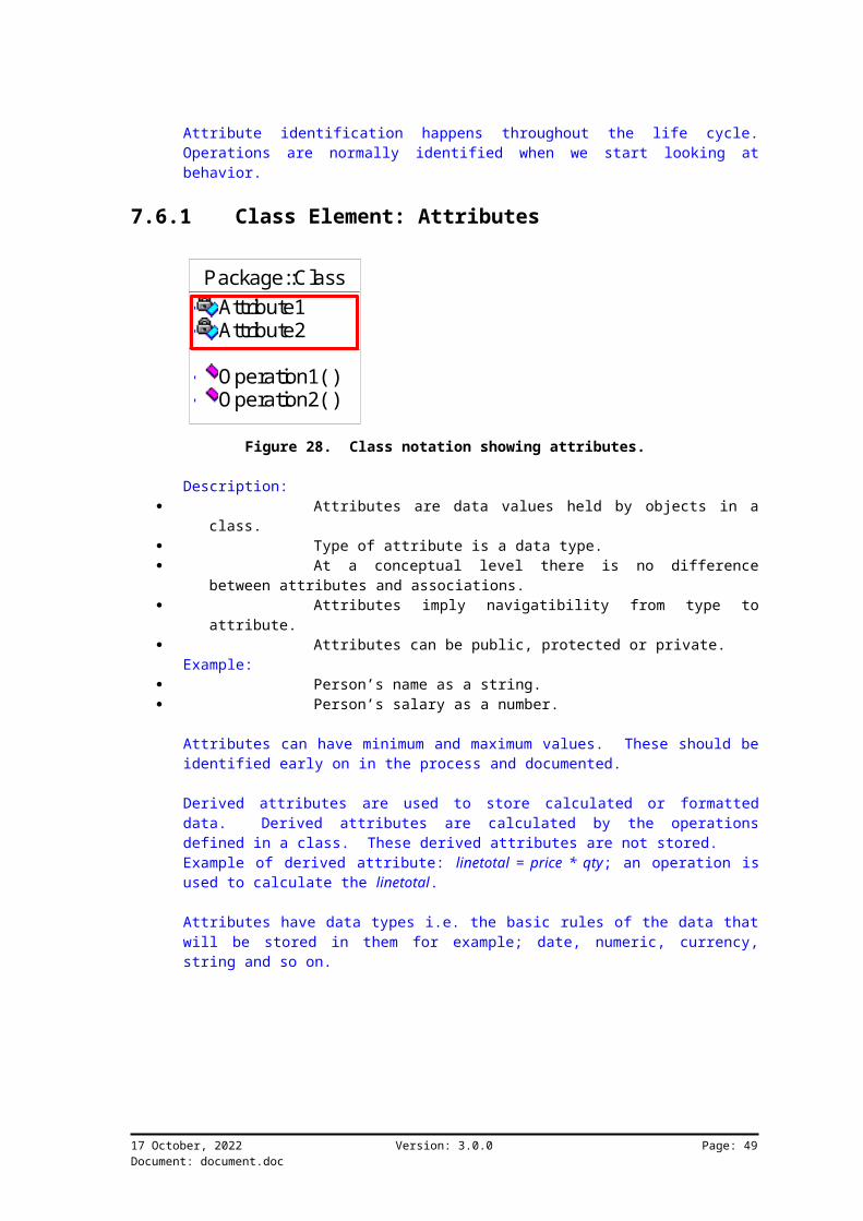
Attribute identification happens throughout the life cycle.Operations are normally identified when we start looking atbehavior.
7.6.1 Class Element: Attributes
Package::ClassAttribute1Attribute2
Operation1( )Operation2( )
Figure 28. Class notation showing attributes.
Description: Attributes are data values held by objects in a
class. Type of attribute is a data type. At a conceptual level there is no difference
between attributes and associations. Attributes imply navigatibility from type to
attribute. Attributes can be public, protected or private.
Example: Person’s name as a string. Person’s salary as a number.
Attributes can have minimum and maximum values. These should beidentified early on in the process and documented.
Derived attributes are used to store calculated or formatteddata. Derived attributes are calculated by the operationsdefined in a class. These derived attributes are not stored.Example of derived attribute: linetotal = price * qty; an operation isused to calculate the linetotal.
Attributes have data types i.e. the basic rules of the data thatwill be stored in them for example; date, numeric, currency,string and so on.
17 October, 2022 Version: 3.0.0 Page: 49Document: document.doc

7.6.2 Class Element: Operations
Package::ClassAttribute1Attribute2
Operation1( )Operation2( )
Figure 29. Class notation showing operations.
Description: Processes that a class knows to carry out. Show responsibilities of the class. Operations are invoked on objects. Operations can be public, protected or private.
Example: BuyVehicle DriveVehicle
Operations are the behaviors of a particular class. These areexplored further when we get to the sequence and collaborationdiagrams.
Operations can have other diagrams attached to it. Interaction(sequence and collaboration) diagrams are used normally to showmore detail.
Operations are shown in classes in a specific way. They arecalled by name with a parameter list and return types.
Operations are made up of the following elements: visibility name (parameter list): return-type-
expression {property string} visibility is + (public), # (protected), -
(private) name is a string parameter list contains (optional) arguments whose
syntax is the same as that for attributes return-type-expression is an optional
specification property-string indicates property values that
apply to the given operation
Operations live with objects in classes but time is only shown insequence and collaboration diagrams.
17 October, 2022 Version: 3.0.0 Page: 50Document: document.doc

Operations are used to connect objects from different classestogether. Foreign keys are used to make this connection. Thisis presented in interaction diagrams that will be discussedlater.
: Company : Person
1: GetsPaid( )Person
Figure 30. Using operations in object interaction.
The operation GetsPaid is performed on the objects in the personclass. This is why the operation exists on the person class.
7.6.3 Usage in ProcessAttributes and operations are built up during the analysis anddesign phases. Each iteration will assist in identifying moreitems. This identification process could result in changes tothe class structure.
It is possible to identify some of these during the understandingphase, but don't spend too much time on it.
7.6.4 Case StudyRambling:Companies employ employees. They can only work for one companyat a time. Employees can be candidates that can be booked ontraining. Lecturers present courses. Courses can be allocatedto training programs. Courses are scheduled for a certain momentin time. Bookings are taken for courses that are scheduled.Every scheduled course has certain stock items that must beissued. These items will be recorded as transactions against theschedule.
17 October, 2022 Version: 3.0.0 Page: 51Document: document.doc
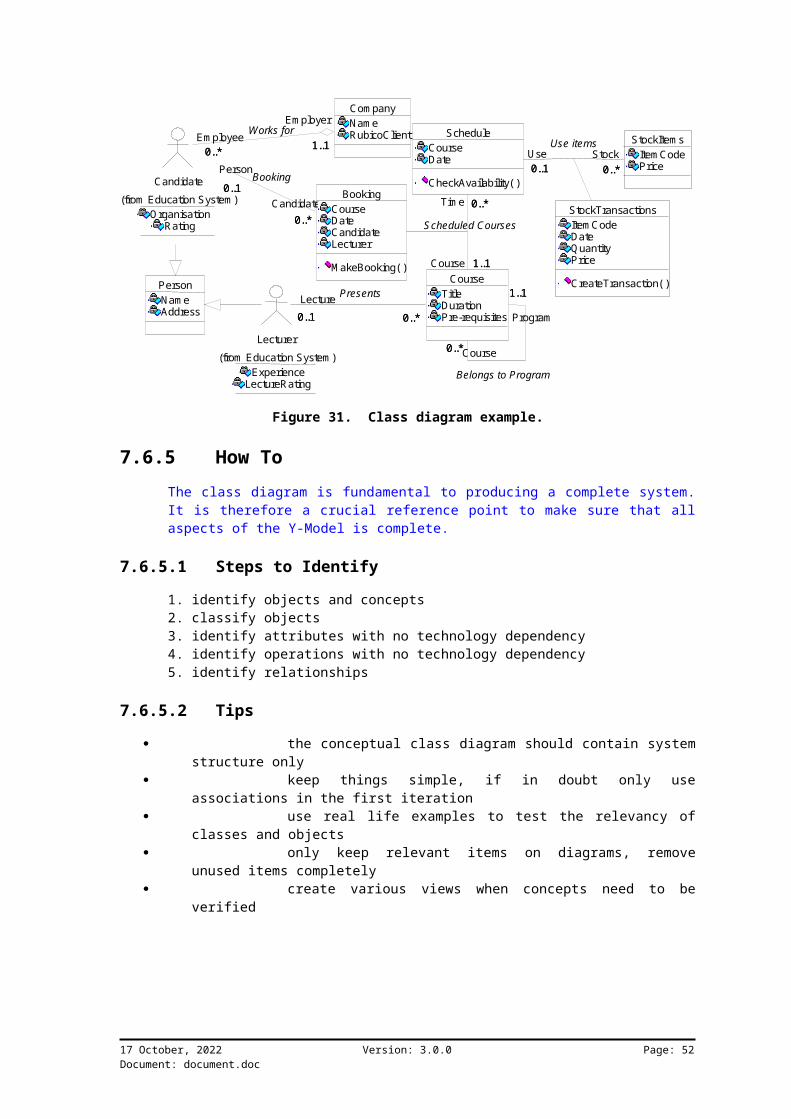
PersonNam eAddress
Em ployer
1..1
Com panyNam eRubicoClientEm ployee
0..*
Candidate0..*
BookingCourseDateCandidateLecturer
M akeBooking( )
Person0..1Candidate
OrganisationRating
(from Education System )
1..10..*
Works for
0..*
0..1Booking
Course0..*
Program
1..1
0..*Lecture0..1
Lecturer
ExperienceLectureRating
(from Education System )
Tim e 0..*
Course 1..1Course
TitleDurationPre-requisites
0..*
1..1
Belongs to Program
0..*0..1
Presents
Stock0..*
Use0..1
ScheduleCourseDate
CheckAvailability( )0..*
1..1
S cheduled C ourses
StockItem sItem CodePrice0..*0..1
Use items
StockTransactionsItem CodeDateQuantityPrice
CreateTransaction( )
Figure 31. Class diagram example.
7.6.5 How ToThe class diagram is fundamental to producing a complete system.It is therefore a crucial reference point to make sure that allaspects of the Y-Model is complete.
7.6.5.1 Steps to Identify
1. identify objects and concepts2. classify objects3. identify attributes with no technology dependency4. identify operations with no technology dependency5. identify relationships
7.6.5.2 Tips
the conceptual class diagram should contain systemstructure only
keep things simple, if in doubt only useassociations in the first iteration
use real life examples to test the relevancy ofclasses and objects
only keep relevant items on diagrams, removeunused items completely
create various views when concepts need to beverified
17 October, 2022 Version: 3.0.0 Page: 52Document: document.doc
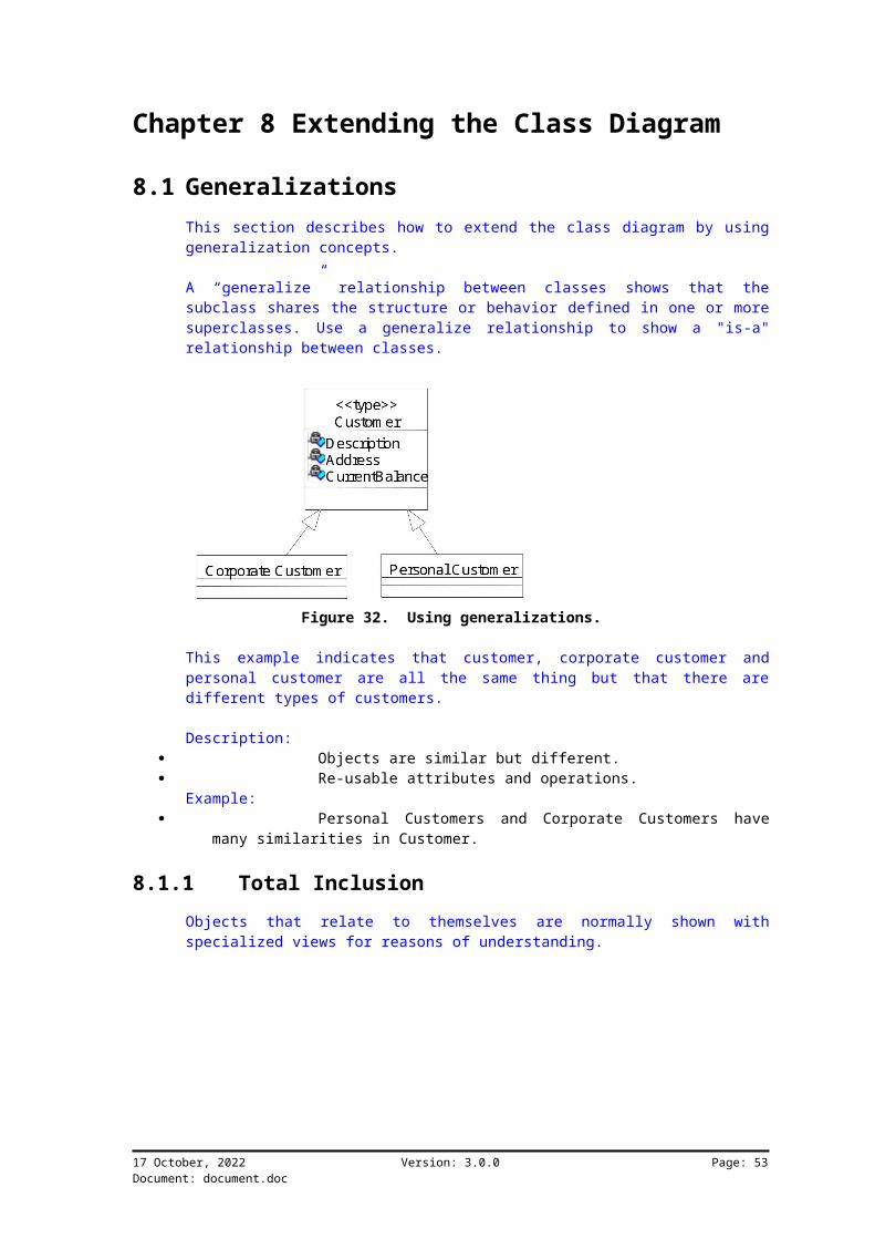
Chapter 8 Extending the Class Diagram
8.1 GeneralizationsThis section describes how to extend the class diagram by usinggeneralization concepts.
A “generalize” relationship between classes shows that thesubclass shares the structure or behavior defined in one or moresuperclasses. Use a generalize relationship to show a "is-a"relationship between classes.
Figure 32. Using generalizations.
This example indicates that customer, corporate customer andpersonal customer are all the same thing but that there aredifferent types of customers.
Description: Objects are similar but different. Re-usable attributes and operations.
Example: Personal Customers and Corporate Customers have
many similarities in Customer.
8.1.1 Total InclusionObjects that relate to themselves are normally shown withspecialized views for reasons of understanding.
17 October, 2022 Version: 3.0.0 Page: 53Document: document.doc

Course Item0..*
0..1+course0..*
+program 0..1
Course Item
Course(from Education)Program
0..*0..1 0..*0..1
Figure 33. Showing total inclusions.
In this example, program and course are both specialized classesfrom the generalized class, course item.
8.1.2 Type PartitionsType partitions are used to indicate that only one valid item canbe used.
Corporate Custom er
Personal Custom er
Custom erDescriptionAddressCurrentBalance
Custom er Type10..* 10..*
Figure 34. Showing types of objects.
In this example "Customer Type" can be either "CorporateCustomer" or "Personal Customer". The association back to"Customer" is for only one valid type.
17 October, 2022 Version: 3.0.0 Page: 54Document: document.doc

8.1.3 Many to Many to SelfShowing many to many relationships to the same class can beconfusing. The model is easier to understand wheregeneralizations are used.
Course Item Item Links0..*1
0..*1
1
1
0..*
0..*
header
detail
Course Item
Program Course(from Education)Item Links
0..*1 0..* 11 0..* 0..* 1
header detail
Figure 35. Showing many to many to self.
Attribute associations can also be used to describe an activeassociation between two objects.
8.1.4 Relationship Sub-typesWhen a class relies on two associations to another class, but thereasons are specific, use specialized classes to make it moreunderstandable.
17 October, 2022 Version: 3.0.0 Page: 55Document: document.doc
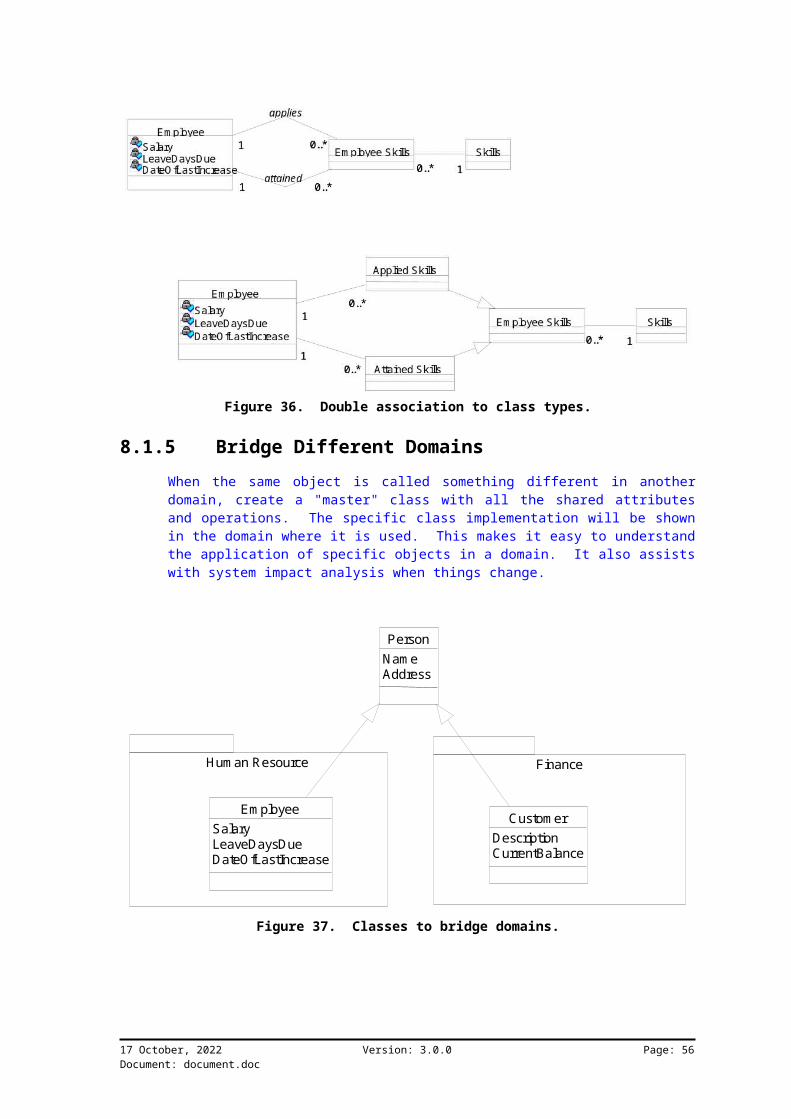
Figure 36. Double association to class types.
8.1.5 Bridge Different DomainsWhen the same object is called something different in anotherdomain, create a "master" class with all the shared attributesand operations. The specific class implementation will be shownin the domain where it is used. This makes it easy to understandthe application of specific objects in a domain. It also assistswith system impact analysis when things change.
Hum an Resource Finance
Custom erDescriptionCurrentBalance
PersonNam eAddress
Em ployeeSalaryLeaveDaysDueDateOfLastIncrease
Figure 37. Classes to bridge domains.
17 October, 2022 Version: 3.0.0 Page: 56Document: document.doc

8.1.6 How To8.1.6.1 Steps to Identify
These steps relate to existing class diagrams.1. identify objects that share properties2. identify the classes3. for each class, identify generalization specialization: “As
superclass what are the subclasses”4. question: “what are the attributes and operations that may be
shared”5. identify polymorphic operations eg car.start() motor.start()6. create or update class diagram and specification
8.1.6.2 Tips
if in doubt create a separate class roles can become classes eg. person with role
employee Create a subtype of a supertype when the subtype has additional attributes of interest the subtype has additional operations of interest the subtype concept is operated upon in ways that
are of interest the subtype concept represents an animate thing
that behaves different than the supertype
8.2 AggregationsThis section describes how the concepts of aggregation are usedto extend class diagrams.
Use the aggregate relationship to show a whole and partrelationship between two classes.
The class at the client end of the aggregate relationship issometimes called the aggregate class. An instance of theaggregate class is an aggregate object. The class at the supplierend of the aggregate relationship is the part whose instances arecontained or owned by the aggregate object.
Use the aggregate relationship to show that the aggregate objectis physically constructed from other objects or that it logicallycontains another object. The aggregate object has ownership ofits parts.
Use the relationship name to identify the type or purpose of therelationship.
17 October, 2022 Version: 3.0.0 Page: 57Document: document.doc

1..*
Custom er O rder0..*11 0..*
Product O rder Details1..*
0..*11 0..*Figure 38. Class notation for aggregates.
This example shows that order details are part of order.Description:
It is a “part of” or “bill of materials”relationship between objects.
Aggregate objects are constructed from otherobjects.
Example: Order contains Order Details that can only be
obtained via order.
8.2.1 CompositionConcepts:
transitivity: if A is part of B and B is part ofC, then A is part of C
antisymmetric: if A is part of B, then B is notpart of A
propagation: sharing of common operations andattribute values from the aggregate to the part possibly withmodifications
Additional semantic rules required: creation, copy, and deletion, eg. do you want to delete details when header is
removed?
17 October, 2022 Version: 3.0.0 Page: 58Document: document.doc

Class2Attribute1
Operation1()untitled()
Class3Attribute1
Operation1()
Class1Attribute1
Operation1()
/part of
Figure 39. Transitivity example.
Transitivity is used to test the correctness of an aggregaterelationship. For example if assembly has product and producthas parts, parts are for assembly.
Antisymmetric is a way to check part of for example part is partof product, but product is not part of part.
8.2.2 Derived ObjectsSpecialization can be used to show derived objects.
17 October, 2022 Version: 3.0.0 Page: 59Document: document.doc

Com pany
Division Em ployee1..*1..*
0..*0..* Com pany
Division1..*
Em ployedCom pany
Em ployee0..*
0..*1..*
0..*
0..*
Figure 40. Access path via derived objects.
In this example "EmployedCompany" is not a physical item butpurely a way to indicate that employee is working for company.This is also used to shorten the access path. Access path is theroute to get to an object. For example to get to “Employee” inthe first model you need to go through “Division”. In the secondmodel “EmployedCompany” provides direct access.
8.2.3 How To8.2.3.1 Steps to Identify
Key questions to ask: would you use the phrase “part of”? are some operations on the whole automatically
applied to its parts? are some attribute values from the whole applied
to to all or some parts?
8.2.3.2 Tips
don’t use external examples as the gurus can’tagree
when multiplicity is 1..1 to 1..* make it anaggregation
when the whole live and dies together make it anaggregation
17 October, 2022 Version: 3.0.0 Page: 60Document: document.doc

Chapter 9 Behavior Modeling
9.1 IntroductionThis chapter describes the use of behavioral models.
System behavior is driven by the stimuli between Actors and UseCases. For each stimuli there should be at least one interactiondiagram. This chapter discusses object interaction.
Figure 41. Y model with behavior focus.
Behavioral models show: Shows the stimulus-response behavior of the system
and objects in the system. Behavior is how the system behaves to this
stimuli. “What happens over time in a system?” Shows the “what” not the “how”.
Interaction diagrams (behavior) describe how Use Cases arerealized as interactions among societies of objects. Eachstimulus is associated with one or more scenarios.
Behavior is a description of what the system without describinghow. Operations have pre-conditions, work and post-conditions.This means that there are certain things that can or must happenbefore the operation is initiated. It also means that work willbe done, describing the actual reason of existence and lastlycertain post-coditions will occur where values are passed orprepared for output.
17 October, 2022 Version: 3.0.0 Page: 61Document: document.doc
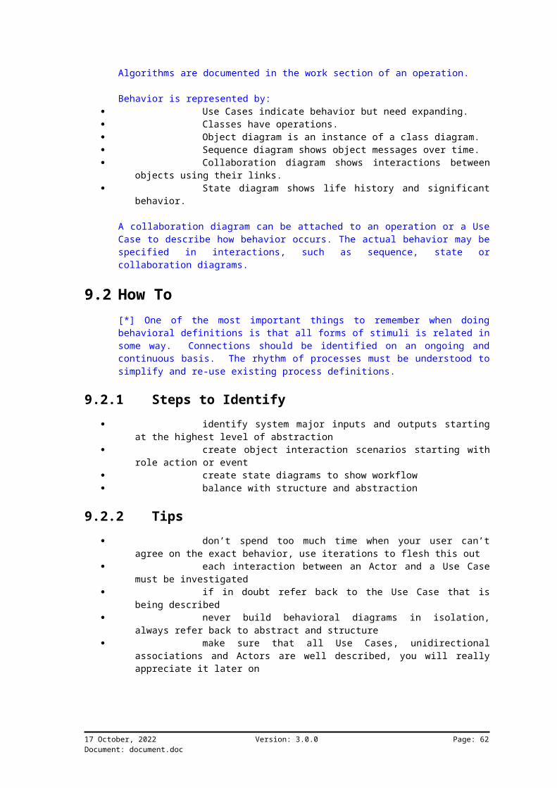
Algorithms are documented in the work section of an operation.
Behavior is represented by: Use Cases indicate behavior but need expanding. Classes have operations. Object diagram is an instance of a class diagram. Sequence diagram shows object messages over time. Collaboration diagram shows interactions between
objects using their links. State diagram shows life history and significant
behavior.
A collaboration diagram can be attached to an operation or a UseCase to describe how behavior occurs. The actual behavior may bespecified in interactions, such as sequence, state orcollaboration diagrams.
9.2 How To[*] One of the most important things to remember when doingbehavioral definitions is that all forms of stimuli is related insome way. Connections should be identified on an ongoing andcontinuous basis. The rhythm of processes must be understood tosimplify and re-use existing process definitions.
9.2.1 Steps to Identify identify system major inputs and outputs starting
at the highest level of abstraction create object interaction scenarios starting with
role action or event create state diagrams to show workflow balance with structure and abstraction
9.2.2 Tips don’t spend too much time when your user can’t
agree on the exact behavior, use iterations to flesh this out each interaction between an Actor and a Use Case
must be investigated if in doubt refer back to the Use Case that is
being described never build behavioral diagrams in isolation,
always refer back to abstract and structure make sure that all Use Cases, unidirectional
associations and Actors are well described, you will reallyappreciate it later on
17 October, 2022 Version: 3.0.0 Page: 62Document: document.doc

Chapter 10 Object Sequence DiagramsThis section describes how the Sequence diagram is used to defineinteractions between objects.
Elements in a Sequence diagram are created from class diagrams.Sequence diagrams can be, and normally should be, attached tooperations and Use Case diagrams.
In Sequence diagrams: Interaction amongst objects is shown in a time
sequence. Actors interact with system via operations. Sequence diagrams describe the behavior of Use
Cases.
Sequence diagrams and Collaboration diagrams are alternaterepresentations of an interaction. A Sequence Diagram traces theexecution of an interaction in time.
Object Definition in context of interaction:An object has state, behavior, and identity. The structure andbehavior of similar objects are defined in their commonly namedclass. Each object in a diagram indicates some instance of aclass. An object that is not named is referred to as a classinstance.
: Company : Person
1: GetsPaid( )Person
Figure 42. Messages between objects use operations to communicate.
17 October, 2022 Version: 3.0.0 Page: 63Document: document.doc

10.1 Notation
: Actor : Class1 Object1 :
Class2O bject2 : Class2
1: Operation1 ( )2: Operation1 ( )
Describe the operation
3: Operation1 ( )
4: Operation1 ( )5: Operation1 ( )
Figure 43. Notation for the Sequence diagram.
Actors are brought in from either the class of Use Case diagrams.Classes come from the class diagrams. Notes are used to describemessages further and can be permanently attached to an operation.
A message flow is the sending of a message from one object toanother. The implementation of a message may take various forms,such as a procedure call, the sending of a signal between activethreads, the explicit raising of events, and so on.
10.1.1 ObjectsDescription:
Instance of a class. Being performed on.
Example: Joe:Person Jack:Employee
17 October, 2022 Version: 3.0.0 Page: 64Document: document.doc

Object1 : Class2
object’s life line
Figure 44. Objects live for a duration in time.
The object life line indicates the duration for which the objectwill be “alive” in a particular sequence.
10.1.2 MessagesDescription:
connects two life lines of objects shown top to bottom to depict time message name is the operation that is performed messages can have arguments messages have various types
Example: Prepare() CheckCredit(Customer) Update(Customer)
Operations are attached to messages to show that objects arebeing acted upon.
17 October, 2022 Version: 3.0.0 Page: 65Document: document.doc

: Actor : Class1 O bject1 :
Class2O bject2 : Class2
1: Operation1 ( )2: Operation1 ( )
Describe the operation
3: Operation1 ( )
4: Operation1 ( )5: Operation1 ( )
only proceedwhen accepted
abandon whennot ready
abandon whennot ready inspecified tim e send m essage
and continue
Figure 45. Different messages are used to communicate between objects.
Different types of messages are used to show actual systembehavior. Messages can be sent to objects in other classes or toitself. Messages to self means that an operation will be invokedinternally.
The implementation of a message may take various forms, such as aprocedure call, the sending of a signal between active threads,the explicit raising of events, and so on.
Different messages control the flow. The following arrowheadvariations may be used to show different kinds of messages:
filled solid arrowhead: Procedure call or othernested flow of control. The entire nested sequence iscompleted before the outer level sequence resumes. May be usedwith ordinary procedure calls. May also be used with
17 October, 2022 Version: 3.0.0 Page: 66Document: document.doc

concurrently active objects when one of them sends a signaland waits for a nested sequence of behavior to complete.
stick arrowhead: Flat flow of control. Each arrowshows the progression to the next step in sequence. Normallyall of the messages are asynchronous.
half stick arrowhead: Asynchronous flow ofcontrol. Used instead of the stick arrowhead to explicitlyshow an asynchronous message between two objects in a proce-dural sequence.
other variations: Other kinds of control may beshown, such as “balking” or “time-out”, but these are treatedas extensions to the UML core Message label.
The label has the following syntax: predecessor guard-condition sequence-expression return-value :=message-name argument-list
The label indicates the message sent, its arguments and returnvalues, and the sequencing of the message within the largerinteraction, including call nesting, iteration, branching,concurrency, and synchronization.
10.2 System as a Black Box
: System - Finance
: System - Education
2: Deposits ( )
: System - Hum an Resource : Training
Coordinator1: SkillsUpdate ( )
3: CourseBooking ( )
4: SkillsRequest ( )5: SkillsUpdate ( )
6: CourseBooking ( )
System - Finance
Deposits( )
System - Education
CourseBooking( )SkillsUpdate( )CourseBooking( )
System - Hum an Resource
SkillsUpdate( )SkillsRequest( )
Use Case textcan be used forclarity
use these todescribe systembehavior aswhole
Figure 46. Sequence diagrams are used to “black box” systems.
With Actors shown on Sequence diagrams, unidirectionalassociation descriptions can be used to check completeness.
All system operations can be defined in a class to determinepossible interactions. This way interfaces can be clearlydocumented and controlled.
17 October, 2022 Version: 3.0.0 Page: 67Document: document.doc

10.3 Case Study
Figure 47. Classes are for Use Cases and are used in Sequence diagrams.
Sequence diagrams need a number of classes to explain theirfunctionality. Functionality is grouped for a domain and isrepresented as a Use Case.
10.4 How To10.4.1 Steps to Identify
start with a physical representation of thesystem, listing events and system operations
identify the objects and their classes egJoe:Person
identify inputs that possibly lead to output check class diagram, associated and aggregated
relationships generally have messages create the Sequence diagram
10.4.2 Tips only use return messages for clarity check messages from and to Actors at Use Case
level take classes from a view under the Use Case that
is being described
17 October, 2022 Version: 3.0.0 Page: 68Document: document.doc

create operations in classes when needed in aSequence diagram
17 October, 2022 Version: 3.0.0 Page: 69Document: document.doc

Chapter 11 Object Collaboration Diagrams
This section describes how the collaboration diagram is used todefine interactions between objects.
Collaboration and Sequence diagrams are from the same family.They show the same concepts but are slightly different.
Shows the interaction organized around the objects in theinteraction and their links to each other.Unstructured view compared to Sequence diagram.Class instances can interact.
Collaboration Diagrams and Sequence Diagrams are alternaterepresentations of an Interaction.
A Collaboration diagram is an interaction diagram that shows thesequence of messages that implement an operation or atransaction. Behavior is implemented by sets of objects thatexchange messages within an overall interaction to accomplish apurpose. A Collaboration diagram shows objects, their links, andtheir messages. Collaboration diagrams can also contain simpleclass instances and class utility instances.
Each Collaboration diagram provides a view of the interactions orstructural relationships that occur between objects and object-like entities in the current model.
To understand the mechanisms used in a design, it is important tosee only the objects and the messages involved in accomplishing apurpose or a related set of purposes, projected from the largersystem of which they are part for other purposes. Such a staticconstruct is called a collaboration.
A collaboration may be attached to an operation or a Use Case todescribe the context in which their behavior occurs. The actualbehavior may be specified in interactions, such as Sequencediagrams or collaboration diagrams. A collaboration may also beattached to a class to define the class’s static structure.
A collaboration may be expressed at different levels ofgranularity. A coarse-grained collaboration may be refined toproduce another collaboration that has a finer granularity. Thismeans that collaboration diagrams can be attached to Use Cases atany level of abstraction.
17 October, 2022 Version: 3.0.0 Page: 70Document: document.doc

11.1 Notation
: Actor
: Class1
Object1 : Class2
Object2 : Class2
3: Operation1 ( )
1: Operation1 ( )
dataflow there
dataflow back2: Operation1 ( )
5: Operation1 ( )4: Operation1 ( )
Figure 48. Notation for the collaboration diagram.
The notation is exactly the same as Sequence diagrams except forthe fact that object connections are shown in a free formfashion.
Data flows are used to further explain messages, and arerepresented by an arrow with a hollow tail.
11.2 Navigability
Class1Attribute1
Operation1( )
Class2Attribute1
Operation1( )untitled( )
0..*1 0..*1
uses
Figure 49. Notation to show navigability.
Navigability is used on a class diagram to indicate thatimplementation will only occur in one direction.
17 October, 2022 Version: 3.0.0 Page: 71Document: document.doc

11.3 Case Study
: Candidate
: Schedule
: Booking
: Course : Training Coordinator
1: RequestCourse7: M akeBooking
6: Inform Candidate
4: CheckAvailability
5: Availability
8: M akeBooking ( ) 3: CheckAvailability ( )
2: CheckCourse
Figure 50. Example collaboration diagram.
17 October, 2022 Version: 3.0.0 Page: 72Document: document.doc

Chapter 12 State DiagramsThis section describes the use of state transitions to make therequirements definition complete.
State diagrams model the following: Shows the sequences of states that an object or
interaction goes through in its life in response to stimuli. Shows the state space of a given class. Illustrate the events and states of objects. System states can be shown in Use Cases and
Classes.
A state transition diagram is used to show the state space of agiven class, the events that cause a transition from one state toanother, and the actions that result from a state change. Eachstate diagram is associated with one class or with a higher-levelstate diagram.
A state diagram is a directed graph of states connected bytransitions. A state diagram describes the life history ofobjects of a given class. A state diagram shows exactly onestart state, one or more states, one or more end states, and thestate transitions between them. Each class in the current modelthat possesses significant event-ordered behavior can contain asingle state diagram to describe that behavior.
State diagrams can be used during the initial stages of a projectto capture workflow definitions for individual Use Cases. Design
17 October, 2022 Version: 3.0.0 Page: 73Document: document.doc

captures the dynamic behavior of individual classes orcollaborations of classes.
Operations in the class are used to change the state of anobject. States could also be presented as classes on the classdiagram.
12.1 NotationStart State
End State
State 1entry: actionexit: actiondo: action
on event( argum ent )[ condition ]: action
State 2
State 3
State 4
End State
State 3
State 4
End State
Event( Argum ent )[ Condition ] / Action
Figure 51. Notation for the state diagram.
A statechart (state) diagram represents a state machine. Thestates are represented by state symbols and arrows connecting thestate symbols represent the transitions. States may also containsub-diagrams by physical containment. Each state diagram has astart state and one or more end states.
12.1.1 EventDescription:
It is a significant or noteworthy occurrence. External events are caused from outside of our
system. Internal events are caused by something inside the
boundaries of our system. Temporal events are caused by the specific
occurrence of time.Example:
telephone receiver taken off the hook customer buys product
17 October, 2022 Version: 3.0.0 Page: 74Document: document.doc
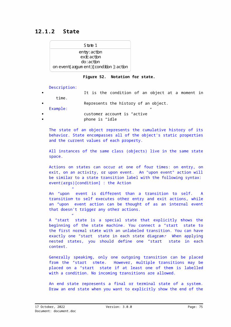
12.1.2 State
State 1entry: actionexit: actiondo: action
on event( argum ent )[ condition ]: action
Figure 52. Notation for state.
Description: It is the condition of an object at a moment in
time. Represents the history of an object.
Example: customer account is “active” phone is “idle”
The state of an object represents the cumulative history of itsbehavior. State encompasses all of the object's static propertiesand the current values of each property.
All instances of the same class (objects) live in the same statespace.
Actions on states can occur at one of four times: on entry, onexit, on an activity, or upon event. An "upon event" action willbe similar to a state transition label with the following syntax:event(args)[condition] : the Action
An “upon” event is different than a transition to self. Atransition to self executes other entry and exit actions, whilean “upon” event action can be thought of as an internal eventthat doesn't trigger any other actions.
A “start” state is a special state that explicitly shows thebeginning of the state machine. You connect a “start” state tothe first normal state with an unlabeled transition. You can haveexactly one “start” state in each state diagram. When applyingnested states, you should define one “start” state in eachcontext.
Generally speaking, only one outgoing transition can be placedfrom the “start” state. However, multiple transitions may beplaced on a “start” state if at least one of them is labelledwith a condition. No incoming transitions are allowed.
An end state represents a final or terminal state of a system.Draw an end state when you want to explicitly show the end of the
17 October, 2022 Version: 3.0.0 Page: 75Document: document.doc

state machine. Transitions can only occur into an end state; oncethe state machine ends, it goes out of existence.
Normally, you can assume that the state machine associated with aclass will go out of existence when its enclosing object isdestroyed and, therefore, never reaches an end state. However,you can use an end state to explicitly show the end, ifnecessary. There can be any number of end states per context.
12.1.3 Transition
Start State
Event( Argum ent )[ Condition ] / Action
State 1entry: actionexit: actiondo: action
on event( argum ent )[ condition ]: action
Figure 53. Notation for transitions.
Description: It is the relationship between two states. It indicates that when an event occurs, the object
moves from one state to another.
A state transition is a change of state caused by an event. Usestate transitions to connect two states in a state diagram orshow state transitions from a state to itself. You can show oneor more state transitions from a state as long as each transitionis unique. Transitions emanating from a state can not have thesame event, unless there are conditions on the event.
You must label each state transition with the name of at leastone event that causes the state transition. You do not have touse unique labels for state transitions because the same eventcan cause a transition to many different states.
An event label is a symbolic name.
Transitions are labeled with the following syntax:event (arguments) [condition] / action
Only one event is allowed per transition, and one action perevent.
17 October, 2022 Version: 3.0.0 Page: 76Document: document.doc

12.2 Case StudyRambling:A booking can go through a number of stages. When a candidatewants to get booked on training, information is recorded. If anexisting client gets booked on training, it is confirmedimmediately. If someone from outside is booked on training,confirmation can only be given once a deposit is paid. Trainingcourses can only be cancelled 5 days before start date. Trainingprograms must be cancelled 30 days before start date.
Phone call
Recorded booking
Confirm booking Cancel booking
Deposit required
Booking confirm ed
Request for Training
Stored[ Existing client ]
Stored[ Outside client ]
[ Deposit not in tim e ] / 30 days before program OR 5 days before
coursePaid[ Deposit paid ] /
Received
Figure 54. Booking-status state diagram.
12.3 How To12.3.1 Steps to Identify
want to describe object life cycle or Use Casebehavior
identify the events identify the start and end points identify the states identify the transitions describe transitions with conditions review the state diagram for each event
12.3.2 Tips don’t ever look directly into the sun
17 October, 2022 Version: 3.0.0 Page: 77Document: document.doc

Chapter 13 Process Patterns
13.1 IntroductionThis chapter describes some of the concepts needed to manage aprocess. Iterative and evolutionary development concepts areused. We will show how the UML is used as part of a process todeliver a business solution.
Object Oriented Systems are built using the following genericphases:
Addressing problem via objects in a domain Analysis finds and describes objects Design defines logical implementation Building makes it practical
A problem domain is addressed by finding all the related objects.The focus is on objects meaning things, concepts, entities, andso on. We all see the world as a totally integrated set ofobjects that are all dependent on one another.
The analysis phase is to find and describe the objects. Theseare the concepts of the problem domain. What does the businessdo and who does it? This is used to identify the processes androles in a problem domain.
The design phase is used to define all the logical softwareobjects that will be used to implement the solution. It is notalways that clear when the process moves into design, thereforeone should not really differentiate.
Software objects are configured during the construction phaseinto the appropriate technology.
13.2 DeadlinesA deadline is a predefined point in time where specified thingsmust be delivered. The problem in the industry is that “we are95% complete” where there is nothing to measure thiscompleteness.
Delivery can only be on time when you know what it is that youneed to deliver, and when there is a mature process to follow.These two items are rarely found in the computer industry and yetthere are many companies delivering solutions.
17 October, 2022 Version: 3.0.0 Page: 78Document: document.doc
13.3 Timebox DeliveryWhat is Timebox delivery:Is mostly applied in building or configuration of system.Iterative in short cycles of delivery.Small, dynamic teams are used for best results.Issues when running multiple timeboxes:
solid basis or framework is needed coordination is important dependencies must be managed
We found that projects normally overrun because requirements arenot defined adequately. But how long do you think it will takefor the industry to produce models that adequately reflect theusers’ view of the world effectively? One of the ways to containrisk is to reduce the time spent on producing software systemsthat are based on inadequate requirements. Shorter cycles allowfor proper testing and feedback of the implemented requirements.We will discuss other ways of determining complete requirements abit later.
Small dynamic teams are needed to produce prototypes in anacceptable timebox. Large teams create too much managementoverhead and just increases the risk of failure. When projectsare planned, use multiple timeboxes to produce deliverablesrather than one large and bulky project.
There are some challenges when running timeboxes in parallel,including coordination and inter-dependencies of products anddeliverables. Project management principles must be applied withdiscipline.
13.3.1 Timebox MethodThe key concept behind the timebox is that of functionalitycompromise. This does not mean you can just excludefunctionality at random, but that the process of prioritizationmust direct the effort in delivering smaller but working systems.The customer is an integral part of this process.
When things change; the customer wants something new or wants tochange business rules, a process of change management must beused. Each and every refinement must be evaluated forappropriateness.
The timebox concept relies heavily on a predefined and matureprocess. It can be used on an add-hoc basis but estimates andother planning related issues would be meaningless. Every time atimebox is used as part of a project, complete measurement data
17 October, 2022 Version: 3.0.0 Page: 79Document: document.doc

must be collected for analysis afterwards. Measurement isimportant.
13.3.2 Creeping FunctionalityFeaturitis is a term used to describe the way in which usersextend system functionality on the fly. If someone showed them away to collect requirements, then this would not happen.
17 October, 2022 Version: 3.0.0 Page: 80Document: document.doc

Figure 55. The timebox process.
The timebox process starts with a proposal. It could be aproject definition or any form of project kick-off. The systemdefinition is where requirements are obtained from the users viaa workshop method. The output of this is then sent into atimebox where the functionality is put into practice by using aniterative development approach. Iterative development can easilyoverrun estimated time frames and that is why we need to timeboxthis area. When this is completed we need to evaluate theresults. There could be an implementable system at this time,but if there is not, then the next iteration will start.
13.3.3 ConsiderationsThere are some issued to consider when using the timebox method:
The team or teams working on the project must ownthe results. They must take full responsibility for allworkproducts and project management.
A solid framework is required to manage people andprocess issues.
The teams must include people with businessknowledge of the domain under study.
Because of the short life cycle and intenseness ofthe effort, people would be reluctant to change or addfunctionality while the process is underway.
17 October, 2022 Version: 3.0.0 Page: 81Document: document.doc

13.4 Macro ProcessUser involvement is required throughout the process. This forcesthe consultant to be customer centric.
The consultant is involved with the sales cycle from thebeginning. This means that prototypes are built and proposalsprepared before the actual sale is concluded.
Project delivery is where the project is delivered based on theproposal as prepared in the sales cycle. This involves takingthe customer through a series of phases that include theunderstanding of the existing situation, re-designing theexisting into a “to-be” situation, designing of a softwaresolution through to building and implementing a final solution.
Service management kicks in once the site has been handed to overthe customer and maintenance is required.
13.4.1 Using Workshops
Prepare for W orkshop
Perform W orkshop
Post W orkshop Process
Set the stage for workshop/s. Invite people, obtain general understanding, logistix.
Produce workshop deliverables as per agenda. Apply facilitation and m odeling skills.
Validate all artifacts produced during the workshops and prepare for the next cycle.
Figure 56. The workshop process.
Workshops are used to get maximum user involvement throughout theprocess of delivering a business solution. It involves a three-stage approach namely, preparing for the workshop, performing theworkshop and performing post workshop work. Workshops must be
17 October, 2022 Version: 3.0.0 Page: 82Document: document.doc

lead by a trained facilitator who knows how to handle differentkinds of audiences.
There are different kinds of workshops depending on theobjectives of the process of delivering a solution:
Scoping is the process of defining the boundariesof a part of the business under consideration for change.During a scoping workshop, the group defines the businessprocesses and categories within the scope, the interfacessurrounding it and the interactions between the scope andinterfaces.
A domain analysis workshop is performed toestablish the objects, behavior and abstractions to beincluded in the design. The workshop is particularlyproductive since it brings together customer, users andconsultants to perform initial analysis. The domain analysisworkshop deals with the users' views of objects, objectrelationships, behavior and abstraction. Due to timeconstraints and the specific project requirements, domainanalysis is kept at a high level of abstraction.
Generic workshops for reviews, testing and otheractivities are also used.
13.4.1.1 Pre-Workshop Activities
Planning and Scoping Workshop The workshop type must be determined before the
workshop planning starts. Each workshop must have specific objectives and
pre-defined deliverables. Participant Selection and Preparation
Identify use of sub-teams and alternate structuresfor each workshop and post-workshop processes.
Executive Owner Briefing Perform an interview prior to briefing or kickoff
to obtain an understanding of issues that might arise. Arrange kickoff message.
Conduct Kickoff Meeting Educate participants on the concepts that will be
used. Address all workshop and project issues before
continuing. Assign preparation assignments to all
participants.
Logistical Arrangement Schedule and obtain a facility.
17 October, 2022 Version: 3.0.0 Page: 83Document: document.doc

Gather all relevant materials needed for theworkshop/s.
Arrange participant schedules.
Select Workshop Exercises Customize the agenda based on the initial
templates. Review background documentation and models. Prepare “script” or workshop notes.
Prepare Scribe(s) Train the workshop participants in the user
workshop technique. Describe the facilitator support functions. Prepare the models and tools.
13.4.1.2 Workshop Activities
Ice-breakers are used to obtain rapport with the participants.The facilitator must direct the way in which the workshop isconducted. Workshop objectives and deliverables must be kept inmind at all times. The scribe will record the ramblings andbusiness rules in various forms including graphical models.
13.4.1.3 Post-Workshop Activities
All the deliverables must be reviewed once the workshop hascompleted. Feedback must also be given to the participants toput these in perspective.
The models and documentation collected during the workshops mustbe cleaned up and balanced before the next workshop starts.
13.5 Process PhasesThis section describes the project phases.
13.5.1 Process Phase: Perform SalesThe consultant is involved with the sales cycle from thebeginning. This means that prototypes are built and proposalsprepared before the actual sale is concluded.
An understanding of the existing technology environment must beobtained to investigate the impact of a new implementation.
13.5.2 Process Phase: Project DeliveryProject delivery is the process where most of the work isperformed to build a business solution.
17 October, 2022 Version: 3.0.0 Page: 84Document: document.doc

The “As-Is” situation is investigated to get a feel for thecurrent strengths and weaknesses and strengths of the business asa whole. It is achieved by breaking the business into processareas and then concentrating on the important ones.
The “To-Be” situation is the future desired state of thebusiness. It is directed by the business vision. This meansthat new processes might need to be innovated to satisfy thevision and organizational goals. It is not always possible todeploy all new innovations at the same time. So, smaller partscan be deployed with incremental improvements over time.
With requirements clearly defined after the process innovations,system design can begin. All aspects of the system must bedesigned including; business processes in detail, technologyarchitecture and how the user interacts with the system.
The system is then built based on the design. The user isinvolved with accepting the software solution beforeimplementation starts.
Implementation starts after the user has accepted the system.
13.5.2.1 Understand the “As-Is” Situation
During this phase the overall project is defined and the domainsthat need further work are identified.
The first step is to create a project plan using the ProjectManagement Plan template. In this plan the scope, deliverablesand other project-related issues are recorded. Remember that atthis point there is no indication as to the size or complexity ofthe system. Only an outline of what the project must produce iscreated. This becomes a guideline for the project team.
As part of the initial investigation a requirements document isprepared outlining the current situation. This investigationwould reveal some of the problems and opportunities of theproject.
A common set of terms is needed to describe the specifics of aproject. This must be compiled into the glossary that must beplaced in the back of the “requirements” document. The glossarymust evolve with the system.
The process of obtaining the initial requirements is calledorientation. The consultant and the customer can together form apicture of what the project should entail.
17 October, 2022 Version: 3.0.0 Page: 85Document: document.doc

When requirements are defined the intended use of the system isidentified. The project scope and the requirements must beconstantly verified and validated. Requirements can be recordedat a high level in a rambling format. Ramblings are the conceptsas explained by the user without translation. These must betranslated effectively into the requirement document.
To build a mockup or prototype at this time could be done easilyif the technology permits it. The important thing to remember isthat the prototype is used to test the concepts as documented inthe requirement.
When Use Cases are defined conceptually, a clear picture of thesystem can be obtained. But what is a Use Case? It is agrouping of functionality in the system. Actors are people orexternal systems that use Use Cases to get the system to performwork. Test cases are the concepts that must be tested withregards to the functionality per Use Case.
Only once a high-level picture had been completed can we refinethe plan by elaborating the phases required to deliver theproject. All the workproducts that are needed as part of theproject can be planned for at this time. This will allow theproject leader to control the project effectively, as there willbe an audit trail of documentation.
13.5.2.2 Building Solution
13.5.2.2.1 Define the “To-Be” Situation
Defining the “To-Be” situation may not be done in some projects.Issues will surface with the design and building of the system.The “analyze” and “design” activities will contribute the most todelivering the new solution.
13.5.2.2.2 Design and Build the System
The building phase produces complete and workable systems. Webelieve the only way to get this right is to have a number ofbuild cycles where any anomalies can be addressed before finalhand-over. Each cycle must have a clearly defined set ofdeliverables so that the outcomes can be measured. It is alsoneeded to facilitate incremental builds where each build isdependent on the previous.
Timeboxing concepts are used to manage the individual cycles ofdelivery.
The project plan is refined at each cycle. A minute of meetingand project controls must show problems with the plan and who isgoing to address those. These minutes can then be used as
17 October, 2022 Version: 3.0.0 Page: 86Document: document.doc

activity lists to manage the day by day deliverables of theproject. The user, if involved, should sign off every cycle.
With workproducts produced on an ongoing basis, validation andverification is needed before a cycle is attempted. This willensure correct input into the analysis process.
The analysis phase is used to study the entire domain, but onlyfor the level of abstraction that is required as part of thecycle. The design phase will take the models produced as part ofanalysis and produce a set of more technically-oriented models.
Models are taken into software in the building phase. This iswhen a working solution is produced in the analysis phase anddesign of the current cycle.
Use Cases are used to direct the testing effort. These should beprioritized and used to drive the effort that goes into testing.If the current cycle has built on the previous one, then aregression testing strategy must exist. This means thatcomponents are tested incrementally to make sure that the systemsstill functions as a whole.
Analyse and Further Define Solution
There should be maximum user involvement during the analysisphase. Workshops are used to direct the collection of userrequirements.
The conceptual Use Cases and conceptual models will normally bedefined with the user as part of the workshop. Conceptual modelsshow how objects relate to the real world scenario.
Objects go through a life cycle, For example, when a person getsemployed his or her status would be “valid employee”. If theperson leaves, then the state will become “invalid employee”. Itis possible for an invalid employee to become a valid employee.
Sequence and collaboration diagrams are used to depictinteraction between objects and show the time domain.
During this phase the following questions are normally asked:What are the domain processes?What are the concepts and terms used in a domain?What are the system events and operations, and what do they do?
Note:Collaboration and Sequence diagrams are classified as Interactiondiagrams. These show how objects interact in a real worldscenario.
17 October, 2022 Version: 3.0.0 Page: 87Document: document.doc

Design the System
The analysis phase emphasized an understanding of therequirements and concepts in relation to the domain or domainsunder study. So analysis is characterized by the “what” of thedomain i.e. processes, concepts, abstractions, etc.
Once the analysis documents are produced you can initiate thedesign process. Interaction diagrams are mostly used, whichillustrate the interaction between objects to fulfilrequirements.
The conceptual view that is itself a class diagram, is nowexpanded into a more detailed view of the objects in a domain.
Next, Use Cases are defined in detail. This means that allrelated views must be covered, these views are:
Classes that relate to the functionality as perUse Case.
Interaction diagrams showing how the objects inthese classes interact.
State diagrams showing specific detailed workflowrequirements.
Interface requirements are then used to show what the systemwould look like to the outside world. It shows user interfacerequirements and reporting needs.
By now the system architecture should be fairly well understood.System Architecture (SA) refers to the overall structure of howthe system hangs together. The different views covered upto nowprovide major input into this. By refining the SA, shortcomingsare highlighted that can be addressed in the next iteration.
System interactions are used to describe the physical flow ofinformation. It could mean that the flow of capturinginformation on a screen is shown. Interaction diagrams are usedto indicate this.
Design classes are used to show a lower level of implementation.At his point the classes, operations, and so on can be mapped tothe solution.
13.5.2.3 User Acceptance
User acceptance is where the user gives the final go ahead andthe system is put into operation.
17 October, 2022 Version: 3.0.0 Page: 88Document: document.doc

13.5.2.4 Implement System
The transition phase is initiated once all the build phases for aproject have been completed. User training and data conversionsnormally start at the same time. It might be necessary to doinitial takeons to have valid test data in the system fortraining and final user acceptance testing.
Ongoing monitoring of the system kicks off once the system isinstalled and handed over to the customer.
13.5.3 Process Phase: Service ManagementBusiness changes normally occur over time and these need to bereflected in the information technology solutions. This phasedeals with the ongoing changes that occur over time.
13.6 Process Management
Figure 57. How models become complete.
Models normally evolve in the following direction: From Abstraction and boundaries to Structure to Behavior.
Models are checked in the following way: Behavior for abstraction. Structure for behavior. Abstraction for structure.
17 October, 2022 Version: 3.0.0 Page: 89Document: document.doc

The above diagram might not make a lot of sense at this point.It is necessary to show how the different concepts evolve as partof a systems life cycle. During the understanding phase you areconcerned with system boundaries and abstraction. Systemstructure is defined at a conceptual level, after this behavioralmodels are used to depict sequence of work over time.
There is a process that works in reverse, where all concepts arebacktracked to check completeness and correctness of the models.
17 October, 2022 Version: 3.0.0 Page: 90Document: document.doc

Chapter 14 Process Artifacts
14.1 IntroductionAn artifact is any form of object that is needed to describe aconcept. Artifacts can be broken into two areas:
Workproducts; the documents needed and produced aspart of a process.
Other products; video clippings, scanned images,voice etc.
The UML is a common communications medium used on projects. Theprocess used on projects deliver certain workproducts. These twoneed to come together to complete all aspects of projectdelivery.
14.2 Initial Process Artifacts
Requirem ents Specification
Use Cases
Schedule
Prototypes from Com ponents
Glossary
Conceptual Structures
Test Cases
tim ebox
Figure 58. Initial process artifacts and dependencies.
Various artifacts are produced during the understanding phasewhich starts in sales and then move into the “As-Is” situation.The schedule is used as the starting point, and defines the scopeand major deliverables, the schedule is used as an evolutionarydocument to keep the schedule and requirements aligned.
The requirement specification is the glue that holds all theconcepts together in one document. It contains ramblings andbusiness rules included with the visual models.
Conceptual structures are the models that show how objects relateat a business level. An example is; Customers buy Products from
17 October, 2022 Version: 3.0.0 Page: 91Document: document.doc

Suppliers. The conceptual model will show the Customer’srelationship with the Supplier and the Product.
Test cases are generated early in the process and are based onthe requirements.
Prototypes are built from the Requirements Specificationdocument. You might need to produce prototypes to test a conceptor as part of a customer acceptance cycle.
14.3 Expanded Process Artifacts
Requirem ents Specification(from Understanding)
Use Cases(from Understanding)
Schedule(from Understanding)
Prototypes from Com ponents(from Understanding)
Glossary(from Understanding)
Conceptual Structures
(from Understanding)
Interaction Diagram s
State Diagram s
Class Diagram s
Figure 59. Artifacts become more complete as the project moves throughtime.
As can be seen, most areas are initially defined during theunderstanding phase. Class diagrams are built from conceptualviews and are used to further describe the functionality of a UseCase. State diagrams describe life cycle behavior in theconceptual view and the class view. State diagrams are thenattached to the classes. State diagrams are also attached tointeraction diagrams and Use Cases when they are used to showworkflow.
Note:Classes are used to group concepts. The customer, Widgets Incbelongs to the customer class.
17 October, 2022 Version: 3.0.0 Page: 92Document: document.doc

Chapter 15 Model Balancing
15.1 IntroductionBalancing models is a very important activity to make sure thatyour user’s requirements are defined well.
Balancing concepts facilitate: Managing requirement quality. Communication of all related concepts. Validating requirements against the users
understanding.
Balancing is done to make sure that system requirements conformto quality requirements. When anomalies in requirements areidentified, you can start a process of communication with youruser.
Considerations: Understanding the level of abstraction Use Cases and Actors Class diagram views Scenarios Scope of implementation Impact analysis
A full set of models is available after the first analysisactivity. Use Cases are exploded into sequence andcollaborations diagrams. Class diagram views are used to makesure that classes needed for a Use Case are grouped.
Use Cases are used in projects. By having requirements groupedwill direct project effort to implement the Use Case.
17 October, 2022 Version: 3.0.0 Page: 93Document: document.doc

Use case has behaviorUse case has structure
O bjects interact
O bjects go through life cycle
Figure 60. Objects interact and is sourced from the Use Case view.
The three views of a system must be kept in balance to have acomplete picture of the world. Critical concepts could beoverlooked if any of the dimensions are not attended to.
15.2 Quality RequirementsSolutions have functional and non-functional requirements. Non-functional requirements look after quality and stability aspectsof any system. These non-functional requirements must be kept inmind when generating requirement specifications.
17 October, 2022 Version: 3.0.0 Page: 94Document: document.doc

Figure 61. ISO 9126 as a guideline for quality requirements.
15.2.1 Functionality Suitability - Attribute of software that bears on
the presence and appropriateness of a set of functions forspecified tasks.
Accuracy - Attributes of software that bear on theprovision of right or agreed results or effects.
Interoperability - Attributes of software thatbear on its ability to interact with specified systems.
Compliance - Attributes of software that make thesoftware adhere to application related standards orconventions or regulations in laws and similar prescriptions.
Security - Attributes of software that bear on itsability to prevent unauthorized access, whether accidental ordeliberate, to programs and data.
15.2.2 Reliability Maturity - Attributes of software that bear on
the frequency of failure by faults in the software. Fault tolerance - Attributes of software that bear
on its ability to maintain a specified level of performance incases of software faults or of infringement of its specifiedinterface.
Recoverability - Attributes of software that bearon the capability to re-establish its level of performance andrecover the data directly affected in case of a failure and onthe time and effort needed for it.
17 October, 2022 Version: 3.0.0 Page: 95Document: document.doc

15.2.3 Usability Understandability - Attributes of software that
bear on the users’ effort for recognizing the local conceptand its applicability.
Learnability - Attributes of software that bear onthe user’s effort for learning its application (for example,operation control, input, output).
Operability - Attributes of software that bear onthe users’ effort for operation and operation control.
15.2.4 Efficiency Time behavior - Attributes of software that bear
on response and processing times and on throughput rates inperforming its function.
Resource behavior - Attributes of software thatbear on the amount of resources used and the duration of suchuse in performing its function.
15.2.5 Maintainability Analyzability - Attributes of software that bear
on the effort needed for diagnosis of deficiencies or causesof failures, or for identification of parts to be modified.
Changeability - Attributes of software that bearon the effort needed for modification, fault removal or forenvironmental change.
Stability - Attributes of software that bear onthe risk of unexpected effect of modifications.
Testability - Attributes of software that bear onthe effort needed for validating the modified software.
15.2.6 Portability Adaptability - Attributes of software that bear on
the opportunity for its adaptation to different specifiedenvironments without applying other actions or means thatthose provided for this purpose the software considered.
Installability - Attributes of software that bearon the effort needed to install the software in a specifiedenvironment.
Conformance - Attributes of software that make thesoftware adhere to standards or conventions relating toportability.
17 October, 2022 Version: 3.0.0 Page: 96Document: document.doc

Chapter 16 Design Issues
16.1 IntroductionDesign is when the details of the analysis model are used toproduce a technical implementation. The final software solutionmust reflect the business requirements as per the analysis model.
16.1.1 StereotypesStereotypes are used to extend the UML. Rubico created a numberof stereotypes to facilitate the smooth integration betweenproducts.
[1] A stereotype represents the subclassification of a modelelement. It represents a class within the UML metamodel itself(i.e., a type of modeling element).
Some stereotypes are already predefined, but you can also defineyour own to add new kinds of modeling types.
16.1.2 Software ProductsThe UML is implemented in many different software products thatassist in producing graphical models.
This chapter discusses some considerations when using RationalRose.
16.2 Class Diagram Considerations16.2.1 Classes into Rubico Structure System
Stereotype DescriptionStructure Classes that are taken into
structure names. If a classhas no related <<Group>>stereotypes then the classwill be used to generate aone level Rubico group inthe structure system.
Group This stereotype is used with<<Structure>> to indicateall the groups. Aggregatesindicate the sequence asdefined in the structuresystem.
17 October, 2022 Version: 3.0.0 Page: 97Document: document.doc

16.2.2 Classes into Rubico Cube ConfigurationStereotype DescriptionCubeName The Cube name as used in
Rubico.CubeItem The items in the cube.
16.2.3 Attributes into Rubico Attribute ManagementStereotype Description
Class attributes go into the Rubico Attribute structure.
16.2.4 Operations into Rubico Rules and CalcsStereotype Description
Class operations are taken into Rubico calc names. The Calcdetails are specified in the semantics of the operation.
16.2.5 Associations into Item Code AttributesStereotype Description
Attribute type: Item code.
16.2.6 Aggregations and Transactions into Rubico Generics
Stereotype DescriptionTransaction
16.3 Sequence and Collaboration Diagram ConsiderationsObject Sequences into Attribute Events.
Rubico object sequences in a sequence diagram. Events linked tomessages.
16.4 State Diagram ConsiderationsObject States into Rubico State Transitions.Use Case linked States into Rubico Workflow.
17 October, 2022 Version: 3.0.0 Page: 98Document: document.doc

Appendix A: Complete Case Study
Chapter 1 Introduction
1.1 Purpose of this chapterThe purpose of this document is to describe the “To Be” andbusiness operation of the client in a case study environment. Itencapsulates the current vision, strategic considerations,processes and activities used to manage and execute the day today operation of the organisation for the Procurement system forPurchase Orders and Goods Receiving only.
1.2 Scope of the Case StudyThis case study will only show the Procurement system forpurchase orders and goods receiving. Section 3 of this documentis a first cut of the To Be Documentation presented to the Clientfor PO and GR. Section 4 of this document covers the finalversion of the To Be Documentation. Section 5 covers the designdocumentation which is based on the final To Be Documentation.
1.3 Definitions, acronyms and abbreviationsPO Purchase OrdersGR Goods ReceivingMRP Material Requirements PlanningMPS Master Production scheduling
1.4 ReferencesThe content of this appendix was drawn from the procurementprocess used at an existing manufacturing concern.
17 October, 2022 Version: 3.0.0 Page: 99Document: document.doc

Chapter 2 Creating the Environment
2.1 The ClientThe Client has approached Rubico to develop an Enterprise widesolution for one of it manufacturing companies. The Enterprisesolution must cover the following process as detailed in theSystem diagram below.
W arehousing Accounts Payable
Accounts Receivable
Cash Book
General Ledger
M PS
M RPProduction
O rder Processing
Planning & Distribution
Procurem ent
Dem and Planning
Access(from Third Party)
2.2 What this Case Study CoversTo keep the case study within reasonable limits, only the POsystem and the GR System from the procurement package will beincluded in this document. The sections of work used in this casestudy start in chapter 3 with the initial documentation for theTo Be phase, then evolve to chapter 4 which is the To BeDocumentation at the end of the phase. chapter 5 is the designdocumentation which is based on the business rules laid out inthe To Be document.
As mentioned before, this case study covers Purchase orders andGoods received vouchers. For both modules to be Documentation iscomplete. The design Documentation on GRV's is only in draftform, while the design Documentation of Purchase orders hasreached Version 1. This document is set out in such a way to show
17 October, 2022 Version: 3.0.0 Page: 100Document: document.doc

the evolution from beginning of the To Be Phase to near the endof the Design Phase. It is not recommended to read the designDocumentation until a clear understanding of a businessrequirements has been achieved.
To get clear understanding of Procurement and the elementsthereof, the client should be able to read the Documentation anda get clear understanding of the business requirements and theconsultants understanding of them. Whenever documenting userrequirements in Rubico, collect them so that any third partyreading the requirements can understand of the process.
2.3 The Business EnvironmentThe procurement process is broken into logical packages. Eachpackage has documentation explaining its relevance to theprocess. Situated within each package is a Use Case diagram withit documentation and notes. Each modelling element in UML has gotdocumentation against it for clarity for both the consultant andthe client.
17 October, 2022 Version: 3.0.0 Page: 101Document: document.doc

Chapter 3 To Be Documentation for Procurement and Goods Receiving – First Draft
3.1 Business Process OverviewThe procurement function will consist of tasks starting atrequisitioning and ordering through to goods receiving. Quotes,vendor selection and contracts will also be included. For thisProject import documentation has been excluded. Where possible,printing must be on the cheapest format (A4, tractor feed). Userrequires economical, speedy and quality printouts for reporting.
3.1.1 Process Package Overview
The purchasing function involves the procurement of materials,supplies, equipment and services at certain costs with requiredquality standards. This is done to support the production ofmerchandise and products.The objective of a procurement system should be the following:
Identifying the need for goods or services Placing purchase orders Acceptance of goods delivered Validation.
17 October, 2022 Version: 3.0.0 Page: 102Document: document.doc
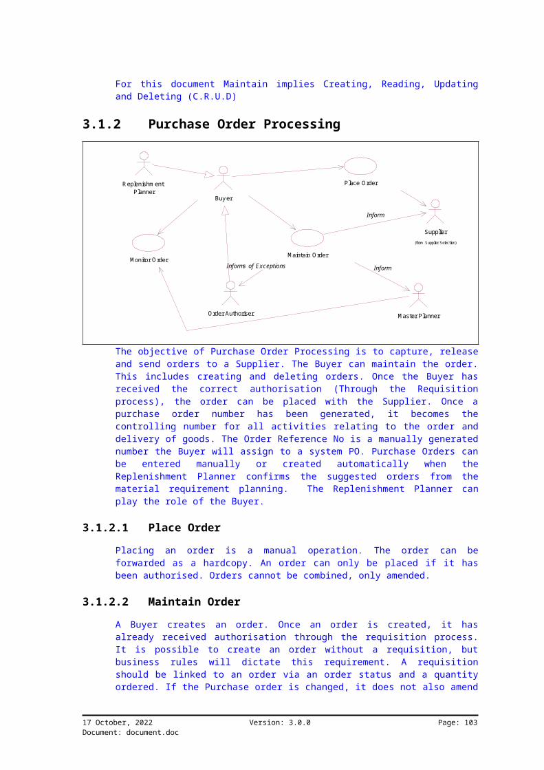
For this document Maintain implies Creating, Reading, Updatingand Deleting (C.R.U.D)
3.1.2 Purchase Order Processing
Replenishm ent Planner
Place Order
Supplier(from Supplier Selection)
Order Authoriser
Maintain Order
Inform
Informs of E xceptions
Buyer
Monitor Order
Master Planner
Inform
The objective of Purchase Order Processing is to capture, releaseand send orders to a Supplier. The Buyer can maintain the order.This includes creating and deleting orders. Once the Buyer hasreceived the correct authorisation (Through the Requisitionprocess), the order can be placed with the Supplier. Once apurchase order number has been generated, it becomes thecontrolling number for all activities relating to the order anddelivery of goods. The Order Reference No is a manually generatednumber the Buyer will assign to a system PO. Purchase Orders canbe entered manually or created automatically when theReplenishment Planner confirms the suggested orders from thematerial requirement planning. The Replenishment Planner canplay the role of the Buyer.
3.1.2.1 Place Order
Placing an order is a manual operation. The order can beforwarded as a hardcopy. An order can only be placed if it hasbeen authorised. Orders cannot be combined, only amended.
3.1.2.2 Maintain Order
A Buyer creates an order. Once an order is created, it hasalready received authorisation through the requisition process.It is possible to create an order without a requisition, butbusiness rules will dictate this requirement. A requisitionshould be linked to an order via an order status and a quantityordered. If the Purchase order is changed, it does not also amend
17 October, 2022 Version: 3.0.0 Page: 103Document: document.doc

the Quantity Ordered and the status on the requisition. A Reportcan then be created to compare the variances between theRequisitions and the orders.
Only the date can be amended on a Purchase Order. Quantities canbe changed but only down, not up. If quantities need to beamended up, the PO must be deleted and a new PO must be put infor the correct quantities.
It must be determined whether or not an order can be created inone location for another location (i.e. can the Buyer inJohannesburg create an order for the Durban branch, on behalf ofthe Durban Buyer?).
3.1.2.2.1 Scenario: Create Purchase Order
: Buyer : Purchase Order HDR : O rder
Authoriser : Purchase Order DETL
Create( )
Create( )
Inform of Exceptions( )
The buyer can create an order. An order is normally linked to oneor many requisitions, but some orders can be created without arequisition depending on the business rules. If the buyer has thecorrect authority, then the buyer plays the role of the OrderAuthoriser. Orders do not need to be authorised. Allauthorisations have already taken place during RequisitionProcessing. An exception report will highlight any irregularitiesby comparing requisition quantities to the quantities ordered.Phase 2 requirement
17 October, 2022 Version: 3.0.0 Page: 104Document: document.doc

3.1.2.2.2 Scenario: Maintain Purchase Order
: Buyer : Purchase O rder : Supplier : Master Planner
Modify/Delete( )Inform ( )
M odify Date and quantity down only. Inform of PO C hanges( )
Depending on whether the am ended order is accepted or declined, the supplier m ust be inform ed.
The Buyer can amend an existing order. If the buyer has theauthorisation to amend the order, the supplier and the MasterPlanner must be informed.Quantities can be move down and Dates modified.
3.1.2.3 Monitor Order
Depending on the business rules, various employees can have theability to view or Monitor their relevant orders (On-line or viaa hard copy) The Buyer, creditors clerk and the master plannershould be allowed to view the orders.
17 October, 2022 Version: 3.0.0 Page: 105Document: document.doc

3.1.2.3.1 Scenario: Monitor Order
: Buyer : Purchase Order : M aster Planner : Replenishm ent
Planner
View( )
The Buyer, Creditors Clerk, M aster Planner, Store Keeper...To be Checked.
View( )
View( )
3.1.3 Goods Receiving
QA Inspector
Receive GoodsQA R equired
Supplier(from Supplier Selection)
Return Goods Advice generated
R eturn Goods & Documentation
GRN GeneratedStorem an
M onitor Deliveries
Requestor(from Requisition Processing)
Receiving Clerk
Inform of QA R esults
Deliver Goods & Documentation
Release Goods
Buyer(from Purchase O rder Processing)
Notified of Exceptions
The Receiving Clerk along with the Buyer can monitor for expecteddeliveries. Once the goods have been received a Goods ReceivingVoucher (GRV) is generated. From there the goods can be released
17 October, 2022 Version: 3.0.0 Page: 106Document: document.doc

to stock or go for a quality inspection. Only the Storeman canreturn goods for various reasons. For this a Goods Returned Note(GRN) must be generated. The Buyer should always be notified ofexceptions in case there is a need to re-order some goods. Whennon-replenishment goods are received, the Requestor must beinformed. A GRA (Goods Returned Advice) is generated when goodsare received but returned immediately for various reasons. APartial GRA can be created for goods returned. The rest of thegoods will then be recorded on the GRV.
Two scenarios exist when returning goods- Firstly, return goodson receipt (GRA) and secondly, return goods after they have beenreleased to stock (GRN). The GRA (Goods Returned Advice) is tobe a manual process. No stock write backs or financial entrywrite backs are done. The GRN will be a system function and willalso write back stock and create the appropriate financialentries
When the Storeman creates a GRN the Creditors Clerk must beinformed.
3.1.3.1 Receive Goods
A Goods Received Voucher (GRV) needs to be generated for everydelivery. No GRV can be created for direct services. It isimportant to note that an order can have many deliveries, butthat a GRV can only belong to one order. Not all goods that arereceived are released to stock. E.g. CAPEX (A non-replenishmentstock item)
Can allow the Receiving clerk to over receive. The Clerk must beinformed of the excess and decide whether to receive the goods ornot. A PO order should be created for the excess amount. The POmust be closed for the correct Qty received.
17 October, 2022 Version: 3.0.0 Page: 107Document: document.doc
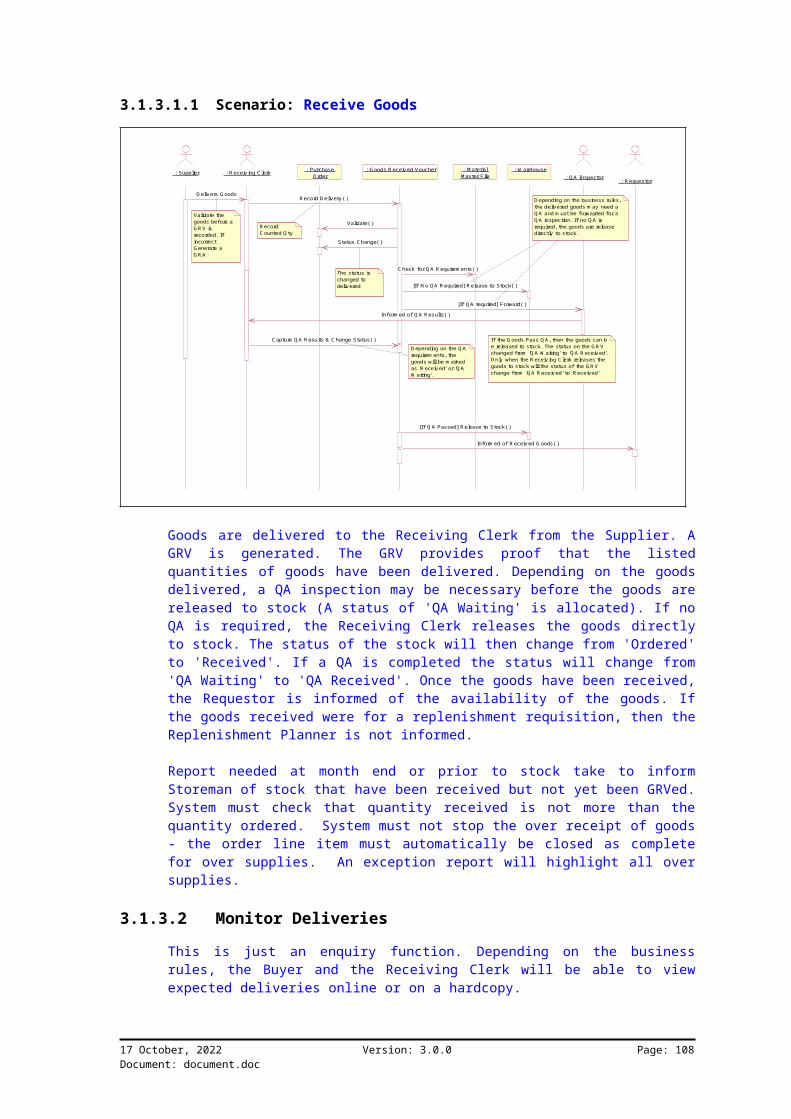
3.1.3.1.1 Scenario: Receive Goods
: Supplier : R eceiving C lerk : G oods R eceived Voucher : M aterial Master File
: W arehouse : QA Inspector : R equestor
: Purchase Order
D elivers G oodsRecord D elivery( )
Validate( )
Status Change( )
The status is changed to delivered
C heck for Q A R equirem ents( )
[If N o QA R equired] R elease to Stock( )
Capture QA R esults & C hange Status( )
[If Q A required] Forward( )
D epending on the business rules, the delivered goods m ay need a Q A and m ust be forwarded for a Q A inspection. If no Q A is required, the goods are release directly to stock.
D epending on the Q A requirem ents, the goods will be m arked as 'R eceived' or 'Q A W aiting'.
If the G oods Pass Q A, then the goods can be released to stock. The status on the GR V changed from 'Q A W aiting' to 'Q A R eceived'. O nly when the R eceiving C lerk releases the goods to stock will the status of the G R V change from 'Q A R eceived' to 'Received'
Inform ed of R eceived G oods( )
Inform ed of Q A Results( )
[If Q A Passed] Release to Stock( )
Record C ounted Q ty
Validate the goods before a GR V is recorded. If incorrect G enerate a GR A
Goods are delivered to the Receiving Clerk from the Supplier. AGRV is generated. The GRV provides proof that the listedquantities of goods have been delivered. Depending on the goodsdelivered, a QA inspection may be necessary before the goods arereleased to stock (A status of 'QA Waiting' is allocated). If noQA is required, the Receiving Clerk releases the goods directlyto stock. The status of the stock will then change from 'Ordered'to 'Received'. If a QA is completed the status will change from'QA Waiting' to 'QA Received'. Once the goods have been received,the Requestor is informed of the availability of the goods. Ifthe goods received were for a replenishment requisition, then theReplenishment Planner is not informed.
Report needed at month end or prior to stock take to informStoreman of stock that have been received but not yet been GRVed.System must check that quantity received is not more than thequantity ordered. System must not stop the over receipt of goods- the order line item must automatically be closed as completefor over supplies. An exception report will highlight all oversupplies.
3.1.3.2 Monitor Deliveries
This is just an enquiry function. Depending on the businessrules, the Buyer and the Receiving Clerk will be able to viewexpected deliveries online or on a hardcopy.
17 October, 2022 Version: 3.0.0 Page: 108Document: document.doc
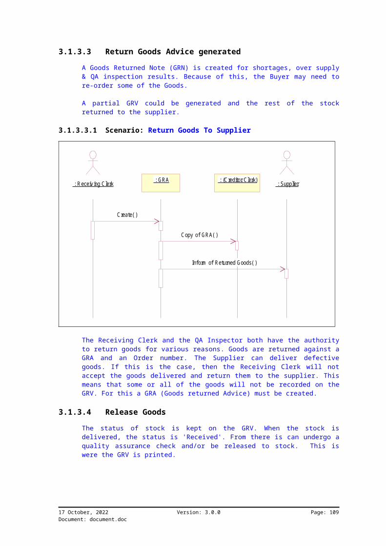
3.1.3.3 Return Goods Advice generated
A Goods Returned Note (GRN) is created for shortages, over supply& QA inspection results. Because of this, the Buyer may need tore-order some of the Goods.
A partial GRV could be generated and the rest of the stockreturned to the supplier.
3.1.3.3.1 Scenario: Return Goods To Supplier
: R eceiving Clerk : GRA : (C reditor Clerk) : Supplier
Create( )
Copy of GRA( )
Inform of Returned Goods( )
The Receiving Clerk and the QA Inspector both have the authorityto return goods for various reasons. Goods are returned against aGRA and an Order number. The Supplier can deliver defectivegoods. If this is the case, then the Receiving Clerk will notaccept the goods delivered and return them to the supplier. Thismeans that some or all of the goods will not be recorded on theGRV. For this a GRA (Goods returned Advice) must be created.
3.1.3.4 Release Goods
The status of stock is kept on the GRV. When the stock isdelivered, the status is 'Received'. From there is can undergo aquality assurance check and/or be released to stock. This iswere the GRV is printed.
17 October, 2022 Version: 3.0.0 Page: 109Document: document.doc

3.1.3.4.1 Scenario: Release Goods
: W arehouse : Receiving Clerk : Goods Received Voucher
The Buyer is inform ed of the goods received. This includeds exceptions.E.g. quantities that need to be re-ordered.
Record Qty To Stock( )[If GRV for Stock] Update Stock( )
Print( )
Creditors : Purchase Order
Update
Update Qty Received( )
[If final GRV] PO closed( )
Prom pt if Qty is still outstanding.
Prom pt:" Is this the Last line item entry?" This m ay related to a Role.
The Receiving Clerk releases goods. There are to types of goodsnamely Stock and Non-Stock Items. Must have the ability to re-open PO's. Once the total quantity received equals the totalquantity ordered the system must close the order line item ascomplete. The system must allow relevant users to manually closethe order line item as being completed, even if the quantityordered does not equal the quantity received for that order line.
3.1.3.5 GRN Generated
Only the Storeman can create a GRN (Goods Received Note for itemsreturned.) GRNs will be covered in detail in Warehousing -Inventory Management.
17 October, 2022 Version: 3.0.0 Page: 110Document: document.doc

3.1.4 Class Diagram
Stoc
Re CaC oAut OrCaUn
SuppliTrade Discount 1Trade Discount 2Supplier CodeMaterial Item CodeDate OnDate Off
W are
Em ploEm ployee Nam eEm ployee Surnam eEm ployee ID
N on-SGL CodeGL TypeQuoted Reference No.
Stock M aterial Item C odeItem DescriptionSuppliers Item CodeSpecial Instructions
BudBudget Am ount
Em plo
0..*
1
0..*
1
GL
0..*
1
0..*
10..*
10..*
1
AO rd
Pay
N o
Buyer
(from Purchase O rder Processing)
PurchSupplierTransaction N o.Order TypeCreated ByDateTim e CreatedOrder StatusSettlem ent DiscountOrder R eference No
PO Request N oRequisition TypeCreated ByRequested ByAuthorised ByDateTim e C reatedRequest Status
Tran
0..*
1
0..*
1
0..*
1
0..*
1
St
0..*
1
0..*
1
0..*
1
0..*
1
Split Date RequiredQty Required
Goo G oo QA QA Rele
C ar<<Inquiry>>
Sup
PurchW arehouseRequest NoUOMQty RequiredDate RequiredQuote R eference NoPriceTrade Discount 1Trade Discount 2Requested ByLine Item Status
1
1..*
1
1..*0..*0..*
0..*
1
0..*
1
1
0..*
1
0..*
PO W arehouseSupplier C odeU OMQ ty RequiredD ate R equiredPriceTrade D iscount 1Trade D iscount 2Line Status
1
1..*
1
1..*
0..*
1
0..*
1
0..*
1
0..*
1
Sup<<Inquiry>>
W arehW arehouse CodeW arehouse Description
BuyW arehouseProduct Group0..*1 0..*1
1
0..*
1
0..*
Supplier Supplier CodeSupplier Nam eSupplier StatusSettlem ent DiscountStandard Trade DiscountAddress - PhysicalAddress - PostalChain CodeBanking DetailsE-m ail AddressCreditor Contact PersonMD Nam eMD Num berPhone N um berFax NoOrder Placem ent M ethodStatem ent Delivery MethodPaym ent Term sMethod of Paym entSupplier RatingDate Created
0..*1 0..*1
0..*
1
0..*
1
0..*
1
0..*
1
MateriProduct G roupMaterial Item CodeMaterial D escriptionInspection R equiredDefault W arehouseSupplier Item CodeLead tim eStandard CostUO MEOQMinim um Order QtyMaxim um O rder Q tyTAXMaterial C ostLast Cost PriceInventory UnitLot C ontrolPeriod for Shelf lifeForecast M ethodInventory on HandInventory on HoldInventory on Order
0..*
1
0..*
1
Ite<<Inquiry>>
PO R equ<<Inquiry>>
Unit of Unit of Measure CodeDescription
0..*
1
0..*
1
0..*
1
0..*
1
GR AG RA No.Q ty on GR ASupplier C odeSuppliers Invoice/D elivery N oteO rder R ef NoQ ty ReturnedR eason
C reate()
GR
GR<<Inquiry>>
G oods G RN N oSupplier CodeSuppliers Invoice/Delivery NoteG RV Ref N oO rder Ref NoQ ty on GR NQ ty R eturnedN et PriceR eason
Goods GR V NoSupplier CodeGR V StatusOrder Ref. N oOrder Transaction N o.Suppliers Invoice/Delivery NoteUO MDate ReceivedQty On GRAQty on Delivery N oteQty CountedQty Inspected OKQty RejectedQty to Stock
1 0..*1 0..*
0..*
1
0..*
1PO <<Inquiry>>
Purc
0..*
1
0..*
11
0..*
1
0..*

3.1.4.1 Class Name: Purchase Order
CancelledO rdered
Received Archived
Null
Captured
Com plete
Cancel PO
Partial Receipt
G oods / Services ReceivedAfter Elapsed Period
Capture PO
Buyer O verride
Release to Stock
3.1.4.2 Class Name: Goods Received Voucher
If the Qty on the delivery note varies from the Qty GRN then aGRN must be generated (Pop-up)
Null
Print GRV (Released to Stock)
Q A W aiting
Goods Received
Goods Accepted on Receipt
Q A Received
Goods Returned
G oods Not Accepted
QA Com pleted
QA Com pleted and Failed
G oods Counted
17 October, 2022 Version: 3.0.0 Page Document: document.doc
112

3.1.4.2.1 Attribute Name: GRV No
Description: A system generated, sequential number, unique toeach GRV.Type: Numeric. No decimals.
3.1.4.2.2 Attribute Name: Supplier Code
3.1.4.2.3 Attribute Name: GRV Status
3.1.4.2.4 Attribute Name: Order Ref. No
Description: The number of the order that this GRV relates to.Type: Numeric.
3.1.4.2.5 Attribute Name: Order Transaction No.
Description: The number of the order that this GRV relates to.Type: Numeric.
3.1.4.2.6 Attribute Name: Suppliers Invoice/Delivery Note
Description: The invoice number or the supplier.Type: String, mixed.
3.1.4.2.7 Attribute Name: UOM
Description: Code that reflects the measurement that the item ismeasured in (i.e. Unit of Measure).Type: Item Code (Unit of Measure structure)
3.1.4.2.8 Attribute Name: Date Received
Type: Item Code (Unit of Measure structure)
3.1.4.2.9 Attribute Name: Qty On GRA
Description: Goods returned adviceComments: GRA is created if the goods are returned before theyare GRV
3.1.4.2.10 Attribute Name: Qty on Delivery Note
Description: Total number of items as per the Goods ReceivedVoucher.Type: Numeric.
3.1.4.2.11 Attribute Name: Qty Counted
Description: Total number of items that were counted as receivedfrom the supplier.Type: Numeric.
17 October, 2022 Version: 3.0.0 Page Document: document.doc
113

3.1.4.2.12 Attribute Name: Qty Inspected OK
Description: Total number of items that were inspected during theQA inspection.Type: Numeric.
3.1.4.2.13 Attribute Name: Qty Rejected
Description: Total number of items that were rejected during theQA inspection.Type: Numeric.
3.1.4.2.14 Attribute Name: Qty to Stock
Description: Total number of items released to stock.Type: Numeric.
3.1.4.3 Class Name: Goods Returned Note
3.1.4.3.1 Attribute Name: GRN No
Description: Unique system generated, sequential number thatidentifies a Goods Received Note.Type: Numeric, no decimals.
3.1.4.3.2 Attribute Name: Supplier Code
3.1.4.3.3 Attribute Name: Suppliers Invoice/Delivery Note
3.1.4.3.4 Attribute Name: GRV Ref. No
Description: The GRV number that this GRN relates to.Type: Numeric, no decimals.
3.1.4.3.5 Attribute Name: Order Ref. No
Description: The Order number that this GRN relates to.Type: Numeric, no decimals.
3.1.4.3.6 Attribute Name: Qty on GRN
Description: Total number of items to be returned.Type: Numeric.
3.1.4.3.7 Attribute Name: Qty Returned
Description: Total number of items actually returned.Type: Numeric.
17 October, 2022 Version: 3.0.0 Page Document: document.doc
114

3.1.4.3.8 Attribute Name: Net Price
3.1.4.3.9 Attribute Name: Reason
3.1.4.4 Class Name: Purchase Order HDR
3.1.4.4.1 Attribute Name: Supplier
3.1.4.4.2 Attribute Name: Transaction No.
Comments: Auto generates at time of creation of the PO
3.1.4.4.3 Attribute Name: Order Type
Description: The type of orderType: Item Code. (Transaction Type Structure).
3.1.4.4.4 Attribute Name: Created By
Description: Name of the user who created the Purchase Order.Type: String, Mixed.
3.1.4.4.5 Attribute Name: Date Time Created
Description: The date and time that the Purchase Order wascreated.Type: Date.
3.1.4.4.6 Attribute Name: Order Status
Description: The current status of the Purchase Order.Type: Item Code (Status Structure).
3.1.4.4.7 Attribute Name: Settlement Discount
Comments: Defaults to settlement discount on supplier master. Canbe overridden. Need a report to compare all that have beenoverridden
3.1.4.4.8 Attribute Name: Order Reference No
Type: String Validations: Check for duplicate order Reference numbers.Comments: This must be a manual numbering system
3.1.4.5 Class Name: Purchase Order DETL
There must be the ability to duplicate detail lines
3.1.4.5.1 Attribute Name: Warehouse
Description: The warehouse where the item is to be stored.Type: Item Code (Location Structure).
17 October, 2022 Version: 3.0.0 Page Document: document.doc
115

Comments: Each material item could have a default warehousedepicting where the item is to be stored. This can be altered atthe time that the Purchase Order is captured.
3.1.4.5.2 Attribute Name: Request No
Type: Numeric.Comments: There will be no enquiry facility by requisitionnumber. (Phase 1)
3.1.4.5.3 Attribute Name: UOM
Description: Code that reflects the measurement that the item ismeasured in (i.e. Unit of Measure).Type: Item Code (Unit of Measure structure)
3.1.4.5.4 Attribute Name: Qty Required
Description: Total number of items to be purchased.Type: Numeric.
3.1.4.5.5 Attribute Name: Date Required
Description: Date on which the item being purchased is required.Type: Date.Comments: Need to be able to split the order.
3.1.4.5.6 Attribute Name: Quote Reference No
Description: The quotation that this order refers to.Type: Numeric.
3.1.4.5.7 Attribute Name: Price
Description: Price that was quoted for the item to be purchased.Type: Numeric. 2 decimals.Comments: This price is the standard price and can be overridden.Need a report to compare the price to the standard cost on theitem master file.
3.1.4.5.8 Attribute Name: Trade Discount 1
Description: Percentage discount that is to be allowed for theitem to be purchased.Type: Numeric. 2 decimals.Validations: Between 0.00 and 100.00Comments: This discount will vary from supplier to supplier aswell as from material item to material item. Only applies to Rawmaterials, trading goods and selected stock items. This may beover written at time of entry. A report is required to comparethe Trade discount to the standard trade discounts on thesupplier material master file
17 October, 2022 Version: 3.0.0 Page Document: document.doc
116

3.1.4.5.9 Attribute Name: Trade Discount 2
Description: Additional percentage discount that is to beallowed for the item to be purchased.Type: Numeric. 2 decimals.Validations: Between 0.00 and 100.00Comments: Additional discount after calculation of net priceafter Trade Discount 1
3.1.4.5.10 Attribute Name: Requested By
Description: Name of the user who requested the material item.Type: Sting, Mixed.
3.1.4.5.11 Attribute Name: Line Item Status
Description: The current status of the Purchase Order line item.Type: Item Code. (Status Structure).
3.1.4.6 Class Name: PO Inquiry
17 October, 2022 Version: 3.0.0 Page Document: document.doc
117

Chapter 4 To Be Documentation for Procurement and Goods Receiving – Final Version
4.1 Business Process OverviewThe procurement function will consist of tasks starting atrequisitioning and ordering through to goods receiving. Quotes,vendor selection and contracts will not be included. For thisProject import documentation has been excluded. Where possible,printing must be on the cheapest format. User requireseconomical, speedy and quality printouts for reporting.Requisition processing and Supplier selection are notrequirements for Phase 1 of this project.
4.1.1 Process Package Overview
Requisition Processing
Purchase O rder Processing
Goods Receiving
Order M onitoring
Supplier Selection
The purchasing function involves the procurement of materials,supplies, equipment and services at certain costs with requiredquality standards. This is done to support the production ofmerchandise and products.The objective of a procurement system should be the following:
Placing purchase orders Acceptance of goods delivered
17 October, 2022 Version: 3.0.0 Page Document: document.doc
118

Validation.
4.1.2 Purchase Order Processing
Replenishm ent Planner
Order Authoriser
Maintain OrderInforms of E xceptionsMonitor Order
Buyer
Stock Item only
Master Planner
Inform
Place Order
The objective of Purchase Order Processing is to capture and sendorders to a Supplier. (Sending Orders to the Supplier may be viafax, e-mail or a manual process.) The Buyer can maintain theorder. This includes creating and deleting orders. Once the Buyerhas received the signed copy of the Requisition, the order can beplaced with the Supplier. Once a purchase order number has beengenerated, it becomes the controlling number for all activitiesrelating to the order and delivery of goods.
The customers 'Authority No' is a manually generated number theBuyer will assign to a system PO. The Authority no. Will defaultto the Order number. This Authority number can be overwrittenwith a 'Authority number' given to the client. A check must beput in to confirm that the authority number is unique. PurchaseOrders can be entered manually or created automatically when theReplenishment Planner confirms the suggested orders from thematerial requirement planning run. The Replenishment Planner canplay the role of the Buyer for stock items only.
4.1.2.1 Place Order
The order can be forwarded as: hardcopy system generated fax e-mail manual process
17 October, 2022 Version: 3.0.0 Page Document: document.doc
119
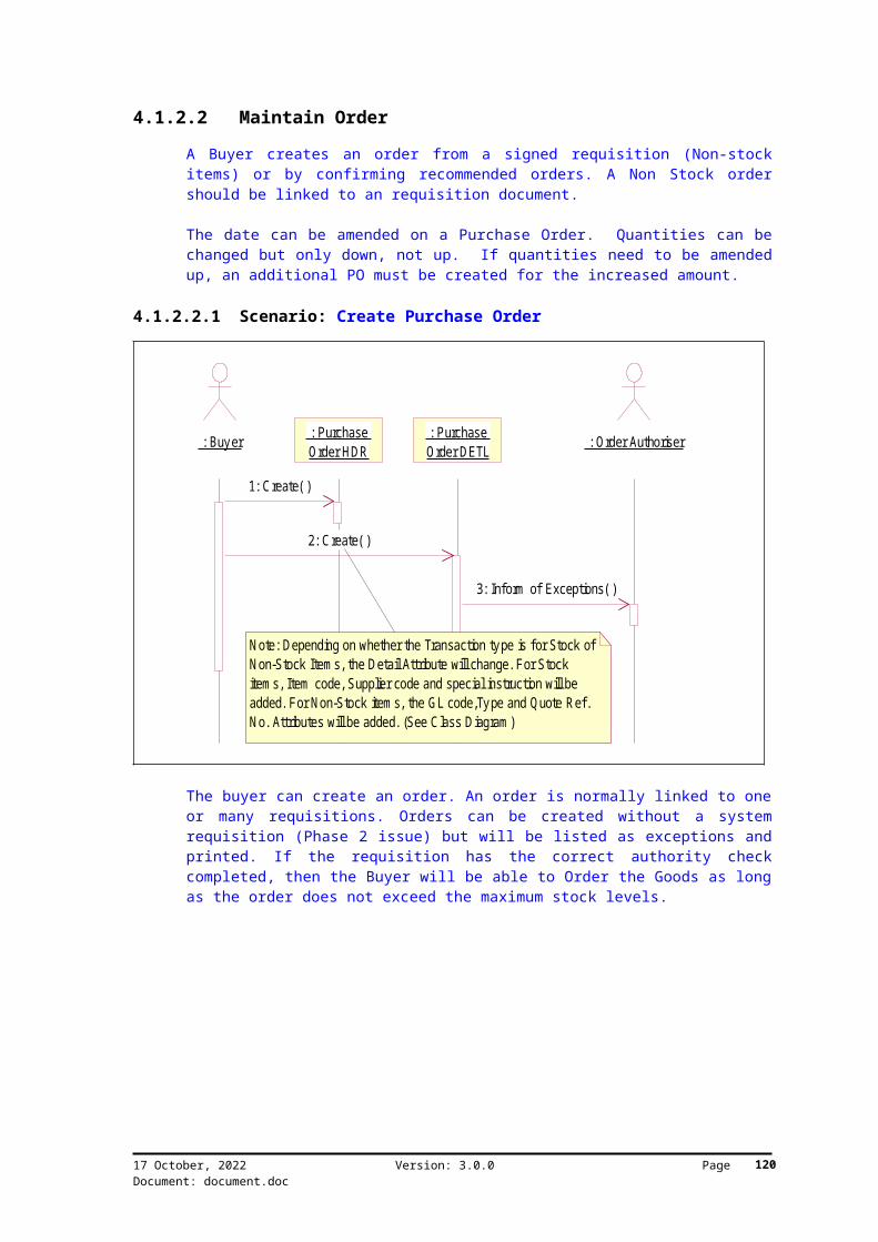
4.1.2.2 Maintain Order
A Buyer creates an order from a signed requisition (Non-stockitems) or by confirming recommended orders. A Non Stock ordershould be linked to an requisition document.
The date can be amended on a Purchase Order. Quantities can bechanged but only down, not up. If quantities need to be amendedup, an additional PO must be created for the increased amount.
4.1.2.2.1 Scenario: Create Purchase Order
: Buyer : Purchase Order HDR : Order Authoriser : Purchase
Order DETL
1: Create( )
2: Create( )
3: Inform of Exceptions( )
Note: Depending on whether the Transaction type is for Stock of Non-Stock Item s, the Detail Attribute will change. For Stock item s, Item code, Supplier code and special instruction will be added. For Non-Stock item s, the GL code,Type and Quote Ref. No. Attributes will be added. (See Class Diagram )
The buyer can create an order. An order is normally linked to oneor many requisitions. Orders can be created without a systemrequisition (Phase 2 issue) but will be listed as exceptions andprinted. If the requisition has the correct authority checkcompleted, then the Buyer will be able to Order the Goods as longas the order does not exceed the maximum stock levels.
17 October, 2022 Version: 3.0.0 Page Document: document.doc
120

4.1.2.2.2 Scenario: Maintain Purchase Order
: Buyer : Purchase Order : Supplier : Master Planner
1: M odify/Delete( )2: Inform ( )
M odify Date and quantity down only. 3: Inform of PO C hanges( )
Depending on whether the am ended order is accepted or declined, the supplier m ust be inform ed.
The Buyer can amend an existing order. If the buyer has theauthorisation to amend the order, the supplier and the MasterPlanner must be informed.Quantities can be move down and Dates modified.
4.1.2.2.3 Scenario: Close PO
: Buyer : Purchase Order
1: Close( )
The Buyer will change the status manually to 'Completed' even ifnot all the line items have been received.
4.1.2.3 Monitor Order
Depending on the business rules, various employees can have theability to view or Monitor their relevant orders (On-line or viaa hard copy) The Buyer, creditors clerk and the master planner
17 October, 2022 Version: 3.0.0 Page Document: document.doc
121

should be allowed to view the orders. This Report, the "POReport", can be found in the 'Reporting Requirements' section ofthis document.
4.1.2.3.1 Scenario: Monitor Order
: Buyer : Purchase Order : M aster Planner : Replenishm ent
Planner
1: View( )2: View( )
3: View( )
The Buyer can monitor an order online or via a hardcopy. Arequestor can monitor the order via the requisition status andquantity ordered. The Store keeper might also need to viewrelevant orders.(e.g. Warehouse)
17 October, 2022 Version: 3.0.0 Page Document: document.doc
122
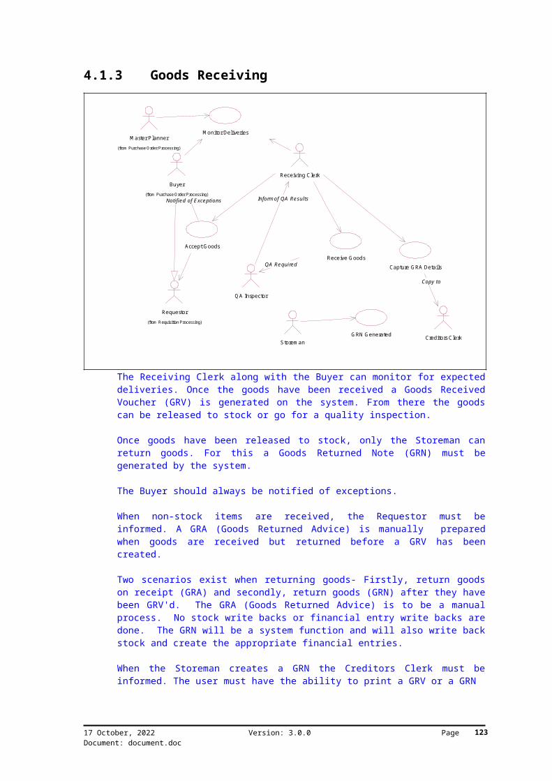
4.1.3 Goods Receiving
G RN G eneratedStorem an
Requestor(from Requisition Processing)
Creditors Clerk
Q A Inspector
Receive G oodsQA Required
Accept G oods
Capture G RA Details
Copy to
Buyer(from Purchase Order Processing)
Notified of E xceptions
Receiving Clerk
Inform of QA Results
M onitor DeliveriesM aster Planner
(from Purchase Order Processing)
The Receiving Clerk along with the Buyer can monitor for expecteddeliveries. Once the goods have been received a Goods ReceivedVoucher (GRV) is generated on the system. From there the goodscan be released to stock or go for a quality inspection.
Once goods have been released to stock, only the Storeman canreturn goods. For this a Goods Returned Note (GRN) must begenerated by the system.
The Buyer should always be notified of exceptions.
When non-stock items are received, the Requestor must beinformed. A GRA (Goods Returned Advice) is manually preparedwhen goods are received but returned before a GRV has beencreated.
Two scenarios exist when returning goods- Firstly, return goodson receipt (GRA) and secondly, return goods (GRN) after they havebeen GRV'd. The GRA (Goods Returned Advice) is to be a manualprocess. No stock write backs or financial entry write backs aredone. The GRN will be a system function and will also write backstock and create the appropriate financial entries.
When the Storeman creates a GRN the Creditors Clerk must beinformed. The user must have the ability to print a GRV or a GRN
17 October, 2022 Version: 3.0.0 Page Document: document.doc
123

4.1.3.1 Receive Goods
A Goods Received Voucher (GRV) needs to be generated for thereceipt of every Stock and Non-stock items. i.e. a GRV is createdfor all payments.
It is important to note that an order can have many deliveries,but that a GRV can only belong to one order.
Receiving clerk can over receive. The Clerk must be informed(prompted) of the excess and decide whether to receive the goodsor not. The PO detail line must be closed automatically when theQty accepted is equal to the Qty ordered.
4.1.3.1.1 Scenario: Receive Goods
: Supplier : R eceiving Clerk : G oods Received Voucher : Item Master File
: W arehouse : Q A Inspector : R equestor : Purchase O rder
1: D eliver G oods( )2: R ecord D elivery( )
3: Validate( )
4: Status Change( )
The status is changed to delivered
5: Check for QA Requirem ents( )
6: [If No Q A R equired] R elease to Stock( )
9: C apture Q A Results & C hange Status( )
7: [If Q A required] Forward( )
Depending on the business rules, the delivered goods m ay need a QA and m ust be forwarded for a QA inspection. If no QA is required, the goods are release directly to stock.
Depending on the Q A requirem ents, the goods will be m arked as 'Received' or 'Q A W aiting'.
If the G oods Pass QA, then the goods can be released to stock. The status on the G R V changed from 'QA W aiting' to 'Q A Received'. Only when the Receiving C lerk releases the goods to stock will the status of the G R V change from 'Q A Received' to 'R eceived'
11: Inform ed of Received G oods( )
8: Inform ed of QA Results( )
10: [If Q A Passed] R elease to Stock( )
R ecord C ounted Qty
Validate the goods before a GR V is recorded. If incorrect Generate a GRA
Goods are delivered to the Receiving Clerk from the Supplier. AGRV is generated (The GRV Status is now "OPEN"). When the orderno is captured, the status of the PO will change from 'Ordered'to 'Received' The GRV provides proof that the listed quantitiesof goods have been delivered. Depending on the goods delivered, aQC inspection may be necessary before the goods are released tostock (A status of 'QC Waiting' is allocated to the GRV). If noQC is required, the Receiving Clerk releases the goods directlyto stock. The status of the PO line item will then change from'Received' to 'Completed' if the Qty Accepted >= Qty Ordered. AGRV detail line must be linked to a PO detail line.
17 October, 2022 Version: 3.0.0 Page Document: document.doc
124

If a QC is completed the status will change from 'QC Waiting' to'CLOSED' once the goods have been received. This is when theRequestor is informed of the availability of the goods. If thegoods received were for a suggested orders, then theReplenishment Planner is informed.
Report needed at month end or prior to stock take to informStoreman of stock that have been received but not yet been GRVed.System must check that quantity received is not more than thequantity ordered. The System must not stop the over receipt ofgoods - the order line item must automatically be closed ascomplete for over supplies. An exception report will highlightall over supplies.
4.1.3.2 Monitor Deliveries
Depending on the business rules, the Buyer and the ReceivingClerk will be able to view expected deliveries online or on ahardcopy. Need the ability to list outstanding PO's by supplier,due date, item etc. (See the available filters in PO 'ReportingRequirements' within this document.) This will be an on-lineinquiry and reporting function.
4.1.3.3 Capture GRA Details
This is a manual process.
4.1.3.3.1 Scenario: Return Goods To Supplier
: Receiving Clerk : G RA : C reditors Clerk : Supplier
1: Create( )
2: Copy of GRA( )
3: Inform of Returned Goods( )
17 October, 2022 Version: 3.0.0 Page Document: document.doc
125

The Receiving Clerk and the QA Inspector both have the authorityto request the return of goods for various reasons. Goods arereturned against a GRV detail line. If the supplier deliversdefective goods, the Receiving Clerk will not accept the goodsdelivered and return them to the supplier. This means that someor all of the goods will not be recorded on the GRV. In thisinstance, a GRA details (Goods Returned Advice) must be captured.
4.1.3.4 Accept Goods
When the goods/services are delivered, the line item status onthe GRV is changed to 'Received'. From there it can undergo aquality assurance check and/or be accepted to stock. This is werethe GRV is printed.
4.1.3.4.1 Scenario: Release Goods
: W arehouse : Receiving Clerk : Goods Received Voucher
The Buyer is inform ed of the goods received. This includeds exceptions.E.g. quantities that need to be re-ordered.
1: Record Accepted Q ty( )2: [If G RV for Stock] Update Stock( )
6: Print( )
Creditors : Purchase O rder
3: Update
4: Update Q ty Am m ended( )
5: [If final GRV] PO closed( )
Prom pt if Qty is still outstanding.
Prom pt:" Is this the Last line item entry?" This m ay related to a R ole.
The Receiving Clerk releases goods. There are two types of goodsnamely: Stock Items and Non stock items. The Buyer must have theability to re-open PO's only when there is still an outstandingQty on the PO. Once the total quantity accepted equals or exceedsthe total quantity ordered the system must close the order lineitem as complete. The system must allow relevant users tomanually close the order line item as being completed, even ifthe quantity ordered does not equal the quantity accepted forthat order line.
17 October, 2022 Version: 3.0.0 Page Document: document.doc
126

4.1.3.5 GRN Generated
Only the Storeman can create a GRN (Goods Received Note for itemsreturned.) GRNs will be covered in detail in Warehousing -Inventory Management.
17 October, 2022 Version: 3.0.0 Page Document: document.doc
127

4.1.4 Class Diagram
Stock Account
Cardex Report<<Enquiry>>
Supplier Inquiry<<Enquiry>>
Item Inquiry<<Enquiry>>
Requisition Inquiry<<Enquiry>>
G RV Inquiry<<Enquiry>>
PO Inquiry<<Enquiry>
G RN Inquiry<<Enquiry>>
Em ployee M aster FileEm ployee No.Em ployee Nam eEm ployee Surnam eEm ployee ID No.
Non-Stock ItemG L CodeItem CodeItem DescriptionGL TypeQ uoted Reference No.
Stock Item sItem CodeItem DescriptionSuppliers Item CodeSpecial Instructions
BudgetBudget Am ount
Em ployee G L Accounts
0..*
1
0..*
1
G L Account
0..*
1
0..*
1
0..*
1
0..*
1
G RN HDRG RN NoSupplier CodeSupplier DescriptionSuppliers Invoice/Delivery NoteG RV Ref NoPurchase O rder No.Authority No.Date Returned
G RN DetailItem CodeItem DescriptionQty on G RNQty ReturnedUnit Net PriceG RN Reason CodeReason DescriptionSupplier Credit NoteSupplier Value
G RV HDRG RV NoSupplier CodeSupplier Description G RV StatusAuthority NoPurchase O rder No.Suppliers Invoice/Delivery NoteDate Received
G RV DetailItem CodeItem DescriptionW arehouseUO MQ ty on Delivery NoteQ ty CountedQ ty Inspected O KQ ty RejectedQ ty AcceptedUnit Net PriceQ ty O n G RASupplier Invoice No.Supplier Invoice Value
GRAGRA No.Qty ReturnedReason
Requisition Status
PO Requisition
PO Status
G RV Status
G oods Returned Note
Purchase Order
0..*
1
0..*
1
G oods Received Voucher
0..*
1
0..*
11
0..*
1
0..*
1
0..*
1
0..*
Buyer(from Purchase O rder Processing)
Buyer RoleW arehouseProduct G roup
1
0..*
1
0..*
W arehouseW arehouse CodeW arehouse Description
0..*1 0..*1
Item M aster FileItem CodeItem DescriptionDefault W arehouse CodeStandard CostUO MTAXM aterial CostLast Cost PriceInventory UnitForecast M ethodD/Note inquiryM RP - Lead tim eM RP - Supplier CodeM RP - W /H
0..*
1
0..*
1
W arehouse ItemW /H CodeItem CodeInventory on HoldInventory on OrderSupplier CodeLead tim eInventory on HandM inim um O rder Q tyM axim um O rder Q tyRe-order PointStocking UO MO rdering UO MConversion Factor
1..*
0..1
1..*
0..1
1..*
0..1
1..*
0..1
Purchase O rder HDRPurchase O rder NoSupplier CodeSupplier DescriptionO rder TypeBuyerDateTim e CreatedOrder StatusSettlem ent DiscountAuthority NoDelivery AddressVersion No
Supplier Status
Supplier W /H Item M atrixSupplier CodeItem CodeW /H CodeTrade Discount 1Trade Discount 2PriceDate O nDate O ffM ax Stock LevelM inim um Stock LevelM ultiplesType (M RP or RO P)Record Q ty on D/Note?Record Q ty Counted?Record Q ty Inpected O K?Record Q ty Rejected?Record Q ty Accepted?EO Q
Purchase O rder DETLW arehouseRequest NoUO MQ ty RequiredQ ty ReceivedDate RequiredQ uote Reference NoPriceTrade Discount 1Trade Discount 2Requested ByLine Item Status
1
1..*
1
1..*
PO Requisition HDRRequest NoRequisition TypeCreated ByRequested ByAuthorised ByDateTim e CreatedRequest Status
Transaction Type
0..*
1
0..*
10..*
10..*
1
0..*0..*
Supplier M asterfileSupplier CodeSupplier Nam eSupplier StatusSettlem ent DiscountStandard Trade DiscountStreet No.Street Nam eSuburbCityPhysical Postal CodeP.O Box No.SuburbPostal CodeChain CodeBanking DetailsE-m ail AddressCreditor Contact PersonM D Nam eM D Num berPhone Num berFax NoO rder Placem ent M ethodStatem ent Delivery M ethodPaym ent Term sM ethod of Paym entSupplier RatingDate Created
0..*
1
0..*
1
1..*1 1..*1
0..*
1
0..*
1
Split line ItemDate RequiredQty Required
1
0..*
1
0..*
PO Requisition DETLW arehouseSupplier CodeUO MQty RequiredDue DatePriceTrade Discount 1Trade Discount 2Line Status
1
1..*
1
1..*
0..*
1
0..*
1
0..*
1
0..*
1
17 October, 2022 Version: 3.0.0 Page Document: document.doc
128

4.1.4.1 Class Name: Purchase Order
Both the Header and Detail must have a notes field. Amended POmust be highlighted if the PO is changed.
Note: Depending on whether the Transaction type is for Stock ofNon-Stock Items, the Detail Attribute will change. For Stockitems, Item code, Supplier code and special instruction will beadded. For Non-Stock items, the GL code, Type and Quote Ref. No.Attributes will be added.
4.1.4.2 Class Name: Goods Received Voucher
If the Qty on the delivery note varies from the Qty GRN then aGRN must be generated (Pop-up)
4.1.4.3 Class Name: Purchase Order HDR
4.1.4.3.1 Attribute Name: Purchase Order No
Type: Alpha Numeric, Must be prefixed with a Factory and Deliveryaddress.Validations: Prefix must be checked against a factory and adelivery address.Attribute Triggers:Comments: Auto generate at time of creation of the PO
4.1.4.3.2 Attribute Name: Supplier Code
Description: Unique Code for the supplierType: Item Code.Validations: Supplier structure
4.1.4.3.3 Attribute Name: Supplier Description
Description: Displays the name of the supplier selectedType: Sting, Mixed
4.1.4.3.4 Attribute Name: Order Type
Description: The type of orderType: Item Code.Validations: Transaction Type StructureComments: To see the various transaction types an there statetransition see PO Status.
4.1.4.3.5 Attribute Name: Buyer
Description: Role of the user who created the Purchase Order.Type: item code...allowed
17 October, 2022 Version: 3.0.0 Page Document: document.doc
129
4.1.4.3.6 Attribute Name: DateTime Created
Description: The date and time that the Purchase Order wascreated.Type: Date.
4.1.4.3.7 Attribute Name: Order Status
Description: The current status of the Purchase Order.Type: Item Code (Status Structure).
4.1.4.3.8 Attribute Name: Settlement Discount
Type: NumericComments: Defaults to settlement discount on supplier master. Canbe overridden. Need a report to compare all that have beenoverridden
4.1.4.3.9 Attribute Name: Authority No
Type: Alpha Numeric, Must be prefixed with a Factory andDelivery address. Must get this prefix info from DeliveryAddress.Validations: Check for duplicate order authority numbers.Comments: This must be a manual numbering system, Must beprefixed with the warehouse location code.
4.1.4.3.10 Attribute Name: Delivery Address
Type: item codeValidations: Delivery structureComments: Must be prefixed with a Factory and Delivery address(E.g. VR100 = Vaal Replenishment 100)
4.1.4.3.11 Attribute Name: Version No
Type: numeric, non- edit.Validations: every time the date or quantity is changed on thePO, this number must be incrementedAttribute Triggers:Comments: Starts at ZERO.
4.1.4.4 Class Name: Purchase Order DETL
Note: Depending on whether the Transaction type is for Stock ofNon-Stock Items, the Detail Attribute will change. For Stockitems, Item code, Supplier code and special instruction will beadded. For Non-Stock items, the GL code, Type and Quote Ref. No.Attributes will be added. (There must be the ability toduplicate detail lines.)
17 October, 2022 Version: 3.0.0 Page Document: document.doc
130

4.1.4.4.1 Attribute Name: Warehouse
Description: The warehouse where the item is to be stored.Type: Item CodeValidations: W/H Location StructureAttribute Triggers:Comments: Each material item could have a default warehousedepicting where the item is to be stored. This can be altered atthe time that the Purchase Order is captured.
4.1.4.4.2 Attribute Name: Request No
Type: Numeric.Comments: Must duplicate this in the detail lines (Can beoverwritten).There will be no inquiry facility by requisitionnumber.(Phase 1)
4.1.4.4.3 Attribute Name: UOM
Description: Code that reflects the measurement that the item ismeasured in (i.e. Unit of Measure).Type: Item Code Validations: Unit of Measure structure
4.1.4.4.4 Attribute Name: Qty Required
Description: Total number of items to be purchased.Type: Numeric.
4.1.4.4.5 Attribute Name: Qty Received
Description: Total number of items received on GRVType: Numeric.(No-Edit field)Comments: This value will be obtained from the GRV
4.1.4.4.6 Attribute Name: Date Required
Description: Date on which the item being purchased is required.Type: Date.Comments: Need to be able to split the order.
4.1.4.4.7 Attribute Name: Quote Reference No
Description: The quotation that this order refers to.Type: Numeric.
4.1.4.4.8 Attribute Name: Price
Description: Price that was quoted for the item to be purchased.Type: Numeric. 2 decimals.
17 October, 2022 Version: 3.0.0 Page Document: document.doc
131

Comments: This price is the standard price and can be overridden.Need a report to compare the price to the standard cost on theitem master file.
4.1.4.4.9 Attribute Name: Trade Discount 1
Description: Percentage discount that is to be allowed for theitem to be purchased.Type: Numeric. 2 decimals.Validations: Between 0.00 and 100.00Comments: This discount will vary from supplier to supplier aswell as from material item to material item. Only applies to Rawmaterials, trading goods and selected stock items. This may beover written at time of entry. A report is required to comparethe Trade discount to the standard trade discounts on thesupplier material master file.
4.1.4.4.10 Attribute Name: Trade Discount 2
Description: Additional percentage discount that is to beallowed for the item to be purchased.Type: Numeric. 2 decimals.Validations: Between 0.00 and 100.00Comments: Additional discount after calculation of net priceafter Trade Discount 1
4.1.4.4.11 Attribute Name: Requested By
Description: Name of the user who requested the material item.Type: Sting, Mixed.
4.1.4.4.12 Attribute Name: Line Item Status
Description: The current status of the Purchase Order line item.Type: Item Code.Validations: Status Structure
4.1.4.5 Class Name: Stock Items
4.1.4.5.1 Attribute Name: Item Code
Description: unique Code for the item that is to be purchased Type: item codeValidations: item structure
4.1.4.5.2 Attribute Name: Item Description
Description: The description of goods, services to be ordered.Type: StringComments: In the case of a replenishment order the descriptionwould come from the material item master file. In the other
17 October, 2022 Version: 3.0.0 Page Document: document.doc
132

cases, this field would have to be entered. The description couldalso come from the material master & could be overridden.
4.1.4.5.3 Attribute Name: Suppliers Item Code
Description: code of the supplierType: item codeValidations: supplier structureComments: Come from the item master (default supplier)
4.1.4.5.4 Attribute Name: Special Instructions
Description: Field for entering special instructionsType: string, mixedValidations: none
4.1.4.6 Class Name: Non-Stock Item
4.1.4.6.1 Attribute Name: GL Code
Type: Numeric.Comments: If an item needs to be split over a range of GL codes,a detail line needs to be generated for each GL code. There mustbe the ability to duplicate detail lines
4.1.4.6.2 Attribute Name: Item Code
Non-stock item code
4.1.4.6.3 Attribute Name: Item Description
Description: Description of the item ordered, but not linked tothe item code chosen.Type: Item codeValidation: Non-stock item description structureAttribute triggers: Mandatory
4.1.4.6.4 Attribute Name: GL Type
Description: When the GL Code is entered, the Type of GL accountwill be displayed in this field. The type could be DirectServices, CAPEX or Non-Stock Item Type: Numeric.
4.1.4.6.5 Attribute Name: Quoted Reference No.
4.1.4.7 Class Name: Split line Item
There must be the ability to split a detail line to cater formultiple deliveries. i.e. Have different deliveries for variousdates.
17 October, 2022 Version: 3.0.0 Page Document: document.doc
133

4.1.4.7.1 Attribute Name: Date Required
Description: Date on which the item being purchased is required.Type: Date.Comments: This will effect the availability of stock
4.1.4.7.2 Attribute Name: Qty Required
Description: Total number of items to be purchased.Type: Numeric.Comments: This will effect the availability of stock
4.1.4.7.3 Attribute Name: GRA No.
4.1.4.7.4 Attribute Name: Qty Returned
Description: Total number of items actually returned.Type: Numeric.
4.1.4.7.5 Attribute Name: Reason
4.1.4.8 Class Name: GRV Status
CLOSED
QC W aiting
D/Note Received, Goods Counted
Null
Open
No Q C Required
Q C Required
Qty Accepted
Qty Inspected OK, Qty Rejected
The Notes in this diagram indicate the attributes captured oractions taken that will cause a GRV to go from one status to thenext.
4.1.4.9 Class Name: GRV Inquiry
Must have a view only function of transaction
4.1.4.10 Class Name: PO Inquiry
Must be able to view per item & view detail lines per order.
17 October, 2022 Version: 3.0.0 Page Document: document.doc
134

4.1.4.11 Class Name: PO Status
CancelledO rdered
Received Archived
N ull
C aptured
Com plete
C ancel PO
Partial Receipt
Goods / Services R eceivedAfter Elapsed Period
Capture PO
Release to Stock
4.1.4.12 Class Name: GRV HDR
4.1.4.12.1 Attribute Name: GRV No
Description: A system generated, sequential number, unique toeach GRV.Type: Numeric. No decimals.
4.1.4.12.2 Attribute Name: Supplier Code
Description: Unique code of the supplier.Type: String, Mixed.Attribute Triggers: Mandatory
4.1.4.12.3 Attribute Name: Supplier Description
4.1.4.12.4 Attribute Name: GRV Status
Description: The different states that a GRV can go through.Type: item code Validations: GRV Status structureComments: See the class diagram of State transition diagram forthe various GRV states.
4.1.4.12.5 Attribute Name: Authority No
Description: The number of the order that this GRV relates to.Type: Numeric.Comments: This attribute relates to the manually generated POnumber.
4.1.4.12.6 Attribute Name: Purchase Order No.
Description: The number of the order that this GRV relates to.
17 October, 2022 Version: 3.0.0 Page Document: document.doc
135

Type: Numeric.Validations: This number cannot be referenced unless the orderhas been generated in the system.Attribute Triggers: MandatoryComments: This order reference number is related to the ordernumber generated by the system. Not the manual order number.
4.1.4.12.7 Attribute Name: Suppliers Invoice/Delivery Note
Description: The invoice number or the supplier.Type: String, mixed. The supplier invoice number might be alpha-numeric. i.e. string)
4.1.4.12.8 Attribute Name: Date Received
Description: The date that goods were received
4.1.4.13 Class Name: GRV Detail
4.1.4.13.1 Attribute Name: Item Code
4.1.4.13.2 Attribute Name: Item Description
4.1.4.13.3 Attribute Name: Warehouse
Description: The warehouse where the item is to be stored.Type: Item Code (Location Structure).Comments: Each material item could have a default warehousedepicting where the item is to be stored. This can be altered atthe time that the Purchase Order is captured.
4.1.4.13.4 Attribute Name: UOM
Description: Code that reflects the measurement that the item ismeasured in (i.e. Unit of Measure).Type: Item Code Validations: Unit of Measure structure
4.1.4.13.5 Attribute Name: Qty on Delivery Note
Description: Total number of items delivered according to thesupplier invoice.Type: Numeric, decimals dependant on UOMValidations: Must check against UOM
4.1.4.13.6 Attribute Name: Qty Counted
Description: Total number of items that were counted as receivedfrom the supplier.Type: Numeric.
17 October, 2022 Version: 3.0.0 Page Document: document.doc
136

4.1.4.13.7 Attribute Name: Qty Inspected OK
Description: Total number of items that were inspected during theQA inspection.Type: Numeric.
4.1.4.13.8 Attribute Name: Qty Rejected
Description: Total number of items that were rejected during theQA inspection.Type: Numeric.
4.1.4.13.9 Attribute Name: Qty Accepted
Description: Total number of items released to stock.Type: Numeric.
4.1.4.13.10 Attribute Name: Unit Net Price
4.1.4.13.11 Attribute Name: Qty On GRA
Description: Goods returned advice amountType: Numeric, decimals dependant on UOMValidations: Must check against UOMComments: GRA is created if the goods are returned before theyare GRV
4.1.4.13.12 Attribute Name: Supplier Invoice No.
4.1.4.13.13 Attribute Name: Supplier Invoice Value
17 October, 2022 Version: 3.0.0 Page Document: document.doc
137

Chapter 5 Design Documentation for Procurement and Goods Receiving
5.1 System Diagram
Requisition Processing
Purchase O rder Processing
Goods Receiving
Order M onitoring
Supplier Selection
The procurement function will consist of tasks starting atrequisitioning and ordering through to goods receiving. Quotes,vendor selection and contracts will not be included. For thisProject import documentation has been excluded. Where possible,printing must be on the cheapest format. User requireseconomical, speedy and quality printouts for reporting.Requisition processing and Supplier selection are notrequirements for Phase 1 of this project.
17 October, 2022 Version: 3.0.0 Page Document: document.doc
138

5.2 Roles and Security
17 October, 2022 Version: 3.0.0 Page Document: document.doc
Requisition Authorisor
(from Requisition Processing)
Order Authoriser(from Purchase O rder Processing)
Requestor(from Requisition Processing)
Buyer(from Purchase O rder Processing)
Q C Inspector(from G oods Receiving)
Storem an(from G oods Receiving)Inform of QA R esults
139

Object Oriented Analysis and Design using UML
5.2.1 Roles and Securities TableProcess Role Design Object Business Object CR
UDDesign: Create a Purchase Order Buyer
OrderAuthoriser
PO_CAP_MAN DYNAMIC_MESS
Design: Maintain Purchase Order BuyerMasterPlannerSupplier
PO_CAP_MAN DYNAMIC_MESS
Design: Close Purchase Order Buyer PO_CAP_MAN
Design: Placing an Order Buyer DYNAMIC_MESS
Design: Monitor GRV's ReceivingClerkBuyerMasterPlanner
GRV_CAP GRV_Form
Design: Receive Goods ReceivingClerk
PO_LIST_GRV PO_CAP_MAN GRV_Form
Design: Update W/H Item & QC Receivi GRV_Form
17 October, 2022 Version: 3.0.0 Page Document: document.doc
140

Object Oriented Analysis and Design using UML
ngClerk
Design: Release Goods ReceivingClerk
GRV_Form DYNAMIC_MESS PO_CAP_MAN
Design: Monitor Purchase Order BuyerReplenishmentPlannerMasterPlanner
PO_Enquiry PO_CAP_MAN
17 October, 2022 Version: 3.0.0 Page Document: document.doc
141

Object Oriented Analysis and Design using UML
5.3 Design Processes5.3.1 Design: Purchase Order Processing
PO Status
Purchase OrderPO Inquiry<<Enquiry>>
PO_ORD_M AN
Store()Cancel()Update Header()Update Detail Line()Call Selected PO()
<<Visual>>
RGT009<<Core>>
M A_PO_NO_GEN<<Hidden>>
M AH200<<Core>>
M AH100<<Core>>
M A_ITEM _DESCATTR_TKEY : InputLIST : InputST_ITEM _CODE : OutputST_DES_DESC : OutputST_GROUP_CODE : OutputST_STDES_CODE : OutputST_W ORK_LIST : OutputCHILD_ITEM S : Output
<<Hidden>>M A_ALLOW ED_ITEMATTR_TKEY : InputALLOW ED_ST : InputLIST : InputM A_VALUE : OutputST_W ORK_LIST : Output
<<Hidden>>
PO_Buyer2Supplier<<Visual>>
STF062<<Core>>
M A_CHECK_ITEMLIST_A : InputLIST_B : InputRESULT : Output
<<Hidden>>
DYNAM IC_M ESS<<Visual>>
M AH020
Stock Item sItem CodeItem Description
Transaction Type
Purchase Order HeaderPurchase Order NoSupplier CodeSupplier DescriptionOrder TypeBuyerDateTim e CreatedOrder Status : PO StatusSettlem ent DiscountAuthority NoW /H CodeW /H DescriptionVersion No 1
0..*
1
0..*
Purchase Order DetailSpecial InstructionsRequisition NoOrdering UOMQty RequiredQty ReceivedDate RequiredStandard CostSupplier PriceTrade Discount 1Trade Discount 2Requested ByTotal Value (Excl.Vat)Line Item Status : PO Status
1
0..*
1
0..*
Split line ItemDate RequiredQty Required
Non-Stock ItemExpence CodeCost CenterDescription of ProductQuoted Reference No.
M A_VERSION_CONT<<Hidden>>
M A_READ_CUBE<<Hidden>>
CAPEX Item (Detail)GL CodeDescriptionQuoted Reference No.
CAPEX Item (Header)Capital Vote No.
M A_DATE_CALCDATE_1 : InputDATE_2 : InputVALUE : InputTYPE : InputRESULT : OutputRESULT_LIST : OutputTEST_RESULT : Output
<<Hidden>>M A_CHECK_PREVATTR_TKEY : InputPROCESS_TKEY : InputVALUE : InputRESULT : Output
<<Hidden>>M A_SEND_INFOATTR_TKEY : InputTYPE : InputREPORT : Input
<<Hidden>>
PO_Enquiry<<Visual>>
RGL003<<Core>>
17 October, 2022 Version: 3.0.0 Page Document: document.doc
143

Object Oriented Analysis and Design using UML
5.3.1.1 Use Case Diagram: Design: Purchase Order Processing
Replenishm ent Planner
Order Authoriser
Maintain OrderInforms of E xceptionsMonitor Order
Buyer
Stock Item only
Master Planner
Inform
Place Order
The objective of Purchase Order Processing is to capture and sendorders to a Supplier. (Sending Orders to the Supplier may be viafax, e-mail or a manual process.) The Buyer can maintain theorder. This includes creating and deleting orders. Once the Buyerhas received the signed copy of the Requisition, the order can beplaced with the Supplier. Once a purchase order number has beengenerated, it becomes the controlling number for all activitiesrelating to the order and delivery of goods.
The customers 'Authority No' is a manually generated number theBuyer will assign to a system PO. The Authority no. will defaultto the Order number. This Authority number can be overwrittenwith a 'Authority number' given to the client. A check must beput in to confirm that the authority number is unique. PurchaseOrders can be entered manually or created automatically when theReplenishment Planner confirms the suggested orders from thematerial requirement planning run. The Replenishment Planner canplay the role of the Buyer for stock items only.
5.3.1.2 Use Case Breakdown
5.3.1.2.1 Use Case: Place Order
The order can be forwarded as: - a hardcopy. - a system generated fax - e-mail - a manual process
17 October, 2022 Version: 3.0.0 Page Document: document.doc
145

Object Oriented Analysis and Design using UML
5.3.1.2.2 Design: Placing an Order
5.3.1.2.3 Use Case: Maintain Order
A Buyer creates an order from a signed requisition (Non-stockitems) or by confirming recommended orders. A Non Stock ordershould be linked to an requisition document.
The date can be amended on a Purchase Order. Quantities can bechanged but only down, not up. If quantities need to be amendedup, an additional PO must be created for the increased amount.
5.3.1.2.4 Analysis: Create Purchase Order
17 October, 2022 Version: 3.0.0 Page Document: document.doc
: Buyer : DYNAM IC_M ESS
: M A_SEND_INFO
1: Select Fax, E-M ail or Print( )2: [Depending on Selection] Send Info( )
: Buyer : O rder Authoriser
: Supplier : Supplier Purchase Order
: Purchase Order
1: Create( )
2: Com plete M andatory Data( ) 3: Inform of Exceptions( )
5: Generate PO( ) 6: Receive Purchase Order( )
4: Select Fax, E-M ail or Print( )
146

Object Oriented Analysis and Design using UML
The buyer can create an order. An order is normally linked to oneor many requisitions. Orders can be created without a requisitionsystem (Phase 2 issue) but will be listed as exceptions andprinted. If the requisition has the correct authority checkcompleted, then the Buyer will be able to Order the Goods as longas the order does not exceed the maximum stock levels.
5.3.1.2.5 Design: Create a Purchase Order
: Buyer : PO_ORD_M AN
: DYNAM IC_M ESS : Order
Authoriser : M A_
SEND_INFO : M A_
VERSION_
1: Create( )
3: Store( )
7: Cancel( )
2: [If Qty > M ax Stock] Display Error M essage( )
8: Update Header( )
9: Update Detail Line( )
10: Inform of Exceptions( )
This Could be Via I-m ail or via a Report
4: Ask: Fax, E-M ail, Print( ) 5: Send E-M ail, Fax or Print( )
6: Update Version no. if M odified( )
17 October, 2022 Version: 3.0.0 Page Document: document.doc
147

Object Oriented Analysis and Design using UML
5.3.1.2.6 Design: Create a Purchase order - HDR Attribute Triggers
: Buyer : PO_ORD_M AN
: Purchase Order Header
: M A_ITEM _DESC
: M A_CHECK_ITEM
: M A_CHECK_PREV
: M A_ALLOW ED_ITEM
1: Create( )
2: Select Supplier( ) 3: Get Supplier Inform ation( )
6: Select Status( )
4: Get Allowed Suppliers for Buyer( )
5: Check Allowed Suppliers against Buyers( )
7: Get Allowed Status for PO( )
8: Check if status selected is allowed( )
9: Enter Authority No.( )10: Check if Auhtority no. has been used( )
11: Select W arehouse( ) 12: Get Allowed W arehouses against Supplier( )
13: Check is W arehouse selected is allowed( )
5.3.1.2.7 Design: Create a Stock PO - DETL Attribute Triggers
: Buyer : PO_ORD_M AN
: Purchase Order Header
: Purchase Order Detail
: M A_DATE_CALC
: M A_ALLOW ED_
: M A_READ_CUBE
1: Create( )
2: Capture Header Attributes( )
3: Capture Item Code( ) 4: Get Allowed Status for PO( )
5: Get Supplier W /H Item Info( )
6: Do Lead tim e Calcs( )
17 October, 2022 Version: 3.0.0 Page Document: document.doc
148

Object Oriented Analysis and Design using UML
5.3.1.2.8 Analysis: Maintain Purchase Order
: Buyer : Purchase Order : Supplier : M aster Planner
1: M odify/Delete( )2: Inform ( )
M odify Date and quantity down only. 3: Inform of PO Changes( )
Depending on whether the am ended order is accepted or declined, the supplier m ust be inform ed.
The Buyer can amend an existing order. If the buyer has theauthorisation to amend the order, the supplier and the MasterPlanner must be informed.Quantities can be move down and Dates modified.
5.3.1.2.9 Design: Maintain Purchase Order
: Buyer : PO_ORD_M AN
: M A_CHECK_PREV : M aster Planner : Supplier : M A_
SEND_INFO : DYNAM IC_M ESS
1: View( )
2: M odify Q uantity Received( ) 3: Check that Qty am ended is < Previous( )
4: [If Qty > M ax Stock] Display Error M essage( )
5: [If PO is for a Stock Item ] Inform of Changes( )
6: Ask: Fax, E-M ail, Print( )7: Send E-M ail, Fax or Print( )
8: Inform ( )
17 October, 2022 Version: 3.0.0 Page Document: document.doc
149
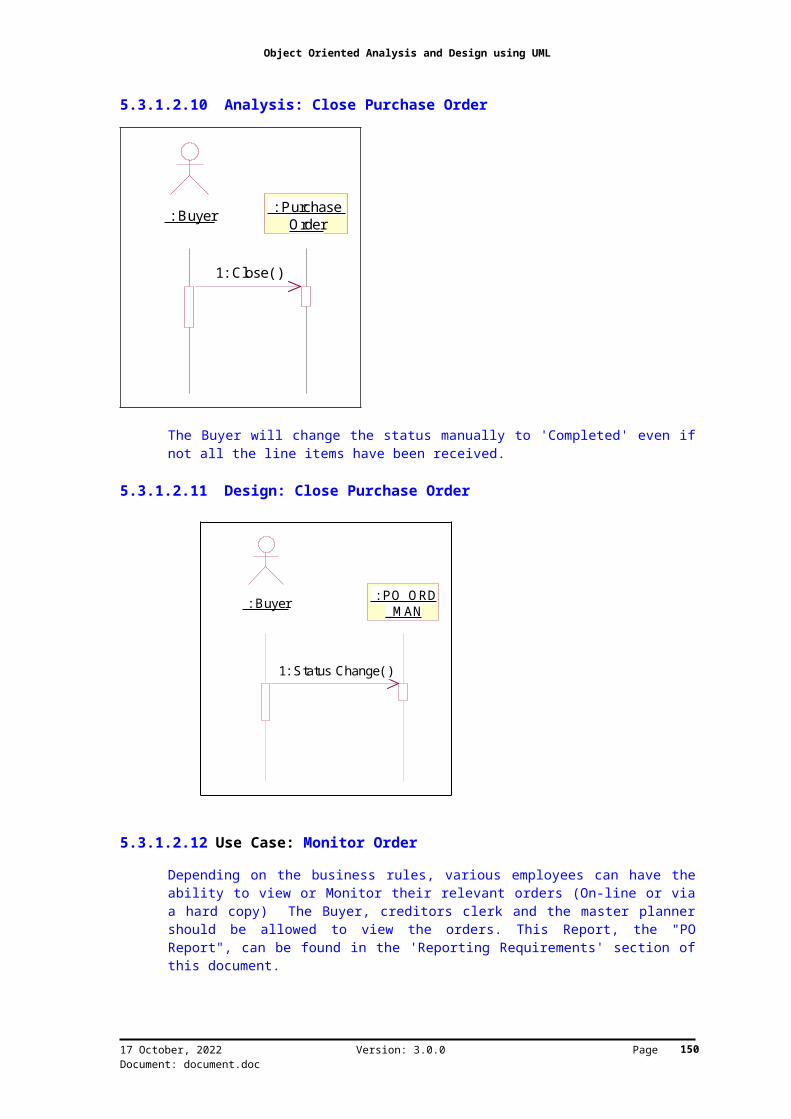
Object Oriented Analysis and Design using UML
5.3.1.2.10 Analysis: Close Purchase Order
: Buyer : Purchase Order
1: Close( )
The Buyer will change the status manually to 'Completed' even ifnot all the line items have been received.
5.3.1.2.11 Design: Close Purchase Order
5.3.1.2.12 Use Case: Monitor Order
Depending on the business rules, various employees can have theability to view or Monitor their relevant orders (On-line or viaa hard copy) The Buyer, creditors clerk and the master plannershould be allowed to view the orders. This Report, the "POReport", can be found in the 'Reporting Requirements' section ofthis document.
17 October, 2022 Version: 3.0.0 Page Document: document.doc
: Buyer : PO _O RD_M AN
1: Status Change( )
150

Object Oriented Analysis and Design using UML
5.3.1.2.13 Analysis: Monitor Order
The Buyer can monitor an order online or via a hardcopy. Arequestor can monitor the order via the requisition status andquantity ordered. The Store keeper might also need to viewrelevant orders.(e.g. Warehouse)
17 October, 2022 Version: 3.0.0 Page Document: document.doc
: Buyer : Purchase Order
: W arehouses 2 User
: Stock Item s : CAPEX Item (Header)
: CAPEX Item (Detail)
: Non-Stock Item
: PO Finder : M aster Planner : Replenishm ent Planner
1: Retrieve PO by Filters( )
2: Retrieve PO by Filters( )
3: Retrieve PO by Filters( )4: [If Stock Item ] Display Stock Item Attributes( )
5: [If CAPEX Item ] Display CAPEX attributes( )
6: [If CAPEX Item ] Display CAPEX attributes( )
7: [If Non Stock Item ] Display Non Stock Attributes( )
8: Check for allowed W arehouses for User( )
9: View Required PO( )
: Buyer : Replenishm ent Planner
: M aster Planner : PO_Enquiry
: PO_ORD_M AN
1: Find specific PO( )2: Find specific PO( )
3: Find specific PO( )
4: Call Selected PO( )
151

Object Oriented Analysis and Design using UML
5.3.1.2.14 Design: Monitor Purchase Order
17 October, 2022 Version: 3.0.0 Page Document: document.doc
152

Object Oriented Analysis and Design using UML
5.3.2 Design: Goods Receiving5.3.2.1 Class Diagram: Design: Goods Receiving
17 October, 2022 Version: 3.0.0 Page Document: document.doc
153

Object Oriented Analysis and Design using UML
5.3.2.2 Use Case Diagram: Design: Goods Receiving
The Receiving Clerk along with the Buyer can monitor for expecteddeliveries. Once the goods have been received a Goods ReceivedVoucher (GRV) is generated on the system. From there the goodscan be released to stock or go for a quality inspection.
Once goods have been released to stock, only the Storeman canreturn goods. For this a Goods Returned Note (GRN) must begenerated by the system.
The Buyer should always be notified of exceptions.
When non-stock items are received, the Requestor must beinformed. A GRA (Goods Returned Advice) is manually preparedwhen goods are received but returned before a GRV has beencreated.
Two scenarios exist when returning goods- Firstly, return goodson receipt (GRA) and secondly, return goods (GRN) after they have
17 October, 2022 Version: 3.0.0 Page Document: document.doc
GRN GeneratedStorem an
Requestor(from Requisition Processing)
Creditors Clerk
Receive GoodsAccept Goods Capture GRA Details
Copy to
Supplier(from Supplier Selection)
Return Goods & Documentation
QC Inspector
QA Required
Buyer(from Purchase O rder Processing)
Notified of E xceptions
Receiving Clerk
Deliver Goods & Documentation
Inform of QA Results
M onitor DeliveriesM aster Planner(from Purchase O rder Processing)
154

Object Oriented Analysis and Design using UML
been GRV'd. The GRA (Goods Returned Advice) is to be a manualprocess. No stock write backs or financial entry write backs aredone. The GRN will be a system function and will also write backstock and create the appropriate financial entries.
When the Storeman creates a GRN the Creditors Clerk must beinformed. The user must have the ability to print a GRV or a GRN
5.3.2.3 Use Case Breakdown
5.3.2.3.1 Use Case: Receive Goods
A Goods Received Voucher (GRV) needs to be generated for thereceipt of every Stock and Non-stock items. i.e. a GRV is createdfor all payments.
It is important to note that an order can have many deliveries,but that a GRV can only belong to one order.
Receiving clerk can over receive. The Clerk must be informed(prompted) of the excess and decide whether to receive the goodsor not. The PO detail line must be closed automatically when theQty accepted is equal to the Qty ordered.
5.3.2.3.2 Analysis: Receive Goods
: Supplier : Receiving Clerk : Goods Received Voucher
: Item M aster File
: W arehouse Item : QA Inspector : Requestor : Purchase
Order
1: Deliver Goods( ) 2: Record Delivery( )
3: Validate( )
4: Status Change( )
The status is changed to delivered
5: Check for Q A Requirem ents( )
6: [If No QA Required] Release to Stock( )
9: Capture QA Results & Change Status( )
7: [If QA required] Forward( )
Depending on the business rules, the delivered goods m ay need a QA and m ust be forwarded for a QA inspection. If no QA is required, the goods are release directly to stock.
Depending on the Q A requirem ents, the goods will be m arked as 'Received' or 'QA W aiting'.
If the Goods Pass QA, then the goods can be released to stock. The status on the GRV changed from 'QA W aiting' to 'QA Received'. Only when the Receiving Clerk releases the goods to stock will the status of the GRV change from 'QA Received' to 'Received'
11: Inform ed of Received G oods( )
8: Inform ed of Q A Results( )
10: [If QA Passed] Release to Stock( )
Record Counted Qty
Validate the goods before a GRV is recorded. If incorrect Generate a GRA
17 October, 2022 Version: 3.0.0 Page Document: document.doc
155
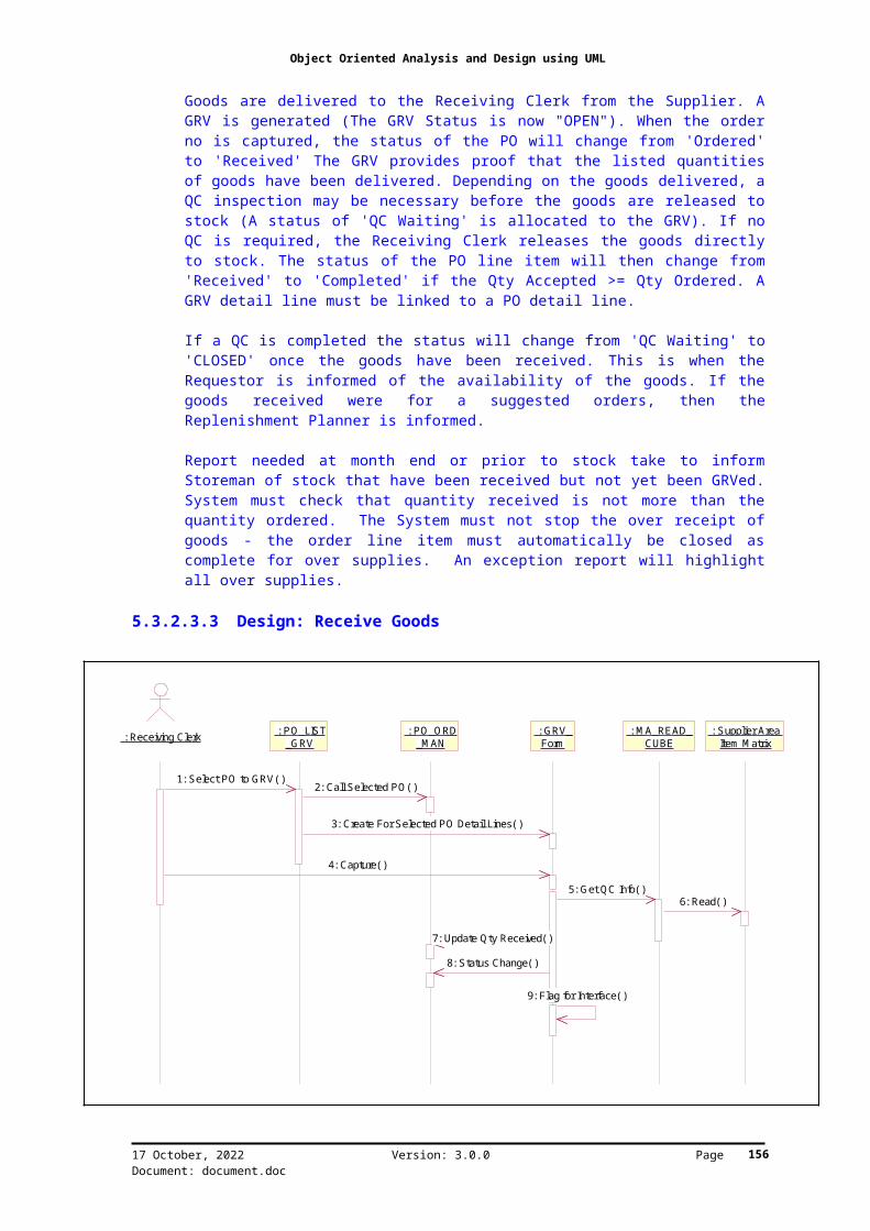
Object Oriented Analysis and Design using UML
Goods are delivered to the Receiving Clerk from the Supplier. AGRV is generated (The GRV Status is now "OPEN"). When the orderno is captured, the status of the PO will change from 'Ordered'to 'Received' The GRV provides proof that the listed quantitiesof goods have been delivered. Depending on the goods delivered, aQC inspection may be necessary before the goods are released tostock (A status of 'QC Waiting' is allocated to the GRV). If noQC is required, the Receiving Clerk releases the goods directlyto stock. The status of the PO line item will then change from'Received' to 'Completed' if the Qty Accepted >= Qty Ordered. AGRV detail line must be linked to a PO detail line.
If a QC is completed the status will change from 'QC Waiting' to'CLOSED' once the goods have been received. This is when theRequestor is informed of the availability of the goods. If thegoods received were for a suggested orders, then theReplenishment Planner is informed.
Report needed at month end or prior to stock take to informStoreman of stock that have been received but not yet been GRVed.System must check that quantity received is not more than thequantity ordered. The System must not stop the over receipt ofgoods - the order line item must automatically be closed ascomplete for over supplies. An exception report will highlightall over supplies.
5.3.2.3.3 Design: Receive Goods
17 October, 2022 Version: 3.0.0 Page Document: document.doc
: Receiving Clerk : PO_LIST_GRV
: PO_ORD_M AN
: GRV_Form
: M A_READ_CUBE
: Supplier Area Item M atrix
1: Select PO to GRV( ) 2: Call Selected PO( )
3: Create For Selected PO Detail Lines( )
4: Capture( )
7: Update Qty Received( )
5: Get QC Info( )6: Read( )
8: Status Change( )
9: Flag for Interface( )
156

Object Oriented Analysis and Design using UML
5.3.2.3.4 Design: Update W/H Item & QC
5.3.2.3.5 Use Case: Monitor Deliveries
Depending on the business rules, the Buyer and the ReceivingClerk will be able to view expected deliveries online or on ahardcopy. Need the ability to list outstanding PO's by supplier,due date, item etc. (See the available filters in PO 'ReportingRequirements' within this document.) This will be an on-lineinquiry and reporting function.
5.3.2.3.6 Design: Monitor GRV's
17 October, 2022 Version: 3.0.0 Page Document: document.doc
: Receiving Clerk : G RV_Form
: M A_READ_CUBE
: Area Item M aster
1: Capture( ) 2: Update Availibility( ) 3: Update( )
157

Object Oriented Analysis and Design using UML
5.3.2.3.7 Use Case: Capture GRA Details
This is a manual process.
5.3.2.3.8 Analysis: Return Goods To Supplier
17 October, 2022 Version: 3.0.0 Page Document: document.doc
: Receiving Clerk : Buyer : M aster Planner : GRV_CAP
: G RV_Form
1: Select GRV( )
2: Select GRV( )
3: Select GRV( )
4: View Selected GRV( )
: Receiving Clerk : GRA : Creditors Clerk : Supplier
1: Create( )
2: Copy of GRA( )
3: Inform of Returned Goods( )
This is a M anual Process
158

Object Oriented Analysis and Design using UML
The Receiving Clerk and the QA Inspector both have the authorityto request the return of goods for various reasons. Goods arereturned against a GRV detail line. If the supplier deliversdefective goods, the Receiving Clerk will not accept the goodsdelivered and return them to the supplier. This means that someor all of the goods will not be recorded on the GRV. In thisinstance, a GRA details (Goods Returned Advice) must be captured.
5.3.2.3.9 Use Case: Accept Goods
When the goods/services are delivered, the line item status onthe GRV is changed to 'Received'. From there it can undergo aquality assurance check and/or be accepted to stock. This is werethe GRV is printed.
5.3.2.3.10 Analysis: Release Goods
17 October, 2022 Version: 3.0.0 Page Document: document.doc
: Receiving Clerk : Goods Received Voucher
1: Record Accepted Qty( )
: Purchase Order
: GRV Report : Requestor : Availability
3: Update Qty Received( )
2: Am end Availability( )
4: [If final GRV] PO closed( )
6: M onitor all Receipts( )
5: Inform ed of Received Goods( )
159

Object Oriented Analysis and Design using UML
The Receiving Clerk releases goods. There are two types of goodsnamely: Stock Items and Non stock items. The Buyer must have theability to re-open PO's only when there is still an outstandingQty on the PO. Once the total quantity accepted equals or exceedsthe total quantity ordered the system must close the order lineitem as complete. The system must allow relevant users tomanually close the order line item as being completed, even ifthe quantity ordered does not equal the quantity accepted forthat order line.
17 October, 2022 Version: 3.0.0 Page Document: document.doc
160

Object Oriented Analysis and Design using UML
5.3.2.3.11 Design: Release Goods
17 October, 2022 Version: 3.0.0 Page Document: document.doc
: Receiving Clerk : GRV_Form
: DYNAM IC_M ESS
: Area Item M aster
: PO _ORD_M AN
1: Record Delivery( )2: Check if Last Line Item Entry( )
3: [If Stock] Update( )
4: Update Qty Received( )
161

Object Oriented Analysis and Design using UML
5.4 Object Design Documentation5.5 Visual Alias Documentation: PO_CAP_MAN
5.5.1 Business Class: Purchase Order Both the Header and Detail must have a notes field. Amended POmust be highlighted if the PO is changed.
Note: Depending on whether the Transaction type is for Stock ofNon-Stock Items, the Detail Attribute will change. For Stockitems, Item code, Supplier code and special instruction will beadded. For Non-Stock items, the GL code, Type and Quote Ref. No.Attributes will be added.
Once the PO has been Printed, the status must be changed toPrinted.... See new Printing status diagram.
5.5.1.1 Purchase Order Header
AttributeName
Attribute Documentation
PurchaseOrder No
Description: This will be a system generated no.for uniquely identifying a PO.Syntax: No EditType: Alpha Numeric, Must be prefixed with aFactory and Delivery address. Suffix with Stockor non StockValidations: Prefix must be checked against a
17 October, 2022 Version: 3.0.0 Page Document: document.doc
162

Object Oriented Analysis and Design using UML
factory and a delivery address.Attribute Triggers: NoneComments: Auto generate at time of creation ofthe PO using MA_PO_NO_GEN.
SupplierCode
Description: Unique Code for the supplierSyntax: EditableType: Item Code.Validations: Supplier structureAttribute Triggers: Leave field Trigger:MA_ITEM_DESC to get supplier details. UseMA_ITEM_DESC to get Supplier Description. OR AMTrules: DIPLAY SUPPLIER NAME. Use amount rules toget DateTime Created information.Comments: Once a Supplier Code is selected, theSupplier description must be populated with therelated description.
SupplierDescription
Description: Displays the name of the supplierselectedSyntax: No-editType: Sting, MixedValidations: Dependant on the Supplier CodeSelectedAttribute Triggers: None.Comments:
OrderType
Description: The type of orderSyntax: No-editType: Drop Down List BoxValidations: NoneAttribute Triggers: None.Comments: There are two Transaction typesnamely: Stock and Non-Stock Items
Buyer Description: Role of the user who created thePurchase Order.Syntax: EditableType: item codeValidations: User Structure. Must check allowedsuppliers for a buyer.Attribute Triggers: Field Get Focus: UseMA_Allowed_Item to get allowed Buyers for theSupplier Leave FieldTrigger: Check if the Buyer entered is the sameas the allowed Buyers- Use MA_CHECK_LIST If a Message isnecessary, then use DYNAMIC_MESSComments: Buyers Matrix against a supplier
DateTime Description: The date and time that the Purchase
17 October, 2022 Version: 3.0.0 Page Document: document.doc
163

Object Oriented Analysis and Design using UML
Created Order was created.Syntax: No EditType: DateValidations: NoneAttribute Triggers: NoneComments: Will get populated when the supplieris chosen.
OrderStatus
Description: The current status of the PurchaseOrder.Syntax: EditableType: Item Code (Status Structure).Validations: State transitions as outlined inthe State transition diagramAttribute Triggers: None.Comments: To see the various transaction typesand there state transition see PO Status.
SettlementDiscount
Description: This is the discount given to theclient when he/she settles there accountType: NumericValidations: checked against the Supplier Masterfor the Supplier Chosen.Attribute Triggers: None. Will get populatedwhen the Supplier is chosenComments: Defaults to settlement discount onsupplier master. Can be overridden. Need areport to compare all that have been overridden
AuthorityNo
Description: This is a manual number given to aspecific POSyntax: EditableType: Alpha NumericValidations: Check for duplicate orderauthority numbers.Attribute Triggers: Leave field Trigger to checkfor duplicate authority numbers. UseComments: This must be a manual numbering system
W/H Code Description: The warehouse where the item is tobe stored.Type: Item CodeValidations: W/H Location StructureAttribute Triggers: Mandatory. (If Transactiontype is Non-Stock Item, then the W/H MustDefault to Consumable Stores) When theTransaction Type is Selected, the W/H Code &Description will be Populated if the TransactionType is Non-Stock.Comments: Each material item could have a
17 October, 2022 Version: 3.0.0 Page Document: document.doc
164
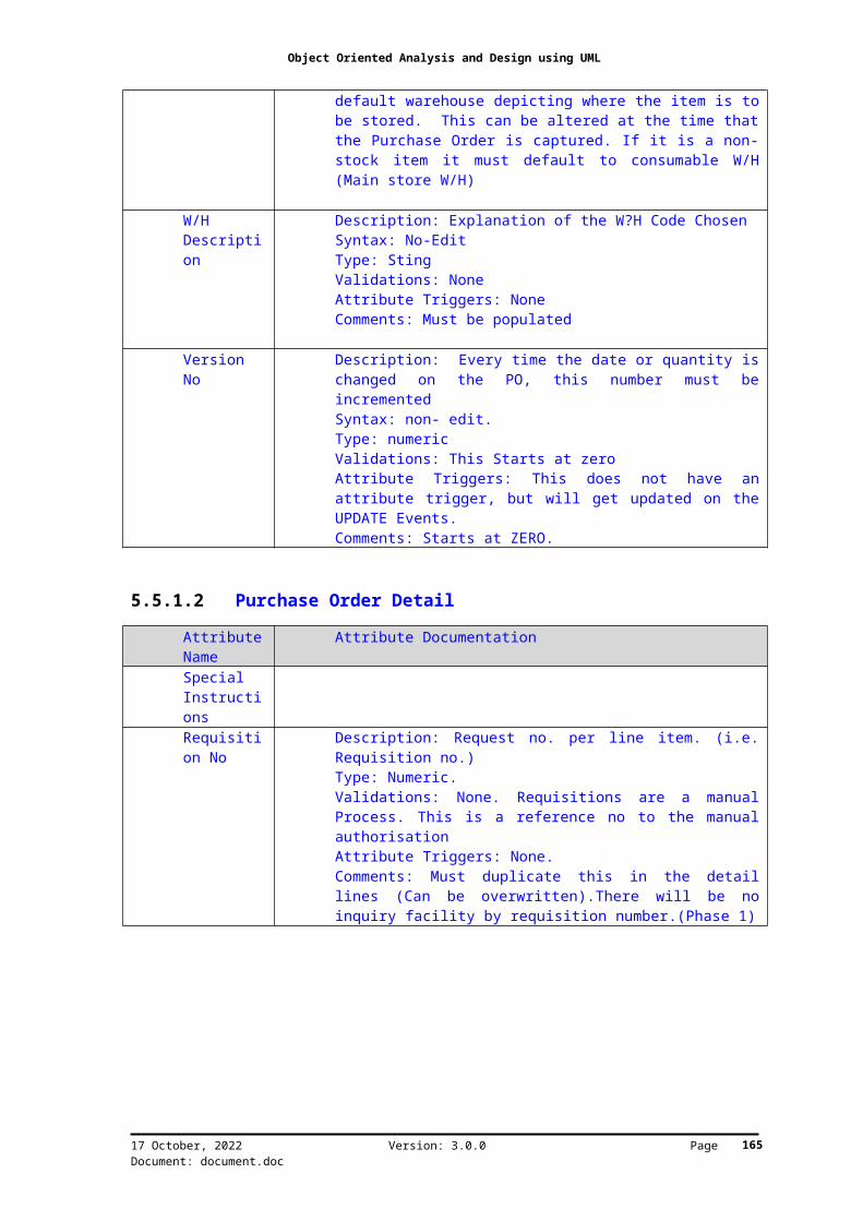
Object Oriented Analysis and Design using UML
default warehouse depicting where the item is tobe stored. This can be altered at the time thatthe Purchase Order is captured. If it is a non-stock item it must default to consumable W/H(Main store W/H)
W/HDescription
Description: Explanation of the W?H Code ChosenSyntax: No-EditType: StingValidations: None Attribute Triggers: NoneComments: Must be populated
VersionNo
Description: Every time the date or quantity ischanged on the PO, this number must beincrementedSyntax: non- edit.Type: numericValidations: This Starts at zeroAttribute Triggers: This does not have anattribute trigger, but will get updated on theUPDATE Events.Comments: Starts at ZERO.
5.5.1.2 Purchase Order Detail
AttributeName
Attribute Documentation
SpecialInstructions
Requisition No
Description: Request no. per line item. (i.e.Requisition no.)Type: Numeric. Validations: None. Requisitions are a manualProcess. This is a reference no to the manualauthorisationAttribute Triggers: None.Comments: Must duplicate this in the detaillines (Can be overwritten).There will be noinquiry facility by requisition number.(Phase 1)
17 October, 2022 Version: 3.0.0 Page Document: document.doc
165

Object Oriented Analysis and Design using UML
OrderingUOM
Description: Code that reflects the measurementthat the item is measured in (i.e. Unit ofMeasure).Syntax: EditableType: Item CodeValidations: Unit of Measure structureAttribute Triggers: None. This information willbe obtained when the Item is selected from theSupplier/ W/H/ Item MatrixComments: None
QtyRequired
Description: Total number of items to bepurchased.Syntax: EditableType: Numeric.Validations: May not exceed the Maximum stocklevel. This value will be checked against theMaximum stock level in the Supplier | W/H| ItemMaster. Attribute Triggers: Leave field to check value.Use DYNAMIC_MESS to notify user of excessordering.Comments: None.
QtyReceived
Description: Total number of items received onGRVSyntax: No-Edit fieldType: Numeric.Validations: Must balance against the number ofGRV's received for a PO detail item.Attribute Triggers: NoneComments: This value will be obtained from theGRV
DateRequired
Description: Date on which the item beingpurchased is required.Syntax: EditableType: DateValidations: The Date can't be in the pastAttribute Triggers: Populated with the currentdate PLUS the lead-time of the ITEM chosen. Thisinformation comes from the Supplier | W/H| ItemMaster. Use MA_DATE_CHECK to see if the datechosen is in the past.Comments: Need to be able to split the order.
StandardCost
Description: This is the National Standard Costfor the Chosen item.Syntax: No EditType: NumericValidations: NoneAttribute Triggers: None
17 October, 2022 Version: 3.0.0 Page Document: document.doc
166

Object Oriented Analysis and Design using UML
Comments: This comes from the item master(standard cost)...convert to Ordering UOM forthe PO.
SupplierPrice
Description: Price that was quoted for the itemto be purchased. It will first be populated withthe Standard Cost, but can be overwritten.Syntax: EditableType: Numeric. 4 decimals.Validations: NoneAttribute Triggers: NoneComments: This price is the standard price andcan be overridden. Need a report to compare theprice to the standard cost on the item masterfile.
TradeDiscount1
Description: Percentage discount that is to beallowed for the item to be purchased. This willbe populated with values from the Supplier |W/H| Item Master.Syntax: EditableType: Numeric. 2 decimals.Validations: Between 0.00 and 100.00Attribute Triggers: None. Comments: This discount will vary from supplierto supplier as well as from material item tomaterial item. Only applies to Raw materials,trading goods and selected stock items. This maybe over written at time of entry. A report isrequired to compare the Trade discount to thestandard trade discounts on the suppliermaterial master file
Can be modified TradeDiscount2
Description: Additional percentage discountthat is to be allowed for the item to bepurchased. This will be populated with valuesfrom the Supplier | W/H| Item Master.Syntax: EditableType: Numeric. 2 decimals.Validations: Between 0.00 and 100.00Attribute Triggers: NoneComments: Additional discount after calculationof net price after Trade Discount 1. Can Bemodified
RequestedBy
Description: Name of the user who requested thematerial item.Syntax: EditableType: Item CodeValidations: User StructureAttribute Triggers: NoneComments: None
17 October, 2022 Version: 3.0.0 Page Document: document.doc
167

Object Oriented Analysis and Design using UML
TotalValue(Excl.Vat)
Description: This is the Supplier Price x theQty required.Syntax: No EditType: Numeric. 4 decimalsValidations: None.Attribute Triggers: NoneComments: None
Line ItemStatus
Description: The current status of the PurchaseOrder line item.Syntax: EditableType: Item Code.Validations: Status Structure and Statetransition diagram specs.Attribute Triggers: NoneComments: Goes to completed when the Qty ordered>= Qty Received. After this it cannot beamended.
17 October, 2022 Version: 3.0.0 Page Document: document.doc
168

Object Oriented Analysis and Design using UML
5.6 Visual Alias Documentation: GRV_Form
5.6.1 Business Class: Goods Received Voucher If the Qty on the delivery note varies from the Qty GRN then aGRN must be generated (Pop-up)
5.6.1.1 GRV Header
AttributeName
Attribute Documentation
GRV No Description: A system generated, sequentialnumber, unique to each GRV.Syntax: No EditType: Numeric. No decimals.Validations: NoneAttribute Triggers: NoneComments: This no. is generated at the time ofthe creation of a GRV.
SupplierCode
Description: Unique code of the supplier.Type: String, Mixed.Validations:Attribute Triggers: MandatoryComments:
SupplierDescription
17 October, 2022 Version: 3.0.0 Page Document: document.doc
169

Object Oriented Analysis and Design using UML
GRVStatus
Description: The different states that a GRV cango through.Type: item code Validations: GRV Status structureAttribute Trigger:Comments: See the class diagram of Statetransition diagram for the various GRV states.
AuthorityNo
Description: The number of the order that thisGRV relates to.Type: Numeric.Validations:Attribute Triggers:Comments: This attribute relates to the manuallygenerated PO number.
PurchaseOrder No.
Description: The number of the order that thisGRV relates to.Type: Numeric.Validations: This number cannot be referencedunless the order has been generated in thesystem.Attribute Triggers: MandatoryComments: This order reference number is relatedto the order number generated by the system. Notthe manual order number.
SuppliersInvoice/DeliveryNote
Description: The invoice number or the supplier.Type: String, mixed. The supplier invoice numbermight be alpha-numeric. i.e. string)Validations:Attribute Trigger:Comments:
DateReceived
Description: The date that goods were receivedType: date Validations:Attribute Triggers:Comments:
5.6.1.2 GRV Detail
AttributeName
Attribute Documentation
UOM Description: Code that reflects the measurementthat the item is measured in (i.e. Unit ofMeasure).Type: Item Code Validations: Unit of Measure structureAttribute Triggers:
17 October, 2022 Version: 3.0.0 Page Document: document.doc
170

Object Oriented Analysis and Design using UML
Comments:
QtyOrdered
QtyReceivedto Date
Qty onDeliveryNote
Description: Total number of items deliveredaccording to the supplier invoice.Type: Numeric, decimals dependant on UOMValidations: Must check against UOMAttribute Triggers:Comments:
QtyCounted
Description: Total number of items that werecounted as received from the supplier.Type: Numeric.Validations:Attribute Triggers:Comments:
QtyInspectedOK
Description: Total number of items that wereinspected during the QA inspection.Type: Numeric.Validations:Attribute Triggers:Comments:
QtyRejected
Description: Total number of items that wererejected during the QA inspection.Type: Numeric.Validations:Attribute Triggers:Comments:
QtyAccepted
Description: Total number of items released tostock.Type: Numeric.Validations:Attribute Triggers:Comments:
Unit NetPrice
Qty OnGRA
Description: Goods returned advice amountType: Numeric, decimals dependant on UOMValidations: Must check against UOMAttribute Triggers:Comments: GRA is created if the goods arereturned before they are GRV
17 October, 2022 Version: 3.0.0 Page Document: document.doc
171

Object Oriented Analysis and Design using UML
SupplierInvoiceNo.
SupplierInvoiceValue
Populated from AP
GRV Total(Excl.Vat)
17 October, 2022 Version: 3.0.0 Page Document: document.doc
172
Object Oriented Analysis and Design using UML
Appendix B: Glossary of Terms
ArtifactsProducts that are produced as part of a process.
Business AnalystA person that knows the domain under study.
DomainDomains are logical areas of business or functionality.
MetadataMetadata describes the use of data and other system components.
ModelingGraphical views of showing English text.
NotationGraphical representation where objects have specific ways ofusage.
OOADObject Oriented Analysis and Design is the process of taking therequirementsof the world into physical products.
RamblingRamblings are collected from people when they verbalize concepts.These concepts can be used to produce business rules.
UMLUnified modeling language.
17 October, 2022 Version: 3.0.0 Page Document: document.doc
173

Object Oriented Analysis and Design using UML
Chapter 6 Appendix C: Bibliography
Published BooksShirley A. Becker, James A. Whittaker, Cleanroom Software EngineeringPractices (1997), Idea Group Publishing, ISBN 1-878289-34-913: definition of specification, transaction and requirement124-131: cleanroom and organisational maturity
Capers Jones, Applied Software Measurement Second Eddition (1996), McGraw-Hill, ISBN 0-07-032826-9210: ranges in creeping software requirements310-311: problems in industry pointing at requirements definition229: defect in five categories234: requirements reuse289: most common software weaknesses and strengths298-305: sizing the project including requirements through todelivered system
Capers Jones, Estimating Software Costs (1998), McGraw-Hill, ISBN 0-07-913094-9443-448: requirements defects and other quality related issues527: changes in requirements
Dick B. Simmons, Newton C. Ellis, Hiroko Fujihara, Way Kuo,Software Measurement, A visualization toolkit for project control and processimprovement (1998), Prentice Hall, Inc, ISBN 0-13-840695-2255-257: developing software quality: features88-89,324-326: usability objectives during phases of project anduser characteristics Robert B. Grady, Successful Software Process Improvement (1997), PrenticeHall, Inc, ISBN 0-13-626623-1259: understanding business needs
Peter Senge, The Fifth Discipline Fieldbook (1998), Nicholas BrealeyPublishing Limited, ISBN 1-85788-060-931: systems analysis tools usage when modeling an organization
Ron Sanchez, Aime Heene, Strategic Learning and Knowledge Management(1997), John Wiley & Sons Ltd, ISBN 0-471-96881-1165-167: beyond tacit knowledge, the problems of understandinganother organization171-172: contexts of knowledge, knowledge transfer via visual andother aids172-179: sharing knowledge between organizations, know-how, know-why and know-what179: contents of knowledge, the strategic hierarchy of knowledge
17 October, 2022 Version: 3.0.0 Page Document: document.doc
174

Object Oriented Analysis and Design using UML
Ivar Jacobson, Martin Griss, Patrik Jonsson, Software Reuse,Architecture, Process and Organization for Business Success (1997), ACM Press,ISBN 0-201-92476-553-54: definition of software engineering, graphical modeling asa tool55-58: se as a systematic model building environment59-64: objects, their connections and packaging64-69: use cases as a requirements definition starting point69-75: the analysis model75-77: the design model115-116: use case model shapes the rest of the system133-137: object models define system architecture and design172-174,176: layered architecture and software systems191-192: multiple models when working with the layeredarchitecture197-203, 205-206: use cases and their definitions (interactions)in the layered system220-224: use cases and the value adding processes inorganizations226-228: information systems and the support of use cases252: applications family engineering model with related actors262-266: prioritizing use cases to implement274-279, 305: check robustness of models280-288: define system in architectural layers299-304: capturing requirements focusing on variability
Len Bass, Paul clements, Rick Kazman, Software Architecture in Practice(1998), Software Engineering Institute (SEI) Series in SoftwareEngineering, Addison Wesley Longman, Inc, ISBN 0-201-19930-017-18: what makes a good architecture21-22: what is software architecture76-85: architectural quality attributes85-87: business qualities98-104: object oriented architectural style108-109: feature-based classification of architectural styles243-244: requirements and qualities331-334: product lines and reuse as the ultimate goal335-337: product lines and the customer
Hans-Eric Eriksson, Magnus Penker, UML Toolkit (1998), John Wiley &Sons, Inc, ISBN 471-19161-213-43: UML overview45-64: use cases and use case modeling65-107: objects, classes and relationships113-117: model quality122-131: state diagrams136-142: sequence diagrams142-149: collaboration diagrams149-159: activity diagrams200-204: layered architecture and the UML220-221: extending the UML, understanding of the UML meta-models
17 October, 2022 Version: 3.0.0 Page Document: document.doc
175

Object Oriented Analysis and Design using UML
320-326: requirements and requirements analysis including domainanalysis328-337: design models
Ivar Jacobson, The Object Advantage, Business ProcessReengineering with Object Technology (1995), ACM Press, ISBN 0-201-42289-128-34: what is modeling, what is business modeling36-42: why do we need business models45-52: what is object orientation, what is an object52-67: objects are linked and classified77-78: object orientation and the business100-101: architectural business models101-111: use case models112-126: object models and associations132-133, 191-194: interaction diagrams156-160, 170-180: finding and prioritizing use cases in theexisting business162-165, 180-188: building the object model253-261: requirements analysis 320-332: use cases at different abstract levels
Craig Larman, Applying UML and Patterns, An Introduction toObject-Oriented Analysis and Design (1997), Prentice Hall Inc,ISBN 0-13-748880-714-15: the differences between analysis and design41: definition of requirements41-46: system functions, what are they?49-61: use cases and use case modeling75-76: ranking use cases98-101: the need for specifications and the modeling of theunreal world145-154: contracts help to define system behavior161-162: from analysis to design172-183: collaboration diagrams and how to use them368-371: conceptual model summary, system packages385-389: state diagrams and state-dependant types427-432: other UML notation
Grady Booch, Object-Oriented Analysis and Design with Applications, Second Edition(1994), The Benjamin/Cummings Publishing Company Inc, ISBN 0-8053-5340-25-6: complexity of the problem domain20-21,41-44: the role of abstraction and hierarchy39: what is object oriented analysis and design49-54: encapsulation72-75: concurrency81-86: what is an object103-104: what is a class155-161,252-254: object oriented analysis, domain analysis, usecase analysis
17 October, 2022 Version: 3.0.0 Page Document: document.doc
176
Object Oriented Analysis and Design using UML
217-219: interaction diagrams255-257: purpose of design
Jeffrey L. Whitten, Lonnie D. Bentley, Systems Analysis and DesignMethods Fourth Edition (1998), Irwin/McGraw-Hill, ISBN 0-256-19906-X##must tray and find ISBN 0-256-23826-X, the instructors versionof this book
Articles and PapersA. Sutcliffe, N. Maiden, IEEE Transactions on SoftwareEngineering, Volume 24, Number 3, March 1998, Paper: The DomainTheory for Requirements Engineering (1996)175-179: use of domain knowledge in requirements engineering181-182: analyzing and critiquing requirements185-187: objects and hierarchy191: origins of domain theory and cognitive science
Dirk Baumer, Communications of the ACM, Volume 40, Number 10,October 1997, Paper: Framework Development for Large Systems(1997)54-55: organizational concepts in the application domain56-57: framework construction for large systems
Mike Mannion, Barry Keepence, David Harper, IEEE Software,January/February 1998, Research Paper: Using Viewpoints to DefineDomain Requirements (1997)96: domain requirements97: domain engineering overview
Neil A.M. Maiden, Cornelious Ncube, Andrew Moore, Communicationsof the ACM, Volume 40, Number 12, December 1997, Paper: LessonsLearned During Requirements Acquisition for COTS Systems (1997)22-25: lessons when selecting requirements, product-requirementsscores
Anol Bhattacherjee, James Gerlach, IEEE Software, May/June 1998,Paper: Understanding and Managing OOT Adoption (1998)92-95: adopting OOT and organizational learning, learn by doing
Soren Lauesen, Houman Younessi, IEEE Software, July/August 1998,Paper: Is Software Quality Visible in the Code? (1998)69: requirement errors found during requirements reviews wouldnever have been found in code71: what is requirement quality72: requirements related defects
Daniel M. Berry, Brian Lawrence, IEEE Software, March/April 1998,Paper: Requirements Engineering (1998)26: what to build makes systems difficult
17 October, 2022 Version: 3.0.0 Page Document: document.doc
177

Object Oriented Analysis and Design using UML
31-32: it’s in the writing and not the reading of requirements38-40: scenario usage in practice, support of business processes47-56: lessons learnt in evaluating COTS
Mohamed E. Fayad, Wei-Tek Tsai, Milton L. Fulghum, Communicationsof the ACM, Volume 39, Number 2, February 1996, Paper: Transitionto Object-Oriented Software Development (1996)110-111: the transition process117-118: requirement in analysis and design
Standards BodiesISO 9000-1, 19943: quality and product requirements are different5: process concepts
ISO 900-3, 19915: requirements as input to development phases6: design methodology needed
ISO 9004-1, 19949: defining product specification, design planning13: requirements and specification
ISO 2382-20, 1990, Information Technology VocabularyISO 2382-1, 1993, Information Technology VocabularyISO 8402, 1994, Quality Management and quality AssuranceVocabulary
ISO/IEC 12207, 199517-18: system and software requirements analysis
ISO/IEC 9126, 19912-3: software quality characteristics
PMI 1996, Project Management Institute, PMBOK (Project ManagementBody of Knowledge)
17 October, 2022 Version: 3.0.0 Page Document: document.doc
178

Object Oriented Analysis and Design using UML
Index
abstraction5, 11, 18, 22, 27, 29,32, 51, 58, 69, 72, 74, 75, 78
antisymmetric..................47artifacts..................11, 76Classification..................5domain5, 12, 18, 19, 26, 29, 45, 57, 66, 68, 69, 72, 73, 147
Encapsulation...................5Inheritance.....................5
interaction..25, 29, 39, 41, 50, 51, 52, 56, 58, 61, 73, 77
metadata.......................31packages...............18, 23, 31Polymorphism....................5transitivity...................47UML............10, 11, 12, 55, 66work breakdown structure.......26workproducts...........68, 72, 76
17 October, 2022 Version: 3.0.0 Page Document: document.doc
179
Copyright © 2022 FDOKUMEN