
OBJECT-ORIENTED ANALYSIS & DESIGN - Zieg.com
40
COSC 5010 Webster University Dr. Mike Moody Mark Zieg December 15, 1997 OBJECT-ORIENTED ANALYSIS & DESIGN
-
Upload
khangminh22 -
Category
Documents
-
view
0 -
download
0
Transcript of OBJECT-ORIENTED ANALYSIS & DESIGN - Zieg.com

COSC 5010
Webster University
Dr. Mike Moody
Mark Zieg
December 15, 1997
OBJECT-ORIENTEDANALYSIS & DESIGN

Assignment #1
TEXTBOOKEXERCISES

Chapter 1: Introduction
1 . 5 All objects have identity and are distinguishable. However, for large collections ofobjects, it may not be a trivial matter to devise a scheme to distinguish them.Furthermore, a scheme may depend on the purpose of the distinction. For each of thefollowing collections of objects, describe how they could be distinguished:
a . All persons in the world for thepurpose of sending mail.
Country; state or province; city; street and number;apartment, suite, or mail drop; name (ie, USA ->Florida -> Orlando -> 633 N Orange Ave -> MailPoint 85 -> Mark Zieg)
b . All persons in the world for thepurpose of criminal investigations.
Known aliases, fingerprints, photo, results ofrestriction-enzyme DNA tests (ie, Andrew Wiggen,AKA Ender Wiggen, AKA Xenocide)
c . All customers with safe depositboxes in a given bank.
Box number (ie, 1258)
d . All telephones in the world formaking telephone calls.
National code, local exchange (area code), localnumber (ie, 10-104 (407) 420-6072)
e . All customers of a telephonecompany for billing purposes.
Area code, telephone number (ie, (407) 420-6072)
f . All electronic mail addressesthroughout the world.
Server domain or IP, account name (ie,[email protected])
g . All employees of a company torestrict access for securitypurposes.
Department; clearance level; name, social securitynumber, or employee number (ie, SYSTEMS-L15-2072)
1 . 7 There are two lists below. The first is a list of classes that describe implementationobjects. The second is a list of operations. For each class, select the operations thatmake sense for the objects in that class. Discuss the behavior of each operationlisted for each class.
Classes:Variable length array ordered collection of objects, indexed by an integer,
whose size can vary at run-timesymbol table a table that maps text keywords into descriptorss e t unordered collection of objects with no duplicates
Operations:append add an object to the end of a collectioncopy make a copy of a collectioncount return the number of elements in a collectiondelete remove a member from a collectionindex retrieve an object from a collection at a given positionintersect determine the common members of two collectionsinsert place an object into a collection at a given positionupdate add a member to a collection, writing over whatever is
already there

A variable length array would make effective use of the following operations: append, copy,count, delete, index, insert, and update. The only operation which wouldnÕt make a great deal ofsense would be intersect. The append operation makes sense because the ordered nature of the arraypresupposes a ÒbeginningÓ and an ÒendÓ. The append operation would allow object users to easilyadd something to the end of the array, in the manner of a queue or other common data structure.Copy makes sense with any object, because multiple object instantiations are frequently found inmany common applications. Count makes since because it provides a bound to the index range,although the question didnÕt specifically mention that the indexes had to be sequential or positivevalues. Delete is another natural operation, especially when parameterized with a Òbeginning,ÓÒend,Ó or Ò[index]Ó indicator. Index would be essential in order to access various elements. Insertwould be a more flexible version of append, and indeed under some interfaces render it unnecessary.Update would be important in any application in which data needed to be modified without goingthrough a delete/insert sequence. Intersect could readily be provided if really desired, but I havenÕthad much call do use such an operation on an ordered array.
A symbol table uses a somewhat smaller set of operations. Here, copy, delete, intersect, andupdate are the most likely candidates. Again, copy is universally popular. Update, in the sense ofan unordered insert, would be necessary to propagate the table, and delete would be necessary toflush unnecessary values. Intersect somehow sounds more likely for this class than for array,because you certainly need to compare elements of symbol tables when linking libraries and objectcode. Some sort of operation to retrieve or read an entry would also be necessary, although IwouldnÕt call it Òindex,Ó which suggests an ordered position rather than a key value. Append,index, and the ordered insert make less sense because they provide implementation-specific detailswhich arenÕt necessary and contradict the tenets of OOD. Count could perhaps be useful in certainsystems, but many could do perfectly well without it.
Finally a set could use copy, count, delete, intersect, and update operationsÑalmost the same listas a symbol table, and for similar reasons. Copy is universal (as long as you give due credit toyour source :-) Update (unordered insert) and delete are fundamental to all collections, and count isjust plain handy to have around. Once again, some sort of read or retrieve operation would be niceto have available, but index has all the wrong connotations. You could have ÒdeleteÓ return anitem, I suppose. On the other hand, append, index, and insert violate the premise ofÒunorderedness.Ó And having a set class without intersect (as well as union) just wouldnÕt beproper.
Chapter 2: Modeling as a Design Technique
2 . 2 Suppose your bathroom sink is clogged and you have decided to try to unclog it bypushing a wire into the drain. You have several types of wire available around thehouse, some insulated and some not. Which of the following wire characteristicswould you need to consider in selecting a wire for the job? Explain your answers.
a . Immunity to electrical noise Makes no sense. There is precious little electricityrunning through household sinks, and if there is anyyou should unplug it before performing maintenanceanyway.
b . Color of the insulation DoesnÕt merit a response (unless the plumber inquestion was severely colorblind :-)
c . Resistance of the insulation tosaltwater
ShouldnÕt be a factor; most indoor faucets these daysare of the freshwater sort, which is a pity because youcan catch some nice sea bass in the saltwater variety.

d . Resistance of the insulation to fire Would be something to consider, except that when Ihave a fire in my sink plumbing, my first response isto turn on the tap for a few minutes. The second isto cut back on my caffeine intake.
e . Cost This might actually be a genuine issue. I certainlywouldnÕt lop off a loop of premium co-ax when atwisted coat-hanger will do.
f . St i f fness Of key importance, since it does no good to shove aline down a tube if it only loops back and runs outthe top again.
g . Ease of stripping the insulation MaybeÑmaybeÑif you have porcelain piping, orthin copper, or some other material that might beeasily scratched by contact with open metal.
h . Weight Only inasmuch as wire weight is frequentlyproportional to stiffness (cf 2.2f).
i . Availability Well, gee, if it isnÕt there, you canÕt very well use it,can you?
j . Strength Depends on the strength being measured.Compression-strength would matter, provided thewire was sufficiently stiff to not bend first. However,stretch-strength shouldnÕt matter unless you weretrying to hook the clog and drag it back out.
k . Resistance to high temperatures Cf 2.2d, ÒfireÓ. Unless, one might speculate, thehousehold bathroom in question backed up against aforge in the garage.
l . Resistance to stretching Cf 2.2i
2 . 4 If you were designing a protocol for transferring computer files from one computer toanother over telephone lines, which of the following details would you select asrelevant? Explain how your selected details are relevant:
a . Electrical noise on thecommunication lines
Definitely. High levels of noise should be met by aprotocol feature to renegotiate the bit rate to a lowerbandwidth, allowing more signal samples per bittransmitted.
b . The speed at which serial data istransmitted, typically 300, 1200,2400, 4800, or 9600 bits persecond
This would be necessary if the designer desired theprotocol to be sufficiently generalized to be used in aheterogeneous environment in which DTEÕssupporting different ranges of connection rate wereexpected to communicate.
c . Availability of a relationaldatabase
Not unless you want a really flexible log file.

d . Availability of a good full screeneditor
This wouldnÕt necessarily impact the protocol itself,but I wouldnÕt be caught dead designing anythingwithout a good full-screen editor (say, BBEdit, Brief,or UltraEdit). So for me, this is a definiterequirement.
e . Buffering and flow control such asan XON/XOFF protocol to regulatean incoming stream of data
Only if you start with the unreasonable expectationthat the data sent will actually resemble the datafinally received.
f . Number of tracks and sectors onthe hard and/or floppy drive
This information should all be politely swept underthe rug by the file system.
g . Character interpretation such asspecial handling of controlcharacters
This would be a very good idea if the designer wishedto send binary files, or even 8-bit ANSI text.
h . File organization, linear stream ofbytes versus record oriented, forexample
As I understand it, some early and crude file-transportprotocols did seem to care about this, but almost allmodern protocols are transparent in this regard.
i . Math co-processor Not unless you wanted to bundle in a bizarre andcomputationally-expensive compression scheme(although I can envision a few security encodings thatcould benefit from an FPU).
Chapter 3: Object Modeling
3 . 6 Prepare a class diagram from the instance diagram in Figure E3.4.
(Person)a grandmother
Mate
MateSibling
Cousin
(Person)an aunt
child child child
child child
(Person)a cousin
(Person)you
(Person)your father
(Person)your mother
(Person)a grandfather
Figure E3.4

Class Diagram:
childMate Cousin
Sibling
Person
NameBirthday
3 . 1 5 Prepare object diagrams showing at least 10 relationships among the following objectclasses. Include associations, aggregations, and generalizations. Use qualifiedassociations and show multiplicity balls in your diagrams. You do not need to showattributes or operations. Use association names where needed. As you prepare thediagrams, you may add additional object classes.
a . school, playground, principal, school board, classroom, book, student,teacher, cafeteria, restroom, computer, desk, chair, ruler, door, swing
Book
Board Member
Student
ComputerChairRuler
Playground
School Board
Superintendent
Principal
School
Classroom DeskCafeteriaRestroom
Slide
Swing
Room
enrolls
book #is-issuedsits-at
governs
appoints
appoints
sit-on
A School Board is composed of five elected Boardmembers, who then appoint a Superintendent.The SuperintendentÕs chief duty is to hire and assign Principals to individual Schools. EachSchool has Rooms, Students, Desks, a Principal, and perhaps a Playground. If it has aPlayground, the Playground can have Swings and/or Slides. Rooms may be Restrooms,Classrooms, or Cafeterias. Any Room may have Restrooms attached, although in a pinch oneRestroom may service several Rooms. Desks are placed in Classrooms and seat Students. Deskseach have a Chair, and some have Rulers and/or Computers. Students are issued Books, which aretracked by their book #.

b . castle, moat, drawbridge, tower, ghost, stairs, dungeon, floor, corridor, room,window, stone, lord, lady, cook
Castle
Stairs
Cooridor
Drawbridge
Tower
Room
Dungeon
Furniture
Ghost Floor
Wall
Ceiling
Window
Door
Stone
Lord
Cook
Lady Moat
TableTapestry Bed
2
Cornerru
les
haun
tsweds
contains
retains crosses
joins
A Lord may rule Castles and wed Ladies. Each Lady may have a staff including Cooks. A Castlehas Rooms and may have a Moat. Moats must have at least one Drawbridge to permit crossing.Rooms can be Corridors, Dungeons, or Towers, and each may be haunted by a Ghost. Towerscontain other Rooms, while Corridors may or may not have Stairs. Each Room has a Floor,Walls, and may have a Ceiling and may be Furnished. Each Wall may be joined to other Walls atCorners, and the number of Walls is not limited (a Tower may have only one WallÑroundÑwhereas the Room atop a Tower may have no walls at all, only a Floor). Floors, Walls, andCeilings are all made of Stones. Each Ceiling may be also a Floor to another Room. Walls mayhave Windows and Doors. While one Room may have several Doors, each Door connects exactlytwo Rooms. Furniture can include a Tapestry, a Bed, or a Table.

Chapter 4: Advanced Object Modeling
4 . 1 The object diagram in Figure E4.1 is a partial representation of the structure of anautomobile. Improve it by changing some of the associations to aggregations.
Door Body
Automobile
PowerTrain
Engine Transmission BrakeSwitch
BrakeLightWheel
ExhaustSystem
PipeMuffler
ElectricalSystem
Brake
Battery AlternatorStarter
SteeringSystem
BrakingSystem
GasTank
Figure E4.1
Door Body
Automobile
PowerTrain
Engine Transmission BrakeSwitch
BrakeLightWheel
ExhaustSystem
PipeMuffler
ElectricalSystem
Brake
Battery AlternatorStarter
SteeringSystem
BrakingSystem
GasTank
Note my object model allows multiple gas tanks, since many vans and trucks have that feature.

4 . 2 Figure E4.2 is a partially completed object diagram for an interactive diagram editor. Asheet is a collection of links and boxes. A link is a sequence of line segments thatconnect two boxes. Each line segment is specified by two points. A point may beshared by a vertical and a horizontal line segment in the same link. A selection is acollection of links and boxes that have been highlighted in anticipation of an editingoperation. A buffer is a collection of links and boxes that have been cut or copiedfrom the sheet. As it stands, the diagram does not express the constraint that a linkor a box belongs to one buffer or one selection or one sheet. Revise the objectdiagram and use generalization to express the constraint by creating a superclass forthe classes Buffer, Selection, and Sheet . Discuss the merits of the revision.
Link
Box
SheetLine
Segment PointSelectionBuffer2
21,2
Figure E4.2
Sheet
Box
LinkLine
Segment
Point
Selection
Set
Buffer
21,2
2
The main benefit is the inheritance of attributes, operations, and associations from the superclass(set) to the subclasses (buffer, selection, sheet). A single constructor or destructor can now applyto all sets, and the structures for links and boxes will be prebuilt for each set. This saves a lot ofcoding time and reduces potential for error. Also, common operations like copy, cut, and paste canbe shared, as well as typical traits like size, dimensions, and object-count.
Chapter 5: Dynamic Modeling
5 . 1 Write scenarios for the following activities:
a . Moving a bag of corn, a goose, and a fox across a river in a boat. Only onething may be carried in the boat at a time. If the goose is left alone with thecorn, the corn will be eaten. If the goose is left alone with the fox, the goosewill be eaten. Prepare two scenarios, one in which something gets eaten andone in which everything is safely transported across the river.

Scenario #1
Step 1: The user takes the Fox across the river.Step 2: The Goose eats the Corn.Error State: Something was eaten.
Scenario #2
Step 1: The user takes the Goose across the river.Step 2: The user returns alone.Step 3: The user takes the Fox across the river.Step 4: The user returns with the Goose.Step 5: The user takes the Corn across the river.Step 6: The user returns alone.Step 7: The user takes the Goose across the river.Final State: Everything has been taken safely across.
b . Getting ready to take a trip in your car. Assume an automatic transmission.DonÕt forget your seat belt and emergency brake.
Step 1: Make sure the user has keys with them.Step 2: Lock the home or office being left.Step 3: Travel to the car.Step 4: Walk once completely around the vehicle to make sure there are no children or
toys behind the car.Step 5: Use the remote to disable the security system.Step 6: Unlock the driverÕs-side door.Step 7: Enter the vehicle.Step 8: Close the door.Step 9: If the previous driver was of a different shape or height, adjust seat and steering
wheel positions and realign mirrors.Step 10: Connect seat belt.Step 11: Place key in ignition.Step 12: Turn key, applying modulated pressure to the accelerator if necessary.Step 13: Engine starts.Step 14: Release key.Step 15: Lower the radio volume; make mental note to yell at kids.Step 16: Apply foot-brake.Step 17: Release emergency brake.Step 18: Move gear to Reverse or Drive, depending on how the vehicle was last parked.Final State: Ready to take trip.
c . An elevator ride to the top floor.
Step 1: Press the up button.Step 2: Button lights up.Step 3: Wait for elevator.Step 4: Elevator door opens, with two passengers visible inside.Step 5: Man gets out.Step 6: Woman inside asks, ÒGoing down?ÓStep 7: Indicate to the negative, grind teeth.Step 8: Door closes.Step 9: Wait, tapping toe impatiently.
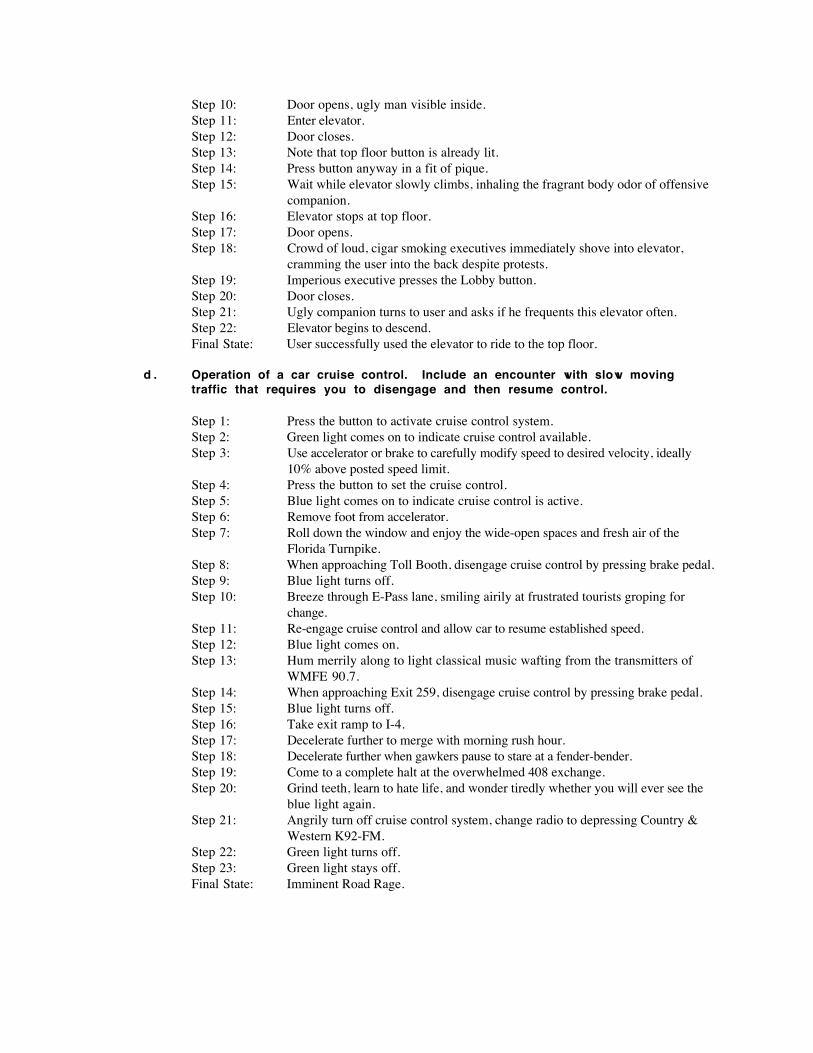
Step 10: Door opens, ugly man visible inside.Step 11: Enter elevator.Step 12: Door closes.Step 13: Note that top floor button is already lit.Step 14: Press button anyway in a fit of pique.Step 15: Wait while elevator slowly climbs, inhaling the fragrant body odor of offensive
companion.Step 16: Elevator stops at top floor.Step 17: Door opens.Step 18: Crowd of loud, cigar smoking executives immediately shove into elevator,
cramming the user into the back despite protests.Step 19: Imperious executive presses the Lobby button.Step 20: Door closes.Step 21: Ugly companion turns to user and asks if he frequents this elevator often.Step 22: Elevator begins to descend.Final State: User successfully used the elevator to ride to the top floor.
d . Operation of a car cruise control. Include an encounter with slow movingtraffic that requires you to disengage and then resume control.
Step 1: Press the button to activate cruise control system.Step 2: Green light comes on to indicate cruise control available.Step 3: Use accelerator or brake to carefully modify speed to desired velocity, ideally
10% above posted speed limit.Step 4: Press the button to set the cruise control.Step 5: Blue light comes on to indicate cruise control is active.Step 6: Remove foot from accelerator.Step 7: Roll down the window and enjoy the wide-open spaces and fresh air of the
Florida Turnpike.Step 8: When approaching Toll Booth, disengage cruise control by pressing brake pedal.Step 9: Blue light turns off.Step 10: Breeze through E-Pass lane, smiling airily at frustrated tourists groping for
change.Step 11: Re-engage cruise control and allow car to resume established speed.Step 12: Blue light comes on.Step 13: Hum merrily along to light classical music wafting from the transmitters of
WMFE 90.7.Step 14: When approaching Exit 259, disengage cruise control by pressing brake pedal.Step 15: Blue light turns off.Step 16: Take exit ramp to I-4.Step 17: Decelerate further to merge with morning rush hour.Step 18: Decelerate further when gawkers pause to stare at a fender-bender.Step 19: Come to a complete halt at the overwhelmed 408 exchange.Step 20: Grind teeth, learn to hate life, and wonder tiredly whether you will ever see the
blue light again.Step 21: Angrily turn off cruise control system, change radio to depressing Country &
Western K92-FM.Step 22: Green light turns off.Step 23: Green light stays off.Final State: Imminent Road Rage.

5 . 2 Some combined bath-showers have two faucets and a lever for controlling the flow ofthe water. The lever controls whether the water flows from the shower head or directlyinto the tub. When the water is first turned on, it flows directly into the tub. When thelever is pulled, a valve closes and latches, diverting the flow of water to the showerhead. To switch from shower to bath with the water running, one must push the lever.Shutting off the water releases the lever so that the next time the water is turned on, itflows directly into the tub. Write a scenario for a shower that is interrupted by atelephone call.
Step 1: Fetch cordless phone.Step 2: Fetch large ziplock bag.Step 3: Place phone in bag, with antenna poking through small hole in corner.Step 4: Seal bag.Step 5: Strip.Step 6: Turn on hot faucet to 75% flow.Step 7: Turn on cold faucet to 25% flow.Step 8: Wait for hot water to flow from solar panels on roof.Step 9: Test temperature.Step 10: Decrease hot flow by 10%.Step 11: Test temperature.Step 12: Smile happily.Step 13: Decide to use toilet.Step 14: Flush.Step 15: Reach into shower and flip lever to showerhead position.Step 16: Step into shower.Step 17: Scream.Step 18: Jump back out of shower.Step 19: Wait until toilet tank finishes refilling from cold water pipes.Step 20: Gingerly test temperature.Step 21: Sigh with relief.Step 22: Re-enter shower.Step 23: Lather hair.Step 24: Phone rings.Step 25: Smiling in satisfaction at your paranoia, reach out of shower and pick up
waterproofed phone.Final State: Clean and Communicating.

5 . 4 An extension ladder has a rope, pulley, and latch for raising, lowering, and locking theextension. When the latch is locked, the extension is mechanically supported and youmay safely climb the ladder. To release the latch, you raise the extension slightly withthe rope. You may then freely raise or lower the extension. The latch produces aclacking sound as it passes over the rungs of the ladder. The latch may be reengagedwhile raising the extension by reversing direction just as the latch is passing a rung.Prepare a state diagram of an extension ladder.
Lo
cked Rope Slac
k
Lo
cked RopeTa
ut P
assing Rung
Up
Unlocked
lowerra
ise
raise
raiserais
elower
lower
Chapter 6: Functional Modeling
6 . 1 Describe the meaning of the data flow diagram in Figure E6.1.
electricalanalysis
electrical parameters
loadcharacteristics
electrical torque
air flow
spee
d
loss
es
fan
torq
ue
tem
pera
ture
voltage, frequency
thermal parameters
ambient temperature
thermalanalysis
mechanicalanalysis
fananalysis
Figure E6.1

The model shown is a data flow diagram for an electrical motor diagnostic analysis. There are fouranalyses which must be determined: the electrical system, the mechanical system, the fansubsystem, and a thermal analysis. Each of the analyses directly or indirectly contribute to thestudies of the other systems.
The electrical analysis takes values from the applied voltage and signal frequency, as well as otherelectrical parameters. It also takes speed data from the mechanical analysis and temperature resultsfrom the thermal analysis. In turn, it produces an electrical torque reading which is used forsubsequent mechanical analyses and a losses value for ongoing thermal analysis.
Likewise, the mechanical analysis receives load characteristics and, together with fan torque datafrom the fan analysis and electrical torque data from the electrical analysis, computes speedinformation which is returned to the electrical and fan analyses.
The fan analysis uses this speed data to refine its computations and produces an air flow result forthe thermal analysis (as well as returning fan torque data to the mechanical analysis).
Finally, the thermal analysis takes the air flow data from the fan analysis, the electrical loss datafrom the electrical analysis, as well as thermal parameters and ambient temperature readings fromoutside the system, and creates the temperature data used by the electrical analysis.
6 . 5 Prepare a data flow diagram for computing the mean of a sequence of input values. Aseparate control input is provided to reset the computation. Each time a new value isinput, the mean of all values input since the last reset command should be output.Since you have no way of knowing how many values will be processed between resets,the amount of data storage that you use should not depend on the number of inputvalues. Detail your diagram down to the level of multiplications, divisions, andadditions.
Add
Value toTotal
Incr
ement Count
Divi
de
Total by Count
Stor
e
Result in Mean
Outp
ut Mean
Get
Next Input
Sto
re
Zero toTotalSt
ore
Zero to Count
Value
Res
et

Chapter 7: Methodology Preview
7 . 2 This book explains how to use object-oriented techniques to implement programs anddatabases. Discuss how object-oriented techniques could be applied in other arenas,such as language design, knowledge representation, and hardware design, forexample.
Many of the principles of object-oriented analysis and design could be applied to fields beyondcomputer programming. Two such fields are structural engineering and educational curriculumdevelopment. Each of these fields involves analyses and planning of large-scale projects involvingmany sub-processes and components that must interact together in complex patterns and whichoften share similar traits and operations. Object-oriented tools such as the OMT model could beapplied to manage complexity and help visualize, track, and quality-test component relationshipsin a scaleable and comprehensible manner.
Structural engineering, for instance, is often called into play in the design, analysis, andconstruction of large office buildings such as the new Orlando Courthouse facility. Each buildingis composed of many rooms, hallways, columns, etc, with a great many infrastructure systemsembedded into the walls, floors, and ceilings. These systems include climate control, plumbing,data communications, and many other underlying frameworks. The number of systems whichmust be understood to design, analyze, and build a single room of a single building would beoverwhelming for the most educated architect, laborer, or electrician. However, object-orientedmodeling would allow each subsystem to be logically isolated from the others, with the fewinstances of interaction clearly called out for implementation or study.
Educators often face similarly complex decisions when developing an instructional curriculum,especially in the interdisciplinary and holistic environment encouraged today by educationaltheorists. An individual lesson should contain elements of literature and composition,mathematical reasoning skills, draw from a broad body of scientific knowledge, and be presentedwithin an appropriate historical context. Meanwhile, the activities themselves should be executedin a systemic framework involving a lively lead-in with ties to previous lessons, contentinstruction, guided practice, individual or group practice, evaluation, and review. Many teachersfind themselves prematurely gray after trying to effectively meet each of those state-mandated goalswithin 40-minute class periods, a forty-hour week, and little or no instructional budget. Byincorporating elements of object-oriented analysis and design, teachers could more easily andquickly produce well-rounded and effective lesson plans. Object inheritance could help providecommon delivery characteristics, state diagrams could help manage the flow of activities andmaterials among dozens of students, and object models employing generalization and aggregationcould help students and teachers visualize connections between different content areas.
Through careful application of object-oriented analysis and design methodologies, professionals ina wide variety of fieldsÑincluding education and structural engineering, but also cosmologists,psychology, neonatal child care, and hundreds of other complex subjectsÑcan better comprehendthe myriad entities they must deal with and more accurately anticipate the relationships betweenthem.
Chapter 8: Analysis
8 . 3 Rephrase the following requirements to make them more precise. Remove any designdecisions posing as requirements:
b . A system for automating the production of complex machined parts is needed.The parts will be designed using a three-dimensional drafting editor that is part

of the system. The system will produce tapes that can be used by numericalcontrol (N/C) machines to actually produce the parts.
A system for automating the production of arbitrarily shaped machined parts is needed. The designenvironment will provide advanced visualization and object-manipulation tools to the editor.
The drafting editor will design the parts in a graphical environment in which views can becontrolled to accurately display objects at any ratio between 10,000:1 and 1:100 scale, from anyvirtual position and at any angle. The system must be able to provide such views in eitherwireframe, filled plane, or light-rendered mode, and should correctly portray the visualcharacteristics of typical materials including steel, glass, and a range of polymers. All views mustbe storable for later retrieval or printing.
The editing environment must allow full manipulation of virtual object surfaces and should forefficiency provide a template library of typical objects (sphere, cube, torus, sheet, etc). The usershould be able to add new objects to the library to speed creation of similar widgets, and should beable to store and retrieve an arbitrary number of widgets. After design, the widgets may be outputto a different system which will actually produce the parts.
Finally, the system should be sufficiently scaleable so that additional storage or computationalcapacity may be added as needed. There should be a facility for moving widgets between similarsystems if we acquire additional units.
c . A desktop publishing system is needed, based on a WYSIWYG philosophy. Thesystem will support text and graphics. Graphics include lines, squares, boxes,polygons, circles, and ellipses. Internally, a circle is represented as a specialcase of an ellipse and a square as a special case of a box. The system shouldsupport interactive, graphical editing of documents.
A full pagination system is required which will allow digital development of all aspects of abroadsheet daily newspaper. Editors, reporters and columnists, illustrators, photographers, andadvertising and classified staff will use the system to combine their individual elements into acompleted newspaper ready for imaging.
The system must be graphical in nature so that illustrations and photographs may be accuratelyvisualized on a page, and proportional multi-face type will be rendered on screen as it will appearon the final printed product. Sophisticated color matching and calibration will be essential so thatelements coming from different sources will be correctly displayed on a variety of 3rd-partymonitors. Color matching will also be of paramount importance at the printed stage, so thatdiffering hues of paper stock, from brown newsprint to white high-gloss, can be used successfully.
A comprehensive routing capability should be used throughout, so that editors can create layouts,content producers can fill in their elements, editors can review the composition and return itrepeatedly for correction, then route the approved document to preflight and press.
Text elements should be capable of containing an arbitrary amount of type set in PostScript Type1 fonts. A third-party H&J (hyphenation and justification) engine may be accessed to set the typeaccurately and quickly. Graphic elements may be either TIFF, Scitex-CT, or EPS images.
Some sort of ÒframeÓ or ÒregionÓ interface should be provided, allowing editors to layout a pagebefore specific content is available. These layouts should be reusable so that old layouts can havenew content (images, text) ÒflowedÓ into them. Some sort of identification system should therebybe provided to record the position, shape, intended contents, and other key attributes of each region.

There may be a distinction between basic elements which can be created and edited directly withinthe system and advanced elements which require the use of a third party program such as MicrosoftWord, Adobe Photoshop, or Macromedia Freehand. Basic text entry, editing, and type stylingshould be feasible within the layout system, but advanced features such as spell-checking,outlining, etc may be left to an outside program. Likewise, basic graphic elements such as linesand hollow or filled boxes, polygons, and ellipses should be accessible within the layout program,but more advanced options like soft drop-shadows and morphing may be relegated to an outsidesystem.
It is essential that, once data is entered into the system, it should be accessible by outsideprograms through a published API. For instance, an outside program should be able to call up thefull text of every story, together with associated images, and extract them to repurpose for onlinepublishing.
With respect to printing, the system should automatically position pages for side-by-side foldedduplex imaging, so that a sample 4-page run would actually print one duplex broadsheet withpages 4 and 1 on one side and 2 and 3 on the inside.
Finally, an automated archive and integrated version-tracking application should maintain a log ofaccesses and modifications by user, date, and story, and automatically archive each paper in a full-text searchable format to a reliable and cost-effective media such as CD-R.
e . A system for distributing electronic mail over a network is needed. Each userof the system should be able to send mail from any computer account andreceive mail on one designated account. There should be provisions foranswering or forwarding mail, as well as saving messages in files or printingthem. Also, users should be able to send messages to several other users atonce through distribution lists. Each computer on the net should hold anymessages destined for computers which are down.
A system for distributing electronic mail over a network is needed. Each user of the system shouldbe able to send mail from any computer account and receive mail on one designated account. Thereshould be provisions for answering or forwarding mail, as well as saving messages in files orprinting them. Also, users should be able to send messages to several other users at once. Thesystem should be sufficiently fault-tolerant that undelivered messages will not be lost if thedestination account is temporarily malfunctioning or otherwise unavailable.
Assignment #2
BANKSYSTEM
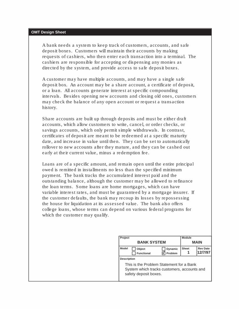
A bank needs a system to keep track of customers, accounts, and safe deposit boxes. Customers will maintain their accounts by making requests of cashiers, who then enter each transaction into a terminal. The cashiers are responsible for accepting or dispensing any monies as directed by the system, and provide access to safe deposit boxes.
A customer may have multiple accounts, and may have a single safe deposit box. An account may be a share account, a certificate of deposit, or a loan. All accounts generate interest at specific compounding intervals. Besides opening new accounts and closing old ones, customers may check the balance of any open account or request a transaction history.
Share accounts are built up through deposits and must be either draft accounts, which allow customers to write, cancel, or order checks, or savings accounts, which only permit simple withdrawals. In contrast, certificates of deposit are meant to be redeemed at a specific maturity date, and increase in value until then. They can be set to automatically rollover to new accounts after they mature, and they can be cashed out early at their current value, minus a redemption fee.
Loans are of a specific amount, and remain open until the entire principal owed is remitted in installments no less than the specified minimum payment. The bank tracks the accumulated interest paid and the outstanding balance, although the customer may be allowed to refinance the loan terms. Some loans are home mortgages, which can have variable interest rates, and must be guaranteed by a mortgage insurer. If the customer defaults, the bank may recoup its losses by repossessing the house for liquidation at its assessed value. The bank also offers college loans, whose terms can depend on various federal programs for which the customer may qualify.
BANK SYSTEM MAIN
1 12/7/97
Project
Model
Functional
Description
Module
Sheet Rev Date
This is the Problem Statement for a Bank System which tracks customers, accounts and safety deposit boxes.
Object
Problem
Dynamic
OMT Design Sheet

OMT Design Sheet
BANK SYSTEM MAIN
2 12/9/97
Project
Model
Functional
Description
Module
Sheet Rev Date
This is the Object Model for a Bank System which tracks customer accounts and safety deposit boxes.
Object
Problem
Dynamic
Safe_Deposit_Box
Assign
Account
Interest_RateCompound_PeriodBalance
OpenCloseCheck_BalanceRequest_History
Transaction
TypeAmountDateTimeStamp
Terminal
Customer
NameAddress
Create
Bank
CD
Maturity_DatePurchase_PricePremature_Redeem_FeeAuto_Rollover
Cash_Out
Mortgage
Variable_RateMortgage_InsAssessed_Value
Repossess
Loan
Loan_AmtCum_InterestMin_Payment
Make_PaymentRefinanceCalc_Principal_Owed
College
Federal_Programs
Cashier
Dispense_CashAccept_Money
Share
Make_Deposit
Draft
Write_CheckCancel_CheckOrder_Checks
Saving
Withdraw
Acct #Accesses
Uses
Acct #
Has
Owns
Employs
Holds
Has
Retreives
Box #
Rents
Talks To

Terminal
Main Screendo: display screen
Main Screendo: display screen
do: request accountnumber
do: display accountinfo and balance
do: prompt to continue
do: requesttransaction kind
do: request amount
[enter account number]
enter data
[enter deposit / withdrawal]
[enter balanceinquiry]
OMT Design Sheet
BANK SYSTEM MAIN
3 12/7/97
Project
Model
Functional
Description
Module
Sheet Rev Date
This is the state diagram for a terminal.
Object
Problem
Dynamic
display results
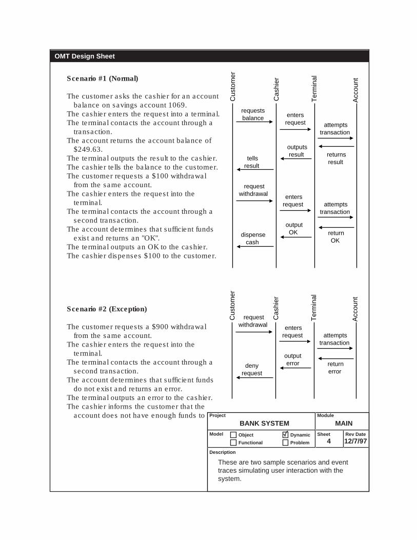
Scenario #1 (Normal)
The customer asks the cashier for an account balance on savings account 1069.
The cashier enters the request into a terminal.The terminal contacts the account through a
transaction.The account returns the account balance of
$249.63.The terminal outputs the result to the cashier.The cashier tells the balance to the customer.The customer requests a $100 withdrawal
from the same account.The cashier enters the request into the
terminal.The terminal contacts the account through a
second transaction.The account determines that sufficient funds
exist and returns an "OK".The terminal outputs an OK to the cashier.The cashier dispenses $100 to the customer.
Scenario #2 (Exception)
The customer requests a $900 withdrawal from the same account.
The cashier enters the request into the terminal.
The terminal contacts the account through a second transaction.
The account determines that sufficient funds do not exist and returns an error.
The terminal outputs an error to the cashier.The cashier informs the customer that the
account does not have enough funds to BANK SYSTEM MAIN
4 12/7/97
Project
Model
Functional
Description
Module
Sheet Rev Date
These are two sample scenarios and event traces simulating user interaction with the system.
Object
Problem
Dynamic
OMT Design Sheet
Cus
tom
er
Cas
hier
Ter
min
al
Acc
ount
dispensecash
outputOK return
OK
attemptstransaction
entersrequest
requestsbalance
requestwithdrawal
tellsresult
outputsresult returns
result
attemptstransaction
entersrequest
Cus
tom
er
Cas
hier
Ter
min
al
Acc
ount
denyrequest
outputerror return
error
attemptstransaction
entersrequest
requestwithdrawal

BANK SYSTEM MAIN
5 12/7/97
Project
Model
Functional
Description
Module
Sheet Rev Date
This is the Context DFD and Level 0 DFD for the Bank System.
Object
Problem
Dynamic
OMT Design Sheet
BankSystem
Cashier
Customer
acct #, transaction
type, amounts
account info,messages
Cashier
Account
readinputsCustomer
acct #, transaction
type, amountsaccount info,
messages
account in
fo,
cash
, checks
requests, cash
account in
fo,
cash
, checks
requests, cash
bala
nce
performtransaction
generateoutputs
Context Data Flow Diagram (DFD)
Level 0 Data Flow Diagram (DFD)
Level 1 Data Flow Diagram (DFD)(sheet 6)

BANK SYSTEM MAIN
6 12/7/97
Project
Model
Functional
Description
Module
Sheet Rev Date
This is the Level 1 Data Flow Diagram showing Level 1 processes substituted into the Level 0 DFD.
Object
Problem
Dynamic
OMT Design Sheet
Cashier
AccountDatabase
Customer
Terminal
acct #, transaction
type, amounts
acct #, transaction
type, amounts
account info,messages
account info,messages
account in
fo,
cash
, checks
acct #
bala
nce
chan
ge
New Account
Number
acct
#, t
ype,
am
ount
requests, cash
generateoutputs
computebalance
updateaccount
openaccount
enterinputsdisplay
results
Level 1 Data Flow Diagram (DFD)

BANK SYSTEM MAIN
7 12/7/97
Project
Model
Functional
Description
Module
Sheet Rev Date
This is the process decomposition diagram for the Bank System.
Object
Problem
Dynamic
OMT Design Sheet
Main
readInputs
customermakes
requests ofcashier
cashierenters into
terminalopen
account
generatenew account
numbercreatesaccount
updateaccount
makewithdrawal
adddeposit
computebalance
terminaldisplaysresults
to cashier
cashierrelaysresults
tocustomer
processtransaction
generateoutputs
addinterest deduct
fees
Process Decomposition Diagram
Level 0
Level 1
Level 2

Assignment #3
HYPERTEXTSYSTEM

A simplified hypertext system is needed which will allow browsers to navigate through linked web pages. Pages will be hosted on a web server, may include GIF and JPEG graphics, and may include links to other resources. The system should support concurrent browsers and current accesses to the same resource.
The user may view a web page or image by specifying a URL (Universal Resource Locator). The browser will then send the URL to the appropriate web server in the form of an HTTP request. The server should accept the request and return the requested resource. If the resource was an HTML page including image tags, the associated images should be returned to the browser as well. The browser should then render the page as described by the tags. If the user clicks on a link within the displayed web page, the browser should send a new HTTP request to the server to retreieve the linked resource.
Pages will be written in a subset of the HTML markup language. Supported tags are limited to <A HREF> and <IMG SRC>. <A HREF> tags link to the URL of other resources. <IMG SRC> tags indicate that a specific image should be passed to the browser along with the enclosing HTML file. Beside HTML tags, individual web pages may also contain body text.
GIFs may be transparent, include GIF89a animations, or be saved with a specific palette. JPEGs may be progressive and are saved at specific compression ratios.
HYPERTEXT SYSTEM MAIN
1 12/7/97
Project
Model
Functional
Description
Module
Sheet Rev Date
This is the Problem Statement for a Hypertext System.
Object
Problem
Dynamic
OMT Design Sheet

OMT Design Sheet
HYPERTEXT SYSTEM MAIN
2 12/7/97
Project
Model
Functional
Description
Module
Sheet Rev Date
This is the Object Model for a HyperText System which allows uses to browse linked web pages.
Object
Problem
Dynamic
HTTP Server
Accept_HTTP_RequestSend_FileSend_FileFind_File
Word
Web PageImage
File
URL
<A HREF>
GIF
transparentGIF89aPalette
JPEG
ProgressiveCompression Ratio
Body TextHTML Tag
Browser
Open_LocationSend_HTTP_RequestRender_Page
<IMG SRC>URL
links to
pathname
hosts
contains
communicateswith
URLloads

Browser
Web Server
OMT Design Sheet
HYPERTEXT SYSTEM MAIN
3 12/7/97
Project
Model
Functional
Description
Module
Sheet Rev Date
These are the state diagrams for a browser and a web server.
Object
Problem
Dynamic
Wait for response
Errordo: display 404 error message
Renderdo: Display returned resources on the monitor
Get Resource
do: send HTTP request to web server
Ready
user quits browser
user launches browser
server returns an erroror timeouts
server returns files
user enters a URL or clicks a link
do: scan web page
do: transmit web page
do: transmit graphic file
Errordo: return 404 error message
do: find requested resource
Ready
shutdown
found image tag
found image file
no images found
found text file
file not found
receive HTTP request ( URL )
boot

Scenario #1 (Normal)
The user tells the browser to open page "HelloWorld.html" on server "Webster.edu"
The browser sends an HTTP request to Webster.edu.
The Webster.edu server accepts the requests and scans file HelloWorld.html.
The Webster.edu server sends the file HelloWorld.html back to the browser.
The Webster.edu server sends the file Logo.gif back to the browser.
The browser renders the page.The user clicks on a link to the file "Index.html"
on the server "Yahoo.com".The browser sends an HTTP request to
Yahoo.com
Scenario #2 (Exception)
The user tells the browser to open page "HelloWorld.html" on server "Webster.edu"
The browser sends an HTTP request to Webster.edu.
The Webster.edu server accepts the request.The Webster.edu server cannot find the file
HelloWorld.html.The Webster.edu server returns an error
message to the browser.The browser displays an error message to the
user.
HYPERTEXT SYSTEM MAIN
4 12/7/97
Project
Model
Functional
Description
Module
Sheet Rev Date
These are two sample scenarios and event traces simulating user interaction with the system.
Object
Problem
Dynamic
OMT Design Sheet
Browser Web ServerUser
requests Index.html
clicks on Yahoo.com/Index.html
displays Logo.gif
rendersHelloWorld.html
sends Logo.gif
SendsHelloWorld.html
requestsHelloWorld.html
opens Webster.edu/HelloWorld.html
displayserror message
Sendserror message
requestsHelloWorld.html
opens Webster.edu/HelloWorld.html

HYPERTEXT SYSTEM MAIN
5 12/7/97
Project
Model
Functional
Description
Module
Sheet Rev Date
This is the Context DFD and Level 0 DFD for the HyperText System.
Object
Problem
Dynamic
OMT Design Sheet
HyperTextSystem
UserRequests pages
graphical pageviews
Context Data Flow Diagram (DFD)
Level 0 Data Flow Diagram (DFD)
User
Browser WebServer
requests pages,
mouse clicks
HTTP requests
HTML files,GIF and JPEG images
renderedgraphical views,
error messages

Main
getinput
typeinto
browserclick on
link requestfrom server
opennetwork
connection
sendHTTP
request
closenetwork
connection
findfile
scanweb page
renderweb page
and graphics
placeimage
drawtext
displayerror
message
retrieveresource
determinefiles tosend
sendfiles to
browser
displayoutput
opennetwork
connectiontransmit
fileclose
networkconnection
Process Decomposition Diagram
Level 0
Level 1
Level 2
HYPERTEXT SYSTEM MAIN
6 12/7/97
Project
Model
Functional
Description
Module
Sheet Rev Date
This is the process decomposition diagram for the HyperText System.
Object
Problem
Dynamic
OMT Design Sheet

Assignment #4
WORK ORDERSYSTEM

A school district needs a work-order system to help track computer repairs. Each work order is reported by a school-based technology manager. After being reported, the order is routed to the District Support Manager, who assigns it to a technician. Orders are tracked by date, technician, computer, and facility for cost auditing. The initial problem and final solution to each order are also retained to help solve future orders. Each technician can be assigned several orders at once, and each technology manager can have several open orders. Each school owns many computers, but only has one technology manager. A separate order is always filed for each computer involved in a problem, and a new order is opened with each reoccurance of the problem. New work orders are unassigned until a technician is given responsibility for them.
WORK ORDER SYSTEM MAIN
1 12/7/97
Project
Model
Functional
Description
Module
Sheet Rev Date
This is the Problem Statement for a Work Order System.
Object
Problem
Dynamic
OMT Design Sheet

OMT Design Sheet
WORK ORDER SYSTEM MAIN
2 12/7/97
Project
Model
Functional
Description
Module
Sheet Rev Date
This is the Object Model for a Work Order System which tracks computer service and repair.
Object
Problem
Dynamic
District Support Manager
Work Order
DateProblemSolutionCost
addclose
Technician
Computer
Prop-Rec-NumRAMHDWarranty Date
Technology Manager
District
Teacher
School
Name
owns
manages
reports
is-assigned
assigns
complains-to
serves
uses
teaches atis based at
has
involves
complete (order)

Computer Work Order
OMT Design Sheet
WORK ORDER SYSTEM MAIN
3 12/7/97
Project
Model
Functional
Description
Module
Sheet Rev Date
These are the state diagrams for a computer and a work order
Object
Problem
Dynamic
Works
Broken
Dead
( unfixable )
( fixable )/ fixed
/ someone sneezes
( brand-new )
Closed
Assigned
Unassigned
/ complete
/ assign
/ reported

Scenario #1 (Normal—not really)
A floppy disk drive breaks on a teacher's Mac at a school
The teacher complains to the school's Technology Manager.
The school's Technology Manager creates a new work order.
The Technology sends the work order to the District Support Manager.
The District Support Manager assigns the order to Alfonso the technician.
Alfonso fixes the drive.Alfonso reports success to the
District Support Manager.The District Support Manager
closes the work order.The District Support Manager
reports success to the school Technology Manager.
The Technology Manager tells the teacher.
Scenario #2 (Exception—not really)
A PC breaks at a school.The teacher complains to the
school's Technology Manager.The school's Technology Manager
creates a new work order.The Technology sends the work
order to the District Support Manager.
The District Support Manager assigns the order to John the technician.
John never shows up.The Technology Manager reports
an error message to the District Support Manager and the teacher.
HYPERTEXT SYSTEM MAIN
4 12/7/97
Project
Model
Functional
Description
Module
Sheet Rev Date
These are two sample scenarios and event traces simulating user interaction with the system.
Object
Problem
Dynamic
OMT Design Sheet
Tec
hnic
ian
Tec
hnol
ogy
Man
ager
Dis
tric
tS
uppo
rtM
anag
er
Wor
k O
rder
Tea
cher
Com
pute
r notifies
fixes
assigns-to
notifies
notifies
closes
sends-to
creates
complainsto
breaks
assigns-to
reportserror
sends-to
reports error
creates
complainsto
breaks

WORK ORDER SYSTEM MAIN
5 12/7/97
Project
Model
Functional
Description
Module
Sheet Rev Date
This is the Context DFD and Level 0 DFD for the Work Order System.
Object
Problem
Dynamic
OMT Design Sheet
Work OrderSystem
Context Data Flow Diagram (DFD)
Level 0 Data Flow Diagram (DFD)
Tech Mgr
Technician
Support Mgr
what broke, when, whe
re, ho
w
how
what has broken
recently
who should fix it
what was done
to fix it
Tech Mgr
Technician
Add NewOrder
CompleteOrder
AssignOrder
Support Mgr
what broke, when, whe
re, ho
w
how
what has broken
recently
who should fix it
what was done
solu
tion
to fix it
ServiceDatabasewhat
what
which are mine
wh
o

Main
addorder
enterwork orderdata values
routeto District
Support Mgrcalculateoptimum
assignment
entersolution
closeorder
assignorder
routeto selectedtechnician
computecurrent travel
plan for alltechs
computecurrent load
for alltechs
combineweightedfactors
computehistorical
effectivenessw/similarproblems
completeorder
Process Decomposition Diagram
Level 0
Level 1
Level 2
WORK ORDER SYSTEM MAIN
6 12/7/97
Project
Model
Functional
Description
Module
Sheet Rev Date
This is the process decomposition diagram for the Work Order System.
Object
Problem
Dynamic
OMT Design Sheet


![[An object-oriented intelligent engineering design approach for lake pollution control]](https://static.fdokumen.com/doc/165x107/633611b6b5f91cb18a0baa8d/an-object-oriented-intelligent-engineering-design-approach-for-lake-pollution-control.jpg)