Object Oriented Modelling and Design (17CSI731)
139
Object Oriented Modelling and Design (17CSI731)
-
Upload
khangminh22 -
Category
Documents
-
view
1 -
download
0
Transcript of Object Oriented Modelling and Design (17CSI731)

Object Oriented Modelling and Design (17CSI731)

UNIT – 3
ADVANCED STATE MODELING, INTERACTION MODELING:
State Modeling: Nested state diagrams; Nested states; Signal Advanced generalization; Concurrency; A sample state model; Relation of class and state models; Practical tips. Interaction Modeling: Use case models; Sequence models; Activity models. Use case relationships; Procedural sequence models; Special constructs for activity models.
Two major features are introduced for controlling complexity and combinatorial explosion in state diagrams◦ Nested state diagrams◦ Concurrent state diagramsMany other features are also added◦ propagated transitions◦ broadcast messages◦ actions on state entry, exit◦ …
Features of State Diagram
Nested State Diagrams
Concurrent State Diagrams

Activities in states are composite items denoting other lower-level state diagrams
A lower-level state diagram corresponds to a sequence of lower-level states and events that are invisible in the higher-level diagram.
Nested State Diagram
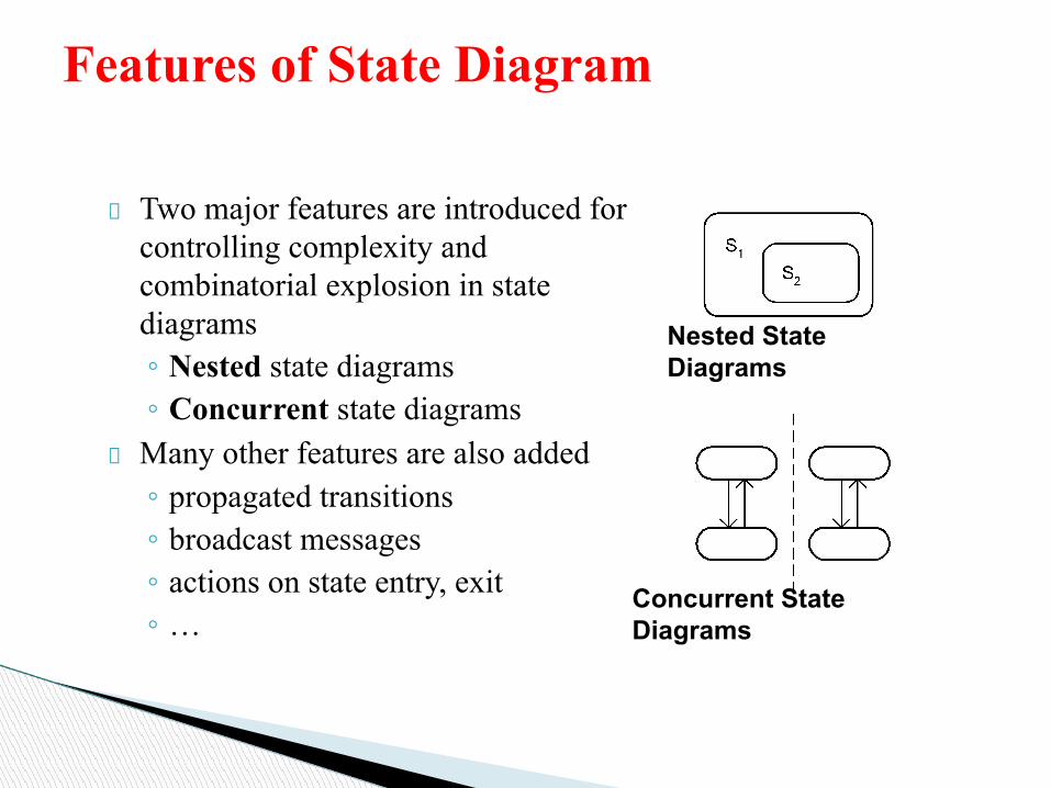
When one state is complex, you can include substates in it.◦ drawn as nested rounded
rectangles within the larger state
Caution: Don't over-use this feature.◦ easy to confuse separate states
for sub-states within one state
Super/substates

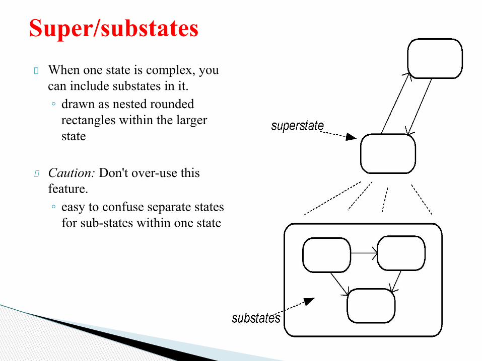
A state may be represented as nested substates.◦ In UML, substates are shown by nesting them in a superstate box.◦ A substate inherits the transitions of its superstate.
Nested States

Nested states

Nested State Diagram
State Diagram - Nested States
Super-state
A Bevent-1
C
event-2
A B
C
event-1
event-2
event-2
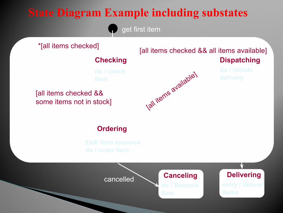
Checkingdo / check Item
Dispatchingdo / initiate delivery
Delivering
[all items checked && some items not in stock]Order item
[all items checked && all items available]Dispatch items
[all items a
vailable]
Item receive
d
delivery
get first item
Cancelingcancelled
Ordering
Exit/ Item receiveddo / order Item
*[all items checked]get next item
entry / deliver Items
do / Remove Item
State Diagram Example including substates

Superstates (nested states)

Transitions can be specific◦ A transition can be from a specific
substate (T1)◦ A transition can be to a specific
substate inside the nested state (T2)Transitions can be general◦ We saw that a transition from the
superstate is valid for all substates (T3)
◦ A transition into the superstate (T4) normally goes to the default initial state (start state leading to F)
Transitions to and from Nested States

◦ concurrency is a property of systems in which several computationsconcurrency is a property of systems in which several computations are executing simultaneously, and potentially interacting with each other.
◦ Dashed line indicates that an order is in two different states, e.g. Checking & Authorizing
◦ When order leaves concurrent states, it’s in a single state: Canceled, Delivered or Rejected
◦ Concurrent Sub states - Used when two or more state diagrams are executing concurrently within a single object.
Concurrency in state diagrams

Complex systems usually have concurrency◦ “subsystems” that operate (mostly)
independentlyHeart monitor device◦ The power supply and the heart
monitoring application are really concurrent subsystems◦ They should be modeled that way!!◦ They are mostly independent: the
monitoring application doesn’t care where it gets its power
Concurrent State Machines

Heart Monitor as Concurrent State Machine

How to model concurrency within an object
release keyturn key to start
Ignition
turn key off
[Transmission in
Neutral]
depress accelerator
release accelerator
Accelerator
Transmissionpush R
push N
push Fpush N
upshift
downshift
upshift
downshift
stopForward
depress brake
release brake
Brake
Car
off starting on
NeutralReverse
firstsecond
third
onoff onoff

Two types of concurrency1. System concurrency
◦ State of overall system as the aggregation of state diagrams, one for each object. Each state diagram is executing concurrently with the others.
2. Object concurrency◦ An object can be partitioned into subsets of states (attributes and
links) such that each of them has its own subdiagram. ◦ The state of the object consists of a set of states: one state from
each subdiagram.◦ State diagrams are divided into subdiagrams by dotted lines.
Modeling Concurrency

The class model describes the class & objects in a system and their relationship.
The state model describes the life cycles of the objects.
The interaction model describes how the objects interact.
The interaction model starts with use cases that are then elaborated with sequence and activity diagrams
Interaction Models

Use case: focuses on functionality of a system- i.e, what a system does for users
Sequence diagrams: shows the object that interact and the time sequence of their interactions
Activity diagrams: elaborates important processing steps
Interaction Models

Use Case Diagrams


Functional vs. Non-Functional
Requirements
Functional
Non-Functional
Functional requirement are user ‘visible’ features and aretypically initiated by stakeholders of the system – generate report, login, etc.
Non-functional requirements are ‘non-visible’ features and but required for a effective running of an application – security, backup, etc.


Use Case diagrams show the various activities the users can perform on the system.
◦ System is something that performs a function.
They model the dynamic aspects of the system.
Provides a user’s perspective of the system.
28
Use Case Diagrams

A use case is a model of the interaction between External users of a software product (actors) and The software product itself
More precisely, an actor is a user playing a specific role describing a set of user scenarios capturing user requirements contract between end user and software developers
Use-Case Diagrams
Use case diagrams are used to visualize, specify, construct, and document the (intended) behavior of the system, during requirements capture and analysis.
Provide a way for developers, domain experts and end-users to Communicate.
Serve as basis for testing.
Use case diagrams contain use cases, actors, and their relationships.
30
Using Use Case Diagrams

Use-Case Diagrams
Actors: A role that a user plays with respect to the system, including human users and other systems. e.g., inanimate physical objects (e.g. robot); an external system that needs some information from the current system.Use case: A set of scenarios that describing an interaction between a user and a system, including alternatives.
System boundary: rectangle diagram representing the boundary between the actors and the system.
Association: Communication between an actor and a use case; Represented by a solid line.

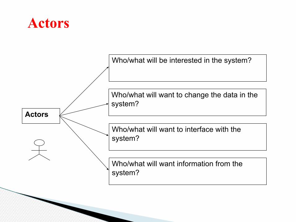
Actors
Actors
Could be human beings, other systems, timers and clocks or hardware devices.
Actors that stimulate the system and are the initiators of events are called primary actors (active)Actors that only receive stimuli from the system are called secondary actors (passive)
Actors
Actors
Who/what will be interested in the system?
Who/what will want to change the data in the system?
Who/what will want to interface with the system?
Who/what will want information from the system?

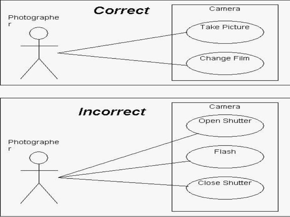
Use Case Diagram– Guidelines & Caution
1. Avoid showing communication between actors.
2. Actors should be named as singular. i.e student and NOT students. NO names should be used – i.e John, Sam, etc.

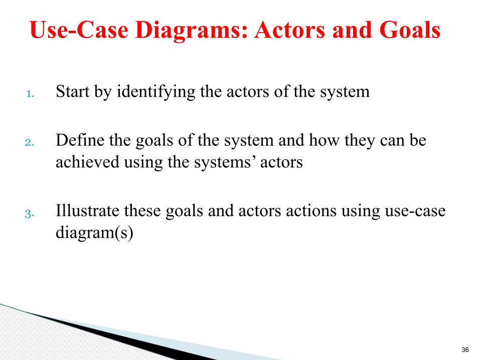
1. Start by identifying the actors of the system
2. Define the goals of the system and how they can be achieved using the systems’ actors
3. Illustrate these goals and actors actions using use-case diagram(s)
36
Use-Case Diagrams: Actors and Goals

A use case describes a sequence of actions a system performs to yield an observable result or value to a particular actor Naming convention = verb + noun (or) verb + noun-phrase, ◦ e.g. withdraw cashA good use case should:◦ Describe a sequence of transactions performed by a system that
produces a measurable result (goal) for a particular actor◦ Describe the behavior expected of a system from a user's
perspective◦ Enable the system analyst to understand and model a system from
a high-level business viewpoint◦ Represent the interfaces that a system makes visible to the
external entities and the interrelationships between the actors and the system
37
Use-case Diagram: Use-case

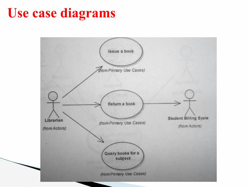
Use case is a particular activity a user can do on the system.
Is represented by an ellipse.
Following are two use cases for a library system.
38
Use Case Diagrams – Use Cases
Reserve
Borrow


• What are the tasks of each actor?• Will any actor create, store, change, remove, or read the
information?• Will any actor need to inform the system about the
sudden, external changes?• Does any actor need to informed about certain
occurrences in the system?• What use cases will support and maintain the system?• Can all functional requirements be performed by the
use cases?
Identifying use cases for a system

Construct Description Notation
Use-case A sequence of transactions performed by a system that produces a measurable result for a particular actor
Actor A coherent set of roles that users playwhen interacting with these use cases
System Boundary
The boundary between the physical system and the actors who interact with the physical system
41
Summary of Notations


• Functionality provided by the system• Consist of a series of steps which collectively add value
to the user of the system• Examples
– Issue a book to a member– Receive a book back from a member– Query the current location of a book– Maintain member’s information– Maintain book’s information
Use cases
Use case diagrams
46
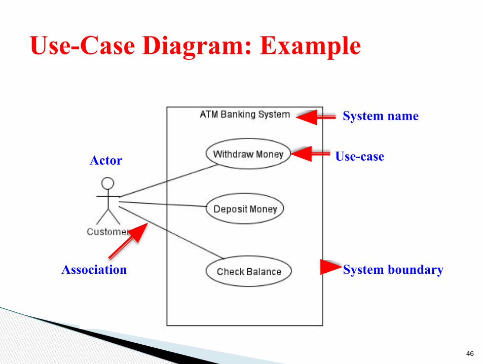
Use-Case Diagram: Example
Actor
Association System boundary
Use-case
System name

47
Use Case Diagram – Example1 (Library)
A Library System.
client employee
supervisor
library system
borrow
reserve
Order title
Fine payment

48
Use Case Diagram for Student Assessment Management System
Teacher
Student
Printing administrator
Grade system
Record grades
View gradesDistributeReport cards
Create report cards


Use-Case Diagrams
Extend: a dotted line labeled <<extend>> with an arrow toward the base case. The extending use case may add behavior to the base use case. The base class declares “extension points”.
<<extend>>
Include: a dotted line labeled <<include>> beginning at base use case and ending with an arrows pointing to the include use case. The include relationship occurs when a chunk of behavior is similar across more than one use case. Use “include” in stead of copying the description of that behavior.
<<include>>

The base use case explicitly incorporates the behavior of another use case at a location specified in the base.
The included use case never stands alone. It only occurs as a part of some larger base that includes it.
ניתוח מערכות מידע 52
Include
base included<<include>>

Enables to avoid describing the same flow of events several times by putting the common behavior in a use case of its own.
ניתוח מערכות מידע 53
More about Include
updatinggrades
outputgenerating
verifyingstudent id
<<include>>
<<include>>


Include relationships are used when two or more use cases share some common portion in a flow of events
This common portion is then grouped and extracted to form an inclusion use case for sharing among two or more use cases
Most use cases in the ATM system example, such as Withdraw Money, Deposit Money or Check Balance, share the inclusion use-case Login Account
55
The <<include>> Relationship

56
The <<include>> Relationship
Login Account
(Included use case)
Withdraw Money
(Base use case)

57
The <<include>> Relationship: Example

The base use case implicitly incorporates the behavior of another use case at certain points called extension points.
The base use case may stand alone, but under certain conditions its behavior may be extended by the behavior of another use case.
ניתוח מערכות מידע 58
Extend
base extending<<extend>>

In UML modeling, you can use an extend relationship to specify that one use case (extension) extends the behavior of another use case (base)
This type of relationship reveals details about a system or application that are typically hidden in a use case
59
The <<extend>> Relationship

60
The <<extend>> Relationship
Process Excess Amount (Extending use case)
Withdraw Money (Base use case)
If conditional guard is true, extending flow is executed
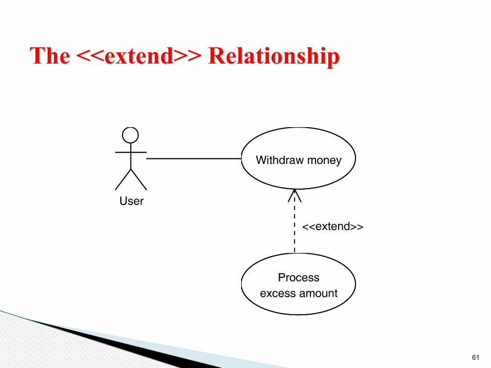
61
The <<extend>> Relationship

Slide 2 (of 48)
Example – Include and Extend

Use-Case Diagrams
Figure 16.12

Generalization.
ניתוח מערכות מידע 64
Relationships between Actors
student
non-graduatestudent
graduatestudent
Construct Description Notation
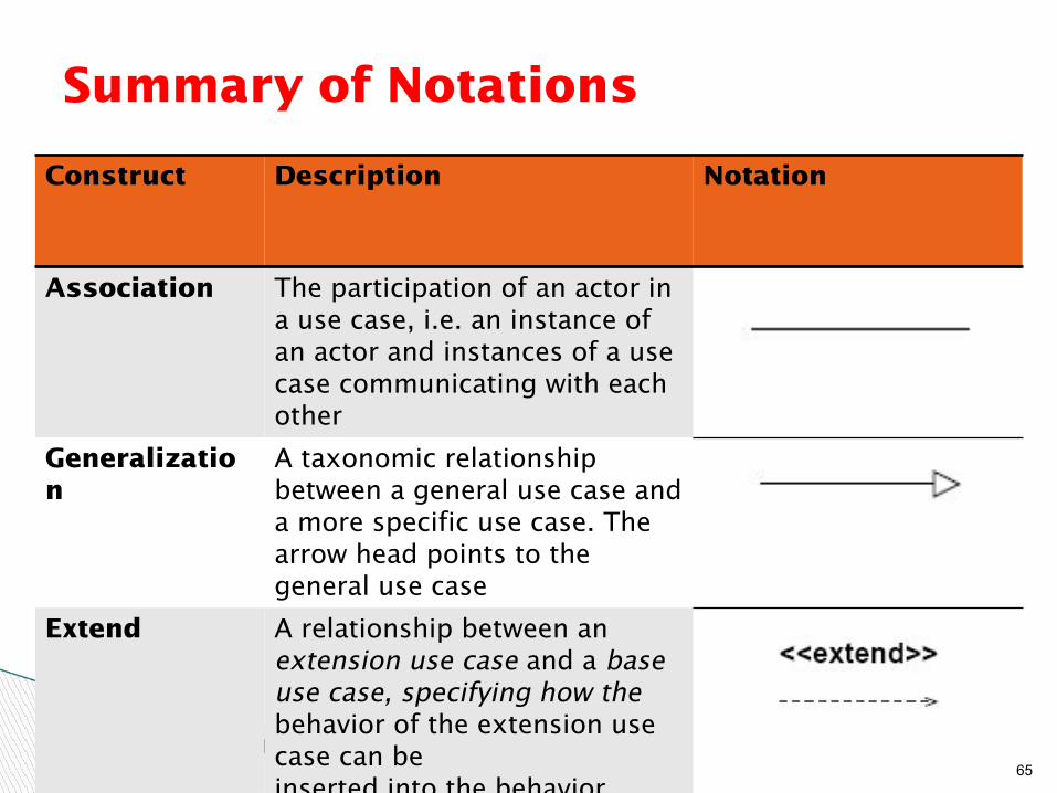
Association The participation of an actor in a use case, i.e. an instance of an actor and instances of a use case communicating with each other
Generalization
A taxonomic relationship between a general use case and a more specific use case. The arrow head points to the general use case
Extend A relationship between an extension use case and a base use case, specifying how the behavior of the extension use case can beinserted into the behavior defined for the base use case. The arrow head points to the base use case
65
Summary of Notations

Construct Description Notation
Include A relationship between a base use case and an inclusion use case, specifying how the behavior for the inclusion use case is inserted into the behavior defined for the base use case. The arrow head points to theinclusion use case
66
Summary of Notations
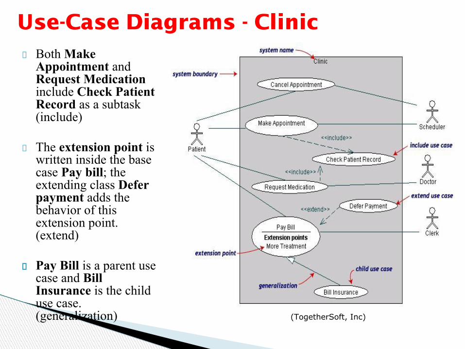
Use-Case Diagrams - ClinicBoth Make Appointment and Request Medication include Check Patient Record as a subtask (include)
The extension point is written inside the base case Pay bill; the extending class Defer payment adds the behavior of this extension point. (extend)
Pay Bill is a parent use case and Bill Insurance is the child use case. (generalization) (TogetherSoft, Inc)


Use Case Description:Each use case may include all or part of the following
▪ Title or Reference Name - meaningful name of the UC▪ Author/Date - the author and creation date▪ Modification/Date - last modification and its date▪ Purpose - specifies the goal to be achieved▪ Overview - short description of the processes▪ Cross References - requirements references▪ Actors - agents participating▪ Pre Conditions - must be true to allow execution▪ Post Conditions - will be set when completes normally▪ Normal flow of events - regular flow of activities▪ Alternative flow of events - other flow of activities▪ Exceptional flow of events - unusual situations▪ Implementation issues - foreseen implementation problems
ע יד
מות
רכמע
ח תו
ני
72
Sequence Models

The sequence model elaborates the themes of use cases.
Two kinds of sequences models
Scenarios
Sequence diagram
Sequence Models

A scenario is a sequence of events that occurs during one particular execution of a system.
For example:John logs in, transmits a message from John to the
broker system.
Scenarios


SEQUENCE DIAGRAM
A sequence diagram shows the participants in an interaction and the sequence of messages among them.
A sequence diagram shows the interaction of a system with its actors to perform all or part of a use case.
Each use case requires one or more sequence diagrams to describe its behaviour.
Sequence Diagram
Sequence diagrams, also known as event diagrams or event scenarios, illustrate how processes interact with each other by showing calls between different objects in a sequence.
These diagrams have two dimensions:
The vertical lines show the sequence of messages and calls in chronological orderHorizontal elements show object instances where the messages are relayed.
Sequence Diagrams

Components Of A Sequence Diagram
Sequence Diagram
Sequence Diagram
MessagesActive objects
Activation Box LifelineControl
Information

Active Objects:◦ Any objects that play a role in the system◦ Can be any object or class that is valid within the system◦ Can be an Actor that is external to the system and derives benefits
from the systemMessages:
◦ Used to illustrate communication between different active objects.
◦ Used when an object needs ● to activate a process of a different object● to give information to another object
SEQUENCE DIAGRAM (important components)

Lifeline◦ Denotes the life of actors/objects over time during a sequence
Focus of control (activation box)◦ Means the object is active and using resources during that time
period
Control information◦ Shows the control flow in the system◦ Creation and destruction of an object through <<create>> and
<<destroy>>
SEQUENCE DIAGRAM (other components)

Squares with object type, optionally preceded by object name and colon◦ write object's name if it clarifies the diagram◦ object's "life line" represented by dashed vert. line
83
Representing objects

Objects are displayed at the top of the diagramThe vertical dimension represents timeEach object has a dashed line – lifeline – extending below it – to indicate the period of time during which objects playing that role actually exist
Lifeline
Object Name

Creation: arrow with 'new' written above it
Deletion: an X at bottom of object's lifeline
85
Lifetime of objects

The messages in an interaction are drawn from top to bottom, in the order that they are sent.
Messages are shown as arrows pointing from the lifeline of the role sending the message to the lifeline of the receiver.
When a message is sent, control passes from the sender of the message to the receiver.
Message
Object Name Object Name
message

Return of control is shown using dashed arrow returning to the calling object.
Return
Object Name Object Name
message
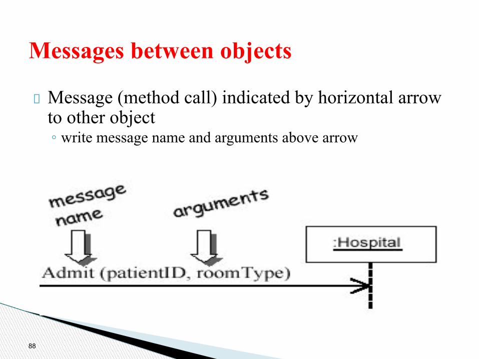
Message (method call) indicated by horizontal arrow to other object◦ write message name and arguments above arrow
88
Messages between objects

Activations - show when a method is active – either executing or waiting for a subroutine to return
◦ Either that object is running its code, or it is on the stack waiting for another object's method to finish
89
Indicating method calls

• Period of time during which an object is processing a message, Shown on a lifeline as a narrow rectangle whose top is connected to a message.
• When an object finishes processing a message, control returns to the sender of the message
Activation
Object Name Object Name
message

Sequence Diagram
a : Assembly part : CatalogEntry
getNumber()
: Client
count(part)
return number
Lifeline
Activation(optional)
Messages
control returns to the sender of the message (optional)

Sequence Diagram Syntax

Sequence Diagram(make a phone call)
Caller Phone Recipient
Picks up
Dial tone
Dial
Ring notification Ring
Picks up
Hello

Sequence Diagram Example

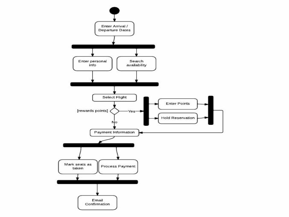
Activity Diagrams

Activity diagrams and use cases are logical model which describe the business domain’s activities without suggesting how they are conduct.
A diagram that emphasizes the flow of control from activity to activity in an object.
Similar to the traditional program flowchart.
Used to provide detail for complex algorithms.
Primary activities and the relationships among the activities in a process.
What Is an Activity Diagram?

Purpose
◦ to model a task (for example in business modelling)
◦ to describe a function of a system represented by a use case
◦ to describe the logic of an operation
◦ to model the activities that make up the life cycle in the Unified Process
Drawing Activity Diagrams

The Activity Diagram Components
Initial NodeControl FlowAction or ActivityObject FlowBranch
Merge
Fork Join
Final Node
* 98

Initial NodeThis represents the start of the flow of an activity diagram.
An activity diagram contains a single start node.
The name of the initial node is entered on the node. It takes the form of an adjective.
* 99

Control Flow
A control flow connects any combination of: ◦ activities ◦ branches◦ merges◦ forks◦ joinsA control flow has direction, which is indicated by the arrow head – you may only traverse the control flow in the direction of the arrow.A control flow may not enter an initial state.A control flow may not exit a final node.A control flow is the representation of an occurrence of an event. The name of the event is entered on the control flow. It takes the form of something has been done, noun-verb(past-tense)
*10
0
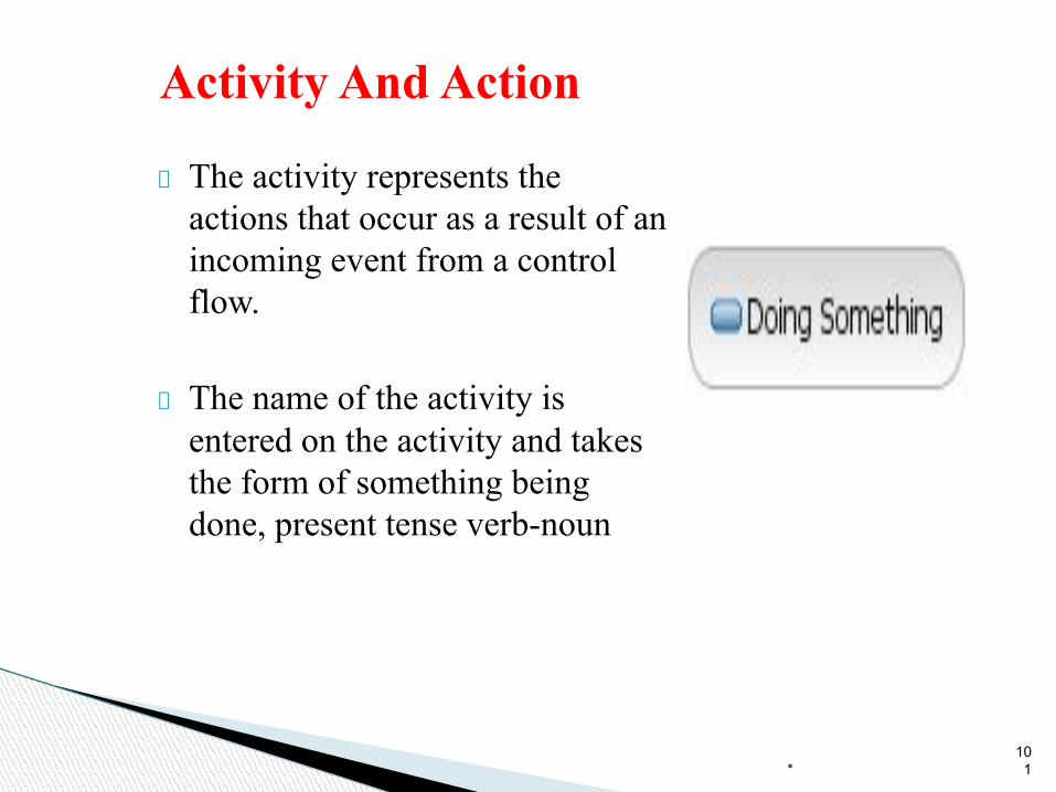
Activity And Action
The activity represents the actions that occur as a result of an incoming event from a control flow.
The name of the activity is entered on the activity and takes the form of something being done, present tense verb-noun
*10
1
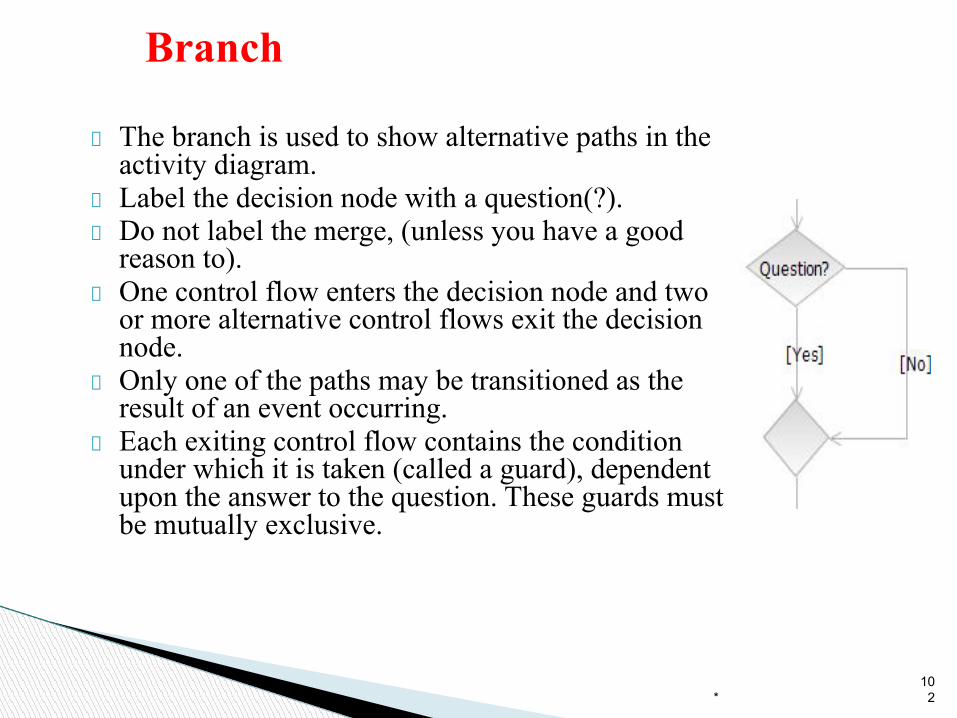
Branch
The branch is used to show alternative paths in the activity diagram.Label the decision node with a question(?).Do not label the merge, (unless you have a good reason to).One control flow enters the decision node and two or more alternative control flows exit the decision node. Only one of the paths may be transitioned as the result of an event occurring. Each exiting control flow contains the condition under which it is taken (called a guard), dependent upon the answer to the question. These guards must be mutually exclusive.
*10
2
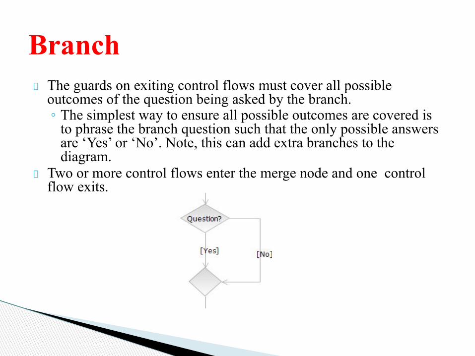
The guards on exiting control flows must cover all possible outcomes of the question being asked by the branch.◦ The simplest way to ensure all possible outcomes are covered is
to phrase the branch question such that the only possible answers are ‘Yes’ or ‘No’. Note, this can add extra branches to the diagram.
Two or more control flows enter the merge node and one control flow exits.
Branch

Fork
*10
4
The fork may be represented by vertical or horizontal bars.The fork represents that the flow through the diagram has split into 2 paths that are running in parallel (multitasking).The fork has a single control flow on entry and several control flows exiting.Use a fork when there is no requirement on the order of activities in a flow. ◦ For example, the Dematerializer receives an
event that the door is shut. It now suspends the cargo and creates a vacuum, but these actions may be performed in parallel, so we model them with a fork.

Join
*10
5
For every fork there should be a join (if not your activity diagram is broken).The join may be represented by vertical or horizontal bars.A join simply shows that when the parallel activities have finished that they then come back to join a single flow again.The join has several control flows entering and a single control flow on exit.The exiting control flow cannot be executed until every incoming control flow has completed.There is no need to label the fork or join.
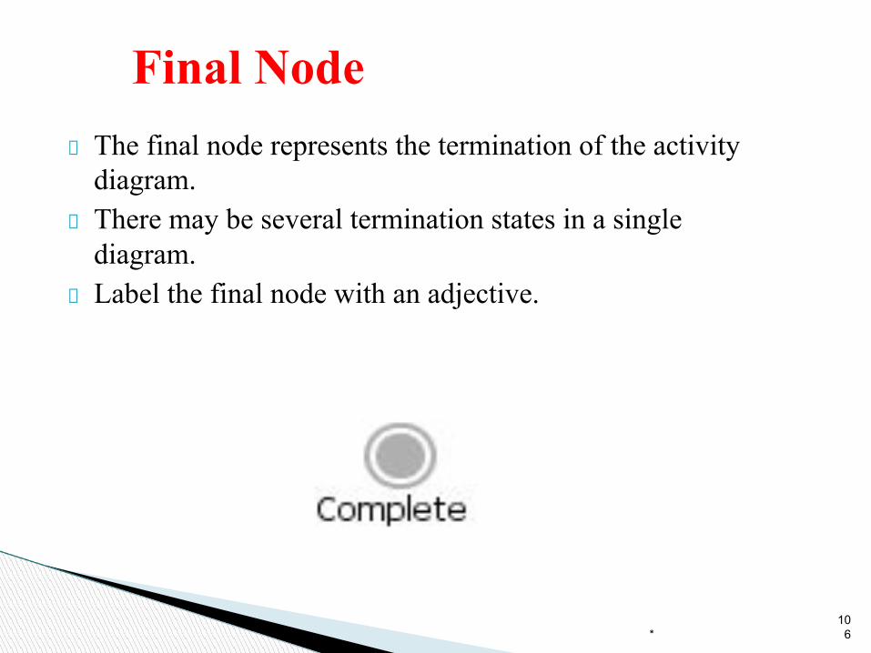
Final NodeThe final node represents the termination of the activity diagram.There may be several termination states in a single diagram. Label the final node with an adjective.
*10
6

Let’s review the shapes
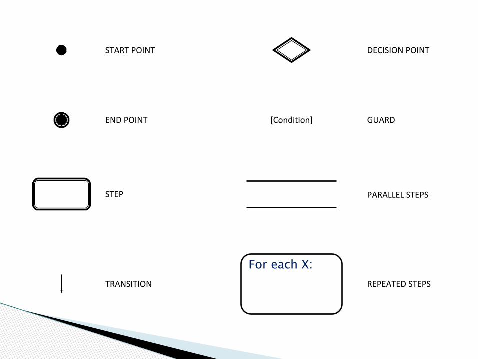
[Condition]
For each X:
START POINT
END POINT
STEP
TRANSITION
DECISION POINT
GUARD
REPEATED STEPS
PARALLEL STEPS


START POINT

The Start Point represents the
EVENT that triggers the use
case.

END POINT
Actor elects to Add Customer
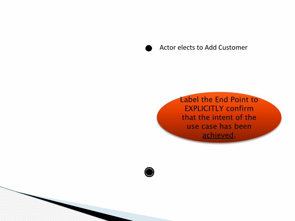
Actor elects to Add Customer
Label the End Point to EXPLICITLY confirm
that the intent of the use case has been
achieved.

Actor elects to Add Customer
Customer added
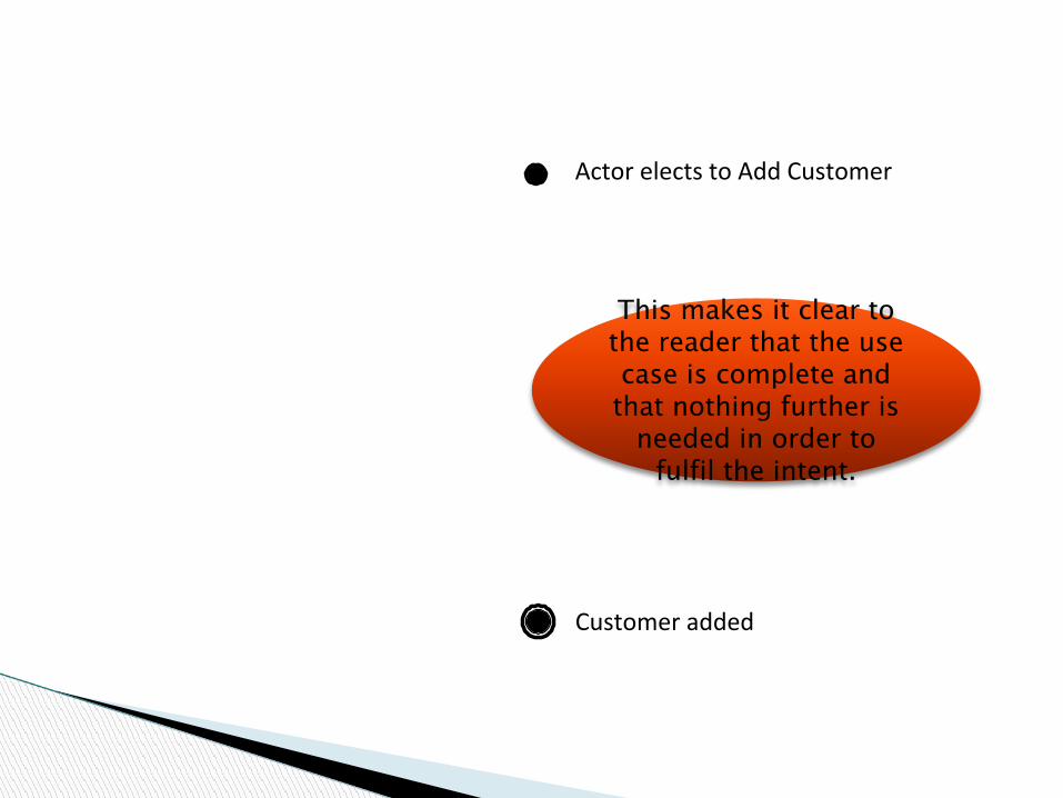
Actor elects to Add Customer
Customer added
This makes it clear to the reader that the use case is complete and
that nothing further is needed in order to
fulfil the intent.

Actor elects to Add Customer
End of process

To reach the End Point…

… you need to model STEPS.

Link the steps with
TRANSITIONS.
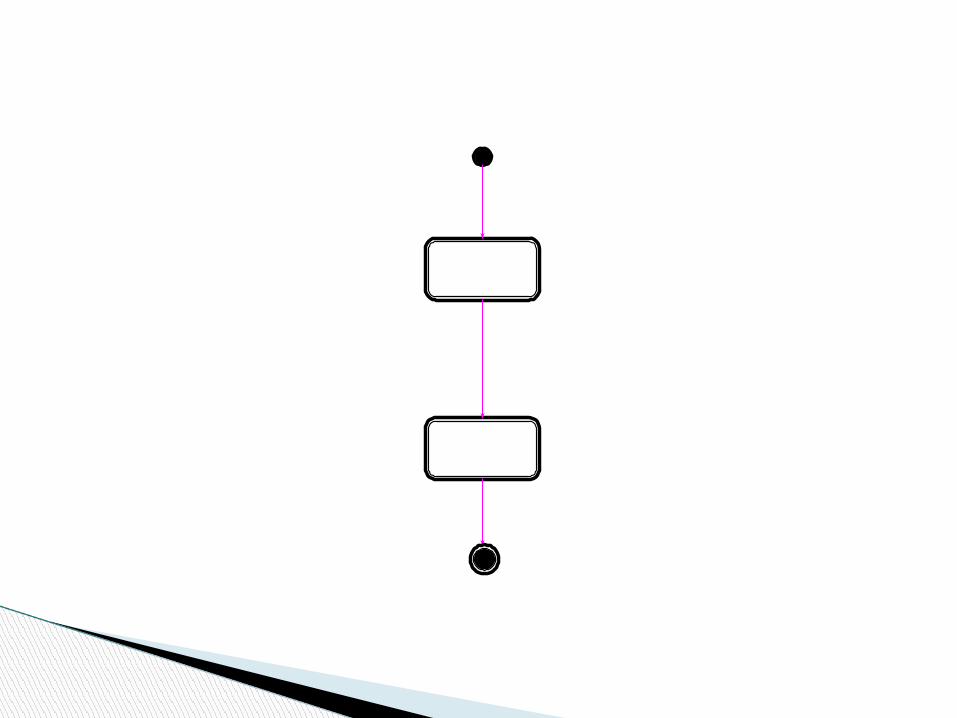

Transitions use arrow heads to show the
direction of process flow.
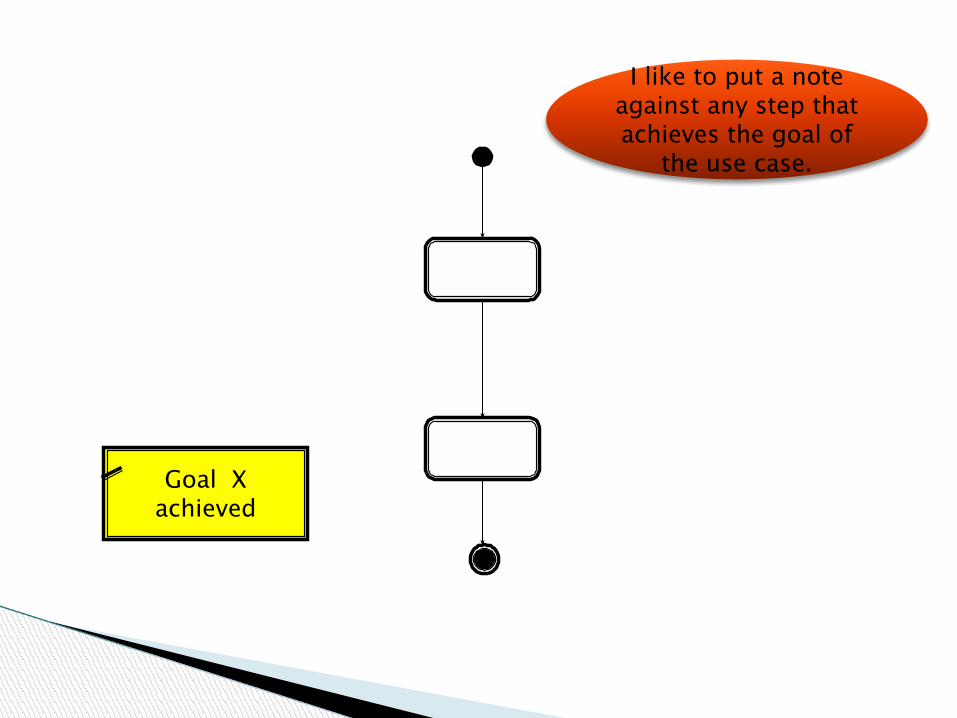
I like to put a note against any step that achieves the goal of
the use case.
Goal X achieved

… because it might not be the last step.
Goal X achieved

Often in a use case the System has to make a decision
based on business rules...

The actual decision takes place within
a STEP

System determines
whether X or Y
The actual decision takes place within
a STEP

System determines
whether X or Y A DECISION POINT
is then used to help the reader
navigate the diagram.

DECISION POINT

Decision Points contain text which
describes the nature of the decision to be
made.

So was it X or Y?

Decision points allow the flow to
branch away from the Primary Path.

[Condition 2]
[Condition 1]
Transitions coming out of Decision Points
must have a GUARD.

[IT WAS “Y”]
[IT WAS “X”]
A Guard needs to explicitly describe a
condition which must be true in order to proceed down that
path.

[Condition 2]
[Condition 1]
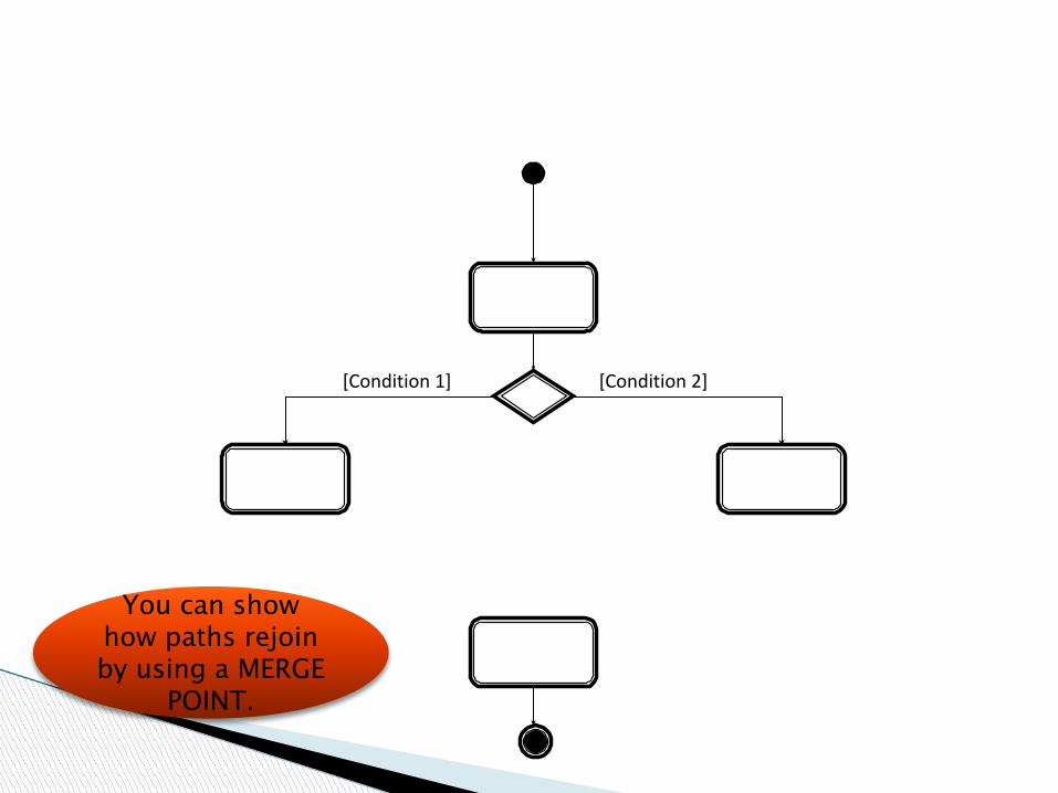
If the flow rejoins the
Primary Path, it is known as an Alternate
Path.
[Condition 2][Condition 1]
You can show how paths rejoin by using a MERGE
POINT.

[Condition 2][Condition 1]
You can show how paths rejoin by using a MERGE
POINT.

[Condition 2][Condition 1]
I prefer to model merging paths like
this.