Object-oriented modelling of information systems : the INCA ...
290
Object-oriented modelling of information systems : the INCA conceptual object model Citation for published version (APA): Bakker, H. (1995). Object-oriented modelling of information systems : the INCA conceptual object model. Rijksuniversiteit Limburg. https://doi.org/10.26481/dis.19950118hb Document status and date: Published: 01/01/1995 DOI: 10.26481/dis.19950118hb Document Version: Publisher's PDF, also known as Version of record Please check the document version of this publication: • A submitted manuscript is the version of the article upon submission and before peer-review. There can be important differences between the submitted version and the official published version of record. People interested in the research are advised to contact the author for the final version of the publication, or visit the DOI to the publisher's website. • The final author version and the galley proof are versions of the publication after peer review. • The final published version features the final layout of the paper including the volume, issue and page numbers. Link to publication General rights Copyright and moral rights for the publications made accessible in the public portal are retained by the authors and/or other copyright owners and it is a condition of accessing publications that users recognise and abide by the legal requirements associated with these rights. • Users may download and print one copy of any publication from the public portal for the purpose of private study or research. • You may not further distribute the material or use it for any profit-making activity or commercial gain • You may freely distribute the URL identifying the publication in the public portal. If the publication is distributed under the terms of Article 25fa of the Dutch Copyright Act, indicated by the “Taverne” license above, please follow below link for the End User Agreement: www.umlib.nl/taverne-license Take down policy If you believe that this document breaches copyright please contact us at: [email protected] providing details and we will investigate your claim. Download date: 29 May. 2022
-
Upload
khangminh22 -
Category
Documents
-
view
5 -
download
0
Transcript of Object-oriented modelling of information systems : the INCA ...
Object-oriented modelling of information systems : theINCA conceptual object modelCitation for published version (APA):
Bakker, H. (1995). Object-oriented modelling of information systems : the INCA conceptual object model.Rijksuniversiteit Limburg. https://doi.org/10.26481/dis.19950118hb
Document status and date:Published: 01/01/1995
DOI:10.26481/dis.19950118hb
Document Version:Publisher's PDF, also known as Version of record
Please check the document version of this publication:
• A submitted manuscript is the version of the article upon submission and before peer-review. There canbe important differences between the submitted version and the official published version of record.People interested in the research are advised to contact the author for the final version of the publication,or visit the DOI to the publisher's website.• The final author version and the galley proof are versions of the publication after peer review.• The final published version features the final layout of the paper including the volume, issue and pagenumbers.Link to publication
General rightsCopyright and moral rights for the publications made accessible in the public portal are retained by the authors and/or other copyrightowners and it is a condition of accessing publications that users recognise and abide by the legal requirements associated with theserights.
• Users may download and print one copy of any publication from the public portal for the purpose of private study or research.• You may not further distribute the material or use it for any profit-making activity or commercial gain• You may freely distribute the URL identifying the publication in the public portal.
If the publication is distributed under the terms of Article 25fa of the Dutch Copyright Act, indicated by the “Taverne” license above,please follow below link for the End User Agreement:
www.umlib.nl/taverne-license
Take down policyIf you believe that this document breaches copyright please contact us at:
providing details and we will investigate your claim.
Download date: 29 May. 2022
Object-Oriented Modelling ofInformation Systems
The INCA Conceptual Object Model
CIP-GEGEVENS KONINKLIJKE BIBLIOTHEEK, DEN HAAG
Bakker, Harm
Object-oriented modelling of information systems:the INCA conceptual object model / Harm Bakker. - [S.I. :s.n.]. - 111., fig., tab.Proefschrift Maastricht. - Met index, lit. opg. - Metsamenvatting in het Nederlands.ISBN 90-9007906-8 geb.NUGI 855
Trefw.: object-georienteerd programmeren / informatiesystemen / computers.
Cover design: Marielle Bakker-Tromp
© by the author

--. - f % H < ^
Vbor Marie/ie, MaaiA;e en T/iomas

Object-Oriented Modelling ofInformation Systems
The INC A Conceptual Object Model
PROEFSCHRIFT
ter verkrijging van de graad van doctoraan de Rijksuniversiteit Limburg te Maastricht,
op gezag van de Rector Magnificus, Prof. dr. H. Philipsen,volgens het besluit van het College van Dekanen,
in het openbaar te verdedigenop woensdag 18 januari 1995 om 16.00 uur
door
Harm Bakker

Promotor: Prof. dr. H. J. van den HerikCopromotor: Dr. P. J. Braspenning
Leden van de beoordelingscommissie: .;««» ,j>i,rfProf. dr. ir. J. L. G. DietzProf. dr. ing. D. K. Hammer (Technische Universiteit Eindhoven)Prof. dr. ir. A. HasmanProf. dr. P. T. W. HudsonProf. dr. A. Ollongren (Rijksuniversiteit Leiden)
Preface
The research for a thesis is impossible without the help of many persons, asis the writing of it. I intend to let all my helpers have due recognition. Theresearch part would have been impossible without the incessant support ofJaap van den Herik. We first met in Delft in 1987 during a programmingcontest, which became the starting point for a Master's thesis in Delft, andthen developed into a doctoral thesis at the University of Limburg, Maastricht.I thank Jaap for his trust and patience. With Bob Herschberg prompting, heprovided me with sufficient examples of fine English. I aimed at their level ofproficiency, but am aware that I have fallen short, for which the responsibilitymust be mine.
Peter Braspenning has been the main force behind the INCA project. Sixyears ago we became acquainted in Maastricht. We combined our ideas onmodelling, object orientation and information systems. Our numerous work-ing sessions during the past years have been a great source of inspiration.Peter's enthusiasm and positive thinking helped to overcome my doubts andhesitations.
The final version of this thesis has benefitted greatly from the valuable sug-gestions from my professorial teachers of the thesis committee. It took manyan extra evening to grasp their suggestions, let alone to incorporate them. Mygratitude is not diminished by the fact that they caused me more work.
My former colleagues in the Department of Computer Science of the Univer-sity of Limburg always have made me feel at home. I especially thank HansHenseler and Eric Postma for their support, good humour and for the experi-ences they were ready to share. Cooperating with Luc van Leeuwen and JosUiterwijk in the INCA project has been a source of inspiration I wish to puton record.
Keeping up my good spirits was greatly aided through the interest shown bymy parents, parents-in-law, brothers, sister and friends. I certainly wish to
vii
viii Preface
express my gratefulness towards my colleagues at the Telematics ResearchCentre in Enschede. In the past year, their interest and ceaseless queries haveaccelerated the process of finishing this thesis. If proof were needed this showsthe importance of being part of a social 'infrastructure'.
One person never stopped supporting me. ^One person never stopped being patient. 3 ! 3 . ( F > I ^ T ' «One person never stopped caring.One person never objected.Marielle, thank you for keeping up with me.In the last few months, Maaike's "Papa werken!" has gradually changed intoa timid "Papa stoeien?", which, I'm sure, will change for the better into animperative "Papa stoeien!". I hope Thomas will soon echo the inviting wordsof his elder sister.
Harm BakkerEnschede, November 1994
Contents
List of Tables ,. xv
List of Figures ' xvii
1 Introduction . • 1
1.1 INCA 1
1.2 Structure of the thesis 2
2 The software crisis 52.1 Information systems and the software crisis 5
2.2 Complexity 9
2.3 Software-development methodologies 12
2.3.1 Stages 14
2.3.2 Models 15
2.3.3 Decomposition 19
2.4 Support for systems development 21
2.4.1 Programming-language support 21
2.4.2 Tool support 25
2.5 Problem statement 30
3 Object-oriented modelling 353.1 Object-oriented programming 36
3.1.1 Objects 36
3.1.2 Classes and instances 38
ix
x Contents
3.1.3 Inheritance and delegation 41
3.1.4 Messages and methods 42
3.1.5 Typing and binding 43
3.1.6 Concurrency 45
3.1.7 Reuse and reusability 47
3.1.8 Memory management and persistence 48
3.2 Modelling 50
3.2.1 Representation and interpretation 52
3.2.2 Types of models 55
3.2.3 Linguistic specification 58
3.3 Conceptual modelling 60
3.3.1 Direction of fit 62
3.3.2 Object-oriented modelling 64
3.3.3 Object-oriented modelling and INCA-COM 65
3.3.4 Object-oriented conceptual modelling 68
3.4 Object-oriented concepts 71
3.4.1 Thing 71
3.4.2 Classification and instantiation 72
3.4.3 Generalization and specialization 73
3.4.4 Composition and decomposition 74
4 The INCA Conceptual Object Model 77
4.1 Basic concepts 77
4.1.1 Object 77
4.1.2 Description 78
4.1.3 Sort 80
4.2 The framework 81
4.2.1 World 81
4.2.2 Application domains 83
4.2.3 Applications 84
4.3 INCA models 85
4.4 Information model 86
Contents xi
:-i; 4.4.1 Propert ies and a t t r ibutes *.«J ;«?<•>£ 87
. : 4.4.2 Relations and links 89
. : ! 4.4.3 Displays 93
4.4.4 Versions 93
4.4.5 State and state space 94
4.5 Event model 95
4.5.1 Events 96
4.5.2 Law statements 97
4.5.3 Modelling of laws 98
4.6 Behavioural model 103
4.6.1 Behaviour 104
4.6.2 Actions 105
4.6.3 The state of active objects 105
. 4.7 Communication model 107
4.7.1 Communication 107
4.7.2 Speech acts 108
4.7.3 Conversations 109
4.8 Comparison with other approaches 112
5 Structuring principles 115
5.1 Sort hierarchies and specification 116
5.1.1 Sorts 116
5.1.2 Sort hierarchies 119
5.1.3 Naming of objects 125
5.2 Inheritance mechanisms 127
5.2.1 Inheritance and the modelling process 130
5.2.2 Multiple inheritance 131
5.3 Composition and grouping 132
5.3.1 Composite objects 134
5.3.2 A-composition 137
5.3.3 Groups of objects 138
5.3.4 Systems 139
xn Contents
5.3.5 Systems in INCA-COM 140
5.4 A conceptual model 141
5.4.1 World 142
5.4.2 Conference-registration domain 145
5.4.3 Conference-registration system 147
5.5 Chapter summary 148
6 Version management 151
6.1 Versions 151
6.1.1 Versions as partial objects 152
6.1.2 Versions as version objects 153
6.1.3 Comparison of the two version approaches 153
6.2 Version management of composite objects 154
6.3 Operational semantics of composite versions 156
6.3.1 Addition of a version 156
6.3.2 Deletion of a version 158
6.4 Operational semantics of composite objects 164
6.4.1 Addition of an object to a composition 164
6.4.2 Deletion of an object of a composition 165
6.5 Chapter summary 168
7 Modelling objects using INCA-COM 169
7.1 Data-Flow Diagrams 169
7.2 Modelling the DFDE 171
7.3 Modelling the DFM 174
7.4 Modelling the DFD 177
7.5 Chapter summary 180
8 An object-oriented model for spreadsheets 183
8.1 Existing spreadsheets 183
8.2 A new spreadsheet 184
8.3 New concepts 187
8.4 Chapter summary 192
Contents xiii
9 INCATOOL 1959.1 Requirements of modelling support 196
9.2 The INCA ontology 197
9.2.1 INCA-COM as application domain 201
9.3 Descriptor reflection 2029.3.1 Descriptors as application domain 207
9.4 The location of the ontology 210
9.5 Architecture of INCATOOL 212
9.6 Chapter summary 215
10 Evaluation 21710.1 Summary of contributions 217
10.2 Conclusions 219
10.3 Suggestions for future research 221
A Visual displays 223
B Hypothetical session with INCATOOL 227
Glossary . 235
References 241
Index 255
Summary 261
Samenvatting 265
Curriculum Vitae 260

xiv Contents
1= '.Hi • ; t-
i * In ,'f- ;
List of Tables
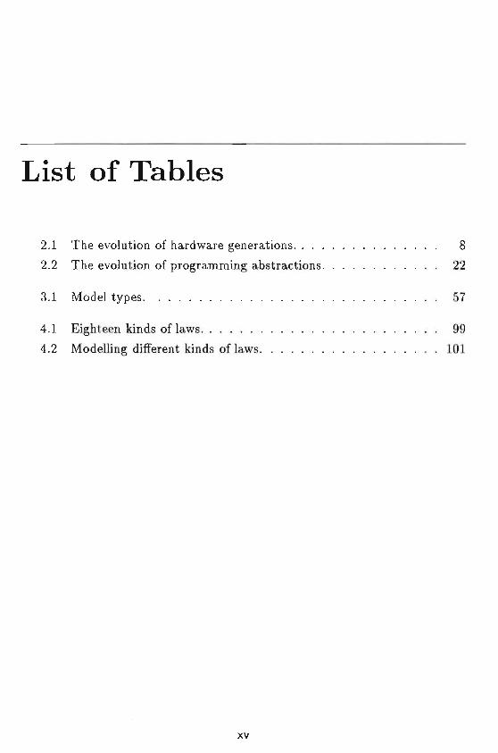
2.1 The evolution of hardware generations 8
2.2 The evolution of programming abstractions 22
3.1 Model types 57
4.1 Eighteen kinds of laws 994.2 Modelling different kinds of laws 101
xv

XVI List of Tables
aei '•> ,T£!
List of Figures
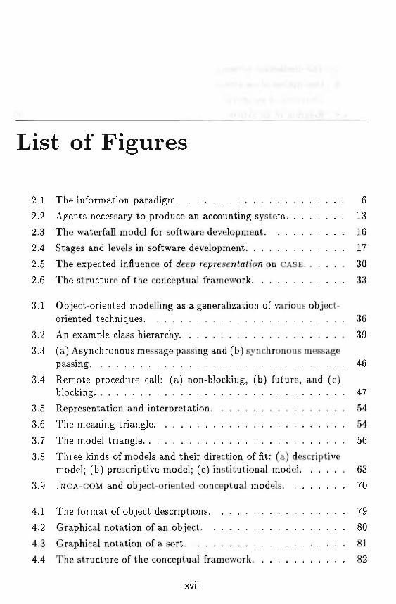
2.1 The information paradigm 6
2.2 Agents necessary to produce an accounting system 13
2.3 The waterfall model for software development 16
2.4 Stages and levels in software development 17
2.5 The expected influence of deep representation on CASE 30
2.6 The structure of the conceptual framework 33
3.1 Object-oriented modelling as a generalization of various object-oriented techniques 36
3.2 An example class hierarchy 39
3.3 (a) Asynchronous message passing and (b) synchronous messagepassing 46
3.4 Remote procedure call: (a) non-blocking, (b) future, and (c)blocking 47
3.5 Representation and interpretation 54
3.6 The meaning triangle 54
3.7 The model triangle 56
3.8 Three kinds of models and their direction of fit: (a) descriptivemodel; (b) prescriptive model; (c) institutional model 63
3.9 INCA-COM and object-oriented conceptual models 70
4.1 The format of object descriptions 79
4.2 Graphical notation of an object 80
4.3 Graphical notation of a sort 81
4.4 The structure of the conceptual framework 82
xvii
xviii List of Figures
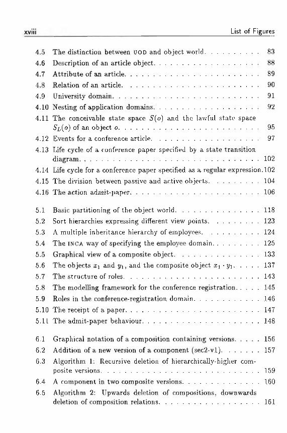
4.5 The distinction between UOD and object world 83
4.6 Description of an article object 88
4.7 Attribute of an article 89
4.8 Relation of an article 90
4.9 University domain 91
4.10 Nesting of application domains 92
4.11 The conceivable state space 5(o) and the lawful state space5L(O) of an object o 95
4.12 Events for a conference article 97
4.13 Life cycle of a conference paper specified by a state transitiondiagram 102
4.14 Life cycle for a conference paper specified as a regular expression. 102
4.15 The division between passive and active objects 104
4.16 The action admit-paper 106
5.1 Basic partitioning of the object world 118
5.2 Sort hierarchies expressing different view points 123
5.3 A multiple inheritance hierarchy of employees 124
5.4 The INCA way of specifying the employee domain 125
5.5 Graphical view of a composite object 133
5.6 The objects i j and J/J, and the composite object £i • t/i 137
5.7 The structure of roles 143
5.8 The modelling framework for the conference registration 145
5.9 Roles in the conference-registration domain 146
5.10 The receipt of a paper 147
5.11 The admit-paper behaviour 148
6.1 Graphical notation of a composition containing versions 156
6.2 Addition of a new version of a component (sec2-vl) 157
6.3 Algorithm 1: Recursive deletion of hierarchically-higher com-posite versions 159
6.4 A component in two composite versions 160
6.5 Algorithm 2: Upwards deletion of compositions, downwardsdeletion of composition relations 161
List of Figures xix
6.6 Algorithm 3: Redirection of the entering composition relation. . 161
6.7 Algorithm 3: Recovery of the original object after adding andsubsequent deleting 162
6.8 Algorithm 3: The recursion stops because book-vl is not iden-
; tical to book ...,»,»..*.,*• . • • 163
6.9 Addition of a new part (index) to a composition 165
6.10 Deletion of a non-composite part 166
7.1 An example Data-Flow Diagram of a compiler 170
7.2 A particular DFDE 171
7.3 The DataFlowDiagramEditorsort 172
7.4 The extended DataFlowDiagramEditor sort 173
7.5 The DataFlowModel 174
7.6 The sorts Process and DataFlow 175
7.7 Modelling levels 176
7.8 Events of a DataFlowModel 177
7.9 The metasort VisualizationMetaSort 178
7.10 Sort hierarchies of visual displays 179
7.11 The GraphicalEditor 180
8.1 The prototype spreadsheet 184
8.2 The spreadsheet extended with sorts 185
8.3 The spreadsheet extended with sorts and descriptor types. . . . 186
8.4 The INCA description of Peter 186
8.5 The descriptors treated as objects 188
8.6 Composition in a spreadsheet 190
8.7 Focus on object parts 191
8.8 Versions in the spreadsheet 191
8.9 Focus on versions 191
9.1 The INCA ontology 198
9.2 Reflection in INCA-COM 201
9.3 An application domain in which the descriptors are treated asobjects in the descriptor domain 204
xx List of Figures
9.4 The semantics of the Instance.of descriptor 206
9.5 The relationship between objects, ontological concepts, and de- >
'u?U scriptions 208
9.6 The location of the ontology 211
9.7 Ontology as the representation of INCA concepts 213
9.8 Applications and their users 214
A.I Primitive visual displays 224
A.2 Composite and constrained visual displays 225
B.I INCATOOL'S user interface 228
B.2 Sort hierarchies 229B.3 The sort Circle 230B.4 The sorts PolyLine, Square and Triangle 232
B.5 The sort hierarchy after creating the sort PolyGon 233
Chapter 1
Introduction
1.1 INCA
This thesis is the result of a five-year period of research at the Universityof Limburg in Maastricht, the Netherlands. In September 1988 the INCA(iNtelligent CASE) project was launched in the computer-science department,with the long-term objective of developing an INtelligent computer-aided sys-tems engineering (CASE) environment for systems development.
Early 1989, the research field of computer science witnessed the rebirth ofo6/ec< oneniah'on. In fact, commercial objectives led the way to make objectorientation the new /ir/pe-o/-^e-j/ear. Object orientation, it was proclaimed,held the promise of systems development in a controlled manner, enablinglarge-scale software reuse through the distinguished feature, in/ien'tance. Thelabel of object orientation has since become synonymous with good. However,the inheritance of object orientation as a hype-of-the-year has also causedconfusion on what it really means: today one can read advertisements forobject-oriented drawing tools, referring to the capability of treating manipu-lated items as objects.
In our opinion, object orientation, when treated adequately and seriously,really keeps a promise for future software development. The arguments aretwofold: (1) object orientation allows a natural view of the world, and (2)object orientation offers good concepts for software engineering.
Object orientation as a natural view of the world The use of objectsfor representing a domain goes back to Minsky's seminal paper on frames
Chapter 1. Introduction
(Minsky, 1975; Minsky, 1981). The frames were used to represent particularobjects in a domain, with slots describing the different properties of an object.Since the introduction of frames, the notion of object orientation has hadseveral adaptations and extensions in knowledge representation and knowledgeengineering.
Object orientation for software engineering Considering the develop-ment of software, object orientation has a great importance for software en-gineering. Object orientation combines important ideas from the software-engineering field, such as encapsulation (combining and shielding various itemswithin one structure), data hiding (focus on the external workings of an entity,not its internal realization), modularization (dividing a program into distinctparts), and inheritance (defining new types in terms of existing ones).
The above examples aided in choosing the concepts of object orientation forthe realization of an iNtelligent CASE (INCA) environment. The two main goalsof an INCA environment are (1) to furnish a representation system for capturingthe real world in which a (future) information system is to be employed, and(2) to offer concepts for modelling and constructing information systems, interms of the representation of (1). As we stated above, object orientationcombines concepts for the representation system of an INCA environment withconcepts for software engineering. This combination of concepts led us early1989 to choose object orientation as a research issue for the development ofour INCA environment.
In this thesis, we describe the concepts of a concepiua/ o6/ec< mode/, capableof capturing the semantics of real-world objects and their relations, occurringin a complex domain such as CASE.
1.2 Structure of the thesis
After the Introduction in Chapter 1, Chapter 2 describes the evolution ofhardware and the so-called software crisis. It forms the background of thisthesis. We then formulate the problem statement describing the subjects tobe addressed. Software engineering is introduced as a possible answer to thesoftware crisis, and the concept of CASE is presented as a particular way ofassisting software engineers in performing their tasks. As an intermediatestation along the way to automatic programming, INtelligent CASE is proposedas the next goal to be accomplished.
1.2 Structure of the thesis
In Chapter 3 we introduce object orientation from the programming-languageperspective. Subsequently, we treat the different kinds of modelling perspec-tives which a modeller may have, ranging from empirical models to formalmodels. The chapter ends with a unifying view on object orientation andmodelling by describing object-oriented conceptual modelling.
Chapter 4 presents the main ideas underlying the INCA Conceptual ObjectModel (INCA-COM). It focusses on the importance of semantics in the objectmodel. The object-describing entities distinguished as important for describ-ing a model in an object-oriented fashion are introduced. Subsequently, fourdifferent models for modelling according to INCA-COM are presented; they arethe information model, the event model, the behaviour model and the com-munication model.
Chapter 5 deals with structuring principles which are part of INCA-COM. Wetreat sort hierarchies, specification, composite objects, grouping, and systems.
Since versions are also part of INCA-COM, Chapter 6 discusses the version-management mechanism for composite objects. We believe it to be indispens-able in an object-oriented model for complex objects. We clarify the ideas ofversion management with examples.
In Chapters 7 and 8 we illustrate the modelling concepts of INCA-COM by (1)constructing and describing a model of data-flow diagrams, and (2) showingthe application of INCA concepts to the domain of spreadsheets.
Chapter 9 describes INCATOOL, a tool supporting the modelling with INCA-COM. Based on an ontology for object-oriented modelling and a form of lan-guage reflection, called descriptor reflection, the architecture of INCATOOL isdescribed.
Chapter 10 concludes the thesis with a review of the main goals set forth forthe INCA project, and lists possible directions for future research.

Chapter 1. Introduction
Chapter 2
The software crisis
A general goal of information science is to study the concepts of informationprocessing. To this end information scientists are doing research on informa-tion systems, i.e., systems which process and store information. The researchhas spawned many useful methods and techniques for the actual developmentof these systems. Yet, there have been numerous accidents in systems devel-opment, leading to the so-called so/ftwzre crisis: software projects finished toolate and costed much more than predicted, software systems were often unre-liable and performed rather poorly (Sommerville, 1992). Although methodsand techniques have been improved considerably, the software crisis still per-sists. And with the steady increase in computer capacity, the software crisisis likely to stay around for several years.
In order to reduce the costs of systems development the /ewe/ of specificationof an information system plays an important role. In this chapter we addressthe importance of raising </ie /eve/at which an information system is specified.This leads to our problem statement. Moreover, it provides some indicationson how we deal with the problems stated in this thesis.
2.1 Information systems and the software crisis
All organizations employ information to conduct their business. Whether it isa university, a building company, or a bridge club, information plays an impor-tant role. Any ensemble of information and information processing agents, hu-mans or machines, is called an in/ormaJion sj/stem. The in/ormaJicm paradigmfor systems splits any system into a real system and an information system(Brussaard and Tas, 1980). The rea/ system is the system being controlled,
Chapter 2. The software crisis
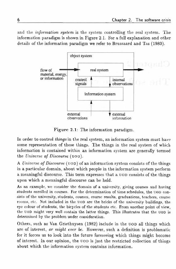
and the m/ormaiion system is the system controlling the real system. Theinformation paradigm is shown in Figure 2.1. For a full explanation and otherdetails of the information paradigm we refer to Brussaard and Tas (1980).
flow of ~ ~material, energy.or information
object system
real system
control 'signals
internalf observations
information system
i
externalobservations
' externalinformation
Figure 2.1: The information paradigm.
In order to control Mings in the real system, an information system must havesome representation of these things. The things in the real system of whichinformation is contained within an information system are generally termedthe f/ntverse o/ Discourse (UOD).
A f/niverse o/Discourse (UOD) of an information system consists of the thingsin a particular domain, about which people in the information system performa meaningful discourse. This term expresses that a UOD consists of the thingsupon which a meaningful discourse can be held.
As an example, we consider the domain of a university, giving courses and havingstudents enrolled in courses. For the determination of time schedules, the UOD con-sists of the university, students, courses, course results, graduations, teachers, courserooms, etc. Not included in the UOD are the bricks of the university buildings, theeye colour of students, the bicycles of the students etc. From another point of view,the UOD might very well contain the latter things. This illustrates that the UOD isdetermined by the problem under consideration.
Others, such as Van Griethuysen (1982) include in the UOD all things whichare of interest, or mijf/it ever fee. However, such a definition is problematicfor it forces us to look into the future foreseeing which things might becomeof interest. In our opinion, the UOD is just the restricted collection of thingsabout which the information system contains information.
2.1 Information systems and the software crisis
Currently, information systems are progressively being automated. The au-tomation of an information system consists of assigning parts of the informa-tion system to information-processing machines. The information-processingmachines can be dedicated to a particular task, such as vending or weaving,or they can be general-purpose machines (computers), which have been in-structed to act as particular information-processing machines. The latter areinteresting: they require a special set of instructions (a program) to make itbehave as the intended information processor. In case the information systemis large and a fair part of it is being automated, the resulting programs can alsobe considered as a system. A set of programs cooperating as an informationprocessor, is called a so/tware system.
The increasing demand for automated information systems requires softwaresystems to be built. In combination with the increasing power of computers,the demand for large and complex software systems is increasing. The develop-ment of these software systems has been a complex task for developers for over25 years now. Its complexity causes problems with the software-developmentprocess and introduces errors in the software. The problems, such as the spec-ification and implementation of large software systems, have become knownas the so/tioare crisis.
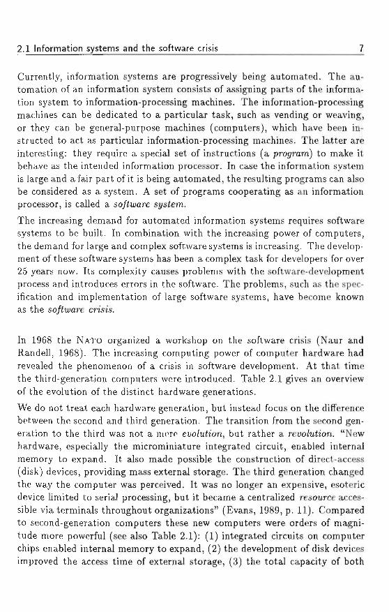
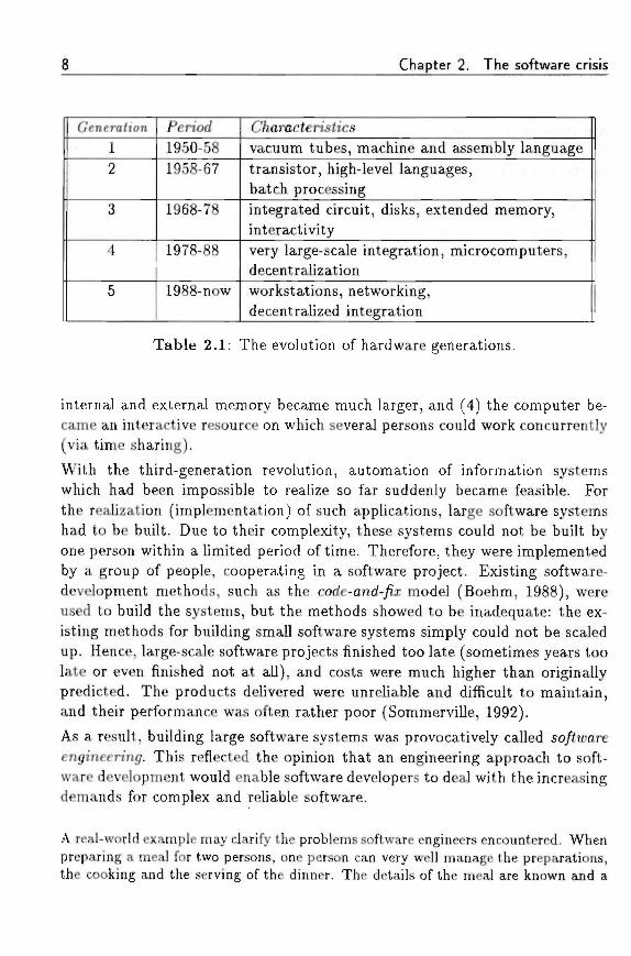
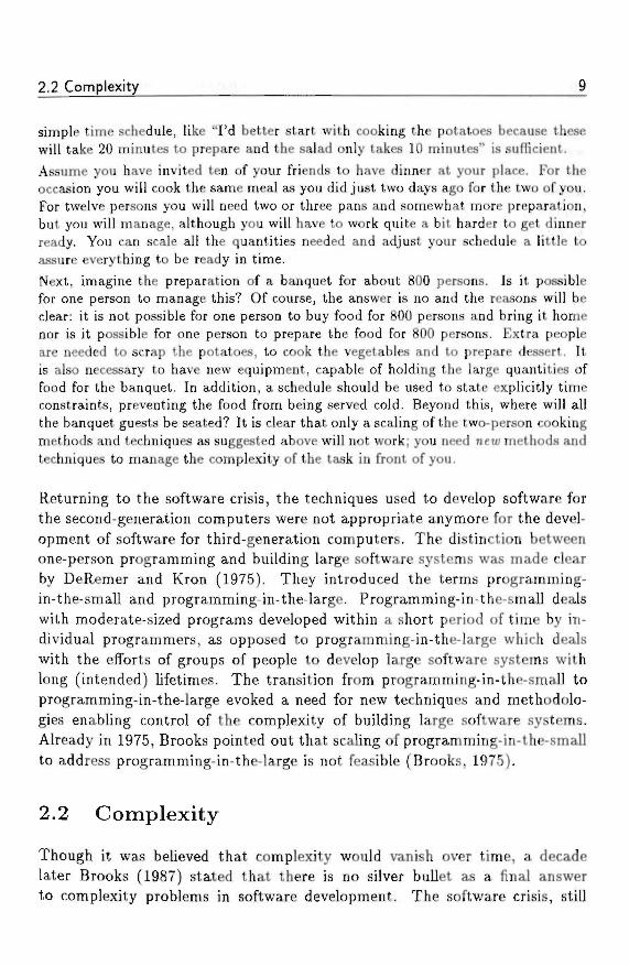
In 1968 the NATO organized a workshop on the software crisis (Naur andRandell, 1968). The increasing computing power of computer hardware hadrevealed the phenomenon of a crisis in software development. At that timethe third-generation computers were introduced. Table 2.1 gives an overviewof the evolution of the distinct hardware generations.
We do not treat each hardware generation, but instead focus on the differencebetween the second and third generation. The transition from the second gen-eration to the third was not a mere euo/uiion, but rather a reuo/uta'on. "Newhardware, especially the microminiature integrated circuit, enabled internalmemory to expand. It also made possible the construction of direct-access(disk) devices, providing mass external storage. The third generation changedthe way the computer was perceived. It was no longer an expensive, esotericdevice limited to serial processing, but it became a centralized resource acces-sible via terminals throughout organizations" (Evans, 1989, p. 11). Comparedto second-generation computers these new computers were orders of magni-tude more powerful (see also Table 2.1): (1) integrated circuits on computerchips enabled internal memory to expand, (2) the development of disk devicesimproved the access time of external storage, (3) the total capacity of both
Chapter 2. The software crisis
Genera/ion12
3
4
5
PenW1950-581958-67
1968-78
1978-88
1988-now
CViaracterish'csvacuum tubes, machine and assembly languagetransistor, high-level languages,batch processingintegrated circuit, disks, extended memory,interactivityvery large-scale integration, microcomputers,decentralizationworkstations, networking,decentralized integration
Table 2.1: The evolution of hardware generations.
internal and external memory became much larger, and (4) the computer be-came an interactive resource on which several persons could work concurrently(via time sharing).
With the third-generation revolution, automation of information systemswhich had been impossible to realize so far suddenly became feasible. Forthe realization (implementation) of such applications, large software systemshad to be built. Due to their complexity, these systems could not be built byone person within a limited period of time. Therefore, they were implementedby a group of people, cooperating in a software project. Existing software-development methods, such as the code-and-yix model (Boehm, 1988), wereused to build the systems, but the methods showed to be inadequate: the ex-isting methods for building small software systems simply could not be scaledup. Hence, large-scale software projects finished too late (sometimes years toolate or even finished not at all), and costs were much higher than originallypredicted. The products delivered were unreliable and difficult to maintain,and their performance was often rather poor (Sommerville, 1992).
As a result, building large software systems was provocatively called so/tat>areengineermg. This reflected the opinion that an engineering approach to soft-ware development would enable software developers to deal with the increasingdemands for complex and reliable software.
A real-world example may clarify the problems software engineers encountered. Whenpreparing a meal for two persons, one person can very well manage the preparations,the cooking and the serving of the dinner. The details of the meal are known and a
2.2 Complexity
simple time schedule, like "I'd better start with cooking the potatoes because thesewill take 20 minutes to prepare and the salad only takes 10 minutes" is sufficient.Assume you have invited ten of your friends to have dinner at your place. For theoccasion you will cook the same meal as you did just two days ago for the two of you.For twelve persons you will need two or three pans and somewhat, more preparation,but you will manage, although you will have to work quite a bit harder to get dinnerready. You can scale all the quantities needed and adjust your schedule a little toassure everything to be ready in time.
Next, imagine the preparation of a banquet for about 800 persons. Is it possiblefor one person to manage this? Of course, the answer is no and the reasons will beclear: it is not possible for one person to buy food for 800 persons and bring it homenor is it possible for one person to prepare the food for 800 persons. Extra peopleare needed to scrap the potatoes, to cook the vegetables and to prepare dessert. Itis also necessary to have new equipment, capable of holding the large quantities offood for the banquet. In addition, a schedule should be used to state explicitly timeconstraints, preventing the food from being served cold. Beyond this, where will allthe banquet guests be seated? It is clear that only a scaling of the two-person cookingmethods and techniques as suggested above will not work; you need new methods andtechniques to manage the complexity of the task in front of you.
Returning to the software crisis, the techniques used to develop software forthe second-generation computers were not appropriate anymore for the devel-opment of software for third-generation computers. The distinction betweenone-person programming and building large software systems was made clearby DeRemer and Kron (1975). They introduced the terms programming-in-the-small and programming-in-the-large. Programming-in-the-small dealswith moderate-sized programs developed within a short period of time by in-dividual programmers, as opposed to programming-in-the-large which dealswith the efforts of groups of people to develop large software systems withlong (intended) lifetimes. The transition from programming-in-the-small toprogramming-in-the-large evoked a need for new techniques and methodolo-gies enabling control of the complexity of building large software systems.Already in 1975, Brooks pointed out that scaling of programming-in-the-smallto address programming-in-the-large is not feasible (Brooks, 1975).
2.2 Complexity
Though it was believed that complexity would vanish over time, a decadelater Brooks (1987) stated that there is no silver bullet as a final answerto complexity problems in software development. The software crisis, still
10 Chapter 2. The software crisis
existing after 25 years, has made clear that complexity is an inherent part ofsoftware and software development. In this section we will systematically lookat the three different forms of complexity, which make software developmentinherently difficult: (1) complexity of the exzsimgr in/ormah'on system; (2)complexity of the deue/opmeni process; and (3) complexity of the resumingso/<u;are system.
Complexity of the existing information system Information systemsare being used for centuries. They are used for "support or replacement ofspoken or written communication in goal-directed activities" (Nijssen, 1989).Thus, an information system supports or replaces human communication. Hu-man communication is based by and large on natural language, which is theconceptually richest language we have. An information system holds informa-tion for the real system it controls. Very often, the real system is a complexsystem, consisting of people, business goals, plans, production machines, andmaterials, etc. In order to control the real system adequately, the informationsystem must contain information on all relevant objects in the real system.This information is used for decisions regarding the control of the real system.Although an information system contains abstractions of things in the realsystem, it is often as complex as its real system. Furthermore, to support orreplace human communication, an information system must be able to repre-sent the real system in sufficient detail. If such is not the case, the decisionprocesses cannot function adequately. Thus, the complexity of the existinginformation system is caused by an equally complex real system.
Complexity of the development process The development process of alarge software system can, in princip/e, be accomplished by one person. How-ever, if the system is to become operational within a short period of time,the necessary work has to be split into separate pieces. Thus, several peoplecan work on these pieces in parallel. In order to control the development pro-cess, an effective work-breakdown structure and a time schedule are needed,enlarging the complexity of the process. Regarding the division of work, com-munication of results between the different project members is crucial. Ifcommunication fails, the project will fail. The communication between projectmembers requires a common "language" in which the object of communica-tion, the intended software system, can be addressed. Such common languagesrange from graphical languages (diagrams) to programming languages. Still,the use of such a common development language has its drawbacks. First, it
2,2 Complexity 11
needs to be learned by the project members. Second, there exist no standardsfor such languages. Frequently, different projects use different languages forcommunication. In addition to the problems with a common developmentlanguage, the number of communication lines between the project membersincreases non-linearly with the number of project members.
Complexity of the resulting software system The software, i.e., theprogram for an automated information system is complex in itself, whichmakes it hard to understand. As Brooks (1987) describes, comp/exity, con/or-im'lj/, c/iangeata'/ity and mmsibi'/tty are the four essential properties of software.Software is inherently complex because of the following three reasons. First,no piece of software is the same; if two pieces of software are similar, they arecoded as a subroutine or function, making it unique and generic. In this sense,software systems are different from computers, buildings, or cars, where re-peated elements abound. Second, the state space of a software system is verylarge compared to other systems. The conception, description, and testingof such a system is difficult. Third, the different pieces of a software systemmostly interact in a non-linear fashion. Scaling of such a system increases itscomplexity more than linearly.
Conformity, changeability, and invisibility influence complexity in a negativeway. Con/ormiiy requires that a software system has the ability to com-municate with other systems. This conformity requires software systems tohave multiple interfaces, which enlarge the overall complexity of the system.C/iangea6i7i<2/ of software makes it possible to extend a system's functionalityby changing the software. Current software systems are indeed frequently up-dated in order to enhance functionality or to remove errors (bugs). /nin'si6z7t<j/of software hinders its understanding. Since software is immaterial and ab-stract, it has no adequate geometrical representation in the way that a househas a construction map, and a electrical system has a diagram. Insufficientunderstanding of a software system leads to communication problems amongproject members, which introduces cost overruns, system flaws and scheduledelays. Moreover, insufficient understanding leads to management problemsof the development process.
Summarizing, the complexity of the existing information system is caused bythe complexity of the real system it controls. This complexity makes it diffi-cult to understand the existing information system. The development processof software is complex since it requires the work to be divided among project
12 Chapter 2. The software crisis
members. Moreover, communication between project members requires theuse of a common language. Due to the complexity of a software system it isdifficult to construct and understand such a system. The insufficient under-standing of a software system leads to functional and technical problems andto management problems.
In order to make complexity manageable, software scientists have developedsoftware-development methodologies. The concept of a methodology is thesubject of the next section.
2.3 Software-development methodologies
The software crisis and the complexities of software development spawnedresearch activities into so/iiyare-deue/opmen^ mei/iodo/ogtes. A software-development methodology offers a framework for the ordered and controlleddevelopment of a software system. In order to control software development,two aspects of the development need to be addressed: the process and itsoutput. Therefore, a methodology generally consists of two parts: (1) a pro-cess model, and (2) a development model. A process mode/ describes w/i«c/istapes in software development are recognized, and how they relate to eachother. Such a model is used for controlling a project, i.e., keeping it withinbudget and time, using available resources optimally. A deue/opmeni mode/describes /IOU; the particular stages, distinguished by a process model, shouldbe executed. The development model offers a set of atsiracta'ons to be usedfor analyzing an existing information system, designing a software system, andimplementing a software system. The development model also offers methodsfor creating the intended output based on the input of a particular stage. Theoutput of each stage serves as the input for subsequent stages.
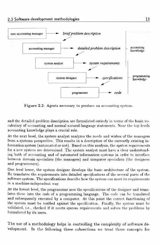
To illustrate the process of system development using stages and /et;e/s o/ a&sirach'on,we give an example of the construction of an accounting system in Figure 2.2. Ourexample is based on a similar example of Rich and Waters (1986).
Assume that a non-accounting manager faces the need for particular accounting in-formation. He' produces a 6rie/profc/em <fescnp<ton concerning the information heneeds. This brief problem description is forwarded to an accounting manager whoelaborates it into a rfe/ai/erf pro6/em rfescn'p<ton. Both the brief problem description
'We remark that the personal pronoun /ie and words such as manager, analyst, designer,and programmer refer to both male and female persons.
2.3 Software-development methodologies 13
non-accounting manager
accounting manager
system analyst
description
detai/edprofe/em description
.system
accountingknowledge
system designer
programmer code
programmingknowledge
Figure 2.2: Agents necessary to produce an accounting system.
and the detailed problem description are formulated entirely in terms of the basic vo-cabulary of accounting and normal natural-language statements. Near the top levelsaccounting knowledge plays a crucial role.
At the next level, the system analyst analyzes the needs and wishes of the managersfrom a systems perspective. This results in a description of the currently existing in-formation system (automated or not). Based on this analysis, the system regutremen/sfor a new system are determined. The system analyst must have a clear understand-ing both of accounting and of automated information systems in order to interfacebetween domain specialists (the managers) and computer specialists (the designersand programmers).
One level lower, the system designer develops the basic architecture of the system.He translates the requirements into detailed speci/»ca<ions of the several parts of thesoftware system. The specifications describe how the system can meet its requirementsin a machine-independent way.
At the lowest level, the programmer uses the specifications of the designer and trans-lates these into the corfe of a programming language. The code can be translatedand subsequently executed by a computer. At this point the correct functioning ofthe system must be verified against the specification. Finally, the system must bevalidated, i.e., checked if it meets system requirements and solves the problems byformulated by its users.
The use of a methodology helps in controlling the complexity of software de-velopment. In the following three subsections we treat three concepts for
Chapter 2. The software crisis
managing complexity.
1. The complexity of the development process is managed by distinguishingstages in the development process, dividing the development process intoa sequence of manageable pieces.
2. The complexity of existing information systems is managed by usingmo</e/s, enabling analysts to view a system in a less complex and moreabstracted manner.
3. The complexity of a software system is managed by the decompositionof a system into components.
2.3.1 Stages
The process model of a methodology divides the development of software intostages with well-defined inputs and outputs. The output of each stage serves asthe input of the next stage. Ideally, the input of the entire process is a problemstatement, which, through several transformations, results in a software sys-tem. All process models are based on the so/toare /«/e cyc/e, which describesthe stages any piece of software will go through during its life. The softwarelife cycle consists of six stages, which are commonly recognized nowadays (see,e.g., Sommerville (1992)). Below we provide a short characterization of eachstage.
1. Analysis During analysis the needs and wishes of the users of the soft-ware system are analyzed. The result of this stage is a description of thecurrently existing information system (automated or not).
2. Requirements specification The software requirements, i.e., the sys-tem's functionality and operational constraints, must be specified. Atthis stage, Wiaf the system is expected to do is described.
3. Design Following the requirements specification, the system designerdescribes /iou> the requirements may be accomplished in a machine-independent way.
4. Implementation During implementation the design is gradually con-verted into a machine-executable form, i.e., a program for a particularkind of computer system.
2.3 Software-development methodologies 15
5. Testing After the implementation, the correct working of the systemmust be checked, i.e., it must be checked whether the system meets therequirements.
6. Operation and maintenance The system must be installed and used.If errors are discovered they must be corrected. The maintenance of aworking system comprises two components:
(a) tracking and fixing of bugs that show up during the operation ofthe system;
(b) modifying the system due to changes in the environment.
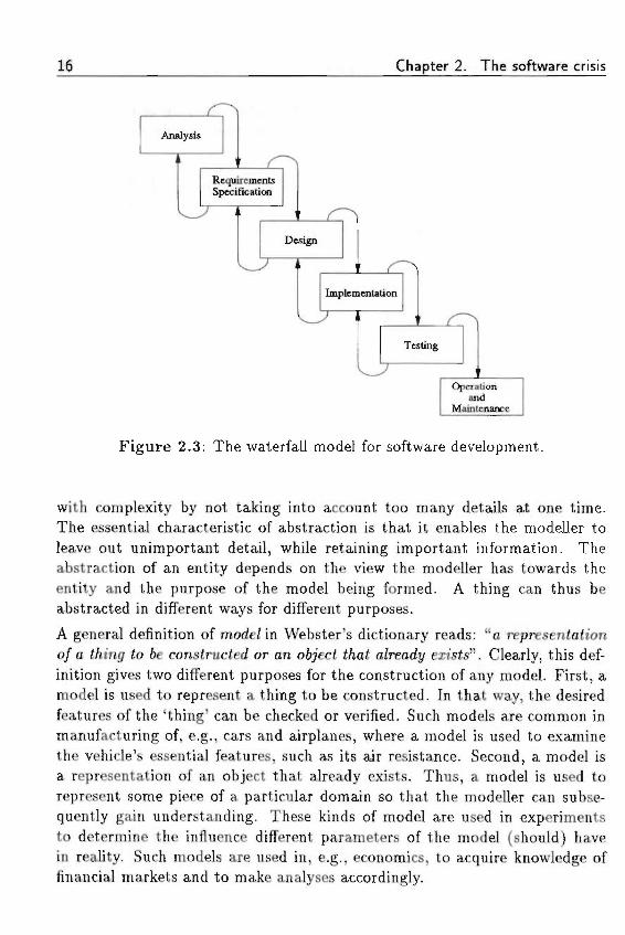
Different varieties of process models arise because of different trajectoriesthrough the life-cycle stages. In the stagfewise process mode/ the stages areordered linearly. Despite the linear order, it will often be necessary to go backto a previous stage since errors or inconsistencies, introduced during a previousstage, are discovered. Royce (1970) recognized the existence of such iterationsor recurrent entrances , but in his opinion it was important to restrict them tosuccessive stages of the life cycle in order to eliminate development risks. It hasresulted in the wafer/a// mode/for software development, shown in Figure 2.3(Royce, 1970).
This process model is most frequently used nowadays. The importance of iter-ation in the software-development process has been acknowledged by Boehm(1988), who proposed a spz'ra/ process mode/ of software development.
2.3.2 Models
Whereas a process model, such as the waterfall model, describes what steps(including their order) have to be taken in software development, a develop-ment model describes what fcinds o/ mode/ are to be produced in a particularstage of the development process. During the distinct stages different kinds of'things' are modelled.
A model is an abstract representation of reality that excludes much of theworld's intricate detail. The purpose of a model is to gain understanding ofthe nature and behaviour of a phenomenon. A model reduces complexity byleaving out details that do not interfere with a phenomenon's relevant features.
The essence of building a model is abstraction, i.e., the formation of conceptsapart from concrete things. In general, abstraction is the human way to deal
16 Chapter 2. The software crisis
Analysis
RequirementsSpecification
Design
Implementation
Testing
Operationand
Maintenance
Figure 2.3: The waterfall model for software development.
with complexity by not taking into account too many details at one time.The essential characteristic of abstraction is that it enables the modeller toleave out unimportant detail, while retaining important information. Theabstraction of an entity depends on the view the modeller has towards theentity and the purpose of the model being formed. A thing can thus beabstracted in different ways for different purposes.
A general definition of mode/ in Webster's dictionary reads: "a representaftono/a £/un<7 <o 6e constructed or an o6?ec< t/«a( a/readt/ exists". Clearly, this def-inition gives two different purposes for the construction of any model. First, amodel is used to represent a thing to be constructed. In that way, the desiredfeatures of the 'thing' can be checked or verified. Such models are common inmanufacturing of, e.g., cars and airplanes, where a model is used to examinethe vehicle's essential features, such as its air resistance. Second, a model isa representation of an object that already exists. Thus, a model is used torepresent some piece of a particular domain so that the modeller can subse-quently gain understanding. These kinds of model are used in experimentsto determine the influence different parameters of the model (should) havein reality. Such models are used in, e.g., economics, to acquire knowledge offinancial markets and to make analyses accordingly.
2.3 Software-development methodologies 17
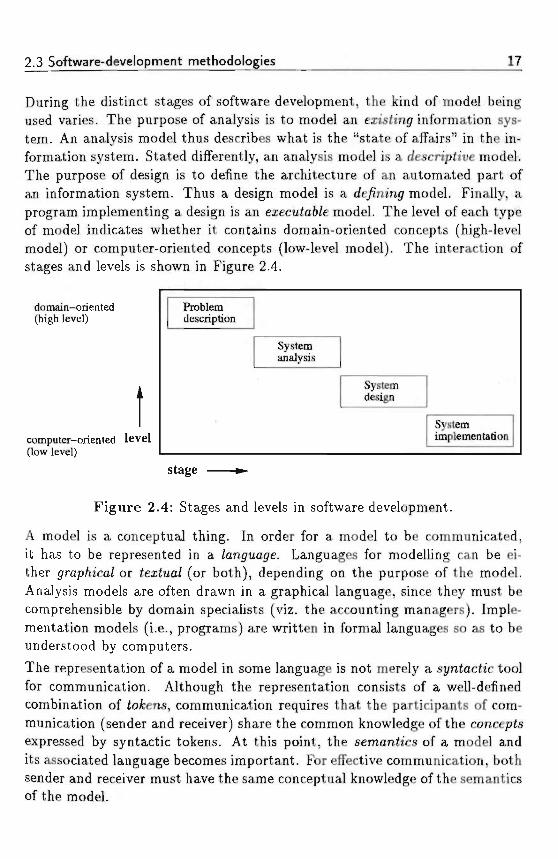
During the distinct stages of software development, the kind of model beingused varies. The purpose of analysis is to model an eiishng information sys-tem. An analysis model thus describes what is the "state of affairs" in the in-formation system. Stated differently, an analysis model is a descn'pttue model.The purpose of design is to define the architecture of an automated part ofan information system. Thus a design model is a rfe/mm<7 model. Finally, aprogram implementing a design is an ea;ecu£a6/e model. The level of each typeof model indicates whether it contains domain-oriented concepts (high-levelmodel) or computer-oriented concepts (low-level model). The interaction ofstages and levels is shown in Figure 2.4.
domain-oriented(high level)
computer-oriented level(low level)
Problemdescription
Systemanalysis
Systemdesign
Systemimplementation
stage
Figure 2.4: Stages and levels in software development.
A model is a conceptual thing. In order for a model to be communicated,it has to be represented in a /anguage. Languages for modelling can be ei-ther </rap/i2ca/ or <ez£ua/ (or both), depending on the purpose of the model.Analysis models are often drawn in a graphical language, since they must becomprehensible by domain specialists (viz. the accounting managers). Imple-mentation models (i.e., programs) are written in formal languages so as to beunderstood by computers.
The representation of a model in some language is not merely a sj/n<ac<ic toolfor communication. Although the representation consists of a well-definedcombination of fofcens, communication requires that the participants of com-munication (sender and receiver) share the common knowledge of the conceptsexpressed by syntactic tokens. At this point, the semanizcs of a model andits associated language becomes important. For effective communication, bothsender and receiver must have the same conceptual knowledge of the semanticsof the model.
18 Chapter 2. The software crisis
Different methodologies use different models. We will not provide an exten-sive overview of existing models and methods. Instead, we focus on particularinteresting ones in the scope of this thesis. The 'structured' modelling tripodaddresses the stages analysis, design and implementation. Structured Anal-ysis (DeMarco, 1979) models an information system by describing the <iaia/Zow through different processes. This kind of model is represented in data-/Zou> diagrams (DFDS). Structured Design (Yourdon and Constantine, 1978) isbased on the division of a system into a Aierarc/ij/ o/ modu/es, which commu-nicate by means of parameters and flags. This kind of model is representedin structure c/mr<s. Structured Programming only uses three basic controlstructures (sequence, iteration and selection) in order to make programs read-able and maintainable. Similar methods based on data-flow diagrams are theWarnier/Orr method (Warnier, 1976), the Gane/Sarson method (Gane andSarson, 1979). For a short description of these methods, we refer to Orr et a/.(1989).
Information Engineering (Macdonald, 1986) stresses the importance of anextensive ftusmess mode/ describing the information within an organization.Based on such a business model several information-manipulating applicationscan be designed. In a similar line of reasoning, Jackson System Development(Jackson, 1983) stresses the adagium that "model precedes function". Thatis, before trying to build information systems, it is necessary to model theinformation being manipulated in these systems. The reason for this is thedifference in stability between information on the one hand and functionsmanipulating this information on the other hand. The information in an or-ganization will be much less subject to change, whereas the functions (read:systems) may vary according to the particular needs.
The entity-relationship approach (Chen, 1976; March, 1988) has been exten-sively used for the modelling of data, especially for relational database systems.It is based on modelling entities (read: things) in a domain, and the relationsbetween these entities. It is widely used during analysis and design of databaseapplications. .
Natural-language Information Analysis Method (NIAM) (Wintraecken, 1985;Nijssen, 1989) is based on the analysis of information expressed in natural-language sentences. The choice for natural language has been made for rea-sons of communication and conceptual richness. The information in a domainshould be phrased by domain specialists, i.e., users. Since natural language isknown to everyone it is ideally suited for modelling information in a way whichis understandable for other users. The accompanying development model
2.3 Software-development methodologies 19
(ISDM) unifies the in/ormation mode/ (what), the process mode/ (how), andthe impu/se mode/ (when) into a model of information systems.
Dietz (1987, 1992a) uses the concept of natural-language communication basedon speec/i acts (Searle, 1969) in a model for information systems. An infor-mation system consists of active objects communicating about a UOD. Thecommunication is based on two types of conversation. These are modelled ac-cording to speech act theory, which states that any utterance of a propositionhas a propositiona/ content and an i//ocutionart/ /orce. The propositional con-tent is the proposition being uttered, and the illocutionary force describes whatforce the proposition possesses, such as a command, a directive, a declaration,or a denial, etc. The first type of conversation is the /act-craih'ngr conversa-tion during which a state of affairs in the UOD is communicated between twoactive objects. Such a state is called a /act. Fact-creating conversations arebased on the stafufjue and acceptive illocutionary forces. The second type ofconversation is the act-creating conversation during which an actor proposesanother actor to commit itself to execute some future action. These commit-ments are called agenda. Act-creating conversations are based on the directiveand commissiue illocutionary forces.
All methods cover parts of the software life cycle. In general there is a trendtowards higher-level specification methods. JSD (Jackson, 1983) is one ofthe early methods recognizing that a model of information should be con-structed before trying to model systems. The interesting ideas of Nijssen(1989) and Dietz (1992a) take information systems back to their origins ofnatural-language communication.
2.3.3 Decomposit ion
The human means to deal with complexity is abstraction. A well-known wayof abstraction of a system is to decompose it into a set of suftsystems or com-ponents. The division of a system into its composing subsystems is called itsdecomposition. The decomposition of a software system is often a hierarchyof components, in which each component itself is decomposed until a suitablelevel of detail has been reached. Sommerville (1992) names the following com-ponents in such a hierarchy for system decomposition: system, subsystem,program unit (module, procedure, or function).
The overall organization of a system and its subsystems is generally called thesystem arc/u'tecture. The decision for a particular architecture can be based
20 Chapter 2. The software crisis
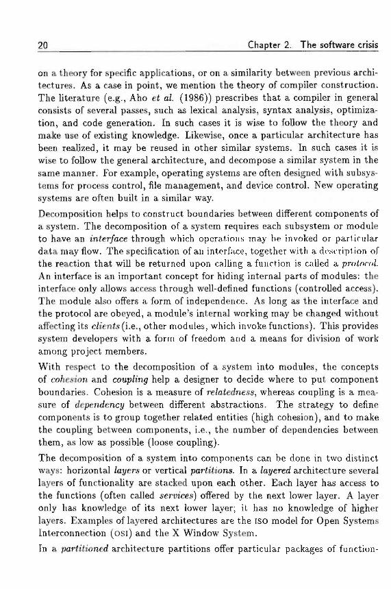
on a theory for specific applications, or on a similarity between previous archi-tectures. As a case in point, we mention the theory of compiler construction.The literature (e.g., Aho e£ a/. (1986)) prescribes that a compiler in generalconsists of several passes, such as lexical analysis, syntax analysis, optimiza-tion, and code generation. In such cases it is wise to follow the theory andmake use of existing knowledge. Likewise, once a particular architecture hasbeen realized, it may be reused in other similar systems. In such cases it iswise to follow the general architecture, and decompose a similar system in thesame manner. For example, operating systems are often designed with subsys-tems for process control, file management, and device control. New operatingsystems are often built in a similar way.
Decomposition helps to construct boundaries between different components ofa system. The decomposition of a system requires each subsystem or moduleto have an mier/ace through which operations may be invoked or particulardata may flow. The specification of an interface, together with a description ofthe reaction that will be returned upon calling a function is called a proioco/.An interface is an important concept for hiding internal parts of modules: theinterface only allows access through well-defined functions (controlled access).The module also offers a form of independence. As long as the interface andthe protocol are obeyed, a module's internal working may be changed withoutaffecting its c/ien<s(i.e., other modules, which invoke functions). This providessystem developers with a form of freedom and a means for division of workamong project members. '
With respect to the decomposition of a system into modules, the conceptsof co/iesion and coup/mgf help a designer to decide where to put componentboundaries. Cohesion is a measure of re/a<edness, whereas coupling is a mea-sure of dependenct/ between different abstractions. The strategy to definecomponents is to group together related entities (high cohesion), and to makethe coupling between components, i.e., the number of dependencies betweenthem, as low as possible (loose coupling).
The decomposition of a system into components can be done in two distinctways: horizontal /at/ers or vertical pariiiions. In a /at/ered architecture severallayers of functionality are stacked upon each other. Each layer has access tothe functions (often called services) offered by the next lower layer. A layeronly has knowledge of its next lower layer; it has no knowledge of higherlayers. Examples of layered architectures are the ISO model for Open SystemsInterconnection (osi) and the X Window System.
In a par(t<ioned architecture partitions offer particular packages of function-
2.4 Support for systems development 21
ality. Partitions are more or less independent of each other (decoupling). Anoperating system is often designed in such a way.
Summarizing this section, for managing complexity a software-developmentmethodology comprises the three concepts stages, mode/s, and decomposition.The concepts stages and models influence each other. During analysis a de-scriptive mode/ is used, during design a defining mode/, and during program-ming an exec«ta6/e mode/. Decomposition is important irrespective of thestage or the kind of model being used. Both an analysis model, such as adata-flow analysis in a data-flow diagram, and an executable model, such asa program, must be decomposed into components.
2.4 Support for systems development
To offer support for systems development, we distinguish between two typesof support: programming-language support and tool support. Proyramminy-/anguage support is needed to express the appropriate system concepts. Too/support helps a systems developer to focus on the creative aspects of develop-ment, while tools takeover bookkeeping and translation tasks. Both languagesand tools show a trend to raise the level of specifications. We first describeprogramming-language support, and then tool support.
2.4.1 Programming- language suppor t
The trend in programming-language design has been to move away from im-perative languages to languages describing the key abstractions in a problemdomain. As a case in point, structured programming in the 1970s was soonfollowed by structured design and analysis, effectively raising the specificationlevel.
As with hardware generations, there have been generations in programminglanguages. There are two important differences, however, between the evo-lutionary scenarios of hardware and software. First, new hardware has beeninvented and constructed by a technology pus/i, and new programming lan-guages were designed due to a market (= software developer's) pu//. Second,today's computers do not use hardware components of thirty years ago, whileone of the earliest programming paradigms, procedural programming, is stillbeing used. An important aspect of the complexity of software systems, is the
22 Chapter 2. The software crisis
dominant hardware style used in computers today. The so-called von Neu-mann architecture encourages a procedural programming style, and successivehardware generations have not changed this. The main attraction of new hard-ware has been a scaling of the von Neumann architecture, resulting in immenseadvances in processing power. In order to raise the level of specification, a pro-gramming language must support concepts corresponding to concepts in theproblem domain. Nevertheless, a program in a programming language mustbe executable as well, meaning that a suitable translator or interpreter mustbe available. Translators and interpreters bridge the gap between high-levelproblem-domain oriented models and low-level bits and bytes of executableprograms.
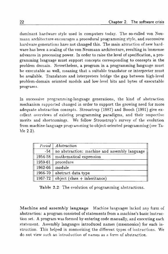
In successive programming-language generations, the kind of abstractionmechanism supported changed in order to support the growing need for moreadequate abstraction concepts. Stroustrup (1987) and Booch (1991) give ex-cellent overviews of existing programming paradigms, and their respectivemerits and shortcomings. We follow Stroustrup's survey of the evolutionfrom machine-language programming to object-oriented programming (see Ta-ble 2.2).
PenW-54
1954-581959-611962-661966-701967-72
j46strac£ionno abstraction: machine and assembly languagemathematical expressionproceduremoduleabstract data typeobject (class + inheritance)
Table 2.2: The evolution of programming abstractions.
Machine and assembly language Machine languages lacked any form ofabstraction: a program consisted of statements from a machine's basic instruc-tion set. A program was formed by entering code manually, and executing eachstatement. Assembly languages introduced names (mnemonics) for each in-struction. This helped in memorizing the different types of instructions. Wedo not view such an introduction of names as a form of abstraction.
2.4 Support for systems development 23
Mathematical expression Within a few years, computers were increas-ingly used for computing simple formulas. This resulted in languages fortranslating formulas automatically into machine code. A well-known languagewas FORTRAN, designed for /ormula translation.
• • • ••• • • • •• • • . . • • • ? " t H
Procedural programming Procedural programming is probably still theparadigm most commonly used. Procedural programming focusses on thedesign of processing and the algorithms needed to perform the desired compu-tations. The need for efficient and fast algorithms was caused by the costs ofprocessing time, which were relatively high in the early days of programming.FORTRAN, initially developed for translating formulas into computer language,is the original procedural-programming language, but languages such as Al-gol60, Algol68, Pascal and C are languages in the same tradition.
Modular programming Over the years the emphasis on processing hasshifted towards the organization of the data acted upon. The paradigm knownas the da£a /tiding princip/e emphasizes the importance of the data by parti-tioning a program into modu/es, i.e., sets of related procedures combined withthe data they manipulate. Programming with modules leads to the central-ization of data controlled by a type-manager module. Compared to the or-ganization of functions and procedures using procedural programming, this issurely an improvement, but "types" created in this fashion are still differentfrom the built-in types used in a programming language. Each of the type-manager modules must have procedures to create and delete variables, andmake assignments to them. Variables created in such a way lack the usualscope rules and cannot be passed as arguments in the usual way.
Abstract data types To overcome the problems with modules, in languagessuch as C++ and Ada it is possible to define types that behave in (nearly) thesame way as built-in types. These types are often called atsiracf data types,although a more appropriate name would be user-de/ined data types. Theparadigm supporting this style of programming is called the da2a-a6s<rach'onparadigm. Abstract data types define a sort of black box. Once specified, atype cannot be adapted to new uses, except by changing the actual definitionof the type. A well-known example of an abstract data type is the ubiquitousstack type on which elements can be pushed and from which elements may bepopped. The implementation of such a type is hidden from c/ien<s (users ofthe stack type), who can only see the externally defined procedures pop and
24 Chapter 2. The software crisis
push. The black box thus defined by the abstract data type, results in a severeshortcoming of programming with this paradigm. Once the data type stack isdefined, it can be used. But the only way to extend the stack type is to copy itsdefinition and provide additional functionalities, resulting in two functionallysimilar data types, which are unrelated in their definition. To eliminate thedisadvantage of the black-box approach, it is necessary to include a mechanismfor defining new abstract data types in terms of other ones. This latter featureis precisely the distinguishing feature of oftjectf-onented programming.
As an illustration, suppose we have certain types of geometric shapes such as squares,circles and triangles. Some routines can be specified handling operations on objectsof these types, e.g., routines to move, rotate and draw a shape. A routine must knowwhat kind of shape is acted upon. Its structure will, e.g., consist, of a Pascal caseor C switch statement, enumerating all known shapes and performing the necessarytype-specific actions. Assume now we want to add a new type of shape. Since thenew shape must have the possibility of rotating, moving and drawing as well, it isnecessary to examine and modify the existing routines on shapes. Every case state-ment enumerating the possible shapes it acts upon, must be extended to cope withthe new shape, with the risk of introducing bugs in the existing code. The problemis that there are no possibilities to distinguish between the properties of any shape(a shape has a location, a shape can be drawn) and the properties of a specie shape(a circle has a center and a radius, a square has an upper-right corner and a lower-left corner). Operations should not decide which code to execute depending on thetype of object. The object itself should be in control to choose what operation ithas to perform. This is concisely phrased by Gorlen e< a/. (1990, p. 104) as "Switchstatement considered harmful." Expressing and using the commonalities and differ-ences between certain kinds of objects is the essence of object-oriented programming(Wegner, 1987a; Meyer, 1988).
Currently, object-oriented programming is being used progressively during im-plementation. The possibility to define types in terms of previously definedtypes enables the reuse of software. Object-oriented programming is a stageof an evolution of different programming paradigms. Similar evolutions takeplace in non-programming domains, such as enterprise-modelling languages,data-modelling languages, and semantic-modelling languages. In order to ab-stract from the programming domain and to assess the concepts of objectorientation, we address o6jec<-onen<ed mode/Zing (see Chapter 3).
2.4 Support for systems development 25
2.4.2 Tool support , ; •
Software tools support a developer in focussing on creative aspects of soft-ware development. The lack of appropriate tools leads to analyses and designswhich are not up-to-date, because of the trouble people have in modifyingthem. A data-flow diagram, once drawn by hand, is tedious to change be-cause of its graphical complexity. In the following subsections we treat theevolution of software tools from programming too/s, via programming enuiron-ments and computer-aided so/iware-engineen'ng enw'ronmen/s, to the use ofartiyicia/-inte//igence tec/miaues in software development, such as automaticprogramming, and infe//igent assistance.
Programming tools
Programming tools are focussed on supporting the tasks of a programmer inthe software life cycle. Since programmers in the early days of programmingwere the only interactors with a computer, it was a natural choice to providethem with appropriate tools first. On first-generation computers, programswere written in number code or mnemonic assembler code, which could di-rectly be translated into machine code by an assemfr/er. The transition fromfirst-generation to second-generation computers enabled the introduction ofhigh-level programming languages, such as FORTRAN and COBOL. Compi/ersand interpreters were introduced to translate programs written in such lan-guages into machine code. The use of compilers also necessitated the use ofassociated tools, such as link editors and librarians. The set of tools to supporta programmer has become known as a programming environment.
Programming environments
A programming environment consists of all the supporting software a pro-grammer uses in the course of preparing his program. Compilers, linkers,loaders, librarians, and documentation tools are all part of a programming en-vironment. Because computers in the 1960s were largely batch-oriented, earlyprogramming environments were also batch-oriented. The computer gathereda batch of jobs, say FORTRAN programs to be translated, and invoked thecompiler for each of the jobs during night time. The next day, a programmerwould check the results of his job and make corrections if an error had oc-curred. During the next night, the corrected version was compiled, and so on.In this way it could take some time to have a program running correctly.
26 Chapter 2. The software crisis
The advent of the third-generation computers, changed the way of workingfrom batch processing to interactive use of computer resources (see Table 2.1).Consequently, programming environments also changed from batch-orientedto interactive programmmj environments, in which a programmer invokes thetools he needs interactively. The effect of interactive programming environ-ments was a gain in programmer productivity, because now it became possibleto develop programs in an edit-compile-run fashion.
The tools in an interactive programming environment are the same as in a(batch-oriented) programming environment, extended with some specific in-teractive tools, such as syntax-driven editors, and debuggers. A characteristicexample of an interactive programming environment is the UNIX ProgrammingEnvironment (Kernighan and Pike, 1984).
Computer-aided software-engineering environments
Batch-oriented and interactive programming environments only supported theprogrammer (i.e., the final stage of the development process) in his task. Theuse of new concepts in software engineering, such as the stages of the soft-ware life cycle, paved the way for software environments for software devel-opment. Such environments have become known as computer-aided so/ftuare-
environments or CASE environments.
Winograd (1973) recognized the problem of complexity in large software sys-tems from his own experiences with SHRDLU, a program which conversed inEnglish about a blocks world. Complex interactions between SHRDLli's com-ponents gave the program much of its power, but at the same time they werea formidable obstacle to understanding and extending it. Winograd suggestedthat the comp/exity barrier as he called it, could best be broken by buildinglarge programming support systems. He proposed a programming-supportsystem, called A, with the following characteristics: (1) since A may requirethe user to do extra work (e.g., describe the motivation for a decision), thesystem must in return provide substantial support to the user; (2) A should becoherent and integrated; a system consisting of several tools pasted togetherwould prove insufficient; (3) A should be capable of maintaining higher-leveldescriptions of the program; simply remembering the program at the source-code level is insufficient; (4) A should know a great deal of specific knowledgeabout the process of programming.
The first three characteristics are addressed by current CASE environments(Dart et a/., 1987). Characteristic four is still being studied; many papers have
2.4 Support for systems development 27
been published on the subject, but the work still has not proceeded beyond theresearch stage. In the next subsection we treat the use of artificial-intelligencetechniques during software development.CASE environments are designed to support all stages of the software life cycle,from requirements specifications to maintenance. Their support can be con-fined to one specific methodology, or can encompass several methodologies.Most CASE environments are highly interactive and require high-resolutiondisplays and pointing devices like a mouse or a touch tablet.
The tendency in CASE development is to raise gradually the level of the prob-lems that can be handled by the environment. It is no longer only the pro-gramming stage that is being supported. Gibson (1989) signals a functionalseparation of CASE into upper, middle, and lower CASE, f/pper CASE supportscorporate planning, mieM/e CASE supports systems analysis and design, and/oiyer CASE supports automated-systems development. By this tripartition-ing, a CASE environment is an integrated system of components supportingthe stages of the software life cycle.
In the first stages of the life cycle, planners using upper CASE create specifica-tions for the corporate plans, i.e., the planning requirements for the company'sfundamental activities. During this phase the focus is on the company's coreactivities, which means that software systems are not addressed at all. Usingmiddle CASE, system analysts convert the planning requirements to require-ments for information systems. System designers refine the system require-ments into design specifications. The design specifications finally are used toproduce the development specifications. At this stage one enters the domainof lower CASE. System developers elaborate the development specifications tomake them more comprehensive. Lower CASE systems use the developmentspecifications to generate the application system and accompanying end-userdocumentation.Thus, with CASE technology the computer is used as a development tool tointegrate planning with the design and development of computerized informa-tion systems.As we remarked in Section 2.3, model building is an important concept insoftware-development methods. Since model building is an iterative process,it requires the model builder to revise the various models during the develop-ment process. The benefit of CASE is that it encourages an iterative approachof modelling by making the revision of a model as easy as possible. Neverthe-less, software development still remains a creative task, and the use of CASE
tools will by no means replace the intellectual input from human software
28 Chapter 2. The software crisis
developers. In order to come to intelligent tools, artificial-intelligence tech-niques have been used to equip software-development tools with intellectualcapabilities.
Artificial-intelligence techniques
The ultimate goal of applying artificial intelligence to software developmenthas been automate programming (Rich and Waters, 1986). In the limit, auto-matic programming would allow a user simply to say what is wanted and havea program produced completely automatically (Simon, 1986). However, it isunlikely that this kind of system will be available soon, if at all. As a result,the application of artificial-intelligence techniques has shifted focus towardsm£e//i<7en< assistance. In this respect, the goals of automatic-programmingresearch have become directed towards CASE.
Automatic programming The success of compilers, initially called auto-matic-programming systems (ACM, 1958, p. 8), tempted researchers to believethat automatic programming could indeed fulfil the need for a system trans-lating users' wishes into programs. Automatic programming initially focussedon raising the level at which programs are specified. To this end, Rich andWaters (1986) consider the different levels of Figure 2.2. The phrase "a usersimply says what is wanted" is then rephrased into three particular questions:(1) who is the user; (2) what does the user say; and (3) how does the userexpress himself?
Figure 2.2 shows the agents necessary to produce an accounting system. Italso shows the levels at which automatic programming might be applied. Atthe lowest level, the programmer is the user of an automatic-programmingsystem (a compiler), which converts high-level code into machine-executablecode. In this case the user expresses himself in a programming language.
At the next two levels, the system analyst and the system designer would liketo use a specification language as input to the automatic-programming system.Such a specification language would resemble a normal programming languagewith additional support for abstract concepts, such as sets and quantifiers, andsystems and modules.
At the second highest level, the accounting manager should be able to inputthe requirements of the program into the automatic-programming system. Atthis level, the automatic-programming system replaces both the analyst and
2.4 Support for systems development 29
the programmer and therefore should have extensive knowledge of accountingand programming.At the highest level, the manager uses free-form English to state the problemand the automatic-programming system produces a solution. At this level thesystem would have to be an accounting expert itself.
Research into automatic programming has focussed on the speci/icafion mei/iodand the mei/iod o/ operation of an automatic-programming system. The spec-ification method varies from a programming language to a natural language(viz. the levels in Figure 2.2). Since natural-language translation is still anopen problem, it is at least doubtful whether this approach will ever becomesuccessful. The method of operation of an automatic-programming systemvaries from theorem-proving techniques to programming-by-examples. Yet,most efforts have not passed the research stage. Rich and Waters (1986) pro-vide a collection of papers on the different aspects of software engineering andartificial intelligence.
Instead of full automation at some levels, partial automation of several tasksat all levels has shown to be more fruitful. In that way, a form of m<e//iffen<assistance is realized.
Intelligent assistance Instead of trying to translate natural-language spec-ifications into programs, intelligent assistance is based on taking a slice throughthe software-development process. It provides partial automation at each level.This kind of system thus performs bookkeeping and takes over several othertasks. The advantage of this approach is that such a system can be usedimmediately, while incremental improvements are added to it.
The idea of a p/an-ftased assistant is that many programs can be viewed asthe composition of standard program fragments or "plans". Winograd (1973)proposed a system based on this principle (see also Section 2.4.2). Such asystem is the focus of the Programmer's Apprentice project (Rich and Waters,1990). In the future, the level of this kind of system (programming level) willbe lifted to address design and analysis problems: Rich and Waters proposeto proceed with similar concepts to construct a Designer's Assistant.As Rich and Waters (1990) portray (see Figure 2.5), the next generation ofCASE environments will have to be based on deep-representation concepts andinspection methods. Deep representation means that tools are not just basedon the textual or graphical representation of program code or diagrams, butthat they have a deeper knowledge of programs, in terms of composition of
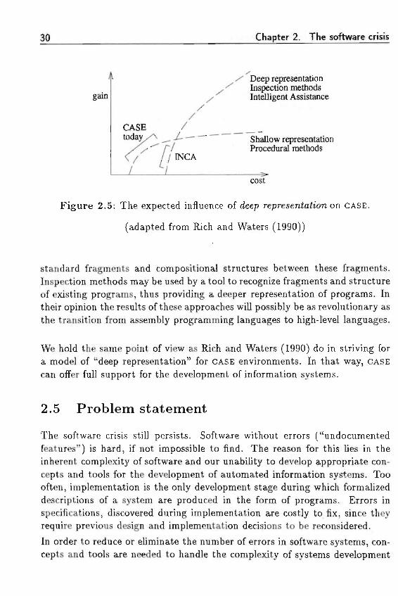
30 Chapter 2. The software crisis
gain
Deep representation •Inspection methodsIntelligent Assistance
Shallow representationProcedural methods
/ INCA
cost
Figure 2.5: The expected influence of deep representation on CASE.
(adapted from Rich and Waters (1990))
standard fragments and compositional structures between these fragments.Inspection methods may be used by a tool to recognize fragments and structureof existing programs, thus providing a deeper representation of programs. Intheir opinion the results of these approaches will possibly be as revolutionary asthe transition from assembly programming languages to high-level languages.
We hold the same point of view as Rich and Waters (1990) do in striving fora model of "deep representation" for CASE environments. In that way, CASEcan offer full support for the development of information systems.
2.5 Problem statement
The software crisis still persists. Software without errors ("undocumentedfeatures") is hard, if not impossible to find. The reason for this lies in theinherent complexity of software and our unability to develop appropriate con-cepts and tools for the development of automated information systems. Toooften, implementation is the only development stage during which formalizeddescriptions of a system are produced in the form of programs. Errors inspecifications, discovered during implementation are costly to fix, since theyrequire previous design and implementation decisions to be reconsidered.
In order to reduce or eliminate the number of errors in software systems, con-cepts and tools are needed to handle the complexity of systems development
?5 Problem statement 31
throughout the software life cycle. At the implementation level of informationsystems, object-oriented programming languages are being used progressively.The reasons for this are the naturalness of concepts in object-oriented pro-gramming languages, and the possibility for reuse of specifications. However,current object-oriented programming languages only address the implementa-tion phase of software development. In order to use the concepts of object ori-entation during analysis and design, the level of (object-oriented) specificationshould be raised. Currently, methods for object-oriented analysis and object-oriented design are being developed (e.g., Object-Oriented Design (Booch,1991) and Object Modelling Technique (Rumbaugh e< a/., 1991)). In order tofacilitate the use of object-oriented concepts during analysis and design theyshould offer abstractions which are meaningful for human beings (i.e., users,analysts and designers) and which at the same time may be used by support-ing software tools to assist a modeller during the modelling process. Thus, aset of concepts for object-oriented analysis and design should be developed formodelling information systems at a conceptual (i.e., non-programming) level.What are the requirements and characteristics for such a concepiua/ o6;'ecfmode/? This is the basis for the problem statement, which we formulate asfollows:
What is the nature of a conceptual object model for the analysisand design of information systems?
Below, five requirements for the conceptual object model (COM) are enumer-ated. A conceptual object model should offer concepts for:
1. representing the UOD of an information system. Using such concepts,a context for information systems can be created. The environment inwhich an information system has to become operational can be modelled.
2. modelling generic parts of a UOD. This enables different informationsystems to share a common context.
3. modelling specific parts of a UOD. This enables different informationsystems to create a particular context, suited to the purpose of the in-formation system.
4. modelling information systems by means of well-defined (de)compositionprinciples.
5. reuse of specifications to allow cheap systems to be built.
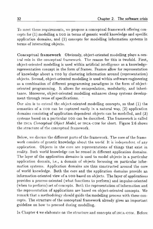
32 Chapter 2. The software crisis
To meet these requirements, we propose a conceptual framework offering con-cepts for (1) modelling a UOD in terms of generic world knowledge and specificapplication domains, and (2) concepts for modelling information systems interms of interacting objects.
Conceptual framework Obviously, object-oriented modelling plays a cen-tral role in the conceptual framework. The reason for this is twofold. First,object-oriented modelling is used within artificial intelligence as a knowledge-representation concept in the form of frames. Frames allow for representationof knowledge about a UOD by clustering information around (representation)objects. Second, object-oriented modelling is used within software engineeringas a combination of different programming paradigms in the form of object-oriented programming. It allows for encapsulation, modularity, and inheri-tance. Moreover, object-oriented modelling enhances cheap systems develop-ment through reuse of specifications. •Our aim is to extend the object-oriented modelling concepts, so that (1) thesemantics of a UOD can be captured easily in a natural way, (2) applicationdomains consisting of application-dependent objects can be modelled, and (3)systems based on a particular UOD can be described. The framework is calledthe INCA ConcepJua/ O6jeci Mode/, or INCA-COM for short. Figure 2.6 showsthe structure of the conceptual framework.
Below, we discuss the different parts of the framework. The core of the frame-work consists of generic knowledge about the wor/d. It is independent of anyapplication. Objects in the core are representations of things that exist inreality. Such world knowledge can be reused in different application domains.The layer of the app/ica<ion domains is used to model objects in a particularapplication domain, i.e., a domain of objects focussing on particular infor-mation systems. Application domains are thus constructed around the coreof world knowledge. Both the core and the application domains provide aninformation-oriented view of a UOD based on objects. The layer of app/icaiionsprovides a process-oriented (what functions to perform) and impulse-oriented(when to perform) set of concepts. Both the representation of information andthe representation of applications are based on object-oriented concepts. Weremark that a methodology should guide the modelling process with these con-cepts. The structure of the conceptual framework already gives an importantguideline on how to proceed during modelling.
In Chapter 4 we elaborate on the structure and concepts of INCA-COM. Before
2.5 Problem statement
Figure 2.6: The structure of the conceptual framework.
doing so, in Chapter 3 we investigate the nature of object-oriented modellingand determine which concepts are particularly significant for the conceptualframework of INCA-COM.

34 Chapter 2. The software crisis
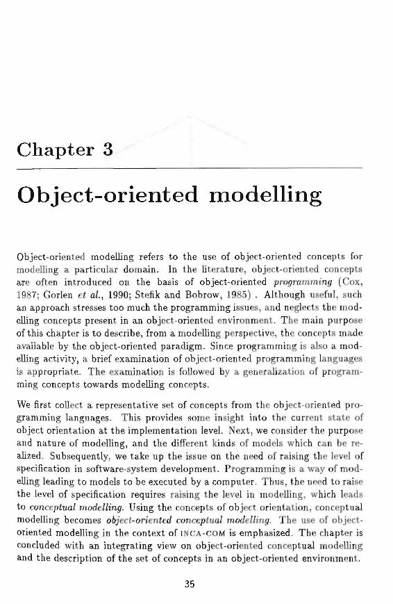
Chapter 3 i
Object-oriented modelling
Object-oriented modelling refers to the use of object-oriented concepts formodelling a particular domain. In the literature, object-oriented conceptsare often introduced on the basis of object-oriented programming* (Cox,1987; Gorlen e< a/., 1990; Stefik and Bobrow, 1985) . Although useful, suchan approach stresses too much the programming issues, and neglects the mod-elling concepts present in an object-oriented environment. The main purposeof this chapter is to describe, from a modelling perspective, the concepts madeavailable by the object-oriented paradigm. Since programming is also a mod-elling activity, a brief examination of object-oriented programming languagesis appropriate. The examination is followed by a generalization of program-ming concepts towards modelling concepts.
We first collect a representative set of concepts from the object-oriented pro-gramming languages. This provides some insight into the current state ofobject orientation at the implementation level. Next, we consider the purposeand nature of modelling, and the different kinds of models which can be re-alized. Subsequently, we take up the issue on the need of raising the level ofspecification in software-system development. Programming is a way of mod-elling leading to models to be executed by a computer. Thus, the need to raisethe level of specification requires raising the level in modelling, which leadsto concepJua/ mocfel/zngr. Using the concepts of object orientation, conceptualmodelling becomes o6jeci-on'enfeff concepJua/ mode/Zing. The use of object-oriented modelling in the context of INCA-COM is emphasized. The chapter isconcluded with an integrating view on object-oriented conceptual modellingand the description of the set of concepts in an object-oriented environment.
35
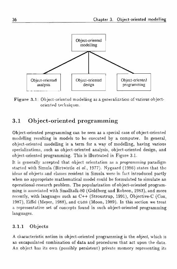
36 Chapter 3. Object-oriented modelling
Object-orientedmodelling
Object-orientedanalysis
Object-orienteddesign
Object-orientedprogramming
Figure 3.1: Object-oriented modelling as a generalization of various object-oriented techniques.
3.1 Object-oriented programming
Object-oriented programming can be seen as a special case of object-orientedmodelling resulting in models to be executed by a computer. In general,object-oriented modelling is a term for a way of modelling, having variousspecializations, such as object-oriented analysis, object-oriented design, andobject-oriented programming. This is illustrated in Figure 3.1.It is generally accepted that object orientation as a programming paradigmstarted with Simula (Birtwistle e< a/., 1977). Nygaard (1986) states that theideas of objects and classes resident in Simula were in fact introduced partlywhen no appropriate mathematical model could be formulated to simulate anoperational-research problem. The popularization of object-oriented program-ming is associated with Smalltalk-80 (Goldberg and Robson, 1983), and morerecently, with languages such as C++ (Stroustrup, 1991), Objective-C (Cox,1987), Eiffel (Meyer, 1988), and CLOS (Moon, 1989). In this section we treata representative set of concepts found in such object-oriented programminglanguages.
3.1.1 Objects
A characteristic notion in object-oriented programming is the o6/ec<, which isan encapsulated combination of data and procedures that act upon the data.An object has its own (possibly persistent) private memory representing its
3.1 Object-oriented programming 37
, together with its public interface, defining operations other objects mayinvoke. (Often, the term protocol is used to denote an interface. However, aprotocol defines a typical interaction sequence between two or more objects,and thus has a dynamic nature, whereas an interface is static.)
Wegner (1987a) contrasts objects with functions which have no state or mem-ory. In this view, an object is identical to a 'system with memory', able torespond to particular inputs with well-defined outputs: "An object has a setof 'operations' and a 'state' that remembers the effect of operations. Objectsmay be contrasted with functions, which have no memory. Function valuesare completely determined by their arguments, being precisely the same foreach invocation. In contrast, the value returned by an operation on an objectmay depend on its state as well as its arguments. An object may learn fromexperience, its reaction to an operation being determined by its invocationhistory."
Besides state and operations (behaviour), Booch (1991) and Rumbaugh et a/.(1991) suggest a definition, which includes object identity: "An object hasstate, behaviour, and identity; the structure and behaviour of similar objectsare defined in their common class." The same notion of identity was alreadysuggested in one of the early papers on INCA-COM (Braspenning e< a/., 1989b).The identity of objects accounts for the fact that two objects which have thesame structure and behaviour are counted as different. Thus, two objectsrepresenting two similar green apples of 50 grams, which can fall from a treeand can be eaten, are still distinct. The state of an object is expressed inthe values of its aiin'&utes, which are representations of the object's features.Each object has its own private collection of attributes. The 6e/iam'our of anobject is the way it responds to interface requests by invoking a met/iod (i.e.,a procedure or function corresponding to the requested operation).
An object fulfils two important roles with regard to the software-engineeringconcepts for abstraction and decomposition. First, an object is a natural rep-resentation of some entity in the problem domain. An object helps abstractionby offering an encapsulated unit of both state and operations. Second, the ob-ject provides a modular unit for decomposition by dividing a program intoa set of interacting components. Other objects are not allowed to changethe state of an object directly. Instead, objects request each others' servicesthrough their interfaces. Interface requests are typically sent via
38 Chapter 3. Object-oriented modelling
3.1.2 Classes and instances
Although a single object is a useful unit of abstraction, the common featuresof objects are specified in a c/ass. This allows the class to act as the unit ofabstraction in the specification of a program. During execution of a program,however, objects are the unit of execution. Classes form a sort of templatethrough which objects can be instantiated. Objects belonging to a certainclass are often called instances of that particular class. A class is similar toan abstract data type: it defines a set of operations that its instances willbe able to perform. The main problem of programming with abstract datatypes (see Section 2.4.1) is the inability to define a new type in terms of apreviously defined one. To alleviate this problem, classes in object-orientedprogramming languages are ordered into a c/ass /uerarc/iy which provides ameans of genera/ization (going up the hierarchy) and specialization (goingdown the hierarchy). The ability to define classes in terms of more generalclasses is the essence of an object-oriented programming language (Wegner,1989).The top of a class hierarchy is the most generic class of which all other classesin the hierarchy are su6c/asses. At the lower levels of the hierarchy one findsclasses that are more specialized. An example of such a class hierarchy ofshapes for a graphical editor is presented in Figure 3.2.The class Shape at the top of the hierarchy is the most general one; thisclass defines the most general attributes and methods of shapes. For example,Shape defines that each shape has a colour and a location, and additionally hasmethods to draw, move, cut and copy itself. The lower classes in the hierarchyare the more specialized ones. Specialization of a class into a suftc/ass can bedone in two distinct ways. First, a subclass can extend its superc/ass (i.e., itshierchically higher class) by defining new attributes or methods, in additionto the ones defined in the superclass. Examples of the extending form ofsubclassing are the classes Line, Polygon, and Oval. They extend the Shapeclass by defining attributes, such as a begin and ending point (Line), a setof points (Polygon) or two radiuses (Oval). Second, a class can constrain thevalues of some of the attributes defined in its superclass. Examples of theconstrained form of subclassing are the Square and the Circle subclasses. Theclass Square constrains the length of the sides of a Rectangle to be equal, andthe class Circle constrains the two radiuses of an Oval to have equal lengths.The two forms of specialization both make the descriptions of subclasses morespecific (i.e., the intension of a subclass is greater than the intension of itssuperclass, meaning that it is applicable to less objects than its superclass).

3.1 Object-oriented programming
Line Polygon
Rectangle
1Square
Triangle
Oval
Circle
Figure 3.2: An example class hierarchy.
Therefore, both forms of specialization are shown in Figure 3.2 with the sametype of line.Some object-oriented languages allow subclasses to override completely thespecification offered by the superclass. This way of (ab)using the generaliza-tion/specialization relation between classes should be avoided, since it deniesthe fact that the subclass IS-A specialization of its superclass.
Classes in object-oriented programming languages have three roles which es-pecially focus on programming. First, a class object has a me(/iods dzch'onarj/holding the methods for the specific messages that can be sent to its instances.Conceptually each object has methods to respond to incoming messages, butin most implementations of object-oriented programming languages, an objectreceiving a message uses the methods dictionary of its class. Second, the classacts as an o6jec</ac<orj/ or iemp/afe. Every class is equipped with a mechanismfor constructing a new instance according to the template (i.e., the structure)specified by the class. Third, the class has a role as an o6j'ec< t«are/iouse in thesense that the collection of its instances is in some way attached to it.
The distinction between classes and instances is based on the philosophicaldistinction between <7eneric concepts and mch'vtciua/s. However, the distinction
40 Chapter 3. Object-oriented modelling
is not always clear, and is often dependent on the context in which the conceptis used. Consider, e.g., the following list of classes and instances, taken fromHofstadter (1979, p. 351):
(1) a publication(2) a newspaper
(3) T/ie San Francisco C/ironic/e(4) the May 18 edition of the C/ironic/e
(5) my copy of the May 18 edition of the CVirom'c/e
As Hofstadter points out, when viewed from newspaper (2), TTie San FranciscoCVironic/e (3) is one of its instances (namely a particular newspaper). However,when viewed from T/ie CAronic/e o/Mar/ 75 (4), 77ie San Francisco C/ironic/e(3) is a class, one of its instances being (4). This line of reasoning seemsto be right. However, there is a difficulty with this view. When talkingabout 77ie San Francisco Chronic/e as an instance of a newspaper and, moregeneric, as an instance of a publication, one is interested in the features ofthe 77ie San Francisco CTironic/e as a newspaper, such as its editor-in-chief,its place of publication, and its first year of appearance. However, the May18 edition of the CVironic/e is an instance of different class, the class of SanFrancisco C/ironic/e editions. For this class, features such as the date of issue,the number of pages, the number of articles, and the subjects covered areinteresting. In a similar vein, my copy of the May 18 edition of the C/ironic/eis an instance of yet another class, The San Francisco Chronicle edition issue.The latter defines features such as the number of issues, the paper and inkused for printing, and the price of the newspaper. Of course, these classes arestrongly related to each other. There might be relations along which defaultvalues for features for the different classes are distributed. It is the task ofan information analyst to detect problem cases such as sketched above. Theambivalent role of classes often is caused by mixing different UODs, in whichclasses can have different roles.
In order to handle the ambivalence of classes, in some object-oriented lan-guages, classes are implemented as objects. This, of course, gives rise to thequestion what the class of a class (viewed as an object) is. For this purpose,the concept of a me<ac/ass is introduced. It is a class having classes as itsinstances. To break an infinite recursion, such a metaclass is often an instanceof itself.
The ability to treat classes as objects offers in principle the same means ofdescription as objects have: a class can have attributes and methods. A typical
3.1 Object-oriented programming 41
example of using a class as an object is by sending it an instantation message(usually the message named new), by which the class is asked to instantiate anew object. CYass attributes are typically used to model attributes which arecommon to all instances of the class.
3.1.3 Inheritance and delegation
The organization of a class hierarchy is based on the relations generalizationand specialization between classes. A class /I is called a superclass of a class27 if .4 is a generalization of 5 . A class 5 is called a subclass of class .4 if 27is a specialization of A Sometimes the generalization/specialization relationis called the IS-A relation, reminiscent of the similar relation used in semanticnetworks. The specialization relation is used to express that the subclass isa particular case of its superclass. In virtually all object-oriented languages,the class hierarchy is used as a vehicle for a form of code sharing, referredto as in/ien'iance. Some people call the generalization/specialization relationbetween two classes the inheritance relation (e.g., Snyder (1987)), but we avoidthis. Generalization/specialization is the relation between classes, whereasinheritance is only a mechanism for the effective reuse of code among classes,valid since the subclass is a specialization of the superclass (see also Chapter 5).
There are two possible ways to share code in object-oriented languages. Thefirst one is the use of m/ien'tance, referred to above, and the second is the useof
Inheritance Inheritance structures come in two flavors. Some object-oriented languages organize the class hierarchy as a tree, which allows classesto inherit directly from one superclass. This form of inheritance is referredto as sinj/e in/ien'tance, /lierarc/iica/ in/ien'tance or /mear m/ien'<ance. Thesecond possible form is to allow classes to inherit directly from more than oneclass. The class hierarchy thus forms a tfirected acyc/ic jrap/i or /a<iice. Thisform is called mu/<ip/e m/ien'(ance.
Delegation Whereas inheritance is used for code sharing, based on the classhierarchy, Lieberman (1986) presents de/egaiion as the means for code sharingamong objects (not classes). Delegation is based on message passing to mimicthe effects of code sharing using inheritance. The idea is that an object thatdoes not know how to respond to a message should have objects to whichthe message may be forwarded instead. In the literature, much has been said
42 Chapter 3. Object-oriented modelling
about the difference between delegation and inheritance. Lieberman (1986)stated that delegation is a more powerful concept, but Stein (1987) has shownthat every concept using delegation can be realized with suitable inheritancemechanisms.
An important difference between the two code-sharing concepts is that in del-egation systems a method is executed in the context of the delegate, whereaswith inheritance a method is executed in the context of the delegating objectitself. Inheritance can thus be seen as copying the method from the superclassto the delegating object. Another difference is that delegation is a relation be-tween two objects, whereas inheritance is based on a relation between classes.
3.1.4 Messages and methods
For communication, objects can sencl each other a messajfe. The messageconcept in object orientation is used in different ways. First, message passingcan be used as a me<ap/ior for communication. This corresponds to the use ofmessages in Smalltalk, where sending a message to an object has the effect ofa dynamically bound procedure call (or method invocation). Second, messagepassing can be used as a way of communication. This form is mostly usedin parallel and distributed systems. In such systems, messages are entities,which are sent between objects.
Objects can request other objects to perform some operation by sending it amessage. A message generally consists of four possible parts: (1) the receiver,i.e., an identification of the object that is to receive the message; (2) the sender,i.e., an identification of the object sending the message; (3) the se/ec£or, i.e.,the name of the operation to be performed by the receiver; (4) parametersneeded to perform the requested operation.The selector in a message specifies which action is to be performed. Thereceiver (or some kind of dispatcher) checks its interface to see whether it hasa me</iod corresponding to the selector, and if so, it invokes this method. Amethod is thus a procedure that is indirectly invoked by other objects viamessages.
The use of messages introduces po/ymorp/iism. Polymorphism is not a particu-lar charachteristic of object-oriented programming languages. It is also foundin procedural languages. In general the term polymorphism means "havingor assuming different forms". In the context of object-oriented programming,
3.1 Object-oriented programming
polymorphism refers to the capability of variables to contain values of differenttypes. Messages sent to such a variable result in an appropriate, polymorphicresponse, depending on the actual type of the object the variable is referringto at the moment the message is sent. Using polymorphism a programmerno longer has to provide code for checking the actual type of a variable: therun-time environment of a program checks the type of object and invokes theappropriate method. Polymorphism facilitates the extension of programs sincenew types may easily be added, by providing a subtype with specific opera-tions. There is no need to update existing code to include type checks for thenew subtype: the run-time environment handles such objects appropriately.
Polymorphism allows programs to address uniformly objects that arise fromdifferent classes. It extends the notion of modularity by allowing objects tointerchange as long as their interfaces are the same. For example, in an object-oriented program classes for Integer numbers and Real numbers often havethe same interface, consisting of the definition of operations for adding andsubtracting numbers. Thus, instances of both classes can be used in arithmeticexpressions such 2 + 3.4 — 0.98. In Smalltalk, the execution of this expressionresults in a '+ ' message sent to the object 2, with argument 3.4, resulting in aninstance 5.4 of the class Real, which is subsequently sent the '- ' message withargument 0.98. Both classes of Integers and Reals have the same interface,but the implementation of their operations may differ considerably.
Related to polymorphism is operator ouer/oa<im<7, which means that an opera-tor may be used by different classes to refer to similar operations. An exampleof overloading, is defining the operator '+ ' both for the class of numbers, as anarithmetic operator, and for the class of character strings, as a string concate-nation operator. The gain of overloading is an enhanced legibility of programs,since operators may be used in different classes to refer to suitable operations.
Polymorphism and operator overloading are not solely features of object-oriented programming languages. Procedural languages may also includethem.
3.1.5 Typing and binding
A type is a set of objects that share some properties, notably the operationsthat can be performed on them (see, e.g., Wegner (1987b)). Programminglanguages can handle typing in two different ways. The first way is to requirethat each value is to be annotated by the programmer to be of a particulartype. This is commonly referred to as siron^ (ypinj. The main advantage is
44 Chapter 3. Object-oriented modelling
that the compiler can check for possible tj/pmjf con/Iicte in an early stage. Thesecond way of typing is to have each value carry with it typing informationduring run time, so operations to be performed on a value can check theirapplicability. This form of typing is called weafc typing. The drawback is thatan operation may find out during run time, that one of its parameters is of anincorrect type, resulting in a run-time type error.
As an advantage of weak typing the ease of programming is mentioned. Indeed,the programmer does not have to specify any typing information, but he stillhas some sort of information about the usage of certain variables. Makingsuch knowledge explicit, is precisely what typing is about.
The class hierarchy is used often as the source of typing information, but Amer-ica (1987) points out that subtyping and subclassing should not be mixed.Subtyping is a relation between classes sharing some external interface (i.e.,the operations one can perform on instances of the type), whereas subclassingenables reuse of code of the superclass by its subclasses. In other words, sub-typing specializes the infer/ace of supertypes, whereas subclassing specializesthe descn'ph'on (or in this case, imp/emeniah'on) of operations specified bythe interface. Mixing both specialization concepts leads to discussions on the'right' way of using the subclass relation. An illustration of such a discussionon the subclass relation between a class Square and a class Rectangle is foundin ACM (1993, p. 112). In the concept-oriented view, a Square is a specialcase of a Rectangle; thus, Square should be modelled as a subclass of Rect-angle. However, in the program-oriented view a Rectangle is a Square, withadditional operations with respect to the operations defined for Squares.
is the process of linking messages or procedure calls to the programcode to be executed. There are two forms of binding. The first form of bindingis called stah'c or ear/y imdmgf. In languages like C and Pascal, all procedureand function calls are said to be statically bound, because the compiler cansolve at compile time which routine has to be executed. The second form ofbinding is called dynamic or /ate ftmdtng. In object-oriented languages likeSmalltalk, it is not known at compile time which method is to be called inresponse to a message, because the (class of the) recipient of the message is notknown at compile time. In such languages the actual code to be executed isselected during run time. Typing and binding are two independent concepts.So it is possible to have strong typing, combined with late binding, as, e.g.,C++ illustrates.
3.1 Object-oriented programming 45
3.1.6 Concurrency
A source of inspiration of the Smalltalk project at Xerox was Alan Kay (1977).His vision of the future of computing was built around the Dynabook, a power-ful computer like today's workstations, with the size of a notebook, and withgraphical capabilities as well. In Kay's view, Smalltalk should become the(programming) language for communication between user and system. Theobjects in the system were to be all little machines, running concurrently andindependently, communicating via messages.
The application of concurrency to object orientation has led to the develop-ment of object-oriented concurrent languages. An important feature of con-current languages in general is the means of interaction between concurrentobjects. The most important characteristic of the interaction mechanism is,whether it is st/nc/ironous or asynchronous. A synchronous construction in-hibits an object to perform any action after it has sent a message. An asyn-chronous construction allows an object to continue its activity after it hassent a message. Since an interaction in an object-oriented language requiresone object sending a message, and another receiving it, there are four pos-sible communication primitives: blocking send, non-blocking send, blockingreceive, and non-blocking receive. Using these communication primitives, alanguage designer may construct different kinds of interaction mechanisms.The character of a parallel language is determined by the choice of interactionmechanisms.
Tomlinson and Scheevel (1989) list the following five interaction mechanismsfound in object-oriented programming languages.
Asynchronous message passing With this interaction mechanism, the re-ceiver blocks until a message is available. The sender is non-blockingand hands the message over to the underlying machine, that is respon-sible for buffering messages. Graphically this form of communication isdepicted in Figure 3.3a.
The activity of an object is shown in a straight line, with time continuingdownwards. Solid lines indicate activity of an object, whereas a dashedline indicates that an object is inactive, waiting for an external stimulus.In Figure 3.3a object B is blocked waiting for a message. As object Asends a message M to B, B is deblocked.
Synchronous message passing With this construction both send and re-ceive operations are blocking, as is shown in Figure 3.3b. Synchronous
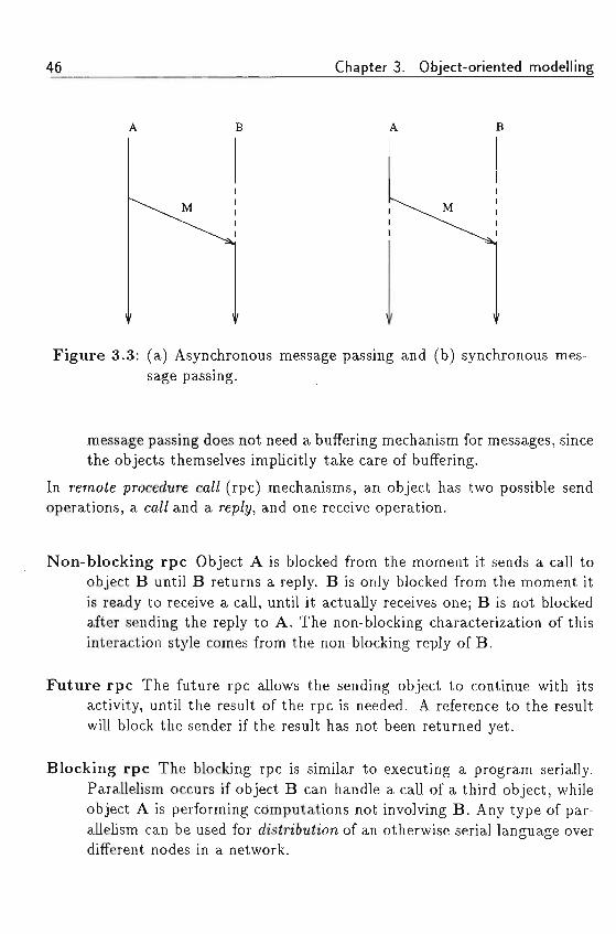
46 Chapter 3. Object-oriented modelling
B
M
Figure 3.3: (a) Asynchronous message passing and (b) synchronous mes-sage passing.
message passing does not need a buffering mechanism for messages, sincethe objects themselves implicitly take care of buffering.
In remote procedure ca// (rpc) mechanisms, an object has two possible sendoperations, a ca// and a rep/y, and one receive operation.
Non-blocking rpc Object A is blocked from the moment it sends a call toobject B until B returns a reply. B is only blocked from the moment itis ready to receive a call, until it actually receives one; B is not blockedafter sending the reply to A. The non-blocking characterization of thisinteraction style comes from the non-blocking reply of B.
Future rpc The future rpc allows the sending object to continue with itsactivity, until the result of the rpc is needed. A reference to the resultwill block the sender if the result has not been returned yet.
Blocking rpc The blocking rpc is similar to executing a program serially.Parallelism occurs if object B can handle a call of a third object, whileobject A is performing computations not involving B. Any type of par-allelism can be used for dis<n'6utfjon of an otherwise serial language overdifferent nodes in a network.
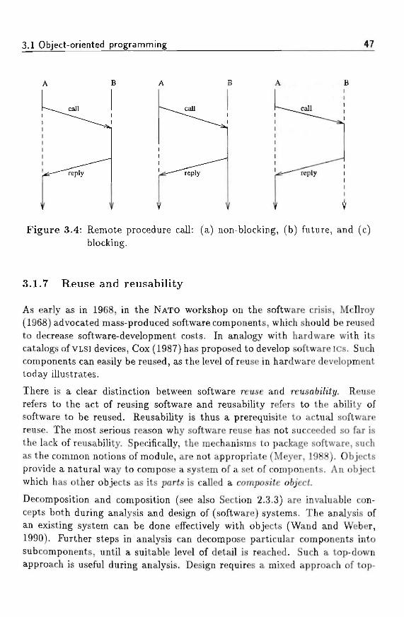
3.1 Object-oriented programming 47
Figure 3.4: Remote procedure call: (a) non-blocking, (b) future, and (c)blocking. ' !
3.1.7 Reuse and reusability
As early as in 1968, in the NATO workshop on the software crisis, McDroy(1968) advocated mass-produced software components, which should be reusedto decrease software-development costs. In analogy with hardware with itscatalogs of VLSI devices, Cox (1987) has proposed to develop software ics. Suchcomponents can easily be reused, as the level of reuse in hardware developmenttoday illustrates.
There is a clear distinction between software reuse and reusa&i'/tJy. Reuserefers to the act of reusing software and reusability refers to the ability ofsoftware to be reused. Reusability is thus a prerequisite to actual softwarereuse. The most serious reason why software reuse has not succeeded so far isthe lack of reusability. Specifically, the mechanisms to package software, suchas the common notions of module, are not appropriate (Meyer, 1988). Objectsprovide a natural way to compose a system of a set of components. An objectwhich has other objects as its parts is called a composite o6jecf.
Decomposition and composition (see also Section 2.3.3) are invaluable con-cepts both during analysis and design of (software) systems. The analysis ofan existing system can be done effectively with objects (Wand and Weber,1990). Further steps in analysis can decompose particular components intosubcomponents, until a suitable level of detail is reached. Such a top-downapproach is useful during analysis. Design requires a mixed approach of top-
48 Chapter 3. Object-oriented modelling
down decomposition and bottom-up composition. Reuse requires that partic-ular low-level components can be combined into larger components, eventuallyforming parts of the intended software system.
3.1.8 Memory management and persistence
An important issue in the implementation of object-oriented systems, is mem-ory management. In general, two aspects of memory management are con-sidered: (1) object construction and destruction, and (2) garbage collection.Both aspects can either be arranged by the programmer or by the run-timeenvironment of a program.
Object construction and destruction New objects are constructed byspecialized object-construction methods often attached to a class of objects.Such methods are called constructors. They may be invoked explicitly by aprogrammer providing a statement calling the constructor, or implicitly bythe run-time environment when the scope rules of the language necessitatethe creation of an object.
In a similar way, objects are destructed by so-called object-desctruction meth-ods, called destructors. They are invoked by the programmer, or by the run-time environment when an object needs to be destructed according to scoperules.
Garbage collection Garbage collection is the process of reclaiming mem-ory space that is not used, or that is used by objects which are no longerbeing referenced by a process. Garbage collection is often necessary since aprocess does not have an unlimited amount of memory. A special process, theyartajfe co//ector is responsible for keeping track of references to objects beingused. The garbage collector may be activated explicitly by a programmer,or by the run-time environment when available memory space becomes toosmall. On activation, the garbage collector reclaims the space occupied byunreferenced objects. Various algorithms for garbage collection are available,such as reference counting or generation scavenging.
Both the explicit and implicit forms of object construction/destruction andgarbage collection have their merits and drawbacks. Implicit garbage collec-tion has the advantage of levering the programmer from specifying the details
3,1 Object-oriented programming 49
of when and how memory is to reclaimed. The disadvantage is the unpre-dictable moment at which the garbage collector is activated, making suchan arrangement ill-suited for real-time applications. The latter disadvantageis remedied by making the programmer responsible for deallocating unusedmemory, allowing detailed control of memory management. The disadvantageof this approach is that it is cumbersome and error-prone. Errors in programsare often caused by incorrect memory (de)allocations. Such errors are hard toreproduce and thus difficult to correct.
In traditional languages the lifetime of data usually is not longer than theduration of a particular program. Databases store data whose persistencetranscends that of individual programs. When an object-oriented languageis equipped with persistence, it can be used as a basis for an o6jec£-onen<e</da(a6ase. Objects provide an adequate starting point for databases, since theyintroduce the concept of state between the execution of operations. Object-oriented databases are in some important aspects more appropriate for storinglarge amounts of information than relational databases.
1. An object-oriented database is capable of /jand/mjf composite o6jects. Arelational database only provides tuples, so that composite objects haveto be mapped onto lower-level structures, i.e., they have to be decom-posed and stored in multiple tuples. A client of a relational databasemust therefore have extensive knowledge of the database-representationschema in order to retrieve such composite objects.
2. In an object-oriented database, an object has an identify, which is in-dependent of its value. In a relational database, there is no concept ofidentity: an object is represented as a 'bundle' of properties. Two tupleswith equal values for their properties, representing two distinct objects,cannot be distinguished as being different in a relational database. Ob-ject identity is an important feature for sharing, updating and persis-tence.
3. A c/ass /lierarc/ij/ in an object-oriented database allows classes/types tobe defined in terms of other classes/types. In a relational database, sucha mechanism is not available.
4. £Vicapsu/a£ion o/ state and 6e/iauiour enables both data and operationsto be stored in an object-oriented database. Using a relational databaseforces a separation between data in the database, and the operationsperformed on the data by application programs.
50 Chapter 3. Object-oriented modelling
In this section, we have presented a representative set of concepts in object-oriented programming languages. From a modelling perspective, programsin an object-oriented programming language are models to be executed by acomputer. In the next section we discuss the use of modelling and its role inproblem solving. In the sections thereafter, the discussion of object-orientedconcepts for modelling is taken up.
3.2 Modelling
In this section we discuss the nature of modelling and examine its usefulnessin handling complex problems (a special case of which is software-systems de-velopment). When doing so, we seek answers to the following three questions:
1. why is modelling useful?
2. what is modelling? and
3. what is a model?
Problem solving in large-scale, complex systems requires adequate means tohandle complexity. In the systems-oriented approach modelling is the centralprocess of representing a problem domain into a model for subsequent analy-sis. The usefulness of modelling in problem solving is pro6/em sz'mp/z/icafa'on6y aistfrach'on. By representing a system in a model which is simpler thanthe original system, the complexity of the system is reduced, thus simplifyingthe problem. Simplification of reality is necessary for the following two rea-sons: (1) human beings are unable to handle the complexity of reality; and (2)not every detail of reality is important for the problem under consideration.Working with models requires the human modeller to be aware of this simpli-fication. The problem under consideration indicates which aspects of realityare important. It is the task of the modeller to determine the important as-pects to be represented in the model of the system. The quality of a model ismeasured by its purpose for the problem at hand. So, the quality of a modeldepends on the kind of problem and the ability of the modeller to recognizethe important aspects of the system. This implies that there is no single truemodel for all problems to be solved.
A system is defined by the elements or objects contained in it, together with therelations between these objects. The latter defines the sirucJure of a system.
3.2 Modelling 51
For solving problems using a model, there must be some form of correspon-dence between the original system and the model. In fact, this correspondencebetween system and model makes it necessary for the model to be a systemitself, for how can a system be modelled by something differing from it innature? Thus, the use of models is always based on at least two systems: 5,the system to be modelled, and M, the system used as the model of 5". Inorder for M to be an adequate model of 5 it has to be isomorp/iic with it.An isomorphic transformation of a system into another is a transformation inwhich the structure of both systems is similar.' In other words, the structureof the relations of 5 must be reflected in the structure of M.
A well-known example of two isomorphic systems is the hydro-electrical isomorphism,by which an electrical system is modelled by a similar waterworks system. In such anisomorphism, pipes correspond to electrical wire, taps to lights, pumps to batteries,valves to resistors and containers to capacitors. The structure of an electrical net-work, i.e., the electrical wire connections between the elements, should be translatedinto similar pipe connections between elements in the waterworks system. If doneproperly, the behaviour of a shining electrical lamp can now be studied by openingthe corresponding tap. Since the waterworks system is more familiar, it is helpful touse this model in order to understand the electrical analogy. Even only the mentaltransformation of an electrical system into a waterworks system is often insightful. Ofcourse, the waterworks system is not useful in all aspects. For example, the electricaleffect of a short circuit can be simulated in the waterworks model, but will never leadto fire as it does in the electrical model.
We can now be more precise on the steps a modeller has to make duringmodelling. First, the modeller has to select a part of the problem domainwhich is of interest to the problem under consideration. This comes downto selecting a system in the problem domain, in which the problem occurs.Second, the modeller has to determine which aspects of the system are to berepresented in the model. This entails the determination of an aspect systemof the system. Finally, the resulting aspect system has to be represented asa model system by applying an isomorphic transformation on it. All this iscondensed in the following definition.
Definition 3.1 Modelling is t/ie process o/ f/J determining a system in t/iepro6/em domain; ^ determining an aspect system o/ t/ie system; and f<?J/mding an isomorp/uc frans/ormation ftrans/afionj o/ t/ie aspect system intoa mode/ system.
The term frans/ormation often refers to a relation in which the /orm of the two sys-tems is not similar. In this thesis the term trana/ation is used to denote an isomorphictransformation.
52 Chapter 3. Object-oriented modelling
We note that in this definition the determination of a system includes (1)finding the relevant entities, and (2) finding the relevant relations betweenthese entities. It is not sufficient to consider a system as a set of relatedentities, since the nature of the relations would then still be unknown.
Sometimes, the correspondence between a system and its model is claimedto be based on a /jomomorp/iic transformation. That is, a transformation inwhich two or more different relations in the original system are transformedinto one relation in the model system. However, we think that such a modellingapproach based on homomorphism does not distinguish between the threeaspects of modelling as given in the definition discerned (i.e., the modellingapproach based on a homomorphic relation between system and model systemis itself homomorphic).
The definition of modelling leaves implicit what the nature of a model is. Itsuffices here to say that a model of a system is itself a system. We will comeback on the relation between systems and models later in this section.
3.2.1 Representation and interpretation
Models can have a physical nature, such as model cars and model trains.In computer science the nature of models is conceptual, i.e., consisting of(mathematical) concepts, such as data flows, functions, and predicates, etc.Since a conceptual model is often used as a means for communication too (e.g.,between people), one needs a mechanism to convey the model to a mediumfor communication. This in general comes down to making a /orma/izaiionof the model, such that its meaning is preserved in the formal description ofthe model. In order to communicate (or to visualize) models in computerscience, a /anyuo^e, i.e., a system of coded signs is used. Here, a language is acollection of agreements on the use of toibens that have a particular meom'np.
Bunge (1974, p. 8) defines signs used for communication in the following way:"An artificial sign, whether written, uttered, or in any other guise, is a physicalobject which (1) represents some other object (physical or conceptual); (2)belongs to a sign system (language), within which it can concatenate withother signs to produce further signs, and such that the whole system is usedfor (3) the communication or transmission of information concerning ideas,etc." Languages can be divided into sr/mfto/ie and non-sym&o/ic languages.The latter are of no interest for computer science, since they have a physicalnature. An example of such a language is the scent female animals release toattract male partners.
3.2 Modelling 53
Symbolic languages are based on symbols, which by convention designate cer-tain objects. The syntax of a symbolic language defines the set of basic symbolsor tokens (the alphabet) and the rules (the grammar) according to which thebasic symbols can be concatenated to form expressions (also called well-formedformulas). The tokens of a language designate certain objects in the real world.The semantics of a language is given by adding to its syntax a coding functionwhich associates every token with a set of objects called the denotatum ofthe token. For example, in arithmetic, numbers are designated by numerals:'number 3' is designated by the numerals "3" or "III". For effective communi-cation using a symbolic language it is necessary for the sender and the receiverto share a common background in order to understand the tokens of the lan-guage. A subset of symbolic languages, so-called conceptua/ /anguages focuson the expression of concepts. Such languages are used in mathematics andcomputer science. In a conceptual language, tokens designate concepts.
The modelling process consists of making a suitable representation of a UOD.The process of representation is based on conceptualization, and subsequentlyformalization. Both a conceptualization and a formalization assume a basic setof concepts and tokens, respectively. This is shown in Figure 3.5. The dashedboxes in the middle provide the basic concepts and tokens. A formalizationmay be used for communication. To this end, the sender transmits the tokensof the formalization by means of signals through some channel. The receiverdetects these signals and reconstructs the tokens by interpreting the signals.Of course, the receiver also needs to know u>/iic/i tokens can be accepted inthe transmission process. Subsequently, the tokens are interpreted to findthe corresponding concepts. The process of reconstructing tokens, concepts,and eventually the (possible) reality intended by the sender is a process ofinterpretation, shown in Figure 3.5 on the right hand side.
The relations between a token, the concept it designates, and the objects inthe world the token denotes are shown in Figure 3.6, which is known as themeaning triangle (Sowa, 1983). A concept re/ers to objects in the UOD, whichare the objects to which the concept applies. A generic concept (e.g., car) isapplicable to several objects, while an mdtvtdua/ concept (e.g., Amsterdam)only refers to one object. The combination of designation and reference iscalled denotation: a token denotes an object in the UOD. When the denotatumof a token happens to be conceptual, designation and denotation coincide.Such is the case, e.g., in arithmetic where "3" both designates and denotes'number 3', since 'number 3' is a conceptual denotatum.
The relations in the meaning triangle are the basis for defining the concepts
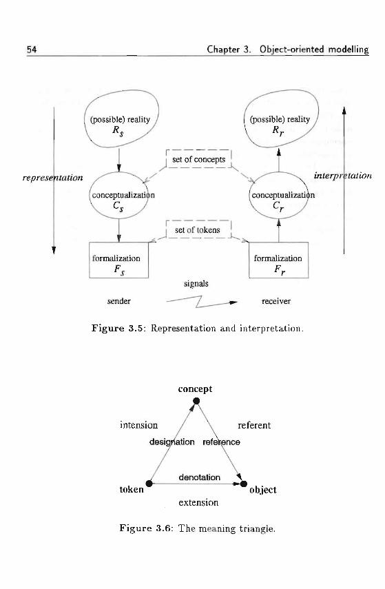
54 Chapter 3. Object-oriented modelling
repre.se itofion
SCI Ul IUKCI15
mterpr
formalization
signals
formalization
sender receiver
Figure 3.5: Representation and interpretation.
concept
intension / \ referent
designation reference
token " ~ objectextension
Figure 3.6: The meaning triangle.
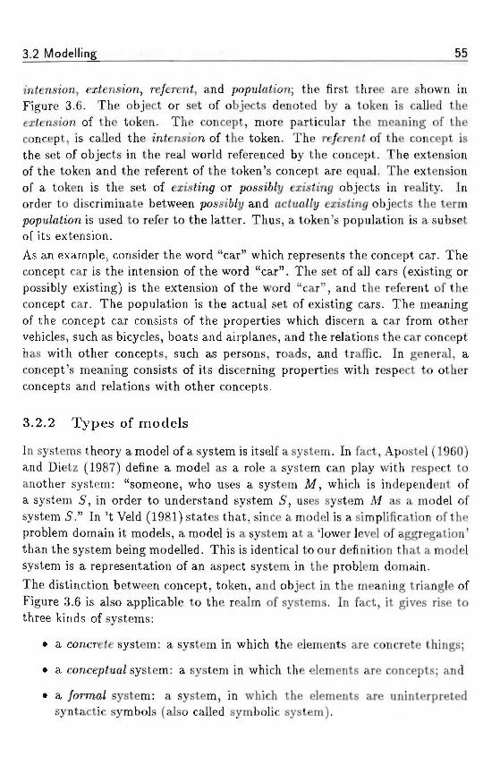
3.2 Modelling 55
intension, extension, re/erent, and popu/ation; the first three are shown inFigure 3.6. The object or set of objects denoted by a token is called theextension of the token. The concept, more particular the meaning of theconcept, is called the intension of the token. The re/eren< of the concept isthe set of objects in the real world referenced by the concept. The extensionof the token and the referent of the token's concept are equal. The extensionof a token is the set of existing or possi6/?/ exisfrng objects in reality. Inorder to discriminate between possi6/y and aciua//t/ eztsling objects the termpopu/ation is used to refer to the latter. Thus, a token's population is a subsetof its extension.As an example, consider the word "car" which represents the concept car. Theconcept car is the intension of the word "car". The set of all cars (existing orpossibly existing) is the extension of the word "car", and the referent of theconcept car. The population is the actual set of existing cars. The meaningof the concept car consists of the properties which discern a car from othervehicles, such as bicycles, boats and airplanes, and the relations the car concepthas with other concepts, such as persons, roads, and traffic. In general, aconcept's meaning consists of its discerning properties with respect to otherconcepts and relations with other concepts.
3.2.2 Types of models
In systems theory a model of a system is itself a system. In fact, Apostel (1960)and Dietz (1987) define a model as a role a system can play with respect toanother system: "someone, who uses a system M, which is independent ofa system 5, in order to understand system 5, uses system M as a model ofsystem 5." In 't Veld (1981) states that, since a model is a simplification of theproblem domain it models, a model is a system at a 'lower level of aggregation'than the system being modelled. This is identical to our definition that a modelsystem is a representation of an aspect system in the problem domain.
The distinction between concept, token, and object in the meaning triangle ofFigure 3.6 is also applicable to the realm of systems. In fact, it gives rise tothree kinds of systems:
• a concrete system: a system in which the elements are concrete things;
• a conceptua/system: a system in which the elements are concepts; and
• a /orma/ system: a system, in which the elements are uninterpretedsyntactic symbols (also called symbolic system).
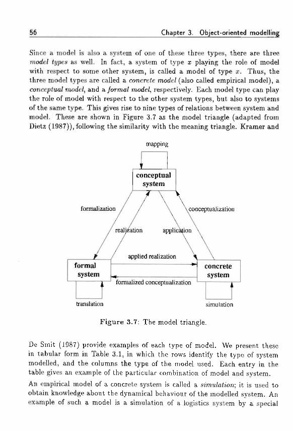
Chapter 3. Object-oriented modelling
Since a model is also a system of one of these three types, there are threemode/ <j/pes as well. In fact, a system of type x playing the role of modelwith respect to some other system, is called a model of type x. Thus, thethree model types are called a concrete mode/ (also called empirical model), aconcepiua/ mode/, and a /orma/ mode/, respectively. Each model type can playthe role of model with respect to the other system types, but also to systemsof the same type. This gives rise to nine types of relations between system andmodel. These are shown in Figure 3.7 as the model triangle (adapted fromDietz (1987)), following the similarity with the meaning triangle. Kramer and
mapping
fl!conceptual
system
formalization conceptualization
formalsystem
^ formalized conceptualization
concretesystem
translation simulation
Figure 3.7: The model triangle.
De Smit (1987) provide examples of each type of model. We present thesein tabular form in Table 3.1, in which the rows identify the type of systemmodelled, and the columns the type of the model used. Each entry in thetable gives an example of the particular combination of model and system.
An empirical model of a concrete system is called a simu/ahon; it is used toobtain knowledge about the dynamical behaviour of the modelled system. Anexample of such a model is a simulation of a logistics system by a special
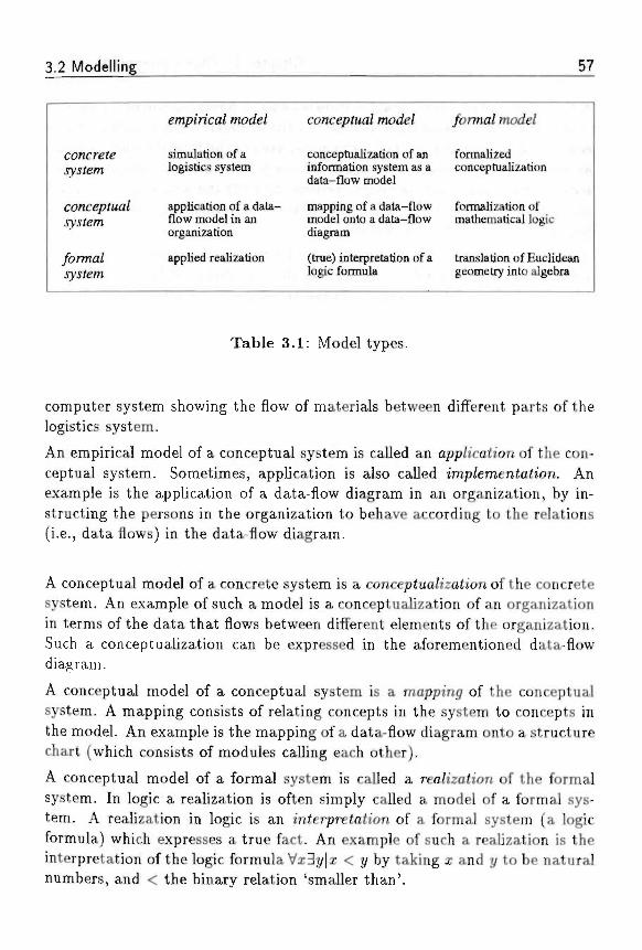
3.2 Modelling 57
concrete
concep/walsystem
ybrmalsystem
empirical mode/
simulation of alogistics system
application of a data-flow model in anorganization
applied realization
conceptual model
conceptualization of aninformation system as adata-flow model
mapping of a data-flowmodel onto a data-flowdiagram
(true) interpretation of alogic formula
/ormal model
formalized 'conceptualization
formalization ofmathematical logic
translation of Euclideangeometry into algebra
Table 3.1: Model types.
computer system showing the flow of materials between different parts of thelogistics system.
An empirical model of a conceptual system is called an app/zcah'on of the con-ceptual system. Sometimes, application is also called imp/emenZa<iem. Anexample is the application of a data-flow diagram in an organization, by in-structing the persons in the organization to behave according to the relations(i.e., data flows) in the data-flow diagram.
A conceptual model of a concrete system is a concep<ua/iza<zon of the concretesystem. An example of such a model is a conceptualization of an organizationin terms of the data that flows between different elements of the organization.Such a conceptualization can be expressed in the aforementioned data-flowdiagram.
A conceptual model of a conceptual system is a mapping of the conceptualsystem. A mapping consists of relating concepts in the system to concepts inthe model. An example is the mapping of a data-flow diagram onto a structurechart (which consists of modules calling each other).
A conceptual model of a formal system is called a rea/izah'on of the formalsystem. In logic a realization is often simply called a model of a formal sys-tem. A realization in logic is an interpretation of a formal system (a logicformula) which expresses a true fact. An example of such a realization is theinterpretation of the logic formula Vx3y|a; < t/ by taking x and j/ to be naturalnumbers, and < the binary relation 'smaller than'.
58 Chapter 3. Object-oriented modelling
A formal model of a conceptual system is called a /orma/izaiion of the concep-tual system. A formalization focusses on the symbolic representation of con-cepts in uninterpreted symbols. Examples are (1) the formalization of math-ematical logic, allowing the inference of true propositions by using formalizedreasoning schemes such as modus ponens, and (2) the axiomatic systems ofmathematics, in which symbol manipulation is performed without referring tothe interpretation of these symbols.
A formal model of a formal system is called a frans/ah'on of the formal system.Examples of such formal models are (1) the translation of Euclidean geome-try into algebra and vice versa, (2) the translation of Cartesian coordinatesinto polar coordinates, and (3) the translation of ASCII symbols into EBCDICsymbols.
The two direct relations between a formal system and a concrete system do notexist directly. They only exist through the intermediate step of a conceptualsystem. This is reflected in the naming of these relations: one can speak ofan applied realization (application and realization) and a formalized concep-tualization (formalization and conceptualization). This illustrates the centralrole conceptual models play within the modelling process. In fact, concep-tual models allow us to describe and circumscn'&e the empirical reality usingconcepts. Such conceptualizations can be used for formalizations, but, moreimportantly, they also allow us to conceptualize reality as we wo«W /ifce i< io6e. This twofold role of conceptual models is used in software developmentfor analysis and design purposes. The result of analysis is a model describingwhat is the case in the UOD, whereas design focusses on the description ofwhat is intended to be the case in the UOD, i.e., a description of a system ofwhich a part may be an automated system. Next, we look at the importanceof linguistic specification in modelling.
3.2.3 Linguistic specification
In the model triangle, a conceptual model refers to a UOD. In order to com-municate a conceptual model to another person, one has to express the modellinguistically. Such a representation is called a concep£ua/-mode/ speczyica-<»'on (or concep<«a/-mode/ sc/iema). The language a modeller uses is generallycalled a concep<ua/-mode/ speci/ica<ion /anguage. It is important to see thatany conceptualization requires some language. Such a language can be formalor informal, graphical or textual, etc. The use of a language in the representa-tion of a conceptual model presupposes some basic set of concepts which can
3.2 Modelling 59
be expressed in a conceptual model. In order to communicate a conceptualmodel M to a person p, the model is expressed in a language agreed upon bysender and receiver. The resultant representation i? is transferred via somemedium to the person p, who interprets the tokens of the language accordingto the concepts the language is meant to express. Communication succeeds ifp is able to interpret .ft and reconstruct M.
A program in a programming language is nothing else than a representation ofa conceptual model, in terms of the concepts on which the programming lan-guage is based. However, a program is both a conceptual-model specificationand a formal specification. A program in Pascal, e.g., is a conceptual-modelspecification, since it can be understood by a person familiar with the basicPascal concepts, such as program, procedure, function, variable, type, state-ment etc. However, the same Pascal program is also a formal specificationof an algorithm. Such a formal specification can be interpreted by a suitableprocessor, either directly, or with an intermediate irans/ah'on by means of acompiler into a similar formal specification (such as machine code). The pro-cess of interpretation of such a formal specification gives rise to a machine,i.e., a concrete system, which plays the role of empirical model with respectto the conceptual model specified by the Pascal program (cf. the model trian-gle). Thus, with reference to the model triangle, the resulting concrete systemis an application of the conceptual model, and an applied realization of theformal-model specification. The machine interpreting the formal specificationis, however, not aware of the concepts expressed in the formal specification; itonly knows which tokens to recognize, and what to do with these recognizedtokens. In fact, conceptual interpretation is the distinguishing feature whichhuman beings do and machines do not possess.
To sum up, any model specification presupposes an interpretation mechanism.Such an interpretation mechanism can either be at a low level, such as acomputer interpreting zeros and ones. Or it can be at a high level, such asnatural language or diagrams in human communication. The question remainswhich concepts are useful for human communication, and yet can also beinterpreted by a suitable automated interpreter. This is in fact the focus ofconceptual modelling in a more narrow sense than the one we sketched here.The next section on conceptual modelling sheds light on this more restrictedview of conceptual modelling, focussing on the aspects of tmderstamimy andcommunication among human beings.
60 Chapter 3. Object-oriented modelling
3.3 Conceptual modelling
The development of information systems also deals with automating partsof existing information systems. To this end, every automated informationsystem must contain an 'image' of the UOD it controls. Such an image is aconceptualization of a part of the world. Therefore, the problem of developinginformation systems can be viewed as a problem of conceptual-model develop-ment. Models are developed as part of the two most important phases in thesoftware life cycle, namely ana/ysis and design. During analysis, the currentinformation system has to be modelled; this is followed by the specification ofthe requirements of a new information system. During design, a model of thenew information system has to be developed.
The complexity of software development, treated in Chapter 2, makes it im-portant to have a clear understanding of both the UOD and the informationsystem to be realized. For this purpose, conceptual modelling can be usedto model information systems at a conceptual level, i.e., a level allowing con-cepts to be expressed. Thus, conceptual modelling addresses two importantproblems in systems development: (1) it allows to make a description of anexisting information system and its UOD in terms of abstract concepts; and(2) it allows to make a description of an automated information system at anabstract conceptual level. Referring to the model triangle, a conceptual modelplays a central role in system development. First, a conceptual model of theexisting information system and its UOD is the final 'product' of analysis ofthe UOD (conceptualization). Second, the conceptual model of the new infor-mation system is the output of the design process, which can be used for anapp/ication or imp/emen<ation in the UOD.
The focus of conceptual modelling is understanding and communication, asMylopoulos (1992) defines it: "Conceptua/ mode/Zinc is t/ie acfim j/ o//or-ma/ly describing some aspects o/ t/ie p/iysica/ and socia/ u>or/d around us /orpurposes o/ understanding and communication." The description resultingfrom conceptual modelling is often called a conceptua/-mode/ sc/iema. Refer-ring to the model triangle, a conceptual-model schema is a formalization ofa conceptual model. Often, the term conceptual model is used to denote theset of language elements a modeller may use when constructing a conceptual-model schema. Using such terminology, one may think of the relation betweena conceptual-model schema and the conceptual model in a similar way as therelation between a database schema, describing the schema of a particular
3.3 Conceptual modelling 61
database, and a data model, being the set of language elements to constructdatabase schemas. • . . . - . •
Conceptual modelling is the emerging result of streams in artificial intelli-gence (knowledge representation), databases (semantic data modelling), andsoftware engineering (object-oriented programming languages) (Brodie e< a/.,1984; Loucopoulos, 1992). We now consider the differences of conceptual mod-elling with respect to knowledge representation, semantic data models, andprogramming languages. The introduction of /raroes in the field of artificial in-telligence has led to the development of frame-based knowledge-representationlanguages, such as KL-ONE, KEE, and SRL (Brachman and Schmolze, 1985).Traditionally, knowledge representation focusses on interesting reasoning pat-terns and their computational representation. This assumes that the knowl-edge bases resulting from this representation will be used by some computerprogram to perform an 'intelligent' task. Conceptual modelling, however, fo-cusses on representation for understanding and communication among humanbeings (Mylopoulos, 1992).
Semantic data roode/s in database theory introduced the concepts of data inde-pendence and a6s£rac<ion /orms (Rolland and Cauvet, 1992). The idea of dataindependence is that the conceptual schema of a database should be free fromthe physical structure of the database, allowing a conceptual view of the UOD.Different abstraction forms aid during conceptual modelling. The most im-portant abstraction forms are c/assi/ica<ion, composition, genera/izaJion, andgrouping. A large variety of semantic data models have been proposed, such asthe ER model (Chen, 1976), RM/T (Codd, 1979), TAXIS (Borgida e< a/., 1984),SDM (Hammer and McLeod, 1981), DAPLEX (Shipman, 1981). For an overviewand comparison of the field of semantic data models, we refer to Peckham andMaryanski (1988).
The shortcoming of semantic data models is their orientation towards thestructure of passive data: there is no way to represent behaviour of entitiesin the UOD. In order to address this issue, oty'ecf-oriented data mode/s havebeen developed, such as GemStone (Maier and Stein, 1987), Orion (Kim e< a/.,1987; Kim e< a/., 1989; Banerjee and Kim, 1987), Ontos (Andrews and Har-ris, 1987), IRIS (Fishman e< a/., 1987) and O2 (Bancilhon et a/., 1987). Foran overview of object-oriented data models we refer to, e.g., ACM (1991).Semantic data modelling shares with conceptual modelling the objective ofrepresenting the UOD with appropriate abstraction mechanisms. However, se-mantic data modelling is by nature oriented towards the static aspects of the
62 Chapter 3. Object-oriented modelling
UOD. Furthermore, it introduces assumptions about the way the conceptualschema will eventually be realized in a database. Semantic data modelling isthus more data-oriented, whereas conceptual modelling is concept-oriented.
The evolution of abstraction mechanisms in programmm^ /anguages has re-sulted in object-oriented programming (see also Section 2.4.1 and Section 3.1).In contrast with semantic data models, object-oriented programming lan-guages focus on the representation of objects with behaviour. The executionof an object-oriented program then consists of a collection of objects invok-ing each other's operations via messages. The concept of an object has beenintroduced in Simula (Birtwistle e< a/., 1977), followed in numerous other lan-guages. There are at least over eighty different object-oriented programminglanguages, as reported by Saunders (1989). The advantage of object-orientedprogramming languages is the natural orientation towards the UOD. An objectis an abstraction of some entity in the UOD, including its operations. The di-chotomy between data structures and algorithms is thus addressed by objects,combining both a data perspective and an operational perspective. The dis-advantage of object-oriented programming languages is the inability to modelprocesses in an adequate way. In most object-oriented programming languages,the description of a process is 'hidden' in the description of the various be-haviours of participating objects. Object-oriented programming languages areoriented towards both representation of a the UOD and a program operatingwith the abstracted UOD. The representational aspects and the processingaspects are combined in the object, which makes an object-oriented program-ming language ill-suited for representation and communication of the UOD,since the representation is cluttered with implementation aspects.
3.3.1 Direction of fit
Wieringa (1990) observes that conceptual models can have different roles. Herefers to a direction o/^ii between a conceptual model and the UOD it models,also described by Searle and Vanderveken (1985). The direction o//i< betweentwo entities is an arrow which points to the entity to which the other entitymust adjust itself in case there is a mismatch between the two. Three differentkind of models resulting from their direction of fit with the UOD are shown inFigure 3.8.
The direction of fit determines the role of the conceptual model. If the modelshould be adjusted in case there is a mismatch between model and UOD, sucha model is called a descrt'phue mode/ (Figure 3.8a). If the UOD should be
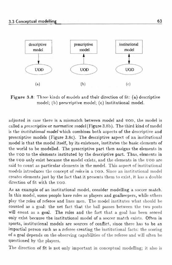
3.3 Conceptual modelling 63
descriptivemodel
i
prescriptivemodel
i i
institutionalmodel
(a) («=)
Figure 3.8: Three kinds of models and their direction of fit: (a) descriptivemodel; (b) prescriptive model; (c) institutional model.
adjusted in case there is a mismatch between model and UOD, the model iscalled a prescn'ph'ue or normative mode/ (Figure 3.8b). The third kind of modelis the msh'tutiona/ mode/ which combines both aspects of the descriptive andprescriptive models (Figure 3.8c). The descriptive aspect of an institutionalmodel is that the model itself, by its existence, institutes the basic elements ofthe world to be modelled. The prescriptive part then assigns the elements inthe UOD to the elements instituted by the descriptive part. Thus, elements inthe UOD only exist because the model exists, and the elements in the UOD aresaid to count as particular elements in the model. This aspect of institutionalmodels introduces the concept of ro/es in a UOD. Since an institutional modelcreates elements just by the fact that it presents them to exist, it has a doubledirection of fit with the UOD.
As an example of an institutional model, consider modelling a soccer match.In this model, some people have roles as players and goalkeepers, while othersplay the roles of referee and lines men. The model institutes what should becounted as a goal: the net fact that the ball passes between the two postswill count as a goal. The roles and the fact that a goal has been scoredonly exist because the institutional model of a soccer match exists. Often insports, institutional models are sources of conflict, since there has to be animpartial person such as a referee creating the institutional facts: the scoringof a goal depends on the observing capabilities of the referee and will often bequestioned by the players.
The direction of fit is not only important in conceptual modelling; it also is
64 Chapter 3. Object-oriented modelling
applicable to programs. Conceptual models and programs can contain de-scriptive, institutional, and prescriptive elements. In a conceptual model, e.g.,Ji/pes describe the kinds of entities in the UOD and /aws can be used to prescribehow the entities should behave. In a computer program, c/asses describe thecommon structure of objects with assertions prescribing particular invariantsto be true in every state of the program execution. *
3.3.2 Object-oriented modelling
Conceptual modelling is based on the existence of a set of concepts and struc-tures that may be represented in a conceptual model. Different varieties ofconceptual modelling arise by taking different sets of concepts and structures.Thus, object-oriented modelling is a specialization of conceptual modellingwith concepts of object orientation. Based on the earlier definition of mod-elling, we define object-oriented modelling in a similar way.
Definition 3.2 Object-oriented modelling uses t/«e concepts o/ o6/ec£ orien-tation <o produce an object-oriented mode/.
The term object model could be used to denote a model resulting from theobject-oriented modelling process. However, we use it here in the sense of theset of basic concepts to model any UOD or application domain.
Definition 3.3 ,4n object model foM j de/mes t/ie conceptual entities t/iat can6e used/or t/je object-oriented mode/Zing o/ an app/ication domain or UOD.
We remark that within a particular modelling environment there is always oneobject model, which is the base on which any model within that particularcontext is founded. Thus, it is normal to speak about t/ie Smalltalk objectmodel or t/ie C++ object model. When it is clear from the context whichobject model we are referring to, we usually refer to it as t/ie object model.The object model thus refers to a class of models based on the same con-cepts. Similar terminology is also used in, e.g., Booch (1991), who presentsthe framework for object-oriented design as t/ie object mode/. Analogously, t/«erelational model in database research stands for the class of all possible logicalmodels of all possible specifications in a relational language. Any modellingactivity presupposes some basic set of concepts. This comes readily apparentif we compare the different kinds of programming styles that are used to-day, together with their basic abstractions: procedure-oriented modelling uses
3.3 Conceptual modelling 65
algorithms, object-oriented modelling uses classes and objects, rule-orientedmodelling uses if-then rules etc. In short, we adhere to the common practiceof calling the concepts for object-oriented modelling the object model, whichwill be apparent from its context as well. In case of ambiguity we will makethe distinction between object model and model explicit.
The result of modelling a particular domain in an object-oriented way is calledan oftjeci-onented mode/.
Definition 3.4 .4n object-oriented model (boM,) is </ie resu/< o/ mode//m<7 apar£icu/ar domain using t/ie concepts oj ered 6y an o6jec< mode/.
A final remark should be made on the use of the term me(a mode/, which shouldbe distinguished clearly from the term object model. A meta model describesthe generic structure of models that can be constructed. So, a meta model isa model for models. A meta model is also expressed in some language, whichis not necessarily the same for expressing 'normal' models. An illustration ofa meta model is the use of the Backus-Naur formalism to specify the syntaxof a programming language. The specification of, e.g., the syntax of Pascal, isthe meta model for all syntactically correct Pascal programs. In this example,the meta model is specified in terms of the Backus-Naur formalism, whereasa Pascal program is defined in terms of a program, functions, procedures, andvariables. A meta model which is defined in similar terms as the models itrefers to introduces the important concept of rejection, which we come backto later in this thesis.
3.3.3 Object-oriented modelling and INCA-COM
There is no consensus about a commonly accepted definition of the object-oriented approach. As Wand (1989) premises, much of this confusion sur-rounds objects because they emerged as programming concepts and, therefore,were driven by implementation considerations. He suggests that the perspec-tive of the object-oriented paradigm should move from implementation-drivento modelling-driven. This is in line with the earlier observations of, e.g., Cox(1987) and Abbott (1987), viz. that there is a continuous evolution in program-ming, away from computer-oriented principles towards problem- or knowledge-oriented principles. Indeed, the Smalltalk programming environment focusseson implementation, and its class hierarchy reflects this by offering a large setof classes for this purpose, such as lists and bitmaps. However, describing a
66 Chapter 3. Object-oriented modelling
problem domain using domain concepts is gaining importance over implemen-tation techniques. This requires an adequate set of concepts for modellingcomplex object domains.The multitude of object-oriented programming languages shows that there isa great interest in adopting new concepts. The focus of the past years hasbeen directed towards the application of object-oriented concepts during theimplementation of software systems. The attraction of this style of workinghas been an improvement of program code, and consequently, a gain in ef-fectiveness of software maintenance. Using an object-oriented programminglanguage does not imply better designs: it is still possible, when using object-oriented techniques, to make a system which is difficult to maintain. Afterall, designing is and will remain a creative task, requiring human or artificialintelligence.
The concepts of object orientation are by no means new. They are natural tohuman thinking as illustrated by the ontologic conceptualization of reality interms of interacting objects. It is worthwhile to search for means of adoptingthe object-oriented modelling paradigm at higher levels than solely duringimplementation, i.e., adopting it during the analysis and design of a system.Efforts in this direction are geared towards the development of object-orientedana/ysis and object-oriented
Among the current methodologies for object-oriented analysis are Object-Oriented Requirements Specification (Bailin, 1989) and Object-Oriented Anal-ysis (Coad and Yourdon, 1991; Shlaer and Mellor, 1988). Fichman and Ke-merer (1992) give a clear exposition on today's methodologies for object-oriented analysis and design. They conclude that the current methodologiesfor object-oriented analysis are revolutionary compared to the process-oriented(i.e., data flow-oriented) structured methodologies, such as Structured Anal-ysis (DeMarco, 1979). Compared to the <fatfa-onen£ed methodologies, suchas Information Engineering (Martin, 1990) and even JSD (Jackson, 1983),object-oriented analysis methodologies are more akin. From this point of view,object-oriented analysis methods are an evolutionary step.
The purpose of object-oriented design is to define the arc/iiieciure of a softwaresystem. It is important during design to use software-engineering concepts, inorder to make the resulting design understandable and easy to modify. En-capsulation and modularity introduce two levels of partitioning within object-oriented design: they are based on (1) the object, and (2) groups of related ob-jects. Currently, Object-Oriented Design (Booch, 1991) and Object Modelling
3.3 Conceptual modelling 67
Technique (Rumbaugh ef a/., 1991) are the most widely used object-orienteddesign methodologies.
Object-oriented modelling at higher levels The way to object-orientedanalysis and design is a bottom-up approach. The first models built withobject-oriented concepts were computer programs. Since the object-orientedapproach to programming proved to be successful, it was adopted also fordesign and analysis. We note that a similar bottom-up approach has takenplace with structured programming. As soon as structured programming wasbeing used, researchers tried to exploit similar concepts for design and even-tually analysis. The 1970s have become known as the structured era, withDijkstra (1968) (structured programming), Page-Jones (1980) (structured de-sign), and Yourdon and Constantine (1978) (structured analysis) making upthe structured tripode.Analysis and design models should be defined independently of any imple-mentation considerations. For the purposes of understanding a domain andcommunication with other people one needs to construct models which areclose to a human being's perception of the real world. Such modelling activ-ity is called concep£ua/ mode/Zing and the models resulting from conceptualmodelling are called concep<ua/ mode/s. Within the context of object orienta-tion, a conceptual model is called an o6jec<-onenied conceptua/ mode/(OOCM).The conceptual framework containing the concepts a modeller may use for theconstruction of a OOCM is called a conceptua/ o6jec< mode/ (COM).
Following the same terminology for the object model in the context of object;oriented modelling, the concepJua/ object model is used in the context ofobject-oriented concepiua/ modelling. Below we give two relevant definitions.
Definition 3.5 i4 conceptual object model (COM,) de/ines Me concept* <o 6eused /or Me o6;ec<-onen<ed concepiua/ mode//m<7 o/ an app/icah'on domain orUOD.
Analogous to an object-oriented model we define the object-oriented concep-tual model.
Definition 3.6 .4n object-oriented conceptual model (OOCM,) is Me resu/i o/mode//ina a particu/ar domain usino Me concepts Ojffered 6y a concepiua/ o6jec<mode/.
For the construction of OOCMS, one needs a COM offering the designer theconceptual tools to construct an object-oriented model of an interesting slice
68 Chapter 3. Object-oriented modelling
of reality. Such an OOCM can then be used for implementing the system ina programming language. Ultimately, the OOCM can be used as a "program"itself by making the objects in the OOCM alive, thus creating a simulation ofthe real world.
The complexity of current systems is so high that existing COMs are notadequate in addressing it. Their most serious drawback is their semanticalpoverty, i.e., the concepts used do not refer to the concepts human beingsuse. This observation has been made too by Lenat ei a/. (1990) as the ma-jor source of so/^ware 6n'M/eness: "Programs often use names for conceptssuch as predicates, variables, etc., that are meaningful to humans examiningthe code; however, only a shadow of that rich meaning is accessible to theprogram itself." The shortcoming of existing COMs is their inadequacy tomodel the essential meaning of objects, caused by a too small set of descrip-tive means: existing COMs only offer a modeller attributes and methods todescribe objects (Braspenning e< a/., 1989b). The use of such COMs has seri-ous drawbacks. First, the modeller has to translate the things found in the realworld to model concepts (representation). Such a translation often becomesa <rans/ormaiion, since existing COMs do not have enough concepts neces-sary for describing real-world entities. Second, users of such a model haveto transform the model concepts back again to their real-world equivalents(interpretation). Both representation and interpretation implicitly suppose acommon background shared by modeller and model user. In complex domainsthis background is complex as well, and leaving it implicit is risky since themodeller and model user may understand the model differently. Such misun-derstandings can have great impacts when discovered too late. Boehm (1981)has shown that the costs of corrections in software systems increase signifi-cantly as a function of the stage in which the change is made. Object-orientedconceptual modelling addresses the issues of representation and interpretationof a UOD. It is based on object-oriented concepts, the meaning of which canbe enhanced by using semantically motivated means for description and bymeaningful associations between objects.
3.3.4 Object-oriented conceptual modelling
Having described modelling, object-oriented modelling and conceptual mod-elling, we conclude this chapter with an integrating view on 067'ecZ-on'erifee/conceptua/ mode//mg. This will provide the basis for INCA-COM and a valida-tion of using object-oriented concepts in INCA-COM.
3.3 Conceptual modelling 69
We stress that INCA-COM will offer concepts for object-oriented models dur-ing analysis and design. It is frequently advocated that the object-orientedparadigm is the solution to the software crisis through its unified use of objectsduring the entire software life cycle. However, analysis and design are differ-ent stages and should not be intermingled (although iteration between themis useful). Analysis strives to a clear view of w/iai is currently the case in theUOD. Using the analysis, a decision has to be made regarding the part of theUOD to be automated. This results in a requirements specification of a systemto be developed. Based on the requirements specification, a system must bedesigned, describing the system in a machine and language-independent way.Finally, the design should be implemented and tested. (See also Figure 2.3 forthe steps in the software life cycle.)
So, the two stages analysis and design are intimately bound, but the analysisdescribes the UOD and the design describes the system. Both analysis anddesign add knowledge to the models, but their nature differs: analysis pro-duces domain knowledge about the UOD, whereas design results in applicationknowledge. In our opinion, the distinction between domain knowledge and ap-plication knowledge should be reflected in INCA-COM. The role of INCA-COMwith respect to the different roles of OOCMS is shown in Figure 3.9. The phasesof the software life cycle are shown in bold type face (see also Figure 2.3). Ev-ery life-cycle activity results in a particular model, such as an analysis model, adesign model, and a computer program. The analysis results in a descriptionof the current real and information system, whereas the computer programmodel resulting from the implementation describes the automated informa-tion system, which is a part of the larger information system. A completeddesign model can be used for simu/a£ion purposes to check the validity of theautomated information system.
Why should one adopt object-oriented concepts for conceptual modelling?By answering this question we give insight into the usefulness of the object-oriented approach for conceptual modelling in software-system development.There are three main reasons to use object-oriented concepts during conceptualmodelling. Each will be treated below. For similar reasons see also, e.g.,Fiadeiro et a/. (1992).
Natural view of the world
The development of automated information systems deals with automatingparts of existing information systems. Before automating, a clear description
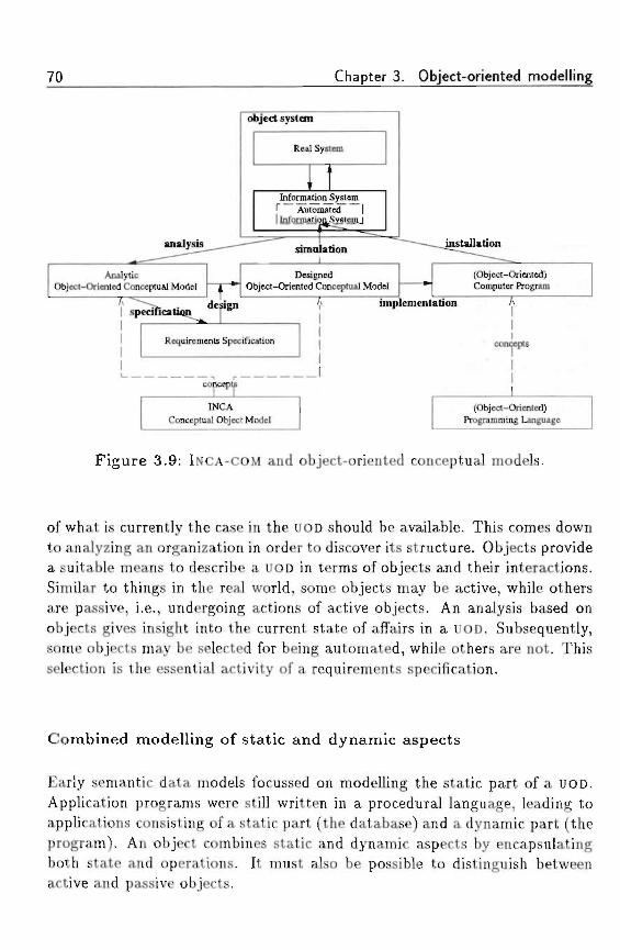
70 Chapter 3. Object-oriented modelling
object system
Real System
Information System1" Automated I1 InformationSystem 1
simulation
AnalyticObject-Oriented Conceptual Model
DesignedObject-Oriented Conceptual Model
(Object-Oriented)Computer Program
implementation
Requirements Specification concepts
INCAConceptual Object Model
(Object-Oriented)Programming Language
Figure 3.9: INCA-COM and object-oriented conceptual models.
of what is currently the case in the UOD should be available. This comes downto analyzing an organization in order to discover its structure. Objects providea suitable means to describe a UOD in terms of objects and their interactions.Similar to things in the real world, some objects may be active, while othersare passive, i.e., undergoing actions of active objects. An analysis based onobjects gives insight into the current state of affairs in a UOD. Subsequently,some objects may be selected for being automated, while others are not. Thisselection is the essential activity of a requirements specification.
Combined modelling of static and dynamic aspects
Early semantic data models focussed on modelling the static part of a UOD.Application programs were still written in a procedural language, leading toapplications consisting of a static part (the database) and a dynamic part (theprogram). An object combines static and dynamic aspects by encapsulatingboth state and operations. It must also be possible to distinguish betweenactive and passive objects.
3.4 Object-oriented concepts
Unit for modularity and reuse '
An analytic OOCM is used as the basis for the development of an automatedinformation system. Such an information system can be seen as a collectionof interacting objects. The development process starts with the OOCM, byautomating particular objects. An object provides a unit for modularizingthe resulting information system and dividing the development process. Fur-thermore, since objects are abstractions of particular entities in the UOD, itis likely that such automated objects may be reused in different informationsystems. Of course, implementation reuse is not new, since software (function)libraries provide similar facilities. However, reuse based on objects with stateand operations, provides a better unit for reuse.
Finally, one question remains to be answered: which concepts are useful inobject-oriented modelling?
3.4 Object-oriented concepts
This section concludes the chapter by introducing concepts which a COMshould be able to represent. The concepts are based on ontological princi-ples. In ontology there is a distinction between (1) things and (2) genericconcepts (classes). Things are entities in the UOD having an identity and adescription. We call the representation of a thing an object. Classes are ab-stractions of concrete things. For the semantics of a UOD, the structure of aUOD should be expressed in the structure of the resulting OOCM. Therefore,objects and classes can be related to each other in meaningful ways. Threeof such semantics enhancing relations are classification, generalization, andcomposition; their dual relations are instantiation, specialization, and decom-position (see also, e.g., Kristensen and 0sterbye (1991)). Below we treat theconcept </im<7 and the three relations mentioned above, together with theirduals. In Chapter 4 they are used for the concepts in INCA-COM.
3.4.1 Thing
In Bunge's ontology the concept of "thing" is introduced as the basic elementthe world is composed of (Bunge, 1977). A thing is a combination of substanceand /orm, which will be introduced below.
72 Chapter 3. Object-oriented modelling
Substance The basic principle of Bunge's ontology is the existence of sub-stantial individuals (also called entities). A substantial individual is the resultof stripping a thing of its properties. Thus, a substantial individual is a 6are
Form Substance expresses the fact that there exist individuals, which wecan study apart from their form. However, this is a simplification. In reality,substance is bound to form: there are no bare individuals (formless substance)except in our imagination, nor are there pure forms apart from matter. Bunge(1977) makes a distinction between different types of properties. Substantialproperties are features of substantial individuals, and conceptual propertiesare features of conceptual individuals (conceptual properties are also calledattributes). Because a model of substantial individuals is built with concepts,it contains attributes, representing substantial properties. It is important tonote, that the main purpose of Bunge's ontology is descriptive modelling, i.e.,modelling the existing world through description. The distinction betweenproperties and attributes is based on descriptive modelling: an (existing)object possesses properties, which are captured within a descriptive modelthrough attributes. Some properties are represented in the model, while oth-ers are not.
Thing A Mmg is a substantial individual endowed with all its properties.Thus, the concepts of substance and form are combined in the concept of athing: a thing is something that exists (substance) and about which some-thing can be said (form). A substantial individual possesses properties, whichbecome known to us via attributes.
3.4.2 Classification and instantiation
Classification and instantiation are relations between generic concepts andindividuals. Classification consists of assigning an individual to a concept.The concept to which an individual belongs is also called its class. The inverserelation of classification is instantiation. It consists of the formation of anindividual based on a concept.
According to Wieringa (1990), the goal of classification is to formulate lawsthat obtain in the UOD. That is, the classes in a classification should be suchthat all and only objects of a class obey a law. Laws may be empirical (humanshave an age), analytical (the age of a human is a positive natural number),
3.4 Object-oriented concepts |_ 73
normative (each person should have a name and address), or institutional(persons older than 18 are voters). '; .; . . , >,(,??
Although both classification and instantiation relate concepts and concretethings, their application domain is quite different. Classification is importantin conceptfua/ models, in which the description of a particular domain is es-sential. Classification is thus a means of identifying objects. To identify anobject with respect to a classification is to determine, given a few propertiesof the object, of which class(es) it is a member (Wieringa, 1990, p. 68). Thiskind of classification is important in qualitative sciences, such as biology andchemistry. It represents knowledge about the classified objects, which can beused to infer new knowledge about the objects. . ' ' .
Instantiation is used in programs to create new instances, based on the inten-sion of the class. Once the common underlying structure of a set of objectshas been determined (i.e., finding the generic concept and forming a class),the class can be used as a 'factory' creating distinct objects, which share thecommon structure. The objects belonging to a class are called the instancesof the class. The term instantiation is used primarily in programming lan-guages, which are implementation languages. We remark that the term classis used in these languages both to designate a concept and to act as a run-timeimplementation mechanism.
3.4.3 Generalization and specialization
The concept of a hierarchy plays an important role in handling the variousabstractions distinguished in a particular domain. A hierarchy is used toorder different abstractions. A hierarchical organization is a simplificationof a particular domain, that helps human beings to organize it. The twomost important appearances of hierarchy are the generalization/specializationhierarchy, and the part/whole hierarchy.
Whereas classification organizes a UOD with respect to the difference betweenconcrete things and concepts, generalization and specialization order differentconcepts. Generalization and specialization are relations between generic con-cepts. The resulting network of relations is called a taxonomy, since it imposesan order on the different concepts.
A taxonomy is the result of the classical way of specifying the essence of objectsin a class (the intension of the class). This method is used, e.g., in biology andis based on the method of genus and dij^erence. A class is specified by givingits genus and its specific differences. As Wieringa (1990, p. 80) describes
74 Chapter 3. Object-oriented modelling
it: "(1) The jrenus is that part of essence which is predicable also of otherthings differing from it in kind; (2) The speoi/jc dzjfferences are those partsof the essence which distinguish it from other subclasses of the same genus.These subclasses are called species." The definition by genus and difference isby nature hierarchical. For this reason, taxonomies of classes are also calledc/ass /iierarc/iies. Each definition of a class in a taxonomy defines a generalconcept, which is the intension of the defined class. Since the definitions form ahierarchy by the method of genus and difference, the concepts form a hierarchyas well. And since the concepts are class intensions, the corresponding classextensions are also hierarchically ordered.
The definition method of genus and difference makes the species more spe-cific than its genus: the definition of a species consists of its genus, and anyadditional specific characteristics. Since the intension of the species is morespecific, it is predicable of a smaller number of things. The intension of thegenus is less specific and thus predicable of more things than the intension(s)of its species. As a result, the extension of a genus is larger than the extensionof its species. The hierarchical definition of genus and difference thus givesrise to a subset relation on the extensions of the classes. This subset relationis contrary to the intension of the classes defined. A class G generalizes a class5 if G's intension is less specific than 5"s intension, and G's extension includes5's extension. G is called a generalization of 5", and 5 is called a specializationof G.
3.4.4 Composition and decomposition
Besides the hierarchical ordering of classes by means of generalization andspecialization, a second form of hierarchy is the use of composite objects. Acomposite object is an object which has other objects as its parts. Whereasgeneralization and specialization structure a domain by relating different con-cepts, composition and decomposition order object instances by relating themin terms of Wio/es and paris.
There are several applications of composition and decomposition. The well-known methodology of stepun'se re/memen£ is based on the algorithmic de-composition of programs into smaller program units. This process leads toan organization of a program as a composition of functions and proceduresat different /eue/s o/ a6s/rac<icm. Structured programming is based on thismethodology.
A level concept is a natural way of structuring a domain. Human beings
3.4 Object-oriented concepts 75
employ levels of abstraction when considering, e.g., a book as a hierarchy ofchapters, sections, subsections, paragraphs, subparagraphs, sentences, words,and characters. This example illustrates that for each decomposition, their issome basic level, serving as the atomic level of decomposition. The level ofcharacters, e.g., is the atomic level for decomposition of books.
Frequently, composition as a structuring relation between part objects andcomposite objects is not supported explicitly by object-oriented languages.The usual way of constructing a composite object is using the values of at-tributes to refer to the parts of the composite object. The disadvantage ofthis lack of support is that the semantics of composition are not supported bythe programming language, but must be guarded by the programmer. For ex-ample, the deletion of a composite object should ideally result in the deletionof its part objects. Normally, it is not sufficient to delete only the referencesto part objects because then these may continue to exist. For effective reuse,a programming language should support composite objects by offering specialfacilities for describing compositional structures.
This chapter has set the stage for the discussion of INCA-COM. We haveinvestigated several object-oriented programming languages, and extracted theconcepts found in such languages. Object-oriented programming is defined asa specialization of object-oriented modelling, which is a form of conceptualmodelling. For use in INCA-COM we have looked at the importance of object-oriented concepts in high-level conceptual modelling. The three main reasonsto adopt an object-oriented approach in high-level conceptual modelling are:(1) object-oriented concepts allow a natural view of the world; (2) objectsprovide a unified concept for modelling both static and dynamic aspects ofthe world; and (3) objects are an adequate unit for modularity, enhancingtheir reuse. The next chapter defines the concepts of INCA-COM.

76 Chapter 3. Object-oriented modelling
« . . ' * • : : , • , 1 >••!•!!•
' f: if
Chapter 4
The INCA ConceptualObject Model
If you tell the truth, you don't have to remember anything.Twain
In this chapter we resume the description of INCA-COM outlined at the endof Chapter 2. In Chapter 3 we discussed the necessary concepts of objectorientation for INCA-COM. The description of INCA-COM is started with anintroduction of the basic concepts of object, description, and sort. It is followedby an elaboration of the conceptual framework of Figure 2.6. Next, we describethe four different kinds of models of objects and systems. The chapter isconcluded with a comparison of INCA-COM and related work.
4.1 Basic concepts
Before treating the four different models used in INCA-COM, we turn to thebasic concepts, i.e., the concepts underlying the models. These are essentiallythe following three concepts: object, description, and sort.
4.1.1 Object
An object is defined as an individual concept having an own identity. Theform of an object is captured in its descriptions. Thus, a (conceptual) objectreflects Bunge's ontological concept of thing (see Section 3.4). Additionally, anobject can be distinguished from other objects by means of its name , i.e, the
77
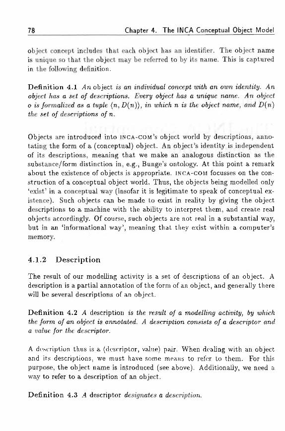
78 Chapter 4. The INCA Conceptual Object Model
object concept includes that each object has an identifier. The object nameis unique so that the object may be referred to by its name. This is capturedin the following definition.
Definition 4.1 .4n object is an mcfa'm'dua/ concept un'i/i an own identity. .4nofcjcci /ias a se< o/ descnpttons. £uen/ o6;ect /ias a unique name. /In 06/ecto is /orma/ized as a tup/e (n, .D(n)), in w/iic/i n is f/ie o6;eci name, and -D(n)t/ie se< o/ descriptions o/ n.
Objects are introduced into INCA-COM'S object world by descriptions, anno-tating the form of a (conceptual) object. An object's identity is independentof its descriptions, meaning that we make an analogous distinction as thesubstance/form distinction in, e.g., Bunge's ontology. At this point a remarkabout the existence of objects is appropriate. INCA-COM focusses on the con-struction of a conceptual object world. Thus, the objects being modelled only'exist' in a conceptual way (insofar it is legitimate to speak of conceptual ex-istence). Such objects can be made to exist in reality by giving the objectdescriptions to a machine with the ability to interpret them, and create realobjects accordingly. Of course, such objects are not real in a substantial way,but in an 'informational way', meaning that they exist within a computer'smemory.
4.1.2 Description
The result of our modelling activity is a set of descriptions of an object. Adescription is a partial annotation of the form of an object, and generally therewill be several descriptions of an object.
Definition 4.2 .4 description is t/ie resu/t o/ a mode/Zing actiuity, 6y to/iic/it/ie /orm o/ an o6;'ect is annotated. .4 description consists o/ a descriptor anda ua/ue /or t/ie descriptor.
A description thus is a (descriptor, value) pair. When dealing with an objectand its descriptions, we must have some means to refer to them. For thispurpose, the object name is introduced (see above). Additionally, we need away to refer to a description of an object.
Definition 4.3 4 descriptor designates a description.
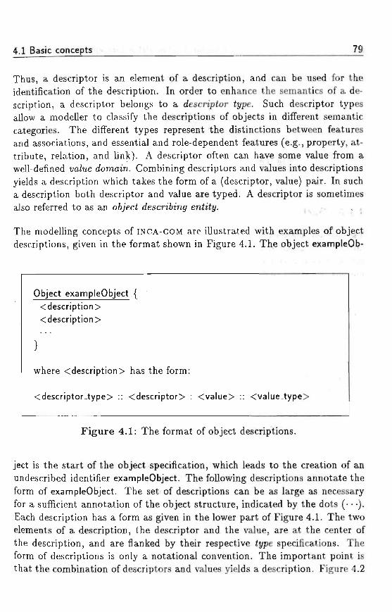
4,1 Basic concepts 79
Thus, a descriptor is an element of a description, and can be used for theidentification of the description. In order to enhance the semantics of a de-scription, a descriptor belongs to a descriptor type. Such descriptor typesallow a modeller to classify the descriptions of objects in different semanticcategories. The different types represent the distinctions between featuresand associations, and essential and role-dependent features (e.g., property, at-tribute, relation, and link). A descriptor often can have some value from awell-defined uo/ue domain. Combining descriptors and values into descriptionsyields a description which takes the form of a (descriptor, value) pair. In sucha description both descriptor and value are typed. A descriptor is sometimesalso referred to as an o6jecf descri6zn<7 entity. , -. ,. , ,
The modelling concepts of INCA-COM are illustrated with examples of objectdescriptions, given in the format shown in Figure 4.1. The object exampleOb-
Object exampleObject {<description> .<description>
} • • • • : . . ." • - -
where <description> has the form:
<descriptor_type> :: <descriptor> : <value> :: <value_type>
Figure 4.1: The format of object descriptions.
ject is the start of the object specification, which leads to the creation of anundescribed identifier exampleObject. The following descriptions annotate theform of exampleObject. The set of descriptions can be as large as necessaryfor a sufficient annotation of the object structure, indicated by the dots (•••).Each description has a form as given in the lower part of Figure 4.1. The twoelements of a description, the descriptor and the value, are at the center ofthe description, and are flanked by their respective type specifications. Theform of descriptions is only a notational convention. The important point isthat the combination of descriptors and values yields a description. Figure 4.2
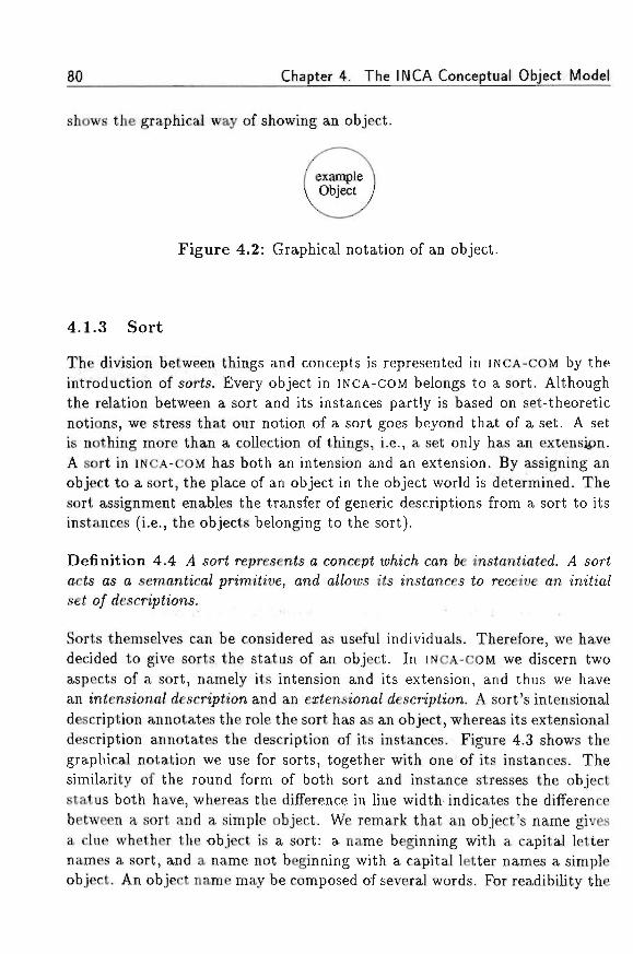
80 Chapter 4. The INCA Conceptual Object Model
shows the graphical way of showing an object. ' :
Figure 4.2: Graphical notation of an object.
4.1.3 Sort '
The division between things and concepts is represented in INCA-COM by theintroduction of sorts. Every object in INCA-COM belongs to a sort. Althoughthe relation between a sort and its instances partly is based on set-theoreticnotions, we stress that our notion of a sort goes beyond that of a set. A setis nothing more than a collection of things, i.e., a set only has an extension.A sort in INCA-COM has both an intension and an extension. By assigning anobject to a sort, the place of an object in the object world is determined. Thesort assignment enables the transfer of generic descriptions from a sort to itsinstances (i.e., the objects belonging to the sort).
Definition 4.4 .4 sort represents o concept u>/iic/i can 6e instantiated. 4 sortacts as a semantica/ pn'mitiue, ana" a//ou;s its instances to receive an initia/set o/ descriptions.
Sorts themselves can be considered as useful individuals. Therefore, we havedecided to give sorts the status of an object. In INCA-COM we discern twoaspects of a sort, namely its intension and its extension, and thus we havean intensiona/ description and an exfensiona/ description. A sort's intensionaldescription annotates the role the sort has as an object, whereas its extensionaldescription annotates the description of its instances. Figure 4.3 shows thegraphical notation we use for sorts, together with one of its instances. Thesimilarity of the round form of both sort and instance stresses the objectstatus both have, whereas the difference in line width indicates the differencebetween a sort and a simple object. We remark that an object's name givesa clue whether the -object is a sort: a name beginning with a capital letternames a sort, and a name not beginning with a capital letter names a simpleobject. An object name may be composed of several words. For readibility the

4.2 The framework
constituent words of the name are capitalized. Thus, in Figure 4.3 ExampleSortis a sort, and exampleObject is a simple object.
Figure 4.3: Graphical notation of a sort.
An elaborate discussion on sorts, specification, and sort hierarchies follows inChapter 5.
4.2 The framework
The purpose of INCA-COM is to extend the object-oriented modelling conceptsin such a way that (1) the semantics of world objects can be captured ade-quately, (2) application domains can be modelled, and (3) systems based onan application domain can be described. Figure 4.4 shows the structure of theconceptual framework of Chapter 2 in more detail. The core of the frameworkcontains world objects. These are the basis for modelling particular applica-tion domains. Applications are based on these application domains.
In the following three subsections we elaborate on the different parts of INCA-COM. These are modelling of the wor/d, of app/ica<ion domains, and of app/t-cah'ons.
4.2.1 World
An ontological perspective sheds light on what there is (things). However,in order to study things, they have to be represented in a way enabling usto perform a discourse and to formalize them. For this reason Bunge (1977)
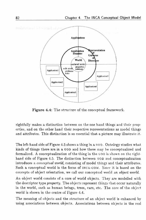
82 Chapter 4. The INCA Conceptual Object Model
Application ^presentationdomiins
Universe
Figure 4.4: The structure of the conceptual framework.
rightfully makes a distinction between on the one hand things and their prop-erties, and on the other hand their respective representations as model thingsand attributes. This distinction is so essential that a picture may illustrate it.
The left-hand side of Figure 4.5 shows a thing in a UOD. Ontology studies whatkinds of things there are in a UOD and how these may be conceptualized andformalized. A conceptualization of the thing in the UOD is shown on the right-hand side of Figure 4.5. The distinction between UOD and conceptualizationintroduces a concepfua/ wor/d, consisting of model things and their attributes.Such a conceptual world is the focus of INCA-COM. Since it is based on theconcepts of object orientation, we call our conceptual world an object worW.
An object world consists of a core of world objects. They are modelled withthe descriptor type property. The objects represent things that occur naturallyin the world, such as human beings, trees, cars, etc. The core of the objectworld is shown in the centre of Figure 4.4.
The meaning of objects and the structure of an object world is enhanced byusing associations between objects. Associations between objects in the real
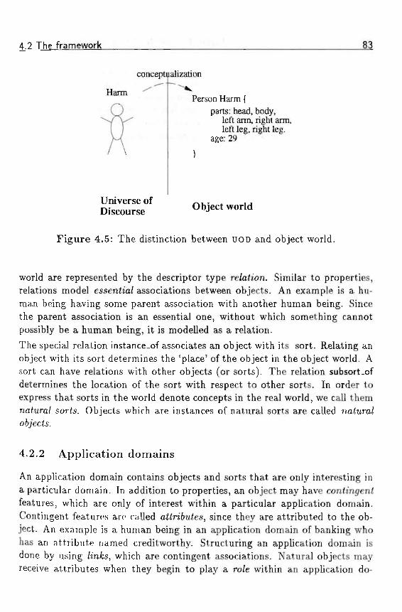
4.2 The framework
conceptualization
Harm ^ "Person Harm {
parts: head, body,left arm, right arm,left leg, right leg.
age: 29
Universe of ~ . . , , ,Discourse Object world
Figure 4.5: The distinction between UOD and object world.
world are represented by the descriptor type re/aiion. Similar to properties,relations model esseniza/ associations between objects. An example is a hu-man being having some parent association with another human being. Sincethe parent association is an essential one, without which something cannotpossibly be a human being, it is modelled as a relation.
The special relation instance_of associates an object with its sort. Relating anobject with its sort determines the 'place' of the object in the object world. Asort can have relations with other objects (or sorts). The relation subsort.ofdetermines the location of the sort with respect to other sorts. In order toexpress that sorts in the world denote concepts in the real world, we call themnaiura/ sorts. Objects which are instances of natural sorts are called na<ura/o6/ecfs.
4.2.2 Application domains
An application domain contains objects and sorts that are only interesting ina particular domain. In addition to properties, an object may have contingentfeatures, which are only of interest within a particular application domain.Contingent features are called attn'6u£es, since they are attributed to the ob-ject. An example is a human being in an application domain of banking whohas an attribute named creditworthy. Structuring an application domain isdone by using /mfcs, which are contingent associations. Natural objects mayreceive attributes when they begin to play a ro/e within an application do-
84 Chapter 4. The INCA Conceptual Object Model
main. During their life time, objects may start or cease to play various roles.A natural object may play different roles within an application domain, ordifferent roles within different application domains. When an object ceasesto play a role, the role object disappears, but the natural object temporarilyplaying that role persists. If a natural object 'dies', all its roles also cease toexist. The sorts in an application domain are called app/icah'on sorts or ro/esorts. The representation of a UOD consists of the combination of a (slice ofthe) world and an application domain.
4.2.3 Applications
For modelling applications, the information paradigm (see Figure 2.1) servesas the conceptual model for an information system. An information systemconsists of (1) active objects performing discourse about a UOD, and (2) arepresentation of the UOD supporting the discourse of active objects. Therepresentation of a UOD has been described above; it consists of a (slice of the)world and an application domain. For the discourse of active objects we adoptspeec/i act i/ieory (Searle, 1969; Searle and Vanderveken, 1985). This enablesus to model the communication between active objects in a way close to humancommunication. Thus, an information system contains a representation of aUOD in terms of passive oft/'ects, about which aeh'ue 067'ecte perform a discourse.This approach is similar to, e.g., Dietz (1992b) who proposes a model forinformation systems analysis consisting of communicating actors, based onspeech act theory.
The division between active objects and passive objects seems counterintuitiveto the general idea of object orientation that state and behaviour should becombined. Thus, one might argue that the division between active and pas-sive objects is similar to the classical program/data division: active objectsare the sources of activity, while passive objects are recipients of the actionsof active objects. However, we believe that such a division is necessary for thefollowing reason. An information system contains a representation of a UOD.Although the represented things can be active (in their own 'real world'),their representation is under the control of active objects within the informa-tion system. The division between active objects and passive objects is not astep back to a procedural way of modelling. After all, both active and pas-sive objects can be described in an 067'ect-oriented way, using the dichotomiesof classification/instantiation, generalization/specialization, and composition/decomposition introduced in Section 3.4.
4.3 INCA models 85
The difference between essential features (properties and relations) and con-tingent role features (attributes and links) is used as follows. Active objectsacting on passive objects may only change attributes and links within theapplication domain under consideration. Properties and relations used in anapplication domain are read-on/r/ features. The latter does not mean that aproperty or relation has a constant value. Its value can change under influenceof natural processes, e.g., age. It just cannot be changed by an application.Thus, the structure of the framework implies that there is a core of essen-tial features, called properties and relations, and several application domainsintroducing attributes and links.
Supporting the division of an information system into a passive representationpart and an active processing part, we introduce four different INCA models.The representation part is based on passive objects, modelled in an informationmodel and an event model. The processing part is based on active objects,modelled in a behavioural model and a communication model.
4.3 INCA models
It is interesting to see that both an object-oriented design method, such asOMT (Rumbaugh e< a/., 1991), and an information-systems oriented method,such as NIAM-ISDM (Nijssen, 1989) incorporate analogous models for informa-tion systems. OMT and NIAM-ISDM divide (a model of) an information systeminto three basic models: (1) an o6jeci or in/orma<zon model describing thestructure of information; (2) a /unciiona/ or process model describing whatprocesses act on the information; and (3) a dynamic or impu/se model de-scribing when the functions/processes are executed. Rolland and Cauvet(1992) add to these models a 6e/iam'our or /i/e-cyc/e mode/, accounting forthe definition and ordering of events which may occur during the life cycle ofobjects.
In summary, the four perspectives in modelling information systems are: (1)the siahc perspective: what is the structure of information and what rela-tionships are there? (2) the /i/e ct/c/e perspective: which events may occurto objects and what is their order? (3) the process perspective: what is thestructure of processes and how are objects used in processes? and (4) theimpu/se perspective: when are the processes activated? In INCA-COM, weintroduce four different models to capture a UOD from these perspectives.
1. The m/brma<ion mode/ describes the structure of the information and
86 Chapter 4. The INCA Conceptual Object Model
M the relations that are valid between various elements of the descriptions.« In addition, the information model offers a role concept, which allows
for the description of roles within different application domains. Thedifferent aspects of object descriptions are semantically categorized byintroducing different £j//>es of object-describing entities. The descriptionof an object is the basis for defining different states in which an objectcan be. The information model is discussed in Section 4.4.
2. The euen< mode/ describes which events can take place in the objectworld, and which order is imposed on these events. An event is definedas a state transition of an object (the cause of which is not relevant in theevent model). The event model describes the interface of passive objects,since it models the possible events an object may suffer. Thus, the eventmodel provides a shopping list view of events which might happen in theobject world, similar to the ideas expressed by Meyer (1988). The eventmodel is discussed in Section 4.5.
3. The 6e/iaw'oura/ mode/ describes which objects are active (i.e., performactions) by displaying particular behaviour. The behaviour of such activeobjects consists of particular actions, which give rise to events in theobject world. The relation between behavioural model and event modelis thus a correspondence between a particular action and a possible event.The goal of an active object is to accomplish the actions it has committedto. Following Dietz (1992b), the commitments constitute the agenda ofan active object. The behavioural model is discussed in Section 4.6.
4. The communication mode/ describes what interactions take place be-tween active objects. Communication between active objects is basedon speech act theory, similar to the application of speech acts as givenin Dietz (1992b). The communication model is discussed in Section 4.7.
4.4 Information model
The information model is used to describe the structure of information andthe relations between different objects. This is done by combining descriptorsand values, thus forming descriptions, INCA-COM offers the following six typesof descriptors:
1. properties,
4.4 Information model 87
2 . a t t r i b u t e s , • ' ; • - : • • " •• • •. • • : • > • ,.
3. relations, . : i , ^ . . :
4 . l i n k s , ' • • • • • • - ' - . • . • - : : . • : •' - • - • : . : ;
5. displays, and -
6. v e r s i o n s . • • • ; •
In the following subsections we treat the different types of descriptors and theirusage in modelling. For clarity's sake, we treat properties and attributes, andrelations and links in one subsection each. After the sections on displays andversion, we close with a section on state and state space.
4.4.1 Properties and attributes
To describe a feature of an object, INCA-COM introduces two descriptor types,namely properties and attributes. Although these two entities are frequentlyused in other COMs to denote a feature of an object, we make a clear dis-tinction between the two types. An analogous distinction as our property/attribute distinction, is the distinction between essentia/ and non-essentia/(or conh'n<7en<) features of objects (Wieringa, 1990). By saying that an objecthas essenfia/ features, we mean that the object will have those features inevery possible state or application, i.e, it is inherent to the object's being. Bysaying that an object has contingent features, we mean that the object hasfeatures, which it may fail to have in some other state or application.
A property represents a feature of a real-world thing. It is a descriptor whichapart from the object does not possess any descriptive value. It 6e/onjs tothe object and describes nothing in isolation. The real-world thing's identityimplies that it has the property. This gives an important clue to decide ifsomething should be modelled as a property: if a feature is essential to a thing'sidentity, it is modelled as a property. In the framework of Figure 4.4 propertiesare descriptors for objects in the 'world core', and are thus independent of anyapplication domain.
Definition 4.5 J4 property is an essentia//eature o/an 067'ect, meaning </ia<i/ie 067'ect Aas t/ie property in every possi6/e app/ication.
As an example, in the domain of university, we might model researchers, whoare writing scientific articles to be sent to conferences. A property of a scientific
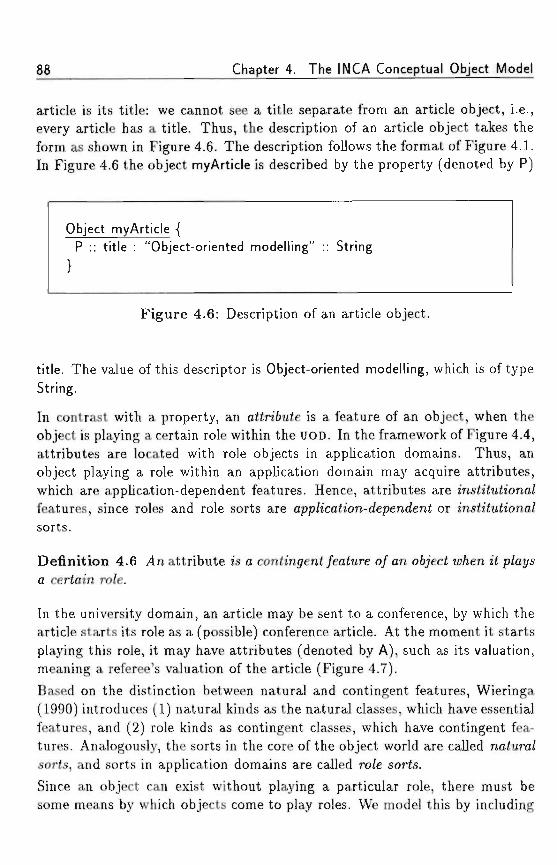
88 Chapter 4. The INCA Conceptual Object Model
article is its title: we cannot see a title separate from an article object, i.e.,every article has a title. Thus, the description of an article object takes theform as shown in Figure 4.6. The description follows the format of Figure 4.1.In Figure 4.6 the object myArticle is described by the property (denoted by P)
Object myArticle {P :: title : "Object-oriented modelling" :: String
Figure 4.6: Description of an article object.
title. The value of this descriptor is Object-oriented modelling, which is of typeString.
In contrast with a property, an attribute is a feature of an object, when theobject is playing a certain role within the UOD. In the framework of Figure 4.4,attributes are located with role objects in application domains. Thus, anobject playing a role within an application domain may acquire attributes,which are application-dependent features. Hence, attributes are t'nsfc'tuftona/features, since roles and role sorts are app/ication-a'ependent or institutiona/sorts.
Definition 4.6 yln attribute is a contingent/eature o/on 067'ect w/ien it p/at/sa certain ro/e.
In the university domain, an article may be sent to a conference, by which thearticle starts its role as a (possible) conference article. At the moment it startsplaying this role, it may have attributes (denoted by A), such as its valuation,meaning a referee's valuation of the article (Figure 4.7).
Based on the distinction between natural and contingent features, Wieringa(1990) introduces (1) natural kinds as the natural classes, which have essentialfeatures, and (2) role kinds as contingent classes, which have contingent fea-tures. Analogously, the sorts in the core of the object world are called natura/sorts, and sorts in application domains are called rote sorts.
Since an object can exist without playing a particular role, there must besome means by which objects come to play roles. We model this by including
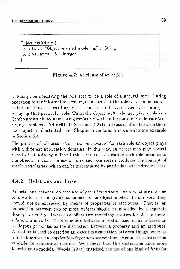
4.4 Information model
Object myArticle {P :: title : "Object-oriented modelling" :: StringA :: valuation : 8 :: Integer •. . ,
Figure 4.7: Attribute of an article.
a description specifying the role sort to be a role of a natural sort. Duringoperation of the information system, it means that the role sort can be instan-tiated and that the resulting role instance r can be associated with an objecto playing that particular role. Thus, the object myArticle may play a role as aConferenceArticle by associating myArticle with an instance of ConferenceArti-cle, e.g., conferenceArticleOl. In Section 4.4.2 the role association between thesetwo objects is illustrated, and Chapter 5 contains a more elaborate examplein Section 5.4.
The process of role association may be repeated for each role an object playswithin different application domains. In this way, an object may play severalroles by instantiating different role sorts, and associating each role instance tothe object. In fact, the use of roles and role sorts introduces the concept ofms<i<u<iona/ fcmds, which can be instantiated by particular, authorized objects.
4.4.2 Relations and links
Associations between objects are of great importance for a good structuringof a world and for giving coherence to an object model. In our view theyshould not be expressed by means of properties or attributes. That is, anassociation between two or more objects should be modelled by a separatedescriptive entity. INCA-COM offers two modelling entities for this purpose:re/aiions and /mfcs. The distinction between a relation and a link is based onanalogous principles as the distinction between a property and an attribute.A relation is used to describe an essenfia/association between things, whereasa link describes an app/ication-depen<ieni association. Again, this distinctionis made for semantical reasons. We believe that this distinction adds moreknowledge to models. Woods (1975) criticized the use of one kind of /mfcsfor
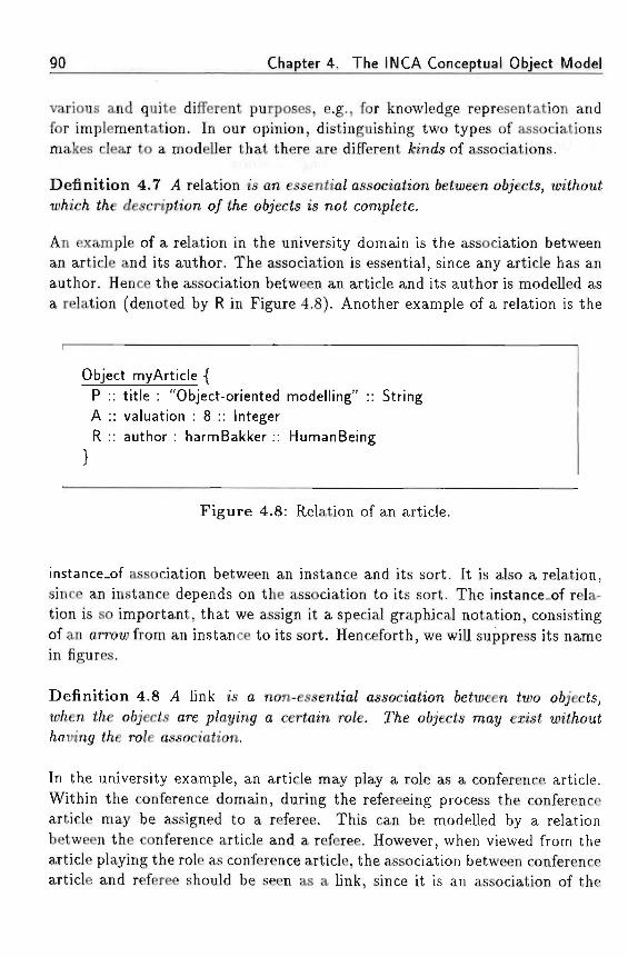
90 Chapter 4. The INCA Conceptual Object Model
various and quite different purposes, e.g., for knowledge representation andfor implementation. In our opinion, distinguishing two types of associationsmakes clear to a modeller that there are different fcrncte of associations.
Definition 4.7 ,4 relation ts an essenh'a/ association 6etiueen o6;'ec<s, tmt/iouiu;/iic/i </ie descnpft'on o/ t/ie oijects is not comp/ete.
An example of a relation in the university domain is the association betweenan article and its author. The association is essential, since any article has anauthor. Hence the association between an article and its author is modelled asa relation (denoted by R in Figure 4.8). Another example of a relation is the
Object myArticle {P :: title : "Object-oriented modelling" :: StringA :: valuation : 8 :: IntegerR :: author : harmBakker :: HumanBeing
Figure 4.8: Relation of an article.
instance.of association between an instance and its sort. It is also a relation,since an instance depends on the association to its sort. The instance.of rela-tion is so important, that we assign it a special graphical notation, consistingof an arrow from an instance to its sort. Henceforth, we will suppress its namein figures.
Definition 4.8 J4 link is a non-essentia/ association 6etu;een <iuo ot/'ects,«;/ien £/ie o6/'ec<s are p/aying a certain ro/e. TVie objects may erist wit/iout
t/ie ro/e association.
In the university example, an article may play a role as a conference article.Within the conference domain, during the refereeing process the conferencearticle may be assigned to a referee. This can be modelled by a relationbetween the conference article and a referee. However, when viewed from thearticle playing the role as conference article, the association between conferencearticle and referee should be seen as a link, since it is an association of the
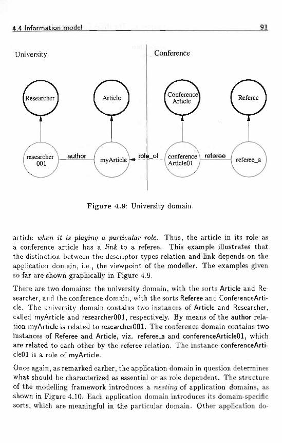
4.4 Information model
University Conference
researcher \ author001
conference \ refereeArticleOl
Figure 4.9: University domain.
article w/ien i£ is p/aymjf a parhcu/ar ro/e. Thus, the article in its role asa conference article has a /mifc to a referee. This example illustrates thatthe distinction between the descriptor types relation and link depends on theapplication domain, i.e., the viewpoint of the modeller. The examples givenso far are shown graphically in Figure 4.9.
There are two domains: the university domain, with the sorts Article and Re-searcher, and the conference domain, with the sorts Referee and ConferenceArti-cle. The university domain contains two instances of Article and Researcher,called myArticle and researcherOOl, respectively. By means of the author rela-tion myArticle is related to researcherOOl. The conference domain contains twoinstances of Referee and Article, viz. referee_a and conferenceArticleOl, whichare related to each other by the referee relation. The instance conferenceArti-cleOl is a role of myArticle.
Once again, as remarked earlier, the application domain in question determineswhat should be characterized as essential or as role dependent. The structureof the modelling framework introduces a nesh'njr of application domains, asshown in Figure 4.10. Each application domain introduces its domain-specificsorts, which are meaningful in the particular domain. Other application do-
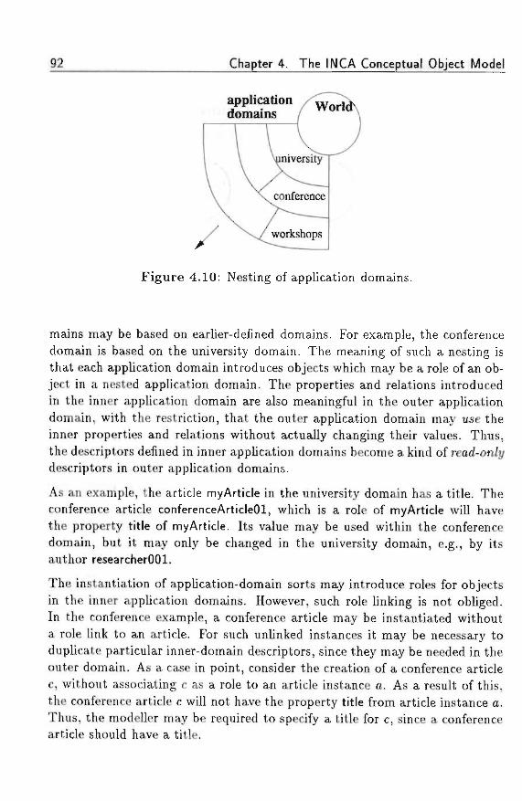
Chapter 4. The INCA Conceptual Object Model
applicationdomains
Figure 4.10: Nesting of application domains.
mains may be based on earlier-defined domains. For example, the conferencedomain is based on the university domain. The meaning of such a nesting isthat each application domain introduces objects which may be a role of an ob-ject in a nested application domain. The properties and relations introducedin the inner application domain are also meaningful in the outer applicationdomain, with the restriction, that the outer application domain may use theinner properties and relations without actually changing their values. Thus,the descriptors defined in inner application domains become a kind of read-on/ydescriptors in outer application domains.
As an example, the article myArticle in the university domain has a title. Theconference article conferenceArticleOl, which is a role of myArticle will havethe property title of myArticle. Its value may be used within the conferencedomain, but it may only be changed in the university domain, e.g., by itsauthor researcherOOl.
The instantiation of application-domain sorts may introduce roles for objectsin the inner application domains. However, such role Unking is not obliged.In the conference example, a conference article may be instantiated withouta role link to an article. For such unlinked instances it may be necessary toduplicate particular inner-domain descriptors, since they may be needed in theouter domain. As a case in point, consider the creation of a conference articlec, without associating c as a role to an article instance a. As a result of this,the conference article c will not have the property title from article instance a.Thus, the modeller may be required to specify a title for c, since a conferencearticle should have a title.
4.4 Information model 91
We remark that the distinctions we make between properties/attributes, andrelations/links depend on the chosen domain. When viewed from the univer-sity domain, myArticle has a /infc with a referee, whereas conferenceArticleOlhas a re/ah'on with a referee. The different views express that within theconference domain the article-referee association is essential, whereas in theuniversity domain this association is role dependent. Additionally, it may evenbe the case that an article from a university domain plays several roles as aconference article, although conference organizers often only accept originalarticles for presentation at their conference. ; .
4.4.3 Displays
The descriptor type of disp/ays specifies how an object will manifest itself tothe outside world. Although a display is usually associated with a mere visualstyle of presentation, we stress that a display is used to describe how the objectexhibits itself via one or another medium (such as sound, vision, or otherwise).One could specify, e.g., that a C program modelled as an object displays itselfvisually as a program structure diagram, or that an error condition displaysitself as a bell on a terminal. In Chapter 7 we shall address displays of objectsmore extensively.
An object can have several displays, depending on the roles it plays in differentapplication domains. In one application domain, a person may be presented bymeans of a bitmapped photograph, whereas in another domain it may happenby means of its name.
4.4.4 Versions
Versions of an object are also descriptors, analogous to the descriptor typesdiscussed above. With a version we mean a variation on a theme (in this casethe theme being the object). Semantically, such a variation differs not enoughfrom the object to be modelled as a new object. Nevertheless, a version may,purely syntactically speaking, differ considerably from the original object.
For instance, consider the modelling of program sources as objects. One suchobject might be a program for sorting numbers according to the quicksortalgorithm. Within the world of source objects there could exist many versionsof quicksort in different programming languages, which from a semantical pointof view all refer to the same object.
94 Chapter 4. The INCA Conceptual Object Model
We remark that every object in INCA-COM can have versions. We note, how-ever, that a version in INCA is no< an object, although in special cases versionscan be modelled as so-called version 067'ecte. For a more profound analysis ofversions, we refer to Chapter 6.
4.4.5 Sta te and s ta te space
In order to introduce a concept of event as a transition from one state toanother, it is necessary to have a concept for the state of an object. Thedescriptors introduced in the information model provide the basis for a con-ceptualization of the state and the state space of an object.
In ontology, it is hypothesized that at a given time every object is in somestate. In order to illustrate the concept of state, we follow Bunge (1977). Thedescription of an object o is a functional schema, which we call a descriptionsc/iema, i.e., the set of descriptions of an object is a n-component function P,which is defined as £> = {.D,|l < i < n}. Each .D,(o) is a descriptor of objecto. The domain of the function .D; is the extension of the sort 5 to whicho belongs and the range is KZ?i, the value domain of descriptor .Dj. Eachcomponent £\ : 5 —> VZ), of P is called a description of the sort 5 to which obelongs. The description schema P is called the se< 0/ descriptions for o, andits value Do = (-Di, • • •, Z^n)(o) = (-Di(o),..., Z)^(o)) for oGQ represents thestate of o. $7 is the object world, i.e., the population of objects at a particulartime.
The various descriptions of an object are in general not independent. Oftendescriptors and their values are somehow related to each other by constrainingthe values each descriptor can have. Any such constraint on the values ofdescriptors is called a /aw s(o<emen<, for it describes in which lawful statesan object can be. As an example of such a law statement in the universitydomain, consider the statement that a researcher should have a salary whichis not below a particular minimum.
The description schema as a representation of an object's state gives rise to astate space for objects. If we take the Cartesian product of the ranges of thecomponents of X> the range VD of £> itself is formed. The range V.D is calledthe conceit;a6/e state space 5(o) for the object represented. However, not everyvalue in the range K.D is permitted, as expressed by the law statements of theobject. Thus, the states in which an object may be, is a constrained subset ofthe conceivable state space 5(o), which is called the /oic/u/ state space 5i(o)-Figure 4.11 shows the state space of a university employee o consisting of two
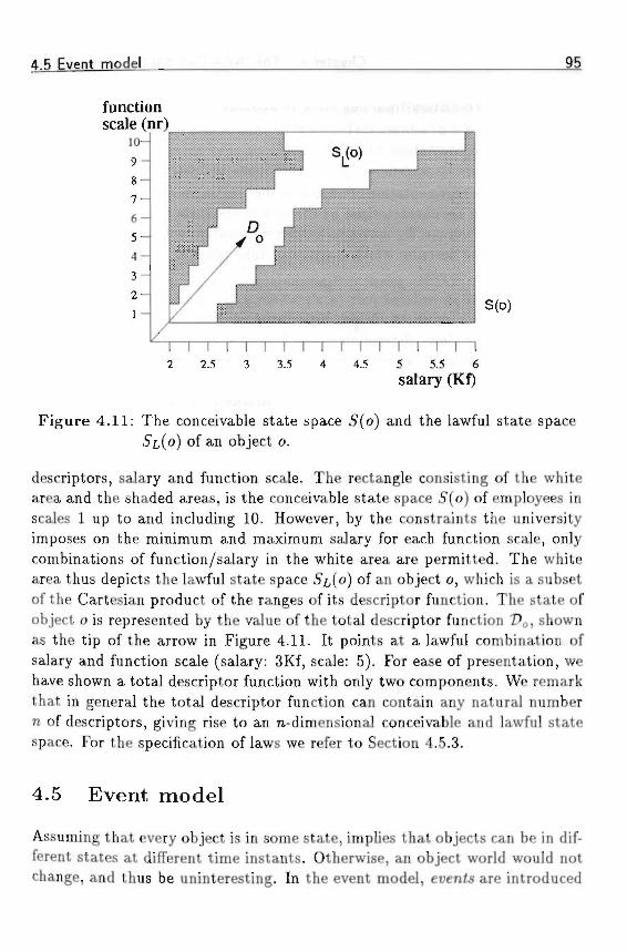
4.5 Event model _95
S(o)
1 I r2 2 . 5
I I I I I I I I I I I I I3 3 . 5 4 4 . 5 5 5 . 5 6
salary (Kf)
Figure 4.11: The conceivable state space 5"(o) and the lawful state space5i,(o) of an object o.
descriptors, salary and function scale. The rectangle consisting of the whitearea and the shaded areas, is the conceivable state space 5(o) of employees inscales 1 up to and including 10. However, by the constraints the universityimposes on the minimum and maximum salary for each function scale, onlycombinations of function/salary in the white area are permitted. The whitearea thus depicts the lawful state space 5£,(o) of an object o, which is a subsetof the Cartesian product of the ranges of its descriptor function. The state ofobject o is represented by the value of the total descriptor function 2?o, shownas the tip of the arrow in Figure 4.11. It points at a lawful combination ofsalary and function scale (salary: 3Kf, scale: 5). For ease of presentation, wehave shown a total descriptor function with only two components. We remarkthat in general the total descriptor function can contain any natural numbern of descriptors, giving rise to an n-dimensional conceivable and lawful statespace. For the specification of laws we refer to Section 4.5.3.
4.5 Event model
Assuming that every object is in some state, implies that objects can be in dif-ferent states at different time instants. Otherwise, an object world would notchange, and thus be uninteresting. In the event model, events are introduced
96 Chapter 4. The INCA Conceptual Object Model
as an object's transition from one state to another. \••**.< 1' • • A * .
4.5.1 Events
The state-space representation of objects is the starting point for the definitionof events, which are characterized by changes in the state of an object. Underthe influence of events, D<> moves to a different location within its lawful statespace. Below we describe which events can take place in an object world bydescribing event types.
An event type is an ordered pair (s, 5') where 5 and 5' are states of an objecto. The event space of an object consists of all such ordered pairs, but ingeneral there are laws determining which events are lawful and which not.Consider, for instance, again a university employee o with state X>o equal to(salary: 3Kf, scale: 5). All ordered pairs (Po,Dj,), where 2^, is a lawful state,can be considered as a conceivable event. However, by constraints from theuniversity, the event ((salary: 3Kf, scale: 5), (salary: 2Kf, scale: 1)) is not alawful event. Thus, similar to the lawful state space, there exists a subset ofthe event space with events which are permitted by the laws for the domainunder consideration. The event space of permitted events is called the /aw/u/eueni space.
For the modelling of a UOD it is not sufficient to treat events as mere statetransitions. The reason is that the representational purpose of objects requiresthat state transitions of things in the UOD are represented within the infor-mation system's representation of the UOD. This, in turn, requires the statetransitions of objects to be invoked by acta'ue objects. Thus, in INCA-COM eachevent type is given a name by which it can be invoked. Naturally, each eventtype represents a meaningful event type in the UOD. The modelling of eventtypes results in a set of applicable operations, which transfer the object's statefrom one lawful state to another. The specification of an event type includesfour aspects:
1. the name;
2. names and types/sorts of the parameters (also called the event signa-ture);
3. preconditions, stating the requirements for the event's applicability; and
4. postconditions, describing the state of the object after the event.
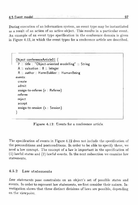
4 5 Event model
During execution of an information system, an event type may be instantiatedas a result of an action of an active object. This results in a particular event.An example of an event type specification in the conference domain is givenin Figure 4.12, in which the event types for a conference article are described.
Object conferenceArticleOl {P :: title : "Object-oriented modelling" :: StringA :: valuation : 8 :: IntegerR :: author : HarmBakker :: HumanBeing
events: -createadmitassign-to-referee (r : Referee)refereerejectacceptassign-to-session (s : Session)
Figure 4.12: Events for a conference article.
The specification of events in Figure 4.12 does not include the specification ofthe preconditions and postconditions. In order to be able to specify these, weneed a law concept. The concept of a law is important in the specification of(1) lawful states and (2) lawful events. In the next subsection we examine lawstatements.
4.5.2 Law statements
statements pose constraints on an object's set of possible states andevents. In order to represent law statements, we first consider their nature. In-vestigation shows that three distinct divisions of laws are possible, dependingon the viewpoint.
98 Chapter 4. The INCA Conceptual Object Model
1. As described above, there is a division of laws into static /aius and dy-namic /aws. A static law constrains the conceivable state space of anobject to its lawful state space. Similarly, a dynamic law constrains theset of possible state transitions. Additionally, laws may put contraintson the existence of objects without necessarily referring to their state.
2. Orthogonal to the division of laws into static, dynamic, and existencelaws, laws can either be /oca/or o/o6a/. A local law constrains the possi-ble states and state transitions of a single object, whereas a global lawconstrains the possible states of two or more objects.
3. A third division of laws is suggested, among others, by Wieringa (1990),in which three kinds of laws are distinguished: (1) analytical laws,which hold because of the propositional content of the law; (2) empiricallaws, which hold because of empirical evidence; and (3) deontic laws,which express obligations or permissions, that can be violated by thingsin the UOD.
An example of an analytic law, is the law statement 'age is a positivenumber'. This law holds since the concept of age includes that its valueis positive. An empirical law is 'the age of a human being is less than200', which holds since no human being lives more than 200 years. Itmight some day be invalidated by a person living longer than 200 years,in which case such a law should be redefined. A deontic law constrainsthe state space of objects, by imposing institutional constraints. Deonticlaws can be, and frequently are, violated by the objects to which theyapply. As an example, consider the deontic law in a library statingthat 'Every book should be returned within four weeks'. Such a lawstatement is frequently violated, and it is the task of some agent in thelibrary system to take corrective action in order to ensure that the bookis returned (by, e.g., sending a person a reminder).
The three viewpoints on laws give rise to 18 different types of laws. Table 4.1shows the different kinds of laws, with an example of each kind. We remarkthat analytical existence laws (both global and local) cannot be formulated,because of their nature.
4.5.3 Modelling of laws
The various kinds of laws described in the previous section can all be modelledin INCA-COM. Below we describe the modelling process.
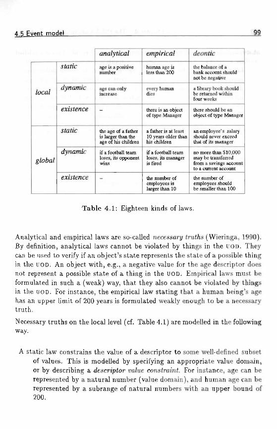
4.5 Event model
/oca/
g/o6fl/
stofic
tfyna/nic
existence
sto/ic
existence
ana/yrica/
age is a positivenumber
age can onlyincrease
—
the age of a fatheris larger than theage of his children
if a football teamloses, its opponentwins
—
empirica/
human age isless than 200
every humandies
there is an objectof type Manager
a father is at least10 years older thanhis children
if a football teamloses, its manageris fired
the number ofemployees islarger than 10
deonrtc
the balance of abank account shouldnot be negative
a library book shouldbe returned withinfour weeks
there should be anobject of type Manager
an employee's salaryshould never exceedthat of its manager
no more than $10,000may be transferredfrom a savings accountto a current account
the number ofemployees shouldbe smaller than 100
Table 4.1: Eighteen kinds of laws.
Analytical and empirical laws are so-called necessary <rut/is (Wieringa, 1990).By definition, analytical laws cannot be violated by things in the UOD. Theycan be used to verify if an object's state represents the state of a possible thingin the UOD. An object with, e.g., a negative value for the age descriptor doesnot represent a possible state of a thing in the UOD. Empirical laws must beformulated in such a (weak) way, that they also cannot be violated by thingsin the UOD. For instance, the empirical law stating that a human being's agehas an upper limit of 200 years is formulated weakly enough to be a necessarytruth.
Necessary truths on the local level (cf. Table 4.1) are modelled in the followingway.
A static law constrains the value of a descriptor to some well-defined subsetof values. This is modelled by specifying an appropriate value domain,or by describing a descriptor va/ue constraint. For instance, age can berepresented by a natural number (value domain), and human age can berepresented by a subrange of natural numbers with an upper bound of200.
100 Chapter 4. The INCA Conceptual Object Model
A dynamic law imposes appropriate conditions on an event. This is modelledby event pre- and postconditions, formulated in terms of an equationbetween the descriptor values before and after the event under consid-eration. For instance, a birthday event in a human being's life cycleshould only be allowed to increase age. This can be modelled with anevent postcondition expressing that age' = age + 1. We use the primecharacter "'" to denote the value of a descriptor after the application ofan event, age' is the value of the age descriptor after a birthday event.
An existence law is a constraint on a sort's extension. For the specificationof existence constraints we introduce the symbol £"zi referring to theextension of sort. For instance, to express that there is an object ofsort Manager, the description includes an existence constraint such as•Ez/(Manager) > 0.
Necessary truths on the global level are modelled in the following way.
A static law is a global descriptor-value constraint, relating two descriptorsof different objects. For instance, stating that a mother's age is largerthan the age of her children is expressed by a global descriptor valueconstraint, specifying the age descriptor of the mother to be at least aslarge as that of her children.
A dynamic law is a common event. This means that two (or more) objectsare subjected to one event. For instance, if a football team loses, itsopponent wins.
An existence law is a constraint on a sort's extension. This is similar to alocal existence law (see above).
Deontic laws express obligations or permissions of things in the UOD. Theyare useful in the specification of institutional elements of object-oriented con-ceptual models (see Section 3.3). Deontic laws are modelled in the same wayas analytical and empirical laws, with the additional specification that it is alaw that may be violated by things in the UOD. The difference between on theone hand analytical and empirical laws, and on the other hand deontic lawsis that all objects obey analytical and empirical laws, whereas there may beobjects that do not obey deontic laws.
Every deontic law requires that an active object guards its violation and takescorrective actions to suppress the violation. Examples of such active objects
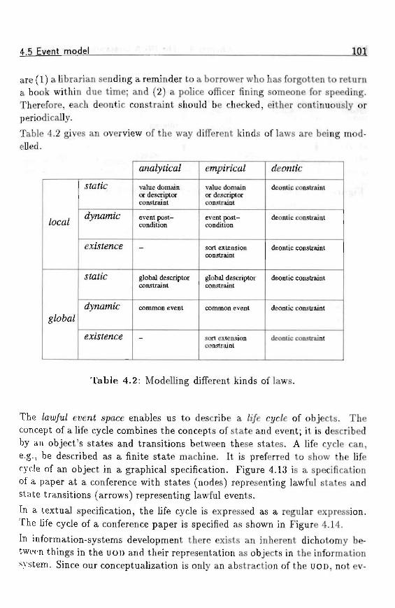
4.5 Event model
are (1) a librarian sending a reminder to a borrower who has forgotten to returna book within due time; and (2) a police officer fining someone for speeding.Therefore, each deontic constraint should be checked, either continuously orperiodically.
Table 4.2 gives an overview of the way different kinds of laws are being mod-elled.
/oca/
g/ofca/
5to«c
dynamic
exwfe/ice
jtor/c
rfynamjc
ejcw/e/ice
a/ia/yrtca/
value domainor descriptorconstraint
event post-condition
—
global descriptorconstraint
common event
—
empirica/
value domainor descriptorconstraint
event post-condition
sort extensionconstraint
global descriptorconstraint
common event
sort extensionconstraint
deonft'c
deontic constraint
deontic constraint
deontic constraint
deontic constraint
deontic constraint
deontic constraint
Table 4.2: Modelling different kinds of laws.
The /aw/u/ et>en( space enables us to describe a /i/e cyc/e of objects. Theconcept of a life cycle combines the concepts of state and event; it is describedby an object's states and transitions between these states. A life cycle can,e.g., be described as a finite state machine. It is preferred to show the lifecycle of an object in a graphical specification. Figure 4.13 is a specificationof a paper at a conference with states (nodes) representing lawful states andstate transitions (arrows) representing lawful events.
In a textual specification, the life cycle is expressed as a regular expression.The life cycle of a conference paper is specified as shown in Figure 4.14.
In information-systems development there exists an inherent dichotomy be-tween things in the UOD and their representation as objects in the informationsystem. Since our conceptualization is only an abstraction of the UOD, not ev-
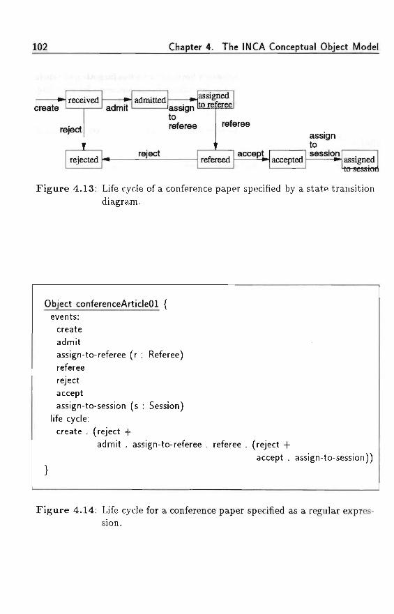
102 Chapter 4. The INCA Conceptual Object Model
•
- . . . ,„ . ,
received
reject
rejected
admitadmitted
reject
assigntoreferee
assignedto referee
1
referee
refereed accept accepted
• . . - . i i l
assigntosession assigned
Figure 4.13: Life cycle of a conference paper specified by a state transitiondiagram.
Object conferenceArticleOl {events:
createadmitassign-to-referee (r : Referee)refereerejectacceptassign-to-session (s : Session)
life cycle:create . (reject +
admit . assign-to-referee . referee . (reject +accept . assign-to-session))
Figure 4.14: Life cycle for a conference paper specified as a regular expres-sion.
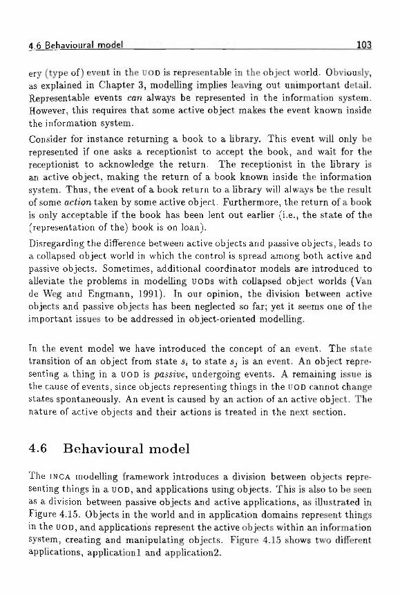
4.6 Behavioural model ; ; 103
ery (type of) event in the UOD is representable in the object world. Obviously,as explained in Chapter 3, modelling implies leaving out unimportant detail.Representable events can always be represented in the information system.However, this requires that some active object makes the event known insidethe information system.
Consider for instance returning a book to a library. This event will only berepresented if one asks a receptionist to accept the book, and wait for thereceptionist to acknowledge the return. The receptionist in the library isan active object, making the return of a book known inside the informationsystem. Thus, the event of a book return to a library will always be the resultof some action taken by some active object. Furthermore, the return of a bookis only acceptable if the book has been lent out earlier (i.e., the state of the(representation of the) book is on loan).
Disregarding the difference between active objects and passive objects, leads toa collapsed object world in which the control is spread among both active andpassive objects. Sometimes, additional coordinator models are introduced toaUeviate the problems in modelling UODs with collapsed object worlds (Vande Weg and Engmann, 1991). In our opinion, the division between activeobjects and passive objects has been neglected so far; yet it seems one of theimportant issues to be addressed in object-oriented modelling.
In the event model we have introduced the concept of an event. The statetransition of an object from state s, to state Sj is an event. An object repre-senting a thing in a UOD is passive, undergoing events. A remaining issue isthe cause of events, since objects representing things in the UOD cannot changestates spontaneously. An event is caused by an action of an active object. Thenature of active objects and their actions is treated in the next section.
4.6 Behavioural model
The INCA modelling framework introduces a division between objects repre-senting things in a UOD, and applications using objects. This is also to be seenas a division between passive objects and active applications, as illustrated inFigure 4.15. Objects in the world and in application domains represent thingsin the UOD, and applications represent the active objects within an informationsystem, creating and manipulating objects. Figure 4.15 shows two differentapplications, applicationl and application2.
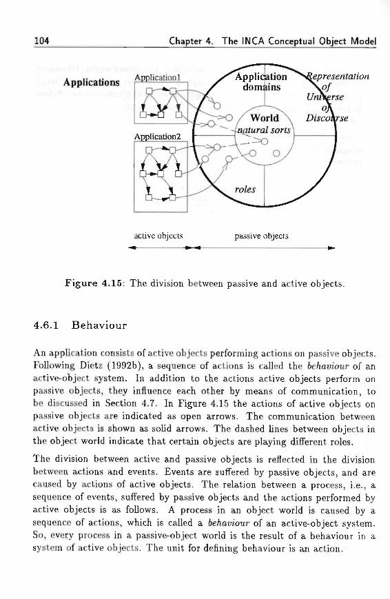
104 Chapter 4. The INCA Conceptual Object Model
Applications Applicationdomiuns
active objects passive objects
Figure 4.15: The division between passive and active objects.
4.6.1 Behaviour
An application consists of active objects performing actions on passive objects.Following Dietz (1992b), a sequence of actions is called the 6e/iatnour of anactive-object system. In addition to the actions active objects perform onpassive objects, they influence each other by means of communication, tobe discussed in Section 4.7. In Figure 4.15 the actions of active objects onpassive objects are indicated as open arrows. The communication betweenactive objects is shown as solid arrows. The dashed lines between objects inthe object world indicate that certain objects are playing different roles.
The division between active and passive objects is reflected in the divisionbetween actions and events. Events are suffered by passive objects, and arecaused by actions of active objects. The relation between a process, i.e., asequence of events, suffered by passive objects and the actions performed byactive objects is as follows. A process in an object world is caused by asequence of actions, which is called a 6e/mtnour of an active-object system.So, every process in a passive-object world is the result of a behaviour in asystem of active objects. The unit for defining behaviour is an action.
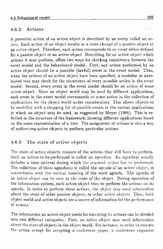
4.6 Behavioural model IQS
4.6.2 Act ions • • • • • • • ' > < : ' • » ' > < «
A potential action of an active object is described by an entity called an ac-tion. Each action of an object results in a state change of a passive object oran active object. Therefore, each action corresponds to an event either definedfor a passive object or an active object. Describing for an active object whichactions it may perform, offers two ways for checking consistency between theevent model and the behavioural model. First, any action performed by anactive object should be a possible (lawful) event in the event model. Thus,when the actions of an active object have been specified, a modeller or auto-mated tool may check for the occurrence of every possible action in the eventmodel. Second, every event in the event model should be an action of someactive object. Since an object world may be used by different applications,each event in the event model corresponds to some action in the collection ofapplications for the object world under consideration. This allows objects tobe modelled with a shopping list of possible events in the various applicationsin which an object may be used, as suggested by Meyer (1988). This is re-flected in the structure of the framework, showing different applications basedon the same representation of a UOD. The assignment of actions is also a wayof oui/iorzzin<7 active objects to perform particular actions.
4.6.3 The s ta te of active objects
The state of active objects consists of the actions they still have to perform.Such an action-to-be-performed is called an agendum. An agendum usuallyincludes a time interval during which the required action has to performed.The collection of these agendums is called the agenda of an active object, inconcordance with the normal meaning of the word agenda. The agenda ofan active object can be seen as the state of the object. During operation ofthe information system, each active object tries to perform the actions on itsagenda. In order to perform these actions, the object may need informationabout the state of other passive objects, or other active objects. Thus, bothobject world and active objects are a source of information for the performanceof actions.
The information an active object needs for executing its actions can be dividedinto two different categories. First, an active object may need informationabout the state of objects in the object world. For instance, in order to executethe action accept for accepting a conference paper, a conference organizer
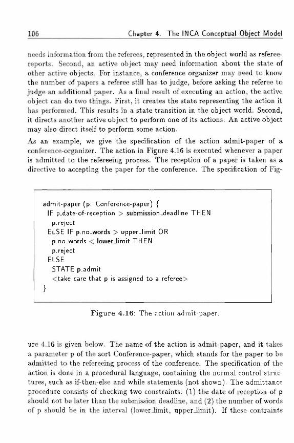
106 Chapter 4. The INCA Conceptual Object Model
needs information from the referees, represented in the object world as referee-reports. Second, an active object may need information about the state ofother active objects. For instance, a conference organizer may need to knowthe number of papers a referee still has to judge, before asking the referee tojudge an additional paper. As a final result of executing an action, the activeobject can do two things. First, it creates the state representing the action ithas performed. This results in a state transition in the object world. Second,it directs another active object to perform one of its actions. An active objectmay also direct itself to perform some action.
As an example, we give the specification of the action admit-paper of aconference-organizer. The action in Figure 4.16 is executed whenever a paperis admitted to the refereeing process. The reception of a paper is taken as adirective to accepting the paper for the conference. The specification of Fig-
admit-paper (p: Conference-paper) {IF p.date-of-reception > submission-deadline THEN
p. rejectELSE IF p.no.words > upper-limit OR
p.no_words < lowerJimit THENp. reject
ELSESTATE p.admit<take care that p is assigned to a referee>
Figure 4.16: The action admit-paper.
ure 4.16 is given below. The name of the action is admit-paper, and it takesa parameter p of the sort Conference-paper, which stands for the paper to beadmitted to the refereeing process of the conference. The specification of theaction is done in a procedural language, containing the normal control struc-tures, such as if-then-else and while statements (not shown). The admittanceprocedure consists of checking two constraints: (1) the date of reception of pshould not be later than the submission deadline, and (2) the number of wordsof p should be in the interval (lower-limit, upper-limit). If these contraints
4.7 Communication model 1Q7
are met p is admitted to the conference. This is specified by the line STATEp.admit, causing the event admit suffered by p. After p has been admitted, itshould be assigned to a referee. This is expressed as a comment; in the nextsection we come back to the issue of communication between active objects.
By describing the actions of an object and relating the active object to theinformation it needs, one effectively constructs a process model of a system,similar to data-flow diagrams used in Structured Analysis. The informationan active object needs is similar to the use of data flows in a DFD. In addition,the action specification contains a specification of the state change it hasperformed (p.admit), by which the connection between behavioural modeland event model is established.
4.7 Communication model
The communication model specifies which active objects communicate witheach other, and what the object of their communication is. The commu-nication model closely follows the application of speec/i ac< </ieorj/ (Searle,1969; Searle and Vanderveken, 1985) as presented in Dietz (1992b).
4.7.1 Communicat ion
Actions specified in the behavioural model are the actions of active objects.For such an action to be represented within the object world, the result has tobe communicated to some other active object. The latter one checks whetherthe result of the action is in concordance with the expected result. In theconference example, a researcher can perform an action, such as submittingan article to the conference. For such an action to be successful, first the usermust send the article to the conference organizer, and second the conferenceorganizer has to admit the paper to the refereeing process. If the latter is notdone, the article formally has not been submitted.
Thus, actions performed by active objects must be communicated before theycan be represented as a /aci in the object world. Of course, an active objectcan itself be the target for communication, but such self-communication is ingeneral not interesting to be modelled (if an object has different roles, thesemight very well communicate; such communication takes place between therole objects).
108 Chapter 4. The INCA Conceptual Object Model
4.7.2 Speech acts
Speech act theory is a theory of communication between people, stating thatcommunication is not only a means for spreading information, but also a wayof acting (Searle, 1969; Searle and Vanderveken, 1985). The minimal unitsof human communication are speech acts of a type called i//ocutionart/ acts.In speech act theory any utterance of a sentence has a propositiona/ contendand an i//ocutionan/ /orce. The propositional content is the proposition beinguttered, and the illocutionary force is the intention the speaker has in utteringthe proposition.
As an example, consider the proposition 'Peter is present'. Different kinds ofillocutionary forces can be attached to this proposition. The utterance can be,e.g., a statement (Peter is present), a question (Is Peter present?), a command(Peter must be present), a promise (Peter will be present) or an apology (I'msorry that Peter is present). As the examples show, illocutionary forces areexpressed in natural language by means of syntactic features, such as wordorder, stress, and intonation. However, not only natural languages implementspeech acts. Any language used for communication serves as a means forperforming speech acts, and so it can be applied usefully in communicationwithin information systems, including automated parts of such informationsystems.
An illocutionary force in general consists of seven components, which we willnot treat here. The most important for our purposes is the i7/ocuhonarj/point, which expresses the goal the speaker has in uttering a proposition. Thefollowing five categories of illocutionary points are recognized by Searle andVanderveken (1985).
1. .4sserfive or descriptive pointAn illocutionary force has the assertive or descriptive point if the propo-sition expressed is presented as representing an actual state in the UOD.Examples of such assertive verbs are: in/orm, state, deny, and respond.
2. Commissive pointAn illocutionary force has the commissive point if a speaker commitshimself to execute the future course of action specified by the proposition.Examples of such commissive verbs are: commit, promise, guarantee.
3. Directive pointAn illocutionary force has the directive point if the speaker tries to get
4.7 Communication model 109
the hearer to carry out the future course of action specified by the propo-sition. Examples of such dtrech'ue verbs are: order, request, suooest, andpray.
4. Ztec/arative point •An illocutionary force has the declarative point if the speaker bringsabout the state of affairs represented by the proposition by his utterance.Examples of such dec/ara<iue verbs are: dec/are, approve, excommunicate,and 6/ess.
5. £"xpressive pointAn illocutionary force has the expressive point if the speaker expresseshis feelings about the state of affairs represented by the proposition.Examples of such expressive verbs are: t/ianA;, reoret, and apo/ooize.
Communication is a form of acting by which information is transferred fromone active object to another. In this context, Dietz (1992b) proposes a model,DEMO (Dynamical Essential Modelling), for communication between activeobjects based on speech acts. In DEMO, active objects perform so-called essen-tiaf actions. These are actions which result in a change in the UOD. However,the result of such an action has to be represented in the representation of theUOD, so that it may be shared with other objects. Hence, communication isused as the means by which the results of actions are communicated, and bywhich active objects influence each other by proposing one another to performessential actions.
4.7.3 Conversations
The communication between two active objects takes place by means of con-versations. A conversation is a combination of two different types of speechacts. There are three different types of conversation, listed below.
1. directive conversation, by which an active object asks another to performan action; directive conversations consist of a directive and a commissiveillocutionary force;
2. statutive conversation, by which an active object informs another objectof a state fact in the UOD; statutive conversations consist of a assertive/declarative and an expressive illocutionary force;
110 Chapter 4. The INCA Conceptual Object Model
3. informative conversation, by which an object asks information about the: state of another (active or passive) object; an informative conversation
is similar to a auery.
The first type of conversation is the direcftue conversation during which an ac-tive object 5i directs another active object 52 to execute some action. Subject52 may respond to 5j that it will execute the proposed action, which results inthe creation of a commitment of 52 to execute the action within some futuretime range. These commitments are called agenda, and they consist of theproposed action, together with the time interval within which the action is tobe performed. Directive conversations are based on the directive and commis-siue illocutionary forces. An example of directive conversation between twoactive objects 5i and 52 is:
51 : Please referee my paper for your conference.52 : Ok, we will referee your paper within four weeks.
51 directs 52 to referee his paper for acceptance at a conference. 52 responds tothis directive by committing to do so within a period of four weeks. After thisconversation has finished, 52's agenda will contain the particular refereeingaction with the particular period of time.
The second type of conversation is the s ta tu te conversation, which is focussedon the establishment of a state change in the UOD. An active object proposesanother active object to accept a state change. The result of such a statechange is called a sfaie /ac<. A statutive speech act is either an assertivespeech act, i.e., describing an actual state in the UOD, or a declarative speechact, i.e., creating an actual state in the UOD by means of declaring it as beingthe case. Statutive conversations are based on the asserJiue/dec/arah'ue andezpresstue illocutionary forces. An example of such a statutive conversationbetween two active objects 52 and 5i is:
52 : Your paper has been accepted at our conference.5i : That's great.
52 states (to 5i) that his paper has been accepted for the conference to which5] sent his article. Prior to this notification, 52 has decided to accept thearticle, thus creating the state of affairs being expressed in the statutive speechact. Author 5i is happy about this state of affairs, which is shown in the finalspeech act of the above conversation. The difference we make here with respect
4 7 Communication model 111
to Dietz (1992b) is the following. In Dietz' view, the fact that the paper hasbeen accepted is only created after Si accepts the fact as being the case.Dietz therefore introduces a type of illocutionary force called the acceptiveillocutionary force, which is not mentioned originally by Searle. In the aboveexample, it is unnatural to assume that the paper is only accepted after 5ihas accepted it to be the case. After all, 52's decision to accept the paperalready creates the corresponding fact, which was the objective of Si- Thus,in our opinion 52's decision creates a state, of which Si is informed.
In Chapter 5, Section 5.4 the concepts of communication by means of speech-act conversation will be illustrated by an example of a conference-registrationsystem.
History and future
As shown earlier, (passive) objects are at a certain time in a particular state.This also holds for active objects, although the elements of their state is dif-ferent from that of passive objects. The state of a passive object is the resultof state-changing operations performed on it. These operations are executedby active objects. The collection of facts, i.e., the state of all objects in therepresentation of a UOD is a factual representation of the /listorj/, i.e., a rep-resentation of all facts which hold in the UOD. The state of an active objectconsists of the agenda it still has to perform. These are the results of direch'ueconversations with other active objects. The collection of agenda is a list ofthe states of all active objects. They represent the operations that have to beperformed, accounting for the /uture.
The use of speech acts for modelling conversations between active objects in-troduces an otjecf inter/ace for communication. In the behavioural model,active objects are described by the actions they may perform, e.g., which per-missions they have. The object interface specifies how an object will respondto communications from other objects, and which agenda will be created. Theinfluence of active objects among each other reflects the purpose of the infor-mation system.
The conceptual division of an information system into an object world andactive objects communicating about the object world gives rise to two differentsystem concepts. First, each represented object is a system, consisting ofdescriptions and laws/constraints between these descriptions. We call such asystem a descriptor system. An object world thus consists of a set of descriptor
112 Chapter 4. The INCA Conceptual Object Model
systems. Second, each application is a system of active objects which influenceeach other by means of communicative actions. We call such a system anacfiue-oftjecf system.
Since the concept of a system plays an important role in INCA-COM, we willtreat composite objects and systems as one of the important structuring prin-ciples (Chapter 5).
Automation and implementation
The division into active objects performing speech acts on passive objects ishelpful in automating (part of) an information system. A modeller may auto-mate certain active objects, by deciding which speech acts may be performedby automated objects. Automation consists of granting automated objectsthe possibility to perform certain speech acts. Such a decision has to followedby a realization of the automated objects by means of an implementation. Animplementation generally consists of a description of automated objects, tobe executed by a suitable machine or interpreter. The conversations betweenhuman active objects and automated active objects can be used then as amodel of user-interface dialogues, which can be realized in various ways.
4.8 Comparison with other approaches
The models in INCA-COM are inspired by and partly based on the followingsources:
• ontological concepts from philosophy of science by Bunge (1977) andBunge (1979) on objects and systems;
• the thesis by Wieringa (1990) on the formal modelling of dynamic ob-jects, including the concepts of natural kinds, roles, and different rolesof conceptual models;
• the article by Wand (1989) on the formalization of an object model,especially the concept of communication by means of laws;
• the work by Dietz (1992a) on the distinction between active objects andpassive objects;
4.8 Comparison with other approaches 113
• the work by Van de Weg and Engmann (1991) on the life cycle of ob-jects, and the development of an object-oriented method for analysis anddesign.
Bunge (1977, 1979) furnishes an interesting ontology of objects (things) andsystems. He also makes a distinction between properties and attributes, butputs it at another conceptual location than INCA-COM. In Bunge's ontologya natural object has properties, which become known to us as attributes in amodel. So properties may or may not be represented in a model as attributes,and even if they are represented, it may be in an inaccurate way. We use thedistinction between properties and attributes to distinguish between essentialfeatures and contingent (role) features. In addition, Bunge (1979) gives a cleanconcept for systems. This ontologic notion of a system is, however, focussedon natural systems, such as societies, families, molecules, etc. The concept forinformation systems is not extensively addressed.
Dietz (1992b) uses Bunge's system model in his methodology Ztynarmcaf £s-senfia/M0cte//m(7 (DEMO) in a subject-oriented model for information systems.The communication model in INCA-COM is for a large part based on DEMO.
However, the information-oriented part of DEMO is not object-oriented, butbased on NIAM'S fact-oriented approach and predicate calculus.Other approaches are, e.g., Semantical Object Model (SOM) (Velho andCarapu^a, 1992), which focusses on semantical modelling of objects. It doesnot include a concept for systems. It also uses a role (phase) concept.Wand (1989) uses Bunge's (1977) ontological object model for the formal-ization of objects. However, this formal model also lacks a system concept.Wieringa(1990, 1991) describes a method for algebraic specifications of dy-namic conceptual models. His model includes a role concept, but these rolesare to be subclasses of the class of objects playing the role. So, an object play-ing several roles in parallel must necessarily belong to several subclasses (onefor each role) in the same hierarchy. Van de Weg and Engmann (1991) do notdifferentiate between active objects and passive objects. The result is a mixof active and passive descriptions of objects. An object paper in their modelcontains behaviours such as accept, which change the state of the paper intoaccepted. However, it is not clear who activates this behaviour. Conceptuallya paper should not have such an active behaviour, since it is in principle apassive object.
In this chapter we have described the modelling concepts of INCA-COM. Fourmodels, (1) the information model, (2) the event model, (3) the behavioural
114 Chapter 4. The INCA Conceptual Object Model
model, and (4) the communication model have been introduced. In the nextchapter, we treat the principles for structuring object worlds.
' • • : - : * « • • ; . ' ; . . ' ' j , r -
. • • • • « • . • T V - - : ' i ' ; ' « - • I - " ' ;
Chapter 5
Structuring principles
In addition to the descriptional structuring of objects, INCA-COM offers fourstructuring principles on the domain of objects: sort /u'erarc/ues, specification,composition, and grouping. They offer a modeller meaningful relations amongobjects, in order to bring structure into an object world.
5ort /werarc/iies act as tazonomica/ structuring devices. A sort hierarchy out-lines a UOD according to some point of view. A UOD can be viewed fromdifferent view points, each requiring a corresponding sort hierarchy.
5peci/ication allows assigning one or more sorts to an object. Hence, the 'place'of an object with respect to other objects in the object world is determined.Sort hierarchies and specification are treated in Section 5.1.The structures and relations, spanned by sort hierarchies and specification arethe basis for defining three types of inheritance, which we treat in Section 5.2.
Composition allows an object to be composed of other objects forming a so-called composite object. A composite object is more than a mere set of objects.A set is just a collection of objects. A composite object has the status of anobject. Additionally, a composite object may have a particular structure,relating component objects, by which the component objects influence eachother. A composite object with an additional structure is a system.
Grouping can be used to collect useful and intensionally-defined (meaningful)sets of objects. The composition of an object is an example of an intensionally-defined set of objects. Composition and grouping are treated in Section 5.3.
Section 5.4 describes in detail the modelling of the UOD of a conference, anda conference-registration system. It illustrates the concepts of INCA-COM.
During the description of the modelling concepts introduced in this chapter,
115
116 Chapter 5. Structuring principles
we provide several heuristics and guidelines for modelling with INCA-COM.They are presented as numbered modelling requirements.
5.1 Sort hierarchies and specification*
Modelling a new application starts with an outline of the structure of the UOD.Structuring a UOD consists of finding the semantic primitives, and finding re-lations between these primitives. The semantic primitives are called sorts, andthe relations between sorts give rise to so-called sort /u'erarc/iies. 5peci/icationallows a modeller to relate objects to their sorts, thus determining the placeof an object with respect to other objects.
In this section we subsequently treat sorts, sort hierarchies, and the namingof objects. Moreover, when treating the sort hierarchies, two example specifi-cations are given. .
5.1.1 Sorts
In INCA-COM, sorts are the semantic primitives to model a UOD. Within manyCO Ms every object is thought to belong to a specific type or c/ass. Often such atype is only relevant during the modelling of objects, but it loses its relevanceduring execution of the object world. In case the type is also a meaningfulrun-time entity, it appears to be identical with the set o/ objects of that type.The notion of a sort superficially resembles the concepts of a type or a class,but it is not identical with these.
We distinguish two aspects of a sort, namely its extension, denoting the poten-tial set of its instances, and its intension or particular meaning as expressedby means of a description. In this respect our notion of sort is more like theclassical notion, in Latin termed species. Hence, it is more than merely a setor class of instances (i.e., the extension).
We have assigned the full 067'ect status to sorts, thus making it possible todescribe sorts in the same manner as primary objects (see also Section 4.1.3).Another reason for granting sorts the full object status is that sorts often playan ambiguous role, depending on the point of view. See also Section 3.1.2on the different points of view on a news paper and its instances. To solve
'The ideas of this section stem from cooperation with J. W. H. M. Uiterwijk and P. J.Braspenning and have been published as a conference paper 5pec«/ication and /n/ieritance «nINCA-COM (Uiterwijk and Braspenning, 1990).
5.1 Sort hierarchies and specification 117
this ambiguity, sorts in INCA-COM are full-blown objects, thereby making itpossible to view sorts both as an instance of some sort, and as a class for otherobjects (instances).By the introduction of sorts, each primary object is associated with at leastone sort by means of a special relational descriptor (the sort descriptor). Sincethis must also be valid for sorts when viewed as instances themselves, oneenters into a possibly infinite recursion. Therefore, the convention is that asort also can have sorts it belongs to. Such sorts are called metasorte, andas far as a modeller wishes to specify them, metasorts can (again) belong tometametasorts, and so on. In this way the entire object world is fundamentallypartitioned into two parts:
1. primary objects, i.e., objects which do not have instances, and
2. sort objects (sorts), i.e., objects which can have instances.
The partitioning is illustrated in Figure 5.1. The closed line represents thedivision between sort objects and primary objects; the dashed lines representthe division between sorts and metasorts. An advantage of the object statusof sorts is that there exists no conceptual gap between instances and sorts as in,e.g., Smalltalk's class system. Treating sorts as objects leads to a homogeneousobject world, consisting of objects, some of which are sorts, and some of whichare primary objects. For the same principal reason the authors of ObjVlispalso have chosen to treat their classes as "first-class citizens" (Cointe, 1987),although their new class concept differs from our concept of a sort.A sort object in its role of sort determines (partly) the structure of its instances(via its eifenszona/ structure), and additionally also behaves as a dynamical(run-h'me) object (via its mfensiona/structure). This distinction in intensionaland extensional structure of sorts is a valuable modelling aid of INCA-COM. Inlanguages like Smalltalk and Loops c/ass uan'a6/es are both used for describingfeatures common to all instances of a class (i.e., eztensiona/ /eafures) and forfeatures of classes themselves (i.e., features, which do not belong to separateinstances, but to their classes: miensiona//eatures). This leads to somewhatconfusing discussions on whether information should be stored in class vari-ables of a class or, instead, in instance variables of its metaclass (Briot andCointe, 1987). In our model such information distribution is clear, as willbecome evident in Section 5.2.
To support our reasoning about sorts and objects we use the following defini-tions.
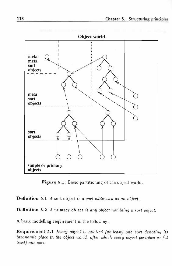
its Chapter 5. Structuring principles
Object world
simple or primaryobjects
Figure 5.1: Basic partitioning of the object world.
Definition 5.1 .4 sort object is a sort addressed as an o6jec£.
Definition 5.2 .4 primary object is ant/ 067'ecf noi 6ein<7 a sort o6;'ecf.
A basic modelling requirement is the following.
Requirement 5.1 £t>erj/ o&jecf is a//o££ed fa£ /eas^ one sort denotingiazonomic p/ace in t/ie oijecf u;or/d, a/<er w/iic/i every o6jec< pariafces in/eas<) one sort.
5.1 Sort hierarchies and specification 119
Often the term classification is used to denote the structuring of object do-mains. However, we prefer the term specification to emphasize the differenceamong sorts in the INCA model and classes or types in many others (while re-ferring again to the notion of species used in biological classification, see alsoChapter 3).
In the literature (e.g., Stroustrup (1991)), normal types are usually distin-guished from so-called abstract types, the latter being types without instances(and therefore only useful as a pass-through for shared characteristics). Inthe INCA model such a distinction is not semantically justified, since everysort object has an existence of its own (either with or without associated in-stances). In its role as sort oft/ect it may have its own properties, attributes,etc. Therefore, any difference between normal and abstract makes no sense inour object model.
5.1.2 Sort hierarchies
Within INCA-COM, sort /uerarc/iies act as taxonomical structuring devices. Asort hierarchy outlines a UOD according to some point of view. Sort hierarchieshave a free structure, in which subsequent layers lower in the tree denote levelsof increasing specialization according to the point of view expressed by thehierarchy. Sort hierarchies make it possible to specify certain sorts as subsorts(specia/ization) or supersorts (genera/zzafzon) of other sorts.
Definition 5.3 Let /I and 5 6e too sorts. 5 is a subsort o/ .4 in some sort/izerarc/it/ z/ and on/y z/ 5 zs a specia/izafion o/ .4 according <o t/ie particu/arpoint o/ tn'eto associated wi</i f/ie /lierarc/i?/. // 5 is a sutsort o/ .4, Men A tsa supersort o / 5 .
We note that, in this definition, 5 being a subsort of A depends on the sorthierarchy in which both sorts partake. As the specialization relation is tran-sitive, all sorts above a particular sort in a hierarchy are to be considered assupersorts. But then, all (direct) instances of a sort (by specification) arealso (indirect) instances of all sorts in the hierarchy above that sort. A prag-matic requirement, which ensures the largest set of such possible in/erences,is expressed in the following modelling requirement.
Requirement 5.2 £"very o6j>'ec< is mode//ed as a fdirec<^ instance o/t/ie mostspeci/ic sortfsj in one or more sort /lierarc/iies.
120 Chapter 5. Structuring principles
The specification of a domain by means of a sort hierarchy makes subsorts morespeci/ic than their supersorts. A (sub)sort's definition consists of the definitionof its supersorts, and any additional descriptions, which are speci/ic for thesubsort with respect to its supersorts. Thus, on the one hand the intensionof a subsort is more specific than the intension of its supersorts, hence it isapplicable to a smaller number of objects. On the other hand, the intension ofa supersort is less specific, and thus applicable to a larger number of objectsthan the intension of its subsorts. The order relation between intensions ofsorts gives rise to a subset relation on the sorts' extensions. This is capturedin the following requirement.
Requirement 5.3 Lei G and 5" 6e too sorts, and 5 6e a su6sort o / C XTien£/ie /o//ou;m<7 regions /io/d: ^ij TTie intension o/ 5" is more speci/zc t/ian £/ieintension o/ G: /s > /G, itf/iere /^ denotes </ie intension o/ sort X and >denotes £/ie order re/aiion 6etoeen intensions; fj?j TV»e extension o/ 5 is asubset o/ f/ie extension o/ 6*: £5 C £G> w/iere £^ denotes £/ie extension 0/sort X and C is i/ie set inc/usion.
We stress that the specification of a domain by sort hierarchies introduces asubtyping mechanism. The implication of the previous proposition is that ifsort 5 is a subsort of sort G, then an instance of sort 5" may be used whereveran instance of sort G is needed, since an instance of sort 5 is also an instanceof sort G. The assignment of a sort G to an object o furnishes an initia/ setof descriptions for object o. The initial set of descriptions furnished by G isapplicable to all its direct and indirect instances, which makes it possible touse an instance of sort 5 wherever an instance of sort G is needed.
Nevertheless, we do not hold the view that a particu/ar instance of sort G,say 51 is replaceable by another (direct or indirect) instance of sort G. Thereason for this is that #1 may have received additional descriptions, besidesthose already specified by its sort G. Those descriptions are not necessarilyshared by other (direct or indirect) instances of G. Therefore, an instanceof sort G is in princip/e not replaceable by an (indirect) instance of sort G,although an instance of subsort 5 remains an indirect instance of sort G.
With respect to mu/iip/e inheritance (see Section 5.2.2), we do not agree withthe rather wide-spread opinion that it is meaningful to use a sort which is adirect subsort of more than one supersort (multiple supersorting). The reasonis that the division of a domain into several (sub)sorts must be semanticallyrelevant, i.e., any sort to be distinguished within a particular domain must
5.1 Sort hierarchies and specification 121
have its own meaning, different from other sorts u>t</im f/»e Jazonorm'ca/ pointo/ view. A sort which is a direct subsort of several other sorts entangles thepoints of view of its supersorts.The point of view of a sort hierarchy acts as a /undamen^um diw'sionis, used inclassical hierarchical taxonomies (see, e.g., Joseph (1916)), according to whicheach sort in the hierarchy is different from its supersort. Several points ofview can be modelled by using several sort hierarchies. We stress, that thesedifferent points of view must not be intermingled: different points of view on anapplication domain should be represented by strictly disjoint sort hierarchies.This view of sort hierarchies differs from, e.g., Lenat ei a/. (1990), who allowmultiple supersorting, and additionally divide categories into mutually disjointsubsets. Such a division is expressed in INCA-COM by constructing two or moresort hierarchies expressing these points of view. Disjoint sort hierarchies on adomain span together a /oresf of hierarchy trees. The previous observationsare condensed in the following requirement.
Requirement 5.4 5pectyica£ion o/ an o6;'ec£ domain is per/ormed 6y usinjrdisjoin* sor£ /iierarc/iy irees.
In contrast with sorts, which are not allowed to be the direct subsort of morethan one sort, we do allow primary objects to partake in two or more sorts.These sorts are required to belong to different sort hierarchies, i.e., we do notallow objects to be instances of different sorts within one and the same sort hi-erarchy. The reason is similar to the one for not allowing multiple supersorting,namely that particularizing objects as instances of multiple sorts in one andthe same sort hierarchy would deny the semantical difference between thosesorts. However, this does not apply to sorts in different hierarchies, since theydenote alternate taxonomic views on the same domain: they are not meant tobe distinguished /rom each other, but they are meant to be ort/iopona/ <o eachother. This gives rise to a further modelling requirement.
Requirement 5.5 yl// fmos£ speci/ic,) sor<s o/an oftjiecJ s/iou/d 6e/ongr <o/eren< ('i.e., s£ric</?/ disjoin^ sori /iierarc/jies.
Thus, a primary object is allowed to participate (as an instance of severalsorts) in different sort hierarchies. This is noi an entanglement of points ofview on the structure of the domain, but a multi-dimensional allocation of theobject along sort(-hierarchical) dimensions. A similar notion of point of viewis the notion of /rame o/ re/erence (Bunge, 1977). A frame of reference M
122 Chapter 5. Structuring principles
is analogous to our point of view, introducing a set of functions on M whichrepresent properties of objects within the frame of reference. We addressthis issue in Chapter 7 when describing the extensional features of objectsbelonging to a sort.
Example specifications
Below, the previous definitions and propositions are illustrated by two exam-ples. The first example is on figure modelling, and the second on employeemodelling. The latter illustrates how multiple supersorting can be avoided.
Example 1: Figure modelling
Figure 5.2 provides an object domain of figures, viewed from two differentpoints of view (Shape and FillPattern). The thick lines in the figure indicatethe subsort/supersort relation between two sorts. The sort hierarchy at the topspecifies the object domain with respect to the form each object has; the rootsort of this hierarchy expresses this by its name, Shape. The sort hierarchy onthe left specifies the same domain, with respect to the fill pattern each figurehas; again, the root sort FillPattern indicates the associated point of view. Theorientation of the two sort hierarchies expresses the different points of viewon the domain of figures. Particular objects can be an instance of the sortsin both hierarchies, which is indicated by the arrows pointing from objects tosorts. Of course, such a specification is only applicable if the point of view isappropriate. As a case in point, we mention that the instance of Point in thelower right corner has no sort in the FillPattern sort hierarchy, since a pointhas no fill pattern.
In this way it may appear as if we have fully described the sample domain.However, in addition to the descriptional structure of objects due to theirspecification, our model allows instance objects to have their own descriptions,such as the length of a particular square, the radius of some circle, etc. Such(instance) descriptions are not indicated in Figure 5.2.
We do not require subsorts taken together to ez/iaustf their immediate supersort(by which we mean that the unions of the extensions of the subsorts are equalthe extension of the supersort). For instance, in many cases it will not be usefulto subdivide the sort Rectangle into the sorts Square and NotSquare, since thelatter sort has probably no relevant additional description compared with thesort Rectangle. In INCA-COM such an irrelevant sort is unnecessary, since we
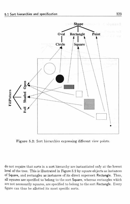
5.1 Sort hierarchies and specification 123
Shape
Oval Rectangle Point
;: >'' Circle /Square
Figure 5.2: Sort hierarchies expressing different view points.
do not require that sorts in a sort hierarchy are instantiated only at the lowestlevel of the tree. This is illustrated in Figure 5.2 by square objects as instancesof Square, and rectangles as instances of its direct supersort Rectangle. Thus,all squares are specified to belong to the sort Square, whereas rectangles whichare not necessarily squares, are specified to belong to the sort Rectangle. Everyfigure can thus be allotted its most specific sorts.
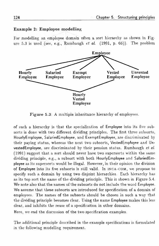
124 Chapter 5. Structuring principles
Example 2: Employee modelling
For modelling an employee domain often a sort hierarchy as shown in Fig-ure 5.3 is used (see, e.g., Rumbaugh e£ a/. (1991, p. 66)). The problem
Employee
HourlyEmployee
SalariedEmployee
ExemptEmployee
Vested UnvestedEmployee Employee
HourlyVestedEmployee -
Figure 5.3: A multiple inheritance hierarchy of employees.
of such a hierarchy is that the specialization of Employee into its five sub-sorts is done with two different dividing principles. The first three subsorts,HourlyEmployee, SalariedEmployee, and ExemptEmployee, are discriminated bytheir paying status, whereas the next two subsorts, Vested Employee and Un-vested Employee, are discriminated by their pension status. Rumbaugh ei a/.(1991) suggest that a sort should never have two supersorts within the samedividing principle, e.g., a subsort with both HourlyEmployee and SalariedEm-ployee as its supersorts would be illegal. However, in their opinion the divisionof Employee into its five subsorts is still valid. In INCA-COM, we propose tospecify such a domain by using two disjoint hierarchies. Each hierarchy hasas its top sort the name of the dividing principle. This is shown in Figure 5.4.We note also that the names of the subsorts do not include the word Employee.We assume that these subsorts are introduced for specification of a domain ofemployees. The names of the subsorts should be chosen in such a way thatthe dividing principle becomes clear. Using the name Employee makes this lessclear, and inhibits the reuse of a specification in other domains.
Here, we end the discussion of the two specification examples.
The additional principle described in the example specifications is formulatedin the following modelling requirement.
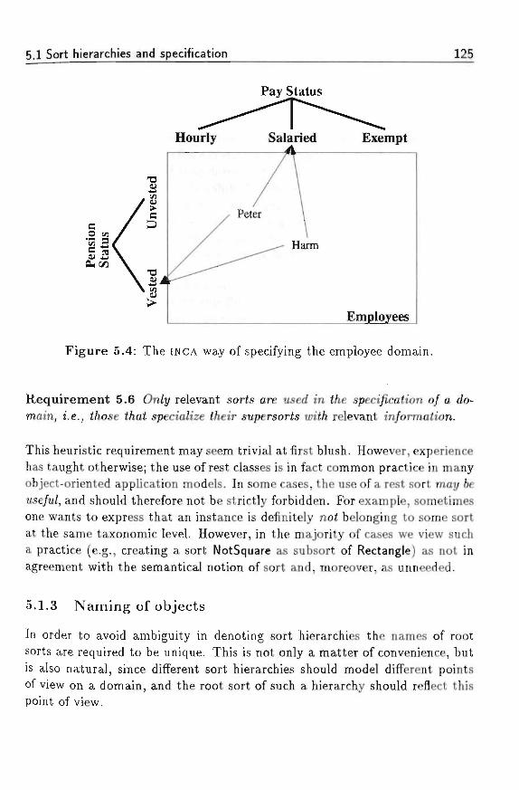
5.1 Sort hierarchies and specification 125
Pay Status
CUCA
Unv
este
dV
este
dHourly
/
/
Salaried
/ Peter \
^^— Harm
Exempt
Employees
Figure 5.4: The INCA way of specifying the employee domain.
Requirement 5.6 On/y relevant sorts are used *n f/ie speci/icah'on o/ a do-main, i.e., 2/iose £/ia£ specia/ize </ieir supersorts u>i</i relevant in/orma<ion.
This heuristic requirement may seem trivial at first blush. However, experiencehas taught otherwise; the use of rest classes is in fact common practice in manyobject-oriented application models. In some cases, the use of a rest sort may 6e«se/u/, and should therefore not be strictly forbidden. For example, sometimesone wants to express that an instance is definitely not belonging to some sortat the same taxonomic level. However, in the majority of cases we view sucha practice (e.g., creating a sort NotSquare as subsort of Rectangle) as not inagreement with the semantical notion of sort and, moreover, as unneeded.
5.1.3 Naming of objects
In order to avoid ambiguity in denoting sort hierarchies the names of rootsorts are required to be unique. This is not only a matter of convenience, butis also natural, since different sort hierarchies should model different pointsof view on a domain, and the root sort of such a hierarchy should reflect thispoint of view.
126 Chapter 5. Structuring principles
Requirement 5.7 A ames o/ t/ie sorts ai f/ie top o/ a// sort /lierarc/iies mustfee unigue and s/iou/d reyiecf t/ie point o/ mew associated un't/i t/ie sort /iierarc/ij/.
We note that the name of a root sort in some sort hierarchy may thus equallywell be used to denote this particular sort as the full sort hierarchy in question.As an example, we consider the hierarchies depicted in Figure 5.2. Althoughthe same primary objects are modelled, different specifications are discernedin both hierarchies. The names suggest (as it should be) that in one view themodeller concentrates on the forms of the figures (Shape), i.e., only consider-ing their silhouette, whereas the other specification structures the domain offigures as just filling patterns (FillPattern), not having any concrete form.
Definition 5.4 £uerj/ sort /ias a sort name and a full sort name. 77*e sortname is denoted 6t/ a text string. T/ie full sort name o/ a sort consists o/ itssort name /o/Zowed 6t/ t/ie /u// sort name o/ its supersort, i/ any, separated 6ya dot.
According to this definition the name space of all sort objects is treated by anierarc/iica/ naming sc/ieme. By virtue of Requirement 5.7 and Definition 5.4full names of sorts are always unique. If no ambiguity exists for some sort (i.e.,if its sort name is unique), the use of its full name is allowed, but not obliged.For instance, in the hierarchies of Figure 5.2 the leftmost and downmost sortmay equally well be denoted by Circle and Circle.Oval.Shape; sometimes theuse of full names clarifies the meaning of the sorts specified (Full.FillPatterninstead of Full). Further, in the context of a particular sort hierarchy the useof full names is not necessary.
This naming scheme is analogous to the well-known directory structure offilenames. One of the differences is the order of the sort names constitut-ing a full sort name, from more special to more general. In this way it iseasier to memorize the intended meaning of sorts from their names (if well-chosen); for instance, compare names such as Large.Disk or Point.Shape withtheir reversely-ordered names.
In Chapter 3, an object was defined as having a unique name. The definitionof sort names already introduces a. naming scheme in which each sort has aunique (full) name. The requirement that every object (both sort objects andprimary objects) have a unique identifier, and hence a unique name can nowbe realized by requiring each sort to have uniquely-named instances.
Requirement 5.8 /I// direct instances o/a sort must nave unigue names.
5 2 Inheritance mechanisms 127
To assure that equally-named instances of different sorts can be identified bytheir name, we define the instance name of an object in the following way.
Definition 5.5 £ac/i instance /ws an instance name and a full instance name.77ie instance name o/ an 067'ecf is its o6jec< name preceded 6y t/ie sort name0/ its sort, separated 6t/ t/ie '::' sign. T/ie full instance name 0/ an 06/ect isits o&ject name preceded 6y t/ie /u// sort name 0/ its sort, separated 61/ t/ie ';:'
By this definition, each object can be identified by using its (full) instancename. Examples of the usage of this naming scheme are the instance namesSquare::mysquare (an instance name), and Circle.Oval.Shape::yourCircle (a fullinstance name).
We note that by Definition 5.4 and Definition 5.5 a sort can be named in twodistinct ways: it has a (full) sort name, and it has a (full) instance name. Forexample, the sort named Point has the full sort name Point.Shape and the fullinstance name Metasort::Point (assuming Metasort is the name of the metasortin the particular domain). These names correspond (1) to the role a sort hasan instantiate semantic primitive, and (2) to the role a sort has a sort object,being an instance of a metasort. Thus, a sort can be addressed as a sort byusing its sort name, or it can be addressed as a sort object by using its instancename.
Furthermore, we require that each sort has an associated name sort, used togenerate names for instances of the sort.
Requirement 5.9 >1 sort /ias an associated name sort to generate names /orits instances.
In the next section we present the inheritance mechanisms in INCA-COM, whichare based on sort hierarchies and specification.
5.2 Inheritance mechanisms
Sort hierarchies are used as a vehicle for inheritance, though they are quiteuseful even without such a mechanism for reasoning about the place of anobject. For example, an instance of a sort in a sort hierarchy can be reasonedto be an instance of any of the supersorts of that particular sort.In most literature inheritance is somewhat derisively called "the ability to cre-ate classes that will automatically model themselves on other classes" (Tello,
128 Chapter 5. Structuring principles
1989, p. 7). Snyder (1987, p. 166) states that "inheritance can be used to definea class in terms of one or more other classes" and Meyer (1988, p. 59) definesit as follows: "A class is a descendant of one or more other ones when it isdesigned as an extension or specialization of these classes. This is the powerfulnotion of (multiple) inheritance." Although specification and inheritance areintimately bound, we do not adhere to these viewpoints, because they denythe difference between specification and inheritance. In our view, specificationis an organizafiona/ too/ for structuring object worlds, whereas inheritance is aprogramming too/, used to obtain less coding effort. The view that inheritanceis a programming tool is shared among others by Meyer (1988) and Cox (1987,p. 83) stating that "inheritance is a technique for bringing generic code intoplay when producing new code." Thus, generalization and specialization areused the denote the relations between sorts, whereas inheritance refers to amechanism for sharing descriptions (Rumbaugh et a/., 1991, p .42).
Nevertheless, the specification of an object domain is useful for guiding theuse of inheritance. INCA-COM supports three different types of inheritance (allthree precisely defined below): common in/ien'<ance, norma/ in/ieritance, ands<ruc£ura/ in/ieritance.
Definition 5.6 Common inheritance indicates t/ie conceptual trans/er o/ de-scriptor/va/ue pairs /rom ft/ie eztensiona/ description o/J a sort to its in-stances. 77ie in/ierited descriptions u>i// 6e sfrict/y common to a// instances,i.e., a// instances s/ia// possess t/ie descriptors u>it/i t/ie associated ua/ues.
The term strictly should be taken literally, i.e., if only one instance of a sortlacks some property then this property should not be modelled as common.We use the term 'common descriptions' (CDS) as a shortcut for descriptions tobe obtained by common inheritance. The same holds for 'normal descriptions'(NDS) and 'structural descriptions' (SDS) to be defined below. An obviousexample is modelling humans as instances of some sort HumanBeing with thecommon property of being mortal.The use of common inheritance enables universally quantified statements oninstances. As such, common descriptions can be conceived as partially definingthe objects (namely partially determining and /izinj their descriptive struc-ture). We note that the inheritance of common descriptions, being universallyvalid, may be described by first-order predicate logic. The category of descrip-tors most appropriate for common inheritance is the category of properties,but also relations (e.g., between all instances of one sort and all instances ofa second sort) can often profitably be modelled as common descriptors.
5 2 Inheritance mechanisms 129
Definition 5.7 Normal inheritance indicates </ie concepfua/ trans/er o/ de-scriptor/ua/ue pairs /rom a sort £o its instances. T/je dij^erence u>it/i commoninheritance is t/ie possi6i/ity io ouerru/e t/ie in/ieri/ec/ ua/ues o/ t/ie descriptorsa< t/ie /eue/ o/ instances. 77*e in/ierited ua/ues are de/au/t ua/ues /or instances,/or tu/iic/i reason norma/ in/ien'tance can 6e seen as default inheritance.
Normal inheritance allows a&normality to be described. Normal inheritanceis analogous to common inheritance except that the descriptive values pre-scribed by the sort to inherit from can be overruled. This is similar to themodel of exception handling (see, e.g., Touretzky (1986) and references foundthere). The sort from which descriptions are inherited only provides de/au/tvalues for the descriptors, which may be overwritten either by whole subsorts(ezceptiona/ subsorts) or by particular instances (ezceptiona/ instances).An instructive example for this kind of inheritance may be the modelling ofanimals using a sort Mammal of which the extension is described, for instance,with normal property No_of Jegs = 4 and subsort Human Being with overwritingproperty No_of_legs = 2 (exceptional subsort), whereas some disabled (one-legged) soldier would be modelled as an instance of Human Being with theoverwriting property No_of_legs = 1 (exceptional instance).
In contrast with common descriptions, the inheritance of normal descriptionscorresponds to some form of non-monotonic logic, e.g., default logic (Ether-ington and Reiter, 1985).
We remark that the treatment of exceptions is the task (and responsibility) ofthe modeller. This means that, whereas the model offers the tools to overwritedefault values of normal descriptions, it does not prescribe u;/ien and /lowoverwriting has to be done. As such, normal inheritance yields tools for themanagement of norma/ity, but not of a6norma/ity.
Definition 5.8 Structural inheritance dea/s u>it/i t/ie concepfua/ frans/er o/descriptors ftuif/iouf any particu/ar ua/ues^ /rom a sort to its instances. 77&eua/ues o/ t/ie descriptors are to 6e speeded &y t/ie mode//er at t/ie /eue/ o/instances.
In this way only a (partial) descriptional structure (i.e., without values) isimposed on the instances. Although the statements implied by structurallyinherited descriptors say nothing in particular about an instance itself, theyare still meaningful, since they partia//y determine the set of descriptions ofthe instance: they give a partial framework within which meaningful asser-tions on an object can be stated. As such, these statements do not denote
130 Chapter 5. Structuring principles
propositions on the domain, but metapropositions about the way objects areto be described (partially).
The use of structural inheritance will often be apparent in those cases whereusing normal inheritance would lead to overwriting of the inherited values forall or most instances. For instance, let us assume that persons are modelledas objects having a property Length. Since we feel it semantically unjustifiedto impose lengths on persons by using a sort Person with a normal propertyLength = 'Unknown' (or even worse Length = '180 cm'), followed by yieldingnew length specifications to all persons instantiated, we prefer to equip Personwith "only" a structural property Length. Thus, by the use of structuralinheritance we are saying, in effect, that our Persons should be described by,e.g., Length.
Since structural descriptions only impose certain descriptors on instances andsince these descriptors are universally valid at the description level of all in-stances of a particular sort, structural inheritance may be modelled, like com-mon inheritance, by first-order predicate logic.
We emphasize that, with respect to the inheritance modes discussed, all cat-egories of descriptors are viewed as similar. A distinction with Smalltalk andLOOPS is the clearer notion of semantics-driven inheritance modes. Instancevariables are subject only to structural inheritance in Smalltalk (values areonly specified at the instance level) or normal inheritance in LOOPS (defaultvalues specified at the class level), but lack the possibility of common inheri-tance. Although the use of class variables in Smalltalk or LOOPS enables someform of s/mmf information between instances, this is not common in the sensewe use it, since each instance has access to the contents of the class variablesof its class, which it can also modify.
Most other object-oriented languages, such as CLOS (Moon, 1989) and C++(Stroustrup, 1991), show analogous restrictions on method inheritance andon shared descriptions as Smalltalk and LOOPS. TO our knowledge no COMsupports inheritance equally for all descriptions and as fully as INCA-COM.
5.2.1 Inher i tance and the modelling process
The distinction between CDs, NDs, and SDs introduced above (after Defini-tion 5.6) may be used as a modelling aid. This is expressed in the followingrequirement.
ft ? Inheritance mechanisms 131
Requirement 5.10 // descn'pta'ons are parh'a//t/ de/mino/or all instances o/asort, t/iey s/iou/d 6e p/aced «;i</i t/ie appropriate sort as common descriptions. //descriptions are meant mere/j/ to supp/y a descripiiona/ structure to instances,t/iey s/iou/d 6e mode/Zed as structural descriptions o/ t/ie sort. // frot/i cases donot app/y, descriptions are 6est mode/Zed as normal descriptions.
The three kinds of descriptions used may correspond with three phases inthe object modelling process. Since common descriptions de/ine (partially)the objects, they are suited for a first structuring activity of the sorts in theobject domain, the identi/ication o/sorts. Normal descriptions can be viewedas assertions on objects. Therefore, the modelling of these descriptions is mostappropriate for a second phase of structuring, consisting of the descriptivere/mement 0/ sorts. Finally, the structural descriptions impose assertiona/temp/ates on the instances, i.e., prescribing what kind of assertions should bepossible. This corresponds mainly with a third phase of modelling, namely thedescription of objects that will belong to the different sorts. These three phasesexhibit a gradual shift from the emphasis on sorts to instances. Summarizing,they may guide the modelling process as follows.
Requirement 5.11 T/ie structura/ specification 0/ an 067'ect domain s/iou/d6e divided into t/iree p/iases, corresponding to identifying common descriptions(partia/ definitions^), nonnol descriptions (sort-6ased assertions,) and structure/descriptions (067'ect-directed assertiona/ temp/afes,) consecutiveZy.
Since inheritance uses the sort hierarchies for information distribution andsince sort hierarchies are built from specializations, the distinction between thethree kinds of descriptions entails a natural enhancement of the semantics ofspecialization. Therefore, specialization not only adds information to objectsor restricts the value domain for descriptors, but may also change the statusof some descriptions to be inherited in a well-defined manner. The allowedtransformations are from SDs to NDs (adding normal values of descriptions) andfrom NDs or SDs to CDs (in both cases stating common values of descriptionsby definition).
5.2.2 Multiple inheritance
As mentioned in Section 5.1.2 we do not allow sorts to have multiple (di-rect) supersorts. Instances, however, may have more than one sort. There-fore, instances are in principle subject to some form of mu/tip/e inheritance
132 Chapter 5. Structuring principles
in INCA-COM. Since we require such multiple sorts to be part of strictly dis-joint hierarchies and since we consider sort hierarchies to represent particularpoints of view on the object domain, multiple inheritance seldomly results incon/Jictinj inherited descriptions. This is due to the fact that descriptions areoften fully dependent on a particular point of view and as such unlikely toappear in more than one sort hierarchy. Therefore, although the INCA-COMm princip/e does allow multiple inheritance, there will be rarely conflictingsituations in practice.
We note that in the case of cons/7ic<m<7 mtito'p/e inheritance O/CDS the follow-ing position is possible. Since CDs are by definition universally valid for all(direct and indirect) instances of a sort, it follows that if an instance inherits acommon descriptor along two paths with different values, both values must bevalid, i.e., that the descriptor in question is a mu/<i-ua/ued description. We notethat this point of view does not follow from the INCA-COM described so far,since it is also possible to forbid the use of homonymous common descriptorsin different sort hierarchies as an illegal modelling activity, thereby avoidingconflicting multiple inheritance of common descriptions. The consequences ofwhatever point of view is held are not elaborated here. Also other detailsof multiple inheritance mechanisms (for normal descriptions) await furtherelaboration.
We have elaborated upon the structuring of a UOD by means of sorts, sorthierarchies, and specification. Within the framework of Chapter 4, sorts andsort hierarchies are particularly used for modelling the core of the frameworkconsisting of natural sorts, and for modelling application domains consistingof role sorts. Specification allows objects to be assigned to sorts determiningtheir place in the object world.
Having described sort hierarchies, specification, and their associated inheri-tance mechanisms, in the next section we address the concepts of compositionand grouping in INCA-COM, which are necessary for describing composite ob-jects and systems of interacting components.
5.3 Composition and grouping
Besides the structuring of an object domain by sort hierarchies and specifica-tion, INCA-COM supports objects composed of other objects. Most object con-ceptions describe these composite 067'ects using a hierarchical-decompositionprinciple (e.g., LOOPS (Bobrow and Stefik, 1983; Stefik and Bobrow, 1985)
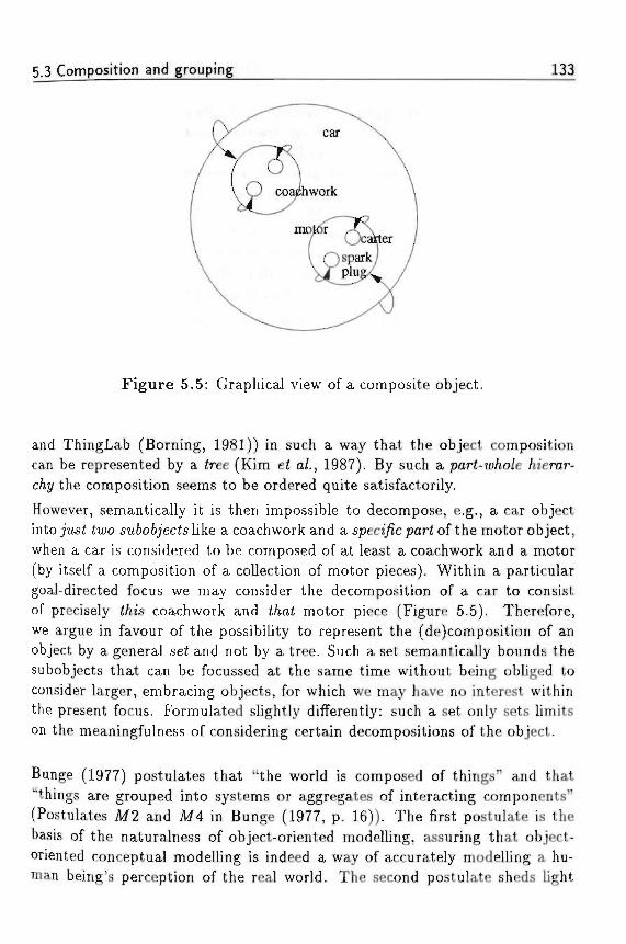
5.3 Composition and grouping 133
Figure 5.5: Graphical view of a composite object.
and ThingLab (Borning, 1981)) in such a way that the object compositioncan be represented by a <ree (Kim ei a/., 1987). By such a pari-w/w/e /lierar-C/M/ the composition seems to be ordered quite satisfactorily.
However, semantically it is then impossible to decompose, e.g., a car objectinto just <iwo s«6o6_;'ecis like a coach work and a speci/ic par< of the motor object,when a car is considered to be composed of at least a coachwork and a motor(by itself a composition of a collection of motor pieces). Within a particulargoal-directed focus we may consider the decomposition of a car to consistof precisely t/iis coachwork and £/m£ motor piece (Figure 5.5). Therefore,we argue in favour of the possibility to represent the (de)composition of anobject by a general sei and not by a tree. Such a set semantically bounds thesubobjects that can be focussed at the same time without being obliged toconsider larger, embracing objects, for which we may have no interest withinthe present focus. Formulated slightly differently: such a set only sets limitson the meaningfulness of considering certain decompositions of the object.
Bunge (1977) postulates that "the world is composed of things" and that"things are grouped into systems or aggregates of interacting components"(Postulates M2 and M4 in Bunge (1977, p. 16)). The first postulate is thebasis of the naturalness of object-oriented modelling, assuring that object-oriented conceptual modelling is indeed a way of accurately modelling a hu-man being's perception of the real world. The second postulate sheds light
134 Chapter 5. Structuring principles
on the question what the nature of systems is. In Bunge's view the world isa large system, of which all other things are components. Of course, such aview is legitimate, but it is hardly usable, since the world or universe shouldthus be seen as a composition of all atoms in the universe. Bunge's final pos-tulate states however that "there are several levels of organization" (Postulate10 (Bunge, 1977, p. 17)), which makes modelling and describing the worldeasier. In Chapter 2 we already mentioned the importance of a level conceptin software development. Although software development entails the creationof artificial systems, the ontological principles are applicable, since ontologystudies both natural and artificial (i.e., man-made) systems.
In this section, we elaborate the composition concept in INCA-COM. A com-posite object is not a simple bundle of component objects. Rather, we focus onthe systemic aspect of composite objects, which allows us to contribute holisticfeatures to them. We stress the important distinction between a compositeobject and a system. A composite object is an object with a composition. Asystem is a composite object, enhanced with a structure. As an example of thedifference between a composite object and a system, consider again a car, com-posed of a coachwork, a motor, a carter, a sparkplug etc. A working car is notjust a composite of components, but a system of components which interactin a well-defined way. If we decompose a car, lining up all the components, wedo not have a car: we only have the collection of components. If we combinethe components in such a way that the wheels are connected to the coachwork,and the motor forces the wheels to rotate, the result is a car. However, if wecombine the components in some other way, the resulting system might noteven come close to a car. So, a system is a composite object with additionalvalue. The additional value of a system is a particular s^ruciure, consisting ofthe relations and interactions between the components.
5.3.1 Composite objects
Using the concept of an object as defined in Chapter 4, we follow Bunge(1977) for the conceptualization of composite objects. Bunge's basis for defin-ing composite objects is the assumption that there is an association </ieon/.This allows objects to associate with each other to form other objects. Suchan association theory is formally captured in the definition of a commuta-tive monoid of idempotents, including an association operation (Bunge, 1977,p. 113). The important parts of the definition are presented below (followingWand (1989)).
5.3 Composition and grouping 135
Definition 5.9 Let ft be t/ie o6;ec£ u>or/(f. T/ie Wnan/ operation • ca//ed asso-ciation is de/med in t/ie /ollotnnj wot/. ••.-,.-
/. 7/x and y are objects, t/ien x • y is a/so an object;
J?. x • x = x ^objects are idempoteni under association^;
5. • is commutative and associative.
In other words, the above association theory states that an association ofobjects is itself an object, that the order of association is not important andthat an object cannot be associated with itself to form a new object. Usingthe above association theory, an object association xi • X2 • . . . • x^ representsan object composed of other objects.
Definition 5.10 ;4n object o is composite i^ it is composed o/ objects ot/iert/ian itse//. /.e., o £ ft is composite ijff t/iere exist objects y,z £ ft suc/i //iato = y •.? and eacA differs /rom o. Ot/iertuise t/ie object is simple.
The composite-object definition boils down to considering an object as com-posite if it can be described as consisting of (at least) two other objects. Forexample, if a computer can be decomposed into a system unit and a monitor(each of which might be decomposed further), then it is a composite object.The composition principle for objects is the basis for the definition of theparLo/relation.
Definition 5.11 7/x and j / £ ft are objects, t/ien y is a partjof x ijffy-x = x.77ie symbo/ /or t/ie part.o/ re/ation is: C, so y C i .
We can now define the composition of an object using the part_o/relation. Thecomposition of an object o is the set of objects which are part of o.
Definition 5.12 TVie composition C o/ an object o is t/ie set o/ its parts:C(^) = {y £ ft|y C o} /or any o £ ft.
The interesting thing to remark about the above definition is that it definesthe composition of an object as the set of all part objects. The latter set isintensionally defined by the function C, which consists of applying the pred-icate C to all objects to find an object's composition. Such a meaning/u/ setof objects is called a group in INCA-COM(see Section 5.3.3).
136 Chapter 5. Structuring principles
The difference between the composite object o = x • y and its composition{i , t/} is, that the former is an object, while the latter is a group. Furthermore,the partjof relation is a partial order relation, meaning that it is (1) reflexive(a; C a;), (2) asymmetric ( i [ t / - » ->(y [I z)), and (3) transitive ( i II j /At /Cz —> a; C z). The set of composite objects is denoted by the symbol F.
A composite object is the result of associating two or more objects. Thefeatures of such a composite object are divided into /iereditan/ and emergentfeatures. First, features of a composite object may be related to the features ofobjects in its composition. Such features are thus inherited by the compositeobject by composing it of other objects, and are called hereditary descriptors.Second, a composite object may have features which emerge as a result ofcombining the parts in a particular way. Such features can be modelled anddescribed for the composite object because of its object status. Hence, a com-posite object can have its own descriptors, which emerge through composition.This is captured in the following definition.
Definition 5.13 Le< F k a /ea^ure o/ an o&jec* o urc£/i composih'on C(o).77ien
./. F is a hereditary feature o/o ij[f </iere ezz'ste j / £ C(o),y ^ o, suc/iF is a /eature o/ y.
2. F is an emergent feature o/ o i^ i/iere is no j / G C"(o), j / ^ o, suc/iF is a /eature o/ y.
As an example consider again a composite object car. The colour of a car isusually taken to be the colour of its coachwork. Since the coachwork of thecar is an object in its composition, the colour of a car is an hereditary feature.Analogously, a car's ability to drive is not a feature possessed by any of itsparts. It emerges because the parts are put together in a particular way, sothat the motor propels the wheels, the motor is attached to the coachworketc. The car's ability to drive is an emergent feature.
We note that the concept of an hereditary feature is not related to the conceptof inheritance in object-oriented programming languages. In such program-ming languages, inheritance is a mechanism for distributing features alongclass hierarchies, in order to equip the instances of classes with the appropri-ate set of features. In object-oriented modelling, classification is performed onthe basis of the features an object has. Inheritance of features in the sense offurnished by a class or superclass plays no role in object-oriented modelling.
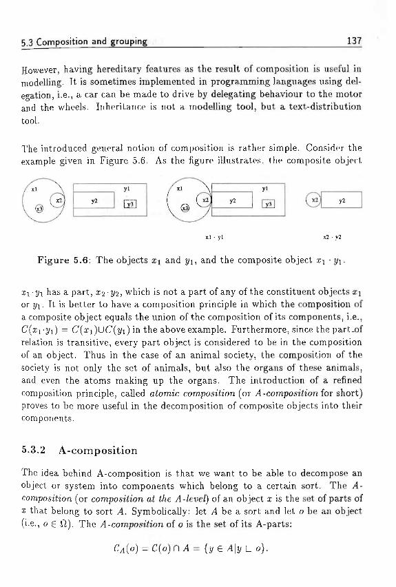
5,3 Composition and grouping 137
However, having hereditary features as the result of composition is useful inmodelling. It is sometimes implemented in programming languages using del-egation, i.e., a car can be made to drive by delegating behaviour to the motorand the wheels. Inheritance is not a modelling tool, but a text-distributiontOOl. , - . ;
The introduced general notion of composition is rather simple. Consider theexample given in Figure 5.6. As the figure illustrates, the composite object
yi
yz
yi
. . . - v . . . xl • yl x2 • y2
Figure 5.6: The objects Zi and j/i, and the composite object Zi • j/i.
i i yi has a part, a^jte, which is not a part of any of the constituent objects i ]or j/i. It is better to have a composition principle in which the composition ofa composite object equals the union of the composition of its components, i.e.,C(zri/i) = C(zi)uC(i/i) in the above example. Furthermore, since thepart_ofrelation is transitive, every part object is considered to be in the compositionof an object. Thus in the case of an animal society, the composition of thesociety is not only the set of animals, but also the organs of these animals,and even the atoms making up the organs. The introduction of a refinedcomposition principle, called atomic composition (or >1 -composition for short)proves to be more useful in the decomposition of composite objects into theircomponents.
an
5.3.2 A-composition
The idea behind A-composition is that we want to be able to decomposeobject or system into components which belong to a certain sort. The J4-composition (or composition at tne j4-/eve/) of an object x is the set of parts ofa: that belong to sort 4. Symbolically: let 4 be a sort and let o be an object(i.e., o £ ft). The .4-composition of o is the set of its A-parts:
o) = C(o) f l ^l = {y G o}.
Chapter 5. Structuring principles
The previously defined composition is sometimes also referred to as the a6so-/u<e composition in order to distinguish it clearly from the A-composition. Theconcept of A-composition has the property that the A-composition of a com-posite object i i -j/i equals the union of the A-compositions of the components:
As an example consider the composition of a body of water. The molecularcomposition of a body of water is the set of its #20 molecules. The atomiccomposition of the same body is the set of if and 0 atoms composing it;and the elementary-particle composition is its total collection of electrons,neutrons, and protons.A-composition introduces a concept of /eve/s in composition. Such a levelconcept is a fundamental modelling aid with respect to abstraction. It allowsa composite object to be decomposed in particular components of a certainsort. A computer program can be decomposed into modules, modules can bedecomposed into functions, and functions can be decomposed into statements,and statements are composed of characters. During the development of com-plex software systems (i.e., man-made artefacts) we are not interested in thecharacters of the final statements making up the program. Instead, we like tofocus on architectural issues such as the gross organization of modules and theinteraction between them. The atomic level of specifying computer programsis the statement.
5.3.3 Groups of objects
Beyond the structuring principles such as a sort hierarchy and a composite-object graph we introduce another structuring principle, the group o/ oi;ects.This should be a meam'ng/u/ set of objects. Hence, a group of objects is morethan just some collection of objects. The importance of the group conceptis that it provides the modeller with a tool to model coherent sets of objectswithout loading the object world with taxonomies or composite objects oflimited importance. We require that a group can be defined by a meaningfulpredicate.
Definition 5.14 .4 group of objects is a set 0/067'ects, de/med fry a meara-tngf/u/ predicate.
We note that a group, in contrast to a sort or a composite object, has noobject status. That is, groups are fundamentally different from the objectsthat are being grouped by them.
5.3 Composition and grouping 139
In Section 5.3.1, one such meaningful predicate, based on the parLo/relationbetween objects, has been used for defining a composite's object composition.Thus, the composition of a composite object is a group, defined by the part.o/relation.
5.3.4 Systems
The composition is one of the important aspects of a composite object. Inorder to distinguish a system from a mere composite object, it is necessary tointroduce the concept of interaction between objects.
Earlier in this section we introduced a system as a composite object withadditional value. We can now be more precise about this additional value. Thedistinguishing feature of a system is that its components interact. Interactionis based on a coupling between objects, which is different from a mere relation,such as being older. A coupling (or bond) between objects makes a differenceto its relata. Thus, two objects are coupled or bonded in case one of themacts upon the other. An object acts upon another object if it modifies thelatter's history (although we have not defined the history of an object, it isthought of as the trajectory of its state function in the state space). If bothobjects act upon each other, they are said to interact. The interaction betweencomponents defines the influence each component has on other components.The set of influence relations defines the structure of a system. Furthermore, asystem has an environment consisting of the objects outside the system, whichinfluence (parts of) the system. Thus, a system is defined in the following way.
Definition 5.15 >ln o6ject is a system ij^ it is composed o/ at /east two di/-/erent coup/ed objects. 77ie composition o/ a system is t/ie set o/ e/ementso/ tAe system. 77ie environment o/ a system is f/ie set o/ e/ements not in t/»ecomposition o/ t/ie system, u;/iic/i are in/Zuenced 6y or in/Zuence e/ements o/ f/iecomposition o/ t/ie system. JTie structure o/ a system is </ie set o/ in/Zuencere/afions 6etween t/ie e/ements o/ a system.
We note that, similar to a composite object, for an object to be called a system,it requires to be composed of at least two other objects. The difference betweena composite object and a system is the influence among the components. Forthe set of systems we use the symbol E. According to Definition 5.15 andDefinition 5.10 of a composite object, the set of systems E is a subset of theset of composite objects T, which is a subset of the entire object world fi:
140 Chapter 5. Structuring principles
For ease of systems analysis, two organization principles are often used. A firstorganization principle is that different categories of systems are distinguished,each of which has its own type of atomic e/ement. The atomic elements ofsocial systems, e.g., are individual persons. Although the brains and otherbody parts are part of individuals, they do not qualify as elements of socialsystems, since they do not enter into social relations. Ontology distinguishesthe following five system categories; after the category, the category elementsare given in parentheses:
1. physical things (atoms and fields);
2. chemical systems (protein-synthesizing units);
3. biosystems (organisms and their organs);
4. sociosystems (societies and their subsystems);
5. artificial or technical systems (man-made artefacts).
A second organization principle is the /eve/ o/ organization. Within each sys-tem category there are systems composed of elements which are not atomic,but which are themselves systems composed of atomic elements. Thus, in thecategory of social systems there might exist levels such as persons, which com-pose into families, which compose into cities, which compose into provinces,which compose into countries etc. Thus, each level of organization introducesa system sort, which decomposes into systems of a lower level.
5.3.5 Systems in INCA-COM
Having introduced a concept for a system, we can now be more precise aboutthe two different types of system in INCA-COM. Following the framework ofChapter 4, an information system consists of two parts: a passive object world,representing a UOD, and a system of active objects communicating about theobject world.
The object world is a composite object, i.e., its composition is the set of objectsacting as representation of things in the UOD. In the information model andthe event model, we have chosen to model such objects by means of descriptors,events, and laws, constraining the state space of objects. Modelling an objectworld thus has a declarative nature, expressing which state of affairs holds inthe UOD and which objects are represented. We remark that the term object
5.4 A conceptual model 141
is chosen deliberately to express that the representation of a UOD is not initself a system. By this we mean that, although some objects in an object worldmay influence each other, not every object (directly or indirectly) influencesother objects. We reiterate that particular objects in an object world can bea system. The specification of an object world thus consists of the followingsteps: (1) determination of the things in the UOD to be represented as objects;(2) for each object: describing it in terms of descriptors, events, and laws.Active objects form a system by communicating on the object world. The spec-ification of an active object is done in the behavioural model, expressing whichtasks can be performed by active objects. The structure of an active-objectsystem consists of the set of communication links between the active objectsin the system, specified in the communication model. The environment ofsuch a system is the set of objects not in the composition of the system, whichcommunicate with elements in the system. The specification of behaviour hasa procedural nature, which is better suited for expressing task-like steps. Thespecification of an active-object system consists of the following steps: (1)determination of the appropriate object world; (2) determining which activeobjects are component of the active-object system; (3) determining the envi-ronment of the system, and (4) describing the structure of the system in termsof communicative associations (influence relations) between active objects.
5.4 A conceptual model
In this section we describe a conceptual model of a con/erence-regrts^rah'onsystem, and its UOD. The UOD is divided into a world, and an applicationdomain, the conference-registration domain. The modelling process illustratesthe concepts we have introduced in Chapter 4 and the previous sections of thischapter.
The description of the case to be modelled is as follows. The conference isorganized by an organizer, who distributes a call for papers. Potential authorswho have received or noticed the call for papers, can write and submit papersfor presentation at the conference. Each paper is assigned to a referee, whojudges the paper and decides to accept or reject it. The result of the refereeingprocess is communicated to the senior author of the paper.
The specification of a conceptual model always follows the structure of theframework of Figure 4.4. A modeller first specifies the natural sorts of interest,then the application domain by means of role sorts, and finally the application.
142 Chapter 5. Structuring principles
In the example we specify
• the world containing the natural sorts person and article (Section 5.4.1);
• the conference-registration domain containing the role sorts researcher,conference organizer, referee and conference paper (Section 5.4.2); and
• the conference-registration system consisting of the active objects orga-nizer, and referee, admitting articles, and refereeing them, respectively(Section 5.4.3).
5.4.1 World
The world contains sorts like HumanBeing and Person. Such nafura/sorts aremeant to be used in various application domains (see Section 4.2.1). In orderto enhance the reuse of HumanBeing and Person, they are modelled by the leastcommon description, useful for every application wishing to use Human Beingsand Persons. Thus, the sort HumanBeing is described by a date of birth anda place of birth, and the sort Person is described by a name, an address, anda residence. Each sort specified introduces a name sort, which is used togenerate names for identification of instances for the sort under consideration(see Section 5.1.3). For HumanBeing the name sort generates numbers (nr)as instance names and for Person the name sort constructs instance namesconsisting of an identification number (ID).
Role sorts, introduced in application domains, are institutionally defined sorts.The instances of such sorts are created within particular application domains.Often, such an institutional instance is a role of an instance of a natural sort.Such an association between a natural instance and a role instance is realizedby linking the two instances with a ro/e /mfc. The boundary between naturalsorts and role sorts seems appropriate to distinguish between naturally occur-ring objects, and institutionally defined objects. However, as the natural sortPerson illustrates, this is not really the case: one may argue that propertiessuch as name, address, and residence are not properties of Persons, but at-tributes, institutionally defined by societies, and attributed to HumanBeingswhen playing a role as a Person. Thus, an application domain may be basedon other application domains, resulting in a nesting of application domains(see Section 4.4). This is illustrated in Figure 5.7, showing the structure ofobjects playing particular roles. The arrow at the top of the figure shows thedirection in which subsequent roles may be assumed.
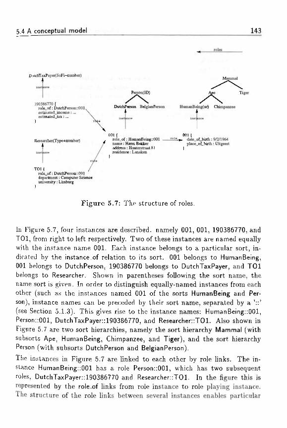
5.4 A conceptual model 143
rote
DutchTaxPayer(SoFi-nuinber)
190386770 (role_of: DulchPerson::001estiruated_income: ...estimated_t£x:...
Researcher(Type+nurnber)
TOHrole_of: DutchPerson::001department: Computer Scienceuniversity: Limburg
)
Mammal
Person(ID) Ape Tiger
/ \ ADutchPerson BelgianPerson HumaaBeing(nr) Chimpanzee
001 (role.of: HumanBeing::001name: Harm Bakkeraddress: Houterctraat 81residence: Lanaken
001 (• date_of_birth: 9/2/1964
place_of_birth : Uitgeest
Figure 5.7: The structure of roles.
In Figure 5.7, four instances are described, namely 001, 001, 190386770, andTOl, from right to left respectively. Two of these instances are named equallywith the instance name 001. Each instance belongs to a particular sort, in-dicated by the instance.of relation to its sort. 001 belongs to HumanBeing,001 belongs to DutchPerson, 190386770 belongs to DutchTaxPayer, and TOlbelongs to Researcher. Shown in parentheses following the sort name, thename sort is given. In order to distinguish equally-named instances from eachother (such as the instances named 001 of the sorts HumanBeing and Per-son), instance names can be preceded by their sort name, separated by a '::'(see Section 5.1.3). This gives rise to the instance names: HumanBeing::001,Person::001, DutchTaxPayer::190386770, and Researcher::T01. Also shown inFigure 5.7 are two sort hierarchies, namely the sort hierarchy Mammal (withsubsorts Ape, HumanBeing, Chimpanzee, and Tiger), and the sort hierarchyPerson (with subsorts DutchPerson and BelgianPerson).
The instances in Figure 5.7 are linked to each other by role links. The in-stance HumanBeing::001 has a role Person::001, which has two subsequentroles, DutchTaxPayer::190386770 and Researcher::T01. In the figure this isrepresented by the rolejof links from role instance to role playing instance.The structure of the role links between several instances enables particular
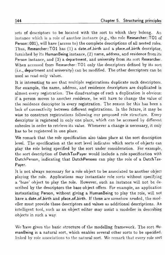
144 Chapter 5. Structuring principles
sets of descriptors to be located with the sort to which they belong. Aninstance which is a role of another instance (e.g., the role Researcher::T01 ofPerson::001), will have (access to) the complete descriptions of all nested roles.Thus, Researcher::T01 has (1) a date_of_birth and a place_of_birth descriptor,furnished by its HumanBeing instance, (2) name, address, and residence from itsPerson instance, and (3) a department, and university from its sort Researcher.When accessed from Researcher: :T01 only the descriptors defined by its sort(i.e., department and university) can be modified. The other descriptors can beused as read-only values.
It is interesting to see that multiple registrations duplicate such descriptors.For example, the name, address, and residence descriptors are duplicated inalmost every registration. The disadvantage of such a duplication is obvious:if a person moves to another residence, he will have to change the value ofthe residence descriptor in every registration. The reason for this has been alack of connectivity between different registrations. In the future, it may bewise to construct registrations following our proposed role structure. Everydescriptor is registered in only one place, which can be accessed by differentsubroles in order to retrieve its value. Whenever a change is necessary, it onlyhas to be registered in one place.
We remark that the role specification also takes place at the sort descriptionlevel. The specification at the sort level indicates which sorts of objects canplay the role being specified by the sort under consideration. For example,the sort description of DutchTaxPayer would include a role specification withDutchPerson, indicating that DutchPersons can play the role of a DutchTax-Payer.
It is not always necessary for a role object to be associated to another objectplaying the role. Applications may instantiate role sorts without specifyinga 'base' object to play the role. However, such an instance will not be de-scribed by the descriptors the base object offers. For example, an applicationinstantiating Person, without giving a HumanBeing to play the role, will nothave a date_of_birth and place_of_birth. If these are somehow needed, the mod-eller must provide these descriptors and values as additional descriptions. Anintelligent tool, such as an object editor may assist a modeller in describingobjects in such a way.
We"have given the basic structure of the modelling framework. The sort Hu-manBeing is a natural sort, which enables several other sorts to be specified,linked by role associations to the natural sort. We remark that every role sort
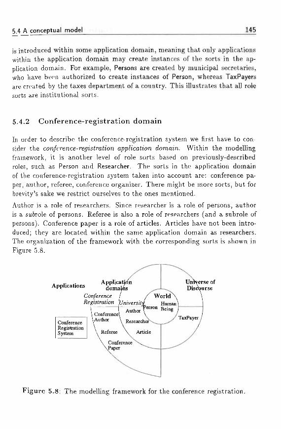
5.4 A conceptual model 145
is introduced within some application domain, meaning that only applicationswithin the application domain may create instances of the sorts in the ap-plication domain. For example, Persons are created by municipal secretaries,who have been authorized to create instances of Person, whereas TaxPayersare created by the taxes department of a country. This illustrates that all rolesorts are institutional sorts.
5.4.2 Conference-registration domain
In order to describe the conference-registration system we first have to con-sider the con/erence-re<7«s£rah'on app/icafo'on domain. Within the modellingframework, it is another level of role sorts based on previously-describedroles, such as Person and Researcher. The sorts in the application domainof the conference-registration system taken into account are: conference pa-per, author, referee, conference organizer. There might be more sorts, but forbrevity's sake we restrict ourselves to the ones mentioned.
Author is a role of researchers. Since researcher is a role of persons, authoris a su&role of persons. Referee is also a role of researchers (and a subrole ofpersons). Conference paper is a role of articles. Articles have not been intro-duced; they are located within the same application domain as researchers.The organization of the framework with the corresponding sorts is shown inFigure 5.8.
ApplicationsUniverse ofDiscourse
ConferenceRegistrationSystem
Figure 5.8: The modelling framework for the conference registration.
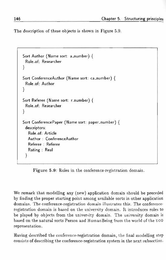
146 Chapter 5. Structuring principles
The description of these objects is shown in Figure 5.9. '
Sort Author (Name sort: a_number) {Role.of: Researcher
Sort ConferenceAuthor (Name sort: ca_number) {Role.of: Author
Sort Referee (Name sort: r_number) {Role_of: Researcher
Sort ConferencePaper (Name sort: paper_number) {descriptors:
Role.of: ArticleAuthor : ConferenceAuthorReferee : RefereeRating : Real
Figure 5.9: Roles in the conference-registration domain.
We remark that modelling any (new) application domain should be precededby finding the proper starting point among available sorts in other applicationdomains. The conference-registration domain illustrates this. The conference-registration domain is based on the university domain. It introduces roles tobe played by objects from the university domain. The university domain isbased on the natural sorts Person and HumanBeing from the world of the UODrepresentation.
Having described the conference-registration domain, the final modelling stepconsists of describing the conference-registration system in the next subsection.
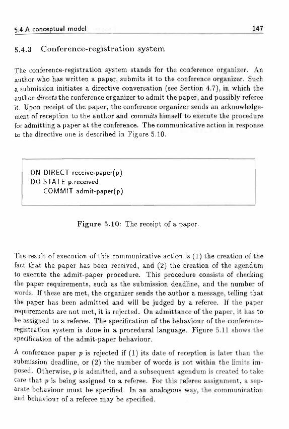
5.4 A conceptual model 147
5.4.3 Conference-registration system
The conference-registration system stands for the conference organizer. Anauthor who has written a paper, submits it to the conference organizer. Sucha submission initiates a directive conversation (see Section 4.7), in which theauthor directs the conference organizer to admit the paper, and possibly refereeit. Upon receipt of the paper, the conference organizer sends an acknowledge-ment of reception to the author and commit himself to execute the procedurefor admitting a paper at the conference. The communicative action in responseto the directive one is described in Figure 5.10.
ON DIRECT receive-paper(p)DO STATE p.received
COMMIT admit-paper(p)
Figure 5.10: The receipt of a paper.
The result of execution of this communicative action is (1) the creation of thefact that the paper has been received, and (2) the creation of the agendumto execute the admit-paper procedure. This procedure consists of checkingthe paper requirements, such as the submission deadline, and the number ofwords. If these are met, the organizer sends the author a message, telling thatthe paper has been admitted and will be judged by a referee. If the paperrequirements are not met, it is rejected. On admittance of the paper, it has tobe assigned to a referee. The specification of the behaviour of the conference-registration system is done in a procedural language. Figure 5.11 shows thespecification of the admit-paper behaviour.
A conference paper p is rejected if (1) its date of reception is later than thesubmission deadline, or (2) the number of words is not within the limits im-posed. Otherwise, p is admitted, and a subsequent agendum is created to takecare that p is being assigned to a referee. For this referee assignment, a sep-arate behaviour must be specified. In an analogous way, the communicationand behaviour of a referee may be specified.
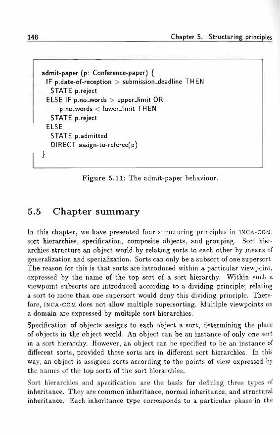
148 Chapter 5. Structuring principles
admit-paper (p: Conference-paper) {IF p.date-of-reception > submission_deadline THEN
STATE p.rejectELSE IF p.no.words > upper-limit OR
p.no-words < lowerJimit THENSTATE p.reject
ELSE
STATE p.admitted ,DIRECT assign-to-referee(p)
Figure 5.11: The admit-paper behaviour.
5.5 Chapter summary
In this chapter, we have presented four structuring principles in INCA-COM:
sort hierarchies, specification, composite objects, and grouping. Sort hier-archies structure an object world by relating sorts to each other by means ofgeneralization and specialization. Sorts can only be a subsort of one supersort.The reason for this is that sorts are introduced within a particular viewpoint,expressed by the name of the top sort of a sort hierarchy. Within such aviewpoint subsorts are introduced according to a dividing principle; relatinga sort to more than one supersort would deny this dividing principle. There-fore, INCA-COM does not allow multiple supersorting. Multiple viewpoints ona domain are expressed by multiple sort hierarchies.
Specification of objects assigns to each object a sort, determining the placeof objects in the object world. An object can be an instance of only one sortin a sort hierarchy. However, an object can be specified to be an instance ofdifferent sorts, provided these sorts are in different sort hierarchies. In thisway, an object is assigned sorts according to the points of view expressed bythe names of the top sorts of the sort hierarchies.
Sort hierarchies and specification are the basis for defining three types ofinheritance. They are common inheritance, normal inheritance, and structuralinheritance. Each inheritance type corresponds to a particular phase in the
5.5 Chapter summary 149
modelling process.Composition allows objects to be composed of other objects. The compositionof an object is defined as the set of objects being a part of the object. Such anintensionally-defined set of objects is called a group in INCA-COM. A systemis a special kind of composite object. In addition to a composition, a systemhas a structure, consisting of the influence relations between the elementsin the composition, and an environment, interacting with elements in thesystem. An object world in INCA-COM is an example of a composite object. Itscomposition is the group of objects representing things in the UOD. An objectworld is modelled in a declarative manner, with objects, descriptors, laws, andevents. A composite object consisting of active objects communicating witheach other is an example of a system. The structure of such a system consistsof the communication links between the active objects. The behaviour of anactive-object system is modelled in a procedural way, allowing task-like stepsto be specified.
In the final section of this chapter we have illustrated the modelling conceptsof INCA-COM in a model of a conference-registration system. The use of sortsfor the representation of natural kinds and role kinds introduces a distinc-tion between essential and contingent object features. A natural object mayplay various roles in different application domains. Each role a natural ob-ject assumes within an application domain attributes additional features tothe object, which are only interesting within the viewpoint of that particularapplication domain.
The construction of a conceptual model following the framework of INCA-COM
determines precisely (1) the objects to be represented; (2) the roles in anapplication domain; (3) the active objects; (4) the communication betweenactive objects; and (5) the behaviour of active objects. The resulting modelcan be used for (1) understanding an application domain; (2) simulating anapplication domain; or (3) (partly) automating particular active objects.

150
' > [ « . • T- . l l ' *'.•>
Chapter 5. Structuring principles
Chapter 6
Version management*
The complexity of a real-world system being modelled often brings about amodel with a large amount of objects. The evolution of the objects partici-pating in the model normally introduces even more objects. Close inspectionof such new objects makes clear that they are quite often versions of the orig-inal objects. To reduce the number of objects, a growing need arises to keeptrack of different versions of the original objects. In this chapter we describethe version model within INCA-COM and address the specific problems whenmanipulating versions of composite objects.
6.1 Versions
Versions introduce a notion of time in a domain to be modelled (Bjornerstedtand Hulten, 1989). In the literature, there has not been much agreement onthe terminology to be used with respect to versions. As a case in point, Perry(1987) distinguishes three kinds of versions: (1) successive versions followingeach other in time as a result of small corrections or improvements; (2) par-allel versions resulting from providing alternate implementations or differentfunctionality; (3) composed versions resulting from constructing objects fromseparate components. However, Perry (1987) does not make clear when cor-rections or improvements are to be considered "small" and when they give riseto alternate implementations. In addition, a parallel version can be revised aswell, leading to a successive version of a parallel version.
Parts of this chapter have been published as an article for the European Simulation Mul-ticonference 1990 as Version Management o/ Composite /nstantiated O6jecf« (Bakker ef a/.,1990).
151
152 Chapter 6. Version management
Perry (1987) describes three different levels of version management. At thefirst level there is no automated version management. For instance, at the levelof the operating system Unix no facilities for version management are available.The user is responsible for keeping track of the appropriate versions.
The second level of version management (basic version management) consistsof managing versions of text files. Such version management is provided bysystems such as the Source Code Control System (sees) and Revision ControlSystem (RCS),^ which operate on top of an operating system such as Unix.According to Perry (1987), these systems support all three kinds of versions,although the support for composed versions is questionable. Of course, the textfiles under control of the version-management system may contain programs.
The third level of version management is used in systems such as the SystemVersion Control Environment (SVCE) described by Kaiser and Habermann(1983). This environment allows for a much more detailed specification of theobjects constituting a composite object than the systems of the second level.In SVCE granularity surpasses the level of files: even small granular, syntacticobjects such as data structures and functions/procedures can be distinguished.
In INCA-COM, versions are supported at the object level, i.e., version man-agement takes place at the third level mentioned above. Basically, versionsare semantic variations of an object, merely denoting the existence of an ob-ject's variation. Consequently, a version is in principle not an object, as thesevariations can simply be attached to the object. However, when coping witha complex, real-world modelling problem (e.g., modelling the domain of aCASE environment), one encounters sometimes the need for versions that havetheir own particular relations with other versions or objects. For this reason,INCA-COM contains two different approaches for modelling versions of objects:versions as parh'a/ o&;'ec£s and version as version 067'ecte.
6.1.1 Versions as partial objects
In the first approach for modelling versions, a version is treated as a parte'a/o6jec<, because its descriptor space is a subspace of the descriptor space of afull-blown object. Some descriptors are applicable, while others are inapplica-ble to versions. The inapplicability of some descriptors warrant the consistency
^Within sees and Res, the terminology used differs from the one used by Perry (1987).For instance, a parallel version is indicated as a branch in sees, and a version is called arewision in RCS.
ft T Versions ' ' 153
of the version space, because they are attached only to the original object. Forinstance, a version as a partial object has no sort descriptor, because if wouldbe semantically unjustified to have a version with its own sort.
6.1.2 Versions as version objects
In the second approach for modelling versions, a version is initially treated asmerely existing without descriptive structure. When description of a version isnecessary, the version is promoted to a version 067'ecL A version object is a full-blown object, allowing them to be described using the descriptors for objects.However, the ua/ues of some of the descriptors are constrained: for instance,a version object has a sort descriptor, the value of which is constrained to beidentical to the value of the sort descriptor of its original object.
6.1.3 Comparison of the two version approaches
The partial-object approach differs from the version-object approach in itstreatment of versions. In the partial-object approach, every version is treatedas a partial object, whereas in the version-object approach a version is onlytreated as a version object when a meaningful description can be attached toit.
The advantage of the partial-object approach is the smaller number of alterna-tives. For modelling versions in the partial-object approach, the modeller hasto deal with two alternatives: an object and a partial object. In the version-object approach, a modeller has to choose among an object, a version, and aversion object, requiring more modelling skill.
The disadvantage of the partial-object approach is the possible proliferationof (partial) objects, making the overall model less transparent. Further, apartial object is a rather rich concept to represent a version, having the riskof stimulating the modeller to introduce unnecessary descriptors for versions.
The advantage of the version-object approach is the possibility for refrain-ing from describing versions, giving a minimum of overhead (e.g., regardinginheritance).
The disadvantage of the version-object approach is the gap between the twodifferent kinds of versions possible, namely the version entity only (seen as anabstract store of the voriation of the original object), and the version object(describing a version as an o&jecf).
154 Chapter 6. Version management
6.2 Version management of composite objects
As is known from Section 5.3, we have established a way of describing compos-ite objects. Two characteristics of the composition principle in INCA-COM arethat (1) objects can only be composed of other objects (i.e., objects cannotbe composed of versions), and (2) the composition of an object is a set of ob-jects, limiting the meaningfulness of particular decompositions of a compositeobject. - . . . . :
Thus, an object can only be part of one composition hierarchy. Objects consti-tuting other objects are referred to as parts. A composite object is describedby HAS_PART relations to its parts. All parts have a PART_OF relation withtheir hierarchically-higher object. The hierarchically-highest object is calledthe top object. Both HAS_PART and PART-OF are referred to as compositionrelations.
Since objects may only have other objects as parts, an object cannot be com-posed of partial objects, since they lack the status of object by definition. Anobject may, however, be composed of version objects, which are full-blownobjects indeed.
The INCA-COM presented so far supports versioned composite objects, sincea composite object is a normal object. Since the parts of a composite objectare themselves objects (see book in Figure 6.1), INCA-COM allows versions ofcomposite objects to have versions of the parts as components. Consequently,to establish this possibility (see book-vl in Figure 6.1) we need to extend thenotion of a version of a composite object. Below we describe the semantics ofsuch composite versions and the semantical requirements INCA-COM imposeson them.
Requi rement 6 .1 /1 composite version is a version o/ a composite o6jeddeno<in<7 uj/iic/i parts or versions o/parts constitute it.
Hence, composite versions have their own PART.OF relations to parts or ver-sions of these parts. We use the generic term component to denote an objector a version having a PART-OF relation to another object or version. A groupof components connected by composition relations is called a composition.Furthermore, an object or version A is a component of object or version B ifthere is a path from A to B consisting of PART-OF relations. The object orversion that contains a component is called the w/io/e of that component.
6.2 Version management of composite objects 155
In INCA-COM'S semantics, a composite version should have a reason to exist.This means that the composition of a composite version should be (1) dif-ferent from the composition of the original object and (2) different from thecomposition of other composite versions of the original object. The structuraldifference between composite versions is reflected in our semantics. .
Requirement 6.2 .A composite version s/iou/d rco< /mve </ie same compositionos f/ie composite o6;ect itsef/or any o/ its ot/ier composite versions.
Different composite versions can result from the creation of new versions ofparts, as well as from the addition or the deletion of components. Thus, weallow versions of composite objects to have other (or more) components thanthe object itself has, or to lack any originally participating components. Thefigures in the Sections 6.3 and 6.4 provide examples of this situation.
Requirement 6.3 .4 part o/ a composite version is not necessari/j/ part o/t/ie orijfina/ composite 067'ect.
Requirement 6.4 /I part 0/ a composite object is not necessari/j/ part 0/ a//composite versions 0/ t/iat composite 067'ect.
As stated in this section, we maintain that an object cannot be part of morethan one composite object. In contrast with Kim et a/. (1987), we believethat a version of a composite object is closer to the idea of a configuration,describing which specific versions of the parts constitute this version of thecomposite object. This is reflected in the following requirement.
Requirement 6.5 06/ects or t/ieir versions can be a component 0/ severa/versions 0/ one ana* t/te same composite 067'ect.
Requirement 6.5 is in line with the Reuse Approach advocated by Alderson(1989), based on developing new releases of a software system not by changingthe old release of the system, but by reusing parts of older releases of thatsystem. Alderson believes that this approach is not widespread because of theimpositions on the performance of the object-management system.Requirements 6.1 to 6.5 are in accordance with the two version approachesin INCA-COM presented in Section 6.1. In the partial-object version model, aversion has a restricted set of descriptors, which may contain compositionaldescriptors. In the version-object model a version is a descriptor of an object,merely denoting existence of a version. A version can be promoted to a versionobject, offering all descriptive possibilities for full-blown objects.
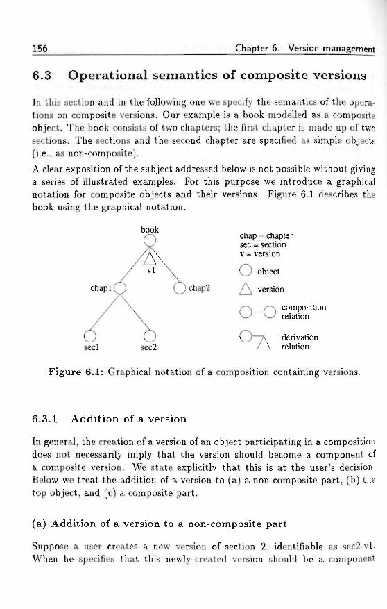
156 Chapter 6. Version management
6.3 Operational semantics of composite versions
In this section and in the following one we specify the semantics of the opera-tions on composite versions. Our example is a book modelled as a compositeobject. The book consists of two chapters; the first chapter is made up of twosections. The sections and the second chapter are specified as simple objects(i.e., as non-composite). ;
A clear exposition of the subject addressed below is not possible without givinga series of illustrated examples. For this purpose we introduce a graphicalnotation for composite objects and their versions. Figure 6.1 describes thebook using the graphical notation.
book ,chap = chaptersec = sectionv = version
O object
chaplQ Qchap2 ^ version
,^A__/'-A compositionv J w relation
O ~ 7 \ derivationseel sec2 Z-A relation
Figure 6.1: Graphical notation of a composition containing versions.
6.3.1 Addition of a version
In general, the creation of a version of an object participating in a compositiondoes not necessarily imply that the version should become a component ofa composite version. We state explicitly that this is at the user's decision.Below we treat the addition of a version to (a) a non-composite part, (b) thetop object, and (c) a composite part.
(a) Addition of a version to a non-composite part
Suppose a user creates a new version of section 2, identifiable as sec'2-vl.When he specifies that this newly-created version should be a component
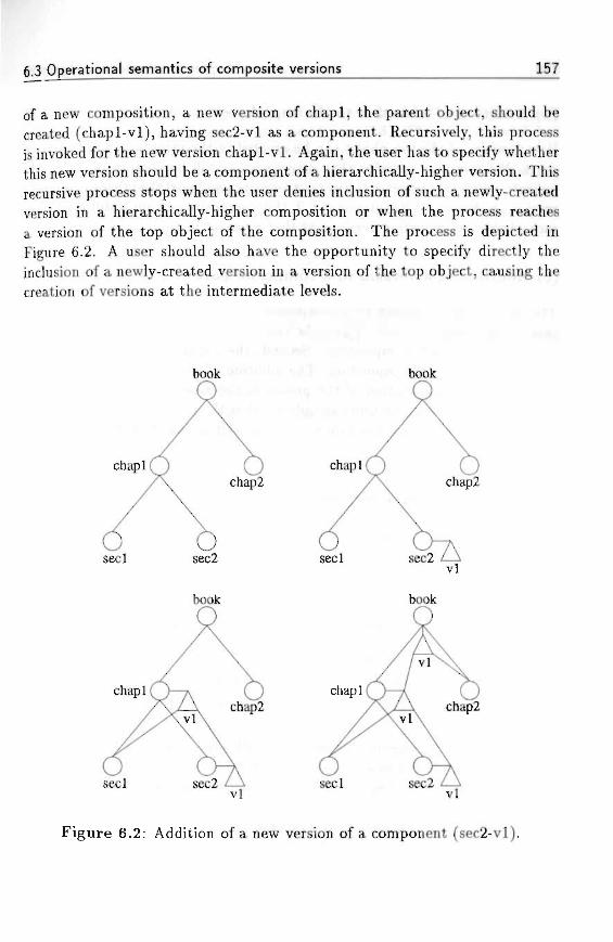
6.3 Operational semantics of composite versions 157
of a new composition, a new version of chapl, the parent object, should becreated (chapl-vl), having sec2-vl as a component. Recursively, this processis invoked for the new version chapl-vl. Again, the user has to specify whetherthis new version should be a component of a hierarchically-higher version. Thisrecursive process stops when the user denies inclusion of such a newly-createdversion in a hierarchically-higher composition or when the process reachesa version of the top object of the composition. The process is depicted inFigure 6.2. A user should also have the opportunity to specify directly theinclusion of a newly-created version in a version of the top object, causing thecreation of versions at the intermediate levels.
book
chapl
seelvl
Figure 6.2: Addition of a new version of a component (sec2-vl).
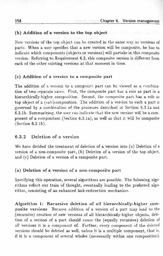
158 Chapter 6. Version management
(b) Addition of a version to the top object •• ^
New versions of the top object can be created in the same way as versions ofparts. When a user specifies that a new version will be composite, he has toindicate which components (objects or versions) will partake in this compositeversion. Referring to Requirement 6.2, this composite version is different fromeach of the other existing versions at that moment in time. . ,., ..,,..
(c) Addition of a version to a composite part ' •'• ?
The addition of a version to a composite part can be viewed as a combina-tion of two separate cases. First, the composite part has a role as part in ahierarchically-higher composition. Second, the composite part has a role astop object of a (sub)composition. The addition of a version to such a part isgoverned by a combination of the processes described in Section 6.3.1a and6.3.1b. Summarizing, the user can indicate that the new version will be a com-ponent of a composition (Section 6.3.1a), as well as that it will be composite(Section 6.3.1b).
6.3.2 Deletion of a version
We have divided the treatment of deletion of a version into (a) Deletion of aversion of a non-composite part, (b) Deletion of a version of the top object,and (c) Deletion of a version of a composite part.
(a) Deletion of a version of a non-composite part
Specifying this operation, several algorithms are possible. The following algo-rithms reflect our train of thought, eventually leading to the preferred algo-rithm, consisting of an enhanced link-redirection mechanism.
Algorithm 1: Recursive deletion of all hierarchically-higher com-posite versions Because addition of a version of a part may lead to the(recursive) creation of new versions of all hierarchically-higher objects, dele-tion of a version of a part should cause the (equally recursive) deletion ofall versions it is a component of. Further, every component of the deletedversions should be deleted as well, unless it is a multiple component, that is,if it is a component of several wholes (necessarily within one composition).
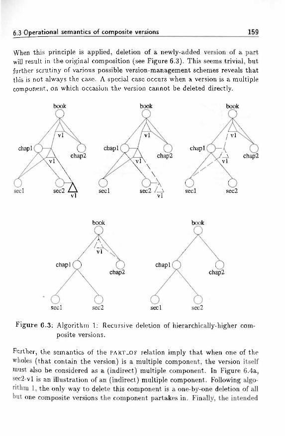
6.3 Operational semantics of composite versions 159
When this principle is applied, deletion of a newly-added version of a partwill result in the original composition (see Figure 6.3). This seems trivial, butfurther scrutiny of various possible version-management schemes reveals thatthis is not always the case. A special case occurs when a version is a multiplecomponent, on which occasion the version cannot be deleted directly.
book book
chapl
book
chapl
seel sec2 /—i seel sec2vl
book book
chapl
seel
chapl
sec2 seel sec2
Figure 6.3: Algorithm 1: Recursive deletion of hierarchically-higher com-posite versions.
Further, the semantics of the PART-OF relation imply that when one of thewholes (that contain the version) is a multiple component, the version itselfmust also be considered as a (indirect) multiple component. In Figure 6.4a,sec2-vl is an illustration of an (indirect) multiple component. Following algo-rithm 1, the only way to delete this component is a one-by-one deletion of allbut one composite versions the component partakes in. Finally, the intended
160 Chapter 6. Version management
deletion of the component can take place. Figures 6.4b and 6.4c illustratethis process.
book
seel
a. sec2-vl as component of twocomposite versions of book:book-vl and book-v2.Hence not deletable.
seel
b. sec2-vl now in only onecomposition (book-vl deleted)
c. sec2-vl deletedbook-v2 deletedchap2-vl also deleted.
Figure 6.4: A component in two composite versions.
Algorithm 2: Deletion of composition relations Figure 6.4 shows thatthe process of recursive deletion of Algorithm 1 has the drawback of alsodeleting chap2-vl. The algorithm can be improved. By deleting only thecomposition relation to this version, the singularly-referenced version remainsundisturbed. Figure 6.5 shows the situation in which a version is not deleted,although the composition of which it was a component disappears. The versionremains, so it may be used in another version of the composition createdafterwards.
Algorithm 2 still has a disadvantage. If sec2-vl is deleted, chapl-vl and book-vl are deleted too, while chap2-vl is preserved. The deletion is reasonablefor chapl-vl, because its right of existence (the presence of sec2-vl) has beendeleted. However, the deletion of composite version book-vl seems unreason-able, because it still has a right of existence, being its component chap2-vl.
Algorithm 3: Enhanced deletion mechanism via redirecting compo-sition links Algorithm 3 does not have the disadvantages mentioned above.Yet, it also has the feature that deletion of a newly-created version results inthe previous composition. Looking at Figure 6.4a, there is another possibility
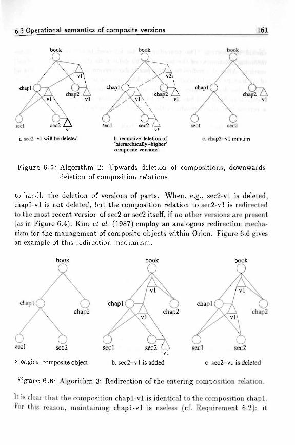
6.3 Operational semantics of composite versions 161
book book book
chapl
vl
seel
a. sec2-vl will be deleted
vl
b. recursive deletion of'hierarchically-higher'composite versions
seel sec2
c. chap2-vl remains
Figure 6.5: Algorithm 2: Upwards deletion of compositions, downwardsdeletion of composition relations. . . * '
to handle the deletion of versions of parts. When, e.g., sec2-vl is deleted,chapl-vl is not deleted, but the composition relation to sec2-vl is redirectedto the most recent version of sec2 or sec2 itself, if no other versions are present(as in Figure 6.4). Kim e< a/. (1987) employ an analogous redirection mecha-nism for the management of composite objects within Orion. Figure 6.6 givesan example of this redirection mechanism.
book book book
chapl chapl chapl
seel seel sec2
c. sec2-vl is deleted
seel sec2
a. original composite object b. sec2-v 1 is added
Figure 6.6: Algorithm 3: Redirection of the entering composition relation.
It is clear that the composition chapl-vl is identical to the composition chapl.For this reason, maintaining chapl-vl is useless (cf. Requirement 6.2): it
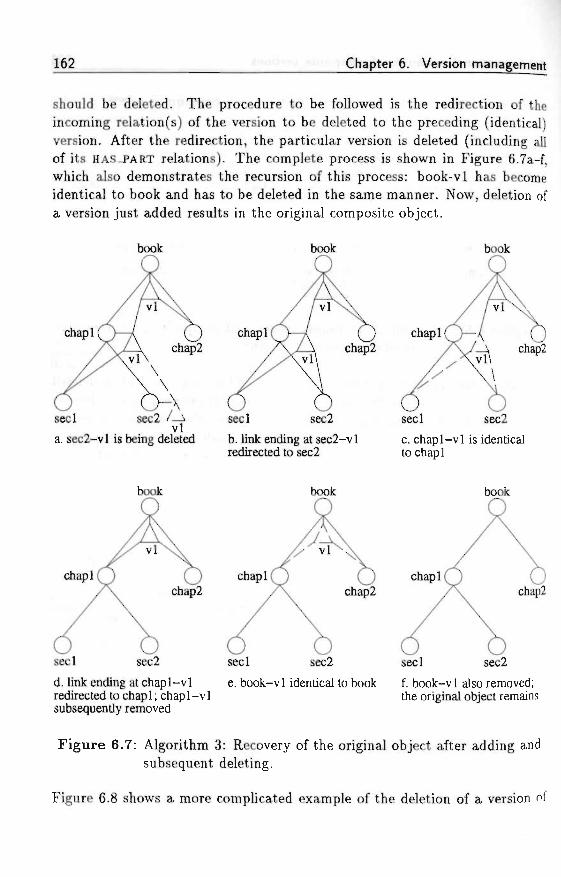
Chapter 6. Version management
should be deleted. The procedure to be followed is the redirection of theincoming relation(s) of the version to be deleted to the preceding (identical)version. After the redirection, the particular version is deleted (including allof its HAS.PART relations). The complete process is shown in Figure 6.7a-f,which also demonstrates the recursion of this process: book-vl has becomeidentical to book and has to be deleted in the same manner. Now, deletion ofa version just added results in the original composite object.
book book book
chapl
seelvl
a. sec2-vl is being deleted
chapl
seel
chapl
sec2 seel sec2
b. link ending at sec2-vlredirected to sec2
c. chapl-vl is identicalto chapl
book book book
chapl
seel sec2
chapl
seel sec2
chapl
seel sec2
d. link ending at chapl-vl e. book-vl identical to book f. book-v 1 also removed;redirected to chapl; chapl-vl the original object remainssubsequently removed
Figure 6.7: Algorithm 3: Recovery of the original object after adding andsubsequent deleting.
Figure 6.8 shows a more complicated example of the deletion of a version of
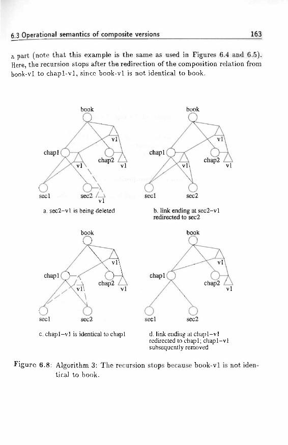
6.3 Operational semantics of composite versions 163
a part (note that this example is the same as used in Figures 6.4 and 6.5).Here, the recursion stops after the redirection of the composition relation frombook-vl to chapl-vl, since book-vl is not identical to book.
book book
chapl
seel
a. sec2-vl is being deleted
book
chapl
vl
seel sec2
c. chapl-vl is identical to chapl
chapl
vl
seel sec2
b. link ending at sec2-vlredirected to sec2
book
chapl
vl
seel sec2
d. link ending at chapl-vlredirected to chapl; chapl-vlsubsequently removed
Figure 6.8: Algorithm 3: The recursion stops because book-vl is not iden-
tical to book.
164 Chapter 6. Version management
(b) Deletion of a version of the top object •'-<: ,'.-.,-.^ - *-.._
When a version of the top object of a composition has to be deleted, theprocedure is as follows:
1. delete the composition relations to its components;
2. delete this particular version of the top object.
From this procedure it is clear that no components of the deleted version areremoved, but only the composition relations to them. Therefore we can callsuch a deletion an "explosive" deletion.
(c) Deletion of a version of a composite part
The deletion of a version of a part is a combination of two separate cases: (1)the version plays a role as a component in a hierarchically-higher composition,and (2) the version plays a role as version of a top object of a (sub)composition.These cases are described in the Sections 6.3.2a and 6.3.2b.
6.4 Operational semantics of composite objects
Here we address the semantics of the operations a user may apply to parts ofcomposite objects. We treat the addition of a new object to a composition,and the deletion of a part of a composite object.
It is the user's responsibility to specify whether the introduction of a newpart or the deletion of an existing part is consistent with the nature of thecomposition. If the nature of the composition is jeopardized, the originalcomposition has to be copied in order to preserve the composite object as itwas before.
6.4.1 Addit ion of an object to a composit ion ^
The addition of a new part to a composition leads to the creation of a newcomposite version of the object it will partake in. This causes one of theprocedures described in Section 6.3.1 to be invoked. Figure 6.9 illustrates thissituation.
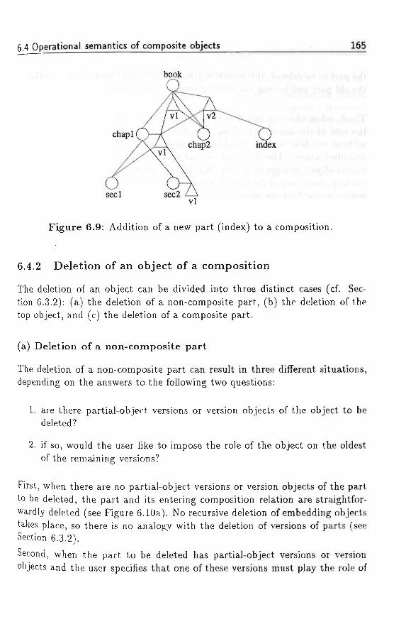
6.4 Operational semantics of composite objects • 165
chapl
seel
Figure 6.9: Addition of a new part (index) to a composition.
6.4.2 Deletion of an object of a composition
The deletion of an object can be divided into three distinct cases (cf. Sec-tion 6.3.2): (a) the deletion of a non-composite part, (b) the deletion of thetop object, and (c) the deletion of a composite part.
(a) Deletion of a non-composite part
The deletion of a non-composite part can result in three different situations,depending on the answers to the following two questions:
1. are there partial-object versions or version objects of the object to bedeleted?
2. if so, would the user like to impose the role of the object on the oldestof the remaining versions?
First, when there are no partial-object versions or version objects of the partto be deleted, the part and its entering composition relation are straightfor-wardly deleted (see Figure 6.10a). No recursive deletion of embedding objectstakes place, so there is no analogy with the deletion of versions of parts (seeSection 6.3.2).
Second, when the part to be deleted has partial-object versions or versionobjects and the user specifies that one of these versions must play the role of
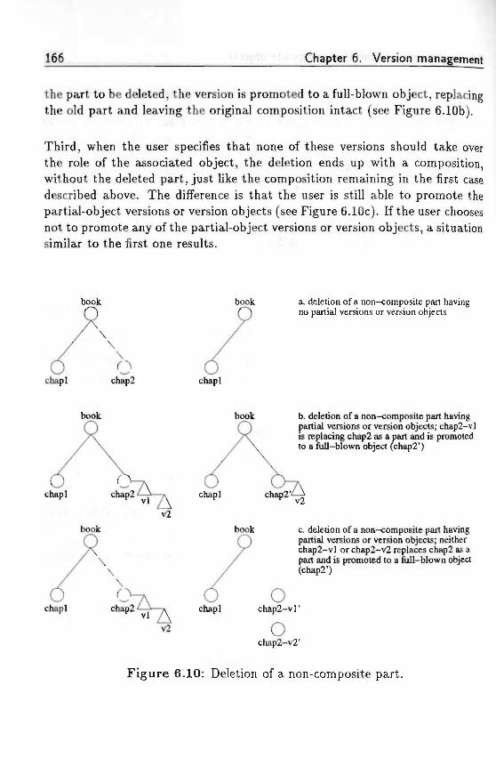
Chapter 6. Version management
the part to be deleted, the version is promoted to a full-blown object, replacingthe old part and leaving the original composition intact (see Figure 6.10b).
Third, when the user specifies that none of these versions should take overthe role of the associated object, the deletion ends up with a composition,without the deleted part, just like the composition remaining in the first casedescribed above. The difference is that the user is still able to promote thepartial-object versions or version objects (see Figure 6.10c). If the user choosesnot to promote any of the partial-object versions or version objects, a situationsimilar to the first one results. -
book book
chapl chap2 chapl
a. deletion of a non-composite part havingno partial versions or version objects
book
chapl
book b. deletion of a non-composite part havingpartial versions or version objects; chap2-vlis replacing chap2 as a part and is promotedto a full-blown object (chap2')
chapl
chapl chapl
book c. deletion of a non-composite part havingpartial versions or version objects; neitherchap2-vl or chap2-v2 replaces chap2 as a
' •' part and is promoted to a full-blown object(chap2')
ochap2-vl" . .
ochap2-v2' . .
Figure 6.10: Deletion of a non-composite part.
6.4 Operational semantics of composite objects 167
(b) Deletion of the top object of a composition
One might believe that deletion of the top object of a composition shouldcause the entire composition including all its parts to disappear. However,a composition of objects merely describes the composite structure betweenthese objects, which have an existence of their own. Therefore, the effect ofthe deletion of a top object is defined as follows:
1. The deletion of the merely existential versions of the top object.
2. The possible copying of the HAS_PART relations to a version that willtake the place of the top object. This depends on the same two questionsas in Section 6.4.2a. If both questions are answered affirmatively, thecomposite structure of the top object is not deleted, but copied intothe version that will be the new top object. Otherwise, the top objectis deleted without its composition relations being copied, and if it hasversions as mentioned in the first question, then the user is asked if hewants these versions to be promoted to separate objects. Objects createdin this way are not part of any composition at that moment.
3. The deletion of the top object.
4. The parts of the deleted top object are left untouched.
The deletion of composite objects described here only deletes the compositionrelations between the top object and its parts. The parts themselves are notdeleted. We believe there should also be a more destructive operation whichdeletes an entire composite object, including all its components. The formeroperation resembles the explosion of an object into pieces and therefore couldbe called the ezp/ode operation, while the latter in fact really deletes thecomposite object and could be called the de/ete operation.
(c) Deletion of a composite part
When dealing with the deletion of composite parts one has to consider twodifferent aspects:
1. the role the part is playing as part of the composition, and
2. the role the part is playing as top object of a (sub)composition.
168 Chapter 6. Version management
With respect to the second role, the effects have been described in Sec-tion 6.4.2b. One should combine these consequences with the effects the op-eration has with regard to its first role.
We start with the most simple case: the object to be removed has no partial-object versions nor version objects. As we described in Section 6.4.2b, deletionof such an object results in a situation wherein its parts persist as independentobjects, while the object itself is deleted together with its top-object role asmentioned above. Consequently, its role as part should be abandoned, so theobject is removed, as well as its PART-OF and HAS-PART relations.
The other cases can be treated in the same way as described above. Therefore,we conclude that the current operation has the same semantics as the operationdescribed in Section 6.4.2b. When one of the versions of the part to be removedtakes over the role as top object of the subcomposition, it also takes over therole as part of the embedding composite object.
6.5 Chapter summary
Versions introduce a notion of time in a domain to be modelled. In an objectmodel, versions are variations of objects. Version management is especiallyimportant for composite objects, because of the structure of the relations be-tween the composite object and its part objects. The creation of new versionsof part objects may induce new versions of the composite object to be created.
INCA-COM contains two approaches for modelling versions. The first approachtreats versions as parha/ objects. The descriptor space of a partial object is asubspace of the descriptor space of a full-blown object. The second approachtreats versions, when it is necessary to describe them, as version 067'ecte. Aversion object is a full-blown object, with contraints on some of the values ofthe descriptors (e.g., the sort descriptor).
We have focussed on a mechanism for version management of composite ob-jects. We have constructed a composite-version mechanism which gives anatural result when deleting a version just added, namely the original com-position. Moreover, the devised version mechanism is capable of coping withmore complicated compositions and remains semantically justified. Compar-ing Figure 6.7 to Figure 6.3 we see that, although the mechanisms of versiondeletion differ, the results are identical, being the original composite objectbefore addition of sec2-vl.
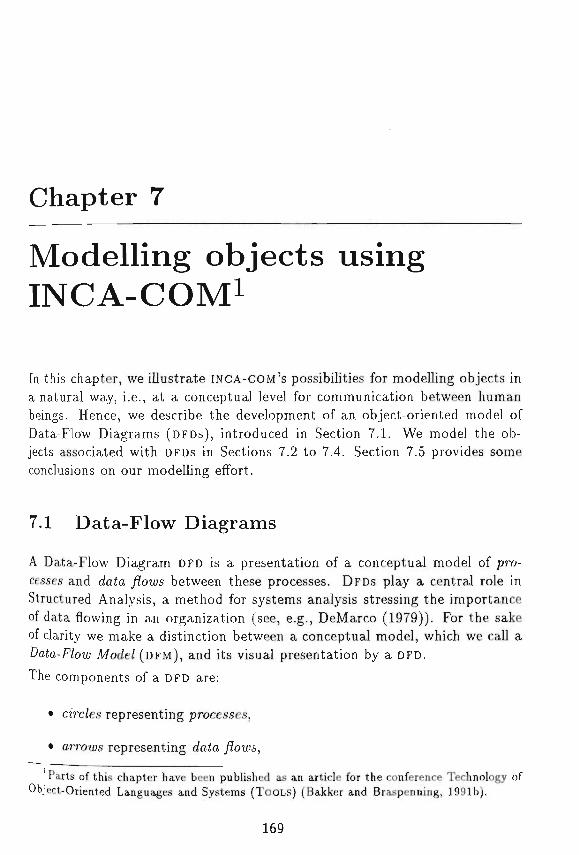
Chapter 7
Modelling objects usingINCA-COM*
In this chapter, we illustrate INCA-COM'S possibilities for modelling objects ina natural way, i.e., at a conceptual level for communication between humanbeings. Hence, we describe the development of an object-oriented model ofData-Flow Diagrams (DFDs), introduced in Section 7.1. We model the ob-jects associated with DFDs in Sections 7.2 to 7.4. Section 7.5 provides someconclusions on our modelling effort.
7.1 Data-Flow Diagrams
A Data-Flow Diagram DFD is a presentation of a conceptual model of pro-cesses and data /3Ws between these processes. DFDs play a central role inStructured Analysis, a method for systems analysis stressing the importanceof data flowing in an organization (see, e.g., DeMarco (1979)). For the sakeof clarity we make a distinction between a conceptual model, which we call a£>a£a-F/otu Mode/ (DFM), and its visual presentation by a DFD.
The components of a DFD are:
• circ/es representing processes,
• arrows representing datfa
Parts of this chapter have been published as an article for the conference Technology ofObject-Oriented Languages and Systems (TOOLS) (Bakker and Braspenning, 1991b).
169
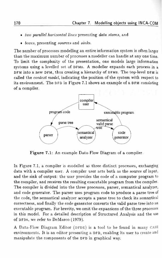
170 Chapter 7. Modelling objects using INCA-COM
• (wo para//e/ /lonzonfa/ fines presenting da<a stores, and
• 6oies, presenting sources and stnAs.
The number of processes modelling an entire information system is often largerthan the maximum number of processes a modeller can handle at any one time.To limit the complexity of the presentation, one models large informationsystems using a levelled set of DFMs. A modeller expands each process in aDFM into a new DFM, thus creating a hierarchy of DFMs. The top-level DFM iscalled the context mode/, indicating the position of the system with respect toits environment. The DFD in Figure 7.1 shows an example of a DFM consistingof a compiler.
programcode
parse tree
parser
^ compileruser
semantical\ analyzer
\execul
semanticalvalid parse
--tree~~^~-».\ /
J I
^ble program
^ \code \generator /
Figure 7.1: An example Data-Flow Diagram of a compiler.
In Figure 7.1, a compiler is modelled as three distinct processes, exchangingdata with a compiler user. A compiler user acts both as the source of input,and the sink of output: the user provides the code of a computer program tothe compiler, and receives the resulting executable program from the compiler.The compiler is divided into the three processes, parser, semantical analyzer,and code generator. The parser uses program code to produce a parse tree ofthe code, the semantical analyzer accepts a parse tree to check its semanticalcorrectness, and finally the code generator converts the valid parse tree into anexecutable program. For brevity, we omit the expansions of the three processesin this model. For a detailed description of Structured Analysis and the useof DFDs, we refer to DeMarco (1979).
A Data-Flow Diagram Editor (DFDE) is a tool to be found in many CASE
environments. It is an editor presenting a DFD, enabling its user to create andmanipulate the components of the DFD in graphical way.
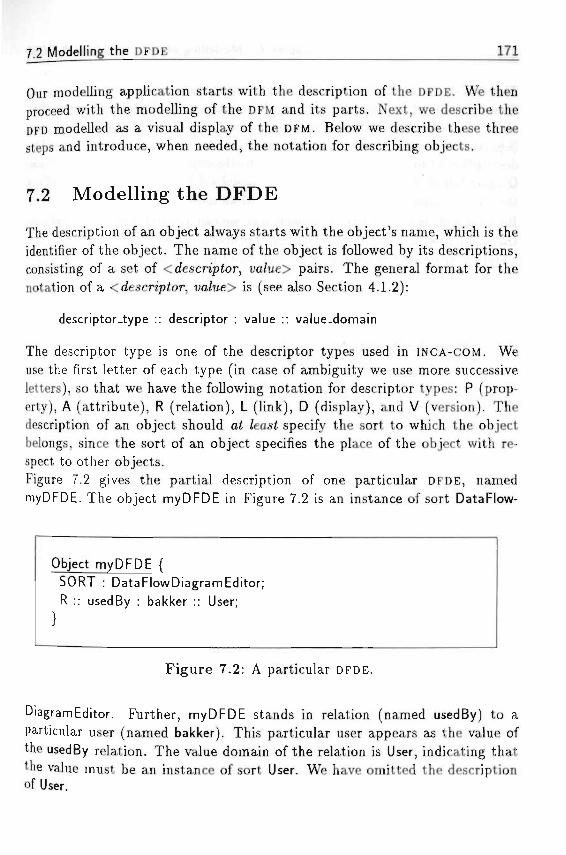
7.2 Modelling the DFDE 171
Our modelling application starts with the description of the DFDE. We thenproceed with the modelling of the DFM and its parts. Next, we describe theDFD modelled as a visual display of the DFM. Below we describe these threesteps and introduce, when needed, the notation for describing objects.
7.2 Modelling the DFDE ^
The description of an object always starts with the object's name, which is theidentifier of the object. The name of the object is followed by its descriptions,consisting of a set of < descriptor, ua/ue> pairs. The general format for thenotation of a < descriptor, wa/ue> is (see also Section 4.1.2):
descriptor-type :: descriptor : value :: value-domain
The descriptor type is one of the descriptor types used in INCA-COM. Weuse the first letter of each type (in case of ambiguity we use more successiveletters), so that we have the following notation for descriptor types: P (prop-erty), A (attribute), R (relation), L (link), D (display), and V (version). Thedescription of an object should ai /east specify the sort to which the objectbelongs, since the sort of an object specifies the place of the object with re-spect to other objects.Figure 7.2 gives the partial description of one particular DFDE, namedmyDFDE. The object myDFDE in Figure 7.2 is an instance of sort DataFlow-
Object my DFDE {SORT : DataFlowDiagramEditor;R :: usedBy : bakker :: User;
Figure 7.2: A particular DFDE.
DiagramEditor. Further, myDFDE stands in relation (named usedBy) to aparticular user (named bakker). This particular user appears as the value ofthe usedBy relation. The value domain of the relation is User, indicating thatthe value must be an instance of sort User. We have omitted the descriptionof User.
172 Chapter 7. Modelling objects using INCA-COM
The descriptor for sorts, such as SORT : DataFlowDiagramEditor is a nota-tional shorthand for the more lengthy R :: instance.of : DataFlowDiagramEdi-tor :: , where the value-domain indication ' ' stands for all sort objects(i.e., the extension of the domain's metasort, to be explained below). Thedescription of myDFDE relies partly on the description of the sort DataFlow-DiagramEditor. It is common practice to model a domain initially by modellingthe sorts occurring in the domain, rather than modelling particular instances.Because sorts in INCA-COM are objects too, we can describe the sort DataFlow-DiagramEditor in the same manner as "normal objects", resulting in the de-scription given in Figure 7.3. The sort descriptor of a sort has as its value
Sort DataFlowDiagramEditor {SORT : EditorMetaSort;SUPERSORT : GraphicalEditor;
Sort EditorMetaSort {SORT : EditorMetaSort;
' *•' F igure 7.3: The DataFlowDiagramEditor sort.
a metasort (here called EditorMetaSort), which is the sort of all sorts withinthis particular domain. Because a metasort is a sort, and therefore (again)an object, it has to be an instance of a sort too. To break an infinite recur-sion, a metasort is an instance of itself. The supersort descriptor is used forthe construction of sort hierarchies, which guide the inheritance mechanismsdescribed in Section 5.2. We see that the sort DataFlowDiagramEditor has assupersort the sort GraphicalEditor, which we describe in Section 7.4.At first sight, a sort in INCA-COM seems similar to the usual notion of a 'type'or 'class' as used in many object-oriented languages. There is, however, animportant difference. As we have stated in Chapter 4 and Chapter 5, thewhole description of a sort can be divided into an eztercszona/ part, whichdescribes the structure of potential instances of the sort, and an mtensiono/part, which describes the meaning of the sort itself. In Figure 7.3, we have onlydescribed (and even incompletely) the intensional part of the sorts. For the
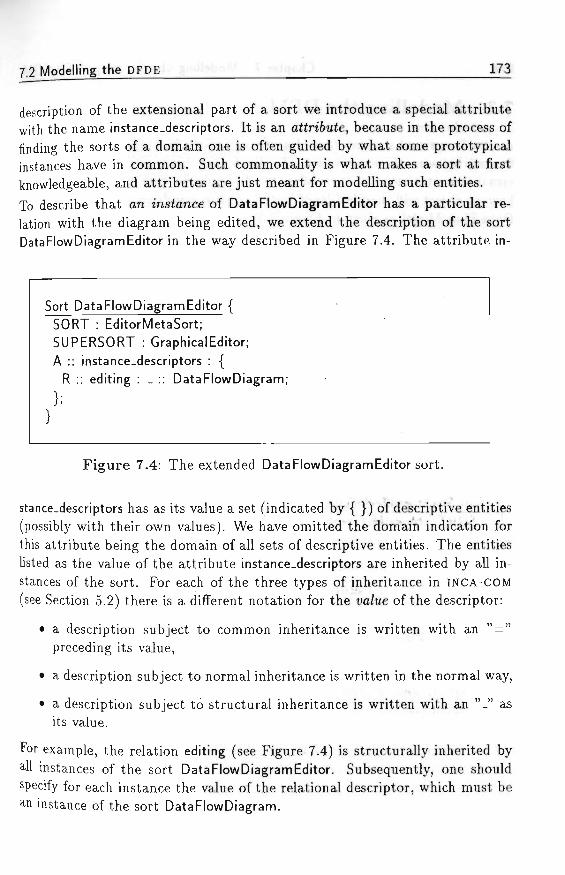
7jModelling the DFDE I73F
description of the extensional part of a sort we introduce a special attributewith the name instance-descriptors. It is an attribute, because in the process offinding the sorts of a domain one is often guided by what some prototypicalinstances have in common. Such commonality is what makes a sort at firstknowledgeable, and attributes are just meant for modelling such entities.To describe that an instance of DataFlowDiagramEditor has a particular re-lation with the diagram being edited, we extend the description of the sortDataFlowDiagramEditor in the way described in Figure 7.4. The attribute in-
Sort DataFlowDiagramEditor {SORT : EditorMetaSort; S ^SUPERSORT : GraphicalEditor; ^ WA :: instance-descriptors : { «»«.^.v.v>»b.*v*6Jsr«, : A
R :: editing : . :: DataFlowDiagram; •'' •'' * * » - ^ .?TS-5~
•« . • * . *
Figure 7.4: The extended DataFlowDiagramEditor sort. $
stance-descriptors has as its value a set (indicated by { }) of descriptive entities(possibly with their own values). We have omitted the domain indication forthis attribute being the domain of all sets of descriptive entities. The entitieslisted as the value of the attribute instance-descriptors are inherited by all in-stances of the sort. For each of the three types of inheritance in INCA-COM
(see Section 5.2) there is a different notation for the ua/ue of the descriptor:
• a description subject to common inheritance is written with an "="preceding its value, • , . . , . . . - , , .
• a description subject to normal inheritance is written in the normal way,
• a description subject to structural inheritance is written with an "_" asits value.
For example, the relation editing (see Figure 7.4) is structurally inherited byall instances of the sort DataFlowDiagramEditor. Subsequently, one shouldspecify for each instance the value of the relational descriptor, which must bean instance of the sort DataFlowDiagram.
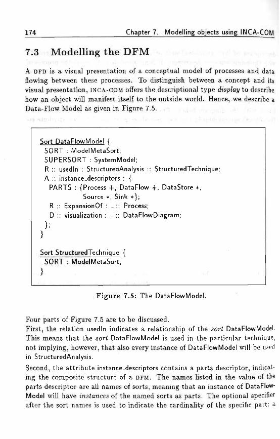
174 Chapter 7. Modelling objects using INCA-COM
7.3 Model l ing t h e D F M . ^ , > • , «,, ^
A DFD is a visual presentation of a conceptual model of processes and dataflowing between these processes. To distinguish between a concept and itsvisual presentation, INCA-COM offers the descriptional type disp/aj/to describehow an object will manifest itself to the outside world. Hence, we describe aData-Flow Model as given in Figure 7.5. . - : , , , , , . , . .--.
Sort DataFlowModel { ' " ' ""'
SORT : ModelMetaSort; . - ^ .... : .. ;, ,,..;•
SUPERSORT : SystemModel; •.',. ' •
R :: usedln : StructuredAnalysis :: StructuredTechnique; •
A :: instance-descriptors : { .. , . ,
PARTS : {Process + , DataFlow + , DataStore *,
Source * , Sink * } ;
R :: ExpansionOf : _ :: Process;
D :: visualization : _ :: DataFlowDiagram;
};} •• - ' • . • - • • - • : • . . - . . - . • ; =
Sort StructuredTechnique { . . . ' , .SORT : ModelMetaSort; ..'....' . • '
F igure 7.5: The DataFlowModel., - « . r . , - • ,• • . - . • . • •. - • -
Four parts of Figure 7.5 are to be discussed.First, the relation usedln indicates a relationship of the sort DataFlowModel.This means that the sort DataFlowModel is used in the particular technique,not implying, however, that also every instance of DataFlowModel will be usedin StructuredAnalysis.Second, the attribute instance-descriptors contains a parts descriptor, indicat-ing the composite structure of a DFM. The names listed in the value of theparts descriptor are all names of sorts, meaning that an instance of DataFlow-Model will have instances of the named sorts as parts. The optional specifierafter the sort names is used to indicate the cardinality of the specific part: a
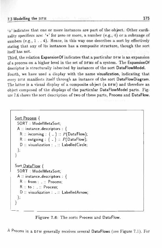
7 j Modelling the DFM • ;-x *• - . . ^ - . ^ 175
'+' indicates that one or more instances are part of the object. Other cardi-nality specifiers are: '*' for zero or more, a number (e.g., 4) or a subrange ofnumbers (e.g., 1 . . 4). Hence, in this way one describes a sort by effectivelystating that any of its instances has a composite structure, though the sortitself has not. * ,/,. , , .... • , . • > , , ,w .;, ;
Third, the relation ExpansionOf indicates that a particular DFM is an expansionof a process on a higher level in the set of DFMs of a system. The ExpansionOfdescriptor is structurally inherited by instances of the sort DataFlowModel.
Fourth, we have used a display with the name visualization, indicating thatevery DFM manifests itself through an instance of the sort DataFlowDiagram.The latter is a visual display of a composite object (a DFM) and therefore anobject composed of the <fisp/ays of the particular DataFlowModel parts. Fig-ure 7.6 shows the sort description of two of these parts, Process and DataFlow.
Sort Process {SORT : ModelMetaSort;A :
RRD
Sort
instance-descriptors:: incoming : { _ } :::: outgoing : { - } : ::: visualization : _ ::
DataFlow {SORT : ModelMetaSort;A :
RRD
instance-descriptors:: from : _ :: Process:: to : _ :: Process;:: visualization : _ ::
: {_P( Data Flow);P(DataFlow); .LabelledCircle;
: {
LabelledArrow;
Figure 7.6: The sorts Process and DataFlow.
A Process in a DFM generally receives several DataFlows (see Figure 7.1). For

Chapter 7. Modelling objects using INCA-COM
this reason, the value indication of the relations incoming and outgoing is shownas { _ } to indicate that the value is a set of Data Flows, drawn from the powerset P of DataFlows in the model. A Process and a DataFlow display themselvesby means of a LabelledCircle and a LabelledArrow, respectively.
Figure 7.7 shows the three levels (or domains) we have discerned in the mod-elling process. It is important to see why we have made the distinctions
Figure 7.7: Modelling levels.
between a DFDE, a DFD and a DFM. A way of understanding is by lookingat the operations one can perform on objects at each level. All operationsat a certain level are mapped onto the next /ou>er level, e.g., the addition ofa process to a DFM is mapped to the addition of a LabelledCircle to a DFD,which is mapped to an operation (or series of operations) for the DFDE. Sucha mapping is what makes an editor well-suited: every conceptual operation
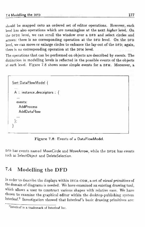
7 4 Modelling the DFD 177
should be mapped onto an ordered set of editor operations. However, eachlevel has also operations which are meaningless at the next /iig/ier level. Onthe DFDE level, we can scroll the window over a DFD and select circles andarrows; there is no corresponding operation at the DFD level. On the DFDlevel, we can move or enlarge circles to enhance the lay-out of the DFD; again,there is no corresponding operation at the DFM level.
The operations that can be performed on objects are described by events. Thedistinction in modelling levels is reflected in the possible events of the objectsat each level. Figure 7.8 shows some simple events for a DFM. Moreover, a
Sort DataFlowModel {
A :: instance-descriptors :
events:Add ProcessAddDataFlow
{ • " " • ' • • • ' •
Figure 7.8: Events of a DataFlowModel.
DFD has events named MoveCircle and MoveArrow, while the DFDE has eventssuch as SelectObject and DeleteSelection.
7.4 Modelling the DFD
In order to describe the displays within INCA-COM, a set of uisua/ pnrmfoues ofthe domain of diagrams is needed. We have examined an existing drawing tool,which allows a user to construct various shapes with relative ease. We havechosen to examine the graphical editor within the desktop-publishing systemInterleaf. Investigation showed that Interleaf's basic drawing primitives are:
Interleaf is a trademark of Interleaf Inc.
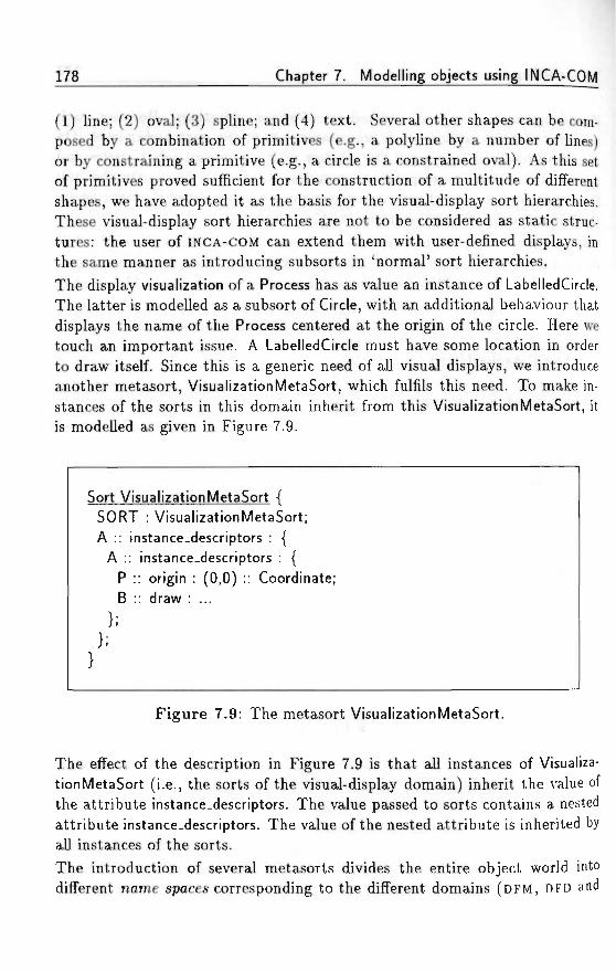
178 Chapter 7. Modelling objects using INCA-COM
(1) line; (2) oval; (3) spline; and (4) text. Several other shapes can be com-posed by a combination of primitives (e.g., a polyline by a number of lines)or by constraining a primitive (e.g., a circle is a constrained oval). As this setof primitives proved sufficient for the construction of a multitude of differentshapes, we have adopted it as the basis for the visual-display sort hierarchies.These visual-display sort hierarchies are not to be considered as static struc-tures: the user of INCA-COM can extend them with user-defined displays, inthe same manner as introducing subsorts in 'normal' sort hierarchies.The display visualization of a Process has as value an instance of LabelledCircle.The latter is modelled as a subsort of Circle, with an additional behaviour thatdisplays the name of the Process centered at the origin of the circle. Here wetouch an important issue. A LabelledCircle must have some location in orderto draw itself. Since this is a generic need of all visual displays, we introduceanother metasort, VisualizationMetaSort, which fulfils this need. To make in-stances of the sorts in this domain inherit from this VisualizationMetaSort, itis modelled as given in Figure 7.9.
Sort VisualizationMetaSort {SORT : VisualizationMetaSort;A :: instance-descriptors : {
A :: instance-descriptors : {P :: origin : (0,0) :: Coordinate;B :: draw : ...
F igure 7.9: The metasort VisualizationMetaSort.
The effect of the description in Figure 7.9 is that all instances of Visualiza-tionMetaSort (i.e., the sorts of the visual-display domain) inherit the value ofthe attribute instance-descriptors. The value passed to sorts contains a nestedattribute instance-descriptors. The value of the nested attribute is inherited byall instances of the sorts.
The introduction of several metasorts divides the entire object world intodifferent name spaces corresponding to the different domains (DFM, DFD and
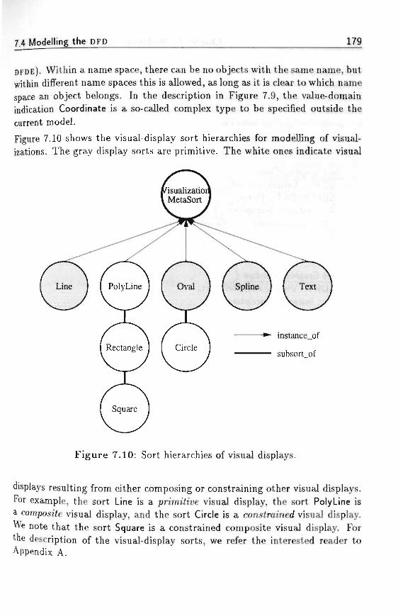
7.4 Modelling the DFD 179
DFDE). Within a name space, there can be no objects with the same name, butwithin different name spaces this is allowed, as long as it is clear to which namespace an object belongs. In the description in Figure 7.9, the value-domainindication Coordinate is a so-called complex type to be specified outside thecurrent model. v , •. •, s : - r v y . v i . ' ; - .... , . t ? > ^ . ^ -.,••
Figure 7.10 shows the visual-display sort hierarchies for modelling of visual-izations. The gray display sorts are primitive. The white ones indicate visual
instance_of
subsort of
Figure 7.10: Sort hierarchies of visual displays.
displays resulting from either composing or constraining other visual displays.For example, the sort Line is a primj<rue visual display, the sort PolyLine isa composite visual display, and the sort Circle is a constrained visual display.We note that the sort Square is a constrained composite visual display. Forthe description of the visual-display sorts, we refer the interested reader toAppendix A.
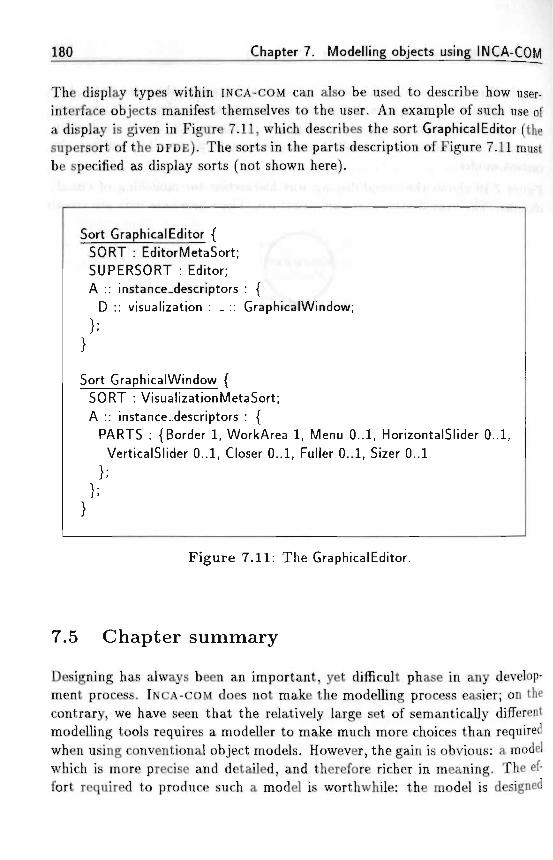
180 Chapter 7. Modelling objects using INCA-COM
The display types within INCA-COM can also be used to describe how user-interface objects manifest themselves to the user. An example of such use ofa display is given in Figure 7.11, which describes the sort GraphicalEditor (thesupersort of the DFDE). The sorts in the parts description of Figure 7.11 mustbe specified as display sorts (not shown here).
Sort GraphicalEditor { ^-•-—-^SORT : EditorMetaSort; / . ASUPERSORT : Editor; f "•";'! S j ,A :: instance-descriptors : {
D :: visualization : _ :: GraphicalWindow;
Sort GraphicalWindow {SORT : VisualizationMetaSort;A :: instance_descriptors : {
PARTS : {Border 1, WorkArea 1, Menu 0..1, HorizontalSlider 0..1,VerticalSlider 0..1, Closer 0..1, Fuller 0..1, Sizer 0..1
F igure 7.11: The GraphicalEditor.
7.5 Chapter summary > /r
Designing has always been an important, yet difficult phase in any develop-ment process. INCA-COM does not make the modelling process easier; on thecontrary, we have seen that the relatively large set of semantically differentmodelling tools requires a modeller to make much more choices than requiredwhen using conventional object models. However, the gain is obvious: a modelwhich is more precise and detailed, and therefore richer in meaning. The ef-fort required to produce such a model is worthwhile: the model is designed
7.5 Chapter summary 181_
only once, but is usable for many more times. Furthermore, due to the highlevel of specification and the fact that most object-oriented programming lan-guages adhere to at least part of the same principles as INCA-COM, it shouldbe relatively easy to implement such a design model. The mapping onto aprogramming language can be automated at least partly.
In our modelling application, the clear distinction between application-domainconcepts and their displays enables a clear understanding of the concepts,without being blurred by details for displaying objects. We believe this dis-tinction is beneficial for the addition of knowledge and reasoning mechanismsin order to come to an iNtelligent CAse environment. Moreover, the modellingapplication has guided us in the development of the 6asic m'suaZ-cfop/ay sorf/iierarc/nes, which can be used in other application domains too.
In order to specify more complex objects than the ones we have described, onewould surely need a sophisticated object design editor. Such an editor shouldsupport a modeller in:
• showing multiple sort hierarchies in a graphical way,
• navigating through sort hierarchies,
• creating and editing objects; for instance, as soon as the sort of an objecthas been specified, the editor should allow to show all the descriptorsthe new object inherits (with actual and possible values),
• specifying displays in a graphical way; this should be done using a graph-ical editor.
In Chapter 9 we elaborate on such a tool, called INCATOOL, which is modelledusing the INCA principles for application domains and applications.

Chapter 7. Modelling objects using INCA-COM
• y ! • • • : , - . ' . - • > • • . . . ' t t . ' . ' : ' ' ! . ' , ' M . •• ; • ' • i - , • • : • !
Chapter 8
An object-oriented model forspreadsheets*
We have described INCA-COM as the basis of the next generation of INtelligentCAse environments. Of course, other complex application domains can alsoprofit from the descriptive power of our model for object orientation. In thischapter we treat the application of INCA-COM to the domain of spreadsheets.Through this application we describe a new kind of spreadsheet, and showpart of the descriptive power of INCA-COM.
8.1 Existing spreadsheets
The flexibility of spreadsheets is a key factor to its world-wide success, butit is also a well-known disadvantage in maintaining and adapting applicationmodels. A spreadsheet modeller possesses some kind of mental model whenidentifying the information to be represented. Much of this knowledge is leftimplicit, and thus cannot be used by a spreadsheet program assisting themodeller. Human users can also have trouble identifying the information valuein a spreadsheet, if it consists of numbers only.
The usual manner to overcome such limitations is to use cognitive pointers tothe intended meaning of the different cells by giving names or text labels toparticular rows and columns of the spreadsheet. Although the labels aid the
Parts of this chapter have been published as an article for the European SimulationSymposium 1992 (Bakker and Braspenning, 1992).
183
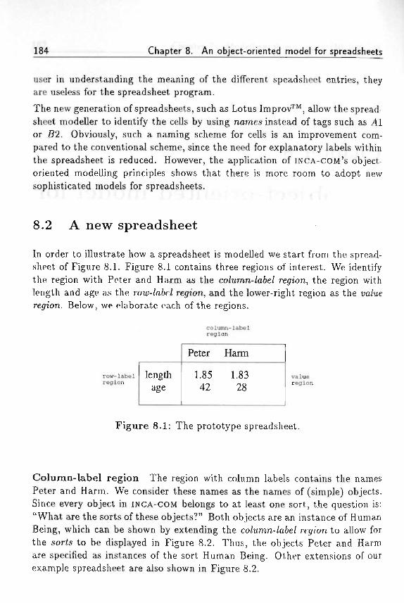
184 Chapter 8. An object-oriented model for spreadsheets
user in understanding the meaning of the different speadsheet entries, theyare useless for the spreadsheet program.
The new generation of spreadsheets, such as Lotus Improv™, allow the spread-sheet modeller to identify the cells by using names instead of tags such as 41or 52. Obviously, such a naming scheme for cells is an improvement com-pared to the conventional scheme, since the need for explanatory labels withinthe spreadsheet is reduced. However, the application of INCA-COM'S object-oriented modelling principles shows that there is more room to adopt newsophisticated models for spreadsheets. .
8.2 A new spreadsheet r ?" •' ' '' i • ?
In order to illustrate how a spreadsheet is modelled we start from the spread-sheet of Figure 8.1. Figure 8.1 contains three regions of interest. We identifythe region with Peter and Harm as the co/umn-/a6e/ region, the region withlength and age as the roiu-/aie2 region, and the lower-right region as theregion. Below, we elaborate each of the regions. .
column-labelregion
row-labelregion
lengthage
Peter Harm
1.85 1.8342 28
valueregion
Figure 8.1: The prototype spreadsheet.
Column-label region The region with column labels contains the namesPeter and Harm. We consider these names as the names of (simple) objects.Since every object in INCA-COM belongs to at least one sort, the question is:"What are the sorts of these objects?" Both objects are an instance of HumanBeing, which can be shown by extending the co/umn-/a6e/ region to allow forthe sorts to be displayed in Figure 8.2. Thus, the objects Peter and Harmare specified as instances of the sort Human Being. Other extensions of ourexample spreadsheet are also shown in Figure 8.2.
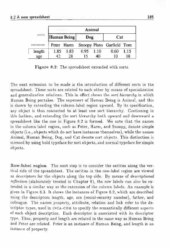
8.2 A new spreadsheet 185
sorts
instances
lengthage
Human
Peter1.8542
Being
Harm1.8328
Animal
Dog
Snoopy Pluto0.95 1.10
15 40
Cat
Garfield0.60
10
Tom1.15
18
Figure 8.2: The spreadsheet extended with sorts.
The next extension to be made is the introduction of different sorts in thespreadsheet. These sorts are related to each other by means of specializationand generalization relations. This in effect shows the sori /n'erarc/ij/ in whichHuman Being partakes. The supersort of Human Being is Animal, and thisis shown by extending the column-label region upward. By its specification,any object is thus connected to at least one sort hierarchy. Continuing inthis fashion, and extending the sort hierarchy both upward and downward aspreadsheet like the one in Figure 8.2 is formed. We note that the namesin the column-label region, such as Peter, Harm, and Snoopy, denote simpleobjects (i.e., objects which do not have instances themselves), while the namesAnimal, Human Being, Dog, and Cat denote sort objects. This distinction isstressed by using bold typeface for sort objects, and normal typeface for simpleobjects.
Row-label region The next step is to consider the entities along the ver-tical side of the spreadsheet. The entities in the row-label region are viewedas descriptors for the objects along the top side. By means of descn'ph'ona/re/?ec£ion (elaborately treated in Chapter 9), the row labels can also be ex-tended in a similar way as the extension of the column labels. An example isgiven in Figure 8.3. It shows the instances of Figure 8.2, which are describedusing the descriptors length, age, ssn (social-security number), father, andcolleague. The names property, attribute, relation and link refer to the de-scriptor types, used in INCA-COM to specify the semantically different aspectsof each object description. Each descriptor is associated with its descriptortype. Thus, property and length are related in the same way as Human Beingand Peter are related. Peter is an instance of Human Being, and length is aninstance of property.
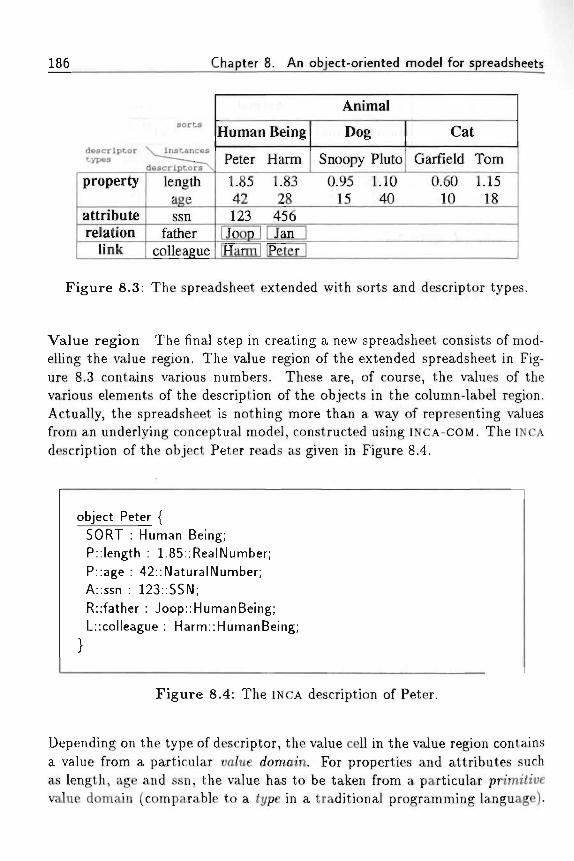
186 Chapter 8. An object-oriented model for spreadsheets
I •
descriptortypes
property
attributerelation
link
sorts
N^lnstances
descriptors~*\
lengthagessn
fathercolleague
Human
Peter
1.8542123
[Joop 1iHarml
Being
Harm
1.8328
4561 Jan 1Peter 1
Animal
Dog
Snoopy Pluto
0.95 1.1015 40
Cat
Garfield
0.6010
Tom
1.1518
Figure 8.3: The spreadsheet extended with sorts and descriptor types.
Value region The final step in creating a new spreadsheet consists of mod-elling the value region. The value region of the extended spreadsheet in Fig-ure 8.3 contains various numbers. These are, of course, the values of thevarious elements of the description of the objects in the column-label region.Actually, the spreadsheet is nothing more than a way of representing valuesfrom an underlying conceptual model, constructed using INCA-COM. The INCA
description of the object Peter reads as given in Figure 8.4.
object Peter {SORT : Human Being;P::length : 1.85::RealNumber;P::age : 42::NaturalNumber;A::ssn : 123::SSN;R::father : Joop::HumanBeing;L::colleague : Harm::HumanBeing;
Figure 8.4: The INCA description of Peter.
Depending on the type of descriptor, the value cell in the value region containsa value from a particular wz/ue domain. For properties and attributes suchas length, age and ssn, the value has to be taken from a particular pnrm7ii;evalue domain (comparable to a type in a traditional programming language).
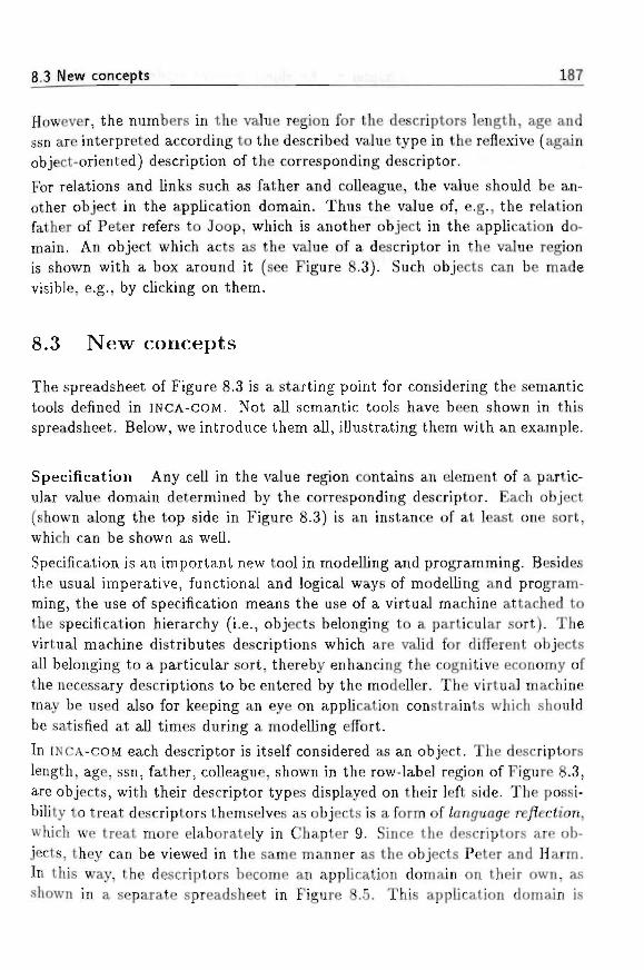
8.3 New concepts 187
However, the numbers in the value region for the descriptors length, age andssn are interpreted according to the described value type in the reflexive (againobject-oriented) description of the corresponding descriptor.
For relations and links such as father and colleague, the value should be an-other object in the application domain. Thus the value of, e.g., the relationfather of Peter refers to Joop, which is another object in the application do-main. An object which acts as the value of a descriptor in the value regionis shown with a box around it (see Figure 8.3). Such objects can be madevisible, e.g., by clicking on them.
8.3 New concepts
The spreadsheet of Figure 8.3 is a starting point for considering the semantictools defined in INCA-COM. Not all semantic tools have been shown in thisspreadsheet. Below, we introduce them all, illustrating them with an example.
Specification Any cell in the value region contains an element of a partic-ular value domain determined by the corresponding descriptor. Each object(shown along the top side in Figure 8.3) is an instance of at least one sort,which can be shown as well.
Specification is an important new tool in modelling and programming. Besidesthe usual imperative, functional and logical ways of modelling and program-ming, the use of specification means the use of a virtual machine attached tothe specification hierarchy (i.e., objects belonging to a particular sort). Thevirtual machine distributes descriptions which are valid for different objectsall belonging to a particular sort, thereby enhancing the cognitive economy ofthe necessary descriptions to be entered by the modeller. The virtual machinemay be used also for keeping an eye on application constraints which shouldbe satisfied at all times during a modelling effort.
In INCA-COM each descriptor is itself considered as an object. The descriptorslength, age, ssn, father, colleague, shown in the row-label region of Figure 8.3,are objects, with their descriptor types displayed on their left side. The possi-bility to treat descriptors themselves as objects is a form of /anguage re/7ech'on,which we treat more elaborately in Chapter 9. Since the descriptors are ob-jects, they can be viewed in the same manner as the objects Peter and Harm.In this way, the descriptors become an application domain on their own, asshown in a separate spreadsheet in Figure 8.5. This application domain is
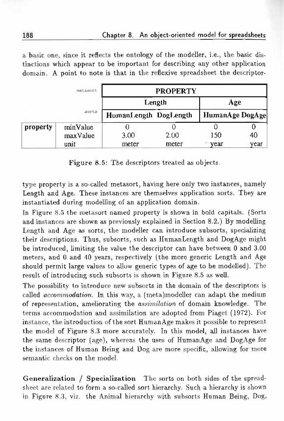
188 Chapter 8. An object-oriented model for spreadsheets
a basic one, since it reflects the ontology of the modeller, i.e., the basic dis-tinctions which appear to be important for describing any other applicationdomain. A point to note is that in the reflexive spreadsheet the descriptor-
mecasort
sorts
property minValuemaxValueunit
PROPERTY
Length
HumanLength DogLength
03.00meter
02.00meter
Age
HumanAge
0150year
DogAge
040year
Figure 8.5: The descriptors treated as objects.
type property is a so-called metasort, having here only two instances, namelyLength and Age. These instances are themselves application sorts. They areinstantiated during modelling of an application domain.
In Figure 8.5 the metasort named property is shown in bold capitals. (Sortsand instances are shown as previously explained in Section 8.2.) By modellingLength and Age as sorts, the modeller can introduce subsorts, specializingtheir descriptions. Thus, subsorts, such as HumanLength and DogAge mightbe introduced, limiting the value the descriptor can have between 0 and 3.00meters, and 0 and 40 years, respectively (the more generic Length and Ageshould permit large values to allow generic types of age to be modelled). Theresult of introducing such subsorts is shown in Figure 8.5 as well.The possibility to introduce new subsorts in the domain of the descriptors iscalled accommodation. In this way, a (meta)modeller can adapt the mediumof representation, ameliorating the assimi/ah'on of domain knowledge. Theterms accommodation and assimilation are adopted from Piaget (1972). Forinstance, the introduction of the sort HumanAge makes it possible to representthe model of Figure 8.3 more accurately. In this model, all instances havethe same descriptor (age), whereas the uses of HumanAge and DogAge forthe instances of Human Being and Dog are more specific, allowing for moresemantic checks on the model.
Generalizat ion / Specialization The sorts on both sides of the spread-sheet are related to form a so-called sort hierarchy. Such a hierarchy is shownin Figure 8.3, viz. the Animal hierarchy with subsorts Human Being, Dog,
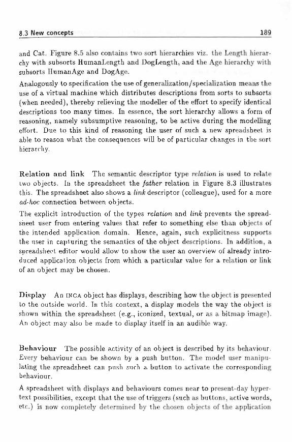
8.3 New concepts 189
and Cat. Figure 8.5 also contains two sort hierarchies viz. the Length hierar-chy with subsorts HumanLength and DogLength, and the Age hierarchy withsubsorts HumanAge and DogAge.
Analogously to specification the use of generalization/specialization means theuse of a virtual machine which distributes descriptions from sorts to subsorts(when needed), thereby relieving the modeller of the effort to specify identicaldescriptions too many times. In essence, the sort hierarchy allows a form ofreasoning, namely subsumptive reasoning, to be active during the modellingeffort. Due to this kind of reasoning the user of such a new spreadsheet isable to reason what the consequences will be of particular changes in the sorthierarchy.
Relation and link The semantic descriptor type re/afion is used to relatetwo objects. In the spreadsheet the /ai/jer relation in Figure 8.3 illustratesthis. The spreadsheet also shows a /mfc descriptor (colleague), used for a morearf-/ioc connection between objects.
The explicit introduction of the types re/afton and /m& prevents the spread-sheet user from entering values that refer to something else than objects ofthe intended application domain. Hence, again, such explicitness supportsthe user in capturing the semantics of the object descriptions. In addition, aspreadsheet editor would allow to show the user an overview of already intro-duced application objects from which a particular value for a relation or linkof an object may be chosen.
Display An INCA object has displays, describing how the object is presentedto the outside world. In this context, a display models the way the object isshown within the spreadsheet (e.g., iconized, textual, or as a bitmap image).An object may also be made to display itself in an audible way.
Behaviour The possible activity of an object is described by its behaviour.Every behaviour can be shown by a push button. The model user manipu-lating the spreadsheet can push such a button to activate the correspondingbehaviour.
A spreadsheet with displays and behaviours comes near to present-day hyper-text possibilities, except that the use of triggers (such as buttons, active words,etc.) is now completely determined by the chosen objects of the application
190 Chapter 8. An object-oriented model for spreadsheets
domain. Thus, all hypertext possibilities are here under the control of a com-mon object-oriented framework providing hypertext-like reacte'm'ty through theuse of particular behaviours attached to any object.
Composition As an example of a composite object, we consider the spread-sheet of Figure 8.6. Analogously to the above, the column-label region contains
sorts
instances
parts
property revenuescostsprofit
Company
myCompany
deptl
422022
dept2
522032
yourCompany
deptl
822062
dept2
943460
Figure 8.6: Composition in a spreadsheet.
the sort Company. Two of its instances are myCompany and yourCompany.They are so-called composite 067'ecte, i.e., objects which have other objects astheir parts. The parts of the companies are departmentl and department2.The composition of the companies allows them to be viewed by using thedepartment as the focus. The result of viewing the companies by their depart-ments is shown in Figure 8.7. We remark that the information presented in theFigures 8.6 and 8.7 is the same. The difference is the way of presenting it. InFigure 8.6 the numbers for revenues, costs, and profit are presented per com-pany, while in Figure 8.7 they are presented by focussing on the departments(parts) of each company.
Versions An INCA object can have uersions, which are variations of theobject. In the spreadsheet of Figure 8.8, each department is shown to havethree versions, namely 1988, 1989, and 1990. Similar to using the compositionof objects for changing the focus, the versions of the objects can be usedto view the model in distinct ways. Figure 8.9 shows the result of usingthe versions 1988, 1989, and 1990 as the primary focus on the companies.Thus, the versions are used in Figure 8.9 to view the properties revenues,costs, and profit per department, but even viewing them per company can beaccomplished easily.

8.3 New concepts 191
sorts
parts
instances
property revenuescostsprofit
Company
department 1
myCmy
422022
yourCmy
822062
department2
myCmy
522032
yourCmy
943460
Figure 8.7: Focus on object parts.
sorts
inseancss
parca
versions
property revenuescostsprofit
myCompany
departmentl
1988
422022
1989
281810
1990
301713
Company
department2
1988
522032
1989
542034
1990
562036
)raurCompany
departmentl
1988
822062
1989
993366
1990
986830
department!
1988
943460
1989 1990
96 5430 3066 24
Figure 8.8: Versions in the spreadsheet.
Multiple sort hierarchies INCA-COM does not allow sorts to have multiplesupersorts. The reason for disallowing multiple inheritance is that a sorthierarchy should provide one point of view on a domain, according to whichsubsorts are introduced (see also Section 5.1).
Therefore a sort is not allowed to partake in another hierarchy, since thiswould be a mixing of different points of view, and would ignore the differentpoints of view each of tjie hierarchies expresses. Moreover, since every sort
sores
• Instances
*• versions
pares
property revenuescostsprofit
1988
deptl
422022
depl2
522032
myCompany
1989
deptl dept2
28 5418 2010 34
Company
1990
deptl
301713
depl2
562036
1988
deptl
822062
dept2
943460
yourCompany
1989
deptl dept2
99 9633 3066 66
1990
deptl
986830
dept2
543024
Figure 8.9: Focus on versions.
192 Chapter 8. An object-oriented model for spreadsheets
hierarchy allows for a form of subsumptive reasoning, the points of view shouldbe clearly distinguished. However, it is allowed for an object to have multiplesorts. Thus, an object can be specified from different points of view, which isa quite natural way of modelling.
In the spreadsheet model, different points of view can be shown by usingthree-dimensional visualization with different planes. Each hierarchy in whichan object partakes is shown on a different plane. The planes are ordered inthe third dimension, and the user can select the point of view (plane) of hisinterest.
8.4 Chapter summary
The application of INCA-COM to the general domain of a spreadsheet showsthat INCA-COM'S semantic tools can be used to express the different aspectsand relations of objects. In order to have full benefit of a spreadsheet manipu-lating program it is necessary to regard the conventional row-column display asmerely a view on a model. By bringing semantics into this underlying model,the spreadsheet program is able to manipulate the model views in ways notpossible with current spreadsheet programs. In this chapter we have shownhow INCA-COM is used for the description of the underlying model.
We have divided a spreadsheet into three different regions: the co/umn-/a&e/rej/ton, the rou>-/a6e/ region, and the i>ot/ue region. The column-label regioncontains the names o/ o6;'ec<s. These objects are assigned to their soris, whichare also located in the column-label region. The sorts can be related to eachother, thus forming sor£ /n'erarc/iies, resulting in additional structure in theobject world.
The row-label region contains the names of the descriptors for objects in thecolumn-label region. The six descriptor types in iNCA-cOMare property, a£-<n'6u<e, re/a<ion, /infc, disp/ay, and uersion. The relation type comprises at leastthree presupposedly important relations, viz. the ms<ance_o/, the sutsorLo/and the porLo/relations, which are used for specification, specialization, andcomposition, respectively. These three relations structure an application do-main, so that the spreadsheet program can assist a user with different viewson the model.
The value region contains the values of the descriptors in the row-label region.The values have to be taken from a particular value domain. For descriptorsfrom the types property and attribute the values have to be from a primitive
8.4 Chapter summary if.-vwnHic-ki «A ;• 193
value domain, and for descriptors from the types relation and link the valueshave to be objects within the application domain.
The semantic categorization of descriptors furthers easy assimi/afa'on of do-main knowledge. In addition, INCA-COM uses descriptional reflection: everydescriptor and its type are treated as objects too. By this reflection a mod-eller may extend interactively the modelling tools of INCA-COM by creatingadditional descriptor types and associated application descriptors (occommo-
The use of reflection will be elaborated in Chapter 9.
In addition to modelling spreadsheets in INCA-COM, the new spreadsheet con-cept appears to be an effective way of presenting information to a user, andtherefore we will adopt a similar INCATOOL interface for presenting any objectmodel in whichever domain to a modeller and to other users.

194 Chapter 8. An object-oriented model for spreadsheets
,-...;..,,, „,;,.-
* ••• t - ' M . « • •"'..':'•
Chapter 9
INCATOOLl
In this chapter we describe the tool INCATOOL, which supports the modellingwith INCA-COM. The emphasis of the description is on the architecture. INCA-TOOL's main purpose is supporting the construction of an INCA model basedon the structure of the modelling framework of Chapter 4 and the structur-ing principles of Chapter 5. Modelling with INCA-COM has an iterative andevolutionary nature, and therefore is best supported by an interactive andopen-ended software tool, allowing high-level design decisions to be changedor discarded, continuously showing the consequences of the decisions. Ap-pendix B presents an hypothetical session with INCATOOL illustrating the kindsof operations a modeller may perform during modelling.
We describe the requirements of modelling support by considering modellingas a form of knowledge acquisition, during which assimilation and accommo-dation play an important role. In order to assist a modeller, INCATOOL usesexplicit knowledge about the concepts of INCA-COM and their representationby means of language elements, INCATOOL'S architecture is based on the re-flective representation of INCA concepts and language elements in terms ofINCA-COM leading to the concepts of an ontology and a descriptor domain.The latter two are defined as follows:
• an ontology contains the concepts used when modelling with INCA-COM;
This chapter is based on two articles: Geautomatiseerde onderateurjing wan object-jeorienteerd mode//eren (Dutch Conference on Applications of Artificial Intelligence 1991,Bakker and Braspenning (1991a)) and Z)e onto/ojjie en generteifce fcenmerJten uan een o6jec(-georienfeerrfe faa/ uoor fcennis<7e6aseerde ana/yje en onttoerp (Dutch Conference on ArtificialIntelligence 1992, Bakker et a/. (1992))
195
196 Chapter 9. INCATOOL
• a descriptor domain contains the language elements used for the descrip-tion of application objects.
The concept of an ontology is based on considering the INCA concepts asobjects. The concept of a descriptor domain is based on treating descriptorsas objects.The chapter also provides an integrating view on the relations between ontol-ogy, application domain, and descriptor domain. It ends with a descriptionINCATOOL's architecture.
s * *• " I ' "" * •? a ' *"'•' •
9.1 Requirements of modelling support
Following Piaget (1972), asszmz7ataon and accommodation are the two impor-tant aspects of knowledge-acquisition processes as explained in Braspenning(1989a): ••-• ; ' .
• assimilation of fact and rule structures concerns the representation ofUOD knowledge by means of partial ma<c/«es with template-like repre-sentation structures;
• accommodation of the system's own knowledge-representation capabili-ties concerns changing the cognitive templates used during assimilation.
If we supply the knowledge about INCA-COM in a reflective manner, i.e., inthe form of INCA objects, assimilation of application-domain knowledge andaccommodation of the representation language can be performed with INCA-
TOOL. Consequently, we take assimilation and accommodation as require-ments for INCATOOL. The two requirements facilitate the construction of anontology and the determination of a descriptor domain.
Assimilation entails the use of a fixed set of concepts, which act as templatesfor the modelling of objects in an application domain. In order to support themodeller, INCATOOL must have knowledge about the concepts (and descrip-tors) available in INCA-COM. This kind of knowledge is required for assistingthe modeller during the modelling of a particular application domain and par-ticular application(s).
Accommodation is required to enable a modeller to modify the knowledgeabout the descriptors durmjf modei/ing. Thus, a modeller can extend (or ac-commodate) the descriptors used in INCA-COM in order to describe applicationobjects which cannot be represented adequately in in INCA-COM'S core.
9.2 The INCA ontology 197
Stated otherwise, the knowledge base containing explicit knowledge aboutINCA-COM is used by INCATOOL to support the modelling process (assimila-tion), and can be extended interactively by the modeller (accommodation).
INCA-COM offers the groundwork for the description of objects in an appli-cation domain, such as the conference-registration domain. In INCA-COM adescription of an object is usually incomplete: a description should be seenas a parta'a/ description, which is added to the already existing description ofthe object. The description process evolves into a final object description. Asstated in Chapter 4, each object in INCA-COM is identified by a unique name,taking care of the identity of the object. The object description has the formof an ordered set of (descriptor, value) pairs. A descriptor is identified by aname and is assigned to one of the descriptor types introduced in Section 4.4.
The space of object descriptors and their relations can be seen as an applicationdomain itself, which can be described with INCA-COM as well. The descriptorsand their types thus become the subject of description. For the modeller itsuffices to specify the semantic type of a descriptor by means of a descriptortype indication.
The local description of objects is supported by INCATOOL, offering mecha-nisms for the efficient distribution of descriptions applicable to various objects.In order to support a modeller, INCATOOL should give immediate feedbackby showing the effects of editing operations, such as addition or removal ofdescriptions. Immediate feedback on modelling decisions is essential for anevolutionary way of modelling.
9.2 The INCA ontology
By introducing an ontology for object-oriented modelling, we do not aim atstarting a philosophical discussion on the essence of things or on the studyof being. The previous chapters have focussed on primitives such as objects,sorts, properties, attributes, etc. Here, a tec/mica/ concept of ontology, rep-resenting a set of concepts to be used in ant/ application model is discussed.Based on the concept of an object, our view of an ontology provides the basicdistinctions, useful in any modelling effort. After all, modelling presupposesan initial choice of concepts for looking at the world, and expressing a model.The INCA ontology thus does not imply existence of things denoted by its on-tological primitives, but it merely provides useful concepts for modelling. Theconcepts are used for assimilation of application-domain knowledge.
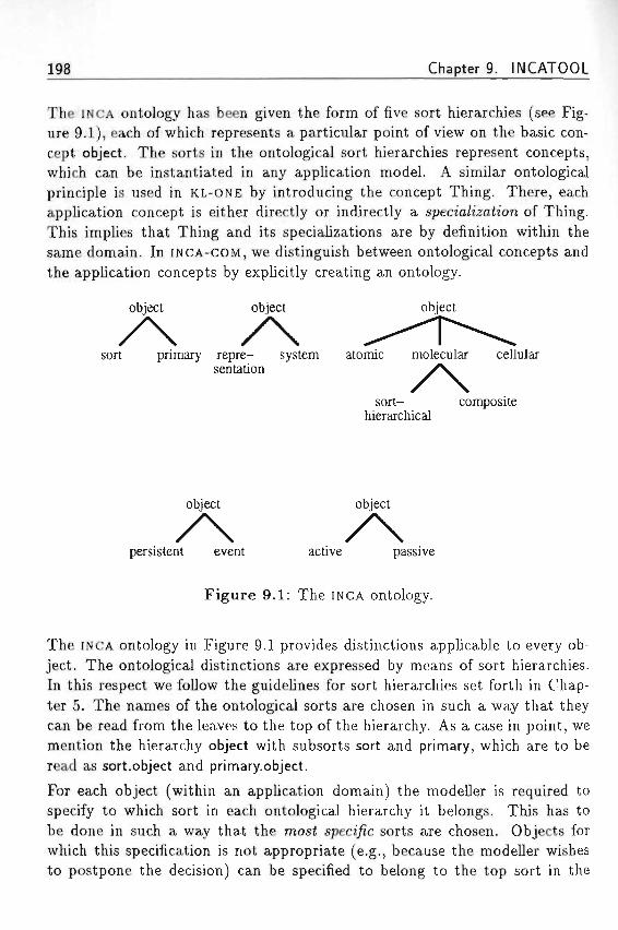
198 Chapter 9. INCATOOL
The INCA ontology has been given the form of five sort hierarchies (see Fig-ure 9.1), each of which represents a particular point of view on the basic con-cept object. The sorts in the ontological sort hierarchies represent concepts,which can be instantiated in any application model. A similar ontologicalprinciple is used in KL-ONE by introducing the concept Thing. There, eachapplication concept is either directly or indirectly a specia/izaiion of Thing.This implies that Thing and its specializations are by definition within thesame domain. In INCA-COM, we distinguish between ontological concepts andthe application concepts by explicitly creating an ontology.
object object object
sort primary repre- system atomic molecular cellularsentation VV
•",-•••• '.-• sort- composite, . hierarchical
object object
persistent event active passive
Figure 9.1: The INCA ontology.
The INCA ontology in Figure 9.1 provides distinctions applicable to every ob-ject. The ontological distinctions are expressed by means of sort hierarchies.In this respect we follow the guidelines for sort hierarchies set forth in Chap-ter 5. The names of the ontological sorts are chosen in such a way that theycan be read from the leaves to the top of the hierarchy. As a case in point, wemention the hierarchy object with subsorts sort and primary, which are to beread as sort.object and primary.object.
For each object (within an application domain) the modeller is required tospecify to which sort in each ontological hierarchy it belongs. This has tobe done in such a way that the mos£ speci/ic sorts are chosen. Objects forwhich this specification is not appropriate (e.g., because the modeller wishesto postpone the decision) can be specified to belong to the top sort in the
9.2 The INCA ontology 199
sort hierarchy under consideration. Later, the object may receive a morespecific sort instead of the top sort, i.e., a lower one in the particular hierarchy.Further, the INCA principle that an object may only belong to one sort in thesame hierarchy is preserved. This is similar to the use of partt'tionmi/s inthe ontology of Cyc (Lenat e< a/., 1990), which are used to model exclusivedivisions of sorts into subsorts. The five ontological distinctions are discussedbelow.
Sort and primary object The first distinction is made between a sort anda primary object. This distinction results from the decision to describe andtreat sorts similar to objects (see Section 5.1). A sort object is a sort withrespect to its instances, and an instance with respect to its (meta) sort, butthe distinction we make here explicit clearly divides all application objectsinto primary instances (objects in the application) and application sorts.
Representation and system object The second distinction is made be-tween a representation and a system object. A representation object refersto (is a representation of) an object in the initial application domain, whilea system object has been introduced for the description of a representationobject. A system object has no reference to an object within the universe ofdiscourse. In a certain way, the distinction between representation and systemobjects can be seen as the definition of an app/icah'on cursor, which constantlyrefers to the original application level, while the modeller may be modellingat a different (i.e., higher) level. Such higher-level objects are system objects,while objects at the application level are representation objects.
Atomic, molecular, and cellular object The fact that particular groupsof objects are used for constructing composite objects is the basis for a dis-tinction between atomic, mo/ecu/ar, and ce//u/ar objects. Atomic objects areobjects which are not composite. They are used as the building blocks formore complex objects. Molecular objects are objects consisting of a particulargroup of objects. A molecular object has the object status. Thus, it has theability to relate to other objects, and it can be described by means of a set ofdescriptions.
Two explicit specializations of the ontological sort of molecular objects arethe sort /iierarc/i?/ and the composite ofrjeci. A sort hierarchy is defined by agroup of sort objects, related by the relation subsort^of. A composite objectis defined by a group of objects, related by the relation part_of.
200 Chapter 9. INCATOOL
In addition to atomic and molecular objects, another distinction is made intocellular objects. Cellular objects are also defined by a group of objects, relatedto each other by particular relations. The difference with molecular objects isthat a cellular object has the functionality of (sub)system, meaning that thereis interaction between the parts of the cellular object.
In INCA-COM the group concept is used for modelling sets of objects by meansof a predicate (see also Chapter 5). A group is generated by evaluation of thecorresponding predicate. Thus, a group is defined by an intensional descriptionof a collection of objects.
A group has no object status, but as we described earlier in Chapter 5 acomposite object is an object, described partially by its composition. Thecomposition of such an object is in fact a group, defined by a predicate parLo/:the objects having the parLo/relation with a composite object are elements ofits composition. Because of their lack of object status, groups are not presentin the ontology.
Persistent and event object There is no dynamics in an object world, ifthere is no change. One of the reasons to consider objects is that they arethe constant elements within the flux of events in the object world. Objectsand events are dual concepts. However, the duality also enables a modellerto consider events as meaningful objects. For instance, in a windows environ-ment, the clicking of a button in a window is an event, resulting in a changein a window object. It may also be useful to consider such an event as anobject by describing it in terms of a time instant, a duration, and its relationwith previous events. Within the INCA ontology we have therefore made adistinction between persistent and event objects. Persistent objects have a lifecycle due to a sequence of events changing their state (see also Sections 4.4and 4.5). By modelling events as objects, they are considered as instances ofparticular sorts of events, describing their generic nature.
Active and passive object The fifth ontological distinction concerns thedistinction between active and passive objects. Passive objects representthings in the UOD, about which information is represented in the object world.Passive objects are the subjects of discourse of active objects. Events changethe state of passive objects. Active objects communicate with each other aboutpassive objects. The actions of active objects correspond to events in the ob-ject world. A sequence of actions is called the behaviour of an active-object
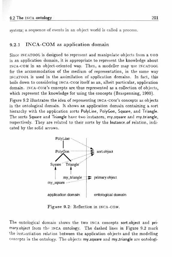
9.2 The INCA ontology 201
system; a sequence of events in an object world is called a process.
9.2.1 I N C A - C O M as appl ica t ion domain
Since INCATOOL is designed to represent and manipulate objects from a UOD
in an application domain, it is appropriate to represent the knowledge aboutINCA-COM in an object-oriented way. Then, a modeller may use INCATOOLfor the accommodation of the medium of representation, in the same wayINCATOOL is used in the assimilation of application domains. In fact, thisboils down to considering INCA-COM itself as an, albeit particular, applicationdomain. INCA-COM's concepts are thus represented as a collection of objects,which represent the knowledge for using the concepts (Braspenning, 1990).
Figure 9.2 illustrates the idea of representing INCA-COM'S concepts as objectsin the ontological domain. It shows an application domain containing a sorthierarchy with the application sorts PolyLine, PolyGon, Square, and Triangle.The sorts Square and Triangle have two instances, my_square and my_triangle,respectively. They are related to their sorts by the Instance.of relation, indi-cated by the solid arrows.
PolyLine •-.,
PolyGon •
Square " Triangle'
tmy_triangle "
my_square ---
application domain
sort.object
primary.object
ontological domain
Figure 9.2: Reflection in INCA-COM.
The ontological domain shows the two INCA concepts sort.object and pri-mary.object from the INCA ontology. The dashed lines in Figure 9.2 markthe instantiation relation between the application objects and the modellingconcepts in the ontology. The objects my square and my.triangle are ontologi-
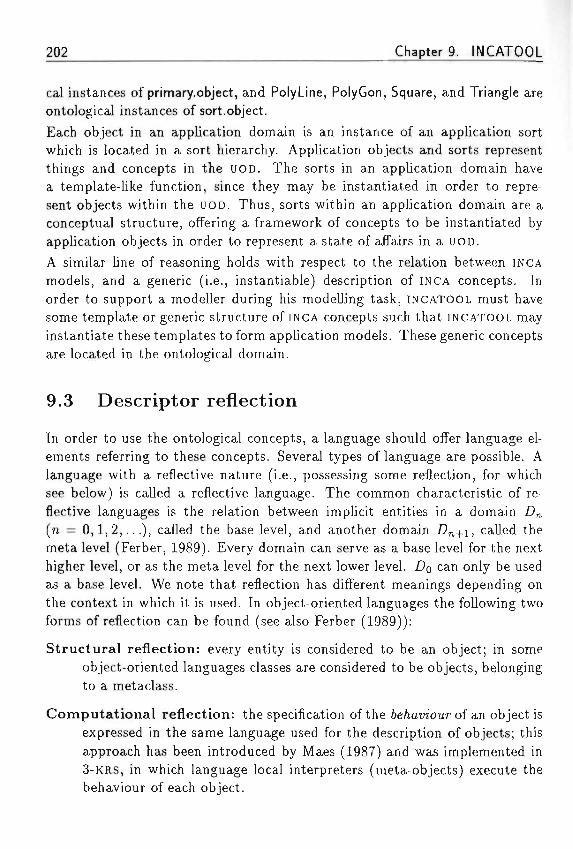
202 Chapter 9. INCATOOL
cal instances of primary.object, and PolyLine, PolyGon, Square, and Triangle areontological instances of sort.object.Each object in an application domain is an instance of an application sortwhich is located in a sort hierarchy. Application objects and sorts representthings and concepts in the UOD. The sorts in an application domain havea template-like function, since they may be instantiated in order to repre-sent objects within the UOD. Thus, sorts within an application domain are aconceptual structure, offering a framework of concepts to be instantiated byapplication objects in order to represent a state of affairs in a UOD.A similar line of reasoning holds with respect to the relation between INCAmodels, and a generic (i.e., instantiable) description of INCA concepts. Inorder to support a modeller during his modelling task, INCATOOL must havesome template or generic structure of INCA concepts such that INCATOOL mayinstantiate these templates to form application models. These generic conceptsare located in the ontological domain.
9.3 Descriptor reflection
In order to use the ontological concepts, a language should offer language el-ements referring to these concepts. Several types of language are possible. Alanguage with a reflective nature (i.e., possessing some reflection, for whichsee below) is called a reflective language. The common characteristic of re-flective languages is the relation between implicit entities in a domain £>„(n = 0,1,2,...), called the base level, and another domain .Dn+i, called themeta level (Ferber, 1989). Every domain can serve as a base level for the nexthigher level, or as the meta level for the next lower level. Z?o can only be usedas a base level. We note that reflection has different meanings depending onthe context in which it is used. In object-oriented languages the following twoforms of reflection can be found (see also Ferber (1989)):
Structural reflection: every entity is considered to be an object; in someobject-oriented languages classes are considered to be objects, belongingto a metaclass.
Computational reflection: the specification of the 6e/mt>iour of an object isexpressed in the same language used for the description of objects; thisapproach has been introduced by Maes (1987) and was implemented in3-KRS, in which language local interpreters (meta-objects) execute thebehaviour of each object.

9.3 Descriptor reflection 203
When modelling an application domain with INCA-COM emphasis is on the de-scription of the applition objects and not on the behaviour of the applicationobjects. This implies that computational reflection is not an essential ingre-dient of our language. As we see it, computational reflection is a specializedform of language reflection, which is defined as follows.
Language reflection: the language elements for describing objects refer toobjects of the same type as the objects described by the language.
This definition entails that language reflection contains on the one hand com-putational reflection and on the other hand descriptor reflection. The focusof INCA-COM is description by means of descriptors. Incorporating languagereflection in INCA-COM leads to a specialized form of language reflection, whichwe call descn'pfor re/Zech'on, defined as follows.
Descriptor reflection: the descriptors for describing INCA objects in an ap-plication domain refer to INCA objects in a separate descriptor domain.
In INCA-COM structural reflection and descriptor reflection are used in thefollowing way. First, treating a sort as an object is a form of structural re-flection. The advantage of this is the possibility to describe sorts in the sameway as normal objects. Describing sorts as normal objects has been treatedearlier in Chapters 4 and 5. Second, descriptor reflection consists of treatingdescriptors of objects at the level of an application domain as objects at ahigher level application domain, called the descriptor domain. The advantageof descriptor reflection is the possibility to describe descriptors using the sameconcepts as normal objects and to accommodate the representation languageby introducing specialized types of descriptors as explained in Section 9.1.
Figure 9.3 gives an example of a description in which the descriptors of objectsin an application domain are treated as objects in the descriptor domain. Thedescription in the application domain contains two object descriptions, namelythe objects HumanBeing and Harm. Each object description starts with theindication of the ontological sort(s) to which the object under considerationbelongs. The object HumanBeing is specified to be a sort.object. The set ofdescriptions further indicates that (1) HumanBeing is a subsort of Animal notfurther described here and (2) its set of InstanceDescriptors contains a descrip-tor Age meaning that each instance of HumanBeing is at least described by anAge descriptor. Such an instantiated object is the object Harm, specified to be
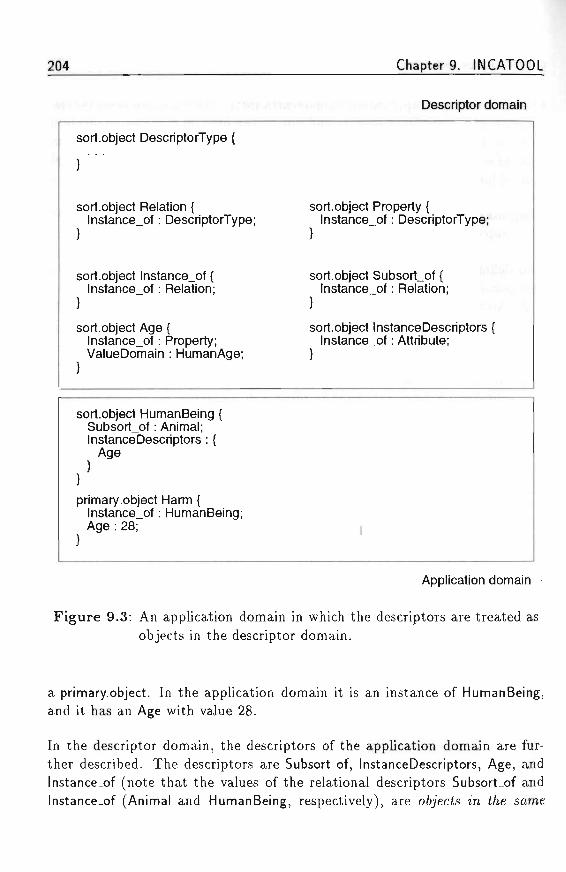
204 Chapter 9. INCATOOL
sort.object DescriptorType {
sort.object Relation {lnstance_of: DescriptorType;
sort.object lnstance_of {lnstance_of: Relation;
sort.object Age {lnstance_of: Property;ValueDomain : HumanAge;
sort.object HumanBeing {Subsort_of: Animal;InstanceDescriptors: {
Age
}primary.object Harm {
lnstance_of: HumanBeing;Age : 28;
. f.r vi : ; : •-»'.: Descriptor domain
sort.object Property {lnstance_of: DescriptorType;
sort.object Subsort_of { ' -»lnstance_of: Relation;
• sort.object InstanceDescriptors {lnstance_of: Attribute;
Application domain
Figure 9.3: An application domain in which the descriptors are treated asobjects in the descriptor domain.
a primary.object. In the application domain it is an instance of HumanBeing,and it has an Age with value 28.
In the descriptor domain, the descriptors of the application domain are fur-ther described. The descriptors are Subsort.of, InstanceDescriptors, Age, andlnstance_of (note that the values of the relational descriptors Subsort-of andInstance.of (Animal and HumanBeing, respectively), are ofc/'ecte in f/ie same
9.3 Descriptor reflection 205
opp/icaiion rfomam, hence they are not described in the descriptor domain,but in the application domain, which is not shown here). They are describedin the descriptor domain as objects. We remark that each of these objectsis a sort.object. The reason for this is that they are to be instantiated inthe application domain, for every object in whose description they are used.Thus, a descriptor name in the application domain refers to an equally-nameddescriptor sort in the descriptor domain. The actual descriptional use of sucha name leads to the instantiation of the descriptor sort. The instance nameof an instantiated descriptor is generated by the underlying naming system;it should not be used by the modeller, but only serves to distinguish betweenthe different instances of the various descriptor types.
The sets of descriptions of the four objects Subsort.of, InstanceDescriptors, Age,and lnstance_of contain a description indicating the type of the descriptor.lnstance_of is specified to be an instance of Relation, Age is an instance ofProperty, Subsort-of is an instance of Relation, and InstanceDescriptors is aninstance of Attribute. The descriptor domain also shows that the descriptortypes, such as Relation and Property, are described as sort objects (in fact,they are meta sorts, since their instances are sort objects), belonging to thesort DescriptorType not further described here.
Referring to the idea of Section 9.1 to consider the space of object descrip-tions and their relations as application domain we now treat the descriptionof descriptors in the descriptor domain. This enables a modeller to specifythe semantics of descriptors. In order to illustrate such a specification, weshow how the semantics of the lnstance_of descriptor can be specified. In Fig-ure 9.4 the object lnstance_of is described. Its ontological sort is sort.object,which means that it is to be instantiated in the application domain, for ev-ery object description in which the lnstance_of descriptor is used. The typeof the Instance-of descriptor is specified by the (self-referential) descriptor In-stance.of, relating the descriptor to its sort, Relation. Note that in this specialcase the description of a descriptor contains a reference to the descriptor beingdescribed. This implies, of course, that initially some particular descriptorsare present, since it would be impossible to give any description whatsoeverwithout such initial descriptors (bootstrapping problem).
The descriptor type Relation furnishes two descriptors, o and s, which denotethe source and target object between which a particular relation holds. Thesetwo descriptors are used for the description of the semantics of the Instance.ofdescriptor.

206 Chapter 9. INCATOOL
sort.object Ins tance-of { .Instance.of : Relation; ... > : Tsemantics(o,s) : {
lnstance.of(o, primary.object) A->lnstance_of(s, sort.object)errorMessage('Only sorts have instances.');
lnstance.of(o, primary.object) A lnstance_of(s, sort.object) -description(o) + = InstanceDescriptors(s);
Figure 9.4: The semantics of the Instance.of descriptor.
The use of a descriptor implies that its semantics is checked. The semanticsof the lnstance_of descriptor consists of two rules, which are applied if theirpreconditions are met:
• if the Instance-of descriptor is not associating an object with a sort ob-ject, an appropriate error message is generated;
• if the lnstance_of descriptor is actually associating an object o with a sortobject 5, the description of o is extended with the extensional descriptionof the sort object 5 (given by the attribute InstanceDescriptors).
This semantics is given in Figure 9.4 as semantics. It takes two parameterso and s specifying the object for which the descriptor is used, and the valuespecified in the (descriptor, value) pair, respectively.
During the interactive modelling process INCATOOL plays an important role.It should assist the modeller whenever an as yet unspecified descriptor is be-ing used. This can be accomplished by starting a dialogue during which themodeller describes the newly-introduced descriptor. The sort specification ofthe descriptor object specifies to which descriptor type the descriptor belongs,such as property, attribute, relation, or link.
9.3 Descriptor reflection 207
9.3.1 Descriptors as application domain
The most important modelling activity, is speci/ica(ion of objects (see alsoChapter 5). By assigning an object to its sort(s), it is assigned its placewithin the object world. By such a sort assignment, an object receives itsinitial description given by the extensional description of its sort(s). Besidesthe primary description of an object by means of sort assignments, INCA-COM
contains a set of descriptor types for the semantic categorization of objectdescriptions. The idea to treat the space of object descriptors and their typesas a separate application domain enables a modeller to view the descriptortypes as sorts and particular descriptors as instances of these sorts. Earlier,ideas on this subject have been presented in Braspenning (1990); in Chapter 8we have given an example by showing the modelling of descriptors such asLength and Age. A similar approach has also been employed in the TELOS
knowledge-representation system (Mylopoulos, 1992).
The organization of a domain by means of sort hierarchies can be employed tomodel each semantic descriptor type as the top sor< of a separate sort hierarchy.Such an approach enables a modeller to refine each type by specialization. Thepossibility to treat descriptors as objects is an extension to KL-ONE (Brachmanand Schmolze, 1985), which does not include a feature to extend the mediumof representation. Specializing a descriptor sort or descriptor type into a morespecific type, a specialized type should have an extended description: its in-tension is greater than the intension of its supersort (i.e., specialization is anenhancement of intension). As an example, the descriptor married-to shouldbe assigned to the semantic descriptor type Relation, whereas the descriptorlargerJhan should be assigned to the type Transitive.Relation, which is a spe-cialization of Relation. By adapting the elements of INCA-COM, a modellercreates a particular specialized, accommodated modelling environment for anadequate representation of an application model in a particular applicationdomain.
The descriptor domain is not located within the original application domain,but is thought of as an application domain on top of it. The descriptorsand their types thus become the subject of description: the elements of a(descriptor, value) pair are viewed as consisting of particular instances ofgeneric sorts of descriptors and generic sorts of values, respectively. A de-scription is viewed as a combination of particular instances of these genericsorts, and, similarly, describing objects becomes a way of combining particular(descriptional) objects. Figure 9.5 extends Figure 9.2 by showing the relation
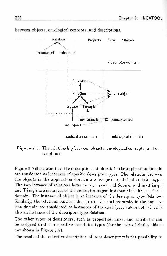
208 Chapter 9. INCATOOL
between objects, ontological concepts, and descriptions. ••
•'• -',-: Relation Property Link Attribute
mstance_of subsort_ofi i * •
i
•
i
i
; PolyLine --.,
: 1' PolyGon -—
: / \' ...X'
Square " Triangle'
1 my_triangle y_my_square ' "
application domain
descriptor domain
• - ^ sort.object
. ^ primary.object
ontological domain
Figure 9.5: The relationship between objects, ontological concepts, and de-scriptions.
Figure 9.5 illustrates that the descriptions of objects in the application domainare considered as instances of specific descriptor types. The relations betweenthe objects in the application domain are assigned to their descriptor type.The two Instance-of relations between my_square and Square, and my.triangleand Triangle are instances of the descriptor object lnstance_of in the descriptordomain. The lnstance_of object is an instance of the descriptor type Relation.Similarly, the relations between the sorts in the sort hierarchy in the applica-tion domain are considered as instances of the descriptor subsort_of, which isalso an instance of the descriptor type Relation.
The other types of descriptors, such as properties, links, and attributes canbe assigned to their respective descriptor types (for the sake of clarity this isnot shown in Figure 9.5).
The result of the reflective description of INCA descriptors is the possibility to
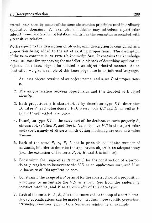
9.3 Descriptor reflection 209
extend INCA-COM by means of the same abstraction principles used in ordinaryapplication domains. For example, a modeller may introduce a particularsubsort TransitiveRelation of Relation, which has the semantics associated witha transitive relation. , , • . * • - !• ... ;,; ^
With respect to the description of objects, each description is considered as aproposition being added to the set of existing propositions. The descriptionof the INCA concepts is iNCATOOL's fcnouj/edge 6ase. It contains the knowledgeINCATOOL uses for supporting the modeller in his task of describing applicationobjects. This knowledge is formulated in an object-oriented manner. As anillustration we give a sample of this knowledge base in an informal language.
1. An INCA object consists of an object name, and a set P of propositions
P- • .
2. The untqrue relation between object name and P is denoted with object
3. Each proposition p is characterized by descriptor type Z)T, descriptorZ), value V, and value domain VZ?, where both Z?T and Z), as well as Vand VZ? are related (see below).
4. Descriptor type Z)T is the meta sort of the declarative sorts property P ,aiiriftuie J4, re/ation iZ, and /mJb Z-. Value domain VZ) is also a particularmeta sort, namely of all sorts which during modelling are used as a valuedomain.
5. Each of the sorts P , /4, iZ, Z- has in principle an infinite number ofinstances, in order to describe the application object in an adequate way(i.e., the extension of the sorts P , ,4, /2, and X is infinite).
6. Constraint: the usage of an Z£ or an Z- for the construction of a propo-sition p requires to instantiate the VZ) as an app/ication sort, and V asan instance of this application sort.
7. Constraint: the usage of a P or an .4 for the construction of a propositionp requires to instantiate the VZ) as a data type from the underlyingabstract machine, and V as an exemp/ar of this data type.
8. Each of the sorts P , J4, # , Z- is to be conceived as the top of a sort hierar-chy, so specializations can be made to introduce more specific properties,attributes, re/ations, and /infcs; a transitive re/ation is an example.
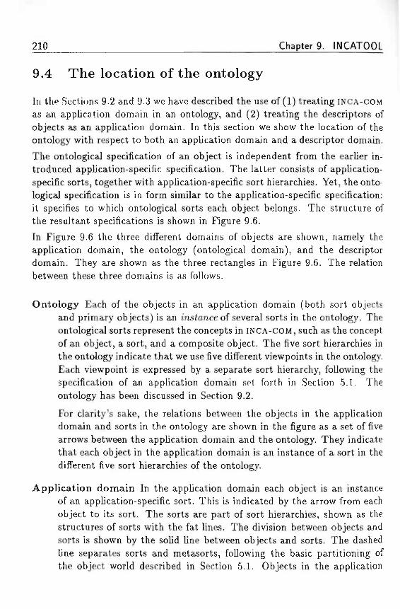
210 Chapter 9. INCATOQL
9.4 The location of the ontology
In the Sections 9.2 and 9.3 we have described the use of (1) treating INCA-COMas an application domain in an ontology, and (2) treating the descriptors ofobjects as an application domain. In this section we show the location of theontology with respect to both an application domain and a descriptor domain.
The ontological specification of an object is independent from the earlier in-troduced application-specific specification. The latter consists of application-specific sorts, together with application-specific sort hierarchies. Yet, the onto-logical specification is in form similar to the application-specific specification:it specifies to which ontological sorts each object belongs. The structure ofthe resultant specifications is shown in Figure 9.6.
In Figure 9.6 the three different domains of objects are shown, namely theapplication domain, the ontology (ontological domain), and the descriptordomain. They are shown as the three rectangles in Figure 9.6. The relationbetween these three domains is as follows.
Ontology Each of the objects in an application domain (both sort objectsand primary objects) is an instance of several sorts in the ontology. Theontological sorts represent the concepts in INCA-COM, such as the conceptof an object, a sort, and a composite object. The five sort hierarchies inthe ontology indicate that we use five different viewpoints in the ontology.Each viewpoint is expressed by a separate sort hierarchy, following thespecification of an application domain set forth in Section 5.1. Theontology has been discussed in Section 9.2.
For clarity's sake, the relations between the objects in the applicationdomain and sorts in the ontology are shown in the figure as a set of fivearrows between the application domain and the ontology. They indicatethat each object in the application domain is an instance of a sort in thedifferent five sort hierarchies of the ontology.
Application domain In the application domain each object is an instanceof an application-specific sort. This is indicated by the arrow from eachobject to its sort. The sorts are part of sort hierarchies, shown as thestructures of sorts with the fat lines. The division between objects andsorts is shown by the solid line between objects and sorts. The dashedline separates sorts and metasorts, following the basic partitioning ofthe object world described in Section 5.1. Objects in the application

9.4 The location of the ontology 211
Descriptor domain Ontology
Application domain
Figure 9.6: The location of the ontology.
domain are described by descriptors. For instance, object o is describedby a descriptor
Descriptor domain The objects in the descriptor domain are the descriptorsfor objects in the application domain. Thus, the descriptors (and someof the values, in case of relations and links) are viewed as objects, whichare located at a higher level, on top of the application domain. Thefigure illustrates this by object o in the application domain described
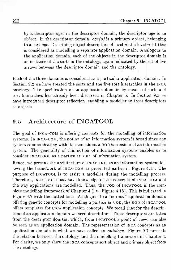
212 Chapter 9. INCATOOL
* by a descriptor ogre: in the descriptor domain, the descriptor age is anobject. In the descriptor domain, cu/efoj is a primary object, belongingto a sort age. Describing object descriptors of level n at a level n + 1 thusis considered as modelling a separate application domain. Analogous tothe application domain, each of the objects in the descriptor domain isan instance of the sorts in the ontology, again indicated by the set of fivearrows between the descriptor domain and the ontology. ,
Each of the three domains is considered as a particular application domain. InSection 9.2 we have treated the sorts and the five sort hierarchies in the INCAontology. The specification of an application domain by means of sorts andsort hierarchies has already been discussed in Chapter 5. In Section 9.3 wehave introduced descriptor reflection, enabling a modeller to treat descriptorsas objects.
9.5 Architecture of INCATOOL
The goal of INCA-COM is offering concepts for the modelling of informationsystems. In INCA-COM, the notion of an information system is broad since anysystem communicating with its users about a UOD is considered an informationsystem. The generality of this notion of information systems enables us toconsider INCATOOL as a particular kind of information system.
Hence, we present the architecture of INCATOOL as an information system fol-lowing the framework of INCA-COM as presented earlier in Figure 4.15. Thepurpose of INCATOOL is to assist a modeller during the modelling process.Therefore, INCATOOL must have knowledge of the concepts of INCA-COM andthe way applications are modelled. Thus, the UOD of INCATOOL is the com-plete modelling framework of Chapter 4 (i.e., Figure 4.15). This is indicated inFigure 9.7 with the dotted lines. Analogous to a "normal" application domainoffering generic concepts for modelling a particular UOD, the UOD of INCATOOLoffers templates for INCA application concepts. We recall that for the descrip-tion of an application domain we need descriptors. These descriptors are takenfrom the descriptor domain, which, from INCATOOL's point of view, can alsobe seen as an application domain. The representation of INCA concepts as anapplication domain is what we have called an onto/ogy. Figure 9.7 presentsthe relation between the ontology and the modelling framework of Chapter 4.For clarity, we only show the INCA concepts sort.object and primary.object fromthe ontology.
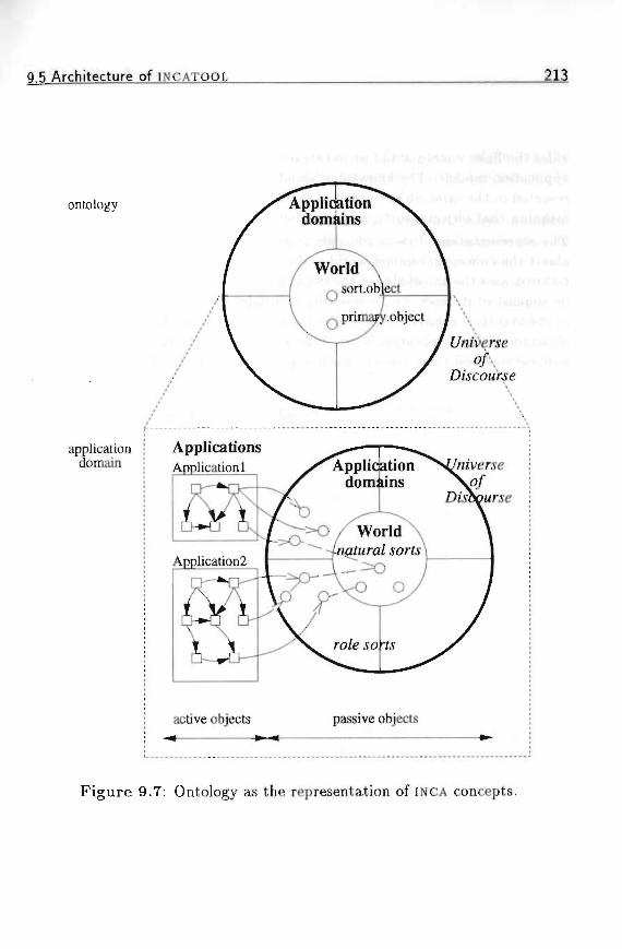
Q,5 Architecture of INCATOOL 213
• H ; - • • , • • • • » • ; : : * ?•
ontology Applicationdomnins
applicationdomain
ApplicationsApplication 1 Application
domains
Application2
active objects passive objects
Figure 9.7: Ontology as the representation of INCA concepts.
214 Chapter 9. INCATOOL
Figure 9.7 shows that the (representation of the) UOD in the ontology concernsthe domain of INCA concepts. This gives the essence of the ontology: it pro-vides the basic concepts and model structures to be instantiated for particularapplication models. The knowledge about the use of the INCA concepts is rep-resented in the same object-oriented manner as "normal" application domainsmeaning that objects, sorts, and sort hierarchies are used.The representation of INCA concepts is used by INCATOOL for communicatingabout the conceptual-model world and creating particular object models. IN-CATOOL uses the knowledge of the INCA ontology to perform particular actionson request of its user (i.e., a modeller). Besides viewing a modeller as a userof INCATOOL, a similar relation exists between an application user and an ap-plication at the application level. Figure 9.8 illustrates this relation betweenapplications and their users at both application level and INCATOOL level.
Applicationmodeller INCATOOL ontology
Applicationuser
--'
Application - Applicationdomain
Universe ofDiscourse
Figure 9.8: Applications and their users.
At the application level, an application user employs an application to createa representation of a UOD. To this end, the application domain offers specificsorts reflecting concepts in the UOD. An application user uses these sorts astemplates to instantiate specific objects, corresponding to things in the UOD.By doing so, an application user may also be regarded as a mode/Zer, since theuse of an application entails transforming or translating facts holding in theUOD into application-domain objects.
In a similar way, at the level of INCATOOL an application modeller uses aspecific application, INCATOOL, to create specific application domains, with
9.6 Chapter summary 215
associated applications, to be used by application users. Of course, such anapplication domain must reflect its UOD by an appropriate choice of conceptscorresponding to the model of application users. This process of finding theright concepts to model a UOD is especially important during analysis in thesoftware life cycle.
The structure of application domains, applications, and their users is similarto the structure proposed by Nijssen (1989). The INCA conceptualization ofan application domain, consisting of objects playing specific roles allows par-ticular sorts, i.e., generic UOD structures, to be reused in different applicationdomains. Furthermore, our conceptualization of an application consisting ofcommunicating active objects is more detailed than the concepiua/ m/ormah'onprocessor proposed by Nijssen (1989). Nevertheless, Nijssen's work is insight-ful regarding the relation between a meta model and an application-domainmodel.
9.6 Chapter summary
In this chapter we have described the architecture of INCATOOL. We havetaken assimilation and accommodation, two important aspects of knowledge-representation processes, as requirements for INCATOOL. The need for assimi-lation has facilitated the construction of an ontology of INCA concepts, whichfurnishes a set of basic concepts to be used in modelling any application do-main. The need for accommodation has enabled us to consider the space ofobject descriptors as an application domain, the descriptor domain. Thus, de-scriptors are treated as objects, leading to a form of language reflection, calleddescriptor reflection. By treating descriptors as objects, the descriptor typesintroduced in Chapter 4 become the sorts of the descriptor domain. Describ-ing objects entails instantiating the descriptor sorts in the descriptor domain.Descriptor reflection enables the modeller to specify the semantics of the de-scriptors which are used during modelling. Furthermore, descriptor reflectionallows a modeller to accommodate the modelling language by introducing newtypes of descriptors.
In the context of the conceptual framework described in Chapter 4, INCATOOLis an application communicating with a user about changes in the applicationdomain. In the case of INCATOOL, the application domain is the domain ofINCA concepts represented in the INCA ontology. It offers the basic conceptsto be used in modelling application domains. In interaction with its user,
216 Chapter 9. INCATOOL
INCATOOL instantiates INCA concepts from the ontology. The ontology pre-sented furnishes a universal framework for modelling objects. By specifyingthe sorts and their structure for a particular application, a specific applica-tion framework is created. The descriptions of the (conceptual) objects inan application domain are formed by instantiating the sorts in the descriptordomain. Accommodation of the modelling language by introducing new typesof descriptors can be performed with INCATOOL since the descriptor domainis also an application domain.
• . ' "l'i..7 "..i .-'it, >"?- i i i f
Chapter 10
Evaluation
In this chapter, we summarize the contributions of this thesis and draw someconclusions on the problem statement set forth in Chapter 2. Thereafter, wesuggest directions for future research.
10.1 Summary of contributions
The evolution of software-development tools to address the complexity ofsoftware-systems development has taken place in two separate domains. First,the automation of tasks in programming has stimulated developments ofsoftware-engineering tools, such as compilers and eventually integrated com-binations of tools, known as computer-aided so/£iuare en^meen'ngf (CASE) en-vironments. Second, within artificial intelligence there has been research intoautomatic programming. The ultimate goal of automatic programming is toarrive at automatically-created computer programs on the basis of a problemdescription. However, this goal has, by far, not been reached and it remainsan open question whether it will ever be. The more promising way to combinethe efforts of both software engineering and artificial intelligence leads to theconcept of mie/%enf CASE environments. Led by the wish to create the foun-dations for future intelligent CASE environments, we formulated the followingproblem statement in Chapter 2.
What is the nature of a conceptual object model for the analysisand design of information systems?
In the previous chapters we have provided the concepts and structuring prin-ciples for the INCA Conceptual Object Model (INCA-COM).
217
218 Chapter 10. Evaluation
An important decision has been to base INCA-COM on object-oriented concepts.The reason for this is twofold: object orientation has emerged in artificialintelligence as a knowledge-representation tool, and in programming as anevolution of different programming paradigms. The purpose of our researchhas been the identification of the concepts enabling the level of object-orientedmodelling to be raised to the levels of analysis and design, such that (1) aUOD can be represented; (2) application domains can be represented; and (3)systems can be modelled.
For the modelling of information systems we have developed and describeda conceptual framework consisting of three distinct parts. First, objects oc-curring in the real-world outside of an information system are modelled bya core of objects belonging to so-called nature/ sorts. Second, objects in anapplication domain are modelled by describing ro/e sorts, i.e., sorts to be in-stantiated by applications. Third, the active part of an information systemconsists of active objects communicating with each other about objects in thereal world and the roles these objects are playing. Communication betweenactive objects is based on speech-act theory.
The models used in modelling according to the proposed framework are (1)the in/ormation mode/describing the structure of information, including roles;(2) the euenf mode/ describing which events can take place in the object worldand which order is imposed on these events; (3) the 6e/iamoura/ mode/ describ-ing which objects are active by performing particular actions, which give riseto events in the object world; and (4) the communication mode/ describingwhat interactions take place between active objects. The information modeland the event model are used for modelling a passive object world, whereasthe behavioural model and the communication model are used for modellinga system of active objects. Such a division between a passive-object worldand an active-object system may seem counterintuitive to the general idea ofobject orientation as a unifying and uniform concept. However, we think sucha division is essential in modelling information systems: the nature of an in-formation system entails that it contains a representation of a UOD. Althoughsuch represented objects can be active in the real world, their representation isunder the control of active objects within the information system. Modellingan information system with only one type of object does not aid in developinga clear conceptual model.
For the description of objects we have introduced different types of descriptors.They allow a modeller to express different semantic purposes of descriptions.A property is used to model an essential feature of an object, which it will have
10,2 Conclusions 212
in every possible application. An attn'6u£e is a contingent feature of an objectwhen it plays a role. A re/afa'on is an essential association between objects, anda /in& is a non-essential association between objects, when they are playing arole.
In addition to the descriptional structuring of objects according to the mod-elling framework, INCA-COM contains four structuring principles on the domainof objects. They are sort hierarchies, specification, composition, and group-ing. These structuring principles are based on meaningful relations betweenobjects and sorts. The inheritance mechanisms in INCA-COM are based on sorthierarchies and specification. We have described three types of inheritance,namely common inheritance, normal inheritance, and structural inheritance.A system is a composite object with a structure. In INCA-COM, active objectscommunicating among each other on an object world form an active-objectsystem. In order to allow objects to evolve over time, a version concept ispart of INCA-COM. We have assessed the problems in managing versions ofcomposite objects, and have presented algorithms for addition and deletion ofversions and parts of composite objects.
For support during modelling with INCA-COM we have described the archi-tecture of INCATOOL. It supports the assimilation and accommodation ofapplication knowledge. The architecture is based on the model for informa-tion systems presented in Chapter 4, leading to an ontology of INCA concepts.Modelling with INCA-COM is supported by INCATOOL, using the ontology as itsapplication domain. INCA-COM has been extended with reflective capabilities.Two types of reflection are provided. First, structural reflection consists oftreating sorts are objects, allowing them to be described in the same manneras normal objects. Second, descriptor reflection, a form of language reflec-tion, consists of treating descriptors as objects, allowing the language to beaccommodated to enhance the process of assimilation of object descriptions.
10.2 Conclusions
In the previous section we have briefly described the nature of INCA-COM, pro-viding the answer to the problem statement of Section 2.5. Object-orientedmodelling is often seen as a panacea for addressing complexity problems duringthe development of information systems. Especially the concept of an object ismentioned as unifying the behavioural aspect and the representational aspectof an information system. However, for the analysis and the design of informa-
220 Chapter 10. Evaluation
tion systems a division is necessary between (1) active model concepts, takingcare for the execution of processes, and (2) passive model concepts, accountingfor the representation of a UOD in the information system. By assigning theseaspects to a single type of object, combining both procedures and data, thedistinction between processing and representation is denied. In INCA-COM themodelling of an information system is based on two different types of object:the active object and the passive object.
In Section 2.5 we mentioned five requirements for the conceptual object model.Below, we repeat each requirement, and describe how it has been fulfilled byINCA-COM.
1. fiepresentmg t/ie UOD o/an in/ormatzon system.The UOD of an information system is modelled explicitly in INCA-COMusing the information model and the event model. These models allowa modeller to express which things in the context of an informationsystem are represented as objects, and which events can take place. Therepresentation of a UOD forms an object world, consisting of passiveobjects.
2. A/ode//in<7 generic parts o/ a UOD.Generic parts of a UOD are modelled by natural sorts in the core of theobject world. They represent sorts of objects which occur naturally indifferent applications.
3. A/ode//in<7 specie parts o/ a UOD.Specific parts of a UOD are modelled by role sorts in application domainsof the object world. They represent roles of natural objects occurring inan application domain.
4. A/ode//ing in/ormation systems 6y means o/ iwe/Z-cte/mea' fdejeomposztionprincip/es.An information system or application is modelled by active objects, com-municating on an object world. Applications are modelled using thebehavioural model and the communication model. The structure of aninformation system consists of the communication links between the ac-tive objects.
5. /teuse o/ spect/ications to a//ou> c/ieap systems to 6e 6ut/f.The use of object-oriented principles for both representation of a UOD
10,3 Suggestions for future research 221
and modelling of an information system enhances the reuse of specifi-cations. The distinction between a passive-object world and an active-object system enhances the understanding and subsequent reuse of dif-ferent parts of an information system. • * '• > :?^ >mu«m>so: ..w-ns, ^
Regarding the long-term objective of the INCA project, i.e., realizing anI intelligent CASE environment for systems development, we remark the fol-lowing, INCA-COM offers concepts for modelling information systems. Sincea CASE environment is also a (special) kind of information system, it can bemodelled with the INCA concepts. The conceptual architecture of INCATOOLsketched in Chapter 9 gives a starting point for the realization of such a CASE
environment. INCATOOL contains knowledge on the concepts in INCA-COM, en-abling to assist a modeller in describing the objects in an information system.The realization of INCATOOL should be tackled in future projects.
10.3 Suggestions for future research
In order to achieve full INtelligent CASE, based on the concepts of INCA-COM,the following research is envisaged.
• The language for modelling with INCA-COM should be defined formally.This includes a formal notation for modelling of laws.
• A standardized set of system architectures should be made available.The availability of such a set allows system designers to reuse particularsystems, and to implement systems with a predefined architecture, suchas a client/server system or a blackboard system.
• The architecture of INCATOOL, based on a reflective metamodel of INCA-COM, should be proven by implementing it in a suitable way. Someexperience with this in C++ has shown that implementation of reflectionin such a language is non-trivial. The concept of so-called meta CASE
tools is interesting in this context.
• The value of the concept of an active-object system communicating on anobject world by means of speech acts should be assessed for conceptualmodels for so-called act-management systems, logistics systems, and,more generally for telematics systems.

222 Chapter 10. Evaluation
We conclude this thesis by stressing that the main point of modelling infor-mation systems is the conceptual division between passive objects as repre-sentations of things in the UOD of the information system, and active objectsas actors, controlling passive objects in a purposeful manner. Object-orientedmodelling of information systems should therefore offer concepts for modellingboth passive objects and active objects. The concepts of object orientationcan be used for both, but they should not be intermingled. • . ,

Appendix A
Visual displays
This appendix contains the descriptions of the visual displays, which have beenintroduced in Chapter 7. Figure A.I contains the descriptions of the primitivevisual displays, and Figure A.2 contains the descriptions of the constrainedand/or composite visual displays.
223
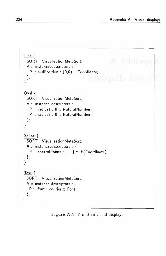
224 Appendix A. Visual displays
Line {SORT : VisualizationMetaSort; ./*,A :: instance-descriptors : {
P :: endPosition : (0,0) :: Coordinate;
}; - •• , ; v -j - • i -
Oval {SORT : VisualizationMetaSort;A :: instance-descriptors : {
P :: radiusl : 0 :: NaturalNumber;P :: radius2 : 0 :: NaturalNumber;
Spline {SORT : VisualizationMetaSort; .A :: instance-descriptors : {
P :: controlPoints : { - } : : P(Coordinate);
}
Text {SORT : VisualizationMetaSort;A :: instance-descriptors : {
P :: font : courier :: Font;
ft-
Figure A.I: Primitive visual displays.
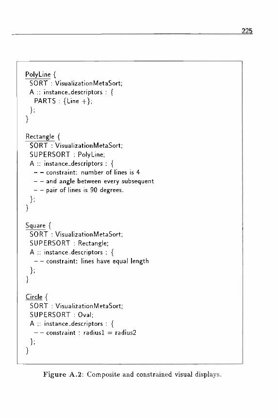
225
PolyLine {SORT : VisualizationMetaSort;A :: instance-descriptors : {
PARTS : {Line + } ;
Rectangle {SORT : VisualizationMetaSort;SUPERSORT : PolyLine;A :: instance-descriptors : {
— constraint: number of lines is 4and angle between every subsequent
— pair of lines is 90 degrees.
Square {SORT : VisualizationMetaSort;SUPERSORT : Rectangle;A :: instance-descriptors : {
— constraint: lines have equal length
Circle {SORT : VisualizationMetaSort;SUPERSORT : Oval;A :: instance-descriptors : {
— constraint : radiusl = radius2
Figure A.2: Composite and constrained visual displays.

226 Appendix A. Visual displays
f fliir
• » - • ' • •
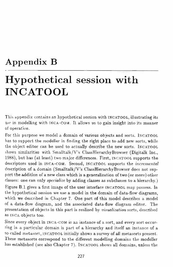
Appendix B
Hypothetical session withINCATOOL
This appendix contains an hypothetical session with INCATOOL, illustrating itsuse in modelling with INCA-COM. It allows us to gain insight into its mannerof operation.
For this purpose we model a domain of various objects and sorts. INCATOOL
has to support the modeller in finding the right place to add new sorts, whilethe object editor can be used to actually describe the new sorts. INCATOOLshows similarities with Smalltalk/V's ClassHierarchyBrowser (Digitalk Inc.,1988), but has (at least) two major differences. First, INCATOOL supports thedescriptors used in INCA-COM. Second, INCATOOL supports the increment/description of a domain (Smalltalk/V's ClassHierarchyBrowser does not sup-port the addition of a new class which is a generalization of two (or more) otherclasses: one can only specia/ize by adding classes as subclasses to a hierarchy.)Figure B.I gives a first image of the user interface INCATOOL may possess. Inthe hypothetical session we use a model in the domain of data-flow diagrams,which we described in Chapter 7. One part of this model describes a modelof a data-flow diagram, and the associated data-flow diagram editor. Thepresentation of objects in this part is realized by msua/zzah'em sorts, describedas INCA objects too.
Since every object in INCA-COM is an instance of a sort, and every sort occur-ring in a particular domain is part of a hierarchy and itself an instance of aso-called metasort, INCATOOL initially shows a survey of all metasorts present.These metasorts correspond to the different modelling domains the modellerhas established (see also Chapter 7). INCATOOL shows all domains, unless the
227
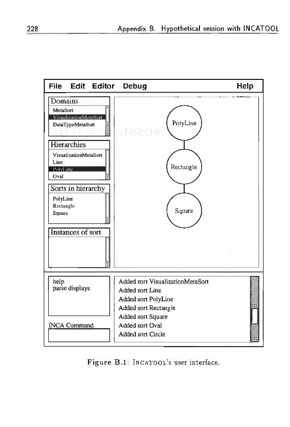
228 Appendix B, Hypothetical session with INCATOOL
File Edit Editor Debug Help
Domains
DataTypeMelaSort
Hierarchies
VisualizationMetaSortLine
Sorts in hierarchy
PolyLineRectangleSquare
Instances of sort
i •" •
helpparse displays
INCA Command
Added sort VisualizationMetaSort
Added sort Line
Added sort PolyLine
Added sort Rectangle
Added sort Square
Added sort Oval
Added sort Circle -- . . - .
Figure B.I: INCATOOL'S user interface.
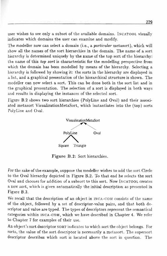
222
user wishes to see only a subset of the available domains. INCATOOL visuallyindicates which domains the user can examine and modify.The modeller now can select a domain (i.e., a particu/ar metasort), which willshow all the names of the sort hierarchies in the domain. The name of a sorthierarchy is determined uniquely by the name of the top sort of the hierarchy:the name of this (op sor( is characteristic for the modelling perspective fromwhich the domain has been modelled by means of the hierarchy. Selecting ahierarchy is followed by showing it: the sorts in the hierarchy are displayed ina list, and a graphical presentation of the hierarchical structure is shown. Themodeller can now select a sort. This can be done both in the sort list and inthe graphical presentation. The selection of a sort is displayed in both waysand results in displaying the instances of the selected sort.
Figure B.2 shows two sort hierarchies (PolyLine and Oval) and their associ-ated metasort VisualizationMetaSort, which instantiates into the (top) sortsPolyLine and Oval.
VisualizationMetaSort
7\Square Triangle
Figure B.2: Sort hierarchies.For the sake of the example, suppose the modeller wishes to add the sort Circleto the Oval hierarchy depicted in Figure B.2. To that end he selects the sortOval and chooses for addition of a subsort to this sort. Now INCATOOL createsa new sort, which is given automatically the initial description as presented inFigure B.3.
We recall that the description of an object in INCA-COM consists of the nameof the object, followed by a set of descriptor-value pairs, and that both de-scriptor and value are typed. The types of descriptors represent the semanticalcategories within INCA-COM, which we have described in Chapter 4. We referto Chapter 7 for examples of their use.
An object's sort descriptor SORT indicates to which sort the object belongs. Forsorts, the value of the sort descriptor is necessarily a metasort. The supersortdescriptor describes which sort is located above the sort in question. The
230 Appendix B. Hypothetical session with INCATOOL
CircleSORT: VisualizationMetaSort;SUPERSORT: Oval;A ::
P :BP :P :
instance-descriptors: {: location : - :: Coord; - -: Draw : ... ;: radiusl : _ :: Real;: radius2 : _ :: Real;
fromfromfromfrom
VisualizationMetaSort L''. : ^' •'VisualizationMetaSort . ?.. ' >.: . .supersort . . ,_;,;supersort . . . , .
• • ' i "
Figure B.3: The sort Circle.
attribute (A) named INSTANCE_DESCRIPTORS is used only for the descriptionof sorts and indicates the descriptors which the instances of the sort Circle willhave. In this case, a circle will have a property location, a behaviour Draw,and two properties, radiusl and radius2.
The modeller now has to indicate in what ways the sort Circle differs fromits supersort Oval. The sort Circle differs from Oval in its constraint on theproperties radiusl and radius2: a circle has two equal radiuses. The modellercan specify this by constraining the value of radius2 to be equal to the valueof radiusl. Such a constraint is expressed in a /au; attached to radius2, suchthat the values of both radiuses are always equal.
The above example shows the creation of a subsort by constraining f/ie ua/ue ofone of its descriptors. In this case, the values of two descriptors are linked byputting them on a par. In addition, a subsort can be specified by constrainingthe ua/ue domain of a descriptor. It is not possible to create a subsort whichhas a broader value domain. If such is the case, the modeller possibly shouldexchange the subsort and supersort.
Besides specialization by constraining f/ie ua/ue domain of descriptors, there isa second way of specializing sorts. It consists of the addition of descriptors tothe description of a sort. For example, the modeller can specify a subsort ofCircle, called LabelledCircle, which adds a text string to supply a circle witha label. Such a labelled circle can be used for example for the visualizationof processes in a data-flow diagram. The specification of such a subsort isdone in an analogous way as described above, taking into account that a newdescriptor is being added. Of course, it is also possible to create subsorts which
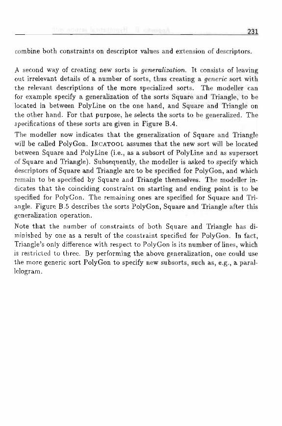
combine both constraints on descriptor values and extension of descriptors.
A second way of creating new sorts is jenera/izafo'on. It consists of leavingout irrelevant details of a number of sorts, thus creating a generic sort withthe relevant descriptions of the more specialized sorts. The modeller canfor example specify a generalization of the sorts Square and Triangle, to belocated in between PolyLine on the one hand, and Square and Triangle onthe other hand. For that purpose, he selects the sorts to be generalized. Thespecifications of these sorts are given in Figure B.4.
The modeller now indicates that the generalization of Square and Trianglewill be called PolyGon. INCATOOL assumes that the new sort will be locatedbetween Square and PolyLine (i.e., as a subsort of PolyLine and as supersortof Square and Triangle). Subsequently, the modeller is asked to specify whichdescriptors of Square and Triangle are to be specified for PolyGon, and whichremain to be specified by Square and Triangle themselves. The modeller in-dicates that the coinciding constraint on starting and ending point is to bespecified for PolyGon. The remaining ones are specified for Square and Tri-angle. Figure B.5 describes the sorts PolyGon, Square and Triangle after thisgeneralization operation.
Note that the number of constraints of both Square and Triangle has di-minished by one as a result of the constraint specified for PolyGon. In fact,Triangle's only difference with respect to PolyGon is its number of lines, whichis restricted to three. By performing the above generalization, one could usethe more generic sort PolyGon to specify new subsorts, such as, e.g., a paral-lelogram.
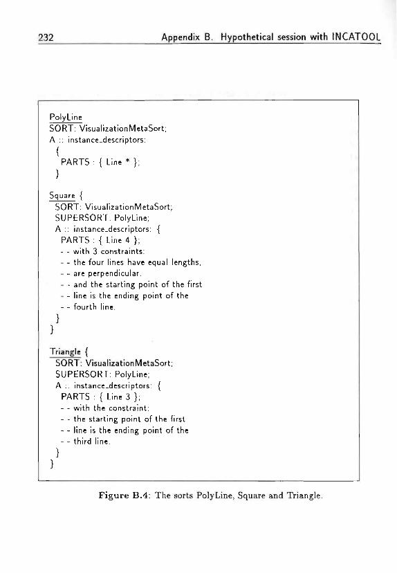
232 Appendix B. Hypothetical session with INCATOOL
PolyLineSORT: VisualizationMetaSort;A :: instance-descriptors:
{PARTS : { Line * };
Square {SORT: VisualizationMetaSort;SUPERSORT: PolyLine;A :: instance-descriptors: {
PARTS : { Line 4 };- - with 3 constraints:- - the four lines have equal lengths,- - are perpendicular,- - and the starting point of the first- - line is the ending point of the- - fourth line.
Triangle {SORT: VisualizationMetaSort;SUPERSORT: PolyLine;A :: instance-descriptors: {
PARTS : { Line 3 };- - with the constraint:- - the starting point of the first- - line is the ending point of the- - third line.
Figure B.4: The sorts PolyLine, Square and Triangle.
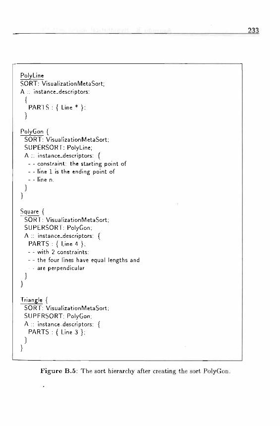
233
PolyLineSORT: VisualizationMetaSort;A :: instance-descriptors:
{PARTS : { Line * };
PolyGon {SORT: VisualizationMetaSort;SUPERSORT: PolyLine;A :: instance-descriptors: {
- - constraint: the starting point of- - line 1 is the ending point of- - line n.
Square {SORT: VisualizationMetaSort;SUPERSORT: PolyGon;A :: instance-descriptors: {
PARTS : { Line 4 };- - with 2 constraints:- - the four lines have equal lengths and- - are perpendicular
Triangle {SORT: VisualizationMetaSort;SUPERSORT: PolyGon;A :: instance-descriptors: {
PARTS : { Line 3 };
Figure B.5: The sort hierarchy after creating the sort PolyGon.

234 Appendix B. Hypothetical session with INCATOOL
Glossary
active object an object which has an active role within an information sys-tem. Active objects perform a discourse on an object world among eachother by means of speech acts.
actor synonymous with active o6jec<.
application domain part of a UOD that is specific for an application.
attribute (a descriptor type). A contingent feature of an object when it playsa certain role in an application domain.
composite object an object composed of objects other than itself,
composition the set of component objects of a composite object.
conceptual model resulting model from conceptual modelling. In the modeltriangle, a conceptual model is a role of a conceptual system with respectto the three types of possible systems.
conceptual modelling the activity of formally describing some aspects ofthe physical and social world around us for purposes of understandingand communication.
conceptual object model conceptual model having objects as its primaryconcept.
conceptual schema Formal description which results from conceptual mod-elling (Mylopoulos, 1992).
conversation combination of different types of speech acts, by which meansactive objects perform a discourse, and by which active object may in-fluence each other.
235
236 Glossary
description Annotation of an object, resulting from modelling. Consists ofa combination of a (typed) descriptor, and a (typed) value.
descriptor element of a description, used to designate the description.
descriptor type Type of a descriptor. INCA-COM contains six descriptortypes: property, attribute, relation, link, display, and version. The setof available descriptor types may be extended by a modeller.
display (a descriptor type). A display describes how an object manifestsitself, e.g., by means of a visual presentation, a textual presentation, oraudible presentation.
empirical model resulting model from empirical modelling. In the modeltriangle, an empirical model is a role of a concrete system with respectto the three types of possible systems. An example of an empirical modelis a simulation of a logistics system.
entity substantial individual, something which exists.
extension the set of objects denoted by a token (or belonging to a sort inINCA-COM).
formal model resulting model from formal modelling. In the model triangle,a formal model is a role of a formal system with respect to the three typesof possible systems.
illocutionary act Type of speech act, in which a speaker expresses her/hisintention, by means of an illocutionary force, which includes an illocu-tionary point.
illocutionary point intention of an illocutionary act. There are five illocu-tionary points: (1) assertive or descriptive; (2) commissive; (3) directive;(4) declarative; and (5) expressive.
INCA Abbreviation of iNtelligent CASE. Refers to a next generation of CASE
tools, based on a formally defined conceptual model of an informationsystem. The two main goals of an INCA environment are (1) to fur-nish a representation system for capturing the real world in which a(future) information system is to be employed, and (2) to offer conceptsfor modelling and constructing information systems, in terms of the rep-resentation of (1).
Glossary 237
INCA-COM Abbreviation of iNtelligent CASE Conceptual Object Model.INCA-COM has been designed with the purpose of providing a concep-tually rich basis for the modelling of information systems, in order toenable a modeller to express a model in a natural way (i.e., with conceptsbeing used by humans, not by computers).
information system An ensemble of information and information process-ing agents, humans or machines.
intension the concept being designated by a token, i.e., the meaning of atoken.
interface part of an object which defines the operations other objects mayinvoke, and which parameters must be provided.
link (a descriptor type). A contingent association of an object with anotherobject, when the object is playing a role.
meaning triangle A way of visualizing the relations between tokens (sym-bols), concepts, and things (objects). A token designates a concept anddenotes a thing, and a concept refers to a thing. The relations in themeaning triangle are the basis for defining the concepts intension, ex-tension, re/erent, and population.
method a way of working in order to solve a problem.
methodology set of methods for solving a particular kind of problems (suchas system development). In Dutch there is a distinction between a'methodiek', standing for a set of methods for solving practical kindsof problems, and a 'methodologie', standing for the scientific knowledgeon which method to use.
model the notion of model is based on a relation between two different sys-tems: "someone, who uses a system M, which is independent of a system5, in order to understand system 5, uses system M as a model of sys-tem 5." There are three types of models: empirical models, consistingof concrete things, conceptual models, consisting of concepts, and formalmodels, consisting of uninterpreted syntactic symbols (forms).
model triangle way of visualizing the relations between the three differ-ent kinds of models, empirical model, conceptual model, and symbolicmodel.

238 Glossary
modeller anyone who is modelling. Programmers, designer, analysts are con-sidered to be modellers. '
modelling the process of (1) determining a system in the problem domain;(2) determining an aspect system of the system; and (3) finding an iso-morphic transformation (translation) of the aspect system into a modelsystem.
object In object-oriented programming: an encapsulated combination of dataand procedures that act upon the data. The data form the state ofthe object, the procedures are the operations other objects may invokethrough the object's interface.In INCA-COM: an individual concept with an own identity. An objecthas a set of descriptions. Every object has a unique name. An object
• ,: o is formalized as a tuple (n, J9(n)), in which n is the object name, and.D(ft) the set of descriptions of n.
object model An o6/ec£ mode/ (OM) defines the conceptual entities that canbe used for the object-oriented modelling of an application domain orUOD.
object-oriented model An object-oriented model is the result of expressinga particular domain using the concepts offered by an object model.
object world Conceptualization of a UOD in terms of concepts offered byobject orientation (objects).
ontology the set of concepts to be used when modelling with INCA-COM.More generally, an ontology defines the basic concepts for modelling adomain.
passive object an object which has a passive role within an informationsystem. A passive object is a representation of a thing in the UOD of aninformation system.
property (a descriptor type). An essential feature of an object, meaning thatthe object has the property in every possible application.
protocol A typical interaction sequence between two or more objects. Aprotocol has a dynamic nature, as opposed to an interface, which isstatic.
Glossary 239
relation (a descriptor type). An essential association between objects, with-out which the description of the objects is not complete.
role when an object plays another object in an application domain, it has arole in the application domain.
sort A sort represents a concept which can be instantiated. A sort acts as asemantical primitive, and allows its instances to receive an initial set ofdescriptions.
speech act minimal unit of human communication. One type of speech actis the i7/ocuhonarj/ ac£. In speech act theory any utterance of a sentencehas a proposifaona/ conteni and an tV/ocufo'onarj/ /orce.
speech act theory theory of communication between people, stating thatcommunication is not only a means for spreading information, but alsoa way of acting (Searle, 1969; Searle and Vanderveken, 1985). Commu-nication consists of sequences of speech acts.
symbolic model See formal model.
system object with a composition (the set of component objects), a structure(the relations between the component objects, and the relations betweenthe component objects and objects in the environment), and an environ-ment (the objects not contained in the system, but having relations withcomponents in the system).
thing ontological term for a substantial individual together with its proper-ties.
Universe of Discourse see UOD.
UOD The UOD of an information system consists of the things in a partic-ular domain, about which people in the information system perform ameaningful discourse.
version (a descriptor type). A version is a variation of an object.
world core of the representation of a UOD containing natural sorts, beingrepresentations of concepts which can be reused in different applicationdomains.

240
' - • ' . ' - i
Glossary
!•< s j ;
• ' ' I ' J J - . , > f f t ; ' ; • ' • ':•••: ' :' •.'.- S ;
/•= * - ; ; . ' ; . - . ; . . '
$ > • ; . .
References
The numbers between parentheses after each entry refer to the pages on whicha reference to the entry in question occurred.
Abbott R. J. (1987). Knowledge Abstraction. Communications of the ACM,Vol. 30, No. 8, pp. 664-671. (65)
ACM (1958). Table of automatic programming systems. Communications ofthe ACM, Vol. 1, No. 4, p. 8. (28)
ACM (1991). Special issue on next-generation database systems. Communi-cations of the ACM, Vol. 34, No. 10, pp. 31-120. (61)
ACM (1993). Discussion on concept-oriented view and program-oriented view.Communications of the ACM, Vol. 36, No. 1, p. 112. (44)
Aho A. V., Sethi R., and Ullman J. D. (1986). Compi/ers: Princip/es, Tech-niques, and Too/s. Addison-Wesley, Reading, Massachusetts. (20)
Alderson A. (1989). Current Approaches to Configuration Management. EspritMACS project, document number MCSS0006. (155)
America P. (1987). Inheritance and Subtyping in a Parallel Object-OrientedLanguage. Proceedings of the European Conference on Object-Oriented Pro-gramming (Bezivin et al., J987J, pp. 234-242. (44)
Andrews T. and Harris C. (1987). Combining Language and Database Ad-vances in an Object-Oriented Development Environment. Proceedings of theSecond ACM Conference on Object-Oriented Programming Systems, Lan-guages and Applications (Meyrowitz, i987j, pp. 430-440. Reprinted in Zdonikand Maier (1990). (61)
241
242 References
Apostel L. (1960). Towards a formal study of models in the non-formal sci-ences. Synthese, Vol. 1960, No. 12, pp. 125-161. (55)
Bailin S. C. (1989). An Object-Oriented Requirements Specification Method.Communications of the ACM, Vol. 32, No. 5. (66)
Bakker H. and Braspenning P. J. (1991a). Geautomatiseerde ondersteuningvan object-georienteerd modelleren. Proceedings AJToepassingen '9J (eds.B. R. van der Spek and J. Treur). Nederlandse Vereniging voor KunstmatigeIntelligence. In Dutch. (195)
Bakker H. and Braspenning P. J. (1991b). Modelling Objects using the INCAConceptual Object Model. Proceedings of Techno/ogy of Object-Oriented Lan-guages and Systems (Meyer and flezivin, i99ij, pp. 175-186. (169)
Bakker H. and Braspenning P. J. (1992). An Object-Oriented Model ofa Spreadsheet. Proceedings of the European Simulation Symposium (eds.W. Krug and A. Lehmann), pp. 193-197, San Diego, California. Society forComputer Simulation International. (183)
Bakker H., Leeuwen L.C.J. van, Braspenning P. J., and Uiterwijk J. W. H. M.(1990). Version Management of Composite Instantiated Objects. Proceedingsof the European Simu/ation Mu/ticonference (ed. B. Schmidt), pp. 93-98, SanDiego, California. The Society for Computer Simulation International. (151)
Bakker H., Braspenning P. J., and Vassilev V. (1992). De ontologie en generie-ke kenmerken van een object-georienteerde taal voor kennisgebaseerde analyseen ontwerp. Proceedings NA/C '92 (eds. H. de Swaan Arons, H. Koppelaar,and E. J. H. Kerckhoffs), pp. 117-128. Nederlandse Vereniging voor Kunst-matige Intelligence. In Dutch. (195)
Bancilhon F., Barbedette G., Benzaken V., Delobel C, Gamerman S., LecluseC , Pfeffer P., Richard P., and Velez F. (1987). The Design and Implementationof O2, an Object-Oriented Database System. Advances in Object-OrientedDatabase Systems (Dittrich, J9S7J, pp. 1-22. (61)
Banerjee J. and Kim W. (1987). Semantics and Implementation of SchemaEvolution in Object-Oriented Databases. Proceedings of the ACM S/GMODConference on the Management of Data, pp. 311-322. (61)
Barstow D., Shrobe H., and Sandewall E. (eds.) (1984). Interactive Program-ming Environments. McGraw-Hill, New York, New York. (253)
References 243
Bezivin J., Hullot J.-M., Cointe P., and Lieberman H. (eds.) (1987). Proceed-ings of the European Conference on Object-Oriented Programming. Springer-Verlag, Berlin, Germany. (241,251) . . , . . , .-,.•:••
Birtwistle G. M., Dahl 0-J., Myhrhaug B., and Nygaard K. (1977). SimulaBegin. Studentlitteratur, Lund, Sweden. (36,62)
Bjornerstedt A. and Hulten C. (1989). Version Control in an Object-OrientedArchitecture. Object-Oriented Concepts, Databases, and Applications (Aimand Lochovsky, 1989), pp. 451-485. (151)
Bobrow D. G. and Collins A. (eds.) (1975). Representation and [/nderst an ding(Studies in Cognitive Science). Academic Press, New York, New York. (253)
Bobrow D. G. and Stefik M. (1983). The LOOPS Manuai. Xerox Palo AltoResearch Centre. (132)
Boehm B. W. (1981). Software Engineering Economics. Prentice-Hall, Engle-wood Cliffs, New Jersey. (68)
Boehm B. W. (1988). A Spiral Model of Software Development and En-hancement. Software Engineering Project Management. In Thayer (1988),pp. 128-142. (8, 15)
Booch G. (1991). Object-oriented design with applications. Benjamin Cum-mings, Englewood Cliffs, New Jersey. (22, 31, 37, 64, 66)
Borgida A., Mylopoulos J., and Wong H. K. T. (1984). Generalization /specialization as a basis for software specification. On Conceptua/ Model/ing(Brodie et al., 1984J, pp. 87-114. (61)
Borning A. H. (1981). The Programming Aspects of ThingLab, a Constraint-oriented Simulation Laboratory. ACM Transactions on Programming Lan-guages and Systems, Vol. 3, No. 4, pp. 353-387. (133)
Brachman R. J. and Levesque H. J. (eds.) (1985). Readings in KnowledgeRepresentation. Morgan Kaufmann, Los Altos, California. (253)
Brachman R. J. and Schmolze J. G. (1985). An Overview of the KL-ONEKnowledge Representation System. Cognitive Science, Vol. 9, pp. 171-216.(61, 207)

244 References
Braspenning P. J. (1989a). A Framework for Modelling Complex Objects.Proceedings of Jfierarchica/ Object-Oriented Design, Brunei Science Park,Uxbridge, England. UNICOM Seminars Ltd. (196)
Braspenning P. J., Uiterwijk J. W. H. M., Bakker H., and Leeuwen L. C. J. van(1989b). Conceptual Tools for Modelling Complex Objects. Proceedings oftiie European Simuiation Mu/ticonference (eds. G. Iazeolla, A. Lehmann, andH. J. van den Herik), pp. 256-262, San Diego, California. The Society forComputer Simulation International. (37,68)
Braspenning P. J. (1990). A Reflexive Representation System for Objects. Pro-ceedings of the i 990 Summer Computer Simuiation Conference (eds. B. Svrcekand J. McRae), pp. 854-859, San Diego, California. The Society for ComputerSimulation International. (201, 207)
Briot J.-P. and Cointe P. (1987). A Uniform Model for Object-Oriented Lan-guages using the Class Abstraction. Proceedings JJCA/ '87, pp. 40-43. (117)
Brodie M. L., Mylopoulos J., and Schmidt J. W. (eds.) (1984). On ConceptuaiModei/ing, Perspectives from Artificiai Jnteiiigence, Databases, and Program-ming Languages. Springer Verlag, New York, New York. (61, 243)
Brooks F. P. (1975). The Mythica/ Man-Month. Addison-Wesley, Reading,Massachusetts. (9)
Brooks F. P. (1987). No Silver Bullet: Essence and Accidents of SoftwareEngineering. JEEE Computer, Vol. 20, No. 4, pp. 10-19. (9, 11)
Brussaard B. K. and Tas P. A. (1980). Information and Organization Policiesin Public Organization. Information Processing 80 (ed. S. H. Lavington),Amsterdam, The Netherlands. North-Holland. (5, 6)
Bunge M. (1974). Treatise on Basic Phiiosophy, Semantics 7: Sense and .Ref-erence. Reidel, Boston, Massachusetts. (52)
Bunge M. (1977). Treatise on Basic Phiiosophy, Onto/ogy /: The Furnitureof the Wbrid. Reidel, Boston, Massachusetts. (71, 72, 81, 94, 112, 121, 133,134)
Bunge M. (1979). Treatise on Basic Phiiosophy, Ontoiogy //: A Wbrid ofSystems. Reidel, Boston, Massachusetts. (112, 113)
References 245
Chen P. P. (1976). Entity-Relationship Model: Toward a Unified View ofData. ACM Transactions on Database Systems, Vol. 1, No. 1, pp. 9-36. (18,61)
Coad P. and Yourdon E. (1991). Object-oriented anaiysis (second edition).Prentice Hall, Englewood Cliffs, New Jersey. (66)
Codd E. F. (1979). Extending the database relational model to capture moremeaning. ACM Transaction on Database Systems, Vol. 4, No. 4, pp. 397-434.(61)
Cointe P. (1987). Metaclasses are First Class: the ObjVlisp Model. Pro-ceedings of the Second ACM Conference on Object-Oriented ProgrammingSystems, Languages and Applications (Meyrowitz, 2987), pp. 156-167. (117)
Cox B. J. (1987). Object-Oriented Programming-An Evo/utionary Approach.Addison-Wesley, Reading, Massachusetts. (35, 36, 47, 65, 128)
Dart S. A., Ellison R. J., Feiler P. H., and Habermann A. N. (1987). SoftwareDevelopment Environments. IEEE Computer, Vol. 20, No. 11, pp. 18-28.(26) . .
DeMarco T. (1979). Structured Ana/ysis and System Specification. Prentice-Hall, Englewood Cliffs, New Jersey. (18, 66, 169, 170)
DeRemer F. and Kron H. (1975). Programming in the large versus program-ming in the small. IEEE Transactions on Software Engineering, Vol. 1, No. 1.(9)
Dietz J. L. G. (1987). Mode/ieren en specificeren van Jnformatiesystemen.PhD thesis, Technische Universiteit, Eindhoven, The Netherlands. In Dutch.(55, 56)
Dietz J. L. G. (1992a). LeerboeA' JnformatieAundige Ana/yse. Kluwer, Deven-ter, The Netherlands. In Dutch. (19, 112)
Dietz J. L. G. (1992b). Subject-oriented modelling of open active systems.Technical report, Limburg University, Faculty of Economics, Maastricht, TheNetherlands. ISSN 0926-9878. (84, 86, 104, 107, 109, 111, 113)
Digitalk Inc. (1988). Smaiita/A'/V 286: Tutoria/ and Programming Handbook.Digitalk Inc., Los Angeles, California. (227)
246 References
Dijkstra E. W. (1968). Go To Statement Considered Harmful. Communica-tions of the ACM, Vol. 11, No. 3, pp. 147-148. (67) A, . , , ; , ,
Dittrich K. R. (ed.) (1987). Advances in Object-Oriented Database Systems.Springer-Verlag, Berlin. Lecture Notes in Computer Science, number 334.(242) . . . . . . . . . . , , „ . . „ „
Etherington D. W. and Reiter R. (1985). On Inheritance Hierarchies withExceptions. .Readings in Know/edge Representation, pp. 329-334, Los Altos,California. Morgan Kaufmann. Reprint of article in Proc. AAAI-83, Washing-ton D.C.,pp. 104-108. (129)
Evans M. W. (1989). The Software Factory. John Wiley and Sons, New York,New York. (7)
Ferber J. (1989). Computational Reflection in Class-based Object-orientedLanguages. Proceedings of the Second ACM Conference on Object-OrientedProgramming Systems, Languages and Applications (Meyrowitz, J9<S9 ), pp.317-326. (202)
Fiadeiro J., Sernadas C , Maibaum T., and Sernadas A. (1992). Describingand Structuring Objects for Conceptual Schema Development. ConceptualModei/ing, Databases, and CASE (Xoucopouios and Zicari, J992J, pp. 117—138. (69)
Fichman R. G. and Kemerer C. F. (1992). Object-Oriented and ConventionalAnalysis and Design Methodologies. LEEE Computer, Vol. 25, No. 10, pp.22-39. (66)
Fishman D. H., Beech D., Cate H. P., Chow E. C , Connors T., Davis J. W.,Derrett N., Hoch C. G., Kent W., Lyngbaek P., Mahbod B., Neimat M. A.,Ryan T. A., and Shan M. C. (1987). Iris: An Object-Oriented Database Man-agement System. ACM Transactions on Office /nformation Systems, Vol. 5,No. 1, pp. 48-69. Reprinted in Zdonik and Maier (1990). (61)
Gane C. and Sarson T. (1979). Structured Systems Analysis. Prentice-Hall,Englewood Cliffs, New Jersey. (18)
Gibson M. L. (1989). The CASE Philosophy. Byte, Vol. 14, No. 4, pp. 209-218.(27)
Goldberg A. and Robson D. (1983). Sma//ta/fc-S0: The Language and itsimplementation. Addison-Wesley, Reading, Massachusetts. (36)
References 247
Gorlen K. E., Orlow S. M., and Plexico P. S. (1990). Data Abstraction andObject-Oriented Programming in C++. John Wiley & Sons, Chichester, Eng-land. (24, 35)
Hammer M. and McLeod D. (1981). Database description with SDM: A se-mantic database model. ACM Transaction on Database Systems, Vol. 6, No. 3,pp. 351-386. Reprinted in Zdonik and Maier (1990). (61)
Hofstadter D. R. (1979). Godel, Escher, Bach: An Eterna/ Go/den Braid.Basic Books, New York. (40)
In 't Veld J. (1981). Anaiyse van Organisatieprobiemen: Een toepa.ssing vandenA'en in systemen en processen. Elsevier, Amsterdam, The Netherlands. InDutch. (55)
Jackson M. A. (1983). System Development. Prentice-Hall, Englewood Cliffs,New Jersey. (18, 19, 66)
Joseph H. W. B. (1916). An /ntroduction to Logic. Clarendon Press. (121)
Kaiser G. E. and Habermann A. N. (1983). An Environment for System Ver-sion Control. Digest of Papers Spring CompCon, pp. 415-420. Also appearedas Tech. Rep., Dept. of Comp. Science, Carnegie-Mellon University, Nov. 1982.(152)
Kay A. C. (1977). Microelectronics and the Personal Computer. ScientificAmerican, Vol. September, pp. 231-244. (45)
Kernighan B. W. and Pike R. (1984). The [/nix Programming Environment.Prentice-Hall, Englewood Cliffs, New Jersey. (26)
Kim W. and Lochovsky F. H. (eds.) (1989). Object-Oriented Concepts,Databases, and Applications. ACM Press, New York, New York. (243, 249,252)
Kim W., Banerjee J., Chou H.-T., Garza J. F., and Woelk D. (1987). Com-posite Object Support in an Object-Oriented Database System. Proceedingsof the Conference on Object-Oriented Programming Systems, Languages andApplications (Meyrowitz, i9S7j, pp. 118-125. (61, 133, 155, 161)
Kim W., Bertino E., and Garza J.F. (1989). Composite Objects Revisited.Proceedings of the ACM S/GMOD Conference on the Management of Data,pp. 337-347. (61)
248 References
Kramer N. J. T. A. and De Smit J. (1987). Sys teem den A'en. Stenfert Kroese,Leiden, The Netherlands. In Dutch. (56)
Kristensen B. B. and 0sterbye K. (1991). Conceptual Modeling and Program-ming. Technical report, Institute for Electronic Systems, Aalborg, Denmark.ISSN 0106-0791. (71)
Lenat D. B., Guha R. V., Pittman K., Pratt D., and Shepherd M. (1990).Cyc: Toward Programs With Common Sense. Communications of the ACM,Vol. 33, No. 8, pp. 30-49. (68, 121, 199)
Lieberman H. (1986). Using Prototypical Objects to Implement Shared Be-haviour in Object-Oriented Systems. Proceedings of the First ACM Confer-ence on Object-Oriented Programming Systems, Languages and Appiications.(41,42) ^
Loucopoulos P. and Zicari R. (eds.) (1992). Conceptual Modeling, Databases,and CASE. John Wiley and Sons, New York, New York. (246, 248, 249, 250)
Loucopoulos P. (1992). Conceptual Modelling. Conceptuai Modeling,Databases, and CASE (Xoucopou/os and Zicari, I992J, pp. 1-26. (61)
Macdonald I. (1986). Information Engineering - An improved, automatablemethodology for designing data sharing systems, information System Method-ologies: improving the practice (O//e et al., i986"). (18)
Maes P. (1987). Concepts and Experiments in Computational Reflection. Pro-ceedings of the Second ACM Conference on Object-Oriented ProgrammingSystems, La;iguages and App/ications (Meyrowitz, J987J, pp. 147-155. (202)
Maier D. and Stein J. (1987). Development and Implementation of anObject-Oriented DBMS. .Research Directions in Object-Oriented Program-ming fShriver and Wegner, J987J, pp. 355-392. Reprinted in Zdonik andMaier (1990). (61)
March S. (ed.) (1988). Entity-ile/ationship Approach. North-Holland, NewYork. (18)
Martin J. (1990). Information Engineering, BooA's J, /J, and ///. Prentice Hall,Englewood Cliffs, New Jersey. (66)
Mcllroy D. (1968). Mass-produced software components. Proceedings NATOConference on Software Engineering. In Naur and Randell (1968). (47)
References 249
Meyer B. and Bezivin J. (eds.) (1991). Proceedings of Technology of Object-Oriented Languages and Systems. Prentice-Hall, Hemel Hempstead, UnitedKingdom. (242)
Meyer B. (1988). Object-Oriented Software Construction. Prentice-Hall, NewYork, New York. (24, 36, 47, 86, 105, 128)
Meyrowitz N. (ed.) (1987). Proceedings of the Second ACM Conference onObject-Oriented Programming Systems, Languages and Applications. Asso-ciation for Computing Machinery, New York, New York. Appeared as SpecialIssue of SIGPLAN Notices, Vol. 22, No. 10. (241, 245, 247, 248, 251, 253)
Meyrowitz N. (ed.) (1989). Proceedings of the ACM Conference on Object-Oriented Programming Systems, Languages and Appiications. Association forComputing Machinery, New York, New York. Appeared as Special Issue ofSIGPLAN Notices, Vol. 24, No. 10. (246)
Minsky M. (1975). A Framework for Representing Knowledge. The Psycho/ogyof Computer Vision (ed. P. H. Winston), New York, New York. McGraw Hill.(2)
Minsky M. (1981). A Framework for Representing Knowledge. Mind Design:Phiiosophy, Psychology, Artificia/ Jnte/iigence (ed. J. Haugeland), pp. 95-128,Montgomery. Bradford Books. (2)
Moon D. A. (1989). The COMMON LISP Object-Oriented Programming Lan-guage Standard. Object-Oriented Concepts, Databases, and Applicationsftfim and Lochovsfcy, i989j, pp. 49-78. (36, 130)
Mylopoulos J. (1992). Conceptual Modelling and Telos. Conceptua/ Modei/ing,Databases, and CASE (Xoucopouios and Zicari, i992), pp. 49-68. (60, 61,207, 235)
Naur P. and Randell B. (1968). Proceedings NATO Conference on SoftwareEngineering. NATO, Scientific Affairs Division, Brussels, Belgium. (7, 248)
Nijssen G. M. (1989). Gronds/agen van Bestuur/ijA'e /nformatiesystemen. Ni-jssen Adviesbureau voor Informatica, Slenaken, The Netherlands. In Dutch.(10, 18, 19, 85,215)
Nygaard K. (1986). Basic Concepts in Object-Oriented Programming. S/G-PLAN Notices, Vol. 21, No. 10, pp. 128-132. (36)
250 References
Olle T. W., Sol H. G., and Verrijn-Stuart A. A. (eds.) (1986). informationSystem Methodologies: Improving the practice. IFIP-North Holland. (248)
Orr K., Gane C, Yourdon E., Chen P. P., and Constantine L. L. (1989).Methodology: The Experts Speak. Byte, Vol. 14, No. 4, pp. 221-233. (18)
Page-Jones M. (1980). The practicai guic/e to Structured Systems Design.Yourdon Press, New York, New York. (67)
Peckham J. and Maryanski F. (1988). Semantic Data Models. ACM Comput-ing Surveys, Vol. 20, No. 3, pp. 153-189. (61)
Perry D. E. (1987). Version Control in the Inscape Environment. Proceedingsof the IEEE 9th International Conference on Software Engineering, pp. 142-149, Washington, D.C. IEEE Computer Society Press. (151, 152)
Piaget J. (1972). The Psychology of Intelligence. Adams, Littlefield, USA.(188, 196)
Rich C. and Waters R. C. (eds.) (1986). Readings in Artificial Intelligence andSoftware Engineering. Morgan Kaufmann Publishers, Los Altos, California.(12,28,29)
Rich C. and Waters R. C. (eds.) (1990). The Programmer's Apprentice. ACMPress, Reading, Massachusetts. (29, 30)
Rolland C. and Cauvet C. (1992). Trends and Perspectives in ConceptualModelling. Conceptual Modelling, Databases, and CASE (Xoucopoulos andZicari, i992j, pp. 27-48. (61, 85)
Royce W. W. (1970). Managing the Development of Large Software Systems.Proceedings of IEEE WESCO1V. IEEE. Reprinted in Thayer (1988). (15)
Rumbaugh J., Blaha M., Premerlani W., Eddy F., and Lorensen W. (1991).Object-oriented modeling and design. Prentice Hall, London, United King-dom. (31, 37, 67, 85, 124, 128)
Saunders J. H. (1989). A Survey of Object-Oriented Programming Languages.Journal of Object-Oriented Programming, Vol. 1, No. 6, pp. 5-11. (62)
Searle J. R. and Vanderveken D. (1985). Foundations of Jllocutionary Logic.Cambridge University Press, Cambridge, United Kingdom. (62, 84, 107, 108,239)
References 251
Searle J. R. (1969). Speech Acts. An Essay in the Philosophy of Language.Cambridge University Press, Cambridge, United Kingdom. (19, 84, 107, 108,239)
Shipman D. W. (1981). The Functional Data Model and the Data LanguageDAPLEX. ACM Transactions on Database Systems, Vol. 6, No. 1, pp. 140-173.Reprinted in Zdonik and Maier (1990). (61)
Shlaer S. J. and Mellor S. J. (1988). Object-oriented systems ana/ysis: mod-eiing the worid in data. Yourdon Press, Englewood Cliffs, New Jersey. (66)
Shriver B. and Wegner P. (1987). Research Directions in Object-OrientedProgramming. MIT Press, Cambridge, Massachusetts. (248, 251, 253)
Simon H. A. (1986). Whether Software Engineering Needs to Be ArtificiallyIntelligent. IEEE Transactions on Software Engineering, Vol. 12, No. 7, pp.726-732. (28)
Snyder A. (1987). Inheritance and the Development of Encapsulated SoftwareComponents. Research Directions in Object-Oriented Programming fShriverand Wegner, J987J, pp. 165-188. (41, 128)
Sommerville I. (1992). Soft ware Engineering. Addison-Wesley, London, UnitedKingdom. 4th ed. (5, 8, 14, 19)
Sowa J. F. (1983). Conceptua/ structures: information processing in mind andmachine. Addison-Wesley, Reading, Massachusetts. (53)
Stefik M. and Bobrow D. G. (1985). Object-Oriented Programming: Themesand Variations. The A7 Magazine, Vol. 6, No. 4, pp. 40-62. (35, 132)
Stein L. A. (1987). Delegation is Inheritance. Proceedings of the SecondACM Conference on Object-Oriented Programming Systems, Languages andApplications fMeyrowitz, J987J, pp. 138-146. (42)
Stroustrup B. J. (1987). What is "Object-Oriented Programming"? Pro-ceedings of the European Conference on Object-Oriented Programming(Bezivin et al., J957 ), pp. 51-70, Berlin. (22)
Stroustrup B. (1991). The C++ Programming Language, second edition.AT&T Bell Telephone Laboratories. (36, 119, 130)
252 References
Tello E. R. (1989). Object-Oriented Programming for Artificial intelligence.Addison-Wesley. (127) . . , . . : . . - .
Thayer R. H. (ed.) (1988). Software Engineering Project Management. IEEEComputer Society Press, Washington. (243, 250)
Tomlinson C. and Scheevel M. (1989). Concurrent Object-Oriented Program-ming Languages. Object-Oriented Concepts, Databases, and App/ications(Kim and Lochovs/cy, J989), pp. 79-124. (45)
Touretzky D. S. (1986). The mathematics of inheritance systems. MorganKaufmann, Los Altos. (129)
Uiterwijk J. W. H. M. and Braspenning P. J. (1990). Specification and In-heritance in the INCA-COM. Proceedings of Software Engineering and itsApplications (ed. M. Galinier), pp. 889-901. (116)
Van de Weg R. L. W. and Engmann R. (1991). A Framework for Object-Oriented Information Systems Design. Proceedings of Computing Science inthe Netherlands J99i, pp. 600-616. (103, 113)
Van Griethuysen J. J. (ed.) (1982). Concepts and terminology for the Concep-tual Schema and the information Base. ISO. Report ISO TC97/SCS/WG3.(6)
Velho A. V. and Carapu?a R. (1992). SOM: A Semantic Object Model. To-wards an Abstract, Complete and Unifying Way to Model the Real World.Proceedings of the Third international WbrA'ing Conference on Dynamic Mod-eiiing of information Systems (eds. H. G. Sol and A. Verbraeck), pp. 65-93.Delft University of Technology. (113)
Wand Y. and Weber R. (1990). An Ontological Model of an InformationSystem. iEEE Transactions on Software Engineering, Vol. 16, No. 11, pp.1282-1292. (47)
Wand Y. (1989). A Proposal for a Formal Model of Objects. Object-OrientedConcepts, Databases, and Appiications (A'im and LochovsAy, J989J, pp. 537-559. (65, 112, 113, 134)
Warnier J.-D. (1976). Logicai Construction of Programs. Van Nostrand Rein-hold, New York, New York. (18)
References 253
Wegner P. (1987a). Dimensions of Object-Based Language Design. Proceed-ings of the Second ACM Conference on Object-Oriented Programming Sys-tems, Languages and Applications ("Meyrowitz, 1987), pp. 168-181. (24, 37)
Wegner P. (1987b). The Object-Oriented Classification Paradigm. ResearchDirections in Object-Oriented Programming (Shriver and Wegner, i987), pp.479-560. (43)
Wegner P. (1989). Learning the Language. Byte, Vol. 14, No. 3, pp. 245-253.(38)
Wieringa R. J. (1990). Algebraic Foundations for Dynamic Conceptual Mod-els. PhD thesis, Vrije Universiteit, Amsterdam, The Netherlands. (62, 72,73,87, 88,98,99, 112)
Wieringa R. J. (1991). Steps towards a method for the formal modeling ofdynamic objects. Data& Knowledge Engineering, Vol. 6, No. 6, pp. 509-540.
Winograd T. (1973). Breaking the Complexity Barrier (again). Proceedings ofthe ACM S/GPLAJV/S7GIR interface Meeting on Programming Languages -information .Retrieval, pp. 13-30. Reprinted in Barstow e< a/. (1984), pp.3-18.(26, 29)
Wintraecken J. J. V. R. (1985). Jnformatie-analyse volgens N/AM. AcademicService, Den Haag. In Dutch. (18)
Woods W. A. (1975). What's in a Link. Representation and UnderstandingBobrow and Collins (i975), pp. 35-82. Reprinted in Brachman and Levesque(1985), pp. 217-241. (89)
Yourdon E. and Constantine L. L. (1978). Structured Design. Yourdon Press,New York. (18, 67)
Zdonik S. B. and Maier D. (eds.) (1990). Readings in Object-OrientedDatabase Systems. Morgan Kaufmann, San Mateo, California. (241, 246,247, 248, 251)

254 ; References
. . : — • * •
Index
Symbols::, 79, 127, 143, 171
instance-descriptors, 173, 174,178,232
attributes, 37
A-composition, 137-138abstract data types, 38abstraction, 15-16abstractions, 12accommodation, 188, 193, 195-197active object, 84active-object system, 112, 141agenda, 105, 110analysis, 58, 60, 69analytical law, 98application, 57, 81application domain, 81, 83application domains, 32applications, 32architecture •
layered, 20partitioned, 20von Neumann, 22
artificial intelligence technique, 28-30
aspect system, 51assertive point, 108assimilation, 188, 193, 195-197attribute, 87-89, 171
Bbehaviour, 37, 104behavioural model, 85, 86, 103-107binding, 43-44
dynamic, 44static, 44
C++, 36, 44, 64, 130CASE,26-28class, 38-41class hierarchy, 38-41classification, 61, 71, 72, 119CLOS,36,130cohesion, 20commissive point, 108common description, 128common inheritance, 128, 173communication, 104, 107communication model, 85, 86, 107-
112complexity, 9-12
of development process, 14of existing information system,
14
255
256 Index
of software system, 14composite object, 47, 132, 134, 135composite version, 154, 155composition, 47, 61, 71, 74, 115,
132-141computational reflection, 202concept, 39conceptual
model, 67modelling, 60-71 ' 'object model, 67
conceptual model, 57 ' 'conceptual system, 55conceptual world, 82 oconceptual-model schema, 58, 60conceptual-model specification, 58conceptual-model specification lan-
guage, 58conceptualization, 57concrete system, 55concurrency, 45-46constructors, 48 'contingent feature, 83, 85conversations, 109coupling, 20
DData-Flow Diagram, 169data-flow diagrams, 18Data-Flow Model, 169, 174declarative, 109decomposition, 19-21, 37, 47, 71,
74delegation, 41-42demo, 109deontic law, 98, 100description, 77-80descriptive model, 62
descriptor, 78, 79, 87semantics, 205
descriptor domain, 195, 196descriptor reflection, 202-209descriptor system, 111descriptor type, 79, 86 7> Jk» * I idescriptor value, 78design, 58, 60, 69destructors, 48development model, 12difference, 74direction of fit, 62directive conversation, 109directive point, 108display, 93, 171, 174
visualization, 175dynamic law, 98
EEiffel, 36emergent feature, 136empirical law, 98empirical model, 56, 57employee modelling, 124encapsulation, 36, 37entity-relationship approach, 18essential feature, 85event, 95event model, 85, 86, 95-103event name, 96event type, 96existence law, 98expressive, 109extension, 55, 74, 80, 116
figure modelling, 122
Index 257
formal model, 58 % . • •>formal system, 55 ..formalization, 52, 58full instance name, 127 >'• • ipl-full sort name, 126 •fundamentum divisionis, 121 vfH.;future, 111 • d',
G ' . j .garbage collection, 48generalization, 38, 61, 71, 73, 189,
233genus, 74global law, 98group,135,138-139grouping, 61, 115, 132-141
information model, 85-95 •*; iu-Kinformation paradigm, 5, 84information system, 5-9informative conversation, 110inheritance, 41-42, 136 "inheritance mechanisms, 127-132instance, 38-41instance name, 127 ' 'x _of, 8 3 , 1 9 2 ' •'••"- '•
instantiation, 38-41, 71, 72institutional model, 63intelligent assistance, 29intension, 38, 55, 73, 74, 116interface, 20, 37interpretation, 68isomorphic, 51isomorphic transformation, 51
Hhereditary feature, 136hierarchical naming scheme, 126history, 111homomorphic transformation, 52
Jackson System Development, 18
Kknowledge representation, 61
identity, 37illocutionary acts, 108illocutionary force, 108INCA-COM, 32, 35, 77-114
attribute, 87display, 87link, 87property, 86relation, 87version, 87
INCATOOL, 195-216architecture, 212-215
individual, 39
Llanguage, 52
conceptual, 53non-symbolic, 52symbolic, 52
language reflection, 203law, 97law statement, 94, 97-103lawful state space, 94level
of specification, 5raising, 5
link, 89-93, 171
258 Index
• ; U
local law, 98 •*JV»»H.'••'• ''Loops, 117, 130 .'SV'7-
M " ' ' • " • ' ' ' ^
mapping, 57meaning triangle, 53, 55, 56memory management, 48-50message, 37, 42-43
asynchronous, 45new, 41synchronous, 45 ,,,,= , ,
meta model, 65 ,,...,•metaclass, 40metasort, 117, 172, 178method, 37, 42-43
dictionary, 39model, 15-19model triangle, 56, 58-60model types, 55-58modelling, 50-59multiple inheritance, 120, 131-132multiple supersorting, 120
Nname sort, 127natural objects, 83natural sorts, 83necessary truths, 99NIAM, 18normal description, 128normal inheritance, 128, 129, 173normative model, 63
object, 36, 77, 78construction, 48destruction, 48
f a c t o r y , 3 9 • • • ; . • • •
name, 77, 125-127warehouse, 39 •
object describing entity, 79object interface, 111object model, 64 ; , . .>•,;.object orientation
natural view of world, 1software engineering, 2
object world, 82, 111, 117, 140object-oriented
conceptual model, 67conceptual modelling, 35, 68-
71concurrent language, 45modelling, 35-75programming, 35-50
object-oriented database, 49object-oriented model, 65Objective-C, 36ontology, 195, 197, 199, 210
partjof, 135, 192partial object, 152passive object, 84persistence, 49population, 55postcondition, 96 >precondition, 96prescriptive model, 63primary object, 117, 118primary objects, 117process model, 12, 14
iteration, 15spiral, 15stagewise, 15
programming
Index 259
abstract data types, 23automatic, 28environment, 25evolution of abstraction, 22-24machine language, 22mathematical expression, 23modular, 23object-oriented, 24procedural, 23tools, 25
programming-in-the-large, 9programming-in-the-small, 9programming-language support, 21-
24property, 82, 87-89, 171protocol, 20, 37
Rreal system, 5realization, 57referent, 55reflection, 65relation, 83, 89-93, 171remote procedure call, 46
blocking, 46future, 46non-blocking, 46
representation, 37, 53, 68reuse, 47-48role, 83
semantic data model, 61semantic data models, 61semantics, 53simple object, 135Simula, 36, 62
simulation, 56, 68, 69Smalltalk, 44, 45, 64, 65, 117, 130Smalltalk-80, 36software crisis, 5-33 jsoftware engineering, 8software life cycle, 14, 69
analysis, 14design, 14implementation, 14operation, 15requirements specification, 14six stages, 14testing, 15
software system, 7software-development methodology,
12-21sort, 77, 80-81,116-119sort descriptor, 117sort hierarchies, 115sort hierarchy, 116-127
name of, 231top sort, 231
sort name, 126sort object, 117, 118specialization, 36, 38, 71, 73, 189specification, 115-127speech act, 109speech act theory, 84, 86, 107, 108speech acts, 19spreadsheet model, 183-193stage, 12-15state, 37, 94state space, 94static law, 98statutive conversation, 109structural description, 128structural inheritance, 128,129,173structure, 134
260 Index
Structured Analysis, 18 j^i:Structured Design, 18Structured Programming, 18stuctural reflection, 202subclass, 38-41 •• •
constraining superclass, 38extending superclass, 38
subsort, 119x _of, 83, 192 •.; -superclass, 38-41 ,supersort, 119system, 51, 134, 139-140
structure, 50system architecture, 19system with memory, 37
visualization, 229
wwaterfall model, 15world, 81
. ' . * • ' • --. ; 5 j . -
•. .-iV-.fi
* . * * < • • " > .
template, 39thing, 6, 71-72, 77third-generation computers, 7token, 52-59tool support, 25-30translation, 58typing, 43-44
uUniverse of Discourse, 6UOD, 6, 19, 31, 32, 40, 53, 58, 60-
64, 68-73
Vvalue domain
constraining a, 232value domain, 79version, 93-94, 151, 171, 190version management, 151-168version object, 153
Summary
This thesis describes research on object-oriented modelling of information sys-tems. Led by the wish to use object orientation during analysis and design,and to create the foundations for future intelligent CASE environments, Chap-ter 1 announces the development of the INCA Conceptual Object Model (INCA-
COM) as the goal of our research (CASE stands for Computer-Aided SystemsEngineering; INCA for INtelligent CASE). Chapter 2 introduces the software cri-sis, and describes the developments in software engineering for managing thecomplexity of systems development. Nowadays, object-oriented programminglanguages combine several important abstraction principles in programming,and CASE tools are currently widely available for aiding software engineersduring systems development.
To reach our goal we took the decision to base INCA-COM on object-orientedconcepts. The reason is twofold: object orientation has emerged in artificialintelligence as a knowledge-representation tool, and in programming as anevolution of different programming paradigms. The requirements for INCA-COM are that (1) the Universe of Discourse (UOD) of an information system canbe represented; (2) application domains can be represented; and (3) systemscan be modelled.
Chapter 3 assesses object-oriented modelling from both the programming andthe modelling perspective. The programming perspective shows that objectorientation combines different forms of abstraction, such as identity, state,behaviour, class, class hierarchies, and inheritance. The modelling perspectivesheds light on the use and nature of different types of model, i.e., concrete,conceptual, and formal models. Modelling a system consists of finding orconstructing an appropriate system that can act as a model for the systembeing modelled. As a case in point we mention that programming is a wayof conceptual modelling resulting in computer programs, i.e., models to beexecuted on a computer.
261
262 Summary
In Chapter 4 the concepts of object-oriented modelling are identified. Formodelling of information systems a conceptual framework consisting of threedistinct parts is described. First, things occurring in the UOD of an informationsystem are modelled by a core of objects belonging to so-called natura/ sorts.Second, objects in an application domain are modelled by describing ro/e sorts,i.e., sorts to be instantiated by applications. Third, the active part of aninformation system consists of active objects communicating with each otherabout things in the UOD and the roles these things are playing. Communicationbetween active objects is based on speech-act theory.
The models in the proposed framework are (1) the in/ormation mode/describ-ing the structure of information, including roles; (2) the euerat mode/describingwhich events can take place in the object world and which order is imposed onthese events; (3) the 6e/iawoura/ mode/ describing which objects are active bythe performance of particular actions, which give rise to events in the objectworld; and (4) the communication mode/ describing what interactions takeplace between active objects. The information model and the event model areused for modelling a passive object world, whereas the behavioural model andthe communication model are used for modelling a system of active objects.Such a division between a passive-object world and an active-object systemmay seem counterintuitive to the general idea of object orientation as a uni-fying and uniform concept. However, such a division is essential in modellinginformation systems: the nature of an information system entails that it con-tains a representation of a UOD. Although such represented objects can beactive in the real world, their representations are under the control of activeobjects within the information system. Modelling an information system withonly one type of object does not aid in developing a clear conceptual model.
Chapter 5 describes four structuring principles, in INCA-COM, for the domainof objects: sort hierarchies, specification, composition, and grouping. Thesestructuring principles are based on meaningful relations between objects andsorts. The inheritance mechanisms in INCA-COM are based on sort hierarchiesand specification. We have described three types of inheritance, namely com-mon inheritance, normal inheritance, and structural inheritance.A system is a composite object with a structure. In INCA-COM, active objectscommunicating among each other on an object world form an active-object sys-tem. We have illustrated the principles by modelling a conference-registrationsystem with associated application domain.
In Chapter 6 we introduce a version concept for INCA-COM, in order to allowobjects to evolve over time. We assess the problems in managing versions of
Summary 263
composite objects, and present algorithms for addition and deletion of versionsand parts of composite objects.
Chapter 7 presents the modelling of a domain of data-flow diagrams and Chap-ter 8 the modelling of a domain of spreadsheets.
Chapter 9 describes the architecture of INCATOOL to be used as a supportingtool during the modelling process with INCA-COM. The architecture is basedon the model for information systems presented in Chapter 4. The idea behindthe architecture is that INCATOOL is an information system having the conceptsin INCA-COM as its application domain. The representation of INCA concepts,in terms of the concepts themselves, is called an ontology. INCA-COM has beenextended with reflective capabilities. Two types of reflection are provided:structural reflection and descriptor reflection. The former consists of treatingsorts are objects, allowing them to be described in the same manner as normalobjects. The latter is a form of language reflection, treating descriptors asobjects. Thus, the modelling language can be extended with new descriptorsand new types of descriptors.
Chapter 10 concludes the thesis by evaluating how the requirements fromChapter 2 are met by INCA-COM. It is stressed that modelling of informationsystems requires a division between passive objects as representations of thingsin the UOD of an information system, and active objects as actors, controllingpassive objects in a purposeful manner. Both domains benefit from objectorientation, but they should not be intermingled.

264 Summary
• " = » « . - • • ? • : " - * < • ' • ! - i *
• : ' ; • . ! " :
.Vif
Samenvatting
Dit proefschrift beschrijft onderzoek naar object-georienteerd modelleren vaninformatiesystemen. Geleid door de wens om object-orientatie tijdens defasen analyse en ontwerp in te zetten en om de basis te leggen voor toekom-stige intelligente CASE-omgevingen, kondigt hoofdstuk 1 de ontwikkeling vanhet INCA Conceptueel Object Model (iNCA-COM) als het doel van het onder-zoek aan (CASE staat voor Computer-Aided Systems Engineering; INCA voorINtelligente CASE). Hoofdstuk 2 introduceert de software-crisis, en beschrijft deontwikkelingen in de software engineering voor het hanteren van de complex-iteit van systeemontwikkeling. Tegenwoordig combineren object-georienteerdeprogrammeertalen diverse belangrijke abstractieprincipes van programmeren,en CASE-tools zijn tegenwoordig beschikbaar ter ondersteuning van systeem-ontwikkeling.
Om ons doel te bereiken hebben we de beslissing genomen INCA-COM tebaseren op object-georienteerde concepten. De reden is tweevoudig: object-orientatie is ontwikkeld in de kunstmatige intelligentie als middel voor ken-nisrepresentatie, en in het programmeren als een combinatie van verschillendeabstractievormen. INCA-COM moet concepten bieden voor het modelleren van(1) het Universe of Discourse (UOD) van een informatiesysteem; (2) appli-catiedomeinen; en (3) een systeem.
In hoofdstuk 3 wordt object-georienteerd modelleren beschouwd vanuit hetprogrammeerperspectief en het modelleerprespectief. Het programmeerper-spectief toont dat object-orientatie verschillende abstractievormen combineert,zoals identiteit, toestand, gedrag, klassen, klassehierarchieen, en overerving.Het modelleerperspectief geeft inzicht in het gebruik en de aard van verschil-lende typen van modellen, te weten concrete, conceptuele en formele modellen.Het modelleren van een systeem komt er op neer een geschikt systeem te vin-den of te construeren dat als model van het te modelleren systeem kan dienen.Als voorbeeld noemen we dat programmeren een manier van conceptueel mo-
265
266 Samenvatting
delleren is die resulteert in computerprogramma's, ofwel modellen die dooreen computer kunnen worden uitgevoerd.
In hoofdstuk 4 zijn de concepten van object-georienteerd modelleren bepaald.Voor het modelleren van informatiesystemen beschrijft het hoofdstuk een con-ceptueel raamwerk bestaande uit drie onderdelen. Ten eerste worden entiteitenin het UOD van een informatiesysteem gemodelleerd door een kern van objectendie tot zogenoemde natuurlijke soorten behoren. Ten tweede worden objectenin een applicatiedomein gemodelleerd door rolsoorten te beschrijven. Dit zijnsoorten die door applicaties worden geinstantieerd. De kern en een appli-catiedomein vormen te zamen een objectenwereld die de representatie van eenUOD vormt. Ten derde bestaat het actieve deel van een informatiesysteem uitactieve objecten die onderling communiceren over de entiteiten in het UOD ende rollen die deze entiteiten spelen. De communicatie is gebaseerd op taalhan-delingstheorie (speech-acttheorie).
De modellen in het voorgestelde raamwerk zijn (1) het m/ormafiemode/waarmee de structuur van de informatie in een systeem wordt beschreven;(2) het <7e6euriemsmo</e/ waarmee de gebeurtenissen die in een objectenwereldkunnen plaatsvinden worden beschreven; (3) het gedragsroode/ waarmee wordtbeschreven welke objecten actief zijn en bepaalde acties uitvoeren, die resul-teren in gebeurtenissen in de objectenwereld; en (4) het commumcah'emocfe/waarmee wordt beschreven welke interacties er zijn tussen de actieve objecten.Het informatiemodel en het gebeurtenismodel worden gebruikt voor het mo-delleren van passieve-objectenwereld, en het gedragsmodel en het communi-catiemodel worden gebruikt voor het modelleren van een systeem van actieveobjecten. De splitsing tussen een passieve-objectenwereld en een actieve-objectensysteem lijkt in strijd met het algemene idee dat object-orientatie eenuniforme manier is om zowel gegevens als processen te modelleren. Toch is bijhet modelleren van een informatiesysteem een dergelijke splitsing essentieel.De aard van een informatiesysteem bepaalt dat zich in het informatiesysteemeen representatie bevindt van een UOD. Alhoewel dergelijke representatie-objecten actief kunnen zijn in de echte wereld, staat hun representatie onderbesturing van de actieve objecten in het informatiesysteem. Modelleren vaneen informatiesysteem met slechts een type van objecten is niet bevorderlijkvoor het ontwikkelen van een helder conceptueel model.
Hoofdstuk 5 beschrijft de vier structuringsprincipes in het domein van ob-jecten: de soorthierarchie, specificatie, compositie, en groepering. De struc-tureringsprincipes zijn gebaseerd op betekenisvolle relaties tussen objecten en
Samenvatting 267
soorten. De mechanismen voor overerving in INCA-COM zijn gebaseerd op soor-thierarchieen en specificatie. Er zijn drie typen van overerving onderscheiden,namelijk gemeenschappelijke, normale en structurele overerving.Een systeem is een composiet object met een bepaalde structuur. In INCA-COM vormen actieve objecten die met elkaar communiceren over een objecten-wereld een systeem van actieve objecten. De principes worden geillustreerddoor het modelleren van een conferentieregistratiesysteem met bijbehorendapplicatiedomein.
In hoofdstuk 6 introduceren we een versieconcept voor INCA-COM, om ob-jecten de mogelijkheid te geven in de tijd te veranderen. We behandelen deproblemen die optreden bij het beheren van versies van composiete objecten,en beschrijven algoritmen voor het toevoegen en verwijderen van versies endeelobjecten van composiete objecten.
Om de modelleerconcepten in INCA-COM te illustreren worden in het proef-schrift diverse voorbeelden gegeven. Hoofdstuk 7 presenteert het modellerenvan een domein van data-flow-diagrammen en hoofdstuk 8 het modelleren vaneen spreadsheet.
Hoofdstuk 9 beschrijft de architectuur van INCATOOL, een hulpmiddel bij hetmodelleren met INCA-COM. De architectuur is gebaseerd op het iNCA-modelvan een informatiesysteem. Het idee achter de architectuur is dat INCATOOLeen informatiesysteem is met de concepten uit INCA-COM als applicatiedomein.De representatie van iNCA-concepten, in termen van de concepten zelf wordteen ontologie genoemd. INCA-COM is uitgerust met twee mogelijkheden voorreflectie. Ten eerste worden soorten behandeld als objecten, zodat ze opdezelfde manier als normale objecten kunnen worden beschreven. Ten tweedeworden de descriptoren als objecten behandeld. Hierdoor ontstaat de mo-gelijkheid de modelleertaal uit te breiden met nieuwe descriptoren en nieuwetypen van descriptoren.
Hoofdstuk 10 besluit het proefschrift door te evalueren op welke wijze INCA-COM tegemoet komt aan de eisen die in hoofdstuk 2 zijn gesteld. Tenslottewordt benadrukt dat het modelleren van een informatiesysteem een scheidingnoodzakelijk maakt tussen enerzijds passieve objecten als representatie vanentiteiten in het UOD van het informatiesysteem, en anderzijds actieve objectenals actoren, die de passieve objecten met een bepaald doel besturen. Beidedomeinen hebben profijt van object-georienteerd modelleren, maar moetenniet door elkaar worden gehaald.

268 Samenvatting
Curriculum Vitae
Harm Bakker werd op 9 februari 1964 geboren in Uitgeest. Van 1976 tot 1982volgde hij een gymnasium-/? opleiding aan het Murmellius Gymnasium in Alk-maar. Van 1982 tot 1987 studeerde hij Informatica aan de Technische Univer-siteit Delft. In 1985 werd hij voor een jaar studentassistent bij de vakgroepToegepaste Taalkunde en werkte hij aan programmatuur voor het automa-tisch vertalen van natuurlijke taal. In december 1986 deed hij mee aan eenprogrammeerwedstrijd voor studenten met een demonstratieprogramma voorhet grafisch ontwerpen en manipuleren van programma-structuurdiagrammen.Het idee achter dit programma leidde tot zijn afstudeeropdracht bij het TNO-Instituut voor Toegepaste Informatica. Hier ontwierp en implementeerde hijeen editor voor het omzetten van pseudocode in een grafisch programma-structuurdiagram. Na zijn afstuderen maakte hij van dat systeem een hulp-middel voor onderwijsdoeleinden aan een MTS.
In 1988 trad hij in dienst van de Vakgroep Informatica van de RijksuniversiteitLimburg in Maastricht, eerst als onderzoeksassistent later als toegevoegd on-derzoeker. Hier heeft hij tot 1993 onderzoek verricht op het gebied van object-georienteerd modelleren onder supervisie van Prof. dr. H. J. van den Herik enDr. P. J. Braspenning. De resultaten van het onderzoek zijn in dit proefschriftbeschreven. Hij heeft diverse artikelen gepubliceerd en voordrachten gehoudenop congressen in binnen- en buitenland. Tevens voerde hij in 1992 een projectuit voor de politieregio Limburg Zuid, waarin de mogelijkheden van regionalemultimediale informatievoorziening werden onderzocht.
Sinds 1993 is hij wetenschappelijk onderzoeker bij het Telematica ResearchCentrum in Enschede. Hij doet daar onderzoek naar telematicasystemen ende maatschappelijke gevolgen van telematica. Zijn aandachtsgebieden zijntelematicatoepassingen in de juridische wereld, herontwerp van bedrijfspro-cessen, multimediasystemen, telematica in verkeer en vervoer, en Internet-toepassingen.
269