
Pattern-Based Approach for Object Oriented Software Design
209
Pattern-Based Approach for Object Oriented Software Design Said Jamal 1 Department of Computer Science K.U.Leuven [email protected] Steegmans Eric Department of Computer Science K.U.Leuven August 18, 2003 1 Tel. +32–016–327662
-
Upload
khangminh22 -
Category
Documents
-
view
0 -
download
0
Transcript of Pattern-Based Approach for Object Oriented Software Design
Pattern-Based Approach for Object Oriented
Software Design
Said Jamal1
Department of Computer Science
K.U.Leuven
Steegmans Eric
Department of Computer Science
K.U.Leuven
August 18, 2003
1Tel. +32–016–327662

ii

Contents
1 Introduction 1
1.1 Software Development : Real Challenges . . . . . . . . . . . . 3
1.2 Our Approach: Pattern-Based Software Design . . . . . . . . 6
1.3 Describing Design Patterns . . . . . . . . . . . . . . . . . . . 11
1.4 The Catalog of Design Patterns . . . . . . . . . . . . . . . . . 14
1.5 Overview . . . . . . . . . . . . . . . . . . . . . . . . . . . . . 16
2 Related Work 19
2.1 Software Development Techniques . . . . . . . . . . . . . . . 19
2.2 Developing Structured Programs . . . . . . . . . . . . . . . . 20
2.3 Object-Oriented Designs Methods . . . . . . . . . . . . . . . 20
2.4 Design patterns . . . . . . . . . . . . . . . . . . . . . . . . . . 22
2.5 Pattern Categories . . . . . . . . . . . . . . . . . . . . . . . . 24
2.6 Other Object-Oriented Design methods . . . . . . . . . . . . 26
2.7 Software Quality Measurement and Evaluation . . . . . . . . 28
3 Unirelational Patterns 31
3.1 Integrator . . . . . . . . . . . . . . . . . . . . . . . . . . . . . 31
3.2 Reverse Integrator . . . . . . . . . . . . . . . . . . . . . . . . 41
3.3 Unifier . . . . . . . . . . . . . . . . . . . . . . . . . . . . . . . 49
3.4 Coordinator . . . . . . . . . . . . . . . . . . . . . . . . . . . . 58
3.5 Reversed Coordinator . . . . . . . . . . . . . . . . . . . . . . 68
3.6 Container . . . . . . . . . . . . . . . . . . . . . . . . . . . . . 76
3.7 Collaborator . . . . . . . . . . . . . . . . . . . . . . . . . . . 86
4 Birelational Patterns 101
4.1 Bi-integrator . . . . . . . . . . . . . . . . . . . . . . . . . . . 101
4.2 Reverse Bi-integrator . . . . . . . . . . . . . . . . . . . . . . . 114
4.3 Refinement Integrator . . . . . . . . . . . . . . . . . . . . . . 123
4.4 Bi-Collaborator . . . . . . . . . . . . . . . . . . . . . . . . . . 136
4.5 Nester . . . . . . . . . . . . . . . . . . . . . . . . . . . . . . . 149
iii
5 Inheritance Patterns 161
5.1 Delegator . . . . . . . . . . . . . . . . . . . . . . . . . . . . . 1615.2 Multiple Inheritance Organiser . . . . . . . . . . . . . . . . . 169
6 Conclusions and Future Work 183
6.1 Summary . . . . . . . . . . . . . . . . . . . . . . . . . . . . . 1836.2 Contribution . . . . . . . . . . . . . . . . . . . . . . . . . . . 1866.3 Future Work . . . . . . . . . . . . . . . . . . . . . . . . . . . 1876.4 Published Papers . . . . . . . . . . . . . . . . . . . . . . . . . 187
Appendix A 199
iv

List of Figures
1.1 Successive phases in a software development process . . . . . 2
1.2 Pattern-based approach for software design . . . . . . . . . . 7
1.3 Unary relation with restricted multiplicity . . . . . . . . . . . 9
1.4 Unary relation with unrestricted multiplicity . . . . . . . . . 9
3.1 Several copies of the same book . . . . . . . . . . . . . . . . . 32
3.2 Structuring of a participating class A and a refined class Binvolving a mutable binding with unrestricted multiplicity. . . 33
3.3 Structure of the participating class A in which a refined classB has been integrated. . . . . . . . . . . . . . . . . . . . . . . 35
3.4 Copy objects are integrated into class Book . . . . . . . . . . 37
3.5 Project-objects assigned to Enterprise-objects . . . . . . . . . 41
3.6 Structure of the Reverse Integrator applied on the refinedclass B . . . . . . . . . . . . . . . . . . . . . . . . . . . . . . . 44
3.7 Project class assigned to an integrated enterprise . . . . . . . 46
3.8 Association between assistants and their thesis students . . . 49
3.9 Refined class B in association with a participating class A . . 50
3.10 Participating class A presenting a Unifier pattern . . . . . . . 52
3.11 Thesis students unified with their assistant. . . . . . . . . . . 55
3.12 A class of contracts associated with a class of expiry dates. . 58
3.13 A one-to-one relationship between a participating class A anda refined class B. . . . . . . . . . . . . . . . . . . . . . . . . . 60
3.14 Structure of the participating class A and the refined class Bimplemented with Coordinator pattern. . . . . . . . . . . . . 61
3.15 The Contract-class with a one-way, one-to-one associationwith the ExpiryDate-class. . . . . . . . . . . . . . . . . . . . . 66
3.16 Salary class is associated to Employee class . . . . . . . . . . 68
3.17 Class B is referencing class A . . . . . . . . . . . . . . . . . . 69
3.18 Structure of Reversed Coordinator from the refined class Bto the participating class A . . . . . . . . . . . . . . . . . . . 71
3.19 The Salary-class with a one-way, one-to-one association withthe Employee-class. . . . . . . . . . . . . . . . . . . . . . . . . 74
3.20 Structure of one-to-many association between Customer andOrder classes . . . . . . . . . . . . . . . . . . . . . . . . . . . 76
v
3.21 Structure of one-to-many association between the participat-ing class A and the refined class B . . . . . . . . . . . . . . . 77
3.22 Structure of Container Object from the participating class Ato the refined class B . . . . . . . . . . . . . . . . . . . . . . . 79
3.23 Structure of Container pattern from the participating classCustomer to the refined class Order . . . . . . . . . . . . . . 83
3.24 An airport with multiple flights . . . . . . . . . . . . . . . . . 87
3.25 A participating class A and a refined class B involved in atwo-way relationship. . . . . . . . . . . . . . . . . . . . . . . . 88
3.26 Structure of the participating class A and the refined class Binvolved in the Collaborator pattern. . . . . . . . . . . . . . . 89
3.27 Class Airport and class Flight involving unrestricted multi-plicity and mutability . . . . . . . . . . . . . . . . . . . . . . 95
4.1 Class Account is refined by a binary relation involving classesCustomer and Bank . . . . . . . . . . . . . . . . . . . . . . . 102
4.2 Structure of the participating classes A and B including therefined class R involving unrestricted multiplicity . . . . . . . 103
4.3 Structure of the participating class A where the refined classR and the participating class B are integrated . . . . . . . . . 104
4.4 Structure of the participating class Customer where the re-fined class Account and the participating class Bank are bothintegrated in it . . . . . . . . . . . . . . . . . . . . . . . . . . 108
4.5 Contract model with a customer and a supplier . . . . . . . . 114
4.6 The participating classes A and B with the refined class Rinvolving unrestricted multiplicity . . . . . . . . . . . . . . . 115
4.7 Structure of the Reversed bi-integrator applied on the refinedclass R . . . . . . . . . . . . . . . . . . . . . . . . . . . . . . . 117
4.8 Project class assigned to an integrated enterprise . . . . . . . 120
4.9 Author book relationship . . . . . . . . . . . . . . . . . . . . 123
4.10 Book class with two-way relationship with Person class, inwhich Authorship class is integrated. . . . . . . . . . . . . . . 124
4.11 The participating classes A and B with the refined class Rinvolving unrestricted multiplicity . . . . . . . . . . . . . . . 125
4.12 Structure of the Refinement Integrator applied to the refinedclass R . . . . . . . . . . . . . . . . . . . . . . . . . . . . . . . 126
4.13 Class Book with two-way relationships with class Author, inwhich Authorship class is integrated. . . . . . . . . . . . . . . 132
4.14 An association between the Customer, Order, and Companyclasses . . . . . . . . . . . . . . . . . . . . . . . . . . . . . . . 137
4.15 The participating classes A and B with the refined class Rinvolving unrestricted multiplicity . . . . . . . . . . . . . . . 138
4.16 Two-way, one-to-many relationship between the participatingclasses A and B and the refined class R . . . . . . . . . . . . 140
vi

4.17 Two-way, one-to-many relationship between the participatingclasses A and B and the refined class R . . . . . . . . . . . . 145
4.18 The participating classes Person and Bank with the refinedclass Account involving unrestricted multiplicity . . . . . . . 149
4.19 Structure of the participating classes A and B including therefined class R involving unrestricted multiplicity . . . . . . . 150
4.20 Structure of the participating class A as the outer class ,encapsulating class R and the other participating class B asinner classes . . . . . . . . . . . . . . . . . . . . . . . . . . . . 152
4.21 Structure of the participating class Person as the outer class ,encapsulating class Account and the participating class Bankas inner classes . . . . . . . . . . . . . . . . . . . . . . . . . . 157
5.1 Structure of the subclass Stack inheriting from superclass Vector1625.2 Structure of the subclass B inheriting from superclass A . . . 1635.3 Delegator pattern including classes A & B . . . . . . . . . . . 1645.4 The Stack-class with a one-way, one-to-one association with
the Vector-class. . . . . . . . . . . . . . . . . . . . . . . . . . 1685.5 An example of multiple inheritance where class Amphibious
Vehicle inherits from both Land Vehicle and Water Vehicle . 1705.6 Structure of a multiple inheritance hierarchy . . . . . . . . . 1715.7 Structure of multiple inheritance hierarchy implemented with
Multiple Inheritance Organiser patter . . . . . . . . . . . . . 1735.8 Structure of vehicle hierarchy implemented with Multiple In-
heritance Organiser patter . . . . . . . . . . . . . . . . . . . . 181
vii
Acknowledgments
This work has been accomplished at the Software DevelopmentMethodology Research Group, Department of Computer Scienceof the Katholieke Universitiet Leuven.
Before you start Reading this thesis, I would like to draw yourattention to the many people who have made this work possible.
First of all, to Professor Eric Steegmans, the supervisor of thisthesis. He was able to bring me certainty when there was a doubtand to convey a fresh idea when the previous one was wiped away. I am indeed in dept for his continuous support and thetime he has spent with me in discussion. I highly appreciatethe fruitful and constructive weekly meetings, during which heprovided me with valuable comments and inspiring criticisms. Iwish to express my sincere gratitude to him for the enrichmentof doing research at his multidisciplinary group.
There remains me the pleasant task of acknowledging the gen-erous help of colleagues and friends of SOM group for their con-structive comments on this work. All of them have helped me inhandling this research. But very special thanks to Geert Dela-note for our cooperative daily discussions on many obscure top-ics, and to Marko Van Dooren for his technical supports that Ineeded to manage this work.
I would like also to thank all my friends who provided me thenecessary encouragement and shared with me their experience.
Last but not least, I would like to thank the Katholieke Uni-versitiet Leuven where I have done most of my studies and gainedmy research experience.
viii
Chapter 1
Introduction
The only thing we maintain is user satisfaction
[Leh80]
If we do not learn to manage change, we will become its victims, not its
beneficiaries. Edward H. Bersoff and Alan M. Davis [PDR91]
The change in requirements and the increase in size of software
systems need rigorous techniques and tools to model and structure
them. Life as we know is increasingly dependent on software. Virtually anydomain has incorporated software to achieve functionalities that could notbe achieved earlier. The increased demand for new functionalities, and thecontinuous change in software system requirements enforces software engin-eers to develop new software systems that are adaptable in their structureand large in their size. These software systems are generally far too large andcomplex to be effectively developed in ad hoc ways. Therefore, developersneed rigorous techniques and tools to develop and produce quality softwaresystems.
The Object-Oriented paradigm has the potential to cope with
large and complex software systems. The object-oriented paradigmof software development is now generally accepted as the most promisingapproach for the construction of complex software systems. As for otherareas of engineering, the development of a software system is split into anumber of activities. As illustrated in Figure 1.1 the development of asoftware system evolves through four major steps, namely analysis, design,implementation, and verification or testing.
• The major purpose of analysis is to establish the requirements forthe software system to be developed. In view of the object-orientedparadigm, a conceptual model of relevant objects is developed includ-ing a specification of their characteristics and their behaviour.
1

Chapter 1. Introduction
• Once a conceptual model is available, design focuses on how to accom-plish things in terms of software system. In this thesis, object-orienteddesign is introduced as a pattern-based process. Each pattern solves atypical design problem imposed by a particular structure. When ap-plied, each pattern will have impact on the software system’s qualityfactors.
• As soon as a design model is available describing the general struc-ture of the ultimate software system, its implementation is started.Whenever possible, the principles of object-oriented programming willbe applied in this phase, although other types of programming lan-guages such as procedural languages and functional languages can beused as well.
• Finally, testing focuses on a comprehensive control of each of the re-quirements established during analysis. At this stage, both functionaland non-functional requirements must be coped with.
Fig. 1.1: Successive phases in a software development process
2

1.1. Software Development : Real Challenges
1.1 Software Development : Real Challenges
The development of a large software system is a resource-consuming activity.It evolves through different stages to produce a software application. Thesoftware evolution should be handled carefully, such that maintenance is aslow as possible. Maintenance is an important issue in software development,since it dominates most of software system’s cost. In section 1.1.1, weintroduce the importance of maintenance and its relation with evolution. Insection 1.1.2, the conventional way of analysis/design evolution is discussed.In section 1.1.3, the need for considering software quality during the earlystages of development is addressed.
1.1.1 Software Evolution
Lientz and Swanson (1980) found that large organizations devoted at least50% of their programming effort to maintenance and evolution. McKee(1984) suggests that the amount of effort spent on maintenance is between65% and 75% of the total effort. Other researchers such as [Mey97, Bos00]have shown that 80% of the total cost of software development is devotedto maintenance. Maintenance is therefore probably the most expensive soft-ware engineering activity. Maintainability is classified into four types:
corrective maintenance - the repair of actual errors;
adaptive maintenance - adapting the software to changes in the environ-ment, such as new hardware of the next release of operating or data-base systems;
perfective maintenance - adapting the software to new or changed userrequirements, such as extra functions to be provided by the system.
preventive maintenance - increasing the system’s future maintainability,such as updating the documentation, adding comments, or improvingthe modular structure of a system.
Perfective maintenance has a direct link to software evolution.It can be easily seen that the various types of maintenance have a directlink to the change that occurs on the software system during developmentas well as after the system is put in operation. In fact, evolution can beclassified in life-cycle evolution on the one hand, and system evolution onthe other hand.
life-cycle evolution: deals with the evolution of the software system throughall the different phases, namely analysis, design, implementation, andtesting. Life-cycle evolution deals with the production of software sys-tems from scratch.
3

Chapter 1. Introduction
system evolution: system evolution is nothing but updating previous ver-sions of the software to new ones, such that they meet new require-ments and up to date technologies. Software systems evolve in time.As time passes, clients ask for new functionalities, which requires soft-ware engineers to adapt the current version of the software to newrequirements.
In this text we focus on object-oriented life-cycle evolution in general, and onsoftware design in particular. We believe that managing life-cycle evolutionwill lead to successful software applications.
1.1.2 Analysis and Design : State of the Art
Conceptual models and design models should not be developed
independently. Object-oriented analysis (OOA) is supposed to model theproblem space; object-oriented design (OOD) then models a particular im-plementation space. In the current state of the art, the transition from aconceptual model into a design model is done manually. Typically, peoplefirst develop a conceptual model, and then start developing a design modelfrom scratch without a proper binding between both models. In fact, theanalysis phase is often skipped in practice, or only a brief study of the prob-lem domain is carried out before turning to the design. Such a movement isabrupt and disjoint: in the best case, designers get partial information fromconceptual models, and then go off to the ’real stuff’, namely the design.This way of working fails to bring the requirements as a central issue intodesign. It does not address the evolutionary nature of the software life-cycle,because of problems in traceability between the two phases.
Software development is cyclic and iterative. Object-oriented soft-ware development is an engineering activity. It is cyclic and iterative. Infact, most object-oriented life-cycle models (e.g., fountain model [Hen90],Objectory [Jac92], recursive/parallel life-cycle [Ber93], and round-tripgestalt design [Booch94]) that have been proposed, explicitly reflect the needfor iteration. The cause of iteration during software system development isthat we don’t succeed in completing one phase before turning to the nextphase. Therefore, during development, analysis and design phases shouldnot be separated and the gap between them should be bridged. There isno physical boundary between the various phases in the software life-cycle.The analysis model and the design model are interrelated and should belinked to each other. In our view, bridging the gap between analysis anddesign is essential to cope with the evolutionary and cyclic nature of soft-ware life-cycle. This approach leads to successful software systems and to amore disciplines form of software development.
Recent work has recognised an important kind of design: object-orienteddesign patterns, i.e., recurring patterns of relationships between classes,
4

1.1. Software Development : Real Challenges
objects, methods, etc. that define preferred solutions to common object-oriented design problems. In this thesis, object-oriented design is viewedas a pattern-based software process. Each pattern captures a solution toa common object-oriented design problem that is imposed by a particularstructure. Each pattern will have an impact on the software system’s qualityfactors.
1.1.3 Software Quality
Software quality is an explicit issue; not an implicit one. Anothercrucial point during software development is quality assessment. Conven-tional object-oriented design methods [Booch94, Jac92, Rum91] tend tofocus on achieving the required system functionality and pay only limitedattention to quality requirements. Implicitly, these methods assume thatthe object-oriented approach automatically leads to re-usable and flexiblesystems. In this way, one could state that the maintainability and re-usability requirements are incorporated to some extent. However, thesequality factors are only considered implicitly.
Quality assessment must be done at the early stages in the de-
velopment process not afterwards. In order to create and maintain ahigh quality software system, quality assurance must be done during thesoftware development process. Currently, software quality factors are typic-ally measured and tested after the system is put in operation. This requiressoftware developers to redesign and re-implement part of the software sys-tem, if the system fails to meet its quality requirements. This approach is atime, and resource-consuming activity. It requires changes to working codethat can introduce subtle bugs. It can also set you back days, even weeks ifnot done properly, or ad hoc, and increases the development cost of the soft-ware system. Therefore, quality assessment during development is needed inthe form of model (e.g., design model) evaluation and reviews. Consider theapplication of design patterns. Each pattern will have consequences on thequality factors of the software application. Some quality factors are posit-ively influenced, while other are negatively influenced. These consequencesmust be rendered explicit by measuring the impact of the applied patternon the software quality factors.
Quality factors conflict each other and are interrelated. Un-like functional requirements, quality requirements cannot generally be pin-pointed to a particular part of the application; they are selected to theapplication as a whole. Quality factors conflict with each other: improvingone or more quality factors will be at the expense of others. Therefore, qual-ity factors need to be optimised and balanced such that the software systemmeets its non-functional requirements. Furthermore, considering the effectof individual patterns during the development itself, will minimise the risk ofbuilding systems that fail to meet their quality requirements. Furthermore,
5

Chapter 1. Introduction
quality assurance during development is important to enhance the softwaredevelopment process. It improves the traditional development methods byconsidering non-functional requirements during development.
1.2 Our Approach: Pattern-Based Software Design
Patterns for software development are one of the latest ”hot topics” toemerge from the object-oriented community. They are a literary form ofsoftware an engineering problem-solving discipline that has its roots in adesign movement of the same name in contemporary architecture, literateprogramming, and the documentation of best practices and lessons learnedin all vocations. Fundamental to any science or engineering discipline is acommon vocabulary for expressing its concepts, and a language for relat-ing them together. The goal of patterns within the software communityis to create a body of literature to help software developers resolve recur-ring problems encountered throughout all aspects of software development.Patterns help create a shared language for communicating insight and exper-ience about these problems and their solutions. Formally, codifying thesesolutions and their relationships lets us successfully capture the body ofknowledge that defines our understanding of good design architectures thatmeet the needs of their users. Forming a common pattern language forconveying the structures and mechanisms of our architectures, allows usto intelligibly reason about them. The primary focus is not so much ontechnology as it is on creating a culture to document and support soundengineering architecture and design.
We view the software design as a process in which different types ofpatterns are successively applied to software artifacts. Each pattern providesa solution to a particular design problem. The pattern should be specificto the problem at hand but also general enough to address future problemsand requirements.
1.2.1 Designing Software with Patterns
Without a repeatable process, the only results you are likely to produce
are errors. [MSG96]
The pattern-based approach includes three steps
1. Identify the problem of a given design model.
2. Select a pattern that captures the solution of the given problem.
3. Apply the pattern and evaluate the consequences that happen to thesoftware quality factors after the pattern is applied.
6

1.2. Our Approach: Pattern-Based Software Design
Fig. 1.2: Pattern-based approach for software design
Figure 1.2, illustrates the graphical representation of the pattern-basedapproach.
In this text we will present some patterns that capture solutions to prob-lems that frequently occur (within structures, i.e., relations that exhibit theproperty of existential dependency and constraints of multiplicity and mut-ability) during software design. In addition, some patterns will also dealwith generalisation/specialisation hierarchies. These structures specify abase-line architecture for developing the design patterns.
1.2.2 Base-Line Architectures
• Property of existential dependency :
Many objects in a design come from the analysis model. In each applic-ation objects that are represented in the design model have somehowbeen related to one another during the analysis phase. We view theserelationships as characteristics of objects involved. Consequently, re-lationships of the same sort are grouped in a class. As an example,relationships between persons and companies expressing that compan-ies employ persons, first of all lead to the notion of employments. The
7
Chapter 1. Introduction
additional characteristics inherent to relationships are made explicitby introducing relations. In our view, a relation is said to refine theobjects of a given class. A refinement expresses that a refined objectcannot exist without being related to objects of the classes particip-ating in the given relation. For the class of employments, a relationwill be introduced refining objects of a class of employments in orderto express that no employment can exist without being related to aperson on the one hand and to a company on the other hand. In ourapproach a relation is either a binary relation or a unary relation. Thedefinition of a binary relation involves two participating classes andone refined class; the definition of a unary relation involves a singleparticipating class and a single refined class.
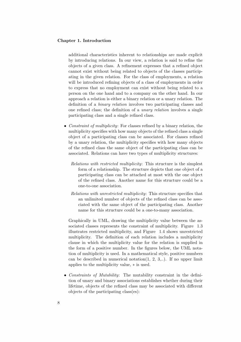
• Constraint of multiplicity : For classes refined by a binary relation, themultiplicity specifies with how many objects of the refined class a singleobject of a participating class can be associated. For classes refinedby a unary relation, the multiplicity specifies with how many objectsof the refined class the same object of the participating class can beassociated. Relations can have two types of multiplicity structures:
Relations with restricted multiplicity : This structure is the simplestform of a relationship. The structure depicts that one object of aparticipating class can be attached at most with the one objectof the refined class. Another name for this structure could be aone-to-one association.
Relations with unrestricted multiplicity : This structure specifies thatan unlimited number of objects of the refined class can be asso-ciated with the same object of the participating class. Anothername for this structure could be a one-to-many association.
Graphically in UML, drawing the multiplicity value between the as-sociated classes represents the constraint of multiplicity. Figure 1.3illustrates restricted multiplicity, and Figure 1.4 shows unrestrictedmultiplicity. The definition of each relation includes a multiplicityclause in which the multiplicity value for the relation is supplied inthe form of a positive number. In the figures below, the UML nota-tion of multiplicity is used. In a mathematical style, positive numberscan be described in numerical notation(1, 2, 3,..). If no upper limitapplies to the multiplicity value, ∗ is used.
• Constraints of Mutability : The mutability constraint in the defini-tion of unary and binary associations establishes whether during theirlifetime, objects of the refined class may be associated with differentobjects of the participating class(es):
8

1.2. Our Approach: Pattern-Based Software Design
Fig. 1.3: Unary relation with restricted multiplicity
Fig. 1.4: Unary relation with unrestricted multiplicity
– Whenever a participating class is designated mutable, it will bepossible to change the binding between objects of the underlyingrefined class with objects of the associated participating class. Inother words, consider an object of a class refined by a relationinvolving a participating class that has been designated mutable.At a certain instance, that refined object will be associated withsome object of that participating class; at another instance oftime, the same refined object may be associated with anotherobject of the associated participating class.
– Whenever a participating class is designated immutable, the bind-ing of objects of the underlying refined class with objects of thatparticipating class can not be changed during the refined object’slife time. In other words, once an object of the refined class hasbeen associated with an object of the given participating class,the binding will be kept forever.
9

Chapter 1. Introduction
1.2.3 Quality Assessment
The Pattern-based approach considers the effect of each applied
pattern on the quality of the design model. During the design processeach pattern that is applied to solve a given problem will have an impacton the quality of the resulting design model. Since software quality factorsconflict each other, they must be balanced and assessed so that we canachieve a design model satisfying the stated non-functional requirements.In our approach we have chosen four main quality factors to be controlledduring design:
• Adaptability : How easy is it to extend the functionality.
• Re-usability : The ability of software elements to serve as buildingblocks for other applications.
• Efficiency : How much hardware resources (e.g., processor time andspace occupied in internal and external memories) the software systemrequires.
• Simplicity : How easy is it to understand the model.
In our approach we measure these quality factors indirectly; with the helpof other software qualities (such as complexity, cohesion, and coupling). Inour terminology we call adaptability, re-usability, efficiency, and simplicityquality factors, and cohesion, coupling, complexity quality attributes.
Software quality factors and software quality attributes are in-
terrelated. Let’s consider the coupling attribute and check its relationwith adaptability, re-usability, and performance. Coupling is defined as thenumber of other classes to which a given class is coupled. In other words,it is the ”number of other classes a class requires to compile”. As couplingincreases, it is likely that the reusability of a class will decrease since it willbe depending on other classes in the model. Furthermore, high couplingmakes the system less adaptable as it becomes more complicated to modifythe system. High values of coupling also decrease efficiency because of mes-sage passing between objects, which affect the performance of the program.This is consistent with the general guideline to reduce coupling in conven-tional software. Therefore, coupling can be used to indirectly measure somequality factors during development.
In developing a design model, it is likely that each application of a pat-tern has an impact on the overall quality of the model. As an example, somepatterns suggest not introducing classes for less important objects; otherssuggest to introduce additional associations among classes involved in themodel. Obviously, the quality of the resulting design model is affected bysuch decisions. In this work, we will use some metrics to measure the qualityattributes of the structure resulting form the application of a pattern. We
10
1.3. Describing Design Patterns
use weighted method per class (WMC) to measure the complexity of theresulting structure. We use lack of cohesion in methods (LOCM) to meas-ure its cohesion, and we use the metric coupling factor (CF) to measurecoupling. These metrics are helpful (at the level of design) to strengthen orweaken the intuitive evaluation of the quality factors.
1.2.4 Automation: Tool Support
Automated support for object-oriented methods is vital to develop
complex software systems. Currently the pattern-based approach is donemanually. However, if an automated tool would support the approach, itwill help both the experienced designer (who gains additional insight) andthe novice designer (who obtains an additional view that would otherwisebe unavailable). Even though such a tool can never replace a human expert,it can help him to identify types of design patterns that can be used tosolve a particular design problem. The tool can also help to compare designalternatives by evaluating each alternative in terms of quality factors andby evaluating the results.
In summary, our objective is to develop an approach that scales up tolarge industrial software systems. Our aim is to improve the software de-velopment process by focusing on the cyclic and evolutionary nature of thesoftware life cycle. In our study, we focus on developing patterns of relation-ships between classes and objects that define preferred solutions to commonobject-oriented design problems and resolve possible quality conflicts arisingfrom the application of these patterns.
1.3 Describing Design Patterns
Alexander [Als77] says that ”every pattern we define must be formulatedin the form of a rule which establishes a relationship between a context, asystem of forces which arises in that context, and a configuration, whichallows these forces to resolve themselves in that context. Alexander also re-commends using pictorial examples: ”First there is a picture which shows anarchetypal example of the pattern.” Several different formats have been usedfor describing patterns. The pattern description format used in Alexander’swork is called the ”Alexandrian form”. The format used in [GoF] is referredto as the ”GoF format”. The section headings of the paragraphs, whichimmediately follow, make up what is called the ”canonical form” (some-times this too is called the ”Alexandrian form”) and is the format used by[POSA], AGCS, and many others (often with slight adaptations). Despitethe use of these differing pattern formats, it is generally agreed that a pat-tern should contain certain essential elements. Regardless of the particularformat/headings used (or lack thereof), the following elements should beclearly recognizable upon reading a pattern:
11

Chapter 1. Introduction
Name
Each pattern must have a meaningful name. This allows usto use a single word or short phrase to refer to the pattern,the knowledge, and the structure it describes. It would be veryunwieldy to have to describe or even summarize the pattern everytime we used it in a discussion. Good pattern names form avocabulary for discussing conceptual abstractions.
Example
An example from the real life in which the problem is explainedand can be easily understood.
Problem
A statement of the problem which describes its intent: the goalsand objectives it wants to reach within the given context andforces. Often the problem includes the applicability of the pat-tern.
Context
The preconditions under which the problem and its solution seemto recur, and for which the solution is desirable. This tells usthe pattern’s applicability. It can be thought of as the initialconfiguration of the system before the pattern is applied to it.Context refers to a recurring set of situations in which patternapplies
Forces
A description of the relevant forces and constraints and howthey interact/conflict with one another and with goals we wishto achieve (perhaps with some indication of their priorities). Aconcrete scenario, which serves as the motivation for the pattern,is frequently employed (see also Examples). Forces reveal theintricacies of a problem and define the kinds of trade-offs thatmust be considered in the presence of the tension or dissonancethey create. A good pattern description should fully encapsulateall the forces, which have an impact upon it.
Solution
Static relationships and dynamic rules describing how to real-ize the desired outcome. This is often equivalent to giving in-structions that describe how to construct the necessary workproducts. The description of the pattern’s solution may indicate
12

1.3. Describing Design Patterns
guidelines to keep in mind (as well as pitfalls to avoid) whenattempting a concrete implementation of the solution. Some-times possible variants or specializations of the solution are alsodescribed.
Structure
The description may encompass diagrams and prose, which identifythe pattern’s structure, its participants, and their collaborations.It describes the static structure that tells us the form and or-ganization of the pattern. It also includes a description of themethods that express the behavioral aspects of the pattern whenit ”comes alive”.
Implementation
What pitfalls, hints, or technologies should you be aware of whenimplementing the pattern?
Sample Code
Code fragments that illustrate how you might implement thepattern in Java.
Examples Revised
One or more sample applications of the pattern, which illus-trate: a specific initial context; how the pattern is applied to,and transforms, that context; and the resulting context left inits wake. Examples help the reader understand the pattern’s useand applicability. Visual examples and analogies can often beespecially illuminating. An example may be supplemented by asample implementation to show one way the solution might berealized. Easy-to-comprehend examples from known systems areusually preferred.
Consequences
The state or configuration of the system’s quality factors afterthe pattern has been applied, including the consequences (bothgood and bad) of applying the pattern, and other problems andpatterns that may arise from the new context. It describes thepostconditions and side-effects of the pattern. This is sometimescalled resolution of forces because it describes which forces havebeen resolved, which ones remain unresolved, and which pat-terns may now be applicable. Documenting the resulting contextproduced by one pattern helps you correlate it with the initialcontext of other patterns (a single pattern is often just one steptowards accomplishing some larger task or project).
13

Chapter 1. Introduction
Metrics and Evaluation
Measurements of the quality attributes of the pattern in terms ofcomplexity, cohesion, and coupling using some quality metrics.This section also relates the results of the metrics to evaluatetheir impact on quality factors (such as adaptability, efficiency,re-usability, and simplicity).
Variants
The description of the pattern’s solution that reveals a specialcase or a minor change that happens to appear on the structureon the constraints of the pattern.
1.4 The Catalog of Design Patterns
The catalog presented in this work contains different types of patterns. Eachone is applicable to a particular problem that appears in a certain structure.
1. Patterns for uni-relational architectures.
Integrator: The integrator pattern helps with the integration of com-ponents that together form a semantic unit. The integrator com-ponent encapsulates its constituent functionalities, organizes theircollaboration and provides a common interface to them.
Reverse Integrator: The Reverse Integrator Pattern assists in theintegration of composed objects into one of their components.The integrating component monitors the functionalities ascribedto composed objects, encapsulates characteristics ascribed to themand unifies the interface to component objects and composed ob-jects.
Unifier: The Unifier Pattern helps with unifying related abstractionsof different classes that together form a meaningful substantialunit. The pattern encapsulates the tasks and related functional-ities into one coherent component.
Coordinator: The Coordinator pattern helps with designing a small,simple, one-to-one relationship involving objects of two classes.The relationship is worked out as an attribute in one of theclasses, referred to as the participating class. The pattern co-ordinates responsibilities and organizes collaboration between theobjects involved.
Reversed Coordinator: The Reversed Coordinator pattern helpswith designing a small, simple, one-to-one relationship involvingobjects of two classes. The relationship is worked out as an at-tribute in one of the classes, referred to as the refined class. The
14

1.4. The Catalog of Design Patterns
pattern coordinates responsibilities and organizes collaborationbetween the objects involved.
Container: The Container helps with designing a complex, one-to-many relationship from the participating class to the refined class.It defines relationships where the participating object is linked toan unlimited number of refined objects. The one participatingobject simply stores a collection that holds the many refined ob-jects involved in the relationship.
Collaborator: The Collaborator pattern helps with designing a com-plex, two-way, one-to-many relationship between the participat-ing class and the refined class. It defines relationships where theparticipating object is linked to an unlimited number of refinedobjects. A single participating object simply stores a collectionthat holds references to all the refined objects to which it is as-sociated. The refined class, on the other hand, represents itsrelationship with the participating class as a single-valued attrib-ute.
2. Patterns for bi-relational architectures.
Bi-integrator: The Bi-integrator pattern helps with the integrationof components that together from a semantic unit involving threeclasses, one refined class and two participating classes. The Bi-integrator integrates a refined class and a participating class intothe other participating class. The pattern encapsulates the com-ponents constituent functionalities, organizes their collaborationand provides a common interface to them.
Reverse Bi-integrator: The Reverse Bi-integrator pattern helps inintegrating the related objects into one of their components. Itcombines the two participating classes into the refined class. Iteliminates the dependency effect imposed on the refined class bythe relation formed with the participating classes. The integrat-ing component monitors the functionalities ascribed to composedobjects, encapsulates characteristics ascribed to them and unifiesthe interface to component objects and composed objects.
Refinement Integrator The Refinement Integrator pattern helps indesigning relationships involving two participating classes and arefined class. The pattern combines the refined class into oneof the participating classes. It encapsulates the dependency ef-fect imposed on the refined class by the relation formed with theparticipating classes.
Bi-Collaborator: The Bi-Collaborator pattern facilitates designinga complex, two-way, one-to-many relationship between two par-ticipating classes and one refined class. It defines relationships
15
Chapter 1. Introduction
where each object of the participating classes is linked to an un-limited number of refined objects. The one participating objectsimply stores a collection that holds the many refined objectsinvolved in the relationship. The refined class represents its re-lationship with the participating class as an attribute. The Bi-Collaborator pattern explicitly defines the relationship betweenthe participating classes and the refined class. It manages thetwo-way relationships between their objects in a consistent way.Moreover, it organizes their collaboration and provides a flexibleand re-usable structure for them.
Nester: The Nester pattern nests classes involved in a relationshipinto one outer class. One of the participating classes will bedesignated as the outer class, and the other two will be designatedas the inner classes. The Nester pattern bounds the inner classesand the outer class by an implicit association.
3. Patterns for generalisation/specialisation architectures.
Delegator: The Delegator pattern helps with converting inheritancerelationships into a one-to-one association between the superclassand subclass. The Delegator merely resends (i.e., delegates) amessage to the superclass to accomplish the desired behavior forthe subclass. Delegation makes explicit the dependencies betweenthe delegate class and the receiver class.
Multiple Inheritance Organiser: The Multiple Inheritance Organ-iser helps with converting multiple inheritance hierarchies intosingle inheritance hierarchies. The pattern simply converts oneof the multiple inheritance relationships into one-to-one associ-ation using the Delegator pattern and introduces an interface toassure polymorphism. The Multiple Inheritance Organiser pat-tern assures dynamic binding and increase adaptability of thegive hierarchy.
1.5 Overview
The structure of the thesis is as follows. Chapter 2, discusses the recentdevelopment in object-oriented design and life cycle evolution. It addressesthe existing object-oriented software methodologies and design patterns. Itaddresses history and origins of design patterns. Moreover, it discussesthe software quality assessment and evaluation. Chapter 3, includes designpatterns for structures that involve two classes. It includes seven designpatterns (Integrator, Unifier, Reverse Integrator, Coordinator, Reversed Co-ordinator, Container Object, and Collaborator) for architectures involving
16
1.5. Overview
unary relations. Chapter 4, addresses the design patterns for structures in-volving three classes. It includes five design patterns (Bi-integrator, ReverseBi-integrator, Refinement Integrator, Bi-collaborator, and Nester) for archi-tectures involving binary relations. Chapter 5, introduces some patternsthat involve generalisation/specialisation hierarchies. It includes Delegator,Multiple Inheritance Organiser. Chapter 6, concludes the work. It presentsa summary of our research and of the results obtained, and presents somefuture work.
17


Chapter 2
Related Work
Our research applies a pattern-based approach to recent developments inobject-oriented design and evolution. This chapter highlights the significantcontributions impacting this research.
2.1 Software Development Techniques
This work distinguishes between specification-to-source, phase-to-phase, pattern-based, and source-to-source approaches.
The Specification-to-source approach starts by high-level program spe-cifications that evolve to compilable source. Examples are software generat-ors [Rea96, Bax90, Bat94]. The ratio between lines of specification to linesof generated code can be one-to-ten or higher. The popularity of softwaregenerators is limited because they are often domain-specific and they requirethe use of non-standard programming languages.
The Phase-to-phase approach is done in a vertical order (either forwardor backward) where the model is transferred from one phase to the nextphase in the software life cycle. This type of transformation results in atarget model that is at a different level of abstraction. Model refinementsand abstractions are two forms of phase-to-phase approach.
The Pattern-based approach proposes patterns as a method of captur-ing expert solutions to many common software problems. A good patterndescription also includes guidelines for its implementation. These can beconsidered as a micro-method for creating the solution to a specific problem-independent analysis and design methods, such as Booch [Booch94] and theObject Modeling Technique [Rum91], by providing methodological steps forsolving concrete recurring problems in software development. In this text,we will propose a catalog of patterns that captures solutions for recurringobject-oriented design problems.
The Source-to-source approach refactors a program coded in a givenlanguage to a new program coded in the same language. They are not
19

Chapter 2. Related Work
limited to a domain and can be written to support standard programminglanguages. Refactoring [Fow99] is a form of behavior-preserving source-to-source transformation.
2.2 Developing Structured Programs
Griswold developed behavior-preserving transformations for programs writ-ten in Scheme [Grs91]. An example transformation is var-to-expr thatreplaces occurrences of a variable with the expression it is bound to. Thegoal of these transformations was to assist in the restructuring of function-ally decomposed software. Software architectures developed using the classicstructured software design methodology [You79] are difficult to restructure.Structured designs represent programs as trees of structure charts whosenodes represent functionality and whose branches represent the transfer ofcontrol and data. The presence of control information makes it difficult torelocate subtrees of the structure chart since both input and output controlinformation can be unique to a specific location in the chart. As a result,most of Griswold’s transformations are limited to the level of a function ora block of code.
Byung-Kyoo Kang and James M. Beiman [Kan99] demonstrate a quant-itative framework for software restructuring. In the framework, restructur-ing decisions are guided by visualizing design information and objectivecriteria. The design information can be extracted directly from code torestructure existing or legacy software. Criteria for comparing alternativedesign structures include measures of design-level cohesion and coupling.Their restructuring framework supports procedural software, such as soft-ware written in C, COBOL, FORTRAN or Pascal.
Baxter’s DMS is a source-to-source transformation system used commer-cially on COBOL programs up to one million lines of code in size [Bax97].The primary functions of Baxter’s transformations are to unify duplicatecode and to remove dead code.
2.3 Object-Oriented Designs Methods
Object-oriented design methodologies favor many different approaches. Youcan write a problem statement, single out the nouns and verbs, and createcorresponding classes and operations. Alternatively, you can focus on thecollaborations and responsibilities in your system, or you can model the realworld and translate the objects found during analysis into design. Therewill always be disagreement on which approach is best [GoF].
Before 1992, there were few notions about what a good object-orienteddesign should be. The most popular book on object-oriented design was
20
2.3. Object-Oriented Designs Methods
the first edition of Booch’s Object-Oriented Analysis and Design with Ap-plications [Boo94]. The major contribution of this text was a method fordocumenting an application’s design. There was little guidance for the cre-ation and for the evolution of good designs. The primary method for trans-ferring the knowledge of experienced object-oriented designers was throughthe publication of rules of thumb for object-oriented design:
• Rochat proposed guidelines for developing good programming styles inSmalltalk [Roc86]. An example guideline is to carefully name classesand class members.
• Johnson and Foote proposed a set of rules for designing reusableclasses [Joh88]. Example rules are to reduce the number of argumentsof a method to less than six and to keep the size of methods small (lessthan thirty lines).
• Lieberherr and others proposed the ”Law of Demeter” which statesthat a method should have limited knowledge of an object model [Lie89].The effect is to prevent a method from being executed through morethan one link (e.g. ”this.a.b.c.d.foo()”). They notice, however, thatthe law can require an increase in the number of methods and methodarguments resulting in poor readability and slower execution [Lie88].
In general, these rules provided a checklist of things to look for and things toavoid but offered limited assistance in solving any particular object-orienteddesign problem.
A new approach to the discipline of object-oriented design experience waspresented in 1992 when Gamma released a preliminary version of a technicalreport, which proposed design patterns as a method of capturing expertsolutions to many common object-oriented design problems. Patterns werediscovered in a wide variety of applications and toolkits including SmalltalkCollections [Gol84], ET++ [Wei88], MacApp, and InterViews [lin92]. Thisreport sparked the patterns revolution in the object-oriented community anda flood of articles and books on patterns were subsequently published [GoF,And94, Bec94]. An interesting extension was the work of Pree who identifiedmeta-patterns which described in an abstract way how many design patternsworked [Pre94]. While design patterns were useful in the initial softwaredesign, they were often applied in the maintenance phase of the software lifecycle [Gam93]. Huni, demonstrated the advantages of adding patterns toan existing design by evolving a framework for network protocols [Hun95].This motivated work on tool support for patterns.
21

Chapter 2. Related Work
2.4 Design patterns
2.4.1 History of Patterns
In 1987, Ward Cunningham and Kent Beck [Wakent], were working withSmalltalk and designing user interfaces. They decided to use some of Alex-ander’s ideas [Als77] to develop a small five pattern language for guidingnovice Smalltalk programmers. They wrote up the results and presentedthem at OOPSLA’87 in Orlando in the paper ”Using Pattern Languages forObject-Oriented Programs” [Bec87].
Soon afterward, Jim Coplien [Jim91](more affectionately referred to as”Cope”) began compiling a catalog of C++ idioms (which are one kindof pattern) and later published them as a book in 1991, Advanced C++Programming Styles and Idioms.
From 1990 to 1992, various members of the Gang of Four [GoF] (ErichGamma, Richard Helm, Ralph Johnson, and John Vlissides) had met oneanother and had done some work compiling a catalog of patterns. Discus-sions of patterns abounded at OOPSLA’91 at a workshop given by BruceAndersen (which was repeated in 1992). Many pattern notables participatedin these workshops, including Jim Coplien, Doug Lea, Desmond D’Souza,Norm Kerth, Wolfgang Pree, and others.
In August 1993, Kent Beck and Grady Booch sponsored a mountainretreat in Colorado, the first meeting of what is now known as the HillsideGroup. Another patterns workshop was held at OOPSLA’93 and then inApril of 1994, the Hillside Group met again (this time with Richard Gabrieladded to the fold) to plan the first PLoP conference.
Shortly thereafter, the [GoF] Design Patterns book was published, andthe rest, is history.
2.4.2 Pattern Origins
Software patterns first became popular with the wide acceptance of the bookDesign Patterns: Elements of Reusable Object-Oriented Software by ErichGamma, Richard Helm, Ralph Johnson, and John Vlissides (frequently re-ferred to as the Gang of Four or just GoF). Patterns have been used formany different domains ranging from organizations and processes to teach-ing and architecture. At present, the software community is using patternslargely for software architecture and design, and (more recently) softwaredevelopment processes and organizations. Other recent books that havehelped popularize patterns are: Pattern-Oriented Software Architecture: ASystem of Patterns (also called the POSA book) by Frank Buschmann,Regine Meunier, Hans Rohnert, Peter Sommerlad, and Michael Stal (some-times called the Siemens Gang of Five or just GoV) [POSA]; and the booksPattern Languages of Program Design and Pattern Languages of ProgramDesign 2, 3, and 4, which are selected papers from the first and second
22

2.4. Design patterns
conferences on Patterns Languages of Program Design (PLoP or PLoPD).Many of these books are part of the Software Patterns Series from Addison-Wesley. The current use of the term ”pattern” is derived from the writingsof the architect Christopher Alexander who has written several books onthe topic as it relates to urban planning and building architecture:
• Notes on the Synthesis of Form, Harvard University Press, 1964, here-after referred to as ”[Notes]”)
• The Oregon Experiment, Oxford University Press, 1975, (hereafterreferred to as ”[Oregon]”)
• A Pattern Language: Towns, Buildings, Construction, Oxford Univer-sity Press, 1977, (hereafter referred to as ”[APL]”)
• The Timeless Way of Building, Oxford University Press, 1979, (here-after referred to as ”[TTWoB]”)
Although these books are ostensibly about architecture and urban plan-ning, they are applicable to many other disciplines, including software de-velopment. In [Notes], Alexander argues that current architectural methodsresult in products that fail to meet the real demands and requirements ofits users, society and its individuals, and are unsuccessful in fulfilling thequintessential purpose of all design and engineering endeavors: to improvethe human condition. Alexander wanted to create structures that are goodfor people and have a positive influence on them by improving their com-fort and their quality of life. He concluded that architects must constantlystrive to produce work products that better fit and adapt to the needs ofall their inhabitants and users and their respective communities. In [APL]Alexander describes some ”timeless” design ideas to try and realize thesegoals. In [TTWoB] Alexander proposes a paradigm for architecture basedon three concepts: the quality, the gate, and the way:
The Quality (a.k.a. ”the Quality Without a Name”) This is the essenceof all things living and useful that imparts unto them qualities such as:freedom, wholeness, completeness, comfort, harmony, habitability, durabil-ity, openness, resilience, variability, and adaptability. It is what makes usfeel ”alive” and ”sated”, gives us satisfaction, and ultimately improves thehuman condition.
The Gate This is the mechanism that allows us to reach the quality.It is manifested as a living common pattern language that permits us tocreate multiform designs, which fulfill multifaceted needs. It is the universal”ether” of patterns and their relationships that permeate a given domain.The gate is the conduit to the quality.
The Way (a.k.a. ”the Timeless Way”) Using the way, patterns fromthe gate are applied using a technique of differentiating space in an orderedsequence of piecemeal growth: progressively evolving an initial architecture,
23

Chapter 2. Related Work
which then flourishes into a ”live” design possessing the quality. Alexanderlikens it to ”a process of unfolding, like the evolution of an embryo, in whichthe whole precedes its parts, and actually gives birth to them, by splitting.”([TTWoB] p. 365). By following the way, one may pass through the gate toreach the quality.
2.5 Pattern Categories
Due to the overwhelming acceptance of the [GoF] book, much of the ini-tial patterns focus in the software community has been on design patterns.The patterns in the [GoF] book are object-oriented design patterns. Thereare many other kinds of software patterns besides design patterns. MartinFowler [Fow97] has written a book of Analysis Patterns. There is also awebsite and mailing list for organizational patterns [Members] which de-scribe the structure and practices of human organizations. Patterns submit-ted to previous PLoP conferences have encompassed all aspects of softwareengineering including: development organization, software process, projectplanning, requirements engineering, and software configuration management(just to name a few). Presently however, design patterns still seem to bethe most popular (though organizational patterns seem to be gaining mo-mentum).
2.5.1 What is a Design Pattern?
The [GoF] book defines design patterns as ”descriptions of communicatingobjects and classes that are customized to solve a general design problem ina particular context.” It then goes on to say that:
A design pattern names, abstracts, and identifies the key aspects of acommon design structure that make it useful for creating a reusable object-oriented design. The design pattern identifies the participating classes andtheir instances, their roles and collaborations, and the distribution of re-sponsibilities. Each design pattern focuses on a particular object-orienteddesign problem or issue. It describes when it applies, whether or not it canbe applied in view of other design constraints, and the consequences andtrade-offs of its use. Since we must eventually implement our designs, adesign pattern also provides sample code to illustrate an implementation.Although design patterns describe object-oriented designs, they are basedon practical solutions that have been implemented in mainstream object-oriented programming languages.
The above description is slanted toward object-oriented design, but withonly minor changes, it could be readily adjusted to describe software designpatterns in general (simply remove the words ”object-oriented” and replace”class” with ”module” or ”subsystem”). Since the [GoF] book was the first(and currently the most popular) of the software patterns books, the term
24

2.5. Pattern Categories
”design pattern” is often used to refer to any pattern, which directly ad-dresses issues of software architecture, design, or programming implement-ation. Many choose to make an important distinction between these threeconceptual levels by categorizing them into architectural patterns, designpatterns, and idioms (idioms are sometimes called coding patterns). Theauthors of Patterns of Software Architecture [POSA] define these threetypes of patterns as follows:
2.5.2 Architectural Patterns
An architectural pattern expresses a fundamental structural organization orschema for software systems. It provides a set of predefined subsystems, spe-cifies their responsibilities, and includes rules and guidelines for organizingthe relationships between them.
2.5.3 Design Patterns
A design pattern provides a scheme for refining the subsystems or compon-ents of a software system, or the relationships between them. It describescommonly recurring structures of communicating components that solve ageneral design problem within a particular context.
2.5.4 Idioms
An idiom is a low-level pattern specific to a programming language. Anidiom describes how to implement particular aspects of components or therelationships between them using the features of the given language. The dif-ference between these three kinds of patterns is in their corresponding levelsof abstraction and detail. Architectural patterns are high-level strategiesthat concern large-scale components and the global properties and mech-anisms of a system. They have wide-sweeping implications, which affectthe overall skeletal structure and organization of a software system. Designpatterns are medium-scale tactics that flesh out some of the structure andbehavior of entities and their relationships. They do not influence over-all system structure, but instead define micro-architectures of subsystemsand components. Idioms are paradigm-specific and language-specific pro-gramming techniques that fill in low-level internal or external details of acomponent’s structure or behavior.
In ”Understanding and Using Patterns in Software Development”, Riehleand Zullighoven make similar distinctions, but seem to partition the differentkinds of patterns among analysis, design, and implementation. They definethe terms conceptual patterns, design patterns, and programming patternsas follows:
25

Chapter 2. Related Work
Conceptual Patterns: A conceptual pattern is a pattern whose form isdescribed by means of terms and concepts from an application domain.
Design Patterns: A design pattern is a pattern whose form is describedby means of software design constructs, for example objects, classes,inheritance, aggregation and use-relationship.
Programming Patterns: A programming pattern is a pattern whose formis described by means of programming language constructs.
Using these definitions, conceptual patterns are based upon metaphors ina restricted application domain. Design patterns complement, or elaborateupon conceptual patterns by delving into the implementation of elementsfrom the conceptual space. And programming patterns descend further intoimplementation details using a specific implementation language.
When comparing and contrasting these two sets of definitions, it appearsthat programming patterns are equivalent to idioms. For the other typesof patterns described above, the first set of authors choose to delineatethem by their architectural scope whereas the latter set of authors chooseto delineate them by whether they employ language from the problem spaceor the solution space.
2.6 Other Object-Oriented Design methods
Bergstein defined a small set of object-preserving class transformations whichcan be applied to class diagrams [Ber91]. Lieberherr implemented thesetransformations in the Demeter object-oriented software environment [Lie91].Example transformations are deleting useless subclasses and moving in-stance variables between a superclass and a subclass. Bergstein’s trans-formations are object-preserving, meaning that they cannot add, delete ormove methods or instance variables exported by a class.
Banerjee and Kim identified a set of schema transformations, which ac-counted for many changes to evolving object-oriented database schema [Ban89].Opdyke defined a parallel set of behavior-preserving transformations forobject-oriented applications based on the work by Banerjee and Kim, thedesign principles of Johnson and Foote [Joh88], and the design history ofthe UIUC Choices software system [May89]. These transformations weretermed refactoring.
Tokuda developed implementations of Opdyke’s refactorings for C++and Batory [Tok95, Tok99] and Schultz [Sch98b]. An implementation forSmalltalk was developed by Roberts [Rob97]. Roberts offered Smalltalk-specific design criteria for a program transformation tool. One criterionthat also applied to C++ software is that users should be allowed to namenew entities introduced through transformations.
26

2.6. Other Object-Oriented Design methods
Opdyke first claimed that a series of refactorings could be used to createabstract classes and part-whole relationships [Opd92, Opd93]. This wasdemonstrated for abstract classes [Tok95] and for part-whole relationshipsin the CIM Works. Scherlis proposed refactorings which were shown tosupport a hypothetical derivation of the Java String and StringBuffer classesfrom an original null-terminated string class [Sch98a]. Tokuda and Batoryproposed and implemented refactorings to support Gamma’s design patternsand Pree’s hot-spot meta-patterns as target states for software restructuringefforts.
Refactorings have been used to alter existing designs. Winsen usedrefactorings (primarily renaming) to make design patterns more explicit[Win96]. Tokuda and Batory [Tok95], Roberts [Rob97] and Shultz [Sch98b]added design patterns to evolve an application’s design. Fowler proposeda set of manual refactorings. An example is to introduce null object whichreplaces checks for a null-object pointer with an object that handles thenull case behavior [Fow84]. Fowler’s refactorings do not state the enablingconditions required to preserve behavior. Compilation and testing is recom-mended at multiple points within each refactoring.
Robert France et. al. [Fra01] introduce an approach to manage evolu-tion of object-oriented software systems. The approach is based on a goal-directed cyclic process, in which object-oriented models are transformedvertically (resulting in a target model that is at a different level of abstrac-tion) or horizontally (resulting in a target model that is at the same level ofabstraction) and quantitatively evaluated in each cycle. This approach de-pends on the Boehm Spiral Model [Bohm87] which separates the developerand the user during the development process. At the beginning of the pro-ject, developers and users are both at the level of requirements. Duringdevelopment the user stays at the requirements level whereas the developersfocus on feasibility. That is why in their approach they evaluate the trans-formations based on coupling which is an internal quality factor. Users anddevelopers, however, have different needs when trying to understand thesoftware system. Furthermore, their transformations are based on designpatterns and model refactoring.
There are a number of tools to instantiate a design pattern and insertit into existing source code [Bud96, Kim96, Flo97]. Instantiations are notnecessarily refactorings, so testing of any changes may be required. Also, thenumber of lines of code added by instantiating a pattern is generally small.Budinsky offers an array of implementation options for each pattern, whichwould also be beneficial for refactorings. Florijn and Meijers check invariantsgoverning a pattern and repair violations when possible. Refactorings do nothave this pattern-level knowledge.
A related approach for adding patterns is to provide language constructswhich directly support a pattern’s implementation. Bosch proposes languagesupport for eight of Gamma’s design patterns [Bos98]. Language constructs
27

Chapter 2. Related Work
reduce pattern implementation costs and make patterns easier to recognize.The major drawback to this approach is that no standard language existsthat includes the language features proposed.
Other researchers propose the Catalysis method [Sou98]. Catalysis providesextensive guidelines for refining and abstracting object-oriented models, butthe description is informal and there seems to be no support for rigorousapplications of refinement and abstraction techniques.
2.7 Software Quality Measurement and Evaluation
2.7.1 Software Quality Measurement
Briand et al, [Bri96] identify five major quantifiable software design con-cepts: size, length, complexity, cohesion and coupling. Size can be meas-ured in terms of counts of entities, while length implies some kind of distancebetween entities. Complexity ”depends on the relationships between entit-ies” and is not a property of an isolated element. Here, complexity refersto ”artifact complexity” rather than to psychological complexity of a hu-man interacting with a design [Cur79]. Cohesion refers to the relatednessof module components. Cohesive modules are difficult to split into separatecomponents. Coupling refers to the connectedness of modules. A modulewith high coupling has many connections with other modules. Couplingdiffers from complexity in that coupling is generally measured with respectto an individual element or a pair of elements.
A commonly used heuristic is to design modules with high cohesion andlow coupling [Stev74]. Developers also try to minimize system complexityand component size.
No prior work addresses elements within specific architectural designcontexts. Rather, published principles focus on elements within abstract,semantic-free constructs.
2.7.2 Measuring Quality of Object-Oriented Design
Published measures of structure of object-oriented software primarily quantifyproperties of individual classes and their relationships to the rest of the sys-tem. Chidamber and Kemerer’s suite of object-oriented measures includeonly single class measures (i.e. class-based metrics suit) [Chid94]. Otherresearchers, including one of the authors, have developed cohesion measuresfor individual classes [Bie95, Bri99, Hit95, Ott95].
Work on quantifying interclass properties (properties of collections ofclasses) includes Hitz and Montazeri’s work to quantify coupling in object-oriented systems [Hit95]. They classify individual dependencies betweenclasses and between objects, and they propose an ordinal measure of the
28

2.7. Software Quality Measurement and Evaluation
strength of coupling by a single dependency and the change in depend-encies between two components. Others study the coupling between twoclasses or objects: Coad and Yourdon [Coa91] define inheritance couplingand design coupling between two classes; Wild [Wild91] defines a hierarchythat classifies coupling between two classes. Briand et al. [Bri99] describe theproperties of 30 different object-oriented coupling measures. These couplingdefinitions and measures do not directly address coupling between classesthat are components of specific architectural contexts or patterns.
One of the key reasons to use object-oriented methods is the often-asserted claim that they lead to more reusable and adaptable systems. Meas-ures of reuse and re-usability are needed to evaluate these claims. Severalrelevant reuse abstractions, attributes, measures and measurement tools areapplicable to object-oriented systems [Bie92, Bie95, Bie95]. The measuresand tools are based on both the inheritance and calling structure of a system.
Inheritance and inheritance hierarchies are unique features of object-oriented systems and should have measurable attributes. Properties of inher-itance hierarchies or inheritance clusters [Mard96] are subjects for analysisand measurement. The relationship between inheritance tree shapes and re-use through inheritance can be measured in terms of ”code savings [Kan97].These measured interclass properties are relevant to inheritance use, in gen-eral, but do not provide direct guidance for design pattern use.
29


Chapter 3
Patterns for Unirelational
Architectures
3.1 Integrator
The integrator pattern helps with the integration of components that to-gether form a semantic unit. The integrator component encapsulates itsconstituent functionalities, organizes their collaboration and provides acommon interface to them.
3.1.1 Example
Suppose you are developing an application involving books in a library. In alibrary you might find different copies of the same book. Conceptually, eachCopy-object is attached to precisely one Book-object. The relation betweena Book-object and its copies implies existential dependency. Copy-objectshave no meaning without being attached to a Book-object.
Suppose further that, as a designer, you are only interested in the numberof copies a book has, and not in other information concerning copies of booksin the library. Moreover, you do not expect Copy-object to become moreimportant for the application you are designing.
In this case, you may decide to integrate Copy-objects into the Book-object to which they are associated. As a result, the ultimate system willonly store the number of copies that are available for each book. The in-tegrator pattern will help you implement this design. In the example, thepattern will integrate Copy-objects into their Book-object by introducingan additional attribute for each Book-object in which the number of copiesis registered.
31

Chapter 3. Unirelational Patterns
Fig. 3.1: Several copies of the same book
3.1.2 Context
An object encapsulates data or information provided by other componentobjects.
3.1.3 Problem
objects may form structures, or relations that have a known set of prop-erties (methods, attributes, and/or relationships) and defined constraints(e.g., multiplicity, existential dependency and/or mutability) that must besatisfied in order for an object to be in a valid state.
In almost every software system, objects that are associated to eachother. Some associations imply existential dependency, meaning that someobjects (referred to as refined objects) cannot exist without being attachedto other objects (referred to as participating objects). Some of these associ-ations have an unrestricted multiplicity, meaning that an unlimited numberof refined objects can be attached to the same participating object.
Refined objects sometimes carry little information and associated func-tionality. Moreover, one may expect that these objects will not become moreimportant at times when new requirements are added to the application. Insuch cases, the Integrator pattern may be helpful. This pattern will reducerefined objects to a single counter integrated in their participating object.As a result, refined objects are no longer introduced as separate objects,thereby simplifying the design model and increasing its efficiency.
The context of the Integrator pattern is schematically illustrated in Fig-ure 3.2. Class A acts as the participating class, to which an unlimitednumber of objects of the refined class B can be associated. Because of themultiplicity at the side of class A, objects of the refined class B must at alltimes be associated with an object of the participating class A.
32

3.1. Integrator
Fig. 3.2: Structuring of a participating class A and a refined class B involving a mutablebinding with unrestricted multiplicity.
3.1.4 Forces
Several forces drive the structure for this pattern:
• Existential dependency : This property implies that a refined objectmust at all times be attached to a participating object. Existentialdependency has a major impact on the construction and the destruc-tion of refined objects.
• Unrestricted multiplicity : Unrestricted multiplicity implies that a singleparticipating object can be associated with an unlimited number of re-fined objects.
• Mutability : This property implies that, during its lifetime, a refinedobject may be associated with several participating objects. This prop-erty requires methods by means of which a refined object can be trans-ferred to another participating object.
• Class weight in the model : The refined class must carry little inform-ation and associated functionality. Moreover, it is to be expected thatthe refined class will not become more important at times new require-ments are added to the application.
• Efficiency : Efficiency in time and space is a major concern in the ap-plication to be developed. In particular, adaptability and re-usabilityare no dominant requirements imposed on the refined class.
• Simplicity and Understandability : Simplicity is another major concernfor the application to be developed. The Integrator pattern reducesthe number of classes involved in a model, which turns the designeasier to understand and simpler to implement.
33

Chapter 3. Unirelational Patterns
3.1.5 Solution
The Integrator pattern solves the addressed problem by combining objectsof the refined class into objects of the participating class. The pattern intro-duces an integer attribute to store the number of refined objects integratedin each participating object. In addition, as illustrated in Figure 3.3, thepattern adds the functionalities of the integrated component by introducinga constructor to add a new refined object, a destructor to remove an existingrefined object, a mutator to transfer a refined object to another participatingobject, and an inspector to retrieve the number of refined objects integratedin a single participating object.
3.1.6 Structure
The structure shown in Figure 3.3 schematically illustrates the resultingstructure of applying the integrator pattern to a model involving a refinedclass B and a participating class A. The participating class A includes anadditional integer attribute that counts the number of integrated refinedobjects.
At the level of the participating class A, the following methods are added:
• addB : a public method to increment the number of refined B-objectsintegrated in the participating A-object to which the method is ap-plied. This method reflects the construction of a new refined object tobe associated with the given participating object.
• removeB : a public method to decrement the number of refined B-objects for the participating A-object to which the method is applied.This method reflects the destruction of a refined object that was as-sociated with the given participating object.
• getNumberOfBs: a public method to retrieve the number of refined B-objects integrated in the participating A-object to which the methodis applied. Obviously, other, more specific queries cannot be offeredat the level of the integrating class.
• transferBTo: a public method to transfer a refined B-object, integ-rated in the participating A-object to which the method is applied, toanother participating A-object. This method reflects the mutation ofbindings between refined objects and participating objects.
3.1.7 Implementation
To implement the integrator pattern carry out the following steps:
1. Introduce an integer instance variable \$counter to store the numberof integrated refined objects.
34

3.1. Integrator
Fig. 3.3: Structure of the participating class A in which a refined class B has beenintegrated.
2. Implement the refined component’s functionalities:
• A constructor for creating new participating A-objects. This con-structor will initialize the number of integrated B-objects to 0.
• The method addB applicable to objects of class A, incrementingthe number of refined B-objects integrated in the given particip-ating A-object. This method increments the internal counter by1.
• The method removeB applicable to objects of class A, decrement-ing the number of refined B-objects integrated in the given parti-cipating A-object. This method decrements the internal counterby 1.
• The inspector getNumberofBs returning the number of refinedB-objects integrated in the given participating A-object.
• The mutator transferBTo applicable to objects of class A, decre-menting the number of refined B-objects integrated in the givenparticipating A-object. At the same time, the number of refinedB-objects for the other participating A-object is incremented.
• The method terminate destroying the given participating A-object and all the refined B-objects integrated in it.
3.1.8 Sample Code
Listing 3.1: Integrating the refined class B into the participating class A involvingunrestricted multiplicity
public class A {
35

Chapter 3. Unirelational Patterns
/**
* Initialize a new A-object without
* B-objects integrated in it.
* @post No B-objects are integrated into the new A-object.
* | getNumberOfBs() = 0 ;
*/
public A () {$counter = 0;
}/**
* Destroy this A-object and all
* B-objects integrated into it.
*/
public void terminate() {}/**
* Return the number of B-objects integrated into
* this A-object.
*/
public int getNumberOfBs() {return $counter;
}/**
* Construct a new B-object integrated into this A-object.
* @post The number of B-objects integrated
* into this A-object is incremented by 1.
* | new.getNumberOfBs() = getNumberOfBs() + 1
*/
public void addB() {$counter++;
}/**
* Remove one of the B-objects integrated
* into this A-object.
* @pre This A-object must have at
* least one integrated B-object.
* | getNumberOfBs() > 0
* @post The number of B-objects integrated in this
* A-object is decreased by 1.
* | new.getNumberOfBs() = getNumberOfBs() - 1
*/
public void removeB() {$counter−−;
}/**
* Transfer one of the B-objects integrated
* into this A-object to the given A-object.
* @pre The given A-object must be effective.
* | a != null
* @pre This A-object must have at least
36

3.1. Integrator
* one integrated B-object.
* | getNumberOfBs() > 0
* @post The number of B-objects integrated in
* this A-object is decremented by 1.
* | new.getNumberOfBs() = getNumberOfBs()- 1
* @post The number of B-objects integrated in the
* given A-object is increased by 1.
* | (new a).getNumberOfBs() = a.getNumberOfBs() + 1
*/
public void transferBTo( A a) {this .removeB();a.addB();
}
private int $counter;}
3.1.9 Example Resolved
In our library example, the integrator pattern can be applied to the associ-ation between books and their copies. This obviously assumes that, in thecontext of the application to be developed, we are only interested in thenumber of copies per book. Moreover, we don’t expect new functionalitiesthat would increase the weight of the class of copies in the model.
The integrator pattern will encapsulate all the functionalities related toindividual copies in the class of books. The resulting structure is schemat-ically Illustrated in Figure 3.4.
Fig. 3.4: Copy objects are integrated into class Book
• The constructor of Copy-objects becomes the method addCopy.
/**
* Construct a new Copy-object integrated into this Book-object.
37

Chapter 3. Unirelational Patterns
* @post The number of Copy-objects integrated
* into this Book-object is incremented by 1.
* | new.getNumberOfCopies() = getNumberOfCopies() + 1
*/
public void addCopy() {$nbCopies++;
}
• The destructor of Copy-objects becomes removeCopy.
/**
* Destroy one of the Copy-objects integrated
* into this Book-object.
* @pre This Book-object must have at
* least one integrated Copy-object.
* | getNumberOfCopies() > 0
* @post The number of Copy-objects integrated in this
* Book-object is decreased by 1.
* | new.getNumberOfCopies() = getNumberOfCopies() - 1
*/
public void removeCopy() {$nbCopies−−;
}
• The inspector of Copy-objects becomes getNumberOfCopies.
/**
* Return the number of Copy-objects integrated into
* this Book-object.
*/
public int getNumberOfCopies() {return $nbCopies;
}
• The mutator of Copy-objects becomes transferCopyTo. This methodis only meaningful, if it must be possible to correct faulty registrationsof copies.
/**
* Transfer one of the Copy-objects integrated
* into this Book-object to the given Book-object.
* @pre The given Book-object must be effective.
* | b != null
* @pre This Book-object must have at least
* one integrated Copy-object.
* | getNumberOfCopies() > 0
* @post The number of Copy-objects integrated in
* this Book-object is decremented by 1.
* | new.getNumberOfCopies() = getNumberOfCopies() - 1
* @post The number of Copy-objects integrated in the
38

3.1. Integrator
* given Book-object is increased by 1.
* | (new b).getNumberOfCopies() = b.getNumberOfCopies() + 1
*/
public void transferCopyTo( Book b) {this.removeCopy();b.addCopy();
}
3.1.10 Consequences
With the Integrator pattern, the software engineer chooses for the qualityfactors of efficiency and simplicity over adaptability and re-usability.
1. Efficiency is emphasized first of all because memory requirements arelow. Instead of assigning separate memory to refined objects, theseobjects are represented by a simple integer attribute inside objects ofthe participating object. In addition, the attribute results in softwaresystems that are more efficient in time. As an example, the process ofcreating a new object of the refined class is reduced to incrementingthe integer attribute, instead of allocating and initializing memory tothe new object.
2. Because one class is removed from the original model, the design modelbecomes simple and easier to understand.
3. Design models resulting from the integrator pattern are not very ad-aptable, in the sense that it cannot withstand future modifications.As soon as objects of the refined component become more and moreimportant, the integrator pattern should not be applied.
4. Finally, chances for re-using a component in which another componentis integrated are not that high. Indeed, the integrating pattern is re-commended only with applications in which the integrated componentis just of minor importance.
3.1.11 Metrics and Evaluation
The Integrator pattern affects the external quality factors of efficiency, sim-plicity, adaptability, and re-usability. These quality factors can be measuredindirectly by measuring (directly) the internal quality attributes of cohesion,coupling and complexity using the following metrics.
• Lack of Cohesion in Methods (LOCM). In Listing 3.1, we have fivemethods all of which share the same instance variable $counter, andwe do not have unshared method pairs. As a result, LOCM is equalto 5. Low LOCM means good cohesion. The reason we have this lowvalue of LOCM is because we assumed that the refined class involved
39

Chapter 3. Unirelational Patterns
in the pattern does not have attributes. However, if the refined classwould hold attributes or extra information the LOCM value obviouslywill drop. Indeed, methods related to these additional attributes wouldnot have an impact on attributes of the participating class.
• Weighted Methods per Class (WMC). In the given scheme, WMC isincreased by 4. We can see that the number of methods for class A al-most doubled, which indeed increases its complexity. In discussing theconsequences of the Integrator pattern, we nevertheless claimed thatsimplicity increases. This is because we were considering model-basedquality, instead of class-based quality. Obviously, when the numberof classes involved in a model decreases, that model becomes simplerand easier to understand and to deal with. In applying the integratorpattern, the complexity of the integrating class increases for obviousreasons.
• Coupling factor (CF). The value of CF after applying the integratorpattern is zero, because only one component is still part of the designmodel.
3.1.12 Variants
Strict Integrator : In applying the Integrator pattern, it is possible that theassociation between the refined class and the participating class is immut-able. In the example of the copies and the books, this would mean thatCopy-objects cannot be transferred from one Book-object to another. Inthat case, the method transferBTo will not be part of the definition of theresulting participating class A.
Integrator with Attributes: The Integrator pattern may also be appliedin the case that the refined class has a few attributes. Then, each of theseattributes must also be integrated in objects of the participating class. Inparticular, a collection will be introduced in each object of the participatingclass, collecting all the values of a single attribute for all the refined objectsintegrated in the given participating object. If we assume permanent bindingfor these attributes (meaning that each object of the refined class must havea proper value for each of these attributes), the internal counter can beremoved.
40

3.2. Reverse Integrator
3.2 Reverse Integrator
The Reverse Integrator pattern helps the integration of composed objectsinto one of their components. The integrating component monitors thefunctionalities ascribed to composed objects, encapsulates characteristicsascribed to them and unifies the interface to component objects and com-posed objects.
3.2.1 Example
Suppose you are designing an application involving projects and enterprises.In the model shown in Figure 3.5, each enterprise may set up an unlimitednumber of projects. In other words, the relationship between Enterprise-objects and Project-objects implies an unrestricted multiplicity. The rela-tionship also implies existential dependency in the sense that Project-objects(refined objects) cannot exist without being associated at all times to anEnterprise-object (the participating object). As a result, for the projectobjects to be in a valid state, an enterprise object has to exist.
Fig. 3.5: Project-objects assigned to Enterprise-objects
Suppose further that, in the context of the application to be developed,the class of enterprises is pulling out its weight from the model. As an ex-ample, you might be only interested in some information the class provides,such as the name of the enterprise or the number of persons its employs.Moreover, the application does not require information concerning enter-prises that are not setting up any projects. As a result, the class of enter-prises will not introduce a large number of methods that can be applied tothem. Moreover, you do not expect any changes in this situation, even ifadditional requirements are imposed on the application in the future. In thiscase, you may decide to eliminate the dependencies the class of enterprisesimposes on the class of projects, and integrate the information needed fromenterprises into the class of projects. The Reverse Integrator pattern willbe a good choice for you to commit this design. In the example, the pattern
41

Chapter 3. Unirelational Patterns
will integrate enterprises inside projects they have set up. Attributes andmethods related to enterprises are transferred to the class of projects.
3.2.2 Context
A component object encapsulates data provided by the object in which it iscomposed.
3.2.3 Problem
Every software application has to deal with associations among objects. Aconsiderable number of associations, objects of the one class (referred toas the refined class) are existentially dependent from objects of the otherclass (referred to as the participating class). This means that refined ob-jects cannot exist without being attached to a participating object. Otherconstraint, such as constraints of multiplicity determines how many objectsof the refined class can be associated with one object of the participating.
Participating objects sometimes carry little or no information, and areonly there to give meaning to the refined objects. Moreover, one may oftenexpect that such participating objects will never play a crucial role in thecontext of the ultimate application. In such cases, the Reverse Integratorpattern may be helpful. It optimizes both classes and their associations byintegrating the participating into the refined class. The integration involvestransferring the information provided by the participating class to the refinedclass. In associations involving unrestricted multiplicity, this may lead toduplication of information concerning a single participating object.
Traditional solutions often involve defining long lists of parameters atcreation time. An alternative consists in working out a two-step construc-tion, starting with the construction of a naked, invalid object followed by aseparate validation step. This section presents an alternative solution thatcan be more generally applied.
3.2.4 Forces
Several forces drive the structure for this pattern:
• Existential dependency : This property implies that a refined objectmust at all times be attached to a participating object. Existentialdependency has a major impact on the construction and the destruc-tion of refined objects.
• Multiplicity : This property determines how many objects of the refinedclass can be associated with a single participating object. The patterncan be applied for all possible multiplicity values. However, in case ofunrestricted multiplicity, the designer must be aware of the duplication
42
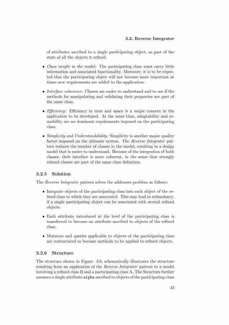
3.2. Reverse Integrator
of attributes ascribed to a single participating object, as part of thestate of all the objects it refined.
• Class weight in the model : The participating class must carry littleinformation and associated functionality. Moreover, it is to be expec-ted that the participating object will not become more important attimes new requirements are added to the application.
• Interface coherence: Classes are easier to understand and to use if themethods for manipulating and validating their properties are part ofthe same class.
• Efficiency : Efficiency in time and space is a major concern in theapplication to be developed. At the same time, adaptability and re-usability are no dominant requirements imposed on the participatingclass.
• Simplicity and Understandability : Simplicity is another major qualityfactor imposed on the ultimate system. The Reverse Integrator pat-tern reduces the number of classes in the model, resulting in a designmodel that is easier to understand. Because of the integration of bothclasses, their interface is more coherent, in the sense that stronglyrelated classes are part of the same class definition.
3.2.5 Solution
The Reverse Integrator pattern solves the addresses problem as follows:
• Integrate objects of the participating class into each object of the re-fined class to which they are associated. This may lead to redundancy,if a single participating object can be associated with several refinedobjects.
• Each attribute introduced at the level of the participating class istransferred to become an attribute ascribed to objects of the refinedclass.
• Mutators and queries applicable to objects of the participating classare restructured to become methods to be applied to refined objects.
3.2.6 Structure
The structure shown in Figure 3.6, schematically illustrates the structureresulting from an application of the Reverse Integrator pattern to a modelinvolving a refined class B and a participating class A. The Structure furtherassumes a single attribute alpha ascribed to objects of the participating class
43

Chapter 3. Unirelational Patterns
Fig. 3.6: Structure of the Reverse Integrator applied on the refined class B
A. This attribute is transferred to become an attribute of the refined classB.
At the level of the refined class the following methods are added:
• setAlpha: a public method to register the given value as the new valuefor the attribute alpha.
• getAlpha: a public method returning the current value for the attributealpha. that ends the B-object’s lifetime. Notice that removing A-object implies terminating B-object.
3.2.7 Implementation
The application of the Reverse Integrator pattern involves the followingsteps:
• Introduce a boolean attribute reflecting whether or not a refined objectis still alive. This attribute will be set to true at construction time.It will be set to false as soon as the refined object is destroyed. Theattribute will be complemented with a public inspector isAlive.
• Introduce an attribute of the appropriate type for each attribute ori-ginally ascribed to objects of the participating class.
• Introduce a proper set of methods for manipulating each of these at-tributes. Typically, a getter will be defined for retrieving the currentvalue of the attribute. For mutable attributes, a setter may also beintroduced for changing the value of the attribute.
3.2.8 Sample Code
Listing 3.2: Reverse Integration of the participating class A into the refined class B
public class B {
44
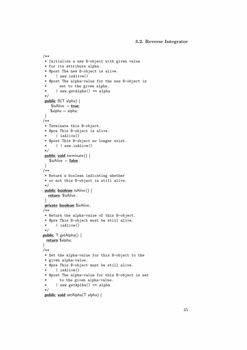
3.2. Reverse Integrator
/**
* Initialize a new B-object with given value
* for its attribute alpha.
* @post The new B-object is alive.
* | new.isAlive()
* @post The alpha-value for the new B-object is
* set to the given alpha.
* | new.getAlpha() == alpha
*/
public B(T alpha) {$isAlive = true;$alpha = alpha;
}/**
* Terminate this B-object.
* @pre This B-object is alive.
* | isAlive()
* @post This B-object no longer exist.
* | ! new.isAlive()
*/
public void terminate () {$isAlive = false ;
}/**
* Return a boolean indicating whether
* or not this B-object is still alive.
*/
public boolean isAlive () {return $isAlive ;
}private boolean $isAlive ;/**
* Return the alpha-value of this B-object.
* @pre This B-object must be still alive.
* | isAlive()
*/
public T getAlpha() {return $alpha;
}/**
* Set the alpha-value for this B-object to the
* given alpha-value.
* @pre This B-object must be still alive.
* | isAlive()
* @post The alpha-value for this B-object is set
* to the given alpha-value.
* | new.getAplha() == alpha
*/
public void setAlpha(T alpha) {
45

Chapter 3. Unirelational Patterns
$alpha = alpha;}private T $alpha;
}
3.2.9 Example Revised
In our example of projects conducted by enterprises, the Reverse Integratorpattern can be applied. In that case, we assume that enterprises have nodominant role in the application to be developed, and will never have sucha role.
The pattern will transfer all the attributes and associated methods ascribedto enterprises, to each of the projects they conduct. In the example we willassume that only the name of the enterprise is relevant. In addition, anattribute reflecting the name of the project itself is also taken into account.
Fig. 3.7: Project class assigned to an integrated enterprise
• In the constructor of a new Project-object, its own name and the nameof its enterprise are set.
/**
* Initialize a new Project-object with given name and
* conducted by an enterprise with given name.
* @post The new Project-object is alive.
* | new.isAlive()
* @post The name of the new Project-object is set to the
* given project name.
* | new.getProjectName() == projectName
* @post The name of the enterprise conducting the new
* Project-object is set to the given enterprise name.
* | new.getEnterpriseName() == enterpriseName
*/
public Project(String projectName, String enterrpriseName) {$isAlive = true;
46

3.2. Reverse Integrator
$projectName = projectName;$enterpriseName = enterpriseName;
}
• The destructor for Project-objects terminates their life.
/**
* Terminate this Project-object.
* @pre This Project-object is alive.
* | isAlive()
* @post This Project-object no longer exists.
* | ! new.isAlive()
*/
public void endProject() {$isAlive = false;
}
• Inspector returning then name of a project.
/**
* Return the name of this project.
* @pre This project must still be alive.
* | isAlive()
*/
public String getProjectName() {return $projectName;
}
• Inspector to return the name of the conducting enterprise.
/**
* Return the name of the enterprise conducting
* this project.
* @pre This Project-object must be alive.
* | isAlive()
*/
public String getEnterpriseName(){return $enterpriseName;
}
3.2.10 Consequences
The Reverse Integrator pattern has the following advantages and disadvant-ages:
• Simplicity : If the number of classes in a design model is low, simplicityand understandability of the model are in general high. The ReverseIntegrator pattern reduces the number of classes, by eliminating theneed for the class of participating objects.
47

Chapter 3. Unirelational Patterns
• Adaptability and re-usability are not optimal. This is typical for struc-tures in which several things are worked out at the same time.
• Efficiency is improved first of all because memory requirements arelow. Indeed, instead of allocating separate memory to refined objectson the one hand and to participating objects on the other hand, alloc-ation of memory is only needed for refined objects. As an immediateconsequence, efficiency in time increases in creating, terminating andinspecting refined objects.
3.2.11 Metrics and Evaluation
Applying the Reverse Integrator pattern affects the internal quality attrib-utes of cohesion, coupling and complexity in the following ways:
• Lack of Cohesion in Methods (LOCM). According to the definition ofthe refined class, the values for the LOCM metrics is 0. Recall that alow LOCM value means high cohesion. We must notice however that,as soon as some attributes are introduced that apply to the refined ob-jects themselves, and other attributes that apply to the participatingobjects, the class becomes less and less cohesive. This explains whythe Reverse Integrator pattern is said not to promote adaptability andre-usability.
• Weighted Methods per Class (WCM). Complexity of classes is typicallymeasured amongst others by the WMC metric. The number of meth-ods in the refined class resulting from the application of the ReverseIntegrator pattern is higher, when opposed to a model in which bothclasses are kept apart. This would imply that complexity would in-crease. However, at the level of the entire model, complexity is reducedbecause the number of classes diminishes.
• CF: Coupling is minimal since we have a single class model.
3.2.12 Variants
Strict Reverse Integrator. The relationship between the refined class and theparticipating class may have a restricted multiplicity, meaning that at mostone refined object can be associated with the same participating object. Inthis case, one must be careful when applying the Reverse Integrator pattern.As an example, at the time a refined object is created, one must be surethat no other refined object already exist involving the given participatingobject. One option is to impose a precondition on the application of theconstructor. Another option is to collect all participating objects in use,and to check the given participating object against this collection.
48

3.3. Unifier
3.3 Unifier
The Unifier pattern helps with unifying related abstractions of differ-ent classes that together form a meaningful substantial unit. The pat-tern encapsulates the tasks and related functionalities into one coherentcomponent.
3.3.1 Example
Suppose that you are designing an academic application in which assistant-objects and thesis student-objects1 are involved. Suppose that the applica-tion imposes a restricted multiplicity on the relationship between assistant-objects and thesis student-objects. In other words, we assume that only onethesis student-object can be associated with one assistant-object. Moreover,the relationship between assistant-objects and thesis student-objects in-volves existential dependency: no thesis student-object can exist withoutbeing attached at all times to an assistant-object. Figure 3.8 illustrates themodel of assistants and thesis students.
Suppose further that, in the context of the envisaged software system,you are only interested in knowing whether or not thesis student-objects areassociated with assistant-objects. In other words, we assume that there is noneed for further information concerning thesis student-objects, such as theirname or their study program. In addition, you do not expect thesis student-objects to become more important for the application you are designing.
Under all these assumptions, you may choose to combine each thesisstudent-object with their assistant-object, introducing a boolean attributein the class Assistant reflecting whether or not an assistant-object has anassigned thesis student-object. The Unifier pattern will be the perfect choiceto work out such a design.
Fig. 3.8: Association between assistants and their thesis students
1A thesis student is a last year undergraduate student who has to do a thesis to complete
his undergraduate program
49

Chapter 3. Unirelational Patterns
3.3.2 Context
Unifying two classes into one coherent component.
3.3.3 Problem
Developing software for an application domain that needs to cope with abroad spectrum of related abstractions is a nontrivial task. Abstractions insoftware applications can be strictly associated and/or coupled, such thatone of them (the refined class) is existentially dependent on the other (theparticipating class).
In some software applications, relationships between participating ob-jects and refined objects have a restricted multiplicity. In such cases, asingle participating object can be linked at most to one refined object. Inaddition, the component that represents the refined class sometimes holdslittle information and performs little functionality in the underlying applic-ation. Moreover, one may not expect the refined class to become moreimportant for the application at times new requirements must be workedout.
In such cases, the Unifier Pattern can be applied to unify the relatedabstractions in one coherent component by combing the refined class into theparticipating class. The pattern eliminates the refined class by introducinga boolean attribute at the level of the participating class. The booleanattribute reflects whether or not the participating object has a refined objectassigned to it.
Fig. 3.9: Refined class B in association with a participating class A
3.3.4 Forces
The following forces steer the structure for this pattern:
• Existential dependency : This property implies that a refined objectmust at all times be attached to a participating object. Existentialdependency has a major impact on the construction and the destruc-tion of refined objects.
50

3.3. Unifier
• Restricted multiplicity : For this pattern, the relationship between therefined class and the participating class must have restricted multipli-city. This property implies that one participating object can be linkedto at most one refined object.
• Mutability : This property implies that, during its lifetime, a refinedobject may be associated with different participating objects. Thisproperty implies the introduction of methods by means of which a re-fined object can be associated with another (free) participating object.
• Class weight in the model : The refined class must carry little informa-tion and functionality. Moreover, it is to be expected that the refinedclass will not evolve or become more important at times new require-ments are added to the application.
• Efficiency : Efficiency in time and space must be a major concern in theapplication to be developed. At the same time, adaptability and re-usability may not be dominant requirements imposed on the ultimatestructure.
• Simplicity and Understandability : Simplicity is another major concernfor the application to be developed. The Unifier pattern reduces thenumber of classes involved in a model, which turns the design easierto understand and simpler to implement.
3.3.5 Solution
The following steps are taken in working out a solution for the addressedproblem by the Unifier pattern:
• Compose the refined class with the participating class, resulting in asingle component.
• Add a new boolean attribute to the participating class. The booleanattribute serves to reflect whether or not a refined object is associatedwith a participating object.
• Add to the participating class functionalities related to the composedrefined class. In particular, a constructor to add a new refined object,a destructor to remove an existing refined object and a mutator totransfer a refined object to another participating object will be intro-duced as part of the participating class.
3.3.6 Structure
Figure 3.10 schematically illustrates the structure resulting from the ap-plication of the Unifier pattern to a model involving a refined class B and
51
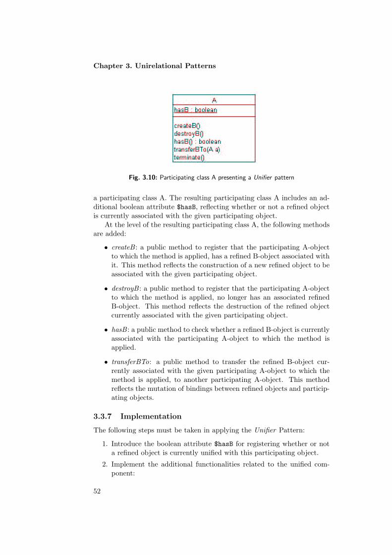
Chapter 3. Unirelational Patterns
Fig. 3.10: Participating class A presenting a Unifier pattern
a participating class A. The resulting participating class A includes an ad-ditional boolean attribute $hasB, reflecting whether or not a refined objectis currently associated with the given participating object.
At the level of the resulting participating class A, the following methodsare added:
• createB : a public method to register that the participating A-objectto which the method is applied, has a refined B-object associated withit. This method reflects the construction of a new refined object to beassociated with the given participating object.
• destroyB : a public method to register that the participating A-objectto which the method is applied, no longer has an associated refinedB-object. This method reflects the destruction of the refined objectcurrently associated with the given participating object.
• hasB : a public method to check whether a refined B-object is currentlyassociated with the participating A-object to which the method isapplied.
• transferBTo: a public method to transfer the refined B-object cur-rently associated with the given participating A-object to which themethod is applied, to another participating A-object. This methodreflects the mutation of bindings between refined objects and particip-ating objects.
3.3.7 Implementation
The following steps must be taken in applying the Unifier Pattern:
1. Introduce the boolean attribute $hasB for registering whether or nota refined object is currently unified with this participating object.
2. Implement the additional functionalities related to the unified com-ponent:
52

3.3. Unifier
• A constructor for creating new participating A-objects. This con-structor will initialize the new participating object such that itis not yet unified with any refined object.
• The method createB applicable to objects of class A, changestheir state such that they are unified with a new refined object.This method sets the internal boolean attribute to true. Becauseof the restricted multiplicity, this method can only be performedif the given A-object is not already unified with a refined object.
• The method destroyB applicable to objects of class A, changestheir state such that they are no longer unified with a refinedobject. This method sets the internal boolean attribute to false.For obvious reasons, this method can only be performed if thegiven A-object is already unified with a refined object.
• The inspector hasB returns a boolean reflecting whether or notthe participating object to which it is applied, is currently unifiedwith a refined object.
• The mutator transferBTo applicable to objects of class A, des-troys transfers the refined B-object unified with the participatingA-object to which the method is applied, to the given particip-ating A-object. As a result, the participating A-object to whichthe method is applied is no longer unified, whereas the givenparticipating object becomes unified.
• The method terminate destroys the participating A-object towhich it is applied, along with the refined object unified with it,if any.
3.3.8 Sample Code
Listing 3.3: Unifying the refined class B with the participating class A involving amutable binding with restricted multiplicity
public class A {/**
* Initialize a new A-object without a unified B-object.
* @post The new A-object has no B-object unified with it.
* | ! hasB()
*/
public A() {$hasB = false;
}/**
* Destroy this A-object along with its unified B-object,
* if any.
*/
53

Chapter 3. Unirelational Patterns
public void terminate () {}/**
* Return a boolean indicating whether or not
* this A-object has a unified B-object.
*/
public boolean hasB() {return $hasB;
}/**
* Construct a new B-object unified with this A-object.
* @pre This A-object may not already have a unified B-object.
* | ! hasB()
* @post This A-object has a unified B-object.
* | hasB()
*/
public void createB() {$hasB = true;
}/**
* Destroy the B-object unified with this A-object.
* @pre This A-object must have a unified B-object.
* | hasB()
* @post This A-object no longer has a unified B-object.
* | ! hasB()
*/
public void destroyB() {$hasB = false;
}/**
* Transfer the B-object unified with this A-object
* to the given A-object.
* @pre The given A-object must be effective.
* | a != null
* @pre This A-object must have a unified B-object.
* | hasB()
* @pre The given A-object muay not have a unified B-object.
* | ! a.hasB()
* @post This A-object does not have a unified B-object.
* | ! new.hasB()
* @post The given A-object has a unified B-object.
* | (new a).hasB()
*/
public void transferBTo(A a) {destroyB();a.createB();
}
private boolean $hasB;
54

3.3. Unifier
}
3.3.9 Example Resolved
In our academic example, the Unifier Pattern can be applied to the asso-ciation between assistants and thesis students they are supervising. If thepattern is applied, we must be aware that it will be hard to add additionalinformation concerning thesis students in future extensions to the model. Inthe example, the Unifier Pattern will encapsulate information concerning athesis student supervised by an assistant. The resulting structure is schem-atically illustrated in Figure 3.11. Notice that a boolean attribute is added,reflecting whether or not the given assistant-object is currently supervisingsome thesis student.
Fig. 3.11: Thesis students unified with their assistant.
• The constructor of a thesis student-object becomes startThesisStudentSupervision
/**
* Indicate that this Assistant-object starts supervising a
* thesis student.
* @pre This Assistant-object may not yet supervise a thesis student.
* | ! supervisesThesisStudent()
* @post This Assistant-object supervises a thesis student.
* | new.supervisesThesisStudent()
*/
public void startThesisStudentSupervision() {$supervisesThesisStudent = true;
}
• The destructor of a thesis student-object becomes stopThesisStudentSupervision.
/**
* Indicate that this Assistant-object no longer supervises
* a thesis student.
55

Chapter 3. Unirelational Patterns
* @pre This Assistant-object must supervise a thesis student.
* | supervisesThesisStudent()
* @post This Assistant-object no longer supervises a thesis student.
* | ! new.supervisesThesisStudent()
*/
public void stopThesisStudentSupervision() {$supervisesThesisStudent = false;
}
• The inspector concerning a thesis student-object becomes supervisesThesisStudent.
/**
* Check whether this Assistant-object supervises a thesis student.
*/
public boolean supervisesThesisStudent() {return $supervisesThesisStudent;
}
• The mutator of a thesis student-object becomes transferThesisStu-dentTo.
/**
* Transfer the thesis student currently supervised by this
* Assistant-object to the given Assistant-object.
* @pre The given Assistant-object must be effective.
* | assistant != null
* @pre This Assistant-object must supervise a thesis student.
* | supervisesThesisStudent()
* @pre The given Assistant-object must not supervise a thesis student.
* | ! assistant.supervisesThesisStudent()
* @post This Assistant-object no longer supervises a thesis student.
* | ! new.supervisesThesisStudent()
* @post The given Assistant-object supervises a thesis student.
* | (new assistant).supervisesThesisStudent()
*/
public void transferThesisStudentTo(Assistant assistant) {stopThesisStudentSuperrvision();assistant .startThesisStudentSupervision();
}
3.3.10 Consequences
With the Unifier Pattern, the software engineer chooses for the qualityfactors of efficiency and simplicity over adaptability and re-usability.
1. Efficiency is emphasized first of all because memory requirements arelow. Instead of assigning separate memory to each refined object, theseobjects are represented by a simple boolean attribute inside particip-ating objects. In addition, the attribute results in software systems
56

3.3. Unifier
that are more efficient in time. As an example, the process of creat-ing a new object of the refined class is reduced to setting the booleanattribute to true, instead of allocating and initializing memory for anew object.
2. Because the number of classes involved in the design model diminishesby applying the Unifier Pattern, simplicity and understandability ofthe model are improved.
3. Flexibility diminishes slightly because the resulting structure cannotwithstand all possible modifications. Indeed, as soon as the refinedclass becomes more and more important, additional attributes andmethods must probably be added to the unifying class. In such cases,the Unifier Pattern is best replaced by another pattern in which therefined class is worked out as a n integral part of the design model.
4. Finally, chances for re-using an object unifying several are rather low.Indeed, the Unifier Pattern is recommended only with applications inwhich each of the individual components is not a dominant element.
3.3.11 Metrics and Evaluation
The Unifier Pattern affects the external quality factors of flexibility, re-usability, simplicity and efficiency. These external quality factors can bemeasured in terms of the internal quality attributes of cohesion, coupling,and complexity.
• Lack of Cohesion in Methods (LOCM). As a result of applying the Uni-fier Pattern, four methods are added to the definition of the participat-ing class. Each of these methods manipulates the Additional Booleanattribute. Without additional characteristics ascribed to objects ofthe participating class, LOCM is equal to 5. High LOCM means goodcohesion. In our academic application we unified each Assistant-objectwith the Thesis Student-object it supervises. Without additional char-acteristics for assistants or thesis students, the resulting class of as-sistants is still cohesive. The reason we have this high value of LOCMis because we assumed that both classes involved in the pattern donot have attributes. As soon as at least one of the se classes hassome additional attributes and associated methods, cohesion drops assoon as the Unifier Pattern is applied. Indeed, the methods added tothe participating class basically only manipulate the internal Booleanvariable.
• Weighted Methods per Class (WMC). The number of methods for theparticipating class is increased due to the added functionalities of therefined class. In the given scheme, WMC increases by 4. As the num-ber of methods in the class increases, its complexity also increases.
57

Chapter 3. Unirelational Patterns
However, in terms of the whole model, complexity decreases and sim-plicity increases because the total number of classes involved in theentire model decreases.
• Coupling Factor (CF). Coupling decreases because we have only oneclass left after the Unifier Pattern has been applied. As a consequence,CF is 0. It is a well-known fact that the more coupling decreases, themore understandability and simplicity of the model increase.
3.3.12 Variants
Immutable Unifier : Sometimes the association between objects of the par-ticipating class and objects of the refined class is immutable. As a con-sequence, each refined object will be associated with the same participatingobject during its entire lifetime. In this variant, the method transferBTo
will not be part of the definition of the resulting participating class.
3.4 Coordinator
The Coordinator pattern helps with designing a small, simple, one-to-onerelationship involving objects of two classes. The relationship is workedout as an attribute in one of the classes, referred to as the participatingclass. The pattern coordinates responsibilities and organizes collaborationbetween the objects involved.
3.4.1 Example
Suppose you are designing an application involving contracts and expirydates. In the design model, as shown in Figure 3.12, each ExpiryDate-object must be assigned to exactly one Contract-object. In other words,the relationship between objects of the class of contracts and objects ofthe class of expiry dates involves restricted multiplicity. In addition, therelationship involves existential dependency in the sense that no ExpiryDate-object (referred to as refined objects) can exist without being associated toa Contract-object (referred to as participating objects).
Fig. 3.12: A class of contracts associated with a class of expiry dates.
58

3.4. Coordinator
Suppose further that, in the context of the application to be developed,the expiry date is important to the contract, but the contract is not import-ant to the expiry date. As a consequence, the navigation for the relationshipcan be kept uni-directional from Contract-objects to ExpiryDate-objects.The navigability is important to organize the collaboration and to definethe responsibility of each object involved in the relationship. In this case,Contract-objects are responsible for starting, ending, accessing, and chan-ging ExpiryDate-objects.
In this example, you may decide to use the Coordinator pattern in design-ing the relationship between contracts and expiry dates.. This pattern rep-resents the relationship as a simple attribute in the Contract-class. Be-cause of the restricted navigability, no attribute will be introduced in theExpiryDate-class.
3.4.2 Context
A class has a one-to-one relationship with another class, and navigation forthat relationship must only be supported in one direction.
3.4.3 Problem
Relationships, also known as associations, are one of the dominant structur-ing elements during object-oriented design. They organize the way objectscollaborate and communicate among each other. Relationships are also cru-cial to insure consistency.
One kind of relationships that must be worked out quite often in a designmodel is a relationship involving existential dependency. This means thateach object of the one class (referred to as the refined class) cannot existwithout being related to an object of the other class (referred to as theparticipating class). Another crucial aspect in the definition of relationshipsis their multiplicity. This characteristic answers the question as to how manyobjects of the one class can be associated with the same object of the otherclass. In the model shown in Figure 3.13, class A acts as the participatingclass, class B as the refined class, and the association between both classeshas restricted multiplicity. In other words, only one object of the refinedclass B can be associated with the same object of the participating classA. The association shown in Figure 3.13 is said to model a one-to-onerelationship.
Simple one-to-one associations are very common in object-oriented mod-els. Such relationships often carry little weight in the application domain. Assuch, this type of relationships is often important to only one of the classes.This pattern addresses the case in which the refined class B is importantto the participating class A, but the participating class A is not importantto the refined class B. Therefore, navigability is only supported from the
59

Chapter 3. Unirelational Patterns
Fig. 3.13: A one-to-one relationship between a participating class A and a refined classB.
participating class A to the refined class B. As an immediate consequence,the participating class A will manage the relationship. The participatingclass A will be responsible for creating, removing, changing and queryingassociations with objects of the refined class.
Because one-to-one associations arise so often, it is important to define ageneral structure for embedding them in object-oriented design models. Thepattern must be such that it imposes a minimal overhead on the ultimateapplication, both in terms of the space required to represent the relation-ship and in terms of the time taken to manipulate it. The Coordinatorpattern implements one-to-one relationships by defining an attribute in theparticipating class, registering a reference to the associated object of therefined class. In addition, the pattern introduces a set of simple methodsfor manipulating that attribute.
3.4.4 Forces
The structure imposed by the Coordinator pattern has to take care of thefollowing forces:
• Existential dependency : This property implies that objects of the re-fined class must at all times be associated to objects of the particip-ating class. Because of this property, restrictions must be imposed onthe creation and the destruction of objects of the refined class.
• Restricted multiplicity : This property implies that at most one objectof the refined class can be associated with a single objects of the par-ticipating class. As for existential dependency, restricted multiplicityalso influences the construction, the destruction and the mutation ofrefined objects.
• Efficiency : Efficiency in time and space is not a crucial requirementimposed on the relationship to be worked out. Nevertheless, setting upand breaking down associations between objects of both classes mustbe fast.
60

3.4. Coordinator
• Simplicity : Simplicity must be a major concern for the relationshipto be worked out. Complexity in managing, creating and removingassociations must be avoided.
• Adaptability : Adaptability is another crucial requirement imposed onthe relationship. It must be simple to add characteristics and associ-ated methods to both classes involved.
• Re-usability : This requirement is especially imposed on the refinedclass. It must be possible to re-use the definition of that class withoutany restrictions in other applications in which the class is needed.
3.4.5 Solution
The Coordinator pattern solves the addressed issues in the following ways:
• Define an attribute (instance variable) locally in the participating classrepresenting the one-way relationship. This attribute allows register-ing an association between the participating object and a refined ob-ject.
• Add a constructor for setting up an association, a destructor for break-ing down an association, a mutator for changing an association, andan inspector for querying an association.
3.4.6 Structure
The structure shown in Figure 3.14 schematically illustrates the collab-oration between the participating class A and the refined class B, as it isworked out by the Coordinator pattern. The participating class A includesthe attribute $refB, registering the relationship, if any, between a particip-ating A-object and a refined B-object. In addition, the resulting structureincludes the following methods:
Fig. 3.14: Structure of the participating class A and the refined class B implementedwith Coordinator pattern.
61

Chapter 3. Unirelational Patterns
• constructB : a public method to construct a new refined B-object, tobe associated with the participating A-object upon which the methodis applied.
• destructB : a public method to destroy the refined B-object attachedto the participating A-object upon which the method is applied.
• getB : a public method to retrieve the refined B-object, currently as-sociated with the participating A-object upon which the method isapplied.
• transferB : a public method to transfer the refined B-object, currentlyassociated with the participating A-object upon which the method isapplied, to another participating A-object.
3.4.7 Implementation
The application of the Coordinator pattern involves the following steps:
1. Define the attribute refB as part of the participating class A, enablingto register a reference to an object of the refined class B.
2. The participating class A is given the responsibility of creating, re-moving, accessing, and changing associations with refined B-objects:
• A constructor for creating new participating objects. This con-structor will initialize the new object in such a way that it doesnot yet reference any refined object.
• The creation of a new refined B-object is offered by the methodconstructB. This method creates a new object of the refinedclass B, and registers a reference to it in the participating objectinvolved.
• The destruction of an existing refined B-object is managed by themethod destructB. This method destroys the refined B-object,currently associated with the given participating A-object, andremoves the reference to that destroyed object.
• Access to refined B-objects is governed by the method getB. Thismethod returns a reference to the refined object currently asso-ciated with the given participating A-object.
• Changing associations between participating objects and refinedobjects is handled by the method transferB. This method breaksthe association between the participating A-object upon whichthe method is applied and its refined object. At the same time,a new association between that refined object and a given parti-cipating A-object is established.
62

3.4. Coordinator
3.4.8 Sample Code
Listing 3.4: Definition of the participating class A, supporting a one-way one-to-onerelationship with the refined class B.
public class A {/**
* Initialize a new A-object not yet associated with
* a B-object.
* @post The new A-object doesn’t reference a B-object.
* | new.getB() == null
*/
public A() {$refB= null;
}/**
* Return the B-object associated with this A-object.
*/
public B getB() {return $refB;
}/**
* Create a new B-object attached to this A-object.
* @pre No B-object must be associated with
* this A-object.
* | getB() == null
* @post A new B-object is attached to this A-object.
* | new.getB() != null;
*/
public void constructB () {setB(new B());
}/**
* Destruct the B-object associated with this A-object.
* @pre A B-object must be associated with this A-object.
* | getB() != null;
* @post No B-object is associated with this A-object.
* | new.getB() == null;
*/
public void destructB () {setB(null );
}/**
* Transfer the B-object attached to this A-object to
* the given A-object.
* @pre The given A-object must be effective.
* | a != null
* @pre The given A-object is not associated to any
* B-object.
* | a.getB() == null
63

Chapter 3. Unirelational Patterns
* @post This A-object is no longer attached to a B-object.
* | new.getB() == null
* @post The given A-object is attached to the B-object,
* previously attached to this A-object.
* | (new a).getB() == this.getB()
*/
public void transferB ( A a) {a.setB(getB());this .destructB ();
}/**
* Attach the given B-object to this A-object.
* @post The given B-object is attached to this A-object.
* | new.getB() == b
*/
void setB(B b) {$refB = b;
}private B $refB;}
//------------------------------------------------
public class B {/**
* Initialize a new B-object.
*/
B() { }}
3.4.9 Example Revised
The Coordinator pattern can be applied to the model involving contractsand expiry dates as shown in Figure 3.15. In that case, the Contract-class will manage all aspects of its relationship with the ExpiryDate-class.The example further assumes that an attribute date is associated with eachExpiryDate-object.
• The creation of a new expiry date is handled by the method setExpiryDate.
/**
* Set a new expiry date for this Contract-object.
* @pre No expiry date must be associated with
* this Contract-object.
* | getExpiryDate() == null;
* @post A new expiry date is attached to this Contract-object.
* | new.getExpiryDate() != null;
*/
public void setExpiryDate(Date date) {
64

3.4. Coordinator
setExpiryDate(new ExpiryDate(date));}
• The destruction of an ExpiryDate-object is the responsibility of themethod breakExpiryDate.
/**
* Remove the expiry date from this Contract-object.
* @pre An expiry date must be associated with this
* Contract-object.
* | getExpiryDate() != null;
* @post No expiry date is associated with
* this Contract-object.
* | new.getExpiryDate() == null;
*/
public void breakExpiryDate() {setExpiryDate(null);
}
• The query getExpiryDate will return the expiry date of the contractto which the method is applied.
/**
* Return the expiry date associated with this Contract-object.
*/
public ExpiryDate getExpiryDate() {return $expdate;
}
• The method transferExpiryDateTo makes it possible to transfer theexpiry date from one contract to another contract.
/**
* Transfer the expiry date for this Contract-object to
* become the expiry date for the given Contract-object.
* @pre The given Contract-object must be effective.
* | contract != null
* @pre The given Contract-object does not have an expiry date.
* | contract.getExpiryDate() == null
* @post This Contract-object no longer has an expiry date.
* | new.getExpiryDate() == null
* @post The expiry date of the given Contract-object is
* set to the former expiry date of this Contract-object.
* | (new contract).getExpiryDate() == this.getExpiryDate()
*/
public void transferExpiryDateTo(Contract contract) {contract.setExpiryDate(getExpiryDate());this.breakExpiryDate();
}
65

Chapter 3. Unirelational Patterns
Fig. 3.15: The Contract-class with a one-way, one-to-one association with theExpiryDate-class.
• ExpiryDate class is shown in this listing below.
//------------------------------------------------
//definition of class ExpiryDate
import java.util.Date;
public class ExpiryDate {
/* The constructor may only be used by class Contract.*/
ExpiryDate(Date date) {$date = date;
}/**
* Return the date of expiry.
*/
Date getDate() {return (Date) $date.clone();
}
/**
* Register the date of expiry.
* @pre date must be effective.
* |date != null;
* @pst The given Date is assigned to this ExpiryDate
* object.
* this.getDate() == date
*/
void setDate (Date date){$date = date;
}
private Date $date ;}
66

3.4. Coordinator
3.4.10 Consequences
1. Simplicity : This pattern simplifies the design model by making thenavigation uni-directional. Contrary to bi-directional associations,uni-directional associations do not raise any problems related to theconsistency of the bindings between objects involved.
2. Efficiency : Efficiency is improved as the overhead imposed on ma-nipulating the one-way, one-to-one relationships is kept low. Uni-directional associations are known to reduce memory requirements;they also minimize the time needed to manipulate associations.
3. Re-usability : The Coordinator pattern diminished re-usability of therefined class, because the participating class that holds the refer-ence manages most of its functionalities. As a consequence, the re-usability of the participating class is also compromised. Its interfacegets clustered with methods related to the refined class.
4. Adaptability : Changes to the participating class do not affect the re-fined class. In this respect, adaptability is not compromised. However,as soon as characteristics must be added to the refined class, the defin-ition of the participating class must be changed as well.
3.4.11 Metrics and Evaluation
• WMC is increased by 4. The complexity of the model involving boththe participating class A and the refined class B is decreased sincenavigation is uni-directional. However, if we look at the classes indi-vidually we can see a change in complexity. The complexity of theparticipating class A increases because the number of methods in itincreased by 4. This is an immediate consequence of the decision togrant the participating class A full responsibility for the relationshipwith the refined class. The complexity of the refined class on the otherhand is low. Its interface is not loaded with methods for manipulatingits association with the participating class.
• Cohesion for the refined class B increases, as it is not polluted withaspects of its relationship with the participating class. However, co-hesion for the participating class A is reduced, because a series ofmethods are added to the definition of the class for manipulating itsassociation with the refined class B.
• Coupling : Coupling is reduced as we only have a uni-directional as-sociation. The participating class A knows about the refined class B;the refined class B does not know about the participating class A. CFhas a value of 0.5.
67

Chapter 3. Unirelational Patterns
3.4.12 Variants
Strict Coordinator : In applying the Coordinator pattern, it is possible thatthe association between the refined class and the participating class is im-mutable. This is most likely the case in the example of the contracts andthe expiry dates. In that case, the method to transfer a refined object toanother participating object will not be worked out as part of the definitionof the participating class A.
3.5 Reversed Coordinator
The Reversed Coordinator pattern helps with designing a small, simple,one-to-one relationship involving objects of two classes. The relationshipis worked out as an attribute in one of the classes, referred to as the refinedclass. The pattern coordinates responsibilities and organizes collaborationbetween the objects involved.
3.5.1 Example
You are modelling a human resources application involving salaries that areassigned to employees. You are aware of the fact that Salary object cannotexist without being referred to an Employee object. You also know thatonly one salary can be assigned to a single employee. In other terms, themodel requires restricted multiplicity.
Fig. 3.16: Salary class is associated to Employee class
Suppose further that, in the context of the application to be developed,the employee is important to the salary to perform certain functional re-quirements. In the model shown in Figure 3.16, you wish to know, forexample, the employee that is assigned to a given salary. Furthermore, youneed to perform some functional requirements such as increasing or decreas-ing the amount of money a given employee receives. Or you might wantto stop paying fired employees. As a consequence, the navigation for therelationship can be kept uni-directional from Salary-objects to Employee-objects. The navigability is important to organize the collaboration and todefine the responsibility of each object involved in the relationship.
68

3.5. Reversed Coordinator
In this example, you may decide to use the Reversed Coordinator patternin designing the relationship between salaries and employees. This patternrepresents the relationship as a simple attribute in class Salary. Because ofthe restricted navigability, no attribute will be introduced in class Employee.
3.5.2 Context
A class has a one-to-one relationship with another class, and navigation forthat relationship must only be supported in one direction.
3.5.3 Problem
Relationships, also known as associations, are one of the dominant structur-ing elements during object-oriented design. They organize the way objectscollaborate and communicate among each other. Relationships are also cru-cial to insure consistency.
One kind of relationships that must be worked out quite often in a designmodel is a relationship involving existential dependency. This means thateach object of the one class (referred to as the refined class) cannot existwithout being related to an object of the other class (referred to as theparticipating class). Another crucial aspect in the definition of relationshipsis their multiplicity. This characteristic answers the question as to how manyobjects of the one class can be associated with the same object of the otherclass. In the model shown in Figure 3.17, class A acts as the participatingclass, class B as the refined class, and the association between both classeshas restricted multiplicity. In other words, only one object of the refinedclass B can be associated with the same object of the participating classA. The association shown in Figure 3.17 is said to model a one-to-onerelationship.
Fig. 3.17: Class B is referencing class A
Simple one-to-one associations are very common in object-oriented mod-els. Such relationships often carry little weight in the application domain.As such, this type of relationships is often important to only one of theclasses. This pattern addresses the case in which the participating class A isimportant to the refined class B, but not the other way around. Therefore,navigability is only supported from the refined class B to the participating
69

Chapter 3. Unirelational Patterns
class A. As an immediate consequence, the refined class B will manage therelationship. The refined class B will be responsible for creating, removing,changing and querying associations with objects of the participating class.
Because one-to-one associations arise so often, it is important to define ageneral structure for embedding them in object-oriented design models. Thepattern must be such that it imposes a minimal overhead on the ultimateapplication, both in terms of the space required to represent the relationshipand in terms of the time taken to manipulate it. The Reversed Coordinatorpattern implements one-to-one relationships by defining an attribute in therefined class, registering a reference to the associated object of the particip-ating class. In addition, the pattern introduces a set of simple methods formanipulating that attribute.
3.5.4 Forces
The structure imposed by the Reversed Coordinator pattern has to take careof the following forces:
• Existential dependency : This property implies that objects of the re-fined class must at all times be associated to objects of the particip-ating class. Because of this property, restrictions must be imposed onthe creation and the destruction of objects of the refined class.
• Restricted multiplicity : This property implies that at most one objectof the refined class can be associated with a single objects of the par-ticipating class. As for existential dependency, restricted multiplicityalso influences the construction, the destruction and the mutation ofrefined objects.
• Efficiency : Efficiency in time and space is not a crucial requirementimposed on the relationship to be worked out. Nevertheless, setting upand breaking down associations between objects of both classes mustbe fast.
• Simplicity : Simplicity must be a major concern for the relationshipto be worked out. Complexity in managing, creating and removingassociations must be avoided.
• Adaptability : Adaptability is another crucial requirement imposed onthe relationship. It must be simple to add characteristics and associ-ated methods to both classes involved.
• Re-usability : This requirement is especially imposed on the particip-ating class. It must be possible to re-use the definition of that classwithout any restrictions in other applications in which the class isneeded.
70

3.5. Reversed Coordinator
3.5.5 Solution
The Reversed Coordinator pattern solves the addressed issues in the follow-ing manner:
• Define an attribute (instance variable) locally in the refined class rep-resenting the one-way one-to-one relationship. This attribute allowsregistering an association between the participating object and a re-fined object.
• Add a constructor for setting up an association, a destructor for break-ing down an association, a mutator for changing an association, andan inspector for querying an association.
3.5.6 Structure
The structure shown in Figure 3.18, illustrates the collaboration of a par-ticipating A-object with a refined B-object implemented by the ReversedCoordinator pattern. Class B includes the attribute $refA which definesthe relationship between B-object and A-object. Also the structure includesthe following methods:
Fig. 3.18: Structure of Reversed Coordinator from the refined class B to the particip-ating class A
• constructB : public method to construct a new B-object.
• terminateB : public method to remove the B-object attached to thereferenced A-object.
• getA: public method to access the participating A-object.
• setA: public method to set the binding between a given A-object andthe involved B-object.
71

Chapter 3. Unirelational Patterns
3.5.7 Implementation
The Reversed Coordinator pattern will be implemented as follows:
1. Define the attribute refA as part of the refined class B, enabling toregister a reference to an object of the participating class A.
2. Class B will include the following responsibilities of creating, removing,accessing, and changing associations with participating A-objects.
• The creation of B-object will be implemented by the methodconstructB.
• Removing B-object will be managed by the method destructB.This method sets the referenced A-object to null.
• Access to participating A-objects will be overseen through themethod getA. This method returns a reference to the participat-ing object currently associated with the given refined B-object.
• Changing associations between participating objects and refinedobjects is handled by the method setA. This method breaks theassociation between the refined B-object upon which the methodis applied and its participating A-object. At the same time, a newassociation between that refined object and a given participatingA-object is established.
3.5.8 Sample Code
Listing 3.5: Reversed Coordinator pattern: Class B holds a reference to class A, theassociation involves mutability and restricted multiplicity
class B {/**
* Initialize a new B-object.
* @pre The given A-object must be effective.
* | a != null;
* @post The new B-object is associated with
* the given A-object.
* | new.getA() == a
*/
public B (A a) {$refA = a;
}/**
* Destroy this B-object.
* @post This B-object is no longer associated
* with an A-object.
* | new.getA() == null
*/
72

3.5. Reversed Coordinator
public void destructB() {$refA = null ;
}/**
* Return the A-object associated with this B-object.
*/
public A getA() {return $refA;
}/**
* Register the given A-object as the new A-object
* attached to this B-object.
* @post The given A-object is attached to this B-object.
* | new.getA() == a
*/
public void setA(A a) {$refA = a;
}private A $refA;
}
//----------------------------------------
// definition of class A
public class A {// The constructor may only be used by class B.
A(){}}
3.5.9 Example Revised
The Reversed Coordinator pattern can be applied to the model involvingsalary and employee as shown in Figure 3.19. In that case, the Contract-class will manage all aspects of its relationship with the ExpiryDate-class.The example further assumes that an attribute date is associated with eachExpiryDate-object.
• The creation of a new salary is handled by the constructor of theSalary-class.
/**
* Initialize a new Salary-object.
* @pre The given Employee-object must be effective.
* | e != null;
* @post The new Salary-object is associated with
* the given Employee-object.
* | new.getEmployee() == e
*/
public Salary (Employee e) {
73

Chapter 3. Unirelational Patterns
Fig. 3.19: The Salary-class with a one-way, one-to-one association with the Employee-class.
$refEmployee = e;}
• The termination of Salary-object is the responsibility of the methodterminateSalary.
/**
* Destroy this Salary-object.
* @post This Salary-object is no longer associated
* with an Employee-object.
* | new.getEmployee() == null
*/
public void terminateSalary() {$refEmployee = null;
}
• The query getEmployee will return the employee of the salary to whichthe method is applied.
/**
* Return the Employee-object associated with this Salary-object.
*/
public Employee getEmployee() {return $refEmployee;
}
• The method setEmployee makes it possible to transfer the salary fromone employee to another employee.
/**
* Register the given Employee-object as the new Employee-object
* attached to this Salary-object.
* @post The given Employee-object is attached to this Salary-object.
* | new.getEmployee() == e
*/
public void setEmployee(Employee e) {
74

3.5. Reversed Coordinator
$refEmployee = e;}
3.5.10 Consequences
The Reversed Coordinator has the following advantages and disadvantages:
1. Simplicity : This pattern simplifies the design model by making thenavigation uni-directional. Contrary to bi-directional associations,uni-directional associations do not raise any problems related to theconsistency of the bindings between objects involved.
2. Efficiency : Efficiency is improved as the overhead imposed on ma-nipulating the one-way, one-to-one relationships is kept low. Uni-directional associations are known to reduce memory requirements;they also minimize the time needed to manipulate associations.
3. Re-usability : The Reversed Coordinator pattern diminished re-usabilityof the participating class, because the refined class that holds the ref-erence handles most of its functionalities. As a consequence, the re-usability of the refined class is also compromised. Its interface getsclustered with methods related to the participating class.
4. Adaptability : Changes to the refined class do not affect the participat-ing class. In this respect, adaptability is not compromised. However,as soon as characteristics must be added to the participating class, thedefinition of the refined class must be changed as well.
3.5.11 Metrics and Evaluation
• WMC is increased by 3. The complexity of the model involving boththe participating class A and the refined class B is decreased sincenavigation is uni-directional. However, if we look at the classes in-dividually we can see a change in complexity. The complexity of therefined class B increases because the number of methods in it increasedby 3. This is an immediate consequence of the decision to grant therefined class B full responsibility for the relationship with the particip-ating class A. The complexity of the participating class on the otherhand is low. Its interface is not loaded with methods for manipulatingits association with the refined class.
• Cohesion for the participating class A increases, as it is not pollutedwith aspects of its relationship with the refined class B. However, co-hesion for the refined class B is reduced, because a series of methodsare added to the definition of the class for manipulating its associationwith the participating class A.
75
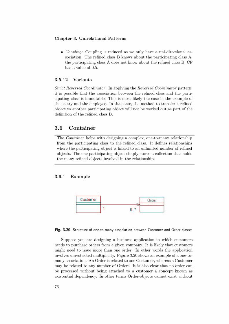
Chapter 3. Unirelational Patterns
• Coupling : Coupling is reduced as we only have a uni-directional as-sociation. The refined class B knows about the participating class A;the participating class A does not know about the refined class B. CFhas a value of 0.5.
3.5.12 Variants
Strict Reversed Coordinator : In applying the Reversed Coordinator pattern,it is possible that the association between the refined class and the parti-cipating class is immutable. This is most likely the case in the example ofthe salary and the employee. In that case, the method to transfer a refinedobject to another participating object will not be worked out as part of thedefinition of the refined class B.
3.6 Container
The Container helps with designing a complex, one-to-many relationshipfrom the participating class to the refined class. It defines relationshipswhere the participating object is linked to an unlimited number of refinedobjects. The one participating object simply stores a collection that holdsthe many refined objects involved in the relationship.
3.6.1 Example
Fig. 3.20: Structure of one-to-many association between Customer and Order classes
Suppose you are designing a business application in which customersneeds to purchase orders from a given company. It is likely that customersmight need to issue more than one order. In other words the applicationinvolves unrestricted multiplicity. Figure 3.20 shows an example of a one-to-many association. An Order is related to one Customer, whereas a Customermay be related to any number of Orders. It is also clear that no order canbe processed without being attached to a customer a concept known asexistential dependency. In other terms Order-objects cannot exist without
76

3.6. Container
being attached to Customer-object. The association between a Customer-object and its Order-object allows the Customer to communicate with itsOrders by invoking methods offered by the Order object’s interface. Thelink is directed from the Customer-object to the Order-object.
Implementing an association in one direction only is preferred when pos-sible (rather than also having an Order-object hold a reference to its Cus-tomer). One reason for this is that maintaining consistency for two-wayrelationships is a problem. Another reason is the goal of reducing coupling.
3.6.2 Context
Uses a container or a collection to model one-way one-to-many, associationrelationship.
3.6.3 Problem
One-way, one-to-many relationships are almost common in object-orientedmodels. Because they are so common they need to be implemented as easilyas efficiently as possible. In addition to unrestricted multiplicity defined atone end of the relationship, some relationships involve existential depend-ency. This constraint states that one object (referred to as the refined object)cannot exist without being attached to the other object (referred to as theparticipating object) involves in the relationship. Existential dependencyhas a major impact on constructing and destructing refined objects.
Managing such types of relationships in a flexible, understandable, andmaintainable way is nontrivial task. This is often related to whether a rela-tionship is represented explicitly by single element of a design, or whetherit is dispersed across several objects, attributes, and methods; and whethera change of state in a relationship is local, affecting only those objects par-ticipating in the relationship, or global, affecting other objects in the soft-ware system. Representing a relationship explicitly between objects makesit easier to identify the relationship within the design. Representing therelationship explicitly means defining direction of navigation.
Fig. 3.21: Structure of one-to-many association between the participating class A andthe refined class B
77

Chapter 3. Unirelational Patterns
Unidirectional navigation decreases the complexity of maintaining therelationships and ensures that objects are properly created and removed.Unidirectional navigation limits interdependency between the participatingclass and the refined class.
One-way, one-to-many relationship, as shown in Figure 3.21, cannot beimplemented as attribute, because the number of attributes in each objectis fixed, and each attribute must be accessed individually. One-to-manyrelationships can be implemented by hard coding the relationship into everyrefined object, but this disperses the relationship across all refined objects,couples them very tightly, and cannot be re-used across similar relationshipin a design.
The Container pattern, manages this type of relationships by making aContainer pattern to model the relationship. The one participating objectsimply stores a collection that holds the many refined objects sharing therelationship.
3.6.4 Forces
• Existential dependency : This property implies that a refined objectmust at all times be attached to two participating objects. Existentialdependency has a major impact on the construction and the destruc-tion of refined objects
• Unrestricted multiplicity : The relationship between the refined classand the participating class requires unrestricted multiplicity. It impliesthat each participating object is linked to an unlimited number ofrefined objects.
• Mutability : This property implies that, during its lifetime, a refinedobject may be associated with several participating objects of the sameclass. This property requires methods by means of which a refined ob-ject can be transferred to another participating object. Changing thebindings between the current associated objects should be consideredwith high care to insure consistency.
• Adaptability : It provides flexibility to add and remove responsibilitiesto objects at run-time simply by attaching and detaching them.
• Re-usability : The Container and the objects stored inside it are veryweakly coupled, and so each can be reused in different contexts, buta Container pattern introduces one or more extra objects at run-timedepending on its implementation, and the extra level indirection re-duces execution speed.
78

3.6. Container
3.6.5 Solution
The solution of this problem is done by:
• Defining a collection object in the participating class to store the rela-tionship. The collection couples a participating object with unlimitednumber of refined objects.
• Add inspector to retrieve the information needed from the refined ob-jects.
• Add mutator to change the relationship between the involved refinedand participating objects.
3.6.6 Structure
The structure shown in Figure 3.22, illustrates a one-way one-to-many re-lationship between a participating A-object and unlimited refined B-objectsimplemented by the Container pattern. Class A includes the collection ob-ject $refBs which defines the relationship between A-object and B-object.Also the structure includes the following methods:
Fig. 3.22: Structure of Container Object from the participating class A to the refinedclass B
• addB : public method to add new refined B-object to the collection.
• removeB : public method to remove a B-object from the collection.
• getBs: public method to access the refined B-objects.
• transferBTo: public method to change the relationship between theassociated participating and refined objects.
• getNbBs: public method to get the number of refined B-objects at-tached to the current A-object.
79

Chapter 3. Unirelational Patterns
• B-objects are destroyed implicitly at the time A-object becomes outof reach
3.6.7 Implementation
1. Define a collection refBs in the participating A-object to store ref-erences to the refined B-objects. The collection will represent theone-to-many relationship.
2. Class A will include the following responsibilities of adding, removing,accessing, and changing the relationship:
• The method addB will add a new B to the list of refined B-objects
• Removing B-object will be managed by the method removeB.This method remove the given B-object from the collection ofB-objects referenced by the participating A-object.
• Accessing the referred B-objects will be by calling the methodgetBS. It returns an array of the current refined B-objects thatis associated to this A-object.
• The mutator is defined in the method transferBTo. This methodassigns the given B-object to the given A-object and removes thegiven B-object from the collection of B-objects referenced by thisA-object. The transfer is implemented by breaking the currentlink between the givenB-object and this A-object, and then anew link is established between the given B-object and the givenA-object.
3.6.8 Sample Code
Listing 3.6: Container pattern involving mutability and unrestricted multiplicity betweenthe participating Class A and the refined class B
class A {/**
* Initialize a new A-object without any B-objects
* attached to it.
* @post The new A-object is initialized without
* any B-objects attached to it.
* | new.getBs().length == 0;
*/
public A() {$refBs = new B[20];
}/**
* Return an array of B-objects attached to this A-object.
*/
80

3.6. Container
public B[] getBs() {B[] result = new B[$nbBs];for( int i = 0; i< $nbBs;i++)
result [ i ] = $refBs [ i ];return result ;
}/**
* Return the number of B-objects attached to this
* A-object.
* @return The number of elements in the array
* of B-objects attached to this A-object.
* | getBs().length
*/
public int getNbBs() {return $nbBs;
}/**
* Add the given B-object to this A-object.
* @pre The given B-object must be effective.
* | b != null
* @pre No more than 19 B-objects may already
* be attached to this A-object.
* | getNbBs() < 20
* @post The number of B-objects attached
* to this A-object is incremented by 1.
* | new.getNbBs() == getNbBs() + 1
* @post The given B-object is added to
* the B-objects attached to this A-object.
* | new.getBs()[this.getNbBs()-1] == b
*/
public void addB(B b) {$refBs [$nbBs]= b;$nbBs ++;
}/**
* Remove the given B-object from this A-object.
* @pre The given B-object must be effective.
* | b != null
* @pre The given B-object must be attached to
* this A-object.
* | for some i in 0..getNbBS()-1:
* | getBs()[i] == b
* @post The number of B-objects attached to
* this A-object is decremented by 1.
* | new.getNbBs() == getNbBs() - 1
* @post The given B-object is no longer
* attached to this A-object.
* | for each i in 0..new.getBs()-1:
* | new.getBs()[i] != b
81

Chapter 3. Unirelational Patterns
*/
public void removeB(B b){int i = 0;while ($refBs [ i ] != b)
i++;for ( int j = i ; j < $nbBs−1; j++)
$refBs[ j ] = $refBs [ j+1];$nbBs−−;
}/**
* Transfer the given B-object from this A-object
* to which it is attached to the given A-object.
* @pre The given A-object must be effective
* | a != null.
* @pre The given B-object must be attached to
* this A-object.
* | for some i in 0..getNbBS()-1:
* | getBs()[i] == b
* @pre The given B-object must be effective.
* | b != null
* @pre No more than 19 B-objects may already
* be attached to the given A-object.
* | a.getNbBs() < 20
* @post The number of B-objects attached
* to this A-object is decremented by 1.
* | new.getNbBs() == getNbBs() - 1
* @post The number of B-objects attached to the
* given A-object is incremented by 1.
* | (new a).getNbBs() == a.getNbBs() + 1
* @post The given B-object is no longer part of the
* B-objects attached to this A-object.
* | for each i in 0..new.getNbBs():
* | new.getBs()[i] != b
* @post The given B-object is added to the B-objects
* attached to the given A-object.
* | (new a).getBs()[(new a).getNbBs()-1] == b
*/
public void transferBTo(B b, A a){removeB(b);a.addB(b);
}private B[] $refBs ;int $nbBs = 0;
}
3.6.9 Example Revised
The implementation of Customer-Order model shown in figure 3.23 will beas follows the model has a customer that can issue up to 20 orders:
82
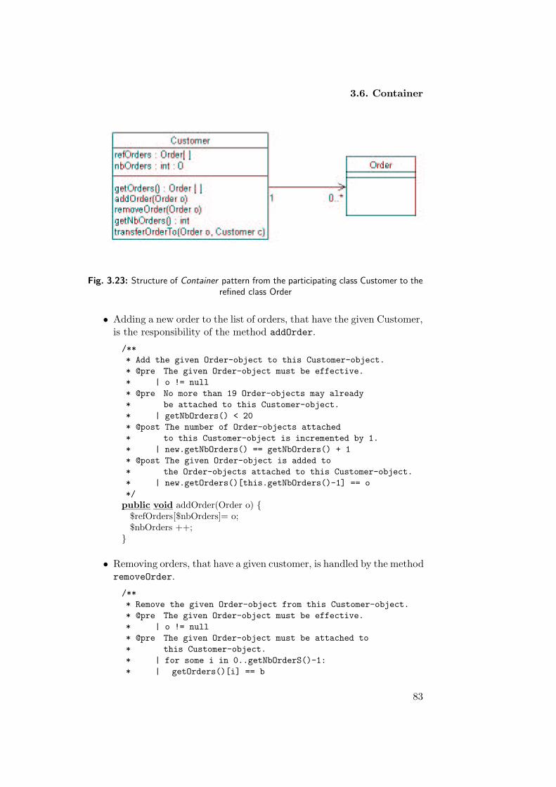
3.6. Container
Fig. 3.23: Structure of Container pattern from the participating class Customer to therefined class Order
• Adding a new order to the list of orders, that have the given Customer,is the responsibility of the method addOrder.
/**
* Add the given Order-object to this Customer-object.
* @pre The given Order-object must be effective.
* | o != null
* @pre No more than 19 Order-objects may already
* be attached to this Customer-object.
* | getNbOrders() < 20
* @post The number of Order-objects attached
* to this Customer-object is incremented by 1.
* | new.getNbOrders() == getNbOrders() + 1
* @post The given Order-object is added to
* the Order-objects attached to this Customer-object.
* | new.getOrders()[this.getNbOrders()-1] == o
*/
public void addOrder(Order o) {$refOrders[$nbOrders]= o;$nbOrders ++;
}
• Removing orders, that have a given customer, is handled by the methodremoveOrder.
/**
* Remove the given Order-object from this Customer-object.
* @pre The given Order-object must be effective.
* | o != null
* @pre The given Order-object must be attached to
* this Customer-object.
* | for some i in 0..getNbOrderS()-1:
* | getOrders()[i] == b
83

Chapter 3. Unirelational Patterns
* @post The number of Order-objects attached to
* this Customer-object is decremented by 1.
* | new.getNbOrders() == getNbOrders() - 1
* @post The given Order-object is no longer
* attached to this Customer-object.
* | for each i in 0..new.getOrders()-1:
* | new.getOrders()[i] != o
*/
public void removeOrder(Order o){int i = 0;while ($refOrders[i ] != o)
i++;for (int j = i ; j < $nbOrders−1; j++)
$refOrders[ j ] = $refOrders[ j+1];$nbOrders−−;
}
• Accessing the collection of orders that have the given customer, issupported by the method getOrders.
/**
* Return an array of Order-objects attached to this Customer-object.
*/
public Order[] getOrders() {Order[] result = new Order[$nbOrders];for(int i = 0; i< $nbOrders;i++)
result [ i ] = $refOrders[ i ];return result;
}
• The number of orders that assigned to the current customer, can beretrieved by applying the method getNbOrders.
/**
* Return the number of Order-objects attached to this
* Customer-object.
* @return The number of elements in the array
* of Order-objects attached to this Customer-object.
* | getOrders().length
*/
public int getNbOrders() {return $nbOrders;
}
• The transfer of order from its current customer to another customeris handled by the method transferOrderTo.
/**
* Transfer the given Order-object from this Customer-object
* to which it is attached to the given Customer-object.
84

3.6. Container
* @pre The given Customer-object must be effective
* | c != null.
* @pre The given Order-object must be attached to
* this Customer-object.
* | for some i in 0..getNbOrderS()-1:
* | getOrders()[i] == o
* @pre The given Order-object must be effective.
* | o != null
* @pre No more than 19 Order-objects may already
* be attached to the given Customer-object.
* | c.getNbOrders() < 20
* @post The number of Order-objects attached
* to this Customer-object is decremented by 1.
* | new.getNbOrders() == getNbOrders() - 1
* @post The number of Order-objects attached to the
* given Customer-object is incremented by 1.
* | (new c).getNbOrders() == c.getNbOrders() + 1
* @post The given Order-object is no longer part of the
* Order-objects attached to this Customer-object.
* | for each i in 0..new.getNbOrders():
* | new.getOrders()[i] != o
* @post The given Order-object is added to the Order-objects
* attached to the given Customer-object.
* | (new c).getOrders()[(new c).getNbOrders()-1] == o
*/
public void transferOrderTo(Order o, Customer c){removeOrder(o);c.addOrder(o);
}
3.6.10 Consequences
1. Efficiency : Has this pattern been applied efficiency in terms of speedand space will be decreased. This pattern introduces new object atrun-time, which might decrease execution speed.
2. Adaptability : It provides flexibility to add and remove responsibilitiesto objects at run-time simply by attaching and detaching them.
3. Re-usability : The Container object and the objects stored inside itare weakly coupled due to the unidirectional navigation between theparticipating object and the refined objects.
4. Simplicity : Simplicity is since we have one directional associationbetween the involved participating and refined objects.
3.6.11 Metrics and Evaluation
• The complexity of class A is increased as the number of methods in theparticipating class increased due to the container object that represent
85

Chapter 3. Unirelational Patterns
the relationship. WMC is increased by 6.
• Cohesion for the model is improved due to the unidirectional naviga-tion. Contrary to the refined class, cohesion for the participating classis negatively affected because of the relationship presented in it andthe added functionalities to access and manipulate it.
• Coupling: Coupling for this relationship is low as we have only uni-directional navigation. CF has a value of 0.5, which is a significant lowvalue. However, placing the reference in the participating class makesit tightly coupled to the refined class, which decreases its adaptability.
3.6.12 Variants
Immutable Container: This pattern could be restricted by not allowing themutation to take place. For example suppose class B does not allow changein binding between objects with the participating class A, then methodtranferBTo will be removed from the class. The rest of the pattern will beleft untouched.
3.7 Collaborator
The Collaborator pattern helps with designing a complex, two-way, one-to-many relationship between the participating class and the refined class. Itdefines relationships where the participating object is linked to an unlim-ited number of refined objects. A single participating object simply storesa collection that holds references to all the refined objects to which it isassociated. The refined class, on the other hand, represents its relationshipwith the participating class as a single-valued attribute.
3.7.1 Example
Consider the model fragment in Figure 3.24. An instance of the Flight-classrepresents a flight that has occurred, along with the airports to which thisflight belongs. Each Flight-object must belong to a departure airport and toa destination airport. The model further shows that an unlimited numberof flights can be assigned to an airport. An Airport-object needs a two-wayrelationship with its Flight objects - airports must be able to enumeratetheir flights to manage their arrivals and departures, flights need to knowtheir destination airport and their departure airport.
In a two-way relationship, each object involved in the relationship iseasily accessible from every object to which it is associated, and vice versa.A change in any one object participating in the relationship may affect allother objects in the relationship. Suppose that a flight needs to be diverted
86

3.7. Collaborator
to another airport then it must be possible to notify the new airport of thisnew flight, such that it is added to its collection of current flights. In workingout two-way relationship it is important to maintain consistency among theassociated objects in the relationship. The Collaborator pattern will helpimplementing such a design.
Fig. 3.24: An airport with multiple flights
3.7.2 Problem
For some relationships, known as two-way relationships, the objects involvedare equally important. In other words, each object involved in a relationshipneeds to have access to every other object to which it is associated. As itis shown in Figure 3.25, the type of relationships dealt with in this sectionassume particular structural constraint at both ends of the relationship. Atone end of the relationship unrestricted multiplicity is assumed, whereas ex-istential dependency must apply at the other end of the relationship. Theformer states that one A-object (referred to as a participating object) is at-tached to unlimited number of B-objects (referred to as the refined objects).The latter constraint expresses that refined B-objects cannot exist withoutbeing associated to exactly one participating A-object.
In a two-way relationship, each object must be easily accessible fromevery other object to which it is associated. A change in any one parti-cipating object may affect all other refined objects in the relationship. Inparticular, if an object joins or leaves the relationship, the objects to whichit was associated must be informed in order to maintain consistency forthe entire relationship. The Collaborator pattern tackles this problem andmanages two-way relationships in a consistent way.
3.7.3 Forces
• Existential dependency : This property implies that refined objectsmust at all times be attached to a participating object. Existentialdependency has a major impact on the construction and the destruc-tion of refined objects.
• Unrestricted multiplicity : The relationship between the refined class
87
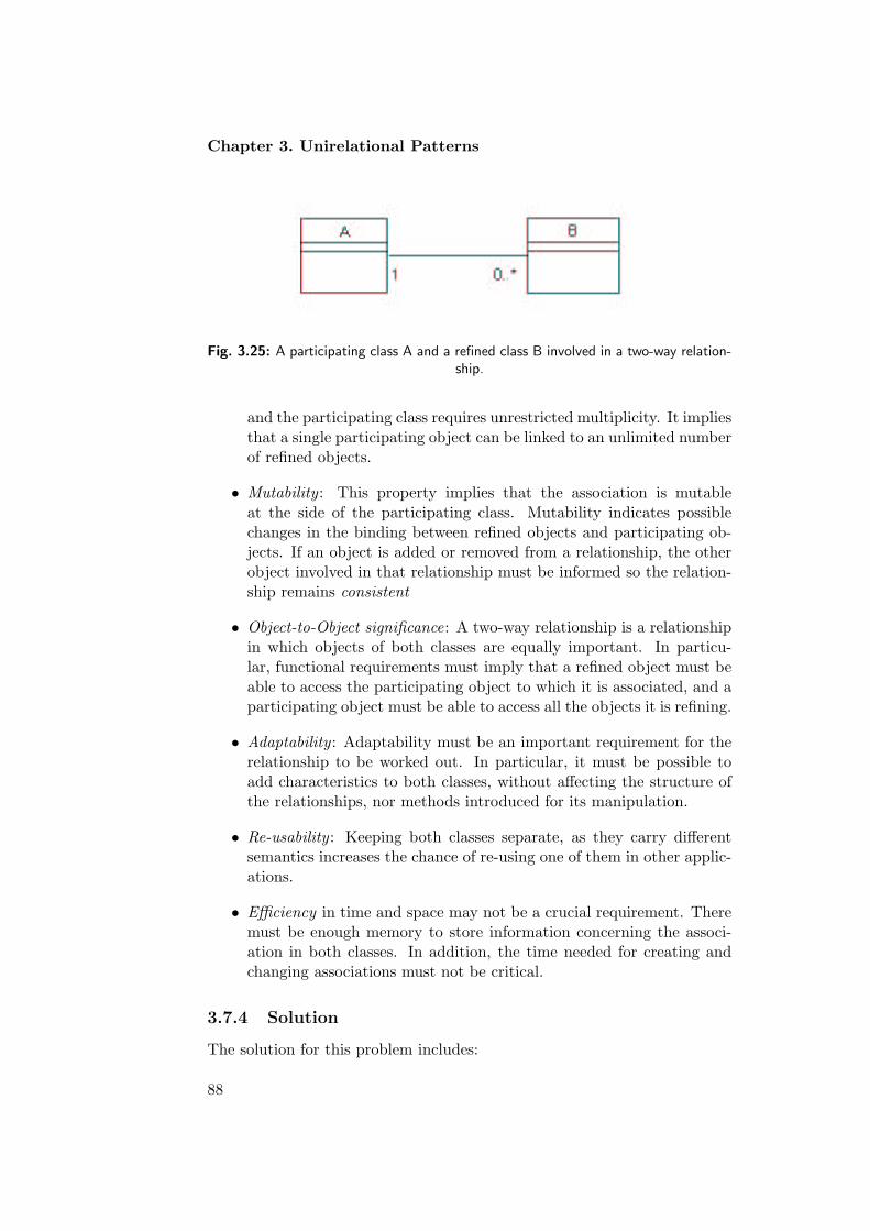
Chapter 3. Unirelational Patterns
Fig. 3.25: A participating class A and a refined class B involved in a two-way relation-ship.
and the participating class requires unrestricted multiplicity. It impliesthat a single participating object can be linked to an unlimited numberof refined objects.
• Mutability : This property implies that the association is mutableat the side of the participating class. Mutability indicates possiblechanges in the binding between refined objects and participating ob-jects. If an object is added or removed from a relationship, the otherobject involved in that relationship must be informed so the relation-ship remains consistent
• Object-to-Object significance: A two-way relationship is a relationshipin which objects of both classes are equally important. In particu-lar, functional requirements must imply that a refined object must beable to access the participating object to which it is associated, and aparticipating object must be able to access all the objects it is refining.
• Adaptability : Adaptability must be an important requirement for therelationship to be worked out. In particular, it must be possible toadd characteristics to both classes, without affecting the structure ofthe relationships, nor methods introduced for its manipulation.
• Re-usability : Keeping both classes separate, as they carry differentsemantics increases the chance of re-using one of them in other applic-ations.
• Efficiency in time and space may not be a crucial requirement. Theremust be enough memory to store information concerning the associ-ation in both classes. In addition, the time needed for creating andchanging associations must not be critical.
3.7.4 Solution
The solution for this problem includes:
88

3.7. Collaborator
• Splitting the relationship into a pair of one-way relationships. First ofall, a one-way, one-to-many relationship from the participating classto the refined class using the Container pattern, which introduces acollection to represent the relationship. Secondly, a one-way, one-to-one relationship from the refined class to the participating class usingthe Reverse Coordinator pattern, which introduces an attribute in therefined class to represent the relationship.
• The one-way relationships must be kept consistent. In this pattern,we have chosen the participating object as the director of the relation-ship. Another pattern could be worked out in which the refined objectis given responsibility over the association. The participating objectcentralizes the responsibility for maintaining the relationship. If therefined object needs to make a change to the relationship, it shoulddelegate the change to its participating object.
3.7.5 Structure
The structure shown in Figure 3.26, illustrates the structure imposed bythe Collaborator pattern involving a participating class A whose objectscan be associated with an unlimited number of objects of a refined classB. Class A includes the collection object $refBs Registering references of aparticipating A-object with refined B-objects. Class B includes an attribute$refA referencing the participating A-object to which the refined object isassociated.
In addition to the structural elements, the following methods must beintroduced for manipulating the two-way relationship:
Fig. 3.26: Structure of the participating class A and the refined class B involved in theCollaborator pattern.
1. Methods at the level of the participating class A:
• addB : a public method to add a reference to a new refined B-object to the collection of objects to which the given participatingobject is associated.
89
Chapter 3. Unirelational Patterns
• removeB : a public method to remove a given refined B-objectfrom the collection of objects to which the given participatingobject is associated.
• getBs: a public method returning references to all the refinedB-objects to which the given participating object is associated.
• getNbBs: a public method returning the number of refined B-objects to which the given participating object is associated.
• Notice that refined B-objects are destroyed implicitly at the timethe participating A-object to which they are associated becomesout of reach.
2. Methods at the level of the refined class B:
• A constructor to initialize a new refined B-object.
• destructB : a public method to destroy the given B-object.
• getA: a public method returning a reference to the participatingA-object to which the given refined object is associated.
• transferBTo: a public method to transfer the given refined B-object from the participating A-object to which it is associated,to become associated with the given participating A-object.
3.7.6 Implementation
1. Define a collection $refBs in the participating class A to store ref-erences to associated refined B-objects. The collection represents theone-to-many relationship.
2. The participating class A will include the following responsibilities foradding, removing, accessing, and changing the relationship:
• The method addB will add a new B-object to the list of refinedB-objects associated with the given participating A-object.
• Removing B-objects can be accomplished by the method removeB.This method removes the given B-object from the collection ofB-objects attached to the given participating A-object.
• Accessing associated B-objects is obtained by invoking the methodgetBs. This inspector returns an array of all refined B-objectsthat are currently associated to the given participating A-object.
• The property of existential dependency must be considered whendestroying a participating A-object. Before an A-object can bedestroyed, all the refined B-objects associated with the given par-ticipating A-object must be destroyed as well.
90

3.7. Collaborator
3. Define an attribute $refA in the refined class B. This attribute rep-resents the one-to-one association from the refined class B to the par-ticipating class A.
4. The refined class B will include the following additional responsibilitiesfor accessing and changing the relationship:
• When a B-object is constructed, a reference to a participating A-object must be initialized because of the property of existentialdependency.
• The destruction of a B-object is the responsibility of the methoddestructB. Notice that the reference to the destroyed B-objectis removed from the participating A-object to which it was asso-ciated.
• Refined B-objects access their related participating A-object bymeans of the method getA.
• The mutator transferBTo changes the participating A-object towhich the given refined B-object is associated, to the given par-ticipating A-object. The change is implemented by breaking thecurrent link between the given refined B-object and the particip-ating A-object to which it was associated. Subsequently, a newlink in both directions is set between the given refined B-objectand the given participating A-object.
5. The multiplicity is implemented by defining a collection object ofpointers to objects of the refined class. If the ordered property isset on the role, then the collection object must be an array or someother kind of sequence enabling to order its elements. In the othercase, some form of set can be used. If the multiplicity is fixed, then afixed-length array can be used. However, in view of adaptability, it iswise is to use variable-length collections of objects for all multiplicitiesgreater than one.
Sample Code
Listing 3.7: Mutable one-to-many relationship from the participating class A to therefined class B.
import java. util . Collection ;import java. util . ArrayList ;
public class A {/**
* Initialize a new A-object without any B-objects
* attached to it.
* @post The new A-object is initialized
* without B-objects attached to it.
91

Chapter 3. Unirelational Patterns
* | new.getBs().size() == 0;
*/
public A () {$refBs = new ArrayList();
}/**
* Return a Collection of B-objects attached to this A-object.
*/
public Collection getBs() {return ( Collection ) $refBs . clone ();
}/**
* Add the given B-object as another B-object
* attached to this A-object.
* @pre The given B-object must be effective.
* | b != null
* @post The number of B-objects attached
* to this A-object is incremented by 1.
* | new.getNbBs() == this.getNbBs() + 1
* @post The given B-object is added to
* the B-objects attached to this A-object.
* | new.getBs().get(new.getNbBs()-1) == b
*/
void addB(B b) {$refBs .add(b);}/** Remove the given B-object from the set of
* all B-objects attached to this A-object.
* @pre The given B-object must be attached to
* this A-object.
* | for some i in 0..getNbBs()-1:
* | (getBs()).get(i) == b
* @post The number of B-objects attached to
* this A-object is decremented by 1.
* | new.getNbBs() == this.getNbBs() - 1
* @post The given B-object is no longer part
* of the B-objects attached to this A-object.
* | for each i in 0..new.getNbBs()-1:
* | (new.getBs()).get(i) != b
*/
void removeB(B b){$refBs .remove(b);}/** Transfer the given B-object from this A-object
* to become attached to the given A-object.
* @pre The given A-object must be effective
* | a != null.
* @pre The given B-object must be attached to
92

3.7. Collaborator
* this A-object.
* | for some i in 0..getNbBs()-1:
* | getBs()[i] == b
* @post The number of B-objects attached
* to this A-object is decremented by 1.
* | new.getNbBs() == this.getNbBs() - 1
* @post The number of B-objects attached
* to the given A-object is incremented by 1.
* | (new a).getNbBs() == a.getNbBs() + 1
* @post The given B-object is no longer part of the
* B-objects attached to this A-object.
* | for each i in 0..a.getNbBs()-1:
* | new.getBs()[i] != b
* @post The given B-object is added to the B-objects
* attached to the given A-object.
* | ((new a).getBs()).get(a.getNbBs()) == b
*/
public void transferBTo(B b, A a){removeB(b);a.addB(b);
}/**
* Return the number of B-objects attached to this
* A-object.
* @return The number of elements in the array
* of B-objects attached to this A-object.
* | getBs().size()
*/
public int getNbBs() {return $refBs . size ();
}
private ArrayList $refBs ;
}
Listing 3.8: Mutable one-to-one relationship from the refined class B to the particip-ating class A
public class B {/**
* Initialize a new B-object attached to the given
* A-object.
* @pre The given A-object must be effective.
* | a != null
* @post The new B-object is associated with
* the given A-object.
* | new.getA() == a
93

Chapter 3. Unirelational Patterns
* @post The new B-object is added to the
* array of B-objects referenced by
* the given A-object.
* | for some i in 0..a.getnbBs():
* | (new a).getBs()[i] == this
* @post The number of B-objects for the given
* A-object is incremented by 1.
* | (new a).getNbBs() == a.getNbBs() + 1
*/
public B (A a) {$refA = a;a.addB(this);
}/**
* Terminate this B-object.
* @post The A-object referenced by this B-object
* no longer references this B-object.
* | for each i in 0..(new getA()).getnbBs()-1:
* | (new getA()).getBs()[i] != this
* @post The number of B-objects attached to the A-object
* referenced by this B-object is decremented by 1.
* | (new getA()).getNbBs() == getA().getnbBs() - 1
*/
public void destructB() {getA().removeB(this);$refA = null ;
}/** Divert this B-object from the A-object
* to which it is attached to the given A-object.
* @pre The given A-object must be effective
* | a != null
* @post This B-object is attached to the given A-object.
* | new.getA() == a
* @post The number of B-objects attached
* to the A-object to which this B-object was
* associated, is decremented by 1.
* | (new getA()).getNbBs() == getA().getNbBs() - 1
* @post This B-object is no longer part of the B-objects
* attached to the A-object, to which this B-object
* was attached.
* | for each i in 0..(new getA()).getNbBs()-1:
* | (new getA()).getBs()[i] != this
* @post The number of B-objects attached to the
* given A-object is incremented by 1.
* | (new a).getNbBs() == a.getNbBs() + 1
* @post This B-object is added to the B-objects
* attached to this A-object.
* | (new a).getBs()[(new a).getNbBs()-1] == this
*/
94

3.7. Collaborator
public void transferBTo(A a){getA().removeB(this);a.addB(this);$refA = a;
}/**
* Return the A-object attached to this
* B-object.
*/
public A getA() {return $refA;
}private A $refA;
}
3.7.7 Example Revised
The Collaborator pattern can be applied to the model involving airports andflights. In fact, the pattern must be applied to both associations betweenthe Airport class and the Flight class. The resulting structure is illustratedin Figure 3.27. In the fragments of code listed below, aspects related to theassociation between the destination airport and the flight are Worked out.
Fig. 3.27: Class Airport and class Flight involving unrestricted multiplicity and mutab-ility
1. One-to-many relationship from an airport to all flights that have thatairport as their destination.
95

Chapter 3. Unirelational Patterns
• Adding a new flight to the list of flights, that have the givenairport as their destination, is the responsibility of the methodaddDestinationFlight to an Airport-object.
/**
* Add the given flight to the flights that
* have this airport as their destination.
* @pre The given flight must be effective.
* | flight != null
* @post The number of flights that have this airport
* as their destination is incremented by 1.
* | new.getNbDestinationFlights() ==
* this.getNbDestinationFlights() + 1
* @post The given flight is added to all the flights
* that have this airport as their destination.
* | new.getDestinationFlights().
* get(new.getNbDestinationFlights()-1) == flight
*/
void addDestinationFlight(Flight flight ) {$destinationFlights .add(flight );
}
• Cancelling flights, that have a given airport as their destination,is handled by the method cancelDestinationFlight.
/**
* Cancel the given flight such that it no longer has
* this airport as its destination.
* @pre The given flight must be effective.
* | flight != null
* @post The number of flights that have this airport
* as their destination attached is decremented by 1.
* | new.getNbDestinationFlights() ==
* this.getNbDestinationFlights() - 1
* @post The given flight is no longer part of all flights
* that have this airport as their destination.
* | for each i in 0..new.getNbDestinationFlights():
* | new.getDestinationFlights()[i] != flight
*/
void cancelDestinationFlight(Flight flight ) {$destinationFlights .remove(flight );
}
• Accessing the collection of flights, that have the given airport astheir destination, is supported by the method getDestinationFlights.
/**
* Return a collection of all flights that have this airport
* as their destination.
*/
public Collection getDestinationFlights() {
96

3.7. Collaborator
return (Collection)$destinationFlights .clone ();}
• The number of flights, that have the given airport as their destina-tion, can be retrieved by applying the method getNbDestinationFlights
to that airport.
/**
* Return the number of flights that have this airport
* as their destination.
* @return The number of elements in the collection of flights that
* have this airport as their destination.
* | getDestinationFlights().size()
*/
public int getNbDestinationFlights() {return $destinationFlights.size ();
}
2. One-to-one relationship from flights to their destination airport.
• A constructor is offered to initialize a new flight with given departure-airport and given destination-airport.
/**
* Initialize a new Flight-object with given departure-airport
* and given destination-airport.
* @pre The given airports must be effective.
* | (departure != null) && (destination != null)
* @post The new Flight-object has the given airports as
* its departure, respectively its destination.
* | (new.getDepartureAirport() == departure) &&
* | (new.getDestinationAirport() == destination)
* @post The new flight is added to all the flights that have
* the departure-airport as its departure.
* | for some i in 0..(new departure).getnbDepartureFlights()-1:
* | (new departure).getDepartureFlights()[i] == this
* @post The number of flights that have the given departure-airport
* as its departure, is incremented by 1.
* | (new departure).getNbDepartureFlights() ==
* | departure.getNbDepartureFlights() + 1
*
*/
public Flight(Airport departure, Airport destination) {$departure = departure;departure.addDepartureFlight(this);$destination = destination;destination .addDestinationFlight(this);
}
• Accessing the destination-airport for a given flight is supportedby the method getDestinationAirport.
97

Chapter 3. Unirelational Patterns
/**
* Return the destination-airport for this flight.
*/
public Airport getDestinationAirport() {return $destination;
}
• To divert a flight from its current destination-airport to anotherairport, the method divertFlightTo can be applied to that flight.This method will also change all flights that have the given air-ports as their destination.
/**
* Divert this flight such that the given airport
* is registered as its new destination.
* @pre The given airport must be effective.
* | airport != null
* @post This flight has the given airport as its destination.
* | new.getDestinationAirport() == airport
* @post The number of flights that have the old airport as their
* destination, is decremented by 1.
* | (new getDestination()).getNbDestinationFlights() ==
* | getDestination().getNbDestinationFlights() - 1
* @post This flight is no longer part of all flights that have
* the old airport as their destincation.
* | for each i in 0..(new getDestination()).
* getNbDestinationFlights():
* | (new getDestination()).getDestinationFlights()[i] != this
* @post The number of flights that have the given airport as its
* destination is incremented by 1.
* | (new airport).getNbDestinationFlights() ==
* | airport.getNbDestinationFlights() + 1
* @post This flight is added to the flights that have the given
* airport as their destination.
* | (new airport).getDestinationFlights()
* | [(new airport).getNbDestinationFlights()-1] == this
*/
public void divertFlightTo(Airport airport){getDestinationAirport().cancelDestinationFlight(this);airport .addDestinationFlight(this);$destination = airport;}
• To terminate a flight, the method terminateFlight must beapplied to it.
/**
* Terminate this flight.
* @post The airport acting as the destination of this flight
* no longer references this flight.
98

3.7. Collaborator
* | for each i in 0..(new
* getDestinationAirport()).
* getNbDestinationFlights() - 1 :
* | (new getDestinationAirport()).
* getDestinationFlights()[i] != this
* @post The number of flights for the airport
* acting as the destination
* of this flight is decremented by 1.
* | ((new getDestinationAirport()).
* getNbDestinationFlights() ==
* | getDestinationAirport().getNbDestinationFlights() - 1
* @post The airport acting as the departure of this flight
* no longer references this flight.
* | for each i in 0..(new
* getDepartureAirport()).getNbDepartureFlights() - 1 :
* | (new getDepartureAirport()).
* getDepartureFlights()[i] != this
* @post The number of flights for the airport
* acting as the departure of this
* flight is decremented by 1.
* | ((new getDepartureAirport()).getNbDepartureFlights() ==
* | getDepartureAirport().getNbDepartureFlights() - 1
*/
public void terminateFlight() {getDestinationAirport().cancelDestinationFlight(this);$destination = null;getDepartureAirport().cancelDepartureFlight(this);$departure = null;
}
3.7.8 Consequences
1. Adaptability : The Collaborator offers the flexibility to add and removecharacteristics to the classes involved in the application, without af-fecting the methods introduced to manipulate the two-way association.
2. Re-usability : Because both classes model singular objects, each ofthem having different semantics, there is a bigger chance of re-usingone of them in other applications.
3. efficiency : Efficiency is negatively affected both in terms of spaceneeded to store the objects involved in the relationship, and in ex-ecution time needed to register associations between objects. Noticehowever, that the pattern supports an efficient inspection of associ-ations, and this regardless of the starting object.
4. Simplicity : The Collaborator pattern is not simple and must be workedout with great care. Especially at the time new associations must be
99
Chapter 3. Unirelational Patterns
registered, or existing ones must be changed, the consistency of theregistered bindings must be preserved.
3.7.9 Metrics and Evaluation
• The complexity for the Collaborator pattern is high as the objectsneed to access each other in the underlying two-way relationship. Foreach class, an additional number of methods is added to access andmanipulate the relationship. For the participating class WMC is in-creased by 4, due to the one-to-many association with the refined classB. For the refined class B, WMC is increased by 3, which is the num-ber of methods added to handle the responsibility of the one-to-onerelationship from the refined class to the participating class.
• Cohesion for the model is decreased due to the two-way relationship.The functionalities defined in the related objects are interrelated andmust be managed in order to preserve the consistency. Low cohesionnegatively affects re-usability of the involved classes.
• Coupling: Coupling is high as we have bi-directional navigation. CFhas a value of 1.0, which is a significant high value. This is an immedi-ate consequence of registering the references in both the refined classand in the participating class. High coupling decreases the adaptabil-ity of the resulting model.
3.7.10 Variants
Immutable Collaborator: The Collaborator pattern could be restricted bynot allowing any changes to associations that have been created. In thatcase, the refined class B does not allow to change their binding with objectsof the participating class A. In that case, the method tranferBTo will notbe offered in the definition of the refined class B. Similarly, the participatingclass will not offer the method transferBTo. The rest of the definitions ofthe classes involved in the pattern is left untouched.
100

Chapter 4
Patterns for Birelational
Architectures
4.1 Bi-integrator
The Bi-integrator pattern helps with the integration of components thattogether from a semantic unit involving three classes, one refined classand two participating classes. The Bi-integrator integrates a refined classand a participating class into the other participating class. The patternencapsulates the components constituent functionalities, organizes theircollaboration and provides a common interface to them.
4.1.1 Example
Consider the model fragment in Figure 4.1. The model shows that therelationship between customers and banks is characterised through accounts.It shows that customers can hold an unlimited number of accounts in a bank,and that a bank can issue an unlimited number of accounts to a customer. Inour view, a binary relation involving class Customer and class Bank refinesthe Account class. As a result, this relationship expresses that Account-objects cannot exist without being attached to Customer-objects that holdthem, and to Bank-objects that grant them. In other words, this type ofstructure implies the existential dependency constraint on the refined class.
Suppose that during designing the software system, you figured out thatboth the Bank class and the Account class have little weight in the model,and you are only interested in the number of accounts a customer holdsand/or the number of Banks a person is registered at, and not in otherinformation concerning accounts or banks in the application. Moreover, youdo not expect the Account objects and the Bank objects to become moreimportant to the application you are designing.
101

Chapter 4. Birelational Patterns
Fig. 4.1: Class Account is refined by a binary relation involving classes Customer andBank
In this case, you may decide to decrease the state space of the modelby bi-integrating both Account-objects and Bank-objects into Customer-objects to which they are associated. The integration includes defining twoattributes that will tell how many accounts a customer holds, respectivelyat how many banks a customer is registered. These attributes store only thenumber of accounts and the number of banks available for each customer.The Bi-integrator pattern will help you implement this design. The Bi-integrator pattern integrates a refined class and a participating class intothe other participating class by introducing two attributes in which thenumber of refined objects and participating objects are stored.
4.1.2 Context
A participating object encapsulates data or information provided by otherrefined and participating objects.
4.1.3 Problem
In software applications you may encounter structures or relationships thatinclude three classes in which one of the related objects (referred to as the re-fined objects) implies existential dependency on the other two objects (referto as the participating objects). Such relationships may have an unrestric-ted multiplicity, meaning that an unlimited number of refined objects canbe attached to the same participating object.
Some of those objects that form the relationship may carry little inform-ation and a few associated functionality. Moreover, one may expect thatthese objects will not become more important at the time new requirementsare added or existing ones are modified in the underlying application. Theremight be situations in which the designer is only interested in the numberof those objects and does not intend to introduce them as separate objects.
In such cases, the Bi-integrator pattern will combine the objects thatare pulling out their weight in the relationship into the object that is moresignificant to the underlying application. This pattern reduces the givenstructure shown in Figure 4.2 to the minimum number of objects it can
102

4.1. Bi-integrator
have, mainly to one object. The Bi-integrator pattern integrates the re-fined objects and one of the involved participating objects into the otherparticipating object. It introduces the integrated objects as attributes inthe participating object. As a result, the related objects are no longer in-troduced as separate objects, there by simplifying the design model andincreasing its efficiency.
Fig. 4.2: Structure of the participating classes A and B including the refined class Rinvolving unrestricted multiplicity
4.1.4 Forces
Several forces drive the solution to this problem
• Existential dependency : This property implies that a refined objectmust at all times be attached to two participating objects. Existentialdependency has a major impact on the construction and the destruc-tion of refined objects
• Property unrestricted multiplicity : The relationship between the re-fined class and the participating classes requires unrestricted multipli-city. It implies that each participating object is linked to unlimitednumber of refined objects.
• Property mutability : This property implies that a refined object mightbe mutable. Mutability indicates the change in binding between therefined object and the participating objects.
• Class weight in the model : The refined class and one of the participat-ing classes must carry little information and a few associated function-ality. Moreover, you may expect that their objects will not becomemore important at times new requirements are added or existing onesare modified in the application.
• Efficiency : If the state space of the design model is reduced, efficiencyin terms of time and space is improved.
• Simplicity and Understandability : Once number of objects in the modelis decreased it can be easier to understand and simpler to implement.
103

Chapter 4. Birelational Patterns
4.1.5 Solution
The Bi-integrator pattern solves the addressed problem by:
• Combining objects of the refined class and objects of one of the twoparticipating classes into objects of the remaining participating class.The integration includes defining two attributes in either of the par-ticipating classes, one to store the number of the integrated-refinedobjects, and one to store the number of the integrated-participatingobjects.
• Adding the functionalities of the integrated refined and participatingcomponents by introducing a constructor, destructor, mutator and aninspector, to respectively add, remove, change, and access the inform-ation related to the integrated objects.
4.1.6 Structure
The structure shown in Figure 4.3 presents the integrator pattern for amodel involving the refined class R and the participating classes A andB. The participating class A includes a two added attributes that countsthe number of integrated refined R-objects and the number of integratedparticipating B-objects. Also the structure includes the following methods:
Fig. 4.3: Structure of the participating class A where the refined class R and theparticipating class B are integrated
1. Methods for the integrated-refined R-objects
• addR: public method to increment the number of integrated R-objects. This method may increment the B-objects if new B-object is required to complete the relationship.
104

4.1. Bi-integrator
• removeR: public method to decrement the number of integratedA-objects. Similar to the previous method this can also decre-ment the number of B-objects
• getNumberOfRs: public method to retrieve the number of integ-rated R-objects.
• transferRTo: public method to change the binding between therefined R-object and the given A-object.
2. Methods for the integrated-participating B-objects
• addB : public method to increment the number of integrated B-objects.
• removeB : public method to decrement the number of integratedB-objects.
• getNumberOfBs: public method to retrieve the number of integ-rated B-objects.
4.1.7 Implementation
To implement the Bi-integrator pattern carry out the following steps.
1. Introduce the integer variable $numberOfRs to store the number ofintegrated-refined R-objects.
2. Implement the refined R-objects’ functionalities:
• The method addR increments the number of R-objects attachedto the given A-object. This method increments the counter$numberOfRs by 1. Since the refined R-object requires an ob-ject of both participating classes A and B, a boolean is added asa formal argument in the method. This boolean is added to in-sure whether the newly added R-object requires us to incrementthe number of B-objects that are currently integrated in the givenA-object.
• The method removeR decrements the number of R-objects in-tegrated into the given A-object. This method decrements thecounter $numberOfRs by 1. Notice also that when removing R-objects the user has to tell whether or not the number of B-objectsinvolved must also be decremented. Therefore, a boolean flag isadded as a formal argument for this method.
• The inspector getNumberofRs returns the number of R-objectsintegrated into the current A-object.
• The mutator transferRTo decrements the number of R-objectsattached to it. At the same time, the number of R-objects forthe given A-object is incremented.
105
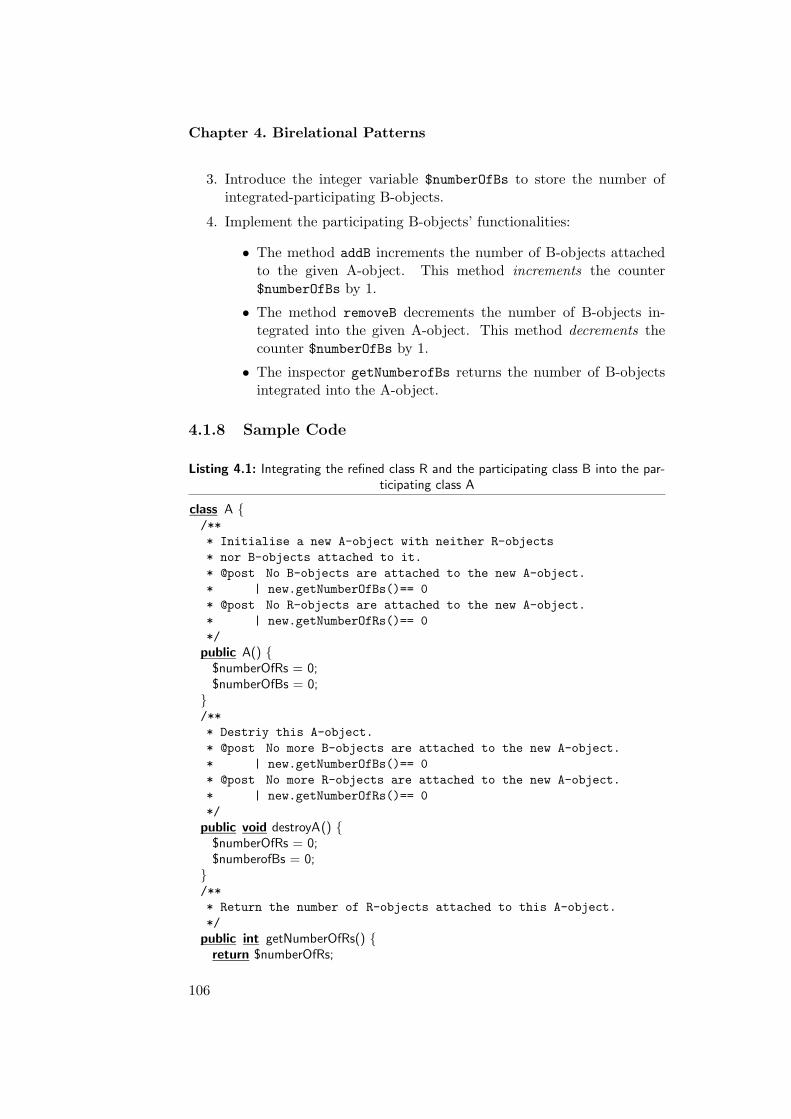
Chapter 4. Birelational Patterns
3. Introduce the integer variable $numberOfBs to store the number ofintegrated-participating B-objects.
4. Implement the participating B-objects’ functionalities:
• The method addB increments the number of B-objects attachedto the given A-object. This method increments the counter$numberOfBs by 1.
• The method removeB decrements the number of B-objects in-tegrated into the given A-object. This method decrements thecounter $numberOfBs by 1.
• The inspector getNumberofBs returns the number of B-objectsintegrated into the A-object.
4.1.8 Sample Code
Listing 4.1: Integrating the refined class R and the participating class B into the par-ticipating class A
class A {/**
* Initialise a new A-object with neither R-objects
* nor B-objects attached to it.
* @post No B-objects are attached to the new A-object.
* | new.getNumberOfBs()== 0
* @post No R-objects are attached to the new A-object.
* | new.getNumberOfRs()== 0
*/
public A() {$numberOfRs = 0;$numberOfBs = 0;
}/**
* Destriy this A-object.
* @post No more B-objects are attached to the new A-object.
* | new.getNumberOfBs()== 0
* @post No more R-objects are attached to the new A-object.
* | new.getNumberOfRs()== 0
*/
public void destroyA() {$numberOfRs = 0;$numberofBs = 0;
}/**
* Return the number of R-objects attached to this A-object.
*/
public int getNumberOfRs() {return $numberOfRs;
106
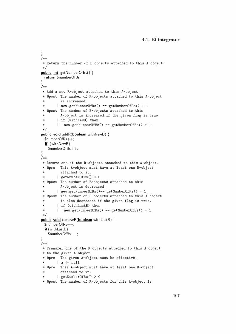
4.1. Bi-integrator
}/**
* Return the number of B-objects attached to this A-object.
*/
public int getNumberOfBs() {return $numberOfBs;
}/**
* Add a new R-object attached to this A-object.
* @post The number of R-objects attached to this A-object
* is increased.
* | new.getNumberOfRs() == getNumberOfRs() + 1
* @post The number of B-objects attached to this
* A-object is increased if the given flag is true.
* | if (withNewB) then
* | new.getNumberOfBs() == getNumberOfBs() + 1
*/
public void addR(boolean withNewB) {$numberOfRs++;if (withNewB)
$numberOfBs++;}/**
* Remove one of the R-objects attached to this A-object.
* @pre This A-object must have at least one R-object
* attached to it.
* | getNumberOfRs() > 0
* @post The number of R-objects attached to this
* A-object is decreased.
* | new.getNumberOfRs()== getNumberOfRs() - 1
* @post The number of B-objects attached to this A-object
* is also decreased if the given flag is true.
* | if (withLastB) then
* | new.getNumberOfBs() == getNumberOfBs() - 1
*/
public void removeR(boolean withLastB) {$numberOfRs−−;if (withLastB)
$numberOfBs−−;}/**
* Transfer one of the R-objects attached to this A-object
* to the given A-object.
* @pre The given A-object must be effective.
* | a != null
* @pre This A-object must have at least one R-object
* attached to it.
* | getNumberOfRs() > 0
* @post The number of R-objects for this A-object is
107
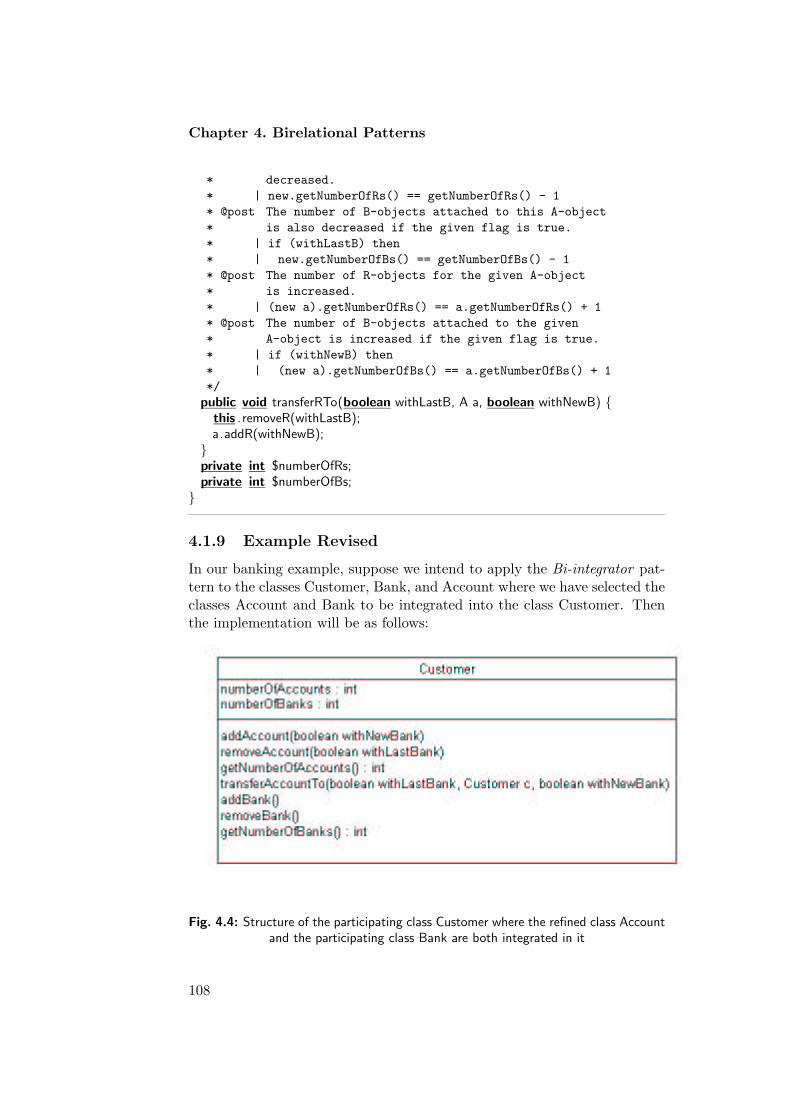
Chapter 4. Birelational Patterns
* decreased.
* | new.getNumberOfRs() == getNumberOfRs() - 1
* @post The number of B-objects attached to this A-object
* is also decreased if the given flag is true.
* | if (withLastB) then
* | new.getNumberOfBs() == getNumberOfBs() - 1
* @post The number of R-objects for the given A-object
* is increased.
* | (new a).getNumberOfRs() == a.getNumberOfRs() + 1
* @post The number of B-objects attached to the given
* A-object is increased if the given flag is true.
* | if (withNewB) then
* | (new a).getNumberOfBs() == a.getNumberOfBs() + 1
*/
public void transferRTo(boolean withLastB, A a, boolean withNewB) {this .removeR(withLastB);a.addR(withNewB);
}private int $numberOfRs;private int $numberOfBs;
}
4.1.9 Example Revised
In our banking example, suppose we intend to apply the Bi-integrator pat-tern to the classes Customer, Bank, and Account where we have selected theclasses Account and Bank to be integrated into the class Customer. Thenthe implementation will be as follows:
Fig. 4.4: Structure of the participating class Customer where the refined class Accountand the participating class Bank are both integrated in it
108

4.1. Bi-integrator
1. Introduce the integer variable $numberOfAccounts to store the num-ber of integrated-refined Account-objects.
2. Implement the Account-objects’ functionalities:
• The method addAccount increments the number of Account-objects attached to the given Customer-object. This method in-crements the counter $numberOfAccounts by 1. Since the refinedAccount-object requires an object of both participating classes,Customer and Bank, a boolean is added to in the formal argu-ments of the method. This boolean is added to insure whether thenewly added Account-object requires us to increment the num-ber of Bank-objects that are currently integrated in the givenCustomer-object.
/**
* Add a new Account-object attached to this
* Customer-object.
* @post The number of Account-objects attached
* to this Customer-object is increased.
* | new.getNumberOfAccounts()==
* getNumberOfAccounts() + 1
* @post The number of Bank-objects attached to this
* Customer-object is increased if the given
* flag is true.
* | if(withNewBank) then
* new.getNumberOfBanks() ==
* getNumberOfBanks() + 1
*/
public void addAccount(boolean withNewBank){$numberOfAccounts++;if (withNewBank)
$numberOfBanks++;}
• The method removeAccount decrements the number of Account-objects integrated into the given Customer-object. This methoddecrements the counter $numberOfAccounts by 1. Notice also,that when removing Account-objects the user has to tell whetheror not the number of Bank-objects involved must also be decre-mented. Therefore, a boolean flag is added as a formal argumentfor this method.
/**
* Remove one of the Account-objects attached
* to this Customer-object.
* @pre This Customer-object must have at
* least one Account-object attached to it.
* | new.getNumberOfAccounts()> 0
109

Chapter 4. Birelational Patterns
* @post The number of Account-objects
* attached to this Customer-object
* is decreased.
* | new.getNumberOfAccounts()==
* getNumberOfAccounts() - 1
* @post The number of Bank-objects attached
* to this Customer-object is also decreased
* if the given flag is true.
* | if( withLastBank) then
* new.getNumberOfBanks()== getNumberOfBanks() - 1
*/
public void removeAccount(boolean withLastBank) {$numberOfAccounts−−;if (withBank)
$numberOfBanks−−;}
• The inspector getNumberofAccounts returns the number of Account-objects integrated into the current Customer-object.
/**
* Return the number of Account-objects
* attached to this Customer-object.
*/
public int getNumberOfAccounts() {return $numberOfAccounts;
}
• The mutator transferAccountTo decrements the number of Account-objects attached to it. At the same time, the number of Account-objects for the given Customer-object is incremented.
/**
* Transfer one of the Account-objects
* attached to the given Customer-object
* to the given Customer-object.
* @pre The given Customer-object
* must be effective.
* | c != null
* @pre This Customer-object must have at
* least one Account-object attached to it.
* | getNumberOfAccounts()> 0
* @post The number of Account-objects for this
* Customer-object is decreased
* | new.getNumberOfAccounts() ==
* getNumberOfAccounts() - 1
* @post The number of Bank-objects attached to this
* Customer-object is also decreased if the given
* flag is true.
* | if (withLastBank) then
110

4.1. Bi-integrator
* | new.getNumberOfBanks() == getNumberOfBanks() - 1
* @post The number of Account-objects of
* the given Customer-object is increased.
* | (new c).getNumberOfAccounts() ==
* c.getNumberOfAccounts() + 1
* @post The number of Bank-objects attached to the given
* Customer-object is increased if the given flag is true.
* | if (withNewBank) then
* | (new c).getNumberOfBanks() == c.getNumberOfBanks() + 1
*/
public void transferAccountTo(boolean withLastBank,Customer c, boolean withNewBank) {
this.removeAccount(withLastBank);c.addAccount(withNewBank);
}
3. The integer variable $numberOfBanks to store the number of integrated-participating Bank-objects is introduced.
4. Implement the participating Bank-objects’ functionalities:
• The method addBank increments the number of Bank-objects at-tached to the given Customer-object. This method incrementsthe counter $numberOfBankss by 1.
/**
* Add a new Bank-object integrated in this Customer-object.
* @post The number of Bank-objects integrated in
* this Customer-object is increased.
* | new.getNumberOfBanks() == getNumberOfBanks() + 1
*/
void addBank() {$numberOfBanks ++;
}
• The method removeBank decrements the number of Bank-objectsintegrated into the given Customer-object. This method decre-ments the counter $numberOfBanks by 1.
/**
* Remove one of the Bank-objects integrated in
* this Customer-object.
* @pre This Customer-object must have at least one Bank-object.
* | getNumberOfBanks() > 0
* @post The number of Bank-objects integrated in this Customer-object
* is decremented by one.
* | new.getNumberOfBanks()== getNumberOfBanks() - 1
*/
void removeBank() {$numberOfBanks−−;
}
111

Chapter 4. Birelational Patterns
• The inspector getNumberofBanks returns the number of Bank-objects integrated into the Customer-object.
/**
* Return the number of Bank-objects attached to this Customer-object.
*/
public int getNumberOfBanks() {return $numberOfBanks;
}
4.1.10 Consequences
With the Bi-integrator pattern, the software engineer chooses for the qualityfactors of efficiency and simplicity over adaptability and re-usability.
1. Efficiency : Efficiency is emphasized first of all because memory re-quirements are low. Instead of assigning separate memory to threeobjects, two of these objects are represented by a simple attribute in-side objects of the class Bi-integrator. In addition, the attribute resultsin software systems that are more efficient in time. As an example,the process of creating a new object of the refined component is re-duced to incrementing the integer attribute by one inside objects ofthe participating component.
2. Simplicity : Because two class is removed, the state space of the modelis decreased, which becomes simpler and easier to understand. How-ever, on the Bi-integrator class base, it may complicate its definition.
3. Adaptability : The Bi-integrator pattern is not flexible to withstandfuture modifications for the integrated objects. As soon as objects ofthe integrated classes become more and more important, other typesof patterns should replace this pattern.
4. Re-usability : Finally, chances for re-using a component in which an-other component is integrated are not that high. Indeed, the Bi-integrator pattern is recommended only with applications in whichthe integrated components are just of minor importance.
4.1.11 Metrics and Evaluation
This Bi-integrator pattern affects the external quality factors efficiency, sim-plicity, adaptability, and re-usability. These quality factors can be measuredindirectly by measuring (directly) the internal quality attributes, cohesion,coupling and complexity using the following metrics:
• Lack of Cohesion in Methods (LOCM).
In Listing 4.1, we have seven added methods some of which sharethe same instance variables. The calculated LOCM value is equal to
112

4.1. Bi-integrator
5. The reason that we have this high value of LOCM is because wehave various abstractions mixed and integrated into each other. As aresult the value of LOCM is high and the cohesion for the resultingstructure is low. Moreover, if the integrated classes hold attributesor extra information the cohesion might increase or decrease dependswhether the methods presented in the class share or unshared thoseextra attributes. Notice, high LOCM means low cohesion.
• Weighted Methods per Class (WMC).
In the given scheme WMC is increased by 7 methods. We can seethat the number of methods for class A almost doubled which indeedincreases its complexity. We claimed that simplicity increases becausewe considered model based and not class based. When the number ofclasses decreases, the model becomes simpler and easier to understand.But for the class itself complexity obviously increases.
• Coupling factor (CF).
The value of CF after applying the integrator pattern is zero, becauseone component is presented in the model. Coupling in fact affects re-usability. Excessive coupling between objects is harmful to modulardesign and prevents re-use. The more independent a class is, the easierit is to re-use it in another application. In fact, the Bi-integratordecreases coupling since we are left with only one class, which can beeasily re-used. However, the claim we made that re-usability decreasewas about the integrated classes and not the remaining participatingclass in the model.
4.1.12 Variants
Immutable Bi-integrator : Suppose the association between the refined classand the participating classes is immutable. For example, you do not allowR-objects to be transferred from one A-object to another. In this case, themethod transferRTo will not be valid anymore the rest of the pattern willbe the same.
Bi-integrator with attributes: You may encounter that the classes onwhich you want to apply the integrator pattern have attributes. When ap-plying the pattern the attributes of the integrated components will becomepart of the attributes of the participating component. However, these at-tributes must always satisfy the permanent binding constraint with theirintegrated objects. In other words, to modify the values of integrated at-tributes a class invariant must be added to assure that the integrated objectsexist before changing the values of their attributes.
113

Chapter 4. Birelational Patterns
4.2 Reverse Bi-integrator
The Reverse Bi-integrator pattern helps in integrating the related objectsinto one of their components. It combines the two participating classesinto the refined class. It eliminates the dependency effect imposed on therefined class by the relation formed with the participating classes. Theintegrating component monitors the functionalities ascribed to composedobjects, encapsulates characteristics ascribed to them and unifies the in-terface to component objects and composed objects.
4.2.1 Example
Suppose you are designing an application involving a customer and a supplierand between them a contract is established. In the model shown in Figure4.5, each customer can sign an unlimited number of contracts that are gran-ted by a supplier. Vice versa, a supplier can set up an unlimited numberof contracts with its customers. In other words, the relationship betweenCustomer-objects, Contract-objects and Supplier-objects involves unrestric-ted multiplicity. It also involves existential dependency in the sense that aContract-object, also known as the refined object, cannot exist without be-ing associated to a Customer-object and a Supplier-object (referred to asthe participating objects). As a result, for the Contract-objects to be in avalid state, a Supplier-object and a Customer-object must at all times exist.
Fig. 4.5: Contract model with a customer and a supplier
Later, during the design of the application, you realise that the classesCustomer and Supplier have little weight in the model. As such, you mightbe only interested in some information these classes provide, such as thename of the supplier and/or the customer and not in all its related function-alities. You realise that, while the two classes impose dependency constraintson the Contract class, they introduce little functionalities in the model. Onthe other hand, it is very likely that the class Contract carries other inter-esting information (such as billing data) and cannot reasonably be removedfrom the model.
114

4.2. Reverse Bi-integrator
In this case, you may decide to eliminate dependencies the classes Sup-plier and Customer impose on the Contract class and integrate the inform-ation needed from them into the Contract class. The Reverse Bi-integratorpattern will be a good choice for you to commit this design.
4.2.2 Context
Integrates the information provided by the two participating classes into therefined class, and transfer the needed information to the refined class.
4.2.3 Problem
Every software application includes participating classes and refined classesthat together form a semantical unit (see Figure 4.6). The relationshipbetween the refined objects and the participating objects must involve exist-ential dependency. Meaning that refined objects cannot exist without beingattached to participating objects. Other constraints such as unrestrictedmultiplicity, determines how many objects of one class can be associatedwith one object of the other class and vice versa. These constraints must beimportant to organize the message passing among the objects and to insurevalidity of the created objects at runtime.
Fig. 4.6: The participating classes A and B with the refined class R involving unres-tricted multiplicity
During design, these classes and their relations are restructured and op-timised, often leaving some of their related classes with only a few attributesand little behaviour. Some of those classes (even though have little weightin the design model) might still impose some dependency constraints to-wards their related classes (such as the refined classes). If the participatingclasses involved in the relation do not reveal any additional behaviour ornew characteristics, and provide little information to the application, theparticipating classes can then be integrated into the refined class. The in-tegration involves transferring the information provided by the participatingclasses to the refined class.
115

Chapter 4. Birelational Patterns
4.2.4 Forces
• Existential dependency : This property implies that a refined objectmust at all times be attached to two participating objects. Existentialdependency has a major impact on the construction and the destruc-tion of refined objects
• Property unrestricted multiplicity : The relationship between the re-fined class and the participating classes requires unrestricted multi-plicity. It implies that one participating object is linked to unlimitednumber of refined objects.
• Classes weight in the model : The participating classes must providelittle information and have few related functionality. Moreover, youmay expect that the participating objects will not become more im-portant at times new requirements are added to the application.
• Interface coherence: Classes are easier to understand and to use if themethods for manipulating and validating their properties are part ofthe same class.
• Re-usability : Minimizing communication and dependencies betweenclasses is a common design goal to achieve re-usability.
• Simplicity and Understandability : Developers often have a desire tokeep things simple when creating a design by minimizing the numberof classes and relationships.
4.2.5 Solution
The Reverse Bi-integrator pattern solves the given problem by:
• Integrate objects of the participating classes into each object of the re-fined class to which they are associated. This may lead to redundancy,if a single participating object can be associated with several refinedobjects.
• Each attribute introduced at the level of the participating class istransferred to become an attribute ascribed to objects of the refinedclass.
• Mutators and queries applicable to objects of the participating classare restructured to become methods to be applied to refined objects.
116

4.2. Reverse Bi-integrator
Fig. 4.7: Structure of the Reversed bi-integrator applied on the refined class R
4.2.6 Structure
The structure shown in Figure 4.7 schematically illustrates the structureresulting from an application of the Reverse Bi-integrator pattern to a modelinvolving a refined class R and participating classes A and B. The structurefurther assumes a single attribute alpha ascribed to objects of the particip-ating class A and a single attribute ascribed to objects of the participatingclass B. Those attributes are transferred to become an attribute of the re-fined class R.
At the level of the refined class the following methods are added:
• setAlpha: a public method to register the given value as the new valuefor the attribute alpha.
• getAlpha: a public method returning the current value for the attributealpha. that ends the R-object’s lifetime. Notice that removing A-object implies terminating R-object.
• setBeeta: a public method to register the given value as the new valuefor the attribute beeta.
• getBeeta: a public method returning the current value for the attributebeeta that ends the R-object’s lifetime. Notice that removing B-objectimplies terminating R-object.
4.2.7 Implementation
The application of the Reverse Bi-integrator pattern involves the followingsteps:
• Introduce a boolean attribute reflecting whether or not a refined objectis still alive. This attribute will be set to true at construction time.
117

Chapter 4. Birelational Patterns
It will be set to false as soon as the refined object is destroyed. Theattribute will be complemented with a public inspector isAlive.
• Introduce an attribute of the appropriate type for each attribute ori-ginally ascribed to objects of the participating classes.
• Introduce a proper set of methods for manipulating each of these at-tributes. Typically, a getter will be defined for retrieving the currentvalue of the attribute. For mutable attributes, a setter may also beintroduced for changing the value of the attribute.
4.2.8 Sample Code
Listing 4.2: Integrating Classes A and B into class R involving unrestricted multiplicity
public class R {/**
* Initialize a new R-object with given value
* for its attributes alpha and beeta.
* @post The new R-object is alive.
* | new.isAlive()
* @post The alpha-value for the new R-object is
* set to the given alpha.
* | new.getAlpha() == alpha
* @post The beeta-value for the new R-object is
* set to the given beeta.
* | new.getBeeta() == beeta
*/
public R(AlphaType alpha, BeetaType beeta) {$isAlive = true;$alpha = alpha;$beeta = beeta;
}/**
* Terminate this R-object.
* @pre This R-object is alive.
* | isAlive()
* @post This R-object no longer exists.
* | ! new.isAlive()
*/
public void terminate () {$isAlive = false ;
}/**
* Return a boolean indicating whether
* or not this R-object is still alive.
*/
public boolean isAlive () {return $isAlive ;
118

4.2. Reverse Bi-integrator
}private boolean $isAlive ;/**
* Return the alpha-value of this R-object.
* @pre This R-object must be still alive.
* | isAlive()
*/
public AlphaType getAlpha() {return $alpha;
}/**
* Set the alpha-value for this R-object to the
* given alpha-value.
* @pre This R-object must be still alive.
* | isAlive()
* @post The alpha-value for this R-object is set
* to the given alpha-value.
* | new.getAplha() == alpha
*/
public void setAlpha(AlphaType alpha) {$alpha = alpha;
}private AlphaType $alpha;/**
* Return the beeta-value of this R-object.
* @pre This R-object must be still alive.
* | isAlive()
*/
public BeetaType getBeeta() {return $Beeta;
}/**
* Set the beeta-value for this R-object to the
* given beeta-value.
* @pre This R-object must be still alive.
* | isAlive()
* @post The beeta-value for this R-object is set
* to the given beeta-value.
* | new.getBeeta() == beeta
*/
public void setBeeta(BeetaType beeta) {$beeta = beeta;
}private BeetaType $beeta;
}
119
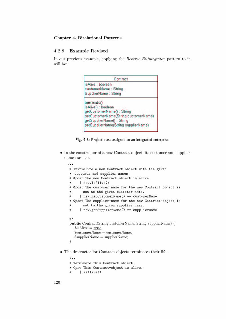
Chapter 4. Birelational Patterns
4.2.9 Example Revised
In our previous example, applying the Reverse Bi-integrator pattern to itwill be:
Fig. 4.8: Project class assigned to an integrated enterprise
• In the constructor of a new Contract-object, its customer and suppliernames are set.
/**
* Initialize a new Contract-object with the given
* customer and supplier names.
* @post The new Contract-object is alive.
* | new.isAlive()
* @post The customer-name for the new Contract-object is
* set to the given customer name.
* | new.getCustomerName() == customerName
* @post The supplier-name for the new Contract-object is
* set to the given supplier name.
* | new.getSupplierName() == supplierName
*/
public Contract(String customerName, String supplierName) {$isAlive = true;$customerName = customerName;$supplierName = supplierName;
}
• The destructor for Contract-objects terminates their life.
/**
* Terminate this Contract-object.
* @pre This Contract-object is alive.
* | isAlive()
120

4.2. Reverse Bi-integrator
* @post This Contract-object no longer exist.
* | ! new.isAlive()
*/
public void terminate() {$isAlive = false;
}
• Inspector returning the name of the involved supplier.
/**
* Return the supplier-name of this Contract-object.
* @pre This Contract-object must be still alive.
* | isAlive()
*/
public String getSupplierName() {return $supplierName;
}
• Inspector to return the name of the involved customer.
/**
* Return the customer-name of this Contract-object.
* @pre This Contract-object must be still alive.
* | isAlive()
*/
public String getCustomerName() {return $customerName;
}
4.2.10 Consequences
The Reverse Bi-integrator pattern has the following advantages and disad-vantages:
1. Efficiency : limiting the state space of the objects involved in the re-lation increases Efficiency. Instead of having three objects only oneobject represents the model.
2. Re-usability : Since communication and dependencies between the in-volved classes are minimized, re-usability of the resulting structure isincreased. However, re-usability of the integrated participating objectsis not supported by this pattern.
3. Adaptability : The adaptability of the refined class is decreased due tointegration. Extending the refined class might be more difficult whenit has other classes integrated in it than without objects integrated init. The fact that the refined class represents mixed abstractions makesit hard for it to be modified and extended.
121

Chapter 4. Birelational Patterns
4. Simplicity and Understandability : The number of classes and relation-ships are minimized which increases simplicity and understandabilityof the involved model.
4.2.11 Metrics and Evaluation
Applying the Reverse Bi-integrator pattern affects the internal quality at-tributes, cohesion, coupling as well as complexity.
• Cohesion is measured using the LOCM metric. The measured value ofLOCM is equal to 0, which is considerably low. Low value of LOCMimplies high cohesion. The visible decrease in LOCM reveals the in-crease in re-usability of the refined class.
• Complexity is measured using the WMC metric. The measured valueof WMC for the Reverse Bi-integrator pattern is 6. It is very likelythat the number of methods in the refined class is increased due to theintegrated components. This in turn increases the complexity of therefined class. However, the complexity of the underlying model de-creases due to the decrease in the number of classes and relationships.
• Coupling is measured using CF metric. The measured value of CF iszero since the Reverse Bi-integrator has only one class. The reductionin coupling is because we have single class model. For example, onlyclass R presents in the model. The reduction in coupling implies theincrease in re-usability and simplicity.
4.2.12 Variants
Strict Reverse Bi-integrator. Classes might have relationships where onlyone single object is linked to only another single object. In other words,multiplicity is restricted. In this case we have to be careful when applying theReverse Integrator pattern. For example, when creating Contract object wehave to be sure that we do not assign a Contract-object with two customersor suppliers that have the same name. Therefore, each time you createContract object you have to assign it to a Customer and a supplier withunique names. Therefore, restricted multiplicity has to be carefully handledto assure consistency and validity of the created objects at runtime. Addinga class invariant that defines this constraint helps solving this problem.
122

4.3. Refinement Integrator
4.3 Refinement Integrator
The Refinement Integrator pattern helps in designing relationships in-volving two participating classes and a refined class. The pattern combinesthe refined class into one of the participating classes. It encapsulates thedependency effect imposed on the refined class by the relation formed withthe participating classes.
4.3.1 Example
Suppose you are designing an information system involving authors of books.A considerable number of persons may have written many books, and somebooks may have more than one person. In other words, the relationshipbetween an Author and a Book involves unrestricted multiplicity. The modelshown in Figure 4.9, expresses the relation between persons and books interms of an intermediate class of authorships. A single person can be in-volved in several authorships; in the same way, a book can be involved inseveral authorships. Notice that objects of the class Authorship cannot ex-ist without an association with both Person-object and Book-object. Inother words, the model involves existential dependency in the sense thatAuthorship-objects (referred to as refined objects) cannot exist without be-ing associated to a Person-object and to a Book-object (referred to as theparticipating objects).
Fig. 4.9: Author book relationship
Suppose further that, at a later stage in designing the application, yourealize that the class Authorship has little weight in the model. You may beonly interested in some information provided by the class Authorship, suchas the type of authorship the given author has (such as first author, secondauthor or editor) and not in other properties. You realize that, while thetwo participating classes carry a considerable weight in terms of number ofattributes and methods, the refined class has little associated functionalityand it is not expected to grow later in the application.
In this case, you may decide to integrate the refined class Authorship intothe class Person. This integration would result in the model shown in theFigure below. Notice that the class Person has been renamed into Authorto emphasize the role object of this class have in the model. This is only
123

Chapter 4. Birelational Patterns
possible if persons have no other roles in the entire model. Notice the bi-directional many-to-many association between both classes. The RefinementIntegrator will be a good choice for implementing this design.
Fig. 4.10: Book class with two-way relationship with Person class, in which Authorshipclass is integrated.
4.3.2 Context
Integrate the information implied by a refined class into one of the twoparticipating classes.
4.3.3 Problem
Every software application includes participating classes and refined classesthat together form a semantical unit (see Figure 4.11). The relationshipbetween the refined objects and the participating objects must involve ex-istential dependency. This means that refined objects cannot exist withoutbeing attached to exactly one object of each of the participating classes.Constraints of multiplicity determine how many objects of the one particip-ating class can be associated with a single object of the other participatingclass and vice versa. These constraints have a major impact to organizethe message passing among the objects and to insure validity of the createdobjects at runtime.
During design, these classes and their relations can be restructured andoptimized, because some of the classes involved turn out to carry only a fewattributes and little behavior. If the refined class involved in the relationdoes not reveal any significant behavior or characteristics, it can then beintegrated into either of the two participating classes. The integration in-volves transferring the information implied by the refined class into one ofthe participating classes in which it will be integrated. This participatingclass will serve as the information provider for the integrated refined class.
124

4.3. Refinement Integrator
Fig. 4.11: The participating classes A and B with the refined class R involving unres-tricted multiplicity
4.3.4 Forces
• Existential dependency : This property implies that a refined objectmust at all times be attached to two participating objects. Existentialdependency has a major impact on the construction and the destruc-tion of refined objects
• Unrestricted multiplicity : The relationship between the refined classand the participating classes requires unrestricted multiplicity. It im-plies that each participating object is linked to an unlimited numberof refined objects.
• Mutability : This property implies that, during its lifetime, a refinedobject may be associated with several participating objects of the sameclass. This property requires methods by means of which a refinedobject can be transferred to another participating object.
• Class weight in the model : The refined class must carry little informa-tion and related functionality. Moreover, you may expect that refinedobjects will not become more important at times new requirementsare added to the application.
• Efficiency : Efficiency in time and space is a major concern in the ap-plication to be developed. In particular, adaptability and re-usabilityare no dominant requirements imposed on the refined class.
• Simplicity and Understandability : Simplicity is another major concernfor the application to be developed. The pattern reduces the numberof classes involved in a model, which turns the design to be easier tounderstand and simpler to implement.
4.3.5 Solution
The Refinement Integrator pattern solves the addressed problem by:
125

Chapter 4. Birelational Patterns
• Bringing together objects of the refined class into one of the two par-ticipating classes.
• Adding the attributes of the refined class, which provide informationrelated to it, to the participating class.
4.3.6 Structure
Fig. 4.12: Structure of the Refinement Integrator applied to the refined class R
The structure shown in Figure 4.12 presents the Refinement Integratorpattern in which the refined class R is integrated in the participating classA. Class A introduces an integer attribute counting the number of refinedobjects integrated in it. In addition, the integrating class will include theinformation ascribed to the integrated refined objects.
At the level of the participating classes, the following methods are added:
1. Methods related to the participating class A in which the refined classR is integrated.
• constructR: A public method to construct a new refined R-objectintegrated in the participating A-object. This method reflectsthe construction of a new refined object to be associated withthe current participating A-object. This method must be com-plemented with the identity of the B-object to which the newR-object must be associated.
• destructR: A public method to destroy one of the R-objects integ-rated in the current participating A-object. This method mustbe complemented with the identity of the B-object to which theR-object was associated.
• getNbRsRefinedWith: A public method that returns the numberof R-objects integrated in the current participating A-object.
126

4.3. Refinement Integrator
• getBs: A public method returning all the participating B-objectsinvolved in the refinement of R-objects integrated in the parti-cipating A-object.
• transferRTo: A public method to transfer a refined B-object, in-tegrated in the participating A-object to which the method isapplied, to another participating A-object. This method reflectsthe mutation of bindings between refined objects and participat-ing objects. The association with the participating B-object isleft unaffected.
• destructA: A public method to destroy the participating A-objectto which the method is applied. All refined R-objects integratedin this A-object are destroyed as well.
2. Methods related to the participating class B.
• getAs: A public method that returns all the A-objects associatedwith the participating B-object.
• destructB : A public method to destroy the participating B-object.All R-objects refined with that B-object are destroyed as well.
• detachFromA: An auxiliary method to break the link betweenthe participating B-object to which the method is applied andthe given A-object. attachToA An auxiliary method to set up athe link between the participating B-object to which the methodis applied and the given A-object.
4.3.7 Implementation
• The constructor for creating new R-objects is implemented in themethod constructR. Usually the constructor of R-objects involves anargument of both participating classes. Because R-objects are to beintegrated in A-objects, that argument becomes implicit. Therefore,the method constructR is left with a single argument, identifying theobject of the other participating class B that is involved in the con-struction of the new R-object. As it is explained in the specificationof the method, the number of refined objects integrated in the givenA-object and involving the given B-object is incremented by 1. Be-cause of the bi-directional binding, a similar clause is needed statingchanges to the state of the given B-object. Notice, the information(the data structure) that is needed concerning the B-objects involvedin the refinement of R-objects integrated in each A-object.
• The same principles applied for the constructor for objects of the re-fined class R, equally apply to their destructor. As a result, the de-structor is implemented in the method destructR. Because the actual
127

Chapter 4. Birelational Patterns
R-object is hidden inside an A-object, information is needed concern-ing which of the hidden R-objects must be destroyed. For that pur-pose, the object of the other participating class B, refining the R-objectto be destroyed, is passed as an argument.
• The method getNumberOfRs returns how many R-objects are cur-rently integrated in A-object. Notice that the result of the inspectorgetNumberOfRs is specified in terms of the B-objects that are involvedin the association with the current A-object.
• Another inspector getBs is introduced to return a vector of B-objectscurrently involved in the refinement of R-objects integrated in a givenA-object.
• The method transferRToTo is introduced to transfer a refined objectto be integrated in another A-object. The specification (and imple-mentation) of this method is basically obtained as a combination ofthe more basic methods constructR and destructR. These methodsremove an R-object from the current A-object and assign it to thegiven A-object.
4.3.8 Sample Code
Listing 4.3: Integrating the refined class R into the participating class A
class A {/**
* Initialise a new A-object without any R-objects integrated in it.
* @post No B-objects are attached to the new A-object.
* | new.getBs().size() == 0
*/
public A() {$refBs = new Vector();
}/**
* Destruct this A-object and all R-objects integrated in it.
* @post No B-object is still associated with this terminated A-object.
* | for each b in B:
* | (new b).getNbAssociationsWith(this) == 0
*/
public void destructA() {for( int i=0; i<$refBs.size (); i++)
((B)($refBs.elementAt(i ))). detachFromA(this);}/**
* Return a vector collecting all B-objects refining an R-object
* integrated in this A-object.
* If a B-object refines several R-objects, it will be included
128
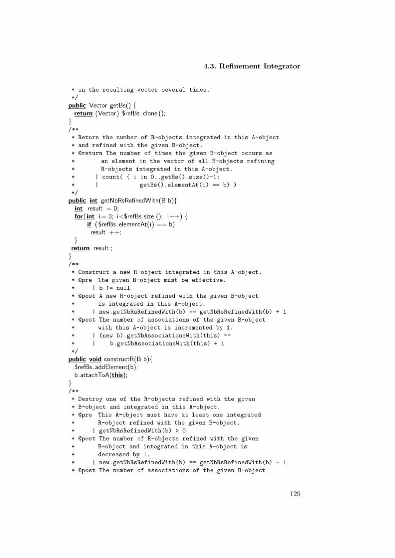
4.3. Refinement Integrator
* in the resulting vector several times.
*/
public Vector getBs() {return (Vector) $refBs . clone ();
}/**
* Return the number of R-objects integrated in this A-object
* and refined with the given B-object.
* @return The number of times the given B-object occurs as
* an element in the vector of all B-objects refining
* R-objects integrated in this A-object.
* | count( { i in 0..getBs().size()-1:
* | getBs().elementAt(i) == b} )
*/
public int getNbRsRefinedWith(B b){int result = 0;for( int i= 0; i<$refBs.size (); i++) {
if ($refBs .elementAt(i) == b)result ++;
}return result ;}/**
* Construct a new R-object integrated in this A-object.
* @pre The given B-object must be effective.
* | b != null
* @post A new R-object refined with the given B-object
* is integrated in this A-object.
* | new.getNbRsRefinedWith(b) == getNbRsRefinedWith(b) + 1
* @post The number of associations of the given B-object
* with this A-object is incremented by 1.
* | (new b).getNbAssociationsWith(this) ==
* | b.getNbAssociationsWith(this) + 1
*/
public void constructR(B b){$refBs .addElement(b);b.attachToA(this);
}/**
* Destroy one of the R-objects refined with the given
* B-object and integrated in this A-object.
* @pre This A-object must have at least one integrated
* R-object refined with the given B-object.
* | getNbRsRefinedWith(b) > 0
* @post The number of R-objects refined with the given
* B-object and integrated in this A-object is
* decreased by 1.
* | new.getNbRsRefinedWith(b) == getNbRsRefinedWith(b) - 1
* @post The number of associations of the given B-object
129

Chapter 4. Birelational Patterns
* with this A-object is decreased by 1.
* | (new b).getNbAssociationsWith(this) ==
* | b.getNbAssociationsWith(this) - 1
*/
public void destructR(B b) {$refBs .remove(b);b.detachFromA(this);
}/**
* Transfer one of the R-objects integrated in this A-object
* and refined with the given B-object to the given A-object.
* @pre The given A-object must be effective.
* | a != null
* @pre This A-object must have at least one integrated
* R-object refined with the given B-object.
* | getNbRsRefinedWith(b) > 0
* @post The number of R-objects refined with the given
* B-object and integrated in this A-object is
* decreased by 1.
* | new.getNbRsRefinedWith(b) == getNbRsRefinedWith(b) - 1
* @post A new R-object refined with the given B-object
* is integrated in the given A-object.
* | (new a).getNbRsRefinedWith(b) == a.getNbRsRefinedWith(b) + 1
* @post The number of associations of the given B-object
* with this A-object is decreased by 1.
* | (new b).getNbAssociationsWith(this) ==
* | b.getNbAssociationsWith(this) - 1
* @post The number of associations of the given B-object
* with the given A-object is incremented by 1.
* | (new b).getNbAssociationsWith(a) ==
* | b.getNbAssociationsWith(a) + 1
*/
public void transferRTo(A a, B b) {destructR(b);a.constructR(b);
}}
Listing 4.4: Definition of the participating class B associated with the participatingclass A
class B {/**
* Initialise a new B-object without associations with A-objects.
* @post The new B-object has no associated A-objects.
* | new.getAs().size() == 0
*/
public B() {$refAs = new Vector();
}
130

4.3. Refinement Integrator
/**
* Destruct this B-object.
* @post No A-object still has an integrated refined R-object
* that is still associated with this B-object.
* | for each a in A:
* | (new a).getNbRsRefinedWith(this) == 0
*/
public void destructB() {while ($refAs . size () > 0)
((A)($refAs.elementAt($refAs. size ()−1))).destructR(this );}/**
* Return a vector collecting all A-objects with which this
* B-object is associated. If this B-object is associated several
* times with the same A-Object, it will be included in the
* in the resulting vector several times.
*/
public Vector getAs() {return (Vector) $refAs . clone ();
}/**
* Return the number of times this B-object is associated
* with the given A-object.
* @return The number of times the given A-object occurs as
* an element in the vector of all A-objects with
* which this B-object is associated.
* | count( { i in 0..getAs().size()-1:
* | getAs().elementAt(i) == a} )
*/
public int getNbAssociationsWith(A a){int result = 0;for( int i= 0; i<$refAs.size (); i++) {
if ($refAs .elementAt(i) == a)result ++;
}return result ;}/**
* Remove one of the associations of this B-object with the
* given A-object.
* @post The number of associations of this B-object with
* the given A-object is decreased by 1.
* | new.getNbAssociationsWith(a) ==
* | getNbAssociationsWith(a) - 1
*/
void detachFromA(A a) {$refsA.remove(a);
}/**
131

Chapter 4. Birelational Patterns
* Register a new association of this B-object with the
* given A-object.
* @post The number of associations of this B-object with
* the given A-object is incremented by 1.
* | new.getNbAssociationsWith(a) ==
* | getNbAssociationsWith(a) + 1
*/
void attachToA(A a) {$refsA.addElement(a);
}}
4.3.9 Example Revised
In our previous example, applying the Refinement Integrator pattern willbe as follows:
Fig. 4.13: Class Book with two-way relationships with class Author, in which Author-ship class is integrated.
• When the Authorship is created the book object must be given in theformal argument of the method constructAuthorship.
/**
* Construct a new Authorship-object integrated in this Author-object.
* @pre The given Book-object must be effective.
* | b != null
* @post A new Authorship-object refined with the given Book-object
* is integrated in this Author-object.
* | new.getNbAuthorshipsRefinedWith(b) ==
* getNbAuthorshipsRefinedWith(b) + 1
* @post The number of associations of the given Book-object
* with this Author-object is incremented by 1.
* | (new b).getNbAssociationsWith(this) ==
* | b.getNbAssociationsWith(this) + 1
*/
public void constructAuthorship(Book b){
132

4.3. Refinement Integrator
$refBooks.addElement(b);b.attachToAuthor(this);
}
• The Authorship is terminated by the method destructAuthorship.
/**
* Destroy one of the Authorship-objects refined with the given
* Book-object and integrated in this Author-object.
* @pre This Author-object must have at least one integrated
* Authorship-object refined with the given Book-object.
* | getNbAuthorshipsRefinedWith(b) > 0
* @post The number of Authorship-objects refined with the given
* Book-object and integrated in this Author-object is
* decreased by 1.
* | new.getNbAuthorshipsRefinedWith(b) ==
* getNbAuthorshipsRefinedWith(b) - 1
* @post The number of associations of the given Book-object
* with this Author-object is decreased by 1.
* | (new b).getNbAssociationsWith(this) ==
* | b.getNbAssociationsWith(this) - 1
*/
public void destructAuthorship(Book b) {$refBooks.remove(b);b.detachFromAuthor(this);
}
• The inspector getNbAuthorshipsRefinedWith returns the authorshipsthis Author has in the given Book-objects.
/**
* Return the number of Authorship-objects integrated in this Author-object
* and refined with the given Book-object.
* @return The number of times the given Book-object occurs as
* an element in the vector of all Book-objects refining
* Authorship-objects integrated in this Author-object.
* | count( { i in 0..getBooks().size()-1:
* | getBooks().elementAt(i) == b} )
*/
public int getNbAuthorshipsRefinedWith(Book b){int result = 0;for(int i= 0; i<$refBooks.size (); i++) {
if ($refBooks.elementAt(i) == b)result ++;
}return result;}
• The mutator transferAuthorshipTo terminate the authorship of thisauthor and assign it to the given one.
133

Chapter 4. Birelational Patterns
/**
* Transfer one of the Authorship-objects integrated in this Author-object
* and refined with the given Book-object to the given Author-object.
* @pre The given Author-object must be effective.
* | a!= null
* @pre This Author-object must have at least one integrated
* Authorship-object refined with the given Book-object.
* | getNbAuthorshipsRefinedWith(b) > 0
* @post The number of Authorship-objects refined with the given
* Book-object and integrated in this Author-object is
* decreased by 1.
* | new.getNbAuthorshipsRefinedWith(b) ==
* getNbAuthorshipsRefinedWith(b) - 1
* @post A new Authorship-object refined with the given Book-object
* is integrated in the given Author-object.
* | (new a).getNbAuthorshipsRefinedWith(b) ==
* a.getNbAuthorshipsRefinedWith(b) + 1
* @post The number of associations of the given Book-object
* with this Author-object is decreased by 1.
* | (new b).getNbAssociationsWith(this) ==
* | b.getNbAssociationsWith(this) - 1
* @post The number of associations of the given Book-object
* with the given Author-object is incremented by 1.
* | (new b).getNbAssociationsWith(a) ==
* | b.getNbAssociationsWith(a) + 1
*/
public void transferAuthorshipTo(Author a, Book b) {destructAuthorship(b);a.constructAuthorship(b);
}
4.3.10 Consequences
The Refinement Integrator pattern has the following advantages and disad-vantages:
1. efficiency : Efficiency is improved since the number of objects needs tobe stored in memory are decreased, instead of three objects only twoobjects remain. The participating classes do not need the refined classto access each other and to retrieve their related information; theyhave direct access and can invoke functionalities among each other.However, efficiency might be negatively affected because of the extraobjects needed to store the collections that represent the two-way re-lationships, and the reduction in execution speed due to consistencychecking.
2. Re-usability : The fact that, having both objects that carry differentsemantics presented in the model increases the chance of re-using one
134

4.3. Refinement Integrator
of them in different applications.
3. Adaptability : The adaptability of the refined class is decreased due tointegration. Extending the participating class might be more difficultwhen it has other classes integrated in it. The fact that the particip-ating class represents mixed abstractions makes it hard for it to bemodified and extended.
4. Simplicity and Understandability : The Refinement Integrator patternenhances simplicity by removing one class form the model which makesthe model easier to understand. However, simplicity might be affecteddue to the two-relationships. For example, every object involved in therelationship needs to be easily accessible from every other object. Alsoa change in any one participating object may affect all other particip-ating objects in the relation. If an object is added or removed fromthe relationship, the other objects must be informed so the relationshipremains consistent.
4.3.11 Metrics and Evaluation
Applying the Refinement Integrator pattern affects the internal quality at-tributes, cohesion, coupling as well as complexity of the class in which therefined objects are integrated.
• Cohesion is measured using the LOCM metric. The measured valueof LOCM is equal to 10, which is considerably high. High value ofLOCM implies low cohesion. The visible increase in LOCM is due tothe mixed abstractions of the participating objects with the refinedobjects. Low cohesion affects the re-usability of the underlying classand decrease adaptability as well.
• Complexity is measured using the WMC metric. The measured valueof WMC for the Refinement Integrator pattern is 4. It is very likelythat the number of methods in the participating class is increased dueto the integrated refined component. This in turn increases the com-plexity of the participating class. However, the complexity of the un-derlying model decreases due to the decrease in the number of classesand relationships.
• Coupling is measured using CF metric. The measured value of CF is1 since the Refinement Integrator includes two classes. The couplingis increased due to the two-way many-to-many associations betweenthe involved participating classes. The increase in coupling implies thedecrease in re-usability.
135

Chapter 4. Birelational Patterns
4.3.12 Variants
Strict Refinement Integrator. Classes might have relationships where onlyone single object is linked to only another single object. In other words,multiplicity is restricted. In this case we have to be careful when applyingthe Refinement Integrator pattern. For example, when creating new R-object we have to be sure that we do not assign it twice to the same A-objectand same B-object . Therefore, each time you create R-object you have toassign it to a unique A-object and unique B-object. Therefore, restrictedmultiplicity has to be carefully handled to assure consistency and validityof the created objects at runtime. Adding a class invariant that defines thisconstraint helps solving this problem.
4.4 Bi-Collaborator
The Bi-Collaborator pattern facilitates designing a complex, two-way, one-to-many relationship between two participating classes and one refinedclass. It defines relationships where each object of the participating classesis linked to an unlimited number of refined objects. The one participat-ing object simply stores a collection that holds the many refined objectsinvolved in the relationship. The refined class represents its relationshipwith the participating class as an attribute. The Bi-Collaborator patternexplicitly defines the relationship between the participating classes and therefined class. It manages the two-way relationships between their objectsin a consistent way. Moreover, it organizes their collaboration and providesa flexible and re-usable structure for them.
4.4.1 Example
Suppose you are designing a business application involving customers whopurchase orders from a company. Some of the customers issue many ordersat various companies, and at the same time companies register many ordersfor different customers. In other words, the relationship between customers,orders, and companies involve unrestricted multiplicity. The model shownin Figure 4.14 addresses a relation between a Customer-object who has alist of Order-objects at a given Company-object. Objects of the class Ordercannot exist without a Customer-object and a Company-object. There-fore, the model fragment involves existential dependency in which Order-objects (known as refined objects) cannot exist without being associated toa Customer-object on the one hand, and to a Company-object on the otherhand. The latter objects are referred to as participating objects.
The model shows that an unlimited number of orders can be assignedto a single Customer-object. Suppose each Customer-object needs a two-
136

4.4. Bi-Collaborator
way relationship with its Order-objects, perhaps because customers mustbe able to enumerate their orders to add or cancel some of them. Supposefurther that each Company-object also needs a two-way relationship withtheir registered orders. In this way, companies are able to list the ordersassigned for each customer. Obviously, Order-objects need to know in whichcompanies they are registered and to which customers they belong.
Fig. 4.14: An association between the Customer, Order, and Company classes
In two-way relationships, each object involved in the relationship needsto be easily accessible from every other object. A change in any one objectparticipating in the relationship may affect all other objects in the relation-ship. As an example, suppose that an order must be diverted to anothercustomer. Then it is important to notify the new customer of this new orderthat has been added to its list of orders. Two-way relationships are difficultbecause they must maintain consistency among the objects involved in therelationship.
4.4.2 Problem
Some of these two-way relationships, known as two-way relationships, ad-dress the significance of each object presented in it as equally important. Inother words, each object involved in the relationship needs to be shared byevery other object in the relationship. In addition, this type of relationships,such as the model shown in Figure 4.15 impose other structural constraintat one end of the relationship such as unrestricted multiplicity and exist-ential dependency. The former states that one A-object (referred to as theparticipating object) is attached to unlimited number of R-objects (referredto as the refined objects. also on the other side one B-objects is associatedwith unlimited number of refined R-objects. The later expresses that the re-fined R-objects cannot exist without being associated to each participatingobjects (A and B) present in the model.
The model fragment illustrated in the figure facilitates a flexible archi-tecture in which objects of the classes sharing the relationship are easilyaccessible from each other. If an object joins or leaves the relationship, theother objects must be informed so the relationship remains consistent. Alsochances of reusing and extending the related classes are high when their rela-tionships are explicitly stated and the interdependency between their objects
137

Chapter 4. Birelational Patterns
Fig. 4.15: The participating classes A and B with the refined class R involving unres-tricted multiplicity
are unambiguously defined. The Bi-Collaborator pattern explicitly definesthe relationships between both participating classes and the refined class.It manages their objects responsibilities in a consistent way. Moreover, itorganises their collaboration and provides flexible and re-usable structurefor them.
4.4.3 Forces
• Existential dependency : This property implies that refined objectsmust at all times be attached to a participating object. Existentialdependency has a major impact on the construction and the destruc-tion of refined objects
• Property unrestricted multiplicity : The relationship between the re-fined class and the participating class requires unrestricted multipli-city. It implies that one participating object is linked to unlimitednumber of refined objects.
• Property mutability : This property implies that a refined object mightbe mutable. Mutability indicates the change in binding between therefined objects and the participating object.
• Object-to-Object significance: A two-way relationship is a relationshipwhere both the one participating object and the many refined objectsare equally important to each other.
• Accessibility : Every object involved in the relationship needs to beeasily accessible from every other object.
• Consistency : A change in any one participating object may affect allother refined objects in the relation. If an object is added or removedfrom the relationship, the other objects must be informed so the rela-tionship remains consistent
• Adaptability : It provides flexibility to add and remove responsibilitiesto objects at run-time simply by attaching and detaching them.
138

4.4. Bi-Collaborator
• Re-usability : The fact that, having all classes that carry different se-mantics increases the chance of re-using one of them in different ap-plications. However, this property might have negative effects on ef-ficiency both in terms of space needed to store the objects involvedin the relationship and the extra object needed to present the rela-tionship. Moreover, the execution speed is also reduced due to thetime needed for consistency checking when objects are created and/orremoved at run-time.
4.4.4 Solution
The solution for this problem includes:
• Splitting the relationship into two pairs of a two-way relationships. Apair of two-way relationship between the participating classes A andthe refined class B, and a pair between the participating class B andthe refined class R. Each pair includes, one-to-many relationship fromthe participating object to the refined objects, where a collection isdefined in the participating class to represent the relationship, anda one-to-one relationship from the refined object to the participatingobject, where an attribute is defined in the refined class to representthe relationship.
• The one-way relationships must be kept consistent. We chose the re-fined object as director of the relationship, since the refined objectis existentially dependent on the participating objects. The refinedobject centralizes the responsibility for maintaining the relationshipin a single object. If the refined object needs to make a change tothe relationship, it should delegate the change to its participating ob-jects. Furthermore, it is the refined object through which the differentparticipating objects can access and retrieve information from eachother.
4.4.5 Structure
The structure shown in Figure 4.16 , illustrates a relationship of a par-ticipating A and B-objects with unlimited refined R-objects implementedby Bi-Collaborator pattern. Classes A and B include the collection object$refRs which defines the relationship, one-to-many, between A-object andR-objects and from B-object to R-objects. Class R includes an attribute$refA and $refB referencing the, one-to-one relationship from the refinedobject to the participating objects. Also the structure includes the followingmethods:
1. Methods of the participating class A:
139

Chapter 4. Birelational Patterns
Fig. 4.16: Two-way, one-to-many relationship between the participating classes A andB and the refined class R
• getRs: public method to access the refined R-objects.
• destructA: public method to remove the A-object from the rela-tionship.
2. Methods of the participating class B:
• getRs: public method to access the refined R-objects.
• destructB : public method to remove the B-object from the rela-tionship.
3. Methods of the refined class R:
• A constructor to initialise B-objects
• destructR: public method to remove R-objects.
• getA: public method to access the participating A-object.
• getB : public method to access the participating B-object.
• transferRTo: public method to change the link between the R-object and the current attached A-object, and to establish a newlink in both directions between the R-object and the given A-object.
4.4.6 Implementation
1. Participating class methods and responsibilities
• The destructor destructA of the participating A-object impliesthe destruction of the refined R-objects. Because of the existen-tial dependency before any participating object is destroyed onemust check whether this object is holding references to a refinedobject or not. If so all these refined objects must be destroyedbeforehand.
140

4.4. Bi-Collaborator
• The inspectors getRs defined in both classes return the current R-objects associated with either of the participating objects. Noticethat the method returns an array in which references to all R-objects are stored.
2. Refined class methods.
• Because of the property of existential dependency - R-objectscannot be created without being attached to an A-object on onehand and to a B-object on the other hand. Therefore, when R-objects are created it must initialise references to objects of theparticipating classes. Objects of the participating classes, on theother hand, can exist without being involved in associations withobjects of the refined class. Consequently, the constructor at thelevel of the participating class initialises a new object withoutany association to objects of the refined class.
• The destructor for the R-objects as it is specified at the level ofanalysis is implemented in the method destructR. Notice thatthe reference to the destroyed object is removed from the parti-cipating objects.
• The inspectors getA and getB defined in the refined class R returnthe participating objects in the current relationship.
• The mutator defined in the method transferRTo transfers thisR-object to the participating A and B-objects.
4.4.7 Sample Code
Listing 4.5: Bi-collaborator pattern involving classes A and B as participating classesand class R as refined class.
public class A {/**
* Initialise a new A-object refining
* no R-objects.
* @post No R-objects are refined by
* the new A-object.
* | new.getRs().size() == 0
*/
public A() {$refRs = new Vector();
}/**
* Terminate this A-object.
* @post No R-object still exists refined
* with this A-object.
* | for each r in R:
141

Chapter 4. Birelational Patterns
* | r.getA() != this
*/
public void destructA() {for ( int i=$refRs.size ()−1; i>=0; i++)
((R)($refRs.elementAt(i ))). destructR ();$refRs .removeAllElements();
}/**
* Returns a vector collecting all R-objects
* refined by this A-object.
*/
public Vector getRs() {return (Vector) $refRs . clone ();
}/**
* Link the given R-object to this A-object.
* @pre The given R-object must be effective.
* | r != null
* @post The number of R-objects refined by
* this A-object is incremented.
* | new.getNbRs() == getNbRs() + 1
* @post This A-object references the given
* R-object as one of its refined objects.
* | new.getRs().contains(r)
*/
void linkR(R r) {$refRs .addElement(r);
}/**
* Detach the given R-object from this A-object.
* @post This A-object no longer reference the given
* R-object as an object it refines.
* | ! new.getRs().contains(r)
*/
void unlinkR(R r) {$refRs .removeElement(r);
}/**
* Variable registering R-objects referenced by
* this A-object.
*/
private java . util .Vector $refRs ;}
Listing 4.6: Class R refined by the participating class A and the participating class Bin a bicompact association
public class R {/**
* Initialize a new R-object refined with the given
142

4.4. Bi-Collaborator
* A-object and B-object.
* @pre The given A-object must be effective.
* | a != null
* @post The new R-object references the given A-object.
* | new.getA() == a
* @post The number of R-objects refined by
* the given A-object is incremented.
* | (new a).getNbRs() == a.getNbRs() + 1
* @post The given A-object references the new
* R-object as one of its refined objects.
* | (new a).getRs().contains(this)
* @pre The given B-object must be effective.
* | b != null
* @post The new R-object references the given B-object.
* | new.getB() == b
* @post The number of R-objects refined by
* the given B-object is incremented.
* | (new b).getNbRs() == b.getNbRs() + 1
* @post The given B-object references the new
* R-object as one of its refined objects.
* | (new b).getRs().contains(this)
*/
public R( A a, B b) {$refA = a;a. linkR(this );$refB = b;b. linkR(this );
}/**
* Return the A-object refining this R-object.
*/
public A getA() {return $refA;
}/**
* Return the B-object refining this R-object.
*/
public B getB(){return $refB;
}/**
* Terminate this R-object.
* @post The A-object previously refining this
* R-object no longer references this R-object
* as one of the objects it refines.
* | ! (new getA()).getRs().contains(this)
* @post The B-object previously refining this
* R-object no longer references this R-object
* as one of the objects it refines.
143
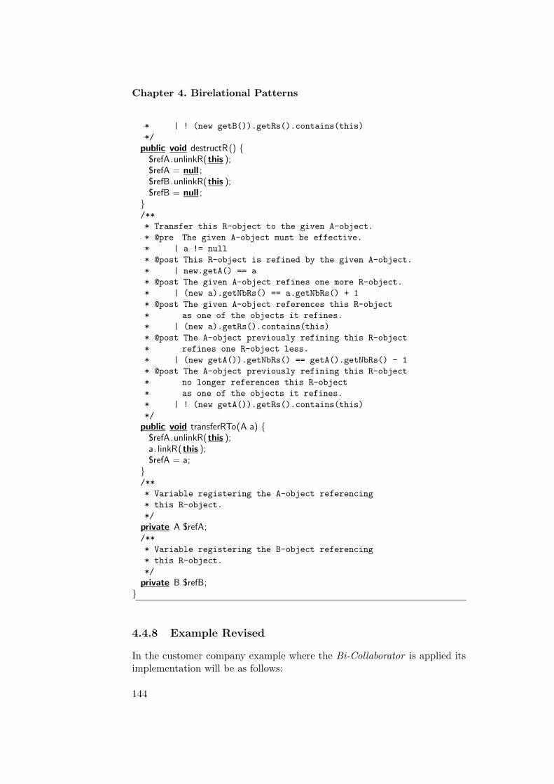
Chapter 4. Birelational Patterns
* | ! (new getB()).getRs().contains(this)
*/
public void destructR() {$refA.unlinkR(this );$refA = null ;$refB.unlinkR(this );$refB = null ;
}/**
* Transfer this R-object to the given A-object.
* @pre The given A-object must be effective.
* | a != null
* @post This R-object is refined by the given A-object.
* | new.getA() == a
* @post The given A-object refines one more R-object.
* | (new a).getNbRs() == a.getNbRs() + 1
* @post The given A-object references this R-object
* as one of the objects it refines.
* | (new a).getRs().contains(this)
* @post The A-object previously refining this R-object
* refines one R-object less.
* | (new getA()).getNbRs() == getA().getNbRs() - 1
* @post The A-object previously refining this R-object
* no longer references this R-object
* as one of the objects it refines.
* | ! (new getA()).getRs().contains(this)
*/
public void transferRTo(A a) {$refA.unlinkR(this );a. linkR(this );$refA = a;
}/**
* Variable registering the A-object referencing
* this R-object.
*/
private A $refA;/**
* Variable registering the B-object referencing
* this R-object.
*/
private B $refB;}
4.4.8 Example Revised
In the customer company example where the Bi-Collaborator is applied itsimplementation will be as follows:
144

4.4. Bi-Collaborator
Fig. 4.17: Two-way, one-to-many relationship between the participating classes A andB and the refined class R
1. Implementation of Customer class.
• When the customer is created no orders need to be perceived inconstructor.
/**
* Initialise a new Customer-object without
* any orders.
* @post No Order-objects are refined by
* the new Customer-object
* | new.getOrders().size() == 0
*/
public Customer() {$orders = new Vector();
}
• The customer is terminated by the method destructCustomer.
/**
* Terminate this Customer-object.
* @post No Order-object still exists refined
* with this Customer-object.
* | for each o in Order:
* | o.getCustomer() != this
*/
public void destructCustomer() {for (int i=$orders.size()−1; i>=0; i++)
((Order)($orders.elementAt(i))).destructOrder();$orders.removeAllElements();
}
• The inspector getOrders returns the orders this Customer has.
/**
* Return a vector collecting all
* Order-objects refined by this Customer-object.
*/
145

Chapter 4. Birelational Patterns
public Vector getOrders() {return (Vector) $orders.clone();
2. Implementation of Order class.
• Order-object when created need to initialise both Customer andCompany objects.
/**
* Initialize a new Order-object refined with the given
* Customer-object and Company-object.
* @pre The given Customer-object must be effective.
* | c != null
* @post The new Order-object references the given Customer-object.
* | new.getCustomer() == c
* @post The number of Order-objects refined by
* the given Customer-object is incremented.
* | (new c).getNbOrders() == c.getNbOrders() + 1
* @post The given Customer-object references the new
* Order-object as one of its refined objects.
* | (new c).getOrders().contains(this)
* @pre The given Company-object must be effective.
* | co != null
* @post The new Order-object references the given Company-object.
* | new.getCompany() == co
* @post The number of Order-objects refined by
* the given Company-object is incremented.
* | (new co).getNbOrders() == co.getNbOrders() + 1
* @post The given Company-object references the new
* Order-object as one of its refined objects.
* | (new co).getOrders().contains(this)
*/
public Order( Customer c, Company co) {$customer = c;c.linkOrder(this);$company = co;co.linkOrder(this);
}
• The order is terminated by the method terminateOrder.
/**
* Terminate this Order-object.
* @post The Customer-object previously refining this
* Order-object no longer references this Order-object
* as one of the objects it refines.
* | ! (new getCustomer()).getOrders().contains(this)
* @post The Company-object previously refining this
* Order-object no longer references this Order-object
* as one of the objects it refines.
146

4.4. Bi-Collaborator
* | ! (new getCompany()).getOrders().contains(this)
*/
public void destructOrder() {$customer.unlinkOrder(this);$customer = null;$company.unlinkOrder(this);$company = null;
}
• The mutator transferOrderTo transfers this order from the cur-rent attached Customer to the given one.
/**
* Transfer this Order-object to the given Customer-object.
* @pre The given Customer-object must be effective.
* | c!= null
* @post This Order-object is refined by the given Customer-object.
* | new.getCustomer() == c
* @post The given Customer-object refines one more Order-object.
* | (new c).getNbOrders() == c.getNbOrders() + 1
* @post The given Customer-object references this Order-object
* as one of the objects it refines.
* | (new c).getOrders().contains(this)
* @post The Customer-object previously refining this Order-object
* refines one Order-object less.
* | (new getCustomer()).getNbOrders() ==
* getCustomer().getNbOrders() - 1
* @post The Customer-object previously refining this Order-object
* no longer references this Order-object
* as one of the objects it refines.
* | ! (new getCustomer()).getOrders().contains(this)
*/
public void transferOrderTo(Customer c) {$customer.unlinkOrder(this);c.linkOrder(this);$customer = c;
}
4.4.9 Consequences
As the Bi-Collaborator pattern aims at better support for flexibility andre-usability, it has drawbacks on simplicity and efficiency.
1. Adaptability : Limiting each of the involved classes to a specific area ofinterest (i.e. cohesion) highlights flexibility and adaptability. In theseaspects future modifications to the software system are endorsed.
2. Reusability : This pattern is considered to be highly reusable becauseall the classes that form the semantical unit are presented in the rela-tionship.
147

Chapter 4. Birelational Patterns
3. Efficiency : Bi-Collaborator reduces efficiency in terms of time andspace. Objects of the involved classes need a separate location inmemory, each of which affects the performance of the software system.The creation of new objects of the classes and the message passingbetween them increase overhead and slower the execution speed.
4. Simplicity : Simplicity is not supported by this pattern since couplingis high. It requires message passing between objects of the classesinvolved. The message passing might lead to inconsistencies, if bi-directional associations are not designed and implemented with greatcare.
4.4.10 Metrics and Evaluation
• complexity : The complexity for Bi-Collaborator pattern is high asthe objects need to access each other in a two-way relationship. Foreach class, additional methods are added to access and manipulate therelationship. For the participating classes WMC is increased by 4 dueto the one-to-many association with the refined class R. Moreover,WMC for the refined class R is increased by 3, number of methodsadded to carry the responsibility of the one-to-one relationship fromthe refined to the participating class.
• Cohesion: Cohesion for the pattern is high since classes that form therelationship are separated. Each one represents a single abstractionand carries specific responsibilities.
• Coupling : Coupling is high as we have bi-directional navigation. CFhas a total value of 2.0, which is a significant high value. Placing thereferences in both the refined object and participating objects makesthem tightly coupled, which in turn might decrease the patterns ad-aptability.
4.4.11 Variants
Immutable Bi-Collaborator: This pattern could be restricted by not allowingthe mutation to take place. For example suppose class R does not allowchange in binding between its objects and the participating class A, thenmethod tranferRTo will be removed from the class. The rest of the patternwill be left untouched.
148

4.5. Nester
4.5 Nester
The Nester pattern nests classes involved in a relationship into one outerclass. One of the participating classes will be designated as the outer class,and the other two will be designated as the inner classes. The Nester pat-tern bounds the inner classes and the outer class by an implicit association.
4.5.1 Example
Suppose you are designing a banking application involving persons who aregranted accounts in certain bank. In the model fragment shown in Figure4.18 each Account-object is existentially dependent on a Bank-object thatgrants them and on a Person-object that holds them. In other words, anAccount-object cannot exist without being attached to a Bank-object on theone hand and to a Person-object on the other hand.
You are concerned about the accessibility constraints of the informationprovided by the classes in the model and you are intending to encapsulatethe information concerning accounts and banks into objects of the classPerson. Moreover, you are willing to decrease the top-level classes in thedesign model. In this, nesting will help you implement this design.
Fig. 4.18: The participating classes Person and Bank with the refined class Accountinvolving unrestricted multiplicity
4.5.2 Context
A participating class plays the role of an outer class that encapsulates dataor information provided by other refined and participating classes, whichare designated as an inner classes.
4.5.3 Problem
Relations that involve between classes might include three classes. Theclasses that are related and associated to each other impose structural con-straints on each other. Among those constraints is the existential depend-ency, which implies that a class (referred to as the refined class) cannotexist without being attached to other classes (referred to as the participat-ing class). Other types of constraints are unrestricted multiplicity, meaning
149

Chapter 4. Birelational Patterns
that an unlimited number of refined objects can be attached to the sameparticipating object.
Fig. 4.19: Structure of the participating classes A and B including the refined class Rinvolving unrestricted multiplicity
Suppose later during design you want limit the accessibility between thegiven classes in involved in the relationship, and you want to encapsulatethe information provided by them in one outer class. Moreover, you arewilling to decrease the top-level classes in the design model. Therefore,nesting will help you implemented this design. Nested classes are a powerfulabstraction mechanism that facilitates much more convenient and manage-able software than it would be when using only top-level classes. Nestedclass provides a way for the class designer to completely prevent any type-coding dependencies and to completely hide details about implementation.In addition, objects on an inner class have access to an outer class objectthat it was created within. Without nested classes, all classes would haveto be declared at package level, which would conflict with the convention ofrestricting declarations to the minimum scope.
4.5.4 Forces
• Existential dependency : This property implies that refined objectsmust at all times be attached to a participating object. Existentialdependency has a major impact on the construction and the destruc-tion of refined objects
• Property unrestricted multiplicity : The relationship between the re-fined class and the participating class requires unrestricted multipli-city. It implies that one participating object is linked to unlimitednumber of refined objects.
• Property mutability : This property implies that a refined object mightbe mutable. Mutability indicates the change in binding between therefined objects and the participating object.
• Accessibility : Every object involved in the relationship needs to beeasily accessible from every other object. Also information hiding is
150

4.5. Nester
important to facilitate encapsulation between the related classes.
• Adaptability : It provides flexibility to add and remove responsibilitiesto objects at run-time simply by attaching and detaching them.
• Simplicity : The fact that, having two classes defined as inner classeswill reduce the top-level classes which in turn increases simplicity andunderstandability of the model.
4.5.5 Solution
The Nester pattern solves the addressed problem by:
• Defining one participating class and the refined class, also known asthe refined classes, into the other participating class (the outer class).This process establishes an implicit association between the two innerclasses and the outer class.
• Implementing the functionalities of nested classes by introducing aconstructor, destructor, and an inspector, to respectively add, remove,and access the information related to the nested objects.
4.5.6 Structure
The structure shown in Figure 4.20 presents the Nester pattern for a modelinvolving the refined class R and the participating classes A and B. Theparticipating class A plays the role of the outer class where the refined classR and the other participating class B play the role of the inner classes. Alsothe structure includes the following methods:
1. Methods of the outer class A:
• getRs: public method that returns the nested R-objects.
• destructA: public method to eliminate the participating A-objects.
2. Method of the inner refined class R.
• getA: public method that returns the outer A-object.
• getB : public method that returns the inner B-object.
• The class also contains a constructor as well.
3. Methods of the participating inner class B.
• destructB : public method that destroys the inner B-object.
• getRs: public method that returns the associated R-objects.
• getNumberOfRs: public method that returns the number of R-objects that are nested in the participating class A.
151

Chapter 4. Birelational Patterns
Fig. 4.20: Structure of the participating class A as the outer class , encapsulating classR and the other participating class B as inner classes
4.5.7 Implementation
• Constructing objects of the refined class R will be by invoking the con-structor of the class R. Notice also that the outer class is responsiblefor creating objects of the inner classes. This constructor when in-voked will also initialize a B-object due to the existential dependencyconstraint. Notice that since the creation of R-objects depends on anA-object in which they are nested, R-objects automatically store im-plicit references to A-objects. As a result, the inner class objects havedirect access to the instance variables of the outer class object. It isthe compiler that generates the implicit reference to the outer classobjects itself.
• Concerning mutation, the binding of R-objects with A-objects cannotbe changed, because an object of an inner class change its implicitreference to an object of the outer class. As a consequence, no mutatorcan be introduced at the level of the refined class, or at the level ofthe participating class A.
• The inspectors getA and getB when invoked will return both the par-ticipating outer class A and the inner class B respectively.
4.5.8 Sample Code
Listing 4.7: Implementation of the nested classes B and R into the outer class A
public class A {
152

4.5. Nester
private java . util .Vector $Rs;/**
* Initialise a new A-object with no
* refined objects nested in it.
* @post No R-objects are nested in
* the new A-object.
* | new.getRs().size()== 0
*/
public A() {$Rs = new Vector();
}/**
* Terminate this A-object.
* @pre This A-object does not refine any
* R-objects.
* | getNbRs() == 0
*/
public void destructA() {$Rs = null;
}/**
* Return a vector collecting all R-objects
* refined by this A-object.
*/
public Vector getRs() {return (Vector) $Rs.clone ();
}/**
* Return the number of R-objects nested
* in this A-object.
* @return The number of nested R-objects.
* | getRs().size()
*/
public int getNbRs() {return getRs(). size ();
}
// Definition of the other participating class B.
public static class B {/**
* Collection of references to Rs refined by
* this B-object.
*/
private java . util .Vector $Rs ;/**
* Initialize a new B-object refining no R-objects.
* @post No R-objects are refined by the new B-object.
* | new.getNbRs() == 0
*/
153

Chapter 4. Birelational Patterns
public B() {$Rs = new Vector();
}/**
* Destruct this B-object.
* @pre This B-object does not refine any R-objects.
* | getNbRs() == 0
*/
public void destructB() {$Rs = null;
}/**
* Return a vector collecting references to all R-objects
* refined by this B-object.
*/
public Vector getRs() {return (Vector) $Rs.clone ();
}/**
* Return the number of R-objects refined by
* this B-object.
* @return The number of elements in the vector
* collecting R-objects refined by this
* B-object.
* | getRs().size()
*/
public int getNbRs () {return $Rs. size ();
}/**
* Add the given R-object to the collection of
* R-objects refined by this B-object.
* @pre The given R-object may not be null.
* | r != null
* @post The number of R-objects refined by
* this B-object is increased.
* | new.getNbRs() = getNbRs() + 1
* @post This B-object references the given R-object.
* | new.getRs().contains(r)
*/
void addToB(R r) {$Rs.addElement(r);
}/**
* Remove the given R-object from the collection of
* R-objects refined by this B-object.
* @pre The given R-object must be one of the objects
* refined by this B-object.
* | getRs().contains(r)
154
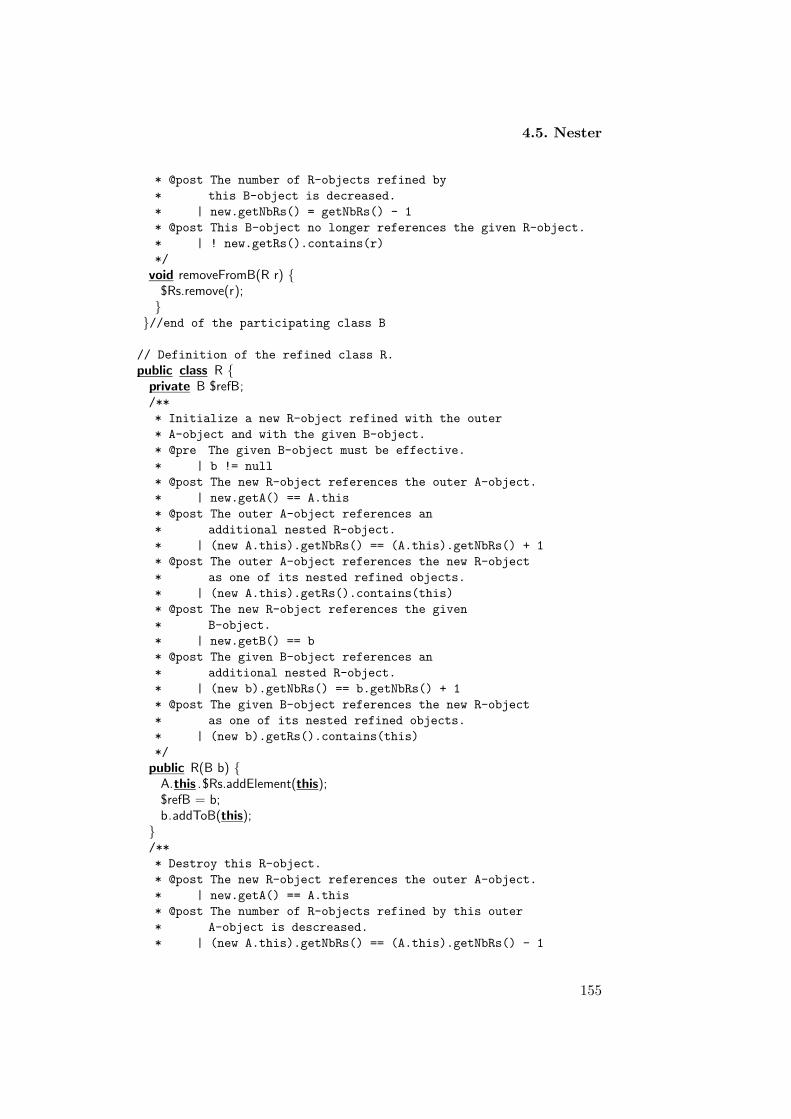
4.5. Nester
* @post The number of R-objects refined by
* this B-object is decreased.
* | new.getNbRs() = getNbRs() - 1
* @post This B-object no longer references the given R-object.
* | ! new.getRs().contains(r)
*/
void removeFromB(R r) {$Rs.remove(r);}
}//end of the participating class B
// Definition of the refined class R.
public class R {private B $refB;/**
* Initialize a new R-object refined with the outer
* A-object and with the given B-object.
* @pre The given B-object must be effective.
* | b != null
* @post The new R-object references the outer A-object.
* | new.getA() == A.this
* @post The outer A-object references an
* additional nested R-object.
* | (new A.this).getNbRs() == (A.this).getNbRs() + 1
* @post The outer A-object references the new R-object
* as one of its nested refined objects.
* | (new A.this).getRs().contains(this)
* @post The new R-object references the given
* B-object.
* | new.getB() == b
* @post The given B-object references an
* additional nested R-object.
* | (new b).getNbRs() == b.getNbRs() + 1
* @post The given B-object references the new R-object
* as one of its nested refined objects.
* | (new b).getRs().contains(this)
*/
public R(B b) {A.this .$Rs.addElement(this);$refB = b;b.addToB(this);
}/**
* Destroy this R-object.
* @post The new R-object references the outer A-object.
* | new.getA() == A.this
* @post The number of R-objects refined by this outer
* A-object is descreased.
* | (new A.this).getNbRs() == (A.this).getNbRs() - 1
155

Chapter 4. Birelational Patterns
* @post The outer A-object no longer references this
* R-object as one of its nested refined objects.
* | ! (new A.this).getRs().contains(this)
* @post The number of R-objects refined by the B-object
* refning this R-object is decreased.
* | (new getB()).getNbRs() == getB().getNbRs() - 1
* @post The B-object refining this R-object no longer
* references the new R-object as one of its
* nested refined objects.
* | ! (new getB()).getRs().contains(this)
*/
public void destructR {A.this .$Rs.removeElement(this);b.removeFromB(this);
}/**
* Return the A-object in which this R-object is nested.
*/
public A getA() {return A.this ;
}/**
* Return the B-object refining this
* R-object.
*/
public B getB(){return $refB;
}} //End of the refined class R.
}
4.5.9 Example revised
In our banking example the classes Account and Bank will be nested in theouter class Person.
Listing 4.8: Implementation of the nested classes Band and Account into the outerclass Person
public class Person {private java . util .Vector $Accounts;/**
* Initialise a new Person-object with no
* refined objects nested in it.
* @post No Account-objects are nested in
* the new Person-object.
* | new.getAccounts().size()== 0
*/
public Person() {
156
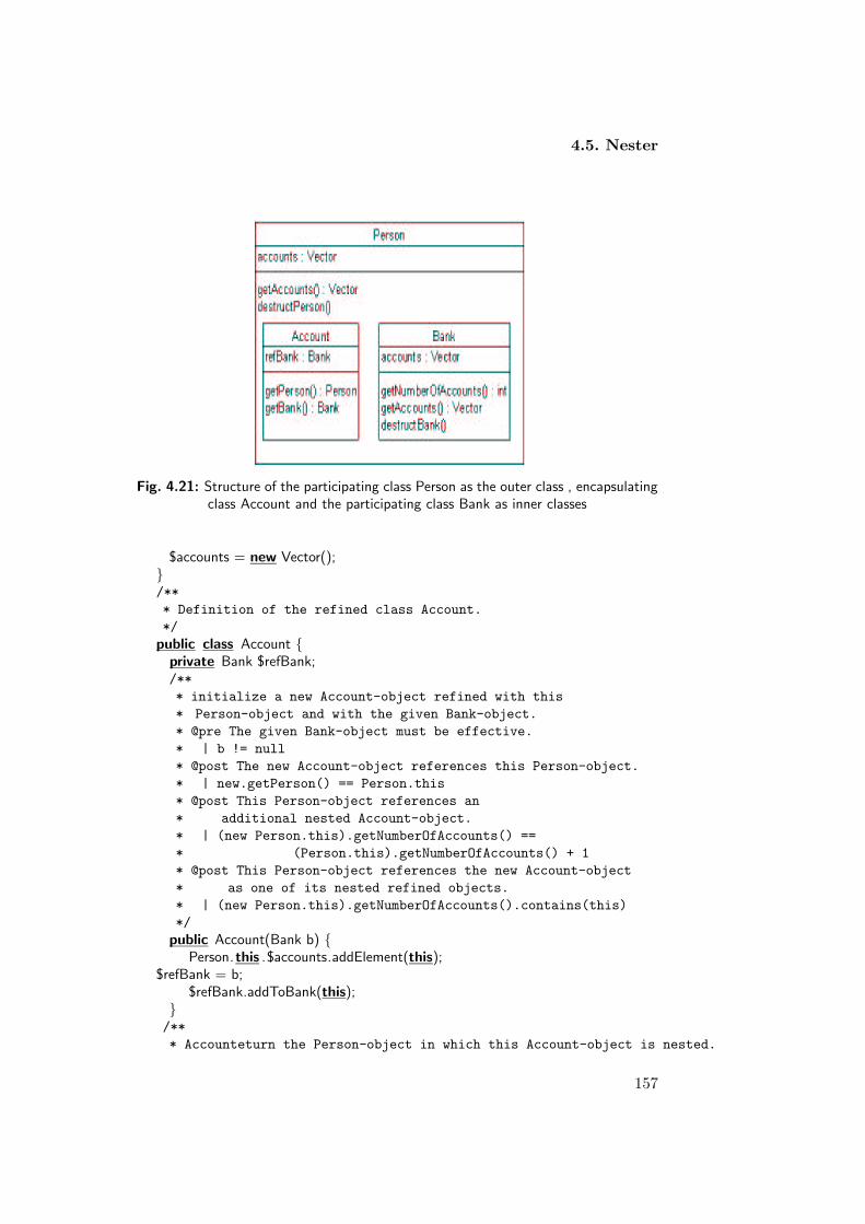
4.5. Nester
Fig. 4.21: Structure of the participating class Person as the outer class , encapsulatingclass Account and the participating class Bank as inner classes
$accounts = new Vector();}/**
* Definition of the refined class Account.
*/
public class Account {private Bank $refBank;/**
* initialize a new Account-object refined with this
* Person-object and with the given Bank-object.
* @pre The given Bank-object must be effective.
* | b != null
* @post The new Account-object references this Person-object.
* | new.getPerson() == Person.this
* @post This Person-object references an
* additional nested Account-object.
* | (new Person.this).getNumberOfAccounts() ==
* (Person.this).getNumberOfAccounts() + 1
* @post This Person-object references the new Account-object
* as one of its nested refined objects.
* | (new Person.this).getNumberOfAccounts().contains(this)
*/
public Account(Bank b) {Person.this .$accounts.addElement(this);
$refBank = b;$refBank.addToBank(this);
}/**
* Accounteturn the Person-object in which this Account-object is nested.
157

Chapter 4. Birelational Patterns
*/
public Person getPerson() {return Person.this ;
}/**
* Return the Bank-object refining this
* Account-object.
*/
public Bank getBank(){return $refBank;
}}//end of the refined class Account
//definition of class Bank.
public class Bank {/**
* Collection of references to Accounts attached
* to this Bank-object. The vector doesn’t contain
* duplicates and does not contain null references.
*/
private java . util .Vector $accounts ;/**
* Initialize a new Bank-object refining no Account-objects.
* @post No Account-objects are refined by the new Bank-object.
* |new.getNumberOfAccounts() == 0
*/
public Bank() {$accounts = new Vector();
}/**
* Destruct this Bank-object.
* @post No Account-objects still exist that are refined by
* the terminated Bank-objects.
*/
public void destructBank() {for( int i = 0; i <$accounts.size (); i++) {
((Account) ($accounts.elementAt(i ))). destructAccount();$accounts.removeAllElements();}
}/**
* Return the number of Account-objects refined with
* this Bank-object.
* @return The number of elements of the vector
* collecting Account-objects refined by this
* Bank-object.
* | getAccounts().size()
*/
public int getNumberOfAccounts () {
158

4.5. Nester
return $accounts. size ();}/**
* @pre The given Account-object may not be null.
* | a != null
* @post The number of Account-objects refined by
* this Bank-object is increased.
* | new.getNumberOfAccounts() = getNumberOfAccounts() + 1
* @post This Bank-object references the given Account-object.
* | new.getAccounts().contains(a)
*/
void addToBank (Account a) {if (! $accounts.contains(a)) {
$accounts.addElement(a);}
}/**
* Return a vector collecting references to all Account-objects
* refined by this Bank-object.
*/
public Vector getAccounts() {return (Vector) $accounts.clone ();
}}//end of the participating class Bank
/**
* Return a vector collecting all Account-objects
* refined by this Person-object.
*/
public Vector getAccounts() {return (Vector) $accounts.clone ();
}/**
* Terminate this Person-object.
* @post No Account-objects still exist refined
* with this terminated Person-object.
*/
void destructPerson () {for( int i = 0; i < $accounts. size (); i++)
((Account)($accounts.elementAt(i ))). destructAccount();$accounts.removeAllElements();
}}
4.5.10 Consequences
1. Adaptability : The Nester pattern helps in making the involved classeseasy to change. In association when one of the two associated classes isexpected to change we must take the navigability under consideration -
159

Chapter 4. Birelational Patterns
whether the involved class is bi-directional or unidirectional, whereas,in nesting we know already that the inner classes objects have implicitreferences to their outer ones.
2. Simplicity : This pattern is considered to be simple since it decreasesthe number of classes introduced at the package level. This makes themodel easier to understand and to maintain. It also limits the numberof message passing between the associated classes.
3. Re-usability : Re-usability is decreased with nesting. If a class is nestedin another, you can only re-use either classes or nothing at all. If theclasses are more loosely coupled (as in ordinary associations) you canre-use one class, without dragging along the other.
4. Efficiency : Nested classes increase time efficiency because of the spe-cial bond between objects of the outer class and of the inner class.
4.5.11 Metrics and Evaluation
• complexity : The complexity for Nester pattern is low as the objectsneed to access each other implicitly. There is no change in the numberof method s for each class the only thing differ is that the refinedclass R and the participating class B are defined in the scope of theparticipating class A. Therefore there is no change in the complexityof the outer class A in terms of the number of defined methods.
• Cohesion: Cohesion for the pattern is low since classes that form therelationship are nested. Even though each one represents a singleabstraction and carries specific responsibilities the outer class still actsas the manager of the inner classes.
• Coupling : Coupling is high as we have bi-directional navigation. CFhas a total value of 2.0, which is a significant high value. Placing thereferences in both the refined object and participating objects makesthem tightly coupled, which in turn might decrease the patterns ad-aptability.
160

Chapter 5
Patterns for Generalisation
Specialisation Architecture
5.1 Delegator
The Delegator pattern helps with converting inheritance relationships intoa one-to-one association between the superclass and subclass. The Deleg-ator merely resends (i.e., delegates) a message to the superclass to accom-plish the desired behavior for the subclass. Delegation makes explicit thedependencies between the delegate class and the receiver class.
5.1.1 Example
Suppose you want to design an application involving a single inheritancehierarchy where one superclass and one subclass is involved. Even thoughinheritance is a wonderful thing, it is sometimes not what you want.
Consider the example shown in 5.1 where a stack is defined as a sub-class of a vector. The class Stack performs four things: push, pop, size, andempty. The only useful method it inherits from the class Vector is the sizemethod. Other methods applicable to vectors in general, such as insertEle-mentAt or remove are not to be applied to stacks. You realise that, eventhough the Stack class is defined as subclass, it uses its superclass Vectormainly for purposes of code-re-use. Furthermore, one may expect that theVector class will not become more important to the Stack class at the timenew requirements are added or existing ones are modified in the underlyingapplication.
In such cases, the use of inheritance will not be a good design. Anotheralternative for such cases is the use of the Delegator pattern. By using theDelegator pattern, you make it clear that you are making only partial useof the delegated class (superclass). The Delegator pattern enables you to
161

Chapter 5. Inheritance Patterns
Fig. 5.1: Structure of the subclass Stack inheriting from superclass Vector
control which aspects of the superclass to take and which to ignore. TheDelegator pattern defines a one-way one-to-one association from the subclassto the superclass.
5.1.2 Context
A component object forwards and delegates a message to another object toaccomplish certain behaviour.
5.1.3 Problem
In software applications you may encounter structures or relationships thatinclude inheritance hierarchies where only one superclass and one subclassare involved. In such relationships, such as the one illustrated in Figure 5.2you may find that the subclass must not inherit all features offered by itssuperclass. Moreover, one may expect that the superclass will not becomemore important to the subclass at the time new requirements are added orexisting ones are modified in the underlying application.
In such cases, the Delegator pattern will relate the subclass and thesuperclass to one another by introducing a one-to-one association betweenthem. The direction of navigation will be from the subclass to the superclassto enable the subclass to re-use functionalities defined in the superclass.This pattern allows the subclass to re-use only those functionalities fromthe superclass it really needs. The Delegator pattern enables the developerto control which aspects of the superclass to take and which to ignore.
Delegation is a powerful programming tool. It allows for direct manipu-lation systems that aim to make construction of software artifacts ”tangible”[Smi95]. In such systems, objects are directly combined to form larger solu-tions, instead of separating compile-time ingredients from run-time ingredi-ents (classes and objects).
162

5.1. Delegator
Fig. 5.2: Structure of the subclass B inheriting from superclass A
The principal difference between class-based inheritance and delegationis that the former relates whole classes, whereas the later relates individualobjects. This enables each object to make its own decision as to when andwhere it delegates, allowing the pattern of inheritance to vary dynamically.In contrast, the inheritance pattern in a class-based system is fixed at thetime the classes are created. This makes delegation a more flexible andpowerful way of organising objects, in that it can be used to model class-based inheritance, whereas the reverse is not true.
5.1.4 Forces
• Single class hierarchy : The inheritance hierarchy involves one super-class and one subclass, and the subclass only needs portions of func-tionality offered by the superclass.
• Restricted multiplicity : This property implies that at most one objectof the delegate class can be associated with a single object of thedelegated class.
• Re-usability : There must be some important reasons to re-use thefunctionality offered by the superclass. Re-usability for the delegateclass, isolated from its superclass, must not be an important require-ment. Code re-use increases the quality of the program and makesit more efficient. Code-reuse is a major concept in object-orientedsoftware.
• Adaptability : The dynamics of the system based on object delegation issupported. When the functionalities of the delegated class are modifiedthe modification will propagate to the delegate dynamically.
163

Chapter 5. Inheritance Patterns
5.1.5 Solution
The Delegator pattern solves the addressed problem as follows:
• Introduce a one-to-one association from the delegate class (the sub-class) to the delegated class (the superclass). This can be accomplishedby defining an attribute that stores a reference to (an object of) thedelegated class.
• Adjust methods to delegate to the delegated class.
5.1.6 Structure
The structure shown in Figure 5.3 presents the Delegator pattern for amodel involving class A and class B. In the figure class B acts as the delegateclass, and class A acts as the delegated class. The structure includes thefollowing methods:
Fig. 5.3: Delegator pattern including classes A & B
1. In addition to methods h and z class A includes:
• f : A public method to be re-used by B-object.
• g : A public method to be re-used by B-object.
2. In addition to method x class B includes:
• f : A public method that delegates to method f implemented inA-object.
• g : A public method that delegates to method g implemented inA-object.
5.1.7 Implementation
The application of the Delegator pattern involves the following steps:
• Define the attribute $refA as part of the subclass B, enabling to re-gister a reference to an object of the superclass B. The attribute im-plements the one-to-one association between the delegate object andthe delegated object.
164

5.1. Delegator
• The subclass B is given the responsibility to delegate methods to thesuperclass A when needed. For example, in Figure 5.3 Class B re-usesmethod f and method g by resending messages to class A through thereference variable $refA.
5.1.8 Sample Code
Listing 5.1: Delegator pattern
/**
* The delegated class A.
*/
public class A {/**
* Initialize a new A-object.
*/
public A () {}/**
* Method to be re-used by the delegate class B.
*/
public void f () {...
}/**
* Method to be re-used by the delegate class B.
*/
public T g() {...
}/**
* Method not to be re-used by the delegate class B.
*/
public void h() {...
}/**
* Method not to be re-used by the delegate class B.
*/
public void z() {...
}}
/**
* Definiton of the delegate class B.
*/
public class B {private A $refA ;
165

Chapter 5. Inheritance Patterns
/**
* Initialize a new B-object attached
* to a new A-object.
* @post The new B-object is attached to a new A-object.
* | new.getA() != null.
*/
public B() {$refA = new A();
}/**
* Initialize a new B-object attached
* to the given A-object.
* @pre The given A-object must be effective.
* | a != null
* @post The new B-object is attached to the given A-object.
* | new.getA() == a.
*/
public B(A a) {$refA = a;
}/**
* Return the A-object to which this B-object
* is attached.
*/
public A getA() {return $refA;
}/**
* Method only applicable to objects of class B.
*/
public void x() {...
}/**
* Method delegating to class A.
*/
public void f () {$refA. f ();
}/**
* Method delegating to class A.
*/
public T g() {return $refA.g();
}}
166

5.1. Delegator
5.1.9 Example Revised
The Delegator pattern can be applied to the model involving stack andvector as shown in Figure 5.4. In that case, the class Stack will manage allaspects of its relationship with the class Vector.
• The method pop in the class Stack is implemented as:
/**
* Removes the object on top of this stack.
* @pre This stack must have at least one element.
* | size() > 0
* @post The number of elements in this stack is
* decreased.
* | new.size() == size() - 1
*/
public Object pop() {Object result = $refVector.firstElement ();$refVector.removeElementAt(0);return result;
}
• The method push is implemented as :
/**
* Pushes the given object on top of this stack.
* @post The number of elements in this stack is
* incremented.
* | new.size() == size() + 1
*/
public void push(Object element) {$refVector.insertElementAt(element, 0);
}
• The method empty is implemented as :
/**
* Tests if this stack is empty.
*/
public boolean empty() {return $refVector.isEmpty();
}
• The method size is delegated to the method size in class Vector.
/**
* Return the number of elements in this stack.
*/
public int size () {return $refVector.size ();
}
167

Chapter 5. Inheritance Patterns
Fig. 5.4: The Stack-class with a one-way, one-to-one association with the Vector-class.
5.1.10 Consequences
1. Adaptability : The Delegator pattern increases flexibility and it is apowerful way of organising objects. It enables each object to make itsown decision as to when and where it delegates, allowing the relatedobjects to vary dynamically.
2. Simplicity : This pattern is not considered to be simple since dynamicand highly parameterised objects are harder to understand than morestatic ones.
3. Re-usability : Re-usability is decreased with delegation. If a class isdelegated to another class then reusing the delegate class becomesdifficult. The reason is that the delegate class re-uses methods fromanother class, meaning that the delegated class must be re-used aswell. In contrast, the delegated class can be re-used since couplingis only uni-directional from the delegate to the delegated class. Thisimposes no restrictions for the delegated class to be re-used.
4. Efficiency : The Delegator pattern makes it easy to compose behaviourat run-time and to change the way they are composed. This mightincrease efficiency.
5.1.11 Metrics and Evaluation
• Complexity : The complexity for Delegator pattern is higher as themethods to be implemented explicitly increases. There is no changein the total number of methods for each class. The only difference isthat the delegate class invokes methods from the receiving class, whichmakes it more difficult to understand.
• Cohesion: Cohesion for the delegate class is low since it invokes func-tionalities from the delegated class. However, cohesion for the deleg-ated class will not be affected since the association is uni-directional.
• Coupling : Coupling is not that high as we have one-way one-to-oneassociation between the delegate object and the receiving object. CF
168

5.2. Multiple Inheritance Organiser
has a total value of 0.5, which does not dramatically compromise ad-aptability of the referenced class.
5.2 Multiple Inheritance Organiser
The Multiple Inheritance Organiser helps with converting multiple inher-itance hierarchies into single inheritance hierarchies. The pattern simplyconverts one of the multiple inheritance relationships into one-to-one asso-ciation using the Delegator pattern and introduces an interface to assurepolymorphism. The Multiple Inheritance Organiser pattern assures dy-namic binding and increase adaptability of the give hierarchy.
5.2.1 Example
Suppose you want to design an application involving a multiple inherit-ance hierarchy where one subclass inherits from tow immediate superclasses.Even though multiple inheritance is a wonderful thing, it sometimes lead tocomplex class hierarchies and is not supported by all object-oriented pro-gramming languages.
Consider the example shown in Figure 5.5, where an amphibious vehicleinherits from both land vehicle and water vehicle superclasses. If both LandVehicle and Water Vehicle define accelerate method, but the two classesimplement the method differently, then Amphibious Vehicle inherits twoconflicting implementations of that method. It is obvious that such complexstructures are not recommended in software systems and implementing suchhierarchies in a given application is an indication for a poor design.
Suppose later during designing the software system you intend to avoidsuch complex hierarchy and want to elaborate it to a more flexible design.A good alternative for you is to apply the Multiple Inheritance Organiserpattern. The pattern resolves conflicting implementations by convertingone of the two inheritance relationships to one-way one-to-one associationwhere the subclass delegate to that class to re-use the needed functionalitydefined in that class. Furthermore, an interface is added to support the poly-morphic properties of the converted relationship. In the figure below, theinheritance relationship defined between the Land Vehicle and AmphibiousVehicle is converted to one-to-one association with direction of navigationfrom Amphibious Vehicle to Land Vehicle. In addition both Land Vehicleand Amphibious Vehicle implement an interface in which the methods ofthe land Vehicle superclass (now called delegated class) are defined. Theinterface is added to support polymorphism to the applied pattern.
169
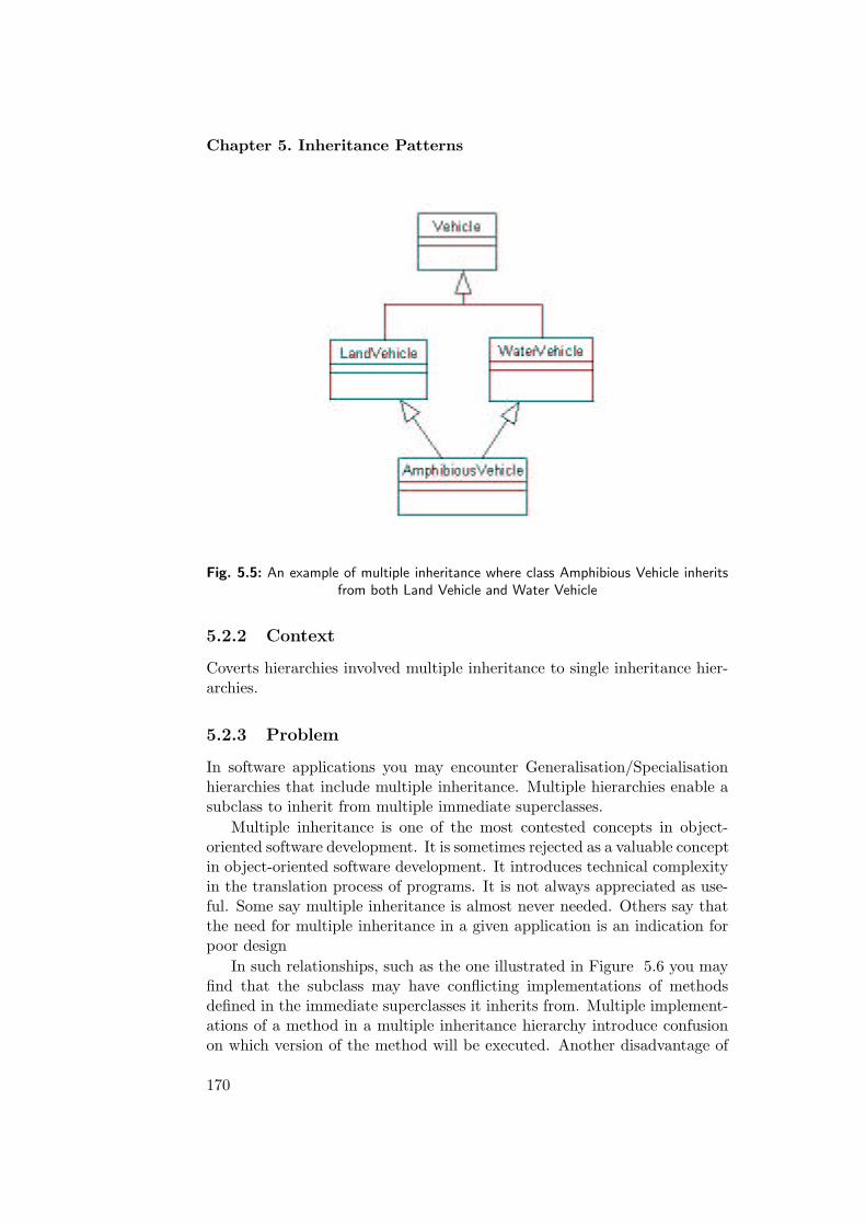
Chapter 5. Inheritance Patterns
Fig. 5.5: An example of multiple inheritance where class Amphibious Vehicle inheritsfrom both Land Vehicle and Water Vehicle
5.2.2 Context
Coverts hierarchies involved multiple inheritance to single inheritance hier-archies.
5.2.3 Problem
In software applications you may encounter Generalisation/Specialisationhierarchies that include multiple inheritance. Multiple hierarchies enable asubclass to inherit from multiple immediate superclasses.
Multiple inheritance is one of the most contested concepts in object-oriented software development. It is sometimes rejected as a valuable conceptin object-oriented software development. It introduces technical complexityin the translation process of programs. It is not always appreciated as use-ful. Some say multiple inheritance is almost never needed. Others say thatthe need for multiple inheritance in a given application is an indication forpoor design
In such relationships, such as the one illustrated in Figure 5.6 you mayfind that the subclass may have conflicting implementations of methodsdefined in the immediate superclasses it inherits from. Multiple implement-ations of a method in a multiple inheritance hierarchy introduce confusionon which version of the method will be executed. Another disadvantage of
170

5.2. Multiple Inheritance Organiser
multiple inheritance is that not all object-oriented programming languagesdo support its implementation.
Fig. 5.6: Structure of a multiple inheritance hierarchy
In such cases, the Multiple Inheritance Organiser pattern will relate thesubclass and one of its superclasses by a one-to-one association using theDelegator pattern. The direction of navigation will be from the subclass tothe superclass to enable the subclass to re-use functionalities defined in thesuperclass. It also adds an interface to the hierarchy that will be implemen-ted by the former superclass (delegated class) and the subclass (delegateclass). This pattern allows the subclass to re-use only those functionalitiesfrom the superclass it really needs.
Multiple Inheritance Organiser makes the hierarchy more flexible andeasier to implement. It organises the hierarchy in a powerful was such that allobject-oriented concepts are supported (i.e., polymorphism). It also avoidsthe confusion of implementing the methods residing in the superclass.
The Multiple Inheritance Organiser pattern offers flexibility and resolvecomplexity of multiple method implementations. It avoids confusion inmethod invocation by introducing every method in the right place and re-moves the risk of related implementations. It increases adaptability andre-usability of the involved hierarchy.
5.2.4 Forces
• Multiple inheritance hierarchy : The inheritance hierarchy involves asubclass that inherits from more than one superclass that includes
171

Chapter 5. Inheritance Patterns
multiple method implementations.
• Restricted multiplicity : This property implies that at most one objectof the delegate class can be associated with a single object of thedelegated class.
• Re-usability : There must be some important reasons to re-use thefunctionality offered by the superclass. Re-usability for the delegateclass, isolated from its superclass, must not be an important require-ment. Code re-use increases the quality of the program and makesit more efficient. Code-reuse is a major concept in object-orientedsoftware. Notice that re-usability for the delegate class (subclass) de-creases since by delegation only functionalities can be re-used but notdata from the delegated class.
• Adaptability : Adaptability is another crucial requirement imposed onthe relationship. It must be simple to add characteristics and associ-ated methods to the classes involved in the hierarchy.
• Simplicity : Simplicity is important to enable understandability of thehierarchy as well as to avoid confusion of multiple method implement-ations, and superclass methods invocations.
• Dynamic Binding and Polymorphism: It is important to keep dynamicbinding and polymorphism in the hierarchy as they are the sole pur-pose of generalisation/specialisation in object-oriented software devel-opment.
5.2.5 Solution
The Multiple Inheritance Organiser pattern solves the addressed problemas follows:
• Remove one of the two inheritance hierarchies and introduce a one-to-one association from the delegate class (the subclass) to the delegatedclass (the superclass). This can be accomplished by defining an at-tribute that stores a reference to (an object of) the delegated class.
• Adjust methods to delegate to the delegated class.
• Add a new interface in which methods of the former superclass (deleg-ated class) is defined. The interface will be implemented by both thedelegate class (subclass) and the delegated class.
172

5.2. Multiple Inheritance Organiser
5.2.6 Structure
The structure shown in Figure 5.7 presents the Multiple Inheritance Or-ganiser pattern for a model involving parent class A which is subclassed byclass B and class C; class C is subclassed by class D; class D also referenceclass B and implements the interface BI. In the figure class D acts as thedelegate class, and class B acts as the delegated class. The structure alsoincludes the following methods:
Fig. 5.7: Structure of multiple inheritance hierarchy implemented with Multiple Inher-itance Organiser patter
1. Methods of the parent class A:
• f : A public method to be re-used by subclasses B and C.
• g : A public method to be re-used by subclasses B and C. Thismethod is overwritten in only subclass B.
• h: A public method to be re-used by subclasses B and C. Thismethod is overwritten in both subclasses B and C.
2. Methods of the subclass B (a.k.a the delegated class):
173

Chapter 5. Inheritance Patterns
• g : A public method implements the method g defined in theinterface and overwrite the method g defined in the parent classA.
• h: A public method implements the method h defined in theinterface and overwrite the method h defined in the parent classA.
• z : A public method that is added to the interface.
3. Methods of the subclass C:
• h: A public method overwrite the method h defined in the parentclass A.
• z : A public method that differs from the method z defined in thedelegated class.
4. Methods of the subclass D ( a.k.a the delegate class):
• It implements the methods defined in the interface BI by deleg-ating them to the delegated class B, and inherits the methodsdefined in the superclass C.
5. The interface BI define the methods g, h, and z.
5.2.7 Implementation
The application of the Multiple Inheritance Hierarchy pattern involves thefollowing steps:
• The inheritance relationship between the subclass D and the superclassB is removed and replaced by a one-way one-to-one association withthe superclass B. The direction of the association is from the subclassto the superclass.
• Define the attribute $refB as part of the subclass D, enabling to re-gister a reference to an object of the delegated class B. The attributeimplements the one-to-one association between the delegate object andthe delegated object.
• The subclass D is given the responsibility to delegate methods to thesuperclass B when needed. For example, in Figure 5.7 Class D re-usesmethod g, h , and Z by resending messages to class A through the ref-erence variable $refA. The delegation process serves as implementingthe methods defined in the interface BI.
• Method z defined in the superclass C has different implementationfrom the one defined in the delegated class B.
174

5.2. Multiple Inheritance Organiser
5.2.8 Sample Code
Listing 5.2: Multiple inheritance with interface and delegation; subclass B and subclassD implements the interface BI, and subclass D inherits from the superclass C
/**
* The parent class A.
*/
public class A {/**
* Initialize a new A-object.
*/
public A() {
}/**
* Method not overwritten by the subclasses B and C.
*/
public void f () {...
}/**
* Method that is overwritten by only the subclass-B.
*/
public T g() {...
}/**
* Method overwritten by both subclasses B and C.
*/
public void h() {...
}
}
−−−−−−−−−−−−−−−−−−−−−−−−−−−−−−−−−−−−−−−−−−−−−−−/**
* The delegated class B.
*/
public class B extends A implements BI{/**
* Initialize a new B-object.
*/
public B () {}/**
* Method to be re-used by the delegate object-D.
*/
175

Chapter 5. Inheritance Patterns
public T g() {...
}/**
* Method to be re-used by the delegate object-D.
*/
public void h() {...
}/**
* Method to be re-used by the delegate object-D.
* This method differs from the method
* defined in the superclass C.
*/
public void z() {...
}}−−−−−−−−−−−−−−−−−−−−−−−−−−−−−−−−−−−−−−−−−−−−−−−/**
* Definition of the subclass C that is
* the superclass of D.
*/
public class C extends A {/**
* Initialize a new C-object
*/
public c() {}
/**
* Method to be inherited by the
* subclass D.
*/
public void h() {...
}/**
* Method to be inherited by the subclass D.
* This method differs from the method
* defined in the superclass B.
*/
public void z() {...
}}−−−−−−−−−−−−−−−−−−−−−−−−−−−−−−−−−−−−−−−−−−−−−−−/**
* Definiton of the delegate class D.
176

5.2. Multiple Inheritance Organiser
*/
public class D extends C implements BI {private B $refB ;/**
* Initialize a new D-object attached
* to a new B-object.
* @post The new D-object is attached to a new B-object.
* | new.getB() != null.
*/
public D() {$refB = new B();
}/**
* Initialize a new D-object attached
* to the given B-object.
* @pre The given B-object must be effective.
* | b != null
* @post The new D-object is attached to the given B-object.
* | new.getB() == b.
*/
public D(B b) {$refB = b;
}/**
* Return the B-object to which this D-object
* is attached.
*/
public B getB() {return $refB;
}/**
* Method delegating to object-B.
*/
public T g() {return $refB.g();
}/**
* Method delegating to object-B.
*/
public void h() {$refB.h();
}/**
* Method delegating to object-B.
*/
public void z() {$refB.z ();
}}
177

Chapter 5. Inheritance Patterns
−−−−−−−−−−−−−−−−−−−−−−−−−−−−−/**
* Definition of the interface BI.
*/
public interface BI{/**
* Method to be implemented by the delegate object-D
* and the delegated object-B.
*/
public T g();/**
* Method to be implemented by the delegate object-D
* and the delegated object-B.
*/
public void h();/**
* Method to be implemented by the delegate object-D
* and the delegated object-B.
*/
public void z ();
}
5.2.9 Example Revised
The Multiple Inheritance Organiser pattern can be applied to the hierarchyinvolving vehicles in Figure 5.8. In that case, the class Amphibious Vehiclewill delegate to the class Land Vehicle to re-use the functionalities definedin that class. By doing so it will implement also the methods defined in theinterface Land Vehicle.
• In the parent class Vehicle, the method drive is overwritten in thesubclass B. Its implementation in the parent class is as follows:
/**
* Let this Vehicle ride with the given speed.
* @pre The speed must not be negative and
* must not exceed 100 km/h
* | (0 <= speed) && (speed <= 100)
* @post The speed of this vehicle is set to speed.
* | new.getSpeed() == speed
*/
public void drive(int speed) {.......
}
It is redefined in the subclass Land Vehicle as follows:
178

5.2. Multiple Inheritance Organiser
/**
* Let this LandVehicle ride at the given speed.
* @pre The speed must not be negative and
* must not exceed 120 km/h.
* | (0 <= speed) && (speed <= 120)
* @post The speed of this LandVehicle is set to speed.
* | new.getSpeed() == speed
*/
public void drive(int speed) {.......
}
• In the parent class Vehicle the method accelerate is overwritten inboth the subclasses Land Vehicle and Water Vehicle. Its implementa-tion in the parent class is as follows:
/**
* Accelerate this vehicle during the given period of time.
* @post The speed of this vehicle is incremented with
* at least 10 km/h for each second of acceleration.
* | new.getSpeed() >= getSpeed() + 10*period
*/
public void accelerate (int period) {........
}
It is redefined in the subclass Water Vehicle and implemented as fol-lows:
/**
* Accelerate this WaterVehicle during the given period of time.
* @post The speed of this WaterVehicle is incremented with
* at least 5 km/h for each second of acceleration.
* | new.getSpeed() == getSpeed() + 5*period
* @see superclass
*/
public void accelerate (int period) {........
}
It is redefined in the subclass Land Vehicle and implemented as follows:
/**
* Accelerate this LandVehicle during the given period of time.
* @post The speed of this LandVehicle is incremented with
* at least 15 km/h for each second of acceleration.
* | new.getSpeed() == getSpeed() + 15*period
179

Chapter 5. Inheritance Patterns
* @see superclass
*/
public void accelerate (int period) {......
}
• To avoid confusion at the level of the subclass Amphibious vehiclethe method accelerate, the class Amphibious Vehicle delegate thismethod to the delegated class Land Vehicle if it needs to implementthat method when it rides on land as follows:
/**
* Accelerate this AmphibiousVehicle during the given period of time.
* @post The speed of this AmphibiousVehicle is incremented with
* at least 15 km/h for each second of acceleration.
* | new.getSpeed() == getSpeed() + 15*period
* @see delegated class
*/
public void accelerate (int period) {$refLandVehicle.accelerate(period);
}
5.2.10 Consequences
1. Re-usability : There must be some important reasons to re-use thefunctionality offered by the superclass. Re-usability for the delegateclass, isolated from its superclass, must not be an important require-ment. Code re-use increases the quality of the program and makesit more efficient. Code-reuse is a major concept in object-orientedsoftware. Notice that re-usability for the delegate class (subclass) de-creases since by delegation only functionalities can be re-used but notdata from the delegated class.
2. Adaptability : Adaptability is increased by applying this pattern. Itoffers flexibility in adding methods and updating the existing oneseasily. It is simple to add characteristics and associated methods tothe classes involved in the hierarchy.
3. Simplicity : Simplicity is important to enable understandability of thehierarchy as well as to avoid confusion of multiple method implement-ations, and superclass methods invocations.
4. Efficiency :
5.2.11 Metrics and Evaluation
• complexity : Multiple Inheritance Organiser decreases complexity as itresolves the misuse of multiple method implementations. It Organises
180
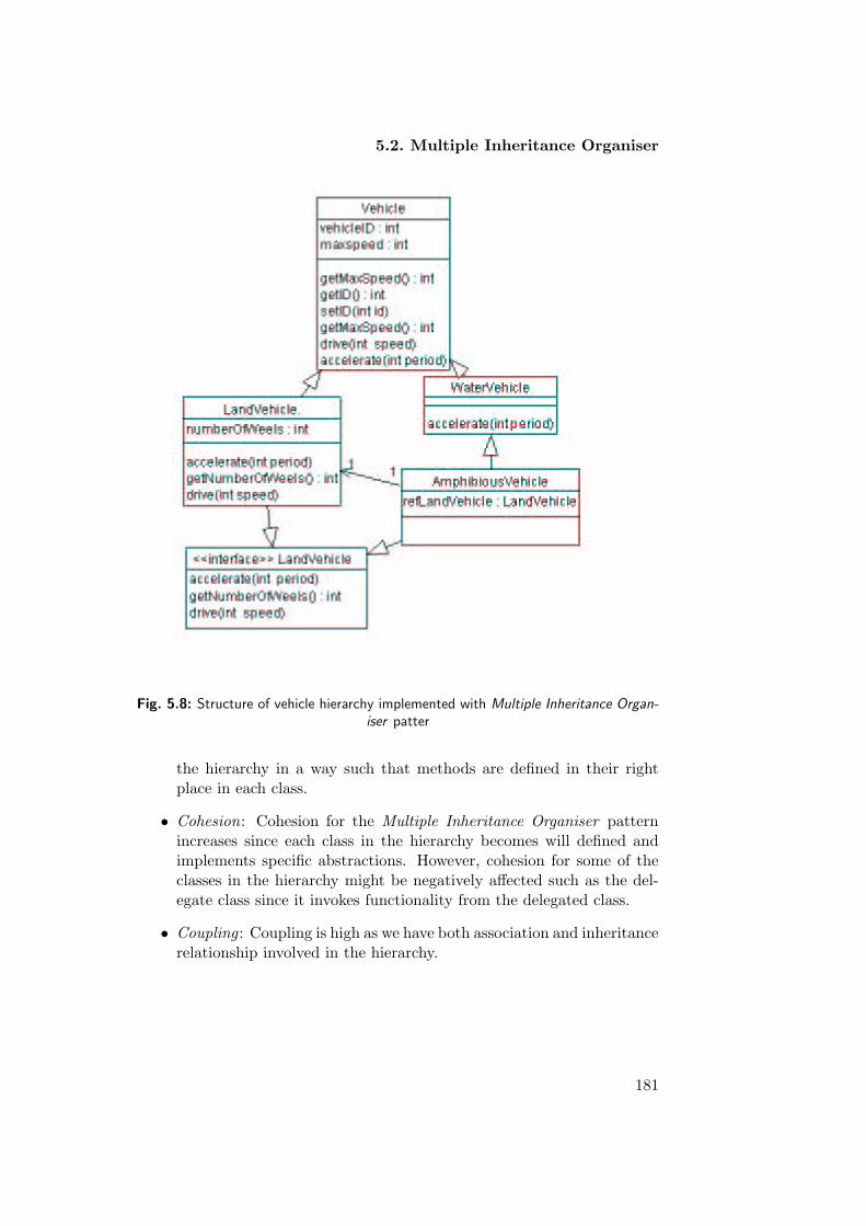
5.2. Multiple Inheritance Organiser
Fig. 5.8: Structure of vehicle hierarchy implemented with Multiple Inheritance Organ-
iser patter
the hierarchy in a way such that methods are defined in their rightplace in each class.
• Cohesion: Cohesion for the Multiple Inheritance Organiser patternincreases since each class in the hierarchy becomes will defined andimplements specific abstractions. However, cohesion for some of theclasses in the hierarchy might be negatively affected such as the del-egate class since it invokes functionality from the delegated class.
• Coupling : Coupling is high as we have both association and inheritancerelationship involved in the hierarchy.
181


Chapter 6
Conclusions and Future
Work
In this chapter, we summarize the basic concepts introduced in this thesis toenhance the concept of object-oriented design and life-cycle evolution. Wepresent the main contributions of this thesis as well. Finally, we describe thework that still should be done to achieve the goals of object-oriented designin a satisfactory and adequate manner. We do not claim that we solved allthe problems encountered in object-oriented software development process.We have provided some building blocks that can pave the way for a clearand adequate pattern-oriented design process. We do hope that this workwill benefit both the experienced designers who gain additional insights, andthe novice designers who obtain an additional view that would otherwise beunavailable.
6.1 Summary
1. Life-cycle evolution and quality assessment
We identified in this thesis a number of important problems that arerelated to software development. We believe that the current softwaredevelopment methodologies are inadequate to provide full solutions forthose problems. The following issues are handled in this thesis:
• Managing software life-cycle evolution through design
patterns, which is blurred in many object-oriented soft-
ware development methodologies.
People develop conceptual models, and then start developing adesign model from scratch without the proper binding betweenthem. Such a strategy fails to provide effective solutions for thedesign problems at hand. The transition is abrupt: designers getsome information - usually incomplete - from the analysis, and
183

Chapter 6. Conclusions and Future Work
then go off to ’real design’. Such an approach fails to bring therequirements as a central issue into design. Moreover, it fails tocope with the evolutionary nature of the software developmentprocess, which requires constant adjustments to the design, andimplementation of the system. Moreover, traceability betweenphases is difficult, because the correspondence between modelsdeveloped during successive phases is lacking. As a result, thecontents of the models are not will matched and may be misin-terpreted. In the end, this may lead to an undisciplined form ofsoftware development in which engineers move rather randomlybetween phases.
• Early assessment of software quality factors. Conventionalobject-oriented design methods tend to focus on achieving thefunctional requirements and pay little or no attention to qualityrequirements. These methods assume that an object-oriented ap-proach more or less automatically leads to re-usable and flexiblesystems. In order to create and maintain a high quality softwaresystem, quality assurance must be done during the developmentprocess. Currently, software quality factors are typically meas-ured and tested after the system is put in operation. This requiressoftware developers to redesign and re-implement part of the soft-ware system if the system fails to meet its quality requirements.
• Software automation. Object-oriented software developmentmethods exist to develop large and complex software systems.This is obviously a time-and resource-consuming activity. Usuallythese methods include a number of heuristic rules and guidelinesthat are intended to produce successful software systems. Some-times, these rules are structured in different ways, leading todifferent software development processes. Apart from the manyenvironments with diagram editors and visualization tools, com-plete and integrated tools, which support the entire life cycle,are not yet available in practice. Automated support for object-oriented methods will decrease complexity, increase re-usability,and provide better support for adaptability, and continuous im-provement.
2. Dealing with life-cycle evolution and quality assessment prob-
lems
• To deal with the first problem, we proposed a pattern-based ap-proach for designing software systems. The overall objective ofthe patterns is to present proper solutions for recurring designproblems. From a technical perspective, this means that we wantto support developers in defining architectures, which meet the
184
6.1. Summary
(functional and non-functional) needs of the systems they arebuilding. In particular, patterns help them to create the mosteffective solutions for the design problems at hand, under theconstraints imposed on them by their clients. From a humanperspective, the intent of each pattern is to enable developersto understand and control the design process and provide designswith good quality. In this thesis we have presented 15 patterns forobject-oriented design. Most of them deal with relational struc-tures involving existential dependency and constraint of multipli-city and of mutability. The patterns take care of the evolutionarynature of the software development process; in which we can ad-just the resulting structure whenever necessary.
• To solve the second problem, we considered quality requirementsduring development. During the design process each applied pat-tern will have an impact on the quality of the software systemboth positively or negatively. Since software quality factors con-flict each other, they must be balanced and assessed so that wecan achieve the design model with the desired quality. In our ap-proach we have chosen four main quality factors to be controlledduring design, namely adaptability, re-usability, efficiency, andsimplicity. These quality factors were measured indirectly bymeasuring the internal quality attributes complexity, coupling,and cohesion. The internal quality attributes were then relatedto the external quality factors. As an example, coupling is definedas the number of other classes to which a given class is coupled.As coupling increases, it is likely that the re-usability of a classwill decrease since it will be depending on other classes in themodel. Furthermore, high coupling makes the system less adapt-able as it becomes complicated to modify the system. High valuesof coupling also decrease efficiency because of extensive messagepassing between objects.
• Finally, we have handled the issue of automation by partially de-veloping a tool which includes a mechanism using XML to applythe selected patterns. We linked both models with the factorypattern. The tool enables the developer to select among the pat-terns catalog, apply the selected pattern, and generate Java codeautomatically. Automation is essential to accommodate the com-plexity in applying the design patterns and locating the resourcesneeded. It relieves the experienced developer from a lot of mech-anical work, and allows the novice developers to design softwaresystems with more confidence.
185
Chapter 6. Conclusions and Future Work
6.2 Contribution
Our main focus was on developing patterns to provide solutions for recurringsoftware design problems. Our work makes the following contribution:
1. Patterns for Uni-relational Architectures: We developed sevendesign patterns for structures that involve unary relations. The pat-terns catalog includes (Integrator, Unifier, Reverse Integrator, Co-ordinator, Reversed Coordinator, Container Object, and Collaborator).Furthermore, we considered the effect of each pattern on the qualityfactors of the classes involved in the relation. For example, the In-tegrator pattern increases efficiency but decreases re-usability. TheCollaborator pattern increases flexibility but increases coupling.
2. Patterns for Bi-relational Architectures: Binary relations dif-fer from unary relations by having three classes involved in the re-lation. The patterns catalog we developed for binary relations in-cludes (Bi-integrator, Reverse Bi-integrator, Refinement Integrator,Bi-collaborator, and Nester). Again, each pattern was evaluated basedon the same quality factors as those for the unary relations.
3. Patterns for Inheritance hierarchies: generalisation/specializa-tion hierarchies were also studied in our thesis. We have developed fourpatterns, which include (Delegator, Delegator with Interface, Hier-archy Collapser).
4. Quality management: Each pattern has an impact on the qualityfactors of the design model. Therefore, we evaluated some qualityfactors such as re-usability, flexibility, efficiency, and simplicity usingthe internal quality factors of complexity, coupling, and cohesion. Weused part of the CK metrics suit to measure the internal quality attrib-utes and with the given results we drew inferences about the impacton external quality factors.
5. Tool Support: We have started developing tool support for an auto-matic application of the patterns. The tool uses XML and its relatedtechnologies (XSLT) to apply the patterns, and to generate their im-plementation automatically. The tool operates on an XML documentrepresenting the design model. Once the developer locates the prob-lem that he is facing, the tool offers alternative patterns that can beapplied to solve the current problem. Each pattern is represented bya separate XSLT. So far, we have only implemented the Integratorpattern.
186

6.3. Future Work
6.3 Future Work
As a future work we intend to examine and extend the pattern-based ap-proach:
1. By adding new patterns to the patterns catalog to make the approachcomplete and cover all the possible artifacts and structures that couldbe possible in the design model. Moreover, we will extend the pat-terns catalog to cover other aspects in software development such as,concurrency, distribution and real-time aspects.
2. Another subject we will consider is to implement the patterns in differ-ent object-oriented programming languages like C++, SmallTalk andC#.
3. We would like to continue our work on the development of the toolsupport. The work will consider most of the patterns, and also de-velop a graphical user interface to the tool. Furthermore, we want tointegrate a mechanism by which we can measure the quality effect ofeach selected pattern.
6.4 Published Papers
1. J. Said, and E. Steegmans, Transformation of Unary Relations, Proc.of the 13th International Conference on Software & Systems Engin-eering and Applications, vol. 4, 2000, pp. 1-14.
2. J. Said, and E. Steegmans, Transformation of binary relations, Proc.of the Sixth International Conference on Computer Supported Cooper-ative Work in Design (W. Shen and M. Kamel, eds.), NRC ResearchPress, 2001, pp. 575-580, Sponsored by IEEE.
3. J. Said, and E. Steegmans, Transformation of binary relations withnesting and association, Proc. Formal Foundation for Software Evol-ution, 2001, pp. 80- 88.
4. J. Said, and E. Steegmans, Automatic Transformation of ConceptualModels into Design Models. Proc. of Automating Object - OrientedSoftware Development Methods, ECOOP workshop 2001, pp 109- 115.
5. J. Said, and E. Steegmans, Validating Quality requirements of Object-Oriented Design, Proc. Software Quality Week Europe. 2002.
187


Bibliography
[Als77] C. Alexander, S. Ishikawa, M. Silverstien, M. Jacobson. I. Fiksdahl-king, and S. Angel. A pattern Language. Oxford University Press,New York, 1977.
[And94] B. Anderson. Patterns: Building Blocks for Object-Oriented Soft-ware Architectures. In Software Engineering Notes, January 1994.
[Ban89] J. Banerjee and W. Kim. Semantics and Implementation of SchemaEvolution in Object-Oriented Databases. In Proceedings of the ACMSIGMOD.
[Bat94] D. Batory et.al. JTS: Scalable Software Library. In Proceedings ofACM SIGSOFT, Deceber 1993.
[Bax90] I. Baxter. Design Maintenance Systems. In Communications of theAcm 35(4), April, 1992.
[Bax97] I. Baxter. and C. Pidgeon. Software Change Through Design Main-tenance. In Proceedings of the International Conference on SoftwareMaintenance 97, IEEE Press, 1997.
[PDR91] E.H. Bersoff and A.M. Davis. Impact of life cycle models onsoftware configuration management. Communication of the ACM,34(8):104-118, August, 1991.
[Bec94] K. Beck, R. Johnson. Patterns Generate Architectures. In Proceed-ings ECOOP 94, Springer-Verlag, 1994.
[Bec87] K. Beck, W. Cunningham. Ysing Pattern Language for Object-Oriented Programs. In Proceedings of OOPSLA-87 workshop onthe Specification and Design for Object-Oriented Programming,http://c2.com/doc/oopsla87.html, 1987.
[Ber93] E.V. Berard, Essays on Object-Oriented Software Engineering,Volume I, Printice Hall, Englewood Cliffs, NJ, 1993.
[Ber91] P. Bergstein. Object-Preserving Class Transformations. In Proceed-ings of OOPSLA 91, 1991.
189

[Bie92] J. Bieman. Deriving measures of software reuse in object-orientedsystems. In T. Denvir, R. Herman, and R. Whitty, editors, FormalAspects of Measurement. pp. 63-83. Springer-Verlag, 1992.
[Bie95] J. Bieman and B.-K. Kang. Cohesion and reuse in an object-orientedsystem. Proc. ACM Symp. Software Reusability (SSR95), pp. 259-262, April 1995.
[Bie95] J. Bieman and J. Zhao. Reuse through inheritance: A quantitat-ive study of c++ software. Proc. ACM Symp. Software Reusability(SSR95), pp. 47-52, April 1995.
[Bie95] J. Bieman and S. Karunanithi. Measurement of language supportedreuse in object oriented and object based software. J. Systems andSoftware., 28(9):271-293, Sept. 1995.
[Bohm87] B. Boehm, A spiral model of software development and enhace-ment, Software Engineering Project Management. pp. 128-142, 1987.
[Boo94] G. Booch Object-Oriented Analysis and Design with Applications.Benjamin/Cummings, Redwood City, California, 1994.
[Booch94] Booch, G. Object-Oriented Analysis and Design with Application,1994.
[Bos00] J. Bosch, Design and Use of Software Architectures, Addison-Wesley, Britain, 2000.
[Bos98] J. Bosch. Design Patterns as Language Constructs. In Journal ofObject-Oriented programming, Vol. 11, No. 2, pp. 18-32, May 1998.
[Bri96] L. Briand, S. Morasca, and V. Basili. Property-based software engin-eering measurement. IEEE Trans. Software Engineering, 22(1):68-85,Jan 1996.
[Bri98] L. Briand, J. Daly, and J. W ust. A unified framework for cohesionmeasurement in object-oriented systems. Empirical Software Engin-eering, 3(1):65-117, 1998.
[Bri99] L. Briand, J. Daly, and J. W ust. A unified framework for coup-ling measurement in object-oriented systems. IEEE Trans. SoftwareEngineering, 25(1):91-121, 1999.
[Bru00] B. Bruegge, A. H. Dutoit, Object-Oriented Software Engineering:Conquering Complex and Changing Systems, Prentice Hall, NJ, 2000.
[Bud96] F. J. Budinsky et.al., Automatic Code Generation from DesignPatterns. In IBM Systems Journal, Volume 35, No. 2, 1996.
190

[Card90] D. Card, R. Glass. Measuring Software Design Quality. Prentice-Hall, Englewood Cliffs, NJ, 1990.
[Chid94] S. Chidamber, and C. Kemerer, ”A Metric Suite for Objected Ori-ented Desing”, IEEE Trans. on Software Eng. J., vol. 20, no. 6, June1994.
[Coa91] P. Coad and E. Yourdon. Object-Oriented Design. YourdonPress/Prentice-Hall, Englewood Cliffs, NJ, 1991.
[Coa92] P. Coad. Object-Oriented Patterns. In Communications of theACM, V35 N9, pages 152-159, September 1992.
[CORBA] OMG.CORBA Components. http://www.omg.org. 2000.
[CY91] P. Coad and E. Yourdon. Object-Oriented Analysis. YourdonPress/Prentice-Hall, Englewood Cliffs, NJ, 1991.
[Cur79] B. Curtis, S. Sheppard, P. Milliman, M. Borst, and T. Love. Measur-ing the psychological complexity of software maintenance tasks withthe halstead and mccabe metrics. IEEE Trans. Software Engineering,SE-5(2):295-303, 1979.
[Dri91] W. Griswold. Program Restructuring as an Aid to Software Main-tenance. PhD thesis. University of Wahinton, August 1991.
[ELD95] Steegmans, E., Lewi, J., D’Haese, M., Dockx, J., Jehoul, D,Swennen, B., Van Baelen, S., and Van Hirtum, P., EROOS ReferenceManual Version 1.0, Department of Computer Science, K.U.Leuven,CW Report 208, Leuven, B, 1995, 176 p.
[Flo97] G. Florijn, M. Meijers, and P. van Winsen. Tool Support forObject-Oriented Patterns. In Proceedings, ECOOP 97, pages 472-495, Springer-Verlag, 1997.
[Fow84] M. Fowler. Refactoring. Improving the Design of Existing Code.Addison-Wesley, Reading, Massachusetts, 1984.
[Fow97] M. Fowler, Analysis Patterns: Reusable Object Models Addison-Wesley, 1997.
[Fow99] M. Fowler, Refactoring: Improving the Design of Existing Code.Addison Wesley, 1999.
[Fra01] R. France, J.M. Biean, Multi-View Software Evolution: A UML-based Framework for Evolving Object-Oriented Software. In proceed-ing of ICSM, Nov., 2001.
191

[Gam93] E. Gamma et. al. Design Patterns: Abstraction and Reuse ofObject-Oriented Design. In Proceedings, ECOOP 93, pages 406-421,Springer-Verlag, 1993.
[GoF] E. Gamma et.al. Design Patterns Elements of Reusable Object-Oriented Software. Addison-Wesley, Reading, Massachusetts, 1995.
[Gol84] A. Goldberg. Smalltalk-80: The Interactive Programming Environ-ment. Addison-Wesley, Reading, Massachusetts, 1984.
[Grs91] W. Griswold. Program Restructuring as an Aid to Software Main-tenance. PhD thesis. University of Washington. August 1991.
[Har00] N. Harrison, B. Foote, H. Rohnert.Pattern Languages of ProgramDesign. The Software Pattern Series, Addison-Weslely, 2000.
[Harr98] R. Harrison, S.J. Counsell, and R.V. Nithi, ”An Evaluation ofthe MOOD Set of Object-Oriented Software Metrics, ”IEEE Trans.Software Engineering, vol. 24, no. 6, pp. 491-496, June, 1998.
[Hen90] B. Henderson-Sellers, and J.M. Edwards, The Object-Oriented Sys-tems Life Cycle. Communications of the ACM 33, pp. 142-59, 1990.
[Hit95] M. Hitz and B. Montazeri. Measuring coupling and cohesion in ob-ject oriented systems. Proc. Int. Symp. Applied Corporate Comput-ing, 1995.
[Hun95] H. Huni, R. Johnson and R. Engel. A Framework for Network Pro-tocol Software. In Proceedings of OOPSLA 95, 1995.
[Jac92] I. Jacobson, M. Christerson, P. Jonsson, and G. Overgaard, Object-Oriented software engineering: A use case approach. Addison-Wesley,1992.
[Joh88] R. Johnson. and B. Foot. Designing Reusable Classes. In Journal ofObject-Oriented Programming, Pages 22-35, June/July 1988.
[Joh92] R. Johnson. Docuenting Frameworks with Patterns. In OOPSLA’’92.
[JBean] JavaSoft. Enterprise Java Beans Specification 1.1.http://www.javasoft.com. 200.
[Kan97] B.-K. Kang and J. Bieman. Inheritance tree shapes and reuse. Proc.Fourth Int. Software Metrics Symposium (Metrics97), pp. 34-42, Nov.1997.
[Kan99] B. Kang, J. Bieman. A Quantitative Framework for Software Re-structuring. Technical Report. Dept. Computer Sicence , Coloradostate Univcersity, 1999.
192

[Kim96] J. Kim and K. Benner. An Experience Using Design Patterns: Les-sons Learned and Tool Support, Theory and Practice of Object Sys-tems, Volume 2, No. 1, pages 61-74, 1996.
[Leh80] M.M Lehman. Programs, Life Cycles, and Laws of Software Evolu-tion. Proceedings of IEEE, vol. 69(9) :pp. 1060-1076, 1980.
[Lie88] K. Lieberherr, I. M. Holland, and A. Riel. Object-oriented program-ming: An objective sense of style. In Proceedings OOPSLA ’88,September 1988.
[Lie89] K. Lieberherr and I. M. Holland. Assuring good style for object-oriented programs. In IEEE Software, September 1989.
[Lie91] K. Lieberherr, W. Hursch, and C. Xiao. Object-Extending ClassTransformations. Techinal report, College of Computer Science,Northeastern University, 360 Huntington Ave., Boston, Massachu-setts, 1991.
[lin92] M. Linton. Encapsulating a C++ Library. In Proceedings of the 1992USENIX C++ Conference, pages 57-66, Portland, Oregon, August1992.
[Lor94] M. Lorenz, and J. Kidd, ”Object-Oriented Software Metrics,Prentice-Hall, 1994.
[Mard96] J. Mayrand, F. Guay, and E. Merlo. Inheritance graph assessmentusing metrics. Proc. Third Int. Software Metrics Symposium (Met-rics96), 1996.
[May89] P. Maydany et.al. A Class Hierarchy for Building Stream-OrientedFile Systems. In Proceedings of ECOOP 89, Nottingham, UK, July1989.
[Mey97] B. Meyer, ”Objectg Oriented Software Construction,” PrenticeHall, 1997.
[Mey96] M. Meyer, Reality: A cousin twice removed. IEEE computer, vol.29(7), pp. 96-97, 1996.
[MSG96] R.R. Macala, L.D. Stuckey, Ir., and D.C. Gross. Managing DomainSpecific, Product-Line Development. IEEE Software, vol. 13(3), pp.57-68, 1996.
[OMG00] Object Managment Group: OMG Unified Modeling LanguageSpecificaion, Version 1.3, March 2000.
[Opd92] W. F. Opdyke. Refactoring Object-Oriented Frameworks. PhDthesis, University of Illinois, 1992.
193

[Opd93] W. F. Opdyke and R. E. Johnson. Creating abstract superclassesby refactoring. In ACM 1993 Computer Science Conference. February1993.
[Ott95] L. Ott, J. Bieman, B.-K. Kang, and B. Mehra. Developing measuresof class cohesion for object-oriented software. Proc. Annual OregonWorkshop on Software Metrics (AOWSM95), June 1995.
[Pre92] R. Pressman. Software Engineering A Practitioner’s Approach, Mc-Graw Hill, 1992.
[Pre94] W. Pree. Meta Patterns A Means for Capturing the Essentialsof Reusable Object-Oriented Design. In Proceedings, ECOOP 94,Springer-Verlag, 1994.
[POSA] F. Buschmann, R. Meunier, H. Rohnert, P. Sommerland, and M.Stal. Pattern-Oriented Software Architecture: A System of Patterns. John Wiley & Sons Ltd. 2001.
[Rea96] Reasoning System. REFINE Users’s Giude, Reasoning SystemsInc., Palo Alto, 1986.
[Rob97] D. Roberts, J. Brant, R. Johnson. A Refactoring Tool for Smalltalk.In Theory and Practice of Object Systems, Vol. 3 Number 4, 1997.
[Roc86] R. Rochat. In search of good Salltalk programming style. TechnicalReport CR-86-19, Tektronix, 1986.
[Rum99] J. Rumbaugh, I. Jacobson, & G. Booch. The Unified ModelingModeling Language Reference Manual. Addison Wesley, 1999.
[Rum91] Rumbaugh, J., Balaha, M., Premerlani, W., Eddy, F.andLorensen, W., Object-Oriented modleing and design. Prentice hall,1991.
[Sch98a] W. Scherlis. Systematic Change of Data Representation: ProgramManipulations and Case Study. In Proceedings of ESOP 98, 1998.
[Sch98b] B. Schulz et. al. On the Computer Aided Introduction of DesignPatterns into Object-Oriented Systems. In Proceedings of the 27thTOOLS Conference, IEEE CS Press, 1998.
[Smi95] R. Smith, and D. Ungar, Programming as an experience :the in-speraion of Self: Olthoff W. (ed.) ”Proceedings, ECOOP95, LectureNotes in Computer Science, No. 952,pp. 303-330,Spring-Verlag, Ber-lin, 1995.
[Som96] I. Sommerville, Software Engineering. Addison-Wesley, 1996.
194

[Sou98] D.F.D’Souza and A.C. Wills, Objects, Components, and Frame-works with UML: The Catalysis Approach. Addison-Wesley, 1998.
[Steph99] S. Schach. Classical and Object-Oriented Software Engineeringwith UML and C++, MCGraw-Hill, 1999.
[Stev74] W. Stevens, G. Myers, and L. Constantine. Structured design. IBMSystems J., 13(2):115-139, 1974.
[Tok95] L. Tokuda and D. Batory. Automated Software Evolution viaDesign Pattern Transformations. In Proceedings of the 3rd Inter-national Symposium on Applied Corporate Computing, Monterrey,Mexico, October 1995. Conference, 1987.
[Tok99] L. Tokuda and D. Batory. Evolving Object-Oriented Architectureswith Refactorings. To appear in ASE 99.
[Wei88] A. Weinand, E. Gamma, and R. Marty. ET++ – An Object-Oriented Application Framework in C++. In Object-Oriented Pro-gramming Systems, Languages, and Applications Conference, pages46-57, San Diego, California, September 1988.
[Wild91] F. Wild. Managing class coupling: Applying the principles ofstructured design to object-oriented programming. UNIX Review,9(10):44-47, Oct. 1991.
[Win96] P. van Winsen. (Re)engineering with Object-Oriented Design Pat-terns. Masters Thesis, Utrecht University, INF-SCR-96-43, Novem-ber, 1996.
[Wol97] B. Woolf. ”Polymorphic Hierarchy. ”The smalltalk Report. January1997.
[You79] E. Yourdon and L. Constantine. Structure Design. Prentice Hall,1979.
[Wakent] http://c2.com/cgi-bin/wiki?WardAndKent.
[Jim91] http://www1.bell-labs.com/user/cope/.
[GoF] http://c2.com/cgi/wiki?GangOfFour.
[Alex] http://www.math.utsa.edu/sphere/salingar/Chris.text.html
[Members] http://www.bell-labs.com/cgi-user/OrgPatterns/OrgPatterns?OldOrgPatterns.
Some good URLs for learning more about patterns are:
[Doug1] Doug Lea’s. ”Patterns-Discussion FAQ”,http://g.oswego.edu/dl/pd-FAQ/pd-FAQ.html
195

[Doug2] Doug Lea’s paper, ”Christopher Alexander:An Introduction for Object-Oriented Designers”http://gee.cs.oswego.edu/dl/ca/ca/ca.html
[Dirk] Dirk Riehle and Heinz Zullighoven’s ”Un-derstanding and Using Patterns in SoftwareDevelopment”http://www.riehle.org/1996/TAPOS-96-Survey.html
[DougS] Doug Schmidt and Ralph Johnson’s introduction tothe October 1996, CACM Special Issue on patternshttp://www.cs.wustl.edu/ schmidt/CACM-editorial.html
[Jim1] Excerpts from Jim Coplien’s SIGS management briefing SoftwarePatterns http://www.sigs.com/books/
[Jim2] Jim Coplien’s paper ”Software Design Pat-terns: Common Questions and An-swers”ftp://st.cs.uiuc.edu/pub/patterns/papers/PatQandA.ps
[John] John Vlissides’ article ”Patterns: The Top 10 Miscon-ceptions” in the March 1997 Object Magazine Onlinehttp://www.sigs.com/publications/docs/objm/9703/9703.vlissides.html
[Hist] The ”History of Patterns” on Ward Cunningham’s WikiWiki Webhttp://c2.com/cgi-bin/wiki?HistoryOfPatterns
[Defn] ”Pattern Definitions” from the Patterns Home pagehttp://hillside.net/patterns/definition.htm
[Stev] Steve Berczuk’s ”Finding solutions through pattern languages”http://world.std.com/ berczuk/pubs/Dec94ieee.html
[Notes] ”Some Notes on Christopher Alexander”, by Nikos A. Salingaroshttp://www.math.utsa.edu/sphere/salingar/Chris.text.html
[Linda] ”Design Patterns: Elements of Reusable Architectures”, by LindaRising http://www.agcs.com/techpapers/patterns.htm
[Brian] Brian Kurotsuchi’s Design Patterns Tutorialhttp://www.csc.calpoly.edu/ dbutler/tutorials/winter96/patterns/
[Ravi] Ravi Palepu’s ”Modelling the Real World: Application of Pat-terns to Reduce Complexity in the Software Development Process”http://www.scs.carleton.ca/ palepu/pat.html
[Doug] Doug Schmidt’s ”Pattern Writer’s Workshop Tutorial”http://www.cs.wustl.edu/ schmidt/writersworkshop.html
196

[Ward] Ward Cunningham’s ”Tips for Writing Pat-tern Languages” on the WikiWiki Webhttp://c2.com/cgi/wiki?TipsForWritingPatternLanguages
[Gerd] ”A Pattern Language for Pattern Writing” by Gerard Meszaros andJim Doble http://hillside.net/patterns/Writing/
[Gabr] Richard Gabriel’s article ”Developing Patterns Studies” from In-foWorld on-line http://www.infoworld.com/cgi-bin/
[wik] A ”Patterns BookList” on the WikiWiki Webhttp://c2.com/cgi/wiki?BookList
Other more general patterns resources on the web are:
[Home] The Patterns Home Page http://hillside.net/patterns/patterns.html
[Prtld] The Portland Pattern Repository http://www.c2.com/ppr
[Ward] Ward Cunningham’s wonderful WikiWiki Webhttp://c2.com/cgi/wiki?WelcomeVisitors
[Front] Patlets FrontPage - a Patterns Databasehttp://hillside.net/patterns/patlet/?FrontPage
[Links] Cetus Links: Patterns, hundreds of links to pattern-related pageshttp://www.objenv.com/cetus/
[Brad] Brad Appleton’s ”Software Patterns Links”http://www.bradapp.net/links/sw-pats.html
[AGsys] AG Communications Systems Patterns Pageshttp://www.agcs.com/patterns/
[Org] The OrganizationPatterns FrontPage http://www.bell-labs.com/cgi-user/OrgPatterns/OrgPatterns
[list] The ”Design Patterns Mailing Lists by thread”http://iamwww.unibe.ch:80/ fcglib/WWW/OnlineDok-u/archive/DesignPatterns/
[Archive] The ”Organization-patterns Mail Archive by thread”http://www.bell-labs.com/ cope/Patterns/organization-patterns-archive/
197

198

Appendix A
Software Engineering
Software engineering is a modeling activity. Software engineeringdeal with complexity through modeling, by focusing at any onetime on only the relevant details and ignoring everything else.In the course of development, software engineers build many dif-ferent models of the system and of the application domain.
Software engineering is a problem-solving activity. Models areused to search for an acceptable solution. This search is drivenby experimentation. Software engineers do not have infinite re-sources and are constrained by budget and deadlines. Given thelack of fundamental theory, they often have to rely empiricalmethods to evaluate the benefits of different alternatives.
Software engineering is a knowledge acquisition activity. In mod-eling the application and solution domain, software engineerscollect data, organise it into information, and formalise it intoknowledge. Knowledge acquisition is nonlinear, as a single pieceof data can invalidate complete models.
Software engineering is a rationale-driven activity. When ac-quiring knowledge and making decisions about the system or itsapplication domain, software engineers also need to capture thecontext in which decisions were made and the rationale behindthese decisions. Rationale information, represented as a set ofissue models, enables software engineers to understand the im-plication of a proposed change when revisiting a decision.
Software Engineering Concepts
• Activity: An activity is a set of tasks that is performed toward aspecific purpose. For example, requirements elicitation is an activity
199

whose purpose is to define with the client what the system will do.Delivery is an activity whose purpose is to install the system at anoperational location. Management is an activity whose purpose is tomonitor and control the project such that it meets its goals (e.g., dead-line, quality, budget). Activities can be composed of other activities.The delivery activity includes a software installation activity and anoperator training activity. Activities are also sometimes called phases.
• Task: A task represents an atomic unit of work that can be man-aged: A manager assigns it to a developer, the developer carries itout, and the manager monitors the progress and completion of thetask. Tasks consume resources, result in work products, and dependon work products produced by other tasks.
• Resources: are assets that are used to accomplish work. Resourcesinclude time, equipment, and labour. When planning a project, a man-ager breaks down the work into tasks and assigns them to resources.
• Goal: A goal is a high-level principle that is used to guide the project.Goals define the attributes of the system that are important. Differentprojects have different goals. The primary goal of the development ofthe space shuttle guidance software is to produce a system that is safe(i.e., which does not put human life in danger). The primary goal fora ticket distributor is to produce a system that is highly available (i.e.,which functions correctly most of the time). Goals often conflict; thatis, they are difficult to achieve simultaneously. For example, produ-cing a safe system such as a passenger aircraft is expensive. Aircraftmanufacturers, however, also need to pay attention to the retail costof the aircraft, that is, to produce an aircraft that is cheaper than thecompetition. Safety and low cost are conflicting goals. A substantialamount of complexity in software development comes from ill-definedor conflicting goals.
• Requirements: Requirements are features that the system musthave . A functional requirements is an area of functionality that thesystem must have, whereas a nonfunctional requirements is a con-straint on the operation of the system. Fore example, Providing theuser with ticketing information is a functional requirement. Provid-ing feedback in less than one second is a nonfunctional requirement.Providing a reliable system is a design goal. Providing a system at lowcost is a managerial goal. Other constraints include requiring a specifichardware platform for the system or requiring backward compatibilitywith a legacy system that the client is unwilling to retire.
• Notation: A notation is a graphical or textual set of rules for rep-resenting a model. The Roman alphabet is a notation for representing
200

words. UML (Unified Modeling Language) is an object-oriented nota-tion for representing models.
• Method: A method is a repeatable technique for solving a specificproblem. A recipe is a method for cooking a specific dish. A sortingalgorithm is a method for ordering elements of a list. Rationale man-agement is a method for justifying change. Configuration managementis a method for tracking change.
• Methodology: A methodology is a collection of methods for solv-ing a class of problems. A seafood cookbook is a methodology forpreparing seafood. The Unified Software Development Process the Ob-ject Modeling Technique (OMT) the Booch methodology, and Cata-lysis, are object-oriented methodologies for developing software. Soft-ware development methodologies decompose the process into activ-ities. OMT provides methods for three activities: Analysis, whichfocuses on formalizing the system requirements into an object model,System Design, which focuses on strategic decisions, and Object Design,which transforms the analysis model into object model that can be im-plemented. The OMT methodology assumes that requirements havealready been defined and does not provide methods for eliciting re-quirements. The Unified Software Development Process also includesan Analysis activity and treats System Design and Object Design asa single activity called Design. The Unified Process, unlike OMT,includes a Requirements Capture activity for eliciting and modelingrequirements. Catalysis, while using the same notation as the UnifiedProcess, focuses more on reuse of design and code using patterns andframeworks. All of these methodologies focus on dealing with complexsystems.
201