Use Case Driven Object Modeling with UML
471
THE EXPERT’S VOICE ® IN UML MODELING Doug Rosenberg and Matt Stephens Use Case Driven Object Modeling with UML Theory and Practice Fast-track your project from use cases to working, maintainable code Packed with examples and student exercises Packed with examples and student exercises
-
Upload
khangminh22 -
Category
Documents
-
view
6 -
download
0
Transcript of Use Case Driven Object Modeling with UML

CYANMAGENTA
YELLOWBLACKPANTONE 123 CV
this print for content only—size & color not accurate 7" x 9-1/4" / CASEBOUND / MALLOY(0.9375 INCH BULK -- 472 pages -- 50# Thor)
THE EXPERT’S VOICE® IN UML MODELING
Doug Rosenberg and Matt Stephens
Use Case DrivenObject Modelingwith UMLTheory and Practice
Fast-track your project from use cases to working, maintainable code
BOOKS FOR PROFESSIONALS BY PROFESSIONALS®
Use Case Driven Object Modeling with UML:Theory and PracticeDear Reader,
In theory you’d like to be using UML and use cases, but in practice it’s oftendifficult. Here are a few reasons why:
• UML is too big. In theory it’s all good, but in practice UML’s size makes itimpractical and causes analysis paralysis. We’ll teach you a UML core subsetand a minimalist process that’s been proven on hundreds of projects.
• Your analysts write vague and ambiguous use cases. In theory the use casesare abstract, technology-free, and implementation independent, but inpractice they’re vague and ambiguous, so your programmers ignore them.We’ll teach you how to disambiguate them.
• Your team has difficulty getting from use cases to code. In theory it seemseasy, but in practice something doesn’t quite mesh. The team has difficultycrossing the gap between “what” and “how.” We’ll unveil secrets of the“missing link” between analysis and design that have been closely guardedby goat-herding Druids in darkest Wales for centuries.
• You have dysfunctional requirements. In theory you’re capturing everything(functional, nonfunctional, and behavior requirements), but in practice theseare all intermangled together. We’ll show you how to disintermangle theactive-voice scenarios from the passive-voice requirements.
• Your team struggles with issues like requirements traceability, test cover-age, and keeping models and code in sync. In theory tools should help youwith these problems, but in practice you’re not sure how it all fits togetherand whether all the requirements have been implemented, even though youunit test. We’ll show you the latest in automated tools and process supportfor these issues.
This book is suitable for classroom use and as a resource for professionals.We take an example project (the Internet Bookstore) from use cases andrequirements all the way through working Java/Spring code and unit tests, in astep-by-step approach with dozens of exercises and questions at the back ofeach chapter.
Doug Rosenberg and Matt Stephens
Doug Rosenberg,author of
Use Case Driven ObjectModeling with UML: APractical Approach
Applying Use Case DrivenObject Modeling with UML:An Annotated e-CommerceExample
Extreme ProgrammingRefactored: The CaseAgainst XP (Apress, 2003)
Agile Development withICONIX Process: People,Process, and Pragmatism(Apress, 2005)
Shelve inSystems Analysis
User level:Intermediate–Advanced
www.apress.comSOURCE CODE ONLINE
THE APRESS ROADMAP
Use Case Driven ObjectModeling with UML:Theory and Practice
Fast Track UML 2.0Agile Development with ICONIX Process: People,
Process, and Pragmatism
Use Case DrivenObject M
odeling with UM
LRosenberg,
StephensISBN-13: 978-1-59059-774-3ISBN-10: 1-59059-774-5
9 781590 597743
90000
CompanioneBook Available
Packed withexamples and
student exercises
Packed withexamples and
student exercises
Matt Stephens, author of
Extreme ProgrammingRefactored: The CaseAgainst XP (Apress, 2003)
Agile Development withICONIX Process: People,Process, and Pragmatism(Apress, 2005)
Companion eBook
See last page for details on $10 eBook version

Doug Rosenberg and Matt Stephens
Use Case Driven ObjectModeling with UMLTheory and Practice
7745fmfinal.qxd 12/13/06 9:23 PM Page i

Use Case Driven Object Modeling with UML: Theory and Practice
Copyright © 2007 by Doug Rosenberg and Matt Stephens
All rights reserved. No part of this work may be reproduced or transmitted in any form or by any means,electronic or mechanical, including photocopying, recording, or by any information storage or retrievalsystem, without the prior written permission of the copyright owner and the publisher.
ISBN-13 (pbk): 978-1-59059-774-3
ISBN-10 (pbk): 1-59059-774-5
Printed and bound in the United States of America 9 8 7 6 5 4 3 2 1
Trademarked names may appear in this book. Rather than use a trademark symbol with every occurrenceof a trademarked name, we use the names only in an editorial fashion and to the benefit of the trademarkowner, with no intention of infringement of the trademark.
Lead Editor: Jonathan GennickTechnical Reviewer: Dr. Charles SuscheckEditorial Board: Steve Anglin, Ewan Buckingham, Gary Cornell, Jason Gilmore, Jonathan Gennick,
Jonathan Hassell, James Huddleston, Chris Mills, Matthew Moodie, Dominic Shakeshaft, Jim Sumser,Matt Wade
Senior Project Manager: Tracy Brown CollinsCopy Edit Manager: Nicole FloresAssistant Production Director: Kari Brooks-CoponySenior Production Editor: Laura CheuCompositor: Linda Weidemann, Wolf Creek PressProofreader: Nancy RiddioughIndexer: Toma MulliganArtist: Kinetic Publishing Services, LLCCover Designer: Kurt KramesManufacturing Director: Tom Debolski
Distributed to the book trade worldwide by Springer-Verlag New York, Inc., 233 Spring Street, 6th Floor,New York, NY 10013. Phone 1-800-SPRINGER, fax 201-348-4505, e-mail [email protected],or visit http://www.springeronline.com.
For information on translations, please contact Apress directly at 2560 Ninth Street, Suite 219, Berkeley,CA 94710. Phone 510-549-5930, fax 510-549-5939, e-mail [email protected], or visit http://www.apress.com.
The information in this book is distributed on an “as is” basis, without warranty. Although every pre-caution has been taken in the preparation of this work, neither the author(s) nor Apress shall have anyliability to any person or entity with respect to any loss or damage caused or alleged to be caused directlyor indirectly by the information contained in this work.
The UML model and source code for the example use cases in this book are available to readers athttp://www.apress.com and http://www.iconixprocess.com/InternetBookstore.
7745fmfinal.qxd 12/13/06 9:23 PM Page ii

For Rob, who has the brightest future of anyone I know.Keep locating your fastball in unhittable spots,
and good things will continue to happen.
—Doug Rosenberg
To Michelle, for her never-ending patience and support.
—Matt
7745fmfinal.qxd 12/13/06 9:23 PM Page iii
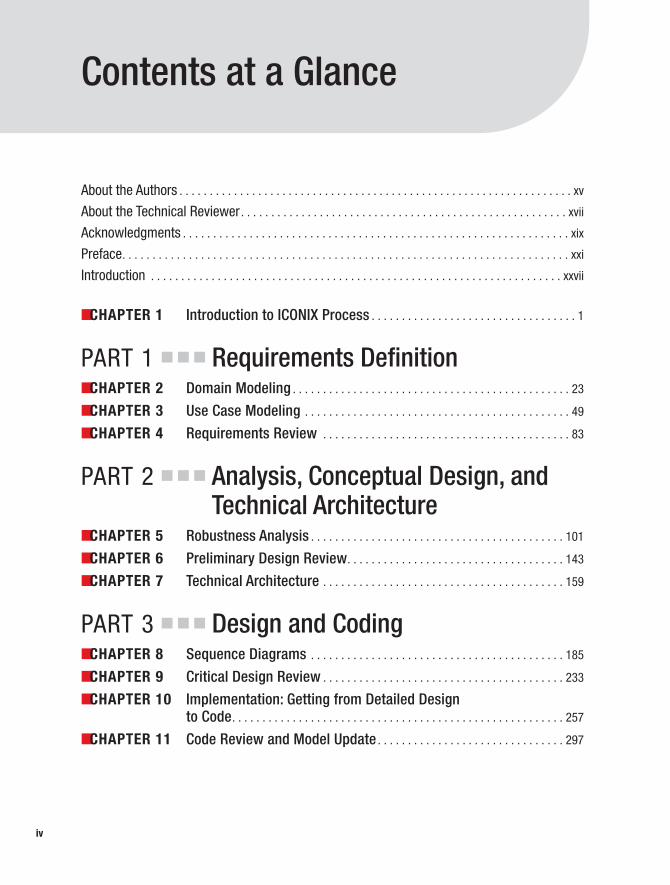
Contents at a Glance
About the Authors . . . . . . . . . . . . . . . . . . . . . . . . . . . . . . . . . . . . . . . . . . . . . . . . . . . . . . . . . . . . . . . . . xv
About the Technical Reviewer. . . . . . . . . . . . . . . . . . . . . . . . . . . . . . . . . . . . . . . . . . . . . . . . . . . . . . xvii
Acknowledgments . . . . . . . . . . . . . . . . . . . . . . . . . . . . . . . . . . . . . . . . . . . . . . . . . . . . . . . . . . . . . . . . xix
Preface. . . . . . . . . . . . . . . . . . . . . . . . . . . . . . . . . . . . . . . . . . . . . . . . . . . . . . . . . . . . . . . . . . . . . . . . . . xxi
Introduction . . . . . . . . . . . . . . . . . . . . . . . . . . . . . . . . . . . . . . . . . . . . . . . . . . . . . . . . . . . . . . . . . . . . xxvii
■CHAPTER 1 Introduction to ICONIX Process . . . . . . . . . . . . . . . . . . . . . . . . . . . . . . . . . . 1
PART 1 ■ ■ ■ Requirements Definition■CHAPTER 2 Domain Modeling . . . . . . . . . . . . . . . . . . . . . . . . . . . . . . . . . . . . . . . . . . . . . . 23
■CHAPTER 3 Use Case Modeling . . . . . . . . . . . . . . . . . . . . . . . . . . . . . . . . . . . . . . . . . . . . 49
■CHAPTER 4 Requirements Review . . . . . . . . . . . . . . . . . . . . . . . . . . . . . . . . . . . . . . . . . 83
PART 2 ■ ■ ■ Analysis, Conceptual Design, andTechnical Architecture
■CHAPTER 5 Robustness Analysis . . . . . . . . . . . . . . . . . . . . . . . . . . . . . . . . . . . . . . . . . . 101
■CHAPTER 6 Preliminary Design Review. . . . . . . . . . . . . . . . . . . . . . . . . . . . . . . . . . . . 143
■CHAPTER 7 Technical Architecture . . . . . . . . . . . . . . . . . . . . . . . . . . . . . . . . . . . . . . . . 159
PART 3 ■ ■ ■ Design and Coding■CHAPTER 8 Sequence Diagrams . . . . . . . . . . . . . . . . . . . . . . . . . . . . . . . . . . . . . . . . . . 185
■CHAPTER 9 Critical Design Review . . . . . . . . . . . . . . . . . . . . . . . . . . . . . . . . . . . . . . . . 233
■CHAPTER 10 Implementation: Getting from Detailed Design to Code. . . . . . . . . . . . . . . . . . . . . . . . . . . . . . . . . . . . . . . . . . . . . . . . . . . . . . . 257
■CHAPTER 11 Code Review and Model Update . . . . . . . . . . . . . . . . . . . . . . . . . . . . . . . 297
iv
7745fmfinal.qxd 12/13/06 9:23 PM Page iv
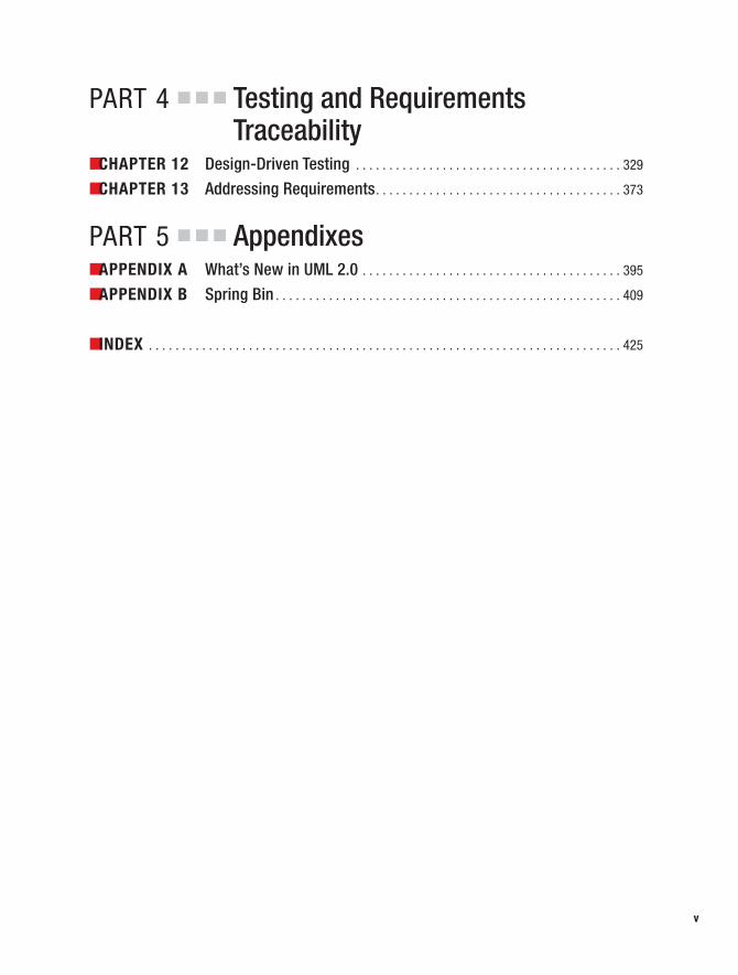
PART 4 ■ ■ ■ Testing and RequirementsTraceability
■CHAPTER 12 Design-Driven Testing . . . . . . . . . . . . . . . . . . . . . . . . . . . . . . . . . . . . . . . . 329
■CHAPTER 13 Addressing Requirements. . . . . . . . . . . . . . . . . . . . . . . . . . . . . . . . . . . . . 373
PART 5 ■ ■ ■ Appendixes■APPENDIX A What’s New in UML 2.0 . . . . . . . . . . . . . . . . . . . . . . . . . . . . . . . . . . . . . . . 395
■APPENDIX B Spring Bin . . . . . . . . . . . . . . . . . . . . . . . . . . . . . . . . . . . . . . . . . . . . . . . . . . . . 409
■INDEX . . . . . . . . . . . . . . . . . . . . . . . . . . . . . . . . . . . . . . . . . . . . . . . . . . . . . . . . . . . . . . . . . . . . . . . 425
v
7745fmfinal.qxd 12/13/06 9:23 PM Page v

7745fmfinal.qxd 12/13/06 9:23 PM Page vi

Contents
About the Authors . . . . . . . . . . . . . . . . . . . . . . . . . . . . . . . . . . . . . . . . . . . . . . . . . . . . . . . . . . . . . . . . . xv
About the Technical Reviewer. . . . . . . . . . . . . . . . . . . . . . . . . . . . . . . . . . . . . . . . . . . . . . . . . . . . . . xvii
Acknowledgments . . . . . . . . . . . . . . . . . . . . . . . . . . . . . . . . . . . . . . . . . . . . . . . . . . . . . . . . . . . . . . . . xix
Preface. . . . . . . . . . . . . . . . . . . . . . . . . . . . . . . . . . . . . . . . . . . . . . . . . . . . . . . . . . . . . . . . . . . . . . . . . . xxi
Introduction . . . . . . . . . . . . . . . . . . . . . . . . . . . . . . . . . . . . . . . . . . . . . . . . . . . . . . . . . . . . . . . . . . . . xxvii
■CHAPTER 1 Introduction to ICONIX Process . . . . . . . . . . . . . . . . . . . . . . . . . . . . . 1
ICONIX Process in Theory. . . . . . . . . . . . . . . . . . . . . . . . . . . . . . . . . . . . . . . . . . 2
Overview: Getting from Use Cases to Source Code . . . . . . . . . . . . . . . 2
Requirements . . . . . . . . . . . . . . . . . . . . . . . . . . . . . . . . . . . . . . . . . . . . . . . 4
Analysis/Preliminary Design . . . . . . . . . . . . . . . . . . . . . . . . . . . . . . . . . . 9
Detailed Design . . . . . . . . . . . . . . . . . . . . . . . . . . . . . . . . . . . . . . . . . . . . 12
Implementation . . . . . . . . . . . . . . . . . . . . . . . . . . . . . . . . . . . . . . . . . . . . 15
Extensions to ICONIX Process . . . . . . . . . . . . . . . . . . . . . . . . . . . . . . . . . . . . . 19
Persona Analysis . . . . . . . . . . . . . . . . . . . . . . . . . . . . . . . . . . . . . . . . . . . 19
Test-Driven Development (TDD) . . . . . . . . . . . . . . . . . . . . . . . . . . . . . . 19
Driving Test Cases from the Analysis Model . . . . . . . . . . . . . . . . . . . . 20
ICONIX Process in Practice: The Internet Bookstore Example . . . . . . . . . . 20
Summary . . . . . . . . . . . . . . . . . . . . . . . . . . . . . . . . . . . . . . . . . . . . . . . . . . . . . . 20
PART 1 ■ ■ ■ Requirements Definition
■CHAPTER 2 Domain Modeling . . . . . . . . . . . . . . . . . . . . . . . . . . . . . . . . . . . . . . . . . . . 23
The 10,000-Foot View . . . . . . . . . . . . . . . . . . . . . . . . . . . . . . . . . . . . . . . . . . . 24
What’s a Domain Model? . . . . . . . . . . . . . . . . . . . . . . . . . . . . . . . . . . . . 24
Why Start with the Domain Model Instead of Use Cases? . . . . . . . . 25
Domain Modeling in Theory. . . . . . . . . . . . . . . . . . . . . . . . . . . . . . . . . . . . . . . 26
Top 10 Domain Modeling Guidelines . . . . . . . . . . . . . . . . . . . . . . . . . . 26
Internet Bookstore: Extracting the First-Pass Domain Model from High-Level Requirements . . . . . . . . . . . . . . . . . . . . . . . . . . . . 30
Internet Bookstore: Second Attempt at the Domain Model. . . . . . . . 35
Internet Bookstore: Building Generalization Relationships . . . . . . . . 37vii
7745fmfinal.qxd 12/13/06 9:23 PM Page vii

Domain Modeling in Practice. . . . . . . . . . . . . . . . . . . . . . . . . . . . . . . . . . . . . . 39
Exercises . . . . . . . . . . . . . . . . . . . . . . . . . . . . . . . . . . . . . . . . . . . . . . . . . . 39
More Practice . . . . . . . . . . . . . . . . . . . . . . . . . . . . . . . . . . . . . . . . . . . . . . . . . . . 45
Summary . . . . . . . . . . . . . . . . . . . . . . . . . . . . . . . . . . . . . . . . . . . . . . . . . . . . . . 47
■CHAPTER 3 Use Case Modeling. . . . . . . . . . . . . . . . . . . . . . . . . . . . . . . . . . . . . . . . . . 49
The 10,000-Foot View . . . . . . . . . . . . . . . . . . . . . . . . . . . . . . . . . . . . . . . . . . . 49
Why Do I Need Use Cases in Addition to Functional Requirements? . . . . . . . . . . . . . . . . . . . . . . . . . . . . . . . . 50
Don’t Forget the Rainy-Day Scenarios . . . . . . . . . . . . . . . . . . . . . . . . . 50
Do an Initial Domain Model Before You Write the Use Cases . . . . . . 50
Driving Your Design (and Your Tests) from the Use Cases. . . . . . . . . 51
Use Case Modeling in Theory . . . . . . . . . . . . . . . . . . . . . . . . . . . . . . . . . . . . . 51
Top 10 Use Case Modeling Guidelines . . . . . . . . . . . . . . . . . . . . . . . . . 51
Organizing Use Cases into Packages: Internet Bookstore. . . . . . . . . 61
Use Case Relationship Roundup . . . . . . . . . . . . . . . . . . . . . . . . . . . . . . 67
Internet Bookstore: Refining Use Cases . . . . . . . . . . . . . . . . . . . . . . . . 70
Internet Bookstore: Basic and Alternate Courses . . . . . . . . . . . . . . . . 72
A Couple of Thoughts on Use Case Templates . . . . . . . . . . . . . . . . . . 74
Use Case or Algorithm? . . . . . . . . . . . . . . . . . . . . . . . . . . . . . . . . . . . . . 76
Use Case Modeling in Practice . . . . . . . . . . . . . . . . . . . . . . . . . . . . . . . . . . . . 77
Exercises . . . . . . . . . . . . . . . . . . . . . . . . . . . . . . . . . . . . . . . . . . . . . . . . . . 77
Exercise Solutions . . . . . . . . . . . . . . . . . . . . . . . . . . . . . . . . . . . . . . . . . . 78
More Practice . . . . . . . . . . . . . . . . . . . . . . . . . . . . . . . . . . . . . . . . . . . . . . . . . . . 80
Summary . . . . . . . . . . . . . . . . . . . . . . . . . . . . . . . . . . . . . . . . . . . . . . . . . . . . . . 81
■CHAPTER 4 Requirements Review . . . . . . . . . . . . . . . . . . . . . . . . . . . . . . . . . . . . . . 83
Requirements Review in Theory . . . . . . . . . . . . . . . . . . . . . . . . . . . . . . . . . . . 84
Why Review Requirements? . . . . . . . . . . . . . . . . . . . . . . . . . . . . . . . . . 84
Top 10 Requirements Review Guidelines . . . . . . . . . . . . . . . . . . . . . . 85
Allocating Functional Requirements to Use Cases. . . . . . . . . . . . . . . 89
Requirements Review in Practice: Internet Bookstore . . . . . . . . . . . . . . . . 89
Removing Everything That’s Out of Scope. . . . . . . . . . . . . . . . . . . . . . 90
Naming Participating Domain Objects . . . . . . . . . . . . . . . . . . . . . . . . . 92
Making Sure You Have All the Alternate Courses . . . . . . . . . . . . . . . . 93
Checking That the Use Case Text Isn’t Too Abstract . . . . . . . . . . . . . 93
Changing Passive Voice to Active Voice . . . . . . . . . . . . . . . . . . . . . . . . 95
Tracing Each Requirement to Its Use Cases . . . . . . . . . . . . . . . . . . . . 96
Summary . . . . . . . . . . . . . . . . . . . . . . . . . . . . . . . . . . . . . . . . . . . . . . . . . . . . . . 97
■CONTENTSviii
7745fmfinal.qxd 12/13/06 9:23 PM Page viii

PART 2 ■ ■ ■ Analysis, Conceptual Design, andTechnical Architecture
■CHAPTER 5 Robustness Analysis. . . . . . . . . . . . . . . . . . . . . . . . . . . . . . . . . . . . . . . 101
The 10,000-Foot View . . . . . . . . . . . . . . . . . . . . . . . . . . . . . . . . . . . . . . . . . . 101
Where Does Robustness Analysis Fit into the Process? . . . . . . . . . 102
Like Learning to Ride a Bicycle . . . . . . . . . . . . . . . . . . . . . . . . . . . . . . 102
Anatomy of a Robustness Diagram . . . . . . . . . . . . . . . . . . . . . . . . . . 103
Robustness Analysis in Theory . . . . . . . . . . . . . . . . . . . . . . . . . . . . . . . . . . . 104
Top 10 Robustness Analysis Guidelines. . . . . . . . . . . . . . . . . . . . . . . 104
More About Robustness Diagram Rules. . . . . . . . . . . . . . . . . . . . . . . 112
How Do You Perform Robustness Analysis? . . . . . . . . . . . . . . . . . . . 114
Updating Your Domain (Static) Model . . . . . . . . . . . . . . . . . . . . . . . . . 125
Robustness Analysis in Practice . . . . . . . . . . . . . . . . . . . . . . . . . . . . . . . . . . 128
Exercises . . . . . . . . . . . . . . . . . . . . . . . . . . . . . . . . . . . . . . . . . . . . . . . . . 128
Exercise Solutions . . . . . . . . . . . . . . . . . . . . . . . . . . . . . . . . . . . . . . . . . 132
More Practice . . . . . . . . . . . . . . . . . . . . . . . . . . . . . . . . . . . . . . . . . . . . . . . . . . 140
Summary . . . . . . . . . . . . . . . . . . . . . . . . . . . . . . . . . . . . . . . . . . . . . . . . . . . . . 141
■CHAPTER 6 Preliminary Design Review . . . . . . . . . . . . . . . . . . . . . . . . . . . . . . . . 143
Preliminary Design Review in Theory . . . . . . . . . . . . . . . . . . . . . . . . . . . . . 144
Why Do a PDR At All? . . . . . . . . . . . . . . . . . . . . . . . . . . . . . . . . . . . . . . 144
Top 10 PDR Guidelines . . . . . . . . . . . . . . . . . . . . . . . . . . . . . . . . . . . . . 145
Preliminary Design Review in Practice: Internet Bookstore . . . . . . . . . . . 149
PDR for the “Write Customer Review” Robustness Diagram . . . . . 149
The Finished “Write Customer Review” Robustness Diagram. . . . 155
Summary . . . . . . . . . . . . . . . . . . . . . . . . . . . . . . . . . . . . . . . . . . . . . . . . . . . . . 157
■CHAPTER 7 Technical Architecture. . . . . . . . . . . . . . . . . . . . . . . . . . . . . . . . . . . . . 159
The 10,000-Foot View . . . . . . . . . . . . . . . . . . . . . . . . . . . . . . . . . . . . . . . . . . 160
What Is Technical Architecture? . . . . . . . . . . . . . . . . . . . . . . . . . . . . . 160
What Are the Duties of a Technical Architect? . . . . . . . . . . . . . . . . . 160
Technical Architecture in Theory. . . . . . . . . . . . . . . . . . . . . . . . . . . . . . . . . . 161
Top 10 Technical Architecture Guidelines . . . . . . . . . . . . . . . . . . . . . 161
Architectural Layering . . . . . . . . . . . . . . . . . . . . . . . . . . . . . . . . . . . . . . 162
Technical Architecture in Practice: Internet Bookstore . . . . . . . . . . . . . . . 164
About Spring Framework . . . . . . . . . . . . . . . . . . . . . . . . . . . . . . . . . . . 164
Anatomy of Spring Framework . . . . . . . . . . . . . . . . . . . . . . . . . . . . . . 165
■CONTENTS ix
7745fmfinal.qxd 12/13/06 9:23 PM Page ix

The Internet Bookstore Architecture. . . . . . . . . . . . . . . . . . . . . . . . . . . . . . . 172
Layered Architecture . . . . . . . . . . . . . . . . . . . . . . . . . . . . . . . . . . . . . . . 172
Flow of Events . . . . . . . . . . . . . . . . . . . . . . . . . . . . . . . . . . . . . . . . . . . . 178
Testability . . . . . . . . . . . . . . . . . . . . . . . . . . . . . . . . . . . . . . . . . . . . . . . . 179
Web Security. . . . . . . . . . . . . . . . . . . . . . . . . . . . . . . . . . . . . . . . . . . . . . 179
Top 10 Technical Architecture Errors (the “Don’ts”) . . . . . . . . . . . . . . . . . 180
Summary . . . . . . . . . . . . . . . . . . . . . . . . . . . . . . . . . . . . . . . . . . . . . . . . . . . . . 181
PART 3 ■ ■ ■ Design and Coding
■CHAPTER 8 Sequence Diagrams . . . . . . . . . . . . . . . . . . . . . . . . . . . . . . . . . . . . . . . 185
The 10,000-Foot View . . . . . . . . . . . . . . . . . . . . . . . . . . . . . . . . . . . . . . . . . . 185
Sequence Diagrams and Detailed OOD . . . . . . . . . . . . . . . . . . . . . . . 186
Sequence Diagram Notation . . . . . . . . . . . . . . . . . . . . . . . . . . . . . . . . 186
Sequence Diagramming in Theory . . . . . . . . . . . . . . . . . . . . . . . . . . . . . . . . 187
Top 10 Sequence Diagramming Guidelines . . . . . . . . . . . . . . . . . . . 187
How to Draw a Sequence Diagram: Four Essential Steps . . . . . . . 195
Continuing the Internet Bookstore Example . . . . . . . . . . . . . . . . . . . 206
Updating Your Class Diagrams As You Go Along . . . . . . . . . . . . . . . . 210
Synchronizing the Static and Dynamic Parts of the Model . . . . . . . 211
Internet Bookstore: Updating the Static Model . . . . . . . . . . . . . . . . . 211
Sequence Diagramming in Practice. . . . . . . . . . . . . . . . . . . . . . . . . . . . . . . 217
Exercises . . . . . . . . . . . . . . . . . . . . . . . . . . . . . . . . . . . . . . . . . . . . . . . . . 217
Exercise Solutions . . . . . . . . . . . . . . . . . . . . . . . . . . . . . . . . . . . . . . . . . 221
More Practice . . . . . . . . . . . . . . . . . . . . . . . . . . . . . . . . . . . . . . . . . . . . . . . . . . 228
Summary . . . . . . . . . . . . . . . . . . . . . . . . . . . . . . . . . . . . . . . . . . . . . . . . . . . . . 230
■CHAPTER 9 Critical Design Review. . . . . . . . . . . . . . . . . . . . . . . . . . . . . . . . . . . . . 233
The 10,000-Foot View . . . . . . . . . . . . . . . . . . . . . . . . . . . . . . . . . . . . . . . . . . 234
Critical Design Review in Theory . . . . . . . . . . . . . . . . . . . . . . . . . . . . . . . . . 235
Top 10 Critical Design Review Guidelines . . . . . . . . . . . . . . . . . . . . . 235
Using the Class Diagrams to Find Errors on the Sequence Diagrams. . . . . . . . . . . . . . . . . . . . . . . . . . . . . . . . . . . . . 238
■CONTENTSx
7745fmfinal.qxd 12/13/06 9:23 PM Page x
Critical Design Review in Practice: Internet Bookstore . . . . . . . . . . . . . . . 238
CDR for the “Show Book Details” Use Case . . . . . . . . . . . . . . . . . . . 238
CDR for the “Write Customer Review” Use Case . . . . . . . . . . . . . . . 245
The Updated Bookstore Diagrams . . . . . . . . . . . . . . . . . . . . . . . . . . . 252
Summary . . . . . . . . . . . . . . . . . . . . . . . . . . . . . . . . . . . . . . . . . . . . . . . . . . . . . 255
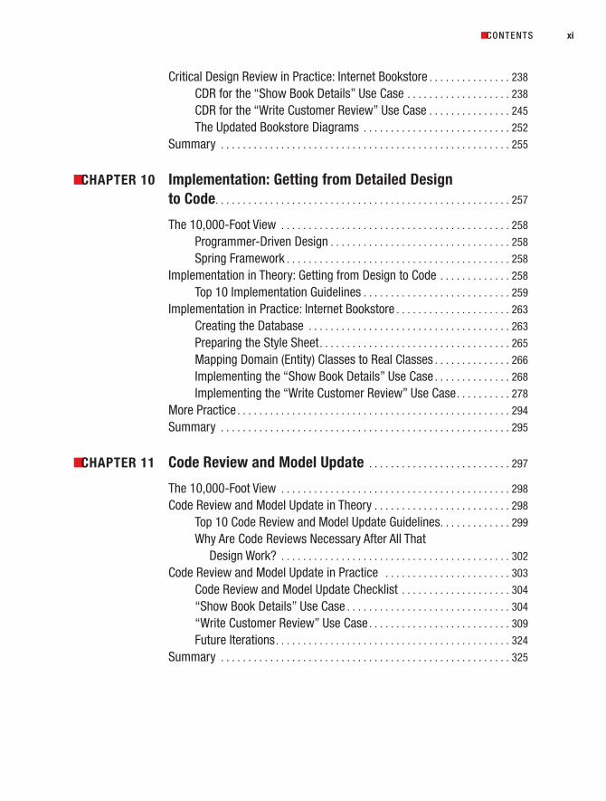
■CHAPTER 10 Implementation: Getting from Detailed Design to Code. . . . . . . . . . . . . . . . . . . . . . . . . . . . . . . . . . . . . . . . . . . . . . . . . . . . . . 257
The 10,000-Foot View . . . . . . . . . . . . . . . . . . . . . . . . . . . . . . . . . . . . . . . . . . 258
Programmer-Driven Design . . . . . . . . . . . . . . . . . . . . . . . . . . . . . . . . . 258
Spring Framework . . . . . . . . . . . . . . . . . . . . . . . . . . . . . . . . . . . . . . . . . 258
Implementation in Theory: Getting from Design to Code . . . . . . . . . . . . . 258
Top 10 Implementation Guidelines . . . . . . . . . . . . . . . . . . . . . . . . . . . 259
Implementation in Practice: Internet Bookstore . . . . . . . . . . . . . . . . . . . . . 263
Creating the Database . . . . . . . . . . . . . . . . . . . . . . . . . . . . . . . . . . . . . 263
Preparing the Style Sheet. . . . . . . . . . . . . . . . . . . . . . . . . . . . . . . . . . . 265
Mapping Domain (Entity) Classes to Real Classes . . . . . . . . . . . . . . 266
Implementing the “Show Book Details” Use Case . . . . . . . . . . . . . . 268
Implementing the “Write Customer Review” Use Case. . . . . . . . . . 278
More Practice . . . . . . . . . . . . . . . . . . . . . . . . . . . . . . . . . . . . . . . . . . . . . . . . . . 294
Summary . . . . . . . . . . . . . . . . . . . . . . . . . . . . . . . . . . . . . . . . . . . . . . . . . . . . . 295
■CHAPTER 11 Code Review and Model Update . . . . . . . . . . . . . . . . . . . . . . . . . . 297
The 10,000-Foot View . . . . . . . . . . . . . . . . . . . . . . . . . . . . . . . . . . . . . . . . . . 298
Code Review and Model Update in Theory . . . . . . . . . . . . . . . . . . . . . . . . . 298
Top 10 Code Review and Model Update Guidelines. . . . . . . . . . . . . 299
Why Are Code Reviews Necessary After All That Design Work? . . . . . . . . . . . . . . . . . . . . . . . . . . . . . . . . . . . . . . . . . . 302
Code Review and Model Update in Practice . . . . . . . . . . . . . . . . . . . . . . . 303
Code Review and Model Update Checklist . . . . . . . . . . . . . . . . . . . . 304
“Show Book Details” Use Case . . . . . . . . . . . . . . . . . . . . . . . . . . . . . . 304
“Write Customer Review” Use Case . . . . . . . . . . . . . . . . . . . . . . . . . . 309
Future Iterations. . . . . . . . . . . . . . . . . . . . . . . . . . . . . . . . . . . . . . . . . . . 324
Summary . . . . . . . . . . . . . . . . . . . . . . . . . . . . . . . . . . . . . . . . . . . . . . . . . . . . . 325
■CONTENTS xi
7745fmfinal.qxd 12/13/06 9:23 PM Page xi
PART 4 ■ ■ ■ Testing and RequirementsTraceability
■CHAPTER 12 Design-Driven Testing . . . . . . . . . . . . . . . . . . . . . . . . . . . . . . . . . . . . . 329
Design-Driven Testing in Theory . . . . . . . . . . . . . . . . . . . . . . . . . . . . . . . . . . 330
Top 10 Design-Driven Testing Guidelines . . . . . . . . . . . . . . . . . . . . . 330
Different Kinds of Testing . . . . . . . . . . . . . . . . . . . . . . . . . . . . . . . . . . . 331
Driving Test Cases from Robustness Diagrams . . . . . . . . . . . . . . . . 334
Using the Agile ICONIX/EA Add-in . . . . . . . . . . . . . . . . . . . . . . . . . . . . 336
Driving Unit Tests from the Test Cases. . . . . . . . . . . . . . . . . . . . . . . . 338
A Quick Introduction to JUnit . . . . . . . . . . . . . . . . . . . . . . . . . . . . . . . . 339
Writing Effective Unit Tests. . . . . . . . . . . . . . . . . . . . . . . . . . . . . . . . . . 342
Design-Driven Testing in Practice. . . . . . . . . . . . . . . . . . . . . . . . . . . . . . . . . 343
Unit Tests for the Internet Bookstore . . . . . . . . . . . . . . . . . . . . . . . . . 344
Top 10 Design-Driven Testing Errors (the “Don’ts”). . . . . . . . . . . . . 369
More Practice . . . . . . . . . . . . . . . . . . . . . . . . . . . . . . . . . . . . . . . . . . . . . . . . . . 370
Summary . . . . . . . . . . . . . . . . . . . . . . . . . . . . . . . . . . . . . . . . . . . . . . . . . . . . . 371
■CHAPTER 13 Addressing Requirements . . . . . . . . . . . . . . . . . . . . . . . . . . . . . . . . . 373
Requirements Gathering in Theory. . . . . . . . . . . . . . . . . . . . . . . . . . . . . . . . 374
Top 10 Requirements Gathering Guidelines . . . . . . . . . . . . . . . . . . . 374
Why Bother Tracking Requirements? . . . . . . . . . . . . . . . . . . . . . . . . . 377
Requirements Allocation and Traceability in Theory . . . . . . . . . . . . 378
Requirements Gathering in Practice. . . . . . . . . . . . . . . . . . . . . . . . . . . . . . . 379
Organizing Requirements in EA: BillyBob 2.0 . . . . . . . . . . . . . . . . . . 379
Using a Visual Modeling Tool to Support Requirements . . . . . . . . . 382
More Practice . . . . . . . . . . . . . . . . . . . . . . . . . . . . . . . . . . . . . . . . . . . . . . . . . . 389
Summary . . . . . . . . . . . . . . . . . . . . . . . . . . . . . . . . . . . . . . . . . . . . . . . . . . . . . 390
■CONTENTSxii
7745fmfinal.qxd 12/13/06 9:23 PM Page xii

PART 5 ■ ■ ■ Appendixes
■APPENDIX A What’s New in UML 2.0 . . . . . . . . . . . . . . . . . . . . . . . . . . . . . . . . . . . . 395
Overview of Changes in UML 2.0 . . . . . . . . . . . . . . . . . . . . . . . . . . . . . . . . . 395
Composite Structure Diagrams . . . . . . . . . . . . . . . . . . . . . . . . . . . . . . 396
Activity and State Diagrams. . . . . . . . . . . . . . . . . . . . . . . . . . . . . . . . . 399
Sequence and Interaction Overview Diagrams. . . . . . . . . . . . . . . . . 401
Timing Diagrams . . . . . . . . . . . . . . . . . . . . . . . . . . . . . . . . . . . . . . . . . . 404
Component and Deployment Diagrams . . . . . . . . . . . . . . . . . . . . . . . 406
What’s Still Missing in UML . . . . . . . . . . . . . . . . . . . . . . . . . . . . . . . . . . . . . . 407
■APPENDIX B Spring Bin . . . . . . . . . . . . . . . . . . . . . . . . . . . . . . . . . . . . . . . . . . . . . . . . . . 409
Spring in More Detail . . . . . . . . . . . . . . . . . . . . . . . . . . . . . . . . . . . . . . . . . . . 409
A (Very) Brief Example of IoC . . . . . . . . . . . . . . . . . . . . . . . . . . . . . . . . 409
Models, Views, and Controllers . . . . . . . . . . . . . . . . . . . . . . . . . . . . . . 412
Internet Bookstore Design: Spring Details. . . . . . . . . . . . . . . . . . . . . . . . . . 414
“Show Book Details” Use Case . . . . . . . . . . . . . . . . . . . . . . . . . . . . . . 414
“Write Customer Review” Use Case . . . . . . . . . . . . . . . . . . . . . . . . . . 416
Internet Bookstore Implementation: Spring Details . . . . . . . . . . . . . . . . . . 417
Folder Structure . . . . . . . . . . . . . . . . . . . . . . . . . . . . . . . . . . . . . . . . . . . 418
Contents of the war\WEB-INF Folder . . . . . . . . . . . . . . . . . . . . . . . . . 418
Contents of the war\WEB-INF\jsp and war\WEB-INF\jsp\include Folders . . . . . . . . . . . . . . . . . . . . . . . . . 421
Java Package Hierarchy . . . . . . . . . . . . . . . . . . . . . . . . . . . . . . . . . . . . 422
■INDEX . . . . . . . . . . . . . . . . . . . . . . . . . . . . . . . . . . . . . . . . . . . . . . . . . . . . . . . . . . . . . . . . . . . . . . . 425
■CONTENTS xiii
7745fmfinal.qxd 12/13/06 9:23 PM Page xiii

7745fmfinal.qxd 12/13/06 9:23 PM Page xiv

About the Authors
■DOUG ROSENBERG is the founder and president of ICONIX SoftwareEngineering, Inc. (www.iconixsw.com). Doug spent the first 15 years of hiscareer writing code for a living before moving on to managing program-mers, developing software design tools, and teaching object-orientedanalysis and design.
Doug has been providing system development tools and training fornearly two decades, with particular emphasis on object-oriented methods.
He developed a unified Booch/Rumbaugh/Jacobson design method in 1993 that precededRational’s UML by several years. He has produced more than a dozen multimedia tutorials onobject technology, including “COMPREHENSIVE COM” and “Enterprise Architect for PowerUsers,” and is the coauthor of Use Case Driven Object Modeling with UML (Addison-Wesley,1999) and Applying Use Case Driven Object Modeling with UML (Addison-Wesley, 2001), bothwith Kendall Scott, as well as Extreme Programming Refactored: The Case Against XP (Apress,2003) with Matt Stephens, and Agile Development with ICONIX Process (Apress, 2005) withMatt Stephens and Mark Collins-Cope.
A few years ago, Doug started a second business, an online travel website(www.VResorts.com) that features his virtual reality photography and some innovative mapping software.
■MATT STEPHENS is a Java developer, project leader, and technical architectbased in Central London. He’s been developing software commercially forover 15 years, and has led many agile projects through successive cus-tomer releases. He has spoken at a number of software conferences onOO development topics, and his work appears regularly in a variety ofsoftware journals.
Matt is the coauthor of Extreme Programming Refactored: The CaseAgainst XP (Apress, 2003) with Doug Rosenberg, and Agile Development with ICONIX Process(Apress, 2005) with Doug Rosenberg and Mark Collins-Cope.
Catch Matt online at www.softwarereality.com.
xv
7745fmfinal.qxd 12/13/06 9:23 PM Page xv

7745fmfinal.qxd 12/13/06 9:23 PM Page xvi

About the Technical Reviewer
■DR. CHARLES SUSCHECK is an assistant professor of computer information systems atColorado State University, Pueblo campus. He specializes in software development method-ologies and project management, and has over 20 years of professional experience in infor-mation technology.
Dr. Suscheck has held the positions of process architect, director of research, principalconsultant, and professional trainer at some of the most recognized companies in America.He has spoken at national and international conferences on topics related to project manage-ment. Most recently, he’s been heavily involved in delivering the “ICONIX Process Roadmap”(as defined by the activity diagrams in this book) via the Eclipse Process Framework.
xvii
7745fmfinal.qxd 12/13/06 9:23 PM Page xvii

7745fmfinal.qxd 12/13/06 9:23 PM Page xviii

Acknowledgments
First and foremost, thanks to Gary Cornell for picking up this project midstream.Thanks to Geoff Sparks and the folks at Sparx Systems for building a great product, for
tailoring it to support ICONIX Process, and for helping us with the UML 2.0 tutorial inAppendix A.
Thanks to Philip Nortey for his valuable feedback and his contribution to the chapteron design-driven testing; to Chuck Suscheck for his reviews and insights, especially about thestudent exercises; and to Mark Collins-Cope for his contribution to the architecture chapter.
And thanks, of course, to the Apress team: Gary; our editor, Jonathan Gennick; “The PM,”Tracy Brown-Collins (Queen of the 48-hour chapter-editing turnaround deadline), without whoseschedule this project would have forever remained in “manuscript paralysis”; “The World’s Great-est Copy Editor” (once again), Nicole Flores; Diana Van Winkle for the outstanding design; andour production editor, Laura Cheu.
xix
7745fmfinal.qxd 12/13/06 9:23 PM Page xix

7745fmfinal.qxd 12/13/06 9:23 PM Page xx

Preface
Matt’s PrefaceThis book illustrates how to get from use cases to working, maintainable source code in as fewsteps as possible . . . but without cutting the essential corners. It’s also about how to minimizethe amount of rework you need to do once you’ve gotten to source code.
Learning by DoingIn this book we’ve tried to capture the essential qualities of Doug’s ICONIX training courses—that is, the “magic qualities” of learning by doing. The ICONIX Jumpstart courses are verypractical and hands-on; they draw students in by encouraging them to learn new skills bypracticing, often on the real projects that they’ll be returning to once the course is finished.
This idea of learning by doing has long been recognized as an optimal form of education.Even at the start of the twentieth century, John Dewey, an American psychologist and educa-tional reformer, recognized that learning from experience gives rise to increasing productivity.The key is to engage the brain with practical tasks rather than to fall into the all-too-familiar“study trap” of rote learning. Memorizing long lists of names or API functions might helpsomeone score highly on a test, but it isn’t the same as understanding a subject in depth. Forone thing, people tend not to retain information for very long if they’ve simply memorized it.
In this book, we do several things to avoid the “rote learning” trap. We walk through exam-ple diagrams, each starting with a blank screen, and show the steps—and, essentially, thethought process—involved in creating the various types of diagrams. Each step in the ICONIXProcess finishes with a review. For the review milestones, we’ve had some fun and created fic-tional dialogues between a reviewer and a developer, to demonstrate the sorts of issues thatreviewers or senior developers should address at each stage. We also highlight the most com-mon (and the most dangerous) mistakes that developers tend to make.
A key part of learning by doing concerns learning from your mistakes. From the daywe’re born, we learn by discovering how not to do things, and then trying over and over untilwe get it right. Experts eventually “perfect” their art because they no longer make mistakes (atleast none that they’ll admit to!). So again, we’ve applied the principle in this book and createdan Internet Bookstore example that we follow from use cases to source code, making plenty of“deliberate mistakes” along the way, which then get corrected. Also, throughout the book,you’ll find workbook exercises, student exercises, and inline exercises within the chapters.(See the “Introduction” section for more information about these different types of exercises.)
The large number of exercises and step-by-step examples should help to explain why thisbook contains around 400 pages, to describe a process that is essentially “minimal yet suffi-cient.” You could say that it’s a 150-page book at heart, but it’s packed with an unusual numberof exercises and examples. It’s safe to say that after reading this book and completing all theexercises, you’ll have a thorough, in-depth understanding of use case–driven object modeling!
xxi
7745fmfinal.qxd 12/13/06 9:23 PM Page xxi

ICONIX: A Pluggable ProcessICONIX Process is a “cookbook” process in that it describes a series of specific steps that we’vefound work really well on many different projects. However, it doesn’t prescribe the projectlife-cycle side of things in the way that most other development methodologies do.
So the decision of whether to do just a little bit of up-front modeling before code (one usecase at a time) or model all the use cases first before coding is entirely yours to make. You canbe as agile (with short iterations and quick, successive releases) or as “waterfall” (first writingall the requirements, then doing all the design, and then writing all the code) as befits yourproject, and still be following ICONIX Process.1
For this reason, the process should plug neatly into other development methodologies,as it covers the analysis and design steps but doesn’t make any fixed assumptions about theproject life cycle. But however you choose to apply the process to your own projects, we hopeyou’ll start to see positive results very quickly.
Matt StephensSoftware Reality, www.softwarereality.com
Doug’s PrefaceIt was 13 or 14 years ago, somewhere around 1992 or 1993, when one of my first trainingclients, Dan Mosten of Philip Morris in New York, said to me, “You should write a cookbookon how to design for OO. My people like cookbooks.”
At that time, Grady Booch was at Rational, Jim Rumbaugh was at GE writing books aboutOMT, and Ivar Jacobson was in Sweden working on his Objectory CASE Tool. There was noUML, no Java language, no C#/.NET, and the Internet itself largely existed only in universities.Smalltalk and C++ were the dominant object-oriented (OO) languages. The ancestor of Ratio-nal Rose was being developed by Jon Hopkins at Palladio Software as a Booch diagrammingtool for the PC. There was no eXtreme Programming (jumping too quickly to code was knownas “hacking” back then), and no Agile Manifesto had yet declared tools and process to besecond-class citizens.
The More Things Change, the More They Stay the SameAt ICONIX, we were trying to make some sense out of OO analysis and design (like everybodyelse), and our efforts produced a tool called ObjectModeler, which supported Booch, Rum-baugh (OMT), and Jacobson (Objectory) methods. We got into training because we hadto—nobody would buy our object-oriented analysis and design (OOAD) tool if they didn’tunderstand OOAD.
We synthesized what is now known as ICONIX Process (and was originally called “A Uni-fied Object Modeling Approach”) from what we felt were the best aspects of the three method-ologies that were combined a few years later to form the UML. As we did this, it seemed clearthat the art of driving object models from use cases ought to be the core of our approach, and
■PREFACExxii
1. Most projects benefit from being somewhere between these two extremes. We show how to fit ICONIXProcess into an “ideal medium” agile project life cycle in this book’s companion volume, Agile Devel-opment with ICONIX Process (Apress, 2005).
7745fmfinal.qxd 12/13/06 9:23 PM Page xxii

as we gained experience in teaching it to clients, it became obvious that Jacobson’s approach(use cases, robustness diagrams, and sequence diagrams) really worked pretty well.
In fact it continually amazed us how well it worked on a wider and wider range of proj-ects. Experience in teaching the process convinced us that the “missing link” betweenrequirements and design was the robustness diagram, and when UML was created and thisdiagram got relegated to an obscure appendix in the UML specification, we were seriouslyconcerned that it would become a lost art form.
Our training business was given a bit of a boost when UML came into existence, as sud-denly a lot more people were interested in how to do OOAD using a combined Jacobson/Rumbaugh/Booch approach, while our tools business (being Macintosh-based) didn’t fareas well.
So ICONIX became a training company instead of a tools company, and, as our experi-ence delivering training grew, there eventually came an opportunity to write a book: Use CaseDriven Object Modeling (UCDOM), which I wrote with Kendall Scott. One of the reviewers ofthat book, Greg Wilson of Dr. Dobbs Journal, suggested that we write an example-intensivecompanion workbook, which we did. Applying Use Case Driven Object Modeling (AUCDOM),built around the Internet Bookstore example, was published a few years later.
The Truth About DisambiguationMeanwhile, we continued to deliver training, year after year, and (as far as we could tell) ourclients continued to succeed with it. At least, they kept hiring us back to teach additionalclasses, which was the best metric we could think of for judging this.
OO technologies such as CORBA and COM appeared on the scene, followed by Java,DCOM, EJBs, C#, and .NET, and our use case–driven approach just kept right on workingwithout skipping a beat. Occasionally we’d sit back and ponder why it hadn’t broken, and itseemed like we (following in Ivar Jacobson’s footsteps) had hit on a systematic approach thatprovided the answers to some fundamentally important questions that addressed the issueof how to get from use cases to code. This approach involved things like understanding allthe scenarios and user interactions (both sunny- and rainy-day scenarios) before trying todo design; taking a little bit of extra time to disambiguate the behavior requirements beforeattacking detailed design issues; and focusing on “object discovery” first and “behavior allo-cation” (assigning operations to classes) later.
As the years went by and the number of training classes grew from dozens to hundreds, itbecame increasingly obvious that the notion of disambiguating behavior requirements usingrobustness diagrams was one of the most important “fundamental truths” that had emergedfrom Jacobson’s work.
We can state that fundamental truth as follows: one of the main reasons that program-mers get frustrated by attempts to bring analysis and design (and especially use cases) intotheir projects is that they are generally given vague and ambiguous requirements to designagainst. And the reason for so much ambiguity in use cases is that so many of the booksand gurus out there preach “abstract, essential, technology-free, and implementation-independent” as the right way to write use cases.
To carry it one small step further, I’ll make the following claim: if you hand a programmeran abstract, technology-free, implementation-independent, “essential” use case, that pro-grammer will find the use case to be vague, ambiguous, incomplete, and therefore incorrect.
■PREFACE xxiii
7745fmfinal.qxd 12/13/06 9:23 PM Page xxiii

ICONIX Process seems to resonate better with programmers than many other approachesto use cases and UML/OOAD because it actually forces the use cases into concrete, tangible,and specific statements of required system behavior that programmers can deal with effi-ciently. If there’s a secret to all of this, that’s it.
What’s NewI took a writing detour for a few years (while continuing to deliver training in ICONIX Process)and Matt Stephens and I wrote Extreme Programming Refactored: The Case Against XP 2 andAgile Modeling with ICONIX Process 3 for Apress. Matt and I discovered that we work prettywell together, so he’s joined me for the current effort. Meanwhile, Use Case Driven Object Mod-eling continues to sell and reached somewhere around 45,000 copies, including Chinese,Japanese, and Korean editions the last time I checked.
When we decided to do an update, we determined that there were a number of thingsthat we could do that might justify a new edition (aka this book), including the following:
■PREFACExxiv
FOOTLOOSE AND TECHNOLOGY-FREE
Without disambiguation, analysts write “essential, abstract, technology-free, and implementation-independent” use cases. The programmers who must read these use cases are, from their perspective,reading “vague, ambiguous, incomplete, and incorrect” use cases.
These use cases don’t have enough detail to allow programmers to get to code while driving theOO design from the use cases. So, the use case–driven process doesn’t work very well without robustnessanalysis (a technique we describe in detail in this book).
2. See www.softwarereality.com/ExtremeProgrammingRefactored.jsp.
3. See www.softwarereality.com/AgileDevelopment.jsp.
7745fmfinal.qxd 12/13/06 9:23 PM Page xxiv

• Merge UCDOM and AUCDOM into a single title, all based around the Internet Book-store example
• Add student exercises, with the idea that some universities might start using the bookas a text
• Create “top 10 to-do” lists, in addition to the “top 10 error” lists we already had
• Carry the Internet Bookstore forward all the way through code and test
• Update the process with a few new tricks we’ve learned over the years, and fully lever-age some advances in modeling tools
• Update the book to be current with the new UML 2.0 specification (and with IvarJacobson’s new ideas on aspect-oriented programming [AOP])
As you’ll see, these goals have resulted in a typical chapter structure that’s in three parts:“Theory” (the process explained, using the Internet Bookstore as a running example), “Prac-tice” (workbook exercises), and “More Practice” (student exercises). Matt went ahead andimplemented a small Internet bookstore in Java, complete with unit tests driven from the usecases, which has allowed us to extend the book both in breadth and depth over the originaltitles (thanks, Matt).
We think that we’ve improved upon the original books in a number of ways, and we hopethat you agree and like the result.
Doug RosenbergICONIX, www.iconixsw.com
■PREFACE xxv
7745fmfinal.qxd 12/13/06 9:23 PM Page xxv

7745fmfinal.qxd 12/13/06 9:23 PM Page xxvi

Introduction
The difference between “theory” and “practice” is that in theory there is no difference
between theory and practice, but in practice, there is.
Doug has been using this phrase to open each and every training class for so long now thathe’s forgotten where he first heard it. Matt did some research and found that it’s commonlycredited to a Jan L. A. van de Snepscheut, who, in addition to having a wonderful name, wasquite a distinguished professor at Caltech.4
Matt also found the quote attributed to Yogi Berra, who said, “In theory there is no differ-ence between theory and practice. In practice there is.”5 This makes us wonder if ProfessorSnepscheut might have been a baseball fan, or if Yogi made a practice of attending lectures atCaltech in the off-season, but no matter—they were both right.
Regardless of who said it first, we like to apply this statement to UML modeling, because,to be blunt, UML is way too big. A project trying to ingest all of UML into its working practicesresembles a python that has just swallowed a pig. It’s going to take an awfully long time todigest, and your project probably can’t afford it.
The Unified Modeling Language User Guide by Grady Booch, James Rumbaugh, and IvarJacobson (Addison-Wesley, 1998) tells us that “you can do 80% of your modeling with 20% ofthe UML” somewhere after page 400.6 They would have saved the industry many millions (bil-lions?) of dollars and horrific cases of analysis paralysis (see the upcoming sidebar titled “TheMysterious Case of Analysis Paralysis”) if they had said that in the Introduction, but they did-n’t. To compound the felony, they never tell us which 20% of UML is the useful part.
Most people that we meet usually want to apply UML in the up-front stages of their proj-ect. And most of them usually want to start their analysis process with use cases. So, in oursearch for the “minimal, yet sufficient” core subset of UML, we focus on the question, Howdo you get from use cases to code?
So, in theory, everything in the UML is useful, but in practice, a whole lot of people andprojects need to know how to drive an OO software design from use cases. And they also needto know which diagrams from the UML directly help to accomplish this.
This book explains the minimalist, core subset of UML and the thought process behindusing it to drive OO software designs from use cases (collectively referred to as ICONIXProcess), with an eye toward the practical as opposed to the theoretical. We hope the journeywill be both informative and entertaining.
xxvii
4. Read Edgser W. Djikstra’s “In Memoriam” for Professor Snepscheut at www.cs.utexas.edu/users/EWD/transcriptions/EWD11xx/EWD1177.html.
5. More Yogi-isms can be found here: http://en.wikiquote.org/wiki/Yogi_Berra. Yogi also said, “It’stough to make predictions, especially about the future,” which clearly applies to software cost estima-tion, and “It was hard to have a conversation with anyone; there were so many people talking,” whichis applicable to the “all the programmers in one big room” XP working environment.
6. See page 431 of the first edition.
7745fmfinal.qxd 12/13/06 9:23 PM Page xxvii

■INTRODUCTIONxxviii
THE MYSTERIOUS CASE OF ANALYSIS PARALYSIS
It was a blustery, cold, rainy night at our flat on Baker Street. The howl of the wind whipping raindrops againstthe windows could be heard over Holmes’ violin as I read the paper in front of the fireplace. Mrs. Hudson hadjust cleared away the dishes from our late supper of pork pie and beans, when Holmes suddenly paused in thearia he was playing, sat bolt upright in his chair, and exclaimed, “Watson, the game’s afoot!”
A few moments later, our good friend Inspector Lestrade from Scotland Yard clattered up the stairs andburst in the doorway, exclaiming, “Thank goodness you’re home, Mr. Holmes—you’ve got to come quickly!”
“Come in, Lestrade. Pray take a seat by the fire and tell us every detail,” said Holmes.“They’re all dead, Mr. Holmes, every one of them—the whole project’s dead! And no signs of violence,
not a mark on any of them!” said Lestrade.“Who’s dead?” I asked.“The entire staff of Scotland Yard’s new automated fingerprint recognition system,” Lestrade responded.
“The whole technical staff . . . sitting dead right in the conference room . . . as if they’d been frozen to theirchairs!”
“Has anything been touched?” asked Holmes.“No, I’ve left the strictest instructions that the conference room be completely sealed off until you could
inspect it,” said Lestrade.“Most excellent,” murmured Holmes. “You are learning, Lestrade. Come along, Watson.” Grabbing our
coats and hats, we hastened down to Lestrade’s waiting hansom cab.We arrived shortly at Scotland Yard and were escorted to the conference room, where we were con-
fronted by a bizarre and grisly death scene. Still in their seats, but struck down by some mysterious assassin,was the entire staff of the new automated fingerprint recognition project. Holmes walked around the roomexcitedly, his highly trained senses alert for any sort of clue. He paused at the whiteboard, and again at astack of UML books on the table.
“You see, Mr. Holmes, they’re all dead, and not a mark on any of them. How could a whole project justdie like that?” asked Lestrade.
“Elementary, my dear Lestrade. A clear case of that obscure poison from the Amazon jungle known asanalysisparalysisflagrantis. Perhaps you’ve seen my monograph on the topic? No? Tut, tut,” murmuredHolmes.
“But Holmes, how can you be sure?” I queried. “All I can see is these UML books scattered around thetable. Here’s one called Fully Dressed Use Cases: The Hallway Closet Approach by Professor Moriarty. Itsuggests you should stuff everything you can think of into your use cases, just like you do with the hallwaycloset,” I said.
“You see, Watson, but you do not observe. Notice the three-day growth of beard on all the corpses, andthe scrawls of <<includes>> and <<extends>> on the whiteboards?” asked Holmes.
“Sure enough, Mr. Holmes,” said Lestrade. “Even the women have grown beards!”“Great Scott!” I exclaimed. “Gives me the shivers.”“Analysis paralysis, Watson,” said Holmes. “The second fastest killer of software projects, after
DoingTheSimplestThingThatCanPossiblyWork, and nearly as dangerous. It’s caused by a lethal overdose offormality and strict adherence to the UML semantics documentation. Moriarty’s been up to his evil tricksagain. You see the hollow expressions on the victims’ faces, caused by interminable meetings spent debatingtopics of marginal uselessness. The despair and the anguish. The feverish search for a practical approachinstead of highbrow theories. And all so easily avoidable,” he sighed. “Come along, Watson, we have arrivedtoo late.”
We headed homeward toward Baker Street and the fireplace.
7745fmfinal.qxd 12/13/06 9:23 PM Page xxviii

Theory, in PracticeEach chapter in this book starts with the theory, and then explores said theory using the Inter-net Bookstore project. Over the course of the book, we’ll demonstrate, in practice, the theoryof getting from use cases to source code, using the Internet Bookstore as the main examplethroughout.
The practice doesn’t stop there, though. This book also contains practical exercises of var-ious types, which we describe here.
Workbook ExercisesIt’s been clear for some time that the process of reviewing models is critically important andnot well understood by many folks. So, in this book, we dissect the design of the InternetBookstore, step by step, in great detail. This involves showing many common mistakes, andthen showing the relevant pieces of the model with their mistakes corrected.
We’ve been teaching workshops using the Internet Bookstore example for many years,and as a result we have a rich source of classroom UML models with real student mistakes inthem. We’ve collected some of our favorite mistakes—that is, the kinds of mistakes we sawrepeated over and over again—and turned these into workbook exercises that you can find atthe end of many of the chapters.
The following aspects are common to each set of exercises:
• There’s an example diagram, with some errors intentionally left in.
• There’s a corrected version of the diagram a few pages later. Corrections to the errorspresented on the associated “bad” page are explicitly indicated; explanations of themistakes are provided in detail.
Student ExercisesAt the end of most chapters in the “More Practice” section, you’ll find student exercises to helpyou to test whether you truly “got” what the chapter is about. These exercises are in the formof more traditional numbered questions, and can thus be assigned as tasks for students.
For this reason, we don’t provide the answers to these exercises in the book, althoughof course it’s possible to learn the answers by reading and understanding the chapters! We do plan to provide some sort of “teacher’s guide” material on the book’s website,www.iconixprocess.com. The exact form of this teacher’s guide has yet to be determined,so check the website for details.
Inline Exercises Within the ChaptersGetting things right first time is great, but getting something wrong initially and then learningfrom your mistakes is a much better way to learn. Because of the way your brain is wired, youend up with a deeper understanding of the subject that way.
As we develop the example Internet Bookstore application through the course of thebook, we don’t just show the right thing to do next. We slip some “deliberate” mistakes into thediagrams, and then discover and correct them later (usually in the review chapters). However,unlike the “More Practice” exercises (where we do reveal the errors, in great detail), we don’t
■INTRODUCTION xxix
7745fmfinal.qxd 12/13/06 9:23 PM Page xxix

tell you precisely what the mistake is for these inline exercises. Instead, we provide a clue as tothe nature of the error, and then invite you to scrutinize the diagram (and the relevant reviewchapter) and figure out what’s wrong with it.
Trying to figure out what’s wrong in the diagram is a good way to learn, but there’sanother element to this. Notice that we didn’t say “the answer can be found on page 141” or“check the list of answers at the end of this chapter,” as that would be too easy. An importantpart of the learning process is in searching through the next chapter, looking for the para-graph that reveals the answer. You’ll be surprised how well you learn while you’re huntingdown the solution to a particular problem.
Cool set of premises, aren’t they? We’re not aware of another book like this one, andwe’re hoping you’ll find it useful in your efforts to apply use case–driven object modelingwith UML.
Top 10 Things People Who Use ICONIX Process Like About ItEach chapter in this book kicks off with a top 10 list of guidelines, and the first half of eachchapter is structured around its top 10 list. For this Introduction, we’ve put together a list ofthe top 10 comments that we’ve heard from clients who’ve applied ICONIX Process on theirown projects.
10. The process uses a core subset of UML.
(We’d rather learn 4 diagrams than 14 . . .)
9. It actually gets me all the way to code.
(I have 13 use case books on my shelf that don’t get within 50 miles of code.)
8. It’s traceable from one step to the next.
7. It addresses both sunny- and rainy-day scenarios.
(If another one of my programmers tells me they’re “Doing The Simplest Thing ThatCould Possibly Work” [DTSTTCPW], I think I’m gonna scream.)
6. It assumes that the requirements I’m initially given are vague, ambiguous, incomplete,and incorrect.
(Have Doug and Matt actually met our business analysts?)
5. It actually drives the OO design from the use cases.
(I know RUP says that it’s use case–driven, but I get lost somewhere around the Elabo-ration phase.)
4. It works well in an “agile” (short iteration, small increment) environment.
(I wish somebody would write a book on how to do Agile/ICONIX, though.)7
■INTRODUCTIONxxx
7. We did: Agile Development with ICONIX Process (Apress, 2005).
7745fmfinal.qxd 12/13/06 9:23 PM Page xxx
0c8b62c78daaa2d101c6afa8a1dc3480

3. It doesn’t drown me in five-syllable buzzwords.
(What about multiple polymorphic inheritance, anyway?)8
2. It operates at a tangible level where the use cases talk about what the users are doing onthe screens, and there are no huge use case templates.
(In other words, the use cases aren’t abstract, essential, technology-free, or implemen-tation independent.)
1. It’s a practical approach that’s been proven to work in the real world, on hundreds ofprojects.
■INTRODUCTION xxxi
8. Although we do have fun making up new buzzwords and phrases, like “disintermangling dysfunc-tional requirements.”
7745fmfinal.qxd 12/13/06 9:23 PM Page xxxi

7745fmfinal.qxd 12/13/06 9:23 PM Page xxxii

Introduction to ICONIX Process
One process is much larger
And the other’s way too small
And the full UML that OMG gives you
Is incomprehensible to all . . .
(Sing to the tune of “Go Ask Alice” by Jefferson Airplane)
In theory, every single aspect of the UML is potentially useful, but in practice, there neverseems to be enough time to do modeling, analysis, and design. There’s always pressure frommanagement to jump to code, to start coding prematurely because progress on software proj-ects tends to get measured by how much code exists. ICONIX Process, as shown in the chap-ter’s opening figure, is a minimalist, streamlined approach that focuses on that area that lies in between use cases and code. Its emphasis is on what needs to happen at that point in thelife cycle where you’re starting out: you have a start on some use cases, and now you need todo good analysis and design.
1
C H A P T E R 1
GUI Storyboard Use Case
ModelSequence
Diagram
Robustness Diagram
Dynamic
Static
Domain
ModelUpdated
Domain Model Class Model
Test Plans
Code
Tests+ Unit
Test 1
Test 2Test 3
7745ch01final.qxd 12/13/06 8:26 PM Page 1
WHEN TO USE A COOKBOOK
There’s a growing misconception in software development that cookbook approaches to software develop-ment don’t work. We agree with this to an extent, because analysis and programming are massive, highlycomplex fields, and the number of different software project types is roughly equal to the number of softwareprojects. However, we firmly believe that analysis and design can—and in fact should—be a specificsequence of repeatable steps. These steps aren’t set in stone (i.e., they can be tailored), but it helps to havethem there. In a world filled with doubt and uncertainty, it’s nice to have a clearly defined sequence of “how-to” steps to refer back to.
Way back in the pre-UML days when Doug first started teaching a unified Booch/Rumbaugh/Jacobsonmodeling approach (around 1992/1993), one of his early training clients encouraged him to “write a cook-book, because my people like following cookbook approaches.” While many have claimed that it’s impossibleto codify object-oriented analysis and design (OOAD) practices into a simple, repeatable set of steps (and itprobably isn’t possible in its entirety), ICONIX Process probably comes as close as anything out there to acookbook approach to OOAD.
While there’s still room for significant flexibility within the approach (e.g., adding in state or activity dia-grams), ICONIX Process lays down a simple, minimal set of steps that generally lead to pretty good results.These results have proven to be consistent and repeatable over the last 12 years.
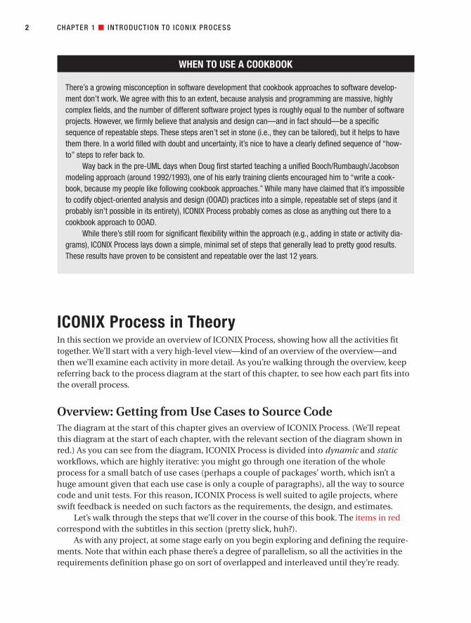
ICONIX Process in TheoryIn this section we provide an overview of ICONIX Process, showing how all the activities fittogether. We’ll start with a very high-level view—kind of an overview of the overview—andthen we’ll examine each activity in more detail. As you’re walking through the overview, keepreferring back to the process diagram at the start of this chapter, to see how each part fits intothe overall process.
Overview: Getting from Use Cases to Source CodeThe diagram at the start of this chapter gives an overview of ICONIX Process. (We’ll repeatthis diagram at the start of each chapter, with the relevant section of the diagram shown inred.) As you can see from the diagram, ICONIX Process is divided into dynamic and staticworkflows, which are highly iterative: you might go through one iteration of the wholeprocess for a small batch of use cases (perhaps a couple of packages’ worth, which isn’t ahuge amount given that each use case is only a couple of paragraphs), all the way to sourcecode and unit tests. For this reason, ICONIX Process is well suited to agile projects, whereswift feedback is needed on such factors as the requirements, the design, and estimates.
Let’s walk through the steps that we’ll cover in the course of this book. The items in redcorrespond with the subtitles in this section (pretty slick, huh?).
As with any project, at some stage early on you begin exploring and defining the require-ments. Note that within each phase there’s a degree of parallelism, so all the activities in therequirements definition phase go on sort of overlapped and interleaved until they’re ready.
2 CHAPTER 1 ■ INTRODUCTION TO ICONIX PROCESS
7745ch01final.qxd 12/13/06 8:26 PM Page 2

■Note There are many different types of requirements (e.g., nonfunctional requirements such asscalability). However, at a process level, we distinguish between functional requirements and behavioralrequirements.
1. REQUIREMENTS
a. Functional requirements: Define what the system should be capable of doing.Depending on how your project is organized, either you’ll be involved in creatingthe functional requirements or the requirements will be “handed down from onhigh” by a customer or a team of business analysts.
b. Domain modeling: Understand the problem space in unambiguous terms.
c. Behavioral requirements: Define how the user and the system will interact (i.e.,write the first-draft use cases). We recommend that you start with a GUI prototype(storyboarding the GUI) and identify all the use cases you’re going to implement,or at least come up with a first-pass list of use cases, which you would reasonablyexpect to change as you explore the requirements in more depth.
d. Milestone 1: Requirements Review: Make sure that the use case text matches thecustomer’s expectations. Note that you might review the use cases in smallbatches, just prior to designing them.
Then in each iteration (i.e., for a small batch of use cases), you do the following.
2. ANALYSIS/PRELIMINARY DESIGN
a. Robustness analysis: Draw a robustness diagram (an “object picture” of the steps in a use case), rewriting the use case text as you go.
b. Update the domain model while you’re writing the use case and drawing therobustness diagram. Here you will discover missing classes, correct ambiguities,and add attributes to the domain objects (e.g., identify that a Book object has aTitle, Author, Synopsis, etc.).
c. Name all the logical software functions (controllers) needed to make the use casework.
d. Rewrite the first draft use cases.
3. Milestone 2: Preliminary Design Review (PDR)
4. DETAILED DESIGN
a. Sequence diagramming: Draw a sequence diagram (one sequence diagram per use case) to show in detail how you’re going to implement the use case. The pri-mary function of sequence diagramming is to allocate behavior to your classes.
CHAPTER 1 ■ INTRODUCTION TO ICONIX PROCESS 3
7745ch01final.qxd 12/13/06 8:26 PM Page 3
b. Update the domain model while you’re drawing the sequence diagram, and addoperations1 to the domain objects. By this stage, the domain objects are reallydomain classes, or entities, and the domain model should be fast becoming astatic model, or class diagram—a crucial part of your detailed design.
c. Clean up the static model.
5. Milestone 3: Critical Design Review (CDR)
6. IMPLEMENTATION
a. Coding/unit testing: Write the code and the unit tests. (Or, depending on yourpreferences, write the unit tests and then the code.2)
b. Integration and scenario testing: Base the integration tests on the use cases, so thatyou’re testing both the basic course and the alternate courses.
c. Perform a Code Review and Model Update to prepare for the next round of devel-opment work.
For most of the rest of this chapter, we describe these steps in a little more detail.Throughout the rest of the book, we describe these steps in much greater detail, and providelots of examples and exercises to help you understand how best to apply them to your ownproject.
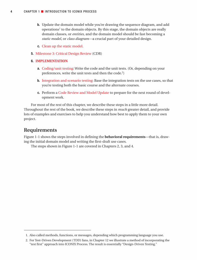
RequirementsFigure 1-1 shows the steps involved in defining the behavioral requirements—that is, draw-ing the initial domain model and writing the first-draft use cases.
The steps shown in Figure 1-1 are covered in Chapters 2, 3, and 4.
CHAPTER 1 ■ INTRODUCTION TO ICONIX PROCESS4
1. Also called methods, functions, or messages, depending which programming language you use.
2. For Test-Driven Development (TDD) fans, in Chapter 12 we illustrate a method of incorporating the“test first” approach into ICONIX Process. The result is essentially “Design-Driven Testing.”
7745ch01final.qxd 12/13/06 8:26 PM Page 4

CHAPTER 1 ■ INTRODUCTION TO ICONIX PROCESS 5
Figure 1-1. Requirements analysis
Identify real-worlddomain objects
Draw the domainmodel
Do some rapidprototyping of the
proposed new system
Identify use cases, andput them on use case
diagrams
Organize the use caseslogically into groups.
Capture this information ina package diagram
Allocate functionalrequirements to the use
cases and domain objects
Milestone 1: Requirements Review
Write the first-draftuse cases
Gather information aboutthe legacy system you're
re-engineering
Screens
Databasetables
Requirements Analysis
Put the domainobjects on here
7745ch01final.qxd 12/13/06 8:26 PM Page 5

Functional Requirements (What Will the System Be Capable Of?)Right at the start of the project, somebody (possibly a team of business analysts) will be talk-ing to the customer, end users, and various project stakeholders, and that person (or team)will most likely create a big Microsoft Word document packed to the brim with functionalrequirements. This is an important document, but it’s difficult to create a design from (or tocreate an accurate estimate from, for that matter), as it tends to be quite unstructured. (Even if every requirement is numbered in a big document-length list, that still doesn’t quite countas being structured.)
■Note The initial stages of ICONIX Process involve creating a set of unambiguous behavioral requirements(use cases) that are “closer to the metal” than the functional requirements specification, and that can beeasily designed from.
Creating functional requirements falls just slightly outside the scope of ICONIX Process,but we do offer some advice on the matter.3 Probably the best way to describe our approach torequirements gathering is to list our top 10 requirements gathering guidelines. We describethese in more detail in Chapter 13.
10. Use a modeling tool that supports linkage and traceability between requirements anduse cases.
9. Link requirements to use cases by dragging and dropping.
8. Avoid dysfunctional requirements by separating functional details from your behav-ioral specification.
7. Write at least one test case for each requirement.
6. Treat requirements as first-class citizens in the model.
5. Distinguish between different types of requirements.
4. Avoid the “big monolithic document” syndrome.
3. Create estimates from the use case scenarios, not from the functional requirements.
2. Don’t be afraid of examples when writing functional requirements.
1. Don’t make your requirements a technical fashion statement.
With the functional requirements written (whether by your team or by somebody else),you’ll really want to do some additional analysis work, to create a set of behavioral require-ments (use cases) from which you can create a high-level, preliminary design.
CHAPTER 1 ■ INTRODUCTION TO ICONIX PROCESS6
3. In Chapter 13, we show how to link your use cases back to the original requirements.
7745ch01final.qxd 12/13/06 8:26 PM Page 6

Domain ModelingDomain modeling is the task of building a project glossary, or a dictionary of terms used inyour project (e.g., an Internet bookstore project would include domain objects such as Book,Customer, Order, and Order Item). Its purpose is to make sure everyone on the project under-stands the problem space in unambiguous terms. The domain model for a project defines thescope and forms the foundation on which to build your use cases. The domain model alsoprovides a common vocabulary to enable clear communication among members of a projectteam. Expect early versions of your domain model to be wrong; as you explore each use case,you’ll “firm up” the domain model as you go.
Here are our top 10 domain modeling guidelines. We describe these in more detail inChapter 2.
10. Focus on real-world (problem domain) objects.
9. Use generalization (is-a) and aggregation (has-a) relationships to show how the objectsrelate to each other.
8. Limit your initial domain modeling efforts to a couple of hours.
7. Organize your classes around key abstractions in the problem domain.
6. Don’t mistake your domain model for a data model.
5. Don’t confuse an object (which represents a single instance) with a database table(which contains a collection of things).
4. Use the domain model as a project glossary.
3. Do your initial domain model before you write your use cases, to avoid nameambiguity.
2. Don’t expect your final class diagrams to precisely match your domain model, butthere should be some resemblance between them.
1. Don’t put screens and other GUI-specific classes on your domain model.
Once you have your first-pass domain model, you can use it to write the use cases—thatis, to create your behavioral requirements, which we introduce in the next section.
Behavioral Requirements (How Will the User and the System Interact?)ICONIX Process is a scenario-based approach; the primary mechanism for decomposing andmodeling the system is on a scenario-by-scenario basis. But when you use ICONIX Process,your goal is to produce an object-oriented design that you can code from. Therefore, you needto link the scenarios to objects. You do this by writing the use cases using the domain modelthat you created in the previous step.
Storyboarding the GUI
Behavior requirements detail the user’s actions and the system’s responses to those actions.For the vast majority of software systems, this interaction between user and system takesplace via screens, windows, or pages. When you’re exploring the behavioral requirements,
CHAPTER 1 ■ INTRODUCTION TO ICONIX PROCESS 7
7745ch01final.qxd 12/13/06 8:26 PM Page 7

you capture the usage scenarios in narrative text form in the use cases, and these narrativeshave come from detailed conversations with customers and end users.
It’s notoriously difficult for us humans to picture a proposed system in our mind’s eye. So quite often it’s easier for the customers and end users to relate to a visual aid, which oftentakes the form of a sequence of screens. These can be simple line drawings on paper, a Power-Point slide show that sequences through the screens, an HTML prototype with core function-ality left out—the exact form doesn’t matter much. What’s important is that they present asequence of screens as they will appear to the users within the context of the usage scenariosbeing modeled.
It’s also important that the screen mockups include details about the various buttons,menus, and other action-oriented parts of the UI. It’s amazing how often a use case donewithout this sort of accompanying visual aid will omit alternate course behavior for eventslike “user clicks Cancel button,” and how much better the use cases become when accompa-nied by a UI storyboard.
Use Case Modeling
Use cases describe the way the user will interact with the system and how the system willrespond. Here are our top 10 use case modeling guidelines. We describe these in more detailin Chapter 3.
10. Follow the two-paragraph rule.
9. Organize your use cases with actors and use case diagrams.
8. Write your use cases in active voice.
7. Write your use case using an event/response flow, describing both sides of theuser/system dialogue.
6. Use GUI storyboards, prototypes, screen mockups, etc.
5. Remember that your use case is really a runtime behavior specification.
4. Write the use case in the context of the object model.
3. Write your use cases using a noun-verb-noun sentence structure.
2. Reference domain classes by name.
1. Reference boundary classes (e.g., screens) by name.
Milestone 1: Requirements ReviewRight at the end of Figure 1-1, you’ll see the Requirements Review milestone. This vital stepensures that the requirements are sufficiently well understood by both the development teamand the customer/users/project stakeholders.
Here are our top 10 requirements review guidelines. We describe these in more detail inChapter 4.
CHAPTER 1 ■ INTRODUCTION TO ICONIX PROCESS8
7745ch01final.qxd 12/13/06 8:26 PM Page 8

10. Make sure your domain model describes at least 80% of the most important abstrac-tions (i.e., real-world objects) from your problem domain, in nontechnical languagethat your end users can understand.
9. Make sure your domain model shows the is-a (generalization) and has-a (aggregation)relationships between the domain objects.
8. Make sure your use cases describe both basic and alternate courses of action, in activevoice.
7. If you have lists of functional requirements (i.e., “shall” statements), make sure theseare not absorbed into and “intermangled” with the active voice use case text.4
6. Make sure you’ve organized your use cases into packages and that each package has atleast one use case diagram.
5. Make sure your use cases are written in the context of the object model.
4. Put your use cases in the context of the user interface.
3. Supplement your use case descriptions with some sort of storyboard, line drawing,screen mockup, or GUI prototype.
2. Review the use cases, domain model, and screen mockups/GUI prototypes with endusers, stakeholders, and marketing folks, in addition to more technical members ofyour staff.
1. Structure the review around our “eight easy steps to a better use case” (see Chapter 4).
Once the requirements review is complete, you can move on to the preliminary designstage.
Analysis/Preliminary DesignAnalysis is about building the right system. Design is about building the system right.Preliminary design is an intermediate step between analysis and design.
Preliminary design explicitly recognizes something that many people recognize implicitly:
You usually can’t fully understand the requirements that you’re dealing with unless you
do some exploratory design.
Figure 1-2 (which follows on from Figure 1-1) shows the preliminary design steps.
CHAPTER 1 ■ INTRODUCTION TO ICONIX PROCESS 9
4. In Chapter 13, we introduce the term “intermangled” to describe use case text that has had functionalrequirements text mangled into it.
7745ch01final.qxd 12/13/06 8:26 PM Page 9

CHAPTER 1 ■ INTRODUCTION TO ICONIX PROCESS10
Figure 1-2. Analysis/preliminary design
For each use case . . .iterative
Milestone 1: Requirements Review
Disambiguate thefirst-draft use case text
Perform robustnessanalysis:
Identify a first cut ofobjects that
accomplish eachscenario
Update your domainmodel as you discover
new objects andattributes
Finish updating theanalysis-level class
diagram
Milestone 2: Preliminary Design Review
7745ch01final.qxd 12/13/06 8:26 PM Page 10

The preliminary design step (aka robustness analysis) involves doing the exploratorydesign you need to understand the requirements, refining and removing ambiguity from (akadisambiguating) those requirements as a result of the exploratory design, and linking thebehavior requirements (use case scenarios) to the objects (domain model).
The steps shown in Figure 1-2 are covered in Chapters 5, 6, and 7.
Robustness AnalysisTo get from use cases to detailed design (and then to code), you need to link your use cases toobjects. Robustness analysis helps you to bridge the gap between analysis and design by doingexactly that. It’s a way of analyzing your use case text and identifying a first-guess set ofobjects for each use case.
Here are our top 10 robustness analysis guidelines. We describe these in more detail inChapter 5.
10. Paste the use case text directly onto your robustness diagram.
9. Take your entity classes from the domain model, and add any that are missing.
8. Expect to rewrite (disambiguate) your use case while drawing the robustness diagram.
7. Make a boundary object for each screen, and name your screens unambiguously.
6. Remember that controllers are only occasionally real control objects; they are typi-cally logical software functions.
5. Don’t worry about the direction of the arrows on a robustness diagram.
4. It’s OK to drag a use case onto a robustness diagram if it’s invoked from the parent use case.
3. The robustness diagram represents a preliminary conceptual design of a use case, not a literal detailed design.
2. Boundary and entity classes on a robustness diagram will generally become objectinstances on a sequence diagram, while controllers will become messages.
1. Remember that a robustness diagram is an “object picture” of a use case, whose pur-pose is to force refinement of both use case text and the object model.
With the preliminary design complete, your use cases should now be thoroughly dis-ambiguated and thus written in the context of the domain model. The domain model itselfshould have helped to eliminate common issues such as duplicate names for the same item,and the classes on the domain model should also have attributes assigned to them (but notoperations, yet).
In theory you should now be ready to start the detailed design, but in practice, it reallyhelps to perform a quick Preliminary Design Review (PDR) first.
CHAPTER 1 ■ INTRODUCTION TO ICONIX PROCESS 11
7745ch01final.qxd 12/13/06 8:26 PM Page 11

Milestone 2: Preliminary Design ReviewThe Preliminary Design Review (PDR) session helps you to make sure that the robustnessdiagrams, the domain model, and the use case text all match each other. This review is the “gate-way” between the preliminary design and detailed design stages, for each package of use cases.
Here are our top 10 PDR guidelines. We describe these in more detail in Chapter 6.
10. For each use case, make sure the use case text matches the robustness diagram, usingthe highlighter test.
9. Make sure that all the entities on all robustness diagrams appear within the updateddomain model.
8. Make sure that you can trace data flow between entity classes and screens.
7. Don’t forget the alternate courses, and don’t forget to write behavior for each of themwhen you find them.
6. Make sure each use case covers both sides of the dialogue between user and system.
5. Make sure you haven’t violated the syntax rules for robustness analysis,
4. Make sure that this review includes both nontechnical (customer, marketing team,etc.) and technical folks (programmers).
3. Make sure your use cases are in the context of the object model and in the context of the GUI.
2. Make sure your robustness diagrams (and the corresponding use case text) don’tattempt to show the same level of detail that will be shown on the sequence diagrams(i.e., don’t try to do detailed design yet).
1. Follow our “six easy steps” to a better preliminary design (see Chapter 6).
With this review session complete, you can now be confident that the diagrams and theuse case text match each other, and that both are complete and correctly represent the desiredsystem behavior. It should now be a relatively straightforward matter to create the detaileddesign.
Detailed DesignDetailed design is about building the system right. We hope that by the time you get to thispoint, you have a pretty good understanding of what the “right system” is, because you’veworked hard to develop that understanding. So now you’re worrying about efficiency in termsof execution times, network loading, and memory footprint, and you’re concerned withreusability of code where possible.
Figure 1-3 shows the steps involved in detailed design.The steps shown in Figure 1-3 are covered in Chapters 8 and 9.
CHAPTER 1 ■ INTRODUCTION TO ICONIX PROCESS12
7745ch01final.qxd 12/13/06 8:26 PM Page 12
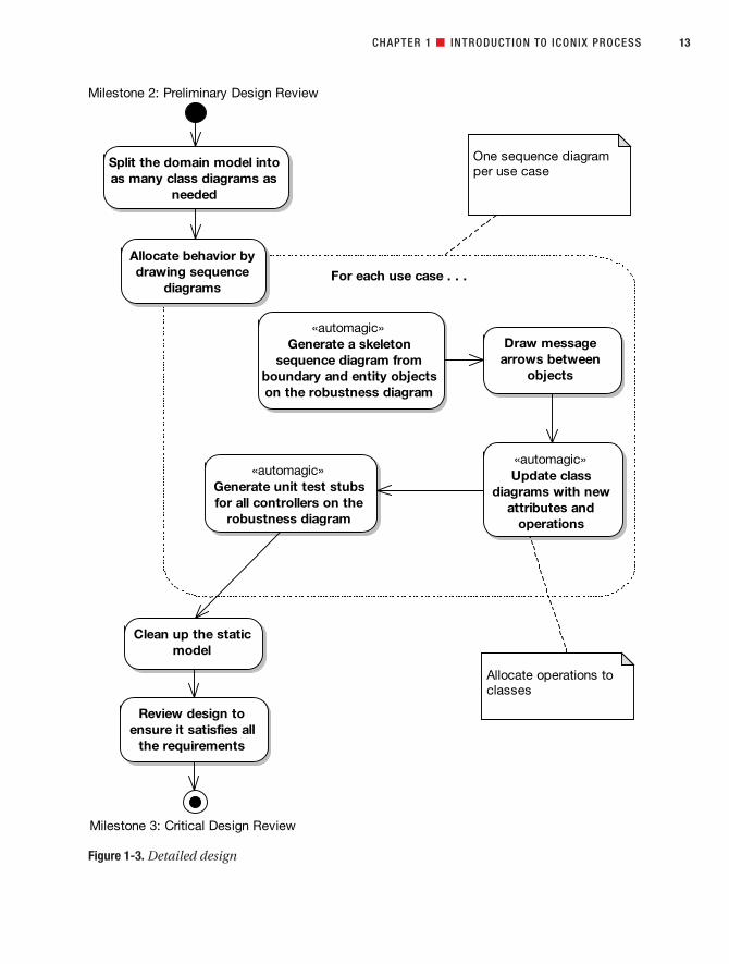
CHAPTER 1 ■ INTRODUCTION TO ICONIX PROCESS 13
Figure 1-3. Detailed design
For each use case . . .iterative
Milestone 2: Preliminary Design Review
Allocate behavior bydrawing sequence
diagrams
«automagic»Generate a skeleton
sequence diagram fromboundary and entity objectson the robustness diagram
«automagic»Update class
diagrams with newattributes and
operations
Clean up the staticmodel
Review design toensure it satisfies all
the requirements
Milestone 3: Critical Design Review
One sequence diagramper use case
Split the domain model intoas many class diagrams as
needed
«automagic»Generate unit test stubsfor all controllers on the
robustness diagram
Draw messagearrows between
objects
Allocate operations toclasses
7745ch01final.qxd 12/13/06 8:26 PM Page 13

Sequence Diagramming (Allocate Behavior to Classes)ICONIX Process uses the sequence diagram as the main vehicle for exploring the detaileddesign of a system on a scenario-by-scenario basis.
In object-oriented design, a large part of building the system right is concerned with find-ing an optimal allocation of functions to classes (aka behavior allocation). The essence of thisis drawing message arrows on sequence diagrams and allowing a modeling tool to automati-cally assign an operation to the class of the target object that receives the runtime message.
Here are our top 10 sequence diagramming guidelines. We describe these in more detailin Chapter 8.
10. Understand why you’re drawing a sequence diagram, to get the most out of it.
9. Do a sequence diagram for every use case, with both basic and alternate courses onthe same diagram.
8. Start your sequence diagram from the boundary classes, entity classes, actors, and usecase text that result from robustness analysis.
7. Use the sequence diagram to show how the behavior of the use case (i.e., all the con-trollers from the robustness diagram) is accomplished by the objects.
6. Make sure your use case text maps to the messages being passed on the sequencediagram. Try to line up the text and message arrows.
5. Don’t spend too much time worrying about focus of control.
4. Assign operations to classes while drawing messages. Most visual modeling toolssupport this capability.
3. Review your class diagrams frequently while you’re assigning operations to classes, to make sure all the operations are on the appropriate classes.
2. Prefactor your design on sequence diagrams before coding.
1. Clean up the static model before proceeding to the CDR.
By now, you’re almost ready to begin coding. You’ll need to perform a Critical DesignReview (CDR) first; but before that, it pays dividends to revisit the static model and clean it up.
Cleaning Up the Static ModelTake a long, hard look at your static model, with a view toward tidying up the design, resolv-ing real-world design issues, identifying useful design patterns that can be factored in toimprove the design, and so on. This should at least be done as a final step before proceedingto the CDR, but you can start thinking at this level in the design before drawing the sequencediagram.
By this stage, you should have an extremely well-factored design that works within thereal-world constraints of your project’s requirements, application framework design, deploy-ment topology, and so forth. There’s just one last stop before you begin coding: the CDR.
CHAPTER 1 ■ INTRODUCTION TO ICONIX PROCESS14
7745ch01final.qxd 12/13/06 8:26 PM Page 14

Milestone 3: Critical Design ReviewThe CDR helps you to achieve three important goals, before you begin coding for the currentbatch of use cases:
• Ensure that the “how” of detailed design matches up with the “what” specified in yourrequirements.
• Review the quality of your design.
• Check for continuity of messages on your sequence diagrams (iron out “leaps of logic”in the design).
Here are our top 10 CDR guidelines. We describe these in more detail in Chapter 9.
10. Make sure the sequence diagram matches the use case text.
9. Make sure (yes, again) that each sequence diagram accounts for both basic and alter-nate courses of action.
8. Make sure that operations have been allocated to classes appropriately.
7. Review the classes on your class diagrams to ensure they all have an appropriate set ofattributes and operations.
6. If your design reflects the use of patterns or other detailed implementation constructs,check that these details are reflected on the sequence diagram.
5. Trace your functional (and nonfunctional) requirements to your use cases and classesto ensure you have covered them all.
4. Make sure your programmers “sanity check” the design and are confident that theycan build it and that it will work as intended.
3. Make sure all your attributes are typed correctly, and that return values and parameterlists on your operations are complete and correct.
2. Generate the code headers for your classes, and inspect them closely.
1. Review the test plan for your release.
If you’ve gone through the detailed design for each use case and performed a CDR (as described in Chapter 9), then your design really should be fighting-fit now, and easilyready for coding.
Implementation Figure 1-4 shows the steps involved in coding and testing (i.e., implementation).
Once you’ve made the effort to drive a model from use cases through detailed design,it would be lunacy to disregard the model and just start coding totally independent of themodel you’ve produced.
Similarly, your modeling should provide a basis for knowing exactly what software func-tions will need to be unit tested, so you can drive the unit tests from the model in a similarmanner to generating code from the detailed class diagrams.
CHAPTER 1 ■ INTRODUCTION TO ICONIX PROCESS 15
7745ch01final.qxd 12/13/06 8:26 PM Page 15

CHAPTER 1 ■ INTRODUCTION TO ICONIX PROCESS16
Figure 1-4. Implementation
For each controller on the robustness diagram . . .iterative
Milestone 3: Critical Design Review
Write the sourcecode
Implement unit tests
Tests
passed?
Run the tests
Coding and testing
Perform system anduser-acceptance
testing
Generate your
unit test stubs
from the
robustness
diagram
controllers
Milestone 4: Delivery
Code Review andModel Update
Generate thedomain classes
Also generate whatever code
you can get your IDE or code
generator to create for you
Synchronize the design with the
code in preparation for the next
release or iteration
yes
no
7745ch01final.qxd 12/13/06 8:26 PM Page 16

Technology available in today’s modeling tools (at least the ones we use) also provides foreasy and convenient linkage between the UML model and the coding environment. We’veextended ICONIX Process to leverage this exciting new technology.
The steps shown in Figure 1-4 are covered in Chapters 10, 11, and 12.
Implementation (Coding)Here are our top 10 implementation guidelines. We describe these in more detail in Chapter 10.
10. Be sure to drive the code directly from the design.
9. If coding reveals the design to be wrong in some way, change it. But also review theprocess.
8. Hold regular code inspections.
7. Always question the framework’s design choices.
6. Don’t let framework issues take over from business issues.
5. If the code starts to get out of control, hit the brakes and revisit the design.
4. Keep the design and the code in sync.
3. Focus on unit testing while implementing the code.
2. Don’t overcomment your code (it makes your code less maintainable and moredifficult to read).
1. Remember to implement the alternate courses as well as the basic courses.
Unit testing is an important (and integral) part of implementation.
Unit TestingWhile coding, you should also be writing unit tests that are tied into the use cases. These testsallow you to prove, in an automated and repeatable way, that the system behavior describedin each use case has been implemented correctly. Essentially, you’re testing all the softwarefunctions that you identified during robustness analysis.
Here are our top 10 unit testing guidelines. We describe these in more detail in Chapter 12.
10. Adopt a “testing mind-set” wherein every bug found is a victory and not a defeat. If youfind (and fix) the bug in testing, the users won’t find it in the released product.
9. Understand the different kinds of testing, and when and why you’d use each one.
8. When unit testing, create one or more unit tests for each controller on each robustnessdiagram.
7. For real-time systems, use the elements on state diagrams as the basis for test cases.
CHAPTER 1 ■ INTRODUCTION TO ICONIX PROCESS 17
7745ch01final.qxd 12/13/06 8:26 PM Page 17
6. Do requirement-level verification (i.e., check that each requirement you have identi-fied is accounted for).
5. Use a traceability matrix to assist in requirement verification.
4. Do scenario-level acceptance testing for each use case.
3. Expand threads in your test scenarios to cover a complete path through the appropri-ate part of the basic course plus each alternate course in your scenario testing.
2. Use a testing framework like JUnit to store and organize your unit tests.
1. Keep your unit tests fine-grained.
As we discuss in Chapter 12, other types of testing are performed on different project arti-facts and at different stages in the project—in particular, integration/scenario testing.
Expand Threads for Integration and Scenario TestingThis activity involves expanding the sunny day/rainy day threads of the use cases. The inte-gration tests come from the use cases, in the form of testing the following:
1. The entire sunny-day scenario (the basic course)
2. Part of the sunny-day scenario plus each individual rainy day scenario (the alternatecourses)
For example, a use case with three alternate courses would need (at minimum) four inte-gration test scenarios: one for the basic course and one for each alternate course (includingwhichever part of the basic course goes along with it).
With the code and tests written for a particular use case (and with the tests passing!), it’simportant to perform a Code Review and Model Update.
Code Review and Model UpdateThe main purpose of the Code Review and Model Update milestone is to synchronize thecode and the model before the next iteration begins. This ongoing effort to keep the designtight prevents entropy, or code rot, from setting in as more and more functionality is addedto a complex system. Once you’ve completed this milestone, the design and the codeshould be in a very good state, ready for development to begin on the next use case (orbatch of use cases).
Here are our top 10 Code Review and Model Update guidelines. We describe these inmore detail in Chapter 11.
10. Prepare for the review, and make sure all participants have read the relevant reviewmaterial prior to the meeting.
9. Create a high-level list of items to review, based on the use cases.
8. If necessary, break down each item in the list into a smaller checklist.
7. Review code at several different levels.
CHAPTER 1 ■ INTRODUCTION TO ICONIX PROCESS18
7745ch01final.qxd 12/13/06 8:26 PM Page 18

6. Gather data during the review, and use it to accumulate boilerplate checklists forfuture reviews.
5. Follow up the review with a list of action points e-mailed to all people involved.
4. Try to focus on error detection during the review, not error correction.
3. Use an integrated code/model browser that hot-links your modeling tool to your codeeditor.
2. Keep it “just formal enough” with checklists and follow-up action lists, but don’t overdothe bureaucracy.
1. Remember that it’s also a Model Update session, not just a Code Review.
That about wraps up our overview of ICONIX Process. It probably seems as if there’s alot of information to absorb, but the process itself is actually very straightforward once youunderstand exactly why each step is performed.
Extensions to ICONIX ProcessAlthough it’s been used in hundreds of large-scale IT projects, the core ICONIX Process hasstayed much the same in the last 10 to 15 years. However, in Agile Development with ICONIXProcess (Apress, 2005), we published some extensions to the core process. These extensionsinclude the following:
• Performing persona analysis
• Supplementing the process with Test-Driven Development (TDD)
• Driving test cases from the analysis model
Persona AnalysisPersona analysis as an interaction design technique makes actors and use cases more concreteand tangible for project stakeholders. Many people find actors and use cases too abstract, sothis approach addresses the issue head-on.
A persona is a description of a fictional person: a prototypical target user. The person isgiven a name and a brief description of his or her job, goals and aspirations, level of ability—anything that might be relevant to how that person uses and perceives the product you’redesigning. You’d then write interaction scenarios (a form of use case that describes in moredetail the user’s motivations behind his or her interaction with the system), based around the persona you’ve defined. Using ICONIX Process, you would write a few detailed interactionscenarios to make sure the system is correctly focused on your target user, and then proceedto write the more minimal, ICONIX-style use cases for the system as a whole.
Test-Driven Development (TDD)TDD is an increasingly popular method of designing software by writing unit tests. The designeffectively “evolves” as you write the code. Teams have begun to realize that TDD by itself can
CHAPTER 1 ■ INTRODUCTION TO ICONIX PROCESS 19
7745ch01final.qxd 12/13/06 8:26 PM Page 19
be a long-winded design process (to say the least) and benefits greatly from some initial, up-front design modeling. ICONIX Process is a prime candidate for this, because its robustnessanalysis technique works well in collaborative design workshops with teams modeling on a whiteboard (or on a CASE tool hooked up to a projector).
Driving Test Cases from the Analysis ModelIt makes sense to link your models as closely as possible to testing, and in fact to drive thetesting effort from your use case–driven models. This extension to ICONIX Process drives theidentification of test cases directly from the robustness diagram, in a parallel manner to theway we drive the creation of a skeleton sequence diagram from a robustness diagram. Inshort, the nouns (Entity and Boundary objects) from the robustness diagram become objectinstances on the sequence diagram, and the verbs (controllers) get test cases created forthem. We discuss this process in depth in Chapter 12.
ICONIX Process in Practice: The Internet Bookstore ExampleStarting in the next chapter, we’re going to be following a running example, which we call the Internet Bookstore, through each phase of the process we’ve just outlined for you.
When we get to the sequence diagramming (detailed design) stage in Chapter 8, we’llbegin to implement the Internet Bookstore using the Spring Framework, a popular Javaenterprise application framework. This book isn’t primarily about Spring, so we won’t dwellon the technical details regarding Spring itself (although we will suggest further resources,both print and online). Instead we’ll focus on the ways in which ICONIX Process is used tocreate well-designed source code for a realistic web-based application.
The techniques we describe in this book should still be more than relevant to users ofother application frameworks and other object-oriented programming languages.
The use cases we’ll be working through and the classes we’ll discover exist to satisfycertain requirements that our customer (the fictional owner of the bookstore we’re going to build) has specified. We’ll cover these requirements in Chapter 2, where we show how toderive our first-pass version of the domain model from the requirements.
SummaryIn this chapter we introduced ICONIX Process and described its background and the drivingprinciples behind it. We also described its key features and walked through the process, fromuse cases to code.
In the next chapter, we describe in detail the first major stage of ICONIX Process: domainmodeling.
CHAPTER 1 ■ INTRODUCTION TO ICONIX PROCESS20
7745ch01final.qxd 12/13/06 8:26 PM Page 20

Requirements Definition
P A R T 1
7745ch02final.qxd 12/13/06 8:28 PM Page 21

7745ch02final.qxd 12/13/06 8:28 PM Page 22

Domain Modeling
Imagine if everyone on your team was talking a different language. Let’s say you’re speakingGerman, your teammate is speaking French, and someone else is speaking Swahili. Everytime someone speaks, people glean whatever slivers of meaning they can, and then nod as if they’ve understood perfectly. They then walk away with a completely wrong interpretationof what the speaker was really trying to say.
In virtually all IT projects, the problem of miscommunication is rampant, but it’s rarelynoticed because everybody thinks they’re speaking the same language. They’re not. One per-son says “book review” and some people interpret this as meaning “editorial review” (a reviewwritten by an editorial team), whereas others might interpret it as meaning “customer review”(a review written by a customer and posted to the site). The results can be—and often are—catastrophic, as the system gets developed with everyone interpreting the requirements andthe design differently.
The domain model is a live, collaborative artifact. It is refined and updated throughoutthe project, so that it always reflects the current understanding of the problem space.
23
C H A P T E R 2
7745ch02final.qxd 12/13/06 8:28 PM Page 23
In this chapter we’ll look at domain modeling, which aims to solve the problem ofmiscommunication on projects by establishing a common vocabulary that maps out theproblem space.
The 10,000-Foot ViewDomain modeling is the task of building a project glossary, or a dictionary of terms used inyour project. The domain model for a project defines the scope and forms the foundation onwhich to build your use cases. A domain model also provides a common vocabulary to enableclear communication between members of a project team. So even though this book is aboutuse case–driven development, we have to begin at the beginning with domain modeling.
What’s a Domain Model?As just mentioned, a domain model is, essentially, a project glossary: a “live” dictionary of allthe terms used in your project. But a domain model is better than a project glossary, becauseit shows graphically how all these different terms relate to each other. In practice it’s a simpli-fied class diagram, with lines drawn between the different classes (domain objects) to showhow they relate to each other. The domain model shows aggregation and generalization rela-tionships (has-a and is-a relationships) between the domain classes.
Figure 2-1 shows an excerpt from a domain model. Don’t worry about the details fornow—our purpose in presenting this figure is just so you can visualize what it is we’re going to be talking about the rest of the chapter.
24 CHAPTER 2 ■ DOMAIN MODELING
7745ch02final.qxd 12/13/06 8:28 PM Page 24

Why Start with the Domain Model Instead of Use Cases?You’ll find that it really helps if you take a quick stab at a domain model right at the start of a project. When you write use cases, it’s tempting to make them abstract, high-level, vague,and ambiguous. In fact, some gurus even recommend that you write your use cases this way(only they call it “abstract,” “essential,” “technology-free,” etc.)—but more about that later. Our advice is pretty much the opposite: your use case text should be grounded in reality, and it should be very close to the system that you’ll be designing. In other words, the use casesshould be written in the context of the object model (i.e., the use case text needs to referencethe domain objects by name). By doing this, you’ll be able to tie together the static anddynamic parts of the model, which is crucial if you want your analysis and design effort to be driven forward by your use cases.
So before you write your use cases, you need to come up with a first-pass attempt at a domain model. The domain model forms the foundation of the static part of your model,while the use cases are the foundation of the dynamic part. The static part describes struc-ture; the dynamic part describes behavior.
■Note At the analysis level, the terms “object” and “class” are sometimes used interchangeably (an objectis a runtime instance of a class). However, when we get to the more grounded design level, the distinctionbetween objects and classes becomes more important.
CHAPTER 2 ■ DOMAIN MODELING 25
Figure 2-1. Example of a domain model diagram
BookReview
EditorialReview
ReaderReview
BookRating
Book
Line Item
Price
BookCatalog
MasterBook
Catalog
Category
7745ch02final.qxd 12/13/06 8:28 PM Page 25

Domain Modeling in TheoryAs you read this book, you’ll see that each chapter follows a familiar pattern. We start bydescribing an aspect of modeling “in theory,” using our Internet Bookstore example to illus-trate the points we make. Then we cover it “in practice,” showing typical modeling errorsand how to correct them, and presenting a number of exercises. Finally, we round off eachchapter with “more practice.”
Top 10 Domain Modeling GuidelinesThe principles discussed in this chapter can be summed up as a list of guidelines. Our top 10list follows.
10. Focus on real-world (problem domain) objects.
9. Use generalization (is-a) and aggregation (has-a) relationships to show how the objects relate to each other.
8. Limit your initial domain modeling efforts to a couple of hours.
7. Organize your classes around key abstractions in the problem domain.
6. Don’t mistake your domain model for a data model.
5. Don’t confuse an object (which represents a single instance) with a database table(which contains a collection of things).
4. Use the domain model as a project glossary.
3. Do your initial domain model before you write your use cases, to avoid nameambiguity.
2. Don’t expect your final class diagrams to precisely match your domain model, but there should be some resemblance between them.
1. Don’t put screens and other GUI-specific classes on your domain model.
Let’s look at each of these in more detail.
10. Focus on Real-World ObjectsWhen creating a domain model, be sure to focus on real-world objects within the problemdomain. Try to organize your software architecture around what the real world looks like. Thereal world tends to change less frequently than software requirements.
CHAPTER 2 ■ DOMAIN MODELING26
7745ch02final.qxd 12/13/06 8:28 PM Page 26

9. Use Generalization (Is-a) and Aggregation (Has-a) RelationshipsOver time, you’ll flesh out your domain model with new domain classes, as and when youidentify them. You’ll also notice relationships (or associations) between them—for example, a Book Review belongs to a Book, and a Purchase Order and Credit Card are two of a kind, asthey’re both Payment Types.
The first relationship (Book Review belongs to a Book) is called aggregation (has-a,because a Book has a Book Review). The second relationship (Purchase Order and Credit Cardare both Payment Types) is called generalization (is-a, because a Purchase Order is a PaymentType). Figure 2-3 shows an illustration of these concepts.
CHAPTER 2 ■ DOMAIN MODELING 27
CLASS NOTATION
Figure 2-2 shows two different types of class notation. On a full-blown detailed class diagram, you’d use theversion on the left, with attributes and operations. However, during the initial domain modeling effort, it’s tooearly to allocate these parts of a class. It’s better to use the simpler notation shown on the right. This versiononly shows the domain class’s name.
Figure 2-2. Class notations
Figure 2-3. Aggregation and generalization relationships
Book
Book Review PurchaseOrder
Credit Card
PaymentType
7745ch02final.qxd 12/13/06 8:28 PM Page 27

These and regular (plain vanilla) associations are the most important relationships inyour domain model. Ninety-five percent of your model’s class relationships can be modeledusing aggregation and generalization relationships.
■Tip Wherever possible, place your associations so that they read left to right and top to bottom, just likeregular text. This will improve the readability of your diagrams.
8. Limit Your Initial Domain Modeling Efforts to a Couple of HoursWe recommend that you establish a time budget for building your initial domain model. A couple of hours is all you should need. You’re not going to make it perfect anyway, so do itquickly and expect to fix it as you proceed. You should be vigilant about making necessaryadjustments to your analysis-level class model in response to discoveries made during robust-ness analysis and throughout the project.
You’ll discover missing objects as you work through use cases and robustness diagrams.The use case–driven process assumes that the domain model is incomplete and provides a mechanism for discovering what was missed.
The initial domain modeling session is probably the most important two hours you’llspend on the project! It’s likely that you’ll discover 80% of your domain classes during thattwo-hour brainstorming session. If you can get 80% of your domain vocabulary disambig-uated, then that’s two hours well spent.
7. Organize Your Classes Around Key Abstractions in the Problem DomainIt’s generally good practice to organize your classes around key abstractions in the problemdomain. Remember that the domain model is a first-cut class diagram that becomes the foun-dation of your software architecture. This makes the model more resilient in the face ofchange. Organizing the architecture around real-world abstractions makes the model moreresilient in the face of changing requirements, as the requirements will usually change morefrequently than the real world does.
6. Don’t Mistake Your Domain Model for a Data ModelEven though the diagrams might look similar, remember that what’s good practice on a datamodel is not likely to be good practice on a class diagram (and vice versa). Classes are smalland tables are bigger. A table in a relational database often relates a number of things. Con-versely, classes are better designed if they’re relatively small packets of data and behavior.
In a class diagram, it’s likely that you’ll have a class that manages a database table, andyou might show some sort of TableManager class aggregating a regular domain class. The pur-pose of these TableManager-type classes is to hide the details of the database managementsystem (DBMS) from the rest of the code base.
CHAPTER 2 ■ DOMAIN MODELING28
7745ch02final.qxd 12/13/06 8:28 PM Page 28

5. Don’t Confuse an Object with a Database TableAn object represents a single instance of something. A database table represents a collec-tion of things. You don’t have to be as literal-minded as in the Enterprise JavaBeans (EJB)world, where an entity bean generally represents a single row in a table. Domain classes are similar, though. If you call a domain class Book, then you don’t mean a book table—youmean a single book.
Columns in a table generally map to attributes on a class. However, database tablestypically contain a lot more columns than a class contains attributes (tables often haveforeign keys, as one example), so there may not be a direct 1:1 mapping between table rows and objects.
4. Use the Domain Model As a Project GlossaryIf ambiguous requirements are the enemy, the domain model is the first line of defense.Ambiguous usage of names by “subject matter experts” is very common and very harmful.The domain model should serve as a project glossary that helps to ensure consistent usageof terms when describing the problem space.
Using the domain model as a project glossary is the first step toward disambiguating yourmodel. In every Jumpstart workshop that Doug teaches, he finds at least two or three domainclasses where students are using ambiguous names (e.g., “shopping cart,” “shopping basket,”or “shopping trolley”).
3. Do Your Domain Model Before You Write Your Use CasesSince you’re using the domain model to disambiguate your problem domain abstractions, it would be silly to have your use cases written using ambiguous terms to describe domainclasses. So spend that two hours working on the domain model before writing your use cases.Writing the use cases without a domain model to bind everything together stores up lots ofproblems for later.
2. Don’t Expect Your Final Class Diagrams to Precisely Match Your Domain ModelThe class diagrams will become a lot more detailed than the domain model as the designprogresses; the domain model is deliberately kept quite simple. As you’re designing (usingsequence diagrams), detailed design constructs such as GUI helpers, factory classes, andinfrastructure classes get added to the class diagram, and the domain model diagram willalmost certainly be split out into several detailed class diagrams. However, it should still be possible to trace most classes back to their equivalent domain class.
1. Don’t Put Screens and Other GUI-Specific Classes on Your Domain ModelDoing so opens up Pandora’s box and leads to an overcrowded domain model containing lotsof implementation-specific detail. Performance optimization classes, helper classes, and soon should also be kept out of the domain model. The domain model should focus purely onthe problem domain.
CHAPTER 2 ■ DOMAIN MODELING 29
7745ch02final.qxd 12/13/06 8:28 PM Page 29

Internet Bookstore: Extracting the First-Pass Domain Modelfrom High-Level RequirementsWhen you’re creating your domain model, a good source of domain classes includes the high-level requirements—the ones that are usually (but not always) written in the form “The systemshall do this; the system shall not do that.” It’s useful to scan these requirements, extractingthe nouns and noun phrases. You can then refine these to create the initial domain model.
With that in mind, let’s go through the high-level requirements for the Internet Bookstoreand extract some domain classes from them.
1. The bookstore will be web based initially, but it must have a sufficiently flexiblearchitecture that alternative front-ends may be developed (Swing/applets, webservices, etc.).
2. The bookstore must be able to sell books, with orders accepted over the Internet.
3. The user must be able to add books into an online shopping cart, prior to checkout.
a. Similarly, the user must be able to remove items from the shopping cart.
4. The user must be able to maintain wish lists of books that he or she wants to purchaselater.
5. The user must be able to cancel orders before they’ve shipped.
6. The user must be able to pay by credit card or purchase order.
7. It must be possible for the user to return books.
8. The bookstore must be embeddable into associate partners’ websites using mini-catalogs, which are derived from an overall master catalog stored in a centraldatabase.
a. The mini-catalogs must be defined in XML, as they will be transferred between thisand (later to be defined) external systems.
b. The shipping fulfillment system shall be carried out via Amazon Web Services.
9. The user must be able to create a customer account, so that the system remembers the user’s details (name, address, credit card details) at login.
a. The system shall maintain a list of accounts in its central database.
b. When a user logs in, his or her password must always be matched against thepasswords in the master account list.
10. The user must be able to search for books by various search methods—title, author,keyword, or category—and then view the books’ details.
11. It must be possible for the user to post reviews of favorite books; the review commentsshould appear on the book details screen. The review should include a customer rat-ing (1–5), which is usually shown along with the book title in book lists.
CHAPTER 2 ■ DOMAIN MODELING30
7745ch02final.qxd 12/13/06 8:28 PM Page 30

a. Book reviews must be moderated—that is, checked and “OK’d” by a member ofstaff before they’re published on the website.
b. Longer reviews should be truncated on the book details screen; the customer mayclick to view the full review on a separate page.
12. It must be possible for staff to post editorial reviews of books. These should alsoappear on the book details screen.
13. The bookstore shall allow third-party sellers (e.g., second-hand bookstores) to addtheir own individual book catalogs. These are added into the overall master bookcatalog so that sellers’ books are included in search results.
14. The bookstore must be scalable, with the following specific requirements:
a. The bookstore must be capable of maintaining user accounts for up to 100,000customers in its first six months, and then a further 1,000,000 after that.
b. The bookstore must be capable of serving up to 1,000 simultaneous users (10,000after six months).
c. The bookstore must be able to accommodate up to 100 search requests per minute(1,000/minute after six months).
d. The bookstore must be able to accommodate up to 100 purchases per hour(1,000/hour after six months).
These requirements are a rich source of domain classes. Let’s put all the highlightednouns and noun phrases into a list (in the process, we’ll turn all the plurals into singulars, and put them all in alphabetical order):
CHAPTER 2 ■ DOMAIN MODELING 31
Associate Partner
Author
Book
Book Catalog
Book Details
Book List
Book Review
Bookstore
Category
Checkout
Credit Card
Customer
Customer Account
Customer Rating
Database
Editorial Review
Internet
Item
Keyword
List of Accounts
Master Account List
Master Book Catalog
Master Catalog
Mini-Catalog
Order
Password
Purchase Order
Review Comment
Search Method
Search Results
Seller
Shipping FulfillmentSystem
Shopping Cart
Title
User Account
Wish List
7745ch02final.qxd 12/13/06 8:28 PM Page 31

There’s quite a bit of duplication in this list; similar terms are being used for basically thesame thing. But that’s really the main benefit of the domain modeling approach: you get toidentify and eliminate these duplicate terms early on in the project.
■Exercise Disambiguation via Grammatical Inspection: We’ll go through this list next, whipping it intoshape and eliminating the duplicate terms. But first, try to identify the six duplicate pairs in the list. (Be care-ful: one pair seems like a duplicate but really isn’t.)
Some of the items in the list are simply unnecessary because they fall outside the scope ofthe domain model, or they’re actions sneakily masquerading as nouns.
Let’s step through the list now and tune it up a bit:
• You’d think that the terms “Customer” and “Customer Account” are duplicates, but infact they represent subtly different things: “Customer Account” is an entity stored in thedatabase, whereas “Customer” is an actor (see the next item in this list).
• “Customer” and “Seller” are actors, and thus should be placed on use case diagrams.(See Chapter 3.)
• The terms “User Account” and “Customer Account” are duplicates. The choice of whichone to keep is fairly arbitrary, so we’ll go with “Customer Account.”
• The terms “List of Accounts” and “Master Account List” are duplicates, so one of themshould be removed. As we also have a “Master Book Catalog,” the consistent thingwould be to keep “Master Account List.”
• The terms “Book Review” and “Review Comment” are duplicates, so we’ll keep “BookReview.”
• We have several different candidate terms for a catalog, or list of books: “Book Catalog,”“Book List,” “Mini-Catalog,” and “Master Catalog.” Catalogs and lists are probably dif-ferent concepts. In fact, it seems that the requirements are trying to tell us something,which may just be implied in the text. When in doubt, talk to the customer. Ask ques-tions until you get a clear, unambiguous answer.
“Book Catalog” and “Master Catalog” are in fact the duplicates here, so we’ll keep“Master Catalog,” as it provides a good contrast with “Mini-Catalog.” “Book List,”meanwhile, is probably an umbrella term for different types of lists; we’ll keep it inthere for now and see how it fits in when we draw the domain model diagram.
• There’s another duplicate in this area: “Master Catalog” and “Master Book Catalog.”We’ll delete “Master Catalog,” as “Master Book Catalog” is the more descriptive term.
• The word “Internet” is too generic and doesn’t add anything here.
• The word “Password” is a too small to be an object and would be shown as a UI ele-ment, so we should remove it from the domain model. If we start to include all the UIelements in the domain model, we’re opening a serious can of worms and could behere all night backed into a corner, fighting them away with a large stick.
CHAPTER 2 ■ DOMAIN MODELING32
7745ch02final.qxd 12/13/06 8:28 PM Page 32

• Same goes for “Title” and “Keyword.”
• Yet another duplicate is “Book” and “Book Details.” We’ll just keep “Book,” as it’s moreconcise than “Book Details,” without losing any meaning.
• The word “Item” is just vague and fuzzy, but it does represent a valid concept: an itemthat’s been added to the user’s shopping cart. So we’ll rename it “Line Item” and keep it in the list.
• The word “Bookstore” is a bit too broad and is unlikely to be referred to explicitly, so wecan get rid of it.
Following is the updated list of candidate domain classes. Figure 2-4 shows those classeslaid out in a class diagram.
As we mentioned earlier, although grammatical inspection techniques are useful to get a quick start, you shouldn’t spend weeks or even days doing this. (As you’ll see in Chapter 4,the rest of the objects for the Internet Bookstore were identified during robustness analysis.) A couple of hours is about the right amount of time to spend on the domain model beforegetting started writing the use cases.
■Caution Don’t get bogged down in grammatical inspection.
Figure 2-4 shows one type of relationship, aggregation (aka has-a), which we describedearlier. As this is a first-pass attempt, not all the relationships shown are correct.
A helpful technique is to read the diagram aloud and include the term “has-a.” Forexample, a Shopping Cart “has” Line Items. But, does an Order “have” Checkouts? Perhapsnot. Notice that a few of the domain objects currently don’t match up with anything else(namely, Associate Partner, Shipping Fulfillment System, Database, and Search Method).We’ve grouped these together over on the right for now; during robustness analysis, thesemay get linked to other objects, warped into something different, or removed altogether.
CHAPTER 2 ■ DOMAIN MODELING 33
Associate Partner
Author
Book
Book List
Book Review
Category
Checkout
Credit Card
Customer Account
Customer Rating
Database
Editorial Review
Line Item
Master Account List
Master Book Catalog
Mini-Catalog
Order
Purchase Order
Search Method
Search Results
Shipping FulfillmentSystem
Shopping Cart
Wish List
7745ch02final.qxd 12/13/06 8:28 PM Page 33

CHAPTER 2 ■ DOMAIN MODELING34
Figure 2-4. First-pass domain model for the Internet Bookstore project
AssociatePartner
Author
Book
Book List
Book Review
Category
Checkout
Credit Card
CustomerRating
Database
EditorialReview
Line Item
Mini-Catalog
MasterAccount List
MasterBook
Catalog
Order
PurchaseOrder
SearchMethod
SearchResults
ShippingFulfillment
System
Shopping Cart
Wish List
Customer
Seller
CustomerAccount
7745ch02final.qxd 12/13/06 8:28 PM Page 34

There’s still some work that needs to be done on this domain model before we’re ready tomove on to the next stage, so let’s do some more tidying up work next. Hopefully, this will helpto illustrate an important element of the ICONIX approach: continuous improvement viaongoing iteration and refinement.
Internet Bookstore: Second Attempt at the Domain ModelWhen drawing up the domain model diagram, you’re generally brainstorming as a team. Oftenthe team will identify further domain objects that weren’t in the requirements, but insteadhave been dredged from somebody’s own understanding of the problem domain. To illustratethis, let’s say we’ve discovered two additional domain objects: Order History and OrderDispatch. These weren’t mentioned explicitly in the requirements, but they could still classifyas minimum requirements for an Internet bookstore.
The updated diagram is shown in Figure 2-5, with the new domain classes shown in red.In Figure 2-5, we’ve explored the concept of order fulfillment and dispatch. Shipping
Fulfillment System still remains on the diagram, but we’ll have to decide whether this is inscope for the current model or it’s an external system that we need to interface with. Externalsystems are always modeled as actors.
We’ve also removed Checkout, as on reflection this was really a verb in noun’s clothing.And we’ve removed Author, as this is really just another field in the Book (i.e., it’s too small to bea first-class object on the domain model1). Authors . . . who needs ’em?
There’s some ambiguity around Master Book Catalog, which we’ve attempted toresolve. We’ve removed the link between Book and Master Book Catalog, and instead addeda class called Book Catalog and linked Book to that instead. So we end up with a tangle ofrelationships: we’re effectively saying that a Book belongs to a Book Catalog, and a BookCatalog belongs to a Master Book Catalog (i.e., a Master Book Catalog is really a catalog ofcatalogs). Ideally, a Mini-Catalog should also belong to the Master Book Catalog. But thistangle is getting complicated. What we really need is a simple way of saying that a Book canbelong to Book Catalogs, and there can be various types of Book Catalogs. Luckily, a lightsprinkling of generalization can work wonders on such relationship tangles, as you’ll see in the next section.
CHAPTER 2 ■ DOMAIN MODELING 35
1. Remember we’re not creating a data model here. If this were a database design, we would almost cer-tainly create a separate Authors table.
7745ch02final.qxd 12/13/06 8:28 PM Page 35

CHAPTER 2 ■ DOMAIN MODELING36
Figure 2-5. Second snapshot of the evolving domain model for the Internet Bookstore project
7745ch02final.qxd 12/13/06 8:28 PM Page 36

Internet Bookstore: Building Generalization RelationshipsA generalization relationship is one in which one class is a “kind of” some other class—for example, a Cat is a kind of Animal. This is why generalization is often called an is-arelationship.
Cat is more specific than Animal (Cat is a “refinement” of the more general Animal class),hence the term “generalization.” The more specific class is called the subclass, and the moregeneral class is the superclass. Creating subclasses of more general classes is known assubtyping.
Within the Internet Bookstore, Book Catalog is a good candidate for subtyping, becausedoing so will help to “de-cloud” the relationship between Mini-Catalog and Master BookCatalog. Book List is also a good candidate for subtyping, because there may well be differ-ent types of accounts and different types of book lists.
As we delve more deeply into the user’s needs for the Internet Bookstore system, we’rebeginning to identify different types of book lists: customer wish lists, recommendation lists,Related Books, Search Results, and so on. It’s becoming clear that these are all simply lists ofBooks, so they could (conceptually, at least) have a common parent class. We’ve discoveredthat there are indeed aspects of Wish Lists, Related Books, and so on that are differentenough to justify separate treatment, while they still have enough in common that they’re all kinds of Book List. Figure 2-6 shows the notation for this generalization structure.
The new classes (Related Books, Recommendation List, Wish List, and Search Results)inherit the attributes and operations that we define for Book List. Let’s read this diagram outloud: A book list has books. Related Books is a book list. Recommendation List is a book list.Wish List is a book list. Search Results is a book list. All true statements that describe the prob-lem space? Great, let’s move on.
■Tip You could also add additional specialized attributes and operations for each of the new classes. Inother words, if you were to add an operation to Related Books, it would only be available to RelatedBooks. However, if you add it to Book List, the new operation would be available to all of its subclasses.
CHAPTER 2 ■ DOMAIN MODELING 37
Figure 2-6. Book Lists detail from the Internet Bookstore domain model
BookBook List
RelatedBooks
RecommendationList
Wish List SearchResults
7745ch02final.qxd 12/13/06 8:28 PM Page 37

Figure 2-7 shows the updated Internet Bookstore domain model, which makes good useof generalization to clarify the relationships between the domain classes. The new classes areshown in red.
CHAPTER 2 ■ DOMAIN MODELING38
Figure 2-7. Third snapshot of the evolving domain model for the Internet Bookstore project
7745ch02final.qxd 12/13/06 8:28 PM Page 38

We’ve also changed the definition of Book Review, so that it’s now the parent class forEditorial Review and the new class, Reader Review. And, finally, we’ve disentangled the rela-tionships surrounding Order and its payment types (Credit Card and Purchase Order), byadding a new superclass, Payment Type.
■Tip If you need to, you can generalize to more than one level of subclass. Remember to look for is-astatements that are true in the real world.
Domain Modeling in PracticeThe following exercises, taken from the domain model for the Internet Bookstore, aredesigned to test your ability to spot the most common mistakes that people make duringdomain modeling. After the exercises, you can find the diagrams with the errors highlightedon them, followed by the corrected diagrams.
ExercisesEach of the diagrams in Figures 2-8 to 2-11 contains one or more typical modeling errors. Foreach one, try to figure out the errors and then draw the corrected diagram. The answers are inthe next section.
Exercise 2-1
Figure 2-8 shows a class diagram produced during the initial domain modeling effort. The UML syntax is correct,yet the diagram does point out a process-related error. Why is that? (Hint: The diagram is showing too muchdetail.)
CHAPTER 2 ■ DOMAIN MODELING 39
Figure 2-8. Class diagram from the initial domain modeling effort
ShoppingCart
Line Item
OrderCustomer
0..*
0..1
1
1
7745ch02final.qxd 12/13/06 8:28 PM Page 39
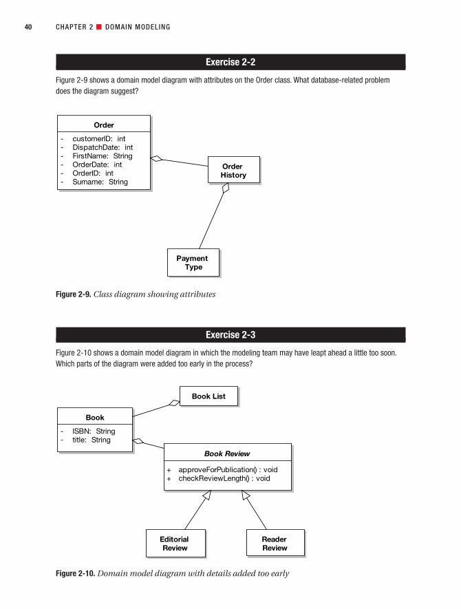
Exercise 2-2
Figure 2-9 shows a domain model diagram with attributes on the Order class. What database-related problemdoes the diagram suggest?
Exercise 2-3
Figure 2-10 shows a domain model diagram in which the modeling team may have leapt ahead a little too soon.Which parts of the diagram were added too early in the process?
CHAPTER 2 ■ DOMAIN MODELING40
Figure 2-9. Class diagram showing attributes
Order
- customerID: int- DispatchDate: int- FirstName: String- OrderDate: int- OrderID: int- Surname: String
OrderHistory
PaymentType
Figure 2-10. Domain model diagram with details added too early
Book List
Book
- ISBN: String- title: String
Book Review
+ approveForPublication() : void+ checkReviewLength() : void
EditorialReview
ReaderReview
7745ch02final.qxd 12/13/06 8:28 PM Page 40
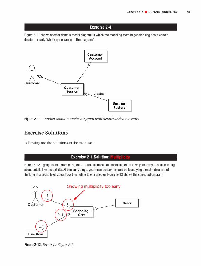
Exercise 2-4
Figure 2-11 shows another domain model diagram in which the modeling team began thinking about certaindetails too early. What’s gone wrong in this diagram?
Exercise Solutions
Following are the solutions to the exercises.
Exercise 2-1 Solution: Multiplicity
Figure 2-12 highlights the errors in Figure 2-9. The initial domain modeling effort is way too early to start thinkingabout details like multiplicity. At this early stage, your main concern should be identifying domain objects andthinking at a broad level about how they relate to one another. Figure 2-13 shows the corrected diagram.
CHAPTER 2 ■ DOMAIN MODELING 41
Figure 2-11. Another domain model diagram with details added too early
Customer
CustomerAccount
SessionFactory
CustomerSession
creates
Figure 2-12. Errors in Figure 2-9
7745ch02final.qxd 12/13/06 8:28 PM Page 41

Exercise 2-2 Solution: Mapping Database Tables to Domain Classes
The Order domain class includes attributes that really don’t seem like they belong in an Order class (seeFigure 2-14). The most likely cause is that the modeler has mapped these domain classes directly from arelational database schema. Figure 2-15 gives the corrected diagram. The extra attributes have been sepa-rated out into their own domain classes (Customer Account and Dispatch). Note that we’d generally notshow the attributes at all during domain modeling.
CHAPTER 2 ■ DOMAIN MODELING42
Figure 2-13. Corrected version of Figure 2-9
ShoppingCart
Line Item
OrderCustomer
Figure 2-14. Order class domain attributes erroneously influenced from database schema
7745ch02final.qxd 12/13/06 8:28 PM Page 42

Exercise 2-3 Solution: Operations and Abstract Classes
The domain model diagram shown in Figure 2-16 has a couple of problems. The first is that Book Review is anabstract class. While this isn’t especially destructive, and the world probably won’t end as a direct result, domainmodeling is just a bit too early in the development process to be thinking about these sorts of design details.
Staying with Book Review, the other problem is that a couple of operations have been assigned:checkReviewLength() and approveForPublication(). Identifying and assigning operations to classes isvery much a design thing—so again, domain modeling is just too early to be thinking about these sorts of details.
Figure 2-17 shows the corrected diagram.
CHAPTER 2 ■ DOMAIN MODELING 43
Figure 2-15. Domain attributes from Figure 2-14, but this time in more appropriate classes
Order
- OrderDate: int- OrderID: int
OrderHistory
PaymentType
Customer Account
- CustomerID: int- FirstName: String- Surname: String
Dispatch
- DispatchDate: int
7745ch02final.qxd 12/13/06 8:28 PM Page 43

Exercise 2-4 Solution: Premature Patternization
In Figure 2-18, you can see the telltale beginnings of a Factory design pattern. Using this particular design pattern,the SessionFactory class will create new instances of CustomerSession. A SessionFactory is clearly part of the solution space, not the problem space, as are most design patterns. This sounds an awful lot likedesign, and the use cases haven’t even been written yet, so again this is way too early to be thinking aboutimplementation details.
CHAPTER 2 ■ DOMAIN MODELING44
Figure 2-16. Solution-space details (design) added into the problem space (domain model)
Figure 2-17. Corrected version of Figure 2-16
Book List
Book
Book Review
EditorialReview
ReaderReview
7745ch02final.qxd 12/13/06 8:28 PM Page 44

Design patterns usually begin to emerge during robustness analysis (preliminary design), but domain modelingreally isn’t the time to be thinking about them.
Figure 2-19 shows the corrected diagram.
More PracticeThis section provides a list of modeling questions that you can use to test your knowledge ofdomain modeling. The questions get progressively harder, but the answers can all be found byreading (and thinking about!) the domain modeling techniques described in this chapter.
1. Which of the following is not one of the four types of association in a domain model?
a) Has-a
b) Creates
c) Is-a
d) Knows about
CHAPTER 2 ■ DOMAIN MODELING 45
Figure 2-18. Design details added too early in the project
Figure 2-19. Domain model diagram with the design details removed
Customer
CustomerAccount
CustomerSession
7745ch02final.qxd 12/13/06 8:28 PM Page 45

2. When creating a domain class list, how do you tell when you have an attribute?
a) An attribute has cardinality in all cases.
b) An attribute can only be contained in instances with no behavior.
c) An attribute has a value that is typically not compound.
d) An attribute has a value that is made up of lots of other values.
3. What technique(s) can you use to figure out domain classes in a system?
a) Noun phrase analysis
b) Reverse engineering
c) Class verb category
d) Extreme Programming
4. What term is used to describe when a child class is an extension of a parent class?
a) Aggregation
b) Inheritance
c) Composition
d) Encapsulation
5. Draw a domain model for an online music store, first by trying to imagine how it worksin the abstract, without looking at any screens, and then after looking at an examplewebsite such as iTunes or Napster. Which of your domain models is better? Explain.
6. Assume you could reverse engineer the database schema from Amazon.com andimport this into a visual modeling tool. Would this be a good starting point for adomain model? What changes would need to be made to a reverse-engineered database schema to make it a good domain model?
7. Assume someone hands you some Java code for a GUI prototype of a new Internetbookstore and you reverse engineer it into UML. Would this be a good starting pointfor a domain model? What changes would need to be made to a reverse-engineeredGUI prototype to make it a good domain model?
8. Assume you are working on Release 3 of a project, and you have a detailed set of classdiagrams showing the complete implementation of Release 2 that has been reverseengineered from C# code. Release 3 involves migrating the system to a new GUI frame-work and a different DMBS. What changes would need to be made to your detailedclass diagrams from the previous release to make it a good domain model for the cur-rent release?
CHAPTER 2 ■ DOMAIN MODELING46
7745ch02final.qxd 12/13/06 8:28 PM Page 46

SummaryIn this chapter we described in detail the first major stage of ICONIX Process. Domain model-ing forms the basis for the whole object modeling activity. As you’ll see in the next chapter, theuse cases are written in the context of the domain model, and (as you’ll see in Chapter 5)robustness analysis helps to tighten up both the domain model and the use case text, bringingthem closer together.
The activity diagram in Figure 2-20 shows how domain modeling fits into the overallrequirements analysis effort. The activities we covered in this chapter are shown in red.
CHAPTER 2 ■ DOMAIN MODELING 47
7745ch02final.qxd 12/13/06 8:28 PM Page 47

CHAPTER 2 ■ DOMAIN MODELING48
Figure 2-20. Requirements Analysis Checkpoint 1
7745ch02final.qxd 12/13/06 8:28 PM Page 48

Use Case Modeling
With an initial domain model in place, it’s time to begin writing use cases. Use cases giveyou a structured way of capturing the behavioral requirements of a system, so that you canreasonably create a design from them. They help you to answer some fundamental questions:What are the users of the system trying to do? What’s the user experience? A surprising amountof what your software does is dictated by the way in which users must interact with it.
The 10,000-Foot ViewUse cases give you something that you can design from, and from which you can reliablyestimate time and effort. While some use case books treat use cases as more of an abstractrequirements specification technique, this book teaches you how to write use cases as thefirst step toward doing a good object-oriented design and as a means to help you getquickly to high-quality code.
49
C H A P T E R 3
7745ch03final.qxd 12/13/06 8:29 PM Page 49

■Note Look again at the process diagram at the start of this chapter. As you can see, you should createyour use case model close to the start of the development process, just after creating an initial attempt atthe domain model.
Why Do I Need Use Cases in Addition to FunctionalRequirements?Functional requirements tend to be a mixture of high- and low-level requirements—virtually a stream of consciousness from managers, customers, and the marketing team captured inserial form and placed into a Word document. Not that there’s anything wrong with that; it’sjust the first, early step along the path of getting a finalized, clear, unambiguous set of behav-ioral requirements that you can realistically create a design from.
Functional specifications are important, of course. But designing, coding, or estimatingdirectly from a functional spec is like playing an enthralling game of “pick a random number.”You need to do some exploratory work to even out the playing field. Use case modeling—andpreliminary design after it—gets you there.
■Note Functional requirements aren’t the only source of use cases. Further in-depth conversations withthe customer and end users are also a very important source. Creating storyboards and prototypes (UI mock-ups, barely functional demos—those sorts of things) helps enormously when defining the use cases.
Don’t Forget the Rainy-Day ScenariosWhen you’re writing your use cases, write them in such a way that your efforts are focusedon capturing your users’ actions and the associated system responses. As you’ll see, use casemodeling involves analyzing both the basic course (a user’s typical “sunny-day” usage of thesystem; often thought of as 90% of the behavior) and the alternate courses (the other 90% ofthe system functionality, consisting of “rainy-day” scenarios of the way in which the userinteracts with the system; in other words, what happens when things go wrong, or when theuser tries some infrequently used feature of the program). If you capture all of this in youruse cases, you have the vast majority of the system specced out.
Do an Initial Domain Model Before You Write the Use CasesThe use case is written in the context of the domain model—that is, all the terms (nounsand noun phrases) that went into the domain model should also be used directly in your usecase text.
The ICONIX approach assumes that the initial domain model is wrong and providesfor incrementally improving it as you analyze the use cases. That’s why you should spendonly a couple of hours at most on domain modeling before you begin use case modeling. As you write your use cases, you’ll inevitably want to feed information and changes back
50 CHAPTER 3 ■ USE CASE MODELING
7745ch03final.qxd 12/13/06 8:29 PM Page 50

into the domain model. Do so! Keep on updating the domain model, correcting it, and flesh-ing it out with details. That’s how it evolves from the first-cut domain model into yourdetailed design-level static model.
During preliminary design, the domain model turns into an updated domain model,which in turn eventually (during detailed design) becomes your class model (i.e., the staticmodel that defines the software classes). You should update the domain model not just whenmodeling use cases, but also when drawing robustness diagrams and sequence diagrams.
Driving Your Design (and Your Tests) from the Use CasesOver the next few chapters, we’ll show you how to write use cases that are directly tied into theclasses that you design from. This gives you traceability from your code and your unit tests allthe way back up to your behavioral requirements.
We’ve found in practice that if you write your use cases in the way we describe in thischapter and do robustness analysis (see Chapter 5), then it’s also quite easy to identify a set ofunit tests that verify your behavioral requirements. In other words, you’re writing tests thatprove that the use cases have been implemented.
Use Case Modeling in TheoryIn this section, we describe the theory behind use case modeling, interspersed with examplesfrom the Internet Bookstore project. Your primary concern is with writing use cases that youcan drive the design from. In practical terms, this means that there’s a very close relationshipbetween your use cases and your classes. We’ll begin with our top 10 list of things you shoulddo when writing use cases.
Top 10 Use Case Modeling GuidelinesThe principles discussed in this chapter can be summed up as a list of guidelines. Theseguidelines, in turn, can be summed up in a single sentence:
DESCRIBE SYSTEM USAGE IN THE CONTEXT OF THE OBJECT MODEL.
Items 10 through 5 of the following list relate to describing system usage, and items 4through 1 relate to putting the usage description in the context of the object model.
10. Follow the two-paragraph rule.
9. Organize your use cases with actors and use case diagrams.
8. Write your use cases in active voice.
7. Write your use case using an event/response flow, describing both sides of the user/system dialogue.
6. Use GUI prototypes and screen mock-ups.
5. Remember that your use case is really a runtime behavior specification.
4. Write the use case in the context of the object model.
CHAPTER 3 ■ USE CASE MODELING 51
7745ch03final.qxd 12/13/06 8:29 PM Page 51

3. Write your use cases using a noun-verb-noun sentence structure.
2. Reference domain classes by name.
1. Reference boundary classes (e.g., screens) by name.
Let’s look at each of these items in more detail.
10. Follow the Two-Paragraph RuleEach use case should fit comfortably into two paragraphs, including both the basic courseand alternate courses. Anything much longer than two paragraphs will result in some incom-prehensible sequence diagrams. If your use case goes over two paragraphs, it probably needsto be divided into two or more separate use cases.
If someone gives you a long use case template, you can almost bet that that person isnot expecting you to drive a software design from those use cases (at least not any timesoon). Long use case templates slow you down! It’s also a good bet that the template willbe full of non-use-case information such as functional requirements. (See the sidebar titled“Disintermangling Dysfunctional Requirements from the Scenario Text” in Chapter 13.)
■Tip The use case writer should not include long lists of functional requirements in his or her scenariotext. Instead, the writer should just write about how the users will be using the system and what the systemwill do in response.
CHAPTER 3 ■ USE CASE MODELING52
HOW TO WRITE A USE CASE: THE THREE MAGIC QUESTIONS
Well, OK, this whole chapter describes how to write a use case. But when writing use cases, you need tokeep asking the following three fundamental questions:1
1. What happens?
(This gets your “sunny-day scenario” started.)
2. And then what happens?
(Keep asking this question until your “sunny-day scenario” is complete.)
3. What else might happen?
(Keep asking this one until you’ve identified all the “rainy-day scenarios” you can think of, anddescribed the related behavior.)
1. For more about these “three magic questions,” see p. 48 of Use Case Driven Object Modeling withUML: A Practical Approach by Doug Rosenberg and Kendall Scott (Addison-Wesley, 1999).
7745ch03final.qxd 12/13/06 8:29 PM Page 52

9. Organize Your Use Cases with Actors and Use Case DiagramsThis seems like as good a time as any to stop for a moment and talk about use case diagramsand how they relate to use cases and actors.
A use case diagram shows multiple use cases on the one diagram. It’s an overview of a related group of use cases. The text in each oval is the use case title. Figure 3-1 shows anexample use case diagram.
An actor is represented on the diagram as a stick figure and is analogous to a “role” thatusers can play. Sometimes the actor will just be called “User,” but is often given a specific rolename. For example, our Internet Bookstore system will have actors called Webmaster, Stock
CHAPTER 3 ■ USE CASE MODELING 53
Questions 1 and 2 relate to the use case’s basic course (also known as a sunny-day scenario, or thebasic series of steps when it all goes right). Question 3 relates to the alternate courses (also known asrainy-day scenarios, or what happens when the user does something wrong or steps outside the basiccourse in some way). We’ll return to these three questions later in the chapter, but it’s worth stating themup front because, boiled down to the essence, they are really what writing use cases is all about.
Figure 3-1. Example use case diagram
Customer Checkout
Pay by Card
Enter Address
Pay byPurchase
Order
Pay by Check
7745ch03final.qxd 12/13/06 8:29 PM Page 53

Purchaser, Shipping Clerk, and Customer. The user (actor) is external to the system—he orshe is on the “outside,” whereas the system is on the “inside.” Actors can represent nonhumanexternal systems as well as people. Sometimes people are confused by this notion; we’vefound that drawing a “robot stick figure” icon seems to clear this up.
An association from the actor to a use case means that the actor is the one who carriesout that use case. The association can also signify responsibilities. For example, an Adminis-trator pointing to a Moderate Forum Messages use case means “The administrator is responsi-ble for moderating forum messages.”
You can have more than one actor pointing to one use case, which simply means that theuse case is associated with more than one role. Similarly, a user can serve as more than onetype of actor; the same user might be both the Stock Purchaser and the Shipping Clerk.
8. Write Your Use Cases in Active VoiceIf you weren’t paying attention in your high-school English class (and you don’t have a greatcopy editor like we do), then you may not be familiar with the terms active voice and passivevoice. The terms have to do with the perspective from which you write a sentence. When youwrite in passive voice, you describe what is done without emphasizing—indeed, often withoutmentioning—who or what is performing the action. For example:
The capability is provided for users to log in, using a password-protected authorization
scheme.
Isn’t this great? The capability is apparently already provided, so you don’t have to worryabout it. Unfortunately, that may or may not be the case (you might have to build that capabil-ity). The problem with passive sentences is that they hide the actor(s) and, more important,the software functions. The sentence just doesn’t tell you. The example sentence also soundsremarkably like a functional requirement—the kind of thing that you tend to see in big, pas-sively worded requirements specs (aka dusty tomes), and that it’s your job to decipher foreveryone by respecifying the requirements in use cases (i.e., by using active voice behavioraldescriptions of the system).
To identify passive sentences, watch for forms of the verb “to be” (“is” in the precedingexample) in front of another verb (“provided” in the example). The second verb is often in thepast tense. A form of “to be” followed by a past-tense verb is a sure sign of a passive sentencethat you should rewrite in active voice.
Passive sentences are often unclear and they lack energy; your readers will doze off. Activesentences make clear who does what, and they keep readers awake. Use active sentences and writefrom the user’s perspective, and your use cases will be sharper and less likely to be misconstrued.
Here’s an active voice rewrite of this use case:
The user enters her username and password, and then clicks the Login button. The sys-
tem looks up the user profile using the username and checks the password. The system
then logs in the user.2
CHAPTER 3 ■ USE CASE MODELING54
2. Remember this is the basic course—the sunny-day scenario that assumes everything goes correctly.There would also be an alternate course describing what happens if the username or passwordweren’t found.
7745ch03final.qxd 12/13/06 8:29 PM Page 54

7. Write Your Use Case Using an Event/Response FlowA use case is often triggered by a user-initiated event that the system has to respond to. How-ever, it can also be triggered by a system-initiated event to which the user responds. But ineither case, the use case follows the event/response flow (see Figure 3-2).
■Note Quite often, the user is reacting to a system action, so the use case starts with “The systemdisplays the XYZ screen (showing ZZZ information),” and then the user does something in response. Themain benefit of starting your use case with "The system displays..." is that the system showing some-thing on the screen involves initialization behavior (getting ZZZ information from somewhere) that is oftenforgotten otherwise.
We can refine our use case a bit further by starting with the system action, which has thebeneficial effect of causing us to assign an unambiguous name to the screen, as follows (withthe new sentence in red):
The system displays the Login screen. The user enters her username and password, and
then clicks the Login button. The system looks up the user profile using the username
and checks the password. The system then logs in the user.
CHAPTER 3 ■ USE CASE MODELING 55
Figure 3-2. Anatomy of a use case scenario
7745ch03final.qxd 12/13/06 8:29 PM Page 55

Notice that in this version, we’ve identified more detail than the original passive-voicerequirement contained. We now know that to log in, the user must click a Login button andthat the system must then find the user profile using the username. This gets at the heart ofwhat use cases are about: show, don’t tell. That is, instead of saying, “The system allows usersto log in via a password-protected authorization scheme,” you should actually describe thesteps involved in logging in: the user entering the username and password, the user clickingthe Login button, and then the system checking the details and responding. Writing the usecases in this format encourages you to think through the finer details of the system’s behavior.
It’s also important to remember to write both sides of the user/system dialogue in youruse case. Use case modeling can be thought of as an outside-in type of approach. When youwrite use case scenarios, you’re describing the user’s interaction with the system. But interac-tion is a two-way thing, so you also need to describe the system’s behavior in addition to theuser’s behavior. A use case will typically consist of several steps. Each step involves an eventand a response: the user’s action and the system’s reaction, or vice versa (see Figure 3-2).
So a use case really describes a dialogue between a user and the system. You need towrite about the user side of the dialogue to keep your behavior requirements firmly user-focused, but it’s not sufficient to just write down what the user does, because ultimatelyyou’re trying to spec software, and software really consists of the system’s behavior. So it’svitally important to describe both sides of the dialogue between the user and the system inevery use case.
6. Use Storyboards, GUI Prototypes, and Screen Mock-upsStoryboards, GUI prototypes, and screen mock-ups are often very useful visual aids whenwriting a use case. If you’re basing the use case on a GUI prototype, for example, it’s impor-tant to include all the buttons and menus the user can touch to generate events within theuse case.
Recently we’ve been gravitating toward the term “storyboard” instead of “prototype,”because there’s always the danger that GUI prototyping can escalate into extended GUIdesign. Then little bits of functionality get added into the supposedly “nonfunctional” proto-type UI, and suddenly you’ve implemented the “complete” system, all cobbled together withstring and sticky tape, before you’ve even begun to analyze the alternate courses (that other90% of the system functionality).
If this scenario worries you, there are a few possible remedies:
• Use something like the Napkin Look & Feel3 to give your prototype GUI that “sketchedon the back of a napkin” appearance. This look sets management and customer expec-tations appropriately, so they don’t think that your team has somehow miraculouslyreached the implementation stage yet.
• Use line drawings like the one in Figure 3-3. This keeps everyone focused on opera-tional concepts, rather than being sidetracked with GUI minutiae (“That button shouldbe 3 pixels to the right! Use spin buttons—no, a pop-up scrollbar!”). There will be plentyof time (although hopefully not too much time) for that tortuous experience later.
CHAPTER 3 ■ USE CASE MODELING56
3. See http://napkinlaf.sourceforge.net.
7745ch03final.qxd 12/13/06 8:29 PM Page 56

• Use your CASE tool to storyboard your screens and attach them to your use cases.For example, in Enterprise Architect (EA), you can create a Custom (Extended Class)diagram as a subdiagram beneath your use case, and then place UI elements on thediagram.
Here’s an example use case derived from the storyboard in Figure 3-3:
The user clicks the Edit Shopping Cart button, and the system shows the Edit Shopping
Cart page with a list of books in the user’s shopping cart. The user selects one of the
books, changes the quantity, and clicks the Update button. The system shows the page
with the quantities and price totals updated.
The use case avoids making any references to specific element types. The hyperlinks foreach book title could turn into buttons next to the book titles, for example, if you switchedfrom an HTML front-end to a Flash rich-client front-end. But the use case text doesn’t focuson these details, and instead focuses on event/response behavior.
If you created your UI files outside your CASE tool or have screenshots from a legacysystem, then using Rational Rose or Enterprise Architect you can link the UI files to your usecases (see Figure 3-4).
CHAPTER 3 ■ USE CASE MODELING 57
Figure 3-3. Example UI storyboard
Internet Bookstore - Edit Shopping Cart
Items in Your Shopping Cart Price: Qty:
1$42.65Domain Driven Design
1$29.65Extreme Programming Refactored
Update
7745ch03final.qxd 12/13/06 8:29 PM Page 57

5. Remember That Your Use Case Is Really a Runtime Behavior SpecificationWith ICONIX Process, you’re driving the design from the use cases. In practical terms, thismeans that you draw a sequence diagram for each and every use case in the current release.The sequence diagram shows in great detail how object instances collaborate together at run-time to accomplish the behavior of the use case. Therefore, the use case text will serve as aspecification of the runtime behavior that you show on the sequence diagrams.
CHAPTER 3 ■ USE CASE MODELING58
Figure 3-4. Linking files to use cases within Enterprise Architect
Q&A: USE CASE = USER DOCUMENTATION?
You can always think of the use case text as being a narrative describing the user’s adventures when inter-acting with the system. So it goes, “First the user does this; next the user does that.”
Q: But don’t I also have to describe the system’s response?A: Yes. So the text should really go, “First the user does this; then the system responds with that. Next theuser does something; then the system responds with . . .” and so on.
Q: Isn’t that similar to writing a user guide?A: You got it. In fact, being “use case driven” can be summed up like this: First write the user guide and thenwrite the code.
7745ch03final.qxd 12/13/06 8:29 PM Page 58
Win 8 64Bit VS7
Highlight
Win 8 64Bit VS7
Highlight

4. Write Your Use Case in the Context of the Object ModelRepeat this mantra at least a hundred times before breakfast:
You can’t drive object-oriented designs from use cases unless you tie your use casesto objects.
In practical terms, this means that you need to reference domain classes that partici-pate in the use case, and you need to name your screens and other boundary objectsexplicitly in the use case text. Otherwise, your behavior requirements will be completelydisconnected from your object model, and (surprise!) you won’t be able to drive designsfrom the use cases.
3. Write Your Use Cases Using a Noun-Verb-Noun Sentence StructureYou’ll be amazed how much easier it is to create an object-oriented design if your use casetext follows the noun-verb-noun style. Your use case text will ultimately reside on the marginof your sequence diagram (see Chapter 8). And sequence diagrams are fundamentally gearedaround nouns and verbs:
• The nouns are the object instances. These usually either come from the domain model(entities) or are boundary/GUI objects.
• The verbs are the messages between objects. These represent the software functions(controllers) that need to be built.
So, by writing your use case in noun-verb-noun format, you’re setting yourself up tomake the sequence diagramming task considerably easier than it would be otherwise.
2. Reference Domain Classes by NameRemember from Chapter 2 that the domain model serves as a project glossary that helps toensure consistent usage of terms when describing the problem space. As we mentioned initem 4, when you try to drive an object-oriented design from use cases, it’s critically impor-tant that the use cases are linked to the objects. While this may seem obvious after it’s stated,
CHAPTER 3 ■ USE CASE MODELING 59
Q: Presumably this principle carries all the way through to the design?A: Yes, the goal is to build something that implements the behavior requirements, so the system you’ll bedesigning will be strongly correlated with the viewpoint of the end users. In other words, first you’re describ-ing system usage from the user’s perspective, and then you’re designing and unit-testing from the user’sperspective, too.
Q: What if we’re updating a legacy system?A: The same principle still applies. Simply work backward from the user guide. Analyze the existing function-ality, and then make changes based on how those functions will be performed in the new system. You shouldfind yourself breaking the legacy user guide down into its fundamental components, from which you can thenderive your use case scenarios.
7745ch03final.qxd 12/13/06 8:29 PM Page 59
Win 8 64Bit VS7
Highlight
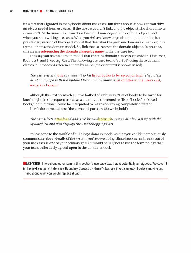
it’s a fact that’s ignored in many books about use cases. But think about it: how can you drivean object model from use cases, if the use cases aren’t linked to the objects? The short answeris you can’t. At the same time, you don’t have full knowledge of the eventual object modelwhen you start writing use cases. What you do have knowledge of at that point in time is apreliminary version of the object model that describes the problem domain in unambiguousterms—that is, the domain model. So, link the use cases to the domain objects. In practice,this means referencing the domain classes by name in the use case text.
Let’s say you have a domain model that contains domain classes such as Wish List, Book,Book List, and Shopping Cart. The following use case text is “sort of” using these domainclasses, but it doesn’t reference them by name (the errant text is shown in red):
The user selects a title and adds it to his list of books to be saved for later. The system
displays a page with the updated list and also shows a list of titles in the user’s cart,
ready for checkout.
Although this text seems clear, it’s a hotbed of ambiguity. “List of books to be saved forlater” might, in subsequent use case scenarios, be shortened to “list of books” or “savedbooks,” both of which could be interpreted to mean something completely different.
Here’s the corrected text (the corrected parts are shown in bold):
The user selects a Book and adds it to his Wish List. The system displays a page with the
updated list and also displays the user’s Shopping Cart.
You’ve gone to the trouble of building a domain model so that you could unambiguouslycommunicate about details of the system you’re developing. Since keeping ambiguity out ofyour use cases is one of your primary goals, it would be silly not to use the terminology thatyour team collectively agreed upon in the domain model.
■Exercise There’s one other item in this section’s use case text that is potentially ambiguous. We cover itin the next section (“Reference Boundary Classes by Name”), but see if you can spot it before moving on.Think about what you would replace it with.
CHAPTER 3 ■ USE CASE MODELING60
7745ch03final.qxd 12/13/06 8:29 PM Page 60
Win 8 64Bit VS7
Highlight
Win 8 64Bit VS7
Highlight

1. Reference Boundary Classes by NameSince you’re on a mission to write unambiguous behavior requirements, and since behaviorrequirements nearly always involve the user interface, it’s a good idea to not write vague andambiguous phrases like “The system displays a web page” in your use cases. Rather, nameyour screens explicitly—for example, “The system displays the Checkout page.”
In many cases, significant software behavior is related to initializing a page before display,and you need to write about this behavior as well: “The system displays the Checkout pageshowing the user’s default billing and shipping addresses.” Notice how the use case text is get-ting progressively less ambiguous!
Returning to the Wish List example, here’s how the text would appear once the boundaryclass is referred to by name (the corrected text is shown in bold):
The user selects a Book and adds it to his Wish List. The system displays the user’s WishList Page (which also shows the user’s up-to-date Shopping Cart).
Note that we’ve progressively squeezed ambiguity out of the use case by putting it in thecontext of the object model and the GUI.
Organizing Use Cases into Packages: Internet BookstorePretty soon we’re going to start writing some of the use cases for the Internet Bookstore. Butbefore we do that, we need some way of organizing all of these use cases. In a decent-sizedsystem, you could have anywhere from 100 use cases upward.
Luckily, the UML provides us with the package mechanism, which is a way of groupingrelated elements (e.g., classes, diagrams, or use cases). Packages are basically hierarchicalcontainers that can contain almost any UML constructs, including other packages. If you’rea Java programmer, UML packages are not entirely dissimilar to Java packages, in that theyallow you to divide your work broadly into different areas.
For the Internet Bookstore, Figure 3-5 shows a package diagram containing four packages.Each package contains lots of use cases. In addition, the shopping package contains an actor(Customer), and the admin package contains four actors (Customer Service, Seller, ShippingClerk, and Webmaster).
CHAPTER 3 ■ USE CASE MODELING 61
7745ch03final.qxd 12/13/06 8:29 PM Page 61

Figures 3-6 through 3-9 show the individual use case diagrams for each of the four pack-ages. You’ll notice that we haven’t bothered to pretty up the diagrams or even connect all theuse case bubbles with arrows. That’s because the more important part of the job is writing the use case text.
We do provide a brief discussion of the relationships that we’ve drawn in, but as you’llgather by the end of the discussion, we value what goes into the use case text much morethan the relationships between the use cases.
CHAPTER 3 ■ USE CASE MODELING62
Figure 3-5. Package diagram for the Internet Bookstore example
admin+ Customer Service
+ Seller
+ Shipping Clerk
+ Webmaster
+ Add Books to Catalog
+ Add Editorial Review
+ Add External Books to Catalog
+ Dispatch Order
+ Moderate Customer Reviews
+ Monitor Stock Levels
+ Order Books from Publisher
+ Process Refund
+ Remove Books from Catalog
+ Remove External Books from Catalog
+ Respond to Enquiry
+ Unlock Locked Account
general+ Add to Wish List
+ Cancel Order
+ Edit Shopping Cart
+ Login
+ Logout
+ Open an Account
+ Return a book
+ View Order History
+ Where's My Stuff?
searching+ Advanced Search
+ Search by Author
+ Search by Category
+ Search by Keyword
+ Search by Title
+ Search for Books
shopping+ Customer
+ Add Item to Shopping Cart
+ Checkout
+ Edit Shopping Cart
+ Enter Address
+ Pay by Card
+ Pay by Check
+ Pay by Purchase Order
+ Remove Item From Shopping Cart
+ View Recommendations
+ View Review
+ Write Reader Review
7745ch03final.qxd 12/13/06 8:29 PM Page 62

CHAPTER 3 ■ USE CASE MODELING 63
FACTORING OUT COMMON BEHAVIOR
The last thing you want to do when writing use cases is to repeat the same behavior multiple times. This is a horrendous waste of effort, which you don’t have time for, and one of the leading causes of analysisparalysis. So you need a mechanism for factoring this common behavior into its own use case. Our prefer-ence for this is an association called <<invokes>> and its partner-in-crime <<precedes>>.
Figure 3-7 has an arrow labeled “invokes” that points to Dispatch Order. You should read this in thedirection of the arrow—in other words, “Checkout invokes Dispatch Order.” It simply means that in thecourse of stepping through the Checkout use case, the Dispatch Order use case can be invoked.
You should mention the use case being invoked in the use case text; otherwise, the invokes relationshipwon’t make a lot of sense. So the use case description might say, “The user clicks the Confirm Order button;invoke Dispatch Order.”
The << and >>s are the UML notation for stereotypes. The stereotype is UML’s extension mechanism,so you can extend its core notation with your own semantics by assigning a stereotype to a UML element.
Figure 3-6. Use case diagram for the “general” package
Return a book
View Order History
Login
Logout
Where's My Stuff?Edit Shopping Cart
Add to Wish ListCancel Order
Open an Account
Customer
(from shopping)
7745ch03final.qxd 12/13/06 8:29 PM Page 63

WHAT ABOUT <<INCLUDES>> AND <<EXTENDS>>?
UML defines some standard stereotypes for moving between use cases (notably, <<includes>> and<<extends>>; more about the subtle distinction between these shortly). You read <<includes>> associa-tions in the direction of the arrow, while you read <<extends>> associations in the reverse direction.
It’s good practice to have your use cases reviewed by “non-UML-experts” like end users and marketingpeople (because they’re the ones who understand what the behavior should be). We’ve noticed that these folkssometimes get confused trying to read use case diagrams with some of the associations pointing forward andsome pointing backward. And, after working with use cases for 15 years or so, we’re convinced that thedetails inside the use cases are really the important bits, not the associations on the diagrams. You can thinkof <<invokes>> as a superset of <<includes>> and <<extends>>. If A invokes B, you can get to B from A,
CHAPTER 3 ■ USE CASE MODELING64
Figure 3-7. Use case diagram for the “admin” package
Shipping Clerk
Customer Service
Seller
Webmaster
Process Refund
ModerateCustomerReviews
Remove Booksfrom Catalog
Respond toEnquiry
Unlock LockedAccount
Dispatch Order
(from shopping)
Checkout Monitor StockLevels
Order Booksfrom Publisher
Add ExternalBooks to Catalog
Add EditorialReview
Add Books toCatalog
Remove ExternalBooks from
Catalog
«invokes»«invokes»
«invokes»
«invokes»
7745ch03final.qxd 12/13/06 8:29 PM Page 64

CHAPTER 3 ■ USE CASE MODELING 65
and the subtle details of inclusion and extension usually aren’t all that important to getting the job done (seethe sidebar titled “Use Cases and Aspects” later in this chapter for a case where those details are important).
Recall from Figure 3-7 that there is some sort of connection between Checkout and the use cases sur-rounding it. In Figure 3-8 (the complete version of that use case diagram) we’ve drawn in the relationshipsusing <<invokes>> arrows.
Figure 3-8. Use case diagram for the “shopping” package
Customer
Enter Address
Checkout
Pay by Check
Pay by Card
Add Item toShopping Cart
Remove ItemFrom Shopping
Cart
View ReviewEdit Shopping
CartView
Recommendations
Write ReaderReview
(from general)
Login
Pay by PurchaseOrder
«precedes»
«precedes»
«invokes»
«invokes»
«invokes»
«invokes»
7745ch03final.qxd 12/13/06 8:29 PM Page 65
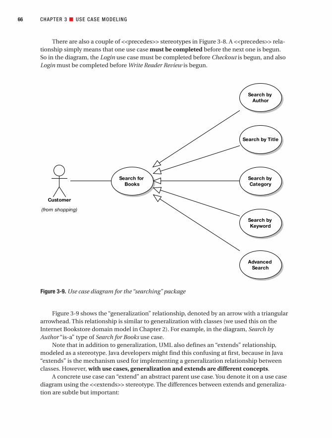
There are also a couple of <<precedes>> stereotypes in Figure 3-8. A <<precedes>> rela-tionship simply means that one use case must be completed before the next one is begun. So in the diagram, the Login use case must be completed before Checkout is begun, and alsoLogin must be completed before Write Reader Review is begun.
Figure 3-9 shows the “generalization” relationship, denoted by an arrow with a triangulararrowhead. This relationship is similar to generalization with classes (we used this on theInternet Bookstore domain model in Chapter 2). For example, in the diagram, Search byAuthor “is-a” type of Search for Books use case.
Note that in addition to generalization, UML also defines an “extends” relationship,modeled as a stereotype. Java developers might find this confusing at first, because in Java“extends” is the mechanism used for implementing a generalization relationship betweenclasses. However, with use cases, generalization and extends are different concepts.
A concrete use case can “extend” an abstract parent use case. You denote it on a use casediagram using the <<extends>> stereotype. The differences between extends and generaliza-tion are subtle but important:
CHAPTER 3 ■ USE CASE MODELING66
Figure 3-9. Use case diagram for the “searching” package
Search forBooks
Customer
(from shopping)
Search byAuthor
Search by Title
Search byCategory
Search byKeyword
AdvancedSearch
7745ch03final.qxd 12/13/06 8:29 PM Page 66

• Extends defines a set of extension points in the parent use case; generalization doesn’t.
• With extends, the parent must know that it’s going to be extended (in order to definethe extension points); this is not so with generalization.
• Extends adds to the parent’s functionality; generalization overrides it (i.e., totallyreplaces it, albeit with something similar).
However, our experience with generalization has been that it’s almost always of no valuewhatsoever in use case modeling. For example, in Figure 3-9, what do we gain from modelingthe different search use cases as types of an abstract Search for Books use case? Absolutelynothing! The reason we don’t gain anything from modeling this is because for our purposes,use cases are not classes, they’re fragments of a user guide.
■Tip If you think you might need to show use case generalization on your diagram, think of what youintend to do as “user guide generalization,” and hopefully (like us) you’ll then think, “Huh?!”
With class design, generalization is useful, because you can use it to factor out common-ality and eliminate duplicate code. However, with use cases, generalization doesn’t give youthis benefit. There are, however, other relationships that you can use to factor out commonal-ity, to avoid writing duplicate use case text. (See Table 3-1 in the next section.)
Our advice is to really not dwell on these different relationship types for very long, if atall. Imagine you’re doing some critical use case modeling with a roomful of expensive busi-ness consultants, and your main objective is to elicit all of the behavioral requirements fromthem. But the clock’s ticking before they all stampede out for their three-hour liquid lunchbreak. What’s more important: getting the notation exactly right, or extracting all the detailsthat you can from the consultants, while you have them in the room with you?
■Tip Remember, it’s what’s inside the use cases that counts, not the way they’ve been drawn together onthe use case diagram.
Use Case Relationship RoundupJust as the deck chairs on the Titanic could be arranged in different configurations, usecases can be related many different ways, the most common of which are listed in Table 3-1.Note that it’s perfectly acceptable to make hissing noises at the following table and to backcarefully away shouting, “Back, evil stereotype spirits!” Use case relationships have been thecause of many lost hours of valuable use case modeling time, as analysts argue heatedlyover which one would be best suited to put on their diagram next. Our own advice is simplyto pick one of these and stick with it, and to not worry too much about which ones to use.
CHAPTER 3 ■ USE CASE MODELING 67
7745ch03final.qxd 12/13/06 8:29 PM Page 67

■Tip We’ve found that 97.3% of the time, the <<invokes>> and <<precedes>> relationships work justfine for linking up use cases; the other relationships shown in Table 3-1 mostly aren’t needed.
For regular (non-aspect-oriented) OOAD, the important thing is that you’re showing thatthe use cases are logically related in some way, and the really important thing is what goesinside the use case descriptions, because that’s what you’ll be designing, testing, and estimat-ing from. You drive OOAD from class diagrams and sequence diagrams; the use cases drive thesequence diagrams. Therefore, the includes/extends construct is a distraction. It doesn’t buyyou anything, it slows you down, and it confuses readers of the use case model.
■Note There’s a big exception to our point about includes/extends being a distraction. If you’re going tostructure your code along use case boundaries via aspects, then suddenly the distinction between includesand extends becomes important. See the sidebar “Use Cases and Aspects” later in this chapter.
Table 3-1. Common Use Case Relationships
Relationship Description Most Effective Remedy
Generalization (denoted Use case B is a type of use case A➤(Think of Garlic placed around by an arrow pointing it as an “overrides” relationship, as the child the neck while sleepingfrom B to A, with a white use case inherits none of the steps of the triangle arrowhead) parent use case.)
A <<includes>> B Halfway through use case A, use case B is Silver bulletcalled. When B finishes, A carries on from where it left off. Most similar to a function call or a GOSUB in BASIC.➤A bit like saying “A has-a B.”
A <<extends>> B All the steps from use case A are performed Stake through the heartduring the execution of use case B, at the extension point which is specified within B.➤For the most part, <<extends>> is <<includes>> with a backward arrow. (Both are subtypes of invokes.)
A <<precedes>> B Use case A must take place in its entirety Holy waterbefore use case B even begins.
A <<invokes>> B Use case B happens during the lifespan of A nice cup of tea and a use case A. chocolate Easter egg
You might notice from Table 3-1 that all of these relationship types are remarkably simi-lar; they’re just subtly different enough to make them a real pain when people disagreeabout which one to use. In fact, we’re hoping that the (quite factual) description in the side-bar “Use Case Diagram Stereotypes As a Treatment for Insomnia” should help to persuadeyou that 99% of the time, the distinction between these relationships just isn’t important.
CHAPTER 3 ■ USE CASE MODELING68
7745ch03final.qxd 12/13/06 8:29 PM Page 68

CHAPTER 3 ■ USE CASE MODELING 69
USE CASE DIAGRAM STEREOTYPES AS A TREATMENT FOR INSOMNIA
If you’re worried about whether to use <<extends>>, <<includes>>, <<precedes>>, <<invokes>>, orgeneralization on your use case diagram, or if you’ve been having difficulty sleeping recently, this handy littlesidebar should help you to decide and/or help you doze off. Feel free to print this out on a postcard and placeit above your monitor:
The extending use case must define extension points where it may be extended, but the extended usecases must remain independent of the extending use cases, whereas including use cases do not defineextension points even though their behavior is extended by the included use case, which is similar to usecases using generalization, which also do not define extension points but their behavior is not extended bythe included use case per se—it’s overridden, as opposed to preceding use cases, which must take place intheir entirety before the child use case begins. The extends arrow MUST be drawn from the extended usecase to the extending use case in an analogous fashion to a generalization arrow being drawn from the sub-class toward its parent class, while an includes arrow is ALWAYS drawn from the including use case to theincluded use case in an analogous fashion to an aggregation arrow being drawn from the aggregate class tothe classes being aggregated. You may consider both includes and extends to be subtypes of invokes (that isto say, invokes includes extends and invokes also includes includes, but includes does not include invokes,nor does extends include invokes), with the distinction being all that stuff about extension points and whetherthe extended use case knows about the use case that’s extending it or not. If you think of a use case as afragment of a user guide, as opposed to thinking of it as a classifier, which is, of course, how it is formallydefined within the UML, you may discover that the difference between having extension points or simplyincluding the use case into which you will be branching is not particularly significant, in which case a simpleinvokes may suffice and you don’t have to worry about which way you should draw the arrow on the diagramsince the extends arrow points in the opposite direction from the includes arrow, in a similar manner to howa generalization and an aggregation arrow are drawn in opposite directions, more specifically the extendsarrow MUST be drawn from the extended use case to the extending use case in an analogous fashion to a generalization arrow being drawn from the subclass toward its parent class, while an includes arrow isdrawn from the including use case to the included use case in an analogous fashion to an aggregation arrowbeing drawn from the aggregate class to the classes being aggregated. The bottom up-arrow convention forextends being analogous to generalization may cause confusion between generalization and extends, espe-cially among Java programmers, to whom extends already means generalization. (Extends is a subtype ofinvokes, so you could say that extends extends invokes; but here we’re using extends in the generalizationsense, not in the UML extends sense, so it’s an extension of the extended OO terminology; but to say thatextends extends extends [but not a UML extends] would be extending the truth.) Additionally, when non-technical personnel are asked to review the use cases, they occasionally experience consternation whileattempting to follow the arrows on the use case diagrams, since some arrows point from the invoking usecase to the invoked use case, while others point from the invoked use case back toward the invoking usecase. This problem is generally indicative of a lack of UML training among nontechnical personnel and isreadily solved by forcing all users and marketing folks to attend a three-day “UML for nontechnical person-nel” workshop, which will educate them on these subtle yet critically important features of UML. Precedes,on the other hand, is a somewhat different stereotype than includes, invokes, or extends, in that it simplyindicates a temporal precedence; that is to say it is occasionally useful to indicate on a use case diagramthat use case A needs to happen BEFORE use case B (i.e., there is temporal precedence in which A MUSTOCCUR before B). Neither of the standard UML use case diagram stereotypes (i.e., neither includes norextends) provides a convenient mechanism for expressing this concept of temporal precedence (despite thefact that showing temporal precedence is often more useful than showing whether the invoked use case has
7745ch03final.qxd 12/13/06 8:29 PM Page 69

Internet Bookstore: Refining Use CasesIt’s high time that we wrote the use case description for our first Internet Bookstore use case.We’ll start with Write Reader Review, which over the course of the book we’ll follow all the wayto source code. (We’ll also track the progress of the Show Book Details use case, beginning inChapter 4.)
Checking the latest version of the domain model (see Figure 2-7), we have two types ofbook reviews: Reader Reviews (reviews submitted by Customers) and Editorial Reviews(reviews written by staff).
Here’s the first cut of our use case:
The user types in a review of the selected item, gives it a score, and sends it. The review is
sent to a moderator.
■Exercise The Write Reader Review use case scenario captures the basic points of the user’s interactionwith the system, but the text is rather terse. When it comes to writing text for use cases, a detailed descrip-tion is preferable to a terse one. We improve on our current version in just a moment, but first, have a look at the reader review process on existing bookstore websites (e.g., Amazon.com or SpringerOnline.com), andtry writing a more detailed version.
The text of your use case is important enough to take some care with. In particular, makesure that it’s in active voice (present tense, describing user actions and system responses, orvice versa) and that you explicitly name the domain objects that participate. Your goals are tounambiguously describe the required behavior of the system and to identify which domainobjects will be performing that required behavior.
CHAPTER 3 ■ USE CASE MODELING70
knowledge of the invoking use case or not), and so in these cases you MAY find it useful to label the arrowwith a stereotype of precedes. It is strongly recommended that in these cases the precedes arrow shouldoriginate from A (i.e., the preceding use case) and terminate with the arrowhead pointing at B (i.e., the usecase that has been preceded), lest you cause massive confusion among readers of the use case diagram.Precedes does not necessarily imply that the preceded use case has intimate knowledge of the precedinguse case, although in practice this is often the case, but the precedes stereotype simply indicates a temporalprecedence. The case has been made that it is possible to draw an equally valid use case diagram by revers-ing the direction of the arrow and changing the stereotype from precedes to invokes, but IN FACT themeaning is changed subtly by this action, in that the invokes arrow would generally indicate that the invokinguse case invokes the invoked use case during its execution, while the precedes arrow would indicate that thepreceding use case actually temporally precedes (that is to say, happens earlier in time) than the precededuse case.
Conclusion (assuming you’re still awake): Don’t worry about it, just focus on what goes inside theuse cases.
7745ch03final.qxd 12/13/06 8:29 PM Page 70

■Tip Any ambiguity you leave in a use case will just result in more disambiguation work later, so try to beas precise as you can in your descriptions.
Let’s now expand the use case text and put some meat on its bones:
The Customer selects the book. The system displays a book detail page. The Customer
clicks the Write Review button, and the system shows the Write Review screen. The user
types in a review of the book, gives it a rating out of five stars, and clicks the Send button.
The system ensures that the review isn’t too long or short, and that the rating is within
one and five stars. The system then displays a confirmation screen, and the review is sent
to a moderator, ready to be added.
With this new version, the narrative has begun slightly too early. By describing the eventsleading up to the Write Review page, we’re actually describing part of a different use case. Solet’s remove the duplicate text:
The Customer clicks the Write Review button for the book currently being viewed, and
the system shows the Write Review screen. The Customer types in a Book Review, gives it
a Book Rating out of five stars, and clicks the Send button. The system ensures that the
Book Review isn’t too long or short, and that the Book Rating is within one and five
stars. The system then displays a confirmation screen, and the review is sent to a Moder-
ator, ready to be added.
Reading through the use case, you can see how it relates back to the domain model.Objects such as Book Review and Book Rating, which appear on the domain model, are refer-enced explicitly by name in the use case. There’s a human actor named Customer, and we’vealso identified a new actor called Moderator (someone responsible for checking the reviewsbefore they are added). And there will also be some kind of Write Reader Review screen.
The updated use case also describes the validation that the system performs on the sub-mitted data (e.g., checking that the Book Rating is a legal value, within one and five stars). As you’ll see when we move on to robustness analysis in Chapter 5, describing the validationright in the use case text is an important method of identifying controllers.
One last thing: The actual name of the use case also needs some work. It’s called WriteReader Review, but in the domain model the name we have for the reader is Customer. So to keep the use case matched up with the domain model, we should change the title to WriteCustomer Review.
■Exercise One question that our use case hasn’t yet answered is, What happens if the Customer doessomething wrong? This important question is covered by exploring the alternate courses, which we coverin the next section. But before that, have another look at the use case text and try to think about the differentways that the Customer might stray off the beaten track.
CHAPTER 3 ■ USE CASE MODELING 71
7745ch03final.qxd 12/13/06 8:29 PM Page 71

Internet Bookstore: Basic and Alternate CoursesWithin the Write Reader Review use case, all the text we have at this point is for the basic course,such as “The Customer types in a Book Review, gives it a Book Rating out of five stars, and clicksthe Send button.” There’s an implicit assumption that the Customer has entered all the data forthe given review correctly—the review isn’t longer than The Lord of the Rings and War andPeace combined, the rating is in the range 1–5 (there may well be JavaScript validation in thebrowser, but the user could feasibly fiddle their local HTML page so that they can enter a 100-star rating, for example), and so forth. We should identify some alternate courses. Remember,keep asking yourself “What else happens?” Sort of like this:
We have our basic course. But, what else happens?
Uh . . . the user might not be logged in?
OK. And what else might happen?
The user might enter a review that is too long.
CHAPTER 3 ■ USE CASE MODELING72
SUNNY-DAY/RAINY-DAY SCENARIOS
A use case describes a sequence of events—the “flow” of a user’s interaction with the system. But usersoften don’t use a system as if they’re on rails. They do different or unexpected things, or the system might gowrong somehow (e.g., network error). But you have to ask yourself, “What happens if something goes wrong,or if the user does something out of the typical path?”
So, a use case consists of an “on rails” scenario and various “gone off the rails” scenarios.There’s one basic course (sometimes called the sunny-day scenario) and one or more alternate courses
(rainy-day scenarios) Alternates can represent less typical usage paths as well as errors.In their zeal to create a “use case guru” market by making the inherently simple task of modeling use
cases incomprehensively complex, some authors (you know who you are) have proposed long and compli-cated use case templates to follow when describing users interacting with the various scenarios of a system.Overly complicated use case templates usually just create unnecessary work; you end up trying to dreamdetails up (i.e., guess) to go into an array of subheadings that probably aren’t appropriate for your use caseanyway. (See the section “A Couple of Thoughts on Use Case Templates” later in this chapter.) So, our usecase “template” is really simple. It just consists of a “BASIC COURSE” heading and an “ALTERNATECOURSES” heading. Trust us, it’s all you need!
The important thing (well, one of them) is not to skip any of the rainy-day scenarios. Remember the“three magic questions” from earlier in this chapter? The third one to keep asking is “What else might hap-pen?” Each time you ask this question, the answer gets you a new alternate course for your use case. Write itdown under the “ALTERNATE COURSES” heading.
7745ch03final.qxd 12/13/06 8:29 PM Page 72

Cool. What else?
The review might be too short.
Too short?
Like, blank, or fewer than ten characters, say.
. . .and so on.
With these rainy-day scenarios typed up as alternate courses, our Write Reader Review usecase should now look like this:
BASIC COURSE:
The Customer clicks the Write Review button for the book currently being viewed, and
the system shows the Write Review screen. The Customer types in a Book Review, gives it
a Book Rating out of five stars, and clicks the Send button. The system ensures that the
Book Review isn’t too long or short, and that the Book Rating is within one and five
stars. The system then displays a confirmation screen, and the review is sent to a Moder-
ator, ready to be added.
ALTERNATE COURSES:
User not logged in: The user is first taken to the Login screen and then to the Write
Review screen once he is logged in.
The user enters a review that is too long (text > 1MB): The system rejects the review and
responds with a message explaining why the review was rejected.
The review is too short (< 10 characters): The system rejects the review.
■Exercise See if you can uncover some more alternate courses for this use case (there are plenty moreto be found!). If you’re stuck, read each line of the basic course and ask yourself, “How might this gowrong?” and “What might the user do differently here?”
CHAPTER 3 ■ USE CASE MODELING 73
7745ch03final.qxd 12/13/06 8:29 PM Page 73

A Couple of Thoughts on Use Case TemplatesTeams who adopt use cases usually do so because they are trying to “do the right thing.” Sothe natural assumption would be that they therefore need to bury the project under reamsof documentation, especially long and complex use case templates. Although well inten-tioned, this approach is—dare we say it—horribly misguided.
■Caution Don’t waste time with long and involved use case templates.
Here’s an example of a long and particularly ghastly (in our opinion) use case templatefrom renowned guru Alistair Cockburn’s book Writing Effective Use Cases:4
CHAPTER 3 ■ USE CASE MODELING74
USE CASES AND ASPECTS
Synergy between use case modeling and aspect-oriented programming (AOP) is the topic of Ivar Jacob-son’s book, Aspect-Oriented Software Development with Use Cases (Addison-Wesley, 2004). We highlyrecommend you give this book a careful read-through, but we would like to present the following briefintroduction to the material here. As it turns out, if you’re doing AOP, the difference between extends andincludes can be significant.
• Use cases help us to organize requirements around user concerns, while aspects help us to organizecode around user concerns.
• A pervasive problem in software development is cross-cutting concerns, which generally affect multi-ple classes and components. Examples of cross-cutting concerns would be things like security,transaction management, persistence, and so forth.
• There are two main types of cross-cutting concerns, and they can be modeled as use cases: peer usecases (separate, independent use cases) and extension use cases. Extension use cases can extendone use case (e.g., enhancements) or multiple use cases (e.g., security, transaction management, per-sistence). The latter are called infrastructure use cases.
• In traditional (non-aspect) languages, implementation of peers can become tangled and/or scatteredamong components, and it’s difficult to keep extension behavior separate from base behavior.
• Aspects help to organize peer code without scattering or tangling, and extensions can be kept separateusing pointcuts and advices.
In short, if you partition your software into use cases and choose to program in an aspect-oriented lan-guage, you can basically organize your code along use case boundaries, something you can’t readily do intraditional OO programming languages. Organizing code along use case boundaries has the potential formajor cost savings over the lifetime of a program.
4. Alistair Cockburn, Writing Effective Use Cases (New York: Addison-Wesley, 2000), p. 119.
7745ch03final.qxd 12/13/06 8:29 PM Page 74

USE CASE 24: FULLY DRESSED USE CASE TEMPLATE <NAME>
<the name should be the goal as a short active verb phrase>
Context of use: <a longer statement of the goal, if needed, its normal occurrence
conditions>
Scope: <design scope, what system is being considered black-box under design>
Level: <one of: summary, user-goal, subfunction>
Primary Actor: <a role name for the primary actor, or description>
Stakeholders & Interests: <list of stakeholders and key interests in the use case>
Precondition: <what we expect is already the state of the world>
Minimal Guarantees: <how the interests are protected under all exits>
Success Guarantees: <the state of the world if goal succeeds>
Trigger: <what starts the use case, may be time event>
Main Success Scenario:
<put here the steps of the scenario from trigger to goal delivery and any cleanup after>
<step #> <action description>
Extensions:
<put here there [sic] extensions, one at a time, each referring to the step of the main
scenario>
<step altered> <condition>: <action or sub use case>
<step altered> <condition>: <action or sub use case>
Technology & Data Variations List:
<put here the variations that will cause eventual bifurcation in the scenario>
CHAPTER 3 ■ USE CASE MODELING 75
7745ch03final.qxd 12/13/06 8:29 PM Page 75

<step or variation #> <list of variations>
<step or variation #> <list of variations>
Related Information:
<whatever your project needs for additional information>
We regard this template as ghastly because, while it is theoretically elegant in that itcomprehensively covers everything you might possibly want to discuss in conjunction witha use case, in practice, if you require your team to “fill out the long form” use case template,they will rapidly discover that
1. They are wasting time.
2. Wasting time will turn them off to the entire modeling process.
3. They can mindlessly fill out the form without focusing on the important parts (basiccourse and alternate courses) of the use case, and nobody will know the difference.
We’ve seen this happen in the real world on many occasions.Consider the statements we just made as warnings about ways you might build up resist-
ance to doing use cases, which offers an excuse to ditch modeling altogether—and we allknow what happens then. (Hint: “The code’s written, so I guess we’re done!”)
Use Case or Algorithm?Many people get confused over the difference between use cases and algorithms, as bothtend to be described with verb phrases and generally can be thought of as a sequence ofsteps. So here are some guidelines on how to differentiate between the two.
One of the main differences between a use case and an algorithm is that an algorithm,while it may contain a sequence of steps, will not represent the dialogue between a userand the system. From the use case perspective, even very complicated algorithms shouldjust be considered a single step within the user/system dialogue. If you’re faced with hav-ing to describe a complex algorithm when writing a use case (e.g., generating a list ofrecommended books, or sorting the list alphabetically), you should specify the algorithmelsewhere, but give the algorithm a name (e.g., “Generate Recommendations,” “Sort List”)so that it can be referred to in the use case text.
Table 3-2 sums up the differences between a use case and an algorithm.
CHAPTER 3 ■ USE CASE MODELING76
7745ch03final.qxd 12/13/06 8:29 PM Page 76

Table 3-2. Use Case vs. Algorithm
Use Case Algorithm
Dialogue between user and system “Atomic” computation
Event/response sequence Series of steps
Basic/alternate courses One step of a use case
Multiple participating objects Operation on a class
User and System All System
Use Case Modeling in PracticeIn this section, we illustrate the theory presented in the first part of this chapter by walkingthrough a series of exercises that show the most commonly made use case modeling mistakes.
ExercisesFor each of the following use cases, see how many errors you can spot, and try to rewrite theuse case text. Then compare your rewritten version with the “fixed” version found near theend of this chapter. Good luck!
Exercise 3-1: Search by Author
BASIC COURSE:
The system displays the page with the search form; the user clicks the Author field and types in an author name(e.g., Fred Smith). The user clicks the Search button; the system reads the search form, looks up any booksmatching that author name, and displays them in a list.
ALTERNATE COURSES:
No matching books found: A page is displayed informing the user that no matching books were found.
CHAPTER 3 ■ USE CASE MODELING 77
7745ch03final.qxd 12/13/06 8:29 PM Page 77

Exercise 3-2: Edit Shopping Cart
PRECONDITIONS:
The user has logged in.
The user has navigated to the Edit Shopping Cart page.
BASIC COURSE:
The user adds or removes whatever items he wants to change, and then clicks the Update button. The systemadds or removes the items, and then displays the page with the updated shopping cart.
ALTERNATE COURSES:
Shopping cart is empty: No items can be removed.
Exercise 3-3: Open an Account
BASIC COURSE:
The system displays the Create New Account page and enters the following fields: Username (must be unique),password, confirm password, first name, last name, address (first line), address (second line), city, state, country,zip/postal code, telephone number, and e-mail address. Then the user clicks the Submit button; the system checksthat the Username is unique, creates the new user account, and displays the main Hub Page, along with a mes-sage indicating that the user account is now created and logged in.
ALTERNATE COURSES:
Password and Confirm Password don’t match: The page is redisplayed with a validation message.
Username not unique: The page is redisplayed and the user is asked to choose a different username.
Exercise SolutionsFollowing are the solutions to the exercises.
Exercise 3-1 Solution: Explicit Boundary Object Names
The same problem can be found several times in this use case: the boundary objects haven’t been given explicitnames. The fixed version follows.
BASIC COURSE:
The system displays the Search Page; the user clicks the Author field and types in an author name (e.g., FredSmith). The user clicks the Search button; the system reads the search form, looks up any books matching thatauthor name, and displays the Search Results page showing the resulting Book List.
ALTERNATE COURSES:
No matching books found: The Search Not Found page is displayed.
CHAPTER 3 ■ USE CASE MODELING78
7745ch03final.qxd 12/13/06 8:29 PM Page 78

Exercise 3-2 Solution: Vague and Ambiguous
There are at least three problems with this use case.
Problem 1: The use case includes a “Preconditions” clause. Although on very rare occasions, you might find thatit’s useful to include this clause, most of the time it serves no appreciable purpose. In this example, it actuallythrows the use case text off course, as the initial “display” action is missed. This would in turn be missed out onthe robustness diagram, meaning it would likely be skipped on the design, not estimated for, and not tested.
Problem 2: The basic course text is a bit woolly. It doesn’t describe a specific scenario, but instead tries to coverall bases (“The user adds or removes whatever item . . .”). As a result, an important behavioral aspect is missed:the user wouldn’t necessarily want to add items from this page, just remove them (or change the quantity).
Problem 3: The alternate course doesn’t tie into any particular action in the use case text. There are also severalrelatively obvious alternate courses that are missing.
The fixed version follows.
BASIC COURSE:
The system displays the Shopping Cart page. The user clicks the Remove button next to a Line Item. The systemremoves the item from the user’s Shopping Cart, and then redisplays the page. The user then clicks the Quantitytext field for another Line Item, changes its value from 1 to 2, and clicks the Update button. The system updatesthe Shopping Cart, recalculates the total amount, and redisplays the page.
ALTERNATE COURSES:
Item not found: The item that the user chose to remove wasn’t found in the Shopping Cart (this could happen ifthe user had two browser tabs open and is viewing an older version of the page). The system refreshes the Shop-ping Cart page, along with a warning message that the user’s action failed because the page was out of date.
Quantity changed to zero: This counts as removing the item, so the item is removed from the Shopping Cart.
Negative value or non-numeric “value” entered: The page is redisplayed with the original Quantity value, and a message next to it informs the user that he entered an invalid value.
Exercise 3-3 Solution: Too Many Presentation Details
This use case gets bogged down in presentation details; it spends too long listing the fields to be found on the CreateNew Account page. Instead, these fields should be added as attributes to the appropriate class in your domain model(most likely the Customer class). Then, when you need them later, they’ll be right there. The fixed version follows.
BASIC COURSE:
The system displays the Create New Account page and enters the fields to define a new Customer account (user-name, password, address, etc.). Then the user clicks the Submit button; the system checks that the Username isunique, creates the new user account, and displays the main Hub Page, along with a message indicating that theuser account is now created and logged in.
ALTERNATE COURSES:
Password and Confirm Password don’t match: The page is redisplayed with a validation message.
Username not unique: The page is redisplayed and the user is asked to choose a different username.
CHAPTER 3 ■ USE CASE MODELING 79
7745ch03final.qxd 12/13/06 8:29 PM Page 79
Win 8 64Bit VS7
Highlight
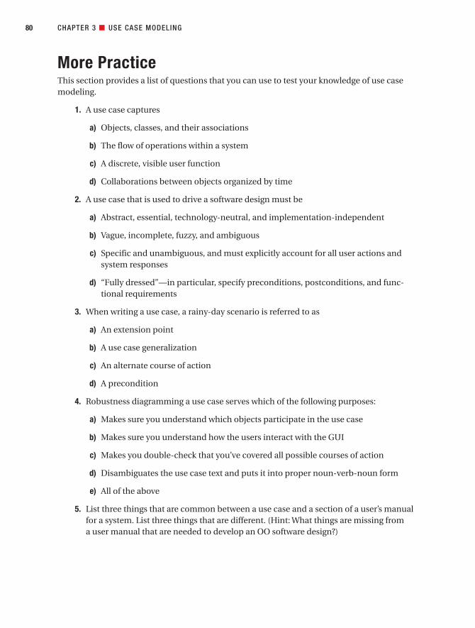
More PracticeThis section provides a list of questions that you can use to test your knowledge of use casemodeling.
1. A use case captures
a) Objects, classes, and their associations
b) The flow of operations within a system
c) A discrete, visible user function
d) Collaborations between objects organized by time
2. A use case that is used to drive a software design must be
a) Abstract, essential, technology-neutral, and implementation-independent
b) Vague, incomplete, fuzzy, and ambiguous
c) Specific and unambiguous, and must explicitly account for all user actions andsystem responses
d) “Fully dressed”—in particular, specify preconditions, postconditions, and func-tional requirements
3. When writing a use case, a rainy-day scenario is referred to as
a) An extension point
b) A use case generalization
c) An alternate course of action
d) A precondition
4. Robustness diagramming a use case serves which of the following purposes:
a) Makes sure you understand which objects participate in the use case
b) Makes sure you understand how the users interact with the GUI
c) Makes you double-check that you’ve covered all possible courses of action
d) Disambiguates the use case text and puts it into proper noun-verb-noun form
e) All of the above
5. List three things that are common between a use case and a section of a user’s manualfor a system. List three things that are different. (Hint: What things are missing from a user manual that are needed to develop an OO software design?)
CHAPTER 3 ■ USE CASE MODELING80
7745ch03final.qxd 12/13/06 8:29 PM Page 80

6. Attack or defend the following statement:
Long use case templates that include items like preconditions, postconditions, andfunctional requirements are a cause of analysis paralysis, and thus long templatesshould be avoided.
Cite the pros and cons of this argument, and explain your conclusion.
7. List three major differences between use cases and Extreme Programming (XP) userstories. What are the advantages of each?
8. Explain the difference between <<includes>> and <<extends>> according to the UMLspecification. In particular, attack or defend the following statement:
The difference between the <<includes>> and <<extends>> stereotypes on associa-tions on use case diagrams is not generally significant unless the software is to beimplemented using an aspect-oriented programming language that directly sup-ports organizing code around extensions.
How does the <<invokes>> stereotype relate to <<includes>> and <<extends>>? Whatis the primary purpose of all three of these stereotypes? Which do you feel are the moreuseful set of stereotypes: <<invokes>> and <<precedes>>, or <<includes>> and<<extends>>?
SummaryIn this chapter, we covered in detail how to write the kinds of use cases that can be used todrive a software design. The activity diagram in Figure 3-10 shows how use case modeling fitsinto the overall requirements analysis effort; the tasks we discussed in this chapter are shownin red.
At Milestone 1, you’ll have written the first-draft version of your use cases, having quizzedand grilled the customer, end users, and others to extract all the information you can fromthem about how the new system should behave. But the customer’s role doesn’t end there. Inthe next chapter, we cover the Requirements Review stage, in which you ensure that thedomain model and the use cases work together to address the customer’s requirements.
CHAPTER 3 ■ USE CASE MODELING 81
7745ch03final.qxd 12/13/06 8:29 PM Page 81

CHAPTER 3 ■ USE CASE MODELING82
Figure 3-10. Requirements Analysis Checkpoint 2
7745ch03final.qxd 12/13/06 8:29 PM Page 82

Requirements Review
The requirements review session ensures that the system as described genuinely matches up with the requirements. It’s a collaborative review session involving the customer represen-tative(s), end users (i.e., the people who will actually be using the system, or who are using thecurrent system being replaced), and marketing people—basically, all the project stakeholderswho have a vested interest in ensuring the requirements fit their view of the system.
In this chapter, we provide an overview of the Requirements Review stage, and then showan example review for the Internet Bookstore.
83
C H A P T E R 4
7745ch04final.qxd 12/13/06 8:31 PM Page 83

Requirements Review in TheoryIn this section, we look at the key elements of requirements review, including our top 10requirements review guidelines.
Why Review Requirements?Why bother reviewing requirements? Here’s a hypothetical conversation that we hope willshed some light on the subject.
Q: My project looks like it’s in pretty good shape already. I have a domain model thatI’ve updated as I wrote the use case descriptions, and my use cases are, for the mostpart, written in the context of the domain model. It must be time to start coding, right?(After all, I’ve never done this much up-front work pre-coding before.)
A: Well, almost, but not quite. The customer was involved in the initial requirements-gathering effort and hopefully also involved in your use case modeling workshop. But,now that the first-draft use cases are all written up, you need to get the customer back andmake sure that the system as described genuinely matches up with their requirements.
Q: That sounds like a tall order. My customer never even reads requirements specs—why should I waste time producing them?
A: If you e-mailed your customer a 200-page document and asked them to reply with a “Yes, please” or a set of required modifications, chances are that you’ll just get a “Yes,please” a few minutes later. Then, in a year’s time, the system you produce will benothing like what the customer wanted.
What’s needed (aside from breaking down the development into smaller releases) is tomake the sign-off process collaborative. You need to get the customer representativesinto the room for a requirements review session, and go through all of the use cases withthem.
There’s a whole set of techniques for doing these reviews that work pretty well in practice.We’ll demonstrate those in this chapter.
Q: But what if I can’t get the customer to visit me for the requirements review session?
A: Sure, all customers are infinitely busy. But if your customer won’t offer you even a cou-ple hours of their time before signing off on a costly IT project, then you’re probablyalready looking at a “death march” project, whatever process you follow. But at least wedon’t require the customer to be in the same room as the programmers for the full dura-tion of the project (like some “processes” we know)!1
84 CHAPTER 4 ■ REQUIREMENTS REVIEW
1. For a lyrical view of why this is a bad thing, see “The Customer’s a Beast of Burden” on page 120 of ourbook Extreme Programming Refactored: The Case Against XP (Apress, 2003).
7745ch04final.qxd 12/13/06 8:31 PM Page 84
Top 10 Requirements Review GuidelinesThe advice given in this chapter is summed up in our top 10 requirements review guidelines.
10. Make sure your domain model describes at least 80% of the most important abstrac-tions from your problem domain (i.e., real-world objects), in nontechnical languagethat your end users can understand.
9. Make sure your domain model shows the is-a (generalization) and has-a (aggregation)relationships between the domain objects.
8. Make sure your use cases describe both basic and alternate courses of action, in activevoice.
7. Make sure that passive voice, functional requirements (i.e., “shall” statements), are notabsorbed into and “intermangled” with the active voice use case text.2
6. Make sure you’ve organized your use cases into packages and that each package has at least one use case diagram.
5. Make sure your use cases are written in the context of the object model.
4. Make sure your use cases are written in the context of the user interface.
3. Make sure you’ve supplemented your use case descriptions with some sort of story-board, line drawing, screen mock-up, or GUI prototype.
2. Review the use cases, domain model, and screen mock-ups/GUI prototypes with endusers, stakeholders, and marketing folks, in addition to more technical members ofyour staff.
1. Structure the review around our “eight easy steps to a better use case.”
Let’s walk through these top 10 items in more detail, and then we’ll illustrate them inpractice by following a requirements review for the Internet Bookstore.
10. Make Sure Your Domain Model Covers the Problem DomainSometimes “the best is the enemy of the good.”3 You don’t want to spend endless weeks (andcatch a case of analysis paralysis) fiddling around with the domain model, trying to make itperfect. Instead, you should be aiming for the following:
• A domain model diagram that has the most important abstractions from the problemdomain
CHAPTER 4 ■ REQUIREMENTS REVIEW 85
2. In Chapter 13, we introduce the term “intermangled” to describe use case text that has had functionalrequirements text mangled into it.
3. General George S. Patton, War as I Knew It (New York: Mariner Books, 1995), p. 335 (referring to battleplanning).
7745ch04final.qxd 12/13/06 8:31 PM Page 85
• All the boxes on this diagram have unambiguous names that the users of the systemcan relate to
• Getting this diagram done quickly!
Further details will be uncovered as you analyze the use cases.
9. Show Generalization and Aggregation RelationshipsThese generalization (is-a) and aggregation (has-a) relationships go a long way toward makingthe diagram concrete and specific as opposed to vague and ambiguous.
Occasionally, you might need a “link class” (especially if you have underlying many-to-many relationships in the data model), but it’s best not to overuse this construct. You can getmost of the way just by using is-a and has-a.
Don’t split hairs (yet) between aggregation and composition, either—it’s too early toworry about this distinction.
8. Describe Both Basic and Alternate Courses of Action, in Active VoiceYou already know this, but the use cases describe how the users are using the system, in pres-ent tense, active voice, and they must include both normal (sunny day) usage as well as lesstypical (rainy day) usage.
We know that you already know this, but we’ve also seen many of your peers who (in the-ory) already knew, but didn’t do it correctly (in practice). So we’re telling you again. We mighttell you a couple more times, too.
7. Don’t Mix Functional Requirements into Your Use Case TextFunctional requirements are passive voice “shall” requirements (e.g., “The system shall dothis”). A common mistake is to include these in the use case descriptions. Instead, the func-tional requirements should be kept separately and “allocated” to the use cases. That is, theuse cases satisfy the functional requirements, but the passive voice “shall” requirementsdon’t compose the use cases. Keep the use cases focused on system usage (active voice).
In Chapter 13, we’ll show you how easy it is to allocate requirements to use cases. It’s justa single drag and drop if you do it correctly.
6. Organize Your Use Cases into PackagesYou can organize your use case model by functionally related areas (subsystems), by release,or both. One useful strategy is to identify all the use cases within a functional area on the usecase diagram, but write the narrative descriptions only for the use cases that will participate in the current release.
■Tip It’s useful to use color-coding on the use case diagram to show which use cases will be implementedin the current release.
CHAPTER 4 ■ REQUIREMENTS REVIEW86
7745ch04final.qxd 12/13/06 8:31 PM Page 86

By all means don’t get hung up on trying to perfect your use case diagram with a flawlessuse of stereotypes—here again, “the best is the enemy of the good” (i.e., you don’t have timeon your schedule for endless fiddling around). The use case diagram really serves as a visualtable of contents for the package, and so it should be clear and easy to understand, but thereal “meat” of the use case model is the text of the use cases and the corresponding robustnessand sequence diagrams for each use case.
5. Write Your Use Cases in the Context of the Object ModelBy far the most effective way to base your use cases on the domain model is to do the domainmodel first, and write the use cases to explicitly reference the domain objects by name.
Much of the ambiguity in use cases arises from the fact that they are often written entirelyin “user terms” without explicitly and precisely referring to the particular “problem domainelements” that are affected by the scenario in question. So the first step in disambiguatingyour use case text is to make that text explicitly refer to the appropriate domain objects.
4. Put Your Use Cases in the Context of the User InterfaceTo base your use cases on the user interface, name the screens that will participate in the usecase, and use those names in the use case text.
The use cases really need to link not only the object model but also the GUI model to thenarrative behavior descriptions. In practical terms, this usually means that you should nameyour screens explicitly and use those names in the use case text.
While there is a theory that preaches keeping your use cases completely divorced fromthe user interface, our experience is that in practice, this inevitably leads to vagueness andambiguity in the use cases. So name your screens. Trust us, you’ll need to give them namesanyway. You’ll be happy that you’ve named them. Really.
■Tip Name your screens, and use those names in your use case descriptions.
3. Use Storyboards, Line Drawings, Screen Mock-ups, or GUI PrototypesMake sure all of the user’s behavior (e.g., buttons they can click, menus they can pick from) is accounted for in the use cases.
Once you’ve given your screen a name, you have no excuse for not creating some sort ofstoryboard or mock-up that helps you to walk through the actions that users can take whenthey interact with the system. It’s amazing how much system behavior might be tied to, let’ssay, the Cancel button in, for example, a transaction-oriented system. You might have to rollback to the previously completed transaction. But if you don’t draw some sort of visual aidthat shows what’s on the screen, you might forget to write the “On Click Cancel” behavior inyour use case text. And you wouldn’t want to forget that, would you?
Remember that these mock-ups don’t need to be high-fidelity renderings with animatedbuttons (“the best is the enemy of the good,” again). They need to be simple, clear illustrationsthat focus on what system behavior can be triggered by the user, and they need to be quick tocreate (otherwise you’ll ignore our advice and skip drawing them—admit it!).
CHAPTER 4 ■ REQUIREMENTS REVIEW 87
7745ch04final.qxd 12/13/06 8:31 PM Page 87

■Tip Don’t be afraid to build some exploratory prototypes to help validate your requirements.
If you do have any exploratory prototypes, walk through them in conjunction withreviewing the use cases to gain insight into the required behavior. Sometimes a storyboardmight not be enough, and you want to string a few screens together before a presentation toyour users. If you need to do this, go right ahead.
2. Review the Behavioral Requirements with the Right PeopleReview the use cases, domain model, and screen mock-ups/GUI prototypes with end users,stakeholders, and marketing folks, in addition to more technical members of your staff. Makesure the requirements are well understood and agreed upon by all parties before proceedingtoward design.
Your requirements review is a collaborative workshop that should be attended by the cus-tomer (or representatives of the customer), the business analyst (i.e., the senior analystresponsible for the use cases), and a senior member of your development team, plus any proj-ect managers who will be closely involved in the project. Ideally, an actual end user of theproposed (or current) system should also be there, to provide real-world feedback on whetherthe new system matches up with what is really needed.
The goal of your requirements review session is to achieve basic agreement among allparties that the use cases capture the behavioral requirements of the system.4 And in order to achieve that goal, you must ensure that the required system behavior is unambiguouslyunderstood by all.5
In fact, you’re not just reviewing the use cases; you also need to review the domain modeland whatever prototype elements are in place. This works best when everyone is in a roomtogether, with a facilitator/moderator who keeps the conversations on track and a scribe whorecords the results and the action items.
Call us old-fashioned, but we’ve found that “ready-aim-fire” works better than “ready-fire-aim.” We’ve found over the years of doing Jumpstart training workshops that an amazingamount of understanding can be gained in a remarkably short period of time by gettingeverybody on the team to agree to a set of screens, a set of behavior descriptions that explainhow users will use those screens, and a set of objects that support the behavior descriptions.We haven’t met a project yet that didn’t benefit from a common understanding of thesethings, reached early in the life cycle of the project.
1. Structure the Review Around Our “Eight Easy Steps to a Better Use Case”Once you have everyone in the room, and they all understand why they’re there and what theymust achieve during the review session, then the following steps can be performed. As you’llsee shortly, these steps form the bulk of the review session:
CHAPTER 4 ■ REQUIREMENTS REVIEW88
4. Doug Rosenberg and Kendall Scott, Applying Use Case Driven Object Modeling With UML (New York:Addison-Wesley, 2001), p. 53.
5. Ibid.
7745ch04final.qxd 12/13/06 8:31 PM Page 88

1. Remove everything that’s out of scope.
2. Change passive voice to active voice.
3. Check that your use case text isn’t too abstract.
4. Accurately reflect the GUI.
5. Name participating domain objects.
6. Make sure you have all the alternate courses.
7. Trace each requirement to its use cases.
8. Make each use case describe what the users are trying to do.
These eight steps will help you transmogrify your use case from a vague and ambiguouspiece of mush to a razor-sharp, concise, and precise behavior specification. In the “Require-ments Review in Practice” section, we walk through an example requirements review thatillustrates most of these checks.
Allocating Functional Requirements to Use CasesAt some stage, you’ll need to link up the functional requirements to the use cases, so that youcan demonstrate that all the customer’s requirements have been successfully implemented.It’s good practice to do this just after you’ve written the use case descriptions, as the act ofallocating requirements to use cases often shows up some areas of the requirements thatmight have been left out. But if you don’t perform this activity at that stage, then you shoulddefinitely try to do this during the requirements review.
If you’ve used the functional requirements as the primary source of use cases, then thereshould already be a direct correlation between the requirements and the use cases. But forothers (e.g., use cases that were discovered from UI prototypes or legacy user manuals), somebackward-tracing (and possible updating of the functional requirements, in collaborationwith the customer) may need to be done.
In Chapter 13, we show an example of modeling the linkages between functional require-ments and use cases visually using the Enterprise Architect tool.
Requirements Review in Practice: Internet BookstoreIn this section, we illustrate the theory from the first part of this chapter, using an examplefrom our Internet Bookstore project. We’ll walk through an example review of the Show BookDetails use case (we provided a “critique” of the Write Customer Review use case in Chapter 3).
For the Internet Bookstore requirements review, we’ll follow the reviewer/use case analystconversation as it unfolds in the following subsections.
CHAPTER 4 ■ REQUIREMENTS REVIEW 89
7745ch04final.qxd 12/13/06 8:31 PM Page 89

■Note As described earlier, the requirements review should include at least one customer representative,the business analyst, a senior member of your development team, an end user, and any managers closelyinvolved in the project. For the purposes of this example, and to keep the dramatis personae from runningrampant, we’re only following the conversation between the business analyst and a reviewer (who alsodoubles as a process mentor).
Removing Everything That’s Out of ScopeA common affliction when specifying behavioral requirements is to begin or end each usecase in the wrong place, or to include extra information that’s way outside the scope of thesimple use case being described. What follows is an extreme, but all too familiar, example.
Analyst: Here’s the text for Show Book Details:
USE CASE: Show Book Details
LEVEL: User Goal
PRECONDITIONS:
1. The user MUST be viewing the website.
2. The user MAY be logged in.
BASIC COURSE:
If the user has an account, he MAY log in first (though this isn’t essential for this use
case). The user MAY navigate to the website’s main area. This area MUST be easily
accessible and SHOULD provide easy access to a search area and various book direc-
tories (e.g., top 10 bestsellers in different categories, editors’ picks, etc.). Then the user
browses the details for a book title. The system displays the screen showing the book
information. If the user wishes to, he may proceed to purchase the book. Allowed pay-
ment options are as follows: Visa, American Express, and check (the check must be
received by the billing department before the order is dispatched).
POSTCONDITIONS:
1. The Book Details screen is being shown.
2. The details for the selected book have been retrieved.
CHAPTER 4 ■ REQUIREMENTS REVIEW90
7745ch04final.qxd 12/13/06 8:31 PM Page 90

Reviewer: (Silently, to self) Oh, sweet mother of our great Lord Cthulhu. Where to begin?
Analyst: I’m actually quite proud of this use case, as I’ve packed in loads of extra detailaround the subject matter.
Reviewer: Well, there are several ways this use case could be improved. We’ll take them oneat a time. To summarize, though, we can shorten the template and move those precondi-tions and postconditions out of the use case text. Remember the purpose of these use cases:we want to be able to link them to our classes, so that we can drive the design directly fromthe use case text. So things like preconditions and postconditions aren’t needed.
Analyst: But hang on, the preconditions are important. They describe things that must bein place before the use case can proceed.
Reviewer: You’re absolutely right that the information they contain is important, and itdoes need to be recorded somewhere. But the preconditions and postconditions describestuff outside the scope of this use case. Most of the time, you can just delete them fromthe use case text, and you won’t lose anything. If you must show them, it’s better to showthe ordering on the use case diagram with a <<precedes>> link between the two usecases.
Analyst: So you could have a Login use case that precedes Show Book Details.
Reviewer: Yep. You could also lose the Level field at the top of the use case template, as it doesn’t achieve a huge amount. So that gives us the following:
BASIC COURSE:
If the user has an account, he MAY log in first (though this isn’t essential for this use
case). The user MAY navigate to the website’s main area. This area MUST be easily
accessible and SHOULD provide easy access to a search area and various book direc-
tories (e.g., top 10 bestsellers in different categories, editors’ picks, etc.). Then the user
browses the details for a book title. The system displays the screen showing the book
information. If the user wishes to, he may proceed to purchase the book. Allowed pay-
ment options are as follows: Visa, American Express, and check (the check must be
received by the billing department before the order is dispatched).
Reviewer: That’s much more concise and, if you think about it, doesn’t actually conveyany less information. But it’s still a long way from being the kind of use case we need. Forone thing, the description still goes outside the use case’s scope. Remember, we’re onlyconcerned with describing the steps involved to view a book’s details. So all the stuffabout proceeding to purchase the book is irrelevant. It all really belongs in a different usecase.
CHAPTER 4 ■ REQUIREMENTS REVIEW 91
7745ch04final.qxd 12/13/06 8:31 PM Page 91

Analyst: OK, so if we move that stuff out, then we’re left with this:
BASIC COURSE:
The user MAY navigate to the website’s main area. This area MUST be easily accessible
and SHOULD provide easy access to a search area and various book directories (e.g.,
top 10 bestsellers in different categories, editors’ picks, etc.). Then the user browses the
details for a book title. The system displays the screen showing the book information.
Reviewer: Yes. Those other steps are important, of course, but they just belong in a differ-ent use case.
Naming Participating Domain ObjectsWhen you try to drive an object-oriented design from use cases, it’s vital that the use cases arelinked to the objects. In the next review segment, our reviewer discovers a major disconnectbetween the use case text and the objects in the domain model.
Reviewer: This is a critical point. Most of this text doesn’t match up with the domainmodel. That’s just inviting trouble, because we’ll end up talking at cross-purposes, thedesigners will add in duplicate classes, and so on.
Analyst: I didn’t think it was that bad. Can you give me some examples?
Reviewer: Sure. Let’s take a look at the first sentence: “The user may navigate to the web-site’s main area.” The domain model doesn’t have a “user,” but it does have a Customer.And instead of saying “website” you should really say Bookstore. Keep it consistent.
Analyst: OK . . .
Reviewer: Similarly, later on you have “book directories,” but in the domain model wehave “Book Lists” (see Figure 2-7). More precisely, we have an abstract Book List class,with concrete types called Wish List, Recommendation List, Related Books, and so on. It looks as if we could add another Book List type called, say, Bestseller List, or maybeHome Page List, to represent lists of books that appear on the Bookstore's home page.
Analyst: OK, I see what you’re getting at. We also have “book information” in the finalsentence. Perhaps that should match up with a domain object as well?
Reviewer: Well, since the use case is called Show Book Details, we could have an objectcalled Book Details. But really, that’s what the Book domain object is. So, for consistencywe could reword “showing the book information” to be “showing the Book Details.”Anyway, here’s the updated text:
BASIC COURSE:
The Customer MAY navigate to the Bookstore’s main area. This area MUST be easily
accessible and SHOULD provide easy access to a search area and various Bestseller
Lists. Then the Customer browses the details for a book title. The system displays the
screen showing the Book Details.
CHAPTER 4 ■ REQUIREMENTS REVIEW92
7745ch04final.qxd 12/13/06 8:31 PM Page 92

Making Sure You Have All the Alternate CoursesWhen you decompose a system along usage scenario boundaries, it’s a good idea to considernot just sunny-day scenarios (the basic course) but also rainy-day scenarios (the alternatecourses)—at least if you’re planning to build a robust system. While some methodologies offermantras such as Do The Simplest Thing That Could Possibly Work (DTSTTCPW) and YouAren’t Gonna Need It (YAGNI), our experience has been that these philosophies, when takenliterally, and especially when combined together, can often lead to disastrous results. Themain reason for this is that well over half of the complexity of a software project is usuallycaused by dealing with alternate courses of action. Failure to build adequate infrastructureto account for the rainy-day behavior is simply unacceptable on many industrial-strengthsoftware projects. So, make sure you’ve accounted for all the alternate courses of action.
Reviewer: I couldn’t help noticing that this use case has no alternate courses. I guess thatthe main alternate course is just what happens if the book details aren’t found. Let’s addthat at least:
ALTERNATE COURSES:
Book not found: The system displays a Book Details Not Found screen.
Reviewer: Notice that we’ve just identified a new screen, or page.
Analyst: Handling a book not found is a fairly obvious one, I suppose. But now that youmention it, there are several other parts of the system where we could identify all sorts of“special cases.” That adds up to a lot of missing functionality.
Reviewer: And all that functionality would have been missed when you estimate how longit’s all going to take to develop. Plus it would have been missed when you wrote the testcases, did the design, and so on . . .
■Tip If you see a use case without any alternate courses, alarm bells should start ringing. It’s often a tell-tale sign that the user and system behavior for that use case haven’t been explored in sufficient depth.
Checking That the Use Case Text Isn’t Too AbstractMany books about use cases, especially those that are focused strictly on use cases as arequirements definition technique, preach writing use cases that are “abstract, essential,technology-free, and implementation-independent.” Our approach is a bit different, asyou’ll see in the following review segment, since we both come from a programming back-ground (most programmers would call the aforementioned use cases “vague, ambiguous,incomplete, and incorrect”).
CHAPTER 4 ■ REQUIREMENTS REVIEW 93
7745ch04final.qxd 12/13/06 8:31 PM Page 93
Reviewer: The original text did get quite abstract in places, although we seem to havedeleted most of it now. But there are a couple of things we could improve on, such as,what’s a bookstore main area?
Analyst: The home page, I guess.
Reviewer: Actually, while we’re at it, “browses the details for a book title” is a bit vague. Infact, the sentences around it seem rather strange:
Then the Customer browses the details for a book title. The system displays the screen
showing the Book Details.
Analyst: Should that change to “displays the Book Details screen”?
Reviewer: I think what we’re missing here is the whole user action/system response thing.The use case isn’t describing the user’s action followed by the system’s response to thataction. So those two sentences should be
Then the Customer clicks a link to view a Book. The system retrieves the Book details
and displays the Book Details screen.
Reviewer: That’s much more specific. It describes exactly how the customer interacts withthe UI: clicking a link to view a book. And then it describes precisely what the system doesin response. This is the kind of use case text that can be designed from. Let’s go throughthe rest of the text and make it all follow the same user action/system response pattern.
BASIC COURSE:
The Customer MAY navigate to the Bookstore’s main area, which the system displays.
This area MUST be easily accessible, and SHOULD provide easy access to a search
area and various Bestseller Lists). Then the Customer clicks a link to view a Book. The
system retrieves the Book details and displays the Book Details screen.
ALTERNATE COURSES:
Book not found: The system displays a Book Details Not Found screen.
Analyst: So why is this version better?
Reviewer: Well, it still isn’t perfect (we’ll fix the remaining problems in a moment). But it’sin a much better state, where we could hand this to the programmers and reasonably askthem to create a design from it. You want to avoid writing use cases that are abstract,essential, technology-free, or implementation-independent.
CHAPTER 4 ■ REQUIREMENTS REVIEW94
7745ch04final.qxd 12/13/06 8:31 PM Page 94

Analyst: Hey, but I just read a book on use cases that specifically told me to write usecases that are abstract, essential, technology-free, and implementation-independent.
Reviewer: Surprisingly, yes, it’s depressingly common advice. But think about what hap-pens when you hand that abstract, vaguely written use case to a programmer. Wouldn’t it be better if the use case was coherent, specific, and unambiguous? That’s the sort of usecase that can be coded from!
Changing Passive Voice to Active VoiceGenerally, passive voice statements describe requirements. Some people like to “intermangle”the passive voice requirements with the active voice usage descriptions (see the sidebar titled“Disintermangling Dysfunctional Requirements from the Scenario Text” in Chapter 13). Weadvocate linking the requirements to the use cases and keeping the active voice description(which becomes a runtime behavior specification) separate. As you’ll see in the followingreview segment, activities are much more effectively described in active voice.
Reviewer: We’re getting there. There’s a lot of passive voice text in there, though: “The Cus-tomer MAY navigate . . . SHOULD provide easy access . . .” These sound like functionalrequirements to me. They definitely don’t belong in a use case.
Analyst: But we can’t just delete this stuff. I wrote those details in there because they’reimportant!
Reviewer: Agreed. The goal here isn’t to delete important requirements—it’s just to makesure that they get recorded in the appropriate place. In this case, that will be the func-tional requirements spec, not the use case.
Analyst: I’m still not convinced that we can’t just describe these details in the use case itself.
Reviewer: Think about it this way. “Use case” is a shorter way of saying “usage scenario”—that is, a scenario that describes how the user is interacting with the system. The key wordhere is “interacting.” Describing user interactions and system responses is by its verynature a description of the user’s activities. Can we describe activities in passive voice?Not really. “Shall” statements such as “the system shall support 300 concurrent transac-tions per minute” don’t describe user actions or system responses.
Analyst: I see. So if we mix those “shall” statements into the use case, it’s really defeatingthe purpose of the use case format.
Reviewer: You got it. OK, here’s the reviewed and updated text for Show Book Details:
BASIC COURSE:
The Customer types in the URL for the bookstore’s home page, which the system dis-
plays. Then the Customer clicks a link to view a Book. The system retrieves the Book
details and displays the Book Details screen.
CHAPTER 4 ■ REQUIREMENTS REVIEW 95
7745ch04final.qxd 12/13/06 8:31 PM Page 95

ALTERNATE COURSES:
Book not found: The system displays a Book Details Not Found screen.
Analyst: Actually, in retrospect, perhaps we should have made the active voice changeright at the start of the review.
Reviewer: I think you’re right. Out of all these steps, it’s the one that helped clean up theuse case text the most, so doing it at the start would have made a lot of other things fallright into place early on. That plus the “remove everything that’s out of scope” step.
■Note ICONIX Process is an intensely feedback-driven process. In the next chapter, we cover robustnessanalysis, in which the use case text gets even more of a going-over, to prepare it for the design stage.
Tracing Each Requirement to Its Use CasesWe once read a newsgroup posting by a famous and self-important “guru” that asked thequestion “Why would anybody want to trace requirements?” and then went on to profess thatrequirements traceability was all a matter of “fear” (see the inside front cover of Extreme Pro-gramming Refactored: The Case Against XP [Apress, 2003] if you’d like to find out who said it).
Our feeling about this is that it would be funny if it wasn’t so sad. In the world we live in,project teams trace requirements (for example) to make sure that they are fulfilling their con-tractual obligations, which then allows them to get paid for delivering what the client ordered.If you’re going to describe the functionality being delivered as a set of use cases, it would seempretty obvious that those requirements would need to be traced back to the use cases. In ourfinal requirements review segment, we show how this process could be started (see Chapter 13for more about traceability).
Reviewer: OK, let’s do a final check of the Show Book Details use case. Currently, we don’thave a traceability matrix to show which requirements are satisfied by this use case, so weshould sort that out.
■Tip As we discuss in Chapter 13, the Enterprise Architect (EA) tool has a useful Relationship Matrix fea-ture for tracing between requirements and use cases, among other model elements (see Figure 13-10).
Analyst: Well, we were meant to go through the use cases earlier on and allocate them tothe functional requirements. (See Figure 3-10 and the section “Allocating FunctionalRequirements to Use Cases” in this chapter.) But as we didn’t do that then, we shouldreally do it now.
CHAPTER 4 ■ REQUIREMENTS REVIEW96
7745ch04final.qxd 12/13/06 8:31 PM Page 96

Reviewer: OK. So, looking at the requirements list (see Chapter 2), Show Book Detailspretty clearly relates back to these requirements:
11. It must be possible for the user to post reviews of their favorite books; the reviewcomments should appear on the book details screen. The review should include a
customer rating (1–5), which is usually shown along with the book title in book lists.
a. Book reviews must be moderated—that is, checked and “OK’d” by a member of
staff before they’re published on the website.
b. Longer reviews should be truncated on the book details screen; the customermay click to view the full review on a separate page.
Analyst: What about requirement number 1?
1. The bookstore will be web based initially, but it must have a sufficiently flexible
architecture that alternative front-ends may be developed (Swing/applets, web serv-
ices, etc.).
Reviewer: Strictly speaking, all the use cases could be traced back to that one, althoughthere isn’t a very concrete connection there. We’re really looking for functional linksbetween the use cases and the requirements.
Analyst: Ah, OK.
SummaryIn this chapter, we covered the Requirements Review milestone. It’s a vital step because itensures that the requirements are sufficiently well understood by both the developmentteam and the customer/users/project stakeholders.
In the next chapter, we launch into preliminary design, a step that provides intensivefeedback into the use cases and domain model, and an essential bridge between analysisand design.
Figure 4-1 shows where we are. (The item covered in this chapter is shown in red.)
CHAPTER 4 ■ REQUIREMENTS REVIEW 97
7745ch04final.qxd 12/13/06 8:31 PM Page 97
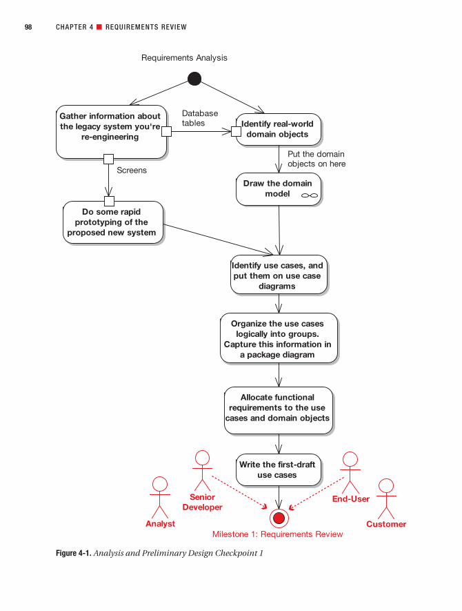
CHAPTER 4 ■ REQUIREMENTS REVIEW98
Figure 4-1. Analysis and Preliminary Design Checkpoint 1
7745ch04final.qxd 12/13/06 8:31 PM Page 98

Analysis, ConceptualDesign, and TechnicalArchitecture
P A R T 2
7745ch05final.qxd 12/14/06 11:24 AM Page 99

7745ch05final.qxd 12/14/06 11:24 AM Page 100

Robustness Analysis
To get from use cases to detailed design (and then to code), you need to link your use cases to objects. The technique we describe in this chapter, robustness analysis, helps you to bridgethe gap from analysis to design by doing exactly that. In a nutshell, it’s a way of analyzing youruse case text and identifying a first-guess set of objects for each use case. These are classifiedinto boundary objects, entity objects, and controllers (which are often more like functionsthan objects).
The 10,000-Foot ViewA robustness diagram is an object picture of a use case. The robustness diagram and the usecase text have to match precisely, so the robustness diagram forces you to tie the use case textto the objects. This enables you to drive object-oriented designs forward from use cases, andthis is really the “magic” of robustness analysis.
101
C H A P T E R 5
7745ch05final.qxd 12/14/06 11:24 AM Page 101

Drawing a robustness diagram ensures that the use case is written in the context of thedomain model—that is, all the terms (nouns and noun phrases) that went into the domainmodel should also be used directly in your use case text.
Where Does Robustness Analysis Fit into the Process?Looking at Figure 5-1, robustness analysis sort of takes place in the murky middle groundbetween analysis and design. If you think of analysis (i.e., the use cases) as the “what” anddesign as the “how,” then robustness analysis is really preliminary design. During this phase,you start making some preliminary assumptions about your design, and you start to thinkabout the technical architecture (also see Chapter 7) and to think through the various possi-ble design strategies. So it’s part analysis and part design.
It’s also an important technique to remove ambiguity from (disambiguate) your use case text.
Like Learning to Ride a BicycleLearning this technique has a bit in common with learning to ride a bicycle. Until you “get it,”robustness analysis can seem devilishly difficult, but once you do get it, it’s really very simple.To jump-start your understanding, we’ll walk through plenty of examples in this chapter.Experience has shown us that you usually need to draw six or so robustness diagrams beforethe penny drops and you suddenly get it. Just remember, a robustness diagram is an objectpicture of a use case.
Once you get the hang of it, you should be able to rattle off a robustness diagram in aboutten minutes (or less) for each use case. Actually, as you’ll see, the trick is in writing your usecase correctly. If a robustness diagram takes more than ten minutes to draw, you can betyou’re spending most of that time rewriting your use case text.
■Tip Using a CASE tool can make your life easier, but robustness diagrams are really quick and simplediagrams that you can scribble on a piece of paper or a whiteboard. It’s often very helpful to sketch yourdiagram on paper before attempting to draw it on the computer (especially when you’re first learning thetechnique).
102 CHAPTER 5 ■ ROBUSTNESS ANALYSIS
Figure 5-1. Bridging the gap between “what” and “how”
7745ch05final.qxd 12/14/06 11:24 AM Page 102

Anatomy of a Robustness DiagramA robustness diagram is somewhat of a hybrid between a class diagram and an activity dia-gram. It's a pictorial representation of the behavior described by a use case, showing bothparticipating classes and software behavior, although it intentionally avoids showing whichclass is responsible for which bits of behavior. Each class is represented by a graphical stereo-type icon (see Figure 5-2). However, a robustness diagram reads more like an activity diagram(or a flowchart), in the sense that one object “talks to” the next object. This flow of action isrepresented by a line between the two objects that are talking to each other.
There’s a direct 1:1 correlation between the flow of action in the robustness diagram andthe steps described in the use case text.
The three class stereotypes shown in Figure 5-2 are as follows:
• Boundary objects: The “interface” between the system and the outside world (thinkback to Figure 3-2). Boundary objects are typically screens or web pages (i.e., the pres-entation layer that the actor interacts with).
• Entity objects: Classes from the domain model (see Chapter 2).
• Controllers: The “glue” between the boundary and entity objects.
It’s useful to think of boundary objects and entity objects as being nouns, and controllersas being verbs. Keep the following rules in mind when drawing your robustness diagrams:
• Nouns can talk to verbs (and vice versa).
• Nouns can’t talk to other nouns.
• Verbs can talk to other verbs.
We’ll revisit these rules later in this chapter (see Figures 5-8 and 5-9).
CHAPTER 5 ■ ROBUSTNESS ANALYSIS 103
Figure 5-2. Robustness diagram symbols
7745ch05final.qxd 12/14/06 11:24 AM Page 103

■Exercise Two of the following are legal constructs, but which two?
a. Boundary ➤ Controller ➤ Entity
b. Entity ➤ Entity
c. Controller ➤ Controller
d. Boundary ➤ Boundary ➤ Controller
These rules help to enforce a noun-verb-noun pattern in your use case text. If your usecase text follows this pattern, robustness diagrams are a snap to draw; if not, the diagrams canbe really difficult to draw.
Think of this as an early warning signal: if you can’t draw a simple ol’ robustness diagramfrom a use case, how are you ever going to create a detailed design from it? Sequence diagramsare completely noun-verb-noun in nature: the objects are the nouns, and the messages thatgo between them are the verbs. So by getting your text in noun-verb-noun format now, you’remaking the detailed design task much easier than it would otherwise be.
Robustness analysis provides a sanity check for your use cases.
Robustness Analysis in TheoryIn this section, we describe the theory behind robustness analysis, interspersed with exam-ples from the Internet Bookstore project. We’ll begin with our top 10 robustness analysisguidelines.
Top 10 Robustness Analysis GuidelinesThe principles discussed in this chapter can be summed up as a list of guidelines. Our top 10list follows.
10. Paste the use case text directly onto your robustness diagram.
9. Take your entity classes from the domain model, and add any that are missing.
8. Expect to rewrite (disambiguate) your use case while drawing the robustness diagram.
7. Make a boundary object for each screen, and name your screens unambiguously.
6. Remember that controllers are only occasionally real control objects; they are moretypically logical software functions.
5. Don’t worry about the direction of the arrows on a robustness diagram.
4. It’s OK to drag a use case onto a robustness diagram if it’s invoked from the parent usecase.
CHAPTER 5 ■ ROBUSTNESS ANALYSIS104
7745ch05final.qxd 12/14/06 11:24 AM Page 104

3. The robustness diagram represents a preliminary conceptual design of a use case, nota literal detailed design.
2. Boundary and entity classes on a robustness diagram will generally become objectinstances on a sequence diagram, while controllers will become messages.
1. Remember that a robustness diagram is an “object picture” of a use case, whosepurpose is to force refinement of both use case text and the object model.
Let’s walk through the items in this list in more detail.
10. Paste the Use Case Text Directly onto Your Robustness DiagramDoing this really helps to reinforce the fact that you’re drawing an object picture of the eventsdescribed in the use case. Plus, you’ll work through the use case a sentence at a time as youdraw the diagram, so it’s handy to have the text nearby.
Figure 5-3 shows an example work-in-progress robustness diagram for the Internet Book-store, for the Login use case. This is a snapshot of the diagram in its early stages. So far, onlythe first few sentences of the use case have been drawn onto the diagram.
In Figure 5-3, the use case text has been pasted directly into a note on the diagram. Because the robustness diagram is essentially a pictorial representation of the use case, it helpsto have the text right there on the diagram: they’re two different views of the same thing, so youshould be able to walk through the text and trace it on the diagram (and vice versa).
■Tip Using a CASE tool such as EA, it’s possible to create a live link between the use case and the note onthe robustness diagram, so that if the use case is updated, the note on the diagram is updated automatically.
■Exercise We show the completed version of this diagram later, in Figure 5-5. But before you take alook, try completing the diagram, following the example of the controllers and message arrows that we’veadded so far in Figure 5-3. Simply follow the use case text, and draw the literal interpretation into the dia-gram (without trying to think about design details. Remember, you’re not doing a real OO design yet—you’re doing just enough preliminary design to validate that you understand the use case).
(Hint: It’s early days yet, as we’ve only barely introduced the basic concepts, so expect to make somemistakes. But don’t be discouraged; the intention here is simply to give it a try, and then think about thediagram that you drew while you read the next few pages.)
CHAPTER 5 ■ ROBUSTNESS ANALYSIS 105
7745ch05final.qxd 12/14/06 11:24 AM Page 105

9. Take Your Entity Classes from the Domain Model, and Add Any That Are MissingMost of the entities on your robustness diagram will come from your domain model. However,since you time-boxed your initial domain modeling effort at a couple of hours, it’s natural toexpect that you might be missing some domain classes. When you’re drawing robustness dia-grams and this happens, make sure you add the missing classes into the domain model.
ICONIX Process assumes that your initial domain model will be incomplete and expectsthat missing objects will be discovered during robustness analysis. In this book, we refer tothis process as object discovery.
CHAPTER 5 ■ ROBUSTNESS ANALYSIS106
Figure 5-3. Partially completed robustness diagram with the use case text pasted in
BASIC COURSE:
The user clicks the login link from
any of a number of pages; the
system displays the login page.
The user enters their username
and password and clicks Submit.
The system checks the master
account list to see if the user
account exists. If it exists, the
system then checks the
password. The system retrieves
the account information, starts an
authenticated session, and
redisplays the previous page with
a welcome message.
ALTERNATE COURSES:
User forgot the password: The
user clicks the What's my
Password? link. The system
prompts the user for their
username if not already entered,
retrieves the account info, and
emails the user their password.
Invalid account: The system
displays a message saying that
the "username or password" was
invalid, and prompts them to
reenter it.
Invalid password: The system
displays a message that the
"username or password" was
invalid, and prompts them to
reenter it.
User cancels login: The system
redisplays the previous page.
Third login failure: The system
locks the user's account, so the
user must contact Customer
Support to reactivate it.
User
Login page
Display login page
Enter username and
password
Does account exist?
click submit
7745ch05final.qxd 12/14/06 11:24 AM Page 106

8. Expect to Rewrite Your Use Case While Drawing the Robustness DiagramExperience has shown that first-draft use cases tend to exhibit the following characteristics:they are typically vague, ambiguous, incomplete, and incorrect. Small wonder that so manyprojects have struggled with use cases in the absence of a disambiguation technique likerobustness analysis. Removing ambiguity from use cases is one of the primary purposes ofthis technique.
The “magic” of this technique is in reality hard work: drawing a robustness diagramforces you to work through the use case one sentence at a time. This simple act almost
CHAPTER 5 ■ ROBUSTNESS ANALYSIS 107
TYING YOUR USE CASE TO THE DESIGN
The robustness diagram ties three elements to your use case: the GUI, the domain classes, and an intendedlist of software functions (see Figure 5-4).
As Figure 5-4 shows, the behavior requirements defined in your use case need to touch on severaldifferent aspects of the system, including how users interact with the GUI and manipulate the core objectsfrom the problem domain. In between the GUI and the domain objects is the place where the softwarefunctions live.
On robustness diagrams, you describe GUI elements using boundary objects, software functions usingcontrollers, and domain objects using entities. Note that this is substantially different from a collaborationdiagram, which is sometimes confused with a robustness diagram. (Collaboration diagrams simply showobject interactions.)
Figure 5-4. Robustness diagrams tie three elements to your use case.
7745ch05final.qxd 12/14/06 11:24 AM Page 107

always brings to the surface errors in the first-draft use case text, so it’s important to rewritethe use case in parallel with drawing the robustness diagram.
7. Make a Boundary Object for Each ScreenDrawing a robustness diagram can enforce unambiguous naming (or, as we like to say, disam-biguated nomenclature of your boundary objects1). If you see boundary objects labeled “webpage” on a robustness diagram, stop, figure out the name of the page, and use the real name.
6. Remember that Controllers Are Typically Logical Software FunctionsIt’s certainly possible to have control-intensive classes in your design (e.g., managerclasses), and you can definitely represent these as controllers. However, don’t presume thatevery controller on a robustness diagram will represent an actual control class. In manycases, a controller on a robustness diagram is simply used as a placeholder for a softwarefunction. Overuse of controller classes (e.g., one use case controller per use case) in a designcan lead us back to functional decomposition, so controller classes should be used spar-ingly.2 Showing a mix of objects and functions is one of the other ways in which a robustnessdiagram is substantially different from a collaboration diagram.
If you see a cluster of controllers on a robustness diagram that are all communicatingwith each other, then that’s a good candidate for a manager class (especially if the finitestate behavior is nontrivial). If you feel like you might need to draw a state diagram for theuse case, you might also need a controller class, but the majority of your use cases generallyaren’t likely to be state-intensive (even in some real-time systems).
5. Don’t Worry About the Direction of the Arrows on a Robustness DiagramRemember that your robustness diagram has two main missions in life:
• To force you to disambiguate your use case text
• To help you to discover missing objects in your domain model
Which direction the arrowheads point on the robustness diagram does nothing to furthereither of these goals. As a consequence, the direction of the arrows just . . . doesn’t . . . matter.Seriously. Trust us. It really doesn’t. Oh, and one other thing: it’s not important.
Formally speaking, arrows on robustness diagrams represent communicationassociations. You can show either data flow or control flow and, in case we didn’t mention itbefore, the direction of the arrows is not important.
CHAPTER 5 ■ ROBUSTNESS ANALYSIS108
1. For the benefit of any XPers who might be reading this book (!), that’s“DisambiguatedNomenclatureOfYourBoundaryObjects.”
2. As you’ll see later, the current trend seems to be an even greater overuse of controller classes, whereeach software function actually has a controller class. It seems to us that the industry might havetaken a giant step backward with this sort of thinking.
7745ch05final.qxd 12/14/06 11:24 AM Page 108
4. Show Invoked Use Cases on Your Robustness DiagramIt’s OK to drag a use case onto a robustness diagram if it’s invoked from the parent use case.
Not only is it OK to do this, but it’s also the simplest way to show one case being invokedby another on a robustness diagram. In fact, it’s the only reasonable way that we’ve found. Try it—it works really well.
3. The Robustness Diagram Represents a Preliminary Conceptual Design of a Use CaseHere are a couple of fundamental truths about system development:
• It’s a good idea to fully understand the requirements before doing a design.
• It’s often impossible to fully understand the requirements without doing someexploratory design.
These two statements may seem contradictory, but the solution is quite simple: you cando a conceptual design for the purpose of validating the behavior requirements before doingthe real design, which you’re going to code from. The robustness diagram represents the con-ceptual design, whereas the real design is shown on the sequence diagrams.
Programmers often have trouble with robustness diagrams because they’re accustomedto thinking in terms of concrete detailed designs, and they need to take a step back from beingliteral-minded and learn to think at a slightly more abstract, conceptual level. This can betricky, as programming tends to be a very literal-minded skill. However, once you’ve masteredthe skill of manipulating designs at the conceptual level of abstraction, you’ll find that anumber of benefits result, especially the ability to write precise and unambiguous use cases.
The good news is, mastering this skill doesn’t require you to retire to a Tibetan monasteryto meditate and practice for several years; it only takes a few hours of drawing diagrams.
2. Objects on Your Robustness Diagram Will “Morph” into the Detailed DesignBoundary and entity classes on a robustness diagram will generally become object instanceson a sequence diagram, while controllers will become messages. It’s also advisable to createtest cases for the controllers.
Keep in mind that both boundary objects and entity objects are nouns, and that con-trollers are verbs (i.e., an action performed on an object). As such, it makes sense that thecontrollers (the actions) will become methods on the boundary and entity classes.
1. Remember That a Robustness Diagram Is an “Object Picture” of a Use CaseA robustness diagram is an “object picture” of a use case, whose purpose is to force refinementof both use case text and the object model. Robustness diagrams tie use cases to objects (andto the GUI).
A robustness diagram isn’t the same as a UML collaboration diagram. You show object-to-object communication on a collaboration diagram, but a robustness diagram is quite literallyan object picture of a use case. Since the robustness diagram and the use case text have tomatch precisely, the robustness diagram forces you to tie the use case text to the objects, thusenabling you to drive object-oriented designs forward from use cases.
An important implication of all of this is that, because the robustness diagram must showall of the use case, it must show not just the basic course, but all the alternate courses as well
CHAPTER 5 ■ ROBUSTNESS ANALYSIS 109
7745ch05final.qxd 12/14/06 11:24 AM Page 109

(all on the same diagram). This is a good reason why your use cases should follow the two-paragraph rule (see Chapter 3).
Figure 5-5 shows the completed diagram for the Login use case (which we began earlier in this chapter), showing the basic course and the alternate courses.
CHAPTER 5 ■ ROBUSTNESS ANALYSIS110
Figure 5-5. Example robustness diagram
7745ch05final.qxd 12/14/06 11:24 AM Page 110

■Tip In Figure 5-5, some of the objects are shaded red. These are the objects (mainly controllers) for thealternate courses. Though it isn’t essential, it’s helpful to show the alternate courses in a different color fromthe basic course. The same effect can be achieved (and has an additional benefit as a form of review) byprinting out the diagram and using different colored highlighter pens to trace the basic course and alternatecourses.
CHAPTER 5 ■ ROBUSTNESS ANALYSIS 111
DO I REALLY NEED ALL THOSE #$%^ DISPLAY CONTOLLERS?
A common issue that some people get concerned about when drawing robustness diagrams is that theirdiagram sometimes has a number of Display controllers.
Generally, if a controller is talking to a boundary object (as in Figure 5-6), then it wouldn’t violate thediagram’s noun-verb-noun rules to leave out the additional Display controller. The fact that the page is goingto be displayed is already implied by the arrow from the Get Requested Addresses controller to the DeliveryAddress Page boundary object.
However, if you think of Display as being “Initialize page,” it makes sense to put the Display con-troller on the diagram wherever needed (see Figure 5-7). In fact, if it helps, call it “Initialize page” instead of“Display.” In Figure 5-7, you can see that the system is getting the default delivery address and then initializ-ing the page with the default settings (via the Display controller).
Display initialization code tends to be nontrivial, so it helps to place a Display controller explicitly on the robustness diagram. If you start leaving out the Display controllers, then you’re actually skipping alot of initialization behavior in the use case. For the most part, this is not stuff you want to forget about.When you draw a Display controller, ask yourself, “What gets displayed on this screen? Do I have to fetch it from the database?” (etc.)
In fact, when you begin drawing the sequence diagrams from the use case text (see Chapter 8), theDisplay controller usually becomes an operation on the boundary class, but that’s a design decision (allocat-ing operations to classes), and you shouldn’t worry about design details while drawing the robustnessdiagrams.
As you’ll see in Chapter 12, you can generate test cases directly from the controllers on your robust-ness diagrams, so this is another impetus to add that Display controller!
7745ch05final.qxd 12/14/06 11:24 AM Page 111

More About Robustness Diagram RulesThe robustness diagram noun-verb-noun rules may seem unnecessarily restrictive at first,but in reality they help you to prepare your use case text for the much more rigorous (ifsometimes implicit) rules that you would need to apply when you create designs from youruse cases. The robustness diagram rules are easy to learn, but there’s now emerging toolssupport to catch rule violations. Figures 5-8 and 5-9 show our favorite modeling tool, EA,validating a couple of robustness diagrams for model errors. As far as we know, the folks atSparx Systems (www.sparxsystems.com) are the only ones who have implemented rule check-ing for this diagram, as of the time of this writing.
CHAPTER 5 ■ ROBUSTNESS ANALYSIS112
Figure 5-6. Controller talking directly to the boundary object
User Account
Get DefaultAddress
DeliveryAddress Page
Shopping CartPage
Click checkout
Figure 5-7. Controller talking to the boundary object via a Display controller
User Account
Get DefaultAddress
DeliveryAddress Page
Shopping CartPage
Display
Click checkout
7745ch05final.qxd 12/14/06 11:24 AM Page 112

In Figure 5-8, all of the possible valid relationships are shown (even though the diagramitself doesn’t make a huge amount of sense), and in Figure 5-9, all of the possible invalid rela-tionships are shown.
The relationships shown in Figure 5-8 are allowed because
• An Actor can talk to a Boundary Object.
• Boundary Objects and Controllers can talk to each other (Noun <-> Verb).
• A Controller can talk to another Controller (Verb <-> Verb).
• Controllers and Entity Objects can talk to each other (Verb <-> Noun).
CHAPTER 5 ■ ROBUSTNESS ANALYSIS 113
Figure 5-8. All possible valid robustness diagram relationships
7745ch05final.qxd 12/14/06 11:24 AM Page 113

The relationships shown in Figure 5-9 are not allowed because
• An Actor can’t talk directly to a Controller or an Entity (must talk to a Boundary Object).
• Boundary Objects and Entity Objects can’t talk directly to each other (must go via aController).
• Entities can’t talk directly to other Entities (must go via a Controller).
• Boundary Objects can’t talk directly to other Boundary Objects (must go via a Controller).
How Do You Perform Robustness Analysis?You perform robustness analysis for a use case by working through the use case text, onesentence at a time, and drawing the actor(s), the appropriate boundary and entity objects andcontrollers, and the connections among the various elements of the diagram. You should beable to fit the basic course and all of the alternate courses on one diagram.
CHAPTER 5 ■ ROBUSTNESS ANALYSIS114
Figure 5-9. Robustness diagram rule checker in EA showing all possible invalid relationships
7745ch05final.qxd 12/14/06 11:24 AM Page 114

Now for a couple of examples (both from the Internet Bookstore). We’ll start with a com-pleted robustness diagram, and then we’ll walk through another diagram step by step.
Robustness Diagram for the “Show Book Details” Use CaseFigure 5-10 shows a first attempt at the robustness diagram for the Show Book Details usecase, which we introduced in Chapter 4.
As you can see, it’s possible to walk through the robustness diagram by reading the usecase text and following along in the diagram itself. If you ever find that there’s something inthe use case text that isn’t in the diagram, then the diagram is incomplete (and vice versa).
CHAPTER 5 ■ ROBUSTNESS ANALYSIS 115
Figure 5-10. A first attempt at a robustness diagram for the Show Book Details use case
7745ch05final.qxd 12/14/06 11:24 AM Page 115

There are a few issues with this diagram that are worth clearing up:
• The “click link” should come from the home page boundary object and go to a controllerthat drives the display of the book details page (it’s probably a “book details page” and nota “view book details page”). Always show the user actions coming off the boundary objectand thus linking the previous screen/page to the next screen/page via a controller.
• Right now there are two boundary classes: “view book details page” and “book detailsJSP.” Are there really two boundaries at the conceptual design level? Or do both of theserepresent the book details page? Is the “view book details page” boundary actually sup-posed to be a controller called “display book details page”?
• Don’t call things JSPs (or ASPs, or whatever) on the robustness diagrams, as that’s tootechnology specific for conceptual design. It’s better to call them screens and pages(this is already done in the use case text).
• Try not to mix nouns and verbs as in “view book details page”—you will confuse your-self! The name of the page should be a noun.
Figure 5-11 shows the corrected version.
CHAPTER 5 ■ ROBUSTNESS ANALYSIS116
Figure 5-11. Corrected robustness diagram for the Show Book Details use case
7745ch05final.qxd 12/14/06 11:24 AM Page 116

We’ll return to the Show Book Details use case periodically throughout the book, and we’lltake it all the way to source code.
Of course, it’s easy for us to simply show you a finished diagram and say, “There, that’show you do it!” So in the next section, we’ll walk through the process of drawing a robustnessdiagram from the beginning.
Robustness Diagram for the “Write Customer Review” Use CaseWe’ll now walk through the robustness analysis process step by step for the Write CustomerReview use case.
The first step is shown in Figure 5-12. We create a new, blank robustness diagram.
■Tip Make the robustness diagram a child diagram of the use case you’re modeling. (The same goes forthe sequence diagram, which you’ll add later.) Nest these diagrams “inside” the use case in the projectbrowser.
Next, paste the use case text directly onto the diagram.The next stage is to read through the first sentence of the basic course in the use case text:
The Customer clicks the Write Review button for the book currently being viewed, and
the system shows the Write Review screen.
The first thing referenced is the Customer, so we need to put a Customer actor onto thediagram.
■Tip You can drag the actor directly from the tree view (project browser).
■Tip If you’re staring at the screen wondering how to begin . . . well, you aren’t alone. When you’re learn-ing how to draw robustness diagrams, getting started on a new diagram is usually the trickiest part.
The easiest way to begin is simply to start at the first sentence of the use case text and drawwhat you read. If it just won’t translate easily onto the diagram, then it’s possible that the use case isstarting at the wrong point (e.g., if it describes the actions leading up to the user’s first action, then it’sprobably describing part of a different use case and should be rewritten).
CHAPTER 5 ■ ROBUSTNESS ANALYSIS 117
7745ch05final.qxd 12/14/06 11:24 AM Page 117

Next, it seems like the obvious thing to do would be to show the Write Review button as a boundary object and show the Customer interacting with it (see Figure 5-13).
You might wonder whether it’s OK to put GUI widgets such as buttons on our robust-ness diagrams. In practice, we find that doing so opens up Pandora’s box. If you include oneGUI widget, then you start to think that you should include them all, which means . . . you’llbe there all night drawing controllers and boundary objects for all the text fields, list boxes,buttons, labels, and so on for every screen. Yikes. It’s better to avoid falling into that trap,and avoid drawing individual GUI widgets (below the screen/page/frame level) on therobustness diagrams.
As you can see in Figure 5-14, we’ve removed the Write Review Button boundary objectand relegated it to a message between the Customer and the Write Review Screen object. Ifthe UI element absolutely must be mentioned explicitly (e.g., if you feel it makes the diagramclearer), then it could be included as a message label, as we’ve done in Figure 5-15. It isn’tessential, though—in fact, the diagram would probably even be slightly clearer without it.
CHAPTER 5 ■ ROBUSTNESS ANALYSIS118
Figure 5-12. Step 1: Create a new, blank Write Customer Review robustness diagram
BASIC COURSE:
The Customer clicks the
Write Review button for the
book currently being viewed,
and the system shows the
Write Review page. The
Customer types in a Book
Review, gives it a Book
Rating out of 5 stars, and
clicks the Send button. The
system ensures that the
Book Review isn't too long
or short, and that the Book
Rating is within 1-5 stars.
The system then displays a
confirmation page, and the
review is sent to a Moderator
ready to be added.
ALTERNATE COURSES:
User not logged in: The user
is first taken to the Login
page, and then to the Write
Review page once they've
logged in.
The user enters a review
which is too long (text >
1MB): The system rejects
the review, and responds
with a message explaining
why the review was rejected.
The review is too short (< 10
characters): The system
rejects the review.
7745ch05final.qxd 12/14/06 11:24 AM Page 118
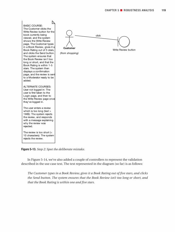
In Figure 5-14, we’ve also added a couple of controllers to represent the validationdescribed in the use case text. The text represented in the diagram (so far) is as follows:
The Customer types in a Book Review, gives it a Book Rating out of five stars, and clicks
the Send button. The system ensures that the Book Review isn’t too long or short, and
that the Book Rating is within one and five stars.
CHAPTER 5 ■ ROBUSTNESS ANALYSIS 119
Figure 5-13. Step 2: Spot the deliberate mistake.
BASIC COURSE:
The Customer clicks the
Write Review button for the
book currently being
viewed, and the system
shows the Write Review
page. The Customer types
in a Book Review, gives it a
Book Rating out of 5 stars,
and clicks the Send button.
The system ensures that
the Book Review isn't too
long or short, and that the
Book Rating is within 1-5
stars. The system then
displays a confirmation
page, and the review is sent
to a Moderator ready to be
added.
ALTERNATE COURSES:
User not logged in: The
user is first taken to the
Login page, and then to
the Write Review page once
they've logged in.
The user enters a review
which is too long (text >
1MB): The system rejects
the review, and responds
with a message explaining
why the review was
rejected.
The review is too short (<
10 characters): The system
rejects the review.
Customer
(from shopping)Write Review button
click
7745ch05final.qxd 12/14/06 11:24 AM Page 119

There are a few issues with this diagram so far. The two messages between the Customerand the Write Review Screen boundary object are quite clumsy. In addition, this approachintroduces some ambiguity into the diagram, as it isn’t clear which controller is called whenthe user clicks the Write Review button versus when the user enters the review and clicksSend. As it turns out, the first sentence of the use case text (“The Customer clicks the WriteReview button for the book currently being viewed”) hints at a Book Detail screen, which isn’tshown either in the text or on the diagram. If we add that screen, then we can have an arrowgoing from the Customer to the Book Detail screen, and we can also add a Display controllerto show the Write Review screen being displayed.
Another issue is that the controller name “Is Book Review text too long or short?” is a tadlong, so we could shorten this to “Is Book Review length OK?”
CHAPTER 5 ■ ROBUSTNESS ANALYSIS120
Figure 5-14. Step 3: We’ve now corrected the mistake and added some validation controllers.
BASIC COURSE:
The Customer clicks the
Write Review button for the
book currently being
viewed, and the system
shows the Write Review
page. The Customer types
in a Book Review, gives it a
Book Rating out of 5 stars,
and clicks the Send button.
The system ensures that
the Book Review isn't too
long or short, and that the
Book Rating is within 1-5
stars. The system then
displays a confirmation
page, and the review is
sent to a Moderator ready
to be added.
ALTERNATE COURSES:
User not logged in: The
user is first taken to the
Login page, and then to
the Write Review page once
they've logged in.
The user enters a review
which is too long (text >
1MB): The system rejects
the review, and responds
with a message explaining
why the review was
rejected.
The review is too short (<
10 characters): The system
rejects the review.
Write Review page
Customer
(from shopping)
Is Book Review text too
long or short?
Is rating in allowed
range?
enter review and
click Send
click Write Review button
7745ch05final.qxd 12/14/06 11:24 AM Page 120

In Figure 5-15, we’ve corrected the diagram and also walked through the remainder of thebasic course text. Notice that we’ve also corrected the use case text so that it doesn’t just hintat a Book Detail screen, but instead refers to it explicitly.
The text shown in the new part of the diagram is
The system then displays a confirmation screen, and the review is sent to a Moderator,
ready to be added.
(As you’ll discover later, this text also needs work!)
CHAPTER 5 ■ ROBUSTNESS ANALYSIS 121
Figure 5-15. Step 4: The remainder of the basic course text in graphic form
Write Review page
Is Book Review length
okay?
Is Review Rating in
allowed range?
Customer
(from shopping)
Confirmation page
Display
(from admin)
ModerateCustomer Reviews
Book Detail page
Display
BASIC COURSE:
On the Book Detail page
for the book currently
being viewed, the
Customer clicks the Write
Review button, and the
system shows the Write
Review page. The
Customer types in a Book
Review, gives it a Book
Rating out of 5 stars, and
clicks the Send button.
The system ensures that
the Book Review isn't too
long or short, and that the
Book Rating is within 1-5
stars. The system then
displays a confirmation
page, and the review is
sent to a Moderator ready
to be added.
ALTERNATE COURSES:
User not logged in: The
user is first taken to the
Login page, and then to
the Write Review page
once they've logged in.
The user enters a review
which is too long (text >
1MB): The system rejects
the review, and responds
with a message explaining
why the review was
rejected.
The review is too short (<
10 characters): The
system rejects the review.
click Write
Review
button
yes
invoke
yes
enter Review
and click Send
7745ch05final.qxd 12/14/06 11:24 AM Page 121
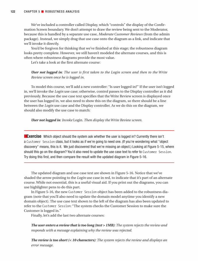
We’ve included a controller called Display, which “controls” the display of the Confir-mation Screen boundary. We don’t attempt to draw the review being sent to the Moderator,because this is handled by a separate use case, Moderate Customer Reviews (from the adminpackage). Instead, we simply drag that use case onto the diagram as a link, and indicate thatwe’ll invoke it directly.
You’d be forgiven for thinking that we’ve finished at this stage; the robustness diagramlooks pretty complete. However, we still haven’t modeled the alternate courses, and this isoften where robustness diagrams provide the most value.
Let’s take a look at the first alternate course:
User not logged in: The user is first taken to the Login screen and then to the Write
Review screen once he is logged in.
To model this course, we’ll add a new controller: “Is user logged in?” If the user isn’t loggedin, we’ll invoke the Login use case; otherwise, control passes to the Display controller as it didpreviously. Because the use case text specifies that the Write Review screen is displayed oncethe user has logged in, we also need to show this on the diagram, so there should be a linebetween the Login use case and the Display controller. As we do this on the diagram, weshould also modify the use case to match:
User not logged in: Invoke Login. Then display the Write Review screen.
■Exercise Which object should the system ask whether the user is logged in? Currently there isn’t a Customer Session class, but it looks as if we’re going to need one. (If you're wondering what "objectdiscovery" means, this is it. We just discovered that we're missing an object.) Looking at Figure 5-15, where should this go on the diagram? You’d also need to update the use case text to refer to Customer Session.Try doing this first, and then compare the result with the updated diagram in Figure 5-16.
The updated diagram and use case text are shown in Figure 5-16. Notice that we’veshaded the arrow pointing to the Login use case in red, to indicate that it’s part of an alternatecourse. While not essential, this is a useful visual aid. If you print out the diagrams, you canuse highlighter pens to do this part.
In Figure 5-16, the new Customer Session object has been added to the robustness dia-gram (note that you’ll also need to update the domain model anytime you identify a newdomain object). The use case text shown to the left of the diagram has also been updated torefer to the Customer Session: “The system checks the Customer Session to make sure theCustomer is logged in.”
Finally, let’s add the last two alternate courses:
The user enters a review that is too long (text > 1MB): The system rejects the review and
responds with a message explaining why the review was rejected.
The review is too short (< 10 characters): The system rejects the review and displays an
error message.
CHAPTER 5 ■ ROBUSTNESS ANALYSIS122
7745ch05final.qxd 12/14/06 11:24 AM Page 122

Note the two implied requirements: the book review length shall not exceed 1MB, and thebook review length shall not be fewer than ten characters.
The updated diagram is shown in Figure 5-17 (again, the objects for the alternate coursesare shown in red).
CHAPTER 5 ■ ROBUSTNESS ANALYSIS 123
Figure 5-16. Step 5: The first alternate course has been added.
7745ch05final.qxd 12/14/06 11:24 AM Page 123

■Exercise In Figure 5-17, following the “enter Review and click Send” arrow, it’s difficult to say whichcontroller we go to after Write Review page. How could the diagram be improved to make this clearer? We reveal the answer during the PDR in Chapter 6.
CHAPTER 5 ■ ROBUSTNESS ANALYSIS124
Figure 5-17. Step 6: Robustness diagram with the last two alternate courses added
7745ch05final.qxd 12/14/06 11:24 AM Page 124

■Exercise In Figure 5-17, the diagram invokes the Moderate Customer Reviews use case, but this doesn’tmatch up with the text on the left. What should be done to make the diagram and the text match up? (Again,check the PDR in Chapter 6 for the answer.)
This diagram is now “functionally” complete, and you could reasonably happily draw a sequence diagram from it. But there are still a few ambiguities that should be ironed out, a couple of which are mentioned in the Exercise elements here. Ironing out these ambiguitieswill make our lives that much easier when we draw the sequence diagram.
This fresh in from the Department of Cliffhanger Endings: We’ll cover those issues (andimprove this diagram some more) in the Preliminary Design Review (PDR) in Chapter 6.
Updating Your Domain (Static) ModelWhile you’re drawing robustness diagrams, it’s a good idea to also be updating the domainmodel incrementally, as you go along. You’ll almost inevitably discover new domain classes.You’ll also identify attributes to be added to classes. This all needs to go on the domain model(aka analysis-level static model), and it’s best do it now, as soon as you identify these changesor new details, before they’re forgotten about.
The new attributes may be discovered from the use case text, or from the UI prototypes,or even from the functional requirements.
■Caution Try not to get sidetracked by assigning operations to your classes just yet—that’s a detaileddesign activity. If you spend time doing that now, you’ll probably just need to redo it later.
The feedback cycle between the robustness model and the static model is shown in Figure 5-18.
CHAPTER 5 ■ ROBUSTNESS ANALYSIS 125
7745ch05final.qxd 12/14/06 11:24 AM Page 125

Figure 5-19 shows the updated static model for the Internet Bookstore, following robust-ness analysis for the Show Book Details and Write Customer Review use cases. The added orupdated classes are shown in red.
The changes that we’ve made to this diagram are as follows.After doing robustness analysis for the Show Book Details use case (see Figure 5-11), we
• Added attributes to Book: title and synopsis (these details weren’t in the use case text,but were found from looking at the screen UI mock-ups)
After doing robustness analysis for the Write Customer Review use case (see Figure 5-17), we
• Added CustomerSession, gave it an attribute called loggedIn (a Boolean), and linked it toCustomerAccount (which will later, in Chapter 8, become simply Customer)
• Deleted CustomerRating, because it turned into an attribute on BookReview
• Added new attributes to BookReview that were mentioned in the use case text
CHAPTER 5 ■ ROBUSTNESS ANALYSIS126
Figure 5-18. Robustness model/static model feedback loop
7745ch05final.qxd 12/14/06 11:24 AM Page 126

There’s one last step before you finish robustness analysis. Once all of your robustnessdiagrams are drawn, you must finish updating the analysis-level class diagram. Take a sweepthrough all of the robustness diagrams that you’ve drawn for this release, and make sure thatall of the relevant details have been fed back into the static model.
CHAPTER 5 ■ ROBUSTNESS ANALYSIS 127
Figure 5-19. Static model for the Internet Bookstore, after robustness analysis for two use cases
7745ch05final.qxd 12/14/06 11:24 AM Page 127

Robustness Analysis in PracticeThe following exercises, taken from the preliminary design activities for the Internet Book-store, are designed to test your ability to spot the most common mistakes that people makeduring robustness analysis.
ExercisesEach of the diagrams in Figures 5-20 to 5-23 contains one or more typical modeling errors. Foreach one, try to figure out the errors and then draw the corrected diagram. The answers are inthe next section.
Exercise 5-1
Figure 5-20 shows an excerpt from a robustness diagram for the Create New Customer Account use case. It vio-lates one of the rules of robustness analysis that we described earlier in this chapter—but which one?
Exercise 5-2
Figure 5-21 shows a robustness diagram for the Add External Books to Catalog use case (in which booksellerpartners may add their own titles to the Internet Bookstore website). It contains a couple of errors to do with thesort of detail you should put on a robustness diagram (Hint: Look at External Book) and an error where the alter-nate course doesn’t have any relation to the events in the basic course. Speaking of alternate courses, there’salso one other error related to alternate courses.
CHAPTER 5 ■ ROBUSTNESS ANALYSIS128
Figure 5-20. Excerpt from a robustness diagram showing an invalid relationship
User
Create NewAccount page
create
CustomerAccount
AccountCreated page
enter details andclick Submit
display
7745ch05final.qxd 12/14/06 11:24 AM Page 128
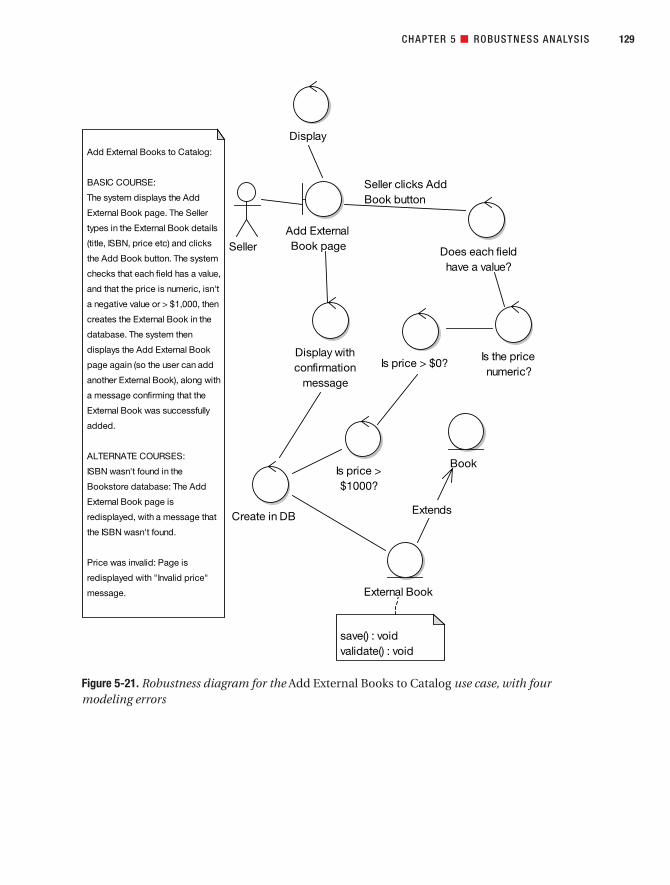
CHAPTER 5 ■ ROBUSTNESS ANALYSIS 129
Figure 5-21. Robustness diagram for the Add External Books to Catalog use case, with fourmodeling errors
Seller clicks Add
Book button
Seller
Add External Books to Catalog:
BASIC COURSE:
The system displays the Add
External Book page. The Seller
types in the External Book details
(title, ISBN, price etc) and clicks
the Add Book button. The system
checks that each field has a value,
and that the price is numeric, isn't
a negative value or > $1,000, then
creates the External Book in the
database. The system then
displays the Add External Book
page again (so the user can add
another External Book), along with
a message confirming that the
External Book was successfully
added.
ALTERNATE COURSES:
ISBN wasn't found in the
Bookstore database: The Add
External Book page is
redisplayed, with a message that
the ISBN wasn't found.
Price was invalid: Page is
redisplayed with "Invalid price"
message.
Display
Add External
Book pageDoes each field
have a value?
Is the price
numeric?Is price > $0?
Is price >
$1000?
Create in DB
External Book
Book
Display with
confirmation
message
save() : void
validate() : void
Extends
7745ch05final.qxd 12/14/06 11:24 AM Page 129

Exercise 5-3
The robustness diagram excerpt in Figure 5-22 shows at least five modeling errors, including at least one in theuse case text, in the last sentence of the basic course, and two where the text and the diagram don’t match up.Have fun finding them all!
CHAPTER 5 ■ ROBUSTNESS ANALYSIS130
Figure 5-22. Excerpt from a robustness diagram containing five errors
Checkout:
BASIC COURSE:
The system displays the Edit
Shopping Cart page. The user
clicks the Checkout button; the
system displays the Delivery
Address page showing any
addresses already registered
for the user's account. The user
selects the address; the
system sets the delivery
address in the order.
. . .
User
Proceed to
checkout button
Select address
Set delivery
addressOrder
click
7745ch05final.qxd 12/14/06 11:24 AM Page 130

Exercise 5-4
The robustness diagram in Figure 5-23 is for the Search for Books use case. The diagram shows a total of eightmodeling errors, including one in the first sentence of the use case text (Hint: Page name) and another in the fourthparagraph of the use case text. See how many errors you can find!
CHAPTER 5 ■ ROBUSTNESS ANALYSIS 131
Figure 5-23. Robustness diagram for the Search for Books use case showing eight errors
BASIC COURSE:
The system displays a page allowing
the user to enter the Search Criteria:
The user enters Search Criteria and
clicks the Search Now button.
The system verifies the Search Criteria
and creates a Search Criteria Object.
The system searches the Catalog
using the Search Criteria and adds any
matching entries to the Search Results.
The system then displays the Search
Results via the Use Case "View
Search Results".
ALTERNATE COURSES:
No Text entered in Search Criteria: The
system re-displays the Search page
and prompts the user to re-select the
required Search Criteria.
No matches found : The system returns
a message indicating no matches
found and prompts the user to re-enter
the Search Criteria.
User Search page
Display with
default settings
Verify search
details
Create Search
Criteria object
enter search criteria
and click Search
Search Catalog
ViewSearchResults
«invokes»
7745ch05final.qxd 12/14/06 11:24 AM Page 131

Exercise SolutionsFollowing are the solutions to the exercises.
Exercise 5-1 Solution: Noun-Noun Relationship
Figure 5-24 highlights the part of the diagram that violates a robustness diagramming relationship rule. The“Create New Account page” boundary object is talking to the “Account Created page” boundary object. Theseare both “nouns,” and a noun-noun relationship isn’t allowed. There must be a controller (a verb) betweenthem, so that the relationship is noun-verb-noun.
Looking at Figure 5-24, the arrow is already labeled “display,” so it makes sense simply to create a Display con-troller. Figure 5-25 shows the corrected diagram.
■Note See Figures 5-8 and 5-9 for all of the possible valid and invalid relationships that you can show ona robustness diagram.
CHAPTER 5 ■ ROBUSTNESS ANALYSIS132
Figure 5-24. The robustness diagram excerpt from Exercise 5-1, with the error highlighted
7745ch05final.qxd 12/14/06 11:24 AM Page 132

Exercise 5-2 Solution: Allocating Behavior
Figure 5-26 highlights the errors in Figure 5-21.
Let’s start at the top of the diagram and work our way down. The diagram contains the validation controllers tocheck the incoming form values for the Add External Book page, but it doesn’t show what happens if any of thevalidation checks fail. The solution is actually pretty straightforward—we just need a “Display with error message”controller pointing back to the Add External Book page—but it still needs to be shown on the diagram, so that theextra processing doesn’t get forgotten about.
The next error, over on the left of Figure 5-26, is that there’s an alternate course called “ISBN wasn’t found in theBookstore database,” but there’s no matching text in the basic course for this error condition to ever arise. The factthat it appeared in the alternate courses shows that the error condition was on the use case author’s mind, but itneeds to be stated explicitly so that the designers know that they’re meant to deal with it.
Over to the right, Figure 5-26 shows an extends relationship between External Book and its parent Book. While thismight be a valid relationship, the robustness diagram definitely isn’t the right place to capture this sort of informa-tion. Extends relationships belong on the domain model diagram (and later, the class diagrams).
Finally, there’s a note attached to External Book showing two methods (save() and validate()). Again, therobustness diagram just isn’t the right place to allocate operations to classes; this information should go on theclass diagrams and be captured during sequence diagramming (see Chapter 8).
CHAPTER 5 ■ ROBUSTNESS ANALYSIS 133
Figure 5-25. The corrected robustness diagram excerpt for Exercise 5-1
User
Create NewAccount page
create
CustomerAccount
AccountCreated page
enter details andclick Submit
Display
7745ch05final.qxd 12/14/06 11:24 AM Page 133

CHAPTER 5 ■ ROBUSTNESS ANALYSIS134
Figure 5-26. The robustness diagram from Exercise 5-2, with errors highlighted
7745ch05final.qxd 12/14/06 11:24 AM Page 134

Figure 5-27 shows the corrected diagram. In this version, we’ve also collapsed three controllers into one andcalled the new controller Check legal price range.
CHAPTER 5 ■ ROBUSTNESS ANALYSIS 135
Figure 5-27. The corrected robustness diagram from Exercise 5-2
7745ch05final.qxd 12/14/06 11:24 AM Page 135

Exercise 5-3 Solution: Diagram Doesn’t Match Up with the Description
Figure 5-28 highlights the errors in Figure 5-22. The first error in the example is that the text starts at an earlierpoint in time than the diagram (a common mistake). An easy way to spot this type of error is to use the “highlightertest” (see earlier in this chapter).
The second error—the GUI widget is shown as a boundary object—is another common mistake. A GUI widgetsuch as a button is too fine-grained to be the boundary object; instead, the boundary object should be the screenor web page.
The third error is rather fundamental: an entire chunk of the use case text has been left off the diagram. It’s sur-prising how often this happens. It's usually a sign that somebody isn't working through the use case one sentenceat a time.
The fourth and final error is a direct consequence of ambiguous use case text: the text wasn’t tied closely enoughto the objects, so the modeler just sort of went off in a pseudo-random direction and, lacking the real boundaryobject to work with, used “Select address” as the boundary object, even though it’s a verb and therefore is a con-troller masquerading as a boundary object. And as we’re sure you know by now, actors can’t talk directly tocontrollers.
Figure 5-29 shows the corrected diagram and use case text. In redrawing the diagram, we discovered anotherambiguity in the text (funny how that happens!). The text “the system displays the Delivery Address page showingany addresses already registered for the user’s account” implies some search and retrieval initialization behavior,which currently also doesn’t appear anywhere on the diagram. So we rewrote this part of the use case and added
CHAPTER 5 ■ ROBUSTNESS ANALYSIS136
Figure 5-28. The robustness diagram excerpt from Exercise 5-4, with errors highlighted
7745ch05final.qxd 12/14/06 11:24 AM Page 136

it into the diagram, and in the process we discovered another domain class (Delivery Address List). This is exactlythe kind of scenario where robustness analysis proves invaluable—discovering hidden functionality and missingdomain classes, just in time to begin designing.
Exercise 5-4 Solution: Alternate Courses Not Shown
Figure 5-30 highlights the errors in Figure 5-23.
To kick off, the text “a page allowing the user to enter the Search Criteria” sounds like a roundabout way of saying“the Search Page,” and it’s always better to give your pages explicit names.
On the arrow between User and Search Page, the text “click Search” should be “click the Search Now button” tomatch it up with the use case text.
On the controller at the top right, some extra detail has been added to the diagram—“Display with default settings”—thatdoesn’t appear in the use case text. Remember, the text and the diagram should be virtual carbon copies of each other.As “Display with default settings” is a bit like saying, “The system displays what it displays” (i.e., it doesn’t add anythingmeaningful in this case since the screen doesn't have to fetch any data when it initializes), it can safely be removed.
Back in the use case description, the text “adds any matching entries to the Search Results” is rather vague.It doesn’t describe exactly what the “entries” are. “Entries” is vague and ambiguous. This is another example ofuse case text that isn’t tied closely enough to the domain model. Simply replacing “matching entries” with “match-ing Books” fixes this.
CHAPTER 5 ■ ROBUSTNESS ANALYSIS 137
Figure 5-29. The corrected robustness diagram excerpt for Exercise 5-4
Checkout:
BASIC COURSE:
The system displays the Edit
Shopping Cart page. The user
clicks the Checkout button; the
system retrieves the Delivery
Addresses already registered
for this user, and then displays
the Delivery Address page.
The user selects the address
to use from the Customer
Address list selector, and
clicks the Select button. The
system sets the Delivery
Address in the Order.
. . .
User
Edit Shopping
Cart page
display
Delivery
Address page
display
retrieve for this
user
Delivery
Address List
OrderSet Delivery
Address
click Checkout
Button
select address
7745ch05final.qxd 12/14/06 11:24 AM Page 137

There’s another naming mismatch on the “Verify search details” controller: it should be called “Verify SearchCriteria.” And while we’re at it, this is really validating the search form, but the diagram doesn’t walk through thevalidation checks, which it should.
CHAPTER 5 ■ ROBUSTNESS ANALYSIS138
Figure 5-30. The robustness diagram from Exercise 5-3, with errors highlighted
7745ch05final.qxd 12/14/06 11:24 AM Page 138

■Note The robustness diagram doesn’t need to specify the validation checks in detail, as that would bequite cumbersome, but it should at least name the function, with a controller per function (or group of closelyrelated functions).
These validation checks have been left off because of the next (and biggest) error, which is that the diagramdoesn’t show any of the alternate courses! (This happens surprisingly often, but the alternate courses representa huge proportion of the system functionality, so they must be given the same amount of attention as the basiccourse.)
Finally, the diagram is missing entity objects. Two should be on there: Search Criteria and Catalog.
Figure 5-31 shows the corrected robustness diagram. We’ve also done a small amount of additional tidying-up inthe corrected version: see if you can spot what else we’ve fixed.
CHAPTER 5 ■ ROBUSTNESS ANALYSIS 139
Figure 5-31. The corrected robustness diagram from Exercise 5-4
7745ch05final.qxd 12/14/06 11:24 AM Page 139
More PracticeThis section provides a list of modeling questions that you can use to test your knowledge ofrobustness analysis.
1. Which of the following is not accomplished during robustness analysis?
a) Object discovery
b) Disambiguation of use case text
c) Modeling the problem domain
d) Validation of requirements by doing conceptual design
2. Which of the following is probably not a boundary class?
a) Login screen
b) Account table
c) Mailbox
d) Error dialog
3. Arrows on a robustness diagram can represent
a) Data flow
b) Control flow
c) Communication associations
d) All of the above
4. Which of the following is probably not a controller?
a) Validate password
b) Transaction manager
c) Line item
d) Display error message
5. Performing robustness analysis as an intermediate step between writing use casesand drawing sequence diagrams adds an additional modeling step and an additionalrequired diagram to a software process, as opposed to drawing sequence diagramsimmediately after writing use cases. Does adding this additional step make theprocess more or less efficient? Give at least three reasons to support your answer.
6. Robustness diagrams and collaboration diagrams (also called communication dia-grams in UML2) both show objects collaborating. Does this mean that a robustnessdiagram and a collaboration diagram are the same, or are they different? Explain.
CHAPTER 5 ■ ROBUSTNESS ANALYSIS140
7745ch05final.qxd 12/14/06 11:24 AM Page 140

7. List four things accomplished during robustness analysis that help to close the gapbetween “what” (requirements analysis) and “how” (detailed design). Explain the ben-efits of each.
8. Attack or defend the following statement:
It’s impossible to completely understand your requirements without doing someexploratory design.
If you agree with the statement, list three benefits of doing this exploratory design as a “conceptual design” modeling step, as opposed to doing all exploratory design in code.
SummaryIn this chapter, we moved from analysis to design, using one of the industry’s most useful andyet best-kept secrets: robustness analysis.
The activity diagram in Figure 5-32 shows where we are (the tasks we discussed in thischapter are shown in red). This brings us to Milestone 2 (Preliminary Design Review), whichwe cover in the next chapter.
CHAPTER 5 ■ ROBUSTNESS ANALYSIS 141
7745ch05final.qxd 12/14/06 11:24 AM Page 141

CHAPTER 5 ■ ROBUSTNESS ANALYSIS142
Figure 5-32. Analysis and Preliminary Design Checkpoint 2
7745ch05final.qxd 12/14/06 11:24 AM Page 142

Preliminary Design Review
The Preliminary Design Review (PDR) session helps you to make sure that the robustnessdiagrams, the domain model, and the use case text all match each other. This review is the“gateway” between the preliminary design and detailed design stages, for each package of use cases.
In this chapter, we provide an overview of the PDR, and then we show an examplereview for the Internet Bookstore.
143
C H A P T E R 6
7745ch06final.qxd 12/14/06 11:25 AM Page 143
Preliminary Design Review in TheoryIn this section, we look at the key elements of the PDR, including our top 10 PDR guidelines.
Why Do a PDR At All?Why bother reviewing your model after robustness analysis? Here’s a hypothetical conversa-tion that we hope will shed some light on the subject.
Q: I’ve drawn a robustness diagram for each use case, and as a result I think the usecases are in pretty good shape. Can I start designing now?
A: There’s just one quick review step first: the Preliminary Design Review (PDR). Thisreview session helps you to make sure that the robustness diagrams, the domain model,and the use case text all match each other.
Q: Who should be involved in the PDR session?
A: The same group of people you had at the requirements review: customer representa-tives, the development team, and any managers who are closely involved in the project.The customer is quite closely involved in the proceedings, but this review is the last stagein the process where the customer has direct input. After this, it’s detailed design—the jobof the senior developers.
■Note Of course, the customer may still comment on work in progress, screenshots, and so forth, but youwouldn’t want a nontechnical (or worse, semitechnical) customer to be commenting on or driving the design.
Q: But what if the customer wants to add new requirements later on?
A: That’s a different issue. All we’re saying is that the customer doesn’t have input intothe design and coding (i.e., the remaining steps following the PDR and leading up todelivery).
Q: If the customer does want to add new requirements, how does this affect theprocess?
A: Then you’re back to step 1 of the process (modifying use cases and the domainmodel, as needed), at least for the new requirements. Handling the analysis and designeffort in a sea of changing requirements is a complex subject with many pitfalls, sowe’ve written a separate book about that.1
144 CHAPTER 6 ■ PRELIMINARY DESIGN REVIEW
1. Doug Rosenberg, Matt Stephens, and Mark Collins-Cope, Agile Development with ICONIX Process(Berkeley, CA: Apress, 2005).
7745ch06final.qxd 12/14/06 11:25 AM Page 144

Q: So what else needs to be achieved during the PDR?
A: It’s a good opportunity to make sure your entity classes have been populated withattributes, that the screens in your system all have names, and that you can trace the dataflow between the screens and the entity classes.
Q: If we’re on the verge of doing a detailed design, shouldn’t we also be thinking aboutthe technical architecture (TA)?
A: Yes, the TA should also be reviewed during this session. You need to make sure that theburgeoning new design is going to work with your chosen architecture.
Top 10 PDR GuidelinesThe principles discussed in this chapter can be summed up as a list of guidelines. Our top 10list follows.
10. For each use case, make sure the use case text matches the robustness diagram,using the highlighter test.
9. Make sure that all the entities on all robustness diagrams appear within the updateddomain model.
8. Make sure that you can trace data flow between entity classes and screens.
7. Don’t forget the alternate courses, and don’t forget to write behavior for each of themwhen you find them.
6. Make sure each use case covers both sides of the dialogue between user and system.
5. Make sure you haven’t violated the syntax rules for robustness analysis.
4. Make sure that this review includes both nontechnical (customer, marketing team,etc.) and technical folks (programmers).
3. Make sure your use cases are in the context of the object model and in the contextof the GUI.
2. Make sure your robustness diagrams (and the corresponding use case text) don’tattempt to show the same level of detail that will be shown on the sequence diagrams(i.e., don’t try to do detailed design yet).
1. Follow our “six easy steps” to a better preliminary design (see Chapter 6).
Let’s look at each of these top 10 items in more detail.
10. Use the Highlighter Test to Match the Use Case Text with the DiagramSometimes people think they should show only the basic course of action on a robustnessdiagram, or that they should do a separate diagram for each alternate course. But it’s best toshow the entire use case (basic and all alternates) on a single robustness diagram.
If the diagram becomes too big (or if you find that the alternates have their own subalter-nates), consider splitting up the use case.
CHAPTER 6 ■ PRELIMINARY DESIGN REVIEW 145
7745ch06final.qxd 12/14/06 11:25 AM Page 145

■Tip Many people like to use a different color for the alternates to make the diagram easier to follow.
A 59-cent highlighter proves to be an invaluable tool for verifying that your use case textmatches your diagram. Simply highlight a sentence of your use case, highlight the correspon-ding section of your robustness diagram, and continue until all the text is highlighted. Youshould also see the entire robustness diagram highlighted.
If you find a mismatch between the text and the diagram (and trust us, you will), thenyou have more work to do.
9. Make Sure That All the Entities Appear Within the Updated Domain ModelSince object discovery is one of the primary purposes of robustness analysis, it makes littlesense to discover new objects on our robustness diagrams and not add them back into theclass model (which is evolving from the domain model).
The safest way to avoid forgetting to add them to the class model is to actually add thenew classes on the class model, stereotype them as entities, and then drag them onto therobustness diagram.
8. Make Sure That You Can Trace Data Flow Between Entity Classes and ScreensYour use case very likely involves users specifying information by using the screens of thesystem. This data needs to find its way into the entity classes, which hold the values entered as attributes. Of course, this also works the other way: values from the entity classes will bedisplayed on the screens.
One of your tasks before coding is to determine the set of attributes that each of yourclasses needs. So, as you’re tracing data flow between screens and entity classes, populate the class model with any missing attributes that are needed.
7. Don’t Forget the Alternate Courses, and Don’t Forget to Specify Their BehaviorYou’re probably tired of hearing us say this by now, but we wouldn’t keep repeating it if itwasn’t important. Forgetting about alternate courses (aka “Whoops, it crashed!”) is one of the main failure modes in software development.
■Note Alternate courses are not necessarily error paths but can include infrequent/atypical usage paths.
For each alternate course, make sure that the system behavior in response to the con-dition that triggers it is fully detailed. Identifying that an alternate course can happen isnecessary, but not sufficient to complete your use case. In addition to simply listing thealternate courses, it’s critical that you detail the exact behavior (of the user and system) ofhow the alternate course is handled.
Since alternate courses generally account for more than half the complexity of a pieceof software, it should be obvious why you need to specify the behavior for the alternates. Ifyou don’t, your classes will be missing all the operations that handle the alternate courses.
CHAPTER 6 ■ PRELIMINARY DESIGN REVIEW146
7745ch06final.qxd 12/14/06 11:25 AM Page 146

6. Make Sure Each Use Case Covers Both Sides of the User/System DialogueOne of the most common errors we’ve seen among people learning to write use cases forthe first time is that they simply write down all the steps that the user follows and thenannounce that they’ve completed their use cases (inevitably faster than anyone else in thetraining class).
This flawed process ignores a fundamentally important point: in most cases, the goalis to fully understand and specify the software behavior of the system. If you write onlythe user actions and ignore the system behavior, you’re just not going to make very muchprogress toward the goal of specifying the software behavior.
■Tip Always keep in mind that a use case is a dialogue between the user(s) and system, and you need towrite about both sides of that dialogue.
5. Make Sure You Haven’t Violated the Syntax Rules for Robustness AnalysisRefer back to Figures 5-8 and 5-9 for the full rules of robustness analysis. In particular, duringthe review make sure that
• Actors are only linked to boundary objects.
• There’s no noun-noun communication between boundary/entity, boundary/boundary,or entity/entity objects without controllers in between. The controllers represent thesystem behavior, so it would be a very bad thing to leave them out.
The robustness analysis syntax rules might seem a little bit irksome at times, but bashingyour use case’s preliminary design into shape so that it fits these rules seriously prepares youruse case for detailed design. Coding should be a breeze if you get this stage right.
Think about it: if a use case is proving troublesome to turn it into a valid robustness dia-gram, then turning it into a valid working design (and valid working, maintainable code)will be ten times as troublesome! The robustness diagram provides a handy early warningsystem that the use case text needs more work (i.e., is vague, ambiguous, incomplete, etc.).
As you saw in Chapter 5, automated tools support for ICONIX Process is continuing toimprove. Validating the robustness diagram syntax rules is now as easy as pulling down a menu.
■Tip As you’ll see later, you can automatically generate unit test stubs for each controller as well.
4. Include Both Nontechnical and Technical People in the ReviewYour use cases after robustness analysis should be treated as “mini-contracts” between theclients and the programmers. As such, they need to be understandable by the end users andclients, but unambiguous enough to be clearly understood by the programmers. It’s duringPDR that you finalize those contracts.
CHAPTER 6 ■ PRELIMINARY DESIGN REVIEW 147
7745ch06final.qxd 12/14/06 11:25 AM Page 147

To put it another way, each use case must reach the magic abstraction level—not vagueand ambiguous, but not geek-speak—where everybody understands what the use casemeans, very clearly. (What a concept!)
3. Make Sure Your Use Cases Are in the Context of Both the Object Model and the GUIThe magic abstraction level we just described is readily achieved by putting the use case in thecontext of the object model and of the GUI. In practical terms, this means that you’ve namedyour screens and your domain classes. Resolving name ambiguity in usage of domain objectsand screens solves a great many problems.
The use cases at this level also need to be in the context of the (evolving) technical architec-ture of the system, but they shouldn’t cross the line into detailed design, because you’ll quicklylose the attention of the nontechnical clients if they do. (Hint: If you notice all of the nontechni-cal folks looking glassy-eyed in the review meeting, consider whether they might have enteredthe state of hypnotic stupor while trying to follow a use case that discusses the details of objectinstantiation via the factory pattern. Also check to see if somebody spiked the coffee.)
2. Don’t Drift into Detailed Design TerritoryRemember that the robustness diagram represents an idealized, conceptual design, not the“real software design.” In practical terms, this means that decisions related to allocatingbehavior among classes should not be made on robustness diagrams. These decisions arebest deferred until you draw the sequence diagrams.
ICONIX Process takes a two-pass approach to get to detailed design. In the first pass,you intentionally ignore “who’s doing what” and focus on identifying objects, namingscreens, and unambiguously describing behavior. Once you’ve done this correctly (andyou’ve verified it during the PDR), you’re ready to take on the behavior allocation problem(i.e., how the methods are distributed among the classes) during detailed design.
1. Follow Our “Six Easy Steps” to a Better Preliminary DesignTo achieve the purpose of the PDR (as described at the start of this chapter), it helps to carryout some key checks on the preliminary design diagrams and the use case text. For eachrobustness diagram that you’re reviewing2
• Make sure the diagram matches the use case text.
• Make sure the diagram follows the rules of robustness analysis.
• Check that the diagram focuses on the logical flow of the use case.
• Make sure the diagram shows all alternate courses of action for the use case.
• Watch out for “design-pattern-itis” in the diagram.
• Check that the diagram isn’t trying to be a detailed design.
We’ll illustrate these steps in the review conversation in the next section.
CHAPTER 6 ■ PRELIMINARY DESIGN REVIEW148
2. These steps are described in more detail in Chapter 6 of Applying Use Case Driven Object Modelingwith UML by Doug Rosenberg and Kendall Scott (Addison-Wesley, 2001).
7745ch06final.qxd 12/14/06 11:25 AM Page 148

Preliminary Design Review in Practice: Internet BookstoreIn this section, we illustrate the theory from the first part of this chapter, using an examplefrom our Internet Bookstore project. The result is actually a continuation of the robustnessdiagram we developed step by step in Chapter 5.
PDR for the “Write Customer Review” Robustness DiagramFor this example PDR session, we’ll follow the reviewer/analyst conversation as it unfolds. We left the robustness diagram in Figure 5-15, so it’s worth flipping back to that version of thediagram as you walk through this example session.
The Customer Review Object Isn’t a Container for the “Enter Review” TextA common theme for the topics in this review is that the diagram didn’t go into sufficientdetail, or it skipped over vital details that were mentioned in the use case text.
Reviewer: Looking at the robustness diagram (see excerpt in Figure 6-1), I’d expect theCustomer Review object to be the container for the “enter Review” text that’s entered on the screen, but it’s not connected.
Analyst: We could draw a line between the “Write Review page” boundary and theCustomer Review entity . . .
Reviewer: It’s tempting, but it would violate the rules of robustness analysis. Remember,noun-noun communication is a major no-no.
■Note Such a strict and seemingly restrictive rule exists for a very good reason: if you’re drawing a linebetween two nouns on the diagram, then there’s almost certainly some behavior (aka verbs) not beingaccounted for.
Analyst: Come to think of it, I don’t think we’re showing the behavior for two user actions:assigning a rating and typing in the review text.
CHAPTER 6 ■ PRELIMINARY DESIGN REVIEW 149
Figure 6-1. “enter Review” should be a controller
Customer
Write Review page Customer Review
enter Reviewand click Send
7745ch06final.qxd 12/14/06 11:25 AM Page 149

Reviewer: We should add controllers to handle both of these behaviors and use them tolink “Write Review page” with the Customer Review entity. Problem solved! (The “clickSend” label also needs to move, but we’ll cover that in the next segment; Figure 6-2 showsthe updated excerpt.)
Label Positioning Makes for Ambiguous PathsFixing one problem sometimes leads to the identification of another. After taking a thoughtfullook at the two new controllers added in Figure 6-2, our reviewer spots another potentialsource of trouble.
CHAPTER 6 ■ PRELIMINARY DESIGN REVIEW150
“BUT WE’RE MODELING WEB PAGE INTERACTIONS . . .”
A common reaction to this advice (showing the user inputting text or other data into the UI as a controller) isthat if it’s implemented in the form of a web page, then you’ll never actually write code to handle theseevents—it’s all done in the browser.
The simple answer to this is that you’re not actually designing at this stage. What you’re primarily inter-ested in with this diagram is showing everything from the use case text in picture form. Going to this level ofdetail might seem like a drag at first, but it’s amazing how much hidden functionality gets uncovered thisway. These details would have otherwise been left uncovered until after the software had been designed andcoding had begun.
In extreme cases, the details might not have been discovered until after the software shipped, the userdid something unexpected, and the program crashed because the excruciating details hadn’t been properlyanalyzed during robustness analysis. So, the lesson to learn from this is, if it’s in the use case text, put iton the diagram!
Figure 6-2. Label text is “promoted” to be a controller, and a second controller is identified.
CustomerWrite Review page Customer Review
Enter review text
Assign reviewrating
click Send
7745ch06final.qxd 12/14/06 11:25 AM Page 150
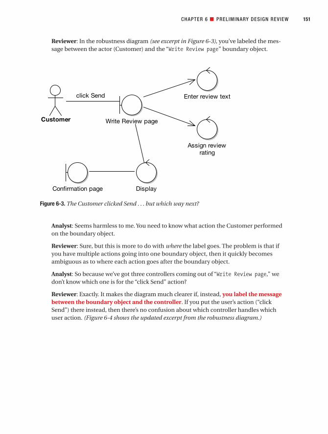
Reviewer: In the robustness diagram (see excerpt in Figure 6-3), you’ve labeled the mes-sage between the actor (Customer) and the “Write Review page” boundary object.
Analyst: Seems harmless to me. You need to know what action the Customer performedon the boundary object.
Reviewer: Sure, but this is more to do with where the label goes. The problem is that ifyou have multiple actions going into one boundary object, then it quickly becomesambiguous as to where each action goes after the boundary object.
Analyst: So because we’ve got three controllers coming out of “Write Review page,” wedon’t know which one is for the “click Send” action?
Reviewer: Exactly. It makes the diagram much clearer if, instead, you label the messagebetween the boundary object and the controller. If you put the user’s action (“clickSend”) there instead, then there’s no confusion about which controller handles whichuser action. (Figure 6-4 shows the updated excerpt from the robustness diagram.)
CHAPTER 6 ■ PRELIMINARY DESIGN REVIEW 151
Figure 6-3. The Customer clicked Send . . . but which way next?
Customer Write Review page
Enter review text
Assign reviewrating
DisplayConfirmation page
click Send
7745ch06final.qxd 12/14/06 11:25 AM Page 151

Display Controllers Need More Detailed NamesSometimes when you’re adding controllers left, right, and center, it’s tempting to leave detailout of the diagram. But this can result in ambiguity that comes back to bite you later, duringthe detailed design. In the next example, the reviewer discovers that some detail has been sub-tly left out of the diagram.
Reviewer: You’ve used a single boundary object (“Review Rejected page”) to show theresults of the two alternate-course validation controllers (“Is Review Rating in allowedrange?” and “Is Book Review length OK?”). However, each one has its own Display con-troller. (See excerpt in Figure 6-5.)
Analyst: But I thought we’re meant to show separate Display controllers like that?
Reviewer: Absolutely. But they’re just a tad ambiguous. The problem is that a specificmessage would be constructed to tell the user why the review was rejected, such as“The review needs to be at least ten characters long, but yours contained only fivecharacters.”
Analyst: Let me guess, we’re not stating explicitly what gets displayed differently on the“Review Rejected page” for each controller.
Reviewer: You’ve got it. To correct this, let’s rename each Display controller to somethingmore specific. (See Figure 6-6.)
CHAPTER 6 ■ PRELIMINARY DESIGN REVIEW152
Figure 6-4. Improved label positioning eliminates ambiguity in the diagram.
Customer Write Review page
Enter review text
Assign reviewrating
DisplayConfirmation page
Customerclicked Send
7745ch06final.qxd 12/14/06 11:25 AM Page 152

CHAPTER 6 ■ PRELIMINARY DESIGN REVIEW 153
Figure 6-5. Insufficient detail on what gets displayed to the user
Figure 6-6. Disambiguated Display controllers
7745ch06final.qxd 12/14/06 11:25 AM Page 153

The Use Case Text Is Missing Some DetailDuring the PDR, you should be equally focused on the use case text as on the robustnessdiagrams. In the final example from this review, the reviewer notices some missing detail inthe use case description.
Reviewer: OK, this is really starting to look like a diagram that you could easily produce a detailed design from. Just one last thing, though. The diagram invokes another use casecalled Moderate Customer Reviews. In the use case, it matches up with this text:
The system then displays a confirmation screen, and the review is sent to a Moderator,
ready to be added.
But the text is missing some of the details of what actually happens. At the moment, we’retaking it as read that the newly submitted review will somehow find its way to the Moder-ator, who will then check the Customer’s Review before it’s published on the site. As Imentioned, the Moderator’s actions are handled by a separate use case, Moderate Cus-tomer Reviews. But what we haven’t modeled (or described) is how the Review makes itsway to the second use case.
Analyst: We could update the use case text like this:
The system then displays a confirmation screen, and the Customer Review is queued
for moderation (this will be handled by the Moderate Customer Reviews use case).
Reviewer: It’s better, but don’t forget that we need to tie the use cases to the objects.Simply saying that “the review is queued for moderation” doesn’t quite do that, as itdoesn’t provide any sort of link to the object that will track the incoming CustomerReviews.
Analyst: (Pondering) “The object that will track the incoming Customer Reviews”? Hmm, itsounds as if we’ve just identified a new domain object—an object that queues up theincoming Customer Reviews.
Reviewer: Let’s call it “Pending Reviews Queue.”
Analyst: OK, so here’s the updated use case text (the updated text is shown in red):
The system then displays a confirmation screen and the Customer Review is added tothe Pending Reviews Queue for moderation (this will be handled by the Moderate
Customer Reviews use case).
Reviewer: This also suggests that the Book ID needs to be an attribute of the CustomerReview, which in turn suggests that Book should probably also be on the diagram some-where. Now we can add our new Pending Reviews Queue object to the diagram.
Analyst: Wow, all that new detail discovered, just by tying the use case text more closelywith the model!
CHAPTER 6 ■ PRELIMINARY DESIGN REVIEW154
7745ch06final.qxd 12/14/06 11:25 AM Page 154

■Tip If you leave the behavior implied on the robustness diagram and in the use case, it never getsdone on the sequence diagram, and (if you’re allocating operations to classes by working through the usecases) it just sort of falls through the cracks to be dealt with in coding-land. The more stuff that fallsthrough those cracks, the less useful the models are, and the less the team will “model like they mean it.”
The Finished “Write Customer Review” Robustness DiagramFigure 6-7 shows the finished version of the robustness diagram. As you can see, it’s nowpossible to read the use case on the left of the diagram and walk your way through the dia-gram at the same time. (A common convention is to start the use case at the top-left of thediagram and finish at the bottom-right, although this is by no means essential.) Nothing inthe use case has been assumed or left to chance, and the text is nicely tied to the domainobject model. We’ve done the groundwork, so this diagram is now something that we candesign from very easily.
Astute readers will have noticed that this diagram has now become what we commonlycall “very big.” In fact, it’s pretty much at the upper limit of use case size (remember the two-paragraph rule from Chapter 3). If the use case was any longer, or the diagram any morecomplex, we’d seriously think about splitting it into two or more smaller use cases (and hence,two or more smaller robustness diagrams).
In Chapter 8, we’ll return to the Write Customer Review use case and show the next step:drawing the sequence diagram.
CHAPTER 6 ■ PRELIMINARY DESIGN REVIEW 155
7745ch06final.qxd 12/14/06 11:25 AM Page 155

CHAPTER 6 ■ PRELIMINARY DESIGN REVIEW156
Figure 6-7. The completed, fully disambiguated robustness diagram
7745ch06final.qxd 12/14/06 11:25 AM Page 156
SummaryIn this chapter, we covered the Preliminary Design Review (PDR) milestone. This step involvesmaking sure that the diagrams and the use case text match each other and that both are com-plete and correctly represent the desired system behavior.
Once the PDR is complete, you’re ready to move on to the detailed design, which wecover in Chapter 8. The technical architecture (TA) is also a vital step. The formulation ofthe TA begins during robustness analysis, but it really kicks into high gear just prior to thedetailed design. We cover the TA in Chapter 7.
Figure 6-8 shows where we are (the milestone covered in this chapter is shown in red).
CHAPTER 6 ■ PRELIMINARY DESIGN REVIEW 157
7745ch06final.qxd 12/14/06 11:25 AM Page 157

CHAPTER 6 ■ PRELIMINARY DESIGN REVIEW158
Figure 6-8. Analysis and Preliminary Design
7745ch06final.qxd 12/14/06 11:25 AM Page 158

Technical Architecture
The purpose of technical architecture (TA) is to get an overall feel for the system that you’regoing to be developing. Will it be a web-based system? Or a rich-client system in VB .NET orJava Swing? Does it need to use a specific application framework (e.g., a company-standardframework)?
There’s no standard notation or format for documenting the TA; the depth and format ofthe technical architecture—and the conventions for creating it—vary widely from company to company, so we don’t dwell in this area for too long. In this chapter, we follow a practicalexample of TA in action, for the Internet Bookstore.
■Note What we describe in this chapter isn’t by any means a “standard ICONIX method” for creating anarchitecture, but it provides us with an opportunity to discuss the server-side framework (Spring Framework)that we’ll use to design and build the Internet Bookstore example.
159
C H A P T E R 7
7745ch07final.qxd 12/13/06 8:37 PM Page 159

The 10,000-Foot ViewYou should start thinking seriously about TA during robustness analysis (see Chapter 5). TAshould be reflected to a degree on the robustness diagrams, but it must be finalized onceyou’ve finished robustness analysis, and it really needs to be nailed down before you begin the detailed design (see Chapter 8).
■Note Although TA precedes robustness analysis in the process, we’ve left the discussion of TA until nowso as not to introduce too many different topics all at once.
What Is Technical Architecture?Technical architecture (also referred to as system architecture and software architecture) gen-erally describes the system you’re intending to build in terms of structure. The architecture isbuilt to satisfy the business and service-level requirements of the system you’re going to build.The architecture includes (but isn’t limited to) the system topology (the server nodes, physi-cal location on the network, choice of application server[s], etc.).
A good TA will be based on some thorough analysis of the “numbers” involved—that is,the number of people who will be using the system at any time, whether there are peak usagehours (and what those peaks are likely to be), the number of transactions per minute, failovercriteria, and so on. These numbers will play a huge role in deciding such factors as what sortof application server (or web server) should be used, how many licenses to buy, and whichserver- and client-side technologies the project should use. These are not decisions for thefainthearted!
Documented architectures range in depth and formality from several volumes of detailedspecs (with every “i” dotted and “t” crossed) to a bunch of e-mails and Visio diagrams. Theideal level lies somewhere between the two extremes, though of course the needs will varydepending on the nature and size of the project.
What Are the Duties of a Technical Architect?In addition to simply creating the right architecture to solve the problem posed by the require-ments, the architect must also document the architecture in an expressive and unambiguouswritten format, and make sure the latest version is available to everyone on the project. Thetechnical architect must also truly believe in the TA he or she has created, and be prepared toevangelize it and communicate its intent to all the project stakeholders. This is an importantpoint, because an architect who doesn’t follow the courage of his or her convictions will endup with a disjointed system, where individual teams or team members head off in differentdirections and do slightly different things. For example, one team will use WebWork for theirpresentation tier, another team will use Velocity, another JSP, and so on. Nothing will quite fittogether properly, and it will never quite be clear whether the requirements have been fullymet. If one part of the system meets the failover requirements, but another part has beendesigned slightly differently, has the requirement been met?
160 CHAPTER 7 ■ TECHNICAL ARCHITECTURE
7745ch07final.qxd 12/13/06 8:37 PM Page 160

This means that the architect needs leadership skills. The architect must be prepared toresolve disputes and help the team to reach a compromise if needed. There may also be teamleaders involved, and a project manager, and so on, but ultimately it’s the architect who bindsthe whole thing together and sees the project through to completion. (And don’t get us startedon nontechnical architects who write a big, quasi-academic architecture document and thenswan off onto a different project!)
■Tip A list of the duties of a chief software architect can be found at the Carnegie Mellon Software Engi-neering Institute website: www.sei.cmu.edu/activities/architecture/arch_duties.html.
Technical Architecture in TheoryIn this section, we take a brief look at what TA is. After that, we’ll dive into the TA for theInternet Bookstore project.
Top 10 Technical Architecture GuidelinesThe principles discussed in this chapter can be summed up as a list of guidelines. Our top 10list follows.
10. Separate functional, data, and system architecture.
Architectures generally cover three broad areas:
• The deployment model (network and application servers, and how they fittogether; system topology; web browsers supported; etc.)
• The package/component model (separation of concerns to different strata/components)
• The data model
9. Understand why you’re creating an architecture.
Before you even think about the system’s architecture, it’s important to understandprecisely why an architecture is even needed.
8. Base the architecture objectively on the requirements.
It’s tempting to base the architecture on the latest technology or whatever happens tobe the “flavor of the month,” rather than listening to what the requirements are tryingto tell you and making an objective decision based on what’s needed. Budget consider-ations are also important. If you decide that, technically speaking, the best applicationserver for the project is “BankBreaker 8.0 Service Pack 12,” is the budget available tohandle this? Are there cheaper (and more robust) alternatives that match the require-ments just as well?
CHAPTER 7 ■ TECHNICAL ARCHITECTURE 161
7745ch07final.qxd 12/13/06 8:37 PM Page 161

7. Consider factors such as scalability, security, and availability.
6. Consider internationalization and localization.
5. Pose hard questions to all the people involved.
Questions regarding such issues as security, auditing, portability, and scalability needto be answered now, not six months into the project.
4. If you don’t get the answers you need, ask again—and keep on asking!
3. Consider testability.
Our co-author on Agile Development with ICONIX Process (Apress, 2005), Mark Collins-Cope, described a trading system he’d been working on. According to the spec, ordersshould time out after between 1 and 30 days. To test this, the team couldn’t really waitaround (a tad boring), so they built functionality to enable the UI to set the date andtime, specifically for testing. This is just one example of how testing must be consid-ered even in the early stages when you’re thinking about the architecture.
2. Explore which external systems you’ll need to interface with.
Scour the requirements for anything relating to synchronous or asynchronous externalsystem interaction. For synchronous systems, think about external system availability.Is it a requirement that your system be able to operate without the other system?
1. Have the courage to believe that your architecture is right and the strength to push itsadoption throughout the project.
Building software is a complex process. It’s all too easy to end up with a big plate ofspaghetti, tangled and amorphous, rather than an elegant haute cuisine plate of pris-tine perfection (see the next section on layering for the “lasagna model”). You wouldthink that those involved would pull together to achieve the latter instead of the for-mer. But people are people, and if they’re simply left to it, each individual or group willform its own “micro-project” with its own direction, set of goals, and set of standards—even its own “mini-architecture.” The technical architect (actually, the chief architect)must communicate his or her documented architecture and make sure everyoneunderstands it, not just at the beginning of the project but throughout.
Architectural Layering
■Note Our thanks to Mark Collins-Cope, our co-author on Agile Development with ICONIX Process (Apress,2005), for providing most of this section’s content.
Architectural layering is a visual metaphor whereby the software that makes up a system isdivided into bands (layers) in an architectural diagram. Many such diagrams have been used,and by way of introduction we show two of these.
CHAPTER 7 ■ TECHNICAL ARCHITECTURE162
7745ch07final.qxd 12/13/06 8:37 PM Page 162

Figure 7-1 presents a view of a strictly layered architecture.
Figure 7-2 shows a type of ad hoc architecture diagram that is not uncommon in moderntechnical documentation.
Some common themes run through these diagrams:
• It’s possible to identify a number of layers in the construction of pieces of software.
• Some layers sit on top of others (although there may be some question as to what onelayer being above another actually means).
• We may broadly categorize layers as being either horizontal (applicable across many, ifnot all, business domains) or vertical (applicable across a subset or only one domain).
CHAPTER 7 ■ TECHNICAL ARCHITECTURE 163
Figure 7-1. Layered architecture example
Client Program
Network Layer
SQL Layer
DBMS Layer
Figure 7-2. Typical ad hoc architectural layering diagram
Business Objects
Application Framework
Platform
Application 1 Application 2
7745ch07final.qxd 12/13/06 8:37 PM Page 163

Turning to UML class diagrams (a younger notation), we notice that common conven-tion usually places subclasses, which are more specialized, below their parents, which aremore general purpose (see Figure 7-3). This convention is the exact opposite of the architec-tural convention “highest is most specific” and the cause of an undoubtedly confusing visualmetaphor mismatch. This mismatch is discussed further in the article “The Topsy TurvyWorld of UML.”1
Technical Architecture in Practice: Internet BookstoreIn this section, we show an example of a TA for the Internet Bookstore. This project usesSpring Framework, so we’ll also use this opportunity to introduce the basic concepts behindSpring. We describe these concepts in more detail during detailed design (Chapter 8), duringCDR (Chapter 9), and when we begin coding (Chapter 10).
About Spring FrameworkDuring TA, one of the really big design decisions is (for web-based systems) which web frame-work to use, if any, and of course which programming language to code the solution in. Eventhe basic assumption that this is to be a web-based system shouldn’t be taken for granted. Ofcourse, in many projects, this decision will already have been made at a sales or managementlevel before the software designers get involved, but (in theory at least) it should be an entirelydesign-driven decision, led by the technical needs as uncovered by the requirements. (Oh, foran ideal world . . .)
CHAPTER 7 ■ TECHNICAL ARCHITECTURE164
Figure 7-3. Class diagrams and architectural views
1. Hubert Matthews and Mark Collins-Cope, “The Topsy Turvy World of UML,” ObjectiveView Issue 4,available at www.softwarereality.com/ObjectiveView.jsp, 2000.
7745ch07final.qxd 12/13/06 8:37 PM Page 164

So, we know that we need to design a web-based system from our use cases. For thisexample, we’ll implement the Internet Bookstore using Java, and we’ll use Spring Framework,2
a popular lightweight J2EE container. More specifically, we’ll use the part of Spring Frameworkcalled Spring Web MVC. As the name suggests, this part of Spring allows you to create a webapplication using a Model-View-Controller (MVC) architecture. For the front-end (the “View”part of the MVC), we’ll use JavaServer Pages (JSP),3 augmented with Sun’s standard JSP TagLibrary (JSTL).4 For the back-end data store connected to our model, we’ll use Spring’s JDBCsupport to implement our Data Access Objects (DAOs).
Because this is a “quick ’n easy” demo application, we’ll use HSQL5 for the database.HSQL is a “personal” database, not suited for large-scale multiuser web applications, but it’scertainly well suited for quick and painless prototype development work.
■Tip HSQL includes an in-memory persistence mode, which (because it doesn’t access the hard disk) is very fast and ideal for unit testing.
We’ll also show how to use EA to generate Spring-ready Java code from the domainobjects and controllers in our UML model.
Although some familiarity with Spring Framework will help you to follow the InternetBookstore example, it isn’t essential. In fact, one of the qualities of Spring is that it allows youto program using so-called Plain Old Java Objects (or POJOs), which have absolutely nodependency on the container framework. POJOs are just straightforward JavaBeans with theusual “getters and setters.” In Chapter 9, we show how to generate these directly from yourstatic model. Using Spring, dependencies between JavaBeans can be set up by wiring thebeans together using simple XML files.
We’ll describe more about Spring Framework (or at least the parts of it that we need) aswe go along. We’ll also return to it when we create the detailed design in Chapter 9 and whenwe begin programming from the detailed design in Chapter 10. The next section introducesthe basic concepts underlying Spring.
Anatomy of Spring FrameworkTo follow along with the Internet Bookstore example, it isn’t essential for you to know howSpring works. However, this section should help to explain why we’re designing and codingthings in the way that we are. Although this book isn’t really about Spring, you’ll gain a goodunderstanding of Spring and the way it’s used for building web applications using JSP, JSTL,and JDBC.
CHAPTER 7 ■ TECHNICAL ARCHITECTURE 165
2. See www.springframework.org.
3. See http://java.sun.com/products/jsp.
4. See http://java.sun.com/products/jsp/jstl.
5. See http://hsqldb.sourceforge.net.
7745ch07final.qxd 12/13/06 8:37 PM Page 165

What Exactly Is Spring Framework?Spring Framework is many things. It’s generally viewed as a lightweight J2EE applicationframework, although it isn’t necessarily limited to J2EE. In fact it also has a rich-client sub-project (Spring Rich Client), which makes use of its elegant design to create Java Swingclient-side applications. However, Spring is mostly used on the server.
The definition is further complicated because Spring allows different frameworks to be“plugged in” to handle object-relational mapping (ORM), views/templating, and so forth.On the ORM side of things, Spring has support for JDBC, Hibernate, Java Data Objects (JDO),and iBATIS. On the view side, Spring has support for a number of templating/web contentsolutions including JSP, Velocity, and Struts.
Spring’s JDBC support is particularly nice because it provides you with “ultimate” controlover how your objects are persisted to (and read from) the database, while eliminating theswathes of repetitive boilerplate code that JDBC-based programs normally suffer from.
To make use of Spring’s J2EE features, you need to run it inside a J2EE server. At the veryleast, to use its web MVC features, you need to run it in a Java servlet/JSP container such asTomcat or Resin. For the Internet Bookstore we’ll use Tomcat.6
In the next few sections, we take a quick look at some of what Spring Framework has tooffer, with particular emphasis on how we’ll use it for the Internet Bookstore.
Inversion of Control/Dependency InjectionThe most compelling aspect of Spring is its use of the Inversion of Control (IoC) design pat-tern. In short, IoC allows a class to be written as a “pure” JavaBean with its own properties, butwithout any dependencies on the framework that it’s running in.
Compare this with EJB, for example, where an entity bean must implement theEntityBean interface, and therefore must include methods such as ejbActivate() andejbRemove(), and must have a matching remote interface which extends EJBObject, and so on. As a result, EJBs are tightly coupled with the server technology. An EJB can be nothing butan EJB—that’s no life for a young Java class to look forward to. To top it all, if the entity beanneeds to access a resource (such as a database connection or another entity bean), it musttake it upon itself to go looking for the resource. This often results in repetitive, brittle code in which semantics leak between classes, and (as the program increases in size) it’s increas-ingly difficult to make changes or test individual functions in isolation.
Using the IoC design pattern, objects (or “beans”) don’t actively go looking for data.Instead, dependent objects are handed to the bean via the framework. It’s best to illustrate thisidea with a quick example, so here goes.
■Note You should find it useful to get an idea of how we’ll be using Spring’s IoC mechanism in our designto bind the classes together. See the section “A (Very) Brief Example of IoC” in Appendix B.
CHAPTER 7 ■ TECHNICAL ARCHITECTURE166
6. See http://jakarta.apache.org/tomcat.
7745ch07final.qxd 12/13/06 8:37 PM Page 166
Spring Web MVCSpring’s web framework centers around a Java servlet called DispatcherServlet. As the namesuggests, this servlet dispatches requests to controllers and provides some additional func-tionality that web applications can make good use of.
So as you might expect, the Internet Bookstore’s design will be based around Spring’sDispatcherServlet. When a request is received from the customer’s web browser, it is first“picked up” by the web server (in our case, Tomcat). Tomcat passes the request toDispatcherServlet, which then hands the request on to one of the Internet Bookstore’scontroller classes.
The “MVC” part of Spring Web MVC refers to the Model-View-Controller design pattern.This is a well-known design pattern that fits in very nicely with the boundary, entity, and con-troller classes used by ICONIX Process, and it is almost a ubiquitous design pattern for bothrich-client and web-based thin client GUI applications (i.e., it isn’t limited to Spring). Thepremise behind MVC is that the application is divided into three distinct areas:
• Model: This is an object representation of the data, usually read in from a database.Sitting “behind” the model is all the detailed plumbing code for mapping objects totables, rows, columns, and relationships in the database.
• View: This is the boundary between the computer and the user. In a web application,the view typically refers to both the web page and the template (e.g., JSP or Velocity file)that creates the web page.
• Controller: Controllers are the “glue” between the view and the model. When a requestis received, the controller fetches (or updates) the data from the model, decides whichview to show the user, and hands the requisite data to the view. Typically an MVC appli-cation has lots of fine-grained controllers (using ICONIX Process, these are mappeddirectly from the controllers on the robustness diagrams). The controllers might actu-ally contain both application logic and business logic; in a highly structured design,these may be separated into different layers.
■Note If you design your domain logic into separate layers, be careful not to fall into the trap of turningyour domain classes into “data-only” containers without any behavior of their own. During the developmentof the Internet Bookstore example over the next few chapters, we demonstrate what can happen if yourdomain classes become data-only containers, and we discuss ways of avoiding this trap.
One of Spring’s great strengths is the way in which it separates the view from the rest ofthe MVC framework. Essentially, this means that you can choose which view technology youwant to use (e.g., Tiles, Velocity, XSLT, and even Acrobat or Excel files).
For the Internet Bookstore, the view will be handled by JSP coupled with JSTL. In the nextsection, we look at Spring’s support for JSP.
CHAPTER 7 ■ TECHNICAL ARCHITECTURE 167
7745ch07final.qxd 12/13/06 8:37 PM Page 167

ControllersA controller is an intrinsic part of the MVC design pattern. Controllers are where the applica-tion processing logic goes. In Spring, a Controller object interprets user input and transformsthe result into a model that will be shown to the user in the view.
■Note Controllers and controllers: As Spring makes use of Controller classes, this might causeconfusion when we’re also talking about the controllers on our robustness diagrams. As luck would haveit, Spring Controller classes are almost always mapped directly from controllers on the robustnessdiagrams. Where we need to distinguish between the two, we’ll refer to them as Spring Controllers(capital “C”) and UML controllers (lowercase “c”).
To carry data between the view and the controller, Spring uses Command objects, so we’llintroduce those next. See Appendix B for more details about Spring Controllers.
Command ObjectsYou’ll see much discussion in the next few chapters about Command objects, especially when we get to the design review stage.
In a web application, a Command object contains data that has been read in from thebrowser’s request parameters. For example, a page that handles a user login form might have a Command object called UserLoginCommand with two properties, username and password. TheHTML login form would, in turn, have two matching field names called, as you might expect,username and password. The UserLoginCommand would be passed into aUserLoginFormController to process the form login and to determine which page the usershould be presented with next.
In Spring, Command objects don’t have to implement a special interface or extend a “Spring-only” superclass. Instead, any old POJO will do, as long as its property names match up withthe names used in the request parameters.
■Tip Though you may not find this tip in the Spring literature, we’ve found that after putting all the workinto creating a domain model, creating additional, separate Command classes is quite counterintuitive. TheCommand classes often end up being thin wrappers around your domain classes, which seems like rather a waste to us. Instead, try to use your domain classes where you would normally create an additionalCommand class. We show an example of this in the next chapter, with the CustomerReview domain class.
ViewsThe view is the JSP page that will generate the HTML that the user sees. Controllers in Springgenerally return a ModelAndView object, which tells Spring what view to send back to thebrowser and what model data to populate it with.
CHAPTER 7 ■ TECHNICAL ARCHITECTURE168
7745ch07final.qxd 12/13/06 8:37 PM Page 168

■Note We’ll explain this mechanism in more detail when we start coding the Internet Bookstore inChapter 10. Also see Appendix B for more about creating and configuring JSP views using Spring. Fornow, we’re just introducing what you’ll need in order to draw the sequence diagrams in the next chapter.
DAO and JDBC SupportOne of the reasons we chose Spring for the Internet Bookstore example is that it allows you to create a persistent object model using straightforward JavaBeans, with simple get and setmethods for each property. These JavaBeans are our domain classes; there is (for the mostpart) a direct mapping between these and the classes in the domain model.
Spring also provides excellent DAO support. It allows you to define DAOs as simple inter-faces (with methods such as findBooksByTitle()). At runtime, these DAOs are mapped ontoconcrete classes that utilize the object persistence technology of your choice (e.g., JDBC, JDO,or Hibernate).
■Note See Appendix B for more details about Spring’s JDBC support and how we’ve used it for theInternet Bookstore example.
Is a DAO a Collection?When you’re domain modeling, it’s useful to include a Collection object to represent manyinstances of the same domain class. For example, a Book domain class might be associatedwith a BookCollection. The BookCollection is analogous to a database table, whereas the Book is analogous to a row in the table.
Often this representation carries over perfectly well into the detailed static model. How-ever, on other occasions, the analogy might not quite fit the implementation and designdetails. For example, with DAOs, a DAO class is really a source of Collections (where aCollection in this case is actually derived from the java.util.Collection interface, meaningthat it’s a cluster of objects). In other words, the DAO isn’t a Collection itself, but it’s a sourceof Collections. The DAO will return different Collection objects (collections of Books) of dif-ferent sizes and containing different subsets of Books depending on the DAO method called.
Even in this case, it’s useful when at the domain modeling stage to think in terms of Bookand BookCollection. Figure 7-5 shows the transition from the initial, analysis-level domainmodel to the implementation-focused static model.
CHAPTER 7 ■ TECHNICAL ARCHITECTURE 169
7745ch07final.qxd 12/13/06 8:37 PM Page 169

CHAPTER 7 ■ TECHNICAL ARCHITECTURE170
ALL IN A DAO’S WORK
A Data Access Object (DAO) provides an abstraction from the underlying database. A DAO class includes“finder” methods that access the database and return instances of domain classes.
DAOs aren’t specific to Spring; they’re found in many other frameworks and languages. For example,they’re common in the Visual Basic and VB .NET worlds.
It’s useful to think of a DAO as being the database table and a domain object as being a row in the table(see Figure 7-4). Note that the mapping between the DAO and the table isn’t necessarily 1:1 (although itoften is). For example, if DAO A uses Table A, which in turn contains a reference to Table B, but no other DAOsuse Table B, then it might make sense simply to access Table B from DAO A. However, most of the time it’suseful to think of a DAO as being directly analogous to a database table. See Figure 7-5 for an example of a group of related domain objects transitioning into a set of classes in the detailed design.
Figure 7-4. A domain object is to a DAO as a row is to a table.
DAO
+ findById() : Object+ findByCategory() : Collection
DomainObject
Table
«column» id:«column» category:
row
0..*
read datafrom...
0..*
7745ch07final.qxd 12/13/06 8:37 PM Page 170

Spring AOPAspect-oriented programming (AOP) is turning out to be an interesting (if controversial)extension to object-oriented programming (OOP). AOP allows you to define cross-cuttingconcerns through your code (e.g., to precede all methods starting with “write” with some codethat first authenticates the user). AOP is typically used for logging, user authorization andauthentication, and transactions.
CHAPTER 7 ■ TECHNICAL ARCHITECTURE 171
Figure 7-5. Transition from domain model to static model
7745ch07final.qxd 12/13/06 8:37 PM Page 171

AOP is controversial because some people feel that it provides the programmer with toomuch power to create impossible-to-debug code; it’s potentially a return to the spaghetti-codewild-west days of the GOTO statement. Of course, in the right hands, AOP can be an extremelypowerful and useful tool that can help to reduce the number of lines of code.
Spring provides its own AOP solution, making it particularly useful for all three typicaluses we just mentioned. In our Internet Bookstore example, we don’t actually make use of AOP(it was tempting, but we wanted to keep the example under control!), so if you’re unfamiliarwith AOP then don’t panic. We just mention it here because we believe that in the near future,AOP might become much more important for use case–driven development.
Spring Framework SummaryIn this section, we described the features of Spring Framework that are relevant for designingthe Internet Bookstore. We didn’t want the sequence diagrams to be generic or high-level dia-grams that don’t truly reflect the implementation details. For this reason, we’ve had to delvesome way into the underlying framework that we’ll be building on.
Note that Spring Framework is a huge product. It includes lots of features not coveredhere, as we’ve mainly just covered the areas relevant to the Internet Bookstore example. For more about Spring, check out their spring-reference.pdf document (available fromwww.springframework.org/documentation). We can also recommend the book Spring Liveby Matt Raible (SourceBeat, 2005).7
Also note that Spring isn’t the only “lightweight” framework of its kind, although it cer-tainly seems to be the most popular of the current new breed of J2EE frameworks. It alsorepresents a trend in the J2EE world—a change in direction away from heavyweight EJBstowards IoC-based frameworks, which are generally much easier to develop with. As such,the principles we describe in the Internet Bookstore example should be applicable to mostother Java or .NET-based web frameworks.
The Internet Bookstore ArchitectureNow that we know which language and platform we’re targeting, let’s briefly map out ourarchitecture. We’ll need this so that our sequence diagrams make sense when we draw them in the next chapter.
Layered ArchitectureLet’s start by attempting to separate the Internet Bookstore architecture into different layers.Figure 7-6 shows the first attempt. Note that it’s an ad hoc “lines and boxes” diagram, not fol-lowing an official notation.
CHAPTER 7 ■ TECHNICAL ARCHITECTURE172
7. Available in traditional pulped-tree format or as an e-book subscription from www.sourcebeat.com.
7745ch07final.qxd 12/13/06 8:37 PM Page 172

It’s a start, but Figure 7-6 raises a few issues:
• The diagram appears to be mixing two aspects of architecture: the deployment modeland the package/component model. We should separate these out into two diagrams.
• Tomcat runs on the application server (middle tier), not the presentation layer. How-ever, what the diagram is attempting to show is that, as this is an MVC architecture,we’re using JSP to create the presentation layer (the “view”). The reason for the mix-upis again because we’re attempting to show two separate things in the same diagram.
CHAPTER 7 ■ TECHNICAL ARCHITECTURE 173
Figure 7-6. Internet Bookstore architecture
HSQLDBDatabase
Data Access
DAOs(Interfaces)
Domain Model(Beans/POJOs)
ApplicationLogic
InputValidators
PresentationLayer
Tomcat (Web/JSP Server)
BookstoreJSPs
BookstoreControllers
JDBC DAOImplementations
SpringDispatcherServlet
7745ch07final.qxd 12/13/06 8:37 PM Page 173

• Spring’s DispatcherServlet almost certainly should be on the application servermiddle tier; the presentation tier should be the web browser. Again, this comes backto the issue of what the diagram is attempting to show. What question is the diagramattempting to answer? Is it a) What is the deployment architecture of the InternetBookstore? or b) What are the components that make up the Internet Bookstore?
• It isn’t clear from the diagram what the input validators are doing. You’ll know from theprevious section that these are an artifact of Spring Framework, which requires us toseparate out the validation code into separate classes.
• It isn’t clear what the arrows represent. They actually represent dependencies so, forexample, the Bookstore Controllers use (or “depend on”) the Data Access Objects(DAOs).
Let’s take another attempt and separate the diagram into two separate diagrams (seeFigures 7-7 and 7-8).
CHAPTER 7 ■ TECHNICAL ARCHITECTURE174
Figure 7-7. Internet Bookstore package/component architecture
Model
DAOs(Interfaces)
Controllers
ViewSpringDispatcherServlet
BookstoreJSPs
BookstoreControllers
JDBC DAOImplementations
Arrows show dependencies between components.
Domain Model(Beans/POJOs)
InputValidators
7745ch07final.qxd 12/13/06 8:37 PM Page 174

In Figure 7-7, we’ve removed the data layer entirely, as this is more relevant to the deploy-ment diagram. We’ve also renamed each of the layers, to make it more obvious that this is aclassically mapped-out MVC architecture. While this move wasn’t essential, it always helps toutilize well-known terminology to make the architecture more expressive. The people whoneed to refer to this diagram will (we would hope) already know what MVC is all about, so wecan use that to our advantage.
■Exercise Later in this book, during the review stages, you’ll find that we have issues with domainclasses that contain no behavior, just data. The root of the problem can be seen in Figure 7-7. What shouldhave changed here, at the architectural level, to encourage a more “behavior-rich” set of domain classes?(Check the code review for the Write Customer Review use case in Chapter 11 for the answer.)
It was debatable whether Spring’s DispatcherServlet should remain in the view layer.It isn’t strictly speaking the view, because it handles incoming requests from the web browserand then delegates to the JSP to create the actual view. It’s more of a request/response router,or go-between. From that perspective, it probably doesn’t even need to be on this diagram atall, except that it does help to show visually where in the component/layer hierarchy theSpring Web component is involved.
■Caution If you’re unsure whether something belongs on one diagram or another, don’t dwell on it, justput it somewhere and move on. Teams often get stuck for days on these sorts of fine details. But trust us,99% of the time, it just doesn’t matter. Will it affect the eventual design? Probably not. Getting stuck on suchissues typifies analysis paralysis, which we introduced in the Introduction and which we spend a large partof this book describing how to avoid. For more about making your models minimal yet sufficient, see thisbook’s companion volume, Agile Development with ICONIX Process (Apress, 2005).
The controller layer contains the “guts” of the Internet Bookstore application. It’s respon-sible for validating and processing the user’s input (via browser requests and formsubmissions) and deciding which page should be sent back to the user next.
The data access layer provides a façade over the database (or whatever the persistencemechanism may be). The DAOs are “clean” interfaces, designed to hide away the details of thecode behind them. A DAO is roughly equivalent to an EJB Home, in that it’s used to find beans(domain objects) and persist changes.
Figure 7-8 shows the deployment model, using a nonstandard notation so as to model thelayered architecture.
CHAPTER 7 ■ TECHNICAL ARCHITECTURE 175
7745ch07final.qxd 12/13/06 8:37 PM Page 175

We could also show this using a “proper” UML deployment diagram—see Figure 7-9.8
The result of this layered approach is that the domain classes have absolutely no depend-encies on the database being used. Even the DAO interfaces can remain unchanged if we swapin a different database. In fact, each layer is only dependent on the layer directly beneath it.
The interaction with the user’s web browser is handled by the web server (Tomcat), whichcontains the DispatcherServlet and the JSPs for the Internet Bookstore. (As you’ll see later, theInternet Bookstore page URLs don’t end in .jsp, though, because the user doesn’t request theJSP pages directly. Instead, a suitable JSP is resolved by the Internet Bookstore Controllers andhanded back to the DispatcherServlet, which then invokes the JSP and sends the resultantHTML page back to the browser.)
This is, of course, a very simple architecture, because we have only one application server(Tomcat), which is also our web server. For persistence, our database is HSQLDB (oftenreferred to for historical reasons as HSQL).
CHAPTER 7 ■ TECHNICAL ARCHITECTURE176
Figure 7-8. Internet Bookstore deployment architecture using nonstandard notation
Web/ApplicationServer
SpringDispatcher Servlet
Bookstore Controllers
Web BrowserPresentationLayer
Bookstore JSPs
Data Access Components
HSQLDBDatabase
8. We show another example of a deployment diagram in Appendix B, in Figure B-13.
7745ch07final.qxd 12/13/06 8:37 PM Page 176

CHAPTER 7 ■ TECHNICAL ARCHITECTURE 177
Figure 7-9. Internet Bookstore deployment architecture using a UML deployment diagram
Presentation Layer
Web/Application Server
Database
Web Browser
Spring DispatcherServlet
Bookstore JSPs
Bookstore Controllers
Data Access Components
HSQLDB
7745ch07final.qxd 12/13/06 8:37 PM Page 177

Flow of EventsFigure 7-10 shows, at a broad level, what happens to a browser request when it “hits” the webserver.
Let’s walk through the sequence of events shown in Figure 7-10. First, the user requests a page from the web server (in our development example this is Tomcat, but it could be anyJSP-compliant web server). Assume the request’s URL is something like this:
http://localhost/bookstore/bookDetails.jsp?bookid=101
The “bookstore” part of the URL tells Tomcat that this is the Bookstore web application, so without further ado, the incoming request is handed to the Bookstore, which is configuredto use Spring’s DispatcherServlet. This servlet uses the Internet Bookstore application’s XMLconfig to determine which controller to map the request to. Spring also dissects the requestand creates “command” objects to represent any parameters that were part of the request (inour example, “bookid” would go into a property in a Command object). The Command object is alsohanded to the controller.
The Controller that receives the request hands the book ID value to the appropriateDAO, which finds the book in the database and returns a Book domain object (a simple Java-Bean). The Controller returns a ModelAndView object, which—as the name suggests—givesSpring two things: the view (JSP page) to use and the objects (model) to populate the JSP pagewith. This JSP page is then processed, and the resultant HTML page is handed back to thebrowser.
CHAPTER 7 ■ TECHNICAL ARCHITECTURE178
Figure 7-10. Life cycle of a typical Internet Bookstore browser request
Browser DispatcherServlet
BookstoreController
DAOs
Spring/JDBC
Database(HSQL)
BookstoreApplication
Context(XML Config)
JSP Page(View)
Model(JavaBeans)
build responseusing a...
contact MotherShipfor instructions
sendrequest
map requestto a...
returnModelAndView
use
query
create
7745ch07final.qxd 12/13/06 8:37 PM Page 178

If that seems like a lot of stuff to remember, don’t worry. To follow along with the sequencediagrams, the key parts that you’ll need to know are as follows:
1. When a browser request is received, Spring dissects the request, populates Commandobjects (similar to Struts actions) to hold the request parameters, and hands therequest to a Controller object.
2. The Controller object does whatever it wants to process the request and returns a ModelAndView object that tells Spring which JSP page to process and send back to the browser.
3. The domain objects are stored in JavaBeans (or POJOs).
4. The Controller objects use DAOs to fetch and save domain objects to and from thedatabase.
TestabilityOne of the advantages of the IoC architecture is that individual classes are very easy to test.Each class can be instantiated individually and tested outside of the application server. Forexample, you could write some JUnit tests that run inside your IDE or that are executed by anautomated Ant build script. Being able to test your application logic without deploying to anapplication server and restarting the whole framework is a major time-saver.
Because we’re keeping all of the application logic code out of the view, the JSPs them-selves should be very straightforward. So testing of the JSPs should mostly be a case of “visualtesting”—stepping manually through the use cases’ basic and alternate courses. As long aswe’ve done our job well, once created, the JSPs shouldn’t need to change very much. If youdesperately want to unit-test the view components, though, web testing frameworks such asHttpUnit are available.
Note, however, that testability isn’t just about unit testing; it’s also about testing for non-functional requirements such as scalability and failover.
Web SecurityTo keep the example under control, we’re just going to use “pretend” user authentication/authorization. We’ll use a class called CustomerSession that gets stored in the servlet’sHttpSession attributes (i.e., each customer/user gets his or her own CustomerSession object).CustomerSession consists simply of a “get” method to get the customer’s name and a staticfactory method to get new CustomerSessions.
Spring Framework doesn’t actually offer its own security framework. However, a numberof open-source security frameworks exist. One that’s particularly worth a look is Acegi Security(www.acegisecurity.org), which is designed specifically for Spring applications.
Security frameworks like Acegi handle a lot of the user security details for you. The deci-sion of how security is handled should be made as early as possible in the project (ideallybefore the sequence diagrams are drawn), as it’s one of those fundamental details that affectseverything. You definitely don’t want security to be “bolted on” to a project late in the day.
CHAPTER 7 ■ TECHNICAL ARCHITECTURE 179
7745ch07final.qxd 12/13/06 8:37 PM Page 179

Top 10 Technical Architecture Errors (the “Don’ts”)The following list could be thought of as the flip side of the top 10 “do’s” that we described atthe start of this chapter. These are some common errors that we’ve seen in real projects.
10. Picking an architecture without considering the cost of the hardware or new hardware.
9. Using the old legacy architecture because “that’s the way it’s always been done.”
8. Not considering scalability.
Think about the numbers. How many users will typically be using the system at anytime? Are there periods of peak usage? How many transactions per minute must thesystem handle? These are all questions that affect the TA (and therefore pretty muchthe whole project), so they need to be thought through and answered up-front.
7. Not considering security.
By “security,” we mean authentication and authorization of the people using the sys-tem (the users). All too often, security is bolted on to a system near the end of its lifecycle. This typically results in a system riddled with security flaws.
AOP is promising to make it a little easier to apply security to projects where it wasn’tinitially a first-rate concern. But getting it right first time is still the best way. The secu-rity should run through a system like the writing in a stick of Brighton rock.9 It’s theonly way to make sure your product is watertight.
6. Picking a new technology (language, platform, framework) because that’s the way themarket is heading, and not really knowing about the technology.
“We must use this technology because everyone in the papers is talking about it!” In particular, XML-HELL comes to mind. Commonly, this TA error means picking anarchitecture that uses a platform you and your team have no prior experience with. By definition, the fashionable new technology is new. As we discussed earlier, however,an effective architect really needs to have an in-depth knowledge and prior experiencewith the technology he or she is evaluating and mixing into the design.10
5. Failing to formulate the TA objectively based on the project’s requirements.
4. Spending too long on the architecture before delving into design.
Architectural paralysis can be as dangerous and project-stopping as analysis paralysis.Because the architecture is so important, it’s tempting to spend six or more monthsthinking about it and debating it with your colleagues. Eventually someone mightremember that there’s also a system to be written.
CHAPTER 7 ■ TECHNICAL ARCHITECTURE180
9. See http://en.wikipedia.org/wiki/Rock_(confectionery).
10. The article “Software Fashion” equates designers who automatically buy into the latest technologywith “fashion victims”: www.softwarereality.com/soapbox/softwarefashion.jsp
7745ch07final.qxd 12/13/06 8:37 PM Page 180

3. Forgetting to think about how the system will be tested.
2. Defining the TA before understanding what the users need to do.
1. Failing to do an architecture at all.
SummaryIn this chapter, we took a brief look at technical architecture (TA). We dug deeper than whatmight be considered "architecture-level", in order to introduce Spring Framework, and towalk through the way in which we'll use it for the Internet Bookstore.
TA varies immensely from project to project (and from organization to organization), andit isn’t the core focus of ICONIX Process, so we’ve touched on the subject only briefly in thischapter.
Figure 7-11 shows where TA sits in the preliminary design stage of the process.In the next chapter, we look at detailed design and flesh out the Internet Bookstore using
sequence diagrams.
CHAPTER 7 ■ TECHNICAL ARCHITECTURE 181
7745ch07final.qxd 12/13/06 8:37 PM Page 181

CHAPTER 7 ■ TECHNICAL ARCHITECTURE182
Figure 7-11. Technical architecture and the preliminary design stage
7745ch07final.qxd 12/13/06 8:37 PM Page 182

Design and Coding
P A R T 3
7745ch08final.qxd 12/13/06 8:38 PM Page 183

7745ch08final.qxd 12/13/06 8:38 PM Page 184

Sequence Diagrams
Once you’ve finished robustness analysis, and you’ve held a preliminary design review, it’stime to begin the detailed design effort. By this time, your use case text should be complete,correct, detailed, and explicit. In short, your use cases should be in a state where you cancreate a detailed design from them.
All the steps in the process so far have been preparing the use cases for the detaileddesign activity. Having completed robustness analysis and the PDR, you should now havediscovered pretty much all of the domain classes that you’re going to need. You also need to have the technical architecture (TA) nailed down by this stage.
The 10,000-Foot ViewBefore we leap into the details of sequence diagramming, let’s take a step back (or up) andlook at the bigger picture of object-oriented design (OOD).
185
C H A P T E R 8
7745ch08final.qxd 12/13/06 8:38 PM Page 185
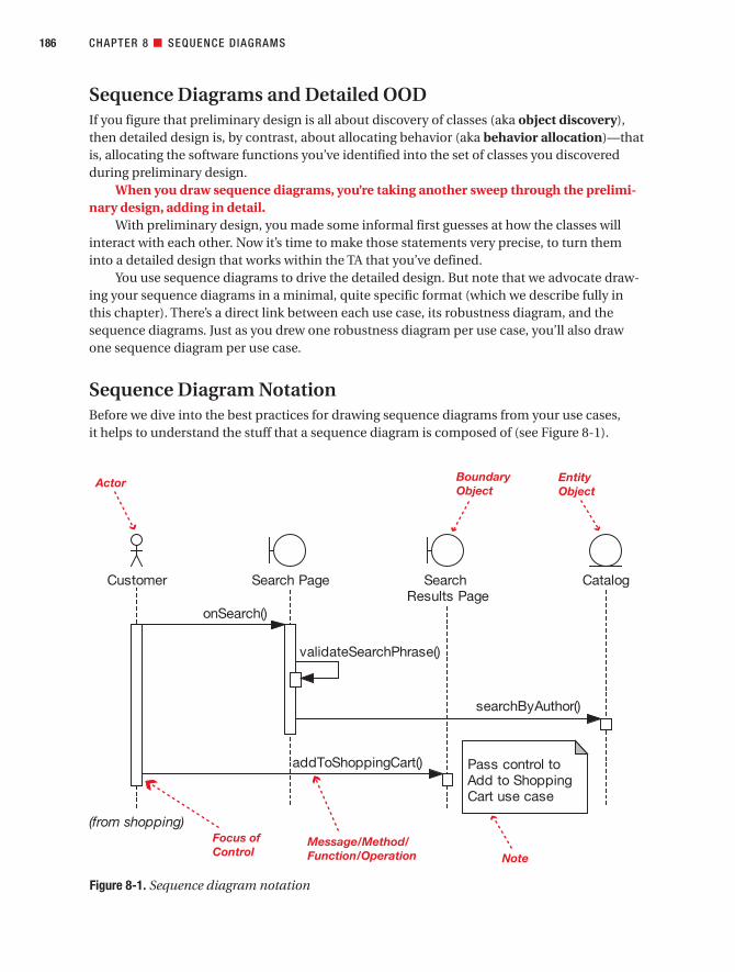
Sequence Diagrams and Detailed OODIf you figure that preliminary design is all about discovery of classes (aka object discovery),then detailed design is, by contrast, about allocating behavior (aka behavior allocation)—thatis, allocating the software functions you’ve identified into the set of classes you discoveredduring preliminary design.
When you draw sequence diagrams, you’re taking another sweep through the prelimi-nary design, adding in detail.
With preliminary design, you made some informal first guesses at how the classes willinteract with each other. Now it’s time to make those statements very precise, to turn theminto a detailed design that works within the TA that you’ve defined.
You use sequence diagrams to drive the detailed design. But note that we advocate draw-ing your sequence diagrams in a minimal, quite specific format (which we describe fully inthis chapter). There’s a direct link between each use case, its robustness diagram, and thesequence diagrams. Just as you drew one robustness diagram per use case, you’ll also drawone sequence diagram per use case.
Sequence Diagram NotationBefore we dive into the best practices for drawing sequence diagrams from your use cases, it helps to understand the stuff that a sequence diagram is composed of (see Figure 8-1).
186 CHAPTER 8 ■ SEQUENCE DIAGRAMS
Figure 8-1. Sequence diagram notation
7745ch08final.qxd 12/13/06 8:38 PM Page 186

The objects across the top of the diagram (Customer, Search Page, etc.) are interactingwith each other by passing messages back and forth. The vertical dotted lines (or object life-lines) represent time, so the process shown in the diagram begins with the topmost message(Customer calling onSearch() on Search Page).
An actor (the Customer in Figure 8-1) is the user whose interaction with the systemyou’ve described in each of the use cases. (See the “system boundary” diagram in Figure 3-2.)You should recognize the boundary object and entity object icons from robustness diagram-ming in Chapter 5. (In Figure 8-1, the boundary objects are Search Page and Search ResultsPage; the entity object is Catalog.)
However, notice that there are no controller objects on the sequence diagram(although there could be). This is because when you draw the sequence diagrams, thecontrollers (the verbs) are turned into messages on the boundary and entity objects (thenouns). Sometimes you’ll find real controller classes, such as a “manager” or a “dispatcher”class, and sometimes a framework might tempt you to litter your design with dozens of tiny“controller classes,” but as a general rule of thumb, 80% or so of the controllers from therobustness diagrams can be implemented as one or more operations on the entity andboundary classes. (More about this important aspect of sequence diagramming later.)
The focus of control represents the time that a particular method/function has control. It starts with the arrow going into the function and finishes when the function returns.
■Note You normally don’t need to draw a return arrow, except in special circumstances (e.g., to show anasynchronous return value). That’s because parameters can be passed back as arguments to the operation.
As you’ll see in item 5 in the next section, the focus of control is best switched off, as ittends to be something of a distraction from what you’re trying to achieve at this stage in theprocess.
Sequence Diagramming in TheoryIn this section, we demonstrate how to use sequence diagrams as a mechanism for exploringand filling in the detailed OO design for each use case. We illustrate this theory with examplesfrom the Internet Bookstore project. And we begin, as usual, with our top 10 guidelines list.
Top 10 Sequence Diagramming Guidelines
10. Understand why you’re drawing a sequence diagram, to get the most out of it.
9. Draw a sequence diagram for every use case, with both basic and alternate courses onthe same diagram.
8. Start your sequence diagram from the boundary classes, entity classes, actors, and usecase text that result from robustness analysis.
CHAPTER 8 ■ SEQUENCE DIAGRAMS 187
7745ch08final.qxd 12/13/06 8:38 PM Page 187

7. Use the sequence diagram to show how the behavior of the use case (i.e., all the con-trollers from the robustness diagram) is accomplished by the objects.
6. Make sure your use case text maps to the messages being passed on the sequencediagram. Try to line up the text and message arrows.
5. Don’t spend too much time worrying about focus of control.
4. Assign operations to classes while drawing messages. Most visual modeling toolssupport this capability.
3. Review your class diagrams frequently while you’re assigning operations to classes, to make sure all the operations are on the appropriate classes.
2. Prefactor your design on sequence diagrams before coding.
1. Clean up the static model before proceeding to the CDR.
Let’s look at each of these top 10 guidelines in more detail.
10. Understand Why You’re Drawing a Sequence DiagramWhen drawing sequence diagrams, you’re meticulously exploring the ins and outs of thedetailed design for each use case, in microscopic detail. This means exploring not just thebasic course, but also all the alternate courses of action in each use case. (We can’t stressthis point strongly enough!)
It’s surprising how many design issues can be caught at this stage, saving time on refac-toring your design later, so it pays to design and explore every facet of each use case, not justthe sunny-day scenario.
Sequence diagramming has three primary goals in ICONIX Process:
• Allocate behavior to your classes: You identified these classes during robustness analy-sis. During sequence diagramming, the controllers (also discovered during robustnessanalysis) are turned into operations on the classes. However, you don’t necessarily endup with a 1:1 correlation between the controllers and the operations. Often, a controllerturns into two or more operations. (Check the examples later in this chapter to see howthis happens.) And as we mentioned earlier, occasionally a controller may also beturned into a controller class.
• Show in detail how your classes interact with each other over the lifetime of the usecase: When sequence diagramming, you should be exploring how the system willaccomplish the behavior described in your use cases. You do this by thinking aboutand then depicting how your objects (runtime instances of a class) will interact witheach other at runtime.
• Finalize the distribution of operations among classes: Having performed robustnessanalysis, you should by now have identified at least three-quarters of the attributes(the data) on your classes, but very few, if any, of the operations (the behavior). Bynow you’ve probably gathered that we advocate a two-pass approach to the design.The first pass (preliminary design) is driven by thinking about attributes while deliber-ately ignoring “who’s doing what to whom.” Then the second pass (the subject of this
CHAPTER 8 ■ SEQUENCE DIAGRAMS188
7745ch08final.qxd 12/13/06 8:38 PM Page 188

chapter) focuses all your attention on that exact question. That’s because during pre-liminary design, the information just wasn’t there to allocate operations withoutguessing. However, now that you’re at the detailed design stage, you should haveeverything in place to correctly allocate the behavior among your classes.
■Note Objects interact by sending messages to each other. In the Ruby programming language, themessage paradigm is used literally, and all object interactions are considered to be messages. However,in other languages such as Java or C++, the messages you draw on sequence diagrams equate tomethod or function calls. To complicate things a little, in UML each message is also called an operationonce it’s assigned to a class.
■Note Messages, methods, functions, operations, verbs, and controllers—these are all basically differentversions of the same thing: the behavior that you allocate to a class (via sequence diagramming) and even-tually implement and test.
9. Do a Sequence Diagram for Every Use CaseIt’s pretty simple to make sure you’ve covered everything in your design, if you stick to thesetwo simple rules:
• Write a use case for every scenario you’re going to build in your current release (includebasic and alternate courses in each use case).
• Draw a sequence diagram for each use case and use the sequence diagram to put theoperations on the classes.
CHAPTER 8 ■ SEQUENCE DIAGRAMS 189
DON’T TRY TO DRAW FLOWCHARTS ON SEQUENCE DIAGRAMS (FOCUS ON BEHAVIOR ALLOCATION INSTEAD)
UML 2.0 allows you to draw full-blown flowcharts on your sequence diagrams. However, even though thenotation supports it, we consider the practice of drawing flowcharts on sequence diagrams to be inadvisable,because it puts emphasis on the wrong part of the problem.
In large part this is because drawing flowcharts simply misses the point of what you should bethinking about when you draw a sequence diagram. If you’re trying to drive a software design from usecases, it’s vitally important to get the allocation of operations to classes correct. This allocation of operationsto classes tends to be a make-or-break design issue.
In ICONIX Process, the primary purpose of the sequence diagram is to make this behavior allocationvisible so that you get it right. If your mind is on drawing a flowchart, it’s not going to be focused on thiscritically important set of behavior allocation decisions.
7745ch08final.qxd 12/13/06 8:38 PM Page 189

Simple but effective. You’ve then allocated all the software behavior you need, and pre-sumably nothing you don’t need, into your classes.
■Tip When you’re starting a sequence diagram, the very first thing you should do is paste the text of theuse case into a Note on the left margin.
One question that we often get asked is, “Should I have a separate sequence diagram foreach alternative course of action?” This question is frequently posed by people who haveenormous use case templates and ten-page use cases.
Our preference is to keep the use case short (see the two-paragraph rule in Chapter 3),and thus be able to show the entire use case (sunny- and rainy-day scenarios) on a singlesequence diagram. It’s too easy to lose track of one or two alternate courses of action if yousplit up the use case and sequence diagrams. And losing track of alternate courses of actiontends to be problematic.
8. Start from Where You Left Off with Robustness AnalysisYou identified which objects will be collaborating together on the sequence diagram whenyou drew your robustness diagram. If your use case has a GUI, the boundary objects will rep-resent screens and other UI elements. Entity classes from the domain model will collaboratewith the GUI objects.
In many cases, controllers from the robustness diagram will not actually be “real con-troller objects” on a sequence diagram, although in some cases they will be. In the remainingcases, controllers will map to messages between objects on the sequence diagram.
Keep in mind that your sequence diagram shows the design at a much more concreteand detailed view than the idealized conceptual design shown on a robustness diagram. Soyour sequence diagram may show additional helper infrastructure objects, details of persist-ence storage mechanisms, and so forth.
7. Show How the Use Case’s Behavior Is Accomplished by the ObjectsControllers on a robustness diagram generally map to “logical” software functions. Eachlogical function may be realized by one or more messages between objects that will beshown on the sequence diagram. As you draw messages, you are actually allocating oper-ations to classes, so the sequence diagram is “about” allocating behavior amongcollaborating objects.
CHAPTER 8 ■ SEQUENCE DIAGRAMS190
EXAMPLE SEQUENCE DIAGRAM: DISPLAYING THE BOOK DETAILS PAGE
Our Write Customer Review use case example (which we’ll return to shortly) gets quite involved at the designstage, as it uses lots of different parts of Spring Framework, JSP, and our own controller logic. So it makessense to ease you into sequence diagramming (and Spring Framework) with a simple example first.
We’ll start out with a very small use case, Show Book Details. The use case text is as follows:
7745ch08final.qxd 12/13/06 8:38 PM Page 190

CHAPTER 8 ■ SEQUENCE DIAGRAMS 191
BASIC COURSE:The Customer types in the URL for the bookstore’s home page, which the system displays. Then the Customerclicks a link to view a Book. The system retrieves the Book details and displays the Book Details screen.ALTERNATE COURSES:
Book not found: The system displays a Book Details Not Found screen.
We weren’t kidding when we said this is a simple use case! Really, this barely qualifies as a use case(remember the two-paragraph rule from Chapter 3). However, it suffices for our purpose, which is to illustratehow we get from the use case to a finished sequence diagram.
We showed the robustness diagram for this use case back in Figure 5-11. The accompanying sequencediagram is shown in Figure 8-2 (the part of the diagram that handles the alternate course is shown in red).
The processing in this diagram is quite detail-rich, so we’ve lumped it into Appendix B (in the sectiontitled “‘Show Book Details’ Use Case”). If you’re interested in the Spring plumbing, please do take a lookthere before moving on.
Later in this chapter, we walk through a step-by-step example of drawing a sequence diagram directlyfrom its matching robustness diagram. As you’ll see, when done properly, it’s really a mechanical processallowing us to focus on the design details.
Figure 8-2. Sequence diagram for the Show Book Details use case
7745ch08final.qxd 12/13/06 8:38 PM Page 191

■Exercise The Book class in Figure 8-2 doesn’t appear to do a huge amount, except exist. This doesn’tseem especially domain-oriented, as domain classes are meant to contain both data and behavior. Lookingat Figure 8-2, how could the design be improved to give Book a more prominent role?
■Note Although the design shown in Figure 8-2 seems fine on the surface—and (we regret to say) a lot ofweb-based applications are created this way—it actually violates a key principle of the ICONIX approach,namely that the domain class should be the central point of responsibility for operations relating tothat domain class. For example, all of the responsibilities related to a Book Review ought to be located inthe Book Review domain class, even if that class delegates some of those responsibilities to helper classes.
Violating this principle often results in several superfluous one-line classes and no obvious starting pointif you’re trying to track something down in the code. We review this diagram in Chapter 9 to hammer thedesign into shape.
6. Map Your Use Case Text to the Messages on the Sequence DiagramThe use case text that appears on the left margin of the sequence diagram is really a contractbetween clients and programmers. It should unambiguously specify the runtime behaviorrequirements that satisfy the customer’s needs. Since we have this contract, it makes sense to use the sequence diagram to show graphically how the design meets the behavior require-ments. In fact, reading your sequence diagram should give you a visual trace from the designback to the requirements.
Whenever possible, try to make the message arrows and the use case text line up visu-ally. This makes it much easier to review the diagrams and verify that the design meets therequirements.
5. Don’t Spend Too Much Time Worrying About Focus of ControlFocus of control refers to the little rectangles that magically appear on the object lifelineswhen using a visual modeling tool. They indicate which object “has the focus,” or is cur-rently in control (see Figure 8-1).
In theory, this is a very useful thing to display on a sequence diagram. But in practice,with many visual modeling tools, it can be really annoying to try to get the focus-of-controlrectangles to behave the way you want them to. Once again, this can become a distractionfrom the real purpose of the sequence diagram, which is (repeat after us) allocation ofbehavior among collaborating objects.
If focus of control starts to become a distraction, the easiest thing to do is just switch it off. You might find that your diagrams are cleaner and more readable without this extradetail anyway.
■Tip Using EA, simply right-click the diagram and choose Suppress Focus of Control.
CHAPTER 8 ■ SEQUENCE DIAGRAMS192
7745ch08final.qxd 12/13/06 8:38 PM Page 192

CHAPTER 8 ■ SEQUENCE DIAGRAMS 193
ARE SEQUENCE DIAGRAMS DIFFICULT TO DRAW?
Many people find sequence diagrams rather tortuous to draw for the following reasons:
• Sequence diagrams can be difficult to draw and edit in some CASE tools (especially if the focus of control is visible).
• The diagrams are densely packed with information, which can make them as difficult to read as to draw, unless they’re carefully organized.
• The people who draw sequence diagrams often don’t really know why they’re drawing them or whatthey’re supposed to be getting out of the diagram.
To make matters worse, this is the time when you’re also making the really hard design decisions—when you are presented with a bunch of analysis documents and are expected to somehow magicallytransform them into a detailed design that captures every last nuance of the business analyst’s (oftenabstractly worded) requirements.
One issue we have with many approaches to UML is that there’s generally a lack of emphasis on pre-liminary design, so developers must take a giant leap of faith between analysis and design, assuming (orpraying) that the resultant design will somehow match up with the use cases. This is why many people findsequence diagrams so difficult to draw: they’re trying to answer too many questions (i.e., juggle too manydust-bunnies) all at once.
ICONIX Process, however, is specifically geared toward laying the groundwork for sequence diagram-ming, so if you’ve performed robustness analysis properly, drawing the sequence diagrams should be significantly easier.
To answer the three issues we just listed:
• Sequence diagrams are difficult to draw using a CASE tool: This tends to be the case whensomeone doesn’t really understand what it is he is trying to draw, so he spends most of his timestruggling with the sequence diagram notation, wondering why the sequence diagram editor won’tallow him to just draw whatever he wants. We’ve observed in practice that this frustration happensmost often when the use case the person is trying to nail down with a sequence diagram isvague and ambiguous, and he has to keep changing it around as he’s in the middle of drawing thesequence diagram. The CASE tool often takes the blame for this frustration. At any rate, as youalready know, we’re strong advocates of completely and thoroughly disambiguating the behaviorrequirements (see Chapter 5) before starting detailed design.
• Sequence diagrams are densely packed with information: You do need to show lots of detail on each sequence diagram, because it’s describing in detail how the use case behavior is going to be implemented. If necessary, you can split the diagram onto more than one page, if it makes iteasier to draw; but even better, learn to keep your use cases short by factoring them on the usecase diagrams using invokes and precedes.
• Sequence diagram authors are unclear on their purpose and goals: Having a clear idea of whatyou’re trying to achieve when you draw a diagram definitely makes life easier. See “Understand WhyYou’re Drawing a Sequence Diagram” earlier in this chapter.
Separating the “what” from the “how” (see Figure 5-1) is an essential task in software develop-ment, as is having a clear transition between them.
7745ch08final.qxd 12/13/06 8:38 PM Page 193

4. Assign Operations to Classes While Drawing MessagesGenerally speaking, there are two ways to label messages on a sequence diagram:
• By simply typing a label on the arrow
• By using an explicit command such as a right-click or button-press near the arrowhead
The second option directly adds an operation to the class of the target. It’s important touse the sequence diagram to drive the allocation of operations to classes. So, if that’s yourintent when drawing a message, make sure to use the second option.
3. Review Your Class Diagrams Frequently While You’re Assigning Operations to ClassesSince you’re now actively assigning operations to classes, and since it’s very easy to makemistakes while drawing sequence diagrams, you should continually cross-check yoursequence diagram and your class diagram to make sure that when you assign an operation to a class, you’ve done it in a way that makes sense.
An excellent reference that can help you to make good design decisions is RebeccaWirfs-Brock’s book Object Design: Roles, Responsibilities, and Collaborations (Addison-Wesley, 2002). This book teaches a very useful technique called Responsibility-Driven Design (we describe this technique in a little more detail later in this book).
2. Prefactor Your Design on Sequence DiagramsPrefactoring your design on sequence diagrams saves massive amounts of refactoring aftercode. Many times, the need for code-level refactoring is the result of the programmer makingsuboptimal behavior allocation decisions. Refactoring techniques such as “Move Method,”“Replace Method with Method Object,” and (deep breath) “Consolidate Duplicate ConditionalFragments”1 involve moving methods around among classes. The sequence diagram shouldbe used as a tool to help you to prefactor your design and make these behavior allocation deci-sions correctly, before going to all the trouble of coding and unit testing.
If you use a sequence diagram for this purpose, you’ll find that you spend a lot less timeusing refactoring techniques to fix the mistakes that you avoided making in the first place. The lost art of getting the design right the first time can still be practiced (and quite success-fully) using sequence diagrams. And you don’t even have to be a Druid to do it.2
1. Clean Up the Static Model Before Proceeding to the CDRTake a long, hard look at your static model, with a view toward tidying up the design, resolv-ing real-world design issues, identifying useful design patterns that can be factored in toimprove the design, and so on. This should at least be done as a final step before proceedingto the CDR, but you can get started thinking at this level in the design even before drawingyour sequence diagrams.
After you complete preliminary design, the class model should have fewer holes in itthan it did before robustness analysis. Chances are that some additional classes have beendiscovered that were missing from the original domain model, and many of the classes
CHAPTER 8 ■ SEQUENCE DIAGRAMS194
1. See Refactoring: Improving the Design of Existing Code by Martin Fowler (Addison-Wesley, 2000).
2. See our next book, Prefactoring the Druid Way. No goats required.
7745ch08final.qxd 12/13/06 8:38 PM Page 194

should be populated with attributes. However, even when you consider that the systembehavior will be allocated to the classes as message arrows are drawn on the sequencediagrams, in most cases the class model will require additional work to complete it to thepoint that it’s ready to code from.
Here are a few examples of the sorts of things that you may still need to deal with:
• Using infrastructure/scaffolding classes
• Using design patterns
• Meshing the design with application frameworks
• Completing parameter lists on operations
• Etc.
So, plan on finalizing your class model during detailed design along with doing yoursequence diagrams. It’s often a good idea to do a lot of this finalizing before the sequence dia-gram is drawn, so that the sequence diagram simply represents the way the code is going towork. An alternative strategy is to draw the sequence diagram at a slightly simplified leveland then finalize the class model in the coding environment.
■Tip New tools, such as MDG Integration from Sparx Systems (www.sparxsystems.com), make thesynchronization task between model and code orders of magnitude easier than it used to be.
Now that we’ve described the notation you use to draw sequence diagrams, and we’veexamined the top 10 guidelines of sequence diagramming, we’ll walk through the stepsinvolved in drawing a sequence diagram effectively.
How to Draw a Sequence Diagram: Four Essential StepsWe’ve distilled the process of drawing a sequence diagram to four essential steps, which wedescribe in this section. We illustrate these steps by drawing the sequence diagram for theWrite Customer Review use case.
The first three steps are completely mechanical in nature. This means they can be auto-mated, which can be very useful in achieving momentum as you get serious about yourdesign. The fourth step, deciding which methods go on which classes, is really what sequencediagramming is all about.
Figure 8-3 shows the four steps you perform when drawing sequence diagrams theICONIX way. Next, we describe the four steps in more detail. To illustrate the steps, wereturn to the Write Customer Review use case we disambiguated using robustness analysisin Chapter 5.
■Note In Chapter 12, we extend these steps to show how to systematically build a suite of test cases at the same time as your sequence diagrams (see Figure 12-2).
CHAPTER 8 ■ SEQUENCE DIAGRAMS 195
7745ch08final.qxd 12/13/06 8:38 PM Page 195

CHAPTER 8 ■ SEQUENCE DIAGRAMS196
IF THE STEPS ARE MECHANICAL, WHY NOT AUTOMATE THEM?
In fact, we’ve turned the first three steps of our process for drawing a sequence diagram into an executablescript that automatically generates a skeleton of a sequence diagram. We originally did this some years agofor Rational Rose, and if you use Rose, you can download a copy of this script here: www.iconixsw.com/RoseScripts.html. More recently, we’ve created an upgraded version for the EA tool from Sparx Systems.The upgraded version also generates test cases for each controller on the robustness diagram (see Figure 12-7) and is available as an add-in on Doug’s CD “Enterprise Architect for Power Users.” (Moreinformation can be found at www.iconixsw.com/EA/PowerUsers.html.)
Scripts and add-ins such as this have proven to be very useful in achieving momentum as you get seri-ous about your design. You get an immediate payback in time savings from the work you invested in yourrobustness diagrams, which can help to get some buy-in to the process from your team.
Figure 8-3. Building a sequence diagram in four essential steps
7745ch08final.qxd 12/13/06 8:38 PM Page 196

Step 1: Copy the Use Case Text Straight into the DiagramAfter all the preparatory steps that you’ve gone through so far, the use case text should beremarkably fit and healthy. Having put all that effort into writing disambiguated use casesthat you can design from, it makes sense to place the use case text directly on the designdiagram so that, as you’re doing the design, the required system behavior is right there onthe diagram too. The initial version of the Write Customer Review sequence diagram, withjust this first step completed, is shown in Figure 8-4.
Remember that each use case is, essentially, a mini-contract that should have gottensign-off from the project stakeholders. And because each use case is quite fine-grained (twoparagraphs at most), it’s a small capsule of discrete, self-contained functionality. Having thetext there on the screen helps you to keep the sequence diagram focused on just the stepsdescribed in those two paragraphs.
Also remember that the robustness diagram you drew was an object picture of thegiven use case, and the process of drawing the robustness diagram caused you to rewritethe use case so that it uses the domain object names literally in the text. As a result, whenyou’re designing, you should be able to look at the use case text and (when you get reallygood at it) visualize the named objects interacting with each other. For example, the text“The system places the Book Review on the Reviews Pending Queue” strongly suggests thatthere will be a BookReview class, a ReviewsPendingQueue class, and a message between thetwo probably called addToQueue(bookReview).
■Note Because you’re designing directly from the use case text, then it follows that if you didn’t analyzethe use case in detail and write down all its alternate courses, you shouldn’t be doing detailed design yet.Designing from an incomplete use case means that you won’t discover all of the necessary methods foryour objects.
CHAPTER 8 ■ SEQUENCE DIAGRAMS 197
7745ch08final.qxd 12/13/06 8:38 PM Page 197
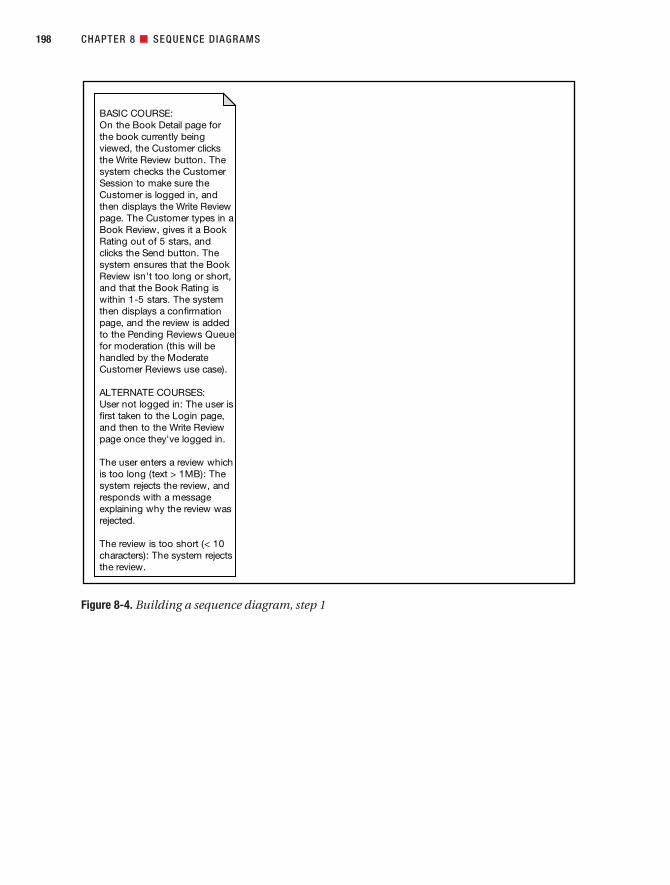
CHAPTER 8 ■ SEQUENCE DIAGRAMS198
Figure 8-4. Building a sequence diagram, step 1
BASIC COURSE:
On the Book Detail page for
the book currently being
viewed, the Customer clicks
the Write Review button. The
system checks the Customer
Session to make sure the
Customer is logged in, and
then displays the Write Review
page. The Customer types in a
Book Review, gives it a Book
Rating out of 5 stars, and
clicks the Send button. The
system ensures that the Book
Review isn't too long or short,
and that the Book Rating is
within 1-5 stars. The system
then displays a confirmation
page, and the review is added
to the Pending Reviews Queue
for moderation (this will be
handled by the Moderate
Customer Reviews use case).
ALTERNATE COURSES:
User not logged in: The user is
first taken to the Login page,
and then to the Write Review
page once they've logged in.
The user enters a review which
is too long (text > 1MB): The
system rejects the review, and
responds with a message
explaining why the review was
rejected.
The review is too short (< 10
characters): The system rejects
the review.
7745ch08final.qxd 12/13/06 8:38 PM Page 198

Step 2: Copy the Entity Objects from the Robustness DiagramAssuming you updated your static model during robustness analysis, the entity objects shouldnow each have an equivalent class on one of the class diagrams (see Figure 8-5). (And if youhaven’t updated your static model yet, be sure to do it now.) The updated Write CustomerReview sequence diagram is shown in Figure 8-6.
Until now, the entity objects have been little more than simple bags of data with lots ofattributes but no behavior (read: no personality). This will change during sequence diagram-ming. Now that they’re on the diagram, you’ll soon start to allocate operations to them—ineffect, assigning their classes with behavior. But first you need to get the remaining “nouns”(the boundary objects and actors) onto the diagram.
CHAPTER 8 ■ SEQUENCE DIAGRAMS 199
Figure 8-5. How your entity objects evolve into full-fledged classes
7745ch08final.qxd 12/13/06 8:38 PM Page 199

Step 3: Copy the Boundary Objects and Actors from the Robustness DiagramSee Figure 8-7. The boundary objects and actors are the remaining “nouns” (see Chapter 5).There can be more than one actor on the sequence diagram, although typically there’s onlyone, and it usually goes on the left of the diagram. The updated Write Customer Reviewsequence diagram is shown in Figure 8-8.
You win the ripest piece of fruit in the fruit bowl if you wondered why we’re adding theboundary objects and actors from the robustness diagram and not from the domain model. Infact, the boundary objects and actors were never added to the domain model, as they’re partof the solution space (the “how”). By contrast, the entity objects that we’ve added were on thedomain model, as they’re part of the problem space (the “what”).
Depending on the type of GUI you’re creating, the boundary classes usually turn into JSPor ASP pages. So you have the option to treat the boundary classes as “not real classes,” and
CHAPTER 8 ■ SEQUENCE DIAGRAMS200
Figure 8-6. Building a sequence diagram, step 2
CustomerReview
CustomerSession
Book Pending ReviewsQueue
BASIC COURSE:
On the Book Detail page for
the book currently being
viewed, the Customer clicks
the Write Review button. The
system checks the Customer
Session to make sure the
Customer is logged in, and
then displays the Write Review
page. The Customer types in a
Book Review, gives it a Book
Rating out of 5 stars, and
clicks the Send button. The
system ensures that the Book
Review isn't too long or short,
and that the Book Rating is
within 1-5 stars. The system
then displays a confirmation
page, and the review is added
to the Pending Reviews
Queue for moderation (this will
be handled by the Moderate
Customer Reviews use case).
ALTERNATE COURSES:
User not logged in: The user is
first taken to the Login page,
and then to the Write Review
page once they've logged in.
The user enters a review which
is too long (text > 1MB): The
system rejects the review, and
responds with a message
explaining why the review was
rejected.
The review is too short (< 10
characters): The system rejects
the review.
7745ch08final.qxd 12/13/06 8:38 PM Page 200

not allocate behavior to them. How GUIs are treated varies widely if you’re doing JSP, ASP.NET,HTML, or a desktop application (for example). So during sequence diagramming, it’s better tofocus on allocating behavior into the domain/entity classes (see step 4).
■Note We’re not saying that you should never add attributes or operations to your view/boundary classes,but as a general rule, these classes (or pages) tend not to do any of their own processing. Your own experi-ences may vary depending on the GUI or web-application toolkit that you’re using.
■Tip It helps to maintain a pure domain model diagram, containing only the entity classes (but not showingany attributes or operations). But at some point (right about now, in fact, during detailed design), you’ll needto draw some more detailed class diagrams that show both solution space classes and problem spaceclasses. As you’ll end up with some very large detailed class diagrams, you should split them up—for exam-ple, have one diagram per use case package. (Refer to Chapter 3 for a discussion of use case packages.)
■Tip And another thing: These detailed class diagrams should use the same elements as on the sequencediagrams, so when you assign a message on the sequence diagram (the dynamic model), an operation isautomatically added to the appropriate class in the static model.
CHAPTER 8 ■ SEQUENCE DIAGRAMS 201
Figure 8-7. How your boundary objects evolve into view classes or view pages (e.g., JSP pages)
RobustnessAnalysis
SequenceDiagramming
Boundary Object
'View' Classor ASP/JSP
Discover lots of these...
Put the 'view' classesin context with the restof the design...
Added to the 'solutionspace' class diagram,the Boundary Objectbecomes...
7745ch08final.qxd 12/13/06 8:38 PM Page 201

Once you’ve finished these steps, you’re over the hump of getting your design started, andit’s time to move on to the real work.
Step 4: Assign Operations to Your ClassesThis step is where the real decision-making takes place (see Figure 8-9). Up until now, every-thing has been rather mechanical and aimed at prepping the sequence diagram so that thehighly skilled surgeon (that’s you) can come in and amaze everyone with his or her precise
CHAPTER 8 ■ SEQUENCE DIAGRAMS202
Figure 8-8. Building a sequence diagram, step 3
7745ch08final.qxd 12/13/06 8:38 PM Page 202

and scrupulous design work. A surgeon must make some high-pressure decisions during anoperation (we should know, we’ve seen reruns of Dr. Kildare), and similarly, when you’redesigning software, you’re faced with difficult decisions that mostly shouldn’t be put off untillater. You’ve done all the preparatory work leading up to this point, and this next step is thecrux, the essence of detailed design.
Unfortunately, as you may have gathered, this step is also pretty hard (at least until youget the hang of it). Every decision, large and small, really counts. Experience and talent arerequired to do a good job at detailed design.
What you’ve done with this process so far is to clear the way so that, during detaileddesign, there are no distractions—all you need to think about is the design itself. But you stillneed to do the actual thinking, of course. On the bright side, the more you do it, the betteryou’ll become. As your experience grows, you’ll find it becomes easier to make good designdecisions.
The best place to get started with behavior allocation is to convert the controllers fromthe robustness diagram.
Converting the Controllers from Your Robustness Diagram
To allocate operations/methods to your classes, you need to convert the controllers fromthe robustness diagram into messages on your sequence diagram. It’s possible to do thissystematically. Step through each controller on the robustness diagram. For each one, drawthe corresponding message(s) on the sequence diagram, and then check the controller off(rather like a checklist) and move on to the next controller.
■Tip Remember that when you step through each controller on the robustness diagram, each messageshould automatically be turned into an operation (or several operations) on the appropriate class(es). on theappropriate class. Make your CASE tool work harder, so that you can work smarter!
CHAPTER 8 ■ SEQUENCE DIAGRAMS 203
Figure 8-9. How your controllers evolve into operations on your domain classes
RobustnessAnalysis
SequenceDiagramming
Controller
DomainClass
Discover lots of these...
Assign each controller asone or more operations on...
7745ch08final.qxd 12/13/06 8:38 PM Page 203

Remember that you’ve already checked the robustness diagram against the use case text.So by using the robustness diagram as a checklist for your sequence diagram, you’re providinga level of assurance that you are designing precisely what the user needs—in other words,you’re ensuring that your design matches up with the requirements.
Although we recommend turning each controller into an operation, every now and thenit makes sense to turn a controller into a full-fledged control class. How often this happensdepends on whether you’re building a real-time embedded system and whether the frame-work you’re using more-or-less demands that you have lots of itty-bitty controller classes allover the place.
■Tip Have both the sequence diagram and any relevant class diagrams at hand. You should be flippingbetween the sequence and class diagrams frequently while you assign operations and think about thedesign. It’s a two-way process: sometimes you make a change to the class diagram and then feed thechange back into the sequence diagram, and vice versa.
During this stage in the design, it pays to have a catalog of well-established design pat-terns to fall back on. The “classic set” of patterns can be found in the book Design Patterns:Elements of Reusable Object-Oriented Software by Erich Gamma, Richard Helm, Ralph John-son, and John Vlissides (Addison-Wesley, 1995). If you’re developing enterprise software, wecan also recommend Patterns of Enterprise Application Architecture by Martin Fowler(Addison-Wesley, 2002). Although the book’s title suggests that it’s about architecture, thepatterns it describes are really design patterns for the enterprise.
However, it’s also important to not become too obsessed with design patterns. Alwaystry to remember that they’re there for guidance—a starting point for when doing your owndetailed designs. We’ve seen the unfortunate results of many projects that have become toocomplex for their own good, because of a tendency to overapply design patterns. AsGroucho Marx once said, “I like my cigar, too, but I take it out of my mouth once in a while!”
Deciding Which Controllers to Assign to Which Classes
This is the big one, of course. To decide which controllers go on which classes, you mustanswer two questions:
• What are the classes?
• Which classes are responsible for which operations?
The second question has as its roots Rebecca Wirfs-Brock’s Responsibility-Driven Design(RDD). A responsibility is a combination of things: knowledge or data (the attributes), behav-ior (the operations), and the major decisions made at runtime that affect others.
Usually, you’ll find that the decision of which responsibilities to put in which classes isclear-cut. For example, it should be obvious that a BookReview will be responsible for validat-ing its own data. Sometimes, however, the decision isn’t quite so clear-cut. Responsibilitiescan be hazy or too complex to be comfortably managed by a single class. In Object Design:
CHAPTER 8 ■ SEQUENCE DIAGRAMS204
7745ch08final.qxd 12/13/06 8:38 PM Page 204
Roles, Responsibilities and Collaborations, Wirfs-Brock describes how complex responsibilitiesshould be allocated:3
An object has three options for fulfilling any responsibility. It can either:
* Do all the work itself
* Ask others for help doing portions of the work (collaborate with others)
* Delegate the entire request to a helper object
When you’re faced with a complex job, ask whether an object is up to this responsibility
or whether it is taking on too much. A responsibility that is too complex to be imple-
mented by a single object essentially introduces a new sub design problem. You need to
design a set of objects that will collaborate to implement this complex responsibility.
These objects will have roles and responsibilities that contribute to the implementation
of the larger responsibility.
As we described earlier, assigning responsibilities to each class involves giving your classsome personality, but it’s also possible for a class to become overallocated and end up withperhaps a little too much personality. Dan Rawsthorne (a former ICONIX instructor) oncesummarized the responsibility-driven thought process to Doug as follows:
If you think of your objects (or classes) as people, then the set of behaviors (operations)
that they are responsible for gives them a sort of personality. We want to watch out for
schizophrenic objects (that is, objects with split or multiple personalities) because an
object should be focused on a cohesive, related set of behaviors.
A class with a split personality—or multiple personalities—is a class that has more thanone responsibility. A clear sign of such a troubled class is if it contains discordant attributes—that is, attributes that don’t seem to fit in with their peers. If you discover discordant attrib-utes, use aggregation (see Chapter 2) to move them into separate, more appropriate classes.Most likely, these new classes will need to collaborate with each other.
Four Criteria of a Good Class
While you are making behavior allocation decisions, you are making decisions that affect thequality of the classes in your design. Grady Booch’s Object-Oriented Analysis and Design withApplications (Addison-Wesley, 1994) introduces the Halbert/O’Brien criteria of reusability,applicability, complexity, and implementation knowledge.
If you follow the RDD thought process, you’ll generally wind up with a set of behaviorsthat are all applicable (i.e., not schizoid), don’t depend on implementation details of another
CHAPTER 8 ■ SEQUENCE DIAGRAMS 205
3. Rebecca Wirfs-Brock and Alan McKean, Object Design: Roles, Responsibilities and Collaborations(New York: Addison-Wesley, 2003), p. 132
7745ch08final.qxd 12/13/06 8:38 PM Page 205

class, aren’t overly complex for any single class, and result in a reusable piece of code thatmaps nicely to a problem-domain abstraction.
Following a responsibility-driven thought process (done correctly) results in classes thatmeet the Halbert/O’Brien quality criteria. Or, to go back another 15 years or so: maximizecohesion, minimize coupling.
Continuing the Internet Bookstore ExampleTo illustrate the theory step by step, let’s return to our Internet Bookstore example and theWrite Customer Review use case. So far we’ve added the entities, actor, and boundary objectsto our sequence diagram (see Figure 8-8). The next step, as described in the previous section,is to walk systematically through the controllers on the robustness diagram and apply themto the sequence diagram.
Referring back to the robustness diagram in Figure 6-7, you can see that the Customerclicks the Write Review button on the Book Detail page. The system then performs a checkto see if the Customer is logged in. On the robustness diagram, this is represented as the “Is user logged in?” controller. This controller checks the Customer Session entity. On thesequence diagram, then, we’d have an isUserLoggedIn() method on a class calledCustomerSession.
As we now need to be thinking in terms of the implementation details, we need toestablish where the CustomerSession instance is found. In our Spring/JSP example, theCustomerSession would be an object contained in the HTTP Session layer (i.e., naturallyassociated with the current user session). When the user browses to the bookstore website, a new CustomerSession object is created and added as an attribute to HttpSession. This isthen used to track the user’s state (currently just whether the user is logged in). To make thisexplicit, we should show HttpSession on the sequence diagram, so that we can see exactlywhere CustomerSession is found.
Figure 8-10 shows the (nearly) completed sequence diagram. Notice that it’s possible to read through the use case text on the left and simultaneously walk through the sequencediagram, tracing the text to the messages on the diagram.
■Exercise In Figure 8-10, the “User not logged in” alternate course describes (at a high level) theprocess of logging in before proceeding with the current use case. Should the sequence diagram invokea separate Login use case, and if so, how would this be represented on the sequence diagram? We dis-cuss the answer in the CDR in Chapter 9.
As it turns out, a couple of objects weren’t used at all. Review Rejected Screen wasn’tused, although we originally (in the use case text) described the system taking the user to aseparate screen to show that the review was rejected. However, on drawing the sequence dia-gram, it seemed like it would be much nicer to take the user back to the Write Review Screenand show the validation errors there, so that the user can simply correct the errors and resub-mit the review. We should update the use case text at the earliest opportunity (this meansright now) to reflect this, so that the use case doesn’t fall out of sync with the design (and thuslose its usefulness).
CHAPTER 8 ■ SEQUENCE DIAGRAMS206
7745ch08final.qxd 12/13/06 8:38 PM Page 206
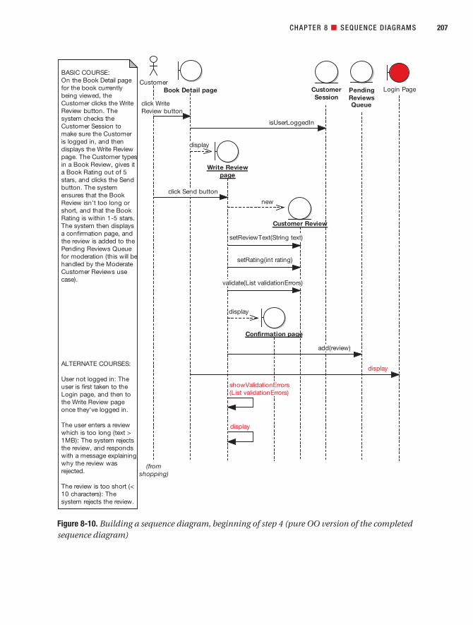
CHAPTER 8 ■ SEQUENCE DIAGRAMS 207
Figure 8-10. Building a sequence diagram, beginning of step 4 (pure OO version of the completedsequence diagram)
7745ch08final.qxd 12/13/06 8:38 PM Page 207

■Caution You don’t need to go back and redraw the robustness diagram 17 more times once you’rein the middle of sequence diagramming. You know the robustness diagrams aren’t going to be perfect, andthat’s OK—it isn’t important to make your preliminary design diagrams look like you clairvoyantly knewwhat the detailed design would look like (doing this would, in fact, cause analysis paralysis). It’s only impor-tant that the preliminary design gets you properly started with detailed design.
Additionally, Book wasn’t used at all so, after double, triple-checking to make sure we had-n’t missed a critical detail, we removed it. We discuss the reasons why Book fell off the diagramwhen we get to the CDR (see Chapter 9).
■Note Figure 8-10 raises some other issues, which we’ll also address during the CDR. In fact, most ofthese issues would have been caught using a design-driven testing (DDT) approach, which we describein Chapter 12.
This version of the diagram follows a pure OO design. It’s a “wouldn’t it be great if . . .”diagram reflecting the OO design principles we’ve discussed. As it’s quite high level, it couldbe transferred to a target platform other than Spring Framework without much (or indeedany) modification. In other words, so far we haven’t tied the design in very closely with thenitty-gritty implementation details of our target framework—and we’ll need to do thatbefore we begin coding.
Because we’re reusing a third-party web framework rather than designing our own, thedesign is dictated to an extent by the framework’s creators. For example, in Figure 8-10 weshow the validation taking place as a method on the entity class being validated. However,the approach in Spring Framework is to separate validation into a separate class. This isn’tpure OO, as it breaks encapsulation and we potentially end up with lots of tiny “controllerclasses,” each of which implements a single function. Having said that, there are practical,ground-based reasons why Spring does it this way.4
So, we need to explore the implementation details and fill in these details on thesequence diagram before we can really code from it. To complete the final step in our fouressential steps, we need to add in more detail taking into account the framework and the tech-nology being targeted.
Figure 8-11 shows the finished diagram. This is now something that we can code fromdirectly (after the CDR, of course!).
The processing in this diagram is quite detail-rich, so we’ve moved the description intoAppendix B (in the section titled “‘Write Customer Review’ Use Case”). If you’re interested inthe Spring details, please do take a look there before moving on.
CHAPTER 8 ■ SEQUENCE DIAGRAMS208
4. Spring is actually one of the better frameworks for not imposing too many design constraints. Forexample, Struts (a popular MVC web framework) contains a much more rigid design, in which yourclasses must extend specific Struts classes. Because Java doesn’t allow multiple inheritance, this canbe a limiting factor.
7745ch08final.qxd 12/13/06 8:38 PM Page 208

CHAPTER 8 ■ SEQUENCE DIAGRAMS 209
Figure 8-11. Building a sequence diagram, completing step 4 (the completed sequence diagram)
7745ch08final.qxd 12/13/06 8:38 PM Page 209

■Exercise WriteCustomerReviewCommand seems quite redundant, as it’s simply there to hold datathat gets set in the CustomerReview domain class anyway. What could be done to improve this part of thedesign? We reveal the answer during the CDR in the next chapter.
■Exercise The Book class in Figure 8-11 doesn’t seem to do a huge amount. How could this design beimproved to give Book a more prominent role? (Remember, we had the same problem with the Show BookDetails sequence diagram in Figure 8-2.) Again, we reveal the answer during the CDR in the next chapter.
Now that we’ve completed the sequence diagram, it’s time to bring the static model up todate. After walking through the theory, we show the updated static model for the InternetBookstore.
Updating Your Class Diagrams As You Go AlongAs you’ve probably gathered by now, you need to keep updating and refining your static model(the class diagrams) as you go along (see Figure 8-12).
CHAPTER 8 ■ SEQUENCE DIAGRAMS210
Figure 8-12. Updating your static model, again
7745ch08final.qxd 12/13/06 8:38 PM Page 210

Synchronizing the Static and Dynamic Parts of the ModelCASE tools take much of the burden out of keeping the static and dynamic models in syncby putting operations on classes as you draw message arrows on sequence diagrams. But wedo recommend that, with each message arrow you draw on the sequence diagram, you takea peek at the class diagram to make sure it’s updated correctly.
It’s a good habit to check that the operations are added to the correct class each time youdraw a message, and if you spot any missing attributes, add them as soon as you notice they’remissing. Seeing each class evolve should also cause you to think about the class structure, andevolve the class design. You might spot an opportunity for generalization, for example; youmay see a possible use of a design pattern; or you could find that a class has gained too manyresponsibilities and needs to be split in two using aggregation.
As you’re adding implementation details to the sequence diagrams, don’t be surprised ifyou start to see lots of new classes appear on the static model that were never there on thedomain model during analysis. That’s because you’re now identifying the solution spaceclasses. By contrast, the domain model shows classes only from the problem space.
The two spaces are now converging during detailed design. By updating the staticmodel as you work through the sequence diagrams, you’re now converging the problemspace with the solution space.
So, as you add in more functionality from the use cases, you’ll also come up with scaffold-ing and other types of infrastructure (e.g., “helper” classes).
Adding getters and setters to your class diagrams can be time-consuming and doesn’tgive you much in return, except a busy-looking class diagram. Our advice is to avoid addingthem to your model. For now, just add the attributes as private fields and utilize encapsula-tion. As you only ever allow access to attributes via getters and setters, adding them is kindof redundant. When you generate code, you should be able to generate get and set methodsfrom attributes anyhow. Pretty much all modern IDEs and diagramming tools are scriptableor have this sort of automation built in.
Although we suggested that you avoid adding too much design detail during domainmodeling (since there just wasn’t enough supporting information available at that time), nowthat you’re at the detailed design stage, this really is the time to go wild (so to speak) and thinkthe design through in fine detail. You and your team are shaping up the design—collabora-tively, we hope—and getting it ready for coding.
In the next section, we illustrate how to synchronize the static and dynamic parts of themodel for the Internet Bookstore.
Internet Bookstore: Updating the Static ModelIn this section, we show three different versions of the static model updated from thesequence diagrams (review the previous version in Figure 5-19 to see how the static modelhas evolved so far). Figure 8-13 shows the static model updated from the pure OO sequencediagram shown in Figure 8-10.
Book and BookCollection are on the static model because they also appeared on thedomain model; however, neither class has operations yet because we haven’t drawn anysequence diagrams that allocate behavior to them.
CHAPTER 8 ■ SEQUENCE DIAGRAMS 211
7745ch08final.qxd 12/13/06 8:38 PM Page 211

CustomerSession used to have a loggedIn attribute (see the domain model diagram inFigure 5-19), but after sequence diagramming, this has turned into a method,isUserLoggedIn(), without an attribute to back it (i.e., it’s a “live” or calculated value that is rechecked each time the method is called).
Figure 8-13 reveals some commonality between some of the classes. Each of the bound-ary classes has its own display() method. So it would make sense to move this up to a newparent class. Figure 8-14 shows the result of this prefactoring (it’s much quicker to do thissort of thing now, while we’re looking at the bigger picture, before we have source codedependent on the class we’re prefactoring).
CHAPTER 8 ■ SEQUENCE DIAGRAMS212
Figure 8-13. Internet Bookstore static model based on the pure OO sequence diagram in Figure 8-10
«boundary»
BookDetailScreen
+ display() : void
«boundary»
WriteReviewScreen
+ display() : void+ showValidationErrors(List) : void
«entity»
CustomerReview
- rating: int- reviewText: String
+ setRating(int) : void+ setReviewText(String) : void+ validate(List) : void
«boundary»
ConfirmationScreen
+ display() : void
«entity»
CustomerSession
+ isUserLoggedIn() : boolean
«entity»
PendingReviewsQueue
+ add(CustomerReview) : void
«boundary»
LoginScreen
+ display() : void
«entity»
Book
+ synopsis: String+ title: String
«entity»
BookCollection
«boundary»
HomePage
+ display() : void
7745ch08final.qxd 12/13/06 8:38 PM Page 212

In Figure 8-14, we created a new abstract class called View, which contains the commondisplay() method. The boundary classes only need to override this method if they’re doingsomething special. In this case, WriteReviewScreen overrides it because it needs to display thevalidation errors set via showValidationErrors().
CHAPTER 8 ■ SEQUENCE DIAGRAMS 213
Figure 8-14. Prefactored Internet Bookstore static model, still pure OO
«boundary»
BookDetailScreen«boundary»
WriteReviewScreen
+ display() : void+ showValidationErrors(List) : void
«entity»
CustomerReview
- rating: int- reviewText: String
+ setRating(int) : void+ setReviewText(String) : void+ validate(List) : void
«boundary»
ConfirmationScreen
«entity»
CustomerSession
+ isUserLoggedIn() : boolean
«entity»
PendingReviewsQueue
+ add(CustomerReview) : void
«boundary»
LoginScreen
«boundary»
View
+ display() : void
Overriding display()method to showvalidation errors.
«entity»
BookCollection
«boundary»
HomePage
«entity»
Book
- synopsis: String- title: String
7745ch08final.qxd 12/13/06 8:38 PM Page 213
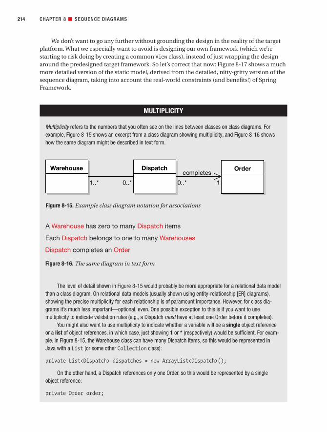
We don’t want to go any further without grounding the design in the reality of the targetplatform. What we especially want to avoid is designing our own framework (which we’restarting to risk doing by creating a common View class), instead of just wrapping the designaround the predesigned target framework. So let’s correct that now: Figure 8-17 shows a muchmore detailed version of the static model, derived from the detailed, nitty-gritty version of thesequence diagram, taking into account the real-world constraints (and benefits!) of SpringFramework.
CHAPTER 8 ■ SEQUENCE DIAGRAMS214
MULTIPLICITY
Multiplicity refers to the numbers that you often see on the lines between classes on class diagrams. Forexample, Figure 8-15 shows an excerpt from a class diagram showing multiplicity, and Figure 8-16 showshow the same diagram might be described in text form.
The level of detail shown in Figure 8-15 would probably be more appropriate for a relational data modelthan a class diagram. On relational data models (usually shown using entity-relationship [ER] diagrams),showing the precise multiplicity for each relationship is of paramount importance. However, for class dia-grams it’s much less important—optional, even. One possible exception to this is if you want to usemultiplicity to indicate validation rules (e.g., a Dispatch must have at least one Order before it completes).
You might also want to use multiplicity to indicate whether a variable will be a single object referenceor a list of object references, in which case, just showing 1 or * (respectively) would be sufficient. For exam-ple, in Figure 8-15, the Warehouse class can have many Dispatch items, so this would be represented inJava with a List (or some other Collection class):
private List<Dispatch> dispatches = new ArrayList<Dispatch>();
On the other hand, a Dispatch references only one Order, so this would be represented by a singleobject reference:
private Order order;
Figure 8-15. Example class diagram notation for associations
Warehouse Dispatch Order
1..* 0..* 0..*
completes
1
Figure 8-16. The same diagram in text form
7745ch08final.qxd 12/13/06 8:38 PM Page 214

Figure 8-17 has been updated to show the details from the sequence diagrams for boththe Show Book Details and Write Customer Review use cases.
CHAPTER 8 ■ SEQUENCE DIAGRAMS 215
Figure 8-17. Internet Bookstore static model after drawing sequence diagrams for two use cases
7745ch08final.qxd 12/13/06 8:38 PM Page 215

What’s changed in Figure 8-17?
• We’ve introduced a couple of Spring classes (DispatcherServlet and ModelAndView)and a class from the Java Servlet API (HttpSession), and we’ve shown which of ourown classes relate to them.
• The aggregation relationships now show their multiplicity (see the previous sidebar).
• We’ve filled in the properties that were identified in the use case, plus any supplemen-tary specs (screen mock-ups, passive-voice functional specifications, etc.).
• Our Screen classes have been replaced with (mostly) Spring Controller classes. Whichbrings us to the next point . . .
• Some of the methods that originated from controllers on the robustness diagramshave escaped and turned into their own Controller classes. While we wouldn’t nor-mally recommend this, Spring requires that each form has its own Controller class.This class handles the details of extracting postvalidated data, processing it, andthen telling the framework which JSP page to send back to the user.
• We’ve introduced a Command class (WriteCustomerReviewCommand), which represents thedata extracted from the user’s form post.
■Note In the next chapter, we revisit this part of the design and look at how to make it more “domainoriented” while lessening our reliance on separate Command and Controller classes and still fitting into the Spring design mold.
• We’ve got DAOs. BookDao, CustomerReviewDao—you name it, we’ve got it. Rememberthat a DAO (e.g., BookDao) is analogous to a database table, whereas a domain class(e.g., Book) is analogous to a row in a database table. A BookDao is a source of Books, so it’s similar to an EJB Home object.
• BookCollection has disappeared. Instead we have BookDao, as mentioned in theprevious point. In fact, BookDao will actually return collections of Books—though we haven’t shown this yet, as we haven’t drawn these Collection operations on anyof the sequence diagrams.
• Because Spring has its own validation framework that we want to take advantage of,we’ve separated the CustomerReview validation into its own separate class,CustomerReviewValidator. (Note that although this separation of concerns seems like a good idea on the surface, it turns out to be not that good an idea after all. We discussthe reasons why in Chapter 11.)
CHAPTER 8 ■ SEQUENCE DIAGRAMS216
7745ch08final.qxd 12/13/06 8:38 PM Page 216

Although it contains a lot of detail, Figure 8-17 contains purely the detail we’ve uncoveredduring domain modeling, robustness analysis, and sequence diagramming, and nothingmore. There are no leaps of logic, leaps of faith, or leaps of any kind. The operations on eachclass are taken directly from the messages we drew on the sequence diagrams. The relation-ships between each class are also derived from the relationships in the domain model andfrom the operations. The attributes on each class are derived from the detail in the use casesand any supplementary specs that the use cases reference (e.g., screen mock-ups, data mod-els, etc.).
It’s tempting to add detail to the class diagram because you think it might be needed, but(as we hope we’ve demonstrated) it’s better fill in the detail while drawing the sequence dia-grams. If, after you’ve fleshed out the static model using the sequence diagrams, the staticmodel still appears to be missing some detail, then you should revisit the sequence diagrams(and possibly even the robustness diagrams and use cases), as it’s likely that something hasbeen missed. Always trust your gut instinct, but use it as an indication that you need to revisityour previous diagrams, not that you need to second-guess yourself and add detail arbitrarilyto the static model.
We’ve now finished the detailed design for the two use cases we’re implementing. Thenext stage before coding will be the CDR, a “sanity check” involving senior technical staff tomake sure the design is shipshape before the use cases are implemented.
Sequence Diagramming in PracticeThe following exercises, taken from the detailed design activities for the Internet Bookstore,are designed to test your ability to spot the most common mistakes that people make duringsequence diagramming.
ExercisesEach of the diagrams in Figures 8-18 to 8-20 contains one or more typical modeling errors. Foreach diagram, try to figure out the errors and then draw the corrected diagram. The answersare in the next section.
CHAPTER 8 ■ SEQUENCE DIAGRAMS 217
7745ch08final.qxd 12/13/06 8:38 PM Page 217

Exercise 8-1
Figure 8-18 shows an excerpt from a sequence diagram for the Add External Books to Catalog use case (whichyou also encountered in the exercises in Chapter 5). It shows quite a few examples of a common behavior allo-cation error. (Hint: Which objects are the messages pointing to?) Try to explain why the behavior allocation in thediagram is wrong, and then draw the corrected diagram.
CHAPTER 8 ■ SEQUENCE DIAGRAMS218
Figure 8-18. Excerpt from a sequence diagram showing several behavior allocation errors
SellerAdd External Books toCatalog:
BASIC COURSE:The system displaysthe Add External Bookpage. The Seller typesin the External Bookdetails (title, ISBN,price etc) and clicksthe Add Book button.
The system checksthat each field has avalue, and that theprice is numeric, isn't anegative value or >$1,000. The systemalso checks thatthere's a matchingISBN in the Bookstoredatabase.
The system thencreates the ExternalBook in the database.
. . .
Add ExternalBook page
ExternalBook
BookstoreDatabase
display
submit form
checkFieldsHaveValues
checkPriceIsNumeric
checkPriceIsInRange
doesISBNExist
book= create
save(book)
7745ch08final.qxd 12/13/06 8:38 PM Page 218

Exercise 8-2
Figure 8-19 shows an excerpt from a sequence diagram for the Create New Book use case (this use case isintended for Bookstore staff, so that they can add new Book titles to their online Catalog). There are a couple ofproblems with this diagram excerpt (one of which is repeated many times in the diagram). See if you can findthem both.
CHAPTER 8 ■ SEQUENCE DIAGRAMS 219
Figure 8-19. Excerpt from a sequence diagram showing a couple of pretty major problems
CatalogAdministrator
CreateNew Book
page
Book
BookDAO
enter book details and click Create
create a Book object
fill in details from form
tell Book to save itself to the DB
make JDBC call to database
confirmation messageredisplay page with
7745ch08final.qxd 12/13/06 8:38 PM Page 219

Exercise 8-3
Figure 8-20 shows an excerpt from a sequence diagram for the Edit Shopping Cart use case. The problems withthis diagram are partly related to the diagram showing too much detail in some aspects, but also (ironically per-haps) the diagram displays too little detail where it should be showing more of the design’s “plumbing.” There arealso a couple of issues to do with the use case’s scope (i.e., where it starts and finishes). In total, you should findsix errors on this diagram. Good luck!
CHAPTER 8 ■ SEQUENCE DIAGRAMS220
Figure 8-20. Excerpt from a sequence diagram showing both too much and too little detail
The system displays
the Checkout page;
the user clicks on
Edit Shopping Cart.
The system displays
the Edit Shopping
Cart page.
The user picks a
Line Item from the
Edit Shopping Cart
page.
The user modifies
the quantity of the
Line Item, then
clicks Submit.
The system validates
the entry and
redisplays the Edit
Shopping Cart page
with the totals
updated and a
confirmation
message.
The user clicks
Checkout; the
system takes the
user to the Checkout
page.
User Checkout page Edit Shopping
Cart page
Shopping Cart Line Item
display
click Edit
Shopping Cart
display
load(customerID)
fetchList
return list of Line Items
submit modified Line Item qty
validate
display
display page
click Checkout
display page
7745ch08final.qxd 12/13/06 8:38 PM Page 220

Exercise SolutionsFollowing are the solutions to the exercises.
Exercise 8-1 Solution: Non-OO Behavior Allocation
Figure 8-21 highlights the parts of the sequence diagram where the messages were allocated incorrectly. Thehighlighted messages are really the responsibility of ExternalBook. In the current design, the validation check-ing goes on in the boundary object, and only after that’s all done is the ExternalBook object created. Its onlypurpose in life is to be passed into BookstoreDatabase for saving.
Note that two of the methods haven’t been highlighted: checkFieldsHaveValues andcheckPriceIsNumeric. These are legitimately a part of the boundary object, as they’re checking that theincoming data is both present and in the correct format. checkPriceIsInRange, on the other hand, is “genuine”data validation, so it belongs on ExternalBook.
On BookstoreDatabase (over on the right of Figure 8-21), two more methods have been highlighted:doesISBNExist and save(book). In this case, it’s the caller that’s wrong—both methods should be called by ExternalBook.
Figure 8-22 shows the corrected diagram.
CHAPTER 8 ■ SEQUENCE DIAGRAMS 221
7745ch08final.qxd 12/13/06 8:38 PM Page 221
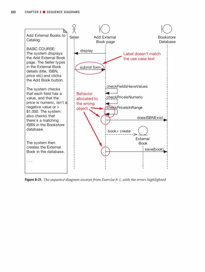
CHAPTER 8 ■ SEQUENCE DIAGRAMS222
Figure 8-21. The sequence diagram excerpt from Exercise 8-1, with the errors highlighted
7745ch08final.qxd 12/13/06 8:38 PM Page 222

Exercise 8-2 Solution: Flowcharting
Figure 8-23 highlights the parts of the sequence diagram that have gone wrong. The main issue is that thesequence diagram is being used as a flowchart, instead of for its primary purpose in life: to allocate behavior toclasses.
Flowcharting on sequence diagrams isn’t necessarily an evil thing in and of itself, and it is almost certainly betterthan not doing the sequence diagram at all. But we consider it to be (at best) a weak usage of a sequence diagrambecause it doesn’t leverage the ability to assign operations to classes while drawing message arrows. Since, in ouropinion, this activity is pretty much the fundamental place where “real OOD” happens, we’ve flagged it as an error.We think you can (and should) do better than just using the sequence diagram as a flowchart.
CHAPTER 8 ■ SEQUENCE DIAGRAMS 223
Figure 8-22. The corrected sequence diagram excerpt for Exercise 8-1
SellerAdd External Booksto Catalog:
BASIC COURSE:The system displaysthe Add ExternalBook page. The Sellertypes in the ExternalBook details (title,ISBN, price etc) andclicks the Add Bookbutton.
The system checksthat each field has avalue, and that theprice is numeric, isn'ta negative value or >$1,000.
The system alsochecks that there's amatching ISBN in theBookstore database.
The system thencreates the ExternalBook in thedatabase.
. . .
Add ExternalBook page
ExternalBook
BookstoreDatabase
display
click AddBook button
checkFieldsHaveValues
checkPriceIsNumeric
book= create
validate
checkPriceIsInRange
doesISBNExist
save
save(this)
7745ch08final.qxd 12/13/06 8:38 PM Page 223

The second issue is that there’s no validation performed on the incoming form data—and therefore no error han-dling code for rejecting bad data. Either the validation steps were left out of the use case or the designer didn’tdraw the sequence diagram directly from the use case text.
Figure 8-24 shows the corrected diagram. The corrected version includes the alternate course (shown in red) forwhen the form validation fails.
CHAPTER 8 ■ SEQUENCE DIAGRAMS224
Figure 8-23. The sequence diagram excerpt from Exercise 8-2, with the errors highlighted
7745ch08final.qxd 12/13/06 8:38 PM Page 224
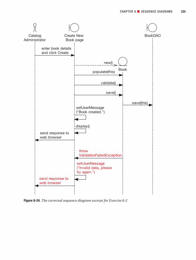
CHAPTER 8 ■ SEQUENCE DIAGRAMS 225
Figure 8-24. The corrected sequence diagram excerpt for Exercise 8-2
7745ch08final.qxd 12/13/06 8:38 PM Page 225

Exercise 8-3 Solution: Plumbing
Figure 8-25 highlights the parts of the sequence diagram that have gone wrong.
CHAPTER 8 ■ SEQUENCE DIAGRAMS226
Figure 8-25. The sequence diagram excerpt from Exercise 8-3, with the errors highlighted
7745ch08final.qxd 12/13/06 8:38 PM Page 226

The use case starts and finishes at the wrong stages, suggesting a problem with the overall scope of the use case.It’s a use case about editing the Shopping Cart, but it contains details about interacting with the Checkout page(i.e., the use case lacks focus). Luckily in this example, the problem is easy to fix, but normally you’d expect tocatch this kind of scope issue during robustness analysis or the PDR at the latest. If you encounter a sequencediagram where the use case’s scope is still wrong, you should take a look at the process and work out what’s gone wrong.
The next issue is more a matter of personal taste than an egregious error. The sequence diagram is showing thefocus of control (the rectangles that indicate the “lifetime” of each message). Note that this isn’t necessarily anerror, as some people do prefer to show these, but for the purposes of behavior allocation, our preference is tonot show them, as they clutter the diagram and make it more difficult to draw, without giving a whole lot backin return.
On to the next issue, which is definitely a modeling error. In the load(customerID) message, you’d be for-given for wondering where the customerID sprang from. Any time you see a leap of logic on a sequencediagram, where it isn’t clear where something came from, then it’s probable that a part of the design has beenmissed. In this case, the diagram is missing the CustomerAccount object, which should have been populatedwhen the session began. This can then be retrieved from CustomerSession. These design details all need tobe shown on the diagram, as it’s essential “plumbing” work. (In this example, it would be reasonable to put a note on the diagram stating that CustomerSession and CustomerAccount are set up during the Login usecase, so that the diagram remains focused on the use case that we’re currently designing.) In fact, it would alsomake sense to retrieve the ShoppingCart from the CustomerAccount, instead of telling the ShoppingCartto “go find itself” based on the customer’s ID.
Next up is the fetchList method, which ShoppingCart calls on LineItem. A quick check of the class diagram(assuming this is being automatically updated as you allocate messages on the sequence diagram) quickly revealsthat fetchList() just doesn’t belong on the LineItem class, as it returns a list of LineItems. Instead, it wouldmake more sense for this method to be on ShoppingCart itself, but to be called from the EditShoppingCartboundary object.
Still on LineItem, the “return list of Line Items” arrow isn’t needed. Normally, you don’t need to draw an arrowto show return values, as the method returning is implied by the arrow that initially calls the method.
Finally, there shouldn’t be a display method going from the ShoppingCart entity, as the boundary object isalready in control, and the very next thing it does is display the page anyway.
Figure 8-26 shows the corrected diagram.
■Exercise Figure 8-26 still lacks some detail around populating the LineItems list component—for example, where does the Edit Shopping Cart page get the names and quantities from for each Line Itemin the list? Try redrawing the diagram with this additional detail added.
CHAPTER 8 ■ SEQUENCE DIAGRAMS 227
7745ch08final.qxd 12/13/06 8:38 PM Page 227

More PracticeThis section provides a list of modeling questions that you can use to test your knowledge ofsequence diagramming. If you can’t answer a question, review the relevant sections in thischapter until you can answer it.
CHAPTER 8 ■ SEQUENCE DIAGRAMS228
Figure 8-26. The corrected sequence diagram excerpt for Exercise 8-3
From the Checkout
page, the user clicks on
Edit Shopping Cart.
The system displays
the Edit Shopping Cart
page.
The user clicks on a
Line Item in the list of
items in his Shopping
Cart, then modifies the
quantity of the Line
Item, and clicks
Update.
The system checks that
the quantities entered
are valid, and redisplays
the Edit Shopping Cart
page with the totals
updated and a
confirmation message.
. . .
User Edit Shopping
Cart page
Shopping Cart
Line Item
Customer
Session
Customer
Account
click link
displayPage
customer= getCustomerAccount
cart= getShoppingCart
lineItems= fetchList
{for each LineItem in
the ShoppingCart }
*new
populate
LineItems
Component
display page
submit modified
LineItem qty
updateList
checkQuantities
createConfirmationMessage
display page
7745ch08final.qxd 12/13/06 8:38 PM Page 228

1. The primary purpose of a sequence diagram should be
a) To show detailed flow of control for a use case
b) To specify real-time, finite-state behavior
c) To help make an optimal allocation of functions to classes within the context of ause case
d) To separate out alternate courses of action
2. A sequence diagram should always be
a) Cross-checked against a class diagram with operations shown on the classes
b) Reviewed to make sure all behavior specified in the use case is accounted for bymessages between objects
c) Reviewed against a GUI prototype or storyboard to make sure all possible useractions are accounted for
d) All of the above
3. Readability of a sequence diagram is best accomplished by
a) Using detailed use case templates showing pre- and postconditions
b) Drawing it to the same level of detail as a robustness diagram
c) Following the two-paragraph rule and keeping the use cases short
d) Showing branching and conditional logic on the diagram
4. Which of the following statements is not true?
a) It’s preferable to show all alternate course of actions on a single diagram ratherthan produce a separate diagram for each alternate.
b) It’s OK to turn off “focus of control” if it gets in your way.
c) Sequence diagrams show essentially the same information as collaborationdiagrams, in a different format.
d) You should always rewrite your use case text when drawing a sequence diagram.
5. What things should you consider when drawing a message between objects on asequence diagram? List at least four criteria, and explain why you should considereach of them.
6. The allocation of behavior can be effectively accomplished by following aresponsibility-driven thought process. Explain the premise of Responsibility-DrivenDesign (RDD). (Hint: A good book on RDD was written by Rebecca Wirfs-Brock.)
7. Is it a good idea to draw flowchart-level sequence diagrams that focus on branchingand conditional logic? Why or why not?
CHAPTER 8 ■ SEQUENCE DIAGRAMS 229
7745ch08final.qxd 12/13/06 8:38 PM Page 229

8. How should the level of abstraction of the use case text that appears on the margin ofthe sequence diagram compare to the abstraction level of the diagram? (Hint: The dia-gram should show an object/message detailed design view.)
Discuss the pros and cons of each of the following possibilities:
a) Use case text should match the diagram’s abstraction level.
b) Use case text should remain at the abstract, technology-free, implementation-independent requirements level as in the first-draft use cases.
c) Use case text should remain at the robustness diagram abstraction level (concep-tual design), while the sequence diagram should show additional design detail.
SummaryIn this chapter we covered detailed design, the second step in the two-step design process(the first step was preliminary design). Figure 8-27 shows where we are; the items covered inthis chapter are shown in red.
Once you’ve drawn all the sequence diagrams for the use cases you’re working on in thecurrent release and updated your static model, then you can safely say that you’ve finishedthis stage in the process.
By now, you’re almost ready to begin coding. There’s just one last stop before code: theCritical Design Review (CDR), which we cover in the next chapter. It’s an essential step, as itforms something of a reality check for your design.
CHAPTER 8 ■ SEQUENCE DIAGRAMS230
7745ch08final.qxd 12/13/06 8:38 PM Page 230

Figure 8-27. Activities during the detailed design stage
CHAPTER 8 ■ SEQUENCE DIAGRAMS 231
7745ch08final.qxd 12/13/06 8:38 PM Page 231

7745ch08final.qxd 12/13/06 8:38 PM Page 232

Critical Design Review
Your project should now be in much better shape than many other projects normally are bythis stage. By now, you’ve used robustness analysis to disambiguate the use case text and dis-cover any missing domain classes, you’ve held a Preliminary Design Review (PDR) to makesure the use cases match up with what the customer really wants, and you’ve carefully crafteda detailed design for the use cases you’re implementing in this release.
So, you’re nearly ready to begin coding—there’s just one quick (but vital) milestone tocheck off the list first: the Critical Design Review (CDR).
233
C H A P T E R 9
7745ch09final.qxd 12/13/06 8:40 PM Page 233

The 10,000-Foot ViewWhy bother reviewing the design again? Here’s a hypothetical conversation that we hope willshed some light on the subject.
Q: What’s a CDR and why am I spending time on it when I could be writing code?
A: The CDR helps you to achieve three important goals, before you begin coding:
• Ensure that the “how” of detailed design matches up with the “what” specified inyour requirements. In other words, for each use case, you need to match up the usecase with its sequence diagram.
• Review the quality of your design. So you’ll want to have at least one design expertin the room.
• Check for continuity of messages. You need to check the direction of the messagearrows on your sequence diagrams, and make sure you can always tell whichobject is in control. Sometimes you’ll see leaps between objects that don’t involve amessage between them. These leaps of logic need to be ironed out.
■Note See the section “Using the Class Diagrams to Find Errors on the Sequence Diagrams” later in thischapter for an example problem caused by leaps of logic.
Q: Who should be involved in the CDR?
A: This might surprise you, but the customer should not be involved in the CDR—just thedesigners and developers. It’s a technical review session, so it should be populated bytechnically minded people.
The customer (plus key users, etc.) has a lot to contribute to the functional requirements,use cases and so forth, but unless the customer really is a technically minded designexpert who can contribute to a design review, it’s preferable that he or she not attend theCDR. Picture yourself having to explain to a nontechnical customer, for the fiftieth time,what a Façade pattern is and why you’re not using it in this particular design!
Q: But isn’t it supposed to be better if the customer is closely involved in the project?
A: Absolutely—just not to the point of silliness. Remember that by this stage, the cus-tomer has signed off on the use cases twice. And—assuming you’re following an agileprocess with small, frequent releases—the customer will get to give lots of feedback onthe evolving feature set and on the UI during development. Also, keep in mind that it ispossible for a customer to micromanage a software project. Your programmers might notactually enjoy this too much, unless of course you’ve negotiated an “optional-scope con-tract”1 whereupon the scope of what you deliver is optional, and customers are promisedthey can change their mind about the requirements during coding “for free.”
234 CHAPTER 9 ■ CRITICAL DESIGN REVIEW
1. See “Optional-Scope Contracts” on page 260 of Extreme Programming Refactored: The Case Against XP(Apress, 2003).
7745ch09final.qxd 12/13/06 8:40 PM Page 234

Q: When is the right time to begin the CDR?
A: You need to have completed all of the sequence diagrams for the use cases that you’replanning to implement in the current release. You should also have updated the class dia-grams so that all of the operations that you assigned during sequence diagramming arereflected in the static model. Having to update the diagrams during the review would betoo much of a distraction, so it’s important to make sure all of that work is finished beforethe review begins.
Critical Design Review in TheoryIn this section, we cover the key elements of CDR, structured as usual around our top 10guidelines.
Top 10 Critical Design Review GuidelinesThe principles discussed in this chapter can be summed up as a list of guidelines. Our top 10list follows.
10. Make sure the sequence diagram matches the use case text.
9. Make sure (yes, again) that each sequence diagram accounts for both basic and alter-nate courses of action.
8. Make sure that operations have been allocated to classes appropriately.
7. Review the classes on your class diagrams to make sure they all have an appropriateset of attributes and operations.
6. If your design reflects the use of patterns or other detailed implementation constructs,make sure that these details are reflected on the sequence diagram.
5. Trace your functional (and nonfunctional) requirements to your use cases and classesto ensure you have covered them all.
4. Make sure your programmers “sanity check” the design and are confident they canbuild it and that it will work as intended.
3. Make sure all your attributes are typed correctly, and that return values and parameterlists on your operations are complete and correct.
2. Generate the code headers for your classes, and inspect them closely.
1. Review the test plan for your release.
Let’s walk through these top 10 CDR practices in more detail.
CHAPTER 9 ■ CRITICAL DESIGN REVIEW 235
7745ch09final.qxd 12/13/06 8:40 PM Page 235

10. Make Sure the Sequence Diagram Matches the Use Case TextYou need to be able to trace from the behavior requirements (on the left margin) across to seehow those requirements will be implemented by messages being sent between objects.
The sequence diagram should provide a visual requirements trace at a glance. That is,the disambiguated behavior requirements should be clearly visible on the left margin of thediagram, and directly to the right of each sentence should be the objects/messages that willimplement those behavior requirements. So it should be trivially simple to see back to therequirements while looking at the detailed design.
During reviews, the “highlighter test” works exceptionally well (again). Highlight a sen-tence of use case text on the margin, and then highlight the messages that show the design forthat bit of required behavior. Then just “lather, rinse, repeat” the process until the whole usecase has been checked.
9. Cover Both Basic and Alternate Courses of ActionDon’t make the mistake of saying YAGNI2 about those pesky rainy-day scenarios. They’re tooimportant.
8. Make Sure That Operations Have Been Allocated to Classes AppropriatelyFollow the principles of Responsibility-Driven Design (RDD; see Chapter 8), and make sureeach of your classes has a cohesive, focused set of operations. With automated tools, you canusually distinguish between operations on classes and messages that have just been labeledon the sequence diagram by looking for parentheses “()” following the operation name on themessage arrow.
7. Review the Attributes and Operations on Your ClassesYou need to review the classes on your class diagrams to ensure they all have an appropriateset of attributes and operations. The easiest way to do this is to continuously bounce backand forth between the sequence diagram and a detailed class diagram that shows all theattributes and operations for the classes. It’s easy to make mistakes on sequence diagrams,so after you draw each arrow, take a peek at the class diagram and make sure you’ve put theoperation where you intended it to go.
■Tip Look for classes without attributes and for classes with “schizophrenic personalities” (i.e., unrelatedsets of operations).
Sometimes you’ll find that you’ve overloaded a class with too many responsibilities, oryou may find that, once all the behavior allocation is done, some classes end up rather impov-erished, with no responsibilities (as in the Book example later in this chapter).
CHAPTER 9 ■ CRITICAL DESIGN REVIEW236
2. YAGNI stands for You Aren’t Gonna Need It, a much-loved saying among Extreme Programmers.
7745ch09final.qxd 12/13/06 8:40 PM Page 236

You’ll notice a responsibility-driven theme in the Internet Bookstore review later on. Thethought process behind assigning responsibilities to classes is summed up nicely by RebeccaWirfs-Brock in her book Designing Object-Oriented Software:3
Responsibilities are meant to convey a sense of the purpose of an object and its place in
the system. The responsibilities of an object are all the services it provides for all the con-
tracts it supports.When we assign responsibilities to a class we are stating that each and
every instance of that class will have those responsibilities, whether there is just one
instance or many.
6. Make Sure the Chosen Design Patterns (Etc.) Are in Your Sequence DiagramsWhile there are some exceptions, the general guideline here is that the sequence diagram shouldshow the “real design” as you intend to code it. Magic is not permissible on sequence diagrams.
5. Trace Your Requirements to Your Use Cases and ClassesTrace your functional (and nonfunctional) requirements to your use cases and classes to makesure you have covered them all. Adjust your formality level to what’s appropriate for your proj-ect and organization, but if you’re going to trace requirements to the design, this is the besttime to do it. Tools like EA make it easy with the built-in traceability matrix.
4. Make Sure Your Programmers “Sanity Check” the DesignIt doesn’t do anybody any good to have your analysts attempt to dictate a design that’s ineffi-cient or otherwise problematic to build. Programmers need to be involved in detaileddesign.
3. Check for Correctness (Return Values, Typos, Etc.)Make sure all your attributes are typed correctly, and that return values and parameter lists onyour operations are complete and correct. You’re going to hit the Generate Code button realsoon now, so you’d best have all your ducks lined up before you do.
2. Generate the Code Headers for Your Classes, and Inspect Them CloselySee, we told you that you were about to generate code. Once you’ve done so, inspect the codeheaders carefully.
1. Review the Test Plan for Your ReleaseThe key here is that you’re generating a list of unit tests at the logical software function level—that is, as defined by the controllers on your robustness diagrams. Each of these logical func-tions might explode to more than one message on a sequence diagram, and you’ll probably
CHAPTER 9 ■ CRITICAL DESIGN REVIEW 237
3. Rebecca Wirfs-Brock, Brian Wilkerson, and Laura Wiener, Designing Object-Oriented Software (UpperSaddle River, NJ: Prentice-Hall, 1990), p. 62.
7745ch09final.qxd 12/13/06 8:40 PM Page 237

want to unit test each of these as well, but generating skeleton tests from the robustness dia-gram will make sure you test the logical result of each of these functions as well.
■Tip Remember that you can generate (stub) test cases for the controllers on your robustness diagramsautomatically using EA with the ICONIX Process add-in. You can then collect these into a test plan, and alsogenerate the class/method skeletons for your unit tests.
In the second part of this chapter, we illustrate some of these points by following a CDRsession for the Internet Bookstore.
Using the Class Diagrams to Find Errors on the Sequence DiagramsA technique that works really well during the CDR is, as the title of this section suggests,using the class diagrams to find errors on the sequence diagrams. Basically, this involves thereviewer zooming in on various classes in the class diagram and looking for methods on thewrong classes, or other anomalies, and then finding the guilty sequence diagrams.
In a recent training workshop, Doug found a Queue class that had only an Add method.Nobody was removing anything from the queue, ever! Doug found the sequence diagram thatwas supposed to use the items from the queue and discovered that the message arrows weredrawn backward—the Pull Item from Queue method had been put on the wrong class. TheQueue was on the sequence diagram (as it should have been) because the diagramming toolput it there automatically, but somehow they still managed to draw the arrow backward.
You can find most sequence diagram errors by looking at the class diagram.
Critical Design Review in Practice: Internet BookstoreIn this section, we walk through an example CDR for the Show Book Details and Write Cus-tomer Review use cases. To make things a bit more interesting, we’ve structured the reviewas a typical conversation between the reviewer and one of the designers.
CDR for the “Show Book Details” Use CaseThe sequence diagram for the Show Book Details use case raises some important questionsabout the role of encapsulation and RDD in designing modern web applications. For theoriginal sequence diagram, refer back to Figure 8-2, and for the class diagram, refer toFigure 8-17.
Book Is Devoid of All ResponsibilitiesIn the following conversation, our astute reviewer uncovers a flaw in the design. The flaw isindicated by a class that does no work. Listen in as the details unfold.
CHAPTER 9 ■ CRITICAL DESIGN REVIEW238
7745ch09final.qxd 12/13/06 8:40 PM Page 238

Reviewer: I’ve had this nagging feeling at the back of my mind about this design. I couldn’tput my finger on it for a while, but then it struck me while I was gargling Beethoven’s Fifthduring my shower this morning. In short, the use case is all about finding a book and dis-playing its details—but the Book class isn’t at the center of the design. It’s just kinda hang-ing off the right edge of the diagram on its own.
Designer: Well, the Book is a domain class, so it contains all the data you’d associate with a book: title, description, and so on.
Reviewer: But it has no behavior. It will end up with lots of getters and setters, but noactual responsibilities.
Designer: It’s a flexible, loosely coupled design, though. We have all these other classesto handle individual aspects of Book’s behavior. We have a validator class,BookDetailsController, BookDetailsCommand . . .
Reviewer: That’s exactly the thing that’s been nagging away at the back of my mind! Allthe behavior that should be in Book will be spread about in other classes, making for arather amorphous design with no obvious starting point. What you’re talking aboutamounts to functional decomposition. Distribution of responsibilities among classeshas been taken so far that you now have lots of tiny, single-method classes. In effect,each class is being used just like a function.
■Note Back in the days of the Roman Empire, the old “OO-decomposition vs. functional decomposition”debates used to rage fast and furious on the object design forums. The matter has long since been settled:RDD good, functional decomposition bad.
Designer: But it’s more maintainable this way . . .
Reviewer: You’d think so, but it often turns out to be less maintainable, because there’s nosingle point in the design to go to if you want to find out, say, what a Book does. It makes ittime-consuming and problematic to track things down. If you make a change that affectsBook, you have to change five or six (or more) classes instead of just one, and sometimes itisn’t entirely clear whether you’ve tracked down all the classes that need to change.
Designer: So, what you’re saying is, Book should be the main focal element in the designfor all Book-related behaviors and responsibilities?
Reviewer: You’ve got it. Obviously, you have to take into account the design limitationsimposed on you by the framework that you’re using. Will Spring allow you to make such aprofound change in the design?
Designer: It’s a change in design philosophy. So yes, it’s quite profound as changes go.Luckily Spring is quite flexible, so you can do whatever you want with it, up to a point.
Reviewer: That’s good to hear. What this design is missing is good, old-fashioned OOencapsulation (coupled with RDD).
CHAPTER 9 ■ CRITICAL DESIGN REVIEW 239
7745ch09final.qxd 12/13/06 8:40 PM Page 239
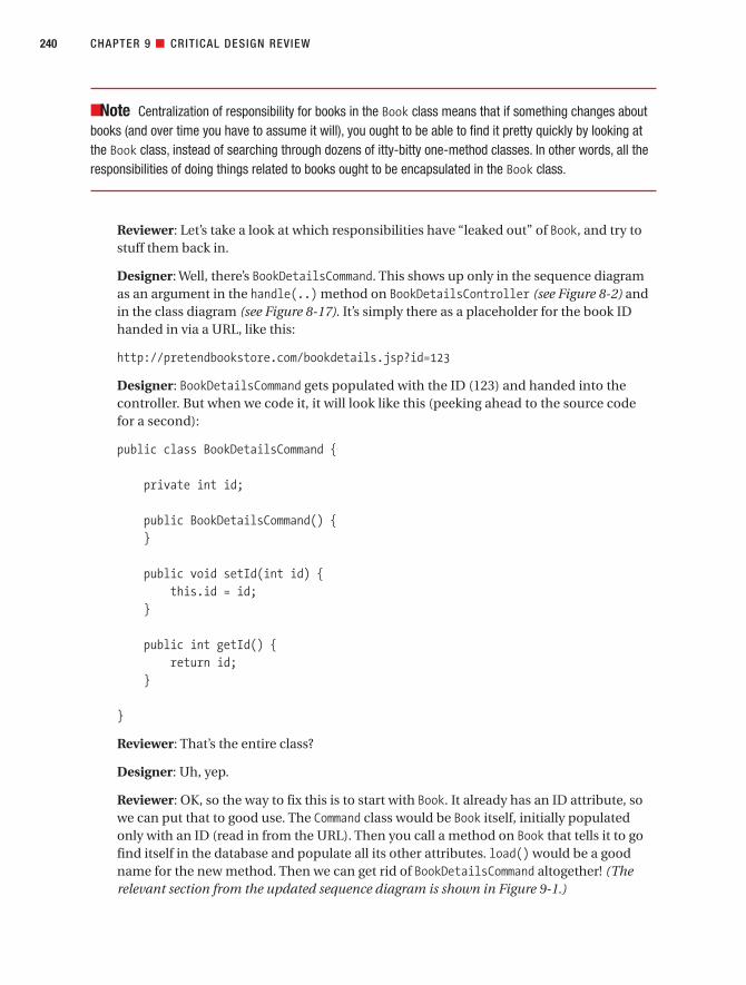
■Note Centralization of responsibility for books in the Book class means that if something changes aboutbooks (and over time you have to assume it will), you ought to be able to find it pretty quickly by looking atthe Book class, instead of searching through dozens of itty-bitty one-method classes. In other words, all theresponsibilities of doing things related to books ought to be encapsulated in the Book class.
Reviewer: Let’s take a look at which responsibilities have “leaked out” of Book, and try tostuff them back in.
Designer: Well, there’s BookDetailsCommand. This shows up only in the sequence diagramas an argument in the handle(..) method on BookDetailsController (see Figure 8-2) andin the class diagram (see Figure 8-17). It’s simply there as a placeholder for the book IDhanded in via a URL, like this:
http://pretendbookstore.com/bookdetails.jsp?id=123
Designer: BookDetailsCommand gets populated with the ID (123) and handed into thecontroller. But when we code it, it will look like this (peeking ahead to the source codefor a second):
public class BookDetailsCommand {
private int id;
public BookDetailsCommand() {}
public void setId(int id) {this.id = id;
}
public int getId() {return id;
}
}
Reviewer: That’s the entire class?
Designer: Uh, yep.
Reviewer: OK, so the way to fix this is to start with Book. It already has an ID attribute, sowe can put that to good use. The Command class would be Book itself, initially populatedonly with an ID (read in from the URL). Then you call a method on Book that tells it to gofind itself in the database and populate all its other attributes. load() would be a goodname for the new method. Then we can get rid of BookDetailsCommand altogether! (Therelevant section from the updated sequence diagram is shown in Figure 9-1.)
CHAPTER 9 ■ CRITICAL DESIGN REVIEW240
7745ch09final.qxd 12/13/06 8:40 PM Page 240

■Note The first operation, getCommandClass(), is how Spring “knows” to create a Book for theCommand class. Because the incoming URL has a parameter called id, Spring will look for a property on the Command class (i.e., Book) called setId.
CHAPTER 9 ■ CRITICAL DESIGN REVIEW 241
Figure 9-1. Excerpt from the updated Show Book Details sequence diagram
7745ch09final.qxd 12/13/06 8:40 PM Page 241
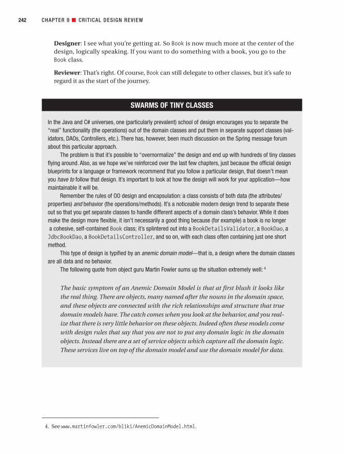
Designer: I see what you’re getting at. So Book is now much more at the center of thedesign, logically speaking. If you want to do something with a book, you go to the Book class.
Reviewer: That’s right. Of course, Book can still delegate to other classes, but it’s safe toregard it as the start of the journey.
CHAPTER 9 ■ CRITICAL DESIGN REVIEW242
SWARMS OF TINY CLASSES
In the Java and C# universes, one (particularly prevalent) school of design encourages you to separate the“real” functionality (the operations) out of the domain classes and put them in separate support classes (val-idators, DAOs, Controllers, etc.). There has, however, been much discussion on the Spring message forumabout this particular approach.
The problem is that it’s possible to “overnormalize” the design and end up with hundreds of tiny classesflying around. Also, as we hope we’ve reinforced over the last few chapters, just because the official designblueprints for a language or framework recommend that you follow a particular design, that doesn’t meanyou have to follow that design. It’s important to look at how the design will work for your application—howmaintainable it will be.
Remember the rules of OO design and encapsulation: a class consists of both data (the attributes/properties) and behavior (the operations/methods). It’s a noticeable modern design trend to separate theseout so that you get separate classes to handle different aspects of a domain class’s behavior. While it doesmake the design more flexible, it isn’t necessarily a good thing because (for example) a book is no longera cohesive, self-contained Book class; it’s splintered out into a BookDetailsValidator, a BookDao, aJdbcBookDao, a BookDetailsController, and so on, with each class often containing just one shortmethod.
This type of design is typified by an anemic domain model—that is, a design where the domain classesare all data and no behavior.
The following quote from object guru Martin Fowler sums up the situation extremely well: 4
The basic symptom of an Anemic Domain Model is that at first blush it looks like
the real thing. There are objects, many named after the nouns in the domain space,
and these objects are connected with the rich relationships and structure that true
domain models have. The catch comes when you look at the behavior, and you real-
ize that there is very little behavior on these objects. Indeed often these models come
with design rules that say that you are not to put any domain logic in the domain
objects. Instead there are a set of service objects which capture all the domain logic.
These services live on top of the domain model and use the domain model for data.
4. See www.martinfowler.com/bliki/AnemicDomainModel.html.
7745ch09final.qxd 12/13/06 8:40 PM Page 242

The Updated Diagram Doesn’t Go into Enough DetailSequence diagrams need to be detailed. You’re well past the point at which you can gloss overpoorly thought-out functionality. It’s time to spell out the hard details.
Reviewer: I feel like we’re making some progress here now. But the sequence diagram wejust updated (see Figure 9-1) still tells only half the story. What happens when the load()method is called on Book? Presumably the book’s DAO is called? That seems like a wholelot of stuff that’s just left to the reader’s imagination, so to speak.
Designer: Yeah, I just thought I’d summarize that on the diagram, as it’s a lot of detail to draw in.
Reviewer: Well, let’s try drawing it in anyway, and see where it takes us.
Designer: OK, so when load() is called, Book needs to call the equivalent load() methodon BookDao. Hang on, that means that Book needs to be handed an instance of BookDao.
Reviewer: So we’ll need to draw a setBookDao() line from BookDetailsController to Book,before the load(). Anything else?
Designer: The next thing is . . . wait a minute. At the moment, BookDao has only afindById() method, which returns a new Book. That’s no good—we want it to populateour own Book object. So we’ll need to change the way that the DAO operates.
Reviewer: For example, instead of doing this . . . (See Figure 9-2.)
Reviewer: . . . we’re doing this. (See Figure 9-3.)
Designer: If you want to load a Book, it’s implicit that you have to first set its ID. So wecould make that explicit by combining the setId() and load() methods.
CHAPTER 9 ■ CRITICAL DESIGN REVIEW 243
The fundamental horror of this anti-pattern is that it’s so contrary to the basic idea
of object-oriented design; which is to combine data and process together. The ane-
mic domain model is really just a procedural style design, exactly the kind of thing
that object bigots like me (and Eric5) have been fighting since our early days in
Smalltalk. What’s worse, many people think that anemic objects are real objects,
and thus completely miss the point of what object-oriented design is all about.
For the Internet Bookstore, we’ve tried to reach a compromise: using aggregation to link all the itty-bittyclasses that Spring wants to see to the Book domain class, and having Book delegate behavior into thesehelper classes. We can thus still easily understand our design (all the “bookish” behavior is in the Bookclass), while following the “Spring rules” of using validators, DAOs, and so forth.
While some separation can be useful in order to satisfy certain design patterns, a balance needs to beachieved between monolithic, thousand-line classes at one extreme and swarms of tiny classes at the other.
5. Eric Evans is the author of Domain-Driven Design: Tackling Complexity in the Heart of Software(Addison-Wesley, 2003).
7745ch09final.qxd 12/13/06 8:40 PM Page 243
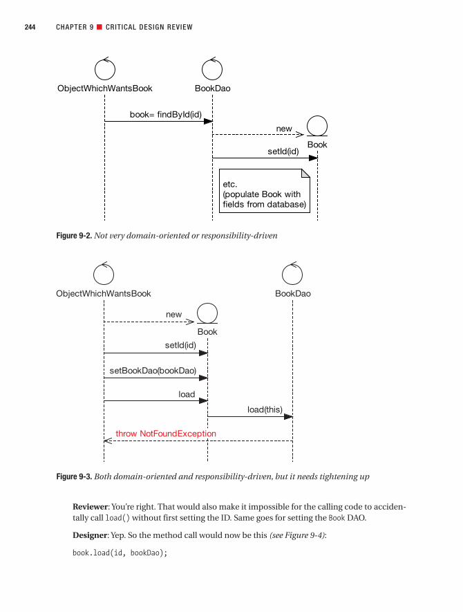
Reviewer: You’re right. That would also make it impossible for the calling code to acciden-tally call load() without first setting the ID. Same goes for setting the Book DAO.
Designer: Yep. So the method call would now be this (see Figure 9-4):
book.load(id, bookDao);
CHAPTER 9 ■ CRITICAL DESIGN REVIEW244
Figure 9-2. Not very domain-oriented or responsibility-driven
Book
BookDaoObjectWhichWantsBook
etc.(populate Book withfields from database)
book= findById(id)
new
setId(id)
Figure 9-3. Both domain-oriented and responsibility-driven, but it needs tightening up
7745ch09final.qxd 12/13/06 8:40 PM Page 244

Designer: If we’re taking this approach throughout the design, we could get rid of thefindByID() method altogether, which means we don’t have to test for it, and so on.
Reviewer: It’s a good thing we decided to design the system in detail before we began cod-ing, then! (The finished, updated sequence diagram is shown in Figure 9-7.)
CDR for the “Write Customer Review” Use CaseAs it turns out, several questions are raised by the sequence diagram for the Write CustomerReview use case. These questions lead to some further issues that need to be tightened upbefore we move to code. We cover these questions in the next few sections, and then we showthe updated diagrams.
For the sequence diagram that’s being reviewed here, refer back to Figure 8-11, and forthe class diagram, refer back to Figure 8-17.
Should the Sequence Diagram Be Invoking a Login Use Case?In the next part of the review, a question arises about whether it’s OK to invoke a use case froma sequence diagram—and what that actually even means, in practice.
Reviewer: Let’s look at the first alternate course, “User not logged in.” Rather than saying“take user to Login JSP” and drawing a message arrow to the Dispatcher servlet (at thebottom of Figure 8-11), it would make more sense to invoke a separate Login use case.
CHAPTER 9 ■ CRITICAL DESIGN REVIEW 245
Figure 9-4. Narrowing the number of possible defects
7745ch09final.qxd 12/13/06 8:40 PM Page 245

■Tip To show a use case being invoked, simply add a note to the sequence diagram with text such as“Invoke Login use case and then restart sequence diagram.” Or if your modeling tool supports it, drag theuse case directly onto the sequence diagram.
Designer: I guess that would make more sense. It might be a bit unclear what’s invokingthe use case, so the note could read “CustomerSession invokes the Login use case . . .” I think the diagram should still show the login check, but then invoke a separate use caseto handle the case where the user needs to log in.
Reviewer: Actually, invoking a use case isn’t the same thing as making a software functioncall at all. It just means you jump from one scenario into another.
Designer: Uh-huh.
Reviewer: Hey, while we’re at it, we could even separate out the login check as well as theactual login.
Designer: Well, remember that the user doesn’t have to be logged in for all the use casesin the Internet Bookstore. You can search for books, view book details, that sort of thing.It’s only when you want to update stuff—write a review, buy a book, or whatever—thatyou need to be logged in.
Reviewer: So you’re saying we should keep the login check in each diagram where it’sperformed, but separate the actual login part into a separate use case? OK, let’s runwith that.
Why Is “Book” Unused on the Sequence Diagram?If you find an object sitting all on its own on the sequence diagram, without any messagesbeing passed to it, it’s likely that you’ve discovered a part of the design that hasn’t been thoughtthrough in sufficient detail. Questioning the object’s existence can uncover all manner ofdesign questions, as our reviewer and designer now find out.
Reviewer: Over on the right of the sequence diagram (see Figure 8-11), you create a newBook instance, and then (near the center of the diagram) you pass the new instance intoWriteCustomerReviewCommand. However, Book itself isn’t used at all. You can determine thisby the simple observation that no message arrows point at Book.
Designer: Yikes, you’re right. So, we could fix it by simply removing Book from the dia-gram. But it makes me wonder why Book appeared on there at all if it isn’t even used.
Reviewer: This has happened because the use case text and the robustness diagram don’tmatch. The use case doesn’t mention that “the system sets the book ID on the review” . . .therefore, the sequence diagram doesn’t have a setBookId() method on it. This wouldhave been caught if we’d done the “highlighter test” on the robustness diagram.
CHAPTER 9 ■ CRITICAL DESIGN REVIEW246
7745ch09final.qxd 12/13/06 8:40 PM Page 246

Designer: Here’s the thing, though: I’m still not sure if we even need Book at all here. Froman implementation standpoint, the book ID would be passed in via the URL, somethinglike this: (Jumps up and starts scribbling on the whiteboard)
www.pretendbookstore.com/review.jsp?bookID=1234
Reviewer: So you’re saying that you would never have to actually get Book to retrieve itsID, because you’ve already got it?
Designer: Exactly.
Reviewer: Except that now we’re missing a validation step: checking that the ID reallyexists in the database. But perhaps more important, the fact that we’re talking aboutremoving Book raises an alarm bell, kind of. It suggests to me that we’re not following aresponsibility-driven approach to the design—that is, designing around the domainclasses.
Designer: (Thinks for a minute) How about this? We could use Book to validate whetherthe ID exists in the database. We’d do something like create a Book instance, set its IDfrom the incoming request, and then call a method on it called doesBookIDExist() tomake sure it’s in the database.
Reviewer: That’s the sort of thing. Or we could call a load() method, which throws aNotFoundException if the book ID doesn’t exist.
Designer: OK, that would also make it more consistent with the Show Book Details usecase, I guess.
Reviewer: In fact, you’re right, we already solved this problem. We can reuse the designfrom the previous use case. (See Figure 9-4.)
WriteCustomerReviewCommand Seems RedundantIt’s easy to simply accept design decisions that are pushed on you by your application frame-work. But holding a CDR, in which reviewers question the design from different angles, canoften result in an improved design.
Reviewer: Looking at the class diagram (see excerpt in Figure 9-5), it seems likeWriteCustomerReviewCommand is just a wrapper class around the CustomerReview entity. Is the Command class really needed?
Designer: It’s part of the Spring design. When you get an input from a form, the form datamust be encapsulated in a command object, hence WriteCustomerReviewCommand. Thecommand object gets populated from the form fields, then validated, and then passedinto the controller. The controller then transfers the data from the command class to thedomain object, which we then save to the database.
Reviewer: So we need to keep a command class of some sort; fair enough. But could youuse CustomerReview itself as the command class?
Designer: Let me take a look at the design. Actually, yes, that could simplify things andstill fit within the Spring “design way.”
CHAPTER 9 ■ CRITICAL DESIGN REVIEW 247
7745ch09final.qxd 12/13/06 8:40 PM Page 247

Reviewer: One other thing while we’re looking at this particular diagram: At this stage ofthe design process, we really should have identified the multiplicity for all these kinds ofrelationships and added them onto the diagram.
The updated class diagram excerpt is shown in Figure 9-6. As you can see, simply elimi-nating that strange “wrapper” class makes the design much cleaner, reducing the number ofdependencies between classes.
■Exercise If you compare Figure 9-6 with the domain model shown back in Figure 2-7, there’s an errorto do with aggregation. Can you spot what it is? (We revisit the error during the Code Review and ModelUpdate in Chapter 11; see the fixed diagram in Figure 11-9.)
CHAPTER 9 ■ CRITICAL DESIGN REVIEW248
Figure 9-5. Command class for WriteCustomerReviewController, pre-prefactoring
WriteCustomerReviewController
+ doSubmitAction(WriteCustomerReviewCommand) : void+ formBackingObject(HttpServletRequest) : WriteCustomerReviewCommand
CustomerReview
+ book: Book+ customer: Customer+ id: int+ rating: int+ review: String
WriteCustomerReviewCommand
+ book: Book+ customer: Customer+ customerReview: CustomerReview
+ getRating() : int+ getReview() : String+ getTitle() : String
Book
+ id: int+ synopsis: String+ title: String
Customer
+ email: String+ firstName: String+ id: int+ lastName: String
getRating(), getTitle() andgetReview() are wrappermethods around theCustomerReview properties.
7745ch09final.qxd 12/13/06 8:40 PM Page 248

SEARCHING FOR A STABLE SET OF ABSTRACTIONS
In the old days, before refactoring replaced up-front design, it used to be a goal of a development team to min-imize the amount of code breakage and rewriting that happened over time, as these activities were deemedquite costly. This perception of costliness has changed (hey, change is free!), but perhaps not the reality.
If you’re trying to minimize code breakage and resultant refactoring, you want to try really hard to iden-tify the most stable set of abstractions you can find, and then organize your code around those abstractionsthat will change the least as your system evolves over time. This leads to a resilient architecture that doesn’tbreak when small changes happen.
Which abstractions should you choose? The use cases? The requirements? The feature set of the pro-gram? The feature set of the framework? The data model? The answer is . . . none of the above. You reallywant to base the key abstractions in the code on true statements about the problem domain, becausethe problem domain winds up being the most stable.
Consider the Internet Bookstore example. You want to sell books on the Internet and give people theability to view details of the books, and to read and write reviews of the books. Visitors need to be able tosearch a book catalog to find the book they want. So a catalog has books, and the books have details, whichinclude reviews.
CHAPTER 9 ■ CRITICAL DESIGN REVIEW 249
Figure 9-6. Command class for WriteCustomerReviewController, after prefactoring and withmultiplicity added in for good measure
WriteCustomerReviewController
+ doSubmitAction(CustomerReview) : void+ formBackingObject(HttpServletRequest) : CustomerReview
CustomerReview
+ book: Book+ customer: Customer+ id: int+ rating: int+ review: String
Book
+ id: int+ synopsis: String+ title: String
Customer
+ email: String+ firstName: String+ id: int+ lastName: String
1
0..*
1
0..*
7745ch09final.qxd 12/13/06 8:40 PM Page 249

Is the Save Method on CustomerReviewDao or JdbcCustomerReviewDao?A CDR can also help to ensure that the team truly understands the design that they’reproposing.
Reviewer: Hmm, I’m not sure if your sequence diagram matches the class diagram. The sequence diagram shows WriteCustomerReviewController calling the “save”method on JdbcCustomerReviewDao. But on the class diagram, the method is actually on CustomerReviewDao.
Designer: Yep, CustomerReviewDao is the interface, but the method is actually imple-mented in JdbcCustomerReviewDao. It seemed sort of redundant to show the samemethod twice on the class diagram. You can infer from looking at the diagram that if it’s defined in the interface, then the nonabstract implementing class must also have it.A bit too subtle, perhaps?
Reviewer: Depends on your audience. Think about it: if you have to take the time toexplain the method’s absence, then would its inclusion have really been redundant?
Designer: I guess I had been wondering if the sequence diagram should haveCustomerReviewDao on it instead of the concrete JDBC class. Do we want the sequencediagram to be showing the JDBC implementation, or a slightly more generic version thatwould work if we switched to some other persistence/ORM toolkit (which is where theDAO approach with all its interfaces and abstractions finally comes in handy)?
Reviewer: Well, we’re designing a solution here, not an abstract framework. So let’s keepthe concrete class, JdbcCustomerReviewDao, on the sequence diagram.
CHAPTER 9 ■ CRITICAL DESIGN REVIEW250
You can add a new use case to your design, you can change the database from SQL Server to Oracle,a new release of Spring Framework can come out that changes how the MVC paradigm works, and therequirement to rate books between one and five stars can expand to six stars. But you’re still selling bookson the Internet, and users are still searching catalogs, viewing book details, and writing reviews.
So if you organize the behavior of the software around these abstractions, your architecture will proveresilient to change. How do you accomplish this? Follow a responsibility-driven approach and allocate behav-ior into the domain classes.
7745ch09final.qxd 12/13/06 8:40 PM Page 250

The Entity Classes Don’t Have Any AttributesFinally, the CDR is an effective technique for discovering areas in the analysis space thathaven’t been fully explored.
Reviewer: Looking at the class diagram (see Figure 8-17), we have Book, Customer, andCustomerReview, but all three classes are totally empty. What gives?
Designer: I was driving the methods and fields from the actions on the sequence diagramand from the use case text. The situation didn’t come up where I “identified” that theyneeded any attributes (or operations for that matter), so I left them off.
Reviewer: If you know that a class needs an attribute, add it to the class diagram! It’s yourlast chance to do so before coding. You identified the attributes—book ID, title, and soon—partly in the use case text, and also (if there were any) in the page specs and proto-types. These are all added to the domain model as it gets fleshed out and transforms intothe detailed static model.
■Tip You should identify attributes and add them to their classes during robustness analysis. You then put the functions where the data lives (one of the essential thought processes of OOD) as you draw thesequence diagrams. You’ll also find that your understanding of the domain model is increased greatly bygoing through the exercise of putting attributes on the classes.
You can also identify attributes from functional requirements. If the project is using an existing datamodel, you should use this to identify which fields go in your entity classes. Another good source is your GUI prototype/storyboard. Fields on screens often imply attributes on entity classes.
CHAPTER 9 ■ CRITICAL DESIGN REVIEW 251
7745ch09final.qxd 12/13/06 8:40 PM Page 251

The Updated Bookstore DiagramsFigure 9-7 shows the sequence diagram for the Show Book Details use case, and Figure 9-8shows the sequence diagram for the Write Customer Review use case, which have both beenupdated following the CDR.
■Exercise If you’ve been paying close attention to the details of the Spring “command” mechanism,you’ll notice a flaw in the sequence diagram in Figure 9-7. (Fairly major hint: Look at Book its ID.) See if youcan spot the flaw. We’ll let slip another hint when we look at the source code for BookDetailsControllerin Chapter 10, and then we’ll revisit and fix the error during the Code Review and Model Update in Chapter 11.
CHAPTER 9 ■ CRITICAL DESIGN REVIEW252
Figure 9-7. Updated sequence diagram for the Show Book Details use case
7745ch09final.qxd 12/13/06 8:40 PM Page 252

CHAPTER 9 ■ CRITICAL DESIGN REVIEW 253
Figure 9-8. Updated sequence diagram for the Write Customer Review use case
7745ch09final.qxd 12/13/06 8:40 PM Page 253
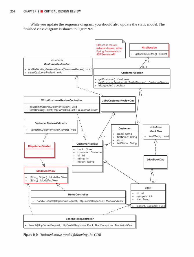
While you update the sequence diagram, you should also update the static model. Thefinished class diagram is shown in Figure 9-9.
CHAPTER 9 ■ CRITICAL DESIGN REVIEW254
Figure 9-9. Updated static model following the CDR
7745ch09final.qxd 12/13/06 8:40 PM Page 254

■Exercise As we mentioned earlier in this chapter (for Figure 9-6), Figure 9-9 shows an aggregationerror if you compare it with the domain model diagram (see Figure 2-7). If you couldn’t find the error earlieron, try again here. (We revisit the error during the Code Review and Model Update in Chapter 11.)
The changes to this diagram aren’t as severe as the changes to the sequence diagrams.However, a couple of things have changed (see the original in Figure 8-17).WriteCustomerReviewCommand, of course, has disappeared; instead, CustomerReview itself isbeing used as the command class. The Book, Customer, and CustomerReview entities now haveattributes (meaning that when you’re coding, you won’t need to guess what they are). BookDaohas a new method, doesBookIdExist(int), which came straight from the sequence diagram.And following the Show Book Details CDR, BookDetailsCommand has disappeared altogether.We’ve also moved some of the classes around to tidy up the layout.
■Caution It’s useful to tidy up class diagrams so that the layout is clearer. But try not to spend hourstinkering with the layout until it’s so tidy and symmetrical it could be mistaken for a map of midtown Man-hattan. Class diagrams just aren’t meant to be about that—they’re about showing a structural overview ofthe code you’re about to write.
Notice how the Customer entity doesn’t have a CustomerDao. This is because we’re skimpingsomewhat on the security concerns for this example, but in a real-world project you’d expectto see a CustomerDao, which CustomerSession uses to lookup the “real” customer IDs.
SummaryIn this chapter, we looked at the Critical Design Review (CDR), an important milestone thattakes place between detailed design and implementation. As we discussed at the start of thischapter, the CDR involves three main goals:
• Matching the use case text with its sequence diagram
• Checking for continuity of messages
• Reviewing for good design
If you’ve gone through the detailed design for each use case and reviewed it for thesethree criteria, then your design really should be fighting-fit now and easily ready for coding.
In the next chapter, we delve into implementation. If you have your detailed design right(as verified by the CDR milestone), then implementation should be a relatively short andstraightforward process. For this reason, we focus mainly on coding the Internet Bookstoreexample, so that you can see how the code is driven directly from the sequence diagrams anddetailed class diagrams.
Figure 9-10 shows where we are (the areas covered in this chapter are shown in red).
CHAPTER 9 ■ CRITICAL DESIGN REVIEW 255
7745ch09final.qxd 12/13/06 8:40 PM Page 255

CHAPTER 9 ■ CRITICAL DESIGN REVIEW256
Figure 9-10. Review activities during the detailed design stage
7745ch09final.qxd 12/13/06 8:40 PM Page 256
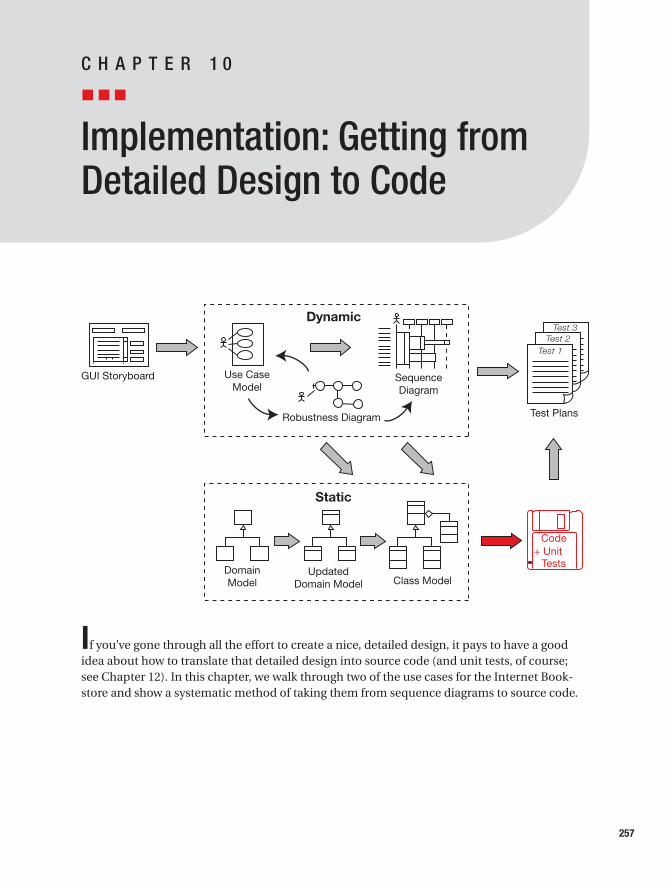
Implementation: Getting fromDetailed Design to Code
If you’ve gone through all the effort to create a nice, detailed design, it pays to have a goodidea about how to translate that detailed design into source code (and unit tests, of course; see Chapter 12). In this chapter, we walk through two of the use cases for the Internet Book-store and show a systematic method of taking them from sequence diagrams to source code.
257
C H A P T E R 1 0
7745ch10final.qxd 12/13/06 8:44 PM Page 257

The 10,000-Foot ViewAssuming you’ve done a good job with your analysis and design, you can expect coding to be a nice, straightforward process. But you must continue to keep a close eye on your users’requirements and, of course, on the design itself. However, if any part of the design turns outto be wrong once you’ve begun coding, don’t hesitate to correct it.
The effort you’ve put into the design should make your life a lot easier, but it isn’tsacrosanct.
Programmer-Driven DesignHopefully the design wasn’t handed down to the programmers like an ironclad contract. Thatsort of arrangement is highly dysfunctional and should be avoided if at all possible. The pro-grammers should have been heavily involved in the design process (better still, they should bedriving the design). The programmers will have the greatest insight into the implementationdetails and the issues that they’re likely to face.
Spring FrameworkWe’re targeting Spring Framework for the Internet Bookstore. In this chapter, we show how toimplement the Internet Bookstore use cases that we’ve been following from their inception.
Remember that the process we’ve described so far can be applied equally well to anyobject-oriented language. The purpose of this chapter is to provide an example of how tomake that last little leap from the detailed design to the source code, to show how it all fitstogether. Specifically, we’ll use Spring Web MVC using JSP for the HTML templating andSpring’s JDBC support for data access.
■Note To keep the example from getting too bogged down in Spring-specific details, we’ve moved someof the heavier explanations into Appendix B.
Implementation in Theory: Getting from Design to CodeBefore you begin coding from your design, you need to make sure that you have a sequencediagram for each use case for which you’re going to deliver code in the current release, andyou need to make sure you’ve completed the Critical Design Review (CDR; see Chapter 9).
258 CHAPTER 10 ■ IMPLEMENTATION: GETTING FROM DETAILED DESIGN TO CODE
7745ch10final.qxd 12/13/06 8:44 PM Page 258

Top 10 Implementation GuidelinesThe principles discussed in this chapter can be summed up as a list of guidelines. Our top 10guidelines list follows.
10. Be sure to drive the code directly from the design.
9. If coding reveals the design to be wrong in some way, change it. But also review the process.
8. Hold regular code inspections.
7. Always question the framework’s design choices.
6. Don’t let framework issues take over from business issues.
5. If the code starts to get out of control, hit the brakes and revisit the design.
4. Keep the design and the code in sync.
3. Focus on unit testing while implementing the code.
2. Don’t overcomment your code (it makes your code less maintainable and moredifficult to read).
1. Remember to implement the alternate courses as well as the basic courses.
Let’s look at each guideline in turn.
10. Be Sure to Drive the Code Directly from the DesignYou’ve spent the time producing a highly focused, unambiguous, clean, crisp design. Makesure you use it! (However, see the next guideline.)
■Tip Try to automate the process, and generate source code, SQL, XML, and so forth directly from thedesign diagrams whenever possible.
■Note You shouldn’t attempt to generate SQL from the domain model, which is not a data model. But youcan draw out the database schema on a separate diagram and then generate SQL, Data Definition Language(DDL), and so forth from it.
CHAPTER 10 ■ IMPLEMENTATION: GETTING FROM DETAILED DESIGN TO CODE 259
7745ch10final.qxd 12/13/06 8:44 PM Page 259

9. If Coding Reveals the Design to Be Wrong in Some Way, Change ItAs soon as you realize that something has gone wrong, there’s no point continuing on thebasis that it might get better once you bury the problem under several thousand more lines of code. Instead, fix the design immediately and bring the code and the design back in sync.
But it’s also important to review the design process that led up to the error. Check themilestones listed at the end of each chapter in this book. Were the use cases fully disam-biguated? Is there a tight enough link between the use case text and the object model? And so on.
8. Hold Regular Code InspectionsGive each programmer the space needed to concentrate and write error-free code. But domake sure that everyone in the team is keeping to the design and following the same codingconventions. The code inspection can be a part of the Code Review and Model Update that we illustrate in Chapter 11.
CHAPTER 10 ■ IMPLEMENTATION: GETTING FROM DETAILED DESIGN TO CODE260
INTERNET BOOKSTORE: GENERATING THE ENTITY CLASSES
All of the entity classes that we need are now nicely filled out with details (attributes and operations) in ourEnterprise Architect (EA)1 model. As luck would have it, EA has some useful code generation features, so it’spossible to generate quite a bit of the source code directly from the model. Note that other CASE tools suchas Together,2 Rational XDE,3 and so on also offer code generation features. It’s also possible to use a “dedi-cated” code generator such as the open-source XDoclet4 or the commercial JGenerator5 to do a lot of thegrunt work for you.
For each entity class, we need to generate several classes to be used by Spring: the “plain” entity classitself (a very simple JavaBean consisting mainly of getters and setters; although recall from the review chap-ters that this was something of a bone of contention between the reviewer and the designer!), a Data AccessObject (DAO, actually an interface), and an implementation of the DAO. The implementation class will use aspecific persistence framework (e.g., JDO or Hibernate), which will “plug into” the Spring framework. You canalso model your database schema in UML (using classes with a stereotype of <<table>>) and generate theSQL that creates the database tables.
This is all fairly mechanical stuff—exactly the sort of thing that computers are designed to be goodat—so the more of this that can be automated, the better.
1. See www.sparxsystems.com.au and also www.iconixsw.com.
2. See www.borland.com/together.
3. See www-306.ibm.com/software/awdtools/developer/rosexde.
4. XDoclet is a code generation engine that operates by placing tags in your Java code. Visit http://xdoclet.sourceforge.net/xdoclet for more information.
5. JGenerator is an enterprise software automation tool from Javelin Software. Visit www.javelinsoft.com/jgenerator for more information.
7745ch10final.qxd 12/13/06 8:44 PM Page 260

7. Always Question the Framework’s Design ChoicesIf people didn’t question the design choices made by the creators of their target platform, wewould all still be writing horribly slow, fine-grained entity beans that cause expensive networktraffic for every single method call. If a particular design decision that the framework forcesupon you is questionable, look for better ways of approaching the problem, and if necessarychoose a different framework.
Speaking of frameworks . . .
6. Don’t Let Framework Issues Take Over from Business IssuesThe moment that framework design issues start to drive the shape of the finished productinstead of the customer’s business requirements, something has gone wrong. It gives a wholedifferent meaning to the term “inversion of control.”
In fact, we often question the wisdom of using a framework at all. The framework is ulti-mately there to save you from having to write the same “plumbing” code over and over—inother words, it’s there to save time and effort. If the framework you’ve chosen for your projectdemands that you jump through crazy design-pattern hoops, fill out reams of XML forms intriplicate, and sacrifice a stray cat on the second Tuesday of every month, it’s time to hit thepanic button and think about alternatives.
5. If the Code Starts to Get out of Control, Hit the Brakes and Revisit the DesignActually, if you’ve followed all the steps we’ve suggested up until now, and the code is still get-ting out of control, you probably have some serious issues to address. Like, for example, arethe programmers ignoring the design completely?
Once you’ve done detailed sequence and class diagrams, programming should mostlyinvolve filling in the algorithmic details for relatively small methods that reside within highlycohesive classes. Pretty much the whole point of everything you’ve done up to this point is toprevent the code from getting out of control, so if you find that it is, pause, take a giant stepbackward, take a couple of deep breaths, and address the underlying issues on your project.Try to answer this question: What went wrong?
a) Your team didn’t do a good design (and you didn’t correct it in the design review).
b) Your programmers ignored the good design and “went cowboy.”
c) Your programmers didn’t participate in the design process.
d) b + c.
e) All of the above.
4. Keep the Design and the Code in SyncSome development processes actually advise you to let the code “escape” from the design andtake its own course, and only to update the design when its obsolescence starts to “hurt.”6 Pre-sumably this means when you discover that half your team has written to completely thewrong set of interfaces because the design model was out of date . . .
CHAPTER 10 ■ IMPLEMENTATION: GETTING FROM DETAILED DESIGN TO CODE 261
6. Scott W. Ambler, Agile Modeling: Effective Practices for eXtreme Programming and the Unified Process(Hoboken, NJ: John Wiley & Sons, 2002), p. 66.
7745ch10final.qxd 12/13/06 8:44 PM Page 261

We much prefer to keep the design and the code in sync. If you’ve kept the design leanand concentrated on keeping it grounded in reality, then keeping the design model in syncwith the developing code really shouldn’t take very long—and it shouldn’t need to be done allthat often.
3. Focus on Unit Testing While Implementing the CodeIt’s a good idea to write the unit tests as you write the code. That way, you can verify that yourcode works as expected and fix any bugs as they’re introduced, instead of having to try andtrack them down later.
■Tip The tests can also be used to ensure that all of the use case scenarios have been implemented.We demonstrate a technique for doing this in Chapter 12.
2. Don’t Overcomment Your CodeOvercommenting your code makes it less maintainable and more difficult to read. If the codeis well designed and you follow a decent naming convention, it should be possible to see whatthe code is doing just by reading it (now there’s a concept!).
CHAPTER 10 ■ IMPLEMENTATION: GETTING FROM DETAILED DESIGN TO CODE262
7. See www.iconixsw.com/EA/MDGLinkIntegration.html. At the time of this writing, Sparx Systems is aboutto release an Eclipse version of this plug-in for Java developers. It will be released before this bookgoes to press.
MDG INTEGRATION FOR ECLIPSE AND FOR VISUAL STUDIO 2005
If you’re using Eclipse or Microsoft Visual Studio 2005, an amazing way of keeping the design model and thecode in sync is to use Sparx Systems’ MDG Integration plug-in.7 The plug-in allows you to edit and navigateyour UML model from inside the IDE, and generate code from your detailed design.
The plug-in will also reverse-engineer your code to synchronize it with the design. You can change yourUML model and push those changes into the IDE, or you can edit the code in the IDE and push the changesback into your model. You can also use the UML model to browse instantly to an operation on a class bydouble-clicking the operation in the UML browser.
As you can probably imagine, we see tools like this as being key components in the implementationand Code Review and Model Update stages of your project, because it’s now possible to right-click a class to synchronize model and code. The tool syncs up one class/method at a time, incrementally. There just isn’tany excuse for letting the model and code get out of sync anymore!
7745ch10final.qxd 12/13/06 8:44 PM Page 262

For example, a block of code with a comment above it like this:
// Wait for the request data to become available:. . .
could be moved out to a separate method called waitForRequestData(), and the commentcould be deleted.
You shouldn’t need comments that narrate what the code is doing step by step; the mostuseful comments generally explain the intent behind the code. But even then, often the veryfact that you need to add a comment may be a warning sign that the design itself needs to beless obtuse.
■Tip Where comments in code are needed to describe the intent behind the code, consider that as long as you’ve followed the process described in this book, it should be very easy to determine which use casescenario is being implemented by comparing the code with the static model and the use case text, so quiteoften, no comment is required.
1. Remember to Implement the Alternate Courses As Well As the Basic CoursesThis point carries over from the detailed design. Recall from Chapter 8 that it’s vital to includethe alternate courses on your sequence diagrams, so that all the bases are covered. Once youbegin coding from the design, you’ll quickly thank yourself for having done this work, as thereshouldn’t now be any nasty surprises lurking in the design—no “Oh my gosh, we didn’t takeinto account what happens if the user cancels at this point!” leading to additional (unsched-uled and undesigned) development work.
Similarly, having spent the time identifying and then designing the alternate courses, youdo need to make sure you remember to implement them all. The use case scenarios form ahandy checklist for making sure that none of the alternate courses have been missed.
Implementation in Practice: Internet BookstoreWithout further ado, let’s leap into the Internet Bookstore implementation, starting with thedatabase tables that we’ll be using.
Creating the DatabaseWe’ve created a very straightforward database to develop and test against. Figure 10-1 showsthe database tables and the relationships between them.
CHAPTER 10 ■ IMPLEMENTATION: GETTING FROM DETAILED DESIGN TO CODE 263
7745ch10final.qxd 12/13/06 8:44 PM Page 263
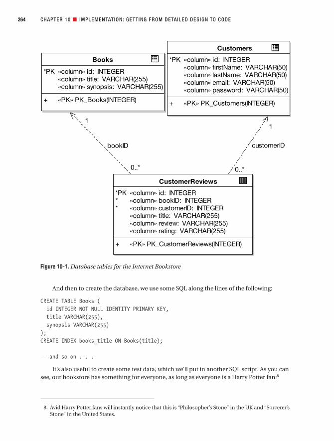
And then to create the database, we use some SQL along the lines of the following:
CREATE TABLE Books (id INTEGER NOT NULL IDENTITY PRIMARY KEY,title VARCHAR(255),synopsis VARCHAR(255)
);CREATE INDEX books_title ON Books(title);
-- and so on . . .
It’s also useful to create some test data, which we’ll put in another SQL script. As you cansee, our bookstore has something for everyone, as long as everyone is a Harry Potter fan:8
CHAPTER 10 ■ IMPLEMENTATION: GETTING FROM DETAILED DESIGN TO CODE264
Figure 10-1. Database tables for the Internet Bookstore
customerID
1
0..*
bookID
1
Books
*PK «column» id: INTEGER«column» title: VARCHAR(255)«column» synopsis: VARCHAR(255)
+ «PK» PK_Books(INTEGER)
CustomerReviews
*PK «column» id: INTEGER* «column» bookID: INTEGER* «column» customerID: INTEGER
«column» title: VARCHAR(255)«column» review: VARCHAR(255)«column» rating: VARCHAR(255)
+ «PK» PK_CustomerReviews(INTEGER)
Customers
*PK «column» id: INTEGER«column» firstName: VARCHAR(50)«column» lastName: VARCHAR(50)«column» email: VARCHAR(50)«column» password: VARCHAR(50)
+ «PK» PK_Customers(INTEGER)
0..*
8. Avid Harry Potter fans will instantly notice that this is “Philosopher’s Stone” in the UK and “Sorcerer’sStone” in the United States.
7745ch10final.qxd 12/13/06 8:44 PM Page 264

// Insert bookstore data:
INSERT INTO Books (id, title, synopsis)VALUES
(101, 'Harry Potter and the Philosopher's Stone','Harry discovers that he is a wizard.'
);
INSERT INTO Books (id, title, synopsis)VALUES
(102, 'Harry Potter and the Chamber of Secrets','Harry and chums attempt to solve the mystery of the Chamber of Secrets.'
);
-- etc . . .
■Note If you’re following along with the Spring technical details, at this juncture you might want to refer to the “Folder Structure” section in Appendix B, and then the “Java Package Hierarchy” section, also inAppendix B.
Preparing the Style SheetThe Internet Bookstore project uses one style sheet, bookstore.css, which looks like this:
body {font-family : Verdana, Arial, Geneva, Helvetica, sans-serif;background-color : white;font-size : 10pt;
}
.navbar {background-color : #CCCCFF;border : 1px solid;padding : 5px;
}
.error {color: #FF0000;font-size: 12pt;
}
We’re sure you’ve seen a style sheet before, but we’re showing you this particular onebecause of the .error style. It’s been said that in any good movie, if the director is going toshow a murder, then he or she must introduce the murder weapon at least two scenes earlier.So we’re kind of doing that here: you’ll see the .error style get used shortly.
CHAPTER 10 ■ IMPLEMENTATION: GETTING FROM DETAILED DESIGN TO CODE 265
7745ch10final.qxd 12/13/06 8:44 PM Page 265

Mapping Domain (Entity) Classes to Real ClassesAs the domain model evolved and turned into the more detailed static model, the entityclasses (i.e., the classes from the domain model) were padded out with attributes (mostlyduring robustness analysis) and operations (mostly during detailed design). Depending onyour target platform, you may or may not be able to map entity classes directly to imple-mentation classes. However, Spring Framework positively thrives on the concept of “pure”domain classes.
■Note We discussed this issue in the sidebar “Swarms of Tiny Classes” in Chapter 9.
We’ll look at three of the completed entity classes here: Book, Customer, andCustomerReview.
Figure 10-2 shows part of the static model that contains these three entity classes (thefull static model is in Figure 9-10). Note that each of these classes corresponds well to a rowin the database tables shown earlier—not to the entire table.
■Note Considering that it represents incoming book reviews, CustomerReview is still somewhat lackingin personality—that is to say, it exhibits no behavior whatsoever. As we’ve discussed, moving the validationlogic into CustomerReview (where it really does belong) would go a long way toward fixing this problem.We’ll revisit this part of the design in Chapter 11.
In Figure 10-2, we’ve suppressed the getters and setters for each of the properties, butwhen we generate the Java code from these classes, the get and set methods will be generatedfor us.
Here’s Book.java, generated directly from the static model:
CHAPTER 10 ■ IMPLEMENTATION: GETTING FROM DETAILED DESIGN TO CODE266
Figure 10-2. The three entity classes from the static model
Book
+ id: int+ title: String+ synopsis: int
+ load(int, BookDao) : void
CustomerReview
+ id: int+ bookId: int+ customerId: int+ review: String+ rating: int
Customer
+ id: int+ firstName: String+ lastName: String+ email: String
7745ch10final.qxd 12/13/06 8:44 PM Page 266

package com.iconixsw.bookstore.domain;
import java.io.*;
public class Book implements Serializable {
private int id;private String title;private String synopsis;
public Book() {}
public int getId() { return id; }public void setId(int id) { this.id = id; }
public String getTitle() { return title; }public void setTitle(String title) { this.title = title; }
public String getSynopsis() { return synopsis; }public void setSynopsis(String synopsis) {
this.synopsis = synopsis;}
public void load(int id, BookDao bookDao) {}
}
There are several points to keep in mind with this code:
• The load method has been generated as an empty method, leaving us to fill in the gap,which we’ll do shortly.
• Book doesn’t extend any particular class, because (unlike other enterprise applicationframeworks), Spring doesn’t force us to use its own class hierarchy—at least not forentity classes. This is the essence of Spring’s “lightweight framework” approach: your entity classes are very simple “beans” that can be instantiated independently ofSpring if needed (e.g., for unit testing).
Customer and CustomerReview are, at this stage at least, a similarly not-too-interesting sea of getters and setters, so we’ll spare you those and press on to the more interesting stuff.
As the project builds up a head of steam and additional use cases are implemented, we would also add new properties and operations to these entity classes; for example, Bookmight also get an author (or authorCollection) property and some “business-level” bookhandling behavior. However, we only add these properties and methods as and when weencounter them in the use cases. It’s important not to add code prospectively, just in case it will be needed later. Luckily, you’ll be able to see exactly what needs to be added becauseyou’ll have mapped out the use cases and the design beforehand.
Now that we have the preliminaries out of the way, let’s take a look at the first of our twouse cases and turn it into working source code.
CHAPTER 10 ■ IMPLEMENTATION: GETTING FROM DETAILED DESIGN TO CODE 267
7745ch10final.qxd 12/13/06 8:44 PM Page 267

Implementing the “Show Book Details” Use CaseWe’ll start with the simpler of the two use cases, Show Book Details. To refresh your memory,here’s the basic course:
The Customer types in the URL for the bookstore’s home page, which the system dis-
plays. Then the Customer clicks a link to view a Book. The system retrieves the Book
details, and displays them on the Book Details page.
The completed sequence diagram for this use case is shown in Figure 9-7.So, the first page we need to implement is the bookstore’s home page. According to the
class diagram in Figure 9-9, we need a HomeController class that tells Spring to displayhome.jsp.
HomeControllerHomeController is about as simple a controller as it’s possible to get. It’s simply there toreturn the main (“home”) view page, so it doesn’t do a huge amount. Figure 10-3 showsHomeController from the static model (ModelAndView is shown in red because it’s an “exter-nal” class—part of the Spring framework).
We need to define homeController in bookstore-servlet.xml, like this:
<bean id="homeController"class="com.iconixsw.bookstore.web.HomeController"/>
This declaration is saying that we want a single instance of the class HomeController, andif it’s to be referred to by other beans in the XML configuration, it shall be referred to using theID homeController.
CHAPTER 10 ■ IMPLEMENTATION: GETTING FROM DETAILED DESIGN TO CODE268
Figure 10-3. HomeController from the static model
7745ch10final.qxd 12/13/06 8:44 PM Page 268

Next, here’s the class in its entirety:
package com.iconixsw.bookstore.web;
// import statements omitted . . .
public class HomeController implements Controller {
public ModelAndView handleRequest(HttpServletRequest request,HttpServletResponse response)
throws ServletException, IOException{
return new ModelAndView("home");}
}
It really is about as simple as the archetypal “Hello World” Java program. All it does is return a new ModelAndView object, primed with the word “home.” This tells Spring’sDispatcherServlet, in effect, to forward the request to home.jsp, which will then be displayedto the user.
The Home Page: home.jspHere’s home.jsp, which will be the first page that the user sees when visiting the website:
<%@ include file="include/IncludeTop.jsp" %>
<h2>Welcome to our streamlined Internet Bookstore.</h2>
<p>We offer a comprehensive range of books, from Harry Potter to Harry Potter.
</p><p>You can <a href="search.jsp">search for books</a>; or alternatively browseusing our bestseller list below, or 'drill down' through ourlist of categories.
</p>
<lu><li><a href="bookdetails.htm?id=101">Harry Potter and the Philosopher's Stone
</a></li>
CHAPTER 10 ■ IMPLEMENTATION: GETTING FROM DETAILED DESIGN TO CODE 269
7745ch10final.qxd 12/13/06 8:44 PM Page 269

<li><a href="bookdetails.htm?id=102">Harry Potter and the Chamber of Secrets
</a></li>
<!-- etc . . . --></lu>
</body></html>
The first line of home.jsp invokes the IncludeTop.jsp file, which gives us the consistenttop section of the page. Then there’s some introductory blurb and a link to a search page(search.jsp, which we haven’t implemented for this example).
The bulk of the page consists of a list of links to “book details” pages for each of thebooks in our catalog. Each link points to bookdetails.htm (a “virtual” page that will map toBookDetailsController) and includes an ID parameter that will map to the command object(Book). (Quick reminder: During the CDR in Chapter 9, we dropped the BookDetailsCommandclass altogether, deciding instead to use Book itself as the command object.)
■Note The book list shown in home.jsp is hard-wired, partly because that was what we specified inthe Show Book Details use case, but also because (given the use cases that we’re implementing) it isn’tyet time to implement the dynamic functionality we’d need to create an automatically updated selectionof books (e.g., a list of top 10 bestsellers).
Later, when it’s time to implement the Search for Books use case, for example, we could return to thispage and turn it into a dynamic list retrieved from the database—something more like what you’d see onthe front page of Amazon.com or BarnesAndNoble.com.
We have enough in place to try building the project (what there is of it so far) and deploy-ing the resultant Web Archive (WAR) file to Tomcat. We won’t go into the details of the build, asyou can get this information from a multitude of Spring books,9 as well as the Spring websiteitself.
Figure 10-4 shows the screenshot for the working home page.
CHAPTER 10 ■ IMPLEMENTATION: GETTING FROM DETAILED DESIGN TO CODE270
9. See www.springframework.com/books for a good list of Spring books. We can also highly recommendMatt Raible’s book Spring Live (SourceBeat, 2005). See www.sourcebeat.com for more information.
7745ch10final.qxd 12/13/06 8:44 PM Page 270

Here’s the sequence of events that led to the home page being displayed (see Appendix Bfor the details of how all this is configured in Spring):
1. The browser request http://<domain>/bookstore/ went to the bookstore webapplication’s default page, index.jsp.
2. index.jsp forwarded the request to the home page, a virtual page called home.htm.
3. This request was picked up by DispatcherServlet, which handed the request toHomeController.
4. HomeController (the equivalent of a “Hello World” Controller) simply returned a ModelAndView object pointing to home.jsp, and home.jsp was then invoked and theresult was displayed in the browser (see Figure 10-4).
Clicking one of the book links in home.jsp will take the user to the Book Details page forthat book. Of course, we still don’t have a Book Details page, so our first use case isn’t yet com-plete. Let’s fix that next.
Checking the sequence diagram for Show Book Details (excerpt shown in Figure 10-6),and the static model (excerpt shown in Figure 10-5), after the user has clicked a Book Detailslink, DispatcherServlet (via various helper classes which it calls behind the scenes) creates a new Book object and then passes the request and the new Book to BookDetailsController, via BookDetailsController’s handle(..) method.
CHAPTER 10 ■ IMPLEMENTATION: GETTING FROM DETAILED DESIGN TO CODE 271
Figure 10-4. The Internet Bookstore’s home page
7745ch10final.qxd 12/13/06 8:44 PM Page 271

BookDetailsControllerFigure 10-5 shows BookDetailsController from the static model.
Figure 10-5 shows that BookDetailsController has a handle() method that returns aModelAndView. So in our code, we’ll need to construct a ModelAndView object. In fact, checkingthe sequence diagram (detail shown in Figure 10-6), we need to create a ModelAndView point-ing to the “bookdetails” view, and—for the alternate course—an alternative ModelAndViewpointing to the “booknotfound” view.
Figure 10-6 shows us pretty much exactly what we need to implement in the handle()method, so coding it is almost entirely a mechanical process.
CHAPTER 10 ■ IMPLEMENTATION: GETTING FROM DETAILED DESIGN TO CODE272
Figure 10-5. BookDetailsController from the static model
PROGRAMMER == DESIGNER == PROGRAMMER
Of course, we’re not trying to push programmers out of a job here—the point is really that detailed designinvolves thinking like a programmer, just as programming involves thinking like a designer. So detaileddesign is as much a part of the programmer’s job as cutting code is.
However, the big benefit when following this approach is that you’ll have separated out the “designing”issues from the “coding” issues to a large extent, and reviewed the design before coding. So, coding itselfbecomes, in effect, a design review stage: you’re validating the design one last time by actually coding it.(As you’ll see in Chapter 12, you can also write unit tests following a Design-Driven Testing approach asanother form of design validation.)
7745ch10final.qxd 12/13/06 8:44 PM Page 272

So, coding from the sequence diagram, here’s BookDetailsController (the code for thealternate course is shown in red):
package com.iconixsw.bookstore.web;
// import all and sundry . . .
public class BookDetailsController extends AbstractCommandController {
public BookDetailsController() {setCommandClass(Book.class);
}
CHAPTER 10 ■ IMPLEMENTATION: GETTING FROM DETAILED DESIGN TO CODE 273
Figure 10-6. Detail from the Show Book Details sequence diagram focused onBookDetailsController
7745ch10final.qxd 12/13/06 8:44 PM Page 273

protected ModelAndView handle(HttpServletRequest request,HttpServletResponse response,Object command,BindException errors) throws Exception {
Book book = (Book) command;try {
book.load(book.getId(), bookDao);}catch (NotFoundException e) {
return new ModelAndView("booknotfound");}return new ModelAndView("bookdetails", "book", book);
}
public void setBookDao(BookDao bookDao) {this.bookDao = bookDao;
}private BookDao bookDao;
}
This extends the Spring class AbstractCommandController, indicating that we want to readcommand objects from the HTTP request (in this case, the book ID parameter). In the construc-tor, we set the bean class (Book) that will be populated.
In the handle(..) method, we cast the incoming command to a Book (which it’s safe to dobecause the command type was set in the constructor). Next, we tell Book to go find itself inthe database and load its data.
■Exercise In the book.load(..) line, the fact that we have to tell the Book its ID by getting it viabook.getId() is a warning sign: the code is trying to tell us that something isn’t quite right. There’s a fairlymajor clue in the sequence diagram in Figure 10-6 that points to the root cause of the problem—see if youcan deduce what it is. The answer will be unveiled during the Code Review and Model Update in Chapter 11.
handle(..) finishes by returning a new ModelAndView object, which it populates as follows:
• The view is “bookdetails,” indicating that the view page will be bookdetails.jsp.
• The model is called “book,” indicating that the JSP page will be able to refer to an objectcalled “book,” and its value will be the Book that we retrieved.
CHAPTER 10 ■ IMPLEMENTATION: GETTING FROM DETAILED DESIGN TO CODE274
7745ch10final.qxd 12/13/06 8:44 PM Page 274
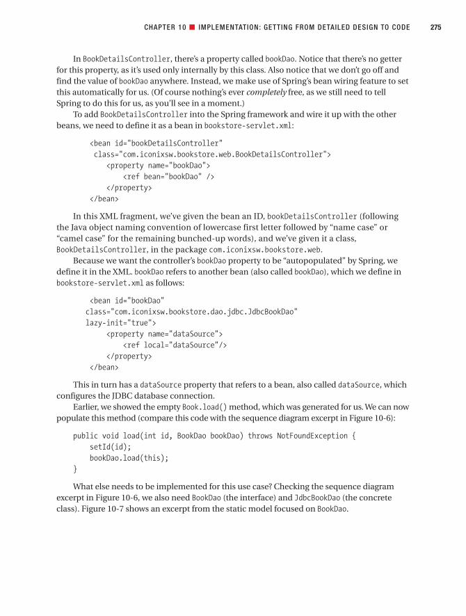
In BookDetailsController, there’s a property called bookDao. Notice that there’s no getterfor this property, as it’s used only internally by this class. Also notice that we don’t go off andfind the value of bookDao anywhere. Instead, we make use of Spring’s bean wiring feature to setthis automatically for us. (Of course nothing’s ever completely free, as we still need to tellSpring to do this for us, as you’ll see in a moment.)
To add BookDetailsController into the Spring framework and wire it up with the otherbeans, we need to define it as a bean in bookstore-servlet.xml:
<bean id="bookDetailsController"class="com.iconixsw.bookstore.web.BookDetailsController">
<property name="bookDao"><ref bean="bookDao" />
</property></bean>
In this XML fragment, we’ve given the bean an ID, bookDetailsController (followingthe Java object naming convention of lowercase first letter followed by “name case” or“camel case” for the remaining bunched-up words), and we’ve given it a class,BookDetailsController, in the package com.iconixsw.bookstore.web.
Because we want the controller’s bookDao property to be “autopopulated” by Spring, wedefine it in the XML. bookDao refers to another bean (also called bookDao), which we define inbookstore-servlet.xml as follows:
<bean id="bookDao"class="com.iconixsw.bookstore.dao.jdbc.JdbcBookDao"lazy-init="true">
<property name="dataSource"><ref local="dataSource"/>
</property></bean>
This in turn has a dataSource property that refers to a bean, also called dataSource, whichconfigures the JDBC database connection.
Earlier, we showed the empty Book.load() method, which was generated for us. We can nowpopulate this method (compare this code with the sequence diagram excerpt in Figure 10-6):
public void load(int id, BookDao bookDao) throws NotFoundException {setId(id);bookDao.load(this);
}
What else needs to be implemented for this use case? Checking the sequence diagramexcerpt in Figure 10-6, we also need BookDao (the interface) and JdbcBookDao (the concreteclass). Figure 10-7 shows an excerpt from the static model focused on BookDao.
CHAPTER 10 ■ IMPLEMENTATION: GETTING FROM DETAILED DESIGN TO CODE 275
7745ch10final.qxd 12/13/06 8:44 PM Page 275

JdbcBookDao is used in both the Show Book Details and Write Customer Review sequencediagrams. The Java code for the DAO interface is pretty straightforward, as it currently definesonly one method:
package com.iconixsw.bookstore.dao;
import com.iconixsw.bookstore.domain.Book;import org.springframework.dao.DataAccessException;
public interface BookDao {public void load(Book book) throws DataAccessException;
}
We won’t go into the details of the JDBC implementation as it’s code-heavy and doesn’tadd a huge amount to the discussion, but if you’re interested, the complete example can bedownloaded from the book’s web page.
So, that’s basically it for this use case. There’s more explanation than code here, so it mightseem more complex than it really is. All that’s left is bookdetails.jsp (the view), which is thefun part.
CHAPTER 10 ■ IMPLEMENTATION: GETTING FROM DETAILED DESIGN TO CODE276
Figure 10-7. BookDao from the static model
Book
+ id: int+ synopsis: int+ title: String
+ load(int, BookDao) : void
JdbcBookDao
+ load(Book) : void
«interface»BookDao
+ load(Book) : void
1
0..*
7745ch10final.qxd 12/13/06 8:44 PM Page 276

The View: bookdetails.jspHere’s bookdetails.jsp in all its brevity:
<%@ include file="include/IncludeTop.jsp" %>
<h2><c:out value="${book.title}"/></h2><p><c:out value="${book.synopsis}"/></p>
<p><a href="writecustomerreview.htm?bookid=<c:out value="${book.id}"/>">Write a review of this book
</a></p>
</body></html>
Let’s look at the first three lines in bookdetails.jsp:
• The first line invokes IncludeTop.jsp, which gives us the top half of the page.
• The second line displays a heading with the book’s title. The c:out tag is part of JSTL;c:out allows us to output the value of bean properties. The “book” bean (referred to in${book.title}) was returned by BookDetailsController in the ModelAndView object,effectively making it available in the JSP page.
• The third line displays a synopsis of the book. Then we see a link to the page for writinga review of the book, which we cover in the next use case.
Figure 10-8 shows the screenshot for the Book Details page.
CHAPTER 10 ■ IMPLEMENTATION: GETTING FROM DETAILED DESIGN TO CODE 277
7745ch10final.qxd 12/13/06 8:44 PM Page 277
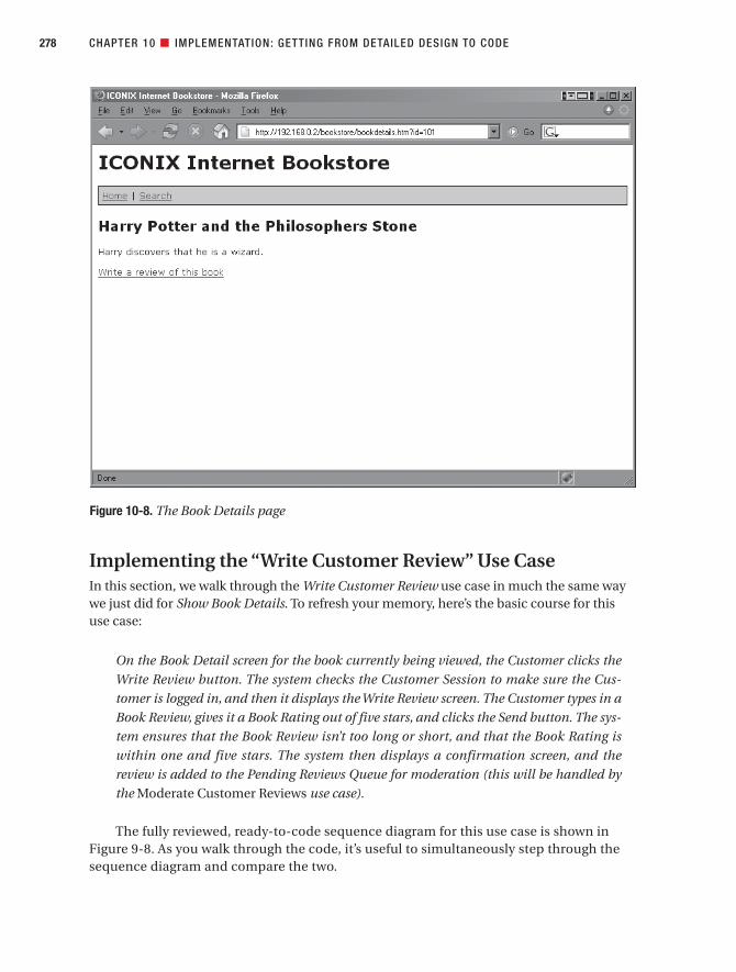
Implementing the “Write Customer Review” Use CaseIn this section, we walk through the Write Customer Review use case in much the same way we just did for Show Book Details. To refresh your memory, here’s the basic course for this use case:
On the Book Detail screen for the book currently being viewed, the Customer clicks the
Write Review button. The system checks the Customer Session to make sure the Cus-
tomer is logged in, and then it displays the Write Review screen. The Customer types in a
Book Review, gives it a Book Rating out of five stars, and clicks the Send button. The sys-
tem ensures that the Book Review isn’t too long or short, and that the Book Rating is
within one and five stars. The system then displays a confirmation screen, and the
review is added to the Pending Reviews Queue for moderation (this will be handled by
the Moderate Customer Reviews use case).
The fully reviewed, ready-to-code sequence diagram for this use case is shown inFigure 9-8. As you walk through the code, it’s useful to simultaneously step through thesequence diagram and compare the two.
CHAPTER 10 ■ IMPLEMENTATION: GETTING FROM DETAILED DESIGN TO CODE278
Figure 10-8. The Book Details page
7745ch10final.qxd 12/13/06 8:44 PM Page 278

WriteCustomerReviewControllerScanning through the sequence diagram from left to right, top to bottom, the first class weneed to implement is WriteCustomerReviewController. Figure 10-9 shows part of the staticmodel for this class.
■Note Peeking ahead slightly, check Figure 11-9 for an updated version of part of this diagram.
The operations assigned to the classes in Figure 10-9 have been derived by steppingmechanically through the relevant parts of the sequence diagram and turning the messagesinto operations on the class diagram. These in turn, of course, turn into Java methods.
If you recall from Chapters 8 and 9, there’s quite a hefty sequence diagram for this usecase. So we’ll walk through it in several smaller segments, writing the code as we go along.
Figure 10-10 shows the first excerpt from the Write Customer Review sequence diagram,focused on the main “form controller” class, WriteCustomerReviewController. This class’spurpose in life is to process the user’s form containing their book review. To achieve this, thecontroller must first turn the form data into a domain-level object representation (i.e., aCustomerReview object), and then it must save the new object to the database. Let’s walkthrough the design to achieve this, and turn it into code.
CHAPTER 10 ■ IMPLEMENTATION: GETTING FROM DETAILED DESIGN TO CODE 279
Figure 10-9. Part of the static model for WriteCustomerReviewController
WriteCustomerReviewController
+ doSubmitAction(CustomerReview) : void+ formBackingObject(HttpServletRequest) : CustomerReview
CustomerSession
+ getCustomerSession(HttpServletRequest) : CustomerSession
Book
+ load(int, BookDao) : void
CustomerReview
+ setBook(Book) : void+ setCustomer(Customer) : void
JdbcBookDao
+ load(book) : void
JdbcCustomerReviewDao
+ save(CustomerReview) : void
CustomerReviewValidator
+ supports(Class) : boolean+ validate(Object, Errors) : void
0..*
1
7745ch10final.qxd 12/13/06 8:44 PM Page 279

Figure 10-10 makes it pretty clear what needs to be done. We need to add a method calledformBackingObject()to WriteCustomerReviewController. This method will turn the user’sincoming review form into a CustomerReview object.
But the class begins with a constructor that defines its command class, CustomerReview:
package com.iconixsw.bookstore.web;
// heaps of imports . . .
CHAPTER 10 ■ IMPLEMENTATION: GETTING FROM DETAILED DESIGN TO CODE280
Figure 10-10. Excerpt from the Write Customer Review sequence diagram focused onWriteCustomerReviewController.formBackingObject()
7745ch10final.qxd 12/13/06 8:44 PM Page 280
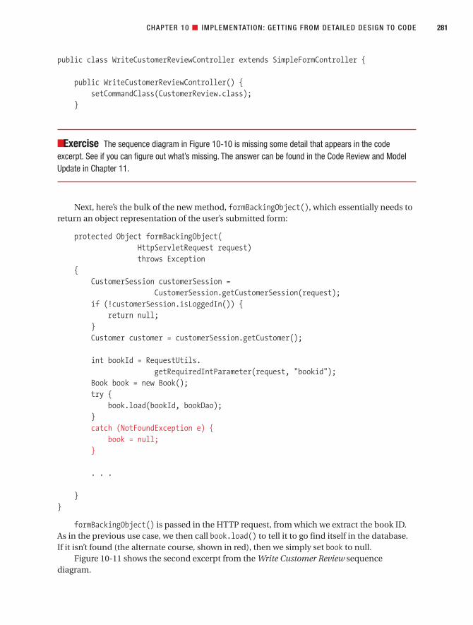
public class WriteCustomerReviewController extends SimpleFormController {
public WriteCustomerReviewController() {setCommandClass(CustomerReview.class);
}
■Exercise The sequence diagram in Figure 10-10 is missing some detail that appears in the codeexcerpt. See if you can figure out what’s missing. The answer can be found in the Code Review and ModelUpdate in Chapter 11.
Next, here’s the bulk of the new method, formBackingObject(), which essentially needs toreturn an object representation of the user’s submitted form:
protected Object formBackingObject(HttpServletRequest request)throws Exception
{CustomerSession customerSession =
CustomerSession.getCustomerSession(request);if (!customerSession.isLoggedIn()) {
return null;}Customer customer = customerSession.getCustomer();
int bookId = RequestUtils.getRequiredIntParameter(request, "bookid");
Book book = new Book();try {
book.load(bookId, bookDao);}catch (NotFoundException e) {
book = null;}
. . .
}}
formBackingObject() is passed in the HTTP request, from which we extract the book ID.As in the previous use case, we then call book.load() to tell it to go find itself in the database. If it isn’t found (the alternate course, shown in red), then we simply set book to null.
Figure 10-11 shows the second excerpt from the Write Customer Review sequencediagram.
CHAPTER 10 ■ IMPLEMENTATION: GETTING FROM DETAILED DESIGN TO CODE 281
7745ch10final.qxd 12/13/06 8:44 PM Page 281

Here’s the code to implement this part of the sequence diagram, finishing off theformBackingObject() method. Note that the “command” variable has been renamed as “review”in the code. This should be addressed in the following Code Review and Model Update:
. . .
CustomerReview review = new CustomerReview();review.setBook(book);review.setCustomer(customer);return review;
}
■Exercise formBackingObject has turned into quite a large method. What could be done to it in orderto make the code more maintainable? We refactor this part of the code and update the design during theCode Review and Model Update in Chapter 11.
Figure 10-12 shows our third and final excerpt from the Write Customer Review sequencediagram.
CHAPTER 10 ■ IMPLEMENTATION: GETTING FROM DETAILED DESIGN TO CODE282
Figure 10-11. Excerpt from the Write Customer Review sequence diagram finishing offWriteCustomerReviewController. formBackingObject()
WriteCustomerReviewController
CustomerReview
command= new
setBook(book)
setCustomer(customer)
7745ch10final.qxd 12/13/06 8:44 PM Page 282

And here’s the doSubmitAction() method in its entirety:
protected void doSubmitAction(Object command) throws Exception {CustomerReview review = (CustomerReview) command;customerReviewDao.save(review);
}
As the name suggests, doSubmitAction() is called when the form is submitted and it’s timeto do something about it. The method is called with a command object (the CustomerReview),which we already populated in the formBackingObject() method. Because Spring passes it inas an Object, we must first cast it to a CustomerReview before we can save it.
■Exercise As you may recall from the responsibility-driven discussions in Chapter 9, the functions shouldgo where the data lives. So, looking at doSubmitAction(), what should be done to make our code followthis rule of thumb? (You can find the answer in the Code Review and Model Update in Chapter 11.)
But how does this class get its reference to the customerReviewDao—and the bookDao, forthat matter? These are set automatically by Spring, via its IoC mechanism. To tell Spring thatwe want these to be set, they’re added to the WriteCustomerReviewController bean definitionin bookstore-servlet.xml as follows:
<bean id="writeCustomerReviewController"class="com.iconixsw.bookstore.web.WriteCustomerReviewController">
<property name="formView"><value>writecustomerreview</value>
</property>
CHAPTER 10 ■ IMPLEMENTATION: GETTING FROM DETAILED DESIGN TO CODE 283
Figure 10-12. Excerpt from the Write Customer Review sequence diagram focusing onWriteCustomerReviewController. doSubmitAction()
WriteCustomerReviewControllerDispatcherServlet
JdbcCustomerReview
Dao
("review" is the form'scommand object)
doSubmitAction(command)
save(review)
7745ch10final.qxd 12/13/06 8:44 PM Page 283

<property name="bookDao"><ref bean="bookDao" />
</property>
<property name="customerReviewDao"><ref bean="customerReviewDao" />
</property></bean>
(We’ve already added the bookDao bean, and we’ll add customerReviewDao in the next section.)Then in the WriteCustomerReviewController class itself, there are a couple of property set-
ters, which Spring then knows to call for us when the object is first initialized:
public void setBookDao(BookDao bookDao) {this.bookDao = bookDao;
}
public void setCustomerReviewDao(CustomerReviewDao customerReviewDao)
{this.customerReviewDao = customerReviewDao;
}
private BookDao bookDao;private CustomerReviewDao customerReviewDao;
Next, let’s move on to the new DAO, CustomerReviewDao.
CustomerReviewDaoFigure 10-13 shows the portion of the static model for CustomerReviewDao and its implement-ing class, JdbcCustomerReviewDao. The diagram also shows the entity class that is the mainproduct of this DAO, CustomerReview.
The static model gives us the structure, but we also need to know in what context the classwill be used so that we can figure out what to put in it. For this purpose, Figure 10-14 shows adetail from the Write Customer Review sequence diagram that deals with CustomerReviewDao(or more specifically, JdbcCustomerReviewDao).
You can see from Figure 10-14 that there isn’t very much interaction withCustomerReviewDao. The only point of contact is when a CustomerReview object needs to be saved, and when it calls a method on itself (addToPendingReviewsQueue()).
CHAPTER 10 ■ IMPLEMENTATION: GETTING FROM DETAILED DESIGN TO CODE284
7745ch10final.qxd 12/13/06 8:44 PM Page 284

CHAPTER 10 ■ IMPLEMENTATION: GETTING FROM DETAILED DESIGN TO CODE 285
Figure 10-13. Part of the static model for CustomerReviewDao
CustomerReview
- bookId: int- customerId: int- id: int- rating: int- review: String
JdbcCustomerReviewDao
+ addToPendingReviewsQueue(CustomerReview) : void+ save(CustomerReview) : void
«interface»
CustomerReviewDao
+ addToPendingReviewsQueue(CustomerReview) : void+ save(CustomerReview) : void
0..*
1
Figure 10-14. Detail from the Write Customer Review sequence diagram focused onJdbcCustomerReviewDao
JdbcCustomerReview
Dao
WriteCustomerReviewController
save(review)
addToPendingReviewsQueue(review)
7745ch10final.qxd 12/13/06 8:44 PM Page 285

Here’s the CustomerReviewDao Java interface, generated directly from the class diagram:
package com.iconixsw.bookstore.dao;
import com.iconixsw.bookstore.domain.*;import java.util.*;import org.springframework.dao.DataAccessException;
public interface CustomerReviewDao {
public void save(CustomerReview review)throws DataAccessException;
}
This DAO interface defines one method: save(). As the name suggests, save() writes a CustomerReview object to the database. It hardly seems worth defining a class for just onemethod, but the interface (and implementing JDBC class) will have new methods added to it as new use cases are implemented.
We won’t cover the JdbcCustomerReviewDao implementation here, as it’s quite code-heavy.However, if you’re interested, you can download the full source code from the book’s web page.10
CHAPTER 10 ■ IMPLEMENTATION: GETTING FROM DETAILED DESIGN TO CODE286
ADDING TO CUSTOMERREVIEWDAO
Later, depending on the use case being implemented, we would expect to add such methods as thefollowing:
public CustomerReview findById(int reviewId)throws DataAccessException;
public Collection findByCustomerId(int customerId)throws DataAccessException;
public Collection findByBookId(int bookId)throws DataAccessException;
The findById method would look up, populate, and return a single CustomerReview instance for a specific review ID.
The findByCustomerId method, on the other hand, would return a Collection ofCustomerReview objects belonging to a single Customer, and findByBookId would return a Collection of CustomerReview objects that were written for one particular Book.
10. See www.iconixprocess.com.
7745ch10final.qxd 12/13/06 8:44 PM Page 286

Finally, we need to tell Spring that the CustomerReviewDao bean will actually be aJdbcCustomerReviewDao. We do this via bookstore-servlet.xml:
<bean id="customerReviewDao"class="com.iconixsw.bookstore.dao.jdbc.JdbcCustomerReviewDao"lazy-init="true">
<property name="dataSource"><ref local="dataSource"/>
</property>
</bean>
CustomerSessionCustomerSession’s purpose in life is to track the login state (and actual Customer object) for anindividual Customer. Actually, for the purposes of this example, CustomerSession is just a pre-tend class. It does a rattlingly good impersonation of a complete customer authenticationsystem, as long as your name is Billy Bob and you’re always expecting to be logged in.
You can see what methods need to be implemented on CustomerSession by checking thesequence diagram “detail” in Figure 10-15.
CHAPTER 10 ■ IMPLEMENTATION: GETTING FROM DETAILED DESIGN TO CODE 287
Figure 10-15. Detail from the Write Customer Review sequence diagram focused onCustomerSession
WriteCustomerReviewController CustomerSession
Static method.If CustomerSession doesn't exist, createnew and add to HttpSession
customerSession= getCustomerSession(request)
isLoggedIn
customer= getCustomer
7745ch10final.qxd 12/13/06 8:44 PM Page 287
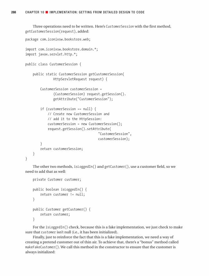
Three operations need to be written. Here’s CustomerSession with the first method,getCustomerSession(request), added:
package com.iconixsw.bookstore.web;
import com.iconixsw.bookstore.domain.*;import javax.servlet.http.*;
public class CustomerSession {
public static CustomerSession getCustomerSession(HttpServletRequest request) {
CustomerSession customerSession =(CustomerSession) request.getSession().getAttribute("CustomerSession");
if (customerSession == null) {// Create new CustomerSession and// add it to the HttpSession:customerSession = new CustomerSession();request.getSession().setAttribute(
"CustomerSession",customerSession);
}return customerSession;
}}
The other two methods, isLoggedIn() and getCustomer(), use a customer field, so weneed to add that as well:
private Customer customer;
public boolean isLoggedIn() {return customer != null;
}
public Customer getCustomer() {return customer;
}
For the isLoggedIn() check, because this is a fake implementation, we just check to makesure that customer isn’t null (i.e., it has been initialized).
Finally, just to reinforce the fact that this is a fake implementation, we need a way ofcreating a pretend customer out of thin air. To achieve that, there’s a “bonus” method calledmakeFakeCustomer(). We call this method in the constructor to ensure that the customer isalways initialized:
CHAPTER 10 ■ IMPLEMENTATION: GETTING FROM DETAILED DESIGN TO CODE288
7745ch10final.qxd 12/13/06 8:44 PM Page 288

public CustomerSession() {makeFakeCustomer();
}
private void makeFakeCustomer() {customer = new Customer();customer.setId(1);customer.setFirstName("Billy Bob");customer.setLastName("Dupree");customer.setEmail("[email protected]");
}
Of course, this method always returns the exact same customer, our old friend Billy Bob.However, it’s (just about) good enough for early development and testing purposes.
■Note If you’re wondering just who the heck Billy Bob is, we encourage you to peek ahead to Chapter 13to find out.
CustomerReviewValidatorNext, let’s create the class that handles the validation of the incoming customer review form.The validate() method checks to see if the review text is empty. This is one of the alternatecourses, so that part of the code is shown here in red.
package com.iconixsw.bookstore.domain.logic;
// import statements omitted . . .
public class CustomerReviewValidator implements Validator {
public boolean supports(Class commandClass) {return commandClass.isAssignableFrom(CustomerReview.class);
}
public void validate(Object command, Errors errors) {ValidationUtils.rejectIfEmptyOrWhitespace(
errors,"review","required","Review text is required");
}
}
CHAPTER 10 ■ IMPLEMENTATION: GETTING FROM DETAILED DESIGN TO CODE 289
7745ch10final.qxd 12/13/06 8:44 PM Page 289

This class was written to fit into Spring’s validation framework. We’re handed an Errorsobject, to which—assuming we find any validation errors in the form—we add one or moreerror messages that will then be displayed to the user, next to the offending form fields.
■Exercise This implementation is missing some vital details that were specified in the use case text (see the finished use case next to its robustness diagram in Figure 6-7). We revisit this part of the code inthe Code Review and Model Update in Chapter 11, but why not see if you can identify what’s missing first?And, for some extra bonus points: Any guesses about why the detail might have been left out?
We also need to wire up this validator class to WriteCustomerReviewController, so that the validator is run automatically before the form gets processed via the doSubmitAction()method. To do that, we add a property to the writeCustomerReviewController bean inbookstore-servlet.xml:
<property name="validator"><beanclass="com.iconixsw.bookstore.domain.logic.CustomerReviewValidator" />
</property>
■Exercise Looking at the code for CustomerReviewValidator, what could be done to make it followa more responsibility-driven design? You can find the answer in the Code Review and Model Update inChapter 11.
The View: writecustomerreview.jspThe JSP page, writecustomerreview.jsp, is the “view” in our MVC setup—that is, it creates theweb page that the user sees, and it includes server-side tags that Spring uses to read in theuser’s form data and populate the objects we’ve designed thus far.
Let’s walk through this JSP page piece by piece:
<%@ include file="include/IncludeTop.jsp" %>
<h2><c:out value="${command.book.title}"/>
</h2>
<h3>Hello <c:out value="${command.customer.firstName}"/>,please enter your review for this book.
</h3>
CHAPTER 10 ■ IMPLEMENTATION: GETTING FROM DETAILED DESIGN TO CODE290
7745ch10final.qxd 12/13/06 8:44 PM Page 290

The <h2> line provides a heading with the book’s title, retrieved via the <c:out> JSTL tagand using the lookup text command.book.title. “command” refers to the name of the mainobject (a CustomerReview) that we populated the view with. command.book.title is the short-hand equivalent of this Java code:
command.getBook().getTitle();
The next part of the page (and the bulk of it) is the form itself. This allows the user to enterthe three form fields (a title for their review, the review text, and a rating):
<form action="<c:url value="writecustomerreview.htm"/>" method="post">
<input type="hidden" name="bookid"value="<c:out value="${command.book.id}"/>" />
<table><tr>
<td>Title</td><td>
<spring:bind path="command.title"><input type="text"
name="title"value="${status.value}" />
<span class="error"><c:out value="${status.errorMessage}" />
</span></spring:bind>
</td></tr>
<tr><td>Your Review</td><td>
<spring:bind path="command.review"><textarea name="review" cols="50" rows="10">
<c:out value="${status.value}"/></textarea><span class="error">
<c:out value="${status.errorMessage}" /></span>
</spring:bind></td>
</tr>
CHAPTER 10 ■ IMPLEMENTATION: GETTING FROM DETAILED DESIGN TO CODE 291
7745ch10final.qxd 12/13/06 8:44 PM Page 291

<tr><td>Rating (1-5)</td><td>
<spring:bind path="command.rating"><input type="text" name="rating"
value="<c:out value="${status.value}"/>" /><span class="error"><c:out value="${status.errorMessage}" />
</span></spring:bind>
</td></tr>
</table>
<input type="submit" value="Save Review" /></form>
Notice that next to each form field is a tag for showing an error message (we’ve shownthese in red as they’re part of the alternate courses). These tags show the validation failuremessages, if any. Each message is shown next to the field that failed validation. We didn’t haveto do any additional work to match these up—one of the benefits of using Spring’s form vali-dation framework.
Finally, we close off the page including a link back to the Book Details page, which wouldinvoke the Show Book Details use case:
<p><a href="bookdetails.htm?bookid=<c:out value="${command.book.id}"/>">
View book details</a>
</p>
</body></html>
Figure 10-16 shows the screenshot for the Write Customer Review page.In the screenshot, Billy Bob has submitted his review but forgot to type in an actual
review, so our alternate course validation failed as you’d expect, and the errant input field hasan error message immediately beneath it in red text. (For those who were waiting with batedbreath for the CSS “murder weapon” we introduced earlier in this chapter, that was it. We hopethe wait wasn’t too suspenseful.)
Notice that the Rating field allows only the values 1–5, but its initial value is 0. The defaultshould really be one of the allowed values; we return to this in Chapter 12 when we cover testing.
■Exercise The validator didn’t catch the 0 rating and highlight it on the form. We also cover this inChapter 12. But in the meantime, looking at the sequence diagram in Figure 9-8, what could be done tocatch this in the validation code? (The answer is in the Code Review and Model Update in Chapter 11.)
CHAPTER 10 ■ IMPLEMENTATION: GETTING FROM DETAILED DESIGN TO CODE292
7745ch10final.qxd 12/13/06 8:44 PM Page 292
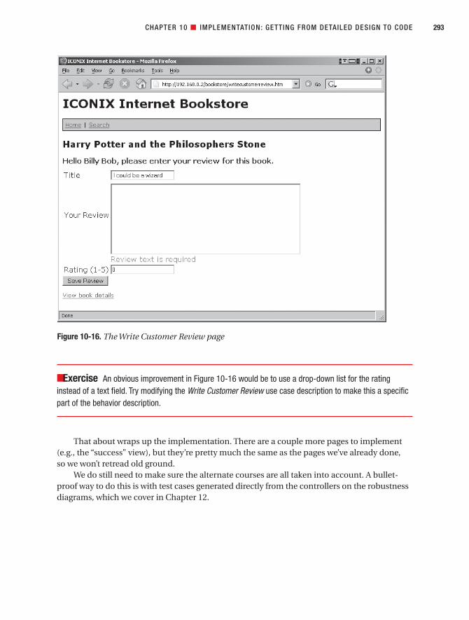
■Exercise An obvious improvement in Figure 10-16 would be to use a drop-down list for the ratinginstead of a text field. Try modifying the Write Customer Review use case description to make this a specificpart of the behavior description.
That about wraps up the implementation. There are a couple more pages to implement(e.g., the “success” view), but they’re pretty much the same as the pages we’ve already done, so we won’t retread old ground.
We do still need to make sure the alternate courses are all taken into account. A bullet-proof way to do this is with test cases generated directly from the controllers on the robustnessdiagrams, which we cover in Chapter 12.
CHAPTER 10 ■ IMPLEMENTATION: GETTING FROM DETAILED DESIGN TO CODE 293
Figure 10-16. The Write Customer Review page
7745ch10final.qxd 12/13/06 8:44 PM Page 293

More PracticeThis section provides a list of questions that you can use to test your knowledge of usecase–driven programming and delivery. If you get stuck, search back through this chapter to extract the answers.
1. Using ICONIX Process, what are the main design artifacts that you drive the sourcecode from?
a) Robustness diagrams and class diagrams
b) Sequence diagrams and class diagrams
c) Sequence diagrams and activity diagrams
d) Robustness diagrams and sequence diagrams
2. Which of the following methods belong on an entity class? For those that should beallocated to other classes, briefly explain where (if anywhere) that the entity classwould be involved in the design.
a) A property (e.g., book title)
b) A method containing validation logic
c) JDBC code to write the entity’s data to a database table
d) A SOAP interface query to retrieve data to go in the entity class
3. Explain why it’s good practice to implement the trickiest parts of the system first and to avoid putting the difficult parts off until the end. Try to quantify your answer.
4. Describe the differences among a CustomerReviewDao class, a CustomerReview entity,and a CustomerReviews database table.
5. If a DAO method takes a Book argument and returns a BookReviewCollection, shouldthe method go on a BookDao or a BookReviewDao? Explain why.
6. If you’re implementing an alternate course in which the customer’s login details can’tbe found, what is the preferable way to implement it?
a) Make the DAO return null so that the form handler can deduce that it should dis-play a “not found” message.
b) Make the form handler throw an exception so that the web application containerredirects to an error page.
c) Make the DAO throw an exception so that the form handler can display a “notfound” message.
d) Make the form handler set a null Customer bean in the JSP page so that the JSPpage logic displays a “not found” message.
CHAPTER 10 ■ IMPLEMENTATION: GETTING FROM DETAILED DESIGN TO CODE294
7745ch10final.qxd 12/13/06 8:44 PM Page 294

7. Describe why a system written in the following style would quickly become unmain-tainable. After deciphering what the code is meant to do, refactor it so that it’s moremaintainable. (Hint: You’ll need to decide which classes to reallocate the behavior to.)
public class ShoppingCartHelper extends AdhocUtilThings {public ShoppingCartHelper() {
init();}public void doAction(Cart c, Book b) {
if (available(b)) c.add(b);else throw new UnavailableException(b);
}}
8. Which of the following statements is not true? Explain why the statement is incorrect.
a) An entity must have a 1:1 mapping with a row in a database table.
b) A DAO can return both individual entity objects and collections of objects.
c) An entity can contain references to other entities.
d) An entity class can delegate to other “helper” classes as needed.
SummaryIn this chapter, we took the sequence diagrams for two of the use cases plus the static model,and turned it all into working source code for the Internet Bookstore. Figure 10-17 showswhere we are; the items covered in this chapter are shown in red.
Because the use case text is fully disambiguated and written in the context of the domainmodel, it’s possible to walk through the use case text and match it up directly with the classand property names in the Java code.
What we haven’t yet done is written any unit tests for the Internet Bookstore—animportant step. Normally, you would expect to write the tests as you write the code. We’vekept the unit testing step separate so that we’re not explaining too many things at once, butin Chapter 12, you’ll see how the unit tests can be driven directly from the controllers on therobustness diagrams.
In the next chapter, we perform a review of the code that’s been written thus far and bringthe model up to date in any places where the code and the model might have diverged.
CHAPTER 10 ■ IMPLEMENTATION: GETTING FROM DETAILED DESIGN TO CODE 295
7745ch10final.qxd 12/13/06 8:44 PM Page 295

CHAPTER 10 ■ IMPLEMENTATION: GETTING FROM DETAILED DESIGN TO CODE296
Figure 10-17. Coding activities during the implementation stage
7745ch10final.qxd 12/13/06 8:44 PM Page 296

Code Review and Model Update
During coding, it’s likely that you’ll have made a few changes to the design, so the code willnow be slightly out of sync with the design diagrams. A depressingly common reaction at thisstage is to deem the design documentation obsolete, throw it away, and continue all subse-quent development work without doing any more design work.
However, ICONIX Process (with some major tools assistance from the folks at SparxSystems) provides an easy technique for rescuing all that design work you did and keeping it current so that it forms the basis of the design work for the remainder of the project.
297
C H A P T E R 1 1
7745ch11final.qxd 12/13/06 8:45 PM Page 297

The 10,000-Foot ViewWhy bother reviewing the code and syncing it up with the design? Here’s a hypothetical con-versation that we hope will shed some light on the subject.
Q: You mean I have to review the code, too? Why? Isn’t working code enough?
A: The purpose of the Code Review and Model Update milestone is to bring the code andthe model back into sync, ready to begin work on the next set of use cases. So, when youstart developing the use cases for the next release, you can build on the design work that’salready done. You’ll continue to update and refine the static model, and reuse the objectsthat are in your domain model.
Q: What does the review involve?
A: As the name suggests, there are two parts to this review: checking the code and giving ita good shaking-up if needed, and comparing the code with the detailed design diagrams.Wherever they’ve diverged, either the code is brought back in line with the design, or thedesign diagrams are updated to be in sync with the code.
Q: How often should this review take place?
A: You’ll need to tailor the timing of the Code Review and Model Update to fit your proj-ect. But the review should ideally take place at least at the end of each release (either toQA or to the end users), in preparation for the next release. Depending on the size of therelease, you could also hold a review session after implementing a few use cases.
Q: I read in an agile development book that I should “update only when it hurts.” Isn’tall this updating going to take forever?
A: Updating only when it hurts is analogous to visiting the dentist only when you have a toothache. It might be a little late by then (unless you like root canal surgery). It mightseem quite time-consuming to have to bring everything back into sync like this. But ifyou don’t leave too much time between reviews, then it doesn’t take very long at all. It’s a good way to keep everyone in the team on the same page, so to speak. Keep theprocess fine-grained, and you’ll catch design or integration issues early, before theybecome a problem.
Code Review and Model Update in TheoryBefore we get started on the Internet Bookstore example, let’s pause for a minute to examinewhy code reviews are even necessary—especially after doing all that up-front analysis anddesign work. But first, the usual top 10 guidelines.
298 CHAPTER 11 ■ CODE REVIEW AND MODEL UPDATE
7745ch11final.qxd 12/13/06 8:45 PM Page 298

Top 10 Code Review and Model Update GuidelinesThe principles discussed in this chapter can be summed up as a list of guidelines. Our top 10list follows.
10. Prepare for the review, and make sure all participants have read the relevant reviewmaterial prior to the meeting.
9. Create a high-level list of items to review, based on the use cases.
8. If necessary, break down each item in the list into a smaller checklist.
7. Review code at several different levels.
6. Gather data during the review, and use it to accumulate boilerplate checklists forfuture reviews.
5. Follow up the review with a list of action points e-mailed to all people involved.
4. Try to focus on error detection during the review, not error correction.
3. Use an integrated code/model browser that hot-links your modeling tool to your codeeditor.
2. Keep it “just formal enough” with checklists and follow-up action lists, but don’t overdothe bureaucracy.
1. Remember that it’s also a Model Update session, not just a Code Review.
Let’s look at these guidelines in more detail.
10. Prepare for the Review, and Make Sure All Participants Have Read the RelevantReview Material Prior to the MeetingAlternatively, don’t bother preparing and have a disorganized, time-wasting meeting. Or try itthe XP way: remove all the chairs from the meeting room and give the meeting a catchy namelike “early morning stand-up meeting.”
9. Create a High-Level List of Items to Review, Based on the Use CasesThe high-level list of items to review should be based on the use case titles. Although it’s possi-ble to create a checklist of specific classes and methods, it’s better to drive the list from the usecases, as this provides for a more structured review, which is more likely to catch behavior-related defects or missing functionality.
8. Break Down Each List Item into a Smaller Checklist (If Necessary)Because the high-level checklist is essentially a list of use case titles, it’s possible to drive thefine-grained list from the controllers on the robustness diagrams.
Note that for some projects, it may not be necessary to break the list into this level ofdetail; the high-level checklist (based on use cases) might be sufficient to start identifyingclasses and methods to review.
CHAPTER 11 ■ CODE REVIEW AND MODEL UPDATE 299
7745ch11final.qxd 12/13/06 8:45 PM Page 299

7. Review Code at Several Different LevelsReview the code for the usual code-level stuff: adherence to coding conventions, design style,naming, and so forth. But also compare the code with the design by walking through thesequence diagrams. In the same way that it should be possible to trace the path of a use casethrough a sequence diagram, it should also be possible to trace the path of a sequence dia-gram through the code.1
As you review the code, walk through the behavior descriptions in the use case text andcompare the scenario text with the code. Sometimes this helps to catch missing functionalitythat might have been lost during the detailed design stage.
If it proves difficult to match up the method names with the actions in the use case text,then the code hasn’t truly been written in the context of the design—or to flip the problemaround, perhaps the use case and the design don’t match. Either way, the problem needs to becorrected so that there’s a direct correlation between the code and the use case text. If neces-sary, break the code into smaller methods, and use descriptive names that allow the code to betraced back to the use cases.
6. Use Data Gathered During the Review to Accumulate Boilerplate Checklists for Future ReviewsDuring code reviews, you tend to notice the same old issues again and again. Turning theseinto a checklist can save a lot of time, and it can help to make sure specific problems aren’tmissed. Over time, add to the list of checklists; in particular, look for insidious problems thatmight otherwise be overlooked, and make them explicit by adding them to the checklist.
If these checklists are in circulation around the company, then programmers can learn to avoid the same old issues in the first place, saving even more time!
5. Follow Up the Review with a List of Action Points E-mailed to All People InvolvedAlternatively, have the meeting, assign action items, and never follow up to make sure theaction items get done.
■Tip Have a follow-up meeting to ensure that all the action points actually did get “actioned.”
4. Try to Focus on Error Detection During the Review, Not Error CorrectionIt’s OK to make small updates to the model during the review, as it’s a good way to make sureeveryone is in agreement. However, if code needs to be updated or major design changes arerequired, that should be done separately and a follow-up review meeting scheduled.
CHAPTER 11 ■ CODE REVIEW AND MODEL UPDATE300
1. Note that if you’re doing aspect-oriented programming (AOP), your code may very well be organizedin exactly this manner. See the sidebar “Use Cases and Aspects” in Chapter 3.
7745ch11final.qxd 12/13/06 8:45 PM Page 300

3. Use an Integrated Code/Model Browser That Hot-Links Your Modeling Tool to Your Code EditorThis saves time and means that, when the programmer is updating the code later, none of thechanges are forgotten about. See the sidebar “Using the UML Model to Browse the Java Code”at the end of this chapter.
2. Keep It “Just Formal Enough” with Checklists and Follow-up Action ListsThe approach described in this chapter is halfway between an informal code review and a formal code inspection. The key is to keep it “just formal enough” without overdoing thebureaucracy.
Some paperwork is necessary to ensure that individual items don’t get forgotten. But, likethe rest of the analysis and design process, too much documentation and too many processhoops can lead to analysis paralysis—or to review and update paralysis, in this case. Learn torecognize when the review has had its positive effect, and when it’s time to move on.
1. Remember That It’s Also a Model Update Session, Not Just a Code ReviewThe present state-of-the-art in development tools makes it trivially easy (at last!) to keepthe model and the code in sync. It borders on the criminal to not take advantage of thesecapabilities.
CHAPTER 11 ■ CODE REVIEW AND MODEL UPDATE 301
2. Douglas Adams fans will recognize the similarity between a “wrongly done” code review and a violentgame of Brockian Ultra-Cricket.
THERE’S A RIGHT WAY AND A WRONG WAY TO CONDUCT A CODE REVIEW
Preparing for the code review is important, and it involves tossing various weighty objects (baseball bats, golfclubs, skis—anything you can get a good swing with2) into the middle of the room, and then running forcover while the reviewer and the programmer dive for the nearest makeshift weapon in order to defend theircriticisms and their code, respectively.
Well, OK, that’s what happens when a code review goes wrong and is taken to its logical conclusion.The ideal code review isn’t so much a fight to the death as a discussion between a programmer and animpartial observer about the code’s adherence to the design. It’s a review of the code rather than a personalperformance review. In fact, as soon as a programmer’s individual abilities are brought into question (evensubtly), that programmer will go on the defensive, and the effectiveness of the review will be dramaticallyreduced.
7745ch11final.qxd 12/13/06 8:45 PM Page 301

Why Are Code Reviews Necessary After All That Design Work?If you perform all of the up-front analysis, up-front design modeling, and the appropriatereviews at each milestone, and you drive the code directly from the design, then the codereally should be in very good shape. It should be highly cohesive, well factored, and closelytied to the use cases. As we discuss in Chapter 12, it will also be tied closely to the unit tests,which in turn are tied closely to the domain model and the use cases. So, given all that, whybother doing a review? Is it a failing of the process? Or a failure of the designers and program-mers to do their job properly? Or none of the above?
We think it’s none of the above. Code reviews are still important, even after you do a goodjob at design. Some reasons spring to mind:
• The people on your team are human (at least, we hope so); they make mistakes.
• The people on your team might well make their best effort to follow the process, butsoftware projects are big, complex beasts, and—even with a cookbook methodology—it isn’t always entirely clear what the correct next step should be.
• If the team is adopting a new process for the first time, it’s likely that they will not followthe process at first, at least not completely. It takes time to adapt, to learn the subtletiesand ins and outs of a new way of working. There might not even be complete buy-in tothe new process, until people start to see the benefits. So in the meantime, to some
CHAPTER 11 ■ CODE REVIEW AND MODEL UPDATE302
CODE REVIEW VS. CODE INSPECTION
The code review as described in this chapter involves checking the code base for adherence to the designand then either bringing the code back into line or updating the design. The review technique we proposehere is more precisely a combined review of the model and the code. In fact, although we informally call thisstep the “Code Review” milestone, it has much in common with more formal code inspections.
Some differences between a code review and a code inspection are as follows.
Code Inspection Code Review
A code inspection involves creating a checklist A code review is more ad hoc. It typically to focus the reviewer’s attention. involves printing out some code and exam-
ining it for adherence to coding standards,scanning for possible bugs and so on.
A code inspection finishes with a formal list A code review finishes with an informal list of of points to fix, usually in the form of defects to-do items, written on a sticky note or in a entered into a defect tracking system. follow-up e-mail.
Data is gathered during a code inspection. The In a code review, gathering of metrics is less data gathered can be useful for identifying common. common types of errors, which can then be focused on in future inspections.
The Code Review and Model Update milestone described in this chapter is really a combination of allthe preceding attributes.
7745ch11final.qxd 12/13/06 8:45 PM Page 302

degree the design will be suboptimal and the code might not have much in commonwith the design. To address this, the first few iterations of the design/code/review lifecycle should be kept quite short, so that these disparities between code and design canbe addressed quickly, before they become too great.
• Although many software projects have key similarities that you can exploit to create a repeatable process, each project has its own variations, meaning that you sometimesneed to improvise, adapt the process, or just do whatever you think is best. But (tomake a long story short) that might not always turn out to have been the right choice.So although it will generally be in very good shape, the design might still need to berevisited once you have working code to use as a baseline.
• An up-front design addresses the majority of design errors, but not all. In this chapter,we try to highlight the sorts of things that up-front design isn’t really “designed” to catchand that you need to keep in mind both when coding and when performing the codereview.
• Sometimes it’s only when you begin coding that you realize there was a better way ofdoing something, or the technology you’re using already provides a prebuilt solution fora particular function. This is why early prototyping is an essential part of the project lifecycle, especially when you’re working with unfamiliar technology. Another goodapproach is to write the unit tests while you’re drawing the sequence diagrams. It’s agood way of getting into the “coding frame of mind” before actually turning the detaileddesign into code.
With these guidelines in mind, in the next section let’s see how our entirely fictionalreviewer handles the Internet Bookstore code review. Note that we intentionally left a coupleof design errors in our example to illustrate the sorts of mistakes that would typically becaught at this stage of the process.
Code Review and Model Update in Practice Now it’s time to put this theory into practice, and attack the Internet Bookstore code that waswritten in Chapter 10. As it turns out, we followed the design process quite closely and thereisn’t a huge amount of tidying up or bulletproofing that we need to do, but there is some.
For the Internet Bookstore code review, we’ll follow the reviewer/programmer conversa-tion as it unfolds. They begin with a list of the use cases and walk through them one by one.For each use case, the reviewer looks through the controllers on the robustness diagram anduses that as the fine-grained review checklist.
■Note During the review you’ll see an occasional “Action Item”—this is a point list that the reviewermakes during the session. The list should be e-mailed to all participants and then followed up on, either afteran agreed period of time or in a follow-up review session.
CHAPTER 11 ■ CODE REVIEW AND MODEL UPDATE 303
7745ch11final.qxd 12/13/06 8:45 PM Page 303

Code Review and Model Update ChecklistIt’s important to go into a review with a prepared checklist. This checklist is essentially just a list of the use cases and their basic and alternate courses (it’s very easy to prepare).
For this review, the reviewer will look at two use cases (you can probably guess whichtwo):
• Show Book Details
• Write Customer Review
The reviewer and the programmer will walk through both of these use cases, and for eachone trace it to the code, via the controllers on the preliminary design and the detailed design.
■Tip If any code doesn’t obviously trace back to the use cases using the reverse of this process, it’s asurefire sign that the code and the requirements aren’t tied closely enough together.
“Show Book Details” Use CaseThe review begins with Show Book Details. *Checking the robustness diagram (see Figure 5-11), this use case has these controllers (logical software functions):
• Display links
• Retrieve List of Books
• Retrieve Book Details
• Display Book Details page
• Display Book Details Not Found page
The code for the first three functions all looks fine, so the review kicks into action with the“Display Book Details page” controller.
“Display Book Details Page” Controller
Reviewer: Here’s the use case text:
BASIC COURSE:
The Customer types in the URL for the bookstore’s home page. The system displays a
list of books from the Catalog on the home page, in the form of clickable links. The
Customer clicks a link on the home page, and the system retrieves the book details
for the selected book and displays them on the Book Details page.
CHAPTER 11 ■ CODE REVIEW AND MODEL UPDATE304
7745ch11final.qxd 12/13/06 8:45 PM Page 304

ALTERNATE COURSES:
Book not found: The system displays a Book Details Not Found page.
Programmer: We can trace the Display Book Details page controller via the sequencediagram to the BookDetailsController class. (See Figure 9-7.)
Reviewer: (Pausing to get his bearings) OK, so let’s take a look at the handle() method inBookDetailsController. If I recall, this handles an incoming browser request to show thedetails of a Book, given its ID. (The code that returns the Book Details view is shown in red.)
protected ModelAndView handle(HttpServletRequest request,HttpServletResponse response,Object command,BindException errors) throws Exception {
Book book = (Book) command;try {
book.load(book.getId(), bookDao);}catch (NotFoundException e) {
return new ModelAndView("booknotfound”);}return new ModelAndView("bookdetails”, "book”, book);
}
Reviewer: (Scratches his head) Hmm, well . . . I think maybe I have a problem with the waythat the book is being loaded. It seems odd that you’re having to pass the book’s ID in toitself, when it obviously already knows the ID.
Programmer: Yep. It’s strange—when I looked on the sequence diagram (see excerpt inFigure 11-1), it didn’t seem to be an issue. But in the code it looks odd.
Reviewer: Here’s the problem: the design is wrong!
■Tip Usually, you can pick up a fairly major warning sign that something is wrong from looking at thesequence diagram. From there, tracking down what’s wrong is rather like following a trail of breadcrumbs(as we demonstrate in this review segment).
Reviewer: (Glues on Poirot moustache) Clue number 1: The load() message passes in anID and a bookDao, but on the diagram there’s not even a hint as to where these come from.It’s a dead giveaway that something in that area of the design hasn’t been thought throughto the required level of detail.
CHAPTER 11 ■ CODE REVIEW AND MODEL UPDATE 305
7745ch11final.qxd 12/13/06 8:45 PM Page 305

Programmer: But that doesn’t explain what’s actually wrong with the design—just thatsomething might not be right.
Reviewer: Well, then, let’s follow the breadcrumbs. We need to find out where the ID andthe bookDao come from. Clue number 2: You’re setting the ID on the Book. But the Book isour Spring “command” object, and the ID should be set automatically for us because it’spassed in via the web request. But—and this is clue number 3—this isn’t shown on thediagram. We also need to show the bookDao being set. And finally, clue number 4: It isn’tactually the DispatcherServlet class that creates the Command object.
Programmer: I know, it’s actually ServletRequestDataBinder, one of Spring’s helperclasses. But we’ve generally used DispatcherServlet to mean “some Spring class orother”—it’s a black box.
Reviewer: Sometimes it’s probably OK to do that. But in this case, glossing over the detailslike that means that you missed a detail.
CHAPTER 11 ■ CODE REVIEW AND MODEL UPDATE306
Figure 11-1. The design is missing a crucial detail.
BookDetailsController
Book
DispatcherServlet
command= new Book()
ModelAndView= handle (request,response, book, errors)
load(id, bookDao)
setId(id)
7745ch11final.qxd 12/13/06 8:45 PM Page 306

■Note ServletRequestDataBinder performs data binding from servlet request parameters to Java-Beans. For example, if the request includes a parameter called id that needs to be mapped to a BookJavaBean, the data binder will look for a property called Book.setId(), and pass in the parameter’s value.In our example, ServletRequestDataBinder is actually used by BaseCommandController, an abstractSpring class that our BookDetailsController extends (see Figure B-2 in Appendix B).
■Action Item Update the sequence diagram to show the “command” Book ID being set where it’s reallybeing set, and then revise the design so that the ID doesn’t have to be passed into the load() method.
Time-warp forward to the follow-up meeting . . .
Programmer: Here’s the corrected diagram (see Figure 11-2). In the diagram, I’m showinga lot more of the behind-the-scenes Spring detail to get to the bottom of the design error.So I’ve shown all the Spring classes and methods in red. BookDetailsController is ourclass, but it extends an abstract Spring class.
Reviewer: That gives a much better idea of what’s really going on. It’s good to map outyour framework’s detail like this for at least one use case, to gain an understanding ofwhat’s going on behind the scenes (but you definitely wouldn’t want to repeat all thisdetail for every single use case).
■Tip Modern UML tools can reverse-engineer source code into sequence diagrams, which can provide anoverview of what the code’s doing where. However, often it’s more useful to just draw the diagrams manu-ally, as it engages the gray matter and gets you thinking about the design—by far the best way to learn howsomething works.
Programmer: And here’s the corrected source code, in BookDetailsController.handle():
book.load(bookDao);
Then in Book, I’ve changed the load(id, bookDao) method so that it no longer takes theredundant ID:
public void load(BookDao bookDao) throws NotFoundException {bookDao.load(this);
}
CHAPTER 11 ■ CODE REVIEW AND MODEL UPDATE 307
7745ch11final.qxd 12/13/06 8:45 PM Page 307

Display “Book Details Not Found Page” Controller
Reviewer: Let’s take a look at the “Book Details Not Found page” controller next.
Programmer: OK, here it is on the robustness diagram. (See excerpt in Figure 11-3.)
Reviewer: In the use case text on the left of the diagram, the alternate course is labeled“Book Not Found,” so we need to make sure that there’s a matching piece of code thatobviously implements the same alternate course. And ideally, it needs to be easy to find,without too much digging and scrutinizing of the code.
CHAPTER 11 ■ CODE REVIEW AND MODEL UPDATE308
Figure 11-2. The design was missing a crucial detail: the fact that the Book ID was being set for us
7745ch11final.qxd 12/13/06 8:45 PM Page 308

Programmer: The code you’re looking for is in the same handle() method that we justlooked at (the alternate course is shown in red):
try {book.load(bookDao);
}catch (NotFoundException e) {
return new ModelAndView("booknotfound”);}
Reviewer: Looks good to me. The fact that you’re being forced to catch aNotFoundException is a good thing, as it shows that the alternate course is being handledcorrectly.
“Write Customer Review” Use CaseThe team now moves on to the second use case, Write Customer Review. Checking the robust-ness diagram (see Figure 6-7), this use case has these logical functions (controllers):
• Is user logged in?
• Display Write Review page
• Enter review text
• Assign Review Rating
• Set Book ID on Customer Review
CHAPTER 11 ■ CODE REVIEW AND MODEL UPDATE 309
Figure 11-3. The constellation of . . . No, hang on—it’s part of the Show Book Details robustnessdiagram.
7745ch11final.qxd 12/13/06 8:45 PM Page 309

• Display Confirmation page
• The “validation” controllers “Is Book Review length OK?” and “Is Review Rating inallowed range?”
• Add Customer Review to Pending Reviews Queue
• Display “review exceeds max length” message
• Display “rating outside allowed range” message
Next, we show the highlights of the review session walking through these behaviorfragments.
Finding a Starting PointReviewer: We may as well start at the top-left of the robustness diagram and work our waythrough the controllers.
Programmer: A lot of these first controllers have been implemented as methods on theWriteCustomerReviewController class, so that seems like a good place to start.
Reviewer: WriteCustomerReviewController has a constructor that defines its commandclass (CustomerReview). But on the detailed design, I can’t see anything that shows this.(See the sequence diagram in Figure 10-10 and the code excerpt immediately following it.)
Programmer: Setting the command class is a function of the framework that we’re using,and it didn’t really figure in the design as it was being driven from the use cases.
■Tip Usually, leaps of logic in the design are exposed during sequence diagramming because you’redesigning at a very low level by that stage (especially if you’re writing the unit test skeletons at the sametime). However, constructor detail is commonly missed. Just something to be aware of.
■Action Item Update the sequence diagram to show the constructor detail forWriteCustomerReviewController.
The “Validation” Controllers, Part 1 (in Which CustomerReview Is Deemed Irresponsible)Reviewer: Before we really get into this controller, there’s a fairly major issue that I havewith this part of the design.
Programmer: (Putting down his chocolate-chip cookie) Mmph?
CHAPTER 11 ■ CODE REVIEW AND MODEL UPDATE310
7745ch11final.qxd 12/13/06 8:45 PM Page 310

Reviewer: We were discussing earlier about RDD, and how each domain class needs to bethe logical starting point if you’re hunting down the behaviors and responsibilities for thatclass. Well, the “validation” controllers are a really obvious candidate for being the respon-sibilities of the domain class.
Programmer: So instead of having a separate CustomerReviewValidator class, you’d putthe validation code in the CustomerReview domain class itself?
Reviewer: That’s exactly right. But we didn’t actually make that change prior to coding.The result is that we now have a separate CustomerReviewValidator class that validates thedata contained in CustomerReview.
Programmer: Yeah, to be honest, I shrugged off the issue because I couldn’t see what theproblem was. It’s just one extra class, after all.
Reviewer: You’re right, it isn’t much of a problem at the moment. But it’s storing up trou-ble for later. Remember, this is only the beginning of the Internet Bookstore project; thereare still lots of use cases and heaps of domain classes to implement. If each one of thosehas its own validator class, that’s twice the number of classes, with no central point ofcontrol for each one.
■Note The root cause of the “swarms of tiny classes” problem can be traced all the way back to the tech-nical architecture. For example, see the “layers” diagram in Figure 7-7. In that diagram, the input validatorsare shown on the Controllers layer, whereas the domain classes are shown separately, in the Model layer.Really, these should be jammed tightly together, as the validation logic should live in the same class as thedata it’s validating.
Programmer: So, I guess what you’re building up to is, we should fix the design nowbefore we implement any more use cases.
Reviewer: Sounds like a plan. But before we get started, looking at the sequence diagram(see excerpt in Figure 11-4; the original is in Figure 8-11), the detail forCustomerReviewValidator hasn’t exactly been fleshed out.
Programmer: Yes, I think we just took it as having been “predesigned” by Spring, so wedidn’t go into detail.
■Tip “We didn’t go into detail” really means “We didn’t think it through in detail.” The golden rule is, if thedetail is in the use case, make absolutely sure that it also appears in the sequence diagram. Otherwise, asyou can see happening in this review, it will just come back to haunt you!
CHAPTER 11 ■ CODE REVIEW AND MODEL UPDATE 311
7745ch11final.qxd 12/13/06 8:45 PM Page 311

Reviewer: A telltale sign is that the alternate course message “add validation errors toErrors list” is a bit vague. I think if we had included the detail, it would have looked some-thing like this. (Brings up sequence diagram on projector and clicks away; see Figure 11-5.)
Reviewer: Now that gives us something we can work with.
■Exercise The sequence diagram in Figure 11-5, though better, is still not quite complete. See if you canidentify what’s missing. (Hint: Compare the diagram with the use case text.) The answer is revealed in thenext review segment.
CHAPTER 11 ■ CODE REVIEW AND MODEL UPDATE312
Figure 11-4. Detail (or lack thereof) from the Write Customer Review sequence diagram
7745ch11final.qxd 12/13/06 8:45 PM Page 312
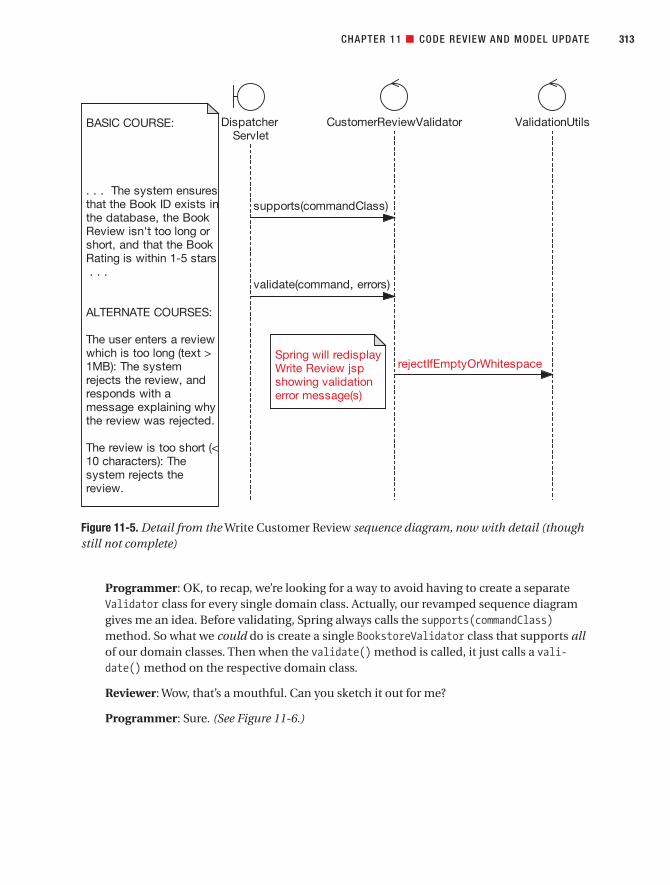
Programmer: OK, to recap, we’re looking for a way to avoid having to create a separateValidator class for every single domain class. Actually, our revamped sequence diagramgives me an idea. Before validating, Spring always calls the supports(commandClass)method. So what we could do is create a single BookstoreValidator class that supports allof our domain classes. Then when the validate() method is called, it just calls a vali-date() method on the respective domain class.
Reviewer: Wow, that’s a mouthful. Can you sketch it out for me?
Programmer: Sure. (See Figure 11-6.)
CHAPTER 11 ■ CODE REVIEW AND MODEL UPDATE 313
Figure 11-5. Detail from the Write Customer Review sequence diagram, now with detail (thoughstill not complete)
7745ch11final.qxd 12/13/06 8:45 PM Page 313

Programmer: (Walking through the diagram) Spring checks to see if BookstoreValidatorsupports this command class, which in this case is CustomerReview. The validator does acheck to see if the command class has a validate() method. One way would be to useJava’s reflection API, like this:
public boolean supports(Class commandClass) {return commandClass.getMethod(
"validate”, new Class[]{}) != null;}
Reviewer: (Drinking from a can of fizzy soda, which suddenly bubbles out of his nose)Sorry. Well, it might be a bit more OO if you define an interface for domain object valida-tors. Alternatively, as we don’t have a common BookstoreDomainObject interface, we couldcreate one of those and define a validate() method on it, and thus make it a requirementthat every one of our domain classes has a validate() method.
■Action Item Replace CustomerReviewValidator with a more generic BookstoreValidator,and move the domain-specific validation code into CustomerReview. Also, create a commonBookstoreDomainObject interface.
CHAPTER 11 ■ CODE REVIEW AND MODEL UPDATE314
Figure 11-6. Proposed design with a single BookstoreValidator class
7745ch11final.qxd 12/13/06 8:45 PM Page 314
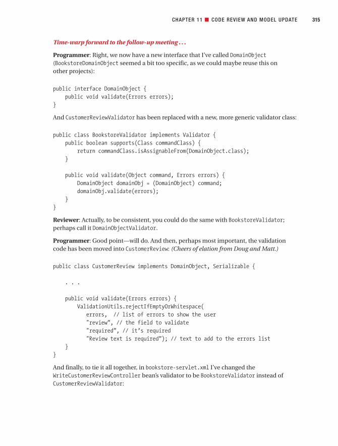
Time-warp forward to the follow-up meeting . . .
Programmer: Right, we now have a new interface that I’ve called DomainObject(BookstoreDomainObject seemed a bit too specific, as we could maybe reuse this on other projects):
public interface DomainObject {public void validate(Errors errors);
}
And CustomerReviewValidator has been replaced with a new, more generic validator class:
public class BookstoreValidator implements Validator {public boolean supports(Class commandClass) {
return commandClass.isAssignableFrom(DomainObject.class);}
public void validate(Object command, Errors errors) {DomainObject domainObj = (DomainObject) command;domainObj.validate(errors);
}}
Reviewer: Actually, to be consistent, you could do the same with BookstoreValidator;perhaps call it DomainObjectValidator.
Programmer: Good point—will do. And then, perhaps most important, the validationcode has been moved into CustomerReview: (Cheers of elation from Doug and Matt.)
public class CustomerReview implements DomainObject, Serializable {
. . .
public void validate(Errors errors) {ValidationUtils.rejectIfEmptyOrWhitespace(
errors, // list of errors to show the user"review”, // the field to validate"required”, // it’s required"Review text is required”); // text to add to the errors list
}}
And finally, to tie it all together, in bookstore-servlet.xml I’ve changed theWriteCustomerReviewController bean’s validator to be BookstoreValidator instead ofCustomerReviewValidator:
CHAPTER 11 ■ CODE REVIEW AND MODEL UPDATE 315
7745ch11final.qxd 12/13/06 8:45 PM Page 315

<bean id=”writeCustomerReviewController”class=”com.iconixsw.bookstore.web.WriteCustomerReviewController”>
. . .
<property name=”validator”><bean class="com.iconixsw.bookstore.domain.BookstoreValidator” />
</property></bean>
Programmer: I’ve also gotten rid of the “logic” package beneath domain, since we’re nowputting all of the logic directly into the domain classes.
Reviewer: Good idea. It’s a useful warning sign, that if you feel the need to create anentire, separate logic package (let alone a separate class), something’s probably gonewrong in the design.
The “Validation” Controllers, Part 2 (in Which Our Intrepid Programmer Discovers That He’sForgotten to Code an Alternate Course of Action)
Programmer: Still looking at validation for Write Customer Review . . . there are a coupleof validation controllers on the robustness diagram: one of them checks the reviewlength, and the other checks that the review rating is within the allowed range. (The vali-date() logic is now in CustomerReview, as just shown.)
Reviewer: Hmm, something doesn’t quite seem right here. Let’s compare the validationcode with the relevant part of the use case text:
The Customer types in a Book Review, gives it a Book Rating out of five stars, and
clicks the Send button. The system ensures that the Book ID exists in the database,the Book Review isn’t too long or short, and that the Book Rating is within one andfive stars.
Programmer: Well let’s see, looking through the code, we check to see if the review text isempty, and . . . whoops, I see what you mean.
Reviewer: Yep, we also need to check that the text isn’t too long, that the Book ID exists,and that the Book Rating is within one and five stars.
Programmer: That’s actually quite a bit of missing functionality right there. I’m surprisedI missed it, when it’s right there in the use case text.
Reviewer: The reason you missed it is because the sequence diagram didn’t have indi-vidual methods for each validation check (see Figure 11-4). Instead, there was a single“blanket” validation method that was meant to contain all of the validation checks. Sothe problem can actually be traced back to our interpretation of the robustness dia-gram, which contained the validation controllers.
CHAPTER 11 ■ CODE REVIEW AND MODEL UPDATE316
7745ch11final.qxd 12/13/06 8:45 PM Page 316
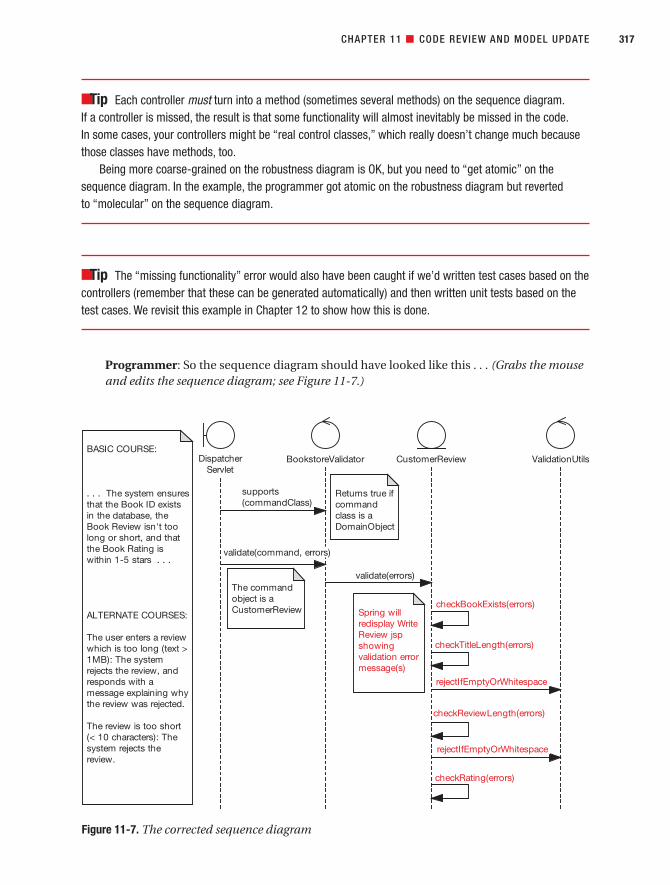
■Tip Each controller must turn into a method (sometimes several methods) on the sequence diagram.If a controller is missed, the result is that some functionality will almost inevitably be missed in the code.In some cases, your controllers might be “real control classes,” which really doesn’t change much becausethose classes have methods, too.
Being more coarse-grained on the robustness diagram is OK, but you need to “get atomic” on thesequence diagram. In the example, the programmer got atomic on the robustness diagram but reverted to “molecular” on the sequence diagram.
■Tip The “missing functionality” error would also have been caught if we’d written test cases based on thecontrollers (remember that these can be generated automatically) and then written unit tests based on thetest cases. We revisit this example in Chapter 12 to show how this is done.
Programmer: So the sequence diagram should have looked like this . . . (Grabs the mouseand edits the sequence diagram; see Figure 11-7.)
CHAPTER 11 ■ CODE REVIEW AND MODEL UPDATE 317
Figure 11-7. The corrected sequence diagram
7745ch11final.qxd 12/13/06 8:45 PM Page 317

Reviewer: I see you’ve also added in a checkTitleLength() message; nice catch. Checkingthe title length wasn’t in the use case text, but it probably should have been. We shouldadd it in now.
■Action Item Code the missing validation steps in CustomerReview according to the revised sequencediagram. Also, update the use case text to mention validating the review title length.
Time-warp forward to the follow-up meeting . . .
Programmer: Here’s the corrected source code:
public class CustomerReview implements DomainObject, Serializable {
public void validate(Errors errors) {checkBookExists(errors);checkTitleLength(errors);checkReviewLength(errors);checkRating(review, errors);
}
Reviewer: OK, so you’re calling four separate validation methods: checkBookExists,checkTitleLength, checkReviewLength, and checkRating. For each one, you pass in theErrors object that we cumulatively add the errors to.
Programmer: Yep. Here’s the first of the new validation methods:
private void checkBookExists(Errors errors) {if (book == null) {
errors.rejectValue("book”,"BookNotFound”,"The selected book could not be found.”);
}}
If the Book was set to null previously by WriteCustomerReviewController, then thatbasically means it wasn’t found (see the alternate course coded up in Chapter 10). So we can, in effect, reject the Book ID that was passed in from the browser, usingerrors.rejectValue().
Reviewer: Looks good so far.
Programmer: Now here’s the next method, checkReviewLength(). It’s remarkably similarto checkTitleLength(), so I’ve skipped over that one for brevity:
CHAPTER 11 ■ CODE REVIEW AND MODEL UPDATE318
7745ch11final.qxd 12/13/06 8:45 PM Page 318

private void checkReviewLength(Errors errors) {
ValidationUtils.rejectIfEmptyOrWhitespace(errors,"review”,"required”,"Review text is required”);
if (review != null && review.length() > 10000) {errors.rejectValue("review”,
"too_long”,"The review you entered is " +"a novel in itself; please try " +"to shorten it”);
}}
Programmer: There’s a bit more to this method, as it’s doing two checks on the review.The first check is unchanged from the previous version—it’s using a convenience methodin ValidationUtils to add an error to the list if the review text is empty. Then after that wedo a manual check to make sure the review text isn’t too long.
Reviewer: You might want to move the 10,000 literal into a constant. Actually, I notice youdidn’t include some of this detail in the sequence diagram, but we’ve broken the back ofthis now, so let’s move on.
Programmer: OK. Here’s the last of the four new methods, checkRating(), which makessure that the rating is between one and five:
private void checkRating(Errors errors) {if (rating < 1 || rating > 5) {
errors.rejectValue("rating”,"outofrange”,
"The rating must be between 1 and 5”);}
}}
Reviewer: Good! Without this, the user would have been able to enter 0, or indeed any old value.
■Note Validation code is a prime candidate for effective unit testing. We describe in Chapter 12 how todrive the unit tests from the (validation) controllers on your robustness diagrams.
CHAPTER 11 ■ CODE REVIEW AND MODEL UPDATE 319
7745ch11final.qxd 12/13/06 8:45 PM Page 319
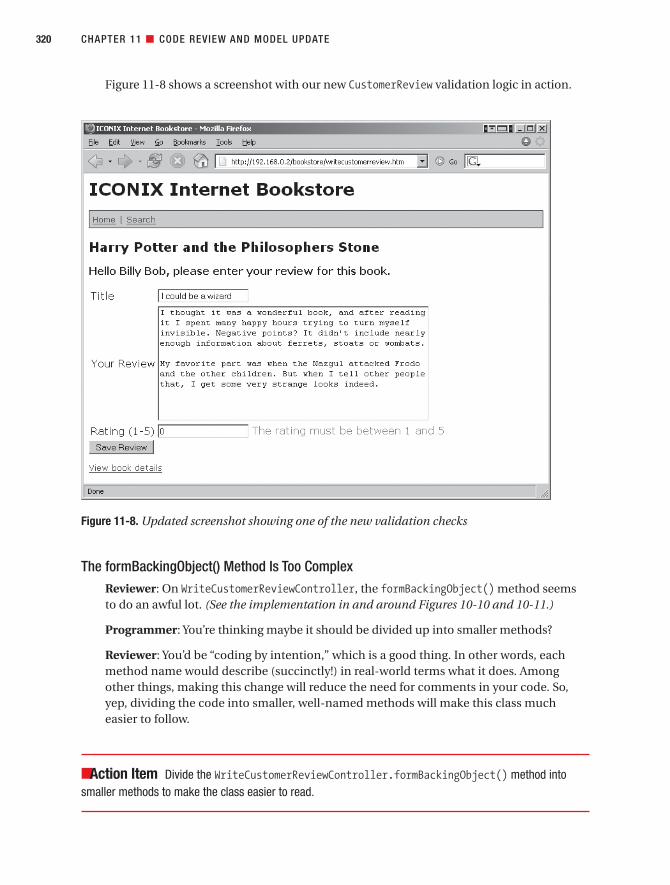
Figure 11-8 shows a screenshot with our new CustomerReview validation logic in action.
The formBackingObject() Method Is Too ComplexReviewer: On WriteCustomerReviewController, the formBackingObject() method seemsto do an awful lot. (See the implementation in and around Figures 10-10 and 10-11.)
Programmer: You’re thinking maybe it should be divided up into smaller methods?
Reviewer: You’d be “coding by intention,” which is a good thing. In other words, eachmethod name would describe (succinctly!) in real-world terms what it does. Amongother things, making this change will reduce the need for comments in your code. So,yep, dividing the code into smaller, well-named methods will make this class mucheasier to follow.
■Action Item Divide the WriteCustomerReviewController.formBackingObject() method intosmaller methods to make the class easier to read.
CHAPTER 11 ■ CODE REVIEW AND MODEL UPDATE320
Figure 11-8. Updated screenshot showing one of the new validation checks
7745ch11final.qxd 12/13/06 8:45 PM Page 320

Time-warp forward to the follow-up meeting . . .
Programmer: I’ve separated out the code into separate methods. So this is what form-BackingObject() looks like now:
protected Object formBackingObject(HttpServletRequest request) throws Exception {
Customer customer = findCustomer(request);if (customer == null) {
return null;}Book book = findBook(request);return newBlankReview(book, customer);
}
Then we have individual methods, like so:
private Customer findCustomer(HttpServletRequest request) {. . .
private Book findBook(HttpServletRequest request) {. . .
private CustomerReview newBlankReview(Book book,Customer customer) {
. . .
Reviewer: That’s much easier to follow. It’s virtually self-commenting.
CustomerReview Doesn’t Have a save() MethodReviewer: One of the prefactorings we made prior to coding was to add a load()method onto Book, because if you wanted to know how to load a Book instance, you’dnaturally go to the Book class first. However, an obvious one that we missed was, simi-larly, to move save() onto CustomerReview. Currently, your form handler class has to callthe DAO directly and pass it the CustomerReview. (See the doSubmitAction() method justafter Figure 10-12.)
Programmer: That’s easily fixed. I can just do the same thing I did for Book: add save()onto CustomerReview and make it delegate to CustomerReviewDao.
■Action Item Move the save() method onto CustomerReview, and make doSubmitAction() call thatinstead of calling the DAO directly.
(This solution is skipped over because it’s basically the same as for Book.load().)
CHAPTER 11 ■ CODE REVIEW AND MODEL UPDATE 321
7745ch11final.qxd 12/13/06 8:45 PM Page 321

But Isn’t a Book Meant to “Have” Reviews?Reviewer: Wait a minute—something about the aggregation of some of these domainclasses has been nagging away at me. I know this is a bit late in the day, but looking backat the class diagram excerpt for WriteCustomerReviewController (see Figure 9-6), I’m surethat on the original domain model (see Figure 2-7), the aggregation for Book andCustomerReview (or Reader Review, as it was back then) was the other way around.
Programmer: You mean that essentially a Book “has” CustomerReviews?
Reviewer: Essentially, yes. But CustomerReview suddenly now “has” a reference to itsparent Book. The relationship has flipped around.
Programmer: The question is, which direction makes more sense? I know that from a design standpoint—at least for the Write Customer Review use case that we’re imple-menting—it will be easier if the CustomerReview knows what its parent Book is.
Reviewer: You have to look at the bigger picture, though. If you go to an online bookstore,you zero in on a particular book and see a list of its reviews. You don’t go to a review firstand then find out which book it belongs to. So from a real-world perspective—which thedomain model is meant to represent—it makes more sense for the Book to have a list ofCustomerReviews. I bet that design-wise, in the majority of cases, it will also work outmuch easier that way around.
Programmer: Similarly, I suppose the Customer class would also have a list ofCustomerReviews that they’ve written. So that one would need to be switched around as well.
■Action Item Reverse the relationship between Book and CustomerReview, so that a Book “has”reviews. Do the same for Customer and CustomerReview.
Time-warp forward to the follow-up meeting . . .
Programmer: Here’s the updated class diagram (see excerpt in Figure 11-9).
Reviewer: OK, we’ve walked through all of the controllers in both of the use cases. You’vegot some action items to bring the code in line with the design, and we’ve updated thedesign where it needed to be brought in line with the code. Nice work!
CHAPTER 11 ■ CODE REVIEW AND MODEL UPDATE322
7745ch11final.qxd 12/13/06 8:45 PM Page 322

CHAPTER 11 ■ CODE REVIEW AND MODEL UPDATE 323
Figure 11-9. Aggregation relationships flipped around
WriteCustomerReviewController
+ doSubmitAction(CustomerReview) : void+ formBackingObject(HttpServletRequest) : CustomerReview
CustomerReview
+ book: Book+ customer: Customer+ id: int+ rating: int+ review: String
Book
+ id: int+ synopsis: String+ title: String
Customer
+ email: String+ firstName: String+ id: int+ lastName: String
0..*1
0..*
1
1
ACTION LIST FOLLOWING THE REVIEW SESSION
From: Wilbert R. Shufflehammer, III (Reviewer)To: Bim (Programmer), Ben (Programmer)Subject: Action list following the Code Review and Model Update
1. Update the sequence diagram to show the “command” Book ID being set where it’s really being set;then revise the design so that the ID doesn’t have to be passed into the load() method. [Bim]
2. Update the sequence diagram to show the constructor detail forWriteCustomerReviewController. [Ben]
3. Replace CustomerReviewValidator with a more generic BookstoreValidator, and move thedomain-specific validation code into CustomerReview. Also create a commonBookstoreDomainObject interface. [Ben]
4. Code the missing validation steps in CustomerReview according to the revised sequence diagram.Also, update the use case text to mention validating the review title length. [Ben]
5. Divide the WriteCustomerReviewController.formBackingObject() method into smallermethods to make the class easier to read. [Bim]
7745ch11final.qxd 12/13/06 8:45 PM Page 323

Future IterationsIn future iterations, we’ll want to add to the code base with new use cases. For example,CustomerReviewDao currently only saves CustomerReview objects to the database; there’s nocode there to retrieve the objects that were saved. The reason for this is simply that, so far, we haven’t identified any need to retrieve saved CustomerReview objects.
Obviously, that will change when we get to the appropriate use case. For example, theModerate Pending Reviews use case (in which a Review Moderator reads submitted bookreviews and either publishes or rejects them) would need to be able to retrieve reviews.Similarly, if our client suddenly decided that the bookstore should allow users to edit theirreviews, we’d create an Edit Customer Review use case that would need to be able toretrieve saved CustomerReview objects. Similarly, users would want to see the reviews thathave been submitted when looking at the Book Details page.
It’s because we’re expecting to add new functionality that the Code Review and ModelUpdate effort is so important. It makes it much easier to fit new design diagrams into thecurrent design when the model is nicely in sync with the code.
CHAPTER 11 ■ CODE REVIEW AND MODEL UPDATE324
6. Move the save() method onto CustomerReview, and make doSubmitAction() call that insteadof calling the DAO directly.
7. Reverse the relationship between Book and CustomerReview, so that a Book “has” reviews. Also dothe same for Customer and CustomerReview.
All items to be completed by the follow-up meeting this Wednesday.
USING THE UML MODEL TO BROWSE THE JAVA CODE
Historically, the separation between modeling and code has always been one of the most serious impedi-ments to programmer acceptance of UML. When the model and the code live in separate universes(tools/environments), the model inevitably falls out of date and is perceived by the developers as an “artifact”that grows increasingly less useful over time, as changes are made in the coding environment.
What’s been needed is a bridge between the modeling environment and the developmentenvironment—in other words, an extension of the IDE to include the UML model. Figure 11-10 shows anexample of this “more integrated” IDE: Eclipse extended with the Sparx MDG Integration plug-in.
As you can see, the UML model for the Internet Bookstore has been “attached” to the project in Eclipse.We can now use the model to browse the code! Click on an operation on a class in the UML browser, and thesource code is displayed in the editing window. Keeping the model and the code synchronized is easilyaccomplished by right-clicking a class and choosing “Synchronize model and code”. New methods can becreated in the IDE and “pushed back” into the UML model, or created within the model and “pushed forward”into code.
7745ch11final.qxd 12/13/06 8:45 PM Page 324

SummaryIn this chapter, we conducted a Code Review and Model Update for the Internet Bookstore.The result was that the code was made more robust and bulletproof, and the model wasupdated to bring it in line with the code.
Figure 11-11 shows where we are. The activity covered in this chapter is shown in red.In addition, by comparing the code with the behavioral descriptions in the use cases,
some missing functionality was uncovered. The cause was discovered to be that one of thesequence diagrams didn’t go into enough detail. So the diagram was updated and the addi-tional functionality was added into the code. This approach of comparing the code with theuse case text was possible because the code was closely tied to the domain model, a result ofthe robustness analysis step. All that disambiguation really paid off!
If the review results in code needing to be updated (which is likely), it’s important to havesome unit tests in place first. And to ensure effective test coverage, those unit tests should bedriven from the controllers on your robustness diagrams. We cover the test-driven aspect ofmodel-driven development in the next chapter.
CHAPTER 11 ■ CODE REVIEW AND MODEL UPDATE 325
Figure 11-10. EA integrated into Eclipse, with the Internet Bookstore project synchronized
7745ch11final.qxd 12/13/06 8:45 PM Page 325

CHAPTER 11 ■ CODE REVIEW AND MODEL UPDATE326
Figure 11-11. Code Review and Model Update activities during the implementation stage
7745ch11final.qxd 12/13/06 8:45 PM Page 326

Testing andRequirementsTraceability
P A R T 4
7745ch12final.qxd 12/13/06 8:46 PM Page 327

7745ch12final.qxd 12/13/06 8:46 PM Page 328

Design-Driven Testing
It’s easy to look at a program module and say, “There, that’s finished,” but this sense of com-pletion can be deceptive. How do you know for sure that the code completes all the use casescenarios—not just the basic courses, but the alternate courses, too?
Design-Driven Testing (DDT) provides a bulletproof method for producing test cases foryou to verify that all the specified scenarios are complete. You can also use this process towrite executable unit tests from these test cases.
Testing is a process that should begin long before coding. Beginning testing the prod-uct after it’s purportedly “finished” is marginally better than a poke in the eye, but thetesting process should begin long before you even start coding. Preparation for testingbegins during the analysis stage, by identifying test cases using your robustness diagrams.It’s possible to eliminate a lot more bugs—before they even exist—by testing early. Testingkicks in shortly after preliminary design, and then writing of unit test code takes place dur-ing implementation.
Make sure that your tests are tied closely to the requirements. That isn’t to say that everytest should be traced back to a requirement, but there should at least be a test to “prove” that
329
C H A P T E R 1 2
7745ch12final.qxd 12/13/06 8:46 PM Page 329

each requirement has been implemented correctly. The process we describe in this chapter isone method for doing just that: driving the unit tests from your use cases.
■Mind the Gap! We should warn you in advance, there’s a chapter split later on, in which Test-DrivenDevelopment (TDD) aficionados should find some useful advice on combining TDD with the up-front designapproach described in this book. The rest of us may find that part of the chapter somewhat mind-bending(and also not an essential part of the process as such), so that section can be safely skipped over for non-TDD afficionados. We’ll clearly signpost the chapter split when we reach it.
Design-Driven Testing in TheoryWe start this chapter by looking at the premise and basic theories of DDT. We provide a fewexamples along the way, and the hands-on stuff will follow in the “Design-Driven Testing inPractice” section later. But it definitely helps to take in some theory first. So—no passing notesthere at the back—let’s put our academic hats on. First up is our top 10 list.
Top 10 Design-Driven Testing GuidelinesThe principles discussed in this chapter can be summed up as a list of guidelines. Our top 10list follows.
10. Adopt a “testing mind-set” wherein every bug found is a victory and not a defeat.
If you find (and fix) the bug in testing, the users won’t find it in the released product.
9. Understand the different kinds of testing, and when and why you’d use each one.
Get to know the different types of testing that we describe later in this chapter (see the“V” model in Figure 12-1) and apply each test at the right time. And, just as important,use the deliverables you create along the way to prepare for each test in advance.
8. When unit testing, create one or more tests for each controller on each robustnessdiagram.
Also create one or more unit tests for each operation on each class within the design.Sometimes these are the same (a controller is implemented as a single operation on aclass), and sometimes a controller is realized as multiple (atomic) operations.
7. For real-time systems, use the elements on state diagrams as the basis for test cases.
For example, test the response to various events that trigger state changes. During thiskind of testing, you monitor changes that take place in an object’s attributes in order totest the interactions among that object’s methods. You can use the elements on statediagrams as the basis for test cases.
330 CHAPTER 12 ■ DESIGN-DRIVEN TESTING
7745ch12final.qxd 12/13/06 8:46 PM Page 330

6. Do requirement-level verification, checking that each requirement you have identifiedis accounted for.
5. Use a traceability matrix to assist in requirement verification.
4. Do scenario-level acceptance testing for each use case.
3. Expand threads in your test scenarios to cover a complete path through the appropri-ate part of the basic course plus each alternate course in your scenario testing.
2. Use a testing framework such as JUnit to store and organize your unit tests.
1. Keep your unit tests fine-grained.
Different Kinds of TestingYou should look at testing as a full member of the iterative and incremental development lifecycle, not just as something you occasionally do after you’ve cranked out a bunch of code. Thereason for this is simple: tests prove that a product is fit for its specified purpose. But if thetests themselves aren’t closely aligned with the specification, then they’re not proving a hugeamount except that running a test suite causes the office lava lamp to light up green.1
Let’s run through that again: tests by themselves don’t prove a huge amount. They provethat some part of your program passes some tests, but that’s about it. The tests themselvesneed to be very closely tied in with the requirements, at a microscopic level. If the tests areclosely aligned with the requirements, then passing the tests proves (to a degree) that yoursoftware is fit for its specified purpose. If the tests aren’t closely aligned with the requirements,then passing the tests is, by itself, pretty meaningless.
A key to testing is to understand the different kinds of tests, and in particular when in thesoftware life cycle each kind of test should be used.
Figure 12-1 shows which tests should be performed for each stage in ICONIX Process.So, to test that the preliminary design has been implemented satisfactorily and to spec,
you perform integration testing, and so on.Preparation for each type of test can begin well in advance. For example, as soon as the
business case (essentially the contract between you and the customer) has been signed off, QA can begin speccing out the release tests based on the contents of the business case. Simi-larly, as soon as each use case is written, your software testers can begin writing the systemtests for that use case. (Having said that, we advise that they wait until the preliminary designfor that use case is finished, as this will undoubtedly have an impact on the use case beinganalyzed.)
Many of the higher-level tests may be written in the form of unit tests. For example, asyou’ll see later in this chapter, it’s desirable to drive the unit test classes and methods directlyfrom the controllers on the preliminary design (which in turn are driven directly by the usecases).
CHAPTER 12 ■ DESIGN-DRIVEN TESTING 331
1. We wish we were kidding, but now your team can set up their own eXtreme Feedback Device (XFD;aka red/green lava lamp) to provide a highly visual indication of their own build/unit test status:www.pragmaticprogrammer.com/pa/pa.html.
7745ch12final.qxd 12/13/06 8:46 PM Page 331

Table 12-1 describes the different kinds of tests shown in Figure 12-1.2
Table 12-1. Different Kinds of Tests and When to Apply Them
Test When (and Why) You Should Do It
Unit testing Begin unit testing before integration/The testing of individual software components. system testing.Stubs may be used to simulate inputs and outputs of a Unit testing is executed on every build component so that it can operate in stand-alone mode. of the software throughout the develop-
ment phase (including the bug-fixingphase after the software has beenreleased to system test).
CHAPTER 12 ■ DESIGN-DRIVEN TESTING332
Figure 12-1. “V” model of software testing applied to ICONIX Process
2. The definitions in Table 12-1 are adapted from the British Computer Society Specialist Interest Groupin Software Testing (BCS SIGIST). Thanks to Philip Nortey for contributing heavily to this section.
7745ch12final.qxd 12/13/06 8:46 PM Page 332

Test When (and Why) You Should Do It
Integration testing This is done after unit testing.Testing performed to expose faults in the interfaces andin the interaction between integrated components. Unlike with compatibility testing (see the next test type), the classes are a part of the overall system being designed.
Compatibility testing This is not quite the same as integration Testing that the system interoperates correctly with testing, although both take place at other, “external” systems with which it is required to roughly the same time.communicate.
System testing This is done after integration testing. Functional and behavioral test case design. Test case System testing tends to be developer selection that is based on an analysis of the specifica- focused. Its purpose is to prove that the tion of the component without reference to its internal system that was specified has been workings. delivered.Functional testing consists mainly of use case and business process path tests, but also includes testing of the functional requirements.
Acceptance testing Acceptance testing operates along the Formal testing conducted by (or on behalf of) the cus- same lines as system testing, but the tomer, to determine whether the system meets the emphasis is different.requirements specified in the contract. Acceptance testing is carried out to prove
that the system delivers what wasactually requested.
Beta testing This is done before acceptance testing to Testing performed by end users who aren’t otherwise exercise the software in an environment involved with the development effort. that is as close as possible to the produc-
tion environment.
Release testing This is done at the point at which the Verifies that the finished product accurately reflects the software is to be delivered to the customerbusiness case. (or at the end of a deliverable milestone
within the project), to ensure that theproduct has been created to spec and ful-fills the goals described in the originalcontract.
In addition, some kinds of testing go on throughout the development process or aren’tbased on a specific deliverable. Table 12-2 shows the more common ones.
Table 12-2. More Kinds of Testing and When to Do Them
Test When You Should Do It
Nonfunctional requirements testing This testing should be done throughout Testing of those requirements that do not relate to the software life cycle (even at the unit functionality (i.e., performance, usability, etc.) test level) where possible. “Nonfunctional
requirements testing” is really anumbrella term for performance, stress,volume, and compatibility testing.
Continued
CHAPTER 12 ■ DESIGN-DRIVEN TESTING 333
7745ch12final.qxd 12/13/06 8:46 PM Page 333

Table 12-2. Continued
Test When You Should Do It
Performance testing This testing can (and should) be done at Testing conducted to evaluate the compliance of a every opportunity, but it is usually system or component with specified performance executed after system testing.requirements
Regression testing This testing is executed after the code hasRetesting of a previously tested program following been released to system test. Note that modification to ensure that faults have not been intro- unit testing is a form of regression testing duced or uncovered as a result of the changes made if it is done properly.
Stress testing This testing is executed after Testing conducted to evaluate a system or component performance testing.at or beyond the limits of its specified requirements
Volume testing This testing is executed after system Testing where the system is subjected to large volumes testing.of data
■Tip For more in-depth information on software testing and QA, we recommend two of Boris Beizer’sbooks on the subject: Software System Testing and Quality Assurance (Van Nostrand Reinhold, 1984) andSoftware Testing Techniques (Van Nostrand Reinhold, 1990). They’re both “golden oldies,” but the techniquesthey describe and the states of mind that they get you into are still very relevant in today’s agile softwareworld, glued together as it mostly is by JUnit assert statements.
Driving Test Cases from Robustness DiagramsWith ICONIX Process, you invest effort in writing use cases, and you identify the objects thatparticipate in a use case and the functions that those objects perform, on robustness diagrams(the functions are shown as controllers). Since you’ve made this investment in identifying thelogical software functions, it would be nice to get some return on that investment in terms of a suite of test cases that remind you to test all the functionality of the use case.
Figure 12-2 shows an overview of DDT, in which the test cases are created directly fromthe controllers on the robustness diagrams.
As Figure 12-2 shows, you can automatically transform a robustness diagram into both askeleton sequence diagram and a test case diagram using a simple script. Test skeleton codecan subsequently be generated for unit testing frameworks like JUnit or NUnit.
Now we’ll provide a more detailed explanation, which we’ll illustrate step by step with anexample. Since you’ve already identified the logical functions within a use case as controllers,it seems natural that all of these functions would need to be tested. Working from the robust-ness diagram, you can create a test case diagram showing a test case for each controller.
How do you do this? Easy! Copy all of the controllers from the robustness diagram onto anew diagram, and then link a test case to each one using <<realize>> connectors. We’ll runthrough an example of this in just a moment.
CHAPTER 12 ■ DESIGN-DRIVEN TESTING334
7745ch12final.qxd 12/13/06 8:46 PM Page 334

■Note The EA tool has a test case element that is a stereotyped use case.
Each test case can contain multiple test scenarios. To identify the test scenarios for eachcontroller/test case, follow these steps:
1. Reread the use case text to remind yourself of the context in which the controller isused.
2. For each test case, create a test scenario for each use case scenario (the basic andalternate courses).
3. Name each test scenario after its use case scenario of origin. For example, for the con-troller Retrieve Book Details, the alternate scenario called Book Not Found would leadto a test scenario called, you guessed it, Book Not Found, in a test case called RetrieveBook Details Test.
CHAPTER 12 ■ DESIGN-DRIVEN TESTING 335
Figure 12-2. Overview of DDT
7745ch12final.qxd 12/13/06 8:46 PM Page 335

Using the Agile ICONIX/EA Add-inWe should stress that ICONIX Process works equally well with any OO programming language,platform, CASE tool, and so on. However, the Enterprise Architect (EA) tool has an especiallyneat add-in that automates much of the “transitional” work when moving between diagramsin ICONIX Process. For example, the add-in will automatically create a set of robustness dia-grams from a use case diagram (see Figure 12-3), and (a serious time-saver) the add-in willpopulate a sequence diagram using the boundary, entity, and controller objects on yourrobustness diagram.
For testing purposes, the add-in automatically creates a test case diagram from the con-trollers on your robustness diagrams (see Figure 12-4). From these controllers, it’s thenpossible to write executable unit tests for each of the test cases.
The test case diagram in Figure 12-4 is based on the robustness diagram in Figure 5-10.Notice that each test case is linked to a controller. In other words, there’s one test case percontroller. The relationship between the test case and the controller is “realizes” (the samerelationship that’s used to show classes implementing/realizing an interface).
CHAPTER 12 ■ DESIGN-DRIVEN TESTING336
Figure 12-3. Using the Agile ICONIX/EA add-in to generate diagrams
7745ch12final.qxd 12/13/06 8:46 PM Page 336

■Exercise The diagram in Figure 12-4 would quickly become quite difficult to work with. Any ideas why?We reveal the answer in a Note later in this chapter.
You can right-click each test case and add individual scenarios (see Figure 12-5).
CHAPTER 12 ■ DESIGN-DRIVEN TESTING 337
Figure 12-4. Generating test cases in EA
7745ch12final.qxd 12/13/06 8:46 PM Page 337

Driving Unit Tests from the Test CasesTo recap, you need to model the test cases on the controllers from your robustness diagrams—that is, each controller gets exactly one test case. And for each test case, create one or moretest scenarios.
Once you’ve created your test cases and allocated test scenarios to each one, it’s time tocreate the unit test skeletons.
Here are some guidelines for driving unit tests from test cases:
• For each test case, create one unit test class. For example, if the test case is called RetrieveBook Details Test, then you’d create a JUnit test class called RetrieveBookDetailsTest.
• For each test scenario, create one test method in your unit test class. For example, if the test case is called Book Not Found, you’d create a test method calledtestBookNotFound().
• Write unit tests from the point of view of the object calling the controller.
• If you discover new alternate courses while thinking up test case scenarios—which is likely—don’t hesitate to add them to the use case!
We’ll walk through some examples of creating unit tests from the test cases in just a moment.
CHAPTER 12 ■ DESIGN-DRIVEN TESTING338
Figure 12-5. Adding test case scenarios in EA
7745ch12final.qxd 12/13/06 8:46 PM Page 338

A Quick Introduction to JUnitFor the code examples later in this chapter, we’ll use JUnit (www.junit.org), a popular Java-based unit testing framework. JUnit is part of the xUnit family; other members includecppUnit for C++, nUnit (www.nunit.org) for C#/.NET, and DUnit for Borland Delphi. Althoughthe flavor of the source code can differ somewhat depending on the language/implementa-tion, the principles discussed in this chapter are basically the same, whichever unit testingframework you use.
With JUnit, you write test cases where each test case is a single Java class. Within thisclass, individual test methods follow the naming convention testXYZ, where XYZ is the name of your test. This naming convention allows JUnit to automatically detect and run your testmethods, without them having to be “declared” somewhere (e.g., in an external XML file).Using JUnit 4.0, test methods may also be identified using Java 5 assertions (see the sidebar"JUnit: The Next Generation" later in this chapter).
■Tip Using the approach described in this chapter, you can map test cases directly to JUnit test classes,and you can map test scenarios directly to individual test methods.
Within a test method, you write Java code that calls methods in the classes being testedand asserts that the result is precisely what was expected. For the assertion part, JUnit pro-vides a number of different assert methods (e.g., to assert that a value is true, or that a value is non-null, or that two values are equal).
Your test class can consist of any number of test methods, although it’s generally agood idea to keep the number below five or so. If the number of test methods in a classgrows, consider dividing them into separate test cases. Similarly, it’s a good idea to limiteach test method to a single assert statement. This keeps the test scenario focused on test-ing a single thing. If you find the need to add more than one assert, it’s likely that you’rereally looking at more than one test scenario squeezed into a single test method, so don’thesitate to separate them out.
Here’s an example of a unit test class:
package test.com.iconixsw.bookstore.web;
import junit.framework.*;
public class AddToShoppingCartTest extends TestCase {
public AddToShoppingCartTest (String testName) {super(testName);
}
public void testShoppingCartEmpty() throws Exception {ShoppingCart cart = new ShoppingCart();assertEquals("Cart should be empty", 0, cart.getNumItems());
}
CHAPTER 12 ■ DESIGN-DRIVEN TESTING 339
7745ch12final.qxd 12/13/06 8:46 PM Page 339
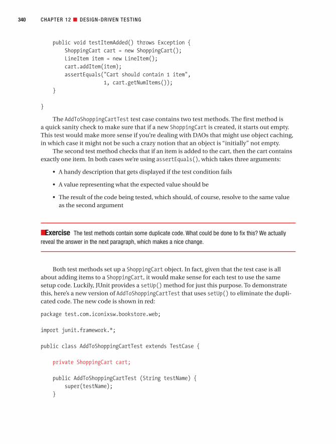
public void testItemAdded() throws Exception {ShoppingCart cart = new ShoppingCart();LineItem item = new LineItem();cart.addItem(item);assertEquals("Cart should contain 1 item",
1, cart.getNumItems());}
}
The AddToShoppingCartTest test case contains two test methods. The first method is a quick sanity check to make sure that if a new ShoppingCart is created, it starts out empty.This test would make more sense if you’re dealing with DAOs that might use object caching,in which case it might not be such a crazy notion that an object is “initially” not empty.
The second test method checks that if an item is added to the cart, then the cart containsexactly one item. In both cases we’re using assertEquals(), which takes three arguments:
• A handy description that gets displayed if the test condition fails
• A value representing what the expected value should be
• The result of the code being tested, which should, of course, resolve to the same valueas the second argument
■Exercise The test methods contain some duplicate code. What could be done to fix this? We actuallyreveal the answer in the next paragraph, which makes a nice change.
Both test methods set up a ShoppingCart object. In fact, given that the test case is allabout adding items to a ShoppingCart, it would make sense for each test to use the samesetup code. Luckily, JUnit provides a setUp() method for just this purpose. To demonstratethis, here’s a new version of AddToShoppingCartTest that uses setUp() to eliminate the dupli-cated code. The new code is shown in red:
package test.com.iconixsw.bookstore.web;
import junit.framework.*;
public class AddToShoppingCartTest extends TestCase {
private ShoppingCart cart;
public AddToShoppingCartTest (String testName) {super(testName);
}
CHAPTER 12 ■ DESIGN-DRIVEN TESTING340
7745ch12final.qxd 12/13/06 8:46 PM Page 340

public void setUp() {cart = new ShoppingCart();
}
public void testShoppingCartEmpty() throws Exception {assertEquals("Cart should be empty", 0, cart.getNumItems());
}
public void testItemAdded() throws Exception {LineItem item = new LineItem();cart.addItem(item);assertEquals("Cart should contain 1 item",
1, cart.getNumItems());}
}
The setUp() method is run automatically, immediately before each test method is called.It’s worth stressing that point: it isn’t run just once for the whole test case. Instead, it’s run oncefor each individual test method. So for each test method, you’re guaranteed a nice, freshinstance of ShoppingCart (or whatever you put in your own setUp() method, naturally).
There’s also a tearDown() method that does the reverse of setUp() and is useful for closingexternal resources like database connections or input/output streams. As you’d expect,tearDown() is called immediately after each individual test method.
CHAPTER 12 ■ DESIGN-DRIVEN TESTING 341
JUNIT: THE NEXT GENERATION
At the time of this book going to press, the next generation of JUnit, version 4.0, is gradually beginning to seeincreased industry adoption (its reliance on the new language features in Java 5 may have slowed its adop-tion). Written by Kent Beck and Erich Gamma, it’s backward-compatible with current versions of JUnit, so allyour existing tests should still run, but it boasts lots of new features and refinements, making it more likeNUnit with extensive support for annotations. Its new features include the following:
• Test classes do not have to extend junit.framework.TestCase.
• Test methods do not have to be prefixed with test. Instead, a test method can be tagged with the@Test annotation.
• Similarly, @Before and @After annotations provide the equivalent of setUp() and tearDown().The benefit of the new approach is that, should you really need to, you can have more than one@Before and @After method in each test class.
• One-time setup and teardown for each test class can be done using the @BeforeClass and@AfterClass annotations.
• Tests can have a timeout value (passed in as a parameter in the @Test annotation).
7745ch12final.qxd 12/13/06 8:46 PM Page 341

For most of the rest of this chapter, we’ll run through lots of examples to show how todrive unit test code directly from the test cases, which in turn are driven from the controllerson your robustness diagrams, which in turn are driven from the use cases. Our aim is to giveyou a detailed understanding of how to tie the tests closely to the requirements, at a micro-scopic level (the proposition that we opened this chapter with).
Writing Effective Unit TestsBefore we get started on the examples, it’s worth outlining some best practices for writinggood unit tests. Entire books have been devoted to unit testing, but effective unit testing tech-niques from a design-driven perspective can be summed up quite succinctly. So here goes:
• Keep unit tests fine-grained. Generally, you should cover a single test case with eachunit test class and a different permutation or assertion of the test case (i.e., the individ-ual test scenarios) in each test method. Which leads us to the next item . . .
• Make sure that each test method tests exactly one thing. Let’s say you want to test theability to add items to a Shopping Cart. You might have a test method that first adds anitem, then asserts that the number of items in the cart is 1, and then (to really prove itwas added successfully) asserts that if you retrieve the item, it’s the same item that wasadded.
But gosh, that’s actually testing two separate things (the clue is that there are two asser-tions). First, it’s testing that an item was definitely added; second, it’s testing thatretrieving an item returns the item you expect it to. Two separate test scenarios, mean-ing two separate test methods.
Your first test method would be called testAddItem(), and the second test methodwould be called testCorrectItemRetrieved().
• Tie the unit tests closely to the classes and methods you’re testing.
• Tie the unit tests closely to the objects in the preliminary design (and therefore alsoto your use cases). Hopefully, you can see the connection between this point and thelast point. If the unit test code is tied closely both to the preliminary design and to theclasses and methods in the “real” production code, it ensures cohesion between thetwo. If it becomes troublesome to tie the unit tests at both ends, then it’s a sign thatthe detailed design/source code might not have been driven 100% from the prelimi-nary design. If this turns out to be the case, correct the design as soon as possible,and review the process step by step to work out where you might have gone wrong.
• Treat unit test code with the same reverence and care that you do production code.The unit test code is “designed” and needs to be maintained as much as the code thatit’s testing. The unit test design is driven as much from the preliminary design as the“real” detailed design is, and just as much care needs to be taken keeping the testcode in trim. In particular . . .
CHAPTER 12 ■ DESIGN-DRIVEN TESTING342
7745ch12final.qxd 12/13/06 8:46 PM Page 342

• Avoid duplication in tests. As you’re driving unit tests from your test cases (which arein turn driven from the controllers), each unit test class will consist of a lot of quitesimilar test methods, testing the different scenarios that pass through each controller.Whenever you see duplicated code, separate it out into shared methods or classes assoon as you see it.
• Make sure your tests always run at 100% success. Neglecting to fix an ailing test is aneasy trap to fall into, especially in a team environment without individual code owner-ship, where a failing test is always somebody else’s problem. If a test is failing, fix itimmediately. This is especially true if you’re following a test-driven methodology, inwhich you first write a failing test, and then write some code to make it pass. If yousurge ahead writing a series of failing tests, then it becomes tempting to just turn ablind eye and concentrate on the code instead of fixing the tests.
• Use mock objects when you need to, but don’t get too hung up on them. We providean example of mock objects in the next section. They basically provide “stub” func-tionality for a real class that will be implemented later, or they act as a nonfunctionalstand-in so as to avoid accessing external resources (e.g., a database), which slowdown the tests and make test configuration more complex.
We’ll probably get hammered by the test-driven crowd for suggesting this but, whilemock objects do have their uses, it’s possible to overuse them. Their purpose is tolessen the code’s dependency on external classes or resources (such as databases).However, every time you change the behavior of your code, you’ll also have to fix themock object tests. JUnit tests are pretty solid; you’re testing the end behavior thatdoesn’t change much. However, with mock objects, you’re testing the flow of a methodcall, hence it is a lot more fragile. If you add one extra method call, or refactor themethod internals, then you also have to change the mock-based tests.
In the next section, we walk through an example for the Internet Bookstore, going all theway from the robustness diagram to the JUnit tests.
Design-Driven Testing in PracticeIn this section, we illustrate the theory from the first part of this chapter, using our InternetBookstore project. We revisit the detailed design as we left it in Chapter 9, and this time,instead of moving straight to code, we first create some test cases directly from the robust-ness diagrams, and match these up with the detailed design. We then use the test cases toverify that
• The detailed design matches up with the use cases.
• The code matches the detailed design and does what it’s meant to.
CHAPTER 12 ■ DESIGN-DRIVEN TESTING 343
7745ch12final.qxd 12/13/06 8:46 PM Page 343

Unit Tests for the Internet BookstoreTo write the unit tests for the Internet Bookstore, we’ll take the controllers from the robustnessdiagrams for the Show Book Details and Write Customer Review use cases, generate test casesfor them, and then write unit tests based on the test cases.
You should do this step just prior to writing the code, so that as you’re coding, you have a decent set of unit tests to compile and test against. Starting to write or generate the tests isalso a good way of getting yourself into the coding frame of mind, which is useful when you’redoing the detailed design modeling.
Figure 12-6 shows the test case diagram. This was generated from the robustness diagramfor Show Book Details shown back in Figure 5-10.
CHAPTER 12 ■ DESIGN-DRIVEN TESTING344
Figure 12-6. Generated test cases for the Show Book Details use case
7745ch12final.qxd 12/13/06 8:46 PM Page 344

The Display Book not Found Page controller and test case are both shown in red becausethey’re the alternate course.
■Note We’ve renamed the Display controllers to be more descriptive, so that they can be differentiated(see the original version in Figure 12-4).
If some of the controllers have the same name (e.g., Display), the resultant test case diagram might be quite difficult (or impossible) to decipher. Wherever you have controllers with the same name on thesame diagram, you should rename the controllers so that you can tell them apart. In the case of Dis-play controllers, just add the name of the boundary object being displayed (e.g., Display Book Details Pageand Display Book Details Page Test).
To recap, each controller from the robustness diagram gets its own test case, and in eachtest case we create one or more test scenarios. For each test case, we create a unit test class,and for each test scenario, we create a unit test method.
We’ll walk through this process once for each of the test cases (in the order shown inFigure 12-6) until it’s crystal clear.
Testing the Display Home Page ControllerIn this section, we’ll create the test scenarios for the Display Home Page controller, the sim-plest of the bunch, and then write its JUnit test class.
Here’s the portion of the use case text that relates to this controller:
The Customer types in the URL for the bookstore’s home page. The system displays a list
of books from the Catalog on the home page, in the form of clickable links.
If you recall from Chapter 10, the list of books is actually just a hard-wired list, so there’sno dynamic cleverness going on here. As a result, the test case for this particular controller isamazingly simple. In fact, we need to add only one test scenario to the test case, because—justthis once—there’s very little that can go wrong. To add a test scenario in EA, double-click thetest case, and in the Properties dialog that pops up, click the Scenario tab (see Figure 12-7).
There’s only actually the one test scenario for this test case, so you’d only expect to seeone test method in the unit test class.
CHAPTER 12 ■ DESIGN-DRIVEN TESTING 345
7745ch12final.qxd 12/13/06 8:46 PM Page 345

Here’s the JUnit test skeleton for this test case:
package test.com.iconixsw.bookstore.web;
import junit.framework.*;
public class DisplayHomePageTest extends TestCase {
public DisplayHomePageTest(String testName) {super(testName);
}
public void testDisplayHomePage() throws Exception {}
}
The test extends TestCase, a JUnit class. In JUnit, any method whose name starts with testis automatically recognized as a test method. So in this case we have just one test method,testDisplayHomePage(), which is derived from the test scenario shown in Figure 12-7. If the testcase had, say, three test scenarios, then you’d see three test methods instead of just the one.
CHAPTER 12 ■ DESIGN-DRIVEN TESTING346
Figure 12-7. Adding a test scenario for the Display Home Page test case
7745ch12final.qxd 12/13/06 8:46 PM Page 346

So far it’s all been quite easy—mechanical, even. However, at this stage it’s difficult to sayexactly what should go in the testDisplayHomePage() method. This is why it’s now a good ideato go ahead and draw the sequence diagram for this use case. Figure 12-8 shows an excerptfrom the Show Book Details sequence diagram that’s relevant to this test case (see the fullsequence diagram in Figure 9-8).
You need to write the tests from the point of view of whatever object is calling the con-troller that you’re testing. In this case, HomeController is being tested, and the object calling it is a boundary object, DispatcherServlet (a Spring class). The unit test must verify that theresult from handleRequest() is what’s expected, given the values being passed in.
With that in mind, here’s the test method:
public void testDisplayHomePage() throws Exception {HomeController homeController = new HomeController();ModelAndView modelAndView =
homeController.handleRequest(null, null);
assertEquals("Should be viewing home.jsp","home",modelAndView.getViewName());
}
The test code first creates a new instance of HomeController, and then it calls thehandleRequest() method. Because HomeController doesn’t actually use the request orresponse, we can get away with just passing in null for those (in fact, that’s a good habit to getinto with tests, as the test explicitly shows that you’re not expecting the request or response tobe used).
Having retrieved the ModelAndView from homeController, the test then asserts that theview returned will indeed take us to home.jsp. (Recall from Chapter 10 that the web applica-tion is configured such that .jsp gets added to any view name, so if home is returned, it willbecome home.jsp.)
CHAPTER 12 ■ DESIGN-DRIVEN TESTING 347
Figure 12-8. Extract from the Display Home Page sequence diagram
7745ch12final.qxd 12/13/06 8:46 PM Page 347
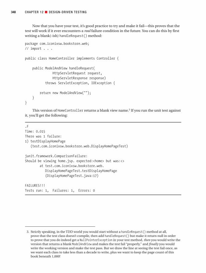
Now that you have your test, it’s good practice to try and make it fail—this proves that thetest will work if it ever encounters a real failure condition in the future. You can do this by firstwriting a blank(-ish) handleRequest() method:
package com.iconixsw.bookstore.web;// import . . .
public class HomeController implements Controller {
public ModelAndView handleRequest(HttpServletRequest request,HttpServletResponse response)
throws ServletException, IOException {
return new ModelAndView("");}
}
This version of HomeController returns a blank view name.3 If you run the unit test againstit, you’ll get the following:
.FTime: 0.015There was 1 failure:1) testDisplayHomePage
(test.com.iconixsw.bookstore.web.DisplayHomePageTest)
junit.framework.ComparisonFailure:Should be viewing home.jsp. expected:<home> but was:<>
at test.com.iconixsw.bookstore.web.DisplayHomePageTest.testDisplayHomePage(DisplayHomePageTest.java:17)
FAILURES!!!Tests run: 1, Failures: 1, Errors: 0
CHAPTER 12 ■ DESIGN-DRIVEN TESTING348
3. Strictly speaking, in the TDD world you would start without a handleRequest() method at all, prove that the test class doesn’t compile, then add handleRequest() but make it return null in order to prove that you do indeed get a NullPointerException in your test method, then you would write theversion that returns a blank ModelAndView and makes the test fail “properly,” and finally you wouldwrite the working version and make the test pass. But we draw the line at seeing the test fail once, aswe want each class to take less than a decade to write, plus we want to keep the page count of thisbook beneath 1,000!
7745ch12final.qxd 12/13/06 8:46 PM Page 348

Good, so that’s proved that the test mechanism is working. We can now implementhandleRequest() “properly”:
public ModelAndView handleRequest(HttpServletRequest request,HttpServletResponse response)
throws ServletException, IOException {
return new ModelAndView("home");}
And running the test we should now get this:
.Time: 0.016
OK (1 test)
The one thing about the test method is that it’s creating a resource in the test methoditself, which is a bad habit to get into. The resource should be created in the setUp() method,which gets called prior to each test method being called.
The refactored code then looks like this:
package test.com.iconixsw.bookstore.web;
// import statements omitted
public class DisplayHomePageTest extends TestCase {
private HomeController homeController;
public DisplayHomePageTest(String testName) {super(testName);
}
public void setUp() throws Exception {homeController = new HomeController();
}
public void tearDown() throws Exception {homeController = null;
}
public void testDisplayHomePage() throws Exception {ModelAndView modelAndView = homeController.handleRequest(null, null);assertEquals("Should be viewing home.jsp.",
"home",modelAndView.getViewName());
}}
CHAPTER 12 ■ DESIGN-DRIVEN TESTING 349
7745ch12final.qxd 12/13/06 8:46 PM Page 349

We’ve turned homeController into a private variable and moved the line of code that cre-ates it into the setUp() method. Notice that we’ve also added a tearDown() method (which getscalled automatically after each test method) to set the homeController back to null. This isn’tstrictly speaking necessary but, even in the Java world, cleaning up after yourself is a mightygood habit to get into. Get into the habit now, and avoid spending days hunting down horri-ble, insidious memory leaks in the future.
A quick rerun of the test shows that none of its assertions has been broken, so that’sabout it for the first controller. We’ll walk through the same process for the other controllersin the Show Book Details use case (even though it may get a bit repetitive), because ensuringproper test coverage for your controllers is an incredibly important part of the whole process,and it is worth repeating over and over until it totally clicks into place.
But just before we move onto the next controller/test case, let’s do a quick bit ofhousekeeping.
Running the Tests from a Test SuiteWe haven’t yet shown how to run all the tests in one try. That’s easy enough with JUnit. There’sa GUI tool that can be launched from the command line, but there’s also a text-based test run-ner that we’re using for these examples.
It’s possible to group all the unit test classes together into a single test suite and run that:
package test.com.iconixsw.bookstore;
import test.com.iconixsw.bookstore.web.*;import junit.framework.*;
public class BookstoreTestSuite {
public static Test suite() {TestSuite suite = new TestSuite();suite.addTestSuite(DisplayHomePageTest.class);// add more tests here . . .
return suite;}
public static void main(String[] args) {junit.textui.TestRunner.run(suite());
}
}
If you run the BookstoreTestSuite from the command line, the main method will callsuite(), which will gather together all of the individual test cases (currently just the one,DisplayHomePageTest) and return them collected together in a single object. These will thenbe passed to the JUnit TestRunner, which produces the “OK” and “Failures!!!” text outputthat you see in this chapter’s examples.
CHAPTER 12 ■ DESIGN-DRIVEN TESTING350
7745ch12final.qxd 12/13/06 8:46 PM Page 350

As you write more test classes, you add them one by one to the test suite so that theycan all be run together. It’s a great way of ensuring that you haven’t broken existing function-ality when you add new controller logic. If your tests run quickly enough, it means you canrun all the tests every time you change something or add something new—meaning completeend-to-end test coverage in a matter of seconds, all driven from the controllers on yourrobustness diagrams.
■Exercise If you have some tests that just have to take a long time (e.g., testing some long-running SQLstatements), what could be done to handle this without losing the benefits of quick-running tests? We dis-cuss some test strategies to handle this situation later in the chapter.
Now let’s move on to the next controller for the Show Book Details use case.
CHAPTER 12 ■ DESIGN-DRIVEN TESTING 351
HERE’S THE CHAPTER SPLIT WE WARNED YOU ABOUT!
The remainder of this “Design-Driven Testing in Practice” section is mostly of interest to developers who arecurrently practicing Test-Driven Development (TDD) as espoused by Kent Beck and his hard-working disci-ples. The rest of us can sit down for a few minutes and have a nice, relaxing cup of tea. A safe place to rejointhe chapter would be the Top 10 Design-Driven Testing Errors, on page 369.
The story told in the remainder of this chapter is true. Only the test case names have beenchanged to protect the innocent.
If you’re not currently a “test-infected” TDD developer, the remainder of this section is . . . a lot of hardwork. In fact, it might seem like a mind-boggling amount of hard work. However, it’s a lot less work thanpracticing TDD without the benefit of an up-front analysis model and a set of use cases that describe alter-nate courses of action and itemize software behavior as controllers. If you are a TDD developer, we hopeyou’ll agree that we can save you quite a bit of work without sacrificing the integrity of the functional testingthat you’re doing.
So, as the Internet Bookstore narrative continues, you’ll notice that we suggest techniques for runningyour unit tests at a lightning-fast pace, so that they can be run repeatedly with each change or addition tothe code. This will make perfect sense to keen TDDers, who essentially evolve the design as they write theunit tests and the code. But if you’ve followed the design process described in this book, rerunning the testsevery few minutes becomes significantly less important. ICONIX Process makes a serious attempt to get asmuch of the refactoring done before coding as possible, and so therefore may also allow a more minimalistapproach to testing than what you’ll be reading about in the remainder of this section.
Having said that, we’ve kept the advice in the chapter because it can still be important if you’re com-bining TDD with a use case–driven up-front design approach. The key here is to apply and adapt the processaccording to the needs (and agile philosophy) of your own project.
We’ll make a few suggestions for more minimalist (“test smarter, not harder”) alternatives as thechapter proceeds.
7745ch12final.qxd 12/13/06 8:46 PM Page 351

Testing the Retrieve Book Details ControllerIn this section, we create the test scenarios for the Retrieve Book Details controller, and thenwrite (and run!) its JUnit test class.
What do we want this particular unit test to do? If we match the Retrieve Book Detailscontroller to the following use case text:
The Customer clicks a link on the home page . . . and the system retrieves the book details
for the selected book . . .
then this suggests that the test should assert that books are being retrieved correctly from thedatabase.
To add test case scenarios in EA, double-click the test case and then, when the Propertiesdialog pops up, click the Scenario tab. You can then add basic and alternate scenarios to thetest case. Figure 12-9 shows the two test scenarios that we’ll add for the Retrieve Book Detailscontroller/test case.
CHAPTER 12 ■ DESIGN-DRIVEN TESTING352
Figure 12-9. Test scenarios for the Retrieve Book Details test case
7745ch12final.qxd 12/13/06 8:46 PM Page 352

Now that you’ve added the test scenarios and further updated the use case and robust-ness diagram if needed, you draw the sequence diagram. The sequence diagram for ShowBook Details is shown back in Figure 9-8. The next stage, then, is to create the unit test skele-ton for this test case, using the scenarios you’ve just added (see Figure 12-9).
Here’s the test class skeleton for the Retrieve Book Details controller/test case. The actualtest methods (derived from the test case scenarios) are in red:
package test.com.iconixsw.bookstore.dao;
import junit.framework.*;
/*** Test case for the Retrieve Book Details controller.*/public class RetrieveBookDetailsTest extends TestCase {
public RetrieveBookDetailsTest(String testName) {super(testName);
}
public void setUp() throws Exception {}
public void tearDown() throws Exception {}
public void testBookIdFound() {}
public void testBookIdNotFound() {}
}
The two empty test methods, testBookIdFound() and testBookIdNotFound(), are deriveddirectly from the two test scenarios shown in Figure 12-9.
As we discussed at the start of this section, we want to test that the Book ID is found (ornot found) correctly in the database. However, a golden rule for unit tests is that they needto be able to run really quickly. If the unit tests don’t run really quickly, then people won’tbother to run them at all while they’re programming. For this reason, it’s good practice totry to avoid writing tests that create connections to external resources (e.g., databases).Connecting to databases (even locally) and running queries or updates can make unit testsrun disproportionately slowly, especially when the same setup or teardown code is iteratedover hundreds of times.
CHAPTER 12 ■ DESIGN-DRIVEN TESTING 353
7745ch12final.qxd 12/13/06 8:46 PM Page 353

■Tip Sometimes you do need some longer-running tests that connect to databases or run lengthyprocesses (e.g., testing a system’s ability to import and parse large files). It’s useful to set up a separate testsuite for these, and schedule the tests to run automatically overnight or (even better) on a build/test PC thatruns hourly.
But if you can’t include database code in your speedy tests, how do you actually testanything? One answer is to use so-called mock objects.4 For example, we could replace ourJDBC-specific DAO classes with “mock” versions, whose sole purpose in life is to providethe same unit test data, over and over, albeit very quickly.
You shouldn’t go crazy and rewrite the entire JDBC data access layer in one attempt;instead, just add the “mock” code that you need, one method at a time, as and when you findthat you need it. In other words, use mock objects sparingly!
Let’s add some code to the test class to retrieve a Book given an ID, and to assert that it’sbeen received:
private BookDao bookDao;
public void testBookIdFound() {Book book = bookDao.findById(1);assertNotNull("ID 1 should be found", book);
}
If you try to run the unit test now, you’ll get a NullPointerException, as the BookDao hasn’tbeen initialized. A good place to do that is in the setUp() method:
public void setUp() throws Exception {bookDao = new MockBookDao();
}
Obviously this won’t compile, as there isn’t yet a MockBookDao class. This is a good time toadd it:
package com.iconixsw.bookstore.dao.mock;
// import statements omitted . . .
public class MockBookDao implements BookDao {
private HashMap booksById;
public MockBookDao() {initData();
}
CHAPTER 12 ■ DESIGN-DRIVEN TESTING354
4. As we discussed in the “Writing Effective Unit Tests” section of this chapter, mock objects are overusedin the test-driven world, but in certain very specific cases they do prove useful.
7745ch12final.qxd 12/13/06 8:46 PM Page 354

public List findAll() throws DataAccessException {return (List) booksById.values();
}
public Book findById(int bookId) throws DataAccessException {return (Book) booksById.get(new Integer(bookId));
}
private void initData() {Book favWidgets = new Book();favWidgets.setId(1);favWidgets.setTitle("My Favorite Widgets");
Book uncommon = new Book();uncommon.setId(2);uncommon.setTitle("The Uncommon Event");
booksById = new HashMap();booksById.put(new Integer(1), favWidgets);booksById.put(new Integer(2), uncommon);
}
}
BookDao does the simplest thing possible (this isn’t production code after all; it’s just adevelopment tool purely for internal use), which is to create a couple of Book objects and stickthem into a HashMap keyed by the book ID. The data never gets saved out to disk; it’s all donein-memory.
Now that we have a compiling test, we should run this through JUnit. But we really wantto see the test fail first, to prove that the test works. So to do that, just briefly change theinitData() method as follows:
Book favWidgets = new Book();favWidgets.setId(5);favWidgets.setTitle("My Favorite Widgets");
We’ve simply changed the 1 to a 5, so that the mock DAO doesn’t return a book with an ID of 1. Running this test now, we get the following results:
.FTime: 0There was 1 failure:1) testBookIdFound
(test.com.iconixsw.bookstore.dao.RetrieveBookDetailsTest)
CHAPTER 12 ■ DESIGN-DRIVEN TESTING 355
7745ch12final.qxd 12/13/06 8:46 PM Page 355

junit.framework.AssertionFailedError:ID 1 should be foundat test.com.iconixsw.bookstore.dao.
RetrieveBookDetailsTest.testBookIdFound(RetrieveBookDetailsTest.java:29)
FAILURES!!!Tests run: 1, Failures: 1, Errors: 0
It seems strange to cheer and holler when you see a test fail, but it should make you feelgood about the test because you now know for sure that, if there’s a time when it really shouldfail, then it will do its job properly.
Now if we change the value back to 1 and rerun the test, here’s the result:
.Time: 0
OK (1 test)
Currently, we’re only testing “one way”—that is, that a Book was found. We also need totest the alternate course:
public void testBookIdNotFound() {Book book = bookDao.findById(-1);assertNull("ID -1 should not be found", book);
}
What’s wrong with this picture so far? You win a pork pie if you noticed that currently thistest class isn’t actually testing any of our real code. Test cases for data-retrieval controllers tendto end up like this, because they’re not doing very much in the way of serious code logic, andbecause we don’t want to test the actual data access (at least not in these particular unit tests),that doesn’t leave very much left to test.
However—and this is the thing—it’s the controllers linked to the data-retrieval controllersthat will get the benefit of all this mock-object effort. For those controllers, we’re not inter-ested in testing the database access; we want to test the controllers themselves, so it doesn’tmatter whether the data came from a mock object, or a real database, or even from a pork pie.
The result of this effort is that we now effectively have a very simple, controlled, in-memory data source (with its own unit tests!), which the other controllers will be able to use.And, to top it all, our tests should now run blazingly fast and have zero configuration becausethey don’t have to hit a real database.
Let’s move on to the next controller.
CHAPTER 12 ■ DESIGN-DRIVEN TESTING356
7745ch12final.qxd 12/13/06 8:46 PM Page 356

Testing the Display Book Details ControllerThe use case text that relates to this test case is as follows:
. . . the system retrieves the book details for the selected book and displays them on the
View Book Details page.
That should be a nice, bite-sized piece of work to write a test case for. Figure 12-10 showsthe test scenarios added into EA for this test case.
There are three test scenarios: “Page displayed,” “Book details found,” and “Book detailsnot found.” However, one of these isn’t quite right.
Impostor alert: We’ve added a “Book details not found” test scenario, which seems like a good idea. However, checking back to the test cases shown in Figure 12-6, there’s already aseparate alternate course (and accompanying test case) for the case where the book detailsaren’t found.
CHAPTER 12 ■ DESIGN-DRIVEN TESTING 357
Figure 12-10. Test scenarios for the Display Book Details controller/test case
7745ch12final.qxd 12/13/06 8:46 PM Page 357

■Tip When you’re adding “alternate” test scenarios, always check that you’re not just duplicating an alter-nate course in the use case itself.
So for this test case, there are really only two test scenarios: “Page displayed” and “Bookdetails found.” Both of these are “basic path” test scenarios, which makes sense, because thetest case itself is for one of the controllers in the use case’s basic course.
Let’s pause to get our bearings. Figure 12-11 shows an excerpt from the Show Book Detailssequence diagram.
Remember that you should write the test from the point of view of the object that is call-ing the controller. The calling object is usually a boundary object, though it may also beanother controller. We only want the calls going into the controller being tested. As you cansee from Figure 12-11, this means testing two methods: handle() and checkBookFound().
Here’s the test class skeleton for the Display Book Details controller/test case (the testmethods are shown in red):
package test.com.iconixsw.bookstore.web;
import junit.framework.*;
/*** Test case for the Display Book Details Page controller.*/public class DisplayBookDetailsPageTest extends TestCase {
CHAPTER 12 ■ DESIGN-DRIVEN TESTING358
Figure 12-11. Excerpt from the Show Book Details sequence diagram
BookDetailsControllerDispatcherServlet
ModelAndView= handle(request, response, command, errors)
boolean=checkBookFound(book)
7745ch12final.qxd 12/13/06 8:46 PM Page 358

public DisplayBookDetailsPageTest(String testName) {super(testName);
}
public void setUp() throws Exception {}
public void tearDown() throws Exception {}
public void testPageDisplayed()throws Exception {}
public void testBookDetailsFound()throws Exception {}
}
Checking Figure 12-11, we’ll want to create a BookDetailsController object to push andprod, and it would make sense to put this in setUp() so that the same setup code can beshared by both the test methods:
public void setUp() throws Exception {bookDetailsController = new BookDetailsController();bookDetailsController.setBookDao(new MockBookDao());
}private BookDetailsController bookDetailsController;
In setUp(), we’re now creating a new BookDetailsController and telling it to use theMockBookDao class that we created earlier.
setBookDao() is a simple setter method on BookDetailsController:
public void setBookDao(BookDao bookDao) {this.bookDao = bookDao;
}private BookDao bookDao;
The following code shows the beginnings of the first of the two test methods,testPageDisplayed():
public void testPageDisplayed() throws Exception {Book command = new Book();command.setId(1);ModelAndView modelAndView =
bookDetailsController.handle(null, null, command, null);
// assert...}
CHAPTER 12 ■ DESIGN-DRIVEN TESTING 359
7745ch12final.qxd 12/13/06 8:46 PM Page 359

We can now add the handle() method to BookDetailsController:
protected ModelAndView handle(HttpServletRequest request,HttpServletResponse response,Object command,BindException errors) throws Exception {
return null;}
Initially it just returns null, because we want to be able to run the test first and see it failcataclysmically. (Well, perhaps not completely cataclysmically, but a simple “test failed” wouldbe nice.)
Unfortunately, the testPageDisplayed() test code won’t compile as it stands, because thehandle() method on BookDetailsController is, rather annoyingly, protected—not public (itoverrides a Spring method). So we would need to make the overriding method public (in Java,it’s legal to increase an overriding method’s visibility). But another problem is that thehandle() method accepts several objects that are difficult to create outside their respectiveAPIs without a lot of boilerplate code. This is one of those wrinkles in the fabric of the other-wise perfect space-time continuum that surfaces to taunt us from time to time.
One solution is to pass null values into the method, but the method is now starting to look and behave less and less like it should in the real world, all for the purposes of testing.
For now, because we can, we’ll leave handle() unaltered and with protected visibility, andinstead add a separate, public method to BookDetailsController so that the test can call it.We’ll prefix the method with “test” so that later we’ll know that it is for a unit test:
public ModelAndView testHandle(Book command)throws Exception {
return handle(null, null, command, null);}
The new method simply delegates to the real handle() method. handle() doesn’t actuallyuse the request, response, or errors parameter, so we can pass in null for these. In fact, theonly parameter that really matters is Book. Now we can rewrite the test method to use this newmethod:
ModelAndView modelAndView =bookDetailsController.testHandle(command);
Checking the sequence diagram in Figure 12-11, we can see that the second method,checkBookFound(), is actually a private method called by handle(), so we don’t need to write a specific test method for it.5 Instead, the output from checkBookFound() will contribute to theeventual output of handle(), which we do need to test.
Now we can compile the test, run it against BookDetailsController (with its emptyhandle() method that returns null), and watch it fail. Hurrah—sort of.
CHAPTER 12 ■ DESIGN-DRIVEN TESTING360
5. If you wanted to really embrace the micro-grained, test-driven spirit of things, you could make check-BookFound() public and write an additional test method for it; it probably wouldn’t do any harm.
7745ch12final.qxd 12/13/06 8:46 PM Page 360
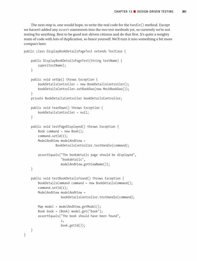
The next step is, one would hope, to write the real code for the handle() method. Exceptwe haven’t added any assert statements into the two test methods yet, so currently we’re nottesting for anything. Best to be good test-driven citizens and do that first. It’s quite a weightyream of code with lots of duplication, so brace yourself. We’ll turn it into something a bit morecompact later.
public class DisplayBookDetailsPageTest extends TestCase {
public DisplayBookDetailsPageTest(String testName) {super(testName);
}
public void setUp() throws Exception {bookDetailsController = new BookDetailsController();bookDetailsController.setBookDao(new MockBookDao());
}private BookDetailsController bookDetailsController;
public void tearDown() throws Exception {bookDetailsController = null;
}
public void testPageDisplayed() throws Exception {Book command = new Book();command.setId(1);ModelAndView modelAndView =
BookDetailsController.testHandle(command);
assertEquals("The bookdetails page should be displayed","bookdetails",modelAndView.getViewName());
}
public void testBookDetailsFound() throws Exception {BookDetailsCommand command = new BookDetailsCommand();command.setId(1);ModelAndView modelAndView =
bookDetailsController.testHandle(command);
Map model = modelAndView.getModel();Book book = (Book) model.get("book");assertEquals("The book should have been found",
1,book.getId());
}}
CHAPTER 12 ■ DESIGN-DRIVEN TESTING 361
7745ch12final.qxd 12/13/06 8:46 PM Page 361

As you can see, each test method initially does more or less the same thing: it sets up a Book command object, assigns it an ID, and then passes it to the BookDetailsControllerand gets a ModelAndView object back. The two methods, testPageDisplayed() andtestBookDetailsFound(), each assigns an ID of 1, an existing Book ID (because these twomethods are testing the basic course).
It seems like it would make sense to move this code into setUp() so that it gets called justprior to each test method. Each test method then starts by callingbookDetailsController.testHandle(), so that the resultant ModelAndView can be pushed andprodded by the test method. Note that bookDetailsController.testHandle() itself doesn’t goin setUp(), as strictly speaking it isn’t really setup code—it’s part of the actual test. By puttingthe code in setUp(), we would effectively be saying to anyone who reads the code, “This is testsetup code, not test code,” which is a tad misleading. So instead, we’ve moved it into a sepa-rate method so it can be shared by both test methods.
Here’s the resultant test code (the refactored code is shown in red):
private Book command;
public void setUp() throws Exception {command = new Book();command.setId(1);
}
public void testPageDisplayed() throws Exception {ModelAndView modelAndView = callTestHandle();assertEquals("The bookdetails page should be displayed.",
"bookdetails",modelAndView.getViewName());
}
public void testBookDetailsFound() throws Exception {ModelAndView modelAndView = callTestHandle();Map model = modelAndView.getModel();Book book = (Book) model.get("book");assertEquals("The book should have been found.",
1,book.getId());
}
private ModelAndView callTestHandle() {return bookDetailsController.testHandle(command);
}
CHAPTER 12 ■ DESIGN-DRIVEN TESTING362
7745ch12final.qxd 12/13/06 8:46 PM Page 362

Running this test class, we get red lights everywhere (aka test failures) because thehandle() method is still returning null; we’ll fix that in a second.
So, to round off this test case, now we can safely add the real code into the handle()method on BookDetailsController:
protected ModelAndView handle(HttpServletRequest request,HttpServletResponse response,Object command,BindException errors) throws Exception {
Book book = (Book) command;book.load(bookDao);return new ModelAndView("bookdetails", "book", book);
}
Running this code through the voracious unit tester, we get green lights, meaning thetests pass. But you’d be right to feel uneasy, because this code doesn’t handle the possibilitythat the book might not have been found. So, somewhat fortuitously, let’s move on to the nexttest case.
Testing the Display Book Not Found Page ControllerIn the final test case, we test the alternate course in which a book ID is passed in that doesn’texist. The use case text that relates to this test case is as follows:
ALTERNATE COURSES:
Book not found: The system displays a Book Details Not Found page.
Figure 12-12 shows the test scenarios added into EA for this test case.There are two test scenarios: “Book Not Found page displayed” and “Book details not
found.” Both of these are categorized as Alternate test scenarios, which makes sense becausethis is a test case for a controller on an alternate course in the use case.
Figure 12-13 shows an excerpt from the sequence diagram that covers the design for thisalternate course. (See the full sequence diagram in Figure 9-7.)
CHAPTER 12 ■ DESIGN-DRIVEN TESTING 363
7745ch12final.qxd 12/13/06 8:46 PM Page 363

CHAPTER 12 ■ DESIGN-DRIVEN TESTING364
Figure 12-12. Test scenarios for the Display Book Not Found controller/test case
Figure 12-13. Excerpt from the Show Book Details sequence diagram for the alternate course
7745ch12final.qxd 12/13/06 8:46 PM Page 364
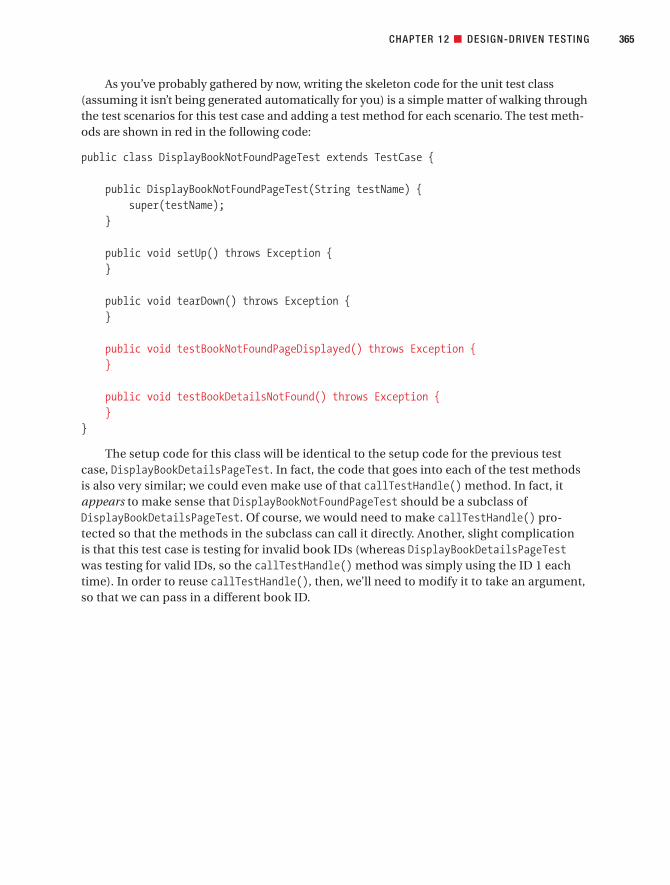
As you’ve probably gathered by now, writing the skeleton code for the unit test class(assuming it isn’t being generated automatically for you) is a simple matter of walking throughthe test scenarios for this test case and adding a test method for each scenario. The test meth-ods are shown in red in the following code:
public class DisplayBookNotFoundPageTest extends TestCase {
public DisplayBookNotFoundPageTest(String testName) {super(testName);
}
public void setUp() throws Exception {}
public void tearDown() throws Exception {}
public void testBookNotFoundPageDisplayed() throws Exception {}
public void testBookDetailsNotFound() throws Exception {}
}
The setup code for this class will be identical to the setup code for the previous testcase, DisplayBookDetailsPageTest. In fact, the code that goes into each of the test methodsis also very similar; we could even make use of that callTestHandle() method. In fact, itappears to make sense that DisplayBookNotFoundPageTest should be a subclass ofDisplayBookDetailsPageTest. Of course, we would need to make callTestHandle() pro-tected so that the methods in the subclass can call it directly. Another, slight complication is that this test case is testing for invalid book IDs (whereas DisplayBookDetailsPageTestwas testing for valid IDs, so the callTestHandle() method was simply using the ID 1 eachtime). In order to reuse callTestHandle(), then, we’ll need to modify it to take an argument,so that we can pass in a different book ID.
CHAPTER 12 ■ DESIGN-DRIVEN TESTING 365
7745ch12final.qxd 12/13/06 8:46 PM Page 365

Figure 12-14 shows how the two classes should fit together (TestCase is shown in red asit’s an external JUnit class).
CHAPTER 12 ■ DESIGN-DRIVEN TESTING366
WHY BOTHER DESIGNING THE UNIT TESTS?
You might wonder why we’re spending time on the design of the unit test classes instead of the “real” pro-duction code. Surely the unit tests are “second-class citizens”?
We’ve noticed a tendency for programmers to write unit tests in an ad hoc fashion, paying virtually zeroattention to their design (the thought process seems to be, “Hey, they’re not part of the main code base, sowhy waste our time on them?”). The result is that once the project contains more than a few small unit tests,it becomes just as difficult to maintain or extend the tests as with “proper” functional source code.
The result also is that the test classes tend to become monolithic, thousand-line beasts. You may alsofind that there will be less and less correlation between the test, the code that it’s testing, and what the test’sassertion was originally meant to be proving. It becomes very difficult to match up a test failure with the rootcause of the failure. A bit like the “fog of war,” you end up with the “fog of test failure.” Rather than the failedtest naturally pointing to the point of failure, you instead have to debug it, spend a while trawling throughpoorly designed test code, and then trace it through the code being tested, eventually tracking down the rootcause of the failure.
But just being aware that some attention must be paid to the test design goes a long, long way towardalleviating this problem. And that’s why you need to keep an eye on the unit test code, and keep its designnice and clean!
Figure 12-14. Class diagram for the two Book Details test cases (first attempt)
7745ch12final.qxd 12/13/06 8:46 PM Page 366

However, the problem with this design is that when DisplayBookNotFoundPageTest is run,the tests from the parent test class will also be run. It isn’t a big problem, but it’s a bit messy. Ineffect, we’re saying that DisplayBookNotFoundPageTest is-a DisplayBookDetailsTest, whichreally it isn’t. Also, using an inheritance relationship in this way could limit the code’s extensi-bility: what if you find that some other test cases could also share the helper method, but areotherwise unrelated (i.e., where an is-a relationship really wouldn’t make any sense)? Similarly,you might want DisplayBookNotFoundPageTest to share some functionality in some otherabstract parent class, but Java doesn’t support multiple inheritance (thank goodness!).
So this design still isn’t quite right. Whatever to do?You could take the “postmodernistic” approach6 and avoid inheritance in favor of aggre-
gation. In other words, you could move the common code into a separate helper class sharedby both test cases (see Figure 12-15).
CHAPTER 12 ■ DESIGN-DRIVEN TESTING 367
6. Shortly after the “Gang of Four” book was published, inheritance was all the rage—everyone who wasanyone was doing it. However, it didn’t take long for people to encounter the sorts of problems we’vedescribed here. So nowadays, aggregation (and copious use of interfaces) is generally seen as a neater,less problematic approach.
Figure 12-15. Class diagram for the two Book Details test cases
7745ch12final.qxd 12/13/06 8:46 PM Page 367

Here’s our sleek, postmodernistic test helper class:
public class ShowBookTestHelper {
public ModelAndView callTestHandle(int bookId) throws Exception {BookDetailsController bookDetailsController =
new BookDetailsController();bookDetailsController.setBookDao(new MockBookDao());
Book command = new Book();command.setId(bookId);return bookDetailsController.testHandle(command);
}
And finally, here’s the new version of DisplayBookNotFoundPageTest, refactored to use thenew shared helper class (the code that uses the helper class is shown in red):
public class DisplayBookNotFoundPageTest extends TestCase {
public DisplayBookNotFoundPageTest(String testName) {super(testName);
}
public void setUp() throws Exception {helper = new ShowBookTestHelper();
}private ShowBookTestHelper helper;
public void testBookNotFoundPageDisplayed() throws Exception {ModelAndView modelAndView = helper.callTestHandle(-1);assertEquals("The booknotfound page should be displayed",
"booknotfound",modelAndView.getViewName());
}
public void testBookDetailsNotFound() throws Exception {ModelAndView modelAndView = helper.callTestHandle(-1);Map model = modelAndView.getModel();Book book = (Book) model.get("book");assertNull("The book should not have been found", book);
}}
DisplayBookDetailsPageTest will also look quite similar to this class after refactoring it to use ShowBookTestHelper. If you’re interested, you can download the finished code from thisbook’s website.
That about wraps it up for the testing element of the use case–driven process. We’ll finishthis chapter with our top 10 list of Design-Driven Testing errors.
CHAPTER 12 ■ DESIGN-DRIVEN TESTING368
7745ch12final.qxd 12/13/06 8:46 PM Page 368

■Note Non-TDDers who opted to skip over this more mind-bending part of the chapter for the much saferoption of a nice cup of tea may safely rejoin the chapter here.
Top 10 Design-Driven Testing Errors (the “Don’ts”)To break with tradition, we’re presenting a top 10 list of the things you shouldn’t do whenDesign-Driven Testing, in addition to the top 10 “do’s” from the start of the chapter.
10. Go overboard with mock objects.
While mock objects do have limited usefulness to “grease the skids” of your testingprocess, they suffer from a law of diminishing returns. It’s all too easy to end up withcode that does this sort of thing:
Unit test: Assert that the mock object returns 3.0
Mock object: Return 3.0
Of course, that isn’t testing for anything—your unit tests and your mock objects arejust giving each other mutual kisses and cuddles. While you may get a warm feelingbecause you have 1,000+ mock objects returning the values that your tests are expect-ing, it doesn’t do much for the quality of your software.
9. Duplicate alternate course scenarios in the alternate test scenarios for basic coursecontrollers.
(Pause for a moment to reread that last line.) When you’re brainstorming test case sce-narios, it’s easy to think up rainy-day scenarios that were already thought of when youwere brainstorming alternate scenarios for your use cases. It’s important to make sureyou don’t duplicate these scenarios. Make sure the rainy-day test scenarios go into theappropriate alternate course test case.
8. Forget to tie the tests closely to the requirements.
7. Leave testing until after the code has been written.
If there’s one thing we have in common with the XP crowd, it’s that we firmly believethat testing should begin before you start writing the code. In fact, you should beginthinking about testing and preparing the way, long before that. Retrospective test-ing (i.e., sitting down and testing the code after it’s been written) is better than notesting at all, but it’s possible to eliminate a lot more bugs, before they even exist, by testing early.
6. Confuse testing with designing.
Well, OK, this one is a bit tongue-in-cheek. But hopefully in the course of this book,we’ve brought home to you the importance of designing before you begin coding andtesting. It is possible to design your code by writing unit tests (the basic premise of
CHAPTER 12 ■ DESIGN-DRIVEN TESTING 369
7745ch12final.qxd 12/13/06 8:46 PM Page 369

Test-Driven Development [TDD]), but we feel that it’s much more efficient and more“bulletproof” to design using the process we’ve described, and then write the tests tovalidate and further hone the design.
5. Ignore problem hot spots.
When you find patches of buggy code, find out why they’re there, and try to fix theproblems at the source. Remember that the probability of finding a bug in a givenpiece of code increases with the number of bugs already found in that piece of code.
■Tip When fixing a bug, always start by writing a test that will fail if the bug reoccurs.
4. Use brute force testing instead of identifying and then targeting “test hot spots” fromyour preliminary design.
3. Use the wrong kind of testing for the wrong situation.
2. Forget to do any testing at all.
1. Test so thoroughly that you never release the product.
More PracticeThis section provides a list of questions that you can use to test your knowledge of DDT.
1. Which of the following would you use to specify your system tests?
a) Robustness diagrams
b) Use cases
c) Sequence diagrams
d) Conceptual design
2. What’s the main difference between integration testing and compatibility testing?
a) Integration testing exposes faults in the interaction between “internal” classes,whereas compatibility testing checks that the system interoperates correctly withother, “external” systems and components.
b) Integration testing checks that the system interoperates correctly with other,“external” systems and components, whereas compatibility testing exposes faultsin the interaction between “internal” classes.
c) Integration testing proves that the system that was specified has been delivered,whereas compatibility testing proves that the system delivers what was actuallyrequested.
d) Integration testing proves that the system delivers what was actually requested,whereas compatibility testing proves that the system that was specified has beendelivered.
CHAPTER 12 ■ DESIGN-DRIVEN TESTING370
7745ch12final.qxd 12/13/06 8:46 PM Page 370

3. Unit tests are derived from, and check the processing logic contained in, which of thefollowing?
a) Controllers
b) Boundary classes
c) Entity classes
d) Use cases
4. What’s the maximum number of test methods you should have in each unit test class?What can happen if the test class (or the individual test methods) grows too large?
5. Which of the following statements is true?
a) You should tie the boundary classes in the preliminary design to the setup meth-ods in the unit test classes.
b) You should tie the controller method names closely to the unit test class names.
c) You should keep your unit test methods coarse-grained.
d) You should tie the unit tests closely to the classes and methods you’re testing.
6. Describe when mock objects are beneficial, and also describe the “point of diminish-ing returns” when they cease to be useful.
7. Why is aggregation a preferable design strategy to generalization when creating testclasses?
8. For each use case, should the alternate courses be tested in the same test class as thebasic course? Explain your answer.
SummaryIn this chapter, we covered the various forms of use case–driven testing and described whenyou would want to use each of them. We also ran through an example of Design-Driven Test-ing (DDT) for the Internet Bookstore and wrote some unit tests to cover the Show Book Detailsuse case.
Figure 12-16 shows where we are. The activities covered in this chapter are shown in red.If you want to further explore the possibilities of combining use case–driven development
with Test-Driven Development (TDD), we provide an in-depth discussion and detailed exam-ple in Agile Development with ICONIX Process (Apress, 2005).
One of the key points in this chapter is that tests don’t prove a huge amount if they aren’ttied microscopically closely in with the requirements (though not so closely that the require-ments are the tests—that would be silly!). In the next and final chapter, we talk aboutrequirements and show how they fit into the overall process.
CHAPTER 12 ■ DESIGN-DRIVEN TESTING 371
7745ch12final.qxd 12/13/06 8:46 PM Page 371

CHAPTER 12 ■ DESIGN-DRIVEN TESTING372
Figure 12-16. Testing activities during the implementation stage
7745ch12final.qxd 12/13/06 8:46 PM Page 372

Addressing Requirements
We’ve held off on discussing requirements until the end of the book for a couple of reasons.First off, there seems to be a lot of confusion about the differences between requirements, usecases, and behavior (operations). Since we talked about use cases in Chapter 3, allocatingbehavior in Chapter 8, and a whole series of techniques driven by use cases and operations in the subsequent chapters, it’s easier to talk about requirements in terms of how they contrastwith those items.
The requirements process described in this chapter isn’t a core part of ICONIX Processas such, so that’s another reason this chapter is at the end. It’s not a core part of the processsimply because different organizations have different strategies for handling requirements. In some companies, the requirements are just handed down from on high, and for political orother reasons, there’s no ability to change the requirements elicitation process. In fact, some-times it seems as if there are as many ways of addressing requirements as there are softwaredevelopment projects. But we believe that if you take the ideas in this chapter to heart, you’llfind your customers will be more satisfied with what you deliver.
373
C H A P T E R 1 3
7745ch13final.qxd 12/13/06 8:48 PM Page 373

Requirements Gathering in TheoryIn this section we describe the theory behind requirements gathering in a use case–drivenproject. First up are our top 10 requirements gathering guidelines.
Top 10 Requirements Gathering GuidelinesThe principles discussed in this chapter can be summed up as a list of guidelines. Our top 10list follows.
10. Use a modeling tool that supports linkage and traceability between requirements anduse cases.
9. Link requirements to use cases by dragging and dropping.
8. Avoid dysfunctional requirements by separating functional details from your behav-ioral specification.
7. Write at least one test case for each requirement.
6. Treat requirements as first-class citizens in the model.
5. Distinguish between different types of requirements.
4. Avoid the “big monolithic document” syndrome.
3. Create estimates from the use case scenarios, not from the functional requirements.
2. Don’t be afraid of examples when writing functional requirements.
1. Don’t make your requirements a technical fashion statement.
Let’s look at each of these items in more detail.
10. Use a Modeling Tool That Supports Linkage and TraceabilityAs irrational as it sounds, there was a time when visual modeling tools didn’t have built-insupport for allocation and traceability “out of the box” (at least not without purchasing sixadditional software modules at a cost of eleventy-million dollars, and then hiring a team ofconsultants to manage the interfaces between the tools). These days, however, matters haveimproved, and we can adopt a much more rational process.
For example, Enterprise Architect (EA) provides support for drag-and-drop allocation ofrequirements and automatic generation of a requirements traceability matrix. We show anexample of that later in this chapter.
9. Link Requirements to Use Cases by Dragging and DroppingWe show an example of this in the second part of this chapter, but in a nutshell you can linkany element in your model back to a requirement by dragging the requirement onto the ele-ment. Naturally, we recommend doing this with use cases (i.e., drag the requirement ontothe use case), as you can then automatically generate and display a traceability matrix to seehow all of your behavioral requirements link back to the customer’s original high-levelrequirements.
374 CHAPTER 13 ■ ADDRESSING REQUIREMENTS
7745ch13final.qxd 12/13/06 8:48 PM Page 374

8. Avoid Dysfunctional RequirementsA recent trend we’ve seen that’s a bit disturbing involves mixing the functional requirementstatements in with use case text. We’re not sure whose advice has led so many different organi-zations to this style of writing use cases, but it certainly seems to be in fashion as we’re writingthis chapter. We’ve seen it often enough during recent Jumpstart classes that we decided toinvent a new term to describe it: we call it intermangling of requirements and scenario text.
In other words, the (passive voice) requirements statements become intermixed andmangled up—intermangled—with the (active voice) scenario text. So you can’t quite tell ifyou’re reading a use case or a requirements document. You’re just not sure: Is it a functionalrequirement? Is it a nonfunctional requirement? Is it a behavioral requirement . . . what is it thatI’m reading here? The use cases are rendered . . . well, useless, actually.
We believe it’s much better to separate out the active voice (use case) stuff from the pas-sive voice (requirement) stuff. When they’re all intermangled together, they aren’t really veryuseful in our experience. So we’ve begun referring to this style of requirements spec as dys-functional requirements. They’re dysfunctional because of their schizophrenic nature. Thespecification is unsure if it’s a list of functional requirements or a list of use case steps; it hasa split personality.
One of the reasons that intermangled requirements and use cases are dysfunctional isthat you can’t disambiguate the use cases and put them in the context of the object modelwhen they’re intermangled with the functional requirements. All the use case text has to beactive voice text that describes how the users interact with the system as the program is run-ning. So you have to disintermangle them before you can disambiguate them. It’s quiteimportant, actually.
■Note We hope you’ve gotten a real-world feeling about ICONIX Process from this book. Doug spends upto 20 weeks a year (sometimes more) out in the field, applying this process on real projects, with more thanhalf of the projects being new developments from existing clients. Having done this for over a decade, wehave a pretty good idea of what works and what doesn’t.
CHAPTER 13 ■ ADDRESSING REQUIREMENTS 375
DISINTERMANGLING DYSFUNCTIONAL REQUIREMENTS FROM THE SCENARIO TEXT
As previously mentioned, dysfunctional requirements are functional requirements that appear in the use casescenario text (which, as you know by now, should contain only behavioral requirements). Here’s an example,with the dysfunctional text in red. (Please, don’t try this at home.)
BASIC COURSE:The user clicks the Advanced Search button on the hub page.The system displays the Advanced Search page.[REQUIREMENT] On this page, there are two search fields: Search by Title, Search by Author; and searchoptions:[REQUIREMENT] Order results by sales rank;[REQUIREMENT] Order results alphabetically by Title;[REQUIREMENT] Order results alphabetically by Author;
7745ch13final.qxd 12/13/06 8:48 PM Page 375

7. Write at Least One Test Case for Each RequirementMake sure that your tests are tied closely to the requirements. That isn’t to say that every testshould be traced back to a requirement, but there should at least be a test to “prove” that eachrequirement has been implemented correctly.
In Chapter 12, we describe several techniques for tying your requirements closely to yourtest cases.
6. Treat Requirements As First-Class Citizens in the ModelGive each requirement a short, catchy name, just as you would a use case or a class.
5. Distinguish Between Different Types of RequirementsRequirements specs tend to be a mixture of high- and low-level requirements, of busi-ness requirements and technical notes—whatever the driving force is that has pushed
CHAPTER 13 ■ ADDRESSING REQUIREMENTS376
[REQUIREMENT] Order results by date.The user enters a book title and clicks the Submit button.[REQUIREMENT] The search results should be fine-tuned to be displayed to the user in no more than fiveseconds.The system displays the Search Results Page.
(We also slipped a nonfunctional requirement in there to show how easy it is to fall into the trap!)The text in red is important and it needs to be specified someplace, but the use case just isn’t that
place. One of the purposes of robustness analysis, in addition to disambiguation, is to remove the interman-gled requirements from the use case text and put them somewhere more appropriate (i.e., in separaterequirement elements that are linked to the use cases).
If that doesn’t seem to make sense, perhaps this will help:
We remove dysfunctionality from the requirements by disintermangling them from
the scenario text and then disambiguating them, in preparation for prefactoring the
design.
Hopefully that clears things up a little . . .
■Note Intermangling has a dangerous cousin that we might call vicious intermangling. A classicexample of vicious intermangling is to repeat the functional requirements inline within each and everyuse case that has anything to do with satisfying the requirement. We once met someone in Phoenixwho, when we pointed out repeated inline instances of functional requirements (each with a uniquenumber!) within the use cases, replied, “Oh, definitely. Some of these are repeated 70 or 80 times.”Whereupon we asked him how he knew whether he had 80 distinct requirements or a single require-ment repeated 80 times. We wish we were making this stuff up.
7745ch13final.qxd 12/13/06 8:48 PM Page 376

the project into existence. But it’s worth separating the requirements into different sec-tions delineated by the types of requirements (e.g., functional, data, performance,capacity, and test requirements).
4. Avoid the “Big Monolithic Document” SyndromeTreat the functional spec as a collection of short, highly focused, interlinked documents linkedback to from the use cases, instead of one big impenetrable 200-page tome.
3. Don’t Create Estimates Directly from the Functional RequirementsBreak the requirements down into use cases first (see Chapter 3), and then create estimatesfrom the use cases. Even better, draw the robustness diagrams (see Chapter 5) and createestimates from the list of controllers.
2. Don’t Be Afraid of Examples When Writing Functional RequirementsWhen writing functional requirements specs, use examples copiously throughout, as a brief,concrete example often illustrates a point much more succinctly than a normative explana-tion. Also remember to keep the examples interesting, to hold the reader’s attention.
1. Don’t Make Your Requirements a Technical Fashion StatementIn this age of trendy open source web frameworks and fashionable coding methodologies,it’s easy to drive the project from such “requirements” as “Must use EJB 3.0,” “Must use AOP,”“Must use Spring Framework,” and so forth. Similarly, projects can end up being delayedbecause the developers wanted to spend longer “improving the design” before releasing tothe customer.
Projects that are driven by technical requirements like these are out of step with the real-world forces that drive the business world. The number 1 business motivator is, of course,profit—not design patterns. As soon as the developers take over, and design patterns becomemore important than the business’ profit, the project has lost touch with reality.
■Tip When gathering requirements, ask the right questions of the right people (project stakeholders, endusers), and keep on asking until you get the specific answers that the project needs.
Why Bother Tracking Requirements?You may wonder whether the approach described in this chapter is overkill or whether only,say, big aerospace companies need to trace requirements to any level of detail. We can see howyou might think that.
We’ll try to shed some light on the topic by telling you a true story about a training work-shop that found Doug at a major corporation in Chicago with a small team (about fivedevelopers) and a really tight deadline. In fact, the code was being written in parallel with themodeling workshop, that’s how tight the deadline was:
CHAPTER 13 ■ ADDRESSING REQUIREMENTS 377
7745ch13final.qxd 12/13/06 8:48 PM Page 377

The project had about 30 named requirements. We had allocated them to the use cases
during analysis, and we were in the process of verifying that our sequence diagrams met
those requirements. Suddenly, as we were tracing the first requirement, the lead engineer
got, well, red in the face with embarrassment and said, “I just coded this last night, and
I completely forgot about that exception condition.”
It can happen to you, too.
Requirements Allocation and Traceability in Theory
■Note Our thanks to Jeff Kantor for contributing this section.
When you look forward in the life cycle, you perform allocation of requirements to use cases,classes, operations, states, and so forth. When you look backward, as you would in a verifica-tion/validation phase of the project, the term traceability comes into play. The two terms aredifferent perspectives on the same relationship, but you traverse the relationship from eachperspective under different circumstances.
When you move from analysis to design, you perform allocation in order to assignrequirements to the design elements that will satisfy them. When you test and integratecode, your concern is with traceability, to determine which requirements led to each pieceof code, and to provide criteria for testing that code. Thus allocation/traceability is a con-cern across the entire life cycle, not just from system requirements to software require-ments, but also from software requirements to preliminary design, from preliminary designto detailed design, and from detailed design to implementation, testing, and integration.
You need to address several aspects of the allocation/traceability problem before you startserious coding.
• Data capture has to do with finding efficient ways to capture the analytical elements ofeach phase of the life cycle (requirements, functional analysis, functional allocation,hardware/software design, code, test, documentation, data) and the allocation/trace-ability relationships among these elements. You also need to consider how you willmanage this information over several iterations of the life cycle phase activities, andhow you will manage updates and changes to the elements and relationships.
• Data analysis and reduction encompasses ensuring that all the allocation/trace point-ers are valid, that all requirements are allocated, and that all requirements trace. Thisaspect also presents management questions as iterative and incremental developmentoccurs. In addition, you need to be aware of the impact that changes have on elementsthroughout the system, and work to ensure that the results leave your design consistentwith the users’ needs.
• Data reporting involves the ability to report efficiently on the results of data captureand data analysis/reduction. This typically takes the form of large tables that should beincluded in ongoing project documentation.
CHAPTER 13 ■ ADDRESSING REQUIREMENTS378
7745ch13final.qxd 12/13/06 8:48 PM Page 378

Requirements Gathering in PracticeIn this section, we dispense with the Internet Bookstore example, and instead reintroduceeveryone’s favorite redneck, Billy Bob (a character from Doug’s first book on ICONIX Process,coauthored by Kendall Scott). We’ll use the requirements from the original Billy Bob exampleto illustrate how to organize your functional requirements in EA.
■Note The remainder of this chapter focuses on requirements management using EA. Non-EA usersshould still find this section helpful, if only because it illustrates just how easy requirements managementand traceability have become these days, using the right tools.
Organizing Requirements in EA: BillyBob 2.0In Doug’s first book on ICONIX Process,1 he and coauthor Kendall Scott introduced to us theinfamous Billy Bob. In the original example, Billy Bob was driving down the road at 80 milesan hour while drinking beer, scratching, and tossing the empty beer cans out the window ofhis pickup truck. From these actions, a set of behavioral requirements was identified: “DrivePickup Truck,” “Drink Beer,” and “Toss Can Out of the Window.”
As this seems to be the storytelling chapter, and since we’re pretty close to the end of thebook, here’s one more. Doug was teaching a class in Oak Ridge, Tennessee, a few years backand one of the students came up at a break and introduced himself as being from Mississippi(or was it Alabama?). At any rate, he proceeded to confess that the Billy Bob story was the onlypart of the book he had actually understood, and then explained that Doug and Kendall had itall wrong, as follows:
You throw the cans into the back of the pickup, but you throw the bottles out of the win-
dow because they make a much more satisfying noise when they hit the signs.
You just can’t make this kind of stuff up, folks. But at any rate, we can use Doug’s student’sexplanation to explore the further adventures of Billy Bob. We can define the requirements forBillyBob 2.0 as follows:
1. Billy Bob shall throw his cans into the back of the pickup.
2. Billy Bob shall recycle his beer cans so he can buy an additional six-pack.
3. Billy shall throw only the bottles out the window.
4. (Performance requirement) The bottles must hit the signs with an accuracy ratio of atleast 63.5%.
We’ll return to these requirements later in this chapter and give a practical demo of howthey can be organized and linked to use cases in EA.
CHAPTER 13 ■ ADDRESSING REQUIREMENTS 379
1. Doug Rosenberg and Kendall Scott, Use Case Driven Object Modeling with UML: A Practical Approach(New York: Addison-Wesley, 1999).
7745ch13final.qxd 12/13/06 8:48 PM Page 379

Figure 13-2 shows the updated domain model, with the domain objects that we’ve identi-fied from the new requirements (the new 2.0 objects are shown in red). The behavior of thesystem will be distributed across these objects.
Figure 13-2 shows the use cases we can identify from our new requirements, as well as thedeclarations we can make about how these use cases are related.
■Exercise Can you spot an additional <<precedes>> relationship that’s missing from Figure 13-2?
Here’s a possible use case for Drink Beer (adapted from Doug’s first book with Kendall,now with our new requirements added):
BASIC COURSE:
Billy Bob removes one hand from the steering wheel and grabs a can of beer from the six-
pack on the seat next to him. He drains it in one prolonged gulp, and then invokes the
Toss Cans in back of Pickup Truck use case.
ALTERNATE COURSE:
Bottle instead of Can: The Toss Bottles out of Window at Signs use case is invoked instead.
CHAPTER 13 ■ ADDRESSING REQUIREMENTS380
Figure 13-1. Domain objects associated with Billy Bob
7745ch13final.qxd 12/13/06 8:48 PM Page 380

Here’s the basic course for the Toss Cans in back of Pickup Truck use case:
Keeping his eyes on the road at all times, Billy Bob tosses the drained Can over his shoul-
der into the back of the Pickup Truck.
■Exercise Should Drained Can be a separate domain object, or should it be an attribute of Beer Can?
And finally, here’s the Toss Bottles out of Window at Signs use case:
BASIC COURSE:
Keeping his eyes on the road at all times, Billy Bob tosses the drained Bottle out the win-
dow, at an approaching sign; the system makes the Bottle hit the sign with a satisfying
noise.
ALTERNATE COURSE:
Bottle misses sign: Satisfying noise not heard.
CHAPTER 13 ■ ADDRESSING REQUIREMENTS 381
Figure 13-2. Billy Bob’s refactored behavior
Billy Bob
Toss Cans in
back of Pickup
Truck
Drink Beer
Drive Pickup
Truck
Take Cans to
Recycle Center
Toss Bottles
out of Window
at Signs
«precedes»
«invokes»
«precedes»
«invokes»
7745ch13final.qxd 12/13/06 8:48 PM Page 381

Using a Visual Modeling Tool to Support RequirementsIn this section, we describe EA’s support for allocating and tracing requirements.
■Note This section is rather EA-specific, but if you’re using a different modeling tool, we think you’ll stillpick up some good ideas about how you can link your functional requirements to your use cases.
Figure 13-3 shows the Require tab that will appear on your use case and class specifica-tions within EA. We’ve linked two requirements to it by dragging the requirements directlyonto the use case (as you’ll see in the next section, these are external requirements). In thescreenshot, a new Testing requirement is being added directly to the use case.
EA has a number of built-in features to help you manage requirements. These featuresinclude the ability to
• Define requirement elements (“external” requirements)
• Link requirements to model elements that implement that requirement
• Link requirements together into a hierarchy
• Report on requirements and move requirements into and out of model elementresponsibilities
CHAPTER 13 ■ ADDRESSING REQUIREMENTS382
Figure 13-3. Require tab within EA
7745ch13final.qxd 12/13/06 8:48 PM Page 382

■Tip If you’re starting out with a set of requirements in an external document, it’s possible to import theserequirements into EA from a comma-separated value (CSV) file.
Internal and External RequirementsEA supports two basic types of requirements: internal and external. Internal means “internalto a UML element” (such as a use case or class), whereas external means “independent of anyspecific UML element.”
Most commonly, you’ll want to associate internal requirements (aka responsibilities) withuse cases. You can double-click a use case to open its Properties dialog, and then click itsRequire tab and enter a list of requirements that are then inherently “part of” the use case (see Figure 13-3).
Alternatively, you can create external Requirement elements and place them on diagrams.These are custom UML elements, so they can be connected to each other and to other UMLelements.
It’s possible to turn internal requirements into external requirements. For example, youmight begin by adding requirements directly into a use case, but then later discover that youwant to associate the same requirements with other use cases. The “simplest thing that canpossibly work” would be to recreate a carbon copy of the requirements in the other use cases,but we don’t want to do that, as duplication of anything (except fat royalty checks) is bad. So,let’s walk through the process of turning internal requirements into external requirements.Along the way, we’ll discuss some of the ways in which requirements can be organized in EA.
In Figure 13-3, we defined a use case called Toss Bottles out of Window at Signs, and withinit we’ve defined a new internal requirement (requirement 5). To turn this requirement into anexternal requirement (i.e., to “unshackle” it from a specific use case), click the Move Externalbutton on the Require tab. This pops up a dialog (see Figure 13-4), from which you can select a package to move the requirement to.
CHAPTER 13 ■ ADDRESSING REQUIREMENTS 383
Figure 13-4. Choosing where to put the newly “externalized” requirement
7745ch13final.qxd 12/13/06 8:48 PM Page 383

Once you have a sizeable batch of external requirements, you can create a new diagramto place the requirements on and organize them a bit more. The diagram we’ll create is anextended class diagram, the reason being that this diagram type allows custom elements(such as Requirement elements) to be placed on it. To place the Requirement elements ontoa diagram, drag them over from the Project View (see Figure 13-5).
If you recall from earlier in this chapter, there’s a hierarchical aspect to these require-ments: requirement 5 was derived from 4, and 4 was derived from 3. It would be useful toshow this “tree” relationship graphically, so let’s do that next.
CHAPTER 13 ■ ADDRESSING REQUIREMENTS384
Figure 13-5. Placing the external requirements on a new diagram
7745ch13final.qxd 12/13/06 8:48 PM Page 384

Tree of RequirementsRequirements can be linked to show construction of a complete requirements “tree” usingaggregation (see Figure 13-6).
■Caution For some projects, creating a requirements tree might be overkill, but the capability is there ifyou need it. However, it’s more important to allocate the requirements to the use cases and classes than it isto organize them into pretty tree structures.
CHAPTER 13 ■ ADDRESSING REQUIREMENTS 385
Figure 13-6. Structuring the requirements into a tree hierarchy
7745ch13final.qxd 12/13/06 8:48 PM Page 385

Once the links are established, the Hierarchy window will display the complete require-ment implementation/composition detail (see Figure 13-7).
Linking Requirements to Use CasesIf you create your requirements as internal requirements inside a use case and then turnthem into external requirements, they’ll already be linked automatically to the original usecase. However, you might also want to approach the problem from the other direction: startby defining some external requirements and then link ’em up to your use cases (as we did forthe first four requirements we showed earlier).
In fact, use cases aren’t the only model elements that you can link external require-ments to. Pretty much any model element can be linked up to a requirement: classes, inter-faces, components, and so forth. In EA, you link requirements to model elements using theRealization relationship (see Figure 13-8).
CHAPTER 13 ■ ADDRESSING REQUIREMENTS386
Figure 13-7. Structuring the requirements into a tree hierarchy
7745ch13final.qxd 12/13/06 8:48 PM Page 386

As you can see in Figure 13-8, a model element is marked as “realizing” a requirement.Once this link exists, EA will display the requirement in the element’s Require tab, in therequirement hierarchy window, and in the dependency and implementation reports, as wellas in the standard RTF output.
■Tip A quick method of generating a Realization link is to drag a Requirement element from the ProjectBrowser over an element in a diagram that is to be the implementing element. EA will interpret this as arequest to create the realization link and do so automatically. To confirm this, perform the action, and then go to the Require tab page of the target element. There should now be an external relationship to therequirement that was dragged over the target.
External requirements have their own properties and are reported on separately in theRTF documentation.
CHAPTER 13 ■ ADDRESSING REQUIREMENTS 387
Figure 13-8. Linking an external requirement to a use case
7745ch13final.qxd 12/13/06 8:48 PM Page 387

Pain-Free Requirements TraceabilityEA has a rather nifty tool called the Relationship Matrix. It’s a spreadsheet-like display of rela-tionships between model elements. You select a source package and a target package, therelationship type and direction, and then EA will display all the relationships between sourceand target elements by highlighting a grid square.2
You can also use the Relationship Matrix to create and manage the relationships betweenrequirements (see Figure 13-9). This is a convenient way of quickly building up complex rela-tionships and hierarchies. Choose View ➤ Relationship Matrix from the main menu to accessthis window.
A point to note when using requirements and the Relationship Matrix is that multipleelements can be selected and realized to a Requirement element (or any other element) bydragging the mouse across a set of cells or Ctrl-clicking individual cells. When you right-click
CHAPTER 13 ■ ADDRESSING REQUIREMENTS388
2. This brings a nice, satisfying closure to the allocation/traceability discussion we had at the beginningof the chapter. Allocate the requirements to the use cases by dragging them, and the tool produces thetraceability matrix automatically. Can it get any easier? Life is good. (Thank you, Geoff Sparks.)
Figure 13-9. EA’s Relationship Matrix feature
7745ch13final.qxd 12/13/06 8:48 PM Page 388

one highlighted cell and select Create New Relationship, the relationships are set up for allselected cells. This can be very useful when a requirement has impact on a number of ele-ments within a diagram.
More PracticeThis section provides a list of questions that you can use to test your knowledge of require-ments analysis and traceability in a use case–driven project.
1. Describe the differences between a functional requirement and a data requirement.
2. Which of the following is a behavioral requirement?
a) The user must be allowed to select from the following three invoice types: . . .
b) The speed limit of the road along which Billy Bob is driving is 65 mph.
c) If more than 3,000 users connect simultaneously, the system should respond byredirecting excess users to a “busy” page.
d) The user selects one item from the list of available invoice types and clicks Submit . . .
3. Which of the following statements is true?
a) A use case describes the laws that govern a function’s behavior.
b) Requirements describe the individual actions that occur within a use case.
c) Functions are the individual actions that occur within a use case.
d) A use case describes the laws that govern a requirement’s functions.
4. If you turn an internal requirement into an external requirement, how does thatchange its relationship with a use case?
5. Disintermangle the following use case scenario so that the nonbehavioral require-ments are separated out:
On the Maintain Seller Catalog page, the user clicks Add New Catalog. The user should
only be allowed to do this if she is already logged in. The system displays the Add New
Catalog page, showing a Catalog Name field, a book search field, and a list of recently
accessed Books. The system shows the user’s login name so that if she is a different user,
she logs out. The user enters a Book’s ISBN and clicks Add; the system updates the Cata-
log to show the new Book. Then the user repeats this for as many Books as she wants to
add. She shouldn’t be allowed to enter more than 20 Books in one Catalog, or to enter 0
Books. Finally, the user clicks the Save button; the system saves the new Catalog and
takes the user back to the Maintain Seller Catalog page.
6. Describe the differences between data capture and data analysis and reduction.
CHAPTER 13 ■ ADDRESSING REQUIREMENTS 389
7745ch13final.qxd 12/13/06 8:48 PM Page 389

SummaryIn this chapter, we looked at how requirements fit into the development process. We distin-guished between different types of requirements. We also demonstrated how to use EnterpriseArchitect to help support the requirements effort.
We’re about at the end of the book, so we’d like to leave you with this final thought: allhumans are fallible, and one of the best ways to reduce error rates is to focus on one thing at a time. “One thing at a time” is one of the central themes that’s woven throughout ICONIXProcess. Even if you take nothing else from this book, we think you’ll be more successful if youtry to at least keep that simple fact in mind.
Figures 13-10 and 13-11 show (in red) the items that were covered in this chapter.
CHAPTER 13 ■ ADDRESSING REQUIREMENTS390
Figure 13-10. Requirements Analysis Checkpoint 3
7745ch13final.qxd 12/13/06 8:48 PM Page 390
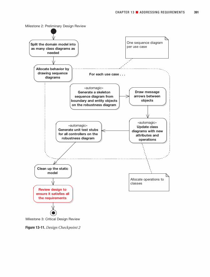
CHAPTER 13 ■ ADDRESSING REQUIREMENTS 391
Figure 13-11. Design Checkpoint 2
7745ch13final.qxd 12/13/06 8:48 PM Page 391

7745ch13final.qxd 12/13/06 8:48 PM Page 392

Appendixes
P A R T 5
7745appACMP2.qxd 12/6/06 9:17 PM Page 393

7745appACMP2.qxd 12/6/06 9:17 PM Page 394

What’s New in UML 2.0
In this appendix, we look at what’s new in UML 2.0, with a keen eye on how (if at all) it affectsICONIX Process. We step outside the “core UML subset” that we’ve defined in this book andlook at all the new diagram types in UML 2.0.
Overview of Changes in UML 2.0The main “theme” for the UML 2.0 update appears to be increased support for precision indiagrams, improving UML’s suitability for modeling real-time embedded systems.
UML 2.0 now consists of the following diagram types (some of these are subdivided intomore types of diagrams, which we cover later in this appendix):
• Use case diagrams
• Package diagrams
• Structure diagrams
• Object diagrams
• Composite structure diagrams
• Communication diagrams
• Activity and state machine diagrams
• Interaction and interaction overview diagrams
• Timing diagrams
• Component and deployment diagrams
There’s still no sign of robustness diagrams, as you can see, so we’ll have to make do withUML’s extension mechanism (UML profiles and stereotype icons) for now. Luckily, support forUML extensions in tools such as EA is pretty advanced these days.
Similarly, there’s no sign of test case diagrams, although the test case notation we describein Chapter 12 is supported in EA and can also be modeled in other tools using UML extensions.(At the time of this writing, EA is the only tool that can actually generate test cases automaticallyfrom your robustness diagrams.)
395
A P P E N D I X A
7745appACMP2.qxd 12/6/06 9:17 PM Page 395

Of the new diagram set, the main ICONIX diagrams remain unchanged: use case dia-grams, structure diagrams (aka class diagrams), and—although there’s some additionalnotation—sequence diagrams (one of the four types of interaction diagrams) also remainlargely unchanged. In fact, there haven’t been major changes to use cases, packages, classdiagrams, or object diagrams in UML 2.0. So, you might say that the UML 2.0 extensionsdon’t really affect ICONIX Process at all. To borrow a phrase, YAGNI (You Aren’t Gonna NeedIt) applies to a lot of the new stuff in UML 2.0 for the majority of projects that we’ve seen. Ofcourse, if you do need this stuff, by all means use it.
A number of new modeling constructs can be shown on composite diagrams. Theseinclude parts, ports, exposed and required interfaces, connectors, assemblies, andcollaborations.
Communication diagrams used to be called collaboration diagrams.1 They still show theinteractions between elements at runtime in much the same manner as a sequence diagram.
Activity diagrams are used to model the behavior of a system and the way in which thesebehaviors are related in an overall flow of the system, while state machine diagrams illustratehow an element can move between states classifying its behavior, according to transition trig-gers, constraining guards, and so on.
UML 2.0 has four different kinds of interaction diagrams: timing diagrams, sequencediagrams, interaction overview diagrams, and communication diagrams.
A timing diagram defines the behavior of different objects within a time scale. It providesa visual representation of objects changing state and interacting over time. Timing diagramsare typically used for defining hardware-driven or embedded software components.
A component diagram illustrates the pieces of software, embedded controllers, and soforth that will make up a system. In UML 2.0, components can be linked by assembly connec-tors. As before, a deployment diagram shows how and where the system will be deployed.Physical machines and processors are reflected as nodes, and the internal construction can be depicted by embedding nodes or artifacts.
UML profiles provide a generic extension mechanism for building UML models in partic-ular domains. A profile is a collection of stereotypes and tagged values that together describesome particular modeling problem and facilitate modeling constructs in that domain.
Let’s go through these changes in more detail.
Composite Structure DiagramsA composite structure diagram reflects the internal collaboration of classes, interfaces, orcomponents to describe some functionality.
Composite structure diagrams are similar to class diagrams, except that they model aspecific usage of the structure. Class diagrams model a static view of class structures, includ-ing their attributes and behaviors. Composite structure diagrams are used to express runtimearchitectures, usage patterns, and the participating elements’ relationships, which might notbe reflected by static diagrams.
396 APPENDIX A ■ WHAT’S NEW IN UML 2.0
1. Actually, they were originally called “object diagrams” in Booch method, then they were renamed to“collaboration diagrams” in UML 1, and they have now become “communication diagrams, a flavor ofinteraction diagrams” in UML 2. This explains why Doug refuses to join any standards committees.There are better things to do in life than to rename diagrams 12 times. Sequence diagrams, by the way,were originally called “object interaction diagrams” in the Jacobson Objectory method. If you’re notconfused yet, you win another pork pie.
7745appACMP2.qxd 12/6/06 9:17 PM Page 396

In UML 2.0, the changes to composite structure diagrams center on parts and ports, inter-faces, connectors and assemblies, and collaborations.
Parts and PortsIn a composite structure diagram, classes are accessed as parts, or runtime instances fulfillinga particular role. These parts can have multiplicity, if the role filled by the class requires multi-ple instances. When parts need to communicate with entities outside of their enclosing class,they will usually do this through a port. The port defines an interface that communicatingparts are required to implement.
There is extensive flexibility and an ensuing complexity that comes with modeling com-posite structures. To optimize your modeling, consider building collaborations that representreusable patterns.
Figure A-1 shows an example of a composite structure diagram.
InterfacesAn interface is a specification of behavior that implementers agree to meet. It is a contract. By implementing an interface, classes are guaranteed to support a required behavior,which allows the system to treat nonrelated elements in the same way, through the com-mon interface.
An interface cannot be instantiated (i.e., you cannot create an object from an interface).You must create a class that “implements” the interface specification and place operations in the class body for each of the interface operations. You can then instantiate the class.
Interfaces may be drawn as a stereotyped class, with operations shown. They may also be drawn as a circle with no explicit operations detailed (see Figure A-2).
APPENDIX A ■ WHAT’S NEW IN UML 2.0 397
Figure A-1. Composite structure diagram
Install
Backup Device
Computer
Software
7745appACMP2.qxd 12/6/06 9:17 PM Page 397

Assembly ConnectorsAn assembly connector bridges a component’s required interface with the provided interface ofanother component (see Figure A-3).
The UML 2.0 specification states the following:
An assembly connector is a connector between two components that defines that one
component provides the services that another component requires. An assembly connec-
tor is a connector that is defined from a required interface or port to a provided interface
or port.
CollaborationsA collaboration defines a set of cooperating roles and their connectors (see Figure A-4).
Collaborations are used to collectively illustrate a specific functionality. A collaborationshould specify only the roles and attributes needed to accomplish a specific task or function.A collaboration often implements a pattern to apply to various situations, and it is drawn as a dashed oval that surrounds the elements that are collaborating.
APPENDIX A ■ WHAT’S NEW IN UML 2.0398
Figure A-2. Interface notation
«interface»Interface1
Interface2
Figure A-3. Assembly connector
Component1 Component2
Figure A-4. Collaboration
Collaboration
7745appACMP2.qxd 12/6/06 9:17 PM Page 398

Activity and State DiagramsActivity diagrams are used to model the behaviors of a system and the way in which thesebehaviors are related in an overall flow of the system.
Activity diagrams are similar to flowcharts, but they allow the specification of concurrentparallel processing paths. Activities on an activity diagram can be partitioned into regions,which are usually called swimlanes because of their visual appearance (regions separated bysolid lines on the diagram).
New Activity Diagram Elements for Communication ActionsUML 2.0 adds some new elements to activity diagrams that are primarily useful for defin-ing real-time systems, very precise business processes, and detailed execution logic (seeFigure A-5). These include action pins and new special symbols for certain types of com-munication actions.
An action pin is used to define the data flow into and out of an action. An input pin pro-vides values to the action, whereas an output pin contains the results from that action. Actionpins can be further characterized as defining exception parameters, streams, or states. Associ-ating a state with a pin defines the state of input or output values.
UML 2.0 includes symbols for accept event, accept time event, and send signal actions.The call behavior and call operation actions are used to reference other activities and classmethods within an activity diagram.
Expansion RegionsUML 2.0 also provides a construct called an expansion region, which is used to denote pro-cessing that occurs in parallel (see Figure A-6). These are shown by a segmented box appear-ing on the top and bottom of the activity symbol. According to The Unified ModelingLanguage Reference Manual, Second Edition,2
APPENDIX A ■ WHAT’S NEW IN UML 2.0 399
Figure A-5. New activity diagram elements
ActionActionPin
Accept
Event
Accept
Event
Timer
Send
Signal
2. James Rumbaugh, Ivar Jacobsen, and Grady Booch, The Unified Modeling Language ReferenceManual, Second Edition (New York: Addison-Wesley, 2004).
7745appACMP2.qxd 12/6/06 9:17 PM Page 399

An expansion region is the expansion of computation containing a multiple value into
a set of computations executed in parallel.
Each input to the expansion region receives a collection value, shown by the segmentedbox icon. One execution of the expansion region is performed for each element of the collec-tions. For each output position in the expansion region, the output values from all of theexecutions are assembled into a single collection value. An expansion region represents a“forall” construct.
APPENDIX A ■ WHAT’S NEW IN UML 2.0400
Figure A-6. Activity diagram expansion regions
FFTparallel ExpansionNode RootComplex
nxtoddnxteven
«Complex»S:Array
«Complex»V:Array
Slower,Supper = cut(s)
nxteven = Lower+ Upper
Nxtodd = (lower -upper) * root
S = Shuffle(sneve, Snodd)
«Complex»S':Array
7745appACMP2.qxd 12/6/06 9:17 PM Page 400

New State Diagram ElementsContinuing with the theme of enhancing real-time modeling capability, UML 2.0 extends statediagrams with entry and exit connection points (see Figure A-7) and junctions. An entry pointconnection is shown by a small circle on the boundary of a substate machine symbol. A transi-tion can be connected from a state to the entry point connection. An exit point connection isshown in a similar manner by a small circle containing an “X”. A transition can be connectedfrom the exit point connection to another state.
The Unified Modeling Language Reference Manual, Second Edition defines a junction as “a pseudostate that is part of a single overall transition step in a state machine,” and furtherstates that a junction state “makes it possible to build a single overall transition from a seriesof transition fragments” and that it is “a dummy state to structure transitions and not a statethat can be active for any finite time.” Junction states are drawn as small filled circles on astate diagram.
Sequence and Interaction Overview DiagramsAn interaction is a generalization for a type of interaction diagram. UML 2.0 has four kinds of interaction diagrams: timing diagrams, sequence diagrams, interaction overview diagrams,and communication diagrams. We discuss timing diagrams later in this appendix.
Sequence DiagramsYou know by now that sequence diagrams are a rather important building block in ICONIXProcess. The basic notation for sequence diagrams hasn’t changed in UML 2.0; however, somenew elements have been introduced, including fragments, gates, states, and message end-points. These new elements collectively make it easier to draw structured control constructson sequence diagrams (see Figure A-8).
APPENDIX A ■ WHAT’S NEW IN UML 2.0 401
Figure A-7. State diagram entry/exit points
ProcessingRequest
Viewing Add to Cart
Start
End
Adding
7745appACMP2.qxd 12/6/06 9:17 PM Page 401

Complex flow of control on a sequence diagram can be shown using combined frag-ments. A combined fragment has a keyword and one or more subfragments, which are calledinteraction operands. Examples of fragments are LOOP, CONDITIONAL, and PARALLEL.Guard conditions and loop conditions may be shown within fragments.
It’s a philosophical question as to whether drawing flowcharts on sequence diagrams is a good idea or not. (Hint: We vote no.) But if you don’t want to draw your flowcharts usingactivity diagrams, you can now draw them on sequence diagrams.
Interaction Overview DiagramsInteraction overview diagrams are used to visualize the cooperation between other interactiondiagrams to illustrate a control flow serving an encompassing purpose (see Figure A-9).
Since interaction overview diagrams are a variant of activity diagrams, most of the dia-gram notation is similar, as is the process in constructing the diagram. Decision points, forks,joins, start points, and end points are the same. The diagram appears very similar to an activ-ity diagram and is conceptualized the same way: as the flow moves into an interaction, thatrespective interaction’s process must be followed before the interaction overview’s flow canadvance.
Instead of activity elements, however, rectangular elements are used. There are two typesof these elements: interaction elements and interaction occurrence elements. Interaction ele-ments display an inline interaction diagram, which can be a sequence diagram, communi-cation diagram, timing diagram, or interaction overview diagrams. Interaction occurrence
APPENDIX A ■ WHAT’S NEW IN UML 2.0402
Figure A-8. New sequence diagram elements
Customer Book SearchPage
Book DetailsPage
loop Book Search
enter search details
View results in separate window
[for each matching Book found]
7745appACMP2.qxd 12/6/06 9:17 PM Page 402

elements are references to an existing interaction diagram. They are visually represented by a frame, with “ref” in the frame’s title space. The diagram name is indicated in the framecontents.
■Note If you’ve been craving a notation that lets you do functional decomposition in UML (like you used todo it on DFDs 15 years ago), the interaction overview diagram makes a strong candidate.
APPENDIX A ■ WHAT’S NEW IN UML 2.0 403
Figure A-9. Interaction overview diagram
Request Item
refSearch For Item
refCheckout
refCreate Record
refCancel Sale Sale Finalized?
Yes
No
Item found
Item not found
7745appACMP2.qxd 12/6/06 9:17 PM Page 403

Timing DiagramsAs with many of the UML 2.0 extensions, timing diagrams came from the world of electri-cal engineering and are most useful if you are modeling real-time, embedded systems (e.g.,embedded software such as that used in a fuel injection system, a microwave controller,etc.). They can also be used for specifying time-driven business processes, although thiswould be a less typical usage.
Timing Diagram BasicsA timing diagram defines the behavior of different objects within a time scale (see Figure A-10).It provides a visual representation of objects changing state and interacting over time.
The UML 2.0 specification states the following:
Timing diagrams are used to show interactions when a primary purpose of the diagram
is to reason about time. Timing diagrams focus on conditions changing within and
among Lifelines along a linear time axis. Timing diagrams describe behavior of both
individual classifiers and interactions of classifiers, focusing attention on time of occur-
rence of events causing changes in the modeled conditions of the Lifelines.
The UML 2.0 specification also states,
The primary purpose of the timing diagram is to show the change in state or condition
of a lifeline (representing a Classifier Instance or Classifier Role) over linear time. The
most common usage is to show the change in state of an object over time in response to
accepted events or stimuli. The received events are annotated as shown when it is desir-
able to show the event causing the change in condition or state.
A timing diagram can have either a state lifeline or a value lifeline.
APPENDIX A ■ WHAT’S NEW IN UML 2.0404
Figure A-10. Timing diagram showing a state lifeline
Tim
eLin
e1
State 1
State 2
State 3
State 4
{Time Constraint}
{Duration Constraint}
Event
0 10 20 30 40 50 60 70 80 90 100
7745appACMP2.qxd 12/6/06 9:17 PM Page 404

State LifelineThe diagram in Figure A-10 shows an example of a state lifeline. The scale along the bottomindicates the passage of time, and the possible states are represented as the vertical scale. Thestepped lifeline shows the state changes that occur over time.
Value LifelineThe diagram in Figure A-11 shows an example timing diagram with both a state lifeline and a value lifeline. (The top two items, User and AC System, are state lifelines, and the bottomitem, User Accepted, is a value lifeline.)
The scale along the bottom again indicates the passage of time, but for the value lifelinethe possible states are represented as named sections of the lifeline. Where two named statestransition, the value lifeline narrows to a single point.
Messages Between LifelinesMultiple lifelines can be shown on the same timing diagram. The lifelines stack verticallywith each lifeline in a separate compartment on the diagram. Messages can be drawnacross compartments, thereby linking events on different lifelines (see the diagonal arrowsin Figure A-11).
APPENDIX A ■ WHAT’S NEW IN UML 2.0 405
Figure A-11. Timing diagram showing two state lifelines and a value lifeline
Use
r Wait Access
Wait Card
IdleStart
Code
{d..d*3}
AC
Sys
tem
No Card
Has Card
Use
rA
ccep
ted
Idle
{d..d*3}
Wait Card Wait Access Idle
0 10 20 30 40 50 60 70 80 90 100
7745appACMP2.qxd 12/6/06 9:17 PM Page 405
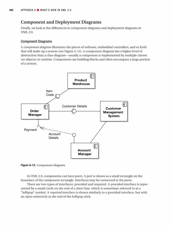
Component and Deployment DiagramsFinally, we look at the differences in component diagrams and deployment diagrams in UML 2.0.
Component DiagramsA component diagram illustrates the pieces of software, embedded controllers, and so forththat will make up a system (see Figure A-12). A component diagram has a higher level ofabstraction than a class diagram—usually a component is implemented by multiple classes(or objects) at runtime. Components are building blocks and often encompass a large portionof a system.
In UML 2.0, components can have ports. A port is shown as a small rectangle on theboundary of the component rectangle. Interfaces may be connected to the ports.
There are two types of interfaces: provided and required. A provided interface is repre-sented by a small circle on the end of a short line, which is sometimes referred to as a“lollipop” symbol. A required interface is shown similarly to a provided interface, but withan open semicircle at the end of the lollipop stick.
APPENDIX A ■ WHAT’S NEW IN UML 2.0406
Figure A-12. Component diagram
ProductWarehouse
OrderManager
Payment
CustomerManagement
System
AccountManager
AccountDetails
Customer Details
ItemCode
7745appACMP2.qxd 12/6/06 9:18 PM Page 406
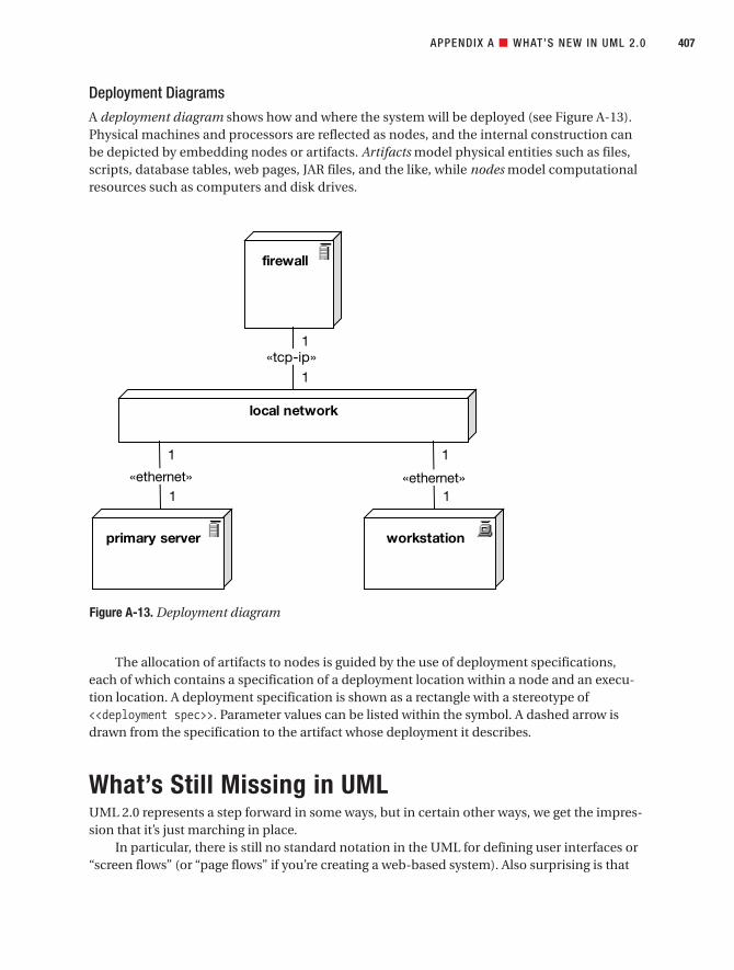
Deployment DiagramsA deployment diagram shows how and where the system will be deployed (see Figure A-13).Physical machines and processors are reflected as nodes, and the internal construction canbe depicted by embedding nodes or artifacts. Artifacts model physical entities such as files,scripts, database tables, web pages, JAR files, and the like, while nodes model computationalresources such as computers and disk drives.
The allocation of artifacts to nodes is guided by the use of deployment specifications,each of which contains a specification of a deployment location within a node and an execu-tion location. A deployment specification is shown as a rectangle with a stereotype of<<deployment spec>>. Parameter values can be listed within the symbol. A dashed arrow isdrawn from the specification to the artifact whose deployment it describes.
What’s Still Missing in UMLUML 2.0 represents a step forward in some ways, but in certain other ways, we get the impres-sion that it’s just marching in place.
In particular, there is still no standard notation in the UML for defining user interfaces or“screen flows” (or “page flows” if you’re creating a web-based system). Also surprising is that
APPENDIX A ■ WHAT’S NEW IN UML 2.0 407
Figure A-13. Deployment diagram
firewall
local network
primary server workstation
1«tcp-ip»
1
1
«ethernet»1
1
«ethernet»1
7745appACMP2.qxd 12/6/06 9:18 PM Page 407

there is still no dedicated diagram for showing data models (whether as an entity-relationshipdiagram or, well, as anything else for that matter).
These two omissions are surprising because the majority of IT projects involve creatingboth a system with a user interface and a system with a back-end database of some sort.There are plenty of diagram types out there to fill these gaps, but they really should be partof the UML itself. Here’s hoping that the next revision of the UML standardizes on thesemuch-needed diagram types.
APPENDIX A ■ WHAT’S NEW IN UML 2.0408
7745appACMP2.qxd 12/6/06 9:18 PM Page 408
Spring Bin
At several points throughout this book, we wanted to describe more about what we weredoing with Spring Framework, but doing so would have detracted from the flow of the maindiscussion (i.e., use case–driven object modeling). So, if you thrive on the technical details,we’ve put the Spring-based implementation notes in this appendix and referred to it in thetext.
Note that none of this material is vital if your main goal here is to learn about use case–driven object modeling, though. We guess that’s why this material is in an appendix . . .
Spring in More DetailIn Chapter 7, we introduced Spring from a technical architect’s perspective. In this section, weexpand on some of the technical discussions from that chapter.
A (Very) Brief Example of IoCWe introduced Inversion of Control (IoC) and its cousin, Dependency Injection (DI), inChapter 7. To illustrate IoC, here’s a straightforward Java bean with one property, propertyA:
package com.iconixsw.example;
public class MyBean {
private YourBean propertyA;
public String getPropertyA() {return propertyA;
}
public void setPropertyA(YourBean propertyA) {this.propertyA = propertyA;
}
Our property, propertyA, is of type YourBean.
409
A P P E N D I X B
7745appBCMP2.qxd 12/6/06 9:29 PM Page 409

Here’s the YourBean class that MyBean refers to via its propertyA property:
package com.iconixsw.example;public class YourBean {
private String title = "Ethel the Aardvark Goes Quantity Surveying";
public String getTitle() {return title;
}}
YourBean simply defines one read-only property called title, which always returns “Ethelthe Aardvark Goes Quantity Surveying” (a vastly underrated page-turner). To wire these twobeans together, you’d define them in some Spring-friendly XML as follows:
<bean name="myBean" class="com.iconixsw.example.MyBean"><property name="propertyA ">
<ref bean="yourBean" /></property>
</bean>
<bean name="yourBean" class="com.iconixsw.example.YourBean" />
410 APPENDIX B ■ SPRING BIN
JAVA NAMING CONVENTIONS: A 30-SECOND CRASH COURSE
If you’re unfamiliar with Java, be aware that it uses some special conventions:
• Variables (references to an object) start with a lowercase letter (e.g., propertyA, customerReview).
• Classes start with an uppercase letter (e.g., YourBean, CustomerReview).
• Variables (i.e., attributes) are typically private, meaning they can be accessed only within the class thatthey belong to.
• To access (and write to) a variable from outside its class, you add a get method and a set method (e.g.,getPropertyA(), setBook()).
• Once a variable has get and set methods, it’s known as a property.
• And (to finish our ultra-packed crash course) Java classes are organized into packages, where a pack-age is basically a folder. Packages can contain classes and other packages. Package naming is kind ofa weird thing, but it makes sense: so that different Java libraries can coexist in the same programspace, packages universally follow the reverse URL convention. In our case, the company domain isiconixsw.com. So the package name for all our classes always begins with com.iconixsw. And theproduct name is “Bookstore,” so all the classes in this product go under com.iconixsw.bookstore(note the lowercase “bookstore”). There will most likely also be subpackages—for example, DAOclasses could go into com.iconixsw.bookstore.dao. And so on . . .
7745appBCMP2.qxd 12/6/06 9:30 PM Page 410

This XML fragment defines an instance of the MyBean class called myBean, and an instanceof the YourBean class called yourBean. By default, each bean declared in a Spring XML file is asingleton (i.e., only one instance of it can exist). It’s possible to override this for each bean, butmost of the time it makes life much easier to know that there’s only one instance of each classflying around.
■Note But aren’t Singletons unfashionable these days? True, the Singleton design pattern has comeunder heavy scrutiny because it imposes some questionable constraints on your software design.1 TheSingleton design pattern ensures that only one instance of a class can exist by making the constructor pri-vate and having a static factory method that always returns the same instance of the class.
While they do work, Singletons are notoriously difficult to test. It’s impossible for a unit test class tocreate and dispose of the same Singleton class, because only the Singleton itself controls its life cycle. Onthe other hand, simply specifying that there should be only one instance of a class (i.e., making it a “single-ton,” lowercase “s”) is fairly harmless, and in a server environment it is useful. As long as the class still hasa public constructor and can be tested, then there’s no harm in it being a singleton.
When Spring initializes our one instance of MyBean, it populates the propertyA propertywith a reference to yourBean (the one instance of the YourBean class). You could therefore addsome code to MyBean that actually does something with yourBean:
public class MyBean {. . .
public void doSomething() {System.out.println(
"The title of our one mysterious bean is: "+ propertyA.getTitle()
);}
}
Notice that you don’t need to actively go and find an instance of YourBean, and you don’tneed to explicitly set a value for propertyA—you’ve “wired up” myBean to yourBean in the XML,so you know that Spring will initialize myBean’s propertyA with yourBean.
That’s the essence of IoC: “bean wiring” is fundamentally how the different componentsin Spring work with each other. In fact, if you use Spring primarily for its IoC features, it’s pos-sible to use it in a stand-alone Java program; it doesn’t have to be part of a J2EE server.However, we are, of course, using it as part of a web application, so in the next section we’llintroduce Spring’s web features.
APPENDIX B ■ SPRING BIN 411
1. For example, see www.softwarereality.com/design/singleton.jsp.
7745appBCMP2.qxd 12/6/06 9:30 PM Page 411

■Note The “flavor” of IoC that we just described is known as Dependency Injection. More specifically it’sactually Method Injection (also known as Setter Injection), because the framework “injects” the values intothe bean via their set methods. Another form of Dependency Injection (which is also supported by Spring) isConstructor Injection, in which the values are passed into the bean’s constructor. For the Internet Bookstore,we only use Method Injection.
Models,Views, and ControllersIn Chapter 7, we introduced Spring Web MVC and described the concepts of controllers, com-mand objects, views, and DAOs.
For the Internet Bookstore, the view is handled by JavaServer Pages (JSP) coupled with theJava Standard Tag Library (JSTL). In the next section, we look at Spring’s support for JSP.
ControllersController support in Spring is both flexible and extensive. However, it’s all based ultimatelyaround a single interface, as follows:
public interface Controller {
/*** Process the request and return a ModelAndView object* which the DispatcherServlet will render.*/ModelAndView handleRequest(HttpServletRequest request,
HttpServletResponse response)throws Exception;
}
The Controller interface defines a single method, handleRequest, which accepts a requestand response, and returns an appropriate model and view. The request and response objectsare both part of the J2EE Servlet API. In fact, this method should look familiar to most server-side Java programmers—the main difference between this and the HttpServlet interface is theModelAndView class it returns. In many ways, this fixes a major flaw in the original Servlet API,by decoupling the model and view from the controller. As a result, your choice of view tech-nology can vary from controller to controller.
ViewsThe view is the JSP page that will generate the HTML that the user sees. Controllers in Springgenerally return a ModelAndView object, which tells Spring which view to send back to thebrowser and what model data to populate it with.
APPENDIX B ■ SPRING BIN412
7745appBCMP2.qxd 12/6/06 9:30 PM Page 412

Let’s say you have a “book details” page that shows the details for a specific book (identi-fied by its ID). You’d have a BookDetailsController class that finds the Book matching the ID,and then returns a ModelAndView:
Book book = [ find book from somewhere . . . ]return new ModelAndView("bookdetails", "book", book);
The first line of code goes off and finds the Book, most likely via a BookDao class (see thenext section). The second line tells Spring to map the view to a JSP file called bookdetails.jsp(the .jsp part gets added by Spring, depending on how you’ve configured your web applica-tion). The second argument passed into the new ModelAndView, book, indicates that the modelfor the view will consist of a variable called book, and the third argument is the book objectitself. The book variable will then be accessible from the bookdetails.jsp page.
DAO and JDBC SupportFor the Internet Bookstore, we’ve used Spring’s support for creating “raw” JDBC DAO imple-mentations. The advantage of this approach is that we can write our own SQL to query andwrite to the database, and map the result set to our JavaBeans (i.e., our domain objects). Apotential disadvantage, however, is that code using JDBC directly tends to become quite ver-bose and repetitive (with lots of similar code for creating and discarding databaseconnections, handling update transactions, etc.).
Luckily, Spring provides some useful JDBC support classes that handle most of thistedious plumbing for you. This means that your JDBC DAOs can focus on the SQL, and on themapping between the result set and the domain objects.
Figure B-1 shows an example DAO and how it fits in with the overall design.In Figure B-1, the BookDao is used by BookDetailsController’s handle() method to find
Book objects. The DAO’s concrete implementation, JdbcBookDao, is actually mapped toBookDetailsController via the XML configuration shown earlier, and it is automatically set via the setBookDao() method when the controller object is created (another example of IoC
in action).
■Note Our final implementation may or may not need findById() and findByTitle() methods—we’llfind out when we draw the sequence diagrams (see Chapter 8).
APPENDIX B ■ SPRING BIN 413
7745appBCMP2.qxd 12/6/06 9:30 PM Page 413
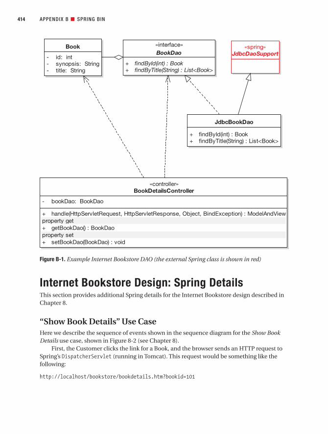
Internet Bookstore Design: Spring DetailsThis section provides additional Spring details for the Internet Bookstore design described inChapter 8.
“Show Book Details” Use CaseHere we describe the sequence of events shown in the sequence diagram for the Show BookDetails use case, shown in Figure 8-2 (see Chapter 8).
First, the Customer clicks the link for a Book, and the browser sends an HTTP request toSpring’s DispatcherServlet (running in Tomcat). This request would be something like thefollowing:
http://localhost/bookstore/bookdetails.htm?bookid=101
APPENDIX B ■ SPRING BIN414
Figure B-1. Example Internet Bookstore DAO (the external Spring class is shown in red)
7745appBCMP2.qxd 12/6/06 9:30 PM Page 414

The request tells Tomcat to hand the request to the “bookstore” web application. Thebookstore web application is configured to use Spring’s DispatcherServlet. Because of thebookdetails.htm part of the URL, Spring hands the request to BookDetailsController via thehandle(request, response, command, errors) method.
■Note The handle(..) method is actually a concrete implementation of an abstract method defined inAbstractCommandController, which our own BookDetailsController extends (see Figure B-2).
Spring also extracts the bookid parameter and puts it in a Command object, which is alsopassed into the handle(..) method. (We haven’t shown the details of Spring extracting therequest parameters and so forth, because this is already implemented in the Spring code, plusit takes place for every request that comes in. Showing this on all of our sequence diagramswould become redundant very quickly.)
Next, BookDetailsController uses its BookDao to get an instance of Book for whatever bookhas the ID 101 (“Ethel the Aardvark Goes Quantity Surveying,” perhaps). Still following thebasic course, the Book instance is returned, so BookDetailsController then creates a newModelAndView object with the parameter bookdetails (a String literal) and the new Book object.The handle(..) method then exits, returning the ModelAndView. The bookdetails parametertells Spring to find a page that matches the name bookdetails.jsp and invoke this so that thebook details are displayed to the user. Spring also hands bookdetails.jsp the Book (becausewe passed it into the ModelAndView). Still with us? Good!
■Note ModelAndView is a Spring class (notated by the fact that it’s shown in red in Figure B-2). It’s theobject returned by the Controller to indicate to the DispatcherServlet which view (JSP page) to useand what data to feed the view with. So it literally is the model and view (or, at least, references to the model and view).
Our one alternate course (shown in red in Figure 8-2) handles the case where the bookdetails weren’t found (e.g., the user might have fiddled with the URL and changed it to a non-existent book ID, or it might simply be an old link and the book no longer exists [shudder]). To handle this alternate course, BookDetailsController creates a new ModelAndView object,but instead of passing it “bookdetails”, it passes it “booknotfound”. This will tell Spring to finda matching “booknotfound” page, which as you’d expect tells the user that the book ID wasn’tfound.
APPENDIX B ■ SPRING BIN 415
7745appBCMP2.qxd 12/6/06 9:30 PM Page 415

“Write Customer Review” Use CaseHere we describe the sequence of events shown in the sequence diagram for the WriteCustomer Review use case shown in Figure 8-11.
In Figure 8-11, the Customer clicks the Write Review button (or link), which has the effectof making a request to Spring’s DispatcherServlet running in Tomcat. DispatcherServletuses the application’s XML configuration to work out which Controller to hand the requestto (we haven’t shown this detail in the sequence diagram as it’s a feature of Spring, alreadyimplemented). The servlet then calls the formBackingObject() method onWriteCustomerReviewController. This method runs some checks to make sure the Customeris logged in, and then it creates and populates the WriteCustomerReviewCommand object. Notethat if the Customer/user isn’t logged in, he or she is redirected to the Login page. (Wehaven’t shown the details for this as it would have complicated an already complex sequencediagram, but you get the general idea.)
APPENDIX B ■ SPRING BIN416
Figure B-2. BookDetailsController class hierarchy
7745appBCMP2.qxd 12/6/06 9:30 PM Page 416

WriteCustomerReviewController calls a static factory method on CustomerSession, whichin turn attempts to get a CustomerSession instance from the servlet’s HttpSession. If theinstance doesn’t exist, it creates a new one and adds it to the session.
To model this, we’ve simply added a note in Figure 8-11. Note, however, that this lack ofdetail causes a problem later and is picked up on during the example Code Review and ModelUpdate in Chapter 11.
At this stage, we’re also updating the static model as we go along. So, for example, we’vedecided that WriteCustomerReviewController will extend the Spring classSimpleFormController. We’ll show the completed class diagram near the end of the chapter.
Still following Figure 8-11, the Write Customer Review page is now being displayed to theCustomer. The Customer fills in the review details and clicks the Submit button (or the buttonmight be titled Save Review, since we don’t want our customer to willingly submit to any-thing). The form is submitted, picked up by Spring’s DispatcherServlet, validated, and finallyhanded to WriteCustomerReviewController via the doSubmitAction() method. This methodpasses in the WriteCustomerReviewCommand object that was created earlier by theformBackingObject() method (effectively providing state between the HTTP GET request,which created the form, and this POST request, which submitted the form).
Note that the form validation process is handled automatically for us by Spring. TheCustomerReviewValidator is actually wired up to our form controller in the XML config. In thesequence diagram we gloss over this slightly, because this side of things is already imple-mented for us in the Spring code.
After that, it’s smooth sailing: the form controller calls the CustomerReviewDao to save theCustomerReview domain object, and the DAO in turn adds it to the Pending Reviews Queue inthe database.
■Note It’s debatable whether the form controller should do this by calling a ReviewsQueueDao object—isit a function of the form controller or the CustomerReviewsDao to handle the application logic? In this case,it seems to simplify things if the DAO handles it. This way, if some other part of the system were to save aCustomerReview via the DAO, the logic of adding it to the queue would be already encapsulated in the DAO,not in a UI form handler elsewhere.
Internet Bookstore Implementation: Spring DetailsThis section ties in closely with the Internet Bookstore implementation described in Chap-ter 10. Here we describe the way in which the Internet Bookstore code and supporting files areorganized.
First, we’ll look at the overall folder structure. Then in the next section, we’ll examine thepackage hierarchy that we’ll use to organize our Java classes.
APPENDIX B ■ SPRING BIN 417
7745appBCMP2.qxd 12/6/06 9:30 PM Page 417
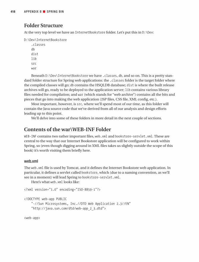
Folder StructureAt the very top level we have an InternetBookstore folder. Let’s put this in D:\Dev:
D:\Dev\InternetBookstore.classesdbdistlibsrcwar
Beneath D:\Dev\InternetBookstore we have .classes, db, and so on. This is a pretty stan-dard folder structure for Spring web applications: the .classes folder is the target folder wherethe compiled classes will go; db contains the HSQLDB database; dist is where the built releasearchives will go, ready to be deployed to the application server; lib contains various libraryfiles needed for compilation; and war (which stands for “web archive”) contains all the bits andpieces that go into making the web application (JSP files, CSS file, XML config, etc.).
Most important, however, is src, where we’ll spend most of our time, as this folder willcontain the Java source code that we’ve derived from all of our analysis and design effortsleading up to this point.
We’ll delve into some of these folders in more detail in the next couple of sections.
Contents of the war\WEB-INF FolderWEB-INF contains two rather important files, web.xml and bookstore-servlet.xml. These arecentral to the way that our Internet Bookstore application will be configured to work withinSpring, so (even though digging around in XML files takes us slightly outside the scope of thisbook) it’s worth visiting them briefly here.
web.xmlThe web.xml file is used by Tomcat, and it defines the Internet Bookstore web application. Inparticular, it defines a servlet called bookstore, which (due to a naming convention, as we’llsee in a moment) will lead Spring to bookstore-servlet.xml.
Here’s what web.xml looks like:
<?xml version="1.0" encoding="ISO-8859-1"?>
<!DOCTYPE web-app PUBLIC"-//Sun Microsystems, Inc.//DTD Web Application 2.3//EN""http://java.sun.com/dtd/web-app_2_3.dtd">
<web-app>
APPENDIX B ■ SPRING BIN418
7745appBCMP2.qxd 12/6/06 9:30 PM Page 418

<servlet><servlet-name>bookstore</servlet-name><servlet-class>
org.springframework.web.servlet.DispatcherServlet</servlet-class><load-on-startup>1</load-on-startup>
</servlet>
<servlet-mapping><servlet-name>bookstore</servlet-name><url-pattern>*.htm</url-pattern>
</servlet-mapping>
<welcome-file-list><welcome-file>index.jsp</welcome-file>
</welcome-file-list>
</web-app>
The <servlet> tag and its contents define the bookstore servlet. The class for thebookstore servlet isn’t actually one of our classes—it’s Spring’s DispatcherServlet.DispatcherServlet will use the servlet name to determine where to get its configuration from;basically it appends -servlet.xml to the name, in this case giving us bookstore-servlet.xml.
The <servlet-mapping> tag tells Tomcat that any browser requests whose page ends in.htm should be handed over to the bookstore servlet (in other words, to DispatcherServlet).This is an important point: our application doesn’t actually contain any files ending in .htm.These are “virtual” files, used purely for mapping browser requests to Controllers. The actualmapping is done in bookstore-servlet.xml, which we’ll get to in just a moment.
The third and final part of web.xml is the <welcome-file-list> tag. This simply tells Tom-cat that if a request doesn’t specify a filename, then it should default to index.jsp.
bookstore-servlet.xmlThe main purpose of bookstore-servlet.xml is to collectively define all the various beans(Java classes) needed in order to make the bookstore servlet hang together. So for the mostpart, it consists almost entirely of <bean> tags. We return to it periodically in Chapter 10 andadd more configuration to it as we create the new classes (aka beans).
<?xml version="1.0" encoding="UTF-8"?><!DOCTYPE beans PUBLIC "-//SPRING//DTD BEAN//EN"
"http://www.springframework.org/dtd/spring-beans.dtd">
<!--- Application context definition for "bookstore" DispatcherServlet.-->
APPENDIX B ■ SPRING BIN 419
7745appBCMP2.qxd 12/6/06 9:30 PM Page 419

<beans><bean id="dataSource"
class="org.springframework.jdbc.datasource.DriverManagerDataSource"><property name="driverClassName">
<value>org.hsqldb.jdbcDriver</value></property><property name="url">
<value>jdbc:hsqldb:file:D:\Dev\TravelBookstore\db\data\test</value></property><property name="username">
<value>matt</value></property><property name="password">
<value>pass</value></property>
</bean>
<bean id="viewResolver" class="org.springframework.web.servlet.view.InternalResourceViewResolver">
<property name="viewClass"><value>org.springframework.web.servlet.view.JstlView</value>
</property><property name="prefix">
<value>/WEB-INF/jsp/</value></property><property name="suffix">
<value>.jsp</value></property>
</bean>
<bean id="homeController"class="com.iconixsw.bookstore.web.HomeController"/>
<bean id="urlMapping"class="org.springframework.web.servlet.handler.SimpleUrlHandlerMapping">
<property name="mappings"><props>
<prop key="/home.htm">homeController</prop></props>
</property></bean>
</beans>
The first bean, dataSource, defines the JDBC data source: the DataSource class that willmanage the whole database connecting thing for us, the driver class, a URL pointing to ourlocal HSQLDB file, and the database username and password.
APPENDIX B ■ SPRING BIN420
7745appBCMP2.qxd 12/6/06 9:30 PM Page 420

The second bean, viewResolver, overrides the default Spring InternalResourceView class.Instead, we want to use the JstlView class, which allows us to put JSTL tags in our JSP pages.viewResolver also defines a couple of other properties, prefix and suffix:
• prefix is given the value /WEB-INF/jsp/, meaning that the view files (our JSP pages) willbe kept in the WEB-INF/jsp folder.
• suffix is given the value .jsp, meaning that all the view files will end in .jsp.
For example, if a view is identified as “home,” then the actual view file will be /WEB-INF/jsp/home.jsp.
The third bean, homeController, is (at last!) one of our classes, and was identified duringthe design for the Show Book Details use case. The declaration is saying that we want a singleinstance of the class HomeController, and if it’s to be referred to by other beans in the XMLconfiguration, it will be referred to using the ID homeController. HomeController is simplythere to return the main (“home”) view page, so it doesn’t do a huge amount.
The fourth bean, urlMapping, uses one of the Spring classes to map HTTP requests toControllers. Currently there’s only one mapping set up: we’re telling the HandlerMapping classthat if a request arrives for a virtual page called home.htm, then the request should be handedto a bean called homeController. Hey, and as luck would have it, we’ve just defined a beancalled homeController.
Back to the remaining folders.
Contents of the war\WEB-INF\jsp and war\WEB-INF\jsp\include FoldersWEB-INF\jsp contains the JSP files (the “view”). Because the JSP files are located beneathWEB-INF, they can’t be accessed directly by the user’s web browser. Instead they are invoked ina controlled fashion by Spring, which sends the output from the JSP back to the browser.
WEB-INF\jsp\include currently just contains one file, IncludeTop.jsp. This is “included”by each one of our JSP files, and it contains the standard stuff that goes at the top of each page,to avoid repetition.
Here’s what IncludeTop.jsp looks like:
<%@ page contentType="text/html" %><%@ taglib prefix="c" uri="http://java.sun.com/jstl/core" %><%@ taglib prefix="fmt" uri="http://java.sun.com/jstl/fmt" %><%@ taglib prefix="spring" uri="http://www.springframework.org/tags" %>
<html><head>
<title>ICONIX Internet Bookstore</title><meta content="text/html; charset=windows-1252" http-equiv="Content-Type" /><link rel="stylesheet" href="elements/bookstore.css" />
APPENDIX B ■ SPRING BIN 421
7745appBCMP2.qxd 12/6/06 9:30 PM Page 421
<META HTTP-EQUIV="Cache-Control" CONTENT="max-age=0"><META HTTP-EQUIV="Cache-Control" CONTENT="no-cache"><meta http-equiv="expires" content="0"><META HTTP-EQUIV="Expires" CONTENT="Tue, 01 Jan 1980 1:00:00 GMT"><META HTTP-EQUIV="Pragma" CONTENT="no-cache">
</head>
<body bgcolor="white"><h1>ICONIX Internet Bookstore</h1>
<div class="navbar"><a href="home.htm">Home</a> |<a href="search.htm">Search</a>
</div>
It’s worth stepping through this file, as it contains a bunch of interesting stuff. The firstline, a JSP tag, simply states that this will be an HTML file. The next two lines import the JSTLtag libraries, and the line after them imports Spring’s tag libraries.
■Note JSTL stands for JSP Standard Tag Library, and it provides core functionality common to many webapplications. Common tasks such as iteration (for/while loops), conditionals (if...then...else), XMLmanipulation, and internationalization are included and can be dropped into your JSP page as simple tags.You can find out more about JSTL at http://java.sun.com/products/jsp/jstl.
Next, the top part of the page is begun, with familiar HTML tags such as <html>, <head>,and <body>.
You’ll notice that there are five lines that begin with <META HTTP-EQUIV=. These collectivelytell the web browser not to cache any of these pages, but always to request the latest versionfrom the server.
Because this is all defined in a shared include file, all of our pages will have the same title,heading, navigation bar, cache settings, and so on.
Java Package HierarchyAll of the classes we’ve identified in our design need to be organized into Java packages.
Each package is a folder in the local file system. The choice of package structure is prettymuch up to you, though it makes sense to follow whatever conventions are used by the frame-work that you’re coding to.
For the Internet Bookstore, the package hierarchy looks like this (located directly beneaththe src folder):
APPENDIX B ■ SPRING BIN422
7745appBCMP2.qxd 12/6/06 9:30 PM Page 422

comiconixsw
bookstoredao
jdbcdomain
logicweb
Packages are referred to in Java using dot notation so, for example, the full name for thedao package is com.iconixsw.bookstore.dao. The physical folder structure for this package (at least in the Windows file system) would be com\iconixsw\bookstore\dao.
As we described in the “Java Naming Conventions: A 30-Second Crash Course” sidebarearlier in this appendix, package names follow a reverse URL convention, so the company’sdomain name is iconixsw.com and the application name is bookstore, hencecom.iconixsw.bookstore.
Here’s a quick rundown of each of the packages beneath bookstore:
• The dao package contains the DAO interfaces (the “home objects” for retrieving domainobjects from the data source).
• The dao.jdbc subpackage contains a concrete implementation of the DAO interfacesfor HSQLDB via JDBC. The DAO design pattern makes it relatively easy to migrate yourapplication to some other database with relatively little rework.
• The domain package contains the domain classes, which in our design are doubling asController classes. Form validators go in the domain.logic subpackage.
• The web package contains all of the Controller classes.
Now that we’ve set up our package structure and basic configuration, we can start to cre-ate the “real” implementation (see Chapter 10).
APPENDIX B ■ SPRING BIN 423
7745appBCMP2.qxd 12/6/06 9:30 PM Page 423

7745appBCMP2.qxd 12/6/06 9:30 PM Page 424

■AAbstractCommandController class, 274acceptance testing, 333Acegi Security, 179actors
adding a Customer actor to a robustnessdiagram, 117
as external to the system, 54as fulfilling several roles, 54modeling external systems as, 35placing on use case diagrams, 32representing nonhuman external systems, 54roles of, in use case diagrams, 53
Add External Books to Catalog use case, 128,218
adding operations to domain objects, 4addToPendingReviewsQueue(), 284AddToShoppingCartTest test case, 340advices, 74aggregation (has-a) relationship, 24, 27, 33algorithms, differentiating from use cases, 76alternate courses
displaying in a different color on robustnessdiagrams, 110
Login use case, example robustness diagram,110
modeling in a robustness diagram, 122analysis and preliminary design phase, 3, 9analysis paralysis, 175anemic domain model, 242architectural layering
architectural diagrams, examples of, 162definition of, 162horizontal vs. vertical layers, 163UML class diagrams, 164
architectural paralysis, 180arrows
as communication associations onrobustness diagrams, 108
showing data flow or control flow, 108aspect-oriented programming (AOP), 74
defining cross-cutting concerns throughcode, 171
as extending object-oriented programming(OOP), 171
problems with, 172assert methods, in JUnit, 339assertEquals(), arguments used, 340attributes, discordant, 205avoiding dysfunctional requirements, 6
■BBeck, Kent, 351behavioral requirements, 3–4, 7Beizer, Boris, 334beta testing, 333BillyBob 2.0, requirements for, 379Book class
distribution of responsibilities in, 238as an unused object on a sequence diagram,
246Book.java, code example, 266BookDao, 243, 255bookdetails.jsp, 274, 277BookDetailsCommand, 240BookDetailsController, 240, 243, 272–273, 275,
305, 359–360, 362bookstore-servlet.xml, 287, 290, 315, 419–421bookstore.css, 265boundary objects, 8, 187
definition of, 103disambiguated nomenclature of, 108referencing by name in use cases, 52, 61treating as nouns, 103
building a project glossary, 7
■CcallTestHandle(), 365Carnegie Mellon Software Engineering Institute,
161CASE tools, 57, 105, 193, 203, 260CDR guidelines, 15checkBookFound(), 358checkRating(), 319checkReviewLength(), 318checkTitleLength(), 318class attributes, relationship to database tables,
29class diagrams, 4
adding getters and setters to, 211conventions of, 164domain model and, 24, 28–29finishing the updating of, 127keeping static and dynamic models in sync,
211tidying up for a clearer layout, 255updating and refining, 210using to find errors on sequence diagrams,
238class notation, types of, 27classes
allocating behavior to, 188assigning operations to, 125distribution of responsibilities among, 239
Index
425
7745idxfinal.qxd 12/13/06 8:50 PM Page 425

organizing around key abstractions in theproblem domain, 28
relationship to use cases, 51searching for classes without attributes, 236subclasses and superclasses, 37
cleaning up the static model, 14Code Review and Model Update
accumulating boilerplate checklists forfuture reviews, 299–300
avoiding review and update paralysis, 299,301
breaking down list items into a smallerchecklist, 299
catching design or integration issues early,298
code review vs. code inspection, 302comparing the code with the design
diagrams, 298conducting a productive code review, 301creating a high-level list of review items (use
case titles), 299emailing action points to all participants,
299–300focusing on error detection, not error
correction, 299–300frequency of, 298guidelines, 299keeping the review just formal enough, 299,
301not forgetting the Model Update session,
299, 301preparing for, 299purpose of, 298quickly addressing disparities between code
and design, 303reusing objects in the domain model, 298reviewing code at different levels, 299–300syncing code with design, 297updating and refining the static model, 298using an integrated code/model browser,
299, 301value of up-front design, 303why code reviews are necessary, 302–303
Code Review and Model Update guidelines, 18coding and testing, 4, 15collaboration diagrams
function of, 109not confusing with robustness diagrams,
107–108purpose of, 107
Command objects, definition of, 168commenting code, 259, 262compatibility testing, 333Constructor Injection, 412Controller interface, 412controller objects
lack of, on sequence diagrams, 187using sparingly, 108
controllers, 3, 11, 412creating test cases for, 109definition of, 103ensuring proper test coverage for, 350as logical software functions, 11
as methods on the boundary and entityclasses, 109
names of, 120as real control objects, 11renaming those with the same name on a
diagram, 345running test cases for data-retrieval
controllers, 356Show Book Details use case, 351treating as verbs, 103
Create New Book use case, 219Create New Customer Account use case, 128Critical Design Review (CDR), 4, 15
allocating operations to classesappropriately, 235–236
centralizing responsibility in a class, 240checking for continuity of messages, 234checking for entity classes without
attributes, 251checking that operations are complete and
correct, 235, 237coupling object-oriented encapsulation with
RDD, 239covering both basic and alternate courses of
action, 235–236determining if the sequence diagram
matches the class diagram, 250discovering unexplored areas in the analysis
space, 251distribution of responsibilities in the Book
class, 238ensuring that the sequence diagram matches
the use case text, 234–236generating and inspecting the code headers
for classes, 235, 237generating skeleton tests from the
robustness diagram, 238guidelines, 235having all patterns reflected on the sequence
diagram, 235, 237identifying a stable set of abstractions, 249identifying attributes from functional
requirements, 251ironing out leaps of logic between objects,
234limiting to designers and developers, not
customers, 234minimizing code breakage and refactoring,
249performing a sanity check on the design,
235, 237primary goals, 234reviewing the attributes and operations on
classes, 235–236reviewing the quality of the design, 234reviewing the test plan for the release, 235,
237searching for classes without attributes, 236setting the starting time for, 235Show Book Details use case, 238tracing functional requirements to use cases
and classes, 235, 237
■INDEX426
7745idxfinal.qxd 12/13/06 8:50 PM Page 426

using class diagrams to find errors onsequence diagrams, 238
Write Customer Review use case, 245cross-cutting concerns
extension use cases, 74infrastructure use cases, 74peer use cases, 74
CustomerReview, 247, 311CustomerReviewValidator class, 311CustomerSession class, 179, 287
■DData Access Objects (DAOs), 165, 169–170, 175data analysis and reduction, definition of, 378data capture, definition of, 378Data Definition Language (DDL), 259data model, 161data reporting, definition of, 378database tables, relationship to class attributes,
29Dependency Injection (DI), 409, 412deployment model, 161, 173, 175design as building the system right, 9Design-Driven Testing (DDT)
acceptance testing, 333adding a tearDown() method, 350AddToShoppingCartTest test case, 340adopting a testing mind-set, 330aligning tests closely to requirements, 331avoiding duplicating alternate course
scenarios, 369avoiding duplication in tests, 343beginning testing before coding, 369beta testing, 333compatibility testing, 333covering basic and alternate courses in
scenario testing, 331creating a resource in the test method itself,
349creating unit tests for each controller on a
robustness diagram, 330DDT errors, list of, 369different types of testing, 330discovering alternate courses during, 338doing requirement-level verification, 331doing scenario-level acceptance testing, 331driving unit tests from test cases, 338driving unit tests from use cases, 330ensuring that each test method tests exactly
one thing, 342finding and fixing buggy code, 370function of, 329generating test skeleton code for unit testing,
334guidelines, 330identifying and targeting “test hot spots”, 370identifying test cases using robustness
diagrams, 329, 334identifying the test scenarios for each
controller/test case, 335integration testing, 333keeping unit tests fine-grained, 331, 342linking one test case to each controller, 336
mapping test cases directly to JUnit testclasses, 339
mock objects, testing with, 354neglecting to fix a failing test, 343nonfunctional requirements testing, 333not writing tests that connect to external
resources, 353performance testing, 334practice questions to test your knowledge,
370–371preparing for, during the analysis stage, 329programmers’ attitudes toward, 331proving a test by trying to make it fail, 348regression testing, 334release testing, 333running tests from a test suite, 350stress testing, 334system testing, 333testing paralysis, 370transforming a robustness diagram into a
test case diagram, 334treating unit test code with reverence, 342tying closely to requirements, 329tying unit tests to the preliminary design
objects, 342understanding the tests required at each life
cycle stage, 331unit test skeletons, guidelines for creating,
338unit testing, 332using “realize” connectors, 334using a testing framework, 331using a traceability matrix, 331using mock objects sparingly, 343, 369using the Agile ICONIX/EA add-in to
generate diagrams, 336volume testing, 334why bother with designing unit tests, 366writing effective unit tests, 342–343writing tests from the calling object’s point of
view, 338, 347, 358writing tests to validate and hone the design,
369detailed design phase, 3, 12, 186discordant attributes, 205DispatcherServlet, 167, 174–176, 178, 269, 271,
306, 347, 415–416, 419Display Book Not Found page controller, 345Display controllers
initialization behavior and, 111necessity for, on robustness diagrams, 111
DisplayBookDetailsPageTest, 365doesBookIDExist(), 247domain classes, 7, 24, 27, 30
candidates for the Internet Bookstore, 33referencing by name in use cases, 52, 59
domain model, 11assumed to be incomplete, 28class diagrams and, 24, 28–29creating before use cases, 29definition of, 24deliberate simplicity of, 29disambiguating, 29
■INDEX 427
Find it faster at http://superindex.apress.com/
7745idxfinal.qxd 12/13/06 8:50 PM Page 427
domain classes and, 24, 30feeding updated information and changes
back into, 51identifying attributes to be added to classes,
125not mistaking for a data model, 28refining and updating throughout a project,
23relationship to use cases, 25removing UI elements from, 32showing aggregation and generalization
relationships, 24, 27updating after identifying a new domain
object, 122updating incrementally while drawing
robustness diagrams, 125using as a project glossary, 24, 26, 29when to update, 51
domain model diagramscreating, 33, 35ensuring coverage of the problem domain,
85showing generalization and aggregation
relationships, 86using a link class, 86
domain modeling, 3creating the initial model in two hours, 28definition of, 7distinguishing domain models from data
models, 7exercises and solutions for spotting
modeling errors, 39–42, 44–45focusing on real-world objects within the
problem domain, 26guidelines, 7, 26identifying and eliminating duplicate terms,
32practice questions in modeling, 45–46static and dynamic parts of, 25
DomainObject interface, 315doSubmitAction(), 283, 290dot notation, 423drawing a robustness diagram, 3, 11driving test cases from the analysis model, 20DUnit, 339dynamic workflows, 2dysfunctional requirements, definition of, 375
■EEdit Customer Review use case, 324Edit Shopping Cart use case, 220Enterprise Architect (EA), 57, 89, 105, 112, 238,
260adding a test case scenario in, 345, 352built-in features for managing requirements,
382creating a requirements tree, 385creating an extended class diagram, 384custom UML elements, 383dragging elements from the Project View, 384dragging requirements onto the use case,
382external requirements, definition of, 383
generating a requirements traceabilitymatrix automatically, 374
Hierarchy window, 386importing requirements from a comma-
separated value (CSV) file, 383internal requirements, definition of, 383linking any model element to a requirement,
386Move External button, 383opening the Properties dialog, 383organizing functional requirements in, 379Relationship Matrix, using, 388Require tab, 382–383requirements for BillyBob 2.0, 379supporting requirements using a visual
modeling tool, 382turning internal requirements into external
ones, 383use cases and domain model for BillyBob
2.0, 380using the Agile ICONIX/EA add-in to
generate diagrams, 336using to generate Spring-ready Java code,
165Enterprise JavaBeans (EJB), disadvantages of,
166entity objects, 187
definition of, 103treating as nouns, 103
entity-relationship (ER) diagrams, 214Errors object, 290extended class diagrams, creating, 384“extends” association, 64, 66, 69external requirements, in Enterprise Architect
(EA), 383external systems, modeling as actors, 35
■Ffacilitator/moderator, benefits of, 88findByCustomerId(), 286findById(), 243, 286flowcharts, not drawing on sequence diagrams,
189focus of control, 187–188, 192formBackingObject(), 280–283, 320–321Fowler, Martin, 242functional requirements, 3
■Ggeneralization (is-a) relationship, 24, 27
notation for, 37getCommandClass(), 241getCustomer(), 288getCustomerSession(), 288GUI prototypes, 51, 56, 87
■Hhandle(), 272, 305, 358handleRequest(), 347–348Hibernate, 166, 260Hierarchy window, 386home.jsp, 269, 271
■INDEX428
7745idxfinal.qxd 12/13/06 8:50 PM Page 428

HomeController, 268, 347–348HSQL database, 176
use of, in-memory persistence mode, 165HttpServlet interface, 412HttpUnit, 179
■IiBATIS, 166ICONIX Process
acceptance testing, 333adding operations to the domain objects, 4allocating behavior to classes, 188analysis and preliminary design phase, 3, 9analysis as building the right system, 9avoiding dysfunctional requirements, 6behavioral requirements, 3–4, 7beta testing, 333boundary classes, 8CDR guidelines, 15class diagram, 4cleaning up the static model, 14Code Review and Model Update guidelines,
18coding and testing, 4, 15compatibility testing, 333completing refactoring before coding, 351controllers, 3, 11Critical Design Review (CDR), 4, 15depicting how objects interact, 188design as building the system right, 9detailed design phase, 3, 12domain modeling, 3, 7, 11drawing a robustness diagram, 3, 11driving test cases from the analysis model, 20dynamic workflows, 2entities, 4extensions to, 19finalizing the distribution of operations
among classes, 188functional requirements, 3implementation (coding) guidelines, 17implementation phase, 4, 15improving by ongoing iteration and
refinement, 35initial domain model as normally
incomplete, 106integration and scenario testing, 4, 18, 333as an intensely feedback-driven process, 96interaction scenarios, 19iterative nature of, 2Model-View-Controller (MVC) architecture,
167naming the logical software functions
(controllers), 3nonfunctional requirements testing, 333organizing use cases into packages, 9overview of, 2performance testing, 334performing a Code Review and Model
Update, 4persona, definition of, 19prefactoring designs, 14Preliminary Design Review (PDR), 3, 12
preliminary design steps, 9preventing entropy (code rot), 18regression testing, 334release testing, 333requirements definition phase, 4requirements gathering guidelines, 6Requirements Review, 3, 8robustness analysis, 3, 11as a scenario-based approach, 7screen mockups, 8sequence diagramming, 3, 14, 188showing generalization and aggregation
relationships, 9static model, 4static workflows, 2storyboarding the GUI, 3, 7stress testing, 334suitability to agile projects, 2syncing code with design, 297system testing, 333Test-Driven Development (TDD), 19types of tests and when to apply them, 332UML 2.0 extensions and, 396understanding the tests required at each life
cycle stage, 331unit testing, 17, 332updating the domain model, 3use case modeling guidelines, 8volume testing, 334
implementation, 4, 15coding as a design review stage, 272correcting wrong coding, 258driving the code directly from the design, 259fixing design problems immediately, 259–260following the same coding conventions, 260guidelines, 17, 259holding regular code inspections, 259–260including alternate courses on sequence
diagrams, 259, 263keeping the design and code in sync, 259,
261not leting framework issues drive business
issues, 259, 261overcommenting code, 259, 262practice questions in programming and
delivery, 294–295preventing code from getting out of control,
259, 261programmer-driven design, 258questioning a framework’s design choices,
259, 261Show Book Details use case, 268Write Customer Review use case, 278writing code and unit tests at the same time,
259, 262, 329“includes” association, 64, 69initData(), changing, 355integration and scenario testing, 4, 18, 333interaction scenarios, 19intermangling, definition of, 375internal requirements, in Enterprise Architect
(EA), 383
■INDEX 429
Find it faster at http://superindex.apress.com/
7745idxfinal.qxd 12/13/06 8:50 PM Page 429

Internet Bookstoreaccounting for alternate courses of action, 93action list following the Code Review and
Model Update, 322actors, 53Add External Books to Catalog use case, 128adding a MockBookDao class, 354adding a tearDown() method, 350adding assert statements into the test
methods, 361adding individual tests to the test suite, 351adding new properties and operations to
entity classes, 267adding save() onto CustomerReview, 321addToPendingReviewsQueue(), 284analyzing basic and alternate courses, 72–73anemic domain model, 242avoiding overly abstract use case text, 93Book class, 238, 266Book Details Not Found page controller, 308Book Not Found page displayed test
scenario, 363Book.java, code example, 266BookDao, 243, 255, 275bookdetails.htm, 270bookdetails.jsp, 274, 277BookDetailsCommand, 240, 255BookDetailsController, 240, 243, 270,
272–273, 275, 305, 360, 362bookstore-servlet.xml, 275, 283, 287, 290,
315, 419–421bookstore.css, 265boundary classes and display(), 212bridging the modeling and development
environments, 324browser request, flow of events, 178–179callTestHandle(), 365candidate domain classes, 33catching a NotFoundException, 309changing statements from passive to active
voice, 95checkBookFound(), 358, 360checkRating(), 319checkReviewLength(), 318checkTitleLength(), 318cheering a failing test, 356clarifying relationships between domain
classes, 38code generation and CASE tools, 260Command classes, 216completed sequence diagram, 208constructor detail as commonly missed, 310Controller classes, 216controller layer, 175Create New Customer Account use case, 128creating a BookDetailsController object, 359creating a first domain model diagram, 33creating a persistent object model using
JavaBeans, 169creating a resource in the test method itself,
349creating a second domain model diagram, 35
creating a single BookstoreValidator class,313
creating the database, 263Customer class, 266CustomerDao, 255CustomerReview, 216, 247, 255, 266, 279, 284,
311CustomerReviewDao class, 284CustomerReviewValidator class, 311CustomerSession class, 179, 206, 287Data Access Objects (DAOs), 165, 169–170,
175, 216, 413dataSource property, 275defining and separating architectural layers,
172, 174–176delegating behavior into helper classes, 243deployment model, 175determining if the sequence diagram
matches the class diagram, 250direct mapping between JavaBeans and
domain classes, 169discovering additional domain objects, 35DispatcherServlet, 167, 174–176, 178, 216,
271, 306, 347Display Book Details controller, test class
skeleton, 358DisplayBookDetailsPageTest, 365DisplayBookNotFoundPageTest, refactored,
368dividing code into smaller, well-named
methods, 320doesBookIDExist(), 247domain classes and database dependencies,
176DomainObject interface, 315doSubmitAction(), 283, 290Edit Customer Review use case, 324ensuring proper test coverage for controllers,
350entity classes and database tables, 266.error style, 265Errors object, 290examining the handle() method, 305expecting to add new functionality, 324exposing leaps of logic in the design, 310extracting domain classes from high-level
requirements, 30–33filling in implementation details on
sequence diagrams, 208findByCustomerId(), 286findById(), 243, 286forgetting to code an alternate course of
action, 316formBackingObject(), 280–283, 320–321generating the entity classes for Spring, 260getCommandClass(), 241getCustomer(), 288getCustomerSession(), 288getting “atomic” on the sequence diagram,
317handle(), 272, 358handleRequest(), 347–348
■INDEX430
7745idxfinal.qxd 12/13/06 8:50 PM Page 430

handling an unused object on a sequencediagram, 246
handling the “validation” controllers, 311home.jsp, 269, 271HomeController class, 268, 271how the home page is displayed, 271HSQL database, 165, 176identifying a stable set of abstractions, 249implementing the home page (home.jsp),
268IncludeTop.jsp, 270, 277, 421index.jsp, 271initData(), changing, 355insufficiently detailed sequence diagram,
243invoking a use case from a sequence
diagram, 245isLoggedIn(), 288isUserLoggedIn(), 206, 212Java package hierarchy, 422–423Java Standard Tag Library (JSTL), 412, 422JavaServer Pages (JSP), 165, 179, 412JdbcBookDao class, 275JdbcCustomerReviewDao class, 284JSP Tag Library (JSTL), 165load(), 240, 243Login use case, 105, 122Login use case, example robustness diagram,
110mapping browser requests to Controllers,
419mapping entity classes to implementation
classes, 266minimizing code breakage and refactoring,
249Model-View-Controller (MVC) architecture,
165, 167ModelAndView object, 178, 216, 272Moderate Customer Reviews use case, 122Moderate Pending Reviews use case, 324moving the validation code into
CustomerReview, 315naming participating domain objects, 92not creating a Validator class for every
domain class, 313not generating SQL from the domain model,
259organizing use cases into packages, 61overall folder structure, 418picking up warning signs from sequence
diagrams, 305prefix and suffix properties, 421preparing the style sheet, 265problems with a single “blanket” validation
method, 316proving a test by trying to make it fail, 348removing out-of-scope information, 90Retrieve Book Details controller, test class
skeleton, 353reversing the relationship between Book and
CustomerReview, 322reviewing the Show Book Details use case,
304
reviewing the Write Customer Review usecase, 309
root cause of the “swarms of tiny classes”problem, 311
running test cases for data-retrievalcontrollers, 356
running the BookstoreTestSuite from thecommand line, 350
save(), 286Search for Books use case, 131setBookDao(), 243, 359setUp(), 354Show Book Details sequence diagram, 347Show Book Details use case, 268, 292, 344,
414–415Show Book Details use case, CDR example,
238Show Book Details use case, robustness
diagram, 115, 126Show Book Details use case, updated
sequence diagram, 252ShowBookTestHelper, 368showing HttpSession on the sequence
diagram, 206showValidationErrors(), 213Spring Framework, 165Spring Web MVC, 165, 167testability, 179testBookDetailsFound(), 362testBookIdFound(), 353testBookIdNotFound(), 353testDisplayHomePage(), 346testing HomeController, 347–348testing that a book was not found, 356testing the Display Book Details controller,
357testing the Display Book Not Found page
controller, 363testing the Display Home Page controller,
345testing the Retrieve Book Details controller,
352testing to retrieve a book using its ID, 354testPageDisplayed(), 359–360, 362tracing individual requirements to use cases,
96tracking the source of the book’s ID, 305turning controllers into methods on
sequence diagrams, 317UML model for, 324updated static model, 126, 210–211user authentication/authorization, 179using a Code Review and Model Update
checklist, 304using Java for, 165using Java’s reflection API, 314validate(), 289, 313validation controllers, 133view (presentation) layer, 173, 175view page (bookdetails.jsp), 274, 277web security, 179WEB-INF folder, 418, 421web.xml, 418–419
■INDEX 431
Find it faster at http://superindex.apress.com/
7745idxfinal.qxd 12/13/06 8:50 PM Page 431

when the use case text and robustnessdiagram don’t match, 246
why bother with designing unit tests, 366Write Customer Review use case, 278, 344,
416–417Write Customer Review use case, CDR
example, 245Write Customer Review use case, reviewing
the controllers, 309Write Customer Review use case, robustness
diagram, 117Write Customer Review use case, updated
sequence diagram, 252Write Reader Review use case, 70–71writecustomerreview.jsp, 290WriteCustomerReviewCommand, 247, 255WriteCustomerReviewController class, 279,
284, 290, 310WriteReviewScreen class, 213writing tests from the calling object’s point of
view, 338, 347, 358writing unit tests prior to coding, 344
Inversion of Control (IoC)Dependency Injection (DI), 409, 412design pattern, 166, 283Java bean example with one property, 409wiring beans together, 411
“invokes” association, 63, 69isLoggedIn(), 288
■JJ2EE Servlet API, 412Java
classes, 410dot notation, 423naming conventions, 410object naming conventions, 275packages and subpackages, naming
conventions, 410property, 410reverse URL convention, 410, 423variables, 410
Java Data Objects (JDO), 166Java Standard Tag Library (JSTL), 412, 422Java Swing, 166JavaBeans, 165JavaServer Pages (JSP), 165–166, 412
testing, 179JDBC, 166, 258JdbcBookDao class, 275JDO, 260JGenerator, 260JSP Tag Library (JSTL), 165Jumpstart training workshops, 88JUnit, 18, 331, 334
adding individual tests to the test suite, 351AddToShoppingCartTest test case, 340assert methods, 339assertEquals(), arguments used, 340introduction to, 339limiting each test method to a single assert
statement, 339
mapping test cases directly to Java testclasses, 339
naming convention followed, 339new features in version 4.0, 341operation of, 339running tests from a test suite, 350setUp(), 340–341suite(), 350tearDown(), 341test skeleton, 346testDisplayHomePage(), 346TestRunner, 350unit test class, code example, 339website of, 339
■Llink class, 86linking use cases to objects, 11load(), 240, 243Login use case, 105, 110, 122
■Mmanager classes, 108MDG Integration, 195, 262messages
differentiating among programminglanguages, 189
labeling on sequence diagrams, 188, 194passing, 187
Method Injection, 412Microsoft Visual Studio 2005, 262miscommunication in IT projects, 23mock objects
testing with, 354using sparingly, 343, 354, 369
MockBookDao class, 354Model-View-Controller (MVC) architecture,
165, 167ModelAndView object, 168, 178, 412, 415modeling aggregation and generalization
relationships, 28Moderate Customer Reviews use case, 122Moderate Pending Reviews use case, 324multiplicity, using, 214
■Nnaming the logical software functions
(controllers), 3nonfunctional requirements testing, 333NotFoundException, 309NullPointerException, 354NUnit, 334, 339
■Oobject discovery, 106object instances, 59object lifelines, 187object model, use cases and, 25object-oriented design (OOD), sequence
diagrams and, 185object-relational mapping (ORM), 166
■INDEX432
7745idxfinal.qxd 12/13/06 8:50 PM Page 432

objectsclassification of, 101definition of, 25
operation, UML definition of, 189organizing use cases into packages, 9, 85–86
■Ppackage/component model, 161, 173packages, 410, 422
definition of, 61performance testing, 334performing a Code Review and Model Update, 4persona, definition of, 19Plain Old Java Objects (POJOs), 165pointcuts, 74“precedes” association, 63, 66, 69, 91prefactoring designs, 14preliminary design, 51
robustness analysis and, 102Preliminary Design Review (PDR), 3, 12preliminary design steps, 9preventing entropy (code rot), 18problem domain, 26, 249problem space, describing, 29problem space classes, 201project glossary, 24, 26project requirements, ongoing changeability of,
28Properties dialog, Enterprise Architect (EA), 383property (in Java), 410
■RRational Rose, 57, 196Rational XDE, 260real-time systems
using elements on state diagrams to buildtest cases, 330
Realization relationship, 386refactoring, 351regression testing, 334Relationship Matrix, 388release testing, 333requirements gathering
allocation and traceability as a life cycleconcern, 378
avoiding dysfunctional (intermangled)requirements, 374–375
avoiding the “big monolithic document”syndrome, 374, 377
creating estimates from use cases orcontrollers list, 374, 377
data analysis and reduction, definition of,378
data capture and data reporting, definitionsof, 378
different corporate strategies for handling,373
distinguishing between types of requirementspecs, 374, 376
drag-and-drop linking of elements back torequirements, 374
driving requirements from business needs,not design patterns, 374, 377
giving each requirement a short, catchyname, 374, 376
guidelines, 6, 374intermangling of requirements and scenario
text, 375–376practice questions in, 389removing dysfunctionality from
requirements, 376separating active-voice use cases from
passive-voice requirements, 375traceability of requirements, 378using examples when writing functional
requirements, 374, 377using modeling tools supporting linkage and
traceability, 374why requirements tracking is vital, 377writing at least one test case for each
requirement, 374, 376Requirements Review, 3, 8
accounting for alternate courses of action, 93achieving basic agreement among all
stakeholders, 88actively describing user interactions and
system responses, 95allocating functional requirements to use
cases, 89avoiding overly abstract use case text, 93avoiding passive-voice functional
requirements in use cases, 85–86benefits of a facilitator/moderator, 88changing statements from passive to active
voice, 95as a collaborative review among project
stakeholders, 83creating clear illustrations of user and
system behavior, 87decomposing a system along usage scenario
boundaries, 93describing basic and alternate courses in
active voice, 86eight steps to a better use case, 88–89guidelines, 8, 85keeping use case terminology concise and
consistent, 92linking the GUI model to the narrative
behavior descriptions, 87making the sign-off process collaborative, 84naming mock-up screens, 87naming participating domain objects, 92organizing use cases into packages, 85–86performing collaboratively with the right
people, 88placing use cases in the user interface
context, 87rationale for, 84referring use case text to the appropriate
domain objects, 87removing out-of-scope information, 90tracing individual requirements to use cases,
96use case diagram, purpose of, 87
■INDEX 433
Find it faster at http://superindex.apress.com/
7745idxfinal.qxd 12/13/06 8:50 PM Page 433

using storyboards and GUI prototypes, 87writing coherent, specific, and unambiguous
use case text, 95writing use cases in the context of the object
model, 87requirements tree, creating, 385Resin, 166Responsibility-Driven Design (RDD), 194, 204,
247reverse URL convention, 410, 423robustness analysis
adding a Customer actor to the robustnessdiagram, 117
boundary objects, 103bridging the gap from analysis to design, 101controllers, 103creating a new, blank robustness diagram,
117enforcing a noun-verb-noun pattern in use
case text, 104entity objects, 103exercises and solutions for fixing modeling
errors, 128, 131–133, 136–137, 139guidelines, 11, 104–105linking use cases to objects, 101as the middle ground between analysis and
design, 102modeling the alternate courses, 122performing for a use case, 114practice questions in modeling, 140–141as preliminary design, 102rules for noun–verb interaction, 103technical architecture (TA), 102, 160using to disambiguate use case text, 102walking through the Write Customer Review
use case, 117robustness diagrams
adding a Customer actor, 117adding missing entity classes to the domain
model, 104, 106arrows as communication associations on,
108avoiding drawing individual UI elements,
118, 136boundary objects, 103CASE tools, 105catching rule violations, 112–114controllers, 103–104, 108creating a new, blank diagram, 117definition of, 101–102disambiguated nomenclature of boundary
objects, 108discovering hidden functionality and
missing domain classes, 137doing a preliminary sketch on paper, 102enforcing a noun-verb-noun pattern in use
case text, 104entity objects, 103expecting to rewrite (disambiguate) the use
case, 104, 107generating skeleton tests from, 238GUI, 107learning to draw the use case text, 117
main purposes of, 108making a boundary object for each screen,
104, 108manager classes, 108modeling alternate courses, 122morphing of objects into the detailed design,
105, 109naming screens unambiguously, 104not allocating operations to classes, 133not confusing with a collaboration diagram,
107–108not including sections of use case text, 136not redrawing endlessly, 208not specifying validation checks in detail,
139not worrying about arrow directions, 104,
108object discovery, 106object messages as verbs, 104as an object picture of a use case, 101, 105,
109objects as nouns, 104page names as nouns, 116pasting the use case text onto, 104–105performing the highlighter test, 122, 136as a preliminary conceptual design of a use
case, 105, 109problems arising from ambiguous use case
text, 136reading like an activity diagram or a
flowchart, 103representing the flow of action between two
objects, 103requirement for matching use case text
precisely, 101rules for noun–verb interaction, 103Show Book Details use case, 115, 126showing invoked use cases, 104, 109showing valid and invalid relationships, 113software functions, 107taking entity classes from the domain model,
104, 106technical architecture (TA) and, 160three class stereotypes, 103time requirements of, 102using controller classes sparingly, 108working through a use case one sentence at
a time, 105, 107, 114Write Customer Review use case, 117
■Ssave(), 286screen mock-ups, 8, 51, 56Search for Books use case, 131sequence diagrams
actor, 187adding implementation details to, 211allocating behavior among collaborating
objects, 192allocating behavior to classes, 188assigning operations to classes, 188, 194, 202behavior allocation error, 218
■INDEX434
7745idxfinal.qxd 12/13/06 8:50 PM Page 434

boundary and entity classes becomingobject instances, 109
boundary object, 187cleaning up the static model before the CDR,
188, 194completed example of, 208controller classes, 187–188controllers becoming messages, 109converging the problem space and solution
space, 211converting controllers from robustness
diagrams, 203copying boundary objects and actors from
robustness diagrams, 200copying entity objects from robustness
diagrams, 199copying use case text directly onto a
diagram, 197depicting how objects interact with each
other, 188determining which controllers go on which
classes, 204difficulty in drawing, 193direct link to use cases, 186discordant attributes, 205drawing notation, 186drawing one diagram for every use case, 58,
187, 189entity object, 187exercises and solutions for fixing errors,
217–218, 220–221, 223–224, 227expanding upon the robustness diagram,
187, 190filling in the implementation details before
coding, 208finalizing the distribution of operations
among classes, 188fixing leaps of logic in, 227focus of control, 187–188, 192four criteria of a good class, 205four essential steps for drawing, 195getting “atomic” on, 317guidelines, 14, 187invoking a use case from, 245keeping the static and dynamic models in
sync, 211lack of controller objects on, 187mapping use case text to messages, 188, 192not drawing flowcharts on, 189as noun-verb-noun in nature, 104object lifelines, 187object-oriented design (OOD), 185overallocating a class, 205overapplying design patterns, 204passing messages, 187pasting the entire use case text onto, 190practice questions in modeling, 228–230prefactoring designs, 188, 194putting the functions where the data lives,
251real design vs. conceptual design, 109reviewing frequently, 188, 194Show Book Details, 347, 353, 358, 363
showing basic and alternate courses on thesame diagram, 187, 189
showing how objects accomplish use casebehavior, 188, 190
turning a controller into a control class, 204turning controllers into operations on
classes, 188understanding the primary goals of, 187–188use cases and, 59using CASE tools, 193using incorrectly as just a flowchart, 223using to drive the detailed design, 186
ServletRequestDataBinder class, 306setBookDao(), 243, 359setUp(), 354Show Book Details use case, 89, 91, 190–191,
238, 252, 268, 292, 344, 414–415ShowBookTestHelper, 368showing generalization and aggregation
relationships, 9singletons, 411software architecture. See technical architecture
(TA)software functions, 107solution space classes, 201, 211Sparx Systems, 112, 195–196, 297
MDG Integration plug-in, 262Spring Framework, 20
AbstractCommandController class, 274Acegi Security, 179anatomy of, 165aspect-oriented programming (AOP) and,
172choosing a view technology, 167Command classes and domain classes, 168Command objects, definition of, 168Constructor Injection, 412Controller classes, 216Controller interface, 412controller, definition of, 167creating a persistent object model using
JavaBeans, 169DAO and JDBC Support, 413Data Access Objects (DAOs), 165, 169–170,
175definition of, 165Dependency Injection (DI), 409, 412differentiating Spring and UML controllers,
168direct mapping between JavaBeans and
domain classes, 169DispatcherServlet, 167, 174–176, 178, 269,
415–416, 419Enterprise JavaBeans (EJB), disadvantages of,
166Errors object, 290form validation, 417Hibernate, 166HttpServlet interface, 412iBATIS, 166Inversion of Control (IoC), 166, 283, 409, 411J2EE Servlet API, 412Java Data Objects (JDO), 166
■INDEX 435
Find it faster at http://superindex.apress.com/
7745idxfinal.qxd 12/13/06 8:50 PM Page 435

Java Swing, 166JavaBeans, 165JavaServer Pages (JSP), 166JDBC, 166, 258lack of a security framework, 179learning more about, 172lightweight framework approach, 267as a lightweight J2EE application framework,
166mapping entity classes to implementation
classes, 266Method Injection, 412model, definition of, 167Model-View-Controller (MVC) architecture,
165, 167ModelAndView object, 168, 178, 412, 415object-relational mapping (ORM), 166Plain Old Java Objects (POJOs), 165Resin, 166running in a Java servlet/JSP container, 166separating the view from the MVC
framework, 167ServletRequestDataBinder class, 306Show Book Details use case, 414–415singletons and the Singleton design pattern,
411Spring Rich Client, 166Spring Web MVC, 165, 167, 258Struts, 166Tomcat server, 166–167using XML files for JavaBean dependencies,
165Velocity, 166view, 167–168, 412wiring beans together, 410–411Write Customer Review use case, 416–417YourBean class, code example, 410
Spring Rich Client, 166Spring Web MVC, 165, 167
Controller interface, 412DAO and JDBC Support, 413HttpServlet interface, 412J2EE Servlet API, 412ModelAndView class, 412, 415view, 412
SQL and the domain model, 259state diagram, 108static model, 4static workflows, 2stereotypes
assigning to a UML element, 63“extends” association, 64, 66, 69“includes” association, 64, 69“invokes” association, 63, 69“precedes” association, 63, 66, 69, 91table of common use case relationships,
67–68storyboards, 3, 7, 51, 56stress testing, 334Struts, 166stubs, using to simulate component
inputs/outputs, 332subject matter experts, 29
subtypingdefinition of, 37subclasses and superclasses, 37
Sun MicrosystemsJava, 165JavaBeans, 165JSP Tag Library (JSTL), 165Plain Old Java Objects (POJOs), 165
system architecture. See technical architecture (TA)
system testing, 333system topology, 160
■TtearDown(), 350technical architect
Carnegie Mellon Software EngineeringInstitute, 161
duties of, 160leadership skills required, 161pushing for TA adoption, 162role in documenting and communicating
system architecture, 160technical architecture (TA)
analysis paralysis, 175analyzing usage and transaction
requirements, 160architectural paralysis, 180basing the architecture on objective
requirements, 161business-level system requirements, 160common errors to avoid, 180–181communicating and disseminating, 160completing before detailed design, 160considering the system’s scalability, security,
and availability, 162data model, 161definition of, 160deployment model, 161, 173, 175documenting, 159–160domain classes containing no behavior, 175examining the maintainability of a design,
242guidelines, 161HttpUnit, 179identifying a stable set of abstractions, 249interfacing with external systems, 162internationalization and localization factors,
162making models minimal yet sufficient, 175minimizing code breakage and refactoring,
249overnormalizing a design, 242package/component model, 161, 173planning ahead for testing, 162purpose of, 159scalability, 180separating functional, data, and system
architecture, 161service-level system requirements, 160testing application logic, 179understanding the purpose of, 161writing JUnit tests, 179
■INDEX436
7745idxfinal.qxd 12/13/06 8:50 PM Page 436

terminology, ambiguous, 29Test-Driven Development (TDD), 19, 330
Beck, Kent, 351testBookDetailsFound(), 362testBookIdFound(), 353testBookIdNotFound(), 353testing
aligning closely to requirements, 331beginning as the code is being written, 329discovering alternate courses during, 338driving unit tests from use cases, 330identifying test cases using robustness
diagrams, 329, 334identifying the test scenarios for each
controller/test case, 335linking one test case to each controller, 336not writing tests connecting to external
resources, 353preparing for, during the analysis stage, 329programmers’ attitudes toward, 331proving a test by trying to make it fail, 348tying closely to requirements, 329unit test skeletons, guidelines for creating,
338testPageDisplayed(), 359–360, 362TestRunner (JUnit), 350Together, 260Tomcat server, 166–167, 173, 270traceability, 96, 374, 378–379, 388–389
■UUML
assigning a stereotype to a UML element, 63custom elements, 383model for the Internet Bookstore, 324operation, definition of, 189package mechanism, 61stereotypes, 63–64synchronizing model and code, 262syntax, 39tools that reverse-engineer code into
sequence diagrams, 307understanding the generalization and
extends concepts in use cases, 66UML 2.0
action pins, 399activity diagrams, 396, 399artifacts, 396, 407assembly connectors, definition of, 398class diagrams, 396collaborations, definition of, 398combined fragments, 402communication diagrams, 396component diagrams, 396, 406composite structure diagrams, 396deployment diagrams, 407diagram types, list of, 395entry and exit point connections, 401expansion regions, definition of, 399extension mechanisms, 395functional decomposition, 403ICONIX diagrams remaining unchanged, 396
increased support for precision in diagrams,395
input and output pins, 399interaction diagrams, 396, 401–402interaction elements and operands
(subfragments), 402interaction, definition of, 401interfaces, definition of, 397junction states, definition of, 401linking components by assembly
connectors, 396new modeling constructs on composite
diagrams, 396new state diagram elements, 401nodes, 396, 407omissions in, 407overview of changes in, 395parts and ports, definitions of, 397profiles, definition of, 396provided and required interfaces, 406robustness diagrams, lack of, 395sequence diagrams, 401state lifeline, 405state machine diagrams, 396stereotyped class, 397swimlanes, 399test case diagrams, lack of, 395timing diagrams, definition of, 396, 404value lifeline, 405
unit testingavoiding duplication in tests, 343creating tests for each controller on each
robustness diagram, 330driving from use cases, 330driving unit test classes and methods from
controllers, 331driving unit tests from test cases, 338ensuring that each test method tests exactly
one thing, 342generating test skeleton code for, 334guidelines, 17keeping unit tests fine-grained, 342neglecting to fix a failing test, 343running unit tests quickly, 353treating unit test code with reverence, 342tying unit tests to the preliminary design
objects, 342using mock objects sparingly, 343, 369why bother with designing unit tests, 366writing effective unit tests, 342–343
use case diagramsactor, role of, 53definition of, 53placing actors on, 32
use casesactively describing user interactions and
system responses, 95allocating functional requirements to, 89analyzing basic and alternate courses, 50, 53,
72answering the three magic questions, 52, 72aspect-oriented programming (AOP), 74avoiding analysis paralysis, 63
■INDEX 437
Find it faster at http://superindex.apress.com/
7745idxfinal.qxd 12/13/06 8:50 PM Page 437

avoiding overly abstract text in, 93avoiding passive-voice functional
requirements, 85–86avoiding vagueness and ambiguity, 60capturing user actions and associated
system responses, 50creating after the domain model, 29describing both sides of the user/system
dialogue, 51, 55describing system usage in an object model
context, 51, 59describing system validation, 71differentiating from algorithms, 76disambiguating, 11driving the design from, 51eight steps for improving, 88–89enforcing a noun-verb-noun pattern in use
case text, 104errors in first-draft use case text, 108exercises and solutions for fixing errors,
77–79“extends” association, 64, 66, 69factoring out commonality to avoid
duplication, 67following the two-paragraph rule, 51–52as fragments of a user guide, 67function of, 49functional requirements and specifications,
50grounding in reality, 25guidelines for writing, 51identifying a first-pass list for
implementation, 3importance of linking to objects, 59“includes” association, 64, 69“invokes” association, 63, 69keeping terminology concise and consistent,
92linking to objects, 11modeling guidelines, 8nouns as object instances, 59organizing into packages, 61, 85–86organizing with actors and use case
diagrams, 51, 53pasting use case text onto robustness
diagrams, 104–105placing in the user interface context, 87practice questions in modeling, 80–81“precedes” association, 63, 66, 69, 91referencing boundary classes by name, 52, 61referencing domain classes by name, 25, 52,
59referencing to the domain model, 71referring text to the appropriate domain
objects, 87relationship of actors to responsibilities, 54removing ambiguity from, 107removing preconditions and postconditions,
91robustness diagram as an object picture of,
101, 105, 109
as a runtime behavior specification, 51, 58sequence diagrams, 59similarity to end-user documentation, 58state diagram, 108sunny day vs. rainy day scenarios, 53, 72table of common stereotypes and
relationships, 68templates and their misuse, 74–76terseness of, 70understanding the generalization and
extends concepts, 66use case diagram, purpose of, 87using an event/response flow, 51, 55using robustness analysis to disambiguate
use case text, 102using storyboards, GUI prototypes, and
screen mock-ups, 51, 56validating the behavior requirements of, 109verbs as messages between objects, 59Write Reader Review scenario, 70–71writing coherent, specific, and unambiguous
text, 95writing first-draft use cases, 3writing from the user’s perspective, 54writing in the active voice, 51, 54writing using a noun-verb-noun sentence
structure, 52, 59writing within the domain model context,
50, 102writing within the object model context, 25,
87user authentication/authorization, 179
■Vvalidate(), 289, 313validation controllers, 133Velocity, 166view, 412Visual Studio 2005, 262volume testing, 334
■WWeb Archive (WAR), 270web security, 179web.xml, 418–419Wirfs-Brock, Rebecca, 237Write Customer Review use case, 175, 195, 206,
245, 252, 278, 344, 416–417Write Reader Review use case, 70–71writecustomerreview.jsp, 290WriteCustomerReviewCommand, 247WriteCustomerReviewController class, 279, 290,
310
■XXDoclet, 260XML, 180
Spring XML file, 411using with JavaBeans, 165
xUnit, 339
■INDEX438
7745idxfinal.qxd 12/13/06 8:50 PM Page 438