
Automatic Generation of Prototypes from UML Collaborations
74
San Jose State University San Jose State University SJSU ScholarWorks SJSU ScholarWorks Master's Projects Master's Theses and Graduate Research Fall 2015 Collaboration Prototyper: Automatic Generation of Prototypes Collaboration Prototyper: Automatic Generation of Prototypes from UML Collaborations from UML Collaborations Ramya Badthody Shenoy San Jose State University Follow this and additional works at: https://scholarworks.sjsu.edu/etd_projects Part of the Computer Sciences Commons Recommended Citation Recommended Citation Shenoy, Ramya Badthody, "Collaboration Prototyper: Automatic Generation of Prototypes from UML Collaborations" (2015). Master's Projects. 436. DOI: https://doi.org/10.31979/etd.99n2-saz5 https://scholarworks.sjsu.edu/etd_projects/436 This Master's Project is brought to you for free and open access by the Master's Theses and Graduate Research at SJSU ScholarWorks. It has been accepted for inclusion in Master's Projects by an authorized administrator of SJSU ScholarWorks. For more information, please contact [email protected].
-
Upload
khangminh22 -
Category
Documents
-
view
4 -
download
0
Transcript of Automatic Generation of Prototypes from UML Collaborations
San Jose State University San Jose State University
SJSU ScholarWorks SJSU ScholarWorks
Master's Projects Master's Theses and Graduate Research
Fall 2015
Collaboration Prototyper: Automatic Generation of Prototypes Collaboration Prototyper: Automatic Generation of Prototypes
from UML Collaborations from UML Collaborations
Ramya Badthody Shenoy San Jose State University
Follow this and additional works at: https://scholarworks.sjsu.edu/etd_projects
Part of the Computer Sciences Commons
Recommended Citation Recommended Citation Shenoy, Ramya Badthody, "Collaboration Prototyper: Automatic Generation of Prototypes from UML Collaborations" (2015). Master's Projects. 436. DOI: https://doi.org/10.31979/etd.99n2-saz5 https://scholarworks.sjsu.edu/etd_projects/436
This Master's Project is brought to you for free and open access by the Master's Theses and Graduate Research at SJSU ScholarWorks. It has been accepted for inclusion in Master's Projects by an authorized administrator of SJSU ScholarWorks. For more information, please contact [email protected].
Collaboration Prototyper: Automatic Generation of Prototypes from UML
Collaborations
A Thesis
Presented to
The Faculty of the Department of Computer Science
San Jose State University
In Partial Fulfillment
Of the Requirements for the Degree
Master of Science
By
Ramya Badthody Shenoy
December 2015

© 2015
Ramya Badthody Shenoy
ALL RIGHTS RESERVED
The Designated Thesis Committee Approves the Thesis Titled
Collaboration Prototyper: Automatic Generation of Prototypes from UML
Collaborations
By
Ramya Badthody Shenoy
APPROVED FOR THE DEPARTMENT OF COMPUTER SCIENCE
SAN JOSE STATE UNIVERSITY
December 2015
Dr. Jon Pearce Department of Computer Science
Dr. Chris Tseng Department of Computer Science
Dr. Suneuy Kim Department of Computer Science
v
ABSTRACT
Collaboration Prototyper: Automatic Generation of Prototypes from UML
Collaborations
By
Ramya Badthody Shenoy
The thesis begins with a discussion of the use of designing versus prototyping in the
initial stages of software development lifecycle. We present the idea of generating a
working prototype directly from a UML analysis model to overcome time spent on
creating a prototype. UML diagrams can be made to give sufficient information to
generate code. Collaborations form the backbone of analysis models. A collaboration can
be defined as a UML class diagram together with one or more sequence diagrams.
Collaborations are the input of the Collaboration Prototyper (CP). CP transforms a
collaboration into a Java prototype.
vi
ACKNOWLEDGEMENT
I would like to thank Dr. Jon Pearce, for his continuous guidance and support provided
during the tenure of this project. Also, I would like to thank the committee members Dr.
Sunuey Kim and Dr. Chris Tseng for monitoring the progress of this project and for their
valuable time.
vii
TABLE OF CONTENTS
CHAPTER
1 Introduction - The Grand Vision ................................................................................... 1
2 Defining Collaborations ................................................................................................ 4
2.1 What is a collaboration? ......................................................................................... 4
2.2 Examples of Collaborations and the output of CP ................................................. 7
2.2.1 Proxy Pattern ................................................................................................... 7
2.2.2 The Entity Control Boundary (ECB) Pattern ................................................ 13
2.2.3 The Use Case Controller Pattern ................................................................... 15
2.3 Significance of code generated from CP ............................................................. 22
3 Overview of Sequence Diagrams ................................................................................ 24
3.1 Basics of Sequence Diagrams .............................................................................. 24
3.1.1 Roles, Lifelines, and Messages ..................................................................... 25
3.1.2 Messages Types ............................................................................................ 29
3.2 Advanced Sequence Diagrams ............................................................................ 31
3.2.1 Combined Fragments .................................................................................... 31
4 Design of Collaboration Prototyper ............................................................................ 34
4.1 What is Collaboration Prototyper (CP)? .............................................................. 34
4.2 StarUML MetaModel ........................................................................................... 35
4.3 Collaboration Prototyper Meta-Model ................................................................. 42
4.3.1 Significance of the CP’s data structure ......................................................... 42
4.3.2 Phase One: Parsing the structure of the collaboration. ................................. 42
4.3.3 Phase Two: Parsing the behavior of the collaboration .................................. 44
4.3.4 Collaboration Prototyper Profile ................................................................... 47
5 Collaboration Prototyper Algorithm Overview .......................................................... 53
5.1 GSON library: Reading in the JSON ................................................................... 53
5.2 Gathering information from Messages in the Sequence Diagram ....................... 54
viii
5.3 How does CP work? ............................................................................................. 56
6 Conclusion .................................................................................................................. 59
6.1 StarUML drawbacks ............................................................................................ 59
6.2 The future of CP ................................................................................................... 59
6.3 Conclusion ........................................................................................................... 60
APPENDIX ....................................................................................................................... 63
Collaboration Prototyper Code ..................................................................................... 63
ix
LIST OF FIGURES Figure 1.1 Example of a component ................................................................................... 2
Figure 2.1 Example of the relation between a component and collaboration ..................... 4
Figure 2.2 Component diagram for client-server architecture ............................................ 5
Figure 2.3 Component diagram example for e-commerce system ..................................... 6
Figure 2.4 Class diagram of the client-server system with proxies .................................... 8
Figure 2.6 Code snippet for interface IServer ................................................................... 11
Figure 2.7 Code snippet for Proxy class ........................................................................... 11
Figure 2.8 Code snippet for class Client ........................................................................... 12
Figure 2.9 Code snippet for class FirewallProxy .............................................................. 12
Figure 2.10 Code generated for the CacheProxy .............................................................. 13
Figure 2.11 Modification of the Hexagonal architecture .................................................. 14
Figure 2.12 Use case diagram for an e-commerce application ......................................... 16
Figure 2.13 Class diagram for an e-commerce system ..................................................... 18
Figure 2.14 Sequence diagram for purchasing items added in the cart ............................ 19
Figure 2.15 The code for the Menu class with PurchaseController .................................. 20
Figure 2.16 The code for PurchaseController ................................................................... 21
Figure 3.5 Interaction messages between two lifelines .................................................... 28
Figure 3.7 Example of a loop fragment in a sequence diagram ........................................ 32
Figure 3.8 Example of an alternate fragment in a sequence diagram ............................... 33
Figure 3.9 Example of an optional fragment in a sequence diagram ................................ 34
Figure 4.2 Example of a JSON object .............................................................................. 36
Figure 4.3 JSON Objects representing a simple class Class1 ........................................... 36
Figure 4.4 JSON Object representation of a class with an Association ............................ 38
Figure 4.6 A Program has a list of MetaClass objects ...................................................... 42
Figure 4.7 Loop, Conditional, MethodInvocation are types of Instruction’s ................... 44
Figure 4.8 Loop and Conditional have a guard, which has a Boolean condition ............. 45
Figure 4.9 MethodInvocation class has a source and target MetaClass ........................... 46
x
Figure 4.10 Package structure required by StarUML ....................................................... 48
Figure 4.11 The main function is the first self-message in a sequence diagram .............. 49
Figure 4.12 Every function has to have a return message ................................................ 49
Figure 4.13 Messages should be tagged with the operand they belong to. ....................... 51
Figure 4.14 A property sheet in StarUML indicating the reference to the Operand ........ 51
Figure 5.1 Program class has Element, which has a RefObject ........................................ 54
Figure 5.2 messageA contains serviceA, which contains serviceB and serviceC ............ 55
Figure 5.3 Example of a message tree .............................................................................. 56
xi
LIST OF TABLES
Table 1 Description of the attributes in a StarUML JSON object .................................... 38
Table 2 Mapping of StarUML types to types in code ....................................................... 41
1
Chapter 1
1 Introduction - The Grand Vision
This thesis articulates the grand vision of generating a working prototype from a
requirements analysis model that instantiates the Entity-Control-Boundary (ECB) [1]
analysis pattern combined with the Use Case Controller pattern [2]. Specifically, this
thesis aims to find out if enough implementation details can be inferred from a properly
constructed collaboration model, the central element of the Use Case Controller pattern.
This query will be answered by building the Collaboration Prototyper (CP).
Designing vs. Prototyping
The Unified Modeling Language (UML) is a modeling language used in software
engineering to provide a standard way to visualize the design of a system. A prototype on
the other hand typically simulates a product and provides an idea whether the product is
feasible. Software architects propose a high-level UML product architecture that is
difficult for software developers to follow down to the last detail. At the same time, the
focus on a limited prototype can distract developers from properly analyzing user
requirements and the complete project. This thesis aims to bridge between these two
ideologies; if it is possible to infer enough implementation information from a UML
design to generate automatically a prototype.
Existing code generators in the market cater mainly to the generation of code from class
diagrams. StarUML has a tool to generate class declarations from UML class diagrams
[3]. However, these class declarations do not include method implementations for the
simple reason that method implementations are not included in class diagrams. However,
if class diagrams are combined with sequence diagrams, as they are in collaboration
models, then it is possible to generate high-level method implementations for important
methods.
2
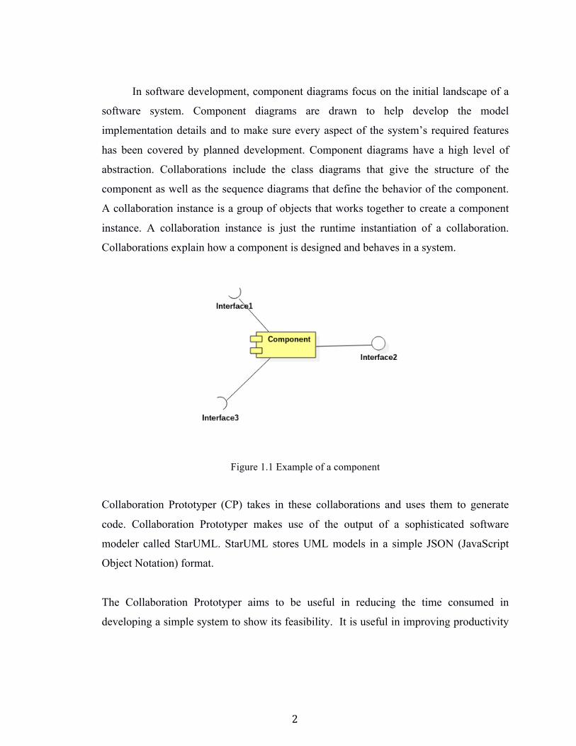
In software development, component diagrams focus on the initial landscape of a
software system. Component diagrams are drawn to help develop the model
implementation details and to make sure every aspect of the system’s required features
has been covered by planned development. Component diagrams have a high level of
abstraction. Collaborations include the class diagrams that give the structure of the
component as well as the sequence diagrams that define the behavior of the component.
A collaboration instance is a group of objects that works together to create a component
instance. A collaboration instance is just the runtime instantiation of a collaboration.
Collaborations explain how a component is designed and behaves in a system.
Figure 1.1 Example of a component
Collaboration Prototyper (CP) takes in these collaborations and uses them to generate
code. Collaboration Prototyper makes use of the output of a sophisticated software
modeler called StarUML. StarUML stores UML models in a simple JSON (JavaScript
Object Notation) format.
The Collaboration Prototyper aims to be useful in reducing the time consumed in
developing a simple system to show its feasibility. It is useful in improving productivity
3
and reproducibility. Slight changes in business rules can be made to the UML and in turn
code can be regenerated to depict the application in question.
Collaboration Prototyper may have disadvantages when it comes to complexity. The code
generated by CP will have to be modified accordingly every time there is a change, and
this may get complicated or difficult to do when there is a large UML collaboration.
4
Chapter 2
2 Defining Collaborations
2.1 What is a collaboration?
A collaboration is a collection of objects that work together to solve a problem. In UML,
a collaboration can be specified by a class diagram showing the classes the collaborators
instantiate and one or more sequence diagrams showing the patterns of message
exchanges between the collaborators.
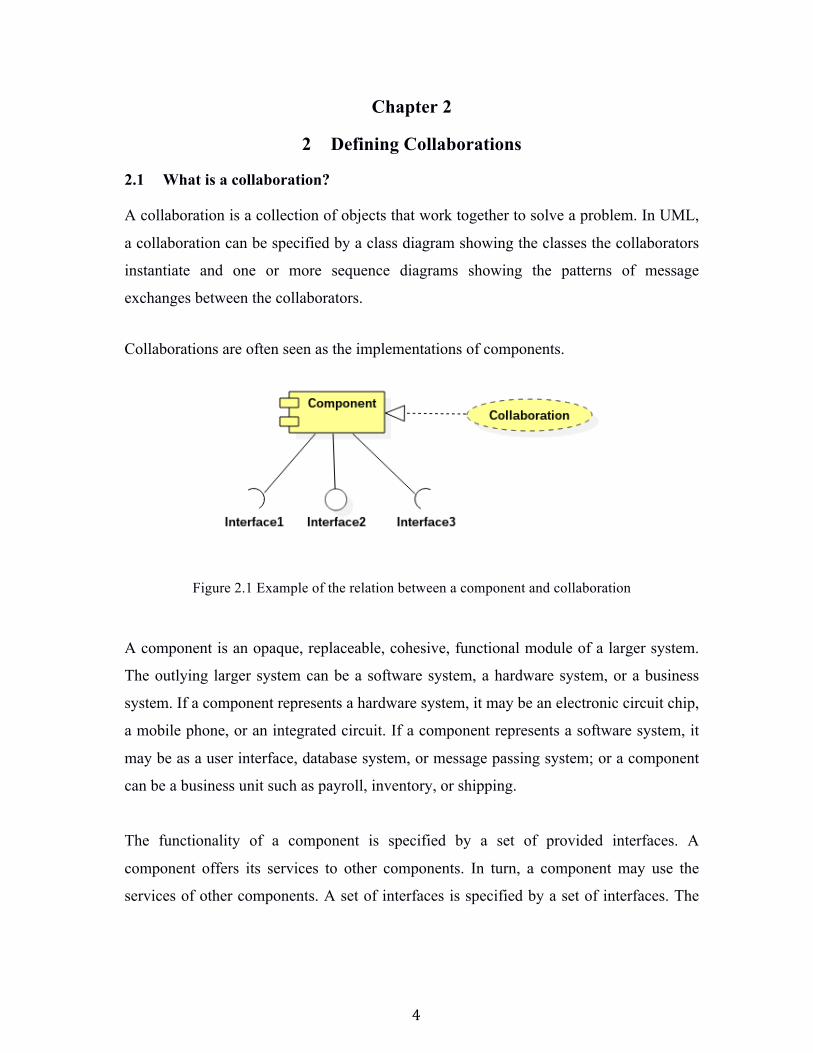
Collaborations are often seen as the implementations of components.
Figure 2.1 Example of the relation between a component and collaboration
A component is an opaque, replaceable, cohesive, functional module of a larger system.
The outlying larger system can be a software system, a hardware system, or a business
system. If a component represents a hardware system, it may be an electronic circuit chip,
a mobile phone, or an integrated circuit. If a component represents a software system, it
may be as a user interface, database system, or message passing system; or a component
can be a business unit such as payroll, inventory, or shipping.
The functionality of a component is specified by a set of provided interfaces. A
component offers its services to other components. In turn, a component may use the
services of other components. A set of interfaces is specified by a set of interfaces. The
5
component diagrams illustrate the organization of the system. In short, we can say that a
component diagram represents the design of a system.
Component Diagram Example 1
A Client-Server Architecture consists of two different types of components: clients and
servers. A server component endlessly listens for requests from client components. When
the server receives a request, it processes the request, and then sends a response back to
the client.
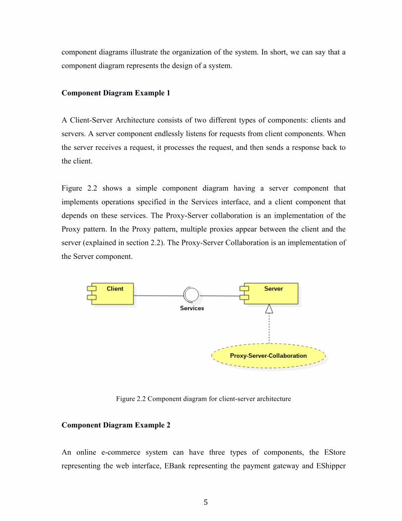
Figure 2.2 shows a simple component diagram having a server component that
implements operations specified in the Services interface, and a client component that
depends on these services. The Proxy-Server collaboration is an implementation of the
Proxy pattern. In the Proxy pattern, multiple proxies appear between the client and the
server (explained in section 2.2). The Proxy-Server Collaboration is an implementation of
the Server component.
Figure 2.2 Component diagram for client-server architecture
Component Diagram Example 2
An online e-commerce system can have three types of components, the EStore
representing the web interface, EBank representing the payment gateway and EShipper
6
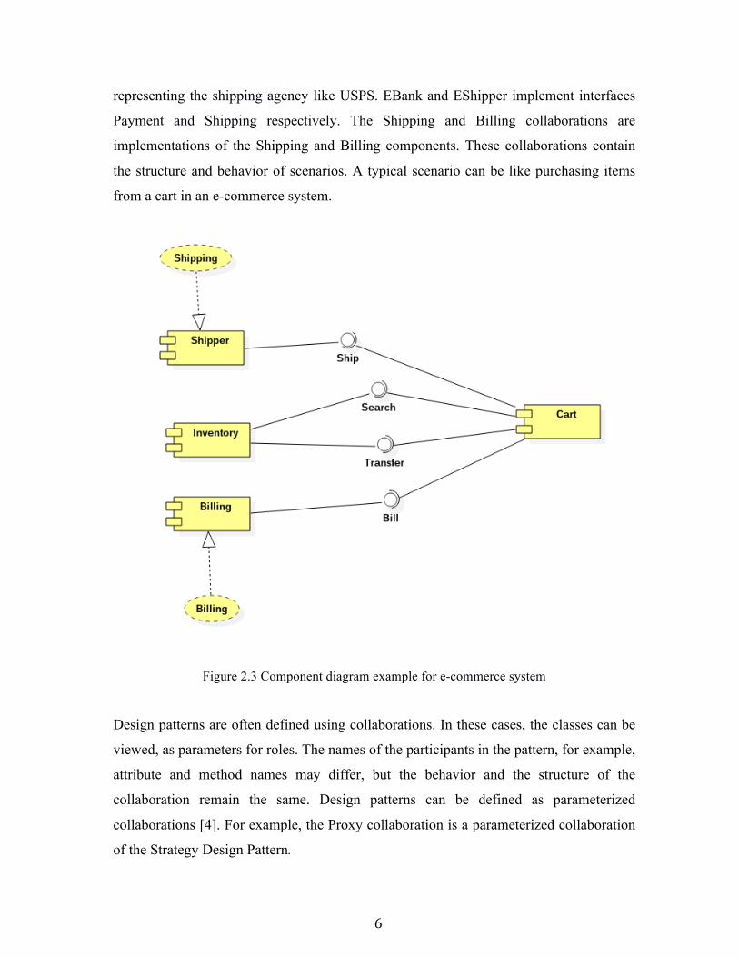
representing the shipping agency like USPS. EBank and EShipper implement interfaces
Payment and Shipping respectively. The Shipping and Billing collaborations are
implementations of the Shipping and Billing components. These collaborations contain
the structure and behavior of scenarios. A typical scenario can be like purchasing items
from a cart in an e-commerce system.
Figure 2.3 Component diagram example for e-commerce system
Design patterns are often defined using collaborations. In these cases, the classes can be
viewed, as parameters for roles. The names of the participants in the pattern, for example,
attribute and method names may differ, but the behavior and the structure of the
collaboration remain the same. Design patterns can be defined as parameterized
collaborations [4]. For example, the Proxy collaboration is a parameterized collaboration
of the Strategy Design Pattern.
7
2.2 Examples of Collaborations and the output of CP
2.2.1 Proxy Pattern
A Proxy is like an agent, which is authorized to act on behalf of another agent. Proxies
are often used in the context of client-server applications to enhance an existing server.
The proxy server acts as an intermediary system for requests from clients seeking
resources from the main servers. A client connects to the proxy server requesting some
resource or service from the server. The resource may be a file, data, connection, web
page or other resource made available by the server. The proxy may pre-process the
request before forwarding it to the server (which may be another proxy in a proxy chain)
and it may post-process the result returned by the server before returning the result to the
client (which may also be a proxy in the chain). Proxies were invented to add structure
and encapsulation to distributed systems. Most proxies today are web proxies, facilitating
access to content on the World Wide Web and providing anonymity.
2.2.1.1 Example In the example in Figure 2.4 below the IServer is the Server interface and the Server is
the actual server. Examples of proxies include cache, synchronization, security, and
firewall proxies.
8
Structure or Class diagram of Proxy Pattern Collaboration
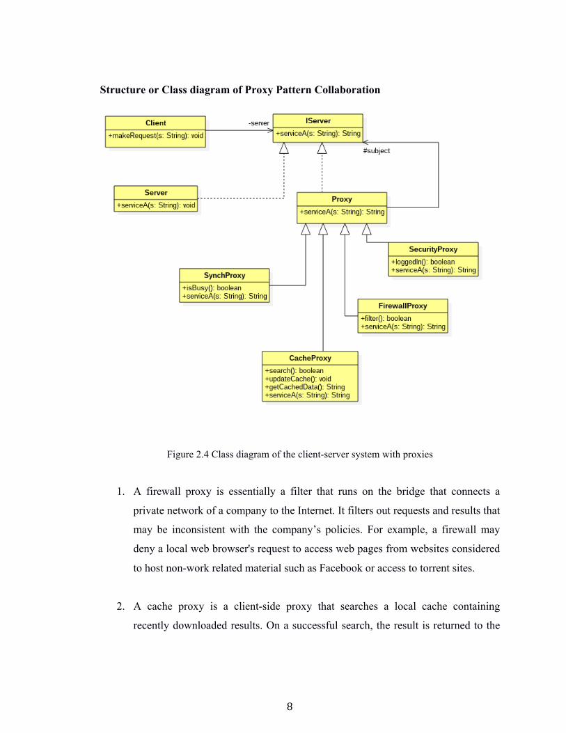
Figure 2.4 Class diagram of the client-server system with proxies
1. A firewall proxy is essentially a filter that runs on the bridge that connects a
private network of a company to the Internet. It filters out requests and results that
may be inconsistent with the company’s policies. For example, a firewall may
deny a local web browser's request to access web pages from websites considered
to host non-work related material such as Facebook or access to torrent sites.
2. A cache proxy is a client-side proxy that searches a local cache containing
recently downloaded results. On a successful search, the result is returned to the
9
client without establishing a connection between the browser and the remote
server. Else, the client request is sent to the server or delegated to another proxy.
For example, most web browsers transparently submit requests for websites to a
caching proxy in between, which attempts to retrieve the page from a local cache
of recently searched web pages. If the search fails, the cache proxy makes a
request to the server to get data and updates the cached data.
3. A synchronization proxy uses techniques similar to locks; commits and
transactions in databases to control the amount of clients that simultaneously
access a server. For example, a file server uses a synchronization proxy to make
sure that two clients do not attempt to write to the same file at the same time.
4. Security Proxy is an additional layer of defense and can protect against some OS
and Web Server specific attacks. For example, it might be necessary to check that
the user is accessing a particular web service is authorized to do so. The Security
Proxy makes this check.
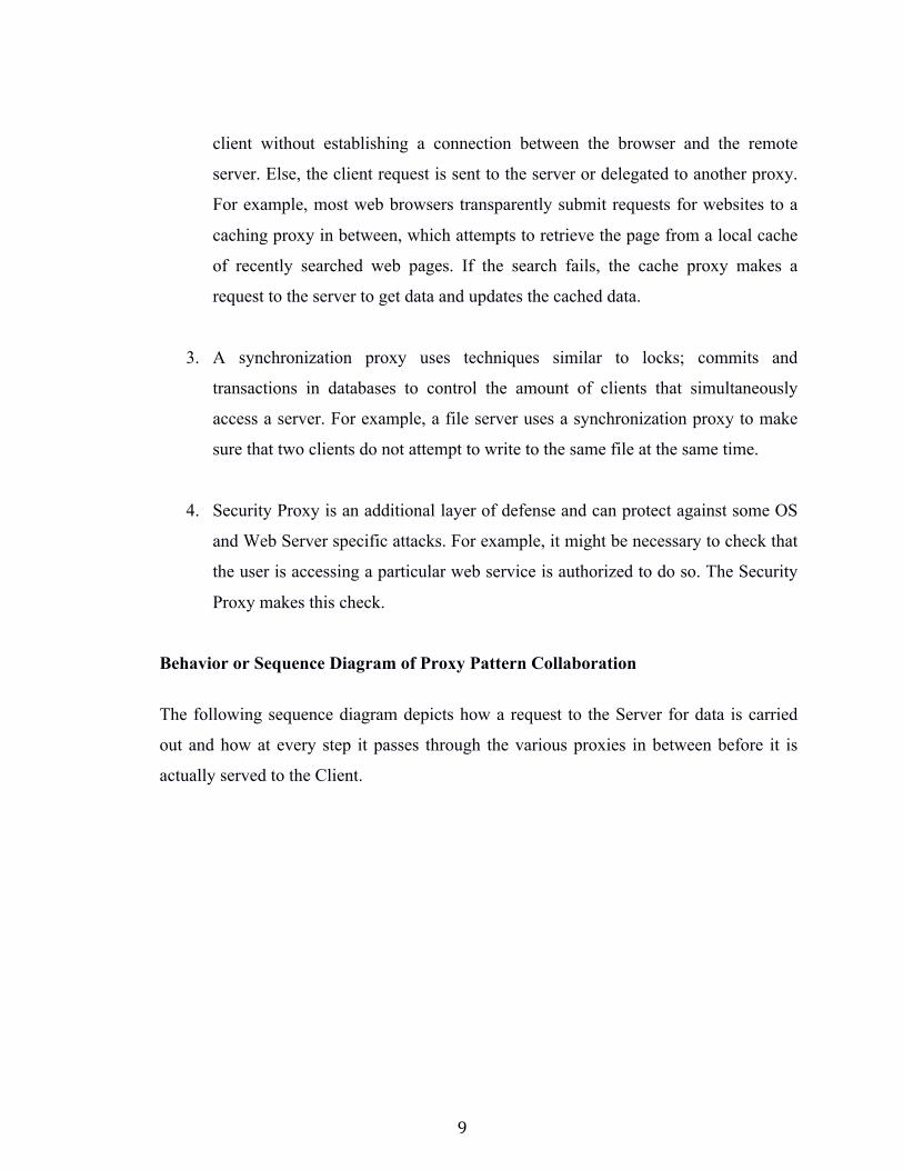
Behavior or Sequence Diagram of Proxy Pattern Collaboration
The following sequence diagram depicts how a request to the Server for data is carried
out and how at every step it passes through the various proxies in between before it is
actually served to the Client.
10
Code generated from Collaboration Prototyper
The file containing the collaboration has to be provided to CP as an argument when
invoking it.
cpro <input file path + file name>
For example, the below line gives a sample invocation of CP with a StarUML .mdj file of
the Proxy collaboration.
cpro proxy.mdj
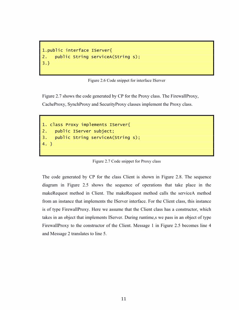
Figure 2.6 shows the code generated by CP for the IServer interface. It has one method
serviceA, which is implemented by the Server, FirewallProxy, CacheProxy, SynchProxy
and SecurityProxy classes.
Figure 2.5 Sequence diagram for interaction between client, server and proxies
11
1.public interface IServer{
2. public String serviceA(String s);
3.}
Figure 2.6 Code snippet for interface IServer
Figure 2.7 shows the code generated by CP for the Proxy class. The FirewallProxy,
CacheProxy, SynchProxy and SecurityProxy classes implement the Proxy class.
1. class Proxy implements IServer{
2. public IServer subject;
3. public String serviceA(String s);
4. }
Figure 2.7 Code snippet for Proxy class
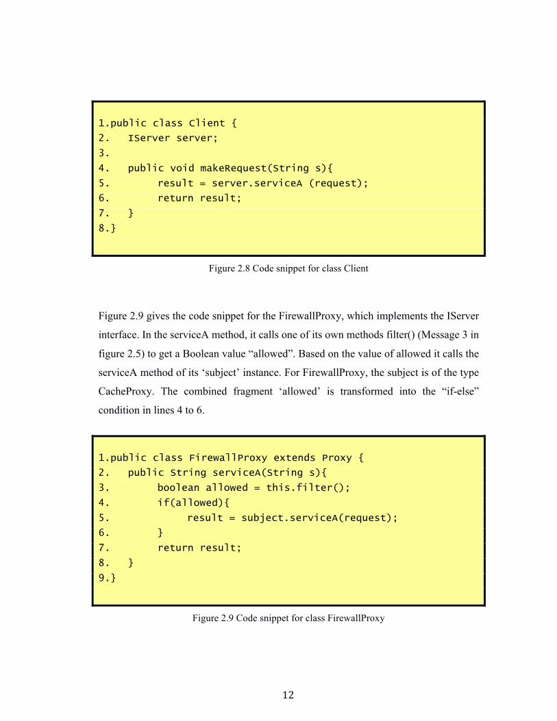
The code generated by CP for the class Client is shown in Figure 2.8. The sequence
diagram in Figure 2.5 shows the sequence of operations that take place in the
makeRequest method in Client. The makeRequest method calls the serviceA method
from an instance that implements the IServer interface. For the Client class, this instance
is of type FirewallProxy. Here we assume that the Client class has a constructor, which
takes in an object that implements IServer. During runtime,s we pass in an object of type
FirewallProxy to the constructor of the Client. Message 1 in Figure 2.5 becomes line 4
and Message 2 translates to line 5.
12
1.public class Client {
2. IServer server;
3.
4. public void makeRequest(String s){
5. result = server.serviceA (request);
6. return result;
7. }
8.}
Figure 2.8 Code snippet for class Client
Figure 2.9 gives the code snippet for the FirewallProxy, which implements the IServer
interface. In the serviceA method, it calls one of its own methods filter() (Message 3 in
figure 2.5) to get a Boolean value “allowed”. Based on the value of allowed it calls the
serviceA method of its ‘subject’ instance. For FirewallProxy, the subject is of the type
CacheProxy. The combined fragment ‘allowed’ is transformed into the “if-else”
condition in lines 4 to 6.
1.public class FirewallProxy extends Proxy {
2. public String serviceA(String s){
3. boolean allowed = this.filter();
4. if(allowed){
5. result = subject.serviceA(request);
6. }
7. return result;
8. }
9.}
Figure 2.9 Code snippet for class FirewallProxy
13
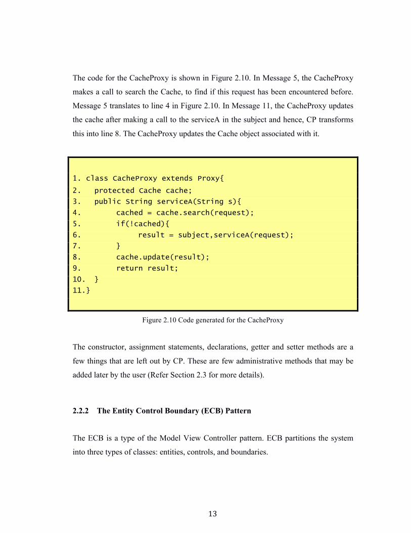
The code for the CacheProxy is shown in Figure 2.10. In Message 5, the CacheProxy
makes a call to search the Cache, to find if this request has been encountered before.
Message 5 translates to line 4 in Figure 2.10. In Message 11, the CacheProxy updates
the cache after making a call to the serviceA in the subject and hence, CP transforms
this into line 8. The CacheProxy updates the Cache object associated with it.
1. class CacheProxy extends Proxy{ 2. protected Cache cache;
3. public String serviceA(String s){
4. cached = cache.search(request);
5. if(!cached){
6. result = subject,serviceA(request);
7. }
8. cache.update(result);
9. return result;
10. }
11.}
Figure 2.10 Code generated for the CacheProxy
The constructor, assignment statements, declarations, getter and setter methods are a
few things that are left out by CP. These are few administrative methods that may be
added later by the user (Refer Section 2.3 for more details).
2.2.2 The Entity Control Boundary (ECB) Pattern
The ECB is a type of the Model View Controller pattern. ECB partitions the system
into three types of classes: entities, controls, and boundaries.
14
1. Entities are objects representing application domain data: Customer, Bank,
Book, etc.
2. Boundaries are objects that interface with actors: Menus, Views, User
Interfaces, gateways, etc.
Controls are objects that communicate between boundaries and entities. Controls often
match to use-cases and correspond to use-case controllers in the design model.
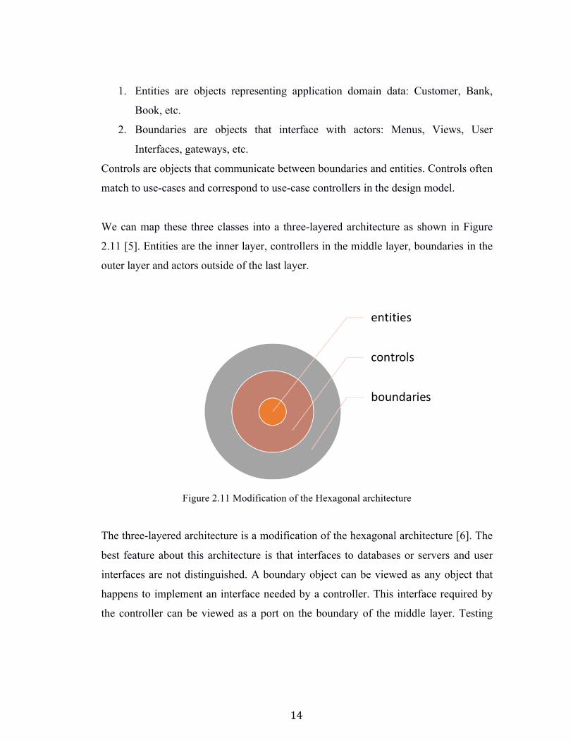
We can map these three classes into a three-layered architecture as shown in Figure
2.11 [5]. Entities are the inner layer, controllers in the middle layer, boundaries in the
outer layer and actors outside of the last layer.
Figure 2.11 Modification of the Hexagonal architecture
The three-layered architecture is a modification of the hexagonal architecture [6]. The
best feature about this architecture is that interfaces to databases or servers and user
interfaces are not distinguished. A boundary object can be viewed as any object that
happens to implement an interface needed by a controller. This interface required by
the controller can be viewed as a port on the boundary of the middle layer. Testing
15
becomes easy since as boundary objects can be implemented as interfaces for real
actors or for mock actors.
2.2.3 The Use Case Controller Pattern
The Use Case Controller pattern associates a controller with each use case. Each use
case controller can be specified as a collaboration between the controller, boundaries,
and entities. This provides an easy, cost-effective implementation. The pattern
suggests delegating the responsibility for managing a use-case and its flow of
execution to a specialized controller object, thus localizing the functionality and its
possible changes.
Use Case Controllers hold together the user interfaces and model entities together and
place much of the application logic separately from system components. Any
necessary future changes will not affect any of the database objects, schemas or
interfaces because much of the changes will reside in the controller logic. User
interfaces and system entities can be changed dynamically as and when required
because there is no interdependency. A single controller can cater to multiple use-case
scenarios while having different interfaces and entities. Developers can easily point to
a code matching a use case.
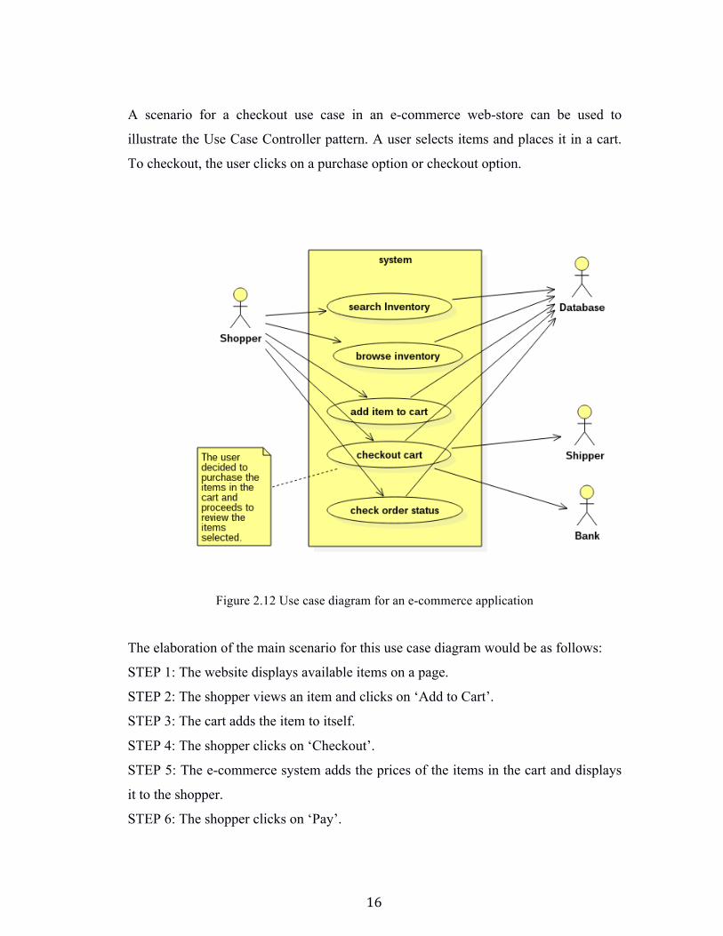
2.2.3.1 Example: E-Commerce Figure 2.12 is a use case diagram depicting use cases in an e-commerce application. A
user browsing an e-commerce website can search for items or browse through items
on the website. If the user wishes to buy a particular item, he can add it to his cart. The
cart holds the items the user has selected to buy. When the user is done browsing, he
can checkout the items in the cart and review the items. He can then make a payment
and give his address for the items to be shipped.
16
A scenario for a checkout use case in an e-commerce web-store can be used to
illustrate the Use Case Controller pattern. A user selects items and places it in a cart.
To checkout, the user clicks on a purchase option or checkout option.
Figure 2.12 Use case diagram for an e-commerce application
The elaboration of the main scenario for this use case diagram would be as follows:
STEP 1: The website displays available items on a page.
STEP 2: The shopper views an item and clicks on ‘Add to Cart’.
STEP 3: The cart adds the item to itself.
STEP 4: The shopper clicks on ‘Checkout’.
STEP 5: The e-commerce system adds the prices of the items in the cart and displays
it to the shopper.
STEP 6: The shopper clicks on ‘Pay’.
17
STEP 7: The e-commerce system asks the shopper for his/her shipping address.
STEP 8: The shopper enters the desired shipping address.
STEP 9: The system contacts the shipper to get the shipping cost and adds it to the
total.
STEP 10: The shopper enters his/her bank details.
STEP 11: The system then contacts the payment gateway of the bank for payment.
STEP 12: On successful payment, the user is shown a virtual receipt. The system tells
the Shipper to ship the item.
Using the ECB pattern, the checkout use case for the web-store can be modeled as
follows:
1. Actors: Shopper, Visitor, Customer
2. Boundary: Menu
3. Controller: CartController, PurchaseController
4. Entities: Bank, Cart, ShippingAgent, Address, Items
The purchase use case is implemented using the PurchaseController, which then
executes and calls multiple other functions in the entity or boundary classes.
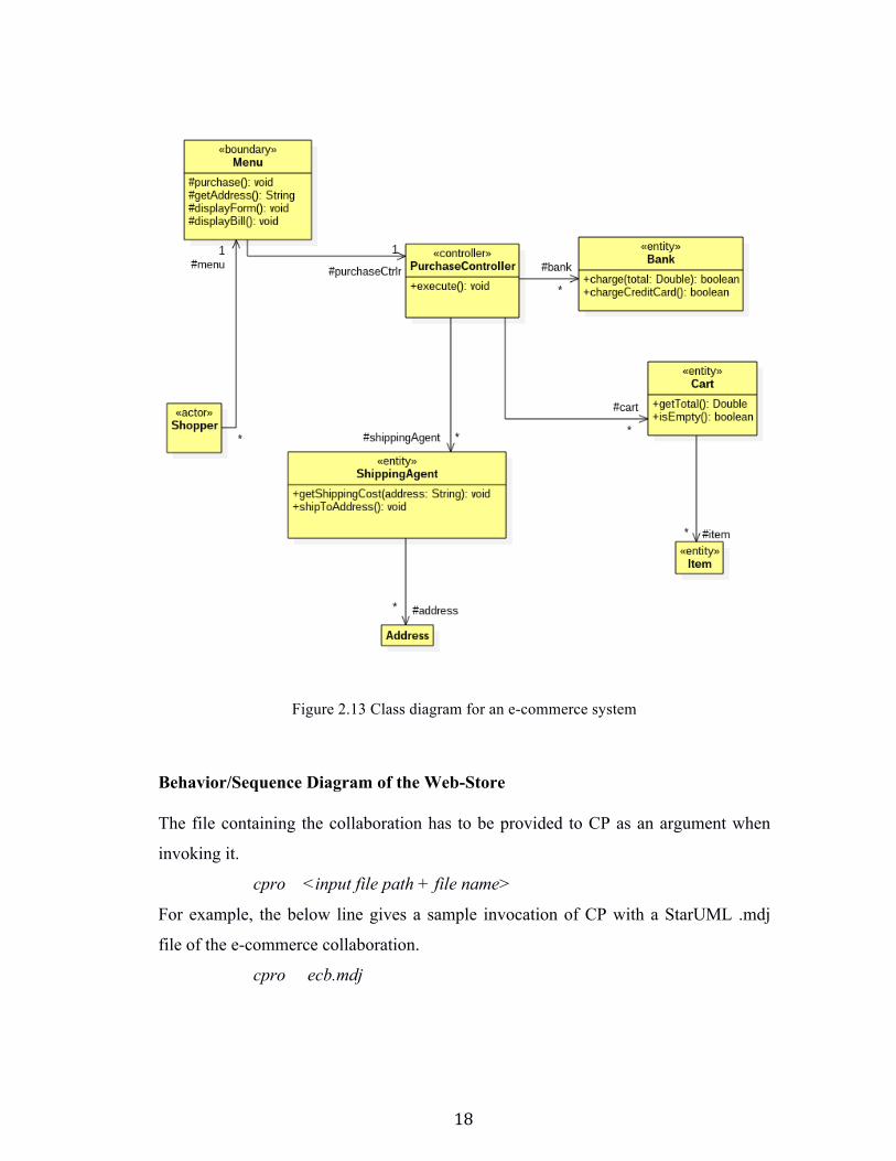
Structure/Class Diagram of the Web-Store The PurchaseController is the Control object; the Menu is the Boundary object and the
Cart is an Entity.
18
Figure 2.13 Class diagram for an e-commerce system
Behavior/Sequence Diagram of the Web-Store The file containing the collaboration has to be provided to CP as an argument when
invoking it.
cpro <input file path + file name>
For example, the below line gives a sample invocation of CP with a StarUML .mdj
file of the e-commerce collaboration.
cpro ecb.mdj
19
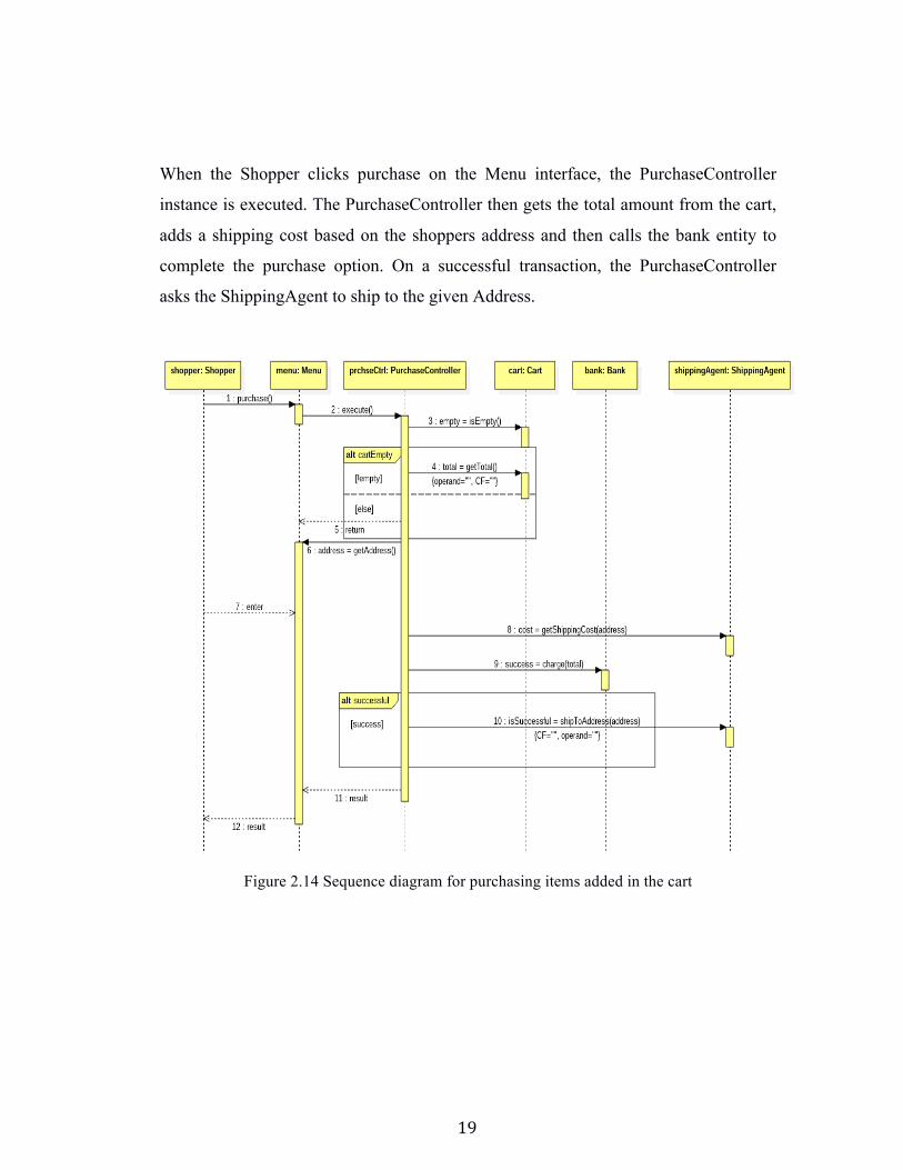
When the Shopper clicks purchase on the Menu interface, the PurchaseController
instance is executed. The PurchaseController then gets the total amount from the cart,
adds a shipping cost based on the shoppers address and then calls the bank entity to
complete the purchase option. On a successful transaction, the PurchaseController
asks the ShippingAgent to ship to the given Address.
Figure 2.14 Sequence diagram for purchasing items added in the cart
20
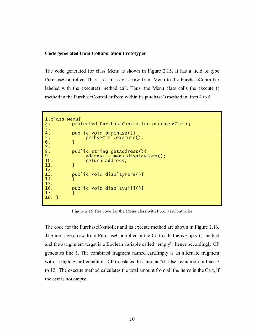
Code generated from Collaboration Prototyper The code generated for class Menu is shown in Figure 2.15. It has a field of type
PurchaseController. There is a message arrow from Menu to the PurchaseController
labeled with the execute() method call. Thus, the Menu class calls the execute ()
method in the PurchaseController from within its purchase() method in lines 4 to 6.
1.class Menu{ 2. protected PurchaseController purchaseCtrlr; 3. 4. public void purchase(){ 5. prchseCtrl.execute(); 6. } 7. 8. public String getAddress(){ 9. address = menu.displayForm(); 10. return address; 11. } 12. 13. public void displayForm(){ 14. } 15. 16. public void displayBill(){ 17. } 18. }
Figure 2.15 The code for the Menu class with PurchaseController
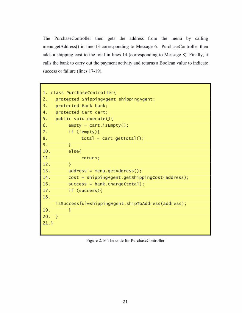
The code for the PurchaseController and its execute method are shown in Figure 2.16.
The message arrow from PurchaseController to the Cart calls the isEmpty () method
and the assignment target is a Boolean variable called “empty”, hence accordingly CP
generates line 6. The combined fragment named cartEmpty is an alternate fragment
with a single guard condition. CP translates this into an “if -else” condition in lines 7
to 12. The execute method calculates the total amount from all the items in the Cart, if
the cart is not empty.
21
The PurchaseController then gets the address from the menu by calling
menu.getAddress() in line 13 corresponding to Message 6. PurchaseController then
adds a shipping cost to the total in lines 14 (corresponding to Message 8). Finally, it
calls the bank to carry out the payment activity and returns a Boolean value to indicate
success or failure (lines 17-19).
1. class PurchaseController{
2. protected ShippingAgent shippingAgent;
3. protected Bank bank;
4. protected Cart cart;
5. public void execute(){
6. empty = cart.isEmpty();
7. if (!empty){
8. total = cart.getTotal();
9. }
10. else{
11. return;
12. }
13. address = menu.getAddress();
14. cost = shippingAgent.getShippingCost(address);
16. success = bank.charge(total);
17. if (success){
18.
isSuccessful=shippingAgent.shipToAddress(address);
19. }
20. }
21.}
Figure 2.16 The code for PurchaseController
22
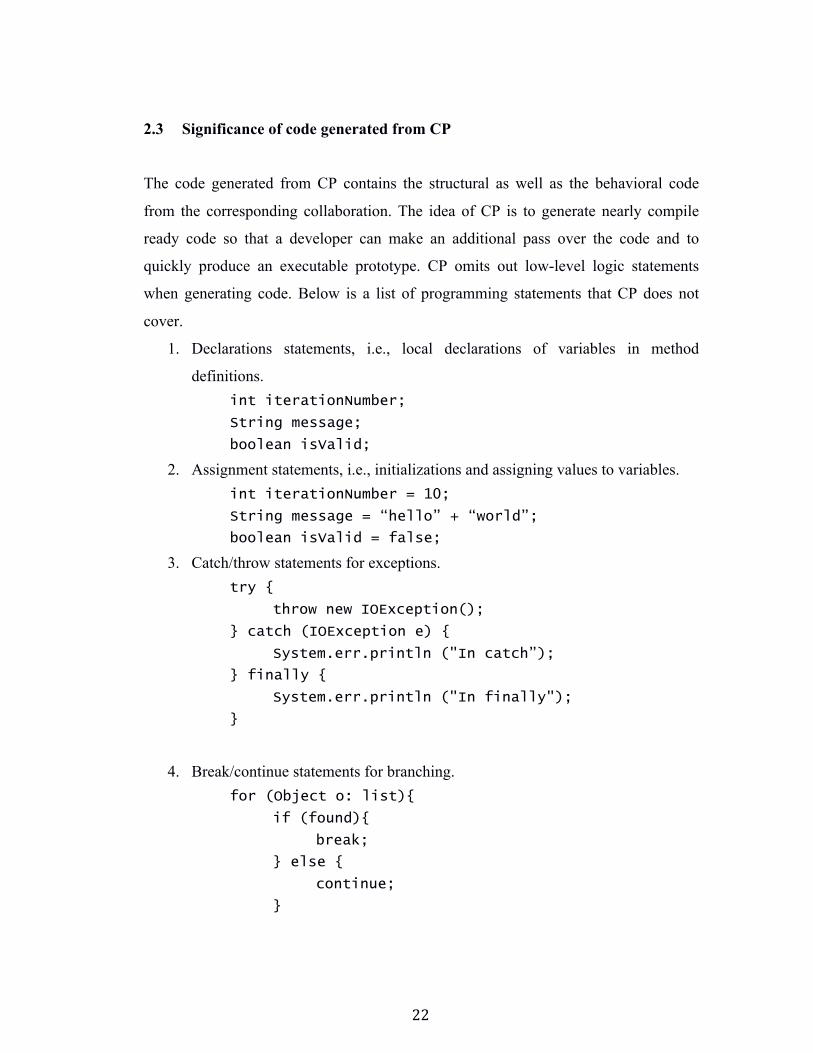
2.3 Significance of code generated from CP
The code generated from CP contains the structural as well as the behavioral code
from the corresponding collaboration. The idea of CP is to generate nearly compile
ready code so that a developer can make an additional pass over the code and to
quickly produce an executable prototype. CP omits out low-level logic statements
when generating code. Below is a list of programming statements that CP does not
cover.
1. Declarations statements, i.e., local declarations of variables in method
definitions. int iterationNumber;
String message;
boolean isValid;
2. Assignment statements, i.e., initializations and assigning values to variables. int iterationNumber = 10;
String message = “hello” + “world”;
boolean isValid = false;
3. Catch/throw statements for exceptions. try {
throw new IOException();
} catch (IOException e) {
System.err.println ("In catch”);
} finally {
System.err.println ("In finally");
}
4. Break/continue statements for branching. for (Object o: list){
if (found){
break;
} else {
continue;
}
23
}
Such statements are too fine grained to be included in sequence diagrams. A
combination of collaborations with lifecycles (state diagrams) can give us more
information about other interactions to generate low-level logic. State diagrams give
an abstract description of the behavior of the system using events and states.
Code generated from CP, can be traced back to the requirements. With CP it is much
easier to verify that the implementation developed matches the design requirements.
This is specifically important in the case of rogue developers who do not understand
the design requirements and deviate from it. Developers can be handed this partially
developed code to work with where they can fill in the relevant missing details and
move ahead with the implementation. Developers do not need to start the
implementation from scratch. CP helps bridge the gap between the design and
implementation. It helps in measuring the overall quality of the application being
designed and understanding of the application. Sudden changes to requirements can be
made immediately by changing the design and then using CP to generate the working
prototype with the changes.
24
Chapter 3
3 Overview of Sequence Diagrams
3.1 Basics of Sequence Diagrams
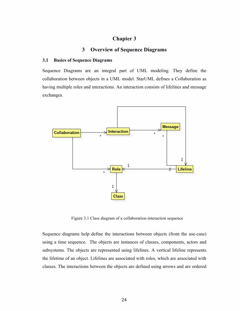
Sequence Diagrams are an integral part of UML modeling. They define the
collaboration between objects in a UML model. StarUML defines a Collaboration as
having multiple roles and interactions. An interaction consists of lifelines and message
exchanges.
Sequence diagrams help define the interactions between objects (from the use-case)
using a time sequence. The objects are instances of classes, components, actors and
subsystems. The objects are represented using lifelines. A vertical lifeline represents
the lifetime of an object. Lifelines are associated with roles, which are associated with
classes. The interactions between the objects are defined using arrows and are ordered
Figure 3.1 Class diagram of a collaboration-interaction sequence
25
based on their occurrence in the scenario. A message sent from object A to object B at
a time 't' is represented by a horizontal arrow connecting A's lifeline to B's lifeline at
position 't'. There are several types of messages including method calls and their return
values. Objects and messages can reappear any number of times in the diagram. The
time sequence helps define complex run time scenarios and behavior that would
otherwise not be explained just with the help of a class diagram.
3.1.1 Roles, Lifelines, and Messages
There are two parts to sequence diagrams as described earlier; the roles i.e. the entity
or objects that acts in the diagram; messages i.e. communication between the
participating entities.
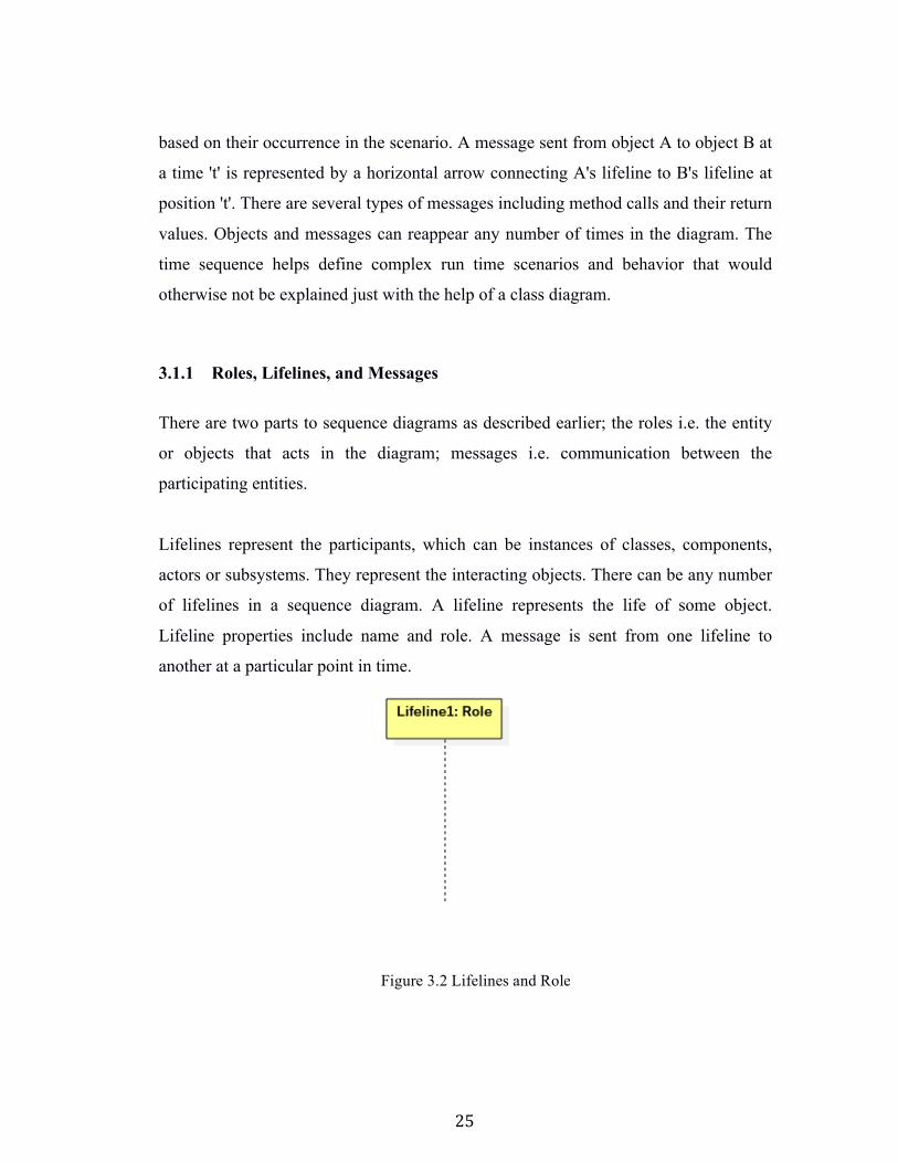
Lifelines represent the participants, which can be instances of classes, components,
actors or subsystems. They represent the interacting objects. There can be any number
of lifelines in a sequence diagram. A lifeline represents the life of some object.
Lifeline properties include name and role. A message is sent from one lifeline to
another at a particular point in time.
Figure 3.2 Lifelines and Role
26
To identify what the lifelines represent, we define roles. These roles are the classes
and components defined in the class diagrams. Roles can only be one of a kind, but
lifelines can represent these roles any number of times. Role properties include name
and type. The type of a role is usually an existing class in the model.
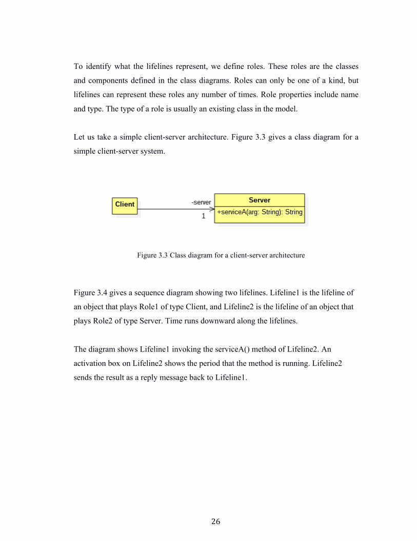
Let us take a simple client-server architecture. Figure 3.3 gives a class diagram for a
simple client-server system.
Figure 3.4 gives a sequence diagram showing two lifelines. Lifeline1 is the lifeline of
an object that plays Role1 of type Client, and Lifeline2 is the lifeline of an object that
plays Role2 of type Server. Time runs downward along the lifelines.
The diagram shows Lifeline1 invoking the serviceA() method of Lifeline2. An
activation box on Lifeline2 shows the period that the method is running. Lifeline2
sends the result as a reply message back to Lifeline1.
Figure 3.3 Class diagram for a client-server architecture

27
We would expect to see the following line of code inside some Client method:
result = server.ServiceA(arg);
Sometimes a lifeline may not be named, and this becomes an anonymous lifeline of
the entity it represents.
The example in the figure below explains how a Shopper buying coffee from a Barista
at a coffee shop would be shown in an interaction.
A Lifeline can also call its own method like Shopper calls it's method drink.
Figure 3.4 Simple sequence diagram for client-server in figure 3.3
28
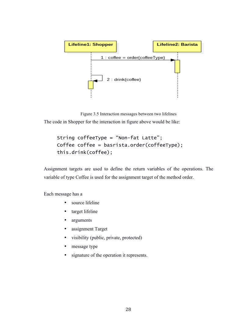
Figure 3.5 Interaction messages between two lifelines
The code in Shopper for the interaction in figure above would be like:
String coffeeType = “Non-fat Latte”;
Coffee coffee = basrista.order(coffeeType);
this.drink(coffee);
Assignment targets are used to define the return variables of the operations. The
variable of type Coffee is used for the assignment target of the method order.
Each message has a
• source lifeline
• target lifeline
• arguments
• assignment Target
• visibility (public, private, protected)
• message type
• signature of the operation it represents.
29
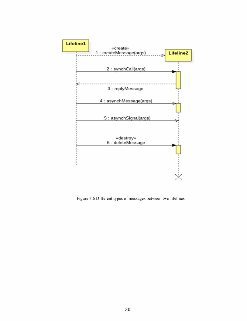
3.1.2 Messages Types There are six different types of Messages. Messages and signals are examples of UML
events. Detailed below are two types of messages used in CP.
1. Synch Call: Synch calls indicate synchronous operations. They have an
activation bar that implies the duration for which the operation has been active.
The activation bar lies on the lifeline at the start of the message. A
synchronous message indicates that the caller waits till the receiver finishes
processing the messages and then continues with the next message.
2. Reply Messages: They are used to indicate the replies to any kind of messages
and are represented with dashed lines. Activation bars may overlap to indicate
concurrent execution of operations.
30
Figure 3.6 Different types of messages between two lifelines
31
3.2 Advanced Sequence Diagrams
3.2.1 Combined Fragments
Combined fragments help define logic control in sequence diagrams. They contain
interaction operands and interaction operator. The interaction operator identifies the type
of logic or conditional statement that defines the behavior of the combined fragment. The
interaction operands contain guard conditions. Combined fragments can be nested and
include other combined fragments as well.
The interaction operator defines the control logic the combined fragment is representing,
for example, iterations (or loops), 1- way conditionals (or alt), 2-way conditionals (opt),
etc.
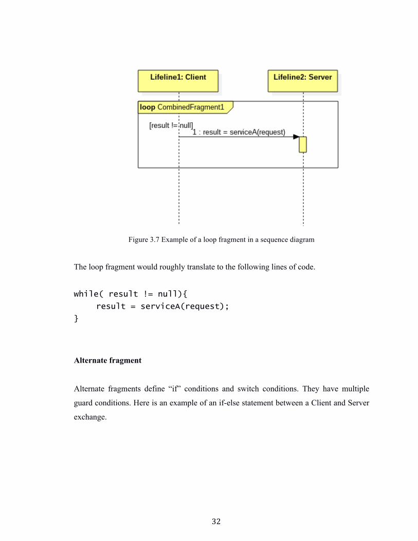
Loop Fragment
Loop fragments typically mean “while” loops. They have a single operand with a guard
condition for the loop. Here is an example of a loop fragment used between a Client and a
Server.
32
Figure 3.7 Example of a loop fragment in a sequence diagram
The loop fragment would roughly translate to the following lines of code.
while( result != null){
result = serviceA(request);
}
Alternate fragment
Alternate fragments define “if” conditions and switch conditions. They have multiple
guard conditions. Here is an example of an if-else statement between a Client and Server
exchange.

33
Figure 3.8 Example of an alternate fragment in a sequence diagram
The code in figure 3.8 would translate to:
class Server{
public String serviceA(String args){
if(arg1 == null){
return “error”;
}else{
//compute result
return result;
}
}
}
34
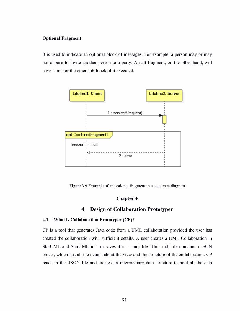
Optional Fragment
It is used to indicate an optional block of messages. For example, a person may or may
not choose to invite another person to a party. An alt fragment, on the other hand, will
have some, or the other sub-block of it executed.
Figure 3.9 Example of an optional fragment in a sequence diagram
Chapter 4
4 Design of Collaboration Prototyper
4.1 What is Collaboration Prototyper (CP)?
CP is a tool that generates Java code from a UML collaboration provided the user has
created the collaboration with sufficient details. A user creates a UML Collaboration in
StarUML and StarUML in turn saves it in a .mdj file. This .mdj file contains a JSON
object, which has all the details about the view and the structure of the collaboration. CP
reads in this JSON file and creates an intermediary data structure to hold all the data
35
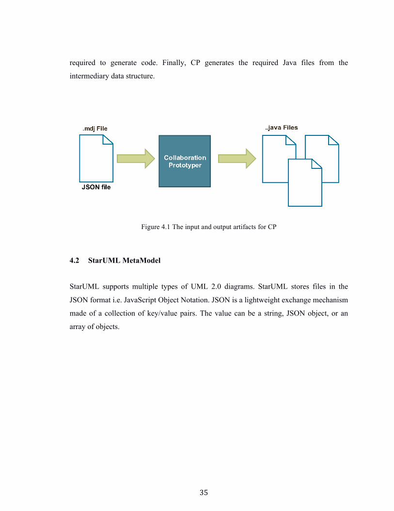
required to generate code. Finally, CP generates the required Java files from the
intermediary data structure.
4.2 StarUML MetaModel
StarUML supports multiple types of UML 2.0 diagrams. StarUML stores files in the
JSON format i.e. JavaScript Object Notation. JSON is a lightweight exchange mechanism
made of a collection of key/value pairs. The value can be a string, JSON object, or an
array of objects.
Figure 4.1 The input and output artifacts for CP
36
{
key1: “value1”,
key2: “value2”
}
Figure 4.2 Example of a JSON object
StarUML uses its own file extension, .mdj (meta data JSON) file. Files can also be saved
in an .mfj (meta data fragments) file and imported into other .mdj files.
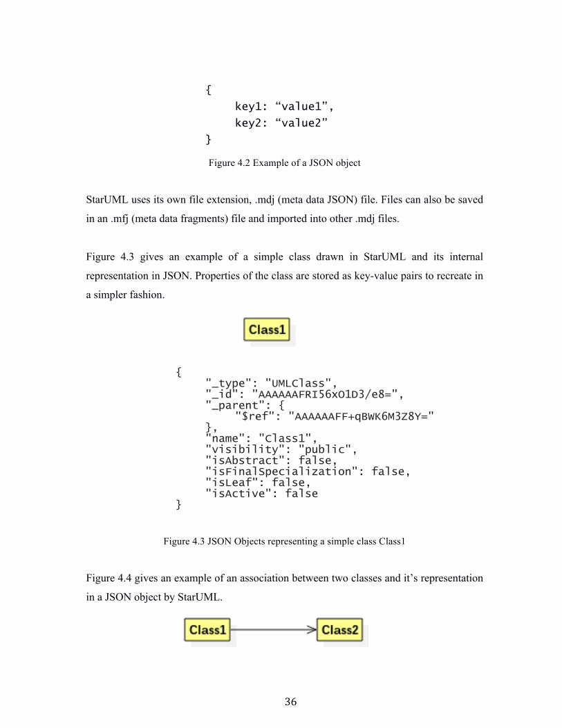
Figure 4.3 gives an example of a simple class drawn in StarUML and its internal
representation in JSON. Properties of the class are stored as key-value pairs to recreate in
a simpler fashion.
{
"_type": "UMLClass", "_id": "AAAAAAFRI56xO1D3/e8=", "_parent": {
"$ref": "AAAAAAFF+qBWK6M3Z8Y=" }, "name": "Class1", "visibility": "public", "isAbstract": false, "isFinalSpecialization": false, "isLeaf": false, "isActive": false
}
Figure 4.3 JSON Objects representing a simple class Class1
Figure 4.4 gives an example of an association between two classes and it’s representation
in a JSON object by StarUML.
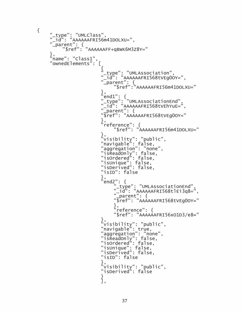
37
{ "_type": "UMLClass", "_id": "AAAAAAFRI56m41DOLXU=", "_parent": {
"$ref": "AAAAAAFF+qBWK6M3Z8Y=" }, "name": "Class1", "ownedElements": [
{ "_type": "UMLAssociation", "_id": "AAAAAAFRI568tVEg0OY=", "_parent": {
"$ref":"AAAAAAFRI56m41DOLXU=" }, "end1": { "_type": "UMLAssociationEnd", "_id": "AAAAAAFRI568tVEhYuE=", "_parent": { "$ref": "AAAAAAFRI568tVEg0OY=" }, "reference": {
"$ref": "AAAAAAFRI56m41DOLXU=" }, "visibility": "public", "navigable": false, "aggregation": "none", "isReadOnly": false, "isOrdered": false, "isUnique": false, "isDerived": false, "isID": false }, "end2": {
"_type": "UMLAssociationEnd", "_id": "AAAAAAFRI568tlEi3q8=", "_parent": { "$ref": "AAAAAAFRI568tVEg0OY=" }, "reference": { "$ref": "AAAAAAFRI56xO1D3/e8="
}, "visibility": "public", "navigable": true, "aggregation": "none", "isReadOnly": false, "isOrdered": false, "isUnique": false, "isDerived": false, "isID": false }, "visibility": "public", "isDerived": false } ],
38
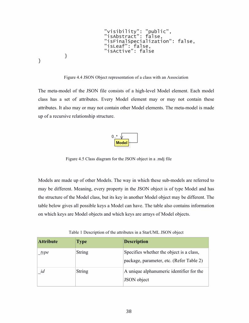
"visibility": "public", "isAbstract": false, "isFinalSpecialization": false, "isLeaf": false, "isActive": false
} }
Figure 4.4 JSON Object representation of a class with an Association
The meta-model of the JSON file consists of a high-level Model element. Each model
class has a set of attributes. Every Model element may or may not contain these
attributes. It also may or may not contain other Model elements. The meta-model is made
up of a recursive relationship structure.
Models are made up of other Models. The way in which these sub-models are referred to
may be different. Meaning, every property in the JSON object is of type Model and has
the structure of the Model class, but its key in another Model object may be different. The
table below gives all possible keys a Model can have. The table also contains information
on which keys are Model objects and which keys are arrays of Model objects.
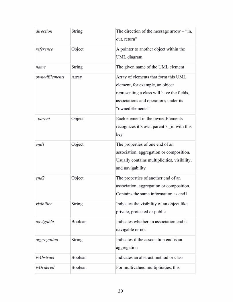
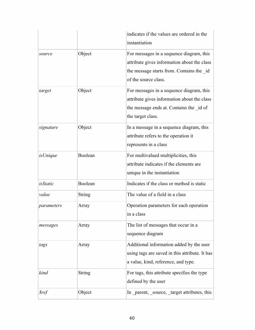
Table 1 Description of the attributes in a StarUML JSON object
Attribute Type Description
_type String Specifies whether the object is a class,
package, parameter, etc. (Refer Table 2)
_id String A unique alphanumeric identifier for the
JSON object
Figure 4.5 Class diagram for the JSON object in a .mdj file
39
direction String The direction of the message arrow – “in,
out, return”
reference Object A pointer to another object within the
UML diagram
name String The given name of the UML element
ownedElements Array Array of elements that form this UML
element, for example, an object
representing a class will have the fields,
associations and operations under its
“ownedElements”
_parent Object Each element in the ownedElements
recognizes it’s own parent’s _id with this
key
end1 Object The properties of one end of an
association, aggregation or composition.
Usually contains multiplicities, visibility,
and navigability
end2 Object The properties of another end of an
association, aggregation or composition.
Contains the same information as end1
visibility String Indicates the visibility of an object like
private, protected or public
navigable Boolean Indicates whether an association end is
navigable or not
aggregation String Indicates if the association end is an
aggregation
isAbstract Boolean Indicates an abstract method or class
isOrdered Boolean For multivalued multiplicities, this
40
indicates if the values are ordered in the
instantiation
source Object For messages in a sequence diagram, this
attribute gives information about the class
the message starts from. Contains the _id
of the source class.
target Object For messages in a sequence diagram, this
attribute gives information about the class
the message ends at. Contains the _id of
the target class.
signature Object In a message in a sequence diagram, this
attribute refers to the operation it
represents in a class
isUnique Boolean For multivalued multiplicities, this
attribute indicates if the elements are
unique in the instantiation
isStatic Boolean Indicates if the class or method is static
value String The value of a field in a class
parameters Array Operation parameters for each operation
in a class
messages Array The list of messages that occur in a
sequence diagram
tags Array Additional information added by the user
using tags are saved in this attribute. It has
a value, kind, reference, and type.
kind String For tags, this attribute specifies the type
defined by the user
$ref Object In _parent, _source, _target attributes, this
41
attribute holds the reference _id
messageSort String Indicates the type of the message like
“SynchCall”, “asynchCall” etc.
participants Array The list of lifelines in a sequence diagram
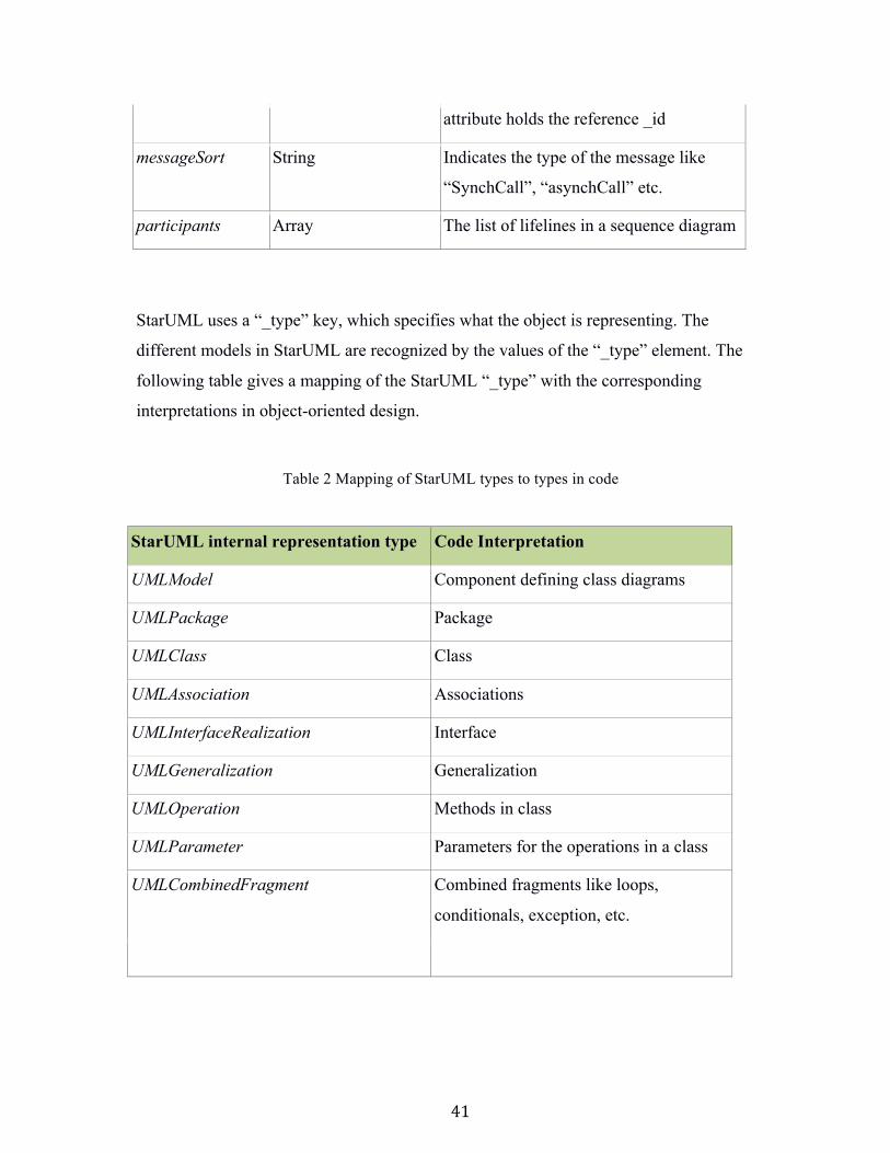
StarUML uses a “_type” key, which specifies what the object is representing. The
different models in StarUML are recognized by the values of the “_type” element. The
following table gives a mapping of the StarUML “_type” with the corresponding
interpretations in object-oriented design.
Table 2 Mapping of StarUML types to types in code
StarUML internal representation type Code Interpretation
UMLModel Component defining class diagrams
UMLPackage Package
UMLClass Class
UMLAssociation Associations
UMLInterfaceRealization Interface
UMLGeneralization Generalization
UMLOperation Methods in class
UMLParameter Parameters for the operations in a class
UMLCombinedFragment Combined fragments like loops,
conditionals, exception, etc.
42
4.3 Collaboration Prototyper Meta-Model
4.3.1 Significance of the CP’s data structure
During its execution CP creates a data structure (details in Section 4.3.2 and 4.3.3), an
intermediate representation of the source code from the UML collaboration. This data
structure has many other uses besides its use for code generation. For example, this data
structure could be used for code optimization. We can analyze the source code for
loopholes and better design options before the actual code generation by making a code
optimization “pass”. This intermediary data structure can be used for “profiling” where
we can analyze the memory utilization, time and space complexity, and frequency of
method calls. Thus, the essence of CP potentially achieves more than just code generation
purpose. CP can be reused as a module for other programmatic purposes.
4.3.2 Phase One: Parsing the structure of the collaboration.
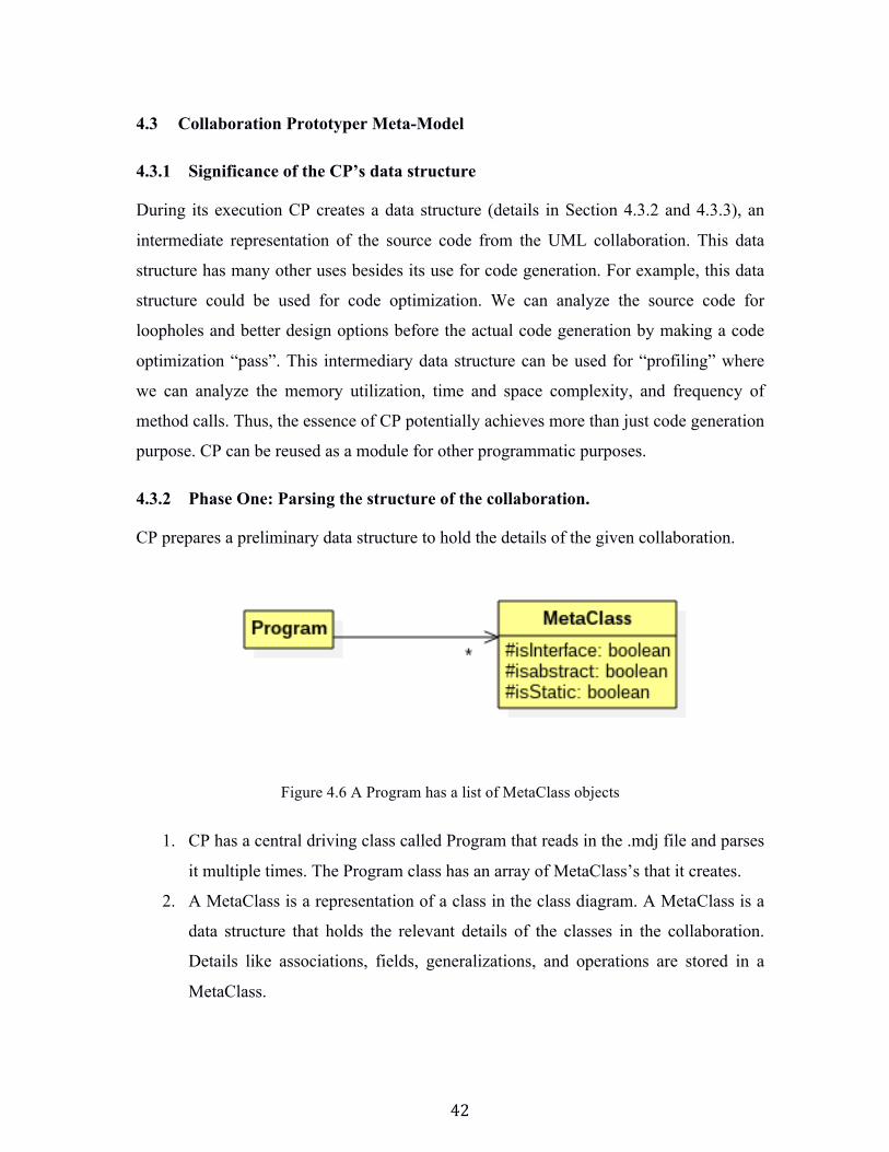
CP prepares a preliminary data structure to hold the details of the given collaboration.
Figure 4.6 A Program has a list of MetaClass objects
1. CP has a central driving class called Program that reads in the .mdj file and parses
it multiple times. The Program class has an array of MetaClass’s that it creates.
2. A MetaClass is a representation of a class in the class diagram. A MetaClass is a
data structure that holds the relevant details of the classes in the collaboration.
Details like associations, fields, generalizations, and operations are stored in a
MetaClass.
43
3. A MetaClass can also be a representation of an interface. The Boolean flag
isInterface in the MetaClass indicates is set if it is representing an interface.
4. If the corresponding class is abstract or static then the Boolean flag isAbstract and
isStatic in the MetaClass will be set respectively.
5. Every MetaClass is associated with an array of Operations and array of Fields.
These arrays may or may not be empty.
6. Once the preliminary details of all the classes are parsed and populated, CP moves
to the next phase, parsing the Sequence Diagrams.
44
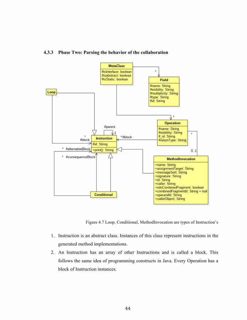
4.3.3 Phase Two: Parsing the behavior of the collaboration
Figure 4.7 Loop, Conditional, MethodInvocation are types of Instruction’s
1. Instruction is an abstract class. Instances of this class represent instructions in the
generated method implementations.
2. An Instruction has an array of other Instructions and is called a block. This
follows the same idea of programming constructs in Java. Every Operation has a
block of Instruction instances.
45
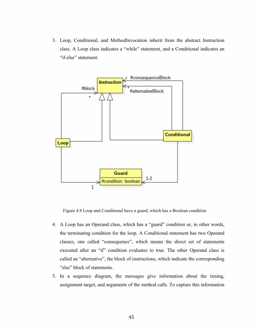
3. Loop, Conditional, and MethodInvocation inherit from the abstract Instruction
class. A Loop class indicates a “while” statement, and a Conditional indicates an
“if-else” statement.
Figure 4.8 Loop and Conditional have a guard, which has a Boolean condition
4. A Loop has an Operand class, which has a “guard” condition or, in other words,
the terminating condition for the loop. A Conditional statement has two Operand
classes, one called “consequence”, which means the direct set of statements
executed after an “if” condition evaluates to true. The other Operand class is
called an “alternative”, the block of instructions, which indicate the corresponding
“else” block of statements.
5. In a sequence diagram, the messages give information about the timing,
assignment target, and arguments of the method calls. To capture this information
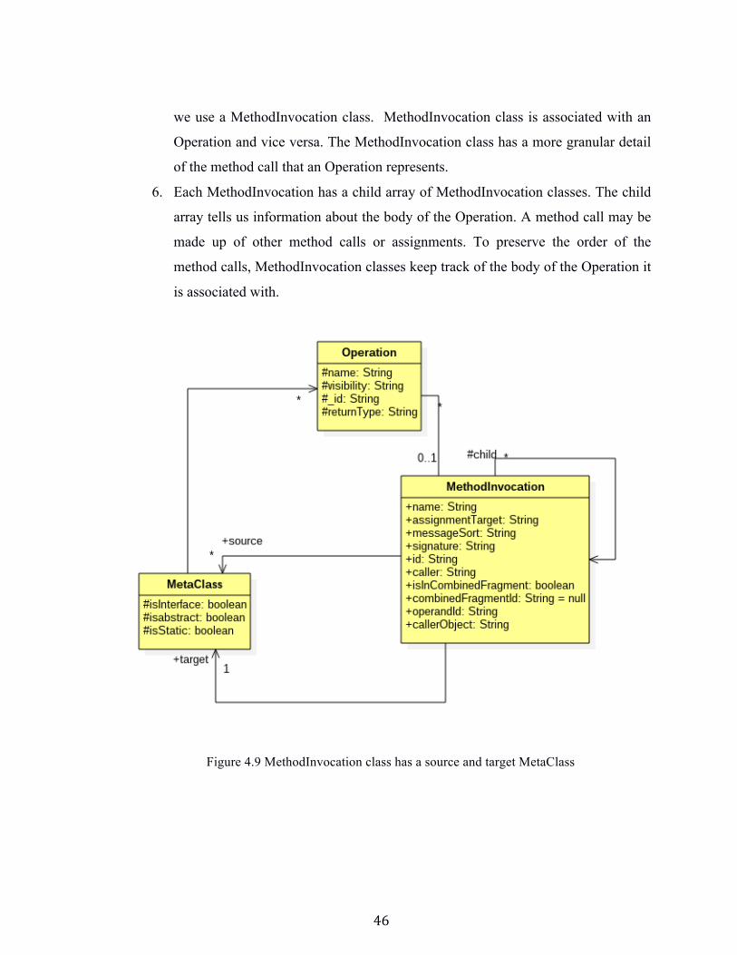
46
we use a MethodInvocation class. MethodInvocation class is associated with an
Operation and vice versa. The MethodInvocation class has a more granular detail
of the method call that an Operation represents.
6. Each MethodInvocation has a child array of MethodInvocation classes. The child
array tells us information about the body of the Operation. A method call may be
made up of other method calls or assignments. To preserve the order of the
method calls, MethodInvocation classes keep track of the body of the Operation it
is associated with.
Figure 4.9 MethodInvocation class has a source and target MetaClass
47
4.3.4 Collaboration Prototyper Profile
A profile is an extension mechanism for customizing UML models for specific domains
or platforms. The extension mechanism adds to the existing UML standard rather than
modifying the UML standard. To specify profiles, we use stereotypes, tags and
constraints that are applied to specific model elements, like Classes, Attributes,
Operations, and Activities. The collection of these extensions makes up a profile.
UML 2.0 distinguishes between models and diagrams. Technically, a UML model
contains elements and their relationships. A UML diagram (sometimes called view)
merely displays parts of a model. In StarUML, most, but not all, of the logical properties
of a system are represented in the model. Unfortunately, some logical properties of a
collaboration model only appear in diagrams. Therefore, it is necessary to introduce a
profile that allows users to add these properties to the model. Also, CP makes several
assumptions about the modeling conventions used.
1. Every collaboration has to have a top-level package, which will tell CP where it
has to start parsing from. This package can have any name. StarUML by default
creates a project called, “Untitled” which can be renamed to anything else or can
be kept the same.
2. The top level Project folder needs to have a model folder under it, which needs to
be named as “Model”. A model can be added by right clicking on the Project >
“Add” menu > “Model”. Internally, StarUML will represent this as a Model of
type “UMLModel”.
3. The Model folder needs to have two sub packages “classes” and “behavior” as
defined in the definition of a collaboration. Note that these sub packages are not
Models and if defined as CP will not recognize Models. The main reason is that
packages have an internal type in StarUML called “UMLPackage” whereas
models have “UMLModel” as their internal type.
48
4. The sub-package “classes” should and must precede the sub package “behavior”
as shown in the figure. This is because the JSON is parsed by CP in a linear
fashion, and it expects the first folder to be “classes”.
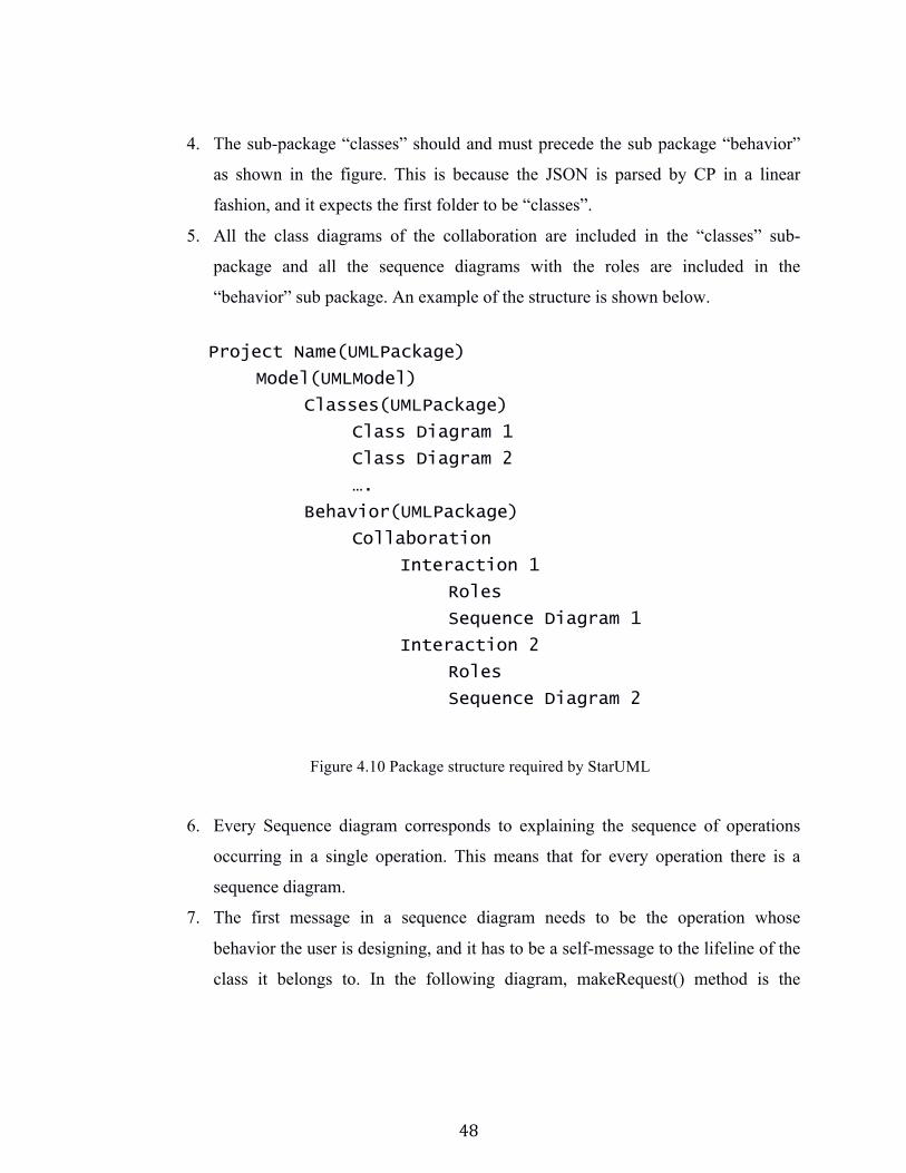
5. All the class diagrams of the collaboration are included in the “classes” sub-
package and all the sequence diagrams with the roles are included in the
“behavior” sub package. An example of the structure is shown below.
Project Name(UMLPackage)
Model(UMLModel)
Classes(UMLPackage)
Class Diagram 1
Class Diagram 2
….
Behavior(UMLPackage)
Collaboration
Interaction 1
Roles
Sequence Diagram 1
Interaction 2
Roles
Sequence Diagram 2
Figure 4.10 Package structure required by StarUML
6. Every Sequence diagram corresponds to explaining the sequence of operations
occurring in a single operation. This means that for every operation there is a
sequence diagram.
7. The first message in a sequence diagram needs to be the operation whose
behavior the user is designing, and it has to be a self-message to the lifeline of the
class it belongs to. In the following diagram, makeRequest() method is the
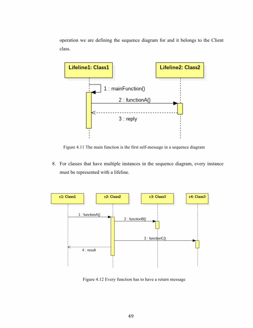
49
operation we are defining the sequence diagram for and it belongs to the Client
class.
Figure 4.11 The main function is the first self-message in a sequence diagram
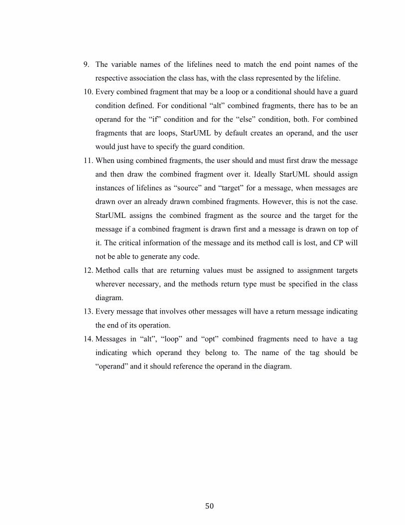
8. For classes that have multiple instances in the sequence diagram, every instance
must be represented with a lifeline.
Figure 4.12 Every function has to have a return message
50
9. The variable names of the lifelines need to match the end point names of the
respective association the class has, with the class represented by the lifeline.
10. Every combined fragment that may be a loop or a conditional should have a guard
condition defined. For conditional “alt” combined fragments, there has to be an
operand for the “if” condition and for the “else” condition, both. For combined
fragments that are loops, StarUML by default creates an operand, and the user
would just have to specify the guard condition.
11. When using combined fragments, the user should and must first draw the message
and then draw the combined fragment over it. Ideally StarUML should assign
instances of lifelines as “source” and “target” for a message, when messages are
drawn over an already drawn combined fragments. However, this is not the case.
StarUML assigns the combined fragment as the source and the target for the
message if a combined fragment is drawn first and a message is drawn on top of
it. The critical information of the message and its method call is lost, and CP will
not be able to generate any code.
12. Method calls that are returning values must be assigned to assignment targets
wherever necessary, and the methods return type must be specified in the class
diagram.
13. Every message that involves other messages will have a return message indicating
the end of its operation.
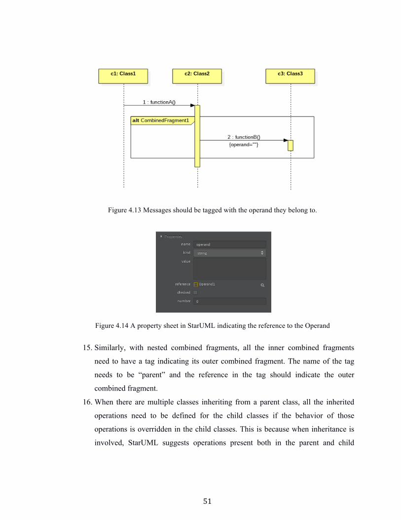
14. Messages in “alt”, “loop” and “opt” combined fragments need to have a tag
indicating which operand they belong to. The name of the tag should be
“operand” and it should reference the operand in the diagram.
51
Figure 4.13 Messages should be tagged with the operand they belong to.
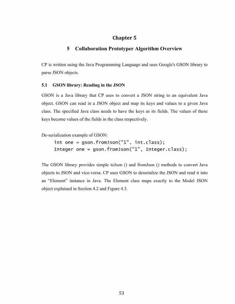
Figure 4.14 A property sheet in StarUML indicating the reference to the Operand
15. Similarly, with nested combined fragments, all the inner combined fragments
need to have a tag indicating its outer combined fragment. The name of the tag
needs to be “parent” and the reference in the tag should indicate the outer
combined fragment.
16. When there are multiple classes inheriting from a parent class, all the inherited
operations need to be defined for the child classes if the behavior of those
operations is overridden in the child classes. This is because when inheritance is
involved, StarUML suggests operations present both in the parent and child

52
classes when drawing the messages. The user needs to be careful while selecting
these operations.
53
Chapter 5
5 Collaboration Prototyper Algorithm Overview
CP is written using the Java Programming Language and uses Google's GSON library to
parse JSON objects.
5.1 GSON library: Reading in the JSON
GSON is a Java library that CP uses to convert a JSON string to an equivalent Java
object. GSON can read in a JSON object and map its keys and values to a given Java
class. The specified Java class needs to have the keys as its fields. The values of these
keys become values of the fields in the class respectively.
De-serialization example of GSON: int one = gson.fromJson("1", int.class);
Integer one = gson.fromJson("1", Integer.class);
The GSON library provides simple toJson () and fromJson () methods to convert Java
objects to JSON and vice-versa. CP uses GSON to deserialize the JSON and read it into
an “Element” instance in Java. The Element class maps exactly to the Model JSON
object explained in Section 4.2 and Figure 4.3.
54
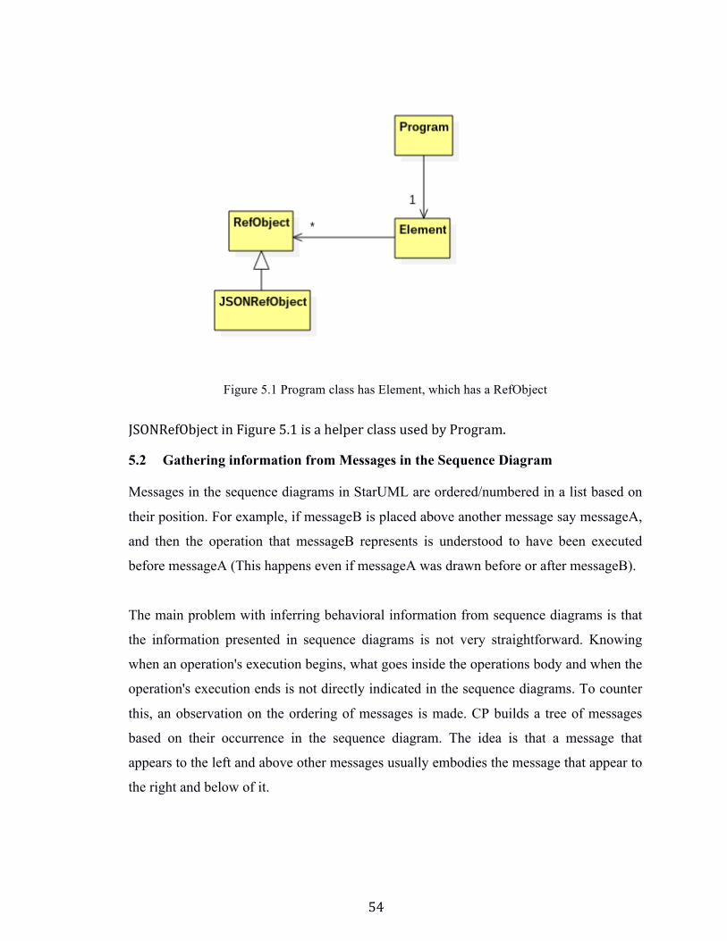
Figure 5.1 Program class has Element, which has a RefObject
JSONRefObject in Figure 5.1 is a helper class used by Program.
5.2 Gathering information from Messages in the Sequence Diagram
Messages in the sequence diagrams in StarUML are ordered/numbered in a list based on
their position. For example, if messageB is placed above another message say messageA,
and then the operation that messageB represents is understood to have been executed
before messageA (This happens even if messageA was drawn before or after messageB).
The main problem with inferring behavioral information from sequence diagrams is that
the information presented in sequence diagrams is not very straightforward. Knowing
when an operation's execution begins, what goes inside the operations body and when the
operation's execution ends is not directly indicated in the sequence diagrams. To counter
this, an observation on the ordering of messages is made. CP builds a tree of messages
based on their occurrence in the sequence diagram. The idea is that a message that
appears to the left and above other messages usually embodies the message that appear to
the right and below of it.
55
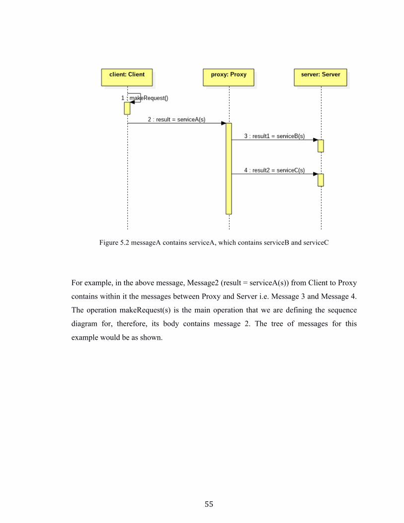
Figure 5.2 messageA contains serviceA, which contains serviceB and serviceC
For example, in the above message, Message2 (result = serviceA(s)) from Client to Proxy
contains within it the messages between Proxy and Server i.e. Message 3 and Message 4.
The operation makeRequest(s) is the main operation that we are defining the sequence
diagram for, therefore, its body contains message 2. The tree of messages for this
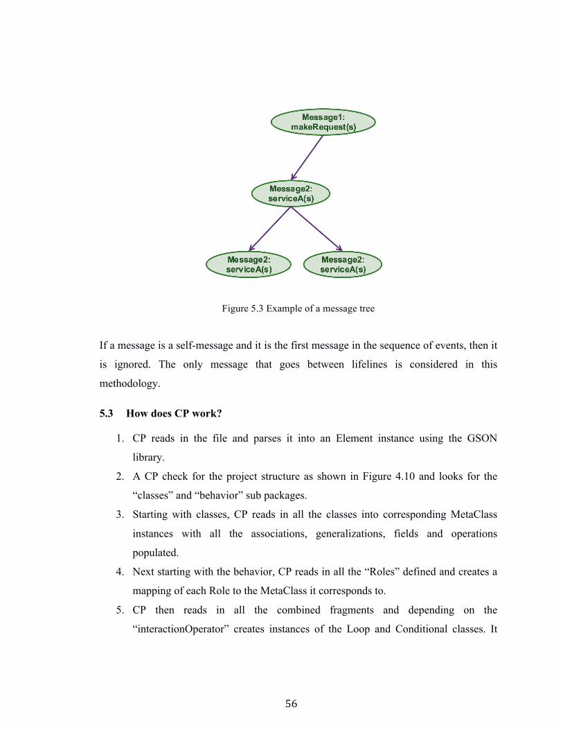
example would be as shown.
56
Figure 5.3 Example of a message tree
If a message is a self-message and it is the first message in the sequence of events, then it
is ignored. The only message that goes between lifelines is considered in this
methodology.
5.3 How does CP work?
1. CP reads in the file and parses it into an Element instance using the GSON
library.
2. A CP check for the project structure as shown in Figure 4.10 and looks for the
“classes” and “behavior” sub packages.
3. Starting with classes, CP reads in all the classes into corresponding MetaClass
instances with all the associations, generalizations, fields and operations
populated.
4. Next starting with the behavior, CP reads in all the “Roles” defined and creates a
mapping of each Role to the MetaClass it corresponds to.
5. CP then reads in all the combined fragments and depending on the
“interactionOperator” creates instances of the Loop and Conditional classes. It
57
checks for nested combined fragments and create a tree of combined fragments
just like the message tree.
6. Next, starting with the first sequence diagram, CP parses in all the participants
representing lifelines in the sequence diagram.
7. For each lifeline, CP creates a Lifeline instance and finds its corresponding role
(MetaClass) and saves this information in a list of Lifeline instances.
Lifeline → Role → Class== Map<Lifeline → MetaClass>
8. For the list of messages in the sequence diagram, CP goes through each and
creates instances of a MethodInovation class and puts them in a list. While doing
so, CP makes a tree of MethodInvocation too as described earlier.
9. CP then makes a mapping of the MethodInovation to the Operation for looking up
later. Map<MethodInvocation, Operation>
10. Next, using both the messageTree and the combinedFragment hierarchy, it iterates
through the messageTree and populates the “block” (ArrayList) of instructions in
every operation.
11. If it encounters a message in a combined fragment, then the message goes into the
block of the Loop or Conditional instance that was created, and the parent
combined fragment instance is added in to the block of the operation.
12. If nested combined fragments are encountered, CP finds the root of the tree and
adds the root to the block of the operation.
13. Finally, after all this information in the MetaClass’s is populated, CP iterates
through each MetaClass and asks it to print itself. Each MetaClass prints its fields,
associations, generalizations and interface realizations if any. Then, the MetaClass
calls the print() in each of its operations, which in turn calls the same print()
function for each of the Instructions in its “block”.

58
59
Chapter 6
6 Conclusion
6.1 StarUML drawbacks
CP has been designed around the many drawbacks and information that StarUML fails to
provide.
A few notable issues in StarUML are
1. StarUML does not provide information on the timeline of a message in a
sequence diagram i.e. the activation bar. This information was crucial for CP
but in StarUML this information is only provided in the view.
2. The JSON Model object in StarUML can be better designed. The Model object
separates information from sequence diagrams such as messages, lifelines, roles
and participants into separate sub-objects instead of grouping together
information that is related.
6.2 The future of CP
CP can be developed in JavaScript as an extension for StarUML. A Profile can be defined
in StarUML, which can be imported and then populated by the user. This would provide
a much simpler way to have a one-click code generation than having two separate
software’s to switch between. In addition, there are a few issues that have not been
covered by CP.
Some collaborations include object lifecycle models in the specification of use case
controllers. These models tell us about the internal states of a controller and their
transitions. Adding this information to our collaborations may allow generation of the
low-level instructions discussed earlier in section 2.3.
In addition to the above,
1. CP does not support multiple packages in a design.
2. CP does not directly add inherited methods to the child classes. It depends on the
user to explicitly specify these.
3. CP does not create getters, setter, declaration and administrative operations.
60
These shortcomings can be challenged and included in the future versions of CP.
6.3 Conclusion
Collaboration Prototyper was developed as a proof of concept to generate code from
StarUML. We defined collaborations, which have the structural and behavioral
information of components. Collaborations thus gave us a starting point for code
generation. We implemented our own profile in StarUML and used it to identify key
information for CP. Finally, the code generated is in a state where it can be compiled and
executed with minor changes. CP helps prove that prototyping can be valuable in the
design phase, and CP can be used to find if an application is feasible or not before
proceeding to the next stages of the software development life cycle.
61
LIST OF REFERENCES [1] Dr. Jon Pearce, The Entity-Control-Boundary Pattern, SJSU Computer Science Department http://www.cs.sjsu.edu/~pearce/modules/lectures/ooa/analysis/ecb.htm [2] Dr. Jon Pearce, The Use Case Controller Pattern, SJSU Computer Science Department http://www.cs.sjsu.edu/~pearce/modules/projects/ooa/ucc/index.htm [3] MKLab, Java Extension for StarUML 2 https://github.com/staruml/Java [4] Dr. Jon Pearce, A Formal Definition of Pattern, SJSU Computer Science Department http://www.cs.sjsu.edu/~pearce/modules/patterns/patterns.htm [5] Dr. Jon Pearce, Implementing Use Cases, SJSU Computer Science Department http://www.cs.sjsu.edu/~pearce/modules/patterns/enterprise/ecb/ecb.htm [6] Alistair Cockburn, Hexagonal Architecture, The Pattern: Ports and Adapters, 2005 http://alistair.cockburn.us/Hexagonal+architecture [7] Sinan Si Alhir, What is the Unified Modeling Language (UML)?,1998 http://citeseerx.ist.psu.edu/viewdoc/summary?doi=10.1.1.36.7220 [8] StarUML 2 Documentation, 2014, MKLab http://docs.staruml.io/en/latest/ [9] Components, Dr. Jon Pearce, SJSU Computer Science Department http://www.cs.sjsu.edu/faculty/pearce/modules/lectures/uml/components/Components [10] Dr. Jon Pearce, Client-Server Architectures, SJSU Computer Science Department http://www.cs.sjsu.edu/~pearce/modules/patterns/distArch/server.htm [11] Dr. Jon Pearce, Proxies, SJSU Computer Science Department http://www.cs.sjsu.edu/~pearce/modules/patterns/distArch/proxies/Proxies.htm [12] Dr. Jon Pearce, The Entity-Control-Boundary Pattern, SJSU Computer Science Department http://www.cs.sjsu.edu/~pearce/modules/lectures/ooa/analysis/ecb.htm [13] Ademar Aguiar ,Alexandre Sousa, Alexandre Pinto, Use-Case Controller, 2001 https://web.fe.up.pt/~aaguiar/as2003-2004/UseCaseCtrl-EuroPLoP2001.pdf
62
[14] Scott W. Ambler, UML 2 Communication Diagramming Guidelines, Agile Modelling, 2014 http://agilemodeling.com/style/collaborationDiagram.htm [15] UML Profile Diagrams, umldiagrams.org, 2009 http://www.uml-diagrams.org/profile-diagrams.html [16] The JSON Data Interchange Format, ECMA International, 2013 http://www.ecma-international.org/publications/files/ECMA-ST/ECMA-404.pdf [17] Unified Modeling Language Infrastructure, Object Management Group, 2005 http://doc.omg.org/formal/2005-07-05.pdf [18] Eclipse, Entity-Control-Boundary Pattern, EPF Wiki, 2008 http://epf.eclipse.org/wikis/openuppt/openup_basic/guidances/concepts/entity_control_boundary_pattern,_uF-QYEAhEdq_UJTvM1DM2Q.html [19] Google Inc, GSON 2.5 API, 2015 http://google.github.io/gson/apidocs/
63
APPENDIX
Collaboration Prototyper Code
The code for CP is hosted at the following link on Github.
https://github.com/rumshenoy/StarUMLCodeGenerator