Learning UML 2.0 - Russ Miles.pdf - Repository UNIKOM
288
-
Upload
khangminh22 -
Category
Documents
-
view
2 -
download
0
Transcript of Learning UML 2.0 - Russ Miles.pdf - Repository UNIKOM


Learning UML 2.0

Other resources from O’Reilly
Related titles UML 2.0 in a Nutshell
UML Pocket Reference
Prefactoring
oreilly.com oreilly.com is more than a complete catalog of O’Reilly books.You’ll also find links to news, events, articles, weblogs, samplechapters, and code examples.
oreillynet.com is the essential portal for developers interested inopen and emerging technologies, including new platforms, pro-gramming languages, and operating systems.
Conferences O’Reilly brings diverse innovators together to nurture the ideasthat spark revolutionary industries. We specialize in document-ing the latest tools and systems, translating the innovator’sknowledge into useful skills for those in the trenches. Visit con-ferences.oreilly.com for our upcoming events.
Safari Bookshelf (safari.oreilly.com) is the premier online refer-ence library for programmers and IT professionals. Conductsearches across more than 1,000 books. Subscribers can zero inon answers to time-critical questions in a matter of seconds.Read the books on your Bookshelf from cover to cover or sim-ply flip to the page you need. Try it today for free.

Learning UML 2.0
Russ Miles and Kim Hamilton
Beijing • Cambridge • Farnham • Köln • Paris • Sebastopol • Taipei • Tokyo

Learning UML 2.0by Russ Miles and Kim Hamilton
Copyright © 2006 O’Reilly Media, Inc. All rights reserved.Printed in the United States of America.
Published by O’Reilly Media, Inc., 1005 Gravenstein Highway North, Sebastopol, CA 95472.
O’Reilly books may be purchased for educational, business, or sales promotional use. Online editionsare also available for most titles (safari.oreilly.com). For more information, contact ourcorporate/institutional sales department: (800) 998-9938 or [email protected].
Editors: Brett McLaughlin and Mary T. O’BrienProduction Editor: Laurel R.T. RumaCopyeditor: Laurel R.T. RumaProofreader: Reba LibbyIndexer: Angela Howard
Cover Designer: Karen MontgomeryInterior Designer: David FutatoCover Illustrator: Karen MontgomeryIllustrators: Robert Romano, Jessamyn Read,
and Lesley Borash
Printing History:
April 2006: First Edition.
Nutshell Handbook, the Nutshell Handbook logo, and the O’Reilly logo are registered trademarks ofO’Reilly Media, Inc. Learning UML 2.0, the image of a gorilla, and related trade dress are trademarks ofO’Reilly Media, Inc.
Many of the designations used by manufacturers and sellers to distinguish their products are claimed astrademarks. Where those designations appear in this book, and O’Reilly Media, Inc. was aware of atrademark claim, the designations have been printed in caps or initial caps.
While every precaution has been taken in the preparation of this book, the publisher and authorsassume no responsibility for errors or omissions, or for damages resulting from the use of theinformation contained herein.
This book uses RepKover™, a durable and flexible lay-flat binding.
ISBN-10: 0-596-00982-8
ISBN-13: 978-0-596-00982-3
[M] [9/07]

v
Table of Contents
Preface . . . . . . . . . . . . . . . . . . . . . . . . . . . . . . . . . . . . . . . . . . . . . . . . . . . . . . . . . . . . . . . . . ix
1. Introduction . . . . . . . . . . . . . . . . . . . . . . . . . . . . . . . . . . . . . . . . . . . . . . . . . . . . . . . 1What’s in a Modeling Language? 2Why UML 2.0? 9Models and Diagrams 12“Degrees” of UML 13UML and the Software Development Process 13Views of Your Model 14A First Taste of UML 16Want More Information? 19
2. Modeling Requirements: Use Cases . . . . . . . . . . . . . . . . . . . . . . . . . . . . . . . . . . 20Capturing a System Requirement 22Use Case Relationships 30Use Case Overview Diagrams 40What’s Next? 41
3. Modeling System Workflows: Activity Diagrams . . . . . . . . . . . . . . . . . . . . . . . 43Activity Diagram Essentials 44Activities and Actions 46Decisions and Merges 47Doing Multiple Tasks at the Same Time 49Time Events 51Calling Other Activities 52Objects 53Sending and Receiving Signals 56
vi | Table of Contents
Starting an Activity 57Ending Activities and Flows 57Partitions (or Swimlanes) 59Managing Complex Activity Diagrams 60What’s Next? 62
4. Modeling a System’s Logical Structure: Introducing Classes and ClassDiagrams . . . . . . . . . . . . . . . . . . . . . . . . . . . . . . . . . . . . . . . . . . . . . . . . . . . . . . . . . 63What Is a Class? 63Getting Started with Classes in UML 67Visibility 67Class State: Attributes 72Class Behavior: Operations 77Static Parts of Your Classes 79What’s Next 82
5. Modeling a System’s Logical Structure: Advanced Class Diagrams . . . . . . . . 83Class Relationships 83Constraints 91Abstract Classes 92Interfaces 96Templates 99What’s Next 100
6. Bringing Your Classes to Life: Object Diagrams . . . . . . . . . . . . . . . . . . . . . . . . 101Object Instances 101Links 103Binding Class Templates 105What’s Next? 107
7. Modeling Ordered Interactions: Sequence Diagrams . . . . . . . . . . . . . . . . . . 108Participants in a Sequence Diagram 109Time 110Events, Signals, and Messages 111Activation Bars 113Nested Messages 114Message Arrows 114Bringing a Use Case to Life with a Sequence Diagram 120Managing Complex Interactions with Sequence Fragments 126What’s Next? 130

Table of Contents | vii
8. Focusing on Interaction Links: Communication Diagrams . . . . . . . . . . . . . . 131Participants, Links, and Messages 131Fleshing out an Interaction with a Communication Diagram 136Communication Diagrams Versus Sequence Diagrams 139What’s Next? 143
9. Focusing on Interaction Timing: Timing Diagrams . . . . . . . . . . . . . . . . . . . . 144What Do Timing Diagrams Look Like? 144Building a Timing Diagram from a Sequence Diagram 146Applying Participants to a Timing Diagram 147States 148Time 149A Participant’s State-Line 152Events and Messages 153Timing Constraints 154Organizing Participants on a Timing Diagram 157An Alternate Notation 159What’s Next? 162
10. Completing the Interaction Picture: Interaction Overview Diagrams . . . . 163The Parts of an Interaction Overview Diagram 163Modeling a Use Case Using an Interaction Overview 165What’s Next? 171
11. Modeling a Class’s Internal Structure: Composite Structures . . . . . . . . . . . 173Internal Structure 174Showing How a Class Is Used 180Showing Patterns with Collaborations 182What’s Next? 185
12. Managing and Reusing Your System’s Parts: Component Diagrams . . . . . . 186What Is a Component? 186A Basic Component in UML 187Provided and Required Interfaces of a Component 188Showing Components Working Together 190Classes That Realize a Component 192Ports and Internal Structure 194Black-Box and White-Box Component Views 196What’s Next? 197

viii | Table of Contents
13. Organizing Your Model: Packages . . . . . . . . . . . . . . . . . . . . . . . . . . . . . . . . . . . 198Packages 199Namespaces and Classes Referring to Each Other 201Element Visibility 203Package Dependency 204Importing and Accessing Packages 205Managing Package Dependencies 208Using Packages to Organize Use Cases 209What’s Next? 210
14. Modeling an Object’s State: State Machine Diagrams . . . . . . . . . . . . . . . . . . 211Essentials 212States 213Transitions 214States in Software 217Advanced State Behavior 218Composite States 220Advanced Pseudostates 221Signals 222Protocol State Machines 223What’s Next? 223
15. Modeling Your Deployed System: Deployment Diagrams . . . . . . . . . . . . . . . 224Deploying a Simple System 224Deployed Software: Artifacts 226What Is a Node? 229Hardware and Execution Environment Nodes 229Communication Between Nodes 231Deployment Specifications 232When to Use a Deployment Diagram 234What’s Next? 235
A. Object Constraint Language . . . . . . . . . . . . . . . . . . . . . . . . . . . . . . . . . . . . . . . . 237
B. Adapting UML: Profiles . . . . . . . . . . . . . . . . . . . . . . . . . . . . . . . . . . . . . . . . . . . . 245
C. A History of UML . . . . . . . . . . . . . . . . . . . . . . . . . . . . . . . . . . . . . . . . . . . . . . . . . . 252
Index . . . . . . . . . . . . . . . . . . . . . . . . . . . . . . . . . . . . . . . . . . . . . . . . . . . . . . . . . . . . . . . . . 259

This is the Title of the Book, eMatter EditionCopyright © 2008 O’Reilly & Associates, Inc. All rights reserved.
Preface | ix
Preface1
The Unified Modeling Language (UML) is the standard way to model systems, par-ticularly software systems. If you are working on a system beyond “Hello, World,” thenhaving UML in your toolbox of skills is a must, and that’s where Learning UML 2.0comes in.
Learning UML 2.0 is about coming to grips with UML quickly, easily, and practi-cally. Along with a thorough set of tutorials on each of the different UML diagramtypes, this book gives you the tools to use UML effectively when designing, imple-menting, and deploying systems. The topics covered include:
• A brief overview of why it is helpful to model systems
• How to capture high-level requirements in your model to help ensure the sys-tem meets users’ needs
• How to model the parts that make up your system
• How to model the behavior and interactions between parts when the system isrunning
• How to move from the model into the real world by capturing how your systemis deployed
• How to create custom UML profiles to accurately model different systemdomains
AudienceLearning UML 2.0 is for anyone interested in learning about UML, but it is helpful tohave some exposure to object-oriented (OO) design and some familiarity with Java.However, even if you have only a small amount of experience with object orienta-tion, Learning UML 2.0 will improve and extend your knowledge of OO conceptsand give you a comprehensive set of tools to work with UML.
Although this book is intended to take you through each subject on the path tolearning UML, some UML modeling subjects, such as use cases and activity dia-grams, are self-explanatory, which means you can dive right into them.

This is the Title of the Book, eMatter EditionCopyright © 2008 O’Reilly & Associates, Inc. All rights reserved.
x | Preface
About This BookLearning UML 2.0 aims to answer the “what,” “how,” and “why should I care?” forevery aspect of UML. Each chapter picks one subject from UML and explains itbased on these questions.
Since not everyone is new to UML, there are two main routes through this book. Ifyou’re new to UML as a subject and want to get an overview of where the modelinglanguage came from, then you should start with Chapter 1. However, if you want toget your hands dirty as quickly as possible, then you can either skip the introductionchapter to delve directly into use cases or jump to the chapter that describes theUML diagram in which you are most interested.
Now you know what Learning UML 2.0 is about, it should be explained what thisbook is not about. This book is not about any one particular modeling tool or imple-mentation language. However, some tools have their own way of doing things, andsome implementation languages do not support everything you can legally model inUML. Wherever appropriate, we have tried to point out where UML tools or imple-mentation languages deviate from or follow the UML standard.
Lastly, because of the large variation in software development processes, this book isnot about any particular process or methodology. Instead, it focuses on modelingand provides guidelines about appropriate levels of modeling that can be applied inthe context of your software development process. Since this book adheres to theUML 2.0 standard, it works alongside any process or methodology you use.
Assumptions This Book MakesThe following general assumptions are made as to the reader’s knowledge andexperience:
• An understanding of object orientation
• Knowledge of the Java™ language for some of the examples
Conventions Used in This BookThe following typographical conventions are used in this book:
ItalicIndicates new terms, URLs, email addresses, filenames, file extensions, path-names, directories, and Unix utilities.
Constant widthIndicates commands, options, switches, variables, attributes, keys, functions,types, classes, namespaces, methods, modules, properties, parameters, values,objects, events, event handlers, XML tags, HTML tags, macros, the contents offiles, or the output from commands.

This is the Title of the Book, eMatter EditionCopyright © 2008 O’Reilly & Associates, Inc. All rights reserved.
Preface | xi
Constant width boldShows commands or other text that should be typed literally by the user.
Constant width italicShows text that should be replaced with user-supplied values.
This icon signifies a tip, suggestion, or general note.
This icon indicates a warning or caution.
Using Code ExamplesThis book is here to help you get your job done. In general, you may use the code inthis book in your programs and documentation. You do not need to contact us forpermission unless you’re reproducing a significant portion of the code. For example,writing a program that uses several chunks of code from this book does not requirepermission. Selling or distributing a CD-ROM of examples from O’Reilly books doesrequire permission. Answering a question by citing this book and quoting examplecode does not require permission. Incorporating a significant amount of examplecode from this book into your product’s documentation does require permission.
We appreciate, but do not require, attribution. An attribution usually includes thetitle, author, publisher, and ISBN. For example: “Learning UML 2.0, by Russ Milesand Kim Hamilton. Copyright 2006 O’Reilly Media, Inc., 0-596-00982-8.”
If you feel your use of code examples falls outside fair use or the permission givenabove, feel free to contact us at [email protected].
Safari® EnabledWhen you see a Safari® Enabled icon on the cover of your favorite tech-nology book, that means the book is available online through theO’Reilly Network Safari Bookshelf.
Safari offers a solution that’s better than e-books. It’s a virtual library that lets youeasily search thousands of top tech books, cut and paste code samples, downloadchapters, and find quick answers when you need the most accurate, current informa-tion. Try it for free at http://safari.oreilly.com.

This is the Title of the Book, eMatter EditionCopyright © 2008 O’Reilly & Associates, Inc. All rights reserved.
xii | Preface
How to Contact UsEverything has been done to ensure that the examples within this book are accurate,tested, and verified to the best of the authors’ ability. However, even though UML isa standard modeling language, the best practices as to its usage may change withtime and this may have an impact on this book’s contents. If so, please address com-ments and questions concerning this book to the publisher:
O’Reilly Media, Inc.1005 Gravenstein Highway NorthSebastopol, CA 95472(800) 998-9938 (in the United States or Canada)(707) 829-0515 (international or local)(707) 829-0104 (fax)
There is a web page for this book where you can find errata, examples, and any addi-tional information. You can access this page at:
http://www.oreilly.com/catalog/learnuml2
To comment or ask technical questions about this book, email:
For more information about our books, conferences, Resource Centers, and theO’Reilly Network, see our web site:
http://www.oreilly.com
Additional information about this topic, including exercises, can be found at:
http://www.learninguml2.com
Acknowledgments
From the AuthorsThanks to Brett and Mary, our ace editors. We are indebted to Brett for providingvaluable guidance throughout, and to Mary for her UML expertise, her amazingwork bringing this book to completion, and her ability to line up an outstandingteam of reviewers.
We’d also like to thank all the kind individuals who put in the hours to provide suchexcellent technical feedback on this book. Thanks to Ed Chou, Glen Ford, StephenMellor, Eric Naiburg, Adewale Oshineye, Dan Pilone and Neil Pitman, and RichardMark Soley (the history of UML would not have been nearly as interesting withoutyour help).

This is the Title of the Book, eMatter EditionCopyright © 2008 O’Reilly & Associates, Inc. All rights reserved.
Preface | xiii
From Russ MilesFirst and foremost, my thanks go to my family and friends: Mum, Dad, Bobbie, Rich,Ad, Corinne (thanks for all your help through the last hectic stages, you’re one in amillion!), Martin and Sam, Jason and Kerry, and Aimee (wonder dog!). You arealways there for me 100 percent and, as a bonus, have the uncanny but very usefulability to get me away from the Mac once in a while when I really need it.
I’d also like to take this opportunity to thank my uncle, Bruce Sargent. You got mestarted on the first steps in this career and for that I am, and always will be, verygrateful!
I’d like to thank all my proofreaders, including Rob Wilson, Laura Paterson, andGrant Tarrant-Fisher. You’ve been great proofreaders, tech reviewers and, most ofall, friends. With your comments this a much better book than anything I could haveput together on my own. Also, a special thanks to Rachel “Kong” Stevens for beingthe unwitting inspiration for the front cover—we love ya!
A big thanks must go to M. David Peterson (http://www.xsltblog.com) and SylvainHellegouarch (http://www.defuze.org) for all their help and inspiration with the CMSexample that is used throughout this book. You’re both top bloggers, developers,and friends and I want to say thanks to you and all the LLUP hackers (http://www.x2x2x.org/projects/wiki) for making my coding life that much more interesting,cheers!
Last, but not least—with what is quickly becoming a standard catch-all—thanks toeveryone who has helped me out while writing this book. I haven’t forgotten yourhelp and I know I owe you all a beer or two!
From Kim HamiltonThanks again to Ed Chou for his gaming expertise that helped create the FPS exam-ple (among his many other excellent contributions!) and for the long hours spentreviewing this book at every phase. A big thanks goes to my reviewers: Frank Chiu,Albert Chu, Yu-Li Lin, Justin Lomheim, Samarth Pal, Leland So, and Delson Ting.You were great at everything—from providing technical feedback to pointing out thehumor in the word OMG. Thanks to John Arcos, Ben Faul, Mike Klug, DwightYorke, and Paul Yuenger, whose support helped me get this book out the door. Also,thanks to Thomas Chen for his CMS help!
Most of all, thanks to my wonderful family and friends—Mom, Dad, Ron, Mark,Grandma and Ed, Grandpa (in loving memory), Aunt Gene, Anne Marie, Kim, Ed C,Sokun, and Tien—who have all been so supportive this past year. Special thanks tomy Mom and Dad: my Mom keeps me going with her love, friendship, and phonecalls; and my Dad has always been my number one technical mentor.


This is the Title of the Book, eMatter EditionCopyright © 2008 O’Reilly & Associates, Inc. All rights reserved.
1
Chapter 1 CHAPTER 1
Introduction1
The Unified Modeling Language (UML) is the standard modeling language for soft-ware and systems development. This statement alone is a pretty conclusive argu-ment for making UML part of your software repertoire, however it leaves somequestions unanswered. Why is UML unified? What can be modeled? How is UML alanguage? And, probably most importantly, why should you care?
Systems design on any reasonably large scale is difficult. Anything from a simpledesktop application to a full multi-tier enterprise scale system can be made up ofhundreds—and potentially thousands—of software and hardware components. Howdo you (and your team) keep track of which components are needed, what their jobsare, and how they meet your customers’ requirements? Furthermore, how do youshare your design with your colleagues to ensure the pieces work together? There arejust too many details that can be misinterpreted or forgotten when developing acomplex system without some help. This is where modeling—and of course UML—comes in.
In systems design, you model for one important reason: to manage complexity. Mod-eling helps you see the forest for the trees, allowing you to focus on, capture, docu-ment, and communicate the important aspects of your system’s design.
A model is an abstraction of the real thing. When you model a system, you abstractaway any details that are irrelevant or potentially confusing. Your model is a simplifi-cation of the real system, so it allows the design and viability of a system to be under-stood, evaluated, and criticized quicker than if you had to dig through the actualsystem itself. Even better, with a formal modeling language, the language is abstractyet just as precise as a programming language. This precision allows a language tobe machine-readable, so it can be interpreted, executed, and transformed betweensystems.
To effectively model a system, you need one very important thing: a language withwhich the model can be described. And here’s where UML comes in.
This is the Title of the Book, eMatter EditionCopyright © 2008 O’Reilly & Associates, Inc. All rights reserved.
2 | Chapter 1: Introduction
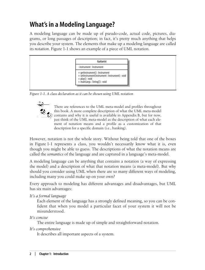
What’s in a Modeling Language?A modeling language can be made up of pseudo-code, actual code, pictures, dia-grams, or long passages of description; in fact, it’s pretty much anything that helpsyou describe your system. The elements that make up a modeling language are calledits notation. Figure 1-1 shows an example of a piece of UML notation.
There are references to the UML meta-model and profiles throughoutthis book. A more complete description of what the UML meta-modelcontains and why it is useful is available in Appendix B, but for now,just think of the UML meta-model as the description of what each ele-ment of notation means and a profile as a customization of thatdescription for a specific domain (i.e., banking).
However, notation is not the whole story. Without being told that one of the boxesin Figure 1-1 represents a class, you wouldn’t necessarily know what it is, eventhough you might be able to guess. The descriptions of what the notation means arecalled the semantics of the language and are captured in a language’s meta-model.
A modeling language can be anything that contains a notation (a way of expressingthe model) and a description of what that notation means (a meta-model). But whyshould you consider using UML when there are so many different ways of modeling,including many you could make up on your own?
Every approach to modeling has different advantages and disadvantages, but UMLhas six main advantages:
It’s a formal languageEach element of the language has a strongly defined meaning, so you can be con-fident that when you model a particular facet of your system it will not bemisunderstood.
It’s conciseThe entire language is made up of simple and straightforward notation.
It’s comprehensiveIt describes all important aspects of a system.
Figure 1-1. A class declaration as it can be shown using UML notation
Guitarist
- instrument : Instrument
+ getInstrument() : Instrument+ setInstrument(instrument : Instrument) : void+ play() : void+ main(args : String[]) : void

This is the Title of the Book, eMatter EditionCopyright © 2008 O’Reilly & Associates, Inc. All rights reserved.
What’s in a Modeling Language? | 3
It’s scaleableWhere needed, the language is formal enough to handle massive system model-ing projects, but it also scales down to small projects, avoiding overkill.
It’s built on lessons learnedUML is the culmination of best practices in the object-oriented community dur-ing the past 15 years.
It’s the standardUML is controlled by an open standards group with active contributions from aworldwide group of vendors and academics, which fends off “vendor lock-in.”The standard ensures UML’s transformability and interoperability, which meansyou aren’t tied to a particular product.
Detail Overload: Modeling with CodeSoftware code is an example of a potential modeling language where none of thedetail has been abstracted away. Every line of code is the detail of how your softwareis intended to work. Example 1-1 shows a very simple class in Java, yet there aremany details in this declaration.
Example 1-1. Even in a simple Java class, there can be a lot of detail to navigate through
package org.oreilly.learningUML2.ch01.codemodel;
public class Guitarist extends Person implements MusicPlayer {
Guitar favoriteGuitar;
public Guitarist (String name) { super(name); }
// A couple of local methods for accessing the class's properties public void setInstrument(Instrument instrument ) { if (instrument instanceof Guitar) { this.favoriteGuitar = (Guitar) instrument; } else { System.out.println("I'm not playing that thing!"); } }
public Instrument getInstrument( ) { return this.favoriteGuitar; }
// Better implement this method as MusicPlayer requires it public void play( ) { System.out.println(super.getName( ) + "is going to do play the guitar now ...");
if (this.favoriteGuitar != null) {

This is the Title of the Book, eMatter EditionCopyright © 2008 O’Reilly & Associates, Inc. All rights reserved.
4 | Chapter 1: Introduction
Example 1-1 shows all of the information about the Guitar class, including inherit-ance relationships to other classes, member variables involving other classes, andeven implementation details for the methods themselves.
What’s wrong with using software source code as your model? All of the details arethere, every element of the language’s notation has meaning to the compiler, andwith some effective code-level comments, such as JavaDoc, you have an accurate rep-resentation of your software system, don’t you?
The truth is that you haven’t actually modeled anything other than the softwareimplementation. The source code focuses only on the software itself and ignores therest of the system. Even though the code is a complete and (generally) unambiguousdefinition of what the software will do, the source code alone simply cannot tell youhow the software is to be used and by whom, nor how it is to be deployed; the big-ger picture is missing entirely if all you have is the source code.
As well as ignoring the bigger picture of your system, software code presents a prob-lem in that you need to use other techniques to explain your system to other people.You have to understand code to read code, but source code is the language for soft-ware developers and is not for other stakeholders, such as customers and systemdesigners. Those people will want to focus just on requirements or perhaps see howthe components of your system work together to fulfill those requirements.Because source code is buried in the details of how the software works, it cannotprovide the higher level abstract views of your system that are suitable for thesetypes of stakeholders.
Now imagine that you have implemented your system using a variety of softwarelanguages. The problem just gets worse. It is simply impractical to ask all thestakeholders in your system to learn each of these implementation languages beforethey can understand your system.
for (int strum = 1; strum < 500; strum++) { this.favoriteGuitar.strum( ); } System.out.println("Phew! Finished all that hard playing"); } else { System.out.println("You haven't given me a guitar yet!"); } }
// I'm a main program so need to implement this as well public static void main(String[] args) { MusicPlayer player = new Guitarist("Russ"); player.setInstrument(new Guitar("Burns Brian May Signature")); player.play( ); }}
Example 1-1. Even in a simple Java class, there can be a lot of detail to navigate through (continued)

This is the Title of the Book, eMatter EditionCopyright © 2008 O’Reilly & Associates, Inc. All rights reserved.
What’s in a Modeling Language? | 5
Finally, if your design is modeled as code, you also lose out when it comes to reusebecause design is often reusable whereas code may not be. For example, reimple-menting a Java Swing application in HTML or .NET is much simpler if the design ismodeled rather than reverse engineering the code. (Reverse engineering is extractingthe design of a system from its implementation.)
All of these problems boil down to the fact that source code provides only one levelof abstraction: the software implementation level. Unfortunately, this root problemmakes software source code a poor modeling language.
Verbosity, Ambiguity, Confusion: Modeling with InformalLanguagesAt the opposite end of the spectrum from complete and precise source code modelsare informal languages. Informal languages do not have a formally defined notation;there are no hard and fast rules as to what a particular notation can mean, althoughsometimes there are guidelines.
A good example of an informal language is natural language. Natural language—thelanguage that you’re reading in this book—is notoriously ambiguous in its meaning.To accurately express something so that everyone understands what you are saying isat best a challenge and at worst flat-out impossible. Natural language is flexible andverbose, which happens to be great for conversation but is a real problem when itcomes to systems modeling.
The following is a slightly exaggerated but technically accurate natural languagemodel of Example 1-1:
Guitarist is a class that contains six members: one static and five non-static. Guitaristuses, and so needs an instance of, Guitar; however, since this might be shared withother classes in its package, the Guitar instance variable, called favoriteGuitar, isdeclared as default.
Five of the members within Guitarist are methods. Four are not static. One of thesemethods is a constructor that takes one argument, and instances of String are calledname, which removes the default constructor.
Three regular methods are then provided. The first is called setInstrument, and it takesone parameter, an instance of Instrument called instrument, and has no return type.The second is called getInstrument and it has no parameters, but its return type isInstrument. The final method is called play. The play method is actually enforced bythe MusicPlayer interface that the Guitarist class implements. The play method takesno parameters, and its return type is void.
Finally, Guitarist is also a runable program. It contains a method that meets the Javaspecification for a main method for this reason.
If you take a hard look at this definition, you can see problems everywhere, almostall resulting from ambiguity in the language. This ambiguity tends to result in the,“No, that’s not what I meant!” syndrome, where you’ve described something as

This is the Title of the Book, eMatter EditionCopyright © 2008 O’Reilly & Associates, Inc. All rights reserved.
6 | Chapter 1: Introduction
clearly as possible, but the person that you are conveying the design to has misunder-stood your meaning (see Figure 1-2).
The problems with informal languages are by no means restricted to written lan-guages. The same description of Guitarist might be presented as a picture like thatshown in Figure 1-3.
Figure 1-3 is another example of an informal language, and it happens to be a nota-tion that I just made up. It makes perfect sense to me, but you could easily misinter-pret my intentions.
Figure 1-2. Even a simple natural language sentence can be interpreted differently by differentstakeholders in the system
Figure 1-3. Informal notation can be confusing; even though my intentions with this diagram mightappear obvious, you really can’t be sure unless I also tell you what the notation means
Natural Language Description:The system needs to be large,
with four legs and a trunk
Natural Language Description:The system needs to be large,
with four legs and a trunk
Communication + Ambiguity = Confusion!
The System Designer’s Perspective The System Implementer’s Perspective
= =
Guitar
uses one of these
Guitarist
Person
is a kind of
Personis one of these
Can be told to play an instrument

This is the Title of the Book, eMatter EditionCopyright © 2008 O’Reilly & Associates, Inc. All rights reserved.
What’s in a Modeling Language? | 7
As with the natural language model, all of the details are present in Figure 1-3’s pic-ture, but without a definition of what the boxes, connections, and labels mean, youcan’t be sure about your interpretation (or mine!).
So, why does any of this matter if your team has a home-grown model-ing technique it’s been using for years and you all understand whateach other means? If you ever have to show your design to externalstakeholders, they might become frustrated trying to understand yourhome-grown symbols, when you could have used a standard notationthey already know. It also means you don’t have to learn a new model-ing technique every time you switch jobs!
The basic problem with informal languages is that they don’t have exact rules fortheir notation. In the natural language example, the meanings of the model’s sen-tences were obscured by the ambiguity and verbosity of the English language. Thepicture in Figure 1-3 may not have suffered from quite the same verbosity problems,but without knowing what the boxes and lines represent, the meaning of the modelwas left largely to guesswork.
Because informal languages are not precise, they can’t be transformed into code as aformal language can. Imagine if Figure 1-3 had a set of formal rules; then you couldgenerate code that implemented the classes for Guitarist, Person, and so on. But thisis impossible without understanding the rules. Unfortunately, informal languageswill always suffer from the dual problem of verbosity and ambiguity, and this is whythey are a poor—and sometimes extremely dangerous—technique for modeling sys-tems, as shown in Figure 1-4.
Figure 1-4. With an informal notation, the problem of confusion through ambiguity still exists
Communication + Ambiguity = Confusion!
The System Designer’s Perspective The System Stakeholder’s Perspective(i.e., the customer)
legs = 4 thing size = large
trunk==
legs = 4 thing size = large
trunk

This is the Title of the Book, eMatter EditionCopyright © 2008 O’Reilly & Associates, Inc. All rights reserved.
8 | Chapter 1: Introduction
Although natural language is dangerously ambiguous, it is still one ofthe best techniques for capturing requirements, as you will see whenyou learn about use cases in Chapter 2.
Getting the Balance Right: Formal LanguagesYou’ve now seen some of the pitfalls of using a too-detailed language for modeling(source code) and a too-verbose and ambiguous language for modeling (natural lan-guage). To effectively model a system—avoiding verbosity, confusion, ambiguity,and unnecessary details—you need a formal modeling language.
Ideally, a formal modeling language has a simple notation whose meaning is well-defined. The modeling language’s notation should be small enough to be learnedeasily and must have an unambiguous definition of the notation’s meaning. UML isjust such a formal modeling language.
Figure 1-5 shows how the code structure in Example 1-1 can be expressed in UML.For now, don’t worry too much about the notation or its meaning; at this point, theUML diagram is meant to be used only as a comparison to the informal pictorial andnatural language models shown previously.
Figure 1-5. Expressing the static structure of the Guitarist class structure in formal UML notation
Guitarist
+ getInstrument() : Instrument+ setInstrument(Instrument instrument) : void+ play() : void+ main(args : String[]) : void
Guitar
1
1
-favoriteGuitar
Person
- name : String
+ getName() : String
<<interface>>MusicPlayer
+ getInstrument() : Instrument+ setInstrument(instrument : Instrument) : void+ play() : void

This is the Title of the Book, eMatter EditionCopyright © 2008 O’Reilly & Associates, Inc. All rights reserved.
Why UML 2.0? | 9
Even if you don’t yet understand all of the notation used in Figure 1-5, you can prob-ably start to grasp that there are some details present in the code—seeExample 1-1—that are not modeled here. For example, the specific implementationof the play( ) method has been abstracted away, allowing you to visualize the code’sstructure without excess clutter.
The best thing about having modeled the system using UML is that the notation inFigure 1-5 has a specific and defined meaning. If you were to take this diagram toany other stakeholder in your system, provided he knows UML, the design would beclearly understood. This is the advantage of using formal languages for modeling asshown in Figure 1-6.
Why UML 2.0?The first version of UML allowed people to communicate designs unambiguously,convey the essence of a design, and even capture and map functional requirements totheir software solutions. However, the world changed more fundamentally with therecognition that systems modeling, rather than just software modeling, could alsobenefit from a unified language such as UML.
The driving factors of component-oriented software development, model-drivenarchitectures, executable UML, and the need to share models between different toolsplaced demands on UML that it had not originally been designed to meet.
Figure 1-6. With a modeling language that has a formally defined meaning, you can ensure thateveryone is reading the picture the same way
Communication + Meaning = Success!
The System Designer’s Perspective The System Stakeholder'sPerspective
(i.e., the customer)
Leg
The System Implementer’sPerspective
Thing
Trunk
4 11
1-size = large
Leg Thing
Trunk
4 11
1-size = large
= =

This is the Title of the Book, eMatter EditionCopyright © 2008 O’Reilly & Associates, Inc. All rights reserved.
10 | Chapter 1: Introduction
Also, UML 1.x and all of its previous revisions were designed as a unified languagefor humans. When it became important for models to be shared between machines—specifically between Computer Aided Systems Engineering (CASE) tools—UML 1.xwas again found wanting. UML 1.x’s underlying notation rules and its meta-modelwere (ironically) not formally defined enough to enable machine-to-machine sharingof models.
Although UML 1.5 described a system fairly well, the model describing the model—the meta-model—had become patched and overly complex. Like any system that hasan overly complex design, and is fragile and difficult to extend, UML had becomeoverly complex, fragile, and difficult to extend; it was time for a re-architecture.
The designers of UML 2.0 were very careful to ensure that UML 2.0 would not betoo unfamiliar to people who were already using UML 1.x. Many of the original dia-grams and associated notations have been retained and extended in UML 2.0 asshown in Table 1-1. However, new diagram types have been introduced to extendthe language just enough so that it can support the latest best practices.
With Version 2.0, UML has evolved to support the new challenges that software andsystem modelers face today. What began many years ago as a unification of the dif-ferent methods for software design has now grown into a unified modeling languagethat is ready and suitable to continue to be the standard language for the myriad ofdifferent tasks involved in software and systems design.
MDA and Executable UMLTwo reasonably new approaches to system development inspired many of theimprovements made in UML 2.0. In a nutshell, Model Driven Architectures (MDAs)provide a framework that supports the development of Platform Independent Models(PIMs)—models that capture the system in a generic manner that is divorced from con-cerns such as implementation language and platform.
PIMs can then be transformed into separate Platform Specific Models (PSMs) that con-tain concrete specifications for a particular system deployment (containing details suchas implementation language and communications protocols, etc.). MDA requires aformally structured and interoperable meta-model to perform its transformations, andthis level of meta-model is now provided by UML 2.0.
For many of the same reasons, executable UML provides a means by which a PSMcould contain enough complete information so that the model can be effectively run.Some day, you could conceivably drag around a few symbols, and complete, runnablesoftware would pop out! An executable UML engine requires that the UML model bedefined well enough for it to be able to generate and execute the modeled system.
Unfortunately, even though UML 2.0 is supposed to provide the mechanisms to makeMDA and executable UML a reality, tools support is not yet fully developed.

This is the Title of the Book, eMatter EditionCopyright © 2008 O’Reilly & Associates, Inc. All rights reserved.
Why UML 2.0? | 11
Table 1-1. To describe the larger landscape of systems design, UML 2.0 renamed and clarified itsdiagrams for the new challenges facing system modelers today
Diagram type What can be modeled?Originally introduced byUML 1.x or UML 2.0
To learn about thisdiagram type, go to…
Use Case Interactions between yoursystem and users or otherexternal systems. Also help-ful in mapping require-ments to your systems.
UML 1.x Chapter 2
Activity Sequential and parallel activ-ities within your system.
UML 1.x Chapter 3
Class Classes, types, interfaces,and the relationshipsbetween them.
UML 1.x Chapters 4 and 5
Object Object instances of theclasses defined in class dia-grams in configurationsthat are important to yoursystem.
Informally UML 1.x Chapter 6
Sequence Interactions between objectswhere the order of the inter-actions is important.
UML 1.x Chapter 7
Communication The ways in which objectsinteract and the connec-tions that are needed tosupport that interaction.
Renamed from UML 1.x’scollaboration diagrams
Chapter 8
Timing Interactions betweenobjects where timing is animportant concern.
UML 2.0 Chapter 9
Interaction Overview Used to collect sequence,communication, and timingdiagrams together to cap-ture an important interac-tion that occurs within yoursystem.
UML 2.0 Chapter 10
Composite Structure The internals of a class orcomponent, and candescribe class relationshipswithin a given context.
UML 2.0 Chapter 11
Component Important componentswithin your system and theinterfaces they use to inter-act with each other.
UML 1.x, but takes on a newmeaning in UML 2.0
Chapter 12
Package The hierarchical organiza-tion of groups of classes andcomponents.
UML 2.0 Chapter 13

This is the Title of the Book, eMatter EditionCopyright © 2008 O’Reilly & Associates, Inc. All rights reserved.
12 | Chapter 1: Introduction
Models and DiagramsMany newcomers to UML focus on the different types of diagrams used to modeltheir system. It’s very easy to assume that the set of diagrams that have been createdactually are the model. This is an easy mistake to make because when you are usingUML, you will normally be interacting with a UML tool and a particular set of dia-grams. But UML modeling is not just about diagrams; it’s about capturing your sys-tem as a model—the diagrams are actually just windows into that model.
A particular diagram will show you some parts of your model but not necessarilyeverything. This makes sense, since you don’t want a diagram showing everything inyour model all at once—you want to be able to split contents of your model acrossseveral diagrams. However, not everything in your model needs to exist on a dia-gram for it to be a part of your model.
So, what does this mean? Well, the first thing to understand is that your model sitsbehind your modeling tool and diagrams as a collection of elements. Each of thoseelements could be a use case, a class, an activity, or any other construct that UMLsupports. The collection of all the elements that describe your system, including theirconnections to each other, make up your model.
However, if all you could do was create a model made up of elements, then youwouldn’t have much to look at. This is where diagrams come in. Rather than actu-ally being your model, diagrams are used merely as a canvas on which you can cre-ate new elements that are then added to your model and organize related elementsinto a set of views on your underlying model.
So, when you next use your UML tool to work with a set of diagrams in UML nota-tion, it is worth remembering that what you are manipulating is a view of the con-tents of your model. You can change elements of your model within the diagram, butthe diagram itself is not the model—it’s just a useful way of presenting some smallpart of the information your model contains.
State Machine The state of an objectthroughout its lifetime andthe events that can changethat state.
UML 1.x Chapter 14
Deployment How your system is finallydeployed in a given real-world situation.
UML 1.x Chapter 15
Table 1-1. To describe the larger landscape of systems design, UML 2.0 renamed and clarified itsdiagrams for the new challenges facing system modelers today (continued)
Diagram type What can be modeled?Originally introduced byUML 1.x or UML 2.0
To learn about thisdiagram type, go to…

This is the Title of the Book, eMatter EditionCopyright © 2008 O’Reilly & Associates, Inc. All rights reserved.
UML and the Software Development Process | 13
“Degrees” of UMLUML can be used as much or as little as you like. Martin Fowler describes three com-mon ways that people tend to use UML:
UML as a sketchUse UML to make brief sketches to convey key points. These are throwawaysketches—they could be written on a whiteboard or even a beer coaster in acrunch.
UML as a blueprintProvide a detailed specification of a system with UML diagrams. These dia-grams would not be disposable but would be generated with a UML tool. Thisapproach is generally associated with software systems and usually involvesusing forward and reverse engineering to keep the model synchronized with thecode.
UML as a programming languageThis goes directly from a UML model to executable code (not just portions ofthe code as with forward engineering), meaning that every aspect of the system ismodeled. Theoretically, you can keep your model indefinitely and use transfor-mations and code generation to deploy to different environments.
The approach used depends on the type of application you’re building, how rigor-ously the design will be reviewed, whether you are developing a software system,and, if it is software, the software development process you’re using.
In certain industries, such as medical and defense, software projects tend to leantoward UML as a blueprint because a high level of quality is demanded. Softwaredesign is heavily reviewed since it could be mission-critical: you don’t want yourheart monitoring machine to suddenly display the “blue screen of death.”
Some projects can get away with less modeling. In fact, some commercial industriesfind that too much modeling is cumbersome and slows down productivity. For suchprojects, it makes sense to use UML as a sketch and have your model contain somearchitectural diagrams and a few class and sequence diagrams to illustrate keypoints.
UML and the Software Development ProcessWhen you are using UML to model a software system, the “degree of UML” youapply is partially influenced by the software development process you use.
A software development process is a recipe used for constructing software—deter-mining the capabilities it has, how it is constructed, who works on what, and thetimeframes for all activities. Processes aim to bring discipline and predictability to

This is the Title of the Book, eMatter EditionCopyright © 2008 O’Reilly & Associates, Inc. All rights reserved.
14 | Chapter 1: Introduction
software development, increasing the chance of success of a project. Since UML isthe language for modeling your software, it’s an important part of the software devel-opment process.
A few well-known software development processes include:
WaterfallThe waterfall method attempts to pin down the requirements early in the projectlife cycle. After gathering requirements, software design is performed in full.Once the design is complete, the software is implemented. The problem with thismethod is that if a change in requirements occurs, the impact can be devastating.
IterativeIterative methods attempt to address the shortcomings of the waterfall approachby accepting that change will happen and, in fact, embracing it. The Unified Pro-cess is a well-known iterative process. It consists of multiple phases, each phasecontaining some amount of the following activities: requirements, design, andimplementation (coding). Iterative methods encompass a wider range ofapproaches (e.g., agile iterative processes), and they can range from using UMLas sketch to using UML as blueprint.
Agile methodsAgile methods use iterations in extremely short bursts and attempt to minimizerisk by always having a working system of expanding capabilities. Methodolo-gies under this category have introduced some of the more interesting develop-ment practices, such as pair programming and test-driven development. Agilemethods emphasize using UML as a sketch.
Views of Your ModelThere are a number of ways to break up your UML model diagrams into perspec-tives or views that capture a particular facet of your system. In this book, we useKruchten’s 4+1 view model to help you show you how each diagram type plays apart in the overall model, as shown in Figure 1-7.
Figure 1-7. Philippe Kruchten’s 4+1 view model
Logical View Process View
Physical View Development View
Use Case View

This is the Title of the Book, eMatter EditionCopyright © 2008 O’Reilly & Associates, Inc. All rights reserved.
Views of Your Model | 15
The 4+1 view model breaks down a model into a set of views, each capturing a spe-cific aspect of your system:
Logical viewDescribes the abstract descriptions of a system’s parts. Used to model what asystem is made up of and how the parts interact with each other. The types ofUML diagrams that typically make up this view include class, object, statemachine, and interaction diagrams.
Process viewDescribes the processes within your system. It is particularly helpful when visu-alizing what must happen within your system. This view typically containsactivity diagrams.
Development viewDescribes how your system’s parts are organized into modules and components.It is very useful to manage layers within your system’s architecture. This viewtypically contains package and component diagrams.
Physical viewDescribes how the system’s design, as described in the three previous views, isthen brought to life as a set of real-world entities. The diagrams in this viewshow how the abstract parts map into the final deployed system. This view typi-cally contains deployment diagrams.
Use case viewDescribes the functionality of the system being modeled from the perspective ofthe outside world. This view is needed to describe what the system is supposedto do. All of the other views rely on the use case view to guide them—that’s whythe model is called 4+1. This view typically contains use case diagrams,descriptions, and overview diagrams.
Each view offers a different and important perspective on your model. If you findyourself asking, “Why do I care about this?” as you read about a particular notationor diagram, refer to the view that the diagram or notation provides to understandwhy it is needed.
To learn more about Kruchten’s 4+1 view model, check out “Archi-tectural Blueprints—The ‘4+1’ View Model of Software Architec-ture” by Philippe Kruchten, at http://www3.software.ibm.com/ibmdl/pub/software/rational/web/whitepapers/2003/Pbk4p1.pdf. For an over-view, visit http://www-128.ibm.com/developerworks/wireless/library/wi-arch11/.
This is the Title of the Book, eMatter EditionCopyright © 2008 O’Reilly & Associates, Inc. All rights reserved.
16 | Chapter 1: Introduction
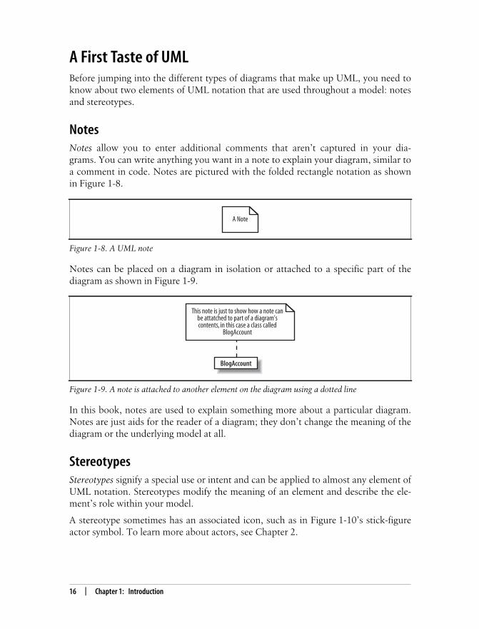
A First Taste of UMLBefore jumping into the different types of diagrams that make up UML, you need toknow about two elements of UML notation that are used throughout a model: notesand stereotypes.
NotesNotes allow you to enter additional comments that aren’t captured in your dia-grams. You can write anything you want in a note to explain your diagram, similar toa comment in code. Notes are pictured with the folded rectangle notation as shownin Figure 1-8.
Notes can be placed on a diagram in isolation or attached to a specific part of thediagram as shown in Figure 1-9.
In this book, notes are used to explain something more about a particular diagram.Notes are just aids for the reader of a diagram; they don’t change the meaning of thediagram or the underlying model at all.
StereotypesStereotypes signify a special use or intent and can be applied to almost any element ofUML notation. Stereotypes modify the meaning of an element and describe the ele-ment’s role within your model.
A stereotype sometimes has an associated icon, such as in Figure 1-10’s stick-figureactor symbol. To learn more about actors, see Chapter 2.
Figure 1-8. A UML note
Figure 1-9. A note is attached to another element on the diagram using a dotted line
A Note
This note is just to show how a note canbe attatched to part of a diagram'scontents, in this case a class called
BlogAccount
BlogAccount

This is the Title of the Book, eMatter EditionCopyright © 2008 O’Reilly & Associates, Inc. All rights reserved.
A First Taste of UML | 17
There isn’t always a special icon for a stereotype; sometimes they take up too muchroom and clutter a diagram. In these cases, the stereotype is shown using guillemotsat either end of the stereotype name, as in «stereotype_name», shown in Figure 1-11.However, because guillemots require an extended character set, you can substitutethem for angle brackets, as in <<stereotype_name>>.
There is no limit to the number of stereotypes with which an element can be associ-ated; sometimes you may end up specifying more than one stereotype, as shown inFigure 1-12.
The UML specification defines a set of “standard” or predefined stereotypes. Some ofthe more useful standard stereotypes include:
Stereotype applied to classes (see Chapters 4 and 5)
utilityRepresents a class that provides utility services through static methods, justas Java’s Math class.
Figure 1-10. The Administrator is represented in the role of an actor because it is using the stickfigure notation associated with that stereotype
Figure 1-11. The Administrator element is still an actor, but its stereotype is now specified using aname rather than an icon
Figure 1-12. The Administrator is now stereotyped as an actor and a person
The stereotype of this element is“actor” as shown by the stick
figure icon
Administrator
<<actor>>Administrator
<<actor, person>>Administrator

This is the Title of the Book, eMatter EditionCopyright © 2008 O’Reilly & Associates, Inc. All rights reserved.
18 | Chapter 1: Introduction
Stereotypes applied to components (see Chapter 12)
serviceA stateless, functional component that computes a value; could be used torepresent a web service.
subsystemA large component that is actually a subordinate system of a larger system.
Stereotypes applied to artifacts (see Chapter 15)
executableA physical file that is executable, such as an .exe file.
fileA physical file used by your system; this could be a configuration file such asa .txt file.
libraryA static or dynamic library file; you could use this to model .dll or .jar libraryfiles.
sourceA source file containing code, such as a .java or .cpp file.
Tagged values
Stereotypes can contain extra information that relates to the element to which theyare applied. This extra information is specified using tagged values.
Tagged values are associated with a stereotype. Say you had an element in yourmodel that represented a login page on a web site, and it was stereotyped as a form.The form stereotype needs to know whether it should validate the contents of theform or not in this case. This validation decision should be declared as a tagged valueof the form stereotype because it is associated with the stereotype that is applied to anelement, not with the element itself.
A tagged value is drawn on a diagram using a similar notation to notes, but thefolded rectangle contains the name of any stereotypes and settings for any associatedtagged values. The tagged value note is then attached to the stereotyped elementusing a dotted line with a circle at the element end, as shown in Figure 1-13. (Thisexample was adapted from UML 2.0 in a Nutshell [O’Reilly].)
Figure 1-13. The form stereotype has an associated validate tagged value, which is set to true in thiscase
<<form>>LoginPage <<form>>
validate = true

This is the Title of the Book, eMatter EditionCopyright © 2008 O’Reilly & Associates, Inc. All rights reserved.
Want More Information? | 19
In UML 2.0, stereotypes and their tagged values are defined using pro-files. To learn more about stereotypes and how to create roles for theelements of your model, see Appendix B.
Want More Information?The next step is to jump into Chapter 2 and start learning UML. If you’re a bit of ahistory buff, then you can also check out a brief history of UML in Appendix C.
UML is a concise language but a big subject. As well as learning about UML, it’sworth reading through the tutorials and documentation available at the ObjectManagement Group’s web site, http://www.omg.org.
This is the Title of the Book, eMatter EditionCopyright © 2008 O’Reilly & Associates, Inc. All rights reserved.
20
Chapter 2CHAPTER 2
Modeling Requirements: Use Cases 2
Imagine that it’s Monday morning and your first day on a new project. The require-ments folks have just popped in for a coffee—and to leave you the 200-page require-ments document they’ve been working on for the past six months. Your boss’sinstructions are simple: “Get your team up to speed on these requirements so thatyou can all start designing the system.” Happy Monday, huh?
To make things just a bit more difficult, the requirements are still a little fuzzy, andthey are all written in the language of the user—confusing and ambiguous naturallanguage rather than in a language that your system stakeholders can easily under-stand. See the “Verbosity, Ambiguity, Confusion: Modeling with Informal Lan-guages” section in Chapter 1 for more on the problems of modeling with natural andinformal languages.
What is the next step, apart from perhaps a moment or two of sheer panic? How doyou take this huge set of loosely defined requirements and distill it into a format foryour designers without losing important detail? UML, as you know from Chapter 1,is the answer to both of these questions. Specifically, you need to work with yoursystem’s stakeholders to generate a full set of requirements and something new—use cases.
A use case is a case (or situation) where your system is used to fulfill one or more ofyour user’s requirements; a use case captures a piece of functionality that the systemprovides. Use cases are at the heart of your model, shown in Figure 2-1, since theyaffect and guide all of the other elements within your system’s design.
Use cases are an excellent starting point for just about every facet of object-orientedsystem development, design, testing, and documentation. They describe a system’srequirements strictly from the outside looking in; they specify the value that the sys-tem delivers to users. Because use cases are your system’s functional requirements,they should be the first serious output from your model after a project is started.After all, how can you begin to design a system if you don’t know what it will berequired to do?

This is the Title of the Book, eMatter EditionCopyright © 2008 O’Reilly & Associates, Inc. All rights reserved.
Modeling Requirements: Use Cases | 21
Use cases specify only what your system is supposed to do, i.e., thesystem’s functional requirements. They do not specify what the sys-tem shall not do, i.e., the system’s nonfunctional requirements. Non-functional requirements often include performance targets andprogramming languages, etc.
When you are working on a system’s requirements, questions often arise as towhether the system has a particular requirement. Use cases are a means to bringthose gaps in the user’s requirements to the forefront at the beginning of a project.
This is a real bonus for the system designer since a gap or lack of understanding iden-tified early on in a project’s development will cost far less in both time and moneythan a problem that is not found until the end of a project. Once a gap has beenidentified, go back to the system’s stakeholders—the customers and users—so theycan provide the missing information.
It’s even better when a requirement is presented as a use case and thestakeholder sees that the requirement has little or no value to the sys-tem. If a stakeholder can discard unnecessary requirements, bothmoney and time are saved.
Once priority and risk are assigned to a use case, it can help manage a project’sworkload. Your use cases can be assigned to teams or individuals to be implementedand, since a use case represents tangible user value, you can track the progress of theproject by use cases delivered. If and when a project gets into schedule trouble, usecases can be jettisoned or delayed to deliver the highest value soonest.
Last but not least, use cases also help construct tests for your system. Use cases pro-vide an excellent starting point for building your test cases and procedures becausethey precisely capture a user’s requirements and success criteria. What better way totest your system than by using the use cases that originally captured what the userwanted in the first place?
Figure 2-1. Use cases affect every other facet of your system’s design; they capture what is requiredand the other views on your model, then show how those requirements are met
Logical View Process View
Physical View Development View
Use Case View

This is the Title of the Book, eMatter EditionCopyright © 2008 O’Reilly & Associates, Inc. All rights reserved.
22 | Chapter 2: Modeling Requirements: Use Cases
Capturing a System RequirementEnough theory for now; let’s take a look at a simple example. Suppose we’re defin-ing requirements for a weblog content management system (CMS).
There’s actually no specific “best way” to start analyzing Requirement A.1, but oneuseful first step is to look at the things that interact with your system. In use cases,these external things are called actors.
The terms shall and should have a special and exact meaning when itcomes to requirements. A shall requirement must be fulfilled; if the fea-ture that implements a shall requirement is not in the final system,then the system does not meet this requirement. A should requirementimplies that the requirement is not critical to the system working but isstill desirable. If a system’s development is running into problems thatwill cause delivery delays, then it’s often the should requirements thatare sacrificed first.
Outside Your System: ActorsAn actor is drawn in UML notation using either a “stick man” or a stereotyped box(see “Stereotypes” in Chapter 1) and is labeled with an appropriate name, as shownin Figure 2-2.
Figure 2-2 captures the Administrator role as it is described in Requirement A.1. Thesystem that is being modeled is the CMS; the requirement’s description indicates
Requirement A.1The content management system shall allow an administrator to create a new blogaccount, provided the personal details of the new blogger are verified using the authorcredentials database.
Blog FeaturesWeblogs, commonly referred to as blogs, originally started out as privately maintainedweb pages for authors to write about anything. These days, blogs are usually packagedinto an overall CMS. Bloggers submit new entries to the system, administrators allo-cate blogging accounts, and the systems typically incorporate advanced features, suchas RSS feeds. A well-publicized blog can attract thousands of readers (see O’Reilly’sblogging site at http://weblogs.oreillynet.com).

This is the Title of the Book, eMatter EditionCopyright © 2008 O’Reilly & Associates, Inc. All rights reserved.
Capturing a System Requirement | 23
that the Administrator interacts with the system to create a new blogger’s account.The Administrator interacts with the system and is not part of the system; therefore,the Administrator is defined as an actor.
Deciding what is and what is not an actor is tricky and is something best learned byexperience. Until you’ve gained some of that experience, Figure 2-3 shows a simpletechnique for analyzing a “thing” that you’ve found in your requirements and how todecide whether it is an actor or not.
Actors don’t have to be actual people. While an actor might be a person, it couldalso be a third party’s system, such as in a business-to-business (B2B) application.Think of an actor as a black box: you cannot change an actor and you are not inter-ested in how it works, but it must interact with your system.
Tricky actors
Not all actors are obvious external systems or people that interact with your system.An example of a common tricky actor is the system clock. The name alone impliesthat the clock is part of the system, but is it really?
The system clock comes into play when it invokes some behavior within your sys-tem. It is hard to determine whether the system clock is an actor because the clock isnot clearly outside of your system. As it turns out, the system clock is often bestdescribed as an actor because it is not something that you can influence. Addition-ally, describing the clock as an actor will help when demonstrating that your systemneeds to perform a task based on the current time.
Figure 2-2. Requirement A.1 contains an Administrator actor that interacts with the system tocreate a blog account
What’s in a Name?It’s actually worth being very careful when naming your actors. The best approach isto use a name that can be understood by both your customer and your system design-ers. Wherever possible, use the original term for the actor as identified within your cus-tomer’s requirements; that way, at least your use cases will be familiar to yourcustomers. This approach also lets system designers get comfortable with the system’sunique context.
Administrator
<<actor>>Administrator

This is the Title of the Book, eMatter EditionCopyright © 2008 O’Reilly & Associates, Inc. All rights reserved.
24 | Chapter 2: Modeling Requirements: Use Cases
It is also tempting to focus on just the users of your systems as the actors in yourmodel, but don’t forget about other people, such as auditors, installers, maintainers,upgraders, and so on. If you focus on only the obvious users of your system, thenyou might forget about some of these other stakeholders, and that can be very dan-gerous! Those actors may have a veto (“We can’t certify this system without proofthat the data has not been tampered with”) or they may have to enforce importantnonfunctional requirements, such as an upgrade in a 10-minute system downtimewindow and an upgrade without shutting the system down, etc. If these actors areignored, these important functions of your system won’t be documented, and yourisk ending up with a worthless system.
Refining actors
When going through the process of capturing all of the actors that interact with yoursystem, you will find that some actors are related to each other, as shown inFigure 2-4.
The Administrator actor is really a special kind of system user. To show that anadministrator can do whatever a regular user can do (with some extra additions), ageneralization arrow is used. For more on generalization and the generalizationarrow, see Chapter 5.
Figure 2-3. Here are a couple of questions to ask yourself when trying to identify an actor
Is the "thing" an actualperson interacting with
the system?
Is the "thing" somethingthat I can change within
the system's design?
No
Identity a "thing" from your requirements
The "thing" is probably not an actor.Anything that you can affect and
have some control over whendesigning your system is likely
to be considered a part of your system.
The "thing" is probably an actor.Be careful when it comes to people;
some people can be consideredpart of your system.
Yes
Yes
No

This is the Title of the Book, eMatter EditionCopyright © 2008 O’Reilly & Associates, Inc. All rights reserved.
Capturing a System Requirement | 25
Use CasesOnce you have captured an initial set of actors that interact with your system, youcan assemble the exact model of those interactions. The next step is to find caseswhere the system is being used to complete a specific job for an actor—use cases, infact. Use cases can be identified from your user’s requirements. This is where thosewordy, blurry definitions in the user requirements document should be distilled intoa clear set of jobs for your system.
Remember, if use cases are truly requirements, then they must havevery clear pass/fail criteria. The developer, the tester, the technicalwriter, and the user must explicitly know whether the system fulfilsthe use case or not.
A use case, or job, might be as simple as allowing the user to log in or as complex asexecuting a distributed transaction across multiple global databases. The importantthing to remember is that a use case—from the user’s perspective—is a complete useof the system; there is some interaction with the system, as well as some output fromthat interaction. For example, Requirement A.1 describes one main use of the CMS:to create a new blog account. Figure 2-5 shows how this interaction is captured as ause case.
Figure 2-4. Showing that an administrator is a special kind of user
Figure 2-5. A use case in UML is drawn as an oval with a name that describes the interaction thatit represents
The moregeneral "User"
actor
User
TheGeneralization
Arrow
The morespecialized
"Administrator" actor
Administrator
Create anew Blog Account

This is the Title of the Book, eMatter EditionCopyright © 2008 O’Reilly & Associates, Inc. All rights reserved.
26 | Chapter 2: Modeling Requirements: Use Cases
After all that build-up, you might have expected a use case to be a complex piece ofnotation. Instead, all you get is an oval! The notation for a use case is very simpleand often hides its importance in capturing system concerns. Don’t be deceived; theuse case is probably the single most powerful construct in UML to make sure yoursystem does what it is supposed to.
Communication LinesAt this point, we’ve identified a use case and an actor, but how do we show that theAdministrator actor participates in the Create a new Blog Account use case? Theanswer is by using communication lines.
A communication line connects an actor and a use case to show the actor participatingin the use case. In this example, the Administrator actor is involved in the Create a newBlog Account use case; this is shown in Figure 2-6 by adding a communication line.
This simple example shows a communication line between only one actor and onlyone use case. There is potential to have any number of actors involved in a use case.There is no theoretical limit to the number of actors that can participate in a use case.
To show a collection of actors participating in a use case, all you have to do is draw acommunication line from each of the participating actors to the use case oval, asshown in Figure 2-7.
What Makes a Good Use Case?Experience will help you determine when you have a good use case, but there is a ruleof thumb that can be used to specify a use case:
A use case is something that provides some measurable result to the user or an externalsystem.
Any piece of system behavior that meets this simple test is likely to be a good candidatefor a use case.
Figure 2-6. A communication line joins the Administrator actor to the “Create a new BlogAccount” use case; the Administrator is involved in the interaction that the use case represents
Administrator
Create anew Blog Account
This is the Title of the Book, eMatter EditionCopyright © 2008 O’Reilly & Associates, Inc. All rights reserved.
Capturing a System Requirement | 27
Sometimes UML diagrams will have communication lines with navigability; for exam-ple, a diagram with an arrow at one end will show the flow of information between theactor and the use case, or show who starts the use case. Although this notation is notreally a crime in UML terms, it’s not a very good use of communication lines.
The purpose of a communication line is to show that an actor is simply involved in ause case, not to imply an information exchange in any particular direction or that theactor starts the use case. That type of information is contained within a use case’sdetailed description, therefore it doesn’t make sense to apply navigation to commu-nication lines. For more on use cases and descriptions, see “Use Case Descriptions,”later in this chapter.
System BoundariesAlthough there is an implicit separation between actors (external to your system) anduse cases (internal to your system) that marks your system’s boundary, UML doesprovide another small piece of notation if you want to make things crystal clear.
To show your system’s boundary on a use case diagram, draw a box around all of theuse cases but keep the actors outside of the box. It’s also good practice to name yourbox after the system you are developing, as shown for the CMS in Figure 2-8.
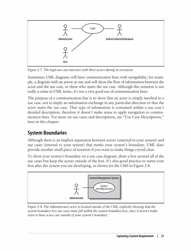
Figure 2-7. The login use case interacts with three actors during its execution
Figure 2-8. The Administrator actor is located outside of the CMS, explicitly showing that thesystem boundary box use cases must fall within the system boundary box, since it doesn’t makesense to have a use case outside of your system’s boundary
Administrator
Login
AuthorCredentialsDatabase
User
Administrator
Create anew Blog Account
Content Management System

This is the Title of the Book, eMatter EditionCopyright © 2008 O’Reilly & Associates, Inc. All rights reserved.
28 | Chapter 2: Modeling Requirements: Use Cases
Use Case DescriptionsA diagram showing your use cases and actors may be a nice starting point, but itdoes not provide enough detail for your system designers to actually understandexactly how the system’s concerns will be met. How can a system designer under-stand who the most important actor is from the use case notation alone? What stepsare involved in the use case? The best way to express this important information is inthe form of a text-based description—every use case should be accompanied by one.
There are no hard and fast rules as to what exactly goes into a use case descriptionaccording to UML, but some example types of information are shown in Table 2-1.
Table 2-2 shows an example use case description for the Create a new Blog Accountuse case and provides a handy template for your own descriptions.
Table 2-1. Some types of information that you can include in your use case descriptions
Use case description detail What the detail means and why it is useful
Related Requirements Some indication as to which requirements this use case partially or completely fulfills.
Goal In Context The use case’s place within the system and why this use case is important.
Preconditions What needs to happen before the use case can be executed.
Successful End Condition What the system’s condition should be if the use case executes successfully.
Failed End Condition What the system’s condition should be if the use case fails to execute successfully.
Primary Actors The main actors that participate in the use case. Often includes the actors that trigger ordirectly receive information from a use case’s execution.
Secondary Actors Actors that participate but are not the main players in a use case’s execution.
Trigger The event triggered by an actor that causes the use case to execute.
Main Flow The place to describe each of the important steps in a use case’s normal execution.
Extensions A description of any alternative steps from the ones described in the Main Flow.
Table 2-2. A complete use case description for the “Create a new Blog Account”use case
Use case name Create a new Blog Account
Related Requirements Requirement A.1.
Goal In Context A new or existing author requests a new blog account from the Administrator.
Preconditions The system is limited to recognized authors and so the author needs to have appro-priate proof of identity.
Successful End Condition A new blog account is created for the author.
Failed End Condition The application for a new blog account is rejected.
Primary Actors Administrator.
Secondary Actors Author Credentials Database.
Trigger The Administrator asks the CMS to create a new blog account.

This is the Title of the Book, eMatter EditionCopyright © 2008 O’Reilly & Associates, Inc. All rights reserved.
Capturing a System Requirement | 29
The format and content in Table 2-2 is only an example, but it’s worth rememberingthat use case descriptions and the information that they contain are more than justextra information to accompany the use case diagrams. In fact, a use case’s descrip-tion completes the use case; without a description a use case is, well, not very useful.
The description in Table 2-2 was reasonably straightforward, but something’s notquite right when you compare the description to the original use case diagram(shown in Figure 2-9; although the use case description mentions two actors, this usecase diagram shows only one).
The use case description has identified a new actor, the Author Credentials Database.By creating a complete description of the Create a new Blog Account use case, itbecomes clear that this actor is missing.
Main Flow Step Action
1 The Administrator asks the sys-tem to create a new blog account.
2 The Administrator selects anaccount type.
3 The Administrator enters theauthor’s details.
4 The author’s details are verified usingthe Author Credentials Database.
5 The new blog account is created.
6 A summary of the new blog account’sdetails are emailed to the author.
Extensions Step Branching Action
4.1 The Author Credentials Databasedoes not verify the author’s details.
4.2 The author’s new blog account applica-tion is rejected.
Figure 2-9. Ensuring that your use case diagrams match the more detailed use case descriptions iscritical
Table 2-2. A complete use case description for the “Create a new Blog Account”use case (continued)
Use case name Create a new Blog Account
Administrator
Create anew Blog Account
Content Management System

This is the Title of the Book, eMatter EditionCopyright © 2008 O’Reilly & Associates, Inc. All rights reserved.
30 | Chapter 2: Modeling Requirements: Use Cases
If you can, it’s worth reviewing your use case model with your users asmuch as possible to ensure that you have captured all of the key usesof your system and that nothing has been missed.
You will often find that items are missing from your diagrams as more detail goesinto your use case descriptions. The same goes for any aspect of your model: themore detail you put in, the more you might have to go back and correct what you didbefore. This is what iterative system development is all about. Don’t be too worriedthough, this refinement of your model is a good thing. With each iteration of devel-opment you will (hopefully!) get a better and more accurate model of your system.
Figure 2-10 shows the corrected use case diagram incorporating the new AuthorCredentials Database actor.
Use Case RelationshipsA use case describes the way your system behaves to meet a requirement. When fill-ing out your use case descriptions, you will notice that there is some similaritybetween steps in different use cases. You may also find that some use cases work in
Figure 2-10. Bring the use case diagram in sync with the use case’s description by adding theAuthor Credentials Database actor
How Many Use Cases Should Your Model Have?There is no set rule for the number of use cases that your use case model should containfor a given system. The number of use cases depends on the of the jobs that your sys-tem has to do according to the requirements. This means that for a particular system,you might only need two use cases or you might need hundreds.
It is more important that you have the right use cases, rather than worrying about theamount you have. As with most things in system modeling, the best way to get youruse cases right is to get used to applying them; experience will teach you what is rightfor your own systems.
Administrator
Create anew Blog Account
Content Management System
AuthorCredentials
Database

This is the Title of the Book, eMatter EditionCopyright © 2008 O’Reilly & Associates, Inc. All rights reserved.
Use Case Relationships | 31
several different modes or special cases. Finally, you may also find a use case withmultiple flows throughout its execution, and it would be good to show those impor-tant optional cases on your use case diagrams.
Wouldn’t it be great if you could get rid of the repetition between use case descrip-tions and show important optional flows right on your use case diagrams? OK, sothat was a loaded question. You can show reusable, optional, and even specializeduse case behavior between use cases.
The <<include>> RelationshipSo far, you have seen that use cases typically work with actors to capture a require-ment. Relationships between use cases are more about breaking your system’s behav-ior into manageable chunks than adding anything new to your system. The purposeof use case relationships is to provide your system’s designers with some architec-tural guidance so they can efficiently break down the system’s concerns into manage-able pieces within the detailed system design.
In addition to blogs, a CMS can have any number of means for work-ing with its content. One popular mechanism for maintaining docu-ments is by creating a Wiki. Wikis allow online authors to create, edit,and link together web pages to create a web of related content, or aWiki-web. A great example of a Wiki is available at http://www.Wikipedia.org.
Take another look at the Create a new Blog Account use case description shown inTable 2-2. The description seems simple enough, but suppose another requirement isadded to the Content Management System.
To capture Requirement A.2 a new use case needs to be added to the ContentManagement System, as shown in Figure 2-11.
Now that we have added the new use case to our model, it’s time to fill out a detaileduse case description (shown in Table 2-3). See Table 2-1 if you need to refresh yourmemory about the meaning of each of the details within a use case description.
Requirement A.2The content management system shall allow an administrator to create a new personalWiki, provided the personal details of the applying author are verified using the AuthorCredentials Database.

This is the Title of the Book, eMatter EditionCopyright © 2008 O’Reilly & Associates, Inc. All rights reserved.
32 | Chapter 2: Modeling Requirements: Use Cases
The first thing to notice is that we have some redundancy between the two use casedescriptions (Tables 2-2 and 2-3). Both Create a new Blog Account and Create a newPersonal Wiki need to check the applicant’s credentials. Currently, this behavior issimply repeated between the two use case descriptions.
Figure 2-11. A new requirement can often mean a new use case for the system, although it’s notalways a one-to-one mapping
Table 2-3. The detailed description for the “Create a new Personal Wiki” use case
Use case name Create a new Personal Wiki
Related Requirements Requirement A.2.
Goal In Context A new or existing author requests a new personal Wiki from the Administrator.
Preconditions The author has appropriate proof of identity.
Successful End Condition A new personal Wiki is created for the author.
Failed End Condition The application for a new personal Wiki is rejected.
Primary Actors Administrator.
Secondary Actors Author Credentials Database.
Trigger The Administrator asks the CMS to create a new personal Wiki.
Main Flow Step Action
1 The Administrator asks the system tocreate a new personal Wiki.
2 The Administrator enters the author’sdetails.
3 The author’s details are verified usingthe Author Credentials Database.
4 The new personal Wiki is created.
5 A summary of the new personal Wiki’sdetails are emailed to the author.
Extensions Step Branching Action
3.1 The Author Credentials Database doesnot verify the author’s details.
3.2 The author’s new personal Wiki appli-cation is rejected.
Administrator
Create anew Blog Account
Content Management System
AuthorCredentials
Database
Create anew Personal Wiki

This is the Title of the Book, eMatter EditionCopyright © 2008 O’Reilly & Associates, Inc. All rights reserved.
Use Case Relationships | 33
This repetitive behavior shared between two use cases is best separated and cap-tured within a totally new use case. This new use case can then be reused by theCreate a new Blog Account and Create a new Personal Wiki use cases using the<<include>> relationship (as shown in Figure 2-12).
The <<include>> relationship declares that the use case at the tail of the dotted arrowcompletely reuses all of the steps from the use case being included. In Figure 2-12, theCreate a new Blog Account and Create a new Personal Wiki completely reuse all of thesteps declared in the Check Identity use case.
You can also see in Figure 2-12 that the Check Identity use case is not directly con-nected to the Administrator actor; it picks this connection up from the use cases thatinclude it. However, the connection to the Author Credentials Database is now solelyowned by the Check Identity use case. A benefit of this change is that it emphasizesthat the Check Identity use case is the only one that relies directly on a connection tothe Author Credentials Details Database actor.
To show the <<include>> relationship in your use case descriptions, you need toremove the redundant steps from the Create a new Blog Account and Create newPersonal Wiki use case descriptions and instead use the Included Cases field andinclude::<use case name> syntax to indicate the use case where the reused stepsreside, as shown in Tables 2-4 and 2-5.
Figure 2-12. The <<include>> relationship supports reuse between use cases
Table 2-4. Showing <<include>> in a use case description using Included Cases and include::<usecase name>
Use case name Create a new Blog Account
Related Requirements Requirement A.1.
Goal In Context A new or existing author requests a new blog account from the Administrator.
Preconditions The author has appropriate proof of identity.
Administrator
Check Identity
Content Management System
AuthorCredentials
DatabaseCreate anew Personal Wiki
Create anew Blog Account
<<include>>
<<include>>

This is the Title of the Book, eMatter EditionCopyright © 2008 O’Reilly & Associates, Inc. All rights reserved.
34 | Chapter 2: Modeling Requirements: Use Cases
Successful End Condition A new blog account is created for the author.
Failed End Condition The application for a new blog account is rejected.
Primary Actors Administrator
Secondary Actors None
Trigger The Administrator asks the CMS to create a new blog account.
Included Cases Check Identity
Main Flow Step Action
1 The Administrator asks the system tocreate a new blog account.
2 The Administrator selects an accounttype.
3 The Administrator enters the author’sdetails.
4
include::Check Identity
The author’s details are checked.
5 The new account is created.
6 A summary of the new blog account’sdetails are emailed to the author.
Table 2-5. The Create a new Personal Wiki use case description also gets a makeover
Use case name Create a new Personal Wiki
Related Requirements Requirement A.2
Goal In Context A new or existing author requests a new personal Wiki from the Administrator.
Preconditions The author has appropriate proof of identity.
Successful End Condition A new personal Wiki is created for the author.
Failed End Condition The application for a new personal Wiki is rejected.
Primary Actors Administrator
Secondary Actors None
Trigger The Administrator asks the CMS to create a new personal Wiki.
Included Cases Check Identity
Main Flow Step Action
1 The Administrator asks the system tocreate a new personal Wiki.
2 The Administrator enters the author’sdetails.
3
include::Check Identity
The author’s details are checked.
Table 2-4. Showing <<include>> in a use case description using Included Cases and include::<usecase name> (continued)
Use case name Create a new Blog Account

This is the Title of the Book, eMatter EditionCopyright © 2008 O’Reilly & Associates, Inc. All rights reserved.
Use Case Relationships | 35
Now you can create a use case description for the reusable steps within the CheckIdentity use case, as shown in Table 2-6.
Why bother with all this hassle with reuse between use cases? Why not just have twouse cases and maintain the similar steps separately? All this reuse has two importantbenefits:
• Reuse using <<include>> removes the need for tedious cut-and-paste operationsbetween use case descriptions, since updates are made in only one place insteadof every use case.
• The <<include>> relationship gives you a good indication at system design timethat the implementation of Check Identity will need to be a reusable part of yoursystem.
5 The new personal Wiki is created.
6 A summary of the new personal Wiki’sdetails are emailed to the author.
Table 2-6. The Check Identity use case description contains the reusable steps
Use case name Check Identity
Related Requirements Requirement A.1, Requirement A.2.
Goal In Context An author’s details need to be checked and verified as accurate.
Preconditions The author being checked has appropriate proof of identity.
Successful End Condition The details are verified.
Failed End Condition The details are not verified.
Primary Actors Author Credentials Database.
Secondary Actors None.
Trigger An author’s credentials are provided to the system for verification.
Main Flow Step Action
1 The details are provided to the system.
2 The Author Credentials Database veri-fies the details.
3 The details are returned as verified bythe Author Credentials Database.
Extensions Step Branching Action
2.1 The Author Credentials Database doesnot verify the details.
2.2 The details are returned as unverified.
Table 2-5. The Create a new Personal Wiki use case description also gets a makeover (continued)
Use case name Create a new Personal Wiki

This is the Title of the Book, eMatter EditionCopyright © 2008 O’Reilly & Associates, Inc. All rights reserved.
36 | Chapter 2: Modeling Requirements: Use Cases
Special CasesSometimes you’ll come across a use case whose behavior, when you start to analyzeit more carefully, can be applied to several different cases, but with small changes.Unlike the <<include>> relationship, which allows you to reuse a small subset ofbehavior, this is applying a use case with small changes for a collection of specific sit-uations. In object-oriented terms, you potentially have a number of specialized casesof a generalized use case.
Let’s take a look at an example. Currently, the Content Management System contains asingle Create a new Blog Account use case that describes the steps required to create anaccount. But what if the CMS supports several different types of blog accounts, andthe steps required to create each of these accounts differs ever so slightly from theoriginal use case? You want to describe the general behavior for creating a blogaccount—captured in the Create a new Blog Account use case—and then define spe-cialized use cases in which the account being created is a specific type, such as a reg-ular account with one blog or an editorial account that can make changes to entriesin a set of blogs.
This is where use case generalization comes in. A more common way of referring togeneralization is using the term inheritance. Use case inheritance is useful when youwant to show that one use case is a special type of another use case. To show usecase inheritance, use the generalization arrow to connect the more general, or par-ent, use case to the more specific use case. Figure 2-13 shows how you could extendthe CMS’s use cases to show that two different types of blog accounts can be created.
Figure 2-13. Two types of blog account, regular and editorial, can be created by the ManagementSystem
Administrator
Check Identity
Content Management System
AuthorCredentials
DatabaseCreate a newBlog Account
Create anew Personal Wiki
<<include>>
<<include>>
Create a newRegular Blog Account
Create a newEditorial Blog
Account

This is the Title of the Book, eMatter EditionCopyright © 2008 O’Reilly & Associates, Inc. All rights reserved.
Use Case Relationships | 37
Taking a closer look at the Create a new Editorial Blog Account specialized use casedescription, you can see how most of the behavior from the more general Create anew Blog Account use case is reused. Only the details that are specific to creating anew editorial account need to be added (see Table 2-7).
Table 2-7. You can show that a use case is a special case of a more general use case within thedetailed description using the Base Use Cases field
Use case name Create a new Editorial Blog Account
Related Requirements Requirement A.1.
Goal In Context A new or existing author requests a new editorial blog account from the Administrator .
Preconditions The author has appropriate proof of identity.
Successful End Condition A new editorial blog account is created for the author.
Failed End Condition The application for a new editorial blog account is rejected.
Primary Actors Administrator.
Secondary Actors None.
Trigger The Administrator asks the CMS to create a new editorial account that will allow anauthor to edit entries in a set of blogs.
Base Use Cases Create a new Blog Account
Main Flow Step Action
1 The Administrator asks the system tocreate a new blog account.
2 The Administrator selects the edito-rial account type.
3 The Administrator enters the author’sdetails.
4 The Administrator selects the blogsthat the account is to have editorialrights over.
5
include::Check Identity
The author’s details are checked.
6 The new editorial account is created.
7 A summary of the new editorialaccount’s details are emailed to theauthor.
Extensions Step Branching Action
5.1 The author is not allowed to edit theindicated blogs.
5.2 The editorial blog account applicationis rejected.
5.3 The application rejection is recordedas part of the author’s history.

This is the Title of the Book, eMatter EditionCopyright © 2008 O’Reilly & Associates, Inc. All rights reserved.
38 | Chapter 2: Modeling Requirements: Use Cases
Use case inheritance is a powerful way of reusing a use case so that you only have tospecify the extra steps that are needed in the more specific use cases. See Chapter 5for more information on inheritance between classes.
But be careful—by using inheritance, you are effectively saying that every step in thegeneral use case must occur in the specialized use cases. Also, every relationship thatthe general use case has with external actors or use cases, as shown with the<<include>> relationship between Create a new Blog Account and Check Identity, mustalso make sense in the more specialized use cases, such as Create a new EditorialBlog Account.
If you really don’t want your more specific use case to do everything that the generaluse case describes, then don’t use generalization. Instead, you might want to con-sider using either the <<include>> relationship shown in the previous section or the<<extend>> relationship coming up in the next section.
The <<extend>> RelationshipAny explanation of the <<extend>> stereotype should be preceded by a warning thatit is the most heavily debated type of use case relationship. Almost nothing is lessunderstood or harder to accurately communicate within the UML modeling commu-nity than the <<extend>> use case relationship, and this presents a bit of a problemwhen you are trying to learn about it. Figure 2-14 shows you how <<extend>> works;take a look, and then let’s dive into some UML concept and theory.
At first glance—particularly if you are a Java programmer—<<extend>> seems verysimilar to inheritance between classes. In Java, a class can extend from a base class.Similarly, in C++ and C#, you can declare inheritance between classes, and youwould often say that a class extends another class. In both these cases, the extendrelationship between classes means inheritance. So, for a programmer, it follows that<<extend>> should mean something like inheritance, right?
Alarm bells should definitely be going off now. You already saw in the previous sec-tion how use cases declare inheritance using a generalization arrow, so why wouldyou need yet another type of arrow with an <<extend>> stereotype? Does the generali-zation arrow mean the same thing as the <<extend>> stereotype? Unfortunately, the<<extend>> stereotype has very little in common with inheritance, and so the two defi-nitely do not mean the same thing.
Figure 2-14. The <<extend>> use case relationship looks a bit like the <<include>> relationship,but that’s where the similarities end
A Use Case An ExtendingUse Case<<extend>>

This is the Title of the Book, eMatter EditionCopyright © 2008 O’Reilly & Associates, Inc. All rights reserved.
Use Case Relationships | 39
The designers of UML 2.0 took a very different view as to the meaning of <<extend>>between use cases. They wanted a means for you to show that a use case might com-pletely reuse another use case’s behavior, similar to the <<include>> relationship, butthat this reuse was optional and dependent either on a runtime or system implemen-tation decision.
From the CMS example, the Create a new Blog Account use case might want to recordthat a new author applied for an account and was rejected, adding this informationto the author’s application history. Extra steps can be added to the Create a new BlogAccount use case’s description to show this optional behavior, as shown in Step 4.3 inTable 2-8.
Table 2-8. Behavior that is a candidate for <<extend>> relationship reuse can usually be found inthe Extensions section of a use case description
Use case name Create a new Blog Account
Related Requirements Requirement A.1.
Goal In Context A new or existing author requests a new blog account from the Administrator.
Preconditions The author has appropriate proof of identity.
Successful End Condition A new blog account is created for the author.
Failed End Condition The application for a new blog account is rejected.
Primary Actors Administrator.
Secondary Actors None .
Trigger The Administrator asks the CMS to create a new blog account.
Included Cases Check Identity
Main Flow Step Action
1 The Administrator asks the system tocreate a new blog account.
2 The Administrator selects an accounttype.
3 The Administrator enters the author’sdetails.
4
include::Check Identity
The author’s details are checked.
5 The new account is created.
6 A summary of the new blog account’sdetails are emailed to the author.
Extensions Step Branching Action
4.1 The author is not allowed to create anew blog.
4.2 The blog account application isrejected.
4.3 The application rejection is recordedas part of the author’s history.

This is the Title of the Book, eMatter EditionCopyright © 2008 O’Reilly & Associates, Inc. All rights reserved.
40 | Chapter 2: Modeling Requirements: Use Cases
The same behavior captured in Step 4.3 would also be useful if the customer wasrefused an account for some reason during the Create a new Personal Wiki usecase’s execution. According to the requirements, this reusable behavior is optional inboth cases; you don’t want to record a rejection if the application for a blog accountor a personal Wiki was accepted. The <<extend>> relationship is ideal in this sort ofreuse situation, as shown in Figure 2-15.
The new Record Application Failure use case, as the name implies, captures all ofthe behavior associated with recording an author’s application failure whether it befor a personal Wiki or for a specific type of blog account. Using the <<extend>>relationship, the Record Application Failure use case’s behavior is optionally reusedby the Create a new Blog Account and Create a new Personal Wiki use cases if an appli-cation is rejected.
Use Case Overview DiagramsWhen you are trying to understand a system, it is sometimes useful to get a glimpseof the context within which it sits. For this purpose, UML provides the Use CaseOverview diagram. Use Case Overview diagrams give you an opportunity to paint abroad picture of your system’s context or domain (see Figure 2-16 for an example).
Figure 2-15. The <<extend>> relationship comes into play to show that both the “Create a newPersonal Wiki” and “Create a new Blog Account” use cases might occasionally share theapplication rejection recording behavior
Administrator
Check Identity
Content Management System
AuthorCredentials
DatabaseCreate a newBlog Account
Create anew Personal Wiki
<<include>>
<<include>>
Create a newRegular Blog
Account
Create a newEditorial Blog
Account
RecordApplication
Failure
<<extend>>
<<extend>>

This is the Title of the Book, eMatter EditionCopyright © 2008 O’Reilly & Associates, Inc. All rights reserved.
What’s Next? | 41
Unfortunately, Use Case Overviews are badly named as they don’t usually containany use cases. The use cases are not shown because the overview is designed to pro-vide a context to your system; the system’s internals—captured by use cases—arenot normally visible.
Use Case Overviews are a useful place to show any extra snippets of informationwhen understanding your system’s place within the world. Those snippets ofteninclude relationships and communication lines between actors. These contextualpieces of information do not usually contain a great deal of detail, they are more aplaceholder and starting point for the rest of your model’s detail.
What’s Next?Although this book, like UML, does not push any particular system developmentprocess, there are some common steps that are taken after the first cut of use casesare captured.
With your use case model in hand, it is often a good time to start delving into thehigh-level activities that your system will have to execute to fulfill its use cases. SeeChapter 3 for information on activity diagrams.
Once you have a good grip on the high-level activities, look at the classes and com-ponents that will actually make up the parts of your system. You already might havesome idea of what those classes contain, and so the next stop naturally would be tocreate a few rudimentary class diagrams. See Chapter 4 for information on classdiagrams.
Figure 2-16. The CMS’s context as shown on a Use Case Overview diagram
Public
Content Management System <<actor>>Author Credentials
Database
ViewsContent
Collaborateswith
Author
Edits Content
Central Storage
Stores author credentials
Stores content
Administrator
AdministratesAdministrates

This is the Title of the Book, eMatter EditionCopyright © 2008 O’Reilly & Associates, Inc. All rights reserved.
42 | Chapter 2: Modeling Requirements: Use Cases
Regardless of your next step, just because you have a use case model does not neces-sarily mean that you are finished with use cases altogether. The only constant in lifeis change, and this certainly applies to your system’s requirements. As a requirementchanges—either because some new system constraint has been found or because auser has changed his mind—you need to go back and refine your use cases to makesure you are still developing the system that the users want.
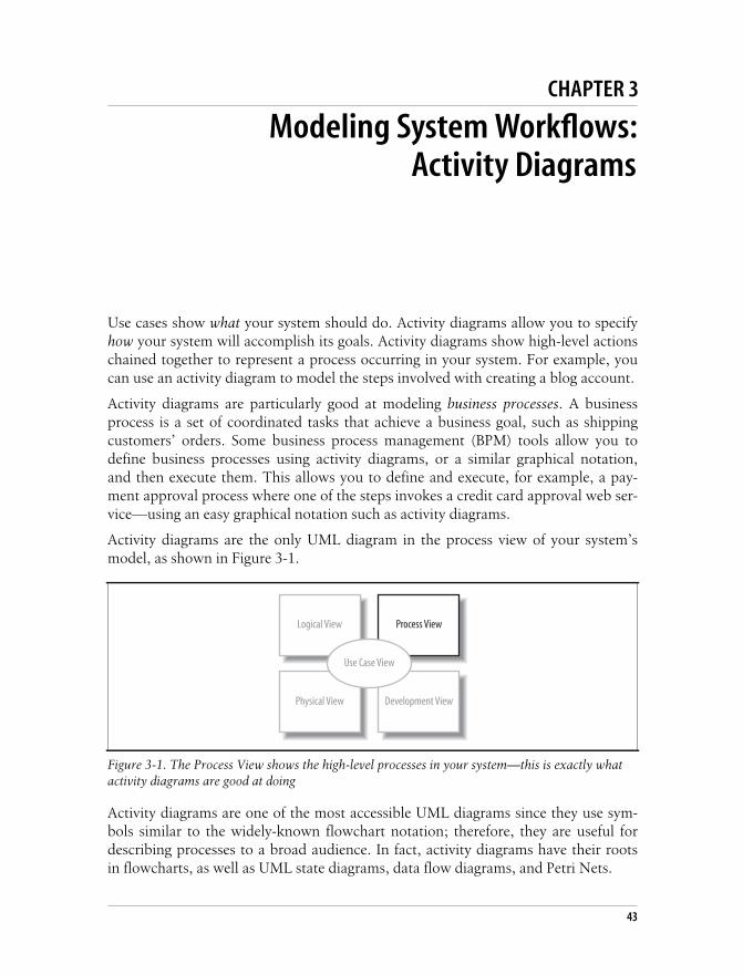
This is the Title of the Book, eMatter EditionCopyright © 2008 O’Reilly & Associates, Inc. All rights reserved.
43
Chapter 3 CHAPTER 3
Modeling System Workflows:Activity Diagrams3
Use cases show what your system should do. Activity diagrams allow you to specifyhow your system will accomplish its goals. Activity diagrams show high-level actionschained together to represent a process occurring in your system. For example, youcan use an activity diagram to model the steps involved with creating a blog account.
Activity diagrams are particularly good at modeling business processes. A businessprocess is a set of coordinated tasks that achieve a business goal, such as shippingcustomers’ orders. Some business process management (BPM) tools allow you todefine business processes using activity diagrams, or a similar graphical notation,and then execute them. This allows you to define and execute, for example, a pay-ment approval process where one of the steps invokes a credit card approval web ser-vice—using an easy graphical notation such as activity diagrams.
Activity diagrams are the only UML diagram in the process view of your system’smodel, as shown in Figure 3-1.
Activity diagrams are one of the most accessible UML diagrams since they use sym-bols similar to the widely-known flowchart notation; therefore, they are useful fordescribing processes to a broad audience. In fact, activity diagrams have their rootsin flowcharts, as well as UML state diagrams, data flow diagrams, and Petri Nets.
Figure 3-1. The Process View shows the high-level processes in your system—this is exactly whatactivity diagrams are good at doing
Logical View Process View
Physical View Development View
Use Case View

This is the Title of the Book, eMatter EditionCopyright © 2008 O’Reilly & Associates, Inc. All rights reserved.
44 | Chapter 3: Modeling System Workflows: Activity Diagrams
Activity Diagram EssentialsLet’s look at the basic elements of activity diagrams by modeling a process encoun-tered earlier in the book—the steps in the blog account creation use case. Table 3-1contains the Create a new Blog Account use case description (originally Table 2-1). TheMain Flow and Extension sections describe steps in the blog account creation process.
Figure 3-2 shows this blog account creation process in activity diagram notation. Anactivity diagram is useful here because it helps you to better visualize a use case’ssteps (compared to the table notation in the use case description), especially thebranching steps that depend on whether the author is verified.
In Figure 3-2, the activity is launched by the initial node, which is drawn as a filledcircle. The initial node simply marks the start of the activity. At the other end of the
Table 3-1. Create a new Blog Account use case description
Use case name Create a new Blog Account
Related Requirements Requirement A.1.
Goal In Context A new or existing author requests a new blog account from the Administrator.
Preconditions The system is limited to recognized authors, and so the author needs to haveappropriate proof of identity.
Successful End Condition A new blog account is created for the author.
Failed End Condition The application for a new blog account is rejected.
Primary Actors Administrator.
Secondary Actors Author Credentials Database.
Trigger The Administrator asks the Content Management System to create a new blogaccount.
Main Flow Step Action
1 The Administrator asks the system tocreate a new blog account.
2 The Administrator selects an accounttype.
3 The Administrator enters the author’sdetails.
4 The author’s details are verified usingthe Author Credentials Database.
5 The new blog account is created.
6 A summary of the new blog account’sdetails are emailed to the author.
Extensions Step Branching Action
4.1 The Author Credentials Database doesnot verify the author’s details.
4.2 The author’s new blog account applica-tion is rejected.

This is the Title of the Book, eMatter EditionCopyright © 2008 O’Reilly & Associates, Inc. All rights reserved.
Activity Diagram Essentials | 45
diagram, the activity final node, drawn as two concentric circles with a filled innercircle, marks the end of the activity.
In between the initial node and the activity final node are actions, which are drawn asrounded rectangles. Actions are the important steps that take place in the overallactivity, e.g., Select Account Type, Enter Author's Details, and so on. An actioncould be a behavior performed, a computation, or any key step in the process.
The flow of the activity is shown using arrowed lines called edges or paths. Thearrowhead on an activity edge shows the direction of flow from one action to thenext. A line going into a node is called an incoming edge, and a line exiting a node is
Figure 3-2. Activity diagrams model dynamic behavior with a focus on processes; the basicelements of activity diagrams are shown in this blog account creation process
Ask System toCreate new Blog
Account
Edge
Select AccountType
Enter Author'sDetails
Verify Author'sDetails
Initialnode
Action
RejectApplication
Create new BlogAccount
Email Blog AccountSummary to Author
MergeActivityfinal node
[authorized] [not authorized]
Decision

This is the Title of the Book, eMatter EditionCopyright © 2008 O’Reilly & Associates, Inc. All rights reserved.
46 | Chapter 3: Modeling System Workflows: Activity Diagrams
called an outgoing edge. Edges string the actions together to determine the overallactivity flow: first the initial node becomes active, then Ask System to create new BlogAccount, and so on.
The first diamond-shaped node is called a decision, analogous to an if-else statementin code. Notice that there are two outgoing edges from the decision in Figure 3-2,each labeled with Boolean conditions. Only one edge is followed out of the decisionnode depending on whether the author is authorized. The second diamond-shapednode is called a merge. A merge node combines the edges starting from a decisionnode, marking the end of the conditional behavior.
The word “flow” was mentioned several times previously and you may ask—what’sflowing? The answer depends on the context. Typically, it’s the flow of control fromone action to the next: one action executes to completion, then gives up its controlto the next action. In later sections you’ll see that, along with control, objects canflow through an activity.
Activities and ActionsActions are active steps in the completion of a process. An action can be a calcula-tion, such as Calculate Tax, or a task, such as Verify Author's Details.
The word “activity” is often mistakenly used instead of “action” to describe a step inan activity diagram, but they are not the same. An activity is the process being mod-eled, such as washing a car. An action is a step in the overall activity, such as Lather,Rinse, and Dry.
The actions in this simple car-washing activity are shown in Figure 3-3.
Figure 3-3. Capturing the three actions—Lather, Rinse, and Dry—that make up washing a car inan activity diagram
Activityframe
Lather Rinse DryWash Car
Activityname
Actions

This is the Title of the Book, eMatter EditionCopyright © 2008 O’Reilly & Associates, Inc. All rights reserved.
Decisions and Merges | 47
In Figure 3-3, the entire activity is enclosed within the rounded rectangle called anactivity frame. The activity frame is used to contain an activity’s actions and is usefulwhen you want to show more than one activity on the same diagram. Write thename of the activity in the upper left corner.
The activity frame is optional and is often left out of an activity diagram, as shown inthe alternative Wash Car activity in Figure 3-4.
Although you lose the name of the activity being displayed on the diagram itself, it isoften more convenient to leave out the activity frame when constructing a simpleactivity diagram.
Decisions and MergesDecisions are used when you want to execute a different sequence of actions depend-ing on a condition. Decisions are drawn as diamond-shaped nodes with one incom-ing edge and multiple outgoing edges, as shown in Figure 3-5.
Each branched edge contains a guard condition written in brackets. Guard condi-tions determine which edge is taken after a decision node.
Figure 3-4. The activity frame can be omitted
Figure 3-5. Only one edge is followed after a decision node
Lather Rinse Dry
Outgoing edge
[authorized]
[not authorized]
Incoming edge
Guardconditions

This is the Title of the Book, eMatter EditionCopyright © 2008 O’Reilly & Associates, Inc. All rights reserved.
48 | Chapter 3: Modeling System Workflows: Activity Diagrams
They are statements that evaluate to true or false, for example:
[authorized]If the authorized variable evaluates to true, then follow this outgoing edge.
[wordCount >= 1000]If the wordCount variable is greater than or equal to 1,000, then follow this out-going edge.
The branched flows join together at a merge node, which marks the end of the condi-tional behavior started at the decision node. Merges are also shown with diamond-shaped nodes, but they have multiple incoming edges and one outgoing edge, asshown in Figure 3-6.
Activity diagrams are clearest if the guards at decision nodes are complete and mutu-ally exclusive. Figure 3-7 shows a situation in which the paths are not mutuallyexclusive.
If an item is in stock and the order is a rush order, then two guards evaluate to true.So which edge is followed? According to the UML specifications, if multiple guardsevaluate to true, then only one edge is followed and that choice is out of your con-trol unless you specify an order. You can avoid this complicated situation by makingguards mutually exclusive.
The other situation to avoid is incomplete guards. For example, if Figure 3-7 had noguard covering out of stock items, then an out of stock item can’t follow any edgeout of the decision node. This means the activity is frozen at the decision node. Mod-elers sometimes leave off guards if they expect a situation not to occur (or if theywant to defer thinking about it until later), but to minimize confusion, you shouldalways include a guard to cover every possible situation. If it’s possible in your activ-ity, it’s helpful to label one path with else, as shown in Figure 3-7, to make sure allsituations are covered.
Figure 3-6. If the input value of age is 1200, then the Notify Blog Entry too long action isperformed
Notify Blog Entrytoo long
Merge
Save Blog Entry
Notify Blog Entrycan't be empty
Display status
[wordCount = 0]
[wordCount >0 &wordCount <1000]
[wordCount > = 1000]
Decision

This is the Title of the Book, eMatter EditionCopyright © 2008 O’Reilly & Associates, Inc. All rights reserved.
Doing Multiple Tasks at the Same Time | 49
If you’re coming from a UML 1.x background, it may not seem necessary to showmerge nodes. In UML 1.x, it was common to see multiple edges starting at a deci-sion node flow directly into an action, as shown in the top part of Figure 3-8. Thismeant the flows were merged implicitly.
As of UML 2.0, when multiple edges lead directly into an action, all incoming flowsare waited on before proceeding. But this doesn’t make sense because only one edgeis followed out of a decision node. You can avoid confusing your reader by explicitlyshowing merge nodes.
Doing Multiple Tasks at the Same TimeConsider a computer assembly workflow that involves the following steps:
1. Prepare the case.
2. Prepare the motherboard.
3. Install the motherboard.
4. Install the drives.
5. Install the video card, sound card, and modem.
So far we’ve covered enough activity diagram notation to model this workflowsequentially. But suppose the entire workflow can be sped up by preparing the case
Figure 3-7. Beware of diagrams where multiple guards evaluate to true
[item in stock]
[item out of stock]
[rush order]
BAD! Two guards mayevaluate to true
[item in stock and rush order]
[item out of stock and not rush order]
[item in stock and not rush order]
[item out of stock and rush order]
[item in stock]
[item out of stock]
[else]
[rush order]
[rush order]
[else]
Modify so that only oneoutgoing guard evaluates to
true, as in these diagrams

This is the Title of the Book, eMatter EditionCopyright © 2008 O’Reilly & Associates, Inc. All rights reserved.
50 | Chapter 3: Modeling System Workflows: Activity Diagrams
and the motherboard at the same time since these actions don’t depend on eachother. Steps that occur at the same time are said to occur concurrently or in parallel.
You represent parallel actions in activity diagrams by using forks and joins, as shownin the activity diagram fragment in Figure 3-9.
Figure 3-8. In UML 2.0, it’s better to be as clear as possible and to show merge nodes
Figure 3-9. Both outgoing paths are followed at the fork, in contrast with decision nodes, whereonly one outgoing path is taken
High PriorityProcessing
Branches pointdirectly into next
action nodeMedium Priority
Processing
Low PriorityProcessing
PostProcessing
High PriorityProcessing
Branches mergeat merge node
Medium PriorityProcessing
Low PriorityProcessing
PostProcessing
[low priority]
[medium priority]
[high priority]
[low priority]
[medium priority]
[high priority]
Preferred in UML 2.0
Commonly seen in UML 1.x
PrepareMotherboard
PrepareCase
Fork Join

This is the Title of the Book, eMatter EditionCopyright © 2008 O’Reilly & Associates, Inc. All rights reserved.
Time Events | 51
After a fork in Figure 3-9, the flow is broken up into two or more simultaneousflows, and the actions along all forked flows execute. In Figure 3-9, Prepare Case andPrepare Motherboard begin executing at the same time.
The join means that all incoming actions must finish before the flow can proceedpast the join. Forks and joins look identical—they are both drawn with thick bars—but you can tell the difference because forks have multiple outgoing flows, whereasjoins have multiple incoming flows.
In a detailed design model, you can use forks to represent multipleprocesses or multiple threads in a program.
Figure 3-10 completes the activity diagram for the computer assembly workflow.
When actions occur in parallel, it doesn’t necessarily mean they will finish at thesame time. In fact, one task will most likely finish before the other. However, the joinprevents the flow from continuing past the join until all incoming flows are com-plete. For example, in Figure 3-10 the action immediately after the join—InstallMotherboard—executes only after both the Prepare Case and Prepare Motherboardactions finish.
Time EventsSometimes time is a factor in your activity. You may want to model a wait period,such as waiting three days after shipping an order to send a bill. You may also needto model processes that kick off at a regular time interval, such as a system backupthat happens every week.
Time events are drawn with an hourglass symbol. Figure 3-11 shows how to use atime event to model a wait period. The text next to the hourglass—Wait 3 Days—shows the amount of time to wait. The incoming edge to the time event means thatthe time event is activated once. In Figure 3-11, the bill is sent only once—not everythree days.
Figure 3-10. The computer assembly workflow demonstrates how forks and joins work in acomplete activity diagram
InstallMotherboard
InstallDrives
PrepareMotherboard
PrepareCase
Install Video Card,Sound Card,and Modem

This is the Title of the Book, eMatter EditionCopyright © 2008 O’Reilly & Associates, Inc. All rights reserved.
52 | Chapter 3: Modeling System Workflows: Activity Diagrams
A time event with no incoming flows is a recurring time event, meaning it’s activatedwith the frequency in the text next to the hourglass. In Figure 3-12, the progress baris updated every second.
Notice that there is no initial node in Figure 3-12; a time event is an alternate way tostart an activity. Use this notation to model an activity that is launched periodically.
Calling Other ActivitiesAs detail is added to your activity diagram, the diagram may become too big, or thesame sequence of actions may occur more than once. When this happens, you canimprove readability by providing details of an action in a separate diagram, allowingthe higher level diagram to remain less cluttered.
Figure 3-13 shows the computer assembly workflow from Figure 3-10, but thePrepare Motherboard action now has an upside-down pitchfork symbol indicatingthat it is a call activity node. A call activity node calls the activity corresponding to itsnode name. This is similar to calling a software procedure.
The Prepare Motherboard node in Figure 3-13 invokes the Prepare Motherboard activ-ity in Figure 3-14. You associate a call activity node with the activity it invokes by
Figure 3-11. A time event with an incoming edge represents a timeout
Figure 3-12. A time event with no incoming flows models a repeating time event
Figure 3-13. Rather than cluttering up the top-level diagram with details of the PrepareMotherboard action, details are provided in another activity diagram
Ship Order Send Bill
Wait 3 days
UpdateProgress Bar
1 SecondTimeout
InstallMotherboard
InstallDrives
PrepareMotherboard
PrepareCase
Install Video Card,Sound Card,and Modem

This is the Title of the Book, eMatter EditionCopyright © 2008 O’Reilly & Associates, Inc. All rights reserved.
Objects | 53
giving them the same name. Call activities essentially break an action down intomore details without having to show everything in one diagram.
The Prepare Motherboard activity diagram has its own initial and activity final nodes.The activity final node marks the end of Prepare Motherboard, but it doesn’t meanthe calling activity is complete. When Prepare Motherboard terminates, control isreturned to the calling activity, which proceeds as normal. This is another reason callactivities resemble invoked software procedures.
Although it’s acceptable to omit the activity frame for top-level activi-ties, you should always show it for invoked activities. The name of theactivity in the activity frame will help you associate invoked activitieswith the invoker.
ObjectsSometimes data objects are an important aspect of the process you’re modeling. Sup-pose your company decides to sell the CMS as a commercial product, and you wantto define a process for approving incoming orders. Each step in the order approvalprocess will need information about the order, such as the payment information andtransaction cost. This can be modeled in your activity diagram with an Order object,which contains the order information needed by the steps. Activity diagrams offer avariety of ways to model objects in your processes.
Objects don’t have to be software objects. For example, in a non-automated computer assembly activity, an object node may be usedto represent a physical work order that starts the process.
Showing Objects Passed Between ActionsIn activity diagrams, you can use object nodes to show data flowing through an activ-ity. An object node represents an object that is available at a particular point in theactivity, and can be used to show that the object is used, created, or modified by anyof its surrounding actions.
Figure 3-14. The Prepare Motherboard activity elaborates on the motherboard preparation process
Install CPU Install Memory
Prepared motherboard

This is the Title of the Book, eMatter EditionCopyright © 2008 O’Reilly & Associates, Inc. All rights reserved.
54 | Chapter 3: Modeling System Workflows: Activity Diagrams
An object node is drawn with a rectangle, as shown in the order approval process inFigure 3-15. The Order object node draws attention to the fact that the Order objectflows from the Receive Order Request action to the Approve Payment action.
See “Sending and Receiving Signals” for a more precise way of modeling the ReceiveOrder Request action—as a receive signal node.
Showing Action Inputs and OutputsFigure 3-16 shows a different perspective on the previous activity using pins. Pinsshow that an object is input to or output from an action.
An input pin means that the specified object is input to an action. An output pinmeans that the specified object is output from an action. In Figure 3-16, an Orderobject is input to the Approve Payment action and an Order object is output from theReceive Order Request action.
Figures 3-15 and 3-16 show similar situations, but pins are good at emphasizing thatan object is required input and output, whereas an object node simply means that theobject is available at that particular point in the activity. However, object nodes havetheir own strength; they are good at emphasizing the flow of data through an activity.
If the Approve Payment action needs only parts of the Order object—not the wholeobject—you can use a transformation to show which parts are needed. Transforma-tions allow you to show how the output from one action provides the input toanother action.
Figure 3-15. The Order object node emphasizes that it is important data in this activity and showswhich actions interact with it
Figure 3-16. Pins in this change request approval process allow finer-grained specification of inputand output parameters
ReceiveOrder Request Order Approve
Payment
Object node
SubmitOrder
ReceiveOrder Request Order
ApprovePayment
Output pin
SubmitOrder
Input pin
Order

This is the Title of the Book, eMatter EditionCopyright © 2008 O’Reilly & Associates, Inc. All rights reserved.
Objects | 55
Figure 3-17 specifies that the Approve Payment action requires the Cost object as inputand shows how this data is obtained from the Order object using the transformationspecified in a note.
Showing How Objects Change State During an ActivityYou can also show an object changing state as it flows through an activity.Figure 3-18 shows that the Order object’s state is pending before Approve Payment andchanges to approved afterward. The state is shown in brackets.
Showing Input to and Output from an ActivityIn addition to acting as inputs to and outputs from actions, object nodes can beinputs to and outputs from an activity. Activity inputs and outputs are drawn asobject nodes straddling the boundary of the activity frame, as shown in Figure 3-19.This notation is useful for emphasizing that the entire activity requires input andprovides output.
Figure 3-19 shows the Order object as input and output for the Approve Payment activ-ity. When input and output parameters are shown, the initial node and activity finalnode are omitted from the activity.
Figure 3-17. Transformations show where input parameters come from
Figure 3-18. The focus of this diagram is the change of state of the Order object throughout theorder approval process
Figure 3-19. Object nodes can be used to emphasize input to and output from an activity
ReceiveOrder Request Order
ApprovePayment
<<transformation>>Order.Cost
SubmitOrder
Cost
ReceiveOrder Request
Order[pending]
ApprovePayment
SubmitOrder
Order[approved]
Order CalculateTotal
AuthorizeCredit Card OrderUpdate Order
Status
Approve Payment

This is the Title of the Book, eMatter EditionCopyright © 2008 O’Reilly & Associates, Inc. All rights reserved.
56 | Chapter 3: Modeling System Workflows: Activity Diagrams
Sending and Receiving SignalsActivities may involve interactions with external people, systems, or processes. Forexample, when authorizing a credit card payment, you need to verify the card byinteracting with an approval service provided by the credit card company.
In activity diagrams, signals represent interactions with external participants. Signalsare messages that can be sent or received, as in the following examples:
• Your software sends a request to the credit card company to approve a credit cardtransaction, and your software receives a response from the credit card company(sent and received, from the perspective of your credit card approval activity).
• The receipt of an order prompts an order handling process to begin (received,from the perspective of the order handling activity).
• The click of a button causes code associated with the button to execute(received, from the perspective of the button event handling activity).
• The system notifies a customer that his shipment has been delayed (sent, fromthe perspective of the order shipping activity).
A receive signal has the effect of waking up an action in your activity diagram. Therecipient of the signal knows how to react to the signal and expects that a signal willarrive at some time but doesn’t know exactly when. Send signals are signals sent toan external participant. When that external person or system receives the message, itprobably does something in response, but that isn’t modeled in your activity diagram.
Figure 3-20 refines the steps in Figure 3-19 to show that the credit card approvalaction requires interaction with external software. The send signal node shows that asignal is sent to an outside participant. In this example, the signal is a credit cardapproval request. Signals are sent asynchronously, meaning the activity does not waitfor the response but moves immediately to the next action after the signal is sent.
The receive signal node shows that a signal is received from an external process. In thiscase, the system waits for a response from the credit card company. At a receive signalnode, the action waits until a signal is received and proceeds only when a signal isreceived.
Figure 3-20. Send and receive signal nodes show interactions with external participants
CalculateTotal
Send Request forCredit Card Approval
ReceiveResponse
Update OrderStatus
Receivesignal node
Sendsignal node

This is the Title of the Book, eMatter EditionCopyright © 2008 O’Reilly & Associates, Inc. All rights reserved.
Ending Activities and Flows | 57
Notice that combining send and receive signals results in behaviorsimilar to a synchronous call, or a call that waits for a response. It’scommon to combine send and receive signals in activity diagramsbecause you often need a response to the signal you sent.
When you see a receive signal node with no incoming flows, it means that the nodeis always waiting for a signal when its containing activity is active. In the case ofFigure 3-21, the activity is launched every time an account request signal is received.
This differs from a receive signal node with an incoming edge, such as the ReceiveResponse node in Figure 3-20; a receive signal node with an incoming edge only startswaiting when the previous action is complete.
Starting an ActivityThe simplest and most common way to start an activity is with a single initial node;most of the diagrams you’ve seen so far in this chapter use this notation. There areother ways to represent the start of an activity that have special meanings:
• The activity starts by receiving input data, shown previously in “Showing Inputto and Output from an Activity.”
• The activity starts in response to a time event, shown previously in “Time Events.”
• The activity starts as a result of being woken up by a signal.
To specify that an activity starts as a result of being woken up by a signal, use areceive signal node instead of an initial node. Inside the receive signal, node you spec-ify what type of event starts the activity. Figure 3-21 shows an activity starts uponreceipt of an order.
Ending Activities and FlowsThe end nodes in this chapter haven’t been very interesting so far; in fact, theyhaven’t acted as much more than end markers. In the real world, you can encountermore complex endings to processes, including flows that can be interrupted andflows that end without terminating the overall activity.
Figure 3-21. Starting an activity with a receive signal node: the receive signal node replaces theusual initial node
ReceiveOrder
ProcessOrder
ShipOrder

This is the Title of the Book, eMatter EditionCopyright © 2008 O’Reilly & Associates, Inc. All rights reserved.
58 | Chapter 3: Modeling System Workflows: Activity Diagrams
Interrupting an ActivityFigure 3-21 above shows a typical activity diagram with a simple ending. Noticethere’s only one path leading into the activity final node; every action in this dia-gram gets a chance to finish.
Sometimes you need to model that a process can be terminated by an event. Thiscould happen if you have a long running process that can be interrupted by the user.Or, in the CMS order handling activity, you may need to account for an order beingcanceled. You can show interruptions with interruption regions.
Draw an interruption region with a dashed, rounded rectangle surrounding the actionsthat can be interrupted along with the event that can cause the interruption. The inter-rupting event is followed by a line that looks like a lightning bolt. Figure 3-22 extendsFigure 3-21 to account for the possibility that an order might be canceled.
In Figure 3-22, if a cancellation is received while Process Order is active, Process Orderwill be interrupted and Cancel Order will become active. Cancellation regions are rele-vant only to the contained actions. If a cancellation is received while Ship Order isactive, Ship Order won’t be interrupted since it’s not in the cancellation region.
Sometimes you’ll see activity diagrams with multiple activity finalnodes instead of multiple flows into a single activity final node. This islegal and can help detangle lines in a diagram that has many branches.But activity diagrams are usually easier to understand if they contain asingle activity final node.
Ending a FlowA new feature of UML 2.0 is the ability to show that a flow dies without ending thewhole activity. A flow final node terminates its own path—not the whole activity. Itis shown as a circle with an X through it, as in Figure 3-23.
Figure 3-22. Interruption region showing a process that can be interrupted
ReceiveOrder
ProcessOrder
ShipOrder
ReceiveCancellation
CancelOrder

This is the Title of the Book, eMatter EditionCopyright © 2008 O’Reilly & Associates, Inc. All rights reserved.
Partitions (or Swimlanes) | 59
Figure 3-23 shows a search engine for the CMS with a two-second window to gener-ate the best possible search results. When the two-second timeout occurs, the searchresults are returned, and the entire activity ends, including the Improve SearchResults action. However, if Improve Search Results finishes before the two-secondtimeout, it will not stop the overall activity since its flow ends with a flow final node.
Be careful when using a flow final node after a fork. As soon as theactivity final node is reached, all other actions in the activity (includingthe ones before the final node) terminate. If you want all forked actionsto run to completion, make sure to add a join.
Partitions (or Swimlanes)Activities may involve different participants, such as different groups or roles in anorganization or system. The following scenarios require multiple participants tocomplete the activity (participant names are italicized):
An order processing activityRequires the shipping department to ship the products and the accounts depart-ment to bill the customer.
A technical support processRequires different levels of support, including 1st level Support, Advanced Sup-port, and Product Engineering.
You use partitions to show which participant is responsible for which actions. Parti-tions divide the diagram into columns or rows (depending on the orientation of youractivity diagram) and contain actions that are carried out by a responsible group. Thecolumns or rows are sometimes referred to as swimlanes.
Figure 3-24 shows a technical support process involving three types of participants:1st level Support, Advanced Support, and Product Engineering.
Figure 3-23. A flow final node terminates only its own path—not the whole activity
Improve SearchResults
Return SearchResults
2 Secondtimeout

This is the Title of the Book, eMatter EditionCopyright © 2008 O’Reilly & Associates, Inc. All rights reserved.
60 | Chapter 3: Modeling System Workflows: Activity Diagrams
You can also show responsibility by using annotations. Notice that there are noswimlanes; instead, the name of the responsible party is put in parentheses in thenode, shown in Figure 3-25. This notation typically makes your diagram more com-pact, but it shows the participants less clearly than swimlanes.
Managing Complex Activity DiagramsActivity diagrams have many additional symbols to model a wide range of processes.The following sections feature some convenient shortcuts for simplifying your activ-ity diagrams. See UML 2.0 in a Nutshell (O’Reilly) for a more complete list.
ConnectorsIf your activity diagram has a lot of actions, you can end up with long, crossing lines,which make the diagram hard to read. This is where connectors can help you out.
Connectors help untangle your diagrams, connecting edges with symbols instead ofexplicit lines. A connector is drawn as a circle with its name written inside. Connectorsare typically given single character names. In Figure 3-26, the connector name is n.
Figure 3-24. Partitions help organize this activity diagram by clarifying responsible parties
Log Complaint
Inform Customer of Fix
Close Call
[known problem]
Investigate Problem
Inform Customerof Workaround
[workaround exists]
Investigate Severity
Add to Change RequestDatabase for Critical Patch
Inform Customer of Status
[else] [else]
Add to Change RequestDatabase for Next Release
[urgent]
[else]
1st Level Support Advanced Support Product Engineering

This is the Title of the Book, eMatter EditionCopyright © 2008 O’Reilly & Associates, Inc. All rights reserved.
Managing Complex Activity Diagrams | 61
Connectors come in pairs: one has an incoming edge and the other has an outgoingedge. The second connector picks up where the first connector left off. So the flow inFigure 3-26 is the same as if Step 3 had an edge leading directly into Step 4.
Figure 3-25. Annotations can be used instead of swimlanes as a way of showing responsibilitydirectly in the action
Figure 3-26. Connectors can improve the readability of a large activity diagram
(1st Level Support)Log Complaint
(1st Level Support)Inform Customer of Fix
(1st Level Support)Close Call
[known problem]
(Advanced Support)Investigate Problem
(Advanced Support)Inform Customerof Workaround
[workaround exists]
(Product Engineering)Investigate Severity
(Product Engineering)Add to Change Request
Database for Critical Patch
(Product Engineering)Inform Customer of Status
[else] [else]
(Product Engineering)Add to Change Request
Database for Next Release
[urgent]
[else]
Step 1
Connector
Step 2 Step 3 n
Step 4 Step 5 Step 6n
Connector

This is the Title of the Book, eMatter EditionCopyright © 2008 O’Reilly & Associates, Inc. All rights reserved.
62 | Chapter 3: Modeling System Workflows: Activity Diagrams
Be careful with connectors: if you use too many different connectors inone diagram, the reader may have a hard time pairing them.
Expansion RegionsExpansion regions show that actions in a region are performed for each item in aninput collection. For example, an expansion region could be used to model a soft-ware function that takes a list of files as input and searches each file for a search term.
Draw an expansion region as a large rounded rectangle with dashed lines and fouraligned boxes on either side. The four boxes represent input and output collections(but they don’t imply that the collection size is four). Figure 3-27 shows that the bugreport is discussed for each bug report in an input collection. If it’s a real bug, thenthe activity proceeds; otherwise the bug is discarded and the flow for that input ends.
What’s Next?Sequence and communication diagrams are other UML diagrams that can model thedynamic behavior of your system. These diagrams focus on showing detailed interac-tions, such as which objects are involved in an interaction, which methods areinvoked, and the sequence of events. Sequence diagrams can be found in Chapter 7.Communication diagrams are covered in Chapter 8.
If you haven’t already, it’s also worth reading Chapter 2 on use cases because activ-ity diagrams offer a great way of showing a visual representation of a use case’s flow.
Figure 3-27. The actions in an expansion region are performed for each item in a collection
Overview ofBug Reports
DiscussBug Report
NotifyEngineering of
Bugs to Fix[operator error]
[real bug]
This is the Title of the Book, eMatter EditionCopyright © 2008 O’Reilly & Associates, Inc. All rights reserved.
63
Chapter 4 CHAPTER 4
Modeling a System’s Logical Structure:Introducing Classes and Class Diagrams4
Classes are at the heart of any object-oriented system; therefore, it follows that themost popular UML diagram is the class diagram. A system’s structure is made up ofa collection of pieces often referred to as objects. Classes describe the different typesof objects that your system can have, and class diagrams show these classes and theirrelationships. Class relationships are covered in Chapter 5.
Use cases describe the behavior of your system as a set of concerns. Classes describethe different types of objects that are needed within your system to meet those con-cerns. Classes form part of your model’s logical view, as shown in Figure 4-1.
What Is a Class?Like any new concept, when first coming to grips with what classes are, it’s usuallyhelpful to start with an analogy. The analogy we’ll use here is that of guitars, and myfavorite guitar is the Burns Brian May Signature (BMS) guitar, shown in Figure 4-2.
The guitar in Figure 4-2 is an example of an object. It has an identity: it’s the one Iown. However, I’m not going to pretend that Burns made only one of this type of
Figure 4-1. The Logical View on your model contains the abstract descriptions of your system’sparts, including classes
Logical View Process View
Physical View Development View
Use Case View

This is the Title of the Book, eMatter EditionCopyright © 2008 O’Reilly & Associates, Inc. All rights reserved.
64 | Chapter 4: Modeling a System’s Logical Structure: Introducing Classes and Class Diagrams
guitar and that it was just for me—I’m not that good a guitarist! Burns as a companywill make hundreds of this type of guitar or, to put it another way, this class of guitar.
A class is a type of something. You can think of a class as being the blueprint out ofwhich objects can be constructed, as shown in Figure 4-3.
In this analogy, the BMS guitar that Burns manufactures is an example of a class ofguitar. Burns know how to build this type of guitar from scratch based on its blue-prints. Each guitar constructed from the class can be referred to as an instance or
Figure 4-2. One of my guitars: a good example of an object
Figure 4-3. The class defines the main characteristics of the guitar; using the class, any number ofguitar objects can be constructed
Instances, or objects,of the classThe Class
Used to define and construct

This is the Title of the Book, eMatter EditionCopyright © 2008 O’Reilly & Associates, Inc. All rights reserved.
What Is a Class? | 65
object of the class, and so my guitar in Figure 4-2 is an instance of the Burns BMSGuitar class.
At its simplest, a class’s description will include two pieces of information: the stateinformation that objects of the class will contain and the behavior that they will sup-port. This is what differentiates OO from other forms of system development. InOO, closely related state and behavior are combined into class definitions, which arethen used as the blueprints from which objects can be created.
In the case of the Burns BMS Guitar class, the class’s state could include informationabout how many strings the guitar has and what condition the guitar is in. Thosepieces of information are the class’s attributes.
To complete the description, we need to know what the guitar can do. This includesbehavior such as tuning and playing the guitar. A class’s behavior is described as thedifferent operations that it supports.
Attributes and operations are the mainstays of a class’s description (see “Class State:Attributes”). Together, they enable a class to describe a group of parts within yoursystem that share common characteristics such as state—represented by the class’sattributes—and behavior—represented by the class’s operations (see “Class Behavior:Operations” later in this chapter).
AbstractionA class’s definition contains the details about that class that are important to you andthe system you are modeling. For example, my BMS guitar might have a scratch onthe back—or several—but if I am creating a class that will represent BMS guitars, doI need to add attributes that contain details about scratches? I might if the class wereto be used in a repair shop; however, if the class were to be used only in the factorysystem, then scratches are one detail that I can hopefully ignore. Discarding irrele-vant details within a given context is called abstraction.
Let’s have a look at an example of how a class’s abstraction changes depending on itscontext. If Burns were creating a model of its guitar production system, then it wouldprobably be interested in creating a Burns BMS Guitar class that models how one isconstructed, what materials are to be used, and how the guitar is to be tested. In con-trast, if a Guitar World store were creating a model of its sales system, then the BurnsBMS Guitar class might contain only relevant information, such as a serial number,price, and possibly any special handling instructions.
Getting the right level of abstraction for your model, or even just for a class, is often areal challenge. Focus on the information that your system needs to know rather thanbecoming bogged down with details that may be irrelevant to your system. You willthen have a good starting point when designing your system’s classes.

This is the Title of the Book, eMatter EditionCopyright © 2008 O’Reilly & Associates, Inc. All rights reserved.
66 | Chapter 4: Modeling a System’s Logical Structure: Introducing Classes and Class Diagrams
Abstraction is key not only to class diagrams but to modeling in gen-eral. A model, by definition, is an abstraction of the system that it rep-resents. The actual system is the real thing; the model contains onlyenough information to be an accurate representation of the actual sys-tem. In most cases, the model abstracts away details that are notimportant to the accuracy of the representation.
EncapsulationBefore we take a more detailed look at attributes, operations, and how classes canwork together, it’s worth focusing on what is the most important characteristic ofclasses and object orientation: encapsulation.
According to the object-oriented approach to system development, for an object to bean object, it needs to contain both data—attributes—and the instructions that affectthe data—operations. This is the big difference between object orientation and otherapproaches to system development: in OO, there is the concept of an object that con-tains, or encapsulates, both the data and the operations that work on that data.
Referring back to the guitar analogy, the Burns BMS Guitar class could encapsulate itsstrings, its body, its neck, and probably some neat electrics that no one should messaround with. These parts of the guitar are effectively its attributes, and some of theattributes, such as the strings, are accessible to the outside world and others, such aselectrics, are hidden away. In addition to these attributes, the Burns BMS Guitar classwill contain some operations that will allow the outside world to work with the gui-tar’s attributes. At a minimum, the guitar class should at least have an operationcalled play so that the guitar objects can be played, but other operations such asclean and possibly even serviceElectrics may also be encapsulated and offered bythe class.
Encapsulation of operations and data within an object is probably the single mostpowerful and useful part of the object-oriented approach to system design. Encapsu-lation enables a class to hide the inner details of how it works from the outsideworld—like the electrics from the example guitar class—and only expose the opera-tions and data that it chooses to make accessible.
Encapsulation is very important because with it, a class can change the way it worksinternally and as long as those internals are not visible to the rest of the system, thosechanges will have no effect on how the class is interacted with. This is a useful fea-ture of the object-oriented approach because with the right classes, small changes tohow those classes work internally shouldn’t cause your system to break.

This is the Title of the Book, eMatter EditionCopyright © 2008 O’Reilly & Associates, Inc. All rights reserved.
Visibility | 67
Getting Started with Classes in UMLSo far we’ve been looking at what a class is and how it enables the key benefits of theobject-oriented approach of system development: abstraction and encapsulation.Now it’s time to take a look at how classes are represented in UML.
At its simplest, a class in UML is drawn as a rectangle split into up to three sections.The top section contains the name of the class, the middle section contains theattributes or information that the class contains, and the final section contains theoperations that represent the behavior that the class exhibits. The attributes andoperations sections are optional, as shown in Figure 4-4. If the attributes and opera-tions sections are not shown, it does not necessarily imply that they are empty, justthat the diagram is perhaps easier to understand with that information hidden.
A class’s name establishes a type for the objects that will be instantiated based on it.Figure 4-5 shows a couple of classes from the CMS in Chapter 2: the BlogAccountclass defines the information that the system will hold relating to each of the user’saccounts, and the BlogEntry class defines the information contained within an entrymade by a user into her blog.
The interaction diagrams covered in Chapters 7 through 10 are used to show howclass instances, or objects, work together when a system is running.
VisibilityHow does a class selectively reveal its operations and data to other classes? By usingvisibility. Once visibility characteristics are applied, you can control access toattributes, operations, and even entire classes to effectively enforce encapsulation.See “Encapsulation” earlier in this chapter for more information on why encapsula-tion is such a useful aspect of object-oriented system design.
Figure 4-4. Four different ways of showing a class using UML notation
Figure 4-5. Two classes of objects have been identified in the CMS
ClassName
AttributeAttribute
OperationOperation
ClassName
AttributeAttribute
ClassName
OperationOperation
ClassName
BlogAccount BlogEntry

This is the Title of the Book, eMatter EditionCopyright © 2008 O’Reilly & Associates, Inc. All rights reserved.
68 | Chapter 4: Modeling a System’s Logical Structure: Introducing Classes and Class Diagrams
There are four different types of visibility that can be applied to the elements of aUML model, as shown in Figure 4-6. Typically these visibility characteristics will beused to control access to both attributes, operations, and sometimes even classes (seethe “Packages” section in Chapter 13 for more information on class visibility).
Public VisibilityStarting with the most accessible of visibility characteristics, public visibility is speci-fied using the plus (+) symbol before the associated attribute or operation (seeFigure 4-7). Declare an attribute or operation public if you want it to be accessibledirectly by any other class.
The collection of attributes and operations that are declared public on a class createthat class’s public interface. The public interface of a class consists of the attributesand operations that can be accessed and used by other classes. This means the pub-lic interface is the part of your class that other classes will depend on the most. It is
Figure 4-6. UML’s four different visibility classifications
Figure 4-7. Using public visibility, any class within the model can access the publicURL attribute
Public(+)
Protected(#)
Package(~)
Private(-)
Name
(Notation)
Less accessible to otherparts of the system
More accessible to otherparts of the system
package1
ClassInSamePackage
package2
BlogAccount+ publicURL
ClassInAnotherPackage SpecializedClassInAnotherPackage
aMethod()

This is the Title of the Book, eMatter EditionCopyright © 2008 O’Reilly & Associates, Inc. All rights reserved.
Visibility | 69
important that the public interface to your classes changes as little as possible to pre-vent unnecessary changes wherever your class is used.
Protected VisibilityProtected attributes and operations are specified using the hash (#) symbol and aremore visible to the rest of your system than private attributes and operations, but areless visible than public. Declared protected elements on classes can be accessed bymethods that are part of your class and also by methods that are declared on anyclass that inherits from your class. Protected elements cannot be accessed by a classthat does not inherit from your class whether it’s in the same package or not, asshown in Figure 4-8. See Chapter 5 for more information on inheritance relation-ships between classes.
Protected visibility is crucial if you want to allow specialized classes to access anattribute or operation in the base class without opening that attribute or operation tothe entire system. Using protected visibility is like saying, “This attribute or opera-tion is useful inside my class and classes extending my class, but no one else shouldbe using it.”
Java confuses the matter a little further by allowing access to pro-tected parts of a class to any other class in the same package. This islike combining the accessibility of protected and package visibility,which is covered in the next section.
Public AttributesTo have public attributes or to not have public attributes? That is the question. Manyobject-oriented designers groan at the use of public attributes: opening a class’sattributes to the rest of the system is like exposing your house to any person off thestreet without requiring him to check with you before entering. There is just as muchpotential for abuse.
It’s usually best to avoid public attributes, but there are always exceptions to the rule.One example where it is generally accepted to use a public attribute is when theattribute is a constant that may be used by a number of different classes. Attributes thatact as constants, i.e., to be given an initial unchangeable value are given the propertyof readOnly (see “Attribute Properties”). In this situation, exposing the attribute to therest of your system is not quite so dangerous since its value cannot be changed.

This is the Title of the Book, eMatter EditionCopyright © 2008 O’Reilly & Associates, Inc. All rights reserved.
70 | Chapter 4: Modeling a System’s Logical Structure: Introducing Classes and Class Diagrams
Package VisibilityPackage visibility, specified with a tilde (~), when applied to attributes and opera-tions, sits in between protected and private. As you’d expect, packages are the keyfactor in determining which classes can see an attribute or operation that is declaredwith package visibility.
The rule is fairly simple: if you add an attribute or operation that is declared withpackage visibility to your class, then any class in the same package can directly accessthat attribute or operation, as shown in Figure 4-9. Classes outside the package can-not access protected attributes or operations even if it’s an inheriting class.In practice,package visibility is most useful when you want to declare a collection of methods andattributes across your classes that can only be used within your package.
For example, if you were designing a package of utility classes and wanted to reusebehavior between those classes, but not expose the rest of the system to that behav-ior, then you would declare package visibility to those particular operations inter-nally to the package. Any functionality of utility classes that you wanted to expose tothe rest of the application could then be declared with public visibility.
See “Package Diagrams” in Chapter 13 for more on how packages control visibilityof elements such as classes.
Figure 4-8. Any methods in the BlogAccount class or classes that inherit from the BlogAccount classcan access the protected creationDate attribute
package1
ClassInSamePackage
package2
BlogAccount# creationDate
ClassInAnotherPackage SpecializedClassInAnotherPackage
aMethod()

This is the Title of the Book, eMatter EditionCopyright © 2008 O’Reilly & Associates, Inc. All rights reserved.
Visibility | 71
Private VisibilityLast in line in the UML visibility scale is private visibility. Private visibility is the mosttightly constrained type of visibility classification, and it is shown by adding a minus(-) symbol before the attribute or operation. Only the class that contains the privateelement can see or work with the data stored in a private attribute or make a call to aprivate operation, as shown in Figure 4-10.
Private visibility is most useful if you have an attribute or operation that you want noother part of the system to depend on. This might be the case if you intend to changean attribute or operation at a later time but don’t want other classes with access tothat element to be changed.
It’s a commonly accepted rule of thumb that attributes should alwaysbe private and only in extreme cases opened to direct access by usingsomething more visible. The exception to this rule is when you need toshare your class’s attribute with classes that inherit from your class. Inthis case, it is common to use protected. In well-designed OO sys-tems, attributes are usually private or protected, but very rarelypublic.
Figure 4-9. The countEntries operation can be called by any class in the same package as theBlogAccount class or by methods within the BlogAccount class itself
package1
ClassInSamePackage
package2
ClassInAnotherPackage SpecializedClassInAnotherPackage
BlogAccount
~ countEntries()aMethod()

This is the Title of the Book, eMatter EditionCopyright © 2008 O’Reilly & Associates, Inc. All rights reserved.
72 | Chapter 4: Modeling a System’s Logical Structure: Introducing Classes and Class Diagrams
Class State: AttributesA class’s attributes are the pieces of information that represent the state of an object.These attributes can be represented on a class diagram either by placing them insidetheir section of the class box—known as inline attributes—or by association withanother class, as shown in Figure 4-11. Associations are covered in more detail inChapter 5.
It doesn’t matter if you are declaring an inline or associated attribute. At a mini-mum, your attribute will usually have a signature that contains a visibility property, a
Figure 4-10. aMethod is part of the BlogAccount class, so it can access the private name attribute;no other class’s methods can see the name attribute
Figure 4-11. The BlogAccount class contains two inlined attributes, name and publicURL, as wellas an attribute that is introduced by the association between the BlogAccount and BlogEntry classes
package1
ClassInSamePackage
package2
BlogAccount
ClassInAnotherPackage SpecializedClassInAnotherPackage
aMethod()-name
BlogAccount-name : String+publicURL : URL
TypeNameVisibility
Inlineattributes BlogEntry
1 *-entries
An attributeby association

This is the Title of the Book, eMatter EditionCopyright © 2008 O’Reilly & Associates, Inc. All rights reserved.
Class State: Attributes | 73
name, and a type, although the attribute’s name is the only part of its signature thatabsolutely must be present for the class to be valid.
Name and TypeAn attribute’s name can be any set of characters, but no two attributes in the sameclass can have the same name. The type of attribute can vary depending on how theclass will be implemented in your system but it is usually either a class, such asString, or a primitive type, such as an int in Java.
In Figure 4-11, the name attribute is declared as private (indicated by the minus (-) signat the beginning of the signature) and after the colon, the type is specified as being ofthe class String. The associated entries attribute is also private, and because of thatassociation, it represents a number of instances of the BlogEntry class.
If the BlogAccount class in Figure 4-11 was going to be implemented as a Java class insoftware, then the source code would look something like that shown inExample 4-1.
Choosing Attribute NamesRemember, one of the primary aims of modeling your system is to communicate yourdesign to others. When picking names of attributes, operations, classes, and packages,make sure that the name accurately describes what is being named. When namingattributes, it’s worth trying to come up with a name that describes the information thatthe attribute represents.
Also, if your class is to be implemented in a specific software language, check to makesure that the name meets the conventions of that language. In Java, it is common to usean uppercase character for each word in your class’s names, e.g., BlogAccount, whileJava packages are usually named all in lowercase (see Chapter 13).
Example 4-1. Java inline and by-association attributes
public class BlogAccount{ // The two inline attributes from Figure 4-11. private String name; private URL publicURL;
// The single attribute by association, given the name 'entries' BlogEntries[] entries;
// ...
}

This is the Title of the Book, eMatter EditionCopyright © 2008 O’Reilly & Associates, Inc. All rights reserved.
74 | Chapter 4: Modeling a System’s Logical Structure: Introducing Classes and Class Diagrams
It’s pretty clear how the two inline attributes are implemented in the BlogAccountJava class; the name attribute is just a Java String and the publicURL attribute is a JavaURL object. The entries attribute is a bit more interesting since it is introduced byassociation. Associations and relationships between classes are covered in Chapter 5.
MultiplicitySometimes an attribute will represent more than one object. In fact, an attributecould represent any number of objects of its type; in software, this is like declaringthat an attribute is an array. Multiplicity allows you to specify that an attribute actu-ally represents a collection of objects, and it can be applied to both inline andattributes by association, as shown in Figure 4-12.
In Figure 4-12, the trackbacks, comments, and authors attributes all represent collec-tions of objects. The * at the end of the trackbacks and comments attributes specifiesthat they could contain any number of objects of the Trackback and Comment class,respectively. The authors attribute is a little more constrained since it specifies that itcontains between one and five authors.
The entries attribute that is introduced using an association between theBlogAccount class and the BlogEntry class has two multiplicity properties specified ateither end of the association. A * at the BlogEntry class end of the association indi-cates that any number of BlogEntry objects will be stored in the entries attributewithin the BlogAccount class. The 1 specified at the other end of the association indi-cates that each BlogEntry object in the entries attribute is associated with one andonly one BlogAccount object.
Those with a keen eye will have also noticed that the trackbacks, comments, andentries attributes also have extra properties to describe in even more detail what themultiplicity on the attributes means. The trackbacks attribute represents any num-ber of objects of the Trackback class, but it also has the unique multiplicity propertyapplied to it. The unique property dictates that no two Trackback objects within thearray should be the same. This is a reasonable constraint since we don’t want anentry in another blog cross-referencing one of our entries more than once; otherwisethe list of trackbacks will get messy.
Figure 4-12. Applying several flavors of attribute multiplicity to the attributes of the BlogAccountand BlogEntry classes
BlogAccount
- name : String+ publicURL : URL - authors : Author [1..5]
1 * BlogEntry
- trackbacks : Trackback [*] {unique}- comments : Comment [*] {ordered}
- entries {ordered}

This is the Title of the Book, eMatter EditionCopyright © 2008 O’Reilly & Associates, Inc. All rights reserved.
Class State: Attributes | 75
By default, all attributes with multiplicity are unique. This means that, as well as thetrackbacks attribute in the BlogEntry class, no two objects in the authors attributescollection in the BlogAccount class should be the same because they are also declaredunique. This makes sense since it specifies that a BlogAccount can have up to five dif-ferent authors; however, it wouldn’t make sense to specify that the same author rep-resents two of the possible five authors that work on a blog! If you want to specifythat duplicates are allowed, then you need to use the not unique property, as used onthe comments attribute in the BlogEntry class.
The final property that an attribute can have that is related to multiplicity is theordered property. As well as not having to be unique, the objects represented by thecomments attribute on the BlogEntry class need to be ordered. The ordered property isused in this case to indicate that each of the Comment objects is stored in a set order,most likely in order of addition to the BlogEntry. If you don’t care about the order inwhich objects are stored within an attribute that has multiplicity, then simply leaveout the ordered property.
Attribute PropertiesAs well as visibility, a unique name, and a type, there is also a set of properties thatcan be applied to attributes to completely describe an attribute’s characteristics.
Although a complete description of the different types attribute properties is proba-bly a bit beyond this book—also, some of the properties are rarely used in practice—it is worth looking at what is probably the most popular attribute property: thereadOnly property.
Other properties supported by attributes in UML include union, sub-sets, redefines, and composite. For a neat description of all of the dif-ferent properties that can be applied to attributes, check out UML 2.0in a Nutshell (O’Reilly).
If an attribute has the readOnly property applied, as shown in Figure 4-13, then thevalue of the attribute cannot be changed once its initial value has been set.
Figure 4-13. The createdBy attribute in the ContentManagementSystem class is given a defaultinitial value and a property of readOnly so that the attribute cannot be changed throughout thelifetime of the system
ContentManagementSystem
- createdBy : String = "Adam Cook Software Corp." {readOnly}

This is the Title of the Book, eMatter EditionCopyright © 2008 O’Reilly & Associates, Inc. All rights reserved.
76 | Chapter 4: Modeling a System’s Logical Structure: Introducing Classes and Class Diagrams
If the ContentManagementSystem class were to be implemented in Java source code,then the createdBy attribute would be translated into a final attribute, as shown inExample 4-2.
Inline Attributes Versus Attributes by AssociationSo, why confuse things with two ways of showing a class’s attributes? Consider theclasses and associations shown in Figure 4-14.
When attributes are shown as associations, as is the case in Figure 4-14, the diagramquickly becomes busy—and that’s just to show the associations, nevermind all of theother relationships that classes can have (see Chapter 5). The diagram is neater andeasier to manage with more room for other information when the attributes are spec-ified inline with the class box, as shown in Figure 4-15.
Example 4-2. Final attributes in Java are often referred to as constants since they keep the sameconstant value that they are initially set up with for their entire lifetime
public class ContentManagementSystem{ private final String createdBy = "Adam Cook Software Corp.";}
Figure 4-14. The MyClass class has five attributes, and they are all shown using associations
Figure 4-15. The MyClass class’s five attributes shown inline within the class box
MyClass
AnotherClass2- anotherObject2
AnotherClass5- anotherObject5
AnotherClass1
- anotherObject1
AnotherClass4 AnotherClass3
- anotherObject4 - anotherObject3
- anotherObject1 : AnotherClass1- anotherObject2 : AnotherClass2- anotherObject3 : AnotherClass3- anotherObject4 : AnotherClass4- anotherObject5 : AnotherClass5
MyClass

This is the Title of the Book, eMatter EditionCopyright © 2008 O’Reilly & Associates, Inc. All rights reserved.
Class Behavior: Operations | 77
Choosing whether an attribute should be shown inline or as an association is really aquestion of what the focus of the diagram should be. Using inline attributes takes thespotlight away from the associations between MyClass and the other classes, but is amuch more efficient use of space. Associations show relationships between classesvery clearly on a diagram but they can get in the way of other relationships, such asinheritance, that are more important for the purpose of a specific diagram.
One useful rule of thumb: “simple” classes, such as the String class inJava, or even standard library classes, such as the File class in Java’s iopackage, are generally best shown as inline attributes.
Class Behavior: OperationsA class’s operations describe what a class can do but not necessarily how it is goingto do it. An operation is more like a promise or a minimal contract that declares thata class will contain some behavior that does what the operation says it will do. Thecollection of all the operations that a class contains should totally encompass all ofthe behavior that the class contains, including all the work that maintains theclass’s attributes and possibly some additional behavior that is closely associatedwith the class.
Operations in UML are specified on a class diagram with a signature that is at mini-mum made up of a visibility property, a name, a pair of parentheses in which anyparameters that are needed for the operation to do its job can be supplied, and areturn type, as shown in Figure 4-16.
In Figure 4-16, the addEntry operation is declared as public; it does not require anyparameters to be passed to it (yet), and it does not return any values. Although this isa perfectly valid operation in UML, it is not even close to being finished yet. Theoperation is supposed to add a new BlogEntry to a BlogAccount, but at the moment,there is no way of knowing what entry to actually add.
Figure 4-16. Adding a new operation to a class allows other classes to add a BlogEntry to aBlogAccount
BlogAccount - name : String+ publicURL : URL - authors : Author [1..5]
+ addEntry() : void An operation
Return TypeParentheses forParamenters
NameVisibility

This is the Title of the Book, eMatter EditionCopyright © 2008 O’Reilly & Associates, Inc. All rights reserved.
78 | Chapter 4: Modeling a System’s Logical Structure: Introducing Classes and Class Diagrams
ParametersParameters are used to specify the information provided to an operation to allow it tocomplete its job. For example, the addEntry(..) operation needs to be supplied withthe BlogEntry that is to be added to the account, as shown in Figure 4-17.
The newEntry parameter that is passed to the addEntry operation in Figure 4-17shows a simple example of a parameter being passed to an operation. At a mini-mum, a parameter needs to have its type specified—in this case, BlogEntry class.More than one parameter can be passed to an operation by splitting the parameterswith a comma, as shown in Figure 4-18. For more information on all the nuances ofparameter notation, see UML 2.0 in a Nutshell (O’Reilly).
Return TypesAs well as a name and parameters, an operation’s signature also contains a return type.A return type is specified after a colon at the end of an operation’s signature and speci-fies the type of object that will be returned by the operation, as shown in Figure 4-19.
There is one exception where you don’t need to specify a return type: when you aredeclaring a class’s constructor. A constructor creates and returns a new instance ofthe class that it is specified in, therefore, it does not need to explicitly declare anyreturn type, as shown in Figure 4-20.
Figure 4-17. Adding a new parameter to the addEntry operation saves a bit of embarrassmentwhen it comes to implementing this class; at least the addEntry operation will now know whichentry to add to the blog!
Figure 4-18. As well as passing the new blog entry that is to be added, by adding anotherparameter, we can also indicate which author wrote the entry
BlogAccount
- name : String+ publicURL : URL - authors : Author [1..5]
+ addEntry(newEntry : BlogEntry) : void
BlogAccount
- name : String+ publicURL : URL - authors : Author [1..5]
+ addEntry(newEntry : BlogEntry, author : Author) : void

This is the Title of the Book, eMatter EditionCopyright © 2008 O’Reilly & Associates, Inc. All rights reserved.
Static Parts of Your Classes | 79
Static Parts of Your ClassesTo finish off this introduction to the fundamentals of class diagrams, let’s take a lookat one of the most confusing characteristics of classes: when a class operation orattribute is static.
In UML, operations, attributes, and even classes themselves can be declared static.To help us understand what static means, we need to look at the lifetime of regularnon-static class members. First, lets take another look at the BlogAccount class fromearlier on in this chapter, shown in Figure 4-21.
Because each of the attributes and operations on the BlogAccount class are non-static,they are associated with instances, or objects, of the class. This means that eachobject of the BlogAccount class will get their own copy of the attributes and opera-tions, as shown in Figure 4-22.
Figure 4-19. The addEntry(..) operation now returns a Boolean indicating whether the entry wassuccessfully added
Figure 4-20. The BlogAccount(..) constructor must always return an instance of BlogAccount, sothere is no need to explicitly show a return type
Figure 4-21. The BlogAccount class is made up of three regular attributes and one regularoperation
BlogAccount
- name : String+ publicURL : URL - authors : Author [1..5]
+ addEntry(newEntry : BlogEntry, author : Author) : boolean
BlogAccount
- name : String+ publicURL : URL - authors : Author [1..5]
+ addEntry(newEntry : BlogEntry, author : Author) : boolean+ BlogAccount(name : String, publicURL : URL)
BlogAccount
- name : String+ publicURL : URL - authors : Author [1..5]
+ addEntry(newEntry : BlogEntry, author : Author) : void

This is the Title of the Book, eMatter EditionCopyright © 2008 O’Reilly & Associates, Inc. All rights reserved.
80 | Chapter 4: Modeling a System’s Logical Structure: Introducing Classes and Class Diagrams
Sometimes you want all of the objects in a particular class to share the same copy ofan attribute or operation. When this happens, a class’s attributes and operations areassociated with the class itself and have a lifetime beyond that of the any objects thatare instantiated from the class. This is where static attributes and operations becomeuseful.
For example (and let’s ignore the possibility of multiple classloaders for now), if wewanted to keep a count of all the BlogAccount objects currently alive in the system,then this counter would be a good candidate for being a static class attribute. Ratherthan the counter attribute being associated with any one object, it is associated withthe BlogAccount class and is therefore a static attribute, as shown in Figure 4-23.
The accountCounter attribute needs to be incremented every time a new BlogAccountis created. The accountCounter attribute is declared static because the same copyneeds to be shared between all of the instances of the BlogAccount class. Theinstances can increment it when they are created and decrement it when they aredestroyed, as shown in Figure 4-24.
Figure 4-22. Both account1 and account2 contain and exhibit their own copy of all the regularnon-static attributes and operations declared on the BlogAccount class
Object account1 is created here Object account1 is deleted here
name
publicURL
authors
addEntry(..)
account1 : BlogAccount
Object account2 is created here Object account2 is deleted here
name
publicURL
authors
addEntry(..)
account2 : BlogAccount
EndStart System Execution Duration(Time)
The Attributes andOperations live with their
containing Object
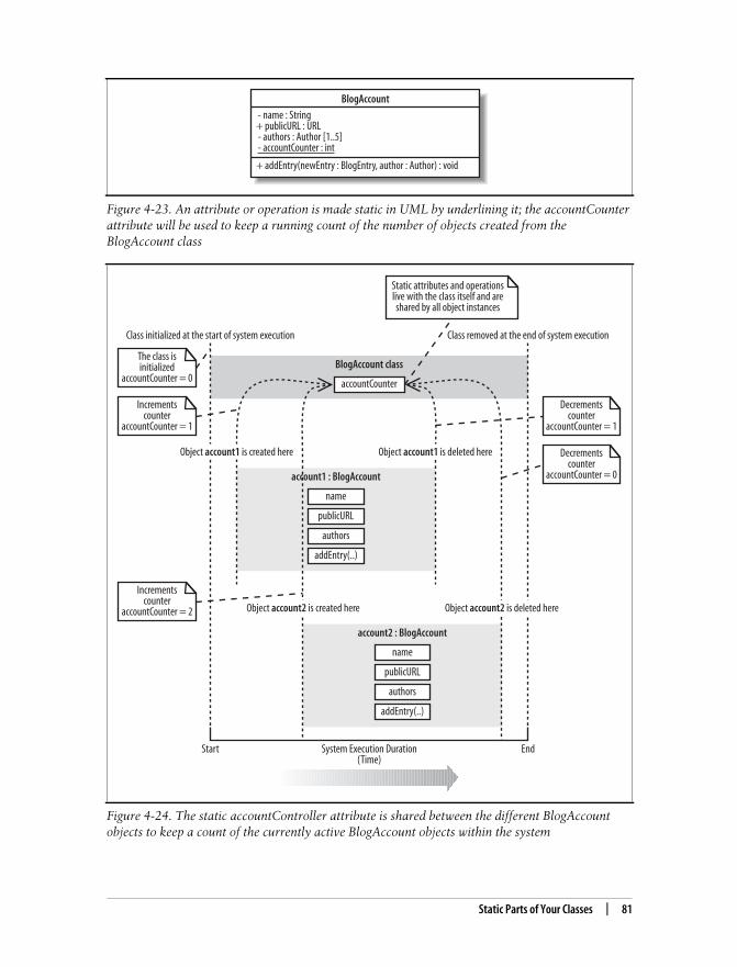
This is the Title of the Book, eMatter EditionCopyright © 2008 O’Reilly & Associates, Inc. All rights reserved.
Static Parts of Your Classes | 81
Figure 4-23. An attribute or operation is made static in UML by underlining it; the accountCounterattribute will be used to keep a running count of the number of objects created from theBlogAccount class
Figure 4-24. The static accountController attribute is shared between the different BlogAccountobjects to keep a count of the currently active BlogAccount objects within the system
BlogAccount
- name : String+ publicURL : URL - authors : Author [1..5] - accountCounter : int
+ addEntry(newEntry : BlogEntry, author : Author) : void
Class initialized at the start of system execution Class removed at the end of system execution
Static attributes and operationslive with the class itself and areshared by all object instances
accountCounter
BlogAccount class
name
publicURL
authors
addEntry(..)
account1 : BlogAccount
Object account1 is created here Object account1 is deleted here
name
publicURL
authors
addEntry(..)
account2 : BlogAccount
Object account2 is created here Object account2 is deleted here
Start EndSystem Execution Duration(Time)
The class isinitialized
accountCounter = 0
Incrementscounter
accountCounter = 1
Incrementscounter
accountCounter = 2
Decrementscounter
accountCounter = 1
Decrementscounter
accountCounter = 0

This is the Title of the Book, eMatter EditionCopyright © 2008 O’Reilly & Associates, Inc. All rights reserved.
82 | Chapter 4: Modeling a System’s Logical Structure: Introducing Classes and Class Diagrams
If the accountCounter attribute were not static, then every BlogAccount instancewould get its own copy of the accountCounter attribute. This would not be very usefulat all since each BlogAccount object would update only its own copy of accountCounterrather than contributing to a master object instance counter—in fact, if accountCounterwere not static, then every object would simply increment its own copy to 1 and thendecrement it to 0 when it is destroyed, which is not very useful at all!
What’s NextThis chapter has given you only a first glimpse of all that is possible with class dia-grams. Classes can be related to one another, and there are even advanced forms ofclasses, such as templates, that can make your system’s design even more effective.Class relationships, abstract classes, and class templates are all covered in Chapter 5.
Class diagrams show the types of objects in your system; a useful next step is to lookat object diagrams because they show how classes come alive at runtime as objectinstances, which is useful if you want to show runtime configurations. Object diagramsare covered in Chapter 6.
Composite structures are a diagram type that loosely shows context-sensitive classdiagrams and patterns in your software. Composite structures are described inChapter 11.
After you’ve decided the responsibilities of the classes in your system, it’s common tothen create sequence and communication diagrams to show interactions between theparts. Sequence diagrams can be found in Chapter 7. Communication diagrams arecovered in Chapter 8.
It’s also common to step back and organize your classes into packages. Package dia-grams allow you to view dependencies at a higher level, helping you understand thestability of your software. Package diagrams are described in Chapter 13.
The Singleton Design PatternAnother great example of when static attributes and operations are used is when youwant to apply the Singleton design pattern. In a nutshell, the Singleton design patternensures that one and only one object of a particular class is ever constructed during thelifetime of your system. To ensure that only one object is ever constructed, typicalimplementations of the Singleton pattern keep an internal static reference to the singleallowed object instance, and access to that instance is controlled using a static opera-tion. To learn more about the Singleton pattern, check out Head First Design Patterns(O’Reilly).

This is the Title of the Book, eMatter EditionCopyright © 2008 O’Reilly & Associates, Inc. All rights reserved.
83
Chapter 5 CHAPTER 5
Modeling a System’s Logical Structure:Advanced Class Diagrams5
If all you could do with class diagrams was declare classes with simple attributes andoperations, then UML would be a pretty poor modeling language. Luckily, objectorientation and UML allows much more to be done with classes than just simpledeclarations. For starters, classes can have relationships to one another. A class canbe a type of another class—generalization—or it can contain objects of another classin various ways depending on how strong the relationship is between the two classes.
Abstract classes help you to partly declare a class’s behavior, allowing other classesto complete the missing—abstract—bits of behavior as they see fit. Interfaces takeabstract classes one stage further by specifying only the needed operations of a classbut without any operation implementations. You can even apply constraints to yourclass diagrams that describe how a class’s objects can be used with the Object Con-straint Language (OCL).
Templates complete the picture by allowing you to declare classes that contain com-pletely generic and reusable behavior. With templates, you can specify what a classwill do and then wait—as late as runtime if you choose—to decide which classes itwill work with.
Together, these techniques complete your class diagram toolbox. They representsome of the most powerful concepts in object-oriented design and, when applied cor-rectly, can make the difference between an OK design and a great piece of reusabledesign.
Class RelationshipsClasses do not live in a vacuum—they work together using different types of rela-tionships. Relationships between classes come in different strengths, as shown inFigure 5-1.
The strength of a class relationship is based on how dependent the classes involvedin the relationship are on each other. Two classes that are strongly dependent on oneanother are said to be tightly coupled; changes to one class will most likely affect the
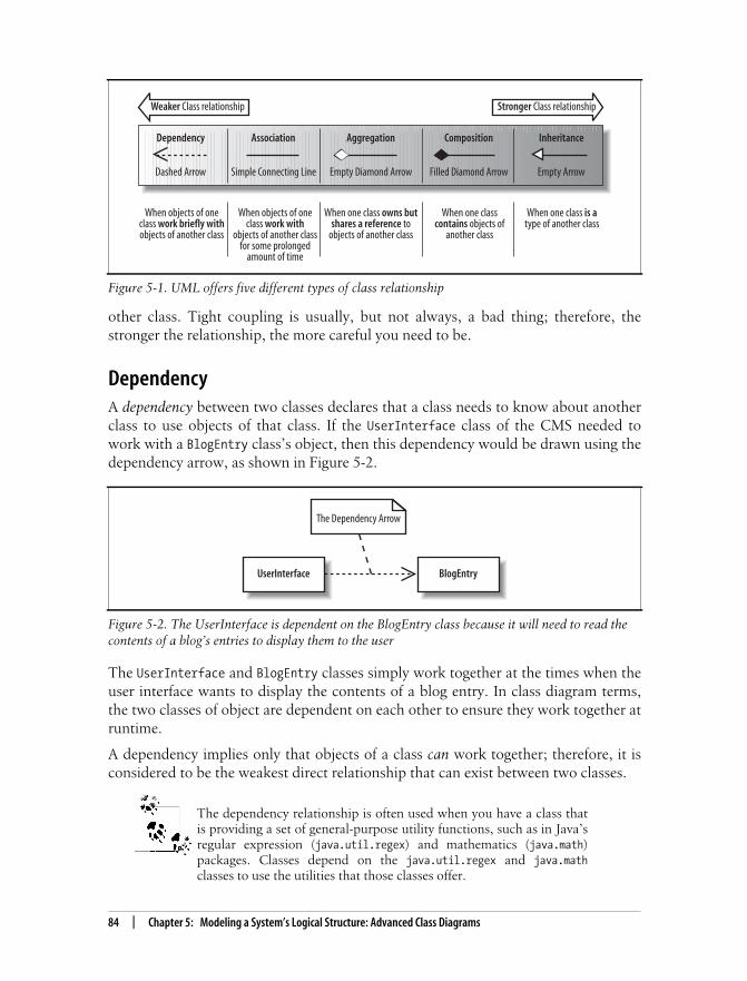
This is the Title of the Book, eMatter EditionCopyright © 2008 O’Reilly & Associates, Inc. All rights reserved.
84 | Chapter 5: Modeling a System’s Logical Structure: Advanced Class Diagrams
other class. Tight coupling is usually, but not always, a bad thing; therefore, thestronger the relationship, the more careful you need to be.
DependencyA dependency between two classes declares that a class needs to know about anotherclass to use objects of that class. If the UserInterface class of the CMS needed towork with a BlogEntry class’s object, then this dependency would be drawn using thedependency arrow, as shown in Figure 5-2.
The UserInterface and BlogEntry classes simply work together at the times when theuser interface wants to display the contents of a blog entry. In class diagram terms,the two classes of object are dependent on each other to ensure they work together atruntime.
A dependency implies only that objects of a class can work together; therefore, it isconsidered to be the weakest direct relationship that can exist between two classes.
The dependency relationship is often used when you have a class thatis providing a set of general-purpose utility functions, such as in Java’sregular expression (java.util.regex) and mathematics (java.math)packages. Classes depend on the java.util.regex and java.mathclasses to use the utilities that those classes offer.
Figure 5-1. UML offers five different types of class relationship
Figure 5-2. The UserInterface is dependent on the BlogEntry class because it will need to read thecontents of a blog’s entries to display them to the user
Weaker Class relationship Stronger Class relationship
Dependency
Dashed Arrow
Association
Simple Connecting Line
Aggregation
Empty Diamond Arrow
Composition
Filled Diamond Arrow
Inheritance
Empty Arrow
When objects of oneclass work briefly withobjects of another class
When objects of oneclass work with
objects of another classfor some prolonged
amount of time
When one class owns butshares a reference to
objects of another class
When one classcontains objects of
another class
When one class is atype of another class
UserInterface
The Dependency Arrow
BlogEntry

This is the Title of the Book, eMatter EditionCopyright © 2008 O’Reilly & Associates, Inc. All rights reserved.
Class Relationships | 85
AssociationAlthough dependency simply allows one class to use objects of another class, associ-ation means that a class will actually contain a reference to an object, or objects, ofthe other class in the form of an attribute. If you find yourself saying that a classworks with an object of another class, then the relationship between those classes is agreat candidate for association rather than just a dependency. Association is shownusing a simple line connecting two classes, as shown in Figure 5-3.
Navigability is often applied to an association relationship to describe which classcontains the attribute that supports the relationship. If you take Figure 5-3 as it cur-rently stands and implement the association between the two classes in Java, thenyou would get something like that shown in Example 5-1.
Without more information about the association between the BlogAccount andBlogEntry classes, it is impossible to decide which class should contain the associa-tion introduced attribute; in this case, both classes have an attribute added. If thiswas intentional, then there might not be a problem; however, it is more common tohave only one class referencing the other in an association.
Figure 5-3. The BlogAccount class is optionally associated with zero or more objects of theBlogEntry class; the BlogEntry is also associated with one and only one BlogAccount
Example 5-1. The BlogAccount and BlogEntry classes without navigability applied to theirassociation relationship
public class BlogAccount {
// Attribute introduced thanks to the association with the BlogEntry class private BlogEntry[] entries;
// ... Other Attributes and Methods declared here ...}
public class BlogEntry {
// Attribute introduced thanks to the association with the Blog class private BlogAccount blog;
// ... Other Attributes and Methods declared here ...}
Association Line
BlogEntry1 *has
- entriesBlogAccount
Association Name(optional)
- blog

This is the Title of the Book, eMatter EditionCopyright © 2008 O’Reilly & Associates, Inc. All rights reserved.
86 | Chapter 5: Modeling a System’s Logical Structure: Advanced Class Diagrams
In our system, it makes more sense to be able to ask a blog account what entries itcontains, rather than asking the entry what blog account it belongs to. In this case,we use navigability to ensure that the BlogAccount class gets the association intro-duced attribute, as shown in Figure 5-4.
Updating the association between the BlogAccount class and the BlogEntry class asshown in Figure 5-4 would result in the code shown in Example 5-2.
Association classes
Sometimes an association itself introduces new classes. Association classes are partic-ularly useful in complex cases when you want to show that a class is related to twoclasses because those two classes have a relationship with each other, as shown inFigure 5-5.
In Figure 5-5, the BlogEntry class is associated with a BlogAccount. However, depend-ing on the categories that the account contains, the blog entry is also associated withany number of categories. In short, the association relationship between a blogaccount and a blog entry results in an association relationship with a set of catego-ries (whew!).
Figure 5-4. If we change Figure 5-3 to incorporate the navigability arrow, then we can declare thatyou should be able to navigate from the blog to its entries
Example 5-2. With navigability applied, only the BlogAccount class contains an associationintroduced attribute
public class BlogAccount {
// Attribute introduced thanks to the association with the BlogEntry class private BlogEntry[] entries ;
// ... Other Attributes and Methods declared here ...}
public class BlogEntry{ // The blog attribute has been removed as it is not necessary for the // BlogEntry to know about the BlogAccount that it belongs to.
// ... Other Attributes and Methods declared here ...}
BlogEntry1 *has
- entriesBlogAccount
The “No Navigability ”Cross
The NavigabilityArrow

This is the Title of the Book, eMatter EditionCopyright © 2008 O’Reilly & Associates, Inc. All rights reserved.
Class Relationships | 87
There are no hard and fast rules for exactly how an association class is implementedin code, but, for example, the relationships shown in Figure 5-5 could be imple-mented in Java, as shown in Example 5-3.
AggregationMoving one step on from association, we encounter the aggregation relationship.Aggregation is really just a stronger version of association and is used to indicate thata class actually owns but may share objects of another class.
Aggregation is shown by using an empty diamond arrowhead next to the owningclass, as shown in Figure 5-6.
Figure 5-5. A BlogEntry is associated with a Category by virtue of the fact that it is associated witha particular BlogAccount
Example 5-3. One method of implementing the BlogEntry to BlogAccount relationship and theassociated Category class in Java
public class BlogAccount { private String name; private Category[] categories; private BlogEntry[] entries;}
public class Category { private String name;}
public class BlogEntry { private String name; private Category[] categories}
Figure 5-6. An aggregation relationship can show that an Author owns a collection of blogs
BlogEntry
- name : String- contents : String
1* BlogAccount
- name : String
Category
- name : String
AggregationDiamond
Author BlogAccounts1 *owns
- blogs

This is the Title of the Book, eMatter EditionCopyright © 2008 O’Reilly & Associates, Inc. All rights reserved.
88 | Chapter 5: Modeling a System’s Logical Structure: Advanced Class Diagrams
The relationship between an author and his blogs, as shown in Figure 5-6, is muchstronger than just association. An author owns his blogs, and even though he mightshare them with other authors, in the end, his blogs are his own, and if he decides toremove one of his blogs, then he can!
Where’s the code? Actually, the Java code implementation for anaggregation relationship is exactly the same as the implementation foran association relationship; it results in the introduction of anattribute.
CompositionMoving one step further down the class relationship line, composition is an even stron-ger relationship than aggregation, although they work in very similar ways. Composi-tion is shown using a closed, or filled, diamond arrowhead, as shown in Figure 5-7.
A blog entry’s introduction and main body sections are actually parts of the blogentry itself and won’t usually be shared with other parts of the system. If the blogentry is deleted, then its corresponding parts are also deleted. This is exactly whatcomposition is all about: you are modeling the internal parts that make up a class.
Similar to aggregation, the Java code implementation for a compositionrelationship results only in the introduction of an attribute.
Generalization (Otherwise Known as Inheritance)Generalization and inheritance are used to describe a class that is a type of anotherclass. The terms has a and is a type of have become an accepted way of deciding
Figure 5-7. A BlogEntry is made up of an Introduction and a MainBody
BlogEntry Introduction1 1
CompositionDiamond
MainBody
1
1

This is the Title of the Book, eMatter EditionCopyright © 2008 O’Reilly & Associates, Inc. All rights reserved.
Class Relationships | 89
whether a relationship between two classes is aggregation or generalization for manyyears now. If you find yourself stating that a class has a part that is an object ofanother class, then the relationship is likely to be one of association, aggregation, orcomposition. If you find yourself saying that the class is a type of another class, thenyou might want to consider using generalization instead.
In UML, the generalization arrow is used to show that a class is a type of anotherclass, as shown in Figure 5-8.
The more generalized class that is inherited from—at the arrow end of the generali-zation relationship, Article in this case—is often referred to as the parent, base, orsuperclass. The more specialized classes that do the inheriting—BlogEntry andWikiPage in this case—are often referred to as the children or derived classes. Thespecialized class inherits all of the attributes and methods that are declared in thegeneralized class and may add operations and attributes that are only applicable inspecialized cases.
The key to why inheritance is called generalization in UML is in the differencebetween what a parent class and a child class each represents. Parent classes describea more general type, which is then made more specialized in child classes.
If you need to check that you’ve got a generalization relationship cor-rect, this rule of thumb can help: generalization relationships makesense only in one direction. Although it’s true to say that a guitarist isa musician, it is not true to say that all musicians are guitarists.
Generalization and implementation reuse
A child class inherits and reuses all of the attributes and methods that the parentcontains and that have public, protected, or default visibility. So, generalizationoffers a great way of expressing that one class is a type of another class, and it offers a
Figure 5-8. Showing that a BlogEntry and WikiPage are both types of Article
Article
The morespecialized classes
BlogEntry WikiPage
The GeneralizationArrow
The moregeneralized classes
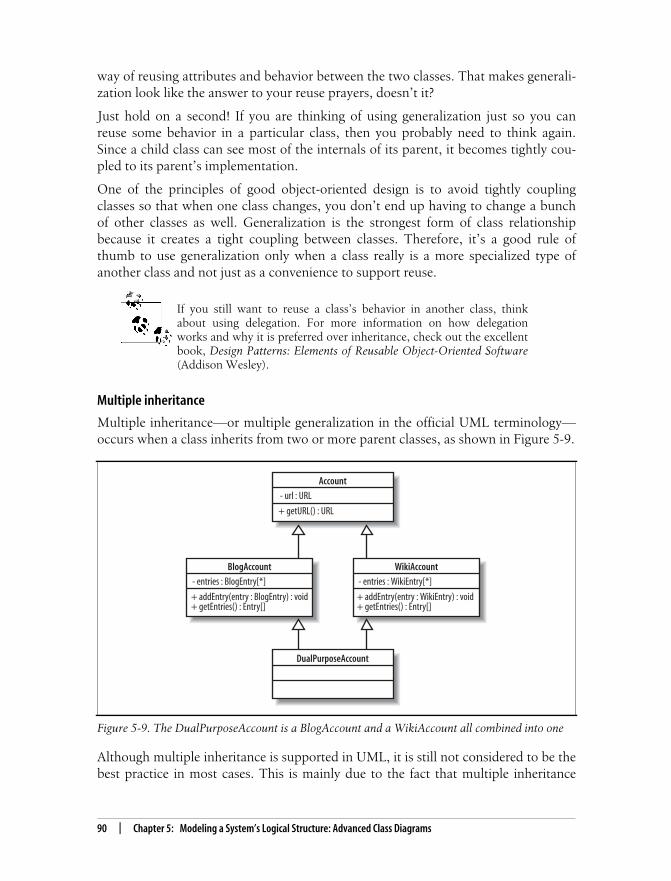
This is the Title of the Book, eMatter EditionCopyright © 2008 O’Reilly & Associates, Inc. All rights reserved.
90 | Chapter 5: Modeling a System’s Logical Structure: Advanced Class Diagrams
way of reusing attributes and behavior between the two classes. That makes generali-zation look like the answer to your reuse prayers, doesn’t it?
Just hold on a second! If you are thinking of using generalization just so you canreuse some behavior in a particular class, then you probably need to think again.Since a child class can see most of the internals of its parent, it becomes tightly cou-pled to its parent’s implementation.
One of the principles of good object-oriented design is to avoid tightly couplingclasses so that when one class changes, you don’t end up having to change a bunchof other classes as well. Generalization is the strongest form of class relationshipbecause it creates a tight coupling between classes. Therefore, it’s a good rule ofthumb to use generalization only when a class really is a more specialized type ofanother class and not just as a convenience to support reuse.
If you still want to reuse a class’s behavior in another class, thinkabout using delegation. For more information on how delegationworks and why it is preferred over inheritance, check out the excellentbook, Design Patterns: Elements of Reusable Object-Oriented Software(Addison Wesley).
Multiple inheritance
Multiple inheritance—or multiple generalization in the official UML terminology—occurs when a class inherits from two or more parent classes, as shown in Figure 5-9.
Although multiple inheritance is supported in UML, it is still not considered to be thebest practice in most cases. This is mainly due to the fact that multiple inheritance
Figure 5-9. The DualPurposeAccount is a BlogAccount and a WikiAccount all combined into one
Account
- url : URL
+ getURL() : URL
BlogAccount
- entries : BlogEntry[*]
+ addEntry(entry : BlogEntry) : void+ getEntries() : Entry[]
WikiAccount
- entries : WikiEntry[*]
+ addEntry(entry : WikiEntry) : void+ getEntries() : Entry[]
DualPurposeAccount

This is the Title of the Book, eMatter EditionCopyright © 2008 O’Reilly & Associates, Inc. All rights reserved.
Constraints | 91
presents a complicated problem when the two parent classes have overlappingattributes or behavior.
So, why the complication? In Figure 5-9, the DualPurposeAccount class inherits all ofthe behavior and attributes from the BlogAccount and WikiAccount classes, but thereis quite a bit of duplication between the two parent classes. For example, bothBlogAccount and WikiAccount contain a copy of the name attribute that they in turninherited from the Account class. Which copy of this attribute does theDualPurposeAccount class get, or does it get two copies of the same attribute? The sit-uation becomes even more complicated when the two parent classes contain thesame operation. The BlogAccount class has an operation called getEntries( ) and sodoes the WikiAccount.
Although the BlogAccount and WikiAccount classes are kept separate, the fact thatthey both have a getEntries( ) operation is not a problem. However, when both ofthese classes become the parent to another class through inheritance, a conflict iscreated. When DualPurposeAccount inherits from both of these classes, which versionof the getEntries( ) method does it get? If the DualPurposeAccount’s getEntries( )operation is invoked, which method should be executed to get the Wiki entries orthe blog entries?
The answers to these question are unfortunately often hidden in implementationdetails. For example, if you were using the C++ programming language, which sup-ports multiple inheritance, you would use the C++ language’s own set of rules abouthow to resolve these conflicts. Another implementation language may use a differentset of rules completely. Because of these complications, multiple inheritance hasbecome something of a taboo subject in object-oriented software development—tothe point where the current popular development languages, such as Java and C#,do not even support it. However, the fact remains that there are situations wheremultiple inheritance can make sense and be implemented—in languages such asC++, for example—so UML still needs to support it.
ConstraintsSometimes you will want to restrict the ways in which a class can operate. For exam-ple, you might want to specify a class invariant—a rule that specifies that a particu-lar condition should never happen within a class—or that one attribute’s value isbased on another, or that an operation should never leave the class in an irregularstate. These types of constraints go beyond what can be done with simple UMLnotation and calls for a language in its own right: the OCL.
There are three types of constraint that can be applied to class members using OCL:
InvariantsAn invariant is a constraint that must always be true; otherwise the system is inan invalid state. Invariants are defined on class attributes.

This is the Title of the Book, eMatter EditionCopyright © 2008 O’Reilly & Associates, Inc. All rights reserved.
92 | Chapter 5: Modeling a System’s Logical Structure: Advanced Class Diagrams
PreconditionsA precondition is a constraint that is defined on a method and is checked beforethe method executes. Preconditions are frequently used to validate input param-eters to a method.
PostconditionsA postcondition is also defined on a method and is checked after the method exe-cutes. Postconditions are frequently used to describe how values were changedby a method.
Constraints are specified using either the OCL statement in curly brackets next tothe class member or in a separate note, as shown in Figure 5-10.
In Figure 5-10, the url attribute is constrained to never being null and the ratingattribute is constrained so that it must never be less than 0. To ensure that theupdateRating(..) operation checks that the rating attribute is not less than 0, aprecondition constraint is set. Finally, the rating attribute should never be morethan 5 after it has been updated, so this is specified as a postcondition constraint onthe updateRating(..) operation.
OCL allows you to specify all sorts of constraints that limit how yourclasses can operate. For more information on OCL, see Appendix A.
Abstract ClassesSometimes when you are using generalization to declare a nice, reusable, genericclass, you will not be able to implement all of the behavior that is needed by the gen-eral class. If you are implementing a Store class to store and retrieve the CMS’s arti-cles, as shown in Figure 5-11, you might want to indicate that exactly how a Store
Figure 5-10. Three constraints are set on the BlogEntry class: self.url>notEmpty( ) and rating>=0are both invariants, and there is a postcondition constraint on the updateRating(..) operation
BlogEntry
self.url->notEmpty()
- url : URL- rating : int {rating >=0}
+ updateRating(newRating : Int) : void
context BlogEntry::updateRating(newRating:int) : voidpre: rating >=0post: rating <= 5

This is the Title of the Book, eMatter EditionCopyright © 2008 O’Reilly & Associates, Inc. All rights reserved.
Abstract Classes | 93
stores and retrieves the articles is not known at this point and should be left to sub-classes to decide.
To indicate that the implementation of the store(..) and retrieve(..) operations isto be left to subclasses by declaring those operations as abstract, write their signa-tures in italics, as shown in Figure 5-12.
An abstract operation does not contain a method implementation and is really aplaceholder that states, “I am leaving the implementation of this behavior to my sub-classes.” If any part of a class is declared abstract, then the class itself also needs tobe declared as abstract by writing its name in italics, as shown in Figure 5-13.
Now that the store(..) and retrieve(..) operations on the Store class are declaredas abstract, they do not have to have any methods implemented, as shown inExample 5-4.
Figure 5-11. Using regular operations, the Store class needs to know how to store and retrieve acollection of articles
Figure 5-12. The store(..) and retrieve(..) operations do not now need to be implemented by theStore class
Figure 5-13. The complete abstract Store class
Example 5-4. The problem of what code to put in the implementation of the play( )operation is solvedby declaring the operation and the surrounding class as abstract
public abstract class Store { public abstract void store(Article[] articles); public abstract Article[] retrieve( );}
Store
+ store(articles : Article[]) : void+ retrieve() : Article[]
Store
+ store(articles : Article[]) : void+ retrieve() : Article[]
Store
+ store(articles : Article[]) : void+ retrieve() : Article[]

This is the Title of the Book, eMatter EditionCopyright © 2008 O’Reilly & Associates, Inc. All rights reserved.
94 | Chapter 5: Modeling a System’s Logical Structure: Advanced Class Diagrams
An abstract class cannot be instantiated into an object because it has pieces missing.The Store class might implement the store(..) and retrieve(..) operations butbecause it is abstract, children who inherit from the Store class will have to imple-ment or declare abstract the Store class’s abstract operations, as shown inFigure 5-14.
By becoming abstract, the Store class has delayed the implementation of the store(..)and retrieve(..) operations until a subclass has enough information to implementthem. The BlogStore class can implement the Store class’s abstract operations becauseit knows how to store away a blog, as shown in Example 5-5.
An abstract class cannot be instantiated as an object because there are parts of theclass definition missing: the abstract parts. Child classes of the abstract class can be
Figure 5-14. The BlogStore class inherits from the abstract Store class and implements the store(..)and retrieve(..) operations; classes that completely implement all of the abstract operationsinherited from their parents are sometimes referred to as “concrete”
Example 5-5. The BlogStore class completes the abstract parts of the Store class
public abstract class Store {
public abstract void store(Article[] articles); public abstract Article[] retrieve( );}
public class BlogStore {
public void store(Article[] articles) { // Store away the blog entries here ... }
public Article[] retrieve( ) { // Retrieve and return the stored blog entries here... }}
Store
+ store(articles : Article[]) : void+ retrieve() : Article[]
Abstractoperations in
italics
BlogStore
+ store(articles : Article[]) : void+ retrieve() : Article[]
Concreteoperations inregular font
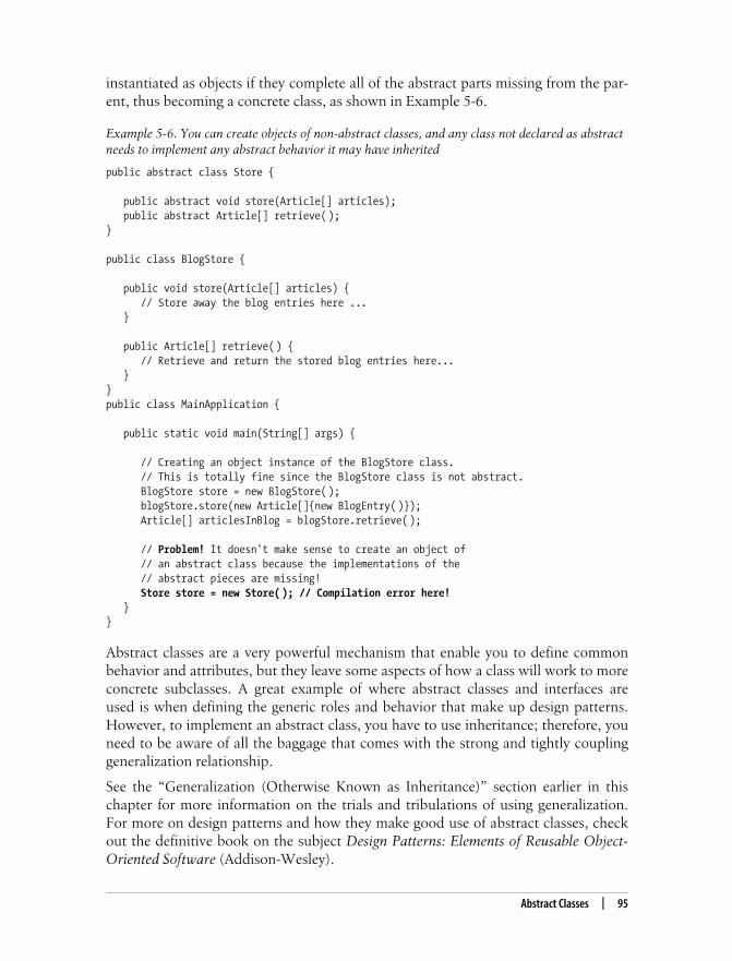
This is the Title of the Book, eMatter EditionCopyright © 2008 O’Reilly & Associates, Inc. All rights reserved.
Abstract Classes | 95
instantiated as objects if they complete all of the abstract parts missing from the par-ent, thus becoming a concrete class, as shown in Example 5-6.
Abstract classes are a very powerful mechanism that enable you to define commonbehavior and attributes, but they leave some aspects of how a class will work to moreconcrete subclasses. A great example of where abstract classes and interfaces areused is when defining the generic roles and behavior that make up design patterns.However, to implement an abstract class, you have to use inheritance; therefore, youneed to be aware of all the baggage that comes with the strong and tightly couplinggeneralization relationship.
See the “Generalization (Otherwise Known as Inheritance)” section earlier in thischapter for more information on the trials and tribulations of using generalization.For more on design patterns and how they make good use of abstract classes, checkout the definitive book on the subject Design Patterns: Elements of Reusable Object-Oriented Software (Addison-Wesley).
Example 5-6. You can create objects of non-abstract classes, and any class not declared as abstractneeds to implement any abstract behavior it may have inherited
public abstract class Store {
public abstract void store(Article[] articles); public abstract Article[] retrieve( );}
public class BlogStore {
public void store(Article[] articles) { // Store away the blog entries here ... }
public Article[] retrieve( ) { // Retrieve and return the stored blog entries here... }}public class MainApplication {
public static void main(String[] args) {
// Creating an object instance of the BlogStore class. // This is totally fine since the BlogStore class is not abstract. BlogStore store = new BlogStore( ); blogStore.store(new Article[]{new BlogEntry( )}); Article[] articlesInBlog = blogStore.retrieve( );
// Problem! It doesn't make sense to create an object of // an abstract class because the implementations of the // abstract pieces are missing! Store store = new Store( ); // Compilation error here! }}
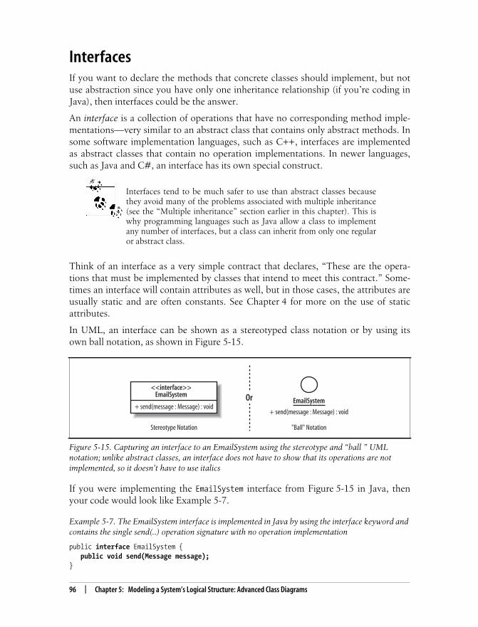
This is the Title of the Book, eMatter EditionCopyright © 2008 O’Reilly & Associates, Inc. All rights reserved.
96 | Chapter 5: Modeling a System’s Logical Structure: Advanced Class Diagrams
InterfacesIf you want to declare the methods that concrete classes should implement, but notuse abstraction since you have only one inheritance relationship (if you’re coding inJava), then interfaces could be the answer.
An interface is a collection of operations that have no corresponding method imple-mentations—very similar to an abstract class that contains only abstract methods. Insome software implementation languages, such as C++, interfaces are implementedas abstract classes that contain no operation implementations. In newer languages,such as Java and C#, an interface has its own special construct.
Interfaces tend to be much safer to use than abstract classes becausethey avoid many of the problems associated with multiple inheritance(see the “Multiple inheritance” section earlier in this chapter). This iswhy programming languages such as Java allow a class to implementany number of interfaces, but a class can inherit from only one regularor abstract class.
Think of an interface as a very simple contract that declares, “These are the opera-tions that must be implemented by classes that intend to meet this contract.” Some-times an interface will contain attributes as well, but in those cases, the attributes areusually static and are often constants. See Chapter 4 for more on the use of staticattributes.
In UML, an interface can be shown as a stereotyped class notation or by using itsown ball notation, as shown in Figure 5-15.
If you were implementing the EmailSystem interface from Figure 5-15 in Java, thenyour code would look like Example 5-7.
Figure 5-15. Capturing an interface to an EmailSystem using the stereotype and “ball ” UMLnotation; unlike abstract classes, an interface does not have to show that its operations are notimplemented, so it doesn’t have to use italics
Example 5-7. The EmailSystem interface is implemented in Java by using the interface keyword andcontains the single send(..) operation signature with no operation implementation
public interface EmailSystem { public void send(Message message);}
<<interface>>EmailSystem
+ send(message : Message) : void
Stereotype Notation
Or EmailSystem
+ send(message : Message) : void
"Ball" Notation

This is the Title of the Book, eMatter EditionCopyright © 2008 O’Reilly & Associates, Inc. All rights reserved.
Interfaces | 97
You can’t instantiate an interface itself, much like you can’t instantiate an abstractclass. This is because all of the implementations for an interface’s operations aremissing until it is realized by a class. If you are using the “ball” interface notation,then you realize an interface by associating it with a class, as shown in Figure 5-16.
If you have used the stereotype notation for your interface, then a new arrow isneeded to show that this is a realization relationship, as shown in Figure 5-17.
Both Figures 5-16 and 5-17 and would have resulted in the same Java code beinggenerated, as shown in Example 5-8.
Figure 5-16. The SMTPMailSystem class implements, or realizes, all of the operations specified onthe EmailSystem interface
Figure 5-17. The realization arrow specifies that the SMTPMailSystem realizes the EmailSysteminterface
Example 5-8. Java classes realize interfaces using the implements keyword
public interface EmailSystem{ public void send(Message message));}
public class SMTPMailSystem implements EmailSystem{ public void send(Message message) { // Implement the interactions with an SMTP server to send the message }
// ... Implementations of the other operations on the Guitarist class ...}
SMTPMailSystem
+ send(message : Message) : voidEmailSystem
+ send(message : Message) : void
<<interface>>EmailSystem
+send(message : Message) : void
The RealizationArrow
SMTPMailSystem
+send(message : Message) : void

This is the Title of the Book, eMatter EditionCopyright © 2008 O’Reilly & Associates, Inc. All rights reserved.
98 | Chapter 5: Modeling a System’s Logical Structure: Advanced Class Diagrams
If a class realizes an interface but does not implement all of the operations that theinterface specifies, then that class needs to be declared abstract, as shown inFigure 5-18.
Interfaces are great at completely separating the behavior that is required of a classfrom exactly how it is implemented. When a class implements an interface, objectsof that class can be referred to using the interface’s name rather than the class nameitself. This means that other classes can be dependent on interfaces rather thanclasses. This is generally a good thing since it ensures that your classes are as looselycoupled as possible. If your classes are loosely coupled, then when a class implemen-tation changes other classes should not break (because they are dependent on theinterface, not on the class itself).
Figure 5-18. Because the SMTPMailSystem class does not implement the send(..) operation asspecified by the EmailSystem interface, it needs to be declared abstract; the VendorXMailSystemclass completes the picture by implementing all of its operations
Using InterfacesIt is good practice to de-couple dependencies between your classes using interfaces;some programming environments, such as the Spring Framework, enforce this interface-class relationship. The use of interfaces, as opposed to abstract classes, is also usefulwhen you are implementing design patterns. In languages such as Java, you don’t reallywant to use up the single inheritance relationship just to use a design pattern. A Javaclass can implement any number of interfaces, so they offer a way of enforcing a designpattern without imposing the burden of having to expend that one inheritance rela-tionship to do it.
<<interface>>EmailSystem
+ send(message : Message) : voidThe interface
SMTPMailSystem
- name : String The abstract class
VendorXMailSystem
+ send(message : Message) : voidThe concrete class
+ getName() : String+ send(message : Message) : void

This is the Title of the Book, eMatter EditionCopyright © 2008 O’Reilly & Associates, Inc. All rights reserved.
Templates | 99
TemplatesTemplates are an advanced but useful feature of object orientation. A template—orparameterized class, as they are sometimes referred to—is helpful when you want topostpone the decision as to which classes a class will work with. When you declare atemplate, as shown in Figure 5-19, it is similar to declaring, “I know this class willhave to work with other classes, but I don’t know or necessarily care what thoseclasses actually end up being.”
The ListOfThings class in Figure 5-19 is parameterized with the type referred to as E.There is no class in our model called E; E is nothing more than a placeholder that canbe used at a later point to tell the ListOfThings class the type of object that it willneed to store.
To use a class that is a template, you first need to bind its parameters. TheListOfSomething class template doesn’t yet know what it’s supposed to be storing;you need to tell the template what actual classes it will be working with; you need tobind the parameter referred to so far as just E to an actual class.
You can bind a template’s parameters to a specific set of classes in one of two ways.First, you can subclass the template, binding the parameters as you go, as shown inFigure 5-20.
Figure 5-19. A template in UML is shown by providing an extra box with a dashed border to thetop right of the regular class box
ListsLists tend to be the most common examples of how to use templates, and with verygood reason. Lists and their cousins, such as maps and sets, all store objects in differentways, but they don’t actually care what classes those objects are constructed from. Forthis reason, one of the best real-world uses of templates is in the Java collection classes.Prior to Java 5, the Java programming language did not have a means of specifying tem-plates. With the release of Java 5 and its generics feature, you can now not only createyour own templates, but the original collection classes are all available to use as tem-plates as well. To find out more about Java 5 generics, check out the latest edition ofJava in a Nutshell (O’Reilly).
ListOfThings
- elements : E
+ add(E newElement) : int - remove(int index) : boolean
E

This is the Title of the Book, eMatter EditionCopyright © 2008 O’Reilly & Associates, Inc. All rights reserved.
100 | Chapter 5: Modeling a System’s Logical Structure: Advanced Class Diagrams
Binding by subclass in Figure 5-20 allows you to reuse all of the generic behavior inthe ListOfThings class and restrict that behavior in the ListOfBlogEntries class toonly adding and removing BlogEntry objects.
The real power of templates is much more obvious when you use the secondapproach to template parameter binding—binding at runtime. You bind at runtimewhen a template is told the type of parameters it will have as it is constructed into anobject.
Runtime template binding is about objects rather than classes; therefore, a new typeof diagram is needed: the object diagram. Object diagrams use classes to show someof the important ways they are used as your system runs. As luck would have it,object diagrams are the subject of the very next chapter.
What’s NextClass diagrams show the types of objects in your system. A useful next step is to lookat object diagrams since they show how classes come alive at runtime as objectinstances, which is useful if you want to show runtime configurations. Object dia-grams are covered in Chapter 6.
Composite structures are a diagram type that loosely shows context sensitive classdiagrams and patterns in your software. Composite structures are described inChapter 11.
After you’ve decided the responsibilities of the classes in your system, it’s common tothen create sequence and communication diagrams to show interactions between theparts. Sequence diagrams can be found in Chapter 7; communication diagrams arecovered in Chapter 8.
It’s also common to step back and organize your classes into packages. Package dia-grams allow you to view dependencies at a higher level, helping you understand thestability of your software. Package diagrams are described in Chapter 13.
Figure 5-20. The ListOfThings class is subclassed into a ListOfBlogEntries, binding the singleparameter E to the concrete BlogEntry class
ListOfThings
- elements : E
+ add(E newElement) : int - remove(int index) : boolean
E
ListOfBlogEntries
<<bind>> <E -> BlogEntry >

This is the Title of the Book, eMatter EditionCopyright © 2008 O’Reilly & Associates, Inc. All rights reserved.
101
Chapter 6 CHAPTER 6
Bringing Your Classes to Life: ObjectDiagrams6
Objects are at the heart of any object-oriented system at runtime. When the systemyou designed is actually in use, objects make up its parts and bring all of your care-fully designed classes to life.
Compared to class diagrams, object diagram notation is very simple. Despite havinga fairly limited vocabulary, object diagrams are particularly useful when you want todescribe how the objects within the system would work together in a particular sce-nario. Class diagrams describe how all of the different types of objects within yoursystem interact with each other. They also draw attention to the many ways that theobjects will exist and interact within your system at runtime. In addition to class dia-grams, object diagrams help you capture the logical view of your model, shown inFigure 6-1.
Object InstancesTo draw an object diagram, the first thing you need to add are the actual objectsthemselves. Object notation is actually very simple if you’re already familiar withclass notation; an object is shown with a rectangle, just like a class, but to show that
Figure 6-1. The Logical View of your model contains the abstract descriptions of your system’sparts, including which objects exist within your system at runtime
Logical View Process View
Physical View Development View
Use Case View
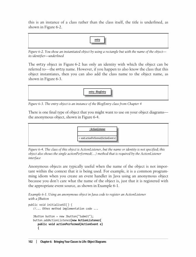
This is the Title of the Book, eMatter EditionCopyright © 2008 O’Reilly & Associates, Inc. All rights reserved.
102 | Chapter 6: Bringing Your Classes to Life: Object Diagrams
this is an instance of a class rather than the class itself, the title is underlined, asshown in Figure 6-2.
The entry object in Figure 6-2 has only an identity with which the object can bereferred to—the entry name. However, if you happen to also know the class that thisobject instantiates, then you can also add the class name to the object name, asshown in Figure 6-3.
There is one final type of object that you might want to use on your object diagrams—the anonymous object, shown in Figure 6-4.
Anonymous objects are typically useful when the name of the object is not impor-tant within the context that it is being used. For example, it is a common program-ming idiom when you create an event handler in Java using an anonymous objectbecause you don’t care what the name of the object is, just that it is registered withthe appropriate event source, as shown in Example 6-1.
Figure 6-2. You show an instantiated object by using a rectangle but with the name of the object—its identifier—underlined
Figure 6-3. The entry object is an instance of the BlogEntry class from Chapter 4
Figure 6-4. The class of this object is ActionListener, but the name or identity is not specified; thisobject also shows the single actionPerformed(…) method that is required by the ActionListenerinterface
Example 6-1. Using an anonymous object in Java code to register an ActionListenerwith a JButton
public void initialiseUI( ) { //... Other method implementation code ...
JButton button = new Jbutton("Submit"); button.addActionListener(new ActionListener{ public void actionPerformed(ActionEvent e) {
entry
entry : BlogEntry
: ActionListener
+ void actionPerformed(ActionEvent e)

This is the Title of the Book, eMatter EditionCopyright © 2008 O’Reilly & Associates, Inc. All rights reserved.
Links | 103
You might also notice in Example 6-1 that the anonymous object isimplementing an interface as it is declared. As the anonymous object isinstantiated, it implements the actionPerformed(...) method that isrequired by the ActionListener interface.
LinksObjects on their own are not very interesting or helpful. To really show how yourobjects will work together in a particular runtime configuration, you need to tiethose objects together using links, as shown in Figure 6-5.
Links between objects on an object diagram show that the two objects can commu-nicate with each other. However, you can’t just link any two objects together. If youcreate a link between two objects, there must be a corresponding associationbetween the classes.
The links on an object diagram work in a similar fashion to links on a communica-tion diagram (see Chapter 8). However, unlike communication diagrams, the onlyadditional piece of information that you can optionally add to a link is a label thatindicates the purpose of the link, as shown in Figure 6-6.
Links and ConstraintsLinks between objects correspond to associations between the object’s classes. Thismeans that where constraint rules have been applied to an association, the link mustkeep to those rules.
System.out.println("The button was pressed so it's time to do something ..."); } });
//... Other method implementation code ...}
Figure 6-5. Links are shown using a line between the two objects that are being linked
Example 6-1. Using an anonymous object in Java code to register an ActionListenerwith a JButton (continued)
ui : UserInterface
entry : BlogEntry

This is the Title of the Book, eMatter EditionCopyright © 2008 O’Reilly & Associates, Inc. All rights reserved.
104 | Chapter 6: Bringing Your Classes to Life: Object Diagrams
In Chapter 5, the relationship between BlogEntry, BlogAccount, and Category wasmodeled using an association class, as shown in Figure 6-7.
If the diagram in Figure 6-7 were left as it is, then the two object diagrams shown inFigure 6-8 would be perfectly valid.
Figure 6-6. To play some tunes, a BlogEntry object is connected to a UserInterface object
Figure 6-7. When a BlogEntry is added to a BlogAccount, it will be grouped under one or morecategories; the Category class is associated with the relationship between a BlogEntry and aBlogAccount
Figure 6-8. A BlogEntry can be associated with a BlogAccount and a set of categories, but there isno rule that states that a BlogEntry must be associated with a category
ui : UserInterface
Optional label
entry : BlogEntry
displays
BlogEntry1*
BlogAccount
- name : String- contents : String
- name : String
Category
- name : String
account : BlogAccount entry : BlogEntryContains
Object Diagram Option 1
account : BlogAccount entry : BlogEntryContains
category : Category
Contains
Object Diagram Option 2

This is the Title of the Book, eMatter EditionCopyright © 2008 O’Reilly & Associates, Inc. All rights reserved.
Binding Class Templates | 105
If you wanted to show that an entry must be associated with a category when it iscontained within a blog account, you need to add some OCL to the original classdiagram, as shown in Figure 6-9. OCL was briefly covered in Chapter 5 and is cov-ered in more depth in Appendix A.
Objects and their links must abide by the rules set by the OCL statements—this isone of the reasons why OCL is called the object constraint language, and not theclass constraint language. With the constraints applied to the class diagram inFigure 6-9, the possible options for an object diagram based on these classes isreduced to something that makes much more sense, as shown in Figure 6-10.
Binding Class TemplatesIn Chapter 5, we saw how the parameters declared on class templates could be real-ized using subclassing on a class diagram. Although this approach works fine, thereal power of templates comes when you bind template parameters at runtime. To
Figure 6-9. The constraint states that within the context of the BlogEntry, a BlogEntry objectshould be associated with a category and that the association should not be null; in other words, fora BlogEntry to be added to a BlogAccount, it must have a category assigned
Figure 6-10. The self.category->notEmpty( ) constraint affects the options available when youcreate an object diagram, ensuring that an entry is associated with a category for it to be added to aBlogAccount
BlogEntry1*
BlogAccount
self.category->notEmpty()
- name : String- contents : String
- name : String
Category
- name : String
account : BlogAccount entry : BlogEntry
category : Category
Contains
ContainsAssigned to

This is the Title of the Book, eMatter EditionCopyright © 2008 O’Reilly & Associates, Inc. All rights reserved.
106 | Chapter 6: Bringing Your Classes to Life: Object Diagrams
do this, you take a template and tell it the types that its parameters are going to be asit is constructed into an object.
Object diagrams are ideal for modeling how runtime binding takes place. When youuse runtime template parameter binding, you are really talking about objects ratherthan classes, so you can’t really model this information on a regular class diagram.
Although this book talks about UML in terms of diagram types, theUML specification is not actually constrained to a particular set of dia-grams. In fact, you could show object diagram notation on a class dia-gram if you wanted to group your classes and their runtime bindingson the same diagram.
Figure 6-11 shows a simple class template for a list collection taken from Chapter 4.Collections are great candidates for templates because they need to manage a collec-tion of objects, but they don’t usually care what classes those objects are.
To model that the ListOfThings template’s E parameter is to be bound at runtime toa particular class, all you need to do is add the parameter binding details to the endof the object’s class description, as shown in Figure 6-12.
Up until recently, showing runtime binding of templates in Java would have beenimpossible; the language did not support templates at all. However, with the releaseof Java 5 and the new generics language features, the runtime binding of theBlogEntry class to the E parameter on the ListOfThings template can now be imple-mented, as shown in Example 6-2.
Figure 6-11. The ListOfThings collection can store and remove any class of object to which the Eparameter is bound
Figure 6-12. The listOfBlogEntries reuses the generic ListOfThings template, binding the Eparameter to the BlogEntry class to store only objects of the BlogEntry class
ListOfThings
- elements : E
+ add(E newElement) : int - remove(int index) : boolean
E
listOfBlogEntries : ListOfThings <E-> BlogEntry>

This is the Title of the Book, eMatter EditionCopyright © 2008 O’Reilly & Associates, Inc. All rights reserved.
What’s Next? | 107
There is a lot more to generics in Java than the simple template implementation pro-vided here. For more examples, see Java 5 Tiger: A Developer’s Notebook (O’Reilly).
What’s Next?Now that you’re considering runtime characteristics of your system, it’s natural tocontinue on this path by studying sequence diagrams and communication diagrams.These show messages passing between parts on your system, demonstrating howyour objects get used.
You can find sequence diagrams in Chapter 7; communication diagrams are coveredin Chapter 8.
Example 6-2. Using Java 5 generics to implement the ListOfThings template and a runtime bindingto the ListOfBlogEntries
public class ListOfThings<E> {
// We're cheating a bit here; Java actually already has a List template // and so we're using that for our ListOfThings templates operations. private List[E] elements;
public ListOfThings { elements = new ArrayList<E>( ); }
public int add(E object) { return elements.add(object); }
public E remove(int index) { return elements.remove(index); }}
public class Application {
public static void main(String[] args) { // Binding the E parameter on the ListOfThings template to a Musician class // to create a ListOfThings that will only store Musician objects. ListOfThings <BlogEntry>listOfBlogEntries= new ListOfThings<BlogEntry>( ); }}

This is the Title of the Book, eMatter EditionCopyright © 2008 O’Reilly & Associates, Inc. All rights reserved.
108
Chapter 7CHAPTER 7
Modeling Ordered Interactions:Sequence Diagrams 7
Use cases allow your model to describe what your system must be able to do; classesallow your model to describe the different types of parts that make up your system’sstructure. There’s one large piece that’s missing from this jigsaw; with use cases andclasses alone, you can’t yet model how your system is actually going to its job. This iswhere interaction diagrams, and specifically sequence diagrams, come into play.
Sequence diagrams are an important member of the group known as interaction dia-grams. Interaction diagrams model important runtime interactions between the partsthat make up your system and form part of the logical view of your model, shown inFigure 7-1.
Sequence diagrams are not alone in this group; they work alongside communicationdiagrams (see Chapter 8) and timing diagrams (see Chapter 9) to help you accu-rately model how the parts that make up your system interact.
Sequence diagrams are the most popular of the three interaction dia-gram types. This could be because they show the right sorts of infor-mation or simply because they tend to make sense to people new toUML.
Figure 7-1. The Logical View of your model contains the abstract descriptions of your system’sparts, including the interactions between those parts
Logical View Process View
Physical View Development View
Use Case View
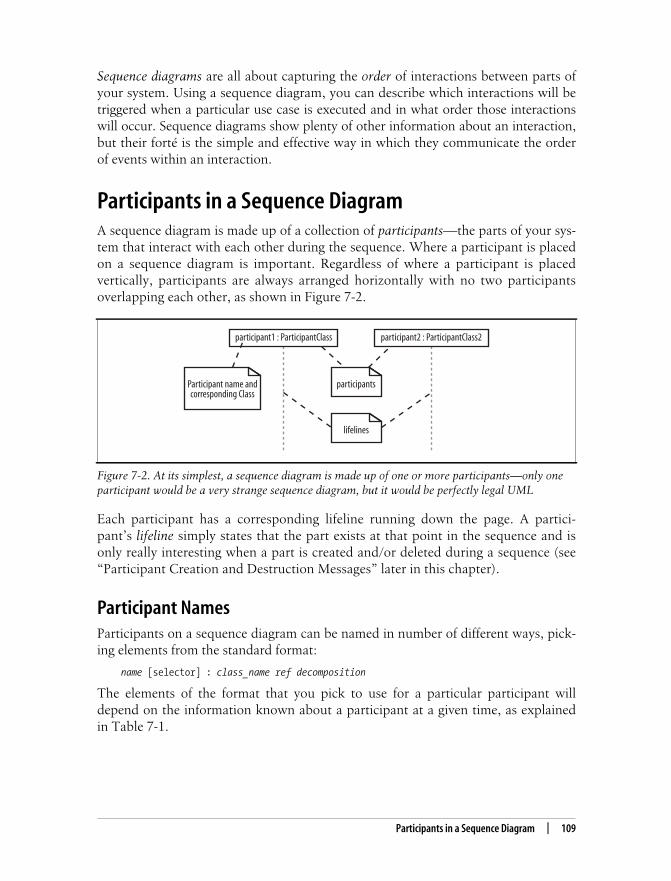
This is the Title of the Book, eMatter EditionCopyright © 2008 O’Reilly & Associates, Inc. All rights reserved.
Participants in a Sequence Diagram | 109
Sequence diagrams are all about capturing the order of interactions between parts ofyour system. Using a sequence diagram, you can describe which interactions will betriggered when a particular use case is executed and in what order those interactionswill occur. Sequence diagrams show plenty of other information about an interaction,but their forté is the simple and effective way in which they communicate the orderof events within an interaction.
Participants in a Sequence DiagramA sequence diagram is made up of a collection of participants—the parts of your sys-tem that interact with each other during the sequence. Where a participant is placedon a sequence diagram is important. Regardless of where a participant is placedvertically, participants are always arranged horizontally with no two participantsoverlapping each other, as shown in Figure 7-2.
Each participant has a corresponding lifeline running down the page. A partici-pant’s lifeline simply states that the part exists at that point in the sequence and isonly really interesting when a part is created and/or deleted during a sequence (see“Participant Creation and Destruction Messages” later in this chapter).
Participant NamesParticipants on a sequence diagram can be named in number of different ways, pick-ing elements from the standard format:
name [selector] : class_name ref decomposition
The elements of the format that you pick to use for a particular participant willdepend on the information known about a participant at a given time, as explainedin Table 7-1.
Figure 7-2. At its simplest, a sequence diagram is made up of one or more participants—only oneparticipant would be a very strange sequence diagram, but it would be perfectly legal UML
participant1 : ParticipantClass participant2 : ParticipantClass2
participants
lifelines
Participant name andcorresponding Class
This is the Title of the Book, eMatter EditionCopyright © 2008 O’Reilly & Associates, Inc. All rights reserved.
110 | Chapter 7: Modeling Ordered Interactions: Sequence Diagrams
The format used when creating names for your participants is totally up to you—ormaybe your company’s style guide. In this book, we lowercase the first word in theparticipant name to make sure that there is as little confusion as possible with thename of a class. However, this is just our convention—similar to the conventionsused when naming objects and classes in Java—and is not something specified byUML.
TimeA sequence diagram describes the order in which the interactions take place, so timeis an important factor. How time relates to a sequence diagram is shown inFigure 7-3.
Time on a sequence diagram starts at the top of the page, just beneath the topmostparticipant heading, and then progresses down the page. The order that interactions
Table 7-1. How to understand the components of a participant’s name
Example participant name Description
admin A part is named admin, but at this point in time the part has not beenassigned a class.
: ContentManagementSystem The class of the participant is ContentManagementSystem, but thepart currently does not have its own name.
admin : Administrator There is a part that has a name of admin and is of the classAdministrator.
eventHandlers [2] : EventHandler There is a part that is accessed within an array at element 2, and it is ofthe class EventHandler.
: ContentManagementSystem ref cmsInteraction The participant is of the class ContentManagementSystem, andthere is another interaction diagram called cmsInteraction thatshows how the participant works internally (see “A Brief Overview ofUML 2.0’s Fragment Types,” later in this chapter).
What Happened to Objects?In UML 1.x, participants on an interaction diagram were usually software objects inthe traditional object-oriented programming sense. Each object was an instance of aclass, and the object name was underlined to indicate this. Because UML 2.0 is moreof a general system modeling language, it makes much more sense to think of it interms of system parts interacting with each other rather than software objects. This iswhy we’ve used the term “participant” to describe a part that is involved in the inter-actions on a sequence diagram. A participant could still be a software object, a la UML1.x, but it could equally be any other part of the system in keeping with the spirit ofUML 2.0.

This is the Title of the Book, eMatter EditionCopyright © 2008 O’Reilly & Associates, Inc. All rights reserved.
Events, Signals, and Messages | 111
are placed down the page on a sequence diagram indicates the order in which thoseinteractions will take place in time.
Time on a sequence diagram is all about ordering, not duration. Although the time atwhich an interaction occurs is indicated on a sequence diagram by where it is placedvertically on the diagram, how much of the vertical space the interaction takes up hasnothing to do with the duration of time that the interaction will take. Sequence dia-grams are first about the ordering of the interactions between participants; moredetailed timing information is better shown on timing diagrams (see Chapter 9).
Events, Signals, and MessagesThe smallest part of an interaction is an event. An event is any point in an interac-tion where something occurs, as shown on Figure 7-4.
Events are the building blocks for signals and messages. Signals and messages arereally different names for the same concept: a signal is the terminology often used bysystem designers, while software designers often prefer messages.
Figure 7-3. Time runs down the page on a sequence diagram in keeping with the participant lifeline
Figure 7-4. Probably the most common examples of events are when a message or signal is sent orreceived
participant1 : ParticipantClass participant2
Time
participant1 : ParticipantClass participant2 : ParticipantClass2
message
A “ReceiveMessage” Event
A “SendMessage” Event

This is the Title of the Book, eMatter EditionCopyright © 2008 O’Reilly & Associates, Inc. All rights reserved.
112 | Chapter 7: Modeling Ordered Interactions: Sequence Diagrams
In terms of sequence diagrams, signals and messages act and look the same, so we’llstick to using the term “messages” in this book.
An interaction in a sequence diagram occurs when one participant decides to send amessage to another participant, as shown in Figure 7-5.
Messages on a sequence diagram are specified using an arrow from the participantthat wants to pass the message, the Message Caller, to the participant that is toreceive the message, the Message Receiver. Messages can flow in whatever directionmakes sense for the required interaction—from left to right, right to left, or evenback to the Message Caller itself. Think of a message as an event that is passed froma Message Caller to get the Message Receiver to do something.
Message SignaturesA message arrow comes with a description, or signature. The format for a messagesignature is:
attribute = signal_or_message_name (arguments) : return_type
You can specify any number of different arguments on a message, each separatedusing a comma. The format of an argument is:
<name>:<class>
The elements of the format that you use for a particular message will depend on theinformation known about a particular message at any given time, as explained inTable 7-2.
Figure 7-5. Interactions on a sequence diagram are shown as messages between participants
participant1 : ParticipantClass participant2
message(arguments)
The MessageSignature
The MessageReceiver
Message ReceiverActivation Bar
(optional)
The Message
Return Arrow(optional)
Message CallerActivation Bar
(optional)
The Message Caller

This is the Title of the Book, eMatter EditionCopyright © 2008 O’Reilly & Associates, Inc. All rights reserved.
Activation Bars | 113
Activation BarsWhen a message is passed to a participant it triggers, or invokes, the receiving partic-ipant into doing something; at this point, the receiving participant is said to beactive. To show that a participant is active, i.e., doing something, you can use anactivation bar, as shown in Figure 7-6.
An activation bar can be shown on the sending and receiving ends of a message. Itindicates that the sending participant is busy while it sends the message and thereceiving participant is busy after the message has been received
Activation bars are optional—they can clutter up a diagram.
Table 7-2. How to understand the components of a message’s signature
Example message signature Description
doSomething( ) The message’s name is doSomething, but no further infor-mation is known about it.
doSomething(number1 : Number, number2 : Number) The message’s name is doSomething, and it takes twoarguments,number1 andnumber2, which are both of classNumber.
doSomething( ) : ReturnClass The message’s name is doSomething; it takes no argu-ments and returns an object of class ReturnClass.
myVar = doSomething( ) : ReturnClass The message’s name is doSomething; it takes no argu-ments, and it returns an object of class ReturnClass thatis assigned to the myVar attribute of the message caller.
Figure 7-6. Activation bars show that a participant is busy doing something for a period of time
participant1 : ParticipantClass participant2 : ParticipantClass
message(arguments)
Message ReceiverActivation Bar
Message CallerActivation Bar

This is the Title of the Book, eMatter EditionCopyright © 2008 O’Reilly & Associates, Inc. All rights reserved.
114 | Chapter 7: Modeling Ordered Interactions: Sequence Diagrams
Nested MessagesWhen a message from one participant results in one or more messages being sent bythe receiving participant, those resulting messages are said to be nested within thetriggering message, as shown in Figure 7-7.
In Figure 7-7, participant1 sends initialMessage(..) to participant2. Whenparticipant2 receives initialMessage(..), participant2 becomes active and sendstwo nested messages to participant3. You can have any number of nested messagesinside a triggering message and any number of levels of nested messages on asequence diagram.
Message ArrowsThe type of arrowhead that is on a message is also important when understandingwhat type of message is being passed. For example, the Message Caller may want towait for a message to return before carrying on with its work—a synchronous mes-sage. Or it may wish to just send the message to the Message Receiver without wait-ing for any return as a form of “fire and forget” message—an asynchronous message.
Sequence diagrams need to show these different types of message using various mes-sage arrows, as shown in Figure 7-8.
To explain how the different types of messages work, let’s look at some simple exam-ples where the participants are actually software objects implemented in Java.
Figure 7-7. Two nested messages are invoked when an initial message is received
participant2 participant3
nestedMessage2(arguments)
nestedMessage1(arguments)initialMessage(arguments)
Messages nestedinside
Initial Message
participant1 : ParticipantClass
The InitialMessage
Initial MessageCaller
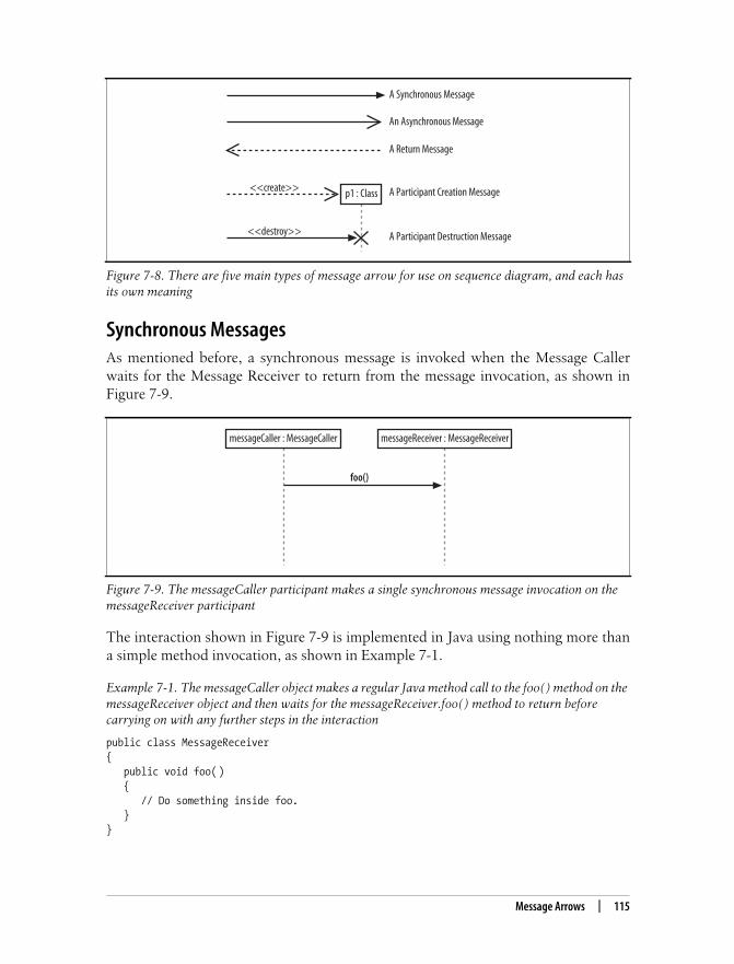
This is the Title of the Book, eMatter EditionCopyright © 2008 O’Reilly & Associates, Inc. All rights reserved.
Message Arrows | 115
Synchronous MessagesAs mentioned before, a synchronous message is invoked when the Message Callerwaits for the Message Receiver to return from the message invocation, as shown inFigure 7-9.
The interaction shown in Figure 7-9 is implemented in Java using nothing more thana simple method invocation, as shown in Example 7-1.
Figure 7-8. There are five main types of message arrow for use on sequence diagram, and each hasits own meaning
Figure 7-9. The messageCaller participant makes a single synchronous message invocation on themessageReceiver participant
Example 7-1. The messageCaller object makes a regular Java method call to the foo( ) method on themessageReceiver object and then waits for the messageReceiver.foo( ) method to return beforecarrying on with any further steps in the interaction
public class MessageReceiver{ public void foo( ) { // Do something inside foo. }}
p1 : Class
A Synchronous Message
An Asynchronous Message
A Return Message
<<create>>
<<destroy>>
A Participant Creation Message
A Participant Destruction Message
messageCaller : MessageCaller messageReceiver : MessageReceiver
foo()

This is the Title of the Book, eMatter EditionCopyright © 2008 O’Reilly & Associates, Inc. All rights reserved.
116 | Chapter 7: Modeling Ordered Interactions: Sequence Diagrams
Asynchronous MessagesIt would be great if all the interactions in your system happened one after the otherin a nice simple order. Each participant would pass a message to another participantand then calmly wait for the message to return before carrying on. Unfortunately,that’s not how most systems work. Interactions can happen at the same point intime, and sometimes you will want to initiate a collection of interactions all at thesame time and not wait for them to return at all.
For example, say you are designing a piece of software with a user interface that sup-ports the editing and printing of a set of documents. Your application offers a but-ton for the user to print a document. Printing could take some time, so you want toshow that after the print button is pressed and the document is printing, the user cango ahead and work with other things in the application. The regular synchronousmessage arrow is not sufficient to show these types of interactions. You need a newtype of message arrow: the asynchronous message arrow.
An asynchronous message is invoked by a Message Caller on a Message Receiver, butthe Message Caller does not wait for the message invocation to return before carry-ing on with the rest of the interaction’s steps. This means that the Message Callerwill invoke a message on the Message Receiver and the Message Caller will be busyinvoking further messages before the original message returns, as shown inFigure 7-10.
A common way of implementing asynchronous messaging in Java is to use threads,as shown in Example 7-2.
public class MessageCaller{ private MessageReceiver messageReceiver;
// Other Methods and Attributes of the class are declared here
// The messageRecevier attribute is initialized elsewhere in // the class.
public doSomething(String[] args) { // The MessageCaller invokes the foo( ) method
this.messageReceiver.foo( ); // then waits for the method to return
// before carrying on here with the rest of its work }}
Example 7-1. The messageCaller object makes a regular Java method call to the foo( ) method on themessageReceiver object and then waits for the messageReceiver.foo( ) method to return beforecarrying on with any further steps in the interaction (continued)

This is the Title of the Book, eMatter EditionCopyright © 2008 O’Reilly & Associates, Inc. All rights reserved.
Message Arrows | 117
If you’re not too familiar with how threads work in Java, check out Java in a Nut-shell, Fifth Edition (O’Reilly) or Java Threads (O’Reilly). See “Applying Asynchro-nous Messages” later in this chapter for a practical example of asynchronousmessages.
Figure 7-10. While the foo( ) message is being worked on by the messageReceiver object, themessageCaller object has carried on with the interaction by executing further synchronousmessages on another object
Example 7-2. The operation1( ) asynchronous message invokes an internal thread on the messagereceiver that in turn spurs the message, immediately returning the flow of execution to themessageCaller
public class MessageReceiver implements Runable {
public void operation1( ) { // Receive the message and trigger off the thread
Thread fooWorker = new Thread(this); fooWorker.start(); // This call starts a new thread, calling the run( ) // method below
// As soon as the thread has been started, the call to foo( ) returns.
}
public void run( ) { // This is where the work for the foo( ) message invocation will // be executed. }}
public class MessageCaller{ private MessageReceiver messageReceiver;
// Other Methods and Attributes of the class are declared here
// The messageRecevier attribute is initialized elsewhere in // the class.
public void doSomething(String[] args) {
messageReceiver : MessageReceiver
bar()
messageReceiver2 : MessageReceiver2
bar()
foo()
messageCaller : MessageCaller

This is the Title of the Book, eMatter EditionCopyright © 2008 O’Reilly & Associates, Inc. All rights reserved.
118 | Chapter 7: Modeling Ordered Interactions: Sequence Diagrams
The Return MessageThe return message is an optional piece of notation that you can use at the end of anactivation bar to show that the control flow of the activation returns to the partici-pant that passed the original message. In code, a return arrow is similar to reachingthe end of a method or explicitly calling a return statement.
You don’t have to use return messages—sometimes they can really make yoursequence diagram too busy and confusing. You don’t have to clutter up yoursequence diagrams with a return arrow for every activation bar since there is animplied return arrow on any activation bars that are invoked using a synchronousmessage.
Although a message will often be passed between two different partici-pants, it is totally normal for a participant to pass a message to itself.Messages from an object to itself are a good way of splitting up a largeactivation into smaller and more manageable pieces and, in terms ofsoftware, can be thought of as being very similar to making a methodcall to the this reference in Java and C#.
Participant Creation and Destruction MessagesParticipants do not necessarily live for the entire duration of a sequence diagram’sinteraction. Participants can be created and destroyed according to the messages thatare being passed, as shown in Figure 7-11.
To show that a participant is created, you can either simply pass a create(..) mes-sage to the participant’s lifeline or use the dropped participant box notation where itis absolutely clear that the participant does not exist before the create call isinvoked. Participant deletion is shown by the ending of the participant’s lifelinewith the deletion cross.
Software participant creation in Java and C# is implemented using the new keyword,as shown in Example 7-3.
// The MessageCaller invokes the operation1( ) operation
this.messageReceiver.operation1( );
// then immediately carries on with the rest of its work }}
Example 7-2. The operation1( ) asynchronous message invokes an internal thread on the messagereceiver that in turn spurs the message, immediately returning the flow of execution to themessageCaller (continued)

This is the Title of the Book, eMatter EditionCopyright © 2008 O’Reilly & Associates, Inc. All rights reserved.
Message Arrows | 119
With some implementation languages, such as Java, you will not have an explicitdestroy method, so it doesn’t make sense to show one on your sequence diagrams.Example 7-3 is one such case where the messageReceiver object will be flagged fordestruction when the doSomething( ) method completes its execution. However, noadditional messages have to be passed to the messageReceiver to make it destroyitself since this is all handled implicitly by the Java garbage collector.
In these cases, where another factor such as the garbage collector is involved, youcan either leave the object as alive but unused or imply that it is no longer needed byusing the destruction cross without an associated destroy method, as shown inFigure 7-12.
Figure 7-11. Both participant2 and participant3 are created throughout the course of this sequencediagram
Example 7-3. The MessageCaller creates a new MessageReceiver object simply by using the newkeyword
public class MessageReceiver { // Attributes and Methods of the MessageReceiver class}
public class MessageCaller {
// Other Methods and Attributes of the class are declared here
public void doSomething( ) { // The MessageReceiver object is created MessageReceiver messageReceiver = new MessageReceiver( ); }}
participant2 : ParticipantClass2
participant3 : ParticipantClass3
create(arguments)
<<create>>
<<destroy>>
<<destroy>>
Destroying twoparticipants
participant1 : ParticipantClass1 The “dropped”participant box
notation
Creating twoparticipants
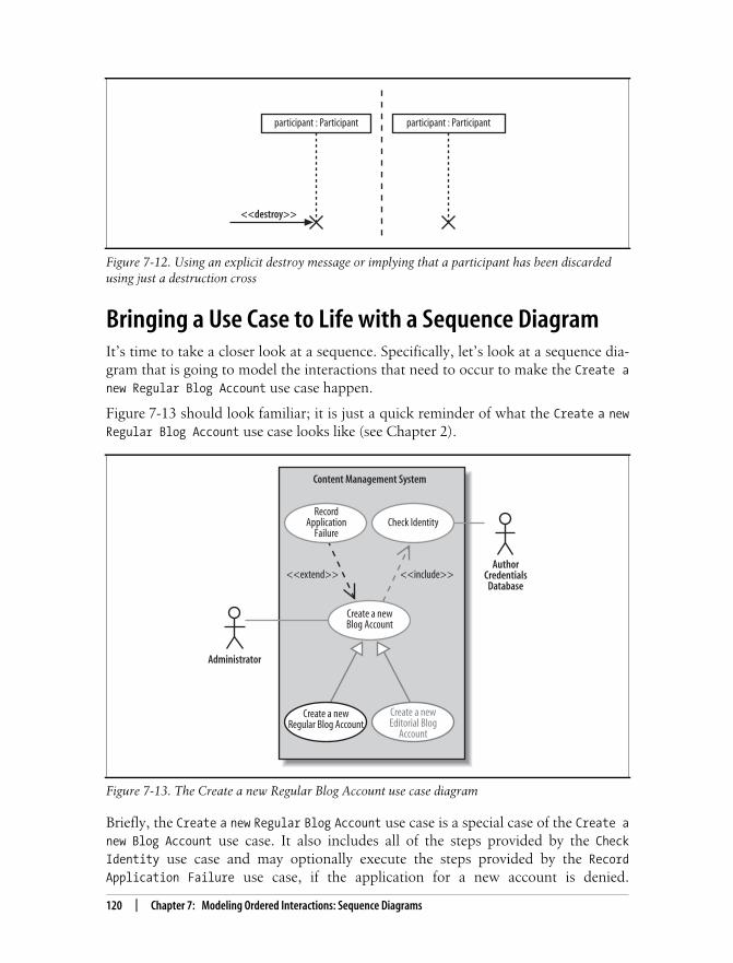
This is the Title of the Book, eMatter EditionCopyright © 2008 O’Reilly & Associates, Inc. All rights reserved.
120 | Chapter 7: Modeling Ordered Interactions: Sequence Diagrams
Bringing a Use Case to Life with a Sequence DiagramIt’s time to take a closer look at a sequence. Specifically, let’s look at a sequence dia-gram that is going to model the interactions that need to occur to make the Create anew Regular Blog Account use case happen.
Figure 7-13 should look familiar; it is just a quick reminder of what the Create a newRegular Blog Account use case looks like (see Chapter 2).
Briefly, the Create a new Regular Blog Account use case is a special case of the Create anew Blog Account use case. It also includes all of the steps provided by the CheckIdentity use case and may optionally execute the steps provided by the RecordApplication Failure use case, if the application for a new account is denied.
Figure 7-12. Using an explicit destroy message or implying that a participant has been discardedusing just a destruction cross
Figure 7-13. The Create a new Regular Blog Account use case diagram
participant : Participant participant : Participant
<<destroy>>
Administrator
Check Identity
Content Management System
AuthorCredentials
Database
Create a newBlog Account
RecordApplication
Failure
<<extend>> <<include>>
Create a newRegular Blog Account
Create a newEditorial Blog
Account

This is the Title of the Book, eMatter EditionCopyright © 2008 O’Reilly & Associates, Inc. All rights reserved.
Bringing a Use Case to Life with a Sequence Diagram | 121
Figure 7-13 is a pretty busy use case diagram, so feel free to jump back to Chapter 2to remind yourself of what is going on.
A Top-Level Sequence DiagramBefore you can specify what types of interaction are going to occur when a use caseexecutes, you need a more detailed description of what the use case does. If you’vealready completed a use case description, you already have a good reference for thisdetailed information.
Table 7-3 shows the steps that occur in the Create a new Regular Blog Account usecase according to its detailed description.
Table 7-3 actually shows all of the steps involved in the Create a new Regular BlogAccount use case, including any steps that it has inherited from Create a new BlogAccount or reused from Check Identity. This has been done just so you can easily seeall of the Main Flow steps in one place.
Supporting the Dropped Title Box TechniqueIt is a sad fact that many standard UML tools do not support the dropped title boxtechnique for showing participant creation or the cross notation for participantdestruction. For example, you will often find that your tool does not allow you to placethe participant’s title box anywhere else but at the top of the diagram. In these cases,the best approach is to show that the creation or deletion message invokes the objectbeing created and to rely on the reader of the diagram to realize that you mean that theparticipant is being created (a note to this effect is often helpful too). Unfortunately,this approach is not the best use of UML, but sometimes it is all you can get the toolto do.
Table 7-3. Most of the detailed information that you will need to start constructing a sequencediagram for a use case should already be available as the Main Flow within the use case’sdescription
Main Flow Step Action
1 The Administrator asks the system to create a new blog account.
2 The Administrator selects the regular blog account type.
3 The Administrator enters the author’s details.
4 The author’s details are checked using the Author Credentials Database.
5 The new regular blog account is created.
6 A summary of the new blog account’s details are emailed to the author.

This is the Title of the Book, eMatter EditionCopyright © 2008 O’Reilly & Associates, Inc. All rights reserved.
122 | Chapter 7: Modeling Ordered Interactions: Sequence Diagrams
In practice, you would probably just look up all three use case descriptions separatelywithout actually going to the bother of actually merging them.
Table 7-3 only shows the Main Flow—that is the steps that would occur withoutworrying about any extensions—but this is a good enough starting point for creat-ing a top-level sequence diagram, as shown in Figure 7-14.
Figure 7-14 focuses on the participants and messages that are involvedin the use case. The same use case was modeled in Chapter 3 as anactivity diagram, which focused on the processes involved rather thanthe particpants.
Breaking an Interaction into Separate ParticipantsAt this point, Figure 7-14 shows only the interactions that must happen between theexternal actors and your system because that is the level at which the use case descrip-tion’s steps were written. On the sequence diagram, your system is represented as asingle participant, the ContentManagementSystem; however, unless you intend on imple-menting your content management system as a single monolithic piece of code (gener-ally not a good idea!), it’s time to break apart ContentManagementSystem to expose thepieces that go inside, as shown in Figure 7-15.
Figure 7-14. This sequence diagram shows the actors that interact with your system and yoursystem is shown simply as a single part in the sequence
<<actor>>admin : Administrator : ContentManagementSystem <<actor>>
acd : AuthorCredentialsDB<<actor>>
es : EmailSystem
createNewBlogAccount
selectBlogAccountType(type)
enterAuthorDetails(author : AuthorDetails)
checkAuthorDetails(author : AuthorDetails)
createNewRegularBlogAccount (author : AuthorDetails)
emailBlogDetails (regularBlogAccount)
sendEmail(email : Email)

This is the Title of the Book, eMatter EditionCopyright © 2008 O’Reilly & Associates, Inc. All rights reserved.
Bringing a Use Case to Life with a Sequence Diagram | 123
Sequence diagrams can get much more complicated by simply adding a couple ofextra participants and some more detailed interactions. In Figure 7-15, the originalsequence diagram has been refined so that the single ContentManagementSystem partic-ipant has been removed and in its place, more detail has been added showing theactual participants that will be involved.
Work on sequence diagrams invariably goes on throughout the life of your system’smodel, and even getting the right participants and interactions in a detailed sequencediagram at the beginning can be hard work. Keeping your sequence diagrams up todate is also a challenge (see “Managing Complex Interactions with Sequence Frag-ments” later in this chapter); therefore, expect to spend some time working withyour sequence diagrams until you get things right.
Applying Participant CreationSomething critical is missing from the sequence diagram shown in Figure 7-15. Thetitle of the use case in which the sequence diagram is operating is Create a newRegular Blog Account, but where is the actual creation of the blog account?Figure 7-16 adds the missing pieces to the model to show the actual creation of a reg-ular blog account.
Figure 7-15. Adding more detail about the internals of your system
<<actor>>admin : Administrator
controller :CreateNewAccountController
<<actor>>acd : AuthorCredentialsDB
<<actor>>es : EmailSystem
createNewBlogAccount()
selectBlogAccountType(type)
clickSubmit()
checkAuthorDetails(author : AuthorDetails)
checkNewRegularBlogAccount (author : AuthorDetails)
emailBlogDetails (regularBlogAccount)
sendEmail(email : Email)
ui :AccountCreationUI
createNewRegularBlogAccount(author : AuthorDetails)
enterAuthorDetails (author : AuthorDetails)

This is the Title of the Book, eMatter EditionCopyright © 2008 O’Reilly & Associates, Inc. All rights reserved.
124 | Chapter 7: Modeling Ordered Interactions: Sequence Diagrams
Participant lifelines are particularly useful when showing that a participant has beencreated. In Figure 7-16, the AuthorDetails and RegularBlogAccount participants arenot in existence when the sequence diagram begins but they are created during itsexecution.
The AuthorDetails and newAccount:RegularBlogAccount participants are created bycorresponding create messages. Each create message connects directly into the titlebox for the participant being created, passing any information needed when creatingthe new participant. By dropping the participant’s title box to the point where thecreate message is actually invoked, the diagram can clearly show the point where theparticipant’s lifeline begins.
Applying Participant DeletionLet’s say that the authorDetails:AuthorDetails participant is no longer required oncethe newAccount:RegularBlogAccount has been created. To show that theauthorDetails:AuthorDetails participant is discarded at this point, you can use anexplicit destroy message connected to the destruction cross, as shown in Figure 7-17.
Applying Asynchronous MessagesSo far, all of the messages on our example sequence diagram have been synchronous;they are executed one after the other in order, and nothing happens concurrently.However, there is at least one message in the example sequence that is a great candi-date for being an asynchronous message, as shown in Figure 7-18.
Figure 7-16. Showing the lifelines of your sequence diagram’s participants
<<actor>>admin : Administrator
controller :CreateNewAccountController
<<actor>>acd : AuthorCredentialsDB
<<actor>>es : EmailSystem
createNewBlogAccount
selectBlogAccountType(type)
clickSubmit()
checkAuthorDetails(authorDetails : AuthorDetails)
emailBlogDetails(newAccount : RegularBlogAccount)
sendEmail(email : Email)
ui :AccountCreationUI
createNewRegularBlogAccount(authorDetails : AuthorDetails)
enterAuthorDetails(author : AuthorDetails)
newAccount :RegularBlogAccount
<<create(authorDetails)>>
: AuthorDetails<<create>>
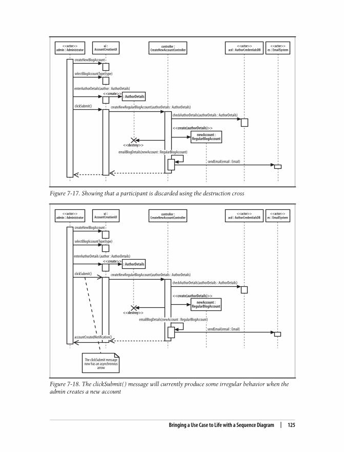
This is the Title of the Book, eMatter EditionCopyright © 2008 O’Reilly & Associates, Inc. All rights reserved.
Bringing a Use Case to Life with a Sequence Diagram | 125
Figure 7-17. Showing that a participant is discarded using the destruction cross
Figure 7-18. The clickSubmit( ) message will currently produce some irregular behavior when theadmin creates a new account
<<actor>>es : EmailSystem
<<actor>>admin : Administrator
controller :CreateNewAccountController
<<actor>>acd : AuthorCredentialsDB
createNewBlogAccount
selectBlogAccountType(type)
clickSubmit()
checkAuthorDetails(authorDetails : AuthorDetails)
emailBlogDetails(newAccount : RegularBlogAccount)
sendEmail(email : Email)
ui :AccountCreationUI
createNewRegularBlogAccount(authorDetails : AuthorDetails)
enterAuthorDetails(author : AuthorDetails)
newAccount :RegularBlogAccount
<<create(authorDetails)>>
: AuthorDetails<<create>>
<<destroy>>
<<actor>>admin : Administrator
controller :CreateNewAccountController
<<actor>>acd : AuthorCredentialsDB
<<actor>>es : EmailSystem
createNewBlogAccount
selectBlogAccountType(type)
clickSubmit()
checkAuthorDetails(authorDetails : AuthorDetails)
emailBlogDetails(newAccount : RegularBlogAccount)
sendEmail(email : Email)
ui :AccountCreationUI
createNewRegularBlogAccount(authorDetails : AuthorDetails)
enterAuthorDetails (author : AuthorDetails)
newAccount :RegularBlogAccount
<<create(authorDetails)>>
: AuthorDetails<<create>>
<<destroy>>
accountCreatedNotification()
The clickSubmit messagenow has an asynchronous
arrow

This is the Title of the Book, eMatter EditionCopyright © 2008 O’Reilly & Associates, Inc. All rights reserved.
126 | Chapter 7: Modeling Ordered Interactions: Sequence Diagrams
In Figure 7-18, when the Administrator clicks on the submit button the systemfreezes, until the new blog account has been created. It would be useful to show thatthe user interface allows the Administrator to carry on with other tasks while thecontent management system creates the new account. What we need is for theclickSubmit( ) message to be asynchronous.
Converting the clickSubmit( ) from a synchronous to an asynchronous messagemeans that the sequence diagram now shows that when the new regular blogaccount information is submitted, the user interface will not lock and wait for thenew account to be created. Instead, the user interface allows the Administrator actorto continue working with the system.
For the Administrator to receive feedback as to whether the new blog account hasbeen created, the simple return arrow has to be replaced with a newaccountCreationNotification( ) asynchronous message since asynchronous messagesdo not have return values.
Managing Complex Interactions with SequenceFragmentsMost of what you’ve seen in this chapter will have been pretty familiar to anyonewho has used sequence diagrams in UML 1.x. But now it’s time for something com-pletely different.
In the bad old days of pre-UML 2.0, sequence diagrams quickly became huge andmessy, and contained far too much detail to be easily understood or maintained.There were no built-in, standard ways to show loops and alternative flows, so youhad to “grow your own” solutions. This tended to contribute to the size and com-plexity of the sequence diagrams rather than helping to manage it.
Something new was needed to help the modeler work with the detail that a sequencediagram needed to capture, allowing her to create organized and structured sequencediagrams that showed complex interactions such as loops and alternate flows. Theanswer from the UML 2.0 designers was the sequence fragment.
A sequence fragment is represented as a box that encloses a portion of the interac-tions within a sequence diagram, as shown in Figure 7-19.
A sequence fragment’s box overlaps the region of the sequence diagram where thefragment’s interactions take place. A fragment box can contain any number of inter-actions and, for large complex interactions, further nested fragments as well. The topleft corner of the fragment box contains an operator. The fragment operator indi-cates which type of fragment this is.

This is the Title of the Book, eMatter EditionCopyright © 2008 O’Reilly & Associates, Inc. All rights reserved.
Managing Complex Interactions with Sequence Fragments | 127
In Figure 7-19, the operator is opt, which means that this is an optional fragment. Allthe interactions contained within the fragment box will be executed according to theresult of the fragments guard condition parameter.
Some fragment types do not need additional parameters as part of their specifica-tion, such as the ref fragment type discussed in the next section, but the guard con-dition parameter is needed by the opt fragment type to make a decision as to whetherit should execute its interactions or not. In the case of the opt fragment type, theinteractions that the fragment contains will be executed only if the associated guardcondition logic evaluates to true.
Using a Sequence Fragment: The ref FragmentThe ref type of sequence fragment finally alleviates some of the maintenance night-mare presented by the huge sequence diagrams that are often created for complex sys-tems. In Figure 7-20, the ref fragment represents a piece of a larger sequence diagram.
The interactions by which the Administrator actor selects a blog account type for cre-ation are now contained within the referenced sequence fragment. Figure 7-21 showshow the referenced fragment can be expressed on a separate sequence diagram.
Figure 7-19. A sequence fragment located as part of a larger sequence diagram, with notes toindicate the fragment box, any parameters, and its operator
<<actor>>admin : Administrator
controller :CreateNewAccountController
<<actor>>acd : AuthorCredentialsDB
<<actor>>es : EmailSystem
createNewBlogAccount
selectBlogAccountType(type)
clickSubmit()
checkAuthorDetails(authorDetails : AuthorDetails)
emailBlogDetails(newAccount : RegularBlogAccount)
sendEmail(email : Email)
ui :AccountCreationUI
createNewRegularBlogAccount(authorDetails : AuthorDetails)
enterAuthorDetails (author : AuthorDetails)
newAccount :RegularBlogAccount
<<create(authorDetails)>>
: AuthorDetails<<create>>
<<destroy>>accountCreatedNotification()
opt [checked = true]
A guard conditionparameter that is tested on
entry to the fragment
The sequencefragment box
The sequencefragment type
operator

This is the Title of the Book, eMatter EditionCopyright © 2008 O’Reilly & Associates, Inc. All rights reserved.
128 | Chapter 7: Modeling Ordered Interactions: Sequence Diagrams
Along with managing the sheer size of large sequence diagrams, the ref fragmentalso presents an opportunity to reuse a set of common interactions. Several ref frag-ment boxes can reference the same set of interactions, thereby reusing the interac-tions in multiple places.
Figure 7-20. Capturing the interactions used to select an account type within a ref sequencefragment
Figure 7-21. A referenced sequence diagram that contains the new account selection interactions
<<actor>>admin : Administrator
controller :CreateNewAccountController
<<actor>>acd : AuthorCredentialsDB
<<actor>>es : EmailSystem
clickSubmit()
checkAuthorDetails(authorDetails : AuthorDetails)
emailBlogDetails(newAccount : RegularBlogAccount)
sendEmail(email : Email)
ui :AccountCreationUI
createNewRegularBlogAccount(authorDetails : AuthorDetails)
enterAuthorDetails (author : AuthorDetails)
newAccount :RegularBlogAccount
<<create(authorDetails)>>
: AuthorDetails<<create>>
<<destroy>>accountCreatedNotification()
opt [checked = true]
ref
Select Account Type
<<actor>>admin : Administrator
createNewBlogAccount()
ui :AccountCreationUI
selectBlogAccountType(type)
sd Select Blog Account Type

This is the Title of the Book, eMatter EditionCopyright © 2008 O’Reilly & Associates, Inc. All rights reserved.
Managing Complex Interactions with Sequence Fragments | 129
The ref fragment type works in a very similar manner to the<<include>> use case relationship. See Chapter 2 for more about the<<include>> use case relationship.
A Brief Overview of UML 2.0’s Fragment TypesUML 2.0 contains a broad set of different fragment types that you can apply to yoursequence diagrams to make them more expressive, as shown in Table 7-4.
Table 7-4. The fragment family and explanations why each type might be useful when creatingsequence diagrams
Type Parameters Why is it useful?
ref None Represents an interaction that is defined elsewhere in the model. Helps you manage alarge diagram by splitting, and potentially reusing, a collection of interactions. Similarto the reuse modeled when the <<include>> use case relationship is applied.
assert None Specifies that the interactions contained within the fragment box must occur exactlyas they are indicated; otherwise the fragment is declared invalid and an exceptionshould be raised. Works in a similar fashion to the assert statement in Java. Usefulwhen specifying that every step in an interaction must occur successfully, i.e., whenmodeling a transaction.
loop min times,
max times,
[guard_condition]
Loops through the interactions contained within the fragment a specified number oftimes until the guard condition is evaluated to false. Very similar to the Java and C#for(..) loop. Useful when you are trying execute a set of interactions a specificnumber of times.
break None If the interactions contained within the break fragment occur, then any enclosinginteraction, most commonly a loop fragment, should be exited. Similar to the breakstatement in Java and C#.
alt [guard_condition1]…
[guard_condition2]…
[else]
Depending on which guard condition evaluates to true first, the corresponding sub-collection of interactions will be executed. Helps you specify that a set of interactionswill be executed only under certain conditions. Similar to an if(..) else state-ment in code.
opt [guard_condition] The interactions contained within this fragment will execute only if the guard condi-tion evaluates to true. Similar to a simple if(..) statement in code with no corre-sponding else. Especially useful when showing steps that have been reused fromanother use case’s sequence diagrams, where<<extend>> is the use case relationship.
neg None Declares that the interactions inside this fragment are not to be executed, ever. Helpfulif you are just trying to mark a collection of interactions as not executed until you’resure that those interactions can be removed. Most useful if you happen to be luckyenough to be using an Executable UML tool where your sequence diagrams are actu-ally being run. Also can be helpful to show that something cannot be done, e.g., whenyou want to show that a participant cannot call read( ) on a socket after close( ).Works in a similar fashion to commenting out some method calls in code.

This is the Title of the Book, eMatter EditionCopyright © 2008 O’Reilly & Associates, Inc. All rights reserved.
130 | Chapter 7: Modeling Ordered Interactions: Sequence Diagrams
Sequence fragments make it easier to create and maintain accurate sequence dia-grams. However, it’s worth remembering that no fragment is an island; you can mixand match any number of fragments to accurately model the interactions on asequence diagram. Be wary if your diagrams become huge and unwieldy even whenyou are using fragments, since you might simply be trying to model too much in onesequence.
We’ve given you a brief overview of sequence diagram fragments here. All the differ-ent sequence diagram fragment types are a big subject in their own right and are alittle beyond the scope of this book. For a more in-depth look at the different typesof sequence diagram fragments, see UML 2.0 in a Nutshell (O’Reilly).
What’s Next?Sequence diagrams are closely related to communication diagrams. So closely, in fact,that many modelers often don’t know when to use sequence versus communicationdiagrams. Chapter 8 describes communication diagrams and concludes with a com-parison between the two, providing some tips about when to use which diagram type.
Sequence and communication diagrams are both interaction diagrams; timing dia-grams are yet another type of interaction diagram. Timing diagrams specialize atshowing time constraints involved with interactions, which is especially useful forreal-time systems. Timing diagrams are covered in Chapter 9.
If your sequence diagram is getting cluttered with too many messages, step back andlook at interaction diagrams on a higher level with interaction overview diagrams.Interaction overview diagrams model the big picture perspective on interactions thatoccur within your system. Interaction overview diagrams are described inChapter 10.
par None Specifies that interactions within this fragment can happily execute in parallel. This issimilar to saying that there is no need for any thread-safe locking required within a setof interactions.
region None Interactions within this type of fragment are said to be part of a critical region. A criti-cal region is typically an area where a shared participant is updated. Combined withparallel interactions, specified using the par fragment type, you can model whereinteractions are not required to be thread- or process-safe (par fragment) and wherelocks are required to prevent parallel interactions interleaving (region fragment). Hassimilarities synchronized blocks and object locks in Java.
Table 7-4. The fragment family and explanations why each type might be useful when creatingsequence diagrams (continued)
Type Parameters Why is it useful?

This is the Title of the Book, eMatter EditionCopyright © 2008 O’Reilly & Associates, Inc. All rights reserved.
131
Chapter 8 CHAPTER 8
Focusing on Interaction Links:Communication Diagrams8
The main purpose of sequence diagrams is to show the order of events between theparts of your system that are involved in a particular interaction. Communicationdiagrams add another perspective to an interaction by focusing on the links betweenthe participants.
Communication diagrams are especially good at showing which links are neededbetween participants to pass an interaction’s messages. With a quick glance at acommunication diagram, you can tell which participants need to be connected for aninteraction to take place.
On a sequence diagram, the links between participants are implied by the fact that amessage is passed between them. Communication diagrams provide an intuitive wayto show the links between participants that are required for the events that make upan interaction. On a communication diagram, the order of the events involved in aninteraction is almost a secondary piece of information.
Sequence and communication diagrams are so similar that most UMLtools can automatically convert from one diagram type to the other.The difference between the two approaches is largely personal prefer-ence. If you’re happier looking at interactions from a link perspective,then communication diagrams are likely to be for you; however, if youprefer to see the order of the interactions as clearly as possible, thenyou’re likely to be in the sequence diagram camp.
Participants, Links, and MessagesA communication diagram is made up of three things: participants, the communica-tion links between those participants, and the messages that can be passed alongthose communication links, as shown in Figure 8-1.

This is the Title of the Book, eMatter EditionCopyright © 2008 O’Reilly & Associates, Inc. All rights reserved.
132 | Chapter 8: Focusing on Interaction Links: Communication Diagrams
Participants on a communication diagram are represented by a rectangle. The partici-pant’s name and class are then placed in the middle of the rectangle. A participant’sname is formatted as <name> : <class>, similar to participants on a sequence diagram.
You need to specify either the participant’s name or class (or both). If, for some rea-son, you do not have both the name and class information—sometimes a partici-pant is anonymous and does not have a name—then either the class or the name canbe left out.
A communication link is shown with a single line that connects two participants. Alink’s purpose is to allow messages to be passed between the different participants;without a link, the two participants cannot interact with each other. A communica-tion link is shown in Figure 8-2.
A message on a communication diagram is shown using a filled arrow from the mes-sage sender to the message receiver. Similar to messages on a sequence diagram, amessage’s signature is made up of the message name and a list of parameters. How-ever, unlike sequence diagrams, the message signature alone is not enough for a com-munication diagram—you also need to show the order in which the messages areinvoked during the interaction.
Communication diagrams do not necessarily flow down the page like sequencediagrams; therefore, message order on a communication diagram is shown using a
Figure 8-1. Much simpler than sequence diagrams, communication diagrams are made up ofparticipants and links
Figure 8-2. Two messages are passed along the link between participant1 and participant2
Participants involvedin the interaction
participant1 :ParticipantClassA
participant2 :ParticipantClassB
LinkNeeded to support anyinteractions between
participant1 andparticipant2
participant1 :ParticipantClassA
participant2 :ParticipantClassB
1. messageA()
2. messageB()

This is the Title of the Book, eMatter EditionCopyright © 2008 O’Reilly & Associates, Inc. All rights reserved.
Participants, Links, and Messages | 133
number before each message. Each message number indicates the order in whichthat message is invoked, starting at 1 and increasing until all of the messages onthe diagram are accounted for. Following this rule, in Figure 8-2, 1. messageA( ) isinvoked first and then 2. messageB( ).
Things get more complicated when a message sent to a participant directly causesthat participant to invoke another message. When a message causes another mes-sage to be invoked, the second message is said to be nested inside the original mes-sage, as shown on Figure 8-3.
Communication diagrams use their message numbering scheme to show the order ofnested messages. If we say that the initial message is numbered 1., then any mes-sages nested within the initial message begin with 1., adding a number after the deci-mal point for the ordering of the nested messages. If an initial message’s number was1., then the first nested message’s number would be 1.1. An example of this nestedmessage ordering is shown in Figure 8-4.
Messages Occurring at the Same TimeCommunication diagrams have a simple answer to the problem of messages beinginvoked at the same time. Although sequence diagrams need complicated con-structs, such as par fragments, communication diagrams take advantage of theirnumber-based message ordering by adding a number-and-letter notation to indicatethat a message happens at the same time as another message, shown in Figure 8-5.
Figure 8-3. Nested messages on sequence diagrams are easy to see; when the initial message,message1(..),is invoked on participant2, participant2 then invokes the nestedmessage2(..) onparticipant3
participant1 participant2
message1(..)
The initialmessage
participant3
The nestedmessage
message2(..)

This is the Title of the Book, eMatter EditionCopyright © 2008 O’Reilly & Associates, Inc. All rights reserved.
134 | Chapter 8: Focusing on Interaction Links: Communication Diagrams
Invoking a Message Multiple TimesWhen describing the messages on a communication diagram, you likely will want toshow that a message is invoked a number of times. This is similar to showing thatyour messages will be invoked in a for(..) loop if you are mapping your communi-cation diagram’s participants to software.
Although UML does not actually dictate how a communication diagram can showthat a message is invoked a number of times, it does state that an asterisk should beused before a looping constraint is applied. This rather complicated statement meansthat the following example is a safe way to specify that something is going to happen10 times:
*[i = 0 .. 9]
In the above looping constraint, i represents a counter that will count up from 0 to9, doing whatever task is associated with it 10 times. Figure 8-6 shows how this loop-ing constraint can be applied to a message on a communication diagram.
Sending a Message Based on a ConditionSometimes a message should be invoked only if a particular condition is evaluatedto be true. For example, your system might have a message that should be invoked
Figure 8-4. messageA( ) directly leads to nested 1.1 messageC( ), followed by nested messageD( ), beforemessage 2 is invoked
Figure 8-5. Messages 2a. messageB( ), 2b. messageB( ), and 2c. messageC() are all invoked at thesame time after 1. messageA( ) has been invoked
participant1 :ParticipantClassA
participant2 :ParticipantClassB
1. messageA()
2. messageB()
The initial message thatcauses nested messages
to be invoked
participant3 :ParticipantClassC
1. 1 messageC()
1. 2 messageD()
Nested messagesinvoked when
1. messageA() is invoked
participant1 :ParticipantClassA
participant2 :ParticipantClassB
1. messageA()
2a. messageB()2b. messageB()2c. messageC()
All of these messagesare invoked at the sametime, i.e., concurrently
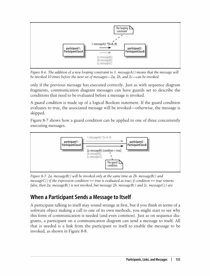
This is the Title of the Book, eMatter EditionCopyright © 2008 O’Reilly & Associates, Inc. All rights reserved.
Participants, Links, and Messages | 135
only if the previous message has executed correctly. Just as with sequence diagramfragments, communication diagram messages can have guards set to describe theconditions that need to be evaluated before a message is invoked.
A guard condition is made up of a logical Boolean statement. If the guard conditionevaluates to true, the associated message will be invoked—otherwise, the message isskipped.
Figure 8-7 shows how a guard condition can be applied to one of three concurrentlyexecuting messages.
When a Participant Sends a Message to ItselfA participant talking to itself may sound strange at first, but if you think in terms of asoftware object making a call to one of its own methods, you might start to see whythis form of communication is needed (and even common). Just as on sequence dia-grams, a participant on a communication diagram can send a message to itself. Allthat is needed is a link from the participant to itself to enable the message to beinvoked, as shown in Figure 8-8.
Figure 8-6. The addition of a new looping constraint to 1. messageA( ) means that the message willbe invoked 10 times before the next set of messages—2a, 2b, and 2c—can be invoked
Figure 8-7. 2a. messageB( ) will be invoked only at the same time as 2b. messageB( ) andmessageC( ) if the expression condition == true is evaluated as true; if condition == true returnsfalse, then 2a. messageB( ) is not invoked, but message 2b. messageB( ) and 2c. messageC( ) are
participant1 :ParticipantClassA
participant2 :ParticipantClassB
1. messageA() *[i=0..9]
2a. messageB()2b. messageB()2c. messageC()
The loopingconstraint
participant1 :ParticipantClassA
participant2 :ParticipantClassB
1. messageA() *[i=0..9]
2a. messageB() [condition = true]2b. mesageB()2c. messageC()
The gaurdcondition

This is the Title of the Book, eMatter EditionCopyright © 2008 O’Reilly & Associates, Inc. All rights reserved.
136 | Chapter 8: Focusing on Interaction Links: Communication Diagrams
Fleshing out an Interaction with a CommunicationDiagramWith the new communication diagram notation out of the way, it’s now time to lookat a practical example. We’re going to take one of the sequence diagrams fromChapter 7 and show how its interactions can also be modeled on a communicationdiagram (see Figure 8-9).
Figure 8-8. The participant can invoke 1. messageA( ) on itself because it has a communication lineto itself
Figure 8-9. This sequence diagram describes the interactions that take place in a CMS when a newregular blog account is created
participant
1. messageA()
1. messageA() isinvoked by the
participant on itself
<<actor>>admin : Administrator
createNewAccountController :CreateNewAccountController
<<actor>>acd : AuthorCredentialsDB
<<actor>>es : EmailSystem
createNewBlogAccount
selectBlogAccountType(type)
clickSubmit()
checkAuthorDetails(authorDetails : AuthorDetails)
emailBlogDetails(newAccount : RegularBlogAccount)
sendEmail(email : Email)
ui :AccountCreationUI
createNewRegularBlogAccount(authorDetails : AuthorDetails)
enterAuthorDetails (author : AuthorDetails)
newAccount :RegularBlogAccount
<<create(authorDetails)>>
: AuthorDetails<<create>>
<<destroy>>accountCreatedNotification()
opt [checked = true]

This is the Title of the Book, eMatter EditionCopyright © 2008 O’Reilly & Associates, Inc. All rights reserved.
Fleshing out an Interaction with a Communication Diagram | 137
Don’t be afraid to refer back to Chapter 7 to help you out with the notation shownon the sequence diagram. Sequence diagrams contain a lot of unique notation, andmastering it all can take some time! It isn’t necessary to have a sequence diagrambefore you create a communication diagram. You can create communication dia-grams or sequence diagrams for your interactions in whatever order you see fit.
The first step is to add the participants from Figure 8-9 to the communication dia-gram shown in Figure 8-10.
Next, the links between each of the participants are added so they can communicatewith each other, as shown in Figure 8-11.
It’s now time to add the messages that are sent between participants during the life-time of the interaction, as shown on Figure 8-12. When adding messages to a com-munication diagram, it’s usually best to start with the participant or event that kicksoff the interaction.
Figure 8-10. The participants involved in an interaction are often the first pieces added to acommunication diagram
<<actor>>admin : Administrator
ui :AccountCreationUI
createNewAccountController :CreateNewAccountController
authorDetails :AuthorDetails
<<actor>>es : EmailSystem
<<actor>>acd : AuthorCredentialsDB
newAccount :RegularBlogAccount

This is the Title of the Book, eMatter EditionCopyright © 2008 O’Reilly & Associates, Inc. All rights reserved.
138 | Chapter 8: Focusing on Interaction Links: Communication Diagrams
Figure 8-11. By looking at the sequence diagram in Figure 8-9, the links required to support themessage passing can be added to the communication diagram
Figure 8-12. The Administrator actor starts things off by passing three separate messages to the ui:AccountCreationUserInterface participant
<<actor>>admin : Administrator
ui :AccountCreationUI
createNewAccountController :CreateNewAccountController
authorDetails :AuthorDetails
<<actor>>es : EmailSystem
<<actor>>acd : AuthorCredentialsDB
newAccount :RegularBlogAccount
<<actor>>admin : Administrator
ui :AccountCreationUI
createNewAccountController :CreateNewAccountController
authorDetails :AuthorDetails
<<actor>>es : EmailSystem
<<actor>>acd : AuthorCredentialsDB
newAccount :RegularBlogAccount
1. createNewAccount()
2. selectAccountType(type)
3. enterAuthorDetails()

This is the Title of the Book, eMatter EditionCopyright © 2008 O’Reilly & Associates, Inc. All rights reserved.
Communication Diagrams Versus Sequence Diagrams | 139
Once the initial message or messages are added to the communication diagram,things start to get more complicated. The 3. enterAuthorDetails( ) message triggersa nested creation message that is sent from the ui : AccountCreationUserInterfaceparticipant to create a new authorDetails : CustomerDetails participant. Nested mes-sages get an additional decimal point based on the triggering message’s number, asshown in Figure 8-13.
With that small hurdle out of the way, the rest of the messages can be added to thecommunication diagram (see Figure 8-14).
Communication Diagrams Versus Sequence DiagramsCommunication and sequence diagrams present such similar information that acomparison is almost inevitable. Setting personal preferences aside, what are the bestreasons for picking a sequence diagram, a communication diagram, or even a combi-nation of both to model a particular interaction?
Figure 8-13. When the <<create>> message is added to the communication diagram, its messageorder number is set to 3.1. to show that it is nested inside the 3. enterAuthorDetails( ) message
<<actor>>admin : Administrator
ui :AccountCreationUI
createNewAccountController :CreateNewAccountController
authorDetails :AuthorDetails
<<actor>>es : EmailSystem
<<actor>>acd : AuthorCredentialsDB
newAccount :RegularBlogAccount
3.1 <<create>>
The nestedcreate message
1. createNewAccount()
2. selectAccountType(type)
3. enterAuthorDetails()
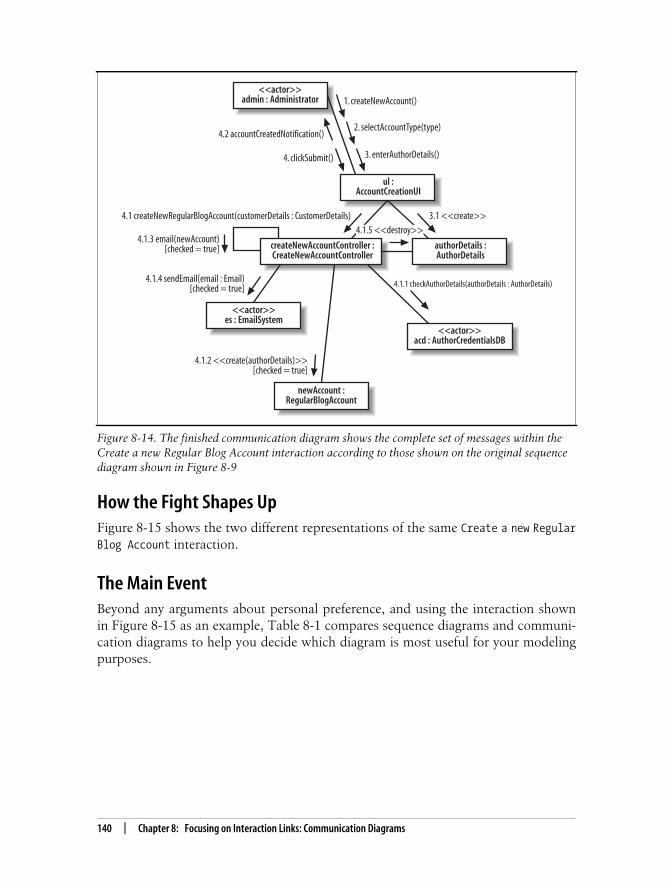
This is the Title of the Book, eMatter EditionCopyright © 2008 O’Reilly & Associates, Inc. All rights reserved.
140 | Chapter 8: Focusing on Interaction Links: Communication Diagrams
How the Fight Shapes UpFigure 8-15 shows the two different representations of the same Create a new RegularBlog Account interaction.
The Main EventBeyond any arguments about personal preference, and using the interaction shownin Figure 8-15 as an example, Table 8-1 compares sequence diagrams and communi-cation diagrams to help you decide which diagram is most useful for your modelingpurposes.
Figure 8-14. The finished communication diagram shows the complete set of messages within theCreate a new Regular Blog Account interaction according to those shown on the original sequencediagram shown in Figure 8-9
<<actor>>admin : Administrator
ul :AccountCreationUI
createNewAccountController :CreateNewAccountController
authorDetails :AuthorDetails
<<actor>>es : EmailSystem
<<actor>>acd : AuthorCredentialsDB
newAccount :RegularBlogAccount
3.1 <<create>>
4. clickSubmit()
4.2 accountCreatedNotification()
4.1 createNewRegularBlogAccount(customerDetails : CustomerDetails)
4.1.5 <<destroy>>
4.1.1 checkAuthorDetails(authorDetails : AuthorDetails)
4.1.2 <<create(authorDetails)>>[checked = true]
4.1.4 sendEmail(email : Email)[checked = true]
4.1.3 email(newAccount)[checked = true]
1. createNewAccount()
2. selectAccountType(type)
3. enterAuthorDetails()

This is the Title of the Book, eMatter EditionCopyright © 2008 O’Reilly & Associates, Inc. All rights reserved.
Communication Diagrams Versus Sequence Diagrams | 141
Figure 8-15. The Create a new Regular Blog Account interaction can be modeled using a sequencediagram and a communication diagram
Vs.
<<actor>>admin : Administrator
ui :AccountCreationUI
1. createNewBlogAccount()2. selectBlogAccountType(type)
3. enterAuthorDetails()
4. clickSubmit()
4.2. accountCreatedNotification()
createNewAccountController :CreateNewAccountController
authorDetails :AuthorDetails
3.1. <<create>>4.1. createNewRegularBlogAccount(customerDetails : CustomerDetails)
4.1.3. email(newAccount)[checked = true] 4.1.5. <<destroy>>
4.1.1. checkAuthorDetails(authorDetails : AuthorDetails)
<<actor>>acd : AuthorCredentialsDB
<<actor>>es : EmailSystem
4.1.4. sendEmail(email : Email)[checked = true]
newAccount :RegularBlogAccount
4.1.2. <<create(authorDetails)>>[checked = true]
<<actor>>admin : Administrator
createNewAccountController :CreateNewAccountController
<<actor>>acd : AuthorCredentialsDB
<<actor>>es : EmailSystem
createNewBlogAccount
selectBlogAccountType(type)
clickSubmit()
checkAuthorDetails(authorDetails : AuthorDetails)
emailBlogDetails(newAccount : RegularBlogAccount)
sendEmail(email : Email)
ui :AccountCreationUI
createNewRegularBlogAccount(authorDetails : AuthorDetails)
enterAuthorDetails (author : AuthorDetails)
newAccount :RegularBlogAccount
<<create(authorDetails)>>
: AuthorDetails<<create>>
<<destroy>>accountCreatedNotification()
opt [checked = true]

This is the Title of the Book, eMatter EditionCopyright © 2008 O’Reilly & Associates, Inc. All rights reserved.
142 | Chapter 8: Focusing on Interaction Links: Communication Diagrams
Table 8-1. Comparing sequence and communication diagrams
Feature Sequence diagrams Communication diagrams The result
Shows participantseffectively
Participants are mostlyarranged along the top ofpage, unless the drop-boxparticipant creation nota-tion is used. It is easy togather the participantsinvolved in a particularinteraction.
Participants as well as linksare the focus, so they areshown clearly as rectangles.
Communication diagramsbarely win. Although bothtypes of diagram can showparticipants as effectively aseach other, it can be arguedthat communication dia-grams have the edge sinceparticipants are one of theirmain focuses.
Showing the linksbetween participants
Links are implied. If a mes-sage is passed from one par-ticipant to another, then it isimplied that a link mustexist between thoseparticipants.
Explicitly shows the linksbetween participants. Infact, this is the primary pur-pose of these types ofdiagram.
Communication diagramswin because they explicitlyand clearly show the linksbetween participants.
Showing message signatures
Message signatures can befully described.
Message signatures can befully described.
Draw! Both types of dia-gram can show messages aseffectively as each other.
Supports parallel messages
With the introduction ofsequence fragments,sequence diagrams aremuch better.
Shown using the number-letter notation on messagesequences.
Draw! Both types of dia-gram show parallel mes-sages equally well.
Supports asynchronousmessages (fire andforget)
Achieved using theasynchronous arrow.
Communication diagramshave no concept of theasynchronous messagesince its focus is not onmessage ordering.
Sequence diagrams are aclear winner here becausethey explicitly support asyn-chronous messages.
Easy to read messageordering
This is a sequence diagram’sforté. Sequence diagramsclearly show message order-ing using the vertical place-ment of messages down thediagram’s page.
Shown using the number-point-nested notation.
Sequence diagrams are aclear winner here since theyreally show off messageordering clearly andeffectively.
Easy to create and main-tain the diagram
Creating a sequence dia-gram is fairly simple. How-ever, maintaining sequencediagrams can be a night-mare unless a helpful UMLtool is being used.
Communication diagramsare simple enough to create;however, maintenance,especially if message num-bering needs to be changed,still ideally needs the sup-port of a helpful UML tool.
This is a difficult one tojudge and is largely basedon personal preference.However, communicationdiagrams do have the edgeon the ease-of-maintenancestakes.

This is the Title of the Book, eMatter EditionCopyright © 2008 O’Reilly & Associates, Inc. All rights reserved.
What’s Next? | 143
OK, so the fight was a little biased and tongue-in-cheek in that the features assessedwere already clear discriminators between communication and sequence diagrams.Although the results shown in Table 8-1 are not really surprising, it’s worth statingonce again that you should:
• Use sequence diagrams if you are mainly interested in the flow of messagesthroughout a particular interaction.
• Use communication diagrams if you are focusing on the links between the differ-ent participants involved in the interaction.
Perhaps the most important message to take away from this comparison is thatalthough both types of diagram convey similar information, communication dia-grams and sequence diagrams offer different benefits; therefore, the best approach,time willing, is to use both.
What’s Next?You’ve seen sequence and communication diagrams, which are the two most com-monly used types of interaction diagrams. Timing diagrams are a more specializedinteraction diagram focusing on time constraints on interactions, which is particu-larly useful for expressing time constraints in real-time systems. Timing diagrams arecovered in Chapter 9.
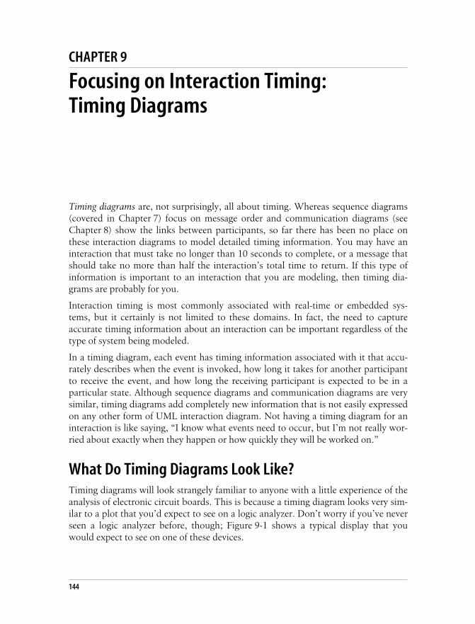
This is the Title of the Book, eMatter EditionCopyright © 2008 O’Reilly & Associates, Inc. All rights reserved.
144
Chapter 9CHAPTER 9
Focusing on Interaction Timing:Timing Diagrams 9
Timing diagrams are, not surprisingly, all about timing. Whereas sequence diagrams(covered in Chapter 7) focus on message order and communication diagrams (seeChapter 8) show the links between participants, so far there has been no place onthese interaction diagrams to model detailed timing information. You may have aninteraction that must take no longer than 10 seconds to complete, or a message thatshould take no more than half the interaction’s total time to return. If this type ofinformation is important to an interaction that you are modeling, then timing dia-grams are probably for you.
Interaction timing is most commonly associated with real-time or embedded sys-tems, but it certainly is not limited to these domains. In fact, the need to captureaccurate timing information about an interaction can be important regardless of thetype of system being modeled.
In a timing diagram, each event has timing information associated with it that accu-rately describes when the event is invoked, how long it takes for another participantto receive the event, and how long the receiving participant is expected to be in aparticular state. Although sequence diagrams and communication diagrams are verysimilar, timing diagrams add completely new information that is not easily expressedon any other form of UML interaction diagram. Not having a timing diagram for aninteraction is like saying, “I know what events need to occur, but I’m not really wor-ried about exactly when they happen or how quickly they will be worked on.”
What Do Timing Diagrams Look Like?Timing diagrams will look strangely familiar to anyone with a little experience of theanalysis of electronic circuit boards. This is because a timing diagram looks very sim-ilar to a plot that you’d expect to see on a logic analyzer. Don’t worry if you’ve neverseen a logic analyzer before, though; Figure 9-1 shows a typical display that youwould expect to see on one of these devices.

This is the Title of the Book, eMatter EditionCopyright © 2008 O’Reilly & Associates, Inc. All rights reserved.
What Do Timing Diagrams Look Like? | 145
A logic analyzer captures a sequence of events as they occur on an electronic circuitboard. A readout from a logic analyzer (such as the one shown in Figure 9-1) willtypically show the time at which different parts of the circuit board are in particularstates and the electronic signals that will trigger changes in those states.
Timing diagrams perform a similar job for the participants within your system. On atiming diagram, events are the logic analyzer’s signals, and the states are the statesthat a participant is placed in when an event is received. The similarities between atiming diagram and a logic analyzer are apparent when you compare Figure 9-1 withFigure 9-2, which gives a sneak preview of how a complete timing diagram looks.This example was taken from UML 2.0 in a Nutshell (O’Reilly).
Figure 9-1. All of the information on a logic analyzer is also shown on a timing diagram in theform of messages, participants, and states
Figure 9-2. Compare this simple yet complete timing diagram for a mail server with the logicanalyzer in Figure 9-1
0 381 762 1143 1524 1905 2286 2667 3048 3429 3802
0
1
2
3
4
5
6
7
Events(messages)
Time
States
Parts of thecircuit board
being monitored(participants)
sd Mail server
:Mai
lSer
ver
Transmitting
Authenticated
IdleLogin
sendMail
DisconnectLifeline
States or conditions(transmitting,
authenticated, and idle)
Line indicateing thecurrent state of the
lifeline
Messages that trigger the changes in state

This is the Title of the Book, eMatter EditionCopyright © 2008 O’Reilly & Associates, Inc. All rights reserved.
146 | Chapter 9: Focusing on Interaction Timing: Timing Diagrams
Building a Timing Diagram from a Sequence DiagramLet’s assemble a timing diagram from scratch. We’re going to work from the sameexample used in the communication and sequence diagram chapters, the Create anew Regular Blog Account interaction, shown in Figure 9-3.
Timing Constraints in System RequirementsThe interaction shown in Figure 9-3 was originally the result of a requirement suchas the one described in Requirement A.2.
Figure 9-3. A sequence diagram contains very little, if any, information about timing, and its mainfocus is the order of events within an interaction
Requirement A.2The content management system shall allow an administrator to create a new regularblog account, provided the personal details of the author are verified using the AuthorCredentials Database.
<<actor>>admin : Administrator
CreateNewAccountController :CreateNewAccountController
<<actor>>acd : AuthorCredentialsDB
<<actor>>es : EmailSystem
createNewBlogAccount
selectBlogAccountType(type)
clickSubmit()
checkAuthorDetails(authorDetails : AuthorDetails)
emailBlogDetails(newAccount : RegularBlogAccount)
sendEmail(email : Email)
ui :AccountCreationUI
createNewRegularBlogAccount(authorDetails : AuthorDetails)
enterAuthorDetails (author : AuthorDetails)
newAccount :RegularBlogAccount
create(authorDetails)
: AuthorDetailscreate()
destroy()accountCreatedNotification()
opt [checked = true]

This is the Title of the Book, eMatter EditionCopyright © 2008 O’Reilly & Associates, Inc. All rights reserved.
Applying Participants to a Timing Diagram | 147
Now, let’s extend the original requirement with some timing considerations so thatwe’ve got something to add by modeling the interaction in a timing diagram.
Requirement A.2 has been modified to include a timing constraint that dictates howlong it should take for the system to accept, verify, and create a new account. Nowthat there is more information about the timing of Requirement A.2, there is enoughjustification to model the interaction that implements the requirement using a tim-ing diagram.
Applying Participants to a Timing DiagramFirst, you need to create a timing diagram that incorporates all of the participantsinvolved in the Create a new Regular Blog Account interaction, as shown in Figure 9-4.
The full participant names have been left out of Figure 9-4 to keep the diagram’ssize manageable, although you could equally have included the full <name>:<type>format for the title of a participant.
Another feature that is missing from Figure 9-4 is the participants that are created anddestroyed within the life of the interaction: the :AuthorDetails and :RegularBlogAccountparticipants. Details of these participants have been left out because timing diagramsfocus on timing in relation to state changes. Apart from being created and/ordestroyed, the :AuthorDetails and :RegularBlogAccount participants do not have anycomplicated state changes; therefore, they are omitted because they would not addanything of interest to this particular diagram.
During system modeling activities, you will need to decide whatshould and should not be explicitly placed on a diagram. Ask your-self, “Is this detail important to understanding what I am modeling?”and “Does including this detail make anything clearer?” If the answeris yes to either of these questions, then it’s best to include the detail inyour diagram; otherwise, leave the additional detail out. This mightsound like a fairly crude rule, but it can be extremely effective whenyou are trying to keep a diagram’s clutter to a minimum.
Requirement A.2 (Updated)The content management system shall allow an administrator to create a new regularblog account within five seconds of the information being entered, provided the personaldetails of the author are verified using the Author Credentials Database.
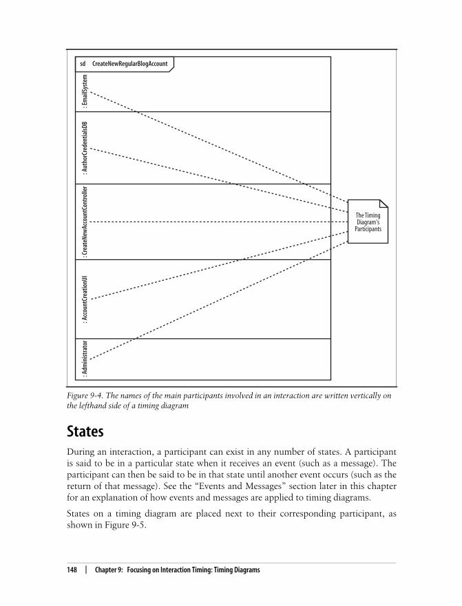
This is the Title of the Book, eMatter EditionCopyright © 2008 O’Reilly & Associates, Inc. All rights reserved.
148 | Chapter 9: Focusing on Interaction Timing: Timing Diagrams
StatesDuring an interaction, a participant can exist in any number of states. A participantis said to be in a particular state when it receives an event (such as a message). Theparticipant can then be said to be in that state until another event occurs (such as thereturn of that message). See the “Events and Messages” section later in this chapterfor an explanation of how events and messages are applied to timing diagrams.
States on a timing diagram are placed next to their corresponding participant, asshown in Figure 9-5.
Figure 9-4. The names of the main participants involved in an interaction are written vertically onthe lefthand side of a timing diagram
sd CreateNewRegularBlogAccount
: Adm
inist
rato
r: A
ccou
ntCr
eatio
nUI
: Cre
ateN
ewAc
coun
tCon
trol
ler
: Aut
horC
rede
ntia
lsDB
: Em
ailS
yste
m
The TimingDiagram's
Participants

This is the Title of the Book, eMatter EditionCopyright © 2008 O’Reilly & Associates, Inc. All rights reserved.
Time | 149
TimeFor a type of diagram that is actually called a “timing” diagram, it might seem a littlestrange that we haven’t yet mentioned time. So far, we’ve just been setting the stage,adding participants and the states that they can be put in, but to really model theinformation that’s important to a timing diagram, it’s now time to add time (punintended).
Figure 9-5. States are written horizontally on a timing diagram and next to the participant thatthey are associated with
sd CreateNewRegularBlogAccount
: Adm
inist
rato
r: A
ccou
ntCr
eatio
nUI
: Cre
ateN
ewAc
coun
tCon
trol
ler
: Aut
horC
rede
ntia
lsDB
: Em
ailS
yste
m Sending Email
Idle
Checking Details
Idle
Details Verified
Creating Account
Idle
Displaying Results
Waiting for Feedback
Accepting New Account Details
Idle
Waiting for a new Account to be Created
Entering New Account Details
Idle
ParticipantStates

This is the Title of the Book, eMatter EditionCopyright © 2008 O’Reilly & Associates, Inc. All rights reserved.
150 | Chapter 9: Focusing on Interaction Timing: Timing Diagrams
Exact Time Measurements and Relative Time IndicatorsTime on a timing diagram runs from left to right across the page, as shown inFigure 9-6.
Time measurements can be expressed in a number of different ways; you can haveexact time measurements, as shown in Figure 9-6, or relative time indicators, asshown in Figure 9-7.
In a timing diagram, t represents a point in time that is of interest. You don’t knowexactly when it will happen because it may happen in response to a message orevent, but t is a way to refer to that moment without knowing exactly when it is.With t as a reference, you can then specify time constraints relative to that point t.
Adding time to the diagram we’ve been putting together so far is tricky because wedon’t have any concrete timing information in the original requirement. See the“Timing Constraints in System Requirements” section earlier in this chapter if youneed a quick reminder as to what the extended Requirement A.2 states.
Figure 9-6. Time measurements are placed on a timing diagram as a ruler along the bottom of thepage
Figure 9-7. Relative time indicators are particularly useful when you have timing considerationssuch as “ParticipantA will be in State1 for half of the time that ParticipantB is in State2”
State3
State2
State1
p1 : P
artic
ipan
t
Time(miliseconds) 0 1 2 3 4 5 6 7 8 9 10 11
State3
State2
State1
p1 : P
artic
ipan
t
Time 0 1t 2t 3t 4t 5t 6t 7t 8t 9t 10t 11t

This is the Title of the Book, eMatter EditionCopyright © 2008 O’Reilly & Associates, Inc. All rights reserved.
Time | 151
However, we still need to apply the constraints mentioned in Requirement A.2, sosome measure of relative time represented by t is shown in Figure 9-8.
In this figure, the initial stages of the interaction are simply measured as seconds, andthe single t value represents a single second wherever it is mentioned on any furthertiming constraints on the diagram. See the “Timing Constraints” section later in thischapter for more on how the value t can be used on a timing diagram.
Figure 9-8. The timing constraints are a blend of exact and relative timings
sd CreateNewRegularBlogAccount
: Adm
inist
rato
r: A
ccou
ntCr
eatio
nUI
: Cre
ateN
ewAc
coun
tCon
trolle
r: A
utho
rCre
dent
ialsD
B :
Emai
lSys
tem Sending Email
Idle
Checking Details
Idle
Details Verified
Creating Account
Idle
Displaying Results
Waiting for Feedback
Accepting new Account Details
Idle
Waiting for a new Account to be Created
Entering new Account Details
Idle
Time (seconds) 0 1 t

This is the Title of the Book, eMatter EditionCopyright © 2008 O’Reilly & Associates, Inc. All rights reserved.
152 | Chapter 9: Focusing on Interaction Timing: Timing Diagrams
A Participant’s State-LineNow that you have added time to the timing diagram (fancy that!), you can showwhat state a participant is in at any given time. If you take a look back at Figure 9-6and Figure 9-7, you can already see how participant’s current state is indicated:with a horizontal line that is called the state-line.
At any given time in the interaction, a participant’s state-line is aligned with one ofthe participant’s states (see Figure 9-9).
Figure 9-10 shows how the Create a new Regular Blog Account timing diagram isupdated to show the state of each participant at a given time during the interaction.
In practice, you would probably add both events and states to a tim-ing diagram at the same time. We’ve split the two activities here sim-ply because it makes it easier for you to see how the two pieces ofnotation are applied (without confusing one with the other).
That’s all there is to showing that a participant is in a specific state at a given time.Now it’s time to look at why a participant changes states in the first place, whichleads us neatly to events and messages.
Figure 9-9. In this example, p1:Participant’s state-line indicates that it is in State1 for 1 unit oftime, State2 for three units of time, and State3 for roughly five units of time (before returning toState1 at the end of the interaction)
State3
State2
State1
p1 : P
artic
ipan
t
Time 0 1t 2t 3t 4t 5t 6t 7t 8t 9t 10t 11t
The state of theparticipant at a given time

This is the Title of the Book, eMatter EditionCopyright © 2008 O’Reilly & Associates, Inc. All rights reserved.
Events and Messages | 153
Events and MessagesParticipants change state on a timing diagram in response to events. These eventsmight be the invocation of a message or they might be something else, such as a mes-sage returning after it has been invoked. The distinction between messages andevents is not as important on a timing diagram as it is on sequence diagrams. Theimportant thing to remember is that whatever the event is, it is shown on a timingdiagram to trigger a change in the state of a participant.
Figure 9-10. Each of the participants needs to have a corresponding state-line to indicate their stateat any given point in time
sd CreateNewRegularBlogAccount
: Adm
inist
rato
r: A
ccou
ntCr
eatio
nUI
: Cre
ateN
ewAc
coun
tCon
trol
ler
: Aut
horC
rede
ntia
lsDB
: Em
ailS
yste
m Sending Email
Idle
Checking Details
Idle
Details Verified
Creating Account
Idle
Displaying Results
Waiting for Feedback
Accepting new Account Details
Idle
Waiting for a new Account to be Created
Entering new Account Details
Idle
Time (seconds) 0 1 t

This is the Title of the Book, eMatter EditionCopyright © 2008 O’Reilly & Associates, Inc. All rights reserved.
154 | Chapter 9: Focusing on Interaction Timing: Timing Diagrams
An event on a timing diagram is shown as an arrow from one participant’s state-line—the event source—to another participant’s state-line—the event receiver (asshown in Figure 9-11).
Adding events to the timing diagram is actually quite a simple task, because you havethe sequence diagram from Figure 9-3 to refer to. The sequence diagram alreadyshows the messages that are passed between participants, so you can simply addthose messages to the timing diagram, as shown in Figure 9-12.
Timing ConstraintsUp until this point, you have really only been establishing the foundation of a timingdiagram. Participants, states, time, and events and messages are the backdrop againstwhich you can start to model the information that is really important to a timing dia-gram—timing constraints.
Timing constraints describe in detail how long a given portion of an interactionshould take. They are usually applied to the amount of time that a participant shouldbe in a particular state or how long an event should take to be invoked and received,as shown in Figure 9-13. By applying constraints to this timing diagram, the dura-tion of event1 must be less than one value of the relative measure t, and p2:Participant2 should be in State4 for a maximum of five seconds.
Figure 9-11. Events on a timing diagram can even have their own durations, as shown by event1taking 1 unit of time from invocation by p1:Participant1 and reception by p2:Participant2
p1 :
Part
icipa
nt1
State1
An event that is a returnfrom a message call
State2
State3
0 11t1t 2t 3t 4t 5t 6t 7t 8t 9t 10t
p2 :
Part
icipa
nt2
State1
State2
State3
State4
event1
message1
Time
Messages and eventsbeing passed
between participants

This is the Title of the Book, eMatter EditionCopyright © 2008 O’Reilly & Associates, Inc. All rights reserved.
Timing Constraints | 155
Timing Constraint FormatsA timing constraint can be specified in a number of different ways, depending on theinformation your are trying to model. Table 9-1 shows some common examples oftiming constraints.
Figure 9-12. Participant state changes make much more sense when you can see the events thatcause them
sd CreateNewRegularBlogAccount
: Adm
inist
rato
r: A
ccou
ntCr
eatio
nUI
: Cre
ateN
ewAc
coun
tCon
trol
ler
: Aut
horC
rede
ntia
lsDB
: Em
ailS
yste
m Sending Email
Idle
Checking Details
Idle
Details Verified
Creating Account
Idle
Displaying Results
Waiting for Feedback
Accepting new Account Details
Idle
Waiting for a new Account to be Created
Entering new Account Details
Idle
Time (seconds) 0 1 t
createNewBlogAccountclickSubmit
createNewRegularBlogAccount
checkAuthorDetails
sendEmail
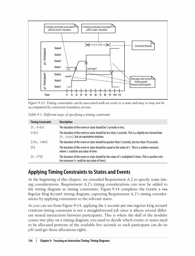
This is the Title of the Book, eMatter EditionCopyright © 2008 O’Reilly & Associates, Inc. All rights reserved.
156 | Chapter 9: Focusing on Interaction Timing: Timing Diagrams
Applying Timing Constraints to States and EventsAt the beginning of this chapter, we extended Requirement A.2 to specify some tim-ing considerations. Requirement A.2’s timing considerations can now be added tothe timing diagram as timing constraints. Figure 9-14 completes the Create a newRegular Blog Account timing diagram, capturing Requirement A.2’s timing consider-ations by applying constraints to the relevant states.
As you can see from Figure 9-14, applying the 5 seconds per new regular blog accountcreation timing constraint is not a straightforward job since it affects several differ-ent nested interactions between participants. This is where the skill of the modelercomes into play on a timing diagram; you need to decide which events or states needto be allocated portions of the available five seconds so each participant can do itsjob (and get those allocations right).
Figure 9-13. Timing constraints can be associated with an event or a state and may or may not beaccompanied by constraint boundary arrows
Table 9-1. Different ways of specifying a timing constraint
Timing Constraint Description
{t..t+5s} The duration of the event or state should be 5 seconds or less.
{<5s} The duration of the event or state should be less than 5 seconds. This is a slightly less formal than{t..t+5s}, but an equivalent notation.
{>5s, <10s} The duration of the event or state should be greater than 5 seconds, but less than 10 seconds.
{t} The duration of the event or state should be equal to the value of t. This is a relative measure,where t could be any value of time.
{t..t*5} The duration of the event or state should be the value of t multiplied 5 times. This is another rela-tive measure (t could be any value of time).
p1 :
Part
icipa
nt1
State1
Constraint Bounds
State2
State3
0 11t1t 2t 3t 4t 5t 6t 7t 8t 9t 10t
p2 :
Part
icipa
nt2
State1
State2
State3
State4
event1
message1
Time
Messages and eventsbeing passed
between participants
{1t}
{t..t+5s}
A timing constraint associatedwith a state’s duration
A timing constraint associatedwith an event’s duration

This is the Title of the Book, eMatter EditionCopyright © 2008 O’Reilly & Associates, Inc. All rights reserved.
Organizing Participants on a Timing Diagram | 157
Organizing Participants on a Timing DiagramWhere you arrange participants on a timing diagram does not at first appear to bevery important. However, as you add more details to your diagram in the form ofevents and timing information, you’ll soon discover that the place where a partici-pant is located on the timing diagram can cause problems if you haven’t thoughtabout it carefully enough (see Figure 9-15).
Figure 9-14. From when the :Administrator clicks on submit until the point at which the system hascreated a new account, no more than five seconds have passed
sd CreateNewRegularBlogAccount
: Adm
inist
rato
r: A
ccou
ntCr
eatio
nUI
: Cre
ateN
ewAc
coun
tCon
trol
ler
: Aut
horC
rede
ntia
lsDB
: Em
ailS
yste
m Sending Email
Idle
Checking Details
Idle
Details Verified
Creating Account
Idle
Displaying Results
Waiting for Feedback
Accepting new Account Details
Idle
Waiting for a new Account to be Created
Entering new Account Details
Idle
Time (seconds) 0 1 t
clickSubmit
createNewRegularBlogAccount
checkAuthorDetails
sendEmail
{t..t+5s}
{t..t+5s}
{t..t+3s}
{t..t+2s}
createNewBlogAccount
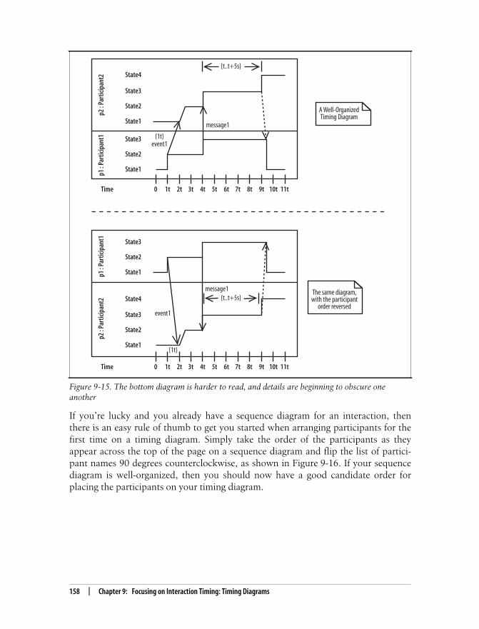
This is the Title of the Book, eMatter EditionCopyright © 2008 O’Reilly & Associates, Inc. All rights reserved.
158 | Chapter 9: Focusing on Interaction Timing: Timing Diagrams
If you’re lucky and you already have a sequence diagram for an interaction, thenthere is an easy rule of thumb to get you started when arranging participants for thefirst time on a timing diagram. Simply take the order of the participants as theyappear across the top of the page on a sequence diagram and flip the list of partici-pant names 90 degrees counterclockwise, as shown in Figure 9-16. If your sequencediagram is well-organized, then you should now have a good candidate order forplacing the participants on your timing diagram.
Figure 9-15. The bottom diagram is harder to read, and details are beginning to obscure oneanother
p1 :
Part
icipa
nt1
State1
The same diagram,with the participant
order reversed
State2
State3
0 11t1t 2t 3t 4t 5t 6t 7t 8t 9t 10t
p2 :
Part
icipa
nt2
State1
State2
State3
State4
event1
message1
Time
{t..t+5s}
p1 :
Part
icipa
nt1
State1
A Well-OrganizedTiming Diagram
State2
State3
0 11t1t 2t 3t 4t 5t 6t 7t 8t 9t 10t
p2 :
Part
icipa
nt2
State1
State2
State3
State4
event1
message1
Time
{1t}
{t..t+5s}
{1t}

This is the Title of the Book, eMatter EditionCopyright © 2008 O’Reilly & Associates, Inc. All rights reserved.
An Alternate Notation | 159
An Alternate NotationReal estate on a UML diagram is almost always at a premium. In previous versions ofUML, sequence diagrams were known as being the hardest diagram to manage when
Figure 9-16. Rotating a sequence diagram’s major participants 90 degrees counterclockwise is aneasy way to get an initial placement for your timing diagram’s participants
<<actor>>admin : Administrator
ui :AccountCreationUI
createNewAccountController :CreateNewAccountController
<<actor>>acd : AuthorCredentialsDB
<<actor>>es : EmailSystem
Sequence Diagram Participants Order
: Adm
inist
rato
r: A
ccou
ntCr
eatio
nUI
: Cre
ateN
ewAc
coun
tCon
trolle
r: A
utho
rCre
dent
ialsD
B: E
mai
lSyste
m
Tim
ing
Diag
ram
Par
ticip
ants
Ord
er

This is the Title of the Book, eMatter EditionCopyright © 2008 O’Reilly & Associates, Inc. All rights reserved.
160 | Chapter 9: Focusing on Interaction Timing: Timing Diagrams
modeling a complex interaction. Although timing diagrams are not going to steal thesequence diagram’s crown in this respect, the regular timing diagram notation shownin this chapter so far doesn’t scale particularly well when you need to model a largenumber of different states.
Some of the problems with sequence diagrams have been alleviatedwith the inclusion of sequence fragments in UML 2.0; see Chapter 7.
The Create a new Regular Blog Account interaction’s timing diagram, as shown inFigure 9-14, is actually a fairly simple example. However, you might already bebeginning to grasp how large a timing diagram can get—at least vertically—for any-thing more than a trivial interaction that includes a small number of states. A goodUML 2.0 tool will help you work with and manage large timing diagrams, but thereis only so much a tool can really do.
The developers of UML 2.0 realized this problem and created an alternative, simplernotation for when you have an interaction that contains a large number of states,shown in Figure 9-17.
When you look closely at the alternative timing diagram notation, things are not dra-matically different from the regular notation. The notation for participants and timehasn’t changed at all. The big change between the regular timing diagram notationand the alternative is in how states and state changes are shown.
The regular timing diagram notation shows states as a list next to the relevant partic-ipant. A state-line is then needed to show what state a participant is in at a giventime. Unfortunately, if a participant has many different states, then the amount ofspace needed to model a participant on the timing diagram will grow quickly.
The alternative notation fixes this problem by removing the vertical list of differentstates. It places a participant’s states directly at the point in time when the partici-pant is in that state. Therefore, the state-line is no longer needed, and all of the statesfor a particular participant can be placed in a single line across the diagram.
To show that a participant changes state because of an event, a cross is placedbetween the two states and the event that caused the state change is written next tothe cross. Timing constraints can then be applied in much the same way as regularnotations.
Bringing the subject of timing diagrams to a close, Figure 9-18 shows the alternatetiming diagram notation in a practical setting: modeling the Create a new RegularBlog Account interaction.

This is the Title of the Book, eMatter EditionCopyright © 2008 O’Reilly & Associates, Inc. All rights reserved.
An Alternate Notation | 161
Figure 9-17. The top diagram’s notation should be familiar to you, but the diagram at the bottomuses the new alternative timing diagram notation
A Second Notation for Timing DiagramsSo, why have a second notation for timing diagrams? Luckily, there is an easy answerto this question: the regular timing diagram notation simply does not scale well whenyou have many participants that can be put in many different states during an interac-tion’s lifetime. Just as the answer is quite simple, so is the rule of thumb you can useto help you decide which notation to adopt for a particular interaction. If a participantis placed in many different states during the course of the interaction, then it is worthconsidering using the alternative notation. Otherwise, use the regular notation since, atthis point of writing, it is more widely recognized throughout the modeling community.
p2 :
Part
icipa
nt2
0 11t1t 2t 3t 4t 5t 6t 7t 8t 9t 10t
p1 :
Part
icipa
nt1
Time
p1 :
Part
icipa
nt1
State1
The regular TimingDiagram notation :
good when fewer statesneed to be shown.
State2
State3
0 11t1t 2t 3t 4t 5t 6t 7t 8t 9t 10t
p2 :
Part
icipa
nt2
State1
State2
State3
State4
event1
message1
Time
{1t}
{t..t+5s}
State 1 State 2 State 3 State 4
State 1 State 2 State 3 State 4
The alternative TimingDiagram Notation :
good when many statesneed to be shown.
{1t}{t..t+5s}
message1event1

This is the Title of the Book, eMatter EditionCopyright © 2008 O’Reilly & Associates, Inc. All rights reserved.
162 | Chapter 9: Focusing on Interaction Timing: Timing Diagrams
What’s Next?The concept of an object’s state is integral to timing diagrams since they show statesof an object at particular times. State machine diagrams show in detail the states of anobject and triggers that cause state changes. Both diagram types are very important tomodels of real-time and embedded systems. State machine diagrams are covered inChapter 14.
Figure 9-18. Even though there are not many states in this interaction, you can begin to see howthe alternate notation is more compact and manageable in a situation where there are many statesper participant
sd CreateNewBlogAccount
Idle Sending Email
sendEmailIdle
{t..t+3s}
Idle Checking DetailscheckCustomerDetails
Idle
{t..t+2s}
Idle Creating AccountcreateNewSavingsAccount
IdleDetails Verified
Accepting New Account DetailscreateNewAccount
Displaying ResultsWaiting for FeedbackIdleclickSubmit
{t..t+5s}
Entering New Account DetailscreateNewAccount
IdleWaiting for a new Account to be CreatedIdle
{t..t+5s}
: Adm
inist
rato
r: A
ccou
tCre
atio
nUI
: Cre
ate N
ewAc
coun
tCon
trolle
r: A
utho
rCre
dent
ialsD
B: E
mai
lSyste
m

This is the Title of the Book, eMatter EditionCopyright © 2008 O’Reilly & Associates, Inc. All rights reserved.
163
Chapter 10 CHAPTER 10
Completing the Interaction Picture:Interaction Overview Diagrams10
Ever been asked to “look at the bigger picture”? Whether you are working on a newidea or modeling in UML, sometimes it helps to take a step back from the details toget a better feel for what you are doing and the context within which you are doingit. This is the job of interaction overview diagrams; they exist to give you that big pic-ture perspective on your system’s interactions.
Interaction overview diagrams provide a high-level view of how several interactionswork together to implement a system concern, such as a use case. Sequence, commu-nication, and timing diagrams focus on specific details concerning the messages thatmake up an interaction, but interaction overview diagrams tie together the differentinteractions into a single complete picture of the interactions that make up a particu-lar system concern.
An interaction overview looks very much like an activity diagram (see Chapter 3)except that each of the actions are interactions within their own right. Think of eachpart of an interaction overview as a complete interaction in itself. If one interactionwithin the overview is most concerned with timing, then a timing diagram could beemployed (see Chapter 9), while another interaction of the overview may need tofocus on message ordering, and so a sequence diagram could be used (seeChapter 7). The interaction overview glues together separate interactions within yoursystem in the notation that makes most sense to the particular interaction to showhow they work together to implement a system concern.
The Parts of an Interaction Overview DiagramThe best way to understand a interaction overview diagram notation is to think of itas an activity diagram, except instead of an action, a complete interaction isdescribed by using its own diagram, as shown in Figure 10-1.
Any number of participants may be involved in the interactions that occur within theoverview. To see which participants are involved across the entire overview, a life-lines subtitle is added to the diagram title, as shown in Figure 10-2.

This is the Title of the Book, eMatter EditionCopyright © 2008 O’Reilly & Associates, Inc. All rights reserved.
164 | Chapter 10: Completing the Interaction Picture: Interaction Overview Diagrams
Figure 10-1. Individual interactions are placed on an interaction overview diagram as though theywere actions on an activity diagram
Figure 10-2. The lifelines subtitle shows the combined list of participants involved in theinteractions within the overview
messageCaller : MessageCaller messageReceiver : MessageReceiver messageReceiver2 : MessageReceiver2
foo()
bar()
bar()
sd Interaction1
participant1 :ParticipantClassA
participant2 :ParticipantClassB
1. messageA()
2. messageB()
cd Interaction3
participant1 :ParticipantClassA
participant2 :ParticipantClassB
1. messageA()
2. messageB()
cd Interaction2
participant1 :ParticipantClassA
participant2 :ParticipantClassB
1. messageA()
2. messageB()
cd Interaction4
messageCaller : MessageCaller messageReceiver : MessageReceiver messageReceiver2 : MessageReceiver2
foo()
bar()
bar()
sd Interaction5
iod : InteractionOverview1
Each “Action” isan interaction in
its own right
iod : interactionOverview1lifelines messageCaller : MesageCaller messageReceiver : MessageReceivermessageReceiver2 : MessageReceiver2 participant1 : ParticipantA participant2 : ParticipantB
Interaction2
messageCaller : MessageCaller
sd
The “lifelines”section in thediagram title

This is the Title of the Book, eMatter EditionCopyright © 2008 O’Reilly & Associates, Inc. All rights reserved.
Modeling a Use Case Using an Interaction Overview | 165
Similar to an activity diagram, the interaction overview begins with an initial nodeand ends with a final node. Control flows between these two nodes and passesthrough each of the interactions in between. However, you are limited not to just asimple sequential flow between the interactions.
Just as control flow on an activity diagram can be subjected to decisions, parallelactions, and even loops, so can the control flow on an interaction diagram, as shownin Figure 10-3.
Modeling a Use Case Using an Interaction OverviewThat’s all the new notation for interaction diagrams; now it’s time to look at a practi-cal example. To set the stage, we are going to develop an interaction overview dia-gram from scratch for the Create a New Regular Blog use case reusing parts from theinteraction diagrams created in the previous chapters.
The big difference between the example in this chapter and the modeling in previouschapters is that with an interaction overview, we can pick and choose from the differ-ent interaction diagram types. By using an interaction overview approach, each part ofthe interaction is modeled using the techniques that are most effective for that part.
Pulling Together the InteractionsFirst, we need to decide how the interaction overview will be broken down into themost effective diagrams for each of the individual interactions, as shown inFigure 10-4.
When modeling the Select Blog Account Type, Create Regular Blog Account, and TidyUp Author Details interactions, message order is more important than any other fac-tor. The relevant steps can be reused from the sequence diagrams modeled inChapter 7, as shown in Figure 10-5.
For variety’s sake, the Enter Author Details will be displayed as a communicationdiagram, as shown in Figure 10-6.
You could decide to represent the Enter Author Details interaction as a communica-tion diagram simply because it is easier to understand, but there is so much similar-ity between sequence and communication diagrams that mixing the two on oneinteraction overview is not often seen; modelers tend to prefer one type of diagram orthe other.
The Check Author Details interaction must enforce the timing constraint that its mes-sages will all be executed within five seconds (see Chapter 9). The focus is on timingfor this part of the overview and thanks to the fact that an interaction overview cancontain any of the different types of interaction diagram, a timing diagram can beemployed for the Check Author Details interaction, as shown in Figure 10-7.

This is the Title of the Book, eMatter EditionCopyright © 2008 O’Reilly & Associates, Inc. All rights reserved.
166 | Chapter 10: Completing the Interaction Picture: Interaction Overview Diagrams
Figure 10-3. Starting with the initial node, the control flow executes Interaction1, followed byInteractions 2 and 3 in parallel; Interaction4 will execute only if the condition is assessed as beingtrue; otherwise, Interaction5 is executed 10 times in a loop before the control flow merges and thefinal node is reached
messageCaller : MessageCaller messageReceiver : MessageReceiver messageReceiver2 : MessageReceiver2
foo()
bar()
bar()
sd Interaction1
participant1 :ParticipantClassA
participant2 :ParticipantClassB
1. messageA()
2. messageB()
cd Interaction3
participant1 :ParticipantClassA
participant2 :ParticipantClassB
1. messageA()
2. messageB()
cd Interaction2
participant1 :ParticipantClassA
participant2 :ParticipantClassB
1. messageA()
2. messageB()
cd Interaction4
messageCaller : MessageCaller messageReceiver : MessageReceiver messageReceiver2 : MessageReceiver2
foo()
bar()
bar()
sd Interaction5
iod : InteractionOverview1lifelines messageCaller : MessageCaller messageReceiver : MessageReceivermessageReceiver2 : MessageReceiver2 participant1 : ParticipantA participant2 : ParticipantB
Merge
[condition = true]
Final Node
[i = 0..10]
Loop, including aloop condition thatindicates that theloop will execute
10 timesDecision
Parallel ControlFlow
Initial Node

This is the Title of the Book, eMatter EditionCopyright © 2008 O’Reilly & Associates, Inc. All rights reserved.
Modeling a Use Case Using an Interaction Overview | 167
An interaction overview diagram can offer an ideal place to use thealternative timing diagram notation, as shown in Figure 10-7. Sinceinteraction overviews can get pretty big, the alternative notation oftenworks best since it makes good use of the space available.
Figure 10-4. All three types of interaction diagram are used in this overview— sd indicates asequence diagram, cd is for a communication diagram, and, not surprisingly, td stands for a timingdiagram
iod : Create a New Regular Blog Account
sd Select Blog Account Type
cd Enter Author Details
td Check Author Details
sd Create Regular Blog Account
sd Tidy Up Author Details

This is the Title of the Book, eMatter EditionCopyright © 2008 O’Reilly & Associates, Inc. All rights reserved.
168 | Chapter 10: Completing the Interaction Picture: Interaction Overview Diagrams
Figure 10-5. Some interactions to are best modeled using sequence diagrams to focus on messageordering
iod : Create a New Regular Blog Account
sd Select Blog Account Type
cd Enter Author Details
td Check Author Details
sd Create Regular Blog Account
sd Tidy Up Author Details
: AuthorDetails
<<actor>>admin : Administrator
createNewBlogAccount()
selectBlogAccountType(type)
ui :AccountCreationUI
<<actor>>admin : Administrator
ui :AccountCreationUI
createNewAccountController :CreateNewAccountController
clickSubmit()
createNewRegularBlogAccount(authorDetails : AuthorDetails)
createNewAccountController :CreateNewAccountController
<<destroy>>

This is the Title of the Book, eMatter EditionCopyright © 2008 O’Reilly & Associates, Inc. All rights reserved.
Modeling a Use Case Using an Interaction Overview | 169
Figure 10-6. Enter Author Details in a communication diagram
iod : Create a New Regular Blog Account
sd Select Blog Account Type
cd Enter Author Details
td Check Author Details
sd Tidy Up Author Details
sd Create Regular Blog Account
<<actor>>admin : Administrator
createNewBlogAccount()
selectBlogAccountType(type)
ui :AccountCreationUserInterface
createNewAccountController :CreateNewAccountController
<<destroy>>
: AuthorDetails
<<actor>>admin : Administrator ui :
AccountCreationUI authorDetails :AuthorDetails
1. enterAuthorDetails()
1.1. <<create>>
<<actor>>admin : Administrator
ui :AccountCreationUI
createNewAccountController :CreateNewAccountController
clickSubmit()
createNewRegularBlogAccount(authorDetails : AuthorDetails)

This is the Title of the Book, eMatter EditionCopyright © 2008 O’Reilly & Associates, Inc. All rights reserved.
170 | Chapter 10: Completing the Interaction Picture: Interaction Overview Diagrams
Figure 10-7. Adding a timing diagram to show critical timing constraints for one interaction withinthe overview
iod : Create a New Regular Blog Account
sd Select Blog Account Type
cd Enter Author Details
td Check Author Details
sd Tidy Up Author Details
sd Create Regular Blog Account
<<actor>>admin : Administrator
createNewBlogAccount()
selectBlogAccountType(type)
ui :AccountCreationUI
createNewAccountController :CreateNewAccountController
<<destroy>>
: AuthorDetails
Idle
{t..t+2s}
SendingEmail
Idle
Idle
{t..t+3s}
CheckingDetails
Idle
sendEmail
checkAuthorDetails
<<actor>>admin : Administrator ui :
AccountCreationUI authorDetails :AuthorDetails
1. enterAuthorDetails()
1.1. <<create>>
<<actor>>admin : Administrator
ui :AccountCreationUI
createNewAccountController :CreateNewAccountController
clickSubmit()
createNewRegularBlogAccount(authorDetails : AuthorDetails)
: Em
ailSy
stem
: Aut
hor
Cred
entia
lsDa
taba
se

This is the Title of the Book, eMatter EditionCopyright © 2008 O’Reilly & Associates, Inc. All rights reserved.
What’s Next? | 171
Now that all the interactions have been added to the interaction overview, all of theparticipants involved are known so we can add their names to the diagram’s title, asshown in Figure 10-8.
Gluing the Interactions TogetherThe final piece of the puzzle in the Create a New Regular Blog Account interaction over-view is the actual flow of control between each of the separate interaction diagrams,as shown in Figure 10-9.
The control flow in Figure 10-9 shows that each of the separate interactions are exe-cuted in order. The one deviation from the normal path occurs at the Create RegularBlog Account interaction, shown as a sequence diagram, which is executed only if theauthor details checked out during the Check Author Details interaction.
What’s Next?Interaction overview diagrams glue together combinations of sequence diagrams,communication diagrams, and timing diagrams, showing the higher-level picture. Atthis point, you’re done considering interaction diagrams, but you may want to backup and review any of the interaction diagram chapters if you weren’t clear when touse which diagram type. Sequence diagrams were covered in Chapter 7; communica-tion diagrams were described in Chapter 8; timing diagrams were covered inChapter 9.
Figure 10-8. Adding each of the participants involved in an interaction to the lifeline list in theinteraction overview’s title bar
iod : Create a New Regular Blog Accountlifelines admin : Administrator ui : AccountCreationUI : AuthorDetailscreateNewAccountController : CreateNewAccountController newAccount : RegularBlogAccountacd : AuthorCredentialsDB es : EmailSystem
sd Select Blog Account Type

This is the Title of the Book, eMatter EditionCopyright © 2008 O’Reilly & Associates, Inc. All rights reserved.
172 | Chapter 10: Completing the Interaction Picture: Interaction Overview Diagrams
Figure 10-9. Starting with an initial node and finishing with a final node, the flow of control is thethread that ties each of the interactions together
iod : Create a New Regular Blog Accountlifelines admin : Administrator ui : AccountCreationUserInterface : AuthorDetailscreateNewAccountController : CreateNewAccountController newAccount : RegularBlogAccountacd : AuthorCredentialsDatabase es : EmailSystem
sd Select Blog Account Type
td Check Author Details
cd Enter Author Details
sd Create Regular Blog Account
sd Tidy Up Author Details
<<actor>>admin : Administrator
createNewBlogAccount
selectBlogAccountType(type)
ui :AccountCreationUI
createNewAccountController :CreateNewAccountController
<<destroy>>
: AuthorDetails
Idle
{t..t+2s}
Sendingemail
Idle
Idle
{t...t+3s}
CheckingDetails
Idle
sendEmail
: Em
ailSy
stem
: Aut
hor
Cred
entia
lsDa
taba
se
checkAuthorDetails
[checked= true]
<<actor>>admin : Administrator
ui :AccountCreationUI
createNewAccountController :CreateNewAccountController
clickSubmit()
createNewRegularBlogAccount(authorDetails : AuthorDetails)
<<actor>>admin : Administrator ui :
AccountCreationUI authorDetails :AuthorDetails
1. enterAuthorDetails()
1.1. <<create>>

This is the Title of the Book, eMatter EditionCopyright © 2008 O’Reilly & Associates, Inc. All rights reserved.
173
Chapter 11 CHAPTER 11
Modeling a Class’s Internal Structure:Composite Structures11
Sometimes the primary UML diagrams, such as class and sequence diagrams, aren’ta perfect match for capturing certain details about your system. Composite struc-tures help fill some of those gaps. Composite structures show how objects create abig picture. They model how objects work together inside a class, or how objectsachieve a goal. Composite structures are fairly advanced, but they’re good to have inyour bag of tricks because they are perfectly suited for specific modeling situations,such as showing:
Internal structuresShow the parts contained by a class and the relationships between the parts; thisallows you to show context-sensitive relationships, or relationships that hold inthe context of a containing class
PortsShow how a class is used on your system with ports
CollaborationsShow design patterns in your software and, more generally, objects cooperatingto achieve a goal
Composite structures provide a view of your system’s parts and form part of the logi-cal view of your system’s model, as shown in Figure 11-1.
Internal StructureChapter 5 introduced possession-related relationships between classes, includingassociation (“has a”) and composition (“contains a”). Composite structures offer analternate way of showing these relationships; when you show the internal structureof a class, you draw the items it possesses directly inside the class. Relationshipsbetween items in a class’s internal structure hold only in the context of the class, soyou can think of them as context-sensitive relationships. To see why internal struc-tures are useful, let’s look at a relationship that a class diagram can’t model.

This is the Title of the Book, eMatter EditionCopyright © 2008 O’Reilly & Associates, Inc. All rights reserved.
174 | Chapter 11: Modeling a Class’s Internal Structure: Composite Structures
When Class Diagrams Won’t WorkFigure 11-2 repeats a class diagram from Chapter 5, showing that BlogEntry con-tains objects of type Introduction and MainBody through composition.
Suppose you want to update your diagrams to reflect that a blog entry’s introduc-tion has a reference to its main body because it’s convenient for other objects to askan Introduction object for the MainBody object it introduces. As a first pass, you mod-ify the class diagram in Figure 11-2 by drawing an association between theIntroduction and the MainBody classes, as shown in Figure 11-3.
But there’s a problem. Figure 11-3 specifies that an object of type Introduction willhave a reference to an object of type MainBody, but it can be any MainBody object—notjust the one owned by the same instance of BlogEntry. That’s because the associa-tion between Introduction and MainBody is defined for all instances of those types.Informally, Introduction doesn’t concern itself with the composition relationshipbetween BlogEntry and MainBody; as far as an Introduction object is concerned, all ithas to do is associate with some MainBody object (but it doesn’t care which one).
Because Figure 11-3 doesn’t specify which Introduction and MainBody objects shouldbe associated, the object diagram in Figure 11-4 conforms to the class diagram inFigure 11-3.
Figure 11-1. The logical view captures the abstract descriptions of a system’s parts, includingcomposite structures
Figure 11-2. Class diagram showing that BlogEntry contains Introduction and MainBody
Logical View Process View
Physical View Development View
Use Case View
BlogEntry
1MainBody
1Introduction
blogIntro blogMain

This is the Title of the Book, eMatter EditionCopyright © 2008 O’Reilly & Associates, Inc. All rights reserved.
Internal Structure | 175
According to the class diagram in Figure 11-3, it’s perfectly legal for an introductionin one blog entry to introduce the main body of another. But what you meant to sayis that the introduction introduces the main body that is contained by the same classthat contains the introduction, as shown in Figure 11-5.
It turns out that class diagrams are not good at expressing how items contained in aclass relate to each other. This is where internal structure comes in: it allows you tospecify relationships in the context of the class that contains them.
Figure 11-3. This first pass at showing that a blog entry’s introduction introduces its main bodydoesn’t quite work
Figure 11-4. Unintended but valid object structure
Figure 11-5. This was the intended object structure
BlogEntry
1MainBody
1Introduction
blogIntro blogMain
1 1
blogIntro
myBlogEntry :BlogEntry
myBlogMain : MainBody
myBlogIntro : Introduction
blogMain
yourBlogEntry :BlogEntry
yourBlogMain : MainBody
yourBlogIntro : IntroductionblogIntro
blogMain
blogIntro
myBlogEntry :BlogEntry
myBlogMain : MainBodymyBlogIntro : IntroductionblogMain
yourBlogEntry :BlogEntry
yourBlogMain : MainBodyyourBlogIntro : IntroductionblogIntro blogMain

This is the Title of the Book, eMatter EditionCopyright © 2008 O’Reilly & Associates, Inc. All rights reserved.
176 | Chapter 11: Modeling a Class’s Internal Structure: Composite Structures
Right now, you may be thinking that this distinction is a bit fussy. If you’re writingthe code to implement these classes, you can make sure that the correct objects arelinked up. You could also use a UML sequence diagram to show the objects’ cre-ation and how they get connected. But keep reading—the internal structure nota-tion is a convenient and simple way to show relationships between contained items,especially when the contained items have complex relationships.
This is just one example of how composite structures can model rela-tionships that are hard to show in class diagrams. For a more thor-ough discussion, see http://www.jot.fm/issues/issue_2004_11/column5.
Parts of a ClassFigure 11-6 shows the internal structure of BlogEntry. Its contained items are nowdrawn directly inside, instead of connected through filled diamond arrowheads.
When showing the internal structure of a class, you draw its parts, or items con-tained by composition, inside the containing class. Parts are specified by the role theyplay in the containing class, written as <roleName> : <type>. In Figure 11-6, the partof type Introduction has the role blogIntro and the part of type MainBody has the roleblogMain. The multiplicity, or number of instances of that part, is written in the upperrighthand corner of the part.
Figure 11-7 shows the internal structure diagram side by side with the class diagramfrom Figure 11-2, allowing you to see how the class names, roles, and multiplicitiescorrespond.
“Part”—as in the parts contained by BlogEntry—sounds straightforward, but it’s asubtle concept. A part is a set of instances that may exist in an instance of the con-taining class at runtime. If that’s confusing, it may help to consider the exampleshown in Figure 11-8, in which the part with role pic has multiplicity of zero to threein the internal structure of BlogEntry.
Figure 11-6. The internal structure of the BlogEntry class
BlogEntry
blogIntro : Introduction1
blogMain : MainBody1
Multiplicity
"Owning"class
Parts

This is the Title of the Book, eMatter EditionCopyright © 2008 O’Reilly & Associates, Inc. All rights reserved.
Internal Structure | 177
In this case, if you run across an instance of BlogEntry at runtime, it will have any-where from zero to three instances of type Image. It may contain one Image object, itmay contain three Image objects, and so on, but with parts, you don’t have to worryabout such details. A part is a general way to describe these contained objects by therole they play, without specifying exactly which objects are present.
Because parts represent the objects that are owned by a single instance of the con-taining class, you can specify relationships between those specific parts and not arbi-trary instances of the class types. This means you can specify that an introductionintroduces the main body in the same blog entry it belongs to—in other words,the introduction doesn’t introduce an arbitrary main body—and you do this withconnectors.
ConnectorsYou show relationships between parts by drawing a connector between the parts withthe multiplicities specified at each end of the connector, as shown in Figure 11-9.
Figure 11-7. How the internal structure of BlogEntry matches up to the class diagram
Figure 11-8. In the internal structure of BlogEntry, the part with role pic has a multiplicity of zeroto three
BlogEntry
1MainBody
1Introduction
blogIntro blogMain
BlogEntry
blogIntro : Introduction1
blogMain : MainBody
Role
ClassMultiplicity ClassRole
Multiplicity
1
converts to
Standard Class Diagram Internal Structure
BlogEntry
pic : Image0..3
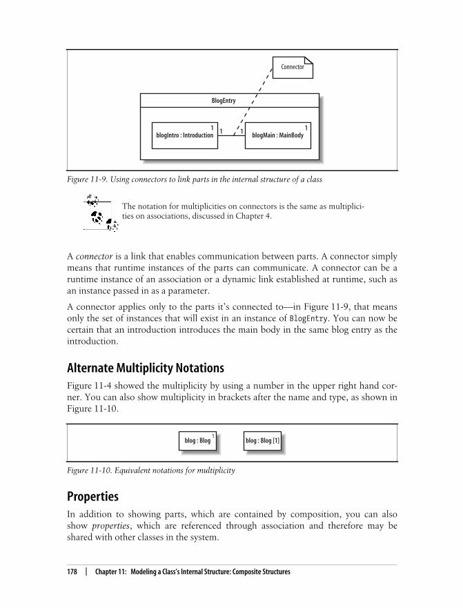
This is the Title of the Book, eMatter EditionCopyright © 2008 O’Reilly & Associates, Inc. All rights reserved.
178 | Chapter 11: Modeling a Class’s Internal Structure: Composite Structures
The notation for multiplicities on connectors is the same as multiplici-ties on associations, discussed in Chapter 4.
A connector is a link that enables communication between parts. A connector simplymeans that runtime instances of the parts can communicate. A connector can be aruntime instance of an association or a dynamic link established at runtime, such asan instance passed in as a parameter.
A connector applies only to the parts it’s connected to—in Figure 11-9, that meansonly the set of instances that will exist in an instance of BlogEntry. You can now becertain that an introduction introduces the main body in the same blog entry as theintroduction.
Alternate Multiplicity NotationsFigure 11-4 showed the multiplicity by using a number in the upper right hand cor-ner. You can also show multiplicity in brackets after the name and type, as shown inFigure 11-10.
PropertiesIn addition to showing parts, which are contained by composition, you can alsoshow properties, which are referenced through association and therefore may beshared with other classes in the system.
Figure 11-9. Using connectors to link parts in the internal structure of a class
Figure 11-10. Equivalent notations for multiplicity
BlogEntry
blogIntro : Introduction1 1 1 blogMain : MainBody
1
Connector
blog : Blog1
blog : Blog [1]

This is the Title of the Book, eMatter EditionCopyright © 2008 O’Reilly & Associates, Inc. All rights reserved.
Internal Structure | 179
Properties are drawn with a dashed outline, unlike parts, which are drawn with asolid outline. Figure 11-11 shows a class diagram in which Frame has an associationwith File, and then shows what File looks like as a property in the internal struc-ture of Frame. Figure 11-11 models a merge tool GUI that displays the two files tocompare in one panel and the merged file in another panel.
The notation for properties and parts is identical except for the dashed versus solidrectangle outlines: you specify roles, types, and multiplicity the same way. As withparts, properties can be connected to other properties or parts using connectors.
Showing Complex Relationships Between Contained ItemsShowing a class’s internal structure is especially useful when its contained itemsrelate to each other in unusual ways. Revisiting the merge tool example inFigure 11-11, suppose you want to explicitly model one panel displaying the two filesbeing compared and the other panel displaying the merged file. You can do this bydefining more detailed roles for files and panels to show how they relate to eachother within a frame, as shown in Figure 11-12.
Figure 11-2 demonstrates that there can be parts (or properties) of the same typeplaying different roles. Internal structures help make these roles and their relation-ships explicit.
Internal Structure InstancesJust as you can model instances of classes (introduced in Chapter 6), you can alsoshow instances of classes possessing internal structure. This is essentially an objectdiagram for classes with internal structure. As in Chapter 6, this lets you showimportant examples of the objects that exist in your system at runtime.
Figure 11-11. Parts and properties in the internal structure of a class
Frame
2Panel
3File
fileToDisplay displayPanel
Frame
fileToDisplay : File3
displayPanel : Panel
Part :solid outline
Property :dashed outline
2
converts to
Standard Class Diagram Internal Structure

This is the Title of the Book, eMatter EditionCopyright © 2008 O’Reilly & Associates, Inc. All rights reserved.
180 | Chapter 11: Modeling a Class’s Internal Structure: Composite Structures
If you’re showing an instance of a class with internal structure, then you also showits parts and properties as instances. Specify instances of the parts and properties bywriting the name followed by a slash, then the usual role and type, e.g., {<name>} /<role> : <type>. Since these are instances, however, they are now underlined.Figure 11-13 shows an example runtime instance of the internal structure diagramshown in Figure 11-12.
As with object diagrams, showing instances of classes with internal structure allowsyou to show example configurations in your runtime system.
Showing How a Class Is UsedThe internal structure of a class focuses on the contents of a class; ports focus on theoutside of a class, showing how a class is used by other classes.
Figure 11-12. A more detailed internal structure diagram that specifies how files and panels relateto each other within a frame
Figure 11-13. An instance of Frame with instances of its contained parts
Frame
outputPanel : PanelmergeFile : File
comparePanel : PanelcompareFile : File2
1
1
1
frame1 : Frame
panel1 /comparePanel : Panel
panel2 /outputPanel : Panel
mf1 / mergeFile : File
file2 / compareFile :File
file1 / compareFile :File

This is the Title of the Book, eMatter EditionCopyright © 2008 O’Reilly & Associates, Inc. All rights reserved.
Showing How a Class Is Used | 181
A port is a point of interaction between a class and the outside world. It represents adistinct way of using a class, usually by different types of clients. For example, a Wikiclass could have two distinct uses:
• Allowing users to view and edit the Wiki
• Providing maintenance utilities to administrators who want to perform actionssuch as rolling back the Wiki if incorrect content is provided
Each distinct use of a class is represented with a port, drawn as a small rectangle onthe boundary of the class, as shown in Figure 11-14. Write a name next to the port toshow the purpose of the port.
It’s common for classes to have interfaces associated with ports. You can use ports togroup related interfaces to show the services available at that port.
Recall from Chapter 5 that a class can realize an interface, and this relationship canbe shown using the ball interface symbol. When a class realizes an interface, theinterface is called a provided interface of the class. A provided interface can be usedby other classes to access the class through the interface.
Similarly, classes can have required interfaces. A required interface is an interface thatthe class requires to function. More precisely, the class needs another class or com-ponent that realizes that interface so it can do its job. A required interface is shownwith an open lollipop, or the socket symbol.
Provided and required interfaces are used to promote loose couplingof classes and components. They are particularly important to compo-nents and so are discussed in more detail in component diagrams (seeChapter 12).
Suppose the Wiki class above implements the interfaces Updateable and Viewable,allowing other classes to update and view the Wiki through these interfaces. Theseinterfaces are associated with the User Services port, so you can draw them extend-ing out from the User Services port, as shown in Figure 11-15.
Figure 11-14. A class with two ports showing that the class provides UserServices and Maintenancecapabilities
Ports
WikiMaintenanceUserServices

This is the Title of the Book, eMatter EditionCopyright © 2008 O’Reilly & Associates, Inc. All rights reserved.
182 | Chapter 11: Modeling a Class’s Internal Structure: Composite Structures
Figure 11-15 shows that the Maintenance port has a provided interface calledRollback, allowing administrators to roll back the Wiki. It additionally has a requiredinterface called VersionControl, which is a service the Wiki uses for version control.
Showing Patterns with CollaborationsCollaborations show objects working together, perhaps temporarily, to get some-thing done. This may sound like object diagrams (see Chapter 6), but collaborationshave a different focus: describing objects by the role they play in a scenario and pro-viding a high-level textual description of what the objects are doing.
Collaborations are a good way to document design patterns, which are solutions tocommon problems in software design. Even if you’ve never heard of them, you’veprobably used some patterns without knowing it. Observer and Observable in theJava API are an implementation of the Observer design pattern—a way for an objectto receive notification that another object changed.
For more on design patterns and how they can improve your softwaredesign, check out Design Patterns: Elements of Reusable Object Ori-ented Software (Addison Wesley), or Head First Design Patterns(O’Reilly).
Let’s consider a problem in the CMS design that can be solved with a design pattern,which we’ll then model using collaborations. Suppose the CMS requires a contentapproval process: the author submits content, the reviewer may reject the content orpass it on to the editor, and the editor may reject or accept the content. You decideto implement this flow with the Chain of Responsibility (COR) design pattern. TheCOR design pattern allows an object to send a request without worrying about whichobject will ultimately handle the request. In the COR pattern, the client submits therequest, and each handler in the chain decides whether to handle the request or topass the request on to the next handler. In the content approval process, the authorwill play the role of client, while the reviewer and editor will each play the role ofhandler. The sequence diagram in Figure 11-16 illustrates this flow. Refer back toChapter 7 for a refresher on sequence diagrams.
Figure 11-15. Ports can be used to group “like” interfaces
Wiki
MaintenanceUserServices
Updateable
Viewable
VersionControl
Rollback

This is the Title of the Book, eMatter EditionCopyright © 2008 O’Reilly & Associates, Inc. All rights reserved.
Showing Patterns with Collaborations | 183
There are two ways to model this pattern using collaborations. The first way uses alarge dashed-lined oval with the collaboration participants drawn inside the oval.You name a participant by the role it plays in the collaboration and its class or inter-face type, written as <role> : <type> . The participants are linked together using con-nectors to show how they communicate. The name of the collaboration is writteninside the oval above a dashed line. Figure 11-17 shows a Chain of Responsibilitycollaboration using the first notation. In this COR collaboration, the participant oftype Author has the role client, and the other participants have the role handler.
You can think of participants in a collaboration as placeholders for objects becauseat runtime, objects will fill those places (or play the roles). Connectors are tempo-rary links; connectors mean that the runtime objects communicate during the collab-oration, but the objects don’t have to communicate outside the collaboration.
The second way to draw a collaboration is shown in Figure 11-18. In this notation,you show the class (or interface) rectangles of the participants, connecting each to a
Figure 11-16. Sequence diagram showing how the COR pattern is used in the content approvalprocess
Figure 11-17. Collaboration showing the COR pattern in the content approval process
review()review()
: Author
"client" role
: Reviewer : Editor
"handler" role "handler" role
client : Author handler : Reviewer handler : Editor
Chain of Responsibility

This is the Title of the Book, eMatter EditionCopyright © 2008 O’Reilly & Associates, Inc. All rights reserved.
184 | Chapter 11: Modeling a Class’s Internal Structure: Composite Structures
small collaboration oval. Write the participants’ roles along the lines. This notationis useful for showing details of the class or interface, such as its operations.
Collaborations may not look particularly useful, but their strength is in their abilityto express patterns that may not be obvious from other diagrams, such as class orsequence diagrams. Without collaborations, you’d have to come up with your owntechnique to describe what’s going on, such as the attached notes in Figure 11-16.
Because collaborations are only temporary relationships, they have some interestingruntime properties that are best described with an everyday example of a collabora-tion. Suppose a company has monthly training sessions in which the topic changesevery session, and in every session the resident expert on the topic performs thetraining. This is modeled as a Training collaboration that has participants with rolestrainer and trainee, as shown in Figure 11-19.
Now let’s turn to some objects that may play these roles at runtime. Ben is the XMLexpert, so during the XML training collaboration, Ben has the role of trainer, and hisco-worker Paul has the role of trainee. However, Paul is the Java expert, so during
Figure 11-18. Alternate representation of the COR design pattern
Figure 11-19. This Training collaboration shows that the objects participating in a collaboration atruntime can interact with different collaborations in different ways
Author
Chain of Responsibility
+ submit()
Reviewer
+ review()
Editor
+ review()
clienthandler
handler
trainer : Employee trainee : Employee
Training

This is the Title of the Book, eMatter EditionCopyright © 2008 O’Reilly & Associates, Inc. All rights reserved.
What’s Next? | 185
the Java training collaboration, Paul has the role of trainer and Ben has the role oftrainee. This training example illustrates the following points:
An object isn’t bound to its role in a collaboration; it can play different roles indifferent collaborations. Employee Ben and employee Paul remain the same
objects; they’re just playing different roles in different training collaborations.
The objects in a collaboration aren’t owned by the collaboration; they may existbefore and after. Ben and Paul have a life outside of training.
Even though objects in a collaboration are linked, they don’t necessarily communi-cate outside the collaboration. Ben and Paul may not talk to each other unless they
absolutely have to during the training sessions.
The training collaboration also demonstrates that you can use collabo-rations to describe any type of object interaction that can be nicelysummarized using a short phrase—not just design patterns.
This is a specialized UML notation because the oval simply draws attention to theexistence of a pattern, describing it in brief, high-level terms. But collaborations arevaluable for exactly that reason. Design patterns are about building a commonvocabulary among developers for solving everyday problems, and collaborations helpcommunicate that vocabulary. Collaborations don’t show detailed interactions suchas messages being passed between objects as sequence and communication dia-grams do, but that can be a benefit when it comes to concisely expressing a well-known pattern.
What’s Next?The concepts of ports and internal structure of a class, which are introduced in com-posite structures, are heavily reused for components in component diagrams. Com-ponent diagrams allow you to show the key components (or reusable parts) in yoursystem. Components are typically major players in your architecture, using otherclasses to achieve their behavior, which is why internal structure is so important tocomponents. Ports are often used to show the primary ways to use a component.Component diagrams are covered in Chapter 12.

This is the Title of the Book, eMatter EditionCopyright © 2008 O’Reilly & Associates, Inc. All rights reserved.
186
Chapter 12CHAPTER 12
Managing and Reusing Your System’sParts: Component Diagrams 12
When designing a software system, it’s rare to jump directly from requirements todefining the classes in your system. With all but the most trivial systems, it’s helpfulto plan out the high-level pieces of your system to establish the architecture andmanage complexity and dependencies among the parts. Components are used toorganize a system into manageable, reusable, and swappable pieces of software.
UML component diagrams model the components in your system and as such formpart of the development view, as shown in Figure 12-1. The development viewdescribes how your system’s parts are organized into modules and components andis great at helping you manage layers within your system’s architecture.
What Is a Component?A component is an encapsulated, reusable, and replaceable part of your software. Youcan think of components as building blocks: you combine them to fit together (possi-bly building successively larger components) to form your software. Because of this,components can range in size from relatively small, about the size of a class, up to alarge subsystem.
Figure 12-1. The Development View of your model describes how your system’s parts are organizedinto modules and components
Logical View Process View
Physical View Development View
Use Case View

This is the Title of the Book, eMatter EditionCopyright © 2008 O’Reilly & Associates, Inc. All rights reserved.
A Basic Component in UML | 187
Good candidates for components are items that perform a key functionality and willbe used frequently throughout your system. Software, such as loggers, XML parsers,or online shopping carts, are components you may already be using. These happento be examples of common third-party components, but the same principles apply tocomponents you create yourself.
In your own system, you might create a component that provides services or accessto data. For example, in a CMS you could have a conversion management compo-nent that converts blogs to different formats, such as RSS feeds. RSS feeds are com-monly used to provide XML-formatted updates to online content (such as blogs).
In UML, a component can do the same things a class can do: generalize and associ-ate with other classes and components, implement interfaces, have operations, andso on. Furthermore, as with composite structures (see Chapter 11), they can haveports and show internal structure. The main difference between a class and a compo-nent is that a component generally has bigger responsibilities than a class. For exam-ple, you might create a user information class that contains a user’s contactinformation (her name and email address) and a user management component thatallows user accounts to be created and checked for authenticity. Furthermore, it’s com-mon for a component to contain and use other classes or components to do its job.
Since components are major players in your software design, it’s important that theyare loosely coupled so that changes to a component do not affect the rest of your sys-tem. To promote loose coupling and encapsulation, components are accessedthrough interfaces. Recall from Chapter 5 that interfaces separate a behavior from itsimplementation. By allowing components to access each other through interfaces,you can reduce the chance that a change in one component will cause a ripple ofbreaks throughout your system. Refer back to Chapter 5 for a review of interfaces.
A Basic Component in UMLA component is drawn as a rectangle with the <<component>> stereotype and anoptional tabbed rectangle icon in the upper righthand corner. Figure 12-2 shows aConversionManagement component used in the CMS that converts blogs to differentformats and provides feeds such as RSS feeds.
In earlier versions of UML, the component symbol was a larger version of the tabbedrectangle icon, so don’t be surprised if your UML tool still shows that symbol.
Figure 12-2. The basic component symbol showing a ConversionManagement component
<<component>>ConversionManagement

This is the Title of the Book, eMatter EditionCopyright © 2008 O’Reilly & Associates, Inc. All rights reserved.
188 | Chapter 12: Managing and Reusing Your System’s Parts: Component Diagrams
You can show that a component is actually a subsystem of a very large system byreplacing <<component>> with <<subsystem>>, as shown in Figure 12-3. A subsystem isa secondary or subordinate system that’s part of a larger system. UML considers asubsystem a special kind of component and is flexible about how you use this stereo-type, but it’s best to reserve it for the largest pieces in your overall system, such as alegacy system that provides data or a workflow engine in the CMS.
Provided and Required Interfaces of a ComponentComponents need to be loosely coupled so that they can be changed without forcingchanges on other parts of the system—this is where interfaces come in. Componentsinteract with each other through provided and required interfaces to control depen-dencies between components and to make components swappable.
A provided interface of a component is an interface that the component realizes.Other components and classes interact with a component through its providedinterfaces. A component’s provided interface describes the services provided by thecomponent.
A required interface of a component is an interface that the component needs tofunction. More precisely, the component needs another class or component that real-izes that interface to function. But to stick with the goal of loose coupling, it accessesthe class or component through the required interface. A required interface declaresthe services a component will need.
There are three standard ways to show provided and required interfaces in UML:ball and socket symbols, stereotype notation, and text listings.
Ball and Socket Notation for InterfacesYou can show a provided interface of a component using the ball symbol introducedin Chapter 5. A required interface is shown using the counterpart of the ball—thesocket symbol—drawn as a semicircle extending from a line. Write the name of theinterface near the symbols.
Figure 12-4 shows that the ConversionManagement component provides theFeedProvider and DisplayConverter interfaces and requires the DataSource interface.
The ball and socket notation is the most common way to show a component’s inter-faces, compared with the following techniques.
Figure 12-3. You can substitute the <<subsystem>> stereotype to show the largest pieces of yoursystem
<<subsystem>>WorkflowEngine

This is the Title of the Book, eMatter EditionCopyright © 2008 O’Reilly & Associates, Inc. All rights reserved.
Provided and Required Interfaces of a Component | 189
Stereotype Notation for InterfacesYou can also show a component’s required and provided interfaces by drawing theinterfaces with the stereotyped class notation (introduced in Chapter 5). If a compo-nent realizes an interface, draw a realization arrow from the component to the inter-face. If a component requires an interface, draw a dependency arrow from thecomponent to the interface, as shown in Figure 12-5.
This notation is helpful if you want to show the operations of interfaces. If not, it’sbest to use the ball and socket notation, since it shows the same information morecompactly.
Figure 12-4. The ball and socket notation for showing a component’s provided and requiredinterfaces
Figure 12-5. The stereotyped class notation, showing operations of the required and providedinterfaces
<<component>>ConversionManagement
FeedProvider
DisplayConverterDataSource
Providedinterfaces
Requiredinterface
<<interface>>DisplayConverter
+ getView(String id) : View
Realizationarrow
<<component>>ConversionManagement
<<interface>>FeedProvider
+ getFeed(String id) : Feed
<<Interface>>DataSource
+ lookup(String id) : Record
Required and provided interfacesare shown using the stereotyped
class notationDependency
arrow

This is the Title of the Book, eMatter EditionCopyright © 2008 O’Reilly & Associates, Inc. All rights reserved.
190 | Chapter 12: Managing and Reusing Your System’s Parts: Component Diagrams
Listing Component InterfacesThe most compact way of showing required and provided interfaces is to list theminside the component. Provided and required interfaces are listed separately, asshown in Figure 12-6.
This notation additionally has an <<artifacts>> section listing the artifacts, or physi-cal files, manifesting this component. Since artifacts are concerned with how yoursystem is deployed, they are discussed in deployment diagrams (see Chapter 15).Listing the artifacts within the component is an alternative to the techniques shownin Chapter 15 for showing that artifacts manifest components.
Deciding when to use which notation for required and provided interfaces dependson what you’re trying to communicate. This question can be answered more fullywhen examining components working together.
Showing Components Working TogetherIf a component has a required interface, then it needs another class or component inthe system to provide it. To show that a component with a required interfacedepends on another component that provides it, draw a dependency arrow from thedependent component’s socket symbol to the providing component’s ball symbol, asshown in Figure 12-7.
As a presentation option for Figure 12-7, your UML tool may let you get away withsnapping the ball and socket together (omitting the dependency arrow), as shown in
Figure 12-6. Listing required and provided interfaces within the component is the most compactrepresentation
Figure 12-7. The ConversionManagement component requires the DataSource interface, and theBlogDataSource component provides that interface
<<component>>ConversionManagement
<<provided interfaces>>FeedProvider,DisplayConverter<<required interfaces>>DataSource<<artifacts>>conversionManagement.jar
<<component>>BlogDataSource
DataSource<<component>>ConversionManagement
FeedProvider
DisplayConverterDataSource

This is the Title of the Book, eMatter EditionCopyright © 2008 O’Reilly & Associates, Inc. All rights reserved.
Showing Components Working Together | 191
Figure 12-8. This is actually the assembly connector notation, which is introducedlater in this chapter.
You can also omit the interface and draw the dependency relationship directlybetween the components, as shown in Figure 12-9.
The second notation (omitting the interface, shown in Figure 12-9) is simpler thanthe first (including the interface, shown in Figure 12-7), so you may be tempted touse that as a shorthand, but keep in mind a few factors when choosing how to drawcomponent dependencies.
Remember that interfaces help components stay loosely coupled, so they are animportant factor in your component architecture. Showing the key components inyour system and their interconnections through interfaces is a great way to describethe architecture of your system, and this is what the first notation is good at, asshown in Figure 12-10.
Figure 12-8. Presentation option that snaps the ball and socket together
Figure 12-9. You can draw dependency arrows directly between components to show a higher levelview
Figure 12-10. Focusing on the key components and interfaces in your system
<<component>>BlogDataSource
<<component>>ConversionManagement
FeedProvider
DisplayConverter
DataSource
<<component>>BlogDataSource
<<component>>ConversionManagement
<<component>>ConversionManagement
FeedProvider
DisplayConverter
DataSource<<component>>
BlogDataSource
<<component>>Log4j
Logger
Logger
DataSource
<<component>>BroadcastEngine
<<component>>BlogViewer
DisplayConverter
FeedProvider
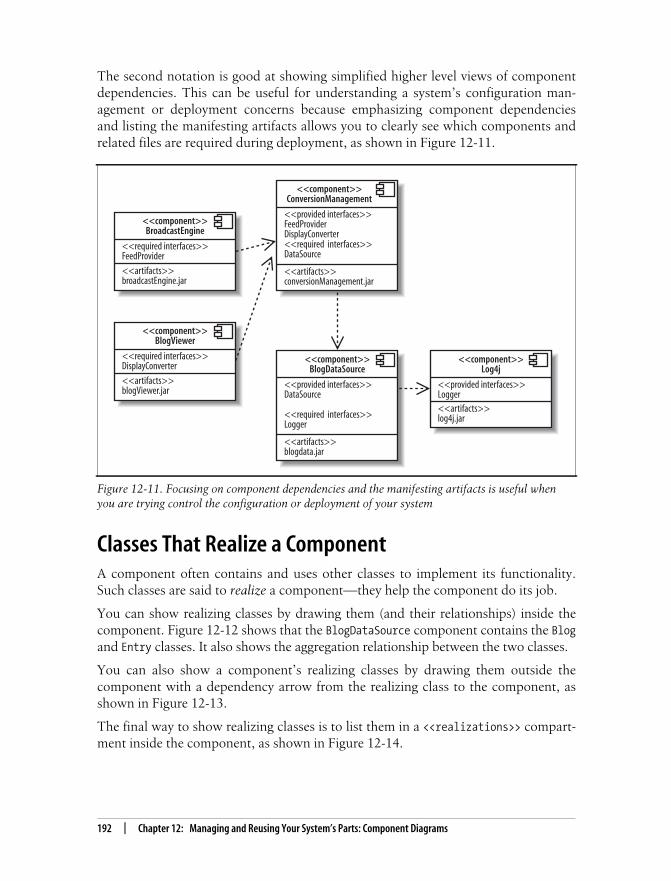
This is the Title of the Book, eMatter EditionCopyright © 2008 O’Reilly & Associates, Inc. All rights reserved.
192 | Chapter 12: Managing and Reusing Your System’s Parts: Component Diagrams
The second notation is good at showing simplified higher level views of componentdependencies. This can be useful for understanding a system’s configuration man-agement or deployment concerns because emphasizing component dependenciesand listing the manifesting artifacts allows you to clearly see which components andrelated files are required during deployment, as shown in Figure 12-11.
Classes That Realize a ComponentA component often contains and uses other classes to implement its functionality.Such classes are said to realize a component—they help the component do its job.
You can show realizing classes by drawing them (and their relationships) inside thecomponent. Figure 12-12 shows that the BlogDataSource component contains the Blogand Entry classes. It also shows the aggregation relationship between the two classes.
You can also show a component’s realizing classes by drawing them outside thecomponent with a dependency arrow from the realizing class to the component, asshown in Figure 12-13.
The final way to show realizing classes is to list them in a <<realizations>> compart-ment inside the component, as shown in Figure 12-14.
Figure 12-11. Focusing on component dependencies and the manifesting artifacts is useful whenyou are trying control the configuration or deployment of your system
<<component>>BroadcastEngine
<<required interfaces>>FeedProvider
<<artifacts>>broadcastEngine.jar
<<component>>ConversionManagement
<<provided interfaces>>FeedProviderDisplayConverter<<required interfaces>>DataSource
<<artifacts>>conversionManagement.jar
<<component>>BlogDataSource
<<provided interfaces>>DataSource
<<required interfaces>>Logger
<<artifacts>>blogdata.jar
<<component>>BlogViewer
<<required interfaces>>DisplayConverter
<<artifacts>>blogViewer.jar
<<component>>Log4j
<<provided interfaces>>Logger<<artifacts>>log4j.jar

This is the Title of the Book, eMatter EditionCopyright © 2008 O’Reilly & Associates, Inc. All rights reserved.
Classes That Realize a Component | 193
How do you decide which notation to use to show the classes that realize a compo-nent? You may be limited by your UML tool, but if you have the choice, many mod-elers prefer the first notation (drawing the realizing classes inside) rather thandrawing them outside since drawing them inside visually emphasizes that the classesmake up a component to achieve its functionality. Listing the realizing classes maybe helpful if you want something compact, but keep in mind that it can’t show rela-tionships between the realizing classes, whereas the first two notations can.
Figure 12-12. The Blog and Entry classes realize the BlogDataSource component
Figure 12-13. Alternate view, showing the realizing classes outside with the dependencyrelationship
Figure 12-14. You can also list the realizing classes inside the component
<<component>>BlogDataSource
Blog EntryDataSource Logger
<<component>>BlogDataSource
Blog Entry
<<component>>BlogDataSource
<<provided interfaces>>DataSource
<<required interfaces>>Logger
<<realizations>>Blog,Entry
<<artifacts>>blogData.jar

This is the Title of the Book, eMatter EditionCopyright © 2008 O’Reilly & Associates, Inc. All rights reserved.
194 | Chapter 12: Managing and Reusing Your System’s Parts: Component Diagrams
Ports and Internal StructureChapter 11 introduced ports and internal structure of a class. Components can alsohave ports and internal structure.You can use ports to model distinct ways that acomponent can be used with related interfaces attached to the port. In Figure 12-15,the ConversionManagement component has a Formatting and a Data port, each withtheir associated interfaces.
You can show the internal structure of a component to model its parts, properties,and connectors (see Chapter 11 for a review of internal structure). Figure 12-16shows the internal structure of a BlogDataSource component.
Components have their own unique constructs when showing ports and internalstructure—called delegation connectors and assembly connectors. These are used toshow how a component’s interfaces match up with its internal parts and how theinternal parts work together.
Delegation ConnectorsA component’s provided interface can be realized by one of its internal parts. Simi-larly, a component’s required interface can be required by one of its parts. In thesecases, you can use delegation connectors to show that internal parts realize or use thecomponent’s interfaces.
Figure 12-15. Ports show unique uses of a component and group “like” interfaces
Figure 12-16. Showing the internal structure of a component
<<component>>ConversionManagement
DataFormatting
FeedProvider
DisplayConverter
DataSource
Reporting
Ports
<<component>>BlogDataSource
: Blog : EntryDataSource Logger

This is the Title of the Book, eMatter EditionCopyright © 2008 O’Reilly & Associates, Inc. All rights reserved.
Ports and Internal Structure | 195
Delegation connectors are drawn with arrows pointing in the “direction of traffic,”connecting the port attached to the interface with the internal part. If the part real-izes a provided interface, then the arrow points from the port to the internal part.
If the part uses a required interface, then the arrow points from the internal part tothe port. Figure 12-17 shows the use of delegation connectors to connect interfaceswith internal parts.
You can think of the delegation connectors as follows: the port represents an open-ing into a component through which communications pass, and delegation connec-tors point in the direction of communication. So, a delegation connector pointingfrom a port to an internal part represents messages being passed to the part that willhandle it.
If you’re showing the interfaces of the internal parts, you can connect delegation con-nectors to the interface instead of directly to the part. This is commonly used whenshowing a component that contains other components. Figure 12-19 demonstrates thisnotation. The ConversionManagement component has a Controller and a BlogParsercomponent. The ConversionManagement component provides the FeedProvider inter-face, but this is actually realized internally by the Controller part.
Assembly ConnectorsAssembly connectors show that a component requires an interface that another com-ponent provides. Assembly connectors snap together the ball and socket symbolsthat represent required and provided interfaces.
Figure 12-19 shows the assembly connector notation connecting the Controllercomponent to the BlogParser component.
Assembly connectors are special kinds of connectors that are defined for use whenshowing composite structure of components. Notice that Controller and BlogParser
Figure 12-17. Delegation connectors show how interfaces correspond to internal parts: the Blogclass realizes the DataSource interface and the Entry class requires the Logger interface
<<component>>BlogDataSource
: Blog : EntryDataSource Logger
Delegationconnector
Delegationconnector

This is the Title of the Book, eMatter EditionCopyright © 2008 O’Reilly & Associates, Inc. All rights reserved.
196 | Chapter 12: Managing and Reusing Your System’s Parts: Component Diagrams
use the roleName:className notation introduced in composite structures and helpform the internal structure of ConversionManagement. But assembly connectors arealso sometimes used as a presentation option for component dependency throughinterfaces in general, as shown earlier in Figure 12-8.
Black-Box and White-Box Component ViewsThere are two views of components in UML: a black-box view and a white-box view.The black-box view shows how a component looks from the outside, including itsrequired interfaces, its provided interfaces, and how it relates to other components.A black-box view specifies nothing about the internal implementation of a compo-
Figure 12-18. Delegation connectors can also connect interfaces of internal parts with ports
Figure 12-19. Assembly connectors show components working together through interfaces
Parser
<<component>>ConversionManagement
<<component>>: BlogParser
DataSource DataSource<<component>>
: Controller
Parser
FeedProviderFeedProvider
DisplayConverter
DisplayConverter
Delegationconnector
<<component>>ConversionManagement
<<component>>: BlogParser
DataSource DataSource<<component>>
: Controller
FeedProviderFeedProvider
DisplayConverter
DisplayConverter
Assemblyconnector
Parser

This is the Title of the Book, eMatter EditionCopyright © 2008 O’Reilly & Associates, Inc. All rights reserved.
What’s Next? | 197
nent. The white-box view, on the other hand, shows which classes, interfaces, andother components help a component achieve its functionality.
In this chapter, you’ve seen both black-box and white-box views. So, what’s the dif-ference in practical terms? A white-box view is one that shows parts inside a compo-nent, whereas a black-box view doesn’t, as shown in Figure 12-20.
When modeling your system, it’s best to use black-box views to focus on large-scalearchitectural concerns. Black-box views are good at showing the key components inyour system and how they’re connected. White-box views, on the other hand, are use-ful for showing how a component achieves its functionality through the classes it uses.
Black-box views usually contain more than one component, whereas in a white-boxview, it’s common to focus on the contents of one component.
What’s Next?Now that you know how to model the components in your system, you may want tolook at how your components are deployed to hardware in deployment diagrams.Deployment diagrams are covered in Chapter 15.
There is heavy overlap between certain topics in component diagrams and compos-ite structures. The ability to have ports and internal structure is defined for classes incomposite structures. Components inherit this capability and introduce some oftheir own features, such as delegation and assembly connectors. Refer back toChapter 11 to refresh your memory about a class’s internal structure and ports.
Figure 12-20. Black-box component views are useful for showing the big picture of the componentsin your system, whereas white-box views focus on the inner workings of a component
<<component>>BlogDataSource
Blog EntryDataSource Logger
<<component>>ConversionManagement
<<component>>BlogDataSource
DataSource
DataSource
FeedProvider
DisplayConverter
Example Black-Box Component View Example White-Box Component View

This is the Title of the Book, eMatter EditionCopyright © 2008 O’Reilly & Associates, Inc. All rights reserved.
198
Chapter 13CHAPTER 13
Organizing Your Model: Packages 13
As a software program grows in complexity, it can easily contain hundreds of classes.If you’re a programmer working with such a class library, how do you make sense ofit? One way to impose structure is by organizing your classes into logically relatedgroups. Classes concerned with an application’s user interface can belong to onegroup, and utility classes can belong to another.
In UML, groups of classes are modeled with packages. Most object-oriented lan-guages have an analog of UML packages to organize and avoid name collision amongclasses. For example, Java has packages, C# has namespaces (although Java pack-ages, and C# namespaces differ significantly in other details). You can use UMLpackages to model these structures.
Package diagrams are often used to view dependencies among packages. Since apackage can break if another package on which it depends changes, understandingdependencies between packages is vital to the stability of your software.
Packages can organize almost any UML element—not just classes. For example,packages are also commonly used to group use cases. Package diagrams form part ofthe development view, which is concerned with how your system’s parts are orga-nized into modules and packages, as shown in Figure 13-1.
Figure 13-1. The Development View describes how your system’s parts are organized into modules,which are represented as packages in UML
Logical View Process View
Physical View Development View
Use Case View

This is the Title of the Book, eMatter EditionCopyright © 2008 O’Reilly & Associates, Inc. All rights reserved.
Packages | 199
PackagesSuppose that during the design of a CMS, you decide to keep classes related to secu-rity (for example, performing user authentication) grouped together. Figure 13-2shows the security package and a few other packages from the CMS in UML. Thesymbol for a package is a folder with a tab. The name of the package is written insidethe folder.
Contents of a PackagePackages organize UML elements, such as classes, and the contents of a package canbe drawn inside the package or outside the package attached by a line, as shown inFigure 13-3. If you draw the elements inside the package, write the name of the pack-age in the folder tab.
The notation shown in Figure 13-3 is used to model Java classes belonging to a Javapackage. In Java, the package keyword at the beginning of a class specifies that a classis in a package. Example 13-1 shows a Java code sample corresponding to theCredentials class in Figure 13-3.
Getting StartedYour UML tool probably doesn’t have a diagram called a package diagram. Packagesare grouping structures that are used to organize almost any UML element, but theirmost common use is to organize classes in class diagrams. Most of the examples in thischapter focus on applications of packages to classes, so create a new class diagram towork along with these examples.
Figure 13-2. Packages in a CMS; each package corresponds to a specific system concern
security
users
search
accounts

This is the Title of the Book, eMatter EditionCopyright © 2008 O’Reilly & Associates, Inc. All rights reserved.
200 | Chapter 13: Organizing Your Model: Packages
Packages can also contain other packages, as shown in Figure 13-4.
It’s common to see deeply nested packages in enterprise applications. Java applica-tions typically use the URL-in-reverse package naming convention (omitting thewww part of the URL). For example, the ACME company with the URL http://www.acme.com would put all its packages under the acme package, which is under com, asshown in Figure 13-5.
Figure 13-3. Two ways to show that the Credentials and IdentityVerifier classes are contained inthe security package
Example 13-1. The Credentials class is located in the security package in this Java implementation
package security;
public class Credentials { ...}
Figure 13-4. A package that contains another package
Figure 13-5. Deeply nested packages are common in enterprise applications: the search andindexing packages are shown in a typical package structure for the ACME company
security
Credentials
IdentityVerifier
security
Credentials IdentityVerifier
search
indexing
com
indexing
acme
search

This is the Title of the Book, eMatter EditionCopyright © 2008 O’Reilly & Associates, Inc. All rights reserved.
Namespaces and Classes Referring to Each Other | 201
Even at this point, these packages consume a lot of space, and if you want to showclasses inside the indexing package, each package containing it would have toexpand in size accordingly. Luckily, there’s an alternate notation that can be easier towork with. You can “flatten” nested packages to write them as packageA::packageB::packageC, and so on. This converts Figure 13-5 into the less cluttered Figure 13-6.
UML Tool VariationCurrently, a small amount of UML tools don’t support the notations shown inFigure 13-3. However, almost all tools can show that a class belongs to a packageusing one of the notations shown in Figure 13-7. The notation to the far right is thestandard UML namespace notation, discussed next in “Namespaces and ClassesReferring to Each Other.”
To specify the package that a class belongs to, most UML tools allow you to enterthe package name in a class specification dialog or manually drag the class into thepackage it belongs to in a tree display of the model elements.
Namespaces and Classes Referring to Each OtherBreaking up your classes into packages introduces some bookkeeping. If you’re aJava programmer, you may have encountered a related issue before. To use anArrayList in a Java program, you have to specify that ArrayList is located in thejava.util package. That is because Java packages define their own namespaces, ornaming contexts. If an item is not in the current namespace, you have to specifywhere it is located.
Similarly, a UML package establishes a namespace. So, if an element in a packagewants to use an element in a different package, it has to specify where the desired
Figure 13-6. Flattening nested packages
Figure 13-7. Common ways UML tools show that a class belongs to a package
com::acme::search
indexing
ClassA(from package2)
ClassA(package2)
package2::ClassA

This is the Title of the Book, eMatter EditionCopyright © 2008 O’Reilly & Associates, Inc. All rights reserved.
202 | Chapter 13: Organizing Your Model: Packages
element is. To specify the context of a UML element, you provide the fully-scopedname, which includes the package name and the element name separated by doublecolons, as in packageName::className. The fully-scoped name for the class Credentialsbelonging to the package security is security::Credentials. If you have two classeswith the same name in different packages, using the fully-scoped name allows you todistinguish between them.
Elements in a namespace must have unique names. This means the security pack-age cannot have two classes named Credentials, but there can be two classes calledCredentials belonging to separate packages, for example security and utils. As dis-cussed previously in “UML Tool Variation,” your UML tool may display the classesin Figure 13-8 differently.
Why does this matter? To specify that a class has a relationship with another class,you may have to specify a namespace.
Classes in the same package are part of the same namespace, so they can refer toeach other without using fully-scoped names. Since they are in the same package,IdentityVerifier can have an attribute of type Credentials and not have to specifythe package (see Figure 13-9).
On the other hand, a class outside the security package, such as User, would have toprovide a scope when accessing Credentials, which it can do by using the fully-scoped name—security::Credentials. Later, in “Importing and Accessing Pack-ages,” you’ll see that there are other ways to provide scope when accessing a class ina different package.
In Java, a fully-scoped name corresponds to specifying the Java pack-age, e.g., security.Credentials instead of just Credentials.
Figure 13-8. Representing a class with its fully-scoped name: both the security and utils packageshave a class named Credentials
Figure 13-9. Classes in different packages have to provide name scope
security::Credentials utils::Credentials
search
User
security
Credentials IdentityVerifier

This is the Title of the Book, eMatter EditionCopyright © 2008 O’Reilly & Associates, Inc. All rights reserved.
Element Visibility | 203
In UML, elements in a nested package can refer to elements in the containing pack-age without scoping the name, which in Figure 13-10 means that an element inindexing could refer to an element in search without using the fully-scoped name.
The implication that elements in nested packages have automatic access to elementsin containing packages doesn’t match with some implementation languages. Forexample, in Java, if a class in the indexing package uses a class in the search pack-age, it has to provide a scope either by using its fully-qualified name or by importingthe search package. Despite the fact that UML semantics of nested packages differfrom Java packages, you could still use Figure 13-10 to model a package search.indexing in a Java system.
Element VisibilityElements in a package may have public or private visibility. Elements with publicvisibility are accessible outside the package. Elements with private visibility are avail-able only to other elements inside the package. You can model public or private visi-bility in UML by writing a plus or minus symbol in front of the element’s name, asshown in Figure 13-11.
In Java, public and private visibility corresponds to a class being public or private toa Java package. A Java class is marked as public to a package by the public accessmodifier, as in:
public class Credentials {}
Figure 13-10. In UML, a nested package implies namespace “inheritance,” which doesn’t apply insome implementation languages
Figure 13-11. Since MD5Crypt has private visibility, it isn’t accessible outside the security package
search
indexing
security
User
+ Credentials + IdentityVerifier
- MD5Crypt
users

This is the Title of the Book, eMatter EditionCopyright © 2008 O’Reilly & Associates, Inc. All rights reserved.
204 | Chapter 13: Organizing Your Model: Packages
If the public keyword is absent, then the class is private to the package. Many UMLtools don’t offer the plus and minus symbols to show element visibility, so don’t besurprised if yours doesn’t.
Package DependencyThe previous sections showed that sometimes a class in one package needs to use aclass in another package. This causes a dependency between packages: if an elementin package A uses an element in package B, then package A depends on package B, asshown in Figure 13-12.
Figure 13-12. Package A depends on package B
Packages in Your SoftwareNow that you’ve seen the basics of package diagrams, it’s a good time to consider whyyou’d want to use packages in your software.
If you’re creating a very small program (consisting of only a few classes), you might notbother organizing your classes into packages. As your program gets bigger and you adddevelopers to the project, packages introduce structure and let you know who’s work-ing on what.
Code related to the graphical user interface (GUI) can belong to a gui package, coderelated to search capabilities can belong to a search package, and common utilities canbelong to a util package. This makes it easier to find classes when looking through acomplex API. For example, to locate a GUI dialog, you would know to look in the guipackage.
Often, programmers work roughly undisturbed in their own or their group’s package.Those working in gui generally don’t change the search package and vice versa. Every-one may use common packages, such as the util package, but such commonly usedpackages are expected to be fairly stable since changes could affect everyone.Beyondorganizing elements, packages can serve other useful functions. They can be used foraccess control: you can declare elements private to a package to prevent it from beingused by other packages.
Packages can assist with organizing classes as deployment modules. For example, ifyou wanted to include search capability in some systems but not others, you couldchoose to include or exclude the search package in the build.
A B

This is the Title of the Book, eMatter EditionCopyright © 2008 O’Reilly & Associates, Inc. All rights reserved.
Importing and Accessing Packages | 205
Understanding the dependencies among your packages is useful for analyzing thestability of your software, as discussed in “Managing Package Dependencies.” Infact, the most common use of UML package diagrams is to give an overview of thecore packages in your software and the dependencies among them, as shown inFigure 13-13.
“Managing Package Dependencies,” later in this chapter, revisits package depen-dency diagrams, showing you how to use them to understand and improve the sta-bility of your software.
Importing and Accessing PackagesWhen a package imports another package, elements in the importing package canuse elements in the imported package without having to use their fully scopednames. This feature is similar to a Java import, in which a class can import a pack-age and use its contents without having to provide their package names.
In an import relationship, the imported package is referred to as the target package.To show the import relation, draw a dependency arrow from the importing packageto the target package with the stereotype import (see Figure 13-14).
Figure 13-13. A typical package diagram featuring core packages and dependencies
search
indexing
utilgui
accounts
users security

This is the Title of the Book, eMatter EditionCopyright © 2008 O’Reilly & Associates, Inc. All rights reserved.
206 | Chapter 13: Organizing Your Model: Packages
A package can also import a specific element in another package instead of the wholepackage, as shown in Figure 13-15.
When importing a package, only public elements of the target package are availablein the importing namespace. For example, in Figure 13-16, elements in users can seeCredentials and IdentityVerifier but not MD5Crypt.
Not only do elements have visibility—the import relation itself has visibility. Animport can be a public import or private import with public as the default. A publicimport means imported elements have public visibility inside the importingnamespace; a private import means imported elements have private visibility insidethe importing namespace. You show a private import with the stereotype accessinstead of import.
The difference between import and access arises when a package imports a packagethat imports or accesses others. Imported elements have public visibility in theimporting package, so they get passed on with further imports, whereas accessed ele-ments do not.
Figure 13-14. The package users imports security, so classes in users may use public classes insecurity without having to specify the package name
Figure 13-15. The users package imports only the Credentials element from the security package
Figure 13-16. Private visibility causes a class not to be seen even though its package is imported
User security
users
<<import>>
security
users<<import>>
+ Credentials + IdentityVerifier
- MD5Crypt
security
users<<import>>
+ Credentials + IdentityVerifier
- MD5Crypt

This is the Title of the Book, eMatter EditionCopyright © 2008 O’Reilly & Associates, Inc. All rights reserved.
Importing and Accessing Packages | 207
In Figure 13-17, package B imports C and accesses D, so B can see public elements in Cand D. A imports B, so A can see public elements in B. A can also see public elements inC because C is publicly imported into B, but A cannot see anything in D because D isprivately imported into B.
Import and access relationships can be used to model the programming world con-cepts of importing of classes into another namespace so that elements in the import-ing namespace may refer to elements in the target namespace without scoping thename. For example, the package relationships in Figure 13-14 could be used tomodel the Java code example in Example 13-2.
The element import in Figure 13-15 corresponds to the Java implementation shownin Example 13-3.
Figure 13-17. Package A can see public elements in C but not D
Example 13-2. Because the User class imports the security package, it can refer to the Credentialsclass without using the fully qualified name security
package users;
// importing all public elements in the security packageimport security.*;
class User {Credentials credentials;
...}
A<<import>>
B
C
D
<<import>>
<<access>>
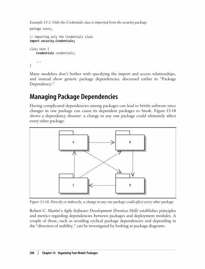
This is the Title of the Book, eMatter EditionCopyright © 2008 O’Reilly & Associates, Inc. All rights reserved.
208 | Chapter 13: Organizing Your Model: Packages
Many modelers don’t bother with specifying the import and access relationships,and instead show generic package dependencies, discussed earlier in “PackageDependency.”
Managing Package DependenciesHaving complicated dependencies among packages can lead to brittle software sincechanges in one package can cause its dependent packages to break. Figure 13-18shows a dependency disaster: a change in any one package could ultimately affectevery other package.
Robert C. Martin’s Agile Software Development (Prentice Hall) establishes principlesand metrics regarding dependencies between packages and deployment modules. Acouple of these, such as avoiding cyclical package dependencies and depending inthe “direction of stability,” can be investigated by looking at package diagrams.
Example 13-3. Only the Credentials class is imported from the security package
package users;
// importing only the Credentials classimport security.Credentials;
class User {Credentials credentials;
...}
Figure 13-18. Directly or indirectly, a change in any one package could affect every other package
DC
BA

This is the Title of the Book, eMatter EditionCopyright © 2008 O’Reilly & Associates, Inc. All rights reserved.
Using Packages to Organize Use Cases | 209
If you have cycles in your dependencies, you can break the cycles in different ways.You could factor out a new package that both packages can depend on or you coulddecide that all the classes really belong together anyway, as shown in Figure 13-19.
Depending in the order of stability means that a package should depend only onpackages more stable than itself. An unstable package depends on many other pack-ages; a stable package depends on few packages. Studying package diagrams canhelp you spot potentially vulnerable designs resulting from the core packages of yoursystem (such as those containing interfaces) depending on unstable packages.
Using Packages to Organize Use CasesJust as packages group classes of similar functionality, packages also group other UMLelements such as use cases. Figure 13-20 shows some use case packages from a CMS.
Rolling up use cases into higher levels of your system can help organize your model,allowing you to see which actors interact with which portions of the system, asshown in Figure 13-21.
Figure 13-19. Removing cycles in package dependencies
B
A
A
reduce into one package
A
B
C
factor out new package

This is the Title of the Book, eMatter EditionCopyright © 2008 O’Reilly & Associates, Inc. All rights reserved.
210 | Chapter 13: Organizing Your Model: Packages
What’s Next?Packages are used to group UML elements such as classes and use cases. You maywant to review those chapters for more detail about showing the contents of a pack-age. Class diagrams are covered in Chapter 4; use case diagrams are covered inChapter 2.
One of the most important applications of package diagrams is to view dependen-cies in your system. Other important high-level system diagrams include componentdiagrams, which show the key software pieces, and deployment diagrams, whichshow how the pieces get deployed to hardware. Component diagrams are describedin Chapter 12; deployment diagrams are covered in Chapter 15.
Figure 13-20. Packaging major use case groups within a CMS
Figure 13-21. Packages enable a higher level view of how actors interact with the system
Account Management
Search
Authoring
Account Management
Search
Authoring
Administrator
Author
Public

This is the Title of the Book, eMatter EditionCopyright © 2008 O’Reilly & Associates, Inc. All rights reserved.
211
Chapter 14 CHAPTER 14
Modeling an Object’s State:State Machine Diagrams14
Activity diagrams and interaction diagrams are useful for describing behavior, butthere’s still a missing piece. Sometimes the state of an object or system is an impor-tant factor in its behavior. For example, if the CMS required potential users to sub-mit an application for an account, which could be approved or rejected, then theAccountApplication object may act differently depending on whether it is pending,accepted, or rejected.
In such situations, it’s helpful to model states of an object and the events causingstate changes—this is what state machine diagrams do best. Continuing the aboveexample, the AccountApplication object could have the states pending, accepted, andrejected as possible values of an attribute, and change states upon events such asapprove or reject. A state machine diagram allows you to model this behavior.
State machine diagrams are heavily used in special niches of software and hardwaresystems, including the following:
• Real-time/mission-critical systems, such as heart monitoring software
• Dedicated devices whose behavior is defined in terms of state, such as ATMs
• First-person shooter games, such as Doom or Half-Life
To reflect these common uses, this chapter will deviate from the CMS example usedthroughout the rest of this book.
Most of this chapter focuses on behavioral state machines, which can show states,transitions, and behavior (inside states and along transitions). There’s another typeof state machine called a protocol state machine that doesn’t model behavior but isuseful for modeling protocols such as network communication protocols. Protocolstate machines are discussed briefly at the end of the chapter.
State machine diagrams are part of the logical model of your system, as shown inFigure 14-1.

This is the Title of the Book, eMatter EditionCopyright © 2008 O’Reilly & Associates, Inc. All rights reserved.
212 | Chapter 14: Modeling an Object’s State: State Machine Diagrams
State machine diagrams are often referred to informally as state diagrams. You mayalso have seen them referred to as a statechart diagrams in the past, since this dia-gram has undergone many name changes.
EssentialsLet’s look at the key elements of state diagrams using a simple example. Figure 14-2shows a state diagram modeling a light. When you lift the light switch, the lightturns on. When you lower the light switch, the light turns off.
A state diagram consists of states, drawn as rounded rectangles, and transitions,drawn as arrows connecting the states. A transition represents a change of state, orhow to get from one state to the next. A state is active when entered through a transi-tion, and it becomes inactive when exited through a transition.
The event causing the state change, or trigger, is written along the transition arrow.The light in Figure 14-2 has two states: Off and On. It changes state when the liftswitch or lower switch triggers occur.
If you haven’t seen state diagrams before, it may help to view the states and transi-tions in table form, as shown in Table 14-1. In the left column are the states, andalong the top row are triggers. The table is interpreted as follows: when the object isin a state and receives a trigger, the object moves to the resulting state specified in
Figure 14-1. The Logical View describes the abstract descriptions of a system’s parts, includingwhen and how those parts can be in different states using state machine diagrams
Figure 14-2. The fundamental elements of a state diagram: states and transitions between states
Logical View Process View
Physical View Development View
Use Case View
On
A transition
Offlift switch
lower switch
A state

This is the Title of the Book, eMatter EditionCopyright © 2008 O’Reilly & Associates, Inc. All rights reserved.
States | 213
the cell. A dash (-) means that no transition happens or that the combination isimpossible. Viewing states and transitions in table form can be helpful when gettingup-to-speed, but don’t depend on this too heavily; details of states and transitionscan be more complex, and it will become easier to work with state diagrams.
State diagrams usually have an initial pseudostate and a final state, marking the startand end points of the state machine, respectively. An initial pseudostate is drawnwith a filled circle, and a final state is drawn with two concentric circles with a filledinner circle, as shown in Figure 14-3.
Pseudostates are special markers that direct the flow of traffic in a state diagram. Asmentioned above, an initial pseudostate models the starting point of a state diagram.There are other pseudostates discussed later in “Advanced Pseudostates” that modelcomplex transitions between states.
Now that you’ve seen the basic elements of state diagrams, let’s look in detail atthese elements.
StatesA state is a condition of being at a certain time. A state can be a passive quality, suchas On and Off for the light object. A state can also be an active quality, or somethingthat an object is doing. For example, a coffeemaker has the state Brewing duringwhich it is brewing coffee. A state is drawn as a rounded rectangle with the name ofthe state in the center, as shown in Figure 14-4.
If the state is a “doing” state, you can write the behavior inside the state, as shown inFigure 14-5.
Table 14-1. Table view of light states and transitions—not UML notation
State/Trigger Light switch lifted Light switch lowered
Off On -
On - Off
Figure 14-3. Initial pseudostate and final states in an AccountApplication state diagram
pending
approved
rejected
finalizing
approve
reject
complete
complete
Final stateInitialpseudostate

This is the Title of the Book, eMatter EditionCopyright © 2008 O’Reilly & Associates, Inc. All rights reserved.
214 | Chapter 14: Modeling an Object’s State: State Machine Diagrams
Do behavior, written as do/behavior, is behavior that happens as long as the state isactive. For example, the coffeemaker in Figure 14-5 does the behavior brew coffeewhile in the Brewing state. Similarly, a CD player could have the behavior do/readdisc while in the Playing state. Do behavior either completes on its own or is forcedto complete when a trigger causes the state to exit, as discussed in “Transitions.”Later in this chapter, you’ll see additional ways to show details of a state, includingentry and exit behavior, reactions to events within a state, and states within states.
TransitionsA transition, shown with an arrow, represents a change of states from a source stateto a target state. A transition description, written along the arrow, describes the cir-cumstances causing the state change to occur.
The previous state diagrams in this chapter had fairly simple transition descriptionsbecause they consisted only of triggers. For example, the light in Figure 14-2 changedstate in response to the triggers lift switch and lower switch. But transition descrip-tions can be more complex. The full notation for transition descriptions istrigger[guard] / behavior, where each element is optional, as shown in Figure 14-6.This section defines each of these elements, and then in “Transition Variations” we’llshow how these elements interact to model different types of state changes.
Figure 14-4. A rectangle with rounded corners and the name in the center is the most common wayto draw a state
Figure 14-5. Showing the behavior details of a “doing” state
Figure 14-6. This input processing state diagram models features a trigger, guard, and transitionbehavior along one of its transitions
Brewing
Brewing
do/brew coffee Do behavior
Gatheringinput
Processinginput
keystroke [input = required_length]/submit input
keystroke [input < required_length]

This is the Title of the Book, eMatter EditionCopyright © 2008 O’Reilly & Associates, Inc. All rights reserved.
Transitions | 215
A trigger is an event that may cause a transition. In a system that processes userinput, a keystroke trigger may cause the system to change states from Gatheringinput to Processing input.
In addition to triggers, transitions can also be prompted by the com-pletion of internal behavior, as discussed later in this chapter.
A guard is a Boolean condition that permits or blocks the transition. When a guard ispresent, the transition is taken if the guard evaluates to true, but the transition isblocked if the guard is false. Continuing the user input example, after a keystroketrigger occurs, a guard can be used to block a transition if the input is less than therequired length. Guards are commonly used to model a transition being blocked or achoice between transitions, as discussed next in “Transition Variations.”
Transition behavior is an uninterruptible activity that executes while the transitiontakes place (if the transition is taken). For example, transition behavior could includesubmitting the user’s input for processing while changing states from Gatheringinput to Processing input.
Figure 14-6 shows all three elements of a transition—trigger, guard, and transitionbehavior. When a keystroke occurs and the input is the required length, the transi-tion from Gathering input to Processing input is taken. While the transition occurs,the transition behavior submit input is invoked. Figure 14-6 also shows that a statecan transition to itself; this is known as a self-transition.
Transition VariationsFigure 14-7 shows a state diagram for a CD player. Its transition descriptions featurean assortment of triggers, guards, and transition behavior. Let’s break this diagramapart to see how combinations of guards and triggers can be used to model differenttypes of state changes.
Figure 14-7. CD player state diagram, featuring a variety of transition descriptions
PlayingStopped
do/read disc
[no more discs]
[another disc]/change disc
press play [disc in tray]
press stop
Pausedpress stop
press pause
press play
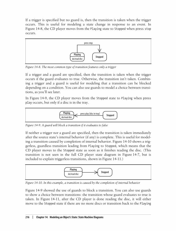
This is the Title of the Book, eMatter EditionCopyright © 2008 O’Reilly & Associates, Inc. All rights reserved.
216 | Chapter 14: Modeling an Object’s State: State Machine Diagrams
If a trigger is specified but no guard is, then the transition is taken when the triggeroccurs. This is useful for modeling a state change in response to an event. InFigure 14-8, the CD player moves from the Playing state to Stopped when press stopoccurs.
If a trigger and a guard are specified, then the transition is taken when the triggeroccurs if the guard evaluates to true. Otherwise, the transition isn’t taken. Combin-ing a trigger and a guard is useful for modeling that a transition can be blockeddepending on a condition. You can also use guards to model a choice between transi-tions, as you’ll see later.
In Figure 14-9, the CD player moves from the Stopped state to Playing when pressplay occurs, but only if a disc is in the tray.
If neither a trigger nor a guard are specified, then the transition is taken immediatelyafter the source state’s internal behavior (if any) is complete. This is useful for model-ing a transition caused by completion of internal behavior. Figure 14-10 shows a trig-gerless, guardless transition leading from Playing to Stopped, which means that theCD player moves to the Stopped state as soon as it finishes reading the disc. (Thistransition is not seen in the full CD player state diagram in Figure 14-7, but isincluded to explain triggerless transitions, shown in Figure 14-11.)
Figure 14-9 showed the use of guards to block a transition. You can also use guardsto show a choice between transitions: the transition whose guard evaluates to true istaken. In Figure 14-11, after the CD player is done reading the disc, it will eithermove to the Stopped state if there are no more discs or transition back to the Playing
Figure 14-8. The most common type of transition features only a trigger
Figure 14-9. A guard will block a transition if it evaluates to false
Figure 14-10. In this example, a transition is caused by the completion of internal behavior
Stopped
press stop
do/read disc
Playing
Stoppedpress play [disc in tray]
do/read disc
Playing
PlayingStopped
do/read disc

This is the Title of the Book, eMatter EditionCopyright © 2008 O’Reilly & Associates, Inc. All rights reserved.
States in Software | 217
state if there are more discs. Notice that if there are more discs, the transitionincludes transition behavior—changing the disc.
As a presentation option for choices, you can use a choice pseudostate, discussedlater in “Advanced Pseudostates.”
States in SoftwareIf you’re a software developer, you’re probably wondering when you’ll ever need tomodel the operation of a CD player or coffeemaker. In software, state diagramsmodel an object’s life cycle, or the states it goes through during its lifespan.Figure 14-12 shows the life cycle of an AccountApplication object as it passes frompending to approved or rejected and then to finalizing.
State diagrams are useful for modeling an object that behaves differently dependingon its state. Considering an AccountApplication object, calling the complete( )method when the object is in the pending state wouldn’t make sense if the finalizingstate performs wrap-up behavior, such as creating the blog account if approved—itwould first have to know whether the application was approved. State diagrams arean effective way to make this information explicit.
If an object has a simple life cycle, then it’s not worth modeling its life cycle with astate diagram. For example, a ContactInformation object that stores an Author’s con-tact information and doesn’t change states other than being created and destroyedprobably doesn’t warrant a state diagram.
Figure 14-11. Using guards to model a choice between paths
Figure 14-12. The life cycle of an AccountApplication object
PlayingStopped
do/read disc
[no more discs]
[another disc]/change disc
pending
approved
rejected
finalizing
approved()
reject()
complete()
complete()

This is the Title of the Book, eMatter EditionCopyright © 2008 O’Reilly & Associates, Inc. All rights reserved.
218 | Chapter 14: Modeling an Object’s State: State Machine Diagrams
If you’re wondering what an object’s states would look like in code—the AccountApplication class could have a status attribute and thestates shown in Figure 14-12 could be possible values of status. Tran-sitions occur when methods on the AccountApplication object areinvoked. See Chapter 4 for a review of how an object’s state is cap-tured in its attributes.
State diagram are also heavily used in certain software niches, such as first-personshooter (FPS) games. In FPS games, state machines are used to model game charac-ter states. For example, a game character, such as a troll, could have the statesNeutral, Attack, Panic, and Die, as shown in Figure 14-13. When the troll is in theAttack state, he is performing behavior, such as unsheathing his sword or charginghis opponent (that’s you). Triggers causing a state change include seeing an oppo-nent or receiving a blow from the opponent.
Advanced State BehaviorYou’ve seen the most common ways to model states. This section shows how tomodel additional details of a state, including entry behavior, exit behavior, and reac-tions to events while in a state.
Figure 14-14 shows the detailed notation for a state: a large rounded rectangle withseparate compartments for internal behavior and internal transitions.
Internal BehaviorInternal behavior is any behavior that happens while the object is in a state. You’vealready seen do behavior, which is behavior that is ongoing while the state is active.Internal behavior is a more general concept that also includes entry and exit behavior.
Figure 14-13. State diagram modeling a troll in a FPS game; the troll’s behavior is determined byhis state
Neutral Attack
DiePanic
see opponent [defeatable]
lost opponent
receive blow [health = 0]/pray
lost opponent receive blow [health = 0]/praysee opponent [undefeatable]

This is the Title of the Book, eMatter EditionCopyright © 2008 O’Reilly & Associates, Inc. All rights reserved.
Advanced State Behavior | 219
Internal behavior is written as label / behavior. The label indicates when the behav-ior executes—in other words, events or circumstances causing the behavior. Thereare three special labels: entry, exit, and do.
Entry behavior happens as soon as the state becomes active and is written as entry/behavior. Exit behavior happens immediately before the state becomes inactive andis written as exit/behavior.
In Figure 14-15, unsheath sword is entry behavior and sheath sword is exit behavior.Unlike do behavior, entry and exit behaviors can’t be interrupted.
Internal TransitionsAn internal transition is a transition that causes a reaction within a state, but doesn’tcause the object to change states. An internal transition is different from a self transi-tion (see Figure 14-11) because self transitions cause entry and exit behavior to occurwhereas internal transitions don’t.
Internal transitions are written as trigger [guard] / behavior, and they are listedinside a state. In Figure 14-16, the Attack has an internal transition: when an oppo-nent swings his weapon and is less than three feet away, the troll dodges.
Figure 14-14. Internal behavior and transitions of the Attack state
Figure 14-15. The middle compartment shows internal behavior
Figure 14-16. The bottom compartment shows internal transitions
Attack
entry/unshealth sworddo/chargeexit/sheath sword
enemy swings [distance<3 ft] / dodge
Internal behavior
Internal transitions
Attack
entry/unshealth sworddo/chargeexit/sheath sword
enemy swings [distance<3 ft] / dodge
Internal behavior
Attack
entry/unshealth sworddo/chargeexit/sheath sword
enemy swings [distance<3 ft] / dodge
Internal transitions
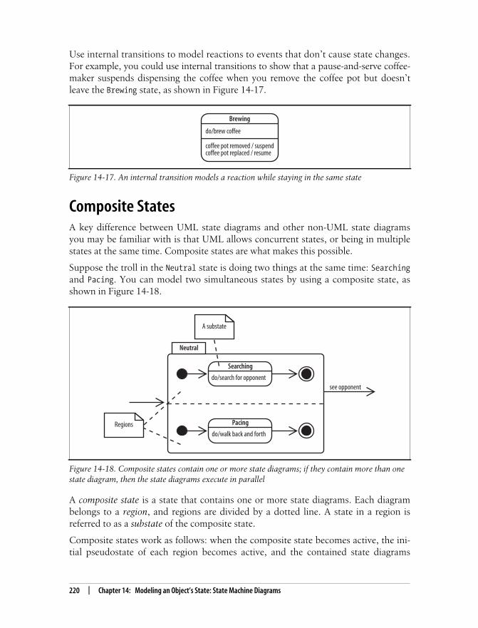
This is the Title of the Book, eMatter EditionCopyright © 2008 O’Reilly & Associates, Inc. All rights reserved.
220 | Chapter 14: Modeling an Object’s State: State Machine Diagrams
Use internal transitions to model reactions to events that don’t cause state changes.For example, you could use internal transitions to show that a pause-and-serve coffee-maker suspends dispensing the coffee when you remove the coffee pot but doesn’tleave the Brewing state, as shown in Figure 14-17.
Composite StatesA key difference between UML state diagrams and other non-UML state diagramsyou may be familiar with is that UML allows concurrent states, or being in multiplestates at the same time. Composite states are what makes this possible.
Suppose the troll in the Neutral state is doing two things at the same time: Searchingand Pacing. You can model two simultaneous states by using a composite state, asshown in Figure 14-18.
A composite state is a state that contains one or more state diagrams. Each diagrambelongs to a region, and regions are divided by a dotted line. A state in a region isreferred to as a substate of the composite state.
Composite states work as follows: when the composite state becomes active, the ini-tial pseudostate of each region becomes active, and the contained state diagrams
Figure 14-17. An internal transition models a reaction while staying in the same state
Figure 14-18. Composite states contain one or more state diagrams; if they contain more than onestate diagram, then the state diagrams execute in parallel
Brewing
do/brew coffee
coffee pot removed / suspendcoffee pot replaced / resume
Regions
Searching
do/search for opponent
Pacing
do/walk back and forth
see opponent
A substate
Neutral

This is the Title of the Book, eMatter EditionCopyright © 2008 O’Reilly & Associates, Inc. All rights reserved.
Advanced Pseudostates | 221
begin executing. The contained state diagrams are interrupted if a trigger on thecomposite state occurs. In Figure 14-18, the substates will be halted when a triggeron the composite state—see opponent—occurs.
If substates have behavior that can run to completion, then the composite state iscomplete when every region’s state diagram is complete.
Advanced PseudostatesYou’ve already seen initial pseudostates, which mark the start of a state diagram.There are additional pseudostates that are useful for directing the flow of trafficbetween states.
A choice pseudostate is used to emphasize that a Boolean condition determineswhich transition is followed. A choice has guards on each of its outgoing transitions,and the transition that is followed depends on the guard. In Figure 14-19, the CDplayer will go back to the Playing state if another disc is available or will go to theStopped state if there are no more discs. Notice that this is an alternate, and cleaner,way to model the transition choice in Figure 14-11.
At least one of the guards following a choice must evaluate to true foryour model to be well-formed. If more than one guard following achoice evaluates to true, then one of them is selected arbitrarily. If thissituation doesn’t make sense for your model, then it’s a sign that youneed to redefine your guards so that exactly one guard at a time evalu-ates to true.
Fork and join pseudostates show branching into concurrent states and then rejoin-ing. For example, in Figure 14-20, the fork breaks the incoming transition into twotransitions, allowing Searching and Pacing to happen simultaneously. The join thenmerges its two incoming transitions into one outgoing transition.
Figure 14-20 is an alternate way to model Figure 14-18. In Figure 14-18, forking andjoining are implied by showing the initial pseudostates and final states.
Figure 14-19. The path followed after a choice depends on the guard
PlayingStopped
do/read disc[no more discs]
[another disc]/change disc
A choicepseudostate

This is the Title of the Book, eMatter EditionCopyright © 2008 O’Reilly & Associates, Inc. All rights reserved.
222 | Chapter 14: Modeling an Object’s State: State Machine Diagrams
SignalsYou can use special icons for transitions to draw attention to transitions and transi-tion behavior. This is called a transition-oriented view.
In this view, a trigger is represented with a receive signal icon and transition behav-ior is represented with a send signal icon. Figure 14-21 shows how Figure 14-6 canbe drawn in this alternate notation. It additionally uses the choice pseudostate intro-duced previously in “Advanced Pseudostates.”
Figure 14-20. Forks and joins show concurrent states
Figure 14-21. The bottom diagram draws transitions and transition behavior as receive and sendsignals
Pacing
A forkpseudostate
Searching
A joinpseudostate
Neutral
Gatheringinput
Submitinputkeystroke Processing
input
Areceive signal
Gatheringinput
Processinginput
keystroke [input = required_length]/ submit input
Asend signal
[input < required_length]
[input =required_length]
keystroke [input < required_length]

This is the Title of the Book, eMatter EditionCopyright © 2008 O’Reilly & Associates, Inc. All rights reserved.
What’s Next? | 223
The main purpose of this notation is to visually emphasize sending and receiving sig-nals. Although both diagrams say the same thing, the version with the signal iconsfocuses on the transitions and, in this case, makes the diagram more readable.
Protocol State MachinesProtocol state machines are a special kind of state machine focusing on how a proto-col, such as a communication protocol (e.g., TCP), works. The main differencebetween protocol state machines and behavioral state machines, which we’vefocused on previously, is that protocol state machines don’t show behavior alongtransitions or inside states. Instead, they focus on showing a legal sequence of eventsand resulting states. Protocol state machines are drawn in a tabbed rectangle with thename of the state machine in the tab followed by {protocol}, as shown inFigure 14-22.
Because protocol state machines don’t show behavior, you can’t model what the sys-tem is doing in response—for example, if it’s sending acknowledgements back. But itcan be useful for showing how to work with an object or system, such as specifying acommunication protocol or an expected call sequence for an object’s operations.
What’s Next?State diagrams show the states of an object and triggers causing a change of state. Ifyou’re interested in modeling object state changes in the context of a workflow, seeactivity diagrams, covered in Chapter 3.
If you want to show timing associated with state changes, then it’s also worth check-ing out timing diagrams, covered in Chapter 9.
Figure 14-22. Protocol state machine modeling the receiver side of a simplified communicationprotocol called My Communication Protocol (MCP)
Closed Listen EstablishedSynReceived
MCP {protocol}
open SYN ACK
timeout
FIN

This is the Title of the Book, eMatter EditionCopyright © 2008 O’Reilly & Associates, Inc. All rights reserved.
224
Chapter 15CHAPTER 15
Modeling Your Deployed System:Deployment Diagrams 15
If you’ve been applying the UML techniques shown in earlier chapters of this book,then you’ve seen all but one view of your system. That missing piece is the physicalview. The physical view is concerned with the physical elements of your system, suchas executable software files and the hardware they run on.
UML deployment diagrams show the physical view of your system, bringing yoursoftware into the real world by showing how software gets assigned to hardware andhow the pieces communicate (see Figure 15-1).
The word system can mean different things to different people; in thecontext of deployment diagrams, it means the software you create andthe hardware and software that allow your software to run.
Deploying a Simple SystemLet’s start by showing a deployment diagram of a very simple system. In this sim-plest of cases, your software will be delivered as a single executable file that willreside on one computer.
To show computer hardware, you use a node, as shown in Figure 15-2.
Figure 15-1. Deployment diagrams focus on the Physical View of your system
Logical View Process View
Physical View Development View
Use Case View
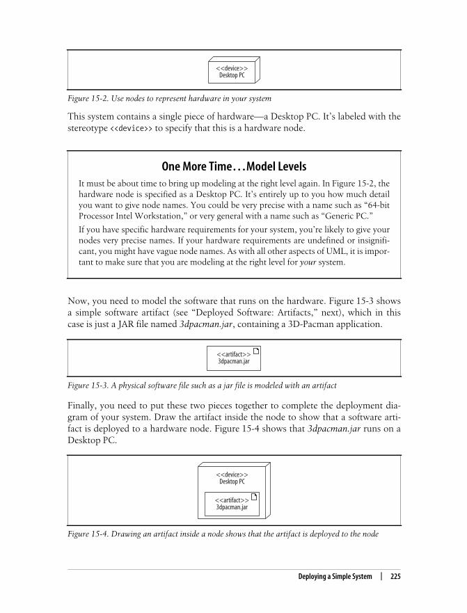
This is the Title of the Book, eMatter EditionCopyright © 2008 O’Reilly & Associates, Inc. All rights reserved.
Deploying a Simple System | 225
This system contains a single piece of hardware—a Desktop PC. It’s labeled with thestereotype <<device>> to specify that this is a hardware node.
Now, you need to model the software that runs on the hardware. Figure 15-3 showsa simple software artifact (see “Deployed Software: Artifacts,” next), which in thiscase is just a JAR file named 3dpacman.jar, containing a 3D-Pacman application.
Finally, you need to put these two pieces together to complete the deployment dia-gram of your system. Draw the artifact inside the node to show that a software arti-fact is deployed to a hardware node. Figure 15-4 shows that 3dpacman.jar runs on aDesktop PC.
Figure 15-2. Use nodes to represent hardware in your system
One More Time…Model LevelsIt must be about time to bring up modeling at the right level again. In Figure 15-2, thehardware node is specified as a Desktop PC. It’s entirely up to you how much detailyou want to give node names. You could be very precise with a name such as “64-bitProcessor Intel Workstation,” or very general with a name such as “Generic PC.”
If you have specific hardware requirements for your system, you’re likely to give yournodes very precise names. If your hardware requirements are undefined or insignifi-cant, you might have vague node names. As with all other aspects of UML, it is impor-tant to make sure that you are modeling at the right level for your system.
Figure 15-3. A physical software file such as a jar file is modeled with an artifact
Figure 15-4. Drawing an artifact inside a node shows that the artifact is deployed to the node
<<device>>Desktop PC
<<artifact>>3dpacman.jar
<<device>>Desktop PC
<<artifact>>3dpacman.jar

This is the Title of the Book, eMatter EditionCopyright © 2008 O’Reilly & Associates, Inc. All rights reserved.
226 | Chapter 15: Modeling Your Deployed System: Deployment Diagrams
But is it really complete? Don’t you need to model the Java Virtual Machine (JVM)because without it, your code wouldn’t execute? What about the operating system;isn’t that important? The answer, unfortunately, is possibly.
Your deployment diagrams should contain details about your system that are impor-tant to your audience. If it is important to show the hardware, firmware, operatingsystem, runtime environments, or even device drivers of your system, then youshould include these in your deployment diagram. As the rest of this chapter willshow, deployment diagram notation can be used to model all of these types ofthings. If there’s a feature of your system that’s not important, then it’s not worthadding it to your diagram since it could easily clutter up or distract from those fea-tures of your design that are important.
Deployed Software: ArtifactsThe previous section showed a sneak preview of some of the notation that can beused to show the software and hardware in a deployed system. The 3dpacman.jarsoftware was deployed to a single hardware node. In UML, that JAR file is called anartifact.
Artifacts are physical files that execute or are used by your software. Common arti-facts you’ll encounter include:
• Executable files, such as .exe or .jar files
• Library files, such as .dlls (or support .jar files)
• Source files, such as .java or .cpp files
• Configuration files that are used by your software at runtime, commonly in for-mats such as .xml, .properties, or .txt
An artifact is shown as a rectangle with the stereotype <<artifact>>, or the docu-ment icon in the upper right hand corner, or both, as shown in Figure 15-5. For therest of the book, an artifact will be shown with both the stereotype <<artifact>> andthe document icon.
Deploying an Artifact to a NodeAn artifact is deployed to a node, which means that the artifact resides on (or isinstalled on) the node. Figure 15-6 shows the 3dpacman.jar artifact from the previousexample deployed to a Desktop PC hardware node by drawing the artifact symbolinside the node.
Figure 15-5. Equivalent representations of a 3dpacman.jar artifact
<<artifact>>3dpacman.jar 3dpacman.jar <<artifact>>
3dpacman.jar

This is the Title of the Book, eMatter EditionCopyright © 2008 O’Reilly & Associates, Inc. All rights reserved.
Deployed Software: Artifacts | 227
You can model that an artifact is deployed to a node in two other ways. You can alsodraw a dependency arrow from the artifact to the target node with the stereotype<<deploy>>, as shown in Figure 15-7.
When you’re pressed for space, you might want to represent the deployment by sim-ply listing the artifact’s name inside the target node, as shown in Figure 15-8.
All of these methods show the same deployment relationship, so here are someguidelines for picking a notation.
Listing the artifacts (without the artifact symbol) can really save space if you have alot of artifacts, as in Figure 15-9. Imagine how big the diagram would get if you drewthe artifact symbol for each artifact.
But be careful; by listing your artifacts, you cannot show dependencies between arti-facts. If you want to show that an artifact uses another artifact, you have to draw theartifact symbols and a dependency arrow connecting the artifacts, as shown inFigure 15-10.
Tying Software to ArtifactsWhen designing software, you break it up into cohesive groups of functionality,such as components or packages, which eventually get compiled into one or morefiles—or artifacts. In UML-speak, if an artifact is the physical actualization of a
Figure 15-6. The 3dpacman.jar artifact deployed to a Desktop PC node
Figure 15-7. An alternate way to model the relationship deployment
Figure 15-8. A compact way to show deployment is to write the name of the artifact inside the node
<<device>>Desktop PC
<<artifact>>3dpacman.jar
<<device>>Desktop PC<<artifact>>
3dpacman.jar<<deploy>>
<<device>>Desktop PC
3dpacman.jar

This is the Title of the Book, eMatter EditionCopyright © 2008 O’Reilly & Associates, Inc. All rights reserved.
228 | Chapter 15: Modeling Your Deployed System: Deployment Diagrams
component, then the artifact manifests that component. An artifact can manifest notjust components but any packageable element, such as packages and classes.
The manifest relationship is shown with a dependency arrow from the artifact to thecomponent with the stereotype <<manifest>>, as shown in Figure 15-11.
Since artifacts can then be assigned to nodes, the manifest relationship provides themissing link in modeling how your software components are mapped to hardware.However, linking a component to an artifact to a node can result in a cluttered dia-gram, so it’s common to show the manifest relationships separate from the deploy-ment relationships, even if they’re on the same deployment diagram.
You can also show the manifest relationship in component diagramsby listing the artifacts manifesting a component within the compo-nent symbol, as discussed in Chapter 12.
Figure 15-9. Listing artifact names inside a node saves a lot of space compared to drawing anartifact symbol for each artifact
Figure 15-10. A deployment notation that uses artifact symbols (instead of listing artifact names)allows you to show artifact dependencies
Figure 15-11. The artifact mycomponent.jar manifests the component MyComponent
<<device>>Server
activation.jaraxis.jarcommons-discovery.jarcommons-logging.jarjaxrpc.jarsaaj.jarlog4j.jarwsdl4j.jarmail.jarxml-apis.jarxerceslmpl.jar
<<device>>Server
<<artifact>>myapplication.jar
<<artifact>>log4j.jar
<<artifact>>mycomponent.jar
<<component>>MyComponent
<<manifest>>

This is the Title of the Book, eMatter EditionCopyright © 2008 O’Reilly & Associates, Inc. All rights reserved.
Hardware and Execution Environment Nodes | 229
If you’re familiar with earlier versions of UML, you may be tempted to model a com-ponent running on hardware by drawing the component symbol inside the node. Asof UML 2.0, artifacts have nudged components toward a more conceptual interpreta-tion, and now artifacts represent physical files.
However, many UML tools aren’t fully up to date with the UML 2.0 standard, soyour tool may still use the earlier notation.
What Is a Node?You’ve already seen that you can use nodes to show hardware in your deploymentdiagram, but nodes don’t have to be hardware. Certain types of software—softwarethat provides an environment within which other software components can be exe-cuted—are nodes as well.
A node is a hardware or software resource that can host software or related files. Youcan think of a software node as an application context; generally not part of the soft-ware you developed, but a third-party environment that provides services to yoursoftware.
The following items are reasonably common examples of hardware nodes:
• Server
• Desktop PC
• Disk drives
The following items are examples of execution environment nodes:
• Operating system
• J2EE container
• Web server
• Application server
Software items such as library files, property files, and executable filesthat cannot host software are not nodes—they are artifacts (see“Deployed Software: Artifacts,” earlier in the chapter).
Hardware and Execution Environment NodesA node is drawn as a cube with its type written inside, as shown in Figure 15-12. Thestereotype <<device>> emphasizes that it’s a hardware node.
Figure 15-13 shows an Application Server node. Those familiar with enterprise soft-ware development will recognize this as a type of execution environment since it’s asoftware environment that provides services to your application. The stereotype<<executionEnvironment>> emphasizes that this node is an execution environment.

This is the Title of the Book, eMatter EditionCopyright © 2008 O’Reilly & Associates, Inc. All rights reserved.
230 | Chapter 15: Modeling Your Deployed System: Deployment Diagrams
Execution environments do not exist on their own—they run on hardware. Forexample, an operating system needs computer hardware to run on. You show that anexecution environment resides on a particular device by placing the nodes inside oneanother, nesting them as shown in Figure 15-14.
It’s not strictly necessary in UML 2.0 to distinguish device nodes from execution envi-ronment nodes, but it’s a good habit to get into because it can clarify your model.
Want more variety? If you’re using a profile (discussed inAppendix B), you can apply node stereotypes that are more relevant toyour domain, such as <<J2EE Container>>. These new node types canbe specified in your profile as a special kind of execution environment.
Showing Node InstancesThere are times when your diagram includes two nodes of the same type, but youwant to draw attention to the fact that they are actually different instances. You canshow an instance of a node by using the name : type notation as shown inFigure 15-15.
Figure 15-12. A Sun Blade Server hardware node marked with the stereotype <<device>>
Figure 15-13. An Application Server node marked with the stereotype <<executionEnvironment>>
Figure 15-14. An Application Server node is shown nested in a Sun Server node, meaning that theApplication Server runs on Sun Server hardware.
Figure 15-15. Showing the name and type of a node; an instance of a Sun Blade Server named svr1
<<device>>Sun Blade Server
<<executionEnvironment>>Application Server
<<executionEnvironment>>Application Server
<<device>>Sun Server
<<device>>svr1 : Sun Blade Server

This is the Title of the Book, eMatter EditionCopyright © 2008 O’Reilly & Associates, Inc. All rights reserved.
Communication Between Nodes | 231
Figure 15-16 shows how two nodes of the same type can be modeled. The nodes inthis example, svr1 and svr2, are assigned different types of traffic from a load bal-ancer (a common situation in enterprise systems).
Communication Between NodesTo get its job done, a node may need to communicate with other nodes. For exam-ple, a client application running on a desktop PC may retrieve data from a serverusing TCP/IP.
Communication paths are used to show that nodes communicate with each other atruntime. A communication path is drawn as a solid line connecting two nodes. Thetype of communication is shown by adding a stereotype to the path. Figure 15-17shows two nodes—a desktop PC and a server—that communicate using TCP/IP.
You can also show communication paths between execution environment nodes. Forexample, you could model a web server communicating with an EJB containerthrough RMI, as shown in Figure 15-18. This is more precise than showing an RMIcommunication path at the device node level because the execution environmentnodes “speak” RMI. However, some modelers draw the communication paths at theoutermost node level because it can make the diagram less cluttered.
Assigning a stereotype to a communication path can sometimes be tricky. RMI is lay-ered using a TCP/IP transport layer. So, should you assign an <<RMI>> or a <<TCP/IP>>stereotype? As a rule of thumb, your communication stereotype should be as high-level as possible because it communicates more about your system. In this case,<<RMI>> is the right choice; it is higher level, and it tells the reader that you’re using
Figure 15-16. One node gets read traffic and the other gets write traffic
Figure 15-17. A Desktop PC and Server communicate via TCP/IP
<<device>>svr1 : Sun Blade Server
<<device>>svr2 : Sun Blade Server
: LoadBalancerwrite trafficread traffic
<<device>>Desktop PC
<<device>>Server
<<TCP/IP>>

This is the Title of the Book, eMatter EditionCopyright © 2008 O’Reilly & Associates, Inc. All rights reserved.
232 | Chapter 15: Modeling Your Deployed System: Deployment Diagrams
a Java implementation. However, as with all UML modeling, you should tailor thediagram to your audience.
Communication paths show that the nodes are capable of communi-cating with each other and are not intended to show individual mes-sages, such as messages in a sequence diagram.
As of UML 2.0, stereotypes are supposed to be specified in a profile, so in theory,you should use only the stereotypes that your profile provides. However, even ifyou’re not using a profile, your UML tool may allow you to make up any stereotype.Since stereotypes are a good way to show the types of communication in a system,feel free to make your own if necessary and if your tool allows. But if you do, try tokeep them consistent. For example, don’t create two stereotypes <<RMI>> and<<Remote Method Invocation>>, which are the same type of communication.
Deployment SpecificationsInstalling software is rarely as easy as dropping a file on a machine; often you have tospecify configuration parameters before your software can execute. A deploymentspecification is a special artifact specifying how another artifact is deployed to anode. It provides information that allows another artifact to run successfully in itsenvironment.
Deployment specifications are drawn as a rectangle with the stereotype <<deploymentspec>>. There are two ways to tie a deployment specification to the deployment itdescribes:
• Draw a dependency arrow from the deployment specification to the artifact,nesting both of these in the target node.
• Attach the deployment specification to the deployment arrow, as shown inFigure 15-19.
The deploy.wsdd file, shown in Figure 15-19, is the standard deployment descriptorfile that specifies how a web service is deployed to the Axis web service engine. Thisfile states which class executes the web service and which methods on the class canbe called. You can list these properties in the deployment specification using the name
Figure 15-18. You can also show communication paths between execution environment nodes
<<executionEnvironment>>Web Server
<<device>>Server
<<executionEnvironment>>EJB Container
<<device>>Server
<<RMI>>

This is the Title of the Book, eMatter EditionCopyright © 2008 O’Reilly & Associates, Inc. All rights reserved.
Deployment Specifications | 233
: type notation. Figure 15-20 shows the deploy.wsdd deployment specification withthe properties className and allowedMethods.
The symbol on the right shows an instance of a deployment specification populatedwith values. Use this notation if you want to show the actual property values insteadof just the types.
This chapter has only briefly mentioned instances of elements indeployment diagrams, but you can model instances of nodes, arti-facts, and deployment specifications. In deployment diagrams, manymodelers don’t bother to specify that an element is an instance if theintent is clear. However, if you want to specify property values of adeployment specification (as on the right side of Figure 15-20), thenthis is a rare situation where a UML tool may force you to use theinstance notation.
Currently, many UML tools don’t support the deployment specifica-tion symbol. If yours is one of them, you can attach a note containingsimilar information.
You don’t need to list every property in a deployment specification—only propertiesyou consider important to the deployment. For example, deploy.wsdd may containother properties such as allowed roles, but if you’re not using that property or it’sinsignificant (i.e., it’s the same for all your web services), then leave it out.
Figure 15-19. Equivalent ways of tying a deployment specification to the deployment it describes
Figure 15-20. Showing the properties of a deployment specification: the notation on the right showsan instance populated with values
<<executionEnvironment>>Axis
<<deployment spec>>deploy.wsdd
<<artifact>>inventoryService.jar
<<executionEnvironment>>Axis
<<artifact>>inventoryService.jar
<<deployment spec>>deploy.wsdd
<<deploy>>
<<deployment spec>>deploy.wsdd
className : StringallowedMethods : String[]
<<deployment spec>>deploy.wsdd
className : inventory.InventoryServiceallowedMethods : *

This is the Title of the Book, eMatter EditionCopyright © 2008 O’Reilly & Associates, Inc. All rights reserved.
234 | Chapter 15: Modeling Your Deployed System: Deployment Diagrams
When to Use a Deployment DiagramDeployment diagrams are useful at all stages of the design process. When you begindesigning a system, you probably know only basic information about the physicallayout. For example, if you’re building a web application, you may not have decidedwhich hardware to use and probably don’t know what your software artifacts arecalled. But you want to communicate important characteristics of your system, suchas the following:
• Your architecture includes a web server, application server, and database.
• Clients can access your application through a browser or through a richer GUIinterface.
• The web server is protected with a firewall.
Even at this early stage you can use deployment diagrams to model these characteris-tics. Figure 15-21 shows a rough sketch of your system. The node names don’t haveto be precise, and you don’t have to specify the communication protocols.
Deployment diagrams are also useful in later stages of software development.Figure 15-22 shows a detailed deployment diagram specifying a J2EE implementationof the system.
Figure 15-22 is more specific about the hardware types, the communication proto-cols, and the allocation of software artifacts to nodes. A detailed deployment dia-gram, such as Figure 15-22, could be used be used as a blueprint for how to installyour system.
You can revisit your deployment diagrams throughout the design of your system torefine the rough initial sketches, adding detail as you decide which technologies,communication protocols, and software artifacts will be used. These refined deploy-ment diagrams allow you to express the current view of the physical system layoutwith the system’s stakeholders.
Figure 15-21. A rough sketch of your web application
Web Server
Firewall
Thin Client
Application Server
Rich Client
Database

This is the Title of the Book, eMatter EditionCopyright © 2008 O’Reilly & Associates, Inc. All rights reserved.
What’s Next? | 235
What’s Next?You’ve finished learning the fundamental UML concepts, but read on to the appen-dixes for an overview of some advanced modeling techniques. The appendices intro-duce you to the Object Constraint Language (OCL), which is a rigorous way to showconstraints in your diagrams, and Profiles, which allow you to define and use a cus-tom UML vocabulary. It’s helpful to review these appendices to get a feel for extraprecision you can add to your model and extra capabilities that result from that pre-cision. The Object Constraint Language is covered in Appendix A; UML profiles aredescribed in Appendix B.
Figure 15-22. You can provide any amount of detail about the physical design of your system
<<executionEnvironment>>Web Server
<<device>>Sun Server
<<executionEnvironment>>EJB Container
<<device>>Sun Server
<<RMI>>
PetAdoptionStore.war PetAdoptionStore.war
Database
Rich Client
<<JDBC>>
Thin Client
Firewall


This is the Title of the Book, eMatter EditionCopyright © 2008 O’Reilly & Associates, Inc. All rights reserved.
237
Appendix A APPENDIX A
Object Constraint Language1
Chapter 5 introduced writing constraints in your class diagrams using OCL. Youdon’t have to use OCL to express constraints—you can use your favorite program-ming language syntax or even natural language. This appendix discusses the advan-tages of OCL and provides more details about how to more use OCL.
Recall from Chapter 5 that a constraint is written in curly braces after the element itconstrains or displayed in an attached note. Figure A-1 shows different ways of speci-fying that the attribute rating has to be non-negative.
Figure A-1 shows that the words expressing a constraint can vary. Constraints can bewritten in natural language, such as:
rating is greater than or equal to zero
Constraints can also look like a programming language expression, such as:
rating >= 0
Because natural language can be ambiguous (and long-winded!), many modelers usesyntax similar to their preferred programming language: notice that rating >= 0 lookslike a Java or C expression.
Constraints can get more complicated; for example, they can specify that a valueisn’t null. This means you have a lot of options for expressing constraints, so how doyou decide which notion to use? Such an expression may look different in differentprogramming languages. If constraints are expressed in a standard and predictableway, not only can you easily understand the constraint, but also automated tools can
Figure A-1. Different ways of attaching and expressing a constraint
BlogEntry
- url : URL- rating : int+ updateRating(newRating : int) : void
{rating is greaterthan or equal to 0}
BlogEntry
- url : URL- rating : int { rating >= 0 }+ updateRating(newRating : int) : void

This is the Title of the Book, eMatter EditionCopyright © 2008 O’Reilly & Associates, Inc. All rights reserved.
238 | Appendix A: Object Constraint Language
understand the constraint. This allows automatic checking of constraints in your dia-grams and in the code generated from the diagrams.
Because of this, the Object Management Group (OMG, the group behind UML) wasconvinced that a single formal constraint language was needed, but the language hadspecific requirements. The language had to allow values to be checked but notchanged—in other words, it had to be an expression language. The language had tobe general enough that you could use it to express constraints in your UML dia-grams regardless of your target implementation language. And finally, the languagehad to be simple enough that people would actually use it, which is not true of manyformal languages.
OCL, developed at IBM for business modeling, had all of these features, and so itwas a perfect match. So, OCL was chosen to work alongside UML to provide a for-mal yet easy-to-understand language for specifying constraints.
You don’t have to use OCL. In general, modelers decide to use OCL depending on acombination of factors, including how extensively they model and how importantthey consider design by contract (discussed later). If these factors apply to you, OCLis worth considering because automated constraint checking allows greater integrityof your model.
In UML diagrams, OCL is primarily used to write constraints in class diagrams andguard conditions in state and activity diagrams.
Building OCL ExpressionsFigure A-2 shows a class diagram with a few OCL expressions, including:
Simple number comparisonbaseCost >= 0.0
More complicated number comparisontotalCost = baseCost * (1+getTaxRate( ))
String comparisonstatus <> 'Unpaid'
Figure A-2. Example OCL constraints of varying complexity
1- fee
Author
1- name : String- status : String {status <> 'Unpaid'}
+ getFee() : double+ getName() : String+ getStatus() : String
AccountFee
- baseCost : double {baseCost>=0.0}- taxRate : double- totalCost : double {totalCost = baseCost * (1+getTaxRate())}
+ setBaseCost(double baseCost) : void+ getTaxRate() : double+ getTotalCost() : double

This is the Title of the Book, eMatter EditionCopyright © 2008 O’Reilly & Associates, Inc. All rights reserved.
Operators | 239
Unlike many languages, such as Java, in OCL the = operator is used tocheck whether two items are equal, not to assign a value.
OCL expressions consist of model elements, constants, and operators. Model ele-ments include class attributes, operations, and members though association. TheOCL expressions in Figure A-2 use the model elements baseCost, totalCost, andgetTaxRate( ). (Later sections contain OCL expressions with members throughassociation.)
Constants are unchanging values of one of the predefined OCL types. In Figure A-2,constants include 0.0 of type Real and 'Unpaid' of type String. Operators combinemodel elements and constants to form an expression. In Figure A-2, operatorsinclude <>, +, and =.
The following sections discuss the basics of OCL types and operators and then showhow to combine these into expressions you can use in your UML models.
TypesOCL has four built-in types: Boolean, Integer, Real, and String. Table A-1 showsexamples of these four types. These examples are typical constants you couldencounter in OCL expressions.
OperatorsOCL has the basic arithmetic, logic, and comparison operators. OCL also has moreadvanced functions such as returning the maximum of two values and concatenat-ing Strings. OCL is a typed language, so the operator has to make sense for its val-ues. For example, you can’t take the sum of an Integer and a Boolean. Table A-2shows commonly used operators in OCL expressions.
Table A-1. Built-in OCL types
Type Examples
Boolean true; false
Integer 1; 6,664; -200
Real 2.7181828; 10.5
String “Hello, World.”

This is the Title of the Book, eMatter EditionCopyright © 2008 O’Reilly & Associates, Inc. All rights reserved.
240 | Appendix A: Object Constraint Language
Operators in the groups Comparison, Equality, and Boolean all return results of typeBoolean. For example, age = 65 evaluates to true or false. The other operators inTable A-2 return the same type with which they’re used. For example, if baseCostand tax are Real, then baseCost + tax will also be Real.
Figure A-2 shows that getTaxRate( ) returns a double (this model was written withJava types), but the table in Table A-2 mentions that the operator + is defined onReals and Integers. That’s perfectly fine; when building an OCL expression, you canmatch your types to the closest OCL type.
OCL can also express operations on collections, such as unions ofsets. For a more complete list of OCL expressions, see UML 2.0 in aNutshell (O’Reilly).
Pulling It TogetherSo far you’ve seen the building blocks of OCL expressions. Now let’s combine themto build a sample OCL expression.
totalCost = baseCost * (1+getTaxRate( ))
This OCL expression is taken from Figure A-2. It contains the following buildingblocks of an OCL expression:
Model elementstotalCost, baseCost, and getTaxRate( )
Constant1
Operators=, *, and +
Table A-2. Commonly used operators in OCL expressions
Group Operators Used with types Example OCL expression
Arithmetic +, -, *, / Integer, Real baseCost + tax
Additional Arithmetic abs(), max(), min( ) Integer, Real score1.max(score2)
Comparison <, <=, >, >= Integer, Real rate > .75
Equality =, <> All age = 65
title <> ‘CEO’
Boolean and, or, xor, not Boolean isMale and (age >= 65)
String concat(), size(),substring( ),toInteger(),toReal( )
String title.substring(1,3)

This is the Title of the Book, eMatter EditionCopyright © 2008 O’Reilly & Associates, Inc. All rights reserved.
Context | 241
The above expression actually consists of several OCL expressions, which are in turncombined by operators. For example, 1+getTaxRate( ) evaluates to a Real, which isthen multiplied with baseCost. That resulting value is checked for equality withtotalCost using the = operator. You can combine model elements, constants, andexpressions according to their type, but the combined expression must be type Bool-ean. This is because we’re focusing on using OCL to express constraints and guards,which must evaluate to true or false.
Another commonly used constraint is to specify that an object isn’t null. To specifythat an object isn’t null, you have to use the OCL’s notation for sets and operationson sets. Figure A-3 shows how to check that Author’s member through associationfee isn’t null using the expression:
self.fee->notEmpty( )
Notice the reference to self in the OCL expression in Figure A-3. Because it is attachedto Author, self refers to objects of type Author. The self keyword is commonly usedwhen you set a context in an OCL expression, as shown in the following section.
ContextFigure A-2 defined OCL expressions on the elements they constrain, whileFigure A-3 defined an OCL expression on the containing class. You can write anOCL expression at different areas in your diagram. How you write the OCL expres-sion depends on the context, or where you are in the diagram.
Figure A-4 shows how to check that baseCost of AccountFee is greater than or equalto 0 at different reference points in the diagram. The first diagram shows this con-straint in the context of baseCost, the second shows this constraint at AccountFee,and the third shows this constraint at Author.
Figure A-3. Constraining that a member isn’t null
1- fee
Author
1- name : String- status : String {status <> 'Unpaid'}
+ getFee() : double+ getName() : String+ getStatus() : String
AccountFee
- baseCost : double {baseCost>=0.0}- taxRate : double- totalCost : double {totalCost = baseCost * (1+getTaxRate())}
+ setBaseCost(double baseCost) : void+ getTaxRate() : double+ getTotalCost() : double
{ self.fee-> notEmpty() }
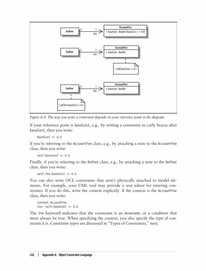
This is the Title of the Book, eMatter EditionCopyright © 2008 O’Reilly & Associates, Inc. All rights reserved.
242 | Appendix A: Object Constraint Language
If your reference point is baseCost, e.g., by writing a constraint in curly braces afterbaseCost, then you write:
baseCost >= 0.0
If you’re referring to the AccountFee class, e.g., by attaching a note to the AccountFeeclass, then you write:
self.baseCost >= 0.0
Finally, if you’re referring to the Author class, e.g., by attaching a note to the Authorclass, then you write:
self.fee.baseCost >= 0.0
You can also write OCL constraints that aren’t physically attached to model ele-ments. For example, your UML tool may provide a text editor for entering con-straints. If you do this, write the context explicitly. If the context is the AccountFeeclass, then you write:
Context AccountFeeinv: self.baseCost >= 0.0
The inv keyword indicates that the constraint is an invariant, or a condition thatmust always be true. When specifying the context, you also specify the type of con-straint it is. Constraint types are discussed in “Types of Constraints,” next.
Figure A-4. The way you write a constraint depends on your reference point in the diagram
1- fee
Author1
AccountFee
+ baseCost : double {baseCost > = 0.0}
1- fee
Author1
AccountFee
+ baseCost : double
{ self.baseCost >=0 }
1- fee
Author1
AccountFee
+ baseCost : double
{ self.fee.baseCost >=0 }

This is the Title of the Book, eMatter EditionCopyright © 2008 O’Reilly & Associates, Inc. All rights reserved.
Types of Constraints | 243
Types of ConstraintsThere are three types of constraints:
InvariantsAn invariant is a constraint that must always be true—otherwise the system is inan invalid state. Invariants are defined on class attributes. For example, inFigure A-4, the baseCost attribute of AccountFee must always be greater than orequal to zero.
PreconditionsA precondition is a constraint that is defined on a method and is checked beforethe method executes. Preconditions are frequently used to validate input param-eters to a method.
PostconditionsA postcondition is also defined on a method and is checked after the method exe-cutes. Postconditions are frequently used to describe how values were changedby a method.
Previous examples in this chapter focused on invariants, but all three constrainttypes can be expressed in your UML diagrams or related documentation. The follow-ing examples will show how to provide preconditions and postconditions for themethod incrementRating. The reference class diagram is shown in Figure A-5.
Suppose incrementRating will increment the value rating by the value amount. Wewant to first specify a precondition that amount is less than a maximum legal amount,say 100, and a postcondition ensuring that rating has been incremented by amount.To write these preconditions and postconditions, you first specify the context andthen the constraints.
context BlogEntry::incrementRating(amount: int) : voidpre: amount <= 100post: rating = rating@pre + amount
Notice the @pre directive: rating@pre is the value of rating before the method exe-cutes. You can use the @pre notation on methods too:
context BlogEntry::incrementRating(amount: int) : voidpre: amount <= 100post: getRating( ) = getRating@pre( ) + amount
Figure A-5. We’ll provide preconditions and postconditions for the incrementRating method
BlogEntry
- rating : int
+ incrementRating(amount : int) : void+ decrementRating (amount : int) : void+ getRating() : int

This is the Title of the Book, eMatter EditionCopyright © 2008 O’Reilly & Associates, Inc. All rights reserved.
244 | Appendix A: Object Constraint Language
Invariants, preconditions, and postconditions are part of an approach known as“Design by Contract,” developed by Bertrand Meyer. “Design by Contract” attemptsto make more reliable code by establishing a contract between a class and its clients.A class’s contract tells its clients that if they call its methods with valid values, thenthey will receive a valid value in response. A contract also establishes invariants on aclass, meaning that the class’s attributes will never violate certain constraints.
If you’re wondering why you haven’t encountered invariants, preconditions, andpostconditions in your code, note that support for Design by Contract differs perprogramming language. “Design by Contract” is built into the Eiffel programminglanguage, which was also developed by Bertrand Meyer. Eiffel has keywords forinvariants, preconditions, and postconditions, and an exception is thrown if any ofthese constraints are violated. With other languages, you have to either implementconstraint handing yourself or use a package such as iContract for Java. iContract isa preprocessor with doc-style tags to specify invariants, preconditions, and postcon-ditions. iContract also throws an exception if a constraint is violated.
OCL AutomationThe real power of OCL comes from tools that can use the OCL constraints fromyour UML model to perform constraint checking for you. While at the moment there iswide variation in tool maturity and level of integration, the ultimate goal is to enhanceintegration of your UML model with the runtime behavior of your system. This has thebenefit of allowing you to catch errors early and saving on debugging time.
Some UML tools focus on placing the OCL constraints from your diagrams into gen-erated code so that the constraints can be checked at runtime (although at themoment, these may only be proposed or partial implementations). Exampleapproaches include generating assert statements directly in your code to allow con-straint checking, or embellishing your code with Java annotations or doc-style tagscontaining OCL constraints, which can then be used by standard OCL tools that cancheck constraints at runtime. For example, the open source UML tool ArgoUMLinserts OCL constraints into generated Java code as doc-style tags. With doc orannotations in your code, you can take advantage of OCL tools (such as ocl4java orthe Dresden OCL Toolkit) that perform code enhancement to provide you runtimefeedback about constraint violations in your executed code.
Stay on the lookout for developments in this area; as MDA and Executable UML(introduced in Chapter 1) become increasingly central to UML, you can expect evenmore of these capabilities to be integrated with modeling tools.

This is the Title of the Book, eMatter EditionCopyright © 2008 O’Reilly & Associates, Inc. All rights reserved.
245
Appendix B APPENDIX B
Adapting UML: Profiles2
This book has used Java code examples to demonstrate UML concepts, but theUML model elements shown apply to almost any object-oriented system, regardlessof the language (e.g., Java, C++, or Smalltalk), platform you’re targeting (e.g., J2EEor .NET), or domain you’re working with (e.g., medical or aerospace).
Object-oriented systems share many common characteristics structurally and behav-iorally: they have classes, interactions among classes, and so on. But when it comesto platforms and domains, object-oriented systems often have many differences interminology. For example, the J2EE platform has EJBs, JARs, and JSPs, whereas the.NET platform has ADOs, assemblies, and ASPs.
When you create your UML model, it is helpful if you label your model elementswith the terminology specific to the environment or platform you’ve chosen. In otherwords, wouldn’t it be great to be able to specify that a component is in fact going tobe an EJB, instead of just calling it a component?
Trying to make UML target every possible platform or domain would be a losing bat-tle and not really in the spirit of a general purpose modeling language. The groupbehind UML, the Object Management Group (OMG), realized this and built a mech-anism by which UML can be adapted and tailored to meet your own specific needs.That mechanism was the profile.
What Is a Profile?Profiles are a lightweight way to adapt UML to a particular platform—J2EE, .NET,etc.—or domain—medical, financial, aerospace, etc. Profiles are made up of stereo-types, tagged values, and a set of constraints. They capture a vocabulary commonlyused across a domain or platform and allow that vocabulary to be applied to yourmodel’s elements to make them more meaningful.

This is the Title of the Book, eMatter EditionCopyright © 2008 O’Reilly & Associates, Inc. All rights reserved.
246 | Appendix B: Adapting UML: Profiles
Even better, code generation tools can use profiles to generate artifacts specific to aplatform or environment. A component labeled with an EJB stereotype could be con-verted to the classes and interfaces it takes to implement an EJB.
In earlier versions of UML, you could make up stereotypes on the fly. This led toconfusion about when to use stereotypes and modelers were left to informally stan-dardize and reuse a common set of stereotypes. UML 2.0 fixed this problem by declar-ing that stereotypes and tagged values (see “Tagged Values” later in this chapter)should be created in a profile.
StereotypesStereotypes signify that an element has a special use or intent. Stereotypes are mostoften shown by specifying the name of the stereotype between two guillemots, as in<<stereotype_name>>; you can substitute angle brackets if you don’t have guillemotsavailable on your system, as shown in Figure B-1.
If a stereotype has an icon associated with it, you may also display the element withits icon. UML tools generally allow you to switch between these display options.Figure B-2 shows the standard JAR stereotype display notation as well as an exampleJAR icon.
There is no limit to the number of stereotypes that can be applied to a particular ele-ment, as shown in Figure B-3.
Figure B-1. An artifact with a JAR stereotype applied to it; this is an example of a stereotype youmight see in a J2EE profile
Figure B-2. Using the <<JAR>> Stereotype and a JAR icon
<<JAR>>bookstore.jar
<<JAR>>bookstore.jar
Standard stereotypenotation
bookstore.jar
Example of a possibleicon notation for the JAR
stereotype

This is the Title of the Book, eMatter EditionCopyright © 2008 O’Reilly & Associates, Inc. All rights reserved.
Tagged Values | 247
Tagged ValuesStereotypes may have one or more associated tagged values. Tagged values provideextra information that is associated with the stereotype.
A tagged value is shown in a note that is attached to the stereotyped element, asshown in Figure B-4.
If multiple stereotypes have been applied to the same element then you split anytagged values for those stereotypes in their corresponding note, shown in Figure B-5.
Figure B-3. The bookstore.jar has both the JAR and file stereotype applied to it
Figure B-4. This tagged value, attached in a note, specifies whether a manifest should be created forthe JAR file
Figure B-5. Applying multiple stereotypes, each with their own set of tagged values
<<JAR, file>>bookstore.jar
<<JAR>>bookstore.jar
<<JAR>>createManifest = false
<<JAR, file>>bookstore.jar
<<JAR>>createManifest = false
<<file>>fileName=/dev/null/bookstore.jar

This is the Title of the Book, eMatter EditionCopyright © 2008 O’Reilly & Associates, Inc. All rights reserved.
248 | Appendix B: Adapting UML: Profiles
ConstraintsUnlike stereotypes and tagged values, constraints don’t correspond to symbols thatyou use in your UML models. Constraints are also specified in the profile definition,but they impose rules or restrictions on model elements. An example of a constraintis shown in “Creating a Profile.”
An introduction to constraints outside the context of profiles can befound in Chapter 5.
Creating a ProfileUsually you will simply use an existing profile that is built into your UML tool orone provided by a standard source such as the OMG. However, if you find thatthere simply is no standard profile available, then many UML tools will allow you tocreate your own.
Be careful when creating your own profiles. The real power of profilesonly comes when they are standardized and in common use, dis-cussed in “Why Bother with Profiles?” later on in this chapter.
Your UML tool may allow you to create a profile using a simple text entry dialog; forexample, it may ask you for the name of the stereotype and ask you to choose whattype of element it can be applied to. However, the behind-the-scenes graphicalmodel of a profile looks like the one shown in Figure B-6.
Stereotypes defined in the profile are themselves given the standard stereotype<<stereotype>>. Two new stereotypes are declared in Figure B-6: WebService andExposed.
To show that the WebService stereotype can be applied to classes an extension arrowpoints from WebService to Class. The extension arrow has a solid arrowhead and itconnects the new stereotype to the element type that it can be applied to. Theextension arrow is also used to show that the Exposed stereotype can be applied tooperations.
If the stereotype has tagged values, they are listed in a compartment below the ste-reotype name. The WebService stereotype has two tagged values: service andencoding. The possible values of these tagged values are shown in the enumerationsServiceStyle and EncodingStyle.
Finally, any applicable constraints on the use of the WebService and Exposed stereo-types are specified in notes. The Exposed stereotype has a constraint, in curly braces,

This is the Title of the Book, eMatter EditionCopyright © 2008 O’Reilly & Associates, Inc. All rights reserved.
Working with the Meta-Model | 249
that specifies that it can be applied only to operations of classes that are themselvesstereotyped as a WebService.
Working with the Meta-ModelAt this point, you may be thinking that the model in Figure B-6 looks similar to theother UML models you’ve seen in this book. However, it contains some striking dif-ferences: the WebService stereotype is related to the element Class for one, and theextension arrow is different from the previous relationships you’ve seen for another.Normally, you would never explicitly refer to Class in your UML models because itis a UML meta-model element.
The term meta-model was introduced in Chapter 1. Meta-models define rules abouthow the UML elements work, e.g., a class can have a subclass or a class can be asso-ciated with any number of other classes. When you are modeling a profile you areworking with the meta-model, customizing the regular UML’s rules for a particularcontext.
Figure B-6. Creating a new profile that contains two stereotypes, Exposed and WebService, andsome associated tagged values and constraints
<<metaclass>>Class
Tagged values
<<stereotype>>WebService
service : ServiceStyleencoding : EncodingStyle
<<enumeration>>ServiceStyle
RPCDocumentWrapped
<<enumeration>>EncodingService
EncodedLiteral
<<metaclass>>Operation
<<stereotype>>Exposed {Class must be stereotyped
as <<WebService>>.}
ConstraintEach operation to beexposed through the webservice should be markedwith this stereotype.
Stereotypes
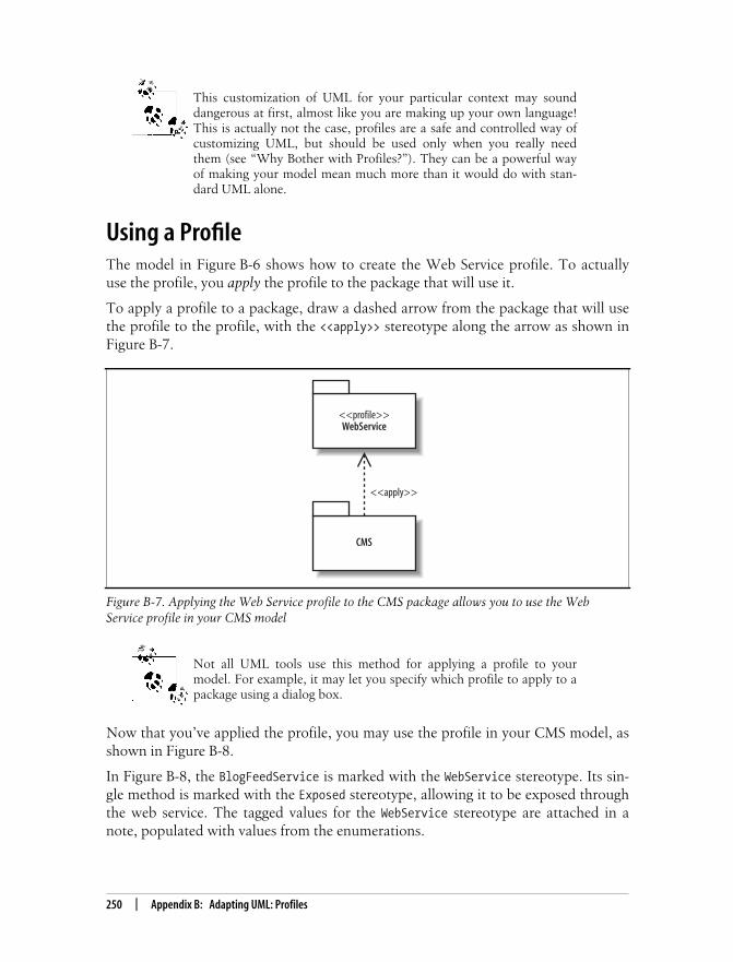
This is the Title of the Book, eMatter EditionCopyright © 2008 O’Reilly & Associates, Inc. All rights reserved.
250 | Appendix B: Adapting UML: Profiles
This customization of UML for your particular context may sounddangerous at first, almost like you are making up your own language!This is actually not the case, profiles are a safe and controlled way ofcustomizing UML, but should be used only when you really needthem (see “Why Bother with Profiles?”). They can be a powerful wayof making your model mean much more than it would do with stan-dard UML alone.
Using a ProfileThe model in Figure B-6 shows how to create the Web Service profile. To actuallyuse the profile, you apply the profile to the package that will use it.
To apply a profile to a package, draw a dashed arrow from the package that will usethe profile to the profile, with the <<apply>> stereotype along the arrow as shown inFigure B-7.
Not all UML tools use this method for applying a profile to yourmodel. For example, it may let you specify which profile to apply to apackage using a dialog box.
Now that you’ve applied the profile, you may use the profile in your CMS model, asshown in Figure B-8.
In Figure B-8, the BlogFeedService is marked with the WebService stereotype. Its sin-gle method is marked with the Exposed stereotype, allowing it to be exposed throughthe web service. The tagged values for the WebService stereotype are attached in anote, populated with values from the enumerations.
Figure B-7. Applying the Web Service profile to the CMS package allows you to use the WebService profile in your CMS model
CMS
<<profile>>WebService
<<apply>>

This is the Title of the Book, eMatter EditionCopyright © 2008 O’Reilly & Associates, Inc. All rights reserved.
Why Bother with Profiles? | 251
The constraint from the Web Service profile isn’t explicitly seen in this model, but itis used because the Exposed stereotype on the getFeed( ) operation is contained in aclass that uses the WebService stereotype.
Why Bother with Profiles?The real power of a profile comes when it is used by many people interested in thatplatform or domain. Not only does it introduce a common vocabulary, but also itallows you to leverage tools that generate source code and other artifacts based onthe profile. For example, a tool could convert a model that uses our Web Service pro-file into a deployable web service. Such a tool could generate the implementationclass and populate a deployment descriptor file with the service type and encodingvalues, keeping the model and code in sync. As another example, the OmondoEclipse IDE plugin provides a J2EE profile which, when applied to your model,allows automatic generation of the medley of classes required to implement an EJB(prior to EJB 3.0) and even deploys them to the application server.
The OMG maintains some common profiles, such as profiles for CORBA and test-ing. The testing profile, for example, describes mappings to JUnit—a widely-usedJava unit testing framework.
Figure B-8. Applying elements of the Web Service profile to the BlogFeedService class in the CMSpackage
<<WebService>>BlogFeedService
<<Exposed>> +getFeed() : Feed
<<WebService>>
service = Documentencoding = Literal
This is the Title of the Book, eMatter EditionCopyright © 2008 O’Reilly & Associates, Inc. All rights reserved.
252
Appendix CAPPENDIX C
A History of UML 3
UML has not always been the de facto modeling language that it is today. In fact, notso long ago, everyone involved in complex system modeling was using a plethora ofdifferent modeling languages—some formal, some informal—and each had its ownassociated development approach.
Nowhere was the problem more apparent than in software modeling. Object orienta-tion had just become a fully recognized technique for developing software, and it didnot take long for new modeling methods to start incorporating this revolutionarytechnique into their practices.
Unfortunately, even though object-oriented software modeling was seen as a goodthing, the mess of different and conflicting approaches to modeling cancelled out alot of the advantages that modeling promised. If you were designing using one mod-eling language and another member of your group was using another modeling lan-guage, the advantages of communicating designs to each other were completely lost.Software and system groups were forced to pick a modeling language, knowing thattheir choice was potentially a dangerous decision that could exclude other groupsfrom easily joining the design effort.
This time of confusion and chaos in the software modeling world is now rather dra-matically referred to as the “method wars.” Three of the primary protagonists inthese method wars were Grady Booch, Ivar Jacobson, and James Rumbaugh. Each ofthese innovators had their own software development methods and a modeling lan-guage with their own distinct notation. More importantly, they also headed up theirown community of users that evangelized their approach to software modeling. Itwas these three approaches to software development and their associated languagesand notation that were to form the basis of UML.

This is the Title of the Book, eMatter EditionCopyright © 2008 O’Reilly & Associates, Inc. All rights reserved.
…with a Sprinkling of OOSE… | 253
Take One Part OOAD…Grady Booch’s approach was named Object-Oriented Analysis and Design (OOAD),or less formally, the Booch method. These grand titles encompassed a method thatincluded a modeling language constructed of diagrams to show classes, state, statetransitions, interactions, modules, and processes.
This formidable collection of diagrams was probably best known for its class nota-tions, which were depicted as clouds and a selection of arrows with simple namessuch as has a that could be used to specify different types of inter-class relationships,as shown in Figure C-1.
The cloud notational style and the simple naming of Booch’s inter-class relationshiparrows worked themselves into the hearts of adopters to such a degree that even tothis day, they reminisce about the clouds. In fact the use of either the cloud notationor the rectangle notation for classes prompted some of the most vehement, and use-less, arguments during the inception of UML.
…with a Sprinkling of OOSE…Ivar Jacobson and his Object-Oriented Software Engineering (OOSE) approach isprobably best known for the revolutionary technique of mapping requirements toobject-oriented software designs, called use cases. There was a definite focus inOOSE to accurately capture and model the problem domain, and use cases were akey technique in achieving this as part of a requirements model.
Figure C-1. A cloud OOAD notation describes classes and the relationships between them
Person
namegetName
Guitarist
instrumentplay()
Guitar
strum()
is a
has a

This is the Title of the Book, eMatter EditionCopyright © 2008 O’Reilly & Associates, Inc. All rights reserved.
254 | Appendix C: A History of UML
OOSE was not just about requirements, though; it also had corresponding modelsfor analysis and design. The analysis model in OOSE was one in which object rela-tionships could be modeled. It drew distinctions between entity objects that containdata, control objects that control other objects, and interface objects that interactwith users or other external systems. UML has inherited these types of objects, andthey are particularly popular on sequence diagrams (see Chapter 7).
The design model allowed you to describe how the system behaves using state transi-tion and interaction diagrams, which—although the notation has changed—are stillpresent to some extent in UML today. Communication diagrams are covered inChapter 8; state machine diagrams are covered in Chapter 14.
To complete the picture, the OOSE also specified implementation and test models.An implementation model captured how use cases were mapped to the underlyingsystem implementation and the test model closed the loop by showing how use casescould drive the development of a system’s tests.
Despite all of these various models, use cases are the thing that OOSE will be mostnoted for; see Figure C-2 for an example. UML has gone through various iterationsover the years, but of all the UML constructs, use cases is the one technique that’sremained unchanged.
Figure C-2. The OOSE use case notation describes three use cases within a system and the twooutside influences—actors—that interact with those use cases
Fans
Pay themsome money
Band
RequestFanzine
Get them toplay
<uses>Manager

This is the Title of the Book, eMatter EditionCopyright © 2008 O’Reilly & Associates, Inc. All rights reserved.
…and Bake for 10 to 15 Years | 255
…Add a Dash of OMT…If Booch’s OOAD brought class modeling and Jacobson’s OOSE gave us use cases,state transitions, and interaction modeling, then James Rumbaugh added his objectmodeling technique (OMT). Although Booch’s class and object diagrams were wellloved by his adopters (those clouds again), it was the class and object diagram nota-tion from OMT that most influenced what was to come. The OMT’s notation for itsobject view was arguably simpler to draw, even if its interclass relationships were notas intuitive as Booch’s (see Figure C-3).
That is not to say that object and class diagram notation was all that OMT added tothe mix. The OMT also had notation for diagrams showing the dynamic qualities ofsoftware, namely sequence diagrams.
…and Bake for 10 to 15 YearsIt is not an understatement to say that the modeling world was in a mess (it was awar, after all!). The mere suggestion of a unified approach to modeling was likely tobring passionate objections as modeling practitioners protected their skills, tools,and—most importantly—approaches.
But it was time for a change. In early 1996, Ivar Jacobson gave Richard Mark Soley acall at home, late at night as always, and confirmed that the time was ripe to stan-dardize on a modeling language and bring an end to the modeling method wars. Atthis point, the modeling tools market was worth about $30 million worldwide total,split among several vendors. The largest vendor was Rational Software Corporation,but even at this point Rational was only a $25 million company—small fish com-pared to software behemoths such as Microsoft and IBM.
As a first step, Soley and Jacobson made a list all of the major methodologists andinvited them to come to an Object Management Group (OMG) meeting to explorethe possibility of developing a standard. Little did they know just how important andsuccessful that meeting would be. The OMG was traditionally a standards body thatspecifically targeted distributed systems; however, in an act of excellent foresight, thegroup organized its first meeting targeted at creating a standard modeling languageHosted by Tandem Computer in San Jose, California, almost every major methodolo-gist or representative of every major methodologist made it to that meeting. According
Figure C-3. This diagram is easy to read, even for a novice developer
Guitarist
- instrument : Instrument
+ getInstrument() : Instrument+ setInstrument(Instrument instrument) : void+ play() : void
Guitarist

This is the Title of the Book, eMatter EditionCopyright © 2008 O’Reilly & Associates, Inc. All rights reserved.
256 | Appendix C: A History of UML
to legend, the organizers were very careful to leave all the windows open so that theroom would not explode with the number of egos—it was a very impressive assem-bly. Early on, it was realized that the most difficult facet of the meeting probablywould be finding the right person to chair it. They needed somebody who would berecognized as a methodologist, who was also sufficiently impartial and focused, andwho could actually guide the meeting towards a useful conclusion.
Mary Loomis was that person. Back then, Mary was a research director at Hewlett-Packard, and she was on the team at General Electric that had developed the OMTmethodology. Mary was the perfect person to keep all those egos in check. Veryquickly, Mary managed to get all the gurus in the room to actually make progresstoward an agreement. The goal was not a technical discussion about which technolo-gies to use, or whether to draw a class as a box or a cloud, but to determine how todevelop a Unified Modeling Language.
This is what the OMG brought into the mix. The OMG excelled at getting directcompetitors to agree on issues, which was the most important aspect of getting to aUnified Modeling Language. Participants agreed that:
• It was time for a standard.
• They would attempt to use the OMG standards process to develop that standard.
These two simple goals were really an amazing achievement. At that point in time,the OMG had used only its standards process to develop specific distributed objectcomputing standards, such as CORBA and its services. The OMG had never createdanything like development standards, which is what a UML specification would haveto be. Without a doubt, managing a community as passionate as the methodologistsand, on top of that, building a successful standard that everyone could sign up forwas new and hazardous territory for the OMG.
But the OMG was in the middle of a transition. During part of that transition, it rec-ognized that one of the group’s biggest strengths was its standards process itself andnot any specific technology. Following its process, the OMG developed and sent arequirements document to the industry that described precisely what was needed ofa standard modeling language. It was then up to industry to send in their own ideasfor how they could meet those requirements.
By the middle of 1997, the OMG had received what was to be an acceptable singlejoint proposal for a standard modeling language. Written by 21 different companies,this joint proposal was the product of a merger between each of those company’sown proposals. The whole process came to an end in September 1997 when theOMG published a specification for a standard modeling language, but there was aslight problem with its preferred name. The OMG had decided to name the stan-dard modeling language the Unified Modeling Language, but UML as a name wasalready owned by one of the companies that had agreed to the original joint pro-posal—Rational Software Corporation.

This is the Title of the Book, eMatter EditionCopyright © 2008 O’Reilly & Associates, Inc. All rights reserved.
…and Bake for 10 to 15 Years | 257
Rational Software employed Jacobson, Booch, and Rumbaugh—collectively knownas the three amigos—and had already given a huge amount of input into the devel-opment of the OMG’s standard, as well as continuing on with research toward theirown joint specification for a modeling language. The Rational modeling languagebrought together the three amigos’ considerably popular methodologies and toolsets,but unfortunately it too had also been called the Unified Modeling Language.
It was crunch time; would the industry slip back into confusion with both the OMGand Rational’s UML, or would the OMG have to find a new name entirely andthereby lose any name recognition that the UML brand had already gained? As ithappens, there was a particularly happy ending to this story. To solve the namingnightmare, the OMG achieved something that was nothing short of a coup.
The OMG were able to convince Rational, even though there was already some con-siderable marketing value to the UML brand, to donate at no charge both the UMLname and the cube logo (see Figure C-4). This way, the OMG could go ahead with atruly open standard modeling language, which could officially be named UML.
For a couple of years afterward, people thought that only Rational was involved inthe development of the UML specification, largely because the UML name and logooriginated with Rational, and Rational Rose was the most popular modeling tool atthe time. In fact, some companies did not want the standard modeling language tobe called UML because they believed the public would continue to associate theUML name with Rational. Those fears have proved largely unfounded over time, andnow more than 90 percent of practitioners recognize that UML is a standard ownedand managed by the OMG.
UML has undergone several revisions as it evolves to accommodate various newindustry advances and best-practice techniques. The original input from Jacobson,Booch, and Rumbaugh, although still very important, now happily works alongsidethe other full set of possible UML 2.0 diagrams, as shown in Figure C-5.
Figure C-4. The UML cube logo

This is the Title of the Book, eMatter EditionCopyright © 2008 O’Reilly & Associates, Inc. All rights reserved.
258 | Appendix C: A History of UML
Systems development techniques, particularly software systems, are in a vibrant stateof flux most of the time. This means that any unified approach to modeling softwaremust be flexible and open to new approaches to still be of practical use; however,with UML, there is finally a common language for expressing your models.
Special thanks to Richard Mark Soley for all the first-hand anecdotes and explanationsabout how the OMG process worked and why it was ideal for standardizing UML.
Figure C-5. Building on the best practices of the past, UML draws on OOSE, OOAD, and OMT aswell as a plethora of other techniques to create the best toolset for modeling systems
Use Case
Class
Object
Sequence
State Machine
Component
Composite Structure
Package
Communication
Activity
Interaction Overview
Timing
Deployment
UML 2.0 Diagram Types
OOSE/Jacobson
OOAD/Booch
OMT/Rumbaugh
DirectlyInfluenced
Brought about bythe adoption of bestpractices from across
many otherapproaches

This is the Title of the Book, eMatter EditionCopyright © 2008 O’Reilly & Associates, Inc. All rights reserved.
259
We’d like to hear your suggestions for improving our indexes. Send email to [email protected].
Index
Symbols[ ] (brackets)
guard conditions, 47multiplicities on connectors, 178
: (colon)in attribute name, 73in operation signature, 78
{ } (curly braces), constraints, 92:: (double colons), in fully-scoped class
name, 202<< >> (guillemots), stereotypes, 17, 96# (hash symbol), protected visibility, 69- (minus symbol), private visibility, 71, 203( ) (parentheses), annotations, 60+ (plus symbol)
public visibility, 68, 203~ (tilde), package visibility, 704+1 view model (Krutchen), 14–15
Aabstract classes, 83, 92–95abstraction level of classes, 65abstractions (see models)<<access>> stereotype, 206actions, 46
in Activity diagram, 45inputs and outputs for, 54objects passed between, 53parallel, 50transformations of objects between, 54
activation barsindicating active participant, 113return messages at end of, 118
active states, 212activities, 46
called within Activity diagram, 52changing state of object, 55enclosing in activity frame, 47ending, 45, 57flow of, 45inputs and outputs for, 55interrupting, 58naming, 47starting, 44, 57
Activity diagram, 11, 43–46actions in, 45calling other activities from, 52compared to Interaction Overview
diagram, 163concurrent tasks in, 49connectors in, 60decisions in, 46, 47–48edges in, 45ending, 57ending flows in, 58expansion regions in, 62final node in, 45guard conditions in, 47–49in process view, 15initial node in, 44inputs and outputs for, 55interrupting, 58merges in, 46, 48–51objects in, 53–55partitions in, 59signals to and from external
participants, 56

This is the Title of the Book, eMatter EditionCopyright © 2008 O’Reilly & Associates, Inc. All rights reserved.
260 | Index
Activity diagram (continued)starting, 57time events in, 51when to create, 41
activity final nodesin Activity diagram, 45multiple, 58object output as alternative to, 55
activity frame, 47, 53actors, 22, 22–24
generalizations used with, 24naming, 23notation for, 22participation with use cases, showing, 26primary actor for use case, 28relationships between, 24system boundaries excluding, 27tricky actors, 23
aggregation between classes, 87agile methods of software development, 14Agile Software Development (Prentice
Hall), 208alt fragment, 129angle brackets (<< >>), stereotypes, 17, 96annotations for partitions, Activity
diagram, 60anonymous objects, 102<<apply>> stereotype, 250“Architectural Blueprints—The “4+1” View
Model of Software Architecture”(Krutchen), 15
arrowsarrowed lines (edges), 45connecting states (transitions), 212dependency arrows, 84, 190dotted arrow (<<include>>
relationships), 33empty diamond arrowhead
(aggregations), 87extension arrow in profile, 248filled diamond arrowhead
(compositions), 88generalization arrow
class inheritance, 89use case inheritance, 36
message arrows, 112, 114–119on communication lines, 27on state-lines, 154(see also diagram notations)
<<artifact>> stereotype, 190, 226artifacts, 226
dependencies between, 227
deploying to a node, 226deployment specifications as, 232manifesting components, 227notation for, 226of components, 190stereotypes applied to, 18
assembly connectors, 191, 195assert fragment, 129association classes, 86associations between classes, 85–87
attributes representing, 72, 76object links requiring, 103properties representing, 178
asynchronous messages, 116–117, 124, 142attributes, 65, 72–77
as collections of objects (multiplicity), 74associated with another class, 72, 76inline attributes, 72, 76naming, 73private visibility for, when to use, 71properties of, 75public visibility for, when to use, 69static, 79–82type of, 73visibility of, 67–71(see also properties)
Bbase use cases, 37behavioral state machines, 211binding templates, 105–107black-box component views, 196blueprint, UML used as, 13boundaries (see system boundaries)BPM (business process management)
tools, 43brackets ([ ])
guard conditions, 47multiplicities on connectors, 178
break fragment, 129business process management (BPM)
tools, 43business processes, 43
(see also Activity diagram)
Ccall activity node, 52Chain of Responsibility (COR) design
pattern, 182child classes, 89choice pseudostates, 221

This is the Title of the Book, eMatter EditionCopyright © 2008 O’Reilly & Associates, Inc. All rights reserved.
Index | 261
Class diagram, 11, 67abstract classes in, 92–95attributes in, 72–77class relationships in, 83–91constraints in, 91in logical view, 15interfaces in, 96–98operations in, 77Package diagram modeled using, 199static class elements in, 79–82templates in, 99when not to use, 174when to create, 41
class invariant, 91classes, 63–66
abstract classes, 83, 92–95abstraction level of, 65aggregation between, 87association classes, 86associations between, 85–87, 178attributes of, 65, 72–77compared to components, 187composition relationship between, 88,
176constraints for, 91, 103delegation and, 90dependencies between, 84encapsulation and, 66generalization relationship
between, 88–91interfaces for, 83, 96–98, 181internal structures of, 174–180logical groupings of (see packages)name of, 67notation for, 67operations of, 65, 77parts of, 176ports for, 173, 180public interface of, 68realizing components, 192relationships between, 83, 83–91static, 79–82stereotypes applied to, 17templates for, 83, 99tightly coupled, 83, 90visibility of elements in, 67–71
clock, system, as tricky actor, 23code (see software code)collaborations, 173, 182–185colon (:)
in attribute name, 73in operation signature, 78
colons, double (::), in fully-scoped classname, 202
comments (see notes)Communication diagram, 11, 131
communication links in, 132, 137compared to Sequence diagram, 131,
139–143creating from interactions, 136–139in logical view, 15incorporated into Interaction Overview
diagram, 165messages in, 132, 137
invoked conditionally, 134invoked multiple times, 134nested, 139sent by pariticipant to itself, 135simultaneous, 133
participants in, 131, 137when to create, 62, 82, 100, 107when to use, 143
communication lines, 26communication links, 132, 137, 142communication paths between nodes, 231Component diagram, 11, 186
components in, 187dependencies in, 190–192in development view, 15interfaces in, 188internal structures in, 194ports in, 194realizing classes in, 192views of components in, 196
<<component>> stereotype, 187components, 186
as subsystems, 188black-box view of, 196compared to classes, 187dependencies between, 190–192interfaces for, 188, 190internal structure of, 194notation for, 187ports for, 194realized by classes, 192stereotypes applied to, 18white-box view of, 196
composite states, 220Composite Structure diagram, 11
classes with internal structuresin, 174–180
collaborations in, 182–185connectors in, 177objects with internal structures in, 179
This is the Title of the Book, eMatter EditionCopyright © 2008 O’Reilly & Associates, Inc. All rights reserved.
262 | Index
Composite Structure diagram (continued)parts of classes in, 176ports in, 180properties in, 178when to create, 82, 100when to use, 173
composition relationship betweenclasses, 88, 176
concurrent tasks, Activity diagram, 49connectors
in Activity diagram, 60in Component diagram, 191, 195in Composite Structure diagram, 177
constraintsfor classes
in Class diagram, 91in Object diagram, 103
in profiles, 248timing constraints, 154
constructors, 78contact information for this book, xiiconventions used in this book, xCOR (Chain of Responsibility) design
pattern, 182create message, 118, 124critical regions, 130curly braces ({ }), constraints, 92
Ddata objects (see objects)decisions, Activity diagram, 46, 47–49delegation, 90delegation connectors, 194dependencies
between artifacts, 227between classes, 84between components, 190–192between packages, 204
<<deploy>> stereotype, 227Deployment diagram, 12, 224–226
artifacts (files) in, 226communication paths in, 231execution environments in, 229hardware in, 224in physical view, 15nodes in, 229when to create, 197when to use, 234
<<deployment spec>> stereotype, 232deployment specifications, 232
design patterns, 182–185abstract classes and, 95collaborations as, 173
Design Patterns: Elements of ReusableObject-Oriented Software(Addison-Wesley), 90, 95, 182
destroy message, 124destroy method, 119development view, 15, 186<<device>> stereotype, 225, 229diagram notations
arrowsarrowed lines (edges), 45connecting states (transitions), 212dependency arrows, 84, 190dotted arrow (<<include>>
relationships), 33empty diamond arrowhead
(aggregations), 87extension arrow in profile, 248filled arrow (messages), 132filled diamond arrowhead
(compositions), 88generalization arrow (class
inheritance), 89generalization arrow (use case
inheritance), 36message arrows, 112, 114–119on communication lines, 27on state-lines, 154
artifact symbol, 226ball and socket (assembly
connectors), 190, 195ball symbol
interfaces, 96provided interfaces, 188
box around use cases (systemboundaries), 27
brackets ([ ])guard conditions, 47multiplicities on connectors, 178
circle with enclosed character(connectors), 60
circle with X (flow final nodes), 58circle, filled
initial node, 44initial pseudostates, 213
circles, concentric, with filled centerfinal node, 45final states, 213

This is the Title of the Book, eMatter EditionCopyright © 2008 O’Reilly & Associates, Inc. All rights reserved.
Index | 263
colon (:)in attribute name, 73in operation signature, 78
columns or rows in (partitions), 59cross
in Sequence diagram (participantdestruction), 121
in Timing diagram (events), 160cube (nodes), 229curly braces ({ }), constraints, 92diamond
decisions, 46, 47merges, 46, 48
double colons (::), in fully-scoped classname, 202
dropped title box (participantcreation), 121
folder with tab (packages), 199forks (joins), 50fragment box (sequence fragments), 126guillemots (<< >>), stereotypes, 17, 96hash symbol (#), protected visibility, 69hourglass (time events), 51italic operations (abstract classes), 93lines
activation bars for activeparticipants, 113
arrowed lines (edges), 45between actors and use cases
(communication lines), 26between classes (associations), 85between nodes (communication
paths), 231between objects (links), 103between participants (communication
links), 132connectors with multiplicities, 177lifelines for participants, 109, 123, 163lightning bolt line (interruption
regions), 58state-lines for participants, 152
minus symbol (-), private visibility, 71,203
nodes (hardware), 224oval (use cases), 26oval, dashed (collaborations), 183, 184parentheses (( )), annotations, 60pins (action inputs and outputs), 54pitchfork, upside-down (call activity
node), 52
plus symbol (+)public visibility, 68, 203
receive signal nodes, 56rectangle
objects, 54participants, 131
rectangle split into sections (classes), 67rectangle with tab icon
(components), 187rectangle with underlined name
(objects), 101rectangle, dashed (properties), 179rectangle, dashed rounded
interruption regions, 58with boxes on sides (expansion
regions), 62rectangle, folded
notes, 16tagged values, 18
rectangle, roundedactions, 45activity frames, 47states, 212
rectangle, tabbed (protocol statemachines), 223
send signal nodes, 56socket symbol (required interfaces), 188stick figure
actors, 22stereotypes, 16
“t” in Timing diagram, 150, 155tilde (~), package visibility, 70
diagramsas views of model, 12complexity of
alternate Timing diagram notationfor, 159
hardware node naming and, 225minimizing, 147Package diagram, 201
list of, 11–12views of, 14–16(see also specific diagrams)
do behavior of states, 219documentation for UML, 19double colons (::), in fully-scoped class
name, 202

This is the Title of the Book, eMatter EditionCopyright © 2008 O’Reilly & Associates, Inc. All rights reserved.
264 | Index
Eedges, Activity diagram, 45encapsulation, 66entry behavior of states, 219events, 111
causing state changes (see triggers)in Timing diagram, 153timing constraints for, 154
exact time measurements, 150<<executable>> stereotype, 18executable UML, 10execution environments, 229<<executionEnvironment>> stereotype, 230exit behavior of states, 219expansion regions, Activity diagram, 62<<extend>> relationships, 38–40extensions of use case, 39
F<<file>> stereotype, 18files (see artifacts)final node, Activity diagram, 45final state, State Machine diagram, 213flow final node, Activity diagram, 58flowchart (see Activity diagram)fonts used in this book, xfork pseudostates, 221forks
flow final nodes and, 59in Activity diagram, 50
formal modeling language, 84+1 view model (Krutchen), 14–15Fowler, Martin (ways of using UML), 13fragment box, 126fragment operator, 126fragments, in Sequence diagram, 126–130functional requirements (see use cases)
Ggeneralization
multiple generalization, 90of actors, 24of classes, 88–91of use cases, 36–38
guard conditionsfor choice pseudostate, 221in Activity diagram, 47–49in Communication diagram, 135in State Machine diagram, 215
guillemots (<< >>), stereotypes, 17, 96
Hhardware
deploying artifacts to, 226nodes representing, 229notation for, 224
hash symbol (#), protected visibility, 69Head First Design Patterns (O’Reilly), 82,
182
Iicons
associated with stereotypes, 246used in this book, xi(see also diagram notations)
<<import>> stereotype, 205–208inactive states, 212<<include>> relationships, 31–35include:: syntax, 33incoming edges, Activity diagram, 45informal languages as modeling
language, 5–8inheritance (see generalization)initial node
in Activity diagram, 44, 57object input as alternative to, 55time event as alternative to, 52
initial pseudostates, State Machinediagram, 213, 221
inline attributes, 72, 76input pins, 54instances (see objects)interaction diagrams, 108
(see also Communication diagram,Sequence diagram, Timingdiagram)
Interaction Overview diagram, 11, 163compared to Activity diagram, 163creating from use case, 165–171when to use, 130
interactionsbreaking into participants, 122creating Communication diagram
from, 136–139executing in parallel, 130timing constraints for, 154
interfacesfor classes, 83, 96–98, 181for components, 188, 190notation for, 96, 188public interface of class, 68

This is the Title of the Book, eMatter EditionCopyright © 2008 O’Reilly & Associates, Inc. All rights reserved.
Index | 265
internal structures, Composite Structurediagram showing, 174–180
interruption regions, 58invariants, 91iterative methods of software
development, 14
JJava 5 Tiger: A Developer’s Notebook
(O’Reilly), 107Java in a Nutshell, 5th Edition
(O’Reilly), 117Java Threads (O’Reilly), 117join pseudostates, 221joins, Activity diagram, 50
KKrutchen, Philippe (“Architectural
Blueprints—The “4+1”View Modelof Software Architecture”), 15
Krutchen’s 4+1 view model, 14–15
L<<library>> stereotype, 18life cycle of object, 217lifelines
in Interaction Overview diagram, 163in Sequence diagram, 109, 123
linesactivation bars for active participants, 113arrowed lines (edges), 45between actors and use cases
(communication lines), 26between classes (associations), 85between nodes (communication
paths), 231between objects (links), 103between participants (communication
links), 132lifelines for participants, 109, 123, 163lightning bolt line (interruption
regions), 58state-lines for participants, 152(see also diagram notations)
linksbetween objects, 103communication links, 132, 137, 142
lists, templates used for, 99, 106
logic analyzer, Timing diagram comparedto, 144
logical view, 15loop fragment, 129
M<<manifest>> stereotype, 227Martin, Robert C. (Agile Software
Development), 208MDAs (Model Driven Architectures), 10merges, Activity diagram, 46, 48–50messages
diagrams showing, 142in Communication diagram, 132, 137
invoked conditionally, 134invoked multiple times, 134nested, 133, 139sent by participant to itself, 135simultaneous, 133
in Sequence diagram, 111arrows used by, 114–119asynchronous, 116–117, 124, 142for participant creation and
destruction, 118nested, 114return messages, 118signature for, 112synchronous messages, 115
in Timing diagram, 153meta-models, 2, 249methods (see operations)minus symbol (-), private visibility, 71, 203Model Driven Architictures (MDAs), 10modeling language, 2
formal languages as, 8informal languages as, 5–8software code as, 3–5(see also UML)
models, 1diagrams as views of, 12sharing between machines, 10views of, 14–16
multiple inheritance (generalization), 90multiple processes, forks representing, 51multiple threads, forks representing, 51multiplicity
of attributes, 74on connectors, 177

This is the Title of the Book, eMatter EditionCopyright © 2008 O’Reilly & Associates, Inc. All rights reserved.
266 | Index
Nnamespaces of packages, 201natural language as modeling language, 5neg fragment, 129nested messages, 139nodes, 229
communication between, 231instances of, 230notation for, 229
non-functional requirements, 21not unique property of multiplicty, 75notation, 2
(see also diagram notations)notes, 16
OObject diagram, 11, 101
binding class templates in, 105–107in logical view, 15links in, 103objects in, 101when to create, 82, 100
objects, 53, 101anonymous objects, 102as inputs and outputs for activity, 55as inputs or outputs for actions, 54as participants in Sequence diagram, 110binding templates with, 105–107changing state during activity, 55classes’ relationship to, 63collaborations of, 182–185internal structures of, modeling, 179life cycle of, 217links between, 103notation for, 54, 101passed between actions, 53state of, modeling (see State Machine
diagram)transformations of, 54
OCL (Object Constraint Language), 237–244expressions, building, 92types of constraints, 91
OMG (Object Management Group), 19, 238,255
operations, 65, 77constructors, 78parameters of, 78return type of, 78static, 79–82visibility of, 67–71, 77
opt fragment, 129
ordered property of multiplicity, 75outgoing edges, Activity diagram, 46output pins, 54
PPackage diagram, 11, 198
in development view, 15modeling using Class diagram, 199size and complexity of, 201when to create, 82, 100
package visibility, 70packages, 198–201
accessing another package, 206dependencies between, 198, 204, 208importing another package, 205–208namespaces of, 201nested, 200, 203notation for, 199, 201target package, 205use cases in, 209using in software, 204visibility of elements in, 203visibility of imports in, 206
par fragment, 130parallel actions, 50parallel messages, 142parameterized classes (see templates)parameters of operations, 78parent classes, 89parent use case, 36parentheses (( )), annotations, 60participants
diagrams showing, 142in Communication diagram, 131, 135,
137in Interaction Overview diagram, 163in Sequence diagram, 109
creating from interactions, 122creation and destruction of, 118creation of, 124cross notation for destruction of, 121destruction of, 124dropped title box for creation of, 121lifelines of, 123naming, 109sending messages between, 112
in Timing diagram, 147organizing, 157state-lines for, 152states of, 148
partitions, Activity diagram, 59paths (see edges, Activity diagram)

This is the Title of the Book, eMatter EditionCopyright © 2008 O’Reilly & Associates, Inc. All rights reserved.
Index | 267
physical view, 15, 224pictures as modeling language, 6PIMs (Platform Independent Models), 10pins, 54Platform Independent Models (PIMs), 10Platform Specific Models (PSMs), 10plus symbol (+)
public visibility, 68, 203ports
for classes, 173, 180for components, 194
postconditions, 92preconditions, 92private import, 206private visibility, 71, 203process view, 15, 43processes, forks representing, 51profiles, 232, 245
as meta-models, 249constraints in, 248creating, 248reasons to use, 251standard, 248, 251stereotypes in, 246using, 250
programming language, UML used as, 13properties
in Composite Structure diagram, 178of attributes, 75(see also attributes)
protected visibility, 69protocol state machines, 211, 223provided interfaces
of classes, 181of components, 188
pseudostates, 213PSMs (Platform Specific Models), 10public import, 206public interface of class, 68public visibility, 68, 203publications
Agile Software Development (PrenticeHall), 208
Design Patterns: Elements of ReusableObject-Oriented Software(Addison-Wesley), 90, 95, 182
Head First Design Patterns (O’Reilly), 82,182
Java 5 Tiger: A Developer’s Notebook(O’Reilly), 107
Java in a Nutshell, 5th Edition(O’Reilly), 117
Java Threads (O’Reilly), 117UML 2.0 in a Nutshell (O’Reilly), 145
RreadOnly property of attributes, 75realization relationship, 97<<realizations>> stereotype, 192receive signals, 56, 57recurring time events, Activity diagram, 52ref fragment, 127, 129region fragment, 130region of states, 220relative time indicators, 150required interfaces
of classes, 181of components, 188
requirements (see system requirements)return messages, 118return type of operation, 78reusability, 5reuse
<<include>> relationships for, 33components for, 186generalization for, 89
Sscalability of UML, 3self-transition, 215send signals, 56Sequence diagram, 11, 109
activation bars in, 113compared to Communication
diagram, 131, 139–143creating from use case, 120–126creating Timing diagram from, 146events in, 111fragments in, 126–130in logical view, 15incorporating into Interaction Overview
diagram, 165messages (signals) in, 111participants in, 109, 122time in, 110when to create, 62, 82, 100, 107when to use, 143
sequence fragments, 126–130<<service>> stereotype, 18shall requirements, 22

This is the Title of the Book, eMatter EditionCopyright © 2008 O’Reilly & Associates, Inc. All rights reserved.
268 | Index
shapes (see diagram notations)should requirements, 22signals
between participants, 56between transitions, 222starting an activity, 57(see also messages)
Singleton design pattern, 82sketch, UML used as, 13software code
as artifact in Deployment diagram, 226as modeling language, 3–5nodes hosting, 229package dependencies and, 208packages used in, 204reuse of
<<include>> relationships for, 33components for, 186generalization for, 89
states in, 217UML model as detailed as, 13
software development processmethods of, 14UML as part of, 13
source state, 214<<source>> stereotype, 18standard for UML, 3standard profiles, 248, 251standard stereotypes, 17State Machine diagram, 12, 211–213
final state of, 213guards in, 215in logical view, 15initial pseudostate of, 213pseudostates in, 213, 221states in, 213transition-oriented view of, 222transitions in, 214–217triggers in, 215when not to use, 217when to use, 211, 217
states, 212, 213active and inactive, 212composite states, 220in software, 217internal behavior of, 218internal transitions of, 219notation for, 212regions of, 220source state, 214substates, 220
target state, 214static classes or class elements, 79–82stereotypes, 16–18
creating new stereotypes, 232for interfaces, 96, 189icons associated with, 246in profiles, 246notation for, 16, 17, 246profiles for, 232standard, list of, 17tagged values for, 18(see also specific stereotypes)
substates, 220<<subsystem>> stereotype, 18, 188subsystems, 188swimlanes (see partitions, Activity diagram)symbols (see diagram notations)synchronous messages, 115system boundaries, 27system clock, as tricky actor, 23system requirements
associated with use case, 28defining, 22shall requirements, 22should requirements, 22(see also use cases)
Ttagged values, 18target package, 205target state, 214templates, 83, 99
binding, 105–107for lists, 99, 106
threadsasynchronous messages used for, 116forks representing, 51
tightly coupled classes, 83, 90tilde (~), package visibility, 70time events, Activity diagram, 51time, in Sequence diagram, 110Timing diagram, 11, 144
alternate notation for, 159complexity of, 159creating from Sequence diagram, 146events in, 153
alternate notation for, 160in logical view, 15incorporated into Interaction Overview
diagram, 165messages in, 153

This is the Title of the Book, eMatter EditionCopyright © 2008 O’Reilly & Associates, Inc. All rights reserved.
Index | 269
participants in, 147organizing, 157state-lines for, 152states of, 148
states in, 148alternate notation for, 160
time measurements in, 150timing constraints in, 154when to use, 143
transformations, 54transition-oriented view of State Machine
diagram, 222transitions, 212, 214–217
internal transitions, 219notation for, 212self-transition, 215signals between, 222
tricky actors, 23triggers, 212, 215tutorials for UML, 19typographical conventions used in this
book, x
UUML (Unified Modeling Language), 1
advantages of, 2, 9degrees of use of, 13documentation and tutorials for, 19executable, 10history of, 252–-258reasons to use, 1software development process and, 13version 2.0, 9–10
UML 2.0 in a Nutshell (O’Reilly), 145Unified Modeling Language (see UML)unique property of multiplicity, 74Use Case diagram, 11
actors in, 22–24communication lines in, 26in use case view, 15system boundaries in, 27use case relationships in, 30–40use cases in, 25
Use Case Overview diagram, 40use case view, 15use cases, 20
base use cases, 37behaviors shared between
<<extend>> relationships, 38–40<<include>> relationships, 31–35inheritance, 36–38
creating Interaction Overview diagramfrom, 165–171
creating Sequence diagramfrom, 120–126
defining, 25description for, 27, 28–30extensions of, 39failed end condition for, 28logical groupings of (see packages)notation for, 26number of, guidelines for, 30packages of, 209participation with actors, showing, 26preconditions of, 28primary actor for, 28requirements fulfilled by, 28successful end condition for, 28system boundaries enclosing, 27tests constructed using, 21tracking progress using, 21trigger for, 28
<<utility>> stereotype, 17
Vvisibility
of class elements, 67–71of elements in package, 203of operations, 77of package import relation, 206
Wwaterfall method of software
development, 14web site resources
about composite structures, 176for this book, xiiKrutchen’s 4+1 view model, 15Object Management Group, 19
white-box component views, 196


About the AuthorsRuss Miles is a software engineer for General Dynamics UK, where he works withJava and Distributed Systems, although his passion at the moment is Aspect Orienta-tion and AspectJ, in particular. To ensure that he has as little spare time as possible,Russ contributes to various open source projects while working on books forO’Reilly. He is currently studying at Oxford University in England for an MSc insoftware engineering.
Kim Hamilton is a senior software engineer at a major aerospace corporation, whereshe has designed and implemented a variety of systems, including web applicationsand distributed systems. Kim has a Master’s in applied math and computer sciencefrom Cornell University.
ColophonThe animal appearing on the cover of Learning UML 2.0 is a gorilla (Gorilla gorilla).Despite its reputation for aggression, the gorilla is generally shy and inoffensive,rising to an erect position and beating its chest only when provoked or threatened.This behavior is meant to intimidate intruders rather than harm them. However, ifthe family group is attacked, male gorillas will risk death to protect their young.Gorillas are the largest and most powerful of the apes, with females weighing up to200 pounds and males up to 400 pounds.
Gorillas are socially flexible, meaning their social structure is not set in stone. Troopscan number as many as 30 individuals but are more often comprised of 6 or 7,including one silverback (mature male), a few females, and their young. In her life-time, a female gorilla gives birth to about three offspring, which remain in her careuntil they are three or four years old. Offspring stay with their troop until they reachsexual maturity—about nine years old—at which time they generally start or joinanother troop.
Populations of gorillas are decreasing due to human encroachment and hunting.Scientists estimate that there are roughly 50,000 gorillas left in the wild in Africa,most of which are western lowland gorillas—only about 600 are mountain gorillas.Most countries have passed laws protecting gorillas, but enforcement is difficult inremote jungles where people survive by hunting. Tourism now generates a great dealof money in Rwanda, Uganda, and Zaire, which helps protect gorillas as well asother species.
The cover image is from Lydekker’s Royal History. The cover font is Adobe ITCGaramond. The text font is Linotype Birka; the heading font is Adobe MyriadCondensed; and the code font is LucasFont’s TheSans Mono Condensed.