A Survey on LoRaWAN Technology: Recent Trends ... - MDPI
32
Citation: Almuhaya, M.A.M.; Jabbar, W.A.; Sulaiman, N.; Abdulmalek, S. A Survey on LoRaWAN Technology: Recent Trends, Opportunities, Simulation Tools and Future Directions. Electronics 2022, 11, 164. https://doi.org/10.3390/ electronics11010164 Academic Editors: Ahmed M. Al-Samman, Tawfik Al-Hadhrami, Ahmad Al Shami and Fuad Alnajjar Received: 28 October 2021 Accepted: 27 December 2021 Published: 5 January 2022 Publisher’s Note: MDPI stays neutral with regard to jurisdictional claims in published maps and institutional affil- iations. Copyright: © 2022 by the authors. Licensee MDPI, Basel, Switzerland. This article is an open access article distributed under the terms and conditions of the Creative Commons Attribution (CC BY) license (https:// creativecommons.org/licenses/by/ 4.0/). electronics Review A Survey on LoRaWAN Technology: Recent Trends, Opportunities, Simulation Tools and Future Directions Mukarram A. M. Almuhaya 1,2, *, Waheb A. Jabbar 1,3, * , Noorazliza Sulaiman 1 and Suliman Abdulmalek 1 1 Faculty of Electrical & Electronic Engineering Technology, Universiti Malaysia Pahang, Pekan 26600, Malaysia; [email protected] (N.S.); suliman.almikhlafi@gmail.com (S.A.) 2 Sana’a Community College (SCC), Sana’a, Yemen 3 Centre of Software Development & Integrated Computing, University Malaysia Pahang, Gambang 26300, Malaysia * Correspondence: [email protected] (M.A.M.A.); [email protected] (W.A.J.) Abstract: Low-power wide-area network (LPWAN) technologies play a pivotal role in IoT applica- tions, owing to their capability to meet the key IoT requirements (e.g., long range, low cost, small data volumes, massive device number, and low energy consumption). Between all obtainable LPWAN technologies, long-range wide-area network (LoRaWAN) technology has attracted much interest from both industry and academia due to networking autonomous architecture and an open standard specification. This paper presents a comparative review of five selected driving LPWAN technologies, including NB-IoT, SigFox, Telensa, Ingenu (RPMA), and LoRa/LoRaWAN. The comparison shows that LoRa/LoRaWAN and SigFox surpass other technologies in terms of device lifetime, network capacity, adaptive data rate, and cost. In contrast, NB-IoT technology excels in latency and quality of service. Furthermore, we present a technical overview of LoRa/LoRaWAN technology by considering its main features, opportunities, and open issues. We also compare the most important simulation tools for investigating and analyzing LoRa/LoRaWAN network performance that has been developed recently. Then, we introduce a comparative evaluation of LoRa simulators to highlight their features. Furthermore, we classify the recent efforts to improve LoRa/LoRaWAN performance in terms of energy consumption, pure data extraction rate, network scalability, network coverage, quality of service, and security. Finally, although we focus more on LoRa/LoRaWAN issues and solutions, we introduce guidance and directions for future research on LPWAN technologies. Keywords: IoT; LPWAN; LoRa; LoRaWAN; LoRa simulation tools 1. Introduction According to Cisco, it is predicted that 500 billion devices will be connected with the Internet of Things (IoT) paradigm by 2030. On the other hand, Industrial Internet of Things (IIoT) and machine-to-machine (M2M) connectivity are directly interconnected concepts and are key players in the next step of Industry 4.0 evolution and intelligent manufacturing [1,2]. These concepts (IoT, IIoT, M2M, and IR 4.0) have changed the method of interaction between people, devices, and machines around them. They pave the way for building ubiquitously connected infrastructures for supporting pioneering services and applications. Such paradigms with promising features are attractive to both customers and industry. Recently, we have witnessed massive IoT devices connected to the Internet in various solutions and purposely designed applications. The IoT and M2M devices are con- nected via low-power wide-area network (LPWAN) technologies wirelessly. They can react, sense their environment, and turn on anytime and anywhere to update data in real time to the cloud [3,4]. LPWANs are meant to solve several problems with existing short-range and communication cellular network technologies to address the IIoT applications. Massive IoT devices are connected in various applications (Figure 1) such as smart buildings, smart meters, smart agriculture, capillary networks, remote health care, connected cars, smart Electronics 2022, 11, 164. https://doi.org/10.3390/electronics11010164 https://www.mdpi.com/journal/electronics
-
Upload
khangminh22 -
Category
Documents
-
view
3 -
download
0
Transcript of A Survey on LoRaWAN Technology: Recent Trends ... - MDPI
�����������������
Citation: Almuhaya, M.A.M.; Jabbar,
W.A.; Sulaiman, N.; Abdulmalek, S. A
Survey on LoRaWAN Technology:
Recent Trends, Opportunities,
Simulation Tools and Future
Directions. Electronics 2022, 11, 164.
https://doi.org/10.3390/
electronics11010164
Academic Editors: Ahmed M.
Al-Samman, Tawfik Al-Hadhrami,
Ahmad Al Shami and Fuad Alnajjar
Received: 28 October 2021
Accepted: 27 December 2021
Published: 5 January 2022
Publisher’s Note: MDPI stays neutral
with regard to jurisdictional claims in
published maps and institutional affil-
iations.
Copyright: © 2022 by the authors.
Licensee MDPI, Basel, Switzerland.
This article is an open access article
distributed under the terms and
conditions of the Creative Commons
Attribution (CC BY) license (https://
creativecommons.org/licenses/by/
4.0/).
electronics
Review
A Survey on LoRaWAN Technology: Recent Trends,Opportunities, Simulation Tools and Future DirectionsMukarram A. M. Almuhaya 1,2,*, Waheb A. Jabbar 1,3,* , Noorazliza Sulaiman 1 and Suliman Abdulmalek 1
1 Faculty of Electrical & Electronic Engineering Technology, Universiti Malaysia Pahang, Pekan 26600, Malaysia;[email protected] (N.S.); [email protected] (S.A.)
2 Sana’a Community College (SCC), Sana’a, Yemen3 Centre of Software Development & Integrated Computing, University Malaysia Pahang, Gambang 26300, Malaysia* Correspondence: [email protected] (M.A.M.A.); [email protected] (W.A.J.)
Abstract: Low-power wide-area network (LPWAN) technologies play a pivotal role in IoT applica-tions, owing to their capability to meet the key IoT requirements (e.g., long range, low cost, small datavolumes, massive device number, and low energy consumption). Between all obtainable LPWANtechnologies, long-range wide-area network (LoRaWAN) technology has attracted much interestfrom both industry and academia due to networking autonomous architecture and an open standardspecification. This paper presents a comparative review of five selected driving LPWAN technologies,including NB-IoT, SigFox, Telensa, Ingenu (RPMA), and LoRa/LoRaWAN. The comparison showsthat LoRa/LoRaWAN and SigFox surpass other technologies in terms of device lifetime, networkcapacity, adaptive data rate, and cost. In contrast, NB-IoT technology excels in latency and quality ofservice. Furthermore, we present a technical overview of LoRa/LoRaWAN technology by consideringits main features, opportunities, and open issues. We also compare the most important simulationtools for investigating and analyzing LoRa/LoRaWAN network performance that has been developedrecently. Then, we introduce a comparative evaluation of LoRa simulators to highlight their features.Furthermore, we classify the recent efforts to improve LoRa/LoRaWAN performance in terms ofenergy consumption, pure data extraction rate, network scalability, network coverage, quality ofservice, and security. Finally, although we focus more on LoRa/LoRaWAN issues and solutions, weintroduce guidance and directions for future research on LPWAN technologies.
Keywords: IoT; LPWAN; LoRa; LoRaWAN; LoRa simulation tools
1. Introduction
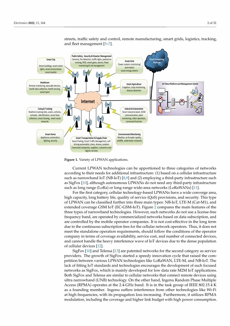
According to Cisco, it is predicted that 500 billion devices will be connected withthe Internet of Things (IoT) paradigm by 2030. On the other hand, Industrial Internetof Things (IIoT) and machine-to-machine (M2M) connectivity are directly interconnectedconcepts and are key players in the next step of Industry 4.0 evolution and intelligentmanufacturing [1,2]. These concepts (IoT, IIoT, M2M, and IR 4.0) have changed the methodof interaction between people, devices, and machines around them. They pave the way forbuilding ubiquitously connected infrastructures for supporting pioneering services andapplications. Such paradigms with promising features are attractive to both customers andindustry. Recently, we have witnessed massive IoT devices connected to the Internet invarious solutions and purposely designed applications. The IoT and M2M devices are con-nected via low-power wide-area network (LPWAN) technologies wirelessly. They can react,sense their environment, and turn on anytime and anywhere to update data in real time tothe cloud [3,4]. LPWANs are meant to solve several problems with existing short-range andcommunication cellular network technologies to address the IIoT applications. MassiveIoT devices are connected in various applications (Figure 1) such as smart buildings, smartmeters, smart agriculture, capillary networks, remote health care, connected cars, smart
Electronics 2022, 11, 164. https://doi.org/10.3390/electronics11010164 https://www.mdpi.com/journal/electronics
Electronics 2022, 11, 164 2 of 32
streets, traffic safety and control, remote manufacturing, smart grids, logistics, tracking,and fleet management [5–7].
Electronics 2022, 11, x FOR PEER REVIEW 2 of 32
the IIoT applications. Massive IoT devices are connected in various applications (Figure 1) such as smart buildings, smart meters, smart agriculture, capillary networks, remote health care, connected cars, smart streets, traffic safety and control, remote manufactur-ing, smart grids, logistics, tracking, and fleet management [5–7].
Current LPWAN technologies can be apportioned to three categories of networks according to their needs for additional infrastructure: (1) based on a cellular infrastructure such as narrowband IoT (NB-IoT) [8,9] and (2) employing a third-party infrastructure such as SigFox [10], although autonomous LPWANs do not need any third-party infrastructure such as long range (LoRa) or long-range wide-area networks (LoRaWANs) [11].
Cloud Computing Platform
Internet
IoT Data Platform and Management Center
Server
User
Industrial AutomationSmart industrial plant, M2M
communication, plant monitoring, robot operation,
connected factories
Smart AgricultureIrrigation, crops monitoring,
disease detection
Smart Transportation & Supply ChainSmart Parking, Smart Traffic Management, self-
driving automobile, trains, drones, aviationConnected companies, suppliers, customers and
logistic services
Smart HomeAppliances automation,
lighting, security
Smart City
Smart buildings, smart street lights, smart environment,
smart dustbin
Healthcare Remote monitoring, wearable devices, health data collection, health sensing,
smart Sport
Smart GridPower systems monitoring/
automationsmart energy meters
Public Safety, Security & Disaster ManagementCameras, fire detection, traffic lights, pedestrian
crossing, RFID, smart gates, alarms, flood monitoring & risk management
Living & TrackingRealtime tracking (kids, assets, vehicles,
animals) , Identification, smart Data collection, smart Sensing, smart social
networks
Environmental MonitoringWeather, air & water quality, wildlife, underwater networks
Figure 1. Variety of LPWAN applications.
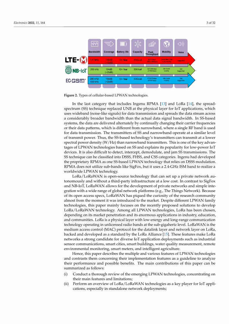
For the first category, cellular technology-based LPWANs have a wide converge area, high capacity, long battery life, quality of service (QoS) provisions, and security. This type of LPWAN can be classified further into three main types: NB-IoT, LTE-M (Cat-M1), and extended coverage GSM IoT (EC-GSM-IoT). Figure 2 compares the main features of the three types of narrowband technologies. However, such networks do not use a license-free frequency band, are operated by commercialized networks based on data subscrip-tion, and are controlled by the mobile operator companies. It is not cost-effective in the long term due to the continuous subscription fees for the cellular network operators. Thus, it does not meet the standalone operation requirements, should follow the conditions of the operator company in terms of coverage availability, service cost, and number of con-nected devices, and cannot handle the heavy interference wave of IoT devices due to the dense population of cellular devices [12].
SigFox [10] and Telensa [13] are patented networks for the second category as service providers. The growth of SigFox started a speedy innovation cycle that raised the compe-tition between various LPWAN technologies like LoRaWAN, LTE-M, and NB-IoT. The lack of fitting IoT standards and technologies encourages the development of such fo-cused networks as SigFox, which is mainly developed for low data rate M2M IoT appli-cations. Both SigFox and Telensa are similar to cellular networks that connect remote de-vices using ultra narrowband (UNB) technology. On the other hand, Ingenu Random Phase Multiple Access (RPMA) operates at the 2.4-GHz band. It is in the task group of IEEE 802.15.4 K as a founding member. Ingenu suffers interference from other technolo-gies like Wi-Fi at high frequencies, with its propagation loss increasing. Furthermore, it utilizes RPMA modulation, including the coverage and higher link budget with high power consumption.
Figure 1. Variety of LPWAN applications.
Current LPWAN technologies can be apportioned to three categories of networksaccording to their needs for additional infrastructure: (1) based on a cellular infrastructuresuch as narrowband IoT (NB-IoT) [8,9] and (2) employing a third-party infrastructure suchas SigFox [10], although autonomous LPWANs do not need any third-party infrastructuresuch as long range (LoRa) or long-range wide-area networks (LoRaWANs) [11].
For the first category, cellular technology-based LPWANs have a wide converge area,high capacity, long battery life, quality of service (QoS) provisions, and security. This typeof LPWAN can be classified further into three main types: NB-IoT, LTE-M (Cat-M1), andextended coverage GSM IoT (EC-GSM-IoT). Figure 2 compares the main features of thethree types of narrowband technologies. However, such networks do not use a license-freefrequency band, are operated by commercialized networks based on data subscription, andare controlled by the mobile operator companies. It is not cost-effective in the long termdue to the continuous subscription fees for the cellular network operators. Thus, it does notmeet the standalone operation requirements, should follow the conditions of the operatorcompany in terms of coverage availability, service cost, and number of connected devices,and cannot handle the heavy interference wave of IoT devices due to the dense populationof cellular devices [12].
SigFox [10] and Telensa [13] are patented networks for the second category as serviceproviders. The growth of SigFox started a speedy innovation cycle that raised the com-petition between various LPWAN technologies like LoRaWAN, LTE-M, and NB-IoT. Thelack of fitting IoT standards and technologies encourages the development of such focusednetworks as SigFox, which is mainly developed for low data rate M2M IoT applications.Both SigFox and Telensa are similar to cellular networks that connect remote devices usingultra narrowband (UNB) technology. On the other hand, Ingenu Random Phase MultipleAccess (RPMA) operates at the 2.4-GHz band. It is in the task group of IEEE 802.15.4 Kas a founding member. Ingenu suffers interference from other technologies like Wi-Fiat high frequencies, with its propagation loss increasing. Furthermore, it utilizes RPMAmodulation, including the coverage and higher link budget with high power consumption.
Electronics 2022, 11, 164 3 of 32
Electronics 2022, 11, x FOR PEER REVIEW 3 of 32
In the last category that includes Ingenu RPMA [13] and LoRa [14], the spread-spec-trum (SS) technique replaced UNB at the physical layer for IoT applications, which uses wideband (noise-like signals) for data transmission and spreads the data stream across a considerably broader bandwidth than the actual data signal bandwidth. In SS-based sys-tems, the data are delivered alternately by continually changing their carrier frequencies or their data patterns, which is different from narrowband, where a single RF band is used for data transmission. The transmitters of SS and narrowband operate at a similar level of transmit power. Thus, the SS-based technology’s transmitters can transmit at a lower spec-tral power density (W/Hz) than narrowband transmitters. This is one of the key ad-vantages of LPWAN technologies based on SS and explains its popularity for low-power IoT devices. It is also difficult to detect, intercept, demodulate, and jam SS transmissions. The SS technique can be classified into DSSS, FHSS, and CSS categories. Ingenu had de-veloped the proprietary RPMA as one SS-based LPWAN technology that relies on DSSS modulation. RPMA does not utilize sub-bands like SigFox, but it uses a 2.4-GHz ISM band to realize a worldwide LPWAN technology.
LoRa/LoRaWAN is open-source technology that can set up a private network auton-omously and without a third-party infrastructure at a low cost. In contrast to SigFox and NB-IoT, LoRaWAN allows for the development of private networks and simple integra-tion with a wide range of global network platforms (e.g., The Things Network). Because of its open access specs, LoRaWAN has piqued the curiosity of the research community almost from the moment it was introduced to the market. Despite different LPWAN fam-ily technologies, this paper mainly focuses on the recently proposed solutions to develop LoRa/LoRaWAN technology. Among all LPWAN technologies, LoRa has been chosen, depending on its market penetration and its enormous applications in industry, educa-tion, and communities. LoRa is a physical layer with low-energy and long-range commu-nication technology operating in unlicensed radio bands at the sub-gigahertz level. Lo-RaWAN is the medium access control (MAC) protocol for the datalink layer and network layer on LoRa, backed and developed as a standard by the LoRa Alliance [15]. These fea-tures make LoRa networks a strong candidate for diverse IoT application deployments such as industrial sensor communications, smart cities, smart buildings, water quality measurement, remote environmental monitoring, smart meters, and intelligent agricul-ture.
Figure 2. Types of cellular-based LPWAN technologies.
Hence, this paper describes the multiple and various features of LPWAN technolo-gies and contrasts them concerning their implementation features as a guideline to ana-lyze their performance and possible benefits. The main contributions of this paper can be summarized as follows: (i) Conduct a thorough review of the emerging LPWAN technologies, concentrating on
their main features and limitations; (ii) Perform an overview of LoRa/LoRaWAN technologies as a key player for IoT appli-
cations, especially in standalone network deployments;
Figure 2. Types of cellular-based LPWAN technologies.
In the last category that includes Ingenu RPMA [13] and LoRa [14], the spread-spectrum (SS) technique replaced UNB at the physical layer for IoT applications, whichuses wideband (noise-like signals) for data transmission and spreads the data stream acrossa considerably broader bandwidth than the actual data signal bandwidth. In SS-basedsystems, the data are delivered alternately by continually changing their carrier frequenciesor their data patterns, which is different from narrowband, where a single RF band is usedfor data transmission. The transmitters of SS and narrowband operate at a similar levelof transmit power. Thus, the SS-based technology’s transmitters can transmit at a lowerspectral power density (W/Hz) than narrowband transmitters. This is one of the key advan-tages of LPWAN technologies based on SS and explains its popularity for low-power IoTdevices. It is also difficult to detect, intercept, demodulate, and jam SS transmissions. TheSS technique can be classified into DSSS, FHSS, and CSS categories. Ingenu had developedthe proprietary RPMA as one SS-based LPWAN technology that relies on DSSS modulation.RPMA does not utilize sub-bands like SigFox, but it uses a 2.4-GHz ISM band to realize aworldwide LPWAN technology.
LoRa/LoRaWAN is open-source technology that can set up a private network au-tonomously and without a third-party infrastructure at a low cost. In contrast to SigFoxand NB-IoT, LoRaWAN allows for the development of private networks and simple inte-gration with a wide range of global network platforms (e.g., The Things Network). Becauseof its open access specs, LoRaWAN has piqued the curiosity of the research communityalmost from the moment it was introduced to the market. Despite different LPWAN familytechnologies, this paper mainly focuses on the recently proposed solutions to developLoRa/LoRaWAN technology. Among all LPWAN technologies, LoRa has been chosen,depending on its market penetration and its enormous applications in industry, education,and communities. LoRa is a physical layer with low-energy and long-range communicationtechnology operating in unlicensed radio bands at the sub-gigahertz level. LoRaWAN is themedium access control (MAC) protocol for the datalink layer and network layer on LoRa,backed and developed as a standard by the LoRa Alliance [15]. These features make LoRanetworks a strong candidate for diverse IoT application deployments such as industrialsensor communications, smart cities, smart buildings, water quality measurement, remoteenvironmental monitoring, smart meters, and intelligent agriculture.
Hence, this paper describes the multiple and various features of LPWAN technologiesand contrasts them concerning their implementation features as a guideline to analyzetheir performance and possible benefits. The main contributions of this paper can besummarized as follows:
(i) Conduct a thorough review of the emerging LPWAN technologies, concentrating ontheir main features and limitations;
(ii) Perform an overview of LoRa/LoRaWAN technologies as a key player for IoT appli-cations, especially in standalone network deployments;
Electronics 2022, 11, 164 4 of 32
(iii) Examine and compare the commonly used LoRa/LoRaWAN simulation tools byhighlighting their capabilities and features for enabling researchers to select the mostsuitable simulator based on their needs and programming skills;
(iv) Highlight the challenges, recent solutions, and future directions to provide guidelinestoward precise deployment of LoRa/LoRaWAN technology as a global network.
The rest of this article is structured as follows. In Section 2, we exhibit an overview ofthe considered LPWAN technologies and compare their main features. Section 3 focuseson LoRa/LoRaWAN technology and its technical features. In Section 4, we present thechallenges and recent solutions to LoRaWAN. Section 5 surveys the available simulationtools to analyze LoRa/LoRaWAN performance. Then, we present the opportunity forenhancement and future works on LoRaWAN in Section 6. Finally, we conclude the articlein Section 7.
2. LPWAN IoT Technologies
The crucial features of LPWAN technologies are a tremendous number of distributed de-vices across vast environmental distances with low-energy connectivity and unprecedentedlow costs. In this section, we introduce a thorough review of select LPWAN technologiesthat were developed to be used in the field of IoT applications and M2M communication.
2.1. NB-IoT
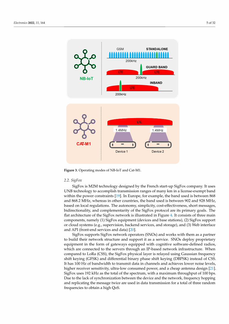
NB-IoT is 3GPP or 4GPP wireless access as a narrowband LPWAN technology thatcan collaborate in LTE or GSM under licensed frequency bands to achieve excellent per-formance. NB-IoT dominates a frequency bandwidth of 200 kHz for downlink and uplinkcommunication [9], and its protocol is based on the LTE communication protocol. Thus,several concepts and building units of LTE’s physical and upper protocol layers are repro-cessed by NB-IoT’s physical and upper protocol layers. In LTE M (Cat M1), the devicereceives a portion of the LTE carrier, as well as devices that are multiplexed across the LTEcarrier, and the device takes advantage of the full leveraging capacity of the widebandLTE carrier. NB-IoT devices have these features in contrast to Cat M1: an NB-IoT carrier ispresent, shared capacity is given to all NB-IoT devices, and the capacity may be scaled byadding additional NB-IoT carriers. The implementation of NB-IoT can be offered through asoftware update and can be installed in three operating modes, as shown in Figure 3 andas follows:
(i) Standalone: This scenario deploys in a standalone 200-kHz spectrum. For increasingcoverage, NB-IoT uses all the transmission power at the base station. The use of thismode will typically be as a substitute for GSM carriers.
(ii) In-band operation: This is deployed in a wideband LTE system, including one ormore (180 kHz) LTE physical source blocks. NB-IoT signals must not be transmittedto the region’s LTE-reserved time–frequency tools (including legacy-controlled areasignals and reference signals). Wideband LTE and NB-IoT technologies share theirtransmission power at the base station and can be useful for consuming the same basestation hardware with the output of either not being affected [16].
(iii) Guard band operation: This is deployed in the guard band of an LTE carrier andco-placed with an LTE cell, as the LTE channel shares the transmission power and thesame power amplifier [17,18].
The efficiency of the battery is conducive to its cost. Single-carrier frequency-divisionmultiple access (FDMA) is utilized by the NB-IoT uplink, while orthogonal FDMA (OFDMA)and quadrature phase shift keying modulation (QPSK) are used in the downlink [9]. TheNB-IoT message has 1600 bytes as a maximum payload size. The uplink data rate isrestricted to 20 kbps, while 200 kbps is the restriction for the downlink.
Electronics 2022, 11, 164 5 of 32Electronics 2022, 11, x FOR PEER REVIEW 5 of 32
Figure 3. Operating modes of NB-IoT and Cat-M1.
2.2. SigFox SigFox is M2M technology designed by the French start-up SigFox company. It uses
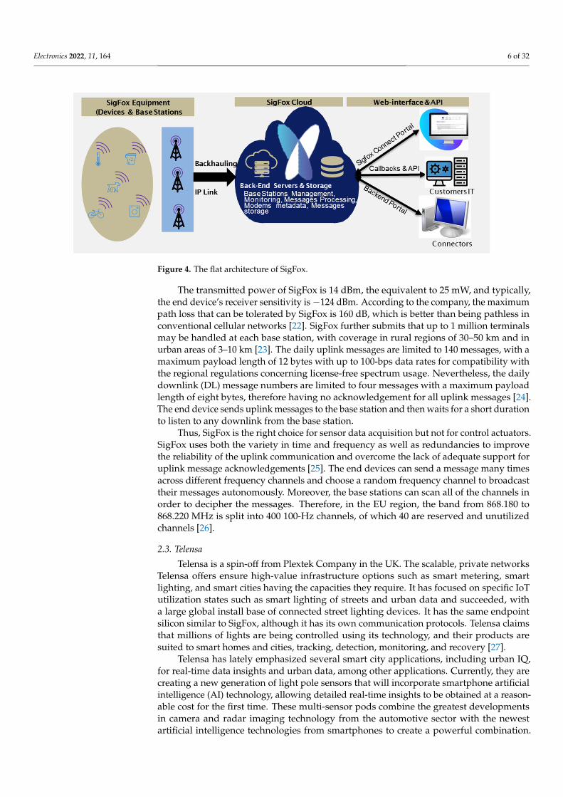
UNB technology to accomplish transmission ranges of many km in a license-exempt band within the power constraints [19]. In Europe, for example, the band used is between 868 and 868.2 MHz, whereas in other countries, the band used is between 902 and 928 MHz, based on local regulations. The autonomy, simplicity, cost-effectiveness, short messages, bidirectionality, and complementarity of the SigFox protocol are its primary goals. The flat architecture of the SigFox network is illustrated in Figure 4. It consists of three main components, namely (1) SigFox equipment (devices and base stations), (2) SigFox support or cloud systems (e.g., supervision, backend services, and storage), and (3) Web interface and API (front-end services and data) [20].
SigFox supports SigFox network operators (SNOs) and works with them as a partner to build their network structure and support it as a service. SNOs deploy proprietary equipment in the form of gateways equipped with cognitive software-defined radios, which are connected to the servers through an IP-based network infrastructure. When compared to LoRa (CSS), the SigFox physical layer is relayed using Gaussian frequency shift keying (GFSK) and differential binary phase shift keying (DBPSK) instead of CSS. It has 100 Hz of bandwidth to transmit data in channels and achieves lower noise levels, higher receiver sensitivity, ultra-low consumed power, and a cheap antenna design [21]. SigFox uses 192 kHz as the total of the spectrum, with a maximum throughput of 100 bps. Due to the lack of synchronization between the device and the network, frequency hop-ping and replicating the message twice are used in data transmission for a total of three random frequencies to obtain a high QoS.
The transmitted power of SigFox is 14 dBm, the equivalent to 25 mW, and typically, the end device’s receiver sensitivity is −124 dBm. According to the company, the maxi-
Figure 3. Operating modes of NB-IoT and Cat-M1.
2.2. SigFox
SigFox is M2M technology designed by the French start-up SigFox company. It usesUNB technology to accomplish transmission ranges of many km in a license-exempt bandwithin the power constraints [19]. In Europe, for example, the band used is between 868and 868.2 MHz, whereas in other countries, the band used is between 902 and 928 MHz,based on local regulations. The autonomy, simplicity, cost-effectiveness, short messages,bidirectionality, and complementarity of the SigFox protocol are its primary goals. Theflat architecture of the SigFox network is illustrated in Figure 4. It consists of three maincomponents, namely (1) SigFox equipment (devices and base stations), (2) SigFox supportor cloud systems (e.g., supervision, backend services, and storage), and (3) Web interfaceand API (front-end services and data) [20].
SigFox supports SigFox network operators (SNOs) and works with them as a partnerto build their network structure and support it as a service. SNOs deploy proprietaryequipment in the form of gateways equipped with cognitive software-defined radios,which are connected to the servers through an IP-based network infrastructure. Whencompared to LoRa (CSS), the SigFox physical layer is relayed using Gaussian frequencyshift keying (GFSK) and differential binary phase shift keying (DBPSK) instead of CSS.It has 100 Hz of bandwidth to transmit data in channels and achieves lower noise levels,higher receiver sensitivity, ultra-low consumed power, and a cheap antenna design [21].SigFox uses 192 kHz as the total of the spectrum, with a maximum throughput of 100 bps.Due to the lack of synchronization between the device and the network, frequency hoppingand replicating the message twice are used in data transmission for a total of three randomfrequencies to obtain a high QoS.
Electronics 2022, 11, 164 6 of 32
Electronics 2022, 11, x FOR PEER REVIEW 6 of 32
mum path loss that can be tolerated by SigFox is 160 dB, which is better than being path-less in conventional cellular networks [22]. SigFox further submits that up to 1 million terminals may be handled at each base station, with coverage in rural regions of 30–50 km and in urban areas of 3–10 km [23]. The daily uplink messages are limited to 140 messages, with a maximum payload length of 12 bytes with up to 100-bps data rates for compatibil-ity with the regional regulations concerning license-free spectrum usage. Nevertheless, the daily downlink (DL) message numbers are limited to four messages with a maximum payload length of eight bytes, therefore having no acknowledgement for all uplink mes-sages [24]. The end device sends uplink messages to the base station and then waits for a short duration to listen to any downlink from the base station.
Thus, SigFox is the right choice for sensor data acquisition but not for control actua-tors. SigFox uses both the variety in time and frequency as well as redundancies to im-prove the reliability of the uplink communication and overcome the lack of adequate sup-port for uplink message acknowledgements [25]. The end devices can send a message many times across different frequency channels and choose a random frequency channel to broadcast their messages autonomously. Moreover, the base stations can scan all of the channels in order to decipher the messages. Therefore, in the EU region, the band from 868.180 to 868.220 MHz is split into 400 100-Hz channels, of which 40 are reserved and unutilized channels [26].
Figure 4. The flat architecture of SigFox.
2.3. Telensa Telensa is a spin-off from Plextek Company in the UK. The scalable, private networks
Telensa offers ensure high-value infrastructure options such as smart metering, smart lighting, and smart cities having the capacities they require. It has focused on specific IoT utilization states such as smart lighting of streets and urban data and succeeded, with a large global install base of connected street lighting devices. It has the same endpoint sil-icon similar to SigFox, although it has its own communication protocols. Telensa claims that millions of lights are being controlled using its technology, and their products are suited to smart homes and cities, tracking, detection, monitoring, and recovery [27].
Telensa has lately emphasized several smart city applications, including urban IQ, for real-time data insights and urban data, among other applications. Currently, they are creating a new generation of light pole sensors that will incorporate smartphone artificial intelligence (AI) technology, allowing detailed real-time insights to be obtained at a rea-sonable cost for the first time. These multi-sensor pods combine the greatest developments in camera and radar imaging technology from the automotive sector with the newest ar-tificial intelligence technologies from smartphones to create a powerful combination. They provide a unique opportunity to gain a thorough understanding of how roadways func-tion. Because no videos are kept and no personal data are gathered, there is no risk to one’s personal information. For its part, Telensa leads an urban data project that builds on the changing economics of data collection and provides cities with the necessary tools to
Figure 4. The flat architecture of SigFox.
The transmitted power of SigFox is 14 dBm, the equivalent to 25 mW, and typically,the end device’s receiver sensitivity is −124 dBm. According to the company, the maximumpath loss that can be tolerated by SigFox is 160 dB, which is better than being pathless inconventional cellular networks [22]. SigFox further submits that up to 1 million terminalsmay be handled at each base station, with coverage in rural regions of 30–50 km and inurban areas of 3–10 km [23]. The daily uplink messages are limited to 140 messages, with amaximum payload length of 12 bytes with up to 100-bps data rates for compatibility withthe regional regulations concerning license-free spectrum usage. Nevertheless, the dailydownlink (DL) message numbers are limited to four messages with a maximum payloadlength of eight bytes, therefore having no acknowledgement for all uplink messages [24].The end device sends uplink messages to the base station and then waits for a short durationto listen to any downlink from the base station.
Thus, SigFox is the right choice for sensor data acquisition but not for control actuators.SigFox uses both the variety in time and frequency as well as redundancies to improvethe reliability of the uplink communication and overcome the lack of adequate support foruplink message acknowledgements [25]. The end devices can send a message many timesacross different frequency channels and choose a random frequency channel to broadcasttheir messages autonomously. Moreover, the base stations can scan all of the channels inorder to decipher the messages. Therefore, in the EU region, the band from 868.180 to868.220 MHz is split into 400 100-Hz channels, of which 40 are reserved and unutilizedchannels [26].
2.3. Telensa
Telensa is a spin-off from Plextek Company in the UK. The scalable, private networksTelensa offers ensure high-value infrastructure options such as smart metering, smartlighting, and smart cities having the capacities they require. It has focused on specific IoTutilization states such as smart lighting of streets and urban data and succeeded, witha large global install base of connected street lighting devices. It has the same endpointsilicon similar to SigFox, although it has its own communication protocols. Telensa claimsthat millions of lights are being controlled using its technology, and their products aresuited to smart homes and cities, tracking, detection, monitoring, and recovery [27].
Telensa has lately emphasized several smart city applications, including urban IQ,for real-time data insights and urban data, among other applications. Currently, they arecreating a new generation of light pole sensors that will incorporate smartphone artificialintelligence (AI) technology, allowing detailed real-time insights to be obtained at a reason-able cost for the first time. These multi-sensor pods combine the greatest developmentsin camera and radar imaging technology from the automotive sector with the newestartificial intelligence technologies from smartphones to create a powerful combination.
Electronics 2022, 11, 164 7 of 32
They provide a unique opportunity to gain a thorough understanding of how roadwaysfunction. Because no videos are kept and no personal data are gathered, there is no riskto one’s personal information. For its part, Telensa leads an urban data project that buildson the changing economics of data collection and provides cities with the necessary toolsto collect and use their data responsibly with full citizen oversight. This project is what isknown as a city’s digital twin, and it is being driven by Telensa. Telensa claims that thisproject has the potential to improve the quality of life for everyone [28].
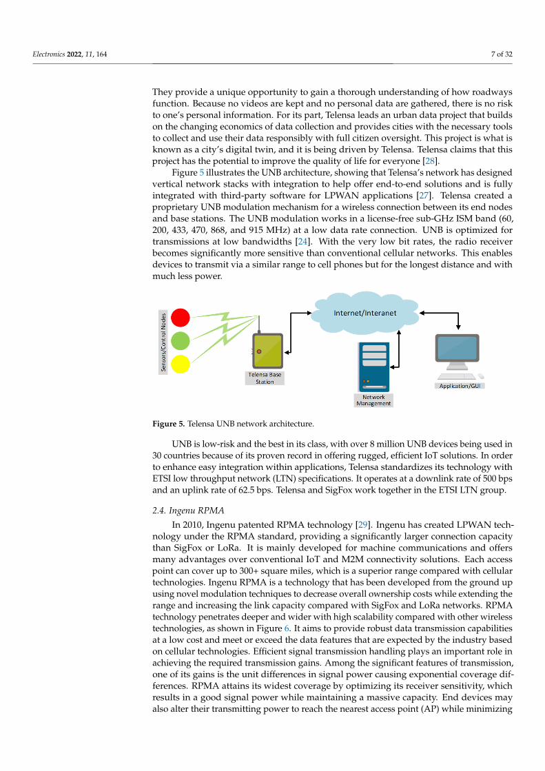
Figure 5 illustrates the UNB architecture, showing that Telensa’s network has designedvertical network stacks with integration to help offer end-to-end solutions and is fullyintegrated with third-party software for LPWAN applications [27]. Telensa created aproprietary UNB modulation mechanism for a wireless connection between its end nodesand base stations. The UNB modulation works in a license-free sub-GHz ISM band (60,200, 433, 470, 868, and 915 MHz) at a low data rate connection. UNB is optimized fortransmissions at low bandwidths [24]. With the very low bit rates, the radio receiverbecomes significantly more sensitive than conventional cellular networks. This enablesdevices to transmit via a similar range to cell phones but for the longest distance and withmuch less power.
Electronics 2022, 11, x FOR PEER REVIEW 7 of 32
collect and use their data responsibly with full citizen oversight. This project is what is known as a city’s digital twin, and it is being driven by Telensa. Telensa claims that this project has the potential to improve the quality of life for everyone [28].
Figure 5 illustrates the UNB architecture, showing that Telensa’s network has de-signed vertical network stacks with integration to help offer end-to-end solutions and is fully integrated with third-party software for LPWAN applications [27]. Telensa created a proprietary UNB modulation mechanism for a wireless connection between its end nodes and base stations. The UNB modulation works in a license-free sub-GHz ISM band (60, 200, 433, 470, 868, and 915 MHz) at a low data rate connection. UNB is optimized for transmissions at low bandwidths [24]. With the very low bit rates, the radio receiver be-comes significantly more sensitive than conventional cellular networks. This enables de-vices to transmit via a similar range to cell phones but for the longest distance and with much less power.
UNB is low-risk and the best in its class, with over 8 million UNB devices being used in 30 countries because of its proven record in offering rugged, efficient IoT solutions. In order to enhance easy integration within applications, Telensa standardizes its technology with ETSI low throughput network (LTN) specifications. It operates at a downlink rate of 500 bps and an uplink rate of 62.5 bps. Telensa and SigFox work together in the ETSI LTN group.
Figure 5. Telensa UNB network architecture.
2.4. Ingenu RPMA In 2010, Ingenu patented RPMA technology [29]. Ingenu has created LPWAN tech-
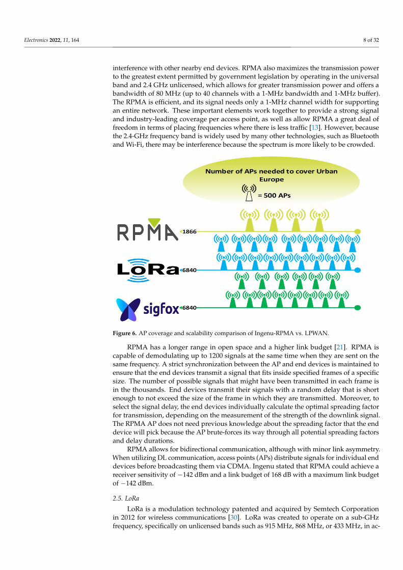
nology under the RPMA standard, providing a significantly larger connection capacity than SigFox or LoRa. It is mainly developed for machine communications and offers many advantages over conventional IoT and M2M connectivity solutions. Each access point can cover up to 300+ square miles, which is a superior range compared with cellular technol-ogies. Ingenu RPMA is a technology that has been developed from the ground up using novel modulation techniques to decrease overall ownership costs while extending the range and increasing the link capacity compared with SigFox and LoRa networks. RPMA technology penetrates deeper and wider with high scalability compared with other wire-less technologies, as shown in Figure 6. It aims to provide robust data transmission capa-bilities at a low cost and meet or exceed the data features that are expected by the industry based on cellular technologies. Efficient signal transmission handling plays an important role in achieving the required transmission gains. Among the significant features of trans-mission, one of its gains is the unit differences in signal power causing exponential cover-age differences. RPMA attains its widest coverage by optimizing its receiver sensitivity, which results in a good signal power while maintaining a massive capacity. End devices may also alter their transmitting power to reach the nearest access point (AP) while min-imizing interference with other nearby end devices. RPMA also maximizes the transmis-sion power to the greatest extent permitted by government legislation by operating in the universal band and 2.4 GHz unlicensed, which allows for greater transmission power and offers a bandwidth of 80 MHz (up to 40 channels with a 1-MHz bandwidth and 1-MHz
Figure 5. Telensa UNB network architecture.
UNB is low-risk and the best in its class, with over 8 million UNB devices being used in30 countries because of its proven record in offering rugged, efficient IoT solutions. In orderto enhance easy integration within applications, Telensa standardizes its technology withETSI low throughput network (LTN) specifications. It operates at a downlink rate of 500 bpsand an uplink rate of 62.5 bps. Telensa and SigFox work together in the ETSI LTN group.
2.4. Ingenu RPMA
In 2010, Ingenu patented RPMA technology [29]. Ingenu has created LPWAN tech-nology under the RPMA standard, providing a significantly larger connection capacitythan SigFox or LoRa. It is mainly developed for machine communications and offersmany advantages over conventional IoT and M2M connectivity solutions. Each accesspoint can cover up to 300+ square miles, which is a superior range compared with cellulartechnologies. Ingenu RPMA is a technology that has been developed from the ground upusing novel modulation techniques to decrease overall ownership costs while extending therange and increasing the link capacity compared with SigFox and LoRa networks. RPMAtechnology penetrates deeper and wider with high scalability compared with other wirelesstechnologies, as shown in Figure 6. It aims to provide robust data transmission capabilitiesat a low cost and meet or exceed the data features that are expected by the industry basedon cellular technologies. Efficient signal transmission handling plays an important role inachieving the required transmission gains. Among the significant features of transmission,one of its gains is the unit differences in signal power causing exponential coverage dif-ferences. RPMA attains its widest coverage by optimizing its receiver sensitivity, whichresults in a good signal power while maintaining a massive capacity. End devices mayalso alter their transmitting power to reach the nearest access point (AP) while minimizing
Electronics 2022, 11, 164 8 of 32
interference with other nearby end devices. RPMA also maximizes the transmission powerto the greatest extent permitted by government legislation by operating in the universalband and 2.4 GHz unlicensed, which allows for greater transmission power and offers abandwidth of 80 MHz (up to 40 channels with a 1-MHz bandwidth and 1-MHz buffer).The RPMA is efficient, and its signal needs only a 1-MHz channel width for supportingan entire network. These important elements work together to provide a strong signaland industry-leading coverage per access point, as well as allow RPMA a great deal offreedom in terms of placing frequencies where there is less traffic [13]. However, becausethe 2.4-GHz frequency band is widely used by many other technologies, such as Bluetoothand Wi-Fi, there may be interference because the spectrum is more likely to be crowded.
Electronics 2022, 11, x FOR PEER REVIEW 8 of 32
buffer). The RPMA is efficient, and its signal needs only a 1-MHz channel width for sup-porting an entire network. These important elements work together to provide a strong signal and industry-leading coverage per access point, as well as allow RPMA a great deal of freedom in terms of placing frequencies where there is less traffic [13]. However, be-cause the 2.4-GHz frequency band is widely used by many other technologies, such as Bluetooth and Wi-Fi, there may be interference because the spectrum is more likely to be crowded.
Figure 6. AP coverage and scalability comparison of Ingenu-RPMA vs. LPWAN.
RPMA has a longer range in open space and a higher link budget [21]. RPMA is ca-pable of demodulating up to 1200 signals at the same time when they are sent on the same frequency. A strict synchronization between the AP and end devices is maintained to en-sure that the end devices transmit a signal that fits inside specified frames of a specific size. The number of possible signals that might have been transmitted in each frame is in the thousands. End devices transmit their signals with a random delay that is short enough to not exceed the size of the frame in which they are transmitted. Moreover, to select the signal delay, the end devices individually calculate the optimal spreading factor for transmission, depending on the measurement of the strength of the downlink signal. The RPMA AP does not need previous knowledge about the spreading factor that the end device will pick because the AP brute-forces its way through all potential spreading fac-tors and delay durations.
RPMA allows for bidirectional communication, although with minor link asym-metry. When utilizing DL communication, access points (APs) distribute signals for indi-vidual end devices before broadcasting them via CDMA. Ingenu stated that RPMA could achieve a receiver sensitivity of −142 dBm and a link budget of 168 dB with a maximum link budget of −142 dBm.
2.5. LoRa LoRa is a modulation technology patented and acquired by Semtech Corporation in
2012 for wireless communications [30]. LoRa was created to operate on a sub-GHz fre-quency, specifically on unlicensed bands such as 915 MHz, 868 MHz, or 433 MHz, in ac-cordance with the regional area regulations. LoRa is a physical layer based on chirp spread spectrum (CSS) modulation, which is not similar to other modulations used in other wire-less networks [31]. LoRa was designed to be low-rate, low-power, and transmit with very a long-range in line-of-sight or rural area situations up to 10 or 20 km outdoors as a result of the higher sensitivity of LoRa CSS modulation enabling long-distance connectivity [32].
Figure 6. AP coverage and scalability comparison of Ingenu-RPMA vs. LPWAN.
RPMA has a longer range in open space and a higher link budget [21]. RPMA iscapable of demodulating up to 1200 signals at the same time when they are sent on thesame frequency. A strict synchronization between the AP and end devices is maintained toensure that the end devices transmit a signal that fits inside specified frames of a specificsize. The number of possible signals that might have been transmitted in each frame isin the thousands. End devices transmit their signals with a random delay that is shortenough to not exceed the size of the frame in which they are transmitted. Moreover, toselect the signal delay, the end devices individually calculate the optimal spreading factorfor transmission, depending on the measurement of the strength of the downlink signal.The RPMA AP does not need previous knowledge about the spreading factor that the enddevice will pick because the AP brute-forces its way through all potential spreading factorsand delay durations.
RPMA allows for bidirectional communication, although with minor link asymmetry.When utilizing DL communication, access points (APs) distribute signals for individual enddevices before broadcasting them via CDMA. Ingenu stated that RPMA could achieve areceiver sensitivity of −142 dBm and a link budget of 168 dB with a maximum link budgetof −142 dBm.
2.5. LoRa
LoRa is a modulation technology patented and acquired by Semtech Corporationin 2012 for wireless communications [30]. LoRa was created to operate on a sub-GHzfrequency, specifically on unlicensed bands such as 915 MHz, 868 MHz, or 433 MHz, in ac-
Electronics 2022, 11, 164 9 of 32
cordance with the regional area regulations. LoRa is a physical layer based on chirp spreadspectrum (CSS) modulation, which is not similar to other modulations used in other wire-less networks [31]. LoRa was designed to be low-rate, low-power, and transmit with very along-range in line-of-sight or rural area situations up to 10 or 20 km outdoors as a result ofthe higher sensitivity of LoRa CSS modulation enabling long-distance connectivity [32]. Itslow energy consumption, coupled with long-distance communication, makes LoRa oneof the potential candidates of LPWAN technologies for IoT applications [33]. As one ofthe most significant benefits of LoRa, the great receiver sensitivity is accompanied by anextremely wide communication connection budget. When utilizing LoRa modulation, thetypical values of SNR for 10 and 12 spreading factors are −20 dB and −15 dB, respectively,resulting in receiver sensitivities of −134 dBm and −129 dBm, respectively, according tothe manufacturer. However, these values are only somewhat equivalent to the averagesensitivity of Wi-Fi or Bluetooth receivers, which is typically in the range from −40 dBm to−80 dBm [31].
Different options for orthogonalizing transmissions as much as is feasible are providedby LoRa, such as the carrier frequency (CF), spreading factor (SF), bandwidth (BW), andcoding rate (CR), and collision-free communications can be achieved simultaneously. TheLoRa radio can transmit with data rates from 250 bps to 5.5 kbps with CSS and up to50 kb/s with FSK. The SF, CR, BW, and CF are transmission parameters of LoRa, whichrequires defining their values. The SF is from 7 to 12 as an integer value. There is an inverserelation between the SF and DR by means of increasing the symbol length due to a higherSF, thus decreasing the DR. The lower layers of LoRa are a property by Semtech, whilethe upper layer is specified by an open standard: LoRaWAN. To connect with a gateway,various end devices can use LoRa modulation, and the LoRa Alliance is developing thatopen standard [23].
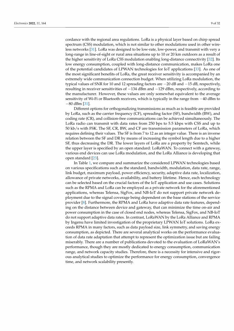
In Table 1, we compare and summarize the considered LPWAN technologies basedon various specifications such as the standard, bandwidth, modulation, data rate, range,link budget, maximum payload, power efficiency, security, adaptive data rate, localization,allowance of private networks, availability, and battery lifetime. Hence, each technologycan be selected based on the crucial factors of the IoT application and use cases. Solutionssuch as the RPMA and LoRa can be employed as a private network for the aforementionedapplications, whereas Telensa, SigFox, and NB-IoT do not support private network de-ployment due to the signal coverage being dependent on the base stations of the serviceprovider [8]. Furthermore, the RPMA and LoRa have adaptive data rate features, depend-ing on the distance between device and gateway, that can minimize the time on-air andpower consumption in the case of closed end nodes, whereas Telensa, SigFox, and NB-IoTdo not support adaptive data rates. In contrast, LoRaWAN by the LoRa Alliance and RPMAby Ingenu have limited investigation of the proprietary LPWAN IoT solutions. LoRa ex-ceeds RPMA in many factors, such as data payload size, link symmetry, and saving energyconsumption, as depicted. There are several analytical works on the performance evalua-tion of data rate adaptation that attempt to represent the optimization issue but are failingmiserably. There are a number of publications devoted to the evaluation of LoRaWAN’sperformance, though they are mostly dedicated to energy consumption, communicationrange, and network capacity studies. Therefore, there is a necessity for intensive and rigor-ous analytical studies to optimize the performance for energy consumption, convergencetime, and network scalability presently.
Electronics 2022, 11, 164 10 of 32
Table 1. LPWAN technology comparison.
Property orTechnology NB-IoT SigFox Telensa Ingenu RPMA LoRa
Founder 3 GPP SigFox Telensa Ingenu Semtech
Standard 3 GPP Release 13and 14 SigFox and ETSI LTN Telensa and ETSI
LTNRPMA and IEEE
802.15.4 K LoRa Alliance
Frequency band Licensed7–900 MHz
Sub-GHz ISMEU: 868 MHzUS: 902 MHz
Sub-GHz ISMEU: 868 MHzUS: 915 MHzAS: 430 MHz
2.4 GHz ISM
Sub-GHz ISMEU: 868 or 433 MHz
US: 915 MHzAS: 430 MHz
Bandwidth 180 kHz 100 or 600 HzDL:1.5 kHz 100 kHz 1 MHz 125,250,500 kHz
ModulationDL: QPSK
UL: π/4-QPSK,π/2-BPSK, QPSK
UL: UNB DBPSKDL: GFSK UNB 2-FSK
UL: RPMA-DSSS
DL: CDMACSS, FSK
MAC TDMA-based MAC ALOHA MAC n/a TDMA-based MAC LoRaWAN/ALOHA-based
Protocol ownership Standard Proprietary Standard Proprietary Partially proprietary
Data rate UL: 64 kbpsDL: 25 kbps
UL: 100 or 600 bpsDL: 600 bps
UL: 62.5 bpsDL: 500 bps
UL: 624 kbpsDL: 156 kbps
LoRa: 0.3–37.5 kbps,FSK: 50 kbps
Range Urban: 1.5 kmRural: 20–40 km
Urban: 3–10 kmRural: 30–50 km
Urban: 3 kmRural: 16 km (NLOS)
Urban: 15 kmRural: 48 km
Urban: 5 kmRural: 45 km
Link budget (dB) 189 EU: 162US: 146
EU: 161US: 149
EU: 168US: 180
EU: 151US: 171
Max. Payload size(bytes) 13 UL: 12
DL: 8 65k 64 250
Tx power (dBm) 35 24 14 21 21
Security L2 security No or encryption athigher level Yes AES 256 b AES 128 b
Interferenceimmunity Low Very high Very high Low Very high
Adaptive data rate No No No Yes Yes
Localization No Yes (RSSI) No No Yes (TDOA)
Topology Star Star Star or tree Star or tree Star-of-stars
Energy consumption Low Very low Low High Very low
Link symmetry No No No No Yes
Allow privatenetworks No No No Yes Yes
Over the air updates No No Yes Yes Yes
Error Correction CRC UL: CRC-16DL: CRC-8 Yes CRC FEC and CRC-8/16
Channel ororthogonal signal 12 carrier 360 multiple 40
EU: 10US: UL 64+8,
DL: 8 + SF
Nodes per gateway 52,000 >1,000,000 5000 500,000 >1,000,000
Cost Moderate Moderate High Low Very low
3. LoRaWAN Networking
With its star-of-stars network structure, LoRaWAN allows for secure bidirectionalcommunication in both directions. Although LoRa/LoRaWAN technology offers manyadvantages in terms of low bit rate and power consumption, wide coverage, simplicity,the possibility of deploying a private network, security, and ease to manage due to itsstar-of-stars topology, recent studies have highlighted a number of potential issues withLoRa/LoRaWAN networks, particularly in terms of scalability in large-scale scenarios.
Electronics 2022, 11, 164 11 of 32
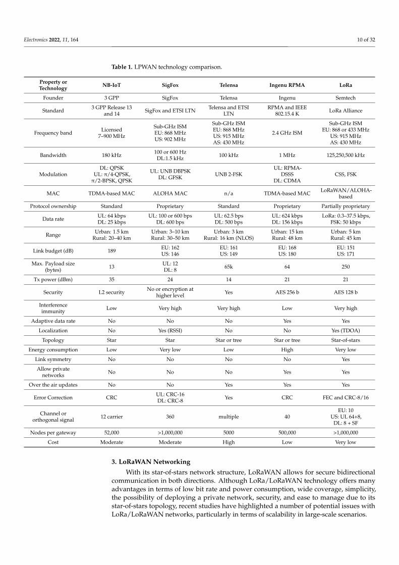
LoRaWAN is a cloud-based MAC layer networking protocol that is designed andmaintained by the LoRa Alliance to define the upper layers of long-range wide-areanetworks with a LoRa physical layer. It is an LPWAN technology for battery-operatedwireless connection of objects to the Internet in regional, national, or worldwide networksthat aims at major IoT needs, including two-way communication, end-to-end protection,mobility, and localization. The LoRa physical layer supports long-range communicationlinks, whereas the LoRaWAN protocol principally functions as a protocol to route thenetwork layer between LoRaWAN gateways and LoRa devices. LoRaWAN also managesthe data rate, communication frequencies, and transmission power for all nodes in thenetwork, which are asynchronous and transmit data on demand. As shown in Figure 7, thetransmitted data by an end device will be received by nearby gateways that forward thedata payloads to the cloud server (The Things Network (TTN)) that is integrated into severalIoT platforms. The duplicated packets will be filtered at the network server, which alsomanages the network and ensures data security. By using any of the available integrations,the received information is forwarded to application servers (Web-based dashboards andMobileApps.). A LoRaWAN technology architecture defines the three fundamental typesof devices as follows:
• End devices (ED): These are devices that either take downlink (DL) traffic from thenetwork server or generate uplink (UL) traffic for transmission to the gateways;
• Gateways (GW): These are the devices that demodulate LoRa communication andtransmit it between the network server and the end devices in a wireless network.Wired or wireless access points link gateways to the Internet. The LoRaWAN gatewayis sophisticated, concurrently listening to the radio on several channels and deliveringthousands of ENs simultaneously;
• Network Server (NS): This is the device which serves as the core backend of a Lo-RaWAN network, collecting traffic from all end devices in the network and processingit on an application server.
Electronics 2022, 11, x FOR PEER REVIEW 11 of 32
links, whereas the LoRaWAN protocol principally functions as a protocol to route the net-work layer between LoRaWAN gateways and LoRa devices. LoRaWAN also manages the data rate, communication frequencies, and transmission power for all nodes in the net-work, which are asynchronous and transmit data on demand. As shown in Figure 7, the transmitted data by an end device will be received by nearby gateways that forward the data payloads to the cloud server (The Things Network (TTN)) that is integrated into sev-eral IoT platforms. The duplicated packets will be filtered at the network server, which also manages the network and ensures data security. By using any of the available inte-grations, the received information is forwarded to application servers (Web-based dash-boards and MobileApps.). A LoRaWAN technology architecture defines the three funda-mental types of devices as follows: • End devices (ED): These are devices that either take downlink (DL) traffic from the
network server or generate uplink (UL) traffic for transmission to the gateways; • Gateways (GW): These are the devices that demodulate LoRa communication and
transmit it between the network server and the end devices in a wireless network. Wired or wireless access points link gateways to the Internet. The LoRaWAN gate-way is sophisticated, concurrently listening to the radio on several channels and de-livering thousands of ENs simultaneously;
• Network Server (NS): This is the device which serves as the core backend of a Lo-RaWAN network, collecting traffic from all end devices in the network and pro-cessing it on an application server.
LoRa Sensors(End nodes)
LoRaWAN Gateways
Integration Plugin
Application Servers
Network Server
IPIP
Web-based Dashboards
Mobile Apps.
IP
Data Storage
Figure 7. LoRaWAN network architecture.
LoRaWAN enables sensing nodes to transmit information as small packets with low energy consumption to a faraway gateway for many kilometers in one hop, and the tech-nology is robust to interference [15]. LoRaWAN networks may be used for relatively dense installations with low latency and reliability requirements, and they are becoming increasingly popular [23].
When compared to other wireless technologies, LoRaWAN provides the option of private network installations as well as easy integration with a variety of WAN network platforms (e.g., TTN). Because of this and its open access specifications, LoRaWAN has attracted the interest of the scientific community, technology manufacturers, and service providers since its first appearance in the market [34].
The adaptive data rate (ADR) is included in the LoRaWAN network to choose a transmission speed that better fits the conditions of the channel. LoRaWAN works on free regional frequency bands such as 915 MHz in America, 868 MHz in Europe, and 433 MHz in Asia as the carrier frequency. It uses 125, 250, or 500 kHz as its bandwidth. For error detection and correction, LoRaWAN uses the coding rate and employed number of bits to
Figure 7. LoRaWAN network architecture.
LoRaWAN enables sensing nodes to transmit information as small packets with lowenergy consumption to a faraway gateway for many kilometers in one hop, and thetechnology is robust to interference [15]. LoRaWAN networks may be used for relativelydense installations with low latency and reliability requirements, and they are becomingincreasingly popular [23].
Electronics 2022, 11, 164 12 of 32
When compared to other wireless technologies, LoRaWAN provides the option ofprivate network installations as well as easy integration with a variety of WAN networkplatforms (e.g., TTN). Because of this and its open access specifications, LoRaWAN hasattracted the interest of the scientific community, technology manufacturers, and serviceproviders since its first appearance in the market [34].
The adaptive data rate (ADR) is included in the LoRaWAN network to choose atransmission speed that better fits the conditions of the channel. LoRaWAN works on freeregional frequency bands such as 915 MHz in America, 868 MHz in Europe, and 433 MHzin Asia as the carrier frequency. It uses 125, 250, or 500 kHz as its bandwidth. For errordetection and correction, LoRaWAN uses the coding rate and employed number of bits toshow this. The combination of all aforementioned features made LoRaWAN a powerfultechnology for very long-range transmission in IoT applications.
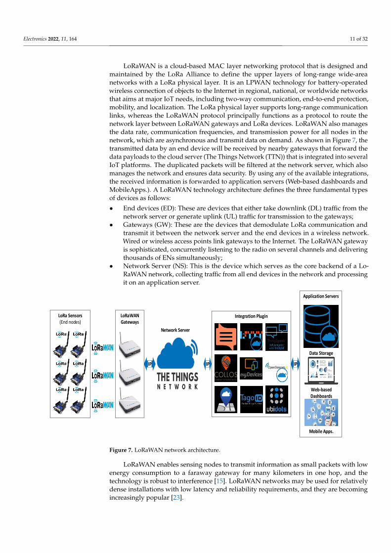
Because of its specific modulation, LoRa is a multipurpose technology that can be ver-satile and function in different types of environments and application groups. LoRaWANdefines three operation modes as classes [35]: A, B, and C. All nodes must be initializedwith Class A, as the default choice mode is considered when EDs send data at any time tothe GW through an ALOHA-based LoRaWAN MAC protocol.
• Class A: This class uses two receiving windows at specific times following each ULtransmission. As a timing diagram in Figure 8, at the beginning of these receivingwindows, only DL transmissions are allowed. With regard to the first window, DLtransmissions are carried out using the identical channel and data rate settings as theprior UL transmission. Nevertheless, the second window uses a static setting (i.e., DR0(SF12/125 KHz)) at 869.525 MHz.
• Class B: This class is an optional mode for ED that needs to receive additional informa-tion from the base station as acknowledgment (ACK) that using this mode is better.Despite no former transmission from the EN, the GWs open more reception windowsby transmitting synchronization beacons. The number of receiving windows allowedby Class B is more than Class A, but with more energy consumption than Class A. Af-ter each UL transmission, the extra regular receiving windows are opened, in additionto the synchronized opening of the two standard receiving windows, called ping slots.The GW beacons are sent periodically every 128 s to guarantee synchronization. Theusable beacon window is a time period between two beacons. It is grouped into 212
ping slots of 30 ms, each counting from 0 to 4095 [36].• Class C: The nodes keep their reception windows open all of the time, only shutting
them when the UL sends a packet to one of them. These ENs increase power consump-tion, since Class C forces the devices to receive constantly, which is incompatible withClass B. The devices that support Class C do not implement Class B.
Electronics 2022, 11, x FOR PEER REVIEW 12 of 32
show this. The combination of all aforementioned features made LoRaWAN a powerful technology for very long-range transmission in IoT applications.
Because of its specific modulation, LoRa is a multipurpose technology that can be versatile and function in different types of environments and application groups. Lo-RaWAN defines three operation modes as classes [35]: A, B, and C. All nodes must be initialized with Class A, as the default choice mode is considered when EDs send data at any time to the GW through an ALOHA-based LoRaWAN MAC protocol. • Class A: This class uses two receiving windows at specific times following each UL
transmission. As a timing diagram in Figure 8, at the beginning of these receiving windows, only DL transmissions are allowed. With regard to the first window, DL transmissions are carried out using the identical channel and data rate settings as the prior UL transmission. Nevertheless, the second window uses a static setting (i.e., DR0 (SF12/125 KHz)) at 869.525 MHz.
• Class B: This class is an optional mode for ED that needs to receive additional infor-mation from the base station as acknowledgment (ACK) that using this mode is better. Despite no former transmission from the EN, the GWs open more reception windows by transmitting synchronization beacons. The number of receiving windows allowed by Class B is more than Class A, but with more energy consumption than Class A. After each UL transmission, the extra regular receiving windows are opened, in addition to the synchronized opening of the two standard receiving windows, called ping slots. The GW beacons are sent periodically every 128 s to guarantee synchronization. The usable beacon window is a time period between two beacons. It is grouped into 212 ping slots of 30 ms, each counting from 0 to 4095 [36].
• Class C: The nodes keep their reception windows open all of the time, only shutting them when the UL sends a packet to one of them. These ENs increase power consump-tion, since Class C forces the devices to receive constantly, which is incompatible with Class B. The devices that support Class C do not implement Class B. Selection of the mode operation or class depends on the application. Thus, Table 2
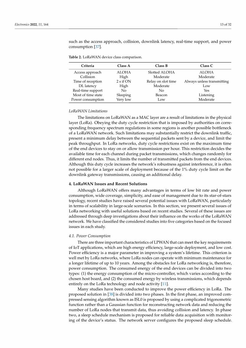
can guide the right class selection by comparing the classes adopted on some criteria such as the access approach, collision, downlink latency, real-time support, and power con-sumption [37].
Table 2. LoRaWAN device class comparison.
Criteria Class A Class B Class C Access approach ALOHA Slotted ALOHA ALOHA
Collision High Moderate Moderate Time of reception 2 s if ON Relay on slot time Always unless transmitting
DL latency High Moderate Low Real-time support No No Yes Most of time state Sleeping Beacon Listening
Power consumption Very low Low Moderate
Transmit RX2RX1Class A
TransmitSleep
RX Delay2
RX Delay1
Transmit RX2RX1Class B
Transmit
RX Delay2
RX Delay1
BCN PNG BCN
Beacon period
PNG
Transmit RXClass C TransmitListening
Time
Time
Time
Figure 8. Class time diagram of LoRaWAN devices.
Selection of the mode operation or class depends on the application. Thus, Table 2can guide the right class selection by comparing the classes adopted on some criteria
Electronics 2022, 11, 164 13 of 32
such as the access approach, collision, downlink latency, real-time support, and powerconsumption [37].
Table 2. LoRaWAN device class comparison.
Criteria Class A Class B Class C
Access approach ALOHA Slotted ALOHA ALOHACollision High Moderate Moderate
Time of reception 2 s if ON Relay on slot time Always unless transmittingDL latency High Moderate Low
Real-time support No No YesMost of time state Sleeping Beacon Listening
Power consumption Very low Low Moderate
LoRaWAN Limitations
The limitations on LoRaWAN as a MAC layer are a result of limitations in the physicallayer (LoRa). Obeying the duty cycle restriction that is imposed by authorities on corre-sponding frequency spectrum regulations in some regions is another possible bottleneckof a LoRaWAN network. Such limitations may substantially restrict the downlink traffic,present a minimum delay between the sequential packets sent by a device, and limit thepeak throughput. In LoRa networks, duty cycle restrictions exist on the maximum timeof the end devices to stay on or allow transmission per hour. This restriction decides theavailable time for each channel during packet transmissions, which changes randomly fordifferent end nodes. Thus, it limits the number of transmitted packets from the end devices.Although this duty cycle increases the network’s robustness against interference, it is oftennot possible for a larger scale of deployment because of the 1% duty cycle limit on thedownlink gateway transmissions, causing an additional delay.
4. LoRaWAN Issues and Recent Solutions
Although LoRaWAN offers many advantages in terms of low bit rate and powerconsumption, wide coverage, simplicity, and ease of management due to its star-of-starstopology, recent studies have raised several potential issues with LoRaWAN, particularlyin terms of scalability in large-scale scenarios. In this section, we present several issues ofLoRa networking with useful solutions based on recent studies. Several of these issues areaddressed through deep investigations about their influence on the works of the LoRaWANnetwork. We have classified the considered studies into five categories based on the focusedissues in each study.
4.1. Power Consumption
There are three important characteristics of LPWAN that can meet the key requirementsof IoT applications, which are high energy efficiency, large-scale deployment, and low cost.Power efficiency is a major parameter in improving a system’s lifetime. This criterion iswell met by LoRa networks, where LoRa nodes can operate with minimum maintenance fora longer lifetime of up to 10 years. Among the obstacles for LoRa networking is, therefore,power consumption. The consumed energy of the end devices can be divided into twotypes: (1) the energy consumption of the micro-controller, which varies according to thechosen host board, and (2) the consumed energy by wireless transmissions, which dependsentirely on the LoRa technology and node activity [11].
Many studies have been conducted to improve the power efficiency in LoRa. Theproposed solution in [38] is divided into two phases. In the first phase, an improved com-pressed sensing algorithm known as ISL0 is proposed by using a complicated trigonometricfunction rather than a Gaussian function for reconstructing network data and reducing thenumber of LoRa nodes that transmit data, thus avoiding collision and latency. In phasetwo, a sleep schedule mechanism is proposed for reliable data acquisition with monitor-ing of the device’s status. The network server configures the proposed sleep schedule.
Electronics 2022, 11, 164 14 of 32
Hence, each node executes its sleep interval cyclically. Two modes are involved in thesleep schedule—sleep mode and semi-sleep mode—and the nodes in the semi-sleep modeare selected randomly in each cycle. This method enables the instantaneous detection ofabnormal information and duly records the overall network data. The authors claimed thatthe results showed that the proposed approaches balanced the energy consumption amongall nodes and maximized the network’s lifetime. The compressed sensing algorithm cansubstantially reduce the number of LoRa nodes that transmit data concurrently and thendecrease the gateway delay, giving LoRaWAN a new idea for penetrating boundaries withthe proposed sleep schedule as only being linked to sampling. The compression values andtotal number of nodes do not affect the network length. The merging of ISL0 algorithmsand mechanisms for energy planning greatly improved the lifespan of the network withoutaffecting the impact of the network observation.
The authors of [39] proposed three schemes for improving power consumption. Thefirst scheme suggested an algorithm that prevents the collision between two colliding sig-nals and thus recovers entire frames without any loss. The second scheme is a special MACbeacon-based protocol that is used to decode two or more overlapping LoRa signals usinga collision resolution technique. The third strategy is to decode an algorithm that slightlydisconcerts and overlays the characteristics of a LoRa physical layer as well as the overlays.The simulation results show that the decoding scheme can be further improved by the useof the already offered CRC in each frame under the suggested collision resolution process.Additionally, the simulation findings revealed that significant performance increases interms of both device energy consumption and throughput were achieved when comparingthe ALOHA LoRaWAN protocol with the CR-MAC protocol, as demonstrated by thesimulation results. Furthermore, the proposed protocol reduced the delay significantly. Thedrawbacks considered were the size of the beacon (10 bytes) and retransmission times ofthe packet loss (one time only). In future work, the proposed protocol must be strengthenedfurther by creating personalized retransmission policies.
In [33], the authors proposed an optimized energy model for sensor nodes based onLoRa/LoRaWAN technologies. The proposed models were evaluated to reduce the lossof energy by the sensing unit, MCU unit, and transmission unit. The energy of each unitwas modeled individually to compare the consumed energy by each part of the LoRa node.The proposed model shows the effect of the selection of hardware and software for thesensor. Additionally, it shows the effect of transmission acknowledgement and the choiceof different LoRa/LoRaWAN parameters. Therefore, it is very important to optimize theseparameters to reduce the energy consumption of the end devices, such as the spread factor,payload size, bandwidth, and coding rate. The findings showed through the numericalresults that with distinct LoRa/LoRaWAN parameters, the consumed energy shifted. ClassA was most energy-efficient in LoRaWAN, which is the basis of the model. However, thestudy only evaluated the power consumption in the hardware parts of the LoRa nodes anddid not suggest an approach to enhance the LoRa radio, merely mentioning the effect ofACK and parameter selection. The optimized energy models could be further enhanced infuture work by LoRa power management algorithms to optimize the sensor node’s lifetime.
In [40], FREE is proposed as a fine-grained scheduling scheme for reliable and energy-efficient data collection. FREE computed the transmission schedule as a slot time (i.e.,the transmitted data must be buffered in a scheduled time slot instead of transmitteddirectly). The study maximized the overhead phase, which was necessary to managethe allocated frequency channels, spreading factors, transmission powers, and time slotsand synchronize the network. Collisions are the big issue of lost and retransmitted data,resulting in more power loss and representing a bottleneck of the standard LoRaWANprotocol. FREE overcomes this issue by utilizing different spreading factors and groupingacknowledgements to achieve scheduled concurrent transmissions. The solution wassimulated by the LoRaSim simulator and compared with other methods for confirmableand unconformable transmissions. The results proved that FREE makes deploymentquite scalable, accomplishing this with roughly 100% data delivery and a battery lifetime
Electronics 2022, 11, 164 15 of 32
increased by 2 additional years until it became over a 10-year battery lifetime, regardless ofthe transmission type or network size. The drawback of this work is the excessive fairnessbetween the devices in terms of power consumed. In order to use the allocations recordedin the previous data sets, this would entail a different allocation method.
4.2. Pure Data Extraction
Improvement of the data extraction rate (DER) aims to enhance the network through-put. In [41], the authors modeled the uplink nodes’ activity using a mathematical modelbased on collected experimental data by implementing DER as a new metric for measuringLoRa network performance. The transmitted messages in a LoRa network should be re-ceived at the backend system. In other words, each transmitted message must be receivedby at least one LoRa gateway. Thus, the authors defined the DER metric as the ratio ofreceived to transmitted messages in a defined interval. The obtained ratio of the DER is afunction of the node or gateway locations, number, and activity. LoRa exhibits the captureeffect since it is a form of frequency modulation. The capture effect happens when twosignals with different strengths reach the receiver. If the difference in the signals’ strengthsis too small, the receiver will not be able to decode any of the received signals. Thus, thestudy suggests adding more gateways to enhance the LoRa throughput.
SF allocation was the focus of [42] to enhance the capacity of the LoRa network. Anoptimization for SF allocation in relation to the LoRa network’s capacity was definedby maximizing the packet success probability (PSP) to increase the connectivity of theend devices. During the SF allocation assignment process, the suggested method tookboth inter- and intra-SF interference into consideration. When the signal of interest hasa signal-to-interference ratio (SIR) greater than a predetermined threshold, the captureeffect is used to combine the two types of considered interference into the signal of interest.The propositioned scheme controls the SF distribution based on the assigned distancesobtained from the problem optimization instead of conventional allocation, which is basedon coverage distances according to the sensitivities of the LoRa’s physical layer. The authorsused stochastic geometry for calculation of the PSP average and assigned SFs to the enddevices according to the received power and SIR of the end devices. Although the proposedapproach is complex, the global optimization solver can overcome this issue.
Another approach to maximize the LoRa network capacity based on SF networkclustering was developed in [43]. A tree-based SF clustering algorithm allocates enddevices to many subnetworks. Several transmission parameters of LoRa are consideredto form multi-mesh subnets with different SFs that are rooted at the gateway for enablingsimultaneous transmissions. The proposed approach balances the traffic load among theend devices using an SF capacity estimation based on the node number, data rates, andnumber of hops, thus avoiding bottlenecks of the subnets. The higher SF values increasethe delay due to the greater air time required to transmit the packets. The authors claimedthat their approach improved the network performance compared with the conventionalSF allocation of the LoRaWAN network with a single hop. Nevertheless, the analysisignored the positive impact of the offloading method since the time response was notfairly distributed among all the cluster heads. Moreover, the transmitted overhead raisesthe energy consumption at the relay nodes. Further investigation is required for fasterprediction of the efficiency and connectivity of the SF based on higher speed data rates.The ADR can be utilized to enhance the DER and maximize network throughput.
The authors of [44] proposed extension modules for ns-3 by implementing the ADR inthe LoRaWAN library to allow the simulation of a real LoRaWAN scenario. The introducedimprovement optimized the data rate of the end nodes, and thus the conducted simulationsachieved a minimal convergence time for the LoRa nodes. Therefore, an enhancementin the PDR was attained in a dynamic LoRa network. The authors claimed that theirproposed ADR outperformed the standard algorithm in the considered scenarios, whiletheir algorithm can be integrated easily to replace the existing ADR LoRaWAN network.However, it is particularly implemented on the TTN server. The network server algorithm
Electronics 2022, 11, 164 16 of 32
fails for the DR0 nodes, with no downlink requirement supported already in numerousLPWAN situations.
4.3. Network Scalability
A number of studies focused on LoRaWAN network scalability. The scalability chal-lenge of LoRaWAN installations occurs owing to the high number of end device requestACKs and the duty cycle constraint that the gateway must comply with. A lack of scalabil-ity may wreak havoc on the current scalability information, which is mostly commercialand assumes the best case scenario. In [41], the authors suggest adding more gateways toenhance LoRa scalability. The authors created a LoRa simulator, dubbed LoRaSim, basedon the Python programming language. They terminated the network with a single gateway,which does not scale well with standard transmissions, while networks that automaticallyadjust the transmission parameters or have several gateways may scale better. The findingof the study is that LoRa network scalability increases if the ToA is minimized by theoptimal configuration parameters as well. However, this model associates over-valueattenuation in open space for LoRa ‘s signals. It needs to be evaluated on-site, as themajority of the coverage area includes conventional connections, which have been definedas connections to dynamic time links. Although the use of various gateways outperformsthe present findings, the efficiency will further be improved by the optical location of thegateways in proportion to the application community.
In [45], the authors describe the results of LoRaWAN scalability research in whichthey created a mathematical model of the transmission process in order to analyze thescalability of LoRaWAN networks. After much deliberation, they came to the conclusionthat the network’s capacity was only 1% of 51 byte frames per second. This amount ofcapacity equates to 5000 motes, each of which can transmit two messages each day onaverage. This capacity is reserved for uplink traffic that has been confirmed. In [46], adifferent method was used by the authors, who examined the scalability of a LoRaWANnetwork in which the end nodes broadcast messages regularly, regardless of the radio dutycycle. In their claim, the authors said that such an evaluation provided a lower constrainton the maximum number of nodes that could be serviced by a single portal. Anotherexample of scalability research was carried out using a simulation model and the results ofmeasurements with actual nodes. However, the measurements were not carried out in aninterference-free environment as in the previous study. Only three particular parametersets for the nodes were taken into consideration by the authors.
In [47], a scalability study for LoRaWAN was carried out using a stochastic geometryframework, and the results were presented. The authors demonstrated that the likelihood ofcoverage decreased exponentially with the rise in the number of end devices. The theoreticalcapability of LoRaWAN in terms of scalability and node throughput has been investigated ina number of research projects [48]. The detrimental impacts of interference were examinedin densely crowded LoRaWAN cells. The authors have investigated several difficultiesrelating to co-distribution which, in particular, damages the scalability of LoRaWANnetworks. All these studies proved that LoRaWAN networks should be configured properlyto connect a great number of end devices.
The authors of [49] contrasted LoRaWAN with other communication technologies.LoRaWAN has benefits in its capacity for open standards, integrated security, GPS-freegeolocation, long-distance communication, low energy consumption, and private deploy-ment choices. In addition, the lower data rate, duty cycle restrictions, and benefits limitLoRaWAN networks in real-time applications. LoRaWAN is ideally suited to circumstancesin which data transfers are infrequent (several packets a day), and the payload size is about10–50 bytes. Smart cities, intelligent grids, intelligent farming, and remote monitoringsystems are the areas of optimum use for LoRaWAN. The ALOHA-based MAC protocol ofLoRaWAN limits its scalability and represents an obstacle for LoRa to lead other LPWANtechnologies as the main representative in the wide-scale deployment of IoT applications.
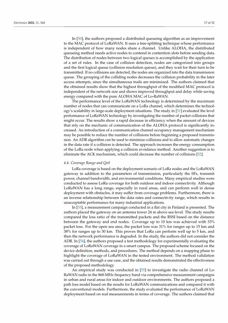
Electronics 2022, 11, 164 17 of 32
In [50], the authors proposed a distributed queueing algorithm as an improvementto the MAC protocol of LoRaWAN. It uses a tree-splitting technique whose performanceis independent of how many nodes share a channel. Unlike ALOHA, the distributedqueueing method needs active nodes to contend in contention slots before sending data.The distribution of nodes between two logical queues is accomplished by the applicationof a set of rules. In the case of collision detection, nodes are categorized into groupsand the first logical queue (collision resolution queue), and they wait for their turn to betransmitted. If no collisions are detected, the nodes are organized into the data transmissionqueue. The grouping of the colliding nodes decreases the collision probability in the lateraccess attempts, since the simultaneous trails are minimized. The authors claimed thatthe obtained results show that the highest throughput of the modified MAC protocol isindependent of the network size and shows improved throughput and delay while savingenergy compared with the pure ALOHA MAC of Lo-RaWAN.
The performance level of the LoRaWAN technology is determined by the maximumnumber of nodes that can communicate on a LoRa channel, which determines the technol-ogy’s scalability in large-scale deployment situations. The study in [51] evaluated the levelperformance of LoRaWAN technology by investigating the number of packet collisions thatmight occur. The results show a rapid decrease in efficiency when the amount of devicesthat rely on the mechanic of communication of the ALOHA protocol is significantly in-creased. An introduction of a communication channel occupancy management mechanismmay be possible to reduce the number of collisions before beginning a proposed transmis-sion. An ADR algorithm can be used to minimize collisions and to allow automatic changesin the data rate if a collision is detected. The approach increases the energy consumptionof the LoRa node when applying a collision avoidance method. Another suggestion is toeliminate the ACK mechanism, which could decrease the number of collisions [52].
4.4. Coverage Range and QoS
LoRa coverage is based on the deployment scenario of LoRa nodes and the LoRaWANgateway in addition to the parameters of transmission, particularly the SFs, transmitpower, channel bandwidth, and environmental conditions. Many empirical studies wereconducted to assess LoRa coverage for both outdoor and indoor connectivity. AlthoughLoRaWAN has a long range, especially in rural areas, and can perform well in densedeployment with obstacles, it may suffer from coverage problems. Furthermore, there isan inverse relationship between the data rates and connectivity range, which results inunacceptable performance for many industrial applications.
In [53], a measurement campaign conducted in a flat city in Finland is presented. Theauthors placed the gateway on an antenna tower 24 m above sea level. The study resultscompared the loss ratio of the transmitted packets and the RSSI based on the distancebetween the gateway and end nodes. Coverage up to 10 km was achieved with 33%packet loss. For the open sea area, the packet loss was 31% for ranges up to 15 km and38% for ranges up to 30 km. This proves that LoRa can perform well up to 5 km, andthen the network performance is degraded. In the study, the authors did not consider theADR. In [54], the authors proposed a test methodology for experimentally evaluating thecoverage of LoRaWAN coverage in a smart campus. The proposed scheme focused on thedevice definition, methods, and procedures. The method depends on a mapping phase tohighlight the coverage of LoRaWAN in the tested environment. The method validationwas carried out through a use case, and the obtained results demonstrated the effectivenessof the proposed methodology.
An empirical study was conducted in [55] to investigate the radio channel of Lo-RaWAN radio in the 868-MHz frequency band via comprehensive measurement campaignsin urban and rural areas for indoor and outdoor environments. The authors proposed apath loss model based on the results for LoRaWAN communications and compared it withthe conventional models. Furthermore, the study evaluated the performance of LoRaWANdeployment based on real measurements in terms of coverage. The authors claimed that
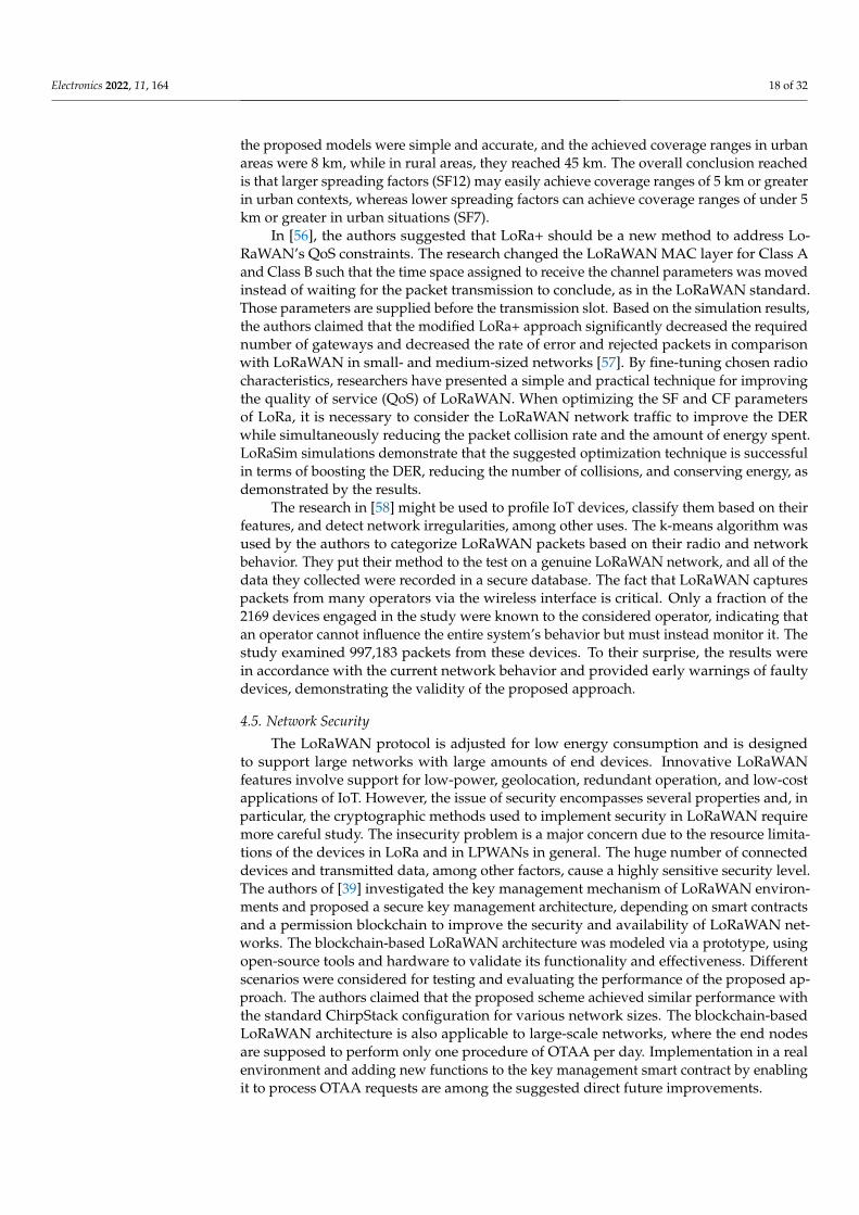
Electronics 2022, 11, 164 18 of 32
the proposed models were simple and accurate, and the achieved coverage ranges in urbanareas were 8 km, while in rural areas, they reached 45 km. The overall conclusion reachedis that larger spreading factors (SF12) may easily achieve coverage ranges of 5 km or greaterin urban contexts, whereas lower spreading factors can achieve coverage ranges of under 5km or greater in urban situations (SF7).
In [56], the authors suggested that LoRa+ should be a new method to address Lo-RaWAN’s QoS constraints. The research changed the LoRaWAN MAC layer for Class Aand Class B such that the time space assigned to receive the channel parameters was movedinstead of waiting for the packet transmission to conclude, as in the LoRaWAN standard.Those parameters are supplied before the transmission slot. Based on the simulation results,the authors claimed that the modified LoRa+ approach significantly decreased the requirednumber of gateways and decreased the rate of error and rejected packets in comparisonwith LoRaWAN in small- and medium-sized networks [57]. By fine-tuning chosen radiocharacteristics, researchers have presented a simple and practical technique for improvingthe quality of service (QoS) of LoRaWAN. When optimizing the SF and CF parametersof LoRa, it is necessary to consider the LoRaWAN network traffic to improve the DERwhile simultaneously reducing the packet collision rate and the amount of energy spent.LoRaSim simulations demonstrate that the suggested optimization technique is successfulin terms of boosting the DER, reducing the number of collisions, and conserving energy, asdemonstrated by the results.
The research in [58] might be used to profile IoT devices, classify them based on theirfeatures, and detect network irregularities, among other uses. The k-means algorithm wasused by the authors to categorize LoRaWAN packets based on their radio and networkbehavior. They put their method to the test on a genuine LoRaWAN network, and all of thedata they collected were recorded in a secure database. The fact that LoRaWAN capturespackets from many operators via the wireless interface is critical. Only a fraction of the2169 devices engaged in the study were known to the considered operator, indicating thatan operator cannot influence the entire system’s behavior but must instead monitor it. Thestudy examined 997,183 packets from these devices. To their surprise, the results werein accordance with the current network behavior and provided early warnings of faultydevices, demonstrating the validity of the proposed approach.
4.5. Network Security
The LoRaWAN protocol is adjusted for low energy consumption and is designedto support large networks with large amounts of end devices. Innovative LoRaWANfeatures involve support for low-power, geolocation, redundant operation, and low-costapplications of IoT. However, the issue of security encompasses several properties and, inparticular, the cryptographic methods used to implement security in LoRaWAN requiremore careful study. The insecurity problem is a major concern due to the resource limita-tions of the devices in LoRa and in LPWANs in general. The huge number of connecteddevices and transmitted data, among other factors, cause a highly sensitive security level.The authors of [39] investigated the key management mechanism of LoRaWAN environ-ments and proposed a secure key management architecture, depending on smart contractsand a permission blockchain to improve the security and availability of LoRaWAN net-works. The blockchain-based LoRaWAN architecture was modeled via a prototype, usingopen-source tools and hardware to validate its functionality and effectiveness. Differentscenarios were considered for testing and evaluating the performance of the proposed ap-proach. The authors claimed that the proposed scheme achieved similar performance withthe standard ChirpStack configuration for various network sizes. The blockchain-basedLoRaWAN architecture is also applicable to large-scale networks, where the end nodesare supposed to perform only one procedure of OTAA per day. Implementation in a realenvironment and adding new functions to the key management smart contract by enablingit to process OTAA requests are among the suggested direct future improvements.
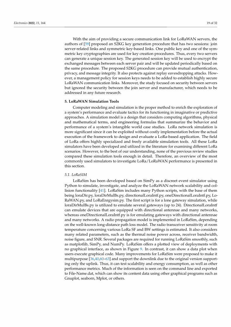
Electronics 2022, 11, 164 19 of 32
With the aim of providing a secure communication link for LoRaWAN servers, theauthors of [59] proposed an S2KG key generation procedure that has two sessions: joinserver-related links and symmetric key-based links. One public key and one of the sym-metric key cryptographies are used for key creation procedures. Thus, every two serverscan generate a unique session key. The generated session key will be used to encrypt theexchanged messages between each server pair and will be updated periodically based onthe same procedure. The proposed S2KG procedure can provide mutual authentication,privacy, and message integrity. It also protects against replay eavesdropping attacks. How-ever, a management policy for session keys needs to be added to establish highly secureLoRaWAN communication links. Moreover, the study focused on security between serversbut ignored the security between the join server and manufacturer, which needs to beaddressed in any future research.
5. LoRaWAN Simulation Tools
Computer modeling and simulation is the proper method to enrich the exploration ofa system’s performance and evaluate tactics for its functioning in imaginative or predictiveapproaches. A simulation model is a design that considers computing algorithms, physicaland mathematical terms, and engineering formulas that summarize the behavior andperformance of a system’s intangible world case studies. LoRa network simulation ismore significant since it can be exploited without costly implementation before the actualexecution of the framework to design and evaluate a LoRa-based application. The fieldof LoRa offers highly specialized and freely available simulation tools. All these LoRasimulators have been developed and utilized in the literature for examining different LoRascenarios. However, to the best of our understanding, none of the previous review studiescompared these simulation tools enough in detail. Therefore, an overview of the mostcommonly used simulators to investigate LoRa/LoRaWAN performance is presented inthis section.
5.1. LoRaSIM
LoRaSim has been developed based on SimPy as a discreet event simulator usingPython to simulate, investigate, and analyze the LoRaWAN network scalability and col-lision functionality [41]. LoRaSim includes many Python scripts, with the base of thembeing loraDir.py, loraDirMulBs.py, directionalLoraIntf.py, oneDirectionalLoraIntf.py, Lo-RaWAN.py, and LoRaEnrgysim.py. The first script is for a lone gateway simulation, whileloraDirMulBs.py is utilized to emulate several gateways (up to 24). DirectionalLoraIntfcan emulate devices that are equipped with directional antennae and many networks,whereas oneDirectionalLoraIntf.py is for emulating gateways with directional antennaeand many networks. A radio propagation model is implemented in LoRaSim, dependingon the well-known long-distance path loss model. The radio transceiver sensitivity at roomtemperature concerning various LoRa SF and BW settings is estimated. It also considersmany related parameters, such as the thermal noise power across, receiver bandwidth,noise figure, and SNR. Several packages are required for running LoRaSim smoothly, suchas matplotlib, SimPy, and NumPy. LoRaSim offers a plotted view of deployments withno graphical interface, as shown in Figure 9. In contrast, it can show a data plot whenusers execute graphical code. Many improvements for LoRaSim were proposed to make itmultipurpose [36,40,60–63] and support the downlink due to the original version support-ing only the uplink. Thus, it can test scalability and energy consumption, as well as otherperformance metrics. Much of the information is seen on the command line and exportedto File-Name.dat, which can show its content data using other graphical programs such asGnuplot, seaborn, Mplot, or others.
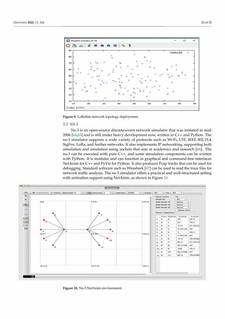
Electronics 2022, 11, 164 20 of 32Electronics 2022, 11, x FOR PEER REVIEW 20 of 32
Figure 9. LoRaSim network topology deployment.
5.2. NS-3 Ns-3 is an open-source discrete-event network simulator that was initiated in mid-
2006 [64,65] and is still under heavy development now, written in C++ and Python. The ns-3 simulator supports a wide variety of protocols such as Wi-Fi, LTE, IEEE 802.15.4, SigFox, LoRa, and further networks. It also implements IP networking, supporting both simulation and emulation using sockets that aim at academics and research [66]. The ns-3 can be executed with pure C++, and some simulation components can be written with Python. It is modular and can function in graphical and command-line interfaces NetA-nim for C++ and PyViz for Python. It also produces Pcap tracks that can be used for de-bugging. Standard software such as Wireshark [67] can be used to read the trace files for network traffic analysis. The ns-3 simulator offers a practical and well-structured setting with animation support using NetAnim, as shown in Figure 10.
Figure 10. Ns-3 NetAnim environment.
A LoRaWAN module was developed and implemented in ns-3 to provide a powerful tool for enabling the simulation of a real LoRaWAN network instead of simulating a sim-plified MAC protocol. This add-on module allows the research community and develop-ers to achieve a greater understanding of the behavior of the physical and MAC layers in LoRa networks, credited to the LoRaSim that allows the users to test a network with var-
Figure 9. LoRaSim network topology deployment.
5.2. NS-3
Ns-3 is an open-source discrete-event network simulator that was initiated in mid-2006 [64,65] and is still under heavy development now, written in C++ and Python. Thens-3 simulator supports a wide variety of protocols such as Wi-Fi, LTE, IEEE 802.15.4,SigFox, LoRa, and further networks. It also implements IP networking, supporting bothsimulation and emulation using sockets that aim at academics and research [66]. Thens-3 can be executed with pure C++, and some simulation components can be writtenwith Python. It is modular and can function in graphical and command-line interfacesNetAnim for C++ and PyViz for Python. It also produces Pcap tracks that can be used fordebugging. Standard software such as Wireshark [67] can be used to read the trace files fornetwork traffic analysis. The ns-3 simulator offers a practical and well-structured settingwith animation support using NetAnim, as shown in Figure 10.
Electronics 2022, 11, x FOR PEER REVIEW 20 of 32
Figure 9. LoRaSim network topology deployment.
5.2. NS-3 Ns-3 is an open-source discrete-event network simulator that was initiated in mid-
2006 [64,65] and is still under heavy development now, written in C++ and Python. The ns-3 simulator supports a wide variety of protocols such as Wi-Fi, LTE, IEEE 802.15.4, SigFox, LoRa, and further networks. It also implements IP networking, supporting both simulation and emulation using sockets that aim at academics and research [66]. The ns-3 can be executed with pure C++, and some simulation components can be written with Python. It is modular and can function in graphical and command-line interfaces NetA-nim for C++ and PyViz for Python. It also produces Pcap tracks that can be used for de-bugging. Standard software such as Wireshark [67] can be used to read the trace files for network traffic analysis. The ns-3 simulator offers a practical and well-structured setting with animation support using NetAnim, as shown in Figure 10.
Figure 10. Ns-3 NetAnim environment.
A LoRaWAN module was developed and implemented in ns-3 to provide a powerful tool for enabling the simulation of a real LoRaWAN network instead of simulating a sim-plified MAC protocol. This add-on module allows the research community and develop-ers to achieve a greater understanding of the behavior of the physical and MAC layers in LoRa networks, credited to the LoRaSim that allows the users to test a network with var-
Figure 10. Ns-3 NetAnim environment.

Electronics 2022, 11, 164 21 of 32
A LoRaWAN module was developed and implemented in ns-3 to provide a powerfultool for enabling the simulation of a real LoRaWAN network instead of simulating a simpli-fied MAC protocol. This add-on module allows the research community and developers toachieve a greater understanding of the behavior of the physical and MAC layers in LoRanetworks, credited to the LoRaSim that allows the users to test a network with varyingSFs based on gateway feedbacks. The LoRaWAN ns-3 module may be used to simulateLoRaWAN networks. Beyond the models created to represent different components ofthe network and the integrated helpers used to set them up, the ns-3 LoRaWAN moduleincludes a packet tracker that can be used to monitor a network’s behavior and analyze itsperformance. It also includes facilities for storing the network topology in a file to debugand monitor. It also provides many scenarios as examples of simple to complex networkuse cases. The integrated LoRaWAN module meets the requirement of Class A devices.That means it can simulate the use cases where devices send uplinks and receive downlinksfrom the server. In comparison with LoRa’s two other available classes (Class B and ClassC), the most power-efficient end devices are of this class. To deliver a highly configurableand agile solution, the physical layer, MAC layer, and transport and use are built. Con-cerning the LoRaWAN-based ns-3 module’s primary features, they are installations of thenetwork server, ADR, confirmed messages, and support for multi-GW. Configurabilityof the LoRaWAN ns-3 module was proposed and allowed new algorithms to be imple-mented on the server side in [68]. In addition, investigational evaluation of LoRaWAN wasconducted by ns-3 in [69], as well as improving LoRa performance with CSMA [70], thepower consumption model [71], the scalability analysis model for a significant scale [66],and several models in [44,72–75].
5.3. FLoRa
A framework for a LoRa (FLoRa) simulator was developed to evaluate the LoRanetwork’s performance using the ADR mechanism. It proved the effectiveness of theADR at increasing the PDR with improving energy efficiency. FLoRa is an end-to-endsimulation framework for LoRa networks that relies on the OMNeT++ network simulatorand also utilizes INET system components [76]. An open-source OMNeT++ library wasdesigned to support the experimentation process for various network protocols. FLoRacode is created by C++, and it enables the development of LoRa networks that supportthe integration of LoRa nodes, gateways, and network server modules. Application logiccan be implemented as separate modules that are linked to a network server. The networkserver and nodes support dynamic configuration parameters controlled via the ADR andconsidering collisions and the capture effect. The module includes an accurate modeling ofthe backhaul network and can simulate multiple gateways. At the end of the simulation,energy consumption statistics can be collected in each node and over the entire network [77].
Aside from that, the modules of the LoRaWAN MAC protocol strive to simulate thephysical layer [78]. This offers a very strong graphical interface compared with the othersimulation applications, since it is based on OMNeT++ and a graphical network description.The developed simulation module includes a sample scenario in the FLoRa simulationsdirectory. The scenario has several features to simulate a network with 10 nodes that areplaced randomly in a square network topology, with one gateway that is linked to a networkserver. Each node transmits a packet at a time based on an exponential distribution witha defined mean. For simulating a LoRa network, several parameters need to be selected,such as the simulation time, warm-up period, SF, the transmission power for each LoRaend node, backhaul network configuration, and links. The simulation statistics and tracingfiles are generated upon completion of the run. The simulation statistics can be viewedthrough the OMNeT++ GUI as in Figure 11.
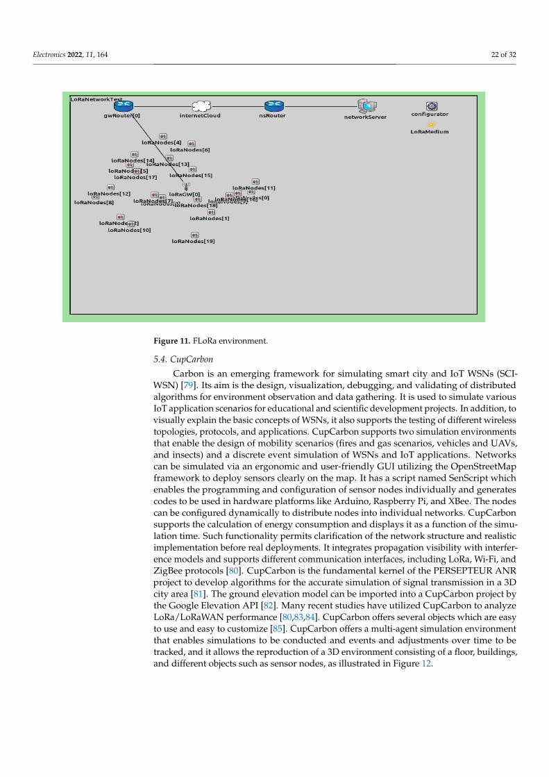
Electronics 2022, 11, 164 22 of 32Electronics 2022, 11, x FOR PEER REVIEW 22 of 32
Figure 11. FLoRa environment.
5.4. CupCarbon Carbon is an emerging framework for simulating smart city and IoT WSNs (SCI-
WSN) [79]. Its aim is the design, visualization, debugging, and validating of distributed algorithms for environment observation and data gathering. It is used to simulate various IoT application scenarios for educational and scientific development projects. In addition, to visually explain the basic concepts of WSNs, it also supports the testing of different wireless topologies, protocols, and applications. CupCarbon supports two simulation en-vironments that enable the design of mobility scenarios (fires and gas scenarios, vehicles and UAVs, and insects) and a discrete event simulation of WSNs and IoT applications. Networks can be simulated via an ergonomic and user-friendly GUI utilizing the Open-StreetMap framework to deploy sensors clearly on the map. It has a script named SenScript which enables the programming and configuration of sensor nodes individually and generates codes to be used in hardware platforms like Arduino, Raspberry Pi, and XBee. The nodes can be configured dynamically to distribute nodes into individual net-works. CupCarbon supports the calculation of energy consumption and displays it as a function of the simulation time. Such functionality permits clarification of the network structure and realistic implementation before real deployments. It integrates propagation visibility with interference models and supports different communication interfaces, in-cluding LoRa, Wi-Fi, and ZigBee protocols [80]. CupCarbon is the fundamental kernel of the PERSEPTEUR ANR project to develop algorithms for the accurate simulation of signal transmission in a 3D city area [81]. The ground elevation model can be imported into a CupCarbon project by the Google Elevation API [82]. Many recent studies have utilized CupCarbon to analyze LoRa/LoRaWAN performance [80,83,84]. CupCarbon offers sev-eral objects which are easy to use and easy to customize [85]. CupCarbon offers a multi-agent simulation environment that enables simulations to be conducted and events and adjustments over time to be tracked, and it allows the reproduction of a 3D environment consisting of a floor, buildings, and different objects such as sensor nodes, as illustrated in Figure 12.
Figure 11. FLoRa environment.
5.4. CupCarbon
Carbon is an emerging framework for simulating smart city and IoT WSNs (SCI-WSN) [79]. Its aim is the design, visualization, debugging, and validating of distributedalgorithms for environment observation and data gathering. It is used to simulate variousIoT application scenarios for educational and scientific development projects. In addition, tovisually explain the basic concepts of WSNs, it also supports the testing of different wirelesstopologies, protocols, and applications. CupCarbon supports two simulation environmentsthat enable the design of mobility scenarios (fires and gas scenarios, vehicles and UAVs,and insects) and a discrete event simulation of WSNs and IoT applications. Networkscan be simulated via an ergonomic and user-friendly GUI utilizing the OpenStreetMapframework to deploy sensors clearly on the map. It has a script named SenScript whichenables the programming and configuration of sensor nodes individually and generatescodes to be used in hardware platforms like Arduino, Raspberry Pi, and XBee. The nodescan be configured dynamically to distribute nodes into individual networks. CupCarbonsupports the calculation of energy consumption and displays it as a function of the simu-lation time. Such functionality permits clarification of the network structure and realisticimplementation before real deployments. It integrates propagation visibility with interfer-ence models and supports different communication interfaces, including LoRa, Wi-Fi, andZigBee protocols [80]. CupCarbon is the fundamental kernel of the PERSEPTEUR ANRproject to develop algorithms for the accurate simulation of signal transmission in a 3Dcity area [81]. The ground elevation model can be imported into a CupCarbon project bythe Google Elevation API [82]. Many recent studies have utilized CupCarbon to analyzeLoRa/LoRaWAN performance [80,83,84]. CupCarbon offers several objects which are easyto use and easy to customize [85]. CupCarbon offers a multi-agent simulation environmentthat enables simulations to be conducted and events and adjustments over time to betracked, and it allows the reproduction of a 3D environment consisting of a floor, buildings,and different objects such as sensor nodes, as illustrated in Figure 12.
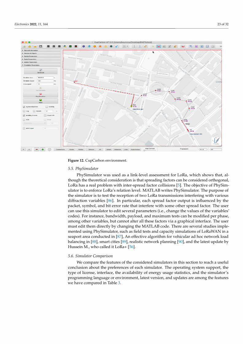
Electronics 2022, 11, 164 23 of 32Electronics 2022, 11, x FOR PEER REVIEW 23 of 32
Figure 12. CupCarbon environment.
5.5. PhySimulator PhySimulator was used as a link-level assessment for LoRa, which shows that, alt-
hough the theoretical consideration is that spreading factors can be considered orthogo-nal, LoRa has a real problem with inter-spread factor collisions [5]. The objective of Phy-Simulator is to enforce LoRa’s relation level. MATLAB writes PhySimulator. The purpose of the simulator is to test the reception of two LoRa transmissions interfering with various diffraction variables [86]. In particular, each spread factor output is influenced by the packet, symbol, and bit error rate that interfere with some other spread factor. The user can use this simulator to edit several parameters (i.e., change the values of the variables’ codes). For instance, bandwidth, payload, and maximum tests can be modified per phase, among other variables, but cannot alter all these factors via a graphical interface. The user must edit them directly by changing the MATLAB code. There are several studies imple-mented using PhySimulator, such as field tests and capacity simulations of LoRaWAN in a seaport area conducted in [87], An effective algorithm for vehicular ad hoc network load balancing in [88], smart cities [89], realistic network planning [90], and the latest update by Hussein M., who called it LoRa+ [56].
5.6. Simulator Comparison We compare the features of the considered simulators in this section to reach a useful
conclusion about the preferences of each simulator. The operating system support, the type of license, interface, the availability of energy usage statistics, and the simulator’s programming language or environment, latest version, and updates are among the fea-tures we have compared in Table 3.
Table 3. LoRa simulator comparison.
Features LoRaSim NS-3 FLoRa CupCarbon PHY Simulator
License type Source is open Source is open Source is open Free
(education) Free
Operating system macOS, Linux,
Windows Linux, Windows
Linux, Windows, macOS
macOS MacOS,
Windows Installation
requirements SimPy, NumPy,
matplotlib Import all
libraries online OMNeT++ 6 and
INET 4.3.1 Java Matlab
Type language Python C++, Python C++ Java MATLAB
GUI Only plot Yes Yes 2D or 3D with
OSM Only plot
Figure 12. CupCarbon environment.
5.5. PhySimulator
PhySimulator was used as a link-level assessment for LoRa, which shows that, al-though the theoretical consideration is that spreading factors can be considered orthogonal,LoRa has a real problem with inter-spread factor collisions [5]. The objective of PhySim-ulator is to enforce LoRa’s relation level. MATLAB writes PhySimulator. The purpose ofthe simulator is to test the reception of two LoRa transmissions interfering with variousdiffraction variables [86]. In particular, each spread factor output is influenced by thepacket, symbol, and bit error rate that interfere with some other spread factor. The usercan use this simulator to edit several parameters (i.e., change the values of the variables’codes). For instance, bandwidth, payload, and maximum tests can be modified per phase,among other variables, but cannot alter all these factors via a graphical interface. The usermust edit them directly by changing the MATLAB code. There are several studies imple-mented using PhySimulator, such as field tests and capacity simulations of LoRaWAN in aseaport area conducted in [87], An effective algorithm for vehicular ad hoc network loadbalancing in [88], smart cities [89], realistic network planning [90], and the latest update byHussein M., who called it LoRa+ [56].
5.6. Simulator Comparison
We compare the features of the considered simulators in this section to reach a usefulconclusion about the preferences of each simulator. The operating system support, thetype of license, interface, the availability of energy usage statistics, and the simulator’sprogramming language or environment, latest version, and updates are among the featureswe have compared in Table 3.
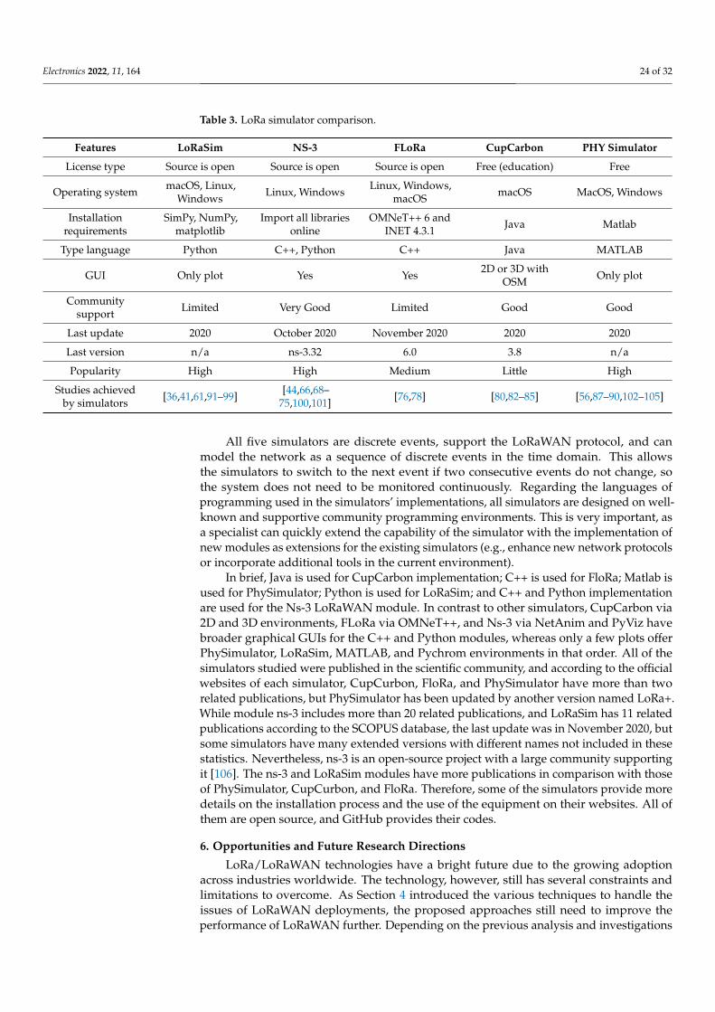
Electronics 2022, 11, 164 24 of 32
Table 3. LoRa simulator comparison.
Features LoRaSim NS-3 FLoRa CupCarbon PHY Simulator
License type Source is open Source is open Source is open Free (education) Free
Operating system macOS, Linux,Windows Linux, Windows Linux, Windows,
macOS macOS MacOS, Windows
Installationrequirements
SimPy, NumPy,matplotlib
Import all librariesonline
OMNeT++ 6 andINET 4.3.1 Java Matlab
Type language Python C++, Python C++ Java MATLAB
GUI Only plot Yes Yes 2D or 3D withOSM Only plot
Communitysupport Limited Very Good Limited Good Good
Last update 2020 October 2020 November 2020 2020 2020
Last version n/a ns-3.32 6.0 3.8 n/a
Popularity High High Medium Little High
Studies achievedby simulators [36,41,61,91–99] [44,66,68–
75,100,101] [76,78] [80,82–85] [56,87–90,102–105]
All five simulators are discrete events, support the LoRaWAN protocol, and canmodel the network as a sequence of discrete events in the time domain. This allowsthe simulators to switch to the next event if two consecutive events do not change, sothe system does not need to be monitored continuously. Regarding the languages ofprogramming used in the simulators’ implementations, all simulators are designed on well-known and supportive community programming environments. This is very important, asa specialist can quickly extend the capability of the simulator with the implementation ofnew modules as extensions for the existing simulators (e.g., enhance new network protocolsor incorporate additional tools in the current environment).
In brief, Java is used for CupCarbon implementation; C++ is used for FloRa; Matlab isused for PhySimulator; Python is used for LoRaSim; and C++ and Python implementationare used for the Ns-3 LoRaWAN module. In contrast to other simulators, CupCarbon via2D and 3D environments, FLoRa via OMNeT++, and Ns-3 via NetAnim and PyViz havebroader graphical GUIs for the C++ and Python modules, whereas only a few plots offerPhySimulator, LoRaSim, MATLAB, and Pychrom environments in that order. All of thesimulators studied were published in the scientific community, and according to the officialwebsites of each simulator, CupCurbon, FloRa, and PhySimulator have more than tworelated publications, but PhySimulator has been updated by another version named LoRa+.While module ns-3 includes more than 20 related publications, and LoRaSim has 11 relatedpublications according to the SCOPUS database, the last update was in November 2020, butsome simulators have many extended versions with different names not included in thesestatistics. Nevertheless, ns-3 is an open-source project with a large community supportingit [106]. The ns-3 and LoRaSim modules have more publications in comparison with thoseof PhySimulator, CupCurbon, and FloRa. Therefore, some of the simulators provide moredetails on the installation process and the use of the equipment on their websites. All ofthem are open source, and GitHub provides their codes.
6. Opportunities and Future Research Directions
LoRa/LoRaWAN technologies have a bright future due to the growing adoptionacross industries worldwide. The technology, however, still has several constraints andlimitations to overcome. As Section 4 introduced the various techniques to handle theissues of LoRaWAN deployments, the proposed approaches still need to improve theperformance of LoRaWAN further. Depending on the previous analysis and investigations
Electronics 2022, 11, 164 25 of 32
of research issues and recently proposed methods in Sections 4 and 5, we emphasize someopen challenges of the LoRaWAN technology in this section.
6.1. Scalability
Poor scalability can result in poor network performance. Presently, the majority of theinformation about the scalability of LoRa technology is commercial in nature and focuseson the best case scenario [107]. Thus, in order to properly analyze the performance levelsof such networks in huge networks, it is necessary to have realistic models available. It ispossible to achieve network scalability by reducing the amount of sent packets per nodeper day or increasing the number of gateways when the end device population expandsrapidly, such as in dense installations. LoRa and LoRaWAN configuration parameters suchas the SF, CF, transmission power, BW, CR, and DR directly affect the scalability of thenetwork, which in turn impacts the generated traffic and energy resources [108]. Therefore,improving network scalability will optimize traffic, conserve energy, and extend the batterylife of edge devices, which are three important goals [109]. This is because energy efficiencyand data traffic are the total data transmissions from the sensor board to the gateway thathave an effect on the performance [110]. Consequently, there is a real need to develop anew data-gathering procedure for LoRaWAN to cope with scalability issues in large-scaledeployment scenarios [111,112]. That will positively affect energy conservation and play asignificant role in improving LoRaWAN network scalability.
There are several metrics directly related to LoRaWAN network scalability. Thus,simulation-based performance evaluation for the proposed approaches needs to be con-ducted, depending on several scalability-related metrics such as energy consumption, PDR,throughput, coverage, and latency. Relying exclusively on simulations has long beenrecognized as one of the key pitfalls of research on wireless networks due to the typicaloversimplifying assumptions of simulation models. Therefore, any simulation results forfuture improvements in LoRaWAN scalability need to and will be complemented with realexperimentation for the proposed approaches using a LoRaWAN testbed for validationpurposes. Most of the existing studies were conducted in a laboratory or limited outdoorareas. The results of the experiments, while proving that the proposed work was effective,are insufficient compared with real deployment environments. Therefore, it is necessaryto further verify the reliability and scalability of the proposed work by deploying it in areal and large-scale environment. In [105], it outperformed the typical methods when theconnectivity was good, but it functioned in a comparable manner when deployed overbroad areas. The improvement over the benchmark solutions being independent of thechannel model used was also demonstrated (no shadowing, uncorrelated, and correlatedshadowing). A fog-based architecture was also demonstrated to be viable, which has theadvantage of reducing the end-to-end latency by a factor of two. The limitation of this workis that the study was limited, and the proposed solutions were ordinary. The purpose of theresearch in [113] was to obtain better knowledge on how to optimize competition-basedchannel access mechanisms at the MAC layer for LoRa and LPWAN radio technology byconducting extensive tests on the LoRa channel activity detection and capture effect feature.
6.2. Regulation
The first opportunity and future work are more so action points for regulators ratherthan engineers. The big drawback of these networks is the hostile interference present inthe unlicensed bands. Although LoRaWANs are envisioned with gateways at ground level,different proposals have suggested putting gateways in the air or even launching them intospace [114–116]. Although it might be technically achievable, these networks will see manymore devices due to the line of sight and see more collisions than there are gateways on theground. For these scenarios and the LoRaWANs on the ground, it is strongly recommendedto free up the spectrum for these networks, because there is a real need for these powerfulnetworks as a good representative for LPWANs. The dedicated spectrum can also allowrelaxed constraints for gateways such that gateways can transmit more downlink messages
Electronics 2022, 11, 164 26 of 32
with a higher power, making the acknowledgements more reliable. Alternatively, with thespectrum freed up for these networks, improved spectrum management of unlicensed orshared bands is also an interesting route. With (private) spectrum management, differentLPWANs, including SigFox and LoRa, can be rolled out in different or overlapping regions,allowing for other configurations and potentially sharing a spectrum. A third party couldoversee the rules at several locations and verify if everybody is playing according tothe rules.
6.3. Routing and Multi-Hop
Unfortunately, LoRaWAN, the current standard protocol for LoRa, supports onlysingle-packet-at-a-time and single-hop transmission in a star-of-stars topology. LoRaWANis a medium-access control protocol and does not provide any special support for thetransmission of large messages. A star topology is simple and easy to manage. However,it limits the scalability of a LoRa wireless network. Although multiple gateways can bedeployed to form multiple star topologies and extend the physical network range, a gatewayin a LoRa network requires an Internet connection and has substantially higher cost andpower consumption requirements than an end device. Multi-hop image transmission usingLoRa is challenging. First, the performance of LoRa has rarely been studied in a widerange of applications, especially large message transmission. Without actual measurements,the feasibility of LoRa being used for large message transmission cannot be confirmed.Second, due to the small maximum transmission unit of LoRa, a large message such asan image must be transmitted using many packets. Such continuous traffic increases notonly the network utilization but also the chance of packet collisions. Third, LoRa’s lowphysical layer data rate makes it difficult to broadcast additional data frequently enough tomaintain the network topology while performing image transmission tasks, which maylead to serious network congestion or even paralysis. Since there is a huge number ofrouting protocols proposed in the literature for various ad hoc networking like MANET,VANET, WSN, and WMN. Thus, there is a real need for testing and adopting such protocolsfor LoRa/LoRaWAN networks to support the multi-hop state of packet transmission and,in addition, to enable communication in the node-node mode instead of node-gateway asin the existing architecture.
6.4. Energy Efficiency
In all wireless networks, energy-related constraints are considered the importantfactors that determine networks’ performance and characteristics because the nodes arebattery-powered. Such constraints result in lower reliability of the communication mediumand cause the loss of data during transmission from the end devices to the gateways andthen the servers. Even though LPWAN technologies are low in power in comparisonwith other wireless networks, energy saving is among the key considerations to improvea LoRaWAN network’s performance. Most of the existing studies focused on Class ALoRaWAN devices, which are the most energy-efficient ones compared with the otherclasses. Therefore, more research needs to be conducted to evaluate the performance andenergy efficiency of Class B and Class C devices. Additionally, scheduling algorithms andadaptive data rates that consider energy constraints are in high demand. Therefore, tomaintain the nature of the low energy consumption of LoRa, it needs to be further studiedto solve the energy issues caused by other factors. LoRaWAN no-battery communicationsare also feasible according to the results in [117] if the right configuration is chosen (i.e.,the capacitor size and turn-on voltage threshold) for different application behaviors (e.g.,transmission interval and UL and DL packet sizes (PSs)) as well as environmental condi-tions, (e.g., the energy harvesting rate). Only small-DL PSs should be considered for thesedevices because the DL in the second reception window significantly impacts performance.The authors in [118] presented a joint distributed queueing system for LoRa that balancesinter-channel traffic. Compared with the DQ, the suggested technique decreases the control

Electronics 2022, 11, 164 27 of 32
overhead by up to 70%. Regardless of the number of arrivals, the protocol achieves notonly near-optimal throughput and access delay but also power efficiency.
6.5. Security
LoRaWAN needs to have the best data security system to stand out from other LPWANtechnology market competitors. With raising awareness of user data privacy, data security-related issues have become a challenging element in all communication protocols. Somecompanies have developed a specific encrypted IC for LoRa devices to decrease the threatsof data being decrypted by a third party. Simultaneously, LoRaWAN service providershave also built considerably safer links using IPSec and MQTTS technologies for protectingdata transmission from gateways to network servers. Therefore, and due to data privacyissues, users will not be motivated to join the enterprise’s data flow ecosystem, and moredata transmission providers will eschew large data servers like MQTT, CoAP, and LWM2Mwhich appear in the market. The challenge will be in allowing such big companies to workindividually under the LoRaWAN Alliance and maintaining data security and privacy.Activation by personal and over time air activation is a method of registering the enddevices offered by LoRaWAN. ABP’s security method is sharing keys beforehand withoutthem being sent on the network. The attacker is not able to decode the payload underthis activation method. While OTAA uses an AES-128 key to encrypt and decrypt in thepre-shared AppKey, if an assailant tries to break the network encryption, they might besuccessful. Moreover, an attacker who is familiar with the protocol might be able to changethe packet’s path to the desired destination due to unencrypted data. This issue needs moreinvestigation and research into viable GITE solutions that can be produced. The gatewaycan collect routing from multiple nodes that could even be providing false data to disruptthe network. Thus, secure data transmission must be involved in LoRaWAN, analysiscountermeasures, and different attacks. These topics need to be focused on in investigations.
Additionally, 5G security services have been deployed, installed, and tested in a real-world 5G-LoRaWAN testbed, demonstrating their feasibility and security viability [119].This study aimed to enable handover roaming in LoRaWAN. The integration of LoRaWANand 5G has been thoroughly examined, analyzed, and contrasted using two alternativemethodologies. LoRaWAN joining procedures can be extended to enable the piggybackingof 5G security material to allow for roaming in LoRaWAN. The current LoRaWAN networkdoes not need to be covered by 5G, but significant changes to the LoRaWAN and 5Gspecifications are required. Using 5G authentication services, the second solution hasbeen chosen for deployment and validation because it adheres to nearly all standardprocedures with just minor alterations. The LoRaWAN joining service and the 5G AUSFhave successfully implemented this strategy with the necessary modifications for the IoTdevice (including in the 5G SIM card component) as outlined in [119].
7. Conclusions
At the cost of low data rates, LPWAN technologies supply long-range, low-power,and low-cost communication. In this paper, we discussed the common features LPWANtechnologies employ, and their characteristics were tested in terms of various aspects,including bandwidth, modulation, data rate, range, link budget, maximum payload, powerefficiency, security, adaptive data rate, localization, allowing private networks, batterylifetime, and availability. In addition, we showed how to pick the technology suitablefor the field of application. On the other hand, LoRa technology as an emerging trendfor IoT applications was the main focus among the LPWAN technologies in this paper.Among LPWAN technologies, LoRaWAN offers several advantages, including an openstandard, low power consumption, long-range transmission, built-in security, the possibilityof private deployments, and GPS-free geolocation. In addition, duty cycle constraintsand low data rate LoRaWAN networks are the advantages of real-time application inClass B. Therefore, the investigations of LoRaWAN issues obtained by deploying LoRaWANnetworks are discussed carefully. Furthermore, we evaluated recent approach solutions
Electronics 2022, 11, 164 28 of 32
and presented some possible methods. However, some still have open issues such asnetwork management, optimization ADR, high-density LoRaWAN installations, and deviceinteroperability that need to be addressed more for practical use.
Author Contributions: Conceptualization, M.A.M.A.; methodology, M.A.M.A. and W.A.J.; analysisand writing—original draft preparation, M.A.M.A. and W.A.J.; writing—review, W.A.J. and N.S.;project administration, W.A.J.; funding acquisition, W.A.J.; editing M.A.M.A., W.A.J. and S.A. Allauthors have read and agreed to the published version of the manuscript.
Funding: This research work was funded by Universiti Malaysia Pahang (UMP) under the researchgrant PDU203229 and the post-graduate research scheme PGRS200340.
Conflicts of Interest: The authors disclose that they have no conflicting interests.
References1. Sisinni, E.; Mahmood, A. Wireless Communications for Industrial Internet of Things: The LPWAN Solutions. In Wireless Networks
and Industrial IoT; Springer: Singapore, 2021; pp. 79–103.2. Catak, E.; Ata, L.D. An efficient transceiver design for superimposed waveforms with orthogonal polynomials. In Proceedings
of the 2017 IEEE International Black Sea Conference on Communications and Networking (BlackSeaCom), Istanbul, Turkey,5–8 June 2017; pp. 1–5.
3. Sisinni, E.; Saifullah, A.; Han, S.; Jennehag, U.; Gidlund, M. Industrial internet of things: Challenges, opportunities, and directions.IEEE Trans. Ind. Inform. 2018, 14, 4724–4734. [CrossRef]
4. Jabbar, W.A.; Shang, H.K.; Hamid, S.N.; Almohammedi, A.A.; Ramli, R.M.; Ali, M.A. IoT-BBMS: Internet of Things-Based BabyMonitoring System for Smart Cradle. IEEE Access 2019, 7, 93791–93805. [CrossRef]
5. Jabbar, W.A.; Bin Yuzaidi, M.A.; Yan, K.Q.; Bustaman, U.S.B.M.; Hashim, Y.; AlAriqi, H.T. Smart and green street lighting systembased on arduino and RF wireless module. In Proceedings of the 8th International Conference on Modeling Simulation andApplied Optimization (ICMSAO), Piscataway, NJ, USA, 15–17 April 2019; pp. 1–6.
6. Jabbar, W.A.; Saad, W.K.; Hashim, Y.; Zaharudin, N.B.; Abidin, M.F.B.Z. Arduino-based buck boost converter for PV solarsystem. In Proceedings of the 2018 IEEE Student Conference on Research and Development (SCOReD), Selangor, Malaysia,26–28 November 2018; pp. 1–6.
7. Jabbar, W.A.; Kian, T.K.; Ramli, R.M.; Zubir, S.N.; Zamrizaman, N.S.M.; Balfaqih, M.; Shepelev, V.; Alharbi, S. Design andfabrication of smart home with internet of things enabled automation system. IEEE Access 2019, 7, 144059–144074. [CrossRef]
8. Wang, H.; Fapojuwo, A.O. A Survey of enabling technologies of low power and long range machine-to-machine communications.IEEE Commun. Surv. Tutor. 2017, 19, 2621–2639. [CrossRef]
9. Wang, Y.-P.E.; Lin, X.; Adhikary, A.; Grovlen, A.; Sui, Y.; Blankenship, Y.W.; Bergman, J.; Shokri-Razaghi, H. A primer on 3GPPnarrowband internet of things. IEEE Commun. Mag. 2017, 55, 117–123. [CrossRef]
10. Zuniga, J.C.; Ponsard, B. Sigfox System Description. Available online: https://www.ietf.org/proceedings/97/slides/slides-97-lpwan-25-sigfox-system-description-00.pdf (accessed on 20 October 2021).
11. Sundaram, J.P.S.; Du, W.; Zhao, Z. A Survey on LoRa Networking: Research Problems, Current Solutions, and Open Issues. IEEECommun. Surv. Tutor. 2019, 22, 371–388. [CrossRef]
12. Jabbar, W.A.; Ismail, M.; Nordin, R. MBA-OLSR: A multipath battery aware routing protocol for MANETs. In Proceedings of the2014 5th International Conference on Intelligent Systems, Modelling and Simulation, Langkawi, Malaysia, 27–29 January 2014;pp. 630–635.
13. Ikpehai, A.; Adebisi, B.; Rabie, K.M.; Anoh, K.; Ande, R.E.; Hammoudeh, M.; Gacanin, H.; Mbanaso, U.M. Low-power wide areanetwork technologies for internet-of-things: A comparative review. IEEE Internet Things J. 2018, 6, 2225–2240. [CrossRef]
14. Alliance, L. LoRa Alliance. 2021. Available online: www.lora-alliance.org (accessed on 1 April 2021).15. Osorio, A.; Calle, M.; Soto, J.D.; Candelo-Becerra, J.E. Routing in LoRaWAN: Overview and Challenges. IEEE Commun. Mag.
2020, 58, 72–76.16. Ratasuk, R.; Mangalvedhe, N.; Zhang, Y.; Robert, M.; Koskinen, J.-P. Overview of narrowband IoT in LTE Rel-13. In Proceedings of the
2016 IEEE Conference on Standards for Communications and Networking (CSCN), Berlin, Germany, 31 October–2 November 2016;pp. 1–7.
17. Sultan, J.; Mohsen, M.S.; Al-Thobhani, N.S.; Jabbar, W.A. Performance of Hard Handover in 5G Heterogeneous Networks. InProceedings of the 2021 1st International Conference on Emerging Smart Technologies and Applications (eSmarTA), Sana’a,Yemen, 10–12 August 2021; pp. 1–7.
18. Yu, C.; Yu, L.; Wu, Y.; He, Y.; Lu, Q. Uplink scheduling and link adaptation for narrowband internet of things systems. IEEE Access2017, 5, 1724–1734. [CrossRef]
19. Qin, Z.; Qin, Z.; Li, F.Y.; Li, G.Y.; McCann, J.A.; Ni, Q. Low-power wide-area networks for sustainable IoT. IEEE Wirel. Commun.2019, 26, 140–145. [CrossRef]
20. Gomez, C.; Veras, J.C.; Vidal, R.; Casals, L.; Paradells, J. A sigfox energy consumption model. Sensors 2019, 19, 681. [CrossRef]
Electronics 2022, 11, 164 29 of 32
21. Queralta, J.P.; Gia, T.; Zou, Z.; Tenhunen, H.; Westerlund, T. Comparative study of LPWAN technologies on unlicensed bands forM2M communication in the IoT: Beyond LoRa and LoRaWAN. Procedia Comput. Sci. 2019, 155, 343–350. [CrossRef]
22. Raza, U.; Kulkarni, P.; Sooriyabandara, M. Low power wide area networks: An overview. IEEE Commun. Surv. Tutor. 2017, 19,855–873. [CrossRef]
23. Augustin, A.; Yi, J.; Clausen, T.; Townsley, W.M. A study of LoRa: Long range & low power networks for the internet of things.Sensors 2016, 16, 1466.
24. Burns, J.K.; Selcuk Marks, P. Future Use of Licence Exempt Radio Spectrum; Plum Consult: London, UK, 2015; Available online:https://plumconsulting.co.uk/wpdm-package/plum-july-2015-future-use-of-licence-exempt-radio-spectrum-pdf/ (accessedon 21 October 2021).
25. Tournier, J.; Lesueur, F.; Le Mouël, F.; Guyon, L.; Ben-Hassine, H. A survey of IoT protocols and their security issues through thelens of a generic IoT stack. Internet Things 2020, 16, 100264. [CrossRef]
26. Bembe, M.; Abu-Mahfouz, A.; Masonta, M.; Ngqondi, T. A survey on low-power wide area networks for IoT applications.Telecommun. Syst. 2019, 71, 249–274. [CrossRef]
27. Telensa. Global Smart Street Lighting & Smart Cities: Market Forecast (2020–2029). 2021. Available online: http://www.telensa.com(accessed on 21 October 2021).
28. IoTnow. Building Smarter Cities with Low Power Radio Networks. 2016. Available online: https://www.iot-now.com (accessedon 21 October 2021).
29. Myers, T.J. Random phase multiple access system with meshing. U.S. Patent 7,773,664, 10 August 2010.30. Hornbuckle, C.A. Fractional-N Synthesized Chirp Generator. U.S. Patent 7791415B2, 7 September 2010.31. Semtech. SX1272/3/6/7/8: LoRa Modem Designer’s Guide. 2013. Available online: www.semtech.com (accessed on 21 October 2021).32. Attia, T.; Heusse, M.; Tourancheau, B.; Duda, A. Experimental characterization of LoRaWAN link quality. In Proceedings of the
2019 IEEE Global Communications Conference (GLOBECOM), Waikoloa, HI, USA, 9–13 December 2019; pp. 1–6.33. Bouguera, T.; Diouris, J.F.; Chaillout, J.J.; Jaouadi, R.; Andrieux, G. Energy consumption model for sensor nodes based on LoRa
and LoRaWAN. Sensors 2018, 18, 2104. [CrossRef]34. Jabbar, W.A.; Wei, C.W.; Azmi, N.A.A.M.; Haironnazli, N.A. An IoT Raspberry Pi-based parking management system for smart
campus. Internet Things 2021, 14, 100387. [CrossRef]35. Adelantado, F.; Vilajosana, X.; Tuset-Peiro, P.; Martinez, B.; Melià-Seguí, J.; Watteyne, T. Understanding the limits of LoRaWAN.
IEEE Commun. Mag. 2017, 55, 34–40. [CrossRef]36. Abdelfadeel, K.; Farrell, T.; Pesch, D. How to Make Firmware Updates over LoRaWAN Possible. In Proceedings of the 2020
IEEE 21st International Symposium on A World of Wireless, Mobile and Multimedia Networks (WoWMoM), Cork, Ireland,31 August–3 September 2020; pp. 16–25.
37. Ayoub, W.; Samhat, A.E.; Nouvel, F.; Mroue, M.; Prevotet, J.C. Internet of mobile things: Overview of LoRaWAN, DASH7, andNB-IoT in LPWANs standards and supported mobility. IEEE Commun. Surv. Tutor. 2019, 21, 1561–1581. [CrossRef]
38. Wu, Y.T.; He, Y.G.; Shi, L.Q. Energy-saving measurement in LoRaWAN-based wireless sensor networks by using compressedsensing. IEEE Access 2020, 8, 49477–49486. [CrossRef]
39. El Rachkidy, N.; Guitton, A.; Kaneko, M. Collision resolution protocol for delay and energy efficient LoRa networks. IEEE Trans.Green Commun. Netw. 2019, 3, 535–551. [CrossRef]
40. Abdelfadeel, K.Q.; Abdelfadeel, K.Q.; Zorbas, D.; Cionca, V.; Pesch, D. FREE $—Fine-grained scheduling for reliable andenergy-efficient data collection in LoRaWAN. IEEE Internet Things J. 2019, 7, 669–683. [CrossRef]
41. Bor, M.C.; Roedig, U.; Voigt, T.; Alonso, J.M. Do LoRa low-power wide-area networks scale? In Proceedings of the 19th ACMInternational Conference on Modeling, Analysis and Simulation of Wireless and Mobile Systems, Malta, Malta, 13–17 November 2016;pp. 59–67.
42. Lim, J.-T.; Han, Y. Spreading factor allocation for massive connectivity in LoRa systems. IEEE Commun. Lett. 2018, 22, 800–803.[CrossRef]
43. Zhu, G.; Liao, C.-H.; Sakdejayont, T.; Lai, I.-W.; Narusue, Y.; Morikawa, H. Improving the capacity of a mesh LoRa network byspreading-factor-based network clustering. IEEE Access 2019, 7, 21584–21596. [CrossRef]
44. Finnegan, J.; Farrell, R.; Brown, S. Analysis and enhancement of the LoRaWAN adaptive data rate scheme. IEEE Internet Things J.2020, 7, 7171–7180. [CrossRef]
45. Bankov, D.; Khorov, E.; Lyakhov, A. On the Limits of LoRaWAN Channel Access. In Proceedings of the 2016 InternationalConference on Engineering and Telecommunication (EnT), Moscow, Russia, 29–30 November 2016; pp. 10–14.
46. Haxhibeqiri, J.; Moerman, I.; Hoebeke, J.; Abeele, F.V.D. LoRa scalability: A simulation model based on interference measurements.Sensors 2017, 17, 1193. [CrossRef]
47. Georgiou, O.; Raza, U. Low power wide area network analysis: Can LoRa scale? IEEE Wirel. Commun. Lett. 2017, 6, 162–165.[CrossRef]
48. Sanchez-Iborra, R.; Gómez, A.S.; Ballesta-Viñas, J.; Cano, M.-D.; Skarmeta, A.F. Performance evaluation of LoRa consideringscenario conditions. Sensors 2018, 18, 772. [CrossRef]
49. Ertürk, M.A.; Aydın, M.A.; Büyükakkaslar, M.T.; Evirgen, H. A survey on LoRaWAN architecture, protocol and technologies.Future Internet 2019, 11, 216. [CrossRef]
Electronics 2022, 11, 164 30 of 32
50. Wu, W.; Li, Y.; Zhang, Y.; Wang, B.; Wang, W. Distributed queueing-based random access protocol for LoRa networks. IEEEInternet Things J. 2020, 7, 763–772. [CrossRef]
51. Lavric, A.; Popa, V. Performance evaluation of LoRaWAN communication scalability in large-scale wireless sensor networks.Wirel. Commun. Mob. Computing 2018, 2018, 6730719. [CrossRef]
52. Pop, A.-I.; Raza, U.; Kulkarni, P.; Sooriyabandara, M. Does bidirectional traffic do more harm than good in LoRaWAN based LPWAnetworks? In Proceedings of the GLOBECOM 2017—2017 IEEE Global Communications Conference, Singapore, 4–8 December 2017;pp. 1–6.
53. Petajajarvi, J.; Mikhaylov, K.; Roivainen, A.; Hanninen, T.; Pettissalo, M. On the coverage of LPWANs: Range evaluation and chan-nel attenuation model for LoRa technology. In Proceedings of the 2015 14th International Conference on ITS Telecommunications(ITST), Copenhagen, Denmark, 2–4 December 2015; pp. 55–59.
54. Alves, H.B.M.; Lima, V.S.S.; Silva, D.R.C.; Nogueira, M.B.; Rodrigues, M.C.; Cunha, R.N.; Carvalho, D.F.; Sisinni, E.; Ferrari, P.Introducing a survey methodology for assessing LoRaWAN coverage in Smart Campus scenarios. In Proceedings of the 2020IEEE International Workshop on Metrology for Industry 4.0 & IoT, Rome, Italy, 3–5 June 2020; pp. 708–712.
55. El Chall, R.; Lahoud, S.; el Helou, M. LoRaWAN network: Radio propagation models and performance evaluation in variousenvironments in Lebanon. IEEE Internet Things J. 2019, 6, 2366–2378. [CrossRef]
56. Mroue, H.; Parrein, B.; Hamrioui, S.; Bakowski, P.; Nasser, A.; Cruz, E.M.; Vince, W. LoRa+: An extension of LoRaWAN protocolto reduce infrastructure costs by improving the quality of service. Internet Things 2020, 9, 100176. [CrossRef]
57. Sallum, E.; Pereira, N.; Alves, M.; Santos, M. Improving quality-of-service in LoRa low-power wide-area networks throughoptimized radio resource management. J. Sens. Actuator Netw. 2020, 9, 10. [CrossRef]
58. Garlisi, D.; Martino, A.; Zouwayhed, J.; Pourrahim, R.; Cuomo, F. Exploratory approach for network behavior clustering inLoRaWAN. J. Ambient. Intell. Humaniz. Comput. 2021, 1–15. [CrossRef]
59. Tsai, K.-L.; Leu, F.-Y.; Hung, L.-L.; Ko, C.-Y. Secure session key generation method for LoRaWAN servers. IEEE Access 2020, 8,54631–54640. [CrossRef]
60. Farooq, M.O.; Pesch, D. Poster: Extended LoRaSim to Simulate Multiple IoT Applications in a LoRaWAN. In Proceedings of theInternational Conference on Embedded Wireless Systems and Networks (EWSN), Madrid, Spain, 14–16 February 2018.
61. Ali, M.A.; Mailah, M.; Jabbar, W.A.; Moiduddin, K.; Ameen, W.; Alkhalefah, H. Autonomous Road Roundabout Detection andNavigation System for Smart Vehicles and Cities Using Laser Simulator–Fuzzy Logic Algorithms and Sensor Fusion. Sensors2020, 20, 3694. [CrossRef]
62. Zorbas, D.; Caillouet, C.; Hassan, K.A.; Pesch, D. Optimal data collection time in LoRa networks—A time-slotted approach.Sensors 2021, 21, 1193. [CrossRef]
63. Zorbas, D.; Kotzanikolaou, P.; Pesch, D. TS-LoRa: Time-slotted LoRaWAN for the industrial internet of things. Comput. Commun.2020, 153, 1–10. [CrossRef]
64. Henderson, T.R.; Roy, S.; Floyd, S.; Riley, G.F. ns-3 project goals. In Proceedings of the 2006 workshop on ns-2: The IP networksimulator-WNS2 ’06, Pisa, Italy, 10 October 2006; ACM Press: New York, NY, USA, 2006; p. 13.
65. Simulator, N. Available online: https://www.nsnam.org (accessed on 20 October 2021).66. Van den Abeele, F.; Haxhibeqiri, J.; Moerman, I.; Hoebeke, J. Scalability analysis of large-scale LoRaWAN networks in ns-3. IEEE
Internet Things J. 2017, 4, 2186–2198. [CrossRef]67. Bilalb, S.M.; Othmana, M. A performance comparison of network simulators for wireless networks. arXiv 2013, arXiv:1307.4129.68. Reynders, B.; Wang, Q.; Pollin, S. A LoRaWAN module for ns-3. In Proceedings of the 10th Workshop on ns-3-WNS3 ’18,
Surathkal, India, 13–14 June 2018; ACM Press: New York, NY, USA, 2018; pp. 61–68.69. Khan, F.H.; Portmann, M. Experimental evaluation of LoRaWAN in NS-3. In Proceedings of the 2018 28th International Telecom-
munication Networks and Applications Conference (ITNAC), Sydney, NSW, Australia, 21–23 November 2018; pp. 453–460.70. To, T.-H.; Duda, A. Simulation of LoRa in NS-3: Improving LoRa performance with CSMA. In Proceedings of the 2018 IEEE
International Conference on Communications (ICC), Kansas City, MO, USA, 20–24 May 2018; pp. 1–7.71. Finnegan, J.; Brown, S.; Farrell, R. Modeling the energy consumption of LoRaWAN in ns-3 based on real world measure-
ments. In Proceedings of the 2018 Global Information Infrastructure and Networking Symposium (GIIS), Thessaloniki, Greece,23–25 October 2018; pp. 1–4.
72. Stellin, M.; Sabino, S.; Grilo, A. LoRaWAN networking in mobile scenarios using a WiFi mesh of UAV gateways. Electronics 2020,9, 630. [CrossRef]
73. Hariprasad, S.; Deepa, T. Improving unwavering quality and adaptability analysis of LoRaWAN. Procedia Comput. Sci. 2020, 17,2334–2342. [CrossRef]
74. Khan, F.H.; Jurdak, R.; Portmann, M. A Model for reliable uplink transmissions in LoRaWAN. In Proceedings of the 2019 15thInternational Conference on Distributed Computing in Sensor Systems (DCOSS), Santorini Island, Greece, 29–31 May 2019; pp.147–156.
75. Finnegan, J.; Brown, S.; Farrell, R. Evaluating the scalability of LoRaWAN gateways for class B communication in ns-3. In Proceed-ings of the 2018 IEEE Conference on Standards for Communications and Networking (CSCN), Paris, France, 29–31 October 2018;pp. 1–6.
76. Mariusz Slabicki, G.P.; Di Francesco, M. FLoRa—Framework for LoRa. Available online: https://omnetpp.org/download-items/FLoRA.html (accessed on 22 October 2021).
Electronics 2022, 11, 164 31 of 32
77. Available online: https://flora.aalto.fi/ (accessed on 19 October 2021).78. Slabicki, M.; Premsankar, G.; Di Francesco, M. Adaptive configuration of LoRa networks for dense IoT deployments. In
Proceedings of the NOMS 2018—2018 IEEE/IFIP Network Operations and Management Symposium, Taipei, Taiwan; pp. 1–9.79. Cupcarbon. Available online: http://cupcarbon.com (accessed on 15 October 2021).80. Lopez-Pavon, C.; Sendra, S.; Valenzuela-Valdés, J.F. Evaluation of CupCarbon network simulator for wireless sensor networks.
Netw. Protoc. Algorithms 2018, 10, 1–27. [CrossRef]81. Cupcarbon. Cupcarbon User Guide. 2020. Available online: https://cupcarbon.com/cupcarbon_ug.html (accessed on 20 October 2021).82. Lounis, M.; Soler, J.; Marc, O.; Bounceur, A.; Euler, R. 3D Environment for IoT Simulation Under CupCarbon Platform. 2017. Available
online: https://www.researchgate.net/publication/319014717_3D_Environment_for_IoT_Simulation_Under_CupCarbon_Platform(accessed on 18 October 2021).
83. Sanchez, E.B.; Sadok, D.F.H. LoRa and LoRaWAN protocol analysis using cupcarbon. In Communications in Computer andInformation Science; Springer: Singapore, 2020; pp. 352–376.
84. John, A.; Kumar, T.A.; Adimoolam, M.; Blessy, A. Energy management and monitoring using IoT with CupCarbon platform. InGreen Computing in Smart Cities: Simulation and Techniques; Springer: Berlin/Heidelberg, Germany, 2020; pp. 189–206.
85. Mehdi, K.; Lounis, M.; Bounceur, A.; Kechadi, T. CupCarbon: A multi-agent and discrete event wireless sensor network designand simulation tool. In Proceedings of the Seventh International Conference on Simulation Tools and Techniques, Lisbon,Portugal, 17–19 March 2014; pp. 126–131.
86. Croce, D.M.G.; Mangione, S.; Santaromita, G.; Tinnirello, I. 2018. Available online: http://lora.tti.unipa.it/ (accessed on 25 October 2021).87. Bardram, A.V.T.; Larsen, M.D.; Malarski, K.M.; Petersen, M.N.; Ruepp, S. LoRaWan capacity simulation and field test in a harbour
environment. In Proceedings of the 2018 Third International Conference on Fog and Mobile Edge Computing (Fmec), Barcelona,Spain, 23–26 April 2018; pp. 193–198.
88. Abbas, A.H.; Audah, L.; Alduais, N.A.M. An efficient load balance algorithm for vehicular ad-hoc network. In Proceedings of the2018 Electrical Power, Electronics, Communications, Controls and Informatics Seminar (EECCIS), Batu, Indonesia, 9–11 October 2018;pp. 207–212.
89. Yu, F.H.; Zhu, Z.M.; Fan, Z. Study on the feasibility of LoRaWAN for smart city applications. In Proceedings of the 2017 IEEE13th International Conference on Wireless and Mobile Computing, Networking and Communications (Wimob), Rome, Italy,9–11 October 2017; pp. 334–340.
90. Dalela, P.K.; Sachdev, S.; Tyagi, V. LoRaWAN Network Capacity for practical network planning in India. In Proceedings of the2019 Ursi Asia-Pacific Radio Science Conference (Ap-Rasc), New Delhi, India, 9–15 March 2019; pp. 1–4.
91. Farooq, M.O.; Pesch, D. Evaluation of multi-gateway LoRaWAN with different Data traffic models. In Proceedings of the 2018IEEE 43rd Conference on Local Computer Networks (LCN), Chicago, IL, USA, 1–4 October 2018; pp. 279–282.
92. Hassan, K. Resource Management and IP Interoperability for Low Power Wide Area Networks. Ph.D. Thesis, University CollegeCork, Cork, Ireland, 2020.
93. Abdelfadeel, K.; Cionca, V.; Pesch, D. A Fair Adaptive Data Rate Algorithm for LoRaWAN. In Proceedings of the InternationalConference on Embedded Wireless Systems and Networks (EWSN 2018), Madrid, Spain, 14–16 February 2018.
94. Bor, M.; Roedig, U. LoRa transmission parameter selection. In Proceedings of the 2017 13th International Conference onDistributed Computing in Sensor Systems (DCOSS), Ottawa, ON, Canada, 5–7 June 2017; pp. 27–34.
95. Voigt, T.; Bor, M.; Roedig, U.; Alonso, J. Mitigating Inter-Network Interference in LoRa Networks. In Proceedings of the 2017International Conference on Embedded Wireless Systems and Networks, Uppsala, Sweden, 20–22 February 2016.
96. Bor, M.; King, A.; Roedig, U. Lifetime bounds of Wi-Fi enabled sensor nodes. Procedia Comput. Sci. 2015, 52, 1108–1113. [CrossRef]97. Bor, M.; Roedig, U. OpenCL as Wireless Sensor Network Programming Abstraction. In Proceedings of the IWOCL 2014, Bristol,
UK, 12–13 May 2014.98. Ta, D.T.; Khawam, K.; Lahoud, S.; Adjih, C.; Martin, S. LoRa-MAB: A flexible simulator for decentralized learning resource
allocation in IoT networks. In Proceedings of the 12th IFIP Wireless and Mobile Networking Conference (WMNC), Paris, France,1–13 September 2019; pp. 55–62.
99. Ta, D.; Khawam, K.; Lahoud, S.; Adjih, C.; Martin, S. LoRa-MAB: Toward an intelligent resource allocation approach for LoRaWAN.In Proceedings of the IEEE Global Communications Conference (GLOBECOM), Waikoloa, HI, USA, 9–13 December 2019; pp. 1–6.
100. Reynders, B.; Wang, Q.; Tuset-Peiro, P.; Vilajosana, X.; Pollin, S. Improving reliability and scalability of LoRaWANs throughlightweight scheduling. IEEE Internet Things J. 2018, 5, 1830–1842. [CrossRef]
101. Magrin, D.; Centenaro, M.; Vangelista, L. Performance evaluation of LoRa networks in a smart city scenario. In Proceedings ofthe 2017 IEEE International Conference on Communications (ICC), Paris, France, 21–25 May 2017.
102. Tomic, I.; Bhatia, L.; Breza, M.J.; McCann, J.A. The limits of LoRaWAN in event-triggered wireless networked control systems. InProceedings of the 2018 Ukacc 12th International Conference on Control (Control), Sheffield, UK, 5–7 September 2018; pp. 101–106.
103. Croce, D.; Gucciardo, M.; Mangione, S.; Santaromita, G.; Tinnirello, I. Impact of LoRa imperfect orthogonality: Analysis oflink-level performance. IEEE Commun. Lett. 2018, 22, 796–799. [CrossRef]
104. Gucciardo, M.; Tinnirello, I.; Garlisi, D. A cell-level traffic generator for LoRa networks. In Proceedings of the 23rd AnnualInternational Conference on Mobile Computing and Networking, Snowbird, UT, USA, 16–20 October 2017; pp. 474–476.
105. Marini, R.; Cerroni, W.; Buratti, C. A novel collision-aware adaptive data rate algorithm for LoRaWAN networks. IEEE InternetThings J. 2021, 8, 2670–2680. [CrossRef]
Electronics 2022, 11, 164 32 of 32
106. Magrin, D.; Avallone, S.; Roy, S.; Zorzi, M. Validation of the ns-3 802.11 ax OFDMA Implementation. In Proceedings of theWorkshop on ns-3, Virtual Event USA, 23–24 June 2021; pp. 1–8. [CrossRef]
107. Di Vincenzo, V.; Heusse, M.; Tourancheau, B. Improving downlink scalability in loRaWAN. In Proceedings of the ICC 2019-2019IEEE International Conference on Communications (ICC), Shanghai, China, 20–24 May 2019; pp. 1–7.
108. Saad, W.K.; Shayea, I.; Hamza, B.J.; Mohamad, H.; Daradkeh, Y.I.; Jabbar, W.A. Handover Parameters Optimisation Techniques in5G Networks. Sensors 2021, 21, 5202. [CrossRef]
109. Zhang, C.; Li, O.; Liu, G.; Li, M. A practical data-gathering algorithm for lossy wireless sensor networks employing distributeddata storage and compressive sensing. Sensors 2018, 18, 3221. [CrossRef] [PubMed]
110. Ghaleb, M.; Subramaniam, S.; Ghaleb, S.M. An adaptive data gathering algorithm for minimum travel route planning in WSNsbased on rendezvous points. Symmetry 2019, 11, 1326. [CrossRef]
111. Muteba, F.; Djouani, K.; Olwal, T. A comparative survey study on LPWA IoT technologies: Design, considerations, challengesand solutions. Procedia Comput. Sci. 2019, 155, 636–641. [CrossRef]
112. Jabbar, W.A.; Ismail, M.; Nordin, R.; Ramli, R.M. EMA-MPR: Energy and mobility-aware multi-point relay selection mechanismfor multipath OLSRv2. In Proceedings of the 2017 IEEE 13th Malaysia international conference on communications (MICC), JohorBahru, Malaysia, 28–30 November 2017; pp. 1–6.
113. Pham, C.; Ehsan, M. Dense deployment of LoRa networks: Expectations and limits of channel activity detection and captureeffect for radio channel access. Sensors 2021, 21, 825. [CrossRef]
114. Zorbas, D.; O’Flynn, B. Collision-free sensor data collection using LoRaWAN and drones. In Proceedings of the 2018 GlobalInformation Infrastructure and Networking Symposium, Thessaloniki, Greece, 23–25 October 2018; pp. 1–5.
115. Sharma, V.; You, I.; Pau, G.; Collotta, M.; Lim, J.D.; Kim, J.N. LoRaWAN-based energy-efficient surveillance by drones forintelligent transportation systems. Energies 2018, 11, 573. [CrossRef]
116. Benites, B.; Chavez, E.; Medina, J.; Vidal, R.; Chauca, M. LoRaWAN applied in swarm drones: A focus on the use of fog for themanagement of water resources in Lima-Peru. In Proceedings of the 2019 5th International Conference on Mechatronics andRobotics Engineering (Icmre 2019), Rome, Italy, 16–19 February 2019; pp. 171–176.
117. Delgado, C.; Sanz, J.M.; Blondia, C.; Famaey, J. Batteryless LoRaWAN communications using energy harvesting: Modeling andcharacterization. IEEE Internet Things J. 2021, 8, 2694–2711. [CrossRef]
118. Huh, J.-H.; Tanjung, D.; Kim, D.-H.; Byeon, S.; Kim, J.-D. Improvement of multi-channel LoRa networks based on distributedjoint queueing. IEEE Internet Things J. 2021. [CrossRef]
119. Torroglosa-Garcia, E.M.; Calero, J.M.A.; Bernabe, J.B.; Skarmeta, A. Enabling roaming across heterogeneous IoT wireless networks:LoRaWAN meets 5G. IEEE Access 2020, 8, 103164–103180. [CrossRef]