UNIT-1 INTRODUCTION TO SOFTWARE ENGINEERING
115
1 UNIT-1 INTRODUCTION TO SOFTWARE ENGINEERING 1.1 Software Software is a collection of computer programs that when executed together with data provide desired outcomes. There exist several definitions of software in the software engineering literature. IEEE defines software as: ”Software is a collection of computer programs, together with data, procedures , rules, and associated documentation, which operate in a specified environment with certain constraints to provide the desired outcomes.” The view of computer software is shown in figure given below. Data Procedures Programs Rules Documentation Fig :Software View A program can be simple input-process-output statements, a function, a component, or program libraries. Software is developed by software engineers for an organization on the requirement of a customer and it is used by the end users. The general attributes of software are efficiency, maintainability, interoperability, portability, usability, performance, understandability, and reliability. 1.1.1 Characteristics of software : (I)Software has logical properties rather than physical Software is an intangible product and has no physical properties. Ithas no shape, no volume, no color, and no odor. Therefore, it is not affected by the physical environment. Software logically consists of several programs connected through well-defined logical interfaces. Software
-
Upload
khangminh22 -
Category
Documents
-
view
4 -
download
0
Transcript of UNIT-1 INTRODUCTION TO SOFTWARE ENGINEERING

1
UNIT-1
INTRODUCTION TO SOFTWARE ENGINEERING
1.1 Software
Software is a collection of computer programs that when executed together with data
provide desired outcomes.
There exist several definitions of software in the software engineering literature.
IEEE defines software as:
”Software is a collection of computer programs, together with data, procedures, rules, and
associated documentation, which operate in a specified environment with certain
constraints to provide the desired outcomes.”
The view of computer software is shown in figure given below.
Data Procedures
Programs
Rules
Documentation
Fig :Software View
A program can be simple input-process-output statements, a function, a component, or
program libraries.
Software is developed by software engineers for an organization on the requirement of a
customer and it is used by the end users.
The general attributes of software are efficiency, maintainability, interoperability,
portability, usability, performance, understandability, and reliability.
1.1.1 Characteristics of software :
(I)Software has logical properties rather than physical
Software is an intangible product and has no physical properties.
Ithas no shape, no volume, no color, and no odor.
Therefore, it is not affected by the physical environment.
Software logically consists of several programs connected through well-defined logical
interfaces.
Software

2
In spite of having no physical properties, software products can be measured (e.g., size)
estimated (e.g., cost, time, and budget), and their performance (e.g., reliability, usability)
can be calculated.
(II) Software is produced in an engineering manner rather than in a
classical manner
Unlike other products which are manufactured in the classical manner, software is
produced in an engineering manner.
(III)Software is mobile to change
Software is a too much flexible product that it can easily be changed.
(IV)Software becomes obsolete but does not wear out or die
Software becomes obsolete due to the increasing requirements of the users and rapidly
changing technologies.
Software products do not wear out as they do not have any physical properties.
Hardware products can wear out due to environmental maladies and high failure rate.
Software does not die but it can be made to retire after reengineering of the existing
software milestones and the product becomes alive again.
(V) Software has a certain operating environment, end user, and customer
Software products run in a specified environment with some defined constraints.
Some software products are platforms independent while others are platform specific.
(VI) Software development is a labor-intensive task
1.1.2 Software Classifications
Software can be either generic or customized.
Generic software products are developed for general purpose, regardless of the type of
business.
Word processors, calculators, database software, are the examples of generic software.
Customized software products are developed to satisfy the need of a particular customer
in an organization.
Order processing software, inventory management software, patient diagnosis software
are the examples of customized software.

3
Generic and customized software products can again divided into several categories
depending upon the type of customer, business, technology, and computer support.
A category of software products is shown in Figure given below
Fig: Software Classification
System Software:
It is the computer software that is designed to operate the computer hardware manage the
functioning of the application software running on it.
Examples of system software are device drivers, boot program, operating systems,
servers, utilities, and so on. Such software reduces the burden of application
programmers.
Application Software
Application Softwareis designed to accomplish certain specific needs of the end user.
Sale transaction software, educational software, video editing software, word processing
software, database software aresome examples of application software.
Programming Software:
Programming software is the class of system software that assists programmers in writing
computer programs using different programming languages in a convenient manner.
System
software
Customized Software Generic Software
Application
Software
Programming
Software
AI
software
Engineering/
Scientific
software
softwarw
Web
software
Product-line
software
Software

4
Artificial Intelligence(AI) software
AI software is made to think like human beings and therefore it is useful in solving
complex problems automatically.
Game playing, speech recognition,understanding natural language. Computer vision,
expert systems, robotics are some applications of AI software.
Embedded software
Embedded software is a type of software that is built into hardware systems.
Controllers, real-time operating systems, communication protocols are some examples of
embedded software.
Engineering /Scientific software
Engineering problems and quantitative analysis are carried out using automated tools.
Scientific software is typically used to solve mathematical functions and calculations.
Computer-aided design and computer-aided manufacturing software (CAD/CAM) ,
electronic design automation (EDA), embedded system software (ESS), statistical process
control software (SPCS), civil engineering and architectural software, math calculation
software, modeling and simulation software, etc.., are the examples of engineering
scientific software.
Web software
Web applications are base on client server architecture, where the client request
information and the server stores and retrieves information from the web software.
Examples include HTML 5.0,JSp,ASP,PHP etc
Product-Line software
Product-line software is a set of software intensive systems that share a common,
managed set of features to satisfy the specific needs of a particular market segment or
mission.
Some common applications are multimedia, database software, word processing software,
etc,.

5
1.2 Software Crisis
It is a term coined in 1960’s to indicate financial losses in software industry due to
catastrophic (unrecoverable) failures of software, inefficientsoftware, low quality
software, delivering software after scheduled dates or with errors etc.
The causes of software crisis are:
i. Projects running over-budget.
ii. Projects running over-time.
iii. Delivering inefficient software, low quality software, unreliable software etc
iv. Software’s not satisfying requirements of customer.
v. Software failures.
vi. Malfunctioning of software systems.
Standish Group has disclosed a report in 2003 which shows the percentage of successful
projects is 28, cancelled projects is 23, and challenged projects is 49.
Most of the projects were cancelled and challenged because they were running behind
schedule and exceeded the budget.
There are several such problems in the software industry.
Software products become costly,are delivered late, are unmanaged, have poor quality,
decrease the productivity of the programmers, increase the maintenance cost and rework,
and lack mature software processes in a complex project.
The solution to these software crisis is to introduce systematic software engineering
practices for systematic software development, maintenance, operation, retirement,
planning, and management software.
1.3 What Is Software Engineering
“Software engineering is an engineering, technological, and managerial discipline that
provides a systematic approach to the development, operation, and maintenance of
software”.
In this definition, the keywords have some specific meanings.
Engineering provides a step-by-step procedure for software engineering that is project
planning, problem analysis, architecture and design, programming, testing and
integration, deployment and maintenance, and project management.
These activities are performed with the help of technological tools that ease the execution
of above activities.

6
For example, project management tools, analysis tools, design tools, testing tools coding
tools and various CASE tools.
Systematic approach means the methodological and pragmatic way of development ,
operation, and maintenance of software.
Development means the construction of software through a series of activities that is
analysis, design, coding, testing and deployment.
Maintenanceis required due to existence of errors and faults, modification of existing
features, addition of new features and technological advancements.
IEEE defines software engineering as “The systematic approach to the development,
operation, maintenance, and retirement of software”.
The main goal of software engineering is to understand customer needs and develop
software with improved quality, on time and within budget
The view of software engineering is shown in Figure given below
Satisfies quality criteria
Systematic approach
Fig: Software engineering view
1.4 EVOLUTION OF SOFTWARE ENGINEERING METHODOLOGIES
A software engineering methodology is a set of procedures followed from the beginning
to the completion of the development process.
The most popular software are methodologies are:
Exploratory methodology
Structure-oriented methodology
Data-structure-oriented methodology
Object oriented Methodology
Component-based development methodology
Customer needs Software

7
The evolution of software engineering methodology is shown in the figure given below
Structure oriented
Exploratory Methodology
FIG: Evolution of Software engineering methodologies
Exploratory Methodology:
Exploratory style uses unstructured programming or design heuristics for program
writing, where the focus is given on global data items .
Unstructured languages ,such as assembly or low-level languages, BASIC, etc., consists
of a sequence of commands or statements ,such as labels, GOTO ,etc.,
State-oriented models, such as flow charts, finite state machines (for example, DFAs,
NFAs, PDAs,),Turing machines, etc., are used for the design of algorithms
STRUCTURE ORIENTED METHODOLOGY
Structured methodology focuses on procedural approach, which, concentrates on
developing functions or procedures.
It uses the features of the unstructured programming and provides certain improvements.
It has three basic elements, namely,
Sequence: The order in which instructions are executed is the sequence of
programming
Programming Technology
Component Programming
Component Oriented
CBD
Models
Object oriented
Programming Parallel Programming Object Oriented
OOA/OOD
Models
Data Structure Oriented
High level Programming
JSD Models
Unstructured Programming SA\SD Models
State Models
Programming
Complexities

8
Selection: If else condition statements and other forms of selection from the second
element .It is because of selection that a program react to choices
Iteration: The use of loops and other forms of repetitive sets of instructions forms
the last building block of procedural programming.
Structure oriented methodology uses a variety of notations, such as data flow diagrams
(DFD),data dictionary ,control flow graphs(CFG),entity relationship(ER)diagrams ,etc.,
to design the solutions to the problem.
Structured –oriented approach is preferred in scripts and embedded systems with small
memory requirements and high speed.
DATA-STRUCTURE-ORIENTED METHODOLOGY
Data-structure-oriented methodology concentrates more on designing data structures
rather than on procedures and control.
Jackson structured design(JSD) methodology developed by Michael Jackson in 1970 is a
famous Data-structure-oriented methodology that expresses how functionality fits in with
the real world.
It describes the real world in terms of entities, actions, and ordering of actions.
JSD-Based development proceeds in two stages: firstly, specifications that determines
“what”, and secondly, implementation that determines “How”.
JSD is a useful methodology for concurrent software, real time software, micro code, and
for parallel computers.
OBJECT-ORIENTED-METHODOLOGY
Object oriented methodology emphasizes the use of data rather than functions.
Object oriented methodology has three important concepts: Modularity, Abstraction and
Encapsulation.
Object oriented analysis(OOA)and Object oriented design (OOD) Techniques are used in
Object oriented methodology.
OOA is used to understand the requirements by identifying the objects and classes, their
relations to other classes, their attributes, and the inheritance relations ship among them
OODcreates object models and maps the real world situation into the software structure.

9
COMPONENT-BASED DEVELOPMENT METHODOLOGY(CBD)
Component-based development(CBD) becomes significant methodology for
communication among different stake holders and for large-scale reuse.
CBD is a system analysis and design methodology that has evolved from the Object
oriented methodology.
CBD employs are architectural elements, such as user interface layer: business layer that
includes process components business domain components and the business infrastructure
components and technical infrastructure components and technical infrastructure layer
1.5 SOFTWARE ENGINEERING CHALLENGES
We will briefly discuss some software engineering challenges:
(1) PROBLEM UNDERSTANDING
There are several issues involved in problem understanding.
Usually customers are from different backgrounds and they do not have a
clearunderstanding of their problems and requirements.
Also, the customers don’t have technical knowledge, especially those who are living in
remote areas.
Similarly, software Engineers do not have the knowledge of all application domains and
detailed requirements of the problems and the expectations of the customer.
The lack of communication among software engineers and customers causes problems for
the software engineers in clearly understanding the customer needs.
Sometimes the customers do not have the sufficient time to explain their problems to
development organization
(2) QUALITY AND PRODUCTIVITY
Quality products provide customer satisfaction .
A good quality products implements features that are required by the customer.
Systematic software engineering practices produce products that have certain quality
attributes, such as reliability, usability, efficiency, maintainability, portability and
functionality.
Production of software is measured in terms of KLOC per person month(PM) .
Software companies focus on improving the productivity of the software, i.e., increasing
the number of KLOC per PM.

10
Higher productivity means that cycle time can be reduced with the low cost of the
product.
But the productivity and the quality of the software depend on several factors, such as
programmer’s ability ,type of technology, level of experience, nature of the projects and
their complexity, available time, development and maintenance approach, stability of
requirements , managerial skills , required resources, etc.
(3) CYCLE TIME AND COST
Software companies put efforts to reduce the cycle time of product delivery and minimize
the product cost.
The cost of the software product is generally the cost of the software, hardware and
manpower resources.
It is calculated on the basis of the number of the person engaged in a project and for how
much time . The cost of the product also depends on the project size and nature.
There are some other factors that can affect the time to market and cost, such as level of
technology , application experience, and the availability of the required resource.
Higher the cycle time higher the product cost.
The cost is finally converted into a dollar amount for standard representation.
(4) RELIABILITY:
Verification and the validation techniques are used to ensure the reliability ratio in the
product.
Defect Detection and the prevention is the prerequisite to high reliability in the product.
Software becomes unreliable due to logical errors present in the programs of the software.
Project complexity is the major issue cause of software unreliability.
Due to unreliable software more than hundred failures were reported in a day at a single
air traffic control location in 1989; 22 fatal crashes of the fly-by-wire UH-60 helicopter
took place; patients were given the fatal doses by malfunctioning hospital computers.
Therefore Software engineers spend more than 75% of time on development in keeping
the computer and software up to date.
(5) CHANGE AND MAINTENANCE:
Change and maintenance in software come when the software is delivered and deployed
at the customer site.

11
They occur if there is any change in the business operations, errors in the software,
addition of some new features.
Due to repeated maintenance and change, software deteriorates its operational life and
quality.
Thus to accommodate increasing requirements and stream line the modern technology
,software is needed to be reengineered on to a modern platform.
(6) USABILITY AND REUSABILITY
Usability means the ease of use of a product in terms of efficiency ,effectiveness, and
customer satisfaction.
Reuse of the existing software components and their development has become an
institutional business in the modern software business scenario.
The analysis of domain knowledge ,development of reusable library ,and integration of
reusable of components in software development are some important issues in reuse
based development .
Reusability increases reliability because reusable components are well tested before
integrating them into software development
(7) REPEATABILITY AND PROCESS MATURITY
Repeatability maintains the consistency of product quality and productivity.
Repeatability can help to plan project schedule ,its deadlines for product delivery ,manage
configuration, and identify locations of bug occurrences.
Repeatability promotes process maturity.
A maturity software process produces quality products and improves software
productivity.
There are several standards , such as CMM,ISO and Six sigma ,which emphasize process
maturity and guidelines.
(8) ESTIMATION AND PLANNING
Present estimation methods, such as lines of codes(LOC),function point(FP),and objective
point(OP),are sometimes enable to accurately estimate project efforts.
It is observed that the project failure ratio is greater the success rates.
Most of the projects fail due to underestimation of budget and time to complete the
project

12
Software Myths :
1. Management myths.
2. Customer myths
3. Practitioner’s myths
1. Management myths
Myth 1 :
We already have a book that’s full of standards and procedures for building software. Won’t
that provide my people with everything they need to know?
Myth 2:
If we get behind schedule, we can add more programmers and catch up (sometimes called the
“Mongolian horde” concept).
Myth 3:
If I decide to outsource the software project to a third party, I can just relax and let that firm
build it.
2 .Customer myths
Myth 1 :
A general statement of objectives is sufficient to begin writing programs—we can fill in the
details later
Myth2 :
Software requirements continually change, but change can be easily accommodated because
software is flexible.
3. Practitioner’s myths
Myth 1 :
Once we write the program and get it to work, our job is done.
Myth 2 :
Until I get the program “running” I have no way of assessing its quality.
Myth 3:
The only deliverable work product for a successful project is the working program.
Myth 4:
Software engineering will make us create voluminous and unnecessary documentation and
will invariably slow us down.

13
1.6 SOFTWARE PROCESS
A software process is a set of ordered activities carried out to produce a software product.
Each activity has well-defined objective,task, and outcome.
An activity is a specified task performed to achieve the process objectives.
Each activity of a software process involves tools and technologies( for example CASE
tools, compiler, .Net etc), procedures, ( for example algorithms, installation procedure
etc)and artifacts(theintermediate or final outcomes).
A software project is an entity , with defined start and end, in which a software process is
being used.
Software project is a cross functional entity which is developed through a series of
projects using the required resource.
A successful project is the one that conforms with the project constraints (cost, schedule,
and quality criteria).
A product is the outcome of a software project produced through processes.
Thus, process, project, product are interrelated to each other for the development of
software.
The relationship between process, project and product is shown in the figure below:
Figure: Process, project and product
1.6.1 SOFTWARE PROCESS MODEL
A software process model is a generic representation of a software process instantiated
for each specific project.
Resources
Product
Needs of client
Project
Process
Used in
Produces Converted into
Used

14
A project model is a set of activities that have to be accomplished to achieve the process
objectives.
Process models specify the activities, work products, relationships, milestones, etc.
Some examples of process models are data flow models, life cycle model, Quality model,
etc.
A generic view of the software process model is shown in fig given below
Fig: Generic representation of a process model
The Generic process model has three phases that are coordinated and supported by
umbrella activities.
The phases in a process model are
(i) Definition Phase
This phase concentrates on understanding the problem and planning for the process model
The activities may include Problem formulation, Problem Analysis, System engineering,
and project planning for the process.
(ii) Development Phase:
This phase focuses on determining the solutions of the problem with the help of umbrella
activities.
The main activities of this phase are designing the architecture and algorithms of the
system,writing codes , and testing the software.
(iii) Implementation Phase
Deployment, Change Management, Defect Removal, and Maintenance activities are
performed in this Phase.
Definition Phase
Development Phase
Implementation Phase
Umbrella
Activities

15
Reengineering may takes over due to the changes in the technology and business.
1.6.2 ELEMENTS OF SOFTWARE PROCESS:
A software process comprises various essential elements.
These elements are discussed as follows:
(1) ARTIFACTS:
Artifacts are tangible work products produced during the development of software .
Examples of artifacts include software architecture, project plan, etc.
(2) ACTIVITY:
Activity specifies the task to be carried out implicitly or explicitly each activity uses
some procedures , rules, policies and guidelines to produce required artifacts.
Examples for Activity include analysis, design, tracking and monitoring etc.
(3) CONSTRAINTS:
Constraints refers to the criteria or condition that must be met or processed by a
software product .
Examples include, a machine allows five users to login at a time, permits seven
transaction per nanoseconds etc.
(4) PEOPLE:
People are persons or stakeholders who are directly or indirectly in the process.
Stakeholders play important role in achieving project goals, software tester quality
checker etc.
Examples of stakeholders include software engineers, system analyst, project managers,
designers, Architects, Release Managers etc.
(5) TOOLS AND TECHNOLOGY:
Tools and technology provides technical support to the methods are techniques to be
used for performed the activites.
Examples include FORTRAN is suitable for scientific problems, CASE tools support in
software development .
(6) METHOD OR TECHNIQUE:
Methods or techniques specifies the way to perform an activity using tools and
technology to accomplish the activity.
It Provides detail mechanism to carry out an activity.

16
Examples include object oriented analysis (OOA), binary search etc.
(7) RELATIONSHIP:
Relationship specifies the link among various activities or entities.
Examples include, maintenance followed by implementation,debugging is required after
error detection etc.
(8) ORGANIZATIONAL STRUCTURE:
Organizational structure specifies the team of people that should be coordinated and
managed during software development.
Examples include, the project leader monitors the work flow of various activites which
are assigned to the software engineers.
1.6.3 CHARACTERISTICS OF A SOFTWARE PROCESS:
There are certain common characteristics of a software process, which are discussed below.
(1) UNDERSTANDABILITY:
The process specification must be easy to understand, easy to learn,and easy to apply.
(2) EFFECTIVENESS:
Effectiveness of a product depend s on certain performance indicators,such as
programmer’s, skills,fund availability,quality of work products, etc.
(3) PREDICTABILITY:
It is about forecasting the outcomes before the completion of a process.
It is the basis through which the cost,quality,and resource requirements are specified in a
project.
(4) MAINTAINABILITY:
It is the flexibility to maintain software through change requirements, defect detection
and correction, adopting it in new operating environments.
Maintainability is a life-long process.
It is one of the primary objectives of a process to reduce the maintenance task in software.
Reduction inmaintenance definitely reduces a project cost.
(5) RELIABILITY:
It refersto the capability of performing the intended tasks.
Unreliability of a process causes product failures and unreliable process waste time and
money.
(6) CHANGEABILITY:
It is the acceptability of changes done in software.

17
Changeability is classified asrobustness, modifiability, and scalability.
Robustness means that a process does not change the product quality due to its internal
and external changes.
Scalability is the ability to change the attributes so that a process can be used in smaller
to larger software development.
Modifiability is the ability of adoptability of change occurrence.
(7) IMPROVEMENT:
It concentrates on identifying and prototyping the possibilities (strengths and weakness)
for improvements in the process itself.
Improvement in a process helps to enhance quality of the delivered products for providing
more satisfactory services to the users.
Process improvements is performed through quality attributes of a process and product
development experiences from the process.
There are various process improvement standards, such as quality improvement
paradigm(QIP),capability Maturity Integration(CMMI),etc.
(8) MONITORING AND TRACKING:
Monitoring and tracking a process in a project can help to determine predictability and
productivity.
It helps to monitor and track the progress of the project based up on past experiences of
the process.
(9) RAPIDITY:
Rapidity is the speed of a process to produce the products under specifications for its
timely completion.
(10) REPEATABILITY:
It measures the consistency of a process so that it can be used in various similar projects.
A process is said to be repeatable if it is able to produce an artifact number of times
without the loss of quality attributes.
There are various other desirable features of a software process, such as quality, adoptability,
visibility, supportability, and so on.
1.7 PROCESS CLASSIFICATION:
Software processes may be classified as
(1) Product development process
(2) Project management process

18
(3) Change management process
(4) Process improvements,and
(5) Quality management process.
In this chapter, we will discuss various software development processes in detail.
The classified processes are discussed below in brief.
PRODUCT DEVELOPMENT PROCESS
Product development processes focus mainly on producing software products.
These processes involve various techniques, tools and technologies for developing
software.
Such processes include various activities like conceptualization, designing, coding,
testing, and implementation of new or existing system.
These are certain work products of these activities, such as software requirement
specifications(SRS), design models, source codes, test reports and documentation.
The most widely used software development process models are the waterfall model,
prototyping model, spiral model, agile model, RUP, and so on.
Customer feedback, reusability, co-ordination, communication and documentation are
some factors that help to decide the application of development process models
PROJECT MANAGEMENT PROCESS
Project management processes concentrate on planning and managing projects in order to
achieve the project objectives.
The goal of these processes is to carry out the development activities with in time, budget
and resources.
Initiating, Planning, coordinating, controlling, executing, and terminating are the main
activities of a general project management process.
The project manager is the key person for handling all the above activities in an
organization.
The project manager designs teams, allocate the tasks and monitors the progress of the
project team members so that the project could be completed on time and within budget.
PROCESS IMPROVEMENT PROCESS
The ultimate goal of improvement in a process is to enable the organization to produce
more quality products.

19
Sometimes, it becomes very difficult to apply an improved software process to achieve
the specified results due to short delivery span, insufficient knowledge of the process and
context, insufficient managerial support, and many other factors.
There exists various process improvement process model,such as CMMI,QIP, continuous
quality improvement (CQI), total quality management (TQM),six sigma, band so on.
CONFIGURATION OR CHANGE MANAGEMENT PROCESS:
Changes may occur in projects, processes, and products as these entities are evolutionary
in nature.
Changes may arise due to either change in the customer requirements or discrepancies in
the work products or procedures from the developer’s side.
Thus, identifying, evaluating, and finally implementing changes is the main function of
software configuration management (SCM) process. configuration management includes
various activities for performing changes , such as identification of configuration items,
devising mechanisms for performing changes, controlling changes, and tracking the status
of those changes
QUALITY MANAGEMENT PROCESS:
A quality management process provides metrics, feedback, and guidelines for the
assurance of product quality.
Software quality organization gives information and expertise to development and
management process for quality production.
The main activities of software quality groups are verification and validation, acceptance
testing, measurement and metrics, process consulting, and so on.
ISO 9000 is a framework that provides certain guidelines for the quality system.
1.8 PHASED DEVELOPMENT LIFE CYCLE:
A product development process is carried out as a series of certain activities for software
production.
Each activity in the process is also referred to as phase.
*The standard outputs obtained at the end of every phase is called work products.*
Collectivity, these activity are called the software development lifecycle(SDLC)or simply
software lifecycle and each of these activities is called life cycle phase.

20
These have been various software development life cycle models proposed for software
development, based on the activities involved in developing and maintaining software.
Some of these models are waterfall, prototyping, spiral, incremental, agile process, RUP
process model, and so on.
1.8.1 PHASED LIFE CYCLE ACTIVITIES:
The general development process activities which are covered in software development
life cycle models are feasibility study, requirements analysis, and design, codingtesting,
deployment, operation, and maintenance.
The software development life cycle various activities is pictorially represented in the
figure given below.
Fig: Software Development Life Cycle Activities
PROJECT INITIATION:
The main activities or work products of this phase are
i. Studying, determining the feasibility (possibility) of anew system; and
SDLC
Client
Needs

21
ii. Define the scope, key elements, and a plan for the successful completion of the
project.
iii. Preliminary Investigation.
iv. Feasibility Study.
v. Project plan
vi. Feasibility Report
vii. Plan for schedule, cost, scope and objectives, expected risks, project charter,
stakeholders, and sponsors, and resources.
Project initiation involves preliminary investigation, feasibility and a project plan.
Preliminary investigation(PI) is the initial step that gives a clear picture of what actually
the physical system is.
PI goes through problem identification,background of the physical system,and the system
proposal for a candidate system.
On the basis of this study,a feasibility study is performed.
The purpose of the feasibility study is to determine whether the implementation of the
proposed system will support the mission and objectives of the organization.
Feasibility study ensure that the candidate system is able to satisfy the user needs;
promotes operational, effective use of resources; and is cost effective.
There are various types of feasibility study performed, such as technical, economical,
operational, and so on.
Technical feasibility:It refers to the availabilityof and expertise on technology in terms
of hardware and software for the successful completion of a project.
Economic feasibility: It is used to evaluate the effectiveness of a system in terms of
benefits and cost saving in a candidate system.
Cost/benefit analysis is carried out to determine economic feasibility.
If benefits of the candidate system outweigh its costs, then a decision is made to design
and implement the system.
Operational feasibility: It states the system will meet the scope and problem of the users.
There are certain other feasibility studies,such as legal, schedule, resources, behavioral,
cultural, and so on.
REQUIREMENT ANALYSIS
The main activities or work productsof this phase are
i. Requirements gathering

22
ii. Requirements Organization
iii. Requirements documenting or specification
iv. Requirements verification and validation.
Requirements analysis is the process ofcollecting factual data, understanding the process
involved, defining the problem, and providing documents for further software
development.
Requirements analysis is a systematic approach to elicit, organizes, and document
requirements of a system.
The requirements analysis phase consist of three main activities:
i. Requirements elicitation,
ii. Requirements specification,
iii. Requirements verification and validation.
Requirements elicitation is about understanding the problem.
Once the problem has been understood, it is described in the requirements specification
documents, which is referred to as software requirement specification(SRS).
This document describes the product to be delivered, not the process of how it is to be
developed.
Requirements verification and validation ascertain that correct requirements are stated
(validation) and that these requirements are stated correctly (verification).
SOFTWARE DESIGN
The goal of design phase is to transform the collected requirements into a structure that is
suitable for implementation in programming languages.
The design phase has two aspects: Physical design and logical design.
Physical design is also called high-level design.
A high level design concentrates on identifying the different modules or components in
system that interact with each other to create the architecture of the system.
In logical design, which is also known as detailed design, the internal logic of a module or
component is described in a pseudo code or in an algorithmic manner.
The main activities or work productsof this phase are
i. Developing architecture of a software system.
ii. Developing algorithms for each component in the system.
iii. Outlining the hierarchical structure.

23
iv. Developing E-R diagrams, DFD’s, UML diagrams etc.
CODING
The coding phase is concerned with the development of the source code that will
implement the design.
The main activities or work productsof this phase are
i. Developing Source code using programming languages.
TESTING
Testing is performed to remove the defects in the developed system.
The main activities or work productsof this phase are
i. Detecting design errors, Requirements errors, Coding errors(syntax errors and
logical errors).
ii. Fixing/correcting/Removing errors
iii. Preparing test cases, test plans, test reports etc
DEPLOYMENT
The purpose of software deployment is to make the software available for operational use.
The main activities or work productsof this phase are
i. Delivery of software to the customer.
ii. Installing software at customer site.
iii. Training employees at customer site.
iv. Providing user manuals and documentation to the customer.
MAINTENANCE
Software maintenance is performed to adapt to changes in a new environment, correct
bugs, and enhance the performance by adding new features.
The main activities or work productsof this phase are
i. Adding new features to existing software.
ii. Changing the software environment.
iii. Collecting new user requirements.
iv. Fixing errors which are detected after software delivery.
v. Preventing problems in the future.
1.9 SOFTWARE DEVELOPMENT PROCESS MODELS

24
Software development organizations follow some development process models when
developing a software product.
The general activities of the software life cycle models are feasibility study, analysis,
design, coding, testing, deployment, and maintenance.
We will discuss the following development process models
Classical waterfall model
Iterative waterfall model
Prototyping model
Incremental model
Spiral model
Agile process model
RUP process model
1.9.1 CLASSICAL WATERFALL MODEL
The waterfall model is a classical development process model proposed by R.W Royce in
1970.
In this model, software development proceeds through an orderly sequence of transitions
from one phase to the next in order( like a waterfall).
There is no concept of Backtracking in this model.
Feasibility
Study
Requirements
Analysis
Software
Design
Coding
Testing and
Integration
Deployment
Operation and
Maintenance
Feasibility Report
Requirement Document
Design Document
Programs
Test Reports
Release Reports

25
Fig: Classical Waterfall Model
Using the waterfall model, it is observed that the maintenance effort in a software product
is higher than the overall development effort.
From the experiences of past projects and literatures, the relative phase-wise efforts
distribution in the waterfall model is
Requirements analysis 10%
Design 15%
Coding 10%
Testing 25%
Maintenance 40%
This result shows that the testing and maintenance phase requires more efforts than
analysis, design, and coding.
The classical waterfall model is illustrated in the fig given below.
Advantages of Classical waterfall model
Simple and easy to understand and use.
Easy to manage due to the rigidity of the model.
Works well for smaller projects where requirements are very well understood.
The amount of resources required to implement this model are minimal.
Development processed in sequential manner so very less chance to rework.
Due to straightforward organization of phases, it is fit for other engineering process
models, such as civil, mechanical etc.
It is a document-driven process that can help new people to transfer knowledge.
Disadvantages of Classical waterfall model
The model assumes that the requirements will not change during the project.
Once an application is in the testing stage, it is very difficult to go back and change
something that was not well-constructed in the earlier stages.
No working software is produced until late during the life cycle.
It is very difficult to estimate time and cost in the waterfall model.
Not a good model for complex and object-oriented projects.
Poor model for long and ongoing projects.
Not suitable for the projects where requirements are at a moderate to high risk of
changing.

26
Less effective if requirements are not very clear at the beginning.
Projects where Classical Waterfall Method is suitable for SDLC:- (*Applicability*)
1) In development of database-related software, eg commercial projects.
2) In development of E-commerce website or portal.
3) In Development of network protocol software.
Some situations where the use of Classical Waterfall model is most appropriate
are(*Applicability*)
Requirements are very well documented, clear and fixed.
Product definition is stable or when changes in the project are stable.
Technology is understood and is not dynamic.
There are no ambiguous requirements.
Ample resources with required expertise are available to support the product.
The project is short or small.
For low budget projects.
1.9.2 ITERATIVE WATERFALL MODEL
Classical Waterfall model was enhanced with a feedback process, which is referred to as
an iterative model.
The iterative waterfall model is an extended waterfall model with backtracking at each
phase to its preceding phases.
This idea was also proposed by R W Royce in 1970.
The life cycle phases are organized similar to those in the classical waterfall model.
The development activities such as feasibility study, analysis, design, coding, testing,
operation and maintenance are performed in a linear fashion.
The only difference between classical and iterative models is backtracking of phases on
detection of errors at any stages.
The iterative waterfall model is shown in the figure given below:
Feasibility
Study
Requirements
Analysis
Software
Design
Coding
Feasibility Report
Requirement Document
Design Document
Programs

27
Fig: Iterative Waterfall Model
Advantages of Iterative waterfall model
In iterative model we are building and improving the product step by step. Hence we
can track the defects at early stages. This avoids the downward flow of the defects.
In iterative model we can get the reliable user feedback.
In iterative model less time is spent on documenting and more time is given for
designing.
Waterfall model is simple to implement and also the amount of resources required for
it are minimal.
In this model, output is generated after each stage (as seen before), therefore it has
high visibility.
Disadvantages of Iterative waterfall model
Each phase of iteration is rigid with no overlaps.
Costly system architecture or design issues may arise because not all requirements are
gathered up front for the entire lifecycle.
Real projects rarely follow the sequential flow and iterations in this model are handled
indirectly. These changes can cause confusion as the project proceeds.
It is often difficult to get customer requirements explicitly.
Some situations where the use of Iterative Waterfall Method is most appropriate are
(*Applicability*)
This model is most suitable for simple projects where the work products are well defined
and their functioning is understood.
This methodology is preferred in projects where quality is more important as compared to
schedule or cost.
Testing and
Integration
Deployment
Operation and
Maintenance
Test Reports
Release Reports
Backtracking

28
1.9.3 PROTOTYPING MODEL
Prototyping is an alternative in which partial working software (i.e. a prototype) is
initially developed instead of developing the final product.
IEEE defines Prototyping as a type of development in which emphasis is placed on
developing prototype early in the development process to permit early feedback and
analysis in support of the development process.
Prototype development is a toy implementation, which provides a chance to the customer
to give feedback for final product development.
The Prototyping model is shown in figure
FIG: Prototyping Model
This model starts with initial known requirements that may have been in the mind of
customer.
A quick design is made and a prototype is developed.
The working prototype is evaluated by the customer.
Based on the customer feedback, the requirements are refined and the modified
requirements are incorporated in the working prototype.
Information Gathering
Quick Design
Customer Evaluation
Design
Coding
Testing
Deployment
Maintenance
Refine Requirements Build Prototype
Incorporate Customer Suggestions Customer Satisfied

29
The development cycle of working prototype is continued until the customer is satisfied
with the requirements that will be implemented in the final system.
Finally the software requirement specification(SRS) document is prepared,which clarifies
all the requirements.
Advantages of Prototyping model
It minimizes the change requests from the customer side and the associated redesign and
redevelopments costs.
The overall development cost might turn out to be lower than that of an equivalent
software development using the waterfall model.
Using the prototype model, customer can get a feeling of the prototype version of the
final product very early.
Disadvantages of Prototyping model
This model requires exclusive involvement of the customer, this is not always possible.
Sometimes bad design decisions during prototype development may propagate to the real
product.
Software development in this way might include extra cost for prototype development.
Some situations where the use of Prototyping model is most appropriate are
(*Applicability*)
The prototype model is well suited for projects where requirements are difficult to
understand and the customer is not confident about illustrating and clarifying the
requirements.
It fits best where the customer risks are related to the changing requirements (software
and hardware requirements) of the project.
1.9.4 INCREMENTAL MODEL
In incremental model the whole requirement is divided into various builds.
Multiple development cycles take place here, making the life cycle a“multi-waterfall”
cycle.
Cycles are divided up into smaller, more easily managed modules.
Each module passes through the requirements, design, implementation
and testingphases.

30
A working version of software is produced during the first module, so you have working
software early on during the software life cycle.
Each subsequent release of the module adds function to the previous release.
The process continues till the complete system is achieved.
The process of Incremental model is shown in the figure given below:
FIG: INCREMENTAL MODEL
Advantages of Incremental model:
Generates working software quickly and early during the software life cycle.
This model is more flexible – less costly to change scope and requirements.
It is easier to test and debug during a smaller iteration.
In this model customer can respond to each built.
Lowers initial delivery cost.
Easier to manage risk because risky pieces are identified and handled during it’d iteration.
Disadvantages of Incremental model:
Needs good planning and design.
Needs a clear and complete definition of the whole system before it can be broken down
and built incrementally.
Total cost is higher than waterfall.
When to use incremental model:
Requirements
Analysis
Design Coding Testing Deployment
Design Coding Testing Deployment
Design Coding Testing Deployment
Operation and
Maintenance
Release 1
Release 2
Release N
Iteration 1
Iteration 2
Iteration N

31
This model can be used when the requirements of the complete system are clearly
defined and understood.
Used when major requirements must be defined; however, some details can evolve
with time.
Used when there is a need to get a product to the market early.
Used when a new technology is being used.
Used when resources with needed skill set are not available.
Used when there are some high risk features and goals.
1.9.5 SPIRAL MODEL
The spiral model is an iterative software development approach which was proposed by
Boehm in 1988.
The spiral model is shown in the figure given below
FIG: SPIRAL MODEL
In this model, activities are organized as a spiral with many loops.
Each loop in the spiral represents Phase of software development.

32
The main focus of this model is identification and resolution of potential risks(product
risks, project risks, and process risks).
Each loop in the spiral is split into four quadrants.
Each of these quadrants is used for the development of each phase.
i. Determine objectives, alternatives, and constraints:
In this quadrant, objectives of a specific phase are determined within the project scope.
The product and process constraints( for example, cost, schedule, interface, etc) are also
defined.Alternative strategies for performing the phases are planned.
ii. Evaluate alternatives; identify and resolve risks:
The aspects of uncertains that are sources of possible risks(product risks, project risks,
and process risks) are identified.
Alternative solutions are evaluated to resolve those risks.
This may involve prototyping, benchmarking, simulation, analytic modeling, etc.
iii. Develop, verify the next level product
If the prototype is functionally and there is less possibility of risks, the product evolution
begins(i.e writing specifications, modeling design, coding, testing and implementation)
using the development model.
The work product is verified and validated for its correctness and reliability.
iv. Plan for the next phase
Upon the successful completion of the phase, a plan is proposed for initiating the next
phase of the project.
The plan of phase may also include partitionof the product or components into cycle for
successive development by the engineers
The spiral model has two dimensions namely
(i) Radial dimension
(ii) Angular dimension
Radial dimension represents the cumulative cost incurred so far for the development of
phases in a project.
Angular dimension indicates the progress made so far in completing each cycle.
The spiral model incorporates the features of all other models which are the waterfall,
prototyping,incremental,simulation and performance models.
Therefore, it is considered as a metamodel.

33
Advantages of Spiral model:
o High amount of risk analysis hence, avoidance of Risk is enhanced.
o Good for large and mission-critical projects.
o Strong approval and documentation control.
o Additional Functionality can be added at a later date.
o Software is produced early in the software life cycle.
o Project estimates in terms of schedule, cost etc become more and more realistic as the
project moves forward and loops in spiral get completed.
Disadvantages of Spiral model:
o Can be a costly model to use.
o Risk analysis requires highly specific expertise.
o Project’s success is highly dependent on the risk analysis phase.
o Doesn’t work well for smaller projects.
o It is not suitable for low risk projects.
o May be hard to define objective, verifiable milestones.
o Spiral may continue indefinitely.
When to use Spiral model:
o It is suitable for high risk projects, where business needs may be unstablebut the
architecture must be realized well enough to provide high loading and stress ability. A
highly customized product can be developed using this.
o This model is most suitable for projects having high risks and also for large, complex,
ambitious projects.
o The military had adopted the spiral model for its Future Combat Systems program.
o Usedwhen releases are required to be frequent.
o Used when creation of a prototype is applicable.
o Usedwhen risk and costs evaluation is important.
o Usedfor medium to high-risk projects.
o When requirements are unclear and complex.
o When changes may require at any time.
o Used when long term project commitment is not feasible due to changes in economic
priorities.
1.9.6 AGILE PROCESS MODEL

34
The agile process model is a group of software development methodologies based on
iterative and incremental development.
The most popular agile methods are extreme programming(XP), Scrum, Dynamic
Systems Development Method (DSDM), Adaptive Software Development (ASD),
Crystal, Feature-driven Development(FDD), Test-Driven Development(TDD), pair
programming, refactoring, agile modeling, Internet speed development, and so on.
Here, we discuss only Extreme Programming (XP) and the Scrum process.
EXTREME PROGRAMMING(XP)
Extreme Programming is one of several popular agile processes.
It was initially formulated by Kent Beck.
It focuses mostly on customer satisfaction by communicating with the customers on a
regular basis.
It improves software development through communication, simplicity, feedback, respect
and courage.
Common XP practices are planning game, small releases, metaphor, simple design,
testing, refactoring, part programming, collective ownership, continuous integration, 40-
hour week, onsite customer, coding standards, open workspace, daily schema migration,
and so on.
XP process is an iterative development process which consists of planning, design, coding
and test phases.
The process of Extreme Programming is shown in the figure given below:

35
FIG: Extreme Programming Process
ADVANTAGES OF EXTREME PROGRAMMING
(1) This practice produces good quality products for the regular involvement of customers.
DISADVANTAGES OF EXTREME PROGRAMMING
(1) It is difficult to get representatives of customers who can sit with the team and work with
them daily.
(2) There is a problem of architectural design because the incremental style of development
means that inappropriate architectural decisions are made at an early stage of process
WHENTOUSE EXTREME PROGRAMMING
(1) The XP process is the most suitable practice for dynamically changing requirements,
projects having risks, small developer groups, and non-fixed scope or price contract.
SCRUM:
Scrum is another popular agile framework with a set of roles and practices.
It is also an iterative process with the idea of timeboxing, which is known as sprint.
There are two roles in the scrum process: pigs and chickens.
Pigs group includes product owner, scrum master, and a scrum team.
A scrum team usually has 5-9 people who do the work.
The group “chickens” involves users, stakeholders, and managers.
A typical scrum process is shown in the figure given below:

36
FIG: THE SCRUM
PROCESS
ADVANTAGES OF SCRUM PROCESS:
(1) It is a completely developed and tested feature in short iterations.
(2) It is a simple process with clearly defined rules.
(3) It increases productivity and the self-organizing team member carries a lot of
responsibility.
(4) I improves communication and combination extreme programming
DISADVANTAGES OF SCRUM PROCESS:
(1) It has no written documentation and sometimes there is violation of responsibilities.
WHEN TO USE SCRUM PROCESS:
(1) The scrum is specially used in conditions when requirements are not fully mature initially
and are to evolve with time called Rolling Wave process.
(2) Scrum is great for projects with little baggage
1.9.7 RUP PROCESS MODEL(RATIONAL UNIFIED PROCESS)
The Rational Unified Process (RUP) is a use-case driven, architecture-centric, iterative,
and incremental process model.
It is a process, product, developed and maintained by Rational software.
The RUP focuses on creating and maintaining models rather than documentation.

37
It is derived from Unified Modeling Language (UML), which is an industry-standard
language that helps to clearly communicate requirements, architectures, and designs.
The RUP divides the development cycle into four consecutive phases, namely
(2) Inception
(3) Elaboration
(4) Construction
(5) Transition
The RUP process model is shown in the figure given below:
FIG: The RUP Process Model
INCEPTION PHASE:
The goal of this phase is to establish
the business case for the system and delimit the project scope.
Inceptionis the first phase of the process, where the seed idea for the development is
brought up.
Various work products developed during inception phase are:
i. Initial Business case
ii. Initial use case model

38
iii. Project plan
iv. Vision document
v. Initial Project Glossary
vi. Initial risk assessment
vii. Business model.
ELABORATION PHASE
The goal of this phase is to analyze
the problem domain, establish an architectural framework, develop the project plan, and
eliminate the highest risk elements of the project.
Elaborationis the second phase of the process, when the product vision and its
architecture are defined.
Various work products developed during elaboration phase are:
i. Requirements articulation
ii. Requirements prioritization
iii. Risk list preparation
iv. Supplementary requirements including non functional requirements
v. Analysis model
vi. Software architecture description
vii. Executable architectural prototype
viii. Preliminary design model
ix. Revised risk list
x. Preliminary user manual
CONSTRUCTION PHASE
During the construction phase, all
the application features are developed, integrated, and thoroughly tested sometimes.
Constructionis the third phase of the process, when the software is brought from an
executable architectural baseline to being ready to be transitioned to the user community.
Various work products developed during construction phase are:
i. Coding

39
ii. Test cases
iii. Design model
iv. Software components
v. Integrated software
vi. Test plan and procedure
vii. Support documentation
viii. User manuals
ix. Installation manuals
TRANSITION PHASE
The goal of this phase is to move
the software product to the user community for working.
Transitionis the fourth phase of the process, when the software is turned into the
hands of the user community.
Various work products developed during transition phase are:
i. Software delivery status
ii. Feedback report from end users
iii. Beta test reports
Each phase in the RUP can be
further broken down into iterations.
Each iteration in the RUP mitigates
risks, manages changes, provides reuse, and produces better quality products as compared
to the traditional waterfall model.
The RUP is suitable for small
development teams as well as for large development organizations.
It can be found in a simple and clear
process architecture that provides commonality across a family of processes.
Work flow represents the sequence
of activities that produces a results of the observable value.
Workflows are divided into six
core workflows
i. Business Modeling Workflow
ii. Requirements Workflow
iii. Analysis and design Workflow

40
iv. Implementation Workflow
v. Test Workflow
vi. Deployment Workflow
There are three supporting
workflows
vii. Project Management Workflow
viii. Configuration and change
management Workflow
ix. Environment Workflow
Business Modeling Workflow
focuses on documenting business process using business use cases.
Requirements Workflow describes
what the system should do and allow the developers and the customer to agree upon the
document.
The goal of analysis and design
workflow is to show how the system will be realized in the implementation phase.
The purpose of implementation
workflow is to produce code, objects, and classes that can be implemented.
Testing workflow focuses on the
verification of codes and integration of various components.
The product is released, and
delivered to the end users in the deployment workflow.
Software project management
workflow concentrates on balancing competing objectives, managing risks, and overcoming
constraints to deliver a product successfully that meets the needs of both the customers and
the users.
Configuration and change
management Workflow provides guidelines for managing multiple variants of evolving
software system.
The purpose of the environment
work flow is to provide software development environment needs to support the development
team.
Advantages of RUP model
1. The development time required is less due to reuse of components.

41
2. RUP allows developers to control the development process satisfactorily and givers
users a high level of security, proponents.
3. RUP was designed to work in a stable organizational environment and offers a
multitude of applications for its users.
4. The Rational Unified Process is a Software Engineering Process
5. It provides a disciplined approach to assigning tasks and responsibilities within a
development organization.
Disadvantages of RUP model(applicability)
1. The team members need to be expert in their field to develop a software under this
methodology.
2. The development process is too complex and disorganized.
When to use RUP MODEL
It is beneficial for larger companies that have teams spread across different geographic
locations or smaller companies that need to access RUP support from a distance.
THE UNIQUE NATURE OF WEBAPPS
In the early days of the World Wide Web (circa 1990 to 1995), websites consisted of little
more than a set of linked hypertext files that presented information using text and limited
graphics.
Network intensiveness. A WebApp resides on a network and must serve the needs of a
diverse community of clients. The network may enable worldwide access and communication
(i.e., the Internet) or more limited access and communication (e.g., a corporate Intranet).
Concurrency. A large number of users may access the WebApp at one time. In many cases,
the patterns of usage among end users will vary greatly.

42
Unpredictable load. The number of users of the WebApp may vary by orders of magnitude
from day to day. One hundred users may show up on Monday; 10,000 may use the system on
Thursday.
Performance. If a WebApp user must wait too long (for access, for serverside processing,
for client-side formatting and display), he or she may decide to go elsewhere.
Availability. Although expectation of 100 percent availability is unreasonable, users of
popular WebApps often demand access on a 24/7/365 basis. Users in Australia or Asia might
demand access during times when traditional domestic software applications in North
America might be taken off-line for maintenance.
Data driven. The primary function of many WebApps is to use hypermedia to present text,
graphics, audio, and video content to the end user. In addition,WebApps are commonly used
to access information that exists on databases that are not an integral part of the Web-based
environment (e.g.,e-commerce or financial applications).
Content sensitive. The quality and aesthetic nature of content remains animportant
determinant of the quality of a WebApp.
Continuous evolution. Unlike conventional application software that evolves over a series of
planned, chronologically spaced releases, Web applications evolve continuously. It is not
unusual for some WebApps (specifically,their content) to be updated on a minute-by-minute
schedule or for content to be independently computed for each request.
Immediacy. Although immediacy—the compelling need to get software to market quickly—
is a characteristic of many application domains, WebApps often exhibit a time-to-market that
can be a matter of a few days or weeks.
Security. Because WebApps are available via network access, it is difficult, if not
impossible, to limit the population of end users who may access the application. In order to
protect sensitive content and provide secure modes of data transmission, strong security
measures must be implemented throughout the infrastructure that supports a WebApp and
within the application itself.
Aesthetics. An undeniable part of the appeal of a WebApp is its look and feel. When an
application has been designed to market or sell products or ideas, aesthetics may have as
much to do with success as technical design. However, WebApps almost always exhibit all of
them.

43
SOFTWARE ENGINEERING PRACTICE
Introducing a generic software process model composed of a set of activities that establish a
framework for software engineering practice. Generic framework activities—communication,
planning, modeling, construction, and deployment—and umbrella activities establish a
skeleton architecture for software engineering work. But how does the practice of software
engineering fit in? In the sections that follow, you’ll gain a basic understanding of the generic
concepts and principles that apply to framework activities.
The Essence of Practice:
It outlined the essence of problem solving, and consequently, the essence of software
engineering practice:
1. Understand the problem (communication and analysis).
2. Plan a solution (modeling and software design).
3. Carry out the plan (code generation).
4. Examine the result for accuracy (testing and quality assurance).
In the context of software engineering, these commonsense steps lead to a series of
essential questions.
Understand the problem
• Who has a stake in the solution to the problem? That is, who are the stakeholders?
• What are the unknowns? What data, functions, and features are required to properly solve
the problem?
• Can the problem be compartmentalized? Is it possible to represent smaller problems that
may be easier to understand?
• Can the problem be represented graphically? Can an analysis model be created?
Plan the solution. Now you understand the problem (or so you think) and you can’t wait to
begin coding. Before you do, slow down just a bit and do a little design:
• Have you seen similar problems before? Are there patterns that are recognizable in a
potential solution? Is there existing software that implements the data, functions, and features
that are required?
• Has a similar problem been solved? If so, are elements of the solution reusable?

44
• Can sub problems be defined? If so, are solutions readily apparent for the sub problems?
• Can you represent a solution in a manner that leads to effective implementation?
Can a design model be created?
Carry out the plan. The design you’ve created serves as a road map for the system you want
to build. There may be unexpected detours, and it’s possible that you’ll discover an even
better route as you go, but the “plan” will allow you to proceed without getting lost.
• Does the solution conform to the plan? Is source code traceable to the design model?
• Is each component part of the solution provably correct? Have the design and code been
reviewed, or better, have correctness proofs been applied to the algorithm?
Examine the result. You can’t be sure that your solution is perfect, but you can be sure that
you’ve designed a sufficient number of tests to uncover as many errors as possible.
• Is it possible to test each component part of the solution? Has a reasonable testing strategy
been implemented?
• Does the solution produce results that conform to the data, functions, and features that are
required? Has the software been validated against all stakeholder requirements? It shouldn’t
surprise you that much of this approach is common sense. In fact, it’s reasonable to state that
a commonsense approach to software engineering will never lead you astray.
SOFTWARE MYTHS
Software myths—erroneous beliefs about software and the process that is used to build it—
can be traced to the earliest days of computing. Myths have a number of attributes that make
them insidious.
Managers with software responsibility, like managers in most disciplines, are often under
pressure to maintain budgets, keep schedules from slipping, and improve quality. Like a
drowning person who grasps at a straw, a software manager often grasps at belief in a
software myth, if that belief will lessen the pressure (even temporarily).
Myth: We already have a book that’s full of standards and procedures for building
software. Won’t that provide my people with everything they need to know?
Reality: The book of standards may very well exist, but is it used? Are software practitioners
aware of its existence? Does it reflect modern software engineering practice? Is it complete?
Is it adaptable? Is it streamlined to improve time-to-delivery while still maintaining a focus
on quality? In many cases, the answer to all of these questionsis “no.”

45
Myth: If we get behind schedule, we can add more programmers and catch up (sometimes
called the “Mongolian horde” concept).
Reality: Software development is not a mechanistic process like manufacturing.In the words
of Brooks [Bro95]: “adding people to a late software project makes it later.” At first, this
statement may seemcounterintuitive. However, as new people are added, people who were
working must spend time educating the newcomers, thereby reducing the amount of time
spent on productive development effort. People can be added but only in a planned and well
coordinated manner.
Myth: If I decide to outsource the software project to a third party, I can just relax and let
that firm build it.
Reality: If an organization does not understand how to manage and control software projects
internally, it will invariably struggle when it outsources software projects.
Customer myths.
A customer who requests computer software may be a personat the next desk, a technical
group down the hall, the marketing/sales department, or an outside company that has
requested software under contract. In many cases, the customer believes myths about
software because software managers and practitioners do little to correct misinformation.
Myths lead to false expectations (by the customer) and, ultimately, dissatisfaction with the
developer.
Myth: A general statement of objectives is sufficient to begin writing programs—we can
fill in the details later.
Reality: Although a comprehensive and stable statement of requirements is not always
possible, an ambiguous “statement of objectives” is a recipe for disaster. Unambiguous
requirements (usually derived iteratively) are developed only through effective and
continuous communication between customer and developer.
Myth: Software requirements continually change, but change can be easily accommodated
because software is flexible.
Reality: It is true that software requirements change, but the impact of change varies with the
time at which it is introduced. When requirements changes are requested early (before design
or code has been started), the cost impact is relatively small.16 However, as time passes, the
cost impact grows rapidly—resources have been committed, a design framework has been
established, and change can cause upheaval that requires additional resources and major
design modification.
Practitioner’s myths.
Myths that are still believed by software practitioners have been fostered by over 50 years of
programming culture. During the early days, programming was viewed as an art form. Old
ways and attitudes die hard.

46
Myth: Once we write the program and get it to work, our job is done.
Reality: Someone once said that “the sooner you begin ‘writing code,’ the longer it’ll take
you to get done.” Industry data indicate that between 60 and 80 percent of all effort expended
on software will be expended after it is delivered to the customer for the first time
.Myth: Until I get the program “running” I have no way of assessing its quality.
Reality: One of the most effective software quality assurance mechanisms can be applied
from the inception of a project—the technical review. Software reviews (described in Chapter
15) are a “quality filter” that have been found to be more effective than testing for finding
certain classes of software defects.
Myth: The only deliverable work product for a successful project is the working program.
Reality: A working program is only one part of a software configuration thatincludes many
elements. A variety of work products (e.g., models, documents, plans) provide a foundation
for successful engineering and, more important, guidance for software support.
Myth: Software engineering will make us create voluminous and unnecessary documentation
and will invariably slow us down.
Reality: Software engineering is not about creating documents. It is about creating a quality
product. Better quality leads to reduced rework. And reduced rework results in faster delivery
times.
PROCESS ASSESSMENT AND IMPROVEMENT
The existence of a software process is no guarantee that software will be delivered on time,
that it will meet the customer’s needs, or that it will exhibit the technical characteristics that
will lead to long-term quality characteristics The existence of a software process is no
guarantee that software will be delivered on time, that it will meet the customer’s needs, or
that it will exhibit the technical characteristics that will lead to long-term quality
characteristics.
Standard CMMI Assessment Method for Process Improvement
(SCAMPI)—provides a five-step process assessment model that incorporates five phases:
initiating, diagnosing, establishing, acting, and learning. The SCAMPI method uses the SEI
CMMI as the basis for assessment
CMM-Based Appraisal for Internal Process Improvement (CBA IPI)— provides a
diagnostic technique for assessing the relative maturity of a software organization; uses the
SEI CMM as the basis for the assessment.

47
SPICE (ISO/IEC15504)—a standard that defines a set of requirements for software process
assessment. The intent of the standard is to assist organizations in developing an objective
evaluation of the efficacy of any defined software process.
ISO 9001:2000 for Software—a generic standard that applies to any organization that wants
to improve the overall quality of the products, systems, or services that it provides. Therefore,
the standard is directly applicable to software organizations and companies
SPECIALIZED PROCESS MODELS
1.Component-Based Development
Commercial off-the-shelf (COTS) software components, developed by vendors who offer
them as products, provide targeted functionality with well-defined interfaces that enable the
component to be integrated into the software that is to be built. The component-based
development model incorporates many of the characteristics of the spiral model. It is
evolutionary in nature demanding an iterative approach to the creation of software. However,
the component-based development model constructs applications from prepackaged software
components.
1. Available component-based products are researched and evaluated for the application
domain in question.
2. Component integration issues are considered.
3. A software architecture is designed to accommodate the components.

48
4. Components are integrated into the architecture.
5. Comprehensive testing is conducted to ensure proper functionality.
The component-based development model leads to software reuse, and reusability
provides software engineers with a number of measurable benefits. Your software
engineering team can achieve a reduction in development cycle time as well as a
reduction in project cost if component reuse becomes part of your culture.
2.The Formal Methods Model
1.The formal methods model encompasses a set of activities that leads to formal
mathematical specification of computer software. Formal methods enable you to specify,
develop, and verify a computer-based system by applying a rigorous, mathematical notation.
A variation on this approach, called cleanroom software engineering.
2. hen formal methods are used during development, they provide a mechanism for
eliminating many of the problems that are difficult to overcome using other software
engineering paradigms. Ambiguity, incompleteness, and inconsistency can be discovered and
corrected more easily—not through ad hoc review, but through the application of
mathematical analysis.
3. When formal methods are used during design, they serve as a basis for program
verification and therefore enable you to discover and correct errors that might otherwise go
undetected.
DISADVATAGES:
• The development of formal models is currently quite time consuming and expensive.
• Because few software developers have the necessary background to apply formal methods,
extensive training is required.
• It is difficult to use the models as a communication mechanism for technically
unsophisticated customers.
3. Aspect-Oriented Software Development
Regardless of the software process that is chosen, the builders of complex software invariably
implement a set of localized features, functions, and information content. These localized
software characteristics are modeled as components (e.g., object oriented classes) and then
constructed within the context of a system architecture.

49
As modern computer-based systems become more sophisticated (and complex), certain
concerns—customer required properties or areas of technical interest—span the entire
architecture.
Some concerns are high-level properties of a system (e.g., security, fault tolerance). Other
concerns affect functions (e.g., the application of business rules), while others are systemic
(e.g., task synchronization or memory management).
Aspectual requirements define those crosscutting concerns that have an impact across the
software architecture. Aspect-oriented software development (AOSD)
Aspect-oriented programming (AOP), is a relatively new software engineering paradigm that
provides a process and methodological approach for defining, specifying, designing, and
constructing aspects—“mechanisms beyond subroutines and inheritance for localizing the
expression of a crosscutting concern”
A distinct aspect-oriented process has not yet matured. However, it is likely that such a
process will adopt characteristics of both evolutionary and concurrent process models.
The evolutionary model is appropriate as aspects are identified and then constructed. The
parallel nature of concurrent development is essential because aspects are engineered
independently of localized software components and yet, aspects have a direct impact on
these components

UNIT II ( 2ND Part)
SOFTWARE DESIGN
• The activities carried out during the design phase (called as design process ) transform
the SRS document into the design document.
• The design process starts using the SRS document and completes with the production of
the design document.
• The design document produced at the end of the design phase should be implementable
using a Programming language in the subsequent (coding) phase.
5.1 OVERVIEW OF THE DESIGN PROCESS
• The design process essentially transforms the SRS document into a design document.
• The following items are designed and documented during the design phase.
• Different modules required
• Control relationships among modules
• Interfaces among different modules
• Data structures of the individual modules
• Algorithms required to implement the individual modules
Different modules required: The different modules in the solution should be clearly
identified.
• Each module is a collection of functions and the data shared by the functions of the
module. Each module should accomplish some well-defined task out of the overall
responsibility of the software.
• Each module should be named according to the task it performs.
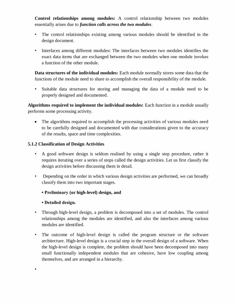
Control relationships among modules: A control relationship between two modules
essentially arises due to function calls across the two modules.
• The control relationships existing among various modules should be identified in the
design document.
• Interfaces among different modules: The interfaces between two modules identifies the
exact data items that are exchanged between the two modules when one module invokes
a function of the other module.
Data structures of the individual modules: Each module normally stores some data that the
functions of the module need to share to accomplish the overall responsibility of the module.
• Suitable data structures for storing and managing the data of a module need to be
properly designed and documented.
Algorithms required to implement the individual modules: Each function in a module usually
performs some processing activity.
The algorithms required to accomplish the processing activities of various modules need
to be carefully designed and documented with due considerations given to the accuracy
of the results, space and time complexities.
5.1.2 Classification of Design Activities
• A good software design is seldom realised by using a single step procedure, rather it
requires iterating over a series of steps called the design activities. Let us first classify the
design activities before discussing them in detail.
• Depending on the order in which various design activities are performed, we can broadly
classify them into two important stages.
• Preliminary (or high-level) design, and
• Detailed design.
• Through high-level design, a problem is decomposed into a set of modules. The control
relationships among the modules are identified, and also the interfaces among various
modules are identified.
• The outcome of high-level design is called the program structure or the software
architecture. High-level design is a crucial step in the overall design of a software. When
the high-level design is complete, the problem should have been decomposed into many
small functionally independent modules that are cohesive, have low coupling among
themselves, and are arranged in a hierarchy.
•

• Many different types of notations have been used to represent a high-level design. A
notation that is widely being used for procedural development is a tree-like diagram
called the structure chart. Another popular design representation techniques called UML
that is being used to document
• object-oriented design, involves developing several types of diagrams to document the
object-oriented design of a systems.
Though other notations such as Jackson diagram [1975] or Warnier-Orr [1977, 1981]
diagram are available to document a software design, we confine our attention in this text
to structure charts and UML diagrams only. Once the high-level design is complete,
detailed design is undertaken
• During detailed design each module is examined carefully to design its data structures
and the algorithms.
• The outcome of the detailed design stage is usually documented in the form of a module
specification (MSPEC) document.
• After the high-level design is complete, the problem would have been decomposed into
small modules, and the data structures and algorithms to be used described using MSPEC
and can be easily grasped by programmers for initiating coding.
• In this text, we do not discuss MSPECs and confine our attention to high-level
design only.
5.1.3 Classification of Design Methodologies
• The design activities vary considerably based on the specific design methodology being
used.
• A large number of software design methodologies are available. We can roughly classify
these methodologies into procedural and object-oriented approaches.
• These two approaches are two fundamentally different design paradigms
Does a design techniques result in unique solutions?
• Unless we know what a good software design is and how to distinguish a superior design
solution from an inferior one, we can not possibly design one.

Analysis versus design
• Analysis and design activities differ in goal and scope.
• The goal of any analysis technique is to elaborate the customer requirements through
careful thinking and at the same time consciously avoiding making any decisions
regarding the exact way the system is to be implemented.
• The analysis results are generic and does not consider implementation or the issues
associated with specific platforms.
• The analysis model is usually documented using some graphical formalism.
• In case of the function-oriented approach that we are going to discuss, the analysis model
would be documented using data flow diagrams (DFDs),
• whereas the design would be documented using structure chart.
• On the other hand, for object-oriented approach, both the design model and the analysis
model will be documented using unified modelling language (UML). The analysis model
would normally be very difficult to implement using a programming language
5.2 HOW TO CHARACTERISE A GOOD SOFTWARE DESIGN?
• The definition of a “good” software design can vary depending on the exact application
being designed.
• For example, “memory size used up by a program” may be an important issue to
Characterise a good solution for embedded software development—since embedded
applications are often required to work under severely limited memory
• sizes due to cost, space, or power consumption considerations.
• For embedded applications, factors such as design comprehensibility may take a back
seat while judging the goodness of design.
• Few desirable characteristics that every good software design for general applications
must possess. These characteristics are listed below:
Correctness: A good design should first of all be correct. That is, it should correctly
implement all the functionalities of the system.
Understandability: A good design should be easily understandable. Unless a design solution
is easily understandable, it would be difficult to implement and maintain it.
Efficiency: A good design solution should adequately address resource, time, and cost
optimisation issues.

Maintainability: A good design should be easy to change. This is an important requirement,
since change requests usually keep coming from the customer even after product release.
5.2.1 Understandability of a Design: A Ma jor Concern
• While performing the design of a certain problem, assume that we have arrived at a large
number of design solutions and need to choose the best one. Obviously all incorrect
designs have to be discarded first. Out of the correct design solutions, how can we
identify the best one?
An understandable design is modular and layered
• How can the understandability of two different designs be compared, so that we can pick
the better one? To be able to compare the understandability of two design solutions, we
should at least have an understanding of the general features that an easily understandable
design should possess. A design solution should have the following characteristics to be
easily understandable:
• It should assign consistent and meaningful names to various design components.
• It should make use of the principles of decomposition and abstraction in good
measures to simplify the design.
Modularity
• A modular design is an effective decomposition of a problem.
• It is a basic characteristic of any good design solution.
• A modular design, in simple words, implies that the problem has been decomposed into a
set of modules that have only limited interactions with each other.
• Decomposition of a problem into modules facilitates taking advantage of the divide and
conquer principle.
• If different modules have either no interactions or little interactions with each other, then
each module can be understood separately. This reduces the perceived complexity of the
• design solution greatly.
• To understand why this is so, remember that it may be very difficult to break a bunch of
sticks which have been tied together, but very easy to break the sticks individually.
• It is not difficult to argue that modularity is an important characteristic of a good design
solution. But, even with this, how can we compare the modularity of two alternate design
solutions?

• From an inspection of the module structure, it is at least possible to intuitively form an
idea as to which design is more modular For example, consider two alternate design
solutions
• A software design with high cohesion and low coupling among modules is the
effective problem decomposition. Such a design would lead to increased productivity
during program development by bringing down the perceived problem complexity.

UNIT-3
FUNCTION-ORIENTED SOFTWARE DESIGN
These techniques, to start with, view a system as a black-box that provides a set of services to the users of the
software. The term top-down decomposition i s often used to denote the successive decomposition of a set of
high-level functions into more detailed functions. After top-down decomposition has been carried out, the
different identified functions are mapped to modules and a module structure is created.
The SA/SD technique can b e used to perform the high-level design of a software.
6.1 OVERVIEW OF SA/SD METHODOLOGY
As the name itself implies, SA/SD methodology involves carrying out two distinct activities:
1) Structured analysis (SA)
2) Structured design (SD)
The roles of structured analysis (SA) and structured design (SD) have been shown schematically in Figure 6.1.
Observe the following from the figure:
During structured analysis, the SRS document is transformed into a data flow diagram (DFD) model.
During structured design, the DFD model is transformed into a structure chart.
The structured analysis activity transforms the SRS document into a graphic model called the DFD model.
During structured analysis, functional decomposition of the system is achieved.i.e,function that the system
needs to perform is analysed and hierarchically decomposed into more detailed functions.
During structured design, all functions identified during structured analysis are mapped to a module structure.
This module structure is also called the high level design or the software architecture for the given problem.
This is represented using a structure chart.
It is important to understand that the purpose of structured analysis is to capture the detailed structure of
the system as perceived by the user, whereas the purpose of structured design is to define the structure of
the solution that is suitable for implementation in some programming language.

6.2 STRUCTURED ANALYSIS
We have already mentioned that during structured analysis, the major processing tasks (high-level functions)
of the system are analysed, and t h e data flow among these processing tasks are represented graphically.
Significant contributions to the development of the structured analysis techniques have been made by Gane
and Sarson [1979], and DeMarco and Yourdon [1978].
The structured analysis technique is based on the following underlying principles:
Top-down decomposition approach.
Application of divide and conquer principle. Through this each highlevel function is independently
decomposed into detailed functions.
Graphical representation of the analysis results u s i n g data flow diagrams (DFDs).
A DFD is a hierarchical graphical model of a system that shows the different processing activities functions
that the system performs and the data interchange among those functions.
NOTE
A DFD model only represents the data flow aspects and does not show the sequence of execution of the
different functions and the conditions based on which a function may or may not be executed.
It completely ignores aspects such as control flow, the specific algorithms used by the functions, etc.
6.2.1 Data Flow Diagrams (DFDs)
The DFD (also known as the bubble chart) is a simple graphical formalism that can be used to represent a
system in terms of the input data to the system, various processing carried out on those data, and the output
data generated by the system.
T he main reason why the DFD technique is so popular is probably because of the fact that DFD is a very
simple formalism— it is simple to understand and use.
A DFD model uses a very limited number of primitive symbols (shown in Figure 6.2) to represent the functions
performed by a system and the data flow among these functions.
Starting with a set of high-level functions that a system performs, a DFD model represents the subfunctions
performed by the functions using a hierarchy of diagrams.
The DFD technique is also based on a very simple set of intuitive concepts and rules.
Primitive symbols used for constructing DFDs
There are essentially five different types of symbols used for constructing DFDs.

Function symbol: A function is represented using a circle. This symbol is called a process or a bubble. Bubbles
are annotated with the names of the corresponding functions.
External entity symbol: An external entity such as a librarian, a library member, etc. is represented by a
rectangle. The external entities are essentially those physical entities external to the software system which
interact with the system by inputting data to the system or by consuming the data produced by the system.
Data flow symbol: A directed arc (or an arrow) is used as a data flow symbol. A data flow symbol represents
the data flow occurring between two processes or between an external entity and a process in the direction
of the data flow arrow.
Data store symbol: A data store is represented using two parallel lines. It represents a logical file. That is, a
data store symbol can represent either a data structure or a physical file on disk.
Each data store is connected to a process by means of a data flow symbol. The direction of the data flow
arrow shows whether data is being read from or written into a data store.
An arrow flowing in or out of a data store implicitly represents the entire data of the data store and hence
arrows connecting t o a data store need not be annotated with the name of the corresponding data items
Output symbol: The output symbol i s as shown in Figure 6.2. The output symbol is used when a hard copy is
produced. The notations that we are following in this text are closer to the Yourdon’s notations than to the
other notations.
Important concepts associated with constructing DFD models
Before we discuss how to construct the DFD model of a system, let us discuss some important concepts
associated with DFDs:
Synchronous and asynchronous operations
Data dictionary
Data definition
Synchronous and asynchronous operations
If two bubbles are directly connected by a data flow arrow, then they are synchronous. This means that they
operate at t h e same speed.

An example of such an arrangement is shown in Figure 6.3(a). Here, the validate-number bubble can start
processing only after t h e readnumber bubble has supplied data to it; and the read-number bubble has to
wait until the validate-number bubble has consumed its data.
However, if two bubbles are connected through a data store, as in Figure 6.3(b) then the speed of operation
of the bubbles are independent. This statement can be explained using the following reasoning.
The data produced by a producer bubble gets stored in the data store. It is therefore possible that the
producer bubble stores several pieces of data items, even before the consumer bubble consumes any of
them.
Data dictionary
A data dictionary lists the purpose of all data items and the definition of all composite data items in terms of
their component data items.consists of several DFDs, viz., level 0 DFD, level 1 DFD, level 2 DFDs, etc.,
For example, a data dictionary entry may represent that the data grossPay consists of the components
regularPay and overtimePay.
grossP ay = regularP ay + overtimeP ay
For the smallest units of data items, the data dictionary simply lists their name and their type.
Composite data items are expressed in terms of the component data items using certain operators. The
operators using which a composite data item can be expressed in terms of its component data items are
discussed subsequently.
The dictionary plays a very important role in any software development process, especially for the following
reasons:
1) A data dictionary provides a standard terminology for all relevant data for use by the developers working in
a project.
2) The data dictionary helps the developers to determine the definition of different data structures in terms
of their component elements while implementing the design.
3) The data dictionary helps to perform impact analysis. That is, it is possible to determine the effect of some
data on various processing activities and vice versa.
For large systems, the data dictionary can become extremely complex and voluminous. Even moderate-sized
projects can have thousands of entries in the data dictionary. It becomes extremely di fficult to maintain a
voluminous dictionary manually.

Computer-aided software engineering (CASE) tools come handy to overcome this problem. Most CASE tools
usually capture the data items appearing in a DFD as the DFD is drawn, and automatically generate the data
dictionary.
• As a result, the designers do not have to spend almost any effort in creating the data
dictionary. These CASE tools also support some query language facility to query about the definition and
usage of data items.
• Query handling is facilitated by storing the data dictionary in a relational database
management system (RDBMS).
• Data definition
• Composite data items can be defined in terms of primitive data items using the following
data definition operators.
• +: denotes composition of two data items,
• example a+b represents data a and b.
• [,,]: represents selection, i.e. any one of the data items listed inside the square bracket can
occur For example, [a,b] represents either a occurs o r b occurs.
• (): the contents inside the bracket represent optional data which may or may not appear.
• example a+(b) represents either a or a+b occurs.
• {}: represents iterative data definition,
• example. {name}5 represents five name data.
• example{name}* represents zero or more instances of name data.
• =: represents equivalence,
• Example a= b+c means that a is a composite data item comprising of both b and c.
• /* */: Anything appearing within /* and */ is considered as comment.
• 6.3 DEVELOPING THE DFD MODEL OF A SYSTEM
• A DFD model of a system graphically represents how each input data is transformed to its
corresponding output data through a hierarchy of DFDs.
• The DFD model of a problem consists of many of DFDs and a single data dictionary.
• The DFD model of a system i s constructed by using a hierarchy of DFDs .
• The top level DFD is called the level 0 DFD or the context diagram. This is the most abstract
(simplest) representation of the system (highest level). It is the easiest to draw and understand. At each
successive lower level D FD s, more and more details are gradually introduced.
• To develop a higher-level DFD model, processes are decomposed into their subprocesses
and the data flow among these subprocesses are identified.

• To develop the data flow model of a system, first the most abstract representation (highest
level) of the problem is to be worked out. Subsequently, the lower level DFDs are developed.
• Level 0 and Level 1 consist of only one DFD each. Level 2 may contain up to 7 separate
DFDs, and level 3 up to 49 DFDs, and so on. However, there is only a single data dictionary for the entire DFD
model. All the data names appearing in all DFDs are populated in the data dictionary and the data dictionary
contains the definitions of all the data items.
• 6.3.1 Context Diagram
• The context diagram is the most abstract (highest level) data flow representation of a
system. It represents the entire system as a single bubble.
• The bubble in the context diagram is annotated with the name of the software system being
developed (usually a noun). This is the only bubble in a DFD model, where a noun is used for naming the
bubble.
• The bubbles at all other levels are annotated with verbs according to the main function
performed by the bubble. This is expected since the purpose of the context diagram is to capture the context
of the system rather than its functionality.
• As an example of a context diagram, consider the context diagram a software developed to
automate the book keeping activities of a supermarket (see Figure 6.10). The context diagram has been
labelled as ‘Supermarket software’.
To develop the context diagram of the system, we have to analyse the SRS document to identify the different
types o f users who would be using the system and the kinds of data they would be inputting to the system
and the data they would be receiving from the system. Here, the term users of the system also includes any
external systems which supply data to or receive data from the system.
• 6.3.2 Level 1 DFD
• The level 1 DFD usually contains three to seven bubbles. That is, the system is represented
as performing three to seven important functions.

• To develop the level 1 DFD, examine the high-level functional requirements in the SRS
document. If there are three to seven highlevel functional requirements, then each of these can be directly
• represented as a bubble in the level 1 DFD.
• Next, examine the input data to these functions and the data output by these functions as
documented in the SRS document and represent them appropriately in the diagram.
• What if a system has more than seven high-level requirements identified in the SRS
document?
• Combined and split
• Decomposition
• Each bubble in the DFD represents a function performed by the system.
• The bubbles are decomposed into subfunctions at the successive levels of the DFD model.
• Decomposition of a bubble is also known as factoring o r exploding a bubble.
• Each bubble at any level of DFD is usually decomposed to anything three to seven bubbles. A
few bubbles at any level m a k e that level superfluous.
• Decomposition of a bubble should be carried o n until a level is reached at which the
function of the bubble can be described using a simple algorithm.
• 1. Construction of context diagram: Examine the SRS document to determine:
• • Different high-level functions that the system needs to perform.
• • Data input to every high-level function.
• • Data output from every high-level function.
• Interactions (data flow) among the identified high-level functions.
• Construction of level 1 diagram:
• Examine the high-level functions described in the SRS document. If there are three to seven
high-level requirements in the SRS document, then represent each of the high-level function in the form of a
bubble.
• If there are more than seven bubbles, then some of them have to be combined. If there are
less than three bubbles, then some of these have to be split.
• Construction of lower-level diagrams:
• Decompose each high-level function into its constituent subfunctions through the following
set of activities:
• •...Identify the different subfunctions of the high-level function.
• •...Identify the data input to each of these subfunctions.

• •...Identify the data output from each of these subfunctions.
• •...Identify the interactions (data flow) among these subfunctions.
• Recursively repeat Step 3 for each subfunction until a subfunction can be represented by
using a simple algorithm.
• Numbering of bubbles
• It is necessary to number the different bubbles occurring in the DFD.
• These numbers help in uniquely identifying any bubble in the DFD from its bubble number.
The bubble at the context level is usually assigned the number 0 to indicate that it is the 0 level DFD.
• Bubbles at level 1 are numbered, 0.1, 0.2, 0.3, etc.
• When a bubble numbered x is decomposed, its children bubble are numbered x.1, x.2, x.3,
etc.
• In this numbering scheme, by looking at the number of a bubble we can unambiguously
determine its level, its ancestors, and its successors
• Balancing DFDs
• The DFD model of a system usually consists of many DFDs that are organised in a hierarchy.
In this context, a DFD is required to be balanced with respect to the corresponding bubble of the parent DFD.
• The data that flow into or out of a bubble must match the data flow at the next level of
DFD. This is known as balancing a DFD.
• Commonly made errors while constructing a DFD model
• 1) Many beginners commit the mistake of drawing more than one bubble in the context diagram. Context
diagram should depict the system as a single bubble.
• 2) Many beginners create DFD models in which external entities appearing at all levels of
DFDs. All external entities interacting with the system should be represented only in the context diagram. The
external entities should not appear in the DFDs at any other level.

• 3) It is a common oversight to have either too few or too many bubbles in a DFD. Only three
to seven bubbles per diagram should be allowed. This also means that each bubble in a DFD should be
decomposed three to seven bubbles in the next level.
• 4) Many beginners leave the DFDs at the different levels of a DFD model unbalanced.
• 5) A common mistake committed by many beginners while developing a DFD model is
attempting to represent control information in a DFD.
• It is important to realise that a DFD represents only data flow, and it does not represent
any control information.
• Illustration 1. A book can be searched in the library catalog by inputting its name. If the
book is available in the library, then the details of the book are displayed. If the book is not listed in the
catalog, then an error message is generated. While developing the DFD model for this simple problem, many
beginners commit the mistake of drawing an arrow (as shown in Figure 6.6) to indicate that the error function
is invoked after the search book. But, this is a control information and should not be shown on the DFD.

• Example 6.1 (RMS Calculating Software)
• A software system called RMS calculating software would read three integral numbers from
the user in the range of –1000 and +1000 and would determine the root mean square (RMS) of the three
input numbers and display it.
• Data dictionary for the DFD model of Example 6.1
• data-items: {integer}3
• rms: float
• valid-data:data-items
• a: integer
• b: integer
• c: integer
• asq: integer
• bsq: integer
• csq: integer
msq: integer

• Example 6.2 (Tic-Tac-Toe Computer Game ) Tic-tac-toe is a computer game in
• which a human player and the computer make alternate moves on a 3 × 3 square. A move consists of
marking a previously unmarked square. The player who is first to place three consecutive marks along a
straight line (i.e., along a row, column, or diagonal) on the square wins. As soon as either of the human player
or the computer wins, a message congratulating the winner should be displayed. If neither player manages to
get three consecutive marks along a straight line, and all the squares on the board are filled up, then the game
is drawn. The computer always tries to win a game.
• Data dictionary for the DFD model of Example 6.2
• move: integer /* number between 1 to 9 */
• display: game+result
• game: board
• board: {integer}9
• result: [“computer won”, “human won”, “drawn”]


• Shortcomings of the DFD model
• In the DFD model, we judge the function performed by a bubble from its label. However, a short label may
not capture the entire functionality of a bubble.
• For example, a bubble named find-book-position has only intuitive meaning and does not specify several
things, e.g. what happens when some input information i s missing or is incorrect. Further, t h e findbook-
position bubble may not convey anything regarding what happens when the required book is missing.
• Not-well defined control aspects are not defined by a DFD. For instance, the order in which inputs are
consumed and outputs are produced by a bubble is not specified. A DFD model does not specify the order in
which the different bubbles are executed. Representation of such aspects is very important for modelling real-
time systems.
• Decomposition: The method of carrying out decomposition to arrive at the successive levels and the
ultimate level to which decomposition is carried out are highly subjective and depend on the choice and
• judgment of the analyst. D u e to this reason, even for the same problem, several alternative DFD
representations are possible. Further, many times it is not possible to say which DFD representation is
superior or preferable to another one.
• Improper data flow diagram: T he da ta flow diagramming technique does not provide any specific
guidance as to how exactly to decompose a given function into its subfunctions and we have to use subjective
judgment to carry out decomposition.
• 6.3.3 Extending DFD Technique to Make it Applicable to Real-time Systems
• In a real-time system, some of the high-level functions are associated with deadlines. Therefore, a function
must not only produce correct results but also should produce them by some prespecified time.
• For real-time systems, execution time is an important consideration for arriving at a correct design.
Therefore, explicit representation of control and event flow aspects are essential. One of the widely accepted
techniques for extending the DFD technique to real-time system analysis is the Ward and Mellor technique
[1985].

• In the Ward and Mellor notation, a type of process that handles only control flows is introduced. These
processes representing control processing are denoted using dashed bubbles. Control flows are shown using
dashed lines/arrows.
• In order to link the data processing and control processing diagrams, a notational reference (solid bar) to a
control specification is used. The CSPEC describes the following:
• The effect of an external event or control signal.
• The processes that are invoked as a consequence of an event. Control specifications represents the
behavior of the system in two different ways:
• It contains a state transition diagram (STD). The STD is a sequential specification of behaviour.
• It contains a pro gra m activation table (PAT). The PAT is a combinatorial specification of behaviour. PAT
represents invocation
• 6.4 STRUCTURED DESIGN
• The aim of structured design is to transform the results of the structured analysis (that i s, the DFD model)
into a structure chart.
• A structure chart represents the software architecture. The various modules making up the system, the
module dependency (i.e. which module calls which other modules), and the parameters that are passed
among the different modules.
• The structure chart representation can be easily implemented using some programming language. Since
the main focus in a structure chart representation is on module structure of a software and the interaction
among the different modules, the procedural aspects (e.g. how a particular functionality is achieved) are not
represented.
• The basic building blocks using which structure charts are designed are as
• following:
• Rectangular boxes: A rectangular box represents a module. Usually, every rectangular box is annotated
with the name of the module it represents.
• Module invocation arrows: An arrow connecting two modules implies that during program execution
control is passed from one module to the other in the direction of the connecting arrow. However, just by
looking at the structure chart, we cannot say whether a modules calls another module just once or many
times. Also, just by looking at the structure chart, we cannot tell the order in which the different modules are
invoked.
• Data flow arrows: These are small arrows appearing alongside the module invocation arrows. The data
flow arrows are annotated with the corresponding data name. Data flo w arrows represent the fact that the
named data passes from one module to the other in the direction of the arrow.
• Library modules: A library module is usually represented by a rectangle with double edges. Libraries
comprise the frequently called modules. Usually, when a module is invoked by many other modules, it is
made into a library module.

• Selection: The diamond symbol represents the fact that one module of several modules connected with
the diamond symbol i s invoked depending on the outcome of the condition attached with the diamond
symbol.
• Repetition: A loop around the control flow arrows denotes that the respective modules are invoked
repeatedly.
• In any structure chart, there should be one and only one module at the top, called the root.
• There should be at most one control relationship between any two modules in the structure chart. This
means that if module A invokes module B, module B cannot invoke module A.
• The main reason behind this restriction is that we can consider the different modules of a structure chart
to be arranged in layers or levels. The principle of abstraction does not allow lower-level modules to be
aware of the existence of the high-level modules.
• However, it is possible for t wo higher-level modules to invoke the same lower-level module. An example
of a properly layered design and another of a poorly layered design are shown in Figure 6.18
• Flow chart versus structure chart
• We are all familiar with the flow chart representation of a program. Flow chart is a convenient technique
to represent t he flo w of control in a program. A structure chart differs from a flow chart in three principal
ways:.
• It is usually difficult to identify the different modules of a program from its flow chart representation.
• Data interchange among different modules is not represented in a flow chart.

• Sequential ordering of tasks that i s inherent to a flow chart is suppressed in a structure chart.
• 6.4.1 Transformation of a DFD Model into Structure Chart
• Systematic techniques are available to transform the DFD representation of a problem into a module
structure represented by as a structure chart. Structured design provides two strategies to guide
transformation of a DFD into a structure chart:
• Transform analysis
• Transaction analysis
• Normally, one would start with the level 1 DFD, transform it into module representation using either the
transform or transaction analysis and then proceed toward the lower level DFDs.
• At each level of transformation, it is important to first determine whether the transform or the transaction
analysis is applicable to a particular DFD.
• Whether to apply transform or transaction processing?
• Given a specific DFD of a model, how does one decide whether to apply transform analysis or transaction
analysis? For this, one would have to examine the data input to the diagram. The data input to the diagram
can be easily spotted because they are represented by dangling arrows.
• If all the data flow into the diagram are processed in similar ways (i.e. If all the input data flow arrows are
incident on the same bubble in the DFD) then transform analysis is applicable.
• Otherwise, transaction analysis is applicable. Normally, transform analysis is applicable only to very simple
processing.
• Please recollect that the bubbles are decomposed until it represents a very simple processing that can be
implemented using only a few lines of code.
• Therefore, transform analysis is normally applicable at the lower levels of a DFD model. Each different way
in which data is processed corresponds to a separate transaction. Each transaction corresponds to a
functionality that lets a user perform a meaningful piece of work using the software.
• Transform analysis
• Transform analysis identifies the primary functional components (modules) and the input and output data
for these components. The first step in transform analysis is to divide the DFD into three types of parts:
• The input portion in the DFD includes processes that transform input data from physical (e.g, character
from terminal) to logical form (e.g. Internal tables, lists, etc.). Each input portion is called an afferent branch.
• The output portion of a DFD transforms output data from logical form to physical form. Each output
portion is called an efferent branch. The remaining portion of a DFD is called central transform.
• In the next step of transform analysis, the structure chart is derived by drawing one functional component
each for the central transform, the afferent and efferent branches. These are drawn below a root module,
which would invoke these modules.

• Transaction analysis
• Transaction analysis is an alternative to transform analysis and is useful while designing transaction
processing programs.
• A transaction allows the user to perform some specific type of work by using the software. For example,
‘issue book’, ‘return book’, ‘query book’, etc., are transactions.
• As in transform analysis, first all data entering into the DFD need to be identified. In a transaction-driven
system, different data items may pass through different computation paths through the DFD.
• This is in contrast to a transform centered system where each data item entering the DFD goes through the
same processing steps. Each different way in which input data is processed is a transaction.
• A simple way to identify a transaction is the following. Check the input data.
• The number of bubbles on which the input data to the DFD are incident defines the number of
transactions. However, some transactions may not require any input data.
• These transactions can be identified based on the experience gained from solving a large number of
examples.

• 6.5 DETAILED DESIGN

• During detailed design the pseudo code description of the processing and the different data structures are
designed for the different modules of the structure chart.
• These are usually described in the form of module specifications (MSPEC). MSPEC is usually written using
structured English.
• The MSPEC for the non-leaf modules describe the different conditions under which the responsibilities are
delegated to the lowerlevel modules. The MSPEC for the leaf-level modules should describe in algorithmic
form how the primitive processing steps are carried out.
To develop the MSPEC of a module, it is usually necessary to refer to the DFD model and the SRS document to
determine the functionality of the module.
• 6.6 DESIGN REVIEW
• Traceability: Whether each bubble of the DFD can be traced to some module in the structure chart a nd
vice versa. They check whether each functional requirement in the SRS document can be traced to some
bubble in the DFD model and vice versa.
• Correctness: Whether all the algorithms and data structures of the detailed design are correct.
• Maintainability: Whether the design can be easily maintained in future.
• Implementation: Whether the design can be easily and efficiently be implemented.
• After the points raised by the reviewers is addressed by the designers, the design document becomes
ready for implementation.

1
USER INTERFACE DESIGN
The user interface portion of a software product is responsible for all interactions with the user. In
the early days of computer, no software product had any user interface. The computers those days
were batch systems and no interactions with the users were supported.
Now, we know that things are very different—almost every software product is highly interactive.
The user interface part of a software product is responsible for all interactions with the end-user.
9.1 CHARACTERISTICS OF A GOOD USER INTERFACE
Speed of use: It indicates how fast the users can perform their intended tasks. The time and user
effort necessary to initiate and execute different commands should be minimal. EX. SEARCH
Speed of recall: Once users learn how to use an interface, the speed with which they can recall
the command issue procedure should be maximised. EX.UP ARROW IN S/W
Consistency: Thus, consistency facilitates speed of learning, speed of recall, and also helps in
reduction of error rate
Aesthetic and attractive: A good user interface should be attractive to use. An attractive user
interface catches user attention and fancy.
Feedback: if any user request takes more than few seconds to process, the user should be
informed about the state of the processing of his request.
Support for multiple skill levels: Experienced users, novice users
Error recovery (undo facility):
User guidance and on-line help: Whenever users need guidance or seek help from the system,
they should be provided with appropriate guidance and help.
Speed of learning: A good user interface should be easy to learn. Speed of learning is hampered
by complex syntax and semantics of the command issue procedures. A good user interface should
not require its users to memorise commands. The following three issues are crucial to enhance the
speed of learning:
— U s e of metaphors and intuitive command names: Speed of learning an interface is greatly
facilitated if these are based on some day-to- day real-life examples or some physical objects with
which the users are familiar with. The abstractions of real-life objects or concepts used in user
interface design are called metaphors.
Consistency: Once, a user learns about a command, he should be able to use the similar
commands in different circumstances for carrying out similar actions.
Component-based interface: Users can learn an interface faster if the interaction style of the
interface is very similar to the interface of other applications with which the user is already
familiar with.

2
9.2 BASIC CONCEPTS
user guidance and on-line help system.
mode-based and a modeless interface
advantages of a graphical interface.
9.2.1 User Guidance and On-line Help
Users may seek help about the operation of the software any time while using the software. This
is provided by the on-line help system.
This is different from the guidance and error messages which are flashed automatically without
the user asking for them.
The guidance messages prompt the user regarding the options he has regarding the next
command, and the status of the last command, etc.
On-line help system: Users expect the on-line help messages to be tailored to the context in
which they invoke the “help system”. Therefore, a good online help system should keep track of
what a user is doing while invoking the help system and provide the output message in a context-
dependent way.
Also, the help messages should be tailored to the user’s experience level.
Guidance messages: The guidance messages should be carefully designed to prompt the user
about the next actions he might pursue, the current status of the system, the progress so far made
in processing his last command, etc.
A good guidance system should have different levels of sophistication for different categories of
users.
Error messages: Error messages are generated by a system either when the user commits some
error or when some errors encountered by the system during processing due to some exceptional
conditions, such as out of memory, communication link broken, etc.
9.2.2 Mode-based versus Modeless Interface
A mode is a state or collection of states in which only a subset of all user interaction tasks can be
performed. In a modeless interface, the same set of commands can be invoked at any time during
the running of the software.
Thus, a modeless interface has only a single mode and all the commands are available all the time
during the operation of the software.
On the other hand, in a mode-based interface, different sets of commands can be invoked
depending on the mode in which the system is, i.e., the mode at any instant is determined by the
sequence of commands already issued by the user.

3
9.2.3 Graphical User Interface (GUI) versus Text-based User Interface
Let us compare various characteristics of a GUI with those of a textbased user interface:
In a GUI multiple windows with different information can simultaneously be displayed on the
user screen.
Iconic information representation and symbolic information manipulation is possible in a GUI.
A GUI usually supports command selection using an attractive and user-friendly menu selection
system.
In a GUI, a pointing device such as a mouse or a light pen can be used for issuing commands.
On the flip side, a GUI requires special terminals with graphics capabilities for running and also
requires special input devices such a mouse. On the other hand, a text-based user interface can be
implemented even on a cheap alphanumeric display terminal. Graphics terminals are usually
much more expensive than alphanumeric terminals.
9.3 TYPES OF USER INTERFACES
user interfaces can be classified into the following three categories:
Command language-based interfaces
Menu-based interfaces
Direct manipulation interfaces
9.3.1 Command Language-based Interface
A command language-based interface—as the name itself suggests, is based on designing a
command language which the user can use to issue the commands. The user is expected to
frame the appropriate commands in the language and type them appropriately whenever required.
A simple command language-based interface might simply assign unique names to the
different commands.
Such a facility to compose commands dramatically reduces the number of command names
one would have to remember. Thus, a command language-based interface can be made concise
requiring minimal typing by the user. Command language-based interfaces allow fast interaction
with the computer and simplify the input of complex commands.
Among the three categories of interfaces, the command language interface allows for most
efficient command issue procedure requiring minimal typing.
Further, a command language-based interface can be implemented even on cheap
alphanumeric terminals. Also, a command language-based interface is easier to develop
compared to a menu-based or a direct-manipulation interface because compiler writing techniques
are well developed.

4
One can systematically develop a command language interface by using the standard compiler
writing tools Lex and Yacc.
However, command language-based interfaces suffer from several drawbacks. Usually, command
language-based interfaces are difficult to learn and require the user to memorise the set of
primitive commands. Also, most users make errors while formulating commands in the
command language and also while typing them. Further, in a command language-based interface,
all interactions with the system is through a key-board and cannot take advantage of effective
interaction devices such as a mouse. Obviously, for casual and inexperienced users, command
language-based interfaces are not suitable.
Issues in designing a command language-based interface
The designer has to decide what mnemonics (command names) to use for the different
commands. The designer should try to develop meaningful mnemonics and yet be concise to
minimise the amount of typing required.
The designer has to decide whether the users will be allowed to redefine the command names to
suit their own preferences.
The designer has to decide whether it should be possible to compose primitive commands to form
more complex commands.
9.3.2 Menu-based Interface
An important advantage of a menu-based interface over a command language-based interface is
that a menu-based interface does not require the users to remember the exact syntax of the
commands.
A menu-based interface is based on recognition of the command names, rather than recollection.
Humans are much better in recognising something than recollecting it.
Further, in a menu-based interface the typing effort is minimal as most interactions are carried out
through menu selections using a pointing device.
we discuss some of the techniques available to structure a large number of menu items:
Scrolling menu:
Walking menu:

5
Hierarchical menu:
This type of menu is suitable for small screens with limited display area such as that in mobile
phones. In a hierarchical menu, the menu items are organised in a hierarchy or tree structure.
Selecting a menu item causes the current menu display to be replaced by an appropriate sub-
menu.
9.3.3 Direct Manipulation Interfaces
Direct manipulation interfaces present the interface to the user in the form of visual models (i.e.,
icons2 or objects). For this reason, direct manipulation interfaces are sometimes called as iconic
interfaces.
In this type of interface, the user issues commands by performing actions on the visual
representations of the objects, e.g., pull an icon representing a file into an icon representing a trash
box, for deleting the file.
Important advantages of iconic interfaces include the fact that the icons can be recognised by the
users very easily, and that icons are language independent.
However, experienced users find direct manipulation interfaces very for too. Also, it is difficult to
give complex commands using a direct manipulation interface.
9.4 FUNDAMENTALS OF COMPONENT-BASED GUI DEVELOPMENT
Graphical user interfaces became popular in the 1980s.
The main reason why there were very few GUI-based applications prior to the eighties is that
graphics terminals were too expensive.
For example, the price of a graphics terminal those days was much more than what a high-end
personal computer costs these days.
One of the first computers to support GUI-based applications was the Apple Macintosh computer.
In fact, the popularity of the Apple Macintosh computer in the early eighties is directly
attributable to its GUI. In those early days of GUI design, the user interface programmer typically
started his interface development from the scratch. He would starting from simple pixel display
routines, write programs to draw lines, circles, text, etc. He would then develop his own routines
to display menu items, make menu choices, etc.
The current user interface style has undergone a sea change compared to the early style.
The current style of user interface development is component-based. It recognises that every user
interface can easily be built from a handfuls of predefined components such as menus, dialog
boxes, forms, etc.

6
9.4.1 Window System
Most modern graphical user interfaces are developed using some window system. A
window system can generate displays through a set of windows. Since a window is the
basic entity in such a graphical user interface, we need to first discuss what exactly a
window is.
Window: A window is a rectangular area on the screen. A window can be considered to be a
virtual screen, in the sense that it provides an interface to the user for carrying out independent
activities, e.g., one window can be used for editing a program and another for drawing pictures,
etc.
window can be divided into two parts—client part, and non-client part.
The client area makes up the whole of the window, except for the borders and scroll bars. The
client area is the area available to a client application for display. The non-client-part of the
window determines the look and feel of the window. The look and feel defines a basic behaviour
for all windows, such as creating, moving, resizing, iconifying of the windows. The window
manager is responsible for managing and maintaining the non-client area of a window.
Window management system (WMS)
A graphical user interface typically consists of a large number of windows. Therefore, it is
necessary to have some systematic way to manage these windows.
Most graphical user interface development environments do this through a window management
system (WMS).
A window management system is primarily a resource manager. It keeps track of the screen area
resource and allocates it to the different windows that seek to use the screen.
From a broader perspective, a WMS can be considered as a user interface management
system (UIMS) —which not only does resource management, but also provides the basic

7
behaviour to the windows and provides several utility routines to the application programmer for
user interface development.
A WMS consists of two parts a window manager, and a window system.
Window manager is the component of WMS with which the end user interacts to do various
window-related operations such as window repositioning, window resizing, iconification, etc.
The window manager is built on the top of the window system in the sense that it makes use of
various services provided by the window system.
The window manager and not the window system determines how the windows look and behave.
In fact, several kinds of window managers can be developed based on the same window system.
The window manager can be considered as a special kind of client that makes use of the services
(function calls) supported by the window system.
The application programmer can also directly invoke the services of the window system to
develop the user interface. The relationship between the window manager, window system, and
the application program is
It is usually cumbersome to develop user interfaces using the large set of routines provided by the
basic window system.
Therefore, most user interface development systems usually provide a high-level abstraction
called widgets for user interface development.
A widget is the short form of a window object. We know that an object is essentially a
collection of related data with several operations defined on these data which are available
externally to operate on these data. The data of an window object are the geometric attributes
(such as size, location etc.) and other attributes such as its background and foreground colour, etc.
The operations that are defined on these data include, resize, move, draw, etc.

8
Widgets are the standard user interface components. A user interface is usually made up by
integrating several widgets. A few important types of widgets normally provided with a user
interface development system
Component-based development
A development style based on widgets is called component-based (or widget-based ) GUI
development style. There are several important advantages of using a widget-based design style.
One of the most important reasons to use widgets as building blocks is because they help
users learn an interface fast.
In this style of development, the user interfaces for different applications are built from the same
basic components. Therefore, the user can extend his knowledge of the behaviour of the standard
components from one application to the other.
Also, the component-based user interface development style reduces the application
programmer’s work significantly as he is more of a user interface component integrator than a
programmer in the traditional sense.
Visual programming
Visual programming is the drag and drop style of program development.
In this style of user interface development, a number of visual objects (icons) representing the
GUI components are provided by the programming environment.
The application programmer can easily develop the user interface by dragging the required
component types (e.g., menu, forms, etc.) from the displayed icons and placing them wherever
required. Thus, visual programming can be considered as program development through
manipulation of several visual objects.
Reuse of program components in the form of visual objects is an important aspect of this style of
programming.
Examples of popular visual programming languages are Visual Basic, Visual C++, etc.
9.4.2 Types of Widgets
Label widget: This is probably one of the simplest widgets. A label widget does nothing except
to display a label, i.e., it does not have any other interaction capabilities and is not sensitive to
mouse clicks. A label widget is often used as a part of other widgets.
Container widget: These widgets do not stand by themselves, but exist merely to contain other
widgets. Other widgets are created as children of the container widget. When the container widget
is moved or resized, its children widget also get moved or resized. A container widget has no
callback routines associated with it.
Pop-up menu: These are transient and task specific. A pop-up menu appears upon pressing the
mouse button, irrespective of the mouse position.

9
Pull-down menu : These are more permanent and general. You have to move the cursor to a
specific location and pull down this type of menu.
Dialog boxes: A dialog box can include areas for entering text as well as values. If an
applycommand is supported in a dialog box, the newly entered values can be tried without
dismissing the box. Though most dialog boxes ask you to enter some information, there are some
dialog boxes which are merely informative, alerting you to a problem with your system or an
error you have made.
Generally, these boxes ask you to read the information presented and then click OK to dismiss the
box.
Push button: A push button contains key words or pictures that describe the action that is
triggered when you activate the button.
Usually, the action related to a push button occurs immediately when you click a push button
unless it contains an ellipsis (. . . ). A push button with an ellipsis generally indicates that another
dialog box will appear.
Radio buttons: A set of radio buttons are used when only one option has to be selected out of
many options. A radio button is a hollow circle followed by text describing the option it stands
for. When a radio button is selected, it appears filled and the previously selected radio button from
the group is unselected. Only one radio button from a group can be selected at any time.
This operation is similar to that of the band selection buttons that were available in old radios.
Combo boxes: A combo box looks like a button until the user interacts with it. When the user
presses or clicks it, the combo box displays a menu of items to choose from. Normally a combo
box is used to display either one-of-many choices when space is limited, the number of choices is
large, or when the menu items are computed at run-time.
9.4.3 An Overview of X-Window/MOTIF
One of the important reasons behind the extreme popularity of the X-window system is probably
due to the fact that it allows development of portable GUIs
Applications developed using the X-window system are device independent.
Also, applications developed using the X-window system become network independent in the
sense that the interface would work just as well on a terminal connected anywhere on the same
network as the computer running the application is.
Here, A is the computer application in which the application is running. B can be any computer
on the network from where you can interact with the application.
Network independent GUI was pioneered by the X-window system in the mid-eighties at MIT
(Massachusetts Institute of Technology) with support from DEC (Digital Equipment
Corporation).

10
Now-a-days many user interface development systems support network-independent GUI
development, e.g., the AWT and Swing components of Java.
The X-window functions are low level functions written in C language which can be called from
application programs. But only the very serious application designer would program directly
using the X-windows library routines.
Built on top of X-windows are higher level functions collectively called Xtoolkit, which consists
of a set of basic widgets and a set of routines to manipulate these widgets. One of the most widely
used widget sets is X/Motif.
9.4.4 X Architecture
The different terms used in this diagram are explained as follows:
Xserver: The X server runs on the hardware to which the display and the key board are attached.
The X server performs low-level graphics, manages window, and user input functions. The X
server controls accesses to a bit-mapped graphics display resource and manages it.
X protocol. The X protocol defines the format of the requests between client applications and
display servers over the network. The X protocol is designed to be independent of hardware,
operating systems, underlying network protocol, and the programming language used.
X library (Xlib). The Xlib provides a set of about 300 utility routines for applications to call.
These routines convert procedure calls into requests that are transmitted to the server. Xlib
provides low level primitives for developing an user interface, such as displaying a window,
drawing characters and graphics on the window, waiting for specific events, etc.
Xtoolkit (Xt). The Xtoolkit consists of two parts:
the intrinsics and the widgets.
Intrinsics are a set of about a dozen library routines that allow a programmer to combine a set of
widgets into a user interface.

11
In order to develop a user interface, the designer has to put together the set of components
(widgets) he needs, and then he needs to define the characteristics (called resources) and
behaviour of these widgets by using the intrinsic routines to complete the development of the
interface.
Therefore, developing an interface using Xtoolkit is much easier than developing the same
interface using only X library.
9.4.5 Size Measurement of a Component-based GUI
Lines of code (LOC) is not an appropriate metric to estimate and measure the size of a
component-based GUI.
This is because, the interface is developed by integrating several pre- built components. The
different components making up an interface might have been in written using code of drastically
different sizes. However, as far as the effort of the GUI developer who develops an interface by
integrating the components may not be affected by the code size of the components he integrates
A way to measure the size of a modern user interface is widget points (wp).
The size of a user interface (in wp units) is simply the total number of widgets used in the
interface. The size of an interface in wp units is a measure of the intricacy of the interface and is
more or less independent of the implementation environment.
However, till now there is no reported results to estimate the development effort in terms of the
wp metric.

12
An alternate way to compute the size of GUI is to simply count the number of screens. However,
this would be inaccurate since a screen complexity can range from very simple to very complex.
9.5 A USER INTERFACE DESIGN METHODOLOGY
At present, no step-by-step methodology is available which can be followed by rote to come up
with a good user interface.
Even though almost all popular GUI design methodologies are user-centered, this concept has to
be clearly distinguished from a user interface design by users.
let us distinguish between a user-centered design and a design by users.
Though users may have good knowledge of the tasks they have to perrform using a GUI, but they
may not know the GUI design issues.
Users have good knowledge of the tasks they have to perform, they also know whether they find
an interface easy to learn and use but they have less understanding and experience in GUI
design than the GUI developers.
9.5.1 Implications of Human Cognition Capabilities on User Interface Design
Limited memory: the GUI designer should not require the user to remember too many items of
information at a time.
Frequent task closure: When the system gives a clear feedback to the user that a task has been
successfully completed, the user gets a sense of achievement and relief.
The user can clear out information regarding the completed task from memory. This is
known as t a sk closure.
When the overall task is fairly big and complex, it should be divided into subtasks, each of which
has a clear sub goal which can be a closure point.
Recognition rather than recall. recognition of information from the alternatives shown to him is
more acceptable.
Procedural versus ob ject-oriented:
Procedural designs focus on tasks, prompting the user in each step of the task, giving them very
few options for anything else. This approach is best applied in situations where the tasks are
narrow and well-defined or where the users are inexperienced, such as a bank ATM.
An object-oriented interface on the other hand focuses on objects. This allows the users a wide
range of options.
9.5.2 A GUI Design Methodology
The GUI design methodology we present here is based on the seminal work of Frank Ludolph
[Frank1998]. Our user interface design methodology consists of the following important steps:
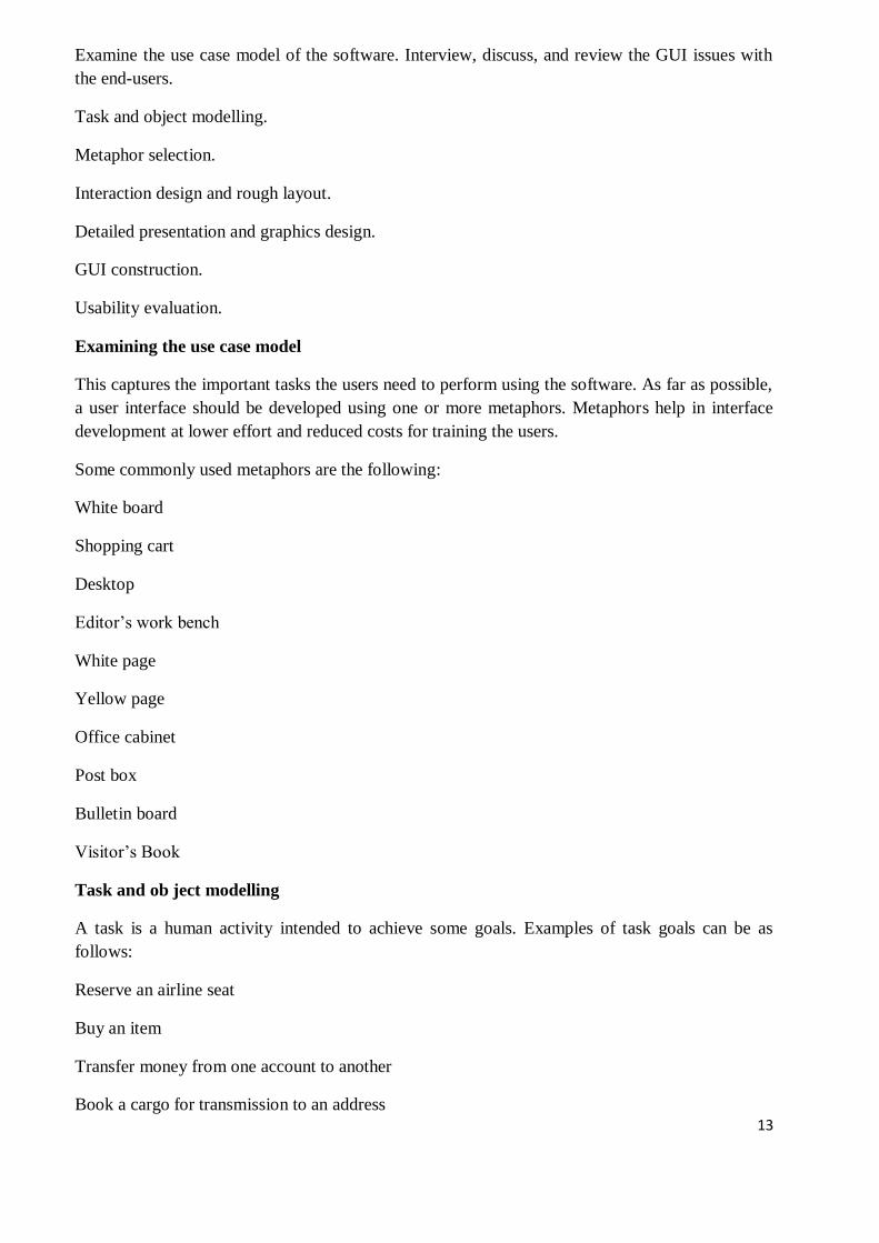
13
Examine the use case model of the software. Interview, discuss, and review the GUI issues with
the end-users.
Task and object modelling.
Metaphor selection.
Interaction design and rough layout.
Detailed presentation and graphics design.
GUI construction.
Usability evaluation.
Examining the use case model
This captures the important tasks the users need to perform using the software. As far as possible,
a user interface should be developed using one or more metaphors. Metaphors help in interface
development at lower effort and reduced costs for training the users.
Some commonly used metaphors are the following:
White board
Shopping cart
Desktop
Editor’s work bench
White page
Yellow page
Office cabinet
Post box
Bulletin board
Visitor’s Book
Task and ob ject modelling
A task is a human activity intended to achieve some goals. Examples of task goals can be as
follows:
Reserve an airline seat
Buy an item
Transfer money from one account to another
Book a cargo for transmission to an address

14
A task model is an abstract model of the structure of a task. A task model should show the
structure of the subtasks that the user needs to perform to achieve the overall task goal. Each task
can be modeled as a hierarchy of subtasks.
A user object model is a model of business objects which the end-users believe that they are
interacting with. The objects in a library software may be books, journals, members, etc.
Metaphor selection
The first place one should look for while trying to identify the candidate metaphors is the set of
parallels to objects, tasks, and terminologies of the use cases.
If no obvious metaphors can be found, then the designer can fall back on the metaphors of the
physical world of concrete objects.
The appropriateness of each candidate metaphor should be tested by restating the objects and
tasks of the user interface model in terms of the metaphor.
Example web-based pay-order shop,
catalog associated with the items by clicking on the item.
Related items can be picked from the drawers of an item cabinet.
The items can be organised in the form of a book, similar to the way information abo u t
electronic components are organised in a semiconductor hand book.
Interaction design and rough layout
The interaction design involves mapping the subtasks into appropriate controls, and other widgets
such as forms, text box, etc. This involves making a choice from a set of available components
that would best suit the subtask. Rough layout concerns how the controls, an other widgets to be
organised in windows.
Detailed presentation and graphics design
Each window should represent either an object or many objects that have a clear relationship to
each other.
At one extreme, each object view could be in its own window. But, this is likely to lead to too
much window opening, closing, moving, and resizing.
At the other extreme, all the views could be placed in one window side-by-side, resulting in a
very large window. This would force the user to move the cursor around the window to look for
different objects.
GUI construction
Some of the windows have to be defined as modal dialogs. When a window is a modal dialog, no
other windows in the application is accessible until the current window is closed.

15
When a modal dialog is closed, the user is returned to the window from which the modal dialog
was invoked. Modal dialogs are commonly used when an explicit confirmation or authorisation
step is required for an action (e.g., confirmation of delete).
Though use of modal dialogs are essential in some situations, overuse of modal dialogs reduces
user flexibility. In particular, sequences of modal dialogs should be avoided.
User interface inspection
Nielson [Niel94] studied common usability problems and built a check list of points which can be
easily checked for an interface. The following check list is based on the work of Nielson
Visibility of the system status: The system should as far as possible keep the user informed
about the status of the system and what is going on.
Match between the system and the real world: The system should speak the user’s language
with words, phrases, and concepts familiar to that used by the user, rather than using system-
oriented terms.
Undoing mistakes: users should be able to undo and redo operations.
Consistency:
Recognition rather than recall:
Support for multiple skill levels:
Aesthetic and minimalist design:
Help and error messages:
Error prevention

1 TEC CSE www.tmecnrt.org
UNIT-4
Coding And Testing: Coding, Code Review, Software Documentation, Testing, Unit Testing,
Black-Box Testing, White-Box Testing, Debugging, Program Analysis Tool, Integration Testing,
Testing Object-Oriented Programs, System Testing, Some General Issues Associated with
Testing.
• Identify the necessity of coding standards.
• Differentiate between coding standards and coding guidelines.
• State what code review is.
• Explain what clean room testing is.
• Explain the necessity of properly documenting software.
• Differentiate between internal documentation and external documentation.
• Explain what is testing.
• Explain the aim of testing.
• Differentiate between verification and validation.
• Explain why random selection of test cases is not effective.
• Differentiate between functional testing and structural testing.
Coding
Good software development organizations normally require their programmers to adhere to
some well-defined and standard style of coding called coding standards. Most software
development organizations formulate their own coding standards that suit them most, and
require their engineers to follow these standards rigorously. The purpose of requiring all
engineers of an organization to adhere to a standard style of coding is the following:
• A coding standard gives a uniform appearance to the codes written by different engineers.
• It enhances code understanding.
• It encourages good programming practices.
A coding standard lists several rules to be followed during coding, such as the way variables
are to be named, the way the code is to be laid out, error return conventions, etc.
Coding standards and guidelines
Good software development organizations usually develop their own coding standards and
guidelines depending on what best suits their organization and the type of products they
develop.
The following are some representative coding standards.
1.Rules for limiting the use of global: These rules list what types of data can be declared
global and what cannot.

2 TEC CSE www.tmecnrt.org
2.Contents of the headers preceding codes for different modules: The information contained
in the headers of different modules should be standard for an organization. The exact format
in which the header information is organized in the header can also be specified. The
following are some standard header data:
• Name of the module.
• Date on which the module was created.
• Author’s name.
• Modification history.
• Synopsis of the module.
• Different functions supported, along with their input/output parameters.
• Global variables accessed/modified by the module
3.Naming conventions for global variables, local variables, and constant identifiers: A possible
naming convention can be that global variable names always start with a capital letter, local
variable names are made of small letters, and constant names are always capital letters
4.Error return conventions and exception handling mechanisms: The way error conditions are
reported by different functions in a program are handled should be standard within an
organization. For example, different functions while encountering an error condition should
either return a 0 or 1 consistently
5.Do not use a coding style that is too clever or too difficult to understand: Code should be
easy to understand. Many inexperienced engineers actually take pride in writing cryptic and
incomprehensible code. Clever coding can obscure meaning of the code and hamper
understanding. It also makes maintenance difficult.
6. Avoid obscure side effects: The side effects of a function call include modification of
parameters passed by reference, modification of global variables, and I/O operations. An
obscure side effect is one that is not obvious from a casual examination of the code. Obscure
side effects make it difficult to understand a piece of code. For example, if a global variable is
changed obscurely in a called module or some file I/O is performed which is difficult to infer
from the function’s name and header information, it becomes difficult for anybody trying to
understand the code.
7.Do not use an identifier for multiple purposes: Programmers often use the same identifier to
denote several temporary entities. For example, some programmers use a temporary loop
variable for computing and a storing the final result.
• Each variable should be given a descriptive name indicating its purpose. This is not possible
if an identifier is used for multiple purposes. Use of a variable for multiple purposes can lead
to confusion and make it difficult for somebody trying to read and understand the code.
• Use of variables for multiple purposes usually makes future enhancements more difficult.

3 TEC CSE www.tmecnrt.org
8.The code should be well-documented: As a rule of thumb, there must be at least one
comment line on the average for every three-source line.
9.The length of any function should not exceed 10 source lines: A function that is very lengthy
is usually very difficult to understand as it probably carries out many different functions. For
the same reason, lengthy functions are likely to have disproportionately larger number of
bugs.
10.Do not use goto statements: Use of goto statements makes a program unstructured and
makes it very difficult to understand.
Code review
Code review for a model is carried out after the module is successfully compiled and
the all the syntax errors have been eliminated.
Code reviews are extremely cost-effective strategies for reduction in coding errors and
to produce high quality code. Normally, two types of reviews are carried out on the
code of a module.
These two types code review techniques are code inspection and code walk through.
Code Walk Throughs
Code walk through is an informal code analysis technique. In this technique, after a
module has been coded, successfully compiled and all syntax errors eliminated.
A few members of the development team are given the code few days before the
walk through meeting to read and understand code.
Each member selects some test cases and simulates execution of the code by hand
(i.e. trace execution through each statement and function execution).
The main objectives of the walk through are to discover the algorithmic and logical
errors in the code. The members note down their findings to discuss these in a walk
through meeting where the coder of the module is present.
Even though a code walk through is an informal analysis technique, several guidelines
have evolved over the years for making this naïve but useful analysis technique more
effective
Some of these guidelines are the following:
The team performing code walk through should not be either too big or too small.
Ideally, it should consist of between three to seven members.
Discussion should focus on discovery of errors and not on how to fix the discovered
errors.
In order to foster cooperation and to avoid the feeling among engineers that they are
being evaluated in the code walk through meeting, managers should not attend the
walk through meetings.
Code Inspection

4 TEC CSE www.tmecnrt.org
In contrast to code walk through, the aim of code inspection is to discover some
common types of errors caused due to oversight and improper programming. In
other words, during code inspection the code is examined for the presence of
certain kinds of errors, in contrast to the hand simulation of code execution done
in code walk throughs.
For instance, consider the classical error of writing a procedure that modifies a
formal parameter while the calling routine calls that procedure with a constant
actual parameter. It is more likely that such an error will be discovered by looking
for these kinds of mistakes in the code, rather than by simply hand simulating
execution of the procedure.
In addition to the commonly made errors, adherence to coding standards is also
checked during code inspection. Good software development companies collect
statistics regarding different types of errors commonly committed by their
engineers and identify the type of errors most frequently committed. Such a list of
commonly committed errors can be used during code inspection to look out for
possible errors.
Following is a list of some classical programming errors which can be checked during
code inspection:
1. Use of uninitialized variables.
2. Jumps into loops.
3. Nonterminating loops.
4. Incompatible assignments.
5. Array indices out of bounds.
6. Improper storage allocation and deallocation
7. Mismatches between actual and formal parameter in procedure calls.
8. Use of incorrect logical operators or incorrect precedence among operators.
9. Improper modification of loop variables.
10. Comparison of equally of floating point variables, etc.
Clean room testing:
• Clean room testing was pioneered by IBM. This type of testing relies heavily on walk
throughs, inspection, and formal verification. The programmers are not allowed to test
any of their code by executing the code other than doing some syntax testing using a
compiler.
• The software development philosophy is based on avoiding software defects by using
a rigorous inspection process. The objective of this software is zero-defect software.

5 TEC CSE www.tmecnrt.org
• The name ‘clean room’ was derived from the analogy with semi-conductor fabrication
units. In these units (clean rooms), defects are avoided by manufacturing in ultra-clean
atmosphere. In this kind of development, inspections to check the consistency of the
components with their specifications has replaced unit-testing.
• This technique reportedly produces documentation and code that is more reliable and
maintainable than other development methods relying heavily on code execution-
based testing.
The clean room approach to software development is based on five characteristics:
1. Formal specification: The software to be developed is formally specified. A state-
transition model which shows system responses to stimuli is used to express the
specification.
2. Incremental development: The software is partitioned into increments which are
developed and validated separately using the clean room process. These increments
are specified, with customer input, at an early stage in the process.
3. Structured programming: Only a limited number of control and data abstraction
constructs are used. The program development process is process of stepwise
refinement of the specification.
4. Static verification: The developed software is statically verified using rigorous software
inspections. There is no unit or module testing process for code components.
5. Statistical testing of the system: The integrated software increment is tested
statistically to determine its reliability. These statistical tests are based on the
operational profile which is developed in parallel with the system specification
The main problem with this approach is that testing effort is increased as walk throughs,
inspection, and verification are time-consuming.
Software documentation
When various kinds of software products are developed then not only the executable files
and the source code are developed but also various kinds of documents such as users’
manual, software requirements specification (SRS) documents, design documents, test
documents, installation manual, etc are also developed as part of any software
engineering process. All these documents are a vital part of good software development
practice.
1. Good documents enhance understandability and maintainability of a software
product. They reduce the effort and time required for maintenance.
2. Use documents help the users in effectively using the system.
6 TEC CSE www.tmecnrt.org
3. Good documents help in effectively handling the manpower turnover problem.
Even when an engineer leaves the organization, and a new engineer comes in, he
can build up the required knowledge easily.
4. Production of good documents helps the manager in effectively tracking the
progress of the project. The project manager knows that measurable progress is
achieved if a piece of work is done and the required documents have been
produced and reviewed.
Different types of software documents can broadly be classified into the following:
1. Internal documentation
2. External documentation
1.Internal documentation is the code comprehension features provided as part of the source code itself. Internal documentation is provided through appropriate module headers and comments embedded in the source code.
• Internal documentation is also provided through the useful variable names, module and function headers, code indentation, code structuring, use of enumerated types and constant identifiers, use of user-defined data types, etc.
• Careful experiments suggest that out of all types of internal documentation meaningful variable names is most useful in understanding the code.
• This is of course in contrast to the common expectation that code commenting would be the most useful.
• The research finding is obviously true when comments are written without thought. For example, the following style of code commenting does not in any way help in understanding the code. a = 10; /* a made 10 */
• But even when code is carefully commented, meaningful variable names still are more helpful in understanding a piece of code. Good software development organizations usually ensure good internal documentation by appropriately formulating their coding standards and coding guidelines.
2.External documentation is provided through various types of supporting documents such as users’ manual, software requirements specification document, design document, test documents, etc. A systematic software development style ensures that all these documents are produced in an orderly fashion.
Program Testing
Testing a program consists of providing the program with a set of test inputs (or test
cases) and observing if the program behaves as expected. If the program fails to
behave as expected, then the conditions under which failure occurs are noted for later
debugging and correction.
Some commonly used terms associated with testing are:
• Failure: This is a manifestation of an error (or defect or bug). But, the mere presence
of an error may not necessarily lead to a failure.

7 TEC CSE www.tmecnrt.org
• Test case: This is the triplet [I,S,O], where I is the data input to the system, S is the
state of the system at which the data is input, and O is the expected output of the
system.
• Test suite: This is the set of all test cases with which a given software product is to be
tested
Aim of testing
• The aim of the testing process is to identify all defects existing in a software
product. However for most practical systems, even after satisfactorily carrying
out the testing phase, it is not possible to guarantee that the software is error
free.
Differentiate between verification and validation. • Verification is the process of determining whether the output of one phase of
software development conforms to that of its previous phase, whereas
validation is the process of determining whether a fully developed system
conforms to its requirements specification. Thus while verification is concerned
with phase containment of errors, the aim of validation is that the final product
be error free.
BLACK-BOX TESTING
Testing in the large vs. testing in the small

8 TEC CSE www.tmecnrt.org
Software products are normally tested first at the individual component (or unit) level. This is
referred to as testing in the small. After testing all the components individually, the
components are slowly integrated and tested at each level of integration (integration testing).
Finally, the fully integrated system is tested (called system testing). Integration and system
testing are known as testing in the large.
Unit testing
Unit testing is undertaken after a module has been coded and successfully reviewed. Unit
testing (or module testing) is the testing of different units (or modules) of a system in
isolation.
In order to test a single module, a complete environment is needed to provide all that is
necessary for execution of the module. That is, besides the module under test itself, the
following steps are needed in order to be able to test the module:
• The procedures belonging to other modules that the module under test calls.
• Nonlocal data structures that the module accesses.
• A procedure to call the functions of the module under test with appropriate parameters.
Modules required to provide the necessary environment (which either call or are called by the
module under test) is usually not available until they too have been unit tested, stubs and
drivers are designed to provide the complete environment for a module. The role of stub and
driver modules is pictorially shown in fig. 10.1.
A stub procedure is a dummy
procedure that has the same I/O parameters as the given procedure but has a highly
simplified behavior. For example, a stub procedure may produce the expected behavior using
a simple table lookup mechanism.
A driver module contain the nonlocal
data structures accessed by the module under test, and would also have the code to call the
different functions of the module with appropriate parameter values.

9 TEC CSE www.tmecnrt.org
Black box testing
In the black-box testing, test cases are designed from an examination of the input/output
values only and no knowledge of design or code is required. The following are the two main
approaches to designing black box test cases.
1.Equivalence class portioning
2.Boundary value analysis
1.Equivalence Class Partitioning
In this approach, the domain of input values to a program is partitioned into a set of
equivalence classes. This partitioning is done such that the behavior of the program is similar
for every input data belonging to the same equivalence class.
The main idea behind defining the equivalence classes is that testing the code with any one
value belonging to an equivalence class is as good as testing the software with any other
value belonging to that equivalence class.
Equivalence classes for a software can be designed by examining the input data and output
data. The following are some general guidelines for designing the equivalence classes:

10 TEC CSE www.tmecnrt.org
1. If the input data values to a system can be specified by a range of values, then one valid
and two invalid equivalence classes should be defined.
2. If the input data assumes values from a set of discrete members of some domain, then one
equivalence class for valid input values and another equivalence class for invalid input values
should be defined
Example#1: For a software that computes the square root of an input integer which can
assume values in the range of 0 to 5000, there are three equivalence classes: The set of
negative integers, the set of integers in the range of 0 and 5000, and the integers larger than
5000. Therefore, the test cases must include representatives for each of the three equivalence
classes and a possible test set can be: {-5, 500,6000}.
Example#2: Design the black-box test suite for the following program. The program
computes the intersection point of two straight lines and displays the result. It reads two
integer pairs (m1, c1) and (m2, c2) defining the two straight lines of the form y=mx + c.
The equivalence classes are the following: • Parallel lines (m1=m2, c1≠c2)
• Intersecting lines (m1≠m2) • Coincident lines (m1=m2, c1=c2)
Now, selecting one representative value from each equivalence class, the test suit (2, 2) (2, 5),
(5, 5) (7, 7), (10, 10) (10, 10) are obtained.
2.Boundary Value Analysis
A type of programming error frequently occurs at the boundaries of different equivalence
classes of inputs. The reason behind such errors might purely be due to psychological factors.
Programmers often fail to see the special processing required by the input values that lie at
the boundary of the different equivalence classes. For example, programmers may improperly
use < instead of <=, or conversely <= for <. Boundary value analysis leads to selection of test
cases at the boundaries of the different equivalence classes.
Example: For a function that computes the square root of integer values in the range of 0 and
5000, the test cases must include the following values: {0, -1,5000,5001}.
Test cases for equivalence class testing and boundary value analysis for a problem
Let’s consider a function that computes the square root of integer values in the range of 0
and 5000. For this particular problem, test cases corresponding to equivalence class testing
and boundary value analysis have been found out earlier.
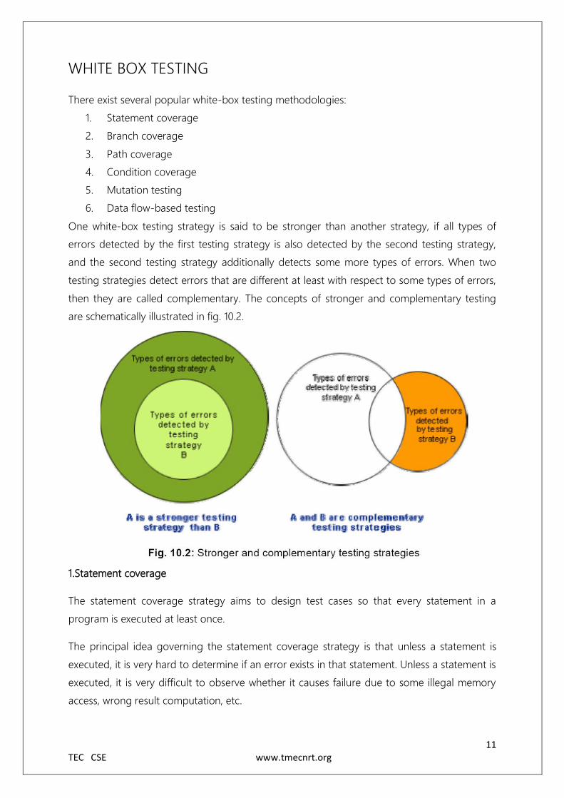
11 TEC CSE www.tmecnrt.org
WHITE BOX TESTING
There exist several popular white-box testing methodologies:
1. Statement coverage
2. Branch coverage
3. Path coverage
4. Condition coverage
5. Mutation testing
6. Data flow-based testing
One white-box testing strategy is said to be stronger than another strategy, if all types of
errors detected by the first testing strategy is also detected by the second testing strategy,
and the second testing strategy additionally detects some more types of errors. When two
testing strategies detect errors that are different at least with respect to some types of errors,
then they are called complementary. The concepts of stronger and complementary testing
are schematically illustrated in fig. 10.2.
1.Statement coverage
The statement coverage strategy aims to design test cases so that every statement in a
program is executed at least once.
The principal idea governing the statement coverage strategy is that unless a statement is
executed, it is very hard to determine if an error exists in that statement. Unless a statement is
executed, it is very difficult to observe whether it causes failure due to some illegal memory
access, wrong result computation, etc.

12 TEC CSE www.tmecnrt.org
However, executing some statement once and observing that it behaves properly for that
input value is no guarantee that it will behave correctly for all input values. In the following,
designing of test cases using the statement coverage strategy have been shown
Example: Consider the Euclid’s GCD computation algorithm:
By choosing the test set {(x=3, y=3), (x=4, y=3), (x=3, y=4)}, we can exercise the program
such that all statements are executed at least once.
2.Branch coverage
In the branch coverage-based testing strategy, test cases are designed to make each branch
condition to assume true and false values in turn. Branch testing is also known as edge testing
as in this testing scheme, each edge of a program’s control flow graph is traversed at least
once.
It is obvious that branch testing guarantees statement coverage and thus is a stronger testing
strategy compared to the statement coverage-based testing. For Euclid’s GCD computation
algorithm , the test cases for branch coverage can be {(x=3, y=3), (x=3, y=2), (x=4, y=3), (x=3,
y=4)}.
3.Condition coverage
In this structural testing, test cases are designed to make each component of a composite
conditional expression to assume both true and false values. For example, in the conditional
expression ((c1.and.c2).or.c3), the components c1, c2 and c3 are each made to assume both
true and false values.
• Branch testing is probably the simplest condition testing strategy where only
the compound conditions appearing in the different branch statements are

13 TEC CSE www.tmecnrt.org
made to assume the true and false values. Thus, condition testing is a stronger
testing strategy than branch testing and branch testing is stronger testing
strategy than the statement coverage-based testing.
• For a composite conditional expression of n components, for condition
coverage, 2ⁿ test cases are required. Thus, for condition coverage, the number
of test cases increases exponentially with the number of component
conditions.
• Therefore, a condition coverage-based testing technique is practical only if n
(the number of conditions) is small.
4.Path coverage: The path coverage-based testing strategy requires us to design test cases
such that all linearly independent paths in the program are executed at least once. A linearly
independent path can be defined in terms of the control flow graph (CFG) of a program.
A control flow graph (CFG) describes:
• the sequence in which different instructions of a program get executed.
• the way control flows through the program
Number all the statements of a program.
Numbered statements: Represent nodes of the control flow graph.
An edge from one node to another node exists:
If execution of the statement representing the first node Can result in transfer
of control to the other node.
Sequence:
1 a=5;
2 b=a*b-1;
Selection:
1 if(a>b) then
2 c=3;
3 else c=5;
4 c=c*c;

14 TEC CSE www.tmecnrt.org
Iteration:
1 while(a>b){
2 b=b*a;
3 b=b-1;}
4 c=b+d;
Example:
int f1(int x,int y){
1 while (x != y){
2 if (x>y) then
3 x=x-y;
4 else y=y-x;
5 }
6 return x; }
fig. 10.4 CFG for Example
Path
A path through a program is a node and edge sequence from the starting node to a terminal
node of the control flow graph of a program. There can be more than one terminal node in a
program. Writing test cases to cover all the paths of a typical program is impractical. For this
reason, the path-coverage testing does not require coverage of all paths but only coverage of
linearly independent paths.

15 TEC CSE www.tmecnrt.org
Linearly independent path: A linearly independent path is any path through the program that
introduces at least one new edge that is not included in any other linearly independent paths.
If a path has one new node compared to all other linearly independent paths, then the path is
also linearly independent.
This is because, any path having a new node automatically implies that it has a new edge.
Thus, a path that is subpath of another path is not considered to be a linearly independent
path.
The path-coverage testing does not require coverage of all paths but only coverage of
linearly independent paths
McCabe’s CYCLOMATIC COMPLEXITY
For more complicated programs it is not easy to determine the number of independent paths
of the program. McCabe’s cyclomatic complexity defines an upper bound for the number of
linearly independent paths through a program
There are three different ways to compute the Cyclomatic complexity. The answers computed
by the three methods are guaranteed to agree
Method 1:
Given a control flow graph G of a program, the Cyclomatic complexity V(G) can be computed
as:
V(G) = E – N + 2
where N is the number of nodes of the control flow graph and E is the number of edges in
the control flow graph.
For the CFG of example shown in fig. 10.4, E=7 and N=6. Therefore, the Cyclomatic
complexity = 7-6+2 = 3.
Method 2:
An alternative way of computing the Cyclomatic complexity of a program from an inspection
of its control flow graph is as follows:
V(G) = Total number of bounded areas + 1
In the program’s control flow graph G, any region enclosed by nodes and edges can be called
as a bounded area. This is an easy way to determine the McCabe’s Cyclomatic complexity
Method 3:

16 TEC CSE www.tmecnrt.org
The cyclomatic complexity of a program can also be easily computed by computing the
number of decision statements of the program. If N is the number of decision statement of a
program, then the McCabe’s metric is equal to N+1.
Data flow-based testing
Data flow-based testing method selects test paths of a program according to the locations of
the definitions and uses of different variables in a program.
For a statement numbered S, let
DEF(S) = {X/statement S contains a definition of X}, and
USES(S) = {X/statement S contains a use of X}
For the statement S:a=b+c;, DEF(S) = {a}. USES(S) = {b,c}. The definition of variable X at
statement S is said to be live at statement S1, if there exists a path from statement S to
statement S1 which does not contain any definition of X.
The definition-use chain (or DU chain) of a variable X is of form [X, S, S1], where S and S1 are
statement numbers, such that X Є DEF(S) and X Є USES(S1), and the definition of X in the
statement S is live at statement S1.
One simple data flow testing strategy is to require that every DU chain be covered at least
once. Data flow testing strategies are useful for selecting test paths of a program containing
nested if and loop statements
Mutation testing
In mutation testing, the software is first tested by using an initial test suite built up from the
different white box testing strategies. After the initial testing is complete, mutation testing is
taken up. The idea behind mutation testing is to make few arbitrary changes to a program at
a time.
Each time the program is changed, it is called as a mutated program and the change effected
is called as a mutant. A mutated program is tested against the full test suite of the program. If
there exists at least one test case in the test suite for which a mutant gives an incorrect result,
then the mutant is said to be dead. If a mutant remains alive even after all the test cases have
been exhausted, the test data is enhanced to kill the mutant.

17 TEC CSE www.tmecnrt.org
The process of generation and killing of mutants can be automated by predefining a set of
primitive changes that can be applied to the program. These primitive changes can be
alterations such as changing an arithmetic operator, changing the value of a constant,
changing a data type, etc. A major disadvantage of the mutation-based testing approach is
that it is computationally very expensive, since a large number of possible mutants can be
generated.
Since mutation testing generates a large number of mutants and requires us to check each
mutant with the full test suite, it is not suitable for manual testing. Mutation testing should be
used in conjunction of some testing tool which would run all the test cases automatically.
Debugging:

18 TEC CSE www.tmecnrt.org
• Explain why debugging is needed.
• Explain three approaches of debugging.
• Explain three guidelines for effective debugging.
• Explain what is meant by a program analysis tool.
• Explain the functions of a static program analysis tool.
• Explain the functions of a dynamic program analysis tool.
• Explain the type of failures detected by integration testing.
• Identify four types of integration test approaches and explain them.
• Differentiate between phased and incremental testing in the context of integration testing.
• What are three types of system testing? Differentiate among them.
• Identify nine types of performance tests that can be performed to check whether the system
meets the non-functional requirements identified in the SRS document.
• Explain what is meant by error seeding.
• Explain what functions are performed by regression testing.
Need for debugging
Once errors are identified in a program code, it is necessary to first identify the precise
program statements responsible for the errors and then to fix them. Identifying errors in a
program code and then fix them up are known as debugging.
Debugging approaches
The following are some of the approaches popularly adopted by programmers for
debugging.
1.Brute Force Method:
This is the most common method of debugging but is the least efficient method. In this
approach, the program is loaded with print statements to print the intermediate values with
the hope that some of the printed values will help to identify the statement in error. This
approach becomes more systematic with the use of a symbolic debugger (also called a
source code debugger), because values of different variables can be easily checked and break
points and watch points can be easily set to test the values of variables effortlessly.
2.Backtracking: This is also a fairly common approach. In this approach, beginning from the
statement at which an error symptom has been observed, the source code is traced
backwards until the error is discovered. Unfortunately, as the number of source lines to be
traced back increases, the number of potential backward paths increases and may become
unmanageably large thus limiting the use of this approach.

19 TEC CSE www.tmecnrt.org
3.Cause Elimination Method: In this approach, a list of causes which could possibly have
contributed to the error symptom is developed and tests are conducted to eliminate each. A
related technique of identification of the error from the error symptom is the software fault
tree analysis.
4.Program Slicing: This technique is similar to back tracking. Here the search space is reduced
by defining slices. A slice of a program for a particular variable at a particular statement is the
set of source lines preceding this statement that can influence the value of that variable
Debugging guidelines
Debugging is often carried out by programmers based on their ingenuity. The following are
some general guidelines for effective debugging:
• Many times debugging requires a thorough understanding of the program design. Trying to
debug based on a partial understanding of the system design and implementation may
require an inordinate amount of effort to be put into debugging even simple problems.
• Debugging may sometimes even require full redesign of the system. In such cases, a
common mistakes that novice programmers often make is attempting not to fix the error but
its symptoms.
• One must be beware of the possibility that an error correction may introduce new errors.
Therefore after every round of error-fixing, regression testing must be carried out
Program analysis tools
A program analysis tool means an automated tool that takes the source code or the
executable code of a program as input and produces reports regarding several important
characteristics of the program, such as its size, complexity, adequacy of commenting,
adherence to programming standards, etc. We can classify these into two broad categories of
program analysis tools:
1. Static Analysis tools
2. Dynamic Analysis tools
1.Static program analysis tools
Static analysis tool is also a program analysis tool. It assesses and computes various
characteristics of a software product without executing it.

20 TEC CSE www.tmecnrt.org
Typically, static analysis tools analyze some structural representation of a program to arrive at
certain analytical conclusions, e.g. that some structural properties hold. The structural
properties that are usually analyzed are:
I) Whether the coding standards have been adhered to?
II)Certain programming errors such as uninitialized variables and mismatch between actual
and formal parameters, variables that are declared but never used are also checked.
Code walk throughs and code inspections might be considered as static analysis methods.
But, the term static program analysis is used to denote automated analysis tools. So, a
compiler can be considered to be a static program analysis tool.
2.Dynamic program analysis tools
Dynamic program analysis techniques require the program to be executed and its actual
behavior recorded. A dynamic analyzer usually instruments the code (i.e. adds additional
statements in the source code to collect program execution traces).
The instrumented code when executed allows us to record the behavior of the software for
different test cases. After the software has been tested with its full test suite and its behavior
recorded, the dynamic analysis tool caries out a post execution analysis and produces reports
which describe the structural coverage that has been achieved by the complete test suite for
the program. For example, the post execution dynamic analysis report might provide data on
extent statement, branch and path coverage achieved.
Normally the dynamic analysis results are reported in the form of a histogram or a pie chart
to describe the structural coverage achieved for different modules of the program. The
output of a dynamic analysis tool can be stored and printed easily and provides evidence that
thorough testing has been done.
The dynamic analysis results the extent of testing performed in white-box mode. If the testing
coverage is not satisfactory more test cases can be designed and added to the test suite.
Further, dynamic analysis results can help to eliminate redundant test cases from the test
suite.
Integration testing

21 TEC CSE www.tmecnrt.org
• The primary objective of integration testing is to test the module interfaces, i.e.
there are no errors in the parameter passing, when one module invokes another
module.
• During integration testing, different modules of a system are integrated in a
planned manner using an integration plan. The integration plan specifies the
steps and the order in which modules are combined to realize the full system.
• After each integration step, the partially integrated system is tested. An important
factor that guides the integration plan is the module dependency graph. The
structure chart (or module dependency graph) denotes the order in which
different modules call each other. By examining the structure chart the
integration plan can be developed.
Integration test approaches • There are four types of integration testing approaches. Any one (or a
mixture) of the following approaches can be used to develop the
integration test plan. Those approaches are the following:
1. Big bang approach 2. Top-down approach 3. Bottom-up approach 4. Mixed-approach
1.Big-Bang Integration Testing
It is the simplest integration testing approach, where all the modules making up a system
are integrated in a single step. In simple words, all the modules of the system are simply
put together and tested. However, this technique is practicable only for very small
systems.
The main problem with this approach is that once an error is found during the integration
testing, it is very difficult to localize the error as the error may potentially belong to any of
the modules being integrated. Therefore, debugging errors reported during big bang
integration testing are very expensive to fix.
2.Bottom-Up Integration Testing
In bottom-up testing, each subsystem is tested separately and then the full system is
tested. A subsystem might consist of many modules which communicate among each other
through well-defined interfaces.

22 TEC CSE www.tmecnrt.org
The primary purpose of testing each subsystem is to test the interfaces among
various modules making up the subsystem. Both control and data interfaces
are tested. The test cases must be carefully chosen to exercise the interfaces in
all possible manners
Large software systems normally require several levels of subsystem testing;
lower-level subsystems are successively combined to form higher-level
subsystems. A principal advantage of bottom-up integration testing is that
several disjoint subsystems can be tested simultaneously.
In a pure bottom-up testing no stubs are required, only test-drivers are
required. A disadvantage of bottom-up testing is the complexity that occurs
when the system is made up of a large number of small subsystems. The
extreme case corresponds to the big-bang approach.
3.Top-Down Integration Testing:
Top-down integration testing starts with the main routine and one or two subordinate
routines in the system. After the top-level ‘skeleton’ has been tested, the immediately
subroutines of the ‘skeleton’ are combined with it and tested.
Top-down integration testing approach requires the use of program stubs to
simulate the effect of lower-level routines that are called by the routines under
test. A pure top-down integration does not require any driver routines.
A disadvantage of the top-down integration testing approach is that in the
absence of lower-level routines, many times it may become difficult to exercise
the top-level routines in the desired manner since the lower-level routines
perform several low-level functions such as I/O.
4.Mixed Integration Testing
A mixed (also called sandwiched) integration testing follows a combination of top-down and
bottom-up testing approaches.
In top-down approach, testing can start only after the top-level modules have been
coded and unit tested. Similarly, bottom-up testing can start only after the bottom
level modules are ready. The mixed approach overcomes this shortcoming of the top-
down and bottom-up approaches.

23 TEC CSE www.tmecnrt.org
In the mixed testing approaches, testing can start as and when modules become
available. Therefore, this is one of the most commonly used integration testing
approaches
Phased vs. incremental testing
The different integration testing strategies are either phased or incremental. A
comparison of these two strategies is as follows:
• In incremental integration testing, only one new module is added to the partial
system each time.
• In phased integration, a group of related modules are added to the partial system
each time.
Phased integration requires less number of integration steps compared to the
incremental integration approach. However, when failures are detected, it is easier to
debug the system in the incremental testing approach since it is known that the error
is caused by addition of a single module. In fact, big bang testing is a degenerate
case of the phased integration testing approach.
System testing
System tests are designed to validate a fully developed system to assure that it meets
its requirements. There are essentially three main kinds of system testing:
• Alpha Testing. Alpha testing refers to the system testing carried out by the test team
within the developing organization.
• Beta testing. Beta testing is the system testing performed by a select group of
friendly customers.
• Acceptance Testing. Acceptance testing is the system testing performed by the
customer to determine whether he should accept the delivery of the system.
In each of the above types of tests, various kinds of test cases are designed by
referring to the SRS document. Broadly, these tests can be classified into functionality
and performance tests. The functionality tests test the functionality of the software to
check whether it satisfies the functional requirements as documented in the SRS
document. The performance tests test the conformance of the system with the
nonfunctional requirements of the system.
Performance testing

24 TEC CSE www.tmecnrt.org
Performance testing is carried out to check whether the system needs the non-
functional requirements identified in the SRS document. There are several types of
performance testing. Among of them nine types are discussed below. The types of
performance testing to be carried out on a system depend on the different non-
functional requirements of the system documented in the SRS document. All
performance tests can be considered as black-box tests.
1. Stress testing 2.Volume testing 3.Configuration testing 4.Compatibility testing
5. Regression testing 6.Recovery testing 7.Maintenance testing
8.Documentation testing 9.Usability testing.
1.Stress Testing
Stress testing is also known as endurance testing. Stress testing evaluates system
performance when it is stressed for short periods of time.
Stress tests are black box tests which are designed to impose a range of abnormal
and even illegal input conditions so as to stress the capabilities of the software.
Input data volume, input data rate, processing time, utilization of memory, etc. are
tested beyond the designed capacity.
For example, suppose an operating system is supposed to support 15
multiprogrammed jobs, the system is stressed by attempting to run 15 or more
jobs simultaneously. A real-time system might be tested to determine the effect of
simultaneous arrival of several high-priority interrupts.
2. Volume Testing
It is especially important to check whether the data structures (arrays, queues, stacks,
etc.) have been designed to successfully extraordinary situations. For example, a
compiler might be tested to check whether the symbol table overflows when a very
large program is compiled.
3.Configuration Testing
This is used to analyze system behavior in various hardware and software
configurations specified in the requirements. Sometimes systems are built in variable
configurations for different users.
For instance, we might define a minimal system to serve a single user, and other
extension configurations to serve additional users. The system is configured in each of
the required configurations and it is checked if the system behaves correctly in all
required configurations.
4.Compatibility Testing

25 TEC CSE www.tmecnrt.org
This type of testing is required when the system interfaces with other types of
systems. Compatibility aims to check whether the interface functions perform as
required. For instance, if the system needs to communicate with a large database
system to retrieve information, compatibility testing is required to test the speed and
accuracy of data retrieval
5.Regression Testing
This type of testing is required when the system being tested is an upgradation of an
already existing system to fix some bugs or enhance functionality, performance, etc.
Regression testing is the practice of running an old test suite after each change to the
system or after each bug fix to ensure that no new bug has been introduced due to
the change or the bug fix.
However, if only a few statements are changed, then the entire test suite need not be
run - only those test cases that test the functions that are likely to be affected by the
change need to be run.
6.Recovery Testing
Recovery testing tests the response of the system to the presence of faults, or loss of
power, devices, services, data, etc. The system is subjected to the loss of the
mentioned resources (as applicable and discussed in the SRS document) and it is
checked if the system recovers satisfactorily.
For example, the printer can be disconnected to check if the system hangs. Or, the
power may be shut down to check the extent of data loss and corruption.
7.Maintenance Testing
This testing addresses the diagnostic programs, and other procedures that are
required to be developed to help maintenance of the system. It is verified that the
artifacts exist and they perform properly.
8.Documentation Testing
It is checked that the required user manual, maintenance manuals, and technical
manuals exist and are consistent. If the requirements specify the types of audience for
which a specific manual should be designed, then the manual is checked for
compliance.
9.Usability Testing
Usability testing concerns checking the user interface to see if it meets all user
requirements concerning the user interface. During usability testing, the display

26 TEC CSE www.tmecnrt.org
screens, report formats, and other aspects relating to the user interface requirements
are tested.
ERROR SEEDING
Sometimes the customer might specify the maximum number of allowable errors that
may be present in the delivered system. These are often expressed in terms of
maximum number of allowable errors per line of source code. Error seed can be used
to estimate the number of residual errors in a system.
Error seeding, as the name implies, seeds the code with some known errors. In
other words, some artificial errors are introduced into the program artificially. The
number of these seeded errors detected in the course of the standard testing
procedure is determined. These values in conjunction with the number of unseeded
errors detected can be used to predict:
1. The number of errors remaining in the product.
2. The effectiveness of the testing strategy.
Let N be the total number of defects in the system and let n of these defects be found
by testing.
Let S be the total number of seeded defects, and let s of these defects be found
during testing.
n/N = s/S
or
N = S × n/s
Defects still remaining after testing = N–n = n×(S – s)/s
Error seeding works satisfactorily only if the kind of seeded errors matches closely
with the kind of defects that actually exist. However, it is difficult to predict the types
of errors that exist in a software. To some extent, the different categories of errors
that remain can be estimated to a first approximation by analyzing historical data of
similar projects. Due to the shortcoming that the types of seeded errors should match
closely with the types of errors actually existing in the code, error seeding is useful
only to a moderate extent.
Regression testing
Regression testing does not belong to either unit test, integration test, or system
testing. Instead, it is a separate dimension to these three forms of testing. The
functionality of regression testing has been discussed earlier.