UNIT 1: Introduction to Computer Networks
113
UNIT 1: Introduction to Computer Networks Computer Engineering Section University Women’s Polytechnic Aligarh Muslim University, Aligarh February 22, 2020 Dr. J. Alam (CES) Unit 1: Introduction February 22, 2020 1 / 113
-
Upload
khangminh22 -
Category
Documents
-
view
0 -
download
0
Transcript of UNIT 1: Introduction to Computer Networks
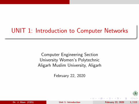
UNIT 1: Introduction to Computer Networks
Computer Engineering SectionUniversity Women’s Polytechnic
Aligarh Muslim University, Aligarh
February 22, 2020
Dr. J. Alam (CES) Unit 1: Introduction February 22, 2020 1 / 113
Outline
Computer Networks: What and Why??
Applications of Computer Networks
Types of Network Connections
Categories of Networks: LAN, MAN & WAN
Network Topologies
Network Configurations: Server Based, Peer-to-Peer & Hybrid
Expanding Networks
Network Segmentation
Types of Servers
Network Performance Parameters: Bandwidth, Throughput,Latency, Jitter etc.
Dr. J. Alam (CES) Unit 1: Introduction February 22, 2020 2 / 113

Computer Network & Networking
A Computer Network is a set of autonomous comput-ers and other devices connected together to exchangeinfromation and sharing resources.
By autonomous we mean that no computer on the net-work can be forcibly start/stop by any other computeron the network.
Another definition is - A group of computers and otherdevices connected together is called a network and theconcept of connected computers sharing informationand resources, is called Networking.
Each device on the network is referred to as node.
Dr. J. Alam (CES) Unit 1: Introduction February 22, 2020 3 / 113

Centralized Computing Vs. Networking I
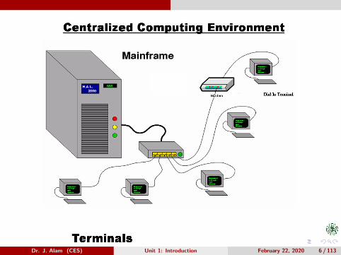
In centralized computing there is a computer with singlepowerful CPU and a number of terminals are connectedto it as shown in the figure on slide 6.
All processing is performed within the boundaries of thesame physical computer.
User terminals are typically dumb ones, incapable offunctioning on their own. They are cabled to the centralcomputer.
Sometimes these terminals have very little processingpower and memory of their own and are called intelli-gent terminals.
Dr. J. Alam (CES) Unit 1: Introduction February 22, 2020 4 / 113

Centralized Computing Vs. Networking II
This architecture places the tremendous burden on thecentral computer.
In recent years, there have been significant advances inthe development of high performance personal comput-ers and networks.
There is now an identifiable trend in industry towardsdownsizing, i.e. replacing expensive mainframe com-puters with more cost effective networks of personalcomputers that achieve the same or even better results.
Dr. J. Alam (CES) Unit 1: Introduction February 22, 2020 5 / 113
Dr. J. Alam (CES) Unit 1: Introduction February 22, 2020 6 / 113

Why Networks??
Networks are all about:
Sharing Resources.
Preserving Information.
Protecting Information.
Dr. J. Alam (CES) Unit 1: Introduction February 22, 2020 7 / 113

Sharing Resources I
Resource sharing means sharing H/W and S/W.
Hardware Resource Sharing:Networked Computers can share:
Printers, Fax Modem, Scanners, Hard Disks, Floppy Disks, CD-ROMS,Tape Backup Units, Plotters, Any device that can be attached to theNetwork.
Software Resource Sharing:Software resources can be used more effectively over networks. Withstand alone computers the software used on the computers must bepresent on each computer’s hard disk, whether or not that computer isused at that moment for the task the software performs.For a large number of stand alone computers S/W cost can becomemore than expectations. It is also difficult and time consuming to installand configure the S/W individually on each computer.
Dr. J. Alam (CES) Unit 1: Introduction February 22, 2020 8 / 113
Sharing Resources II
With a network we can install and configure the software on one com-puter (server) and can share it with other computers on the network.We can also control the access to that S/W.Not all S/W will use a network even if one is installed on the server. Dif-ferent S/W packages have different restrictions on how the software canlegally be used on a network. We must check the S/W documentationto check what features the S/W provides in a networked environment.
Dr. J. Alam (CES) Unit 1: Introduction February 22, 2020 9 / 113
Preserving Information
Besides, information and resource sharing a network al-lows information to be backed up to a central location.
Important information can be lost by mistake or acci-dentally when a stand alone computer has no backupmeans.
It is also difficult to maintain regular backups on a num-ber of stand alone computers.
In a networked environment when we take backup at acentral location from all computers, we have one placeto preserve it.
Dr. J. Alam (CES) Unit 1: Introduction February 22, 2020 10 / 113
Protecting Information
With stand alone computer, access to the computermeans access to the information on that computer.
Networks provide an additional layer of security by meansof passwords.
We can give each network user a different account nameand password, allowing the network server to distinguishamong those who need access to have it and protectingthe information from tampering by those who do not.
Dr. J. Alam (CES) Unit 1: Introduction February 22, 2020 11 / 113
Components of a Data Communication System I
There are f ive components of a data communication sys-tem:
1 Message: The message is the information (data) to becommunicated. Popular forms of information includetext, numbers, pictures, audio, and video.
2 Sender: A sender is a device that sends the data mes-sage. It can be a computer, workstation, telephonehandset, video camera, and so on.
3 Receiver: A receiver is a device that receives the mes-sage. It can be a computer, workstation, telephonehandset, television, and so on.
Dr. J. Alam (CES) Unit 1: Introduction February 22, 2020 12 / 113

Components of a Data Communication System II
4 Transmission Medium: The transmission medium is thephysical path by which a message travels from sender toreceiver. Some examples of transmission media includetwisted-pair wire, coaxial cable, fiber-optic cable, andradio waves
Dr. J. Alam (CES) Unit 1: Introduction February 22, 2020 13 / 113

Components of a Data Communication System III
5 Protocol: A protocol is a set of rules that govern datacommunications. It represents an agreement betweenthe communicating devices. Without a protocol, twodevices may be connected but not communicating, justas a person speaking French cannot be understood bya person who speaks only Japanese.
Dr. J. Alam (CES) Unit 1: Introduction February 22, 2020 14 / 113

Transmission Modes I
The term Transmission Mode defines the direction of theflow of information between two communicating devices i.e.it tells the direction of signal flow between the two devices.There are three ways or modes of data transmission: Sim-plex, Half duplex (HDX) & Full duplex (FDX)
1 Simplex - unidirectional, one can transmit other can only receive,uses entire capacity of channel to send data in one direction. Ex-amples of simplex mode is loudspeaker, television broadcasting,television and remote, keyboard and monitor etc.
Dr. J. Alam (CES) Unit 1: Introduction February 22, 2020 15 / 113
Transmission Modes II
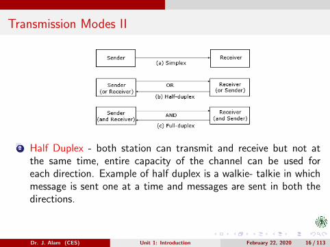
2 Half Duplex - both station can transmit and receive but not atthe same time, entire capacity of the channel can be used foreach direction. Example of half duplex is a walkie- talkie in whichmessage is sent one at a time and messages are sent in both thedirections.
Dr. J. Alam (CES) Unit 1: Introduction February 22, 2020 16 / 113

Transmission Modes III
3 Full Duplex - both stations can transmit and receive simultane-ously, either separate channels or channel can be divided betweensignals traveling in both directions.Example of Full Duplex is a Telephone Network in which there iscommunication between two persons by a telephone line, throughwhich both can talk and listen at the same time.
Dr. J. Alam (CES) Unit 1: Introduction February 22, 2020 17 / 113
Classification of Computer Networks
There is no generally accepted taxonomy for computer net-works but two criteria based on which they can be classifiedare Transmission Technology and Scale.
Based on tramission technology they may be classifiedas:
Broadcast/ Multipoint NetworksPoint-to-Point Networks
Based on scale (physical limits) they can be classifiedas:
Local Area Network (LAN)Metropolitan Area Network (MAN)Wide Area Network (WAN)
Dr. J. Alam (CES) Unit 1: Introduction February 22, 2020 18 / 113

Broadcast Networks I
1 Broadcast networks have a single communication channel that isshared or used by all the machines on the network. Short messagescalled packets sent by any machine are received by all the others.
2 Broadcast systems generally use a special code in the address fieldfor addressing a packet to all the concerned computers. This modeof operation is called broadcasting.
3 Some broadcast systems also support transmission to a subset ofthe machines known as multicasting.
4 Upon receiving a packet, a machine checks the address field. If thepacket is addressed to it then the packet is processed, otherwisethe packet is ignored.
5 The channel’s capacity is shared temporarily among the devicesconnected to the link.
Dr. J. Alam (CES) Unit 1: Introduction February 22, 2020 19 / 113

Broadcast Networks II
Dr. J. Alam (CES) Unit 1: Introduction February 22, 2020 20 / 113

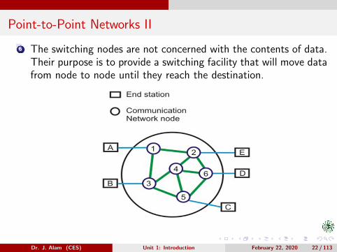
Point-to-Point Networks I
1 A point-to-point connection is a direct link between two devicessuch as a computer and a printer. It uses dedicated link betweenthe devices.
2 The entire capacity of the link is used for the transmission betweenthose two devices.
3 In point to point networks, there exist many connections betweenindividual pairs of machines.
4 To move from sources to destination, a packet (short message)may follow different routes.
5 In point-to-point connection, there can only be a single transmitterand a single receiver. On the other hand, in multipoint connection,there is a single transmitter, and there can be multiple receivers.
Dr. J. Alam (CES) Unit 1: Introduction February 22, 2020 21 / 113
Point-to-Point Networks II
6 The switching nodes are not concerned with the contents of data.Their purpose is to provide a switching facility that will move datafrom node to node until they reach the destination.
Dr. J. Alam (CES) Unit 1: Introduction February 22, 2020 22 / 113
Classificaton Based on Scale ILocal Area Networks (LANs)
A Local Area Network (LAN) is a network that is restricted tosmaller physical areas (few kilometers - typically upto 5 kms) e.g.a local office, school, house, University campus etc.
On a ‘Local Area Network’ data transfer speeds are higher thanWAN & MAN, and that can range from 10.0 Mbps (Ethernetnetwork) to 10 Gbps (10 Gigabit Ethernet).
A LANs is usually implemented using any of the LAN Technolo-gies i.e. Ethernet, Token Ring and FDDI (Fiber Distributed DataInterface).
LAN Technologies are also referred to as Physical and Data LinkLayers Protocols.
Dr. J. Alam (CES) Unit 1: Introduction February 22, 2020 23 / 113
Classificaton Based on Scale IILocal Area Networks (LANs)
Each LAN technolgy offers specific devices (meant for that technol-ogy only) and network layouts (topologies) for connecting severalcomputers as LAN.
The most prevalent LAN Technology is Ethernet. It is standardizedas IEEE 802.3.
The most common forms of Ethernet are 10BASE-T, 100BASE-T,and 1000BASE-T. All three use twisted pair cables. They run at10 Mbit/s, 100 Mbit/s, and 1 Gbit/s, respectively.
Fiber optic variants of Ethernet are also very common in largernetworks, offering high performance and longer distance (tens ofkilometers with some versions).
Also referred to as WiFi, Wireless LANs (WLANs) are standardizedas IEEE 802.11.
Dr. J. Alam (CES) Unit 1: Introduction February 22, 2020 24 / 113

Classificaton Based on Scale IIILocal Area Networks (LANs)
In general, network protocol stack software will work similarly onall varieties.
LANs are restricted in size. It simplifies network management.They are more reliable as compared to MAN and WAN.
Dr. J. Alam (CES) Unit 1: Introduction February 22, 2020 25 / 113
Metropolitan Area Network (MAN) I
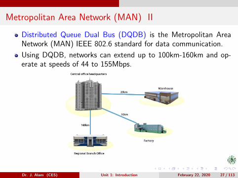
A Metropolitan Area Network (MAN) is a network that connectstwo or more computers, communicating devices or networks in asingle network that has geographic area larger than that coveredby even a large ‘Local Area Network’ but smaller than the regioncovered by a ‘Wide Area Network’ (Typically from more than 5 kmto 160 km).
A Metropolitan Area Networks bridges a number of ‘Local AreaNetworks’ with a fiber-optical links which act as a backbone, andprovides services similar to what Internet Service Provider (ISP)provide to Wide Area Networks and the Internet.
MANs can bridge Local Area Networks without any cables by usingmicrowave, radio wireless communication or infra-red laser whichtransmits data wirelessly.
Dr. J. Alam (CES) Unit 1: Introduction February 22, 2020 26 / 113
Metropolitan Area Network (MAN) II
Distributed Queue Dual Bus (DQDB) is the Metropolitan AreaNetwork (MAN) IEEE 802.6 standard for data communication.
Using DQDB, networks can extend up to 100km-160km and op-erate at speeds of 44 to 155Mbps.
Dr. J. Alam (CES) Unit 1: Introduction February 22, 2020 27 / 113

Wide Area Network (WAN) I
Wide Area Network is a computer network that covers relativelylarger geographical area such as a state, province or country.
It provides a solution to companies or organizations operating fromdistant geographical locations who want to communicate with eachother for sharing and managing central data or for general com-munication.
WAN is made up of two or more Local Area Networks (LANs) orMetropolitan Area Networks (MANs) that are interconnected witheach other.
In ‘Wide Area Network’, Computers are connected through publicnetworks, such as the telephone systems, fiber-optic cables, andsatellite links or leased lines. The ‘Internet’ is the largest WAN inthe world.
Dr. J. Alam (CES) Unit 1: Introduction February 22, 2020 28 / 113

Wide Area Network (WAN) II
WANs are mostly private and are build for a particular organizationby ‘Internet Service Providers (ISPs)’ which connects the LAN ofthe organization to the internet.
Dr. J. Alam (CES) Unit 1: Introduction February 22, 2020 29 / 113

Other Special Types of Networks I
1 Home Area Network(HAN): As the name would suggest, a HANis the connection of network enabled devices in a domestic home.
2 Personal Area Network(PAN):As the name suggests, a personal area network is intended for personaluse within a range of a few ten meters.
Mainly, the technologies used for creating personal area networks arewireless.
Dr. J. Alam (CES) Unit 1: Introduction February 22, 2020 30 / 113

Other Special Types of Networks II
A notable example of WPAN is the Bluetooth technology, mostly foundon portable devices like smartphones, laptops, tablets, wearables, etc.Other PAN technologies are Zigbee, Wireless USB, etc.Wireless BAN can work together with PAN technologies.For instance, a Bluetooth-connected smartphone can be used to syncdata from wearables and various sensors present in the body.
3 Body Area Network(BAN):You can create a body area network by using wearable devices like smart-watches, fitness bands, biometric RFID implants, and medical devicesplaced inside the body like pacemakers.Wireless BAN is the primary form used to created such networks. It isdefined as per the IEEE 802.15.6 standard which describes a short-range,extremely low power wireless communication within or in a vicinity ofthe human body.
Dr. J. Alam (CES) Unit 1: Introduction February 22, 2020 31 / 113
Other Special Types of Networks III
4 Near-me Area Network(NAN):A near-me area network (NAN) is a communication network that focuseson wireless communication among devices in close proximity.Unlike local area networks (LANs), where the devices are in the samenetwork segment and share the same broadcast domain.The devices in a NAN can belong to different proprietary network infras-tructures (for example, different mobile carriers).If two devices are geographically close, the communication path betweenthem might, in fact, traverse a long distance, going from a LAN, throughthe Internet, and to another LAN.Remember chatting with your friends on Facebook while all of you weresitting in the same room. You were part of a NAN, even though youmight be on the networks of different carriers.A message from your device would traverse all the way to Facebookservers over the internet come to your friend’s device sitting right nextto you. In a logical way, both the device are on some sort of network.
Dr. J. Alam (CES) Unit 1: Introduction February 22, 2020 32 / 113

Other Special Types of Networks IV
5 Storage Area Network(SAN):SAN is a high-speed network of storage devices that also connects thosestorage devices with servers.It provides block-level storage that can be accessed by the applicationsrunning on any networked servers.Block-level storage is a type of storage in which each block (consistingof several hard drives) of the storage system can be controlled as anindividual hard drive, and the blocks are managed by a server operatingsystem.SAN devices appear to servers as attached drives
Dr. J. Alam (CES) Unit 1: Introduction February 22, 2020 33 / 113

Other Special Types of Networks V
6 Campus Area Network(CAN):A network infrastructure covering the school, university, or a corporatepremises can be dubbed as campus area network.It can comprise of several LANs and connected to the internet using aleased line or any other means.
Dr. J. Alam (CES) Unit 1: Introduction February 22, 2020 34 / 113
Other Special Types of Networks VI
7 Virtual Private Network(VPN):A virtual private network (VPN) is a private network that is built over apublic infrastructure.VPN is a type of computer network which doesn’t have physical exis-tence.The devices that are part of a VPN could be present anywhere on theearth, connected to each other over the internet.Security mechanisms, such as encryption, allow VPN users to securelyaccess a network from different locations via the Internet.VPNs are used by corporates to interconnect their offices located indifferent places and give their remote employees access to company’sresources.It has phased out another type of network known as Enterprise PrivateNetwork, a physical network created by organizations to link their officelocations.
Dr. J. Alam (CES) Unit 1: Introduction February 22, 2020 35 / 113
Network (LAN) Topologies I
A network topology is the arrangement of a network, including itsnodes and connecting lines.
There are two ways of defining network geometry: the physicaltopology and the logical (or signal) topology.
On a network the way in which connections are made is called thephysical topology of the network.
Physical topology specificaly refers to the physical layout of thenetwork, especially the locations of the computers & devices andhow cable is run between them (Geographical arrangement of com-puters, devices and cables.).
Logical (or signal) topology refers to the nature of the paths thesignals follow from node to node.
Dr. J. Alam (CES) Unit 1: Introduction February 22, 2020 36 / 113
Network (LAN) Topologies II
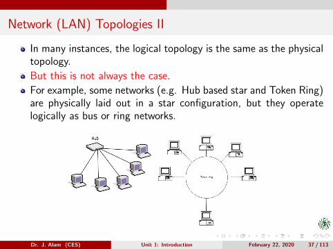
In many instances, the logical topology is the same as the physicaltopology.
But this is not always the case.
For example, some networks (e.g. Hub based star and Token Ring)are physically laid out in a star configuration, but they operatelogically as bus or ring networks.
Dr. J. Alam (CES) Unit 1: Introduction February 22, 2020 37 / 113
Physical Network (LAN) Topologies I
1 Bus Topology
On a bus network, the cable is just one or more wires, with no activeelectronics to amplify the signals or to pass them from one computer toanother.This makes the bus a passive topology.When one computer sends a signal up (or down) the wire, all the othercomputers on the network receives the information.But, only one (the one with the address that matches the address en-coded in the message) accepts the information. The rest discard themessage.Only one computer at a time can send the message.Therefore, the number of computers attached to a bus can significantlyaffect the speed of the network.A computer must wait until the bus is free before it can transmit.These factors also affect star and ring networks.Another important issue in bus network is termination.
Dr. J. Alam (CES) Unit 1: Introduction February 22, 2020 38 / 113
Physical Network (LAN) Topologies II
As the bus is a passive topology, the electrical signal from a transmittingcomputer is free to travel the entire length of the cable.Without termination, when the signal reaches at the end of the wire, itbounces back and travels back up the wire.When a signal echoes back and forth along an unterminated bus, it iscalled ringing.To stop signals from ringing we attach terminators at either end of thebus. Terminators absorb the signals and stop ringing.Ethernet 10Base2 (uses BNC T-Connectors with coaxial cable), alsoreferred to as thinnet is an inexpensive network based on bus topology.Ethernet 10Base5 also referred to as thicknet is another network basedon bus topology. It uses thick coaxial cable compared to one used inthinnet.
Advantages
Simple, Reliable for small networks, Easy to use and install.Requires least amount of cable and therefore less expensive.
Dr. J. Alam (CES) Unit 1: Introduction February 22, 2020 39 / 113

Physical Network (LAN) Topologies III
Scalable: Its easy to extend a bus.Repeaters can be used to boost the signals if a larger bus is required.
Disadvantages
Heavy network traffic can slow down a bus considerably.Problems caused by terminators.Difficult to troubleshoot.
Dr. J. Alam (CES) Unit 1: Introduction February 22, 2020 40 / 113

Physical Network (LAN) Topologies IV
Dr. J. Alam (CES) Unit 1: Introduction February 22, 2020 41 / 113

Physical Network (LAN) Topologies V
2 Star Topology
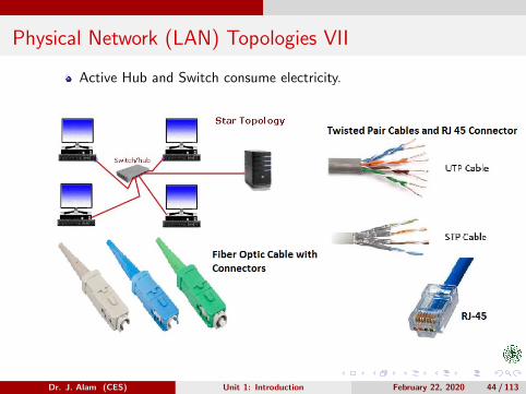
Each computer on a star network communicates with a central device.The central device resends the message to all computers (in a broad-cast star network(hub based)) or only to the destination computer (in aswitched star network).The central device in a star network can be an Active Hub or a PassiveHub or a Switch.An active hub regenerates the electrical signal and sends it to all thecomputers connected to it (broadcast star network).Active Hubs and Switches require electric power to run.A passive hub such as wiring panel or punch-down blocks merely actsas a connection point and doesn’t amplify or regenerates the electricalsignal.Passive Hubs don’t require electric power to run.We can use STP(Shielded Twisted Pair), UTP (Unshilded Twisted Pair)or Fiber Optic cables to implement star networks.
Dr. J. Alam (CES) Unit 1: Introduction February 22, 2020 42 / 113

Physical Network (LAN) Topologies VI
A hybrid hub/ switch can accomodate several types of cable in the samestar network.Ethernet 10Base-T, 100Base-T (Fast Enternet), 1000Base-T (GigabitEthernet) and 10000Base-T (10 G Ethernet) are well known star net-works implemented with twisted pair cables (STP/UTP).In above star based ethernets, if medium (twisted pair cable) is replacedby Fiber Optics then ’T’ gets replaced by ’F’ (e.g. 10Base-F etc.).
Advantages
It is easy to modify and add new computers to a star network withoutdisturbing the rest of the network.The centre of the star is a good place to diagnose network faults.Single computer failure do not bring down the whole star network.Several types of cable can be accomodated on same network.
Disadvantages
If central hub fails the whole network comes to halt.Expensive compared to bus based networks.
Dr. J. Alam (CES) Unit 1: Introduction February 22, 2020 43 / 113
Physical Network (LAN) Topologies VII
Active Hub and Switch consume electricity.
Dr. J. Alam (CES) Unit 1: Introduction February 22, 2020 44 / 113

Physical Network (LAN) Topologies VIII
3 Ring Topology
On a ring network, each computer is connected to the next computerwith the last one connected to the first.Each computer retransmits what it receives from the previous computer.The messages flow around the ring in one direction.Since each computer retransmits what it receives, a ring is an activenetwork and is not subject to the signal loss problem.There is no termination because there is no end to the ring.Some ring networks do token passing .In token passing, a short message called token is passed around the ringuntil a computer whishes to send information to another computer. Thatcomputer captures the token modifies it to adds an electronic addressand data, and sends it around the ring.Each computer in sequence receives the modified token and passes it tothe next computer until either the electronic address matches the addressof a computer or the token returns to its origin.
Dr. J. Alam (CES) Unit 1: Introduction February 22, 2020 45 / 113
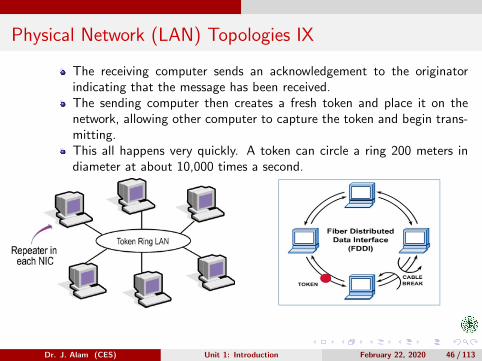
Physical Network (LAN) Topologies IX
The receiving computer sends an acknowledgement to the originatorindicating that the message has been received.The sending computer then creates a fresh token and place it on thenetwork, allowing other computer to capture the token and begin trans-mitting.This all happens very quickly. A token can circle a ring 200 meters indiameter at about 10,000 times a second.
Dr. J. Alam (CES) Unit 1: Introduction February 22, 2020 46 / 113

Physical Network (LAN) Topologies X
The topology of IBM’s Token Ring LAN technology (standardized asIEEE 802.5) uses the similar kind of ring.Physical topology of token ring is star but logically it is a token passingring.Some other ring networks have two counter-rotating rings, that helpthem recover from network faults.The topology of FDDI (Fiber Distributed Data Interface) LAN technol-ogy uses two counter-rotating rings.
Advantages
No computer can monopolize the network as each computer is givenequal chance of capturing the token.Token passing makes ring topology perform better than bus topologyunder heavy traffic.
Disadvantages
Failure of one computer on the ring can affect the whole network.Difficult to trobuleshoot.
Dr. J. Alam (CES) Unit 1: Introduction February 22, 2020 47 / 113

Physical Network (LAN) Topologies XI
Adding or removing computers disrupts the network.
4 Mesh Topology
In a mesh network topology, each of the network node, computer andother devices, are interconnected with one another.In a full mesh topology, every computer in the network has a connectionto each of the other computers in that network.The number of connections in this network can be calculated using theformula n(n − 1)/2, where n indicates the number of devices.
Dr. J. Alam (CES) Unit 1: Introduction February 22, 2020 48 / 113

Physical Network (LAN) Topologies XII
This type of topology is very expensive as there are many redundantconnections, thus it is not mostly used in computer networks.
Advantages
Can handle high amounts of traffic, because multiple devices can trans-mit data simultaneously.A failure of one device does not cause a break in the network or trans-mission of data (fault tolerant).Adding additional devices does not disrupt data transmission betweenother devices.Easy to troubleshoot.
Disadvantages
The cost to implement is higher than other network topologies, makingit a less desirable option.Building and maintaining the topology is difficult and time consuming.Becomes unmanagable as more and more devices join network.
Dr. J. Alam (CES) Unit 1: Introduction February 22, 2020 49 / 113

Hybrid Topologies I
In today’s networks we also see the combinations
of the topologies of bus, star and ring.
A topology which is created by combining two or
more topologies is referred to as a hybrid topol-
ogy .
Some popular hybrid topologies are star-bus &
star-ring.
Figure on next page illustrates each of them.
Dr. J. Alam (CES) Unit 1: Introduction February 22, 2020 50 / 113

Hybrid Topologies II
Dr. J. Alam (CES) Unit 1: Introduction February 22, 2020 51 / 113
Picking a Right Topology (Ethernet LANs)
You must look at following:
Cost.
Scalability / Extendibility.
Ease of installation.
Bandwidth Capacity.
Ease of fault isolation/tolerance/Maintenance.
Dr. J. Alam (CES) Unit 1: Introduction February 22, 2020 52 / 113

Roles of a Computer on a Network I
A Computer can have one of the following three rolesto play on a network:
Client: A Computer which uses but don’t provide Networking Resources.They are also known as nodes or workstations (only when they run UNIXor its flavour)Server: A computer which provides network resources.Peer: A computer which provides as well as uses resources.
Can the role of a computer on a network be determinedby looking at the operating system it is using?:
Clients run client operating system such as MS-DOS, OS/2 etc.Peers run peer operating system such as Win 95/ Win 98/ Win NTworkstation/ Win 2000 Professional/ Win XP (Professional and HomeEditions)/ Win Vista/7/8/10 (Home & Professional Editions) etc.Servers run Network Operating Systems such as Unix/ Linux/ HP-UX/AIX/ Novell Netware/ Solaries/ Win NT/ Win 2000 Server/ Win 2000Advanced Server/ Win 2000 Data Centre Server or higher versions.
Dr. J. Alam (CES) Unit 1: Introduction February 22, 2020 53 / 113

Roles of a Computer on a Network II
Note that simply looking at the operating system wecan’t decide whether a computer on a Network is aclient or a peer or a server as almost all server operatingsystems can also be used as client OS.
So, a straight forward method to identify the role ofa computer on a network is to look for its use on thenetwork.Based on the roles of the computers attached to themnetworks can also be classified as:
Server Based or Client/ Server Networks.Peer-to-Peer Networks.Hybrid Networks.
Dr. J. Alam (CES) Unit 1: Introduction February 22, 2020 54 / 113

Server Based Networks I
Are identified by the presence of server(s) on the network.
Server provides security and administration of the network.
Client/ Server networks divide processing tasks between client andserver.
Clients (referred to as front ends) request services such as filestorage and printing, and servers (referred to as back ends) deliverthem.
Server computers are typically more powerful than client comput-ers. Their hardware is optimized to function as servers.
Windows NT/ Server based networks are organized into domains.
A domain is a logical grouping of network computers that share acentral directory database.
Dr. J. Alam (CES) Unit 1: Introduction February 22, 2020 55 / 113
Server Based Networks II
A directory database contains user accounts and security informa-tion for the domain.
In a domain the directory resides on the computers that are con-figured as domain controllers.
A domain controller is a server that manages all security relateduser/ domain interactions and centralizes administration.
Advantages
Strong central security.
Centralized storage and backup.
Ability to share resources.
Optimized dedicated server which are faster than peers whensharing resources.
Dr. J. Alam (CES) Unit 1: Introduction February 22, 2020 56 / 113
Server Based Networks III
Easy manageability of large number of users.
Disadvantages
Expensive dedicated servers.
Expensive Network Operating System and Client Licenses.
A dedicated network administrator.
Dr. J. Alam (CES) Unit 1: Introduction February 22, 2020 57 / 113

Server Based Networks IV
Dr. J. Alam (CES) Unit 1: Introduction February 22, 2020 58 / 113
Peer Networks I
There are no servers on a peer network.
Are defined by no central control over the network.
Users simply share resources.
Peer networks are organized into workgroups.
A workgroup is a logical grouping of networked computers thatshare resources (and strictly not the security information).
Each Windows (server or client flavour) computer in the workgroupmaintains a local security database which contains a list of useraccounts and resource security information for that computer.
As each computer in the workgroup maintains a local securitydatabase, the administration of user accounts and resource se-curity is decentralized.
Dr. J. Alam (CES) Unit 1: Introduction February 22, 2020 59 / 113
Peer Networks II
A user must have a user account on each computer that the userneeds to access.
Any changes to the user account information such as changing apassword or adding new accounts must be made on each computer.
As already discussed, access to individual resources can be con-trolled if the user who shares the resource requires a password toaccess.
Since there is no central security trust users will have to know theindividual passwords for each resource they wish to access. Thiscan be quite inconvenient.
Peers are also not optimized to share resources.
When a number of users are accessing the resources on a peer,they notice significantly degraded performance.
Dr. J. Alam (CES) Unit 1: Introduction February 22, 2020 60 / 113
Peer Networks III
Advantages
No extra investment on server.
Easy Setup.
No network administrator required.
Ability of users to control the share of resources.
Convenient for limited number of computers in close proximity.
Disadvantages
Additional load on computers because of resource sharing.
Inability of handling large networks.
Lack of central organization which can make data hard to find.
Requirement that users themselves administer the network.
Weak and insecure security.
Dr. J. Alam (CES) Unit 1: Introduction February 22, 2020 61 / 113

Peer Networks IV
Dr. J. Alam (CES) Unit 1: Introduction February 22, 2020 62 / 113
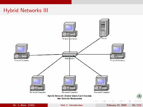
Hybrid Networks I
Hybrid computers have all types of computers operating on themand generally have active domains and workgroups.
It means that while most shared resources are located on servers,users still have access to any resources being shared by the peersin their workgroup.
It also means that network users don’t have to logon to the domaincontroller to access workgroup resources being shared by peers.
If users log on to the network with proper username and passwordthey are eligible to enjoy “all shared” resources either they lie withthe domain controllers or with the peers.
If users don’t log on the network with proper username and pass-word they are eligible to enjoy the resources contributed by thepeers.
Dr. J. Alam (CES) Unit 1: Introduction February 22, 2020 63 / 113

Hybrid Networks II
Advantages
All advantages of Server based networks.
All advantages of Peer Networks.
Disadvantages
All disadvantages of Server Based and Peer Networks.
Dr. J. Alam (CES) Unit 1: Introduction February 22, 2020 64 / 113
Hybrid Networks III
Dr. J. Alam (CES) Unit 1: Introduction February 22, 2020 65 / 113

Expanding Networks: Principles & Devices
The objective is to expand a single network withoutbreaking it into sub-networks.Following devices can be used for this purpose:
Repeater.Passive Hub.Active Hub.Switch.Bridge.
Selection of device(s) strictly depends on a variety offactors.
Hubs and Switches have alredy been discussed.
So, we will examine rest of the devices.
Dr. J. Alam (CES) Unit 1: Introduction February 22, 2020 66 / 113

Repeaters I
All transmission media attenuate (weaken) the electronic signalthat travel through them.
Attenuation therefore limits the distance any medium can carrydata.
Adding a device that amplifies the signal can allow it to travelfarther, increasing the size of the network.
if we are connecting computers that are more than 100/ 500 me-ters apart using a 10BASE-T/ 100BASE-T Ethernet cable, we willrequire a device that amlifies signal to ensure data transmission.
Devices that amplify signals in this way are called Repeaters.
Two types of repeaters are there - Amplifiers and Signal-regenerators(Boosters).
Amplifiers simply amplify the entire incoming signal including noise.
Dr. J. Alam (CES) Unit 1: Introduction February 22, 2020 67 / 113
Repeaters II
Signal-regenerators (Boosters) create an exact duplicate of incom-ing data by identifying it amid the noise, reconstructing it andretransmitting only the desired information.
They reduce noise. The signal is boosted to its original strengthand sent.
Because repeaters simply deal with the actual physical signals ona network, they operate at Layer 1 (Physical Layer) of ISO-OSImodel.
Theoretically, repeaters can be used to combine an unlimited num-ber of cable segments.
Practically, network designs limit the number of repeaters.
An active hub / switch/router is by default a multiport repeater(signal-regenerator).
Dr. J. Alam (CES) Unit 1: Introduction February 22, 2020 68 / 113

Repeaters III
Dr. J. Alam (CES) Unit 1: Introduction February 22, 2020 69 / 113

Bridges I
Bridges connect network segments.
Unlike a repeater, which simply passes all signals it receives, abridge selectively determines the appropriate segment to which itshould pass a signal.
Dr. J. Alam (CES) Unit 1: Introduction February 22, 2020 70 / 113

Bridges II
It does this by reading the source and destination MAC addressesof all the signals it receives.For the network shown in figure, the process takes place as follows:-
The bridge receives all the signal from both segments A and B.The bridge reads the destination address and discards (filters) all signalsfrom segment A that are addressed to computers on segment A, becausethey do not need to crossover the bridge.Signals from segment A addressed to a computer on segment B areretransmitted (regenerated) to segment B.The signals from segment B are treated in the same way.
Bridges regenerate signals (physical layer activity) and read MACaddresses (data link layer addresses), so they are Layer 2 devices.
In future we will learn that a switch is actually a multiport-portbridge.
Dr. J. Alam (CES) Unit 1: Introduction February 22, 2020 71 / 113

Assignment 2
Explain the following:
Bridge loop problem.
Spanning Tree Algorithm.
Dr. J. Alam (CES) Unit 1: Introduction February 22, 2020 72 / 113
Network Segment
A network segment is a portion of a computer networkthat is separated from the rest of the network by adevice such as a repeater, hub, bridge, switch, routeror gateway.
Each segment can contain one or multiple computersor other hosts.
The nature of a segment depends on the nature of thedevice or devices used to interconnect end stations.
Accrdingly, there may be Layer 1, Layer 2 or Layer 3segments in a network.
Dr. J. Alam (CES) Unit 1: Introduction February 22, 2020 73 / 113

Collision & Broadcast Domains I
Collision DomainA collision domain is a network segment connected by a shared mediumor through repeaters where data packets may collide with one anotherwhile being sent.A network collision occurs when more than one device attempts to senda packet on a network segment at the same time, leading to collision.After a collosion has happened both devices must retransmit, one at atime. Not very efficient.Members of a network portion connected by a hub or bus are in the samecollision domain.
Dr. J. Alam (CES) Unit 1: Introduction February 22, 2020 74 / 113

Collision & Broadcast Domains II
Broadcast DomainA broadcast domain is the set of all devices on a network segment thathear all broadcasts sent on that segment.When a host or server sends a network broadcast, every device on thenetwork receives it.For most of the hosts broadcast is of no use.Too many broadcasts may result in Broadcast Storms which may floodthe network.
Dr. J. Alam (CES) Unit 1: Introduction February 22, 2020 75 / 113

Network Segmentation
The process of breaking up a larger network into a number ofsmaller ones is referred to as network segmentation.
Network segmentation is accomplished using bridges, switches,routers and gateways.
At some point of time we will have to break up one large networkinto a number of smaller ones.
This is because as the network grows LAN traffic also grows.Possible causes of LAN traffic congestion are:
Too many hosts in a collision domain.Too many hosts in a broadcast domain.Broadcast Storms.Low Bandwidth.
In following slides we shall study bridges, switches, routers andgateways from the perspective of network segmentation.
Dr. J. Alam (CES) Unit 1: Introduction February 22, 2020 76 / 113
Bridge as Network Segmenter
Breaks the network into collision domains.
Clearly, it reduces network traffic and improves bandwidth.
Can’t break the broadcast domain(s).
Bridge doesn’t stop broadcast, instead forwards it in every portexcept the port on which it is received.
Makes forwarding decisions based on MAC addresses.
Improves existing network performance by breaking collision do-main(s), but can’t be used to create internetworks.
This is because they can’t filter the network based on Layer-3addresses (IP addresses)
Dr. J. Alam (CES) Unit 1: Introduction February 22, 2020 77 / 113

Switch as Network Segmenter I
Like bridges, switches also break up collision domains.
Each port on a switch is a separate collision domain.
They are employed to add functionality to an existing LAN.
The main purpose of switches is to make a LAN work better i.e.to optimize its performance.
Switches accomplish this by breaking up collision domain(s) andthereby providing more bandwidth for LAN users.
They ”switch” frames (based on MAC addresses) from one portto another within the switched network.
When a switch receives a broadcast it forwards the broadcast inevery port except the port on which it is received.
Cleraly, they can’t break broadcast domain(s).
Dr. J. Alam (CES) Unit 1: Introduction February 22, 2020 79 / 113
Switch as Network Segmenter II
They don’t forward packets to other networks (i.e.) can’t filter thenetwork based on Layer-3 addresses (IP address).
So, they are not the devices for internetworking.
Dr. J. Alam (CES) Unit 1: Introduction February 22, 2020 80 / 113

Bridge vs. Switch
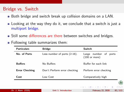
Both bridge and switch break up collision domains on a LAN.
Looking at the way they do it, we conclude that a switch is just amultiport bridge.
Still some differences are there between switches and bridges.
Following table summarizes them:
Particulars Bridge Switch
No. of Ports Less number of ports (2-16). Large number of ports(100 or more)
Buffers No Buffers Buffer for each link
Error Checking Don’t Perform error checking Perform error checking
Cost Low Cost Comparatively high
Dr. J. Alam (CES) Unit 1: Introduction February 22, 2020 82 / 113
Internetworking, Routable and Non-Routable Protocols I
Before going into the details of other networking deviceswe need to discuss Internetworking, Routable and Non-Routable Protocols.
Internetworking is the process or technique of connect-ing different networks by using intermediary devices suchas routers or gateways.An internetwork needs protocols that allow it to identifyeach node on the network using following two things:
1 Address of the network.2 Address of the node (device) itself.
Network protocols that provide both of these featuresare said to be routable.
Dr. J. Alam (CES) Unit 1: Introduction February 22, 2020 83 / 113
Internetworking, Routable and Non-Routable Protocols II
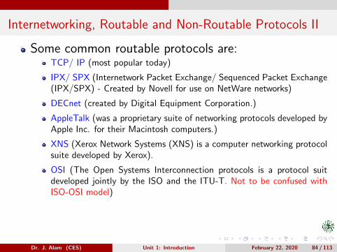
Some common routable protocols are:TCP/ IP (most popular today)
IPX/ SPX (Internetwork Packet Exchange/ Sequenced Packet Exchange(IPX/SPX) - Created by Novell for use on NetWare networks)
DECnet (created by Digital Equipment Corporation.)
AppleTalk (was a proprietary suite of networking protocols developed byApple Inc. for their Macintosh computers.)
XNS (Xerox Network Systems (XNS) is a computer networking protocolsuite developed by Xerox).
OSI (The Open Systems Interconnection protocols is a protocol suitdeveloped jointly by the ISO and the ITU-T. Not to be confused withISO-OSI model)
Dr. J. Alam (CES) Unit 1: Introduction February 22, 2020 84 / 113
Internetworking, Routable and Non-Routable Protocols III
A protocol that needs only a device address (such asMAC address) and not a network address is referred toas a non-routable protocol.Some well known non-routable protocols are:
LAT (Local Area Transport Protocol from DEC).
NetBEUI (NetBios Extended User Interface from Microsoft).
Again, note that internetworking can only be realizedusing routable protocols.
Dr. J. Alam (CES) Unit 1: Introduction February 22, 2020 85 / 113

Router
Like bridges and switchs, routers also break up collisiondomains.
They don’t forward the network broadcast. When arouter receives a broadcast it simply discards it.
So, routers are the only devices which can break thebroadcast domains.
Routers route packets from one network to another,which means they can filter the network based on layer-3 addresses (IP address).
Clearly, they are the devices which are used to createinternetworks.
Dr. J. Alam (CES) Unit 1: Introduction February 22, 2020 86 / 113
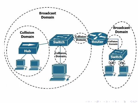

Question???
How many collision and broadcast domains are there in the networkshown below?
Dr. J. Alam (CES) Unit 1: Introduction February 22, 2020 88 / 113

Answer
9 Collision Domains.
3 Broadcast Domains.
Dr. J. Alam (CES) Unit 1: Introduction February 22, 2020 89 / 113

Brouter
A network device which combines the functions of abridge and a router in one unite is called a brouter.
For non-routable protocols brouter operates at Layer 2and is used as a bridge.
For routable protocols brouter operates at Layer 3 andis used as a router.
As networks continue to become more complex, a mixof routable and non-routable protocols has led to theneed for a brouter.
Dr. J. Alam (CES) Unit 1: Introduction February 22, 2020 90 / 113

Gateway I
Routers can successfully connect networks with similarprotocols.
When the networks that must be connected, use com-pletely different protocols from each other, a more pow-erful and intelligent device is required.
A gateway is a device that can interpret and translatethe different protocols that are used on two distinctnetworks.
This way a gateway is merely a multi-protocol router.
Gateways can be comprised of software, dedicated hard-ware or a combination of both.
Dr. J. Alam (CES) Unit 1: Introduction February 22, 2020 91 / 113

Gateway II
They operate at all seven layers of ISO-OSI model.
A gateway can actually convert data so that it workswith an application on a computer on the other side ofthe gateway.
For example, a gateway can receive e-mail messages inone format and convert them into another format.
This shows that how a gateway works at all layers.
Therefore, we can connect networks with different pro-tocols and architectures using a gateway.
Dr. J. Alam (CES) Unit 1: Introduction February 22, 2020 92 / 113

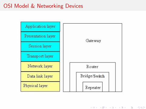
OSI Model & Networking Devices
Types of Servers
Different servers do different jobs, from serving emailand video to hosting Web sites.Some commonly used servers are:
File Server
Application Server
Mail Server
Web Server
Print Server
Real Time Communication Server (Internet Relay Chat)
Proxy Server
DNS Server
Database Server
Multimedia or Media Server
Dr. J. Alam (CES) Unit 1: Introduction February 22, 2020 95 / 113
File ServerOn a network, a file server is a computer responsible for the centralstorage and management of data files.
Other computers on the same network can access these files.
A file server allows users to share information over a network withouthaving to physically transfer files by pen drive or some other externalstorage device.
In its simplest form, a file server may be an ordinary PC that handlesrequests for files and sends them over the network.
In a more sophisticated network, a file server might be a dedicatednetwork-attached storage (NAS) device.
It serves as a remote hard disk drive for other computers, allowing anyoneon the network to store files on it as if to their own hard drive.
A program or mechanism that enables the required processes for filesharing can also be called a file server.
On the Internet, such programs often use the File Transfer Protocol(FTP).
Dr. J. Alam (CES) Unit 1: Introduction February 22, 2020 96 / 113
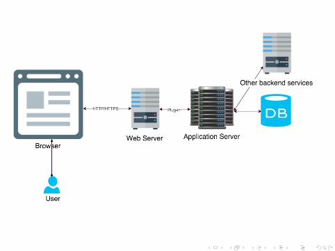
Application ServerThe application server is viewed as part of a three-tier appli-cation development, consisting of a graphical user interface(GUI) server, an application server, and a database and trans-action server.
More descriptively, it can be viewed as dividing an applicationinto:
1 A first-tier, front-end, Web browser-based graphical user interface, usu-ally at a personal computer or workstation.
2 A middle-tier, application or set of applications, possibly on a local areanetwork or intranet server.
3 A third-tier, back-end, database and transaction server, sometimes on amainframe or large server.
In many usages, the application server combines or works witha Web server and is called a Web application server.
Dr. J. Alam (CES) Unit 1: Introduction February 22, 2020 97 / 113
Mail ServerA mail server (sometimes also referred to an e-mail server)is a server that handles and delivers e-mail over a network,usually over the Internet.
A mail server can receive e-mails from client computers anddeliver them to other mail servers.
A mail server can also deliver e-mails to client computers.
A client computer is normally the computer where you read/writeyour e-mails, for example your computer at home or in youroffice.
Also an advanced mobile phone or Smartphone, with e-mailcapabilities, can be regarded as a client computer in thesecircumstances.
Dr. J. Alam (CES) Unit 1: Introduction February 22, 2020 99 / 113

SMTP: Simple Mail Transfer Protocol
POP: Post Office Protocol
Web Server
A web server is a program that uses HTTP (Hy-pertext Transfer Protocol) to serve the files thatform Web pages to users, in response to their re-quests, which are forwarded by their computers’HTTP clients (browsers).
The process is an example of the client/server model.
All computers that host Web sites must have Webserver programs.
Leading Web server programs include Apache (themost widely-installed Web server), Microsoft’s In-ternet Information Server (IIS) etc.
Dr. J. Alam (CES) Unit 1: Introduction February 22, 2020 101 / 113

Print ServerA print server, or printer server, is a device that connectsprinters to client computers over a network.It accepts print jobs from the computers and sends the jobsto the appropriate printers, queuing the jobs locally.A print server may be a networked computer with one or moreshared printers.Alternatively, a print server may be a dedicated device onthe network, with connections to the LAN and one or moreprinters.Print server functionality may be integrated with other devicessuch as a wireless router.A printer may have a built-in print server. Such printers arereferred to as network printers.HP laserjet p2015dn printer in women’s polytechnic lab is anetwork printer.
Dr. J. Alam (CES) Unit 1: Introduction February 22, 2020 102 / 113

Real Time Communication Server (IRC Server)Internet Relay Chat (IRC) is an application layer protocol that facilitates communi-cation in the form of text.The chat process works on a client/server networking model.IRC clients are computer programs that a user can install on his system.These clients communicate with chat servers to transfer messages to other clients.IRC is mainly designed for group communication in discussion forums.But, it also allows one-on-one communication via private messages as well as chatand data transfer, including file sharing.
Dr. J. Alam (CES) Unit 1: Introduction February 22, 2020 103 / 113

Proxy Server
In computer networks, a proxy server is a server(a computer system or an application) that acts asan intermediary for requests from clients seekingresources from other servers.A client connects to the proxy server, requestingsome service, such as a file, connection, web page,or other resource available from a different server.The proxy server evaluates the request and fulfils it.Today, most proxies are web proxies, facilitating ac-cess to content on the World Wide Web.They provide anonymity and may be used to bypassIP address blocking.
Dr. J. Alam (CES) Unit 1: Introduction February 22, 2020 104 / 113

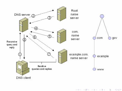
DNS ServerThe Domain Name System (DNS) is the system and networkprotocol used on the Internet.
It translates names of computers to numerical addresses ( IPaddresses ) and vice versa.
It simply involves looking up in tables, in which names arelinked to numbers.
DNS is a client-server system : a requestor (client) requestsa name or address from a provider (DNS server ).
The server returns a reply.
Searching a number with a name is called forward lookup.
Searching a name with a number is called reverse lookup.
Dr. J. Alam (CES) Unit 1: Introduction February 22, 2020 105 / 113
Database ServerA database server is a computer system that provides othercomputers with services related to accessing and retrievingdata from a database.Access to the database server may occur via a ”front end”running locally at a user’s machine (e.g., phpMyAdmin), or”back end” running on the database server itself, accessed byremote shell.
Multimedia or Media ServerA media server refers either to a dedicated computer applianceor to a specialized application software, ranging from an en-terprise class machine providing digital media on demand, to,more commonly, a small personal computer or NAS (NetworkAttached Storage) for the home, dedicated for storing variousdigital media (meaning digital videos/movies, audio/music,and picture files).
Dr. J. Alam (CES) Unit 1: Introduction February 22, 2020 107 / 113

Network Performance Measure I
Network Performance defines how good the network is.
Quality of Service (QOS) is an overall measurement ofnetwork performance.From QOS point of view following measures are con-sidered important:
Bandwidth.Throughput.Latency.Jitter.Error Rate.
Dr. J. Alam (CES) Unit 1: Introduction February 22, 2020 108 / 113
Network Performance Measure II
BandwidthBandwidth is defined as a range within a band of frequenciesor wavelengths.Bandwidth is also defined as the amount of data that can betransmitted through a medium in a fixed amount of time.For digital devices the bandwidth is usually expressed in bitsper second (bps) or less frequently in bytes per second.For analog devices, the bandwidth is expressed in cycles persecond or Hertz (Hz).An increase in bandwidth in Hertz means an increase in thebandwidth in bits per second.It is not generally possible to send more data than dictatedby the Shannon-Hartley Theorem (Shannon channel capacitytheorem).
Dr. J. Alam (CES) Unit 1: Introduction February 22, 2020 109 / 113
Network Performance Measure III
ThroughputIn general throughput means the maximum rate of productionor the maximum rate at which something can be processed.When used in the context of communication networks, suchas Ethernet, throughput or network throughput is the rate ofsuccessful message delivery over a communication channel.Throughput is usually measured in bits per second (bit/s orbps) and sometimes in data packets per second (p/s or pps).
LatencyNetwork Latency is the term used to indicate any kind of delaythat happens in data communication over a network.
The speed of light imposes a minimum propagation time onall electromagnetic signals.
Dr. J. Alam (CES) Unit 1: Introduction February 22, 2020 110 / 113
Network Performance Measure IV
It is not possible to reduce the latency below:
t = s/cm
where s is the distance and cm is the speed of light in themedium.
This approximately means 1 extra millisecond RTT (round-trip-time) for 100km of distance between hosts.
Other delays also occur in intermediate nodes.
Network connections in which small delays occur are calledlow-latency networks.
Network connections which suffer from long delays are calledhigh-latency networks.
Dr. J. Alam (CES) Unit 1: Introduction February 22, 2020 111 / 113
Network Performance Measure V
JitterJitter in an IP networks is the variation in the latency on apacket flow between two systems, when some packets takelonger to travel from one system to the other.Jitter results from network congestion and route changes.Jitter is especially problematic in real-time communicationslike IP telephony and video conferencing.
Error RateIn digital transmission, the number of bit errors (Ne) is thenumber of received bits of a data stream over a communica-tion channel that have been altered due to noise, interference,distortion etc.
Dr. J. Alam (CES) Unit 1: Introduction February 22, 2020 112 / 113
Network Performance Measure VI
The bit error rate or bit error ratio (BER), is the number ofbit errors (Ne), divided by the total number of transferred bits(N) during a studied time interval.Mathematically, during the time interval ∆t, BER is expressedas follows:
BER =Ne
N
BER is a unitless performance measure, often expressed as apercentage.
%BER =Ne
N× 100
Dr. J. Alam (CES) Unit 1: Introduction February 22, 2020 113 / 113