Unit – I: Introduction to Turbo Machinery - WordPress.com
40
Turbo Machines –Course Objectives To provide the knowledge of basic principles, governing equations and applications of turbo machine. To provide the students with opportunities to apply basic thermo- fluid dynamics flow equations to Turbo Machines. To explain construction and working principle and evaluate the performance characteristics of Turbo Machines.
-
Upload
khangminh22 -
Category
Documents
-
view
0 -
download
0
Transcript of Unit – I: Introduction to Turbo Machinery - WordPress.com

Turbo Machines –Course Objectives
To provide the knowledge of basic principles,
governing equations and applications of turbo
machine.
To provide the students with opportunities to
apply basic thermo- fluid dynamics flow
equations to Turbo Machines.
To explain construction and working principle
and evaluate the performance characteristics of
Turbo Machines.

Turbo Machines -Course Outcomes
•Apply thermodynamics and kinematics
principles to turbo machines
•Analyze the performance of turbo machines.
•Ability to select turbo machine for given
application.
• Predict performance of turbo machine using
model analysis.

Turbo MachinesUnit – I : Introduction to Turbo Machinery
Unit –II : Impulse Water Turbines
Unit –III : Reaction Water Turbines
Unit –IV : Steam Turbines
Unit –V : Centrifugal Pumps
Unit –VI : Centrifugal & Axial Compressor

Unit – I: Introduction to Turbo Machinery
Introduction to Turbo Machinery
• Turbo machines (Hydraulic & Thermal), Classification of
Turbo machines, Comparison with positive displacement
machines, Fundamental equation governing turbo machines,
Different losses associated with turbo-machinery,
Applications of Turbo machines.
• Impact of Jet
Impulse momentum principle and its applications, Force
exerted on fixed and moving flat plate, hinged plate, curved
vanes, series of flat plates and radial vanes, velocity triangles
and their analysis, work done equations, vane efficiency.

Fluid MachinesFluid machine is a device exchanging energy (work)
between a fluid and a mechanical system .
Fluid machines are those devices that are used to either
move fluid or extract energy from moving fluid.
In particular turbo machine is a device using a rotating
mechanical system to perform work or extract
energy.
Broadly speaking, fluid machines are divided into two groups:
1-Positive-displacement machines
2-Turbomachines

1-Positive-displacement machines
Positive-displacement machines are those devices that force fluid into confined volumes.
Moves fluid from maximum to minimum volume& Vice versa.
Examples -human heart, reciprocating pumps and compressors.
2-Turbomachines
Turbomachines classified as all those devices in which energy is transferred either to, or from, a continuously flowing fluid by the dynamic action of one or more moving blade rows.
Example- ceiling fans.

Reciprocating pumps
Human heart Pressure gauge ceiling fans
Wind mill

Introduction to Turbomachinery
A turbo machine is basically a rotating machine(wheel).
The rotating wheel is called a rotor /runner / impeller.
The rotor will be immersed in a fluid continuum.
The fluid medium can be gas / steam /water / air.
Energy transfer takes place either
from rotor to fluid, or
from fluid to rotor

Turbomachine - Definition• Turbo or turbinis is of Latin origin and it implies that
which spins or whirls around.
• A turbomachine is a rotary machine
• Which always involves an energy transfer between a continuously flowing fluid and a rotor
• It is a power or head generating machine.
• It uses the dynamic action of the rotor or impeller or runner which changes the energy level of the continuously flowing fluid through the rotor.

Turbomachine - Definition
A turbo machine is a device where mechanical energy in the form of shaft work, is transferred either to or from a continuously flowing fluid by the dynamic action of rotating blade rows. (one or more moving blade rows).
The interaction between the fluid and the turbo machine blades also results in fluid dynamic lift.

TURBOMACHINE


Twice as big as an Airbus A380 turbine


Parts of a turbomachine
The principle components of a turbo machine are:
1. Rotating element Or Rotor blades (vane, impeller or
blades) – operating in a stream of fluid.
2. Stationary elements or Stationary blades – which
usually guide the fluid in proper direction for efficient
energy conversion process.
3. Shaft – This either gives input power or takes output
power from fluid under dynamic conditions and runs at
required speed.
4. Housing – to keep various rotating, stationery and other
passages safely under dynamic conditions of the flowing
fluid.
E.g. Steam turbine parts and Pelton turbine parts.


Turbo machine - Classification
Eg:- Hydraulic Turbine Eg:- Centrifugal Pump

Turbo machine - Classification
• Turbines, compressors, pumps, fans , blowers
• Incompressible or compressible
• Axial-flow, mixed-flow or radial-flow .
• Single stage or multi-stage.
• Turbo-pump, turbo-compressor or torque-converter
• Impulse, reaction or impulse-reaction.

Power Absorbing Turbo machines
Fans - air is the working medium
axial flow
radial flow (centrifugal)
Blowers - air is the working medium
axial flow
radial flow (centrifugal)
Propellers and Ducted Fans- air is the working
medium
Compressors - air is the working medium
reciprocating
rotary
axial flow
radial flow (centrifugal)
mixed flow
Pumps - water is the working medium
reciprocating
rotary
axial flow
radial flow (centrifugal)
mixed flow
Power Producing Turbo machines
Gas turbines – air and combustion gas is the
working medium
axial flow
radial flow
Steam turbine –
steam is the working medium
impulse turbine
reaction turbine
Hydraulic turbines –
water is the working medium
impulse turbine
reaction turbine
mixed flow
axial flow
Wind turbines – air / wind is the working
medium
vertical axis
horizontal axis

CLASSIFICATION OF TURBO MACHINES
1. Based on energy transfer
a) Energy is given by fluid to the rotor - Power generating turbo machine E.g. Turbines
b) Energy given by the rotor to the fluid – Power absorbing turbo machine
E.g. Pumps, blowers and compressors
2. Based on fluid flowing in turbo machine
a) Water
b) Air
c) Steam
d) Hot gases
e) Liquids like petrol etc.

3. Based on direction of flow through the impeller or vanes or
blades, with reference to the axis of shaft rotation
a) Axial flow – Axial pump, compressor or turbine
b) Mixed flow – Mixed flow pump, Francis turbine
c) Radial flow – Centrifugal pump or compressor
d) Tangential flow – Pelton water turbine
4. Based on condition of fluid in turbo machine
a) Impulse type (constant pressure) E.g Pelton water turbine
b) Reaction type (variable pressure) E.g. Francis reaction turbine
5. Based on position of rotating shaft
a) Horizontal shaft – Steam turbines
b) Vertical shaft – Kaplan water turbines
c) Inclined shaft – Modern bulb micro hydel turbines

Comparison of Turbo Machines with positive displacement machines


Applications of Turbo Machines
• Power Generation
Hydro electric- Hydro-electric turbo machinery uses potential
energy stored in water to flow over an open impeller to turn a
generator which creates electricity.
Steam turbines- Steam turbines used in power generation . The
overall principle is high pressure steam is forced over blades
attached to a shaft, which turns a generator.
Gas turbines- Gas turbines work much like steam turbines. Air is
forced in through a series of blades that turn a shaft. Then fuel is
mixed with the air and causes a combustion reaction. This then
causes the shaft to spin faster, creating more electricity.
Wind mills- Also known as a wind turbine. The blades work on the
same principle as an airplane wing. As wind passes over the blades,
it creates an area of low and high pressure, causing the blade to
move, spinning a shaft and creating electricity.

• Marine
• Steam turbine- Steam turbines in marine applications are very
similar to those in power generation. The few differences
between them are size and power output. They aren’t very
common because of their high initial cost, high specific fuel
consumption, and expensive machinery that goes with it.
• Gas turbines- Gas turbines in marine applications are
becoming more popular due to their smaller size, increased
efficiency, and ability to burn cleaner fuels. They are most
popular in naval ships as they can be at a dead stop to full
power in minutes (Kayadelen, 2013), and are much smaller for
a given amount of power. Flow of air through a turbocharger
and engine

• Turbochargers- Turbochargers are one of the most popular turbomachines. They are used mainly for adding power to engines by adding more air.
• Superchargers- Superchargers are used for engine-power enhancement as well, but only work off the principle of compression. They use the mechanical power from the engine to spin a screw or vein, some way to suck in and compress the air into the engine. General
• Pumps- Pumps are another very popular turbo machine. Pumps are used to move fluids around using some sort of mechanical power, from electric motors to full size diesel engines. Pumps have thousands of uses, and are the true basis to turbo machinery .
• Air compressors- Air compressors are another very popular turbo machine. They work on the principle of compression by sucking in and compressing air into a holding tank.
• Fans- Fans are the most general type of turbo machines. They work opposite of wind turbines. Mechanical power spins the blades, forcing air through them and forcing out.
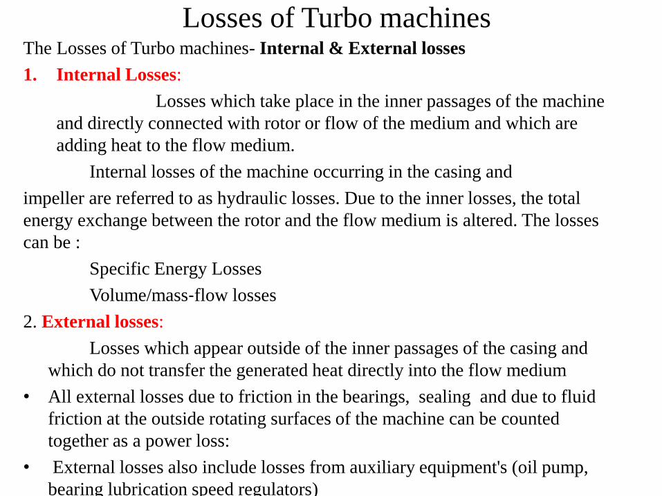
Losses of Turbo machinesThe Losses of Turbo machines- Internal & External losses
1. Internal Losses:
Losses which take place in the inner passages of the machine
and directly connected with rotor or flow of the medium and which are
adding heat to the flow medium.
Internal losses of the machine occurring in the casing and
impeller are referred to as hydraulic losses. Due to the inner losses, the total
energy exchange between the rotor and the flow medium is altered. The losses
can be :
Specific Energy Losses
Volume/mass‐flow losses
2. External losses:
Losses which appear outside of the inner passages of the casing and
which do not transfer the generated heat directly into the flow medium
• All external losses due to friction in the bearings, sealing and due to fluid
friction at the outside rotating surfaces of the machine can be counted
together as a power loss:
• External losses also include losses from auxiliary equipment's (oil pump,
bearing lubrication speed regulators)

3.Frictional and other losses-
The effect of these losses is to
Reduce the stagnation pressure and increase the entropy
Reduce the net work output in a power generating machine and
increase the net work input in a power absorbing machine.
A. Disc Friction Loss
The surface of the rotor which does not form the main flow
passage is surrounded by a fluid medium. while the rotor rotates, a
friction is generated between this rotor surface and its
surrounding fluid medium.
B. Hydraulic Loss
Hydraulic Loss is a specific Energy Loss due to
friction, separation, contraction, diffusion, eddy formation
etc. while the flow passes through the main flow passages from
entrance to discharge flange of the machine.

Hydraulic losses can involve :
Leakage losses:
In case of impulse turbines, whole of the water may not be
striking the buckets and therefore some of the water power may go
waste.
In a reaction turbine, some of the water may be passing through
the clearance between the casing and the runner without striking the
blades and thus not doing any work. These losses are called leakage
losses.
Mechanical losses:
The power produced by the runner is not available as useful
work of the shaft because some power may be lost in bearing
friction as mechanical losses.
Generator losses: Due to generator loss, power produced by the
generator is still lesser than the power obtained at the shaft output.

Fundamental equation governing turbo machines
Basic laws of Fluid Mechanics and Thermodynamics used in
Turbo machines are:
• Equation of continuity
• first law of thermodynamics
• second law of thermodynamics
• Newton’s Second Law of Motion
• Euler’s equation of motion.

Equation of Continuity
Continuity equation states that the rate at which mass
enters a system is equal to the rate at which mass leaves
the system plus the accumulation of mass within the
system.
Or
This Law States that, in absence of sources and
sinks, there is no accumulation of fluid within the
Control volume.
AcAcAcm nnn 222111
.

When a fluid is in motion, it must move in such a way that
mass is conserved. To see how mass conservation places
restrictions on the velocity field, consider the steady flow of fluid
through a duct (that is, the inlet and outlet flows do not vary with
time). The inflow and outflow are one-dimensional, so that the
velocity V and density are constant over the area A.
This is a statement of the principle of mass conservation
for a steady, one-dimensional flow, with one inlet and one
outlet. This equation is called the continuity equation for
steady one-dimensional flow.

First Law of Thermodynamics [Internal Energy]
• first law of thermodynamics is an expression of the conservation of total energy of a system. The increase of the energy of a system is equal to the sum of work done on the system and the heat added to that system: ... is the heat added to that system
• The first law of thermodynamics states that if a system is taken through a complete cycle during which heat is supplied and work is done, then
Where ,
represents the heat supplied to the system during the cycle
work done by the system during the cycle.
During a change of state from 1 to 2, there is a change in the property internal energy and the law is written as
0WQ
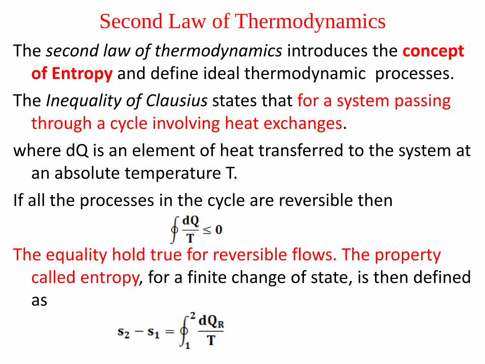
Second Law of Thermodynamics
The second law of thermodynamics introduces the concept of Entropy and define ideal thermodynamic processes.
The Inequality of Clausius states that for a system passing through a cycle involving heat exchanges.
where dQ is an element of heat transferred to the system at an absolute temperature T.
If all the processes in the cycle are reversible then
The equality hold true for reversible flows. The property called entropy, for a finite change of state, is then defined as
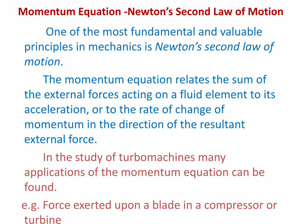
Momentum Equation -Newton’s Second Law of Motion
One of the most fundamental and valuable principles in mechanics is Newton’s second law of motion.
The momentum equation relates the sum of the external forces acting on a fluid element to its acceleration, or to the rate of change of momentum in the direction of the resultant external force.
In the study of turbomachines many applications of the momentum equation can be found.
e.g. Force exerted upon a blade in a compressor or turbine

Considering a system of mass m, the sum of all the body and surface forces acting on m along some arbitrary direction x is equal to the time rate of change of the total x- momentum of the system,
For a control volume where fluid enters steadily at a uniform velocity cx1 and leaves steadily with a uniform velocity cx2, then
The one-dimensional form of the steady flow momentum equation is

Euler’s Equation of Motion
It can be shown for the steady flow of fluid through an elementary control volume that, in the absence of all shear forces, the relation
is Euler’s equation of motion for one-dimensional flow and is derived from Newton’s second law.
01
gdzcdcp

Bernoulli’s Equation
The one-dimensional form of Euler’s equation applies to a control volume whose thickness is infinitesimal in the stream direction Integrating this equation in the stream direction we obtain
which is Bernoulli’s equation.
For an incompressible fluid, is constant and Bernoulli's equation Becomes
This can be written as
Where stagnation pressure p02 and p01 are the stagnation pressures at 2 and 1 station
respectively. Stagnation pressures are given as

Bernoulli’s EquationIn hydraulic turbomachines, the term head H is used
frequently. Head describes the summation given as under
Thus equation becomes
H2 - H1 = 0
If the gas or vapour is subject to only a small pressure change the fluid density is sensibly constant and equation becomes

Bernoulli’s Equation
That is
(1)The stagnation pressure is constant in gas or vapour flows for all incompressible and compressible isentropic process.
(2) Head remains constant in hydraulic machines.