unit 6 introduction to balancing - IGNOU
16
155 UNIT 6 INTRODUCTION TO BALANCING Structure 6.1 Introduction Objectives 6.2 Force on Shaft and Bearing due to Single Revolving Mass 6.3 Balancing of a Single Revolving Mass 6.4 Procedure for Balancing 6.5 External Balancing of Single Revolving Mass 6.6 Static and Dynamic Balancing 6.7 Several Masses Revolving in Same Transverse Plane 6.8 Balancing of Several Masses in Different Transverse Planes 6.9 Summary 6.10 Answers to SAQs 6.1 INTRODUCTION In the system of rotating masses, the rotating masses have eccentricity due to limited accuracy in manufacturing, fitting tolerances, etc. A mass attached to a rotating shaft will rotate with the shaft and if the centre of gravity of the rotating mass does not lie on the axis of the shaft then the mass will be effectively rotating about an axis at certain radius equal to the eccentricity. Since the mass has to remain at that radius, the shaft will be pulled in the direction of the mass by a force equal to the centrifugal force due to inertia of the rotating mass. The rotating centrifugal force provides harmonic excitation to system which thereby causes forced vibration of the machines. We will discuss how such a force can be balanced to remove the effect of unbalance. The unbalance is expressed as product of mass and eccentricity. Objectives After studying this unit, you should be able to understand what is unbalanced force, and the effect of this, how is unbalanced force due to single rotating mass balanced, and how is unbalanced force due to several rotating masses in the same plane determined? 6.2 FORCE ON SHAFT AND BEARING DUE TO SINGLE REVOLVING MASS Figure 6.1 shows a revolving mass attached to a horizontal shaft, which is supported by two bearings. The mass M is at a radius r from the axis of the shaft. The mass is attached to the shaft at a distance a from bearing on the left and at distance b from right hand bearing so that the span of the shaft between the bearings is a + b. The eccentricity is due to the tolerances assigned, the limited accuracy of the manufacturing machines and non- homogenity of the material. The shaft is rotating with an angular velocity rad/s. A dynamic force F will pull the shaft towards the connected mass M. The magnitude of F is given by 2 F M r . . . (6.1)
-
Upload
khangminh22 -
Category
Documents
-
view
1 -
download
0
Transcript of unit 6 introduction to balancing - IGNOU

155
Introduction to
Balancing UNIT 6 INTRODUCTION TO BALANCING
Structure
6.1 Introduction
Objectives
6.2 Force on Shaft and Bearing due to Single Revolving Mass
6.3 Balancing of a Single Revolving Mass
6.4 Procedure for Balancing
6.5 External Balancing of Single Revolving Mass
6.6 Static and Dynamic Balancing
6.7 Several Masses Revolving in Same Transverse Plane
6.8 Balancing of Several Masses in Different Transverse Planes
6.9 Summary
6.10 Answers to SAQs
6.1 INTRODUCTION
In the system of rotating masses, the rotating masses have eccentricity due to limited
accuracy in manufacturing, fitting tolerances, etc. A mass attached to a rotating shaft will
rotate with the shaft and if the centre of gravity of the rotating mass does not lie on the
axis of the shaft then the mass will be effectively rotating about an axis at certain radius
equal to the eccentricity. Since the mass has to remain at that radius, the shaft will be
pulled in the direction of the mass by a force equal to the centrifugal force due to inertia
of the rotating mass. The rotating centrifugal force provides harmonic excitation to
system which thereby causes forced vibration of the machines. We will discuss how such
a force can be balanced to remove the effect of unbalance. The unbalance is expressed as
product of mass and eccentricity.
Objectives
After studying this unit, you should be able to understand
what is unbalanced force, and the effect of this,
how is unbalanced force due to single rotating mass balanced, and
how is unbalanced force due to several rotating masses in the same plane
determined?
6.2 FORCE ON SHAFT AND BEARING DUE TO
SINGLE REVOLVING MASS
Figure 6.1 shows a revolving mass attached to a horizontal shaft, which is supported by
two bearings. The mass M is at a radius r from the axis of the shaft. The mass is attached
to the shaft at a distance a from bearing on the left and at distance b from right hand
bearing so that the span of the shaft between the bearings is a + b. The eccentricity is due
to the tolerances assigned, the limited accuracy of the manufacturing machines and non-
homogenity of the material.
The shaft is rotating with an angular velocity rad/s. A dynamic force F will pull the
shaft towards the connected mass M. The magnitude of F is given by
2F M r . . . (6.1)

156
Theory of Machines
The force F will be a bending force on the shaft and will cause bending moment.
Additional bending stress will be induced and reactions at bearings A and B will occur.
The reactions RA and RB can be calculated by considering the equilibrium. They are
2A
bR M r
a b
. . . (6.2)
2B
aR M r
a b
. . . (6.3)
Figure 6.1 : Revolving Mass attached to a Horizontal Shaft
These reactions on bearings will rotate with the mass, hence will cause fatigue damage.
The wear of bearing all over the circumference will also increase. The shaft will be
subjected to bending moment whose maximum value will occur at the section where the
mass M is connected to the shaft. The bending moment under the revolving mass will be
2abM M r
a b
. . . (6.4)
when the reactions at the supports become more than the tolerable limits of bearings, the
balancing is done.
Example 6.1
A shaft of circular cross-section of diameter 50 mm is supported in two bearings at
a distance of 1 m. A mass of 20 kg is attached to the shaft such that its centre of
gravity is 5 mm from the axis. The mass is placed at a distance of 400 mm from
left hand bearing. To avoid unequal wearing of bearings, the designer places the
mass in the centre of the span. Calculate reactions at bearings, maximum bending
moments and bending stresses if the shaft rotates at 750 rpm.
Solution
The force caused on shaft due to rotation = F
2 2 750
78.54 rad/s60 60
N
2 W
F rg
Use 320 kg, 78.54 rad/s, 5 10 mM r
2 320 (78.5) 5 10 616.85 NF . . . (i)
Case I
Mass at a = 400 mm from left hand (LH) bearing
b = 1000 – 400 = 600 mm
a + b = 1000 mm
A – left, B – right hand bearing (Figure 6.1)
A
bR F
a b
600
616.851000
A B
M
F
a b
r
M
r

157
Introduction to
Balancing
A B
M
M1
r1
r
M
r
M1
r1
or 370.1 NAR . . . (ii)
and 616.85 370.1B AR F R . . . (iii)
or 246.74 NBR
Maximum BM, . 370.1 400AR a
or 3148.04 10 NmmBM . . . (iv)
Bending stress is given by
3
32b
BM
d
where d = 50 mm = shaft diemeter
3
3
32 148.0410
(50)b
or 212.06 N/mmb . . . (v)
Case II
Mass at the centre of span, i.e. a = b = 500 mm
616.85
308.425 N2 2
A B
FR R
Maximum BM, 3308.425 500 154.213 10 Nmm2
Fa . . . (vi)
3
32b
BM
d
3
3
32 154.21310
(50)
or 217.35 N/mmb . . . (vii)
6.3 BALANCING OF A SINGLE REVOLVING MASS
Balancing is a process of the redistribution of the mass in the system such that the
reactions at the bearings are within the tolerable limits of the bearings. There are two
methods of achieving this.
System Method
The effects of an off-axis or eccentric mass connected to a rotating shaft, as
brought out above, has to be nullified. One simple way by which this is achieved
is by attaching another mass M1 at a radius r1, exactly opposite to M as shown in
Figure 6.2. The shaft is rotating at an angular speed of .
Figure 6.2 : Balancing of a Single Revolving Mass : System Method

158
Theory of Machines
The mass M1 and its radius are so chosen that it is equal to the centrifugal force
due to M, i.e.
2 211
MMF r r
g g
which means that 1 1M r M r . . . (6.5)
If Eq. (6.5) is satisfied then the resultant force on the shaft and hence on bearing
will be zero. Thus additional reaction or overload on the bearings is zero and
BM = 0, hence no additional stress in the shaft will be induced. The system is now
called internally balanced. Internal balance is achieved by adding a balancing
mass exactly opposite to revolving mass which causes unbalance. Thus the
disturbing and balancing masses (M and M1, respectively) are in the same plane
for internal balance and they satisfy the condition given by Eq. (6.5).
This method is used for balancing auto wheels, etc.
Second Method
In this method, instead of meutralising centrifugal force, the eccentricity or radius
‘r’ is reduced. By doing this, we intend to reduce the magnitude of the centrifugal
force. This method is used for thicker discs like flywheel where it is possible to
take out mass by shallow drilling. The side of the disc which consists of centre of
gravity is called heavy side as shown in Figure 6.3(a). The opposite side to the
heavy side is called light side. Since heavy side consists of more mass, the mass
M1 as given by the Eq. (6.5) can be taken out by drilling a shallow hole of
diameter ‘d’ and depth ‘b’ as given by the following relation
21
4d b M
where ‘b’ is less than thickness of the disc and is density of material.
Figure 6.3 : Balancing of a Single Revolving Mass : Second Method
6.4 PROCEDURE FOR BALANCING
A thin disc like flywheel or a car wheel may be mounted on an axle or a shaft. It can be
rotated by hand. The side which comes down can be marked. It is rotated again. If the
same side comes down, this is heavy side and opposite to this is light side. If there is no
force measuring device and rotating device, some mass can be mounted whenever it is
possible on light side. The care should be taken that the mounting distance is as large as
possible. If marked heavy side again comes down, more mass can be mounted on the
light side. This process is repeated till any side comes down. Now it is farely balanced.
If there is a machine like wheel balancing machine, it indicates the magnitude of mass
and the location where balancing mass should be mounted. These methods are trial and
error methods and are time consuming methods. This cannot be used in industries where
time available per piece is less. The industries have balancing machines which have
+ +
+
Shallow Hole
CG
CG r
r1
Light Side
Heavy Side

159
Introduction to
Balancing rotating device and transducers to provided magnitude of balancing mass and its
location. In practice, we never aim the perfect balancing. The machine or the component
is balanced till reactions are within a tolerable limit of the bearings.
SAQ 1
(a) What do you mean by unbalance and why it is due to?
(b) What do you mean by balancing?
(c) Why all the rotating systems are not balanced?
Example 6.2
In Example 6.1 find what weight of the balancing mass will achieve complete
balance if the balancing mass has its centre of gravity at a distance of 7.5 mm from
the axis of rotation. Will this be true for both positions of disturbing mass in
Example 6.1.
Solution
Use (Eq. (18.5) with 125 kg, 5 mm, 7.5 mmM r r
125 5 7.5M
1
25 51 16.67 kg
7.5
M . . . (i)
Since the Eq. (6.5) is independent of distance along the shaft the position of
disturbing mass will not affect the magnitude of balancing mass. So balancing
mass is same as at Eq. (i) for M at a = 400 mm or M in the centre of the span.
6.5 EXTERNAL BALANCING OF SINGLE
REVOLVING MASS
The single revolving mass W connected to the shaft at radius r causes the unbalance
force and reactions at the support. However, if two masses W1 at radius r1 and W2 at
radius r2 are attached to the shaft, respectively in the same axial plane then also
balancing of force due to rotation of W can be achieved. The condition of balance in case
as shown in Figure 6.3 will be
2 2 21 21 2
W WWr r r
g g g
The bending moments due to the forces due to rotating masses will be balanced if
2 2 21 21 1 2 2
W WWr a r a r a
g g g
2 2 21 21 1 2 2
W WWr b r b r b
g g g
a, b, a1, b1, a2 and b2 are shown in Figure 6.4.
160
Theory of Machines
The equations are written again by canceling out 2
g
from both sides.
1 1 2 2W r W r W r . . . (6.6)
1 1 1 2 2 2W r a W r a W r a . . . (6.7)
1 1 1 2 2 2W r b W r b W r b . . . (6.8)
Thus the disturbing force or unbalanced force on the shaft is removed. There is no
excess reaction at any of bearings A and B. This is known as external balancing.
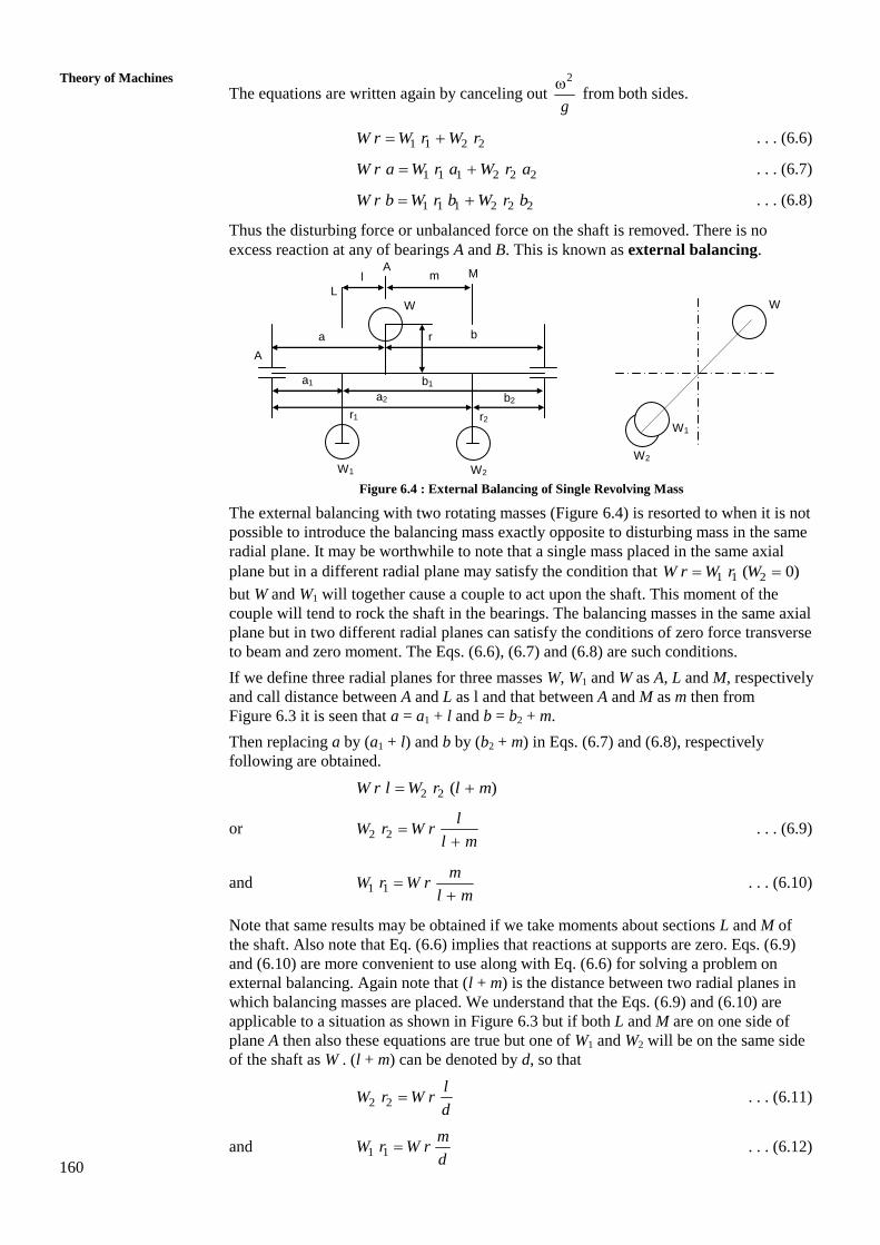
Figure 6.4 : External Balancing of Single Revolving Mass
The external balancing with two rotating masses (Figure 6.4) is resorted to when it is not
possible to introduce the balancing mass exactly opposite to disturbing mass in the same
radial plane. It may be worthwhile to note that a single mass placed in the same axial
plane but in a different radial plane may satisfy the condition that 1 1 2( 0)W r W r W
but W and W1 will together cause a couple to act upon the shaft. This moment of the
couple will tend to rock the shaft in the bearings. The balancing masses in the same axial
plane but in two different radial planes can satisfy the conditions of zero force transverse
to beam and zero moment. The Eqs. (6.6), (6.7) and (6.8) are such conditions.
If we define three radial planes for three masses W, W1 and W as A, L and M, respectively
and call distance between A and L as l and that between A and M as m then from
Figure 6.3 it is seen that a = a1 + l and b = b2 + m.
Then replacing a by (a1 + l) and b by (b2 + m) in Eqs. (6.7) and (6.8), respectively
following are obtained.
2 2 ( )W r l W r l m
or 2 2
lW r W r
l m
. . . (6.9)
and 1 1
mW r W r
l m
. . . (6.10)
Note that same results may be obtained if we take moments about sections L and M of
the shaft. Also note that Eq. (6.6) implies that reactions at supports are zero. Eqs. (6.9)
and (6.10) are more convenient to use along with Eq. (6.6) for solving a problem on
external balancing. Again note that (l + m) is the distance between two radial planes in
which balancing masses are placed. We understand that the Eqs. (6.9) and (6.10) are
applicable to a situation as shown in Figure 6.3 but if both L and M are on one side of
plane A then also these equations are true but one of W1 and W2 will be on the same side
of the shaft as W . (l + m) can be denoted by d, so that
2 2
lW r W r
d . . . (6.11)
and 1 1
mW r W r
d . . . (6.12)
A
b
L
W1
a
r1
r
A M m l
b1
r2
b2 a2
a1
W2
W W
W1
W2

161
Introduction to
Balancing Example 6.3
A mass of 100 kg is fixed to a rotating shaft so that distance of its mass centre
from the axis of rotation is 228 mm. Find balancing masses in following two
conditions :
(a) Two masses – one on left of disturbing mass at a distance of 100 mm
and radius of 400 mm, and other on right at a distance of 200 mm and
radius of 150 mm.
(b) Two masses placed on right of the disturbing mass respectively at
distances of 100 and 200 mm and radii of 400 and 200 mm
The masses are placed in the same axial plane.
Solution
For Case (a) see Figure 6.5.
Figure 6.5 : Figure for Example 6.3
r = 228 mm, l = 100 mm, m = 200 mm, d = l + m = 100 + 200 = 300 mm,
r1 = 400 mm, r2 = 150 mm, 100W
g kg, W1 = ?, W2 = ?
From Eq. (6.6)
1 1 2 2W r W r W r
1 2100 228 400 150W W (g cancels out) . . . (i)
From Eq. (6.11)
2
100150 100 228
300W
2 50.67 kgW . . . (ii)
From Eq. (6.12)
1
100 228 200
400 300W
or 1 38 kgW . . . (iii)
Check with Eq. (i)
22800 = 15200 + 7600
L
W1
r1 = 400
A
M
r2 = 150
W2
r = 228
200 100
W

162
Theory of Machines
For Case (b) see Figure 6.6
Figure 6.6 : Figure for Example 6.3
From Eq. (6.11)
2
100 228 100( 100)
150 100W d
or 2 152 kgW . . . (iii)
From Eq. (6.12)
1
100 228 200
400 100W
or 1 114 kgW . . . (iv)
From Eq. (18.6)
2100 228 114 400 150W
or 2
22800 45600
150W
2 152 kg W . . . (v)
The negative sign indicates W2 is on the other side of W1.
6.6 STATIC AND DYNAMIC BALANCING
If the centre of gravity of all rotating masses is made to coincide with the axis of
rotation, a state is achieved when bearings will carry no additional reaction. However,
the masses may still cause some net bending moment on the shaft. Such bending moment
will keep changing its plane and thus cause shaft to vibrate. Connecting the masses in
such a way that bending moment is made to vanish will result in situation when shaft
will not vibrate.
The balancing when only centers of gravity of attached mass system lies on axis of
rotation is known as static balancing. The balancing with centers of attached mass
system made to coincide with axis of rotation and no net bending moment acting on shaft
is called dynamic balancing. In dynamic balancing forces and moments both are to be
balanced.
6.7 SEVERAL MASSES REVOLVING IN SAME
TRANSVERSE PLANE
A number of masses weighing W1, W2, etc. may be connected to the shaft such that their
respective centres of gravity are at distances of r1, r2, etc. Each of these masses may be
placed at its own angular position in the transverse or radial planes as depicted in
Figure 6.7(a). Each will exert centrifugal force which will be proportional to the product
W1
W2
200
100
W
100
163
Introduction to
Balancing of mass and radius (i.e. W r). If we wish to ascertain if the net effect will be an
unbalanced force, then we draw a polygon of forces. If the force polygon does not close
then the resultant unbalance is equal to the closing side of the polygon. In this case the
closing side is 5, O. Thus a force equivalent to 5, O in the direction 5 to O will close the
polygon. Hence balancing mass may be connected parallel to line joining 5 and O and
the length of this side will be the product of mass and radius.
(a) (b)
Figure 6.7 : Several Masses Revolving in same Transverse Plane
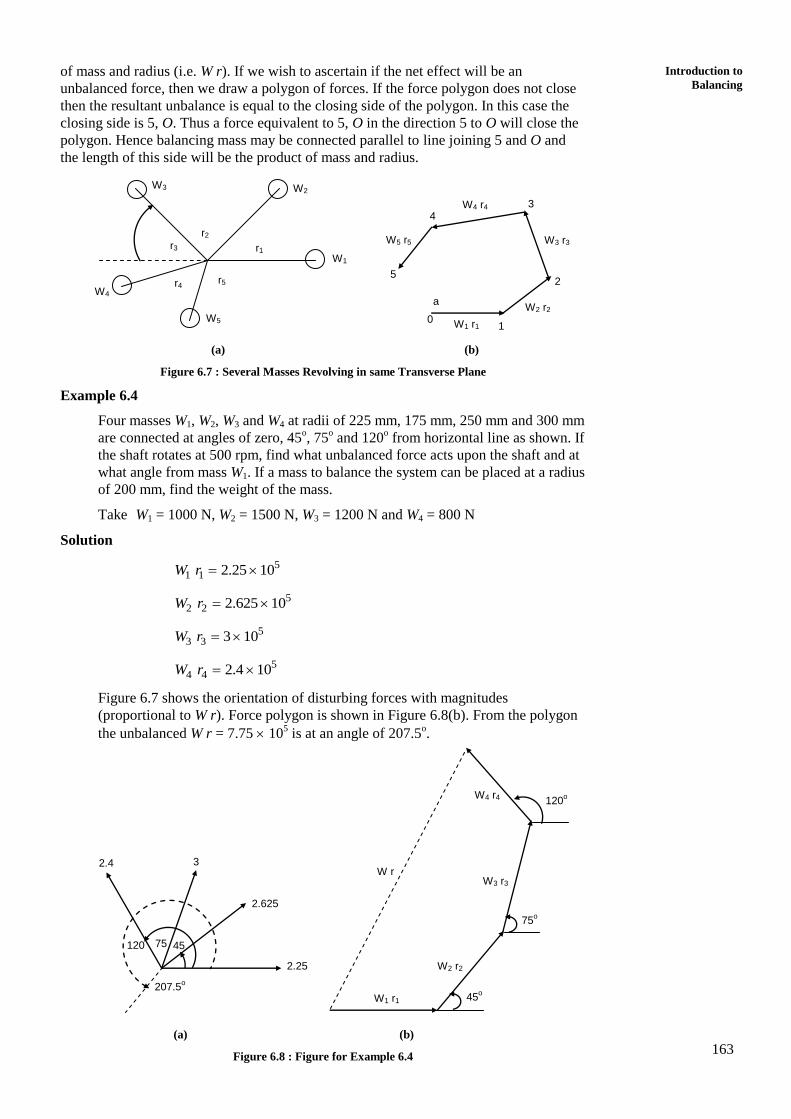
Example 6.4
Four masses W1, W2, W3 and W4 at radii of 225 mm, 175 mm, 250 mm and 300 mm
are connected at angles of zero, 45o, 75
o and 120
o from horizontal line as shown. If
the shaft rotates at 500 rpm, find what unbalanced force acts upon the shaft and at
what angle from mass W1. If a mass to balance the system can be placed at a radius
of 200 mm, find the weight of the mass.
Take W1 = 1000 N, W2 = 1500 N, W3 = 1200 N and W4 = 800 N
Solution
51 1 2.25 10W r
52 2 2.625 10W r
53 3 3 10W r
54 4 2.4 10W r
Figure 6.7 shows the orientation of disturbing forces with magnitudes
(proportional to W r). Force polygon is shown in Figure 6.8(b). From the polygon
the unbalanced W r = 7.75 105 is at an angle of 207.5
o.
(a) (b)
Figure 6.8 : Figure for Example 6.4
2.625
2.25
207.5o
2.4 3
120 75 45
W r
W1 r1
W2 r2
W3 r3
W4 r4 120o
75o
45o
W1
W2 W3
W4
W5
r1
r2
r3
r4 r5
W5 r5
W4 r4
W3 r3
W2 r2
W1 r1
5
4 3
2
1 0
a

164
Theory of Machines
The unbalanced force 2Wr
g
2537.75 10 2 500
109.81 60
52.166 10 N
If radius at which balancing mass is placed is 200 mm.
Then 57.75 10W r
57.75 10
200W
3875 NW
Alternative method is to resolve W r along horizontal and vertical direction and
find their resultant.
5( ) (2.25 2.625 cos 45 3 cos 75 2.4 cos 120) 10 W r H
5(2.25 1.856 0.7765 1.2) 10
= 3.6765 105
5( ) (2.625 sin 45 3 sin 75 2.4 sin 120) 10 W r V
5(1.856 2.9 2.0785) 10
= 6.83 105
5 2 210 [ ( )] [ ( )] W r W r H W r V
5 2 210 [3.6765] [6.83]
= 7.76 105
1 1 1 o( ) 6.83tan tan tan 1.8583 61.7
( ) 3.675
W r V
W r H
Note that W r is the resultant unbalance force which will act upward. The
balancing mass will be placed opposite to it, i.e. downward as shown by broken
line in Figure 18.7(a). 207.5o is the measured angle. The calculated value of the
angle is 360 – 90 – 61.7 = 208.3o.
Compare the Values
From polygon construction
o7.75, 207.5W r
From calculation
o7.76, 208.3W r .
6.8 BALANCING OF SEVERAL MASSES IN
DIFFERENT TRANSVERSE PLANES
To begin with we will name the planes in which masses revolve as A, B, C and D. The
masses rotating in these planes are respectively Wa, Wb, Wc and Wd. The radii at which
centers of gravity lie from axis of rotation in these planes are respectively ra, rb, rc and rd.

165
Introduction to
Balancing The angular separation between masses starting from A and B are , and . The
balancing masses will be placed in two planes L and M which are between A and B and
between C and D, respectively. The Figure 6.9 depicts the system. Distance between
planes L and any of planes A, B, C and D is denoted by l with appropriate suffix. The
same distances for plane M is denoted by m.
Figure 6.9 : Balancing of Several Masses in Different Transverse Plane
The method apparently is same as used in Section 6.4 in which balance masses in two
planes L and M were found. So we need to repeat the procedure for mass in plane A and
balancing mass in planes L and M. Thus we proceed in steps of planes A, B, C and D. A
table of the kind shown below as Table 6.1 will be helpful. Rows will be dedicated to
planes in which masses revolve which could be known or unknown.
For a mass of weight W, revolving at radius r, the force is proportional to W r as 2
g
is a
constant (Eq. (6.1)). Two planes L and M are chosen which are respectively at distances
of l and m from the plane of revolving mass and balancing masses are placed in planes L
and M as given by Eqs. (6.11) and (6.12). So the columns of the table will describe plane
(A, B, C, etc.) weight W; radius r; force W r; distances l and m; balancing forces in L
and M.
Table 6.1 : Calculation of Balancing Masses in Two Planes
Plane Weight
W
Radius
r Force
2
g
W r
Distance From Balancing Force 2
g
Plane L
l
Plane M
m
Plane L Plane M
A Wa ra Wa ra la ma a a aW r m
d a a aW r l
d
B Wb rb Wb rb lb mb b b bW r m
d b b bW r l
d
The sign of the forces in last two columns will be decided by observation. Yet as a rule if
a force is in the same direction as the disturbing force, then it will be positive and if in
the opposite direction it will be negative. After the balancing forces have been calculated
in planes L and M which will be parallel to forces in planes A and B, etc. they are
combined to give a single resultant. Their inclination to force in plane A can be
determined.
The above procedure will be followed in solving the example.
Example 6.5
In Figure 6.9 four masses Wa = 1000 N, Wb = 1500 N, Wc = 1200 N and
Wd = 1300 N revolve respectively at radii of ra = 225 mm, rb = 175 mm,
rc = 250 mm and rd = 300 mm in planes A, B, C and D. Two planes L and M are
Wc
Wm
Wb
Wa
Wd
WL
A L
B C M
D
la lb
lc
ld
md
ma
mc md

166
Theory of Machines
selected to place balancing masses Wl and Wm at a radius of 600 mm. The masses
Wb, Wc and Wd are respectively at angles of 45o, 75
o and 135
o from Wa and
distances between planes are : la = 300 mm, lb = 375 mm, lc = 750 mm,
ld = 1500 mm, ma = 1800 mm, mb = 875 mm, mc = 500 mm, md = 250 mm. Find the
balancing masses and orientation of their radii from radius of mass Wa.
Solution
See Figure 6.9. Proceed as per Table 6.1. The distance between planes L and M,
d = ld – md = 1500 – 875 = 825 mm.
Plane Weight
W
N
Radius
r
mm
Force
2
g
W r
Distance of Plane
From
Balancing Force
2
g
Plane, L
l (mm)
Plane, M
m (mm)
Plane L
Wrm/d
Nmm
Plane M
Wrl/d
Nmm
A 103 225 2.25 105 300 1800 6.48 105 1.08 105
B 1.5 103 175 2.625 105 375 875 3.675
105
1.575
105
C 1.2 103 250 3.00 105 750 500 2.4 105 3.6 105
D 1.3 103 300 3.90 105 1500 250 1.56 105 9.36 105
The last two columns show balancing forces for those in planes A and B, etc.
Hence, these forces will act in opposite direction to Wa, Wb, etc. four forces in
planes L and M will be equal to one force by a single rotating mass. Thus, two
balancing masses – one each in planes L and M will be obtained.
Balancing forces in L plane are shown in Figure 6.10, along with disturbing forces
Wa, Wb, Wc and Wd. To find resultant of all balancing forces we go for their
components along horizontal and vertical directions. The relevant angles are
shown in figure.
Figure 6.10 : Figure for Example 6.5
5 5 5 5( ) 6.48 10 3.675 10 cos 45 2.4 10 cos 75 1.56 10 cos 45Wr H
5(6.48 2.6 0.621 1.1) 10
510.8 10
5 5 5( ) 3.675 10 sin 4.5 2.4 10 sin 75 1.56 10 sin 45Wr V
5(2.6 2.32 1.1) 10
56.02 10
Wd
6.48 105
Wc
Wb
Wa
29o
151o
12.364 105
3.675 105
2.4 105
1.56 105
45o
45o
75o
135
75 45

167
Introduction to
Balancing 2 2(Resultant) [ ( )] [ ( )]W r W r H W r V
5116.64 36.24 10
512.364 10 Nmm
With 512.364 10
600 mm, 2060.7 N600
r W
The angle with
1 1 1 o( ) 6.02tan tan tan 0.5574 29
( ) 10.8a
W r VW
W r H
Balancing forces in M plane are shown in Figure 6.11 along with disturbing forces
Wa, Wb, Wc and Wd. The resultant is found as above.
5( ) (1.08 1.57 cos 135 3.6 cos 105 9.36 cos 45) 10rW H
5(1.08 1.11 0.93 6.62) 10
55.66 10
5( ) (1.57 sin 135 3.6 sin 105 9.36 sin 45) 10rW V
5(1.11 3.48 6.62) 10
511.2 10
2 2 5( ) 5.66 11.2 10rW R
512.55 10
At r = 600 mm, the balancing mass in M plane will be
512.55 10
2091 N600
W
This will be placed at angle with direction of Wa
1 1 o11.2tan tan 1.98 63.2
5.66
Figure 6.11 : Figure for Example 6.5
Wd
Wc
Wb
Wa
135o
1.08 105
3.6 105
12.55 105
1.57 105
45o
105o
9.36 105

168
Theory of Machines
Thus we see that for balancing the revolving masses in planes A, B, C and D we
have to connect two masses of 2060.7 N and 2091 N, respectively which are
between A and B and between C and D.
SAQ 2
(a) What do you understand by balancing of revolving masses?
(b) If not balanced what effects are induced on shaft bearing system due to
unbalanced rotating masses.
(c) How do you achieve balance of rotating masses which lie in parallel
transverse planes of a shaft?
(d) Five masses A, B, C, D and E revolve in the same plane at equal radii. A, B
and C are respectively 10, 5 and 8 kg in mass. The angular direction from A
are 60o, 135
o, 210
o and 270
o. Find the masses D and E for complete balance.
(e) A shaft carries three pulleys A, B and C at distance apart of 600 mm and
1200 mm. The pulleys are out of balance to the extent of 25, 20 and 30 N at
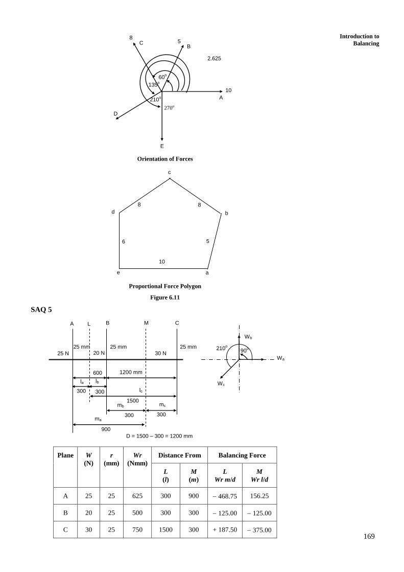
a radius of 25 mm. The angular position of out of balance masses in pulleys
B and C with respect to that in pulley A are 90o and 210
o respectively. It is
required that the pulleys be completely balanced by providing balancing
masses revolving about axis of the shaft at radius of 125 mm. The two
masses are to be placed in two transverse planes midway between the
pulleys.
6.9 SUMMARY
The masses that are connected to shaft and whose centers of gravity do not lie on axis of
the rotation, revolve about the axis at constant radius. Moving in circular path they are
subjected to centrifugal force which may cause bending stress in the shaft and rotating
reactions in the bearing. To nullify their effects, revolving masses can be provided in the
plane of disturbing mass or in some other parallel plane. If balancing masses are placed
in the plane of unbalance for single mass, only one balancing plane is required otherwise
two balancing planes shall be required. The balancing process requires that both the
bending forces and moments on the shaft be made to vanish.
6.10 ANSWERS TO SAQs
SAQ 2
(d) Since the radii are equal, the forces are proportional to masses. The
Figure 6.11 shows the forces and their orientation. Since the system is
balance the force polygon must close whereby we can find the unknown
forces and corresponding masses. We plot only masses hence sides of
polygon will directly give the masses.
In the force (proportional force) polygon known values are written inside
the polygon and measured values are written outside.
Mass D = 8 kg
Mass E = 6 kg
169
Introduction to
Balancing
Orientation of Forces
Proportional Force Polygon
Figure 6.11
SAQ 5
Plane W
(N)
r
(mm)
Wr
(Nmm)
Distance From Balancing Force
L
(l)
M
(m)
L
Wr m/d
M
Wr l/d
A 25 25 625 300 900 468.75 156.25
B 20 25 500 300 300 125.00 125.00
C 30 25 750 1500 300 + 187.50 375.00
2.625
10
210o
8 5
135o
270o
A
60o
B C
D
E
d
c
b
a e
8 8
6
10
5
1200 mm
1500
300 300
900
300 300
600
25 N
25 mm 20 N
25 mm 25 mm
30 N
A L B M C
la lb
lc
mc mb
ma
D = 1500 – 300 = 1200 mm
Wb
Wa
Wc
210o 90
o

170
Theory of Machines
L Plane
( ) 468.75 187.5 cos 30Wr H
631.13
( ) 125 187.5 sin 30Wr V
218.75
2 2( ) 631.13 218.75Wr R
668 Nmm
125 mmr
668
5.34 N125
W
1 1 o218.75tan tan 0.347 19.14
631.13
M Plane
( ) 156.25 375 cos 30 481Wr H
( ) 375 sin 30 156.25 31.25Wr V
2 2( ) 481 31.25 482Wr R
125 mmr
482
3.86 N125
W
31.25
tan 0.065481
o3.7
W
468.75
30o
187.5
125.00
W
375.00
30o
156.25
125