Underwater Optical Communications: A Brief Overview and ...
41
Eng. Sci., 2021, 16, 146–186 146 | Eng. Sci., 2021, 16, 146-186 © Engineered Science Publisher LLC 2021 Engineered Science DOI: https://dx.doi.org/10.30919/es8d574 Underwater Optical Communications: A Brief Overview and Recent Developments Saleha Al-Zhrani, 1, 2 Nada M. Bedaiwi, 1, 3 Intesar F El-Ramley, 4 Abeer Z. Barasheed, 1 Ali Abduldaiem, 1, 5 Yas Al-Hadeethi 1, 6,* and Ahmad Umar 7, 8 Abstract Even though most of the Earth's area is sheltered by the hydrosphere, the underwater world is nonetheless a challenging puzzle that has drawn the attention of scientists and researchers around the globe. Numerous theoretical and experimental research has been conducted to attain a safe and effective means of communication. This is crucial to facilitate the implementation of critical industrial, military and security applications and to guarantee the management of marine resources sustainably. Underwater communication technologies have come a long way as they have been implemented either utilizing wired and wireless techniques, through employing acoustic waves or electromagnetic waves (in the radio-frequency spectrum or the optical spectrum). Even though acoustic communication realizes long communication ranges in Km, its limited data rate, its low speed, and its undesirable impact on the aquatic environment have all led to the realization of electromagnetic waves-based communication. Electromagnetic waves offer a high data rate and high-speed communication. Moreover, underwater radio frequency communications maintain a smooth transition between water and air, and they are unaffected by the turbidity properties of water. However, they come at a huge cost. Intriguingly, wireless communications in the optical spectrum have outperformed all the above techniques. This is owing to its high bandwidth and low cost. For that reason, we focus this review on the different facets of the underwater optical wireless communications (UOWC) field, where we present an overview of the most important communication techniques and highlight their drawbacks and advantages. We also review the most basic physical processes that influence the light propagation and modulation underwater along with the coding techniques. We then discuss the link configurations and the system design, and we provide a summary of the most prominent studies from 1992 to the present. Keywords: Optical communications; Link configurations; Communication security; Light propagation; Modulation; LED. Received: 22 August 2021; Accepted: 14 November 2021. Article type: Review article. 1. Introduction Even though the ocean covers most of our planet, there is much about the deep sea that remains a mystery. Through ocean exploration, we can monitor all important aspects of underwater components such as seafloor, deep-sea and ocean oil pipelines, underwater zoological life, surveillance of unmanned systems and navigation. We can also collect data and information about climate change. [1] This information helps us ensure that ocean resources are managed sustainably and help us plan to prevent potential environmental disasters. Therefore, achieving an effective underwater communication method is an urgent need to perform many critical industrial, military and scientific applications. [2] Ocean exploration technologies have come a long way. Many communication technologies have been developed for underwater applications, such as wired and wireless systems. These systems have been realized through different approaches: acoustic waves, electromagnetic waves (either by using radio-frequency waves or optical waves) or hybrid systems. [3] Underwater acoustic communication technology is largely mature and achieves communication over distances in Km, but it suffers from low speed and low data rate due to the limited bandwidth. It also negatively affects the water’s environment. In addition, it is strongly affected by the characteristics of the water channel, such as the water’s turbidity and salinity, which make its 1 Department of Physics, Faculty of Sciences, King Abdulaziz University, Jeddah-21589, Kingdom of Saudi Arabia. 2 Physics Department, Umm Al-Qura University, Al-Qunfudhah University College, Al-Qunfudhah 21912, Kingdom of Saudi Arabia. 3 Department of Physics, University of Tabuk, Duba University College, Tabuk-71491, Kingdom of Saudi Arabia. 4 INToo Solutions, 202-6940 East Blvd, Vancouver, BC, V6M 3V5.
-
Upload
khangminh22 -
Category
Documents
-
view
1 -
download
0
Transcript of Underwater Optical Communications: A Brief Overview and ...
Eng. Sci., 2021, 16, 146–186
146 | Eng. Sci., 2021, 16, 146-186 © Engineered Science Publisher LLC 2021
Engineered Science
DOI: https://dx.doi.org/10.30919/es8d574
Underwater Optical Communications: A Brief Overview and Recent Developments
Saleha Al-Zhrani,1, 2 Nada M. Bedaiwi,1, 3 Intesar F El-Ramley,4 Abeer Z. Barasheed,1 Ali Abduldaiem,1, 5 Yas Al-Hadeethi1, 6,* and
Ahmad Umar7, 8
Abstract
Even though most of the Earth's area is sheltered by the hydrosphere, the underwater world is nonetheless a challenging puzzle that has drawn the attention of scientists and researchers around the globe. Numerous theoretical and experimental research has been conducted to attain a safe and effective means of communication. This is crucial to facilitate the implementation of critical industrial, military and security applications and to guarantee the management of marine resources sustainably. Underwater communication technologies have come a long way as they have been implemented either utilizing wired and wireless techniques, through employing acoustic waves or electromagnetic waves (in the radio-frequency spectrum or the optical spectrum). Even though acoustic communication realizes long communication ranges in Km, its limited data rate, its low speed, and its undesirable impact on the aquatic environment have all led to the realization of electromagnetic waves-based communication. Electromagnetic waves offer a high data rate and high-speed communication. Moreover, underwater radio frequency communications maintain a smooth transition between water and air, and they are unaffected by the turbidity properties of water. However, they come at a huge cost. Intriguingly, wireless communications in the optical spectrum have outperformed all the above techniques. This is owing to its high bandwidth and low cost. For that reason, we focus this review on the different facets of the underwater optical wireless communications (UOWC) field, where we present an overview of the most important communication techniques and highlight their drawbacks and advantages. We also review the most basic physical processes that influence the light propagation and modulation underwater along with the coding techniques. We then discuss the link configurations and the system design, and we provide a summary of the most prominent studies from 1992 to the present.
Keywords: Optical communications; Link configurations; Communication security; Light propagation; Modulation; LED.
Received: 22 August 2021; Accepted: 14 November 2021.
Article type: Review article.
1. Introduction
Even though the ocean covers most of our planet, there is
much about the deep sea that remains a mystery. Through
ocean exploration, we can monitor all important aspects of
underwater components such as seafloor, deep-sea and ocean
oil pipelines, underwater zoological life, surveillance of
unmanned systems and navigation. We can also collect data
and information about climate change.[1] This information
helps us ensure that ocean resources are managed sustainably
and help us plan to prevent potential environmental disasters.
Therefore, achieving an effective underwater communication
method is an urgent need to perform many critical industrial,
military and scientific applications.[2] Ocean exploration
technologies have come a long way. Many communication
technologies have been developed for underwater applications,
such as wired and wireless systems. These systems have been
realized through different approaches: acoustic waves,
electromagnetic waves (either by using radio-frequency waves
or optical waves) or hybrid systems.[3] Underwater acoustic
communication technology is largely mature and achieves
communication over distances in Km, but it suffers from low
speed and low data rate due to the limited bandwidth. It also
negatively affects the water’s environment. In addition, it is
strongly affected by the characteristics of the water channel,
such as the water’s turbidity and salinity, which make its
1 Department of Physics, Faculty of Sciences, King Abdulaziz
University, Jeddah-21589, Kingdom of Saudi Arabia. 2 Physics Department, Umm Al-Qura University, Al-Qunfudhah
University College, Al-Qunfudhah 21912, Kingdom of Saudi Arabia. 3 Department of Physics, University of Tabuk, Duba University
College, Tabuk-71491, Kingdom of Saudi Arabia. 4 INToo Solutions, 202-6940 East Blvd, Vancouver, BC, V6M 3V5.
Engineered Science Review article
© Engineered Science Publisher LLC 2021 Eng. Sci., 2021, 16, 146-186 | 147
performance weak. Radiofrequency communication is
characterized by its high speed compared to sound waves.
Moreover, radiofrequency waves is not affected by the
characteristics of the water channel; however, they are affected
by the electrical conductivity of the water. They are also bulky,
expensive, and achieve very short communication ranges.
Optical wireless communication (OWC) is a transmission
system of data through an optical carrier, that is ultraviolet
(UV), visible, or infrared, in an unguided propagation medium.
The least attenuated region in the visible spectrum is in the
range between 450–550 nm. Underwater Optical Wireless
Communications (UOWC) are characterized by high data rate,
low cost, high speed, and safety. However, UOWC suffers
from challenges related to the water channel and its modelling
method in a way that makes this method mature and which
causes it to achieve channel models suitable for different water
environments. So far, we have not found a model that fully
covers and addresses the challenges of the underwater channel.
However, UOWC outperformed all methods, through the
above-mentioned features. Aside from the traditional optical,
acoustic and electromagnetic systems, magnetic induction (MI)
communication, as a full of promise substitutional, has drawn
considerable awareness newly.[4] This is attributed to its
inherent excellent features in anticipated channel responses,
imperceptible propagation delay, and its competing energy
consumption.[4-6] Accordingly, currently, there is a wide
interest in research on underwater MI communications.
Furthermore, the progression of antenna design from
traditional single-directional to state-of-the-art multi-
directional MI antennas justifies the wide interest in this
currently hot topic of research. There is also much research
interest on the currently available approaches towards
broadening or reutilizing the accessible bands of frequency to
increase the underwater MI channel capacity.[4]
The major goal of this review is to learn about the main
characteristics and current features of UOWC. Therefore, this
paper covers the following aspects:
• An overview of possible UWC techniques as well as
current published literature.
• A summarized explanation of acoustic and
electromagnetic communication approaches is as well
provided to assist readers in better comprehending how UWC
operates.
• The review also discusses other approaches which
increase the efficacy of UWC systems, like hybrid acousto-
optic systems.
• The optical properties of water are presented and the
comparison in the definition of inherent and apparent optical
properties for various water types is discussed too.
• Furthermore, this study focuses on displaying the major
factors that affect the UOWC as well as the different link
configuration and modulation techniques in UOWC systems.
• The system design and channel coding are also reviewed.
• This survey gives a summary of the different UOWC
systems that are present until 2021, including a description of
their system parameters.
• Conclusions, as well as future prospects, were presented.
(Fig. 1) depicts a chart summarizing the key topics discussed
in this paper.
2. Approaches of underwater communication
The main reasons for the difficulty in underwater
communication (UC) are the physical properties of the
medium. Herein, we provide the main approaches of UC.[7]
2.1. Wired communication
The cable connected directly to the device's platform is one of
the methods of communication. The most common type of this
kind of communication system is a remotely operated vehicle
(ROV). Direct control is allowed by supplying the vehicle
with power via cable and giving the operator real-time video
feedback. The user is allowed to control and collect data in
real time due to the direct connection of the cable. One of the
main advantages of utilizing a cable connection system is to
achieve a much larger power budget by at the same time
delivering power via the same cable.[7] There are many
disadvantages to utilizing the cable connection method. For
instance, it is difficult to maintain large lengths of wires.
Their deployment requires a high cost, and the space that can
be accessed is limited as it depends on the length of the
available cable. Also, due to the difficult water environment,
cables may break or become tangled in rough seas.[7]
2.2. Wireless communication
Nowadays, underwater wireless communications (UWCs) are
realized through communication systems based on acoustic
waves, and electromagnetic waves (radiofrequency waves
(RF), and optical waves)[8]
5 Physics Department, Faculty of Science, Zagazig University,
Zagazig, Egypt. 6 Lithography in Devices Fabrication and Development Research
Group, Deanship of Scientific Research, King Abdulaziz University,
Jeddah-21589, Kingdom of Saudi Arabia. 7 Department of Chemistry, Faculty of Science and Arts, Najran
University, Najran-11001, Kingdom of Saudi Arabia, email:
[email protected]. 8 Promising Centre for Sensors and Electronic Devices (PCSED),
Najran, University, Najran-11001, Kingdom of Saudi Arabia.
*Email: [email protected] (Y. Alhadeethi)
Review article Engineered Science
148 | Eng. Sci., 2021, 16, 146-186 © Engineered Science Publisher LLC 2021
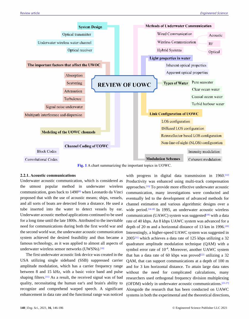
Fig. 1 A chart summarizing the important topics in UOWC.
2.2.1. Acoustic communications
Underwater acoustic communication, which is considered as
the utmost popular method in underwater wireless
communication, goes back to 1490[9] when Leonardo da Vinci
proposed that with the use of acoustic means; ships, vessels,
and all sorts of boats are detected from a distance. He used a
tube inserted into the water to detect vessels by ear.
Underwater acoustic method applications continued to be used
for a long time until the late 1800s. Attributed to the inevitable
need for communications during both the first world war and
the second world war, the underwater acoustic communication
system achieved the desired feasibility and thus became a
famous technology, as it was applied to almost all aspects of
underwater wireless sensor networks (UWSNs).[10]
The first underwater acoustic link device was created in the
USA utilizing single sideband (SSB) suppressed carrier
amplitude modulation, which has a carrier frequency range
between 8 and 15 kHz, with a basic voice band and pulse
shaping filters.[11] As a result, the received signal was of bad
quality, necessitating the human ear's and brain's ability to
recognize and comprehend warped speech. A significant
enhancement in data rate and the functional range was noticed
with progress in digital data transmission in 1960.[12]
Productivity was enhanced using multi-track compensation
approaches.[13] To provide more effective underwater acoustic
communication, many investigations were conducted and
eventually led to the development of advanced methods for
channel estimation and various algorithmic designs over a
wide period.[14-18] In 1995, an underwater acoustic wireless
communication (UAWC) system was suggested[19] with a data
rate of 40 kbps. An 8 kbps UAWC system was advanced for a
depth of 20 m and a horizontal distance of 13 km in 1996.[20]
Interestingly, a higher-speed UAWC system was suggested in
2005[21] which achieves a data rate of 125 kbps utilizing a 32
quadrature amplitude modulation technique (QAM) with a
symbol error rate of 10-4. Moreover, another UAWC system
that has a data rate of 60 kbps was proved[22] utilizing a 32
QAM, that can support communications at a depth of 100 m
and for 3 km horizontal distance. To attain large data rates
without the need for complicated calculations, many
researchers used orthogonal frequency division multiplexing
(OFDM) widely in underwater acoustic communications.[23-27]
Alongside the research that has been conducted on UAWC
systems in both the experimental and the theoretical directions,
Engineered Science Review article
© Engineered Science Publisher LLC 2021 Eng. Sci., 2021, 16, 146-186 | 149
acoustic modems of different designs, that can be used for
underwater applications, have been marketed and have been
commercially available.[1] Despite the amazing technological
progress, underwater acoustic communication has not
achieved effective communication performance due to various
obstacles. The most important obstacles that limit the effective
communication of underwater acoustic communications are
the absence of any similar types of underwater sound channels,
due to the features of the underwater environment where it is
extra vital and challenging. In other words, the system that
works in one place (for example, shallow water) might not
work in another place (such as the deep ocean).[8] Nowadays,
investigations and research on the physical layer of
underwater acoustic communication have arrived at some
degree of maturity. Many sea experiments have proved such
communication across tens of kilometers or even further
away[20] and transmission rates of up to tens of kilobits per
second or even more.[19,21,22,28,29] The latter represents a
significant development in the early stage of the few tens of
bits per second.[30,31]
Acoustic-based video transmission has also been
exhibited.[29] The most significant virtue of underwater
acoustic communication is its vast contact range, which may
reach tens of kilometers, given the enormous ocean width and
the strong attenuation impact of saltwater on other
transmission channels such as the optical wave and the RF
wave.[32] While UAWC systems are capable of delivering
command and control applications because of the long
transmission range they proved, their data rate is inadequate
for multimedia applications underwater.[8] To reduce the time
and frequency dispersion of the underwater acoustic channels,
a new transmission scheme called the time-reversed non-
orthogonal multiple access (TR-NOMA) was used.[33]
Depending on the time difference of arrival (TDOA), a
localization algorithm for underwater acoustic sensor
networks has been proposed.[34] To solve the problems of the
underwater acoustic channel, several modulation schemes
were discussed and proposed. A scheme was proposed[35] to
solve the problem of redundant energy in unique word
orthogonal frequency division multiplexing (UW-OFDM),
and this scheme showed its superiority in terms of bit error rate.
A scheme called X-transform time-domain synchronous index
modulation (IM) OFDM has been proposed.[36] Several
studies[37-41] have suggested different types of spatial
modulation (SM) and shown an improvement in bit error rate.
Also, to improve the bit error rate of the underwater acoustic
channel and increase energy efficiency, different types of
pseudorandom noise training sequence orthogonal frequency
division multiplexing have been proposed.[42,43] The deep
learning coded index modulation-spread spectrum (DL-CIM-
SS) performance has been evaluated, which was proposed,[44]
over simulation and measured underwater acoustic channels.
The simulation results show the ability of the proposed scheme
to increase the underwater acoustic data rate with significant
energy efficiency improvement and low system bit and symbol
error rate.
Whereas the acoustic approach is the most frequent
approach for obtaining UWC, it does have certain intrinsic
technological limitations. Firstly, the acoustic link
transmission data rate is quite low (within Kbps) because
underwater audio wave frequencies range from tens of hertz
to hundreds of kilohertz.[45] Secondly, because of the slow
transmission speed of the acoustic wave in water (for pure
water it is around 1500 m/s at 20 Celsius), the acoustic link
undergoes extreme contact delay (usually in seconds). It
cannot, therefore, support applications that involve an
exchange of large quantities of data in real-time.[46,47] Thirdly,
acoustic transceivers are normally big, expensive with high
consumption of energy. They are costly for large scale
UWSNs applications.[48] This technique can also have an effect
on life in the sea.[49]
2.2.2 Electromagnetic waves
(a) Radio Frequency communications
Due to the long transmission rate of UAWC systems, they are
useful for control and command applications but are not
appropriate for underwater multimedia applications due to
their limited data rate.[1] Electromagnetic waves are a
considerable faster means of communication.[50]
Electromagnetic waves (EM), in the radio frequency (RF)
range, can achieve high data rate transmission in short
distances so it is a good choice for underwater wireless
communications.[51] Waves having a frequency less than 300
GHz are known as radiofrequency waves.[52] Compared to the
speed of sound travel through water, the speed of radio waves
is much faster (about 2 × 10⁵ times) as it travels in water at a
speed of 2.2 5 × 10⁸ ms-1 (assuming water refractive index =
1.3) while radio waves travel in a vacuum at the speed of light
~3× 10⁸ ms-1. Electromagnetic waves are affected by several
factors such as temperature, salinity and depth, and this leads
to severe attenuation of all electromagnetic waves and thus
limits the distance of the signal through water.[50] Due to the
high water electrical conductivity at high frequency, radio
waves propagate in water differently from their propagate in
the air.[52] Due to the high water electrical conductivity at high
frequency, radio waves propagate in water differently from
their propagate in the air 4.3 Siemens/m,[53] which means it is
around 2 to 3 orders of magnitude greater than that of normal
freshwaters.[54] Therefore, due to this high attenuation, most
commercial radio equipment operates in the MHz and GHz
frequencies and therefore does not work in an underwater
environment.[52] For this reason, communication links for
distances – larger than 10 m in the ocean[55] are not easy to
Review article Engineered Science
150 | Eng. Sci., 2021, 16, 146-186 © Engineered Science Publisher LLC 2021
create in both very- and ultra-high frequency ranges (VHF and
UHF, respectively), and even at high frequencies. At lower
frequencies ranges, for example, at extremely and very low-
frequency 2 ranges (ELF and VLF, respectively), the
attenuation of the electromagnetic wave may be regarded as
low enough to grant strong communication over many
kilometers. Regrettably, these frequency ranges between 3 Hz
and 3 kHz, and between 3 kHz and 30 kHz are not broad
enough to require transmissions at high data rates. Regardless
of being utilized in naval[56] and environmental applications,[57]
achieving reliable communication in ELF and VLF frequency
ranges has both operational and financial - challenges, as the
equipment is bulky, costly and has a high consumption of
energy.[55] or this reason, research on the use of low-frequency
RF waves has been carried out in the past, e.g. Moore[58]
suggested a - wireless communication system that is based on
microwaves, over the surface of ocean water. This system is
capable of transmitting data over tens of kilometers. An
underwater - wireless communication system based on
microwaves was used,[59] this system can communicate over a
horizontal distance of 85 m via employing large transmission
powers around 100 W. Nevertheless, it necessitates the use of
advanced antennas and considerable transmission power.[51]
A similar method was obeyed,[60] with a data rate of 500 kbps
over a horizontal distance of 90 m. Uribe and Grote[61] with a
data rate of 500 kbps over a horizontal distance of 90 m. Uribe
and Grote 61 achieved a data rate of 10 Mbps at a distance of
100 m by improving the capacity of underwater wireless
communication systems based on microwaves. Nevertheless,
RF and microwaves undergo severe attenuation in the water,
for example, in the ocean the attenuation is approximately 169
dB/m for the 2.4 GHz band, whereas in freshwater, it is even
higher, i.e., 189 dB/m.[51] For instance, 2.4 GHz radio waves
have an attenuation of about 1,685 dB/m in seawater which
has a conductivity of 4 S/m.[62]
The scientist Lloret used Binary Phase Shift Keying
(BPSK) and Quadrature Phase Shift Keying (QPSK)
modulations in conducting many experiments in the fields of
industry, science, and medicine (ISM)using 2.4 GHz, as he
was able to cover a range of 16-17 cm underwater at a
frequency of 2.4 GHz.[63] The best range of frequencies is (3-
100 MHz) for the incident beam at a depth of fewer than 5 m
from the air into the sea was established.[60] As a result, it's only
good for very short-range applications like control, telemetry,
the gas and oil industries, and marine exploration. More details
about RF communication underwater can be obtained and
found.[32] Extremely low frequency (ELF) electromagnetic
waves, i.e. 30-300 Hz, are widely implemented in military
utilization or the creation of communication lines between
terrestrial and underwater bodies.[64] They are utilized for the
propagation of long-range and they are deployed effectively
for communication with naval submarines. The ELF system
was launched in 1968 to allow deep-sea submarines to
communicate. An alerting mechanism was employed in this
project to summon the submarine to the surface for high-
bandwidth communication through terrestrial radio
networks.[65] In,[59] it was reported that by using dipole
radiation with high transmission powers, about 100 W, RF
frequencies in the MHz range can propagate in seawater up to
the range of 100 meters. Nevertheless, it needs advanced
antennas design and high transmission power.
By comparing the underwater RF communication with the
acoustic wave and optical wave, the method of radio waves
shows two important advantages. The first aspect is the
relatively smooth transmission with an air/water interface,
which permits cross-boundary communication by combining
the terrestrial and underwater radio frequency communication
systems. The second attribute is its excellent resistance to
water turbulence and turbidity.[32] Despite these advantages,
many restrictions limit the development of underwater RF
communication, most notably. First, short link range due to too
much salt in the water that is considered conductive
transmission medium and thus limits the propagation of the
RF waves that propagate a few meters at extremely low
frequencies (30-300 Hz).[45] Secondly, complex design
requirements for very large antennas, depending on their
location above or underwater. Thirdly, the speeds are still very
slow.[50]
(b) Optical communications
Because of the limitations facing the above two wireless
methods, another method was sought to restrict these
limitations. Huge antennas with high transmitter power in
fresh water and significant attenuation in seawater are the most
apparent flaws that limit the usage of RF transmissions. Also,
underwater acoustic wireless communications (UAWC) suffer
from low bandwidth and low data rate limitations.[51] All these
restrictions of acoustic and radio communications prompted
researchers to consider the option of optical wireless
particularly the visible light,[66] to support a high data rate for
a limited communication range.[8] UOWC is able to achieve
Gbps at a distance of several hundred meters because of the
high frequency of optical carrier.[51] Underwater optical
wireless communication (UOWC) is a fairly new field that
over the past decade has gained significant interest. A
significant reason behind this increased interest is the
availability of off-the-shelf commercial electronics (COTS)
components which reduce device complexity, cost, and power
consumption.[7] Optical wireless communication (OWC) is the
transmission of data through an optical carrier, that is
ultraviolet (UV), visible, or infrared, in an unguided
propagation medium. In OWC, the broadly unrestricted
Engineered Science Review article
© Engineered Science Publisher LLC 2021 Eng. Sci., 2021, 16, 146-186 | 151
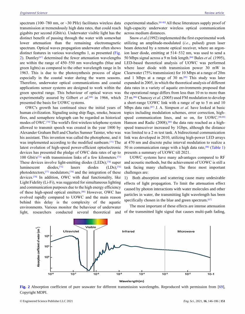
spectrum (100–780 nm, or ~30 PHz) facilitates wireless data
transmission at tremendously high data rates, that could reach
gigabits per second (Gbit/s). Underwater visible light has the
distinct benefit of passing through the water with somewhat
lower attenuation than the remaining electromagnetic
spectrum. Optical waves propagation underwater often shows
distinct features in various wavelengths 1, as presented (Fig.
2). Duntley[67] determined the fewer attenuation wavelengths
are within the range of 450–550 nm wavelengths (blue and
green lights) as compared to the other wavelength range in In
1963. This is due to the photosynthesis process of algae
especially in the coastal water during the warm seasons.
Therefore, underwater optical communications and coastal
applications sensor systems are designed to work within the
green spectral range. This behaviour of optical waves was
experimentally assured by Gilbert et al.[68] in 1966, which
presented the basis for UOWC systems.
OWC's growth has continued since the initial years of
human civilization. Signaling using ship flags, smoke, beacon
fires, and semaphore telegraph can be regarded as historical
modes of OWC.[70] The world's first wireless telephone system
allowed to transmit speech was created in the year 1800 by
Alexander Graham Bell and Charles Sumner Tainter, who was
his assistant. This invention was called the photophone, and it
was implemented according to the modified sunbeam.[71] The
latest evolution of high-speed power-efficient optoelectronic
devices has presented the pledge of OWC data rates of up to
100 Gbit/s[72] with transmission links of a few kilometers.[73]
These devices involve light-emitting diodes (LEDs),[74] super
luminescent diodes,[75] lasers diodes (LDs),[76]
photodetectors,[77] modulators,[78] and the integration of these
devices.[79] In addition, OWC with dual functionality, like
Light Fidelity (Li-Fi), was suggested for simultaneous lighting
and communication purposes due to the high energy efficiency
of these high-speed optical emitters.[80] However, OWC has
evolved rapidly compared to UOWC and the main reason
behind this delay is the complexity of the aquatic
environments. Various monitor the behaviour of underwater
light, researchers conducted several theoretical and
experimental studies.[81-83] All these litterateurs supply proof of
high-capacity underwater wireless optical communication
across medium distances.
Snow et al.(1992) implemented the first experimental work
utilizing an amplitude-modulated (i.e., pulsed) green laser
beam detected by a remote optical receiver, where an argon-
ion laser diode, emitting at 514–532 nm, was used to send a
50 Mbps signal across a 9 m link length.[84] Bales et al. (1995),
LED-based theoretical analysis of UOWC was performed
where laser diode with transmission power 30 mW in
Clearwater (75% transmission) for 10 Mbps at a range of 20m
and 1 Mbps at a range of 30 m.[85] This study was later
expanded in 2005, in which the theoretical analysis of different
data rates in a variety of aquatic environments proposed that
the operational range differs from less than 10 m to more than
25 m.[86] Chancey et al. (2005) used FM modulation to develop
a short-range UOWC link with a range of up to 5 m and 10
Mbps data rate.[87] J. A. Simpson et al. have looked at basic
topics including modulation schemes, error correction, high-
speed communication lines, and so on, for UOWC.[88,89]
Hanson and Radic (2008),[90] the data rate reached as a high-
speed transceiver increased by 1Gbps, although the distance
was limited to a 2 m test tank. A bidirectional communication
link was developed in 2010, utilizing high-power LED arrays
at 470 nm and discrete pulse interval modulation to realize a
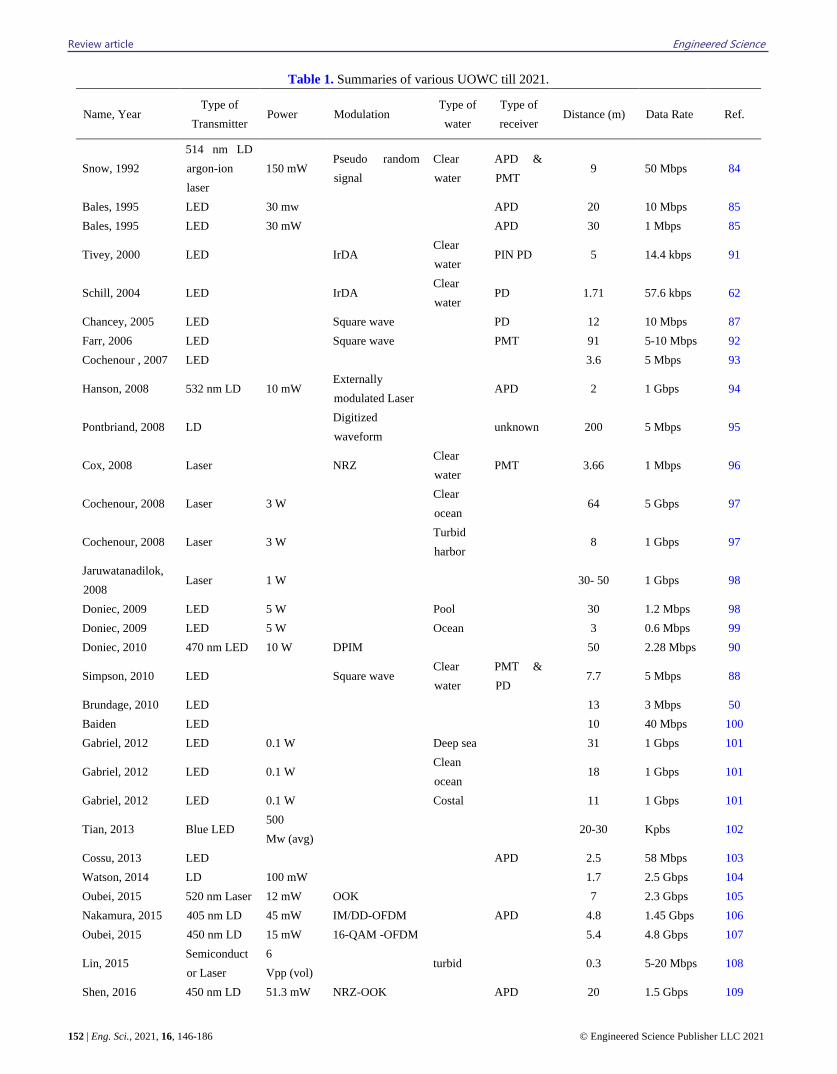
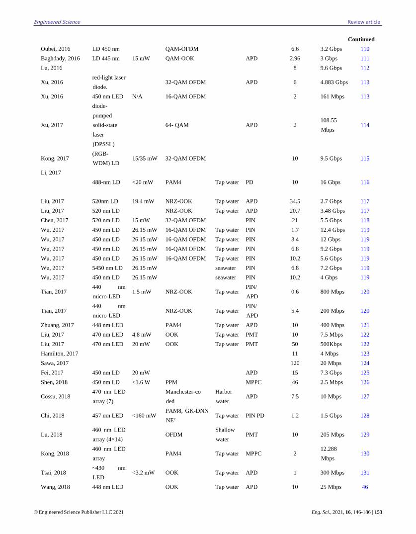
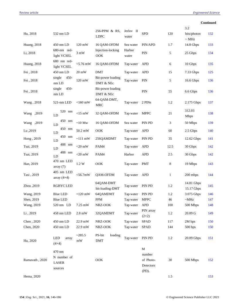
50 m communication range with a high data rate,[90] (Table 1)
presents a summary of UOWC till 2021.
UOWC systems have many advantages compared to RF
and acoustic methods, but the achievement of UOWC is still a
task facing many challenges. The three most important
challenges are:
1) Both absorption and scattering cause many undesirable
effects of light propagation. To limit the attenuation effect
caused by photon interactions with water molecules and other
particles in water, the transmitting light wavelength has been
specifically chosen in the blue and green spectrum.[67]
The most important of these effects are intense attenuation
of the transmitted light signal that causes multi-path fading,
Fig. 2 Absorption coefficient of pure seawater for different transmission wavelengths. Reproduced with permission from [69],
Copyright MDPI.
Review article Engineered Science
152 | Eng. Sci., 2021, 16, 146-186 © Engineered Science Publisher LLC 2021
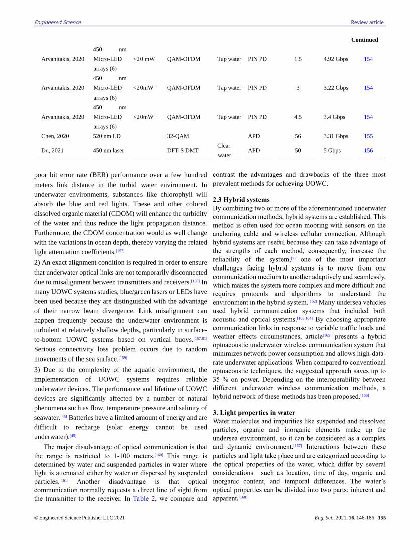
Table 1. Summaries of various UOWC till 2021.
Name, Year Type of
Transmitter Power Modulation
Type of
water
Type of
receiver Distance (m) Data Rate Ref.
Snow, 1992
514 nm LD
argon-ion
laser
150 mW Pseudo random
signal
Clear
water
APD &
PMT 9 50 Mbps 84
Bales, 1995 LED 30 mw APD 20 10 Mbps 85
Bales, 1995 LED 30 mW APD 30 1 Mbps 85
Tivey, 2000 LED IrDA Clear
water PIN PD 5 14.4 kbps 91
Schill, 2004 LED IrDA Clear
water PD 1.71 57.6 kbps 62
Chancey, 2005 LED Square wave PD 12 10 Mbps 87
Farr, 2006 LED Square wave PMT 91 5-10 Mbps 92
Cochenour , 2007 LED 3.6 5 Mbps 93
Hanson, 2008 532 nm LD 10 mW Externally
modulated Laser APD 2 1 Gbps 94
Pontbriand, 2008 LD Digitized
waveform unknown 200 5 Mbps 95
Cox, 2008 Laser NRZ Clear
water PMT 3.66 1 Mbps 96
Cochenour, 2008 Laser 3 W Clear
ocean 64 5 Gbps 97
Cochenour, 2008 Laser 3 W Turbid
harbor 8 1 Gbps 97
Jaruwatanadilok,
2008 Laser 1 W 30- 50 1 Gbps 98
Doniec, 2009 LED 5 W Pool 30 1.2 Mbps 98
Doniec, 2009 LED 5 W Ocean 3 0.6 Mbps 99
Doniec, 2010 470 nm LED 10 W DPIM 50 2.28 Mbps 90
Simpson, 2010 LED Square wave Clear
water
PMT &
PD 7.7 5 Mbps 88
Brundage, 2010 LED 13 3 Mbps 50
Baiden LED 10 40 Mbps 100
Gabriel, 2012 LED 0.1 W Deep sea 31 1 Gbps 101
Gabriel, 2012 LED 0.1 W Clean
ocean 18 1 Gbps 101
Gabriel, 2012 LED 0.1 W Costal 11 1 Gbps 101
Tian, 2013 Blue LED 500
Mw (avg) 20-30 Kpbs 102
Cossu, 2013 LED APD 2.5 58 Mbps 103
Watson, 2014 LD 100 mW 1.7 2.5 Gbps 104
Oubei, 2015 520 nm Laser 12 mW OOK 7 2.3 Gbps 105
Nakamura, 2015 405 nm LD 45 mW IM/DD-OFDM APD 4.8 1.45 Gbps 106
Oubei, 2015 450 nm LD 15 mW 16-QAM -OFDM 5.4 4.8 Gbps 107
Lin, 2015 Semiconduct
or Laser
6
Vpp (vol) turbid 0.3 5-20 Mbps 108
Shen, 2016 450 nm LD 51.3 mW NRZ-OOK APD 20 1.5 Gbps 109
Engineered Science Review article
© Engineered Science Publisher LLC 2021 Eng. Sci., 2021, 16, 146-186 | 153
Continued
Oubei, 2016 LD 450 nm QAM-OFDM 6.6 3.2 Gbps 110
Baghdady, 2016 LD 445 nm 15 mW QAM-OOK APD 2.96 3 Gbps 111
Lu, 2016 8 9.6 Gbps 112
Xu, 2016 red-light laser
diode. 32-QAM OFDM APD 6 4.883 Gbps 113
Xu, 2016 450 nm LED N/A 16-QAM OFDM 2 161 Mbps 113
Xu, 2017
diode-
pumped
solid-state
laser
(DPSSL)
64- QAM APD 2 108.55
Mbps 114
Kong, 2017 (RGB-
WDM) LD 15/35 mW 32-QAM OFDM 10 9.5 Gbps 115
Li, 2017
488-nm LD <20 mW PAM4 Tap water PD 10 16 Gbps 116
Liu, 2017 520nm LD 19.4 mW NRZ-OOK Tap water APD 34.5 2.7 Gbps 117
Liu, 2017 520 nm LD NRZ-OOK Tap water APD 20.7 3.48 Gbps 117
Chen, 2017 520 nm LD 15 mW 32-QAM OFDM PIN 21 5.5 Gbps 118
Wu, 2017 450 nm LD 26.15 mW 16-QAM OFDM Tap water PIN 1.7 12.4 Gbps 119
Wu, 2017 450 nm LD 26.15 mW 16-QAM OFDM Tap water PIN 3.4 12 Gbps 119
Wu, 2017 450 nm LD 26.15 mW 16-QAM OFDM Tap water PIN 6.8 9.2 Gbps 119
Wu, 2017 450 nm LD 26.15 mW 16-QAM OFDM Tap water PIN 10.2 5.6 Gbps 119
Wu, 2017 5450 nm LD 26.15 mW seawater PIN 6.8 7.2 Gbps 119
Wu, 2017 450 nm LD 26.15 mW seawater PIN 10.2 4 Gbps 119
Tian, 2017 440 nm
micro-LED 1.5 mW NRZ-OOK Tap water
PIN/
APD 0.6 800 Mbps 120
Tian, 2017 440 nm
micro-LED NRZ-OOK Tap water
PIN/
APD 5.4 200 Mbps 120
Zhuang, 2017 448 nm LED PAM4 Tap water APD 10 400 Mbps 121
Liu, 2017 470 nm LED 4.8 mW OOK Tap water PMT 10 7.5 Mbps 122
Liu, 2017 470 nm LED 20 mW OOK Tap water PMT 50 500Kbps 122
Hamilton, 2017 11 4 Mbps 123
Sawa, 2017 120 20 Mbps 124
Fei, 2017 450 nm LD 20 mW APD 15 7.3 Gbps 125
Shen, 2018 450 nm LD <1.6 W PPM MPPC 46 2.5 Mbps 126
Cossu, 2018 470 nm LED
array (7)
Manchester-co
ded
Harbor
water APD 7.5 10 Mbps 127
Chi, 2018 457 nm LED <160 mW PAM8, GK-DNN
NEc Tap water PIN PD 1.2 1.5 Gbps 128
Lu, 2018 460 nm LED
array (4×14) OFDM
Shallow
water PMT 10 205 Mbps 129
Kong, 2018 460 nm LED
array PAM4 Tap water MPPC 2
12.288
Mbps 130
Tsai, 2018 ~430 nm
LED <3.2 mW OOK Tap water APD 1 300 Mbps 131
Wang, 2018 448 nm LED OOK Tap water APD 10 25 Mbps 46
Review article Engineered Science
154 | Eng. Sci., 2021, 16, 146-186 © Engineered Science Publisher LLC 2021
Continued
Hu, 2018 532 nm LD 256-PPM & RS,
LDPC
Jerlov II
water SPD 120
3.2
bits/photon
~ MHz
132
Huang, 2018 450 nm LD 120 mW 16 QAM-OFDM Sea water PIN/APD 1.7 14.8 Gbps 133
Li, 2018 680-nm red-
light VCSEL 3 mW
Injection-locking
OOK
Harbor
water PIN 5 25 Gbps 134
Huang, 2018 680 nm red-
light VCSEL <5.76 mW 16 QAM-OFDM Tap water APD 6 10 Gbps 135
Fei , 2018 450 nm LD 20 mW DMT Tap water APD 15 7.33 Gbps 125
Fei , 2018 single 450-
nm LD 120 mW
Bit-power loading
DMT & NEc Tap water PIN 5 16.6 Gbps 136
Fei , 2018 single 450-
nm LD
Bit-power loading
DMT & NEc PIN 55 6.6 Gbps 136
Wang , 2018 521-nm LED <160 mW 64-QAM-DMT,
MRC Tap water 2 PINs 1.2 2.175 Gbps 137
Wang ,2019 520 nm
LD <15 mW 32 QAM-OFDM Tap water MPPC 21
312.03
Mbps 138
Wang ,2019 450 nm
LD ~10 Mw 16 QAM-OFDM Sea water PIN PD 3 50 Mbps 139
Lu ,2019 450 nm
LD 50.2 mW OOK Tap water APD 60 2.5 Gbps 140
Hong , 2019 450 nm
LD ~111 mW 256QAMDMT Tap water PIN PD 35 12.62 Gbps 141
Tsai, 2019 488 nm
LD <20 mW PAM4 Tap water APD 12.5 30 Gbps 142
Tsai, 2019 488 nm
LD <20 mW PAM4 Harbor APD 2.5 30 Gbps 142
Han, 2019 470 nm LED
array (7) 1.2 W OOK Tap water PMT 8 19 Mbps 143
Tasi , 2019 405 nm LED
array (4×4) <56.7mW QAM-OFDM Tap water APD 1 200 mbps 144
Zhou ,2019 RGBYC LED 64QAM-DMT
bit-loading-DMT Tap water PIN PD 1.2
14.81 Gbps
15.17 Gbps 145
Wang, 2019 Blue LED <120 mW 64QAMDMT Tap water PIN PD 1.2 3.075 Gbps 146
Shen, 2019 Blue LED PPM Tap water MPPC 46 ~MHz 147
Wang, 2019 520 nm LD 7.25 mW NRZ-OOK Tap water APD 100 500 Mbps 148
Li , 2019 458 nm LED 2.8 mW 32QAMDMT Tap water PIN array
(2×2) 1.2 20.09 G 149
Chen , 2020 450 nm LD 22.9 mW NRZ-OOK Tap water SPAD 117 2M bps 150
Chen, 2020 450 nm LD 22.9 mW NRZ-OOK Tap water SPAD 144 500 bps 150
Hu, 2020
LED array
(4×4)
~285.5
mW
PS-bit loading
DMT Tap water PIN PD 1.2 20.09 Gbps 151
Ramavath , 2020
470 nm
N number of
LASER
sources
OOK
M
number
of Photo-
Detectors
(PD).
30 500 Mbps 152
Hema, 2020 1.5 153
Engineered Science Review article
© Engineered Science Publisher LLC 2021 Eng. Sci., 2021, 16, 146-186 | 155
Continued
Arvanitakis, 2020
450 nm
Micro-LED
arrays (6)
<20 mW QAM-OFDM Tap water PIN PD 1.5 4.92 Gbps 154
Arvanitakis, 2020
450 nm
Micro-LED
arrays (6)
<20mW QAM-OFDM Tap water PIN PD 3 3.22 Gbps 154
Arvanitakis, 2020
450 nm
Micro-LED
arrays (6)
<20mW QAM-OFDM Tap water PIN PD 4.5 3.4 Gbps 154
Chen, 2020 520 nm LD 32-QAM APD 56 3.31 Gbps 155
Du, 2021 450 nm laser DFT-S DMT Clear
water APD 50 5 Gbps 156
poor bit error rate (BER) performance over a few hundred
meters link distance in the turbid water environment. In
underwater environments, substances like chlorophyll will
absorb the blue and red lights. These and other colored
dissolved organic material (CDOM) will enhance the turbidity
of the water and thus reduce the light propagation distance.
Furthermore, the CDOM concentration would as well change
with the variations in ocean depth, thereby varying the related
light attenuation coefficients.[157]
2) An exact alignment condition is required in order to ensure
that underwater optical links are not temporarily disconnected
due to misalignment between transmitters and receivers.[158] In
many UOWC systems studies, blue/green lasers or LEDs have
been used because they are distinguished with the advantage
of their narrow beam divergence. Link misalignment can
happen frequently because the underwater environment is
turbulent at relatively shallow depths, particularly in surface-
to-bottom UOWC systems based on vertical buoys.[157,81]
Serious connectivity loss problem occurs due to random
movements of the sea surface.[159]
3) Due to the complexity of the aquatic environment, the
implementation of UOWC systems requires reliable
underwater devices. The performance and lifetime of UOWC
devices are significantly affected by a number of natural
phenomena such as flow, temperature pressure and salinity of
seawater.[45] Batteries have a limited amount of energy and are
difficult to recharge (solar energy cannot be used
underwater).[45]
The major disadvantage of optical communication is that
the range is restricted to 1-100 meters.[160] This range is
determined by water and suspended particles in water where
light is attenuated either by water or dispersed by suspended
particles.[161] Another disadvantage is that optical
communication normally requests a direct line of sight from
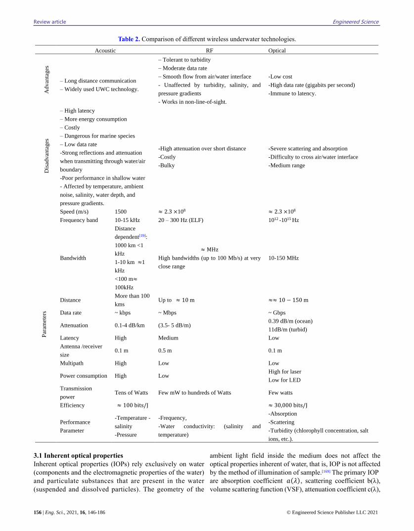
the transmitter to the receiver. In Table 2, we compare and
contrast the advantages and drawbacks of the three most
prevalent methods for achieving UOWC.
2.3 Hybrid systems
By combining two or more of the aforementioned underwater
communication methods, hybrid systems are established. This
method is often used for ocean mooring with sensors on the
anchoring cable and wireless cellular connection. Although
hybrid systems are useful because they can take advantage of
the strengths of each method, consequently, increase the
reliability of the system,[7] one of the most important
challenges facing hybrid systems is to move from one
communication medium to another adaptively and seamlessly,
which makes the system more complex and more difficult and
requires protocols and algorithms to understand the
environment in the hybrid system.[162] Many undersea vehicles
used hybrid communication systems that included both
acoustic and optical systems.[163,164] By choosing appropriate
communication links in response to variable traffic loads and
weather effects circumstances, article[165] presents a hybrid
optoacoustic underwater wireless communication system that
minimizes network power consumption and allows high-data-
rate underwater applications. When compared to conventional
optoacoustic techniques, the suggested approach saves up to
35 % on power. Depending on the interoperability between
different underwater wireless communication methods, a
hybrid network of these methods has been proposed.[166]
3. Light properties in water
Water molecules and impurities like suspended and dissolved
particles, organic and inorganic elements make up the
undersea environment, so it can be considered as a complex
and dynamic environment.[167] Interactions between these
particles and light take place and are categorized according to
the optical properties of the water, which differ by several
considerations such as location, time of day, organic and
inorganic content, and temporal differences. The water’s
optical properties can be divided into two parts: inherent and
apparent.[168]
Review article Engineered Science
156 | Eng. Sci., 2021, 16, 146-186 © Engineered Science Publisher LLC 2021
Table 2. Comparison of different wireless underwater technologies.
3.1 Inherent optical properties
Inherent optical properties (IOPs) rely exclusively on water
(components and the electromagnetic properties of the water)
and particulate substances that are present in the water
(suspended and dissolved particles). The geometry of the
ambient light field inside the medium does not affect the
optical properties inherent of water, that is, IOP is not affected
by the method of illumination of sample.[169] The primary IOP
are absorption coefficient 𝑎(𝜆) , scattering coefficient b(λ),
volume scattering function (VSF), attenuation coefficient c(λ),
Acoustic RF Optical A
dvan
tages
– Long distance communication
– Widely used UWC technology.
– Tolerant to turbidity
– Moderate data rate
– Smooth flow from air/water interface
- Unaffected by turbidity, salinity, and
pressure gradients
- Works in non-line-of-sight.
-Low cost
-High data rate (gigabits per second)
-Immune to latency.
Dis
advan
tages
– High latency
– More energy consumption
– Costly
– Dangerous for marine species
– Low data rate
-Strong reflections and attenuation
when transmitting through water/air
boundary
-Poor performance in shallow water
- Affected by temperature, ambient
noise, salinity, water depth, and
pressure gradients.
-High attenuation over short distance
-Costly
-Bulky
-Severe scattering and absorption
-Difficulty to cross air/water interface
-Medium range
Par
amet
ers
Speed (m/s) 1500 ≈ 2.3 ×10⁸ ≈ 2.3 ×10⁸
Frequency band 10-15 kHz 20 – 300 Hz (ELF) 1012 -1015 Hz
Bandwidth
Distance
dependent[19]:
1000 km <1
kHz
1-10 km ≈1
kHz
<100 m≈
100kHz
≈ MHz
High bandwidths (up to 100 Mb/s) at very
close range
10-150 MHz
Distance More than 100
kms Up to ≈ 10 m ≈≈ 10 − 150 m
Data rate ~ kbps ~ Mbps ~ Gbps
Attenuation 0.1-4 dB/km (3.5- 5 dB/m) 0.39 dB/m (ocean)
11dB/m (turbid)
Latency High Medium Low
Antenna /receiver
size 0.1 m 0.5 m 0.1 m
Multipath High Low Low
Power consumption High Low High for laser
Low for LED
Transmission
power Tens of Watts Few mW to hundreds of Watts Few watts
Efficiency ≈ 100 bits/J ≈ 30,000 bits/J
Performance
Parameter
-Temperature -
salinity
-Pressure
-Frequency,
-Water conductivity: (salinity and
temperature)
-Absorption
-Scattering
-Turbidity (chlorophyll concentration, salt
ions, etc.).
Engineered Science Review article
© Engineered Science Publisher LLC 2021 Eng. Sci., 2021, 16, 146-186 | 157
single scattering albedo 𝜔0, and index of refraction.[170]
Assume a water sample of small volume ΔV and thickness
Δd where a collimated beam with radiant power 𝑃𝐼(λ) is
guided onto the water sample. Part of this power of beam is
absorbed 𝑃𝐴 (λ), part is scattered 𝑃𝑆(λ) by an angle Φ, and
the residual power is transported via water 𝑃𝑇(λ). The ratio of
absorbed power to total incident power is denoted as spectral
absorptance 𝐴(𝜆).
𝐴(𝜆) =𝑃 𝐴 (𝜆)
𝑃𝐼(λ) (1)
In the same way, the spectral scatterance, B(𝜆 ) can be
found by, the ratio of scattered power to the incident power.
𝐵(𝜆) =𝑃𝑆(λ)
𝑃𝐼(λ) (2)
The spectral absorption coefficient 𝑎(𝜆) can be found by
taking the limit, when the thickness approaches zero, for the
ratio of the spectral absorption 𝐴(𝜆) to the thickness Δ𝑑, as
follows:
𝑎(𝜆) = limΔ𝑑⟶0
𝐴(𝜆)
Δ𝑑 (𝑚−1) (3)
And the spectral scattering coefficient 𝑏(𝜆) can be found
by taking the limit when the thickness approaches zero for the
ratio of the spectral scattering 𝐵(𝜆) to the thickness Δ𝑑 , as
follows:
𝑏(𝜆) = limΔ𝑑⟶0
𝐵(𝜆)
Δ𝑑 (𝑚−1) (4)
The spectral beam attenuation coefficient c( 𝜆 ) can be
obtained by combining the spectral absorption coefficient and
the spectral scattering coefficient as:
c(𝜆) = a(𝜆)+ b(𝜆) (5)
where a(𝜆) and b(𝜆) are absorption and scattering coefficient,
respectively. Also the units of coefficients c(𝜆), a(𝜆) and b(𝜆)
are measured in 𝑚−1 and 𝜆 is the vacuum wavelength of
light in (nm)3.
The angular scatterance per unit distance and unit solid
angle, β (Φ, λ) is demarcated as:
β (Φ, 𝜆 ) = limΔ𝑑⟶0
limΔΩ⟶0
β (Φ, 𝜆 )
ΔΩΔ𝑑=
limΔ𝑟⟶0
limΔΩ⟶0
𝑃𝑆 (Φ,𝜆 )
𝑃𝐼ΔΩΔ𝑑 (𝑚−1𝑠𝑟−1) (6)
where β (Φ, 𝜆) is the fraction of power that is scattered out of
the beam through an angle Φ into a solid angle ΔΩ centered
on Φ.
𝑃𝑆(λ) is the spectral power scattered into a solid angle is
calculated as:
𝑃𝑆(Φ, λ) = I𝑠 (Φ, 𝜆 )ΔΩ . (7)
The incident irradiance is computed as follows:
E𝑖 = 𝑃𝐼(λ)/ΔA. (8)
Substituting ΔV = ΔdΔA which is the volume of the
water, results in:
β (Φ, 𝜆 ) = limΔV⟶0
I𝑠 (Φ,𝜆 )
E𝑖( 𝜆) ΔV (9)
This equation denoted the volume scattering function (VSF)
and it can be explained as the scattered intensity per unit
incident irradiance per unit volume of water. By integrating β
(Φ, λ) over all directions, the total scattered power per unit
incidence irradiance and unit volume of water can be
calculated, this parameter is known the scattering coefficient.
𝑏( 𝜆) = ∫ β (Φ, 𝜆 )dΩ = 2𝜋 ∫ β (Φ, 𝜆 ) sin Φ𝑑Φ𝜋
0 (10)
The forward (b𝑓) and backward (b𝑏) scattering coefficients
can be calculated via:
𝑏𝑓( 𝜆) = 2𝜋 ∫ β (Φ, 𝜆 ) sin Φ𝑑Φ𝜋/2
0 (11)
𝑏𝑏( 𝜆) = 2𝜋 ∫ β (Φ, 𝜆 ) sin Φ𝑑Φ𝜋
𝜋/2 (12)
By normalizing the VSF with the scattering coefficient, the
scattering phase function 𝛽 ̃ (Φ, 𝜆 ) can be attained:
𝛽 ̃ (Φ, 𝜆 ) = β (Φ,𝜆 )
b( 𝜆 ) (𝑠𝑟−1) (13)
𝛽 ̃(Φ, 𝜆)can be expressed as the probability of the photon
scattering event in the angular direction Φ.
Single scattering albedo 𝜔0 can be determined as the ratio
of the scattering coefficient to the attenuation coefficient,
where the attenuation coefficient is absorption and scattering,
therefore result of the single scattering albedo law gives the
possibility of photon scattered rather than absorbed:
𝜔0= b( 𝜆 )
c ( 𝜆 ) (14)
If the value of the scattering coefficient is greater than
the value of the absorption coefficient, then the value of single
scattering albedo is 1, and if the value of the absorption
coefficient is bigger than the value of the scattering
coefficient, then the value of single scattering albedo is zero.[52]
3.2. Apparent optical properties
The apparent optical properties (AOPs) are based on two main
factors: the medium and the geometric structure of the
illumination, i.e. whether it is a collimated or diffused
beam.[171] The apparent properties have many benefits, most
notably the following. First, the apparent properties determine
the directional property of the optical beam. Second, they are
utilized to assess the amount of ambient light for
communication nearby the water's surface.[172] Third, when it
comes to radiant energy penetration into the depths of the
ocean, AOPs are very important.[52] Radiance, irradiance, and
reflectance are the most common apparent qualities. The
apparent feature can be produced from regular and stable
lighting sources. Thus, the downwelling irradiance from Sun
is not considered as a clear property due to its variation times
of day and weather state.[171] The diffuse attenuation
coefficient is an optical property that is dependent on the light
field geometry.[170] In those instances, either a ratio of
properties, that are equally impacted by the environment, is
taken into account or a normalized derivative, as indicated by
the following equation[171]
𝑘(𝑧, 𝜆) = −1
𝐸(0,𝜆)
𝑑𝐸(𝑧,𝜆)
𝑑𝑧 (15)
where E is defined as the original apparent property like down
welling irradiance from Sun.
More information about AOPs such as their definitions and
measurements are available at.[168,172-174] Each type of optical
properties have features that contribute to the implementation
Review article Engineered Science
158 | Eng. Sci., 2021, 16, 146-186 © Engineered Science Publisher LLC 2021
of UOWC systems where, AOPs are utilized to compute
ambient luminance near the water surface, whereas IOPs are
utilized to determine communication link budgets.[175]
4. Types of water
Both geographically and vertically differences cause the ocean
waters to differ. The geographical variation ranges from the
clarity of the oceans to coastal areas, and the vertical
difference depends on the amount of light received from the
sun in addition to less background radiation.[176] Despite the
many different types of waters, it can be classified into oceanic
and coastal areas depending on the downwelling irradiance of
sunlight.[176] The oceanic group is divided into four main water
types commonly taken into special consideration in the
literature.[94,177]
• pure seawater, the scattering is low thus the beam
propagates in a nearly straight line, but absorption remains
predominant, leading to a signal loss more than scattering in
these regions.
• clear ocean water, scattering is the dominant factor due to
the abundance of concentration of dissolved particles and
consequently, the scattering has a great effect on overall
attenuation.
• coastal ocean water, the absorption owing to
phytoplankton is the major limiting factor and, hence, the ideal
wavelengths lean towards green.
• Turbid Harbor Water: It shows strong absorption in blue
wavelengths due to the availability of both suspended matter
and color dissolved organic matter (CDOM) like fulvic and
humic acids.
Owing to the salinity that affects the clusters and settling
velocity of suspended particulate matter (SPM), oceans and
estuaries have lower average turbidity than fresh water in lakes
and rivers. Salinity affects the cluster of suspended particles
and attaches them, which leads to their stability at the bottom,
and here shows the interconnectedness between salinity, SPM
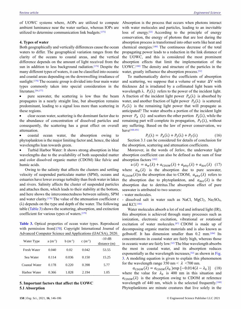
and water clarity.[178] The value of the attenuation coefficient c
(λ) depends on the type and depth of the water. The following
table (Table 3) shows the scattering, absorption, and extinction
coefficient for various types of waters.[179]
Table 3. Optical properties of ocean water types. Reproduced
with permission from[179]. Copyright International Journal of
Advanced Computer Science and Applications (IJACSA), 2020.
Water Type a (m-1) b (m-1) c (m-1) -10 dB
distance (m)
Fresh Water 0.040 0.02 0.042 53.55
Sea Water 0.114 0.036 0.150 15.25
Coastal Water 0.178 0.220 0.398 5.77
Harbor Water 0.366 1.828 2.194 1.05
5. Important factors that affect the UOWC
5.1 Absorption
Absorption is the process that occurs when photons interact
with water molecules and particles, leading to an inevitable
loss of energy.[52] According to the principle of energy
conservation, the energy of photons that are lost during the
absorption process is transformed into other sorts like heat and
chemical energies.[180] The continuous decrease of the total
propagating power leads to a reduction in the link distance of
the UOWC, and this is considered the most prominent
absorption effects that limit the implementation of the
UOWC.[180] The density and structure of the particles in the
water, greatly influence the absorption process.[52]
To mathematically derive the coefficients of absorption
and scattering, we suppose that a volume of water ΔV with
thickness Δ d is irradiated by a collimated light beam with
wavelength λ. 𝑃𝐼(λ) refers to the power of the incident light.
A fraction of the incident light power 𝑃𝐴(λ) is absorbed by
water, and another fraction of light power 𝑃𝑆(λ) is scattered.
𝑃𝑇(λ) is the remaining light power that will propagate as
anticipated? The water absorbs a portion of the incident light
power 𝑃𝐴 (λ) and scatters the other portion 𝑃𝑆(λ), while the
remaining part will complete its propagation, 𝑃𝑇(λ), without
any suffering. Based on the law of power conservation, we
have[168,181]
𝑃𝐼(λ) = 𝑃𝐴(λ) + 𝑃𝑆(λ) + 𝑃𝑇(λ) (16)
Section 3.1 can be considered for details of conclusion for
the absorption, scattering and attenuation coefficients.
Moreover, in the words of Jerlov, the underwater light
absorption coefficient can also be defined as the sum of four
absorption factors [182]
a (𝜆) = 𝑎𝑤(𝜆) + 𝑎𝐶𝐷𝑂𝑀(𝜆) + 𝑎𝑝ℎ𝑦(𝜆) + 𝑎𝑑𝑒𝑡(𝜆) (17)
where 𝑎𝑤(𝜆) is the absorption due to pure seawater,
𝑎𝐶𝐷𝑂𝑀(𝜆)is the absorption due to CDOM, 𝑎𝑝ℎ𝑦(𝜆) refers to
the absorption due to phytoplankton, and 𝑎𝑑𝑒𝑡(𝜆) is the
absorption due to detritus.The absorption effect of pure
seawater is attributed to two sources:
- water molecules.
- dissolved salt in water such as NaCl, MgCl2, Na2SO4,
and KCl.[183]
Water molecules absorb a lot of red and infrared light (IR),
this absorption is achieved through many processes such as
ionization, electronic excitation, vibrational or rotational
excitation of water molecules.[87] CDOM is made up of
decomposing organic marine materials and is also known as
gelbstoff. It has dimension smaller than 0.2 mm.[184] Its
concentrations in coastal water are fairly high, whereas those
in oceanic water are fairly low.[52] The blue wavelength absorbs
the most in coastal water, and its absorption reduces
exponentially as the wavelength increases,[52] as shown in Fig.
3. A modeling equation is given to explain this phenomenon
for the wavelength range 350 nm < 𝜆 <700 nm.
𝑎𝐶𝐷𝑂𝑀(𝜆) = 𝑎𝐶𝐷𝑂𝑀(𝜆0 )exp [−0.014(𝜆 − 𝜆0 )] (18)
where the value for 𝜆0 is 400 nm in this situation and
𝑎𝐶𝐷𝑂𝑀(𝜆) is the absorption owing to CDOM at reference
wavelength of 440 nm, which is the selected frequently.[168]
Phytoplanktons are minute creatures that live solely in the
Engineered Science Review article
© Engineered Science Publisher LLC 2021 Eng. Sci., 2021, 16, 146-186 | 159
photic zone, which is the area of the ocean where sunlight may
propagate into the waters. It has a range of 50 to 200 meters in
clear ocean water, up to 40 meters on continental shelf, and 15
meters in coastal waters.[185] It contains colorful pigments like
chlorophyll, carotenoids, pheophytin, chlorophyllide, and
phaeophorbides, among others, that absorb a substantial
amount of light. Photosynthesis of chlorophyll is primarily
responsible for phytoplankton absorption effects.[186]
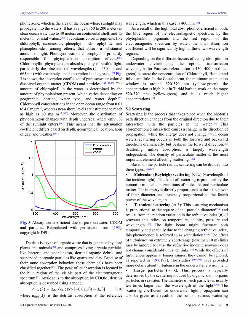
Chlorophyllin phytoplankton absorbs plenty of visible light,
particularly the blue and red wavelengths (𝜆 =430 nm and
665 nm) with extremely small absorption in the green,[168] Fig.
3 is shown the absorption coefficient of pure seawater colored
dissolved organic matter (CDOM) and particles.[183,187-190] The
amount of chlorophyll in the water is determined by the
amount of phytoplankton present, which varies depending on
geographic location, water type, and water depth.[52]
Chlorophyll concentrations in the open ocean range from 0.01
to 4.0 mg m-3, whereas near-shore levels are estimated to reach
as high as 60 mg m−3.[175] Moreover, the distribution of
phytoplankton changes with depth undersea, where only 1%
of the sunlight enters.[185] This means that the attenuation
coefficient differs based on depth, geographical location, hour
of day, and weather.[191]
Fig. 3 Absorption coefficient due to pure seawater, CDOM
and particles. Reproduced with permission from [193],
copyright MDPI.
Detritus is a type of organic waste that is generated by dead
plants and animals[52] and comprises living organic particles
like bacteria and zooplankton, detrital organic debris, and
suspended inorganic particles like quartz and clay. Because of
their same absorption behavior, these chemicals have been
classified together.[192] The peak of its absorption is located in
the blue region of the visible part of the electromagnetic
spectrum.[52] Analogous to the absorption by CDOM, detritus
absorption is described using a model:
𝑎𝑑𝑒𝑡(𝜆) = 𝑎𝑑𝑒𝑡(𝜆0 )exp [−0.011(𝜆 − 𝜆0 )] (19)
where 𝑎𝑑𝑒𝑡(𝜆) is the detritus absorption at the reference
wavelength, which in this case is 400 nm.[168]
As a result of the high total absorption coefficient in both,
the blue region of the electromagnetic spectrum, by the
phytoplankton pigments and the red region of the
electromagnetic spectrum by water, the total absorption
coefficient will be significantly high at these two wavelength
regions.
Depending on the different factors affecting absorption in
underwater environments, the optimal transmission
wavelengths for Pure sea / clear ocean is 450- 400 nm (blue-
green) because the concentration of Chlorophyll, Humic and
fulvic are little. In the Costal ocean, the minimum attenuation
window is around 520-570 nm (yellow-green), the
concentration is high, but in Turbid harbor, work on the range
520-570 nm (yellow-green) and it is much higher
concentrations.[12]
5.2 Scattering
Scattering is the process that takes place when the photon’s
path direction changes from the original direction due to their
interaction with the particles in the water.[52] This
aforementioned interaction causes a change in the direction of
propagation, while the energy does not change.[52] In ocean
waters, scattering occurs in both the forward and backward
directions dramatically, but peaks in the forward direction.[52]
Scattering, unlike absorption, is largely wavelength
independent. The density of particulate matter is the most
important element affecting scattering.[180]
Based on the particle radius, scattering can be divided into
three types.[168,194]
• Molecular (Rayleigh) scattering (≪ λ) (wavelength of
the incident light): This kind of scattering is produced by the
nonuniform local concentrations of molecules and particulate
matter. The intensity is directly proportional to the sixth power
of their diameter and inversely proportional to the fourth
power of the wavelength.
• Turbulent scattering (≫ λ): This scattering mechanism
is proportional to the square of the particle diameter[176] and
results from the random variation in the refractive index (n) of
seawater that relies on temperature, salinity, pressure and
wavelength.[195] The light beam might fluctuate both
temporally and spatially due to the changing refractive index,
this phenomenon is referred to as scintillation.[196] The effect
of turbulence on extremely short-range (less than 10 m) links
may be ignored because the refractive index in seawater does
not change considerably in such links.[81] While the effects of
turbulences appear at longer ranges, they cannot be ignored,
as reported in [197,198]. The studies [199-201] have provided
more details about turbulence in the underwater environment.
• Large particles (∼ λ): This process is typically
determined by the scattering induced by organic and inorganic
particles in seawater. The diameter of such particles is usually
ten times larger than the wavelength of the light.[168] The
scattering coefficient for underwater light propagation can
also be given as a result of the sum of various scattering
Review article Engineered Science
160 | Eng. Sci., 2021, 16, 146-186 © Engineered Science Publisher LLC 2021
factors.[202]
b (𝜆) = 𝑏𝑤(𝜆) + 𝑏𝑝ℎ𝑦(𝜆) + 𝑏𝑑𝑒𝑡(𝜆) (20)
where 𝑏𝑤(𝜆) is the scattering attributed to pure seawater;
𝑏𝑝ℎ𝑦(𝜆) denotes the scattering attributed to phytoplankton;
and 𝑏𝑑𝑒𝑡(𝜆) represents the scattering attributed to detritus.
Because the refractive index changes with flow, salinity,
and temperature fluctuations in pure seawater, the scattering
coefficient will change as well.[180] The Rayleigh scattering
model may be utilized to depict the dispersion generated by
pure saltwater since the wavelength of light is quite high
compared to the size of water molecules.
• At constant temperature and pressure, the absorption
coefficient of water is invariant, although it is highly
dependent on, the scattering coefficient caused by Rayleigh
scattering is similarly highly dependent on. When compared
to absorption, the scattering coefficient has low variance with
temperature and pressure.
• The absorption coefficient of the sea salt is negligible and
it increases towards short 𝜆 . Scattering coefficient due to
Rayleigh scattering, and it is no depends on 𝜆.
• Absorption coefficient is variable with the density of
CDOM, Plankton and detritus also increased towards short 𝜆
but scattering coefficient is negligible by CDOM. Scattering
coefficient is variable with the density of plankton and detritus
(Mie scattering), and increase towards short 𝜆.
Three processes may be used to characterize the effects of
scattering on UOWC links: spatial, temporal, and angular
dispersion.[203]
Spatial dispersion is produced by the beam spreading
owing to the multiple scattering mechanisms. The photon
density at the receiver site decreases as a result of this. Photons
arriving at the receiver from a diffuse beam are spatially
scattered due to the initial distribution as well as the
underwater environment.[97,203] As the light beam hits the
receiver at various times, it causes temporal dispersion. As a
result, there would be a path difference and a time delay,
potentially limiting bandwidth.[97,203,204]
Angular dispersion refers to the distribution of photon
reception angles owing to scattering underwater. Scattering
occurs at small forward angles in seawater, as a result, the
angular dispersion is small. Angular dispersion, on the other
hand, can have major effects in turbid water where scattering
dominates[204] VSF is an essential parameter that defines
scattering in seawater, as discussed in section 3.1. VSF has
been measured by several researchers. The next section
defines the VSF computed by Petzold as well as two analytical
formulae for modelling the VSF.[52]
5.2.1. Petzold scattering function
n underwater scattering modelling, the Petzold phase function
is the most widely quoted and utilized. Reference[205] defines it
as a portrayal of normal ocean water. It is based on the results
of investigations of three forms of water taken in the early
1970s: turbid water, coastal water, and clear water.[206] The
turbid water sample was taken in San Diego Harbor, California,
the coastal water sample was taken in San Pedro Channel,
California, and the clear water sample was taken in the Tongue
of the Ocean, Bahamas Islands.
The VSFs for the three types of water, which was used as
a scattering agent in the laboratory experiment.[207] The VSFs
are clearly peaked forward, meaning that the majority of the
light will disperse at small forward angles.[52]
5.2.2. Analytical phase functions
There have been a number of analytical phase functions
suggested, two of which are considered in this paper.
The first one is Henyey-Greenstein (HG) function,[52] it was
first suggested in 1941 for use in astrophysics to describe the
scattering angles induced by interstellar dust clouds.[208] It is
used by several researchers in underwater environments, but
they point out that it is inaccurate at small angles of less than
20o and broad angles of more than 130o.[209,210]
The equation for the HG phase function is:
𝑃𝐻𝐺(𝛷, 𝜆) =1
4𝜋
1−𝑔2
(1+𝑔2−2𝑔𝑐𝑜𝑠 𝛷)3/2 (21)
where Φ is the scattering angle, and g is the HG asymmetry
parameter, which is equal to the average cosine of the
scattering angle over Φ all directions of scattering and is
dependent on the medium's characteristics.[52]
The amounts of light scattered in the forward direction is
represented by the value of g.[211] If g = 0, the scattering is
isotropic, and if g = 1, the scattering is very forward.[212] More
details about the influence of various g values can be obtained
and found.[213]
The second analytical phase functions are Two-Term
Henyey-Greenstein (TTHG). Haltrin changed the original HG
function to create this phase function.[214] It is more explicit
than the original HG model, but not as accurate as Petzold's[52]
phase function, which is calculated by experiment.
The TTHG function is given by:
𝑃𝑇𝐻𝐺(𝛷, 𝜆, 𝑔 𝐹𝑊𝐷, 𝑔𝐵𝐾𝑊𝐷) = 𝛼𝑃𝐻𝐺(𝛷, 𝑔𝐹𝑊𝐷) +
(1 − 𝛼)𝑃𝐻𝐺(𝛷, −𝑔𝐵𝐾𝑊𝐷) (22)
where α is the forward-directed HG phase function weight,
and 𝑔 𝐹𝑊𝐷 and 𝑔𝐵𝐾𝑊𝐷 are the asymmetry factors for the
forward and backward-directed HG phase function,
respectively.
Absorption is the key limiting factor in pure seawater, but
the low scattering coefficient prevents the beam from
diverging. Clear ocean waters have a larger concentration of
dissolved particles, which impacts scattering. The primary
source of absorption and scattering are high concentrations of
plankton, detritus, and minerals in coastal ocean water. The
highest concentration of dissolved and in-suspension matter is
found in turbid harbor water, which significantly reduces light
propagation.[215]
5.3. Attenuation
The sum of the attenuation caused by absorption and scattering
defines the total attenuation in the UOWC system. By using
Beer-Lambert's law, the attenuation coefficient called also the
Engineered Science Review article
© Engineered Science Publisher LLC 2021 Eng. Sci., 2021, 16, 146-186 | 161
extinction coefficient of the optical signal for a distance z is
determined as shown:
𝐼 = 𝐼0 𝑒−𝑐(𝜆)𝑧 (23)
where 𝐼0 is the power of transmitted light; z signifies the light
transmission distance; I refers to the power of light after
transmitting z distance, and c(λ) indicates the attenuation
coefficient. With various water types and depths, the value of
the attenuation coefficient c(λ) can change. The parameters
that impact the underwater optical wireless communication
transmission system are affected by types of water which
depends on (wavelength, depth, and season). Absorption is
influenced by biological factors such as the concentration of
chlorophyll, fulvic acid and humic acid.[3] Scattering of the
spectra is influenced by biological factors such as large
particles and small particles. The statistical distribution and
scattering strength was used to calculate scattering
coefficients.[3]
Beer's Law has a restricted application because it only
explains the attenuation due to absorption and single events of
scattering.[216] However, several cases of multiple scattering
can occur in nature. It also assumes that the source and
receiver are perfectly aligned with each other, and only in
Line-of-Sight (LOS) contact situations can it be implemented.
Also, Beer's Law avoids temporal dispersion.[22]
The references[53,157,168,217,218] provide more information on
different types of water and differences in attenuation
coefficient with other characteristics like depth, pressure, and
salinity.
5.3.1 Attenuation length
Attenuation length (AL) is the product of attenuation
coefficient c(𝜆) and transmission distance z, and it is a unitless
quantity.[52] AL is the exponential component's argument in the
BL law (𝑐(𝜆)𝑧). The received power would be reduced by a
factor of 1/e, or 63 percent, at 1 AL. To compare the
performance of different systems, particularly at differing
water turbidities and transmission distances, several studies
use attenuation length, (AL=(𝑐(𝜆) ∗ 𝑧).[219]
5.4 Turbulence
Optical turbulence greatly influences optical wireless
communications. It is defined as the random fluctuations of
the refraction index. The underwater nature is very complex
and the transmission of optical beams is also greatly perturbed
by ocean turbulence.[216] Ocean turbulence is the result of many
phenomena, including changes in temperature, differences in
salinity and the formation of air bubbles in seawater.[54]
5.5 Signal noise underwater
There are several noise sources that disturb the system of
optical communication under water. Each noise is addressed
and the expression is given for its variance in.[86,220] In the bit
transmission simulation, the variation of noise converts into
the noise power range that we can use.
The modeled noise consists of (1) background noise, (2)
dark current noise, (3) thermal noise, and (4) shot noise.[98]
5.5.1 Background noise
The background noise comes from the optical environment
and electrical current leakage from photodetector.[51] It consists
of black body radiation and underwater ambient light, the
main source of which is the refracted sunlight from the water's
surface.[98] The background noise power can be written as:
𝑃𝐵𝐺 = 𝑃𝐵𝐺_ 𝑠𝑜𝑙𝑎𝑟 + 𝑃𝐵𝐺 _𝑏𝑙𝑎𝑐𝑘𝑏𝑜𝑑𝑦 (24)
The variance of the background noise is:
𝜎𝐵𝐺2 = 2 𝑞ℜ𝑃𝐵𝐺𝐵 (25)
where ℜ is the responsivity, λ is the wavelength, ℎ =6 .6261 × 10−34 𝐽 ss is the Planck’s constant, the electron
charge 𝑞 = 1 .6 × 10−19 coulombs, η =0 .8 is the quantum
efficiency of the detector, and B is the electronic bandwidth.
Solar background noise: The solar background noise power is:
𝑃𝐵𝐺− 𝑠𝑜𝑙𝑎𝑟 = 𝐴𝑟 × 𝐹𝑜𝑣𝐹𝑎𝑐 × 𝛥𝜆𝑇𝐹 𝐿𝑠𝑜𝑙 (26)
where 𝐴𝑟 = πD2
4 , D is the diameter of the aperture, FOV is
field of view of the system in radians, 𝐹𝑜𝑣𝐹𝑎𝑐 = 𝜋(𝐹𝑂𝑉)2, Δλ is the optical filter bandwidth, and 𝑇𝐹 is the optical filter
transmissivity. The solar radiance 𝐿𝑠𝑜𝑙 (watts/𝑚2) is given by 86:
𝐿𝑠𝑜𝑙 = 𝐸𝑅𝐿 𝑓𝑎𝑐𝑒𝑥𝑝(−𝐾𝐷𝜔)
𝜋 (27)
where E is downwelling irradiance (𝑤𝑎𝑡𝑡𝑠/𝑚2), R is
underwater reflectance of the downwelling irradiance, 𝐿 𝑓𝑎𝑐
is the factor describing the directional dependence of the
underwater radiance, K is the diffuse attenuation coefficient,
and 𝐷 is depth. For a wavelength of 532 nm, E = 1440
watts/ 𝑚2 , R =1 .25%, and 𝐿 𝑓𝑎𝑐 = 2.9 in the horizontal
direction.[86]
2) Blackbody radiation background noise: The noise
power from blackbody radiation is:
𝑃𝐵𝐺−𝑏𝑙𝑎𝑐𝑘𝑏𝑜𝑑𝑦 =2ℎ𝑐2𝛼×𝐹𝑜𝑣𝐹𝑎𝑐×𝐴𝑟𝑇𝐴𝑇𝐹𝛥𝜆
𝜆5[𝑒𝑥𝑝(ℎ𝑐/𝜆𝑘𝑇)−1] (28)
where 𝑐 = 2 .25257 × 108 𝑚 𝑠⁄ is the speed of light in the
water, 𝑇𝐴 = exp( −τo) is the transmission in water, 𝑘 =1 .381 × 10−23 𝐽. 𝐾−1 is the Boltzmann’s constant, and α
=0 .5 is the radiant absorption factor.
In reference,[221] a photon tracing algorithm is used to
develop a unified model for underwater channel
characterization and system performance analysis in the
presence of solar noises, particularly for a shallow
environment. By considering a tight (FOV), the delay spread
and ambient noise impact may be reduced, and the system can
also achieve accuracy when combined with a wide aperture.
5.5.2 Dark current noise
Dark current noise is the noise present in the detector in the
absence of light, when there is no optical power incident on
the photodetector. It also refers to the minimum light intensity
that the (photodiode) can detect and leads to photocurrent
generated by background radiation.[222]
Review article Engineered Science
162 | Eng. Sci., 2021, 16, 146-186 © Engineered Science Publisher LLC 2021
The variance of the dark current noise is:
𝜎𝐷𝐶 2 = 2𝑞𝐼𝐷𝑐𝐵 (29)
where 𝐼𝐷𝑐 = 1 .226 × 10−9 Ampere.
5.5.3 Thermal noise (Johnson noise)
This noise is due to the resistive elements in the pre-amplifiers
used in receivers.
The variance of the thermal noise is
𝜎𝑇𝐻2 =
4𝑘𝑇𝑒𝐹𝐵
𝑅𝐿 (30)
where we suppose that the equivalent temperature 𝑇𝑒 is 290K,
F = 4 is the noise figure of the system, and 𝑅𝐿 = 100 Ω is the
load resistance.
5.5.4 Current shot noise
Shot noise exists when the received signal is present. It
referred also to the quantum noise. It occurs due to random
variance of received photons on the receiver side.[51] It is
related to the statistical fluctuation in both the photocurrent
and the dark current. These fluctuations are due to the
randomness of electrons. In other words, these electrons are
produced in different time and in different areas of photodiode,
so the current which is produced by these electrons has
fluctuations.
The variance of current shot noise is:
𝜎𝑠𝑠 2 = 2 𝑞ℜ𝑃𝑠𝐵 (31)
where 𝑃𝑠 is the signal power. The total noise variance
represents the sum of all noise sources. \Therefore, in the
detector, the variance in current noise without any optical
signal is defined as:
𝜎0 2 = 𝜎𝑇𝐻
2 + 𝜎𝐷𝐶 2 + 𝜎𝐵𝐺
2 (32)
Due to the presence of shot noise, the current noise variance
in the detector for receiving an optical signal is defined as:
𝜎 1 2 = 𝜎𝑇𝐻
2 + 𝜎𝐷𝐶 2 + 𝜎𝐵𝐺
2+ 𝜎𝑠𝑠 2 (33)
5.6 Multipath interference and dispersion
The multipath effect, which occurs in almost all technologies
for land-based and underwater communication, is a significant
factor that causes signals to fade quickly. Since the signals
from different paths arrive at different times at the receiving
unit, the superimposition of the signal results in deformation
or extreme fading of the received signal in the event of a phase
error, eventually leading to bit errors. As in acoustic
communication, it is generated in the optical underwater
channel, when an optical signal reaches the detector after
hitting several scattering objects or several reflections from
other underwater bodies. This eventually leads to the
dispersion of waveform time (time spreading) and reduces the
data rate due to inter-symbol interference (ISI).
The amount of multipath interference depends upon
system specifications and the propagation environment.
Owing to the very high speed of light, the impact of multipath
interference in UOWC is not as evident as it is in acoustic
communication.
Optical waves are reflected from the top to down of a
shallow water region and produce several signals at the
detector. The surface and bottom reflections can be overlooked
in deep oceans. Interference is suppressed using advanced
signal processing methods including channel equalization and
adaptive optics at the receiver.
Even though channel equalization for rapidly fluctuating
underwater channels looks to be a major problem, detailed
characterization of the underwater optical channel will aid in
the selection of appropriate characteristics of device
fabrication for robust and high-quality optical
communications. The authors' work in Refs [94] and [98]
focuses on the channel time dispersion that leads to ISI.
Polarized light is used to examine the influence of
transmission distance on time dispersion,[98] ISI is essential for
long-range transmission (50 m) at high data rates, according
to the findings (1 Gbps). In order to quantify channel time
dispersion in UOWC, the impact of device design features
such as transmitter beam divergence and receiver aperture size
is discussed.[94] The authors,[209] used the Monte Carlo
simulation method to assess UOWC and found that when
working over moderate distances, the channel time dispersion
can be ignored except for the highly turbid environment. As a
result, at distances that are mild, UOWC is capable of handling
high data rates. The performance of ISI on 25 m coastal water
at two different data rates ( 0.5 Gbps and 50 Gbps ) with spatial
diversity is investigated.[223]
Spatial diversity is shown to help reduce the impact of
multipath interference by partially compensating for ISI
degradation, especially at low data rates. Its efficiency,
however, deteriorates, particularly at high data rates.
6. Link configuration of UOWC
UOWC can be classified into four categories based on
connection configurations between nodes in UWSNs, see Fig.
4 below:
6.1. Point-to-point line-of-sight (LOS) configuration
The point-to-point LOS configuration is the most common at
UOWC. This approach necessitates careful alignment of the
transmitter and receiver.[16] In Fig. 4(a), as well as the use of a
coherent light source with a low divergence angle, such as a
laser. In pure water with little absorption and scattering, the
LOS approach works well for long-distance transmission.[224]
However, in the real underwater environment, where perfect
alignment is difficult, especially when the transmitter and
receiver are not fixed nodes, such as underwater autonomous
vehicles (AUVs) and remotely operated vehicles (ROVs), this
is a major problem.[175] Also, the presence of various
impediments, such as phytoplankton, rocks, as well as
turbidity and water turbulence increase the difficulty.[225,226]
The configuration of the LOS UOWC link is similar to that of
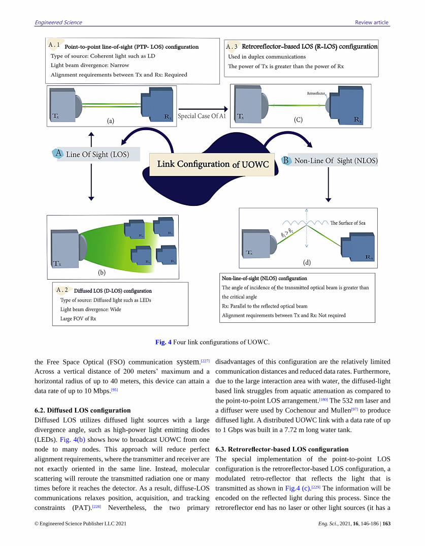
Engineered Science Review article
© Engineered Science Publisher LLC 2021 Eng. Sci., 2021, 16, 146-186 | 163
Fig. 4 Four link configurations of UOWC.
the Free Space Optical (FSO) communication system.[227]
Across a vertical distance of 200 meters’ maximum and a
horizontal radius of up to 40 meters, this device can attain a
data rate of up to 10 Mbps.[95]
6.2. Diffused LOS configuration
Diffused LOS utilizes diffused light sources with a large
divergence angle, such as high-power light emitting diodes
(LEDs). Fig. 4(b) shows how to broadcast UOWC from one
node to many nodes. This approach will reduce perfect
alignment requirements, where the transmitter and receiver are
not exactly oriented in the same line. Instead, molecular
scattering will reroute the transmitted radiation one or many
times before it reaches the detector. As a result, diffuse-LOS
communications relaxes position, acquisition, and tracking
constraints (PAT).[228] Nevertheless, the two primary
disadvantages of this configuration are the relatively limited
communication distances and reduced data rates. Furthermore,
due to the large interaction area with water, the diffused-light
based link struggles from aquatic attenuation as compared to
the point-to-point LOS arrangement.[180] The 532 nm laser and
a diffuser were used by Cochenour and Mullen[97] to produce
diffused light. A distributed UOWC link with a data rate of up
to 1 Gbps was built in a 7.72 m long water tank.
6.3. Retroreflector-based LOS configuration
The special implementation of the point-to-point LOS
configuration is the retroreflector-based LOS configuration, a
modulated retro-reflector that reflects the light that is
transmitted as shown in Fig.4 (c).[229] The information will be
encoded on the reflected light during this process. Since the
retroreflector end has no laser or other light sources (it has a
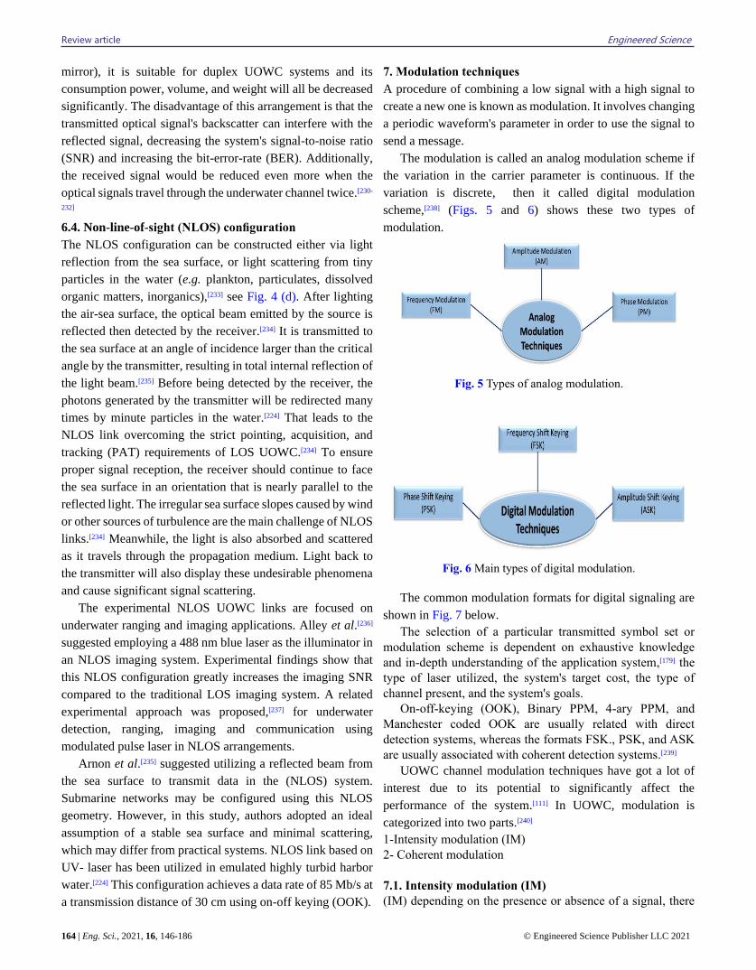
Review article Engineered Science
164 | Eng. Sci., 2021, 16, 146-186 © Engineered Science Publisher LLC 2021
mirror), it is suitable for duplex UOWC systems and its
consumption power, volume, and weight will all be decreased
significantly. The disadvantage of this arrangement is that the
transmitted optical signal's backscatter can interfere with the
reflected signal, decreasing the system's signal-to-noise ratio
(SNR) and increasing the bit-error-rate (BER). Additionally,
the received signal would be reduced even more when the
optical signals travel through the underwater channel twice.[230-
232]
6.4. Non-line-of-sight (NLOS) configuration
The NLOS configuration can be constructed either via light
reflection from the sea surface, or light scattering from tiny
particles in the water (e.g. plankton, particulates, dissolved
organic matters, inorganics),[233] see Fig. 4 (d). After lighting
the air-sea surface, the optical beam emitted by the source is
reflected then detected by the receiver.[234] It is transmitted to
the sea surface at an angle of incidence larger than the critical
angle by the transmitter, resulting in total internal reflection of
the light beam.[235] Before being detected by the receiver, the
photons generated by the transmitter will be redirected many
times by minute particles in the water.[224] That leads to the
NLOS link overcoming the strict pointing, acquisition, and
tracking (PAT) requirements of LOS UOWC.[234] To ensure
proper signal reception, the receiver should continue to face
the sea surface in an orientation that is nearly parallel to the
reflected light. The irregular sea surface slopes caused by wind
or other sources of turbulence are the main challenge of NLOS
links.[234] Meanwhile, the light is also absorbed and scattered
as it travels through the propagation medium. Light back to
the transmitter will also display these undesirable phenomena
and cause significant signal scattering.
The experimental NLOS UOWC links are focused on
underwater ranging and imaging applications. Alley et al.[236]
suggested employing a 488 nm blue laser as the illuminator in
an NLOS imaging system. Experimental findings show that
this NLOS configuration greatly increases the imaging SNR
compared to the traditional LOS imaging system. A related
experimental approach was proposed,[237] for underwater
detection, ranging, imaging and communication using
modulated pulse laser in NLOS arrangements.
Arnon et al.[235] suggested utilizing a reflected beam from
the sea surface to transmit data in the (NLOS) system.
Submarine networks may be configured using this NLOS
geometry. However, in this study, authors adopted an ideal
assumption of a stable sea surface and minimal scattering,
which may differ from practical systems. NLOS link based on
UV- laser has been utilized in emulated highly turbid harbor
water.[224] This configuration achieves a data rate of 85 Mb/s at
a transmission distance of 30 cm using on-off keying (OOK).
7. Modulation techniques
A procedure of combining a low signal with a high signal to
create a new one is known as modulation. It involves changing
a periodic waveform's parameter in order to use the signal to
send a message.
The modulation is called an analog modulation scheme if
the variation in the carrier parameter is continuous. If the
variation is discrete, then it called digital modulation
scheme,[238] (Figs. 5 and 6) shows these two types of
modulation.
Fig. 5 Types of analog modulation.
Fig. 6 Main types of digital modulation.
The common modulation formats for digital signaling are
shown in Fig. 7 below.
The selection of a particular transmitted symbol set or
modulation scheme is dependent on exhaustive knowledge
and in-depth understanding of the application system,[179] the
type of laser utilized, the system's target cost, the type of
channel present, and the system's goals.
On-off-keying (OOK), Binary PPM, 4-ary PPM, and
Manchester coded OOK are usually related with direct
detection systems, whereas the formats FSK., PSK, and ASK
are usually associated with coherent detection systems.[239]
UOWC channel modulation techniques have got a lot of
interest due to its potential to significantly affect the
performance of the system.[111] In UOWC, modulation is
categorized into two parts.[240]
1-Intensity modulation (IM)
2- Coherent modulation
7.1. Intensity modulation (IM)
(IM) depending on the presence or absence of a signal, there
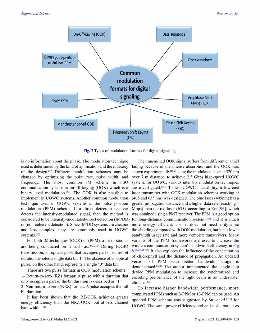
Engineered Science Review article
© Engineered Science Publisher LLC 2021 Eng. Sci., 2021, 16, 146-186 | 165
Fig. 7 Types of modulation formats for digital signaling.
is no information about the phase. The modulation technique
used is determined by the kind of application and the intricacy
of the design.[47] Different modulation schemes may be
changed by optimizing the pulse rate, pulse width, and
frequency. The most common IM scheme in FSO
communication systems is on-off keying (OOK) which is a
binary level modulation.[241] The OOK is also possible to
implement in UOWC systems. Another common modulation
technique used in UOWC systems is the pulse position
modulation (PPM) scheme. If a direct detection receiver
detects the intensity-modulated signal, then the method is
considered to be intensity-modulated/direct detection (IM/DD)
or (non-coherent detection). Since IM/DD systems are cheaper
and less complex, they are commonly used in UOWC
systems.[47]
For both IM techniques (OOK) or (PPM), a lot of studies
are being conducted on it such as.[242,243] During (OOK)
transmission, an optical pulse that occupies part or entire bit
duration denotes a single data bit '1'. The absence of an optical
pulse, on the other hand, represents a single "0" data bit.
There are two pulse formats in OOK modulation scheme:
1- Return-to-zero (RZ) format: A pulse with a duration that
only occupies a part of the bit duration is described as "1".
2- Non-return-to-zero (NRZ) format: A pulse occupies the full
bit duration.
It has been shown that the RZ-OOK achieves greater
energy efficiency than the NRZ-OOK, but at less channel
bandwidth.[111]
The transmitted OOK signal suffers from different channel
fading because of the intense absorption and the OOK was
shown experimentally[105] using the modulated laser at 520 nm
over 7 m distance, to achieve 2.3 Gbps high-speed UOWC
system. for UOWC, various intensity modulation techniques
are investigated.[244] To test UOWC's feasibility, a low-cost
laser transmitter with OOK modulation schemes working at
(405 and 635 nm) was designed. The blue laser (405nm) has a
greater propagation distance and a higher data rate (reaching 1
Mbps) than the red laser (635), according to Ref.[96], which
was obtained using a PMT receiver. The PPM is a good option
for long-distance communication system,[245] and it is much
more energy efficient, also it does not need a dynamic
thresholding compared with OOK modulation, but it has lower
bandwidth usage rate and more complex transceivers. Many
variants of the PPM frameworks are used to increase the
wireless communication system's bandwidth efficiency, in Fig.
8.[246,247,248] It also explores the influence of the concentration
of chlorophyll and the distance of propagation. An updated
version of PPM with better bandwidth usage is
demonstrated.[249] The author implemented the single-chip
device PPM modulation to increase the synchronized and
encoding performance of the light beam in an underwater
climate.[250]
To increase higher bandwidth performance, more
complicated PPMs such as 8-PPM or 16-PPM can be used. An
updated PPM scheme was suggested by Sui et al.[126] for
UOWC. The same power efficiency and anti-noise output as
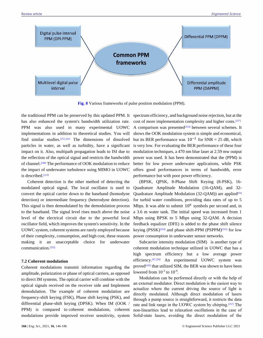
Review article Engineered Science
166 | Eng. Sci., 2021, 16, 146-186 © Engineered Science Publisher LLC 2021
Fig. 8 Various frameworks of pulse position modulation (PPM).
the traditional PPM can be preserved by this updated PPM. It
has also enhanced the system's bandwidth utilization rate.
PPM was also used in many experimental UOWC
implementations in addition to theoretical studies. You will
find similar studies.[251,241] The dimensions of dissolved
particles in water, as well as turbidity, have a significant
impact on it. Also, multipath propagation leads to ISI due to
the reflection of the optical signal and restricts the bandwidth
of channel.[248] The performance of OOK modulation to reduce
the impact of underwater turbulence using MIMO in UOWC
is described.[223]
Coherent detection is the other method of detecting the
modulated optical signal. The local oscillator is used to
convert the optical carrier down to the baseband (homodyne
detection) or intermediate frequency (heterodyne detection).
This signal is then demodulated by the demodulation process
to the baseband. The signal level rises much above the noise
level of the electrical circuit due to the powerful local
oscillator field, which improves the system's sensitivity. In the
UOWC system, coherent systems are rarely employed because
of their complexity, consumption, and high cost, these reasons
making it an unacceptable choice for underwater
communication.[252]
7.2 Coherent modulation
Coherent modulations transmit information regarding the
amplitude, polarization or phase of optical carriers, as opposed
to direct IM systems. The optical carrier will combine with the
optical signals received on the receiver side and Implement
demodulation. The example of coherent modulation are
frequency-shift keying (FSK), Phase shift keying (PSK), and
differential phase-shift keying (DPSK). When IM (OOK /
PPM) is compared to coherent modulations, coherent
modulations provide improved receiver sensitivity, system
spectrum efficiency, and background noise rejection, but at the
cost of more implementation complexity and higher costs.[227]
A comparison was presented[253] between several schemes. It
shows the OOK modulation system is simple and economical,
but its BER performance was 10−2 for SNR = 25 dB, which
is very low. For evaluating the BER performance of these four
modulation techniques, a 470 nm blue laser at 2.59 mw output
power was used. It has been demonstrated that the (PPM) is
better for low power underwater applications, while PSK
offers good performances in terms of bandwidth, error
performance but with poor power efficiency.
(BPSK, QPSK, 8-Phase Shift Keying (8-PSK), 16-
Quadrature Amplitude Modulation (16-QAM), and 32-
Quadrature Amplitude Modulation (32-QAM)) are applied[93]
for turbid water conditions, providing data rates of up to 5
Mbps. It was able to submit 106 symbols per second and, in
a 3.6 m water tank. The initial speed was increased from 1
Mbps using BPSK to 5 Mbps using 32-QAM. A decision
feedback equalizer (DFE) is added to the phase shift silence
keying (PSSK)[254] and phase shift-PPM (PSPPM)[255] for low
power consumption in underwater sensor networks.
Subcarrier intensity modulation (SIM) is another type of
coherent modulation technique utilized in UOWC that has a
high spectrum efficiency but a low average power
efficiency.[47,256] An experimental UOWC system was
proved[103] that utilized SIM, the BER was shown to have been
lowered from 10-3 to 10-9.
Modulation can be performed directly or with the help of
an external modulator. Direct modulation is the easiest way to
actualize where the current driving the source of light is
directly modulated. Although direct modulation of lasers
through a pump source is straightforward, it restricts the data
rate and link range in the UOWC system by chirping.[257] The
non-linearities lead to relaxation oscillations in the case of
Solid-state lasers, avoiding the direct modulation of the
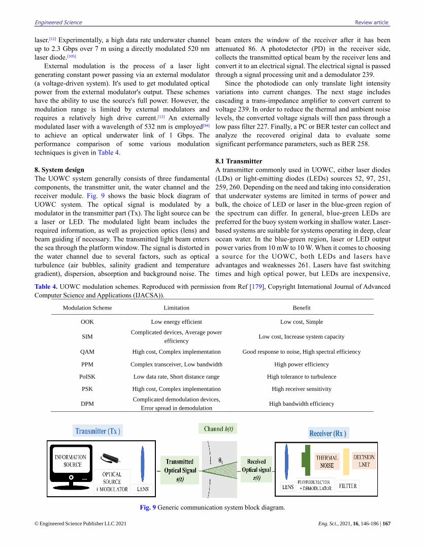
Engineered Science Review article
© Engineered Science Publisher LLC 2021 Eng. Sci., 2021, 16, 146-186 | 167
laser.[12] Experimentally, a high data rate underwater channel
up to 2.3 Gbps over 7 m using a directly modulated 520 nm
laser diode.[105]
External modulation is the process of a laser light
generating constant power passing via an external modulator
(a voltage-driven system). It's used to get modulated optical
power from the external modulator's output. These schemes
have the ability to use the source's full power. However, the
modulation range is limited by external modulators and
requires a relatively high drive current.[12] An externally
modulated laser with a wavelength of 532 nm is employed[94]
to achieve an optical underwater link of 1 Gbps. The
performance comparison of some various modulation
techniques is given in Table 4.
8. System design
The UOWC system generally consists of three fundamental
components, the transmitter unit, the water channel and the
receiver module. Fig. 9 shows the basic block diagram of
UOWC system. The optical signal is modulated by a
modulator in the transmitter part (Tx). The light source can be
a laser or LED. The modulated light beam includes the
required information, as well as projection optics (lens) and
beam guiding if necessary. The transmitted light beam enters
the sea through the platform window. The signal is distorted in
the water channel due to several factors, such as optical
turbulence (air bubbles, salinity gradient and temperature
gradient), dispersion, absorption and background noise. The
beam enters the window of the receiver after it has been
attenuated 86. A photodetector (PD) in the receiver side,
collects the transmitted optical beam by the receiver lens and
convert it to an electrical signal. The electrical signal is passed
through a signal processing unit and a demodulator 239.
Since the photodiode can only translate light intensity
variations into current changes. The next stage includes
cascading a trans-impedance amplifier to convert current to
voltage 239. In order to reduce the thermal and ambient noise
levels, the converted voltage signals will then pass through a
low pass filter 227. Finally, a PC or BER tester can collect and
analyze the recovered original data to evaluate some
significant performance parameters, such as BER 258.
8.1 Transmitter
A transmitter commonly used in UOWC, either laser diodes
(LDs) or light-emitting diodes (LEDs) sources 52, 97, 251,
259, 260. Depending on the need and taking into consideration
that underwater systems are limited in terms of power and
bulk, the choice of LED or laser in the blue-green region of
the spectrum can differ. In general, blue-green LEDs are
preferred for the buoy system working in shallow water. Laser-
based systems are suitable for systems operating in deep, clear
ocean water. In the blue-green region, laser or LED output
power varies from 10 mW to 10 W. When it comes to choosing
a source for the UOWC, both LEDs and lasers have
advantages and weaknesses 261. Lasers have fast switching
times and high optical power, but LEDs are inexpensive,
Table 4. UOWC modulation schemes. Reproduced with permission from Ref [179], Copyright International Journal of Advanced
Computer Science and Applications (IJACSA)).
Modulation Scheme Limitation Benefit
OOK Low energy efficient Low cost, Simple
SIM Complicated devices, Average power
efficiency Low cost, Increase system capacity
QAM High cost, Complex implementation Good response to noise, High spectral efficiency
PPM Complex transceiver, Low bandwidth High power efficiency
PoISK Low data rate, Short distance range High tolerance to turbulence
PSK High cost, Complex implementation High receiver sensitivity
DPM Complicated demodulation devices,
Error spread in demodulation High bandwidth efficiency
Fig. 9 Generic communication system block diagram.
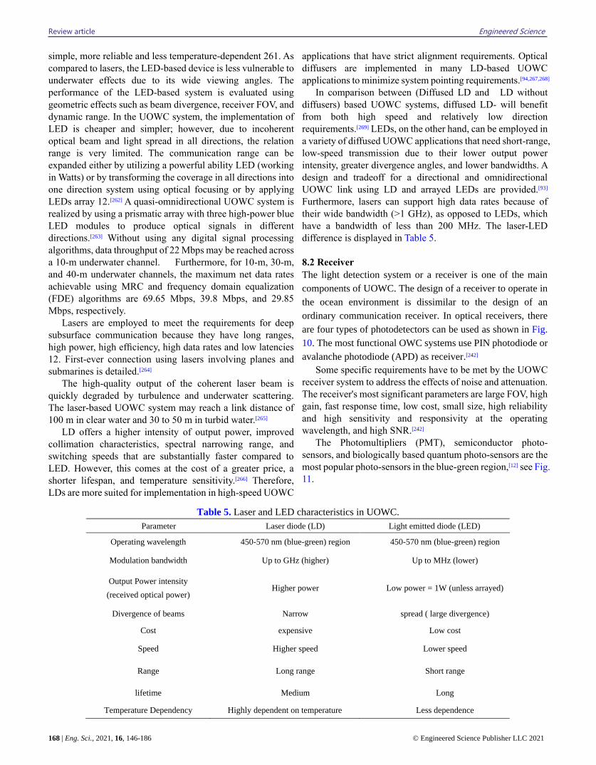
Review article Engineered Science
168 | Eng. Sci., 2021, 16, 146-186 © Engineered Science Publisher LLC 2021
simple, more reliable and less temperature-dependent 261. As
compared to lasers, the LED-based device is less vulnerable to
underwater effects due to its wide viewing angles. The
performance of the LED-based system is evaluated using
geometric effects such as beam divergence, receiver FOV, and
dynamic range. In the UOWC system, the implementation of
LED is cheaper and simpler; however, due to incoherent
optical beam and light spread in all directions, the relation
range is very limited. The communication range can be
expanded either by utilizing a powerful ability LED (working
in Watts) or by transforming the coverage in all directions into
one direction system using optical focusing or by applying
LEDs array 12.[262] A quasi-omnidirectional UOWC system is
realized by using a prismatic array with three high-power blue
LED modules to produce optical signals in different
directions.[263] Without using any digital signal processing
algorithms, data throughput of 22 Mbps may be reached across
a 10-m underwater channel. Furthermore, for 10-m, 30-m,
and 40-m underwater channels, the maximum net data rates
achievable using MRC and frequency domain equalization
(FDE) algorithms are 69.65 Mbps, 39.8 Mbps, and 29.85
Mbps, respectively.
Lasers are employed to meet the requirements for deep
subsurface communication because they have long ranges,
high power, high efficiency, high data rates and low latencies
12. First-ever connection using lasers involving planes and
submarines is detailed.[264]
The high-quality output of the coherent laser beam is
quickly degraded by turbulence and underwater scattering.
The laser-based UOWC system may reach a link distance of
100 m in clear water and 30 to 50 m in turbid water.[265]
LD offers a higher intensity of output power, improved
collimation characteristics, spectral narrowing range, and
switching speeds that are substantially faster compared to
LED. However, this comes at the cost of a greater price, a
shorter lifespan, and temperature sensitivity.[266] Therefore,
LDs are more suited for implementation in high-speed UOWC
applications that have strict alignment requirements. Optical
diffusers are implemented in many LD-based UOWC
applications to minimize system pointing requirements.[94,267,268]
In comparison between (Diffused LD and LD without
diffusers) based UOWC systems, diffused LD- will benefit
from both high speed and relatively low direction
requirements.[269] LEDs, on the other hand, can be employed in
a variety of diffused UOWC applications that need short-range,
low-speed transmission due to their lower output power
intensity, greater divergence angles, and lower bandwidths. A
design and tradeoff for a directional and omnidirectional
UOWC link using LD and arrayed LEDs are provided.[93]
Furthermore, lasers can support high data rates because of
their wide bandwidth (>1 GHz), as opposed to LEDs, which
have a bandwidth of less than 200 MHz. The laser-LED
difference is displayed in Table 5.
8.2 Receiver
The light detection system or a receiver is one of the main
components of UOWC. The design of a receiver to operate in
the ocean environment is dissimilar to the design of an
ordinary communication receiver. In optical receivers, there
are four types of photodetectors can be used as shown in Fig.
10. The most functional OWC systems use PIN photodiode or
avalanche photodiode (APD) as receiver.[242]
Some specific requirements have to be met by the UOWC
receiver system to address the effects of noise and attenuation.
The receiver's most significant parameters are large FOV, high
gain, fast response time, low cost, small size, high reliability
and high sensitivity and responsivity at the operating
wavelength, and high SNR.[242]
The Photomultipliers (PMT), semiconductor photo-
sensors, and biologically based quantum photo-sensors are the
most popular photo-sensors in the blue-green region,[12] see Fig.
11.
Table 5. Laser and LED characteristics in UOWC.
Parameter Laser diode (LD) Light emitted diode (LED)
Operating wavelength 450-570 nm (blue-green) region 450-570 nm (blue-green) region
Modulation bandwidth Up to GHz (higher) Up to MHz (lower)
Output Power intensity
(received optical power) Higher power Low power = 1W (unless arrayed)
Divergence of beams Narrow spread ( large divergence)
Cost expensive Low cost
Speed Higher speed Lower speed
Range Long range Short range
lifetime Medium Long
Temperature Dependency Highly dependent on temperature Less dependence
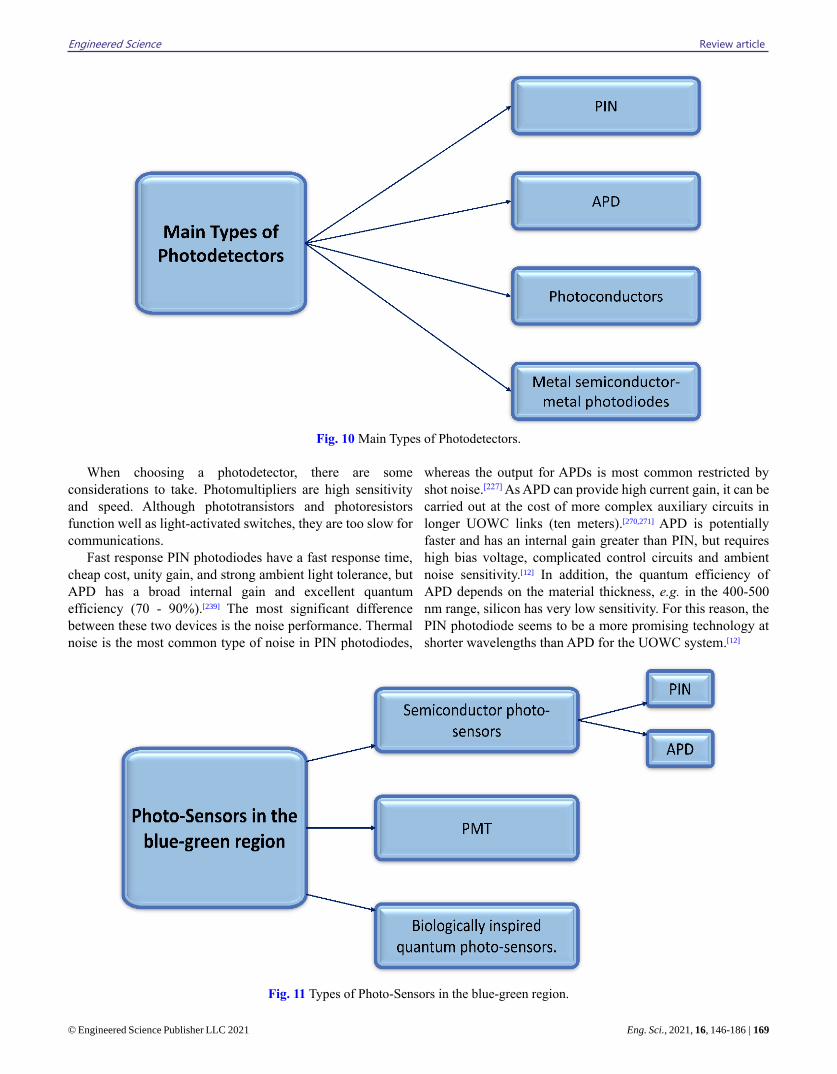
Engineered Science Review article
© Engineered Science Publisher LLC 2021 Eng. Sci., 2021, 16, 146-186 | 169
Fig. 10 Main Types of Photodetectors.
When choosing a photodetector, there are some
considerations to take. Photomultipliers are high sensitivity
and speed. Although phototransistors and photoresistors
function well as light-activated switches, they are too slow for
communications.
Fast response PIN photodiodes have a fast response time,
cheap cost, unity gain, and strong ambient light tolerance, but
APD has a broad internal gain and excellent quantum
efficiency (70 - 90%).[239] The most significant difference
between these two devices is the noise performance. Thermal
noise is the most common type of noise in PIN photodiodes,
whereas the output for APDs is most common restricted by
shot noise.[227] As APD can provide high current gain, it can be
carried out at the cost of more complex auxiliary circuits in
longer UOWC links (ten meters).[270,271] APD is potentially
faster and has an internal gain greater than PIN, but requires
high bias voltage, complicated control circuits and ambient
noise sensitivity.[12] In addition, the quantum efficiency of
APD depends on the material thickness, e.g. in the 400-500
nm range, silicon has very low sensitivity. For this reason, the
PIN photodiode seems to be a more promising technology at
shorter wavelengths than APD for the UOWC system.[12]
Fig. 11 Types of Photo-Sensors in the blue-green region.
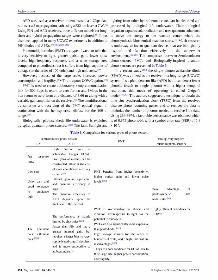
Review article Engineered Science
170 | Eng. Sci., 2021, 16, 146-186 © Engineered Science Publisher LLC 2021
APD was used as a receiver to demonstrate a 1 Gbps data
rate over a 2 m propagation path using a 532 nm laser at 7 W.[94]
Using PIN and APD receivers, three different models for long,
short and hybrid propagation ranges were explored.[99] It has
also been applied in many UOWC experiments in addition to
PIN diodes and APDs.[272,62,260,273-276]
Photomultiplier tubes (PMT) is a type of vacuum tube that
is very sensitive to light, greater optical gain, lower noise
levels, high-frequency response, and a wide storage area
compared to photodiodes, but it suffers from high supplies of
voltage (on the order of 100 volts) and high unit costs.[277]
However, because of the large scale, increased power
consumption, and fragility, PMTs are a poor UOWC option.[278]
PMT is used to create a laboratory setup communication
link for 500 kbps in return-to-zero format and 1Mbps in the
non-return-to-zero form at a distance of 3.66 m along with a
variable gain amplifier on the receiver.[96] The omnidirectional
transmission and receiving of the PMT optical signal in
conjunction with the hemispherical diffuse for the 100 m
range.[279]
Biologically, photosynthetic life underwater is exploited
by spiral quantum photo-sensors.[50,55] The faint Sunlight and
lighting from other hydrothermal vents can be absorbed and
processed by biological life underwater. Their biological
organism captures solar radiation and uses quantum coherence
to move the energy to the reaction center where the
photosynthesis biochemical reaction starts.[12] Much research
is underway to invent quantum devices that are biologically
inspired and function effectively in the underwater
environment.[280-283] The comparison between Semiconductor
photo-sensors, PMT, and Biologically-inspired quantum
photo-sensors are presented in Table 6.
In a recent study,[284] the single photon avalanche diode
(SPAD) was utilized as the receiver in a long-range (UOWC)
system. It's a photodetector like (APD) but it can detect fewer
photons (reach to single photon) with a higher temporal
resolution, this mode of operating is called Geiger’s
mode.[140,285] The authors suggested a technique to obtain the
time slot synchronization clock (TSSC) from the received
discrete photon-counting pulses and to recover the data to
minimize the number of photons needed to receive 1 bit data.
Using 256-PPM, a favorable performance was obtained which
is of 0.875 photons/bit with a symbol error rate (SER) of 1.8
× 10-3.
Table 6. Comparison for various types of photo-sensor.
Semiconductor photo-sensors PMT
Biologically inspired
quantum photo-sensors PIN APD
fast response
time.
Low cost
Unity gain and
good tolerance
to ambiance
light
High current gain is
achievable, Longer UOWC
links (tens of meters) can be
constructed, albeit at the cost
of more complicated auxiliary
circuits.[180]
Internal gain is significant,
and quantum efficiency is
high.[12]
The quantum efficiency of
APD depends upon the
thickness of the material.
PMT benefits from higher sensitivity,
higher optical gain and lower noise
levels.[180]
Take advantage of
photosynthetic life
underwater.[12]
Highly efficient candidates for
UOWC.
The dominant
noise is thermal
noise[227]
The performance is mainly
limited by shot noise.[227]
Faster than PIN and has a
greater internal gain, but
requires a larger bias voltage,
sophisticated control circuitry,
and is more susceptible to
ambient noise.[12]
PMT is oversensitive to shocks and
vibration. Overexposure to light has the
potential to damage it.
PMTs are also significantly more expensive
than photodiodes.[180]
High voltage sources (on the order of
hundreds of volts) and a high unit cost are
disadvantages.[180]
They are a poor candidate for UOWC due to
their large size, higher power consumption,
and fragility.
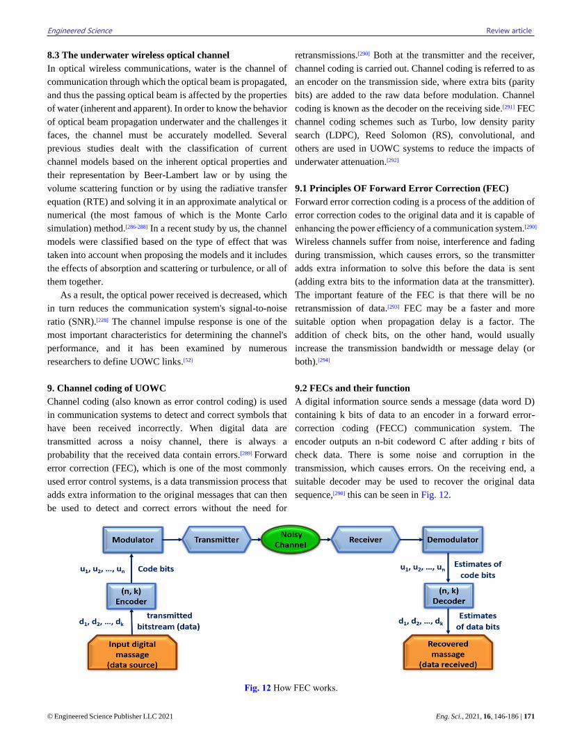
Engineered Science Review article
© Engineered Science Publisher LLC 2021 Eng. Sci., 2021, 16, 146-186 | 171
8.3 The underwater wireless optical channel
In optical wireless communications, water is the channel of
communication through which the optical beam is propagated,
and thus the passing optical beam is affected by the properties
of water (inherent and apparent). In order to know the behavior
of optical beam propagation underwater and the challenges it
faces, the channel must be accurately modelled. Several
previous studies dealt with the classification of current
channel models based on the inherent optical properties and
their representation by Beer-Lambert law or by using the
volume scattering function or by using the radiative transfer
equation (RTE) and solving it in an approximate analytical or
numerical (the most famous of which is the Monte Carlo
simulation) method.[286-288] In a recent study by us, the channel
models were classified based on the type of effect that was
taken into account when proposing the models and it includes
the effects of absorption and scattering or turbulence, or all of
them together.
As a result, the optical power received is decreased, which
in turn reduces the communication system's signal-to-noise
ratio (SNR).[228] The channel impulse response is one of the
most important characteristics for determining the channel's
performance, and it has been examined by numerous
researchers to define UOWC links.[52]
9. Channel coding of UOWC
Channel coding (also known as error control coding) is used
in communication systems to detect and correct symbols that
have been received incorrectly. When digital data are
transmitted across a noisy channel, there is always a
probability that the received data contain errors.[289] Forward
error correction (FEC), which is one of the most commonly
used error control systems, is a data transmission process that
adds extra information to the original messages that can then
be used to detect and correct errors without the need for
retransmissions.[290] Both at the transmitter and the receiver,
channel coding is carried out. Channel coding is referred to as
an encoder on the transmission side, where extra bits (parity
bits) are added to the raw data before modulation. Channel
coding is known as the decoder on the receiving side.[291] FEC
channel coding schemes such as Turbo, low density parity
search (LDPC), Reed Solomon (RS), convolutional, and
others are used in UOWC systems to reduce the impacts of
underwater attenuation.[292]
9.1 Principles OF Forward Error Correction (FEC)
Forward error correction coding is a process of the addition of
error correction codes to the original data and it is capable of
enhancing the power efficiency of a communication system.[290]
Wireless channels suffer from noise, interference and fading
during transmission, which causes errors, so the transmitter
adds extra information to solve this before the data is sent
(adding extra bits to the information data at the transmitter).
The important feature of the FEC is that there will be no
retransmission of data.[293] FEC may be a faster and more
suitable option when propagation delay is a factor. The
addition of check bits, on the other hand, would usually
increase the transmission bandwidth or message delay (or
both).[294]
9.2 FECs and their function
A digital information source sends a message (data word D)
containing k bits of data to an encoder in a forward error-
correction coding (FECC) communication system. The
encoder outputs an n-bit codeword C after adding r bits of
check data. There is some noise and corruption in the
transmission, which causes errors. On the receiving end, a
suitable decoder may be used to recover the original data
sequence,[290] this can be seen in Fig. 12.
Fig. 12 How FEC works.
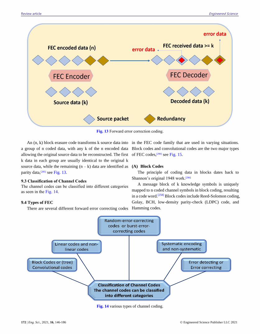
Review article Engineered Science
172 | Eng. Sci., 2021, 16, 146-186 © Engineered Science Publisher LLC 2021
Fig. 13 Forward error correction coding.
An (n, k) block erasure code transforms k source data into
a group of n coded data, with any k of the n encoded data
allowing the original source data to be reconstructed. The first
k data in each group are usually identical to the original k
source data, while the remaining (n – k) data are identified as
parity data,[295] see Fig. 13.
9.3 Classification of Channel Codes
The channel codes can be classified into different categories
as seen in the Fig. 14.
9.4 Types of FEC
There are several different forward error correcting codes
in the FEC code family that are used in varying situations.
Block codes and convolutional codes are the two major types
of FEC codes,[290] see Fig. 15.
(A) Block Codes
The principle of coding data in blocks dates back to
Shannon’s original 1948 work.[296]
A message block of k knowledge symbols is uniquely
mapped to n coded channel symbols in block coding, resulting
in a code word.[258] Block codes include Reed-Solomon coding,
Golay, BCH, low-density parity-check (LDPC) code, and
Hamming codes.
Fig. 14 various types of channel coding.
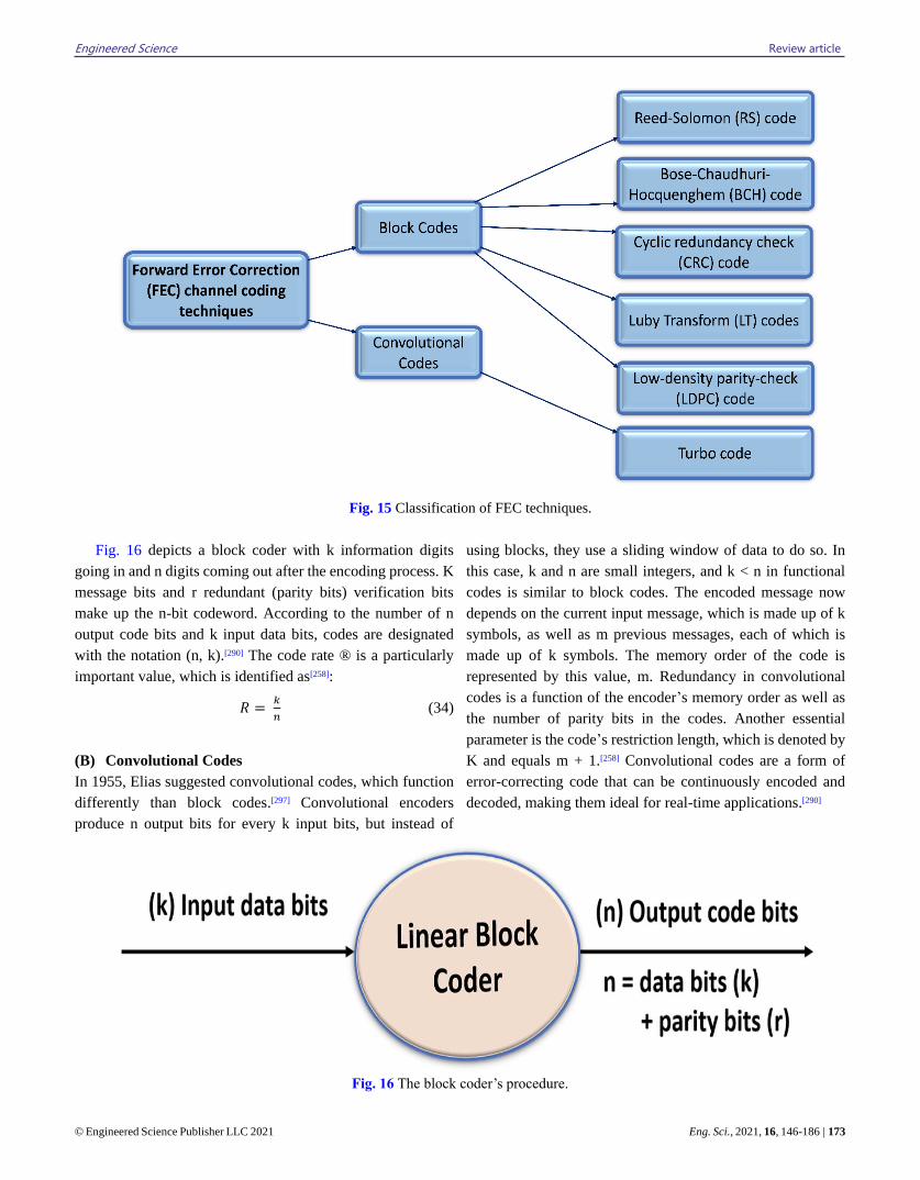
Engineered Science Review article
© Engineered Science Publisher LLC 2021 Eng. Sci., 2021, 16, 146-186 | 173
Fig. 15 Classification of FEC techniques.
Fig. 16 depicts a block coder with k information digits
going in and n digits coming out after the encoding process. K
message bits and r redundant (parity bits) verification bits
make up the n-bit codeword. According to the number of n
output code bits and k input data bits, codes are designated
with the notation (n, k).[290] The code rate ® is a particularly
important value, which is identified as[258]:
𝑅 = 𝑘
𝑛 (34)
(B) Convolutional Codes
In 1955, Elias suggested convolutional codes, which function
differently than block codes.[297] Convolutional encoders
produce n output bits for every k input bits, but instead of
using blocks, they use a sliding window of data to do so. In
this case, k and n are small integers, and k < n in functional
codes is similar to block codes. The encoded message now
depends on the current input message, which is made up of k
symbols, as well as m previous messages, each of which is
made up of k symbols. The memory order of the code is
represented by this value, m. Redundancy in convolutional
codes is a function of the encoder’s memory order as well as
the number of parity bits in the codes. Another essential
parameter is the code’s restriction length, which is denoted by
K and equals m + 1.[258] Convolutional codes are a form of
error-correcting code that can be continuously encoded and
decoded, making them ideal for real-time applications.[290]
Fig. 16 The block coder’s procedure.
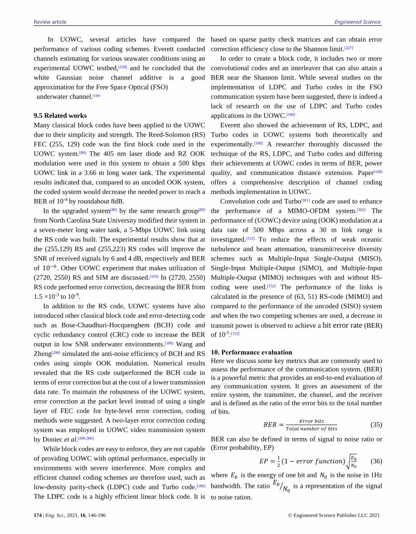
Review article Engineered Science
174 | Eng. Sci., 2021, 16, 146-186 © Engineered Science Publisher LLC 2021
In UOWC, several articles have compared the
performance of various coding schemes. Everett conducted
channels estimating for various seawater conditions using an
experimental UOWC testbed,[258] and he concluded that the
white Gaussian noise channel additive is a good
approximation for the Free Space Optical (FSO)
underwater channel.[180]
9.5 Related works
Many classical block codes have been applied to the UOWC
due to their simplicity and strength. The Reed-Solomon (RS)
FEC (255, 129) code was the first block code used in the
UOWC system.[89] The 405 nm laser diode and RZ OOK
modulation were used in this system to obtain a 500 kbps
UOWC link in a 3.66 m long water tank. The experimental
results indicated that, compared to an uncoded OOK system,
the coded system would decrease the needed power to reach a
BER of 10-4 by roundabout 8dB.
In the upgraded system[88] by the same research group[89]
from North Carolina State University modified their system in
a seven-meter long water tank, a 5-Mbps UOWC link using
the RS code was built. The experimental results show that at
the (255,129) RS and (255,223) RS codes will improve the
SNR of received signals by 6 and 4 dB, respectively and BER
of 10−6. Other UOWC experiment that makes utilization of
(2720, 2550) RS and SIM are discussed.[103] In (2720, 2550)
RS code performed error correction, decreasing the BER from
1.5 ×10⁻³ to 10-9.
In addition to the RS code, UOWC systems have also
introduced other classical block code and error-detecting code
such as Bose-Chaudhuri-Hocquenghem (BCH) code and
cyclic redundancy control (CRC) code to increase the BER
output in low SNR underwater environments.[180] Wang and
Zheng[298] simulated the anti-noise efficiency of BCH and RS
codes using simple OOK modulation. Numerical results
revealed that the RS code outperformed the BCH code in
terms of error correction but at the cost of a lower transmission
data rate. To maintain the robustness of the UOWC system,
error correction at the packet level instead of using a single
layer of FEC code for byte-level error correction, coding
methods were suggested. A two-layer error correction coding
system was employed in UOWC video transmission system
by Doniec et al.[299,300]
While block codes are easy to enforce, they are not capable
of providing UOWC with optimal performance, especially in
environments with severe interference. More complex and
efficient channel coding schemes are therefore used, such as
low-density parity-check (LDPC) code and Turbo code.[180]
The LDPC code is a highly efficient linear block code. It is
based on sparse parity check matrices and can obtain error
correction efficiency close to the Shannon limit.[227]
In order to create a block code, it includes two or more
convolutional codes and an interleaver that can also attain a
BER near the Shannon limit. While several studies on the
implementation of LDPC and Turbo codes in the FSO
communication system have been suggested, there is indeed a
lack of research on the use of LDPC and Turbo codes
applications in the UOWC.[180]
Everett also showed the achievement of RS, LDPC, and
Turbo codes in UOWC systems both theoretically and
experimentally.[168] A researcher thoroughly discussed the
technique of the RS, LDPC, and Turbo codes and differing
their achievements at UOWC codes in terms of BER, power
quality, and communication distance extension. Paper[168]
offers a comprehensive description of channel coding
methods implementation in UOWC.
Convolution code and Turbo[301] code are used to enhance
the performance of a MIMO-OFDM system.[302] The
performance of (UOWC) device using (OOK) modulation at a
data rate of 500 Mbps across a 30 m link range is
investigated.[152] To reduce the effects of weak oceanic
turbulence and beam attenuation, transmit/receive diversity
schemes such as Multiple-Input Single-Output (MISO),
Single-Input Multiple-Output (SIMO), and Multiple-Input
Multiple-Output (MIMO) techniques with and without RS-
coding were used.[152] The performance of the links is
calculated in the presence of (63, 51) RS-code (MIMO) and
compared to the performance of the uncoded (SISO) system
and when the two competing schemes are used, a decrease in
transmit power is observed to achieve a bit error rate (BER)
of 10-5.[152]
10. Performance evaluation
Here we discuss some key metrics that are commonly used to
assess the performance of the communication system. (BER)
is a powerful metric that provides an end-to-end evaluation of
any communication system. It gives an assessment of the
entire system, the transmitter, the channel, and the receiver
and is defined as the ratio of the error bits to the total number
of bits.
𝐵𝐸𝑅 =𝐸𝑟𝑟𝑜𝑟 𝑏𝑖𝑡𝑠
𝑇𝑜𝑡𝑎𝑙 𝑛𝑢𝑚𝑏𝑒𝑟 𝑜𝑓 𝑏𝑖𝑡𝑠 (35)
BER can also be defined in terms of signal to noise ratio or
(Error probability, EP)
𝐸𝑃 =1
2(1 − 𝑒𝑟𝑟𝑜𝑟 𝑓𝑢𝑛𝑐𝑡𝑖𝑜𝑛)√
𝐸𝑏
𝑁0 (36)
where 𝐸𝑏 is the energy of one bit and 𝑁0 is the noise in 1Hz
bandwidth. The ratio 𝐸𝑏
𝑁0⁄ is a representation of the signal
to noise ration.
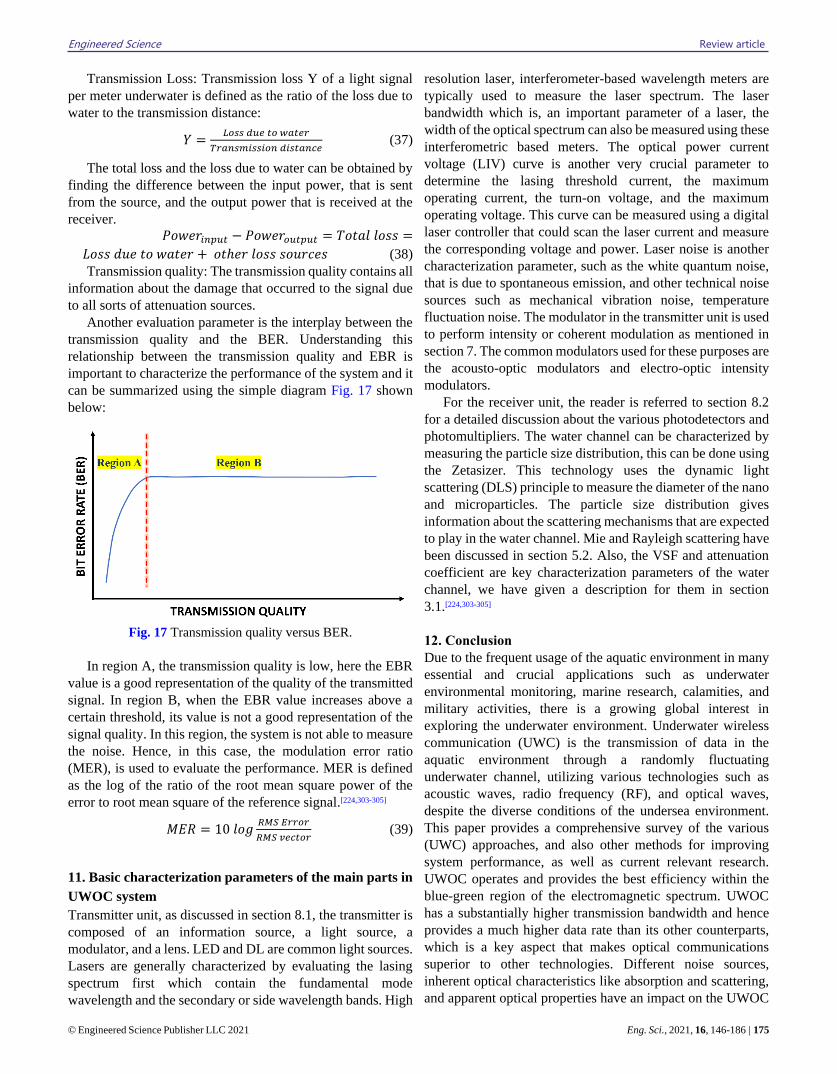
Engineered Science Review article
© Engineered Science Publisher LLC 2021 Eng. Sci., 2021, 16, 146-186 | 175
Transmission Loss: Transmission loss Y of a light signal
per meter underwater is defined as the ratio of the loss due to
water to the transmission distance:
𝑌 =𝐿𝑜𝑠𝑠 𝑑𝑢𝑒 𝑡𝑜 𝑤𝑎𝑡𝑒𝑟
𝑇𝑟𝑎𝑛𝑠𝑚𝑖𝑠𝑠𝑖𝑜𝑛 𝑑𝑖𝑠𝑡𝑎𝑛𝑐𝑒 (37)
The total loss and the loss due to water can be obtained by
finding the difference between the input power, that is sent
from the source, and the output power that is received at the
receiver.
𝑃𝑜𝑤𝑒𝑟𝑖𝑛𝑝𝑢𝑡 − 𝑃𝑜𝑤𝑒𝑟𝑜𝑢𝑡𝑝𝑢𝑡 = 𝑇𝑜𝑡𝑎𝑙 𝑙𝑜𝑠𝑠 =
𝐿𝑜𝑠𝑠 𝑑𝑢𝑒 𝑡𝑜 𝑤𝑎𝑡𝑒𝑟 + 𝑜𝑡ℎ𝑒𝑟 𝑙𝑜𝑠𝑠 𝑠𝑜𝑢𝑟𝑐𝑒𝑠 (38)
Transmission quality: The transmission quality contains all
information about the damage that occurred to the signal due
to all sorts of attenuation sources.
Another evaluation parameter is the interplay between the
transmission quality and the BER. Understanding this
relationship between the transmission quality and EBR is
important to characterize the performance of the system and it
can be summarized using the simple diagram Fig. 17 shown
below:
Fig. 17 Transmission quality versus BER.
In region A, the transmission quality is low, here the EBR
value is a good representation of the quality of the transmitted
signal. In region B, when the EBR value increases above a
certain threshold, its value is not a good representation of the
signal quality. In this region, the system is not able to measure
the noise. Hence, in this case, the modulation error ratio
(MER), is used to evaluate the performance. MER is defined
as the log of the ratio of the root mean square power of the
error to root mean square of the reference signal.[224,303-305]
𝑀𝐸𝑅 = 10 𝑙𝑜𝑔𝑅𝑀𝑆 𝐸𝑟𝑟𝑜𝑟
𝑅𝑀𝑆 𝑣𝑒𝑐𝑡𝑜𝑟 (39)
11. Basic characterization parameters of the main parts in
UWOC system
Transmitter unit, as discussed in section 8.1, the transmitter is
composed of an information source, a light source, a
modulator, and a lens. LED and DL are common light sources.
Lasers are generally characterized by evaluating the lasing
spectrum first which contain the fundamental mode
wavelength and the secondary or side wavelength bands. High
resolution laser, interferometer-based wavelength meters are
typically used to measure the laser spectrum. The laser
bandwidth which is, an important parameter of a laser, the
width of the optical spectrum can also be measured using these
interferometric based meters. The optical power current
voltage (LIV) curve is another very crucial parameter to
determine the lasing threshold current, the maximum
operating current, the turn-on voltage, and the maximum
operating voltage. This curve can be measured using a digital
laser controller that could scan the laser current and measure
the corresponding voltage and power. Laser noise is another
characterization parameter, such as the white quantum noise,
that is due to spontaneous emission, and other technical noise
sources such as mechanical vibration noise, temperature
fluctuation noise. The modulator in the transmitter unit is used
to perform intensity or coherent modulation as mentioned in
section 7. The common modulators used for these purposes are
the acousto-optic modulators and electro-optic intensity
modulators.
For the receiver unit, the reader is referred to section 8.2
for a detailed discussion about the various photodetectors and
photomultipliers. The water channel can be characterized by
measuring the particle size distribution, this can be done using
the Zetasizer. This technology uses the dynamic light
scattering (DLS) principle to measure the diameter of the nano
and microparticles. The particle size distribution gives
information about the scattering mechanisms that are expected
to play in the water channel. Mie and Rayleigh scattering have
been discussed in section 5.2. Also, the VSF and attenuation
coefficient are key characterization parameters of the water
channel, we have given a description for them in section
3.1.[224,303-305]
12. Conclusion
Due to the frequent usage of the aquatic environment in many
essential and crucial applications such as underwater
environmental monitoring, marine research, calamities, and
military activities, there is a growing global interest in
exploring the underwater environment. Underwater wireless
communication (UWC) is the transmission of data in the
aquatic environment through a randomly fluctuating
underwater channel, utilizing various technologies such as
acoustic waves, radio frequency (RF), and optical waves,
despite the diverse conditions of the undersea environment.
This paper provides a comprehensive survey of the various
(UWC) approaches, and also other methods for improving
system performance, as well as current relevant research.
UWOC operates and provides the best efficiency within the
blue-green region of the electromagnetic spectrum. UWOC
has a substantially higher transmission bandwidth and hence
provides a much higher data rate than its other counterparts,
which is a key aspect that makes optical communications
superior to other technologies. Different noise sources,
inherent optical characteristics like absorption and scattering,
and apparent optical properties have an impact on the UWOC
Review article Engineered Science
176 | Eng. Sci., 2021, 16, 146-186 © Engineered Science Publisher LLC 2021
system. This study presents the challenges and advantages of
underwater light propagation, modulation scheme, coding
techniques, and the fundamental physical processes that affect
them. The link configurations and system design are
considered in this paper, with a focus on the different types of
linking methods that can be used to provide underwater
communications, and also the benefits and drawbacks of each
system, as well as the conditions in which each type is utilized.
In addition, the major parts and components of the underwater
optical communication system are discussed in detail.
Moreover, this survey provides an overview of several UOWC
systems that will be given until 2021, with a description of
their system parameters.
13. Future directions
As described in the preceding sections, UWOC's academic and
industry research initiatives have already become a reality.
Nevertheless, this field of study is still in its beginning phases
in many areas, and there are still unsolved issues. To gain a
deeper understanding of the underwater environment and
channel characterization, extensive field investigations and the
utilization of testbeds are required. In the following points,
several potential research challenges at UWOC are mentioned.
➢ Link misalignment is an unavoidable occurrence, as
stated in section 6. Although a few research projects, on smart
transceivers for overcoming link misalignment, have been
proposed, extremely intelligent UWOC transceivers are still
needed.
➢ For UWOC transceivers, more research and study of
novel theoretical models (including statistical and numerical)
are necessary to fully understand laser beam propagation over
a randomly varying underwater channel. Also, most
theoretical UWOC research has not effectively addressed the
effects of transceiver noise on UWOC. The noise model of
UWOC transceivers must be investigated and implemented.
➢ With regards to modulation and coding techniques, prior
research has covered several matching schemes and produced
good results, but modifying the modulation and coding
scheme to react to real-time changes in the link remains a
challenge. Adaptive modulation or coding techniques for
UOWC has been investigated by few implementations. As a
result, various transmission schemes for UOWC systems must
be proposed to extend the system's coverage area and improve
its performance. When a mechanism exists to adaptively
switch modulation and coding schemes based on water
turbidity, the system will save a significant amount of energy
that is necessary for decoding complexity, resulting in a longer
cruising period.
➢ There has only been a few research on UWOC networks
thus far. Novel efficient network protocols must be devised
because of the particular characterization of wireless optical
channels in an underwater environment.
Acknowledgment:
This work was supported by the Deanship of Scientific
Research (DSR), King Abdul Aziz University, Jeddah. The
authors, therefore, gratefully acknowledge the DSR technical
support.
Conflict of interest
There are no conflicts to declare.
Supporting information
Not applicable.
References
[1] N. Saeed, A. Celik, T. Y. Al-Naffouri, M.-S. Alouini, Ad Hoc
Netw., 2019, 94, 101935, doi: 2019.101935.
[2] X. Sun, C. H. Kang, M. Kong, O. Alkhazragi, Y. Guo, M.
Ouhssain, Y. Weng, B. H. Jones, T. K. Ng, and B. S. Ooi, J. Light.
Technol., 2020, 38, 421-431, doi: 10.1364/JLT.38.000421.
[3] T. Fatma Abdalkarim, M. Universiti Tun Hussein Onn, E.
Fakulti Kejuruteraan Elektrik dan, Open ocean underwater
wireless optical communication: chlorophyll and depth
dependent variation in attenuation, Universiti Tun Hussein Onn
Malaysia, Batu Pahat (2015).
[4] Y. Li, S. Wang, C. Jin, Y. Zhang, T. Jiang, IEEE Commun. Surv.
Tutor., 2019, 21, 2466-2487, doi:
10.1109/COMST.2019.2897610.
[5] H. Ma, E. Liu, R. Wang, X. Yin, Z. Xu, X. Qu, B. Li, IEEE
Trans. Veh. Technol., 2019, 69, 3449-3453, doi:
10.1109/TVT.2019.2963357.
[6] K. Arunkumar, C. R. Murthy, IEEE Trans. Signal Process.,
2020, 68, 2435-2448, doi: 10.1109/TSP.2020.2983830.
[7] C. P. Gage, Towards a Modular, Low-Power, Low-Cost, and
High-Speed Underwater Optical Wireless Communication
Transmitter, UC San Diego Electronic Theses and Dissertations,
(2019).
[8] M. F. Ali, D. N. K. Jayakody, T. D. P. Perera,K. Srinivasan, A.
Sharma, and I. Krikidis, Underwater communications: Recent
advances, 2019.
[9] R. Urick, Principles of underwater sound: Peninsula. Los
Altos, 1983.
[10] B. Truax, Acoustic communication, Greenwood Publishing
Group, 2001.
[11] A. Quazi, W. Konrad, in IEEE Commun. Mag., 1982, 20, 24-
30.
[12] H. Kaushal, G. Kaddoum, IEEE Access, 2016, 4, 1518-1547,
doi: 10.1109/ACCESS.2016.2552538.
[13] R. E. Williams, H. F. Battestin, J. Acoust. Soc. Am., 1971, 50,
1433-1442, doi: 10.1121/1.1912785

Engineered Science Review article
© Engineered Science Publisher LLC 2021 Eng. Sci., 2021, 16, 146-186 | 177
[14] M. Stojanovic, L. Freitag, M. Johnson, paper presented at the
Oceans' 99. MTS/IEEE. Riding the Crest into the 21st Century.
Conference and Exhibition. Conference Proceedings (IEEE Cat.
No. 99CH37008), 1999, doi: 10.1109/OCEANS.1999.805007.
[15] W. Li, J. C. Preisig, IEEE J. Ocean. Eng., 2007, 32, 927-939,
doi: 10.1109/JOE.2007.906409.
[16] M. Stojanovic, paper presented at the 2008 IEEE
International Conference on Acoustics, Speech and Signal
Processing, 2008, doi: 10.1109/ICASSP.2008.4518853.
[17] A. Vlasenko, P. Korn, J. Riehme, U. Naumann, Mon.
Weather Rev., 2014, 142, 2502-2520, doi: 10.1175/MWR-D-13-
00205.1.
[18] Y. R. Zheng, paper presented at the MILCOM 2007-IEEE
Military Communications Conference, 2007, doi:
10.1109/MILCOM.2007.4454811.
[19] M. Stojanovic, IEEE J. Ocean. Eng., 1996, 21, 125-136, doi:
10.1109/48.486787.
[20] A. Zielinski, Y.-H. Yoon, L. Wu, IEEE J. Ocean. Eng., 1995,
20, 293-299, doi: 10.1109/48.468243.
[21] H. Ochi, Y. Watanabe, T. Shimura, JPN J. Appl. Phys., 2005,
44, 4689, doi: 10.1143/jjap.44.4689
[22] H. Song, W. Hodgkiss, J. Acoust. Soc. Am., 2013, 134, 905-
908, doi: 10.1121/1.4812762.
[23] F. Frassati, C. Lafon, P.-A. Laurent, J.-M. Passerieux, paper
presented at the Europe Oceans 2005 Conference, 2005,doi:
10.1109/OCEANSE.2005.1513163.
[24] B. Li, S. Zhou, M. Stojanovic, L. Freitag, P. Willett, IEEE J.
Ocean. Eng., 2008, 33, 198-209, doi: 10.1109/JOE.2008.920471.
[25] B. S. Sharif, J. Neasham, O. R. Hinton, A. E. Adams, IEEE
J. Ocean. Eng., 2000, 25, 52-61, doi: 10.1109/48.820736.
[26] M. Stojanovic, Low complexity OFDM detector for
underwater acoustic channels, IEEE, 2006.
[27] Y. V. Zakharov, V. Kodanev, paper presented at the 2000
IEEE International Conference on Acoustics, Speech, and Signal
Processing. Proceedings (Cat. No. 00CH37100), 2000, doi:
10.1109/ICASSP.2000.861150.
[28] A. Song, M. Stojanovic, M. Chitre, IEEE J. Ocean. Eng.,
2019, 44, 1-6, doi: 10.1109/joe.2018.2883872
[29] C. Pelekanakis, M. Stojanovic, L. Freitag, paper presented at
the Oceans 2003. Celebrating the Past. Teaming Toward the
Future (IEEE Cat. No. 03CH37492), 2003, doi:
10.1109/OCEANS.2003.178494.
[30] A. Goalic, J. Labat, J. Trubuil, S. Saoudi, D. Rioualen, paper
presented at the Proceedings of OCEANS'94, 1994, doi:
10.1109/OCEANS.1994.364247.
[31] J. H. Fischer, K. R. Bennett, S. A. Reible, J. H. Cafarella, I.
Yao, paper presented at the OCEANS 92 Proceedings@
m_Mastering the Oceans Through Technology, 1992 of
Conference, doi: 10.1109/OCEANS.1992.607644.
[32] X. Che, I. Wells, G. Dickers, P. Kear, X. Gong, IEEE
Commun. Mag., 2010, 48, 143-151, doi:
10.1109/MCOM.2010.5673085.
[33] H. Esmaiel, Z. A. H. Qasem, H. Sun, J. Qi, J. Wang,Y. Gu,
IET Comm., 2020, 14, 3394-3403.
[34] S. Li, H. Sun, H. Esmaiel, Sensors, 2020, 20, 4457, doi:
10.3390/s20164457
[35] Z. A. Qasem, J. Wang, X. Kuai, H. Sun, H. Esmaiel, IEEE
Wirel. Commun. Lett., 2021, 10, 1886-1889, doi:
10.1109/LWC.2021.3085020.
[36] Z. A. Qasem, H. A. Leftah, H. Sun, J. Qi, H. Esmaiel, IEEE
Syst. J., 2021,1-12,doi: 10.1109/JSYST.2021.3052470.
[37] Z. A. H. Qasem, H. Esmaiel, H. Sun, J. Qi, J. Wang, Sensors,
2020, 20, 6134, doi: 10.3390/s20216134
[38] N. U. R. Junejo, H. Esmaiel, H. Sun, Z. A. H. Qasem, J.
Wang, Symmetry, 2019, 11, 711, doi: 10.3390/sym11050711.
[39] H. Hussein, H. Esmaiel, D. Jiang, Electron. Lett., 2018, 54,
907-909, doi: 10.1049/el.2018.0948
[40] Z. A. H. Qasem, H. Esmaiel, H. Sun, J. Wang, Y. Miao and
S. Anwar, Sensors, 2019, 19, 1519, doi: 10.3390/s19071519.
[41] H. Esmaiel, Z. A. Qasem, H. Sun, J. Wang, N. U. Rehman
Junejo, Sensors, 2019, 19, 5271, doi: 10.3390/s19235271
[42] H. Esmaiel, D. Jiang, Electron. Lett., 2014, 50, 650-652, doi:
10.1049/el.2014.0466.
[43] H. Esmaiel, D. Jiang, Wirel. Pers. Commun., 2017, 96, 1577–
1593, doi: 10.1007/s11277-017-4257-5.
[44] Z. A. H. Qasem, H. A. Leftah, H. Sun, J. Qi, J. Wang, H.
Esmaiel, Veh. Commun., 2021, 28, 100314, doi:
10.1016/j.vehcom.2020.100314.
[45] D. Pompili, I. F. Akyildiz, IEEE Commun. Mag., 2009, 47,
97-102, doi: 10.1109/MCOM.2009.4752684.
[46] P. Wang, C. Li, Z. Xu, J. Light. Technol., 2018, 36, 2627-
2637, doi: 10.1109/JLT.2018.2819985.
[47] A. S. Hamza, J. S. Deogun, D. R. Alexander, IEEE Commun.
Surv. Tutor., 2018, 21, 1346-1382, doi:
10.1109/COMST.2018.2876805.
[48] J. Partan, J. Kurose, B. N. Levine, SIGMOBILE MC2R,
2007, 11, 23-33, doi: 10.1145/1347364.1347372.
[49] W. W. Au, P. E. Nachtigall, J. L. Pawloski, J. Acoust. Soc.
Am., 1997, 101, 2973-2977, doi: 10.1121/1.419304.
[50] H. Brundage, Designing a wireless underwater optical
communication system, Massachusetts Institute of Technology,
2010.
[51] M. F. Ali, D. N. K. Jayakody, Y. A. Chursin, S. Affes, S.
Dmitry, Arch. Comput. Method. Eng., 2020, 27, 1379-1412, doi:
10.1007/s11831-019-09354-8.
[52] F. Jasman, Modelling and Characterisation of Short Range
Underwater Optical Wireless Communication Channels,
University of Warwick, 2016.
Review article Engineered Science
178 | Eng. Sci., 2021, 16, 146-186 © Engineered Science Publisher LLC 2021
[53] J. R. Apel, Principles of ocean physics, Academic Press,
1987.
[54] H. M. Oubei, C. Shen, K. H. Park, A. Kammoun, T. K. Ng,
M. S. Alouini, B. S. Ooi, paper presented at the 2017 22nd
Microoptics Conference (MOC), 2017, doi:
10.23919/MOC.2017.8244482.
[55] C. M. Gussen, P. S. R. Diniz, M. L. R. Campos, W. A.
Martins, F. M. Costa, J. N. Gois, J. Commun. Inf. Sys., 2016, 31,
242-255.doi: 10.14209/jcis.2016.22
[56] Y. Chen, W. Y. Pan, H. Y. Peng, H. Q. Zhang, paper presented
at the Proceedings of the 9th International Symposium on
Antennas, Propagation and EM Theory, 2010, doi:
10.1109/ISAPE.2010.5696513.
[57] R. L. Dowden, R. H. Holzworth, Y. C. J. Rodger, J.
Lichtenberger, N. R. Thomson, A. R. Jacobson, E. La, J. B.
Brundell, T. J. Lyons, S.O. Keefe, Z. Kawasaki, C. Price, V.
Prior, P. Ortiga, P J. Weinman, Y. Mikhailov, O. Veliz, X. Qie, G.
Burns, A. Collier, O. P. Junior, R. Diaz, C. Adamo, E. R. Williams,
S. Kumar, G. B. Raga, J. A. Rosado, E. E. A. Vila, M. A. Clilverd,
T. Ulich, P. Gorham, T. J. G. Shanahan, I. T. Osipowicz, G. Cook,
and Y. Zhao, IEEE Antenn. Propag. Mag., 2008, 50, 40-60, doi:
10.1109/MAP.2008.4674710.
[58] R. K. Moore, IEEE Spectrum, 1967, 4, 42-51, doi:
10.1109/MSPEC.1967.5217169.
[59] A. I. Al-Shamma'a, A. Shaw, S. Saman, IEEE T. Antennas
Propag., 2004, 52, 2843-2849, doi: 10.1109/TAP.2004.834449.
[60] A. Shaw, A. Al-Shamma'a, S. Wylie, D. Toal, paper presented
at the 2006 European Microwave Conference, 2006, doi:
10.1109/EUMC.2006.281456.
[61] C. Uribe, W. Grote, paper presented at the 2009 3rd
International Conference on New Technologies, Mobility and
Security, 2009, doi: 10.1109/NTMS.2009.5384789.
[62] F. Schill, U. R. Zimmer, J. Trumpf, paper presented at the
Proceedings of ACRA, 2004, doi: 10.1.1.529.9671.
[63] J. Lloret, S. Sendra, M. Ardid, J. J. Rodrigues, Sensors, 2012,
12, 4237-4264, doi: 10.3390/s120404237
[64] Lake, Clam, Extremely Low Frequency Transmitter Site
Clam Lake, Wisconsin, 2001, Tech. Rep. [Online]. Available:
fs_clam_lake_elf_hires.PDF (fas.org).
[65] C. A. Altgelt, THE WORLD’S LARGEST “RADIO”
STATION,2005, Tech. Rep. [Online]. Available:
https://www.hep.wisc.edu/~prepost/ELF.pdf
[66] Z. Ahmad, Underwater optical wireless sensor network,
University of Warwick, 2013.
[67] S. Q. Duntley, J. Opt. Soc. Am., 1963, 53, 214-233, doi:
10.1364/JOSA.53.000214.
[68] G. Gilbert, T. Stoner, J. Jernigan, paper presented at the
Underwater Photo Optics I, 1966, doi: 10.1117/12.971001.
[69] G. Schirripa Spagnolo, L. Cozzella, F. Leccese, Sensors,
2020, 20, 2261, doi: 10.3390/s20082261
[70] A. A. Huurdeman, The worldwide history of
telecommunications, John Wiley & Sons, 2003.
[71] S. P. Thompson, Nature, 1880, 22, 481-481, doi:
10.1038/022481a0.
[72] S. A. Hamilton, B. S. Robinson, T. E. Murphy, S. J. Savage,
E. P. Ippen, J. Light. Technol., 2002, 20, 2086-2100, doi:
10.1109/jlt.2002.806781
[73] J. Söderberg, Sci. Technol. Human Values, 2011, 36, 423-450,
doi: 10.1177/0162243910368398.
[74] Y. Wang, L. Tao, X. Huang, J. Shi, N. Chi, IEEE Photonics
J, 2015,7, 1-7, doi: 10.1109/JPHOT.2015.2489927.
[75] C. Shen, C. Lee, T. K. Ng, S. Nakamura, J. S. Speck, S. P.
Denbaars, A. Y. Alyamani, M. M. El-Desouki, and B. S. Ooi, Opt.
Express, 2016, 24, 20281-20286, doi: 10.1364/OE.24.020281.
[76] S. Nakamura, S. F. Chichibu, Introduction to nitride
semiconductor blue lasers and light emitting diodes, CRC Press,
2000.
[77] K. T. Ho, R. Chen, G. Liu, C. Shen, J. H. Lerma, A. A. Al-
Saggaf, T. K. Ng, M. Alouini, J. H. He, and B. S. Ooi, Opt. express,
2018, 26, 3037-3045, doi: 10.1364/OE.26.003037.
[78] C. Shen, T. K. Ng, J. T. Leonard, A. Pourhashemi, H. M.
Oubei, M. S. Alias, S. Nakamura, S. P. DenBaars, J. S. Speck, A.
Y. Alyamani, M. M. Eldesouki, and B. S. Ooi, ACS Photonics,
2016, 3, 262-268, doi: 10.1021/acsphotonics.5b00599.
[79] C. Shen, C. Lee, E. Stegenburgs, J. H. Lerma, T. K. Ng, S.
Nakamura, S. P. DenBaars, A. Y. Alyamani, M. M. El-Desouki,
and B. S. Ooi, Appl. Phys. Express, 2017, 10, 042201, doi:
10.7567/APEX.10.042201.
[80] D. Tsonev, S. Videv, H. Haas, paper presented at the
Broadband Access Communication Technologies VIII, 2014, doi:
10.1117/12.2044649.
[81] X. Yi, Z. Li, Z. Liu, Appl. Opt., 2015, 54, 1273-1278, doi:
10.1364/AO.54.001273.
[82] B. Tu, L. Liu, Y. Liu, Y. Jin, J. Tang, Appl. Opt., 2013, 52,
3147-3155, doi: 10.1364/AO.52.003147.
[83] F. Lu, S. Lee, J. Mounzer, C. Schurgers, paper presented at
the Proceedings of the Fourth ACM International Workshop on
UnderWater Networks, 2009, doi: 10.1145/1654130.1654141.
[84] J. B. Snow, J. P. Flatley, D. E. Freeman, M. A. Landry, C. E.
Lindstrom, J. R. Longacre, and J. A. Schwartz, paper presented at
the Ocean Optics XI, 1992, doi: 10.1117/12.140670.
[85] J. W. Bales, Proc. of Unmaned Unthethered Submergible
Technology, 1995, 9, 406-415, doi: 10.1364/AO.47.000277.
[86] J. W. Giles, I. N. Bankman, paper presented at the MILCOM
2005-2005 IEEE Military Communications Conference, 2005,
doi: 10.1109/MILCOM.2005.1605919.
[87] M. A. Chancey, Short range underwater optical
communication links, (2005).
Engineered Science Review article
© Engineered Science Publisher LLC 2021 Eng. Sci., 2021, 16, 146-186 | 179
[88] J. A. Simpson, C. W. Cox, C. William, R. J. Krier, B.
Cochenour, L. B. Hughes, F. J. Muth, IEEE OCEANS 2010 -
Seattle, WA, USA (2010.09.20-2010.09.23)] 2010, doi:
10.1109/OCEANS.2010.5664429.
[89] W. C. Cox, J. A. Simpson, C. P. Domizioli, J. F. Muth, B. L.
Hughes, paper presented at the OCEANS 2008, 2008, doi:
10.1109/OCEANS.2008.5151992.
[90] M. Doniec, D. Rus, paper presented at the 2010 IEEE
International Conference on Communication Systems, 2010, doi:
10.1109/ICCS.2010.5686513.
[91] M. Tivey, P. Fucile, E. Sichel, Ridge 2000 Events, 2004, 2(1),
27-29, doi: 110802340.
[92] N. Farr, A.D. Chave, L. Freitag, J. Preisig, S.N. White, D.
Yoerger, and F. Sonnichsen, paper presented at the OCEANS
2006, 2006, doi: 10.1109/OCEANS.2006.306806.
[93] B. Cochenour, L. Mullen, A. Laux, paper presented at the
OCEANS 2007, 2007, doi: 10.1109/OCEANS.2007.4449173.
[94] F. Hanson, S. Radic, Appl. Opt., 2008, 47, 277-283, doi:
10.1364/AO.47.000277.
[95] C. Pontbriand, N. Farr, J. Ware, J. Preisig, H. Popenoe, paper
presented at the OCEANS 2008 Conference, 2008, doi:
10.1109/OCEANS.2008.5151977.
[96] W. C. Cox Jr, A 1 Mbps underwater communication system
using a 405 nm laser diode and photomultiplier tube, North
Carolina State University, 2008.
[97] B. Cochenour, L. Mullen, A. Laux, paper presented at the
MILCOM 2008-2008 IEEE Military Communications
Conference, 2008, doi: 10.1109/MILCOM.2008.4753048.
[98] S. Jaruwatanadilok, IEEE J. Sel. Area Commun., 2008, 26,
1620-1627, doi: 10.1109/JSAC.2008.081202.
[99] M. Doniec, C. Detweiler, I. Vasilescu, M. Chitre, M.
Hoffmann-Kuhnt, D. Rus, Mar. Technol. Soc. J., 2010, 44, 55-65,
doi: 10.4031/MTSJ.44.4.6.
[100] G. Baiden, Y. Bissiri, paper presented at the OCEANS'11
MTS/IEEE KONA, 2011, doi:
10.23919/OCEANS.2011.6106950.
[101] C. Gabriel, A. Khalighi, S. Bourennane, P. Léon, V. Rigaud,
EGU General Assembly., 2012, pp. 2685.
[102] B. Tian, F. Zhang, X. Tan, paper presented at the 2013
IEEE/ASME International Conference on Advanced Intelligent
Mechatronics, 2013, doi: 10.1109/AIM.2013.6584317.
[103] G. Cossu, R. Corsini, A. M. Khalid, S. Balestrino, A.
Coppelli, A. Caiti and E. Ciaramella, paper presented at the 2013
2nd International Workshop on Optical Wireless
Communications (IWOW), 2013, doi:
10.1109/IWOW.2013.6777767.
[104] M. A. Watson, P. M. Blancharda, C. Stacea, P. K. Bhogala,
H. J. Whitea, A. E. Kelly, S. Watson, M. Valyrakis, S. P. Najda, L.
Marona, and P. Perlin, paper presented at the
Unmanned/Unattended Sensors and Sensor Networks X, 2014,
doi: 10.1117/12.2073675.
[105] H. M. Oubei, C. Li, K. H. Park, T. K. Ng, M. S. Alouini,
and B. S. Ooi, Opt. Express, 2015, 23, 20743-20748, doi:
10.1364/OE.23.020743.
[106] K. Nakamura, I. Mizukoshi, M. Hanawa, Opt. Express,
2015, 23, 1558-1566, doi: 10.1364/OE.23.001558.
[107] H. M. Oubei, J. R. Duran, B. Janjua, H. Y. Wang, C. T. Tsai,
Y. C. Chi, T. K. Ng, H. C. Kuo, J. H. He, M. S. Alouini, G. R. Lin,
and B. S. Ooi, Opt. Express, 2015, 23, 23302-23309, doi:
10.1364/OE.23.023302.
[108] A. Lin, W. Lu, J. Xu, H. Song, F. Qu, J. Han, X. Gu and J.
Leng, paper presented at the OCEANS 2015-Genova, 2015, doi:
10.1109/OCEANS-Genova.2015.7271456.
[109] C. Shen, Y. Guo, H. M. Oubei, T. K. Ng, G. Liu, K. H. Park,
K.T. Ho, M. S. Alouini, and B. S. Ooi, Opt. Express, 2016, 24,
25502-25509, doi: 10.1364/OE.24.025502.
[110] H. M. Oubei, J. R. Durán, B. Janjua, H. Y. Wang, C. T. Tsai,
Y. C. Chi, T. K. Ng, H. C. Kuo, J. H. He, M. S. Alouini, G. R. Lin,
and B. S. Ooi, paper presented at the Conference on Lasers and
Electro-Optics, San Jose, California, 2016, doi:
10.1364/CLEO_SI.2016.SW1F.1.
[111] J. Baghdady, K. Miller, K. Morgan, M. Byrd, S. Osler, R.
Ragusa, W. Li, B. M. Cochenour, and E. G. Johnson, Opt. Express,
2016, 24, 9794-9805, doi: 10.1364/AO.57.008314.
[112] H. H. Lu, C. Y. Li, H. H. Lin, W. S. Tsai, C. A. Chu, B. R.
Chen, and C. J. Wu, IEEE Photonics J., 2016, 8, 1-7, doi:
10.1109/JPHOT.2016.2601778.
[113] J. Xu, Y. Song, X. Yu, A. Lin, M. Kong, J. Han, and N. Deng,
Opt. Express, 2016, 24, 8097-8109, doi: 10.1364/OE.24.008097.
[114] J. Xu, M. Kong, A. Lin, Y. Song, J. Han, Z. Xu, B. Wu, S.
Gao, and N. Deng, Opt. Lett., 2017, 42, 1664-1667, doi:
10.1364/OL.42.001664.
[115] M. Kong, W. Lv, T. Ali, R. Sarwar, C. Yu, Y. Qiu, F. Qu, Z.
Xu, J. Han, and J. Xu, Opt. Express, 2017, 25, 20829-20834, doi:
10.1364/OE.25.020829.
[116] C. Y. Li, H. H. Lu, W. S. Tsai, M. T. Cheng, C. M. Ho, Y. C.
Wang, Z. Y. Yang, and D. Y. Chen, Opt. Express, 2017, 25, 11598,
doi: 10.1364/OE.25.011598.
[117] X. Liu, S. Yi, X. Zhou, Z. Fang, Z. J. Qiu, L. Hu, C. Cong,
L. Zheng, R. Liu, and P. Tian, Opt. Express, 2017, 25, 27937-
27947, doi: 10.1364/OE.25.027937.
[118] Y. Chen, M. Kong, T. Ali, J. Wang, R. Sarwar, J. Han, C.
Guo, B. Sun, N. Deng, and J. Xu, Opt. Express, 2017, 25, 14760-
14765, doi: 10.1364/OE.25.014760.
[119] T.-C. Wu, Y.-C. Chi, H.-Y. Wang, C.-T. Tsai, G.-R. Lin, Sci
Rep, 2017, 7, 40480, doi: 10.1038/srep40480.
[120] P. Tian, X. Liu, S. Yi, Y. Huang, S. Zhang, X. Zhou, L. Hu,
L. Zheng, and R. Liu, Opt. Express, 2017, 25, 1193-1201, doi:
Review article Engineered Science
180 | Eng. Sci., 2021, 16, 146-186 © Engineered Science Publisher LLC 2021
10.1364/OE.25.001193.
[121] B. Zhuang, C. Li, N. Wu, Z. Xu, paper presented at the
Conference on Lasers and Electro-Optics, San Jose, California,
2017, doi: 10.1364/CLEO_SI.2017.STh3O.3.
[122] T. Liu, H. Zhang, Y. Zhang, J. Song, paper presented at the
2017 4th International Conference on Information Science and
Control Engineering (ICISCE), 2017, doi:
10.1109/ICISCE.2017.313.
[123] S. Hamilton, C. DeVoe, A. Fletcher, I. Gaschits, F. Hakimi,
N. Hardy, T. Howe, N. Mittleman, H. Rao, M. Schienbart, T.
Yarnall, paper presented at Ocean Sensing and Monitoring IX ,
2017,doi: 10.1117/12.2264733
[124] T. Sawa, Study of adaptive underwater optical wireless
communication with photomultiplier tube, Japan Agency for
Marine-Earth Science and Technology, Suruga bay, Japan, KR17-
11 Leg2, Jul. 26, 2017. [Online]. Avaliable:
http://www.godac.jamstec.go.jp/catalog/data/
doc_catalog/media/KR17-11_leg2_all.pdf
[125] C. Fei, J. Zhang, G. Zhang, Y. Wu, X. Hong, and S. He, J.
Light. Technol., 2018, 36, 728-734, doi:
10.1109/JLT.2017.2780841.
[126] J. Shen, J. Wang, X. Chen, C. Zhang, M. Kong, Z. Tong,
and J. Xu, Opt. Express, 2018, 26, 23565-23571, doi:
10.1364/OE.26.023565.
[127] G. Cossu, A. Sturniolo, A. Messa, D. Scaradozzi, E.
Ciaramella, IEEE J. Sel. Area. Commun., 2018, 36, 194-202, doi:
10.1109/JSAC.2017.2774702.
[128] N. Chi, Y. Zhao, M. Shi, P. Zou, X. Lu, Opt. Express, 2018,
26, 26700-26712, doi: 10.1364/OE.26.026700.
[129] I. Lu, Y. Liu, paper presented at the 2018 OCEANS -
MTS/IEEE Kobe Techno-Oceans (OTO), 2018, doi:
10.1109/OCEANSKOBE.2018.8559430.
[130] M. Kong, Y. Chen, R. Sarwar, B. Sun, Z. Xu, J. Han, J.
Chen, H. Qin, and J. Xu., Opt. Express, 2018, 26, 3087-3097, doi:
10.1364/OE.26.003087.
[131] C. Tsai, Y. Lu, C. Yu, Y. Chen, IEEE T. Electron Devices,
2018, 65, 4346-4352, doi: 10.1109/TED.2018.2861892.
[132] S. Hu, L. Mi, T. Zhou, W. Chen, Opt. Express, 2018, 26,
21685-21699, doi: 10.1364/OE.26.021685.
[133] Y. Huang, C. Tsai, Y. Chi, D. Huang, G. Lin, J. Light.
Technol., 2018, 36, 1739-1745, doi: 10.1109/JLT.2017.2782840.
[134] C. Y. Li, H. H. Lu, W. S. Tsai, Z. H. Wang, C. W. Hung, C.
W. Su, and Y. F. Lu, IEEE Photonics J., 2018, 10, 1-9, doi:
10.1109/JPHOT.2018.2842762.
[135] X. H. Huang, C. Y. Li, H. H. Lu, C. W. Su, Y. R. Wu, Z. H.
Wang, Y. N. Chen, Optical Engr., 2018, 57, 066110, doi:
10.1117/1.OE.57.6.066110.
[136] C. Fei, X. Hong, G. Zhang, J. Du, Y. Gong, J. Evans, and S.
He, Opt. Express, 2018, 26, 34060-34069, doi:
10.1364/oe.26.034060
[137] F. Wang, Y. Liu, F. Jiang, N. Chi, Opt. Commun., 2018, 425,
106-112, doi: 10.1016/j.optcom.2018.04.073.
[138] J. Wang, X. Yang, W. Lv, C. Yu, J. Wu, M. Zhao, F. Qu, Z.
Xu, J. Han, J. Xu, Opt. Commun., 2019, 451, 181-185, doi:
10.1016/j.optcom.2019.06.053.
[139] J. Wang, C. Tian, X. Yang, W. Shi, Q. Niu, and T. A.
Gulliver, Appl. Opt., 2019, 58, 4553-4559, doi:
10.1364/AO.58.004553.
[140] C. Lu, J. Wang, S. Li, Z. Xu, paper presented at the
Conference on Lasers and Electro-Optics, San Jose, California,
2019, doi: 10.1364/CLEO_SI.2019.SM2G.6.
[141] X. Hong, C. Fei, G. Zhang, J. Du, S. He, Opt. Lett., 2019,
44, 558-561, doi: 10.1364/OL.44.000558.
[142] W.-S. Tsai, H.-H. Lu, H.-W. Wu, C.-W. Su, Y.-C. Huang,
Sci. Rep., 2019,9, 8605, doi: 10.1038/s41598-019-45125-y.
[143] B. Han, W. Zhao, Y. Zheng, J. Meng, T. Wang, Y. Han, W.
Wang, Y. Su, T. Duan, X. Xie, Sci. Rep., 2019, 434, 184-190, doi:
10.1016/j.optcom.2018.10.037.
[144] C. L. Tsai, Y.-C. Lu, S.-H. Chang, Opt. Laser Technol.,
2019, 118, 69-74, doi: 10.1016/j.optlastec.2019.05.013.
[145] Y. Zhou, X. Zhu, F. Hu, J. Shi, F. Wang, P. Zou, J. Liu, F.
Jiang, and N. Chi, Photon. Res., 2019, 7, 1019-1029, doi:
10.1364/PRJ.7.001019.
[146] F. Wang, Y. Liu, M. Shi, H. Chen, N. Chi, Opt. Eng., 2019,
58, 056117, doi: 10.1117/1.OE.58.5.056117.
[147] J. Shen, J. Wang, C. Yu, X. Chen, J. Wu, M. Zhao, F. Qu, Z.
Xu, J. Han, J. Xu, Opt. Commun., 2019, 438, 78-82, doi:
10.1016/j.optcom.2019.01.031.
[148] J. Wang, C. Lu, S. Li, Z. Xu, Opt. Express, 2019, 27, 12171-
12181, doi: 10.1364/OE.27.012171.
[149] J. Li, F. Wang, M. Zhao, F. Jiang, N. Chi, Appl. Opt., 2019,
58, 383-388, doi: 10.1364/AO.58.000383.
[150] H. Chen, X. Chen, J. Lu, X. Liu, J. Shi, L. Zheng, R. Liu,
X. Zhou, and P. Tian, IEEE Photonics J., 2020, 12, 1-10, doi:
10.1109/JPHOT.2020.2985205.
[151] F. Hu, G. Li, P. Zou, J. Hu, S. Chen, Q. Liu, J. Zhang, F.
Jiang, S. Wang, and N. Chi, paper presented at the Optical Fiber
Communication Conference (OFC) 2020, San Diego, California,
2020, doi: 10.1364/OFC.2020.M3I.4.
[152] P. N. Ramavath, S. Acharya Udupi, P. Krishnan, Opt.
Commun., 2020, 461, 125229, doi:
10.1016/j.optcom.2019.125229.
[153] R. Hema, S. Sudha, K. Aarthi, J Mar Sci Technol, 2020, 26,
97–107, doi: 10.1007/s00773-020-00724-7.
[154] G. N. Arvanitakis, R. Bian, J. J. D. McKendry, C. Cheng,
E. Xie, X. He, G. Yang, M. S. Islim, A. A. Purwita, E. Gu, H. Haas,
and M. D. Dawson, IEEE Photonics J., 2020, 12, 1-10, doi:
10.1109/JPHOT.2019.2959656.

Engineered Science Review article
© Engineered Science Publisher LLC 2021 Eng. Sci., 2021, 16, 146-186 | 181
[155] X. Chen, W. Lyu, Z. Zhang, J. Zhao, J. Xu, Opt. Express,
2020, 28, 23784-23795, doi: 10.1364/OE.399794.
[156] J. Du, Y. Wang, C. Fei, R. Chen, G. Zhang, X. Hong, and S.
He, Opt. Express, 2021, 29, 783-796, doi: 10.1364/OE.416117.
[157] L. J. Johnson, R. J. Green, M. S. Leeson, Appl. Opt., 2013,
52, 7867-7873, doi: 10.1364/AO.52.007867.
[158] S. Arnon, Opt. Eng., 2010, 49, 015001, doi:
10.1117/1.3280288.
[159] Y. Dong, S. Tang, X. Zhang, IEEE Commun. Lett., 2013, 17,
2164-2167, doi: 10.1109/LCOMM.2013.091113.131363.
[160] N. Farr, A. Bowen, J. Ware, C. Pontbriand, M. Tivey, paper
presented at the OCEANS'10 IEEE SYDNEY, 2010, doi:
10.1109/OCEANSSYD.2010.5603510.
[161] D. McKee, A. Cunningham, Estuar. Coast. Shelf. Sci., 2006,
68, 305-316, doi: 10.1016/j.ecss.2006.02.010.
[162] M. Z. Chowdhury, M. K. Hasan, M. Shahjalal, M. T.
Hossan, Y. M. Jang, IEEE Commun. Surv. Tutor., 2020, 22, 930-
966, doi: 10.1109/COMST.2020.2966855.
[163] I. Vasilescu, K. Kotay, D. Rus, M. Dunbabin, P. Corke,
paper presented at the Proceedings of the 3rd international
conference on Embedded networked sensor systems, 2005, doi:
10.1145/1098918.1098936
[164] M. Dunbabin, P. Corke, I. Vasilescu, D. Rus, paper
presented at the Proceedings 2006 IEEE International Conference
on Robotics and Automation, 2006. ICRA 2006., 2006, doi:
10.1109/ROBOT.2006.1642013.
[165] K. Y. Islam, I. Ahmad, D. Habibi, M. I. A. Zahed, J.
Kamruzzaman, IEEE Access, 2021, doi:
10.1109/ACCESS.2021.3088467.
[166] M. Mostafa, H. Esmaiel, E. M. Mohamed, paper presented
at the 2018 IEEE Wireless Communications and Networking
Conference (WCNC), 2018, doi: 10.1109/WCNC.2018.8377209.
[167] V. Haltrin. (Praxis Publ. Ltd., Chichester, UK, 2006).
[168] C. Mobley, Light and Water: Radiative Transfer in Natural
Waters' Academic Press. New York, 1994, vol. 565.
[169] E. Leymarie, D. Doxaran, M. Babin, Appl. Opt., 2010, 49,
5415-5436, doi: 10.1364/AO.49.005415.
[170] H. Buiteveld, J. H. M. Hakvoort, M. Donze, Ocean Opt. XII,
1994, 2258, doi: 10.1117/12.190060.
[171] H. R. Gordon, Limnol. Oceanogr., 1989, 34, 1389-1409, doi:
10.4319/lo.1989.34.8.1389.
[171] R. W. Spinrad, K. L. Carder, M. J. Perry, Ocean Opt.,
Oxford University Press, 1994.
[172] H. R. Gordon, O. B. Brown, M. M. Jacobs, Appl. Opt., 1975,
14, 417-427, doi: 10.1364/AO.14.000417.
[173] A. Morel, H. Loisel, Appl. Opt., 1998, 37, 4765-4776, doi:
10.1364/AO.37.004765.
[174] L. J. Johnson, F. Jasman, R. J. Green, M. S. Leeson, Underw.
Technol. 2014, 32, 167-175, doi: 10.3723/ut.32.167.
[175] G. Giuliano, Underwater optical communication systems,
University of Glasgow, (2019).
[175] B. M. Cochenour, L. J. Mullen, A. E. Laux, IEEE J. Ocean.
Eng., 2008, 33, 513-521, doi: 10.1109/JOE.2008.2005341.
[178] L. Håkanson, Ecol. Res., 2006, 21, 75-90, doi:
10.1007/s11284-005-0098-x.
[179] S. A. H. M. M. Mehedi, A. M. Hasan, M. A. Sadiq, H.
Akhtar, L. S. R. Islam. (IJACSA, 2020).
[180] Z. Zeng, S. Fu, H. Zhang, Y. Dong, J. Cheng, IEEE
Commun. Surv. Tutor., 2016, 19, 204-238, doi:
10.1109/COMST.2016.2618841.
[181] C. Mobley, E. Boss, C. Roesler, Ocean optics web book,
URL http://www.oceanopticsbook. info, 2010.
[182] N. G. Jerlov, Marine optics, Elsevier, 1976.
[183] R. C. Smith, K. S. Baker, Appl. Opt., 1981, 20, 177-184,
doi: 10.1364/AO.20.000177.
[184] A. Bricaud, A. Morel, L. Prieur, Limnol. Oceanogr., 1981,
26, 43-53, doi: 10.4319/lo.1981.26.1.0043.
[185] T. Garrison, Wadsworth Publishing, Belmont, CA, 1996.
[186] H. M. Sosik, B. G. Mitchell, Deep Sea Res. Part I Oceanogr.
Res. Pap., 1995, 42, 1717-1748, doi: 10.1016/0967-
0637(95)00081-G.
[187] A. Bricaud, A. Morel, M. Babin, K. Allali, H. Claustre,
Geophys. Res. Oceans, 1998, 103, 31033-31044, doi:
10.1029/98JC02712.
[188] J. R. Morrison, N. B. Nelson, Limnol. Oceanogr., 2004, 49,
215-224, doi: 10.4319/lo.2004.49.1.0215.
[189] https://www.oceanopticsbook.info/view/optical-
constituents-of-the-ocean/level-2/new-iop-model-case-1-water.
[190] A. P. Vasilkov, J. R. Herman, Z. Ahmad, M. Kahru, B. G.
Mitchell, Appl. Opt., 2005, 44, 2863-2869, doi:
10.1364/AO.44.002863.
[191] J. Wei, Z. Lee, Methods Oceanogr.,, 2013, 8, 56-74, doi:
10.1016/j.mio.2013.12.001.
[192] D. A. Hansell, C. A. Carlson, Biogeochemistry of marine
dissolved organic matter, Academic Press, 2014.
[193] R. Liu, Q. Ling, Q. Zhang, Y. Zhou, C. Le, Y. Chen, Q. Liu,
W. Chen, J. Tang and D. Liu, Remote Sens., 2020, 12, 3021, doi:
10.3390/rs12183021.
[194] W. Breves, R. Reuter, Earth Syst. Sci. Data, 2000, 109, 415-
425, doi: 10.1007/bf02708329.
[195] L. Sun, J. Wang, K. Yang, M. Xia, J. Han, Sens.
Transducers, 2014, 163, 107.
[196] D. Chadha, Terrestrial wireless optical communication.
McGraw Hill Professional, 2013.
[197] R. Austin, G. Halikas, 1976, Tech. Rep. [online]. Available:
https://escholarship.org/content/qt8px2019m/qt8px2019m.pdf.
[198] V. Nikishov, V. Nikishov, Int. J. Fluid Mech. Res., 2000, 27,
doi: 10.1615/InterJFluidMechRes.v27.i1.70.

Review article Engineered Science
182 | Eng. Sci., 2021, 16, 146-186 © Engineered Science Publisher LLC 2021
[199] Y. Ata, Y. Baykal, Wave. Random Complex Media, 2014, 24,
164-173, doi: 10.1080/17455030.2014.884735.
[200] S. Tang, X. Zhang, Y. Dong, paper presented at the 2013
MTS/IEEE OCEANS-Bergen, 2013, doi: 10.1109/OCEANS-
Bergen.2013.6607967.
[201] N. Farwell, Optical beam propagation in oceanic turbulence,
2014.
[202] R. E. Green, H. M. Sosik, J. Geophys. Res. Oceans, 2004,
109, doi: 10.1029/2003JC001977.
[203] G. C. Mooradian, M. Geller, Appl. Opt., 1982, 21, 1572-
1577, doi: 10.1364/AO.21.001572.
[204] H. Zhang, L. Hui, Y. Dong, IEEE Commun. Lett., 2015, 19,
2162-2165, doi: 10.1109/LCOMM.2015.2484351.
[205] R. A. Leathers, T. V. Downes, C. O. Davis, C. D. Mobley,
"Monte Carlo radiative transfer simulations for ocean optics: a
practical guide," Naval Research Lab Washington Dc Appl. Opt.
Branch, 2004
[206] T. J. Petzold, "Volume scattering functions for selected
ocean waters," (Scripps Institution of Oceanography La Jolla Ca
Visibility Lab, 1972), doi: 10.21236/ad0753474.
[207]https://www.oceanopticsbook.info/view/scattering/petzolds
-measurements.
[208] L. G. Henyey, J. L. Greenstein, ApJ, 1941, 93, 70-83, doi:
10.1086/144246
[209] C. Gabriel, M.-A. Khalighi, S. Bourennane, P. Léon, V.
Rigaud, J. Opt. Commun. Netw., 2013, 5, 1-12, doi:
10.1364/JOCN.5.000001.
[210] T. Binzoni, T. S. Leung, A. H. Gandjbakhche, D.
Ruefenacht, D. Delpy, Phys. Med. Biol, 2006, 51, doi:
10.1088/0031-9155/51/17/n04
[211] S. A. Prahl, Light transport in tissue, University of Texas at
Austin,1989.
[212] L. Wang, S. L. Jacques, Monte Carlo Modeling of Light
Transport in Multi-layered Tissues in Standard C, University of
Texas, MD Anderson Cancer Center, Houston, 1992.
[213] https://www.oceanopticsbook.info/view/scattering/level-
2/the-henyey-greenstein-phase-function.
[214] V. I. Haltrin, Appl. Opt., 2002, 41, 1022-1028, doi:
10.1364/AO.41.001022.
[215] C. Gabriel, M.-A. Khalighi, S. Bourennane, P. Leon, V.
Rigaud, paper presented at the 2011 IEEE GLOBECOM
Workshops (GC Wkshps), 2011, doi:
10.1109/GLOCOMW.2011.6162571.
[216] L. K. Gkoura, G. Roumelas, H. Nistazakis, H. Sandalidis,
A. Vavoulas, A. Tsigoulos, G. Tombras, Turbulence Modelling
Approaches–Current State, Development Prospects,
Applications., 2017.
[217] A. L. Alldredge, M. W. Silver, Prog. Oceanogr, 1988, 20,
41-82, doi: 10.1016/0079-6611(88)90053-5.
[218] L. J. Johnson, R. J. Green, M. S. Leeson, Appl. Opt., 2014,
53, 7273-7277, doi: 10.1364/AO.53.007273.
[219] W. Cox, J. Muth, , J. Op.t Soc. Am. A,, 2014, 31, 920-934,
doi: 10.1364/JOSAA.31.000920.
[220] H. Manor, S. Arnon, Appl. Opt., 2003, 42, 4285-4294, doi:
10.1364/AO.42.004285.
[221] X. Wang, M. Zhang, H. Zhou, X. Ren, Electronics, 2021,
10(5), 632, doi: 10.3390/electronics10050632
[222] G. Keiser, Wiley Encyclopedia of Telecommunications,
2003, doi: 10.1002/0471219282.eot158.
[223] M. V. Jamali, J. A. Salehi, F. Akhoundi, IEEE Trans.
Commun., 2016, 65, 1176-1192, doi:
10.1109/TCOMM.2016.2642943.
[224] X. Sun, M. Kong, O. Alkhazragi, C. Shen, E. N. Ooi, X.
Zhang, U. Buttner, T. K. Ng, B. S. Ooi, Opt. Commun., 2020, 461,
125264, doi: 10.1016/j.optcom.2020.125264.
[225] H. M. Oubei, R. T. ElAfandy, K. H. Park, T. K. Ng, M. S.
Alouini, and B. S. Ooi, IEEE Photonics J., 2017, 9, 1-9, doi:
10.1109/JPHOT.2017.2682198.
[226] H. M. Oubei, E. Zedini, R. T. Elafandy, A. Kammoun, M.
Abdallah, T. K. Ng, M. Hamdi, M. S. Alouini, and B. S. Ooi, Opt.
Lett., 2017, 42, 2455-2458, doi: 10.1364/OL.42.002455.
[227] M. A. Khalighi, M. Uysal, IEEE Commun. Surv. Tutor.,
2014, 16, 2231-2258, doi: 10.1109/COMST.2014.2329501.
[228] H. M. Oubei, C. Shen, A. Kammoun, E. Zedini, K. H. Park,
X. Sun, G. Liu, C. H. Kang, T. K. Ng, M. S. Alouini, and B. S.
Ooi, Jpn. J. Appl. Phys., 2018, 57, 08PA06, doi:
10.7567/jjap.57.08pa06.
[229] A. Kakati, D. Sharma, N. N. Aggarwal, Int. J. Res.
Granthaalayah, 2018, 6, 238-245, doi:
10.29121/granthaalayah.v6.i6.2018.1370.
[230] W. C. Cox, K. F. Gray, J. A. Simpson, B. Cochenour, B. L.
Hughes and J. F. Muth, paper presented at OCEANS 2010
MTS/IEEE SEATTLE, 20210, doi:
10.1109/OCEANS.2010.5664432.
[231] L. Mullen, B. Cochenour, W. Rabinovich, R. Mahon, J.
Muth, Appl. Opt., 2009, 48, 328-337, doi:
10.1364/AO.48.000328.
[232] B. Cochenour, L. Mullen, W. Rabinovich, R. Mahon, Proc.
SPIE, 2009, 7317, 73170G, doi: 10.1117/12.818639.
[233] W. Liu, D. Zou, Z. Xu, J. Yu, paper presented at the 2015
IEEE International Conference on Cyber Technology in
Automation, Control, and Intelligent Systems (CYBER), 2015,
doi: 10.1109/CYBER.2015.7288125.
[234] S. Tang, Y. Dong, X. Zhang, paper presented at the 2013
MTS/IEEE OCEANS-Bergen, 2013, doi: 10.1109/OCEANS-
Bergen.2013.6608002.
[235] S. Arnon, D. Kedar, J. Opt. Soc. Am. A, 2009, 26, 530-539,
doi: 10.1364/josaa.26.000530.
Engineered Science Review article
© Engineered Science Publisher LLC 2021 Eng. Sci., 2021, 16, 146-186 | 183
[236] D. Alley, L. Mullen, A. Laux, paper presented at the
OCEANS'11 MTS/IEEE KONA, 2011, doi:
10.23919/OCEANS.2011.6107273.
[237] B. Cochenour, L. Mullen, J. Muth, paper presented at the
Ocean Sensing and Monitoring IV, 2012, doi: 10.1117/12.918711.
[238] D. K. Sharma, A. Mishra, R. Saxena, Int. J. Comput. Sci.
Commun. Technol., 2010, 3, 2007.
[239] S. B. Alexander, Optical communication receiver design.
IET, 1997.
[240] T. Okoshi, K. Kikuchi, Coherent optical fiber
communications, Springer Science & Business Media, 1988, vol.
4.
[241] R. M. Hagem, D. V. Thiel, S. G. O'Keefe, T. Fickenscher,
doi: 10.1109/ISCIT.2012.6380853.
[242] Z. Ghassemlooy, W. Popoola, S. Rajbhandari, Optical
wireless communications: system and channel modelling with
Matlab®. CRC press, 2019.
[243] Y. Fan, R. J. Green, Opt. Eng., 2007, 46, 065001, doi:
10.1117/1.2746010.
[244] C. Gabriel, M.-A. Khalighi, S. Bourennane, P. Léon, V.
Rigaud, paper presented at the 2012 International Workshop on
Optical Wireless Communications (IWOW), 2012, doi:
10.1109/IWOW.2012.6349691.
[245] J. M. Senior, M. Y. Jamro, Optical fiber communications:
principles and practice, Pearson Education, 2009.
[246] D.-s. Shiu, J. M. Kahn, IEEE Trans. Commun., 1999, 47,
1201-1210, doi: 10.1109/26.780456.
[247] Z. Ghassemlooy, A. Hayes, N. Seed, E. Kaluarachchi, IEEE
Commun. Mag., 1998, 36, 95-99, doi: 10.1109/35.735885.
[248] Z. Ghassemlooy, N. Aldibbiat, paper presented at the 2006
International Conference on Transparent Optical Networks, 2006,
doi: 10.1109/ICTON.2006.248423.
[249] S. Meihong, Y. Xinsheng, Z. Zhangguo, paper presented at
the 2009 international conference on communication software
and networks, 2009, doi: 10.1109/ICCSN.2009.95.
[250] M. Chen, S. Zhou, T. Li, paper presented at the 2006
International Conference on Communications, Circuits and
Systems, 2006, doi: 10.1109/ICCCAS.2006.285044.
[251] H. Sari, B. Woodward, paper presented at the IEEE Oceanic
Engineering Society. OCEANS'98. Conference Proceedings (Cat.
No. 98CH36259), 1998, doi: 10.1109/OCEANS.1998.724422.
[252] K.-P. Ho, Phase-modulated optical communication systems.
Springer Science & Business Media, 2005.
[253] S. Meihong, Y. Xinsheng, Z. Fengli, paper presented at the
2009 International Conference on Communication Software and
Networks, 2009, doi: 10.1109/ICCSN.2009.97.
[254] D. K. Kim, H. S. Lee, IEICE Trans. Commun., 2009, 92,
2324-2326, doi: 10.1587/transcom.E92.B.2324.
[255] T. J. Lee, M. S. Han, J. W. Han, K. M. Kim, S. Y. Chun, K.
Son, paper presented at the OCEANS'11 MTS/IEEE KONA,
2011, doi: 10.23919/OCEANS.2011.6107186.
[256] M. Z. Hassan, M. J. Hossain, J. Cheng, V. C. M. Leung,
ZTE Commun., 2019, 14, 2-12, doi: 10.3969/j. issn. 1673-5188.
2016. 02. 001.
[257] P. Corvini, T. Koch, J. Light. Technol., 1987, 5, 1591-1595,
doi: 10.1109/JLT.1987.1075448.
[258] J. S. Everett, Forward-error correction coding for
underwater free-space optical communication, 2009.
[259] B. Cochenour, L. Mullen, J. Muth, IEEE J. Ocean. Eng.,
2013, 38, 730-742, doi: 10.1109/JOE.2013.2255811.
[260] M. Sun, B. Zheng, L. Zhao, X. Zhao, F. Kong, paper
presented at the 2014 Oceans-St. John's, 2014, doi:
10.1109/OCEANS.2014.7003241.
[261] D. Anguita, D. Brizzolara, G. Parodi, Q. Hu, paper
presented at OCEANS 2011 IEEE – Spain, 2011, doi:
10.1109/Oceans-Spain.2011.6003598.
[261] S. U. Rehman, S. Ullah, P. H. J. Chong, S. Yongchareon, D.
Komosny, Sensors, 2019, 19, 1153, doi: 10.3390/s19051153
[263] Z. Tong, X. Yang, X. Chen, H. Zhang, Y. Zhang, H. Zou, L.
Zhao, and J. Xu, Opt. Express, 2021, 29, 20262-20274, doi:
10.1364/OE.429974.
[264] T. Wiener, S. Karp, IEEE Trans. Commun., 1980, 28, 1602-
1607, doi: 10.1109/TCOM.1980.1094858.
[265] J. Loo, J. L. Mauri, J. H. Ortiz, Mobile ad hoc networks:
current status and future trends. CRC Press, 2016.
[266] B. E. A. Saleh, M. C. Teich, Fundamentals of photonics,
2019.
[267] J. A. Simpson, B. L. Hughes, J. F. Muth, paper presented at
the OCEANS 2009, 2009, doi:
10.23919/OCEANS.2009.5422262.
[268] B.Cochenour, L. Mullen, and J. Muth , SPIE , 2012, 8372,
83720S, doi: 10.1117/12.918711.
[269] B. Cochenour, L. Mullen, paper presented at the
OCEANS'11 MTS/IEEE KONA, 2011, doi:
10.23919/OCEANS.2011.6107264.
[270] S. Bloom, E. Korevaar, J. Schuster, H. Willebrand, J. Opt.
Commun. Netw., 2003, 2, 178-200, doi: 10.1364/jon.2.000178
[271] S. Hranilovic, Wireless optical communication systems.
Springer Science & Business Media, 2006.
[272] F. R. Dalgleish, F. M. Caimi, A. K. Vuorenkoski, W. B.
Britton and B. Ramos, paper presented at the Ocean Sensing and
Monitoring II, 2010, doi: 10.1117/12.854775.
[273] L. Mullen, A. Laux, B. Cochenour, Appl. Opt., 2009, 48,
2607-2612, doi: 10.1364/AO.48.002607.
[274] L. Mullen, A. Laux, B. Cochenour, paper presented at the
Ocean Sensing and Monitoring, 2009, doi: 10.1117/12.818588.
[275] D. Anguita, D. Brizzolara, G. Parodi, paper presented at the
OCEANS 2010 MTS/IEEE SEATTLE, 2010, doi:
Review article Engineered Science
184 | Eng. Sci., 2021, 16, 146-186 © Engineered Science Publisher LLC 2021
10.1109/OCEANS.2010.5664321.
[276] D. Anguita, D. Brizzolara, G. Parodi, ECCSC'10,(IEEE,
2010), pp. 185-188.
[277] J. A. Simpson, B. L. Hughes, J. F. Muth, J-SAC, 2012, 30,
964-974, doi: 10.1109/JSAC.2012.120611.
[278] H. Hemmati, A. Biswas, Proc. SPIE, 2014, 8971, doi:
10.1117/12.2042254.
[279] N. E. Farr, N. E., L.Freitag, J. Preisig., D. R Yoerger, S.
N. White, & A. D. Chave, (2011). U.S. Patent No. 7,953,326.
Washington, DC: U.S. Patent and Trademark Office.
[280] M. Lanzagorta, San Rafael, CA, USA Morgan & Claypool,
2013, doi: 10.2200/S00409ED1V01Y201203COM006.
[281] M. Sarkar, A. Theuwissen, Design of a CMOS Image
Sensor in A Biologically Inspired CMOS Image Sensor. Springer,
2013, pp. 49-104.
[282] C. Creatore, M. A. Parker, S. Emmott, A. W. Chin, Phys.
Rev. Lett., 2013, 111, 253601, 10.1103/PhysRevLett.111.253601.
[283] S. Viollet, N. Franceschini, paper presented at the
Proceedings 1999 IEEE/RSJ International Conference on
Intelligent Robots and Systems. Human and Environment
Friendly Robots with High Intelligence and Emotional Quotients
(Cat. No. 99CH36289), 1999, doi: 10.1109/IROS.1999.813005.
[284] Q.-R. Yan, M. Wang, W.-H. Dai, Y.-H. Wang, Opt.
Commun.,2021, 495, 127024, doi:
10.1016/j.optcom.2021.127024.
[285] IEEE Std 802.15.7-2011, 2011, 1-309, doi:
10.1109/IEEESTD.2011.6016195.
[286] L. Johnson, R. Green, M. Leeson, paper presented at the
2013 2nd International Workshop on Optical Wireless
Communications (IWOW), 2013, doi:
10.1109/IWOW.2013.6777765.
[287] A. Al-Kinani, C.-X. Wang, L. Zhou, W. Zhang, IEEE
Commun. Surv. Tutor., 2018, 20, 1939-1962, doi:
10.1109/COMST.2018.2838096.
[288] C. T. Geldard, J. Thompson, W. O. Popoola, paper
presented at the 2019 International Symposium on Electronics
and Smart Devices (ISESD), 2019, doi:
10.1109/ISESD.2019.8909494.
[289] G. C. Clark Jr, J. B. Cain, Error-correction coding for digital
communications. Springer Science & Business Media, 2013.
[290] Z. Yuan, X. Zhao, paper presented at 2012 2nd International
Conference on Consumer Electronics, Communications and
Networks (CECNet), 2012, doi: 10.1109/CECNet.2012.6201904
[291] S. Faruque, Radio frequency channel coding made easy.
Springer, 2016.
[292] K. D. Rao, Channel coding techniques for wireless
communications. Springer, 2015.
[293] K. Elaiyarani, K. Kannadasan, R. Sivarajan, doi:
10.1109/ICCSP.2016.7754111.
[294] A. V. Oppenheim, A. S. Willsky, S. H. Nawab, Señales y
sistemas, Pearson Educación, 1998.
[295] A. Nafaa, T. Taleb, L. Murphy, IEEE Commun. Mag., 2008,
46, 72-79, doi: 10.1109/MCOM.2008.4427233.
[296] C. E. Shannon, Bell Syst. Tech. J., 1948, 27, 379-423, doi:
10.1002/j.1538-7305.1948.tb01338.x.
[297] P. Elias, IRE Conv. Rec. 1955, 3, 37-46.
[298] W.-P. Wang, B. Zheng, paper presented at the 2013 10th
International Computer Conference on Wavelet Active Media
Technology and Information Processing (ICCWAMTIP), 2013,
doi: 10.1109/ICCWAMTIP.2013.6716649.
[299] M. Doniec, M. Angermann, D. Rus, IEEE J. Ocean. Eng.,
2013, 38, 743-757, doi: 10.1109/JOE.2013.2278932.
[300] M. Doniec, A. Xu, D. Rus, paper presented at the 2013
IEEE International Conference on Robotics and Automation,
2013, doi: 10.1109/ICRA.2013.6631308.
[301] G. K. Reddy, A. Tapaswi, G. M. Sheeba, Mater. Today:
Proc., 2021, doi: 10.1016/j.matpr.2020.11.499.
[302] A. A. Sahrab, I. Marghescu, paper presented at 2014 10th
International Conference on Communications (COMM), 2014,
doi: 10.1109/ICComm.2014.6866759.
[303] D. C. Li, C. C. Chen, S. K. Liaw, S. Afifah, J. Y. Sung, and
C. H. Yeh, paper presented at the Photonics (MDPI), 2021, 8, 74
doi: 10.3390/photonics8030074.
[304] D. Large, J. Farmer, Modern cable television technology.
Elsevier, 2004.
[305] https://www.malvernpanalytical.com/en.
Author information
Saleha Al-Zhrani received her B.Sc. degree in physics (first
class with honors) from Umm Al-Qura University(UQU)-
Makkah, KSA, in 2014. In 2017, she was accepted as a
teaching assistant in the Physics Department at Al-Qunfudhah
University College - Umm Al-Qura University(UQU), KSA. In
2019, she was granted a scholarship to study for a master's
degree at King Abdulaziz University (KAU), KSA, specializing
in lasers. She is interested in computer skills and the Python
programming language, and she has many courses in the field
of scientific research and its tools. Since 2019, Saleha involved
in conducting research on underwater optical
communications working on experimental work, design and
construction of a turbidity sensors studying the relationship of
turbidity with voltage and intensity of the absorbed beam,
respectively. Theoretical work was also done in the field
performance estimation of underwater optical wireless
communication channel models.
Nada M. Bedaiwi is currently a PhD student working on a
novel approach to solve optical channel nonlinearities and
Optical Signal Evaluation Inside the Optical Receiver. The
Engineered Science Review article
© Engineered Science Publisher LLC 2021 Eng. Sci., 2021, 16, 146-186 | 185
approach is a combination of Clustering K-Means (CKM) and
Support Vector Machine (SVM) with data support provided by
continually expanding the Blockchain Data Pool (BDP). Nada
(in collaboration with Prof. I F Al-Ramli and Prof Y Al-
Hadeethi) is determined to combine Blockchain and machine
language/artificial intelligence (ML/AI). Furthermore, she is
aiming to introduce how to use such technologies together to
enhance the performance of optical receivers for UWOC and
FSO systems. Nada is experienced with COMSOL
Multiphysics software, Python programming language,
MATLAB for deep learning and machine learning, signal
processing and communications. Nada holds a master's
degree in laser and spectra physics - from King Abdulaziz
University - with an overall grade (excellent). She obtained
her Bachelor’s degree in Science and Education - major in
Physics from Tabuk University - with a general grade
(excellent with honors). Nada awarded many certificates of
excellence and good conduct from KAU. She also obtained the
Tabuk Award for Academic Excellence from His Royal
Highness, the Prince of Tabuk Province. She holds certificates
of excellence and awards from the General Presidency for
Girls' Education in all years of study (primary / intermediate
/ secondary) and a certificate of thanks and appreciation from
the School of Memorizing the Holy Qur’an in Duba. Nada
completed many training courses, the most important of which
is (CYBERSECURITY using AI with python, and Machine
Learning using Python Workshop).
Intesar F El-Ramley was born in Al Adamia, Baghdad, Iraq,
on December 13, 1956. He received the B.Sc. Physics (Honors
– Ranked First) degree from the University of Baghdad, Iraq,
in 1976, and the M.Sc. in Laser Applications and Ph.D. in
Electronic Systems Engineering from the University of Essex,
Colchester, Essex, UK, in 1981 and 1985, respectively.
Between 1985 and 1988, Intesar worked as research professor
in University of Al Mustansiriya and University of Technology
in Baghdad – Iraq. Between 1988 and 1992, he published
several papers in the field of Optical Communication
Modelling and Simulation. Between 1993 and 2019 Intesar
worked in the software industry. During this period, he
founded Meridex Software Corporation in 1999. In 2000,
Intesar filed a full USA patent in 2000 for remote data storage
management, which was later sold. Since then this patent has
been cited by more than ten technology companies like Nokia
Corporation, Research In Motion, and Dropbox. Currently, he
is pursuing his academic interest in Optical Communication
(Optical Fiber, FSO, UWOC) in collaboration with several
research groups in the UK and Middle East.
Abeer Z. Barasheed is a self-motivated, hardworking and
collaborative person with an extreme passion and
determination to solve problems and conduct scientific
research. The approach I strongly believe in, is projecting a
theory on an experiment and interfacing both. On one hand,
working on mathematical modeling has allowed me to build
very good analytical and numerical skills, where I have
intensively worked with COMSOL, Python, MATLAB and
object-oriented programming (OOP). On the other hand, I
have developed great troubleshooting abilities and hands-on
experience through working in experimental laboratories
since 2010, in general, and in microfabrication of membranes
and thin films in specific. The nature of the education I
received and the research I have done since I started this
career is highly multidisciplinary, computational physics, thin
film deposition, material characterization, microfabrication
and big data driven modeling (Machine learning and Artificial
intelligence). In addition, working locally and abroad has
greatly expanded my networking and communication skills
and offered me the pleasure to appreciate diversity and work
in multicultural environments. My current position in KAU as
an assistant professor in the physics department and the
intensive engagement in teaching graduate and
undergraduate courses have further strengthened my skills
scientifically, verbally, and publicly. Dr. Abeer completed his
BSc in Physics in 2006 from King Abdulaziz University, Saudi
Arabia, MS in Materials Science and Engineering in 2010
from King Abdullah University for Science and Technology,
Saudi Arabia and PHD in Physics in 2018 from McGill
University, Canada. Dr. Abeer has published several research
papers in high rank ISI Journals on photonic crystal
membranes (Fabrication and Characterization), Optically
defined mechanical geometry, High-Temperature
Thermoelectric Properties of Strontium Titanate Thin Films
with Oxygen Vacancy and Niobium Doping, Temperature-
dependent thermoelectric properties of chemically derived
gallium zinc oxide thin films, and so on.
Ali Abduldaiem received his Bachelor of Physics from
Zagazig University in 1981 with a grade of excellent with
honors, then he obtained a master’s degree in studying the
electrical properties of some semiconductors in 1987 from
Zagazig University, then he obtained a Doctor of Philosophy
of Science degree in studying the mechanical and electrical
properties and the exact composition of tin-zinc alloys
Bilateral from Zagazig University 1991. Ali worked as a
lecturer at Zagazig University in the Arab Republic of Egypt,
Sana’a University in the Yemen from 1987-1988, at Qar
Younis University in Benghazi from 1994 to 1996, at Al-
Marqab University in Tarhuna in the Libyan Arab Jamahiriya
from 2005-2008 and at King Abdulaziz University in Saudi
Arabia from 2009-2021 as an Associate Professor. Ali Worked
as a visiting researcher in the Department of Material Design,
Faculty of Engineering, Nagoya University, Japan 2004-2005.
He has supervised more than forty graduation projects for
undergraduate students. Ali supervised and co-supervised
three doctoral theses and seven master’s theses at Zagazig
University and King Abdulaziz University in Saudi Arabia.
Also, participated in publishing about thirty papers in
international journals with impact factor. Ali has interests in
designing and manufacturing some practical experiments for
Review article Engineered Science
186 | Eng. Sci., 2021, 16, 146-186 © Engineered Science Publisher LLC 2021
undergraduate, master's and doctoral students.
Yas Al-Hadeethi received his B.Sc. degree in physics (first
class with honors) from Al-Mustansiriya University-Baghdad,
Iraq, in 1982, the Postgraduate diploma; M.Sc. and Ph.D. in
Laser-Physics from Essex University, UK, in 1985,1986 and
1995, respectively. In 1995, Yas joined the Max-Born Institute
for nonlinear-optics and short-pulse spectroscopy, Berlin, as
postdoc fellow. He joined many Arab and European
Universities as professor of physics, chief of researchers and
director of National research programs. Yas received seven
European research awards and 59 funded research projects,
regional and National shields, medals, scientific awards and
decorations. He also acted as principal investigator in more
than 46 projects. He worked for HiPER, the European High-
Power Laser Energy Research facility for Laser‐induced
thermonuclear fusion supervising the High Power Laser
Research Lab at Milano Bicocca University-Italy. Yas
supervised the construction and running of class 100 and class
1000 clean rooms equipped with the most sophisticated nano-
fabrication and characterizations facilities at KAU. He is a
Professor of Laser Physics at the Physics Dept., King
Abdulaziz University (KAU) and the head of the lithography
research group at KAU, Deanship of Scientific research. Yas
was a supervisor and examiner for more than 120 PhD and
Msc Theses in Europe, Arab countries, Malaysia etc. He is
also heading many academic and scientific committees and a
frequent expert to the International conferences of the Arab
Industrial Development and Mining Organization, Associate
of the INFN-Italian National Institute of Nuclear Physics
(INFN) in 2009, and member of the SPIE- The International
Society for Photo-Optical Instrumentation Engineers-
Washington DC since 1987. His h-index=21, Highly Cited in
Field (8), Hot Papers in Field (5). Yas published more than
160 papers, a significantly high number of them at top 5% to
10% Q1 ranking ISI Journals.
Ahmad Umar received his Ph.D. in semiconductor and
chemical engineering from Chonbuk National University,
South Korea. He worked as a research scientist in Brain Korea
21, Centre for Future Energy Materials and Devices, Chonbuk
National University, South Korea, in 2007–2008. Afterwards,
he joined the Department of Chemistry in Najran University,
Najran, Saudi Arabia. He is a distinguished professor of
chemistry and served as deputy director of the Promising
Centre for Sensors and Electronic Devices (PCSED), Najran
University, Najran, Saudi Arabia. Professor Ahmad Umar is
specialized in ‘semiconductor nanotechnology’, which
includes growth, properties and their various high
technological applications, for instance, gas, chemicals and
biosensors, optoelectronic and electronic devices, field effect
transistors (FETs), nanostructure-based energy-harvesting
devices, such as solar cells, Li-ion batteries, super-capacitors,
semiconductor nanomaterial- based environmental
remediation, and so on. He is also specialized in the modern
analytical and spectroscopic techniques used for the
characterizations and applications of semiconductor
nanomaterials. He contributed to the world of science by
editing world’s first handbook series on Metal Oxide
Nanostructures and Their Applications (5-volume set, 3500
printed pages, www.aspbs.com/mona) and handbook series on
Encyclopedia of Semiconductor Nanotechnology (7-volume
set; www.aspbs.com/esn), both published by American
Scientific Publishers (www.aspbs.com). He has published
more than 600 research papers in reputed journals with h-
index of 75 and i10-index of 377 with total citations over
21000 (According to Google scholar).
Publisher’s Note: Engineered Science Publisher remains
neutral with regard to jurisdictional claims in published maps
and institutional affiliations.