Underground Cable Locator RD8000 - RJM Equipment Sales
22
User Guide ™
-
Upload
khangminh22 -
Category
Documents
-
view
6 -
download
0
Transcript of Underground Cable Locator RD8000 - RJM Equipment Sales

User Guide
™

�
Preface
About this guideThis guide provides basic operating instructions for the RD8000 receiver and transmitter. Please read this guide in its entirety before attempting to operate the RD8000.
This guide is intended as a portable reference only. For detailed instructions, please refer to the RD8000 operation manual, which is available for download from www.radiodetection.com. To download the manual go to the Library section, which is accessible via the menu; next go to Cable and Pipe Locators and then select User Manuals and click the RD8000 Operation Manual link.
The online User Manual library also contains links to the SurveyCERT™ and Centros™ Manager manuals.
Copyright statementCopyright 2008 Radiodetection Ltd – SPX Corporation. All rights reserved.
Radiodetection is a subsidiary of SPX Corporation.
SPX and Radiodetection are trademarks of Radiodetection Ltd. and SPX Corporation. Due to a policy of continued development, we reserve the right to alter or amend any published specification without notice.
Copyright 2008 Radiodetection Ltd – SPX Corporation.
This document is protected by copyright and may not be copied, reproduced, transmitted, modified or used, in whole or in part, without the prior written consent of Radiodetection Ltd.
TrademarksRD8000, RD7000, RD4000, SurveyCERT, eCAL, StrikeAlert, SideStep and iLOC are trademarks of Radiodetection Ltd.
The Bluetooth word mark and logos are owned by the Bluetooth SIG, Inc. and any use of such marks by Radiodetection is under licence.
Important noticesWhen reporting any problems to your Radiodetection Dealer or Supplier it is important to quote the unit serial number and the purchase date.
WARNING! This equipment is NOT approved for use in areas where hazardous gases may be present.
WARNING! When using the transmitter, switch off the unit and disconnect cables before removing the battery pack.
Reduce audio level before using the earpiece.

ENG
LISH
DEU
TSC
HES
pAñ
oL
FRA
NÇ
AIS
ITA
LIA
No
NED
ERLA
ND
S
�
Batteries should be disposed of in accordance with your company’s work practice, and/or any relevant laws or guidelines in your country.
This instrument, or family of instruments, will not be permanently damaged by reasonable electrostatic discharge and has been tested in accordance with IEC 801-2. However, in extreme cases temporary malfunction may occur. If this happens, switch off, wait and switch on again. If the instrument still malfunctions, disconnect the batteries for five seconds and then reinstall and switch the unit on.
WARNING! The RD8000 will detect almost all buried conductors but there are some objects that do not radiate any detectable signal. The RD8000, or any other electromagnetic locator, cannot detect these objects so proceed with caution. There are also some live cables which the RD8000 will not be able to detect in Power mode. The RD8000 does not indicate whether a signal is from a single cable or from several in close proximity.
Wireless technology complianceUse of iLOC™ wireless technology may be subject to national telecommunication regulations. Check with your local government authorities for further information.
FCC and Industry Canada statementsThis device complies with part 15 of the FCC Rules. Operation is subject to the following conditions: (1) This device may not cause harmful interference, and (2) this device must accept any interference received, including interference that may cause undesired operation.
Changes or modifications not expressly approved by the party responsible for compliance could void the user’s authority to operate the equipment. To comply with the FCC RD explore compliance requirements, this device and its antenna must not be co-located or operated in conjunction with any other antenna or transmitter.
TrainingRadiodetection provides training services for most Radiodetection products. Our qualified instructors will train equipment operators or other personnel at your preferred location or at Radiodetection headquarters. For more information go to www.radiodetection.com or contact your local Radiodetection representative.
Service and MaintenanceThe receiver and transmitter are designed so that they do not require regular calibration. However, as with all safety equipment, it is recommended that they are serviced at least once a year either at Radiodetection or an approved repair center.
Radiodetection products, including this user guide, are under continuous development and are subject to change without notice. Go to www.radiodetection.com or contact your local Radiodetection representative for the latest information regarding the RD8000 or any Radiodetection product.

�
RD8000 receiver
4
2
1
6
7
8 9 10
11
3
5
8
12 13 1414
15
16
17
18
19
20
21 22 23 24 25 26 27
28
29
30
31
32

ENG
LISH
DEU
TSC
HES
pAñ
oL
FRA
NÇ
AIS
ITA
LIA
No
NED
ERLA
ND
S
�
Receiver featuresKeypad.
LCD.
Battery compartment.
Accessory slot.
Headphone jack.
Receiver keypadPower key : Switches the unit on and off. Opens the receiver menu.
Frequency key : Selects frequency. Closes submenu.
Up and down arrows Adjusts the signal gain. Scrolls through the menu options.
Antenna key : Toggles peak, null, single antenna and combined peak/null modes. Opens a submenu. Prolonged key press toggles between depth or current display on the LCD.
Graph key : Saves SurveyCERT™ measurements.
Transmitter key : Sends iLOC™ commands on iLOC™ enabled receivers to iLOC™ enabled transmitters.
Receiver screen iconsIndicates the signal strength and peak marker.
Signal strength: Numerical indication of signal strength.
Peak / Proportional arrows: Indicates the location of the line relative to the receiver.
Battery icon: Indicates the battery level.
1.
2.
3.
�.
�.
�.
�.
8.
�.
10.
11.
12.
13.
1�.
1�.
Sensitivity and Log number: Displays the log number momentarily after a survey log is saved to memory.
Volume icon: Displays the volume level.
Current Direction arrows.
Radio Mode: Indicates when Radio Mode is active.
Power Mode: Indicates when Power Mode is active.
Accessory indicator: Indicates when an accessory is connected.
CD Mode icon: Indicates when Current Direction Mode is active.
A-Frame icon: Indicates when the A-Frame is connected.
Operating mode indicator.
Bluetooth® icon: Indicates status of Bluetooth® connection. Flashing icon means pairing is in progress. Solid icon indicates an established connection is active.
Antenna mode icon: Indicates antenna selection: Peak, Null, single and combined Peak/Null.
Sonde icon: Indicates that the signal source is from a sonde.
Line icon: Indicates that the signal source is from a line.
Compass: Shows the direction of the located cable relative to the receiver.
Tx status: Displays transmitter connection status.
Tx standby: Indicates that the transmitter is in Standby Mode.
Current / depth indicator.
1�.
1�.
18.
1�.
20.
21.
22.
23.
2�.
25.
2�.
2�.
28.
2�.
30.
31.
32.

8
Tx1, Tx3 and Tx10 transmitters
7
1
2
3
4
5
6
6
8
9
10 11 12
131415
16
17
18
19
20

ENG
LISH
DEU
TSC
HES
pAñ
oL
FRA
NÇ
AIS
ITA
LIA
No
NED
ERLA
ND
S
�
Transmitter featuresKeypad.
LCD.
Removable accessory tray.
Transmitter keypadPower key : Switches the unit on and off. Opens the transmitter menu.
Frequency key : Selects frequency. Menu navigation key.
Up and down arrows : Adjusts the output signal. Scrolls through the menu options.
Measure key : Toggles measurement display between volts, current and impedance. Note: displayed measurements are based on the currently selected mode or the attached accessory, if applicable. Opens a submenu.
Transmitter screen iconsBattery icon: Indicates the battery level.
Alphanumeric description of selected operation mode.
Standby icon: Appears when the transmitter is in Standby Mode.
Output level: Displays transmitter output power.
Clamp icon: Indicates when a clamp or other plug is connected.
DC icon: Appears when the transmitter is powered from a DC source.
Induction indicator: Appears when the transmitter is in Induction Mode.
1.
2.
3.
�.
�.
�.
�.
8.
�.
10.
11.
12.
13.
1�.
A-Frame (Tx3 and Tx10 only): Indicates when the transmitter is in Fault-Find Mode.
CD Mode indicator (Tx10 only): Indicates that the transmitter is in Current Direction Mode.
Voltage warning indicator: Indicates that the transmitter is outputting potentially hazardous voltage levels.
Volume icon: Displays the volume level.
Pairing icon (Tx3B and Tx10B only): Appears when the transmitter and receiver are connected via iLOC™.
Bluetooth® icon (Tx3B and Tx10B only). Indicates status of Bluetooth® connection Flashing icon means pairing is in progress.
1�.
1�.
1�.
18.
1�.
20.

10
Before you begin
IMPORTANT! Please read this section before you attempt to operate the RD8000!
Starting the systemThe receiver and transmitter are battery powered. Install good quality D-cell NiMH or Alkaline batteries into the receiver and transmitter battery compartments. Alternatively, you can power the transmitter from a mains or vehicle power source using a Radiodetection supplied adapter.
To switch the receiver or the transmitter on, press and hold the key for two seconds.
NOTE: Once the system is switched on, pressing the key momentarily will activate the receiver or transmitter menu.
Shutting downTo switch the receiver or the transmitter off, press and hold the key for two seconds.
System setupIt is important that you set up the system according to your personal preferences and operating requirements before you conduct your first survey. You can set the system up using the RD8000 menu as described below.
Before changing settings, ensure the receiver or transmitter is switched on by pressing the keypad key for two seconds.
Power / mains frequencySelect the correct frequency (50 or 60Hz) for your country or region’s national power supply. To change power frequency on the transmitter and the receiver:
Press the key momentarily to enter the menu.
Scroll to the POWER option using the arrow keys.
Press the key to enter the POWER submenu.
Scroll up or down using the or arrows to select the correct frequency.
Press the key to accept your selection and return to the main menu.
Press the key to return to the main operation screen.
1.
2.
3.
�.
�.
�.

ENG
LISH
DEU
TSC
HES
pAñ
oL
FRA
NÇ
AIS
ITA
LIA
No
NED
ERLA
ND
S
11
LanguageTo select your preferred menu language:
Press the key momentarily to enter the menu.
Scroll to the LANG option using the arrow keys.
Press the key ( on the transmitter) to enter the LANG submenu.
Scroll up or down using the or arrows to select your preferred language.
Press the key to accept your selection and return to the main menu.
Press the key to return to the main operation screen.
Units (receiver only)The RD8000 allows you to work in Metric or Imperial (US customary) units. To select your preferred units of measurements:
Press the key momentarily to enter the menu.
Scroll to the UNIT option using the arrow keys.
Press the key to enter the UNIT submenu.
Scroll up or down using the or arrows to select Metric or Imperial units.
Press the key to accept your selection and return to the main menu.
Press the key to return to the main operation screen.
BatteryThe RD8000 receiver and transmitter support both NiMH or ALK batteries. It is important that you set the system to match the currently installed battery type to ensure optimal performance and correct battery level indication. To set your battery type:
Press the key momentarily to enter the menu.
Scroll to the BATT option using the or arrows.
Press the key ( on the transmitter) to enter the BATT submenu.
Scroll up or down to select the correct battery type.
Press the key to accept your selection and return to the main menu.
Press the key to return to the main operation screen.
The RD8000 is now ready to use.
1.
2.
3.
�.
�.
�.
1.
2.
3.
�.
�.
�.
1.
2.
3.
�.
�.
�.

12
Using the menu
The RD8000 receiver and transmitter menus allow you to select or change system options. Once entered, the menu is navigated using the arrow keys. Navigation is consistent on both the transmitter and the receiver. When in the menu, most on-screen icons will temporarily disappear and the menu options will appear in the bottom left-hand corner of the LCD. Note that when browsing the receiver menu, the and keys act as left and right arrows. When browsing the transmitter menu the and keys act as left and right arrows. The right arrow enters a submenu and the left arrow returns to the previous menu.
NOTE: When you select an option and press the Left arrow, the option will be enabled automatically.
To navigate the receiver menu:First power up the receiver.
Press the key to enter the menu.
Use the or arrows to scroll through the menu options.
Press the key to enter the option’s submenu.
Press the key to return to the previous level.
Press the key to return to the main operation screen.
Receiver menu optionsVOL: Adjust the speaker volume from 0 (mute) to 3 (loudest).
LOG: Delete, send or review saved SurveyCERT measurements.
BT: Enable, disable, reset or pair Bluetooth® connections.
UNIT: Select metric or imperial units.
LANG: Select your preferred system language.
POWER: Select national power frequency: �0 or �0Hz.
FREQ: Enable or disable individual frequencies.
ALERT: Enable or disable StrikeAlert™.
BATT: Set battery type. NiMH or ALK.
ANT: Enable or disable any antenna mode with the exception of Peak.
1.
2.
3.
�.
�.
�.
•
•
•
•
•
•
•
•
•
•

ENG
LISH
DEU
TSC
HES
pAñ
oL
FRA
NÇ
AIS
ITA
LIA
No
NED
ERLA
ND
S
13
To navigate the transmitter menu:First power up the transmitter.
Press the key to enter the menu.
Use the or arrows to scroll through the menu options.
Press the key to enter the option’s submenu.
Press the key to return to the previous level or exit the menu.
Press the key to return to the main operation screen.
Transmitter menu optionsVOL: Adjust the speaker volume from 0 (mute) to 3 (loudest).
BT: Enable, disable or pair Bluetooth® connections.
MAX V: Set the output voltage.
MODEL: Specify the model of your RD8000 receiver.
MAX P: Allow the transmitter to output its maximum wattage.
BATT: Set battery type. NiMH or ALK.
OPT F: Enable or disables SideStepauto™.
LANG: Select the transmitter system language.
BOOST: Boost transmitter output for a specified period of time (in minutes).
FREQ: Enable or disables individual frequencies.
1.
2.
3.
�.
�.
�.
•
•
•
•
•
•
•
•
•
•

1�
iLOC™
iLOC lets you control the transmitter remotely using your RD8000 receiver. With iLOC you
can adjust the output frequency, power settings and use SideStep. iLOC commands are
sent over a Bluetooth® module that can operate at distances of up to 800 meters in direct
line of sight.
PairingPairing the receiver to the transmitter is straight-forward; in fact it is easier than pairing your cell phone to a hands free unit as it does not require a security code.
Before you begin, switch off all nearby Bluetooth® equipment as they may interfere with the receiver and transmitter’s pairing process.
On the receiverPower up the receiver by pressing the key.
Once the receiver is switched on, press the key again to enter the menu.
Bluetooth options are located in the BT menu, you can find it by using the or keys to scroll through the options.
Press the key to enter the BT menu.
Scroll to the PAIR menu using the or arrows and press key to enter the PAIR menu.
Scroll to the BT-TX option using the or keys.
The receiver is now ready to pair, follow the instructions for the transmitter to continue.
On the transmitterPower up the transmitter by pressing the key.
Once the transmitter is switched on, press the key to enter the menu.
Scroll to the BT menu using the or keys and press the key to enter the BT menu.
Scroll to the PAIR option using the or keys.
The transmitter is now ready to pair.
1.
2.
3.
�.
�.
�.
�.
1.
2.
3.
�.
�.

ENG
LISH
DEU
TSC
HES
pAñ
oL
FRA
NÇ
AIS
ITA
LIA
No
NED
ERLA
ND
S
1�
Finalizing the pairing processOnce both devices are ready to pair press the key on the transmitter and key on the receiver. You must press these keys within a 30 second window, otherwise the connection may time out.
The transmitter and the receiver will now attempt to pair.
When pairing is in progress, the transmitter and receiver will display a flashing Bluetooth® icon. Pairing can take up to a minute. If the pairing process is successful, the transmitter will display the icon and the receiver will display a persistent Bluetooth® icon for the duration of the connection.
If pairing fails, ensure that any nearby Bluetooth® devices are switched off or invisible then repeat the process.
Once the receiver and transmitter have successfully paired you can use iLOC™ to change the transmitter’s output frequency and power levels remotely with the receiver.
Using iLOC
Changing transmitter frequencySwitch on the receiver and transmitter by pressing the key on their respective keypads.
Pair the receiver and the transmitter if you have not already done so.
On the receiver, select the frequency you want by pressing the key until the frequency is displayed on screen.
iLOC commands are sent using the key, press it to send the new frequency to the transmitter.
The receiver’s LCD will display OK on success or FAIL if the iLOC command was unsuccessful.
Changing transmitter power outputPair the receiver and the transmitter if you have not already done so.
Transmitter power options are located in the TXOUT menu on the receiver. Press and hold the key to display the TXOUT menu.
Press the key to enter the TXOUT menu.
Scroll through the power output options using the or keys; available options are:
STDBY: Transmitter standby mode, the connection is still active but the output is disabled.
LOW: low power output.
MED: medium power output.
HIGH: high power output.
1.
2.
1.
2.
3.
�.
�.
1.
2.
3.
�.
•
•
•
•

1�
BOOST: temporarily boosts transmitter power output to its maximum level.
Once you have selected the mode you want, press the key to confirm.
Next press and hold the key to select the new setting and exit the menu.
Press the key once to send the settings to the transmitter.
Using SideStepSideStep allows you to adjust the frequency by a few Hz to avoid interference where present.
Pair the receiver and the transmitter if you have not already done so.
On the receiver, press and hold the key until STEP appears on
the display.
Press the key on the receiver to send the SideStep command to
the transmitter.
If the command is sent successfully, an asterisk (*) will appear next to
the frequency.
Sleep/Wake the transmitterYou can set the transmitter to sleep and wake it when required to help you prolong battery life.
To put the transmitter to sleep, set it to STDBY using the procedure described above.
To wake the transmitter, select any power mode from LOW to BOOST using the procedure described above.
NOTE: If any iLOC commands fail, you may be too far from the transmitter or your line of sight maybe obstructed by buildings or large vehicles. Move closer to the transmitter and repeat the process.
•
�.
�.
�.
1.
2.
3.
�.

ENG
LISH
DEU
TSC
HES
pAñ
oL
FRA
NÇ
AIS
ITA
LIA
No
NED
ERLA
ND
S
1�
SurveyCERT™
The RD8000 and SurveyCERT make it easy to record your cable and pipe survey using your computer or PDA. With Bluetooth® you can conveniently send survey measurements stored on your RD8000 receiver to your preferred device. SurveyCERT is bundled with the Centros Manager application suite and is available as a free download from www.radiodetection.com.
Installing SurveyCertSurveyCERT is easy to download and install. Follow the instructions on the printed eCAL Guide or the downloadable Centros Manager Operation Manual.
Copy the SurveyCERTpda.exe file in the Centros Manager installation directory to your PDA using ActiveSync. For more information on ActiveSync transfers, please read your PDA’s documentation.
Pairing with your PDAThe pairing process for PDAs greatly differs depending on its brand and software. Please read your PDA’s documentation before you proceed.
On the receiverSwitch your RD8000 on and press the key to enter the menu.
Bluetooth options are located in the BT menu, you can find it by using the or keys to scroll through the options.
Press the key to enter the BT menu.
Scroll to the PAIR menu using the or keys and press key to enter.
Scroll to the BT-PC option.
Press the key when you are ready to pair and the RD8000 will begin the pairing process.
Now follow the instructions for the PDA.
NOTE: You must complete the PDA procedure within 90 seconds to prevent the receiver’s Bluetooth® connection from timing out.
On your PDAYour PDA may function very differently from the procedure suggested in the following steps.
From the Start menu on the PDA, select Settings, then select the Connections Tab and then select the Bluetooth® icon.
Switch the Bluetooth® Radio on and make sure your PDA is visible to other devices.
Select the Devices tab and scan for new partnerships.
1.
2.
1.
2.
3.
�.
�.
�.
�.
1.
2.
3.
18
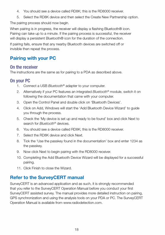
You should see a device called RD8K; this is the RD8000 receiver.
Select the RD8K device and then select the Create New Partnership option.
The pairing process should now begin.
When pairing is in progress, the receiver will display a flashing Bluetooth® icon. Pairing can take up to a minute. If the pairing process is successful, the receiver will display a persistent Bluetooth® icon for the duration of the connection.
If pairing fails, ensure that any nearby Bluetooth devices are switched off or invisible then repeat the process.
Pairing with your PC
On the receiverThe instructions are the same as for pairing to a PDA as described above.
On your PCConnect a USB Bluetooth® adapter to your computer.
Alternatively if your PC features an integrated Bluetooth® module, switch it on following the documentation that came with your computer.
Open the Control Panel and double click on ‘Bluetooth Devices’.
Click on Add, Windows will start the ‘Add Bluetooth Device Wizard’ to guide you through the process.
Check the ‘My device is set up and ready to be found’ box and click Next to search for Bluetooth® devices.
You should see a device called RD8K; this is the RD8000 receiver.
Select the RD8K device and click Next.
Tick the ‘Use the passkey found in the documentation’ box and enter 1234 as the passkey.
Now click Next to begin pairing with the RD8000 receiver.
Completing the Add Bluetooth Device Wizard will be displayed for a successful pairing.
Click Finish to close the Wizard.
Refer to the SurveyCERT manualSurveyCERT is an advanced application and as such, it is strongly recommended that you refer to the SurveyCERT Operation Manual before you conduct your first SurveyCERT assisted survey. The manual provides more detailed instruction on pairing, GPS synchronization and using the analysis tools on your PDA or PC. The SurveyCERT Operation Manual is available from www.radiodetection.com.
�.
�.
1.
2.
3.
�.
�.
�.
�.
8.
�.
10.
11.

ENG
LISH
DEU
TSC
HES
pAñ
oL
FRA
NÇ
AIS
ITA
LIA
No
NED
ERLA
ND
S
1�
Locating pipes and cables
Passive FrequenciesPassive frequency detection takes advantage of signals that are already present on buried metallic conductors. The RD8000 supports four types of passive frequencies: power, radio, CPS and CATV signals. You can detect these frequencies without the aid of the transmitter.
Active FrequenciesActive frequencies are applied direct to the pipe or cable using the transmitter. The transmitter can apply a signal using two methods: induction and direct connection.
InductionThe transmitter is placed on the ground over or near the survey area. You select the appropriate frequency. The transmitter will then induce the signal indiscriminately to any nearby metallic conductor. In induction mode, using higher frequencies is generally recommended as they are induced easier onto nearby conductors.
Direct connectionIn direct connection, you connect the transmitter directly to the pipe or cable you wish to survey. The transmitter will then apply a discreet signal to the line, which you can locate using the receiver. This method provides the best signal on an individual line and enables the use of lower frequencies, which can be traced for longer distances.
Connecting the transmitter to a pipe or line requires the use of a direct connection lead or clamp and a ground stake to complete the circuit.
WARNING! Direct connection to live wires is POTENTIALLY LETHAL. Direct connections should be attempted by fully qualified personnel only!
Signal clampsA signal clamp can apply a signal to a live line without breaking the connection. Signal clamps are connected to the transmitter’s accessory socket. Radiodetection supplies a range of signal clamps to suit most applications. Note that the RD8000 is fully compatible with the RD�000 range of signal clamps.
StethoscopesAt times, it may not be possible to use a clamp around a cable because of congestion or inaccessibility. A stethoscope antenna should be used in place of a clamp to identify cables.
Radiodetection supplies a range of stethoscopes to suit most applications. As with

20
signal clamps RD8000 is fully compatible with the RD�000 range of stethoscopes.
To use a stethoscope, connect it to the receiver’s accessory socket. The receiver will automatically detect the device and filter out location modes that are irrelevant.
NOTE: For more information on Bluetooth® pairing and using SurveyCERT to analyze survey data, please refer to the RD8000 operation manual and the SurveryCERT™ manual, which are available from www.radiodetection.com
Locating sondes
Sondes are battery powered transmitters that are useful for tracking non-metallic pipes. The RD8000 can detect a range of sonde frequencies, including those transmitted by flexisondes and the P350 flexitrax™ crawler.
For a detailed guide on locating sondes, please refer to the RD8000 operation manual.
Using accessories
Both the transmitter and receiver are compatible with a wide range of accessories, including all RD�000 accessories. Use clamps to help apply a signal to pipeline or live wire. Use an A-Frame to provide the RD8000 receiver with advanced fault-finding capabilities.
When an accessory is connected, the receiver or transmitter will instantly recognize it and will enable the mode appropriate to the accessory. For example, attaching an A-Frame to the RD8000 receiver will automatically switch the receiver to fault-find mode and limit the number of available frequencies to those that are compatible with the A-Frame. The LCD will also display an icon of the accessory and will remove any non-essential icons from the screen.
Fault-finding
The RD8000 PDL and PDLB have the ability to detect cable faults accurately using an accessory A-Frame. Fault-finding works by detecting signal to ground bleeding caused by damaged cable sheaths. For a detailed guide to fault-finding, please refer to the RD8000 operation manual.

ENG
LISH
DEU
TSC
HES
pAñ
oL
FRA
NÇ
AIS
ITA
LIA
No
NED
ERLA
ND
S
21
Centros™ Manager and eCAL™
eCAL makes it easy to validate your RD8000 or RD7000 receiver against its original factory calibration. eCAL is bundled with the Centros Manager application suite and is available as a free download from www.radiodetection.com. eCAL runs on laptop and desktop computers with Microsoft Windows XP or Vista and requires one free USB port to connect the receiver to the computer.
Before you can install Centros Manager, you must first register your receiver for the free extended 3-year warranty at www.radiodetection.com/extendedwarranty. To use eCAL, you must also purchase a validation key from www.radiodetection.com/ecal.
Installing Centros ManagerDownload Centros Manager application bundle from www.radiodetection.com to your computer.
Close all applications on your PC, including your internet browser.
Extract the files within the bundle using WinZip or a similar compressed file manager.
Open the folder containing the extracted files and double click setup.exe. An install wizard will load to help guide you through the rest of the process. Click Next to continue and follow the on-screen prompts.
Once the installation process finishes, click Finish to exit the wizard.
Validating a receiver for the first timeMake sure you have purchased a validation key before continuing.
Connect your receiver to your computer using the supplied USB cable. On the receiver, the USB port is located inside the battery compartment.
Ensure the receiver is switched on before continuing with the firmware upgrade.
Open eCAL – Validation from the Windows Start Menu.
If you have previously loaded a validation key, the unit manager window will display a list of any RD8000 or RD�000 receiver for which you have purchased a validation key.
Click the Load Validation Key icon on the toolbar.
Copy and paste your validation key from your validation email into the Add Validation Key dialogue box and click Add.
Expand the tree viewer for the receiver you wish to validate by clicking the Expand tree icon on the toolbar. eCAL will display a list of purchased Validation Keys and the device’s Calibration History.
1.
2.
3.
�.
�.
1.
2.
3.
�.
�.
�.
�.
8.

22
Check that your new key appears under the Key List in the unit manager. The key will be identifiable by the date you added it. The key will expire one week from that date.
Click the Calibrate Unit icon on the toolbar. eCAL will now validate the receiver against the original factory calibration. Do not disconnect the receiver until this process is complete.
For more information about Centros Manager and eCAL, please refer to the Centros Manager Operation Manual, which is available for download from www.radiodetection.com.
Upgrading your RD8000As part of our continuous product improvement strategy, Radiodetection will release new firmware for the RD7000 and RD8000 system from time to time. Upgrading your receiver’s firmware will improve performance, stability and may include new features. This firmware is available free of charge. To receive notification of new firmware releases, users should first register for extended warranty.
To register for extended warranty go to: www.radiodetection.com/extendedwarranty
When new firmware is available, registered users will receive notification automatically via email.
To get more information about firmware upgrades go to: www.radiodetection.com/firmwareupgrades
Extended WarrantyAll RD8000 and RD7000 family products have a 1-year warranty. Users can extend the warranty on all RD�000 and RD8000 receivers and transmitters to 3 years by registering. Registration is free and entitles the user to free firmware upgrades.
To be eligible, customers must register within 3 months of purchase.
Upon registration customers will receive confirmation of registration by email. The email will include a Download key required for firmware upgrades of your RD7000 or RD8000 products using Centros™ Manager.
When new firmware is released, registered users will receive a notification email that links to the new firmware download page on the Radiodetection website. The email will also contain instructions on how to download the firmware and upgrade your RD8000 or RD�000 system.
To register for extended warranty go to: www.radiodetection.com/extendedwarranty
�.
10.

ENG
LISH
DEU
TSC
HES
pAñ
oL
FRA
NÇ
AIS
ITA
LIA
No
NED
ERLA
ND
S
23
Warranty
Subject to the conditions set out herein, Radiodetection Limited expressly and exclusively provides the following warranty to original end user buyers of Radiodetection products. Radiodetection products includes Radiodetection, Pearpoint, Telespec, Bicotest, Riser Bond, Dielectric, Mark Products and Warren G-V brands. Radiodetection hereby warrants that its products shall be free from defects in material and workmanship for one year starting from point of sale to end customer. Extensions of this warranty period are available where the same terms and conditions apply.
Product families include:
• Cable & Pipeline Location • Trenchless • Water Leak Detectors
• Pipeline Integrity • Pipeline Video Inspection • Ground Penetrating Radar
• Cable Test • Cable Dryers
To register for an extended warranty (3 years) go to: www.radiodetection.com/support/warranty
Statement of warranty conditions
The sole and exclusive warranty for any Radiodetection product found to be defective is repair or replacement of the defective product at Radiodetection’s sole discretion. Repaired parts or replacement products will be provided by Radiodetection on an exchange basis and will be either new or refurbished to be functionally equivalent to new.
In the event this exclusive remedy is deemed to have failed of its essential purpose, Radiodetection’s liability shall not exceed the purchase price of the Radiodetection product. In no event will Radiodetection be liable for any direct, indirect, special, incidental, consequential or punitive damages (including lost profit) whether based on warranty, contract, tort or any other legal theory.
Warranty services will be provided only with the original invoice or sales receipt (indicating the date of purchase, model name and dealer’s name) within the
warranty period. This warranty covers only the hardware components of the Radiodetection product. Data storage media or accessories must be removed prior to submission of the product for warranty service.
Radiodetection will not be responsible for loss or erasure of data storage media or accessories. Radiodetection is not responsible for transportation costs and risks associated with transportation of the product. The existence of a defect shall be determined by Radiodetection in accordance with procedures established by Radiodetection.
This warranty is in lieu of any other warranty, express or implied, including any implied warranty of merchantability or fitness for a particular purpose.

2�
This warranty does not cover:
periodic maintenance and repair or parts replacement due to wear and tear
consumables (components that are expected to require periodic replacement during the lifetime of a product such as non-rechargeable batteries, bulbs, etc.)
damage or defects caused by use, operation or treatment of the product inconsistent with its intended use
damage or changes to the product as a result of:
misuse, including: - treatment resulting in physical, cosmetic or surface damage or changes to the product or damage to liquid crystal displays
failure to install or use the product for its normal purpose or in accordance with Radiodetection’s instructions on installation or use
failure to maintain the product in accordance with Radiodetection’s instructions on proper maintenance
installation or use of the product in a manner inconsistent with the technical or safety laws or standards in the country where it is installed or used
virus infections or use of the product with software not provided with the product or incorrectly installed software
the condition of or defects in systems with which the product is used or incorporated except other ‘Radiodetection products’ designed to be used with the product
a.
b.
c.
d.
i.
ii.
iii.
iv.
v.
vi.
use of the product with accessories, peripheral equipment and other products of a type, condition and standard other than prescribed by Radiodetection
repair or attempted repair by persons who are not Radiodetection warranted and certified repair houses
adjustments or adaptations without Radiodetection’s prior written consent, including:
upgrading the product beyond specifications or features described in the instruction manual, or
modifications to the product to conform it to national or local technical or safety standards in countries other than those for which the product was specifically designed and manufactured
neglect e.g. opening of cases where there are no user replaceable parts
accidents, fire, liquids, chemicals, other substances, flooding, vibrations, excessive heat, improper ventilation, power surges, excess or incorrect supply or input voltage, radiation, electrostatic discharges including lighting, other external forces and impacts.
vii.
viii.
ix.
i.
ii.
x.
xi.