‘License to Drink’: White-Collar Female Workers and Japan’s Urban Night Space
Upload
independentCategory
view
0download
0
Tool Code: CCL015
Document: MN-CCL015-K
Casing Collar Locator
CASING COLLAR LOCATOR
111/16″, ULTRAWIRE™
Operational & Maintenance Manual
Date:
Author:
Revised:
Approved:
Tel: +44(0)1252 862 200Fax: +44(0)1252 862 349 www.ge-energy.com/oilfield
This document contains proprietary information. Copyright © Sondex Wireline Limited 1992-2010. All rights reserved.Created: November 5, 2010
29th July 1992
Robert Holding
June 2010
Robert Holding
Title Page

Casing Collar Locator CCL015Contents
Contents
0 About This Manual. . . . . . . . . . . . . . . . . . . . . . . . . . . . . . . . . . . . . . . . . .0-10.1 Manual History 0-10.2 Updates To Be Used With This Manual 0-10.3 Technical Help 0-10.4 Feedback 0-1
1 Description. . . . . . . . . . . . . . . . . . . . . . . . . . . . . . . . . . . . . . . . . . . . . . . .1-11.1 Purpose 1-11.2 Applications 1-11.3 Interfacing & Tool Combinations 1-11.4 Specification 1-2
2 Safety . . . . . . . . . . . . . . . . . . . . . . . . . . . . . . . . . . . . . . . . . . . . . . . . . . .2-12.1 General 2-12.2 Magnets 2-12.3 Electro Static Discharge 2-1
3 Theory Of Operation . . . . . . . . . . . . . . . . . . . . . . . . . . . . . . . . . . . . . . . .3-13.1 Block Diagram 3-13.2 Description 3-1
3.2.1 Magnetic Measurement 3-13.2.2 Electronics 3-2
4 Operating Procedure . . . . . . . . . . . . . . . . . . . . . . . . . . . . . . . . . . . . . . . .4-14.1 Pre-Logging Checks 4-1
4.1.1 Mechanical 4-14.1.2 Electrical 4-14.1.3 Operating 4-1
4.2 Connecting To Toolstring 4-24.3 Logging 4-34.4 Post Logging Disassembly 4-34.5 Transport, Handling & Storage 4-3
5 Mechanical Description . . . . . . . . . . . . . . . . . . . . . . . . . . . . . . . . . . . . . .5-15.1 Disassembly 5-1
5.1.1 Electronics Access 5-15.1.2 Magnets & Detector Coil 5-1
5.2 Reassembly 5-25.2.1 Magnets & Detector Coil 5-25.2.2 Electronics 5-4
This document contains proprietary information. Copyright © Sondex Wireline Limited 1992-2010. All rights reserved.
iDocument: MN-CCL015-K Created: November 5, 2010
Casing Collar Locator CCL015Contents
6 Electrical Description . . . . . . . . . . . . . . . . . . . . . . . . . . . . . . . . . . . . . . . .6-16.1 PSU/Telemetry Circuit Board 6-16.2 CCL VCO Oscillator Circuit Board 6-3
7 Extended Checks . . . . . . . . . . . . . . . . . . . . . . . . . . . . . . . . . . . . . . . . . .7-17.1 Preventative Maintenance 7-1
7.1.1 Grease & Lubricants 7-17.1.2 Mechanical 7-17.1.3 Electrical 7-27.1.4 Ageing of Electronics 7-27.1.5 Heat Testing Above 150°C 7-2
7.2 Extraordinary Maintenance 7-37.3 Troubleshooting 7-3
Appendix A Equipment & Recommended Spares . . . . . . . . . . . . . . . . . . . A-1A.1 Ancillary Equipment A-1A.2 Maintenance Equipment A-1A.3 Recommended Spares A-1
Appendix B Drawings & Parts Lists . . . . . . . . . . . . . . . . . . . . . . . . . . . . . . B-1B.1 Mechanical Drawings B-1B.2 Electronic Drawings B-1
This document contains proprietary information. Copyright © Sondex Wireline Limited 1992-2010. All rights reserved.
iiDocument: MN-CCL015-K Created: November 5, 2010

Casing Collar Locator CCL015Chapter 0. About This Manual
0 ABOUT THIS MANUAL
0.1 MANUAL HISTORY
0.2 UPDATES TO BE USED WITH THIS MANUAL
Consult the CD Directory for the appropriate Manual Updates to be used with this Manual.
0.3 TECHNICAL HELP
For further technical help, contact Sondex as follows: Address: Unit 1, Saxony Way
Blackbushe Business Park Yateley, Hampshire GU46 6AB United Kingdom
Tel: +44(0)1252 862 200 Fax: +44(0)1252 862 349 Web: www.ge-energy.com/oilfield
0.4 FEEDBACK
Please help us improve future issues of this manual by adding your comments or corrections to www.ge-energy.com/oilfield, referencing the document number.
Thank You.
Photographs and sketches are for illustration purposes only. Depending on the tool model that you have, certain features or dimensions may differ from those shown.
Date Issue Description Auth Chk App
23/04/03 G CD80062 up-issued as per ECR1348 & 1406. SA DMO RLH
15/07/04 H Drawings/Parts Lists/Electrical Diagrams updated as per ECR1528/1606/2098/2043.
SA DMO RLH
13/06/06 I Drawings/Parts Lists/Electrical Diagrams updated. ECR3220, 2904, 2822, 3141.
FV SA RLH
02/03/07 J Drawing updates. ECR3920, 4089. FV FV RLH
07/06/10 K Recommendations added to Section 2. Appen-dix A: 91050 up-issued & SAP BOMs added. Appendix B: up-issued 09528, CD-82261 & CD-80062.SAP BOM added.
RS PR PR
This document contains proprietary information. Copyright © Sondex Wireline Limited 1992-2010. All rights reserved.
0-1Document: MN-CCL015-K Created: November 5, 2010

Casing Collar Locator CCL015Chapter 0. About This Manual
Documents from external sources (i.e. MSDS), supplied with/referenced in this manual, are considered the latest version at time of manual issue. However, the document can be altered by the external source without prior notice to Sondex.
This document contains proprietary information. Copyright © Sondex Wireline Limited 1992-2010. All rights reserved.
0-2Document: MN-CCL015-K Created: November 5, 2010
Casing Collar Locator CCL015Chapter 1. Description
1 DESCRIPTION
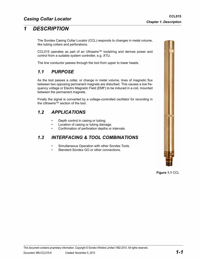
The Sondex Casing Collar Locator (CCL) responds to changes in metal volume, like tubing collars and perforations.
CCL015 operates as part of an Ultrawire™ toolstring and derives power and control from a suitable system controller, e.g. XTU.
The line conductor passes through the tool from upper to lower heads.
1.1 PURPOSE
As the tool passes a collar, or change in metal volume, lines of magnetic flux between two opposing permanent magnets are disturbed. This causes a low fre-quency voltage or Electro Magnetic Field (EMF) to be induced in a coil, mounted between the permanent magnets.
Finally the signal is converted by a voltage-controlled oscillator for recording in the Ultrawire™ section of the tool.
1.2 APPLICATIONS
• Depth control in casing or tubing.• Location of casing or tubing damage.• Confirmation of perforation depths or intervals.
1.3 INTERFACING & TOOL COMBINATIONS
• Simultaneous Operation with other Sondex Tools.• Standard Sondex GO or other connections.
Figure 1.1 CCL
This document contains proprietary information. Copyright © Sondex Wireline Limited 1992-2010. All rights reserved.
1-1Document: MN-CCL015-K Created: November 5, 2010

Casing Collar Locator CCL015Chapter 1. Description
1.4 SPECIFICATION
Parameter Specification Remarks
Temperature (max) 177ºC (350ºC)
Pressure (max) 15,000psi (103,4MPa)
Tool Diameter 111/16″ (43mm)
Make Up Length 18.5″ (470mm)
Shipping Length 22.3″ (566mm) Incl. Thread Protectors.
Measure Point 6.5″ (165.1mm) Above lower tool joint.
Weight in air 12.1lbs (5.5kg)
Operating voltage:
- Nominal +18V DC
- Range +13 to +23V DC
- Absolute Max. +24V DC
Current consumption at 18V 16mA
End threads (top/bottom) 13/16″ 12 UN2A GO Female/Male
End connectors (top/bottom) 4mm single conductor (male pin/female socket)
Sondex Ends
This document contains proprietary information. Copyright © Sondex Wireline Limited 1992-2010. All rights reserved.
1-2Document: MN-CCL015-K Created: November 5, 2010

Casing Collar Locator CCL015Chapter 2. Safety
2 SAFETY
2.1 GENERAL
HOT WORK! Sondex equipment may, under certain circumstances or failure modes, become a potential source of ignition. Using it must therefore be considered "HOT WORK" and appropriate precautionary procedures should be followed when testing at surface in areas where there is a risk of gas leaks or other potentially explosive atmospheres.
Warning!
Liquid O-ring
LOR101 is used for lubricating the tool during maintenance. Contact with skin or eyes can be harmful. For more details, refer to the Material Safety Data Sheet for Liquid O-ring.
2.2 MAGNETS
The two magnets, used in the tool, produce a magnetic field which extends for a considerable distance. When the tool is dismantled, the magnets should be kept at least 1ft from any watches, analogue meters or cathode ray tubes to avoid any ill effects from the field.
The magnets are relatively fragile and can be cracked by small mechanical shocks. Care must be taken not to drop them. They must be carefully wiped free of any swarf before re-assembly. This is easily accomplished with a steel brush.
2.3 ELECTRO STATIC DISCHARGE
When handling tools, which contain electronic parts that are ESD sensitive, the following guidelines should be followed to reduce any possible electrostatic charge build-up on the user’s body and the electronic parts:
• Always ensure proper ESD precautions are taken when handling electronic parts that are ESD sensitive during maintenance.
• Avoid touching the tool electronics, unless stated otherwise in this manual.
Note that ESD is less likely to affect tools when the housing is fitted.
Electro Static Discharge (ESD)
All tools with electronic boards that contain solid state circuits (transistors, diodes, semiconductors) may become damaged when contacted with an electrostatic charge.
Caution!
Caution! Do not store CCL with PGR or PGC tools. Keep at least 1 foot apart. Magnetic field may magnetise pressure housing and seriously reduce sensitivity.
This document contains proprietary information. Copyright © Sondex Wireline Limited 1992-2010. All rights reserved.
2-1Document: MN-CCL015-K Created: November 5, 2010

Casing Collar Locator CCL015Chapter 2. Safety
2.4 RECOMMENDATIONS
High Voltage Risk!
The product should be installed, adjusted and serviced by qualified electrical maintenance personnel. Improper installation or operation of the equipment may cause injury to personnel or equipment. Before beginning any installation or commissioning work make sure the electrical power is disconnected and locked out.
NOTE: Installation must meet National Wiring Regulations in accordance with IEC/UL 61010 latest revision.
WARNING 1: The outer casing of the product should be connected to a known good system ground (earth) before making any other electrical power connection. This system ground (earth) is to be maintained until all electrical power connections are disconnected and locked out.
WARNING 2: Units with exposed Electrical Connectors are supplied with protective insulating end caps bearing a warning of High Voltage. These end caps should be removed only when Electrical Power is disconnected and locked out for the purposes of interconnection to other Units. Under no circumstances should equipment be operated with the Electrical Connectors exposed.
WARNING 3: Units with moving parts (such as callipers) can be activated immediately on application of Electrical Power. A safe area should be established around any such Units before the application of Electrical Power.
WARNING 4: Units with moving parts (such as springs) can retain significant Potential Energy. Great care should be exercised when removing Closing Rings or handling assemblies that have been over-tightened.
WARNING 5: Units that contain seals may trap pressure. Disassembly should be carried only out in accordance with the recommended procedures to make sure the pressure is released prior to the disengagement of cap threads.
WARNING 6: When the equipment is not installed, commissioned and used in accordance with the specifications of the manufacturer, any protection that may have been provided may be impaired.
Standard Personal Safety Gear!
The standard personal safety gear must be worn at all times, including but not limited to: Safety glasses, gloves and steel-toed boots.
Equipment that exceeds 18Kg (39,7lbs) in weight should be handled with extreme care. Heavy items should be lifted mechanically. Any installation of equipment that weighs 10Kg (22lbs) or more and is to be lifted over 1,0 metre (3,3 feet) should be at least a two-man lift. Good lifting practice should be exercised at all times, including but not limited to:
• The use of correct personal safety gear• Lift through the use of the legs and not the back• Not proceeding with a lift in the presence of any doubt of completing the lift safely• The use of mechanical lifting aids wherever possible• Making sure the work area is free of clutter and possible trip hazards
This document contains proprietary information. Copyright © Sondex Wireline Limited 1992-2010. All rights reserved.
2-2Document: MN-CCL015-K Created: November 5, 2010

Casing Collar Locator CCL015Chapter 3. Theory Of Operation
This document contains proprietary information. Copyright © Sondex Wireline Limited 1992-2010. All rights reserved.
3-1Document: MN-CCL015-K Created: November 5, 2010
3 THEORY OF OPERATION
3.1 BLOCK DIAGRAM
Figure 3.1 Ultrawire™ CCL Block Diagram
3.2 DESCRIPTION
See also: Section 6 Electrical Description
3.2.1 MAGNETIC MEASUREMENT
The fields of two opposing permanent magnets pass through a coil positioned between them. It is the movement of the lines of flux through the coil as they are altered by the variation in steel volume and position alongside the tool that produce a change in EMF across the coil output. The output from this coil is the conventional low frequency CCL, which is sent to surface in wireline tools.
This axial arrangement of 2 magnets minimises the unwanted signal from sideways motion in the well.
3.2.2 ELECTRONICS
The low frequency CCL is amplified and filtered before modulating a Voltage Controller Oscillator (VCO), which has a typical centre frequency of 6kHz or 17kHz, depending on revision level. This frequency is stored in the FPGA logic and is read out over the Ultrawire™ toolbus in response to requests from the Telemetry Controller, e.g. MPL or XTU. Various commands are supported in the protocol.
LINE
PSU(PCB82261)
Ultrawire Telemetry
V+Amplifier & Oscillator
(PCB80062)
+12V
ELECTRONICS SECTION MAGNETS & DETECTOR SECTION
S N N S

Casing Collar Locator CCL015Chapter 4. Operating Procedure
4 OPERATING PROCEDURE
4.1 PRE-LOGGING CHECKS
See also: Section 7 Extended Checks
4.1.1 MECHANICAL
Ref.: General Assembly 09528
1 Clean and grease upper and lower O-ring seals. Replace O-rings (item 17) if damaged.
2 Ensure that upper and lower electrical connectors are clean, dry and undamaged.
3 Ensure 3 Grub Screws (item 22) are screwed out very tight; these are the telemetry ground return.
4.1.2 ELECTRICAL
1 Using a Multimeter, check the upper to lower pin resistance. The reading should be less than 0.5Ω.
2 Using a Multimeter, check the Pin to Housing resistance. The reading should be:
• Pin +ve 3 - 4MΩ (Depends on meter.)
4.1.3 OPERATING
The CCL must be electrically connected to a toolstring controller, e.g. UMT or XTU, and to a data acquisition or logging system, e.g. MEMLOG or MIDAS.
1 Move a magnetic material, such as a steel screwdriver, past the measure point. A positive and negative variation (±100Hz typical) from the centre frequency should be observed. Faster and closer movement causes a larger signal. Note that most stainless steels are non-magnetic.
Note: MEMLOG and MIDAS have optional normalisation filters to subtract any drift of the CCLs centre frequency.
• CCL centre frequency: 6 or 17kHz typical.• MEMLOG normalisation frequency: 2.00kHz.• MIDAS normalisation frequency: 0.00kHz.
This document contains proprietary information. Copyright © Sondex Wireline Limited 1992-2010. All rights reserved.
4-1Document: MN-CCL015-K Created: November 5, 2010
Casing Collar Locator CCL015Chapter 4. Operating Procedure
4.2 CONNECTING TO TOOLSTRING
Upper and lower tool joint O-rings and seal surfaces should be clean, undamaged and lightly greased.
The CCL should be inserted into a suitable Ultrawire™ toolstring in any location below the telemetry controller. The use of centralisers is optional. However, for best results, the tool should be run eccentered by using conducting knuckle joints. This will produce a larger CCL signal since the casing collar will pass closer to the magnetic field.
4.3 LOGGING
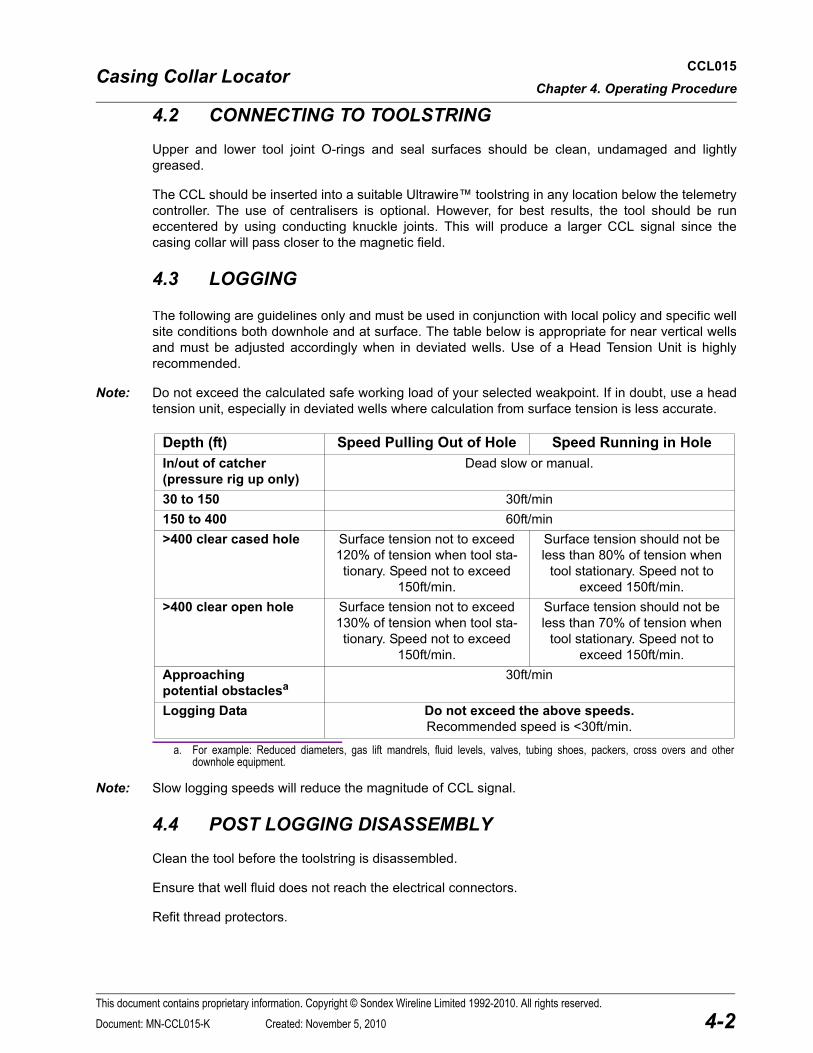
The following are guidelines only and must be used in conjunction with local policy and specific well site conditions both downhole and at surface. The table below is appropriate for near vertical wells and must be adjusted accordingly when in deviated wells. Use of a Head Tension Unit is highly recommended.
Note: Do not exceed the calculated safe working load of your selected weakpoint. If in doubt, use a head tension unit, especially in deviated wells where calculation from surface tension is less accurate.
Depth (ft) Speed Pulling Out of Hole Speed Running in HoleIn/out of catcher (pressure rig up only)
Dead slow or manual.
30 to 150 30ft/min150 to 400 60ft/min>400 clear cased hole Surface tension not to exceed
120% of tension when tool sta-tionary. Speed not to exceed
150ft/min.
Surface tension should not be less than 80% of tension when
tool stationary. Speed not to exceed 150ft/min.
>400 clear open hole Surface tension not to exceed 130% of tension when tool sta-tionary. Speed not to exceed
150ft/min.
Surface tension should not be less than 70% of tension when
tool stationary. Speed not to exceed 150ft/min.
Approaching potential obstaclesa
a. For example: Reduced diameters, gas lift mandrels, fluid levels, valves, tubing shoes, packers, cross overs and other downhole equipment.
30ft/min
Logging Data Do not exceed the above speeds.Recommended speed is <30ft/min.
Note: Slow logging speeds will reduce the magnitude of CCL signal.
4.4 POST LOGGING DISASSEMBLY
Clean the tool before the toolstring is disassembled.
Ensure that well fluid does not reach the electrical connectors.
Refit thread protectors.
This document contains proprietary information. Copyright © Sondex Wireline Limited 1992-2010. All rights reserved.
4-2Document: MN-CCL015-K Created: November 5, 2010

Casing Collar Locator CCL015Chapter 4. Operating Procedure
4.5 TRANSPORT, HANDLING & STORAGE
Store with end threads lightly greased and with water tight thread protectors fitted.
Do not store CCL tools along side another CCL tool, otherwise magnet strength may be reduced.
Do not subject tool to extreme shock, such as dropping or hitting with a hard object.
Caution!Do not store CCL with FDR, or PGR tools which contain photomultiplier tubes, since magnetisation can prevent these from operating. Keep at least 1ft (30cm) apart.
This document contains proprietary information. Copyright © Sondex Wireline Limited 1992-2010. All rights reserved.
4-3Document: MN-CCL015-K Created: November 5, 2010

Casing Collar Locator CCL015Chapter 5. Mechanical Description
5 MECHANICAL DESCRIPTION
The CCL consists of a single main assembly attached to the Lower Head. A Pressure Housing slides over the internal components and screws onto the Lower Head.
The principal elements are as follows:
• Pressure Housing.• Telemetry circuit board.• CCL VCO oscillator circuit board.• Detector Coil.• Two permanent magnets housed in protective steel tube.• Upper End fitted with monoconductor pin.• Lower End fitted with monoconductor socket.
5.1 DISASSEMBLY
5.1.1 ELECTRONICS ACCESS
Ref.: General Assembly 09528
1 Unscrew Housing (item 1) from Lower Head (item 5).
Note: The complete internal assembly remains attached to the Lower Head (item 5).
2 Remove Screws (4x item 21) and remove Large Top Cover (item 4).
Note: The Small Bottom Cover is an integral part of the chassis and should not be removed, particularly if the Large Top Cover is removed.
3 The 2 Circuit Boards (item 8) may be removed by unsoldering the wires as necessary.
Note: To service the Pressure Isolation Head (item 3), refer to Pressure Isolation Head Manual, MN-PIH.
5.1.2 MAGNETS & DETECTOR COIL
Ref.: General Assembly 09528 Assembly Coil and Magnets 00226 CCL Wiring Diagram WD-80075
Note: All item numbers refer to drawing 00226, unless stated otherwise.
Note: The magnets and coil are normally treated as a unit assembly, but can be disassembled if necessary. If either of the magnets or the coil has been replaced, the locking pin holes will probably no longer be lined up and will need to be redrilled. Return the items to Sondex if necessary.
1 Unsolder the red and black wires connecting the Coil (item 1) to the Electronics (item 8, 09528).
2 Unsolder the yellow through wire from the Telemetry board, see WD-80075.
This document contains proprietary information. Copyright © Sondex Wireline Limited 1992-2010. All rights reserved.
5-1Document: MN-CCL015-K Created: November 5, 2010
Casing Collar Locator CCL015Chapter 5. Mechanical Description
3 Screw in the Grub Screws (3x item 22, 09528) sufficient for the Lower Head (item 5, 09528) to be withdrawn from the Magnet Assembly (item 2, 09528). Separate the two parts carefully to avoid damaging the through wire as it is pulled through the centre of the magnet assembly.
4 With a 2mm pin punch, knock in the Spirol Pins (8x item 6) at the ends of the Magnet Cover Tubes (item 3) until they are just below the surface of the tube.
5 Unscrew the Lower Bulkhead (item 2) and remove the Lower Magnet (item 5).
6 Mark the N (coil end) and S (bulkhead end) pole positions of the Magnets.
7 Unscrew the Lower Magnet Cover Tube (item 3) from the Coil (item 1).
8 Unscrew the Coil (item 1) from the Upper Magnet Tube (item 3), taking care that the coil wires can freely rotate in the centre hole of the Upper Bulkhead (item 4) and Upper Magnet (item 5).
9 Remove the Upper Magnet from its Magnet Tube and mark N (coil end) and S (bulkhead end).
10 Carefully knock all Spirol Pins (item 6) through to the centre and thus out of the Coil (item 1) and Bulkheads (item 2 & 4).
Note: Avoid damaging the Coil (item 1) leads or it is likely the Coil (item 1) will need to be replaced.
5.2 RE-ASSEMBLY
5.2.1 MAGNETS & DETECTOR COIL
Ref.: General Assembly 09528 Assembly Coil and Magnets 00226
Note: All item numbers refer to drawing 00226, unless stated otherwise.
1 Check components and wires for damage and replace if necessary.
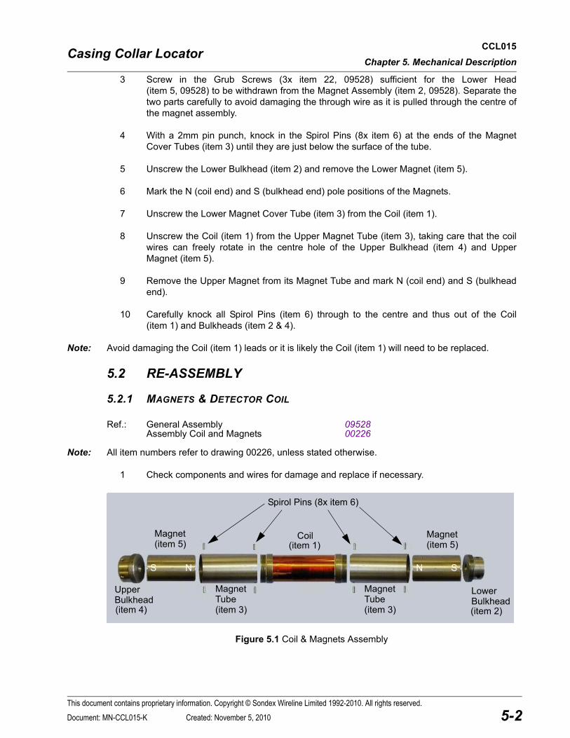
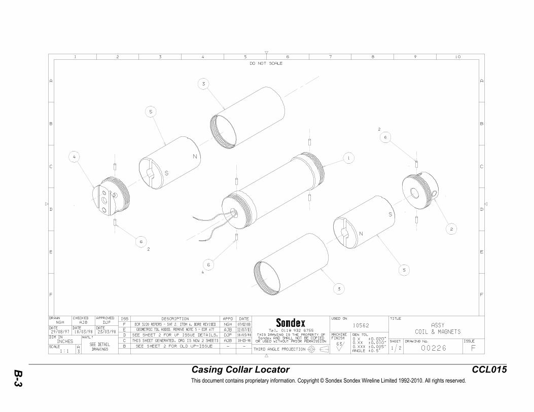
Figure 5.1 Coil & Magnets Assembly
S N
Magnet(item 5)
SN
Magnet(item 5)
Magnet
(item 3)
Coil(item 1)
Lower
(item 2)Bulkhead
Upper
(item 4)Bulkhead Tube
Magnet
(item 3)Tube
Spirol Pins (8x item 6)
This document contains proprietary information. Copyright © Sondex Wireline Limited 1992-2010. All rights reserved.
5-2Document: MN-CCL015-K Created: November 5, 2010
Casing Collar Locator CCL015Chapter 5. Mechanical Description
Note: If any parts have been replaced it will be necessary to lock the Magnet Tubes (item 3) to the Coil Bulkheads (items 2 & 4) in some way. Sondex recommend that the 2mm Ø locking holes should be redrilled. Return to Sondex if necessary.
In an emergency, back off the cover tube a few turns and coat the end threads with Loctite® 242 then screw up hand tight once more.
2 Fit the Upper Magnet (item 5) onto the Coil (item 1), ensuring Magnet polarity orientation as shown in Figure 5.1 (N facing the Coil).
Note: Ensure all inner spaces are free from debris. Pay particular attention to swarf in the region of the magnet.
3 Slide a Magnet Tube Cover (item 3) over each Magnet (item 5), screw hand tight to the Coil (item 1) and secure with Spirol Pins (2x item 6).
4 Feed the Coil Wire through the Upper Bulkhead (item 4) into the electronics cartridge.
5 Screw the Upper Bulkhead (item 4) hand tight into the Magnet Tube Cover (item 3), ensur-ing the coil leads are rotating freely until the Magnet is gripped tightly. Secure with 2x Spirol Pins (item 6), ensuring the Pins are flush with the component circumference and do not protrude.
Note: If no upper magnet or coil parts have been changed, the Spirol Pin holes should be aligned.
6 Screw the Magnet Tube Cover (item 3) onto the Coil Assembly (item 1). Secure with 2x Spirol Pins (item 6), ensuring the Pins are flush with the component circumference and do not protrude.
Note: If no lower magnet or coil parts have been changed, the Spirol Pin holes should be aligned.
7 Refit the Lower Magnet (item 5) into the Magnet Tube Cover (item 3), ensuring Magnet polarity orientation as shown in Figure 5.1 (N facing the Coil).
Note: Ensure all inner spaces are free from debris. Pay particular attention to swarf in the region of the magnet.
8 Screw the Lower Bulkhead (item 2) hand tight into the Magnet Tube Cover (item 3). Secure with 2x Spirol Pins (item 6), ensuring the Pins are flush with the component cir-cumference and do not protrude.
9 Before feeding the through wire through the assembly, it is advised to inspect the Lower Head Pressure Feedthrough (item 11, 09528), including the fitted O-ring, for damage and replace if necessary.
10 Feed the through wire attached to the Lower Sub (item 5, 09528) up through the central hole, which runs through the Magnet & Coil Assembly (item 2, 09528), until it exits into the Electronics Cartridge.
Caution! Due to the strength of the magnetic parts extreme care must be taken when handling magnets as they are prone to crack if subjected to impact.
This document contains proprietary information. Copyright © Sondex Wireline Limited 1992-2010. All rights reserved.
5-3Document: MN-CCL015-K Created: November 5, 2010

Casing Collar Locator CCL015Chapter 5. Mechanical Description
11 Check O-rings (2x item 17 & 2x item 16, 09528) on the Lower Sub (item 5, 09528) and replace if required. Apply Liquid O-ring to the O-rings and the O-ring grooves.
12 Fit the Lower Bulkhead (item 2) into the Lower Sub (item 5, 09528) and align the three locking holes.
13 Screw out the Grub Screws (3x item 24, 09528) until tight.
5.2.2 ELECTRONICS
Ref.: General Assembly 09528 CCL Wiring Diagram WD-80075
1 If removed previously for servicing, reconnect the Pressure Isolation Head (item 3) to the Lower Half Shell (item 4) and secure with Screws (2x item 23).
1 Resolder coil and line wires as indicated in WD-80075 and refit the Electronics Boards (item 8).
2 Replace the Upper Halfshell (item 4) and secure with Screws (2x item 21).
3 Check O-ring (item 15) on the Pressure Isolation Head (item 3) and replace if required. Apply Liquid O-ring to the O-ring and the O-ring groove.
4 Replace the Pressure Housing (item 1) and screw it tight onto the Lower Sub (item 5).
Note: Clean pressure seal surfaces at both ends of the Pressure Housing. Ensure housing is free from debris.
This document contains proprietary information. Copyright © Sondex Wireline Limited 1992-2010. All rights reserved.
5-4Document: MN-CCL015-K Created: November 5, 2010

Casing Collar Locator CCL015Chapter 6. Electrical Description
6 ELECTRICAL DESCRIPTION
6.1 TELEMETRY CIRCUIT BOARD
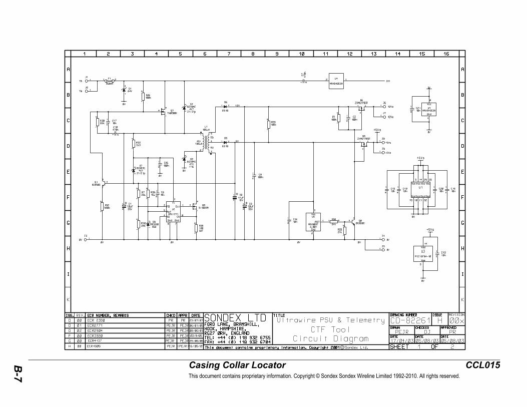
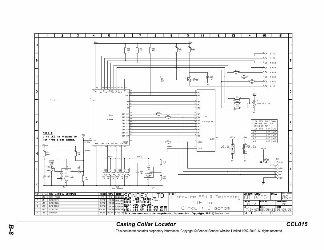
Ref.: Circuit Diagram (PCB82269) CD-82261
The Ultrawire™ Tool Telemetry Board is based on a common PCB (82260) which is populated and programmed according to the tool in which it is fitted. The main functional blocks of the circuit are the power supply, the Ultrawire™ interface (together with its drivers and receivers) and the sensor interface.
Control is implemented by a PIC microcontroller in conjunction with FPGA logic. The code in the PIC differs according to the tool.
Communication between the Telemetry Controller and the tool is via the Ultrawire™ toolbus. This is a single pin bus, which carries power to the tool in addition to its telemetry function. The return for both power and signal is via the chassis.
The Ultrawire™ line carries 18V DC (nom). Power is supplied to the SMPS via Q7, which with associated components generates local power rails at 12V and 5V.
The tool is protected by fuse (F1), which in conjunction with diode (D1) gives overvoltage and reverse polarity protection.
The telemetry is modulated onto the line as 1V AMI (alternate mark inversion) pulses at 500kbaud, see below a typical tool response.
The Ultrawire™ telemetry is a master slave protocol. The controller, which is always the master, sends a command to the tool. This may be a global command (to all tools) or a tool specific command which contains the address of the target tool. Tool specific commands are acknowledged by the tool, global commands are executed but do not generate a response.
0 0000 0
TOOL WORD#2
D4
14
D15
3
SSYNC/DATA S
1BIT NUMBER 2
D6D14 D13 D12 D11 D10 D9 D8 D7 D5
124 5 6 9 1087 11 13
D3 D2 D1 D0 S S
15 16 17 18 19 20
1
1.8us
18V typ
DATA
-1V
CONTROLLERCOMMAND
+1V
1 1
TOOL WORD#1
50-100ustypical
00 100 001 01 0
This document contains proprietary information. Copyright © Sondex Wireline Limited 1992-2010. All rights reserved.
6-1Document: MN-CCL015-K Created: November 5, 2010

Casing Collar Locator CCL015Chapter 6. Electrical Description
For rate-meter type tools, count pulses are collected from the sensor on inputs 1 - 7 of the PCB. These are counted in hardware by the FPGA logic, (U1) and accumulated by the PIC (U3).
When the controller is in logging mode, it will periodically send a global sample command to all the tools and then poll each tool individually for data. The sample command causes the latest count to be frozen in a shadow register, and this count is then passed to the controller in response to the data request.
Electrically, the telemetry is a.c. coupled from the line to the drivers and receivers by capacitor (C7). The received data is removed from the line by a comparator (U4), and passed to the FPGA logic, which validates the address. The command is interpreted by the PIC which if necessary generates the response packet and passes it to the FPGA logic for placement on the line.
6.2 CCL VCO OSCILLATOR CIRCUIT BOARD
Ref.: Circuit Diagram CD-80062
U5 provides a stable 5.00V reference which is amplified to provide 10V power for the amplifier/filter (U1), 6V analogue ground and 9V power for the 555 oscillator U2.
CCL coil is biased to the 6V analogue ground.
D1 and D4 limit the maximum coil voltage.
Amplifier U1b has a gain of around 20 set by the coil resistance (2.5kΩ typical), R1, R2 and R3. R3 reduces the effect of temperature drift on the coil.
U1b output is limited by D2 and D3.
Low pass filter, U1a, compensates for line speed by attenuating the larger CCL coil signals obtained by fast magnetic field variation.
U2 is configured as an oscillator, usually set to a nominal 6kHz. The CCL signal modulates the 'Con-trol Voltage' pin, therefore the 6kHz carrier frequency is modulated.
This document contains proprietary information. Copyright © Sondex Wireline Limited 1992-2010. All rights reserved.
6-2Document: MN-CCL015-K Created: November 5, 2010

Casing Collar Locator CCL015Chapter 7. Extended Checks
7 EXTENDED CHECKS
7.1 PREVENTATIVE MAINTENANCE
7.1.1 GREASE & LUBRICANTS
Sondex recommends the use of “Liquid O-ring type 101” (p/n LOR101) on threads and O-rings.
All O-rings and housing threads are assumed to be and must be lightly greased, unless specifically indicated otherwise.
Correct use of grease and lubricants is essential to the maintenance of all Sondex downhole equipment.
Note that some threads are internal, which can cause grease to get inside the tool. Do not use excessive quantities.
Sondex does not recommend Copper loaded greases since some types can cause electrical leaks. Some types for grease are not suitable for use on O-rings. Silicone grease may be used on O-rings, but must be kept clear of threads, especially stainless steel to stainless steel.
The use of certain greases, which contain volatile content, (e.g. some types of Lubriplate) can cause electrical failure due to production of corrosive gasses inside the tool when burned off.
Caution!
7.1.2 MECHANICAL
Ref.: General Assembly 09528
1 Remove dirt and old grease from pressure housing threads and O-rings and replace with fresh.
2 Inspect O-rings for damage or ageing/hardening and replace where required.
3 Check for:
• Damaged CCL coil.• Damaged wires.• Wires that are loose and likely to be crushed on reassembly.• Damaged components.• Loose screws/nuts/components/connectors.
Note: If RTV or similar compound is used to secure loose components, it must be fully cured before housing is replaced.
• Electrical components shorting to chassis.• Heat or chemical damage (discoloured components).• Incorrect thread grease or excessive quantity, see Section 7.1.1.• Cleanliness of connectors and loose/bent pins before replacing.
4 Check Line wire inside magnet assembly to lower end.
5 Check all fixings for tightness.
This document contains proprietary information. Copyright © Sondex Wireline Limited 1992-2010. All rights reserved.
7-1Document: MN-CCL015-K Created: November 5, 2010

Casing Collar Locator CCL015Chapter 7. Extended Checks
6 Check Grub Screws (3x item 22) are tight.
7 Check the magnets:
• For cracks and replace if necessary.• Oppose each other, normally north poles facing.
7.1.3 ELECTRICAL
1 Check through line resistance and tool current, see Section 4.1.2.
2 Check tool current 16mA at 18V.
3 Connect to Logging System and check for correct data. Apply some gentle vibration, rotation and invert tool to expose potential failure.
4 With an Oscilloscope, check line for +1V and -1V, 2μs pulses. Make sure to check tool pulses not those from the controller which occur first, see figure in Section 6.1.
Pulses should have no ringing, if ringing, also attach bottom tool (CTF, other bottom flowmeter or toolstring terminator (BUL006)).
7.1.4 AGEING OF ELECTRONICS
At 150°C, significant electronic ageing failures are expected after 4000hrs typical use, hence PCB replacement should be considered at this point. Every additional 10°C halves the time. Life of the electronics is also accelerated by vibration and corrosive gas inside the chassis. Visual inspection and logging previous history is recommended, but is unlikely to predict premature failure.
Tools that may be suspected of reliability problems due to age or unusual log response may be heated to 120°C, which would not normally age the electronics, and afterwards subjected to moderate vibration. A moderately hard blow from a wooden hammer is recommended.
DO NOT USE METAL HAMMERS.
7.1.5 HEAT TESTING ABOVE 150°C
This is not generally recommended since it shortens tool life expectancy.
Heat testing may be required for contractual reasons, tool out of use for a long period, or job with unusually high well temperature. The test should be carried out slightly above expected well temperature only and the tool should not be kept at temperature for more than 1 hour.
This document contains proprietary information. Copyright © Sondex Wireline Limited 1992-2010. All rights reserved.
7-2Document: MN-CCL015-K Created: November 5, 2010

Casing Collar Locator CCL015Chapter 7. Extended Checks
7.2 EXTRAORDINARY MAINTENANCE
Ref.: General Assembly 09528
See also: Section 4.1 Pre-Logging Checks
If the tool experiences H2S gas or temperatures above 150°C, the following O-rings must be replaced:
• 2x item 16.• 2x item 17.• 1x item 15.
The Pressure Housing (item 1) is Al/Bronze and will change colour from bronze to black as a sulphide layer is created by H2S gas. This layer should not be removed by polishing.
Magnetic strength may reduce with time, vibration and bad storage. Magnets can be re-magnetised or replaced.
7.3 TROUBLESHOOTING
Refer to Section 5.1 Disassembly and Appendix B where necessary.
An Oscilloscope, Multimeter and other basic test equipment will be required.
Initial inspection Check for:• Damaged wires.• Damaged components.• Electrical components shorting to chassis.• Heat or chemical damage (discoloured components).• Incorrect thread grease or excessive quantity, see Section 7.1.1.
Also check all fixings are tight.Excessive current Disconnect wires to isolate fault to:
• Upper head isolation assembly.• CCL Coil (see Faulty CCL coil below).• Line wire through lower pressure feedthrough and connector.• PCB82269 (CD82261).• PCB80062 (coil disconnected).
Apply Line Signal or 18V direct to PCB82269 Line connection.
Fault find or replace PCB82269.
Upper Head, line wire and lower connector may be tested to 250V relative to chassis to check for electrical leak. Line connection to PCB82269circuit must be disconnected. Resistance should exceed 100MΩ.
Upper head, line wire and lower pressure feedthrough and connector may be disassembled to locate fault.
Isolate high current to either PCB82269 or PCB80062. Fault find or replace PCB.
Little or no current On PCB82269 check LINE = 18V, V+ = 12V and Vc = 5V and 0V wire connects to chassis. Fault find or replace PCB.
This document contains proprietary information. Copyright © Sondex Wireline Limited 1992-2010. All rights reserved.
7-3Document: MN-CCL015-K Created: November 5, 2010
Casing Collar Locator CCL015Chapter 7. Extended Checks
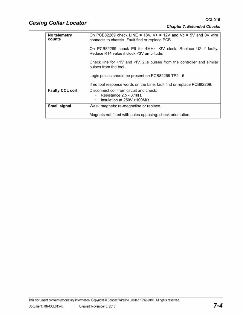
No telemetry counts
On PCB82269 check LINE = 18V, V+ = 12V and Vc = 5V and 0V wire connects to chassis. Fault find or replace PCB.
On PCB82269 check P6 for 4MHz >3V clock. Replace U2 if faulty. Reduce R14 value if clock <3V amplitude.
Check line for +1V and -1V, 2μs pulses from the controller and similar pulses from the tool.
Logic pulses should be present on PCB82269 TP2 - 5.
If no tool response words on the Line, fault find or replace PCB82269.Faulty CCL coil Disconnect coil from circuit and check:
• Resistance 2.5 - 3.1kΩ.• Insulation at 250V >100MΩ.
Small signal Weak magnets: re-magnetise or replace.
Magnets not fitted with poles opposing: check orientation.
This document contains proprietary information. Copyright © Sondex Wireline Limited 1992-2010. All rights reserved.
7-4Document: MN-CCL015-K Created: November 5, 2010

Casing Collar Locator CCL015APPENDIX A. Equipment & Recommended Spares
APPENDIX A EQUIPMENT & RECOMMENDED SPARES
A.1 ANCILLARY EQUIPMENT
A.2 MAINTENANCE EQUIPMENT
A.3 RECOMMENDED SPARES
Note: Spares kits suitable for remote logging operation can be supplied upon request.
Item Part No. Description Qty Remarks
1 CCL015 Casing Collar Locator, 111/16″, Ultrawire™ 1
Item Part No. Description Qty Remarks
None Required.
Item Part No. Description Qty Remarks
1 91050 Tool Kit for all 111/16″ Tools SX and GO 1
2 LOR101 Grease for O-rings & threads 1 5oz. pot
3 LOR101L Grease for O-rings & threads AR 12oz. pot
Item Part No. Description Qty Remarks
1 KITB-CCL1 11/16 Basic Spares Kit. 1 To support one run in hole.
2 KITR-CCL1 11/16 Recommended Spares Kit 1 Support 25 runs in hole.
3 KITRem-PIH, SX Spares Kit for Pressure Isolation Head 1 See Pressure Isolation Manual MN-PIH.
This document contains proprietary information. Copyright © Sondex Sondex Wireline Limited 1992-2010. All rights reserved.
A-1Document: MN-CCL015-K Created: November 5, 2010

Casing Collar Locator CCL015APPENDIX A. Equipment & Recommended Spares
PARTS LISTINGPart Issue
91050 CDescription
Tool Kit for all 1 11/16 Tools SX and GOPARTS LIST
Item Part No Description Qty Units Remarks0001 91005 Spanner Open Ended 42mmx38mm 2 EA0002 91019 Spanner C 50mm 35mm 2 EA0003 10038 Spanner Box 3/8 x 5/16 Modified 2 EA0004 91028 Spanner O/E 3/8x5/16 1 EA0005 93876 Spanner Single Open End 18mm 1 EA0006 91029 Key, Hex Metric (Set) 1 EA0007 91030 Punch Pin Parallel set 1 EA0008 00615 Assy Spanner PKJ 1 EA0009 91293 Screwdriver Parallel tip (3 0 x 75) 1 EA0010 91105 Toolroll With SX Badge Large Black 1 EA0011 91104 Screwdriver Parallel tip (5 5 x 200) 1 EA0012 91103 Pliers Circlip 812 Chrome/Van 1 EA0013 91102 Pliers Mini Flat Nose 5 Inch 1 EA0014 10037 Bar Tommy 2 EA0015 10051 Kemlon tool Sondex - 4BA Hex Socket 1 EA0016 91280 Hammer, 4oz ball pein 1 EA0017 91130 Pin C Spanner 35-50mm 1 EA0018 91822 Medium Flat Blade Screwdriver, 5mm 1 EA0019 91255 T15 Torx driver, Sandvik Belzer 8915 2 EA
This document contains proprietary information. Copyright © Sondex Sondex Wireline Limited 1992-2010. All rights reserved.
A-2Document: MN-CCL015-K Created: November 5, 2010

Casing Collar Locator CCL015APPENDIX A. Equipment & Recommended Spares
PARTS LISTINGPart Issue
KITB-CCL1 11/16 BDescription
Kit, Spares, Basic, CCL 1 11/16PARTS LIST
Item Part No Description Qty Units Remarks0001 99211 O-ring 211 Viton 90 2 EA0002 99124 O-ring 124 Viton 90 2 EA
PARTS LISTINGPart Issue
KITR-CCL1 11/16 BDescription
Kit,Spares, Rec'd(25Run), CCL(1 11/16)PARTS LIST
Item Part No Description Qty Units Remarks0001 95008 O-ring 008 Viton 75 1 EA0002 93019 Pin Coiled 1mm x 08mm LG - SPIROL MCK 2 EA0003 01047 CIRCLIP INTERNAL 5/8 SS N1300 1 EA0004 01030 Scr, Grb Skt Hd, M6 x 6mm Long, St/Steel 3 EA0005 99211 O-ring 211 Viton 90 50 EA0006 99124 O-ring 124 Viton 90 50 EA0007 95211 O-ring 211 Viton 75 5 EA0008 01029 Screw Csk Hd(Slotted) M3 x 06mm LG SS 4 EA0009 01028 Assy, Banana Pin (4mm) 1 EA
This document contains proprietary information. Copyright © Sondex Sondex Wireline Limited 1992-2010. All rights reserved.
A-3Document: MN-CCL015-K Created: November 5, 2010

Casing Collar Locator CCL015APPENDIX B. Drawings & Parts Lists
APPENDIX B DRAWINGS & PARTS LISTS
B.1 MECHANICAL DRAWINGS
B.2 ELECTRONIC DRAWINGS
Description Drawing Parts List
CCL015 General Assembly 09528-E See Drawing.
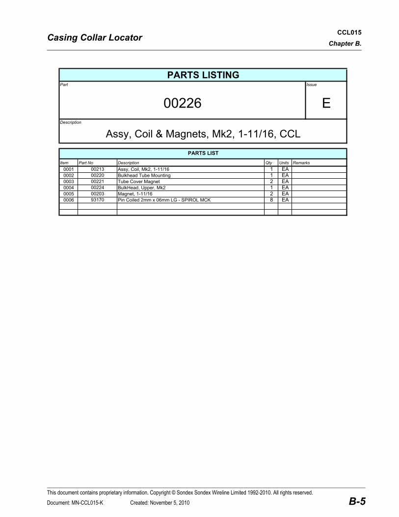
Coil and Magnets - 2 sheets 00226-F 00226-E
Description Type Drawing
Electronics Assembly Wiring Diagram WD-80075-C
Telemetry Board (PCB 82269) - 2 sheets Circuit Diagram CD-82261-H00x
CCL VCO Oscillator Circuit Diagram CD-80062-H
This document contains proprietary information. Copyright © Sondex Sondex Wireline Limited 1992-2010. All rights reserved.
B-1Document: MN-CCL015-K Created: November 5, 2010

CCL015ireline Limited 1992-2010. All rights reserved.
B-2
52
36
ENIHCAMHSINIF
xSW
-:SMETI
NWOHSTON
557
01 11 21
C
B
A
D
E
F
G
.oNGNIWARD
ELTIT
EUSSI
FOYTREPDEIPOC
NOISSIMRE TEEHS
NODESU
DA 82590
72 82 92 03 13 23 33
LOTNEG
X.0 "020.0XX.0 "010.0
XXX.0 "500.0ELGNA °5.0
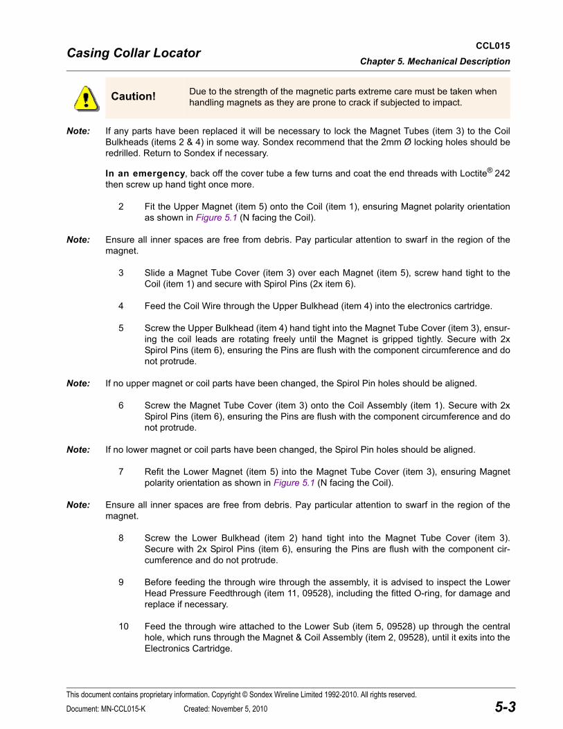
510LCC ROTACOLRALLOCGNISACXS)C771(WU61/111)TUPTUODECNAHNE(
11 E
REBMUN NOITPIRCSED
7530 LCCGNISUOHERUSSERP
6220 STENGAMDNA$LIOCYLBMESSA
7350 MEM)NOITALOSI(XSDAEHKLUBSCINORTCELEYSSA
5101 ELUDOM1SLLEHS-FLAH
2220 )1kM("61/11-1ø,rewoL,buS
8410 )GNIR'OHTIW($RPUDTSXSELAM$ROTCETORPDAERHT
9101 LEBALGNINRAWdna$PTREWOLYSSA
2600 )MEM(LCCTCC,YSSA
9622 demmargorP,retemetaRelgniSWU,yrtemeleT&USP,BCP,YSSA
6300 )tekcoShtiw(XS$rotcennoCrewoLyssA
9002 GNOLONOMNOITALOSIERUSSERPROTCENNOC
40100-1 C002,A6,V003,AepyT,EFTP,eriW
9103 SSGLmm80x1øLORIPSNIP
1623 GLmm7.21xDOmm57.4$URHT3M-RECAPS
1125 57NOTIV112GNIR'O
1129 09NOTIV112GNIR'O
4219 09NOTIV421GNIR'O
7401 0031NEROB8/5LANRETNIPILCRIC
7903 3MredloSgaT
8403 SSGLmm60x3MDETTOLSDHNAPWERCS
9201 SSGLmm60X3MDETTOLSDHKSCWERCS
0301 SSGLmm60x6MDHTKSBURGWERCS
PA800- ROLFAGYT-EPAT
8203 )J9876NID(SS3MLANRETNIDETARRESKCOLREHSAW
00100-1 )kcalB2.0/7(C002,A3,V003,AepyT,EFTP,eriW
20200-1 deR,AepyT,EFTP,21.0/7,eriW
70200-1 teloiV,AepyT,EFTP,21.0/7,eriW
90200-1 etihW,AepyT,EFTP,21.0/7,eriW
01200-1 kniP,AepyT,EFTP,21.0/7,eriW
00000-3 kcalB,mm5.0llaW,C081,HssalC,rebbuRenociliS,gniveelS
10M10- 030ssenkcihtllawerobmm101larutaNeveelSEFTP
C9900-6 903nisoRytivitcAhgiH,7.0uC/3.99nSyollA,eriWredloS
AC990- )%3.3(66#eroC,7.0uC/3.99nSyollA,.loS/W.0133,eriWredloS
62
Casing Collar LocatorThis document contains proprietary information. Copyright © Sondex Sondex W
62.22 SROTCETORPDAERHTGNIDULCNILAO
64.81 HTGNELPU-EKAM
37.6 TNIOPERUSAEM
80099
6
1
71
7
61
81
31
01
11
5
223
2
51
3
32
8
1221
4
412
9
02
4
9142
:NOITIDNOC/TNEMTAERTTAEHA1
SEHCNI
VA
SGNIWARDLIATEDEES
SGNIWARDLIATEDEES
HGN
80/11/60 80/11/60
BPN
80/11/60
:NWARD
:ETAD
ELACS
:LTAM
:ETAD
:DEKCEHC
:ETAD
:D'PPA
NIMID
ednoS62398110.leT
1 2 3 4 5 6 7 8 9
1 2 3
A
B
C
D
E
F
G
H
SSI NOITPIRCSED DPPA ETAD
ORPEHTSIGNIWARDSIHTEBTONLLAHSDNAxednoS
PROIRPTUOHTIWDESURO
E SREFER97595-5RCE HGN
D BPNSREFER1454RCE 90/21/12
01/10/40
ELACSTONOD
NOITCEJORPELGNADRIHT1:1
METI.ON
tluafeD.YTQ/ TRAP
1 1 14
2 1 0
3 1 1
4 1 0
5 1 0
6 1 1
7 1 0
8 1 8
9 1 8
01 1 1
11 1 9
21 R/A 00W
31 1 9
41 2 9
51 1 9
61 2 9
71 2 9
81 1 0
91 1 9
02 1 9
12 21 0
22 3 0
32 R/A 400T
42 1 9
52 R/A 00W
62 R/A 00W
72 R/A 00W
82 R.A 00W
92 R/A 00W
03 R/A 10A
13 R/A 510A
23 R/A 00A
33 R/A 600A
CCL015ireline Limited 1992-2010. All rights reserved.
B-3
Casing Collar LocatorThis document contains proprietary information. Copyright © Sondex Sondex W

CCL015ireline Limited 1992-2010. All rights reserved.
B-4
Casing Collar LocatorThis document contains proprietary information. Copyright © Sondex Sondex W
Casing Collar Locator CCL015Chapter B.
PARTS LISTINGPart Issue
00226 EDescription
Assy, Coil & Magnets, Mk2, 1-11/16, CCLPARTS LIST
Item Part No Description Qty Units Remarks0001 00213 Assy, Coil, Mk2, 1-11/16 1 EA0002 00220 Bulkhead Tube Mounting 1 EA0003 00221 Tube Cover Magnet 2 EA0004 00224 BulkHead, Upper, Mk2 1 EA0005 00203 Magnet, 1-11/16 2 EA0006 93170 Pin Coiled 2mm x 06mm LG - SPIROL MCK 8 EA
This document contains proprietary information. Copyright © Sondex Sondex Wireline Limited 1992-2010. All rights reserved.
B-5Document: MN-CCL015-K Created: November 5, 2010

CCL015ireline Limited 1992-2010. All rights reserved.
B-6
DRAWN
DATE
DRAWING No.
CHECKED APPROVED
DATE DATE
ISSUE REVISION
Casing Collar LocatorThis document contains proprietary information. Copyright © Sondex Sondex W
ISS REV CHANGESDATE
tel 44 118 9326755 fax 9326704
FORD LANE, BRAMSHILL,HOOK RG27 0RH,ENGLAND.
SONDEXCHKD APPD TITLE:
CCL015ireline Limited 1992-2010. All rights reserved.
B-7
Casing Collar LocatorThis document contains proprietary information. Copyright © Sondex Sondex W
CCL015ireline Limited 1992-2010. All rights reserved.
B-8
Casing Collar LocatorThis document contains proprietary information. Copyright © Sondex Sondex W

CCL015ireline Limited 1992-2010. All rights reserved.
B-9
Casing Collar LocatorThis document contains proprietary information. Copyright © Sondex Sondex W
Copyright © 2022 FDOKUMEN