Screw Locator
24
Model VXF Model VXE M3 Bolt Tightening / Compact Model for Light Load Screw Locator New Compact Model for Light Load
-
Upload
khangminh22 -
Category
Documents
-
view
1 -
download
0
Transcript of Screw Locator
CAT.NO.SBR-VXE001-01-GBPrinted in Japan
2017. 8 First 1Ry
http://www.kosmek.com
JQA-QMA10823KOSMEK HEAD OFFICE
● FOR FURTHER INFORMATION ON UNLISTED SPECIFICATIONS AND SIZES, PLEASE CALL US.
● SPECIFICATIONS IN THIS LEAFLET ARE SUBJECT TO CHANGE WITHOUT NOTICE.
KOSMEK (U.S.A.) LTD.650 Springer Drive, Lombard, IL 60148 USATEL. +1-630-620-7650 FAX. +1-630-620-9015
KOSMEK LTD - INDIAF 203, Level-2, First Floor, Prestige Center Point, Cunningham Road, Bangalore -560052 IndiaTEL.+91-988056169567 Soi 58, RAMA 9 Rd., Suanluang, Suanluang, Bangkok 10250TEL. +66-2-300-5132 FAX. +66-2-300-5133
1-5, 2-Chome, Murotani, Nishi-ku, Kobe 651-2241TEL.+81-78-991-5162 FAX.+81-78-991-8787
HEAD OFFICE
BRANCH OFFICE (U.S.A.)
KOSMEK USA Mexico OfficeBlvd Jurica la Campana 1040, B Colonia Punta Juriquilla Queretaro,QRO 76230 MexicoTEL.+52-442-161-2347
MEXICO REPRESENTATIVE OFFICE
BRANCH OFFICE (INDIA)
THAILAND REPRESENTATIVE OFFICE
KOSMEK EUROPE GmbHSchleppeplatz 2 9020 Klagenfurt am Wörthersee AustriaTEL.+43-463-287587 FAX.+43-463-287587-20
BRANCH OFFICE (EUROPE)
Model VXFModel VXEM3 Bolt Tightening /
Compact Model for Light Load
Screw LocatorNew Compact Model for Light Load
NewModel VXE0030
M3 Bolt
Model VXF0040
M4 Bolt
Model VXF0050
M5 Bolt
Model VXF0060
M6 Bolt
Model VXF0080
M8 Bolt
Model VXF0100
M10 Bolt
Model VXF0120
M12 Bolt
Model VXF0160
M16 Bolt
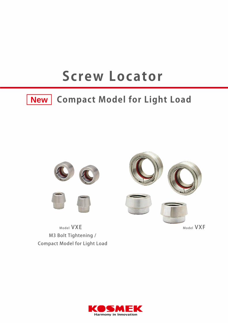
Compact Model for Light Load (Model VXE) Added to the Line-up
Compact Model for Light Load
Screw Locator allows for Drastic Time Reduction for Locating and Setup
M3 Bolt-Tightening Screw Locator (model VXE) is newly added.
Reduced minimum tightening force compared to model VXF,
model VXE is suitable for compact and/or thin pal lets used in
FA appl icat ions which require manual/automatic setups.
New
Before Pallet Setting
Pallet
Locating Bushing
Set the pallet and tighten the bolts.
High Accuracy Locating Completed
Locating RepeatabilityModel VXE:5μmModel VXF:3μm
Locating Pin
BoltBolt
Base Plate
Pallet
Locating Pin
Dual Surface Locating
Locating Bushing

NewModel VXE0030
M3 Bolt
Model VXF0040
M4 Bolt
Model VXF0050
M5 Bolt
Model VXF0060
M6 Bolt
Model VXF0080
M8 Bolt
Model VXF0100
M10 Bolt
Model VXF0120
M12 Bolt
Model VXF0160
M16 Bolt
Compact Model for Light Load (Model VXE) Added to the Line-up
Compact Model for Light Load
Screw Locator allows for Drastic Time Reduction for Locating and Setup
M3 Bolt-Tightening Screw Locator (model VXE) is newly added.
Reduced minimum tightening force compared to model VXF,
model VXE is suitable for compact and/or thin pal lets used in
FA appl icat ions which require manual/automatic setups.
New
Before Pallet Setting
Pallet
Locating Bushing
Set the pallet and tighten the bolts.
High Accuracy Locating Completed
Locating RepeatabilityModel VXE:5μmModel VXF:3μm
Locating Pin
BoltBolt
Base Plate
Pallet
Locating Pin
Dual Surface Locating
Locating Bushing

ScrewLocator
VXE
VXF
FeaturesAction Description
Application ExamplesLineup CautionsHigh Precision Accessories
Reference DataApplication Examples
LineupFeatures
Action DescriptionModel VXE
Model No. / Specifications / External Dimensions
Model VXFModel No. / Specifications / External Dimensions
43
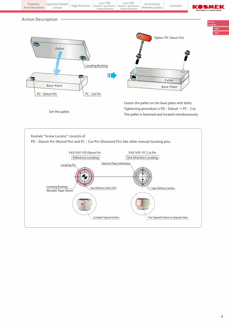
Kosmek ''Screw Locator'' consists of
PD:Datum-Pin (Round Pin) and PC:Cut-Pin (Diamond Pin) like other manual locating pins.
Set the pallet.
Fasten the pallet on the base plate with bolts.
Tightening procedure is PD:Datum → PC:Cut.
The pallet is fastened and located simultaneously.
Tighten 'PD : Datum' first.
PD:Datum Pin PC:Cut Pin
Locating Bushing
High accuracy allows for high quality and less defective parts.
Compact body saves valuable space.
Backlash・Low Accuracy・Space Required
Screw Locator with Dual Surface Tightening
Model VXE/VXF
Screw Locator
Base PlateBase Plate
Pallet
Bolt Bolt
Pallet
Gap
Locating Pin
Dual Surface Locating
Locating Pin
Locating Bushing
(5μm for VXE)
Base Plate
Pal let
Base Plate
Pal let
a gap and poor locating repeatability.General locating pin has
VXE/VXF-PD:Datum Pin VXE/VXF-PC:Cut Pin
Taper Reference SurfaceTaper Reference Surface (360°)
Locating Pin
Locating BushingMovable Taper Sleeve
Notch for Phase Confirmation
Complete Tapered Surface Two Tapered Surfaces on Opposite Sides
The ''Screw Locator'' performs high-precision locating by simply tightening the bolts.
Locating BushingScrew Locator
Screw LocatorLocating Pin
Compact Model for Light Load (Model VXE) Newly Added
Simple High Accuracy Locating by HandVXF:Locating Repeatabil ity 3μm VXE:Locating Repeatabil ity 5μm
Locating Repeatability 3μm
Action Description
Reference Locating One Direction Locating
ScrewLocator
VXE
VXF
FeaturesAction Description
Application ExamplesLineup CautionsHigh Precision Accessories
Reference DataApplication Examples
LineupFeatures
Action DescriptionModel VXE
Model No. / Specifications / External Dimensions
Model VXFModel No. / Specifications / External Dimensions
43
Kosmek ''Screw Locator'' consists of
PD:Datum-Pin (Round Pin) and PC:Cut-Pin (Diamond Pin) like other manual locating pins.
Set the pallet.
Fasten the pallet on the base plate with bolts.
Tightening procedure is PD:Datum → PC:Cut.
The pallet is fastened and located simultaneously.
Tighten 'PD : Datum' first.
PD:Datum Pin PC:Cut Pin
Locating Bushing
High accuracy allows for high quality and less defective parts.
Compact body saves valuable space.
Backlash・Low Accuracy・Space Required
Screw Locator with Dual Surface Tightening
Model VXE/VXF
Screw Locator
Base PlateBase Plate
Pallet
Bolt Bolt
Pallet
Gap
Locating Pin
Dual Surface Locating
Locating Pin
Locating Bushing
(5μm for VXE)
Base Plate
Pal let
Base Plate
Pal let
a gap and poor locating repeatability.General locating pin has
VXE/VXF-PD:Datum Pin VXE/VXF-PC:Cut Pin
Taper Reference SurfaceTaper Reference Surface (360°)
Locating Pin
Locating BushingMovable Taper Sleeve
Notch for Phase Confirmation
Complete Tapered Surface Two Tapered Surfaces on Opposite Sides
The ''Screw Locator'' performs high-precision locating by simply tightening the bolts.
Locating BushingScrew Locator
Screw LocatorLocating Pin
Compact Model for Light Load (Model VXE) Newly Added
Simple High Accuracy Locating by HandVXF:Locating Repeatabil ity 3μm VXE:Locating Repeatabil ity 5μm
Locating Repeatability 3μm
Action Description
Reference Locating One Direction Locating
VXE
VXF
ScrewLocator
FeaturesAction Description
Application ExamplesLineup CautionsHigh Precision Accessories
Reference DataApplication Examples
LineupFeatures
Action Description
Model VXEModel No. / Specifications / External Dimensions
Model VXFModel No. / Specifications / External Dimensionsmodel VXE/VXFScrew Locator
Application Examples Lineup
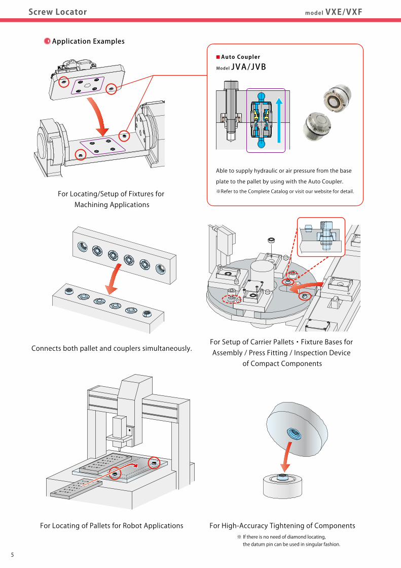
For Locating/Setup of Fixtures for Machining Applications
For High-Accuracy Tightening of Components※ If there is no need of diamond locating, the datum pin can be used in singular fashion.
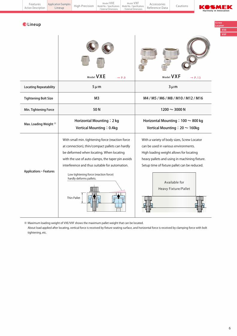
※ Maximum loading weight of VXE/VXF shows the maximum pallet weight that can be located.
About load applied after locating, vertical force is received by fixture seating surface, and horizontal force is received by clamping force with bolt
tightening, etc.
■Auto Coupler
Able to supply hydraulic or air pressure from the base
plate to the pallet by using with the Auto Coupler.
※Refer to the Complete Catalog or visit our website for detail.
Model JVA/JVB
Connects both pallet and couplers simultaneously.For Setup of Carrier Pallets・Fixture Bases for Assembly / Press Fitting / Inspection Device
of Compact Components
For Locating of Pallets for Robot Applications
Locating Repeatability
Tightening Bolt Size
Min. Tightening Force
Max. Loading Weight ※
With small min. tightening force (reaction force
at connection), thin/compact pallets can hardly
be deformed when locating. When locating
with the use of auto clamps, the taper pin avoids
interference and thus suitable for automation.
Low tightening force (reaction force) hardly deforms pallets.
With a variety of body sizes, Screw Locator
can be used in various environments.
High loading weight allows for locating
heavy pallets and using in machining fixture.
Setup time of fixture pallet can be reduced.
Available for
Heavy Fixture/Pallet
Applications・Features
5μm
→ P.13
M3
3μm
M4 / M5 / M6 / M8 / M10 / M12 / M16
50 N
Horizontal Mounting:2 kg
Vertical Mounting:0.4kg
Horizontal Mounting:100 ~ 800 kg
Vertical Mounting:20 ~ 160kg
1200 ~ 3000 N
Model VXF→ P.9Model VXE
Thin Pallet
65
VXE
VXF
ScrewLocator
FeaturesAction Description
Application ExamplesLineup CautionsHigh Precision Accessories
Reference DataApplication Examples
LineupFeatures
Action Description
Model VXEModel No. / Specifications / External Dimensions
Model VXFModel No. / Specifications / External Dimensionsmodel VXE/VXFScrew Locator
Application Examples Lineup
For Locating/Setup of Fixtures for Machining Applications
For High-Accuracy Tightening of Components※ If there is no need of diamond locating, the datum pin can be used in singular fashion.
※ Maximum loading weight of VXE/VXF shows the maximum pallet weight that can be located.
About load applied after locating, vertical force is received by fixture seating surface, and horizontal force is received by clamping force with bolt
tightening, etc.
■Auto Coupler
Able to supply hydraulic or air pressure from the base
plate to the pallet by using with the Auto Coupler.
※Refer to the Complete Catalog or visit our website for detail.
Model JVA/JVB
Connects both pallet and couplers simultaneously.For Setup of Carrier Pallets・Fixture Bases for Assembly / Press Fitting / Inspection Device
of Compact Components
For Locating of Pallets for Robot Applications
Locating Repeatability
Tightening Bolt Size
Min. Tightening Force
Max. Loading Weight ※
With small min. tightening force (reaction force
at connection), thin/compact pallets can hardly
be deformed when locating. When locating
with the use of auto clamps, the taper pin avoids
interference and thus suitable for automation.
Low tightening force (reaction force) hardly deforms pallets.
With a variety of body sizes, Screw Locator
can be used in various environments.
High loading weight allows for locating
heavy pallets and using in machining fixture.
Setup time of fixture pallet can be reduced.
Available for
Heavy Fixture/Pallet
Applications・Features
5μm
→ P.13
M3
3μm
M4 / M5 / M6 / M8 / M10 / M12 / M16
50 N
Horizontal Mounting:2 kg
Vertical Mounting:0.4kg
Horizontal Mounting:100 ~ 800 kg
Vertical Mounting:20 ~ 160kg
1200 ~ 3000 N
Model VXF→ P.9Model VXE
Thin Pallet
65
VXE
VXF
ScrewLocator
FeaturesAction Description CautionsHigh Precision Accessories
Reference DataApplication Examples
LineupFeatures
Action Description
Model VXEModel No. / Specifications / External Dimensions
Model VXFModel No. / Specifications / External Dimensionsmodel VXE/VXFScrew Locator High Precision
87
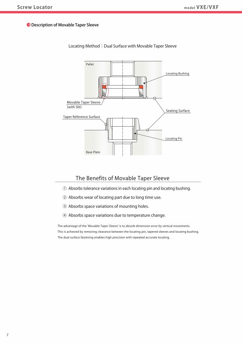
Description of Movable Taper Sleeve
Locating Method:Dual Surface with Movable Taper Sleeve
① Absorbs tolerance variations in each locating pin and locating bushing.
② Absorbs wear of locating part due to long time use.
③ Absorbs space variations of mounting holes.
④ Absorbs space variations due to temperature change.
The advantage of the 'Movable Taper Sleeve' is to absorb dimension error by vertical movements.
This is achieved by removing clearance between the locating pin, tapered sleeves and locating bushing.
The dual surface fastening enables high precision with repeated accurate locating.
The Benefits of Movable Taper Sleeve
Pallet
Base Plate
Taper Reference Surface
Movable Taper Sleeve(with Slit)
Seating Surface
Locating Bushing
Locating Pin
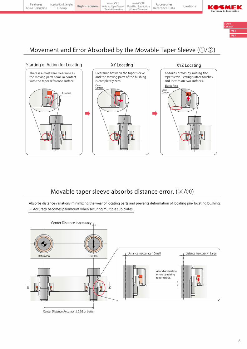
Movement and Error Absorbed by the Movable Taper Sleeve (①/②)
Starting of Action for Locating XY Locating XYZ Locating
There is almost zero clearance asthe moving parts come in contactwith the taper reference surface.
Clearance between the taper sleeve and the moving parts of the bushingis completely zero.
Absorbs errors by raising the taper sleeve. Seating surface touches and locates on two surfaces.
Absorbs distance variations minimizing the wear of locating parts and prevents deformation of locating pin/ locating bushing.
※ Accuracy becomes paramount when securing multiple sub plates.
Center Distance Accuracy ±0.02 or better
Movable taper sleeve absorbs distance error. (③/④)
CloseContact
ContactCloseContact
Elastic Ring
Center Distance Inaccuracy
Datum Pin Cut PinDistance Inaccuracy:Small Distance Inaccuracy:Large
Absorbs variation errors by raisingtaper sleeve.
VXE
VXF
ScrewLocator
FeaturesAction Description CautionsHigh Precision Accessories
Reference DataApplication Examples
LineupFeatures
Action Description
Model VXEModel No. / Specifications / External Dimensions
Model VXFModel No. / Specifications / External Dimensionsmodel VXE/VXFScrew Locator High Precision
87
Description of Movable Taper Sleeve
Locating Method:Dual Surface with Movable Taper Sleeve
① Absorbs tolerance variations in each locating pin and locating bushing.
② Absorbs wear of locating part due to long time use.
③ Absorbs space variations of mounting holes.
④ Absorbs space variations due to temperature change.
The advantage of the 'Movable Taper Sleeve' is to absorb dimension error by vertical movements.
This is achieved by removing clearance between the locating pin, tapered sleeves and locating bushing.
The dual surface fastening enables high precision with repeated accurate locating.
The Benefits of Movable Taper Sleeve
Pallet
Base Plate
Taper Reference Surface
Movable Taper Sleeve(with Slit)
Seating Surface
Locating Bushing
Locating Pin
Movement and Error Absorbed by the Movable Taper Sleeve (①/②)
Starting of Action for Locating XY Locating XYZ Locating
There is almost zero clearance asthe moving parts come in contactwith the taper reference surface.
Clearance between the taper sleeve and the moving parts of the bushingis completely zero.
Absorbs errors by raising the taper sleeve. Seating surface touches and locates on two surfaces.
Absorbs distance variations minimizing the wear of locating parts and prevents deformation of locating pin/ locating bushing.
※ Accuracy becomes paramount when securing multiple sub plates.
Center Distance Accuracy ±0.02 or better
Movable taper sleeve absorbs distance error. (③/④)
CloseContact
ContactCloseContact
Elastic Ring
Center Distance Inaccuracy
Datum Pin Cut PinDistance Inaccuracy:Small Distance Inaccuracy:Large
Absorbs variation errors by raisingtaper sleeve.
FeaturesAction Description CautionsAccessories
Reference DataApplication Examples
LineupFeatures
Action Description
Model VXFModel No. / Specifications / External Dimensions
High PrecisionScrew Locator Compact Model for Light Load model VXENewModel VXE
Model No. / Specifications / External Dimensions
VXE
VXF
ScrewLocator
Datum Pin Cut Pin
Locating Pin Model No.
VXE0030-PD (Datum Pin)
VXE0030-PC (Cut Pin)
Locating Bushing Model No.
VXE0030-B
VXE0030-B
Function
Reference Locating
One Direction Locating
Mounting Bolt Size
M3 Bolt
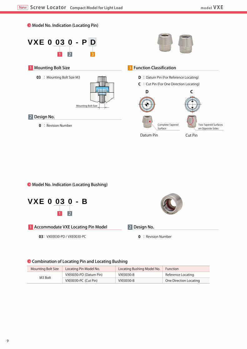
1 2 3
VXE 0 03 0 - P D
2
1 Mounting Bolt Size
03 : Mounting Bolt Size M3
0 : Revision Number
Design No.
3 Function Classification
D : Datum Pin (For Reference Locating)
C : Cut Pin (For One Direction Locating)
CD
Mounting Bolt Size
Model No.
Locating Repeatability mm
Stroke mm
Max. Loading Weight Horizontal Mounting
kg Vertical Mounting
Min. Tightening Force ※1 ※2 N
Tightening Procedure
Operating Temperature ℃
Mass Locating Pin
g Locating Bushing
Notes : 1. This product is made only for locating. It does not have clamping function. Tightening force is required when locating. ※1. Minimum tightening force indicates the required tightening force (pressing force) per locating unit. (It is the required axial force when tightening the center of VXE with a bolt.) Tighten the mounting bolt with appropriate tightening torque. (Refer to P.19 for reference data of bolt axial force and tightening torque.) Tightening torque may differ according to bolt tensile strength grade / plate material. For further information, please refer to JIS B 1083, JIS B 1084 or catalogs of bolt makers. ※2. When tightening/clamping a point other than the VXE center using external clamps, clamping force has to be greater than the minimum tightening force. Refer to P.21 "For tightening (clamping) a point other than the VXE/VXF center." and calculate required tightening force.
VXE0030
0.005
0.2
2.0
0.4
50
VXE-PD → VXE-PC
0~70
1.5
3.0
1 Accommodate VXE Locating Pin Model
03: VXE0030-PD / VXE0030-PC
2 Design No.
0 : Revision Number
1 2
VXE 0 03 0 - B
Model No. Indication (Locating Pin)
Model No. Indication (Locating Bushing)
Combination of Locating Pin and Locating Bushing
Specifications
Two Tapered Surfaces on Opposite Sides
Complete TaperedSurface
109

FeaturesAction Description CautionsAccessories
Reference DataApplication Examples
LineupFeatures
Action Description
Model VXFModel No. / Specifications / External Dimensions
High PrecisionScrew Locator Compact Model for Light Load model VXENewModel VXE
Model No. / Specifications / External Dimensions
VXE
VXF
ScrewLocator
Datum Pin Cut Pin
Locating Pin Model No.
VXE0030-PD (Datum Pin)
VXE0030-PC (Cut Pin)
Locating Bushing Model No.
VXE0030-B
VXE0030-B
Function
Reference Locating
One Direction Locating
Mounting Bolt Size
M3 Bolt
1 2 3
VXE 0 03 0 - P D
2
1 Mounting Bolt Size
03 : Mounting Bolt Size M3
0 : Revision Number
Design No.
3 Function Classification
D : Datum Pin (For Reference Locating)
C : Cut Pin (For One Direction Locating)
CD
Mounting Bolt Size
Model No.
Locating Repeatability mm
Stroke mm
Max. Loading Weight Horizontal Mounting
kg Vertical Mounting
Min. Tightening Force ※1 ※2 N
Tightening Procedure
Operating Temperature ℃
Mass Locating Pin
g Locating Bushing
Notes : 1. This product is made only for locating. It does not have clamping function. Tightening force is required when locating. ※1. Minimum tightening force indicates the required tightening force (pressing force) per locating unit. (It is the required axial force when tightening the center of VXE with a bolt.) Tighten the mounting bolt with appropriate tightening torque. (Refer to P.19 for reference data of bolt axial force and tightening torque.) Tightening torque may differ according to bolt tensile strength grade / plate material. For further information, please refer to JIS B 1083, JIS B 1084 or catalogs of bolt makers. ※2. When tightening/clamping a point other than the VXE center using external clamps, clamping force has to be greater than the minimum tightening force. Refer to P.21 "For tightening (clamping) a point other than the VXE/VXF center." and calculate required tightening force.
VXE0030
0.005
0.2
2.0
0.4
50
VXE-PD → VXE-PC
0~70
1.5
3.0
1 Accommodate VXE Locating Pin Model
03: VXE0030-PD / VXE0030-PC
2 Design No.
0 : Revision Number
1 2
VXE 0 03 0 - B
Model No. Indication (Locating Pin)
Model No. Indication (Locating Bushing)
Combination of Locating Pin and Locating Bushing
Specifications
Two Tapered Surfaces on Opposite Sides
Complete TaperedSurface
109
FeaturesAction Description CautionsAccessories
Reference DataApplication Examples
LineupFeatures
Action Description
Model VXFModel No. / Specifications / External Dimensions
High PrecisionScrew Locator Compact Model for Light LoadModel VXE
Model No. / Specifications / External Dimensionsmodel VXENew
VXE
VXF
ScrewLocator
1211
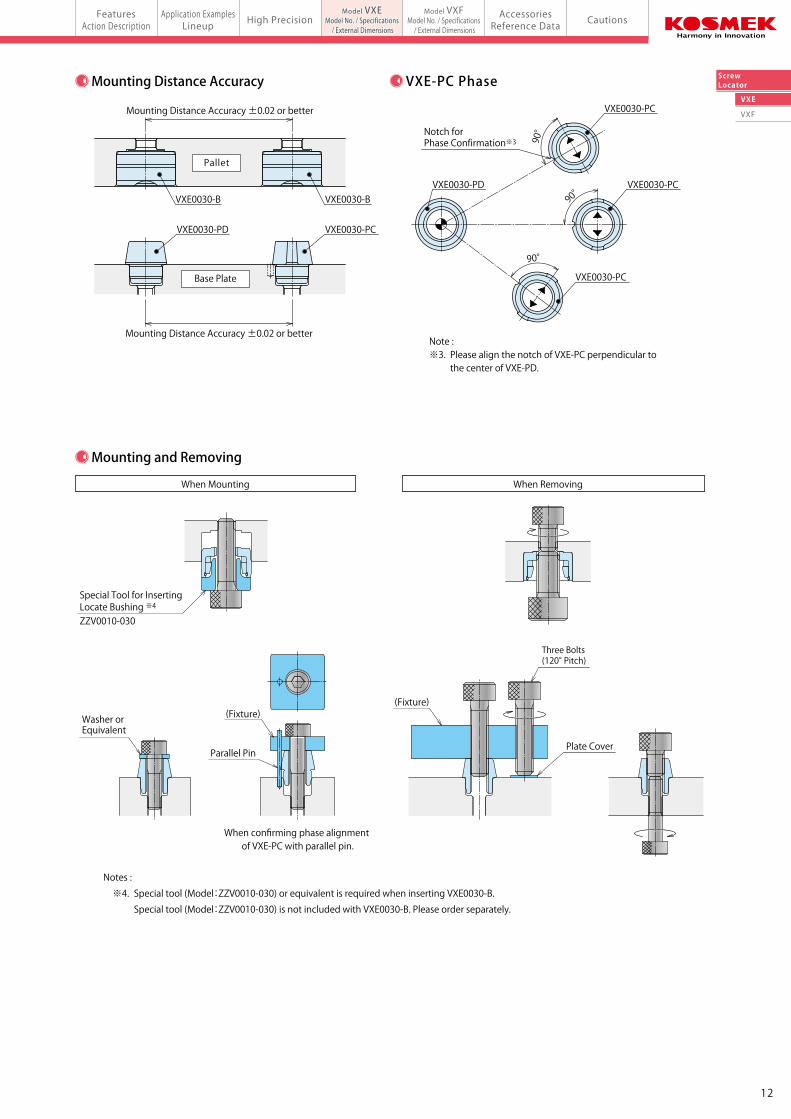
When Mounting When Removing
90°
Note :※3. Please align the notch of VXE-PC perpendicular to the center of VXE-PD.
90°
90°
VXE0030-PC
VXE0030-PCVXE0030-PD
VXE0030-PC
Mounting Distance Accuracy ±0.02 or better
Mounting Distance Accuracy ±0.02 or better
Pallet
Base Plate
VXE0030-B VXE0030-B
VXE0030-PCVXE0030-PD
30°
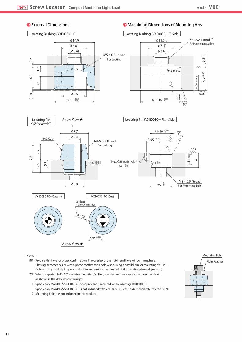
0.2
6.3
(0.2)
30°
0.5
(M4×0.7 Thread)For Mounting and Jacking
※2φ11
φ11H6
φ10.9
φ6.6
φ7.7
φ5.8
φ3.4
(φ3.4) φ3.4
φ6.8
φ11
1.7
3.4
0.5
+0.026+0.013
+ 0.1 0
0- 0.05
+ 0.011 0
M5×0.8 ThreadFor Jacking
Locating PinVXE0030-P□
Arrow View ★
6.5±0.02
4.2 or more
φ7
R0.3 or less
+ 0.1
0
0.3
6.3S
6.3S
Locating Bushing:VXE0030-B Locating Bushing (VXE0030-B) Side
Locating Pin (VXE0030-P□) Side
M4×0.7 ThreadFor Jacking
(-PC:Cut)
2.3
7.7
3.5
4.2
3.5 or more
4
φ6 +0.020+0.010
φ6H6 + 0.008 0
±0.053.95 6.3S
6.3S
0.4 or less
M3×0.5 ThreadFor Mounting Boltφ6 0- 0.1
+ 0.2+ 0.1
(Phase Confirmation Hole※1)(φ1 )
VXE0030-PC (Cut)VXE0030-PD (Datum)
Arrow View ★
+ 0.2+ 0.1φ1
±0.053.95
Notes :
※1. Prepare this hole for phase confirmation. The overlap of the notch and hole will confirm phase. Phasing becomes easier with a phase confirmation hole when using a parallel pin for mounting VXE-PC. (When using parallel pin, please take into account for the removal of the pin after phase alignment.)
※2. When preparing M4×0.7 screw for mounting/jacking, use the plain washer for the mounting bolt
as shown in the drawing on the right.
1. Special tool (Model:ZZV0010-030) or equivalent is required when inserting VXE0030-B.
Special tool (Model:ZZV0010-030) is not included with VXE0030-B. Please order separately (refer to P.17).
2. Mounting bolts are not included in this product.
Mounting Bolt
Plain Washer
φ4.3
External Dimensions Machining Dimensions of Mounting Area Mounting Distance Accuracy
Mounting and Removing
VXE-PC Phase
Special Tool for Inserting Locate Bushing ※4
ZZV0010-030
(Fixture)
Parallel Pin
When confirming phase alignment of VXE-PC with parallel pin.
Notes :
※4. Special tool (Model:ZZV0010-030) or equivalent is required when inserting VXE0030-B.
Special tool (Model:ZZV0010-030) is not included with VXE0030-B. Please order separately.
Notch for Phase Confirmation
Washer orEquivalent
(Fixture)
Three Bolts (120° Pitch)
Plate Cover
Notch for Phase Confirmation※3
FeaturesAction Description CautionsAccessories
Reference DataApplication Examples
LineupFeatures
Action Description
Model VXFModel No. / Specifications / External Dimensions
High PrecisionScrew Locator Compact Model for Light LoadModel VXE
Model No. / Specifications / External Dimensionsmodel VXENew
VXE
VXF
ScrewLocator
1211
When Mounting When Removing
90°
Note :※3. Please align the notch of VXE-PC perpendicular to the center of VXE-PD.
90°
90°
VXE0030-PC
VXE0030-PCVXE0030-PD
VXE0030-PC
Mounting Distance Accuracy ±0.02 or better
Mounting Distance Accuracy ±0.02 or better
Pallet
Base Plate
VXE0030-B VXE0030-B
VXE0030-PCVXE0030-PD
30°
0.2
6.3
(0.2)
30°
0.5
(M4×0.7 Thread)For Mounting and Jacking
※2φ11
φ11H6
φ10.9
φ6.6
φ7.7
φ5.8
φ3.4
(φ3.4) φ3.4
φ6.8
φ11
1.7
3.4
0.5
+0.026+0.013
+ 0.1 0
0- 0.05
+ 0.011 0
M5×0.8 ThreadFor Jacking
Locating PinVXE0030-P□
Arrow View ★
6.5±0.02
4.2 or more
φ7
R0.3 or less
+ 0.1
0
0.3
6.3S
6.3S
Locating Bushing:VXE0030-B Locating Bushing (VXE0030-B) Side
Locating Pin (VXE0030-P□) Side
M4×0.7 ThreadFor Jacking
(-PC:Cut)
2.3
7.7
3.5
4.2
3.5 or more
4
φ6 +0.020+0.010
φ6H6 + 0.008 0
±0.053.95 6.3S
6.3S
0.4 or less
M3×0.5 ThreadFor Mounting Boltφ6 0- 0.1
+ 0.2+ 0.1
(Phase Confirmation Hole※1)(φ1 )
VXE0030-PC (Cut)VXE0030-PD (Datum)
Arrow View ★
+ 0.2+ 0.1φ1
±0.053.95
Notes :
※1. Prepare this hole for phase confirmation. The overlap of the notch and hole will confirm phase. Phasing becomes easier with a phase confirmation hole when using a parallel pin for mounting VXE-PC. (When using parallel pin, please take into account for the removal of the pin after phase alignment.)
※2. When preparing M4×0.7 screw for mounting/jacking, use the plain washer for the mounting bolt
as shown in the drawing on the right.
1. Special tool (Model:ZZV0010-030) or equivalent is required when inserting VXE0030-B.
Special tool (Model:ZZV0010-030) is not included with VXE0030-B. Please order separately (refer to P.17).
2. Mounting bolts are not included in this product.
Mounting Bolt
Plain Washer
φ4.3
External Dimensions Machining Dimensions of Mounting Area Mounting Distance Accuracy
Mounting and Removing
VXE-PC Phase
Special Tool for Inserting Locate Bushing ※4
ZZV0010-030
(Fixture)
Parallel Pin
When confirming phase alignment of VXE-PC with parallel pin.
Notes :
※4. Special tool (Model:ZZV0010-030) or equivalent is required when inserting VXE0030-B.
Special tool (Model:ZZV0010-030) is not included with VXE0030-B. Please order separately.
Notch for Phase Confirmation
Washer orEquivalent
(Fixture)
Three Bolts (120° Pitch)
Plate Cover
Notch for Phase Confirmation※3
FeaturesAction Description CautionsAccessories
Reference DataApplication Examples
LineupFeatures
Action Description High PrecisionModel VXE
Model No. / Specifications / External Dimensionsmodel VXFScrew Locator
Model VXFModel No. / Specifications / External Dimensions
VXE
VXF
ScrewLocator
1 2
VXF 0 08 0 - B1 2 3
VXF 0 08 0 - P D
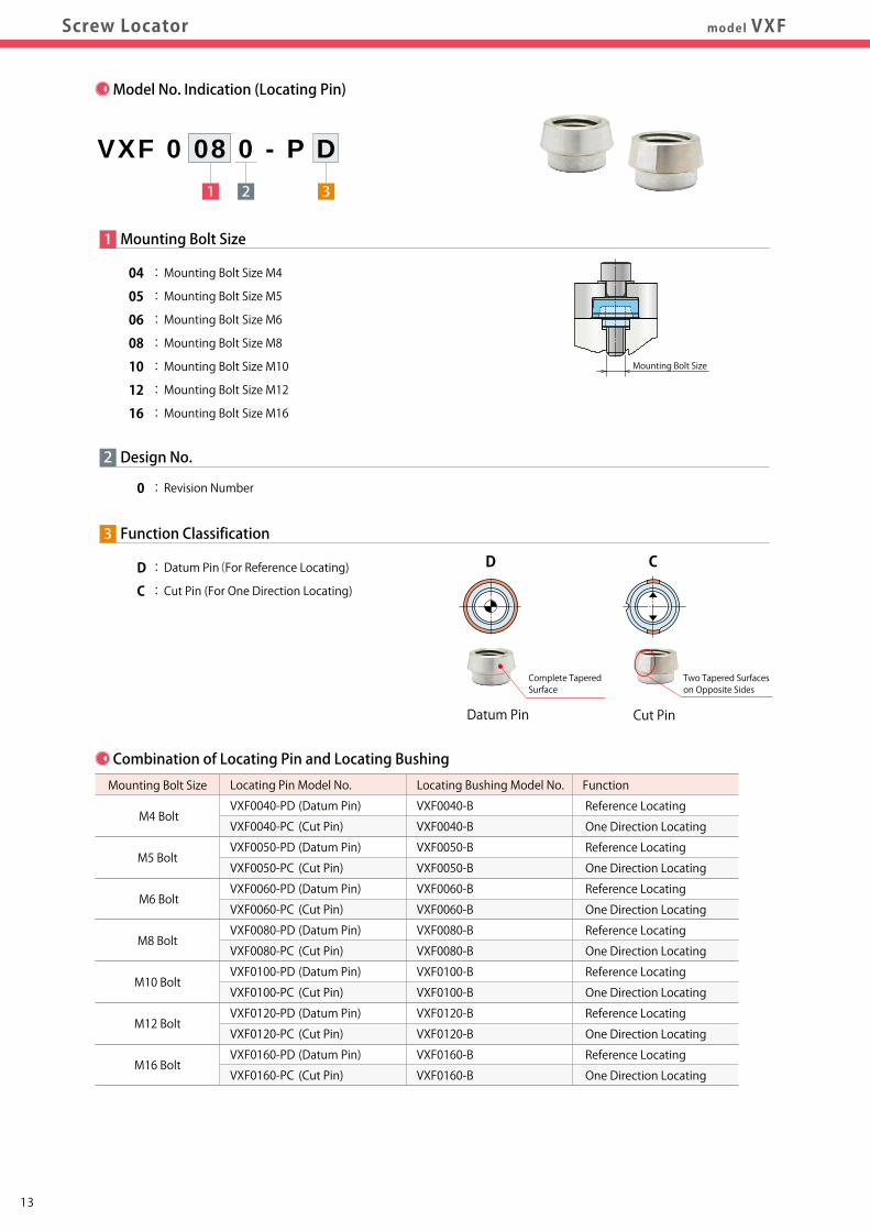
Datum Pin Cut Pin
2
1 Mounting Bolt Size
04 : Mounting Bolt Size M4
05 : Mounting Bolt Size M5
06 : Mounting Bolt Size M6
08 : Mounting Bolt Size M8
10 : Mounting Bolt Size M10
12 : Mounting Bolt Size M12
16 : Mounting Bolt Size M16
0 : Revision Number
Design No.
3 Function Classification
D : Datum Pin(For Reference Locating)
C : Cut Pin (For One Direction Locating)
CD
Complete TaperedSurface
Mounting Bolt Size
Two Tapered Surfaces on Opposite Sides
Model No. Indication (Locating Pin) Model No. Indication (Locating Bushing)
Locating Pin Model No.
VXF0040-PD (Datum Pin)
VXF0040-PC (Cut Pin)
VXF0050-PD (Datum Pin)
VXF0050-PC (Cut Pin)
VXF0060-PD (Datum Pin)
VXF0060-PC (Cut Pin)
VXF0080-PD (Datum Pin)
VXF0080-PC (Cut Pin)
VXF0100-PD (Datum Pin)
VXF0100-PC (Cut Pin)
VXF0120-PD (Datum Pin)
VXF0120-PC (Cut Pin)
VXF0160-PD (Datum Pin)
VXF0160-PC (Cut Pin)
Locating Bushing Model No.
VXF0040-B
VXF0040-B
VXF0050-B
VXF0050-B
VXF0060-B
VXF0060-B
VXF0080-B
VXF0080-B
VXF0100-B
VXF0100-B
VXF0120-B
VXF0120-B
VXF0160-B
VXF0160-B
Function
Reference Locating
One Direction Locating
Reference Locating
One Direction Locating
Reference Locating
One Direction Locating
Reference Locating
One Direction Locating
Reference Locating
One Direction Locating
Reference Locating
One Direction Locating
Reference Locating
One Direction Locating
Mounting Bolt Size
M4 Bolt
M5 Bolt
M6 Bolt
M8 Bolt
M10 Bolt
M12 Bolt
M16 Bolt
Combination of Locating Pin and Locating Bushing
2
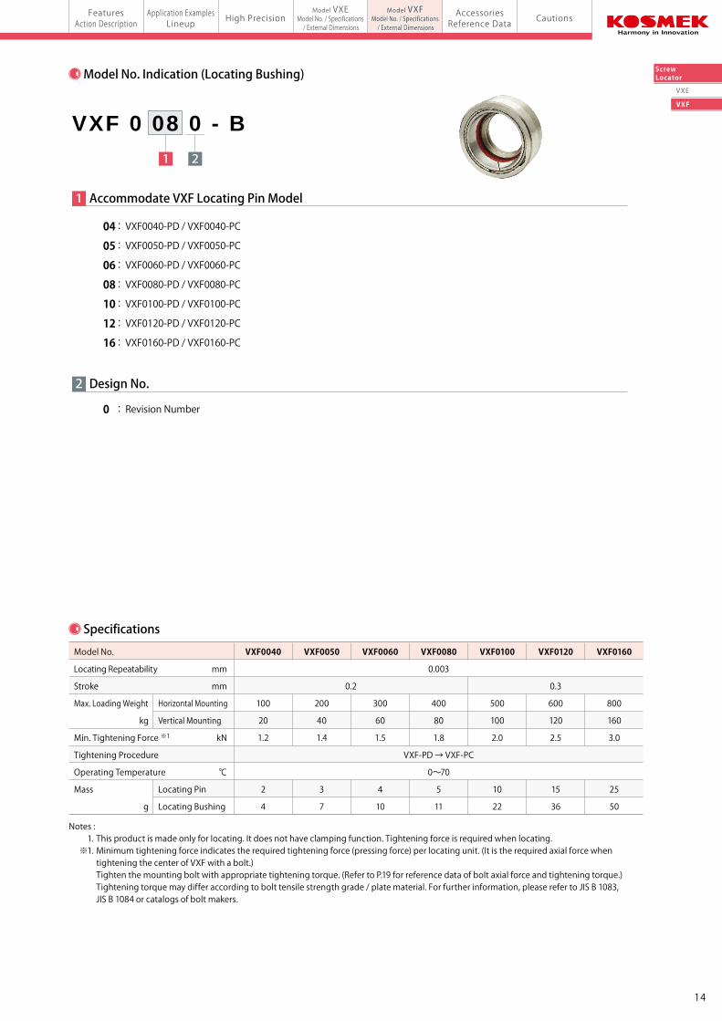
1 Accommodate VXF Locating Pin Model
0 : Revision Number
Design No.
04 : VXF0040-PD / VXF0040-PC
05 : VXF0050-PD / VXF0050-PC
06 : VXF0060-PD / VXF0060-PC
08 : VXF0080-PD / VXF0080-PC
10 : VXF0100-PD / VXF0100-PC
12 : VXF0120-PD / VXF0120-PC
16 : VXF0160-PD / VXF0160-PC
Specifications
Model No.
Locating Repeatability mm
Stroke mm
Max. Loading Weight Horizontal Mounting
kg Vertical Mounting
Min. Tightening Force ※1 kN
Tightening Procedure
Operating Temperature ℃
Mass Locating Pin
g Locating Bushing
Notes : 1. This product is made only for locating. It does not have clamping function. Tightening force is required when locating. ※1. Minimum tightening force indicates the required tightening force (pressing force) per locating unit. (It is the required axial force when tightening the center of VXF with a bolt.) Tighten the mounting bolt with appropriate tightening torque. (Refer to P.19 for reference data of bolt axial force and tightening torque.) Tightening torque may differ according to bolt tensile strength grade / plate material. For further information, please refer to JIS B 1083, JIS B 1084 or catalogs of bolt makers.
VXF0040 VXF0050 VXF0060 VXF0080 VXF0100 VXF0120 VXF0160
0.003
0.2 0.3
100 200 300 400 500 600 800
20 40 60 80 100 120 160
1.2 1.4 1.5 1.8 2.0 2.5 3.0
VXF-PD → VXF-PC
0~70
2 3 4 5 10 15 25
4 7 10 11 22 36 50
1413
FeaturesAction Description CautionsAccessories
Reference DataApplication Examples
LineupFeatures
Action Description High PrecisionModel VXE
Model No. / Specifications / External Dimensionsmodel VXFScrew Locator
Model VXFModel No. / Specifications / External Dimensions
VXE
VXF
ScrewLocator
1 2
VXF 0 08 0 - B1 2 3
VXF 0 08 0 - P D
Datum Pin Cut Pin
2
1 Mounting Bolt Size
04 : Mounting Bolt Size M4
05 : Mounting Bolt Size M5
06 : Mounting Bolt Size M6
08 : Mounting Bolt Size M8
10 : Mounting Bolt Size M10
12 : Mounting Bolt Size M12
16 : Mounting Bolt Size M16
0 : Revision Number
Design No.
3 Function Classification
D : Datum Pin(For Reference Locating)
C : Cut Pin (For One Direction Locating)
CD
Complete TaperedSurface
Mounting Bolt Size
Two Tapered Surfaces on Opposite Sides
Model No. Indication (Locating Pin) Model No. Indication (Locating Bushing)
Locating Pin Model No.
VXF0040-PD (Datum Pin)
VXF0040-PC (Cut Pin)
VXF0050-PD (Datum Pin)
VXF0050-PC (Cut Pin)
VXF0060-PD (Datum Pin)
VXF0060-PC (Cut Pin)
VXF0080-PD (Datum Pin)
VXF0080-PC (Cut Pin)
VXF0100-PD (Datum Pin)
VXF0100-PC (Cut Pin)
VXF0120-PD (Datum Pin)
VXF0120-PC (Cut Pin)
VXF0160-PD (Datum Pin)
VXF0160-PC (Cut Pin)
Locating Bushing Model No.
VXF0040-B
VXF0040-B
VXF0050-B
VXF0050-B
VXF0060-B
VXF0060-B
VXF0080-B
VXF0080-B
VXF0100-B
VXF0100-B
VXF0120-B
VXF0120-B
VXF0160-B
VXF0160-B
Function
Reference Locating
One Direction Locating
Reference Locating
One Direction Locating
Reference Locating
One Direction Locating
Reference Locating
One Direction Locating
Reference Locating
One Direction Locating
Reference Locating
One Direction Locating
Reference Locating
One Direction Locating
Mounting Bolt Size
M4 Bolt
M5 Bolt
M6 Bolt
M8 Bolt
M10 Bolt
M12 Bolt
M16 Bolt
Combination of Locating Pin and Locating Bushing
2
1 Accommodate VXF Locating Pin Model
0 : Revision Number
Design No.
04 : VXF0040-PD / VXF0040-PC
05 : VXF0050-PD / VXF0050-PC
06 : VXF0060-PD / VXF0060-PC
08 : VXF0080-PD / VXF0080-PC
10 : VXF0100-PD / VXF0100-PC
12 : VXF0120-PD / VXF0120-PC
16 : VXF0160-PD / VXF0160-PC
Specifications
Model No.
Locating Repeatability mm
Stroke mm
Max. Loading Weight Horizontal Mounting
kg Vertical Mounting
Min. Tightening Force ※1 kN
Tightening Procedure
Operating Temperature ℃
Mass Locating Pin
g Locating Bushing
Notes : 1. This product is made only for locating. It does not have clamping function. Tightening force is required when locating. ※1. Minimum tightening force indicates the required tightening force (pressing force) per locating unit. (It is the required axial force when tightening the center of VXF with a bolt.) Tighten the mounting bolt with appropriate tightening torque. (Refer to P.19 for reference data of bolt axial force and tightening torque.) Tightening torque may differ according to bolt tensile strength grade / plate material. For further information, please refer to JIS B 1083, JIS B 1084 or catalogs of bolt makers.
VXF0040 VXF0050 VXF0060 VXF0080 VXF0100 VXF0120 VXF0160
0.003
0.2 0.3
100 200 300 400 500 600 800
20 40 60 80 100 120 160
1.2 1.4 1.5 1.8 2.0 2.5 3.0
VXF-PD → VXF-PC
0~70
2 3 4 5 10 15 25
4 7 10 11 22 36 50
1413
FeaturesAction Description CautionsAccessories
Reference DataApplication Examples
LineupFeatures
Action Description High PrecisionModel VXE
Model No. / Specifications / External Dimensionsmodel VXFScrew Locator
Model VXFModel No. / Specifications / External Dimensions
VXE
VXF
ScrewLocatorExternal Dimensions Machining Dimensions of Mounting Area
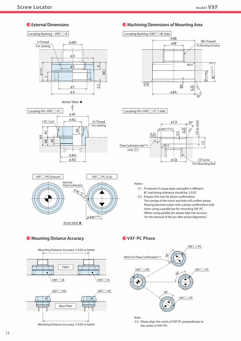
Mounting Distance Accuracy VXF-PC Phase
90°
Note :※3. Please align the notch of VXF-PC perpendicular to the center of VXF-PD.
Mounting Distance Accuracy ±0.02 or better
Pallet
Base Plate
Mounting Distance Accuracy ±0.02 or better
VXF□-B VXF□-B
VXF□-PD VXF□-PC
Notch for Phase Confirmation※3
Notes :
※1. If material of a base plate and pallet is different, BC machining tolerance should be ±0.02. ※2. Prepare this hole for phase confirmation. The overlap of the notch and hole will confirm phase. Phasing becomes easier with a phase confirmation hole when using a parallel pin for mounting VXF-PC. (When using parallel pin, please take into account for the removal of the pin after phase alignment.)
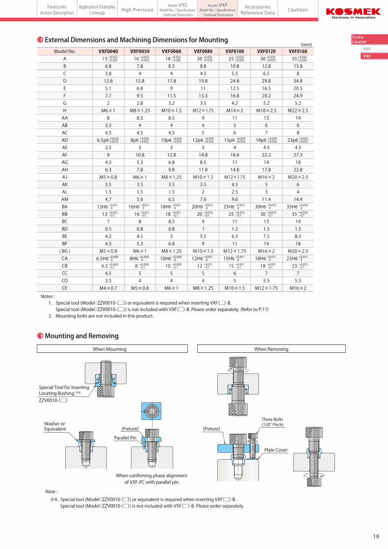
Mounting and Removing
When Mounting When Removing
External Dimensions and Machining Dimensions for Mounting
Three Bolts (120° Pitch)
Special Tool for Inserting Locating Bushing ※4
ZZV0010-□
Washer orEquivalent
When confirming phase alignment of VXF-PC with parallel pin.
Plate Cover
Note :
※4. Special tool (Model:ZZV0010-□) or equivalent is required when inserting VXF□-B. Special tool (Model:ZZV0010-□) is not included with VXF□-B. Please order separately.
Parallel Pin
(Fixture) (Fixture)
Notes : 1. Special tool (Model:ZZV0010-□) or equivalent is required when inserting VXF□-B. Special tool (Model:ZZV0010-□) is not included with VXF□-B. Please order separately. (Refer to P.17) 2. Mounting bolts are not included in this product.
(mm)Model No.
ABCDEFGHAAABACADAEAFAGAHAJAKALAMBABBBCBDBEBF( BG )CACBCCCDCE
+ 0.024+ 0.015
+ 0.024+ 0.015
+ 0.024+ 0.015
+ 0.029+ 0.018
+ 0.029+ 0.018
+ 0.029+ 0.018
VXF008020 8.84.519.81113.33.5
M12×1.75945
12p6 314.88.511.8
M10×1.53.527.6
20H6 20 915.59
M10×1.512H6 12 54
M8×1.25
VXF010025 10.85.524.812.516.84.2
M14×21156
15p6 418.61114.8
M12×1.754.52.59.6
25H6 25 111.26.511
M12×1.7515H6 15 65
M10×1.5
VXF012030 12.86.529.816.520.25.2
M18×2.51367
18p6 4.522.21417.8M16×25311.4
30H6 30 131.57.514
M16×218H6 18 75.5
M12×1.75
+ 0.042+ 0.026
+ 0.035+ 0.022
VXF016035 13.8834.820.524.95.2
M22×2.51468
23p6 4.527.31822.8
M20×2.56414.4
35H6 35 141.58.518
M20×2.523H6 23 75.5
M16×2
+ 0.033+ 0.020
+ 0.033+ 0.020
+ 0.033+ 0.020
+ 0.033+ 0.020
+ 0.033+ 0.020
+ 0.033+ 0.020
VXF006018 8.3417.8911.53.2
M10×1.58.544.5
10p6 312.86.89.8
M8×1.253.51.56.5
18H6 18 8.50.856.8
M8×1.2510H6 10 54
M6×1
VXF005016 7.8415.86.89.52.8
M8×1.258.544.5
8p6 310.85.37.8M6×13.51.55.6
16H6 16 80.84.55.3M6×18H6 8 54
M5×0.8
VXF004013 6.83.812.85.17.72
M6×183.54.5
6.5p6 2.594.36.3
M5×0.83.51.54.7
13H6 13 70.54.24.3
M5×0.86.5H6 6.5 4.53.5
M4×0.7
+ 0.011 0
+ 0.011 0
+ 0.011 0
+ 0.009 0
+ 0.011- 0.1
+ 0.011- 0.1
+ 0.011- 0.1
+ 0.009- 0.1
+ 0.009 0+ 0.009- 0.1
+ 0.009 0+ 0.009- 0.1
+ 0.013 0
+ 0.011 0
+ 0.013- 0.1
+ 0.011- 0.1
+ 0.013 0
+ 0.011 0
+ 0.013- 0.1
+ 0.011- 0.1
+ 0.013 0
+ 0.011 0
+ 0.013- 0.1
+ 0.011- 0.1
+ 0.016 0
+ 0.013 0
+ 0.016- 0.1
+ 0.013- 0.1
90°
90°
VXF□-PC
VXF□-PCVXF□-PD
VXF□-PC
Locating Pin:VXF□-P□
Locating Bushing : VXF□-B
Locating Pin (VXF□-P□) Side
Locating Bushing (VXF□-B) Side
+ 0.2+ 0.1
+ 0.2+ 0.1
Notch for Phase Confirmation
VXF□-PC (Cut)VXF□-PD (Datum)
AJ ThreadFor Jacking
ABAC
AA
(-PC:Cut)
AE
AK
(φBF)
φD
H ThreadFor Jacking
φE
φAφF
φAG
φAD
φAM±0.05
φAH
φAL
φAF
Arrow View ★
Arrow View ★
(BC)G
0.2
C
B±0.02
BD
BE or more
φBA30°
6.3S
R0.4
6.3S
φBF(BG Thread)
For Mounting and Jacking
φBB
φCA 30°
6.3S
6.3S 0.5
CC
φCB
CD or more
For Mounting BoltCE Screw
R0.4(Phase Confirmation Hole※2)
(φAM±0.05)※2
(φAL )
BC±0.05※1
1615
FeaturesAction Description CautionsAccessories
Reference DataApplication Examples
LineupFeatures
Action Description High PrecisionModel VXE
Model No. / Specifications / External Dimensionsmodel VXFScrew Locator
Model VXFModel No. / Specifications / External Dimensions
VXE
VXF
ScrewLocatorExternal Dimensions Machining Dimensions of Mounting Area
Mounting Distance Accuracy VXF-PC Phase
90°
Note :※3. Please align the notch of VXF-PC perpendicular to the center of VXF-PD.
Mounting Distance Accuracy ±0.02 or better
Pallet
Base Plate
Mounting Distance Accuracy ±0.02 or better
VXF□-B VXF□-B
VXF□-PD VXF□-PC
Notch for Phase Confirmation※3
Notes :
※1. If material of a base plate and pallet is different, BC machining tolerance should be ±0.02. ※2. Prepare this hole for phase confirmation. The overlap of the notch and hole will confirm phase. Phasing becomes easier with a phase confirmation hole when using a parallel pin for mounting VXF-PC. (When using parallel pin, please take into account for the removal of the pin after phase alignment.)
Mounting and Removing
When Mounting When Removing
External Dimensions and Machining Dimensions for Mounting
Three Bolts (120° Pitch)
Special Tool for Inserting Locating Bushing ※4
ZZV0010-□
Washer orEquivalent
When confirming phase alignment of VXF-PC with parallel pin.
Plate Cover
Note :
※4. Special tool (Model:ZZV0010-□) or equivalent is required when inserting VXF□-B. Special tool (Model:ZZV0010-□) is not included with VXF□-B. Please order separately.
Parallel Pin
(Fixture) (Fixture)
Notes : 1. Special tool (Model:ZZV0010-□) or equivalent is required when inserting VXF□-B. Special tool (Model:ZZV0010-□) is not included with VXF□-B. Please order separately. (Refer to P.17) 2. Mounting bolts are not included in this product.
(mm)Model No.
ABCDEFGHAAABACADAEAFAGAHAJAKALAMBABBBCBDBEBF( BG )CACBCCCDCE
+ 0.024+ 0.015
+ 0.024+ 0.015
+ 0.024+ 0.015
+ 0.029+ 0.018
+ 0.029+ 0.018
+ 0.029+ 0.018
VXF008020 8.84.519.81113.33.5
M12×1.75945
12p6 314.88.511.8
M10×1.53.527.6
20H6 20 915.59
M10×1.512H6 12 54
M8×1.25
VXF010025 10.85.524.812.516.84.2
M14×21156
15p6 418.61114.8
M12×1.754.52.59.6
25H6 25 111.26.511
M12×1.7515H6 15 65
M10×1.5
VXF012030 12.86.529.816.520.25.2
M18×2.51367
18p6 4.522.21417.8M16×25311.4
30H6 30 131.57.514
M16×218H6 18 75.5
M12×1.75
+ 0.042+ 0.026
+ 0.035+ 0.022
VXF016035 13.8834.820.524.95.2
M22×2.51468
23p6 4.527.31822.8
M20×2.56414.4
35H6 35 141.58.518
M20×2.523H6 23 75.5
M16×2
+ 0.033+ 0.020
+ 0.033+ 0.020
+ 0.033+ 0.020
+ 0.033+ 0.020
+ 0.033+ 0.020
+ 0.033+ 0.020
VXF006018 8.3417.8911.53.2
M10×1.58.544.5
10p6 312.86.89.8
M8×1.253.51.56.5
18H6 18 8.50.856.8
M8×1.2510H6 10 54
M6×1
VXF005016 7.8415.86.89.52.8
M8×1.258.544.5
8p6 310.85.37.8M6×13.51.55.6
16H6 16 80.84.55.3M6×18H6 8 54
M5×0.8
VXF004013 6.83.812.85.17.72
M6×183.54.5
6.5p6 2.594.36.3
M5×0.83.51.54.7
13H6 13 70.54.24.3
M5×0.86.5H6 6.5 4.53.5
M4×0.7
+ 0.011 0
+ 0.011 0
+ 0.011 0
+ 0.009 0
+ 0.011- 0.1
+ 0.011- 0.1
+ 0.011- 0.1
+ 0.009- 0.1
+ 0.009 0+ 0.009- 0.1
+ 0.009 0+ 0.009- 0.1
+ 0.013 0
+ 0.011 0
+ 0.013- 0.1
+ 0.011- 0.1
+ 0.013 0
+ 0.011 0
+ 0.013- 0.1
+ 0.011- 0.1
+ 0.013 0
+ 0.011 0
+ 0.013- 0.1
+ 0.011- 0.1
+ 0.016 0
+ 0.013 0
+ 0.016- 0.1
+ 0.013- 0.1
90°
90°
VXF□-PC
VXF□-PCVXF□-PD
VXF□-PC
Locating Pin:VXF□-P□
Locating Bushing : VXF□-B
Locating Pin (VXF□-P□) Side
Locating Bushing (VXF□-B) Side
+ 0.2+ 0.1
+ 0.2+ 0.1
Notch for Phase Confirmation
VXF□-PC (Cut)VXF□-PD (Datum)
AJ ThreadFor Jacking
ABAC
AA
(-PC:Cut)
AE
AK
(φBF)
φD
H ThreadFor Jacking
φE
φAφF
φAG
φAD
φAM±0.05
φAH
φAL
φAF
Arrow View ★
Arrow View ★
(BC)G
0.2
C
B±0.02
BD
BE or more
φBA30°
6.3S
R0.4
6.3S
φBF(BG Thread)
For Mounting and Jacking
φBB
φCA 30°
6.3S
6.3S 0.5
CC
φCB
CD or more
For Mounting BoltCE Screw
R0.4(Phase Confirmation Hole※2)
(φAM±0.05)※2
(φAL )
BC±0.05※1
1615
FeaturesAction Description CautionsApplication Examples
LineupFeatures
Action Description High PrecisionModel VXE
Model No. / Specifications / External Dimensionsmodel VXE/VXFScrew Locator
Model VXFModel No. / Specifications / External Dimensions
AccessoriesReference Data
VXE
VXF
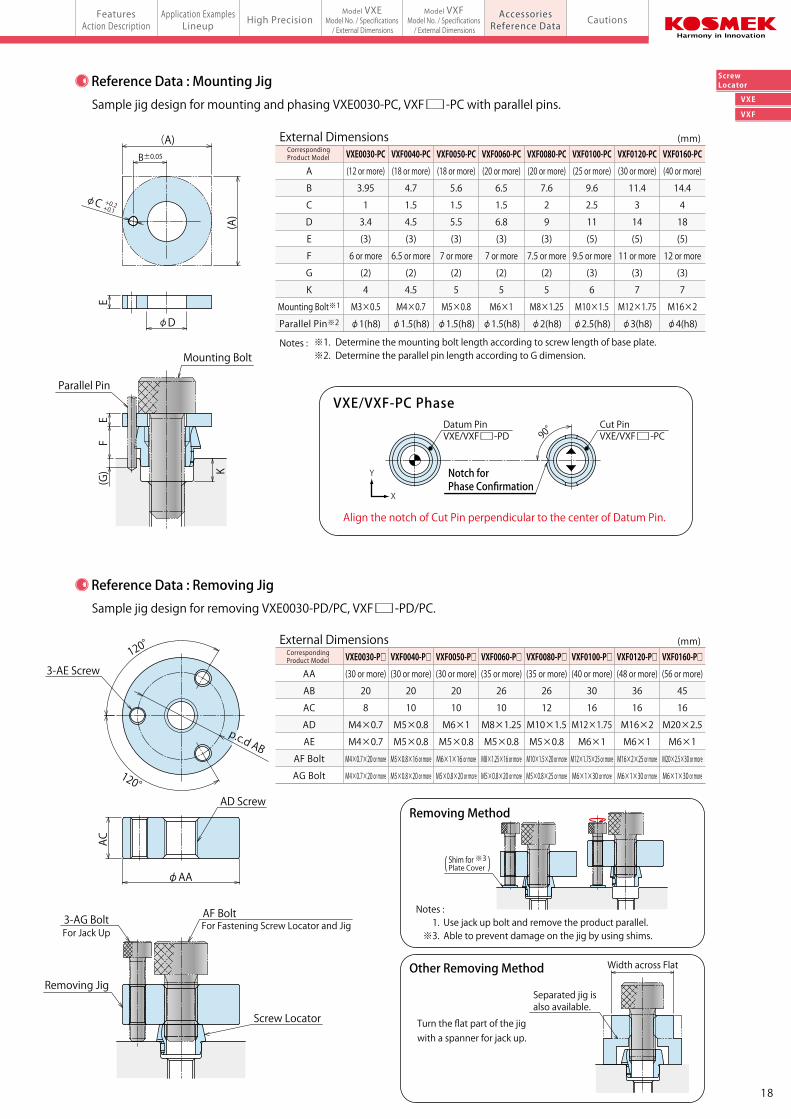
ScrewLocator
Sample jig design for mounting and phasing VXE0030-PC, VXF□-PC with parallel pins.
Sample jig design for removing VXE0030-PD/PC, VXF□-PD/PC.
EF
(G) K
Mounting Bolt
(A)
φD
(A)
B±0.05
+ 0.2+ 0.1φC
Parallel Pin
120°
120°
ACφAA
p.c.d AB
3-AG BoltFor Jack Up
AF BoltFor Fastening Screw Locator and Jig
Removing Jig
Screw Locator
Align the notch of Cut Pin perpendicular to the center of Datum Pin.
VXE/VXF-PC Phase
90°
VXE/VXF□-PDDatum Pin
X
Y
E
VXE/VXF□-PCCut Pin
External Dimensions (mm)
A
B
C
D
E
F
G
K
Mounting Bolt※1
Parallel Pin※2
Notes : ※1. Determine the mounting bolt length according to screw length of base plate. ※2. Determine the parallel pin length according to G dimension.
VXF0060-PC
(20 or more)
6.5
1.5
6.8
(3)
7 or more
(2)
5
M6×1
φ1.5(h8)
VXF0050-PC
(18 or more)
5.6
1.5
5.5
(3)
7 or more
(2)
5
M5×0.8
φ1.5(h8)
VXF0040-PC
(18 or more)
4.7
1.5
4.5
(3)
6.5 or more
(2)
4.5
M4×0.7
φ1.5(h8)
VXE0030-PC
(12 or more)
3.95
1
3.4
(3)
6 or more
(2)
4
M3×0.5
φ1(h8)
VXF0080-PC
(20 or more)
7.6
2
9
(3)
7.5 or more
(2)
5
M8×1.25
φ2(h8)
VXF0100-PC
(25 or more)
9.6
2.5
11
(5)
9.5 or more
(3)
6
M10×1.5
φ2.5(h8)
VXF0120-PC
(30 or more)
11.4
3
14
(5)
11 or more
(3)
7
M12×1.75
φ3(h8)
VXF0160-PC
(40 or more)
14.4
4
18
(5)
12 or more
(3)
7
M16×2
φ4(h8)
External Dimensions (mm)
AA
AB
AC
AD
AE
AF Bolt
AG Bolt
VXF0060-P□
(35 or more)
26
10
M8×1.25
M5×0.8
M8×1.25×16 or more
M5×0.8×20 or more
VXF0050-P□
(30 or more)
20
10
M6×1
M5×0.8
M6×1×16 or more
M5×0.8×20 or more
VXF0040-P□
(30 or more)
20
10
M5×0.8
M5×0.8
M5×0.8×16 or more
M5×0.8×20 or more
VXE0030-P□
(30 or more)
20
8
M4×0.7
M4×0.7
M4×0.7×20 or more
M4×0.7×20 or more
VXF0080-P□
(35 or more)
26
12
M10×1.5
M5×0.8
M10×1.5×20 or more
M5×0.8×25 or more
VXF0100-P□
(40 or more)
30
16
M12×1.75
M6×1
M12×1.75×25 or more
M6×1×30 or more
VXF0120-P□
(48 or more)
36
16
M16×2
M6×1
M16×2×25 or more
M6×1×30 or more
VXF0160-P□
(56 or more)
45
16
M20×2.5
M6×1
M20×2.5×30 or more
M6×1×30 or more
Reference Data : Mounting Jig
Reference Data : Removing Jig
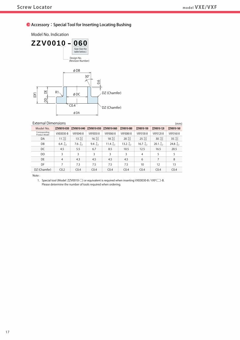
Size (See the table below.)
Design No.(Revision Number)
ZZV0010 - 060Model No. Indication
- 0.2- 0.5
- 0.2- 0.5
- 0.2- 0.5
- 0.2- 0.5
0- 0.2
- 0.2- 0.5
0- 0.2
- 0.2- 0.5
- 0.2- 0.5
0- 0.2
0- 0.2
0- 0.2
0- 0.2
External Dimensions (mm)Model No.
DA
DB
DC
DD
DE
DF
DZ (Chamfer)
- 0.2- 0.5
0- 0.2
Note :
1. Special tool (Model:ZZV0010-□) or equivalent is required when inserting VXE0030-B / VXF□-B. Please determine the number of tools required when ordering.
φDA
φDC
DDDE
( DF)
φDB
30°
R1 DZ (Chamfer)
DZ (Chamfer)C0.4
0.6
ZZV0010-060
VXF0060-B
18
11.4
8.5
3
4.5
7.5
C0.4
ZZV0010-050
VXF0050-B
16
9.4
6.7
3
4.5
7.5
C0.4
ZZV0010-040
VXF0040-B
13
7.6
5.5
3
4.3
7.3
C0.4
0- 0.2
ZZV0010-030
VXE0030-B
11
6.4
4.5
3
4
7
C0.2
ZZV0010-080
VXF0080-B
20
13.2
10.5
3
4.5
7.5
C0.4
ZZV0010-100
VXF0100-B
25
16.7
12.5
4
6
10
C0.4
ZZV0010-120
VXF0120-B
30
20.1
16.5
5
7
12
C0.4
ZZV0010-160
VXF0160-B
35
24.8
20.5
5
8
13
C0.4
Accessory:Special Tool for Inserting Locating Bushing
CorrespondingProduct Model
Notes :
Removing Method
1. Use jack up bolt and remove the product parallel. ※3. Able to prevent damage on the jig by using shims.
Turn the flat part of the jig with a spanner for jack up.
Shim for ※3 Plate Cover( )
Other Removing Method Width across Flat
Separated jig is also available.
CorrespondingProduct Model
Notch for Phase Confirmation
3-AE Screw
AD Screw
CorrespondingProduct Model
1817
FeaturesAction Description CautionsApplication Examples
LineupFeatures
Action Description High PrecisionModel VXE
Model No. / Specifications / External Dimensionsmodel VXE/VXFScrew Locator
Model VXFModel No. / Specifications / External Dimensions
AccessoriesReference Data
VXE
VXF
ScrewLocator
Sample jig design for mounting and phasing VXE0030-PC, VXF□-PC with parallel pins.
Sample jig design for removing VXE0030-PD/PC, VXF□-PD/PC.
EF
(G) K
Mounting Bolt
(A)
φD
(A)
B±0.05
+ 0.2+ 0.1φC
Parallel Pin
120°
120°
AC
φAA
p.c.d AB
3-AG BoltFor Jack Up
AF BoltFor Fastening Screw Locator and Jig
Removing Jig
Screw Locator
Align the notch of Cut Pin perpendicular to the center of Datum Pin.
VXE/VXF-PC Phase
90°
VXE/VXF□-PDDatum Pin
X
Y
E
VXE/VXF□-PCCut Pin
External Dimensions (mm)
A
B
C
D
E
F
G
K
Mounting Bolt※1
Parallel Pin※2
Notes : ※1. Determine the mounting bolt length according to screw length of base plate. ※2. Determine the parallel pin length according to G dimension.
VXF0060-PC
(20 or more)
6.5
1.5
6.8
(3)
7 or more
(2)
5
M6×1
φ1.5(h8)
VXF0050-PC
(18 or more)
5.6
1.5
5.5
(3)
7 or more
(2)
5
M5×0.8
φ1.5(h8)
VXF0040-PC
(18 or more)
4.7
1.5
4.5
(3)
6.5 or more
(2)
4.5
M4×0.7
φ1.5(h8)
VXE0030-PC
(12 or more)
3.95
1
3.4
(3)
6 or more
(2)
4
M3×0.5
φ1(h8)
VXF0080-PC
(20 or more)
7.6
2
9
(3)
7.5 or more
(2)
5
M8×1.25
φ2(h8)
VXF0100-PC
(25 or more)
9.6
2.5
11
(5)
9.5 or more
(3)
6
M10×1.5
φ2.5(h8)
VXF0120-PC
(30 or more)
11.4
3
14
(5)
11 or more
(3)
7
M12×1.75
φ3(h8)
VXF0160-PC
(40 or more)
14.4
4
18
(5)
12 or more
(3)
7
M16×2
φ4(h8)
External Dimensions (mm)
AA
AB
AC
AD
AE
AF Bolt
AG Bolt
VXF0060-P□
(35 or more)
26
10
M8×1.25
M5×0.8
M8×1.25×16 or more
M5×0.8×20 or more
VXF0050-P□
(30 or more)
20
10
M6×1
M5×0.8
M6×1×16 or more
M5×0.8×20 or more
VXF0040-P□
(30 or more)
20
10
M5×0.8
M5×0.8
M5×0.8×16 or more
M5×0.8×20 or more
VXE0030-P□
(30 or more)
20
8
M4×0.7
M4×0.7
M4×0.7×20 or more
M4×0.7×20 or more
VXF0080-P□
(35 or more)
26
12
M10×1.5
M5×0.8
M10×1.5×20 or more
M5×0.8×25 or more
VXF0100-P□
(40 or more)
30
16
M12×1.75
M6×1
M12×1.75×25 or more
M6×1×30 or more
VXF0120-P□
(48 or more)
36
16
M16×2
M6×1
M16×2×25 or more
M6×1×30 or more
VXF0160-P□
(56 or more)
45
16
M20×2.5
M6×1
M20×2.5×30 or more
M6×1×30 or more
Reference Data : Mounting Jig
Reference Data : Removing Jig
Size (See the table below.)
Design No.(Revision Number)
ZZV0010 - 060Model No. Indication
- 0.2- 0.5
- 0.2- 0.5
- 0.2- 0.5
- 0.2- 0.5
0- 0.2
- 0.2- 0.5
0- 0.2
- 0.2- 0.5
- 0.2- 0.5
0- 0.2
0- 0.2
0- 0.2
0- 0.2
External Dimensions (mm)Model No.
DA
DB
DC
DD
DE
DF
DZ (Chamfer)
- 0.2- 0.5
0- 0.2
Note :
1. Special tool (Model:ZZV0010-□) or equivalent is required when inserting VXE0030-B / VXF□-B. Please determine the number of tools required when ordering.
φDA
φDC
DDDE
( DF)
φDB
30°
R1 DZ (Chamfer)
DZ (Chamfer)C0.4
0.6
ZZV0010-060
VXF0060-B
18
11.4
8.5
3
4.5
7.5
C0.4
ZZV0010-050
VXF0050-B
16
9.4
6.7
3
4.5
7.5
C0.4
ZZV0010-040
VXF0040-B
13
7.6
5.5
3
4.3
7.3
C0.4
0- 0.2
ZZV0010-030
VXE0030-B
11
6.4
4.5
3
4
7
C0.2
ZZV0010-080
VXF0080-B
20
13.2
10.5
3
4.5
7.5
C0.4
ZZV0010-100
VXF0100-B
25
16.7
12.5
4
6
10
C0.4
ZZV0010-120
VXF0120-B
30
20.1
16.5
5
7
12
C0.4
ZZV0010-160
VXF0160-B
35
24.8
20.5
5
8
13
C0.4
Accessory:Special Tool for Inserting Locating Bushing
CorrespondingProduct Model
Notes :
Removing Method
1. Use jack up bolt and remove the product parallel. ※3. Able to prevent damage on the jig by using shims.
Turn the flat part of the jig with a spanner for jack up.
Shim for ※3 Plate Cover( )
Other Removing Method Width across Flat
Separated jig is also available.
CorrespondingProduct Model
Notch for Phase Confirmation
3-AE Screw
AD Screw
CorrespondingProduct Model
1817
FeaturesAction Description
Application ExamplesLineup
FeaturesAction Description High Precision
Model VXEModel No. / Specifications / External Dimensionsmodel VXE/VXFScrew Locator
Model VXFModel No. / Specifications / External Dimensions
AccessoriesReference Data Cautions
VXE
VXF
ScrewLocator
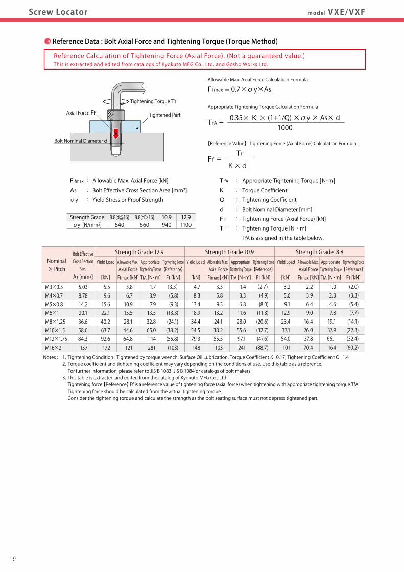
Notes : 1. Tightening Condition : Tightened by torque wrench. Surface Oil Lubrication. Torque Coefficient K=0.17, Tightening Coefficient Q=1.4 2. Torque coefficient and tightening coefficient may vary depending on the conditions of use. Use this table as a reference. For further information, please refer to JIS B 1083, JIS B 1084 or catalogs of bolt makers. 3. This table is extracted and edited from the catalog of Kyokuto MFG Co., Ltd. Tightening force 【Reference】Ff is a reference value of tightening force (axial force) when tightening with appropriate tightening torque TfA. Tightening force should be calculated from the actual tightening torque. Consider the tightening torque and calculate the strength as the bolt seating surface must not depress tightened part.
M3×0.5M4×0.7M5×0.8M6×1M8×1.25M10×1.5M12×1.75M16×2
5.038.7814.220.136.658.084.3157
5.59.615.622.140.263.792.6172
3.86.710.915.528.144.664.8121
1.73.97.913.532.865.0114281
(3.3)(5.8)(9.3)(13.3)(24.1)(38.2)(55.8)(103)
4.78.313.418.934.454.579.3148
3.35.89.313.224.138.255.5103
1.43.36.811.628.055.697.1241
(2.7)(4.9)(8.0)(11.3)(20.6)(32.7)(47.6)(88.7)
3.25.69.112.923.437.154.0101
2.23.96.49.016.426.037.870.4
1.02.34.67.819.137.966.1164
(2.0)(3.3)(5.4)(7.7)(14.1)(22.3)(32.4)(60.2)
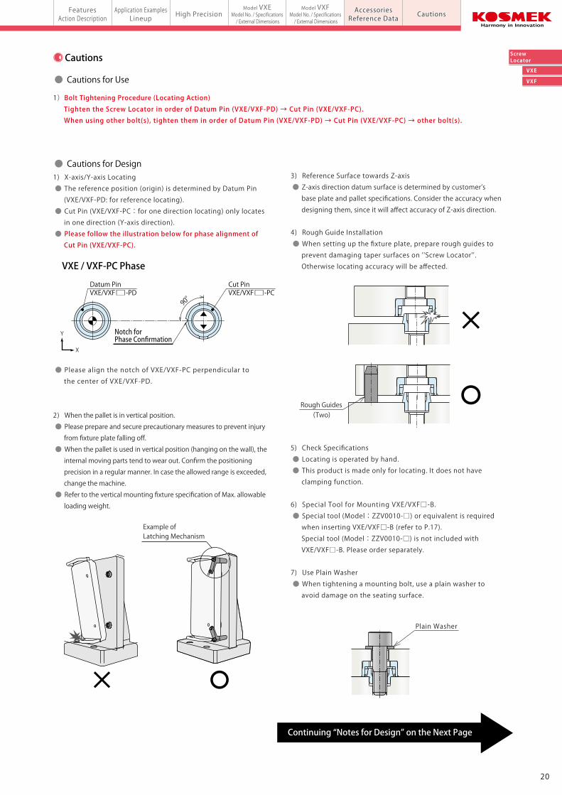
Reference Data : Bolt Axial Force and Tightening Torque (Torque Method) Cautions
● Cautions for Use
● Cautions for Design
Continuing “Notes for Design” on the Next Page
1)Bolt Tightening Procedure (Locating Action) Tighten the Screw Locator in order of Datum Pin (VXE/VXF-PD) → Cut Pin (VXE/VXF-PC). When using other bolt(s), tighten them in order of Datum Pin (VXE/VXF-PD) → Cut Pin (VXE/VXF-PC) → other bolt(s).
1) X-axis/Y-axis Locating
● The reference position (origin) is determined by Datum Pin
(VXE/VXF-PD: for reference locating).
● Cut Pin (VXE/VXF-PC:for one direction locating) only locates
in one direction (Y-axis direction).
● Please follow the illustration below for phase alignment of Cut Pin (VXE/VXF-PC).
● Please align the notch of VXE/VXF-PC perpendicular to
the center of VXE/VXF-PD.
2) When the pallet is in vertical position.
● Please prepare and secure precautionary measures to prevent injury
from fixture plate falling off.
● When the pallet is used in vertical position (hanging on the wall), the
internal moving parts tend to wear out. Confirm the positioning
precision in a regular manner. In case the allowed range is exceeded,
change the machine.
● Refer to the vertical mounting fixture specification of Max. allowable
loading weight.
3) Reference Surface towards Z-axis
● Z-axis direction datum surface is determined by customer’s
base plate and pallet specifications. Consider the accuracy when
designing them, since it will affect accuracy of Z-axis direction.
4) Rough Guide Installation
● When setting up the fixture plate, prepare rough guides to
prevent damaging taper surfaces on ''Screw Locator''.
Otherwise locating accuracy will be affected.
5) Check Specifications
● Locating is operated by hand.
● This product is made only for locating. It does not have
clamping function.
6) Special Tool for Mounting VXE/VXF□-B.
● Special tool (Model:ZZV0010-□) or equivalent is required
when inserting VXE/VXF□-B (refer to P.17).
Special tool (Model:ZZV0010-□) is not included with
VXE/VXF□-B. Please order separately.
7) Use Plain Washer
● When tightening a mounting bolt, use a plain washer to
avoid damage on the seating surface.
VXE / VXF-PC Phase
90°
VXE/VXF□-PCVXE/VXF□-PDCut PinDatum Pin
X
Y
Plain Washer
Reference Calculation of Tightening Force (Axial Force). (Not a guaranteed value.)
Tightened Part
Tightening Torque Tf
F fmax : Allowable Max. Axial Force [kN]
As : Bolt Effective Cross Section Area [mm2]
σy : Yield Stress or Proof Strength
T fA : Appropriate Tightening Torque [N・m]
K : Torque Coefficient
Q : Tightening Coefficient
d : Bolt Nominal Diameter [mm]
F f : Tightening Force (Axial Force) [kN]
T f : Tightening Torque [N・m]
TfA is assigned in the table below.
Allowable Max. Axial Force Calculation Formula
Appropriate Tightening Torque Calculation Formula
Tf
K×dFf =
Bolt Nominal Diameter d
Axial Force Ff
Ffmax = 0.7×σy×As
0.35× K × (1+1/Q) ×σy × As× d
【Reference Value】Tightening Force (Axial Force) Calculation Formula
Strength Gradeσy [N/mm2]
8.8(d≦16)640
8.8(d>16)660
10.9940
12.91100
This is extracted and edited from catalogs of Kyokuto MFG Co., Ltd. and Gosho Works Ltd.
1000TfA =
Strength Grade 12.9Bolt EffectiveCross Section
Area
As [mm2]
Yield Load
[kN]
Allowable Max. Axial Force
Ffmax [kN]
Appropriate Tightening Torque
TfA [N・m]
Tightening Force【Reference】
Ff [kN]
Yield Load
[kN]
Allowable Max. Axial Force
Ffmax [kN]
Appropriate Tightening Torque
TfA [N・m]
Tightening Force【Reference】
Ff [kN]
Yield Load
[kN]
Allowable Max. Axial Force
Ffmax [kN]
Appropriate Tightening Torque
TfA [N・m]
Tightening Force【Reference】
Ff [kN]
Nominal× Pitch
Strength Grade 10.9 Strength Grade 8.8
Notch for Phase Confirmation
Example of Latching Mechanism
(Two)Rough Guides
2019
FeaturesAction Description
Application ExamplesLineup
FeaturesAction Description High Precision
Model VXEModel No. / Specifications / External Dimensionsmodel VXE/VXFScrew Locator
Model VXFModel No. / Specifications / External Dimensions
AccessoriesReference Data Cautions
VXE
VXF
ScrewLocator
Notes : 1. Tightening Condition : Tightened by torque wrench. Surface Oil Lubrication. Torque Coefficient K=0.17, Tightening Coefficient Q=1.4 2. Torque coefficient and tightening coefficient may vary depending on the conditions of use. Use this table as a reference. For further information, please refer to JIS B 1083, JIS B 1084 or catalogs of bolt makers. 3. This table is extracted and edited from the catalog of Kyokuto MFG Co., Ltd. Tightening force 【Reference】Ff is a reference value of tightening force (axial force) when tightening with appropriate tightening torque TfA. Tightening force should be calculated from the actual tightening torque. Consider the tightening torque and calculate the strength as the bolt seating surface must not depress tightened part.
M3×0.5M4×0.7M5×0.8M6×1M8×1.25M10×1.5M12×1.75M16×2
5.038.7814.220.136.658.084.3157
5.59.615.622.140.263.792.6172
3.86.710.915.528.144.664.8121
1.73.97.913.532.865.0114281
(3.3)(5.8)(9.3)(13.3)(24.1)(38.2)(55.8)(103)
4.78.313.418.934.454.579.3148
3.35.89.313.224.138.255.5103
1.43.36.811.628.055.697.1241
(2.7)(4.9)(8.0)(11.3)(20.6)(32.7)(47.6)(88.7)
3.25.69.112.923.437.154.0101
2.23.96.49.016.426.037.870.4
1.02.34.67.819.137.966.1164
(2.0)(3.3)(5.4)(7.7)(14.1)(22.3)(32.4)(60.2)
Reference Data : Bolt Axial Force and Tightening Torque (Torque Method) Cautions
● Cautions for Use
● Cautions for Design
Continuing “Notes for Design” on the Next Page
1)Bolt Tightening Procedure (Locating Action) Tighten the Screw Locator in order of Datum Pin (VXE/VXF-PD) → Cut Pin (VXE/VXF-PC). When using other bolt(s), tighten them in order of Datum Pin (VXE/VXF-PD) → Cut Pin (VXE/VXF-PC) → other bolt(s).
1) X-axis/Y-axis Locating
● The reference position (origin) is determined by Datum Pin
(VXE/VXF-PD: for reference locating).
● Cut Pin (VXE/VXF-PC:for one direction locating) only locates
in one direction (Y-axis direction).
● Please follow the illustration below for phase alignment of Cut Pin (VXE/VXF-PC).
● Please align the notch of VXE/VXF-PC perpendicular to
the center of VXE/VXF-PD.
2) When the pallet is in vertical position.
● Please prepare and secure precautionary measures to prevent injury
from fixture plate falling off.
● When the pallet is used in vertical position (hanging on the wall), the
internal moving parts tend to wear out. Confirm the positioning
precision in a regular manner. In case the allowed range is exceeded,
change the machine.
● Refer to the vertical mounting fixture specification of Max. allowable
loading weight.
3) Reference Surface towards Z-axis
● Z-axis direction datum surface is determined by customer’s
base plate and pallet specifications. Consider the accuracy when
designing them, since it will affect accuracy of Z-axis direction.
4) Rough Guide Installation
● When setting up the fixture plate, prepare rough guides to
prevent damaging taper surfaces on ''Screw Locator''.
Otherwise locating accuracy will be affected.
5) Check Specifications
● Locating is operated by hand.
● This product is made only for locating. It does not have
clamping function.
6) Special Tool for Mounting VXE/VXF□-B.
● Special tool (Model:ZZV0010-□) or equivalent is required
when inserting VXE/VXF□-B (refer to P.17).
Special tool (Model:ZZV0010-□) is not included with
VXE/VXF□-B. Please order separately.
7) Use Plain Washer
● When tightening a mounting bolt, use a plain washer to
avoid damage on the seating surface.
VXE / VXF-PC Phase
90°
VXE/VXF□-PCVXE/VXF□-PDCut PinDatum Pin
X
Y
Plain Washer
Reference Calculation of Tightening Force (Axial Force). (Not a guaranteed value.)
Tightened Part
Tightening Torque Tf
F fmax : Allowable Max. Axial Force [kN]
As : Bolt Effective Cross Section Area [mm2]
σy : Yield Stress or Proof Strength
T fA : Appropriate Tightening Torque [N・m]
K : Torque Coefficient
Q : Tightening Coefficient
d : Bolt Nominal Diameter [mm]
F f : Tightening Force (Axial Force) [kN]
T f : Tightening Torque [N・m]
TfA is assigned in the table below.
Allowable Max. Axial Force Calculation Formula
Appropriate Tightening Torque Calculation Formula
Tf
K×dFf =
Bolt Nominal Diameter d
Axial Force Ff
Ffmax = 0.7×σy×As
0.35× K × (1+1/Q) ×σy × As× d
【Reference Value】Tightening Force (Axial Force) Calculation Formula
Strength Gradeσy [N/mm2]
8.8(d≦16)640
8.8(d>16)660
10.9940
12.91100
This is extracted and edited from catalogs of Kyokuto MFG Co., Ltd. and Gosho Works Ltd.
1000TfA =
Strength Grade 12.9Bolt EffectiveCross Section
Area
As [mm2]
Yield Load
[kN]
Allowable Max. Axial Force
Ffmax [kN]
Appropriate Tightening Torque
TfA [N・m]
Tightening Force【Reference】
Ff [kN]
Yield Load
[kN]
Allowable Max. Axial Force
Ffmax [kN]
Appropriate Tightening Torque
TfA [N・m]
Tightening Force【Reference】
Ff [kN]
Yield Load
[kN]
Allowable Max. Axial Force
Ffmax [kN]
Appropriate Tightening Torque
TfA [N・m]
Tightening Force【Reference】
Ff [kN]
Nominal× Pitch
Strength Grade 10.9 Strength Grade 8.8
Notch for Phase Confirmation
Example of Latching Mechanism
(Two)Rough Guides
2019
FeaturesAction Description
Application ExamplesLineup
FeaturesAction Description High Precision
Model VXEModel No. / Specifications / External Dimensionsmodel VXE/VXFScrew Locator
Model VXFModel No. / Specifications / External Dimensions
AccessoriesReference Data Cautions
VXE
VXF
ScrewLocatorCautions
1)Warranty Period
● The product warranty period is 18 months from shipment from
our factory or 12 months from initial use, whichever is earlier.
2)Warranty Scope
● If the product is damaged or malfunctions during the warranty
period due to faulty design, materials or workmanship, we will
replace or repair the defective part at our expense.
Defects or failures caused by the following are not covered.
① If the stipulated maintenance and inspection are not carried out.
② If the product is used while it is not suitable for use based on
the operator’s judgment, resulting in defect.
③ If it is used or handled in inappropriate way by the operator.
(Including damage caused by the misconduct of the third party.)
④ If the defect is caused by reasons other than our responsibility.
⑤ If repair or modifications are carried out by anyone other than Kosmek,
or without our approval and confirmation, it will void warranty.
⑥ Other caused by natural disasters or calamities not attributable to
our company.
⑦ Parts or replacement expenses due to parts consumption and
deterioration.
(Such as rubber, plastic, seal material and some electric components.)
Damages excluding from direct result of a product defect shall be
excluded from the warranty.
● Warranty● Notes for Design (Continued)
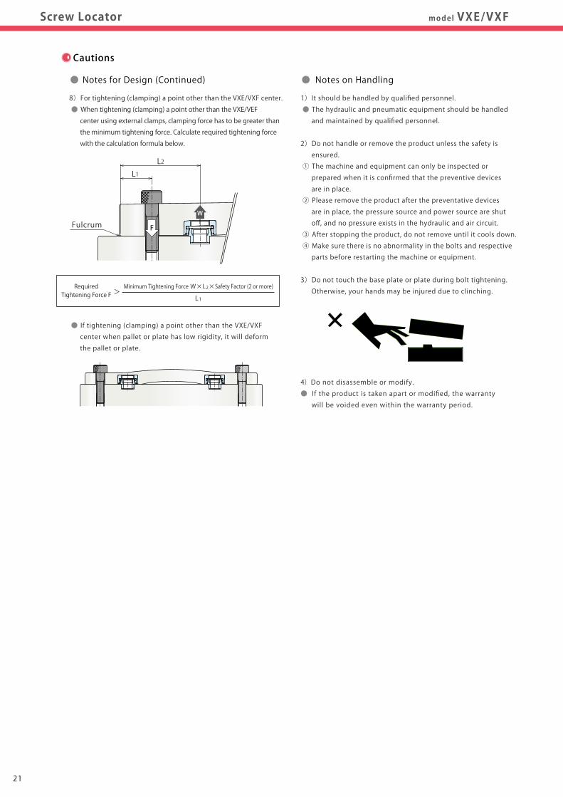
8)For tightening (clamping) a point other than the VXE/VXF center.
● When tightening (clamping) a point other than the VXE/VEF
center using external clamps, clamping force has to be greater than
the minimum tightening force. Calculate required tightening force
with the calculation formula below.
● If tightening (clamping) a point other than the VXE/VXF
center when pallet or plate has low rigidity, it will deform
the pallet or plate.
L1
Fulcrum
L2
F
W
1)It should be handled by qualified personnel.
● The hydraulic and pneumatic equipment should be handled
and maintained by qualified personnel.
2)Do not handle or remove the product unless the safety is
ensured.
① The machine and equipment can only be inspected or
prepared when it is confirmed that the preventive devices
are in place.
② Please remove the product after the preventative devices
are in place, the pressure source and power source are shut
off, and no pressure exists in the hydraulic and air circuit.
③ After stopping the product, do not remove until it cools down.
④ Make sure there is no abnormality in the bolts and respective
parts before restarting the machine or equipment.
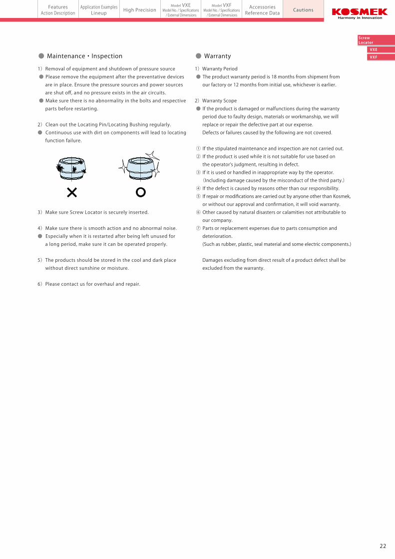
3)Do not touch the base plate or plate during bolt tightening.
Otherwise, your hands may be injured due to clinching.
4)Do not disassemble or modify.
● If the product is taken apart or modified, the warranty
will be voided even within the warranty period.
● Notes on Handling
1)Removal of equipment and shutdown of pressure source
● Please remove the equipment after the preventative devices
are in place. Ensure the pressure sources and power sources
are shut off, and no pressure exists in the air circuits.
● Make sure there is no abnormality in the bolts and respective
parts before restarting.
2) Clean out the Locating Pin/Locating Bushing regularly.
● Continuous use with dirt on components will lead to locating
function failure.
3)Make sure Screw Locator is securely inserted.
4)Make sure there is smooth action and no abnormal noise.
● Especially when it is restarted after being left unused for
a long period, make sure it can be operated properly.
5)The products should be stored in the cool and dark place
without direct sunshine or moisture.
6)Please contact us for overhaul and repair.
● Maintenance・Inspection
Minimum Tightening Force W×L2×Safety Factor (2 or more)
L1
RequiredTightening Force F >
2221
FeaturesAction Description
Application ExamplesLineup
FeaturesAction Description High Precision
Model VXEModel No. / Specifications / External Dimensionsmodel VXE/VXFScrew Locator
Model VXFModel No. / Specifications / External Dimensions
AccessoriesReference Data Cautions
VXE
VXF
ScrewLocatorCautions
1)Warranty Period
● The product warranty period is 18 months from shipment from
our factory or 12 months from initial use, whichever is earlier.
2)Warranty Scope
● If the product is damaged or malfunctions during the warranty
period due to faulty design, materials or workmanship, we will
replace or repair the defective part at our expense.
Defects or failures caused by the following are not covered.
① If the stipulated maintenance and inspection are not carried out.
② If the product is used while it is not suitable for use based on
the operator’s judgment, resulting in defect.
③ If it is used or handled in inappropriate way by the operator.
(Including damage caused by the misconduct of the third party.)
④ If the defect is caused by reasons other than our responsibility.
⑤ If repair or modifications are carried out by anyone other than Kosmek,
or without our approval and confirmation, it will void warranty.
⑥ Other caused by natural disasters or calamities not attributable to
our company.
⑦ Parts or replacement expenses due to parts consumption and
deterioration.
(Such as rubber, plastic, seal material and some electric components.)
Damages excluding from direct result of a product defect shall be
excluded from the warranty.
● Warranty● Notes for Design (Continued)
8)For tightening (clamping) a point other than the VXE/VXF center.
● When tightening (clamping) a point other than the VXE/VEF
center using external clamps, clamping force has to be greater than
the minimum tightening force. Calculate required tightening force
with the calculation formula below.
● If tightening (clamping) a point other than the VXE/VXF
center when pallet or plate has low rigidity, it will deform
the pallet or plate.
L1
Fulcrum
L2
F
W
1)It should be handled by qualified personnel.
● The hydraulic and pneumatic equipment should be handled
and maintained by qualified personnel.
2)Do not handle or remove the product unless the safety is
ensured.
① The machine and equipment can only be inspected or
prepared when it is confirmed that the preventive devices
are in place.
② Please remove the product after the preventative devices
are in place, the pressure source and power source are shut
off, and no pressure exists in the hydraulic and air circuit.
③ After stopping the product, do not remove until it cools down.
④ Make sure there is no abnormality in the bolts and respective
parts before restarting the machine or equipment.
3)Do not touch the base plate or plate during bolt tightening.
Otherwise, your hands may be injured due to clinching.
4)Do not disassemble or modify.
● If the product is taken apart or modified, the warranty
will be voided even within the warranty period.
● Notes on Handling
1)Removal of equipment and shutdown of pressure source
● Please remove the equipment after the preventative devices
are in place. Ensure the pressure sources and power sources
are shut off, and no pressure exists in the air circuits.
● Make sure there is no abnormality in the bolts and respective
parts before restarting.
2) Clean out the Locating Pin/Locating Bushing regularly.
● Continuous use with dirt on components will lead to locating
function failure.
3)Make sure Screw Locator is securely inserted.
4)Make sure there is smooth action and no abnormal noise.
● Especially when it is restarted after being left unused for
a long period, make sure it can be operated properly.
5)The products should be stored in the cool and dark place
without direct sunshine or moisture.
6)Please contact us for overhaul and repair.
● Maintenance・Inspection
Minimum Tightening Force W×L2×Safety Factor (2 or more)
L1
RequiredTightening Force F >
2221
CAT.NO.SBR-VXE001-01-GBPrinted in Japan
2017. 8 First 1Ry
http://www.kosmek.com
JQA-QMA10823KOSMEK HEAD OFFICE
● FOR FURTHER INFORMATION ON UNLISTED SPECIFICATIONS AND SIZES, PLEASE CALL US.
● SPECIFICATIONS IN THIS LEAFLET ARE SUBJECT TO CHANGE WITHOUT NOTICE.
KOSMEK (U.S.A.) LTD.650 Springer Drive, Lombard, IL 60148 USATEL. +1-630-620-7650 FAX. +1-630-620-9015
KOSMEK LTD - INDIAF 203, Level-2, First Floor, Prestige Center Point, Cunningham Road, Bangalore -560052 IndiaTEL.+91-988056169567 Soi 58, RAMA 9 Rd., Suanluang, Suanluang, Bangkok 10250TEL. +66-2-300-5132 FAX. +66-2-300-5133
1-5, 2-Chome, Murotani, Nishi-ku, Kobe 651-2241TEL.+81-78-991-5162 FAX.+81-78-991-8787
HEAD OFFICE
BRANCH OFFICE (U.S.A.)
KOSMEK USA Mexico OfficeBlvd Jurica la Campana 1040, B Colonia Punta Juriquilla Queretaro,QRO 76230 MexicoTEL.+52-442-161-2347
MEXICO REPRESENTATIVE OFFICE
BRANCH OFFICE (INDIA)
THAILAND REPRESENTATIVE OFFICE
KOSMEK EUROPE GmbHSchleppeplatz 2 9020 Klagenfurt am Wörthersee AustriaTEL.+43-463-287587 FAX.+43-463-287587-20
BRANCH OFFICE (EUROPE)
Model VXFModel VXEM3 Bolt Tightening /
Compact Model for Light Load
Screw LocatorNew Compact Model for Light Load