
Screw drives Screw Jacks - MN systems
118
NEFF G E W I N D E T R I E B E Screw drives Screw Jacks 09/2015
-
Upload
khangminh22 -
Category
Documents
-
view
0 -
download
0
Transcript of Screw drives Screw Jacks - MN systems

NEFFG E W I N D E T R I E B E
Screw drivesScrew Jacks09/2015

Neff moves!The name NEFF traditionally stands for high-quality screw drives. For over 100 years threads have been cut, spun, rolled or grounded. Today NEFF Gewindetriebe GmbH is a highly qualified development and manufacturing company. Our screw drives and lifting systems move machines and plants in the most diverse industries all over the world.
It has always been noticeable with NEFF that everything revolves around the customer. Not only do we supply first-class products; we as the NEFF team aim to offer customer-oriented, sustaina-ble solutions. We want to pass on our extensive experience and communicate openly.Entirely in keeping with this style, this revised and extended catalogue not only lists our stock standards, but is also intended to communicate basic technical principles in order to support the
user with the various drive tasks.Regardless of whether you are a long-standing NEFF customer or whether you are just discovering us as a new customer – we look forward to cooperating with you.
On behalf of the entire NEFF team,Your
Hartmut WandelChief Executive Officer
Here you can find us:
NEFF Gewindetriebe GmbH
Karl-Benz-Straße 24D-71093 Weil im Schönbuch
Phone 07157 53890-0Fax 07157 53890-25
NEFF Gewindetriebe GmbHLocation Heilbronn
Ochenbrunnenstraße 10D-74078 Heilbronn
Phone 07131 27177-60Fax 07131 27177-66

NEFF Gewindetriebe GmbH 09/15 . Phone: +49 (0) 71 57/5 38 90-0 3
Contents
Overview ______________________________________________ 4 - 5
Ball screw drive KGTGeneral technical data _______________________________________ 6 - 7Ball screws KGS _______________________________________________ 8Ordering code for ball screws ___________________________________ 9 Ball nut KGM/KGF ________________________________________ 10 - 14Ordering code for ball screw drive _______________________________ 15Calculation Ball screw drive ________________________________ 16 - 20
Trapezoidal screw drive TGTGeneral technical data _____________________________________ 21 - 22Trapezoidal screw _________________________________________ 23 - 24Calculation Trapezoidal-threaded spindle _________________________25Trapezoidal-threaded nut TGM ______________________________ 26 - 30Ordering code Trapezoidal screw drive ___________________________31Calculation Trapezoidal screw drive _________________________ 32 - 37
Accessories KGT and TGTScrew end machining _____________________________________ 38 - 41Fixed bearing units _______________________________________ 42 - 43Grooved nut _________________________________________________44Adaptor bracket _______________________________________________45Universal joint adapter _________________________________________46Bellow __________________________________________________ 47 - 48Spiral spring cover ________________________________________ 49 - 51Lubricants _______________________________________________ 52 - 53Lubricant dispenser ___________________________________________53
Installation and maintenance ________________________54
Screw JacksGeneral technical data _____________________________________ 55 - 56Dimensions and Verions M/J _______________________________ 57 - 61Performance tables M/J ___________________________________ 62 - 64Ordering code Worm gear screw jacks M/J _______________________65High-speed screw jacks G1-G3 _____________________________ 66 - 68Performance tables G1-G3 _________________________________ 69 - 72Ordering code High-speed screw jacks __________________________73Examples of arrangement and direction of rotation ____________ 74 - 75Calculation screw jacks ____________________________________ 76 - 82
Accessories Screw JacksMounting feet ________________________________________________83Universal joint adapter _________________________________________84Universal joint bearing _________________________________________85Top plate BP _________________________________________________86Fork end GK __________________________________________________86Spherical bearing GA _________________________________________87High-performance joint head HG ________________________________87Bellow FB _______________________________________________ 88 - 89Spiral spring cover SF _________________________________________90Lubricants ___________________________________________________91 Lubricant dispenser ___________________________________________923-phase motors __________________________________________ 93 - 94Handwheels _____________________________________________ 95 - 96Motor adaptor flanges _____________________________________ 97 - 98Couplings _______________________________________________ 99 - 100Universal joint shaft _____________________________________ 101 - 103Pedestal bearings ____________________________________________104Bevel gearboxes ________________________________________ 105 - 113Ordering code Bevel gearboxes ________________________________ 114
Installation and maintenance ______________________ 115
Contact person _______________________________________ 117

NEFF Gewindetriebe GmbH 09/15 . Phone: +49 (0) 71 57/5 38 90-04
Trapezoidal screw drives
NEFF trapezoidal screws are manufactured from special semi-finis-hed goods with high demands on straightness. The series conforms to DIN 103 and offers an extensive range of nuts made from various materials – all ready for installation. The very low backlash in the nuts allows low radial forces to be absorbed.
Trapezgewindespindelnn Precision-rolled trapezoidal screws RPTS, Ø 10 – 80 mm
in versions with single or multi-start threads.n Planetary-milled trapezoidal screws WPTS, Ø 16 –120 mm
(the trapezoidal screws can also be supplied in coated and rustproof versions).
Trapezoidal nutsn KSM, , steel nut, round, Ø 10 – 80 mmn SKM, steel nut, hexagonal, Ø 10 – 80 mmn SFM, red bronze, ready to install, Ø 10 – 80 mmn LRM, red bronze nut, Ø 10 – 80 mmn EFM, red bronze, ready to install, Ø 10 – 80 mmn Central flanged nut, bronze GBZ 12n Central flanged nut, plastic, PTFE alloyn Universal joint nut, bronze GBZ 12n Universal joint nut, plastic, PTFE alloyn Bracket nut, bronze GBZ 12n Bracket nut, plastic, PTFE alloy
Screw drive accessories
The NEFF screw drive accessory range offers an extensive range of accessories for all common accessory parts of a screw drive, from ready-to-install bearing units to the appropriate spindle grease. If desired we also manufacture tailor-made solutions in our modern machine pool.
n End machiningn Fixed bearing/movable bearing unitsn Grooved nutsn Adaptor brackets KONn Pivot adaptors KARn Bellows FBn Spiral spring covers SFn Lubricant dispensersn Grease cartridges
Ball screw drives
The range conforms to DIN 69051 and the NEFF standard. All nuts (flanged and cylinder versions) can be supplied with the correspon-ding DIN connections. Pre-tensioned double-nut units achieve high positioning accuracies. Special nuts on enquiry. All ball screw drives are available with customer-specific end machining.On request we can supply soft-annealed ends for you to carry outyour own end machining.
Ball screwsn Precision-rolled ball screws, Ø 12 – 80 mm
Pitch from 5 - 50 mm, pitch accuracies of 23 μm, 50 μm and 200 μm/300 mm
n polished ball screws, Ø 6-120 mm, Pitch from 5 - 50 mm, pitch accuracies of 6-52 μm/300 mm
Ball nutsn KGF-N NEFF flanged single nutn KGF-D DIN DIN flanged single nutn KGM-N NEFF cylinder single nutn KGM-N DIN cylinder single nutn KGM-E screw-in cylinder single nut(the ball nuts can also be supplied free of play and pre-tensioned in conjunction with spindles.)
OverviewNEFF Screw drives

NEFF Gewindetriebe GmbH 09/15 . Phone: +49 (0) 71 57/5 38 90-0 5
OverviewNEFF Screw Jacks
Worm Gear Screw Jacks
The range encompasses 11 sizes with lifting forces from2.5 to 500 kN, with fixed and rotating spindles.n Some sizes are available as standard with lifetime lubricationn Significantly improved efficiency through optimisation of
tolerances and surface qualityn Limited absorption of lateral forces through the use of the
NEFF glide screwn Optionally also available with ball screw or trapezoidal screw driven Mountable in any position thanks the cubic design
High-speed screw jacks
NEFF high-speed screw jacks supplement the existing screw jack range in the medium load range for high stroke speed and higher duty cycle.n 3 sizesn Gearboxes with ratios of 1:1, 2:1 and 3:1 availablen Hardened, polished and spiral-toothed bevel gearboxesn Mountable in any position thanks to the cubic designn Available with up to 4 output shafts (except transmission
ratio 1:1)
Screw jack accessories
The NEFF screw jack accessory range offers an extensive selection of accessories for all common accessory parts of a screw jack, from precise pivot bearings to the appropriate grease dispenser.
If desired we also manufacture tailor-made solutions in our modern machine pool.n Bevel gearboxesn Fastening strips BL-Ln Pivot adaptors KAn Pivot bearing flangen Pivot bearing pedestaln Mounting plate BPn Limit switchn Fork end GKn Spherical bearing GAn High-performance rod end HGn Spiral spring cover SFn Bellows FBn Three-phase motors Mn Motor adaptor flanges MGn Shaft coupling GSn Shaft coupling RA, RGn Universal joint shaft ZRn Universal joint shaft GXn Pedestal bearing SNn Grease cartridgesn Lubricant dispensersn Adaptor brackets KONn Pivot adaptors KARn Bellows FBn Spiral spring covers SFn Lubricant dispensersn Grease cartridges

NEFF Gewindetriebe GmbH 09/15 . Phone: +49 (0) 71 57/5 38 90-06
Ball screw drive
Ball screw drives from Neff screw drives are the result of many de-cades of innovative further development of the ball screw drive.
We offer ball screw drives in all common sizes in precision-rolled versi-ons at competitive prices, in extraordinary quality and with a complete quality concept.
The Neff ball screw range corresponds to DIN 69051 and the NEFF standard (exchangeability of EFM trapezoidal nuts to ball screw nuts)
The spindles are available with customised end machining, or on request with soft-annealed ends for your own machining.
The high mechanical efficiency < 98% requires a lower drive power and a significantly lower breakaway torque than with trapezoidal screw drives.
Thanks to the low rolling friction and deflection systems that have been developed further over many years, Neff ball screw drives have a parti-cularly long and reliable service life
2-start Neff ball screw drive with channel deflection:

NEFF Gewindetriebe GmbH 09/15 . Phone: +49 (0) 71 57/5 38 90-0 7
Generaltechnical data
Manufacturing processThe thread profile of NEFF ball screws is produced by cold rolling in the thread rolling method. Both screw and nut have an arched thread profile. The load angle is 45°.
Linear speedsAt present the permissible speed limit is in the region of 3000 rpm, with individual dimensions up to 4500 rpm. This limit defines the maxi-mum speed, which may be run only under ideal operating conditions.
Installation positionThe position in which the screw drive is installed can always be freely chosen. Please consider that all radial forces that occur need to be absorbed by external guides.
Accuracy classes of the spindlesT5 = pitch accuracy 23 μm/300 mmT7 = pitch accuracy 52 µm/300 mmT9 = pitch accuracy 130 µm/300 mmT10 = pitch accuracy 200 µm/300 mmIf nothing different is specified we deliver class T7.
Self-lockingBall screw drives are generally not self-locking due to the low friction. It is therefore advisable to install suitable motors with holding brake, particu-larly when the ball screw drive is installed vertically.
EfficiencyTrapezoidal screw drives have a max. mechanical efficiency of 50 %,ball screw drives achieve a mechanical efficiency of up to 98 %.
Duty cycleThe ball screw drive permits a duty cycle of up to 100 %. Extreme-ly high forces in combination with high duty cycles can shorten the service life.
TemperaturesAll screw drives are designed for continuous operation at ambient temperatures of –30 °C up to 80 °C. Temperatures of up to 110 °C are also permitted for brief periods. Ball screw drives are suitable only in exceptional cases for operation at sub-zero temperatures.
RepeatabilityThe repeatability is defined as the capability of a screw drive to reach an actual position again that has been reached once before under the same conditions. It refers to the average position variation according to VDI/DGQ 3441. The repeatability is influenced amongst other things by:n Loadn Speedn Decelerationn Direction of traveln Temperature
Aggressive operating conditionsIn cases of heavy dirt and fine dust particles/swarf, an additional bellow or a spiral spring cover is recommended.
Installation and maintenancesee page: 54
Neff ball screw profiles Neff ball screw profiles have a Gothic pointed arch profile with a 45° contact angle and optimised osculation. (Ratio of ball race radius to ball diameter)
Neff deflection systemsSingle deflection:In this type of deflection the balls are lifted up out of the spindle after each circuit and set back by one thread pitch.(Only for single-start ball screw drives)
Channel deflection:In channel deflection the balls, after several circuits, are steered by an integrated deflection piece into a return channel in the nut and fed back (For single-start and multi-start ball screw drives)
Cover deflection:In cover deflection the balls are steered via special deflection covers into the return channel in the nut and fed back.(For multi-start ball screw drives)
Types of pre-loading:In principle all Neff ball screw nuts are combinable for a backlash-free, O-pre-loaded nut unit if a ball screw drive is selected with a pitch accuracy of ≤ T7.With less accurate pitch classes only low-backlash can be set (≥ 0.03mm)
O-pre-loading:In the O-pre-loading the force lines run with a diamond form, i.e. the nuts are pressed apart by a specially manufactured intermediate piece.The standard pre-loading is about 10% of the dynamic load rating Cdyn
Pre-loading by ball selection:The ball screw nut can be adjusted for low backlash by means of ball selection.

Technical data ball screw KGS
d0= nominal diameter, d1= outside diameter, d2= core diameter, L= spindle length
d1
h11
L
2d
0d
NEFF Gewindetriebe GmbH 09/15 . Phone: +49 (0) 71 57/5 38 90-08
Ball screwsKGS
TypeDiameter [mm]Pitch [mm]Right hand thread Division Ball size
Dimensions [mm] Distributed load WKGS[kg/m]
Geometrical moment of inertia ly[104 mm4]
Moment of resistance1)
[103 mm3]
Mass moment of inertia[kg m2/m]d0 d1 d2 L max.
KGS-1205 2 12 11.5 10.1 2000 0.75 0.051 0.101 1.13 · 10-5
KGS-1605 3.5 16 15.5 12.9 5600 1.26 0.136 0.211 3.21 · 10-5
KGS-1610-P5 3 16 15.4 13.0 5600 1.26 0.140 0.216 3.21 · 10-5
KGS-1616-P8 3 16 15.4 13.0 5600 1.26 0.140 0.216 3.21 · 10-5
KGS-2005 3.5 20 19.5 16.9 5600 2.04 0.400 0.474 8.46 · 10-5
KGS-2020-P5 3.5 20 19.5 16.9 5600 2.04 0.400 0.474 8.46 · 10-5
KGS-2050-P10 3.5 20 19.1 16.5 5600 2.04 0.364 0.441 8.46 · 10-5
KGS-2505-P5 3.5 25 24.5 21.9 5600 3.33 1.129 1.031 2.25 · 10-4
KGS-2510-P5 3.5 25 24.5 21.9 5600 3.33 1.129 1.031 2.25 · 10-4
KGS-2520-P5 3.5 25 24.6 22.0 5600 3.33 1.150 1.045 2.25 · 10-4
KGS-2525-P5 3.5 25 24.5 22.0 5600 3.33 1.150 1.045 2.25 · 10-4
KGS-2550-P10 3.5 25 24.1 21.5 5600 3.33 1.049 0.976 2.25 · 10-4
KGS-3205 3.5 32 31.5 28.9 5600 5.63 3.424 2.370 6.43 · 10-4
KGS-3210 7.144 32 32.7 27.3 5600 5.63 2.727 1.998 6.43 · 10-4
KGS-3220-P10 5 32 31.7 27.9 5600 5.63 2.974 2.132 6.43 · 10-4
KGS-3240-P10 3.5 32 30.9 28.3 5600 5.63 3.149 2.225 6.43 · 10-4
KGS-4005 3.5 40 39.5 36.9 5600 9.01 9.101 4.933 1.65 · 10-3
KGS-4010 7.144 40 39.5 34.1 5600 8.35 6.737 3.893 1.41 · 10-3
KGS-4020-P10 5 40 39.7 35.9 5600 9.01 8.154 4.542 1.65 · 10-3
KGS-4040-P10 3.5 40 38.9 36.3 5600 9.01 8.523 4.696 1.65 · 10-3
KGS-5010 7.144 50 49.5 44.1 5600 13.50 18.566 8.420 3.70 · 10-3
KGS-5020-P10 7.144 50 49.5 44.1 5600 13.50 18.566 8.420 3.70 · 10-3
KGS-6310 7.144 63 62.5 57.1 5600 22.03 52.181 18.280 9.84 · 10-3
KGS-8010 7.144 80 79.65 74.2 5600 36.43 148.600 39.950 2.69 · 10-2
Left hand thread
KGS-2005 LH 3.5 20 19.5 16.9 5600 2.04 0.400 0.474 8.46 · 10-5
KGS-2505 LH 3.5 25 24.5 21.9 5600 3.33 1.129 1.031 2.25 · 10-4
KGS-3205 LH 3.5 32 31.5 28.9 5600 5.63 3.424 2.370 6.43 · 10-4
1) The polar resistive torque is twice as large as the resistive torque
n Diameter: _______________________ Standard: 12 – 80 mmn Pitch: ___________________________ Standard: 5 – 50 mmn Number of starts: ________________ 1 – 5n Thread direction: _________________ Right hand thread,
KGS 2005 + 3205 also left hand thread
n Length: _________________________ Standard: 5600 mm KGS 1205: 2000 mm to 11000 mm auf Anfrage
n Material: ________________________ 1.1213 (Cf 53) Ball track inductively hardened and polished, Spindle end and spindle core soft
n Straightness: ____________________ L < 500 mm: 0,05 mm/m L = 500 – 1000 mm: 0,08 mm/m L > 1000 mm: 0,1 mm/m
n Right-hand/left-hand spindle: ______ KGS 2005 + 3205 only

NEFF Gewindetriebe GmbH 09/15 . Phone: +49 (0) 71 57/5 38 90-0 9
Ordering codeBall screws
- - - - - - - -
1 2 3 4 5 6 7 8 9
Ordering code for ball screws
No. Designation Code Description
1 Product abbreviation KGS Ball screw
2 Spindle abbreviation
R Rolled
W Spun
S Grounded
3 Thread designation e.g. 2005 (diameter 20 mm, pitch 5 mm)
4 Accuracy class of the spindle
T5 23µ/300 mm
T7 50µ/300 mm
T9 130µ/300 mm
T10 200µ/300 mm
5 Pitch directionRH Right-hand thread
LH Left-hand thread
6 Spindle end A 0
A
GA
GB
K
D
F
H
J
L
S
T
W
Fk
FF
BK
BF
M
AS
RS
VS
Z
Ends only sawn and brushedEnd with chamfer1st end annealed (indicate length in the additional text)2nd end annealed (indicate length in the additional text)End according to customer drawing or project drawing no.End fixed bearing form D for bearing ZKLFEnd fixed bearing form F for bearing ZARNEnd fixed bearing form H for bearing ZARF/LTNEnd fixed bearing form J for bearing FDX 12-40End fixed bearing form L for bearing 7201-7208End movable bearing form S for bearing 6001-6211End movable bearing form T for needle bearing HK1614-4518End movable bearing form W for bearing 6001-6211End fixed bearing unit FK4-FK30End movable bearing unit FF6-FF30End fixed bearing unit BK10-BK40End movable bearing unit BF10-BF40Metric threaded stem SHGEnd hollowing safeguard SHGEnd worm gear connection rotary spindle SHGEnd anti-twist device SHGcylindrical bearing journal SHG with rotary spindle
7 Spindle end B
8 Overall length in (mm) e.g. 1000
9 Special requirements0 None
1 According to specification, description or drawing

NEFF Gewindetriebe GmbH 09/15 . Phone: +49 (0) 71 57/5 38 90-010
Flanged ball nuts KGF-Daccording to DIN 69051
Material: 1.7131 (ESP65) or 1.3505 (100 Cr 6)
TypeDiameter [mm]Pitch [mm]Right-hand thread Fo
rm
Bore
pat
tern Dimensions [mm] Axial
backlash max[mm]
No. of circuits
Load rating [kN]Lubrica-tion bore
GD1 D4 D5 D6 L1 L2 L6 L7 L8 Lg L10 C2) C3) Co= Coa
KGF-D 1605 RH-EE E 1 28 38 5.5 48 10 42 – 10 40 10 5 M 6 0.08 3 12.0 9.3 13.1
KGF-D 1610 RH-EE E 1 28 38 5.5 48 10 55 – 10 40 10 5 M 6 0.08 6 23.0 15.4 26.5
KGF-D 1616-P8-3 RH-EE E 1 28 38 5,5 48 10 55 – 10 40 10 5 M 6 0,08 6 23,0 15,4 26,5
KGF-D 1640-P10-3 RH-EE S 1 32 42 5,5 52 10 45 10 10 40 8 5 M6 0,08 4 - 8,5 13
KGF-D 2005 RH-EE E 1 36 47 6.6 58 10 42 – 10 44 10 5 M 6 0.08 3 14.0 10.5 16.6
KGF-D 2505 RH-EE E 1 40 51 6.6 62 10 42 – 10 48 10 5 M 6 0.08 3 15.0 12.3 22.5
KGF-D 2510 RH-EE E 1 40 51 6.6 62 16 55 – 10 48 10 5 M 6 0.08 3 17.5 13.2 25.3
KGF-D 2520 RH-EE S 1 40 51 6.6 62 4 35 10.5 10 48 8 5 M 6 0.15 4 19.0 13.0 23.3
KGF-D 2525 RH-EE S 1 40 51 6.6 62 9 35 8 10 48 8 5 M 6 0.08 5 21.0 16.7 32.2
KGF-D 2550 RH-EE S 1 40 51 6.6 62 10 58 10.0 10 48 8 5 M 6 0.15 5 22.5 15.4 31.7
KGF-D 3205 RH-EE E 1 50 65 9 80 10 55 – 12 62 10 6 M 6 0.08 5 24.0 21.5 49.3
KGF-D 3210 RH-EE5) E 1 531) 65 9 80 16 69 – 12 62 10 6 M 8x1 0.08 3 44.0 33.4 54.5
KGF-D 3220 RH-EE E 1 531) 65 9 80 16 80 – 12 62 10 6 M 6 0.08 4 42.5 29.7 59.8
KGF-D 3260-P10-3,5 RH-EE S 1 53 65 9 80 16 68 10 12 62 10 6 M 6 0,08 4,8 - 20 49,3
KGF-D 4005 RH-EE E 2 63 78 9 93 10 57 – 14 70 10 7 M 6 0.08 5 26.0 23.8 63.1
KGF-D 4010 RH-EE E 2 63 78 9 93 16 71 – 14 70 10 7 M 8x1 0.08 3 50.0 38.0 69.1
KGF-D 4020 RH-EE E 2 63 78 9 93 16 80 – 14 70 10 7 M 8x1 0.08 4 44.5 33.3 76.1
KGF-D 4040 RH-EE S 2 63 78 9 93 16 85 7.5 14 –4) 10 7 M 8x1 0.08 8 42.0 35.0 101.9
KGF-D 5010 RH-EE E 2 75 93 11 110 16 95 – 16 85 10 8 M 8x1 0.08 5 78.0 68.7 155.8
KGF-D 5020 RH-EE E 2 851) 1031) 11 125 22 95 – 18 95 10 9 M 8x1 0.08 4 82.0 60.0 136.3
KGF-D 6310 RH-EE E 2 90 108 11 125 16 97 – 18 95 10 9 M 8x1 0.08 5 86.0 76.0 197
KGF-D 8010 RH-EE E 2 105 125 13.5 145 16 99 – 20 110 10 10 M 8x1 0.08 5 - 82.7 221.9
Left-hand thread
KGF-D 2005 LH-EE E 1 36 47 6.6 58 10 42 – 10 44 10 5 M 6 0.08 3 16.5 10.5 16.6
1) D1 not conforming to DIN 69051. 4) Round flange.2) Dynamic load rating according to DIN 69051 part 4 draft 1978. 5) Also available with Ø 50 mm according to DIN.3) Dynamic load rating according to DIN 69051 part 4 draft 1989.
Holepattern 1 FlangedForm B according toDIN 69051
Holepattern 2 FlangedForm B according toDIN 69051

NEFF Gewindetriebe GmbH 09/15 . Phone: +49 (0) 71 57/5 38 90-0 11
Flanged ball nuts KGF-Naccording to NEFF standard
Material: 1.7131 (ESP65) or 1.3505 (100 Cr 6)
TypeDiameter [mm]Pitch [mm]Right-hand thread
Form Dimensions [mm] Axial backlash
max[mm]
No. of circuits
Load rating [kN]
Lubrication bore GD1 D4 D5 D6 L1 L2 L6 L7 Lg L10 C1) C2) Co= Coa
KGF-N 1605 RH-EE E 28 38 5.5 48 8 44 – 12 8 6 M 6 0.08 3 12.0 9.3 13.1
KGF-N-1616-P8-3-RH-EE E 28 38 5,5 48 8 45 – 12 8 6 M 6 0,08 3,75 – 10 16,4
KGF-N 2005 RH-EE E 32 45 7 55 8 44 – 12 8 6 M 6 0.08 3 14.0 10.5 16.6
KGF-N 2020 RH-EE S 35 50 7 62 4 30 8 10 8 5 M 6 0.08 4 12.0 11.6 18.4
KGF-N 2050 RH-EE S 35 50 7 62 10 56 8 10 8 5 M 6 0.15 5 18.0 13.0 24.6
KGF-N 2505 RH-EE E 38 50 7 62 8 46 – 14 8 7 M 6 0.08 3 15.0 12.3 22.5
KGF-N 3205 RH-EE E 45 58 7 70 10 59 – 16 8 8 M 6 0.08 5 24.0 21.5 49.3
KGF-N 3210 RH-EE E 53 68 7 80 10 73 – 16 8 8 M 8x1 0.08 3 44.0 33.4 54.5
KGF-N 3240 RH-EE S 53 68 7 80 14 45 7.5 16 10 8 M 6 0.08 4 17.0 14.9 32.4
KGF-N-3260-P10-3,5 RH-EE E 53 68 7 80 16 68 10 16 8 8 M 6 0,08 4,8 – 20 49,3
KGF-N 4005 RH-EE E 53 68 7 80 10 59 – 16 8 8 M 6 0.08 5 26.0 23.8 63.1
KGF-N 4010 RH-EE E 63 78 9 95 10 73 – 16 8 8 M 8x1 0.08 3 50.0 38.0 69.1
KGF-N 5010 RH-EE E 72 90 11 110 10 97 – 18 8 9 M 8x1 0.08 5 78.0 68.7 155.8
KGF-N 6310 RH-EE E 85 105 11 125 10 99 – 20 8 10 M 8x1 0.08 5 86.0 76.0 197.0
KGF-N 8010 RH-EE E 105 125 13.5 145 10 101 – 22 8 11.5 M 8x1 0.08 5 - 82.7 221.9
1) Dynamic load rating according to DIN 69051 part 4 draft 1978.2) Dynamic load rating according to DIN 69051 part 4 draft 1989.
Bore pattern 3Neff standard

NEFF Gewindetriebe GmbH 09/15 . Phone: +49 (0) 71 57/5 38 90-012
Cylindrical ball nuts KGM-Daccording to DIN 69051
Material: 1.7131 (ESP65) or 1.3505 (100 Cr 6)
1) Position of the lubrication bore not defined
TypeDiameter [mm]Pitch [mm]Right-hand thread
Form Dimensions [mm]
Axial backlash
max[mm]
No. of circuits
Load rating [kN]
D1 D8 L2 L8 L9 L10 BxT C2) C3) Co= Coa
KGM-D 1605 RH-EE E 28 3 34 7 7 20 5x2 0,08 3 12,5 9,3 13,1
KGM-D 1610 RH-EE E 28 3 50 7 15 20 5x2,2 0,08 6 23,0 15,4 26,5
KGM-D-1616-P8 E 28 3 45 7 12,5 20 5x2,2 0,08 3,75 – 10 16,4
KGM-D 1640-P10-3 RH-EE E 28 1,5 45 14,5 17,5 10 5x2 0,08 4 – 8,5 13
KGM-D 2005 RH-EE E 36 3 34 7 7 20 5x2 0,08 3 14,0 10,5 16,6
KGM-D 2505 RH-EE E 40 3 34 7 7 20 5x2 0,08 3 15,0 12,3 22,5
KGM-D 2510 RH-EE E 40 3 45 7,5 12,5 20 5x2 0,08 3 17,5 13,2 25,3
KGM-D 2520 RH-EE S 40 1,5 35 14 11,5 12 5x3 0,15 4 19,0 13,0 23,3
KGM-D 2525 RH-EE S 40 1,5 35 11,5 11 13 5x3 0,08 5 21,0 16,7 32,2
KGM-D 2550 RH-EE S 40 1,5 58 17 19 20 5x3 0,15 5 22,5 15,4 31,7
KGM-D 3205 RH-EE E 50 3 45 7,5 8 30 6x2,5 0,08 5 24,0 21,5 49,3
KGM-D 4005 RH-EE E 63 3 45 7,5 8 30 6x2,5 0,08 5 26,0 23,8 63,1
KGM-D 4010 RH-EE E 63 4 60 10 15 30 6x2,5 0,08 3 50,0 38,0 69,1
KGM-D 4020 RH-EE E 63 3 70 7,5 20 30 6x2,5 0,08 4 44,5 33,3 76,1
KGM-D 4040 RH-EE S 63 1,5 85 15 27,5 30 6x3,5 0,08 8 42,0 35,0 101,9
KGM-D 5010 RH-EE E 75 4 82 11 23 36 6x2,5 0,08 5 78,0 68,7 155,8
KGM-D 6310 RH-EE E 90 4 82 11 23 36 6x2,5 0,08 5 86,0 76,0 197,0
Left-hand thread
KGM-D 2005 LH-EE E 36 3 34 7 7 20 5x2 0.08 3 16.5 10.5 16.6
1) Position of the lubrication bore not defined.2) Dynamic load rating according to DIN 69051 part 4 draft 1978.3) Dynamic load rating according to DIN 69051 part 4 draft 1989.

NEFF Gewindetriebe GmbH 09/15 . Phone: +49 (0) 71 57/5 38 90-0 13
1) Position of the lubrication bore not defined
Material: 1.7131 (ESP65) or 1.3505 (100 Cr 6)
TypeDiameter [mm]Pitch [mm]Right-hand thread
Form Dimensions [mm] Axial backlash
max[mm]
No. of circuits
Load rating [kN]
D1 D8 L2 L8 L9 L10 BxT C2) C3) Co= Coa
KGM-N 1205 RH-OO E 204) – 24 – 5 14 3x1.8 0.08 3 6.0 4.4 6.8
KGM-N 2005 RH-EE E 32 3 34 7 7 20 5x2 0.08 3 14.0 10.5 16.6
KGM-N 2020 RH-EE S 35 1.5 30 11.5 9 12 5x3 0.08 4 12.0 11.6 18.4
KGM-N 2050 RH-EE S 35 1.5 56 16 18 20 5x2.2 0.15 5 18.0 13.0 24.6
KGM-N 2505 RH-EE E 38 3 34 7 7 20 5x2 0.08 3 15.0 12.3 22.5
KGM-N 3205 RH-EE E 45 3 45 7.5 8 30 6x2.5 0.08 5 24.0 21.5 49.3
KGM-N 3210 RH-EE E 53 4 60 10 15 30 6x2.5 0.08 3 44.0 33.4 54.5
KGM-N 3220 RH-EE E 53 3 70 7.5 20 30 6x2.5 0.08 4 42.5 29.7 59.8
KGM-N 3240 RH-EE S 535) 1.5 45 13 10 25 6x4 0.08 4 17.0 14.9 32.4
KGM-N-3260-P10-3,5 RH-EE S 53 1,5 68 15,5 21,5 25 6x2,5 0,08 4,8 – 19,8 46,6
KGM-N 4005 RH-EE E 53 3 45 7.5 8 30 6x2.5 0.08 5 26.0 23.8 63.1
KGM-N 5010 RH-EE E 72 4 82 11 23 36 6x2.5 0.08 5 78.0 68.7 155.8
KGM-N 5020 RH-EE E 85 4 82 10 23 36 6x2.5 0.08 4 82.0 60.0 136.3
KGM-N 6310 RH-EE E 85 4 82 11 23 36 6x2.5 0.08 5 86.0 76.0 197.0
KGM-N 8010 RH-EE E 105 4 82 11 23 36 8x3 0.08 5 - 82.7 221.9
1) Position of the lubrication bore not defined.2) Dynamic load rating according to DIN 69051 part 4 draft 1978.3) Dynamic load rating according to DIN 69051 part 4 draft 1989.4) Nut without wiper.5) D1 -0,2/-0,8 does not apply, therefore D1 -1,0/-1,5.
Cylindrical ball nuts KGM-Naccording to NEFF standard

W
NEFF Gewindetriebe GmbH 09/15 . Phone: +49 (0) 71 57/5 38 90-014
Material: 1.7131 (ESP65) or 1.3505 (100 Cr 6)
Ball nuts KGM-E
Size Dimensions [mm]
D1h11 D2 L L2 L3 L4 G1 G2 W
KGM-E-1605-RH 32 3.2 42 12 3 M26x1.5
KGM-E-2005-RH 38 8 45 14 8 8 M35x1.5 M6 90°
KGM-E-2505-RH 43 8 60 19 15 10 M40x1.5 M6 90°
KGM-E-2510-RH 43 8 74 19 16 16 M40x1.5 M6 180°
KGM-E-3205-RH 52 8 63 19 15 10 M48x1.5 M6 90°
KGM-E-3210-RH 54 8 78 19 8 8 M48x1.5 M6 90°
KGM-E-4005-RH 60 8 63 19 15 10 M56x1.5 M8x1 90°
KGM-E-4010-RH 65 8 84 24 15 8 M60x2 M8x1 90°
KGM-E-5010-RH 78 8 111 29 15 8 M72x2 M8x1 90°
- - - - -
1 2 3 4 5 6
Ordering code for ball nuts
No. Designation Code Description
1 Product abbreviationKGF Flanged ball nuts
KGM Cylindrical ball nuts
2 Nut version
D Nut according to DIN 69051 standard
N Nut according to NEFF standard
E Nut with screw-in thread
S Nut with special dimensions
3 Thread designation e.g. 2005 (diameter 20 mm, pitch 5mm)
4 Pitch directionRH Right-hand thread
LH Left-hand thread
5 Seal0 without wiper
EE with double-sided wiper
6 Special requirements0 None
1 According to specification, description or drawing

NEFF Gewindetriebe GmbH 09/15 . Phone: +49 (0) 71 57/5 38 90-0 15
- - - - - - - - - - -
1 2 3 4 5 6 7 8 9 10 11 12
Ordering code for ball screw
No. Designation Code Description
1 Product abbreviation KGT Ball screw
2 Spindle abbreviation
R Rolled
W Spun
S Grounded3 Spindle designation e.g. 2005 (diameter 20 mm, pitch 5 mm)
4 Accuracy class of the spindle
T5 23µ/300 mm
T7 50µ/300 mm
T9 130µ/300 mm
T10 200µ/300 mm
5 Pitch directionRH Right-hand threadLH Left-hand thread
6 Spindle end A 0
A
GA
GB
K
D
F
H
J
L
S
T
W
Fk
FF
BK
BF
M
AS
RS
VS
Z
Ends only sawn and brushedEnd with chamfer1st end annealed (indicate length in the additional text)2nd end annealed (indicate length in the additional text)End according to customer drawing or project drawing no.End fixed bearing form D for bearing ZKLFEnd fixed bearing form F for bearing ZARNEnd fixed bearing form H for bearing ZARF/LTNEnd fixed bearing form J for bearing FDX 12-40End fixed bearing form L for bearing 7201-7208End movable bearing form S for bearing 6001-6211End movable bearing form T for needle bearing HK1614-4518End movable bearing form W for bearing 6001-6211End fixed bearing unit FK4-FK30End movable bearing unit FF6-FF30End fixed bearing unit BK10-BK40End movable bearing unit BF10-BF40Metric threaded stem SHGEnd hollowing safeguard SHGEnd worm gear connection rotary spindle SHGEnd anti-twist device SHGcylindrical bearing journal SHG with rotary spindle
7 Spindle end B
8 Overall length in (mm) e.g. 1000
9 Special requirements spindle0 none1 According to specification, description or drawing
10 Ball nut or nut unit with installation note
M Single nut, cylindricalMM Nut unit, cylindrical, pre-loadedF0 Flanged single nut (flange to fixed bearing or longer end)0F Flanged single nut (flange to movable bearing or shorter end)FM Nut unit flanged nut + cylinder nut (flange to fixed bearing or longer end)MF Nut unit flanged nut + cylinder nut (flange to movable bearing or shorter end)FF Nut unit flanged nut + flanged nutEO Single nut with screw-in thread (thread to fixed bearing or longer end)OE Single nut with screw-in thread (thread to movable bearing or shorter end)
11 Nut versionD Nut with DIN 69051 dimensionsN Nut with Neff dimensionsS Nut with special dimensions (according to drawing)
12 Special requirements for nut0 none1 According to specification, description or drawing
Ordering code Ball screw

NEFF Gewindetriebe GmbH 09/15 . Phone: +49 (0) 71 57/5 38 90-016
CalculationBall screw Drive
Required drive torque
(XV)
Fax . P
Md = = + Mrot 2000 . p . hA
Required drive torque and drive powerThe required drive moment of a screw drive results from the acting axial load, the thread pitch and the efficiency of the screw drive and its bearing. In case of short acceleration times and high speeds the accele-ration torque must be checked.Fundamentally it must be noted that trapezoidal screw drives have to overcome a breakaway torque when starting up.
Fax Total acting axial force [N]P Thread pitch [mm]hA Efficiency of the complete drive = hKGT · hBall screw drive · hFixed bearing hKGT (µ = 0.1) = 0.9 … 0.95 hMovable flange = 0.95 Md Required drive torque [Nm]Mrot Rotary acceleration torque [Nm] = Jrot · α0 = 7.7 · d4 · L · 10-13
Jrot Rotary moment of inertia [kgm2] d Nominal spindle diameter [mm] L Spindle length [mm] α0 Angular acceleration [1/s2]
Md Required drive torque [Nm]n Spindle speed [1/min]Pa Required drive power [kW]
Drive power
(XVII)
Md . n
Pa = 9550

NEFF Gewindetriebe GmbH 09/15 . Phone: +49 (0) 71 57/5 38 90-0 17
CalculationBall screw Drive
Caution!Note that vibrations and impact loads can negatively affect the service life of the ball screw
n1, n2, … Speeds in [rpm] during the interval q1, q2, …nm Average speed in [1/min]q1, q2, …Percentage of the loading period in one load direction in [%]
F1, F2, … Axial loads in [N] in one load direction during the interval q1, q2, …
Fm Dynamic equivalent axial load Since a ball screw can be loaded in two directions, Fm must
initially be determined for each of the two load directions. The larger value is then taken for the calculation of L. In general it is useful to prepare a diagram. In doing so, remember that any pre-loading represents a constant load.
C Axial, dynamic load rating Centrally acting load in [N] of a constant size and direction,
with which a sufficient large number of identical ball screws achieved a service life of 106 revolutions.
L10 Service life of the ball screw, expressed in the number of rollovers achieved by 90% (L10) of a sufficiently large number of obviously identical ball screws before the first signs of material fatigue appear.
Service life LThe (nominal) service life of a ball screw is calculated in the same way as the service life of a ball bearing.
Average speed (I) n1 . q1 + n2 . q2 + ... + ni . qi nm = 100
Dynamic equivalent axial load (II)
n1 . q1 n2 . q2 ni . qi Fm = 3 F13 . + F2
3 . + ... + Fi3 .
nm . 100 nm . 100 nm . 100
Service life of the ball screw (III)
in rollovers
C 3 L10 = . 106
Fm
in hours L10
Lh = nm . 60
Service life of a ball screw with a pre-loaded nut systemThe pre-loading force of the nut unit acts as constant load on the ball screw.
Fm1, Fm2, … Dynamic equivalent axial load of the first or second nut respectively [N].
C Axial, dynamic load rating Centrally acting load in [N] of a constant size and
direction, with which a sufficient large number of identical ball screws achieved a service life of 106 revolutions.
Calculation of the average force FmSimilar to the single nut
Service life L(IV) 10 10
-0,9
L = Fm13 + Fm2
3 . C3 . 106
The calculation methods are only valid under perfect lubrication condi-tions. The service life can be reduced considerably in case of dirt or a lack of lubricant . Also, a shortening of the service life is to be expected with very short strokes. In these cases please consult our product advisors.
Caution!Ball screws can absorb neither radial forces nor pull-out torques

NEFF Gewindetriebe GmbH 09/15 . Phone: +49 (0) 71 57/5 38 90-018
CalculationBall screw
Example calculation Lifetime of a ball screwGiven:F1 = 30000 N at n1 = 150 1/min for q1 = 21 % of the duration of operationF2 = 18000 N at n2 = 1000 1/min for q2 = 13 % of the duration of operationF3 = 42000 N at n3 = 75 1/min for q3 = 52 % of the duration of operationF4 = 1800 N at n4 = 2500 1/min for q4 = 14 % of the duration of operation
∑ = 100 %Required:Maximum attainable service life under the given switch-on conditions.Ball screw KGT 5010
Average spindle speed nm from (I) n1 . q1 + n2 . q2 + n3
. q3 + n4 . q4 nm = ______________________________ 100
150 . 21 + 1000 . 13 + 75 . 52 + 2500 . 14
nm = ______________________________________ 1/min 100
nm = 550.5 1/min
Dynamic equivalent axial load Fm from (II)
n1 . q1 n2 . q2 n3 . q3 n4 . q4 Fm = 3 F13 . ________ + F2
3 . ________ + F33 . ________ + F4
3 . ________ nm . 100 nm . 100 nm . 100 nm . 100
150 . 21 1000 . 13 75 . 52 2500 . 14 Fm = 3 300003 . ___________ + 180003 . ___________ + 420003 . ___________ + 18003 . ___________ N 550.5 . 100 550.5 . 100 550.5 . 100 550.5 . 100
Fm = 18943 N
Service life of the ball screw L10 from (III)
C 3 Dynamic load rating C = 68700 N L10 = ___ . 106
Fm 68700 3 L10 = ______ . 106 Number of rollovers L10 18943 L10 = 47,7 . 106
L10 47,7 . 106
Lh = _______ = _________ = 1444 h Service life in hours Lh nm . 60 550.5 . 60
Result Under the given loads the selected screw drive has a total service life of 47.7 . 106 rollovers, which corresponds to a timespan of 1444 hrs.

Lk Lkr
Lkr Lk
Lk Lkr
Lk Lkr
NEFF Gewindetriebe GmbH 09/15 . Phone: +49 (0) 71 57/5 38 90-0 19
CalculationBall screw
Types of bearingTypical values for the correction factor fk according to the classic installation cases for standard spindle bearings.
Neff bearing case IFixed bearing – loose end, correction factor fk=0.25 / fkr=0.43
Neff bearing case IIMovable bearing – movable bearing, correction factor fk=1 / fkr=1.21
Neff bearing case IIIFixed bearing – movable bearing, correction factor fk=2.05 / fkr=1.89
Neff bearing case IVFixed bearing – fixed bearing, correction factor fk=4 / fkr=2.74
Critical buckling force of ball screwsWith slim components such as spindles there is a danger of lateral buckling under axial compressive loads. Using the procedure described below, the permissible, axial force can be determined according to Euler. The safety factors applying to the system must be considered before determining the permissible compressive force.
Maximum permissible axial force in:
Fzul = Fk . fk . 1Sf
Fzul Maximum permissible axial force [kN]Fk Theoretically critical buckling force [kN]fk Correction factor that takes into account the type of spindle
bearingd2 Core diameter of the spindle [mm]Lk Unsupported length on which the force acts on the spindle
[mm]Sf Safety factor (specified by the user)
Caution!The operating force must not exceed 80% of the maximum permissible axial force
Critical speed of ball screwsWith slim, rotating components such as spindles there is a risk of re-sonant vibration. The procedure described below enables the resonant frequency to be estimated, assuming an adequately rigid installation. In addition, speeds close to the critical speed greatly increase the risk of lateral buckling. The critical speed must therefore also be considered in connection with the critical buckling force.
Theoretically critical buckling force in [kN]:
Fk = (d24. 105):1000
Lk2
Theoretically critical speed in [rpm]
Fkr = (d2
. 108)
Lkr2
nzul Maximum permissible spindle speed [1/min]nkr Theoretically critical spindle speed [rpm] that leads to
resonant vibrationsfkr Correction factor that takes into account the type of spindle
bearingd2 Core diameter of the spindle [mm]Lkr unsupported spindle length [mm]
Caution!The operating force must not exceed 80% of the maximum permissible axial force
Maximum permissible speed of rotation in [rpm]
fkr = Fkr . fk . 0,8

NEFF Gewindetriebe GmbH 09/15 . Phone: +49 (0) 71 57/5 38 90-020
CalculationBall screw
100 200 300 400 500 600 800 1000 2000 3000 4000 6000 1
2
3
4 5 6
8 10
20
30
40 50 60
80 100
200
300
400 500 600
800 1000
2000 3000
Kriti
sche
Kni
ckkr
aft F
k in
[kN
]
Ungestützte Länge lk in [mm]
KGS 40
500 1000 1500 2000 2500 3000 3500 4000 5000 6000 10
20
30
40
50 60 70 80 90
100
200
300
400
500 600 700 800 900
1000
2000
3000
Ungestützte Länge Lkr in [mm]
Theo
retis
ch k
ritisc
he D
rehz
ahl F
kr in
[1/m
in]
Crit
ical
buc
klin
g fo
rce
F k [k
n]C
ritic
al s
peed
F kr [r
pm]
Theoretically permissible buckling force:
Theoretically permissible speed:
Unsupported length
Unsupported length

NEFF Gewindetriebe GmbH 09/15 . Phone: +49 (0) 71 57/5 38 90-0 21
General technical dataTrapezoidal-threaded spindles
Trapezoidal-threaded spindles from Neff Gewindetriebe are manufactured by rolling according to DIN 103.Thanks to the non-cutting cold forming, the grain is not interrupted; the surface of the thread is compacted and burnished.
Advantages of rolled trapezoidal-threaded spindles:
n Improved tensile strengthn Higher resistance to wearn High dimensional accuracyn Improved bending strength
Precision trapezoidal-threaded spindle RPTS
Trapezoidal-threaded nuts
Thread Ø Pitch Number of starts
Direction of rotation Length Material Weldability Accuracy Straightness Surface
Standard
MetricISO trapezoi-
dal threadaccording to DIN 103-7e
10-80 mm 2-24 mm Up to 6 starts
right-handed,
single-startalso left-handed
3000 mmup to
Tr 18x4,6000 mm
from Tr 20x6
1.0401 bright steel C15,
stress-relieved glowed
very easily weldable
50-300 mm/300mm 0,1-0,5 mm/300 mm Burnished
Stainless
MetricISO trapezoi-
dal threadaccording to
DIN 103-7e (1)
18-40 mm 4-7 mm single-start right and left-handed
3000 mmup to
Tr 20x4,6000 mm
from Tr 30x6
1.4305 X8Cr-NiS18-9, austenite
and corrosion resistant
bright steel
conditionally weldable
50-300 µm/300mm 0,1-0,5 mm/300 mm Burnished
Manganese-phosphated
MetricISO trapezoi-
dal threadaccording to
DIN 103-7e (1)
10-80 mm 2-24 mm Up to 6 starts
right-handed,
single-startalso left-handed
3000 mmup to
Tr 18x4,6000 mm
from Tr 20x6
1.0401 bright steel C15,
stress-relieved glowed,
weldable, manganic
phosphate- treated
very easily weldable
50-300 µm/300mm 0,1-0,5 mm/300 mm
Crystalline phosphate
surface
Areas of application:
Rolled trapezoidal-threaded spindles can be used wherever an inexpen-sive solution is required for the transformation of rotary motion into translatory motion, even under harsh environmental conditions.
Typ TGM-SKM TGM-KSM TGM-LRM TGM-EFM TGM-SFM TGM-LKM
Thread DIN 103-7H DIN 103-7H DIN 103-7H DIN 103-7H DIN 103-7H DIN 103-7H
Nominal DM 10-70 mm 10-80 mm 10-80 mm 12-80 mm 12-80 mm 12-50 mm
Pitch 2-10 mm 2-10mm 2-10mm 3-10 mm 3-10 mm 3-8 mm
Number of threads single-start single-start single or multi-start single or multi-start single or multi-start single or multi-start
Thread direction Right or left-hand thread Right or left-hand thread Right or left-hand thread Right or left-hand thread Right or left-hand thread Right or left-hand thread
Material 1.0718 (9SMn 28K) 1.0718 (9SMn 28K) 2.1090 (G-CuSn7ZnPb) 2.1090 (G-CuSn7ZnPb) 2.1090 (G-CuSn7ZnPb) PETP
Suitable for
Clamping processes,adjustment movements in manual operation
Clamping processes,adjustment movements in manual operation
Low and medium-speed movement drives
Movement drives with particularly favourable wear characteristics
Safety-relevant movement drives with particularly favourable wear characteristics
For low-noise movement drives with higher speed and duty cycle

PhP
BB
NEFF Gewindetriebe GmbH 09/15 . Phone: +49 (0) 71 57/5 38 90-022
General technical dataTrapezoidal-threaded spindles
D1 = d-2H1 = d-PH1 = 0.5PH4 = H1+ac = 0,5P+ach3 = H1+ac = 0,5P+acz = 0.25P = H1/2D4 = d+2acd3 = d-2h3 (due to the rolling process max. 0.15 x P smaller sized)d2 = D2 = d-2z = d-0.5Pac = backlashR1 = max. 0.5R2 = max. ac (is omitted with rolled spindles and replaced by
0.15 x P/2 = flow radius)
P ac (1) R1 max. R2 max. (2)
1.5 0.15 0.075 0.2625
2 0.25 0.125 0.4
3 0.25 0.125 0.475
4 0.25 0.125 0.55
5 0.25 0.125 0.625
6 0.5 0.25 0.95
7 0.5 0.25 1.025
8 0.5 0.25 1.1
9 0.5 0.25 1.175
10 0.5 0.25 1.25
Dimensions for thread profile
Multi-start threads have the same profile as single-start threads with the pitch Ph = division P.
Ph = pitch:Distance along the effective pitch diameter line between neighbouring flanks in the same direction of the same thread pitch.
P = division:Distance along the effective pitch diameter line between neighbouring flanks in the same direction.
Pitch = 2x divisionDivision
Profiles for multi-start threads:

A (5 : 1)
L
d2d d
1
30°
1H
A (5 : 1)
NEFF Gewindetriebe GmbH 09/15 . Phone: +49 (0) 71 57/5 38 90-0 23
Trapezoidal-threa-ded spindles RATS
Rolled precision trapezoidal-threaded spindle RATS made of case-hardened steel C15
Material: 1.4305 (X8CrNiS18-9)Tolerance class: 7eManufacturing length: 3000mm up to ø 20mm, 6000mm from ø 20mmExcess lengths: up to 12000 mm on enquiry
TypeOutside diameter [mm]Pitch [mm]right/left-handed
Dimension [mm]
Accuracy[μm/
300 mm]
Straight-ness[mm/
300 mm]
Pitch angle(2.1. 2.2. 2.3)
Efficiency (3) Linear load
Geome-trical
moment of inertia
Resi-stive
torque
Mass moment of
inertia
d d1 min d1 max d2 H1(1) α h [kg/m] [cm4] [cm3] [kg m2/m]
RATS Tr 18x4 18 15.640 15.905 12.80 2 50 0.1 4° 32’ 0.43 1.58 0.132 0.206 5.05 · 10-5
RATS Tr 18x8 P4 18 15.640 15.905 12.80 2 50 0.2 9° 14’ 0.43 1.58 0.132 0.206 5.05 · 10-5
RATS Tr 20x4 20 17.640 17.905 14.80 2 50 0.1 4° 2’ 0.40 2.00 0.236 0.318 8.10 · 10-5
RATS Tr 24x5 24 21.094 21.394 17.50 2.5 50 0.1 4° 14’ 0.41 2.85 0.460 0.526 1.65 · 10-4
RATS Tr 30x6 30 26.547 26.882 21.90 3 50 0.1 4° 2’ 0.40 4.50 1.130 1.030 4.10 · 10-4
RATS Tr 36x6 36 32.547 32.882 27.90 3 50 0.1 3° 18’ 0.35 6.71 2.970 2.130 9.10 · 10-4
RATS Tr 40x7 40 36.020 36.375 30.50 3.5 50 0.1 3° 29’ 0.37 8.21 4.250 2.790 1.37 · 10-3
(1) Thread depth of the basic profile according to DIN 103(2.1) Self-locking from the movement < 2.4°(2.2) Self-locking from the fill level > 2.4° < 4.5°(2.3) No self-locking > 4.5°(3) Efficiency, calculated with friction value 0.1

L
d2d d
1
30°
1H
A (5 : 1)A (5 : 1)
NEFF Gewindetriebe GmbH 09/15 . Phone: +49 (0) 71 57/5 38 90-024
Trapezoidal screw spindles RPTS
Rolled precision trapezoidal-threaded spind-les RPTS made of case-hardened steel C15
Material: 1.0401 (C15)Tolerance class: 7eManufacturing length: 3000mm up to ø 20mm, 6000mm from ø 20mmExcess lengths: up to 12000 mm on enquiry
TypeOutside diameter [mm]Pitch [mm]right/left-handed
Dimension [mm]
Accuracy[μm/
300 mm]
Straight-ness[mm/
300 mm]
Pitch angle
(2.1, 2.2, 2.3)
Efficiency (3) Linear load
Geometrical moment of
inertia
Resistive torque
Mass moment of
inertia
d d1 min d1 max d2 H1 (1) α h [kg/m] [cm4] [cm3] [kg m2/m]
RPTS Tr 10x2 10 8.739 8.929 6.89 1 300 0.5 4° 2’ 0.40 0.500 0.011 0.032 0.51 · 10-5
RPTS Tr 10x3 8.191 8.415 5.84 1.5 300 0.5 6° 24’ 0.51 0.446 0.0057 0.020 0.40 · 10-5
RPTS Tr 12x3 12 10.191 10.415 7.84 1.5 300 0.5 5° 11’ 0.46 0.68 0.019 0.047 0.94 · 10-5
RPTS Tr 12x6 P3 12 10.165 10.415 7.84 1.5 300 0.5 10° 18’ 0.62 0.68 0.019 0.047 0.94 · 10-5
RPTS Tr 14x3 14 12.191 12.415 9.84 1.5 300 0.5 4° 22’ 0.42 0.96 0.046 0.094 1.88 · 15-5
RPTS Tr 14x4 11.640 11.905 8.80 2 300 0.5 6° 3’ 0.50 0.888 0.029 0.067 1.60 · 10-5
RPTS Tr 16x2 16 14.729 14.929 12.89 1 50 0.1 2° 36’ 0.28 1.39 1.36 0.21 3.9 · 10-5
RPTS Tr 16x4 16 13.640 13.905 10.80 2 50 0.1 5° 11’ 0.46 1.21 0.067 0.124 2.96 · 10-5
RPTS Tr 16x8 P4 16 13.608 13.905 10.80 2 300 0.3 10° 18’ 0.62 1.21 0.067 0.124 2.96 · 10-5
RPTS Tr 18x4 18 15.640 15.905 12.80 2 50 0.1 4° 32’ 0.43 1.58 0.132 0.206 5.05 · 10-5
RPTS Tr 18x8 P4 18 15.640 15.905 12.80 2 50 0.2 9° 14’ 0.43 1.58 0.132 0.206 5.05 · 10-5
RPTS Tr 20x4 20 17.640 17.905 14.80 2 50 0.1 4° 2’ 0.40 2.00 0.236 0.318 8.10 · 10-5
RPTS Tr 20x8 P4 17.608 17.905 14.80 2 200 0.2 8° 3’ 0.57 2.00 0.236 0.318 8.10 · 10-5
RPTS Tr 20x16 P4 17.608 17.905 14.80 2 200 0.2 15° 47’ 0.71 2.00 0.236 0.318 8.10 · 10-5
RPTS Tr 22x5 22 19.114 19.394 15.50 2.5 50 0.1 4° 39’ 0.43 2.34 0.283 0.366 1.11 · 10-4
RPTS Tr 22x24 P4 S 19.140 19.505 16.50 2.5 200 0.2 21° 34’ 0.75 2.34 0.364 0.441 1.11 · 10-4
RPTS Tr 24x5 24 21.094 21.394 17.50 2.5 50 0.1 4° 14’ 0.41 2.85 0.460 0.526 1.65 · 10-4
RPTS Tr 24x10 P5 21.058 21.394 17.50 2.5 200 0.2 8° 25’ 0.58 2.85 0.460 0.526 1.65 · 10-4
RPTS Tr 26x5 26 23.094 23.394 19.50 2.5 50 0.1 3° 52’ 0.39 3.40 0.710 0.728 2.35 · 10-4
RPTS Tr 28x5 28 25.094 25.394 21.50 2.5 50 0.1 3° 34’ 0.37 4.01 1.050 0.976 3.26 · 10-4
RPTS Tr 30x6 30 26.547 26.882 21.90 3 50 0.1 4° 2’ 0.40 4.50 1.130 1.030 4.10 · 10-4
RPTS Tr 30x12 P6 26.507 26.882 21.90 3 200 0.2 8° 3’ 0.57 4.50 1.130 1.030 4.10 · 10-4
RPTS Tr 32x6 32 28.547 28.882 23.90 3 50 0.1 3° 46’ 0.38 5.19 1.600 1.340 5.45 · 10-4
RPTS Tr 36x6 36 32.547 32.882 27.90 3 50 0.1 3° 18’ 0.35 6.71 2.970 2.130 9.10 · 10-4
RPTS Tr 36x12 P6 36 32.547 32.882 27.90 3 50 0.1 6° 41’ 0.35 6.71 2.970 2.130 9.10 · 10-4
RPTS Tr 40x7 40 36.020 36.375 30.50 3.5 50 0.1 3° 29’ 0.37 8.21 4.250 2.790 1.37 · 10-3
RPTS Tr 40x14 P7 35.978 36.375 30.50 3.5 200 0.2 6° 57’ 0.53 8.21 4.250 2.790 1.37 · 10-3
RPTS Tr 44x7 44 40.020 40.275 34.50 3.5 50 0.1 3° 8’ 0.34 10.10 6.950 4.030 2.10 · 10-3
RPTS Tr 48x8 48 43.468 43.868 37.80 4 100 0.1 3° 18’ 0.35 12.00 10.000 5.300 2.90 · 10-3
RPTS Tr 50x8 50 45.468 45.868 39.30 4 100 0.1 3° 10’ 0.34 13.10 11.700 5.960 3.40 · 10-3
RPTS Tr 55x9 55 50.500 51.060 43.60 4.5 100 0.2 3° 14’ 0.33 15.40 17.740 8.140 5.01 · 10-4
RPTS Tr 60x9 60 54.935 55.360 48.15 4.5 200 0.3 2° 57’ 0.33 19.00 26.400 11.000 7.30 · 10-3
RPTS Tr 70x10 70 64.425 64.850 57.00 5 200 0.3 2° 48’ 0.32 26.00 51.800 18.200 1.40 · 10-2
RPTS Tr 80x10 80 74.425 74.850 67.00 5 200 0.3 2° 25’ 0.29 34.70 98.900 29.500 2.40 · 10-2
(1) Thread depth of the basic profile according to DIN 103 (2.2) Self-locking from the fill level > 2.4° < 4.5° (3) Efficiency, calculated with friction value 0.1(2.1) Self-locking from the movement < 2.4° (2.3) No self-locking > 4.5°
NEFF Gewindetriebe GmbH 09/15 . Phone: +49 (0) 71 57/5 38 90-0 25
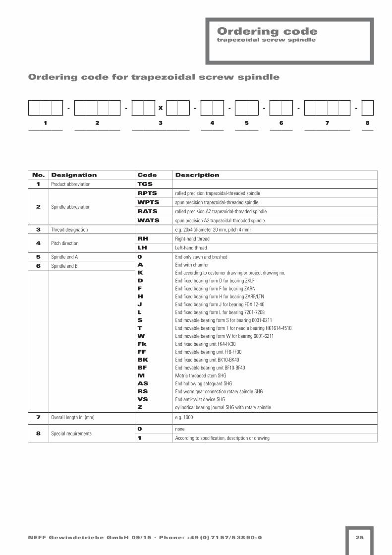
Ordering code trapezoidal screw spindle
- - X - - - - -
1 2 3 4 5 6 7 8
Ordering code for trapezoidal screw spindle
No. Designation Code Description
1 Product abbreviation TGS
2 Spindle abbreviation
RPTS rolled precision trapezoidal-threaded spindle
WPTS spun precision trapezoidal-threaded spindle
RATS rolled precision A2 trapezoidal-threaded spindle
WATS spun precision A2 trapezoidal-threaded spindle
3 Thread designation e.g. 20x4 (diameter 20 mm, pitch 4 mm)
4 Pitch directionRH Right-hand thread
LH Left-hand thread
5 Spindle end A 0
A
K
D
F
H
J
L
S
T
W
Fk
FF
BK
BF
M
AS
RS
VS
Z
End only sawn and brushedEnd with chamferEnd according to customer drawing or project drawing no.End fixed bearing form D for bearing ZKLFEnd fixed bearing form F for bearing ZARNEnd fixed bearing form H for bearing ZARF/LTNEnd fixed bearing form J for bearing FDX 12-40End fixed bearing form L for bearing 7201-7208End movable bearing form S for bearing 6001-6211End movable bearing form T for needle bearing HK1614-4518End movable bearing form W for bearing 6001-6211End fixed bearing unit FK4-FK30End movable bearing unit FF6-FF30End fixed bearing unit BK10-BK40End movable bearing unit BF10-BF40Metric threaded stem SHGEnd hollowing safeguard SHGEnd worm gear connection rotary spindle SHGEnd anti-twist device SHGcylindrical bearing journal SHG with rotary spindle
6 Spindle end B
7 Overall length in (mm) e.g. 1000
8 Special requirements0 none
1 According to specification, description or drawing

L SW
L
D
NEFF Gewindetriebe GmbH 09/15 . Phone: +49 (0) 71 57/5 38 90-026
Trapezoidal- threaded nut TGM
Short steel nut blank, cylindrical KSMSuitable for clamping processes, adjustment movements in manual operation and as a fastening nut. Not suitable for movement drives, since the tribological pairing steel-steel tends towards scuffing.
Further processing: The thread serves as the reference for accurate machining and mounting.
Material: Free-cutting steel 1.0718 (9 SMn 28K)
Type D[mm]
L[mm]
Mass[kg]
KSM Tr 10x2 22 15 0.037
KSM Tr 10x3 22 15 0.036
KSM Tr 12x3 26 18 0.064
KSM Tr 14x3 30 21 0.96
KSM Tr 14x4 30 21 0.96
KSM Tr 16x4 36 24 0.16
KSM Tr 18x4 40 27 0.22
KSM Tr 20x4 45 30 0.31
KSM Tr 22x5 45 33 0.33
KSM Tr 24x5 50 36 0.45
KSM Tr 26x5 50 39 0.47
KSM Tr 28x5 60 42 0.76
KSM Tr 30x6 60 45 0.79
KSM Tr 32x6 60 48 0.81
KSM Tr 36x6 75 54 1.5
KSM Tr 40x7 80 60 1.9
KSM Tr 44x7 80 66 2.7
KSM Tr 48x8 90 72 2.9
KSM Tr 50x8 90 75 2.7
KSM Tr 60x9 100 90 3.7
KSM Tr 70x10 110 105 4.9
KSM Tr 80x10 120 120 6.4
Hexagonal steel nut SKMSuitable for clamping processes, adjustment movements in manual operation and as a fastening nut. Not suitable for movement drives, since the tribological pairing steel-steel tends towards scuffing.
Further processing: The thread serves as the reference for accurate machining and mounting.
Material: Free-cutting steel 1.0718 (9 SMn 28K)
Type SW[mm]
L[mm]
Mass[kg]
SKM Tr 10x2 17 15 0.022
SKM Tr 10x3 17 15 0.022
SKM Tr 12x3 19 18 0.028
SKM Tr 14x3 22 21 0.044
SKM Tr 14x4 22 21 0.044
SKM Tr 16x4 27 24 0.084
SKM Tr 18x4 27 27 0.086
SKM Tr 20x4 30 30 0.17
SKM Tr 22x5 30 33 0.17
SKM Tr 24x5 36 36 0.20
SKM Tr 26x5 36 39 0.20
SKM Tr 28x5 41 42 0.30
SKM Tr 30x6 46 45 0.43
SKM Tr 32x6 46 48 0.42
SKM Tr 36x6 55 54 0.73
SKM Tr 40x7 65 60 1.3
SKM Tr 44x7 65 66 1.2
SKM Tr 48x8 75 72 1.8
SKM Tr 50x8 75 75 1.8
SKM Tr 60x9 90 90 2.8
SKM Tr 70x10 90 105 3.1

NEFF Gewindetriebe GmbH 09/15 . Phone: +49 (0) 71 57/5 38 90-0 27
Trapezoidal- threaded nut TGM
Long red brass nut, cylindrical LRMFor movement drives with particularly favourable wear characteristics.Suitable for use as a lock nut.
Further processing: The thread serves as the reference for accurate machining and mounting.
Material: 2.1090 (G-CuSn 7Zn Pb (Rg7))
TypeD
[mm]L
[mm]Mass[kg]
Bearing percentage
[mm2]
LRM Tr 10x2 22 20 0.056 200
LRM Tr 10x3 22 20 0.056 190
LRM Tr 12x3 26 24 0.092 280
LRM Tr 12x6 P3 26 24 0.092 280
LRM Tr 14x3 30 28 0.14 380
LRM Tr 14x4 30 28 0.14 370
LRM Tr 16x2 36 32 0.25 490
LRM Tr 16x4 36 32 0.25 490
LRM Tr 16x8 P4 36 32 0.25 490
LRM Tr 18x4 40 36 0.34 630
LRM Tr 18x8 P4 40 36 0.34 630
LRM Tr 20x4 45 40 0.48 790
LRM Tr 20x8 P4 45 40 0.45 790
LRM Tr 20x16 P4 45 40 0.45 790
LRM Tr 22x5 45 40 0.46 850
LRM Tr 22x24 P4S 45 40 0.46 880
LRM Tr 24x5 50 48 0.69 1130
LRM Tr 24x10 P5 50 48 0.65 1130
LRM Tr 26x5 50 48 0.58 1240
LRM Tr 28x5 60 60 1.2 1680
LRM Tr 30x6 60 60 1.2 1780
LRM Tr 30x12 P6 60 60 1.2 1780
LRM Tr 32x6 60 60 1.2 1910
LRM Tr 36x6 75 72 2.2 2610
LRM Tr 36x12 P6 75 72 2.2 2610
LRM Tr 40x7 80 80 2.8 3210
LRM Tr 40x14 P7 80 80 2.8 3210
LRM Tr 44x7 80 80 2.6 3560
LRM Tr 48x8 90 100 4.3 4840
LRM Tr 50x8 90 100 4.2 5060
LRM Tr 60x9 100 120 5.7 7320
LRM Tr 70x10 110 140 7.6 10000
LRM Tr 80x10 120 160 9.7 13200
D
L

NEFF Gewindetriebe GmbH 09/15 . Phone: +49 (0) 71 57/5 38 90-028
Trapezoidal- threaded nut TGM
Ready-to-install bronze nut EFMFor movement drives with particularly favourable wear characteristics.
Suitable for use as a lock nut.
EFMs can be mounted using the KON and KAR adaptors.
Material: 2.1090 (G-CuSn 7Zn Pb (Rg7))
Type
Dimensions [mm]Bearing
percentage[mm2]
Mass[kg]D1 D4 D5 6xD6 L1 L2 L3
EFM Tr 12x3 24 40 32 6 28 12 10 0.11 520
EFM Tr 12x6 P3 24 40 32 6 28 12 10 0.11 520EFM Tr 16x4 28 48 38 6 44 12 8 0.25 670EFM Tr 16x8 P4 28 48 38 6 44 12 8 0.25 670EFM Tr 18x4 28 48 38 6 44 12 8 0.25 770EFM Tr 18x8 P4 28 48 38 6 44 12 8 0.25 770EFM Tr 20x4 32 55 45 7 44 12 8 0.30 870EFM Tr 20x8 P4 32 55 45 7 44 12 8 0.30 870EFM Tr 20x16 P4 32 55 45 7 44 12 8 0.30 870EFM Tr 24x5 32 55 45 7 44 12 8 0.30 1040EFM Tr 24x10 P5 32 55 45 7 44 12 8 0.30 1040EFM Tr 30x6 38 62 50 7 46 14 8 0.40 1370EFM Tr 30x12 P5 38 62 50 7 46 14 8 0.40 1370EFM Tr 36x6 45 70 58 7 59 16 10 0.60 2140EFM Tr 36x12 P5 45 70 58 7 59 16 10 0.60 2140EFM Tr 40x7 63 95 78 9 73 16 10 1.70 2930EFM Tr 40x14 P7 63 95 78 9 73 16 10 1.70 2930EFM Tr 50x8 72 110 90 11 97 18 10 2.60 4900EFM Tr 60x9 85 125 105 11 99 20 10 3.70 6040EFM Tr 70x10 95 180 140 17 100 30 16 7.80 8250EFM Tr 80x10 105 190 150 17 110 30 16 8.90 10890

D4
Lkr.
D5
L2 L3L1
D1 h9 L4
L5
Tr..
.
D1
- -0,20
0,30
X 6x60°
(6x) D6
NEFF Gewindetriebe GmbH 09/15 . Phone: +49 (0) 71 57/5 38 90-0 29
Trapezoidal- threaded nut TGM
Safety trap nut SFM
Safety trap nuts are used wherever increased operational reliability is demanded and in order to limit the economic damages in case of a nut breakage.
Safety trap nuts for VBG 14 or VBG 70 requirements on enquiry.
The safety trap nut runs along with the travelling nut without axial load and thus wear-free. As wear of the travelling nut increases, the distance X between the two nuts decreases.
The travelling nut must be replaced when the distance X is reduced by 25%.
If the thread turns of, the travelling nut should break through due to excessive wear, the safety trap nut absorbs the applied load.
The safety trap nut can only be ordered in conjunction with the flange nut.
Type D1 [mm] D4 [mm] D5 [mm] 6xD6 [mm] L1 [mm] L2 [mm] L3 [mm] L4 [mm] L5 [mm] X [mm] mass [kg] Bearing percentage [mm2]
EFM-SFM Tr 12x3 24 40 32 6 28 12 10 24 48 4 0.2 520
EFM-SFM Tr 12x6 P3 24 40 32 6 28 12 10 24 48 4 0.2 520
EFM-SFM Tr 16x4 28 48 38 6 44 12 8 32 72 4 0.5 670
EFM-SFM Tr 16x8 P4 28 48 38 6 44 12 8 32 72 4 0.5 670
EFM-SFM Tr 18x4 28 48 38 6 44 12 8 36 76 4 0.59 770
EFM-SFM Tr 20x4 32 55 45 7 44 12 8 40 80 4 0.75 870
EFM-SFM Tr 20x8 P4 32 55 45 7 44 12 8 40 80 4 0.75 870
EFM-SFM Tr 20x16 P4 32 55 45 7 44 12 8 40 80 4 0.75 870
EFM-SFM Tr 24x5 32 55 45 7 44 12 8 48 88 4 0.95 1040
EFM-SFM Tr 24x10 P5 32 55 45 7 44 12 8 48 88 4 0.95 1040
EFM-SFM Tr 30x6 38 62 50 7 46 14 8 60 102 4 1.6 1370
EFM-SFM Tr 30x12 P6 38 62 50 7 46 14 8 60 102 4 1.6 1370
EFM-SFM Tr 36x6 45 70 58 7 59 16 10 72 127 4 2.8 2140
EFM-SFM Tr 36x12 P6 45 70 58 7 59 16 10 72 127 4 2.8 2140
EFM-SFM Tr 40x7 63 95 78 9 73 16 10 80 149 4 4.5 2930
EFM-SFM Tr 40x14 P7 63 95 78 9 73 16 10 80 149 4 4.5 2930
EFM-SFM Tr 50x8 72 110 90 11 97 18 10 100 193 4 6.8 4900
EFM-SFM Tr 60x9 85 125 105 11 99 20 10 120 215 8 9.4 6040
EFM-SFM Tr 70x10 95 180 140 17 100 30 16 140 236 8 15.4 8250
EFM-SFM Tr 80x10 105 190 150 17 110 30 16 160 266 8 18.6 10890

L
D
NEFF Gewindetriebe GmbH 09/15 . Phone: +49 (0) 71 57/5 38 90-030
Trapezoidal- threaded nut TGM
- - X - -
1 2 3 4 5
Ordering code for trapezoidal-threaded nuts
No. Designation Code Description
1 Product abbreviation TGM
2 Spindle abbreviation
KSM Short steel nut blank, cylindrical
SKM Hexagonal steel nut
LRM Long red brass nut
EFM Ready-to-install bronze nut
LKM Long plastic nut, cylindrical
SFMF Safety trap nut (located on flange side)
SFMZ Safety trap nut (located on centring side)
3 Thread designation e.g. 20x4 (diameter 20 mm, pitch 4 mm)
4 Pitch directionRH Right-hand thread
LH Left-hand thread
5 Special requirements0 None
1 According to specification, description or drawing
Long plastic nut blank, cylindrical LKMFor low-noise movement drives with higher speed and higher duty cycle too.Particularly recommend for use with rolled trapezoidal spindles. Good emergency running characteristics.
Material: PETP
Type D[mm]
L[mm]
Mass[kg]
Bearing percentage
[mm2]
LKM Tr 12x3 26 24 0.012 280LKM Tr 12x6 P3 26 24 0.012 280LKM Tr 16x4 36 32 0.032 490LKM Tr 16x8 P4 36 32 0.032 490LKM Tr 20x4 45 40 0.06 790LKM Tr 20x8 P4 45 40 0.06 790LKM Tr 24x5 50 48 0.088 1130LKM Tr 24x10 P5 50 48 0.088 1130LKM Tr 30x6 60 60 0.15 1780LKM Tr 30x12 P6 60 60 0.15 1780LKM Tr 36x6 75 72 0.30 2610LKM Tr 36x12 P6 75 72 0.30 2610LKM Tr 40x7 80 80 0.37 3210LKM Tr 40x14 P7 80 80 0.37 3210LKM Tr 50x8 90 100 0.55 5060

NEFF Gewindetriebe GmbH 09/15 . Phone: +49 (0) 71 57/5 38 90-0 31
Ordering code trapezoidal screw drive
- - x - - - - - - - -
1 2 3 4 5 6 7 8 9 10 11
Ordering code for trapezoidal screw drive
No. Designation Code Description
1 Product abbreviation TGS
2 Spindle abbreviation
RPTS rolled precision trapezoidal-threaded spindle
WPTS spun precision trapezoidal-threaded spindle
RATS rolled precision A2 trapezoidal-threaded spindle
WATS spun precision A2 trapezoidal-threaded spindle
3 Thread designation e.g. 20x4 (diameter 20 mm, pitch 4 mm)
4 Pitch directionRH Right-hand thread
LH Left-hand thread
5 Spindle end A 0
A
K
D
F
H
J
L
S
T
W
Fk
FF
BK
BF
M
AS
RS
VS
Z
Ends only sawn and brushedEnd with chamferEnd according to customer drawing or project drawing no.End fixed bearing form D for bearing ZKLFEnd fixed bearing form F for bearing ZARNEnd fixed bearing form H for bearing ZARF/LTNEnd fixed bearing form J for bearing FDX 12-40End fixed bearing form L for bearing 7201-7208End movable bearing form S for bearing 6001-6211End movable bearing form T for needle bearing HK1614-4518End movable bearing form W for bearing 6001-6211End fixed bearing unit FK4-FK30End movable bearing unit FF6-FF30End fixed bearing unit BK10-BK40End movable bearing unit BF10-BF40Metric threaded stem SHGEnd hollowing safeguard SHGEnd worm gear connection rotary spindle SHGEnd anti-twist device SHGcylindrical bearing journal SHG with rotary spindle
6 Spindle end B
7 Overall length in (mm) e.g. 1000
8 Special requirements spindle0 none1 According to specification, description or drawing
9Trapezoidal-threaded nut or nut unit with installation note
KSM Short steel nut blank, cylindrical
SKM Hexagonal steel nut
LRM Long red brass nut
EFM Ready-to-install bronze nut
LKM Long plastic nut, cylindrical
SFMF Safety trap nut (safety trap nut located on flange side)
SFMZ Safety trap nut (safety trap nut located on centring side)
10
0 With cylindrical nut
F0 Flange to fixed bearing (or longer spindle end)
0F Flange to movable bearing (or shorter spindle end)
11 Special requirements nut0 none
1 According to specification, description or drawing

NEFF Gewindetriebe GmbH 09/15 . Phone: +49 (0) 71 57/5 38 90-032
Calculation of trapezoidal screw drive
Trapezoidal screw drive values
Calculationtrapezoidal screw drive
Calculations / Values Page Note Page Note
Required bearing surface Aerf P. 34 Comparison with bearing surface in nut tables
Feeding speed s P. 34 -
Drive torque Mta P. 37 -
Friction coefficient µm P. 37 See also value table for friction coefficient
Efficiency h P. 37 -
Friction angle p´ P. 37 -
Pitch angle α P. 37 See also spindle value table
Drive power Pa P. 33 -
Critical speed nkr P. 35/36 -
Permissible operating speed nzul P. 35 -
Max. permissible axial spindle load Fk P. 35/36 -
Permissible axial spindle load Kzul P. 35 -
Sagging of the spindle due to dead weight fmax - -
Required holding torque md´ P. 37 -
Values Page Note
Material characteristic values P. 33 Data for the materials used
pv values P. 34 for determining the max. permissible sliding speed
Friction value P. 34 for determining the efficiency
Bearing surface mm2 P. 26-30 for determining the max. axial force/max surface pressure
Thread depth of basic profile P. 23/24 for determining the bearing surface
Accuracy P. 23/24 Specification of the pitch deviation over 300 mm
Straightness P. 23/24 Specification of the straightness over 300 mm
Pitch P. 23/24 Distance travelled due to one revolution of the spindle/nut
Pitch angle P. 23/24 for determining the self-locking/efficiency
Efficiency with friction coefficient µ 0.1 P. 23/24 for other friction values see equation for efficiency and friction coefficients
Linear load - for determining the max. sagging of the spindle
Bearing surface P. 34 Bearing surface of the thread
Geometrical moment of inertia P. 23/24 for determining the max. sagging of the spindle
Resistive torque P. 23/24 Drive design
Mass moment of inertia P. 23/24 Drive design

NEFF Gewindetriebe GmbH 09/15 . Phone: +49 (0) 71 57/5 38 90-0 33
Calculationtrapezoidal screw drive
Material characteristic values
Material G-CuSn7ZnPb G-CuSn12ZnPb 9 SMn 28K PETP
Min. tensile strength 260 N/mm2 300 N/mm2 460 N/mm2 80 N/mm2
0.2% yield strength RP 0.2 120 N/mm2 180 N/mm2 375 N/mm2 -
Min. elongation at rupture 12% 8% 8% -
Brinell hardness HB 10/1000 70 95 159 -
Density 8.8 kg/dm3 8.71 kg/dm3 8 kg/dm3 1.38 kg/dm3
Elastic module 101000 N/mm2 100000 N/mm2 200000 N/mm2 2800-300 N/mm2
ph value 300 N/mm2 * m/min 400 N/mm2 * m/min - 100 N/mm2 * m/min
Impact strength - - - 40 kJm2
Notch impact strength - - - 4 kJm2
Thermal expansion 1.75 * 10-5 /°C 1.75 * 10-5 /°C 1.19 * 10-5 /°C 8.5 * 10-5 /°C
Water absorption - - - 0.25%
Water saturation - - - 0.60%
Friction against steel - - - 0.05-0.08
Ball indentation hardness H 358/30 - - - 150 N/mm2
Elongation at yield tension 80 N/mm2 - - - 4-5%
max. surface pressure < 15 N/mm2 < 15 N/mm2 < 15 N/mm2 10 N/mm2
max. sliding speed - - - 120 m/min
Md Required drive torque [Nm]n Spindle speed [1/min]Pa Required drive power [kW]
Drive power
Md . n
Pa = 9550

NEFF Gewindetriebe GmbH 09/15 . Phone: +49 (0) 71 57/5 38 90-034
Calculationtrapezoidal screw drive
Load ratings of trapezoidal screw drivesAs a general principle, the load rating of trapezoidal screw drives isdependent on their material, surface quality, state of wear, surfacepressure, lubrication conditions, running speed and temperature, and thus on the duty cycle and the provision for heat dissipation.
The permissible surface pressure is primarily dependent on the running speed of the screw drive.
With motion drives the surface pressure should not exceed5 N per mm2 .
The permissible speed can be calculated from the respective bearing surface of the nut and the pv value of the respective nut material.
pv-factorsMaterial pv-factors [N/mm2 · m/min]
G-CuSn 7 ZnPb (Rg 7) 300
G-CuSn 12 (G Bz 12) 400
Plastic (PETP) 100
Cast iron GG 22/GG 25 200
Aerf Required bearing surface [mm2]Fax Total axial load [N]Pzul Maximum permissible surface pressure = 5 N/mm2
pv-factors See tablevGzul Maximum linear running speed [m/min]
D Flank diameter [mm]nzul Maximum permissible speed of rotation [1/min]
P Thread pitch [mm]szul Permissible feeding speed [m/min]
Required bearing surface(VIII) Fax Aerf = Pzul
Maximum linear running speed(IX) pv-value vGzul = Pzul
Maximum permissible speed of rotation(X) vGzul
. 1000 nzul = D . p
Permissible feeding speed(XI) nzul
. P szul = 1000
Required: What travel speed is still permissible at this load?
Thread pitch P = 6 mm Flank-Ø D = d - P
2 = 36 - 6
2 [mm] = 33 mm
With pv value for Rg 7 = 300 m/min
Example load rating calculation
Given: Screw drive, Trapezoidal-threaded spindle with bronze nut Pzul = 5 N/mm2, Total axial load Fax = 10 000 N
Required bearing surface Aerffrom (VIII) Fax 10 000 N Aerf = = = 2 000 mm2
Pzul 5 N/mm2
Selection of the bronze nut from the technical data36 x 6 with bearing surface A = 2.140 mm2
Maximum permissible running speed VGzulfrom (IX) pv-value 300 N/mm2 . m/min vGzul = = = 60 m/min Pzul 5 N/mm2
Maximum permissible speed of rotationfrom (X) vGzul
. 1000 60 m/min . 1000 mm/m nzul = = = 579 1/min D . p 33 mm . p
Permissible feeding speed from (XI) nzul
. P 579 1/min . 6 mm szul = = = 3,474 m/min 1000 1000 mm/m
Result: At a load of 10.000 N, the trapezoidal screw drive can be operated at a speed of 3.474 metres per min.

Lk Lkr
Lkr Lk
Lk Lkr
Lk Lkr
NEFF Gewindetriebe GmbH 09/15 . Phone: +49 (0) 71 57/5 38 90-0 35
Calculationtrapezoidal screw drive
Types of bearingTypical values for the correction factor fk according to the classic installation cases for standard spindle bearings.
Neff bearing case IFixed bearing – loose end, correction factor fk=0,25 / fkr=0.43
Neff bearing case IIMovable bearing – movable bearing, correction factor fk=1 / fkr=1.21
Neff bearing case IIIFixed bearing – movable bearing, correction factor fk=2,05 / fkr=1.89
Neff bearing case IVFixed bearing – fixed bearing, correction factor fk=4 / fkr=2.74
Critical buckling force of ball screwsWith slim components such as spindles there is a danger of lateral buckling under axial compressive loads. Using the procedure described below, the permissible, axial force can be determined according to the Euler-Case. The safety factors applying to the system must be consi-dered before determining the permissible compressive force.
Maximum permissible axial force in:
Fzul = Fk . fk . 1Sf
Fzul Maximum permissible axial force [kN]Fk Theoretically critical buckling force [kN]fk Correction factor that takes into account the type of spindle
bearingd2 Core diameter of the spindle [mm]Lk Unsupported length on which the force acts on the spindle [mm]Sf Safety factor (specified by the user)
Caution!The operating force must not exceed 80% of the maximum permissible axial force.
Critical speed of ball screwsWith slim, rotating components such as spindles there is a risk of re-sonant vibration. The procedure described below enables the resonant frequency to be estimated, assuming an adequately rigid installation. In addition, speeds close to the critical speed greatly increase the risk of lateral buckling. The critical speed must therefore also be considered in connection with the critical buckling force.
Theoretically critical buckling force in [kN]:
Fk = (d24. 105):1000
Lk2
Theoretically critical speed in [1/min]
Fkr = (d2
. 108)
Lkr2
nzul Maximum permissible spindle speed [rpm]nkr Theoretically critical spindle speed [rpm] that leads to
resonant vibrationsfkr Correction factor that takes into account the type of spindle
bearingd2 Core diameter of the spindle [mm]Lkr unsupported spindle length [mm]
Caution!The operating force must not exceed 80% of the maximum permissible axial force.
Maximum permissible speed of rotation in [rpm]
fkr = Fkr . fk . 0,8

100 200 300 400 500 600 800 1000 2000 3000 4000 6000 1
2
3
4 5 6
8 10
20
30
40 50 60
80 100
200
300
400 500 600
800 1000
2000 3000
Kriti
sche
Kni
ckkr
aft F
k in
[kN
]
Ungestützte Länge lk in [mm]
Tr 26
Tr 36
Tr 60
Tr 70
500 1000 1500 2000 2500 3000 3500 4000 5000 6000 10
20
30
40
50 60 70 80 90
100
200
300
400
500 600 700 800 900
1000
2000
3000
Ungestützte Länge Lkr in [mm]
Theo
retis
ch k
ritisc
he D
rehz
ahl F
kr in
[1/m
in]
NEFF Gewindetriebe GmbH 09/15 . Phone: +49 (0) 71 57/5 38 90-036
CalculationTrapezoidal screw drive
Crit
ical
buc
klin
g fo
rce
F k in
[kn]
Crit
ical
spe
ed F
kr in
[1/m
in]
Theoretically permissible buckling force
Theoretically permissible speed:
Unsupported length
Unsupported length

NEFF Gewindetriebe GmbH 09/15 . Phone: +49 (0) 71 57/5 38 90-0 37
CalculationTrapezoidal screw drive
Required drive torque
Fax . P
Md = = + Mrot 2000 . p . hA
Note:The required drive torque does not represent a criterion for the selec-tion of the motor. The user must decide here, what power he considers necessary!
Efficiency h for other friction coefficients than μ = 0,1
tan α h = tan (α + r‘)
Required drive torque and drive powerThe required drive moment of a screw drive results from the acting axial load, the thread pitch and the efficiency of the screw drive and its bearing. In case of short acceleration times and high speeds the accele-ration torque must be checked.Fundamentally it must be noted that trapezoidal screw drives have to overcome a breakaway torque when starting up.
Fax Total acting axial force [N]P Thread pitch [mm]hA Efficiency of the complete drive = hBall screw drive · hFixed bearing · hMovable bearing hTGT (µ = 0.1) hFixed bearing = 0.9 … 0.95 hMovable bearing = 0.95 Md Required drive torque [Nm]Mrot Rotary acceleration torque [Nm] = Jrot · α0 = 7,7 · d4 · L · 10-13
Jrot Rotary mass moment of inertia [kgm2] d Nominal spindle diameter [mm] L spindle length [mm] α0 Angular acceleration [rad/s2]
h Efficiency for the transformation of a rotary motion into a longitudinal motion
α Pitch angle of the thread [°]:
P tan α = d2 . p
with P P thread pitch [mm] d2 pitch diameter [mm]r’ Thread friction angle [°] tan r’ = µ · 1,07 for ISO trapezoidal threads
µ Friction coefficient
µ in start-up (= µ0) µ in motion
Dry Lubricated Dry Lubricated
Metal nuts ≈ 0,3 ≈ 0,1 ≈ 0,1 ≈ 0,04
Plastic nuts ≈ 0,1 ≈ 0,04 ≈ 0,1 ≈ 0,03
Torque due to an axial loadTrapezoidal threads whose pitch angle α is greater than the friction an-gle r’, are not considered to be self-locking. This means that an applied axial load generates a resulting torque on the spindle. The efficiency for the transformation of h’ longitudinal motion into a rotary motion is lower than for the transformation of a rotary motion into a longitudinal motion.
Required holding torque
Fax . P . h‘ Md‘ = + Mrot 2000 . p
Fax Total acting axial force [N]P thread pitch [mm]h’ Efficiency for the transformation of a longitudinal motion into a
rotary motion tan (α - r’) = tan α = 0,7 . h The influence of the efficiencies of the bearings can be
neglected.Md’ Required holding torque [Nm]Mrot Rotary acceleration torque [Nm] = Jrot · α0 = 7,7 · d4 · L · 10-13
Jrot Rotary mass moment of inertia [kgm2] d Nominal spindle diameter [mm] L spindle length [mm] α0 Angular acceleration [rad/s2]

NEFF Gewindetriebe GmbH 09/15 . Phone: +49 (0) 71 57/5 38 90-038
Screw end machining for movable/fixed bearing Form D, F
The type of bearing influences the stiffness of the entire screw drive, and also the vibration and buckling behaviour of the threaded spindle. The end machining is carried out on the ball screw as necessary for the various types of bearing.
Form D Dimensions [mm] Bearing
ZKLF...2RSTGS/GGS/KGS D1 D2 L1 L2 L3 L4 L5 M1 B1xT1
Thread core diameter d2 > d1 12 9 55 20 32 2.5 16 M 12x1 3x1.8 1255
15 11 58 23 35 3.5 16 M 15x1 4x2.5 1560
20 14 70 30 44 4 22 M 20x1 5x3 2068
25 19 82 40 57 6 28 M 25x1.5 6x3.5 2575
30 24 92 50 67 7 36 M 30x1.5 8x4 3080
Form F Dimensions [mm] Bearing
ZARN...LTNTGS/GGS/KGS D1 D2 L1 L2 L3 L4 L5 M1 B1xT1
Thread core diameter d2 > d1 15 11 73 23 35 3.5 16 M 15x1 4x2.5 1545
20 14 88 30 45 4 22 M 20x1 5x3 2052
20 14 107 30 50 4 22 M 20x1 5x3 2062
25 19 105 40 58 6 28 M 25x1.5 6x3.5 2557
25 19 120 40 63 6 28 M 25x1.5 6x3.5 2572
35 28 145 60 82 10 40 M 35x1.5 8x4 3585
40 36 175 80 103 8.5 63 M 40x1.5 10x5 4090
Thread undercut DIN 76-B
Undercut form F DIN 509 Undercut form E DIN 509

NEFF Gewindetriebe GmbH 09/15 . Phone: +49 (0) 71 57/5 38 90-0 39
Screw end machining for movable/fixed bearing Form H, J, L
Form H Dimensions [mm] Bearing
ZARF...LTNTGS/GGS/KGS D1 D2 L1 L2 L3 L4 L5 M1 B1xT1
Thread core diameter d2 > d1 15 11 85 23 35 3,5 16 M 15x1 4x2,5 1560
20 14 102 30 44 4 22 M 20x1 5x3 2068
20 14 122 30 49 4 22 M 20x1 5x3 2080
25 19 120 40 57 6 28 M 25x1,5 6x3,5 2575
25 19 135 40 63 6 28 M 25x1,5 6x3,5 2590
35 28 160 60 81 10 40 M 35x1,5 8x4 35110
40 36 195 80 105 8,5 63 M 40x1,5 10x5 40115
Form J Dimensions [mm] Bearing
FDXTGS/GGS/KGS D1 D2 L1 L2 L3 L4 L5 M1 B1xT1
Thread core diameter d2 > d1 12 9 88 20 32 2,5 16 M 12x1 3x1,8 12
15 11 92 23 35 3,5 16 M 15x1 4x2,5 15
20 14 107 30 44 4 22 M 20x1 5x3 20
25 19 122 40 57 6 28 M 25x1,5 6x3,5 25
30 24 136 50 72 7 36 M 30x1,5 8x4 30
40 36 182 80 102 8,5 63 M 40x1,5 10x5 40
Form L Dimensions [mm]
BearingTGS/GGS/KGS D1 D2 L1 L2 L3 L4 L5 M1 B1xT1
Thread core diameter d2 > d1 12 9 58 20 30 2,5 16 M 12x1 3x1,8 7201 BE RS
15 11 73 23 33 3,5 16 M 15x1 4x2,5 7202 BE RS
20 14 88 30 43 4 22 M 20x1 5x3 7204 BE RS
25 19 120 40 55 6 28 M 25x1,5 6x3,5 7205 BE RS
35 28 145 60 77 10 40 M 35x1,5 8x4 7207 BE RS
40 36 175 80 103 8,5 63 M 40x1,5 10x5 7208 BE RS
Form AChamfer 2 x 45°: KGS from Ø 12 – 25 mmChamfer 3 x 45°: KGS from Ø 26 – 40 mmChamfer 4 x 45°: KGS from Ø 44 – 50 mm
Thread undercut DIN 76-B
Undercut form F DIN 509 Undercut form E DIN 509

NEFF Gewindetriebe GmbH 09/15 . Phone: +49 (0) 71 57/5 38 90-040
Screw end machining for movable/fixed bearing Form S, T, W
Form S Dimensions [mm]
TGS/GGS/KGS D1 L1 L2 Spacer bush Bearing
Thread core diameter d2 > d1 12 40 45 18x12.1x24 6001 RS
15 46 51 21x15.1x28 6002 RS
20 53 58 27x20.1x29 6004 RS
25 53 58 32x25.1x23 6205 RS
30 60 68 40x30.1x28 6206 RS
40 80 88 50x40.1x44 6208 RS
55 102 110 65x55.1x60 6211 RS
Form T Dimensions [mm]
TGS/GGS/KGS D1 L1 L2 Inner ring Needle bearing
Thread core diameter d2 > d1 12 40 45 2 IR 12x16x20 HK 1614 RS
15 46 51 2 IR 15x20x23 HK 2018 RS
20 53 58 2 LR 20x25x26.5 HK 2518 RS
25 53 58 2 LR 25x30x26.5 HK 3018 RS
30 60 68 2 LR 30x35x30 HK 3518 RS
40 80 88 4 LR 40x45x20 HK 4518 RS
Form G: Screw end annealed to customer’s specification.
Form K: Produced specially to customer’s drawing
Form W Dimensions [mm]
TGS/GGS/KGS D1 L1 L2 Bearing
Thread core diameter d2 > d1 12 8 12 6001 RS
15 9 13 6002 RS
20 12 16 6004 RS
25 15 20 6205 RS
30 16 21 6206 RS
40 18 25 6208 RS
55 21 29 6211 RS
Area for retaining ring DIN 471
Area for retaining ring DIN 471
Undercut form E DIN 509
Undercut form E DIN 509
Area for retaining ring DIN 471
Undercut form E DIN 509

NEFF Gewindetriebe GmbH 09/15 . Phone: +49 (0) 71 57/5 38 90-0 41
Screw end machining Form FK – FF – BK – BF
Designation Ø D1 k6 L2 L1
BF 10 8 10 7
BF 12 10 11 8
BF 15 15 13 9
BF 17 17 16 12
BF 20 20 16 12
BF 25 25 20 15
BF 30 30 21 16
BF 35 35 22 17
BF 40 40 23 18
Designation Ø D1 k6 L2 L1
FF 10 8 10 7
FF 12 10 11 8
FF 15 15 13 9
FF 20 20 19 14
FF 25 25 20 15
FF 30 30 21 16
Designation Ø D1 k6 Ø D2 k6 L1 L2 L3 M1
FK 6 6 4 38 8 16 M6x0.75
FK 8 8 6 44 9 19 M8x1
FK 10 10 8 51 15 26 M10x1
FK 12 12 10 51 15 26 M12x1
FK 15 15 12 69 20 33 M15x1
FK 20 20 17 89 25 42 M20x1
FK 25 25 20 106 30 50 M25x1.5
FK 30 30 25 110 38 63 M30x1.5
Designation Ø D1 k6 Ø D2 k6 L1 L2 L3 M1
BK 10 10 8 54 15 31 M10x1
BK 12 12 10 54 15 29 M12x1
BK 15 15 12 60 20 32 M15x1
BK 17 17 15 76 23 40 M17x1
BK 20 20 17 78 25 40 M20x1
BK 25 25 20 95 30 48 M25x1.5
BK 30 30 25 110 38 63 M30x1.5
BK 35 35 30 128 45 73 M35x1.5
BK 40 40 35 148 50 85 M40x1.5
Circlip DIN 471
Circlip DIN 471
Undercut form F DIN 509
Undercut form F DIN 509
Undercut form F DIN 509Undercut form E DIN 509
Undercut form F DIN 509Undercut form F DIN 509
Thread undercut DIN 76-B
Thread undercut DIN 76-B

B
B1
P
b
h
H1 H
E
4x d2
2x Senkung fürMx DIN 912
d1
L // //
C
D
1 2
321 4
B
A
5 6
--
Ind.
Rz 1geschliffen
=z
geschliffen
=Rz 4y
=Rz 16x
Oberflächen nach DIN ISO 1302
Werkstückkanten nach DIN 6784
Rz 63
=w
-
-
A. Ries
Kanten
Werkstoff:
NameDatumAenderung Artikel-Nr.Ablage
Neff Gewindetriebe GmbHKarl-Benz-Straße 2471093 Weil im Schönbuch
-
Erstellt
-
Zeichnungen und technische Unterlagen sind unser Eigentum, Vervielfältigung, Verwertung oder Mitteilung an Dritte verpflichtet zu Schadenersatz und kann gerichtlich verfolgt werden.
Tolerierung DIN ISO 8015
F:\NEFF Gewindetriebe GmbH\GT+SHG Katalog\Katalog (Neue Ausführung 03-2013)\Katalog-Zeichnungen\Zubehör Gewindetriebe\Loslagereinheit BF-30 aktuelle Version -
-
--
-
-0,3-0,5 +0,5
+0,3
AllgemeintoleranzDIN ISO 2768-m
Maßstab
Gewicht (kg)
Datum Name
Geprüft
Schutzvermerk DIN 34 beachten
Bestellschlüssel:
Rohmaß:
Projekt:
Druckdatum BlattgrößeBlatt von
1:2
-02.07.2013
A41 1
Verfasser:- A. Ries
Version
A
B
C
B
P
E
B1
h
H1 H
b
4x d2
T
2x Senkung für Mx DIN 912
L3 L2
L
d1
L1
C1 C2
NEFF Gewindetriebe GmbH 09/15 . Phone: +49 (0) 71 57/5 38 90-042
Fixed bearing unitsBK-BF
Fixed bearing unit BKThis fixed bearing unit is a pedestal bearing with pre-tensioned axial inclined ball bearings with seals.
The fixed bearing unit is comprised of a burnished steel bearing case with 2 axial inclined ball bearings pre-tensioned by means of a flange, 2 seals with circlips and a securable DRS grooved nut. (Square nuts are used for the smaller sizes).
SizeDimensions in mm Bearing
designa-tion
C stat in
[kN]
C dyn in
[kN]
Weight
Ø d1 L L1 L2 L3 B H b±0,02 h±0,02 B1 H1 E P C1 C2 d2 X Y Z M T
BK10 10 25 5 29.5 5 60 39 30 22 34 32.5 15 46 13 6 5.5 6.6 10.8 5 M3 16 7000 5.2 1.9 0.4BK12 12 25 5 29.5 5 60 43 30 25 34 32.5 18 46 13 6 5.5 6.6 10.8 1 M4 19 7001 6 2.1 0.4BK15 15 27 6 32 6 70 48 35 28 40 38 18 54 15 6 5.5 6.6 11 65 M4 22 7002 6.9 2.4 0.6BK17 17 35 9 44 7 86 64 43 39 50 55 28 68 19 8 6.6 9 14 85 M4 24 7203 12 4.1 1.3BK20 20 35 8 43 8 88 60 44 34 52 50 22 70 19 8 6.6 9 14 85 M4 30 7004 13.1 4.2 1.3BK25 25 42 12 54 9 106 80 53 48 64 70 33 85 22 10 9 11 17 11 M5 35 7205 20.5 7 2.4BK30 30 45 14 61 9 128 89 64 51 76 78 33 102 23 11 11 14 20 13 M6 40 7206 27.1 9.2 3.4BK35 35 50 14 67 12 140 96 70 52 88 79 35 114 26 12 11 14 20 13 M8 50 7207 36.8 14.4 4.4BK40 40 61 18 76 15 160 110 80 60 100 90 37 130 33 14 14 18 26 175 M8 50 7208 46.1 18 6.8
SizeDimensions in mm Bearing
designa-tion
C stat in
[kN]
C dyn in
[kN]
Weight
Ø d1 L B H b±0,02 h±0,02 B1 H1 E P d2 X Y Z
BF10 8 20 60 39 30 22 34 32.5 15 46 5.5 6.6 10.8 5 7000 5.2 1.9 0.4BF12 10 20 60 43 30 25 34 32.5 18 46 5.5 6.6 10.8 1.5 7001 6 2.1 0.4BF15 15 20 70 48 35 28 40 38 18 54 5.5 6.6 11 6.5 7002 6.9 2.4 0.6BF17 17 23 86 64 43 39 50 55 28 68 6.6 9 14 8.5 7203 12 4.1 1.3BF20 20 26 88 60 44 34 52 50 22 70 6.6 9 14 8.5 7004 13.1 4.2 1.3
BF20H 20 26 88 74 44 48 52 64 - 70 - 9 14 8.5 7205 20.5 7 2.4BF25 25 30 106 80 53 48 64 70 33 85 9 11 17 11 7206 27.1 9.2 3.4BF30 30 32 128 89 64 51 76 78 33 102 1 1 14 20 13 7207 36.8 14.4 4.4BF35 35 32 140 96 70 52 88 79 35 114 11 14 20 13 7208 46.1 18 6.8BF40 40 37 160 110 80 60 100 90 37 130 14 18 26 41411
Movable bearing unit BFThis movable bearing unit is a pedestal bearing with a deep-groove ball bearing that adapts itself axially to the elongation of the spindle.
The movable bearing unit consists of a burnished steel bearing case with a deep groove ball bearing.
2x countersinks for MX DIN 912
2x countersinks for MX DIN 912
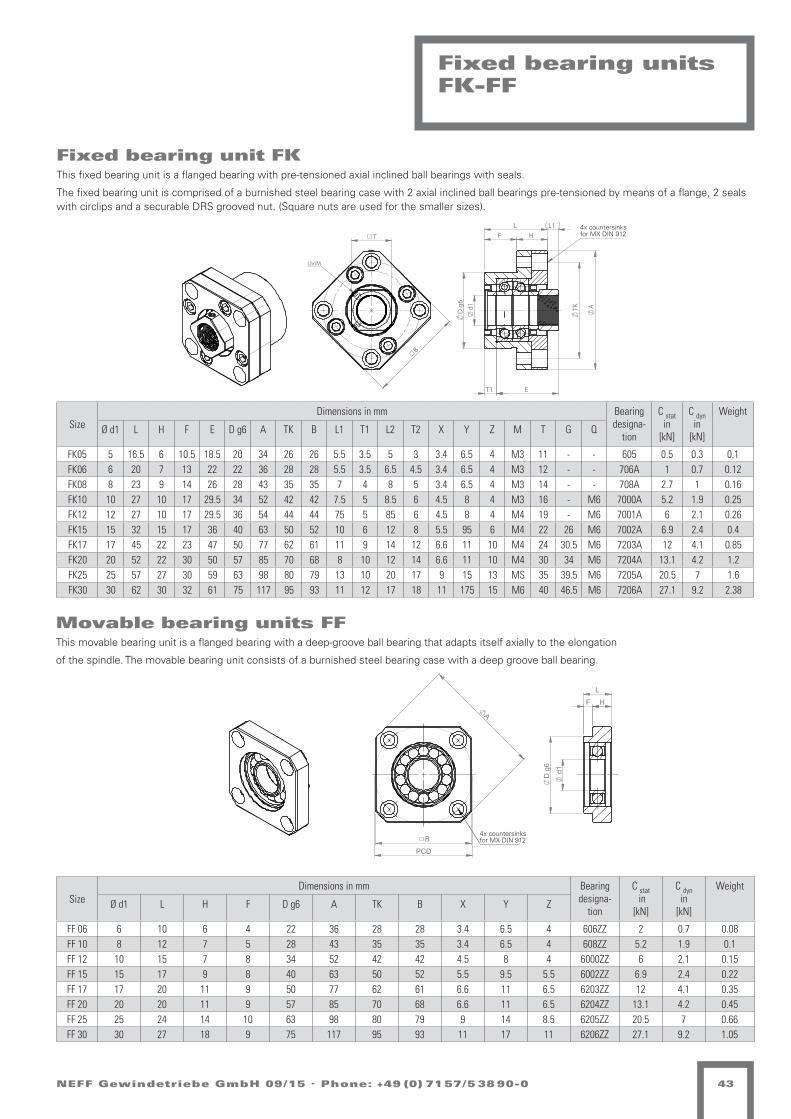
B
PCD
A
4x Senkung fürMx DIN 912
d
1
D
g6
F H
L
C
D
1 2
321 4
B
A
5 6
--
Ind.
Rz 1geschliffen
=z
geschliffen
=Rz 4y
=Rz 16x
Oberflächen nach DIN ISO 1302
Werkstückkanten nach DIN 6784
Rz 63
=w
-
-
Becirovic
Kanten
Werkstoff:
NameDatumAenderung Artikel-Nr.Ablage
Neff Gewindetriebe GmbHKarl-Benz-Straße 2471093 Weil im Schönbuch
-
Erstellt
-
Zeichnungen und technische Unterlagen sind unser Eigentum, Vervielfältigung, Verwertung oder Mitteilung an Dritte verpflichtet zu Schadenersatz und kann gerichtlich verfolgt werden.
Tolerierung DIN ISO 8015
F:\NEFF Gewindetriebe GmbH\GT+SHG Katalog\Katalog (Neue Ausführung 03-2013)\Katalog-Zeichnungen\Zubehör Gewindetriebe\Loslagereinheit FF-30 aktuelle Version -
-
--
-
-0,3-0,5 +0,5
+0,3
AllgemeintoleranzDIN ISO 2768-m
Maßstab
Gewicht (kg)
Datum Name
Geprüft
Schutzvermerk DIN 34 beachten
Bestellschlüssel:
Rohmaß:
Projekt:
Druckdatum BlattgrößeBlatt von
1:2
-02.07.2013
A41 1
Verfasser:- Becirovic
Version
A
B
C
B
T
(2x)M
TK
E
A
F H L1 L
T1
D
g6
d1
(4x)Senkung Mx für DIN 912
4x countersinks for MX DIN 912
4x countersinks for MX DIN 912
NEFF Gewindetriebe GmbH 09/15 . Phone: +49 (0) 71 57/5 38 90-0 43
Fixed bearing unitsFK-FF
Fixed bearing unit FKThis fixed bearing unit is a flanged bearing with pre-tensioned axial inclined ball bearings with seals.
The fixed bearing unit is comprised of a burnished steel bearing case with 2 axial inclined ball bearings pre-tensioned by means of a flange, 2 seals with circlips and a securable DRS grooved nut. (Square nuts are used for the smaller sizes).
Movable bearing units FFThis movable bearing unit is a flanged bearing with a deep-groove ball bearing that adapts itself axially to the elongation
of the spindle. The movable bearing unit consists of a burnished steel bearing case with a deep groove ball bearing.
SizeDimensions in mm Bearing
designa-tion
C stat in
[kN]
C dyn in
[kN]
Weight
Ø d1 L H F E D g6 A TK B L1 T1 L2 T2 X Y Z M T G Q
FK05 5 16.5 6 10.5 18.5 20 34 26 26 5.5 3.5 5 3 3.4 6.5 4 M3 11 - - 605 0.5 0.3 0.1FK06 6 20 7 13 22 22 36 28 28 5.5 3.5 6.5 4.5 3.4 6.5 4 M3 12 - - 706A 1 0.7 0.12FK08 8 23 9 14 26 28 43 35 35 7 4 8 5 3.4 6.5 4 M3 14 - - 708A 2.7 1 0.16FK10 10 27 10 17 29.5 34 52 42 42 7.5 5 8.5 6 4.5 8 4 M3 16 - M6 7000A 5.2 1.9 0.25FK12 12 27 10 17 29.5 36 54 44 44 75 5 85 6 4.5 8 4 M4 19 - M6 7001A 6 2.1 0.26FK15 15 32 15 17 36 40 63 50 52 10 6 12 8 5.5 95 6 M4 22 26 M6 7002A 6.9 2.4 0.4FK17 17 45 22 23 47 50 77 62 61 11 9 14 12 6.6 11 10 M4 24 30.5 M6 7203A 12 4.1 0.85FK20 20 52 22 30 50 57 85 70 68 8 10 12 14 6.6 11 10 M4 30 34 M6 7204A 13.1 4.2 1.2FK25 25 57 27 30 59 63 98 80 79 13 10 20 17 9 15 13 MS 35 39.5 M6 7205A 20.5 7 1.6FK30 30 62 30 32 61 75 117 95 93 11 12 17 18 11 175 15 M6 40 46.5 M6 7206A 27.1 9.2 2.38
SizeDimensions in mm Bearing
designa-tion
C stat in
[kN]
C dyn in
[kN]
Weight
Ø d1 L H F D g6 A TK B X Y Z
FF 06 6 10 6 4 22 36 28 28 3.4 6.5 4 606ZZ 2 0.7 0.08FF 10 8 12 7 5 28 43 35 35 3.4 6.5 4 608ZZ 5.2 1.9 0.1FF 12 10 15 7 8 34 52 42 42 4.5 8 4 6000ZZ 6 2.1 0.15FF 15 15 17 9 8 40 63 50 52 5.5 9.5 5.5 6002ZZ 6.9 2.4 0.22FF 17 17 20 11 9 50 77 62 61 6.6 11 6.5 6203ZZ 12 4.1 0.35FF 20 20 20 11 9 57 85 70 68 6.6 11 6.5 6204ZZ 13.1 4.2 0.45FF 25 25 24 14 10 63 98 80 79 9 14 8.5 6205ZZ 20.5 7 0.66FF 30 30 27 18 9 75 117 95 93 11 17 11 6206ZZ 27.1 9.2 1.05

!"#$%&'()'*+%,-
.
((/0
&'*1 3453
%
6
78+,)##,9
78+),-, (:8;<9
=),-,) %>,:%#')+')8:*?9
@%A+,%69!"#$%"&'
@%A+,%6+?)*%:1
0')
+)B*
,)8#%
?)(
%8C
D)(
)8E"
F')
8,*"
;<(
8',,)
*!)
8+"*
)*-:
?G*?
#';<
?)&
%;<
,D)8
()*
1
6)<%*(#:*?1
(%#%##)#*'
+%",-#)#*&./01
H)D';<,9
I"<&%A9
2#3%4' 567&"8"1
J:+%,-'*C"8&%,'"*9 /79%':7;)9'
.#%,,9
K6)8C# L MG8&) LNG8,)4
O##?)&)'*,"##)8%*-)* *%;< 0PQ PRK STUV W &NL@),%##
08:;>%:+?%6)*M)8>+,"CC9
H)F8XC,9
Y"##)8')8:*? *%;< 0PQ PRK V3/Z
E"*C'?:8%,'"*9H)*)<&'?,9
O##) *';<, 6)&%A,)* E%*,)* 34Z [ \Z] "()8 I 34\ &&
+'*( *';<,
R;<:
,-^)
8&)8
>0
PQ5\
6)%
;<,)
*1_
"F$8
'?<,
E70
`8')
(8';
<
<=Q7`` H)D'*(),8')6) [email protected]!"+,C%;< /S53T//3V M%#()*6:;<Y)#19 3T/ZTLZ5V a3W3`%[9 3T/ZTL Z5V a3WSTDDD1*)CCW?)D'*(),8')6)1()'*C"b>*W?)D'*(),8')6)1()
/1335T cR, 5Td/ ^"* /
&', !"#$%&'()'*+%,- Q@HW111 Y%6)##)
@9S9/
R,%*(%8(
S313V1S33T Y<1 `8')(8';<
O@"*,%?4 S31 O:?:+, S33T //9/\935 B<8
Q:,&:,,)8 Q@H Q:,&:,,)8
!
#
$%&
'"#(#" *+#,*-."/."0,123
4*5/#*!3 6-*##3
7"0+/#8993
:."
/";1
#"0-*
2"<
*09
="<
"0>8
?."
0#18
@A<
0.##"
1B"
0/81
"1(,
2C12
-.@A
2"D
*@A
#="0
<"1
E
!"A*1<-,12E
!"#"##$#%&
'"()*#$#%+,-./
F"=.@A#3
G8AD*53
0#1"2& 345+(6(/
H,/*#(.1980D*#.813 -57"&859$7&
F"?0I9#3
F"1"AD.2#3
J!"09- K 7C0D" KLC0#"M:0,@+*,/2*!"1
N8--"0."0,12 1*@A :OP OQJ RST%
>819.2,0*#.813
U--2"D".1#8--"0*1("1 1*@A :OP OQJ VWXR Y DLK4"#*--U--" 1.@A# !"D*5#"1 >*1#"1 SM% Z $%& 8<"0 G SM$ DD
:(#;"(+&
4*5/#*!/2"1*,E/.1< 1.@A#
Q@A,
#(["
0D"0
+:
OP\$
!"*
@A#"
1E]
8?^0
.2A#
>_:
`0."
<0.@
A
<=
_0/#"--#3
_0/"#(# <,0@A3
P_`` F"=.1<"#0."!" F46LB8/#9*@A TV\SWTTSR 7*-<"1!,@AN"-E3 SWT%WK%\R aSYS`*Z3 SWT%WK %\R aSYVW===E1"99Y2"=.1<"#0."!"E<".198b+1Y2"=.1<"#0."!"E<"
TESS\W cQ# \Wd
P,#D,##"0 P4H
43V3T
Q#*1<*0<
VSESREVSSW NAE `0."<0.@A
U481#*2M VSE U,2,/# VSSW TV3T%3VW ;A0
T [81 T
P,#D,##"0P4HYEEE N*!"--"
U
F"=.1<"/#.9#
SMSS% U
:
D
2
9
6
<<T
]
SM%SGrub screw
Polyamide insert
NEFF Gewindetriebe GmbH 09/15 . Phone: +49 (0) 71 57/5 38 90-044
Grooved nuts
Size d D B d1 a b (Nm) Weight
GUK 12x1 M 12x1 21 7.6 18 18 3 8 10
GUK 15x1 M 15x1 24 8.6 21 21 4 10 13
GUK 20x1 M 20x1 32 9.6 27 27 4 18 24
Size d D B d1 c m b t e f g (Nm)
DRS 6x0.5 M 6x0.5 16 8 12 4 M4 3 2 11 2.5 3.5 2
DRS 10x1 M 10x1 18 8 14 4 M4 3 2 14 2.5 3.5 6
DRS 12x1 M 12x1 22 8 18 4 M4 3 2 17 2.5 3.5 8
DRS 17x1 M 17x1 28 10 23 5 M5 4 2 22.5 3 4 15
DRS 20x1 M 20x1 32 10 27 5 M5 4 2 26 3 4 18
DRS 30x1.5 M 30x1.5 45 12 40 6 M6 5 2 37.5 4 5 32
DRS 45x1.5 M 45x1.5 65 14 59 7 M6 6 2.5 65
DRS 55x2 M 55x2 75 16 68 8 M6 7 3 95
DRS 60x2 M 60x2 80 16 73 8 M6 7 3 100
DRS 70x2 M 70x2 92 18 85 9 M8 8 3.5 130
DRS 80x2 M 80x2 105 18 95 9 M8 8 3.5 160
DRS 90x2 M 90x2 120 20 108 10 M8 10 4 200
DRSThis is a securable grooved nut that is secured by two radial brass pins.
Material: heat treated steel, min. 800 N/mm²
GUKSelf-locking grooved nut with polyamide ring.Secured by a polyamide ring - usable up to max. 100 °C.
Material (strength class): min. 14 H, galvanised and passivated

B1
A2
max
A1
B2
D1
30°
30°
D4
A2
min
x
C1
S
C4
C2
T
G
NEFF Gewindetriebe GmbH 09/15 . Phone: +49 (0) 71 57/5 38 90-0 45
Size Hole pattern 1) A1 A2 max A2 min B1 B2 C1 C2 C4 S D1 D4 G T
KON Tr 16x4/Tr 18x4/KGF-N 1605 3 60 35 25 50 34 40 24 M8 15 28 38 M5 10
KON KGF-D 1605/1610 1 60 35 25 50 34 40 24 M8 15 28 38 M6 10
KON Tr 20x4/Tr 24x5/KGF-N 2005 3 68 37.5 29 58 39 40 24 M8 15 32 45 M6 12
KON KGF-D 2005 1 68 37.5 30 58 39 40 24 M8 15 36 47 M7 12
KON KGF-D 2020/2050 3 75 42.5 32.5 65 49 40 24 M10 15 35 50 M6 12
KON Tr 30x6/KGF-N 2505 3 75 42.5 32.5 65 49 40 24 M10 15 38 50 M6 12
KON KGF-D 2505/2510/2520/2525/2550 1 75 42.5 32.5 65 49 40 24 M10 12 40 51 M6 12
KON Tr 36x6/KGF-N 3205 3 82 45 37 75 54 50 30 M10 12 45 58 M6 12
KON KGF-D 3205 1 92 50 40 85 60 50 30 M12 15 50 65 M8 12
KON KGF-N 3210/3240/4005 3 92 50 42 85 60 50 30 M12 15 53 68 M6 12
KON KGF-D 3210/3220 1 92 50 40 85 60 50 30 M12 15 53 65 M8 12
KON Tr 40x7/KGF-N 4010 3 120 70 50 100 76 65 41 M14 25 63 78 M8 14
KON KGF-D 4005/4010/4020/4040 2 120 70 50 100 76 65 41 M14 25 63 78 M8 14
KON Tr 50x8/KGF-N 5010 3 135 77.5 57.5 115 91 88 64 M16 25 72 90 M10 16
KON KGF-D 5010 2 135 77.5 57.5 115 91 88 64 M16 25 75 93 M10 16
KON KGF-D 5020 2 152 87.5 65 130 101 88 64 M16 30 85 103 M10 16
KON Tr 60x9/KGF-N 6310 3 152 87.5 65 130 101 88 64 M16 30 85 105 M10 16
1) See catalogue illustration of nut hole pattern
Adaptor bracketKON
Adaptor bracket for radial fastening of trapezoidal-threaded flanged nuts EFM or ball screw flanged nuts KGF-N/KGF-D according to DIN 69051.

B1
B3 B2
A2
f8
D1 H7
D4
B3
6x60°
B2
C1
T
G
NEFF Gewindetriebe GmbH 09/15 . Phone: +49 (0) 71 57/5 38 90-046
Size Hole pattern 1) A2 B1 B2 B3 C1 D1 D4 G T
KAR Tr 16x4/Tr 18x4/KGF-N 1605 3 12 70 50 10 20 28 38 M5 10
KAR KGF-D 1605/1610 1 12 70 50 10 20 28 38 M5 10
KAR Tr 20x4/Tr 24x5/KGF-N 2005 3 16 85 58 13.5 25 32 45 M6 12
KAR KGF-D 2005 1 16 85 58 13.5 25 36 47 M6 12
KAR KGF-N 2020/2050 3 18 95 65 15 25 35 50 M6 12
KAR Tr 30x6/KGF-N 2505 3 18 95 65 15 25 38 50 M6 12
KAR KGF-D 2505/2510/2520/2525/2550 1 18 95 65 15 25 40 51 M6 12
KAR Tr 36x6/KGF-N 3205 3 20 110 75 17.5 30 45 58 M6 12
KAR KGF-D 3205 1 25 125 85 20 30 45 58 M8 12
KAR KGF-N 3210/3240/4005 3 25 125 85 20 30 53 68 M6 12
KAR KGF-D 3210/3220 1 25 125 85 20 30 53 65 M8 12
KAR Tr 40x7/KGF-N 4010 3 30 140 100 20 40 63 78 M8 14
KAR KGF-D 4005/4010/4020/4040 2 30 140 100 20 40 63 78 M8 14
KAR Tr 50x8/KGF-N 5010 3 40 165 115 25 50 72 90 M10 16
KAR KGF-D 5010 2 40 165 115 25 50 72 93 M10 16
KAR KGF-D 5020 2 40 180 130 25 50 85 103 M10 16
KAR Tr 60x9/KGF-N 6310 3 40 180 130 25 50 85 105 M10 16
1) See catalogue illustration of nut hole pattern
Universal joint adapter KAR
Universal joint adaptor for universal mounting of trapezoidal-threaded flanged nuts EFM or ball screw flanged nuts KGF-N/KGF-D according to DIN 69051

L max = min+stroke
stroke
NEFF Gewindetriebe GmbH 09/15 . Phone: +49 (0) 71 57/5 38 90-0 47
Bellows FB
For the protection of the spindle against external influences. Available in diameters from 20 mm to 120 mm in 1 mm steps. Horizontal and vertical installation possible.
Calculation of bellows FBFor the dimensioning of the spindle length of screw jacks or screw drives with bellows protection, the spindle must be extended by Lmin.
TO version (thermoplastic sprayed)
Lmin = Fz · LminF
Fz = Lmax : 1,8
Ft = AD - ID
LminF = 6 mm
If space is limited, LminF can be shortened after consultation to the factor 0.835.
SB version (disk bellows)
Lmin= Fz · LminF
Fz = Lmax · 1,1
Fz = Lmax : 1,1
Ft = AD - ID
LminF= 2,5 mm
If space is limited, LminF can be shortened after consultation to the factor 0.64.
A support ring must be installed every 400 mm in case of horizontal installation or every 1000 mm in case of vertical installation. The dimension Lmin is extended here by 1.1 mm per support ring.
Lmin compressed length [mm]Lmax extended length [mm]Ft fold depth [mm]Fz no. of foldsLminF compressed length per fold [mm]
Ft
2
Ft
Ft
2

NEFF Gewindetriebe GmbH 09/15 . Phone: +49 (0) 71 57/5 38 90-048
Ordering code bellows FB
- - - - - - - x - -
1 2 3 4 5 6 7 8 9 10 11
Ordering code for bellows FB
No. Designation Code Description
1 Product abbreviation KGT Ball screw
2 Design
TO Thermoplastic (sprayed)
SB Disk bellows
GR Round fabric, coated
GV Polygonal fabric, coated
3 Lmin in [mm] Retraction length / compressed length of bellows
4 Stroke/Lmax in [mm] Stroke/maximum extension length
5 Inside diameter ID in [mm] > same as diameter of spindle
6 Outside diameter AD in [mm] Outside diameter of bellows
7 Cuff diameter SD1 in [mm] Inside diameter of belows ending 1
8 Cuff diameter SD2 in [mm] Inside diameter of belows ending 2
9 Spindle dimension e.g. 20x4 (diameter 20 mm, pitch 4 mm)
10 Installation positionH Horizontal
V Vertical
11 Special requirements nut0 none
1 According to specification, description or drawing

2/3 Lmin
AF
AD
Lmin Hub Lh/Lv
ID
1/2 Lmin
SD
IF
In diesem Bereich dürfen sichkeine störenden Schrauben, etc. befindenThere may not be any interfering screws, etc. in this area.
stroke
NEFF Gewindetriebe GmbH 09/15 . Phone: +49 (0) 71 57/5 38 90-0 49
Spiral spring cover SF
Spiral springs are used as reliable spindle protective covers against external influences.
The material used is hardened spring band steel. If the spiral springs are exposed to cooling lubricants with a high water content, it is recom-mended to use rustproof spiral springs. (Sizes on enquiry)
SD = Maximum outside diameter / spindle diameterID = Inside diameter of the spiral spring ±1 mmAD = Diameter of the spiral springLh = Maximum extension length in case of horizontal installation
Lv = Maximum extension length in case of vertical installationBB = Width of band, corresponds to LminAF = Inside diameter of the centring flange AD +4 mmIF = Outside diameter of the centring flange ID -2 mm
For KGT-Dm 12-16 For TGT-Dm 12-18
For KGT-Dm 20-25 For TGT-Dm 20-28
For KGT-Dm 32 For TGT-Dm 30-36
For KGT-Dm 32 For TGT-Dm 30-36
Spiral spring SFSD AD Lh
ID-Lv-BB25-100-15 21 36 10025-100-20 21 36 10025-120-20 21 36 10025-150-20 21 38 15025-150-30 21 36 15025-200-20 21 40 20025-200-30 21 38 20025-250-20 21 44 20025-250-30 21 40 20025-250-40 21 39 20025-250-50 21 41 20025-300-20 21 46 25025-300-30 21 42 25025-320-20 21 45 32025-350-30 21 45 30025-350-40 21 42 30025-400-30 21 48 35025-400-40 21 44 35025-450-30 21 49 40025-450-40 21 48 40025-450-50 21 41 40025-500-30 21 52 45025-500-40 21 49 45025-500-50 21 42 45025-550-50 21 43 500
Spiral spring SFSD AD Lh
ID-Lv-BB40-60-20 36 48 6040-70-30 36 50 70
40-150-20 36 53 15040-170-30 36 54 15040-200-20 36 62 15040-250-30 36 56 20040-300-25 36 58 20040-350-30 36 60 35040-400-30 36 64 40040-450-30 36 64 45040-500-30 36 68 50040-550-40 36 68 55040-600-50 36 63 60040-650-50 36 65 65040-660-75 36 64 66040-700-40 36 71 70040-700-50 36 66 70040-700-60 36 64 70040-750-50 36 69 75040-750-60 36 66 75040-750-75 36 66 75040-800-60 36 67 80040-800-75 36 68 80040-850-50 36 71 85040-850-60 36 68 850
Spiral spring SFSD AD Lh
ID-Lv-BB30-100-20 26 43 10030-150-20 26 45 15030-150-30 26 39 15030-150-50 26 40 15030-200-30 26 42 20030-220-30 26 43 22030-250-20 26 51 na30-250-25 26 41 25030-250-30 26 44 25030-250-50 26 42 25030-300-30 26 46 25030-300-35 26 43 na30-350-30 26 49 35030-350-35 26 41 35030-350-40 26 48 35030-350-50 26 45 35030-400-30 26 50 35030-400-35 26 44 40030-400-50 26 46 na30-450-30 26 53 40030-450-35 26 53 na30-450-40 26 53 45030-550-50 26 48 55030-700-40 26 64 70030-900-75 26 55 800
Spiral spring SFSD AD Lh
ID-Lv-BB40-900-60 36 70 90040-900-75 36 71 90040-950-50 36 82 95040-950-60 36 71 950
40-1000-50 36 84 100040-1000-60 36 72 100040-1000-75 36 75 1000
40-1000-100 36 68 100040-1100-60 36 82 110040-1100-75 36 78 110040-1200-75 36 81 1200
40-1200-100 36 71 120040-1300-75 36 84 1300
40-1300-100 36 75 130040-1400-100 36 76 140040-1500-75 36 90 1500
40-1500-100 36 78 150040-1600-100 36 81 160040-1800-100 36 82 180040-1800-100 36 73 180040-1800-100 36 84 180040-1800-120 36 82 180040-2000-100 36 85 200040-2000-120 36 86 200040-2200-120 36 90 2200

NEFF Gewindetriebe GmbH 09/15 . Phone: +49 (0) 71 57/5 38 90-050
Spiral spring cover SF
For KGT-3210/4005 For TGT-Dm 40
For KGT 4010/4020/4040 For TGT-Dm 50-55
For KGT 5010For TGT-Dm 50-55
For KGT 6310 For TGT-Dm 60-70
Spiral spring SFSD AD Lh
ID-Lv-BB50-100-20 46 66 na50-150-30 46 63 15050-150-40 46 61 15050-200-30 46 65 20050-250-30 46 68 25050-250-40 46 68 25050-250-50 46 62 25050-300-40 46 64 30050-350-30 46 73 30050-350-40 46 66 35050-350-50 46 66 35050-400-50 46 68 40050-450-50 46 70 45050-500-50 46 72 500
50-500-100 46 70 50050-550-40 46 74 55050-550-50 46 73 55050-550-60 46 68 55050-600-60 46 72 60050-650-50 46 76 65050-650-60 46 73 65050-700-75 46 79 70050-750-60 46 80 75050-750-75 46 78 75050-800-50 46 81 80050-800-75 46 79 80050-900-60 46 81 90050-900-75 46 84 900
50-1000-60 46 88 90050-1100-75 46 90 110050-1200-75 46 94 120050-1250-75 46 95 125050-1300-75 46 96 1300
50-1300-100 46 80 130050-1350-100 46 82 135050-1500-100 46 88 150050-1600-100 46 89 160050-1650-100 46 90 165050-1700-100 46 91 170050-1800-100 46 94 160050-1900-120 46 96 190050-2000-100 46 103 200050-2100-120 46 100 210050-2200-120 46 103 220050-2300-120 46 105 230050-2500-150 46 116 250050-2600-180 46 105 250050-2800-120 46 118 250050-3000-120 46 120 250050-3000-150 46 123 2500
Spiral spring SFSD AD Lh
ID-Lv-BB65-100-30 61 76 10065-150-25 61 79 15065-150-30 61 78 15065-250-30 61 85 25065-250-50 61 76 25065-350-30 61 95 35065-350-40 61 85 35065-350-50 61 84 35065-350-60 61 82 35065-400-40 61 90 40065-400-50 61 86 40065-450-50 61 88 45065-550-50 61 92 55065-550-60 61 88 55065-650-60 61 93 65065-650-75 61 92 65065-700-60 61 94 70065-700-75 61 92 70065-750-60 61 95 75065-750-75 61 93 75065-800-60 61 98 80065-800-75 61 96 80065-900-60 61 103 900
65-900-100 61 100 90065-1000-75 61 104 1000
65-1000-100 61 91 100065-1100-75 61 107 1100
65-1100-100 61 95 110065-1200-75 61 109 1200
65-1200-100 61 98 120065-1300-100 61 99 130065-1300-120 61 115 130065-1500-75 61 115 1300
65-1500-100 61 108 150065-1500-120 61 100 130065-1700-100 61 113 170065-1700-120 61 106 170065-1800-100 61 117 180065-1900-120 61 109 190065-2000-120 61 111 200065-2100-120 61 113 210065-2200-120 61 119 220065-2300-120 61 118 230065-2400-120 61 125 240065-2500-120 61 128 250065-2600-120 61 126 250065-2800-120 61 134 250065-3000-150 61 142 250065-3250-200 61 138 325065-3500-200 61 148 na
Spiral spring SFSD AD Lh
ID-Lv-BB55-150-30 51 67 15055-250-30 51 73 25055-250-50 51 66 25055-300-40 51 71 30055-350-50 51 71 35055-400-50 51 72 40055-450-40 51 76 45055-450-50 51 74 45055-500-40 51 78 50055-500-50 51 76 50055-500-60 51 74 50055-550-50 51 78 55055-550-60 51 75 55055-600-50 51 78 60055-600-75 51 80 60055-650-60 51 79 65055-700-50 51 83 70055-750-60 51 83 75055-750-75 51 83 75055-800-60 51 86 80055-800-75 51 83 80055-900-60 51 89 90055-900-75 51 89 900
55-1000-60 51 92 100055-1000-75 51 91 100055-1100-75 51 94 1100
55-1100-100 51 85 110055-1120-120 51 93 112055-1300-100 51 89 130055-1300-120 51 92 130055-1500-100 51 94 150055-1500-120 51 94 150055-1700-100 51 98 170055-1700-120 51 96 170055-1800-100 51 102 180055-1800-120 51 102 180055-1900-100 51 98 190055-1900-120 51 100 190055-2100-120 51 105 210055-2300-120 51 110 230055-2500-150 51 118 250055-2500-120 51 116 250055-2800-120 51 123 250055-2800-150 51 121 250055-2800-180 51 114 250055-3000-180 51 126 250055-3250-180 51 130 250055-3500-150 51 130 250055-3500-200 51 133 250055-300-200 51 137 na
Spiral spring SFSD AD Lh
ID-Lv-BB75-150-30 71 92 15075-250-30 71 98 25075-250-50 71 89 25075-350-50 71 94 35075-350-60 71 92 35075-450-50 71 101 45075-500-50 71 105 50075-500-50 71 107 50075-550-50 71 110 55075-550-60 71 99 55075-550-60 71 102 55075-600-75 71 97 60075-650-60 71 103 65075-650-75 71 99 65075-700-60 71 107 70075-700-75 71 104 700
75-700-100 71 98 70075-750-60 71 109 75075-750-75 71 104 75075-900-75 71 111 900
75-900-100 71 102 90075-1000-75 71 114 100075-1100-75 71 118 1100
75-1100-100 71 108 110075-1200-100 71 112 120075-1300-75 71 129 1300
75-1300-100 71 112 130075-1500-75 71 125 1500
75-1500-100 71 120 150075-1500-120 71 115 150075-1550-100 71 120 155075-1700-100 71 124 170075-1700-120 71 122 170075-1800-100 71 128 180075-1800-120 71 122 180075-2000-100 71 133 200075-2000-120 71 127 200075-2000-150 71 135 200075-2100-120 71 133 210075-2200-100 71 136 220075-2200-120 71 132 220075-2200-150 71 137 220075-2400-100 71 140 240075-2400-120 71 137 240075-2400-150 71 140 240075-2600-120 71 142 250075-2600-150 71 144 250075-2800-150 71 145 250075-2800-180 71 143 250075-3250-180 71 156 2500

NEFF Gewindetriebe GmbH 09/15 . Phone: +49 (0) 71 57/5 38 90-0 51
- - - - - - -
1 2 3 4 5 6 7 8
Ordering code spiral spring cover
No. Designation Code Description
1 Product abbreviation SF
2 ID in [mm] Inside diameter of the spiral spring +1 mm
3 Largest length Lh/Lv in [mm] Maximum extension length
4 BB / Lmin in [mm] Width of band, corresponds to Lmin
5 Installation positionH Horizontal
V Vertical
6 MaterialB Standard spring in blued spring steel
S Version in rustproof stainless steel
7
Accessories(If using mounting flanges the possible spindle diameter SD is reduced by 6 mm)
0 Without mounting flange
1 With mounting flange outside (inside diameter +4 mm of outer diameter OD of spiral spring)
2 With mounting flange inside (inside diameter -2 mm of inner diameter ID of spiral spring)
3 With mounting flange inside/outside
8 Special requirements for mounting flange0 None
1 According to specification, description or drawing
Spiral spring cover SF
For KGT 8010 For TGT-Dm 80
For TGT-Dm 100 For TGT-Dm 100 For TGT-Dm 120
Spiral spring SFSD AD Lh
ID-Lv-BB100-200-30 96 120 150100-250-60 96 121 250100-350-60 96 126 350100-450-75 96 124 450100-600-75 96 129 600
100-800-100 96 126 800100-900-100 96 131 900
100-1000-100 96 132 1000100-1100-120 96 129 1100100-1200-100 96 137 1200100-1300-100 96 140 1300100-1500-100 96 146 1500100-1700-120 96 147 1700100-1800-150 96 151 1800100-2000-150 96 157 2000100-2500-150 96 164 2500100-2800-180 96 168 2800100-3000-150 96 188 3000100-3500-200 96 174 2800
Spiral spring SFSD AD Lh
ID-Lv-BB120-250-50 116 141 250120-250-60 116 141 250120-350-50 116 143 na120-350-60 116 145 350120-350-75 116 140 350120-400-60 115 148 na120-450-60 116 150 na120-450-75 116 145 450120-600-75 116 153 600
120-600-120 116 141 600120-650-100 116 142 650120-650-100 116 150 650120-700-100 116 147 700120-750-100 116 147 750120-800-75 116 160 na
120-800-100 116 148 800120-870-120 116 145 870120-900-100 116 150 900120-900-120 116 148 900
Spiral spring SFSD AD Lh
ID-Lv-BB120-1100-120 116 153 1100120-1200-150 116 155 1200120-1300-120 116 158 1300120-1300-150 116 156 1300120-1300-180 116 156 1300120-1500-120 116 162 1500120-1500-150 116 163 na120-1600-180 116 158 1600120-1800-150 116 167 1800120-1800-180 116 161 1800120-2000-150 116 177 2000120-2000-180 116 169 2000120-2000-180 116 175 na120-2200-180 116 174 2200120-2200-200 116 173 2200120-2200-200 116 165 1800120-2400-200 116 170 2400120-2600-200 116 174 2600120-2800-200 116 177 2800
Spiral spring SFSD AD Lh
ID-Lv-BB140-225-75 136 159 225140-250-75 136 158 250140-350-75 136 162 na
140-400-100 136 158 400140-450-75 136 165 450140-600-75 136 166 600
140-700-120 136 170 700140-800-100 136 177 800140-950-100 136 180 950
140-1000-120 136 192 750140-1300-150 136 187 na140-1500-200 136 173 1500140-1700-200 136 184 na140-1800-180 136 188 1800140-1900-200 136 185 na140-2000-200 136 193 2000140-2100-180 136 190 2100140-2400-180 136 200 2100140-2500-200 136 197 na

C
D
1 2
321 4
B
A
5 6
--
Ind.
Rz 1geschliffen
=z
geschliffen
=Rz 4y
=Rz 16x
Oberflächen nach DIN ISO 1302
Werkstückkanten nach DIN 6784
Rz 63
=w
-
-
Becirovic
Kanten
Werkstoff:
NameDatumAenderung Artikel-Nr.Ablage
Neff Gewindetriebe GmbHKarl-Benz-Straße 2471093 Weil im Schönbuch
-
Erstellt
-
Zeichnungen und technische Unterlagen sind unser Eigentum, Vervielfältigung, Verwertung oder Mitteilung an Dritte verpflichtet zu Schadenersatz und kann gerichtlich verfolgt werden.
Tolerierung DIN ISO 8015
F:\NEFF Gewindetriebe GmbH\GT+SHG Katalog\Katalog (Neue Ausführung 03-2013)\Katalog-Zeichnungen\Zubehör Gewindetriebe\NEFF Food Grease 0 aktuelle Version -
-
--
-
-0,3-0,5 +0,5
+0,3
AllgemeintoleranzDIN ISO 2768-m
Maßstab
Gewicht (kg)
Datum Name
Geprüft
Schutzvermerk DIN 34 beachten
Bestellschlüssel:
Rohmaß:
Projekt:
Druckdatum BlattgrößeBlatt von
1:5
-10.07.2013
A41 1
Verfasser:-
Version
A
B
C
C
D
1 2
321 4
B
A
5 6
--
Ind.
Rz 1geschliffen
=z
geschliffen
=Rz 4y
=Rz 16x
Oberflächen nach DIN ISO 1302
Werkstückkanten nach DIN 6784
Rz 63
=w
-
-
Becirovic
Kanten
Werkstoff:
NameDatumAenderung Artikel-Nr.Ablage
Neff Gewindetriebe GmbHKarl-Benz-Straße 2471093 Weil im Schönbuch
-
Erstellt
-
Zeichnungen und technische Unterlagen sind unser Eigentum, Vervielfältigung, Verwertung oder Mitteilung an Dritte verpflichtet zu Schadenersatz und kann gerichtlich verfolgt werden.
Tolerierung DIN ISO 8015
F:\NEFF Gewindetriebe GmbH\GT+SHG Katalog\Katalog (Neue Ausführung 03-2013)\Katalog-Zeichnungen\Zubehör Gewindetriebe\NEFF Food Grease 0 aktuelle Version -
-
--
-
-0,3-0,5 +0,5
+0,3
AllgemeintoleranzDIN ISO 2768-m
Maßstab
Gewicht (kg)
Datum Name
Geprüft
Schutzvermerk DIN 34 beachten
Bestellschlüssel:
Rohmaß:
Projekt:
Druckdatum BlattgrößeBlatt von
1:5
-10.07.2013
A41 1
Verfasser:-
Version
A
B
C
NEFF Gewindetriebe GmbH 09/15 . Phone: +49 (0) 71 57/5 38 90-052
Lubricants
NEFF-Grease 2/3Neff Grease 2/3 was specially developed for use with highly-stressed ball screw drives.
The strongly adhering synthetic grease containing Teflon has very good temperature stability and can withstand high loads and vibrations.
NEFF-Grease 2Neff Grease 2 was specially developed for use in highly-stressed trape-zoidal screw drives, sliding screw drives and worm gear drives.
The heavy-duty grease was specially developed for high surface pressu-re and has outstanding temperature stability
NEFF-Food Grease 2NEFF Food Grease 2 was specially developed for the requirements of the food industry. The grease meets the requirements of DIN V 10517. Suitable for use in applications with occasional food contact (class NSF-H1).

L
52 Gasentwicklungszelle
Tranzparentes Gehäuse
Kolben
Fettfüllung
C
2 31 4
B
A
D
E
F
Version
- Verfasser:
11A4
23.08.2013-
1:1
vonBlattBlattgrößeDruckdatum
Projekt:
Rohmaß:
Bestellschlüssel:
Schutzvermerk DIN 34 beachten
Geprüft
NameDatum
Gewicht (kg)
Maßstab
AllgemeintoleranzDIN ISO 2768-m
+0,5+0,3
-0,3-0,5
11.09.2012
- -
-
aktuelle Version --
Tolerierung DIN ISO 8015
Zeichnungen und technische Unterlagen sind unser Eigentum, Vervielfältigung, Verwertung oder Mitteilung an Dritte verpflichtet zu Schadenersatz und kann gerichtlich verfolgt werden.
Blix3, Gehäuseseite A
Erstellt
-
Neff Gewindetriebe GmbHKarl-Benz-Straße 2471093 Weil im Schönbuch
Ablage Artikel-Nr.Aenderung Datum Name
Werkstoff:
KantenA. Ries
-
-
w
=Rz 63Oberflächen nach DIN ISO 1302
Werkstückkanten nach DIN 6784x Rz 16
=
y Rz 4
=
geschliffen
z
=
geschliffenRz 1
Ind.
- -
Gas formation cell
Transparent housing
Piston
Grease filling
NEFF Gewindetriebe GmbH 09/15 . Phone: +49 (0) 71 57/5 38 90-0 53
The NEFF Lube 1 automatic lubricant dispenser is screwed directly onto the lubrication point. It operates independently and is activated when setting the running time. The lubricant level is always visible in the transparent window.
Readjustment during operation is possible.
The shelf life of the lubricant dispenser expires after 2 years.The NEFF Lube 1 lubricant dispenser is available in 4 sizes:
NEFFLubricant dispenser
Size Contents Length L Connection Grease types Grease delivery per day
Dispensing period
NEFF LUB 1-30 30ml 43mm
R ¼ inch All standard NEFF Grease types 0.08–8.3 ml 1-12 month
NEFF LUB 1-60 60ml 62mm
NEFF LUB 1-125 125ml 100mm
NEFF LUB 1-250 250ml 192mm
When ordering in conjunction with a ball screw or trapezoidal screw drive, please indicate special requirements of the nut in the ordering code.Caution: When the lubricant dispenser is mounted the overall height of the NEFF LUB 1 is increased by about 25 mm due to the connecting/adaptor piece

NEFF Gewindetriebe GmbH 09/15 . Phone: +49 (0) 71 57/5 38 90-054
Installationand maintenance
Trapezoidal screw drives TGT
InstallationTrapezoidal screw drives must be aligned carefully during installation – if suitable measuring equipment is not available, the screw drive should be turned through its entire length by hand before the drive unit is attached.Variations in the amount of force required and/or marks on theexternal diameter of the spindle indicate alignment errors between the spindle axis and guide. In this case, the relevant mounting bolts should first be loosened and the screw drive should be turned through by hand. If the amount of force required is now constant throughout, the appropriate components should be aligned, otherwise the alignment error should be localised by loosening further mounting bolts.
CoverBy virtue of their design, trapezoidal screw drives are less sensitive to dirt than ball screw drives, particularly at low speeds (manual operation).Nevertheless motion drives, especially with plastic nuts, require protection against dirt in the same way as ball screw drives.
Lubrication
Oil lubricationUsed only in special cases for trapezoidal screw drives.
Grease lubricationThe usual lubrication method for trapezoidal screw drives. Lubrication intervals are governed by operating conditions; it is advisable to clean the spindle before greasing, especially by using high-performance lubricating machines.Type of grease: ball bearing grease without solid lubricant. Parts ref. Neff Grease 2
Operating temperatureThis depends on the type of nut used, the lubrication conditions and the user’s requirements. Please consult us in the case of temperatures above 100 °C (plastic nuts 70 °C).
WearThis can be checked manually: the nut should be replaced if the axial backlash with a single-start screw drive is more than 1/4 of the pitch.
Ball screw drives KGT
InstallationBall screw drives are precision machine components; their installation requires specialist knowledge and suitable measuring equipment. Due to the low friction alignment errors can generally not be felt when the screw drive is turned by hand. Radial or eccentric forces must be taken up by external guides. Ball screw drives can absorb only axial forces.To avoid damage to the ball screw drive, limit switches and end stops must be installed in the machine.
CoverDirt that occurs during installation should be removed with paraffin, oil or petroleum ether. Cold cleaners and paint solvents are not permitted. Ball screw drives must be protected against dust, swarf, etc. even if equipped with wipers. Possible protective measures include:
– Bellows (suitable only for vertical installation without additional guide).– Spiral spring cover.– Telescopic tubes or sleeves (these take up a lot of axial space).
LubricationProper lubrication is important for the achievement of the calculated service life of a ball screw drive, to prevent excessive warming and to ensure smooth, quiet running. The same lubricants are used for the KGT ball screw drives as for roller bearings.
Oil-mist lubricationIn the case of central lubrication with oil mist, note that only ball screw nuts without wipers may be used.
Oil lubricationDie zugeführte Ölmenge sollte die Austragsverluste an den Abstreifern nicht überschreiten. (Sonst Ölumlaufschmierung).Ölsorten: Viskosität 25 bis 100 mm2/s bei 100 °C.
Grease lubricationAdd grease corresponding to the volume lost via the wipers (undernormal operating conditions, it is sufficient to add grease every 200 to 300 hours). Experience shows that single lifetime lubrication is not sufficient because of the seepage of grease.
Grease type:Roller bearing grease with no solid lubricant content. The first fill takes place at the supplier’s with roller bearing grease. We recommend Neff Gear Grease 2/3 in the case of high mechanical stresses.
Operating temperatureThe permissible operating temperature range for ball screw drives is between –30 °C and +80 °C, up to +110 °C for brief periods. A precon-dition for this is correct lubrication. The torque may increase by a factor of up to 10 at temperatures below –20 °C.

NEFF Gewindetriebe GmbH 09/15 . Phone: +49 (0) 71 57/5 38 90-0 55
Worm Gear Screw Jacks M/J
Stroke speedTransmission Ratio H (high speed)Worm gear screw jacks with trapezoidal-threaded spindle produce a stroke of 1 mm for each full revolution of the worm shaft. Accordingly the linear speed is 1500 mm per min at 1500 rpm. Worm gear screw jacks with a ball screw achieve 6000 mm/min, depending on size and pitch.
Transmission Ratio L (low speed)Worm gear screw jacks with trapezoidal-threaded spindle produce a stroke of 0.25 mm for each full revolution of the worm shaft. Accordin-gly the linear speed is 375 mm per min at 1500 rpm.
Please note that higher speeds of travel can be achieved by using spindles with larger thread pitches or multi-start threads.
The worm gear screw jack’s maximum drive speed of 3000 rpm must not be exceeded.The higher efficiency of the ball screw drive also permits a longer duty cycle.
Tolerances and backlashn The gearbox housings are machined on the six mounting sides.
The tolerances conform to DIN ISO 2768-mH
n The axial backlash of the jack screw under alternating load is as follows:
– Trapezoidal-threaded spindles: up to 0.4 mm (to DIN 103) – Ball screws: 0.07 mm
n The lateral backlash between the outside diameter of the spindle and the guide diameter is 0.2 mm.
n The backlash in the worm gears is ± 4° for transmission ratio L and ± 1° for transmission ratio H based on the drive shaft.
n Trapezoidal-threaded spindles are manufactured to a straightness of 0.3 – 1.5 mm/m, ball screws to a straightness of 0.02 mm/m over a length of 1000 mm and to the following pitch accuracies: M 0 – M 5: 0.05 mm/300 mm length J 1 – J 5: 0.2 mm/300 mm length.
Lateral forces on the screw jack.Lateral forces can also be absorbed by our screw jacks. Please contact us.
Self-lockingThe self-locking function depends on a variety of parameters:n High pitchesn Different worm gear transmission ratiosn Lubricationn Friction parametersn Environmental influences, such as high or low temperatures,
vibrations, etc.n The mounting position
Versions with ball screw and TGS/KGS with high pitches are therefore not self-locking. Suitable brakes or braking motors must therefore be used in such cases. Self-locking is only conditionally available for smaller pitches (single-start). Self-locking in individual cases on enquiry
Version NThe lifting spindle is driven by a nut thread in the worm gear via the worm shaft. Protection against twisting is achieved by the on-site faste-ning of the spindle.
Version VKThe lifting spindle is driven by a nut thread in the worm gear via the worm shaft. Protection against twisting is achieved by a square protec-tive tube on the gear side.
Version VPThe lifting spindle is driven by a nut thread in the worm gear via the worm shaft. Protection against twisting is achieved by a feather key in the bearing cover of the gearbox and a milled groove in the spindle.
Version RThe lifting spindle is made to rotate by the worm shaft via the worm gear with a feather key connection to the spindle.The rotary motion of the spindle is converted into a linear motion by the on-site anti-twist securing of the travelling nut.
Anti-unscrewing device AThe anti-unscrewing device prevents the spindle from screwing out of the gearbox. It is standard equipment in the ball screw versions N and V and is available as an option in worm gear screw jacks with trapezoidal-threaded spindles.The anti-unscrewing device cannot be used as a fixed stop.
Special versionsIn addition to the extensive standard range, NEFF can also supplyanticlockwise, multi-start and special material worm gear screw jacks on enquiry.
The range includes a total of 11 worm gearscrew jack models in two series: M 0 – M 5with lifting capacities from 2.5 kN to 100 kNand J 1 – J 5 with static lifting capacities from 150 kN to 500 kN.

NEFF Gewindetriebe GmbH 09/15 . Phone: +49 (0) 71 57/5 38 90-056
Generaltechnical data
M 0 M 1 M 2 M 3 M 4 M 5 J 1 J 2 J 3 J 4 J 5
Maximum lifting force [kN]1) 2.5 5 10 25 50 100 150 200 250 350 500
Diameter and pitch [mm] 14 x 4 18 x 4 20 x 4 30 x 6 40 x 7 55 x 9 60 x 9 70 x 10 80 x 10 100 x 10 120 x 14
Stroke per revolution of the drive shaft [mm]
Transmission ratio. H2) 1 1 1 1 1 1 1 1 1 1 1
Transmission ratio. L2) 0.25 0.25 0.25 0.25 0.25 0.25 0.25 0.25 0.25 0.25 0.25
Transmission ratio. Transmission ratio. H2) 4:1 4:1 4:1 6:1 7:1 9:1 9:1 10:1 10:1 10:1 14:1
Transmission ratio. L2) 16:1 16:1 16:1 24:1 28:1 36:1 36:1 40:1 40:1 40:1 56:1
Efficiency [%]3) Transmission ratio. H2) 35 31 29 29 26 24 23 22 20 19 19
Transmission ratio. L2) 27 25 23 23 21 19 18 17 15 15 15
Weight [kg] (without stroke) 0.6 1.2 2.1 6 17 32 41 57 57 85 160
Weight [kg per 100 mm stroke] 0.1 0.26 0.42 1.14 1.67 3.04 3.1 4.45 6.13 7.9 11.5
Idling torque [Nm] H 0.02 0.04 0.11 0.15 0.35 0.84 0.88 1.28 1.32 1.62 1.98
L 0.016 0.03 0.10 0.12 0.25 0.51 0.57 0.92 0.97 1.10 1.42
Housing material G – AL up to M3 GGG – 40
Trapezoidal-thread spindle
Ball screw spindle
M 0 M 1 M 2 M 3 M 4 M 5 J 3
Maximum lifting force [kN]1) 2 5 10 12.5 22 42 65 78
Diameter and pitch [mm] 1205 1605 2005 2505 4005 4010 5010 8010
Stroke per revolution of the drive shaft [mm]
Transmission ratio. H2) 1.25 1.25 1.25 0.83 0.71 1.43 1.1 1
Transmission ratio. L2) 0.31 0.31 0.31 0.21 0.18 0.36 0.28 0.25
Transmission ratio. Transmission ratio. H2) 4:1 4:1 4:1 6:1 7:1 9:1 10:1
Transmission ratio. L2) 16:1 16:1 16:1 24:1 28:1 36:1 40:1
Efficiency [%]3) Transmission ratio. H2) 60 57 56 55 53 56 47 45
Transmission ratio. L2) 48 46 44 43 43 45 37 34
Weight [kg] (without stroke) 0.6 1.3 2.3 7 19 35 63
Weight [kg per 100 mm stroke] 0.09 0.26 0.42 1.14 1.67 3.04 6.13
Idling torque [Nm] H 0.02 0.04 0.11 0.15 0.35 0.84 1.32
L 0.016 0.03 0.10 0.12 0.25 0.51 0.97
Housing material G – AL up to M3 GGG – 40
1) Dependent on stroke speed, duty cycle, etc.2) H =high travel speed,
L = low travel speed3) The specified efficiency values are average values

Bearing cover, side
NEFF Gewindetriebe GmbH 09/15 . Phone: +49 (0) 71 57/5 38 90-0 57
Size Dimensions [mm]
A1 A2 A3 a1 a2 B1 B2 B3 B4 b1 b2 b3 b5 C1TR(2) C1KGT/AS(3) C2 C3
M 0 60 20 18 48 6 21 50 92 52 38 14 3 1.5 20 50 50 27
M 1 80 25 24 60 10 24 72 120 77 52 18 3 1.5 20 50 62 35
M 2 100 32 28 78 11 27.5 85 140 90 63 20 5 1.5 30 60 75 45
M 3 130 45 31 106 12 45 105 195 110 81 36 5 2 35 70 82 50
M 4 180 63 39 150 15 47.5 145 240 150 115 36 6 2 40 90 117 65
M 5 200 71 46 166 17 67.5 165 300 170 131 56 8 2.5 55 100 160 95
J 1 210 71 49 170 20 65 195 325 200 155 56 8 8 55 100 175 95
J 2 240 80 60 190 25 67.5 220 355 225 170 56 8 8 60 110 165 110
J 3 (M6) 240 80 60 190 25 67.5 220 355 225 170 56 8 8 60 110 165 110
J 4 (M7) 290 100 65 230 30 65 250 380 255 190 56 10 8 65 150 220 140
J 5 (M8) 360 135 75 290 35 100 300 500 305 230 90 14 8 100 145 266 200
Size Dimensions [mm]
C4 C5 C6 D1k6 D2 D3 d4 D4Tr D4KGT D5 D6 D7H7 D8 D9 x b6 TK q R
M 0 12 12 25 9 x 20 28 M8 12 Tr14 x 4 1205 26 M6 22 10 (M5 x 6)* 24
M 1 12 19 31 10 x 21.5 32 M12 13 Tr18 x 4 1605 30 M8 32 12 M5 x 6 32
M 2 18 20 37.5 14 x 25 40 M14 15 Tr20 x 4 2005 38.7 M8 35 15 M6 x 10 35
M 3 23 22 41 16 x 42.5 50 M20 15 Tr30 x 6 2505 46 M10 40 17 M8 x 10 44
M 4 32 29 58.5 20 x 45 65 M30 16 Tr40 x 7 4005/4010 60 M12 52 25 M10 x 14 55
M 5 40 48 80 25 x 65 90 M36 30 Tr55 x 9 5010 85 M20 62 28 M12 x 16 70
J 1 40 48 87.5 25 x 62.5 95 M48 x 2 40 Tr60 x 9 – 90 M24 72 28 M12 x 16 70
J 2 40 58 82.5 30 x 65 110 M56 x 2 45 Tr70 x 10 – 105 M30 80 32 M12 x 18 (80)
J 3 (M6) 40 58 82.5 30 x 65 125 M64 x 3 45 Tr80 x 10 8010 120 M30 80 32 M12 x 18 (80)
J 4 (M7) 50 78 110 35 x 62.5 150 M72 x 3 54 Tr100 x 10 – 145 M36 85 40 M16 x 30 (80)
J 5 (M8) 60 118 133 48 x 97.5 180 M100 x 3 80 Tr120 x 14 – 170 M42 90 50 M16 x 40 (115)
* Tapped bore for motor adaptor flange on attachment side A and B standard only centralised. Tapped bore on enquiry.Note: subject to technical changes.
Dimensions,version N
useable stroke + C1 + VL (1)
4x p
er s
ide
(1) VL: Spindle extension (2) Mass C1 for screw jacks with trapezoidal screw drive(3) Mass C1 for screw jacks with ball screw drive or securing against hollowing
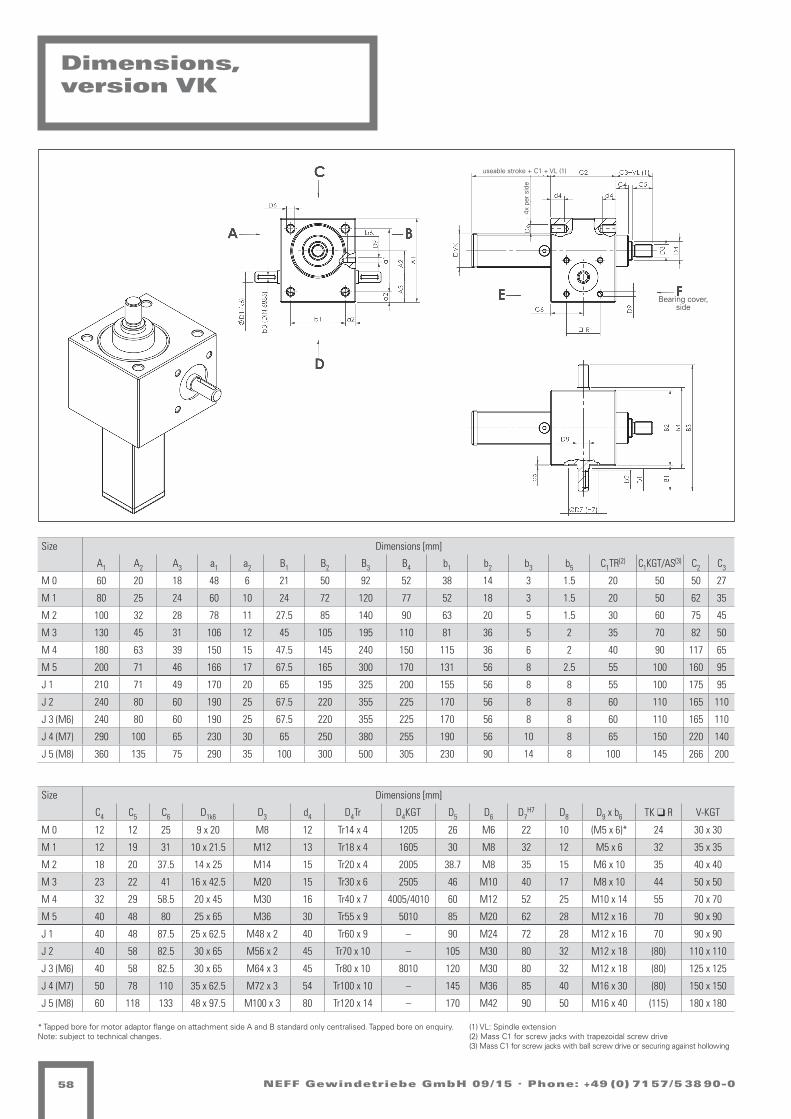
NEFF Gewindetriebe GmbH 09/15 . Phone: +49 (0) 71 57/5 38 90-058
Size Dimensions [mm]
A1 A2 A3 a1 a2 B1 B2 B3 B4 b1 b2 b3 b5 C1TR(2) C1KGT/AS(3) C2 C3
M 0 60 20 18 48 6 21 50 92 52 38 14 3 1.5 20 50 50 27
M 1 80 25 24 60 10 24 72 120 77 52 18 3 1.5 20 50 62 35
M 2 100 32 28 78 11 27.5 85 140 90 63 20 5 1.5 30 60 75 45
M 3 130 45 31 106 12 45 105 195 110 81 36 5 2 35 70 82 50
M 4 180 63 39 150 15 47.5 145 240 150 115 36 6 2 40 90 117 65
M 5 200 71 46 166 17 67.5 165 300 170 131 56 8 2.5 55 100 160 95
J 1 210 71 49 170 20 65 195 325 200 155 56 8 8 55 100 175 95
J 2 240 80 60 190 25 67.5 220 355 225 170 56 8 8 60 110 165 110
J 3 (M6) 240 80 60 190 25 67.5 220 355 225 170 56 8 8 60 110 165 110
J 4 (M7) 290 100 65 230 30 65 250 380 255 190 56 10 8 65 150 220 140
J 5 (M8) 360 135 75 290 35 100 300 500 305 230 90 14 8 100 145 266 200
Size Dimensions [mm]
C4 C5 C6 D1k6 D3 d4 D4Tr D4KGT D5 D6 D7H7 D8 D9 x b6 TK q R V-KGT
M 0 12 12 25 9 x 20 M8 12 Tr14 x 4 1205 26 M6 22 10 (M5 x 6)* 24 30 x 30
M 1 12 19 31 10 x 21.5 M12 13 Tr18 x 4 1605 30 M8 32 12 M5 x 6 32 35 x 35
M 2 18 20 37.5 14 x 25 M14 15 Tr20 x 4 2005 38.7 M8 35 15 M6 x 10 35 40 x 40
M 3 23 22 41 16 x 42.5 M20 15 Tr30 x 6 2505 46 M10 40 17 M8 x 10 44 50 x 50
M 4 32 29 58.5 20 x 45 M30 16 Tr40 x 7 4005/4010 60 M12 52 25 M10 x 14 55 70 x 70
M 5 40 48 80 25 x 65 M36 30 Tr55 x 9 5010 85 M20 62 28 M12 x 16 70 90 x 90
J 1 40 48 87.5 25 x 62.5 M48 x 2 40 Tr60 x 9 – 90 M24 72 28 M12 x 16 70 90 x 90
J 2 40 58 82.5 30 x 65 M56 x 2 45 Tr70 x 10 – 105 M30 80 32 M12 x 18 (80) 110 x 110
J 3 (M6) 40 58 82.5 30 x 65 M64 x 3 45 Tr80 x 10 8010 120 M30 80 32 M12 x 18 (80) 125 x 125
J 4 (M7) 50 78 110 35 x 62.5 M72 x 3 54 Tr100 x 10 – 145 M36 85 40 M16 x 30 (80) 150 x 150
J 5 (M8) 60 118 133 48 x 97.5 M100 x 3 80 Tr120 x 14 – 170 M42 90 50 M16 x 40 (115) 180 x 180
* Tapped bore for motor adaptor flange on attachment side A and B standard only centralised. Tapped bore on enquiry.Note: subject to technical changes.
Dimensions,version VK
Bearing cover, side
4x p
er s
ide
useable stroke + C1 + VL (1)
(1) VL: Spindle extension (2) Mass C1 for screw jacks with trapezoidal screw drive(3) Mass C1 for screw jacks with ball screw drive or securing against hollowing

NEFF Gewindetriebe GmbH 09/15 . Phone: +49 (0) 71 57/5 38 90-0 59
Dimensions,version VP
Size Dimensions [mm]
A1 A2 A3 a1 a2 B1 B2 B3 B4 b1 b2 b3 b5 C1TR(2) C1KGT/AS(3) C2 C3
M 0 60 20 18 48 6 21 50 92 52 38 14 3 1.5 20 50 50 27
M 1 80 25 24 60 10 24 72 120 77 52 18 3 1.5 20 50 62 35
M 2 100 32 28 78 11 27.5 85 140 90 63 20 5 1.5 30 60 75 45
M 3 130 45 31 106 12 45 105 195 110 81 36 5 2 35 70 82 50
M 4 180 63 39 150 15 47.5 145 240 150 115 36 6 2 40 90 117 65
M 5 200 71 46 166 17 67.5 165 300 170 131 56 8 2.5 55 100 160 95
J 1 210 71 49 170 20 65 195 325 200 155 56 8 8 55 100 175 95
J 2 240 80 60 190 25 67.5 220 355 225 170 56 8 8 60 110 165 110
J 3 240 80 60 190 25 67.5 220 355 225 170 56 8 8 60 110 165 110
J 4 290 100 65 230 30 65 250 380 255 190 56 10 8 65 150 220 140
J 5 360 135 75 290 35 100 300 500 305 230 90 14 8 100 145 266 200
* Tapped bore for motor adaptor flange on attachment side A and B standard only centralised. Tapped bore on enquiry.Note: subject to technical changes.
Size Dimensions [mm]
C4 C5 C6 D1k6 D2 D3 d4 D4Tr D4KGT D5 D6 D7H7 D8 D9 x b6 TK q R
M 0 12 12 25 9 x 20 28 M8 12 Tr14 x 4 1205 26 M6 22 10 (M5 x 6)* 24
M 1 12 19 31 10 x 21.5 32 M12 13 Tr18 x 4 1605 30 M8 32 12 M5 x 6 32
M 2 18 20 37.5 14 x 25 40 M14 15 Tr20 x 4 2005 38.7 M8 35 15 M6 x 10 35
M 3 23 22 41 16 x 42.5 50 M20 15 Tr30 x 6 2505 46 M10 40 17 M8 x 10 44
M 4 32 29 58.5 20 x 45 65 M30 16 Tr40 x 7 4005/4010 60 M12 52 25 M10 x 14 55
M 5 40 48 80 25 x 65 90 M36 30 Tr55 x 9 5010 85 M20 62 28 M12 x 16 70
J 1 40 48 87.5 25 x 62.5 95 M48 x 2 40 Tr60 x 9 – 90 M24 72 28 M12 x 16 70
J 2 40 58 82.5 30 x 65 110 M56 x 2 45 Tr70 x 10 – 105 M30 80 32 M12 x 18 (80)
J 3 (M6) 40 58 82.5 30 x 65 125 M64 x 3 45 Tr80 x 10 8010 120 M30 80 32 M12 x 18 (80)
J 4 (M7) 50 78 110 35 x 62.5 150 M72 x 3 54 Tr100 x 10 – 145 M36 85 40 M16 x 30 (80)
J 5 (M8) 60 118 133 48 x 97.5 180 M100 x 3 80 Tr120 x 14 – 170 M42 90 50 M16 x 40 (115)
Bearing cover, side
4x p
er s
ide
useable stroke + C1 + VL (1)
(1) VL: Spindle extension (2) Mass C1 for screw jacks with trapezoidal screw drive(3) Mass C1 for screw jacks with ball screw drive or securing against hollowing

Bearing cover, side
NEFF Gewindetriebe GmbH 09/15 . Phone: +49 (0) 71 57/5 38 90-060
Dimensions,version R
Size Dimensions [mm]
A1 A2 A3 a1 a2 B1 B2 B3 B4 b1 b2 b3 b4 b5 C1 C2 C3 C4 C6
M 0 60 20 18 48 6 21 50 92 52 38 14 3 12 1.5 10 50 12 12 25
M 1 80 25 24 60 10 24 72 120 77 52 18 3 13 1.5 12 62 15 12 31
M 2 100 32 28 78 11 27.5 85 140 90 63 20 5 15 1.5 15 75 20 18 37.5
M 3 130 45 31 106 12 45 105 195 110 81 36 5 15 2 20 82 25 23 41
M 4 180 63 39 150 15 47.5 145 240 150 115 36 6 16 2 25 117 30 32 58.5
M 5 200 71 46 166 17 67.5 165 300 170 131 56 8 30 2.5 25 160 45 40 80
J 1 210 71 49 170 20 65 195 325 200 155 56 8 40 8 25 175 55 40 87.5
J 2 240 80 60 190 25 67.5 220 355 225 170 56 8 45 8 25 165 70 40 82.5
J 3 240 80 60 190 25 67.5 220 355 225 170 56 8 45 8 25 165 75 40 82.5
J 4 290 100 65 230 30 65 250 380 255 190 56 10 54 8 25 220 100 50 110
J 5 360 135 75 290 35 100 300 500 305 230 90 14 80 8 30 266 120 60 133
Size Dimensions [mm]
D1k6 D2j6 D4TR D4KGT D5 D6 D7H7 D8 D9 x b6 q R E1 E2 F1 F2 F3 F4
M 0 9 x 20 8 Tr14 x 4 1205 26 M6 22 10 M5 x 6* 24 12 35 48 28 38 6
M 1 10 x 21.5 12 Tr18 x 4 1605 30 M8 32 12 (M5 x 6)* 32 12/12 44/44 48/48 28/28 38/38 6/6
M 2 14 x 25 15 Tr20 x 4 2005 36.1 M8 32 15 M6 x 10 35 12/12 44/44 55/55 32/32 45/45 7/7
M 3 16 x 42.5 20 Tr30 x 6 2505 46 M10 40 17 M8 x 10 44 14/14 46/46 62/62 38/38 50/50 7/7
M 4 20 x 45 25 Tr40 x 7 4005/4010 60 M12 52 25 M10 x 14 55 16/16 73/59 95/80 63/53 78/68 9/7
M 5 25 x 65 40 Tr55 x 9 5010 85 M20 62 28 M12 x 16 70 18/18 97/97 110/110 72/72 90/90 11/11
J 1 25 x 62.5 45 Tr60 x 9 – 90 M24 72 28 M12 x 16 70 20 99 125 85 105 11
J 2 30 x 65 55 Tr70 x 10 – 105.2 M30 80 32 M12 x 18 (80) 30 100 180 95 140 17
J 3 (M 6) 30 x 65 60 Tr80 x 10 8010 120 M30 80 32 M12 x 18 (80) 30/22 110/101 190/145 105/105 150/125 17/14
J 4 (M 7) 35 x 62.5 80 Tr100 x 10 – 145 M36 85 40 M16 x 30 (80) 35 130 240 130 185 25
J 5 (M 8) 48 x 97.5 95 Tr120 x 14 – 170 M42 90 50 M16 x 40 (115) 40 160 300 160 230 28
* Tapped bore for motor adaptor flange on attachment side A and B standard only centralised. Tapped bore on enquiry.Note: subject to technical changes.(1) NL: usable stroke length
Please specify direction of flanged side
4x p
er s
ide useable
stroke

NEFF Gewindetriebe GmbH 09/15 . Phone: +49 (0) 71 57/5 38 90-0 61
Size Dimensions [mm]
A1 A2 B1 B2 M X Ø D2
M0 65 27 94 30 M12x1 ±10 28
M1 65 27 96 30 M12x1 ±10 32
M2 65 32 100 30 M12x1 ±10 40
M3 75 41 105 30 M12x1 ±10 50
M4 90 52 113 30 M12x1 ±10 65
M5 100 60 125 30 M12x1 ±10 90
J1 100 60 125 30 M12x1 ±10 95
J2
on enquiryJ3
J4
J5
Hub
+ A
1
D2 B1
A2
Hub
X
X
5
X
X
B2
B2
30
49
81
20
10,60M12x1
404,30 8,
20
4
Dimensions Version N/VK/VP with limit switch attachment
Limit switch with roller plunger:
Actuating cam 30° according to DIN 69639- Minimum actuation stroke: 2.6 mm +/- 0.5mm- Differential stroke: 0.85 mm +/- 0.25mm- Minimum switch-on force: 1 N- Start-up speed: 0.001 to 0.1 m/s- Connection: 5-core (brown/blue: normally open; black/black: normally closed; green/yellow: earth conductor- Switching capacity: NFC 63146
stro
ke +
A1
stro
ke

NEFF Gewindetriebe GmbH 09/15 . Phone: +49 (0) 71 57/5 38 90-062
Performance table for worm gear screw jacks M/J
M0
n [rpm]
Stroke speed [m/min]
F=2.5 [kN] F=2 [kN] F=1.5 [kN] F=1 [kN] F=0.75 [kN] F=0.5 [kN] F=0.25 [kN]
4:1 16:1 4:1 16:1 4:1 16:1 4:1 16:1 4:1 16:1 4:1 16:1 4:1 16:1
H L Nm kW Nm kW Nm kW Nm kW Nm kW Nm kW Nm kW Nm kW Nm kW Nm kW Nm kW Nm kW Nm kW Nm kW
1500 1.5 0.375 1.2 0.18 0.4 0.1 0.9 0.15 0.3 0.1 0.7 0.1 0.2 0.1 0.5 0.1 0.2 0.1 0.4 0.1 0.1 0.1 0.2 0.1 0.1 0.1 0.1 0.1 0 0.1
1000 1 0.25 1.2 0.12 0.4 0.1 0.9 0.1 0.3 0.1 0.7 0.1 0.2 0.1 0.5 0.1 0.2 0.1 0.4 0.1 0.1 0.1 0.2 0.1 0.1 0.1 0.1 0.1 0 0.1
750 0.75 0.188 1.2 0.1 0.4 0.1 0.9 0.1 0.3 0.1 0.7 0.1 0.2 0.1 0.5 0.1 0.2 0.1 0.4 0.1 0.1 0.1 0.2 0.1 0.1 0.1 0.1 0.1 0 0.1
600 0.6 0.15 1.2 0.1 0.4 0.1 0.9 0.1 0.3 0.1 0.7 0.1 0.2 0.1 0.5 0.1 0.2 0.1 0.4 0.1 0.1 0.1 0.2 0.1 0.1 0.1 0.1 0.1 0 0.1
500 0.5 0.125 1.2 0.1 0.4 0.1 0.9 0.1 0.3 0.1 0.7 0.1 0.2 0.1 0.5 0.1 0.2 0.1 0.4 0.1 0.1 0.1 0.2 0.1 0.1 0.1 0.1 0.1 0 0.1
300 0.3 0.075 1.2 0.1 0.4 0.1 0.9 0.1 0.3 0.1 0.7 0.1 0.2 0.1 0.5 0.1 0.2 0.1 0.4 0.1 0.1 0.1 0.2 0.1 0.1 0.1 0.1 0.1 0 0.1
100 0.1 0.025 1.2 0.1 0.4 0.1 0.9 0.1 0.3 0.1 0.7 0.1 0.2 0.1 0.5 0.1 0.2 0.1 0.4 0.1 0.1 0.1 0.2 0.1 0.1 0.1 0.1 0.1 0 0.1
50 0.05 0.013 1.2 0.1 0.4 0.1 0.9 0.1 0.3 0.1 0.7 0.1 0.2 0.1 0.5 0.1 0.2 0.1 0.4 0.1 0.1 0.1 0.2 0.1 0.1 0.1 0.1 0.1 0 0.1
M1
n [rpm]
Stroke speed [m/min]
F=5 [kN] F=4 [kN] F=3 [kN] F=2.5 [kN] F=2 [kN] F=1.5 [kN] F=1 [kN]
4:1 16:1 4:1 16:1 4:1 16:1 4:1 16:1 4:1 16:1 4:1 16:1 4:1 16:1
H L Nm kW Nm kW Nm kW Nm kW Nm kW Nm kW Nm kW Nm kW Nm kW Nm kW Nm kW Nm kW Nm kW Nm kW
1500 1.5 0.375 2.7 0.42 0.9 0.1 2.1 0.33 0.7 0.1 1.6 0.25 0.5 0.1 1.3 0.21 0.4 0.1 1.1 0.2 0.3 0.1 0.8 0.1 0.3 0.1 0.5 0.1 0.2 0.1
1000 1 0.25 2.7 0.28 0.9 0.1 2.1 0.22 0.7 0.1 1.6 0.17 0.5 0.1 1.3 0.14 0.4 0.1 1.1 0.1 0.3 0.1 0.8 0.1 0.3 0.1 0.5 0.1 0.2 0.1
750 0.75 0.188 2.7 0.21 0.9 0.1 2.1 0.17 0.7 0.1 1.6 0.13 0.5 0.1 1.3 0.1 0.4 0.1 1.1 0.1 0.3 0.1 0.8 0.1 0.3 0.1 0.5 0.1 0.2 0.1
600 0.6 0.15 2.7 0.17 0.9 0.1 2.1 0.13 0.7 0.1 1.6 0.1 0.5 0.1 1.3 0.1 0.4 0.1 1.1 0.1 0.3 0.1 0.8 0.1 0.3 0.1 0.5 0.1 0.2 0.1
500 0.5 0.125 2.7 0.14 0.9 0.1 2.1 0.1 0.7 0.1 1.6 0.1 0.5 0.1 1.3 0.1 0.4 0.1 1.1 0.1 0.3 0.1 0.8 0.1 0.3 0.1 0.5 0.1 0.2 0.1
300 0.3 0.075 2.7 0.1 0.9 0.1 2.1 0.1 0.7 0.1 1.6 0.1 0.5 0.1 1.3 0.1 0.4 0.1 1.1 0.1 0.3 0.1 0.8 0.1 0.3 0.1 0.5 0.1 0.2 0.1
100 0.1 0.025 2.7 0.1 0.9 0.1 2.1 0.1 0.7 0.1 1.6 0.1 0.5 0.1 1.3 0.1 0.4 0.1 1.1 0.1 0.3 0.1 0.8 0.1 0.3 0.1 0.5 0.1 0.2 0.1
50 0.05 0.013 2.7 0.1 0.9 0.1 2.1 0.1 0.7 0.1 1.6 0.1 0.5 0.1 1.3 0.1 0.4 0.1 1.1 0.1 0.3 0.1 0.8 0.1 0.3 0.1 0.5 0.1 0.2 0.1
M2
n [rpm]
Stroke speed [m/min]
F=10 [kN] F=8 [kN] F=6 [kN] F=4 [kN] F=3 [kN] F=2 [kN] F=1 [kN]
4:1 16:1 4:1 16:1 4:1 16:1 4:1 16:1 4:1 16:1 4:1 16:1 4:1 16:1
H L Nm kW Nm kW Nm kW Nm kW Nm kW Nm kW Nm kW Nm kW Nm kW Nm kW Nm kW Nm kW Nm kW Nm kW
1500 1.5 0.375 5.7 0.89 1.9 0.3 4.5 0.71 1.5 0.24 3.4 0.54 1.1 0.18 2.3 0.36 0.8 0.1 1.7 0.27 0.6 0.1 1.1 0.2 0.4 0.1 0.6 0.1 0.2 0.1
1000 1 0.25 5.7 0.6 1.9 0.2 4.5 0.48 1.5 0.16 3.4 0.36 1.1 0.12 2.3 0.24 0.8 0.1 1.7 0.18 0.6 0.1 1.1 0.1 0.4 0.1 0.6 0.1 0.2 0.1
750 0.75 0.188 5.7 0.45 1.9 0.15 4.5 0.36 1.5 0.12 3.4 0.27 1.1 0.1 2.3 0.18 0.8 0.1 1.7 0.13 0.6 0.1 1.1 0.1 0.4 0.1 0.6 0.1 0.2 0.1
600 0.6 0.15 5.7 0.36 1.9 0.12 4.5 0.29 1.5 0.1 3.4 0.21 1.1 0.1 2.3 0.14 0.8 0.1 1.7 0.1 0.6 0.1 1.1 0.1 0.4 0.1 0.6 0.1 0.2 0.1
500 0.5 0.125 5.7 0.3 1.9 0.1 4.5 0.24 1.5 0.1 3.4 0.18 1.1 0.1 2.3 0.12 0.8 0.1 1.7 0.1 0.6 0.1 1.1 0.1 0.4 0.1 0.6 0.1 0.2 0.1
300 0.3 0.075 5.7 0.18 1.9 0.1 4.5 0.14 1.5 0.1 3.4 0.11 1.1 0.1 2.3 0.1 0.8 0.1 1.7 0.1 0.6 0.1 1.1 0.1 0.4 0.1 0.6 0.1 0.2 0.1
100 0.1 0.025 5.7 0.1 1.9 0.1 4.5 0.1 1.5 0.1 3.4 0.1 1.1 0.1 2.3 0.1 0.8 0.1 1.7 0.1 0.6 0.1 1.1 0.1 0.4 0.1 0.6 0.1 0.2 0.1
50 0.05 0.013 5.7 0.1 1.9 0.1 4.5 0.1 1.5 0.1 3.4 0.1 1.1 0.1 2.3 0.1 0.8 0.1 1.7 0.1 0.6 0.1 1.1 0.1 0.4 0.1 0.6 0.1 0.2 0.1
M3
n [rpm]
Stroke speed [m/min]
F=25 [kN] F=20 [kN] F=15 [kN] F=10 [kN] F=5 [kN] F=2.5 [kN] F=1 [kN]
6:1 24:1 6:1 24:1 6:1 24:1 6:1 24:1 6:1 24:1 6:1 24:1 6:1 24:1
H L Nm kW Nm kW Nm kW Nm kW Nm kW Nm kW Nm kW Nm kW Nm kW Nm kW Nm kW Nm kW Nm kW Nm kW
1500 1.5 0.375 14.7 2.31 5.2 0.82 11.8 1.85 4.2 0.66 8.8 1.39 3.1 0.49 5.9 0.93 2.1 0.33 2.9 0.46 1 0.2 1.5 0.2 0.5 0.1 0.6 0.1 0.2 0.1
1000 1 0.25 14.7 1.54 5.2 0.55 11.8 1.23 4.2 0.44 8.8 0.93 3.1 0.33 5.9 0.62 2.1 0.22 2.9 0.31 1 0.1 1.5 0.2 0.5 0.1 0.6 0.1 0.2 0.1
750 0.75 0.188 14.7 1.16 5.2 0.41 11.8 0.93 4.2 0.33 8.8 0.69 3.1 0.25 5.9 0.46 2.1 0.16 2.9 0.23 1 0.1 1.5 0.1 0.5 0.1 0.6 0.1 0.2 0.1
600 0.6 0.15 14.7 0.93 5.2 0.33 11.8 0.74 4.2 0.26 8.8 0.56 3.1 0.2 5.9 0.37 2.1 0.13 2.9 0.19 1 0.1 1.5 0.1 0.5 0.1 0.6 0.1 0.2 0.1
500 0.5 0.125 14.7 0.77 5.2 0.27 11.8 0.62 4.2 0.22 8.8 0.46 3.1 0.16 5.9 0.31 2.1 0.11 2.9 0.15 1 0.1 1.5 0.1 0.5 0.1 0.6 0.1 0.2 0.1
300 0.3 0.075 14.7 0.46 5.2 0.16 11.8 0.37 4.2 0.13 8.8 0.28 3.1 0.1 5.9 0.19 2.1 0.1 2.9 0.1 1 0.1 1.5 0.1 0.5 0.1 0.6 0.1 0.2 0.1
100 0.1 0.025 14.7 0.15 5.2 0.1 11.8 0.12 4.2 0.1 8.8 0.1 3.1 0.1 5.9 0.1 2.1 0.1 2.9 0.1 1 0.1 1.5 0.1 0.5 0.1 0.6 0.1 0.2 0.1
50 0.05 0.013 14.7 0.1 5.2 0.1 11.8 0.1 4.2 0.1 8.8 0.1 3.1 0.1 5.9 0.1 2.1 0.1 2.9 0.1 1 0.1 1.5 0.1 0.5 0.1 0.6 0.1 0.2 0.1
Duty cycle 10-20%
Duty cycle < 10%
only static permissible
Note: values are valid at an ambient temperature of 20 °C

NEFF Gewindetriebe GmbH 09/15 . Phone: +49 (0) 71 57/5 38 90-0 63
Performance table for worm gear screw jacks M/J
M4
n [rpm]
Stroke speed [m/min]
F=50 [kN] F=40 [kN] F=30 [kN] F=20 [kN] F=10 [kN] F=5 [kN] F=2.5 [kN]
7:1 28:1 7:1 28:1 7:1 28:1 7:1 28:1 7:1 28:1 7:1 28:1 7:1 28:1
H L Nm kW Nm kW Nm kW Nm kW Nm kW Nm kW Nm kW Nm kW Nm kW Nm kW Nm kW Nm kW Nm kW Nm kW
1500 1.5 0.375 31.8 5 11.1 1.7 25.5 4 8.8 1.4 19.1 3 6.6 1 12.7 2 4.4 0.7 6.4 1 2.2 0.3 3.2 0.5 1.1 0.2 1.6 0.3 0.6 0.1
1000 1 0.25 31.8 3.3 11.1 1.2 25.5 2.7 8.8 0.9 19.1 2 6.6 0.7 12.7 1.3 4.4 0.5 6.4 0.7 2.2 0.2 3.2 0.3 1.1 0.1 1.6 0.2 0.6 0.1
750 0.75 0.188 31.8 2.5 11.1 0.9 25.5 2 8.8 0.7 19.1 1.5 6.6 0.5 12.7 1 4.4 0.35 6.4 0.5 2.2 0.2 3.2 0.3 1.1 0.1 1.6 0.1 0.6 0.1
600 0.6 0.15 31.8 2 11.1 0.7 25.5 1.6 8.8 0.6 19.1 1.2 6.6 0.4 12.7 0.8 4.4 0.3 6.4 0.4 2.2 0.1 3.2 0.2 1.1 0.1 1.6 0.1 0.6 0.1
500 0.5 0.125 31.8 1.7 11.1 0.6 25.5 1.3 8.8 0.5 19.1 1 6.6 0.3 12.7 0.7 4.4 0.2 6.4 0.3 2.2 0.1 3.2 0.2 1.1 0.1 1.6 0.1 0.6 0.1
300 0.3 0.075 31.8 1 11.1 0.3 25.5 0.8 8.8 0.3 19.1 0.6 6.6 0.2 12.7 0.4 4.4 0.1 6.4 0.2 2.2 0.1 3.2 0.1 1.1 0.1 1.6 0.1 0.6 0.1
100 0.1 0.025 31.8 0.3 11.1 0.1 25.5 0.3 8.8 0.1 19.1 0.2 6.6 0.1 12.7 0.1 4.4 0.1 6.4 0.1 2.2 0.1 3.2 0.1 1.1 0.1 1.6 0.1 0.6 0.1
50 0.05 0.013 31.8 0.2 11.1 0.1 25.5 0.1 8.8 0.1 19.1 0.1 6.6 0.1 12.7 0.1 4.4 0.1 6.4 0.1 2.2 0.1 3.2 0.1 1.1 0.1 1.6 0.1 0.6 0.1
M5
n [rpm]
Stroke speed [m/min]
F=100 [kN] F=80 [kN] F=60 [kN] F=40 [kN] F=20 [kN] F=10 [kN] F=50 [kN]
9:1 36:1 9:1 36:1 9:1 36:1 9:1 36:1 9:1 36:1 9:1 36:1 9:1 36:1
H L Nm kW Nm kW Nm kW Nm kW Nm kW Nm kW Nm kW Nm kW Nm kW Nm kW Nm kW Nm kW Nm kW Nm kW
1500 1.5 0.375 67.2 10.5 21.5 3.4 53.9 8.5 17.3 2.7 40.6 6.4 13.1 2.1 27.4 4.3 8.9 1.4 14.1 2.2 4.7 0.7 7.5 1.2 2.6 0.4 4.2 0.7 1.6 0.2
1000 1 0.25 67.2 7.0 21.5 2.2 53.9 5.6 17.3 1.8 40.6 4.3 13.1 1.4 27.4 2.9 8.9 0.9 14.1 1.5 4.7 0.5 7.5 0.8 2.6 0.3 4.2 0.4 1.6 0.2
750 0.75 0.188 67.2 5.3 21.5 1.7 53.9 4.2 17.3 1.4 40.6 3.2 13.1 1.0 27.4 2.1 8.9 0.7 14.1 1.1 4.7 0.4 7.5 0.6 2.6 0.2 4.2 0.3 1.6 0.1
600 0.6 0.15 67.2 4.2 21.5 1.3 53.9 3.4 17.3 1.1 40.6 2.6 13.1 0.8 27.4 1.7 8.9 0.6 14.1 0.9 4.7 0.3 7.5 0.5 2.6 0.2 4.2 0.3 1.6 0.1
500 0.5 0.125 67.2 3.5 21.5 1.1 53.9 2.8 17.3 0.9 40.6 2.1 13.1 0.7 27.4 1.4 8.9 0.5 14.1 0.7 4.7 0.2 7.5 0.4 2.6 0.1 4.2 0.2 1.6 0.1
300 0.3 0.075 67.2 2.1 21.5 0.7 53.9 1.7 17.3 0.5 40.6 1.3 13.1 0.4 27.4 0.9 8.9 0.3 14.1 0.4 4.7 0.1 7.5 0.2 2.6 0.1 4.2 0.1 1.6 0.1
100 0.1 0.025 67.2 0.7 21.5 0.2 53.9 0.6 17.3 0.2 40.6 0.4 13.1 0.1 27.4 0.3 8.9 0.1 14.1 0.1 4.7 0.1 7.5 0.1 2.6 0.1 4.2 0.1 1.6 0.1
50 0.05 0.013 67.2 0.4 21.5 0.1 53.9 0.3 17.3 0.1 40.6 0.2 13.1 0.1 27.4 0.1 8.9 0.1 14.1 0.1 4.7 0.1 7.5 0.1 2.6 0.1 4.2 0.1 1.6 0.1
J1
n [rpm]
Stroke speed [m/min]
F=150 [kN] F=100 [kN] F=80 [kN] F=60 [kN] F=40 [kN] F=20 [kN] F=10 [kN]
9:1 36:1 9:1 36:1 9:1 36:1 9:1 36:1 9:1 36:1 9:1 36:1 9:1 36:1
H L Nm kW Nm kW Nm kW Nm kW Nm kW Nm kW Nm kW Nm kW Nm kW Nm kW Nm kW Nm kW Nm kW Nm kW
1500 1.5 0.375 125.7 19.7 42.6 6.7 83.8 13.2 28.4 4.5 67 10.5 22.7 3.6 50.3 7.9 17.1 2.7 33.5 5.3 11.4 1.8 16.8 2.6 5.7 0.9 8.4 1.3 2.8 0.4
1000 1 0.25 125.7 13.2 42.6 4.5 83.8 8.8 28.4 3 67 7 22.7 2.4 50.3 5.3 17.1 1.8 33.5 3.5 11.4 1.2 16.8 1.8 5.7 0.6 8.4 0.9 2.8 0.3
750 0.75 0.188 125.7 9.9 42.6 3.3 83.8 6.6 28.4 2.2 67 5.3 22.7 1.8 50.3 3.9 17.1 1.3 33.5 2.6 11.4 0.9 16.8 1.3 5.7 0.4 8.4 0.7 2.8 0.2
600 0.6 0.15 125.7 7.9 42.6 2.7 83.8 5.3 28.4 1.8 67 4.2 22.7 1.4 50.3 3.2 17.1 1.1 33.5 2.1 11.4 0.7 16.8 1.1 5.7 0.4 8.4 0.5 2.8 0.2
500 0.5 0.125 125.7 6.6 42.6 2.2 83.8 4.4 28.4 1.5 67 3.5 22.7 1.2 50.3 2.6 17.1 0.9 33.5 1.8 11.4 0.6 16.8 0.9 5.7 0.3 8.4 0.4 2.8 0.1
300 0.3 0.075 125.7 3.9 42.6 1.3 83.8 2.6 28.4 0.9 67 2.1 22.7 0.7 50.3 1.6 17.1 0.5 33.5 1.1 11.4 0.4 16.8 0.5 5.7 0.2 8.4 0.3 2.8 0.1
100 0.1 0.025 125.7 1.3 42.6 0.4 83.8 0.9 28.4 0.3 67 0.7 22.7 0.2 50.3 0.5 17.1 0.2 33.5 0.4 11.4 0.1 16.8 0.2 5.7 0.1 8.4 0.1 2.8 0.1
50 0.05 0.013 125.7 0.7 42.6 0.2 83.8 0.4 28.4 0.1 67 0.4 22.7 0.1 50.3 0.3 17.1 0.1 33.5 0.2 11.4 0.1 16.8 0.1 5.7 0.1 8.4 0.1 2.8 0.1
J2
n [rpm]
Stroke speed [m/min]
F=200 [kN] F=150 [kN] F=100 [kN] F=80 [kN] F=60 [kN] F=40 [kN] F=20 [kN]
10:1 40:1 10:1 40:1 10:1 40:1 10:1 40:1 10:1 40:1 10:1 40:1 10:1 40:1
H L Nm kW Nm kW Nm kW Nm kW Nm kW Nm kW Nm kW Nm kW Nm kW Nm kW Nm kW Nm kW Nm kW Nm kW
1500 1.5 0.375 146.0 22.9 47.7 7.5 109.8 17.2 36.0 5.7 73.6 11.6 24.3 3.8 59.2 9.3 19.6 3.1 44.7 7.0 15.0 2.4 30.2 4.7 10.3 1.6 15.7 2.5 5.6 0.9
1000 1 0.25 146.0 15.3 47.7 5.0 109.8 11.5 36.0 3.8 73.6 7.7 24.3 2.5 59.2 6.2 19.6 2.1 44.7 4.7 15.0 1.6 30.2 3.2 10.3 1.1 15.7 1.6 5.6 0.6
750 0.75 0.188 146.0 11.5 47.7 3.7 109.8 8.6 36.0 2.8 73.6 5.8 24.3 1.9 59.2 4.6 19.6 1.5 44.7 3.5 15.0 1.2 30.2 2.4 10.3 0.8 15.7 1.2 5.6 0.4
600 0.6 0.15 146.0 9.2 47.7 3.0 109.8 6.9 36.0 2.3 73.6 4.6 24.3 1.5 59.2 3.7 19.6 1.2 44.7 2.8 15.0 0.9 30.2 1.9 10.3 0.6 15.7 1.0 5.6 0.4
500 0.5 0.125 146.0 7.6 47.7 2.5 109.8 5.7 36.0 1.9 73.6 3.9 24.3 1.3 59.2 3.1 19.6 1.0 44.7 2.3 15.0 0.8 30.2 1.6 10.3 0.5 15.7 0.8 5.6 0.3
300 0.3 0.075 146.0 4.6 47.7 1.5 109.8 3.4 36.0 1.1 73.6 2.3 24.3 0.8 59.2 1.9 19.6 0.6 44.7 1.4 15.0 0.5 30.2 0.9 10.3 0.3 15.7 0.5 5.6 0.1
100 0.1 0.025 146.0 1.5 47.7 0.5 109.8 1.1 36.0 0.4 73.6 0.8 24.3 0.3 59.2 0.6 19.6 0.2 44.7 0.5 15.0 0.1 30.2 0.3 10.3 0.1 15.7 0.2 5.6 0.1
50 0.05 0.013 146.0 0.8 47.7 0.2 109.8 0.6 36.0 0.2 73.6 0.4 24.3 0.1 59.2 0.3 19.6 0.1 44.7 0.2 15.0 0.1 30.2 0.1 10.3 0.1 15.7 0.1 5.6 0.1
Duty cycle 10-20%
Duty cycle < 10%
only static permissible
Note: values are valid at an ambient temperature of 20 °C

NEFF Gewindetriebe GmbH 09/15 . Phone: +49 (0) 71 57/5 38 90-064
J3
n [rpm]
Stroke speed [m/min]
F=250 [kN] F=200 [kN] F=150 [kN] F=100 [kN] F=80 [kN] F=60 [kN] F=40 [kN]
10:1 40:1 10:1 40:1 10:1 40:1 10:1 40:1 10:1 40:1 10:1 40:1 10:1 40:1
H L Nm kW Nm kW Nm kW Nm kW Nm kW Nm kW Nm kW Nm kW Nm kW Nm kW Nm kW Nm kW Nm kW Nm kW
1500 1.5 0.375 209.4 32.9 71.1 11.2 167.5 26.3 56.8 8.9 125.7 19.7 42.6 6.7 83.8 13.2 28.4 4.5 67 10.5 22.7 3.6 50.3 7.9 17.1 2.7 33.5 5.3 11.4 1.8
1000 1 0.25 209.4 21.9 71.1 7.4 167.5 17.5 56.8 6 125.7 13.2 42.6 4.5 83.8 8.8 28.4 3 67 7 22.7 2.4 50.3 5.3 17.1 1.8 33.5 3.5 11.4 1.2
750 0.75 0.188 209.4 16.4 71.1 5.6 167.5 13.2 56.8 4.5 125.7 9.9 42.6 3.3 83.8 6.6 28.4 2.2 67 5.3 22.7 1.8 50.3 3.9 17.1 1.3 33.5 2.6 11.4 0.9
600 0.6 0.15 209.4 13.2 71.1 4.5 167.5 10.5 56.8 3.6 125.7 7.9 42.6 2.7 83.8 5.3 28.4 1.8 67 4.2 22.7 1.4 50.3 3.2 17.1 1.1 33.5 2.1 11.4 0.7
500 0.5 0.125 209.4 11 71.1 3.7 167.5 8.8 56.8 3 125.7 6.6 42.6 2.2 83.8 4.4 28.4 1.5 67 3.5 22.7 1.2 50.3 2.6 17.1 0.9 33.5 1.8 11.4 0.6
300 0.3 0.075 209.4 6.6 71.1 2.2 167.5 5.3 56.8 1.8 125.7 3.9 42.6 1.3 83.8 2.6 28.4 0.9 67 2.1 22.7 0.7 50.3 1.6 17.1 0.5 33.5 1.1 11.4 0.4
100 0.1 0.025 209.4 2.2 71.1 0.7 167.5 1.8 56.8 0.6 125.7 1.3 42.6 0.4 83.8 0.9 28.4 0.3 67 0.7 22.7 0.2 50.3 0.5 17.1 0.2 33.5 0.4 11.4 0.1
50 0.05 0.013 209.4 1.1 71.1 0.4 167.5 0.9 56.8 0.3 125.7 0.7 42.6 0.2 83.8 0.4 28.4 0.1 67 0.4 22.7 0.1 50.3 0.3 17.1 0.1 33.5 0.2 11.4 0.1
J4
n [rpm]
Stroke speed [m/min]
F=350 [kN] F=300 [kN] F=250 [kN] F=200 [kN] F=150 [kN] F=100 [kN] F=50 [kN]
10:1 40:1 10:1 40:1 10:1 40:1 10:1 40:1 10:1 40:1 10:1 40:1 10:1 40:1
H L Nm kW Nm kW Nm kW Nm kW Nm kW Nm kW Nm kW Nm kW Nm kW Nm kW Nm kW Nm kW Nm kW Nm kW
1500 1.5 0.375 371.4 58.3 126.6 19.9 318.3 50 108.5 17 265.3 41.7 90.4 14.2 212.2 33.3 72.3 11.4 159.2 25 54.3 8.5 106.1 16.7 36.2 5.7 53.1 8.3 18.1 2.8
1000 1 0.25 371.4 38.9 126.6 13.3 318.3 33.3 108.5 11.4 265.3 27.8 90.4 9.5 212.2 22.2 72.3 7.6 159.2 16.7 54.3 5.7 106.1 11.1 36.2 3.8 53.1 5.6 18.1 1.9
750 0.75 0.188 371.4 29.2 126.6 9.9 318.3 25 108.5 8.5 265.3 20.8 90.4 7.1 212.2 16.7 72.3 5.7 159.2 12.5 54.3 4.3 106.1 8.3 36.2 2.8 53.1 4.2 18.1 1.4
600 0.6 0.15 371.4 23.3 126.6 8 318.3 20 108.5 6.8 265.3 16.7 90.4 5.7 212.2 13.3 72.3 4.5 159.2 10 54.3 3.4 106.1 6.7 36.2 2.3 53.1 3.3 18.1 1.1
500 0.5 0.125 371.4 19.4 126.6 6.6 318.3 16.7 108.5 5.7 265.3 13.9 90.4 4.7 212.2 11.1 72.3 3.8 159.2 8.3 54.3 2.8 106.1 5.6 36.2 1.9 53.1 2.8 18.1 0.9
300 0.3 0.075 371.4 11.7 126.6 4 318.3 10 108.5 3.4 265.3 8.3 90.4 2.8 212.2 6.7 72.3 2.3 159.2 5 54.3 1.7 106.1 3.3 36.2 1.1 53.1 1.7 18.1 0.6
100 0.1 0.025 371.4 3.9 126.6 1.3 318.3 3.3 108.5 1.1 265.3 2.8 90.4 0.9 212.2 2.2 72.3 0.8 159.2 1.7 54.3 0.6 106.1 1.1 36.2 0.4 53.1 0.6 18.1 0.2
50 0.05 0.013 371.4 1.9 126.6 0.7 318.3 1.7 108.5 0.6 265.3 1.4 90.4 0.5 212.2 1.1 72.3 0.4 159.2 0.8 54.3 0.3 106.1 0.6 36.2 0.2 53.1 0.3 18.1 0.1
J5
n [rpm]
Stroke speed [m/min]
F=500 [kN] F=400 [kN] F=300 [kN] F=200 [kN] F=150 [kN] F=100 [kN] F=50 [kN]
14:1 56:1 14:1 56:1 14:1 56:1 14:1 56:1 14:1 56:1 14:1 56:1 14:1 56:1
H L Nm kW Nm kW Nm kW Nm kW Nm kW Nm kW Nm kW Nm kW Nm kW Nm kW Nm kW Nm kW Nm kW Nm kW
1000 1 0.25 531 55.6 181 18.9 424 44.4 145 15.2 318 33.3 108 11.4 212 22.2 72 7.6 159 16.7 54 5.7 106 11.1 36 3.8 53 5.6 18 1.9
750 0.75 0.188 531 41.7 181 14.2 424 33.3 145 11.4 318 25 108 8.5 212 16.7 72 5.7 159 12.5 54 4.3 106 8.3 36 2.8 53 4.2 18 1.4
600 0.6 0.15 531 33.3 181 11.4 424 26.7 145 9.1 318 20 108 6.8 212 13.3 72 4.5 159 10 54 3.4 106 6.7 36 2.3 53 3.3 18 1.1
500 0.5 0.125 531 27.8 181 9.5 424 22.2 145 7.6 318 16.7 108 5.7 212 11.1 72 3.8 159 8.3 54 2.8 106 5.6 36 1.9 53 2.8 18 0.9
300 0.3 0.075 531 16.7 181 5.7 424 13.3 145 4.5 318 10 108 3.4 212 6.7 72 2.3 159 5 54 1.7 106 3.3 36 1.1 53 1.7 18 0.6
100 0.1 0.025 531 5.6 181 1.9 424 4.4 145 1.5 318 3.3 108 1.1 212 2.2 72 0.8 159 1.7 54 0.6 106 1.1 36 0.4 53 0.6 18 0.2
50 0.05 0.013 531 2.8 181 0.9 424 2.2 145 0.8 318 1.7 108 0.6 212 1.1 72 0.4 159 0.8 54 0.3 106 0.6 36 0.2 53 0.3 18 0.1
Performance table for worm gear screw jacks M/J
Duty cycle 10-20%
Duty cycle < 10%
only static permissible
Note: values are valid at an ambient temperature of 20 °C

NEFF Gewindetriebe GmbH 09/15 . Phone: +49 (0) 71 57/5 38 90-0 65
Ordering codeWorm gear screw jacks
- - : - - - - - - - - - -
1 2 3 4 5 6 7 8 9 10 11 12 13
No. Designation Code Discription
1 SizeM1, M2, …
J1, J2, …
2 Design
N Lifting spindle
VP Lifting spindle, protected against twisting by feather key
VK Lifting spindle, protected against twisting by square tube
R Rotating spindle
3 Transmission ratio
4:1 / 16:1 For M0, M1, M2
6:1 / 24:1 For M3
7:1 / 28:1 For M4
9:1 / 36:1 For M5 and J1
10:1 / 40:1 For J2, J3, J4
14:1 / 56:1 For J5
4 Type of spindleT Trapezoidal screw drive
K Ball screw drive
5 Spindle dimension e.g. 2005 = diameter 20 mm, pitch 5 mm
6 Stroke in [mm] Specification of the stroke length
7Attached part for version N/VK/VP Spindle extension VL, Usable stroke length NL, e.g. due to block dimension bellows, mounting situation.
See product drawings at page 57-60.Usable stroke length NL for version R
8 Spindle end
M Metric threaded stem
A End with chamfer
S Custom (according to specification, description or drawing)
Z Centric stem (standard for version R)
9
Attached part for version N/VK/VP
0 None
BP With fastening plate mounted
GA With spherical bearing mounted
GK With fork end mounted
HG With high-performance fork end mounted
Nut type for version R
F-D Flanged nut according to DIN 69051 (flange direction to housing)
F-N Flanged nut according to NEFF-Norm (flange direction to housing)
D-F Flanged nut according to DIN 69051 (flange direction to screw end)
N-F Flanged nut according to NEFF-Norm (flange direction to screw end)
10 Spindle cover
0 None
FB With bellows
SF With spiral spring cover
11 Anti-unscrewing device0 None
AS With (installed as standard in KGT)
12 Shaft end
0 On both sides A+B (Standard)
A Shaft end on Side A
B Shaft end on side B
13 Special requirements0 None
1 According to specification, description or drawing

NEFF Gewindetriebe GmbH 09/15 . Phone: +49 (0) 71 57/5 38 90-066
High-speed screw jacks G1-G3
NEFF high speed screw jacks supplement our offer of worm gear screw jacks. They are more efficient and may be used in a broader field of applications. They may be used in a medium load range (12.3 kN-117 kN1), with a high lifting speed and longer operating time.
All high speed screw jacks are equipped with hardened, sharpened and spiral-toothed bevel gear transmissions. Therefore, they attain high lifting speeds and improved efficiency.
The models N, V and R are available in three sizes with 2:1 and 3:1 transmissions. With ball screws, high speed screw jacks become even
more dynamic. All high speed screw jacks work in all installation positions. Due to their cubic casing they can be mounted flexibly.
By using ball screws the high-speed screw jacks achieve even better performance values. All high-speed screw jacks are functional in every installation position and can be mounted flexibly thanks to the cubic form of the housing.
According to the customer’s request they are delivered with up to four drive shafts. Lifting assemblies with several high speed screw jacks do not therefore require additional bevel gears.
High Speed Screw Jack G1-G3
Technical data - type N:
Size7) G1-N-TGS 24x5
G1-N-KGS 2505
G2-N-TGS 40x7
G2-N-KGS 3210
G2-N-KGS 4005
G3-N-TGS 60x9
G3-N-KGS 6310
Max. stroke and drag force in [kN] 20.6 12.3 44.5 33.4 23.8 117 76
Stroke per full turn of the srew shaft, ratio 2:1 in [mm] 2.5 2.5 3.5 5 2.5 4.5 5
Stroke per full turn of the srew shaft, ratio 3:1 in [mm] 1.6 1.6 2.3 3.33 1.6 3 3.33
Max. stroke speed in m/minratio 2:1, 3000/min -1 7.5 -2 15 7.5 -3 15
Max. stroke speed in m/minratio 3:1, 3000/min -4 5.01 -5 10 4.99 -6 9.99
Efficiency 0.45 0.75 0.4 0.75 0.75 0.35 0.75
Max. moment of a torqueon the screw shaft in [Nm] 50 50 175 175 175 1600 1600
Technical data - type R:
Size7) G1-R-TGS 24x5
G1-R-KGS 2505
G2-R-TGS 40x7
G2-R-KGS 3210
G2-R-KGS 4005
G3-R-TGS 60x9
G3-R-KGS 6310
Max. stroke and drag force in [kN] 19.6 12.3 56.5 33.4 23.8 117 76
Stroke per full turn of the srew shaft, ratio 2:1 in [mm]8 2.5 2.5 3.5 5 2.5 4.5 5
Stroke per full turn of the srew shaft, ratio 3:1 in [mm]8 1.6 1.6 2.3 3.33 1.6 3 3.33
Max. stroke speed in m/minratio 2:1, 3000/min -1 7.5 -2 15 7.5 -3 15
Max. stroke speed in m/minratio 3:1, 3000/min -4 5.01 -5 10 4.99 -6 9.99
Efficiency 0.45 0.75 0.4 0.75 0.75 0.35 0.75
Max. moment of a torqueon the screw shaft in [Nm] 50 50 175 175 175 1600 1600
1) max. permissible screw revolution speed (max. 4,55m/min at 1820/min)2) max. permissible screw revolution speed (max. 1,82m/min at 520/min)3) max. permissible screw revolution speed (max. 1,44m/min at 320/min)4) max. permissible screw revolution speed (max. 4,55m/min at 2730/min)
5) max. permissible screw revolution speed (max. 1,82m/min at 780/min)6) max. permissible screw revolution speed (max. 1,44m/min at 460/min)7) all screw sizes with other threads in stock8) ratio 1:1 on request

NEFF Gewindetriebe GmbH 09/15 . Phone: +49 (0) 71 57/5 38 90-0 67
High-speed screw jacksDimensions - type R
Size L1 L2 L3 L4 L5 B1 B2 B3 H1 H2 H3 H4 H5 H6 D1 D2 D3 h7
G1 90 140 20 23 25 - 6 - 122 87 10 35 2 25 60 75 90
G2 140 190 25 32 30 113 10 110 180 130 13 50 2 45 95 - 135
G3 230 295 40 40 55 - 16/121 180 305/3101 215/2301 17 90/801 7.5 80/631 150/1201 - 225
Size D4 D5 D6 j6 D7 D9 j6 D10 D11 D12 D13 F1 F2 F3 F4 F5 F6
G1 39 T24x5/K2505 20 M8 18/121 M10 72 - - 50 62 38 7 14 46
G2 60 T40x7/K4005 25 - 32 - - M12 M10 68 80 53 7 16 59
G3 90 T60x9/K6310 45 - 55/401 M20 180 - M16 105 125 85 11 20 99
1) First dimension for ratio 2:1, second dimension for ratio 3:12) NL: usable stroke length

NEFF Gewindetriebe GmbH 09/15 . Phone: +49 (0) 71 57/5 38 90-068
High-speed screw jacks G1Dimensions - type N/V
Size L1 L2 L3 L4 L5 L6 B1 B2 B3 H1 H2 H3 H4 H5 H6 D1 D2 D3 h7
G1 90 140 50 23 22 35/704 - 6 - 122 87 10 35 2 25 60 75 90
G2 140 190 65 32 29 45/1004 113 10 110 180 130 13 50 2 45 95 - 135
G3 230 295 95 40 48 60/1104 - 16/121 180 305/3101 215/2301 17.5 90/801 2/3.51 80/631 150/1201 - 225
Size D4 D5 D6 D7 D8 D9 j6 D10 D11 D12 D13
G1 39 T24x5/K2505 M18/M203 M8 42/402 18/121 M10 72 - -
G2 60 T40x7/K4005 M30/M203 - 65/652 32 - - M12 M10
G3 90 T60x9/K6310 M48x23 - 90/902 55/401 M20 180 - M16
1) First dimension for ratio 2:1, second dimension for ratio 3:12) First dimension for Standard-Version N, second dimension for square-type tube Version V3) First dimension for trapezoidal screw, second dimension for ball screw4) Second dimension for stop collar or locking device5) VL: spindle extansion

NEFF Gewindetriebe GmbH 09/15 . Phone: +49 (0) 71 57/5 38 90-0 69
Performance tableService life over 500 hrs
Service life 100-500 hrs
only static permissible (service life less than 100 hrs)
G1-N-KGS 2505
n [rpm]
Stroke speed [m/min]
F=15 [kN] F=12.5 [kN] F=10 [kN] F=7.5 [kN] F=5 [kN] F=2.5 [kN] F=1 [kN]
2:1 3:1 2:1 3:1 2:1 3:1 2:1 3:1 2:1 3:1 2:1 3:1 2:1 3:1
2:1 3:1 Nm kW Nm kW Nm kW Nm kW Nm kW Nm kW Nm kW Nm kW Nm kW Nm kW Nm kW Nm kW Nm kW Nm kW
3000 7.50 5.00 9.758 3.1 6.8 2.1 8.431 2.6 5.9 1.9 7.1 2.2 5.1 1.6 5.7 1.8 4.3 1.4 4.5 1.4 3.4 1.1 3.1 1.0 2.5 0.8 2.3 0.7 2.0 0.6
2250 5.63 3.75 9.758 2.3 6.8 1.6 8.431 2.0 6.0 1.4 7.1 1.7 5.1 1.2 5.7 1.3 4.3 1.0 4.5 1.0 3.4 0.8 3.1 0.7 2.5 0.6 2.3 0.5 2.0 0.5
1500 3.75 2.50 9.758 1.5 6.8 1.1 8.431 1.3 6.0 0.9 7.1 1.1 5.1 0.8 5.7 0.9 4.3 0.7 4.5 0.7 3.4 0.5 3.1 0.5 2.5 0.4 2.3 0.4 2.0 0.3
1000 2.50 1.67 9.758 1.0 6.8 0.7 8.431 0.9 6.0 0.6 7.1 0.7 5.1 0.5 5.7 0.6 4.3 0.5 4.5 0.5 3.4 0.4 3.1 0.3 2.5 0.3 2.3 0.2 2.0 0.2
750 1.88 1.25 9.758 0.8 6.8 0.5 8.431 0.7 6.0 0.5 7.1 0.6 5.1 0.4 5.7 0.4 4.3 0.3 4.5 0.3 3.4 0.3 3.1 0.2 2.5 0.2 2.3 0.2 2.0 0.2
500 1.25 0.83 9.758 0.5 6.8 0.4 8.431 0.4 6.0 0.3 7.1 0.4 5.1 0.3 5.7 0.3 4.3 0.2 4.5 0.2 3.4 0.2 3.1 0.2 2.5 0.1 2.3 0.1 2.0 0.1
250 0.63 0.42 9.758 0.3 6.8 0.2 8.431 0.2 6.0 0.2 7.1 0.2 5.1 0.1 5.7 0.1 4.3 0.1 4.5 0.1 3.4 0.1 3.1 0.1 2.5 0.1 2.3 0.1 2.0 0.1
G2-N-KGS 4005
n [rpm]
Stroke speed [m/min]
F=50 [kN] F=30 [kN] F=20 [kN] F=15 [kN] F=10 [kN] F=5 [kN] F=2.5 [kN]
2:1 3:1 2:1 3:1 2:1 3:1 2:1 3:1 2:1 3:1 2:1 3:1 2:1 3:1
2:1 3:1 Nm kW Nm kW Nm kW Nm kW Nm kW Nm kW Nm kW Nm kW Nm kW Nm kW Nm kW Nm kW Nm kW Nm kW
3000 7.50 5.00 28.83 9.1 19 6.0 18.22 5.7 12 3.9 13 4.1 9 2.8 10 3.2 7.3 2.3 7.6 2.4 5.6 1.8 5 1.6 3.9 1.2 3.6 1.1 3 1.0
2250 5.63 3.75 28.83 6.8 19 4.5 18.22 4.3 12 2.9 13 3.0 9 2.1 10 2.4 7.3 1.7 7.6 1.8 5.6 1.3 5 1.2 3.9 0.9 3.6 0.9 3 0.7
1500 3.75 2.50 28.83 4.5 19 3.0 18.22 2.9 12 2.0 13 2.0 9 1.4 10 1.6 7.3 1.1 7.6 1.2 5.6 0.9 5 0.8 3.9 0.6 3.6 0.6 3 0.5
1000 2.50 1.67 28.83 3.0 19 2.0 18.22 1.9 12 1.3 13 1.4 9 0.9 10 1.1 7.3 0.8 7.6 0.8 5.6 0.6 5 0.5 3.9 0.4 3.6 0.4 3 0.3
750 1.88 1.25 28.83 2.3 19 1.5 18.22 1.4 12 1.0 13 1.0 9 0.7 10 0.8 7.3 0.6 7.6 0.6 5.6 0.4 5 0.4 3.9 0.3 3.6 0.3 3 0.2
500 1.25 0.83 28.83 1.5 19 1.0 18.22 1.0 12 0.7 13 0.7 9 0.5 10 0.5 7.3 0.4 7.6 0.4 5.6 0.3 5 0.3 3.9 0.2 3.6 0.2 3 0.1
250 0.63 0.42 28.83 0.8 19 0.5 18.22 0.5 12 0.3 13 0.3 9 0.2 10 0.3 7.3 0.2 7.6 0.2 5.6 0.1 5 0.1 3.9 0.1 3.6 0.1 3 0.1
G3-N-KGS 6310
n [rpm]
Stroke speed [m/min]
F=90 [kN] F=75 [kN] F=50 [kN] F=25 [kN] F=10 [kN] F=5 [kN] F=2.5 [kN]
2:1 3:1 2:1 3:1 2:1 3:1 2:1 3:1 2:1 3:1 2:1 3:1 2:1 3:1
2:1 3:1 Nm kW Nm kW Nm kW Nm kW Nm kW Nm kW Nm kW Nm kW Nm kW Nm kW Nm kW Nm kW Nm kW Nm kW
3000 15.00 10.00 99.89 31 68 21 83.98 26 57 18 57 18 40 12 31 9.7 22 6.9 15 4.7 11 3.6 9.7 3 7.8 2.5 7.1 2.2 6.1 1.9
2250 11.25 7.50 99.89 24 68 16 83.98 20 57 13 57 14 40 9.3 31 7.3 22 5.2 15 3.5 11 2.7 9.7 2.3 7.8 1.8 7.1 1.7 6.1 1.4
1500 7.50 5.00 99.89 16 68 11 83.98 13 57 9 57 9 40 6.2 31 4.9 22 3.5 15 2.4 11 1.8 9.7 1.5 7.8 1.2 7.1 1.1 6.1 1
1000 5.00 3.33 99.89 10 68 7.1 83.98 8.8 57 6 57 6 40 4.1 31 3.2 22 2.3 15 1.6 11 1.2 9.7 1 7.8 0.8 7.1 0.7 6.1 0.6
750 3.75 2.50 99.89 7.8 68 5.3 83.98 6.6 57 4.5 57 4.5 40 3.1 31 2.4 22 1.7 15 1.2 11 0.9 9.7 0.8 7.8 0.6 7.1 0.6 6.1 0.5
500 2.50 1.67 99.89 5.2 68 3.6 83.98 4.4 57 3 57 3 40 2.1 31 1.6 22 1.2 15 0.8 11 0.6 9.7 0.5 7.8 0.4 7.1 0.4 6.1 0.1
250 1.25 0.83 99.89 2.6 68 1.8 83.98 2.2 57 1.5 57 1.5 40 1 31 0.8 22 0.6 15 0.4 11 0.1 9.7 0.3 7.8 0.1 7.1 0.2 6.1 0.1
Note: values are valid at an ambient temperature of 20 °C Tables for other spindle types on request.

NEFF Gewindetriebe GmbH 09/15 . Phone: +49 (0) 71 57/5 38 90-070
High-speed screw jacks G1
To calculate the Operating time EDn/h for other speeds, multiply the Operating time in [%] with the speed-factor fnneff:
EDn/h in [%] = EDh x fnneff
If different speeds determine the average of speed:nm = n1 x q1 + n2 x q2 + …ni x qi /100
n1, n2, … = Speed in [1/min] during the clearance
q1, q2, … = Dues of load duration in [%]
nm = Average speed in [1/min]
Operating time-Chart G1 at 1500/min and 20° ambient temperature
speed speed factor fnneff
3000 0.5
2500 0.6
2000 0.75
1000 1.5
750 2
500 3
250 6
Neff high-speed screw jacks G1
Lifting load in [kN]
Dut
y cy
cle
in [%
]

NEFF Gewindetriebe GmbH 09/15 . Phone: +49 (0) 71 57/5 38 90-0 71
To calculate the Operating time EDn/h for other speeds, multiply the Operating time in [%] with the speed-factor fnneff:
EDn/h in [%] = EDd/h x fnneff
If different speeds determine the average of speed:nm = n1 x q1 + n2 x q2 + …ni x qi /100
n1, n2, … = Speed in [1/min] during the clearance
q1, q2, … = Dues of load duration in [%]
nm = Average speed in [1/min]
Operating time-Chart G2 at 1500/min and 20° ambient temperature
speed speed factor fnneff
3000 0.5
2500 0.6
2000 0.75
1000 1.5
750 2
500 3
250 6
High-speed screw jacks G2
Lifting load in [kN]
Neff high-speed screw jacks G2
Dut
y cy
cle
in [%
]
Lifting load in [kN]

NEFF Gewindetriebe GmbH 09/15 . Phone: +49 (0) 71 57/5 38 90-072
To calculate the Operating time EDn/h for other speeds, multiply the Operating time in [%] with the speed-factor fnneff:
EDn/h in [%] = EDd/h x fnneff
If different speeds determine the average of speed:nm = n1 x q1 + n2 x q2 + …ni x qi /100
n1, n2, … = Speed in [1/min] during the clearance
q1, q2, … = Dues of load duration in [%]
nm = Average speed in [1/min]
Operating time-Chart G3 at 1500/min and 20° ambient temperature
speed speed factor fnneff
3000 0.5
2500 0.6
2000 0.75
1000 1.5
750 2
500 3
250 6
High-speed screw jacks G3
Neff high-speed screw jacks G3
Lifting load in [kN]
Dut
y cy
cle
in [%
]

NEFF Gewindetriebe GmbH 09/15 . Phone: +49 (0) 71 57/5 38 90-0 73
Ordering codeHigh Speed Screw Jacks
- - : - - - - - - - - - - - -
1 2 3 4 5 6 7 8 9 10 11 12 13 14 15
No. Designation Code Description
1 Size G1, G2, G3
2 Design
N Lifting spindleV Lifting spindle, protected against twisting by square tubeR Rotating spindle
3 Transmission2:1
Gearboxes available for all sizes 3:1
4 Type of spindleT Trapezoidal screw driveK Ball screw drive
5 Spindle dimension e.g. 2005 = diameter 20 mm, pitch 5 mm6 Stroke in [mm] Specification of the stroke length
7Spindle extension VL for version N/V in [mm] Spindle extension VL, Usable thread length NL eg due to block dimension bellows, mounting situation
see product drawings S. 67-68.Usable stroke length for version R in [mm]
8 Spindle end
M Metric threaded stem
A End with chamfer
S Custom (according to specification, description or drawing)
Z Centric stem (standard for version R)
9
Attached part for version N/VK/VP
0 None
BP With fastening plate mounted
GA With spherical bearing mounted
GK With fork end mounted
HG With high-performance fork end mounted
Nut type for version R
F-D Flanged nut according to DIN 69051 (flange direction to housing)
F-N Flanged nut according to NEFF-Norm (flange direction to housing)
D-F Flanged nut according to DIN 69051 (flange direction to screw end)
N-F Flanged nut according to NEFF-Norm (flange direction to screw end)
10 Spindle cover
0 None
FB With bellows
SF With spiral spring cover
11 Anti-unscrewing device0 None
AS With (installed as standard in KGT)
12 Installation position/attachment side
A
See dimensions G1-G3
B
C
D
E
F
13 Shaft arrangement
1WD 1 shaft end side D
1WE 1 shaft end side E
1WF 1 shaft end side F
2WDE 2 shaft ends sides D and E
2WDF 2 shaft ends sides D and F
2WFE 2 shaft ends sides F and E
3W 3 shaft ends
14 Gear wheel arrangementRO Gear wheel above (viewed on attachment side)
RU Gear wheel below (viewed on attachment side)
15 requirements0 None
1 According to specification, description or drawing

NEFF Gewindetriebe GmbH 09/15 . Phone: +49 (0) 71 57/5 38 90-074
!"!#
$%&'(%)*
+),-./ 1 23-4, 153-(,6
789:
(;<,
-4,-
=>
?@#"
),%
89(,
ABC
DEF-
GH9(
IJ>
K-G,
L-G8
9>
G,',
MA(,
-/%H,
L%
-.N
,L,-
IDE
G,-(
AD89
L-G(
(,A
O,-'
DA,A
;:H3
AH/G8
9H,
4%
89(N
,-L
,AB
P44*
!,(;(, %=(:%/G,'G,-:AH*
J-',(;( L:-89*
J-'(,//(*
!"
+),-./389,
Q//, AG89( ),4%&(,A I%A(,A R6S T "SU DL,- V R6" 44
#$%&'$()
$%&'(%)'H,A%:B
IDA.GH:-%(GDA*
'GAL AG89(>-:8=%:'H%),A
WD//,-G,-:AH A%89 >?@ ?7+ XRYS
Z,A,94GH(*
Z,E-[.(*
*+,-.) /+.')\:'%(;GA.D-4%(GDA*
01+($2$34%5'6)
VD94%&*
Z,NG89(*
7'$89%-%:(;/<3
='%'%%-%:)
Q//H,4,GA(D//,-%A;,A A%89 >?@ ?7+ P]^X _ 451$,(%//
),9%AL/:AHB2,-='(D..*
`/%((*@JKK Z,NGAL,(-G,), Z$`5OD'(.%89 YP#R]YYRX 2%/L,A):89W,/B* R]YS]1S#X aR_R NNNBA,.._H,NGAL,(-G,),BL,K%T* R]YS]1 S#X aR_P] GA.Db=A_H,NGAL,(-G,),BL,
789,4%(% Y
Y <DA #
$DA(%H6 ^B Q:H:'( PRR] YS*#P*PR M9- Q
W9B K-G,L-G89R^BRXBPRR]
7(%AL%-L
$*Y*PRIH
>2
?+ ?@
>:
+
A@
A8
A
+ >@
>8 >5
>'
>
>9
!P
!P !P
!Y
!Y!Y !P
!P !Y
!Y!P!Y!P
!#
!Y !Y
!#
!P !Y
##"
##a ##a
!#
!Y!P!#
!"!#
$%&'(%)*
+),-./ 1 23-4, 153-(,6
789:
(;<,
-4,-
=>
?@#"
),%
89(,
ABC
DEF-
GH9(
IJ>
K-G,
L-G8
9>
G,',
MA(,
-/%H,
L%
-.N
,L,-
IDE
G,-(
AD89
L-G(
(,A
O,-'
DA,A
;:H3
AH/G8
9H,
4%
89(N
,-L
,AB
P44*
!,(;(, %=(:%/G,'G,-:AH*
J-',(;( L:-89*
J-'(,//(*
!"
+),-./389,
Q//, AG89( ),4%&(,A I%A(,A R6S T "SU DL,- V R6" 44
#$%&'$()
$%&'(%)'H,A%:B
IDA.GH:-%(GDA*
'GAL AG89(>-:8=%:'H%),A
WD//,-G,-:AH A%89 >?@ ?7+ XRYS
Z,A,94GH(*
Z,E-[.(*
*+,-.) /+.')\:'%(;GA.D-4%(GDA*
01+($2$34%5'6)
VD94%&*
Z,NG89(*
7'$89%-%:(;/<3
='%'%%-%:)
Q//H,4,GA(D//,-%A;,A A%89 >?@ ?7+ P]^X _ 451$,(%//
),9%AL/:AHB2,-='(D..*
`/%((*@JKK Z,NGAL,(-G,), Z$`5OD'(.%89 YP#R]YYRX 2%/L,A):89W,/B* R]YS]1S#X aR_R NNNBA,.._H,NGAL,(-G,),BL,K%T* R]YS]1 S#X aR_P] GA.Db=A_H,NGAL,(-G,),BL,
789,4%(% Y
Y <DA #
$DA(%H6 ^B Q:H:'( PRR] YS*#P*PR M9- Q
W9B K-G,L-G89R^BRXBPRR]
7(%AL%-L
$*Y*PRIH
>2
?+ ?@
>:
+
A@
A8
A
+ >@
>8 >5
>'
>
>9
!P
!P !P
!Y
!Y!Y !P
!P !Y!Y!P!Y!P
!#
!Y !Y
!#
!P !Y
##"
##a ##a
!#
!Y!P!#
!"!#
$%&'(%)*
+),-./ 1 23-4, 153-(,6
789:
(;<,
-4,-
=>
?@#"
),%
89(,
ABC
DEF-
GH9(
IJ>
K-G,
L-G8
9>
G,',
MA(,
-/%H,
L%
-.N
,L,-
IDE
G,-(
AD89
L-G(
(,A
O,-'
DA,A
;:H3
AH/G8
9H,
4%
89(N
,-L
,AB
P44*
!,(;(, %=(:%/G,'G,-:AH*
J-',(;( L:-89*
J-'(,//(*
!"
+),-./389,
Q//, AG89( ),4%&(,A I%A(,A R6S T "SU DL,- V R6" 44
#$%&'$()
$%&'(%)'H,A%:B
IDA.GH:-%(GDA*
'GAL AG89(>-:8=%:'H%),A
WD//,-G,-:AH A%89 >?@ ?7+ XRYS
Z,A,94GH(*
Z,E-[.(*
*+,-.) /+.')\:'%(;GA.D-4%(GDA*
01+($2$34%5'6)
VD94%&*
Z,NG89(*
7'$89%-%:(;/<3
='%'%%-%:)
Q//H,4,GA(D//,-%A;,A A%89 >?@ ?7+ P]^X _ 451$,(%//
),9%AL/:AHB2,-='(D..*
`/%((*@JKK Z,NGAL,(-G,), Z$`5OD'(.%89 YP#R]YYRX 2%/L,A):89W,/B* R]YS]1S#X aR_R NNNBA,.._H,NGAL,(-G,),BL,K%T* R]YS]1 S#X aR_P] GA.Db=A_H,NGAL,(-G,),BL,
789,4%(% Y
Y <DA #
$DA(%H6 ^B Q:H:'( PRR] YS*#P*PR M9- Q
W9B K-G,L-G89R^BRXBPRR]
7(%AL%-L
$*Y*PRIH
>2
?+ ?@
>:
+
A@
A8
A
+ >@
>8 >5
>'
>
>9
!P
!P !P
!Y
!Y!Y !P
!P !Y
!Y!P!Y!P
!#
!Y !Y
!#
!P !Y
##"
##a ##a
!#
!Y!P!#
!"!#
$%&'(%)*
+),-./ 1 23-4, 153-(,6
789:
(;<,
-4,-
=>
?@#"
),%
89(,
ABC
DEF-
GH9(
IJ>
K-G,
L-G8
9>
G,',
MA(,
-/%H,
L%
-.N
,L,-
IDE
G,-(
AD89
L-G(
(,A
O,-'
DA,A
;:H3
AH/G8
9H,
4%
89(N
,-L
,AB
P44*
!,(;(, %=(:%/G,'G,-:AH*
J-',(;( L:-89*
J-'(,//(*
!"
+),-./389,
Q//, AG89( ),4%&(,A I%A(,A R6S T "SU DL,- V R6" 44
#$%&'$()
$%&'(%)'H,A%:B
IDA.GH:-%(GDA*
'GAL AG89(>-:8=%:'H%),A
WD//,-G,-:AH A%89 >?@ ?7+ XRYS
Z,A,94GH(*
Z,E-[.(*
*+,-.) /+.')\:'%(;GA.D-4%(GDA*
01+($2$34%5'6)
VD94%&*
Z,NG89(*
7'$89%-%:(;/<3
='%'%%-%:)
Q//H,4,GA(D//,-%A;,A A%89 >?@ ?7+ P]^X _ 451$,(%//
),9%AL/:AHB2,-='(D..*
`/%((*@JKK Z,NGAL,(-G,), Z$`5OD'(.%89 YP#R]YYRX 2%/L,A):89W,/B* R]YS]1S#X aR_R NNNBA,.._H,NGAL,(-G,),BL,K%T* R]YS]1 S#X aR_P] GA.Db=A_H,NGAL,(-G,),BL,
789,4%(% Y
Y <DA #
$DA(%H6 ^B Q:H:'( PRR] YS*#P*PR M9- Q
W9B K-G,L-G89R^BRXBPRR]
7(%AL%-L
$*Y*PRIH
>2
?+ ?@
>:
+
A@
A8
A
+ >@
>8 >5
>'
>
>9
!P
!P !P
!Y
!Y!Y !P
!P !Y!Y!P!Y!P
!#
!Y !Y
!#
!P !Y
##"
##a ##a
!#
!Y!P!#
!"!#
$%&'(%)*
+),-./ 1 23-4, 153-(,6
789:
(;<,
-4,-
=>
?@#"
),%
89(,
ABC
DEF-
GH9(
IJ>
K-G,
L-G8
9>
G,',
MA(,
-/%H,
L%
-.N
,L,-
IDE
G,-(
AD89
L-G(
(,A
O,-'
DA,A
;:H3
AH/G8
9H,
4%
89(N
,-L
,AB
P44*
!,(;(, %=(:%/G,'G,-:AH*
J-',(;( L:-89*
J-'(,//(*
!"
+),-./389,
Q//, AG89( ),4%&(,A I%A(,A R6S T "SU DL,- V R6" 44
#$%&'$()
$%&'(%)'H,A%:B
IDA.GH:-%(GDA*
'GAL AG89(>-:8=%:'H%),A
WD//,-G,-:AH A%89 >?@ ?7+ XRYS
Z,A,94GH(*
Z,E-[.(*
*+,-.) /+.')\:'%(;GA.D-4%(GDA*
01+($2$34%5'6)
VD94%&*
Z,NG89(*
7'$89%-%:(;/<3
='%'%%-%:)
Q//H,4,GA(D//,-%A;,A A%89 >?@ ?7+ P]^X _ 451$,(%//
),9%AL/:AHB2,-='(D..*
`/%((*@JKK Z,NGAL,(-G,), Z$`5OD'(.%89 YP#R]YYRX 2%/L,A):89W,/B* R]YS]1S#X aR_R NNNBA,.._H,NGAL,(-G,),BL,K%T* R]YS]1 S#X aR_P] GA.Db=A_H,NGAL,(-G,),BL,
789,4%(% Y
Y <DA #
$DA(%H6 ^B Q:H:'( PRR] YS*#P*PR M9- Q
W9B K-G,L-G89R^BRXBPRR]
7(%AL%-L
$*Y*PRIH
>2
?+ ?@
>:
+
A@
A8
A
+ >@
>8 >5
>'
>
>9
!P
!P !P
!Y
!Y!Y !P
!P !Y
!Y!P!Y!P
!#
!Y !Y
!#
!P !Y
##"
##a ##a
!#
!Y!P!#
!"!#
$%&'(%)*
+),-./ 1 23-4, 153-(,6
789:
(;<,
-4,-
=>
?@#"
),%
89(,
ABC
DEF-
GH9(
IJ>
K-G,
L-G8
9>
G,',
MA(,
-/%H,
L%
-.N
,L,-
IDE
G,-(
AD89
L-G(
(,A
O,-'
DA,A
;:H3
AH/G8
9H,
4%
89(N
,-L
,AB
P44*
!,(;(, %=(:%/G,'G,-:AH*
J-',(;( L:-89*
J-'(,//(*
!"
+),-./389,
Q//, AG89( ),4%&(,A I%A(,A R6S T "SU DL,- V R6" 44
#$%&'$()
$%&'(%)'H,A%:B
IDA.GH:-%(GDA*
'GAL AG89(>-:8=%:'H%),A
WD//,-G,-:AH A%89 >?@ ?7+ XRYS
Z,A,94GH(*
Z,E-[.(*
*+,-.) /+.')\:'%(;GA.D-4%(GDA*
01+($2$34%5'6)
VD94%&*
Z,NG89(*
7'$89%-%:(;/<3
='%'%%-%:)
Q//H,4,GA(D//,-%A;,A A%89 >?@ ?7+ P]^X _ 451$,(%//
),9%AL/:AHB2,-='(D..*
`/%((*@JKK Z,NGAL,(-G,), Z$`5OD'(.%89 YP#R]YYRX 2%/L,A):89W,/B* R]YS]1S#X aR_R NNNBA,.._H,NGAL,(-G,),BL,K%T* R]YS]1 S#X aR_P] GA.Db=A_H,NGAL,(-G,),BL,
789,4%(% Y
Y <DA #
$DA(%H6 ^B Q:H:'( PRR] YS*#P*PR M9- Q
W9B K-G,L-G89R^BRXBPRR]
7(%AL%-L
$*Y*PRIH
>2
?+ ?@
>:
+
A@
A8
A
+ >@
>8 >5
>'
>
>9
!P
!P !P
!Y
!Y!Y !P
!P !Y
!Y!P!Y!P
!#
!Y !Y
!#
!P !Y
##"
##a ##a
!#
!Y!P!#
Worm gear screw jacksExamples for arrangements and direction of rotation

NEFF Gewindetriebe GmbH 09/15 . Phone: +49 (0) 71 57/5 38 90-0 75
$%&'(%)*
+),-./ 1 23-4, 153-(,6
789:
(;<,
-4,-
=>
?@#"
),%
89(,
ABC
DEF-
GH9(
IJ>
K-G,
L-G8
9>
G,',
MA(,
-/%H,
L%
-.N
,L,-
IDE
G,-(
AD89
L-G(
(,A
O,-'
DA,A
;:H3
AH/G8
9H,
4%
89(N
,-L
,AB
P44*
!,(;(, %=(:%/G,'G,-:AH*
J-',(;( L:-89*
J-'(,//(*
!"
+),-./389,
Q//, AG89( ),4%&(,A I%A(,A R6S T "SU DL,- V R6" 44
#$%&'$()
$%&'(%)'H,A%:B
IDA.GH:-%(GDA*
'GAL AG89(>-:8=%:'H%),A
WD//,-G,-:AH A%89 >?@ ?7+ XRYS
Z,A,94GH(*
Z,E-[.(*
*+,-.) /+.')\:'%(;GA.D-4%(GDA*
01+($2$34%5'6)
VD94%&*
Z,NG89(*
7'$89%-%:(;/<3
='%'%%-%:)
Q//H,4,GA(D//,-%A;,A A%89 >?@ ?7+ P]^X _ 451$,(%//
),9%AL/:AHB2,-='(D..*
`/%((*@JKK Z,NGAL,(-G,), Z$`5OD'(.%89 YP#R]YYRX 2%/L,A):89W,/B* R]YS]1S#X aR_R NNNBA,.._H,NGAL,(-G,),BL,K%T* R]YS]1 S#X aR_P] GA.Db=A_H,NGAL,(-G,),BL,
789,4%(% Y
P <DA #
$DA(%H6 ^B Q:H:'( PRR] YS*#R*YR M9- Q
W9B K-G,L-G89R^BRXBPRR]
7(%AL%-L
$*Y*PRIH
>+
"+ "?"8
"2
"'
":
"5
!#!#
!Y!P
!# !#
!Y!P
!#
!Y!P
!P
!#
!Y
!Y!P
!#
!Y!P!S
!S
!^!]
!Y!P
!Y!P
Worm gear screw jacksExamples for arrangements and direction of rotation

NEFF Gewindetriebe GmbH 09/15 . Phone: +49 (0) 71 57/5 38 90-076
CalculationScrew Jacks
The general procedure for the design of worm gear screw jacks is as follows:
1. Definition of the speed, the required force and the possible installa-tion position of the worm gear screw jack.
2. Selection of the drive elements (couplings, shafts, bevel gearbox, motors) for the synchronous drive of the individual worm gear screw jacks. The following criteria are decisive here:
• Lowest possible load on the individual transmission elements. In particular, the introduction of the total drive torque via the toothing of a bevel gearbox is to be avoided
• Lowest possible number of transmission elements and short connecting shafts.
• Device for the protection of the unit by torque-limiting coupling.
Selection of a worm gear screw jack and the associated drive
Axial load F=kNCritical buckling force? see pages 78-80
Speed v = m/min (only version R)Critical speed? see pages 78-80
Duty cycle? DC = % in 1hrsee pages 62-64; 70-72
Select gearbox size
Calculate or look up required drive torquesee page 81
Check permissible drive torque
Check lateral forces acting on the spindle as well as axial and radial forces acting on drive shafts
(avoid lateral forces on spindle = guide)
Calculate necessary drive power in KW (observe breakaway torque)see page 77

NEFF Gewindetriebe GmbH 09/15 . Phone: +49 (0) 71 57/5 38 90-0 77
CalculationScrew Jacks
Feff = MT - M0 .2.p.h
P i
Feff = Axial force on the lifting spindleFS = Resultant of all lateral forces acting on the lifting spindleM = Torque of the lifting spindle or nut (omitted in version V)VH = Stroke speedFax = Axial force on the drive shaftFr = Radial force on the drive shaftMT = Drive torquenT = Drive speedP = Pitch of the spindlei = Transmission ratioh = EfficiencyM0 = Idling torque (p. 28 (Nm))
Forces and torques on the worm gear screw jack
Note: Forces and torques can only be estimated using simplifying assumptions; friction coefficients of sliding pairings and thus their tem-perature rise and service life are functions of load, speed, temperature and lubrication conditions; critical speeds and buckling lengths depend on the rigidity and mass of the clamping and the machine frame etc.
Md Required drive torque [Nm]n Spindle speed [rpm]Pa Required drive power [KW]
Drive power
Md . n
Pa = 9550

NEFF Gewindetriebe GmbH 09/15 . Phone: +49 (0) 71 57/5 38 90-078
CalculationScrew Jacks
Theoretically critical buckling force, worm gear screw jack M/J, high-speed screw jack G1-G3 with ball screw
KGS 40
500 1000 1500 2000 2500 3000 3500 4000 5000 6000 10
20
30
40
50 60 70 80 90
100
200
300
400
500 600 700 800 900
1000
2000
3000
Ungestützte Länge Lkr in [mm]
Theo
retis
ch k
ritisc
he D
rehz
ahl F
kr in
[1/m
in]
100 200 300 400 500 600 800 1000 2000 3000 4000 6000 1
2
3
4 5 6
8 10
20
30
40 50 60
80 100
200
300
400 500 600
800 1000
2000 3000
Kriti
sche
Kni
ckkr
aft F
k in
[kN
]
Ungestützte Länge lk in [mm]
Crit
ical
buc
klin
g fo
rce
F k [k
N]
Unsupported length lk in [mm]
Unsupported length lkr in [mm]
Crit
ical
spe
ed F
kr in
[rpm
]

NEFF Gewindetriebe GmbH 09/15 . Phone: +49 (0) 71 57/5 38 90-0 79
CalculationScrew Jacks
100 200 300 400 500 600 800 1000 2000 3000 4000 6000 1
2
3
4 5 6
8 10
20
30
40 50 60
80 100
200
300
400 500 600
800 1000
2000
3000
Kriti
sche
Kni
ckkr
aft F
k in
[kN
]
Ungestützte Länge lk in [mm]
Tr 26
Tr 36
500 1000 1500 2000 2500 3000 3500 4000 5000 6000 10
20
30
40
50 60 70 80 90
100
200
300
400
500 600 700 800 900
1000
2000
3000
Ungestützte Länge Lkr in [mm]
Theo
retis
ch k
ritisc
he D
rehz
ahl F
kr in
[1/m
in]
Theo
retic
ally
crit
ical
buc
klin
g fo
rce
F k [k
N]
Theo
retic
ally
crit
ical
spe
ed F
kr in
[rpm
]
Theoretically critical buckling force, worm gear screw jack M/J, high-speed screw jack G1-G3 with trapezoidal-threaded spindle
Unsupported length lk in [mm]
Unsupported length lkr in [mm]

Lk Lkr
Lk Lkr
Lkr Lk
Lk Lkr
NEFF Gewindetriebe GmbH 09/15 . Phone: +49 (0) 71 57/5 38 90-080
CalculationScrew Jacks
Types of bearingTypical values for the correction factor fk according to the classic instal-lation cases for standard spindle bearings.
Neff bearing case IFixed bearing-loose end, correction factor fk=0.25 / fkr=0.43
Neff bearing case IIMovable bearing-movable bearing, correction factor fk=1 / fkr=1.21
Neff bearing case IIIFixed bearing-movable bearing, correction factor fk=2.05 / fkr=1.89
Neff bearing case IVFixed bearing-fixed bearing, correction factor fk=4 / fkr=2.74
Critical buckling force, worm gear screw jack M/J, high-speed screw jack G1-G3 with ball screw/trapezoidal-threaded spindle
Maximum permissible axial force in:
Fzul = Fk . fk . 1Sf
Fzul Maximum permissible axial force [kN]Fk Theoretical critical buckling force [kN]fk Correction factor that takes into account the type of spindle
bearingd2 Core diameter of the spindle [mm]Lk Unsupported length on which the force acts on the spindle [mm]Sf Safety factor (specified by the user)
Caution!The operating force must not exceed 80% of the maximum permissible axial force!
Critical buckling force, worm gear screw jack M/J, high-speed screw jack G1-G3 with ball screw
Theoretical critical buckling force in [kN]:
Fk = (d24. 105):1000
Lk2
Theoretically critical speed in [1/min]
Fkr = (d2
. 108)
Lkr2
nzul Maximum permissible spindle speed [rpm]nkr Theoretically critical spindle speed [rpm] that leads to
resonant vibrationsfkr Correction factor that takes into account the type of spindle
bearingd2 Core diameter of the spindle [mm]Lkr unsupported spindle length [mm]
Caution!The operating force must not exceed 80% of the maximum permissible axial force!
Maximum permissible speed in [rpm]
fkr = Fkr . fk . 0.8
Critical buckling forceWith slim lifting spindles there is a risk of lateral buckling under com-pressive loads.
The safety factors applying to the system must be considered before determining the permissible compressive force on the spindle.
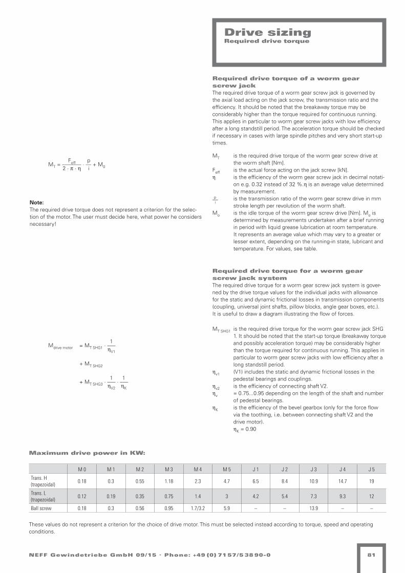
NEFF Gewindetriebe GmbH 09/15 . Phone: +49 (0) 71 57/5 38 90-0 81
Drive sizingRequired drive torque
Feff p MT = _______ · __ + M0 2 · p · h i
Required drive torque of a worm gearscrew jackThe required drive torque of a worm gear screw jack is governed by the axial load acting on the jack screw, the transmission ratio and the efficiency. It should be noted that the breakaway torque may be considerably higher than the torque required for continuous running. This applies in particular to worm gear screw jacks with low efficiency after a long standstill period. The acceleration torque should be checked if necessary in cases with large spindle pitches and very short start-up times.
1 Mdrive motor = MT SHG1 ·
___ hV1
+ MT SHG2
1 1 + MT SHG3 ·
___ · ___ hV2 hK
Required drive torque for a worm gearscrew jack systemThe required drive torque for a worm gear screw jack system is gover-ned by the drive torque values for the individual jacks with allowance for the static and dynamic frictional losses in transmission components (coupling, universal joint shafts, pillow blocks, angle gear boxes, etc.).It is useful to draw a diagram illustrating the flow of forces.
MT is the required drive torque of the worm gear screw drive at the worm shaft [Nm].
Feff is the actual force acting on the jack screw [kN].h is the efficiency of the worm gear screw jack in decimal notati-
on e.g. 0.32 instead of 32 %.h is an average value determined by measurement.
p is the transmission ratio of the worm gear screw drive in mm stroke length per revolution of the worm shaft.
Mo is the idle torque of the worm gear screw drive [Nm]. Mo is determined by measurements undertaken after a brief running in period with liquid grease lubrication at room temperature. It represents an average value which may vary to a greater or lesser extent, depending on the running-in state, lubricant and temperature. For values, see table.
MT SHG1 is the required drive torque for the worm gear screw jack SHG 1. It should be noted that the start-up torque (breakaway torque and possibly acceleration torque) may be considerably higher than the torque required for continuous running. This applies in particular to worm gear screw jacks with low efficiency after a long standstill period.
hv1 (V1) includes the static and dynamic frictional losses in the pedestal bearings and couplings.
hv2 is the efficiency of connecting shaft V2.hv = 0.75...0.95 depending on the length of the shaft and number
of pedestal bearings.hK is the efficiency of the bevel gearbox (only for the force flow
via the toothing, i.e. between connecting shaft V2 and the drive motor).
hK = 0.90
__i
These values do not represent a criterion for the choice of drive motor. This must be selected instead according to torque, speed and operating conditions.
M 0 M 1 M 2 M 3 M 4 M 5 J 1 J 2 J 3 J 4 J 5
Trans. H (trapezoidal) 0.18 0.3 0.55 1.18 2.3 4.7 6.5 8.4 10.9 14.7 19
Trans. L (trapezoidal) 0.12 0.19 0.35 0.75 1.4 3 4.2 5.4 7.3 9.3 12
Ball screw 0.18 0.3 0.56 0.95 1.7/3.2 5.9 – – 13.9 – –
Maximum drive power in KW:
Note:The required drive torque does not represent a criterion for the selec-tion of the motor. The user must decide here, what power he considers necessary!

NEFF Gewindetriebe GmbH 09/15 . Phone: +49 (0) 71 57/5 38 90-082
Drive sizingRequired drive torque
Maximum drive torqueIf the worm gear screw jack jams as a result of the spindle coming intocontact with an obstacle, the toothing can still absorb the following maximum torque values MT at the drive shaft.
In the case of screw jacks connected in series, the screw jack closest to the drive can absorb this torque at its drive shaft.
Selection of drive motorA suitable drive motor can be selected if the required drive torque and drive speed are known. After selecting a drive motor, check that it will not overload any of the worm gear screw jacks or transmission com-ponents. This risk may occur, in particular, in installations with several screw jacks if they are loaded unevenly. It will generally be necessary to install limit switches or torque-limiting couplings to protect the installati-on against impacting against end positions and obstacles.
Forces and torque values on the motor shaftToothed-belt or chain drives may exert considerable radial forces on the motor shaft if a very small sprocket is used. Please consult the motor manufacturer in cases of doubt.
Selection of a bevel gearboxSelection of a bevel gearbox is governed by the following factors:n Drive torquen Drive speed (see dimensional tables)n Duty cycle and drive powern Forces and torques acting on the ends of the shaft(please consult us in cases of doubt).
Required drive speedThe required drive speed is governed by the desired stroke speed, the transmission ratio of the screw jack and the transmission ratio of the other transmission components. A particular stroke speed can normally be achieved in several ways. Correct selection depends on the following criteria:n Favourable efficiency.n Minimum load on transmission components in order to achieve com-
pact, low-cost design.n Avoiding critical speeds for screw jacks and connecting shafts.
Screw jack nut torquesThe nut torque (M) of the screw jack is the torque that the screw jack exerts on the mounting plate (all N versions except V), or the torque that the screw applies to the travelling nut (R Version). It is not to be confused with the drive torque (MT) of the screw jack gears on the worm shaft.M [Nm] = Feff [kN] · fM (applicable in the areas of moderate and high
loads)M is the screw jack nut torque [Nm] for the “Lift under Load”
movement.Feff is the actual supported axial force [kN].fM is a conversion factor that accounts for spindle geometry and
friction. The value is applicable under normal lubrication condi-tions. The higher value applies to dry friction and static friction. In the case of ball screw drives, fM is practically constant.
Acceleration valuesThree-phase asynchronous motor, 4-pole:n Approx. 0.5 m/s2 (when switched on directly).Servo motor:n Max. 5 m/s2 (limited by max. drive torque).
When using screw jacks in conjunction with servo motors, note that:n Greater masses are moved compared with linear axes.n Predominantly constant speeds with different speeds of rotation are
used.n Use is often in the area of the adjustment/positioning of equipment.n Positions are travelled to with relatively short duty cycles and high
acceleration values are therefore less frequently called for.n High acceleration values have only a negligible effect on the overall
stroke time, because of the low stroke speeds.
Forces and torque values acting on the drive shaftIf worm gear screw jacks are not driven free of lateral forces by means of a coupling connected to the motor shaft, but are instead driven by chains or belts, care must be taken to ensure that the radial force acting on the drive shaft does not exceed the limit values (see below).In the worst case due to deflection caused by the radial force FR the worm shaft will lift off of the worm gear wheel. This must be avoided, since it impairs the engagement between worm shaft and worm gear wheel and leads to higher wear.
Size MT max [Nm]
M 0 1.5
M 1 3.4
M 2 7.1
M 3 18
M 4 38
M 5 93
J 1 148
J 2 178
J 3 240
J 4 340
J 5 570
Size FR max [kN]
M 0 0.07
M 1 0.1
M 2 0.2
M 3 0.3
M 4 0.5
M 5 0.8
J 1 0.8
J 2 1.3
J 3 1.3
J 4 2.1
J 5 3.1
Size fM (Trapezoidal screw) fM (Ball screw)
M 0 1.4 1.2
M 1 1.6 1.6
M 2 1.8 1.6
M 3 2.7 1.6
M 4 3.4 1.6/3.2
M 5 4.6 3.2
J 1 5.5 –
J 2 6.4 –
J 3 7.2 3.2
J 4 8.0 –
J 5 10.6 –

NEFF Gewindetriebe GmbH 09/15 . Phone: +49 (0) 71 57/5 38 90-0 83
AccessoriesWorm gear screw-jacks
Mounting feet BL–LSupplied loose with mounting bolts for jack. Burnished.M 1 + 2 with version N-KGT not on side F. Standard: side E.
Size Dimensions [mm] Weight
[kg]A1 A2 A3 A4 A5 A6 A7 A8 A9
BL - L M 0 50 38 6.5 12 75 90 7.5 10 48 0.1
BL - L M 1 72 52 8.5 20 100 120 10 10 60 0.3
BL - L M 2 83 63 8.5 20 120 140 10 10 78 0.4
BL - L M 3 105 81 11 24 150 170 10 12 106 0.8
BL - L M 4 145 115 13.5 30 204 230 13 16 150 1.7
BL - L M 5 171 131 22 40 236 270 17 25 166 3.9
BL - L J 1 205 155 26 50 250 290 20 30 170 5.8
BL - L J 2 235 170 32 65 290 340 25 40 190 10
BL - L J 3 235 170 32 65 290 340 25 40 190 10
BL - L J 4 270 190 39 80 350 410 30 50 230 20.8
BL - L J 5 330 230 45 100 430 500 35 60 290 34.4

NEFF Gewindetriebe GmbH 09/15 . Phone: +49 (0) 71 57/5 38 90-084
Universal joint adapter KA-ZL-CDSupplied loose with mounting bolts for jack. Burnished.Standard: side E. Side F please specify.
Universal joint adapter
Universal joint adapter KA-ZQ-ABSupplied loose with mounting bolts for jack. Burnished.Standard: side E. Side F please specify.
Lengthwise
L1 L2 L3 L4 L5 L6 Ø D f8 ØD1 Ø D2 B
M 0 80 60 38 8 50 64 10 30 13 15
M 1 110 80 49 9 72 84 15 35 18 20
M 2 140 100 60 10 85 104 20 45 23 25
M 3 170 130 76 11 105 134 25 55 28 30
M 4 240 180 102 12 145 184 35 70 38 40
M 5 270 200 117 17 165 204 45 95 48 50
J 1 290 210 120 15 195 214 50 100 56 60
J 2 330 240 140 20 220 244 70 115 76 80
J 3 330 240 140 20 220 244 70 130 76 80
J 4 410 290 165 20 250 294 80 155 88 90
J 5 520 360 210 30 300 364 90 185 96 100
Quer
L1 L2 L3 L4 L5 L6 Ø D f8 ØD1 Ø D2 B
M 0 70 60 38 8 50 54 10 30 13 15
M 1 102 80 49 9 72 76 15 35 18 20
M 2 125 100 60 10 85 89 20 45 23 25
M 3 145 130 76 11 105 109 25 55 28 30
M 4 205 180 102 12 145 149 35 70 38 40
M 5 235 200 117 17 165 169 45 95 48 50
J 1 289 210 120 15 195 199 50 100 56 60
J 2 313 240 140 20 220 224 70 115 76 80
J 3 313 240 140 20 220 224 70 130 76 80
J 4 370 290 165 20 250 254 80 155 88 90
J 5 460 360 210 30 300 304 90 185 96 100

!"#
!$
!
%
%$
!&
!'
(
#$
#&
($
)
%*)+)* -.)/-01*21*3/456
7-82)-96 (0-))6
:*3.2);<<6
=1*
2*>4
)*30-
5*#
-3<
?*#
*3@;
A1*
3)4;
BC#
31))*
4D*
32;4
*4+/
5E45
01BC
5*F
-BC
)?*3
#*4
G
9*C-4#0/45G
!"#"##$#%&
'"()*#$#%+,-./
H*?1BC)6
I;CF-86
0#1"2& 345+(6(/
J/2-)+14<;3F-)1;46 -57"&859$7&
H*A3K<)6
H*4*CF15)6
L9*3<0 M :E3F* M!E3)*N=3/B.-/25-9*4
O;00*31*3/45 4-BC =PQ PRL ST$U
@;4<15/3-)1;46
V005*F*14);00*3-4+*4 4-BC =PQ PRL &"WS X F!M7*)-00V00* 41BC) 9*F-8)*4 @-4)*4 TNU Y ZU[ ;#*3 I TNZ FF
:(#;"(+&
7-82)-925*4-/G214# 41BC)
RBC/
)+\*
3F*3
.=
PQ'Z
9*-
BC)*
4G]
;A^3
15C)
@_=
`31*
#31B
C
<=
_32)*00)6
_32*)+) #/3BC6
Q_`` H*?14#*)31*9* H7(!D;2)<-BC $&'T"$$TS :-0#*49/BCO*0G6 T"$U"MU'S aTXT`-Y6 T"$U"M U'S aTX&"???G4*<<X5*?14#*)31*9*G#*14<;b.4X5*?14#*)31*9*G#*
$GTT'" cR) '"d
-5*3<0-42BC
76$GU6$
R)-4#-3#
TSGTWG&TT" OCG `31*#31BC
`3*1)-5N SG e/41 &TT" $$6'Z6&" >C3
$ \;4 $
XGGG O-9*00*-5*3<0-42BC +/3 %-5*3/45
RBC?*4.0-5*32*14*2 @-3#-4-#-A)*32 ;#*3 *14*2@-3#-40
@%`@-3#-40
(0-B. I-A1#
!"
!
#"
#
$ !%
&
'
$"
'"
$(
#)&*&) ,-&.,/0)10)2.345
6,71&,85 '/,&&5
9)2-1&:;;5
<0)
1)=3
&)2/,
4)$
,2;
>)$
)2?:
@0)
2&3:
AB$
20&&)
3C)
21:3
)3*.
4D34
/0AB
4)E
,AB
&>)2
$)3
F
8)B,3$/.34F
!"#"##$#%&
'"()*#$#%+,-./
G)>0AB&5
H:BE,75
0#1"2& 345+(6(/
I.1,&*03;:2E,&0:35 -57"&859$7&
G)@2J;&5
G)3)BE04&5
K8)2;/ L 9D2E) L!D2&)M<2.A-,.14,8)3
N://)20)2.34 3,AB <OP OQK RS"T
?:3;04.2,&0:35
U//4)E)03&://)2,3*)3 3,AB <OP OQK (%VR W E!L6)&,//U//) 30AB& 8)E,7&)3 ?,3&)3 SMT X YTZ :$)2 H SMY EE
:(#;"(+&
6,71&,814)3,.F103$ 30AB&
QAB.
&*[)
2E)2
-<
OP\Y
8),
AB&)
3F]
:@^2
04B&
?_<
`20)
$20A
B
<=
_21&)//&5
_21)&*& $.2AB5
P_`` G)>03$)&20)8) G6'!C:1&;,AB "(\S%""SR 9,/$)38.ABN)/F5 S%"T%LT\R aSWS`,X5 S%"T%L T\R aSW(%>>>F3);;W4)>03$)&20)8)F$)03;:b-3W4)>03$)&20)8)F$)
?,2$,3/,4)28:A-
65"FT5"
Q&,3$,2$
SRFSVF(SS% NBF `20)$20AB
`2)0&,4M RF c.30 (SS% Sa5Ta5S( =B2
" [:3 "
WFFF N,8)//))03)1?,2$,3,$,@&)21 :$)2 )03)1QAB>)3-/,4)21
?,2$,3/,4)28:A- *.2 #,4)2.34
?#'
'/,A- H,@0$"FSS\% dQ& \%e
NEFF Gewindetriebe GmbH 09/15 . Phone: +49 (0) 71 57/5 38 90-0 85
Universal joint bearing flangefor mounting a universal joint adaptor or a universal joint bearing
Universal joint bearing pedestalfor mounting a universal joint adaptor or a universal joint bearing.
Universal joint bearing
Size Ø d H7 Ø d1 Ø d2 t B B1 H H1 H2 H3 L L1
KLF-0 10 11 6.6 6.8 16 18 32 16 7.5 17 50 35
KLF-1 15 15 9 9 20 22 36 18 9 18 65 45
KLF-2 20 15 9 9 20 23 40 20 10 20 70 50
KLF-3 25 18 11 11 20 22.5 54 27 12 30 80 58
KLF-4 35 20 13.5 13 30 35 70 35 15 40 100 70
KLF-5 45 33 22 21.5 40 43 80 40 20 40 140 100
KLF-200 70 48 33 32 50 58 125 62.5 30 65 220 160
KLF-300 80 57 39 38 62 70 144 72 34 76 245 180
KLF-400 80 57 39 38 62 70 144 72 34 76 245 180
KLF-500 90 66 45 44 80 90 160 80 40 80 28 200
Size Ø d H7 Ø d1 Ø d2 t B B1 H H1 L L1
KLB-0 10 11 6.6 6.8 16 18 30 15 50 35
KLB-1 15 15 9 9 20 22 34 17 65 45
KLB-2 20 15 9 9 20 23 38 19 70 50
KLB-3 25 18 11 11 20 22.5 54 27 80 58
KLB-4 35 20 13.5 13 30 35 70 35 100 70
KLB-5 45 33 22 21.5 40 43 80 40 140 100
KLB-200 70 48 33 32 63 71 124 62 220 160
KLB-300 70 57 39 38 63 71 144 72 245 180
KLB-400 80 57 39 38 63 71 144 72 245 180
KLB-500 90 66 45 44 80 90 160 80 280 200

NEFF Gewindetriebe GmbH 09/15 . Phone: +49 (0) 71 57/5 38 90-086
Attachments
Top plate BPScrewed onto the mounting thread of the screw jack and protected against rotation.Standard: Bore pattern BP symmetrically to SHG housing.Note: Please specify alignment in case of version V.
Size Dimensions [mm] Weight
[kg]B1 B2 Ø B3 B4 B5 B6 B7 x 4 B8
BP M 0 16 6 50 40 26 M8 7 M4 0.1
BP M 1 20 7 65 48 30 M12 9 M5 0.2
BP M 2 21 8 80 60 38.7 M14 11 M6 0.3
BP M 3 23 10 90 67 46 M20 11 M8 0.6
BP M 4 30 15 110 85 60 M30 13 M8 1.2
BP M 5 50 20 150 117 85 M36 17 M10 4.8
BP J 1 50 25 170 130 90 M48 x 2 21 M10 5
BP J 2 60 30 200 155 105 M56 x 2 25 M12 7.7
BP J 3 60 30 220 170 120 M64 x 3 25 M12 9.8
BP J 4 80 40 260 205 145 M72 x 3 32 M12 18.4
BP J 5 120 40 310 240 170 M100 x 3 38 M12 29.6
Fork end GKScrewed onto the mounting thread of the screw jack and protected against rotation. Supplied with split pins and collar pins.Standard: Collar pin mounted parallel to the drive shaft.Note: Please specify alignment in case of version V.
Size Dimensions [mm] Weight [kg]
G2 G3 G4H9 G5 k G6B12 G7 G8 G9 G10 G11
GK M 0 32 16 8 16 8 M4 M8 12 42 14 0.04
GK M 1 48 24 12 24 12 M5 M12 18 62 20 0.15
GK M 2 56 28 14 28 14 M6 M14 22 72 24.5 0.2
GK M 3 80 40 20 40 20 M8 M20 30 105 34 0.8
GK M 4 120 60 30 60 30 M8 M30 43 160 52 2.5
GK M 5 144 72 35 70 35 M10 M36 54 188 60 3.8

NEFF Gewindetriebe GmbH 09/15 . Phone: +49 (0) 71 57/5 38 90-0 87
Attachments
Spherical bearing GAScrewed onto the mounting thread of the screw jack and protected against rotation.Standard: Position of the transverse bore parallel to drive shaft.Note: Please specify alignment in case of version V.
High-performance joint head HG
Size Dimensions [mm] Weight
[kg]G1 G2 G3 G4H8 G6H10 G7 G8 G9
GA M 0 40 30 10 8 12 25 M8 M4 0.1
GA M 1 55 40 15 10 15 30 M12 M5 0.2
GA M 2 63 45 18 12 20 39 M14 M6 0.3
GA M 3 78 53 20 16 30 45 M20 M8 0.6
GA M 4 100 70 30 20 35 60 M30 M8 1.2
GA M 5 130 97 33 22 40 85 M36 M10 2.5
GA J 1 120 75 45 40 60 90 M48 x 2 M10 4.8
GA J 2 130 90 50 50 70 105 M56 x 2 M12 4.8
GA J 3 155 105 60 60 80 120 M64 x 3 M12 8.0
GA J 4 220 135 85 80 110 145 M72 x 3 M12 22.5
GA J 5 300 200 100 90 120 170 M100 x 3 M12 31.5
Dimension ØdH7 M B B1 D D1 D2 L L1 L2 L3 SW Co / (KN) Angle ( ° ) Weight
HG-0 10 M 10 14 10.5 28 19 12.9 57 43 6.5 20 17 17.65 13 0.076
HG-1 12 M 12 16 12 32 22 15.4 66 50 6.5 22 19 20.6 13 0.115
HG-2 14 M 14 19 13.5 36 25 16.8 75 57 8 25 22 29.4 15 0.17
HG-3 20 M 20x1.5 25 18 50 34 24.3 102 77 10 33 32 49.1 15 0.415
HG-4 30 M 30x2 37 25 70 50 34.8 145 110 15 51 41 99.1 15 1.13
HG-5 35 M 36x2 43 28 80 58 37.7 165 125 17 65 50 125 15 1.6
HG-6 70 M 56x4 49 42 160 98 92 280 200 20 80 85 630 6 8.4

NEFF Gewindetriebe GmbH 09/15 . Phone: +49 (0) 71 57/5 38 90-088
Bellows FB
L max = min+stroke
stroke
Bellows cover for the protection of the spindle against external influ-ences. Available in diameters from 20 mm to 120 mm in 1 mm steps. Horizontal and vertical installation possible.
Calculation of bellows FBFor the dimensioning of the spindle length of screw jacks or screw drives with bellows protection, the spindle must be extended by Lmin.
TO version (thermoplastic sprayed)
Lmin = Fz · LminF
Fz = Lmax : 1,8
Ft = AD - ID
LminF = 6 mm
If space is limited, LminF can be shortened after consultation to the factor 0.835.
SB version (disk bellows)
Lmin= Fz · LminF
Fz = Lmax · 1,1
Fz = Lmax : 1,1
Ft = AD - ID
LminF= 2,5 mm
If space is limited, LminF can be shortened after consultation to the factor 0.64.
A support ring must be installed every 400 mm in case of horizontal installation or every 1000 mm in case of vertical installation. The dimension Lmin is extended here by 1.1 mm per support ring.
Lmin compressed length [mm]Lmax extended length [mm]Ft fold depth [mm]Fz no. of foldsLminF compressed length per fold [mm]
Ft
2
Ft
Ft
2

NEFF Gewindetriebe GmbH 09/15 . Phone: +49 (0) 71 57/5 38 90-0 89
- - - - - - - x - -
1 2 3 4 5 6 7 8 9 10 11
Ordering code for bellows FB
No. Designation Code Description
1 Product abbreviation KGT Ball screw
2 Design
TO Thermoplastic (sprayed)
SB Disk bellows
GR Round fabric, coated
GV Polygonal fabric, coated
3 Lmin in [mm] Retraction length / compressed length of bellows
4 Stroke/Lmax in [mm] Stroke/maximum extension length
5 Inside diameter ID in [mm] > same as diameter of spindle
6 Outside diameter OD in [mm
7 Cuff diameter SD1 in [mm] Inside diameter of the bellows end 1
8 Cuff diameter SD2 in [mm] Inside diameter of the bellows end 2
9 Spindle dimension e.g. 20x4 (diameter 20 mm, pitch 4 mm)
10 Installation positionH Horizontal
V Vertical
11 Special requirements for nut0 none
1 According to specification, description or drawing
Bellows FB

NEFF Gewindetriebe GmbH 09/15 . Phone: +49 (0) 71 57/5 38 90-090
Spiral spring coverSF
2/3 Lmin
AF
AD
Lmin Hub Lh/Lv
ID
1/2 Lmin
SD
IF
In diesem Bereich dürfen sichkeine störenden Schrauben, etc. befindenThere may not be any interfering screws, etc. in this area.
stroke
Spiral springs are used as reliable spindle protective covers against external influences.
The material used is hardened spring band steel. If the spiral springs are exposed to cooling lubricants with a high water content, it is recom-mended to use stainless spiral springs. For dimensions see Accessories pages 49 to 51
SD = Maximum outside diameter / spindle diameterID = Inside diameter of the spiral spring ±1 mmAD = Diameter of the spiral springLh = Maximum extension length in case of horizontal installation
Lv = Maximum extension length in case of vertical installationBB = Width of band, corresponds to LminAF = Inside diameter of the centring flange AD +4 mmIF = Outside diameter of the centring flange ID -2 mm
- - - - - - -
1 2 3 4 5 6 7 8
Ordering code spiral spring cover
No. Designation Code Description
1 Product abbreviation SF
2 ID in [mm] Inside diameter of the spiral spring +1 mm
3 Largest length Lh/Lv in [mm] Maximum extension length
4 BB / Lmin in [mm] Width of band, corresponds to Lmin
5 Installation positionH Horizontal
V Vertical
6 MaterialB Standard spring in blued spring steel
S Version in rustproof stainless steel
7
Accessories(If using mounting flanges the possible spindle diameter SD is reduced by 6 mm)
0 Without mounting flange
1 With mounting flange outside (inside diameter +4 mm of outer diameter OD of spiral spring)
2 With mounting flange inside (inside diameter -2 mm of inner diameter ID of spiral spring)
3 With mounting flange inside/outside
8 Special requirements for mounting flange0 None
1 According to specification, description or drawing

NEFF Gewindetriebe GmbH 09/15 . Phone: +49 (0) 71 57/5 38 90-0 91
Lubricants
C
D
1 2
321 4
B
A
5 6
--
Ind.
Rz 1geschliffen
=z
geschliffen
=Rz 4y
=Rz 16x
Oberflächen nach DIN ISO 1302
Werkstückkanten nach DIN 6784
Rz 63
=w
-
-
Becirovic
Kanten
Werkstoff:
NameDatumAenderung Artikel-Nr.Ablage
Neff Gewindetriebe GmbHKarl-Benz-Straße 2471093 Weil im Schönbuch
-
Erstellt
-
Zeichnungen und technische Unterlagen sind unser Eigentum, Vervielfältigung, Verwertung oder Mitteilung an Dritte verpflichtet zu Schadenersatz und kann gerichtlich verfolgt werden.
Tolerierung DIN ISO 8015
F:\NEFF Gewindetriebe GmbH\GT+SHG Katalog\Katalog (Neue Ausführung 03-2013)\Katalog-Zeichnungen\Zubehör Gewindetriebe\NEFF Food Grease 0 aktuelle Version -
-
--
-
-0,3-0,5 +0,5
+0,3
AllgemeintoleranzDIN ISO 2768-m
Maßstab
Gewicht (kg)
Datum Name
Geprüft
Schutzvermerk DIN 34 beachten
Bestellschlüssel:
Rohmaß:
Projekt:
Druckdatum BlattgrößeBlatt von
1:5
-10.07.2013
A41 1
Verfasser:-
Version
A
B
C
C
D
1 2
321 4
B
A
5 6
--
Ind.
Rz 1geschliffen
=z
geschliffen
=Rz 4y
=Rz 16x
Oberflächen nach DIN ISO 1302
Werkstückkanten nach DIN 6784
Rz 63
=w
-
-
Becirovic
Kanten
Werkstoff:
NameDatumAenderung Artikel-Nr.Ablage
Neff Gewindetriebe GmbHKarl-Benz-Straße 2471093 Weil im Schönbuch
-
Erstellt
-
Zeichnungen und technische Unterlagen sind unser Eigentum, Vervielfältigung, Verwertung oder Mitteilung an Dritte verpflichtet zu Schadenersatz und kann gerichtlich verfolgt werden.
Tolerierung DIN ISO 8015
F:\NEFF Gewindetriebe GmbH\GT+SHG Katalog\Katalog (Neue Ausführung 03-2013)\Katalog-Zeichnungen\Zubehör Gewindetriebe\NEFF Food Grease 0 aktuelle Version -
-
--
-
-0,3-0,5 +0,5
+0,3
AllgemeintoleranzDIN ISO 2768-m
Maßstab
Gewicht (kg)
Datum Name
Geprüft
Schutzvermerk DIN 34 beachten
Bestellschlüssel:
Rohmaß:
Projekt:
Druckdatum BlattgrößeBlatt von
1:5
-10.07.2013
A41 1
Verfasser:-
Version
A
B
C
NEFF-Grease 2/3Neff Grease 2/3 was specially developed for use with highly-stressed ball screw drives.
The strongly adhering synthetic grease containing Teflon has very good temperature stability and can withstand high loads and vibrations.
NEFF-Grease 2Neff Grease 2 was specially developed for use in highly-stressed trape-zoidal screw drives, sliding screw drives and worm gear drives.
The heavy-duty grease was specially developed for high surface pressu-re and has outstanding temperature stability
NEFF-Food Grease 2NEFF Food Grease 2 was specially developed for the requirements of the food industry. The grease meets the requirements of DIN V 10517. Suitable for use in applications with occasional food contact (class NSF-H1).

NEFF Gewindetriebe GmbH 09/15 . Phone: +49 (0) 71 57/5 38 90-092
NEFF Lubricant dispenser
L
52 Gasentwicklungszelle
Tranzparentes Gehäuse
Kolben
Fettfüllung
C
2 31 4
B
A
D
E
F
Version
- Verfasser:
11A4
23.08.2013-
1:1
vonBlattBlattgrößeDruckdatum
Projekt:
Rohmaß:
Bestellschlüssel:
Schutzvermerk DIN 34 beachten
Geprüft
NameDatum
Gewicht (kg)
Maßstab
AllgemeintoleranzDIN ISO 2768-m
+0,5+0,3
-0,3-0,5
11.09.2012
- -
-
aktuelle Version --
Tolerierung DIN ISO 8015
Zeichnungen und technische Unterlagen sind unser Eigentum, Vervielfältigung, Verwertung oder Mitteilung an Dritte verpflichtet zu Schadenersatz und kann gerichtlich verfolgt werden.
Blix3, Gehäuseseite A
Erstellt
-
Neff Gewindetriebe GmbHKarl-Benz-Straße 2471093 Weil im Schönbuch
Ablage Artikel-Nr.Aenderung Datum Name
Werkstoff:
KantenA. Ries
-
-
w
=Rz 63Oberflächen nach DIN ISO 1302
Werkstückkanten nach DIN 6784x Rz 16
=
y Rz 4
=
geschliffen
z
=
geschliffenRz 1
Ind.
- -
Gas formation cell
Transparent housing
Piston
Grease filling
The NEFF Lube 1 automatic lubricant dispenser is screwed directly onto the lubrication point. It operates independently and is activated when setting the running time. The lubricant level is always visible in the transparent window.
Readjustment during operation is possible.
The shelf life of the lubricant dispenser expires after 2 years.The NEFF Lube 1 lubricant dispenser is available in 4 sizes:
Size Contents Length L Connection Grease types Grease delivery per day
Dispensing period
NEFF LUB 1-30 30ml 43mm
R ¼ inch All standard NEFF Grease types 0.08–8.3 ml 1-12 month
NEFF LUB 1-60 60ml 62mm
NEFF LUB 1-125 125ml 100mm
NEFF LUB 1-250 250ml 192mm
When ordering in conjunction with a ball screw or trapezoidal screw drive, please indicate special requirements of the nut in the ordering code.Caution: when the lubricant dispenser is mounted the overall height of the NEFF LUB 1 is increased by about 25 mm due to the connecting/adaptor piece

!"#
$%
&' (
&)
*%!
+
,',
-.
/'
0
1 '31 '4
1 '
5'
6)
%
1)
5'
5'
('
7'8'
$
9
5!:
;'/
%
*
5!:
+'
< )=*'>= ?'*@< ':*'>= ?'*@
0)
8
#
%)
A
9
BC#
>=#
D
E/,F,/ (!,+(16/-6/G+D%H
<(I-,(.H J1(,,H
K/G!-,L88H
M6/
-/ND
,/G1(
%/5
(G8
&/5
/G"L
06/
G,DL
AB5
G6,,/
DO/
G-LD
/DF+
%PD%
16AB
%/;
(AB
,&/G
5/D
Q
./B(D51+D%Q
!"#"##$#%&
'"()*#$#%+,-./
R/&6AB,H
SLB;(IH
0#1"2& 345+(6(/
T+-(,F6D8LG;(,6LDH -57"&859$7&
R/0GU8,H
R/D/B;6%,H
V./G81 W KPG;/ WXPG,/>MG+A!(+-%(./D
YL11/G6/G+D% D(AB MZ[ Z\V ]#'=
"LD86%+G(,6LDH
^11%/;/6D,L11/G(DF/D D(AB MZ[ Z\V )_:] C ;XW</,(11^11/ D6AB, ./;(I,/D "(D,/D #>= * 4=` L5/G S #>4 ;;
:(#;"(+&
<(I-,(.-%/D(+Q-6D5 D6AB,
\AB+
,Fa/
G;/G
!M
Z[34
./(
AB,/
DQ7
L09G
6%B,
"bM
cG6/
5G6A
B
<=
bG-,/11,H
bG-/,F, 5+GABH
[bcc R/&6D5/,G6/./ R<JXOL-,8(AB ')3#_''#] K(15/D.+ABY/1QH #_'=_W=3] d#C#c(*H #_'=_W =3] d#C)_&&&QD/88C%/&6D5/,G6/./Q5/6D8Le!DC%/&6D5/,G6/./Q5/
' aLD '<H'H'#
#=Q#4Q)##_ YBQ cG6/5G6AB
M6/D-,(%> ))Q <(6 )##_ #dH)#H=# NBG
MG/B-,GLB;;L,LGQ
< CQQQ Y(./11/
c1(D-AB8LG;
-,
c+I8LG;
0)
%'
-'
1
1 ''
1 ')
5
!"#
$%
&' (
&)
*%!
+
,',
-.
/'
0
1 '31 '4
1 '
5'
6)
%
1)
5'
5'
('
7'8'
$9
5!:
;'/
%
*
5!:
+'
< )=*'>= ?'*@< ':*'>= ?'*@
0)
8
#
%)A
9
BC#
>=#
D
E/,F,/ (!,+(16/-6/G+D%H
<(I-,(.H J1(,,H
K/G!-,L88H
M6/
-/ND
,/G1(
%/5
(G8
&/5
/G"L
06/
G,DL
AB5
G6,,/
DO/
G-LD
/DF+
%PD%
16AB
%/;
(AB
,&/G
5/D
Q
./B(D51+D%Q
!"#"##$#%&
'"()*#$#%+,-./
R/&6AB,H
SLB;(IH
0#1"2& 345+(6(/
T+-(,F6D8LG;(,6LDH -57"&859$7&
R/0GU8,H
R/D/B;6%,H
V./G81 W KPG;/ WXPG,/>MG+A!(+-%(./D
YL11/G6/G+D% D(AB MZ[ Z\V ]#'=
"LD86%+G(,6LDH
^11%/;/6D,L11/G(DF/D D(AB MZ[ Z\V )_:] C ;XW</,(11^11/ D6AB, ./;(I,/D "(D,/D #>= * 4=` L5/G S #>4 ;;
:(#;"(+&
<(I-,(.-%/D(+Q-6D5 D6AB,
\AB+
,Fa/
G;/G
!M
Z[34
./(
AB,/
DQ7
L09G
6%B,
"bM
cG6/
5G6A
B
<=
bG-,/11,H
bG-/,F, 5+GABH
[bcc R/&6D5/,G6/./ R<JXOL-,8(AB ')3#_''#] K(15/D.+ABY/1QH #_'=_W=3] d#C#c(*H #_'=_W =3] d#C)_&&&QD/88C%/&6D5/,G6/./Q5/6D8Le!DC%/&6D5/,G6/./Q5/
' aLD '<H'H'#
#=Q#4Q)##_ YBQ cG6/5G6AB
M6/D-,(%> ))Q <(6 )##_ #dH)#H=# NBG
MG/B-,GLB;;L,LGQ
< CQQQ Y(./11/
c1(D-AB8LG;
-,
c+I8LG;
0)
%'
-'
1
1 ''
1 ')
5
NEFF Gewindetriebe GmbH 09/15 . Phone: +49 (0) 71 57/5 38 90-0 93
3-phase motors M
3-phase 4-pole motors (1500 rpm) in totally enclosed fan-cooled desi-gns in accordance with VDE 0530 Part 1.Standard protection class: IP55. Temperature class F. Other SEW mo-tors on enquiry.Notes: If the free shaft end of the motor is used as shaft for a slip-on emergency hand wheel, a device will be required that interrupts the power supply before the crank engages. Motors with different speeds and brake motors on enquiry.
Performance data
Size Nominal
power
[kW]
Nominal
speed
[rpm]
Power
factor
cos j
Nominal current at
400 V[A]
Rel. starting
current
IA/IN
Nominal
torque
[Nm]
Rel. starting
torque
MA/MN
Rel. run-up
torque
MH/MN
Moment of
inertia JMot
[10-4kgm2]
Moment of
inertia JBremsmot
[10-4kgm2]
Braking
torque
[Nm]
DT71K4 0.15 1380 0.67 0.61 2.9 1.0 1.8 1.7 4.6 5.5 5.0
DT71C4 0.25 1380 0.70 0.80 2.8 1.7 1.8 1.7 4.6 5.5 5.0
DT71D4 0.37 1380 0.76 1.15 3.0 2.6 1.8 1.7 4.6 5.5 5.0
DT80K4 0.55 1360 0.72 1.75 3.4 3.9 2.1 1.8 7.5 7.5 10
DT80N4 0.75 1380 0.73 2.1 3.8 5.2 2.2 2.0 8.7 9.6 10
DT90S4 1.1 1400 0.77 2.8 4.3 7.5 2.0 1.9 25 31 20
DT90L4 1.5 1410 0.78 3.55 5.3 10.2 2.6 2.3 34 40 20
DV100M4 2.2 1410 0.83 4.7 5.9 15.0 2.7 2.3 53 59 40
DV100L4 3.0 1400 0.83 6.3 5.6 20.5 2.7 2.2 65 71 40
DV112M4 4.0 1420 0.84 8.7 5.4 26.9 2.4 2.1 98 110 55
Flange form
Foot form

NEFF Gewindetriebe GmbH 09/15 . Phone: +49 (0) 71 57/5 38 90-094
3-phase motors M
DimensionsThe values in brackets refer to motors with brake.
Size Dimensions [mm]
a1 b1 c1 d d1 e1 f1 g g1 i2 k k0 I I11
DFT71K4 120 80 8 14 11 100 3 145 122(127) 24 232 (296) 208 (296) 30 4
DFT71C4 120 80 8 14 11 100 3 145 122(127) 24 232 (296) 208 (272) 30 4
DFT71D4 120 80 8 14 11 100 3 145 122(127) 24 232 (296) 208 (272) 30 4
DFT80K4 120 80 8 19 14 100 3 145 122(127) 34 292 (356) 258 (322) 40 4
DFT80N4 120 80 8 19 14 100 3 145 122(127) 34 292 (356) 258 (322) 40 4
DFT90S4 160 110 10 24 19 130 3.5 197 154(161) 53.5 323 (408) 273 (358) 50 5
DFT90L4 160 110 10 24 19 130 3.5 197 154(161) 53.5 323 (408) 273 (358) 50 5
DFV100M4 200 130 10 28 19 165 3.5 197 166 60 371 (456) 311 (396) 60 5
DFV100L4 200 130 10 28 19 165 3.5 197 166 60 401 (486) 341 (426) 60 5
DFV112M4 200 130 11 28 24 165 3.5 221 179(182) 64 409 (489) 345 (425) 60 5
Size Dimensions [mm]
I12 l1 l2 l13 l14 s1 t u t1 u1 x x9 y p2
DFT71K4 22 23 24 1 20 6.6 16 5 12.5 4 87 (127) 61 (86) 97 50
DFT71C4 22 23 24 1 20 6.6 16 5 12.5 4 87 (127) 61 (86) 97 50
DFT71D4 22 23 24 1 20 6.6 16 5 12.5 4 87 (127) 61 (86) 97 50
DFT80K4 32 30 31 4 22 6.6 21.5 6 16 5 87 (127) 61 (86) 97 50
DFT80N4 32 30 31 4 22 6.6 21.5 6 16 5 87 (127) 61 (86) 97 50
DFT90S4 40 40 42 4 32 9 27 8 21.5 6 87 (127) 76 (121) 97 50
DFT90L4 40 40 42 4 32 9 27 8 21.5 6 87 (127) 76 (121) 97 50
DFV100M4 50 40 42 4 32 11 31 8 21.5 6 106 (139) 74 (125) 109 56
DFV100L4 50 40 42 4 32 11 31 8 21.5 6 106 (139) 74 (125) 109 56
DFV112M4 50 50 55 5 40 11 31 8 27 8 106 (139) 91 (131) 109 56
Flange shape
Foot shape
Size Dimensions [mm]
a b c e f h m1 n s w1 w2
DT71K4 90 112 5 115 144 71 32 31 7 45 75
DT71C4 90 112 5 115 144 71 32 31 7 45 75
DT71D4 90 112 5 115 144 71 32 31 7 45 75
DT80K4 100 125 10 125 149 80 28 33 9 50 90
DT80N4 100 125 10 125 149 80 28 33 9 50 90
DT90S4 125 140 8 152 176 90 32 32 9 56 106
DT90L4 125 140 8 152 176 90 32 32 9 56 106
DV100M4 140 160 12 170 188 100 35 38 12 63 123
DV100L4 140 160 12 170 188 100 35 38 12 63 123
DV112M4 140 190 14 170 220 112 35 44 12 70 130

A
A
D
d
L
L1
d1
A
l2
l1 A-A
d2
Passfedernut P9DIN 6885-2
Feather key groove P9DIN 6885-2
NEFF Gewindetriebe GmbH 09/15 . Phone: +49 (0) 71 57/5 38 90-0 95
Handwheels HR
Handwheel HR for the emergency adjustment and manual adjustment of worm gear screw jacks or systems.
SizeDimensions in [mm]
Bore d2 H7A D d d1 L1 L l1 l2
HR 80 10 80 31 21 16 29 50 2.5 Ø 10
HR 80 10 80 31 21 16 29 50 2.5 Ø 14
HR 100 10 100 33 21 17 33 50 2.5 Ø 10
HR 100 10 100 33 21 17 33 50 2.5 Ø 14
HR 125 13 125 35 22 18 36 56 2.5 Ø 10
HR 125 13 125 35 22 18 36 56 2.5 Ø 14
HR 140 13 140 37 22 19 39 56 2.5 Ø 14
HR 140 13 140 37 22 19 39 56 2.5 Ø 16
HR 160 16 160 40 23 20 40 65 2.5 Ø 14
HR 160 16 160 40 23 20 40 65 2.5 Ø 16
HR 200 16 200 45 26 24 45 80 2.5 Ø 16
HR 200 16 200 45 26 24 45 80 2.5 Ø 20
HR 250 19 250 52 31 28 50 102 2.5 Ø 20
HR 250 19 250 52 31 28 50 102 2.5 Ø 25

A
A
D
d
L
L1
d1
A
l2
l1
d3
l3
A-A
d2
Passfedernut P9DIN 6885-2Feather key groove P9DIN 6885-2
NEFF Gewindetriebe GmbH 09/15 . Phone: +49 (0) 71 57/5 38 90-096
Safety handwheels SHR
SizeDimensions in [mm]
Bore d2 H7A D d d1 d3 L L1 l1 l2 l3
HR 125 13 125 35 22 28 36 18 56 2.5 5 Ø 14
HR 140 13 140 37 22 28 39 19 56 2.5 5 Ø 14
HR 140 13 140 37 22 28 39 19 56 2.5 5 Ø 16
HR 160 16 160 40 23 32 40 20 65 2.5 6 Ø 14
HR 160 16 160 40 23 32 40 20 65 2.5 6 Ø 16
HR 200 16 200 45 26 38 45 24 80 2.5 6 Ø 18
HR 200 16 200 45 26 38 45 24 80 2.5 6 Ø 20
HR 250 19 250 52 31 45 50 28 102 2.5 12 Ø 22
Safety handwheel SHR for the emergency adjustment and manual adjustment of worm gear screw jacks or systems. Safety handwheels decouple themselves to prevent turning with the spindle. Standstill of the handwheel is guaranteed only up to medium speeds.

!"
!#
$
%
&
()*(
+,-
/ 0+12 (#
3
#4
5 .6.78.
9
:
;#
<
;"
1=>?@A@ BC=DEF
9?@A@? GH@CGIJ?>J?=CKLF
5GM>@GNF -IG@@F
5GM>@GN>L?KGCO
2J?
>?<K
@?=IG
L?B
G=0
P?B
?=&Q
RJ?
=@KQ
DEB
=J@@?
KS?
=>QK
?KAC
LTKL
IJDE
L?U
GDE
@P?=
B?K
O
N?EGKBICKLO
!"#"##$#%&
'"()*#$#%+,-./
V?PJDE@F
;QEUGMF
0#1"2& 345+(6(/
WC>G@AJK0Q=UG@JQKF -57"&859$7&
V?R=X0@F
Y?=H>@Q00F
/IIL?U?JK@QII?=GKA?K KGDE 2Z3 Z![ "\]+ ^ U$_5?@GII
2=CDHGC>LGN?K
:QII?=J?=CKL KGDE 2Z3 Z![ +.#8
[N?=0I _ YT=U? _$T=@?7
V?K?EUJL@F &QK0JLC=G@JQKF
:(#;"(+&
/II? KJDE@ N?UGM@?K &GK@?K .78 ` 48a QB?= ; .74 UU
>JKB KJDE@
!DEC
@Ab?
=U?=
H2
Z3c4
N?G
DE@?
KO%
QRd=
JLE@
&12
(=J?
B=JD
E
<=
1=>@?II@F
31(( V?PJKB?@=J?N? V5-$SQ>@0GDE #"c.\##.+ YGIB?KNCDE:?IOF .\#8\_8c+ ).^.(G`F .\#8\_ 8c+ ).^"\PPPOK?00^L?PJKB?@=J?N?OB?JK0QeHK^L?PJKB?@=J?N?OB?
# bQK #
5Q@Q=LIQDH?K 5V
5F#F8
""O.8O"..\ :EO (=J?B=JDE
2J?K>@GL7 ""O 5GJ "..\ .)F##F#] <E=
5Q@Q=LIQDH?KO
5V ^OOO :GN?II?
NEFF Gewindetriebe GmbH 09/15 . Phone: +49 (0) 71 57/5 38 90-0 97
E-0.
1
Motor adaptor flanges MG
Motor adaptor flanges are used to mount motors to worm gear screw jacks and house the coupling for connecting the motor to the drive shaft.When ordering, please specify the side at which the motor adaptor flange is to be attached (A or B).
Size Motor VersionMG/ZF1)
Dimensions [mm]
A B C D E Ø F q F H I K
MG M 0 DFT63 MG 90 60 44 19 22 50 62 61 10
MG M 1 DFT71 MG 120 80 65 22 32 77 81.5 80 10
MG M 1 DFT80 MG 120 80 56 22 32 62 91.5 90 10
MG M 2 DFT71 MG 120 80 65 26 35 77 81.5 80 10
MG M 2 DFT80 MG 120 80 78 26 35 88 92.5 91 10
MG M 2 DFT90 MG 160 110 90 31 35 110 109.5 108 15
MG M 3 DFT71 MG 120 80 77 28 40 87 91.5 90 10
MG M 3 DFT80 MG 120 80 78 28 40 88 103 101 10
MG M 3 DFT90 MG 160 110 95 28 40 104 125 123 12
MG M 3 DFV100/112 MG + ZF 200 130 100 24 35 145 133 131 29
MG M 4 DFT80 MG 120 80 75 42 52 – 88 105 103 12
MG M 4 DFT90 MG 160 110 98 42 52 114 118 116 15
MG M 4 DFV100/112 MG + ZF 200 130 120 30 52 145 134 131 29
MG M 5 DFT90 MG 160 110 105 45 62 120 138.5 136 15
MG M 5 DFV100/112 MG 200 130 125 35 62 145 154 152 16
1) MG = Motor adaptor flange ZF = Intermediate flange
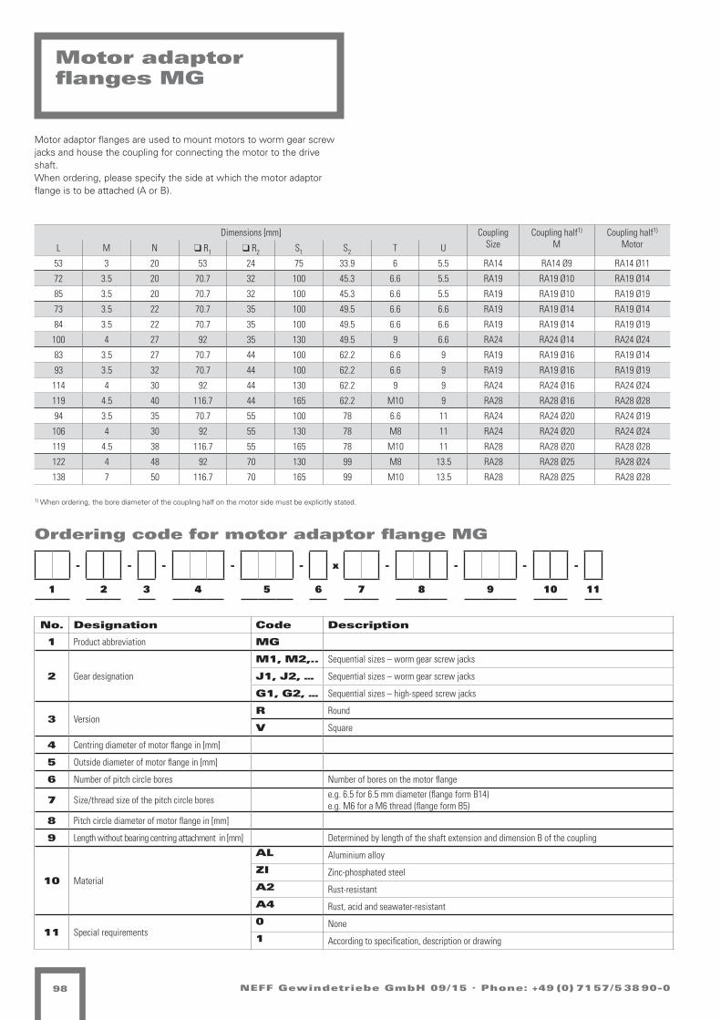
NEFF Gewindetriebe GmbH 09/15 . Phone: +49 (0) 71 57/5 38 90-098
Dimensions [mm] CouplingSize
Coupling half1)
MCoupling half1)
MotorL M N q R1 q R2 S1 S2 T U
53 3 20 53 24 75 33.9 6 5.5 RA14 RA14 Ø9 RA14 Ø11
72 3.5 20 70.7 32 100 45.3 6.6 5.5 RA19 RA19 Ø10 RA19 Ø14
85 3.5 20 70.7 32 100 45.3 6.6 5.5 RA19 RA19 Ø10 RA19 Ø19
73 3.5 22 70.7 35 100 49.5 6.6 6.6 RA19 RA19 Ø14 RA19 Ø14
84 3.5 22 70.7 35 100 49.5 6.6 6.6 RA19 RA19 Ø14 RA19 Ø19
100 4 27 92 35 130 49.5 9 6.6 RA24 RA24 Ø14 RA24 Ø24
83 3.5 27 70.7 44 100 62.2 6.6 9 RA19 RA19 Ø16 RA19 Ø14
93 3.5 32 70.7 44 100 62.2 6.6 9 RA19 RA19 Ø16 RA19 Ø19
114 4 30 92 44 130 62.2 9 9 RA24 RA24 Ø16 RA24 Ø24
119 4.5 40 116.7 44 165 62.2 M10 9 RA28 RA28 Ø16 RA28 Ø28
94 3.5 35 70.7 55 100 78 6.6 11 RA24 RA24 Ø20 RA24 Ø19
106 4 30 92 55 130 78 M8 11 RA24 RA24 Ø20 RA24 Ø24
119 4.5 38 116.7 55 165 78 M10 11 RA28 RA28 Ø20 RA28 Ø28
122 4 48 92 70 130 99 M8 13.5 RA28 RA28 Ø25 RA28 Ø24
138 7 50 116.7 70 165 99 M10 13.5 RA28 RA28 Ø25 RA28 Ø28
Motor adaptor flanges MG
1) When ordering, the bore diameter of the coupling half on the motor side must be explicitly stated.
- - - - - x - - - -
1 2 3 4 5 6 7 8 9 10 11
Ordering code for motor adaptor flange MG
No. Designation Code Description
1 Product abbreviation MG
2 Gear designation
M1, M2,.. Sequential sizes – worm gear screw jacks
J1, J2, … Sequential sizes – worm gear screw jacks
G1, G2, … Sequential sizes – high-speed screw jacks
3 VersionR Round
V Square
4 Centring diameter of motor flange in [mm]
5 Outside diameter of motor flange in [mm]
6 Number of pitch circle bores Number of bores on the motor flange
7 Size/thread size of the pitch circle bores e.g. 6.5 for 6.5 mm diameter (flange form B14)e.g. M6 for a M6 thread (flange form B5)
8 Pitch circle diameter of motor flange in [mm]
9 Length without bearing centring attachment in [mm] Determined by length of the shaft extension and dimension B of the coupling
10 Material
AL Aluminium alloy
ZI Zinc-phosphated steel
A2 Rust-resistant
A4 Rust, acid and seawater-resistant
11 Special requirements0 None
1 According to specification, description or drawing
Motor adaptor flanges are used to mount motors to worm gear screw jacks and house the coupling for connecting the motor to the drive shaft.When ordering, please specify the side at which the motor adaptor flange is to be attached (A or B).

! "
#$
%&
!
#
'"
(
'
)
%&
(
#*
#+
,
- "$
./01(21345 7899/8:;<
=7>,? <<< @0)5//5?(0:A0BA
=7>,? <<<./01(21345 7899/8:;
$ CD: $
E2((FD34G *H< E02 *II& $JKJHK$+ L4B
@4< 'B25AB234*H<IJ<*II&
EK$<*K$E0M1(0)K
N)5BO/ P =QBR5 P%QB(5G
?348
(SC5
BR5B
T#
UVH+
)50
34(5
:<-
D9WB
2;4(
7.#
'B25
AB23
4
!
"
-
#
$
.
H
'
* + J X & Y
Z5(S(5 0T(80/25125B8:;K
.B15(S( A8B34K
.B1(5//(K
!"
#25
15L:
(5B/0
;5A
0BO
F5A
5B7D
925
B(:D
34A
B2((5
:[5
B1D:
5:S8
;Q:;
/234
;5R
034
(F5B
A5:
<
!//5 :234( )5R0M(5: 70:(5: IGJ \ +J] DA5B ^ IG+ RR
#$%&'$()
E0M1(0)1;5:08<
7D:O2;8B0(2D:K
12:A :234(#B83T081;0)5:
@D//5B25B8:; :034 #UV U?N YI$J
,5:54R2;(K
,59B_O(K
*+,-.) /+.')`810(S2:ODBR0(2D:K
01+($2$34%5'6)
^D4R0MK
,5F234(K
7'$89%-%:(;/<3
='%'%%-%:)
!//;5R52:(D//5B0:S5: :034 #UV U?N *&XY > R%PE5(0//
)540:A/8:;<=5BT1(DOOK
"/0((KV.'' ,5F2:A5(B25)5 ,E"%[D1(O034 $*HI&$$IY =0/A5:)834@5/<K I&$J&PJHY aI>I'0\K I&$J&P JHY aI>*&FFF<:5OO>;5F2:A5(B25)5<A52:ODbT:>;5F2:A5(B25)5<A5
,
"$
D4
D3
NEFF Gewindetriebe GmbH 09/15 . Phone: +49 (0) 71 57/5 38 90-0 99
Couplings
Shaft couplings GSThe GS shaft coupling is a special anti backlash shaft coupling.
The toothed ring is installed under pre-tension, resulting in a low sur-face pressure and hence increased rigidity of the system.
This shaft coupling has proved itself due to its flawless function and durability at high speeds and under strong acceleration.
We recommend this shaft coupling with clamping hub or clamping ring hub.
Size D1 H7 D2 H
7 D3 D4 A F t b B B1 G
WK-GS- 9 6-9 6-9 20 23.5 30 10 5 8 10 7.5 M2
WK-GS-14 6-14 6-14 30 32.5 35 11 5 10 13 11.5 M3
WK-GS-19 10-20 10-20 40 46 66 25 12 12 16 14.5 M6
WK-GS-24 10-28 10-28 55 57 78 30 14 14 18 14.5 M6
WK-GS-28 19-38 19-39 65 72.6 90 35 15 15 20 20 M8

!
"
#%
&'
(
"
#%
)*
+,+ -
.
/
.
01
!
1
/
/
!"#$%&'"() +!"#$%&'"() +,
12&3!)3456 789928*:;
<7=>(? =>" ;;; @&06226
-+
0
#%
&'
!
"
(
.. /
!"
#%
)*
(22:6%6)*!A226B&*C6* *&45 +DE DFG HIJK = %LMN6!&22
>A5%&OP
"6Q)45!P
-./0&("()#12'3
4.(.(("()5
G06BR2 M <SB%6 MLSB!6?
F458
!CT6
B%6B
U+
DEVW
06&
45!6
*;#
A9XB
):5!
71+
.B)6
-B)4
5
(
/
#
+
,
1
V
.
HW Y J I K
065&*-28*:;
!6
Z6!C!6 &U!8&2)63)6B8*:P
1B36!C! -8B45P
1B3!622!P
7/(8./#5
<6BU3!ARRP
/2&!!PN&O3!&0P
+)6
36[*
!6B2&
:6-
&BR
Q6-
6B7A
9)6
B!*A
45-
B)!!6
*\6
B3A*
6*C8
:S*:
2)45
:6%
&45
!Q6B
-6*
;
+B84U&83:&06*
@A226B)6B8*: *&45 +DE DFG K],Y
"6*65%):!P
"69B^R!P
9,:";5 2,;.5_83&!C)*RAB%&!)A*P
<=,#/$/3>(?.@5
N&O3!&03:6*&8;
7A*R):8B&!)A*P
(226 *)45! 06%&O!6* 7&*!6* ]?Y ' WY` A-6B > ]?W %%
3)*- *)45!E1.. "6Q)*-6!B)606 "N/L
\A3!R&45 ,HV]I,,]K <&2-6*0845@62;P ]I,YIMYVK a]=].&'P ]I,YIM YVK a]=HI
QQQ;*6RR=:6Q)*-6!B)606;-6)*RAbU*=:6Q)*-6!B)606;-6
, TA* ,
NA*!&:? H]; (8:83! H]]I ,]PVWPHW [5B
@5; .B)6-B)45HH;]Y;H]]I
F!&*-&B-<7=>" ;;;<7=>( ;;;12&3!)3456 789928*:
NP,P,
!
"
#%
&'
(
"
#%
)*
+,+
-
.
/
.
01
!
1
/
/
!"#$%&'"() + !"#$%&'"() +,
12&3!)3456 789928*:;
<7=>(? =>" ;;; @&06226
-
+
0
#%
&'
!
"
(
.. /
!
"
#%
)*
(22:6%6)*!A226B&*C6* *&45 +DE DFG HIJK = %LMN6!&22
>A5%&OP
"6Q)45!P
-./0&("()#12'3
4.(.(("()5
G06BR2 M <SB%6 MLSB!6?
F458
!CT6
B%6B
U+
DEVW
06&
45!6
*;#
A9XB
):5!
71+
.B)6
-B)4
5
(
/
#
+
,
1
V
.
H W Y J I K
065&*-28*:;
!6
Z6!C!6 &U!8&2)63)6B8*:P
1B36!C! -8B45P
1B3!622!P
7/(8./#5
<6BU3!ARRP
/2&!!PN&O3!&0P
+)6
36[*
!6B2&
:6-
&BR
Q6-
6B7A
9)6
B!*A
45-
B)!!6
*\6
B3A*
6*C8
:S*:
2)45
:6%
&45
!Q6B
-6*
;
+B84U&83:&06*
@A226B)6B8*: *&45 +DE DFG K],Y
"6*65%):!P
"69B^R!P
9,:";5 2,;.5_83&!C)*RAB%&!)A*P
<=,#/$/3>(?.@5
N&O3!&03:6*&8;
7A*R):8B&!)A*P(226 *)45! 06%&O!6* 7&*!6* ]?Y ' WY` A-6B > ]?W %%
3)*- *)45!
E1.. "6Q)*-6!B)606 "N/L\A3!R&45 ,HV]I,,]K <&2-6*0845@62;P ]I,YIMYVK a]=].&'P ]I,YIM YVK a]=HIQQQ;*6RR=:6Q)*-6!B)606;-6)*RAbU*=:6Q)*-6!B)606;-6
, TA* ,
NA*!&:? H]; (8:83! H]]I ,]PVWPHW [5B
@5; .B)6-B)45HH;]Y;H]]I
F!&*-&B-<7=>" ;;;<7=>( ;;;12&3!)3456 789928*:
NP,P,
Version 1
Version 1a
NEFF Gewindetriebe GmbH 09/15 . Phone: +49 (0) 71 57/5 38 90-0100
Couplings
Size
Vers
ion Max.
Md
Dimensions [mm] Offsets Locking screw
Weight
max.axial displace-
ment
max. radialnon-alignmentn=1500 1/min.
max.angular displacement
bei n=1500 1/min. Dim. Dim.
[Nm] A1 E F B b D1 D d Cmin1) Cmax
1) D Ka [mm] D Kr [mm] D Kw [Grad] D Kw [mm] G t [kg]
RA 14 1a 7,5 35 – 11 13 10 – 30 10 6 15 1,0 0,17 1,2 0,67 M4 5 0,05
RA 19 1 10 66 20 25 16 12 32 40 18 10 19 1,2 0,20 1,2 0,82 M5 10 0,15
RA 19 1a 10 66 – 25 16 12 – 41 18 19 24 1,2 0,20 1,2 0,82 M5 10 0,15
RA 24 1 35 78 24 30 18 14 40 55 27 14 24 1,4 0,22 0,9 0,85 M5 10 0,25
RA 24 1a 35 78 – 30 18 14 – 56 27 22 28 1,4 0,22 0,9 0,85 M5 10 0,35
RA 28 1 95 90 28 35 20 15 48 65 30 14 28 1,5 0,25 0,9 1,05 M6 15 0,40
RA 28 1a 95 90 – 35 20 15 – 67 30 28 38 1,5 0,25 0,9 1,05 M6 15 0,55
RG 38 1 190 114 37 45 24 18 66 80 38 16 38 1,8 0,28 1,0 1,35 M8 15 0,85
RG 42 1 265 126 40 50 26 20 75 95 46 28 42 2,0 0,32 1,0 1,70 M8 20 1,2
RG 48 1 310 140 45 56 28 21 85 105 51 28 48 2,1 0,36 1,1 2,00 M8 20 1,7
RG 55 1 410 160 52 65 30 22 98 120 60 30 55 2,2 0,38 1,1 2,30 M10 20 7,3
RG 65 1 625 185 61 75 35 26 115 135 68 40 65 2,6 0,42 1,2 2,70 M10 20 11,0
RG 75 1 975 210 69 85 40 30 135 160 80 40 75 3,0 0,48 1,2 3,30 M10 25 17,9
RG 90 1 2400 245 81 100 45 34 160 200 100 50 90 3,4 0,50 1,2 4,30 M12 30 28,5
1) This catalogue does not list all intermediate sizes.Further sizes on enquiry.
The threaded bore G for the locking screw is located opposite the feather key groove.
Shaft couplings RA, RGThe RA or RG shaft couplings are particularly torsionally flexible. They compensate smaller angular, radial and axial shaft displacements.They protect worm gear screw jacks, bevel gearboxes and motors thanks to their shock and vibration damping effect.

!"#$%&& ()(
*+
,+
&-./ +&-./ +0
/+ /1
2+
3+
4
321
*
/5
64
7
8
9
3#
8
8 (
(
9:4-;<; 2=:>?@
7-;<;- 0A;=0/.-4.-:=BC@
*0D4;0E@ 8/0;;@
*0D4;0E4C-B0=F
3.-
4-GB
;-:/0
C-2
0:H
I-2
-:JK
L.-
:;BK
>?2
:.;;-
BM-
:4KB
-B<=
CNBC
/.>?
C-O
0>?
;I-:
2-B
F
E-?0B2/=BCF
!"#"##$#%&
'"()*#$#%+,-./
,-I.>?;@
6K?O0D@
0#1"2& 345+(6(/
P=40;<.BHK:O0;.KB@ -57"&859$7&
,-L:QH;@
R-:A4;KHH@
(//C-O-.B;K//-:0B<-B B0>? 3%$ %!S 1TUV ) O#W*-;0//
3:=>A0=4C0E-B
&K//-:.-:=BC B0>? 3%$ %!S VX+Y
SE-:H/ W RN:O- W#N:;-Z
,-B-?O.C;@ JKBH.C=:0;.KB@
:(#;"(+&
(//- B.>?; E-O0D;-B J0B;-B XZY [ \Y] K2-: 6 XZ\ OO
4.B2 B.>?;
!>?=
;<^-
:O-:
A3
%$5\
E-0
>?;-
BF"
KL_:
.C?;
J93
`:.-
2:.>
?
<=
9:4;-//;@
$9`` ,-I.B2-;:.-E- ,*8#MK4;H0>? +15XT++XV R0/2-BE=>?&-/F@ XT+YTWY5V aX)X`0[@ XT+YTW Y5V aX)1TIIIFB-HH)C-I.B2-;:.-E-F2-.BHKbAB)C-I.B2-;:.-E-F2-
#K>?-/04;.4>?- ,-/-BAI-//- XYFX\F1XXT &?F `:.-2:.>?
3KBB-:4;0CZ YF (L:./ 1XXT +5@Y+@+5 G?:
+ ^KB +*@+@Y
#K>?-/04;.4>?- ,-/-BAI-//-F
P6 )FFF &0E-//-
!"#$%&& 8)8
!"#$%&& ()(
*+
,+
&-./ +&-./ +0
/+ /1
2+
3+
4
321
*
/5
64
7
8
9
3#
8
8 (
(
9:4-;<; 2=:>?@
7-;<;- 0A;=0/.-4.-:=BC@
*0D4;0E@ 8/0;;@
*0D4;0E4C-B0=F
3.-
4-GB
;-:/0
C-2
0:H
I-2
-:JK
L.-
:;BK
>?2
:.;;-
BM-
:4KB
-B<=
CNBC
/.>?
C-O
0>?
;I-:
2-B
F
E-?0B2/=BCF
!"#"##$#%&
'"()*#$#%+,-./
,-I.>?;@
6K?O0D@
0#1"2& 345+(6(/
P=40;<.BHK:O0;.KB@ -57"&859$7&
,-L:QH;@
R-:A4;KHH@
(//C-O-.B;K//-:0B<-B B0>? 3%$ %!S 1TUV ) O#W*-;0//
3:=>A0=4C0E-B
&K//-:.-:=BC B0>? 3%$ %!S VX+Y
SE-:H/ W RN:O- W#N:;-Z
,-B-?O.C;@ JKBH.C=:0;.KB@
:(#;"(+&
(//- B.>?; E-O0D;-B J0B;-B XZY [ \Y] K2-: 6 XZ\ OO
4.B2 B.>?;
!>?=
;<^-
:O-:
A3
%$5\
E-0
>?;-
BF"
KL_:
.C?;
J93
`:.-
2:.>
?
<=
9:4;-//;@
$9`` ,-I.B2-;:.-E- ,*8#MK4;H0>? +15XT++XV R0/2-BE=>?&-/F@ XT+YTWY5V aX)X`0[@ XT+YTW Y5V aX)1TIIIFB-HH)C-I.B2-;:.-E-F2-.BHKbAB)C-I.B2-;:.-E-F2-
#K>?-/04;.4>?- ,-/-BAI-//- XYFX\F1XXT &?F `:.-2:.>?
3KBB-:4;0CZ YF (L:./ 1XXT +5@Y+@+5 G?:
+ ^KB +*@+@Y
#K>?-/04;.4>?- ,-/-BAI-//-F
P6 )FFF &0E-//-
!"#$%&& 8)8Selection B-B Selection A-A
NEFF Gewindetriebe GmbH 09/15 . Phone: +49 (0) 71 57/5 38 90-0 101
Universal joint shaft ZR
The ZR universal joint shaft is particularly torsionally flexible and serves to bridge large shaft distances at rotary speeds of up to 1500 rpm.Thanks to the double arrangement of the toothed rings, large radial displacements are possible with good damping characteristics.The ZR universal joint shaft can be mounted radially without shifting the gearbox or the motor.
Size Manufacturing bore ØdH7 2)
Part 1 Part 1a l1
min Ød2 max Ød2 min Ød1 max Ød1 Ø DH Ø D Ø D1 ØdH l2 M s b E l3 ØR G1 dp
ZR 14 - - 4 14 30 - 30 10.5 11 - 1.5 10 13 35 14x2 M4 2.5
ZR 19 6 19 19 24 40 32 41 18 25 20 2 12 16 66 20x3 M6 4
ZR 24 8 24 24 28 55 40 55 27 30 24 2 14 18 78 30x4 M8 5.5
ZR 28 10 28 28 38 65 48 65 30 35 28 2.5 15 20 90 35x4 M10 7
ZR 38 12 38 38 45 80 66 77 38 45 37 3 18 24 114 40x4 M12 8.5
ZR 42 28 42 42 55 95 75 94 46 50 40 3 20 26 126 45x4 M12 8.5
ZR 48 28 48 48 60 105 85 102 51 56 45 3.5 21 28 140 50x4 M16 12

!"
#"
$
%"
&
#'
#(
)
!
!*+,+* ./+0.12*32*40567
8.93+.:7 )1.++7
;*4/3+<==7
>2*
3*?5
+*41.
6*#
.4=
@*#
*4A<
B2*
4+5<
CD#
42++*
5E*
43<5
*5,0
6F56
12CD
6*G
.CD
+@*4
#*5
H
:*D.5#1056H
!"#"##$#%&
'"()*#$#%+,-./
I*@2CD+7
$<DG.97
0#1"2& 345+(6(/
J03.+,25=<4G.+2<57 -57"&859$7&
I*B4K=+7
I*5*DG26+7
L:*4=1 M ;F4G* MNF4+*O>40C/.036.:*5
P<11*42*4056 5.CD >Q% QRL STUV
A<5=2604.+2<57
&116*G*25+<11*4.5,*5 5.CD >Q% QRL "WXS Y GNM8*+.11&11* 52CD+ :*G.9+*5 A.5+*5 TOV Z (V[ <#*4 $ TO( GG
:(#;"(+&
8.93+.:36*5.0H325# 52CD+
RCD0
+,\*
4G*4
/>
Q%'(
:*.
CD+*
5H]
<B^4
26D+
A_>
`42*
#42C
D
<=
_43+*11+7
_43*+,+ #04CD7
%_`` I*@25#*+42*:* I8)NE<3+=.CD U"'TWUUTS ;.1#*5:0CDP*1H7 TWUVWMV'S aTYT`.Z7 TWUVWM V'S aTY"W@@@H5*==Y6*@25#*+42*:*H#*25=<b/5Y6*@25#*+42*:*H#*
Ic YHHH P.:*11*
87U7V
><55*43+.6O VH &B421 "TTW UT7"W7'V ?D4
U \<5 U
I*1*5/@*11*5H
>4*D3+*2=* I*1*5/@*11*
!"""#"""$""%""&""'""!""#""
#"""
#!""
#&""
#%""
#$""
!"""
!(""
'"""
&"""
("""
%"""
'"""#(""
!"#$%&$' )*+,-./
0#'#.
12#''#.'3.4
#),
,/
)*+#
!"#$%&$' 5 63.4#. 5 !-&4"&,,
)*+$
)*+&
)*+!
)*+,"
)*+'"-("
)*+!(
)*+#%
./010/ 3405367/87/95:;<
$=%(&!
>
'
?
#
@
A
B
C
D3E803F< B6300<
G/9480HII<
!"#$%"&'
F/J3:K65:;L
(%#%##)#*'
+%",-#)#*&./01
)/M7NJ0<
OHJP3E<
2#3%4' 567&"8"1
Q583017:IH9P307H:< /79%':7;)9'
)/R9SI0<
)/:/JP7;0<
TF/9I6 - GU9P/ -VU90/W@95N4358;3F/:
XH66/97/95:; :3NJ @YZ Y[T $"#(
\H:I7;59307H:<
C66;/P/7:0H66/93:1/: :3NJ @YZ Y[T !=%$ + PV-D/0366C66/ :7NJ0 F/P3E0/: \3:0/: "W( ] &(^ HK/9 O "W& PP
@7/
8/_:
0/963
;/K
39I
M/K
/9\H
R7/
90:H
NJK
9700/
:`/
98H:
/:15
;U:;
67NJ
;/P
3NJ
0M/9
K/:
L
D3E803F8;/:35L87:K :7NJ0
[NJ5
01a/
9P/9
4@
YZ'&
F/3
NJ0/
:LA
HRb9
7;J0
\?@
>97/
K97N
J
<=
?980/660<
?98/010 K59NJ<
5>: @0"%30",-O35JF58NJ '=&%=" >H9NJ0/:F/9;X/6L c&, =,&=+,&!&,' >3]L ,& !## ,&
@73;93PP
D<#<#
##L"(L!""= XJL >97/K97NJ
_J9
# aH: #
)/6/:4M/66/ )*+LLL@9/J13J6 + .U:;/: + @73;93PP)/6/:4M/66/ )*+LLL
!"
#"
$
%"
&
#'
#(
)
!
!*+,+* ./+0.12*32*40567
8.93+.:7 )1.++7
;*4/3+<==7
>2*
3*?5
+*41.
6*#
.4=
@*#
*4A<
B2*
4+5<
CD#
42++*
5E*
43<5
*5,0
6F56
12CD
6*G
.CD
+@*4
#*5
H
:*D.5#1056H
!"#"##$#%&
'"()*#$#%+,-./
I*@2CD+7
$<DG.97
0#1"2& 345+(6(/
J03.+,25=<4G.+2<57 -57"&859$7&
I*B4K=+7
I*5*DG26+7
L:*4=1 M ;F4G* MNF4+*O>40C/.036.:*5
P<11*42*4056 5.CD >Q% QRL STUV
A<5=2604.+2<57
&116*G*25+<11*4.5,*5 5.CD >Q% QRL "WXS Y GNM8*+.11&11* 52CD+ :*G.9+*5 A.5+*5 TOV Z (V[ <#*4 $ TO( GG
:(#;"(+&
8.93+.:36*5.0H325# 52CD+
RCD0
+,\*
4G*4
/>
Q%'(
:*.
CD+*
5H]
<B^4
26D+
A_>
`42*
#42C
D
<=
_43+*11+7
_43*+,+ #04CD7
%_`` I*@25#*+42*:* I8)NE<3+=.CD U"'TWUUTS ;.1#*5:0CDP*1H7 TWUVWMV'S aTYT`.Z7 TWUVWM V'S aTY"W@@@H5*==Y6*@25#*+42*:*H#*25=<b/5Y6*@25#*+42*:*H#*
Ic YHHH P.:*11*
87U7V
><55*43+.6O VH &B421 "TTW UT7"W7'V ?D4
U \<5 U
I*1*5/@*11*5H
>4*D3+*2=* I*1*5/@*11*
Leng
th o
f un
iver
sal j
oint
sha
ft [m
m]
Speed of rotation [rpm]
NEFF Gewindetriebe GmbH 09/15 . Phone: +49 (0) 71 57/5 38 90-0102
Universal joint shaft GX
Torsionally rigid universal joint shafts are used to connect several worm gear screw jacks. The shafts attenuate noise, vibrations and impacts and compensate for axial, radial and angular errors. They offer excep-tional torsional rigidity, high temperature and oil resistance and are particularly suitable where long lengths and/or high speeds are required. Elastic universal joint shafts are maintenance-free; the central section can be removed radially (to the side) without axial displacement of the connected units.
They are supplied as a length of tube (dimension L to be specified by customer) fitted with coupling assemblies at both ends. Pedestal bea-rings are generally not required, except for very long connections.For optimum alignment of the screw jacks, we recommend theuse of universal joint shafts with clamping sets
Universal joint shaft diagramas a function of length and speed
permissible speed = speed of rotation*0,8
Size Pilot hole Manufacturing bore ØdH7 2)
A B C Ø d3 d D max (2) E F L2 Ø N2 Ø R T TK / M
GX - 1 24 7 5 56 8 25 22 2 24 36 30 1.5 Ø44/2xM6
GX - 2 24 8 5 85 12 38 20 4 28 55 40 1.5 Ø68/2xM8
GX - 4 28 8 5 100 15 45 24 4 30 65 45 1.5 Ø80/3xM8
GX - 8 32 10 5 120 18 55 28 4 42 80 60 1.5 Ø100/3xM10
GX - 16 42 12 5 150 20 70 36 6 50 100 70 1.5 Ø125/3xM12
GX - 25 46 14 5 170 20 85 40 6 55 115 85 1.5 Ø140/3xM14
GX - 30 58 16 5 200 25 100 50 8 66 140 100 1.5 Ø165/3xM16
GX - 50 58 16 5 200 25 100 50 8 66 140 100 1.5 Ø165/3xM16
GX - 90 70 19 5 260 30 110 62 8 80 160 125 2 Ø215/3xM20

ClicktobuyNOW!
PDF-XC
HANG E
w
ww .docu-trac
k.c
om
ClicktobuyNOW!
PDF-XCHANG E
w
ww .docu-trac
k.c
om
ClicktobuyNOW!
PDF-XC
HANG E
w
ww .docu-trac
k.c
om
ClicktobuyNOW!
PDF-XCHANG E
w
ww .docu-trac
k.c
om
ClicktobuyNOW!
PDF-XC
HANG E
w
ww .docu-trac
k.c
om
ClicktobuyNOW!
PDF-XCHANG E
w
ww .docu-trac
k.c
om
ClicktobuyNOW!
PDF-XC
HANG E
w
ww .docu-trac
k.com
ClicktobuyNOW!
PDF-XCHANG E
w
ww .docu-trac
k.c
om
ClicktobuyNOW!
PDF-XC
HANG E
w
ww .docu-trac
k.c
om
ClicktobuyNOW!
PDF-XCHANG E
w
ww .docu-trac
k.c
om
ClicktobuyNOW!
PDF-XC
HANG E
w
ww .docu-trac
k.c
om
ClicktobuyNOW!
PDF-XCHANG E
w
ww .docu-trac
k.c
om
Axis spacing A
Nominal length L
Nominal length L
Nominal length L
Nominal length L
Nominal length L
Nominal length L
Axis spacing A
Axis spacing A
Axis spacing A
Axis spacing A
Axis spacing A
NEFF Gewindetriebe GmbH 09/15 . Phone: +49 (0) 71 57/5 38 90-0 103
Universal joint shaft GXLength of the universal joint shaft forscrew jacks M with feather key groove
M 0
M 1
M 2
M 3
M 4
M 5

!
"#$%&#'(
)'!*+, . /0*1! .20*&!3
4567
&89!
*1!*
:;
<=>?
'!#
56&!
@AB
CDE*
FG6&
HI;
J*F!
K*F5
6
L
M
B
;
N
I
>
J
O ? P Q R S
T!&8&! #:&7#,F!%F!*7@G(
I*%!&8& K7*56(
I*%&!,,&(
!"
;F!
%!U@
&!*,#
G!K
#*+
V!K
!*HC
DF!
*&@C
56K
*F&&!
@W!
*%C@
!@87
G0@G
,F56
G!1
#56
&V!*
K!@
A
L,,! @F56& '!1#$&!@ H#@&!@ X3P Y ?PZ CK!* [ X3? 11
#$%&'$()
"#$%&#'%G!@#7A
HC@+FG7*#&FC@(
%F@K @F56&;*75:#7%G#'!@
\C,,!*F!*7@G @#56 ;<= <4) SXNP
]!@!61FG&(
]!D*^+&(
*+,-.) /+.')_7%#&8F@+C*1#&FC@(
01+($2$34%5'6)
[C61#$(
]!VF56&(
7'$89%-%:(;/<3
='%'%%-%:)
L,,G!1!F@&C,,!*#@8!@ @#56 ;<= <4) ORQS ` 12."!&#,,
'!6#@K,7@GA/!*:%&C++(
M,#&&(=IJJ ]!VF@K!&*F!'! ]"M2WC%&+#56 NO>XRNNXS /#,K!@'756\!,A( XRNPR.P>S aX`XJ#Y( XRNPR. P>S aX`ORVVVA@!++`G!VF@K!&*F!'!AK!F@+Cb:@`G!VF@K!&*F!'!AK!
AAA ` \#'!,,!
N 9C@ N
4#1%&#G3 OA c7@F OXXR NX(>P(PO U6*
\6A J*F!K*F56O>AXPAOXXR
4&#@K#*K
"(N(NAP
4=4&!6,#G!* ;<= R>Q
% ' 5
K
6
2
G
#
NEFF Gewindetriebe GmbH 09/15 . Phone: +49 (0) 71 57/5 38 90-0104
Pedestal bearings SN
Size Ø d H h e S C a b g (max) Weight kg
SN 505-20 20 75 40 130 15 67 165 46 19 1.4
SN 506-25 25 90 50 150 15 77 185 52 22 1.98
SN 507-30 30 110 50 150 15 82 185 52 22 2.1
SN 508-35 35 110 60 170 15 85 205 60 25 3.1
SN 509-40 40 115 60 170 15 85 205 60 25 2.9
SN 510-50 50 130 60 170 15 90 205 60 25 3.3
SN 511-55 55 135 70 210 18 95 255 70 28 4.6
SN 512-60 60 150 70 210 18 105 255 70 30 5.4
SN 513-65 65 155 80 230 18 110 275 80 30 6.7
SN 515-70 70 175 80 230 18 115 280 80 30 7.3
SN 516-75 75 185 95 260 22 120 315 90 32 9.3
SN 517-80 80 195 95 260 22 125 320 90 32 9.8
SN 518-90 90 215 100 290 22 145 345 100 35 12.5
SN 520-100 100 240 112 320 26 160 380 110 40 15.5
SN 522-110 110 270 125 350 26 175 410 120 45 19.8
The pedestal bearings conforming to DIN 736 come complete with roller bearing, retaining bush and case with felt seals on both sides.These pedestal bearings are very well suited to the intermediate sup-port of our GX and ZR universal joint shafts when these are very long. The retaining bush can be fixed to the outer diameter of the tube.The pedestal bearing is supplied as a movable bearing if nothing in particular is specified.

NEFF Gewindetriebe GmbH 09/15 . Phone: +49 (0) 71 57/5 38 90-0 105
Bevel gearboxesSelection criteria
NEFF bevel gearboxes have strong grey cast iron housings, hardened bevel gears lapped in pairs with spiral toothing and adequately dimensi-oned roller bearings. Spiral bevel gears offer the decisive advantage of very favourable engagement ratios (high degree of overlap).Consequently they are predestined for use under high stresses, cou-pled with optimum smooth running characteristics and high transmissi-on accuracy.The arc-shaped teeth are more resistant to bending than straight or diagonal teeth. A further advantage is the relative insensitivity to elastic deformation of gear wheels, shafts and bearings.The gears can therefore also transmit extreme shock loads.Three standard designs are available. 22 further variations are possible as auxiliary drives. The gearboxes can be used in all installation posi-tions and provided with various mounting holes. Cover and flanges are generally provided with mounting holes.
Transmission ratiosThe following standard transmission ratios are available: 1:1, 1.5:1, 2:1, 3:1, 4:1, 5:1 and 6:1.All transmission ratios are mathematically precise. The gearboxes can be used as step-up and step-down gearboxes.Custom transmission ratios are available. Please enquire.
EfficiencyThe efficiency of the NEFF bevel gearboxes is 94 – 98 %, depending on speed, installation position, sealing and type of lubricant. The efficienci-es refer to the rated performances of the gearboxes.In certain installation positions the bevel gears are fully immersed into the lubricant. In case of larger gearboxes and high peripheral speeds of the gear wheels, the churning losses cannot be neglected and NEFF must be consulted.Note that the start-up efficiency is always smaller than the operational efficiency. The resultant increased breakaway torque must be consi-dered in the design of the drive performance.
Low-backlash versionAs standard the bevel gearboxes have a circumferential backlash of 10 to 30 angular minutes, depending on the size of the transmission and the transmission ratio.However, all NEFF bevel gearboxes can be supplied in a low-backlash version.The circumferential backlash at the slow-running shaft is measured with the drive shaft blocked on a lever arm of 100 mm with a measuring force of 3% of the nominal torque and given as the torsion angle.The following values are adjustable with normal gear wheel sets:Version S1: i = 1:1 to 2:1 < 6 angular minutesVersion S2: i = 3:1 to 6:1 <10 angular minutesTighter values require select, HPGS-toothed or polished gear wheel sets - please enquire.
Preferable direction of rotationIn principle NEFF bevel gearboxes can be driven in both directions of rotation. Together with the direction of rotation, the spiral direction of a gear wheel set determines the internal load ratios of the gearbox.If one selects the direction of rotation of the small gear contrary to its spiral direction (viewed from the shaft end face to the centre of the gearbox), then the axial force acts outwards. As a result the gear wheel set is pressed apart and causes a lowering of the noise level by 1 - 2 dBA.NEFF manufactures the pinion as a left-hand spiral; the preferable direc-tion of rotation is thus clockwise.
Lubrication NEFF bevel gearboxes are delivered with an oil filling and are main-tenance-free under normal operating conditions. In case of extreme requirements or increased service life requirements, we recommend an oil change approx. every 15.000 hours of operation.
NEFF strives to select the best lubricant for each application and in this way to optimise the service life of the gearboxes.Decisive for the choice of lubricants are the peripheral speed of the bevel gears, the power to be transmitted and the operating conditions.
An approximate guiding value for the type of lubrication used can be taken from the two selection diagrams and the lubricant table.
The correct type of lubrication can be selected on the basis of two se-lection diagrams and a lubricant table. The selection diagrams take into account the catalogue nominal torque and the mode of operation of the gearbox with 100% duty cycle or 30% / hr intermittent operation.After the selection of the mode of operation and taking into considera-tion the operating conditions, the type of lubricant is defined with the speed of the slow-running transmission shaft. The type of lubrication, the necessity of gearbox ventilation and the gearbox oil can be taken from the lubricant table shown below.
The actual type of lubrication is defined by us for the specific application and may deviate from the table values!
There is a choice of modern synthetic high-performance lubricants.Proven lubricants with NSF-H1 approval (USDA-H1) can be selected for the use of gearboxes in the pharmaceutical or food industries.
NEFF gearboxes are provided with lifetime lubrication. Lubricant quan-tities are defined internally within the company for the installation po-sition. Of course, biologically degradable oils or lubricants for extreme operating conditions can also be supplied. Please consult NEFF.
Due to the small convection surface the temperature of the gearbox can exceed 50 °C even under normal operating conditions.If the gearbox exceeds this temperature in use, the ventilation filter provided must be installed in order to avoid overpressure in the gearbox and thus a leak in the gearbox.The supply of fresh air must be ensured. Please consult us in cases of extreme environmental conditions (dust, moisture, etc.).The ventilation bore can be dispensed with in case of intermittent operation or other operating conditions where the gearbox temperature is not expected to exceed 50 °C.

NEFF Gewindetriebe GmbH 09/15 . Phone: +49 (0) 71 57/5 38 90-0106
Bevel gearboxesLubrication
Transmission ratios i = 1:1 - 6:1Ambient temperature - 10 °C - +30 °C
Duty cycle100 % / hr Duty cycle 30 % / hr
Select n2 taking into account the maximum permissible values from the performance tables!
Select n2 taking into account the maximum permissible values from the performance tables!
Code Lubrication Ventilation Viscosity
Sta
ndar
d A Splash lubrication Without 460B 0 Splash lubrication Without 220B 1 Splash lubrication with 220B 2 Splash lubrication with 68
Position of the ventilation filter
With the lubrication types B1 and B2 the gearbox is supplied with a ventilation filter. Please refer to the table below for the possible positions of the filter. The side of the gearbox on which the filter will be mounted is to be specified in the ordering designation.e.g.: E4 = ventilation on side 4. If nothing is specified in the order, the position of the ventilation filter is determined by NEFF.
Installation position - type V design, model A0-D0
Gearbox sizen2 [rpm] 065 090 120
200 A A A 300 A A A 400 A A A 500 A A A 600 A A A 700 A A B 0800 A B 0 B 0900 A B 0 B 0
1000 A B 0 B 01100 A B 0 B 01200 B 0 B 0 B 11500 B 0 B 0 B 11600 B 0 B 1 B 11700 B 0 B 1 B 11800 B 0 B 1 B 12200 B 0 B 1 B 13000 B 1 B 1 B 23400 B 1 B 2 B 2
Gearbox sizen2 [rpm] 065 090 120
400 A A A 500 A A A 700 A A A 800 A A A 900 A A A
1000 A A B 01100 A A B 01200 A A B 01300 A A B 01400 A B 0 B 01500 A B 0 B 01700 A B 0 B 01900 A B 0 B 12000 B 0 B 0 B 12200 B 0 B 0 B 12300 B 0 B 1 B 12800 B 0 B 1 B 13000 B 0 B 1 B 23300 B 0 B 1 B 2

NEFF Gewindetriebe GmbH 09/15 . Phone: +49 (0) 71 57/5 38 90-0 107
Bevel gearboxType V
iN / iIst n1 n2 kW Size 1/min 1/min Nm 065 090 120
1:1 - 6:1 P1Nt 1.60 3.80 6.20
1:1
3000 3000 P1N 3.31 8.93 21.82 T2N 10.00 27.00 66.00
2400 2400 P1N 2.65 7.41 18.52 T2N 10.00 28.00 70.00
1500 1500 P1N 1.82 5.29 13.56 T2N 11.00 32.00 82.00
1000 1000 P1N 1.32 3.75 10.14 T2N 12.00 34.00 92.00
750 750 P1N 1.07 3.06 8.51 T2N 13.00 37.00 103.00
500 500 P1N 0.83 2.20 6.34 T2N 15.00 40.00 115.00
250 250 P1N 0.47 1.21 3.39 T2N 17.00 44.00 123.00
50 50 P1N 0.10 0.28 0.72 T2N 18.00 50.00 130.00
T2max 25.00 105.00 220.00
1.5:1
3000 2000 P1N 2.20 5.51 13.45 T2N 10.00 25.00 61.00
2400 1600 P1N 1.76 4.59 11.46 T2N 10.00 26.00 65.00
1500 1000 P1N 1.21 3.20 8.60 T2N 11.00 29.00 78.00
1000 667 P1N 0.88 2.35 6.32 T2N 12.00 32.00 86.00
750 500 P1N 0.72 1.93 5.18 T2N 13.00 35.00 94.00
500 333 P1N 0.55 1.36 3.85 T2N 15.00 37.00 105.00
250 167 P1N 0.31 0.74 1.99 T2N 17.00 40.00 108.00
50 33 P1N 0.07 0.16 0.41 T2N 18.00 45.00 113.00
T2max 25.00 80.00 169.00
2:1
3000 1500 P1N 1.65 3.80 9.26 T2N 10.00 23.00 56.00
2400 1200 P1N 1.32 3.17 8.07 T2N 10.00 24.00 61.00
1500 750 P1N 0.91 2.23 6.03 T2N 11.00 27.00 73.00
1000 500 P1N 0.66 1.71 4.46 T2N 12.00 31.00 81.00
750 375 P1N 0.54 1.32 3.55 T2N 13.00 32.00 86.00
500 250 P1N 0.41 0.94 2.54 T2N 15.00 34.00 92.00
250 125 P1N 0.23 0.50 1.35 T2N 17.00 36.00 98.00
50 25 P1N 0.05 0.10 0.29 T2N 18.00 37.00 107.00
T2max 25.00 80.00 169.00
3:1
3000 1000 P1N 1.10 2.54 6.39 T2N 10.00 23.00 58.00
2400 800 P1N 0.88 2.12 5.56 T2N 10.00 24.00 63.00
1500 500 P1N 0.61 1.49 4.08 T2N 11.00 27.00 74.00
1000 333 P1N 0.44 1.14 3.01 T2N 12.00 31.00 82.00
iN / iIst n1 n2 kW Size 1/min 1/min Nm 065 090 120
3:1
750 250 P1N 0.33 0.88 2.40 T2N 12.00 32.00 87.00
500 167 P1N 0.24 0.63 1.66 T2N 13.00 34.00 90.00
250 83 P1N 0.12 0.33 0.87 T2N 13.00 36.00 95.00
50 17 P1N 0.03 0.07 0.21 T2N 14.00 37.00 110.00
T2max 23.00 70.00 155.00
4:1
3000 750 P1N 1.90 4.96 T2N 23.00 60.00
2400 600 P1N 1.65 4.43 T2N 25.00 67.00
1500 375 P1N 1.12 3.06 T2N 27.00 74.00
1000 250 P1N 0.85 2.18 T2N 31.00 79.00
750 187.5 P1N 0.66 1.69 T2N 32.00 82.00
500 125 P1N 0.47 1.16 T2N 34.00 84.00
250 62.5 P1N 0.25 0.60 T2N 36.00 87.00
50 12.5 P1N 0.05 0.12 T2N 37.00 90.00
T2max 70.00 155.00
5:1
3000 600 P1N 1.52 3.97 T2N 23.00 60.00
2400 480 P1N 1.32 3.44 T2N 25.00 65.00
1500 300 P1N 0.89 2.38 T2N 27.00 72.00
1000 200 P1N 0.68 1.76 T2N 31.00 80.00
750 150 P1N 0.53 1.42 T2N 32.00 86.00
500 100 P1N 0.37 0.98 T2N 34.00 89.00
250 50 P1N 0.20 0.51 T2N 36.00 92.00
50 10 P1N 0.04 0.10 T2N 37.00 95.00
T2max 60.00 140.00
6:1
3000 600 P1N 1.25 2.95 T2N 23.00 54.00
2400 480 P1N 1.09 2.53 T2N 25.00 57.00
1500 300 P1N 0.74 1.75 T2N 27.00 64.00
1000 200 P1N 0.53 1.22 T2N 29.00 66.00
750 150 P1N 0.40 0.94 T2N 29.00 68.00
500 100 P1N 0.27 0.63 T2N 29.00 69.00
250 50 P1N 0.14 0.33 T2N 30.00 71.00
50 10 P1N 0.03 0.06 T2N 33.00 66.00
T2max 50.00 120.00

NEFF Gewindetriebe GmbH 09/15 . Phone: +49 (0) 71 57/5 38 90-0108
Bevel gearboxTyp V 065
Caution: Caution: standard mounting threads in the housing only on sides 1, 2 & 4. Alternatively also possible on sides 3, 5 & 6 in the gird size 54 x 54.
Caution: Caution: standard mounting threads in the housing only on sides 1, 2 & 4. Alternatively also possible on sides 3, 5 & 6 in the gird size 54 x 54.
Transmission ratio
Design
Design
Transmission ratio
d da l v x y z t DR e o p Transmission ratio
d da l v x y z t DR e o p
i = 1:1 - 2:1 12 17 26 0,5 4 3 20 1,5 M4 100 72 44 i = 3:1 12 17 26 0,5 4 3 20 1,5 M4 100 72 44

NEFF Gewindetriebe GmbH 09/15 . Phone: +49 (0) 71 57/5 38 90-0 109
T2 n1 (1/min) n2 (1/min)Nm 3000 1000 500 250 100 50 3000 1000 500 250 100 50
< 12 180 250 300 350 450 550 300 400 500 650 750 900> 12 150 210 250 290 380 460 250 330 420 540 630 750
Bevel gearboxType V 065
Mass moment of inertia J (kgcm2)reduced to the drive shaft (n1)
Gearbox weight (kg)
Performances, torques [n = min-1, P = kW, T = Nm]
Radial forces (N)
For further explanations and reinforced bearings, see GeneralAxial forces FA = 50% of the radial forces - see General
i = 1:1 P1N 1,5:1 P1N 2:1 P1N 3:1 P1N n1 n2 T2N n2 T2N n2 T2N n2 T2N
3000 3000 3.31 2000 2.20 1500 1.65 1000 1.10 10.00 10.00 10.00 10.00
2400 2400 2.65 1600 1.76 1200 1.32 800 0.88 10.00 10.00 10.00 10.00
1500 1500 1.82 1000 1.21 750 0.91 500 0.61 11.00 11.00 11.00 11.00
1000 1000 1.32 667 0.88 500 0.66 333 0.44 12.00 12.00 12.00 12.00
750 750 1.07 500 0.72 375 0.54 250 0.33 13.00 13.00 13.00 12.00
500 500 0.83 333 0.55 250 0.41 167 0.24 15.00 15.00 15.00 13.00
250 250 0.47 167 0.31 125 0.23 83 0.12 17.00 17.00 17.00 13.00
50 50 0.10 33 0.07 25 0.05 17 0.03 18.00 18.00 18.00 14.00
P1Nt 1.60 1.60 1.60 1.60 T2max 25.00 25.00 25.00 23.00
Size Dimension1:1 1,5:1 2:1 3:1
A0 0.3888 0.2406 0.1839 0.1036F0 0.5832 0.3270 0.2325 0.1252M0 0.5832 0.3948 0.3192 0.1856B0. C0 0.4231 0.3111 0.2330 0.1001D0 0.4330 0.3155 0.2355 0.1012G0. H0 0.6175 0.4653 0.3683 0.1821J0 0.6274 0.4697 0.3708 0.1832
Size approx. weight
A0 2.3F0 2.7M0 2.7B0. C0 2.2D0 2.3G0. H0 2.6J0 2.7

Version VVDesign VV
NEFF Gewindetriebe GmbH 09/15 . Phone: +49 (0) 71 57/5 38 90-0110
Bevel gearboxType V 090
Caution: standard mounting threads in the housing only on sides 1, 2 & 4 Alternatively also possible on sides 3, 5 & 6 in the gird size 75 x 75.
Achtung: Caution: standard mounting threads in the housing only on sides 1, 2 & 4 Alternatively also possible on sides 3, 5 & 6 in the gird size 54 x 54.
Transmission ratio
Design
Design
Transmission ratio d da l v x y z t DR e o p Transmission
ratio d da l v x y z t DR e o p
i = 1:1 - 2:1 18 25 35 1 6 3 28 2.5 M6 122 85 60 i = 3:1 12 20 35 0.5 4 3 28 1.5 M4 122 85 60
Transmission ratio d da l v x y z t DR e o p Transmission
ratio d da l v x y z t DR e o p
i = 4:1 12 20 35 0.5 4 3 28 1.5 M4 132 95 60 i = 5:1 - 6:1 12 20 35 0.5 4 3 28 1.5 M4 132 95 60

NEFF Gewindetriebe GmbH 09/15 . Phone: +49 (0) 71 57/5 38 90-0 111
Bevel gearboxType V 090
Mass moment of inertia J (kgcm2)reduced to the drive shaft (n1)
Gearbox weight (kg)
Performances, torques[n = min-1, P = kW, T = Nm]
Radial forces (N)
i = 1:1 P1N 1,5:1 P1N 2:1 P1N 3:1 P1N 4:1 P1N 5:1 P1N 6:1 P1N n1 n2 T2N n2 T2N n2 T2N n2 T2N n2 T2N n2 T2N n2 T2N
3000 3000 8.93 2000 5.51 1500 3.80 1000 2.54 750 1.90 600 1.52 500 1.25 27.00 25.00 23.00 23.00 23.00 23.00 23.00
2400 2400 7.41 1600 4.59 1200 3.17 800 2.12 600 1.65 480 1.32 400 1.09 28.00 26.00 24.00 24.00 25.00 25.00 25.00
1500 1500 5.29 1000 3.20 750 2.23 500 1.49 375 1.12 300 0.89 250 0.74 32.00 29.00 27.00 27.00 27.00 27.00 27.00
1000 1000 3.75 667 2.35 500 1.71 333 1.14 250 0.85 200 0.68 167 0.53 34.00 32.00 31.00 31.00 31.00 31.00 29.00
750 750 3.06 500 1.93 375 1.32 250 0.88 187.5 0.66 150 0.53 125 0.40 37.00 35.00 32.00 32.00 32.00 32.00 29.00
500 500 2.20 333 1.36 250 0.94 167 0.63 125 0.47 100 0.37 83 0.27 40.00 37.00 34.00 34.00 34.00 34.00 29.00
250 250 1.21 167 0.74 125 0.50 83 0.33 62.5 0.25 50 0.20 42 0.14 44.00 40.00 36.00 36.00 36.00 36.00 30.00
50 50 0.28 33 0.16 25 0.10 17 0.07 12.5 0.05 10 0.04 8.3 0.03 50.00 45.00 37.00 37.00 37.00 37.00 33.00
P1Nt 3.80 3.80 3.80 3.80 3.80 3.80 3.80 T2max 105.00 45.00 80.00 70.00 70.00 60.00 50.00
Size Dimension1:1 1,5:1 2:1 3:1 4:1 5:1 6:1
A0 2.5590 1.4822 1.1437 0.8884 0.3631 0.3248 0.3062F0 3.8385 2.0508 1.4636 1.0305 0.4430 0.3760 0.3418M0 3.8385 2.3957 1.9675 1.6346 0.6462 0.5984 0.5769B0. C0 3.3543 2.1833 1.3652 1.0465 0.4607 0.3933 0.3502D0 3.3827 2.1959 1.3723 1.0496 0.4625 0.3945 0.3510G0. H0 4.6338 3.0968 2.1890 1.7927 0.7438 0.6669 0.6209J0 4.6622 3.1094 2.1961 1.7958 0.7456 0.6681 0.6217
Size approx. weight
A0 5.1F0 6.3M0 6.3B0. C0 5.4D0 5.5G0. H0 6.9J0 7
T2 n1 (1/min) n2 (1/min)Nm 3000 1000 500 250 100 50 3000 1000 500 250 100 50
< 30 300 400 470 580 700 800 500 660 800 950 1250 1500> 30 250 330 390 490 590 670 420 550 670 790 1040 1250
For further explanations and reinforced bearings, see GeneralAxial forces FA = 50% of the radial forces - see General

Version VVDesign VV
NEFF Gewindetriebe GmbH 09/15 . Phone: +49 (0) 71 57/5 38 90-0112
Bevel gearboxType V 120
Caution: Standard mounting threads in the housing only on sides 1, 2 & 4. Alternatively also possible on sides 3, 5 & 6.
Caution: Standard mounting threads in the housing only on sides 1, 2 & 4. Alternatively also possible on sides 3, 5 & 6.
Transmission ratio
Design
Design
Transmission ratio d da l v x y z t DR e o p Transmission
ratio d da l v x y z t DR e o p
i = 1:1 - 2:1 25 30 45 1 8 4 36 3 M10 162 115 80 i = 3:1 20 25 45 1 6 4 36 2.5 M6 162 115 80
Transmission ratio d da l v x y z t DR e o p Transmission
ratio d da l v x y z t DR e o p
i = 4:1 20 25 45 1 6 4 36 2.5 M6 172 125 80 i = 5:1 - 6:1 15 20 35 0.5 5 4 28 2 M5 162 125 70

NEFF Gewindetriebe GmbH 09/15 . Phone: +49 (0) 71 57/5 38 90-0 113
Bevel gearboxType V 120
Mass moment of inertia J (kgcm2)reduced to the drive shaft (n1)
Gearbox weight (kg)
Performances, torques[n = min-1, P = kW, T = Nm]
Radial forces (N)
For further explanations and reinforced bearings, see GeneralAxial forces FA = 50% of the radial forces - see General
Installation positions (gearbox side underneath)
Mounting side
i = 1:1 P1N 1,5:1 P1N 2:1 P1N 3:1 P1N 4:1 P1N 5:1 P1N 6:1 P1N n1 n2 T2N n2 T2N n2 T2N n2 T2N n2 T2N n2 T2N n2 T2N
3000 3000 21.82 2000 13.45 1500 9.26 1000 6.39 750 4.96 600 3.97 500 2.95 66.00 61.00 56.00 58.00 60.00 60.00 54.00
2400 2400 18.52 1600 11.46 1200 8.07 800 5.56 600 4.43 480 3.44 400 2.53 70.00 65.00 61.00 63.00 67.00 65.00 57.00
1500 1500 13.56 1000 8.60 750 6.03 500 4.08 375 3.06 300 2.38 250 1.75 82.00 78.00 73.00 74.00 74.00 72.00 64.00
1000 1000 10.14 667 6.32 500 4.46 333 3.01 250 2.18 200 1.76 167 1.22 92.00 86.00 81.00 82.00 79.00 80.00 66.00
750 750 8.51 500 5.18 375 3.55 250 2.40 187.5 1.69 150 1.42 125 0.94 103.00 94.00 86.00 87.00 82.00 86.00 68.00
500 500 6.34 333 3.85 250 2.54 167 1.66 125 1.16 100 0.98 83 0.63 115.00 100.00 92.00 90.00 84.00 89.00 69.00
250 250 3.39 167 1.99 125 1.35 83 0.87 62.5 0.60 50 0.51 42 0.33 123.00 100.00 98.00 95.00 87.00 92.00 71.00
50 50 0.72 33 0.41 25 0.29 17 0.21 12.5 0.12 10 0.10 8.3 0.06 130.00 100.00 107.00 110.00 90.00 95.00 66.00
P1Nt 6.20 6.20 6.20 6.20 6.20 6.20 6.20 T2max 220.00
T2 n1 (1/min) n2 (1/min)Nm 3000 1000 500 250 100 50 3000 1000 500 250 100 50
< 12 180 250 300 350 450 550 300 400 500 650 750 900> 12 150 210 250 290 380 460 250 330 420 540 630 750
Size Dimension1:1 1,5:1 2:1 3:1
A0 0.3888 0.2406 0.1839 0.1036F0 0.5832 0.3270 0.2325 0.1252M0 0.5832 0.3948 0.3192 0.1856B0. C0 0.4231 0.3111 0.2330 0.1001D0 0.4330 0.3155 0.2355 0.1012G0. H0 0.6175 0.4653 0.3683 0.1821J0 0.6274 0.4697 0.3708 0.1832
Size approx. weight
A0 2.3F0 2.7M0 2.7B0. C0 2.2D0 2.3G0. H0 2.6J0 2.7
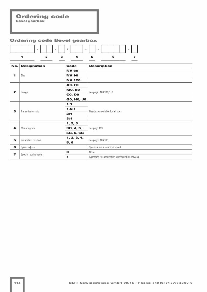
NEFF Gewindetriebe GmbH 09/15 . Phone: +49 (0) 71 57/5 38 90-0114
Ordering codeBevel gearbox
- - : - - -
1 2 3 4 5 6 7
Ordering code Bevel gearbox
No. Designation Code Description
1 Size
NV 65
NV 90
NV 120
2 Design
A0, F0
see pages 108/110/112M0, B0
C0, D0
G0, H0, J0
3 Transmission ratio
1:1
Gearboxes available for all sizes 1,5:1
2:1
3:1
4 Mounting side
1, 2, 3
see page 1133G, 4, 5,
5G, 6, 6G
5 Installation position1, 2, 3, 4,
see pages 106/1135, 6
6 Speed in [rpm] Specify maximum output speed
7 Special requirements0 None
1 According to specification, description or drawing

NEFF Gewindetriebe GmbH 09/15 . Phone: +49 (0) 71 57/5 38 90-0 115
Installationand maintenance
Installation of worm gear screw jack systems
Direction of rotationBefore starting installation work, the direction of rotation of all worm gear screw jacks, bevel gear boxes and the drive motor must be checked with regard to the feed direction of each individual worm gear screw jack.
Alignment errorsAll components must be carefully aligned during installation. Align-ment errors and stresses increase power consumption and lead to overheating and premature wear. Before a drive unit is attached, each worm gear screw jack should be turned through its entire length by hand without load. Variations in the amount of force required and/or axial marks on the outside diameter of the spindle indicate alignment errors between the worm gear screw jack and its additional guides. In this case, the relevant mounting bolts must be loosened and the worm gear screw jack turned through by hand again. If the amount of force required is now constant throughout, the appropriate components must be aligned. If not, the alignment error must be localized by loosening additional mounting bolts.
Test runThe direction of rotation of the complete system and correct operation of the limit switches must be checked again before attaching the drive motor. In the case of version N (translating screw jack), check that the spindle is lubricated with grease from the interior of the gear box and relubricate if necessary. In the case of version R (rotating screw jack), the screw jack should be coated with suitable grease to provide lubri-cation for lifting operation. The first test runs can then be carried out without load. A maximum operating time of 30 % cannot be exceeded at trial runs under weight for worm gear screw jacks with trapezoidal spindles.
OperationThe loads, speeds of rotation and operating conditions specified for the worm gear screw jacks and transmission components must not be exceeded, even briefly. Failure to observe this condition will invalidate all claims under guarantee.
Guiding values for the mounting of bearing covers
Maintenance ofworm gear screw jacks
SafetyAll mounting bolts must be retightened after a short period of operati-on. Under extreme operating conditions, the wear on the screw nut(worm gear) must be checked at shorter intervals, depending on the duty cycle, by inspecting the backlash in the thread. The screw nut (worm gear) must be replaced if the axial backlash with a single-start thread is more than one-quarter of the thread pitch.
LubricationThe worm gear screw jacks are lubricated by the manufacturer and are ready for operation on delivery.The versions N/V must be lubricated via their grease nipples with one of the greases specified below at intervals of 50 – 100 operating hours, depending on the grease seepage and in cases of high duty cycles.The spindle should be cleaned and greased at the same time. We recommend that the gearbox be cleaned to remove old grease and refilled with fresh grease after approx. 1500 operating hours or 36 months.
The worm gear screw jacks can be dismantled relatively easily:n Unscrew the two threaded pins securing the bearing cover.n Unscrew the spindle and remove the spindle protection if necessary.n Unscrew the bearing cover with the aid of a face spanner.
Proceed as follows to refit the bearing cover: fit the bearing cover firmly (using approx. ten times the force shown in the table of “Guiding values for fitting the bearing cover”). Then release it and refit it with the guiding value from the table, at the same time checking the axial backlash and smooth running.
Standard grease:Neff Grease 2
Optional greases:Castrol Spheerol BM2Mobil Mobilgrease XHPShell Retinax HD2Klüber Microlube GBO
Lubrication per screw jack
Type Filling quantity [kg]
M 0 0.03
M 1 0.06
M 2 0.14
M 3 0.24
M 4 0.8
M 5 1.1
J 1 1.5
J 2 2.0
J 3 2.0
J 4 2.7
J 5 3.2
Type Tightening Torque [Nm]
M 0 3
M 1 5
M 2 9
M 3 13
M 4 32
M 5 60
J 1 70
J 2 150
J 3 150
J 4 220
J 5 300

NEFFG E W I N D E T R I E B ENotes

NEFFG E W I N D E T R I E B E
Contact person Design
Contact person Sales
Design Screw drives
Andreas RiesPhone: +49 (0) 71 57 / 5 38 90 -19Fax: +49 (0) 71 57 / 5 38 90 -25email: [email protected]
Design Screw jacks
Serkan SinirciPhone: +49 (0) 7131 / 27177-75Fax: +49 (0) 7131 / 27177-66email: [email protected]
Design Screw jacks
Stephan SteckPhone: +49 (0) 71 57 / 5 38 90 -19Fax: +49 (0) 71 57 / 5 38 90 -25email: [email protected]
Sales Screw drives
Dieter SautterPhone: +49 (0) 71 57 / 5 38 90 -13Fax: +49 (0) 71 57 / 5 38 90 -25email: [email protected]
Sales Screw jacks
Sandro GarofanoPhone: +49 (0) 71 57 / 5 38 90 -16Fax: +49 (0) 71 57 / 5 38 90 -25email: [email protected]
Sales Manager
Stephan Hankel Phone: +49 (0) 7131 / 27177-77 Fax: +49 (0) 7131 / 27177-66 email: [email protected]
Sales Screw drives, Screw jacks
Stefanie EckhardPhone: +49 (0) 7131/ 27177-70Fax: +49 (0) 7131 / 27177-66email: [email protected]
Heilbronn
Heilbronn
Weil im Schönbuch
Weil im Schönbuch
Weil im Schönbuch Weil im Schönbuch
Heilbronn

NEFFG E W I N D E T R I E B E
Contact NEFF Gewindetriebe GmbHKarl-Benz-Str. 2471093 Weil im Schönbuch
Postbox 123071108 WaldenbuchGermany
Phone: +49 (0) 71 57/5 38 90-0Fax: +49 (0) 71 57/5 38 [email protected]