Moon/Mars Underground Mole
7
Moon/Mars Underground Mole C. R. Stoker 1 , A. Gonzales 1 , J. R. Zavaleta 1 [1] NASA Ames Research Center Moffett Field, CA 94035 USA Abstract: the Moon/Mars Underground Mole is a mechanical method of subsurface access using a compact, light-weight, low-power burrowing penetrator that uses an internal hammering mechanism to move downward by mechanical compaction of the surrounding regolith. MMUM was developed for planetary subsurface sampling and in-situ sensing applications targeted to future Mars and/or Lunar missions. This paper covers the main electromechanical and software parts of the system. I. INTRODUCTION Subsurface access systems are needed for the moon and Mars to search for water, understand the geologic history, and in the case of Mars, to look for a record of life that may be destroyed at the surface by UV light and oxidizing conditions. The Moon Mars Underground Mole (MMUM) was built with support from the Mars Instrument Development Program with the objective of building a small, low mass subsurface sampling system that would carry an in situ investigation payload. The design derived from the PLUTO (for PL anetary U nderground TO ol) mole, that was deployed on the unsuccessful “Beagle 2” lander of ESA’s 2003 Mars Express mission [1], [2]. Fig.1, MMUM external and internal view with main components indicated. TABLE I MMUM MAIN CHARACTERISTICS The Moon/Mars Underground Mole, MMUM, a pointed slender cylinder that advances into the soil by way of an internal sliding hammering mass, is prototype ground penetrometer that has resulted from the MIDP development. The energy released by a spring-loaded hammer is transferred to the mole casing with each impact and from there to the regolith, generating displacement. The mole’s current design, Fig. 1, which uses a single motor, allows it to reach depths down to 2 m (limited by tether length), collect an average of 7 grams of soil sample, and conduct RAMAN spectroscopic analysis of the subsurface mineralogy, and take soil temperature measurements. All these tasks are achieved while maintaining a very low mass and low power consumption which make the mole an attractive candidate for further development into a space flight qualified instrument. Additional surface support components include a launch tube for ground insertion, a tether, a reel to pay out and retrieve tether, and power and control electronics. The detailed description of each subcomponent follows below. Table I shows the device’s main general characteristics and, while it was built to the parameters specified, the power, mass, volume, penetration depth, instrument payload, and operating speed are all variables that can be modified in a mole designed for a particular mission application. For example, in certain applications, such as the case where the mole and its deployment station may be operating in a permanently shadowed region of the moon and Parameter Value Mass Mole (actual mass) 2000 grams Mass Deploy/Retrieve System (estimated flight mass) 5000 grams Mole Diameter 4 cm Mole Length 60 cm Peak Power Draw 10 Watts Maximum Penetration Depth 2 m Volume of sample collected 5 cm 3 Operation time to reach maximum depth 20 hours Retraction mechanism Surface winch Retraction force capability 2500 N TRL Level Mole=5, Deploy-retrieve system=4 Science Payload Raman Spectrometer, Temperature sensor Science Data Returned Soil mineralogy, organic content, soil density, porosity, compressive strength, temperature, thermal conductivity, planetary heat flow Steel nose cone Mole outer shell Raman Compartment Temperature sensor Mole Tether Internal Mechanism
-
Upload
independent -
Category
Documents
-
view
0 -
download
0
Transcript of Moon/Mars Underground Mole
Moon/Mars Underground Mole
C. R. Stoker1, A. Gonzales1, J. R. Zavaleta1 [1] NASA Ames Research Center Moffett Field, CA 94035 USA
Abstract: the Moon/Mars Underground Mole is a
mechanical method of subsurface access using a compact, light-weight, low-power burrowing penetrator that uses an internal hammering mechanism to move downward by mechanical compaction of the surrounding regolith. MMUM was developed for planetary subsurface sampling and in-situ sensing applications targeted to future Mars and/or Lunar missions. This paper covers the main electromechanical and software parts of the system.
I. INTRODUCTION
Subsurface access systems are needed for the moon and Mars to search for water, understand the geologic history, and in the case of Mars, to look for a record of life that may be destroyed at the surface by UV light and oxidizing conditions. The Moon Mars Underground Mole (MMUM) was built with support from the Mars Instrument Development Program with the objective of building a small, low mass subsurface sampling system that would carry an in situ investigation payload. The design derived from the PLUTO (for PLanetary Underground TOol) mole, that was deployed on the unsuccessful “Beagle 2” lander of ESA’s 2003 Mars Express mission [1], [2].
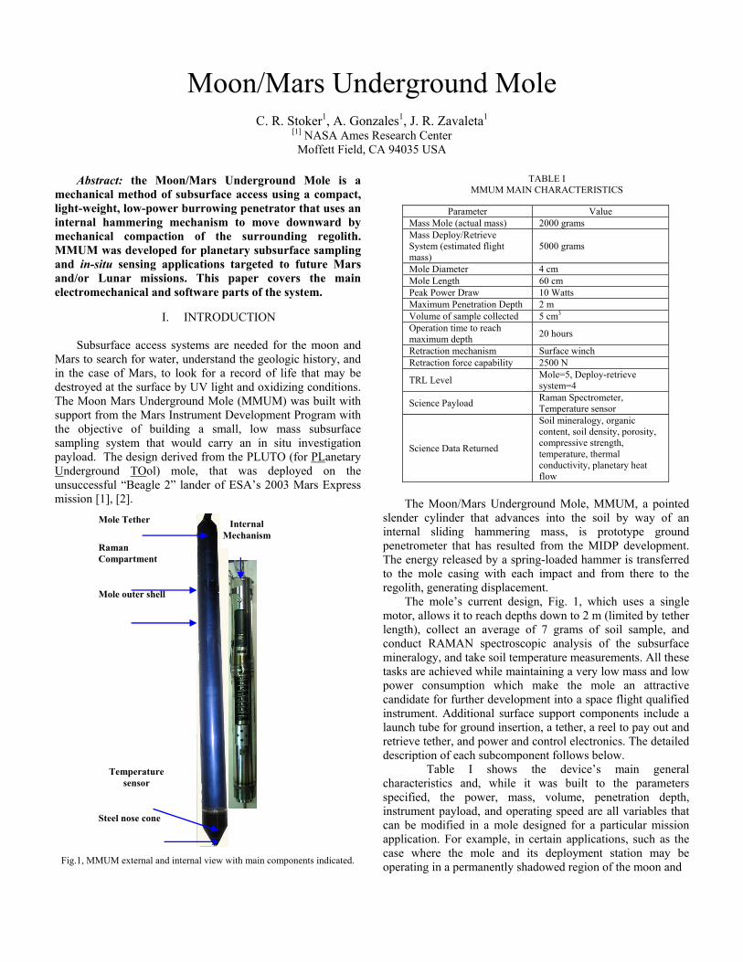
Fig.1, MMUM external and internal view with main components indicated.
TABLE I MMUM MAIN CHARACTERISTICS
The Moon/Mars Underground Mole, MMUM, a pointed
slender cylinder that advances into the soil by way of an internal sliding hammering mass, is prototype ground penetrometer that has resulted from the MIDP development. The energy released by a spring-loaded hammer is transferred to the mole casing with each impact and from there to the regolith, generating displacement.
The mole’s current design, Fig. 1, which uses a single motor, allows it to reach depths down to 2 m (limited by tether length), collect an average of 7 grams of soil sample, and conduct RAMAN spectroscopic analysis of the subsurface mineralogy, and take soil temperature measurements. All these tasks are achieved while maintaining a very low mass and low power consumption which make the mole an attractive candidate for further development into a space flight qualified instrument. Additional surface support components include a launch tube for ground insertion, a tether, a reel to pay out and retrieve tether, and power and control electronics. The detailed description of each subcomponent follows below.
Table I shows the device’s main general characteristics and, while it was built to the parameters specified, the power, mass, volume, penetration depth, instrument payload, and operating speed are all variables that can be modified in a mole designed for a particular mission application. For example, in certain applications, such as the case where the mole and its deployment station may be operating in a permanently shadowed region of the moon and
Parameter Value Mass Mole (actual mass) 2000 grams Mass Deploy/Retrieve System (estimated flight mass)
5000 grams
Mole Diameter 4 cm Mole Length 60 cm Peak Power Draw 10 Watts Maximum Penetration Depth 2 m Volume of sample collected 5 cm3 Operation time to reach maximum depth 20 hours
Retraction mechanism Surface winch Retraction force capability 2500 N
TRL Level Mole=5, Deploy-retrieve system=4
Science Payload Raman Spectrometer, Temperature sensor
Science Data Returned
Soil mineralogy, organic content, soil density, porosity, compressive strength, temperature, thermal conductivity, planetary heat flow
Steel nose cone
Mole outer shell
Raman Compartment
Temperature sensor
Mole Tether Internal Mechanism

Fig. 2. Close-up view of the MMUM hammering mechanism.
solar power is not available, higher speed or reduced system mass may be necessary to minimize resource requirements, and other payload elements such as a water sensor may be desirable.
MMUM can be repeatedly deployed and retrieved from a fixed lander or mobile rover and it has much lower mass than a drill of comparable depth capability and so can become a single payload element on a rover. Also, the MMUM has an inherent advantage over drills for rover-mounted subsurface access applications because once the mole penetrating component is underground there are no surface reaction forces. On our design, deployment and retrieval forces are reacted only on the support system and not on the body of the platform that carries the mole. The following section describes the individual components of the MMUM.
II. SYSTEM DESCRIPTION
A. Mole Hammering Mechanism
The mole hammering mechanism, Fig. 2, consists of a stainless steel housing structure, an encoded motor/gearhead system, a compression spring connecting the motor gearhead to a striking mass, and a recoil absorption spring. The hammering mechanism operates by the motor and gearhead system turning a shaft that drives the spring and compresses it as the mechanism follows a guide path to the release point. Upon reaching the release point –a mechanical feature in the trajectory of the hammer mass travel- the striking mass, is released by the compressed force of the spring. This cycle repeats every few gearhead shaft turns and produces a downward impact force of over 63 N at a rate of about 12 impacts per minute.
B. Sample Collection Mechanism
Fig.3, Sample collection mechanism shown in both, Open and Closed
configurations.
The sample collection mechanism collects a subsurface soil sample but the amount varies depending on the type of the soil, its consistency, and other physical characteristics. Repeated tests in dry 30 grit sand collected 7 gm on average, but this depends on the volume of the sample collection chamber. The sample collection mechanism is operated by the same motor as the hammering mechanism and it is located on the tip end of the mole. For sample collection, however, the motor is operated in reverse mode activating a ball lock mechanism that turns the front-tip guide screw open pulling the nose cone open. The opening mechanism consists of a mechanical configuration that opens the sample compartment exposing the collection chamber. Normally, while in forward penetration mode, the front tip is held closed by a tension spring. When the mole is in sample collection mode, the screw located in the front forces the spring open exposing the collection chamber. While in this configuration, forward hammering drives the mole downward and sample gets shoved into the collection chamber. The collected sample is now trapped in the collection chamber. After a few hammering operations cycles, the mechanism is closed by the screw releasing the additional tension force on the spring and closing it. Once the operation is complete the mole is retrieved to the surface and the sample extracted from the collection chamber, Fig. 3. At this point the sample retrieval is executed by opening the sample collection chamber and discharging the sample. C. RAMAN Spectrometer
A RAMAN spectrometer is integrated into the MMUM comprised of subsurface elements and surface elements. The subsurface elements are the illumination and collection fiber optics which run through the tether and end at the RAMAN optical head located inside the mole system itself, Fig. 4. The laser illumination source, grating spectrometer, and the RAMAN control electronics are located on the surface. The illumination is via a 300 mW Laser diode operating at 785 nm. The detector is a vacuum sealed CCD array (1024 x 128 pixels) TE cooled to operate at -25 C, provides 4 cm-1 spectral resolution from 250 to 1800 cm-1 operating range. The
Fig.4. Left: Raman compartment shown. Right: FC Connectors for excitation and collection fibers.
Hammering mass
Motor & Gearhead mechanism

TABLE II FIBER CHARACTERISTICS
RAMAN spectrometer control and data acquisition take place via 802.11-g wireless bridge to a remote laptop controller running a Windows interface and spectrum library software.
The RAMAN optical head interfaces mechanically to the Moon/Mars Underground Mole by means of an impact and shock-isolated mounting clamp which attaches it to a dedicated section of the mole cylinder located on the upper end of the above the hammering mechanism. This section of the mole is made out of a cylindrical sapphire window of the same diameter as the mole. Two fibers are incorporated into the tether to enable operation of the spectrometer. One fiber is for illumination and the other for the return signal. These fiber optics interface to the optical head inside the mole as well as with the RAMAN spectrometer module via standard FC type fiber optic connectors, 2 on each end. The optical fibers are color coded to ensure proper direction of the illumination and signal light. The optical sampling volume is defined by the focusing optic within the RAMAN spectrometer optical head that is adjusted to place the optical sampling interface 1 mm outside this sapphire window surface. The diode laser illumination and spectrometer modules are contained in a field case. The case is 23cm x 40.6cm x 20cm and it is not intended to be mounted as an integral part of a rover/lander configuration but rather as a proof of concept. The system draws 2.8 Amps during startup and less than 2 Amps for steady operation from a 12 V DC power supply. The data interface is provided by an 802.11g wireless LAN interfacing to the spectrometer data system via an Ethernet cable with RJ-45 connectors.
Table II lists the general specifications for the fiber. The fiber is made of silica clad materials, polymer buffer, and 0.22 NA. These fibers are jacketed in standard communications-grade 2 mm 2mm polymer jacketing, Kevlar strength fibersfor strain relief at the connectors. D. Mole Sensors
The Mars Underground Mole carries an analog soil temperature sensor (Figure 8) to determine subsurface soil temperature. The sensor is a precision temperature sensor (Digi-Key PN: LM135H-ND) and it is located on the lower end of the mole near the nose cone. It provides constant feedback on subsurface soil temperature with an accuracy of 1oC and a range of -55oC to 150oC.
Fig.5. Mole tether internal components. Visible are: outer rubber shield, Kevlar sleeve, ultra flexible stainless steel conduit, fiber optic cables, power
and signal wires, and Kevlar strength member. E. Mole Tether
The mole tether meets many criteria imposed by the unique nature of the mole power and data requirements. The main requirements are protection and accommodation for the standard power and data transmission lines for motor, gearhead, and sensors as well as the RAMAN spectrometer fiber optic cables. The tether wires and fibers are encased within a stainless steel conduit (Stainless steel Type 304, McMaster-Carr PN: 54915K44) that prevents the fibers from exceeding their breaking bend radius and allows wires and fibers to float freely without strain. A braided Kevlar sleeve (Tuff Temp, PN: 77-464) covers the conduit. The Kevlar sleeve is pre-stretched and designed to take loads upward of 150 Kg during the mole retrieval process.
The stainless steel conduit, together with the fibers and wires that it contains, moves freely with respect to the Kevlar; in other words when a load is applied to the tether it is carried by the pre-stretched Kevlar sleeve. The mole tether meets the strenuous environmental and operational demands that the system will face in laboratory and field testing. An internal Kevlar line works as a strength member to prevent the wires from moving internally as the reel winds/unwinds and putting stress on the fibers while providing stress load relief to the fiber optic cables connected to the RAMAN spectrometer optical head. The outside of the tether is covered with a Mil-Spec latex rubber heat shrink tubing which provides the primary protection against abrasion, dirt, water, and humidity. Fig. 5 shows a view of the mole tether and all its internal components.
The Kevlar tether and reel can support retrieval forces up to 2500 N. The tether reel diameter of 21.6 cm requires only 3 turns to reel in 2 m of tether, and avoids the use of slip rings. MMUM incorporates a Raman spectrometer as an instrument payload. Light illumination and collection optics are carried subsurface in a shock mounted subsurface chamber fitted with a Sapphire window. Fiber optics located in the tether transmit light from a surface-mounted laser to illuminate the soil and light collected from the resulting stimulated emission is transmit back to the surface where Raman spectra are obtained. MMUM can be repeatedly deployed and retrieved from a fixed lander or mobile rover. F. Tether Reel System
The tether reel system is designed to retrieve the mole from its underground condition assisted by forward hammering to reduce friction during extraction. The mechanical components that make up the system include the motor powering the reel, a Maxon-Motor RE25 -same as the
Fiber function Core
diameter (μm)
Clad diameter (μm)
Stock illumination 100 120
Stock signal 200 220
Replacement illumination 105 125
Replacement signal 200 240
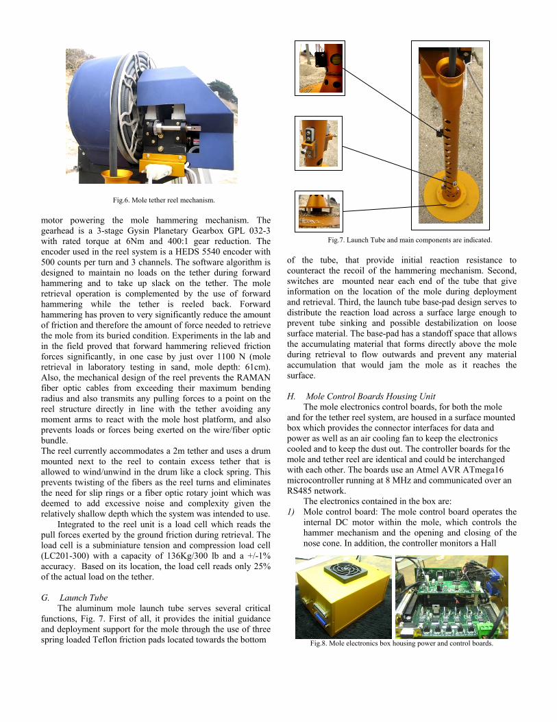
Fig.6. Mole tether reel mechanism. motor powering the mole hammering mechanism. The gearhead is a 3-stage Gysin Planetary Gearbox GPL 032-3 with rated torque at 6Nm and 400:1 gear reduction. The encoder used in the reel system is a HEDS 5540 encoder with 500 counts per turn and 3 channels. The software algorithm is designed to maintain no loads on the tether during forward hammering and to take up slack on the tether. The mole retrieval operation is complemented by the use of forward hammering while the tether is reeled back. Forward hammering has proven to very significantly reduce the amount of friction and therefore the amount of force needed to retrieve the mole from its buried condition. Experiments in the lab and in the field proved that forward hammering relieved friction forces significantly, in one case by just over 1100 N (mole retrieval in laboratory testing in sand, mole depth: 61cm). Also, the mechanical design of the reel prevents the RAMAN fiber optic cables from exceeding their maximum bending radius and also transmits any pulling forces to a point on the reel structure directly in line with the tether avoiding any moment arms to react with the mole host platform, and also prevents loads or forces being exerted on the wire/fiber optic bundle. The reel currently accommodates a 2m tether and uses a drum mounted next to the reel to contain excess tether that is allowed to wind/unwind in the drum like a clock spring. This prevents twisting of the fibers as the reel turns and eliminates the need for slip rings or a fiber optic rotary joint which was deemed to add excessive noise and complexity given the relatively shallow depth which the system was intended to use.
Integrated to the reel unit is a load cell which reads the pull forces exerted by the ground friction during retrieval. The load cell is a subminiature tension and compression load cell (LC201-300) with a capacity of 136Kg/300 lb and a +/-1% accuracy. Based on its location, the load cell reads only 25% of the actual load on the tether. G. Launch Tube
The aluminum mole launch tube serves several critical functions, Fig. 7. First of all, it provides the initial guidance and deployment support for the mole through the use of three spring loaded Teflon friction pads located towards the bottom
Fig.7. Launch Tube and main components are indicated.
of the tube, that provide initial reaction resistance to counteract the recoil of the hammering mechanism. Second, switches are mounted near each end of the tube that give information on the location of the mole during deployment and retrieval. Third, the launch tube base-pad design serves to distribute the reaction load across a surface large enough to prevent tube sinking and possible destabilization on loose surface material. The base-pad has a standoff space that allows the accumulating material that forms directly above the mole during retrieval to flow outwards and prevent any material accumulation that would jam the mole as it reaches the surface. H. Mole Control Boards Housing Unit
The mole electronics control boards, for both the mole and for the tether reel system, are housed in a surface mounted box which provides the connector interfaces for data and power as well as an air cooling fan to keep the electronics cooled and to keep the dust out. The controller boards for the mole and tether reel are identical and could be interchanged with each other. The boards use an Atmel AVR ATmega16 microcontroller running at 8 MHz and communicated over an RS485 network.
The electronics contained in the box are: 1) Mole control board: The mole control board operates the
internal DC motor within the mole, which controls the hammer mechanism and the opening and closing of the nose cone. In addition, the controller monitors a Hall
Fig.8. Mole electronics box housing power and control boards.

RS485
ADC
Timer
Tasks
Kernel
Effect sensor mounted on the hammer that verifies the hammer is functioning, and temperature sensors to measure the soil and H-bridge temperatures. The board regulates power and handles all the mole command functions including control and data collection.
2) The tether reel controller board: also referred to as the surface controller, handles the motor and encoder controls for the tether reel system including tether payout and retrieval, mole position sensors, and load-cell readings. The controller also monitors the upper and lower micro switches in the launch tube and the load cell.
3) Auxiliary board: Handles primary power distribution to the surface and subsurface boards.
4) Connectors: There are two DB-25 connectors: one for the surface board and one for the subsurface board; one DB-9 connector for power distribution, and one RS232 to RS245 adapter for computer to control box communications. Fig. 8 shows the Moon/Mars underground Mole
electronics box and its internal boards I. Mole/K-10 Mechanical Interface
The Mars Underground Mole has been successfully tested as a fully integral part of the K-10 rover’s scientific payload. During the field test the mole ran completely on power and controls handled by the rover, it was driven around over hills, slopes, and rocks and then executed a ground penetration sequence, a sample retrieval operation and finally a mole retrieval sequence. Even though the transition from the transport mode to the operational mode and vice versa is manual, the rest of the operations are fully autonomous; more importantly, the mole-rover field test shows the feasibility of the mole as part of a rover suite of instruments due to its size, power requirements, and ease of interconnection or adaptation to different types of mobility systems.
Fig.9. Mole mounted on K-10 rover. Left: MMUM on travel configuration. Right: MMUM on operational mode.
III. MMUM SOFTWARE DESCRIPTION
A. Mole Firmware
The firmware was programmed with CodeVisionAVR from HP InfoTech using the C programming language and some Assembly language. The Assembly was used to speedup Code-Vision AVR’s integer to ASCII conversion routines because on the 8-bit AVR microcontroller, there is no math coprocessor that can use a single instruction to calculate the quotient and remainder of a binary number; instead, a division function was called each time a quotient and remainder was needed. This resulted in calling the division function twice. By writing the code in Assembly, the division function could be called once and the quotient and remainder could be taken together at the same time. The C compiler could only compile the code to take one or the other but not both. The Assembly code sped up the integer to ASCII conversion routines as little as 3 to as much as 24 times.
The same code ran on both the mole and surface controller board, which used 4052 bytes of FLASH, 198 bytes of RAM, and 6 bytes of EEPROM. A jumper on each board identified the board as either a mole or surface board and was read by the microcontroller so it could execute code specific to that board. B. Operating System
The AVR microcontrollers did not use a commercial off-the-shelf real-time operating system (RTOS). The RTOS was developed in-house. It uses an event-driven scheduler, which was chosen over time slicing and preemptive because it has a faster response, is significantly easier to debug and scores highest on the reliability issues.
The scheduler handled analog to digital conversions (ADC), timer, RS485 communication, and task events.
The analog to digital conversion event took care of reading the soil temperature on the mole board and the load cell on the surface board.
The timer event maintained time at 0.1-second intervals. At each interval the H-Bridge temperature was taken and a LED flashed, signifying a heartbeat. At 10-second intervals the motor encoder positions, which are used in determining the number of hammer strokes and the mole depth, were saved to EEPROM in case of power failure. The next time the microcontrollers started up they could continue where they left off. The RS485 communication event processed commands being sent from the host computer at 9600 Baud. All commands and replies were in text. This made it easy to test and debug using a serial terminal program without needing to build a special application to talk to the controllers. Fig. 10 shows the diagram of an event-driven operating system.
Fig.10. Event-Driven Operating System

C. Subsurface Controller Task The subsurface controller was responsible for feeding and
reeling out the tether line for the mole. The motor fed out the tether for 30 seconds, which was about 3.5 millimeters, and then the slack was taken in by setting a constant voltage on the motor so that it would stall when there was more than about 6 pounds of tension on the tether. The stall was detected by the motor’s encoder counts not changing, at which point an accurate depth could be measured.
During the reverse hammer task, the subsurface controller reeled in the tether by applying power to the motor until it reached its max continuous operation of 3.0 Amps. The controller would continue reeling in the tether until the mole was fully in the launch tube.
D. Graphical User Interface
Two graphical user interfaces (GUIs) where developed: one on Linux that talked to the controllers through a piece of software on the K-10 using the CORBA interface and the other on Windows, depicted in Fig. 11, that talked to the controllers directly through the PC’s serial port attached to the controllers.
The GUIs had buttons for the basic tasks: forward hammer, reverse hammer, and collect sample. They also had a “Stop” button to halt the task and any motor that was running.
A “send command” button was also implemented to send low-level commands to adjust parameters, such as tether feed rate, on the controllers. Both GUIs displayed the status of the controllers and could convert the units from English to Metric and vice-versa
Fig.11. Mole Graphical user Interface display. .
Fig.12. Plots of MMUM penetration performance in dry-sand. E. Data Collection and Processing for Analysis Description: All sensor values that were collected by the microcontrollers were transmitted to the host computer in raw units to save processing time in converting them to engineering units (i.e. Newton, millimeter, etc.). Converting the raw units to engineering was the job for the host computer, which had plenty of speed to do so. Data was collected from the controllers at 10 Hz and was saved to a comma-separated values (CSV) file at 1 Hz. Saving to a CSV file allowed opening the file with Microsoft’s Excel, where the data could be analyzed and plotted. Another advantage to using a CSV file was that it was a flat database and Microsoft’s Open Database Connectivity (ODBC) driver for CSV files could be used. This allowed Excel to query the file, as it was being written to; in one-minute intervals to plot the data live.
IV. MMUM TEST PROGRAM
The MMUM is undergoing system tests in the laboratory and in the field to characterize its performance. While this test program is still underway, it is allowing us to understand performance issues and problems, and institute improvements as necessary.
Fig.13. MMUM Field test setup.
Mission Time
Dep
th, (
mm
)

Fig.14. Plot of MMUM
Results of the tests show that the Mole is capable of good penetration performance in soil. In the laboratory, the mole has been pounded into a 0.8 m diameter and 1.5 m deep barrel containing 30 grit silica dry-sand. This represents a cohesionless material. Fig. 12 shows an example of Mole penetration performance in dry sand.
A full system test of the MMUM was performed in moist beach sand. This material was chosen as an analog of Lunar regolith.
The measured soil density was 1.7 g cm2 and the measured compressive strength of the material was 15 KPascals. The MMUM operated autonomously for 8 hours of continuous operations without problems. During the last hour of the penetration, the rate of penetration slowed. The test was ended and a pit dug, revealing a large stone just below the final depth achieved. Fig. 13 shows the test setup. Fig. 14 shows a plot of penetration during the test.
V. CONCLUSIONS
The MMUM has been developed and tested to show that a low mass system is capable of obtaining geotechnical properties, samples, and compositional information. System tests of MUM have brought the TRL of this system to 5 to 6. An instrument based on MMUM is an attractive candidate for flight and is ready to be brought to the next level of development for flight.
VI. REFERENCES
[1] Coste, P., L. Richter, H. Kochan, V. Gromov, 2001. "Sampling Mole" Development and Application on the Beagle 2 Mars Lander. XXVI General Assembly of the European Geophysical Soc., Nice, France, March 20-25.
[2] Richter, L., P. Coste, V.V. Gromov, H. Kochan, S. Pinna, H.-E. Richter, 2001. Development of the "Planetary Underground Tool" Subsurface Soil Sampler for the Mars Express "Beagle 2" Lander. Adv. Space Res. 28[8], pp. 1,225-1,230.
0
100
200
300
400
500
0:00:00 1:12:00 2:24:00 3:36:00 4:48:00 6:00:00 7:12:00
Mission Time
Dep
th, (
mm
)