THE CONTAINMENT OF UNDERGROUND NUCLEAR ...
97
I MARSHALL ISLANDS FILE TRACKING DOCUMENT Record Number: 35 2 File Name (TITLE): Document Number (ID): Previous Location (FROM): C7K AUTHOR: Addditional Information: OrMIbox: CyMIbox:
-
Upload
khangminh22 -
Category
Documents
-
view
2 -
download
0
Transcript of THE CONTAINMENT OF UNDERGROUND NUCLEAR ...

I
MARSHALL ISLANDS FILE TRACKING DOCUMENT
Record Number: 35 2
File Name (TITLE):
Document Number (ID):
Previous Location (FROM): C7K
AUTHOR:
Addditional Information:
OrMIbox:
CyMIbox:


Office of Technology Assessment
Congressional Board of the 10lst Congress
EDWARD M. KENNEDY, Massachusetts, Chairman
CLARENCE E. MILLER, Ohio, Vice Chairman
Senate
ERNEST F. HOLLINGS South Carolina
CLAIBORNE PELL Rhode Island
TED STEVENS Alaska
ORRIN G. HATCH Utah
CHARLES E. GRASSLEY Iowa
DAVID S. POTTER, Chairman General Motors Corp. (Ret.)
CHASE N. PETERSON, Vice Chairman
University of Utah
CHARLES A. BOWSHER General Accounting Ofice
MICHEL T. HALBOUTY .Michel T. Halbouty Energy Co.
JOHN H. GIBBONS (Nonvoting)
Advisory Council
NEIL E. HARL Iowa State University
JAMES C. HUNT University of Tennessee
HENRY KOFFLER University of Arizona
JOSHUALEDERBERG Rockefeller University
Director
JOHN H. GIBBONS
House
MORRIS K. UDALL Arizona
GEORGE E. BROWN, JR California
JOHN D. DINGELL Michigan
DON SUNDQUIST Tennessee
AM0 HOUGHTON ,Irew York
WILLIAM J. PERRY H&Q Technology Partners
SALLY RIDE California Space tnstitute
JOSEPH E. ROSS Congressional Research Servtce
JOHN F..M. SIMS Usibelli Coal ,Liine, Inc.
The Technology Assessment Board approves the release of this report. The views expressed in this report are not necessarily those of the Board, OTA Advisory Council, or individual members thereof.

The Containment of UNDERGROUND NUCLEAR EXPLOSIONS
CONGRESS OF THE UNITED STATES OFFICE OF TECHNOLOGY ASSESSMENT

Recommended Citation:
U.S. Congress, Office of Technology Assessment, The Containment of Underground Nuclear Explosions, OTA-EC-414 (Washington, DC: U.S. Government Printing Office. October
1989).
Library of Congress Catalog Card Number 89-600707
For sale by the Superintendent of Documents U.S. Government Printing Office, Washington, DC 20402-9325
(order form can be found in the back of this report)

Workshop 1: Containment Monday, Sept. 26,1988
Environmental Research Center University of Nevada, Las Vegas
Neville G. Cook, Chair
Department of Material Science and Mineral Engineering University of California
Frederick N. App Section Leader Containment Geophysics Los Alamos National Laboratory
Norman R. Burkhard Containment Program bader Lawrence Livermore National Laboratory
Jim Carothers Chairman Containment Evaluation Panel Lawrence Livermore National Laboratory
Jack Evemden Lawrence Livermore National Laboratory U.S. Geological Survey
Robert A. Fulkerson Executive Director Citizen Alert
Jack W. House Containment Program Manager Los Alamos National Laboratory
Billy C. Hudson Deputy Containment Program Leader Lawrence Liver-more National Laboratory
Evan Jenkins U.S. Geological Survey
Joseph LaComb Chief Nevada Operations Office Defense Nuclear Agency
James K. Magruder Assistant Manager for Operations and Engineering Nevada Operations Office U.S. Department of Energy
Paul Orkild U.S. Geological Survey
Edward W. Peterson Containment Project Director S-CUBED
John Stewart Director Test Operations Division Nevada Operations Office U.S. Department of Energy
,
iV

Foreword
Within weeks after the ending of World War II, plans for the first nuclear test series “Operation Crossroads” were underway. The purpose then, as now, was to develop new weapon systems and to study the effects of nuclear explosions on military equipment. The development of the nuclear testing program has been paralled by public opposition from both an arms control and an environmental perspective. Much of the criticism is due to the symbolic nature of testing nuclear weapons and from the radiation hazards associated with the early practice of testing in the atmosphere. Recently, however, specific concerns have also been raised about the current underground testing program; namely:
l Are testing practices safe? l Could an accidental release of radioactive material escape undetected? l Is the public being fully informed of all the dangers emanating from the nuclear testing
program?
These concerns are fueled in part by the secrecy that surrounds the testing program and by
publicized problems at nuclear weapons production facilities.
At the request of the House Committee on Interior and Insular Affairs and Senator Omn G. Hatch, OTA undertook an assessment of the containment and monitoring practices of the nuclear testing program. This special report reviews the safety of the nuclear testing program and assesses the technical procedures used to test nuclear weapons and ensure that radioacuve material produced by test explosions remains contained underground. An overall evaluation considers the acceptability of the remaining risk and discusses reasons for the lack oi public confidence.
In the course of this assessment, OTA drew on the experience of many organizations and individuals. We appreciate the assistance of the U.S. Government agencies and pnvate companies who contributed valuable information, the workshop participants who provided guidance and review, and the many additional reviewers who helped ensure the accuracy and objectivity of this report.
JOHN H. GIBBONS

OTA Project Staff-The Containment of Underground Nuclear Explosions
Lionel S. Johns, Assistant Director, OTA Energy, Materials, and International Security Division
Peter Shadman, International Security and Commerce Program Manager*
Alan Shaw, International Security and Commerce Program Manager**
Gregory E. van der Vink, Project Director
Administrative Staff
Jannie Home (through November 1988)
Marie C. Parker (through April 1989)
Jackie Robinson
Louise Staley
Through February 1989.
‘Tram March 1989.
Vi

Workshop 2: Monitoring Tuesday, Sept. 27,1988
Environmental Research Center University of Nevada, Las Vegas
Melvin W. Carter, Chair Neely Professor Emeritus
Georgia Institute of Technology
Lynn R. Anspaugh Division tiader Environmental Sciences Division Lawrence Livermore National Laboratory
Bruce Church
Bemd Franke IFEU
Robert A. Fulkerson Executive Director Citizen Alert
Assistant Manager for Environmental Safety and Health
Nevada Operations Office U.S. Department of Energy
Charles F. Costa Director Nuclear Radiation Assessment Division United States Environmental Protection Agency
Donald R. Elle Chief, Technical Projects Branch Health Physics and Environmental Division Nevada Operations Office U.S. Department of Energy
Michael A. Marelli Chief, Health Protection Branch Health Physics and Environmental Division Nevada Operations Office U.S. Department of Energy
Darryl Randerson Weather Service Nuclear Office

Workshop 2: Monitoring fiesday, Sept. 27,1988
Environmental Research Center University of Nevada, Las Vegas
Melvin W. Carter, Chair Neely Professor Emeritus
Georgia Institute of Technology
Lynn R. Anspaugh Division tiader Environmental Sciences Division Lawrence Livermore National Laboratory
Bruce Church Assistant Manager for Environmental Safety and
Health Nevada Operations Office U.S. Department of Energy
Charles F. Costa Director Nuclear Radiation Assessment Division United States Environmental Protection Agency
Donald R. Elle Chief, Technical Projects Branch Health Physics and Environmental Division Nevada Operations Office U.S. Department of Energy
Bemd Franke IFEU
Robert A. Fulkerson Executive Director Citizen Alert
Michael A. Marelli Chief, Health Protection Branch Health Physics and Environmental Divi\~on Nevada Operations Office U.S. Department of Energy
Darryl Randerson Weather Service Nuclear Office
Y

Workshop 2: Monitoring lbesday, Sept. 27,1988
Environmental Research Center University of Nevada, Las Vegas
Melvin W. Carter, Chair Neely Professor Emeritus
Georgia Institute of Technology
Lynn R. Anspaugh Division Leader
Bemd Franke IFEU
Environmental Sciences Division Lawrence Livermore National Laboratory
Bruce Church Assistant Manager for Environmental Safety and
Health Nevada Operations Office U.S. Department of Energy
Charles F. Costa Director Nuclear Radiation Assessment Division United States Environmental Protection Agency
Donald R. Elle Chief, Technical Projects Branch Health Physics and Environmental Division Nevada Operations Office U.S. Department of Energy
Robert A. Fulkerson Executive Director Citizen Alert
Michael A. Marelli Chief, Health Protection Branch Health Physics and Environmental Division Nevada Operations Office U.S. Depamnent of Energy
Darryl Randerson Weather Service Nuclear Office

Contents
Page
Chapter 1. Executive Summary .......................................................... 3
Chapter 2. The Nuclear Testing Program. ................................................ 11
Chapter 3. Containing Underground Nuclear Explosions .................................... 31
Chapter 4. Monitoring Accidental Radiation Releases ...................................... 59

Acknowledgments
OTA gratefully acknowledges the valuable contributions made by the following:
Lynn R. Anspaugh Lawrence Livetmore National Laboratory
Frederick N. App Los Alamos National Laboratory
Nick Aquilina U.S. Department of Energy
Charles Archambeau CIRES, University of Colorado, Boulder
Stuart C. Black U.S. Environmental Protection Agency
Carter Broyles Sandia National Laboratory
Norman R. B&hard Lawrence Livermore National Laboratory
John H. Campbell U.S. Department of Energy
Jim Carothers Lawrence Livermore National Laboratory
Melvin W. Carter International Radiation Protection Consultant
Bruce Church U.S. Department of Energy
Neville G. Cook University of California, Berkeley
Charles F. Costa U.S. Environmental Protection Agency
Jeff Duncan Office of Congressman Edward J. Markey
Donald R. Elle U.S. Department of Energy
Gerald L. Epstein John F. Kennedy School of Government, Harvard University
Jack Evemden U.S. Geological Survey
Anthony Fainberg office of Technology Assessment, U.S. Congress
Pete Fitzsimmons U.S. Department of Energy
Janet Fogg U.S. Depattment of Energy
Bemd Franke IFEU
Robert A. Fulkerson Citizen Alert
Lany Gabriel Defense Nuclear Agency
David Graham Moore College of Art
Jack W. House Los Alamos National Laboratory
Billy C. Hudson Lawrence Livermore National Laboratory
Evan Jenkins U.S. Geological Survey
Gerald W. Johnson University of California
Joseph W. LaComb Defense Nuclear Agency
James K. Magruder U.S. Department of Energy
Michael A. Marelli U.S. Department of Energy
LTC Samuel D. McKinney Defense Nuclear Agency
David N. McNelis University of Las Vegas, Nevada
Paul Orkild Lawrence Livermore National Laboraton
Edward W. Peterson S-CUBED
Dorothy F. Pope Defense Nuclear Agency
Darryl Randerson Weather Service, Nuclear Office
Karen Randolph U.S. Department of Energy
R.L. Rhodes Diebold. Inc.
Patrick Rowe REECo
Robert Shirkey Defense Nuclear Agency
John 0. Stewart U.S. Department of Energy
Robert Titus Weather Service, Nuclear Office
Dean R. Townsend Fenix & Scission, Inc.
Chris L. West U.S. Department of Energy
Barbara Yoers U.S. Department of Energy
NOTE: OTA appreciates and is grateful for the valuable assistance and thoughtful critiques provided by the conmhu!ors The contributors do not, however, necessarily approve, disapprove, or endorse this report. OTA assumes full responsiblil? :or rhe report and the accuracy of its contents. VII

.

-__. _ r
T&l& Twe Page I-f. Rekasfs pnnn ehwiffgrwndmts. . . . . . . . . . . . . . . . . . . . . . . . . . . . . . * . . . . . * . . . . . . . . . 4

Chapter 1
Executive Summary
The chances of an accidental release of radioactive material have been made as remote as possible. Public concerns about safety arefueled by concerns about the testing program in general and
exacerbated by the government’s policy of not announcing all tests.
INTRODUCTION
During a nuclear explosion, billions of atoms release their energy within a millionth of a second, pressures reach several million pounds per square inch, and temperatures are as high as one-million degrees centigrade. A variety of radioactive elements are produced depending on the design of the explosive device and the contribution of fission and fusion to the explo- sion. The half-lives of the elements produced range from less than a second to more than a million years.
Each year over a dozen nuclear weapons are detonated underground at the Nevada Test Site.’ The tests are used to develop new nuclear weapons and to assess the effects of nuclear explosions on military systems and other hard- ware. Each test is designed to prevent the release of radioactive material. The objective of each test is to obtain the desired experimental infor- mation and yet successfully contain the explo- sion underground (i.e., prevent radioactive ma- terial from reaching the atmosphere).
HOW SAFE IS SAFE ENOUGH?
Deciding whether the testing program is safe requires a judgment of how safe is safe enough. The subjective nature of this judgment is illustrated through the decision-making process of the Containment Evaluation Panel (CEP) which reviews and assesses the containment of each test.* The panel evaluates the probability of containment using the terms “high confidence,” ‘ ‘adequate degree of confidence,” and “some
doubt.” But the Containment Evaluation Panel has no guidelines that attempt to quantify or describe in probabilistic terms what constitutes for example, an “adequate degree of confi- dence.” Obviously, there can never be 100 percent confidence that a test will not release radioactive material. Whether “adequate confi- dence” translates into a chance of 1 in 100, 1 in 1,000, or 1 in 1,000,000, requires a decision about what is an acceptable level of risk. In turn, decisions of acceptable level of risk can only be made by weighing the costs of an unintentional release against the benefits of testing. Conse- quently, those who feel that testing is important for our national security will accept greater risk. and those who oppose nuclear testing will find even small risks unacceptable.
Establishing an acceptable level of risk is difficult, not only because of the value judg- ments associated with nuclear testing, but also because the risk is not seen as voluntary by those outside the testing program. A public that readily accepts the risks associated with volun- tary activities-such as sky diving or smoking- may still consider the much lower risks associ- ated with nuclear testing unacceptable.
HOW SAFE HAS IT BEEN?
Some insight into the safety of the nuclear testing program can be obtained by reviewing the containment record. Releases of radioactive material are categorized with terms that describe both the volume of material released and the conditions of the release:
1Currcntly. all U.S. nuclear test explostons are conducted at the Nevada Rst Site.
*The Containment Evaluation Panel is a group of representatives from various laboratories and technical consulting orgamLatlons who evaluate the proposed containment plan for each test without regard to cost or other outs& cottstderations (see ch. 2 for a complete discusslon~.

4 l Containment of Underwound Nuclear Emlosions
Containment Failures: Containment fail- ures are unintentional releases of radioactive material to the atmosphere due to a failure of the containment system. They are termed “vent- ings,” if they are prompt, massive releases; or “seeps,” if they are slow, small releases that occur soon after the test.
Lute-Time Seeps: Late-time seeps are small releases that occur days or weeks after a test when gases diffuse through pore spaces of the overlying rock and are drawn to the surface by decreases in atmospheric pressure.
Controlled Tunnel Purging: A controlled tunnel purging is an intentional release to allow either recovery of experimental data and equip- ment or reuse of part of the tunnel system.
Operational Release: Operational releases are small, consequential releases that occur when core or gas samples are collected, or when the drill-back hole is sealed.
The containment record can be presented in different ways depending on which categories of releases are included. Reports of total num- bers of releases are often incomplete because they include only announced tests or releases due to containment failure. The upper portion of table l-l includes every instance (for both announced and unannounced tests) where radio- active material has reached the atmosphere under any circumstances whatsoever since the 1970 Baneberry test.
Since 1970, 126 tests have resulted in radio- active material reaching the atmosphere with a total release of about 54,000 Curies (Ci). Of this amount, 11,500 Ci were due to containment failure and late-time seeps. The remaining 42,500 Ci were operational releases, and con- trolled tunnel purgings-with Mighty Oak (36,000 Ci) as the main source. The lower portion of the table shows that the release of radioactive material from underground nuclear testing since Baneberry (54,000 Ci) is extremely small in comparison to the amount of material released
Tablo 1-l-Rolessas From Underground Ibsts (nortnallzad to 12 hours after evmr)
All releases 1971-l 968: Containment Failures:
Carnphor,1971b..............................360C i Diagonal Line, 1971 ......................... .6,600 Rota. 1980 ................................. 3,100 Agnni, 1984 ................................. 690
Late-time Seeps: Kappeli. 1984 ................................. 12 Tierra, 1964 .................................. 600 Labwark.1986.. ........................... ..2 0 Bodie, 19863.. ...........................
Controlled Tunnel Purgings: Hybla Fair, 1974 ......................... Hvbla Gofd. 1977 ......................... Miners Iron, 1980 ..................... ... Huron Landing, 1982 ...................... Mini Jade, 1963 .......................... Mill Yard, 1985 ........................... Diamond Beech, 1985 ..................... Misty Rain, 1985 ......................... Mfghty Oak. 1988 ......................... Mission Ghost, 1987c .....................
Operational Releases: 108 tests from 1970-l988d ...................
52
500 0.005 0.3
260
63 ‘Giiloo
3
5.500
Major pre-1971 releases:
Total since Baneberry: 54,000 Ci
Platte, 1962 . . . . . 1.900.000 Ci Eel. 1962 . . . . .’ 1.9oo.000 Des Moines, 1962 . . . 11.000.000 Baneberry, 1970 . . . . . 6.700,OOO 26 others from 1958-1970.. 3.800.000
Total: 25.300.000 Ci Other Releases for Reference
NTS Atmospheric Testing 1951-1963: 12.000.000.000 CI 1 Kiloton Abovsground Explosion: 10.000.000 Chernobyl (estimate): . . . . . al .ooo,ooo
at+12 values apply only to wntamment fatlures. owners are ar !\me of release.
bThe Camphor failure include8 140 Ci from tunnel pur91ng cBodk and Mission Ghost also had drill-back releases dManyoftheseooperattona/ releases areasscuated wth tests fhatwere not
announced.
SOURCE: Offia, of Technology Assessment. 1989
by pre-Baneberry underground tests (25,300,000 Ci), the early atmospheric tests at the Nevada Test Site (12,000,000,000 Ci), or even the amount that would be released by a single
1 -kiloton explosion conducted aboveground (10,000,000 Ci).
From the perspective of human health risk:
If the same person had been standing at the boundary of the Nevada Test Site in the area of maximum concentration of radioactivity for every test since Baneberry (1970), that

Chapter I-Executive Summary 0 5
person’s total exposure would be equivalent to 32 extra minutes of normal background exposure (or the equivalent of l/1000 of a single chest x-ray).
A worst-case scenario for a catastrophic accident at the test site would be the prompt, massive venting of a 150~kiloton test (the largest allowed under the 1974 Threshold Test Ban Treaty). The release would be in the range of 1 to 10 percent of the total radiation generated by the explosion (compared to 6 percent released by the Baneberry test or an estimated 10 percent that would be released by a test conducted in a hole open to the surface). Such an accident would be comparable to a 15kiloton above- ground test, and would release approximately 150,000,000 Ci. Although such an accident would be considered a major catastrophe today, during the early years at the Nevada Test Site 25 aboveground tests had individual yields equal to or greater than 15 kilotons.
SPECIFIC CONCERNS Recently, several specific concerns about the
safety of the nuclear testing program have arisen, namely:3
1. Does thefracturing of rock at Rainier Mesa pose a danger?
The unexpected formation of a surface col- lapse crater during the 1984 Midas Myth test focused concern about the safety of testing in Rainier Mesa. The concern was heightened by the observation of ground cracks at the top of the Mesa and by seismic measurements indicating a loss of rock strength out to distances greater than the depth of burial of the nuclear device. The specific issue is whether the repeated testing in Rainier Mesa had fractured large volumes of rock creating a “tired mountain” that no longer had the strength to successfully contain future
underground tests. The inference that testing in Rainier Mesa poses a high level of risk implies that conditions for conducting a test on Rainier are more dangerous than conditions for conduct- ing a test on Yucca Flat.4 But, in fact, tests in Rainier Mesa are buried deeper and spaced further apart than comparable tests on Yucca FlaL5 Furthermore, drill samples show no evi- dence of any permanent decrease in rock strength at distances greater than two cavity radii from the perimeter of the cavity formed by the explosion. The large distance of decreased rock strength seen in the seismic measurements is almost certainly due to the momentary opening of pre-existing cracks during passage of the shock wave. Most fractures on the top of the mesa are due to surface spa11 and do not extend down to the region of the test. Furthermore. only minimal rock strength is required for contain- ment. Therefore, none of the conditions of testing in Rainier Mesa-burial depth, sepa- ration distance, or material strength-imply that leakage to the surface is more likely for a tunnel test on Rainier Mesa than for a vertical drill hole test on Yucca Flat.
2. Could an accidental release ~,f’rt~Lirowt~r~e material go undetected?
A comprehensive system for detectmg radio- active material is formed by the combmatlon of:
the monitoring system deployed ior ctach tesr
the onsite monitoring system run by the
Department of Energy (DOE) and:
the offsite monitoring system. run by Environmental protection Agent) ( EPA), including the community monltorlng 5ta- tions.
There is essentially no possibility that a significant release of radioactive material
~Dctakd analysis of these concerns is included in chs. 3 and 4.
4Approximately 90 percent of all nuclear test explosions are vertical drill hole tests conducted on Yucca Flat. See ch. 2 for XI c~p~ar~ruon \>I he various types of rests.
s’l%e greater depth of burial is due to convenience. It is easier to mine tunnels lower in the Mesa

I 6 l Containment of Underground Nuclear Explosions
from an underground test could go unde- tected.
3. Are we running out of room to test at the Test Site?
Efforts to conserve space for testing in Rainier Mesa have created the impression that there is a “real estate problem” at the test site.(j The concern is that a shortage of space would result in unsafe testing practices. Although it is true that space is now used economically to preserve the most convenient locations, other less convenient locations are available within the test site. Suitable areas within the test site offer enough space to continue testing at present rates for several more decades.
4. Do any unannounced tests release radioac- tive material?
A test will be preannounced in the afternoon 2 days before the test if it is determined that the maximum possible yield of the explosion is such that it could result in perceptible ground motion in Las Vegas. An announcement will be made after a test if there is a prompt release of radioactive material, or if any late-time release results in radioactivity being detected off the test site. The Environmental Protection Agency is dependent on the Department of Energy for notification of any late-time releases within the boundaries of the test site. However, if EPA is not notified, the release will still be detected by EPA’s monitoring system once radioactive ma- terial reaches outside the test site. If it is judged that a late-time release of radioactive mate- rial will not be detected outside the bounda- ries of the test site, the test may (and often does) remain unannounced.
OVERALL EVALUATION Every nuclear test is designed to be contained
and is reviewed for containment.7 In each step of the test procedure there is built-in redundancy
and conservatism. Every attempt is made to keep the chance of containment failure as remote as possible. This conservatism and redundancy is essential, however: because no matter how perfect the process may be, it operates in an imperfect setting. For each test, the containment analysis is based on samples, estimates, and models that can only simplify and (at best) approximate the real complexities of the Earth. As a result, predictions about contain- ment depend largely on judgments developed from past experience. Most of what is known to cause problems-carbonate material, water, faults, scarps, clays, etc.-was learned through experience. To withstand the consequences of a possible surprise, redundancy and conservatism is a requirement not an extravagance. Conse- quently, all efforts undertaken to ensure a safe testing program are necessary, and must con- tinue to be vigorously pursued.
The question of whether the testing program is “safe enough” will ultimately remain a value judgment that weighs the importance of testing against the risk to health and environment. ln this sense, concern about safety will continue, largely fueled by concern about the nuclear testing program itself. However, given the continuance of testing and the acceptance of the associated environmental damage, the question of “adequate safety” becomes replaced with the less subjective question of whether any im- provements can be made to reduce the chances of an accidental release. In this regard, no areas for improvement have been identified. This is not to say that future improvements will not be made as experience increases, but only that essentially all suggestions that increase the safety margin have been implemented. The safeguards built into each test make the chances of an accidental release of radioac- tive material as remote as possible.
%x for example: William I. Broad, “Bomb Tests: Technology Advances Against Backdrop of Wide Debate.” New York Times. Apr 15. 1986. pp. Cl-c3.
‘See ch. 3 for a detailed accounting of the review process.

Chapter I-Executive Summary l 7
The acceptability of the remaining risk will depend on public confidence in the nuclear testing program. This confidence currently suf- fers from a lack of confidence in the Department of Energy emanating from problems at nuclear weapons production facilities and from radia- tion hazards associated with the past atmos- pheric testing program. In the case of the present underground nuclear testing program, this mis- trust is exacerbated by DOE’s reluctance to disclose information concerning the testing program, and by the knowledge that not all tests releasing radioactive material to the atmosphere (whatever the amount or circumstances) are announced. As the secrecy associated with the testing program is largely ineffective in prevent- ing the dissemination of information concerning
the occurrence of tests, the justification for such secrecy is questionable.8
The benefits of public dissemination of informa- tion have been successfully demonstrated by the EPA in the area of radiation monitoring. Openly available community monitoring stations allow residents near the test site to independently verify information released by the government, thereby providing reassurance to the community at large. In a similar manner, public concern over the testing program could be greatly mitigated if a policy were adopted whereby all tests are announced, or at least all tests that release radioactive material to theatmos- phere (whatever the conditions) are an- nounced.
Y3cc for example: Rllcy R. Geary. “Nevada Test Site’s dirty little secrets.” Bulletin of the Atomic Scientuts. April 1989, pp, 35-38


The Nuciear Testing Program ’
., .‘
,: ^
Chapter 2

AIvrwuNcE~oFNuuEARTEs?;s :
. . . . . . . . . . . . . . . . . . . . ..~................ 20 I3BTCl~ON A- ANDPROCEDURE . . . . . . . . . .._.A.*....._.._........ 22
w‘ . . L. > . . . .; _ i ,i _
__ Ftpr ” -, _: Figures
2-E. u.s &rear Bsiig’. Page
. . . . . . . . . . ..‘................................”............ 13 -‘. 2-2plkswdr’ILat site _ . . . . . . _ . . . . . . . . . . . . . . . . . .._..... _, . . . . . . ..__ . . .._..... _ . . . . . . . . 16
2-3.~Back Opedcm . . . . .._.........................._... Li . ..~................ 19 z:- ..-L. 2_41~aff’Ihaiael~LRainiaand~~~~,:,~_ . . . . . . . . _....... 21 z1 2’ ,
. .II’_ ; : _ - .. ‘y .f;
7. ::-.,“w.; .” . <:* * .‘>) n-e; ‘;“: ** , .
_. _- - “I \., I” .z p 1. Le’1
2.7’ ;*:_$_ ..\ .; .. . .: 1 + .L r*. ‘: . I 1 .,r. . - ;: * *. --, :I’
: * -a . . _l. .~ I .i ., +“’ _&-i $ _: -., ,a, z _ .‘- . .Z$&, i
_ _ ” ” i - *‘. i .i ,I “. e-9. ‘-. ;, -- ._ _rr ) . ./_ ” 4 :,;;i._ .., _ __ -:*, .
*i*-. _ * I)

Chapter 2
The Nuclear Testing Program
The nuclear testing program has played a major role in developing new weapon systems and
determining the effects of nuclear explosions.
INTRODUCTION In the past four decades, nuclear weapons have
evolved into highly sophisticated and specialized devices. Throughout this evolution. the nuclear testing program has played a major role in develop- ing new weapon systems and determining the effects of nuclear explosions.
THE HISTORY OF NUCLEAR TESTING
On July 16, 1945 the world’s first nuclear bomb (code named “Trinity”) was detonated atop a lOO-foot steel tower at the Alamogordo Bombing Range, 55 miles northwest of Alamogordo, New Mexico.’ The explosion had a yield of 21 kilotons (kts), the explosive energy equal to approximately 21,000 tons of TNT2 The following month, Ameri- can planes dropped two atomic bombs (“Little Boy,” 13 kilotons; “Fat Man,” 23 kilotons) on the Japanese cities of Hiroshima and Nagasaki, ending World War II and beginning the age of nuclear weapons.3
Within weeks after the bombing of Hiroshima and Nagasaki, plans were underway to study the effects of nuclear weapons and explore further design possibilities. A subcommittee of the Joint Chiefs of Staff was created, on November 10, 1945, to arrange the first series of nuclear test explosions. President Truman approved the plan on January 10, 1946. The Bikini Atoll was selected as the test site and the Bikinians were relocated to the nearby uninhabited
Rongerik Atoll. Two tests (“Able” and “Baker”) were detonated on Bikini in June and July of 1946 as part of “Operation Crossroads.” a series designed to study the effects of nuclear weapons on ships, equipment, and material4 The Bikini Atoll. how- ever, was found to be too small to accommodate support facilities for the next test series and so “Operation Sandstone’* was conducted on the nearby Enewetak Atoll. The tests of Operation Sandstone (“X-ray,” “ Yoke,” and “Zebra”) were proof tests for new bomb designs.
As plans developed to expand the nuclear arsenal. the expense, security, and logistical problems of testing in the Pacific became burdensome. Attention turned toward establishing a test site within the continental United States. The Nevada Test Site was chosen in December 1950 by President Truman as a continental proving ground for testing nuclear weap- ons. A month later, the first test-code named “Able’‘-was conducted using a device dropped from a B-50 bomber over Frenchman Flat as part of a five-test series called “Operation Ranger.” The five tests were completed within 11 days at what was then called the “Nevada Proving Ground.”
Although the Nevada Test Site was fully opera- tional by 195 1, the Pacific continued to be used as a test site for developing thermonuclear weapons (also called hydrogen or fusion bombs). On October 31. 1952, the United States exploded the first hydrogen (fusion) device on Enewetak Atoll.s The test. code named “Mike,” had an explosive yield of lO.-tOO kilotons-over 200 times the largest previous test.
‘The Alamogordo Bombing Range is now the White Sands Misstle Range.
zA kiloton (kt) was originally defined as the explosive equtvalent of 1,000 tons of TNT This detiruuon. however. was found IO be rmpreclr for IUO reasons. Fit. there is some vanation in the expertmental and theoretical values of the explosive energy released by TNT (although the maJonty oi values lte in the range from Xl0 to 1,100 calories per gram). Second, the term kiloton could refer to a short ktloton (2x10⁶ pounds). a metnc ktloton (2.205x IO6 pounds). or a long kiloton (2.24x 10⁶ pounds). II was agreed, therefore, dunng the Manhattan RoJect that the term “krloton” would refer to the relc.~se of lOI* (1 .OOO,OOO.fMXWOOJ calories of explosive energy.
slohn Mahk. “The Yields of the Hiroshima and Nagasaki Nuclear Explosions.” Los Alarnos National Laboratory report LA-8819. 1985
jThe target consisted of a fleet of over 90 vessels assembled in the Bikint Lagoon mcluding three captured German and Japanese shops: surplus L S. cruisers. destroyers. and submarines; and amphrbtous craft.
sThe first test of an actual hydrogen bomb (rather than a devrce located on the surface) was “Cherokee” which was dropped from a plane over Btkmr
Atoll on May 20, 1956. Extenstve preparations were made for the test that mcluded the constructton of aniIic~aJ Islands to house mcasurmg equlpmcrir The elaborate experiments required that the bomb be dropped in a precise locauon m space. To accomplish this. the Strategtc Atr Command held a competition for bombing accuracy. Although the winner hit the correct pomt m every Bractice run. dunng the test the bomb was dropped 4 mtles off-target.
-1 l-

12 l The Containment of Underground Nuclear Explosions
The test was followed 2 weeks later by the 500 kiloton explosion “King,” the largest fission weapon ever tested.
At the Nevada Test Site, low-yield fission devices continued to be tested. Tests were conducted with nuclear bombs dropped from planes, shot from cannons, placed on top of towers, and suspended from balloons. The tests were designed both to develop new weapons and to learn the effects of nuclear explosions on civilian and military struc- tures. Some tests were conducted in conjunction with military exercises to prepare soldiers for what was then termed “the atomic battlefield.‘*
In the Pacific, the next tests of thermonuclear (hydrogen) bombs were conducted under “Opera- tion Castle,” a series of six tests detonated on the Bikini Atoll in 1954. The first test, “Bravo,” was expected to have a yield of about 6,000 kilotons. The actual yield, however, was 15,000 kiloton-ver twice what was expected.‘j The radioactive fallout covered an area larger than anticipated and because of a faulty weather prediction, the fallout pattern was more easterly than expected. A Japanese fishing boat, which had accidentally wandered into the restricted zone without being detected by the Task Force, was showered with fallout. When the fishing boat docked in Japan, 23 crew members had radiation sickness. The radio operator died of infectious hepatitis, probably because of the large number of required blood transfusions.’ The faulty fallout prediction also led to the overexposure of the inhabitants of two of the Marshall Islands 100 miles to the East. In a simi!ar though less severe accident, radioactive rain from a Soviet thermonuclear test fell on Japan8 These accidents began to focus world- wide attention on the increased level of nuclear testing and the dangers of radioactive fallout. Public opposition to atmospheric testing would continue to mount as knowledge of the effects of radiation increased and it became apparent that no region of the world was untouched9
Attempts to negotiate a ban on nuclear testing began at the United Nations Disarmament Confer-
ence in May 1955. For the next several years efforts to obtain a test ban were blocked as agreements in nuclear testing were linked to progress in other arms control agreements and as differences over verifica- tion requirements remained unresolved. In 1958, Resident Eisenhower and Soviet Premier Khrushchev declared, through unilateral public statements, a moratorium on nuclear testing and began negotia- tions on a comprehensive test ban. The United States adopted the moratorium after conducting 13 tests in seven days at the end of October 1958. Negotiations broke down first over the right to perform onsite inspections, and then over the number of such inspections. In December 1959, President Eisen- hower announced that the United States would no longer consider itself bound by the “voluntary moratorium” but would give advance notice if it decided to resume testing. Meanwhile (during the moratorium), the French began testing their newly acquired nuclear capability. The Soviet Union, which had announced that it would observe the moratorium as long as the western powers would not test, resumed testing in September 1961 with a series of the largest tests ever conducted. The United States resumed testing two weeks later (figure 2-l).l”
Public opposition to nuclear testing continued to mount. Recognizing that the U.S. could continue its development program solely through underground testing and that the ratification of a comprehensive test ban could not be achieved, President Kennedy proposed a limited ban on tests in the atmosphere, the oceans, and space. The Soviets, who through their own experience were convinced that their test program could continue underground, accepted the proposal. With both sides agreeing that such a treaty could be readily verified, the Limited Test Ban Treaty (LTBT) was signed in 1963, banning all aboveground or underwater testing.
In addition to military applications, the engineer- ing potential of nuclear weapons was recognized by the mid-1950’s. The Plowshare Program was formed in 1957 to explore the possibility of using nuclear explosions for peaceful purposes.” Among the
6Bravo was the largest test ever detonated by the United States.
‘See “The Voyage of the Lucky Dragon.” Ralph E. Lapp, 1957, Harper & Brothers Publishers, New York.
*“Arms Control and Disarmament Agreements, ” United States Arms Control and Disarmamem Agency, Washington. DC. 1982 Edition. p. 34.
%ince the large thermonuclear tests, all people have strontium-90 (a sister element of calcium) in their bones. and cesium-137 (a sister element of potassium) in their muscle. Also, the amount of iodine-131 in milk in the United States comlates with the frequerKy of atmospheric testing.
%ee “Arms Comrol and Disarmament Agreements, ” United States Arms Cottuol and Disarmament Agency, 1982 edition.
ItThe name is from “. . . they shall beat their swords into plowshares,” Isaiah 2:4.

Chapter 2-The Nuclear Testing Program l 13
Flguro 2-l-US. Nudow Ibtlng
TTBT
I I I I 1 I I Key: LTBT = 1963 Limited Test Ban Treaty
I TTBT - 1974 Threshold Test Ban Treaty
LTBT
I loo-
90 -
80 -
,A 70 - ci s z 60-
z -z 50 -
I 40 -
30 -
20 -
lo-
o- t-l
1945 1950 1955 1960 1965 1970 1975 1980 1985
q Above-ground tests
Underground tests
SOURCE: Dam from Iha Swodlrh Dehnw R-arch Inatiiuto.
applications considered were the excavation of canals and harbors, the creation of underground storage cavities for fuel and waste, the fracturing of rock to promote oil and gas flow, and the use of nuclear explosions to cap oil gushers and extinguish fires. It was reported that even more exotic applica- tions, such as melting glaciers for irrigation, were being considered by the Soviet Union.
The frrst test under the Plowshare Program, “Gnome,” was conducted 4 years later to create an underground cavity in a large salt deposit. The next Plowshare experiment, Sedan in 1962, used a 104 kiloton explosion to excavate 12 million tons of earth. In 1965, the concept of “nuclear excavation” was refined and proposed as a means of building a second canal through Panama.l* Three nuclear excavations were tested under the Plowshare pro- gram (“Cabriolef” Jan. 26, 1968; “Buggy,” Mar. 12, 1968; and “Schooner,” Dec. 12, 1968). Schoo- ner, however, released radioactivity off site and, as a consequence, no future crater test was approved. Consideration of the radiological and logistical aspects of the project also contributed to its demise.
Estimates of the engineering requirements indicated that approximately 250 separate nuclear explosions with a total yield of 120 megatons would be required to excavate the canal through Panama. Furthermore. fallout predictions indicated that 16,000 square kilometers of territory would need to be evacuated for the duration of the operation and several months thereafter.13 Because it was also clear that no level of radioactivity would be publicly acceptable, the program was terminated in the early 1970s.
In 1974, President Richard Nixon signed the Threshold l&t Ban Treaty (TTBT) restricting all nuclear test explosions to a defined test site and to yields no greater than 150 kilotons. As a result, all U.S. underground nuclear tests since 1974 have been conducted at the Nevada Test Site. As part of the earlier 1963 Limited Test Ban Treaty, the United States established a series of safeguards. One of them, “Safeguard C,” requires the United States to maintain the capability to resume atmospheric testing in case the treaty is abrogated. The Depart- ment of Energy (DOE) and the Defense Nuclear Agency continue today to maintain a facility for the
Whe 1956 war over the Suez Canal created the fun spec~tic proposals for using nuclear explosions to create an alternative canal.
~3Brucc A. Bolt, “Nuclear Explosions and Earthquakes. The Parted Veil” San Francisco. CA: W.H. Freeman & Co., 1976, pp. 192-196

14 l The Containment of Underground Nuclear Explosions
atmospheric testing of nuclear weapons at the Johnston Atoll in the Pacific Ocean.
LIMITS ON NUCLEAR TESTING
The testing of nuclear weapons by the United States is currently restricted by three major treaties that were developed for both environmental and arms control reasons. The three treaties are:
1. the 1963 Limited Nuclear Test Ban Treaty, which bans nuclear explosions in the atmosphere, outer space, and underwater, and restricts the release of radiation into the atmosphere,
2. the 1974 Threshold Test Ban Treaty, which restricts the testing of underground nuclear weapons by the United States and the Soviet Union to yields no greater than 150 kilotons, and
3. the 1976 Peaceful Nuclear Explosions Treaty (PNET), which is a complement to the Threshold Test Ban Treaty (TTBT). It restricts individual peaceful nuclear explosions (PNEs) by the United States and the Soviet Union to yields no greater than
150 kilotons, and group explosions rcon>l\tlnp of a
number of individual explosions detondtrd ~imulat-
enously) to aggregate yields no greater thm I 300
kilotons.
Although both the 1974 TTBT end rhr ig?ci PNET remain unratified, both the l’n~red SM~\ dnd
the Soviet Union have expressed their ~nrrnr 1~) &lde by the yield limit. Because neither ,I~untn hJ5 indicated an intention not to ratify the (rt’dtlc’\. hoth
parties are obligated to refrain from An! ~th rhdt
would defeat their objective and purpo\r ’ Cun\e- quently, all nuclear test explosions cornpllmt ulth
treaty obligations must be conducted undrrground.
at specific test sites (unless a PNEJ. u~d u Irh :. wlds
no greater than 150 kilotons. The te\t muhr JIN be
contained to the extent that no radroacrl\c dcbns I\
detected outside the territorial limit> or rhe country
that conducted the test.i5 ProvisIon\ do r’~~st. however, for one or two slight. unintentlond breaches
per year of the 150 kiloton limit due to the technical
uncertainties associated with predicting rhe t’xdcf
yields of nuclear weapons tests.16
14Art. 18. I%9 Vienna Convention on the Law of Treaties.
*S&t. I. I(b), 1963 Limited lkst Ban Treaty.
‘6Statcment of understanding included with the transmittal documents accompanying the Threshold Test Ban Treaty and Ihe PC.ILCIU~ huclear Explosions Treaty when submitted to the Senate for advlce and consent to ratification on July 29, 1979.

Chapter 2-The Nuclear Testing Program l I5
OTHER LOCATIONS OF NUCLEAR TESTS
U.S. nuclear test explosions were also conducted in areas other than the Pacific and the Nevada Test Site.
Three tests with yields of 1 to 2 kilotons were conducted over the South Atlantic as “Operation Argus.” The tests (“Argus I,” Aug. 27, 1958; “Argus II,” Aug. 30, 1958; and “Argus III,” Sept. 6, 1958) were detonated at an altitude of 300 miles to assess the effects of high-altitude nuclear detona- tions on communications equipment and missile performance.
Five tests, all involving chemical explosions but with no nuclear yield, were conducted at the Nevada Bombing Range to study plutonium dispersal. The tests, “Project 57 NO 1,” April 24, 1957; “Double Tracks,” May 15, 1963; “Clean Slate I,” May 25, 1963; “Clean Slate II,” May 31, 1963; and “Clean Slate III,” June 9.1963; were safety tests to establish storage and transportation requirements.
Two tests were conducted in the Tatum Salt Dome near Hattiesburg, Mississippi, as part of the Vela Uniform experiments to improve seismic methods of detecting underground nuclear explosions. The first test “Salmon,” October 22, 1964, was a 5.3 kiloton explosion that formed an underground cavity. The subsequent test “Sterling,” December 3, 1966, was 0.38 kt explosion detonated in the cavity formed by Salmon. The purpose of the Salmon/Sterling experi- ment was to assess the use of a cavity in reducing the size of seismic signals produced by an underground nuclear test.”
Three joint government-industry tests were con- ducted as part of the Plowshare Program to develop peaceful uses of nuclear explosions. The experi- ments were designed to improve natural gas extrac- tion by fracturing rock formations. The first test, “Gasbuggy,” was a 29 kiloton explosion detonated on December 10, 1967, near Bloomfield, New Mexico. The next two were in Colorado: “Rulison” was a 40 kiloton explosion, detonated near Grand alley on September 10, 1969; and “Rio Blanco”
was a salvo shot of three explosions, each with a yield of 33 kt, detonated near Rifle on May 17. 1973.
Three tests were conducted on Amchitka Island. Alaska. The fast (October 29, 1965). “Long Shot” was an 80 kiloton explosion that was part of the Vela Uniform project. The second test, “Milrow,” Octo- ber 2, 1969, was about a one megaton explosion to “calibrate” the island and assure that it would contain a subsequent test of the Spartan Anti- Ballistic Missile warhead. The third test, “Canni- kin,” November 6. 1971, was the Spartan warhead test with a reported yield of “less than five
megatons. ’ ’ This test, by far the highest-yield underground test ever conducted by the Cnlted States, was too large to be safely conducted in Nevada.18
Three individual tests were also conducted In various parts ofthe western United States. “Gnome”
was a 3 kiloton test conducted on December 10. 1961 near Carlsbad, New Mexico, to create a large
underground cavity in salt as part of a multipurpose
experiment. One application was the potslble u\e of
the cavity for the storage of oil and gas. “Yhoal” was a 12 kiloton test conducted on October Zh. 1963 near Fallon. Nevada as part of the L’rla l_ nliorm
project. “Faultless” was a test with J yield cf
between 200 and 1,OOOkiloton that wah expicxled on
January 19, 1968, at a remote area neu Hot C-reek
Valley, Nevada. Faultless was a ground-motion calibration test to evaluate aCentral Neb dda Supple-
mental Test Area. The area was proposed JS d
alternative location for high-yield tests 10 decrease
the ground shaking in Las Vegas.
THE NEVADA TEST SITE The Nevada ‘I&t Site is located 65 mllec nonh-
west of Las Vegas. It covers 1,350 square mile\. an
area slightly larger than Rhode Island ~fipure Z-2). The test site is surrounded on three \Ide\ by dn
additional 4.000 to 5,000 square miles belonglnp to
Nellis Air Force Base and the Tonopah Test Range. The test site has an administrative center. ;i control point. and areas where various testing xLCtl\ Iue\ are conducted.
At the southern end of the test site is Mercury. the administrative headquarters and supply base t‘or
%x a complecc discussion of the issues related to Seismic Verification see, U.S. Congress, Office of Technology Assessment. Selsmlc I e rtfic dun of Nuclear Testing Treaties. OTA-ISC-361. Washington, DC: U.S. Govemment Printing Office. May 1988.
t*The predictions of ground motion suggested that an unacceptable amount (in terms of claims and dollars) of damage would occur IO FUUCNCS if thetestwasconductcdinNevada.

16 l The Containment of Underground Nuclear E_xplosionr
flguro 2-2-b- lbst Sit0
Idaho
-_-
_----
_---_
SOURCE: Modtf!d from D8putrnont of Energy.
DOE contractors and other agencies involved in Nevada Operations. Mercury contains a limited amount of housing for test site personnel and other ground support facilities.
Near the center of the test site, overlooking Frenchman Flat to the South and Yucca Flat to the North, is the Control Point (CP). The CP is the command headquarters for testing activities and is the location from which ail tests are detonated and mom tored.
Frenchman Flat is the location of the frost nuclear test at the test site. A total of 14 atmospheric tests occurred on Frenchman Flat between 1951 and 1962. Most of these tests were designed to determine
the effects of nuclear explosions on structures and military objects. The area was chosen for its flat terrain which permitted good photography of deto- nations and fireballs. Also, 10 tests were conducted underground at Frenchman Flat between 1965 and 197 1. Frenchman Flat is no longer used as a location for testing. The presence of carbonate material makes the area less suitable for underground testing than other locations on the test site.ly
Yucca Flat is where most underground tests occur today. These tests are conducted in vertical drill holes up to 10 feet in diameter and from 600 ft to more than 1 mile deep. It is a valley 10 by 20 miles extending north from the CP. Tests up to about 300 kilotons in yield have been detonated beneath Yucca
l%ming au explosion, carbonate material can form carbon dioxide which, under pressure. can cause venting.

Chapter .?-The Nuclear Testing Program l I7
Test Debris on Frenchman Flat
Flat, although Pahute Mesa is now generally re- served for high-yield tests.
Tests up to 1.000 kilotons in yield have occurred beneath Pahute Mesa, a 170 square mile area in the extreme north-western part of the test site. The deep water table of Pahute Mesa permits underground testing in dry holes at depths as great as 2,100 feet. The distant location is useful for high-yield tests because it minimizes the chance that ground motion will cause damage offsite.
Both Livermore National Laboratory and Los Alamos National Laboratory have specific areas of the test site reserved for their use. Los Alamos uses areas 1,3,4(east), 5, and 7 in Yucca Flat and area 19
on Pahute Mesa; Livermore uses areas 2,4(west), 8, 9, and 10 in Yucca Flat, and area 20 on Pahute Mesa (figure 2-2). While Los Alamos generally uses Pahute Mesa only to relieve schedule conflicts on Yucca Flat, Livermore normally uses it for large test explosions where the depth of burial would require the test to be below the water table on Yucca Flat.
The Nevada Test Site employs over 11,000 people, with about 5,000 of them working on the site proper. The annual budget is approximately $1 billion divided among testing nuclear weapons (81%) and the development of a storage facility for radioactive waste (19%). The major contractors are Reynolds Electrical&Engineering Co.. Inc. (REECo),

I8 9 The Containment of Underground Nuclear Explosions
Phoro crem: &9parlm*/n 01 Energy
Aerial View of Yucca Flat
Edgenon, Germeshausen & Greer (EC&G), Fenix & Scisson, Inc., and Holmes & Narver, Inc. REECo has 5,000 employees at the test site for construction, maintenance, and operational support, which in- cludes large diameter drilling and tunneling, on-site radiation monitoring, and operation of base camps. EG&G has 2,200 employees, who design, fabricate, and operate the diagnostic and scientific equipment. Fenix & Scisson, Inc. handles the design, research, inspection, and procurement for the drilling and mining activities. Holmes & Narver. Inc. has respon- sibility for architectural design, engineering design, and inspection. In addition to contractors, several government agencies provide support to the testing program: the Environmental Protection Agency (EPA) has responsibility for radiation monitoring outside the Nevada ‘l&t Site; the National Oceanic and Atmospheric Administration (NOAA) provides weather analyses and predictions; and the United States Geological Survey (USGS) provides geologi- cal, geophysical, and hydrological assessments of test locations.
TYPES OF NUCLEAR TESTS
Presently, an average of more than 12 tests per year are conducted at the Nevada Test Site. Each test is either at the bottom of a vertical drill hole or at the end of a horizontal tunnel. The vertical drill hole tests are the most common (representing over 90% of all tests conducted) and occur either on Yucca Flat or, if they are large-yield tests, on Pahute Mesa. Most vertical drill hole tests are for the purpose of developing new weapon systems. Horizontal tunnel tests are more costly and time-consuming. They only occur once or twice a year and are located in tunnels mined in the Rainier and Aqueduct Mesas. Tunnel tests are generally for evaluating the effects (radia- tion, ground shock, etc.) of various weapons on military hardware and systems. In addition. the United Kingdom also tests at a rate of about once a year at the Nevada Test Site.
It takes 6 to 8 weeks to drill a hole depending on depth and location. The holes used by Livermore and Los Alamos differ slightly. Los Alamos typically uses holes with diameters that range from about 4

Chapter 2-The Nuclear Testing Program l 19
RWIO crsur: ospsrbnem of f%srgy
Emplacement Tower for Vertkal Drill Hole Test
l/2 up to 7 ft; while Livermore typically uses 8-ft diameter holes and an occasional 104 diameter hole.20 Liver-more usually places its experimental devices above the water table to avoid the additional time and expense required to case holes below the water table.
When the device is detonated at the bottom of a vertical drill hole, data from the test are transmitted through electrical and fiber-optic cables to trailers containing recording equipment. Performance infor- mation is also determined from samples of radioac- tive material that are recovered by drilling back into the solidified melt created by the explosion (figure 2-3). On rare occasions, vertical drill holes have been used for effects tests. One such test, “Huron King,” used an initially open, vertical “line-of- sight” pipe that extended upwards to a large
figure 2-3--mill-mck operation
I Drill ria
Surfaced ground zero
SOURCE: Modified from Michael W. Butler, Pasfshof DnNing Handbook, LawMCe Livermore National Laboratory. Jan 19. 1984
enclosed chamber located at the surface. The cham- ber contained a satellite inside a vacuum to simulate the conditions of space. The radiation from the explosion was directed up the hole at the satellite. The explosion was contained by a series of mechan- ical pipe closures that blocked the pipe immediately after the initial burst of radiation. The purpose of the test was to determine how satellites might be affected by the radiation produced by a nuclear explosion.
‘IIntnel tests occur within horizontal tunnels that are drilled into the volcanic rock of Rainier or Aqueduct Mesa. From 1970 through 1988, there
%ivemmrc has umsidcnd the use of 12 R diameter holes, but has not yet used one.

20 l The Containment of Underground Nuclear Emlosions
Huron King Test
have been 31 tunnel tests conducted in Rainier and Aqueduct Mesas (figure 2-4). It may require 12 months of mining, using three shifts a day, to remove the 1 million cubic feet of rock that may be needed to prepare for a tunnel test.
Effects tests performed within mined tunnels are designed to determine the effects of nuclearexplosion- produced radiation on missile nose cones, warheads, satellites, communications equipment, and other military hardware. The tunnels are large enough so that satellites can be tested at full scale in vacuum chambers that simulate outer space. The tests are used to determine how weapons systems will withstand radiation that might be produced by a nearby explosion during a nuclear war. Nuclear
effects tests were the first type of r\;rzr’.>~?!k performed during trials in the Pacific ancf AC-Y 13 extensive part of the testing program in the ! 4’1 h 41
that time, many tests occurred above grtjL:L! A:-~:
included the study of effects on structure> ~‘:t . b defense systems.
Effects tests within cavities provide J :I:cJ;:\ ,: simulating surface explosions underground ,j UC? hemispherical cavity is excavated and an r’ x pi t I\ l 3~ is detonated on or near the floor of the CJL II\ 1% tests are designed to assess the capability or ~h)b c ground explosions to transmit energy :IY!O :mr’ ground. This information is used to ev;tludit: :?c capability of nuclear weapons to destroy sue h t~~ztt! \
as missile silos or underground command wn!~r~

Chapter 2-The Nuclear Testing Program l 21
Topographic of Mesa
Flgure 24--Locations of lunnoi l&a In RWMr rnd Aqueduct Moses
t N
\_ - -- < J
edge b \
1, Raimer Mesa
Aqueduct Mesa
U12e
l Test ‘ocation
- Tmnels
1 000 rll
o- 3.000 ft
SOURCE: ModMod from Dohnr Nudou Agency
ANNOUNCEMENT OF NUCLEAR TESTS
The existence of each nuclear test conducted prior to the signing of the LTBT on August 5, 1963, has been declassified. Many tests conducted since the signing of the LTBT, however, have not been announced. Information concerning those tests is classified. The yields of announced tests are pres-
ently reported only in the general categories of either less than 20 kilotons, or 20 to 150 kilotons. The DOE’s announcement policy is that a test will be preannounced in the afternoon 2 days before the test if it is determined that the maximum credible yield is such that it could result in perceptible ground motion in Las Vegas. The test will be post an- nounced if there is a prompt release of radioactive material or if any late-time release results in

22 l The Containment of Underground Nuclear Explosions
PM0 cm&t: Dad Graham. 1 W
Tunnel Entrance
radioactive material being detected off the test site. In the case of late-time release, however, the test will be announced only if radioactive material is de- tected off-site.
Starting with Trinity, names have been assigned to all nuclear tests. The actual nuclear weapon or device and its description are classified. Conse- quently, test planners assign innocuous code words or nicknames so that they may refer to planned tests. Early tests used the military phonetic alphabet (Able, Baker, Charlie, etc.). As more tests took place, other names were needed. They include names of rivers, mountains, famous scientists, small mammals, counties and towns, fish, birds, vehicles, cocktails, automobiles, trees, cheeses, wines, fab- rics, tools, nautical terms, colors, and so forth.
DETONATION AUTHORITY AND PROCEDURE
The testing of nuclear weapons occurs under the authority of the Atomic Energy Act of 1946 (as amended in 1954). which states:
“The development, use, and control of Atomic Energy shall be directed so as to make the maximum contribution to the general welfare, subject at all times to the paramount objective of making the maximum contribution to the common defense and security.‘*
The act authorizes the U.S. Atomic Energy Commission (now Department of Energy), to “con-

Chapter 2-The Nuclear Testing Program l 23
Interior Tunnel
duct experiments and do research and development work in the military application of atomic energy.”
The fiscal year testing program receives authori- zation from the President. Each fiscal year, the Department of Defense (DoD), Department of En- ergy (DOE), and the weapons laboratories (Law-
rence Livetmore National Laboratory and Los XI mos National Laboratory) develop a nuclear te\ttng program. The Secretary of Energy propoes the upcoming year’s program in a letter to the President through the National Security Council. The Nattonal Security Council solicits comments on the test program from its members and incorporates those

24 l The Containment of Undernround Nuclear Expiosiom
End of Tunnel
comments in its recommendation letter to the inventory to see if a suitable hole is available or if a President. The Nevada Operations Office plans the new one must be drilled. individual tests with the responsible laboratory. Once a hole is selected, the sponsoring laboratory
designs a plan to fill-in (or ‘-stern”) the hole to Both Livermore and Los Alamos maintain stock- contain the radioactive material produced by the
piles of holes in various areas of the test site.21 When explosion. The USGS and Earth scientists from a specific test is proposed. the lab will check its several organizations analyze the geology surround-
2tEach laboratory operates its own drilling crews conunuwsly to maximize the economy of the drilling operation.

Chapter 2-The Nuclear Testing Program l 25
Tunnel Cavity
ing the proposed hole and review it for containment. environmental impact, a nuclear ~te~v \tudy.:? a The laboratory then presents the full containment review of compliance with the TTWT. :he public
plan to the Containment Evaluation Panel (CEP) 2 announcement plans, and any noteuonhh .14pec‘ti of
to 3 months in advance of the detonation. The CEP the test. The DAR package is sent to the DOE Office is a panel of experts that review and evaluate the of Military Application for approval Although test
containment plan for each test.22 Each CEP panel preparations are underway throughout *he dppro-+d
member goes on record with a statement concerning process. no irreversible action to conduct !he test IC
his judgment of the containment. The CEP chairman taken prior to final approval. summarizes the likelihood of containment and gives his recommendation to the manager of Nevada After the test has been approveci. the TC\I Ciroup Operations. Director of the sponsoring LaborJton u III then
request “authority to move, empldcc. .mci \I~!T” the
Following the CEP meeting, a Detonation Au- nuclear device from the Nevada :t’\~ XIX “Test
thority Request (DAR) package is prepared. The Controller’* for that specific test The Pttr (-rmtrol-
DAR package contains a description of the proposed ler also has an advisory panel con\~\r:nr ot d test. the containment plan, the recommendations of Chairman and three other member\ T?Y~ C‘hJlrman
the CEP, the chairman’s statement. a review of the (called the Scientific Advisor) IS J \en~or ~~!r’nust
?zSee Ch. 3. “Containment Evaluation Panel.”
23The nuclear safety study prepared by DOE Safety Division contains safety cotwderations not related to containment. w-h IS ‘kc Y~Y\I!VIIL:, ot
pmmture or inadvertent detonation.
14Ln the case of tests sponsored by the Defense Nuclear Agency (DNA), the Scienttfic Advisor is from Sandra NatIonal LJ~<v.u~J~

26 l The Containment of Underground Nuclear Explosions
from the sponsoring laboratory.24 The three mem- bers are all knowledgeable about the weapons- testing program and consist of:
1. an EPA senior scientist with expertise in radiation monitoring,
2. a weather service senior scientist knowledgea- ble in meteorology, and
3. a medical doctor with expertise in radiation medicine.
Once the test has been approved for execution by the Test Controller’s panel, the Test Controller has sole responsibility to determine when or whether the test will be conducted. The Test Controller and Advisory Panel members conduct the following series of technical meetings to review the test?
D-7 Safety Planning Meeting: The “D-7 Safety Planning Meeting’ l is held approximately 1 week before the test. This meeting is an informal review of the test procedure, the containment plan, the expected yield, the maximum credible yield, the potential for surface collapse, the potential ground shock, the expected long-range weather conditions, the location of radiation monitors, the location of all personnel, the security concerns (including the possibility of protesters intruding on the test site), the countdown, the preannouncement policy, and any other operational or safety aspects related to the test.
D-I Sufety Planning Meeting: The day before the test, the D-l Safety Planning Meeting is held. This is an informal briefing that reviews and updates all the information discussed at the D-7 meeting.
D-Z Containment Briefing: The D-l Containment Briefing is a formal meeting. The laboratory reviews again the containment plan and discusses whether all of the stemming and other containment require- ments were met. The meeting determines the extent to which the proposed containment plan was canied out in the field.26 The laboratory and contractors provide written statements on their concurrence of the stemming plan.
D-l Readiness Briefing: The D-l Readiness Briefing is a formal meeting to review potential
weather conditions and the predicted radiation fallout pattern for the case of an accidental venting.
The night before the test, the weather service sends out observers to release weather balloons and begin measuring wind direction and speed to a height of 1,400 ft above the ground. The area around the test (usually all areas north of the Control Point complex) is closed to all nonessential personnel. The Environmental Protection Agency deploys monitor- ing personnel off-site to monitor fallout and coordi- nate protective measures, should they be necessary.
D-Day Readiness Briejing: The morning of the test, the Test Controller holds the “D-Day Readi- ness Briefing.” At this meeting, updates of weather conditions and forecasts are presented. In additon, the weather service reviews the wind and stability measurements to make final revisions to the fallout pattern in the event of an accidental venting. The fallout pattern is used to project exposure rates throughout the potential affected area. The exposure rates are calculated using the standard radiological models of whole-body exposure and infant thyroid dose from a family using milk cows in the fallout region. The status of on-site ground-based and airborne radiation monitoring is reviewed. The location of EPA monitoring personnel is adjusted to the projected fallout pattern, and the location of all personnel on the test site is confirmed. At the end of the meeting, the Scientific Advisor who is chairman of the Test Controller’s Advisory Panel makes a recommendation to the l&t Controller to proceed or delay.
If the decision is made to proceed, the Test Controller gives permission for the nuclear device to be armed. The operation of all radiation monitors, readiness of aircraft, location of EPA personnel. etc.. are confirmed. If the status remains favorable and the weather conditions are acceptable, the Test Control- ler gives permission to start the countdown and to fire. If nothing abnormal occurs, the countdown proceeds to detonation. If a delay occurs, the appropriate preparatory meetings are repeated.
*‘in the case of tests sponsored by the Defense Nuclear Agency (DNA), the Scientific Advisor is from Sandia National Laboratory.
~Akhougb the test has been planned to be contained. test preparations include provisions for an accidental release of radioactive material. Sud provisions include the deployment of an emergency response team for each test.
BFor example, readings from temperature sensors placed in the aemming plugs are examined to determine whether the plugs have hardened.
Chapter 2-The Nuclear Testing Program l 27
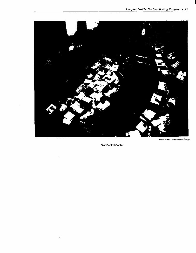
Test Control Center


3
Containing Underground Nucfkti? Explosions
._
.......................... ..*.......~.....~.........~...~*~~~.~.~ ...
Jknths.of a Secoud .............................................................. 32 AFewSeconds ................................................................. 32 Minutes to Days ................................................................. 32
WH~NUCL&AREXPLUSIONSREMAiNCO~NED .......................... 34 SELECTING LOCATION, DEPTH, AND SPACING: .............................. 35 REVIEWING A TEST SITE LOCATION ........................................... 37 CONTAINMENT EVALUATION PAlrlEL ......................................... 38 CONTAINING VERTICAL SHAFI’ TESTS ....................................... 40 CONTAINING HORIZQNTAL TUNNEL TESTS ................................... 4 1 TYPES OFRADIATION RELEASES.. ............................................ 46
co-& Failm ............................................................ 46 Late-Tii !se!cp ................................................................ 46 ConlN?lled ‘I\mntl Purging ...................................................... 47 Oplxational Release ........................ ..- ................................. 47
RECORDOF~NMENT .................................................. Containment Evahation Panel ................................................. VerticaI Drill Hole Tbsts ...................................................... Hoboatal ‘Itin& ‘I&s ....................................................... FromtkPerspectiveofHumanHeakhRi& ...................................
AFEW_ .......................................................... ISTHEREAREALES’IXTEPROBLEMATNTS?. ............................. TIRED MOUNThIN SYNDROME? .............................................. HOWSAFEISSAFEENOUGH?. ...............................................
Bex Box 3-A. Banebeny .................................................................
Figrvrs Figure
3-l. Formation of !bsa “Comabment Cage” ................................... 3-2. Mii SW Sqwation for Drill Hole lksts .............................. 3-3. Minimum m -on for Thnel ltsts .................................. 3-4. *q@car Stemming Plan .................................................. 3-5. vtrce Ibdunbs chmbment Vessels ...................................... 3-&w!ss& I.. .. _.L.. .........................................................
: I Cla6um+. ........................................................ CIo6ure Sequence ..................................................
3 post-shot configuration ........................................... 3-MAJblhof Decmsein Rock Strength.. :. ......................................
.... Tt3bik
Td&
47 47
.48
.48 49 49 51 51 54
PCl#C 33
pow 35 38 39 li 42 43
.a4 45
.-a 53
Page 3-l.ReleaseFmm Underpund’Iksts . . . . . . . . . . . . . . . . . . . . . . . . . . . . . . . . . . . . . . . . . . . . . . 48
I Chapter 3
Containing Underground Nuclear Explosions
Underground nuclear tests are designed and reviewedfor containment, with redundancy and conservatism in each step.
INTRODUCTION The United States’ first underground nuclear test,
codenamed “Pascal-A,” was detonated at the bot- tom of a 499-foot open drill-hole on July 26, 1957.’ Although Pascal-A marked the beginning of under- ground testing, above ground testing continued for another 6 years. With testing simultaneously occur- ring aboveground, the release of radioactive material from underground explosions was at first not a major concern. Consequently. Pascal-A, like many of the early underground tests that were to follow, was conducted “roman candle” style in an open shaft that allowed venting.*
As public sensitivity to fallout increased, guide- lines for testing in Nevada became more stringent. In 1956, the weapons laboratories pursued efforts to reduce fallout by using the lowest possible test yields, by applying reduced fission yield or clean technology, and by containing explosions under- ground. Of these approaches. only underground testing offered hope for eliminating fallout. The objective was to contain the radioactive material, yet still collect all required information. The first experiment designed to contain an explosion com- pletely underground was the “Rainier” test, which was detonated on September 19, 1957. A nuclear device with a known yield of 1.7 kilotons was selected for the test. The test was designed with two objectives: 1) to prevent the release of radioactivity to the atmosphere, and 2) to determine whether diagnostic information could be obtained from an underground test. The test was successful in both objectives. Five more tests were conducted the following year to confirm the adequacy of such testing for nuclear weapons development.
In November 1958, public concern over radioac- tive fallout brought about a nuclear testing morato- rium that lasted nearly 3 years. After the United States resumed testing in September, 1961, almost all testing in Nevada was done underground, while
atmospheric testing was conducted in the Christmas Island and Johnston Island area of the Pacific. From 1961 through 1963, many of the underground tests vented radioactive material. The amounts were small, however, in comparison to releases from aboveground testing also occurring at that time.
With the success of the Rainier test. efforts were made to understand the basic phenomenology of contained underground explosions. Field efforts included tunneling into the radioactive zone. labora- tory measurements, and theoretical work to model the containment process. Through additional tests, experience was gained in tunnel-stemming proc- esses and the effects of changing yields. The early attempts to explain the physical reason why under- ground nuclear explosions do not always fracture rock to the surface did little more than postulate the hypothetical existence of a “mystical magical mem- brane.” In fact, it took more than a decade of underground testing before theories for the physical basis for containment were developed.
In 1963, U.S. atmospheric testing ended when the United States signed the Limited Test Ban Treaty prohibiting nuclear test explosions in any environ- ment other than underground. The treaty also prohibits any explosion that:
. . . causes radioactive debris to be present outside the territorial limits of the State under whose jurisdiction or control such explosion is conducted.3
With the venting of radioactive debris from underground explosions restricted by treaty. con- tainment techniques improved. Although many U.S. tests continued to produce accidental releases of radioactive material, most releases were only detect- able within tire boundaries of the Nevada Test Site. In 1970, however, a test codenamed “Baneberry” resulted in a prompt, massive venting. Radioactive material from Baneberry was tracked as far as the Canadian border and focused concern about both the environmental safety and the treaty compliance of
‘The first underground test was the United States’ 1OOtb nuclear explosion.
*It is interesting to note that even with an open shaft, 90% of the fission products created by Pascal-A were contained underground.
)Arucle 1.1(b). 1963 Limited Test Ban Treaty
-31-

32 a The Containment of Underground Nuclear EqAosions
the testing pr~gram.~ Testing was suspended for 7 months while a detailed examination of testing practices was conducted by the Atomic Energy Commission. The examination resulted in new testing procedures and specific recommendations for review of test containment. The procedures initiated as a consequence of Banebeny are the basis of present-day testing practices.
Today, safety is an overriding concern throughout every step in the planning and execution of an underground nuclear test. Underground nuclear test explosions are designed to be contained. reviewed for containment, and conducted to minimize even the most remote chance of an accidental release of radioactive material. Each step of the testing author- ization procedure is concerned with safety; and conservatism and redundancy are built into the system.5
WHAT HAPPENS DURING AN UNDERGROUND NUCLEAR
EXPLOSION The detonation of a nuclear explosion under-
ground creates phenomena that occur within the following time frames:
Microseconds
Within a microsecond (one-millionth of a sec- ond), the billions of atoms involved in a nuclear explosion release their energy. Pressures within the exploding nuclear weapon reach several million pounds per square inch; and temperatures are as high as 100 million degrees Centigrade. A strong shock wave is created by the explosion and moves outward from the point of detonation.
Milliseconds
Within tens of milliseconds (thousandths of a second), the metal canister and surrounding rock are vaporized, creating a bubble of high pressure steam and gas. A cavity is then formed both by the pressure of the gas bubble and by the explosive momentum imparted to the surrounding rock.
Tenths of a Second
As the cavity continues to expand, the internal pressure decreases. Within a few tenths of a second. the pressure has dropped to a level roughly compara- ble to the weight of the overlying rock. At this point. the cavity has reached its largest size and can no longer grow.6 Meanwhile, the shock wave created by the explosion has traveled outward from the cavity, crushing and fracturing rock. Eventually. the shock wave weakens to the point where the rock is no longer crushed, but is merely compressed and then returns to its original state. This compression and relaxation phase becomes seismic waves that travel through the Earth in the same manner as seismic waves formed by an earthquake.
A Few Seconds
After a few seconds, the molten rock begins to collect and solidify in a puddle at the bottom of the cavity.’ Eventually, cooling causes the gas pressure within the cavity to decrease.
Minutes to Days
When the gas pressure in the cavity declines to the point where it is no longer able to support the overlying rock, the cavity may collapse. The coi- lapse occurs as overlying rock breaks into rubble and falls into the cavity void. As the process continues. the void region moves upward as rubble falls downward. The “chimneying” continues until:
o the void volume within the chimney completely fills with loose rubble.
l the chimney reaches a level where the shape of the void region and the strength of the rock can support the overburden material. or
l the chimney reaches the surface.
If the chimney reaches the surface. the ground sinks forming a saucer-like subsidence crater. Cavity collapse and chimney formation typically occur within a few hours of the detonation but sometimes take days or months.
%e for example. Bruce A. Bolt, Nudeor E,pkx~om and Earrhquakes San Francisco, CA. (W.H. Freeman & Co.. 1976).
%ee “Detonation Authority and Procedures” (ch. 2).
%ze the next section. “How explosions remain contained.” for a detailed explanaoon of cavity formation.
‘The solidified rock contains moSt of the radioacttve products from the explosion. The performance of the nuclear weapon IS analyzed when sarnplcs of this mater4 are recovered by drilling back Into the cavity.

Chapter 3-Containing Underground Nuclear Explosions l 33
Box 3-A-Banebeny
The exact cause of the 1970 Baneberry venting still remains a mystery. The original explanation postulated the existence of an undetected water table. It assumed that the high temperatures of the explosion produced steam that vented to the surface. Later analysis, however, discredited this explanation and proposed an alternative scenario based on three geologic features of the Baneberry site: water-saturated clay, a buried scarp of hard rock, and a nearby fault. It is thought that the weak, water-saturated clay was unable to support the containment structure: the hard scat-p strongly reflected back the energy of the explosion increasing its force; and the nearby fault provided a pathway that gases could travel along. All three of these features seem to have contributed to the venting. Whatever its cause, the Baneberry venting increased attention on containment and. in doing so, marked the beginning of the present-day containment practices.
The venting of Baneberry, 1970.
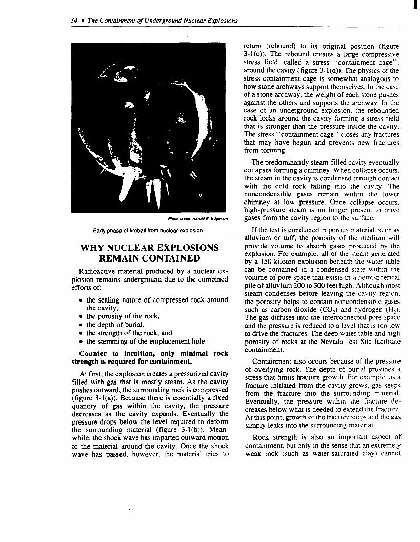
34 l The Containment of Underground Nuclear Explosions
Photo we&: HUM E. E@iwmn
Early phase of fireball from nuclear explosion.
WHY NUCLEAR EXPLOSIONS REMAIN CONTAINED
Radioactive material produced by a nuclear ex- plosion remains underground due to the combined efforts of:
l the sealing nature of compressed rock around the cavity,
l the porosity of the rock, l the depth of burial, l the strength of the rock, and l the stemming of the emplacement hole.
Counter to intuition, only minimal rock strength is required for containment.
At first, the explosion creates a pressurized cavity filled with gas that is mostly steam. As the cavity pushes outward, the surrounding rock is compressed (figure 3-l(a)). Because there is essentially a fixed quantity of gas within the cavity, the pressure decreases as the cavity expands. Eventually the pressure drops below the level required to deform the surrounding material (figure 3-l(b)). Mean- while, the shock wave has imparted outward motion to the material around the cavity. Once the shock wave has passed, however, the material tries to
return (rebound) to its original position (figure 3-l(c)). The rebound creates a large compressive stress field, called a stress “containment cage”, around the cavity (figure 3- 1 (d)). The physics of the stress containment cage is somewhat analogous to how stone archways support themselves. In the case of a stone archway, the weight of each stone pushes against the others and supports the archway. In the case of an underground explosion. the rebounded rock locks around the cavity forming a stress field that is stronger than the pressure inside the cavity. The stress “containment cage” closes any fractures that may have begun and prevents new fractures from forming.
The predominantly steam-filled cavity eventually collapses forming a chimney. When collapse occurs, the steam in the cavity is condensed through contact with the cold rock falling into the cavity. The noncondensible gases remain within the lower chimney at low pressure. Once collapse occurs. high-pressure steam is no longer present to drive gases from the cavity region to the surface.
If the test is conducted in porous material, such as alluvium or tuff, the porosity of the medium will provide volume to absorb gases produced by the explosion. For example, all of the steam generated by a 150 kiloton explosion beneath the water table can be contained in a condensed state within the volume of pore space that exists in a hemispherical pile of alluvium 200 to 300 feet high. Although most steam condenses before leaving the cavity region. the porosity helps to contain noncondensible gases such as carbon dioxide (CO,) and hydrogen (H,). The gas diffuses into the interconnected pore space and the pressure is reduced to a level that is too low to drive the fractures. The deep water table and high porosity of rocks at the Nevada Test Site facilitate containment.
Containment also occurs because of the pressure of overlying rock. The depth of burial provides a stress that limits fracture growth. For example. as a fracture initiated from the cavity grows. gas seeps from the fracture into the surrounding material. Eventually, the pressure within the fracture de- creases below what is needed to extend the fracture. At this point, growth of the fracture stops and the gas simply leaks into the surrounding material.
Rock strength is also an important aspect of containment, but only in the sense that an extremely weak rock (such as water-saturated clay) cannot

Chapter jF--Containing Underground Nuclear Explosions l 35
Figure 3-l-Formation of Stress “Containment Cage”
Compressws residual stress
1) Cavity expands outward and deforms surrounding rock. 2) Natural resistance to deformation stops expansion. 3) Cavlly wnrracts (rebounds) from elastic unloading of distant rock. 4) Rebound locks in compressive residual stress around cavity.
SOURCE: Modifud from Lawrena Livermore Natlonal Laboratory.
support a stress containment cage. Detonation within weak, saturated clay is thought to have been a factor in the release of the Baneberry test. As a result, sites containing large amounts of water-saturated clay are now avoided.
The final aspect of containment is the stemming that is put in a vertical hole after the nuclear device has been emplaced. Stemming is designed to prevent gas from traveling up the emplacement hole. Imper- meable plugs, located at various distances along the stemming column, force the gases into the surround- ing rock where it is “sponged up” in the pore spaces.
How the various containment features perform depends on many variables: the size of the explo- sion, the depth of burial, the water content of the rock, the geologic structure, etc. Problems may occur when the containment cage does not form completely and gas from the cavity flows either through the emplacement hole or the overburden material.* When the cavity collapses. the steam condenses and only noncondensible gases such as carbon dioxide (CO,) and hydrogen (Hz) remain in the cavity.9 The CO, and H, remain in the chimney if there is available pore space. If the quantity of noncondensible gases is large, however, they can act as a driving force to transport radioactivity through
the chimney or the overlying rock. Contequently.
the amount of carbonate material and utter II-I the
rock near the explosion and the amount ol ~run
available for reaction are considered u hen c’\ AI ua-
ing containment.‘O
SELECTING LOCATIOTV, DEPTH, AND SPACING
The site for conducting a nuclear I~\I I, JI :ir;t. selected only on a tentative basis. The tind clc~ I~IW is made after various site charactenstlc\ hdhe been
reviewed. The location, depth of bunJl. U-N.! \p~-~ng
are based on the maximum expected hteld ‘or !he
nuclear device, the requiredgeomet? ol the WI. md
the practical considerations of schedultng. conben-
ience, and available holes. If none ot rhc ~nbenrory
holes are suitable, a site is selected Jnd J hole
drilled. l l
The first scale for determining !IOU jeep dn
explosion should be buried was denkcti rrom rhe
Rainier test in 1957. The depth, bawd on :hc .ube
root of the yield, was originally:
Depth = 300 (yield) ’
where depth was measured in feet .& b~eld in
*Lack of a suess “containment cage” may not be a serious problem if the medium is sufficcntly porous or if the depth of bunai I\ urlfl~cnl
‘Vhc CO, is formed from the vaporization of carbonate material; while the H, is formed when water reacts with the iron III rhc wx ‘cd Icb L c md diagnostics equipment.
l”Thccarbonate material in Frenchman Flat created CO, that is thought to have caused a seep during the Diagonal Line test (Nov :J : 9’ ! i)l igwld Line was the lasl test on Frenchman Flat; rhc area is currcndy considucd impractical for underground testing largely because of the cdrtmdrc -idnub
IlScz ch. 2. “The Nevada Tea Site.” for a description of the areas each Laboratory uses for testing.

36 l The Containment of Underground Nuclear Explosions
Blanca containment failure, 1958
kilotons. The first few tests after Rainier. however, were detonated at greater depths than this formula requires because it was more convenient to mine tunnels deeper in the Mesa. It was not until “Blanca.” October 30. 1958, that a test was conducted exactly at 300 (yield)‘” feet to test the depth scale. The containment of the Blanca expio- sion. however, was unsuccessful and resulted in a surface venting of radioactive material. As a conse- quence, the depth scale was modified to include the
thus became: 300 (yield)‘” “plus-J-IN hundrd-
feet. ’ ’
Today, the general depth of burial C‘.III !Y .t~yrl lr. I mated by the equation:
Depth = 400 (yield) ‘.
where depth is measured in feet JII~~ i ,c:d II kilotons.‘? The minimum depth of burial, how L*L cr.
is 600 feet.13 Consequently, depth\ ot tiun~i i.~r) from 600 feet for a low-yield device. ~0 ~h~~ur :. i CM)
addition of a few hundred feet as a safety factor and feet for a large-yield test. The depth 14 cdcc! !tl :ht’
1*“Public Safety for Nuclear Weapons Tests. *’ Urnred States Enwronmental Protection Agency, January. 1984.
13The 600-foot depth was chosen as a nwnmum after a staustlcal study showed that the likelihood of a seep of radioactlve mater! .II ~$1 “:c \UI’ II : ‘.Y explosions buned 600 feet or more was about l/I2 as great as for explosions at less than 500 feet. even II Lhey were burled al Lhc ww ULIC JC:‘I~ in
each case.

Chapter 3-Containing Underground Nuclear Explosions l 37
“maximum credible yield” that the nuclear device is thought physically capable of producing, not to the design yield or most likely yield.14
Whether a test will be conducted on Pahute Mesa or Yucca Flat depends on the maximum credible yield. Yucca Flat is closer to support facilities and therefore more convenient, while the deep water table at Pahute Mesa is more economical for large yield tests that need deep, large diameter emplace- ment holes. Large yield tests in small diameter holes (less than 7 feet) can be conducted in Yucca Flat. A test area may also be chosen to avoid scheduling conflicts that might result in a test damaging the hole or diagnostic equipment of another nearby test. Once the area has been chosen. several candidate sites are selected based on such features as: proximity to previous tests or existing drill holes; geologic features such as faults, depth to basement rock, and the presence of clays or carbonate materials; and practical considerations such as proximity to power lines, roads, etc.
In areas well suited for testing. an additional site selection restriction is the proximity to previous tests. For vertical drill hole tests, the minimum shot separation distance is about one-half the depth of burial for the new shot (figure 3-2). For shallow shots, this separation distance allows tests to be spaced so close together that in some cases, the surface collapse craters coalesce. The l/2 depth of burial distance is a convention of convenience, rather than a criteron for containment.15 It is, for example, difficult to safely place a drilling rig too close to an existing collapse crater.
Horizontal tunnel tests are generally spaced with a minimum shot separation distance of twice the combined cavity radius plus 100 feet, measured from the point of detonation (called the “working point”) (figure 3-3). In other words, two tests with 100 foot radius cavities would be separated by 300 feet between cavities, or 500 feet (center to center). The size of a cavity formed by an explosion is proportional to the cube root of the yield and can be estimated by:
Radius = 55 (yield)‘“,
where the radius is measured in feet and the yield in
kilotons. For example, an 8 kiloton explosion would be expected to produce an underground cavity with approximately a 110 foot radius. Two such test explosions would require a minimum separation distance of 320 feet between cavities or 540 feet between working points.
Occasionally, a hole or tunnel is found to be unsuitable for the proposed test. Such a situation. however, is rare, occurring at a rate of about 1 out of 25 for a drill hole test and about 1 out of 15 for a tunnel test.16 Usually, a particular hole that is found unacceptable for one test can be used for another test at a lower yield.
REVIEWING A TEST SITE LOCATION
Once the general parameters for a drill-hole have been selected, the sponsoring laboratory requests a pre-drill Geologic Data Summary (GDS) from the U.S. Geological Survey. The GDS is a geologic interpretation of the area that reviews the three basic elements: the structures, the rock type, and the water content. The U.S. Geological Survey looks for features that have caused containment problems in the past. Of particular concern is the presence of any faults that might become pathways for the release of radioactive material, and the close location of hard basement rock that may reflect the energy created by the explosion. Review of the rock type checks for features such as clay content which would indicate a weak area where it may be difficult for the hole to remain intact. and the presence of carbonate rock that could produce CO,. Water content is also reviewed to predict the amount of steam and H2 that might be produced. If the geology indicates less than ideal conditions, alternate locations may be sug- gested that vary from less than a few hundred feet from the proposed site to an entirely different area of the test site.
When the final site location is drilled, data are collected and evaluated by the sponsoring labora- tory. Samples and geophysical logs, including down- hole photography, are collected and analyzed. The U.S. Geological Survey reviews the data. consults with the laboratory throughout the process, and reviews the accuracy of the geologic interpretations.
‘%I many cases IJIC maxImum credible yield is significantly larger than tbe expected yield for a nuclear device.
ISAs discussed later, testing in previously fractured rock is not considered a containment risk in most instances.
%t three occasions tunnels have been abandoned because of unanticipated conditions such as the discovety of a fault or the presence of too much water.

38 l The Containment of Underground Nuclear Explosions
Figure 3-2-Minimum Shot Separation for Drill Hok asts
Yucca flats
% depth of burial
k
Diagram to approximate scale
Scale illustration of the minimum separation distanoe (l/2 depth of burial) for vertical drill hole tests. The depth of burial is based on the maximum credible ylekl.
SOURCE: Offica of Technology Assessment, 1989
To confirm the accuracy of the geologic description and review and evaluate containment considera- tions, the Survey also attends the host laboratory’s site proposal presentation to the Containment Evalu- ation Panel.
CONTAINMENT EVALUATION PANEL
One consequence of the Baneberry review was the restructuring of what was then called the Test Evaluation Panel. The panel was reorganized and new members with a wider range of geologic and hydrologic expertise were added. The new panel was named, the Containment Evaluation Panel (CEP); and their first meeting was held in March, 1971.
The Containment Evaluation Panel presently consists of a Chairman and up to 11 panel members.
Six of the panel members are representatives from Lawrence Livermore National Laboratory, Los Alamos National Laboratory, Defense Nuclear Agency, San- dia National Laboratory, U.S. Geological Survey, and the Desert Research Institute. An additional 3 to 5 members are also included for their expertise in disciplines related to containment. The chairman of the panel is appointed by the Manager of Nevada Operations (Department of Energy). and panel members are nominated by the member institution with the concurrence of the chairman and approval of the Manager. The panel reports to the Manager of Nevada Operations.
Practices of the Containment Evaluation Panel have evolved throughout the past 18 years; however, their purpose, as described by the Containment

Chapter 3-Containing Underground Nuclear Explosions w 39
Rainier Mesa
Flgun 3-3-Mlnlmum Shot Sepamtlon for Tkmnol Bsts
Tunnel tests are typically overburied. Collapse chimneys do not usually extend to surface
Diagram to approximate scale
Soate illustration of the minimum separation distance (2 combined cavity radii plus 100 feet) for
horizontal tunnel tests. Tunnel tests are typically overburied. Collapse chimneys do not usually extend to the surface.
SOURCE: Office of Technology Assessment, 1989
Evaluation Charter, remains specifically defined as follows: 1’
4. maintain a historical record of each evaluation and of the data. proceedings, and discussions pertaining thereto.
1.
2.
3.
evaluate, as an independent organization re- porting to the Manager of Nevada Operations, the containment design of each proposed nuclear test;
assure that all relevant data available for proper evaluation are considered;
advise the manager of Nevada Operations of the technical adequacy of such design from the viewpoint of containment, thus providing the manager a basis on which to request detona- tion authority; and
Although the CEP is charged with rendering a judgment as to the adequacy of the design of the containment, the panel does not vote. Each member provides his independent judgment as to the pros- pect of containment, usually addressing his own area of expertise but free to comment on any aspect of the test. The Chairman is in charge of summarizing these statements in a recommendation to the man- ager on whether to proceed with the test, based only on the containment aspects. Containment Evalua- tion Panel guidelines instruct members to make their judgments in such a way that:
~7Cotttainment Evaluation Charter, June 1. 1986. Secuon II.

40 l The Containment of Underground Nuclear Explosions
Considerations of cost, schedules, and test objectives shall not enter into the review of the technical adequacy of any test from the viewpoint of contain- ment.**
Along with their judgments on containment, each panel member evaluates the probability of contain- ment using the following four categories: l9
1. Category A: Considering all containment fea- tures and appropriate historical, empirical. and analytical data, the best judgment of the member indicates a high confidence in suc- cessful containment as defined in VIILF. below.
2. Category B: Considering all containment fea- tures and appropriate historical, empirical, and analytical data, the best judgment of the member indicates a less, but still adequate, degree of confidence in successful contain- ment as defined in VII1.F. below.
3. Category C: Considering all containment fea- tures and appropriate historical. empirical, and analytical data, the best judgment of the member indicates some doubt that successful containment, as described in VII1.F. below, will be achieved.
4. Unable to Categorize
Successful containment is defined for the CEP as:
. . . no radioactivity detectable off-site as measured by normal monitoring equipment and no unantici- pated release of activity on-site.
The Containment Evaluation Panel does not have the direct authority to prevent a test from being conducted. Their judgment, both as individuals and as summarized by the Chairman. is presented to the Manager. The Manager makes the decision as to whether a Detonation Authority Request will be made. The statements and categorization from each CEP member are included as part of the permanent Detonation Authority Request.
Although the panel only advises the Manager, it would be unlikely for the Manager to request
detonation if the request included a judgment by the CEP that the explosion might not be contained. The record indicates the influence of the CEP. Since formation of the panel in 1970. there has never been a Detonation Authority Request submitted for ap- proval with a containment plan that received a “C” (“some doubt”) categorization t?om even one member.20 21
The Containment Evaluation Panel serves an additional role in improving containment as a consequence of their meetings. The discusslonc of the CEP provide an ongoing forum for technIcal
discussions of containment concepts and prxt~c~
As aconsequence. general improvements to contam- ment design have evolved through the panel d~\cu\- sions and debate.
CONTAINING VERTICAL SHAFT TESTS
Once a hole has been selected and revIewed. J
stemming plan is made for the individual hole The
stemming plan is usually formulated by ddaptlng previously successful stemming plans to the ~LIIICU- larities of a given hole. The objective ot rhc plan I> to prevent the emplacement hole from king rhe pah
of least resistance for the flow ot r~cll~~~~rl\e material. In doing so, the stemming plan muIt t&e
into account the possibility of only a parted coll4.p~: if the chimney collapse extends oni) half u 3’ to the
surface. the stemming above the ~ull~p\~ must
remain intact.
Lowering the nuclear device with the dlapnoacs
down the emplacement hole can take up 10 5 da><. A typical test will have between 50 jnd 250 diagnostic cables with diameters as great JS Ii/q inches packaged in bundles through the \Iemrnlng
column. After the nuclear device is lowered Into the emplacement hole, the stemming is In>railed Figure 3-4 shows a typical stemming plan for d Lsrence
l*Containment Evaluation Panel Charter, June 1. 1986. Sectton fl1.D
‘9Cotttainmcnt Evaluation Panel Charter, June 1. 1986. Secuon VII.
z’%e grading system for containment plans has evolved since the early 1970’s. Prior to April. 1977. the Containment Evaluailon Panel ~dlcgunrcd tests using the Roman numerals (I-IV) where I-111 had about the same meaning as A-C and IV was a D whtch eventually was dropped ti a ICIICI md just became “unable to categonze.”
*IHowever. one shot (Mu&o) was submitted with an “unable to categorize” categorization. Mundo was a joint US-UK test conducted dn Qldy I. 1984.

Chapter Containing Underground Nuclear Explosions l 4 I
1 \ (
Figure 3-c”~pical” Stemming Plan
\
. Cable gas blocks
I r I (Plug to I
I I
true scale) (Diagram not to scale)
Typical stemming sequence of coarsa material, fine material, and sanded gypsum plug used by Lawrence Livermore National Laboratory for vertical drill hole tests.
SOURCE: Mod&d from Lawrence Livermore NatIonal Laboratory
Livermore test with six sanded gypsum concrete plugs.** The plugs have two purposes: 1) to impede gas flow, and 2) to serve as structural platforms that prevent the stemming from falling out if only a partial collapse occurs. Under each plug is a layer of sand-size fine material. The sand provides a base for the plug. Alternating between the plugs and the fines, coarse gravel is used to fill in the rest of the stemming. The typical repeating pattern used for stemming by Los ALamos. for example, is 50 feet of gravel, 10 feet of sand, and a plug.
All the diagnostic cables from the nuclear device In addition to the three containment vessels, there are blocked to prevent gas from finding a pathway is a gas seal door at the entrance of the tunnel system through the cables and traveling to the surface. Cable that serves as an additional safety measure. The gas fan-out zones physically separate the cables at plugs seal door is closed prior to detonation and the area
so that the grout and fines can seal between them. Frequently, radiation detectors are installed between plugs to monitor the post-shot flow of radiation through the stemming column.
CONTAINING HORIZONTAL TUNNEL TESTS
The containment of a horizontal tunnel test is different from the containment of a vertical drill hole test because the experimental apparatus is intended to be recovered. In most tests, the objective is to allow direct radiation from a nuclear explosion to reach the experiment, but prevent the explosive debris and fission products from destroying it. Therefore, the containment is designed for two tasks: 1) to prevent the uncontrolled release of radioactive material into the atmosphere for public safety, and 2) to prevent explosive debris from reaching the experimental test chamber.
Both types of horizontal tunnel tests (effects tests and cavity tests) use the same containment concept of three redundant containment “vessels” that nest inside each other and are separated by plugs (figure 3-5).23 Each vessel is designed to independently contain the nuclear explosion, even if the other vessels fail. If, for example. gas leaks from vessel I into vessel II. vessel II has a volume large enough so that the resulting gas temperatures and pressures would he well within the limits that the plugs are designed to withstand. The vessels are organized as follows:
Vessel I is designed to protect the experiment by preventing damage to the equipment and allowing it to be recovered.
Vessel II is designed to protect the tunnel system so that it can be reused even if vessel I fails and the experimental equipment is lost.
Vessel III is designed purely for containment. such that even if the experimental equipment is lost and the tunnel system contaminated. radioactive material will not escape to the atmosphere.
~*Ahhough Livermore and Los Alamos use the same general stemming philosophy. then are some differences: For example. LIvermore uses sanded gypsum concrete plugs while Los Alamos uses plugs made of epoxy. Also, Livermore uses an emplacement pipe for lowenng Ihe device downhole. whk Los Alamos lowers the dcvlce and diagnosnc canister on a wire rope harness.
*?3ec ch. 2 for a discusslon of types of nuclear tests.

42 l Tk Containment of Underground Nuclear Explosions
Figure S-5-mree Redundant Contalnment Vessels (Plan View)
Three containment vessels for the Mighty Oak Test conducted in the T-Tunnel Comlex.
SOURCE: ModiMd from Defense Nuclear Agency.
between it and the vessel III plug is pressurized to approximately 10 pounds per square inch.
The plugs that separate the vessels are constructed of high strength grout or concrete 10 to 30 feet thick. The sides of the vessel II plugs facing the working point are constructed of s&l. Vessel II plugs are designed to withstand pressures up to 1,000 pounds per square inch and temperatures up to 1,000 “F. Vessel III plugs are constructed of massive concrete and are designed to withstand pressures up to 500 pounds per square inch and temperatures up to 500 ‘F.
Before each test, the tunnel system is checked for leaks. The entire system is closed off and pressurized to 2 pounds per square inch with a gas containing tracers in it. The surrounding area is then monitored
for the presence of the tracer gas. Frequently. the chimney formed by the explosion is also subjected to a post-shot pressurization test to ensure that no radioactive material could leak through the chimney to the surface.
The structure of vessel I, as shown in figure 3-6. is designed to withstand the effects of ground shock and contain the pressure, temperatures, and radiation of the explosion. The nuclear explosive is located at the working point, also known as the “zero room.” A long, tapered, horizontal line-of-sight (l-LOS) pipe extends 1.000 feet or more from rhe working point to the test chamber where the experimental equipment is located. The diameter of the pipe may only be a few inches at the working point, but typically increases to about 10 feet before it reaches

Chapter Containing Underground Nuclear Explosions l 43
Figure 3-6Vessel I
Vessel 1 End of stemmmg
4- Bypass drift
c- HLOS drift
_ Mechanical
Mechanical closure End of stemming closure (MAC)
(GSAC)
Key: GSAC =gas seal auxiliary closure: MAC =modified auxiliary closure; TAPS =Tunnel and pipe seal
The HLOS Vessel I is designed to protect the experimental equipment after allowing radiation to travel down the pipe.
SOURCE: Modified fmm Defense Nuclear Agency.
the test chamber.** The entire pipe is vacuum pumped to simulate the conditions of space and to minimize the attenuation of radiation. The bypass drift (an access tunnel), located next to the line of sight pipe, is created to provide access to the closures and to different parts of the tunnel system. These drifts allow for the nuclear device to be placed in the zero room and for late-time emplacement of test equipment. After the device has been emplaced at the working point, the bypass drift is completely filled with grout. After the experiment, parts of the bypass drift will be reexcavated to permit access to the tunnel system to recover the pipe and experimen- tal equipment.
The area around the I-LOS pipe is also filled with grout, leaving only the HLOS pipe as a clear pathway between the explosion and the test cham- ber. Near the explosion, grout with properties similar to the surrounding rock is used so as not to interfere with the formation of the stress containment cage. Near the end of the pipe strong grout or concrete is used to support the pipe and closures. In between, the stemming is filled with super-lean grout de- signed to flow under moderate stress. The super-lean grout is designed to fill in and effectively plug any fractures that may form as the ground shock collapses the pipe and creates a stemming plug.
As illustrated in figure 3-6, the principal compo- nents of an I-LOS pipe system include a working
point room, a muffler, a modified auxiliary closure (MAC), a gas seal auxiliary closure (GSAC). and a tunnel and pipe seal (TAPS). All these closures are installed primarily to protect the experimental equip- ment. The closures are designed to shut off the pipe after the radiation created by the explosion has traveled down to the test chamber, but before material from the blast can fly down the pipe and destroy the equipment.
The working point room is a box designed to house the nuclear device. The muffler is an ex- panded region of the HLOS pipe that is designed to reduce flow down the pipe by allowing expansion and creating turbulence and stagnation. The MAC (figure 3-7(a)) is a heavy steel housing that contains two 12-inch-thick forged-aluminum doors designed to close openings up to 84 inches in diameter. The doors are installed opposite each other, perpendicu- lar to the pipe. The doors are shut by high pressure gas that is triggered at the time of detonation. Although the doors close completely within 0.03 seconds (overlapping so that each door fills the tunnel), in half that time they have met in the middle and obscure the pipe. The GSAC is similar to the MAC except that it is designed to provide a gas-tight closure. The TAPS closure weighs 40 tons and the design (figure 3-7(b)) resembles a large toilet seat. The door, which weighs up to 9 tons, is hinged on the top edge and held in the horizontal (open) position. When the door is released, it swings down by gravity and slams shut in about 0.75 seconds. Any pressure remaining in the pipe pushes on the door making the seal tighter. The MAC and GSAC will withstand pressures up to 10,000 pounds per square inch. The TAPS is designed to withstand pressures up to 1,000 pounds per square inch, and temperatures up to 1,000 “F.
When the explosion is detonated radiation travels down the HLOS pipe at the speed of light. The containment process (figure 3-8(a-e), triggered at the time of detonation, occurs in the following sequence to protect experimental equipment and contain radioactive material produced by the explosion:
l After0.03 seconds (b), the cavity created by the explosion expands and the shock wave moves away from the working point and approaches the MAC. The shock wave collapses the pipe. squeezing it shut, and forms a stemming “plug.” Both the MAC and the GSAC shut off
2% occasion. the diameter of the pipe has increased to 20 feet.

44 l The Containment of lfnderxround Nuclear Emlosions
Figure 3-7-Vessel I Closures
A)
Mechanical closures (MAUGSAC)
closure (TAPS)
Pre-fire geometry Approxtmate closed FAC geometry
Fast acting closure
(FAC)
A) Mechanical Closures (MACIGSAC) 6) Tunnel and Pipe Seal (TAPS) C) Fast Acting Closure (FAC)
SOURCE: Modified from Defense Nuclear Agency
the pipe ahead of the shock wave to prevent enough to squeeze the pipe shut. The stemming earl; flow of high-velocity gas and dedris into plug stops firming at about the distance where the experiment chamber. the first mechanical pipe closure is located.
l After 0.05 seconds (c), the ground shock moves l After 0.2 seconds (d). the cavity growth is past the second closure and is no longer strong complete. The rebound from the explosion
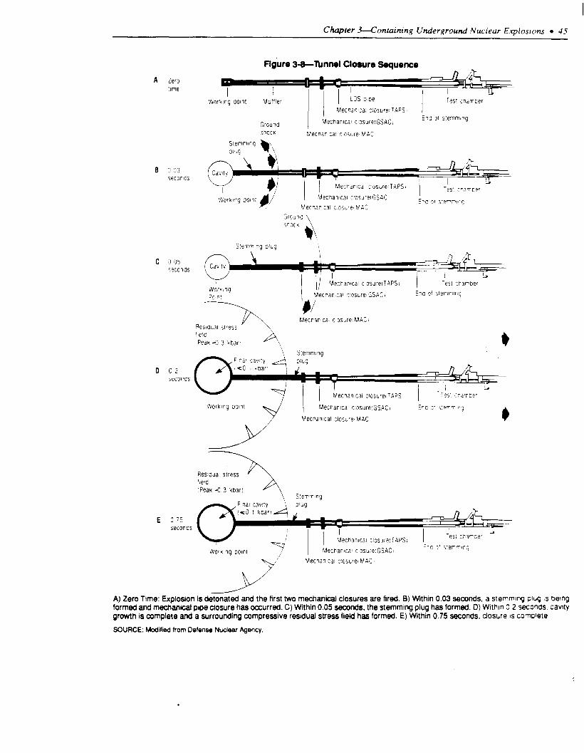
Chapter 3-ContaininR Underaround Nuclear E.~ioswn.~ l J
A zero lime
F&e 3-8-lbnnel Closure Sequence
WCrkIlg OOlfll Muffler
Grounc Mechanical c:osureiGSACl
iPOCK Llecnamcal c!os~re,MAC
B ? 33 w Caw
sewncs
I ki
c 305 seconds
&f& +
I G / blecnapmcal c'osurelTAPSt Test cnapoer
Norwlg P!IIN Vecnan,cai c'osurelGSAC1 Eric jf ;:emmtncj
qes> " Mecnanlcal c!osurel MAGI
"eid 'Pear 4 3 <dart P,
0 02 seconcs
Mechamcal c~osureiTAPSI '-es1 3i-dr"cer
Mecnamcal clowrelGSAC, Ena 3f ,'e-rlna
Mecnamcal CIOSUW MAC,
Reslaual stress
ipeak -0 3 kbarl Stemming 3ijg
E 375 seconds
Mecnamcal :losdreiTAPSi
WOrk!ng OOlfll Mechantcal closbreiGSAC
Mechantcar c:osurel MAC)
A) Zero Time: Explosion is detonated and the first two mechanical closures are fired. 8) Within 0.03 seconds. a stemmq plug 6 being formed and mechanical pipe closure has occurred. C) Within 0.05 seconds, the stemming plug has formed. 13) Withln 0 2 seconds. cavity growth is complete and a surrounding compressive residual stress field has formed. E) Within 0.75 seconds, closure IS comclete
SOURCE: Modified from Defense Nuclear Agency

46 l The Containment of Underground Nuclear Eqdosions
locks in the residual stress field, thereby forming a containment cage. The shock wave passes the test chamber.
l After 0.75 seconds (e), the final mechanical seal (TAPS) closes, preventing late-time explosive and radioactive gases from entering the test c harnber.
The entire closure process for containment takes less than 3/4 of a second. Because the tests are typically buried at a depth greater than necessary for containment, the chimney does not reach the surface and a collapse crater normally does not form. A typical post-shot chimney configuration with its approximate boundaries is shown in figure 3-9.
In lower yield tests, such as those conducted in the P-tunnel complex, the first mechanical closure is a Fast Acting Closure (FAC) rather than a MACZ The FAC (figure 3-7(c)) closes in 0.001 seconds and can withstand pressures of 30,000 pounds per square inch. The FAC acts like a cork, blocking off the HLOS pipe early, and preventing debris and stem- ming material from flying down the pipe. A similar closure is currently being developed for larger yield tunnel tests.
TYPES OF RADIATION RELEASES
Terms describing the release or containment of underground nuclear explosions have been refined to account for the volume of the material and the conditions of the release. The commonly used terms are described below.
Containment Failure
Containment failures are releases of radioactive material that do not fall within the strict definition of successful containment, which is described by the Department of Energy as:
Containment such that a test results in no radioac- tivity detectable off site as measured by normal monitoring equipment and no unanticipated release of radioactivity onsite. Detection of noble gases that appear onsite long after an event, due to changing atmospheric conditions, is not unanticipated. Antici- pated releases will be designed to conform to specific guidance from DOE/HQ.26
Containment failures are commonly described as:
flgure 3-g-~plcal Post-Shot Configuratlon
Approximate chimney boundary
Stemming Plug
Tunnel shots are typically overburied and the collapse cnlmney rarely extends to the surface.
SOURCE: Modified from Defense Nuclear Agency.
Ventings
Ventings are prompt, massive, uncontrolled re- leases of radioactive material. They art chacrrr-
ized as active releases under pressure. such ti u hen
radioactive material is driven out of the ground h\
steam or gas. “Baneberry,” in 1970. I\ :hr !L<FSI
example of an explosion that “vented. ”
Seeps
Seeps, which are not visible, can onl) be cfcrcc14 by measuring for radiation. Seeps are ~huxrrnxci
as uncontrolled slow releases of radioactlke marenal
with little or no energy.
Late-Time Seep
Late-time seeps are small releases of non~on&n-
sable gases that usually occur days or UW~\ d!rer J vertical drill hole test. The nonconden&le ~LXL\C’\ diffuse up through the pore spaces of the o\crl> lng
rock and are thought to be drawn to the \uriacr by J
decrease in atmospheric pressure (called .‘~tmo\-
pheric pumping”).
ZfThe P-tunnel complex is mmed in Aqueduct Mesa and has less overburden than the N-tunnel complex III Riumer Mesa. Therelore. P :unnel I* generally used for lower yield tests.
%ection VlI1.F. Containment Evaluation Panel Charter.

Chapter Containing Underground Nuclear Eqdosions l 4 7
Fast acting closure.
Controlled Tunnel Purging
Controlled tunnel purging is an intentional release of radioactive material to recover experimental equipment and ventilate test tunnels. During a controlled tunnel purging, gases from the tunnel are filtered. mixed with air to’reduce the concentration, and released over time when weather conditions are favorable for dispersion into sparsely populated areas.
Operational Release
Operational releases are small releases of radioac- tivity resulting from operational aspects of vertical drill hole tests. Activities that often result in operational releases include: drilling back down to the location of the explosion to collect core samples (called “drill back”), collecting gas samples from
the explosion (called “gas sampling”), and sealing the drill back holes (called “cement back”)
RECORD OF CONTAINMENT The containment of underground nuclear explo-
sions is a process that has continually evolved through learning, experimentation. and experience. The record of containment illustrates the various types of releases and their relative impact.
Containment Evaluation Panel
The Containment Evaluation Panel defines suc- cessful containment as no radioactivity detectable offsite and no unanticipated release of activity onsite. By this definition, the CEP has failed to predict unsuccessful containment on four occasions since 1970:

48 l The Containment of Underground Nuclear Explosions
Camphor: June 29, 197 1, horizontal tunnel test, less than 20 kilotons, radioactivity de- tected only on-site.
Diagonal Line: November 24. 1971, vertical shaft test, less than 20 kilotons, radioactivity de- tected off-site.
Riola: September 25, 1980, vertical shaft test, less than 20 kilotons, radioactivity de- tected off-site.
Agrini: March 3 I, 1984, vertical shaft test, less than 20 kilotons, radioactivity detected only on-site.
These are the only tests (out of more than 200) where radioactive material has been unintentionally released to the atmosphere due to containment failure. In only two of the cases was the radioactivity detected outside the geographic boundary of the Nevada T&t Site.
There have, however, been several other instances where conditions developed that were not expected. For example, during the Midas Myth test on February 15, 1984, an unexpected collapse crater occurred above the test tunnel causing injuries to personnel. In addition, the tunnel partially collapsed, damaging experimental equipment. During the Mighty Oak test on April 10. 1986, radioactive material penetrated through two of the three containment vessels. Experimental equipment worth $32 million was destroyed and the tunnel system ventilation required a large controlled release of radioactive material (table 3-l 1. In the case of Midas Myth, no radioactive material was released (in fact. all radio- active material was contained within vessel I). In the case of Mighty Oak, the release of radioactive material was intentional and controlled. Conse- quently, neither of these tests are considered con- tainment failures by the CEP.
Vertical Drill Hole Tests
As discussed previously, vertical drill-hole tests commonly use a stemming plan with six sanded gypsum plugs or three epoxy plugs. Approximately SO percent of the vertical drill hole tests show all radiation being contained below the first plug. In some cases, radiation above the plug may not signify plug failure, but rather may indicate that radioactive material has traveled through the medium around the
Plug*
TaMa 3-l-Roka#s From Underground Tests (normalized to 12 hours aftor event9
All releases 1971-l 988: Contartment Failures:
Camphor, 1971b.............................. 360 Ci Diagonal Line, 1971 . . .6.800 Riola, 1960 . . . . . . . . . . . . . . . ,..,...., ,. 3,100 Agnni, 1984 . . . . . . . . . 690
Late-time Seeps: Kappeli, 1984.. . _. _, _. _. _. 12 Tierra.1984..................................600 Labquark. 1986 . . . . 20 Bodie. 19863 . . . . . . . . . . . . . . . . . . . . . . . . . . . . . . . ...52
Controlled Tunnel Purgings: Hybla Fair, 1974 500 HyblaGold. 1977. .0.005 Miners Iron. 1980 0.3 Huron Landing, 1982 280 Mini Jade, 1983 . 1 MillYard. 1985.. _. _. 5.9 Diamond Beech,1985 1 .l Misty Rain, 1985 . , , , , . . . . . 63 Mighty Oak, 1986 . . . . . .36,000 Mission Ghost.1987C . . . . . . . . . . . . . . . . . . . . . . . . . ...3
Operational Releases: 108 tests from 1970-1988d.. . . 5,500
Total since Baneberry: 54,000 CI
Major pre-1971 releases: Platte, 1962 . . . . . . 1,900,OOO Ci
Eel. 1962.. . 1.900.000 Des Moines, 1962 . 11.000.000 Baneberry. 1970 . . .6,700.000 26 others from 1958-1970.. 3.800,OOO
Total: 25.300,OOO Ci Other Releases for Reference
NTS Atmospheric Testing 1951-1963: 12.000.000.000 Ci 1 Kiloton Aboveground Explosion: 10.000.000 Chernobyl (estimate):. .81 .OOO.OOO
=F+l2 values apply only to containment fatlures. otners are al rime of release.
bathe Camphor fallure Includes 140 CI from funflel purging e&due and MSSIO~ Ghost also had drill-back releases dManyof theseoperatlonal releasesare associated wtn tests fhaf were pot
announced.
SOURCE. Offtce of Technology Assessment. 1989
All three of the vertical drill hole tests that released radioactive material through containment failure were low yield tests of less than 30 kilotons. In general. the higher the yield, the less chance there is that a vertical drill hole test will release radioactiv- ity.*’
Horizontal Tunnel Tests
There have been no uncontrolled releases of radioactive material detected offsite in the 3 1 tunnel tests conducted since 1970. Furthermore. all but one test, Mighty Oak, have allowed successful recovery
*‘Higher yield tests are more likely to produce a containment cage and result in the formation of a collapse crater. As dtscussed carher In this L hapter
“why nuclear eaplostons rematn contained, ” such features contnbute to the contautrnent of the explosion.

Chapter jlContaining Underground Nuclear Explosions l 49
**The Mission Ghost release was due to a post-shot dnll hole.
290p. cit.. footnote 20.
of the experimental equipment. Mighty Oak and Camphor are the only tests where radioactivity escaped out of vessel II. In no test, other than Camphor, has radioactive material escaped out of vessel III. Camphor resulted in an uncontrolled release of radioactive material that was detected only on site.
There have been several instances when small amounts of radioactivity were released intentionally to the atmosphere through controlled purging. In these cases, the decision was made to vent the tunnel and release the radioactivity so the experimental results and equipment could be recovered. The events that required such a controlled release are the 10 tests where radioactive material escaped out of vessel I and into vessel II. namely:
Hybla Fair, October 28, 1974.
Hybla Gold, November 1, 1977.
Miners Iron, October 3 1, 1980.
Huron Landing, September 23, 1982.
Mini Jade, May 26, 1983.
Mill Yard, October 9, 1985.
Diamond Beech, October 9, 1985.
Misty Rain, April 6, 1985.
Mighty Oak, April 10, 1986.
Mission Ghost, June 20, 198728
In most cases, the release was due to the failure of some part of the experiment protection system.
Table 3-l includes every instance (for both announced and unannounced tests) where radioac- tive material has reached the atmosphere under any circumstances whatsoever from 1971 through 1988. The lower part of table 3-l summarizes underground tests prior to 1971 and provides a comparison with other releases of radioactive material.
Since 1970, 126 tests have resulted in radioactive material reaching the atmosphere with a total release of about 54,000 Curies(Ci). Of this amount, 11,500 Ci were due to containment failure and late-time seeps. The remaining 42,500 Ci were operational releases and controlled tunnel ventilations-with Mighty Oak (36,000 Ci) as the main source. Section
3 of the table shows that the release of radioactive material from underground nuclear testing since Baneberry (54,000 Ci) is extremely small in compar- ison to the amount of material released by pre- Baneberry underground tests (25,300,000 Ci), the early atmospheric tests at the Nevada Test Site, or even the amount that would be released by a 1 kiloton explosion conducted above ground ( 10,000.ooO Ci).
From the Perspective of Human Health Risk
If a single person had been standing at the boundary of the Nevada Test Site in the area of maximum concentration of radioactivity for every test since Baneberry (1970), that person’s total exposure would be equivalent to 32 extra minutes of normal background exposure (or the equiva- lent of l/1000 of a single chest x-ray).
A FEW EXAMPLES:
Although over 90 percent of all test explosions occur as predicted, occasionally something goes wrong. In some cases, the failure results in the loss of experimental equipment or requires the controlled ventilation of a tunnel system. In even more rare cases (less than 3 percent), the failure results in the unintentional release of radioactive material to the atmosphere. A look at examples shows situations where an unexpected sequence of events contribute to create an unpredicted situation (as occurred in Banebeny (see box 3-l)). and also situations where the full reason for containment failure still remains a mystery.
1. Camphor (June 29. 1971, horizontal tunnel test. less than 20 kilotons, radioactivity detected only on-site.)
The ground shock produced by the Camphor explosion failed to close the HLOS pipe fully. After about 10 seconds, gases leaked through and eroded the stemming plug. As gases flowed through the stemming plug, pressure increased on the closure door behind the experiment. Gases leaked around the cable passage ways and eroded open a hole. Pressure was then placed on the final door. which held but leaked slightly. Prior to the test. the containment plan for Camphor received six “1”s from the CEP.29
.

50 l The Containment of Underground Nuclear Eqdosions
2. Diagonuf Line (November 24, 1971, vertical shaft test. less than 20 kilotons, radioactivity de- tected off-site.)
In a sense, the Diagonal Line seep was predicted by the CEP. Prior to the test. Diagonal Line received all “A” categorizations, except from one member who gave it a “B.“30 It was a conclusion of the panel that due to the high CO, content. a late-time (hours or days after detonation) seepage was a high probability. They did not believe, however, that the level of radiation would be high enough to be detectable off-site. Permission to detonate was requested and granted because the test objectives were judged to outweigh the risk. Diagonal Line was conducted in the northern part of Frenchman Flat. It is speculated that carbonate material released CO, gas that forced radioactive material to leak to the surface. Diagonal Line was the last test detonated on Frenchman Flat.
3. Riola (September 25, 1980, vertical shaft test, less than 20 kilotons. radioactivity detected off-site.)
Ironically, Riola was originally proposed for a different location. The Containment Evaluation Panel, however, did not approve the first location and so the test was moved. At its new location, Riola was characterized by the CEP prior to the test with 8 “A”s. Riola exploded with only a small fraction of the expected yield. A surface collapse occurred and the failure of a containment plug resulted in the release of radioactive material.
4. Agrini (March 31, 1984. vertical shaft test. less than 20 kilotons, radioactivity detected only on- site.)
The Agrini explosion formed a deep subsidence crater 60 feet west of the emplacement hole. A small amount of radioactive material was pushed through the chimmney by noncondensible gas pressure and was detected onsite. The containment plan for Agrini received seven “A”s and two “B”s from the CEP prior to the test. The “B”s were due to the use of a new stemming plan.
5. Midas Myth (February 15, 1984, horizontal tunnel test, less than 20 kilotons, no release of radioactive material.)
All of the radioactive material produced by the
Midas Myth test was contained within vessel I, with no release of radioactivity to either the atmosphere or the tunnel system. It is therefore not considered a containment failure. Three hours after the test. however. the cavity collapsed and the chimney reached the surface forming an unanticipated subsi- dence crater. Equipment trailers were damaged and personnel were injured (one person later died as a result of complications from his injuries) when the collapse crater formed. 31 Analysis conducted after the test indicated that the formation of the collapse crater should have been expected. Shots conducted on Yucca Fiat with the same yield and at the same depth of burial did, at times, produce surface collapse craters. In the case of Midas Myth. collapse
was not predicted because there had never been a collapse crater for a tunnel event and so the analysts was not made prior to the accident. After 3nal~z1ng the test, the conclusion of the Surface Subsidence
Review Committee was:
That the crater is not an indicanon of \ome unusual, anomalous occurrence specific to rhe c’ I To4 emplacement site. Given the normal ~ananon In explosion phenomena, along with yield. depth ai burial, and geologic setting, experience In&cate\ m appreciable chance for the formation oi J ~flac‘r subsidence crater for Midas Myth.
Prior to the test, the Containment ELJudtlon Panel characterized Midas Myth with nine ” A”,
6. Misfy Rain ( April 6, 1985. honzonlal tunnel test, less than 20 kilotons, no unintentlond rele&\e of
radioactive material.)
Misty Rain is unusual in that it is the oni> tunnel test since 1970 that did not have three c‘ontalnment vessels. In the Misty Rain test, the decl\lon uu made that because the tunnel system b= >o I~ge. a vessel II was not needed.32 Despite the Ixk it’ d
vessel II, the CEP categorized the cont;ilnmt’nr oi Misty Rain witheight“A”s,andone “5.““ Dunng the test. an early flow of energy down the HLOS pipe
prevented the complete closure of the Ll.AC doors.
The MAC doors overlapped, but stopped A couple inches short of full closure. The TAPS door cloed only 20 percent before the deformation from ground
shock prevented it from closing. A small amount of
JoIbid.
~tThe injuries were due to the physical circumstances of the collapse. There was no radiation exposure.
Ybe drifts in the tunnel system created over 1 mtllion cubic feet of open volume.
Wne CEP member did not mit~ally categonze the test, after receiving additional information concemutg the test. he categorized the ICU wh an 4

I Chapter -F--Containing Underground Nuclear Explosions l 5 I
radioactive material escaped down the pipe and then seeped from the I-LOS pipe tunnel into the bypass tunnel. Subsequently, the tunnel was intentionally vented so that experimental equipment could be recovered.
7. Mighty Oak (April 10, 1986, horizontal tunnel test, less than 20 kilotons, no unintentional release of radioactive material.)
During the Mighty Oak test, the closure system near the working point was over-pressured and failed. The escaped pressure and temperature caused both the MAC and the GSAC to fail. The loss of the stemming plug near the working point left the tunnel an open pathway from the cavity. Temperatures and pressures on the closed TAPS door reached 2,000 ‘F and 1,400 pounds per square inch. After 50 seconds, the center part (approximately 6 feet in diameter) of the TAPS door broke through. With the closures removed, the stemming column squeezed out through the tunnel. Radioactive material leaked from vessel I, into vessel II, and into vessel III. where it was successfully contained. Approximately 85 percent of the data from the prime test objectives was recovered, although about $32 million of normally recoverable and reusable equipment was lostM Controlled purging of the tunnel began 12 days after the test and continued intermittently from April 22 to May 19, when weather conditions were favorable. A total of 36,000 Ci were released to the atmosphere during this period.
IS THERE A REAL ESTATE PROBLEM AT NTS?
There have been over 600 underground and 100 aboveground nuclear test explosions at the Nevada Test Site. With testing continuing at a rate of about a dozen tests a year, the question of whether there will eventually be no more room to test has been raised. While such a concern may be justified for the most convenient areas under the simplest arrange- ments, it is not justified for the test area in general. Using the drill-hole spacing of approximately one- half the depth of burial, high-yield tests can be spaced about 1,ooO feet apart, and low-yield tests can be spaced at distances of a few hundred feet. Consequently, a suitable square mile of test site may provide space for up to 25 high-yield tests or over
300 low-yield tests. Even with testing occurring at a rate of 12 tests a year, the 1,350 square miles of test site provide considerable space suitable for testing.
In recent years, attempts have been made to use space more economically, so that the most conven- ient locations will remain available. Tests have traditionally been spaced in only 2-dimensions. It may be possible to space tests 3-dimensionally, that is, with testing located below or above earlier tests. Additionally, the test spacing has been mostly for convenience. If available testing areas become scarce, it may become possible to test at closer spacing, or even to test at the same location as a previous test.
Area for horizontal tunnel tests will also be available for the future. The N-tunnel area has been extended and has a sizable area for future testing. P-tunnel, which is used for low-yield effects tests. has only been started. (See figure 2-4 in ch. 2 of this report.) Within Rainier and Aqueduct Mesa alone, there is enough area to continue tunnel tests at a rate of two a year for at least the next 30 years. .Consequently. lack of adequate real estate will not be a problem for nuclear testing for at least several more decades.
TIRED MOUNTAIN SYNDROME?
The “Tired Mountain Syndrome” hypothesis postulates that repeated testing in Rainier Mesa has created a “tired” mountain that no longer has the strength to contain future tests. Suppon for this concern has come from the observation of cracks in the ground on top of the Mesa and from seismologi- cal measurements, indicating that large volumes of rock lose strength during an underground test. Debate exists, however, over both the inference that the weakened rock is a danger to containment. and the premise that large volumes of rock are being weakened by nuclear testing.
Basic to the concern over tired mountain syn- drome is the assumption that weakened rock will adversely affect containment. As discussed previ- ously, only in an extreme situation, such as detonat- ing an explosion in water-saturated clay, would rock strength be a factor in contributing to a leak of radioactive material.35 For example, many tests have
3qContamnentandSqfety Reviewfor theMighry OakNuclear Weqon Effects Tesr. U.S. Department of Energy, NevadaOpcratlons Office. NVO-3 1 I. May 1, 1987.
3%ce earlier section “why do nuclear tests remam contained?”

52 l The Containment of Underground Nuclear Explosions
Fracture on Rainier Mesa.
been detonated in alluvial deposits, which are essentially big piles of sediment with nearly no internal strength in an unconfined state. Despite the weakness and lack of cohesiveness of the material, such explosions remain well contained.
Compared to vertical drill hole tests, tunnel tests are overburied and conservatively spaced. The tunnel system in Rainier Mesa is at a depth of 1,300 feet. By the standards for vertical drill hole tests (using the scaled depth formula3% this is deep enough to test at yields of up to 34 kilotons; and yet all tunnel tests are less than 20 kilotons.37 Conse- quently, all tunnel tests in Rainier Mesa are buried at depths comparatively greater than vertical drill hole tests on Yucca Flat. Furthermore, the minimum separation distance of tunnel shots (twice the com- bined cavity radii plus 100 feet) results in a greater separation distance than the minimum separation
distance of vertical drill hole shots (l/2 depth of burial) for tests of the same yield (compare figures
3-2 and 3-3). Consequently, neither material strength, burial depth, nor separation distance would make leakage to the surface more likely for a tunnel test on Rainier Mesa than for a vertical drill hole tests on Yucca Flat.
Despite the relative lack of importance of strength in preventing possible leakage to the surface, the volume of material weakened or fractured by an explosion is of interest because it could affect the performance of the tunnel closures and possible leakage of cavity gas to the tunnel complex. Dispute over the amount of rock fractured by an underground nuclear explosion stems from the following two, seemingly contradictory, but in fact consistent observations:
1. Post-shot measurements of rock samples r&en from the tunnel complex generally show no change in the properties of the rock at a distance greater than 3 cavity radii from the point of the explosion. This observation implies that rock strength is measurably decreased only within rhe small volume of radius = 165 (yield)‘/3,38 where the radius is measured in feer from the point of the explosion and the yield is measured in kilotons (figure 3-10).
2. Seismic recordings of underground exploGons at Rainier Mesa include signals that indicate the loss of strength in a volume of rock whose radius IS slightly larger than the scaled depth of burial. This observation implies that the rock strength is de- creased throughout the large volume of radius = 9X.I (yield)“‘, where the radius is measured in feet from the point of the explosion and the yield is measured in kilotons (figure 3-11). The loss of strength in a large volume seems to be further supported by cracks in the ground at the top of Rainier Mesa that were created by nuclear tests.
T& first observation is based on tests of samples obtained from drilling back inro the rock surround- ing the tunnel complex after a test explosion. The core samples contain microfractures out to a distance from the shot point equal to two cavity radii. Although microfractures are not seen pasr two cavity radii, measurements of seismic shear velocities
36DepWft) = 400 Cyield(kt))‘D
37”AM~~~edUnitedStatesNuclcar’Rsts.July 1945 through December 1987.” United States DepartrnentofEnergy. NVO-20Y( Rcv.8). Apnl. 1988.
3*1f the radius of a cavity produced by an exploston is equal to 55 (yield)‘“. a distance of three cavity radii would be equal to three times thus. or 165 (yield)*fi.

Chapter 3-Containing Underground Nuclear Explosions l 53
FlgUrO 3-lO-Radlus of Docrwao In Rock Strmgth
/- -----
-- 0 -1
/ ‘\ / \
/ \ \ Surface
Micro,
Seismic meaSuremerItS and meaSuremerItS taken from drill-baCk sarnple~ indicate a seemingly contradictory (but in fact conswent) radius of decreaee in rode strength.
SOURCE: Office of Technology Assessment. 1999.
continue to be low out to a distance of three cavity radii, seismic velocity measurements and strength radii. The decrease in seismic shear velocity indi- tests typically show no change from their pre-shot cates that the rock has been stressed and the strength values, although small disturbances along bedding decreased. At distances greater than three cavity planes are occasionally seen when the tunnels are

S4 l The Containment of Underground Nuclear Explosions
re-entered after the test. Such measurements suggest that the explosion only affects rock strength to a distance from the shot point to about three cavity radii (165 (yield)lh).
The second observation, obtained from seismic measurements of tectonic release, suggests a larger radius for the volume of rock affected by an explosion. The seismic signals from underground nuclear explosions frequently contain signals cre- ated by what is called “tectonic release.” By fracturing the rock, the explosion releases any preexisting natural stress that was locked within the rock. The release of the stress is similar to a small earthquake. The tectonic release observed in the seismic recordings of underground explosions from Rainier Mesa indicate the loss of strength in a volume of rock with a minimum radius equal to 500 (yield)“‘.
Although the drill samples and the seismic data appear to contradict each other, the following explanation appears to account for both: The force of the explosion creates a cavity and fractures rock out to the distance of 2 cavity radii from the shot point. Out to 3 cavity radii, existing cracks are extended and connected, resulting in a decrease in seismic shear velocity. Outside 3 cavity radii, no new cracks form. At this distance, existing cracks are opened and strength is reduced. but only temporarily. The open cracks close immediately after the shock wave passes due to the pressure exerted by the overlying rock. Because the cracks close and no new cracks are formed, the rock properties are not changed. Post- shot tests of seismic shear velocity and strength are the same as pre-shot measurements. This is consis- tent with both the observations of surface fractures and the slight disturbances seen along bedding planes at distances greater than 3 cavity radii. The surface fractures are due to surface spall, which would indicate that the rock was overloaded by the shock wave. The disturbances of the bedding planes would indicate that fractures are being opened out to greater distances than 3 cavity radii. In fact, the bedding plane disturbances are seen out to a distance of 600 (yield)‘“, which is consistent with the radius determined from tectonic release.
The large radius of weak rock derived from tectonic release measurements represents the tran- sient weakening from the shot. The small radius of
weak rock derived from the post-shot tests repre- sents the volume where the rock properties have been permanently changed. From the point of view of the integrity of the tunnel system, it is the smaller area where the rock properties have been perma- nently changed (radius = 165 (yield)‘“) that should be considered for containment. Because the line-of- sight tunnel is located so that the stemming plug region and closures are outside the region of permanently weakened or fractured material, the closure system is not degraded.
HOW SAFE IS SAFE ENOUGH?
Every nuclear test is designed to be contained and is reviewed for containment. In each step of the test procedure there is built-in redundancy and conserva- tism. Every attempt is made to keep the chance of containment failure as remote as possible. This conservatism and redundancy is essential. however: because no matter how perfect the process may be, it operates in an imperfect setting. For each test, the containment analysis is based on samples, estimates, and models that can only simplify and (at best) approximate the real complexities of the Earth. As a result, predictions about containment depend largely on judgments developed from past expenence. Most of what is known to cause problem\+arbonate material, water, faults, scarps, clay{. etc.-was learned through experience. To withstand the conse- quences of a possible surprise, redundancy and conservatism is a requirement not an extravagance. Consequently, all efforts undertaken to ensure a safe testing program are necessary, and they must con- tinue to be vigorously pursued.
Deciding whether the testing program IS safe requires a judgement of how safe is safe enough. The subjective nature of this judgement is Illustrated through the decision-making process of the CEP. which reviews and assesses the containment of each test.39 They evaluate whether a test will be contained using the categorizations of “high confidence.” “adequatedegreeofconfidence,” and “some doubt.” But, the CEP has no guidelines that attempt to quantify or describe in probabilistic terms what constitutes for example, an “adequate degree of confidence.” Obviously one can never have 100 percent confidence that a test will not release radioactive material. Whether “adequate confi-
39he Containment Evaluation Panel is a group of representatives from various laboratories and technical consulting orgamzauons who evaluate the proposed containment plan for each test without regard to cost or other outslde considerations (see ch. 2 for a complete discussIon).

Chapter 3-Containing Underground Nuclear Explosions l 55
dence” translates into a chance of 1 in 100, 1 in 1,000, or 1 in l,ooO,tXlO, requires a decision about what is an acceptable risk level. In turn, decisions of acceptable risk level can only be made by weighing the costs of an unintentional release against the benefits of testing. Consequently, those who feel that testing is important for our national security will accept greater risk. and those who oppose nuclear testing will find even small risks unacceptable.
Establishing an acceptable level of risk is difficult not only because of value judgments associated with nuclear testing, but also because the risk is not seen as voluntary to those outside the testing program. Much higher risks associated with voluntary, every- day activities may be acceptable even though the much lower risks associated with the nuclear test site may still be considered unacceptable.
The question of whether the testing program is “safe enough” will ultimately remain a value
judgment that weighs the importance of testing against the risk to health and environment. In this sense, concern about safety will continue, largely fueled by concern about the nuclear testing program itself. However, given the continuance of testing and the acceptance of the associated environmental damage, the question of “adequate safety” becomes replaced with the less subjective question of whether any improvements can be made to reduce the chances of an accidental release. In this regard, no areas for improvement have been identified. This is not to say that future improvements will not be made as experience increases, but only that essenually all suggestions that increase the safety margin have been implemented. The safeguards built into each test make the chances of an accidental release of radioactive material as remote as possible.


Chapter 4
I,
Monitoring Accidenta Radiation Releases
*.

L,...*...- . . . . . rr...rii.rrr.ci.lr
rt ..*............... CCI r....... bxdew
A NUCLEAR EXPLO!SIoH
PREDICI'ING FALLOUT PATERNS .s..........................................
ACCIDENT NOTIFICATION . . . . . . . . . . . . . . ..L................................... 64 Onsite Monitoring by The Depararrent of Energy . . . . ..I........................... 65 Offsite Monitoring by The Env ironmental Protection Agency . . . . . . . . . . . . . . . . . . . . . . 66
GROUNDWATER . . . . . . . . . . . . . . . . . . . . . . . . . . . . . . . . . . . . . . . . . . . . . . . . . . . . . . . . . . . . . . . 70 MONITORING CAPABiLITY . . . . . . . . . . . . . . . . . . . . . . . . . . ..*................. . . . . . . . 74
FigrrrtS Figure Page
4-1.The?h?icaiBimodalCurveforF~si~PmdrrtYield.. ....................... 60 4-2. Controllable and Uncontroilable Areas ......................................... 62
4-3. Projected Fallout Dispersion Pattern ........................................... 63 4-4. Yield v. Distance ............................................................. 64 4-5. lypical RAM? Array for vertical Drill-Hole Sm ............................. 66 4-6. Typical RAMs Array for lhnnel Shot ........................................ 67 4-7. Air Monitoring Stations
. . ....................................................... 69
4-8. Sample Press Release ....................................................... 72 -; 4-9. Standby Air Surveillance Network Stations .................................... 73 .
4-10. Lacations Monitored With Thermolm&mcent lhimems ..................... 74
4-l 1. Milk Sampling Lacations ..................................................... 75 4-12. Standby Milk Surveillance Network ........................................... 76 4-13. Collection Site for Animals Sampled in 198? .................................. 77
4-14.LacationsofFamiliesiat&:~ae~SmveiuanceRognun.. ............. 78 4-15. well sampling Locatims Ottsite ............................................. 79
4-16. Well Sampling Lo&am Off&e .............................................. 80
Tii Page
Elxgb&l .................................................
g
........................................ 78

Chapter 4
Monitoring Accidental Radiation Releases
Each test is conducted under conditions in which remedial actions could be effective should an accidental release of radioactive material occur.
INTRODUCTION Although nuclear tests are designed to minimize
the chance that radioactive material could be re- leased to the atmosphere, it is assumed as a precaution for each test that an accident may occur. To reduce the impact of a possible accident, tests are conducted only under circumstances whereby reme- dial actions could be taken if necessary. If it is estimated that the projected radioactive fallout from a release would reach an area where remedial actions are not feasible, the test will be postponed.
Responsibility for radiation safety measures for the nuclear testing program is divided between the Department of Energy (DOE) and the Environ- mental Protection Agency (EPA). The Department of Energy oversees monitoring within the bounda- ries of the Nevada Test Site (NTS). The Environ- mental Protection Agency monitors the population around the test site and evaluates the contribution of nuclear testing to human radiation exposure through air, water, and food.
WHAT IS RADIATION?
The nuclei of certain elements disintegrate spon- taneously. They may emit particles, or electromag- netic waves (gamma rays or x-rays), or both. These emissions constitute radiation. The isotopes are called radionuclides. They are said to be radioactive, and their property of emitting radiation is called radioactive decay. The rate of decay is characteristic of each particular radionuclide and provides a measure of its radioactivity.
The common unit of radioactivity was the curie (Ci), defined as 3.7 x 1Oio decays per second, which is the radioactivity of one gram of radium. Recently, a new unit, the becquerel (Bq), has been adopted, defined as one decay per second. Exposure of biological tissue to radiation is measured in terms of rems (standing for roentgen equivalent man). A roentgen (R) is a unit of exposure equivalent to the
quantity of radiation required to produce one cou- lomb of electrical charge in one kilogram of dry air. A rem is the dose in tissue resulting from the absorption of a rad of radiation multiplied by a “quality factor” that depends on the type of radiation. A rad is defined as 100 ergs (a small unit of energy) per gram of exposed tissue. Recently accepted international units of radiation are now the gray (Gy), equal to 100 rads. and the sievert (Sv), equal to 100 rems.
PRODUCTS OF A NUCLEAR EXPLOSION
A nuclear explosion creates two sources of radioactivity: the fust source is the direct products of the nuclear reaction, and the second is the radioactiv- ity induced in the surrounding material by the explosion-generated neutrons. In a fission reaction. the splitting of a nucleus creates two or more new nuclei that are often intensely radioactive. The products occur predominantly in two major groups of elements as shown in figure 4-1. The neutrons produced by the reaction also react with external materials such as the device canister, surrounding rock, etc., making those materials radioactive as well. In addition to these generated radioactivities, unburned nuclear fission fuel (especially plutonium) is also a radioactive containment. The helium nuclei formed by fusion reactions are not radioactive.’ However, neutrons produced in the fusion reaction still will make outside material radioactive. Depend- ing on the design of the explosive device and its percentage of fission and fusion, a wide range of radioactive material can be released with half lives of less than a second to more than a billion years.’ The debris from nuclear detonations contain a large number of radioactive isotopes, which emit predom- inantly gamma and beta radiation. Some of the more common radionuclides involved in a nuclear explo- sion are listed in table 4-l.
tThis. incidentally, is why commercial fusion reactors (if they could be created) would be a relatively clean source of energy.
*The half-life is the time required for half of the atoms of a radioactive substance to undergo a nuclear transformation to a more stable element.
-59-

60 l The Containment of Underground Nuclear Explosions
Figure 4-l-me ‘Irypical Bimodal Curve for Fission-Product Yield
I
Y2 34 106 118 130 142 ‘54 .66
Mass number
Products of a nuclear explosion occur predominantly in two major groups of nudides.
SOURCE: Modified from La&q and Andrew% Prentice-Hall, Inc.. 1972.
An individual radioactive species follows the half-life rule of decay-that is. half of the nuclei disintegrate in a characteristic time, called a “half- life.” However, a mixture of fission products has a more complicated decay pattern. The general rule of thumb for a nuclear explosion is that the total activity decreases by a factor of 10 for every sevenfold increase in time. In other words, if the gamma radiation 1 hour after an explosion has an intensity of 100 units, then 7 hours later it will have an intensity of 10. Consequently, the time after the explosion has a dramatic effect on the amount of radioactivity. A 1 kiloton explosion in the atmos- phere will produce 41 billion curies 1 minute after determination, but this will decrease to 10 million curies in just 12 hours.
Table 4-l-Common Radionuclides involved in a Nuclear Explosion
Radionucltde Half-Life
Uranium-238 ......................... 4.500.000.000 years Plutonium-239 ... ........................ 24.300 years Carbon-14.. ..........
................................................. 5.600 years
Radium-226 1,620 years Ceeium-137 30 years Strontium-90 .... ........................................... 1 .. 26 years Tritium ......................... 12.3 years Krypton-85.. ......................... 10 9 years iodine-131 ........................... 8 days Xenon-133 ......................... 5 2 davs Iodine-132 2 4 ho&
The type of release is also important In predlctlng
what radionuclides will be present. For c\dmple.
atmospheric tests release all radionucl~Js\ ;r<tllted. Prompt, massive ventings have releard J rwnrwgl t - gible fraction of the radionuclides crearcd La-
time. minor seeps, like those since 1970. rtzlt’J\tt oni)
the most volatile radionuclides. In jn underground
explosion. radionuclides also separate t Lulled ‘. trx-
tionation”) according to their chemlcJl or phb ~ILJI characteristics. Refractory particle\ I pa-11~ IO rhdt do not vaporize during the nuclear explc)\lc~rl I \t’[Ilcf out fast underground, while more \oi~t~lc cl<rncnt\
that vaporize easily condense later. Thlb hA\ J \trl’ng
effect on radioactive gases that seep \IWA I\ through
the soil from an underground ~\~N~~\IsuI in dn
underground explosion, nearly all the rcdfc:~i c :vJw rials are filtered out through the so11 Loi \dnln ulcf : he
only elements that come up through :r.c’ V~II :o :h<
atmosphere are the noble gases. pnrmr11~ An;‘ion
and xenon.
CRITERIA FOR CONDUCTIYt; A TEST
Although every attempt is mads 10 vrc*\r’rll :he
accidental release of radioactive nldrr>riJi :(I the atmosphere. several safety program\ LIT i ~rr,c’il out for each test. These programs drt’ J~~i~n~~i to minimize the likelihood and e\r<nr l~r -.1(!1Jlion exposure offsite and to reduce risk\ to pt’tjpl~ -h~~ulci
an accidental release of radioacti\s rnAwnA recur
The Environmental Protection Agency ~INVIIICV\ the
population around the test site and ha\ +Ubil~hed
plans to protect people should an diiil&tnr OLLur.
EPA’s preparations are aimed tou sli rcduc !ng the
whole-body exposure of the off-sltr popul&r: ,nd to
minimizing thyroid dose to offsite rs\ldrnt\. ~JJ-IICU-

Chapter Monitoring Accidental Radiation Releases l 6 I
lady from the ingestion of contaminated milk.3 The whole-body dose is the main concern. However, deposition of radioactive material on pastures can lead to concentration in milk obtained from cows that graze on those pastures. The infant thyroid doses from drinking milk from family cows is also assessed.4
The Department of Energy’s criteria for conduct- ing a test are:
For tests at the Nevada Test Site, when consider- ing the event-day weather conditions and the specific event characteristics, calculations should be made using the most appropriate hypothetical release models which estimate the off-site exposures that could result from the most probable release scenario. Should such estimates indicate that off-site popula- tions, in areas where remedial actions to reduce whole-body exposures are not feasible, could receive average whole-body dose in excess of 0.17 R/year (170 mR/year), the event shall be postponed until more favorable conditions prevail. In addition, events may proceed only where remedial actions against uptake of radionuclides in the food chain are practicable and/or indications are that average thy- roid doses to the population will not exceed 0.5 R/year (500 mR/year).S
These criteria mean that a test can only take place if the estimate of the fallout from an accidental release of radioactivity would not be greater than 0.17 R/year in areas that are uncontrollable. i.e., where “remedial actions to reduce whole-body exposures are not feasible.” Thus, tests are not conducted when the wind is blowing in the general direction of populated areas considered to be uncon- trollable, except under persistent light wind condi- tions that would limit the significant fallout to the immediate vicinity of the NTS. Areas considered to be uncontrollable by EPA are shown in figure 4-2.
The EPA and DOE have also defined a controlla- ble area (figure 4-2), within which remedial actions are considered feasible. Criteria for the controllable area, as defined by the DOE are:
those ateas where trained rad-safe monitors are available, where communications are effective (where the exposure of each individual can be documented). where people can be expected to comply with
recommended remedial actions, and where remedial actions against uptake of radionuclides in the food chain are practicable.
The controllable area is the zone within approxi- mately 125 miles of the test control point (see figure 4-2) for which EPA judges that its remedial actions would be effective. Within this area, EPA has the capability to track any release and perform remedial actions to reduce exposure, including sheltering or evacuation of all personnel (as needed); controlling access to the area; controlling livestock feeding practices, i.e., providing feed rather than allowing grazing; replacing milk; and controlling food and water.
In the case of the controllable area. a test may be conducted if the fallout estimate implies that indi- viduals in the area would not receive whole-body doses in excess of 0.5 R/year and thyroid doses of 1.5 R/year. If winds measured by the weather service indicate that the cloud of radioactive debris pro- duced by the assumed venting would drift over controllable areas, such as to the north. the test is permitted when EPA’s mobile monitors are in the downwind areas at populated places. EPA must be ready to measure exposure and to assist in moving people under cover or evacuating them. if necessv, to keep their exposures below allowable levels.
As a consequence of the geometry of the control- lable area, testc are generally not conducted if winds aloft blow toward Las Vegas or towards other nearby populated locations. In addition, the test will not be conducted if there is less than 3 hours of daylight remaining to track the cloud.
Prior to conducting a test. detailed fallout projec- tions are made by the weather service for the condition of “the unlikely event of a prompt massive venting.” Predictions are made of the projected fallout pattern and the maximum radiation exposures that might occur. An example of such a prediction is shown in figure 4-3. The center line is the predicted path of maximum fallout deposition for a prompt venting, marked with estimated arrival times (in hours) at various distances. Lines to either side indicate the width of the fallout area. The two dashed lines indicate the 500 mR/year area and the
%ee “Offsite Remedial Action Capability for Underground Nuclear Weapons Test Accidents.” U.S. Envuonmental Protecuon .Agency. Envuonmental Monitoring Systems Laboratory-Las Vegas, NV, October 1988.
41n the cape of an accident, however, the actual dose would be minirmzed because the milk would be replaced as much as possible.
Fkc “Offsite Remedial Action Capability for Underground Nuclear Weapons Tess Accidents.” U.S. Environmental Protection Agency. Envuonmental Monitoring Systems Laboratory-Las Vegas, NV, October 1988.

62 l The Containment of Underground Nuclear Explosions
Figure 4-2-Controllable and Uncontrollable Areas :?. _ :- .- L ./ *- ”
Controllable
The controllable area is the region within which remedial actions are considered feasible.
SOURCE: Wifmd from Enwronmental Protection Agency.
170 mR/year level. If 0.17 mR/year (the maximum postponed. Within the predictions \houn in tigure
external exposure allowed during a 12-month period 4-3. the test could be conducted if EPA monitor3
for an uncontrolled population) or more is predicted were prepared to be at each of the r;inche\. mines.
to fail outside the controllable area, the test will be and other populated areas within the dl\penlon

I
Chapter Monitoring Accidental Radiation Releases l 63
Figure 4-3-Projected Fallout Dispersion Pattern
/ l Ely
‘\
PI0 \ Las Vegas
l
Scale rn miles \ c-J
\
Key: H+ number= time of detonation plus elapsed hours; mR - milliREM
Predicted fallout pattern for the casa of an accidental venting.
SOURCE. Modfled from: “Public Safety for Nuclear Weapons Tests.” U.S. Environmental ProtectIon Agency. January 1984.
pattern to measure exposure and perform remedial actions should they be necessary.
The preferred weather conditions for a test are a clear sky for tracking, southerly winds (winds from the south). no thunderstorms or precipitation that would inhibit evacuation, and stable weather pat- terns. During the test preparations, the Weather Service Nuclear Support Office provides the Test Controller with predicted weather conditions. This information is used by the Weather Service to derive the estimated fallout pattern should an accidental release occur. About one-third of all nuclear tests are delayed for weather considerations; the maximum delay in recent years reached 16 days.
PREDICTING FALLOUT PATTERNS
The predicted fallout pattern from an underground test depends on many variables related to the type of nuclear device, the device’s material composition. type of venting, weather conditions. etc. With so many variables and so little experience with actual ventings. fallout predictions can only be considered approximations. The accuracy of this approxima- tion, however, is critical to the decision of whether a test can be safely conducted. Fallout predictions are made by the Weather Service Nuclear Support Office using up-to-date detailed weather forecasts combined with a mode1 for a “prompt massive venting.” The model uses scaling technique based on the actual venting of an underground test that occurred on March 13, 1964. The test. named “Pike,” was a low-yield (less than 20 kilotons) explosion detonated in a vertical shaft. A massive venting occurred 10 to 15 seconds after detonation.6 The venting continued for 69 seconds. at which time the overburden rock collapsed forming a surface subsidence crater and blocking further venting. The vented radioactive debris, consisting of gaseous and particulate material, rose rapidly to about 3.000 feet above the surface.
The Pike scaling mode1 has been used to calculate estimates of fallout patterns for the pasr 20 years because: 1) the large amount of data collected from the Pike venting allowed the development of a scaling model. and 2) Pike is considered to be the worst venting in terms of potential exposure to the public.’
The Pike model, however, is based on a very small release of radioactive material compared to what would be expected from an aboveground test of the same size.* The percentage of radioactive material released from the Baneberry venting (7 percent from table 3-l), for example. is many times greater than the percentage of material released from the Pike test.9 It would therefore appear that Baneberry provides a more conservative mode1 than Pike. This. however, is not the case because Baneberry was not
6Pike was conducted in alluvium m Area 3 of the test site. The release was attributed to a fracture that propagated to rhe surface. Other hctors contributing to the release were an inadequate depth of burial and an inadequate closure of the line-of-sight pope.
“’ 1985 Analyses and Evaluations of tic Radiological and Mete-orologtcal Data from the Pike Event.” National Oceamc and Atmosphcrtc
Administration, Weather Setwce Nuclear Support Office. Las Vegas, NV, December, 1986, NVO-308.
*The exact amount of material released from the 1964 Pike test rematns classified.
9Sec table 3-1 for a comparison of various releases.

64 l The Containment of Underground Nuclear Expiosiom
a prompt venting. Baneberry vented through a fissure and decaying radioactive material was pumped out over many hours. Baneberty released more curies than Pike; however, due to its slower release, a higher percentage of the Baneberry material was in the form of noble gases. which are not deposited. The data suggest that much less than 7 percent of the released material was deposited.tO Therefore, it is thought that Pike is actually a more conservative model than Baneberry.
The sensitivity of the Pike model can be judged by looking at the degree to which its predictions are affected by the amount of material released. For example. consider a test in which 10 percent of the radioactive material produced by the explosion is accidentally released into the atmosphere; in other words, 10 percent of the material that would have been released if the explosion had been detonated aboveground. This also roughly corresponds to the amount of material that would be released if the explosion had been detonated underground at the bottom of an open (unstemmed) hole. The 10 percent release can therefore be used as a rough approxima- tion for the worst case release from an underground test. To evaluate the adequacy of the Pike model predictions to withstand the full range of uncertainty of an accidental release, the question is: what effect would a release of 10 percent rather than, say 1 percent, have on the location of 170~mR and 500~mR exposure lines ? As figure 4-4 illustrates, changing the yield of an explosion by an order of magnitude (in other words, increasing the release from say 1 percent to 10 percent) increases the distance of the 170-mR and 500-mR lines by roughly a factor of 2. Therefore. assuming a worst case scenario of a 10 percent prompt massive venting (as opposed to the more probable scenario of around a 1 percent prompt massive venting), the distance of the exposure levels along the predicted fallout lines would only increase by a multiple of 2. The Pike model therefore provides a prediction that is or least within a factor of about 2 of almost any possible worst-case scenario.
ACCIDENT NOTIFICATION Any release of radioactive material is publicly
announced if the release occurs during, or irnmedi- ately following, a test. If a late-time seep occurs, the release will be announced if it is predicted that the
Figure 4-4-Yield v. Distance
‘.Ooo I Total 1 St year Total 1st year
exposure exposure
50,O mR 170 mR
50 100 150
Distance (miles)
Constant Pike Parameters Wind speed = 15mph
Vertical wmd shear = 20°
Cloud rise - 5,OOOft
Variable
Yield x Pike
Yield (in kilotons) v. distance (in miles) for prolecred fallout using the Pike Model. ‘TYE indicates total first year exposure IncreasIng the yield by a factor of 10 roughly doubles the downwmd drstance of the projected fallout pattern. SOURCE: Provided by NatIonal Oceanic and Atmosphew Adnwstratlon
National *ather Service Nuckar Suborn Oka ’ 988
radioactive material will be detected outside the boundaries of the test site. If no detection off-site is predicted, the release may not be announced. Operational releases that are considered routine (such as small releases from drill-back operations) are similarly announced only if it is estimated that they will be detected off-site.
The Environmental Protection Agency is present at every test and is therefore immediately aware of any prompt release. The Environmental Protection Agency, however, is not present at post-test drill- back operations. In the case of late-time releases or operational releases, the Environmental Protection Agency depends on notification from the Depart- ment of Energy and on detection of the release (once
~~Bancbc~. however, had a limlted data seiel of usable radioactive readings.

Chapter 4-Monitoring Accidental Radiation Releases l 65
it has reached outside the borders of the test site) by the EPA offsite monitoring system.
Estimates of whether a particular release will be detected offsite are made by the Department of Energy or the sponsoring laboratory. Such judg- ments, however, are not always correct. During the drill-back operations of the Glencoe test in 1986, minor levels of radioactive material were detected offsite contrary to expectations. During the Riola test in 1980. minor amounts of radioactive inert gases were detected offsite. In both cases, DOE personnel did not anticipate the release to be detected offsite and therefore did not notify EPA.” Although the releases were extremely minor and well-monitored within the test site by DOE, EPA was not aware of the release until the material had crossed the test site boundaries. Both cases fueled concern over DOE’s willingness to announce acci- dents at the test site. The failure of DOE to publicly announce all releases, regardless of size or cir- cumstance, contributes to public concerns over the secrecy of the testing program and reinforces the perceptions that all the dangers of the testing program are not being openly disclosed.
Onsite Monitoring by the Department of Energy
The Department of Energy has responsibility for monitoring within the boundaries of the Nevada Test Site to evaluate the containment of radioactivity onsite and to assess doses-to-man from radioactive releases as a result of DOE operations. To achieve these objectives, DOE uses a comprehensive moni- toring system that includes both real-time monitor- ing equipment and sample recovery equipment. The real-time monitoring system is used for prompt detection following a test, the sample recovery equipment is used to assess long-term dose and risk.
The heart of the real-time monitoring system is a network of Remote Area Monitors (RAMS). For all tests. RAMS are arranged in an array around the test hole (figure 4-5). Radiation detectors are also frequently installed down the stemming column so the flow of radioactive material up the emplacement hole can be monitored. In tunnel shots, there are RAMS above the shot point, throughout the tunnel complex. outside the tunnel entrance. and in each containment vessel (figure 4-6). In addition to
RAMS positioned for each shot. a permanent RAM network with stations throughout the test site is in continual operation.
During each test, a helicopter with closed-circuit television circles the ground zero location. Nearby.
a second helicopter and an airplane are prepared to track any release that might occur. A third helicopter and an airplane remain on stand-by should they be needed. In addition. a team (called the “Bluebird Team”), consisting of trained personnel in 2 four- wheel drive vehicles outfitted with detection rquip- ment and personnel protection gear IS \tatloned near the projected fallout area to track and monitor ltny release. Approximately 50 radiation monltonnp
personnel are available on the Nevada T&t S~tz to make measurements of exposure rate\ Jnd collect
samples for laboratory analysis \houid the) be
needed. Prior to the test, portions of the tt=\t \Ite are
evacuated unless the operation requires mdnned
stations. If manned stations are required. Jlrect
communication links are established filth the Lcork-
ers and evacuation routes are set-up.
In addition to the real-time monltorlng network.
air and water samples are collected rhroughout the
Test Site and analyzed at regular Intend\ Thl\ comprehensive environmental mon I torlnc yrc)grJrn
is summarized in table 4-2. The netucvh or YampIers
located throughout the Test Sire .n~lucjt’\ I60 thermoluminescent dosimeters; over W dr smplers that collect samples for analysis ot r~dlc~~od:nrs. gross beta. and plutonium-239: tid about half ;t
dozen noble gas samplers. Each > rti ~t’r J.KMJ samples are collected and analyzed tcjr rJdlc)loglcal measurement and characterization t’f !hr Ir~~da Test Site. All sample collection. prrpuJtlun. .uuI\~ - sis. and review are performed bz the \:~ti tjt rhe
Laboratory Operations Section ot KEECO’, Envr-
ronmental Sciences Department.
In the case of a prompt, massive JccidentJ release
of radioactive material. the follouing <rncr:enc) procedures would be initiated:
1. any remaining test site emplo>cc\ cfoun~~nd of the release would be evacuated.
2. monitoring teams and radiologl<dl c\pens would be dispatched to otfqlte cft~n~lnd areas,
‘lIn the case of Riola, the release occurred in the evening and was not reponed until tie following mommg. As a result II u a\ I 1 ‘: hour\ !xlm EP.A was noufied.

66 l The Containment of Underground Nuclear Explosions
Figure 45-apical RAMS Array for Vertical OrIll-Hole Shot
II Access Rd.
Plug truck access rd _--- -----
l-l =lOO feet
In addition to the RAMS located down the drill hole, nine RAMS are placed at the surface around the test hole. SOURCE. Modified from Department of Energy
3.
4.
5.
ground and airborne monitoring teams would measure radioactive fallout and track the radioactive cloud. Federal, State. and local authorities would be notified, and if necessary, persons off-site would be re- quested to remain indoors or to evacuate the area for a short time.‘*
Offsite Monitoring by the Environmental Protection Agency
Under an interagency agreement with the Depart- ment of Energy, the Environmental Protection Agency is responsible for evaluating human radia- tion exposure from ingesting air. water, and food that may have been affected by nuclear testing. To accomplish this, EPA collects over 8,700 samples each year and performs over 15,000 analytical
measurements on water, milk, air. soil, humans. plants, and animals. I3 The sampling system and results are published annually in EPA’s “Offsite Environmental Monitoring Report, Radiation Moni- toring Around United States Nuclear Test Areas.”
The heart of the EPA monitoring system is the network of 18 community monitoring stations. The community monitoring program began in 1981 and was modeled after a similar program instituted in the area surrounding the Three Mile Island nuclear reactor power plant in Pennsylvania. Community participation allows residents to verify independ- ently the information being released by the govem- ment and thereby provide reassurance to the commu- nity at large. The program is run in partnership with several institutions. The Department of Energy funds the program and provides the equipment. The Environmental Protection Agency maintains the equipment. analyzes collected samples, and inter- prets results. The Desen Research Institute manages the network, employs local station managers, and independently provides quality assurance and data interpretation. The University of Utah trains the station managers selected by the various communi- ties. Whenever possible, residents with some scien- tific training (such as science teachers) are chosen as station managers.
There are 18 community monitoring stations (shown as squares in figure 4-7) located around the test site. The equipment available to each station includes:14
Noble Gas Samplers: These samplers compress air in a tank. The air sample is then analyzed to measure the concentration of such radioactive noble gases as xenon and krypton.
Tritium Sampler: These samplers remove mois- ture from the air. The moisture is then analyzed to measure the concentration of tritium in the air.
Particulates and Reactive Gases Sampler: These samplers draw 2 cubic feet of air per minute through a paper filter and then through a canister of activated charcoal. The paper filter collects particles and the charcoal collects reactive gases. Both are analyzed for radioactivity.
‘*Modified from “Onsite Environmental Report for the Nevada Rst Site” (January 1987 buough L&ember 1987). Dame1 A. Conralcr. REECo.. Inc., DOE/NV/10327-39.
131n addition. EPA annually visits each locatIon outside the Nevada Test Site where a nuclear test has occurred.
““Community Radiation Monitoring Program.” U.S. Environmental Protection Agency. January 1984.

Chapter 4-Monitoring Accidental Radiation Releases l 67
Figure 4-6-_llpical RAMS Army for Tunnel Shol (“Mlsdon Cyber,” Doe. 2,1988)
t
N
0 RAM Locations
Scale
H = 200
A total of 41 RAMS (15 above the surface. 26 belowground) are used to monitor the containment of radioactive material from a horizontal tunnel test.
SOURCE: ModNied from Dapartment of Energy
Thermoluminescent Dosimeter (TLD): When heated (thermo-). the TLD releases absorbed energy in the form of light (-luminescent). The intensity of the light is proportional to the gamma radiation absorbed, allowing calculation of the total gamma radiation exposure.
Gamma Radiation Exposure Rate Recorder: A pressurized ion chamber detector for gamma radia- tion is connected to a recorder so that a continuous
record of gamma radiation is obtained and changes in the normal gamma radiation level are easily seen.
Microbarograph: This instrument measures and records barometric pressure. The data are useful in interpreting gamma radiation exposure rate records. At lower atmospheric pressure, naturally occurring radioactive gases (like radon) are released in greater amounts from the Earth’s surface and their radioac- tive decay contributes to total radiation exposure.

68 l The Containment of Underground Nuclear Explosions
Table 4-2-Summary of Onsite Environmental Monltorlng Program
Collection Number
sample we Description frequency of locations Analysis
Air . . . . . . . . . . . . . . . . . . . . Continuous sampling through Weekly 44 Gamma Spectroscopy gross beta. Pu-239
Potable water ..........
Supply wells ...........
Open reservoirs ........
Natural springs .........
Ponds (contaminated) ...
Ponds (effluent) ........
External gamma radiation levels Thermoluminescent Semi-
Dosimeters annually
‘Not all of these locations were sampled due to lnarxesslblllty or la& of water.
gas filter 8 charcoal cartridge Low-volume sampling through Biweekly silica gel Continuous low volume Weekly 1 -liter grab sample Weekly
1 -liter grab sample Monthly
1 -liter grab sample Monthly
1 -liter grab sample Monthly
1 -liter grab sample Monthly
1 -liter grab sample Monthly
16
7 7
16
17’
9’
8‘
5
153 Total integrated exposure over field cycle
Tritium (HTO)
Noble gases Gamma Spectroscopy gross beta.tntium Pu- 239 (quarterly) Gamma 5oectroscopy gross beta.tntium Pu- 239 (quarrerly) Gamma Spectroscopy gross beta,tritlum Pu- 239 (quarterly) Gamma Spectroscopy gross beta.tritlum Pu- 239 (quarterly) Gamma Spectroscopy gross beta.tntium Pu- 239 (quarterly) GammaSpectroscopy gross beta.trWm Pu- 239 (quarterly)
Ptwto crad~t’ Dand Graham. 1988
Community Monitoring Station, Las Vegas, NV.

Chapter Monitoring Accidental Radiation Releases l 69
Flgum 4-7-Air Monitoring Stations
Nevada
Q Pyramid Lake
0 l Austin
Ely n 0
Sunnyside 0. Stone Cabin Rn. Blue Eagle Rn.
Salt Lake City
e
liente
Delta l
Community monitoring stations
Community monitoring stations with noble gas and tritium samplers
Additional air surveillance network stations
i
I
0
I I Ceaar City I
Furnace Creek l
SOURCE: Modifiad from Environmental Protection Agency.

70 l The Containment of Underground Nuclear Explosions
The monitoring stations are extremely sensi- tive; they can detect changes in radiation exposure due to changing weather conditions. For example, during periods of low atmospheric pressure, gamma exposure rates are elevated on the order of 2 to 4 uR/hr because of the natural radioactive products being drawn out of the ground. To inform the public, data from the community monitoring stations are posted at each station and sent to local newspapers (figure 4-8).
In addition to the 18 community monitoring stations, 13 other locations are used for the Air Surveillance Network (shown as circles in figure 4-7) to monitor particulates and reactive gases. The air surveillance network is designed to cover the area within 350 kilometers of the Nevada Test Site. with a concentration of stations in the prevailing down- wind direction. The air samplers draw air through glass fiber filters to collect airborne particles (dust). Charcoal filters are placed behind the glass fiber filters to collect reactive gases. These air samplers are operated continuously and samples are collected three times a week. The Air Surveillance Network is supplemented by 86 standby air sampling stations located in every State west of the Mississippi River (figure 4-9). These stations are ready for use as needed and are operated by local individuals or agencies. Standby stations are used 1 to 2 weeks each quarter to maintain operational capability and detect long-term trends.
Noble gas and tritium samplers are present at 17 of the air monitoring stations (marked with asterisk in figure 4-7). The samplers are located at stations close to the test site and in areas of relatively low altitude where wind drains from the test site. Noble gases, like krypton and xenon, are nonreactive and are sampled by compressing air in pressure tanks. Tritium. which is the radioactive form of hydrogen, is reactive but occurs in the form of water vapor in air. It is sampled by trapping atmospheric moisture. The noble gas and tritium samplers are in continuous operation and samples are recovered and analyzed weekly.
To monitor total radiation doses. a network of approximately 130 TLDs is operated by EPA. The network encircles the test site out to a distance of about 400 miles with somewhat of a concentration in the zones of predicted fallout (figure 4-10). The TLD network is designed to measure environmental radiation exposures at a location rather than expo-
sures to a specific individual. By measuring expo- sures at fixed locations, it is possible to determine the maximum exposure an individual would have received had he or she been continually present at that location. In addition, about 50 people living near the test site and all personnel who work on the test site wear TLD’s. All TLD’s are checked every 3 months for absorbed radiation.
Radioactive material is deposited from the air
onto pastures. Grazing cows concentrate certain radionuclides. such as iodine-l 3 1. strontium-90. and cesium-137 in their milk. The milk therefore be- comes a convenient and sensitive indicator of the fallout. The Environmental Protection Xencb ana- lyzes samples of raw milk each month from about 25 farms (both family farms and commercial ci~nec) surrounding the test site (figure 4-11). In dddltlon to
monthly samples, a standby milk sunelllmcr net- work of 120 Grade A milk producen in ~11 Stares west of the Mississippi River can provtde barnpItt\ III
case of an accident (figure 4-12). Samples trom the
standby network are collected annually.
Another potential exposure route oi human\ to
radionuclides is through meat of l~al mLnlrnJ\. Samples of muscle, lung, liver. kidne). blood. JII~ bone are collected periodically from i~ttlr‘ pur-
chased from commercial herds that grunt mmhex\\[
of the test site. In addition, samples or \ht’ep. Jeer.
horses, and other animals killed b\ hunter\ or
accidents are used (figure 4-13). Soit II\\W LX analyzed for gamma-emitters. Bone Jnci !ILLY XC analyzed for strontium and plutomum. JinJ bioocfi urine or soft tissue is analyzed for tntlum
A human surveillance program is a.l\o ;jmeri out to measure the levels of radioactlke nucil&\ in
families residing in communities and rant bet\ wwnd
the test site (figure 4-14). About 40 farmIle\ ;IL lnp neaf the test site are analyzed tu ICC .I hejr 4 whole-body count of each person is rnJde to J\WS
the presence of gamma-emitting radionuc I idr\
GROUNDWATER About 100 underground nuclear tests hJ\s heen
conducted directly in the groundwater. In ~ddltlon.
many pathways exist for radioactive material trom other underground tests (tests either abok e or belou
the water table) to migrate from the test cab Itw to the groundwater. To detect the migration of radtoac-
tivity from nuclear testing to potable u ater wurce\. a long-term hydrological monitoring program I$

, Chapter 4--Monitoring Accidental Radiation Releases l 71
Whole Body Counter, Environmental Protection Agency.
managed by the Environmental Protection Agency at the Department of Energy’s direction with advice on sampling locations being obtained from the U.S. Geological Survey. Whenever possible, water sam-
elides from underground tests. DOE dnllcd .I [et
well near a nuclear weapons test named “C~mhni ” Cambric had a yield of 0.75 kiloton\ JII~ ud\ detonated in a vertical drill hole in 1965 .A IC‘\I u t’ll
pies are collected from wells downstream (in the direction of movement of underground water) from
was drilled to a depth of 200 feet below the LJ~ III.
sites of nuclear detonations. On the Nevada Test created by Cambric. It was found that ~TIQ~\I ~II !hc
Site. about 22 wells are sampled monthly (figure radioactivity produced by the test UJ\ rcr~lnc~l
4-15). The 29 wells around the Nevada Test Site within the fused rock formed by the cxpio\lon.
(figure 4- 16) are also sampled monthly and analyzed although low concentrations of radioactl\e rnalcnal
for tritium semiannually. were found in the water at the bottom ot the CA\ III \
A satellite well was also drilled 300 tzrr lrom :hc
The flow of groundwater through the Nevada Test cavity. More than 3 billion gallons ot LI d[cr ~crc
Site is in a south-southwesterly direction. The flow pumped from the satellite well in an efion 10 Jr,lu
speed is estimated to be about 10 feet per year, water from the region of the nuclear explwlcln The
although in some areas it may move as fast as 600 only radioactive materials found in the u Ltter ~\c’rt’
feet per year. To study the migration of radionu- extremely small quantities (below the pzrmlrtsd
‘?3ee “Radionuclide Migration m Groundwater al NT’S,” U.S. Department of Energy, September. 1987.

72 l Tk Containment of Underground Nuclear Explosions
Figun 4-8-Sampb Press Release
July 11 to July 20, 1998 TAO Nevadr Test Site
COMMUNIP/ RADIATION MONITORING REPORT
Dell Sullivan, Manager of the Community Radiation Monitoring Station in Alamo, NV reported the results of the radiation measurements at this station for the period July 11 to July 20,1988. The average gamma radiation exposure rate recorded by a Pressurized Ion Chamber at this station was 13.0 microroentgens* per hour as shown on the chart.
AVERAGE GAMMA RADIATION EXPOSURE RATE RECORDED ON THE PRESSURIZED ION CHAMBER AT ALAMO, NV, DURING THE WEEK ENDING JULY 20,1988
This Week
Last Week
Last Year
U [email protected]+ $2 -& I / / , / I
0 10 20 30
Microroentgens Per Hour
The averages of the 16 Community Monitoring Stations operated for the Environmental Protection Agency, Department of Energy and the Desert Research Institute varied from 6.2 microroentgens per hour at Las Vegas, NV to 20.2 microroentgens per hour at Austin, NV. All of the rates for the past week were within the normal background range for the United States as shown on the accompanying chart. Environmental radiation exposure rates vary with altitude and natural radioactivity in the soil. Additional information and detailed data obtained from Community Radiation Monitoring Network Stations, including an annual summary of the results from all monitoring around the Nevada Test Site, can be obtained from Mr. Sullivan (702) 725-35-U or by calling Charles F. Costa at the EPA in Las Vegas (702) 798-2305.
‘The roent en is a measure of exposure to X or gamma radiation. A microroent en is 1 millionth o P a roentgen. For comparison, one chest x-ray results in an exposure of 1 6 ,000 to 20,000 microroentgens. ’ Sum of cosmic plus terrestrial dose rates in air in the U.S.@p37,42, BEIR III, 1980).
Example of community radiation monitoring report that is posted at each monitoring station and sent to the press.
SOURCE. Envtronmental Protection Agency

Chamer 4-Monitorina Accidental Radiation Releases l 73
Figure 4-9Standby Air Surwlllance Network Stations
Texas
86 standby air surveiilame stations are available and samples are collected and analyzed every 3 months to maintain a data base.
SOURCE: Modifiod from Environmental Protection Agency.
level for drinking water) of krypton%, chlorine-36, ruthenium- 106, technetium-99 and iodine- 129.
Radioactive material from nuclear testing moves through the groundwater at various rates and is filtered by rock and sediment particles. Tritium, however, is an isotope of hydrogen and becomes incorporated in water molecules. As a result, tritium moves at the same rate as groundwater. Tritium is
therefore the most mobile of the radioactive materi- als, Although tritium migrates, the short half-life of tritium (12.3 years) and slow movement of the groundwater prevents it from reaching the Test Site boundary. No analysis of groundwater has ever found uitium at a distance greater than a few hundred meters from some of the old test sites. None of the water samples collected outside the bounda-

74 l The Containment of Underground Nuclear Eqlosions
Rgure 4-l O-Low ions Monitored Wlth ThOrmOluminemM Doslmeters (TLDs)
l St. y , ’ City
tieorge /
0 I Cedar
l .
oL Scale in Miles
One hundred thirty locations are monitored with TLDs. All TLDs are checked every 3 months for absorbed radlatlon
SOURCE: Moddied from Envwonmentai Protection Agency.
ties of the test site has ever had detectable levels of radioactivity attributable to the nuclear testing program. An independent test of water samples from around the test site was conducted by Citizen Alert (Reno, Nevada) at 14 locations (table 4-3).
Citizen Alert found no detectable levels of uitium or fission products in any of their samples. With- standing any major change in the water table, there currently appears to be no problem associated with
groundwater contamination offsite of the Nevada Test Site.
MONITORING CAPABILITY
The combination of: 1) the monitoring system deployed for each test. 2) the onsite monitoring system run by DOE, and 3) the offsite monitoring system run by EPA, forms a comprehensive detec- tion system for radioactive material. There is

I Chapter Monitoring Accidental Radiation Releases l 75
!
Flgure 4-l l-Milk Sampling LOCStlOnS
‘\\\ t N Lemon Rn Dyer .
I. Brown Rn.
Scale in Miles
O3” 0 50 100 150
Scale in Kilometers
l Milk sampling locations
Larsen Rn. 0
0 Young Rn.
Burdick Rn. l . H
Round Mtn. Manzonie Rn Lund
Berg Rn. . Currant . l McKenzie Dairy I
l Blue Eagle Rn.
Twin Spgs Rn. . . Nyala Sharp’s Rn.
Frayne Res. Penoyer
John Deer l
. Cedarsage Farm
ecke Rn
Rn.
I June Cox Rn.
BW”f .:res Darry
. Sl %or;e Cannot- : 3-
: and K 3alq Y Decade Corp 0 Knudsen 2~
Loganaale
. Bill Nelson Dairy Hinkley
Samples of raw milk are collected each month from about 25 farms surrounding the test site.
SOURCE: Modified from Envtronmental ProtectIon Agency.

76 l The Containment of Underground Nuclear Explosions
Figure 4124tandby Milk Surveillance Network
All major mllkshads west of rhe Mississippi River are part of the standby mrlk surveillance neWork Samples are collected and analyzed annually.
SOURCE. Modified from Enwronmental ProtectIon Agency.
essentially no possibility that a significant release of radioactive material from an underground nuclear test could go undetected. Similarly, there is essentially no chance that radioactive material could reach a pathway to humans and not be discovered by the Environmental Protection Agency. Allegations that a release of radioactive material could escape from the test site undetected are based on partial studies that only looked at a small portion of the total monitoring system.16 Such criticisms are invalid when assessed in terms of the total monitor- ing system.
The radiation monitoring system continues to improve as new measurement systems and tech- niques become available and as health risks from radiation become better understood. Assuming that
the monitoring effort will continue to evolve. and that such issues as the migration of radioactive material in groundwater will continue to be agpres- sively addressed, there appear to be no valid criti- cisms associated with the containment of under- ground nuclear explosions. This is not to say that future improvement will not be made as experience increases. but only that essentially all relevant suggestions made to date that increase the safety margin have been implemented.
Public confidence in the monitoring system suf- fers from a general lack of confidence in the Department of Energy that emanates from the enivronmental problems at nuclear weapons produc- tion facilities and from the radiation hazards associ- ated with past atmospheric tests. In the case of the
“Tke for example. “A review of off-site cnvironmcntai monitormg of the NevadaTest Site.” Bemd Franke, Health Effccls of Lnderground \ucleclr Tests, OversIght Hearing before the SubcommIttee on Energy and the Environment of the Conumttee on lntenor and Insular ATfurs. HOW 01 Representauves, Sept. 25, 1987. Serial No. 100-X. pp. 120- 144.

Chapter 4-Monitoring Accidental Radiation Releases l 77
Flguro 4-13-Collection Site for Anlmals Sampled In 1987
A
0 Q.C. Smt.
1
0 Coyote Smt.
‘I A
Handcock Smt. n
Nevada Test Site
0 Bighorn Sheep
0 Mule Deer
A Cattle
Chukar
Nellis Air Force Range
OC C
Desert National Wildlife Range
s” n
0
Depending on availability, an assortment of animals are analyzed each year.
SOURCE: Modified from Enwronmental ProtectIon Agency.

78 l The Containment of Under,ground Nuclear Explosions
Table 4-3-Citizen Alert Water Sampling Program
Location Type of Sample
Springdale Ranch Well (hose) Barley Hot Springs Stream 3 mi. south of Flourspar Canyon Amargosa River Lathrop Wells Spigot at gas statan Point of Rook spring, Ash Meadows Pond DewIs Hole, Ash Meadows Pool Shoshone. CA Stream Amargosa Junction Well (hose) Goldfield Well (spigot at gas station) Moore’s Station Pond Six Mile Creek Stream Tybo and Route 6 (DOE facility) Well (tap) Hot Creek and Route 6 Stream Blue Jay Well (hose)
SOURCE. Gtzen Alert. 1988
underground nuclear testing program, this mistrust is exacerbated by the reluctance on the part of the Department of Energy to disclose information con-
ceming the nuclear testing program, and by the knowledge that not all tests that release radioactive material to the atmosphere (whatever the amount or circumstances) are announced. This has led to allegations by critics of the testing program that:
. the Energy Department is continuing its misin-
formation campaign by refusing to disclose the blze of most underground tests, by hushlnp up or downplaying problems that occur and by not an- nouncing most tests in advance. thereb) Ira~lng people downwind unprepared in the event of an accidental release of radioactive matenal\. _
Such concern could be greatly mltlgsted pi LL policy were adopted such that all te\tb LICK ;~n- nounced, or at least that all tests that rcirL4 Jn> radioactive material to the atmosphere ( L+ hdrc\ c‘r the amount or circumstances) were announced.
Figure 4-16Locations of Families in the Offsite Human Surveillance Program
Lake 0 Pyramid
I we I Salt Lake City
Round Mt. 000 Currant o Lund
\ I
Blue Jay 0 ,” Blue Eagle Ranch
Nevada
0 Offsite Family l Community Monitoring Sta.
About 40 families from around the test site are brought in to EPA twice a year for whole-body analysis
SOURCE: Modifwd from Enwronmental Protection Agency.
“John Hanrahan, “‘Rstmg Underground.” Common Case. vol. 15. No. I. January/February 1989.

ChaDter &-Monitoring Accidental Radiation Releases l 79
Figure Sampling Locations Onsite
- _ Well U19c
t N
I
I I
II ,,‘\
: \
\ \
\ Strip
.Well C
CP-1 l Well C-l l 4CP-1
a L
22 wells on the Nevada Test Sit9 are Sampled monthly.
.!WURCE: Modified from Department of Energy.

80 l The Containment of Underground Nuclear Explosions
Figure Cl&VW Sampling LocatIona Offmlta
Twin Springs Rn. . l Nyala
l Adaven Springs 0 Tonopah
l
Tonopah test range Well #6
l Tempiute
l Penoyer(3)
0 Crystal Sprmgs
l Alamo
Scale in Miles
l Calvada Well 1 a
Las Vegas well 128
Lake Mead l Intake
0 10 20’30 I40 50 60
Scale in Kilometers
31 wells around the Nevada Test Site are sampled twice a year.
SOURCE: Mcdifbd from Dopartmont of Energy
Related OTA Report
l Seismic Verification of Nuclear Testing Treaties. OTA-1X-361, 5188; 139 pages. GPO stock #052-003-01108-5; 57.50. NTIS order #PB 88-214 853/XAB.
N~RcpartsaavailablefromtheU.S.GovemmcntRintingOfficc.Sllpaintadcntof~t~W~.D.C.U)402-9i?5(20?--r’-::lh and the National Technical Information Sewce. 5285 Port Royal Road, Springfield. VA 221614001 (70348736501
I

Order PlOCeEUnp code
* 6575
Superintendent of Documents Publication Order Form
Charge your order. It’s easy!
q YES 9 please send me the following indicated publications:
The Containment of Underground Nuclear Explosions
GPO stock number 052-003-01167-l; price $4.25.
1. The total cost of my order is $ (International customers please add an additional 25%.) All prices include regular domestic postage and handling and are good through 2/YO. After this date, please call Order and Information Desk at 202-783-3238-m verity prices.
Please Type or Print
2. (Company or personal name)
3.
(Additional address/attention line)
(Street address)
(City, State, ZIP Code)
( ) -______ .~_~ (IIktylin1c phone including area code)
Please choose method of payment:
cl Check payable to the Superintendent of Documents
cl GPO Deposit Account illll-cl
cl VISA, CHOICE or Mastercard Account
cIIIIIlIIIl1 llIllllI I
(Credit card expiratwn date) Thank you for your order!
(Signature) 1 O/89
4. Mail To: Superintendent of Documents, Government Printing Office, Washington, D.C. 20402-9325


Office of Technology Assessment
The Office of Technology Assessment (OTA) was created in 1972 as an analytical arm of Congress. OTA’s basic function is to help legislative policy- makers anticipate and plan for the consequences of technological changes and to examine the many ways, expected and unexpected, in which technology affects people’s lives. The assessment of technology calls for exploration of the physical, biological, economic, social, and political impacts that can result from applications of scientific knowledge. OTA provides Congress with in- dependent and timely information about the potential effects-both benefi- cial and harmful-of technological applications.
Requests for studies are made by chairmen of standing committees of the House of Representatives or Senate; by the Technology Assessment Board, the governing body of OTA; or by the Director of OTA in consultation with the Board.
The Technology Assessment Board is composed of six members of the House, six members of the Senate, and the OTA Director, who is a non- voting member.
OTA has studies under way in nine program areas: energy and materials; industry, technology, and employment; international security and commerce; biological applications; food and renewable resources; health; communication and information technologies; oceans and environment; and science, educa- tion, and transportation.

OTA-EC-414 OCTOBER 1989