UI CD 1:6) - World Radio History
116
-
Upload
khangminh22 -
Category
Documents
-
view
3 -
download
0
Transcript of UI CD 1:6) - World Radio History

j I \
I
puo Xsopnop ay4
ros UI
uo4op!rind
SOM nooq s!
44 Jo
CD
1:6)
.. ............................. • .........
SI. 7GT SfMC.
.....
a ".• • \Li /
s;v6(,T
• tC.«
L.. -
.........
............... vf•
1831.3T/0016 n e . .........
t.• V
44 .3 • • .........
.)RIZ c",,fitfT
11111111
....... .1Crilare, ••••4 NO,
..........
3-7
0,.

Talk about CONVENIENCE!
ANNOUNCING THE TELEBINDER
In response to your many requests, there is now available
the new TELEBINDER, designed especially for use with
Wallace's TELAIDES. Ruggedly constructed, the binder
has metal rings which open or close instantly for the ad-dition or removal of material. Pages lie flat when the
TELEBINDER is opened. The TELAIDES you now own
are punched to fit exactly the rings of this new binder.
THE TELEBINDER IS CONSTRUCTED SO AS TO HAVE A LONG AND USEFUL LIFE.
Cover material is extremely tough, flexible and attractive-ly stamped.
No tugging at the rings, or jammed fingers --separate
levers at opposite ends of the binder spine instantly open
or close the twenty-two steel rings.
Binder and cover are brass riveted.
USE TELEBINDERS FOR:
Combining TELAIDES for several manufacturers into a
single traveling service reference book!
Combining 1956 and other added information for a single
manufacturer, with the initial TELAIDE covering early
chassis, into one convenient unit!
Collating information in any other manner to fit your in-
dividual needs.
now ready! EMERSON
MOTOROLA
ADMIRAL
ZENITH
SYLVANIA
PHILCO
CROSLEY
RAYTHEON
WESTINGHOUSE
GENERAL ELECTRIC
R.C.A. VICTOR
EACH
Is your TELAIDE library
up-to-date?
COMBINATION No. 1:
Stromberg-Carlson, Kaye-Halbert, Starrett
COMBINATION No. 2:
Arvin, Tray-ler, Philmore
COMBINATION No. 3: (1954 Models)
Admiral, Motorola, Westinghouse
Sylvania, Arvin, Trav-ler
COMBINATION No. 4: (1954 Models)
Philco, Emerson, Zenith, Crosley
Raytheon, Stromberg-Carlson
COMBINATION No. 5:
Late 1954 and Early 1955 Models
for all above manufacturers.
BENDIX (1946-19554
CAPEHART (1947-1955)
SENTINEL (1947-1955)
WESTINGHOUSE
lTELAIDE
WALLACE'S TELAIDES INCORPORATED, 136 DAY STREET, JAMAICA PLAIN 30, MASSACHUSETTS

MODEL INDEX
Models Pages Models Pages Models Pages Models Pages Models Pages Models Pages
800A 2, 3 12C107 42-45 17C108 56, 57 2012 68, 69 21C351 86, 87 COLOR:
800B 2, 3 12C108 42-45 17C109 56, 57 21C103 82, 83 2111 74, 75 15CL100 90-99
800C 4, 5 12C109 42-45 17C110 58, 59 21C104 82, 83 2112 72, 73
800D 4, 5 12K1 46, 47 17C111 58, 59 21C105 82, 83 2113 74, 75
801 6, 7 1211 40, 41 17C112 56, 57 21C114 8C., 81 211-4 70, 71
802 8, 9 1213 42-45 17C113 60, 61 21C115 80, 81 2115 70, 71
803 10, 11 1214 42-45 17C114 56, 57 21C116 80, 81 2116 74, 75
805 12-15 1217 44, 45 17C115 60, 61 21C117 80, 81 2117 76, 77 RADIOS:
806 12-15 14C101 48, 49 17C117 60, 61 21C119 80, 81 2118 76, 77 818 101, 2, 3
807 12-15 14C102 48, 49 17C120 60, 61 21C120 80, 81 21110 80, 81 820 101, 2, 3
809 12-15 1412 48, 49 17C125 74, 75 21C121 80, 81 21111 80, 81 840 101, 2, 3
810 16, 17 1413 48, 49 17C127 80, 81 21C200 68, 69 21112 80, 81 12K1 101, 2, 3
811 16, 17 16C103 52, 53 1711 56, 57 21C201 74, 75 21114 80, 81 16K1 101, 2, 3
814 18, 19 16C104 52, 53 1712 56, 57 21C202 74, 75 21115 80, 81
815 20, 21 16C110 50, 51 1713 56, 57 21C204 74, 75 21117 88, 89
817 22-25 16C111 50, 51 1714 56, 57 21C206 74, 75 21118 88, 89 UHF:
818 26, 27 16C113 52, 53 1715 56, 57 21C208 74, 75 21119 80, 81
UHF-70 104 820 28, 29 16C115 50, 51 1716 56, 57 21C210 74, 75 21120 78, 79
UHF-80 104 821 22-25 16C116 52, 53 1717 60, 61 21C214 74, 75 21121 78, 79
UHF-90 104 830 30, 31 16K1 54, 55 17110 72, 73 21C225 78, 79 21122 82, 83
UHF-101 104 835 32, 33 16K2 54, 55 17111 72, 73 21C226 78, 79 21123 82, 83
840 34, 35 1611 50, 51 17112 72, 73 21C227 78, 79 21124 82, 83 UHF-103 104
RUX-001 82 901 36, 37 1612 50, 51 17114 88, 89 21C228 78, 79 21125 82, 83
910 36, 37 1613 52, 53 17115 80, 81 21C229 78, 79 21126 84, 85 RUX-003 105
RUX-006 105 10C101 38, 39 1614 52, 53 17116 88, 89 21C230 78, 79 21127 84, 85
RUX-007 105 10C102 38, 39 1615 52, 53 17117 80, 81 21C231 78, 79 21130 86, 87
1011 38, 39 1616 52, 53 17120 82, 83 21C232 78, 79 21131 86, 87
10T4 38, 39 17C101 52, 53 19C101 62, 63 21C233 78, 79 24C101 66, 67
1015 38, 39 17C10. 52, 53 20C105 68, 69 21C240 84, 85
1016 38, 39 17C103 56, 57 20C106 68, 69 21C241 84, 85 PRODUCTION
12C101 40, 41 17C104 56, 57 20C107 74, 75 21C348 86, 87 CHANGES 106-111
12C102 40, 41 17C105 56, 57 20C150 64, 65 21C349 86, 87
12C105 40, 41 17C107 56, 57 20C151 64, 65 21C350 86, 87

ELECTROLYTIC CONDENSERS
REF. NO. DESCRIPTION PART NO.
C268
C277
C278
C297
C354
C358
C346
C37I
C372
C373
C374
C299
C325
C327
C3I9
C2I3
40 mf, 300V
10 mf, 150V
150 mf, I5V
100 rnf, 50V
50 mf, 100V
10 mf, 350V
I rnf, 50V 150 nit, 150V
150 mf, 150V.
150 nit, 150V.
150 inf. 150V.
30 mf, 450V
SPECIAL
47 mf, 800V. , mica Hi voltage, 500 rnmf
20,000 V.
TRIMMERS 45-380 mrof. , horiz.
drive trimmer cap.
1.25-1.95 rnmf.,
500V., trimmer
capacitor.
RCE-088
RCE-088
RCE-088
RCE-089
RCE-089
RCE-089
RCE -090
ACE -091
RCE-091
RCE-091 RCE-091
RCE-092
RCN-021 RCN-023
RCY-051
RCY-053
CONTROLS
DESCRIPTION REF. NO. PART NO.
Volume 500K
Volume 500K
Brightness 500K
Brightness 500K
Contrast 500K
Contrast 500K
or. Hold 100K
or. Hold 100K
Vert. Hold 100K
Vert. Hold 100K
Vert. Size 2 meg
Vert. lin. 2K, 2W
ovals 100K ocu• 100K
On-off
On-off WIREWOUND gi SPECIAL
R347
E347,
R261A
R26IA
R26IB
R261B
E321
R321
R298
R298
R302
E300
2.353
2.353
S371
S37I
RRC-099 •
EEC- 104 •• EEC-097 •
RRC-102 ••
EEC-097 •
EEC-100 ••
EEC-098 *
RRC-103 ••
EEC-098 •
EEC- 103 ••
EEC-096
RRC-095
EEC-099 •
EEC-104 ••
EEC-099 •
EEC-104 ••
42. 5K, temp. comp.
Globar, 75 ohms 5 ohms, I/2W (used with
original thermal cutout)
4.6 ohms, 5W(use w/RSR-
002 only)
800A ••800B
R328
2.373,4 E371
E371
ERN-007
RRW-041
RRW-043
RAW -048
COILS
REF. NO DESCRIPTION PART NO.
201
L202,5
L204
1248
1255,6,8
1257
L3I1
L312
L3I6
L34I
L342
L343 L372, 3
L376
Input RF a. Osc. choke 8.2 oh,
RF choke
IF Vid, comp. ch. 165 mic
Vid. comp. choke
Hor. Size
Hoe. lin.
Hor. flywheel
1st audio IF
Focus, clamp type E'ocu•, swivel type
4, 5, 249
RF choke-2.0 oh. Filter reactor-used v.,/
PM speaker
ELF-023
ELI-032
ELF-024 ELF-027 RLI-038
ELI-068
RLD-011
RLD-012
RLD-014
ALI-069
ELF -025
ELF -026
13.L1-063
RTL-096
TRANSFORMERS
DESCRIPTION REF NO. PART NO.
Audio Output
Audio Output
Hor. output (•weepo
Ratio detector
Vertical sweep
Yoke (used w/c lamp
type focus coil a say)
Yoke (used w/swivel type focus coil any)
T342
T342
T3I 1
T34I
TZ91
RT0-062
EEC-066
RT0-076 ai
RTD-008
RT0-064
RLD-010
RLD-013
(•pkr. mounted)
(chassis " )
RKT-010
MISCELLANEOUS
EF. NO. DESCRIPTION PART NO.
371, 2Selenium rectifier-6 pl.
(see RER -007)
Head-rod 180001
RER -004
R-IX-02.7
2
VI 6AU6 1st RF Amplifier
V2 6AU6 2nd RF Amplifier
V3 12AT7 Converter - Oscillator
MISCELLANEOUS
EF. NO. DESCRIPTION PART NO.
X37I Selenium rectifier - 5p1.
limited mounting space adjacent to spkr 0.-SI
RER -007
Spkr, 4" Ion trap replaces earlier
double magnet type
RET -00 3
Head end (800A) RJX-028
Broadcast filter ass'y RLX-027
LSI Speaker -4" electro-
dynamic
ROP-019
13371 Thermal cut out-power
line circuit breaker
ESE-002
S341 Focus switch RSW-066
1,..52 Speaker-4" PM 402C3
lutportont Neu: It is impudent, tke acne, el units, tkot tie proper s•ri•s
resistets R371 is used With otigtnal cut-out, us• RiNT(1143, 5 ohms, 411.,
Se« units, Ft 58.002, require tke seti•s resestenc• 8371, to be RM-044, 4.6 sky... Thereto, when original thermal tut•evt units ere being rut:decent by
RSR•002, the original S elm. series resist. R371 must else be replaced by
RRW-048
V4 6AU6 1st IF Amplifier
V8 12AU7 Video Amplifier V5 6AU6 2nd IF Amplifier
V6 6AU6 3rd IF Amplifier
V7 6AL5 Video Detector - DC Restorer and Clipper
V10 12SN7GT Vert. Multivibrator & Sweep Output
V11 12SN7GT Phase Inverter-Clipper
V12 12SN7GT Hor. AFC & Sweep Gen.
V13 19BG6-G Hor. Sweep Output
V14 IB3GT/8016 H. V. Rectifier
VI5 25Z6GT Hor. Sweep Damper (Model 800 A & B)
V16 6AU6 Audio IF Amp. & Limiter
V17 6AL5 Ratio Detector
V18 6SQ7 1st Audio Amplifier
TEST CONDITIONS
Volume Min.
FOG1173 - Normal
H. Hold - Normal
V. Hold Normal
Brightness Min.
Contrast Max.
Meters:
AC 1000 ohm/volt.
DC 20,000 ohm/volt.
Line volts - 117V. All voltage DC unless otherwise noted.
* Use scale 50V or higher.
t Voltages on Models 800A & B only.
*8 Min. - Max. of Focus Control. e AC voltage reading.
V19 25L6GT Audio Output

1
("vii
¡RATIO DV T 341
81.5
341
SECONDARY TOP
PRIMARY
BOT TOM
1ST AUDIO
I F COIL
iud.m
L244 -(6.9)
L243-®
C297
C3580 C354 e
V12
I2SN7yG
VII
12SN7CTi
VIO
123/4707
.5299 ® -1242
- X 371
BOTTOM VIEW
•
V13
19866
VIS
25 Z6
V14
11336143016
c2 97
TOP VIEW
C35111c
C354 6
-'
X 372
sAu•
4907
6408
681.9
"Ó 1
IZAS?
R204
112 L..2L224 L225 ,6
13 70
2
1227 .228
• 3 64 65 6 7 48 •9 SaRI 40513
boo C222 $0201 310 203
O19 R216
3346EG •HTENKA éreUT 300 01885
R 0 3
1.232
223
.00 ,so 26 INCL
C20
32016
1234 1235 _err
1233
1 8203 K2o€ *--rvvvs-wv-,
51K 51K
117v
60-
geo
1237
4 5 60817 8 9 43 66K
520.8 6AU6 V2 2NoR F
L 204
et'l_2 38
11
VI 6AU6 Isi RF
7
C207 5.0 R207 .00
C204 5000
R202 270
C22I 87
--- 1 V 3t• I V4 CONV I 1ST IF
'.. I2AT 7 6AU6 1
1(-• 8215 I30
>205
R208 8 220K
1209 L2KT 1211 1.212 12,3 .rd er
1214 L215
Ser,
13203 c2I0 K
C- 2I5
2 3 • 5 6 7 e 9 0 II 1213
10
108 C 22 CONTROL
320IC TUNING 82
•
- --71- 017 6704if. S- 2 L7
301r 4
8371
THERMAL
CUT OUT 0371
#371
II S 37. POWER
2372
V38 OSC '/2 I2AT 7
MEAD END CAASS6
C2201
1001
eL2ce_i -
C216 5050 ; I
R209 I 27K I
470
R243 100K
CONTRAST CONTROL
1
1
1
2
R2618 500K
C208
I 55090618FMAIN 1046515
51376 USE0 WITH LS2 PM SPKR IN WHICH CASE HUM BUCK COIL IS OMITTED
+ 27311
0 1371 CR 1 376
+ G37I
C372
1$061F
SPKR FIELD"
00 11 y,- 508F
R312
.2653
.150 v
1000
; 7, 4 012*5513 470K MAS
137'4141 01.00 VERT ST
CUTPUT SWOOP VIDLF 251667 451117GT 64/16
R371
210 381) VID VTO 1ST 2143 OSC V1OU MOLE CET AMR. Re RF CONN( 6406 6406 6415 P2AU7 6ALI6 6.4U6 12477 • 1 9 • 5 4 4 3
75 cry 1Me. 1172 1373 C379 C C387 C38 C377
3000 Ve 5001- 1 Or .0, 500(504 500
065
R374 ez.GT 19006 125N7GT 2 7 2 7 7 8
12917GT 6426 6415 1.374 6507
/5 DAMPER Nort NCR SON 09 /1/0 ALM 1ST OUTPUT C6G Ame DE 7 •uo
C245
100
R244 470
C246
5000 8254
4 5 7.7
V5 2No 1F 6AU6
47
r C342 39
V6 3No IF 6AU6
0249
00
,t.L243 c.ORA
R251 • 70
C248 5000
22K
C279 5000
C254
00
1248 76 UN
C253 5000
0253 1000
V7A CET
1,2 6AL5
24
17 E ,4(.• ...5/1249
2•••-i On 21.84
#265 seo
ce66
5- 1236 ,cd '6SUH D
V8A 1ST VIDEO y212AU7
1255 2
.65 UN
C2e1
84
020 oa
V8B 2 TKoVIDEO lo I2AU7
• 11 C273 0214F
R275
3 .." 3300 , ,Te MEG
C277 y
88 Csay =
•
R39K
5000
265 v
.10 C 302 0234
800A, 8008 V 7B V 9
DC RESTORER &CLIPPER PICTURE TUBE 6AL5 10BP4
J K., 1257
2652H O RED
266 C27.
10K 05 P26 7 4700
26 III
R278
MEG
VERT SWEEP VIOA GENERATOR 1/2 12SN7GT
17301 R291 #292 C293 -4/...V6V36464.46.3.3.34-4.46mv•-1
10K 22% 39« 150
_C300 _C291 .S.292 R294
1002 1002110auf eoK MF
4
R295 c296
Ke. um('
R297 390
1.23
298
VIIA VII8 12SN7GT DATM FOL
V212SN7GT
R336 3,3K 839
470K
8312 22K
81.
135 13,7
*-11-4-1 820 2000
R314 68K
C 516 I-4 220
VERT HOLD
V12A Vl2B I2SN7GT e212SN7GT
AFC HC« SWEEP
0315 47K
.40R SPEED 1313 O' 30321
95 .11
1008 132 R328 GRI-' 059/F 42.58 c332
240 2 R31.5 361EG
C318
02m/
R3.8 E120
C321
28F
200K 220
R319 eoK
.50 v
- C331
VI6 6AU6
LIMITER -AMPLI
0354 470K
5
4265 v
8296 4 MIED
v 2.20 1295 ... 297..1299 -
512€ I 061e +
361EC. R300 "X' ri 20
02
•
1316
VIS 6SQ7
1st auDio
VERT LINEARITY
2 VIOB
Y212SN7GT 1200,,
REO
GREEN
L.238 c269 94(08 çeuo. FieF--0269 390K
BRIGHTNESS R2614 500 K
R279 •70
R306 2 7K
03" D291
0283 224
C271 oc
R304 2K
5 "Tyr----11-313
2 R3:15
C325 47
R270 OOK
7 5./L
BAC
4303 5K
HOP SWEEP OUTPUT
3'. 2 VI3 R330 L. I9BG6-G 47°K
334 voiéTE
33 y002210 _
35 J10"
13327 82
7
V14 !MGT/ 8016 H.V RECTIFIER
8333
C32 4 70K
VI5 25Z6GT DAMPER
211
1312 31.0.
00
HOR SIZE L31 , 102.11
8 8333
330
1324 541E
HOR 32- LINEARITY 0478F
C32 3
047 r4F
334 5.300
C330 6
<330 rIn.
800..
• 5 PAC
1141 6AL5
ID r) 'DETECTOR
0355
S 0001-
I- 1/357
.00 04 '9
C
C34
C344 12oI
2
000 0500 __
5c.301 3
-11
r=.
R341 R342 56/6694. - "MN
33K 68K
343
#3244 1X
0345 220
C306-IMF
194
270 R346 22K
C349
002
C348
5000.
C150 0,V1F
2 0348 47 MEG
6
•
R357133K
R347 1 500K riC356
5000
C339 -TCO3
VI9 25L6GT
265 ',OLT
AUDO OUTPUT Ye7342t,
C352 R356
0 61E
1000
R 35, R352
470K 61 R353 K3OK
R349 220K
FOCUS
8335 60K
1305 mE
v
0061(0 63LuNE
*2 75*
4=11
RED
200
GREEN
0364 220
358
109IF
15. 00 152 (SEE 1.371)
HUM BUCK COIL S34. • COARSE FOCUS
d - 41358
RED 430
342
FOCUS Ca.
Re59 820
R360 820
55418
O O
36 363
54
so MF
3

800C, 8000 ELECTROLYTIC CONDENSERS
REF. NO, DESCRIPTION PART NO.
C266 277 278 C297 354 358 C346
C371,2,
C299 C383,4
C327
C319 C213
40 ml. 300V 10 ml, 150V. 150 ml. I5V. 100 mf, 50V. 50 mf, 100V. 10 mf, 350V. 1 nif. 50V.
3,4 150 inf., 150V 30 mf., 450V 60 mf., 350V
p2.eLi. 500mmf. ZOK V HV
Trimmers
RCE-088
RCE-089
RCE-090
ACE-091 ACE-092 ACE-094
RCN-023
.RCY-051 RCY-053
45-380mmf. hor.d
1. 25-1. 95mmf 500V
CONTROLS
DESCRIPTION ?tEF. NO. PART NO.
Volume 500K Volume 500K Brightness 500K Brightness 500K Contrast 500K Contrast 500K Hor. Hold 100K
Hor. Hold 100K Vert. Hold 100K Vert. Hold 100K Vert. Size 2 meg Vert. Lin. 2K, ZW Focus 100K 'On-off Focus 100K On-off
Wirewound & Special
14.347 11.347 R261A R26IA R26IB R26IB R321
R321 R298 R.298 R302 R300 R353 S371 R.353 S37I
R328 R.373.4 R.371
R371
ARC-099 • ARC-104 4.* RAC-097 • ARC-102 SS ARC-097 • RAC-102 •• RAC-098 •
ARC-103 8* RAC-098 • ARC-103 •• RRC-096 ARC-095 ARC-099 • ARC-099 •
ARC-104 5i RAC-I04 5.•
RAN-007 RRW-041 RRW -0435 5*
RAW -04965*
42.5 temp. compensating Globar - 75 ohms 5 ohms, 1/2 W (use with orig, thermal cut-out) 4.6 ohms, 5W (use with thermal cut-out RSR-002)
COILS
REP. NO. DESCRIPTION PART NO.
1201 1.202. 5 1203.7 1204 1208;
1.209.
1.248 L255,6. L257,6( 1.313,
1,314,
1,341 1,342 L343 1.372.3,4 1,376
Input RF & Osc. ch. 8.2 iii..
RF RF choke 242, 3,4 Video IF plate C222. C223. C2I9, R.220 Broadcast filter Coil-IF B. Vid, comp. ch. 165 rnic Vid. comp. Choke R325 Blocking oscillator 315, 316 Hor. size lin. or flywheel 1st audio IF Focus-clamp type Focus, swivel type 5, 249. RF Ch. 2.0 uh. Filt.React., w/PMI Spiv.
RLF-023 RLI-032 RL1-083 RLF-024
RLP-014
RLX-027 RLF -027 RL1-038 RLI-068
ALI-086 RLD-014
ALI-069 RLF -025 RLF -026 RL1-063 RLI-096
TRANSFORMERS
DESCRIPTION REF. NO. PART NO.
Hor. output (sweep) Audio output Ratio detector Vertical sweep Audio output Yoke u•ed w/clarnp type focus a•s'y Yoke used w/swivel type focus as•'y
T321 T342 T341 T29I T342
RT0-076 RT0-062 RTD-008 RT0-064 RT0-066 RLD-010
RLD-013
t ha••i• mount k
MISCELLANEOUS
REP. NO. DESCRIPTION PART NO.
X371.2 X371
Selenium rectifier-6 pl, Selenium rectifier-5 pl limited mounting space adjacent to electro-
dynamic spkr dictate• the use of this rectifier Ion trap-replaces earl- ier double magnet type
RER -004 (See RER -007) RER -007
RET-003
VI 6AU6 1st RF Amplifier
V2 6AU6 2nd RF Amplifier
V3 12AT7 Converter - Oscillator
MISCELLANEOUS
REF. NO. DESCRIPTION PART WM
Ring -large outside picture centering ring
RHM-059
Ring-small inside picture centering ring
RHM-060
Head end-complete RJX-027 (8000)
LS2 Speaker - 4" PM 402C3
151. 371 Electrodynamic ROP-019
Speaker. 1"
B371 Thermal cut-out RSR-002 •••
S34I Focus Switch RSW-066
••• NOTE: It Is with the chauye of malts, ,he, the peeper series ....slut« 8371 is used. With toduluel «vtutept, use RRW-043, S ohm, 4W., W.W. New ...Its, RS11402, requite the series resistree, 8371, te be RUMS, 4.4 ohms. Thotudere, whore efighoul thetwel cet-turt wits um Ivies replaced by RSR-0(Q. The «Waal S elm seer. lutist« 8371 nest doe be teetered by RRL0411.
• 800C •• 8000
V4 6AU6 let IF Amplifier
V5 6AU6 2nd IF Amplifier
V6 6AU6 3rd IF Amplifier
V7 6AL5 Video Detector - DC Restorer and Clipper
V8 12AU7 Video Amplifier
V10 12SN7GT Vert. Multivibrator & I Sweep Output
V11 12SN7GT Phase Inverter-Clipper
V12 12SN7GT Hor. AFC & Sweep Gen.
V14 1B3GT/8016 H. V. Rectifier
V13 19BG6-G Hor. Sweep Output
u
V15 25W4GT flor. Sweep Damper
(Model 800 C Id D)
V16 6AU6 Audio IF Amp. & Limiter
V17 6AL5 Ratio Detector
V18 68Q7 1st Audio Amplifier
[V19 25L6GT, Audio Output
TEST CONDITIONS
Volume - Min. Focus _ Normal
H. Hold _ Normal
V. Hold - Normal Brightness _ Min.
Contrast _ Max.
Meters:
AC 1000 ohm/volt.
DC 20,000 ohm/volt.
Line volte - 117V. All voltage DC unless otherwise noted.
* Use scale 50V or higher.
t Voltages on Models 800A & B only. *5 Min. - Max. of Focus Control. @ AC voltage reading.
1
1 4

1
SECONDARY TOP
PRIMARY BOTTOM
1
• ttAl.5)
VI Cau6;
L L 341
I ST AUDIO
F COIL
7..v 4.SN /GI
f.ALe
L244 —(67)
L243— @
V 2 •
6AUG)
® —L2 08
V 3
12M?
• VS
GAu6
—L2 42
TOP VIEW
VIS
25164 )
C 3 58•1 C354 à
BOTTOM VIEW
TI
13SO7
"U'
Slut
CALS
r -•-
1224 1.225
• :cm 51 o
510 1-6 INCL.
1.212 1.234 1235 er 1237 peL238
• 25e7 8 9 2 0
52016 6AU6 I onos 6206 V2 2NoR.F I •-.-/S.W-M.A.r--
5 IK 5,4 L 204 .4
12fi.226 VI 6AU6 1st RF
1209 1210 1211
03e Pre xi' L211 L.213
arf
2 3 4 5 6 7 9 0 11
R,05 C210 541y5000
`• czo
3 V 38 OSC
Le°2 12AT 7
V 3A CONV I2AT7
V4 1ST IF 6AU6
1111 6245
800C, 8000
V5 V6 V7A V8A V88 V 7 B V9 2No LE 3Ro IF CET ST VIDEO 2 NoVIDEO DC RESTORER PICTURE TUBE 6AU6 6AU6 t2GAL5 v212AU7 V2 12A.U7 1/2 6AL5 1013F 4
C249
tool3 lOO S op too EL2cati 1242 2 6 L243 6252
RED
6243 100K
CONTRAS CONTROL
62112.2 6201C TUNING C21 HEAD END 10K T CONTROI OIASSIS
— .671.-01iTOT-£1d— OrTC—HirME7.6- 27 i1/71-EL— L208
117V 60-
1371 6)
137264
T 5000 male 4 MAN CHASSIS
* C327 CONNECTED AS INOKATED BY DOTTED LINES watt, C134 86337 OWED à 1376 USED WITFILS2 PM SPEAKER
IN WHICH CASE HUM BUCK COIL IS OMITTED
I-275
8371 THERMAL
CUT OUT
3:5371 POWER
C371 1501.0
' C372 1506W
AL IN0 VFW ITT 2110 396 OUTPUT SEEP VOIT VOLE VOW 25L6GT 129.767 &WS . SAU6 6A06
6373
A 1371 061376
SPICE FELD 80 A
C373
B. • .1659
B. +145 V
+ C374
-12?
VID VIO CET A. GALS emri
R375 470«
1ST 260 OSC RF RF CM 6.4U6 64.416 12477
6374 196666 1256741 12917GT 2141 461 66116 64LS 1374 6.507
HOR Hors, SYN DAMPER V9 056 AIM AmP
D I 0.4 KNA4
3
AUC1 AUD. 1ST DEE AUCI.
CONIT•ssT CO•TROL
,1}••
SIRS
012•• • .
6. c04,47cDoN5 ••• RI-
A 64 coo«
SMr-e'el ;ten,.
1 ..1 L.,. I. I1333 FOCUS con
C278 ISOMF •
VIIA VII8 I2SN7GT CLIPPER
V2I2SN7G
1 6354 I 4709 1
6246 c274
C256
5— L256 165 UM
V2 12SN7G
R301 42, R292 C293
45 NC
73.11
C277
WAF = ._ •
6296 6296 ',ANNA
1000 OOK
LI 6299 2.211
C295 mr 04 SIF
298 2 vxm ibmc
V 12 A V1213 6332
k'212SN7G1 I2SN7GT 75K
AFC HOR SWEEP tie 660 29311
13318 62K
C32t
2MF
- VI7 :6AL5 :DETECT
0
6342
Rae 6 150K 6313 R
200K 220
R319 100K
C348
C349 5000.
- 054E0 j - vOt uNE'
C333
390
I2SN7GT
/C3/9 1200 e 45-380
IIZ
t.i5.61-24216.9.FGREe C 0292
OC 2 5, 266,5069
lox 05 1267 4700
o
OC BLACK
6303 I SK
C326 .0022•0 6130 470K
6279 6279 47K 196G
Vise 25W4GT DAMPER
V14 IB3G 8016 H V RECTIFIER
327 6335 500 470K
304 2 1 2K 8f. 5 811
265 VOLT
VI8 VI9 200
6S07 25L6GT 7344 LSI OR 152 (SEE 1371) Iv AUDIO AUDIO OUTPUT 1641£ GREEN
NoTE LATE PICOUCTKIN 6361,6362.6363 REPLACED ei COE OR R377 11700A SW)
C352 6356
6351 6352
470K IC*
6555 103K
HUM BUCK COIL 53416 COARSE FOCUS

801 ELECTROLYTIC CONDENSERS
REF. NO. DESCRIPTION PART NO.
C64 C31A C3113
C31C C45A C455 C45C C450 ZZA 225 22C 220 C32A,
C62,3
C69
C67A. C112
90 mid., 450V
40 mid., 25V 40 mid., 25V 40 mid., 25V 30 mid.. 450V 30 mid. , 450V 15 mfd., 450V 30 mid., 15V 30 mid.. 450V 30 mfd., 450V 15 mid.. 450V 30 mid., 15V B, C, D 30 mid., 15 mid., 15 mid., 450V 30 mid., 300V
50 mid. , 25V TRIMMERS
RCE-017 RCE-018 RCE-018 RCE-018 RCE-019 RCE-019 RCE-019 RCE-019 RCE-019
RCE-019 RCE-019 RCE-019
RCE-020
RCE -021
RCE-048
ACT-013 RCY-015
B 13.cae tun'g cond TV tuning cond.
CONTROLS
DESCRIPTION REF. NO PART NO.
Volume2 meg.1/2 W. Br ightne• • 500K, dual Contrae 500K. dual Hor. Hold 100K. dual, Hor. Size Vert. Hold250K, 1/2W. Vert. Size Vert. Lin.I000, 2Y/.
Height 100K,dual, Hone. Lin. 250K, I/2W. Tone 500K, 1/2Y/. Focus 5000, 4W. w.w.
Wirewounds
1/2W. I/2W.
2w.
w. w. ZW.
R69A R84A R845 R36
1262
A.58 A61
R19 R695 R88
R50 R69
ARC-022 RAC-023 RAC-023 RAC-020
RRC-021
RRC-024 RAC-020 RAC-021
RRC-022 ARC-025
RAW-011
RRW-012 300 ohms, 7.4W. 3000 ohms, 7. 4 W.
COILS
REP. NO. DESCRIPTION PART NO.
1.1 L2 L3,98 L4 L5 L7 L8 LIO 1.18
LI5,19 1.14 L2I
7 h.. 75 ma.. filt. ch. 7 h.. 140ma.. lilt, ch.
90 uh., video choke 55 uh., video choke
Video detector choke Variable choke hor.•i id Focos Choke-broadcast Choke -RF amplifier "K' Choke -RF amplifier"K' Osc. Cathode Choke Cathode Choke Assy
RLF-005
RLF-006 RLI-007 ALI-008 R12-009 RRC-034 RLF -008 RLF -009 RI.1-003 11.1.1-006 RI.1-019
R1.1-031
TRANSFORMERS
DESCRIPTION AEA. NO. PART ND
Vert. Osc. Vert. Output(sweep Hor. Output4weep)
Audio Output Yoke
FM IF discriminated le Video IF 2nd Video W 3rd Video IF 445 kc IF 4th Video IF Composite 455 kc & 10. 7 mc IF le Video IF
AFC synchronizing Power. 50 cycles Power, 60 cycles B-C antenna B-C oscillator
T8 T9
TIO 1.9 T6
TI T2 T3 T13 T4 T5
T7 TI4 T14 T11 T12
RT0-016 RT0-076
RT0-017 R.1.0-001
RTD-003 RTL-023 RTL-024 RTL-025 RTL-027 RTL-033 RTL-034
RTL -053
RTM-00I RTP-037 ATP-040 ALA-007 RÉ.C-012
MISCELLANEOUS
REF. NO DESCRIPTION PART NO.
SI
LEI
Switch - RF Coil any, complete
Loudspeaker - 12" PM
Replacement Speaker Cone assembly
RJX -014
UOP -1206 UOX -005
VI 6AU6 RF Amplifier
V2 7F8 Cony. 61 Osc.
V3 6AC7 1st Video IF
V4 6AC7 2nd Video IF V15 6SL7GT Hor.disc.-Vert. sync. amp V20 6 S V7 Audio IF
V16 6SN7GT Vert. Multivibrator V21 6AQ7GT Disc. - Audio Amp. V5 6AC7 3rd Video IF
V6 6H6 Vid.det. - Vid IF Bias Rect.
V7 6AC7 Video Amplifier
V9 6SN7GT Clipper -Hor Sync. Amp.
VIO 6SL7GT Hor. Die. -D. C. Amp.
VU 6SN7GT Hor. Multivibrator
V12 807 Hor. Output
V13 8016 H. V. Rectifier
V14 6AS7GT Damping
V17 6V6GT Vert. Output
ina 6SA7 Converter Radio
V19 6SG7 Audio IF
V22 6V6GT Audio Output
V23 5Y3GT Rectifier
V24 5U4G Rectifier
* Measured with VTVM t Measured on 50V scale ** Use multiplier with 1000V scale
@ AC Voltage
Use vacuum tube volt meter unless otherwise noted.
Unless noted all readings are DC taken by a 20,000 ohm/volt meter, selector
switch at channel No.1, contrast at maximum and brilliance at minimum.
6

_Cre • •ICE T•CLE
vi-oor /per
COMM{ ••••
0
TICI.CrISMO,. TM» 110.1e10•1 •SS
.restrkt. noneerat. mauve.
ess
CHASSIS TOP VIEW
CHASSIS BOTTOM VIEW
SMMITOISS ••••
For Production Changes, see Page 106.
RIO 200
lo
VI R F, AMPLIFIER
6AU6
ceco e2
LI dOl
82 U6
LI
LIS
RA SID
TITI 1.0TOM AM IMITM F0.11 OF
MT. SI ME SIMON SCMMTK•ily
lb • S.M., OM FOR IMIT.CITT Toi SUMIR •04•CtliT TO TITS
SIM. Muff COMIESIMOS
OIMITall MS TM AM« libM•Ti•
0MielbOb OF .0[4•111. »var.« •S VOW. fle« FROM OF 51*1 1,14
TH Ce7A
'VVV. 881 LESKO.
C58
05KM 1237
1000
R42
t
c4
V 2A V3 CONVE RTER-TELE VISION Im VIDEO I F
o NANO MVO., - 7F8 Ti6AC7 151 Put I-F
°MOO RA1800
cej 3
722 • •
123
•
1'24 •
125
I A -
me mu. v.v me commute., omen MT IMIMILCOMIST
SAM AS Tt•
VIS CONVERTER-RID*
GSA?
C68 47
-e-Inrs111° r T32
T13 45sec
NM, PSI Gb•MMS •
OM% MT mow couj
toni onm"%ns"°e"e"m ll "I MD sai eOlo«CTIO TIC
UNI •• POI TO.
VW/ AUDIO I F 6SG7
R55-120 R92
33K
TELEVISION TUNING
Co'
V20 AUDIO IF 6SV7
27 91AC TRAP 82 85
100K NCO
V 9A
CLIPPER - 6SP47G7
é
M9 Ilk imEG 0325
1511F
Meg
MEG
VI2
HOR OUTPUT ( 807
Tt 130 PIS 14
801 14 V5 A V7 VS(STERNAL
2» VIDEO IF 2e VICRO IF VIDEO DETECTOR WED AMPURCII INDTrepre COATiNS
6AC7 SAC'? 4- obe SAC/ L3-270•N GROUNDED
73
VIO Vroà
NOR SYNC AMPUFIER MDR. DISCRIMINATOR S,2 - 6SNIGT 42 -6SL707
)
R2S-2.2 lee
824 1000
RES -Ste
179ee DIME
110v 0+
VERT SYNC
TVA V210 V22 CISCRIMINATOR AUDIO AIIPUFER AUDIO OUTPUT
6A07GT 42 6A07GT 6V T •
• 01.1.10
FILAMENT Si
LA £zis. Le:ArS
IISV 1110.1.4
14 47H PIK 1-•
V 108 so
ELC. AMPLIFIER Itt -IISLNIT
032 .03510'
C3IS
401IF
1131 100K 330K 81L •
•
832 IR20 T C32A 17.00 30Yr
Vit
MONIMNO wri•
W eenie" R7 INES.
ve2 • NOR. OUTPUT
.68060
1.11 VERT
L. SEEL FOCUS COL mn 11400-7%.
V 13 H V RECTIFIER
8016
L7 WIDIN effizejs'.
V158 VI6 LINEARITY
VERT STIC AINPUFIER VERT MULTIVISRATOR 42- 6SL7GT 6SN7GT
SUM
_I_ 034 .021IF
V II: VERT OUTPUT
13V6GT
840 TIGE2C 2.2 WES ISIEF
G35 . IMF
842 857 293K 470
VERT
V23 RECTIFIER c..63 • 5730T e--.
V24 RECTIFIER 3048 _ 23.01
415Y
F" 3014F
• t-cle
134 VOLTAGES MEASURED WITH A 20,000 OHM P R VOLTMETER. CHANN L SWITCH AT NOi CONTRAST AT MAX. BRIGHTNESS AT MIN.
'USE MULTIPLIER WITH 1,000v SCALE
7
802 ELECTROLYTIC CONDENSERS
RU. NO, DESCRIPTION PART WI.
C27A.B
WC,
C40A
C4OB
C40C
C4013
C45/3.33
C45C,
C50B,
C50C
C106 C107
C108 CI22A CI 228
C8, 100
C101
Cl 18
30 mid., 300V
D 30 mid., 300V
30 rnfd., 300V
15 rrifd.. 300V
15 rnfd., 300V 15 mfd., 300V
15 infd., 300V
0 30 rnfd., 50V
40 mfd., 25V 40 mfd., 25V
90 mfd., 450V
30 mfd., 300V 30 mfd., 300V
15 mfd, 350V
15 mfd., 350V
TRIMMERS
RCE -043
RCE-043
RCE-044
RCE-044
RCE-044
RCE-044 RCE-043
RCE-043
RCE-018
RCE-018
RCE-017
RCE-045
RCE-045
RCE - 002
RCE-002
RCY-029
RCY-015
RCN-023
I to 8 mmf.,
TV tuning capacitor
SPECIAL
trim.
500 ain't., lectro-
film, HV
CONTROLS
DESCRIPTION REF. NO. PART NO.
Volume 2 meg
Brightness 500K
Contrast 500K Hor Hold 100K
Vert. Hold 250K
Vert. Lin.1K, 2W
Tone-500K. Power switch-500K
Vertical height-100K Hor. linearity 250K
Focu• 5K, 4W
WLFtEWOUND & SPECIAL
R135
RIO8B
RIO8A
R86
RII5
5.58
R107
52
R49 R46
R20
1;1123
119
RRC-045
RRC-051
RRC-051
RRC-041
RRC-042
RRC-043
RRC-040
RRC-040
RRC-041
RRC-042
RRC-057
RRW -011
RRW-012
300 ohms
3000 ohms
COILS
REF. NO, DESCRIPTION PART NO.
LI
L2. 25,26,
L29
L4,8,
L7
LIO
LII
LIZ
L13
LI4,R
LI5
LI6
LI7
LI8
L20
L2I
L22
L24
L28
L3I
L32
L33
L34
L36
C56, 98.
Antenna choke
27 Fllameut Choke Osc. coil asey(17. 4rnc)
30
RF choke
RF Cathode choke
Video coupling
FM osc. padder
Hor. & Vert. deli. ass'y
Focus
132
270 oh. , ch ts 68K ohm.
165 uh. choke
B-C antenna
B-C.oscillator
B-C padder coil
Oscillator cathode
7 henry, 140 ma., lilt. 7 henry, 75 ma., filt.
IF cathode choke Broadcast dummy loop
IF wave trap any
Variable ch. (Hor. size)
Hor. multivibrator ch.
Broadcast ant. choke
21.9 mc trap
127, LI 32
Trim. •trip-B-C RF &
ono. 8, 27.9 mctrap
trimmer & coil a•ey
Hor, width con. (incl.
secondary for AFC
feedback voltage) use
w/la TO-076
ELF-009
R11-034
R LI-030
RLI-006
RLI-003
RLI-009
RLM-010
RLD-001
RLF-008
RLI-039
RLI-038
RLA-013
RLC-023
RLM-007
RLI-019
RLF-006
RLF-005
RLI-033
ALL-023
RLL-029
RRC-034
RLI-031
RLI-008
RLW -002
RLM-011
RLD-017
TRANSFORMERS
DESCRIPTION REF. NO. PART NO.
Vert 0,c.
Vert. Output
Hor. Output H. V.
& Sweep
Audio Output
Power I I7V, 60
cycles.
FM discriminator
1st FM & BCIF
2nd FM & BC IF lut video IF
T20
T25
T27
T26
T24
T22
T23
T15
RIO-016
RT0-076 &
RKT-006
RT0-027
RTP-030
RLD- 005
RTL-037
RTL-038
RTL-046
'/2 7F8 Converter Oscillator
V3 6AC7 1st Video IF Amplifier
V4 6BE6 2nd Converter
V5 6SG7 1st Audio IF Amplifier
TRANSFORMERS (CONCLUDED)
DESCRIPTION REF NO. PART NO.
2nd Video IF
4th Video IF
3rd Video IF
Hor AFC
T16
T18
Ti?
T19
RTL -047
RTL-049
RTL -055 RTAI-001
VI 6AU6 RF Amplifier V6 6SV7 2nd Audio IF Amplifier
V7 6AQ7GT Audio Disc.-Amplifier
V8 6V6GT Audio Output
V9 6SG7 Phono Preamplifier
V10 5Y3GT Low Voltage Rectifier
MISCELLANEOUS
REF. NO. DESCRIPTION PART NO.
SI Swatch -RF coil a
switch any wired &
aligned (incl. tubes)
RJX-021
Pickup-Variable re-
luctance pickup.
RP X-040
Switch-Coarse focus
control switch (not
on early production
receivers).
RSW-038
1.51 Speaker, 12' PM COP-1247
Vil 5U4G Low Voltage Rectifier
V12 6AC7 2nd Video IF Amplifier
V13 6AC7 3rd Video IF Amplifier
V14 '6AC7 Video Amplifier
V15 6H6 Video Det. -DC Restorer
V16 6SN7GT Clipper-H. Sync. Amp.
V17 6SL7GT H. Disc. - DC Amp.
V18 6SL7GT H. Disc. -Vert. Sync. Amp.
V20 6V6GT Vert.Sweep Output Amp.
V21 6SN7GT Hor. Multivibrator
TOP CAP 425 „
V22 6BG6G Hor Sweep Output Amp.
V23 6AS7G Hor. Damping
V25 8016/1B3GT H. V. Rectifier
V26 6BE6 Broadcast Mixer
TEST CONDITIONS
Unless noted all readings are by 20,000
ohm/volt meter.
Selector switch at Channel No. 1.
Contrast Control at Maximum.
Brilliance Control at Minimum.
All readings DC unless otherwise noted.
Use multiplier with 20,000 ohm
voltmeter.
@ AC voltage reading.
1
8

1
Us.
1=f (me •10...
aCIIECEIMMLE
0,77.•
010.7 SOC.
nna 1.40,1177
CHASSIS TOP VIEW
11111MM mas
CHASSIS BOTTOM VIEW
PRODUCTION CHANGES MODEL 802
1. VIDEO COUPLING CAPACITOR, C3-The original value
of this capacitor was 0.5 add. This was reduced to a 0.1 mfd.
capacitor to improve immunity to aircraft and •levated rail-
way flutter. Change mode at approximately Serial No. 8500.
2. COARSE FOCUS SWITCH-This switch was incorporated
at Serial No. 9000 approximately. This permitted the Focus
control on the front panel to always °quote at or near its
add-position.
lab MEMO .7/120171. tavern
on VIOT17
an 117111701.SS .0.
r RADIO 8 FM
TUNING CONTROL
I.
CP .r
CS)
ZOO
ROM
SID
Tr. lamas a. amt. Mama Or be 11.1707. me. 5cc AILS am man cuss • *Tun. sae .• ral Sammo• 7. ow...7. S71. re ma ••17. •••••• CCe• 71.0.0•70 nc OsAnt surtees. IS vas am. Mollerm• or e.o.m. »rat.. ml1•70 ram .0171 IMO« «GM..
li•
•
0211 B C SISES 68E6
GRO TOE 10
MOTOR
VOLTAGES MEASURED WITH A 23.000 IN OHM PER VOLTMETER CHANNEL SWITCH AT NO I CONTRAST AT MAO BRIGHTNESS AT /MN • USE AIUL r 'Ps 1ER WITH 1000v SCALE
3. 21.9 MC WAVE TRAP-The 21.9 mac wavetrop in the diode
video IF transformer, T18, was changed from an absorption
type to a series tuned trop. This was done to improve the
sound carrier rejection. This change was made at approxi-
mately Serial Na. 9000.
V5 £U010 IF 4567
112 113 VIE 013 VOA COMVER TER TELEVISOR NIT VIDEO IF cc P.M/0 IF 34. VIDEO F 010E0 DETECTOR
1/2 7/ us SAC? 1CO SAC? 4•C7
rif CO. a» »My 11011117S Fat 01•071•13 e• immy • el 1•77 sine cas T. May 111 COMILSOOM VD OM«. M• The. • W. •1717 =MGM TM Mg a 17
Vt OSCILLATOR TELEVISION F hi a RADIO V t 7E8
V6 AUDIO IF 6 SV7
ces Ms it
•
PHOMO PRE.AMPUFIER 6 SC 7
0- 010 SO, 01.11
E- ON 110% 0101.1
/7103 • 1•011
TIO
MOP Cell
VISA CLIPPER
02 £5117111
V 7A 45 NC OTSCR.MMIATOR
Vi • 6A07GT
C. Of.
VISO HOR STAG AMPLIFIER
02- 6 SallGT
Via
Tb
T 17 VIM MS 14
VITA NOR INSGRIMMTOR
Tie- 6547 GI
C•7VISA NOR DISCRIMISATOR
172- 151. 7G1
V78 vs WOO AMPLWIF.11 MIND OUTFIT
-6A07GT MOOT
ye* DC AMPUFIER 'It -451.7ST
VISO VERT SYNC AMPLIFIER
V2 • 6SL7417
PaRT au Tee emo s lICfl . Oil
• • 1011 ICIENAVe UMPLIIMMTIOR
an • • 1.1 OTVIE• POSITIONS • OSOCAST IMO • • IWO MODUSAT100 • - peamosomme T • Tt LEM..
? P e
t444444 .F
1114 ROS 024 INDIC MOPUISER OCIIOWi PICTURE TUIX
GAG 7 sm I/2 TINA MUSA
• Roe
Is
VSI NOR 10.71.11.10.7011
6SPITST
I! VERT MULTIVIDRATOR
IS II7GT
It
e
Has
V22 NOW OUTPUT SMOG
a IMO. COL .00.
V20 VERT OUTPUT
601ST
VI, RUT, 1ER
5114G
802 011•11.1
• CETI. t_ cry* Somf OIl
VIO RECTIFIER 5•73GT ,TZT
Lo.
"Ee

803 ELECTROLYTIC CONDENSERS
REF. NO. DESCRIPTION PART NO.
C106
C27A.
C45A,
C40A.
C107,8
C50A,E
C101
Cft 100
Cl 18
90 tad, 450
BCO and
13, C, D:
30-30-15/300
B, C, ID:
30- 30-15-15/ 30/300V
40-40/25V
TRIMMERS:
V
V. 30/50V
300V
RCE-017
RCE-043
RCE-044 RCE-045
RCE-054
RCY-015
RCY-029
RCN-023
TV tuning capacitor
1 to 8 rnmf trimmer
SPECIAL:
500 rnmf lectrofilm,
high voltage
CONTROLS
DESCRIPTION REF. NO. PART NO.
Volume
Ortghtneee Contrast
Hor.
Hor.
Vert. Vert
Vert
Vert.
Hor.
Tone,
5000 ohm,
300 ohm.
dual, 2
500K, dual 500K. dual
Hold 100K Size
Hold 250K Size
Lin. 1000, 2w,
Height, 100K
Lin., 250K, dual
50K
4w, w. w.
WIRE WOUND
meg. RIO7A
R10813
RIO8A
R86
R 115
R58
R49
R46
RIO7B
R20
RI23
RRC-079
RRC-080
RRC-080 EEC-041
RRC-042
RRC-043
EEC-041
EEC-042
EEC-079
EEC-081
RRW-011
COILS
REF. NO. DESCRIPTION PART NO.
Li
L2, 25,
L4,8,30
L7
LIO
LI1
L12
L13
L14
L15
Lit
LI7
L18
L20
L21
L22
123
L29
L2.8
L3I
L33
L34
L36
C56,98
Antenna
26, 27
Filament
RF
RF cathode
Video coupling
FM O•c. padder
Hor. IS Vert, dell. am .),
Foci,.
Choke, 270 uh & 86K
reei•tor
Choke, 165 ib.
B-C antenna
B-C o•cillator
B-C padder
Oec. cathode Theory, 140 ma. , lilt.
7 henry, 75 ma., fin.
Variable (hoe. .me)
Oec., 17.4 rnc.
Loop, broadca•t dummy
IF wavetrap aeeembly
}tor. multivibrator
Antenna broadca•t
21.9 inc trap
127 Trimmer .trip
B-C RF Osc. 1027.9
trap trimmer alse'y
ELF -009
RLI-034
ALI-006
ELI-003
RU-009 RLM-010
RLD-001
RLF -008
ALI-039
RLI-038
RLA-013
RLC-023 ELM-007
RL1-019
RLF-006
RLF -005 EEC-034
RLI-030
ALI-023
ALI-029 RU-031
RLI-008
RLW-002
RLM-01I
TRANSFORMERS
DESCRIPTION REF. NO. PART NO.
FM di•criminator
Lot FM & BC IF
2nd FM Si BC IF
let Video IF
2nd Video IF
3rd Video IF
4th Video IF
Hoe. AFC
Vertical
Audio
Hoe. d high voltage
Power - I I7V, 60
cycle,
T24
T20
T27
T25
T26
RTD-005
RT0-016
RT0-035
RT0-076 d
RKT-007
RTP-030
MISCELLANEOUS
REF. NO, DESCRIPTION PART NO.
SS
SI
SZ
Coar•e focus, switch
RF head end unit
aligned with tube•.
ON - OFF .witch
Sneaker oval
RSW -037
RJX-022
EEC-079
ROP-013
VI 6AU6 RF Amplifier
V2 7F8 Converter - Oscillator
V3 6AC7 1st Video IF Amplifier
V4 6BE6 2nd Converter
V5 6SG7 1st Video IF Amplifier
V6 6SV7 2nd Video IF Amplifier
V8 6V6GT Audio Output
V10 5Y3GT Low Voltage Rectifier
V11 5U4G Low Voltage Rectifier
V12 6AC7 2nd Video IF Amplifier
V13 6AC7 3rd Video IF Amplifier
V14 6AC7 Video Amplifier
V15 6AL5 Vid. Det. -DC Restorer
V16 6SN7GT Clipper - Hor. Sync. Amp.
V17 6SL7GT Hor. Disc. -DC Amp.
V18 6SL7GT H. nifiC. -Vert. Sync. Amp.
V19 6SN7GT Vert. Multivibrator
V20 6V6GT Vert.Sweep Output Amp.
V21 6SN7GT Hor. Multivibrator
V22 6BG6G Hor. Sweep Output Amp.
V25 8016 High Voltage Rectifier
V26 6BE6 Broadcast Mixer
* Use multiplier with 20,000 ohm/volt
meter
@ AC Voltage
Use vacuum tube volt meter
unless otherwise noted.
Unless noted all readings are DC taken
by a 20,000 ohm/volt meter, selector
switch at channel No, I, contrast at
maximum and brilliance at minimum.
1
10

803
teen
VOLK.
00.2
•=ex
e
'MIMI.. feet.
C. SI
1:rgt 1Ve
e
eca e,
L•
"""%eermir (er Meld cd
o
Wed. M•LICKM MILO ▪ LIMIMMT
La, POCK Cd
CIAMMM =rm.
I
Id( MIAMI SCRCK
• 1.[M'raI MM.
.1 .2%
MOM Mi•
eu
worm
r
Med. OrK•
mL_17. CCOMMTIC• e
•c•e« 'Kg WK.. SM.
_ CONTRA*
MC•A
CHASSIS TOP VIEW
CHASSIS BOTTOM VIEW
•••••orti, eon
VI SAO.
• .ord• symer Kee, a. • men.... lode Kmommd“,
CAM, •s A sT•md• LIE ▪ smdca• •K male. "JO' MD re. I•ovot KAI, Loa
0.10.01. ml Comm.. re ...Rd men.re. orlc•mme or cLoc•e• 00.•••• AS mmoTo red radv (Ka letclove•
Lt.
V 26 BC RIVER 60E6
1001.1
CMI MO
FRAM
,-
ICTFrs
e-11'11Z ri' rT
erl. Rm
47.çr
v5 AUDIO IF RSV
02 CONVERTER TELEVISION
1/2. 7E a LIN
O.
RI, cots Roo RR,. Poona Foe otmentLa • II TM. • IT KT 1•0«. COLA L. Tray TM CORMIVONO
OTAKOLLS • MORI • I., me OK caaacTre na LAW
v6 AUDIO If 65v7
AI«
T • Cek r
ICI earlt2 Si.350
T TA
V3 VIE VIS INI VIDEO I F COT Er VIDEO LIT 3 VIDEO IF
RAC? Ice RAC 7 SAC?
na 00.
v16A CLIPPER
V2 ISN7OT
v 7A
• 5 MC. 0.5C mINA TOR 6•07GT
VOLTAGES MEASURED WITH A 20.000 OHM PER VOLTMETER CHANNEL SWITCH AT ROI CONTRAST AT MAX BRIGHTNESS AT MIN
.USE MULTIPLIER WITH ipoo. SCALE
5.
T17 V• PM IT
COMOSITC STK. UM.
VISO NOR SYNC AMPUFrER
V2- 65576T
eVII CI rum
V711
woe AMPLIFIER v2.6•07GT
or .0er Ida
VITA
TOW OPSCRIIrNATOR 1/2- IISLTOT
vs AUDIO OUTRIT
*VOGT
vrfe 0 C AmPLIFIER 1/2 -6SL7GT
VISA 014 VISB 024 VIDEO DETECTOR VIDEO AMPUFTER DC RESTORER pICTuRE TORE
i/2.6AL5 SAC 7 CI. 1/2 6•15 10BP4
•
021 NOR MULTIVIBRATOR
.5.7.1
Ago C40•
Jj I3or
O re HOR DISCRIIRMATOR
112- AIL 76T
VISA VERT SYNC Ala•LIFIER
V2-6SL7GT
MKT d TN{ dal. KIT. • Med. • dot MAM•C•
MIN KIMMATIC IKOPLOKATeel
COO. A ALL OTK. MKT..
MIOADCAST •••0 MOOKAT..
r T.L.VIMOM
v VERT MuLTPFIBRATOR
55575T
VO! NOR OUTPUT
6566G
VERY PIPI
VOS HO RECTIFIER
6016
eat
020 VERT OUTPUT
13v66T
• 6270 for «al
APO
CITE AL =Arum
/ •Rownwo
.2/300v
V23 DAMPING 6•576
440v .25v
RE CTIFICA VIO Lai
5VJGT .0, •
210y
t_c4a4 _
11

805, 806, 807, 809 (EARLY)(T and S) ELECTROLYTIC CONDENSERS
REF. NO, DESCRIPTION PART NO.
C268
C277
C278
C299
C354
C297
C358 C346
C371.2
C3I9
C213
40 mid. , 300V
10 rrifd. , 150V
150 mfd. , I5V
30 rnf. , 450V 10 mf., 350V
100 mf, 50V
50 mf, 100V 1 mt._ 50V
3,4
150 mt., 150V
TRIMMERS
RCE-088
RCE-088
RCE-088
RCE-092
RCE-089
RCE-089
RCE-089
RCE-090
RCE-091
RCY-051
RCY-053
45-380 mmf., Hor.
drive trim. cap.
1.25-1.95 mmL,500V
trimmer cap.
CONTROLS DESCRIPTION REF. NO. PART NO.
Volume
Volume & On-off
Brightne•a
Brightne•s
Contrast
Contrast
Hor. Hold
Her. Hold
Vert. Hold
Vert. Hold
Vert. Lin.
Height
Focus
Focus WIREWOUND
R353
R366
R261A
R226
R26IB
R263
12321
11329
11298
11307
R300
R302
R347
11365
11328
R 373.4 371
RRC-099. RRC-104..
RRC-097* (Tas)
RRC-102.•(earlyl
RRC-097. (T & S)
RRC-102.•
RRC-098.
RRC-103.*
RRC-098.
RRC-103••
RRC-095
RRC-096
RRC-099. RRC-104.•
RRN-007
12RW -041
RRW -043
42.5K temp. comp.
75 ohms, globar 5 ohms, 4W. w. w.
COILS
REF. NO, DESCRIPTION PART NO.
L201
L202 &
L203 &
1.204
L206, 249,
1.208 &
L248 L255, 6
L257
L3I I
1.312
L3I 3
L314,5
L3I6
L341
1.242
L343
L376
Input
L205. RI, & Osc. choke,
8.2 oh.
L207. RI, Coil.
RF Choke.
259; 372 thru 375. Beater choke, 2.0 oh.
L242, 3,4. Video IF plate plug core.
IF Choke 8. Vid, comp. ch. 165uh
Video comp. choke
Horizontal cire
Horizonaal linearity
Blocking oscillator
Hor. size or lin.
Hor. oscillator
let audio IF coil
Focus
Focue Filter reactor.
ALF-023
RU-032
RU-083
RI-F-024
R11-063
RLP-014
RLF-027
R LI-038
R LI-068
RLD-011 (early)
RLD-012 (early)
RLI-086
RLD-014 (T & SI
RLC-091 RU-069
RLF-025 (early)
RLF-026 (T Li S) RTL-096
TRANSFORMERS
DESCRIPTION REF. NO. PART NO
Hor. Output
Bor. Output
Audio Output
Yoke Yoke
Broadcast filter
Ratio detector Vertical sweep
Audio Output sweep
T311
T312
T342
T341
T291
T344
RT0-076 & RKT-010
RT0-071 ( T
RT0-062
RLD-013 RLD-010
RLX-027
RTD-008
RTO--064
RT0-066••
(early)
I 9 only)
(T & S)
(early)
MISCELLANEOUS REF. NO. DESCRIPTION PART NO.
X371,2
LOI
LS2
LS5
B371
5341
5371
5372
Selenium rectifier
Ion trap-I0BP4 pin tube
Lg. outside center.); ring
Sm inside center lg ring
RF head end-complete RF head end-complete
Spk-4" electro -dynamic
Speaker -10 inches.
Speaker-4 inche•, P. M
Thermal cutout
Focus switch
On-Chi ....ditch
On-Off Switch
RER -004
RET-002
REIM-059 RHK.f.-060
RJX-027.•
RJX-028.
ROP-019*
ROP-018..
U0P-487 (T Li S)
RSR -001
RSW -066
RRC )99.
RRC- 104..
• (805, 6, 7) 4.4 (809)
V1 6AU6 RF Amplifier
V2 6AU6 RF Amplifier
V3 12AT7 Converter - Oscillator
V4 6AU6 let IF Amplifier
V5 6AU6 2nd IF Amplifier
V6 6AU6 3rd IF Amplifier
V7 6AL5 Video Detector, DC
Restorer & Clipper
V10 12SN7GT Vert. Multivibrator & Sweep Output
V11 12SN7GT Phase Inverter &
Clipper (Early & T versions)
270K"
60Ku
1 V12 12SN7GT AFC & Hor. Sweep Cbn. (Early & T Versions)
V17 6AL5 Ratio Detector V13 19BG6-G Hor, Sweep Output
V14 1B3GT/8016 H. V. Rectifier
V15 25Z6GT Damper (Early & S)
V15 25W4GT Damper ( T Version)
V16 6AU6 Audio IF Limiter & Amp.
V18 6SQ7 1st Audio Amplifier
V19 25L6GT Audio Output
TEST CONDITIONS
Voltages Measured
Volume - Min.
Focus - Normal
H. Hold - Normal
V. Hold - Normal
Brightness - Min.
Contrast - Max.
Meters:
AC 1000 ohm/volt
DC 20,000 ohm/volt
• Use scale 50V or higher
t Min. - Max. of Focus control
Line volts - 117V
All voltages DC unless otherwise noted.
45) AC voltage reading.
Resistance Measured
Volume - Min. w.v. off
FOCUS - Max.
H. Hold - Max.
V. Hold - Max.
Brightness - Min.
Contrast - Max.
Focus sw.- Tap.4
Meter: 20,000 ohm/volt
12
I
1
SECONDARY TOP
PRIMARY BOTTOM
D297 0358 C554
—1208 CHASSIS TOP VIEW
_ _ _
- X 372
o
BO'ITOM VI
12597
M.14
4114. 5
&AU'
C278 t 501M
L. esaeo °PEN ON CHANNELS 2-6 INCL.
1371(F) I 372414
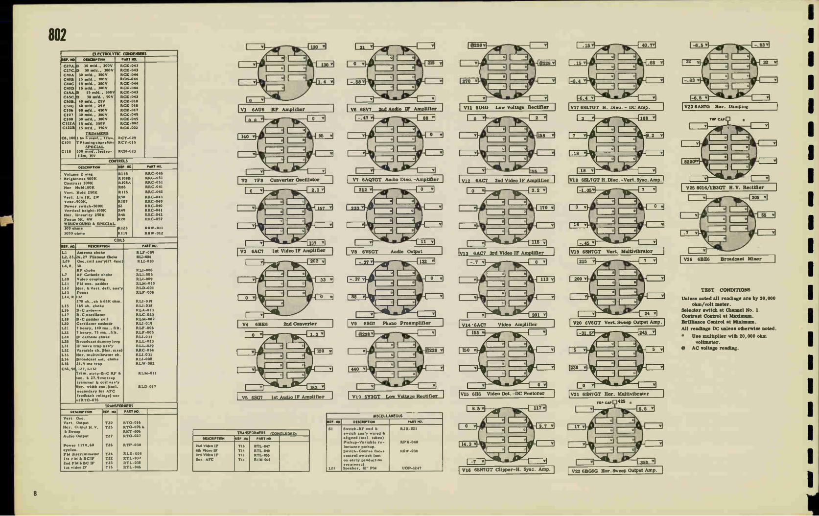
For Production Changes, see Pages 106 and 107. r _
6204 V 3A I V4 157 1 F V5 V6 D6EVAL7TA5 ISTVV814DEO V8 B V78 V 9
..mj L22. L225 ,i2r L227 FerL 228 V Fè 2° N4 TV7 I2AU 7 2PooVIDEO DC RESTORER PICTURE TUBE 108P4 OR 10FP4 I 6AU6 36161 F
• cnol
624e Du l6F
c2s4
I 2 3 94 95 6 97 11.3 te WO N2
-2IC 19r.. 52 1209
1001
_J
I 6 7 70405
'2162a
C.2;439
6 8252
...5176248uN
00
2 91C,:9 L235 E.5UH 2
s,265UN 1260 a2:052211FG:
330,0
6203 Ii 76 05 R201 >RZOB
8244
2 2341 C325 C253 8265
12Au7
• E eer -16252676 c274
1/2 6AL 5
s'R'esIh825S3629;E\ C‘ 26. 19'à GRE eN 2 0312'8'1f:2942
500K
an L29 L226 11-11
SEE NOTE "A" 805, 806, 801, 809 (EARLY) (T and S)
6SATUR670 F
3591.4. ANTENNA MPUT 300 OHMS
-;éQL 2 L13 isi --1'23e°pe
11203 8206 6-1,A4V-We-
516 5Ix
— 6206 - 5000
1201 C2D2 510
6 FNCL 1237 PrL238
szoi• 64U6
V2 2NoRF
1204
L209 1210 1211 1212 1213 173' er Fe ei
2 3 • 5 6 7 8 9 10 12 13 I--
V 38 215 02 2
CONTROL
TUNING t 4 C2,3 1712 ,. OSC Y 12AT7
,.,..........- C.999556 MEAD EN D I
1 •-•,....., I e' _.,
0216 1500 • R209
6243 1COK
CONTRAST CONTROL
1
- C2061 T s000 Noe -L mAN CHASSIS
® 0327 0314NECTED AS INDICATED By 001700 UNES For+ 8097.8065 me 6334 & 6337 ACOED meyEAD Oc09m4 PIN 8 cr vi3 TO 89.
C371 ,501M
C372 ISONF
53T POWER
0371 8371
5
1371
SPKR. FELD 80 fl
C373 1501,4F
6244_
6242 50,00 R24
9275
265V
VIO tST 2ND OSC 2140 380 Mee VERT IS/ CUTPUT 9NEEP v151F 1104F tiOLO (ET AMPL RF NO CCNV 251601 ta9a51 9116 6AU6 6AU4 6AL5 129/17 6Au6 6AU6 i2A77
R373 4 3 9 • 4 4 3
75 /9 C C38I C375 LnL L372 L373 ce, 5001". 50001
''''°I 51115 50001
53'4'1 '°C.15°°°1- 5°°C1
C377
9374 PEO60 1256757 1294751 25W1157 6606 GALS 1374 6507 2 7 7,AB 0.1113 EP.j 3
75 HOR IC« SIN DAriPER CUTPUT OSC Amp
V9 610 AUO. 1ST LE DE1 AL*
08P4 OR Oop4
NOTE "A"
"EARLY" VERSION: Original production. "T" VERSION: Change from a molded type horizontal output transformer T311
to ceramic iron core type T312.
"S" VERSION: In addition to "T" change a larger picture opening in cabinet.
C246 5000 R254
6251 R-470 2211
VI IA VIIB V2 I2SN7GT CLIPPER
1/212SN7G"
8336 3914
6355
04739 74F
-5415/9 113. 470K
C266 5 L756
165 Um â
1/2 I2SN7G
V 124 I2SN7GT FC
V 12B II2SN7GT
HOR SWEEP RED
1313 .11 95
C312 41328 Git 056E 425K c332
C)5 C317 8316 -If •l 220 2000
4265 V
F1:42K8
02MF c321 2MO
2006 2213 R319
- VI7 6AL5 :DETECTOR
D
C34 t -
120
(2o NOTE LATE PFOCUCTEN R361,14362 R363 REPLACED BY PE RESISTOR .R377 moon 5,04)
6337 1346 6800 ram
6323 8326
390 330
328
VI8 6SQ 7
1sT AUDIO
6366
2 11348 47 G
9'-4'AM-4470e: 05 t R267
6326 .06221W 6330 470K
a 0234.1. 71er
VI9 25L6GT
AUDIO OUTPUT 8L GREEN
VI 4 1B3GT/ 8016 H.V RECTIFIER
120011
265 VOLT
7342 LS1
6352 8356
8364 220
C271
8304 128 s eh
6327 R135 540 470K
1216AF 800V
HUM eUCP COIL 534IA COARSE FOCUS
1343
fae
17358 eiMA 430 8339 820
8360 020
13

805, 806, 807, 809 (U and IV) ELECTROLYTIC CONDENSERS
REF. NO DESCRIPTION PART NO.
C268
C277
C278
C299
C346
C354
C358
C297
C37I,2
C213
R328
R373,4
R371
40 mf., 300V
10 ml., 150V
150 ml. , I 5V 30 ml.. 450V
I ml. , 50V
10 mt.. 350V
50 mf., 100V
100 mf., 50V
3,4
150 mf., 150V
TRIMMER
RCE-088
RCE-088
RCE-088
RCE-092 RCE-090
RCE-089
RCE- 089
RCE-089
RCE-091
RCY-053
RRN -007
RRW -041
RRW -043
1.25-1.95 mmf.,
500V, trim. cap.
SPECIAL
42.5K temp. comp.
75 ohms, globar
5 ohms, 4W, w. w.
CONTROLS
DESCRIPTION REF. NO. PART NO.
Volume
Volume
Brightness
Brightness Contrast
Contrast
Hor. Hold
Hor. Hold
Vert. Hold
Vert Hold
Vert. Lin.
Hor. Lin.
Height Foco•
Focus
On-off .witch
•(805, 6, 7) se.(809)
5.353
5.366
5.231
5.226
R227
5.263
R321
R329
R298
R307 5.300
5.402
R302
R347
5.365
5372
RRC-099. ARC- 104...
RRC- 109.
RRC- 102..
RRC- 109.
RRC-102.•
RRC-098.
RRC- 103..
RRC-098.
RRC-103.•
RRC-095
RAC- 108
RRC-096
RRC-099.
RRC- 104. 0
RRC- 104 8,1.
COILS
REF. NO, DESCRIPTION PART NO.
L201
1.202,5
L203, 7
L204
L206,
L208,
L248
L255,6
L257
L3I3
L314, 5
L316
L341
1,343 L376
Input coil
RF le O•c. ch. 8.2 oh,
RF coil
RF Choke
259, 372, 373, 374, 375,2
Heater choke 2.0 iih.
242,243.244
Video IF plate plug core
IF Choke
8 Video comp.ch. 165 id>
Video comp. choke
Blocking o•cillator
Hor. .ire or Hor. lin.
Hor. oscillator
1st audio IF
Focus
Filter reactor
RLF-023
RLI-032
ALI-083
RLF-024
49
RU-063
RLP-014
RLF-027
RLI-038
RLI-068
ALI-086
RLD-014
RLC-091
RLI-069
RLF -026
RTL -096
TRANSFORMERS
DESCRIPTION REF. NO. PART NO.
Ho:. Output
Audio Output
Audio Output
Yoke
Broadca•t filter
Ratio detector
Vertical sweep
T3I2
T344
T312
T34I
T29I
RT0-071
RT0-066
RT0-062
RLD-013
RLX-027
RTD-008
RT0-064
( 809)
(C394, S)
MISCELLANEOUS
REF. MO. DESCRIPTION PART NO.
X371, 2
LS2
LS5
5371
S34I
Selenium Rectifier
Ion Trap-10BP4 pic tub
Lg.Outside center .g ring
Sm. Inside center .13 rani
RF Head End, Complete
RF Head End, Complete
Speaker, 10"(Model 809
Speaker, 4" PM
Thermal Cutout
Focu• Switch
RER -004
e RET -002
RHM-059
RHM-060
RJX-027 (Mod. 809)
RJX-028 (805,6, 7)
ROP-018
UOP-487
RSR-001
R.SW-066
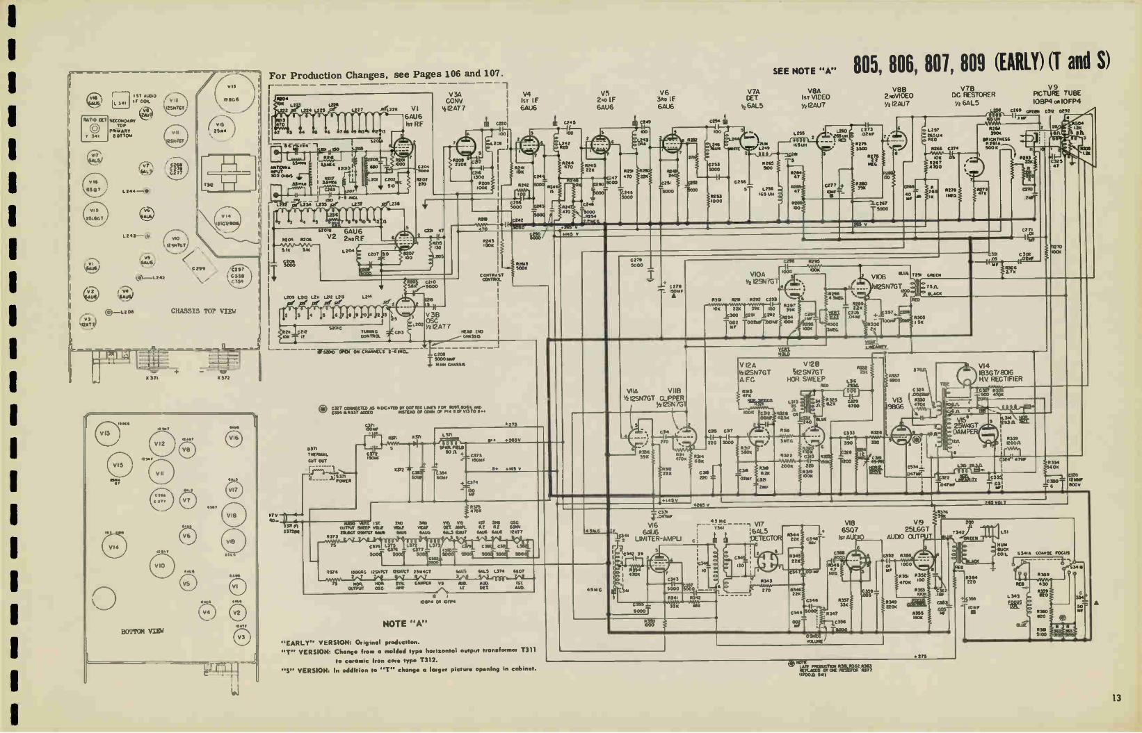
V1 6AU6 RF Amplifier
V2 6AG5 RF Amp. ( W Version)
V3 12AT7 Converter- Oscillator
V4 6AU6 1st IF Amplifier
V5 6AU6 2nd IF Amplifier
V6 6AU6 3rd IF Amplifier
V7 6AL5 Video Detector, DC Restorer and Clipper
V8 12AU7 Video Amplifier
V10 12SN7GT Vert. Multivibrator & Sweep Output
V13 1913G6-G Hor. Sweep Output
V14 1B3GT/8016 H. V. Rectifier
V15 25W4 Damper
V16 6AU6 Audio IF Limiter & Amp.
V17 6AL5 Ratio Detector
V18 6SQ7 1st Audio Amplifier
V20 6SL7GT Sync Inv. di Clipper
V21 12SN7GT Hor. Control & Ose.
V22 6AL5 AFC Discriminator
TEST CONDITIONS
Voltage Measured:
* Measured on 50V Scale.
t Focus control max. - Focus switch max. clockwise.
*8 Measured on 2.5V Scale.
Volume control off.
Focus control - normal
Contrast - max.
Brightness - min.
H-Speed - normal
V-Speed - normal
Resistance Measured:
Power cord - off
Volume control - min.
FOCUB control - max.
H-Speed control - max.
V-Speed control - max.
Contrast control - max.
Brightness control - min.
Vert. Lin. control - max.
Vert. Size control - max.
Focus sw. control - max.
Hor. Lin. control - max.
1
14
1

1
SECONDARY TOP
PRIMARY OT TOM
V2 ®-1242
GAGS fo,
® -1206
4m!Y CHASIS TOP VIEW I
Pet Lz1
X 371 X 372
BOTTOM VIEW
1754
•SOT
•74.,
4444
441"
CD 02 641E6 U. VER5E114
For Production Changes, see Pages 106 and 107. r _
.204 L2 1.226
1222 1224 1225 Pr
43 70
3 4 5
R2i6
ANTONIA 13 (6 MUT #2,2
1% 1 OHM 3ME
•6 17
CL207 V
I L233 L2162-4 1232 er1234 L235
52
• 5 61314
LZ2 7 .314fi.228
1257
7 8 9
S20.4
2
R201 K)00
C202
510
peL238
14205 R206
5 1K SIK
e pti
32018
V2 6AG5M
2NoR F
VI
6AU6
kr R F
R202 270
C224 331414
V 34 CONV
I2AT7
8206 2 20K
C214 1500
R219 00K
5 R218
V4
Is T IF 6AU6
- 7_ C250
MW
R244 10K
5147 C255
470
1.209 12.0 L21 L.212 1213
le pi se le le 1211
3 4 5 6 Silo,
C2. 122 5201C
TUNING CONTROL
sr,
5
R205 CM 5000
2
1202
cze 1
V 3B
OSC
5'2 I2AT 7 KEN) CPO CKASS6
Ft28 7 470K
57V fr4
60- a 137260
estop oam ow CHANNELS 2-6 INCL
SEE T EIS SCHEMATIC FEN
CONNECTIONS OF v26406 USED IN u VERSION
11371
THERMAL
GUT OUT
1:3311 FERRER
C371 1501S
-RP- 72 .57, .2713
C372 150IFF
‘sr2 c3e3-GOW 6CW
L 376 809W ONLY
"\C ONNEC TIC« FOR
C254 5000
R229 221
R227 2 wEG
CONTRAST cONTROL
- if 5000
4265 V
C245
100
L242 MITE
R244
55 /I C373 IC3 150IÉP
4. 74
Too
.150 V
39 0.245 ,5K
C246
5000 R254
V5
2No IF
6AU6
R 3130
REG
V6
3ao IF
6AU6
C249
O0
f,L243 o ORA
470
C248 5000
R268
0293 828
C258 40 S AM •
22K 8381
64%6K3
C392
C.: S:°°° « 1.
V20
6SL 7GT
FiriASE INV Ce4
V7A
DET
42 6AL 5
C 264
u. 1249
QS
R265 500
805, 806, 807, 809 (U and W) V8A V8 B V 7B
I ST VIDEO 2 NoVIDEO DC RESTORER
w2AU7 I/2 124U7 I/2 6AL5
1255 2 *SUN
1160 ‘,265
- - 1 8'.
1256 o .65 UN
C257
coor
'4) C 500
I_275 02ku
11275 3300
?SO
C227 -I-5030
• Rina
.4»
o 1257
E2650
la 26 7 4220
22e 270
#278
11•EG
V 9
PICTURE TUBE
10P84,10FP4
,e ,269 GREEN 03.2 0292
6328 IMP
6266 10K
OR cw TRESS R231 50G K
R2133 22«
22
1270
..! 0
C457°0' c296 R295 1------MMM
5 VIOA 00« .000
I/2-12SN7GT
Ill? #308 394
,C306
le
C309 470
C307 002 Mr
•
• •
e 8294 100K
e • R296 6 k 4 bFIEG.
Pie' 2, cee.ri .1297- "
e 981 4107, I 310V
HOLD
R390 #389
vice "
r2SN7GT 1200 11.
GREEN
C301 .os
C 302 02.6
R506 2 7K
2 2
en
o 7511
BLACK
11_4,411,1z
#303 SK
47
.•• C406 i-T 13W
V2IA
Vz - 12 SN7Q A FC
313 7 30« 2 R384 1MEG,
V22 64%1_5_ DISCH
63218 040
CI« 3900 8391 331
.385 c396
- ME 0,
C395 680
8586 820
391 OZ
3.3 05
V218
22 V2 T 12SN7GT
HOR OSC
I II-2 C400 c•02
4.70 2000 •
R394 68«
3 C401 e 220
-
R393 27«
R 521 00 K
tee
R396 35K
C405 5000
C•04_ 3900
8391, . 3\ 4.7K
C403
911,6 000
da.m
RF181
mc lc°
M. SOFT 1ST 211) 3410 YO OUTPUT 902E1 YICUE VOW VOL? DET 2211.161' 6912GT Soul Yu. &WS 623.5
R373 4
C /OS 220
220 4117
yr. 1901368 12518701 6,4.3 9W_701 254140T641.16 6315 L374 £607 2 7 7 8 6
NOR C4r2 NON AFC SYNC DIMPER A1.10 A1 St Mr our-aura, osc DES
R375 •7011
Vitt ST 210 OSC. MPL R F RE CORN
122437 644.16 6405 OAT?
9 • 4
cp. 1.375 L372 1373 L. c381 c 0318 2.377 C37H-
1 1 5°C° -{ SCCe SCCCI- '°4 5°4 9°°
NOTE CS.C1TOR MLUES ARE à6.6 uALES5 SPECwED
09
E13 AŒ0 TO
3 3IFEG
1001W/F LATE PRODUCTICO EIROACICAST FILTER
4.541 G IS,524
/.•
VI6
6AU6
LIMITER -AMPLI
5 c342 39
8354 470«
1. 1344
5
•
cc.
R3913 VI
198G6
NOR OUT PUT
#326
22
6537 114EG
5
C410
I' R402 25K IN U
DRIVE %v
3
c 326 .002256 #330 • 70K
•011-^
R403 MOO.
1312
VI4
IB3G T/ 8136
I-1.V RECTIFIER
R399 3.3K
R304 2K 8 n.
3
axe uk
R400 500 470N
20
611
S
5 L3I4
20
C332 emu
1.5AV
VI5 5 25W4GT
DAMPER
3 MP
405
• 5 1.4C
T341 :6AL5
'DETECTOR
14
2 c3451_
C 120T
SC 0▪ 3 01- -Ó11 .3. 0 03 5 70
c5.50.5c1,_ 6800t R3t_ ,Re342
543
#011 2
0345 228
c547 00?
C546 447
C368 470.4.4F - C366
5000
o R546 22
C 349
002 MF
e
C348
5000.
*548 1 47 >1EG
R376 39«
VI8 VI9
6507 25L6GT
1ST AUDIO AUDIO OUT T -4444 £ GREEN
R440 epee .
CA42 T
200
73421 D II ISO
7- 1 •
5
8557 33K
347
C"'
C359=
C352 R3
01 11F
1000
V47K 350 le o 1ji) R353 p: AWL
8555 ie0K
C367
C353
005 1./F
OME Y.1..UME
.30 V
RED
R364 220
c 3513 u
,031F
5 344• GCMRSE FOCUS
RED
L 343
S3418
R358 G 0
.VvY• •30
8359 820
#360 820
R377 1700 5w
oa
BLUE
ORO

810, 811 ELECTROLYTIC CONDEKSERS
REF_ MID. DESCRIPTION PART MI
C33
C58
C62.
C35
C59
C60
COI
C63
CIOZ
C59,
C46
C93
15 mid., 450V
30 mid. ,450V
30 refit., 450V
30 rnfd., 50V
15 rnfd., 450V 30 mfd., 450V
10 rnfd., 450V
30 mid., 450V
2000 mid.
60, 61, 63
Capacitor
Capacitor
25 mfd.. 25V
SPECLAL
RCE-070
RCE-070
RCE-070 RCE-070
RCE-071 RCE-071
RCE-071
RCE-071
RCE -083
RCE-084
RCE-093
UCE-065
Model 810
Model 811
Model 81 I
C53 C28
C103 C57
C56
SOO rnmf., ZOK
.047 mfd. , 600V
.0022 mid.. 1K V 4 rnmf.. 1300V
47 rnmf., 800V
TRIMMER
RCN-011
RCN-014
RCN-019 RCN-020
RCN-021
mica
mica
C49,81
C.80
C12,17
C5. 6
25-150 rnmf..
1_25 rnmf..variabl)
tuning condenser
1.5-15 mmf.
0. 4-2. 4 mmf.
RCY-045
RCY-046
RCY-047
RCY-048
mica
rrllea
CONTROLS
DESCRIPTION REF. NO. PART NO.
Vo lurne. 2 Meg; On-Off ins.
Brightness 7500, (dual)
Contrast 500K, (dual)
Hor. Hold 50K, (dual) Hor. Size
Vert. Hold 50K, (dual) Vert. Size 100K
Vert. Lin. 1000, 2W.
Focus 1000. 4W.. w.w.
On-01f switch
NV IREW OUN 0
R86, S2
1095 1013
1046
1029
1031
1033
R72
S2
R70
1097
10105
RRC-091
RRC-089
RRC-089
RRC-090
RRC-090
RRC-087
RRC -086 RRC-088
RRC-091
RRW-028
RRW-029 (81 0)
RRW-034
560 ohms, 7W., w.w.
.65 ohm, 4W. ,w. w.
1.0 ohm. 1/2W., w. w.
COILS
REF. NO. DESCRIPTION PART NO.
LI, 3
L2
L4
L5
L.6.14
LIS
L16,17
L18
L19
L20
LOI
L24
L25
RF input, V2 cathode
RF V2 cathode V2A oscillator cathode
TV audio 1st IF
Video carrier sel trap
TV audio take-off trap
22,23
Video, 165 hy.
Hors., size control
Hurts. lin. control
7 henry, HV sy. filter
TV audio 2d IF
7 henry, LV sply filter
Focus
RLI-006
R1.1-003
RLI-019
RTL-085
RLI-005
RLI-061
RLI-038
RLD-004
RLD-005
ALI-059
RTL-085
RLI-060
RLF-013
TRANSFORMERS
DESCRIPTION REF. NO. PART NO.
Í PowerModel 811 Audio Output
Yoke
Audio discriminator
1st video IF
2nd video IF
3rd video IF
4th video IF
lot audio IF
Hor. blocking ose.
Vert. sweep output Hor. sweep
Power, 60 cy. (810)
Antenna input
T113 T20
T19
T11
T12
T I 3
T14
TOI
TI),
T15
T17
T18
T1
RTP-300
RT0-052
RLD-006
RTD-007
RTL-081
RT1,-0132
RTL-083
RTL-089
RTL-090
RTM-003
RT0-053
RT0-076 f.
RTP-062
RLA-031
RKT-008
MISCELLANEOUS
REF. NO, DESCRIPTION PART NO.
SRI
Centering assembly Includes magnet rings
IS split fiber tube. Selenium rectifier.
Ion Trap- model 811
Contacts-speaker
model 811.
RAX-024
RER -003
RET -002
RJC-002
VI 6AU6 RF Amplifier
V2 12AT7 Converter - Oscillator
V3 6AU6 1st Video IF Amplifier
V4 6AU6 2nd Video IF Amplifier
MISCELLANEOUS
REF. NO, DESCRIPTION PART NO.
Head End Unit- inel.
tubes, completely
aligned.
RJX-023
Speaker-ten inch,
used on early produc-
tion model 811.
ROP-018
Board- Antenna term. UJB-004 LS1 Loudspeaker- 5 1/4
in. PM, model 810. UOP-577
Speaker -eight -inch UOP-867 PM, used on Late
production model 811.
V5 6AU6 3rd Video IF Amplifier
V6 6AL5 Video Det. -Clipper Rect.
W 12AU7 Vid. Amp. - Limiter
V9 6SN7GT Vert. Sweep Generator
V10 6V6GT Vert. Sweep °input
V11 65N7 Phase Inverter - Clipper
V12 6SN7 Hot.. AFC -Sweep Gen.
V13 6BG6-G !for. Sweep Output
V14 1B3G High Voltage Rectifier
V16 5U4G Rectifier
V17 6AU6 Audio IF Amplifier
V18 6S117 Audio IF Limiter
V19 6AQ7GT Audio Disc.-Amplifier
V20 6K6 Audio Output
V21 5Y3GT Rectifier
V22 6AU6 Audio IF Amplifier
* VTVM through 0.5 megohm resistor
** Measured at start of primary winding
t Grid voltage at V3 di V4 indicates range of Contrast Control
@ AC Voltage
Unless noted all readings are DC, taken
by a 20,000 ohm/volt meter, selector
switch at Channel No.4, normal synced
picture, normal brilliance and contrast,
line voltage - 117 Volta.
1
16

810, 811 •667,••• 70166,6. @ONO
r. KW« 771•6311011.46
66•61011 [TO,/
scceo.R+ mono.:
• 16 veg.! 71.665
(S. "1,--i" Roo um« v,» ;' +RR". Rm.
urtneak nul ITIA65
71
rs, vvt0 If
COW
eel%
vOrtKAL MLA .671
60660666 NOLA 11146
CHASSIS TOP VIEW
T 18
117Y 10114
.4 e
Mar
VIDEO CARRIER-SET TRAP
171.14ff c5. _E— C10I t I '-2156114 LIS
o • -a « 64U6 1.14.Z "
, V2B V3 07 R-F AMPuf ER ,, ile T • OK» ceERTER " 3-'1. 6U6S1ST VOE0 K TI2
• N__. __—./ IN 0 0 qfp- i »- C134 i CM
SWF I 7à ,,Cor _LC15 5 heel 244 2
C7 7
l
v2A 4 i2AT7 0770LLATOR
AM 62K
073 10011
Rev« VII 93
47666 C6 CO 15000
2.4 MIF
119 ZAK
«PO TAITE-0« TRAP
21 @MC
For Production Changes, see Page 107.
ios 2.7K • LEK 56K
ea 27K III
C60 AC LI ±.211Mif
701600 AO« litAr
4,3 301IF
5000 Stie COIL
125
Ve V13 0,0s L6
OR,
VN VS VM 41 97
LO
5120 RAEG
022 6M16
1-F 4111PUFIER
• 1f2A 101
O If Té3
031 Co.,
R26 VERTGAL V9 22011 SIZE 6SN7GT
VERT SWEEP GENERATOR
«ss C30 C31 4'
/.0Cele .C4 OW 626 82K
- •
11008
I 5=1
,MLIF
r 065
I
C106 T 5000
1 C90 "SOLO
tee
250V
-1-C2590KO
vn SAUK 65117 I
I-F AMPLIFIER C68 LIMITER , -9 3.
ICOINAF o• MK
i 12 .1 40e a" We a
l
1616 50K
eV, Kee
447 *LLD >240
048 MEG
Ca 030
I4 %.024.2e 33«
_ IHALD
I vs I ,rou,6,10E01-F
C23
VIO 6V6-GT/G
SWEEP OUTPUT
TI•
V6A
-6ALS
DETECTOR
a. C.26 61/111F
RZO u7 MEG
V126 - 85017 GT KOLSWEEP GEKRATOR
22K
il I__ 2
l. E. cro MMF I
= 4211
TM 47 R83 j 68K 7 .75
C74
C73- 68K coM 150 -r
V7A 12AU7
VIDEO AA«
I/26407-6T Is INS0111411MTCH
47
82
C87
C28
criZTis,
VI99
6A07GT MOO AMPLIFIER
979
-12AU7 ICI VIDEO AMPLI 123
ET" 165U14
L22 *SUH 711
T-
Ve 10F P4 or 1013P• PICTURE TUBE
EKTERINA
TWHuomart, EELLEECC5TTROSTTAATTICG.09L o 16
AL
112IERT OULECTON
MT«
12 BUr..K R97 MEG
TEL
CIO rIS R 2«
2.711 .ceodFo
47K
0000
166 196A1414 C54 1-8.1
• 33 a
T20 131
32
* RESISTOR ROO IS EITHER SPIPITE0 OUT OR LEFT IN He CIRCUIT WHEN THE CENTOMI6 OF He VERTCAL HOLD CONTROL 629 6 CHECKED AT THE FACTORY.
17

814 ELECTROLYTIC CONDENSERS
REF. NO. DESCRIPTION PART NO.
C33
C35
C58
C62
C59
C60
C6I
C63 C102
C93
C49
C80
C12 17
C5,6
C8 I
C28
C103
C57
C56
C53
15 rold. , 450V
30 mfd., 50V 30 mfd. , 450V
30 mfd. , 450V 15 rnfd., 450V
30 mid., 450V 10 mfd. , 450V
10 rnfd. , 450V 2000 mfd
25 rnfd, 25V
TRIMMERS
25-150 mrnf, mica
I. 25 rnmf, variable
tuning conden•er. I. 5-15 mmf, mica
trimmer. 0. 6-2. 5 mrnf,
45-380 rnmf,
SPECIAL
.047 mid. 600V
.0022 infd, 1000V 4 mint, 800V, mica
47 mrnf, 800V
mica.
500 inrnf, ZOK V
RCE-076
RCE-076
RCE-076
RCE-076
RCE-077
RCE-077
RCE-077
RCE-077 RCE-083
RCE-086
RCY-045
RCY-046
RCY-047
RCY-048
RCY-051
RCN-014
RCN-019
RCN-020
RCN-021
RCN-023
CONTROLS
DESCRIPTION REF. NO. PART NO.
Volume 2 meg
Brightness (dual)
Contrast (dual)
Hor Hold 50K, (dual)
Vert. Hold 50K, (dual) Vert. Size 250k
Vert. Lio.1000, 2W
Focus w. w.
On-Off switch
WIREWOUND
w. w
R86
R95
R73
R46
R29
R31
5,33
R72
S2
R105 R107
RRC-091
RRC-089
RRC-089
FtRC-090
RRC-090
RRC-084 RRC-086
RRW-033
RRC-091
RRW-034
RRW-035 1.0 ohm, 112W.,
900 ohms, 7W. ,
COILS
REF. NO, DESCRIPTION PART NO.
LI. 3
L2
L4
L6, 14
L16,17
1.22,23
LIS
LI8
LI9
L.20
L21
L24
L25
RF input, V2 cathode
RF choke V2 cathode
VZA oscillator cathode
Vid.trap & filament choke
Video choke, 165 oh.
Audio take-off trap
KO, size cont.
Flor. linearity
7 henry, HV, supply lilt.
TV audio 2nd IF
7 henry, LV, supply filt.
Focus-PM magnet
RLI-006
RLI-003
RU-019
RLI-005
RLI-038
RLI-061
RLD-004
RLD-005
ch. RLI-059 RTL-085
ch. RU-060 RLF-017
TRANSFORMERS
DESCRIPTION REF. NO PART NO.
Vert. Output
Antenna Input
Pow .'" 60 cycles Audio Output
Yoke
Audio disc,
lst video IF 2nd video IF
3rd video IF
4th video IF lst audio IF
Hone. bilk. osc.
Horiz. & high
voltage.
TI5 T1
T18
T20 01,2
T19
TII
T12
TI3
T14
T2I
TI6
T17
RT0-053 RLA-031
RTP-066
RT0-052 RLD-007
RTD-007
RTL-081
RTL-082
RTL-083
RTL-089
RTL-090 RTM-003
RT0-076 &
RKT-009
MISCELLANEOUS
REF. NO. DESCRIPTION PART NO.
RSI
Centering ring sup-
port assembly.
Selenium rectifer
Cunifee centering
ring. RF Head End Complete
Speaker
RAX-025
RER -003
RHM-057
RJX-023
ROP-015
V1 6AU6 RF Amplifier
V2 I2AT7 Converter - Oscillator
V3 6AU6 1st Video IF Amplifier
V4 6AU6 2nd Video IF Amplifier
V5 6AU6 3rd Video IF Amplifier
V6 6AL5 Vid. Det. & Clipper Rect.
V7 12AU7 Vid. Limiter & Amplifier
V9 6SN7GT Vert. Sweep Generator
VIO 6V6GT/G Vert. Sweep Output
V11 6SN7GT Phase Inverter & Clipper
V12 6SN7GT Hor.AFC & Sweep Gen.
V13 6BG6G Hor. Sweep Output
V14 1B3GT/8016 Ri-Voltage Rect.
V15 5V4G Horizontal Damping
V16 5U4G Power Rectifier (H. V.)
V18 6SH7 Audio FM Limiter
V19 6AQ7GT Audio FM Disc. &Amp.
V20 6K6GT/G Audio Output
V21 5Y3GT Power Rectifier (L. V.)
V22 6AU6 Audio IF Amplifier
TEST CONDITIONS
DC Measurements taken on a 20,000 ohm
per volt meter.
Selector switch set at Channel No. 4.
Normal Synced Picture, Normal
Brilliance and Contrast.
Line voltage - 117V. Values listed may have a tolerance of
+20%.
Measured with a VTVM through
1/2 meg ohm resistor.
it AC voltage reading.
All voltages DC unless otherwise noted.
18

S4COMM MEMOIR
ere,. Inn
16:016•1•1 learrrar
MTEOR• TIMM MOM _
vEMC41. IDEO RE.
M1171016,14 a. ^
CHASSIS TOP VIEW
IS 616.11.4T y nun 40,M4
MIR1.167
PRODUCTION CHANGES MODEL 814
RP,
In lot« production Model 814, the audio If coil LS has
been changed to an audio IF transformer, 721, to give
added selectivity in the audio channel to reject vertical
pulses and video signal which couse hum and noise in the
audio.
In lose production Model 814, C3, a 5000 mmf. wafer-type
410vt
• V ocvN.,
TI LI CI
vt 6.6u6
RAVIL.EIER
47
C32 6 ear -
v2A ¡MAT)
OSOLLATOR
Cs 1
MAO tra
V2I 5736T
ceo 4 oc u 1.2ieW
Vit VI 55 v19 me vs V7
7 r r • • • vii
CII 47 WS
capacitor has been replaced by o ceramic capacitor, 1500
mad. Cat. No. RCW-026. On sets using the wafer-type capa-
citor C3, it was found that this capacitor started vibrating
and was a source of howl. Since C3 is comparatively dif-
ficult to replace, it is suggested that a rubber block (Cat.
No. RMM-081) be wedged between the edge of C3 and the
chassis of the head-end unit. To facilitate mounting of this
cm
v22 6AUS
i-F AMPLIFIER
Cal VW -
Doto 120
Au»
RO CARR1ER•SET TRAP
L-2LIMAC
II:AKE-Orr TRAP
Ca 1.5 Owe Len
v3 c.7 Ice 6•116 236.5
ST II-SEO fc tt2 13 '5." ETE119q9(boor° D 0
C22
v. 27,01110 If 1.3
5 WI 1COmas C20 50031 war ,
6
RI?
Ce I SCCO
290 v -5-c67
R31 2505
R26 VERTICAL 220K V9 SIZE
69MGT VERT SWEEP GENERATOR•• R11 CIS 3
.....„......ZE ' 55e I
...--------. R30 22MEG -
vue eel
ilea, .36
11.2K
VT? SAW
1-F AMPLIFIER
VERTICAL HOLD •
23
_ 251 1-0 1 vs 68116 3RD m0E0 IF
Teti - einnr
Rte Ce5 III
I"
v6A
-6AL5
DETECTOR
C26 PiAlf
v711. 12467
VIDEO AMU cze
642 Fit
820 AEG
I ---7, ---. Irv/ rt07-67
I 31
Fat.F 1555
iyOnCRMINATOR
LieeTER Ssv
Vie I é é eSm7 I
re \--Ok C75 T l,i
R75 47 1770:4 - 07191 n " r GSell C
C-6" A, - A •: -.-_-_-.6 C100
850 T OW 21K ,a„,-r be, 0 r _I_ , 1. 1 56K MK
rubber piece, it should be cut into o V shape so that the
edge of the capacitor C3 is held in the channel in the edge
of the rubber block.
Another source of howl was found to be the tube V2 (12AT7)
being or becoming miCrOphOnic. Where this is the cose, o
e
2mEG
CS? Oths
lead cop (Cat. No. RHX-014) should be mounted on the
12AT7 tube.
A third eCterCe of howl was found to be the textolite rotor
and/or the metal guide ring on textolite rotor of the oscil-
lator wafer of the channel switch becoming loose and vib-
rating. The guide ring should be cemented to the textolite
C76 reef
L
v1913
4- 6407GT AuDO AMPL.FIER
I-78 - mau7
VIDEO wet.
C97
ea3-Raires
5-2m8
R61
R23 IDO
Rn
713 123 err` MUM
L22 *Sum 711
Lew R70 3305
863
114•Cx El
C110 029.1f
51.9 2•K
_LC.04 2eff
814 Ve
12KP4 ELECTROSTATIC PICTURE TWIE
SHIELD Exect.1:. 2.3,ATING
vERT,fOiECTeN
K) 02 HOR.
DEFLECTION
CM?
R112 270K
BRIGHTNESS
4 7K T
R116 — C55 33013
JRE ram...WM t
1-141 3311
V20 en-CT/0
A110.5 OUTPUT
315 V acw LS.
nos 15•0*. Fa
mo
32 ̂
• RESISTOR 71110 IS Cana SHORTED OUT OR LEFT IN THE CIRCO wield THE CENTERING Of THE VERTICAL HOLD CONTROL 529 IS CHEWED AT THE
R.13 MAY BE REMOVED FROmi/Cted/Y. THE CIRCUIT AT THE FACTORY WHEN THE CENTERING OF THE VERTICAL HOLD CONTRCL 829 rs CHECKED
rotor and the textolite rotor should be cemented to the
shaft with "Dekodhese Cement". Extreme caution should
be observed when applying this cement. The cement should
only be applied to the guide ring, the textolite rotor, and the
shaft. The cement should not touch the fingers of the elect-
rical contact ring which extend through the textolite rotor.
19

815 ELECTROLYTIC CONDENSERS
REF. NO. DESCRIPTION PART HO.
C97,8 .30
C9I 90
C45A 30
C4513
G45C 15
C45D
G32A
1.7.32G,B15
C32D
G60
C35,6
C95,6
C120 C22A
C22B
C93
CII5
C114
C92
C I 12
inf., 300V
mf., 450V
mf., 450V
30 mf., 450V
mf., 450V
30 mf., 450V 30 mf., 450V
mf., 450V
15 mf., 450V
50 mf., 25V
60 mf., 300V
60 mf., 300V
4E rof., 10V
30 mf., 450V
200 mf., 50V
ZOO mf.. 50V
1000 mf, 6V
500 mf, I5V 100 mf, 25V
TRIMMER
For television
tuning.
RGE-009 RCE-017
RCE-019
RCE-019
RCE-019
RCE-019
RCE-020
RCE-020 RCE-020
RCE-048 RCE-054
RCE-054
RCE-096
RCE-103 RCE-103
RCE-104
RCE - 106
RCE.107
RCE-108
RCY-057
CONTROLS
DESCRIPTION REF. NO PART ND.
Volume .t.ial, 2 meg Brightness
Contrast
Vert. Hold
Vert. Lin.
Tone 500K, dual
Height Horis. Peaking
Focus Horizontal Centering
Vertical Centering
WIREWOUND
55 ohm•, 7 watts.
R69A
R84B
R84A
R35
R.40
R.695
R36
R50 R74
R87
R88
R73
RRC-079
RRC- 117
RRC-I17
RRC-114
RRC-I18
RRC-079
RRC-115
EEC- 116
EEC-119
EEC-IZO
RRC-121
RRW-046
COILS
REF. NO, DESCRIPTION PART MO.
LI
12
L3, Kt 19
L4, 7
L5
Lk
L8
LII
L13
L14
LIS
L18
120
Filter ch., Thy., 140 ma.
Filter ch., 7hy.,140 ma.
RF coupling Width & Hor. lin.
Video detector
Osc. cathode
Focu•
Filter (foci.)
Filter choke, pl. supply
Video amp. Video amp.
RF coupling Cathode, IF
RLF-018
RLF-019
RL1-006
RLD-014
RLI-009
RLI-032
RLF-029 RLF-032
RLF-031
RL1-039
RLI-038
ELI-003
RLI-033
TRANSFORMERS
DESCRIPTION REF. NO, PART NO.
Vert. Osc.
Vert. Output
Hor. Output
Power
Audio Output Antenna input
Audio IF
Osc, & RF
channel 11
FM chsc.
lot video IF
2nd & 3rd video
4th video IF
Vertical blocking
T26
T9 TZ5
T 10 T4
T6
T21
Ti
TI
T2, 3
T4 T27
RT0-074
RT0-068
RTP-303
RT0-073 RLA-033
RL1-089
RU-091
RTD-009
RTL-I01
RTL-102
RTL-104 RTM-007
MISCELLANEOUS
REF. NO. DESCRIPTION PART NO.
SRI
Oval loud•peaker 4.1c6"
ISelenium Rectifier
ROP-015
RER -005
VI 6AU6 RF Amplifier
V2 7F8 Converter - Oscillator
V3 6AC7 1st Video IF Amplifier
V5 6AC7 3rd Video IF Amplifier
V6 6AL5 Video Detector
V7 6AG7 Video Amplifier
V9 6T8 Clipper-Hor. AFC Disc.
V10 6SN7GT Clipper - Limiter
V11 6J5 Vertical Sweep Oscillator
V12 6 SN 7GT Vert. Sweep Output
V14 6BG6G Hor. Sweep Output
V15 1B3-GT High Voltage Rectifier
V16 6W4GT Hor. Sweep Damping
V17 7 5U4G Low B+ Rectifier
5U4 High B+ Rectifier
V19 6AU6 1st Audio IF Amplifier
V20 6AU6 2nd Audio IF Amplifier
V21 6SH7 Audio IF Limiter
V22 6AQ7 Audio Disc. Amplifier
V23 6V6GT Audio Output
TEST CONDITIONS
Readings taken by voltmeter 20, 000
ohms per volt.
@ - AC Voltage Reading.
DNM - Do Not Measure.
20
1

815
1
rc
«dig C4.1
41
eill•CAL Meg, •••••••••
VI RF Amin. WIER
"u'
.0
100
G103 47
R103 3300
V24 GONVERTER It2 - 7F 8
6216
TO 47 2 6104 * ,0 47 •
10.
R102 • •
10« 715
Nee
ee.,ereee 49011 05W 646110114651 37
d-rtyn---f—re=ib TŒ Ir
310 0 723
, 717 , Su,
mg Gams 74.-732 OR MMUS MA. 13 MT SIAM COMER
reeza M"..ri&M"'
Me'
•DJACLN1 TA MAN
r POW COAA•0•01 reaCIrI•Ow7..1.. i/AVgi
ROMA Cor MA».
VI' 1ST MX00 IV 'AU.
r6 7
R92 56«
F.67 22«
V20 210 AUDIO rf
SAUR
76 Lexe-
BOITOM VIEW
V23 922 321 330 959 V16
4123 INEG
04
r 4461 4700
V28 OSOLLATOR u2-7,8
602 4
v2I LUSTER £567
G 12 TELEV.506 TimaNG
699 5000
Ri 47«
6107I470 LS L5 „it
V913 OrSCASSNATOR 1.2 - STD
77 F224 F229
41300F2OUTPUT
r - — Ammer
v3 1ST 410E0 EF 6467
•
•
v9à, 0_410.03• 6UPPER
v2- ET
MEG
<R24
p oll
V4 2NÓ VOE0 1-F
6467
• 12 g ig
278 MC TRAP
CS3
4- 70
••A
548 47500,
Ogir 2 MEG VOLUME
cute eee 5005
S 7 7 5 I 7 3 2 2
7 It 4 3 7 2 8 2 S 4 12 4 7 7
V13 VII2 vi I 344
3
Was 491511155 447 sob gem
NO V9 Ve
91.01
3.4
4E4
611116.48
LEAS ellimultailMIS
re 900112 1f
lcieo 4000 MED
VS 3R0 VIDEO er
6467
C 3211 15,110
725 344 449
v134 VIDEO 0E7EGTOR
1/2- SAL 5
V7 VIDEO AMPLIFIES
SAG?
•
V" PG RESTORER
1.12-134L5
1117 6161 C8
• LIS OuiF i 595
6332 165141. 101.
635-1154* 45.36 1000
co2MEG TRAP cR me ze2t_ 2 ez
RECTIFER SUNG
1.24 OWN
L9 8.11. DEFLECTOR
F12 6634707 V OUT MI
658 C58 R5I1 30X CGS 1.3.
*,
SO
VIS etv REC7601
16367
VO PICT ME TUBE
1641,4
564 465 1179 530 12101 SO« 120«
It LINE 413.71. 10 A
.R66 1 _1.06 <1501(
COI
582 583 680 680
C91 15041. C454 • 6456 905s - 301,0 - 3056
695 - _ C97 606F _ ,.. .-..1- 30.4F __
%DM -lc« Res — our . 301.6 160 •
11,—MAA--•
754 180.11
sorl 1323
V «NM«
015 1000 Mr

811, 821 (T and S) ELECTROLYTIC CONDENSERS
REF. NO, DESCRIPTION PART NO.
C268
C277
C278
C303 C358
C365
C346
C371, 2,
C299
C383
384
C326
C327
C3I9
C2I 3
40 mi, 300V
10 inf, 150V
150 rnf, 15V
10 mf, 350V
50 ml, 100V
100 trif, 50V
Imf, 50V
3, 4
150 mf., 150V
30 rrif, 450V
60 mf, 350V
SPECIAL
.0022 mf., 1K V
HV, 500 mmf.,20KV
TRIMMERS
45-380 mmf.,
horn, drive.
I. 25-1.95 mmf.,
tuning control.
RCE-088 ACE-088
RCE-088
RCE-089 ACE-089
RCE-089
RCE-090
RCE-091
RCE-092
RCE-094
RCN-019
RCN-023
ACY-051
RCY-053
CONTROLS
DESCRIPTION REF. NO. PART NO.
Volume dual, 100K Brightness
Contrast
Hor Hold
Vert. Hold
Vert. Lin. 2000 ohm, 2W
Height 3 rneg Focus, dual, 500K
WIREWOUND & SPECIAL
Temp. comp., 42.5K ohm•
75 ohms, 10W.
R366 R226
R263
R329
17,307
R300
R302
R365
5328
R373,4
ARC-104
ARC-102
ARC-IO2
RAC-103
RAC-103 RRC-095
RAC-096
ARC-104
RRN -007
RAW-041
COILS
REF. NO. DESCRIPTION PART NO.
L201
1202,5
L203
L204
L206,
L207
L242
L243
L244
L248
L249
L255,6
L257, 260
L3I3
L314,
L341
L342
Input
RF & o•c. ch. -8. 3 oh
RF
RF choke-31 oh.
249, 259, 372, 3, 4, 5
Heater choke coil
RF Video IF plate
Video IF plate
Video IF plate
IF choke-7.6 oh.
Heater choke
8
Vid, comp. choke
Vid, comp. choke
Blocking oscillator
15, 16
Hor. width is linearity
lit audio IF coil
Focue-w/PM magnet
Focus w/wing not as•y.
Broadcast filter
RLF -023
R.L1-032
ALI-083
ALF-024
RLI-085
R.LI-083
RLP-014
RLP-014
ALP-014
RLF-027
RLI-085
ALI-038
ALI-068
ALI-086
RLD-014
RLI-069
ALE-017 (817)
ELF -028
RLX-027
TRANSFORMERS
DESCRIPTION REF. NO. PART NO.
Vert. Output
Hor. Output
Audio output (821)
Audio output (817)
Ratio detector
Reactor filter
TZ91
T3I2
T343
T344
T34I
L376
ETC-064
RT0-071
ETC-072
ATO-066
RTD-008
RTL -096
MISCELLANEOUS
REF. NO DESCRIPTION PART NO.
X371
X372
8371
S34I
LS3
LS4
Rectifier -Selenium
250 ma.
RF Head End-corn-
pletely aligned .ith
tubes.
Thermal cutout.
Focus switch.
Speaker-4 in. PM
Model 821.
Speaker-12 in. PM
Model 817.
RER -004
RJ X-027
RSR-001
ASW-066
UOP-477
UOP- 1247
VI 6AU6 RF Amplifier
V2 6AU6 RF Amplifier
I V3 12AT7 Converter - Oscillator
V4 6AU6 1st IF Amplifier
V5 6AU6 2nd IF Amplifier
V6 6AU6 3rd IF Amplifier
V7 6AL5 Video Detector, DC Restorer & Clipper
V8 12AU7 Video Amplifier
VIO 12SN7GT Vertical Multivibrator & Sweep Output
V11 12SN7GY niase IrP.orter
V12 12SN7GT AFC & Hor.S'weep Gen.
VI3 19BG6G Hor. Sweep Output
VI4 1B3GT/8016 H. V. Rectifier
VI5 25W4GT Damper
V17 6AL5 Ratio Detector
V18 6SQ7 1st Audio Amplifier
V19 25L6GT Audio Output
TEST CONDITIONS
Voltage Measured:
Volume - Min.
Focus - Normal
H. Hold - Normal V. Hold - Normal
Brightness - Min.
Contrast - Max.
Meters:
AC 1000 ohm/volt
DC 20,000 ohm/volt
Line volts - 117V
@ AC voltage reading.
* Use scale 50V or higher
t Min.-Max. of Focus Control
Resistance Measured:
Volume Min sw. off.
Focus Max.
H. Hold Max.
V. Hold Max.
Brightness Min.
Contrast Max.
Focus sw. Tap. 4
Meter: 20,000 ohm/volt
1
22
1

1
1
1
0,e
25W4
11S117
BOTTOM VIEW
MU.
CIU.S
ED
For Production Changes, see Pages 107 and 108. - - r -
R204
.38 L29 L226 1.222 ;.M. 1124 L225 pe 3
470
I 2
72212 220
3
8214 lOO
•-•44/..• 4 •5 .6 .7 08
L227
440 411 012
I -
I 8226
I• NN R23.1371'60
I A----euET
300 0,4145 3 ., G eL2,37 L213 2
L232 ,peL231 L235 pr
C201 510
ATeL228
'3
52024
203
52020
.C205 C20
.c.L 201
1 V 6 INCL.
L237
36
2 3 4 5 6 7 8 9 I 12
C202
510
VI 6AU6 IsT RF
72202 2200
12/L238
I R205 R206
51K 51K
__ C5 :11.60
117 V
60-
S2026 6AU6
V2 2 moR F
L 204
L209 L2I0 1.28 1112 L213 L214 e e pi zr RT.' C215 er , 2 9
2 3 1 5 6 7 f3 9 10 II 12 3 L V 38 2.5
p , OSC
3202C C. L.",-„ 1/2 I2AT 7 R211 C22 CONTROLI2 10K 1
TUNING 4 £213 HEAL, Eno 4 9 _- CHASSCS -- ____.- i ...
7
72202 270
V 3A CONV
1/2 I2AT 7
C2201
1001
2013_ i
R2°8 8.C1IV 220K
• fi
72218
C221 47
•
5
72203 c210 5.6 Ky --5000
470
8243 100K
372 1.I1
eS2020 OPEN ON CHANNELS 2-6 INCL. C2013
I5000 MME MAIN CHASSeS
eT3HERMAL CUT OUT
3: 5372ta
C137.1 50,
72371 > 371 L376
C372 • £373 150em
150MF
V4 1ST IF 6AU6
2 6
C255 5000
242
72226 500K
CONTRAST CONTROL
R24 i5
265
C245
00
#244 470
#24
#245 2277
V5 2mo IF 6AU6
47 5000
leC° C246
470 5000 72254
135 V
C249
V6 3mo IF 6AU6
R251
▪ C248 5000
C278 150 MF
V7A V8A V8B CET I ss VIDEO 2 moVIDEO 6AL5 /212AU7 '/2 I2AU7
UH ,760H L 248 WHIT 2 L249
R265 5100
C266
5- L256 165 UN
L255
165 UN
5
R284 47
R2135 47
R2
L260
2 ‘,265 l/F1 - - RED
•
£277
014F
£273 02 MF
72215 3303
R200 3972
72726
MEG
265 V
5.
28
C261
5000
C268
40 MF
811, 821 (T and S) V7B
DC RESTORER & CLIPPER
1/2 6AL5 reL±1269
165 uH tom
o L257 R269
E 265 U n 39077
RED BRIGHTNESS 77263 500K R266 C274
10K 05 R267 • 700
26 8276
INIEG
7
72279 47K
V 9 PICTURE TUBE
12 K P4
GREEN 0313 0293
2
4
R304 2EL 1 2K
8.0 580. 3
R283 2271
C270
DAF
•
x37 7r • - C383. - --C. 184 601e COME
13714- 270D AU0i0 WW1 ST
OUTPUT 9MEEP enDiF VOLE 25L6CT C215147GT 64U6 6406
R373 • fr • 3
C375 q73576 3 C723,7 _ 1373 75
5001". 5000 500C C3780,. 50 15000 500Cr500C1 504
.135 v
R375 4 70K
-
3773 VIO 1.40 ST 2M) OSC «HE CET A. RF RF CPA(
64U6 64L5 12Au 7 64U6 64U6 12477
9374 19806G 125870 I2SN7GT 25w4GT
9 4 • 3 4 3 4
£381 C38
VIIA VIIB 1/2 12SN7GT CLIPPER PHASE INV 1/2 12SN7G
- 270 ss
•--
R 336 I 39K
Mummull9 .4135 el
VIOA 1/2 I2SN7GT
R301 R291 R292 C293 .-4.4"(Wve8AAW(41.~.4.14.4-1
10K 2222 3914 .50
_.c300 S.291 _&292
1002 1.002/001MF MF
C296 R295
i 000 100K
4 •
72297 3921
77294 100K
(
.11
R296 4 36265
294
307 302 COK 3MEC
2 VI OB 8LuEL1.291 GREEN
R299 2221
C305 03 MF
2SN7GT D
R3C7.0 2K
2 7 299
RED
7511.
BLACK
C271 101
C 302 ..021f
R306 2 7K
C325 47
R270 100(
R303 I 5K
C35 c.317
220 2000
R3I4 68K
C 306 220
265 V
UHL tau
VERT .1._PeAp111
V 12 A 1/2 I2SN7GT A FC
R315 47K
/42111/%0rERCNT) 1313
85 o
100K C312 0511F 425K D3.32
R328 Geir
24
V12 B V2I2 SN 7GT
NOR SWEEP ,401k NOW FED
2
72327 5606
C318
- 02m
77328 8221
C32I
2/4F
3/6
R 326 6 150K C3I3 R
200K 220
R319 loom
R332 75K
L 316 2930.
R325 - C329 82K 4700
VI8 6SQ 7
1sT AUDIO
172680C337 270.0
C326 .0022MF
VI3 R330 196G6 •70K
C334 047 MF
T312
VI 4 IB3GT/ 8016 H V RECTIFIER
335 I 2K
3f1.
77335 470K
7/1. .94 ft
VI58 25W4GT DAMPER
50 7
E
L3I4 29.30
R539 3 1203
161
4 47mF
1.315 2930
_C322 „Sin C335
1047e4F 03 C339 eAF 12 ;
265 VOLT
72334 560K
• 5 MC
VI6 T TI T V17 4 5M C IF 6AU6 6AL5
-1324' LIMITER -AMPLI à :DETECTOR , o
641.16 64L5 L374 6507
75 NOR HOR SYN DAMPER V9 6.10 1ST ouTRuT OSC AMP IF DE 1 LuD 4 5 m C
2
5 C342 39
R354 47077
L341
7
£343
-8c3fe7 5000 5000
R34
10
8342
33e( 5000
se«
R550 1000
C31
120
K.*
2
343
7
R344 226
R345 22K
46 IMF
34 7 00,
270 R346 2271
C349
002 MF
C348
5000.
C366
2 R348 • 7 MEG
3
R357 33K
72365
?- 1C356
Tscoo
C359 - 023
Vr9 200
25L6GT T343 1L Ii 0 LOS
AUDIO OUTPUT elle GREEN
3
C352 R356
01 /000 MF
RED
72351 14352
470K
R366 100K
1R349 220K
41 11..1
8355 1/30K
C353_
005 MF
VOLUME 15006
-4275
72364 220
.1.L' .C358
10 MF
53114 COARSE FOCUS
R358
RED 430
R359 L344 1320
S
EiLuE
72360 820
R361 5100
S3418 00
RJR 363
354
50 MF
NO LÁTE PRODUCTION R361, R362,8363 REPLACED El7 ONE RESISTOR R377 (1700/1 541)
23

817, 821 (11 and VI) ELECTROLYTIC CONDENSERS
REF. NO. DESCRIPTION PART NO.
C257
C258
CZ68
C277
C278
C297
C303
C354
C358,
C299
C346
C371,2
C383,4
C406
C3Z6
C327
C2I 3
10 mf. , 45 V
40 mf., 300V
40 inf. , 300V
10 rrif. .150V
150 mf., I5V
10 inf., 350V
50 mf., 100V 50 mf., 100V
365
100 inf., 50V 30 mf, 450V
I inf., 50V
3,4 150 mt., 150V
60 mf., 350V
10 mi., 150V
SPECIAL
V
20K V
RCE-I00
RCE-I00
RCE-088
RCE-088
RCE-088
RCE-089
RCE-089
RCE-089
RCE-089 RCE-092
RCE-090
RCE-091
RCE-094
RCE-I00
RCN-019
RCN-023
RCY-053
.0022 mf. , IK
HV, 500 mmf..
TRIMMERS
I. 25-1. 95 rnmf .
tuning control
CONTROLS
DESCRIPTION REF. NO PART NO.
Volume 100K
Brightness
Contrant
Ho, Hold
Hor. Size
Vert. Hold
Vert. Size
Vert. Lin. 2K, ZW
Height 3 meg
Focus, 500K 25E ohms, drive
WIREWOUND & SPECIAL
R366 5.230
R263
R329
R307
R300
R302
R365 5.402
R328
R373,4
R371
RRC-104 RRC-110
RAC- I 10
RRC- 103
RRC-103
RRC-095
RRC-096 RRC-104
RRC-108
RRN-007
FtRW-041
RRW -043
Temp. comp. 42.5K ohms
75 ohms, IOW
5 ohms, 4W.
COILS
REF. HO, DESCRIPTION PART MO.
L201
L202,5
1.203, 7
L204
L206;219;259;372,
L212,3,4
L248
L342.4
L255,6,8
L257,
L3I4, 315
L3I6
1.341
Input
RF & Ono ch. 8.3 oh
RF Coil
RF Choke 31 oh
3. 4, 5 Heater Choke 2.0 oh
Vid. IF Plate Coil
IF Choke 76 oh
Focu• Coil Focus Coil (Model 817
w/PM magnet)
Vid. Comp. Choke
M60 Vid. Comp. Choke
Hor. width & Lin.
Horizontal O•c.
lot Audio IF
RLF-023
RLI -032
RLI -083
RLF-024
RL1 -085
RLP-014
RLF-027
RLF-028
RLF-017
RLI -038
RLI -068 RLD-014
RLC-091
RLI -069
TRANSFORMERS
DESCRIPTION REF. NO, PART NO.
Yoke Vert. output
Audio output (821)
Ratio detector
Reactor filter
Audio output (817)
(lor. Output
T29I
T343
T34I
L376
T344
T3I2
RLD 015
RT0-064
RT0-072
RTD-008
RTL-096
RT0-066
RT0-071
incl. C344, 5
MISCELLANEOUS
REF. No, DESCRIPTION PART NO.
B37I
S34I
1.53
LS4
X371,2
Broadca•t filter
RE Head end
Thermal cutout
Focus switch
Speaker-4" PM(821)
Speaker 12" PM 1817)
Selenium rectifier
250 ma.
RLX-027
RJX-027
RSR-001
RSW -066
U0P-477
UOP-1247
RER -004
VI 6AU6 RF Amplifier
V2 6AU6 RF Amplifier
V3 12AT7 Converter - Oscillator
Ft. 6AU6 1st IF Amplifier
I V5 6AU6 2nd IF Amplifier
V6 6AU6 3rd IF Amplifier
V7 6AL5 Video Detector, DC Restorer and Clipper
V8 12AU7 Video Amplifier
V.10 12SN7GT Vert. Multivibrator and Sweep Output
V13 19BG6G Hor. Sweep Output
V14 1B3GT/8016 H. V. Rectifier
V15 25W4GT Damper
V16 6AU6 Audio IF Limiter & Amp.
V17 6AL5 Ratio Detector
V18 6SQ7 1st Audio Amplifier
V19 25L6GT Audio Output
br20 6SL7GT Sync. Inv. & Clipper
V21 12SN7GT Hor.Osc. & Reactor
V22 6AL5 AFC Discriminator
TEST CONDITIONS
Voltaes Measured:
* Measured on 50V Scale
t Focus Control Max.-Focus switch
maximum clockwise @ AC voltage reading.
All voltages DC unless otherwise noted.
Volume - Control Off
Focus - Control Normal Contrast - Maximum
Brightness - Minimum
H-Speed - Normal V-Speed - Normal
Resistance Measured:
Power Cord Off
Volume Control Minimum Focus Control Maximum
H-Speed Control Maximum
V-Speed Control Maximum Contrast Control Maximum
Brightness Control Minimum
Vert. Lin. Control Maximum
Vert. Size Control Maximum Focus Sw. Control Maximum
Hor. Lin. Control Maximum 1
24

1
1
1
1
ex 1,0.741r
V13
BOTTOM VIEW
6.4
GAY
OA.
Y2. 6a VERS N947
For Production-Changes, see Pages 107 and 108. r___
11104
LZ L21.6 L.222 L224 L225
2
1227 JEK.2203
5 6 7 11,0 .119 13
1
1203
5202A
C202
120 50 50 V
233 L2362-6 1234 1235 Fir 1237 If1/1238
01 1000
I R205 R206 I •--.N.A.N.-•VW-. SIR MK
1209 L2,0 L2.
al pi se
68K 7 9
$20n 6AG5
V2 2NoRF
L 204
.3
VI 6AU6 1s$ R F
C207 RZO7 100
R202 270
V 3A CONV
'412AT7
Colo -
000
• R29 0011
G224 33.re (---•
100
209
19111
V4 151 If 6AU6
_I_ C250
51•F cZ55
470
1212 1.20
Fer Fer
Z 3 • 5 89
•
1.214 Fe,
/0 11
5202C 529 C212 TONING 10K 12 CONTROL
2.3
C213
R203 C2I0 56y-5000
eS2020 OPEN ON CHANNELS 2-6 INCL. FOR GORNEGTIONS FOR V2 16.061 US(D I"'0" VERSION SU PAGE 27
5371 TNERNAL
0.17 OUT ---
I: 537i PONER
is7v 60-
C371 MOW
C)72
R257 470.
1
ces 2 l I
V 3B OSC 1
L202 I2A-1-7
READ 00 CHASSIS
;7
CONNECTION FOR MODEL «I ONLY -;
Re72 L376
5000
R229 2214
R230 2 mo.
R352 5
lac
. R409
IOU
c24 5
1242 owNTE
R244 39 FR245
15K
COO'
5000 3554
V5 2No IF 6AU6
V6 3No IF 6AU6
IIII G249
03
EL243 oORA
R251 70
248 5000
65
C279 5000
N Mum L248
5000
5255 1000
1.306 Oed ••F
V7A DET 6.415
249
-If
VIOA 12SN7G
R309 15.
C309 470
c 307 002
V8A 1ST VIDEO 1/212AU7
1293
C.295 R295
.000 009
•
297
R294 1009
•••
307 00K
C 500 5000
1R296 II
4 3666
G305 .„ 03«le
.07 Wu.
C273 029F
G26 5000
'YO V
CONNECTION FOR - mom. SI? ONLY
9265V
c2517 _ • 40
•
1500 A 55 + C373 TO«
+ C374
1372.10)
NOTE CAPacrrolL viLLIESARE maw uNLESS SPEOFED
czsz-lowo use No - mov on c4os-o • ea,
C3S11101073 350v 6164-30 130v cry, CO 50.2
AUDIO 51,11 ISO OUTPUT SWEEP VINE 231.567 12:9767 ULM
R373
C408 220
.372 • -c31
•
1605411/4 F
C331 T 04700 5 R375
• 70K
91, 200 3110 vID ve, 1ST DO OSG. VINE vilif DU OWL RF In GO« 6.1.16 406 6065 12aul 611U6 065 8207
00
9150 V
4 44 4
Ci373 1.371 9c03 1 500°
5 L3221373 L371 c C C371 G377 C
"Ceir "C«r e)er 5.34
R374 198668 129961 9.1L5 6517GT 25.0467 EALS 1314 6607 75 2 7 7 4 7 0 5 7 3
C409 - HOP C41 , Now Arc SYNC DANFER MO AM 1St 22L) 4- OUTPUT •7 -I- 05G. Amp 9/\• F trElf AM.
Q 1 V9
• 1300G „110A0 cm,
3 SUES riJ
100919 LATE PROOUCTION BROADCAST FILTER
P390 R5119
C390 02
R3190 1 2
566
V88 21eVIDEO '/z12AU7
COVITROL coes CONTRAST
15000
.1
g1297 2651.1.4
R2177 4700
228 270
vice am( Tr, "WI t2SN7GT Czs.n.
R300 uF 2«
4211). LMANTi
RED
817, 821 (11 and VI) V 7B V 9
DC RESTORER PICTURE TUBE 1/2 6AL5 12 KP4
/ tifro4269 GREEN p3,2 o292 .1 .12
5266
BRIGHTNESS RZ32 SOO K
Z.7
en
11
83 20
C $ce 0261F
10
G325 •7
C299 R30,3 I SR
R265
--NV \AA«
R304 1.211 5 en.
G SI
SOON. •50.
V2IA -I2SN7GT A FG
3151 22K
1--47 C392
-sl000
- . V20 6SL 7GT PHASE INV
V22 6AL5 Discs
• 265
K3
r.e4 T ,30
557 X«
1.354
4505 1WIEG
395 IRO
R3fA 82.
3.9
R380 f NEC
GI« 3900 R33. .13«
1311 01 NF
C399 05 Me
V2I8
N. 12SN7GT KR OSC
I I-2 G400 G.102
„, 470 2.700
, •
3 C401 220
5393 27.
R179 03«
Din
15
R394 686
L9
R396 :79
C405
C404 _ 7900
5395 4.7.
C403 I000
f.
C330 6
R598 15 V13
198G6
OUTPUT
22'
re..z
5
C41.3
I 4' 5402 25K
C326 .0022bif 1732/0 470«
T312
V14 IB3G T/ 8016
RECTIFIER
R399 33.
R400 470.
40
5403
1.314
120
C332 879.10
1.5Xv
VI5 5 25W4GT
DAMPER
u89 3
• 4711,
r45. CMS RAF
459G
VI6 r - 7341
Is.$4, 6AU6 :6415 2 LIMITER-AMPLI c il I !DETECT 22K
0344
3 1, «i f410
C142 39 1 2
45 NG
2
R334 470.
1341
7
co.!
5000
10
357_.00, „--•/1
-11=j4 R341 R342
C355
5000
„AV,' 6800 15.
01.4. C34 I 8345
C l20JJfl
- .F 11341
G346 4111.
G368 4 70•Mai
e -eer--"7 -41346/ 22K
C345 9-1
G349
00
R376 39K
VI8 V19 zoo
6607 25L6GT r$21 o LS5 1s$ AUDIO AUDIO OUTPUTI mum
6 Eligost.60
R348
EG
9357 33K
65
G356
5000
-003539 _
Of MF
1000
R354 R352
470K '°°
7 INC
C353_
5355 lip NOR
Sliz vote'«
9150 Xe.
Rio
01364 220
+_ssse e IONF
5 3•IA 00./ex FOCUS
RED 430
R339 344 IRO
5360 820
R3 7 ? 1700 5W
OR
53410
1014V
25

818 ELECTROLYTIC CONDENSERS
REF. NO. DESCRIPTION PART NO.
C257
C258
C297
C299
C346
C364
C365
C37I,
C383,4
C406
10 mi... 450V 40 mf. , 300V
10 mf. , 350V
30 mf. , 450V
I mf. , 50V
50 mf., 100V
100 mf., 50V
2,3,4
150 mf., 150V
60 mf . , 350V
10 mf.. 150V
SPECIAL
RCE- 100
RCE-I00
RCE-089
ACE-092
RCE-090
RCE -089
RCE-089
RCE -091
RCE-094
RCE-100
C227
C224
C327
C331,
C396
3. 3 mm(. ,•ilver :Mc>
3. 3 mmf.,•ilver mici
500 rnrnf. , 20K V HV
361, 397 .047 rnf., 600V .01 mf. , 600V
TRIMMERS
RCN-028
RCN-028
RCN-023
RCN-014 RCN-018
C5
C2 13
Cap., 2-20 rnmfd.
I. 25-1.95 mf. head-
end unit.
RCY-034
RCY-053
CONTROLS
DESCRIPTION REF. NO. PART NO.
Volume 500K
Brightness 500K
Contrast 2 meg Hor Hold 100K
Vert. Hold 100K Vert. Size 3 ,,,, jg Vert. Lin. 2K . 2w
Focu• 100K
Horis. drive 25K, 1/2W
WIREWOUND a. SPECIAL
Globar. 75 ohms
4 ohms, 1/2W
404
R263A
R227B
R.329
R.307
R302
R300
R369 5.402
5.373
R374
R37I
ARC-113
RAC-110
RAC-110 RAC-I03
ARC-103
RAC-096
RAC-095
RAC-113 RAC-108
FLAW-041
RAW-044
COILS
REF. NO. DESCRIPTION PART NO.
L201
L202.5
L204
L242,3
L3I4
L3I6
L34I
L344
1.371,
1203,7
L256
L376
Input
RF & o•cillator
Choke -RF , 21 oh.
let. 2d, 3d,vid. IF cony.
Horia. •ise Horia. oscillator
Audio IF
Focus
2,3,4
Heater choke, 2 oh.
RF Input
Vid. comp. (165 uh)
Reactor-filter
RLF-023
ALI-032
RLF -024
RLP-014
RLD-018
RLC-09 I
ALI-069
ALF-017
RU-085
RU-083
RU-038
RTL -096
TRANSFORMERS
DESCRIPTION REF. NO. PART NO.
Vert. output
Ratio detector
Inter'stage
Mori.. output
'Yoke
T291 1 341
T345
T312
I310-064 RTD-008
RTM-005
RT0-076
RLD-015
MISCELLANEOUS
REF. NO. DESCRIPTION PART NO
X371, 2
13371
Head End complete
Selenium Rect. , 250 ma
Thermal cutout
Switch-push button Speaker -12' same a•
Distributor speaker
RJX-027
RER -004
RSR-001
RSX-018 OOP-1247
S1200D-7
VI 6AU6 RF Amplifier
V2 6AU6 RF Amplifier
V3 12AT7 Converter - Oscillator
V4 6AU6 1st IF Amplifier
V5 6AU6 2nd IF Amplifier
V6 6AU6 3rd IF Amplifier
V7 6AL5 Vid. Det. , DC Restorer
V8 12AU7 Video Amplifier
VIO 12SN7GT Vertical Multivibrator ,it‘ Sweep Outnut
V13 19BG6G Hor. Sweep Output
V14 IB3GT/8016 H. V. Rectifier
V15 25W4GT Damper
V16 6AU6 Audio IF Limiter & Amp.
V17 6AL5 Ratio Detector
VI8 6J5 1st Audio Amplifier
V19 25L6GT Focus Control
V20 6SL7GT Sync. Inv. & Clipper
V21 125N7GT Hor. Ose. di Reactor
V22 6AL5 AFC Discriminator
TEST CONDITIONS
Voltages Measured:
@ AC voltage reading.
All voltages DC unless otherwise noted.
2.5 volt range
• Voltage will vary more than 20%.
Input 117V, 60. All controls set for normal sweeps,
Focus and Brightness. Measurements are in respect to B- with
a 20,000 ohm/ volt meter.
Resistance Measured:
Short Capacitors C373 and C374
Short Pin 3, V15 to B-
FOCUS shunt R359 shorted.
Focus Control - Full CW
Contrast - Full CW
Brightness - Full CW
V. Hold - Full CW V. Size - Full CW
V. Linearity - Full CW
NOTE: K - 1,000
M 1, 000,000
INF - Infinite Resistance
1
26

SECONOART TOP
PRIMARY OT TON
1 1
FOR RADIO USED WITH THESE CHASSIS, SEE PAGES 101, 102, 103. r
V34 4204
12 CONV 12AT7
16 1224 L225
R216 — I :1203
ANTENNA 3.30EG
«PUT. R2 17 f'. :1S2 /X Ore 33 NE G LI At 1201
ra.2".13-7 •
L233 2 - INCL
Feu 34 a 35 Joe 1231
1227 e[228 VI
6AU6 1st RF
9'L238
C224 4 1S 7 ISIOII
2 n
3 33éro $2028
8209 R206
SIX 5111
%20000.6
V2 6AG5 2NoR F
1 204
1209 12,0 12.1 12,2 12,3
.91 - -
82" I C2I2
L_ sacno °Po. oh CHANNELS 2.6 INCL
1207 5.0 R207 330
LATE. PROO UC TON ADJACENT CHANtEL TRAP
117 if '372 60 -
1. FLUTTER ON STRONG TELEVISION SIGNALS: Inter-
mittent flutter of picture brilliance of a few cycles dura-
tion, similar to airplane flutter, at very strong signal
strength which requires the contrast control set near min-
imum was corrected during production by changing C255
13M
8371
THERNAL
CuT OUT
C371 503ii
•
C372 15001
V 38 OSC
I2AT 7
•
«L2138
1500
R273 00K
ne END cwsses GROuND
v r9 25L6 GT
FOCUS coNTRot._
NOT(000)5 c't",",„.in oN CONTROL OUT IF FOCUS CURR257 IS TOO HIGH
636W c93• GO GC.«
PRODUCTION CHANGES MODEL 818
V4 1st IF 6AU6
_1_ 6250 5C00
R2278 2 MEG
CONTRAST CONTROL
'OCHS VERT 1ST 2220 3R0 VIO OTO ST 2220 OSC CCNTROL SUEZ P vEnl NW Via, CET ArAPL RF RF COIN
R373 221.187 ,29.170 RAU& 6AU6 6•06 6AL5 r2Au7 feu6 GAGS OAT? • 4 4 3
C.08 L375 1322 1373 8-1..57.; 220 1 C35001713 C3,17 7 C.378
on
5020 00 tooó 5045000T 500
e.
8374 198660 1294702 61,5 651 1G , 251r461 6•4/6 6415 1.374 615 7 8 8.,,.j 3 4 7 7 7 4
409 NOR 220 1,Ctffetn
1.0.1 At c 5”.„ OSC A3LP
irons a .05 mfd. to a .5 mf., 200 volt paper capacitar and
changing R280 from a 39K resistor to an 18,000 ohm, )5
watt resistor.
ALIO ISt DET MID
2. INCREASED RF GAIN: Early Model 818's were made
with 6AU6 second RF amplifier. During production, the
second RF amplifier was changed to a 6AG5 to give in-
creased RF gain. Chassis with this tube (6AG5) are mark-
TO «AD END
VS V6 2.D 1F 3RD IF 6AU6 6406
C245 6248
liCre;— 11— .: 100
"•124 3 '"ORA
6275 5000
R381 225
V 7A V8A CET IsT VIDEO
1/2 6AL 5 y2 12407
.41 ,I20 ' 5
WlTI
6.6
5— L256 65 UN
1255
165 UN
C50
8297 C309 3921 470
—C306 — -..- 5294 001 C307 / ICOK •iF 002
NE
1•390 1 #389
50K 1502
V2IA V218 K2 - 12 SN7GT UV V2- I2SN7GT HOR CISC HOR OSO
I li— e; .. 2 C400 c402
R388 s 470 2000 , MEG
8-4 C 596 3900 R 391 3311
RIB5 C396
C273 021AF
V8B 2 RoVIDEO V2 I2AU7
3.1257
E25508
1292 GREEN
C326 002N« 2330 4 702 3
C401 Pc403_1_ 220 Clnao
• R393 27K
C•04_ 3')Or,
818 V76 V 9
DC RESTORER PICTURE TUBE V2 6AL 5 12 K P4 te,.. am 0313 D295
. I 22F
R266
BRIGHTNESS Ri.63A 500K
4 1314
Trt
C1316 e
E C332 82 7 1200
R339
15K V
T 34 5 047.« C2365,0,
• 5 NC. V18 4 5rd c VI6
6AU6 à "DETECTOR "21:
L 60AL5 6J5 Rtur z 1p4, 2 LIMITER -AMPLI
5 R4326; c3461
5
R345 - C5A.:1.606D. 10 AMP
•-•• • 22K
E e. 1201 2
45 a C C368
C 34:723.5.3r
10— •70 R368
C5:3:0400
noo EN
•
21342 I
0 4 7 0 343 MEG
14 7 00.re
70 R 23244K
35,M,M,7 6„„ 68«
cd "W" on the front apron of the television chassis. Elec-
trical connections for V2, 6AG5, second RF, are shown in
schematic diagram.
If the head-end is rewired for a 6AG5 second RF amplifier,
it is necessary to realign the RF head-end circuits. The
following inset shows the connections for a 6AU6 second
RF amplifier.
R 404 0 5.« vOLLON CONTROL
3. REGENERATION: Over-all regeneration on an advanced
setting of the contrast control was removed by connecting a
5000 mmf. capacitor RCW-3014 from pin 4 of V7 to the B—
bus at the terminal strip adjacent to the socket.
V15 25W4GT DAMPER
C335
T ISO
R304 2 28. I 2K
Brt 5 13 El 3
632 5 47
«left
5405
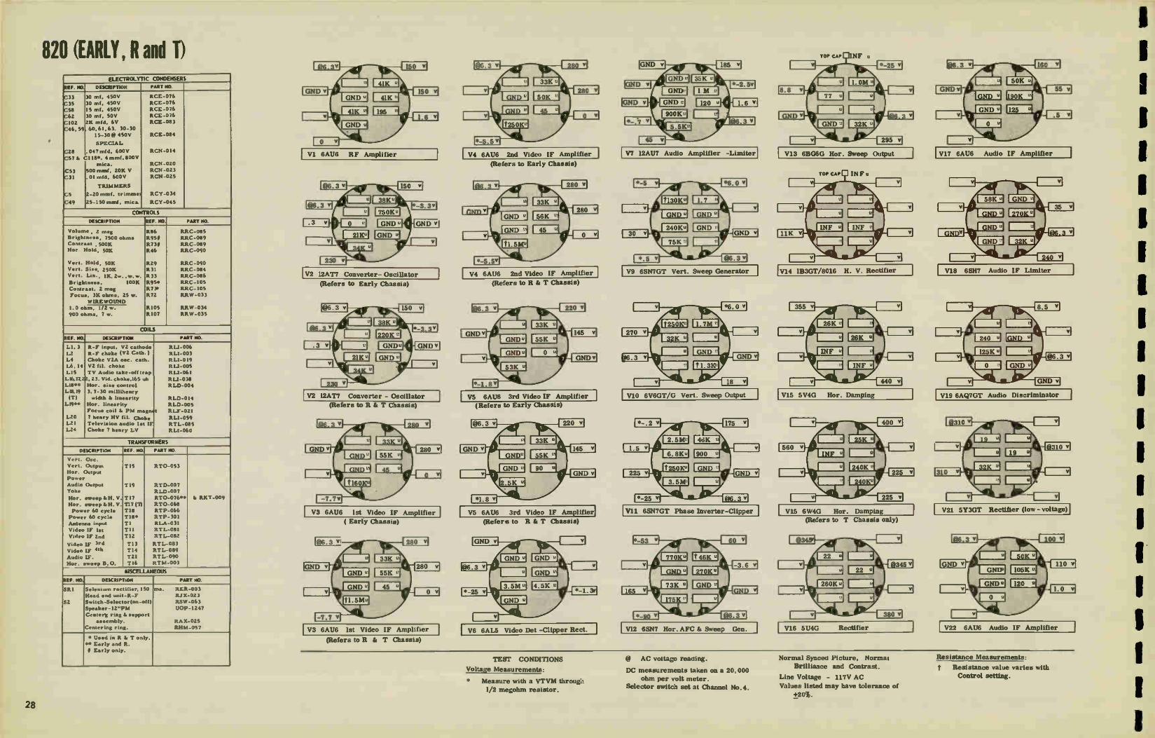
820 (EARLY, R and T)
•
ELECTROLYTIC CONDENSERS
REF. NO. DESCRIPTION PART NCI.
C33
C35
C58
C62
C102
C46, 59
C28
C57 Is
C53
C31
C5
C49
30 ml, 450V
30 ml. 450V
15 ml, 450V
30 ml. 50V
2K mfd, 6V
60,61,63. 30-30
15-30@ 450V
SPECIAL
.047 mfd, 600V
C118*. 4 rnmf, 800V
mica.
500 mmf, 20K V
01 rnfd, 600V
TRIMMERS
2-20 mrnf. trimmer
25-150 omit, mica.
RCE-076
RCE-076
RCE-076
RCE-076
RCE -083
RCE-084
RCN-014
RCN-020
RCN-023
RCN-025
RCY-034
RCY-045
CONTROLS
DESCRIPTION REF. NO. PART NO.
Volume
Brightness,
Contrast
Nor.
Vert.
Vert. Vert.
Brightness,
Contrast,
Focus,
, 2 meg
7500 ohms , SOOK
Hold, 50K
Hold, 50K
Size, 25014
Lin., IK, 2w. ,w.w.
100K
2 meg
3K ohms, 25 w.
WIRE WOUND
R86
R951
R73/ R46
R29
R31
R33
R95*
R73•
R72
R105
R107
RRC-085
EEC-089
RRC-089 RRC-090
RAC-090
EEC-084
EEC-086
EEC-105
RRC-105
RRW-033
RRW-034
RRW -035 1.0 ohrn,
900 ohms,
1/2 w.
7 w.
COILS
REF. NO. DESCRIPTION PART No.
LI, 3
L2
L4
1,6, 14
L15
L16,17,22, L18••
L5,19 (T)
L19**
L20 L21
L24
R-F input, V2 cathode
R-F choke (V2 Cath. )
Choke V2A oec. cath.
V2 fil. choke
TV Audio take-off trap
23. Vid. choke,165 uh
Hor. sine control
3. 7-30 millihenry
width & linearity
Hor. linearity
Focu• coil I. PM magi).
7 henry HV fil. Choke Television audio let IF
Choke 7 henry LV
RI-1-006
R LI-003
RLI-019 RI-1-005
R1-1-061
R LI-038
RLD-004
RLD-014
RLD-005
t RLF-021
R LI-059
RTL -085
RLI-060
TRANSFORMERS
DESCRIPTION REF. /40. PART NO.
Vert. Om-.
Vert. Output Hor. Output
Power
Audio Output Yoke
Hor. sweep &H. V.
Hor. sweep &H. V.
Power 60 cycle
Power 60 cycle
Antenna input
Video IF let
Video IF 2nd
Video IF 3rd
Video IF 41h
Audio W. Hor. sweep B.O.
TI5
T19
T17
T17 (T)
T18
T18*
T1
T I I
T12
T13
T14
T21
T16
RT0-053
RTD-007
RLD-007
RT0-076••
RT0-068
RTP-066
RTP- 301
RLA-031
RTL-081
RTL-082
RTL-083
RTL-089
RTL-090
RTM-003
& RKT-009
MISCELLANEOUS
REF. NO, DESCRIPTION PART NO.
SRI
Si
Selenium rectifier, 150
Head end unit-R-F
Switch-Selector(on-off)
Speaker-12"PM
Center k ring & •upport
assembly.
Centering ring.
ma. RER -003
RIX-023
RSW -063
U0P-1247
RAX-025
RHM-057
• Used in R & T only.
•• Early and R.
II Early only.
VI 6AU6 RF Amplifier
V2 I2AT7 Converter- Oscillator
(Refers I.() Early Chassis)
V2 12AT7 Converter - Oscillator
(Refers to It & T Chassis)
V3 6AU6 1st Video IF Amplifier
( Early Chassis)
V3 6AU6 1st Video IF Amplifier
(Refers to R & T Chassis)
V4 6AU6 2nd Video IF Amplifier
(Refers to Early Chassis)
V4 6AU6 2nd Video IF Amplifier
(Refers to Ft & T Chassis)
V5 6AU6 3rd Video IF Amplifier 1
(Refers to Early Chassis)
V5 6AU6 3rd Video IF Amplifier
(Refers to R & T Chassis)
VG 6AL5 Video Det -Clipper Rect.
V7 12AU7 Audio Amplifier -Limiter
V9 6SN7GT Vert. Sweep Generator
VIO 6V6GT/G Vert. Sweep Output
VII 6SN7GT Phase Inverter-Clipper
VI2 6SN7 Hor. AFC & Sweep Gen,
V13 6BG6G Hor. Sweep Output
V15 5V4G Hor. Damping
V15 6W4G Hor. Damping
(Refers to T Chassis only)
V16 5U4G Rectifier
V17 6AU6 Audio IF Amplifier
V18 6SH7 Audio IF Limiter
V19 6AQ7GT Audio Discriminator
V21 5Y3GT Rectifier (low -voltage)
V22 6AU6 Audio IF Amplifier
TEST CONDITIONS
Voltage Measurements:
* Measure with a VTVM through
1/2 megohm resistor.
@_à. AC voltage reacting.
DC measurements taken on a 20,000 ohm per volt meter.
Selector switch set at Channel No.4.
Normal Synced Picture, Normal
Brilliance and Contrast.
Line Voltage - 117V AC
Values listed may have tolerance of
+20%.
Resistance Measurements:
t Resistance value varies with Control setting.
28

820 (EARLY R and ID
www44
390.04O 199 ,0.41 — n n .
o FPUVILII
meow. W envot.. -1 RATE MUNI
PRESET CONTROLS
vOlemeerw•Ty_fil lei
TOP VIEW
vsRIRAL 430 Ott ee•ORIZEMITAL
POLO A411
WELD 41140
RIO
FOR RADIO USED WITH THESE CHASSIS, SEE PAGES 101, 102, 103.
For Production Changes, see Page 108.
TI LI
"-Li«
ANT TE1491 000.140
rs-9
,
Szc '_ ,as
421 5Y3GT
VI 69.16
MIPL.FER
42* MATT
°SOL L ATC44
ALC40 TANE-OFF
Cm VICIECI CARRIER-SET TRAP TRAP
C9. _L— t CR test «WS
... .. eels 1 à tüls•so Les
le: - d Ice
n 611.16 ,fre.„, 2.9.41W &ben' . 1/29 V3 cir el2AT7 _.„...».
. 4 j----.4 S6001110 .-4 II Ic0. 1411,92 17 el000tooloo .019.19TER 57 VICEO IV 92 DO INSEEI Is tis
n sows ; Ap3 Ica — Komi Cto-4-o".^.m-4 41 22
MOW S WI 244 5000I
Cl 7 2 2
▪ 1 4714144
CS FF
C.
-2.•
▪ I
prays-U.arrrr•-•
COO # RC LI EZIMIF
I.24 9 11.0No7 EGO 900
'5 I SOW out
II 1_ FOCUS COIL :Del 125
r--
4.
_J
VI)
SRI
VN 59 35 94 V7 VIT
R OS
Lo C•02
L6
T :
•
woo IOW MO3
446
rni
120 I I/EG
VIII VSI
-6SN7GT 1-6AL5 PHASE INVERTER CUOMO,
C10.
R42 47
C.9
VERTICAL SOK V9 SIZE
MOOT VERT SWEEP GOEI4ATOR 4* R1.3
iONEG
C30
2.00219
;▪ Co
suP I R30 7244EG -
VI? 43 1 6196 6947 I
AMPLIFIER LIMITERCAS .
cf OFIEcTOR 7)5
BMW
4125
'SWOT 11011.9REEP GETCRATOR
VIA 1201.11
VEIE0 W.IPU
979 i-nour 7a
VIOE0 AMPLI 123
‘122
70 :WSW.
.14 °CIA&
RECEPTACLE
C29
•
V. 1004
PICTURE MOE
ExT e,u. „g
VEREGIIkECT1011
•
R12000, - • I tI
VLSI STIR MK) IS EITHER SHORTED OUT OR LEFT IN THE GROAT WHEN TWE CENTERING OF THE VERTICAL HOLD CONTROL R21 IS CHECKED AT THE FACTOR,.
...RESISTOR (0.3 Ot REHOVE0 F.40à4 99E9E0.1 AT EKE FACTORY WHEN THE CENTERING OF TIME VERTICAL SIZE CORER*. R 31 IS con-orn
29

830 (EARLY, R and P ELECTROLYTIC CONDENSERS
REF NO OUCRIPTION PART NO
C33 IS mid . 450V RCE-070
C35 10 mid., 50V RCE-070 C58 30 mid . 450V RCE-070
C62 30 mid. 450V RCE-070
C59 15 mid . 450V RCE-077
C60 HI mid.. 450V RCE -077 C6I 10 mid., 450V RCE-077
C63 30 mid.. 450V RCE-077 C46 20 mid . 450V RCE-093
C93 25 mid . 25V RCE - 086
C102 2K mid RCE-083
TRIMMERS
C49 25-150 mmf., ink RCY-045
C60 1.1 mmi RCY-046
C12, 17 I. 5-15 :Tim!. , mica RCY -047
C5,6 0.6-2.4 rnrnl. RCY -048
C131 45-380 rnmf, RCY -054
CONTROLS
DESCRIPTION
Volume (on-off) 2 meg
Brightneite 100K
Brightnee• 2 rneg 100K
Contra. 500K
Contra,. 2 met
Hor. Hold 50K
Vert. Hold 50K
Vert. Site 250K
Vert. Lin. OK ZW, w.w.
Focus 3K, 25W.
WIREWOUND
1.0 ohm If 2W
900 ohme 7W
e., R86
ROS
R95
R73
R71
R46
R29
R31
R72
R 05
R107
PART NO
RRC-091
RAC-101 (Early)
RAC-1052 (RIT)
ARC-101 (Early)
RRC-1052(RITI
RRC-090
RRC-090
RAC-084
RAC -086
RAW-033
RRW -034
RRW-015
COILS
DEICRIPTION PART MO
LI I
12
L4 1.6.14
L15
L16,17
L18.19
LI8
L19
L20
1.24
L25
TRANSFORMERS
DESCRIPTION
Choke RI' input V2 c•th
Choke RF V2 cathode
VO -A o•c. c•thode
V21,1. yid. carrier •etir
Audio Take-Off trap
22,23. Vid. (165 Ink.)
Hor. Lin. & Hor, •Ine
Ho..
Nor. Lin.
Cho!. 7 by.. HV fil
Choke 7 by.. LV Isl.
Few us
RLI- 006
RLI-003
RLI- 019
p RLI-005
R LI-061
RL1-038
RLD-014 (T)
RLD-004(E•rly & R)
RLD-005 (Early & R)
RLI-059
RLI-060
RLF -017
REF. NO PART NO.
Vert Output
Audio Output
Yoke
Hor. ',weep. H. V.
Coile-prs & •ac wsnding only.
Power 60 cycle•
Power 60 cycle•
Video IF let
Video IF 2nd
Video IF 3rd
Video IF 4th Audio IF let
Audio IF 2nd
Hor. •weep B.O.
Antenna input
Audio Diec
T15
T20
TI?
T17
T18
T113
TOI
T12
T13
TOO T2I
L2I
T16
T I
T19
RT0-053
RT0-052
RLD-010
RT0-068
RLT-004
RTP-006
RTP• 101
RTL-081
RTL-082
RTL-083
RI L-089 RI L-090
RTL-005
RTM-003
RLA-031
RID-007
(T)
(Early 10)
(T)
MISCELLANEOUS
REP. NO DESCRIPTION PART NO.
SRI Selenium rectifier
He•d end unit.R-F
Loud•p eeeee
Centering rsng
RAR-003
Rix-023
ROP -015
RHM-057
VI 6AU6 RF Amplifier
V2 12AT7 Converter - Oscillator
(Refers to Early only)
V2 12AT7 Converter - Oscillator
(Refers to "R" only)
V2 12AT7 Converter - Oscillator
(Refers to "T" only)
V3 6AU6 1st Video IF Amplifier
(Refers to "R" & "T" only)
V3 6AU6 1st Video IF Amplifier
(Refers to Early Chassis only)
V4 6AU6 2nd Video IF Amplifier
( Refers to Early Chassis)
V4 6AU6 2nd Video IF Amplifier
(Refers to "R" & "T" only)
V5 6AU6 3rd Video IF Amplifier I (Refers to Early Chassis only)
V5 6AU6 3rd Video IF Amplifier (Refers to "R" & "T" only)
V6 6AL5 Vid. Det. & Clipper Rect.
V7 12AU7 Video Limiter & Amplifier
V9 6SN7GT Vert. Sweep Generator
V10 6V6GT/G Vert. Sweep Output
V11 6SN7GT Phase Inverter -Clipper
V12 6SN7 Hor. AFC & Sweep Gen.
V13 6BG6G Hor. Sweep Output
V14 1B3GT/8016 H. V. Rectifier
V15 5V4G Horizontal Damping
(Refers to Early & "R" orgy)
V15 6W4G Horizontal Damping
( Refers to "T" Chassis only)
V16 5U4G Power Rectifier ( H. V. )
V17 6AU6 Audio IF Amplifier
V18 65117 Audio FM Limiter
V19 6AQ7GT Audio FM Disc. & Amp.
V20 6K6G Audio Output
V21 5Y3GT Power Rectifier (L. V.)
V22 6AU6 Audio IF Amplifier
TEST CONDITIONS
Voltage Measured:
@ AC voltage reading.
* Measure with a VTVM through
1/2 meg ohm resistor
All voltages DC unless otherwise noted.
NOTE:
DC measurements taken on a 20,000 ohm per volt meter.
Selector switch set at Channel No. 4.
Normal synced picture, Normal
Brilliance and Contrast.
Line voltage - 117V. Values listed may have a tolerance
of + 20%.
Resistance Measured:
t Resistance value varies with
Control setting.
30

830 (EARLY, R and T)
TOP VIEW
For Production Changes, see Page 108.
Tle
vl GAMS
R-f NAPL,FIER
TI Li CI
u.
4
vZ4
OSOLLATMI
574
cs4 DOM J .
SOO« 571
AUDIO I-F
94SK
7t7 SIR
GOO 4 AC LI tlimif
OU 47 Les
CS .6.24 MA ,-
12•71F"'2.-21T-s-•
•1[5rffr,-.
a.r1-Er•-•
L•15TITS-•
AUDIO
e'IST vefel3e0 7F TO 15.:C75:T1-tce:smlcie" V' , no
VIM CARRIER-SET tRep
5101,
Ce4 n Die ,71_.ec:: 24 11 or 1œMA
@ it. 1
42,4,410
C7 22 5000i COD
47mvf
IAMf
ctojl47.7TE.
V22 SAM
1-F AMPLIFIER
RAW __..
4100
45-
Cel
VI7 VO SALK 63117
1-f AMPLIFIC11 CRATER CAA
IMO viDEOI-F ne
{IMF mc
ISIM-DTM SWEEP OUTPUT
GUIS 0000 MAW
ism UK I
1175 CM
G75— NMI PROF ITO MA
VIA
-GALS OETECTOR
U7 IMEE. I56 UN 7n
NM 124J?
VOTO MIKE
V7I1 -1M? in
vino Amok, 123 eMemmmomi, 1 r . von y '1145. 2 13 •
EeLII4 711
GT9
DO
'vzo OKA -GTFG
Aube OUTPUT
]:
eRCHTNESS
R116 C55 330n
G1i3 ▪ • RESISTOR DO IS EITHER SHORTED OUT OR LEFT NI THE CIRCUIT WHEN THE CENTERING Of THE VERTICAL HOLD CONTROL 1125 IS CHECKED AT THE
CORES, S TOR R113 MAY OF REM FACTORY. FROm THE cificulT AT THE FACTORY WHEN THE CENTERING OF THE VERTICAL SIZE CONT711:4. 1131 IS CHECKED
DEFLEC▪ TION
CZU 08.0.1
RED
Ve «Pe
PICTURE TUSE
EllektEATIING
31

835 (EARLY and R) ELECTROLYTIC CONDENSERS
REF. NO. DESCRIPTION PART NO.
C59
C60 C6I
C63
C102
C33.35 58.62
C93
C46
15 mfd.. 450V
30 rnfd. , 450V
10 mfd.. 450V
30 mfd. , 450V
2K mfd.
30, 30,15 mfd. ,
450V, 100 rid& 50V
25 mt.. Z5V
20 inf., 450V
TRIMMERS
ACE- 071
ACE -071
RCE-071
RCE-071
RCE-083
RCE-085
RCE-086
RCE-093
G49. RI
C80
C12,17
C5,6
25-150 minf., mic
I. 25 ininf. ,variabl,
tuning condenser
I. 5-15 rnmf. , mica
0. 4-2.4 mmf..
t RCY-045
RCY-046
RCY -047
RCY-048
CONTROLS
DESCRIPTION REF. NO PART NO.
Volume Contrast
Brightness
Contrast
Brightness
(on-off) 2 meg. 500K
100K
2 meg
100K
SPECIAL
R86 R73
R95 R73
595
RCC-091 RCC:-101
RCC-101
RCC-105
RCC-105
560 ohms, 65 ohm,
I. 0 ohm,
7 w., w. w. 4 w. ,w. w.
1/2 w., w. w.
R70 R97
R105
RRW-028 RRW -029
R RW-034
COILS
REF. NO, DESCRIPTION PART NO.
1,1, 3
L2
IA
1.6. 14
L15
LI6,
17,22.
23
LI8 L19
L20
L24
L25
Choke RF input V2 cath
Choke R-1 (V2 cathode) Choke, V2A o•c. cath.
Choke Vid carrier set
trap
Choke Audio take-off
trap
Choke Video. 165 henry
Horizontal size
Horisontal linearity
Choke 7 henry HV fil
Choke 7 henry, LV fil.
Focus
R L1-006
R LI-003 RU-019
RU-005
R LI-061
RLI-038
RLD-004
RLD-005
RU-059
RLI-060
RLF-013
TRANSFORMERS
DESCRIPTION REF. NO. PART NO.
Veit. 0,,c.
Vert. Output
Ho, Output
Power 60 cycles Audio Output
Yoke
Hor. adapter kit
Video IF 1st
Video IF 2nd
Video IF 3rd
Video IF 4th
Audio IF, Ind 6 Znd
Audio IF 1st
Antenna input
Audio Disc. Hor. blocking osc.
TI5
T17
T113
T20
D1,2
T 11
T1Z
T13
T14
L5,21
T21
T1
T19 TI6
RT0-061
RT0-071
RTR-062
RT0-052
RLD-006
RKT-008
RTL-081 RTL-08Z
RTL-083
RTL-089
RTL-085
RTL-090
RLA-031
RTD-007 RTM-003
MISCELLANEOUS
REF. NO. DESCRIPTION PART NO.
SRI
Centering a•sy.
Selenium rectifier
Loudspeaker 5 1/4' . PM
RA X-024
RER -003
UOP-577
V1 6AU6 RF Amplifier
V2 12AT7 Converter - Oscillator
(Refers to Chassis Marked Early)
V2 12AT7 Converter - Oscillator
(Refers to Chassis Marked "R")
V3 6AU6 1st Video IF Amplifier
(Refers to Chassis Marked Early)
V3 6AU6 1st Video IF Amplifier (Refers to Chassis Marked "R")
V4 6AU6 2nd Video IF Amplifier
(Refers to Early Chassis)
V4 6AU6 2nd Video IF Amplifier (Refers to Chassis Marked "R")
V5 6AU6 3rd Video IF Amplifier V10 6V6 Vertical Sweep Output
(Refers to Early Chassis)
V5 6AU6 3rd Video IF Amplifier
( Refers to Chassis Marked "R")
V6 GALS Vid. Det. - Clipper Rect.
V7 12AU7 Vid. Amplifier - Limiter I
V9 6SN7 Vert. Sweep Generator
V11 6SN7 Phase Inverter & Clipper
I V12 6SN7 Hor. AFC R.t Sweep Gen.
V13 6BG6 Hor. Sweep Output
V14 1B3 H. V. Rectifier
V16 5U4 Rectifier
V17 6AU6 Audio IF Amplifier V22 6AU6 Audio IF Amplifier
V18 6SH7 Audio IF Limiter
V19 6AQ7 Audio Disc. - Amplifier
V20 6K6 Audio Output
V21 5Y3 Rectifier
TEST CONDITIONS
DC Measurements taken on a 20,000
ohm per volt meter.
Selector switch set at Channel No. 4
Normal Synced Picture, Normal
Brilliance and Contrast.
Line voltage - 117V.
Values listed may have a tolerence
of + 20%
Measure with a VTVM through
1/2 megohm resistor.
t Resistance value varies with con-trol settings.
Value given is with control set giving
maximum reading.
@ AC voltage Reading.
32

835 (EARLY and R)
OCCOMITY INTW•o - n mr.
RUFF 130.1
t-ve vt00.4. 10•111
02.
now93•ML Hole
TOP VIEW
3HELA Mimeo
For Production Changes, see Pages 108 and 109.
vi RAUB
R-F AMILIFIER
TI LI CI
IL] c cLoWo ON
100ARA o
7 .3
1500
Fe 20:1
r;
cel
02 56/1
01 VIDEO CARRIER-SET TRAP 476elf iri 1 *5. -. .. 1
AtEm. -._,--s-....4« -
ry 1 V2B..,
ce. 1--10 n 0 0 1.1.0 0 s--1 .-
13 Slaw *—w -° _I_03
• Ras - MOMS 24K 2 C7 7
470MW CR 5-24 IMF
1270sK 41«
MOO TAKE-OFF TRAP
21 801C LIS
LS V3
64U6 £1 6viuL0 TO ,44" -WOW . IMO 61 VIDEO If Tit 14
,611000er00 5 ,b1IF
2
2411
r vs
I 31U4iDE0 TH
1.w. I 0 811
fa..1 NR ,
L_ íi m
-1-ces 7:t /- 5000
VGA
-GAAS
'DETECTOR
00 Wo• C26
M7 T6IBF 4311 7
LIT 165 UH
230V
LS 16.51,1 7(0
VIA 12047
VICI(0 way.
C27 05 WE
RIO IIIEG.
To
Ca
D47 I.
R21 S6K
278 -12Aul
711 VIDEO AMPLI 123
J
'. L22 :WSW'
711
- 023 PO
8211 3.34
025 ear •
C104 'AF
vs 'OMNI
PICTURE TUBE
XTVITIAANc.igATING
MLI•twomart, ELECTROSTATIC SHIELD
1:ERT OWiTrer
211111
•2
•LACE
TEL
112 loco RED
413.
6
-
er1101 ,-. ti
WAIF 4.111 001P-4 e •-• 22K
COQ AC 1152100F
C64 -I-- 1173 os T 500K war
*Lao 1-F
• CONTRAST
RO
000k I5C00
TSV
859 IlK
032 206
RII7
II K
0121 5000 -eINEG
027
360V
R9 100
103 4711
INF7117
026 VENTCAL 106 220K v• 65/176T SIZE 27K
VERT SWEEP GENERATOR •
...-"*****.---... --................. WIele--030 2291E6 =
's CSO CS
3 .0021e .06 INF
290V
c41_ .001 T
ROI 820
Re VO
VERTICAL HOLD •
VIO 6V6-67,6
SWEEP OUTPUT
9020
080 L5 It
425V
R4 2
VILO Vie - 6511767 1-6ALS PRAM INVERTER CLAMPER
•
V118
«kitIWAT 11R236
4-
me
C37
VV 5Y3GT
R64
RIII 837 1600 SOB
R92 6.930
C37 029 SOK
3024 R45 66/1767 >1006
AFC CCIKTROL
C.3111 R46 506
r .17tIZ § 047 HELD
C39 2 1 " c.• .« -1-.os. 0 , 2 135AW M
R!., C44 1201/167 _G47
If CA3 C45 390 I 854 IMF ••
if
I MEG
1,71 -tri*Ii1 . EP GENERATOR
Kt, TIN
I▪ g 80
3.3 NEG
049 110‘,0
C78 050 ef 82x
RIC°3 3 IL 1
032 •7
C49 25-60 1154 IWIF 000 1112. FRED,
csi moms
0104
413 6866-6
SWEEP OUTPUT .3n,
056
330
C94 SWF I
02 490 If 270 • 065
C97. 00 NE
VIO 183-67/8016 N-V RECTIFIER
063
3311
0000
22« CSI 7111600 I Kee
•MOV
COI CT≥
301e ] 3OIW 117C
•wev nor 540
R97 5
01«
• v 60.3.•
124 in
COS
360V
'SUP
• FOOUS COOL L25
VI VOS V3 • •
V4 22 • t
49
VII
913 mos LB
SRI LO
U el 39 vs V9 V7 V17 -=
230v
422 VIT 1141.16 611U6 6507
I-F IMPLIFIER I-F AMILIFŒR L•IIT▪ ER Cf11 3
C96
21.294C 2 I T21 j
10 ?re-,- - 36.44F a
a
0102 006 22K > 15000
/410
C6
707
11366 MOCO ,
078 10011
R79 22
1.21
C69 50301 War RIO. ROI 560 MK
6
• CFO 5000
t. 4 01114
6100 II ROS II °C. C75
ats - - -!5
C 113
V2 -GT 01501111114000
e
47
II
CM
DOW
2..2131T
C77
C99 310 1 DOS wax ,
R 76 11, 4
= CW94
CO7 01,1F
6
•
V198
- 6407 GT A0 08521.1448
V20 NM -GT/0
AU010 OUTPUT
C93
à T.
KM T20
p0516215 C79
TegLID
RESISTOR RI10 15 EITHER SHORTED OUT 08 LEI' IN THE CIRCUIT WHEN THE CENTERING Of THE VERTICAL HOLD CONTROL Ft29 FS CHECKED AT THE FACTORY.
33
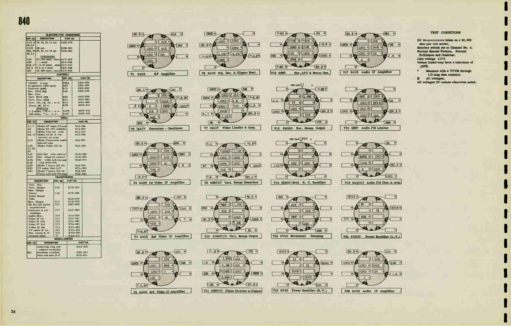
840 ELECTROLYTIC CONDENSERS
EF. NO, DESCRIPTION PART 140.
C33, 35
58,62
C102
G46, 59
60,63
C49
C80
C12,17
C5, 6
C81
30, 30.30, IS rnf.
2K mf.
30, 30,15, 30 ml
TRIMMERS
RCE-070
RCE-083
RCE-084
RCY- 045
RCY-046
RCY-048
RCY-054
25-150 rnmf.. mica
I. I imnf.
1. 5-15 mm!., mic2RCY-047
0. 6-2. 1 mint
45-380 mmf., mica
CONTROLS
DESCRIPTION REF. NO. PART NO.
Volume 2 ,,,,g
Brightness 7500 oho, Contrast 500K
Hoe Hold 50K
Hor. Size Vert. Hold 50K
Vert. Size 250K
Vert. Lin. 1K Zw., w. w,
Focus 3K, 25 w.
SPECIAL
R86q
R95
R73
R46
R29
R3I
R33
R72
R105
R107
EEC-085 EEC-089
RRC-089
RRC-090
RRC-090
EEC-084
EEC-086
RRW-033
RRW-034
RRW -035 1.0 ohms, 1/2 w. , w. w.
900 ohms, 7 w., w. w.
COILS
EF. NO DESCRIPTION PART NO.
LI, 3
L2
LA
L6, 14
LIS
LI6,
17,22,
23
LI8
LI9
L19,
L18
120
1.21
1,24
Choke RE- input,VZ cath
Choke RF (V2 cathode)
Choke V2A osc cath
Choke V2 fil Si Vid
carrier set trap
Choke Televi•ion audio
take-off trap
Choke Video 165 oh
Coil Hor size control
Hor linearity control
Hor width and Lin used
with RT0-076
Choke 7 henry HV, fil.
TV audio (2nd I-F)
Choke 7 henry 1:.V, fil
Focus coil and PM mag
R LI-006
R LI-003
RLI-019
RLI-005
ELI-061
R LI-038
RLD-004
RLD-005
RLD-014
RLI-059
RTL-085
RLI-060
RLF-021
TRANSFORMERS
DESCRIPTION REF. NO. PART NO.
Vert. Osc.
Vert. Output
Hoe. Output
Power
Audio Output
Yoke
Hor. Output
Kit for old stylus transformer.
Coils -pri St sec
windings. Audio Disc.
Video IF 1st
Video IF 2nd
Video IF 3rd
Video IF 4th
TV audio IF 1st Hor. sweep B.0
Antenna input
Tl5
T18
T17
TI7
TI7
TI9
TII
T12
T13
T14
T2I T16
TI
RT0-053
RTP-066
RLD-010
RT0-076
RKT -009
RLT -004
ETD-007
RTL-081
RTL-082
RTL-083
RTL-089
RTL-090 RTM-003
RLA-031
MISCELLANEOUS
EF. NO. DESCRIPTION PART NO.
RI
Centering ring and
support assernbly
Selenium rectifier
Head end unit-R-F
RAX-025
RER -003
RJX-023
VI 6AU6 RF Amplifier
V2 12AT7 Converter - Oscillator
V3 6AU6 1st Video IF Amplifier
V4 6AU6 2nd Video IF Amplifier
V5 6AU6 3rd Video IF Amplifier
V6 6AU6 Vid. Det. gi Clipper Rect.
TV712AU7 Video Limiter ii Amp.
V9 6SN7GT Vert. Sweep Generator
V10 6V6GT/G Vert. Sweep Output
V11 6SN7GT Phase Inverter Id Clipper
V12 6SN7 Hot'. AFC 81 Sweep Gen.
V13 6BG6G Hor. Sweep Output
V14 1B3GT/8016 H. V. Rectifier
V15 5V4G Horizontal Damping
V16 5U4G Power Rectifier (II.V.)
VI7 6AU6 Audio IF Amplifier
V18 6SH7 Audio FM Limiter
V19 6AQ7GT Audio FM Disc. &E Amp,
V21 5Y3GT Power Rectifier (L. V,,)
V22 6AU6 Audio IF Amplifier
TEST CONDITIONS
DC Measurements taken on a 20,000
ohm per volt meter.
Selector switch set at Channel No. 4.
Normal Synced Picture, Normal
Brilliance and Contrast.
Line voltage 117V.
Values listed may have a tolerance of
+20%.
* Measure with a VTVM through
1/2 meg ohm resistor.
@I AC voltages.
All voltages DC unless otherwise noted.
34

ANEMIA TEN•w.M. MI6
PRAWN 114.1
SECCM70/TT 1110TTOWI—.
FAIMSCRold TRAW
W ri....5.10 OO IF COL
2110 A0040 LE CO&
1.104.011E2
PLATE COWRY TRIMMER
VERTICAL 1.111FARITY 1.15
4M.5/
AIN VCE0if Twos
•
W0VEIE01 , TRAMS
ser2r4
OIS wœOM MANS
07
S 0CfreFERLIAUS;
TRY
5. 0.0•61 SELECTOR
TOP VIEW
TIS VERT. OUTPUT
TRAMS
YERTOS. 5.2E
MACKIN& OSC&LATOR
WIANSFONWEN
7101/120ITTIL SUE CONTROL
L10
(7e dn›,
TERMINAL PUJO PE
OFF -M. 52
VERTICAL MOLD ROO
C5O.C60,
Ci02 C63 OC 46
ELEC.
V.
714 ....401
VS
'AU'
Ta NORMCwIAL WEEP TRANSFORWO
CONTRAST— . 1773
t-NOOMONTAL 164.0 Fun
WELD REMOVE0
ORIGNTNESS ROS
FOR RADIO USED WITH THESE CHASSIS, SEE PAGES 101, 102, 103.
OMS OFf •AML.FIER
, L. CI
11.0 ,11- y MOWS o
Li •••
01 4716IF
lo
29
Li. WI MOT G50 100
lohis
Li U Ii or FT:CUSCO&
L25 fooF
SORTI 00213 • • • 2 • 7 SRI
Riœ
SOOT
VI V7 517
LG
111,••
VICEOCAIIMER-S(T TRAP
a 1 1 telswooi
/Zee
SAW R103 J_Ci3 2.11
C7
4710AF
A.2.4 5•AF
PRODUCTION CHANGES MODEL 840
The following changes were mode in production to improve
audio frequency response, and to insure against excessive
bass response causing low frequency rumble when playing
the phonograph and radio.
A. TELEVISION AUDIO RESPONSE:
0) C114 at the television volume control was changed
522 ¡AUG
1.7 PAPLWIER
67 TOCO M Tm
SEE AUDIO AND RADIO POWER CHASSIS, PAGE 102.
42. --nisofttoosit
C22 C20
CA• ;COME
121 L • -e•V•
33516
12.1L0
SIl leek(0.,
- I I000I5I'Y-"' Ci•
2•6
VIO IMG-G76
SWEEP OUTPUT
1 Mr IRO &AUG 115/17
.-F A./PUFFER LISTER C4111
from 1000 mmfd. to 470 mmfd.
Is) C135 in the rodio receiver chassis television audio
input circuit was changed from 470 mmfd. to 1000 mmfd.
It is recommended that the above changes be mode to all
receivers which have not been modified. Note that no ad-
ditional components are necessary since they are inter-
changed.
00*
-EALS
°VECTOR
250V
el?
v7A MAU]
III0E0 •AIPLI
-J
ca
VOS 1- QM),
VIDEO AWL, 7 LOS
C.09 2.7K .05100
6.6
2 •
0 COI
.17 OCTAL RECEPTACLE
840 VO 2254
PICTURE TUSE
EXTLI:ouNNAL017
COON
DEFLECTION
ei›J.
0
• RESISTOR R1106 EITHER SmOITTIO OUT
OR LEFT re THE CIRCUIT WHEN TIE CENTERMG OF ENE VERTICAL NOLO CONTROL Rif IS CRECRED AT ERE FACTORY.
— RESISTOR 0113 MAT BE Rto0,60 FROM T./ECU/COI T AT /NE FACTORY WHEN THE CENTERING Of TIE VERTICAL SIZE CONTROL RN IS CREME°
B. RADIO AND PHONOGRAPH RESPONSE:
a) R39 was removed from the Radio Bass Control circuit..
Is) Removal of R39 disconnected C82, C83, and C84 from
the remainder of the circuit. These capacitors remain in the
chassis and become ineffective. The schematic diagram
shows R39 dotted, representing early production.
35
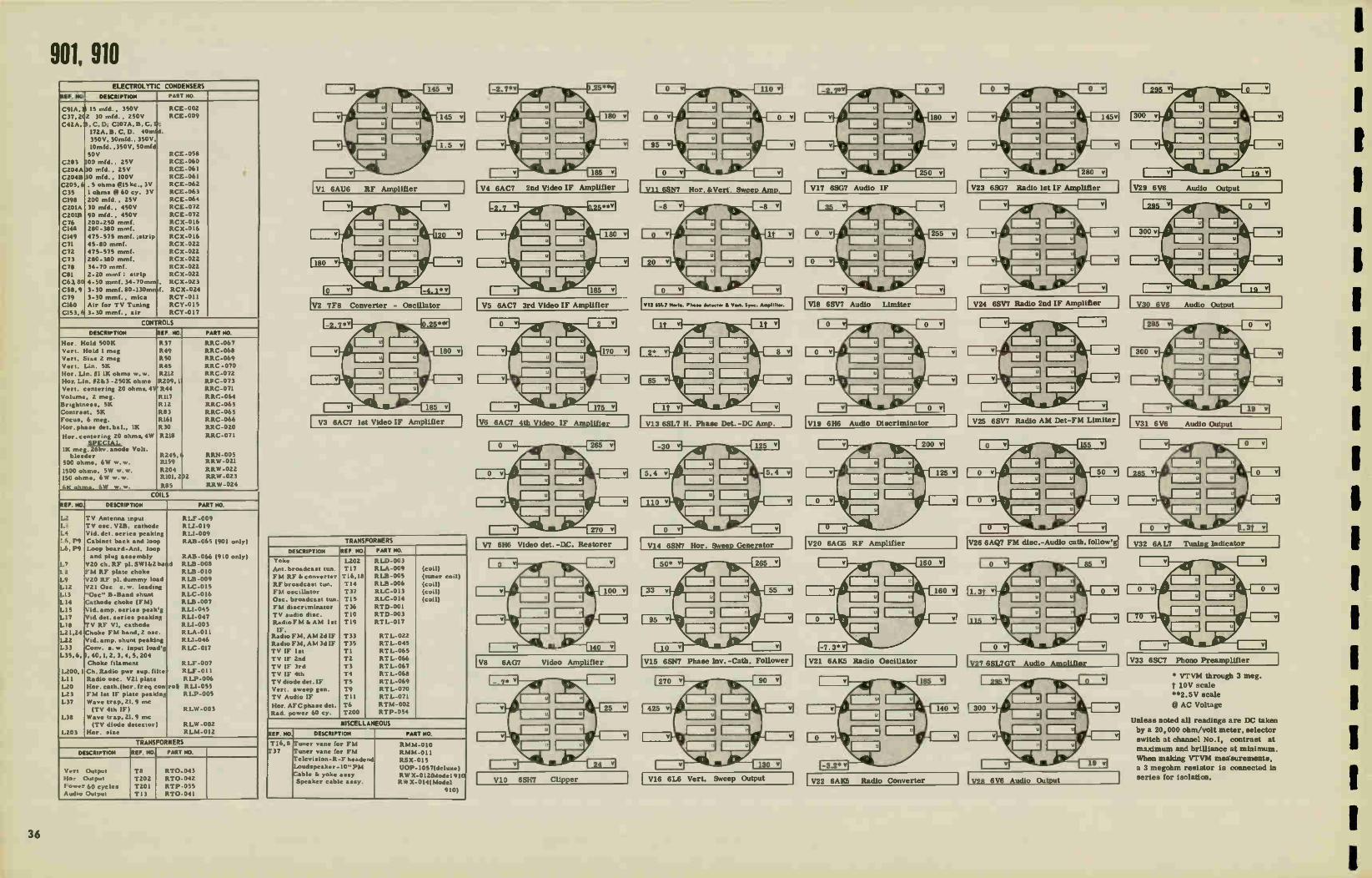
901, 910 ELECTROLYTIC CONDENSERS
REF. NO. DESCRIPTION PART NO.
C9IA, 5
C37, 2(2
C42A,
C203
C204A
C2O4B
0205,6
C35 CI98
C201A
C2OLB C76 C148
C149 C71
C72
C73
C78
C131
C63, 80
C58,9
C79
C160
C153, 6
15 rnfd. , 350V
30 mfd. , 250V
, C, ID; C107A,B, C.»
I72A, 13. C, D. 4Ornad.
350V, 30mfd., 350V.
lOmfd. ,350V, 50mfd
50V 100 infd. , 25V
30 told. , 25V
30 mfd., 100V .5 ohme @l5kc., 3V
1 ohm• @ 60 cy. 3V
200 mfd., 25V
30 mfd., 450V
90 rnfd. , 450V
200-250 rot-rd. 280-380 mrnf.
475-575 mmf. ..trip
45-80 mrrif.
475-575 mmf.
280-380 mmf.
34-70 mmf.
2-20 mmf; •trip
4-50 mmf. 34 -70mmr.
3-30 nun!. 80-130mre
3-30 mmf., mica
Air for TV Tuning
3-30 mmf., air
RCE
RCE-009
RCE-058 RCE-060
RCE-061
RCE-061
RCE-062
RCE-063
RCE-064 RCE-072
RCE-072
RCX-016 RCX-016
RCX-016
RCX-022
RCX-022 RCX-022
RCX-022
RC
RCX-023
RCX-024
RCY-011
RCY-015
RCY
-062
X-022
-0 17
CONTROLS
DESCRIPTION REF. NO. PART NO.
Hor. Hold
Vert.
Vert.
Vert.
Hor. Lin. Hor. Lin.
Vert.
Volume.
Brightne•ii,
Contra
Focue,
Hor. phase
Hoc. centering
1K meg. bleeder
500 ohm•,
1500 ohms, 150 ohm.,
ohm..
500K
Hold 1 meg
Size 2 meg
Lin. 5K
NI IK ohms
1/2&3 -250K
centering 20 ohma
2 meg.
5K
•t, 5K
6 meg.
del, bal.,
20 ohm., SPECIAL
w. w.
ohm•
41,4
1K
4W
Volt.
R37
R49
R50
R45
R212
R209, I
R44
R117
R12
R83
R161
R30
R2I8
R245, R159
R204 RI01, 2
R85
RRC-067
RRC-068
RRC-069
RRC -070
RRC-072
RR C-073 RRC-071
RRC-064
RRC-065
RRC-065
RRC-066
RRC-020
RRC-071
RRN-005 RRW-021
RRW -022
2 RRW-023
RRW -024
26kv. anode
6W w. w.
5W w.w. 6W w.w.
6W w. w. ,_61$
COILS
REF. MO DESCRIPTION PART NO.
L2
L3
L4
1_6, P9
L6, P9
1,
1.3
L9
1,12
1.13
114
LI 5
1,17
LI 8
L21,24
L22 L33
L35, 6„
1.200,1
LI 1
L20
L23
L37
L38
1.203
'TV Antenna input
TV oric. V2B, cathode
Vid. del. series peaking
Cabinet back and loop
Loop board-Ant, loop
and plug a•sembly
V20 ch. RF pl. SW1&Z baad
TM RF plate choke
V20 RF pl. dummy load
V21 Osc e.w. loading
"O.c" B -Band shunt
Cathode choke (FM)
Vid, amp. series peak'g
Vid, del. series peaking
TV RF VI, cathode
Choke FM band, 2 oec.
Vid. amp. shunt peaking
Cony. e. w. input load'g
40,1, 2, 3, 4, 5, 204
Choke filament
Ch. Radio pwr sup. tilts ,
Radio osc. V2I plate
Hor. cath.(hor. freq con
FM 1st IF plate peaking
Wave trap, 21.9 mc
(TV 4th IF) Wave trap, 21.9 mc
(TV diode detector)
Hor. size
roll
RLF -009
PLI-019 Fl LI-009
RAB -065 (901 only)
RAB -066 (910 only)
RLB -008
RLB -010
R LB-009
RLC-015
RLC-016
R LB -007
PLI -045
PLI-047
R LI-003
RLA-011
PLI -046
R LC-017
R LF -007
R LF -011
R LP-006
R LI-055
RLP-005
RLW -003
R LW-002
RI.M-012
TRANSFORMERS
DESCRIPTION REF. NO. PART NO.
Vert. Output
Hor Output
Power 60 cycles Audio Output
T8
T202
T201
T13
RT0-043
RT0-042
RTP
RT0-041
-055
V2 7F8 Converter - Oscillator
V3 6AC7 1st Video IF Amplifier
TRANSFORMERS
DESCRIPTION REF. NO. PART NO.
Yoke
Ant. broadcaet tun.
FM RF & converter
RF broadcast tun.
FM oecillator
Oec. broadcast tun.
FM discriminator
TV audio disc.
Radio FM & AM let
IF. Radio FM, AM 2d IF
Radio FM, AM 3d IF
TV IF let
TV IF 2nd
TV IF 3rd
TV IF 4th
TV diode del. IF
Vert, sweep gen.
TV Audio IF
Hor. AFC phase del. Rad power 60 cy.
L202
TI7
T16,18
TI4
T37 TI5
T36
T 10
T19
T33
T35
T1
T2
T3 T4
T5
T9
T11
T6 T200
RLD-003
RLA-009
RLB-005
RLB-006
RLC -013
RLC-014
RTD-001
RTD-003
RTL-017
RTL-022
RTL-045
RTL-065
RTL-066
RTL-067 RTL-068
RTL -069
RTL-070
RTL-071
RTM-002
RTP-054
(coil)
(tuner coil)
(coil)
(coil)
(coil)
MISCELLANEOUS
REF. NO. DESCRIPTION PART NO.
T16, 8
T37 Tuner vane for FM
Tuner vane for FM
Televittion-R-F headend
Loudspeaker -10" PM Cable & yoke assy
Speaker cable asey.
RMM-010
RMM-011
RSX-0I 5
OOP- 1057(deluxe)
RWX-0124Model 910 RW X-014(Model
910)
V4 6AC7 2nd Video IF Amplifier
V5 6AC7 3rd Video IF Amplifier
V25 6SV7 Radio AM Det-FM Limiter V6 6AC7 4th Video IF Amplifier
V7 6H6 Video det. -OC. Restorer
V8 6AG7 Video Amplifier
VIO 6SH7 Clipper
V17 6SG7 Audio IF V23 6SG7 Radio let IF Amplifier V29 6V6 Audio Output Vil 6SN7 Hor.,BiVer Sweep Amp.
512 MILI Her', Phew dome.«I Vow. Sync. Amplifier.
V13 6SL7 H. Phase Det. -DC Amp.
V20 6AG5 RF Amplifier V26 6AQ7 FM disc.-Audio cath.follow'g V14 6SN7 Hor. Sweep Generator
V15 6SN7 Phase Inv. -Cath. Follower V21 6A1(.5 Radio Oscillator V33 6SC7 Phono Preamplifier
V16 6L6 Vert. Sweep Output
V18 6SV7 Audio Limiter
V19 6H6 Audio Discriminator
V22 6AK5 Radio Converter
V24 6SV7 Radio 2nd IF Amplifier
V27 6SL7GT Audio Amplifier
V26 6V6 Audio Output
V30 6V6 Audio Output
V3I 6V6 Audio Output
V32 6AL7 Tuning Indicator
* Irrvm through 3 meg. T 10V scale
$82.5V scale
@ AC Voltage
Unless noted all readings are DC taken
by a 20,000 ohm/volt meter, selector
switch at channel No.1, contrast at
maximum and brilliance at minimum.
When making VTVM measurements,
a 3 megohm resistor is connected in
series for isolation.
1
1
36

901, 910
wromad.
4•1012.
Mt MI0 Inn
•••/.1611.. Fee
00/6/0161•6 el°
0137
•
11.
11:0«CTha /Ye«,
CeleflUt
Mae..
el•Ce0 TWO«
1=4\ IILLICTO•
4 \ VOW«
TON! •
SCHEMATIC OF POWER CHASSIS
YO 10.
001/0
lee •6010 • /EL el 0.0..entº •••• 04•Aol
.00100C 04 MAW GIUSIe
PO•l• C61663
4L,
{
21_
-t ytte
Lr. 6100Y .11,110/011
.06 0..
.41o.
to I 0000.6 it« 100,..L.
eV006.1101/1.00/6 COT••
060
r
“Mg.. 7.1
To V
GL•
•t
0001•17...
ate 101/e1«.0.
.0,
'1 COL OP MEL
P' l
37

10C101, 10C102, 1011, 1014, 1015, 1016 ELECTROLYTIC CONDENSERS
REF. NO. DESCRIPTION PART NO.
C297,3,
C346
C372,1,
C299 C383,4 C257,8,406.
C2I3
C225,6
58. lOrnf,350V; rnf, 100V;10Orn1,50
I mf., 50V
3,4. 150mf,
30 rnf, 450V
60 rof, 350V
10 rnf/450;
300; 10/150V
Trimmers
50
V
150V
40/
trap
RCE-089
RCE-090 RCE-091
RCE-092
RCE-094
RCE-I00
RCY-059
RCY-060 Tuning control
High channel
CONTROLS
DESCRIPTION REF. NO PART NO.
Contra•t
Vert. Height
Focus
Focu•
Volume
Volume
Brightnee•
Brightne••,
Hor.
Vert.
Hor.
Vert. Her. Hold
75 ohms,
1700 ohms,
4.6 ohms
2 meg •
Lin. 2K, 2W
3 meg
100K ••
•
500K ••
•
500K,
500K •
Drive 25K, 1/2 Hold 100K •
Hold *
Hold 100K AS
I25K ••
SPECIAL
W
R.331 R300
R302
R347
R347
R353
R353
R227
R227
R402
R.298
R.32I
R321
R2913
R373, 4
R377
R372
RRC-124
RRC-095
RRC-096
RRC-099
RRC-I26
RRC-099
RRC-I26
RRC-109
RRC-124
RRC-I08
RRC-125 RRC-125
RRC-I34
RRC-I34
RRW-041
RRW-045
RRW-048
Globar
5W, ww
w. w.
COILS
REF. 110.1 DESCRIPTION PART HO.
L201
L202
L203,
L209, L255,
L246,
L247,
L249,
L245
L256, L260
L269
L314
L3I5
L3I6
L343
L371,
L258
Input Cathode 1.4 rnic
207. RF Input
205. Cony. plate
268. Vid. comp. 110mi
208. 2nd IF plate 248. Vid. det. a•ey
204, 248. Choke P.F.
3Irnic
IF
257. Video comp.
Video peaking
Trap coil 1. 5 mc
Hor. si•e
Linearity
Hor. o•c.
Focus 2, 3,4,5,244, 350.
Heater, 2 mic.
Vid. comp. choke
RLF-023
RLI-033
ALI-083
RLP-016
RL1-093 RU-110
RLX-029
RLF-024
RLI-096
RLI-038
RLI-108
RL1-100
RLD-019
RLD-020
RLC-091 RLF-026
RU-085
RLI-109
TRANSFORMERS
DESCRIPTION REF. NO, PART NCI.
Vert, Output
Hor. Output
Power
Audso Output **
Yoke
Audio Output •
Audio IF let
Ratio detector
T291 T3I2
T342
D3I2
T342
T340
T141
RT0-064
RT0-076
RT0-062
RLD-013
RT0-066
RL1-097
RTD-008
MISCELLANEOUS
REF. NCI DESCRIPTION PART NO.
X37I,2
B37I
5341
LS5
LS5
Selenium rectifier 250
Ion trap-(10BP4)
picture tube IOTI
R-F head end •• R-F head end* Thermal cutout
Switch-focus
4" PM (10T1,4, 5,6)
10" (or(I0C101, 2)
ma. RER -004
RET-003
RJX-036
RIX-038 RSR-002
RSW -066
UOP-487
UOP-1047
• 10C101,102 •• 10T1,4,5,6
VI 6AU6 let RF Amplifier
V2 6BC5 2nd RF Amplifier
( 6AG5 in initial production; replace with 6BC5)
V4 6BC5 1st IF Amplifier
(6AG5 in iagibo5luction; replace
V5 6BC5 2nd IF Amplifier
(6AG5 in initial production; replace with 6BC5)
V6 6BC5 3rd IF Amplifier
( 6AG5 in initial production; replace with 6CB5)
V8 12AT7 Video Amplifier
I V10 12SN7GT Vertical Multivibrator & Sweep Output
V13 19BG6 flor. Sweep Output
V14 1B3GT/8016 H. V. Rectifier
V15 25W4GT Damping Tube
V16 6AU6 Audio Limiter & Amp.
V17 25W4GT Damping Tube
V18 6SQ7 Audio Amplifier
V19 25L6GT Audio Output
V20 6SL7GT Sync. Amp. & Clipper
V21 12SN7GT Hor. Ose. & AFC
V22 6AL5 AFC Discriminator
V23 6AU6 Audio IF Amplifier
TEST CONDITIONS
Voltage Measured:
Meter 20,000 ohm/volt. Line volts - 117V, 60 cycles.
All controls set for normal sweeps, focus and brightness.
All voltages DC unless otherwise noted.
@ AC voltage reading.
t Use 2.5V range. * Voltages vary more than +20%.
Resistance Measured:
Short capacitors C373 and 374.
Short pin 3 of V15 to B-. INF - denotes infinite resistance.
Turn the following controls full:
Focus Contrast
Brightness
Vert. Hold
Vert. Linearity
Vert. Size Values listed may have a tolerance.
1
38

1
1
For Production Changes, see Page 109.
— — — —
0204 OK 12 1224 1222 1224 1225 1227
70 5 6 99 *0
JerL 228 V 1 641.16 Isy RF
0 13
5201* C20,--150 • I 13276 33WEG
maD04* •wv.vv. INPuT 1207 300 oetis R217
C203 C226 01 ce°2
C225 1 IF 680
:L2
2-6 INCL.
7 R201 .000
331£0
150 L215-7 - 34 1235 er 1237
4203
1229
233
.00 III 6R2r9 6 e,,,,
cr205
2
gr12311 à
L_
117V 60-
0205 0206
5.16 5..6
% 216
52016
1204
6
. C207 680 me.
C2I II o
33
C221 800
0202 270
100
*DJ CH TRAP V JU 47 25 WC I CONV l2AT7 2511
02013 220
BOO
33--1 C224 3.3
6AG 5C) 2NoR F
e°7 V2 ioo
AUDIO CARRIER TRAP ADJ CH TRAP
V4 •1 2 5 hiC V5 47 25 MC V6 1 IL 2No 1F iti 3,40 IF ST 1 F 64050 6AG50 uc„, 6AG5 ®
127° Pre 1.808 22 1236 G239
R2135 2281
8218 .54F
C255
1.248
R247
471(
1242
5
R21118 61116
6242
6255 __ 47 G240 1250
5000 1241 5000
5
6.246
0240 68*
0230
•7
0221 47
ii-G237 3 •
1 9. w I
1:L247 -
1 7, L
C 5000-.3-£
5000 _-C238
10C101, 10C102, 1011, 1014, 1015, 1016 I V8A
CET Isr VIDEO IN64 v2 I2AT 7
1
21 1249
)0274 9...„ 470
5000
4)°°°
R265
12 165
72,
R229 226
6276 221.1EG
470
1262 1263 1264 12651266 t 267 215
i2141 gff
3 4 5 6 7 e 9
520.0 0711 C212 .06 r 12
21
TUNING 4(2.3 CONTROL
0203 1208 BOO
2 G223 5
V38 OSC 1/212AT 7
0287 470A
EMILY PRCOUCTION IF TRAP
NEIK, EN) GHASSiS
1256 5000 +135V
•
4 Kzedc TRAP
0278 470K
6290 RIK 2w
V88 2 NoVIDEO 1/2 2417
A - 1267
10 HT — 1267
.05
6220 220
DCINY465ST°FeER V 9 'ICTUFE TUBE
1061,4, 10FR4, OR I OF R44
C269
10K 005 0267 4700 2w
à
• 0266 3.AEG
C270 .23AF
03._ 0292
13304 26 2K
811
11
0203 2274
0281 220K
einGHTNESS
023
lo
244
0227 2 IkrtG
CONTRAST CONTROL c, 5
I 5000
I
4 1 3'244
eszoo
837. 7.7(69+1
COT OW
• ''
1:5371 POWER
OPEN ON CHANNELS -6 1NCL
o NOTE 0330 SNORTED IF 0300 IS NU FOR 8E" LINEARITY
® ON LATE PROOUC 7ION • 6015 MAY BE I l'ED • 68C5 MUST BE USED TO
REPLACE A 6AGS.
C13791 50 R 364 20
1137? —VVVVYA
13717 55 n
4. 4
8372 ....2r,or 13114 —
6030 65*;
• .09 MI
+550V
0411 •70K
+135 V
7- C374
0375 • 70«
Ve9 V 10 V4 1/5 V6 V23 V e VI 62 63 21L6GT 056711 6465 64G5 6415 6406 12477 &Au* 6•65 12AT7
0373 • 9 44 • 3
75
c2r07
cziOn C373 • 5 1372 1373 1371 G376 1377 C378 1386_ 1387
5003 3000 I 50001 50001- 800 I Boor eoo C3439 BOOT
0374 19866G 1736751 6AL5 65L7GT 25VMG7 691.16 6913 1374 6607 75 2 7 7 • 7 8 8 7
¡C I. 47,N3 .1132233 a v22 V20 V15 VIA VI7 VII NOTE SEE VIN
NOTE CaPAC.704 vAL uES AFE 776e UNLESS SPECIFIED
1257 -73MF0 1304 C258-40" 3004 MI C406 ,0 ' 4306 de
C353(10700 3509 SO C334 30 • 150+16 1297- CO • 7SV
Q I 69
V23 64116 AMPLI
R 3*0 22 17EG
25+. Zyil
VERTICAL SWEEP GENERATOR
R293 82«
C258 _40
MF •
390
0308 396
1306
IO 701°: I
C296 0295 I
1000 00" VIOA 1/2 "12SN7GT
C309 470
I 0297 686
.0296 • 4.3 -6 NEG.
294 R266 100K
0390 6389
2913 125K
C397
.059F 1506 7501
309 700
BLUE V108 Lr294
1. 12SN7GT „
RED (C305T TK 5000
02 36,66 3oe
¿03134F 97
0014F
8300 •
GREEN
1301 .05
I c 302 02032
R306 2 76
C325 47
1299 0303 I 51(
1406 LINEARITY Ole
300 V.
0409 1122 .01111F
f. C392 . 220 •
6
I. _
V20 6SL7GT SYNC Amp a CLIPPE
V22 6AL5 ESC
4.250
V214 V2 - :2 SN7GT A FC
T
1 387 100 5C«
R 384 110E0
R3135 MEG
395 6e
R3116 1130K
391
is
V2IB ,a9k2 14- I2SN7GT
I-10R OSC
2 C400 c402 03138 s 4 70 MO IMEG 1
C 398 3900 R391 33K
/396 01 MF
C399 .05 Mr
C401 220
0393 77K
•4;321 F.000à
tie mc1,
• 4 •
•60e
UI6
Ku)
0396 338
C405 5000
c404_, 3900
0395 106
1403 1000
13402
180
,1
_c 3.
a356 VI3 IsK 198G6
OUTPUTHOR
R326
226
111397
IC11
C 326 .00229w 0330 470K
312
V14 1B3G T/ 8016 H V RECTIFIER
.3 399 L3+
327 MI? 20
LI-
13 ,5
r15 ,11_6117
42 A
#403 MOIL
1271
VI5 • 25W4GT
DAMPER
3 rie • 971ff
5000
400.196 13%. 7
C328 Mrr C339 174 0410 Ïs 4701. T 13•K
0354 220
C341
5
VI6 r - 6AU6
4 5..K. Ts4o LIMITER -AMPLI
FL. si a) • , r 3
OK
O
13
45 RC --- VI7
T34I :6AL5
111 :DETECTOR
0343
«u: 0345 226
c70.
355 13360 6000
270
32
7
1545 • 5000
C413 0341 0342
9000 100K 470K 6363 561(
1350 21/6
0346 2211
1349
002 MF
73376 39.4
VI8 V19 • C346 6S07 25L6GT
Isr AUDIO AUDIO OUTPUT
6
1348 0357 336
too>
37« VOLUME
347
1336 3000
1369 .103
G352 0356 •
0351 IT 3S2
4706 ne
0363 IOC*
0349 220K
G342 8355 5000 18CM
B..
--. G353 -00534,
1367 lis
210
Y342 0 155
RED
-6 C358.
IOMF
5341A COARSE FOCUS
t
01358
53415 0
RED 430
0359 L 343 820
R360 920
11377 1700 3W
68.14
»4 4
50
Kv
39 1

12C101, 12C102, 12C105, 1211 ELECTROLYTIC CONDENSERS
REF. NO, DESCRIPTION PART NO.
C299 C383,4 C257 C258 C406 CZ97 C354 C358 C346 C371 Z. 3, 4
C322 C396 C126 C327 C211 C386 C224,7 C237
C213
C225 6
30 mf., 450V 60 mf., 350V 10 mf. , 450V 40 mf. , 300V 10 mf. , 150V 10 mf. , 350V 50 mf., 100V 100 mf., 50V 1 mt., 50V 150 mt. , 150 V
SPECIAL .01 m f.
. 0022 mf., 1K V 500 mint. , NV 800-800 mmf. 450V, ceramic 3.3mmt..silver mica
9 mmf. ,silver mica TRIMMERS
RCE-092 RCE-094 RCE- 100 RCE-I00 RCE-I00 RCE-089 RCE-089 RCE-089 RCE-090 RCE-091
RCN-018
RCN-019 RCN-023 RCN-027 RCN-027 RCN-028 RCN-029
RCY-059
RCY- 060
Tuning control . 2-1 mmf. High channel trap . 7-7 mmf.
CONTROLS
DESCRIPTION REF. NO. PART NO.
Vert. Lin. 2K, 2W Height 3 meg. Hoc. Drive 25K. 1/2W Vert. Hold 100K Vert. Hold 100K Nor. Hold 100K Hoc. Hold
Volume 500K Volume 500K Volume Focue 100K Focus 110K Focus Brightness 500K
Brightness 500K Contrast 2 meg Contrast 2 meg
WIRE WOUND
R300 R302 R.402 R307 R309 A.329 A329
R366 R366 R366 R.365 R.365 R.365 R.230
R230 A.232 R.232
R.373,4 R377 R372
ARC-095 RAC-096 ARC -108 RAC-103 (12T1, C101, 21
RAC-125 (12C105) RAC-103(1M I2C101.4 RAC-125 (12C105)
ARC-104 (12T1) RRC122 (12C101, 4 ARC-123 (12C105) RRC-104 (12T1) ARC-122 (12C101, 2) ARC-123 (12C105) RAC-11042T1,12C301,2)
RAC-124 (12C105) ARC-110(12T1,12001, 4 RAC-124 (12C105)
RAW-041 FtRW-045 RAW -048
Global., 75 ohms IOW 1700 ohms. SW 4.6 ohms
COILS REF. NO, DESCRIPTION PART NO.
L201 1.202 L203,7 L204,48,
L205,9 Lzoa4EaF L245 L247,8 L255,68 L258 L256,7 L260 1269 L315 L3I6 L3I7 L344 L376
Input Cathode, 1.4 mic. RF input 49. RF ch. , 31 mic. for vid. det. a•s'y
Converter plate coil
IF coil Vid. det. ass'y Vid. comp. ch. , 165 mic. Choke vid. comp. 130 mic Vid, comp. ch., 165 mic. Vid. peaking Vid. trap, 4. 5 mc Hor, Lin. Nor, oscillator Width control Focus Filter reactor
RLF-023 RU-003 RLI-083
ALF-024 RLP-016 RLI-110 RLI-096 RLX-029 R11-093 RLI-109 RLI-038 RLI-108 RL1-100 RLD-020 It LC-091 RLD-018 RIS -028 RTL-096
TRANSFORMERS DESCRIPTION REF. NO. PART NO.
Vert. Output Hor. Output Audio Output Audio Output Audio IF 1st Yoke Ratio detector
T291 T312
T344 T340
T341
RT0-064 RT0-076 RT0-077
RT0-066 1I2C R1.1-097 RLD-013 RTD- 008
(12T1)
101, 102, /05)
V1 6AU6 1st RF Amplifier
V2 .6AG5 2nd RF Amplifier
V3 12AT7 Converter - Oscillator
V4 6AG5 1st IF Amplifier I
MISCELLANEOUS
REF. MO. DESCRIPTION PART NO.
Selenium rect. 250 ma. RER -004
R-F Head-end RJX-037
R-F Head-end RJX-038 (12C105-6)
Thermal cutout RSR -002
Switch-focus RSW -066
Detector-Germ. rtal 12465
Detector IN64
Speaker 12" PM uop_ 247 (12C101, 2, 5)
Speaker-5 1/4" PM UOP-577 (12T1)
V5 6AG5 2nd IF Amplifier
V6 6AG5 3rd IF Amplifier
V8 12AT7 Video Amplifier
V10 128N7 Vert. Mult. di Sweep Output
V14 1B3GT/8016 H. V. Rectifier
V16 6AU6 Audio Limiter di Amp.
V17 6AL5 Ratio Detector
V18 69Q7 Audio Amplifier
I V19 25L6GT Audio Output
V20 6SL7GT Sync. Amp. ta Clipper
V21 12SN7GT Hor. 08C. à AFC
V22 6AL5 AFC Discriirinator
TEST CONDITIONS Voltage Nleasioremeitt s:
VOLTAGE MEASUREMENT IN RESPECT 10 6-, METER 20K OHMS/VOLT LINE VOLTS II7V. ISO CYCLES
ALL CONTROLS SET FOR NORMAL SWEEPS • USE 2.5 VOLT RANGE. TTVOLTAGE VARY MORE THAN 24111. iAC VOLTAGE READING.
Resistance Measeumumes.
SNORT CAPACITORS C373 AMO C374. SHORT PIN 3 OF VIS TO IMF. DENOTES INFINITE RESISTANCE. TURN THE FOLLOWING CONTROLS FULL CLOCKWISE: FOCUS CONTROL, CONTRAST. BRIGHTNESS, VER - ICAL HOLD. VERTICAL SIZE, VERTICAL LINE AJITY.
VALUES LISTED MAY HAVE A TOLERANCE OF 2011.
04114 • 00 NOT MEASURE.
1
40

1
1 1 1
TOP VIEW
II
65618T
4507
6811
For Production Changes, see Page 109. I _______ _ —___ ____ we uri I R204 V 3A : I
7;22 1.11f, L224 Le25 „Pe 1227 WK.228 VI tiCle•TV7 L I I L226
I R220 6AU 6 IsT R F 2a I I czzoi
I 2 3 14 43 6 17 1110 o 81213 470 •
5 e
EL 209 i
I--
I ANTENNA INPUT 300 OHis
%2020 R216 ,230‘
1314EG
1207
R217 1201 3314E6
62251
j coo 2-6 INCL. - 1234 1235 pr 1237
1233
21003 4 I K 5 6 6219
33028 19
R61•1238 d
6205 6206 11-15/Wo-N/N/V--
5 11( SIS
216
L 204
6224 33
I 6AG 41)
7 2No R F • C207 680 R207
V2 lung 100
600
1.262 1263 1264 12851266 1. 267
por ye pre rer
2 3 4 5 6 7 8 9 10 12
11211 /OK 6212 12
215
TUNING 4 C213 CONTROL
13203 C208 Seit 800
2
2
C223 L5
V 38
OSC
I2AT 7
L_ 52026 _ S2020 oNan oN CHANNELS
60-
1371
ale 1372 A«
6407 1-+220
53 7, THERMAL
CUT OUT
L3 POWER 0ER
6371 150e6F
6372 o5OIN
"4.7î 2371 4.2605
1372 — CM 601.
R208 220
6214 1500
R210 39«
R2N
AUDIO CARRIER TRAP
41 25 WC V4
Iv I F 6AG5® uwecgs•
R285 2211
62e54e
1245
6
R24
4711
6242 5000
1.236
111
8288 6111«
ADJ CH TRAP 47 25 MC
V5 4 V6 2No IF 360 IF
6AG5 e a°. eC222•2 6AG5®
C239
E1246
242 6136
R255 47 —C240
— 5000 6241 5000
R240 66«
R250
47
6221 47
6250
3
Y 1
DE.
I N64
r i • I C237
9
e1247
238
C266
— 0—I
L R274 470
6247 re1 5000
23
ti I - I GREEN
1248 6273 1236
I — H I 02
V8A
IsT VIDEO
v2 I2AT 7
1249
31U14
11265 3600
1256 165 uH
R233 6800
R276 22 MEG
6229 22K
2
1.2
12C101, 12C102, 12C105, 1211 V8 B
2 NoVIDEO
1/2 I2AT 7
C245 GREEN • 1268 7 ;
1040
8260 8K 2w
686• 0 1260 110 1.81 RED
R275 1.518
\r-
• • C257 1.267 - IMF .05
RED
1257 165 116
72e-
R236
Y 2 V 9
DC RESTORER PICTURE TUBE
IN65 I2KP4A
6269
II-RAF
OK .005 R267 • 700 2w
228 220
R278 470K
Igleoele 5 3
GREEN 0312 0292 e
5504 2 III
8f1
11
11283 22x
C270 _i_ 2MF
R26I 220K
IWAGHTNESS
470
R287 I 47011
EARLY PRODUCTION I LE TRAP
z 640330
R232
500K
lO
11230 2 MEG
CC•ITRAST CONTROL c 1.5
I 5000
#382 5
MEG
y ee 135 V
C279 5000
• egm ire.1"CFÓRIlenEkSir2 LINEARITY
ED ON LATE PROOUCTION A 68C5 MAY 86 USED WHEN REPLACING A 6465
USE A 6565.
L 376
5511
6384 6664F
6331 .0514F
R364
220
+ 250 V
R411 6373 470« 150/0
• 135 V
C374
150
R375 • 70K
VIS v10 V1 VS Ve V23 Ve VI v2 V3 251601 QSN7GT 6605 6665 6405 6AU6 12417 66.16 6AG3 WAT7
R373 4 9 44 3 • 3
75 C408 220 c 375 1375 1372 1573 13D
6376 6377 63 6396 63137 _ 6369
50001 50001 50001 50001 800 eoo I 800 600
#374 1913866 256701 6515 651.701 25•467 6AU6 6515 1374 6507 73 2 7 7 4 7 6 R 7 3 4
640.7.1 Vex_ , "3 621 v22 620 VIS VI7 VIO
220 NOTE SEE VI6
NOTE CAPACITOR on/WEAR( mow uALESS SPEOFIED
C257.064E0 t50v • C25440' 3006 BB 640610 450V ao«
6356 Klow0 350v In C3S4 50 " 150 V • 6257-00" 75V
Q I V9
NOTE FOR 126101 126102
126101
C348
50▪ 00 1 votuee CCOITROL
BASS COMP 6378 I CNCIAT 6379 66K 1 6356
01 î 5000
VERTICAL SWEEP
GENERATOR
R293
6306
390
R301,
VIOA
1/2 -12SN7G
6305 470
*6306 — 62K 001
1.12 C 302 I 002
SI s 6258_ IN 4028 MF •
MF
R390
6296 R295 I- --11AAAaVe
1000 100K
4
6297 eK
6294 10011
601.0
R389
,F 6296 6 4 31.1EG
6294
6307 125K
Il
R381
C390 02 ear
R 380 22 16EG
C39
Sow
11309 470
6303
vice 4 291 GREEN
2SN7GT 7s. • Iv .n 131.16K
RED
6299
316EG .0365 •.'r2300 302 C305 •
106•• 2K
en_ LINEARITY
R303 1.5K
R268
it
630 05
302 D2LIF
R306 276
I"-632 5 47
8
\.„11315 12«
350 V
-_L 6406 1010
290v
130K 15011
R409 6322 DIME
F. 6392 . 220 • •••
Ii
•• 1
V20
6SL7GT
SYNC AMP
a CL V22
6AL5 DISC
250v
#4eK3
C. 4
V214
- 12 SN 7GT
A FC
3 387 00 150K
#384 mac,
R385 168
395 680
11386 1806
R388 IIAEG
C. 398 3900 R39, 3311
C396 — 01
MF
C399 05 F
3
V218
2P),2 t4" I2SN7GT
HOR OSC
1 2 6400 C4CQ s 470 1800
_ o
R394 o •
6401 220
R393 27K
lie. 14_0_0
6811
E60
flb
\ go.
L 316
HOLD
NOK
R396 33K
6405 5000
C404_ 3900
R395 «.. 10K C403 eoo
t330 — 6
Re l \M3
198G6
OUT PUT
11326
2211 5
1 6412 22
R397 '-IMEG
R402 25K
NoN DRIVE
6 326 .0022611 R330 470K
C411
42
R403
IL
13,2
211
V14
183G T/ 8016
RV RECTIFIER
1313 140R L. /a,
632 _T_ R410 1M TC335
470 1W T 11.1f
32 e'e r 500 .
1317
4 399 3.3K
er"--
VI5
25W4GT
DAMPER
3 'at'
TH çee_ILT
4 ANN
V23 6AU6 AMPLI
11354 220
6341 5000
5
6 I
9 R361 1 39K 68
VI6
6 6AU6 • 564
134 LIMITER - AMPLI c
4—
340
g, I • I
331 I
5
634
5000 :36-Sr 1S6s ,cmc 56K c413 R341
1006
r -
11342
470K
L350 -5.-e- C357 -I- 5000
10
•5 MC
1341
01
VI7
6AL5
DETECTOR
631
120
343
7
It C342 elf
R345 22K
MF
E
R350 Le 1K i
270 R346 2211
6349
.002 14F
C3411
5000.
39K
VI8 R376
6SQ.7 25L6GT
1sT AUDIO AUDIO OUTPUT
6 6366 5000
4-1 02346 e 4
R357 e 33«
R365
• 6356
5000
O 560E vOLLIAN
C359 — 603
• •
6352 R356
1000 01 MF
z C353 005MF
3
R351 #332 .70K 100
#349 22O8
U020—
RI
rew
IMF
C3135
5000
+6358.
1CHHF
156
f 1300.
53416 COARSE FOCUS
117 R ese
6E0 11 430
6359 1344 e20 ae
11360 820
11377 1700 3 ‘,/
OR
S3418
00
10 • V

12C101, 12C108, 12C109, 1213, 1214 ELECTROLYTIC CONDENSERS
REF. NO DESCRIPTION PART NO.
C309
C454
C423
C4I0
C3I0
C272
C355
C379
C45I
C452
C453
C2I 2
C219 C220
10 mf. , 350V
50 inf. , 100V
100 mf., 75V
I mt. , 50 V
30 inf., 450V
10 mf., 450V
40 mf . , 300V
10 mt., 150 V
300 mf. , 150V
125 mf. , 350V
80 mf . , 300V
TRIMMERS
RCE-089
RCE-089
RCE-089
RCE-090
RCE-092
RCE- 100
RCE- 100
RCE- 100
RCE- 110
RCE- III
RCE- 112
RCY-059
RCY -060 Tuning capacitor
III channel trap
. 7-7. 0 mrnf.
CONTROLS
DESCRIPTION REF. NO. PART NO.
Volume
Brightness 500E
Contrast
Flor Hold 125K
Nor. Size
Vert. Hold 100K
Vert. Size
Vert. Lin. 4K, 2w.
Height 3 meg
Hor. Drive 25K, 1/2w.
Volume 500K
Volume 500K
Contrast 2 meg
Contrast 2 meg
Focus 100K
WIREWOUND
R421
R365
R305
R3I1
R308
R369
R262
R262
R412
R4I 3
10276
R454, 5
10427
R451
R455
RRC-I30
RRC-135
RRC-135
ARC-127
RRC-096
RRC- 108
RRC-I28
RRC-131
RRC - 128
ARC- 131
RRC-I30
RRW -041
FtRW -045
RRW -048
RRW -054
Globar, 75 ohms, 10 w.
1700 ohms, 3 w.
4.6 ohms 5 w.
350 ohms, 0.6 amp. ,
Globar
COILS
REF. NO. DESCRIPTION PART NO.
L201,2)2
L203
L218
L218, í
L251, í
L252,
L254,
L259
L260
L261
L263,
L264
L351
L352
L353
L401
L45I
L211,2 i
RF input
Input
Cathode ch., 1.4 mic.
26, 7. Cony. plate
65. IF with trap
153. IF Coil !SS. Vid Det Ass'y
Vid. comp. choke 165 mic
4.5 rnc vid. trap
Vid. peaking
;57. Vid comp. 165mic. Vid, comp. choke
Hor. o•cillator
Hor. Lin. control
Width control
Focus Filter reactor
RF Headend complete
4, 5,6. RF choke, 31
mic. for Vid. del.
RLI-083
RLF-023
RLI-003
RLP-016
RU-I23
RLI-110
RLX-029
ALI-093
RU-I00
RLI-108
ALI-038
RLI-109
RLC-091
RLD-020
RLD-014
RLF -028
RTL-096
RJ X-039
RLF-024
TRANSFORMERS
DESCRIPTION REF. NO. PART NO.
Vert, Output
Hor. Output
Power
Audio Output
Yoke
Audio Output • Audio IF 1st
Ratio detector
•I2C107, 108, 109
T301
T351
T403
0301
T404
T401
T402
RT0-064
RT0-076
RT0-081
RLD-013
RT0-086
RLI-097
RTD-008
( 12T3, T4)
MISCELLANEOUS
REP. NO, DESCRIPTION PART NO,
X45I, 2
B45I
Y2
Y I
Rectifier -300ma,Seleriurn
Thermal cutout
Switch-Focus
Detector -Germanium
crystal Detector Germanium
crystal
Speaker-12" PM
Speaker-51/4" PM
RER -009
RSR-002
RSW -066
IN65
IN64
SIZOOD-2
S5270-7
PRODUCTION CHANGES MODELS 12T3, 12T4,
12C107, 12C108 AND 12C109
1. Early production models did not incorporate the 41.25
mc trap on IF coil L265.
2. Early models used a high gm 6AG5 tube in place of a
6BC5 for the second RF amplifier V2. When it is necessary
to replace this 6AG5, o 68C5 tube should be used for re-
placement.
3. Some of the receivers use for tie crystal diode Y2 the
Type 1H48 Instead of 1H65 which does not change the per-
formonce of the receiver.
4. In order to improve electrical performance of the Vertical
Hold Potentiometer, R305, the value was increased from
100,000 ohm (RRC-129) to 125,000 ohm and the new catalog
is RRC-136.
5. Because of procurement difficulites, the capacitor C451
will be replaced by two 150 mf (RCE-091) capacitors; the
capacitor C452 will be replaced by two 60 mf (RCE-094)
capac itors.
Vi 6AU6 1st RF Amplifier
V2 6BC5 2nd RF Amplifiel V7 12AT7 Video Amplifier
V3 12AT7 Converter - Oscillator
V4 6BC5 1st Video IF Amplifier
V5 6BC5 2nd Video IF Amplifier
V6 6BC5 3rd Video IF Amplifier
V9 12SN7GT Vert. Sweep Gen. Output
V10 6SL7GT Sync. Amp. & Clipper
VII 6AL5 Horizontal Discriminator
V12 12SN7GT Hor. AFC & Sweep Osc.
V13 19BG6 Hor. Sweep Output
V15 25W4GT Hor. Damping Tube
VI6 6AU6 Audio IF Amplifier
V17 6AU6 Audio IF Limiter Amp.
V14 1B3GT/8016 H. V. Rectifier VI9 6SQ7 Audio Amplifier
V20 25L6GT Audio Output
TEST CONDITIONS Voltage Aleaseeemetsts:
VOLTAGE MEASUREMENTS IN RESPECT TO METER 20K 01-111/VOLT LINE VOLTS 117Y, 80 CPU-ES.
ALL CONTROLS SET FOR NORMAL SWEEPS. • USE 2.5 VOLT RANGE. ttVOLTAGE VARY MORE THAN 20%. @ AC VOLTAGE READING
Resistance Measureenterts:
SHORT PIN 3 OF VIS TO IS-. INF. DENOTES INFINITE RESISTANCE. TURN THE FOLLOWING CONTROLS FULL CLOCKWISE: FOCUS CONTROL, CONTRAST, BRIGHTNESS, VERT-ICAL HOLD, VERTICAL SIZE, VERTICAL LINEARITY
VALUES LISTED MAY HAVE A TOLERANCE OF 20%. DI4M- DO NOT MEASURE.
1
1
42

SECONOAR TOP
PRIMARY BOTTOM
1
1
ST AUCX0 F TRANS
1260
41
1254
SHIELD
CHANNEL. 11 TRAP
0 0 (TOP2r9 L25
C220 C219 1253 (BOTTOM)
Ce(-1251 (TOP)
L226 (TOP)
là-f72,« M I
TOP VIEW
2422 2451
4607
ALS
EiaPPOM VIEW
eft!
444
Il 477
3 .4 5 6 7 70 III 5202A
ruŒ-
6 520201
_10202-150 2-6 iNCL 1214 1.215 jur 1216
S20213
0212 0213
5.K 5.K
— ec% î
1211
1219 1220 1221 L222 1223
PI ere e
4 [210 VI 6AU6 IsT RF
1203 ozo5
16110"n
1224 1225
2 3 4 5 6750101 2
TUNING c212 OK 0215 G 211
CONTROL
5202C L.
1174
1451 g,
C209 33
0201 G214 56K 500
* S2020 OPEN ON CHANNELS 2-6 iNcL
0451 TNERmAL
CuT OUT
1:5POME-451n
0451 0451 4 6 2457
0213
V 3A CONV ‘12AT 7
ADJ TRAP 4725 M-C _, I
L227 e0218 22 I
C211,
V4 IsT IF 6B C5
0251 5MF
eiO TE gf09.01TOR VALUES ARE mmF UNLESS SPECdoED
C272-10 504 de C355-40MF 3004 C379- tOMF 4504 a
C454-20 MF 3004 II C423-50MF 1504 • 0309.10061F 75V
1451
300 TaF 2654 55 It
2451 7e
8452
220
C454
20MF
420 49 44 45 Ve vi6 47 vi 42 43 231561 29047 ea5 11305 6E105 64U6 1202 64116 9805 12077
R454 9 4 4 75 G457 03 i z ell I d £
n zoo cese 1452 1453 1454 1455 0459 C460 0461 C22I C GS23.. C224
1- 5001 5mo/ scooT BOU T too POO
8455 195660 12911702 6615 6SL7GT 259461 MU& GALS 1456 6607 75 2 7 7 7 8 8 7
V V V15 v17 :,-;-, VIS V19 II 10 i
„:NOTE SEE V17
NOTE FOR 120107. 12CI08 120109
BASS cm. 8414 CIRCUIT 0416 411111
.0114Fi
R413 O 51•16 VOLUME CONTROL
0415 j s000
C255
5
R254 MIK
V16 6AU6 AMPLI
ADJ EN TRAP 4725 MC
V5 V6 2No IF 380 IF 68C5 1213,c22280 68C5
C259
351 02 I-
6351 2.2 NEG.
026 5000
R258 PICTURE, 470K CONTROL
C261
8263 1.5MEG
R353 IMEG 0354
C 353 • 220 •
VIO 6SL7GT SYNC Aé/P &CL •
VI 1 6AL5 DISC.
— C352 05MF
12C101, 12C108, 12C109, 1213, 1214
Y 1 V 7A V 7B DET. 191 VIDEC 2 NoVIDEO IN64 ve 12AT 7 1/2 I2AT7 — — 1
1 I GREEN
L255 C2661 1259 z 7,.crw 7 .• I -H OE
R264 470
C266 -L- '• R265 5000 3600
1257 165
R2 4700 2W
DC. YRÎSTORER PICTURE TUBE V 8
1N65 12KP4A
0275
lAr
C276
8268 22 MEG
8270 1eK 2w
0303 _if 470 i C3 5 030 5)
V ERTICAL SWEEP V9 A I 1000 100K ILUE k m , GENERATOR Et OUTPUT y7.12sN7G 2 V9 B GREEN
i 11 12SN7GT .'« C 75.IL.
0302 o R307 =op A S. Mt 39K 6 4 3MEG R * 030 REO
R304 4700 T1J NO C304 II 68K
R301 • 70 306 + -9. °D 9. 02x sC301 - 8312
• 00, G302 - 00 I 514
E : 1 602 72 Z loe G3013 R311 up 11F 03MF 4 lc
4E0') 0379 41
C3.35-= . NOLO LINF.AftiTY IOMF
Mr • It 359 0360
V I2A 4 5K4
>2- I2SN7GT AFC
C424 5000
R37 »MG
360 600
0362 3900 8362 33K
79 270K 255
- V18 :6AL5 :DETECTOR
0423 391
V I 9 V20 6507 25L6GT
-, Re Iv AUDIO AUDIO OUT T
8418 0420
470K '8°
9421 COR
VULF
1264
130101 53".
9275 I MEG
GREEP1 0351 0301
11278 (!ij 11/65 226
0278 .oseti
0279 2 7K
V14 IB3GT/ 8316 1-1.V RECTIFIER
152
0417 no« 0420 0422 5000 §1110K
5401 COARSE FOCUS
O424 0
430
O425 020
1054
43

12C101, 12C108, 12C109, 1213, 1214, 1211 (B version) ELECTROLYTIC CONDENSERS
REF. NO. DESCRIPTION PART NO.
C4I0
C3I0
C272
C355
C379
C451
C452
C453
C309
C423
C454
1 mi. , 50V
30 mi.. 450V
10 ml. , 450V
40 mi., 300V
10 mf.. 150V
300 inf., 150V
125 mf., 350V
80 mf. , 300V
20 mf., 300V
50 mf., 100V
100 mf. , 75V
SPECIAL
RCE-090
RCE-092
ACE- 100
RCE-I00
RCE-100
RCE-110
RCE- 1 1 I
RCE-112
RCE- 115
RCE - 115
RCE-I15
C419
C372
C376
C36I
C265 C365 C362.7
.01 ml. , 600V
.0022 mi. , 1K V
500 mmf. , 20K V
.01 mf., 600V
9 mmf.. silver mica 1800 rnmf., 600V 3900 mmf.. 500V
TRIMMERS
RCN-018
RCN-019
RCN-023
RCN-025
RCN-029 RCN-033 RCN-034
C207
C230
C213
C206
Trimmer
Trimmer
Tuning capacitor
For MU channel trap .7-7,0 rom!.
RCY-048
RCY-048
R CY-059
RCY -060
CONTROLS
DESCRIPTION REF. NO. PART HO.
Volume,
Brightne••.
Hor.
Vert.
Vert.
Height
Picture
Focus
Hor.
500K
500K
Hold, I25K
Hold, 1130K
Lin. 4K, 2w.
3 meg
2 ineg
100K
Drive 25K, 1/2 w.
WIREWOUND
R412
R276
R365 R305
R311
R308
R262
R421
R369
R45I
R427 R220
RCC-128
RCC-I30
RRC-136 RRC-136
RRC-127
RRC-096 RCC-128
RCC-I30
NEC-140
RRW-048
RRW-045 RRW-049
RRW-054
4.6 ohms, 1700
43 ohm.,
Globar.
5w. , w. w.
ohms, 3w., w.w.
4 w. , W.W. 35 ohms. 0.6 arrip(R455
COILS
REF. NO" DESCRIPTION i
PART NO.
L201
L202
L202
L2I8
L226, 7
L251
L252,3
L254,5
L254.5
L257.63
L259,62
L260
L261
L264
L351
L352
L353
L401
L45I
1.258,
Input
Choke
CHoke
Cathode choke,I. 4 mh.
Converter plate
IF coil
IF coil
.6. RF choke, 31 mic.
for vid. detector
Video detector asey
Vid, comp.. ch. 165 mir
Vid. comp., ch., 165 mic
Trap, 4.5 mc Video
Video Peaking, 110 oh.
Video comp., 130 oh.
Hor. Osc.
Hor. lin.
Width
Focus
Reactor filter
2, 452, 3, 4, 5, 6.
Heater choke. 2 rojo.
RLA-036
RLI-006
RLI-106
RLI-003
RLP-016
ALI-096
ELI-110
RLF-024
RLX-029
RLI-038
RLI-093
RLI-100
RLI- 108
ELI-109
RLC-091
RLD-020
RLD-014
RLF-026
RTL -096
RLI-122
TRANSFORMERS
DESCRIPTION REF. NO. PART NO.
Vert. Output
Hor. Output
Audio Output
Yoke
Audio IF 1st
Ratio detector
T301
T351
T403
0301
T401
T402
KTO-064
RT0-076 RT0-081
RLD-013
RLI-097 RTD-008
MISCELLANEOUS
REF. NO. DESCRIPTION PART NO.
S401,2
Y I
X451,2
5451
Switch-focu• Detector -Germ. xtal
Speaker, 5 1/4" PM
Selenium rect. 300 ma.
Ion Trap
R-F Head-end
Thermal cutout
RSW -066
IN64 S-527D-7
RER -009
RET-005 RJX-040
RSR-002
MODEL 1217 ONLY.
@25.2v 0 v
11.7 - INF
(a19 v 0
0 v INF 100 ‘ v 0. 9 v
10K -
165 v
V1 6AB4 1st RF Amplifier
@l9 v
.
215 v
9 10K
10K • 12.7 v
55
210 v
0 0 "2 7 0 v
450K ,
-0.5 v
V2 6BC5 2nd RF Amplifier
6.3 v • v
• 39K d v -2. 7 v 2 220K
0V 3 0 • 0S 1 V
10 -0 v (c_r12. 7v
5. 6K
280 v
V3 12AT7 Converter - Oscillato—r1
[,y1 6AB4 1st RF Amplifier
V3 12AT7 Converter - Oscillator
V4 6BC5 1st Video IF Amplifier
V5 6BC5 2nd Video IF Amplifier
V6 6BC5 3rd Video IF Amplifier
V7 12AT7 Video Amplifier
V9 12SN7GT Vert. Sweep Gen.& Output
VIO 6SL7GT Sync.Amp. & Clipp2r
V11 6AL5 Horizontal Discriminator
1V12 12SN7GT Hor. AFC & Sweep Ose.
V13 19BG6 Horizontal Output
V14 1B3G/8016 H. V. Rectifier
V15 25W4GT Damper
V16 6AU6 Audio IF Amplifier
V17 6AU6 Audio Limiter & Amplifier
V18 6AL5 Audio Detector
V1S 6SQ7 Audio Amplifier
V20 25L6GT Audio Output
TEST CONDITIONS
Yoko?' Measuremerats;
VOLTAGE MEASUREMENTS IN RESPECT TO IS—, METER 20It OHM/VOLT LINE VOLTS 117V, 60 CYCLES.
ALL CONTROLS SET FOR NORMAL SWEEPS. • USE 2.5 VOLT RANGE.
v. VOLTAGE VARY MORE THAN 20%. AC VOLTAGE READING.
R•sIstaace Measurements:
SHORT CAPACITOR C453. SHORT PIN 3 OF VIS TO IMF. DENOTES INFINITE RESISTANCE. TURN THE FOLLOWING CONTROLS FULL CLOCKWISEi FOCUS CONTROL, CONTRAST, BRIGHTNESS, VERT-ICAL HOLD, VERTICAL SIZE, VERTICAL LINEARITY.
VALUES LISTED MAY HAVE A TOLERANCE OF 20%.
DI4M-DO HOT MEASURE.
1
44

1 SECONDARY
TOP
PRIMARY_i_ BOTTOM
1
1
1
1
1
14T AUDIO F TRANS
L260
[L Y25' 4)
SHIELD
CHANNEL' il TRAP 125 (TOP)
C206 1253 (BOTTOM)
C 2070
TOP VIEW
C>4-1251 (TOP)
Ce- L226 ( TOP)
1227 (BOTTOM)
8452 X 451
ID
490,
BOU'ILM VII :ri
4484
L
II II
il
Il II
1
For Production Changes for 12T7, see Page 109. - ADJ CH TRAP
I 4725 MC - 1
V 3A I Ur 0209
I. CONV ao9 VI I2AT 7 L227 ellt622e L204 L206 1207 •700 L
6484 IsT R F C218 1
3 4 56 S2024
iAt iren.
13
05 C206 -152020
C201 150
F72013 3MEG
R202.3 30E0
C202
2,, L213 L2i4 1300
4 6 L2I5 7.8 9 2 a (---41 vs.v. 15
•
R222 Yit 470 V 2 I10K 6
l 26N0BCR5F I
0216 1215 l
1
56y- 800 I
I
1219 L220 1221 1222 1223 If i 1224 L225 • 1214
Ize Pe er Per er .1 ...i5 1..._ I Fir
I
TONING # C21: 7. .3 V 38 OSC
nap cre I I I
2 3 1 5 4 7 8 9 a II
02161C212 10K 1-12
5202C
CONTROL 1
:121 Y2 12 AT 7
CHASSE 1
I
520213
0212 0213
5171 51K
L_
5
eL226
C217 800
0218 39K
3451 4,
2le C210
803
-* 52020 C1OSEDON CHANNELS 2- INCL.
8451 TNERMAL
Gui 040
5-451 POWER
0451 C45I 46 0452
271 R267 10 6800
6272-10MF 150%. e C355-40MF 300V II 1379-1016F 450V a
C454-201e 1423-50ME 1309-K304e
1.451
300 MF 265V 55 ft
0451 1452 125 OAF
0452
680
300V 150V • 75V
V4 Is T IF 6BC5
6251 615MF
0453 •70K
C222 C223 Cie Boo 0 C224
800 920 V9 V• VS VO 916 V7 VI V2 1 V3
eSN7GT e6C5 acs 41315 64U6 12.4T7 6484 88c5 12477 9 • 4
6458 L.V49 145C3 ....1.45460 e46, 1435
5000 50001. 5000 5000T Cee T T R220,4311. 49/
0455 é 98166 125N7GT 6•5 651.7GT 25404GT Edit* 64L5 1456 6507 35 2 7 7 4 7.8 e 7 3
V VIS VI? ,..•,-, VI8
10 ' 4,-\• ;' NOTE SEE V17 Q 1
V8
NOTE FOR 126107, 126108 126109
BASS 03116P 0414 CIRCUIT 6416 54K
.014IF î
ADJ CH TRAP 4725 MC
V5 V6 2No 3Ro I F 6E105 1253fi,c22280 EBC5
1255 C259
1257 5000
gL252
12C101, 12C108, 12C109, 1213, 1214, 1211 (B version) Y I V 7A V 7 B CET 1ST VIDEC 2 toVIDEO I N64 1/2 12417 1/2 12477
1 41 1265
t!I 1255 C268
1
1 — I 1 05
L256 0264 31Uel
47 470 8268
1266 -L--4 0265 22 MEG 5000 3600
GREEN 1259
C26 5000
470K PejerijR1 126i
0263 L5MEG
R353 470116354
OIMF
C353 •• 470 •
1351 02
VIO 6SL7GT SYNC AMP a CLIPPE
VII 64L5 DSC
1257 F65 JUH
1303 _if 470
VERTICAL SWEEP GENERATOR CUTPUT
0302 39K
V 9 A 1/2 -I2SN7G
0359 0360
4.2 MC TRAP
4.
,. R307 6 4.71/EG.
304 700 68K
C306
0305 304 2 514 !MEG
0270 181( 2W
V124 V128 R367
V2- 12SN7GT ,6t 3 4- 12SN7GT AFC HOR OSC
C 63 C365 7' V13 0373 0361 • 4 0 1800 198G6 47C1L 'MEG' •
- : • R 1372 fl .. • 1(
6 0022 6364 C367 .._ 220 3900 0372 4011
GREEN .,•• 169 G 274 1262 •• ,HE 6
L.263
RED
RI \T
6800 1261 110 UI4 REO
R269 15K
A • C272
IOMF
03)0 2700 + C309 +
R31-; be 4K
1273 0578F
0272 4700 2W
1362 3900 0362 33K
C361 O1
1375 05 PIF
0365 OOK F41 de_ tQL0
- 6352 R379 .05MF 270: 255V
VI 6 VI7 A6AmpU6Li
4 T401I5eC L M6AU61TER -AMPLI
e --I o 0410 R4.5
. 47 IA l G , 1 o OH
EAG7= D c no : 22K 6417 b * i 5000
3.,. 1 6411 402 33 I 001 -
39 i 5000 ,--bb -' 0408 m.
E 270 0411
6406 I
R403 2Elli.. ; %IT J. OK 6425 0405 0406 - 1 9 G4I3 l
100K 470K 4or .1..c409 —1 —4-6 --. R404 1K -- e°°° - 1" 56K c:412 5000 , 1 0412,
•••• 0.5. V
21.01 .-.. C51X3 liEG. 1402
kW 41 .-. •-' 5000
-1 V18 ; 64/5
111 'DETECTOR
6369 6
0418 0420
4705 120
1275
1352 H00104
V 8 PICTURE TUBE
12KP4A OR I2LP4 A
GREEN 0351 0301
8275 MEG
e.g.; I 0277
V14 I B3G T/ 806 H V RECTIFIER
6374 470 TJUF
e
5401 COARSE FOCUS
0424 L9 4 ..MOV9 MCI •30
0425 1401 820
0427 1700 3Y1
t(-
S402 0 0
10XV 4-
1 45

12K1
ELECTROLYTIC CONDENSERS
REF. NO. DESCRIPTION PART NO.
C297
C354
C358
C346
C37I,
2, 3, 4
C299
C383,4
C257,
C258
C406
C5
C2I3
C225
C226
10 mf. , 350V
50 inf. 100V
100mf., 50V
I ml. , 50V
ISO rnf . , 150V
30 mf. 450V
60 mf. 350V
10 rnf. ,450 V
40 mf., 300V
10 mt., 150V
TRIMMERS
RCE-089
RCE-089
RCE-089
RCE-090
RCE-091
RCE-092
RCE-094
RCE-100
RCE-100
RCE-100
RCY-034
RCY-059
RCY-060
2-20 mmf. , ant. te
Tuning control
For high channel
trap . 7 to 7 mmf.
CONTROLS
DESCRIPTION REF. NO. PART NO.
Volume 500K
Br‘ghtne•• 500K Contrast 2 rneg Hor Hold
Hor. Size
Vert. Hold 100K Vert. Size
Vert, Lin. 2K . 2 ,„„.
Height 3 rneg
Hor. Drive 25K
Focus 100K
WIREWOUND
R404
R230
R232
R329
R307
R300
R302
R402
R369
R373,4 R377
R372
RRC-113
RRC-110
RRC-I10
RRC-103
RRC-103
RRC-095
RAC-096
RRC-108
RRC- 113
RRW-041
RRW-045
RRW-048
Globar, 75 ohms
1700 ohms, 5 w . , mw.
4.6 ohms, 5 w. , w.w.
COILS
REF. NO, DESCRIPTION PART NO.
1.201
L202
L203
207
L204
247
L205
209
L208
246
L245
L247
248
L255
268
L256
257
L258
L260
L269
L3I5
L3I6
L3I7
L344
L376
L244,
Input
Cathode, 1.4 mh.
RF input
RF ch, 31 oh. ; for
video detector any
Converter plate coil
IF coil
IF coil
Video detector assy
Video comp choke.
165 tali Video compensating
165 uh.
Video comp., 130 oh.
Video peaking coil
4. 5 mc video trap
Horizontal linearity
Horizontal o•cillator
Width control
Focus
Filter reactor
Headend 44mc IF
Antenna loop any.
350, 371, 2, 3, 4, 5
Heater choke, 2 oh.
PLI -023
PLI -003
PLI -083
RLF-024
RLP-016
PLI -110
Ft LI-096
RLX-029
ALI-093
PLI -038
PLI -109
PLI- 108
PLI -100
RLD-020
PLC-OS 1
RLD-018
RLF-028
RTL-096
RJX-037 RLL-036
PLI-085
TRANSFORMERS
DESCRIPTION REF. NO. PART NO.
Vert. Osc.
Vert. Output
Hor. Output Yoke
Audio IF 1st
Ratio detector
Filter reactor
Interstage
T29I
T32I D295
T340
T341
L376
T345
PTO-064
RT0-076 RLD-013
Ft LI-097
RTD-008
RTL-096 RTM-005
MISCELLANEOUS
REF. NO. DESCRIPTION PART 140.
X371.2
Y I
Y2
Record changer-
triple speed
Speaker-12" PM
Selenium rectifier
250 ma.
Detector -Germanium
crystal
Detector-Germanium
P14
UOP- 1247
RER -004
IN64
11,165
PRODUCTION CHANGES MODEL 12K1
1. IF TRAP: Early production receivers had an IF trap
added in the head-end unit connected between pin 2 of tube
VI and pin 1 on tube V2. The schematic, shows this trap
in broken lines. All sets with this trop hod the coil detuned
and the screw bent so that the slug could not be adjusted.
On later production receivers, this trap was removed.
2. IMPROVEMENT OF PICTURE QUALITY: In order to
improve the picture quality of this receiver, the plate load
resistor (R275) of the first video amplifier, V8A, was re-
duced from 2200 ohms to 1500 ohms (URD-053). The reduc-
tion in gain affected by this change was compensated for
by reducing the vlaue of the screen resistor (R247) of the
first video IF amplifier tube, V4, from 82,000 ohms to
47,000 ohms (URD-089).
3. REDUCTION OF BACKGROUND NOISE DUE TO HAR-
MONICS OF AUDIO IF: Harmonics of the audio IF have a
similor effect on the picture as noise under weaker signal
reception. A simple check for this condition is to short the
limiter tube, V16, grid to cathode and observe the picture
when receiving a station. If there is a noticeable drop in
noise, the following changes should be mode:
An RF choke )L350), RLI-085, and a 5000 mmf. capacitor
(C357), RCW-3014, is added to the sound IF amplifier. This
involves the removal of the connection to the pin 7 of V16
and the ¡unction of resistors R344 and R345 from the B—
bus. These two points are then connected together and re-
turned to B— through the RF choke (L350). The capacitor
(C357)by-posses this choke and connects to chassis ground
(not B—).
The choke location should be from pin 7 of V16 to the
nearest B— bus point, while the capacitor (C357) should
connect from pin 7 of V16 to o ground lug under the dis-
criminator transformer mounting nut. On some receivers it
will be found that the capacitor C357 is added between the
junction of R344 and R345 to chassis ground. This capa-
citor location should be moved and connected as indicated
in the above procedure.
4. CHANGE OF BANDWIDTH: Early production receivers
had a bandwidth of 3.5 mc. In order to prevent sound in the
picture, the IF bandwidth was reduced by 0.25 mc.
5. CHANNEL NO. 11 TRAP: A trap was added to the head-
end unit. The Cat. number FM-037 refers to a unit which
always incorporates the trap.
6. 4.5 MC INTERFERENCE: This causes similar condition
described under paragraph (3). In order to completely
eliminate this trouble, a 5000 mmf. capacitor (RCW-3014)
was connected between socket terminals No. 4 and No. 7
of tube V16.
(continued on Page 109.)
VI 6AU6 lot RF Amplifier
V2 6AG6 2nd RF Amplifier
V3 12AT7 Converter - Oscillator
V4 6AG5 lot IF Amplifier
V5 6AG5 2nd IF Amplifier
V6 6AG5 3rd IF Amplifier
V8 12AT7 Video Amplifier
VIO 12SN7 Vert. Mult. & Sweep Output
V13 19BG6 Hor. Sweep Output
V14 1B3GT High Voltage Rectifier
V15 25W4 Damping Tube
V16 6AU6 Audio Limiter & Amp.
V17 GALS Ratio Detector
V18 6J5 Audio Amplifier
V19 25L6GT Focus Control
V20 6SL6GT Sync.Arnp.& Clipper
V21 12SN7GT Hor. Osc. & AFC
V22 6AL5 AFC Discriminator
V23 6AU6 Audio IF Amplifier
TEST CONDITIONS Voltage Measereamerrts:
VOLTAGE MEASUREMENT IN RESPECT TO 11—, METER 2014 OHMS VOLT, LINE VOLTS 117, 60 CYCLES
ALL CONTROLS SET FOR NORMAL SWEEPS. • USE 2.5 VOLT RANGE. ftVOLTAGE MAY VARY MORE THAN 20%. @AC VOLTAGE READING.
Resistance Measurements: SHORT PLUS 250 TO B. SHORT PIN 3 OF V15 TO S. 111F DENOTES INFINITE RESISTANCE. TURN THE FOLLOWING CONTROLS FULL CLOCKWISE, FOCUS CONTROL. CONTRAST, VERTICAL HOLD, VERTICAL SIZE, VERTICAL LINEARITY.
VALUES LISTED MAY HAVE A TOLERANCE OF 70%. FOCUS SHUNT R338 SHORTED AS DELIVERED FROM FACTORY. OHM- DO NOT MEASURE.
46

1
1 1
1
1
yi 18
425)
4:51.6GT CHANNE71.7.1 TRAP
e C226 C223
Y1
1247
1244 (Top) v113
208 k 125217CT (Bo., TON
@--1245
1‘/..D4 05
t -L209 (Ter)
1205 (BOTTOM)
37;
TOP VIEW
11 372
254.• GT
BOTTOM VIEW
311. 74 T
17 SK 7GT
11 .us
0
GAGS
(E )
QM/
FOR RADIO USED WITH THESE CHASSIS, SEE PAGES 101, 102, 103.
For Production Changes, see Page Opposite and Page 109.
3504
Lt L222 1224 1225
ANTENNA RIPUT 300 011115
C201-I50
*52020
4216 12301 3311EG g
1207 4217
336,1EG 6226
C203-80 - 234 120
52028
5205 3506
518 MK
_C.216 r00
1362 1263 1264 1265 1266 ef ar er
5202G C2.122
27 aeL2211 VI
6AU6 1ST RE
ADJ CH TRAP1 V 3A 47 25 MC I
CONV et I ti 12AT 7 Uesi
1205 22
C2201
15I-r
so 6 AG5'19 2/0oR F
iteoe V 2 100
R203 c206 V
1267 21 Jar C223
2
I
• um
Ara 250v
AUDIO CARRIER TRAP ADJ CH TRAP
V4 • 1 25 MC V5 47 25 MC
1ST IF & 2tio LE ,.,.., et 6AG5 0 6405W FiCtS2
1270 gr 1206 F1 22
6234 6239
LE TRAP
eu
V 36 I OSO I Yz I2AT 7 I
CONTROL 4i2,5,96 04•1843 1 TUineill C2I3 Kb DO I
— cameo
t— -- -- — — — — 1E$2020 OREN ON CNARAELS 2-610011 *GROUNDS MACE TO HEAD EEC, CHASSIS ONLY \le
NOTE . 6310 SHCETED F R300 25L6 GT
LINEARITY 8EST FOCUS O CL DNTR 0 ON LATE PRODUCTION A
68C5 MAT 13F USED WHEN REPLACING A 6665USE • 6863
117V 13,2 OD -
1374
BOTE AMER IS
CLIPPED OUT F 8354 430.5 0434E0 MOO IS 700 NM
C371 J5084
••
GS72 isoas
EMUS 0077
+ 260 v
R358 430
FOOS COE L344, 300,
V19 vs0 v4 v5 VIS v23 Ve VI V2 v3 4373 451148T MINT 6065 4665 6A0 SAMS I2AT 6446 6A65 EAT7 75
C4011
•-1-e•oeZ 2" Z220
8374 ise6136 1291761 6A1.5 6sElGT 25144T fetli 0E5 1374 615 4 7 11
C409 vI3 v21 v22 v20 vi5 VIS Vil va
220 1-40TE SEE VIS
MU: CMICIT001 NOILUE3414E IMF (ALM SPEWED K67,953 -7 G257-10mED 150v à C258 -40 • 500v a G406-0 • 450v KA
467,955-4 c364-tOmED 350v • C36550 • 00v .6 c297-430. 75v
+250 v
V23 6 AU 6 AMPLL
vice 12SN7GT
UK ;Îze.
1 0 5
C270 1-.21, 0 BRIGHTNESS
14232
12M V 9
PICTURE TUBE 12 KP4A
GREEN 0313 0295
2131 220R
VI 4 1133G V 8016 RV RECTIFIER
V 15 25W4GT DAMPER
3 r2333 .
4304 I 2K 811.
V6 Y I V8A V88 Y2 3fto 1E„ CET Ise VIDEO 2..VIDEO DC RESTORER
6AGS ‘."-) — — — JN 4 vi 12AT 7 '12 12477 1N65 111 eeTe
V20 6SL7GT SYNC AMP CLIPPE
V22 64L5 DISC
C331 .051.118
r - 45" - 'I VI7 V16 T341'6415
4.5 mc 6AU6 1 4 §
0 LI _MITER-AMPLI. — 32 4: gI s I à à :CETI 5 f,.'. 044
22X
J. C, Q. C-351 C Izo .
10 Qm 7 li
i ; mie234roe. 0123::
6343 II-4 5000
11341
C.237
1248 G273 .02
8265 3600
1256 ,65
1244
21n4 25 ..
VERTICAL SWEEP
GENERATOR
GREEK 1255
8297 684
11276 UMEG
6256 5000
GREEN L268
\Pr 72 4236 6290 6900
1260
46211C4275 TRAP t.5
kV 1506 150K
V2IA V2I8 4334 K2 - 12SN7GT M2 12SN7GT »lc HOR 05C. HOR. OSC
1 • I i--- M C400 6402
• C« 4348 , 470 OW . 1106,
394
13-1 G404 68K s
1 mEG 3900 220 4364 c 396 c401
t000 3900 er— —
,1391 334
8385 0E6
395 680
6362
5-41-1 C343 002 D2ir
R402 25K HOP 51119E
4370 26K
R404 51012 vOLUNE CONTROL
25W 1345

14C101, 14C102, 1412, 1413 ELECTROLYTIC CONDENSERS
REF. NO DESCRIPTION PART NO.
C410
C3I0
C451
C452
C453
C454
C423
C309
C379
C355
C272
C207 C2 13
C206
C220
1 mf. , 50V
30 mt., 450V
300 mf. , 150V
125 mt. , 350V
80 mf. , 300V
20 mf. , 300V
50 inf. , 100V
100 mf. , 75V
10 mf., 450V
40 mf., 300V
10 inf., 150V TRIMMERS
RCE-090
RCE-092
RCE- 110
RCE- Ill
RCE- 112
RCE- 115
RCE- 115
ACE- 115
RCE- 118
RCE- 118
RCE-118
. 4-2. 4 mmf.
1. 4-2.8 mm!
For high trap
. 7-7 rnrrif.
Trimmer
RCY-048
RCY-059 RCY-060
RCY-063
CONTROLS
DESCRIPTION REF. 140. PART MO.
Brightness 500K
Hor. Hold 100K Vert. Hold I25K
Vert. Lin. 4K, 2 w.
Height 3 meg
Hor. Drive 25K
Focus 10K
Volume 500K (14T2. 3) Volume 500K (14C102, 3)
Contrast 2 rneg(14T2, 3)
Contrast 2 meg(14C102, 3) WIRE WOUND 6: SPECIAL
R276
R365
R305
R311
R308
R369
E424
E4 12
R4I 2
R262
R262
E451
E220
R382
E380
RRC-145 EEC-146
RRC-146
RAC- 127
EEC-096
RRC- 140
EEC-145
EEC-128(off-on)
EEC- I 3I(o)f -on)
EEC-128
EEC-131
RRW-048
RRW-049
RRW -051
RRW -052
RRW -053
4.6 ohms, 5w.
43 ohm•, 4 w.
20 ohm•, Globar ternp.cornp.R454 10. 5K, Globar voltage
sensitive resistor
4K, 7 w.
COILS
REF. NO. DESCRIPTION PART NO.
L201
L202
L218
L226,7
L252,3
L254,5
L256
L25/63
L259, 62667.
L260
L261
L264
L351
L352
L353
L401
L451
Antenna Input
Choke
Cathode Choke
Converter plate
IF coil
Video detector easy.
Choke coil RF
Video choke coil
Video choke ix rests. Trap 4.5 MC video
Choke video Choke video
Hor. oscillator
Nor. linearity
Width
Focus
Filter reactor
RLA-036
RU-106
R11-003
RLP-016
RU-110
RLX-029
RLF-024
RU-038
RU-093
RLI-100
RU-108
RU-105
RLC-091
RLD-016
RLD-014
RLF-039
RTL-096
TRANSFORMERS
DESCRIPTION REF. NO, PART NO.
Vert. Osc.
Vert. Output
Hor. Output Power
Audio Output
Yoke
Audio Output
Audio IF st
Ratio detector
T301
T35I
T403
0301
T403
T401
T402
RT0-064
RT0-090
RT0-081
RLD-025
RT0-086
ELI-097
ETD-008
(14T2, 14T3(
(14C102,103)
MISCELLANEOUS
REF. 140, DESCRIPTION PART NO.
X451,25elenium
B45I
rect., 350 ma Ion trap
Pm-speaker contact
RF Head-end
Cutout Thermal Speaker (I4C102, 3)
Speaker (14T2, 3)
Crystal (11464)
RER -008
RET -003
RJC-00I
RJX-043
RSR-002. 5120007
5527D7
Part of RLX-029
VI 6AB4 1st RF Amplifier
2nd RF Amplifier
V3 I2AT7 Converter - Oscillator
V4 6BC5 1st Video IF Amplifier
V5 6BC5 2nd Video Amplifier
V6 6BC5 3rd Video IF Amplifier
V7 12AT7 Video Amplifier
V9 12SN7GT Vert. Sweep Gen. Fa Blank'
VIO 12AU7 Vert. Sweep Output
VII 6SL7GT Sync. Amp. Fe Clipper
VI2 6AL5 Hor.Freq. Discriminator
V13 12SN7GT Hor. AFC eg Sweep Osc.
V14 25BQ6 Hor. Sweep Output
V15 1X2 High Voltage Rectifier
VI6 25W4GT Hor. Damper Tube
V17 6AU6 Audio IF Amplifier
V19 6AL5 Audio Detector
V20 6SQ7 Audio Amplifier
V21 25L6GT Audio Output
TEST CONDITIONS
Voltage Measurements:
Inputs 117V, 60 cycles.
All controls set for normal sweeps.
Measurements are in respect to B-
with a 20K ohms/volt meter.
* 2.5 volt range.
tf Voltage will vary more than 20%.
@ - AC Voltage Reading. Resistance Measurements:
Short capacitor C453.
Short pin #3 of V16 to B-.
M denotes meg.
Inf. denotes infinite resistance. Turn the following controls full
clockwise: Focus control, contrast
brightness, Vertical hold, vertical size, vertical linearity.
Values listed may have a tolerance of
20%.
DNM - Do Not Measure.
1
il
48

f.
SECONDARY / TOP
PRIMARY BOTTOM
7401
RATIO DEF
251667
CMANNEL' il TRAP
® L252 I TOP)
C206 L 253 ( BOTTOM )
Is* Auoio F TRANS
260
VI
1.2 54
1227 (BOTTOM)
VI 3
I 2SN7GT
VII
6SL7GT
C2726 C 3550 C 379
SHIELD
V9
125/4761
04.—L 251 (TOR)
1226 (TOP)
25806
TOP VIBJ
2451
$2
BOTTOM VIEW
IS sm. FAT
25806
C451
2452
4454
1
For Production Changes, see Pages 109 and 110.
117v 40
78
R27613111E0
R27 3.315EG
* C206 .S202
L203
1.201
2 /213 L214 1 216
R212 9213
5..11 5.16
L219 L220 1221 1222 1.223 L224 1225
1»e Re Pe Frf
9216 IC2I2
1011 'r 12
1451 04)
1452 VF)
52020
VI 6A84
207 NT RE
V3A CONV. I2AT 7
4125 PAC I
1227 e30219 22 I
2
R2I9
'VV.& 470
V 38 •Fel -4-osc i Yz I2AT7 I
C213 NEW (10 I „..................- CRASS* 1
• szoe cuesED0H cmwomELs E-s INCL.
9451 THERMAL
CUY OUT
;.3
ITOR VALUES ARE IMF UNLESS SPECIFIED
0272-101AF :50v IL 0355-4091F 300v II C379- 101:1F 460V
0455-2061F 300V el C423-50MF 100V • C 309- KK31IF 75v
5451 L45. C45I 46 14 52
300 MF 265v 55 A
11452 1251AF
9452
660
255v
R453 • 709 ge C222
V2I V9 v10 VS ve vI7 v7 vi l V2 v3
251.6 eve 12207 68C5 v4 80C3 405 6Aue GATT 6594 8805 12,9T7 4 4 9 • 4
V4 IsT I 6BC5
C251 .5MF
C•54
20MF
C4561 1552 I 1453 I 1454 jt.455
s000 woo' s000 seal 800 I r ee r eooT R22.4
0459 0460 C461 022i 0124
25806 1259.707 64.5 651.70T 255461 ULM BALS 1456 161307
4.2v v V 14 47 13 12 II
v.6 v18 219 220
NOTE :SEE v113
5451 POWER
TRANSLATOR
POWER
NOTE
FOR 15C 102 140 103
0513
8585 COI.P 02021 0416
.011.•
5000
2512 0 5MEG
nVeit C415 6000
0255
5
9254 Sill
VI7 6AU6 AMPL I
14C101, 14C102, 1412, 1413 2#o LE a 3ito LE
6B65 °EeC5
V5
LA250:1.7C.;46 cTmtR2caAeP
V6 CET.
syVv7IDEA 2 moVIDEO V 7B
41 t.1.1 11:12AT7
0259 0261
I IN64 I2,AT 7
¿ 0265 II
0351 .022 mr
ELM itzsee
7
C261 5000
9353 5709 C354
5 C353
_L 352
VI8 6AU6
IMITER-AMPLI.
V9 VERTICAL SWEEP GENERATOR & BLANKING I 2SN7
R 302 395
1255 CM.
I — 1 es
1256
31W4
GREEN 1259
6270 11311 tw
v e PICTURE TUBE I4CP4
0215 OOP
110154
1.1275 MEG.
000 VERTICAL DEFLECTICN COILS 0301,
1000 CiO5 Z.1.3e, R318,476
• 1009 VIO
I2AU7 IFFIUTCAL
BLUE[7301GREEN ?249 4 îte
1
1-4e-41-2 C363 C365
#361 „, 410 4100 IREC
0362 3900 5362 335
-1 VI9 ; 6AL5 ;DETECTOR
41(
VERT. - 0379 LINEARITY
R362 0 (AT 125V1
V20 ss***;:iir-e. • 0410 6907 25L6GT IMF Iv AUDIO AUDIO OUTPUT
5518 " 20
470« ISO
R521 1000
R315 2.2Kg 280
1352 NOR 154
V15 I X2 H.V RECTIFIER
037 .564
Ile* 370V
49

16C110, 16C111, 16C115, 1611, 1612 ELECTROLYTIC CONDENSERS
REF. NO. DESCRIPTION PART NO.
C410
C310
C379
G355 C272
C451 C452
C453
C454
G423
C309
I ref., 50V
30 rnf., 450V
10 rnf., 450V
40 mf. , 300V
10 mf. , 150V
300 mt., 150V
125 mf., 350V
80 mf. , 300V
20 mt. 350V 50 rnf., 100V
100 ntf., 75V
TRIMMERS
RCE-090
RCE-092
ACE- 100 RCE- 100
RCE -100
RCE-110
RCE-111
RCE-112
RCE-115
RCE-115
RGE-115
C207
C230
C213
C206
Trimmer
Trimmer
Trimmer
For htgh channel trap
RGY-048
RCY-048
RCY-059
RCY-060
CONTROLS
DESCRIPTION REF. NO. PART NO.
Brightness 500K
Hor. Hold I25K Vert. Hold 100K
Vert. Lin.
Height 3 mtg. Volume 500K
Volume 500K
Picture, 2 meg.
Picture, 2 meg.
Focus 100K
Hor. Drive 25K WIREWOUND & SPECIAL
R276
15365
15305
15311
R308
R4I2
15412
15258
R258
R421
R369
R427
15451 15454
15220
382
R382
15380
RISC- 130
RISC- 136
RRC-136
RRC-127
RISC-096
RRC-128(16TI, 2)
RISC- I 3M16C110. 1, 5)
RRC-128 (16T1, 2) RRC-13106C110, I, 5)
RRC - 130 RISC- 140
RRW-045
RRW-048 RRW -051
RRW-049
RRW -052
RRW-052
RRW-053
1700 ohm•, 5W
4.6 ohms, 5W 20 ohm•, Globar temp. comp
43 ohms, 4W
20 ohm•, Globar temp. compR
10. 5K, Globar Voltage
•ensitIve re•iator 4K ohms, 7W
COILS
REF. NO, DESCRIPTION PART NO.
L201 L202
L353
L218
L226,
L251
L252, !3,
L254, 55.
L256 L257,
L259
L260,
L264
L261
L35I
L352
L401
L402
L45I
L452, 53.
Input
Choke Width control
Cathode choke
7, 218,19. Cony. plate
2nd Video IF
IF Coil
Video detector
Choke 53. Video Choke
Video choke
0, 71. Trap 4. 5 mc vid.
trap
VIdeo choke
Vtdeo choke Horisontal on,
Hor. linearity
Focu•
Choke
Filter reactor
54, 55, 56, 58. Heater
choke
RLA-034
RLI-106
RLD-014
ALI-003
RLP-016
ALI-096 RLI-110
RLX-029 RLF -024
RLI-038
RLI-093
RLI-100
RLI-109
RLI-108 RLC-091
RLD-016 RLF-038
RLI-085
RTL-096
RLI-122
TRANSFORMERS
DESCRIPTION REF. NO. PART NO.
Vert. Output
Nor. Output Audto Output
Yoke
Audio IF let
Audio Output
Ratio detector
7301
T351
T403
0351
T401
T403
T402
RT0-064
RT0-085
RT0-081
RLD-024
RLI-097
RT0-086 RTD-008
(16T1, 16T2)
(16C110, Ill, 115)
MISCELLANEOUS
REF. NO, DESCRIPTION PART NO.
X451,1
B451
5401,2
LS2 1.52
Selentum rectifier 300
Ion trap
RF tuner Cutout thermal
Switch focu• Speaker (16C110,I1,15) Speaker (I6T1, 2)
ma. RER -008
RET-003
RIX-040
RSR-002
RSW-006
SIZOOD7 052707
VI 6AB4 1st RF Amplifier
V2 6BC6 2nd RF Amplifier I
V3 12AT7 Converter - Oscillator
V4 6BC5 lst Video IF Amplifier
V5 6BC5 2nd Video IF Amplifier
V6 6BC5 3rd Video IF Amplifier
V7 12AT7 Video Amplifier
V9 12SN7GT Vert. Sweep Gen 8zBlank'g
V10 12AU7 Vert. Sweep Output
V11 6SL7GT Sync. Amp. gi Clipper
V12 6AL5 Hor, Freq. Discriminator
V13 12SN7GT Hor.AFC it Sweep Osc.
V14 25BQ6 Hor. Sweep Output
V15 1X2 High Voltage Rectifier
V16 25W4GT Hor. Damper Tube
V17 6AU6 Audio IF Amplifier
V18 6AU6 Audio IF Amp. Limiter
V19 6AL5 Audio Detector
V20 6SQ7 Audio Amplifier
V21 25L6GT Audio Output
TEST CONDITIONS
Voltage Measurements:
Input 117V, 60 cycles.
All controls set for normal sweeps.
Measurements are in respect to B—
with a 20K ohms/volt meter.
* 2.5 volt range.
ttVoltage will vary more than 20%.
@- AC Voltage Reading.
Resistance Measurements:
Short capacitor c453.
Short pin 3 of V16 to B—.
M denotes meg.
Inf. denotes infinite resistance.
Turn the following controls full
clockwise: Focus control,
contrast, brightness, vertical
hold, vertical size, vertical
linearity. Values listed may have a tolerance
of 20%.
DNM - Do Not Measure.
1
50

1 SECONDARY
TOP
genuaer_±... DOT TOM
CHANNEL# 11 TRAP
L252-1 (TOP)
C206 1.255 (BOTTOM)
TOP VIEW 1451
UIT Auceso UP TRANS
L260
Y'
SHIELD
C1.-L 251 (701)
1.226 (TOP)
L227 1130770111
25106
1 22
2451
BOTTOM VIEW
1452
Pr'
For Production Changes, see Page 109.
1
Fig4L
204 pr 1.206 L207
3 4 6 5202
70ReillaWT 1 V
rL
e
G202
212 L213 L- 2,4 L216
VI 6484 Isr RF
à
C206 -152020 6
1.203
1257 5100
4 6
520213
8212 R213
Î2089
L215 7 11 • 213
L219 1.233 1.221 L2221.223
Pi-Pbreer
R211 C212 102 12
63-
1451 .10
L224 L225
52021
- • 52020 C105E0044 CmANNELS 2-6 1NGL
1145t TNERAIAL
CUT OUT
11126/R
1452 171
R454,
1451
300 PAF
V21 V9 va va 25L6 12917 eAU7 6105
4
8451 46
X45i
68C5 281, R F
5457
V4 Is? IF 6BC5
V 3A CONV I2AT 7
V 3B OSC Ys I2AT 7
1.227 Él.C219 at I
1218!
C217 1300
HEAD END CNASS0
_1451.11.c iTOR vALUCS ARE 188
miss spEcinEo
1272-,01,1F :50v & 1355-407AF 500V • 1379-10717 450v &
1454-201W 300v II C425-5011F 230v & 1309.700ii 75v
1451
1452
*8453 e 470K
C222 si. Ce6 ROO C223
800 VS V8 VI? 97 v I V2 v3 no 61315 64u6 OAT? 6034 16C5 2477
4 9 • 4
251306 122170 68L5 64,7GT 25w407 61140 6115 1456 5507 7 7 7 8 e 7
VIA v i8 VIS v20
It 1 Ve
NOTE
FOR 161,10,16Cil i6c1i 5
SASS COW 111CurT G416
12,47
R4,3 05M13
nee, C•15 5000
Arm Ck1 TRAP 4725 MC
V5 V6 2tro lF 30to IF 6BC5 1.253ecao 6BC5
1255 G259
VI? 6AU6 AMPLI
4 TOK W et
1261
5000
1262 5000 T
1262 2 MEG
1- 1265
16C110, 16C111, 16C115, 1611, 1612
V 7B Is' VIDEC
Y I V 7A OET 2 NoVIDEO
IS 72.1.26EN2 eer7 1 1210
I N6t1.14
1.255 12612 GREEN
I2A2 T 7
8264 470
R2611, 1266 8265 22 MEG 5000 T 3600
V 9 VERTICAL SWEEP GENERATOR ti
BLANKING I2SN7
8302 394
0301 ...ed 1301 001 34F
0357 NEIG
360 660
1256 31UN
1.257 65 611
1362 5900 1362 332
1305 8306 1 •
1000 1002
2 1363 1365 ,s470 :SOO
11365 005
IF
H.=
1352 051,4F 1804
1402 2 Um
71406
5000
0405
5000
4414C TRAP
8270 UN' 2w
1369 102
1366 1000
1261 110
RED
• • 6272
101if
L-11369
6
1273 05..
8272 •700 2w
1215
V 8 PICTURE TUBE
I 6K P4
616231 036, 0301
6521 eat
1322 1501
137
V 15 3.34
I X2 Fi V RECTIFIER
C542
s R428 279
LS2
1E0 •30
140. 620
R•27 1700 3*
1 1
2KV
51

52
16C103, 16C104, 16C113, 16C116, 1613, 1614, 1615, 1616, 11C101, 11C102 ELECTROLYTIC CONDENSERS
REF. NO. DESCRIPTION PART NO.
C4I0 C3I0
C45I C452
C453 C454
C423 C309 CZ72 C355
C379
I mt., 50V 30 mf. , 450V
300 mi., 150V
125 mf., 350V 80 mt.. 300V
20 ml. , 350V 50 mf. , 100V 100 mf., 75V
40 ml. , 300V
10 mf., 150V 10 ml.. 450V
TRIMMERS
RCE-090
RCE-092 RCE-I10 RCE- Ill
RCE-I12 RCE-115
RCE- 115 RCE- 115
RCE-I18 RCE- 118 RCE- 118
CZO7
C213 C206
C220
Trimmer Trimmer
Trimmer for high Channel trap
Trimmer SPECIAL
RCY-048
RCY-059
RCY-060
RCY-063
C354,419,
C36I C265 C275 C365,67. C362
C376 C378
C351
311. . Olref., IKV . 01 mf., 10% 600V
9 mrnf.,•ilver rnica.
. I ml., 600V 180Ornmf. , 600V
3900 rturif. , 10% 600V
500 ml. , ZOK V HV
47 rnrof..1500V mica .02 mid.. molded
RCN-018 RCN- 025
RCN-029 RCN-031
RCN-033
RCN-034
RCN-035
RCN-037
RCN-044
CONTROLS
DESCRIPTION REF. NO. PART MO.
Brightne••
Hor. Hold Vert. Hold Vert. Lin.
Height, 3 rneg. Contra•t, 2 meg. •
ContraM, 2 meg. ••
Volume. 500K • Volume, 500K ••
Hor. Drive, 25K
Focu•
WIREWOUND Si SPECIAL
R276 11.365
R.305
R3I I R308 R.262
R262
R.412
R4I2
R369 R242
RRC-145
RRC-I46
RRC-I46 RAC- 127
RRC-096
RRC-I28 RRC-131
RRC-128 RRC-131 RRC-I40 RRC-145
4.6 ohms, 5W 43 ohm•, 4W 20 ohm•, Globar temp comp
10. 5K, Globar
4K, 7W 1.2 ohms, 1/2 w
39 ohms, IW
R.451
R220
R454 R382
R.380 R375 R38I
RRW-048 RRW -049 RAW -051
RRW -052 RAW-053 RRW-058
RRW -059
COILS
REF. NO. DESCRIPTION PART NO.
L201
L202 L2I8,19
L251 1.252,53
L254,55
L255,56 1.257,63
L259 L260,70,71.
L261 L261 L351
L352 L353
L401 IA51
Input
Choke 26,27. Converter plate 2nd Video IF
IF Video detector see.y Choke RF coil
Video choke
Video Trap 4.5MC video
Choke Video Choke video Hor. oscillator
Hor. Lin. Width Focus Reactor filter
RLA-036 RU-106 RLP-016
RU-096 RU-110
RLX-029 RLF-024 RU-038
RU-093 RU-100
RU-108 RU-I09 RLC-091 RLD-016
RLD-014
RLF-039 RTL-096
TRANSFORMERS
DESCRIPTION REF. NO. PART NO.
Vert. output Hor. output Audio output• Audio output•••
Audio IF 1st
Yoke Ratio detector
Reactor filter
T301 T351
T403
T403 T401 D301
T402 1,451
RT0-064 RT0-090
RT0-081 RT0-086
RLI-097 RLD-025
RTD-008 RTL -096
MISCELLANEOUS
REF. MO. DESCRIPTION PART NO.
X451,2
0451 S201
Selenium rect., 350 ma.
loo trap RF tuner Thermal cutout
Selector switch Speaker •
9peaker t Diode Germ. crystal Speaker, 12" PM tt
RER-008 FtET-003 RJX-043
RSR-002 RSW-082
S527137
S1200137 1064 1212D7
•
••
••• t
tt
(161'3,4,5,6) (16C110.111,115,103,104,17C101, (16C113, 116,103,104, I7C
(I6C103,4,113, 116)
(I7C101,2)
2)
01,2)
V1 6AB4 1st RF Amplifier
V2 6BC5 2nd RF Amplifier — 1
V3 12AT7 Converter - Oscillator
V4 6BC5 1st Video IF Amplifier
V5 6BC5 2nd Video IF Amplifier
V6 6BC5 3rd Video IF Amplifier
V7 12AT7 Video Amplifier
V9 I2SN7GT Vert. Sweep Gen &Blanks
V10 12AU7 Vert. Sweep Output
V11 6$1,7GT Sync. Amp. gi Clipper
V12 6AL5 Hor. Freq.Discriminator
V13 12SN7GT Hor. AFC id Sweep Osc.
V14 25BQ6 Hor. Sweep Output
V15 IX2 High Voltage Rectifier
V16 25W4GT Hor. Damper Tube
V17 6AU6 Audio IF Amplifier
V18 6AU6 Audio IF Amp. Limiter
V19 6AL5 Audio Detector
V20 6SQ7 Audio Amplifier
V21 25L6GT Audio Output
TEST CONDITIONS
Voltage Measurements:
Input 117V, 60 cycles
All controls set for normal sweeps.
Measurements are in respect to B-
with a 20K ohm/volt meter.
* 2 5 volt range
ttVoltage will vary more than 20%
@- AC Voltage Reading.
Resistance Measurements:
Short capacitor C453.
Short pin 3 of V16 to B-
M denotes meg.
Inf. denotes infinite resistance.
Turn the following controls full
clockwise: Focus control, con-
trast, brightness, vertical hold
vertical size, vertical linearity
Values listed may have a tolerance
of 20%.
DNM - Do Not Measure
1
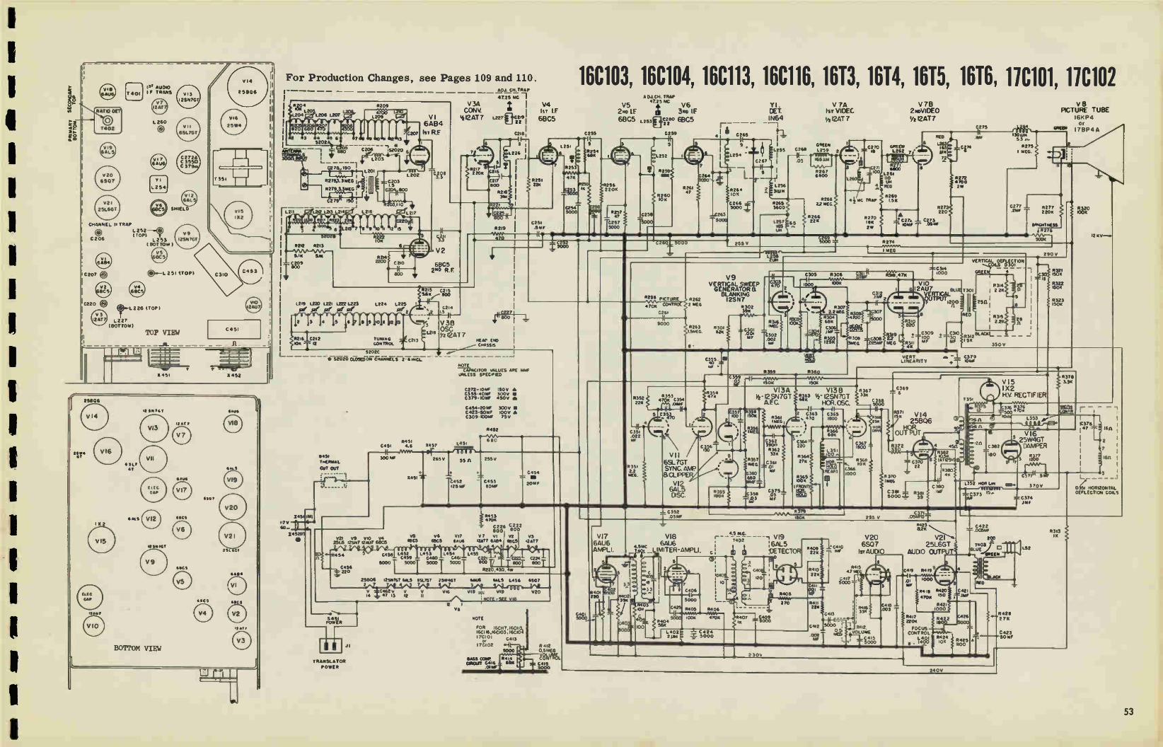
1
1
182 AU010 IF TRANS
RATIO DET
VI 3
I 2SN7GT
VII
6SL7GT
C2728 C 3550 C 379 -
T351
CHANNEL II TRAP
L252 I TOP)
C206 1253 ( BOTTOM
V12 6AL
SHIELD
V9 12581 TOT
las-L 251 STOP)
L226 (TOP)
1227 (BOTTOM)
25806
25806
• AL5 1 X 2
"Au'
5“ 751
11311767
BOTTOM VIEW
SeC
MRCS
For Production Changes, see Pages 109 and 110. AD.C.H.TRAP
4725 17C 1
I lie 4L R209 V 3A 1 V4L2S CONV. 1ST IF
IsT R.F '412AT 7 L227 ÉtG2T 1209 V I 68C5 6464
5202
C2
C206 162:20 6
eLire4"-le
150
5278,3.30EG
5279,1315EG 1
C279
Lat 1.213 1214
• 6
52028
5212 5213 w-VS/ws--i\AN--
SAX 5.11
— Vo°9
1219 1.220 1221 1222 1223
Pe Pi. Se 171
1201
5214 2200
1224 1225
6202G
1451 1M) wry 20-
145251
•
47-sr020cLosED0«
5451 C451 4.6
8451 THERMAL
SIT OUT - s
:
V2I V9 VIO 94 2516 t2SN7 12407 68C5
4
6451 POWER
TRANSLATOR
POWER
C208
7452
0214 1.5
V 38 OSG Yx 12 AT 7
CM.
s I
L22Li
NCTE_ CACITOR VALUES ARE Maw
UNLESS SPECIFIED
0272-101AF :50v A C355-401W 300v C 379- 1011F 450V Rh
0454-201AF C423-50MF C309- 001AF
1451
C452 125 MF
R452
680
300v • 100V • 75V
C25t .5MF
255v
C453 801AF
0454 .7. I.
201F
5453 470K
C2 26 C820202
VS V6 917 V7 vi 92 93 1005 4805 Gaut tAT7 6t04 8805 12,07
4 9 • 4 3
0458 1452 L452.60 .6" 145e 1455 0459 0221 C224
50001- 50001 50CM -{ 5000T 803 800 800
R2K4311, Ow
25806 125.17GT GAL5 6SL7GT 25•46T mus 611.5 1456 6507 2 7 7 7 8 8 7
1 :e23 r, Il
A Ve
vi8 V19
7.0TE 'SEE V18
NOTE
FOR 16c117 16Co3, 16C116,i60103:160104 7ci 0: C•13
i7C102
5000
SASS COW) GOUT G416
.0IMF
0.5MEG
nVet_ tibt C415
1255 0259
16C103, 16C104, 16C113, 16C116, 1613, 1614, 1615, 1616, 11C101, 11C102 AD.LCH. TRAP 47250C
V5 V6 Y I. isiVIIDEA c 270VIDEO
V 7 B 2to 1F : 3to IF CET 68CS 1.253#3C22,80 68C5 r _ _ __INV
il .
41
t1-1 V712AT 7 1/212AT7 I
C265
1254 5000 5257
47
0257 5000
V17 6AU6 AMPLI.
5352 22K
C351 022
535, 2.2 >AEG.
L255 C268
I —1F- - I .05
0266 5265 5000 3600
026 5000 255 v
5353 4 K 0354
Aims
C.313,0
I 05 MF
V 9 VERTICAL SWEEP GENERATOR a BLANKING 12SN7
5302 39K
R263 5301 1.5FAEG: 132.1 C301
001 MF
1257 165 Um
GREEN 1259
5268 22 MEG
5359 5360
0362 3900 5362 33K
2 0363 C365 , 470 Iwo
r-*-91tC. -
et 4.59AC ill - LIMITER -AMPLI. fi0 111:IX I 6AU6
VI8
CD e..3 :6AL5 TECTOR lie:z
1 o
T402
l 2 6
3,s3! 02 3
7 0425
5000 R404 5611
1402 21114
G4C17 120 22K
5405 5406
100st 47011
C•24 5000
1262 7 •
1261 110 1.84 NED
MC TRAP 1.5K
5270 !Om ZW
• • 12r. - 1011F
0369 6
255 V .0561101
C275
8272 •700 2 vi
+ 1210 R312eLj°1-MF 15K
350
i3OuN 53 n-
5275 MEG.
V15 1 X2 H.V. RECTIFIER
3 5 326 41W500 e.
1353 i f- -
C422 82K 1.01AF L 05
V20 5423 2C0
1220410 6S0 7 25L6GT T403 0 AFF IST AUDIO AUDIO OUTPUT u
. 'iNEEN
V 8 PICTURE TUBE
I6KP4 OF
°eel I7BP4A
VI6 25W4GT DAMPER
reor
5415 43 NE
0351 HORIZONTAL DEFLECTION COILS
53

16K1 16K2 ELECTROLYTIC CONDENSERS
REF. NO DESCRIPTION PART NO.
C4I0
C3I0
C379
C355
C272
C451
C452q
C453
C454
C309
C272
C355
C379
C207
C213
C206
C220
1 en!. , 50V
30 rnf., 450V
10 mf., 450V
40 rnf., 300V
IO mt., 150V 300 mt. , 150V
125 mf., 350V
BO mf., 300V
ZO mf. , 350V, 50 mf
100V, 10Orrif. , 75V
10 mf., 450V
40 mf., 300V
10 mt.. 150V
TRIMMERS
RCE-090
RCE-092
RCE-100
RCE-100
RCE-100 ACE-110
RCE-III
ACE-I12
RCE-I15
RCE-118
RCE-118
RCE-118
RCY-048
RCY-059
ACT-060
RCY-063
.6-2.4 mmf.
.2-1 mrnf.
For high channel trap . 7-7 mrnf.
. 3-1.4 rnmf.
CONTROLS
DESCRIPTION REF. NO. PART NO.
Volume. O. 5 meR •
Brightness, 500K
Hor. Hold, 100K
Vert, Hold, I25K
Vert. Size, 3 meg.
Vert. Lin. 4K, 2W
Hor. Drive, 25K. 112W
Foci..., 100K
Contract, 2 meg.
WIRE WOUND
R430
R286
R38I
R305
R308
R311
R369
R435
R285
R45I
R220
?R454
R382
R380
RRC-I47
RRC-I44
RAC-146
RAC-146
RAC-096
ARC-127
ARC-I40
ARC-144
RAC-147
RAW-048
RAW-049
RAW-051
RRW -052
RAW-053
4.6 ohns•, 5W
43 ohm., 4W
20 ohm•, Globar temp corn
10, 500 ohm•, Globar
4K, 7W
COILS
REF. NO, DESCRIPTION PART II0.
L201
L202
L218
1226, 7
,L251
L252, 3
1254, 5
1256
L257,63
1.259 L260,71,
L26I
L264
L35I
L352
1,353
L451
L401
Input tran•forrner
RF choke
Cathode choke Converter plate
2nd Video IF
IF plate Video detector allay.
RF, 31 oh. Vid. choke, 165 ink.
Vid. choke, 165 mic.
71. 4.5 rnc vid. trap
Vid. choke, 110 mic.
Vid. choke, 130 mic.
Horizontal o•cillator
Hor. Linearity
Width control
Reactor filter
RF Head-end AM loop a••ernbly
Focu•
RLA-036
RLI-006
Ft LI-003
RLP-016
RLI-096
ELI-I10
RLX-029 RLF-024
RLI-038 R1.1.093
RLI- 100
ELI-108
RLI-109
RLC-091
RLD-016
RLD-014
RTL-096
RJX-043
RLL-0404
RLF-039
TRANSFORMERS
DESCRIPTION REF. NO. PART NO.
Vert. Output
Hor. Output Yoke
Audio IF 1st
Ratio detector
Reactor filter
Interstage
T301
T351 D301
T401
T402
L45I
T406
RT0-064
RT0-090 RLD-025
R LI-097 RTD-008
RTL-096
RTM-005
MISCELLANEOUS
REF. NO, DESCRIPTION PART NO.
X451, 2
B451
S202
S403, 7
Selenium rectifier 350
Ion trap, single magne
Cut out Thermal
Channel selector switch
Pushbutton switch
Crystal diode Record changer -
3 speed changer
12"PM speaker
ma. RER -008 RET-003
RSR-002
RSW-082
RSW-083
1N64
PIS
S1212D-7
VI 6AEt4 let RF Amplifier j V6 6BC5 3rd Video IF Amplifier
V2 6BC5 2nd RF Amplifier
V3 12AT7 Converter - Oscillator
V4 6BC5 1st Video IF Amplifier
V5 6BC5 2nd Video IF Amplifier
V7 12AT7 Video Amplifier
V9 12SN7GT Vert. Blank'g & Sweep Gen
V10 12AU7 Vert. Sweep Gen. &Output
V11 6SL7GT Sync. Amp. & Clipper
V12 6AL5 Hor. AFC Discriminator
V13 12SN7GT Hor. AFC & Osc.
V14 25BQ6 Hor. Sweep Output
V15 1X2 High Voltage Rectifier
V16 25W4GT Hor. Damper Tube
V17 6AU6 Audio IF (4.5MC) Amp.
V18 6AU6 Audio IF Amp.& Limiter
V20 6J5 Audio Amplifier
V21 25L6GT Focus Control
TEST CONDITIONS
Voltage Measurements:
Input 117V, 60 cycles.
All controls set for normal sweeps.
Measurements are in respect to B-
with a 20K ohms/volt meter.
* Z. 5 volt range.
ttVoltage will vary more than 20%.
@- AC Voltage Reading.
Resistance Measurements:
Short capacitor C453.
Short pin 3 of V16 to B-.
M denotes meg.
Inf. denotes infinite resistance.
Turn the following controls full
clockwise: Focus control. contrast
Brightness, vertical hold, vert-
ical size, vertical linearity.
Values listed may have a tolerance
of 20%.
DNM - Do Not Measure.
54

16K1 16K2
SECONDARY TOP
PRIMARY BOTTOM
V20
&TS
251667
• Y 1
1/41.2 54
V13
1 25N7GT
VII
651101
C2726 C3550 C379
SHIELD
(D.-1251 (TOP)
L226 (TOP)
L227 (BOTTOM)
3451 3452
• 31? •T
• MS
BOTTOM VIEW
FOR RADIO USED WITH THESE CHASSIS, SEE PAGES 101, 102, 103.
34 4725 16C
6 7
"C2-7 750-
11,111(10gA INPUT R 31,1EGI
3" °." 8279.3 3189J
150 _J
— 1.2)2 1.201-e4
100 ZOO
• 52020
R2I2
51K SIX
C209
r °
1219
1201
1216
•
1203
2 10K
6202D 6
2.20 0203
800
R203, 110
1121. L2 17
1.220
•
• V4
CONV. I s r I.F
VI 412AT7 ' 6865
6AB4
Psi RE
3
•• 0217 220K
12.27
C2751 I t-7
5
1226
5
0216
c21 500
4 6218 39«
C211 33
.2.oRF
V2
6 BC5
2.255
0251 224
• I C2L,
.251
0253
•7 K
C253
5030
0254 6511
ADJ CH TRAP
V5 47 25 MC V6
2Poo IF It 3•D IF
6865 "i.czeo 61365 1253 E_T 22
C259
8256 2 20K
0257 47
1.257 5000
C256
1.252 4-
R259 651(
8260 10K
0261 47
1.264 5003
VI V 7A V7B
Isr VIDEO 2 PeVIDEO
1/2 I2AT 7 '/: 12AT 7
11 1.265 l 9 L255 GREEN
F268 L259 I X16
l
1 • I 0
Z
L 264 -
I L.
0264 10K
C266e-.
31um
3600
1257 165 6.5
0267 6500
42.6e .
11268 2261EG
GREEN 2.270 1262
27 100 6800
1261
We' •hic
0269 TRAP L51
4270 1011 2w
C275
RED
-- UK •
e
1/27 22
• . 0273
C-272 tow
C274 6
0272 •700
Zw
Ni PICTURE TUBE
1 6K P4
53.-11215 11,416
11
C277 1 0277 2206
2180 efliGNTNESS
152136
122) 1223
7 9
•216 1.215 see r .00
o 1224 Le>52
5216 C2i2 7128106MK T. CONTROL
L- 5202C *S2 0 2D CLOSED ON CHANNELS 2IINCL
* GROuNOS NAM TO We ENO CHASSIS ONLT 21
25L6 GT
FOCUS CONTROL
% C214
12
C213
V38
OSC I2AT 7
451 TNERNA,
TRANSLA Cwan °UT POWER ----- 1
1,7 v 1451 85
14544F I 9 2
.7-6466 220
1000
C45) 8451 I45
3001,1F 4.6
545)
0:04
1451 550
C227 I
NEW CFO OMSSIS GRouto
_
2506
L403 F00.6 CON.
0427
250 v • C 9
R274 5CO«
O
imEG
1.260 V9 5000
V EERTNeleg .+1 BLANKING
I2SN7
225e inT012 4 1/2135 47,D• ccenRoi. 2 MEG
c26M5000 10263
534EG e
530) 11126
11302 3511
mc301
F
4
r'°3E166
r 002 302
ee
2
3
2306
6305 II 306 wear
WOO
31(1474
11 • e
6
R304 61311
f134,9e1
8307 2 2/46
125
0359 5360
R309 4700
`312 ,ZY k 2
307 5000
nee
•*308 _C308 »EA 10 25/0
40 C351 022 NE
8351 22 'AEG
C359 0561 1504 ,50«
5 C353 Cte ‘470
•
_4_ _
V I 1
6SL7GT
SYNC AMP
a CLPPE
VI 2 6AL5
DISC
V I3A
- 12 SN7G T
HOR CSC
110 1513 iSOK
0356 1 %MG
0357
360
O
536) lea
5362 330
0351 01 31F
1.375 - 05 MF
V1313
Us3 14- 12SN7GT HCR OSC.
I • I I— C363 6365 470 0100 61
• • be« 0364 P=436 220 g 000
••• 100 5364 27K
5565 004
tied NOR
5347 33K
C367 1800'.
5368 10K
5453 4704
C226 C222 1300 800
VS 06 vi7 v7 VI 62 v3 6005 6BC5 6606 12,41 6484 65C5 GAT?
•
1452 1453 1.454 L455 C4513 C459 C460 c461 C22, 5C00 5001 50001 5,0001 OCO Irna° . CM
R220,43 , 4•y
25806 ,29i7G1 EALS 651. 7GT 254,447 651.113 461.3 1456 6J5
614 co32 V V V vi6 vie • 619 V20
I.7 13 12 II' We\ -NOTE SEE 6 113
ROTE cAPAGT011 y40E6442 A» 144.165 SPECS»
C272 •IONF0 iSoy A C335 - 40 3006 • C379 -a • 4509 m
C454 201410 3006
cm, -toe 756
17
6 AU 6
AMPLI
r--
2
noo 220
402
C352 05PAF
V18
VSMC 6AU6
_ ttAITER -AMPLI
39 0E63
45 KC
7402 :6AL5
I CETECT
V19
37
8011
7
C406
5000
1.420 0405
0404 56K
1.402 c424 2 e = 000
5406
1002 470K
lO
•
4 VIO 6 12A117
MIMI MRS
R3I9 <2.21/2
•
R310 620
R3,1 •K
VERT LINEARITY
Cs369
e
wa g 7
c3,5„ec,
5371 vex 1511
25
ouYeuT
R 372
350 R
0370 11PC »I 1306 f 5000
11381 39
s. 28 C379
nes
03130 4K
30
0351 375
I 2
C373 OAF
290V
Via
H.V RECTIFIER
ce6:901
250V C371
.0514FOT
C4213 .25w
374 T
8322 150K
R323 150K
037 33K
R320 100K
3106
160
7
80
L -Ir
D» HORIZONTAL DEFLECTION COLS
12.
7406
94
RE o
5434
Fe
• •
S S
1.427 05 50
BLACK
RED
ORO»

11C103, 11C104, 11C105, 11C101, 11C108, 11C109, 11C112, 11C114, 1111, 1112, 1113, 1114, 1115, 1116 ELECTROLYTIC CONDENSERS
EF. NO DESCRIPTION PART NO.
C310
C379A
C379B
C379C
C4I0
C45I
C452
C453
C454A
C454B
C454C
C206
CZO7
C2I3
C220
C265
C275
311
351
354
361
362
365,7
376
378
30 mt., 450V
10 inf., 450V
40 mt., 300V
10 mi... 150V
I rnf., 50V
300 mf., 150V
125 mf., 350V
80 rnf. , 300V
20 mf., 350V
50 rnf., 100V
100 mf., 75V
TRIMMERS
RCE- 136
RCE- 118
RCE- 118
RCE- 118
RCE-090
RCE- 110
RCE- Ill
RCE- 112
RCE-115
RCE- 115
RCE-115
RCY-060
RCY-048
RCY-059
RCY-063
RCN-029
RCN-031
RCN-030
RCN-044
RCN-018
RCN-025
RCN-034
RCN-033
RCN-035
RCN-037
Hs Channel trap
1.2 RF
Fine tuning control
2nd RF
SPECIAL:
9 mrnf. , 500V
. I mf., 600V
. 01 mf., 1K V.
.02 mf., 1K V.
. 01 mf.. 600V
.01 mf. , 600V 10%
3900 mrnf.. 600V
1800 rnmf. .600V
500 mmf. , 20K V. 47 mini. , 1500 V.
CONTROLS
DESCRIPTION REF. NO. PART NO.
Vert
Vert
Vert,
Vert.
Bor. Drive
Hor. Hold
Hor. Hold
Volume.
Volume, Volume,
Volume,
Brightness
Brightness
Focus
Focus Contrast
Contrast
Contrast
Contrast
Triode
500K
Vertical
mf. cap
4.6 ohms,
43 ohms,
20 ohms,
10,500.
voltage
4K, 10%,
1.2 ohms,
39 ohms,
Sire 3 Meg
Lin. 4K, 2W
Hold 125K
Hold
2.5K, 1/2W
100K
On-Off 2 Meg
On-Off 2 Meg On-Off
On-Off
10K
500K
500K
500K
WIREWOUND
R308
R311 26365
26305
26369
R305
R365
R412
E412
R4I2 26412
26424
R276
26276
R424
26262
26280
26280
E280
C4I9,
26417.8
C301,2
26301,2
R45I
26220
R454
R382
26380
E375
E381
EEC-096
EEC-127
EEC-146
EEC-169 (B & 1) only)
EEC-140
EEC-146
EEC-169 (B & D only)
EEC-164 (A only)
EEC-162 (C only) EEC-170 (B only)
EEC-171 (D only)
EEC-145
EEC-168 (B & D only)
EEC-145
EEC-168 (B & D only)
EEC-164 (A only)
EEC-162 (C only)
EEC-170 (B only)
EEC-171 (D only)
REK-002
REK-003
KR W-048
RRW-049
ER W-051
RRW-052
RR W-053
RAW-058
FtRW-077
couplate, 250K rea.
res., .01 mf, cap.
Integrator, .004002
39K, 82K
20%, 5W
4W
Globar current reg.
10%, 125V Globar
regulating.
7W
10%, I/2W
2W
COILS
REF, NO. DESCRIPTION PART NO.
201
202
203
218
226, 7
251
252, 3
254, 5
265, 7
255
57
263
259
260
261
262
64
351
352
353
401
401
451
258
Antenna input 1st RF
high channel trap
One, oath. 1.4 oh.
Cony, plate and trap
2nd Video IF
3rd video IF and trap
Video detector assy.
Video detector choke
Video 165 ah.
Video
Trap 4. Sreu video Choke vid. plate 110uh
Video comp
Choke video
Norte. ose.
Hor. linearity
Width
For us
Focus Choke filter
402,452,3,4,5,6.
Heater, 2 uh.
RLA-036 ALI-006
RLI- 114 ELI-003
RLP-016
ELI-096
ELI-lb0
RLX-02 ,
ELF-024
RLI-038
RL1-093
RLI-100
RLI-108
ELI-161
RLI-109
RLC-091
RLD-016
RLD-014
RLF-043
RLF-050 (B & D only) RTL -096
RU-122
V5 6BC5 2nd Video IF Amplifier I VI 6AB4 lot RF Amplifier
V2 6BC5 2nd RF Amplifier V6 6BC5 3rd Video IF Amplifier
V3 12AT7 Converter- Oscillator V7 12AT7 Video Amplifier
V4 68C5 lot Video IF Amplifier
TRANSFORMERS
DESCRIPTION REF. NO. PART NO.
Vert. Output
Nor. Output (Early)
Hot% Output (Late)
Audio Output
Audio Output
Audio Output
1st Audio IF
Yoke
Ratio Detector
T301
T351
T551
T403
T403
T403
T401
D301
T402
RT0-064
RT0-090
RTO-114
RT0-081
RT0-082
RT0-086
ELI-097
RLD-025
RTD-008
(A di B only)
(D only)
(C only)
MISCELLANEOUS
REF. NCI DESCRIPTION PART NO,
X451,2 Selenium rectifier 350 ma,
Ion trap
RER-008
RET-003
RF tuner RJX-043 (A di C onl, I
RI, tuner RJX-045 (B ii D only)
13451 Thermal cutout ESR-002 (console)
S201 Switch-channel RSW-082
Y1 Diode-1N64 Germ.crystal IN64
Speaker, 5 1/4" PM S525D7 (B & A only)
Speaker, 12" PM 51212D7 (C & D only)
A - I7T1,2,3
B - 17T4,5,6
C - I7C103, 4,5, 7, 8,9
I) - 17C112, I7C114
V10 12AU7 Vert. Sweep Output
V11 6SL7GT Sync. Amp, gt Clipper
V12 6AL5 Hor. Freq. Discriminator
V13 12SN7GT Hor. AFC &Sweep Ose.
LATE PRODUCTION
IV13 12SN7GT Hor. AFC 81 Sweep Osc.
V14 25BQ6 Bor. Sweep Output
V15 1X2 High Voltage Rectifier
V16 25W4GT Hor. Damper Tube
V17 6AU6 Audio IF Amplifier
V18 6AU6 Audio IF Amp.- Limiter
V19 GALS Audio Detector
V20 6SQ7 Audio Amplifier
V21 25L6GT Audio Output
TEST CONDITIONS
Voltage Measurements:
Input 117V, 60 cycles.
All controls set for normal sweeps,
Focus and brightness measurements
are in respect to B - with a 20K ohm/ volt meter.
Resistance Measurements:
Short capacitor C-453.
Short pin 3 of V16 to 13-
Inf. denotes infinite resistance.
Turn the following controls full
clockwise:
Focus control, Contrast, Brightness
Vertical Hold, Vertical Size,Vert-
ical, Linearity.
Values listed may vary 20%.
@ -AC Voltage Reading.
DNM -Do Not Measure.
1
1
1
56
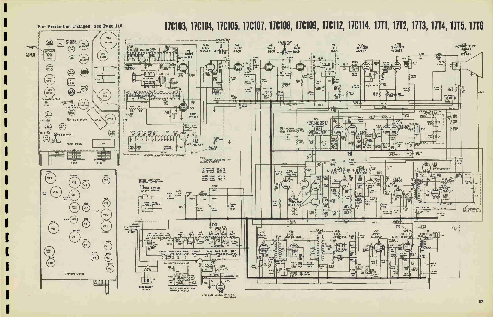
For Production Changes, see Page gO.
SECONDARY TOP
PRIMARY_H., BOTTOM
1
us, Aucno é F TRANS
L260
7402
Y I
L254
® L 252 ( 70P)
C206 1,253 ( BOTTOM)
SHIELD
0.—L 251 (TOP)
L226 (TOP)
L227 (BOTTOM)
162
TOP VIEW
1452
12 95 TOY
BOTTOM VIEW
C451
1451
419C 9
846s
5212 R213 il--«11•51\•—•
5.1k II«
— C209 SOO
117 v
60.44 - 14521/1
11C103, 11C104, 11C105, 11C101, 11C108, 11C109, 11C112, 11C114, 1111, 1112, 1113, 1114, 1115, 1116
R209
R222 10K
VI
6AB4
207 1ST R.F
V 3A CONY
til2AT7
•
ADJ. CU. TRAP
4725 MC 1
L227 #3421.3 ' 22 I
C218,
216
0217 800
5218 394
1 Lz26 I
68C5 2ND R. F.
R221
V4
Is IF
6BC5
5251 22*
0229
1219 1220 1.221 1222 1.223 1224 1225
pie err szi" of
2 3
1721610212
001
1 T 12
1451 1M)
7 9
se'
lo
TUNING 40213 CONTROL
11215 02 .., 9.115..- 800
It 0214
• 2 1.5
V 38 OSC
I2AT 7
5202C •
DOTTED UNES SHOW CONSOLE CONNECTIONS
8451 THERMAL CONSOLE
GUT OUT MOOELS
R219 I
•70
0251 .5 MF
C227___ I
HERD ENO CHASSIS
L 251
5253
•75
3
0254
C252
IP
255
5
111254 MIR
NOTE CAPACITOR VALUES ARE w•F
UNLESS SPECIFIED
C3798- 10PAF 450v a.
ageil= re C45411 • 20MF 300V C4545 • Spur 100V 41 C454C 100W 75v
5451 L45I C451 4.8 X452
300 W 265 v
F 451 TABLE Fug MODELS •
1(451 -N.
921 v9 v10 94 2516 12SN7 724U7 6E105
7 4
55.A.
11452 125 MF
5452
680
255V
C453 SOMF
* 5453 e • 70K ST COW
SOD
C454A .7.
2Our
VS v4 v17 v7 VI vz v3 61105 CRCS 6At4 '207 6AB4 szecs 1201 3 4 34 9 • 4 3
5 -R4511 0458 1452 1453 1,454 L455 •- MAVX-0 0459 C460 C461 C221
5000 I 50001 5000 I 5001 800 C224
SOO 900
_-C242506 R22,43[1,
-••• 250[26 1255176T 65..5 ESL7GT 25,11403 61w6 6 ALS 1456 911127
7 7 4 7 8 8 7 3 4
920 ;..4 1_ :672 .r2 VI8 vi9
NOTE SEE Via
'2 I VI5 vs 7352 3724..4l4 R376
S•51 POWER
II TRANSLATOR
POWER
J1
ALL HEATER CHOKES Len. 54H
11412 QSMEG .1,2Luclà4E15
5000
11412 CONNECTIONS FOR CONSOLE MODELS
*FOR LATE MODELS 1774.5136 17C112.17C44.
C401 5000
A 01CH. TRAP 4725 MC
V5 V6
2fto LE 3Re IF
6BC5 Lzsseer 68C5
C259
e R256 220A
5000 FIT571
C257 Z.
47 1
5000
R401 220
402
5
el252
58
112
8260 10«
R261 47
C2601 5000
7
264
.
DET.
IN64
I a 41 0265
1255 0268
I — 1 es
9 a. • Ims - 2 54 iti64 c26,
.-1
2 4 !!I15: 15 106
C266 5265 5000 .1 3600
263
253 V
uH
R.2 PICTURE
4705 CON3
C26
5000
2.83
R352 22k
C35. 022 P.
533, 2.2 mEG.
39« 03
o«
00
1257 165 CH
V 7A
1ST VIDEO
./2 12AT 7
5267 6800
MEG. 5268
22
5266 27«
V78 2 weVIDEO
12AT7
C270 GREEN L262 7•
271
1261
Uri RED
5269 1.5K
NCO
L 165 Il8 7/2
R27
• l a 220 5270
.C379C3- C273 H3K 1051f .0570
R274
C74
11272 • 700
0275
V 8
PICTURE TUBE
178P4 A OR
ITBP48 e 30 LIN
511
5275 MEG.
10
R277 22011
8154HINESS 4,7276 e SOCH
290 V
5353 4 It 0354
.05oF
VII
6SL7GT
SYNC. WE
GLIPPE
VI2
6AL-5 DSC.
5262 2 m[4
11263 L5•11EG.
V9
VERTICAL SWEEP GENERATOR a
BLANKING I2SN7
'VERTICAL 5302 INTEGRATOR 39.. PLATE
5301 5151
R3I6
C301 - 1 .001 03021 MF eoz I
3
C305 5306
1000 OOK
11318 ,4 711
8307 2 2 111[C•
p304 6811
C106 mat
5303 25K e
C1312
4,00
308 3=4
0307
5000
=C314 1000
6 l2AU7 131_0111'3011 VIO
yiRTTPluCTAL 12,r
+8021 6
R319 C3013 2.2 0251A? MEG
VIT
6AU6
AWL I.
VI8
66
MO 1.5— LIMITER -AMPLI.
C3798 40 mr •
11310
., 820 0454C + IC310
- 100 - 30 R31' ." MF 46
VERTICAL DEFLECTION esot_ -
GREEN • 1 [
R3I41 28 I22KRO
R23.1
R31213LAQ(LI 5K
5
R321 C2133 150K
11322 150K
R323 '50«
.i2KV
VER m. -I 03794 8OLDI NE RR IT
359 11360 C 359
'50K
VI3A - 12 SN7GT AFC.
15011
R4r:
35 35e 6[73 150«
.ss, vie
5355 1505
5361 1MCG
VI3
U 63 14 12SN7GT
HCR.OSC.
2 C363 C365 s 410 MOO
•
1362 3 0364 3900 220 R362 33«
R364 R357 27« WIG 1361
.01 160 MI 680 R 365
00 r rR0v
0375 11051 358 .05 GOLD 123 ear UI
56 5040
5199 251
C369 6
R371 '5K V 1 4
25E106
R. OUT PUT
R 72
C37° 1 22
370eimE
C351 9381 C 380
IMF
g.LI e VI6
25W4GT
C382 DAMPER
.80 R377
----gee
1352 »OR L.7. 169.
1200
C3771( .5
370V
V15
I X2
H.V RECTIFIER T!'s
5378 13K
376 r 8375 9018 : 12
t* er).n. L 353 1
C378 47 16
C373 1511
1_ C352 .05 MF
5
79
1806
4 5 KC
7402 :6e/5
111 :CETECTOR 5ice
7
C406 1—•
5000
04
R404 56«
11405
10OR
a)
0406
470‘ 40? C409 1R 5000
5400 *Yee 210
5410 22K
C41 Dol •••
L402 2 LIN L Rn
: 5000
R411 22«
0412
.002 til
• C410 IMF
C•13
- 5000 r
0.5. MEG.
255 v
V20
6507
1st AUDIO
8415 4.7 mE
C417 5000
4
0371 .0571PD
e. 5423 8.2.1
25L6GT
AUDO OUTPUT TRIODE COUPL ATE
E479- 154 19 5
000
240 V
FOCUS
°K R4is coml.**. 50 R424
8411 504
R12 3
— 574 T .1141
-
2 7
I6A
13251 HORt205711.. DEFI EcT1.35
0422 .ocsss 11313
NEO
S
5425 1100
L401 1425[1
152
8429 275
C4546 50 MF
1K

11C110, 111C111 ELECTROLYTIC CONDENSERS
REF. NO, DESCRIPTION PART NO.
C205
C401A
C4018
C40IC
C402A
C40213
C4O2C
C403A
C40313
C403C
C403D
C104. 6 C105
C 108 C118
C365
I ml . 50V
40 mf. , 350V
90 rnf. , 350V
20 rnf., 350V
30 mf. , 350V
30 rnf. , 350V
100 mf., 75V
20 trif. , 350V
40 mf., 350V 50 mf., 150V
25 rnf. , 25V
1-5 rnmf., trimmer
20-50 trirnf.,trimm.
0.6-2 . 4 rotrif • , trim, Tuning trimmer
100-480 mmf., trim.
RCE-090
RCE-I30
RCE-130
RCE-130
ICE- 128
RCE- 128
RCE-I28
RCE-I29
RCE- 129 RCE-129
RCE-129
RCY-065
RCY-066
RCY-048 RCY-067
RCY-068 (her, drive)
CONTROLS
DESCRIPTION REF. NO. PART NO.
Volume 2 meg
Brightness 100K
Contrast
Hor Hold 100K
Hor. Sire
Vert. Hold 125K Vert. Size
Vert. Lin. 4K
Height 3 meg
Picture Z5K
Focus 10K, w. w. 2400 ohms, 7 w., w. w.
250 ohms, 5 w., w. w.
I5K 150V, Globar 2350 ohm• lOw.. w. w.
1209
1165
1361
R309
1305
R3I2
1169
1217
R371
R381 1370
1402
RRC -156
RRC- 154
RRC-154
RRC- 163
RRC-127
RRC-096
RAC- 156
RRW-073
RRW-069
RRW-071
RRW-072
RRW-083
COILS
REF" .1 NO DESCRIPTION PART MO.
L100
L106 L136
1.137
L138,9 140
LI51
LI52
LI53
LI 59. 3 156
1,154
L155
1.157
LI63
L401
L201
L351
1.352
L353
L..34, 5
Choke RF input
IF Trap
Choke RF
Choke RF heater for V102, V103
Choke RI "D" Tuner
(Late production)
1st IF plate
2nd IF plate
Choke Video detector
Video peaking, 140 oh
Video peaking, 220 uh,
Video peaking, 345 uh.
Audio 4.5 Inc Filter choke, 4 hy
Focus
Hor. osc.
Width and adjustment Linearity &adjustment
Damper 10 uh.
RLI-146
RLI-159 RU-136
RU-144
RU-154
RLP-018
RLP-019 RLF-024
RLX-033
RLI-148
RLI-149
RLI-150 RU-151 RLF -045
RLF-046
RLC-091
RLD-031
RLD-027
RLI-138
TRANSFORMERS
DESCRIPTION REF. NO PART NO.
Hoe. Output
Power
Audio Output
Yoke, (early)
Yoke, (late)
Vertical Output
Vertical Output
Ratio detector
1st Video I-F
Video I-F
Inter•tage
Antenna input
T35I
T401
T202
D301
D301
T301
T301
TZ01
T151
TIO1
T203
TIO0
RT0-101
RTP-309
RTO- I 05
RLD-030 used
RLD-037 used
RTO-102 used
RTO-110 used
RTD-011
RTL-125
RTL-126
RTM-008
RLA-037
w/RTO- 110
w/RT0-102
w/RLD-037
w/RLD-030
(headend out.)
MISCELLANEOUS
REF. MO, DESCRIPTION PART NO.
Ion trap
Speaker 12" PM Crystal diode 1N64
FtET-003
S1212D-7
1N64
V101 6AB4 1st RF Amplifier 1
V102 6CB6 2nd RF Amplifier
V103 12AT7 Converter - Oscillator
V104 6CB6 1st Video IF Amplifier
V105 6CB6 2nd Video IF Amplifier
V106 6CB6 3rd Video IF Amplifier
V107 6CB6 Video Amplifier
V108 6CB6 Audio IF Amplifier I
V109 6AU6 Audio IF Limiter
V110 6AL5 Audio Detector
V111 6SQ7 Audio Amplifier
V112 6W6GT Audio Output
V113 6AU6 AGC Keyer
V114 6AQ7 1st Clipper-Hor. Disc.
V115 6C4 Hor. Reactance Tube
V116 6AU6 Hor. Sweep Oscillator
V117 6AV5GT flor. Sweep Output
V118 6W4GT flor. Damping Tube
LY111_112:_llietLY.Q1tagejteri.-1
V120 12AT7 Vert. Sweep Oscillator
V121 6BL7 Vert. Sweep Output
V123 5U4-G B+ Rectifier
V124 5U4-G Rectifier
TEST CONDITIONS
Voltage Measurements:
Antenna terminals shorted.
Picture control at maximum.
Brightness control at minimum.
Channel selector at channel #13.
All readings taken with VTVM unless
otherwise noted. Readings may vary Z0%.
RF tuner measurements made from top of chassis with tube removed.
Line voltage 117 volts.
Resistance Measurements:
Receiver power disconnected. All potentiometers at maximum.
Readings are in ohms bi may vary
20%. Values on RF tuner (head-end)taken
from top of unit with tubes removed.
@- AC Voltage Reading.
DNM -Do Not Measure. 1
58

1 1
11/1•1T. VERT IMR.
11135 HOLD AMU
4.1 C[Z] R217
[ PCTURE TILT LEVER
CONV 09C V103
TIO1
2FM R-F 1/102
iST R. F VO
HEAD -
UPC
Im AUDIO
F TRIWS
5203
AUDIO TAKE-OFF
L.63 use
VIDEO
DE' ut rm
3« 1E8 • 251/AL 14106 TRAP 6086
T201 RATIO
e 11;252 •
DEI
SIMA
1.1,5›,•
2» PER 47 250C TRAP
ow m IF &H
47255C TRAP L44 poem
Mo
1.1 .1111 •
11/
MANUAL CENTERING y‘ CONTROL
MN TRAP
DEFLECTION YOKE ADJUSTbENTS
FOCUS COL ADJUST
VERT
OLrtP
T301
MOO
CROKE 1.40
OUTPUT
POWER TR.886 1401
TOP VIEW
)DEFLECT ,ON YOKE ADJUSTMENT
C36541I/ NOR DRIVE
NORIZONTAL L35I 005CiLLATOR
VI 16
FOR "EARLY" AND "D" VERSION TUNERS, SEE PAGE 100.
1 uos
RANSL AT 0R POWER
BACK VIEW
V102 6CB6
5100 SHOWN IN CHANNEL 6 P0SITON _ 2_1e_ff 7,21_
6
L.104
UO3
L102
LIO
C102 43
117V
BLACK -RED
11116 IBA
C103
C114 12
•
U14
LI35
L _ •W VERSION
••40 , RED
Vn
R 0-TEL
O
YELLOW
YELLOW
VI23 SUNG
RECTIFIER
y124 5u4G
RECTIFIER
R102
IRK
8103
5600
C112= 800 Ic,o
11, V103• 3.9
1 12477 2 OSC.
2
3.311
115
4Clek 36,
#
• 1.5
Cr2I e 33
36
Cutl .8 -17
e
FINE TUNING
C.08 Q6-24
10
V1038 ,R, ¡I? AT 7 CONy C119
71 •
11112.' 1OK
18,3 220K
- 22K MF
00
I •
0382 05WF
C'
8114
160
S 000
1%1 COO
1
IDI
2 RED
ANC
EN 250v
V108 4 51410 AMP
6086
175V
Eit 250V
For Production Changes, see Page 110.
1203 4.514C
225 '/,.e9 ; :220e. LIMIER
II 50
C2I0
L R222
et< c2
•
217
R223 4 700 IN
240v
224
0221 800
4000 R201 %VW 00«
R202 470K
RATIO DE T. TRANS.
1201
V110 6AL.5 RATIO DE T.
à 020310,120
2 0,E
J201 5201 TV PHONO »Cy__
2
R20 22K
ImC208 - tgy
00CIMF WNW • R205 021ÎT
nr. CON .005
.001
4 7.25MC ADJ. IWO. TRAP
51
L I
ADJ AUD. 47 25
V104 TRAP
6066 Itp 1ST VIDEO y
C i 1. LI61 *0153
C173
•4 800
8. 250v
4123 k 14C TRAP L 39.75MC
V105 C' 715EILK,4 V106 TRAP VOI
210 VIDEO
R157 47
1864 6C 68 L156 DETECTOR 86 60E16
I F 160V C156 1-,
3R1) VIDEO EeTia --4 GI 1
200V I
L152 «
R158 1000
ORANGE
IS
2011
5
820
RIEN
LI
800 RI61
0158
15
F 11166 800 470
• 0401C
R•02 • 2°*2. 2 350 IClw
R257 3000 2M 250V
11256 V-0131
33«
VII3 6426 AGO
RETEN R251
4.6800 Ii 1.251 SEC. CC MOTH
C254
.25 MI
8253
,0011
R252
C253
.05 MP
r. To% OF•T351
F 'To46
'ef T351
8259 SOR
8256 150K
11254 2211
L401
el .C40°14'-FA 350V
LI37
13 ,250v
f VIII 6507
1ST 40010
'&16 C208
R209 2«:.0441EGI-7.1 °,N•3,- VOL CONT.
0021M
R2I 6.e
MEG
105V
IC
8211 22011
C2 11 R212
Coo 8
8213 R214 47 150
11C110, 11C111
VII2 6w6GT
AuD03 OUTPUT
R216 11 00 2W L20
260v
4
35,
FocR,„1:0: F00001J:CR041221. 0
COIL 7.218* 8.28
BLUE 120
R180 AL .1 200
C2I3
2 MF 008
MF
221 6
• L5201
• C403.• 200W 350V
L'63 4.5MC AUDIO
TAKE OFF
RIAS IOK
C160 5 R162 3
075 ew 20
2741
e
RI?
140,3
40162 800100
111M 250
V107 RI63 6086 3300 VC. AMP
B 160V 8+600
• 800
PICTURE CONTROL
869 4 25K 50
MF RITO 350v
5600 •
Ce6.6
MF CI68 6
R 73 3000 2W
07
345,4,
1664
yN C3 75
MF
470
VII4A 6407
SYNC. CLIPPER
135v
R386 10K
R378 141 .-884~ 470«
ROSI
R375 •-
120«
0312
,•, ROIS R C 52
• 4711
.C.%)
*V120 12457
VER/ IAJLTIVIEIRATOR NEIGHT 85,2
0306
47K
C030:.192. ••••
Tar
0307 470
'car R317 1201,
-•
R3/0 100K
N
R308 •7K
125K
Rat 56K
13IIGHT-NESS 0176 R165 100 MF
• 11
R174 470K
R178 27111
VI22 PICTURE TUBE
178P4 8
2 RITA
620K
.00:160: # 47
df •
C'70008
.00,1.1F 1118.
BE BOOST
4
314EG
C303
ROS
VERT. .HOLD
R307 2206
3
110 304
« • .06IM
330111
I6V
V 68L7t21 VERT. OUTPUT
T301 5 028v -2- VERT. OUTPUT
- TRANBSL. j5,0
•
8304 270
R3 41 C402-C VERT 100MF LIN. • 75V
.4;13go
R303 470 1111
250v
•C401 -8 SOME
- 350v
* NOTE
V1148 i640 7 HOR.PNASE
(01-c-e325
C352 120
R354 MEG
R335 I ASEO I
250V
0354
480 1.4F
COOFe
8306 wee.% ISOK
R353 1' 47K
CO?? 4700 8358
8/EG
ROS AIR
5r C355 8 0561 0356 .0082 CO MF
Ms MT
V115 C) 6C4
NOR. REACT 0359
IS V
470 1800
2561 2SV
8360 27«
R359 e,C360 68K t 220
8361 1008 NOR Z
11Oj4
R0,0 18
8069
E
R363 470«
N R362
L35, 450
VII6 64u6
NOR OSC, 130, :31(64
836s, 47° 150K
C363
0362
00
R364 8211
8367
VII? 64v5
NOR OUTPUT
8
WI GLOBAR R370
150v
8381 250 5w R371
2 366 74/
380 .5111F
2 214EG 8382 2
2W
11 1250V
390
4/ n
3
ME
1811
C402-8 - 3061
350V INT
r-C1301 vER t YOKE
3
/1nCR023.5,YOK
8 y
L__
R301 2200
R 383
1200
C30
2
30(1 F2i2"OÓ
1551
TC VII9 183
14.V. NEC T.
8377
.1.1,54IF 0369
500.517, IW
8 BLUE
CWole; H
6 L352 i
To BEYER PLATE
CNT
fen L353
C361= 11ORZ.LW
351 2 011
L355
8373 .#416 gox
L354 VII8
250V. - 6•40T • DAMPEF1
I A 811 BOOST
lORA
00356.2,
500./
180
C381
36
250V
R372 2.7 MEG.
4711
IN EARLY PRODUCT/ON RECEIVERS THE FOLLOWING COMPONENTS WERE USED WITH DIFFERENT VALUES AS MARKED:
8115 -91000 0108 - .0021AF RI59 - 12 000n 0153- BOOM R175-10000011 8 8200011 C156-24mim RIEN - 3300011 C356 -.015MF R215-10000 R2 18-180011 R 306-33000011 R402-20000
v120 IIMS 12/W7 WITH TINE FOLLOWING CIRCUIT VALUES R 303 -15000 R306 - 2.2MEÇ 8308-8200010 C 30• - .04 MF C306- 0033MF
'REWIRED
*0 OPEN RESISTOR DOES NOT INDICATE DEFECTIVE COMPONENT.
e -INOKATES TEST POINT.
ALL CANACITY VALUES ARE IN MIME UNLESS OTRERYCSE 51601 100. ALL RESISTORS ARE ¡ WATT 9
C403

1111, 11C113, 11C115, 11C111, 11C120 ELECTROLYTIC CONDENSERS
REF. NO. DESCRIPTION PART NO.
C310
C379A
C379B
C379C
C4I0
C45I
C452
C453
C454A
C4546
CI04,6
C105 C108
C118
30 mf. , 450V
10 rnf. , 450V
40 rnf., 300V 10 rnf., 150V
I rnf., 50 V
300 mf. , 150V
125 mf., 350V
80 mf. , 300V
20 mf., 300V
100 Inf. , 75V
TRIMMERS
RCE- 136
RCE-I18
RCE-118
RCE-I18
RCE-090
RCE-110
RCE- 111
RCE-112
RCE- 134
RCE-134
RCY-065
RCY-066 RCY-048
RCY -067
1-5 mm!.
20-50 mmf.
.6-2.4 mm!.
. 8-1. 7 mmf., fine
tuning control
CONTROLS
DESCRIPTION REF. NO. PART NO.
Brightness,
Hor.
Vert.
Vert.
Height,
Hon. Volume,
Volume
Volume
Contrast,
Contrast
Contrast
Triode
250K,
Vert. . 002
4.6 ohms
4K,
31 ohms, I. 2 ohms,
5600 ohms.,
20 ohms,
1500 ohms
1400 ohms
22C0ohrns
500K
Hold, 100K
Hold, 125K
Lin., 1K, 2W
3 meg.
Drive, 25K, 20%, 500E
(I7C120 only)
(I7T7 only)
2 meg. (I7C120 only)
(17T7 only)
WIREWOUND
I/2W
rnfd.
mf.
140V
R276
R365
R305
R3I1
R308
R369 R4I3
R4I3
R4I3
R280
R280
R280
C419
R4I7,8
C30I, 2
R45I
R380
R454
R375
K282
R455
R452
R382
R28I
RRC-175
RAC - 173
RRC-174
RRC-I27
RAC-096
RRC-140 RRC-176
RRC-182
RRC-I83 RAC-176
RRC-I82
RRC-I83
REK-002
REK-003
RRW -048
RRW-053
RRW-054
RRW -058
RRW-079
RRW-081
RRW-082
RRW-088
RRW-092
couplate-. 01
500K
Integrator -. 001
mf. , 39K, 82K
, 5w.
7w Globar
1/2 w
5w
, 5w
Globar,
5w
COILS
REF. NO. DESCRIPTION PART NO.
L100
L106
L136
LI37
LI38,
9, 140
L25I
L252, 3
L254
1255,6
L257,
263
L259
L260
L261
L262
L264
L35I
L352
L353
L45I
L258, 402,
Choke RF input VI
Trap IF
Choke I. 4uh o•c. "K"
Choke .56 uh. V2, V3
Choke RF
2nd Video IF
3rd IF coil IS trap
Video detector aesy.
Choke 31 uh. R.F.
Choke 165 uh. video
Video comp choke
Trap 4. 5mc video
Choke 110 uh.
Choke video
Choke 130 uh.
Horis. hold
Horis. lin.
Width control
Filter choke 452, 3, 4, 5, 6.
2 uh. Heater choke
PLI -165
RU-159
PLI- I 36
RU-I44
PLI -154
PLI -096
RU-110
RLX-035 RLF-024
PLI -162
PLI -093
PLI -100
Ft LI-108
RLI-161
PLI -109
RLC-091
RLD-016
RLD-014
RTL-096
PLI -122
TRANSFORMERS
DESCRIPTION REF. NO. PART NO.
Hon. Output Audio Output Yoke
Coil 1st Audio I-F
Sweep Output
Output (I7T7)
Output ( I 7C117)
Fil ., VI, VZ, V3
Filter choke
Video I-F
, Video I-F input
Ratio detector
Antenna input
T35I
T404
D301
T401
T301
T404
T404
T45I
L45I
TIOI
T200
T402
T100
RTO-114
PTO-032
RLD-040
PLI -097
RT0-064
RT0-081
RT0-082
RTF-002
R T L-096
RTL-126
RTL-127
RTD-008
RLA-037
PRODUCTION CHANGES MODELS 17T7, 17C113
17C115, 17C117, AND 17C120
REDUCTION OF CHANNEL 6 "TWEET" - To reduce
channel 6 "tweet" the choke L256 was incorporated into
the detector sasembly which carries the new part No.
RLX-034, see below. When replacing the old assembly with
the new one, it will be necessary to short out the old L256
c hoke.
SCHEMATIC DIAGRAM
SCHEMATIC DIAGRAM
* SOME RECEIVERS USE TYPE IN60
VIDEO DETECTOR ASSEMBLY VERSIONS
To facilitate replacement of the diode an improved design
RLX-035 (marked with a red dot on top of the assembly)
was used to provide top mounting of the diode. It is merely
necessary to slip off the cover of the assembly to expose
the diode.
In some assemblies a special high efficiency diode is used,
marked with a red dot To maintain the same Q of the cir-
cuit and to obtain proper IF bandwidth o resistor of 12,000
is connected across the diode. In replacing this diode
with normal stock do not use this resistor. In case of
doubt check for proper bandwidth.
MISCELLANEOUS
REF. NO. DESCRIPTION PART NO.
Cap-HV rectifier REC-006
X451,2 Selen.Rect. 350 ma. RER -008
Ion trap (for 17BP40) RET-003
Ion trap without spring PET-012
PM Focus unit RLF-049
B45I Thermal cutout RSR-002 (console)
J-5I Speaker, 5 1/4 .' PM 5527D (17T7)
LSI Speaker, 12" PM S1212D (con•ole)
YI IN 64 Crystal Diode (Used in RLX-029)
Crystal Detector (Used in RLX-035)
S451 Switch Part of RRC-176
V1 6AB4 1st RF Amplifier
V7 12AT7 1st & 2nd Video Amplifier V2 6AK5 2nd RF Amplifier
V3 I2AT7 Converter - Oscillator
V4 6CB6 1st IF Amplifier
V5 6CBC 2nd IF Amplifier
V6 6CB6 3rd IF Amplifier
V9 12SN7 Vert.Sweep Gen &Blank'g
V10 12AU7 Vertical Output
V11 6SL7GT Sync. Amp. & Clipper
V12 GALS Hor. AFC Disc .NO VOLTAGES
V13 12SN7GT AFC & Hor. Oscillator
V14 25BQ6 Hor. Output
V15 1X2 High Voltage Rectifier
V16 25W4GT Damper
V17 6AU6 Audio IF Amplifier
V18 6AU6 Audio IF Amp. & Limiter
V19 6AL5 Ratio Det. NO VOLTAGES
V20 6SQ7 lot Audio Amplifier
TEST CONDITIONS
All controls set for normal sweeps, focus and brightness.
Measurements are in respect to B- with
a 20,000 ohm/volt meter.
All readings DC unless otherwise noted.
60

1111, 11C113, 11C115, 11C111, 11C120 ADA CH. TRAP
4100
120
• - stoo- s7ovna--1/1 CHTINNE-C6- 8.011TI-ON 6VAK25
VI 6484 11T RF
ROO 7 O0
103
TWO 1
DI-POLE
to
1.01 B •
3
r
1.102 3100
/4.0V LrO7 021 2 wan,
C123 680
S1004
o
o
ItLX-029 MAW) USE ItLX-035
ALX-034 (EARLY) USE ALX-035
TUBE AND TRIMMER LOCATION
cn7
COW
o
4.02 Ile C112
40°
V3A -- 3.9 V 36 OSC CONV
PAM AT 7 (1, AT 7
5600
C.29
10
13« L .36
Crol CMS
2 %N.1,,.
Cr
1013111.6 •406.1.06 .41,1046 ▪ USIOLTPROSC/014111144.1,44 1. To3146.4144010 oà-44.114343 t/440
:ur :a = GIO, MS MOD tu, segt, c. um .74444 C40. SS 5004646
4 .1411 /MN 444.4 IlC41016 WO« 4.1/4413 /44,4“ En
On* AA 40•1004.44111, Is1111.. 011100. .01.4•41/141/41.11411.610
.1011144104. • 110114611.6144 /OR «MY. 111.0.11.1.00.113,40411•6461e66 1111.614416.043 /OS 4.116.140 TO.
C 1 II
.R MN 13 111
ROO 4
I K
V4 In 6C86.
4725 TAap
Ve' /40V
o
1245
R
252
26
C 255
5 1.231 J 7 140V Ire'
cej 141
5000
4253 1000
C251 .5 UF 1 ,11
4251 IK
C254 > 1 5000
5000
6202 5000
C257 5000
1
42571 00
4256 .4- 220K
V• Y 1 2owt IF. 4f "C 3•• LF DEI V5
6C66 ,253 C280 6C86 1N64 22
6299 I ill h_ 140V 40V •I Cl2(65 .. 1 If 5 , - , '..1.. 1' 55 C268 I
140V 7 r L252
I 4.44 C267 ii .os
I - 1 s ..._ 0
LI2,. 4264 1,28 -31, • 4 I.
C866 -C-41 1- - ii-.26s two 1 so
.±e4 '6B541 82
R 260 s 1K
C 258
5000 4281 2200
263 5000
•
•
I e• teov
14. 250v
I FILAMENT
10011 TRANS.
61$;$
LIST .011111
CI)2 .0541.F. v
1.1341
= C.122 C. 00 e0aT
5452 • 451 _J
2 14 13.91 300 kir :MI 'THERMAL C451 451 265V 550 CUTOUT
C.I 46
- -7-14:14FUSE RE4PCES
-- C 452 125 kW
T1:10047ETLARLeEuT°In 37•57 -1-
1 451 117v
4452
ARC
6500
•25
900
255 v
C 453 80,4F
C4344
r
20 Mr
260 czn 5000.21-
12
6293
110 - -
qe) V9 VO 04 251.6 .2547 t2.607 6086
4 6494 1.452 L453 1454 1•55
5000T C459 5000 4S•
»sie MItocTc... -A-
VS 06 v IT 6 C86 61.86 64u6 3 4 3 • 4 3
jII 1451
v 7 12417
C460 1C441 5000 5000
VID 6 507
25806 12514763 641.5 651.7GT 25 W4GT 61106 6415 1456 2 7 714374 8 7 3 4 4 3
6462 VI3 012 vn v16 VIS V19 NOTE SEE V to
9452 _ROWER
ALL HEATER 00.123 1.80 l2 VR
NOTE CAPACITOR VALUES ARE Miff UNLESS SPECIE. ED C 379 4. 101.1F 450V Am C 379 8- 401F 3004 • C 379 C• 101.F 150V • TRANSLATOR
POWER C 4544 -20 WE 300V C 4548 b0014, 754 •
REDUCTION OF LEAKAGE CURRENT - Capacitor
C352, from B- to ground was changed from a value of .05
mfd. to .02 mfd., UCC-041.
BOWING OF VERTICAL LINES - In order to improve
horizontal linearity, capecitor C373 in horizontal linearity
circuit was changed from a value of .1 mf. to 0.06 mf.
3000
• -
V17 6AU6 AMPLI.
_
2
Z5V r
40004000
391°?
env
6 130
403 SCCOI
•
L257 165 P»
70
V 7A 1wr VIDEO lis 12AT7
GREEN 1.259
4267 61100
4265 22 WEG
4266 22K
C269
V 76 2 we VIDEO
12 AT 7
300V
65V
c2 GL1 N 422.2E ,67,
,554-r11 , - 70 à
r.-11141 L2.0 rE "r" L261
.111 / ten
R269 crea• .910
427 4. C379C • 1 C 273
220
4274 111EG
R273
10 uf .051147
62.74
4272 4700
6275 1.264 1(-• 00000 F r 3e14
4275 11EG
V 8 PICTURE TUBE
17BP4A
2
C277 1 6277 220K .2 1.47
8416.711E9S 26
V.
SOO«
-417011°
4258 PICTURE 4310 470K coene- 71"
C261
5000
a-
HI C 351 .022
4351 2.2
(G.
4263 t.51/1EG.
V 9 VERTICAL SWEEP
C 305
4701 GENERATOR 81 2 5 2V BLANKING \ .• 12SN72:1 _I ,J._
ryikr-a. i.- --w-so2 1 '- 4', I INTEGRATOR 394 i 6 ¡PLATE --..ven.--.16 3.6 S .36: :
I R301 cum C 302 I. I.:c'DKeG r
I 62K 2 --r . 3.4
L Li CX.PI
4306
10011
4307 2.2 REG
see 11 3,]_476 300i 100 1 6 1V2 AU7 511.6
C 312 VERTICAL UF
C 3,4 1000
C307 304 47005 12000 68K C306 1E164.7 .114f c•718.
R 305 4308 1025C3013 2.2 125« 3 MEG WV AEG
43.9
VERT
▪ 360 11 359
17;1947 Îierc 150K
310 20
8
VERTICAL 7071.261106 0301
GREENr
1301
°UTPUTt2oof. 250
C• 548 FC710
11311 Air WE
LINEARITY
314 2.25
REO 4315 2.2K a
_J >5312 1.3 5
1321 0431
4322 150e
4323 HO«
i2KV
ro I.164 O Cl?? • Ran 6 RS"
-1c3r3a tour
MJ,
• 5
-
VII 6SL7GT SYNC.AMP &CLIPPER
V12 6AL5 DtSC.
4354 4711
C?,16
VI 3A , I i12 SN7GT
A.F.C.
100
1056 7 MEG
4358 43011 4311
U88 •• 4362
3510
4355 180K
4357 11EG V.--.-.C36 or
14F
V 138 ',/-12SN7GT MOR.OSC.
4 c.w 6369
- 4366
C364 220
4364 27«
4365 ace
(7110. 0915 213.13.
681C
1351
04.0 CREAM
V15 6969 1 X2
111367 6 14.V. RECTIFIER 5" c3se 7351 < 5000
Fo-
25« 04.
urn
C367 1800 -
4368 C366 OK t000
V14 7 25806
etl OUTPUT
5
I 6g370 iR370 - ....*
1 M: 16 C3 .34 Of i C e?
s . 7 .
9500
•
9 4374 • 5 C371 4
500 204V
1 13
180
5
1352 1.011. LIN MM.
25W4 GT DAMPER
C377 5104
637351 - C374 UF
C 352. R C 371_1_ 051410
4378 3.31(
430
2
7
450
3
0351 HORIZONTAL DEFLECTION COLS
4453 r' 470K 5.
T1F 4.541C_
VIE 6 AU6
UMITER-AMPLI. 22SY
CI IR - 1
3
4403 104
4 C1106 I)-9000
C425 4405
r- - - - -1 V I 9 'GALS t DETECTOR
léo I .0 13.60
6406
C 44045000 100K
404 5611
'CO %lee L 80
470K
1- C424 5000
.311
120
3.0 4408
I I , 4- .11407 -_C409 I 71 I. 5000
e -
"10:
4443 22K
02111 .1.1F
•11 22K 1 14.446
C413 I 1 334
6412 s000 r .3.0.5.K. 1
.002 e" T\ 5.0c. •16
.011.44
410 lee
V 20 6507
III AUDIO
4415 .171.12
6417 5030
4
2
C•22 .005 14F
V2I 25L6GT , •734
AU= OUTPUT/65V I31-v1 Gan.
TRIODE COOK AT E re-0114419 5
°Lac. .0 , 11000 F
11We ei 2.313 500« 1
.003 I 114417 I" 1
0V4 4420
/ 3 2000 mex
4428 NOW, •74
og-
L51
K
(port No. UCC-046). At the same time the cathode (pin 8) of
horizontal output tube V14, 258Q6 was connected directly
to ground, removing R381 and C381. In late production re-
ceivers ion trap RET-003 was replaced by a cunifee ring
type RET-012 to further improve horizontal linearity.
IMPROVEMENT OF 1ST VIDEO IF-To equalize gain of
the staggered IF stages resistor R254 was changed from a
value of 33,000 ohms to 27,000 ohms with a port No. of
URD-083.
6. CHANGE IN AUDIO IF-The 5000 mmf. cossoci3ors C402
and C401 were changed to a dual type of o value of 4000
mmf. each with the new part No. RCN-047.
•
PICTURE TUBE SOCKET
61

19C101 ELECTROLYTIC CONDENSERS
REF. NO DESCRIPTION PART NO,
C22A
C22B
C32A
C32B
C32C
C35,6
95,6 C45A
B,C
C4SAB
C60
C91
C92
C93
C97,8
C115 CI20
C112
30 mf., 450V
200 rnf., 50V
15 mid. , 450V
15 mfd. , 450V
15 rnfd. , 450V 60 it-if.. 300V
30-30 inf. , 450V
30 inf., 50V
30-30-15 mf. 450V
30 mf. , 50V
SO mf., 25V
90 inf. , 450V
100 mf., 25V
200 mf., 50V
30-30 mf., 300V
IK mt., 6V 4K mf., 10V
TRIMMERS:
RCE-103
RCE-103
RCE-I13
RCE-113
RCE-113
RCE-094
RCE-114
RCE-019
RCE-048
RCE-017
RCE-I08
RCE-104
RCE-009
RCE-106
RCE-096
RCY-062 Air for TV tunini
CONTROLS
DESCRIPTION !UV NO. PART NO.
Volume, 2 meg.
Brightness, 2 meg. Contrast, 500K Vert. Hold 2 meg
Vert. Size
Vert. Lin. 2K, 2 w.
Tone 500K
Height 250K Ho, peaking 10K Hor. cent., 500 ohms, 4w, w.w
Vert. centering 20, w. w.CT
Focuti 300 ohms, 25 w.,w...R74
SPECIAL
55 ohms, 7 w., w. w
2.7 ohms, 1/2 w.. w. w.
R69A
R84B R84A R3S
R40
R69B R36
R50
R87
R88
R73
1351
RRC-079
RRC-117 R13C-117 RAC- 114
RRC - 133
RRC-079
RRC-I15
RRC-I16
RRC-120
RRC-121
RISC-132
RRW-046
RRW-050
COILS REF. NO. DESCRIPTION PART NO.
LI
L2
L3, 10,
19
L4
L6
L7
L8
L9
L11
LIZ
LI 3
LI4
LIS
LI8
L20
L21
L23
L25
L5,22
24
Filter choke, 7 hy.
140 ma. (plate supply)
Filter choke. 7 hy.,
140 ma. (plate •upply)
Choke R-F coupling
Hor. linearity
Ono. cathode
Width control No I
Focus
Deflection yoke
Filter choke (focus)
Audio I-F
Filter choke(plate .ply)
Plate video amplifier
Plate video amplifier
R-F coupling choke
Choke-cathode I-F.
Horizontal speed
Width control No. 2
4. 5 mc trap
Audio trap
RLF -018
PLI -019
PLI -006
RLD-014
PLI -032
RLD-018
PLI -037
RLD-023 RLF-032
PLI -090
RLF -031
PLI -099
PLI -038
PLI -003
RU-033
RLC-091
RLD-019
PLI -III
RLW -002
TRANSFORMERS
DESCRIPTION REF. NO, PART NO.
Vert Oar. Blkg Vert. Output
Hor Output
Power
Audio Output
Yoke
FM di•cr
1st Video I-F
2nd or 3rd vid. IF
4th Video I-F
Antenna input
T27
T26
T9
T25
TIO
T7
T1
TZ, 3
T4
TO
RTM-007
RT0-074
R TO-088
RTP-303
RT0-084
RTD-009 RTL -101
RTL -IO2
RTL-104
RLA-033
MISCELLANEOUS
REP. NO, DESCRIPTION PART NO.
SRI
V3,4, 5
7, 10,13
15,21,
V9
V8
LS1
Selenium rectifier
Ion trap
Tube •ocket (octal)
22,23
Tube socket
Tube •ocket
R-F Head end A•sly
Loudspeaker-I2" PM
RER -005
RET-006
RJS-030
RJS-139
RJS-142
RJX-041
S1200D7
VI 6AU6 RF Amplifier
V2 7F8 Converter - Oscillator
V3 6AC7 1st Video IF Amplifier
V4 6AC7 2nd Video IF Amplifier
V5 6AC7 3rd Video IF Amplifier
I V6 6AL5 Video Det. - DC Restorer
V7 6AG7 Video Amplifier
V9 6T8 Clipper - Hor. AFC Disc.
V11 6SN7GT Vert. Sweep Oscillator-
Vert. Sweep Output
V12 6SN7GT Vert. Sweep Output
V19 6AU6 1st Audio IF Amplifier
500K
300Ku
V13 (;5117 Reactance Tube & Hor. Sweep Oscillator
V14 6BG6-G Hor. Sweep Output
V15 1B3-GT H. V. Rectifier
V16 6W6-GT Hor. Sweep Damping
V17 5U5-G Rectifier (Low B+)
400K
V18 5U4-G Rectifier (High B+)
V20 6AU6 2nd Audio IF Amplifier
V21 6SH7 Audio IF Limiter
1 V22 6AQ7 Audio Discriminator Amp. 1
1 V23 6V6GT Audio Output
@ AC voltage reading.
* Voltage varies with signal.
All readings with voltmeter 20,000
ohms per volt.
1
62

19C101 mat
1.10▪ . ▪ Ina, 1.0
11
*D▪ a
Mal
IRS
lagtga•
a11111117.10., 1110a/I111••1
e
cD0 a.
714.1.1a.
••••••
o
4.11.11 1.1
CD@®10 e
aa
oe® e
Ce° eLt
Lee
TOP VIEW
ea nee n77•1•1• •411111alx•
PRODUCTION CHANGES MODEL 19C101
All but a limited quantity of the early production receivers
incorporated the changes described in the following para-
graphs.
v 0-4 MAPS', IR
65,16
SID
noc rem«, • le/no fawn OE
•• • sralatMI er.004•075,N0 ""' nee .7=0.1ger
ri50152. In`fe'elf,Xt
v.9 1ST RU070 If
•
03 4. r GIO4 •7
SIL
OIG GALS Ile.711 OR Popen..5 WIMP! CT Lem COmICT 'NI.] 10
020 200 ALIC00 14
6006
120 092 566 I
C76 RS 5090 22«
SALO 60 To. yaw,
713
4300 114
e—nrr‘-eZ:tr"e0 o 10K
5
10K • •
Zelle› MI .14 .
MI:re
e .1
123
16
erfIrt -74
"i11 1.3s-L Sl•
RIDS MEG
C42 100
C
•00000
04 220
026 OSCILLATOR 1/2- 7F 8
C 05 C. I2 6
012
TELEN SON TUNING
7
.21 r - eràc LINTER 50 65147
V2A GONVERTER 1/2 - 7F 8
CA'
712 47 eCiro
93 04 03 ITT VIDEO IF 2NO I0E0 IF 300 veDE0 If
AC7 60C 7 SAC,
i ST FIX If
098 CoSCRNAINATCA 92 - 678
12 NO MX rE
R5 02 3900 1006
99/1 Ake.0 CirPPER 112-610
C46
045 3900
:4Ét 47 C47 53e 000.
0278
0n 960
—w-C39 0.11f „›,
I0 REG
7 7 R 7 7 5 I 7 3 2 2
2 7 2 8 7 2 8 • e
LIAI 1100026111104/0055 923 922 021 020 VIS EIS N4 043 Ye vm 99
INCREASED RANGE OF HORIZONTAL PEAK CONTROL
A 2200 ohm 1 watt resistor, R77 (Cat. No. URE-1057), was
added in series with R50 to ground, to move the range of
operation of the peaking control to a more favorable point.
REDUCTION OF VERTICAL WHITE BARS IN PICTURE
To reduce vertical white bars in the picture as the Horiz-
ontal Peaking control is adjusted to one of its extreme
positions, on 82 mmf. 1500 volt mica capacitor (CI23, Cot.
No. RCU-289) was connected between terminals No.4 and
No. 8 of T9. Another capacitor (CI24) of the same value
and rating was connected from terminal No. 8 of T9 to
chassis ground.
013 07 96 YS 04
VOA
'F2 eve
56513 5004 TONE
R53 270
INCREASED AUDIO SENSITIVITY-The audio sensitivity
was increased by reducing R60 to 47 ohms, 1 watt, approx-
imately half of its original value. Some receivers will use
two 100 ohm, 14 watt, resistors in parallel, in lieu of the
single resistor Cat. No. URD-017, 47 ohms, 1 watt.
WIRING CHANGE OF DEFLECTION YOKE CONNECTING
PLUGS - To increase the insulation between connections
of the mole and female plugs connecting the yoke assembly
to the chassis, two of the leads have been rearranged as
follows. Reference is made to the schematic, which in-
corporates the plug lead arrangement.
VI
'NV
T3 300 PIC If
926947 T
0,13 • INEG 029
T • 4141 PM 44
C38 CS, 056 041 0917 i154 330
52
'cameo« MTN coonlIt
NMI
132 097 .294, 000
VIA DETECTOR
I/2.6ALS
R7 61300
RIS 22K
c414
22 RIWN
• R63 82 075
or
07 N GEO AMPLIFIER
SAG?
s LIS
270 SRI
I $et 033 030 2204 2506
vI 7 RECTIFIER
02G Tir susc
R34 NEG
C78 102
035 2.4E6 OVOID
948 0 C RESTORER
1/2 -11AL5
LIS a n' 01514H
*120 006
530 220
O L 'NE Al/iTY 80A
085 .80
1. The orange lead from yoke to T26 originally connected
through pin No. 1 was moved to pin No. 2.
2. The brown lead from yoke to arm of R88 originally con-
nected through pin No. 3 was moved to pin No. 4.
Receivers incorporating this wiring change in production
are identified by the letter "G" stomped upon the rear
chassis apron.
PINS OF YORE PLUG (OCTAL)
L FOCUS CO,..
771 I 6041
Lt•
Vs PICTURE TM
ISIAP4
*19 2200
SISA012
E.SN7GT V OuT Rol
5 LO9EFLECTION
a C86 56
C228 200 980
44v RECT0011 01341
06. 065 079 MO I Ca Q0 120•
VIS DANK. 6944GT
123 II SIZE 44.2 len
V GENTLING
PINS OE RUG
(OCTAL)
ciiS 1000
SINGLE YOKE
CONNECTO1

20C150, 20C151 ELECTROLYTIC CONDENSERS
REF. NO. DESCRIPTION PART NO.
C311 ..1 mf.. 50V RCE-090
C406 5 nit.. 150V RCE-056
C457 100 Inf., 150V RCE- 123
C5I7 500 mt., 15V ACE- 126 C605 500 mf., I5V RCE- 126
C600A 60 mf. , 350V RCE- 124
C600B 30 mf., 450V RCE-I24
C6O2A 40 rnf., 450V RCE- 122
C6O2B 30 mf. , 350V RCE-I22
C602C 15 ref., 350V RCE-I22
C6O2D 30 inf., 25V RCE- 122
C603A 30 mf., 450V RCE-I21
C603B 15 mf., 350V RCE- 121
C603C 30 mt., 250V RCE-121
C603D 25 mf., 25V RCE-I21
C604 500 mf., 125V RCE-I25
C606 IK mf., 6V RCE-I06
TRIMMERS:
C104,6 1-5 mm!. RCY-065
C105 20-50 mrnf. RCY-066
C108 .6-2. 4 mmf. RCY-048
Cl 18 .8-1.7 mmf. RCY-067 fine tong control
C465 1-12 mmf. RCY-069 yoke balancing
C5I5 110-580 mrtif. , RCY-064 flor. Drive
CONTROLS
DESCRIPTION REF. NO. PART NO.
Volume(on-off) 2 meg 8.350 RRC-161
Brightness 2 meg 8.611 RAC- 158
Contrast 10K w. wIon-off) 8.401 RRC- 161 Hor. Hold 100K 8.510 RRC- 160
Nor. Sise
Vert. Hold I meg 15456 RRC- 157
Vert. Size 3 meg 15458 RRC- 159
Vert Lin. 2K. 2w. , w. w 55462 RRW-068
AGC 25K 55425 RRC- 140
Focus 400 ohms, 25w.,w.w 55601 RRW -065
Hor. centering 500 ohms 55604 RRW -066
Vert. centering 20 ohms 8.605 RRW -067
WIREWOUND
Capacitor resistor network C451. 2 REK- 001 002 mf. , . 005rtif... 005mf 453
22K, 8.2K, 8.2K ohms. 112w 8.452. 3
resistors; molded integ-
rating network
454
10, 500 ohms, Globar R45I RRW-052 Voltage Sensitive
475 ohms, 15 w. R518 RRW-060
16, 500 ohms @ 155 V Globa
voltage sensitive resistor
R520 RRW -061
3K 5%. 7 w. 8.522 RRW- 062
470 ohms, 25 w. 8.602 RRW-063
1K, 15 w. 8.603 RRW - 064
COILS
REF. NO, DESCRIPTION PART NO.
L209.16 Det. , in ehield can RLX-031
L106 IF trap & core RLI-159
L136 Choke- I. 4 uh. RU-136
LI 37 Choke-. 56 oh. RU-144
LI 38, Choke- 13 uh. RFfil. for RLI-154
139,40 AGC, cony. plate or oec
L201, 2 let Video IF RLI-133
L203 2nd Video IF & tun'g core RU-131
LZ06, 7 3rd Video IF RI_J-132
LZIO Choke-250 ob. RLI-156
L211 Choke-110 uh. , video RLI-108
400
L2I2, 3 Detector -sound RLX-032
L2I4 4.5 mc and core RU-I 39
L2I5 Choke-1.4 uh. RU-142
218, 20 5% filament
L216 Choke-31 oh. RLF-024
L217 Trap-4th Video IF RU-135
L221, Choke 2.2 oh. RLI-122
404,
503
L401 Choke 1K uh.. AGCkeyer RLI-155
L402 Choke 220 uh., video RL1-143
L403 Trap- 10uh. 4%. 4. 5 mc RLI-140
L500 Hor. oec. coil &ach. •Itig RLC- 107
L501 1-for, lin. & tun'g core RLD-027
L504, Choke - 10 oh. RU-I38
505, 6
L600 Choke 5 henries RLF-040
L601 Choke 5 henries RLF-041 L602 Focus RLF-042
TRANSFORMERS
DESCRIPTION REF. NO. PART NO.
Vert Osc.
Vert. Output
Hor. Output
Power, 60cy, 115V
Audio Output
Yoke
Antenna input
Width I. AGC c'pl'g
Rat. detector
Input trap
Trap
Sound I-F
39. 75 mc trap
I- F output
T450
T45I
T500
T600
T350
D600
T100
T501
T301
T200
T201
T300
T202
TIO1
RLC-108
RT0-097
RTO- 109
RTP- 308
RT0-096 RLD-039
RUA -037
RLD- 028
RTD-008
RTL- 118
RTL- 119
RTL-120
RTL- 122
RTL -I26
MISCELLANEOUS
REF. NO. DESCRIPTION PART NO.
5350
LS350
Y200,1
Ion trap PM magnet
Tuner -RF headend an ey
Tuner -ELF headendaisey
Tuner -RF headendasey Tuner RF headendassy Television phono sew.
Socket-Pis tube
Loud•peaker -12"
Crystal diode
Crystal IN64
RET-011
RJX-044C (Early)
RJX-044W (W)
RJX-048WK (WI()
RJX-048CK ICKI RSS-005
RWX-041
S1212D7
1N64
RLX-032 (Part of)
V107 6CB6 4th Video IF Amplifier I V101 6AB4 1st RF Amplifier
V102 6CB6 2nd RF Amplifier
V103 12AT7 Cony. - Ose.
V104 6CB6 1st Video IF Amplifier
V106 6CB6 3rd Video IF Amplifier
V108 6AG7 Video Amplifier
V110 6CB6 Sound Take Off Audio Output
1st Audio IF Amp.
V112 6AU6 Audio IF Limiter
V114 12AX7 Audio Amp. Phase Inv.
V115 6W6 Audio Output V121 654 Vertical Output
V116 6W6
V117 6AU6 AGC Keyer
V118 6T8 1st Clipper-Hor.AFC Disc
V119 I2AU7 2nd Clipper-Reac. Tube
V120 6SN7 Vert. Ose. 8.1 Blanking
, V122 6S4 Vertical Output
V124 6AV5GT flor. Sweep Output
V113 6AL5 Audio Detector V125 1B3GT High Vol ge Rectifier
V127 6W4GT Hor. Damping
V128 5U4G Low B+ Rectifier
TEST CONDITIONS
Voltage Measurements:
Antenna terminals shorted.
Picture control at maximum.
Brightness control at minimum.
Channel selector at channel MI 3.
Readings may vary at 20%.
Head end measurements are mad,-
from the top of the chassis with tube
removed during measurements of
voltage on its socxet.
All voltages are DC unless otherwise
noted.
* Measure to high voltage center tap
of T600.
All readings by VTVM unless other-
wise noted.
@ - AC Voltage Reading.
DNM - Do Not Measure.
64

TO SnaKITI1
4024.4 066880 CIO2C4a
ZO
1.500 •webosc
.1560 TO M100 OCILIG4106 YOKE
05.5
Ma TO 4047 K.
AUDIO I•F 8 OUTPUT
VIDEO OUTPUT VERT SYNC 8 OUTPUT
HOR SYNC
POWER SUPPLY
T0 TOGAS COK
MOR OUTPUT El H V SUPPLY
< • 163GT
INCT•111 *ME SOCKIT
VIDEO I - ANO
DETECTOR
1.212
LEO
L201 ,
L202
0 4, • /
R•F HEAD-ENO
UNIT
Li
TOP VIEW
TUBE LAYOUT
BOTTOM VIEW
FOR OTHER TUNERS USED, SEE PAGE 100. V102 «as
- 5100 SHOWN_ASHAAmLe y p227.0 249.7 r-
L107 LI21
V101 6884 13 S1008 5100C IST Rs
1101
LOO
100
12
7
6
•
L102
7
1,Et1103
9004
e
•
C129
CITO ord•W
CO3 L13 5
106 800(
V128
REct If E R
544 -6
•
003
816 "604
zoo4,
V103A OSO.
4112477
24 13
R 09 8 00
'MOWN 1
"1 .8 n 109 VII? /Ram ".
°es
-. C6008
• KR
CA 800 G17
AGC
L122
0106 1K
L136
c;º Vt038 CONV
li)4477
5
160 V
V104 6C86 r 4
1ST VIOE0,-1
I F w I1102
c225
V103 «Ateen 6C86
ze VIDEO 2c ç5I IF
apj•Auce7244ic '-Jr -2 C202
710
os 800 11114 220«
2
•230
1.1120 9
R206 40
0204
C204
7
>m9
8211
13411M3 Lome
à d
C302 IMe IR
V106 41257 6(86 OWN Aur0
C210 II C2114172,7 27 C2I8
3R0 VIDEO
660 8207 68
2
O
L203
212 47K
3
2 02
R2I7 3341 MO
08 C24I à - 1 Lt V107 41.25MC 1 6C86 OWN AU00 .2 ni7 11464 HOED 7200 I
4TIH F vCE0 C2 39,...,5. I
c 62 4.60 1
11-110; 171Y7', L211
R219 1
R215 470 R216
2 211 7202 39.75MC
C220 600.99.
1221 470
11 C223 RO e d 918 9 3300 C224 1210 5 Ale pee i
R229 1 4 68K
14 •
V108 64G7
VIDEO AMP
20C150, 20C151
VD6 6W6
V109 20GP4
OCT. TUBE 1403 .10/8
C4CO 1402 MI6
2 CAO
P602' Lee'
i'ELL014, .160121
117603 400
RUROL C..11FE9 OCUS
V129 5414 -G
RECTIFIER
4
2100 5,1 06001.
L601 5H
1400 340v
Ci60°04 - 470 MF
15oo.
-egv
1600 5H Ow 8
C60213 307
1116k1 87
239
_f 800
C234 800 I
Pd
• 220 SK
160 R426
VI27
, C235 12 1218 1137 ied BOO
PRODUCTION CHANGES MODEL 20C150
AND 20C151
4.7K
2200
R422C402 tO
• 868 TOR 2426
R424 RI62 22K AEG
R425 2 K
8405 MEG
R403
7Et
NESS
KOK
P601
.0301
lip L5320
1501
.1501
VI17 V118A 64u6 NC 678 AGO 6(5111 11408 CoPF971 r - - - - x-
e.".• rey C40
6 •70x
R407 0 150« 408
.27
• C
4 in 2
TOI> II ceo, 68
AK 4 TEACC.
1m11
C409
R.
68011
V1194 12 MO
•2710 CLIPPER
R4I6 #415
820 1000
560
C 430
0. #450 686
•-• R452 R453 R454
1 2211 8.26 2 1 c45> C45286 C4 I .002 0e
_à R451 lip. C454 2211 4
VERT. SPEED 0455
8456 MEG MEG
, V12013 C463 .i694767
VERT BLANKING
V120A • S147GT
VERTASC. .
4
C44.4 470
7450
RIFE
V1186 678 MSC.
C503 '20 M.
1140
2
180
688(
C502 1000
"*4
8502 600
07503 INE
- 82V
R505
150K
.C305 *00
% 81 5.i't4Ar
`eZ,°,1 11504
100«
4:3 ›St
4.0 #525 61t4
111506 688
(206
V11913 Rex 128.u7 --
REACTANCE C523 yes( 6
C509
,L-5°°
CSII
400
\p/ C510 220 , à 22K E r-HIOR0SC
fig313f R308 27. , .2.) AD j '' ... 220 R509 AO k 0 I
507 .058K “CR SPEED
a NO 100K
VI23 6806 64v5GT ..cw.osc NON SWEEP OUTPUT
VI24
-7/
C514 7
R531
(213 .01
C512 .54 3600 5.71
K.),0
70
'MG
516
NC
22K 001 0E C545 110 - 580
9
VI21 VI22 654 654 VERT OUTPUT
VI25 813GT
10-W71.7 RECT
457 00 EAF 30
VERT LIN. R464
1188 R463 470
SVA 2.71.1EG
RE
1500
VERT
[ sn
,,,, 43182. 706E 0600
l
I
060
b eel,t TO PLuG PRO
8465 06 mocte 2200 100A
LAE
C522
eonc.465
gir VER
•
0466 2200
01622
680 1506 101IN
R605 2
vER T. CE
CENT
J500
8526 R327 #521 R529
8617 68481
8615
-'NJ
54 2111 7501 504
e uE•dm°e•521 10141
O 07H
«MR
ti • • 8LACK RED
4411L501 L 503
• 22K
V118C 160
DISC. 625 V
R619
i2K
0520
".e«,,,1- 2.2e C521 .057
V127 664-67
3 0709R
C525 330
C51111 05MF
ALL CAPACITOR VALUES ARE NON UNLESS OTHERWISE SPEC,FiED
1. Vertical output grid coupling. C459 changed from .2 3. Horizontal output screen by-pass, C516 added in later
mfd. to .1 mfd. in late production, production receivers.
2. Vertical oscillator plate resistor R470 changed from 1 4. Primary power fuse, F600 Cot. No. REF-007, added in 6. RF decoupling capacitor, C2I3, added to IF strip in
megohm to 2.2 megohms, In late production, late production, receivers using rubber stamped " W " , " WK " , and " CK "
RF tuners.
5. Video coupling choke L405 changed from 2.2 to 10.0 mic-
rohenries in all receivers employing o 6AK5, 2nd RF am-
plifier (WK or CK tuners).
e_OCHOTES TEST POINT
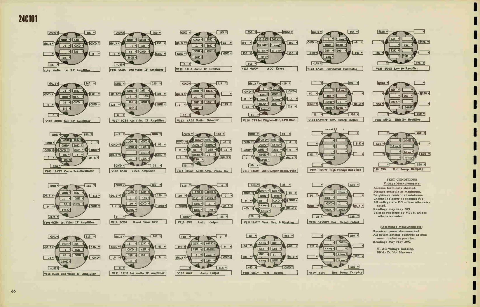
24C101
V101 6AB4 1st RF Amplifier
V102 6CB6 2nd RF Amplifier
V103 12AT7 Converter-Oscillator
V104 6CB6 1st Video IF Amplifier
V105 6CB6 2nd Video IF Amplifier I
V106 6CB6 3rd Video IF Amplifier
V107 6CB6 4th Video IF Amplifier
V108 6AG7 Video Amplifier
V110 6CB6 Sound Take OFF
VIII 6AU6 1st Audio IF Amplifier
V112 6AU6 Audio IF Limiter
V113 tiAL5 Ratio Detector
V114 12AX7 Audio Amp. Phase Inv.
V115 6W6 Audio Output
V116 6W6 Audio Output
V117 6AU6 AGC Keyer
V118 6T8 1st Clipper-Hot'. AFC Disc.
V119 12AU7 2nd CLipper React.Tube
, V120 I2AU7 Vert. Osc. & Blanking
V121 6BL7 Vert. Output
V123 6AU6 Horizontal Oscillator
V124 6AV5GT Hor. Sweep Output
V125 1B3GT High Voltage Rectifier
V126 6AV5GT Hor. Sweep Output
V127 6W4 Hor. Sweep Damping
V128 5U4G Low 13+ Rectifier
V129 5U4G High B+ Rectifier
130 6W4 flor. Sweep Damping
TEST CONDITIONS
Voltage Measurements:
Antenna terminals shorted.
Picture controls at maximum.
Brightness control at minimum.
Channel selector at channel #13.
All voltage are DC unless otherwise
noted.
Readings may vary 20%.
Voltage readings by VTVM unless
otherwise noted.
Resistance Measurements:
Receiver power disconnected.
All potentiometer controls at max-
mum clockwise position.
Readings may vary 20%.
@- AC Voltage Reading.
DNM - Do Not Measure.
66
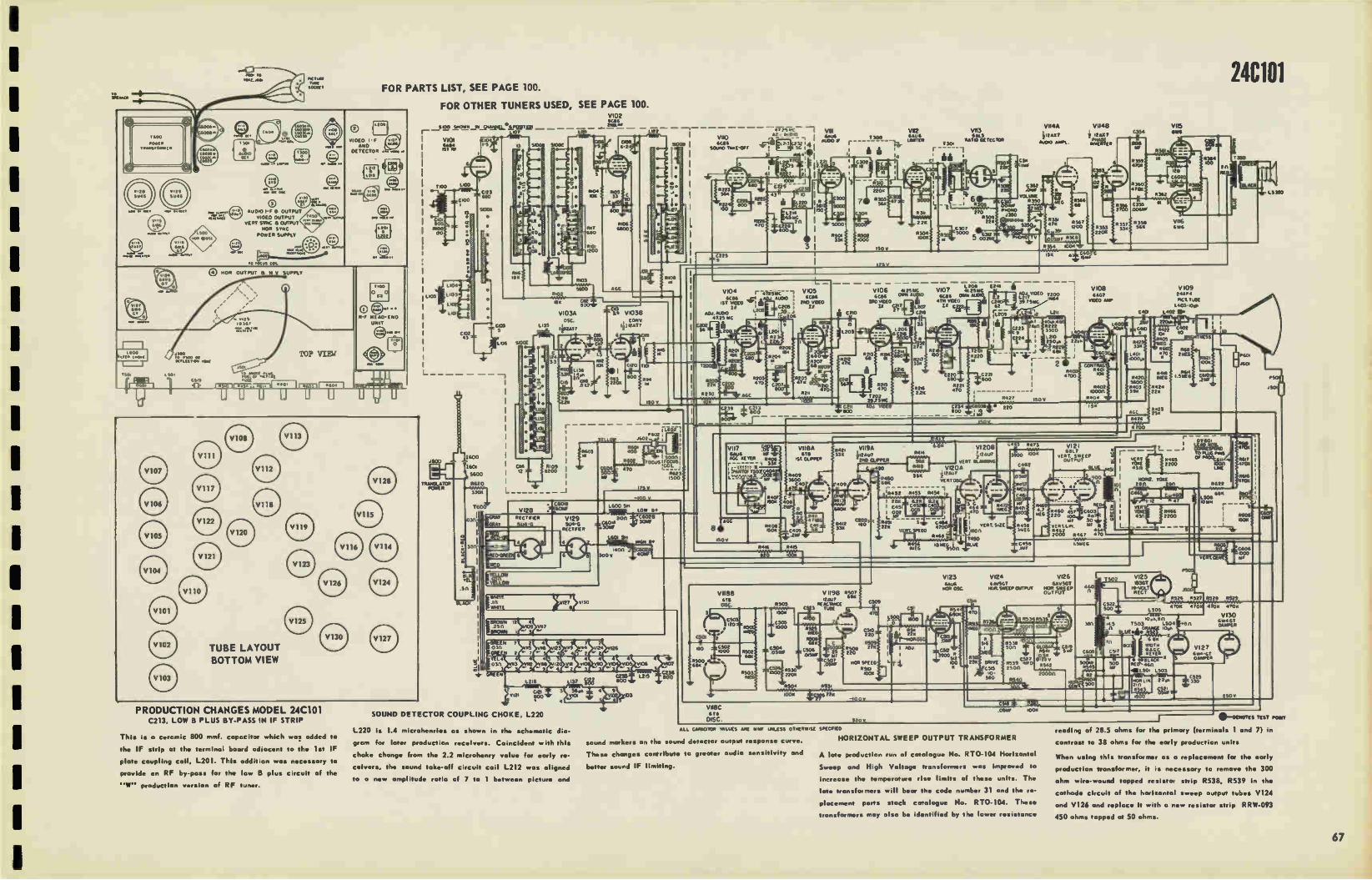
—CD-Pea ,0
PAIL,Sr roof SocAft
•Cf•A <sons
AOSO
501
e Au0.0 OLT
AUDIO 1-r N OUTPUT VIDEO OUTPUT
VERT SYNC & OUTPUT NOR SYNC
POWER SUPPLY
to focus CO.
0 NOR OUTPUT 8 H V SUPPLY
< PSCO Of rOff
TUBE LAYOUT BOTTOM VIEW
PRODUCTION CHANGES MODEL 24C101 C213, LOW B PLUS BY-PASS IN IF STRIP
This is a ceramic 800 rninf. copacitor which was added to
the IF strip at the terminal board odincent to the lot IF
plate coupling coil, L201. This addition was necessary to
provide an RF by-pass for the low B plus circuit of the
"W" production version of RF tuner.
FOR PARTS LIST, SEE PAGE 100.
FOR OTHER TUNERS USED, SEE PAGE 100.
o {L21
VIDEO F AND
DETECTOR ywy
• • RF HEAD - ENO
UNIT
V102 Ace&
— 5 e4 S"C"'" — — T 7e
20
Li*
TRAPELATOR POWER
1600
5600
11620
:lb
0.41 R 09 00
0121
SOUND DETECTOR COUPLING CHOKE, L220
ALL EJAISCJTC. fALUES AEC Ow UNLESS OneRwisE SPECCIED
sound workers on the sound detector output response curve. HORIZONTAL SWEEP OUTPUT TRANSFORMER
L220 is 1.4 rnicrohenries os shown in the schematic dia-
gram for later production receivers. Coincident with this
choke change from the 2.2 microhenry value for early re-
ceivers, the sound take-off circuit coil L212 was aligned better sound IF limiting.
to a new amplitude ratio of 7 to 1 between picture and
1R603
103
I 2
VK ACIDIE
SOuNO 'RAE -Of
Vil8C
6113
DISC
Of ?SW. — 1 ACJ Au020
eig 31
These changes contribute to greater audio sensitivity and
VE2 V113 saus sao
r .4_ ...Tv% f 301 flAn0 DE SEESCA1
r -1
c; gui '
520 v
T500
à
C5111
V11411
ii2ax Auto° Alart
ADJ TOE0 yup Lei? 4461 39 75“C
1000(
A late production run of catalogue No. RT0-104 Horizontal
Sweep and High Voltage transformers was improved to
increase the temperature rise limits of these units. The
late transformers will bear the code number 31 and the re-
placement parts stock catalogue No. RT0-104. These
transformers may also be identified by the lower resistance
Loll
OA
V1148
IT at? pmASE OIVERTEA
V108 ¡ACT OUT &kV
0.04
V109 2•APf
MCI flME LAOS ,oe
C.,. L.02 Ue
lo
24C101
&AEA
15130
ÉTP6% 04:4111411111
J6,01
J50 ,
250v
*Y-OCNCITE nEsy pow
reading of 28.5 ohms for the primary (terminals 1 and 7) in
contrast to 38 ohms for the early production units
When using this transformer as a replacement for the early
production transformer, it is necessary to remove the 300
ohm wire-wound tapped resistor strip R538, R539 in the
cathode circuit of the horizontal sweep output tubes V124
and V126 and replace it with a new resistor strip RRW-093
450 ohms topped at 50 ohms.
67

2012, 20C105, 20C106, 21C200 ELECTROLYTIC CONDENSERS
REF. NO DISCRIPTION PARTIES.
C310
C379A C3795 C379C C410 C45I
C452 C453 C454A C454B
C104 C106 C105 C108 C118
30 mi., 450V 10 mt.. 450V 40 mf., 300V 10 mf., 150V 1 mt.. 50V 300 mf., 150V 125 mt.. 350V 80 ml., 300V 20 mf., 300V 100 mf., 75V
TRDEMERS:
RCE-136 RCE-118 RCE-118 RCE-118 RCE-090 RCE-110 (CE-Ill ACE- 112 RCE-134 RCE-134
RCY-065 RCY-065 RCY-066 RCY-048 RCY-067 (Fine tun's)
l -5 mud . 1-5 mmf. 20-50 mint. .6-2.4 mmf. .8-1.7 rnmf.
CONTROLS DESCRIPTION REF. NO. PART NO.
Volume Brightness 500K Contrast Hoc. Hold 100K Hor. Sise Vert. Hold 125K Vert. Sise Vert. Lin. 4K
Height 3 meg HOT. Drive 25K 1/2w.
Picture 2 meg (Console) Picture 2 meg(20T2 only) Volume 5 meg (Console Volume 500K (20T2 only)
WIREWOUTID
Triode couplate-. 01 mfd, 25K, 500K Vert. Integrator -.001 mf.
. 002 mf. .39K . 82K 4.6 ohms, 5W 20 ohms, Globar 41C, 10%, 7W
1/2 ohms, 10%. I/2W 5600 ohm•, 10%, 5W 1500 ohms, 10%, 5W I4K, 15%, 140V, Globar 2200 ohms. 5W 31 ohms, Globar
R276
R365
R305
11.311 R308 R369 R284 R413 R413 R284
C4I9 R4I7, 8 C301.2 R302, I R451 1t457 R.380
R375 R282 R452 5382 5281 5456
RRC-175
RRC-173
RRC-174
RRC-127 RAC-096 RRC-140 RRC-184 ARC- 186 RRC-184 RRC-186
REK-002
REK-003
RAW -048 SLAW -051 RRW -053
RRW-058 RAW-079 RRW-082 RRW-088 RRW-092 RRW-094
COILS
REF. NO. DESCRIPTION PART NO.
L100 L106 LI36 L137 L138, 9 LI41 L25I L252, 3 L254, 255,6 L255,6 L257 263
L259 L260 L261
L262 L264 L35I L352 L353 L354 L45I
Ch. RF input VI assy.
IF trap & tuning core Ch. I.4uh. V3A o•c. "K' Ch.. 56 u).. V2,V3 heater
RF choke RF choke 2nd Video IF & tun'g 3rd IF, trap &adj. core Video detector as•y. (incl. crystal 0.164)
31 uh. RF choke Video compensating choke 165 uh.
Video comp. ch. 4.5 mc video trap 110 uh. video comp. ch. plate circuit of V7A Ch. Video compen•at'g 130 uh. video comp ch. Hor. hold & adj. slug Hor. Ian. & tuning core Width control
Plate ch. 10 uh. e/supply filter ch. , . 9H
RU-165 RU-I59 RU-145 RU-144 RU-154 RU-152 RU-096 RU-I10 RLX-035
RLF-024 RU-162
ALI-093 RLI-100 RLI-108
RU-161 RU-I09 RLC-091 RLD-016 RLD-014 RU-138 RLF-051
TRANSFORMERS DESCRIPTION REF. NO. PART NO.
Vert. Oar. Vert. Output Hor. Output Audio Output Audio Output Yoke
Antenna input
lit Audio I-F coil Ratio detector assy Filament tran•f
Video IF headend output
Video IF input
T302 T352 7404 T404
0302 T100 T401 T402 T45I TIOI
T200
FITO-117 RTO-116 RT0-082 RT0-081
RLD-041 RLA-037 RLI-097 RTD-008 RTF-002 RTL-126
RTL-127
(for console) ( 21T2)
(for V1,2, 3)
68
TEST CONDITIONS
All controls set for normal sweeps, focus and brightness.
Measurements are in respect to B- with
a 20,000 ohms/volt meter.
All readings DC unless otherwise noted.
IVI 6AB4 1st RF Amplifier
V2 6AK5 2nd RF Amplifier
I V3 12AT7 Converter - Oscillator I
V4 6CB6 let IF Amplifier
MISCELLANEOUS
REF. NO. DESCRIPTION PART NO.
LSI LS2 X451, 2
5200
Picture tube socket Speaker. 5 I/4" PM Speaker, 12" PM Selenium rectifier, 350 ma PM Focus unit PM Focus unit (21C200)
Switch, Local-Distant
R%VX- 045 652707 (20T2) 61212D7 (console) RER-008 RLF-052 RLF-053 RSW-067
V5 6CB6 2nd IF Amplifier
V7 12AT7 1st & 2nd Video Amp.
V9 12SN7 Vert. Sweep Generator
VIO 12BH7 Vertical Out ut
VII 6SL7GT Sync. Amp. & Clipper
V12 6AL5 Discriminator 3rd IF Amplifier V18 6AU6 Audio IF Amp, & Limiter
V13 12SN7GT AFC & Hor. Oscillator
V14 25BQ6 Hor. Sweep Output
V16 25W4GT Damper
V17 6AU6 Audio IF Amplifier
V19 6AL5 Detector
V20 6SQ7 let Audio Amplifier
V21 25L6GT Audio Output
1

1
ITUTP(17
SAAPIR
MC ANA • ani•
PI« 097,97 AILS ON MOIL I.L304
POU reCO LA
(\ LS
6112r924
BOTTOM VI EW
‘Peer:-Q, g T427.11 'MAIM
I.
1 R.F. TUPER IIi
1430
J402
]1]
VO
25L6 61
MV/idà
"U 5110 LI L253 wow
1200
L265 VI WOO/ LI
0,0
C451
9 .1403
"BO .1401 5.8.C.C1
TOP VIEW
NOTE: MODEL 21C200 uses 25L6 os V10.
5429
vs a
VERTICAL SWEEP CIRCUIT of MODEL 21C200.
R IOC,
•NTERNA TERNmat
Let
100 SNOWN GNANAN- 1.6 - OAKS 1
LID/ 2 ea LI I. MO VI
6A84 19, RÉ
L.02
•014 4.111111111410,
4102 G.29 III C112 10 500
C110
1° 1.135
1
0114
'2 T4:
Es
-•1
T-
CIISI Cull .8-L7
FINE TUNiaia
tl
- Ali --FUSE
Go3 3.9 V38
CONV ('N)j2 AT 7
A $1113 22011
680
For Production Changes,
*NOTE. PASS OMAR CMGAT 11114 G44 • TAP ON TOI. CON? I OMITTED OS 7.1010.5 2072.
G4.11 Is .00157 ON MODELS 20C105.•106.
CAPACITOR VALUES ARE luif UNLESS SPECIFIED ▪ 93J 794 -13 C 3,9 • - •5010 C 379 8. 404 300v C 379 C • 1021F 150v • K 677955-10 •541 -20 7if 300v G 454e .0014F 75V a
410200 0111.7 (16▪ 1.161EANS EARLY PROOUCTON CLPINEM23 LATE PRODUCTION
CONTROLS 1ML V"TAGLYTWAMENTS SWEEPS,F03AAVOINIONTNE35 NEAMIVAIENT5 APE IN RESPECT TO 8- MN A mac fl/VOLT METER ••11.1CINIU/ED MON • VIVA
VERTICAL SWEEP GENERATOR
1.141
i le - . I
1025 - LIM I too;
c7-.N6F.A. 11451 0452 45, 15.00 4.4
030000", C451 26521 5512 300 OM
x45.1- -O 452 125 me
71454 C61511 s7152 jL4SS L.S561 jL433 >v7-
5°Ci leT2Wel l
eleGTOLD :W CAlO Jioco
1.. G463 ISO Lai
432 Port*
-il TRANSLATOR POWER
25806 .25174T 654.767 25 *447 6.36 6U.5 L•59
2 7
9.0.te • KO% .511 VIS
12 1 ALL 9(•TER 0700(5 Geni
11390 6 3.91.1EG
R 304 665 C306
4 MF R 305 12511
VERT NCXO
R326 It 306 ic, 309 1 2 3114G 5IAF MEG
V4 19T 1.F. 6C86
125147
•••- C 314
V / 12BH 7 Bue VERT/CAL ÙUTPUT 7
O
A • C 4549 .1E310
100 - 30 311 1.1F MF 411
VERT. UNEARITT • T
VERTICAL SWEEP CIRCUIT, EARLY PRODUCTION
T 302
RED
G500
4!5•1.-
see Pages 110 and 111.
V17 6AU6 AMP
ADJ. CR. TRAP TeX V5 V6
62C1316E LESS cro 63eceB1.:
r
WUXI
11352 22«
C259
C2344 4 C24 9000 1
r I do 1.1.41.0
Y I DEI. I N64
2012, 20C105, 20C106, 21C200 V 7A
ler VIDEO 1•2 I2AT7
L. GREEN f 35 C268 us, 2
.05 1.tr 17F
11217 6800
2.257 IRS MK
e2535 4 • 000..."
G319 [Zej V 9 0,e*Tuie
J-Mer t
C355 tr.:7 -14
4258 PICTURE 5254 \ ccxi.. Ono
CERA
geprb 3 1E-
110°W 168 1 5101 G30k G 302 __Inl.%°°".14 L "44":14''. UMW 52E fDs .5722 -r , 4305.
ESA I- .1
e
R264 2.271EG
1124211.P2 3311 5200
11 ;:6 1(
ael 5
VII / 6SL7GT SYNC.Ake Et CLIPPER
V12 6 AL5 DISC
A 359 C31, 02
VENT. .D.QUE
5340 150«
11429
C372
GRCEN 1262
V 78 V 8 Zoe VIDEO PICTURE TUBE .ita 12AT 7 20CP4 OR 2IEP48
C275 1.264 00000 1306.9
714,
127.g3 4246' =I! lor 220K, 11 C203 R3134
• • C371C G273
.055F
VIO VERTICAL OUTPUT
128117 4385 2200
G22,74
P4010
1000 4711
C277 -11 62 177
J40101 .3„ Suit T302
.02110 I CLAW, 11 (0
124 c psOIG
. C4349 .1.G310e
330 7/401C
- I I li 00 AL _T 30 C R325 o r NW 17170 IL a.
VE St LIN EARITE
'• 445535:521 4 It ,u, 4 io«
, re 3, (431) :3 '‘'34:3 ;77, 25V814Q6 15« 2 i 25« / T HOR
, ern 68« C344 - C147 250 1800 - OUTPUT
L 351 33K 11344 5
4357 UK •,(_)_t 4348 1 C g0 . ..Es -et sc_p Ow G340 ii, IRO- :5370
MO
fl..0.1,0.«,.5 G3 o. 111( •
C375 n - 03 61F Av 1M.D
- G352 P 79 C 371 5000 go« 6-:-235121 .055•0
11453 4704 V18
6AU6 4.5 "c LJMITER- A
- OS
prq
60.
61. 5 MG. SAL5 V 20
- OVETEI9CTOR 5z4tDeD .12 ter ler AUDIO c 1 01 .eb D c.slo 650 7
312 1 c I 2 R4.0
140 22K ! 47 .20 1
5405 5406
9000 1004 470K 5404 564 L40 C424
L
•1.
14 2171
1 Ift411{ C413 i3.11(
v5 vs v67 v7 VC. 2I Vi e 7 ejt 4,031 9C71.1 141 1147 7
.0 K•58 L•St L•53 L454 L •33 S 25LIG7
2:501 .7 75•670T "SLICT ZSAMAT 9636 641.5 VALS 3 • • 3 4511
T
42 449 44.1 S000
¡UK
(17 VO VI VII „„. VI v
• MOTE SEA Val
.cerre acmes tee
11427 474
5277 22011 1505.
5141415(55 in 276
2.2«
439 2.217
V 15 1 X2A H.V. RECTIFIER
11374
G.422 Sc
25L6GT
V2I T.003kor
1404 0 Lel CR LIZ
AUDIO OUTPUT1rre 5100E
CO uPt. ATE - 41 5
25W4 GT PAMPER
4377
C377 .5 Nif
4543 ISOK
Œi
5320 1005
IL1k
.14 • 01A •• i I 4521
14403
450
mole ." 0312 mom 2oNTAL outrun. 001.2
FILAMENT WIRING for MODEL 21C200.
,NO3

2114, 2115 ELECTROLYTIC CONDENSERS
REF. NO, DESCRIPTION PART NO.
C311
C315
C4I0
C379A
C379B
C379C
C43IA
C43IB
C45I
C464
C465
CI04, 6
C105
C108
CI 18
30 mf.. 300V
1 mf., 50V
I mf., 50V
10 mf., 450V
40 mt., 300V
10 mt., 150V
20 mf., 300V
100 mf., 75V
300 mf., 150V 150 mf., 300V
125 mf. , 350V
TRIMMERS:
RCE-141
RCE-090
RCE-090 RCE- 118
RCE- 118
RCE-118
RCE-I42
RCE-I42
RCE-110
RCE-I43 RCE-140
RCY-065
RCY-066
RCY-048
RCY-067
(glass tube type)
(temp.comp type
(fine tuning)
1-5 mmf. ,
20-50 mint'. , .6-2.4 rnrof.
.8-1.7 mmf.
CONTROLS
DESCRIPTION REF. NO. PART NO.
Volume
Brightness
Contrast
Hor
flor.
Vert.
Vert.
Vert.
Height
Picture Hor. Drive
Picture
Triode
250K,
4.6 ohms,
20 ohms,
4K, 7w. I. 2 ohms,
5,600 ohm.,
1,500 ohms,
14K, 140V,
2, 200
3, 300
5 meg
500K
Hold 100K Size Hold 125K
Size
Lin. 4K
3 meg
2 meg
5K, I/2W
stabilizer 3 meg
WIREWOUND
R413
R276
R.365
R.305
R.31I
R308
R284
R388
R34I
C4I9
R417,8
R45I
R457
R.380
R375
R282
/3452
R382
R28I
R297
RRC- 186
RRC- 175
RRC-173
RRC-174
RRC-I27
RRC-096
RRC- 186
RRC-195
RRC- 196
REK-002
RRW-048
RRW-051
RRW-053
RRW - 058
RRW -079
RRW - 082
RRW-088
RRW-092 RRW -098
couplate-. 01 mf.,
500K
5W, 20%
Globar
10%, I/2W
5W.
10%, 5W
Globar IS%
ohms, SW
ohms, IOW
COILS
REF. NO, DESCRIPTION PART NO.
L100
L106
LI36
LI37
L138,9
LI41
L25I
L254
L254,
255,6
L255,6
L257
263
L260
L26I
1.262
L264
1.266,
277
L269
L270
L35I
L352
L353
L45I
Choke R-F input
IF trap & tuning core
1.4 uh, V3A osc. cath.
V2, V3 heater choke
R-F choke
R-F choke 2nd vid. IF & tun'g core
Vid, comp. ch. Vid. Detector assy.
31 oh. R-F choke
Vid, comp. ch. 165 uh.
4. 5rnc.,vid. trap &adj
110 oh. vid. comp. ch.
plate circuit of V7A
Vid, comp. ch.
Vid. comp 3rd vid. IF & tong cor
Vid, comp. ch. 80 oh.
Ch. plate, 10 oh.
Hor. hold 2. adj. slug
Hor. lin. & tun'g core
Width control w/adj. co le
B4 supply fil. ch. .9H
Head end RF a••y.
RL1- 165
RLI-159
RLI-145
RLI-144 RLI-154
RLI-152
RU-096
RLI-093
RLX-035
RLF-024
RLI-162
RLI-100
RU-108
RLI-161
RLI-109
RLI-173
RLI-174 RU-138
RLC-091
RLD-016
RLD-014
RLF-051
R3 X-050
PRODUCTION CHANGES MODELS 21T4 & 21T5
1.PROTECTION OF HORIZONTAL OUTPUT TUBE 25BQ6
In order to reduce the donger of overdriving the horizontal
output tube, 25BQ6 the Horizontal Drive potentiometer was
changed from a value of 25,000 ohms to 5000 ohms.
2. TO IMPROVE VERTICAL SYNC-In order to increase
vertical sync tightness the capacitor C305, 1000 mmf in the
grid circuit of the vertical sweep V9, 12SN7 was changed
to C316, 1200 mmf. Some receivers had o 220 mmf mica
capacitor added to the 1000 mmf capacitor.
3. IMPROVEMENT OF VERTICAL SYNC STABILITY-In
lote production receivers the stability of the vertical sync
was improved by disconnecting the AGC to the 3r d IF tube,
V6, 6CB6; the grid was connected to ground.
TRANSFORMERS
DESCRIPTION REF. NO. PART NO
Vert. ONC .
Vert. Output
Hor. Output
Power
Audio Output
Yoke
Antenna input
1st Audio IF Coil
Ratio detector alsay
Filament
Video IF input
Video IF
T302
T352
T405
D302
T100
T401 T402
T45I
TZ01
TIO1
ESTO- 117
RTO- 116
RT0-081
RLD-041
RLA-037
RLI-097
RTD- 008
RTF-002
RTL- 137
RTL -139
(for VI, 2, 1. 3)
(headend out •
MISCELLANEOUS
REF, NO. DESCRIPTION PART NO.
X451,2
Cap-HV rectifier cap.
Selenium rectifier 350
Ion trap-PM magnet
PM focus assembly Sneaker -51/2" PM
REC-006
ma. RER -008 RET-013
RLF-054
S527D7
V1 6AB4 1st RF Amplifier
V2 6AK5 2nd RF Amplifier
V3 12AT7 Converter - Oscillator
V4 6CB6 1st Video IF Amplifier
V5 6CB6 2nd Video IF Amplifier
V6 6CB6 3rd Video IF Amplifier
V7 12AT7 Video Amplifier
V9 12SN7GT Vert. Sweep Generator
V10 25L6GT Vert. Output
V11 6SL7GT Sync. Amp. & Clipp-e—r1
V12 6AG7 Noise Canceller & Disc.]
V13 12SN7GT Hor. AFC & Sweep Ose.
V14 25BQ6 Hor. Sweep Output
V15 1X2A H. V.Rect. Do Not Measure
V16 25W4GT Hor, Damper Tube.
V17 6AU6 Audio IF (4.5MC) AMP.
V18 6AU6 Audio IF Amp. & Limiter
V19 6AL5 Ratio Detector
V20 6SQ7 1st Audio Amplifier
TEST CONDITIONS
Voltage Measurements:
Input 1 17V, 60 cycles.
All controls set for normal sweeps
Antenna term shorted. Measured with VTVM unless other-
wise noted.
@- AC Voltage Reading.
DNM - Do Not Measure.
70
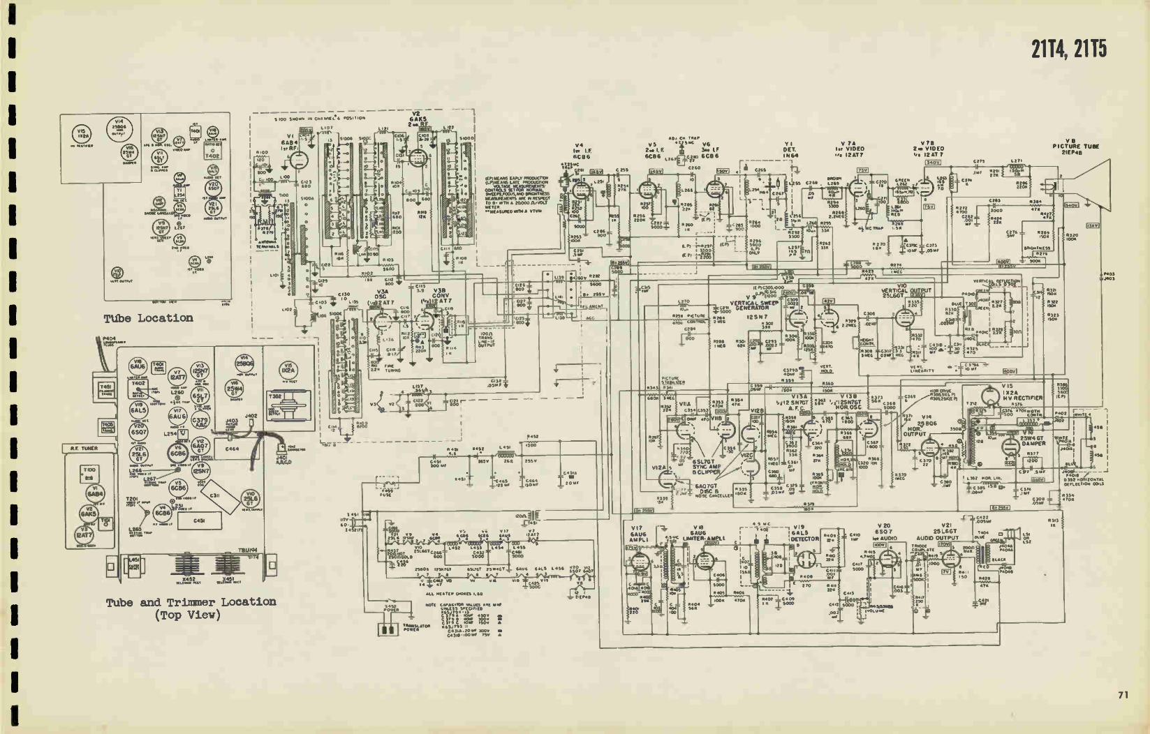
2114, 2115
01,001•4 40•CLL
IV •
IT4°1 .0.0 LIMIER-MR
RATIO Pi
o 1402
WOW OUTPUT
"Ir">
® stele
Tübe Location
ro
.00 SNOWN IN MA NNE L. 6 POSITION
/0,111111,
1 .3 5.008 5.0
1
J402 J403 p
VI 6AB4
RF ,
VIC,
1252 1 I
Tube and Trimmer Location (Top View)
I
1
I 431 117v
60 04021,1
1121
V2 SAKS 2 me, L 122
CIO8 L. 20 70
5 gr
-- ea: .. . Nozz z..... vALUCS ARE in,
UNLESS sy(cirl CD «65/794 • 13
— 1 1 r C 379 • IOW •50v • C 379 II KW 300v • C 371 C 105. 130v a
/ / vRANSLAT001 K63/793 i. POWER C•3i•.20 • 300v •
C4318 • 100 Alf re a
14
600
50 v
(EP)MEANS EARL,' PROOIJCTION IL/WEANS LATE PROOUCTION
CCRITROLS SE T Mg ASUNVNTSMAL vocrAct ME
SIVEERS.FOCUS.ANDIMMITNESS MEASUREMENTS ME N RESPECT TO 13- WITH A 20000 fl/VOLT METER TTMEASUREO WITH A VTVM
L —
VII VIS
ALL 34•TER cre«Cs 1.50
C425 _ 500C
V4 In 1.F. 6C86
4,v1 C 235
AO/. CH TRAP
2.91.E T C V6 VS
6C66 LE*?flIrC ACB 6
EI01
1270
Y I E T. I N64
Ilsovl .1 C265 h_
[1k71 due
2.0
(E PI C305.1000 It 316 .04
V 9 1° ..... C309 VERTICAL SWEEP 10022
10.... C25. GENERATOR er 2
0,238 PICTURE .n . .,0. CM ROL 2 MG « r C294 e' 12SN7 302
39« i'(I‘'
0
•;> 5000
I-9 g 3 306 ,
200
- ¡ 9290 ME 1.11r« i 2I59.ek 0022C —100K : I G e- .-rrz , If T .
33 C268
PICTURE .5111111Une
0341
C3799 T 3 •04.«
0 331
V 7A Is. VIDEO
12 AT 7
BROWN 1.265
V 79 2. VIDEO 1/2 I2AT 7
GREEN L262 /
."r 65R.T.T1t
lab L261
0E0
1_ 53-C4 C TRAP 1.3
cne 3000
¡ 340 V ¡
A 2 70/
.. .05M0 -1-_eC 379C C275
ems 4..
0274
C274 0206 22001
0272 4700
C282
Zcz" I
3000
0424 2251
C276 I 5,47
384
0269 3 .50K k
IM IENTNESS i 11276
LIML 'WOK I
""'ctis.eireer P4010pf. 3
T 302 2 22; REM -
174; 321
1 ¡ 0322 .30K
V e PICTURE TUBE 2 IE P4E1
1F—W 13eilN7—
C275 1271 1 e
134
R334 4 701(
[1303]
1::(%
•sa
— te
450
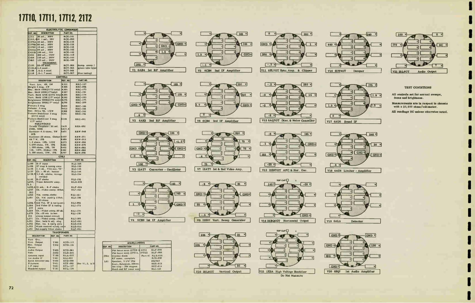
11110, 11111, 11112, 2112 ELECTROLYTIC CONDENSERS
REF. NO DESCRIPTION PART NO.
C311 30 mt., 300V RCE-141 C315,410 I mf.. 50V RCE-090
C379A 10 mf.. 450V RCE-118
C379B 40 mf., 300V RCE-118
C379C 10 mf., 1SOV RCE-118
C431A 20 mf., 300V RCE-I42
C4313 100 mf., 7SV RCE-I42 C451 300 mt., 150V RCE-110 C464 ISO mf.. 300V RCE-143
C465 125 mi.. 350V RCE-I40
TRIMMERS: C105 20-50 mmf. RCY-066 (temp. comp.)
C104,6 1-5 mmf.. RCY-065 (glass tube type
C108 .6-2.4 mm!. RCY-048
C118 .8-1.7 mrnf. RCY-067 (fine tuning)
CONTROLS
DESCRIPTION eEF. NO. PART NO.
Vert. Lin. 4E. ZW R.311 RAC-127 Height 3 meg, 2W R.308 RRC-096 Hor. Hold I 00K(21T2 only) R365 RAC-173 Hor. Hold I 00K(17"only) R.387 RRC-191 Vert. Hold I25K (21T2 only R305 RRC-174 Vert. Hold 125K (17" only) R342 RRC-I93 Brightness 500K(21T2 only) 11.276 RRC-175 Brightness 500K(17" only) 3298 RRC-200
Picture 2 meg R.284 RRC-186 Volume .5 meg 11413 RRC-186 Hor. Drive 5K. 112W 11388 RRC-195 Picture Stabiliser 3 meg R341 RRC-196
(21T2 only) Picture Stabiliser 3 meg
(17" only) R338 RRC-201
WIREWOUND Triode Couplate-. 01 mf. C4I9 REK-002 250K. 500K R.417. 8 Resistor-4.6 ohms, 5W 0.451 RRW-048 20%
Resistor-20 ohms. Globar R457 RRW-051 4K 7 W, 10% R380 RAW-053 1.2 ohms, 10%, 1/2W R375 RRW-058 5,600 ohms. SW, 10% R.282 RRW-079 1, 500 ohms, 10%. SW R452 RRW-082 14E, 140V. Globar 15% R382 RRW-088 3.300 ohms, 10W, 10% R297 RRW -098
COILS
REF. NO, DESCRIPTION PART NO.
L100 R-F input RU-165 L106 IF trap I. tuning core RU-159 LI36 1.4 uh., V3A osc. "K" RLI-145 L137 Ch. -. 56 uh. heater PLI -144 L138.9 3.3 uh. choke. orange
molded RU-154
LI41 R-F choke RU-152 L254, Video detector a•sy. RLX-035 5,6 L255.6 31 mh.. R-F choke RLF-024 L2S7 Ch. -Video comp. 165uh ALT- 162 263
L262 Via. comp. choke RU-I61 L261 Ch. Vid. peak'g 110uh. RU-108
4.85 ohms L266,7 2nd Vid. IF & tong cor : RU-096 L266 277
3rd Video IF & tuning core
RU-173
L269 Ch. -Video comp. 80 ub. RU-174 L270 354
Ch. -10 rnh in hor. sweep output circuit
RU-138
L271 Ch. -Video comp. 130uh PLI- 185 L351 Hor. hold & adj. slug RLC-091 L3S2 Hor. lin. & un'g core RLD-016 L353 Width control w/adj. co .0 RLD-014 L451 34-supply filter choke RLF-051
TRANSFORMERS
DESCRIPTION REF. NO. PART NO.
Vert Our. Vert. Output T302 RTO- 117 Hor. Output T3S2 RT0-116 Power Audio Output T405 RT0-081 Yoke D302 RLD-04S Antenna input T100 RLA-037 lot Audio IF T401 PLI-097 Ratio detector am/. T402 RTD-008 Filament T4S1 RTF-002 (for V1.2. & 3) I- F input T201 RTL-137 Headend output TIOI RTL-I39
V1 6AB4 1st RF Amplifier
V2 6AK5 2nd RF Amplifier
V3 12AT7 Converter - Oscillator
MISCELLANEOUS
REF. NO. DESCRIPTION PART NO.
11464
1.51
PM focus a•sy.(17T10 &
PM focus a say. (17T II, Crystal diode RF tuner, complete
Speaker, 5 1/4" PM Rect., Selenium, 35Orna. Ion trap - PM magnet Head-end RF tuner a•••
21TI) 17TI2)
Part of
ALF-059 RLF -060
RLX-035 RJX-050
552707
RER-015 RET-014 RLI-122
V5 6CB6 2nd IF Amplifier
V6 6CB6 3rd IF Amplifier
V7 12AT7 let & and Video Amp.
V9 125N7 Vert. Sweep Generator
V10 25L6GT Vertical Output
V11 6SL7GT Sync. Amp. & Clipper
V12 6AQ7GT Disc. & Noise Canceller
V13 12SN7GT AFC & Hor. Osc.
V14 25BQ6GT Horizontal Output
V15 1X2A High Voltage Rectifier
Do Not Measure
V16 25W4GT Damper
V17 6AU6 Sound IF
V18 6AU6 Limiter - Amplifier
V19 6AL5 Detector - 1
V20 6SQ7 1st Audio Amplifier
V21 25L6GT Audio Output
TEST CONDITIONS
All controls set for normal sweeps,
focus and brightness.
Measurements are in respect to chassis with a 20,000 ohms/voltmeter.
All readings DC unless otherwise noted.
1
1
72

1 1
1 1
VIO 25906
2544 G
VIO 125107 GT
AK or. 05C.
VII 6517 St
1,1•C • C.i.0.1•
it40 »W.
Y I 1L2541
0 1267
1.40C4.4CTIC44 Z.4 -.
P404 Derygnue•
R TUNER
12 6AK5
62 25L6 GT
L265
14011
1.4•11114 44.
111•110 0.1
o 1402
121 251_6 GT
.040 Ournu ,
Lc)t43
VII 6SL7 GT
10P VII-VV
— ,00 SHOWN IN CHA NNE L. - - --- --- 6 POSITION — V2 6AK5
1 1_101 24o. RF L121 L 122
C10.6.4
105
Li01
VI 6AB4 Im RF
1102
AACD
PRODUCTION CHANGES MODELS 17T10, 17T11
17T12, and 21T2, 17T1O-UHF 17T11-UHF 17T12-UHF
1. VERTICAL SWEEP CIRCUIT: (Models 17710-T11-T12
only).
a) To reduce height changes with different settings of the
Brightness control, R276, the resistor in the cathode of
the picture tube was changed from R289, 150,000 ohms
(URD-101) to R277, 220,000 ohms fURD-105).
b) To eliminate compression at the top of the picture, the
resistor across the vertical output transformer, T302, was
changed from R330, 82,000 ohms (URD-095) to R374,
180,000 ohms, (URD-103).
6
51006 5,00C
r I05 L84 2050
98. R 103
560▪ 0
c,3. 9, 3 C cvo3NBv 1%7 V3A OSC
S 00E = Ill'- 2 AT7 ; 11, cRc.:,:02 G(z 12 AT7
m 7/.
uo 3.4( L136 K1• Ci2 10 0 3
RH3 CH5 Cle 9 III t '0 i no', •4 8 i i
C1141_
'2 _
I 45 u7v
60-
14 2,F
F460 F USE
C1128 800
1 (ERIK ANS EARLT PRODUCTION ILP/MEANS LATE PRODUCTION
VOLTAGE MEASUREMENTS: CONTROLS SET FOR NORMA/ SWEEPS.FOCUS. AND BRIGHTNESS. MEASURENTS ARE IN RESPECT TO CHASSIS WITFI A 20,000/1/V METER +I- MEASURED WITH A VTVM.
10011 TRANS. LINE-IF OUTPUT
C13 - 034F î
CI26 800
CID? , 800 ;
C125 — LI38 Boo;
V4 In 1.F. 6CB 6
A17258C v.' 1,2,4 5 7 2
1139
L141
2b?' 8252 100 C26?
5000
43°4
- 1 °C° .9C 2..51
c 255
j Re
AD.( CH TRAP V5 47î"c V6
24o 1. F. 344 IF 6CE16 L26 2b1_022,073 6CB 6
C260 114 >VI / ) IT
8237 100
R256 2204 _
000i
1_266
8285 221
R 260
62 82
to+255y1
e+ 160V #203
5600
• V %0809. M •
FIL AME ST
AGC
•51 4454 L457
•52
••••••••.-
1500
CASI 2658 260 255 v 300 Mr
T:c 465 -1_125 le
• ±C4diA IC464 _MOM! I 20 Mr
_L-1115 21 VTVI 6 V3 C8 VG VI? 6 6C86 64U6 '26'7 2516 1258.7 V•
VFO 1452 L•53 L•54 L 455
7 7 148.1 3 4 3 • 3 4 5
2205A0H02.coLT . 2516G‘ C266 800T 1:.1Ó3 T IC4419000
42a. 2 58176GT 129.761 6SL7GT 25 4.•GT 2 7 7 7 8
S452 POWER
II TRANSLATOR POWER
,. '4672 VO VI
ALL HE•TER CHOKES ..8Q
V16
6AU6 SAL 5 t. •56 V20 v42 6507 6A07 3 4 •
Pem vei
0* 1 " 3 4704 2 1 6.842 1713P4A
NOTE CAPACITOR VALUES ARE 1414 CABINET UNLESS SPECIFIED GROUND RCE-1113 C 379 • 10.0r 4 !..0 v .4 *FOR MODEL 2172 C 379 13 4064 300v 4. LOTS C 1068 150V RC(-I42
C4 31A . 20 111F 300v C•3113 • 100 mr 75v •
2. HORIZONTAL SYNC CIRCUIT: (Models 17110-T11-T12
only). To improve horizontal sync stability under various
conditions of signal strength levels, the feed-back resistor
connected from the grid of the horizontal oscillator (V13B)
to the discriminator (V12) plate was changed from R279,
180,000 ohms (URD-103) to R390, 330,000 ohms (URD-109).
Y 1 DET.
• C265
I 1,4_4
-
6
9 7
54 8 "6. C 267 3- -1
il
e 8296
.297. 5600 3300'›
181-255V
L1256 1.268
07292 3300 lo
1.257 165 711 P.
V 7A I. VIDEO
12AT 7
8.649 1269 2 -
CW,0
8294 '00 3300 8268
22N1EG R295
334
R323642
11110, 11111, 11112, 2112
V 78 2.• VIDEO 4. 12 AT 7
135011
GREEN 1262 f
5271 6800 I_ 261
110.11
REO
269 C TRAP 1.5
.2 70 18
C275 12 71 Il
liZo 50.4 1 .1.0F 274 ≥ 50
11 272 4700
C 213 loll' I.PSMF
..L- Ta--Z-000 -.-- 8274 18 4-255VI R•29 47 4
8343
L270 mr
.258 PICTURE
.70. CONTROL
C284
1- 1 21300
PICTURE IIZR
5339
L250
V PICTURE TUBE
I7BP4A (MODELS 17110,7117T12.
21(P48,2112)
1.284 2204
C295 C294
í# .0054F
290 564
1400v)
#277 2204., 8289. 1504
BERGH/NESS laR 298
1134 VI
8320 y 100.1
5 C316 1551
9 rzoo _Lvc30, VERTICAL SWEEP I 0022
-L C2 91 GENERATOR 1U11 5000 ;284 1 25•17 2 YEG
#288 EI 30 3 'MEG 82
317 394
506 C293 004
e'T
04
3
;
34
R34 25
C37913 4014F 559
I-6801
COOS I 0314 -
I 25 v I
R3.29 2.2MEG
0324 R33,
- 3.3 ME
.560 -4.U2'
VIO VERTICA I. TPUT 25L6GT 25WG (LP) 3
5
HEIGHT ONTR.
R 308 3 1424
VERT HOLD
BLUE R374
R330 ,i1.1? 824
8349 'Boo
vERTIC•k.o 030
P401D -- 2
'1.322
•
J401Di 302 *2322;
PEEN' —
00
• - C438 • _C311 LAC R325 470
11322.8
-1[379e -1-'J'.1'N'Eri T 10 MF
14003,1
R323
3 YEG
R352 224
290V 4
VIIA
5 C354 c353
.0 7411 .70
R353 4704 TAU VIIB
R 354 •711
— V128 csur
R356 .4E6
R340 C356 T 220 \ 'e) VI2C • 8362 554
";Cb2 6SL7GT - R357 - C56,
C4.6. ...C._ CLIPPER C360 MP 680_
VI 2A - SYNC. AMP
GAO 7GT C277 II 555 C1.57. COTS a DISC 8
F1339 - NOISE CANCELLER leox 031à , 4F 184
*2558j
V 13A. 02 sPoGT A FC.
R358 rjn 1501( 4,341 4
Il • - ' 362 3900 C383 -
--- 220 34.
274
.387 aoK
I 7801,71 VOA.
p379e « 390
0308ii
:11t3 ' V I1B ,a-1251476T KOR.OSC
Il 3 c 343 C365
• 70 1 800 2-
) 113 66 •
11.
8373 C369 3168
C368 6 5000
C367 1800 =f--
?Ag.-• "41 401.0 °«
'RE ARI
t I
398 T•311 VI4 154 25806GT
NOR OUTPUT
5 5
35013
I '1;0
• •54
552
3/5
V 15 I X24 KV. RECTIFIER
4376 c376 470414,0TH 500 Eoya
35
Not
, 8403 Cl .14 03
PA OLA
e 20
3
8370 1R380 1.392 'MEG 44 1108. LIN
COMO
T.,p`ee
5
rINIT‘4
•50 I
25W4 GT ,,-,e,h I ,-•-•5 II 11 —c--4 8
5 -WA"-
DAMPER
C377
1200 I 1 : Yea I
R377 J.1102 1
I( eLtÀ.„, €. I
.5MF P4018 , )440V1 D352 HORIZONTAL
OfFLECT ,ON 0213
V17 38 6AU6 AMPLI
- -
tr 91.1.
.014,4ces
R402. 39«
405 220 20X1
6AU6 4.5"c Lela ER-itel
IR
8404 564
roer
c 406
!COG
0, 140.1406
g004 4704
4 5 r - 1 Y19
GALS r DETECTOR
#407 C • 09
270
C.• .2
V 20 650 7
hrt AUDIO
Re3.0.51eg HOLL..0E
- C374 I.' *8
'•-•.cogor V21
25 L6GT 'E r AUD OUTPUT SLUE IO
F405 0 L ,
7800E ,, GRIEE92I
n:M 3 = 0111 , COUPL•TE4819
8L•Cec
to .F4048 8428 474
W84.1 ,'5
3. VERTICAL OUTPUT CIRCUIT: To improve the vertical ceiver, there is a tendency for the cabinet to induce horiz-
linearity, the vertical output tube was changed from 25L6- ontal sync pulses into the vertical system. The condition
GT to 25W6-GT. These tubes are interchangeable and no is recognized by the fact that the vertical sync is weak
change in tube socket wiring was necessary. and unstable.
4 UHF-103 in METAL CABINET 17710, 21T2: When the To eliminate this trouble, connect a .01 mf. 600 y mo lded
UHF-103 Tuner is installed in a metal cabinet-type re- paper capacitor between the front control apron and chassis.
8313
R334 -1-C308 4701( 1054F
A convenient location for this capacitor is on the right-hand
side of the chassis looking at the front. Connect one lead
of the capacitor to the center ground lug of the existing
terminal board and the other lead to a soldering lug to be
mounted under one of the screws fastening the front chas-
sis mounting foot.

11C125, 20C101, 21C201, 21C202, 21C204, 21C206, 21C208, 21C20811, 21C210, 21C214, 2111, 21T1U, 2113,2116 ELECTROLYTIC CONDENSERS
REF. NO DESCRIPTION PART NO.
C183
C301,214.
C401
C402
C403A
C403B
C403C
C403A
C40313
C404A
C40413
C404C
C404D CI04, 6
C105
C108
C118
5 mf., 350V
. I mf., 50V
300 inf. , 150V
125 mf. , 350V
125 mf. , 350V
100 inf., 75V
5 mf. , 200V
125 mf., 350V
100 mf.. 75V
50 mf. , 25V
40 mt., 300V
30 mf., 300V
40 mf. , 300V 1-5 mmf.
20-50 mnif.
.6-2. 4.mrnf.
.8-1.7 rnmf.
RCE- 153
RCE-090
RCE- 148
RCE-I40
RCE-145*••
RCE- 145 *5*
ACE- 145***
RCE- 152 //
RCE-152/
RCE- 1468. //
RCE-I46 /
RCE-1461
RCE- 146 /
RCY-065 (glass
RCY-066
RCY-048
RCY-067
tube type)
(Temp. comp. )
(Fine tuning)
CONTROLS
Brightne•s
Hor. Hold
Vert.
Vert. Height
AGC 2
Volume
Volume
Contrast
Contrast
Vert. Integrator
4.6 ohms,
5600 ohms,
3K ohms,
4K ohm•,
31 ohm•,
5 meg.
150 ohms,
470 ohms,
100K
Hold 125K
Lin. 2K
4 meg
meg w/loc-di•tant
500K(ZITI, T1U, T6)
500K
3K(21TI, T1U, T6)
3K WIREWOUND
RI77
15363
15314
15325
15316
.*,R171
15188
15188
15210
R.210
P301
R401
R406
R.404
R404
R402
R378
R.377
R318, 17RRW
ARC -191
RRC-19I
RRC-193
RRC-095
RRC-I90
FtRC-I94* & **
RRC-192
RRC-197 RRC-192
RRC-I97
REK-00I
RRW-048
RRW-079
RAW-095 • & ••
RRW- 101 **. I/. // 1515W-097
RRW -099
RRW-100
-102
couplate
10% 5W
5W
10%, 7. 5W
10%, IOW
300 ma. , Globar
HV. (T/C 125, 20C107)
10%, 5W
5W
COILS
REF. NO. DESCRIPTION PART NO.
L152
L153, 4
LI55, 6
L155,6
LI57. 8
LI57, 8
LI59 LI60
LI61
L162
L163
,L163
L164
LI65
L166
L169 LI70
L35I
L352*,
L353*,
L401
L402.
LI67, 356, L168. 434
1,202
1.355
38 mc trap w/62 mm!.
1st vid. IF pl. coil, core,
& 47.25 mc trap
2nd vid. IF pl. coil &
41.25 mc trap w/cap
& tuning cores
2nd vid. IF
Vid. det. can a••'y w/
diode receivers using 6BK7-A vid. ampl.
Vid, det, can ase'y w/
diode receiver• using
I2BH7 vid. ampl.
Choke 31 mic.
4. 5 me audio take-off
Peaking coil-I20 mic.
wound on 15K ohms.
1/2 W resi•tor
Peaking coil 265 mic
4. 5 me trap for use ml
receivers incorporating
a l2BH7 vid. ampl.
4. 5 mc trap for use w/
receivers incorporating
a 68K7-A vid. ampl.
Peaking coil-I20 mic. ,
wound on 3900 ohms
Peaking coil-425 mic. Peaking coil-125 mic. ,
wound on 8200 ohms
Choke coil 80 mic. Choke coil 6.8 mi.,
Hor. oec. coil
352**, 3588, // Width control coil &adj. core 353**, 3590. / Hor, lin.
coil & Adj. core Filter ch. lhy., 26 ohms
3 , 5 Choke 2.2 mic.
Head-end complete 357,1721 ch. -10rnic
Choke coil-I. 4 mic.
Choke.3. 3 uh
Choke, 30 oh, flexible
RLI-179
RLP-020
R LP-021
RLP-022 1
RLX-039
RLX-036
RLF -024
R LI-182
RLI -176
R1.1-184
RLI-181
RLI-202
RLI-175•••
R LI-186
RLI-183
R LI-190 i
RLI-191 I
RLC-091
RLD-049
RLD-048
RLF -056
RLI-122
RJX-049
R LI-138
RLI-142
RLI-154
RLI- 177
TRANSFORMERS
DESCRIPTION REF. NO, PART NO
Vert. Output
Yoke
Yoke
Hor. output for use
w/ yoke RLD-042
Hor. output for use w/yoke RLD-042
Hoc, output for use
w/ yoke RLD-050
Nor. output for use
%N./yoke RLD-050
Audio Output
Audio Output
Interstage (4.5 mc)
4.5 me rat. del. ass),
Filament 6.3V Video IF inpui
Video IF
T301
T351
T351
T351
T351
T202
T202
T201
T203
T401
T151
TI51
RTO-121
RLD-0501,/
RLD-042. di ••
RT0-125. & ••
RT0-127. & ••
RT0-1291, I
RTO-130
RT0-123
RT0-124
RU-180
RTD-01.2
RTF-003
RTL-138
RTL-147
(21" Model)
(17025 &20(107)
(21" Model)
(170125 di 20C107) (Table Model)
(Console Model)
(output @ 6 amp.)
with I2BH7)
with 6BK7-A)
MISCELLANEOUS
REF. NO. DESCRIPTION PART NO.
Xtal Diode. 400 ua 17C125, 20C17, 2IT I
T6, 21C201, C202-C204 C 206-C208-C208
C210-C214
Picture Straightener
2ITI early & late;
21 C201, 2, 4. 6:21C214 Picture Straightener
21TI Late;21T1U;21T3; 21T6;21 C201, 2, 6, 8,
21C210, 21C2-14
Grid Cap• (for 6V3
2ITI)
Fu•e . 1.6 amp. , 125V
Selen. Rect. 35Orria.
PM Focus Unit 21TI
(early) 21C204
PM Focus Unit f/C125, 20C107, ZITI (late)
2ITIU, 2IT3, 21T6,
21C201, 2,6,8,8U,
21c210, 21C214
LOUDSPEAKERS
-T:
-U-
80.
in
214
-
RED-001
REA -003
REA -004
REC-006
REF-008
RER -015
RLF -055
R LF -058
55270-7
S650D-7
S800D 5810D-7
S1012D07
S1212D-7
ROP-025
5 1/4 PM -21T1 (early)
6 1/2PM - 21T6
8" Alnico PM, 3.2 ohm.
21TI (late), 21T11.1. 21T3
8" Alnico PM, -17C125
10" Alnico PM, -20007
12" PM-12C201, 202.204,
206, 208, 208U, 210, 8" PM, 2. 3 ohms 21T1
(late) ZITIU, 2IT3
•
••
•*•
It
//
1st Production
2nd Production
1st, 2nd, & 3rd Production
3rd Production
4th Production
TO TC L355 OF V120(RT0 -12
TO HOR.TOKE 0351
TO TC OF V119
(RTO -125)
TO TC 01119 (RIO -129)
L355 TO c381 (RIO 129- L352 WIDTH CONTROL ONLY)
`..
C3B2 C379 TO TC OF V121
TOV122 FILAMENT(PIN I)
TO V122 FILAMENT(PINI3)
TO VI23 FILAMENT (PIN I) a PICTURE TUBE ANODE TO VI21 FILAMENT(PIN1)
TO V121 FILAMENT(PIN
TO VI23 FILAMENT (PINES
TRANSF. SCHEMATIC RIO -125
RIO -125 TO BE USED WITH YOKE RLD -042 RIO-129 TO BE USED WITH YOKE RLD-050
Wiring Diagram for Horizontal Sweep Output Transformer (21 -inch Models)
8
TRANSF. SCHEMATIC RT0 -129
16-24J424
C382 C379
TO TC OF VI20
(RT1-)27)
(RT0-130)
TO HOR. YOKE 035
(RT0-)30
TO TC OF VII9
(RTO-130)
„2"---. TO C381 L358 WIDTH CONTROL
TO TC OF VI23
TO TC OF VI23
FILAMENT OF VI21 FILAMENT OF VI23
FILAMENT OF VI21 FILAMENT OF VI23 & PICT. TUBE ANODE
..**— eC371
RTO -127 TO BE USED WITH YOKE RLD -042 RT0-130 TO BE USED WITH YOKE RLD -050 MODEL I7C125 OR 20C107
Wiring Diagrams for Horizontal Sweep Output Transformer (Model 17C125 or 20C107)
:701.
lot Production 2nd & 3rd Production
Wiring Diagram for Video Detector Assembly
V102 5100 540.6 Pi cm • MR,* 6 .051 T low 6AK5
IS L.07 2.0 RF uni „Q cizt
VIO 6A134 I07 RF
120
F3ei% nO0
01- POLE
LIO2
R102 «vv.
Cils ills
5100E
1:
1,0
C114 12 I
ARC ft no.oc nove C P79_1374
5600 1
CsOdi
VI034 OSC
(I'd 2 AT 7 Cils
C111.6210
R.,i0111
VI038 CONV
(41)12 AT 7
0,-eT 10113 220e
rIME * R0 11.551MG
0103
4
C32
L131 56
LI»
14
—1
R-F Tuner, Schematic Diagram (4th Production).
TO PIN 5 OF V109 I
TO 17203 3 B C202
TO C205
PRIM SEC
GROUND
• 3 IS
• 4 25
It-12444
4
RLI-I130
Wiring Diagram for 4.5 MC lnterstage Transf T-201
T 201
C204
2
RIO-012
V"
Cl
"0220
Wiring Diagram for Ratio Detector, T203
1
1
74

11C125, 20C101, 21C201, 21C202, 21C204, 21C206, 21C208, 21C2080, 21C210, 21C214, 2111, 2111U, 2113,2116
TUBE LAYOUT
TOP VIEW
Tub• and trimmer location
Note: V122 not used on models 17C123
TUBE LAYOUT BOTTOM VIEW
V113
1 Wiring Diagram for
Video Detector Ass'y
(4th Prod. only)
Wiring Diagram for
L163, 4.5 MC Trap
(4th Prod, only)
11 o
VOLUME CONTROL
MOOELS
9204; 33K
UK*
14,
= Irk:
C212
Pd (2ge'
V109 EOM
AUNO I-7 Ake 180V
5 140V
C173 PROTECTIVE NETWORK LOCATED ON 0645.575 • 150 ANTENNA ORACLE T RM? R F TUNER TERMINALS ,.
, L1WE TO man
Ville 7(1jrj T•IN LEAD V112 •r0 r
i. il
TMS,.:,...."a. 1._ - ... R-F TUNER 900A 1--.• R.25
jute MO 6A05
AU» 111.1! AUCK0 OUTPUT ORANGE
2 COQ R213 210V.,..0
11221
V106 EOM
VE Ce;›,?
R28.?1
101
+2'50V
+140 + OV
1.4201
2- • +250V
V110 44114 r-LOPTER 1114703011
11 r.- 225V 1TIIM. 5.
DITO 25604
0402
7 2 3111 1 GLOSAR
SEE COTE.?
c401x.., 1.40
1,404, 44
'SLOWILOW. 1402
YORE PLUG TERLOCK
5 T401
CHASSM FRONT APRON
TEST POINT
V113A DIT?
"»'14e.,
+250V
NOT USED O SOW SETS/
/11401
NM°
TUT PONT
3a. + 250V
T/03
• +250V
TOAD END
?MADERO FE.
SOW SETS C416 C4I7
,i413E0; 1300
COOS00 C409 800 8001.
WRITE
IZE TEST 0— • POINT
143211
205 14331 eme
.FRINCE 2-2.11 8302
16401(
+200V
.7 TEST ir PONT
O
L151 •7.25MC ItLe040
1 C175
SI C52
v 11 ile••70
TM,
For Production Changes, see Page 111.
V104 V105 6C84 6C1111
ebrc".
5220 Y"R"*1.1!1:' 27e ANC
* SOON) TAKE 0 F
rms CgA
240V4
4, SCOPE SYNCED AT I/O VERTICAL FREQUENCY KT* SCOPE SYNCED AT I/2 HORIZONTAL FREQUENCY
DISCONIVECT INTEGRATOR OUTPUT TO v114A SO THAT VERT OSOLLATOR DOES NOT INFLUENCE PULSE
45/1. 1.35, NOR.
LO
5
L154 412551 Lr54 tlie..AUC40 41.25NC
TRY E.:_}C.114
48
14
TEST PONT
elbee°'
820 WOO
+250V
C61.8 ROO
oeTECTOR ASIEWILY
aP
058
CM2
mm SOUND TAKE-OF
VII4A TEOY\OSC. V1148
r .V1178 VII9 71/Au? _?>806 •TORZ. OSCH. 0 Hot/ OUTPUT
362 G36 C363
I( -I(-- nee -50Va TC 00 .004? .0047MF ME 150V
R372 R348 iooe
330
$03U
.U K
5354
108 6400 300
00L1AGE MEASUREMENTS ARE IN RESPECT TO CHASSIS WITH A 2C1C4)0C1/ VOLT METEN, 417H CEPITROLS SET FOR NORMAL OPERATION, NO SIGNAL APPLED • MEASURED WITH YTOM
330
• ••
470E
I6V—+ C4044 SOME
+ 250V 4
C374 .C47.8
**
LAO
LISO 26506 7511
B +250V
VICE0 AMPTAFMR
Vat V107A 2•
CONTRAST
14174 VeIV 10«
V115 6447 -ST C313 010T. AMP
0122 Fn.
1/123 F1
0121 FIL
7t1 L354 360
C385. -0047
0579 1371
.25 MF
• C4038 1006W 750
+250 SW
110V
• C472 .21•F 071
270e
5524 OV 10i G-
0301 VERT TOPE
O 51 C 3511
I1S SSiS REAP APRON I
rr-{
TOILE CONN.-SLACK
600V
1424 DV. SECT.
To% FIL LOUP ET- 80057
• - 1114 Jai
C383
.0039
TEST FOOT
7, V108
NOT I. ALL REOSTANCES W OHms ALL CAPACITANCES IN MOTO UNLESS coHEReumE NOTED.
2.NORmAL VOYAGE DROP ACROSS 0402 .10 VOLTS.
:71jP4 OR 200P4
Wiring Diagram for 38.0 MC Trap
(let and 2nd production)
cr.n"
Wiring Diagram for lit Video I-F
(let end 2nd production)
Wiring Diagram for
2nd Video I-F
(let and 2nd production)
Wiring Diagram for 4.5 MC
Trap, 1163
(let and 2nd production)
Wiring Diagram for Sound
Take-off, 1160
(1 et and 2nd production)

2117 2118 ELECTROLYTIC CONDENSERS
REF. /40. DESCRIPTION PART NO.
C210
C210
C302
C320
C401A
C401B
C402A
C4028
C402C
C403A
C403B
C403C
C403D
1 mid.. 50V
10 mfd.. 50V
I mld., 50V
I mid.. 50V
40 mfd., 350V
90 mfd., 350V
30 mfd., 350V
20 ;TIM., 350V
100 mfd., 75V
40 mfd., 350V
20 mfd., 350V
5 mid., 350V
10 mid., 25V
RCE-090
RCE-169
RCE-090
RCE-090
RCE-154
RCE-I54
RCE-155
RCE-I55
RCE-155
RCE-156
RCE-156
RCE-156
RCE-156
CONTROLS
DESCRIPTION REF. NO PART NO
Volume, 500K ohms
Volume. 3K ohms
Volume, 500K ohms
Brightness, 100K ohms
Brightness, 20K ohms
Brightness, 100K ohms
Brightness, 20K ohms
Contrast, 1/‘ ohms
Hor. Hold, 100K ohms
Vert. Hold, I75K ohms
Vert. Hold, I75K ohms
Vert. Lin, 2K ohms
Height, 4 meg.
WIREWOUND 8402
8220
8167
8220
8176
8372
8176
8372
8167
8360
8318
8310
8324
R320
&R171
8369
8373
8300
8403
8404
RRC-216.
RRC-216 5
FtRC-192T
RRC-213.
RRC-213.
FtRC-210T
RRC-210t
RRC-192T
FtRC-207
RAC-215 5
RRC-223T
FtRC-208
RRC-209
RRW-053
RRW-103
RRW-105
RRW-I06
RRW-079
RRW- 104
4K ohms, 10W
120 ohms, 5W
3.3 ohms, I/2W
5K ohms, 10W
5600 ohms, 5W 3750 ohms, 10W
COILS
REF. NO, DESCRIPTION PART NO.
L154
L155
L157
L1S8
L159
L161
L162
1-164
L351
L352, 7
L353
L401
1st Video IF
150 mic Choke, wound on
8172
4.5MC Audio Take-off
270 mic. Choke 31 mie Choke
120 mie Choke wound on
8159
220 mie choke
120 mie Choke
Hor. One.
Width
Hor. Lin.
Filter Choke, 4 by
RLI-192
RLI-193
RLI-182
81.1-209
RLI-195
RLI-212
RL1-197
81.1-205
RLC-125
RLD-053
RLD-054
RLF-061
TRANSFORMERS
DESCRIPTION REF. NO. PART NO.
Vert. Output Hor. Output
Audio Output Audio Output
Power
3rd Video IF
1st di 2nd Video IF Ratio Detector,4.5MC
Audio IF,4.5MC
T301
T351
T203
T203
T401
T153
T151,2
T202
T201
RTO-136
RT0-131
RT0-135 •
RTO-134T
RTP-314
RTL-145
RTL-144
RTD-013
RLI-180
MISCELLANEOUS
REF. NO. DESCRIPTION PART HO.
•
Yoke
Video Detector Ass'y
complete
Diode Crystal, Germanium
Tuner Unit, complete
B,eaker,5 1/4" PM
3.2 ohms V.C.
Speaker, 6 1/2" PM
3.2 ohms VC
Model 21T8
Model 21T7
RLD-052
RLX-038
RED-003
8.1X-051
S5270•
5650D-7T
Wiring Diagram for 1152
Wiring Diagram for 1153
r - -
4.5 mc Interstag• Transformer Wiring
PT 0-013
to?
C20
Ratio Detector Wiring
TEST POINT. I lb
R-F TUNER
2.400 INC
1 o
1401
TEST TEST
POINT TINT 17-0 0 • 0 •000• 0
TEST POINT
TEST POINT
TEST POINT rz
TEST POINTE
o o
o o
•o TEST..à_ POINT - 5 ° 3,1
TEST POINT
TEST POINTY
POTE:REFER TO SGOIRATIC DIAGRAM FOR LOCATION OF TEST N PIN FOOTS IN CATCARI.
o •
jo o
IOC
.20
•eie-• /acne
lop
VIO2 100 Sie•MI Is GRANNICA F0511105
SAKS 2. RF
v V101
6/194 NF,
002
To rem...mryi
1107 12
A10/
G.12.A
VI032 OS'
Pis/12677 I,. .' c„.
3.50
1: •
«V
I22
3.9 VI036 CONY
(40 12 AT 7 12 cilj.
0122 1100 •
Test Point Diagram
.m.o•
L
CO -A3 LIME
Gi205 el/ OuTPUT
.00 9•4 1104
AG+
R-F Tuner, Schematic Diagram
04.0 T CRY ROMICI R107 ,06, • VICAR
A-. •
Nu/Vat. 1.0V0.G.
_J
RLX-038 4i clot
Y151 GERMANIUM DIODE RED-003 OR 1N64
C167
TO GROUND
TO JUNCTION ol OF R161 6 C164.- "
TO PIN 5 OF VIO?
•-.2•411
L156
C166
Lise
CeVeC5'3`
Video Detector Wiring Diagram
1
1
1
1
76
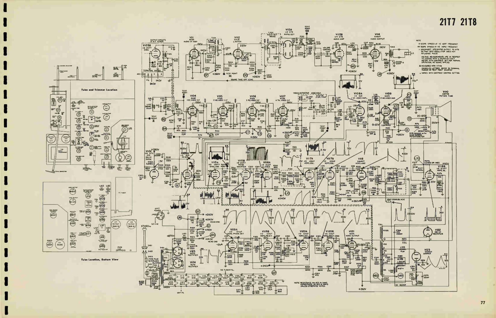
2111 2118
Tube Location, Bohm View
Tube and Trimmer Location
OUTPUT CIPCISTS OF F TUNER
r1,V1033 2 12AT7 6 CORS
7* - -
041 030 39
Ro4
TERMIVIAL 1303R
LAC
C305 - 0.15Z. MP
6.3 VAC II7V60n,
R41) 220« àW
TEST POINT
X
um E POWER
.1402
1401 T•01
eC'ua i.;; E TRANS-EATON POWER BLACK 6406 220K 25 CAOS .00AF
R309
33«
R336
10014
VIII 6C86
Au010 1-F AMP
TEST PONT
V104 6AU6
1ST. VIDEO 1-F
12.1 r TRAM
R203 4700
V112 6Au6 LIMITER
VII3A 1202 1/2 6T0
- -RTiôöEY1 RATIO DE t 1 TRANS lo I 01
/I1 WM TOTAL
47K .00K
R22I 6206 ,OOK •70K 6207
TEST POINT 27« .21 C208 +260V ; s000
SOUND TAKE-OFF 4.5MC
VI05 SAWA
2 00.110E0 1-F MAY
5 7152
TEST POINT
1210
C2I3 .06W
vOLUME CONTROL
C214
VIDEO DETECTOR ASSEMBLY r-
C152 (TON TRAP 41.25 AK
V6A1.066 8 V107 usi
14.ov
, = GO 3 110.VIDEO I-F ,..6,C0E6 t 0 I-F 0.7
Ti53
17182 C
ItNIÔ ItFi)
VI158 VI I5A I/O 12AT 7 VI 16A 2 12AT7 TES NOSE 2 124,37 STP4C.Nat PONT 7nv INVERTER C303 C304 UPPER
6• R304 ". R303 0, 470 -4.6
•7K 1201E 2 , R306
• C302 :3.5V 470. • IMF = 3 50V • C322 R307
R302 .°3». 4V 600K
+150V 3750 • C4028
+270V oo, 'ow i 2r r 4p1
• C401A ton 3600 +140V -rote . 3,a HEAD ENO
lav —C4015 'OA
D3OME 83 - 50y 31*
VI I9A 1/2 12•u7 ORO. PHASE.DET
L'61 6%14 : 166 * C L Le4 141 340' 1
*- 1
V1138 1/4 6T8 £U010 AMP
R212 4 RAMES
Li57 27e
'3° 1160 3
PIÉ .85V TRAP
170
1811 0-22 2W
Lzoi
+240V
4ip r
C2
V114 6VISGT
611010 OUTPUT
6216
. V108A V109 I, 448 ..os
I ST. VIDEO 6461.. I2* 2 rao.viom /UM
ARV
43510 4-8"
3200
no.
TEST A ra .4, 2.5V PONT '" -
In I -, - -,-
1 VII7A V1178 VII8 .5v 1i2 125.7 128117 SANKT
R310 .I. VERT. 05C. C315VERT 03.C. VERT AMP 303 .332 C36 (3322
WOK P301
.0039.AF 7 3.3., .0039WF C307 I C34 MF C323 Do33 I R313 R3I4 5315 . .047W4- boo ,
R311 1 228 1200 5200 1 2 ' R34 9 8200 IC.308 3 .. 82 ,•• C314
002 8
' Mf R316> R3I9 I 9321 R323 47K • .7MEG 2.2MEG 390 20 3 R342 2W
A A-1f A At'r\r-Lf /V1v/V\91v V
1/2 12Aut
R353 HORLREACT. I
1 'MEG 6 030 470 • R354C358
2 _ 1, 68K 100 220 • 800VT
• R352 C354 __ 173. Ye- ....r."" 19359 27K
VI25 ow 100« 3300 "r 001
RECTIFIER SUAS -F- \,.. R353 8'' ', R35i R358( 5360
II33KC352 I K
EL 22V —. 681( 100
120« --C356 C359
-J301351 R356
560« 220« +240V4—•
VI24 5U4G
RECTIFIER
•
RE TUNER FIL.
I V113 11114 2 vI is vut VIrli v120 V112 4 v121 2 6T8 5 666 2 MAx7 4 12AT7 4 5 i2Au7 9 12Au7 4 6AU6 6C06 7
6405 4 6E01 7 12VINH7 5 0EP48,2 APNGT Vile' V100 5 1106 3 v607
61.111 611U6 4 6[86 4 6AuG SAUS
L163 C7785 3 'TLPIVe5* i 800 LARA CI79
, V109 vno
csoorr7z 44«. 500
z.soo • UHF FIL
HOR.POLD on
C312 lea
VERS LIN-
HEIGHT ,374
Ina
VI 208 V121 1/2 12Au7 6CD6 Z 01504 C366 POR2 OUTPUT
C365
II 300
G377
NOTE RESISTANCE VALUES iN ONIS CAPACITANCE VALUES IN MMED UNLESS OTHERWISE NOTED.
.051W
330 1
Ik69
•-C403C :1.561F A
C402C cow 7sva
csrs .0510 WK
R372 20E
R317
33K R372
NESS TU. WITH
R176
325
470
**
•
+2E0V
CS?
1000
R338 33K
C402A 3010 IN -•••
CONTRAST
RIBS
22K
RI06
471(
22«
NOTE
*SCOPE SYNCED AT 112 VERT Nizoazaoy
IS SCOPE SYNCED AT oz 1.3.o F.couec, r OrSONNECT INTEGRATOR OUTPUT To 0117A
SO THAT VERT OSCILLATOR DOES NOT LS INFLUENCE PULSE
vOLTAGE MEASUREMENTS ARE IN RESPECT TO CHASSA WITH • 2000011 i voL METER. WITH CONTROLS SET FOR NORMAL OPERATION, PO SIGNAL *MAL
• MEASURED WITH vTvld.
M EO LETTERS REFER TO TERMINAL Of TEST PONT DIAGRAM
• VANES WITH CONTRAST CONTROL sun...
V110 21E P41
PICTURE TUSE
▪ 20-120V
R378 C372 2.2MEG OR 1 NE8 550\
V1168 433eR377 1/2 12/a7
19 MEG. 6 mORZ.EIL.
R376
11329 22K Ye.
YOKE CONAL(BLACK)
220 C369 120= V
CM.111 470 2000V
345
L359
10M.
R3110
5K,
L357.30
1.354 WIDTH lOIR
en
NOR. LIN, 11,353
V122 113' ST
RECTIFIER
V123 SAINGT
DAMPER

21C225 21C226 21C221 21C228 21C229 21C230 21C231 21C232 21C233 21120 21121 ELECTROLYTIC CONDENSERS
REF. NO DESCRIPTION PART NO.
C210 1 mid., 50V RCE-0905
C210 IO mid., 50V RCE-170T
C2I0 10 mid. , 50V RCE-170.•
C320 1 mfd., 50V RCE-090
C302 1 mid., 50V RCE-090
C401A 40 mid., 350V RCE-154
C40113 90 mid.. 350V RCE-154
C402A 30 mid., 350V RCE-155
C402B 20 mid., 350V RCE-155
C402C 100 mfd., 75V RCE-155•
C403A 40 mfd., 350V RCE-156
C40313 20 rnfd., 350V RCE-156
C403C 5 mfd., 350V RCE-156
C403D 10 mid., 2.5V RCE-156•
C403A 40 mfd., 350V RCE-167
C403B 20 mid., 350V RCE-167
C403C 5 mfd., 350V RCE-167
C403D 25 rafd., 25V RCE-167
C405A 30 mfd.. 350V RCE-168
C4056 20 mid.. 350V RCE-168
C405C 5 mid.. 350V R CE-168
C405D 100 mid., 75V RCE- 68T
C405D 100 mid., 75V RCE-168••
CONTROLS
DESCRIPTION REF. NO. PART NO
Volume, 500K ohms 11167 RRC-2160
Volume, 500K ohms 11167 1211C-21799
Brightness, 20K ohms 11392 RRC-245•••T
Brightness, 100K ohms, dual 12176 RRC-213 5
Brig(rtness, 20K ohms, dual R372 REC-213.
Contrast, 3K ohreS R220 EEC-216k
Contrast, 3K ohms 12220 RI2C-217TT
Hor. Field, 100K ohms 11360 RRC-207
Vert. Hold,I75K,dual, (long) 12318 EEC-215
Vert. Hold. 175K. dual (short) 12318 RRC-244 •• .T
Vert. Lin., 2K ohms, R324 FtRC-208
Height, 4 meg. R320 11.12C-209
WIREWOUND
4K ohms, 10W R171 RRW-053
120 ohms, 5W 11360 RRW-103
3.3 ohms,I/2W R373 RRW-105
5K ohms, 10W 12380 IIRW-106
5600 ohms, 5W 11403 1212W-079
1750 ohms, 5W 11404 RI2W-104
COILS
REF. NO. DESCRIPTION PART NO.
LI54 1st Video IF RLI-192
L155 150 mic choke, wound on
11172. 33K, 112W RLI-193
L157 4.5MC Audio Take-off RLI-226
L157 4. 5 MCAudio Take-off RU-185
L158
L161
270 mie, choke 120 mir choke wound on
RLI-209
12159 RU-212 5
L164 120 mic. choke RLI-205 .
L164 120 mie, choke RU-2059
L166 Peaking, 220 mie. RL1-1979 & ••
LI62 Peaking. 220 mie. RLI-197•
LI69 Peaking, 180 mie. RU-220
L201 3.3 oh, choke RLI -154
L351 Nor. Oscillator RLC-091
L352,51 Width RLD-053•
L353 Nor. Linearity RLD-054 .
L3513 Nor. Lin, must be used
with RTO-146 RLD-056t & ••
L359 Width, must be used with
RTO-146 RLD-058T E ••
L151.50 , 67 Video det. ass'y RLX-038
TRANSFORMERS
DESCRIPTION REF. MO PART NO.
Vert. Output T301 RTO-136
Nor. Output, must be
used with RLD-056
and RLD-058 T352 RT0-146••,T
Nor. Output, must be
used with RLD-053
and RLD-054 T351 RTO-131 5
Audio Output T203 RT0-134TT
Audio Output T203 RT0-1355
Power T401 RTP-314
led Video IF T153 RTL-I45
lot and 2nd Video IF Tist.2 RTL -144
Ratio Detector T202 RTD-014
4.5 MC Audio T201 RU-228
IF 4.5 MC T201 RU-180
V1084
• eat, ...
lo R33..
TO 011 11 1,
U•
ca.
TO MI 7 e ,,iorie•
TO G193 I G1114
1101 I 1:11 v109
111.010.• 1.0.1
000
re>11.1
00••
0105
•
5•260v •
;1ST PC.
1/110 15.8
•NTL•te
•
100.
Lots-Production Vid•o Amplifier, Blanking Circuit and H. V. Supply Circuit
adle TO PIN • or ewe
1.
10 2371
T0103
10 ••• 011.
TO 1.3 ce 0351
'122
..2. .e.I eto• 0701
•
3•
R1117
TO 11328 TO *30 1
(c..1.0.•
C31,2 ▪ os 1.26
.1_74 •••
C
VII6
181
TO .1111 015301
•1413
/2.
113.1
RYPO
•5511 NT‘• • 260v•
41,11
000
0122
4.c ..... •
t.
t 107
0.
1.
84 8/106T
0123
/115 + ire
0.8 Of 010811
MISCELLANEOUS
REF. NO, DESCRIPTION PART NO
6 1/2" PM Spkr. 3. 2 ohm
@ 400 cycles
12" PM Spkr. 3.2 ohms
@ 400 cycles
Crystal Diode. Gerarnium RED-003 Yoke RLD-052 RF Tuner - complete RJX-054
RF Tuner - complete RJX-056
Switch,local-frInge RSS-005 Switch,area RSW-067
• 1st Production
T 2nd Production •• 3rd Production
TT Table Models
• Console Models
1.1114•44114_,
V101 6A84
RFI
vio2 C144 NMI L.6 POSITION SAKS
2 m, RF L 107 Zr
5104 ern(
5117 650
1200
5).33
5600 5102
800
1122
, 9. 121 .; c..3
c tee V103A 3.9 VI038 OSC CONV
c.,o3 ' ° "" k P‘a)12 AT 7 (4 112 AT 7 o. s..,.. /0 T10,5
• I
L102 1 V C116 / ./.., Cet
-
YO 056 (NO
I25•55AL 504110
12
-0 1.
a a
3.5s
0103
;ad
- -
A. Early Production ("EE" Version)
5
800
- ,800
LISO 56s
AGC
650
L
CO-11X I.e
Ten OUTPUT
1C'4 T° 2 5154180 80 ,/ MOTT131.1 • vice
., • rit 2 OV DC 14000G.
7
5126
75
ReLife. 800‘,
100
5 100 SHOWN IN [MANIOC' POSITION
1101
V 01 68K7A.
II Cl2) 680
1122
513 330
5138 200
1.28
o' Itt um 2050
V 0129
5120 • ze o
1102
P79./6.53
R-F Tuner Schematic Diagram
V1038 CONV
(4 1)12 AT 7
" 1' T10,5
2_0 PC.N4
C10911000
:CI35
NS too r 1511
L _
ce -Ax LINE
OUTPUT
OPOTTOSI AGC-11, 04 0‘.0 1 VIEV5
711 24000c. 140var,
91P KIT E SOME [may 14575 USED A CNCNE L,otirt PLACE OF 11-131 _j
B. Lots Production ("BK" 6BK7 Version)
TO CI74 TO PIN1OOF vIto
A • R378 8396
C372 2.2 MEG I MEG +260V4
11(.09.1F R 377
3.9 MEG.
1
C317
TO R32134.-JT 000.°94F
R330
• •":"5.e -1- C318
,OIMF
6
7
VII 6B 1/2 12AX7 HOR Z. BL.
R387
R329 15K
220K
R375
I MEG
svt343141- D
TO WIDTH CONTROL
+ Horizontal Blanking Circuit To I 0> 68-
TO R374 (Late Prod.)
RI72 ,VVV5r-
V1C19 C173 33K
VIDEO AMP .41--1(---43 (MD CHANGE) .1,1 LI55
3.0001) 1500
CI74
BLANKING (NO CHANGE1-1 .2eNt
NORZ. DISCH. STAGE (NO CliANGE1
C366 1 .0047
R368
5
393 3 470K -= I tst R386
126,2W TO C379
R392 20K 3 t
C4030 BRIGHTNESS? 3051
R390 _.J_.J55.4.4 126,1W 84- 260V
V121 6CD6
RI75 cos
2 2IEP4B PI X TUBE
166V
R385 I 0 0
7352
(NO CHANGE)
R389 2 2 MEG
R369 120.0. 5W
R39I 22 K ,2W
M78.1S35A
Brightn•ss Control Circuit (Mid it Late Prod.)
° TEST POINT XII V109
6C16 2 NO VIDEO Awe
TO PIN I Ciel Of vuotte-f-If • 1.6Sur
8184
20K -
TO PiN7. V.°8 .--C403C
1 55'
:Fif9 :12100
TORN'S.
2
73
5172
33K 1155
TEST POSIT
/1 7 4000
.0w
8194
CONTR 4ST 47
RI89
ion
2
IMP Sto' RI13
5195 MEG
-T`leShIC6fr) IR
VItO 2,1848
P1cTuRE TuSE
11 et:: 260V 507805, :613 P82, GA7N;GKE D9170:e 6E65-5_ .711 6CD6 T . SCREEN POT.
0 7(117 r
TO PIN 2 T° Pe C352 Of VII9 OF VII6
,...021.87395
-..-2203c 3508 TO 5353
Mid- g Late-Production Video Amplifier
1 TO R3713 TO 21 C372 L354.
1
78

re.olt 5212210.1
1141.1.[;v11.1
1
.1•211.•215.11C1525
1
7
Ole 1211t1.812.11
1101105n V eal 4trt
te5.1113111•11 reete<1 •
0 11 2.150 ..r
© rm
mireee .1 ,
-g- --0,....• ........ .152••
1:21111. © 11005
.0•0
+2600
MOT Tea
ZMNO.
VI., 0.11..11
ca.•.•• ...2-Rommet
Tube sod Trimmer location
LIM LEM
•:&-
4E-
111221
un-1.11,4
'1.11,0
Of •••••
Tube timeline, peffent Vlsw
WM'
50104... (2.0 P.001 14E1
zee
Midereductlen 11. V. Supply Circuit
21C225 21C226 21C227 21C228 21C229 21C230 21C231 21C232 21C233 21120 21121
A.0
For Production Changes, see Page 111.
OUTPUT 021CAMS f 2111112111
u• 11•77 COnr
VIII Met
YAM 1-f
VII2 SAM
MO« 011 4Q 022. 204
1.30. •7
VII3A 1/2 ST.
- -RAT0 cmt 1 0040 «0 MANS
/
TEST Ken
0110041ff
CMS
o • +260V TEST PONT 274 I lEt 4260V C20. S000
- I,. peov .e: n-12. .....-0.,..5.0C
2010V I I i_
I i 11 2[55 I i .0«, a V104 V105 V106 V107 N11.9 _0111C2001 000(0,1* ...25«
II& CIS3 22 le [Are Str1040 I-, 111 4405 2 00.0020 1-, Mult 5 M. -V MII• 11151.10115 I C.52 Cop, 22.1-11 11
ca, t55v • t55v
1 S Tly F- 5 T. I 2153 V
TEST .--• *0(10
X
+ 260V VIOC
.erriiiceNeir ses&crârn .PeZugg:
MS Me • THESE .21112704111, =STR:CM110-2 TuMel _
T J44, till"
000 PO.M.
.0102
..30« 070.0041
2001
21140.041...
V
7 r'
+150V I V119A 1r$0 • crone è/2 12.1 V1198 . 1..1,,„„,
15 C3 .. Z. ANASE.04, r 2 .2Au7
I4.0 le -TVA MSS 1135rCL C552 CM +140V " I(
MI NM O SSO MA04.0 4"C°3 f IMO 4 IL OC..... se 030.11 CS« • C3118. . .__........., e MI -.NM 2 1 ma .rw-r..7,......4.
-C-41° IMF . 3500 .e- - C3341 C355- 2702 VI25 i 1.00.c 3300T .occ-
• .0. 'reor Rue IMO' LIN SUM1
RECT.14. - MSS , 330 MO 1000 NORM/0
22V 120.
5124 1_ SMS +240V4
nun.... M•
V 4307 DOM
/
3100 231.1 11.2
+260V
VI138 In ST. LIMO AMP
65V L201
V114 trier
MVO OuTPuT
C. ., AlIO
10V NOT 024 220 •70 •• 2.
coo
V1011A Izo Sue
I 11.010 C.
Iles
,''«ï , -, e - - ::42.51/ ry-II
il\--T VII7A 35V %gin vtte 30V In lam/ 72 12507 SANSGT
_ I 0EMOSC. «I« OSC. «RE MP
_ Cs.5 4.3 .337 CI., MU 240V * la V
umf FL
Wiring Diagram fer T133 Wiring Diagram fer 2132
0.05 MM.
LAS 078 LISO L••• MO Clou CITA
CI« 500 .00
là.0-0311
1[1.110.61 0.002 1(0 005 01
C11111
10 41.11:1
To A...Tee .1.•1 oe 1.1 ace
TO 21.
052
C1111
V120A ./2 ez•u7 .10.1
2110 -20
TO-
00 corm >3s3
SMACK.
0345 .344
I ..o -q ...Z liel-w..--: C3101
470
9".fr#
VI209 5121 v2 12Au SCOS
C.1.4 MORI OUTPUT
NO"' weeeitestre. MUSS OTNINMS4 NOTED. L.. INOMITES 1..ATER WPM.
IT «MAT« EARLY «MM.
ruNCT.. Or 44111 • 1.0.63;)
0.051 • LOS
Vid.. Detector Wiring Diagram
• +260V
•••82.0611
C207
10 OF tr3
T.?
T203
it,O•
+260V •4
5109 ecos
z.60.VIC40 abge
"EE" SERIES SOTE
• icon SMICSO AT ért MITT MOOR,
••100.4 MAX. AT tit IOU flIOMMICT
SAVE SNAKS TAXI. WITH .0.1.44. «MM. APPLIED
•.110002 ser Tu.. TO MT./ Trim Ilmit MOM
.11.TAGE MERIMMENTS AM IN RESPECT TO Cm«. •01014 A 1000011,00sT 114TEN wow cœTIMS 547 FM «Mom OPERSTION NO MOM AMNIED
• IMMURED ee 4 rive
TEST PONT
VaUebV4Ver,..,7`.7..lar«,0,-
VII0 lo PM
MUM TU«
4400 C3.8 6. .375
'MG
CM« 5122 24•70 011.1-GT
20XN Pccre-44
0141
2a 43.4
120m M.
LIST
Tex
jJI
%red 0209
TOC; PIN S
T01120 s C20
TO PO4 5 Of 052
Retie Detector Wiring
V123 SAmST Om«.
Al t I
:2•L . C-entr-
• •
1=0 L.:. •••

17C127 11115 17117 21C114 21C115 21C116 21C111 21C119 21C120 21C121 21110 21111 21112 21114 21115 21119 ELECTROLYTIC CONDENSERS
REF. NO DESCRIPTION PART NO.
C167
C309
C401A
C40IB
C401C
C401D C402A
C402B
C402C
C402D
1 mfd., 50V
10 mid.. 25V
90 mid., 350V
30 tnfd., 350V
5 mid., 350V
100 mfd., 75V 40 mfd., 350V
40 mid., 350V
30 mfd., 350V 10 mid.. 25V
RCE-176
RCE-170
RCE-163
RCE-163
RCE-163
RCE-163
RCE-161
RCE-161
RCE-161
RCE-161
CONTROLS
DESCRIPTION REF MO. PART NO.
Volume
Volume
Volume,
Brightness,
Brightness,
Contrast,
Contrast,
Contrast,
Nor. Hold, Vert. Hold,
Vert. Hold.
Vert. Hold Vert. Lin.,
Height,
Height, Area, 2
Area, 2
4K ohms,
150 ohms,
5K ohms,
3.3 ohms, 3K ohms,
5,600 ohms,
:r1OK.., 1/8" Sh.sit
, 500K, 2 3/8"
500K, 3 1/4" Shaft
100K, 2 I/2"Shaft
100K.2 9/16"Shaft
700 ohms, 3
700 ohms, 2 343"Shaft
750 ohms, 3 I/4"Shaft
200K ohms
I25K, 2 9,46"
125K, 13/16" ,125K. 2 1/2"
4K ohms,
2 meg.. Knurl
3 meg. Knurl
meg., Knurl
meg., Slotted WIRE WOUND
Shalt
1/9"Shaft
Shaft
Shaft Shaft
w.w.
Shaft
Shaft
Shaft
Shaft
R178
R178
R178
R175
R175
R320
R320 11320
R264
R205
R205
16205
16211
16180
R221
R207
R188
16172
16270
R272
R273
R402
R404
FtRC-211 RRC-233
RRC-236
RRC-191
RRC-222 RRC-211
RRC-233 RRC-236
RRC-219 RRC-237
RRC-243
FtRC-193 RRC-218
RRC-225
RRC-246
FtRC-225
FtRC-235
RRW-053
RRW-100
RRW-106. 8. f
KR W-105
RRW-095 RRW-079
10W
4W
IOW
1/2 W
7.5W
SW
COILS
REF. NO. DESCRIPTION PART NO.
L152
1.154 .56
L155
L157 &
L158
LI59
L251
L252
L253
L401
L154
L160
1st Video IF Grid
& 60 Trap Assy 47 mic. cathode choke
254 Choke, 10 mie.
300 mic. plate coil 270 mic, plate coil
Hor. M. V. stabilizer
Width
Flor. linearity 13+ Filter choke, 1.5 hy
Choke. 31 oh
Choke, 1 3 ich
RLI-192
RLI-215
RLI -214
RLI-138
RL1-208
RLI-209 RLI- 210
RLD-058
RLD-057
RLF-062
RLF-024
RLI-216
TRANSFORMERS
DESCRIPTION REF NO PART NO.
Vert. Output
Hot. Output
Audio Output for
ROP-IRS & S1212D-7
Audio Output for S527
D7 di S625-D7
1st and 2nd Vid. IF
Ratio Detector
Video Detector Ass'y
IF Filter (40 MC)
Audio (4.5MC) 2 core
type
Interstage 3. 3mrnf Power
1201
T251
T303
T303
T151-2
T302
TI53
T301
T301 T401
RTO-142
RTO-141
RTO-140
RT0-139
RTL-144
RTD-014
RLX-042
RLW-010
R1.1-228t E •
RLI-180. RTP-315
MISCELLANEOUS
REF. NO. DESCRIPTION PART NO.
YI51
• f
•'•
Speaker. 5 1/4" PM
Speaker, 6 1/4" PM
Speaker, 10" PM
Speaker, 12" PM
RF Tuner Complete
RF Tuner Complete
RF Tuner "D" version
Complete Yoke Crystal diode Germ.
1st ProdUction 2nd Production
3rd Production
S-527-D7
S-625-D7
ROP-018
S-1212-137
RJX-052
RJX-053
RJX-057
KID-052 RED-003
302
Wiring Diagram for L156
Wiring Diagram for T301
s.
Wiring Diagram for T153
Wiring Diagram for T302
ANTENNA INPUT
TERMINAL S
1100
® AC o
es-a+ 250V
NOTE 01 ARROWS INDICATE DIRECTION OF ROTATION FROM CH2 TO C.13 SWITCH SHOWN IN CHO POSITION
121 Santo., WAFERS S1, 52,53.54 GANGED
1311E P1 INDICATES EARLY PRODUCTION, (L.P.) INDICATES LATE PRODUCTION.
141 MINOR CIRCUIT VARIATIONS HAY BE ENCOUNTERED IN A FEW TUNERS.
A MEASURED WITH VIVIA 8404
F PONT
V101 6EICS RF AMR LIGO
52 RE AR
LI 04
I ''C
RIOS
C103
cISC
clot 8106 eoo CEP.)e zoo
/VW 54 59
FRONT RE AR
uo5
LIS3
TO CHASSIS
41.25 MC TRAP
11.41.1"
TO 0156
CHASSIS
Wiring Diagram for L153
5.685W
»HL .P1
LIS!
TO CHASSIS
eoo I
104
FINE T UNING
C152
CHASSIS
Wiring Diagram for L151
1.110 10
RI 07 ISK
41.
5.1
111IN
621E.P.1
(L.P.) -se/
If? lAC
CON V.
VIO2B ,7? r>J6
OSC.
T-81,1417
2/50
— CIES Z .sooc
L
Ch
1
I's
1 .800
LOS"
<\i=
0
• • o o
ØI' F OUTPUT
0, 135V
06.3 v AC
C)
Schematic Diagram for R-F Tuner RJX-052 or RJX-053
C165
VIDEO DEI
L156
TEST POINT
AGC 1 F
AGC RF TUNE
CI53 .05MF
253 Late Production AGC Circuit
32-keS,
RI83
470K I/2 W
RI84 220K
0171 .2
RI 88 AREA CONTROL ¿MEG
4 TOK
C253 470
Wiring Diagram for T152
V107A SYNC CLIPPER
CHAS515 CEPS
Wiring Diagram for L152
Fig. 40. Schematic Diagram for R-F Tuner, RJX-057
/01.104
8.260V
caew11,4
Rot
CUM e,,,je
8109 04,44,1•11440110
V.7A:
POCiel 101 •1414.• .0.04 001,1•
Ce 44.
Vertical Output Blanking Circuit & Pix Tube Circuit (Mid & Late Production)
8+ 250V
R201 0202 8202
82A K)00 826
TO PIN I _....C201 OF 5(07 1-.001MF 111 2 54 -air
0203 470
R22I
*Rif. 3 MEG
R220 V110 4.7 MEG 6.15
VERT OSC
B + BOOST
VIII 6AHACT
C206 R208 VERT. OUTP.
TO T201 5 AC208
TO 8181
R210 330 401 •
100
LIN. VERT. MF
R211 4K
• 111J.011.
Vertical Sire Circuit (Mid & Late Production)
1
1
1
80

1 11C121 11115 11117 21C114 21C115 21C116 21C111 21C119 21C120 21C121 21110 21111 21112 21114 21115 21119
1
1
Tube and Trimmeir Location
Ke*
LI52
Le3 L151 e .Kree (13
TISI
noel.
n-reTL
US6
OGLE POIo
Tahne and Trimmer Location, Bottom View
T401
IA a., 0%01
R263 at Horizontal Hold Control
changed from 47K to 68K ohms
in later production
1
tO
504-G
1403 YOKE PLUG INTERLOCK
I 5401
V +250V
OUTPUT CIRCUITS OF R-F TUNER UNIT 842 052057
V102A j2-6J6
CO//V.
8404
TUNER AGC
F.,...71.filcesmil 2, 2f. nAIR_U,L017.,
V102A 1 1/2 I2AT7 CONN 1
F401 FUSE 4 AMP
1170
'7>W4C'0K1 402
1 401
II 711.60
1 •01
T 4c I
HEAD END FIL. UHF FR_
V120 VI21 3u•G 31..6 PE CY AEC
Late Prod. Pow's, Transformer Wiring
V120 V121 5u4G SU AS RE CT REEL
For Production Changes, see Page 111.
V103 V104 6CB6 6CB6 1ST I-F 1-F
220V T15, 2ND 200V ns2
41.25 MC TRAP
CI56 6
800 CI52
POINT I X TEST
+250V FL.6.3V AC
AGE
28e"
2402 FOR UHF ONLY)
R402
8134 V +160V 100K
IE OR 471(
• TEST POINT
Chi .21(IF
10 OUTPUT
• • • C402A 470 .1 -my
- 350V .3 OMVF
5,03 ,2 4 , v 1▪ 9 V107 5112 vuS
_35
6C 136 6C N 6AH4G T bv6GT 12AT7 12AU7 64144
°C*AD
+160V
i-225V
13+260V
OV
6Au6
3
2 4)
V106 V118 v108 v109 Vil6 V113 12AT 7 6TH GAG? PIG 6C86 6806
(OR 6E1.6)
NOTE ER275 MAY BE REMOVED TO (OTERO RANGE OF SYNC CONTRCt
ALL RESISTANCES IN OHMS ALL CAPACITANCES IN MMED UNLESS
OTHERWISE NOTED. K • 1000 MEG •1,000.000
(ITT p.KNENCATES 1ST PRODUCTION. (21-40 PI INDICATES 2410 PRODUCTION. ( spDp.) INDICATES 3R0 PRODUCTION.
DOTTED UNES INDICATE LATER PRODUCTIONS. CIRCLED NUMBERS AT YOKE REFER TO PIN CONNECTIONS ON YOKE PLUG
*SCOPE SYNCED AT 1,2 VERT. FREQUENCY. ** SCOPE SYNCED AT I/ 2 140611. FREQUENCY.
WAVE SHAPES TAKEN WITH NORMAL CONTROL SETTINGS & NORMAL SIGNAL APPLIED.
VOLTAGE MEASUREMENTS ARE IN RESPECT TO CHASSIS WITH A 200000/VOLT METER, WITH CONTROLS SET FOR NORMAL OPERATeON, NO SIGNAL APPLIED
MEASURED WITH VTVM
ENCIRCLED LETTERS REFER TO TERMINAL BOARDS OF TEST POINT DIAGRAM
2.2 MEG
RITO 1 mEG R188
F1,77 2 MEG AREA
CONTROL
/
00V
TEST POINT
8+260V
f:îe % r02e145 C25,
C MF 47 - .. 2 70 5.,,27,4_,427503
V116 AC 86
AVOID I-F AMR
2V R301 180
210V
VIO7A I/O 12AT T YAC. CLIP.
13+260
I.
45V—
C203 . 470
1,212A77 PHASE OET.
-).75V
*
n'41 0.41[iTl
VIO5 6C66 3P0 IF 200v
8+260V
-r 95V
P01
7151 LIST 7153 - 10 pt.
C172
I(
L154 3186
nE e TEST
C165 POINT
68
L156
V106A V1066 I/O 12477 SYNC OWL
RI62 RISOS 3 3-314 2.2 MFG
8214 R207 ROIS
2.7MEG
V110 625 RD OSC.
5i7 R202 R201 202 626
, rJor
T 301 V 117 TRANS 45 MC SAUR
1 LIMITER
R303 4700 1W
R305 10014
POINTT
23
C204 IMF
• 7 R258 100%
"9/2e
8 V A
R252 2.28
R 306 470K
B+260V
204ES 1 MEG OR 1.3 MEL
R206 1.4 GOP
27v cms
9 .5.3V 8204 10014
8205 1256
VERT HOLD
8259 826
7**
7302
[1:1 RATIO TRANS
C256
IIG
Z.5000
6208 iOOK Ann.,
.022 MF
11166 68K OR 31K
1/2 I2AT 7 NOISE CANCL
CI66 .2MF
8 + BOOST Mal a-vic,9)
V 111 6AH4GT
VERT. OUTPUT
VERT. LIN.
C4010 100 MF 75V
V 12 12•117 HOR. M.V.
60 R260
‘ 560 2 I
/
#261 8.2V 8214
C257_ 82,5,1 8264 .001 220K<: ZOOK MF > HOP,
C258 , HOLD 0 5MF_._ ,-,. —
SEE NOTE •
V 118 A 1/2 678 RATIO DET.
8257 NNW' 10K
20V
TEST POINT
31 , C3I2 VOLUME 22K OIMF «: CONTROL
- C314
C311 OST.0 e ChLY
— 500K
C309 _
25V
(C317
.01ME
CONSkES ONLY
C2081_ 047
14300 15 MEGCNI)&3RD Pl
"F" SERIES
VIOB 6•47
c,66 VIDEO AMPL
.05MF RI68 2206
Ir2
CONTRAST CONTROL
— C167 • I MF 50V
8169 2.2 MEG.
8+260V
GREEN
nrro 225V " K
1.5 0178 700
SAIF 354/V
(1;- C169 BOO OR 750
18173 8216
300V
D20)
DEFL TCKE 3911
R 75 100K
= BRIGHTNESS
4 600. R 7 3511
R212 L. — _ _ _ 470
>13+260V
8269 330
R267 6800
VII8B 1/4 6T13
AUDIO AMP.
8314 470K
6806 HOR OUT.
8210 ISO w
C263
C4020 1044F 25V
8271 ,K 2W
B+260V: 7
V119 606 ST
AUDIO OUTP.
C3I6 23 BLuE .0013Ali TO 1000V T.
5
C265 .0IME_._
-r
+255V
(3F0 PI 8
0913 14V 470K
/). 260V R317 470 ZW
+240V
RED
100v
V109 PICTURE TUBE 17QP4,21EP4-A
••—I6KV
8+260V
V114 1133
11V RECT,
8307 2.21(13RDP)
61.4 PAMPER
MORO. LIN. C268
*à4DE I
C2671
Ti
lira+ 130057
B+ 260V
LOUDSPEAKER
81
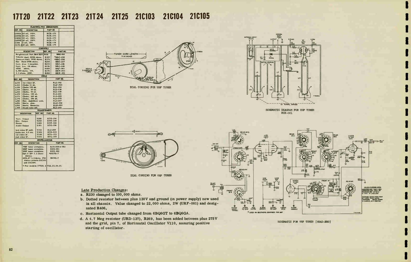
1 11120 21122 21123 21124 21125 21C103 21C104 21C105
ELECTROLYTIC CONDENSERS
REF. NO. DESCRIPTION PART NO.
C400A 60 mi., 350V. RCE-173
C400B 80 mf, 350V. RCE-173
C400C 40 mf, 350V. RCE-173
C400D 20 ml. 350V. RCE-173
C308 5 mi., 50V. RCE-174
C235, 620 rnf, 300V. RCE-175
CONTROLS
DESCRIPTION REF. NO. PART NO.
Brightness& Vert. Hold 11177 R231 RRC-252
Volume dual, 500K ohms. R307 RRC-250 Contrast dual, 700K ohm•. R171 •RRC-250
Hor Hold 100K ohm•. 11255 RRC-247
Vert, SIze 3 rnegohrn. R233 RRC-246
Vert Lln. 2K ohm•. R236 RRC-248
100K ohm•. R400 RFLF -001 4,000 ohm•, 5W. 11175 RRW-053
3.3 ohm., 112W. 11268 RRW-I05
COWS
REF. HO. DESCRIPTION PART NO.
L151 1.1 video IF. RL1-192
LI53 Choke 31 uh. RLF-024
LI54 Choke 330 oh. RLI-194
LISO Choke. 10 uh. RL1-138
L254 Choke, 10 oh. RLI-138
LI70 Choke, 100 uh. RLI-241
L173 Choke, 180 oh. RU-220
L174 Choke, 390 uh, RU-270
L25G Hor. •tabilieer coil. RU-247
L.251 Horie. .i.e. RLD-058
L252 Horiz. linearity. RLD-060
L300 Sound take-off. RU-243
TRANSFORMERS
DESCRIPTION REF. NO PART NO.
Vert. Output T200 RTO-154
Hor Output T250 RTO-149
Power T400 RTP-318
Audio Output T301 RTO-156
3rd video IF coil. T152 RU-269
Ratio dei. 4.5 rnc. T300 RTD-015
list video IF. T150 RTL-I53
2nd video IF. T151 RTL-I55
MISCELLANEOUS
REF NO. DESCRIPTION PART MO.
VHF tuner complete. RJ X-059 or 062
UHF tuner complete. RUX-001
UHF tuner complete. RUX-002
Spk-5 I/4" 3.2 ohms •5527D-7
Alnico.
SPK-8" 3. 2 ohms, PM S8250-7
Alnico model. 2 IC103
and 2IC104.
• For model. 17T20, 21T22, 23, 24.25.
F---TUNER CORD LENGTH-1 711/4 INCHES
—71
STEP 9 3 COMPLETE
TURNS
r - -
DIAL CORDING FOR UHF TUNER
DIAL CORDING FOR VHF TUNER
TO Ewe OUTPUT
Late Production Changes:
a. R230 changed to 100,000 ohms.
b. Dotted resistor between plus 130V and ground (in power supply) now used
in all chassis. Value changed to 22,000 ohms, 2W (URF-081) and desig-
nated R406.
c. Horizontal Output tube changed from 6BQ6GT to 6BQ6GA.
d. A 4.7 Meg resistor (URD-137), R269, has been added between plus 275V
and the grid, pin 7, of Horizontal Oscillator V110, assuring positive
starting of oscillator.
110
LIO1
CRYSTAL TEST
ANTENNA INPUT P0/PIT 30011 OJ Pur b
• •
e
REARS1P5
A.
FRONT•PS
V +I75V eme E ORANGE)
REAR #4
L2
L•
CIA
L6.
YI 33 IN132A
5
C2
Due
EIF +135V AGC 6 3VAG 6 3VAG +250V To UHF (O//TE) (BROwN I TO UHF INE01
• 1.1580 ON RECt7vERS EQUIPIED Fe* We
COLPING
•
CII3
C4
L8
6 3vAC +135s, VI
CS Ems CO (000 — ou
I
Ell
8200
LO
L13
C I C
hO
CI TUNING, GANGED
P2 6800 iw
SCHEMATIC DIAGRAM FOR UHF TUNER RUX-001
V101 V102 6007A EXE,
REAR
V102A 02 608 OSO
C1-2
no.neoà.
I35V 10RANGE)
FRONT
b.5
_Otr
SCHEMATIC FOR VHF TUNER (HEAD—END)
REAR le2 VIO2B
6X0 CONy
>AM 15«
.—IFTESTa POINT
MC«
LISS 20
TO r r AMP
orYlk.55 OTMINAITA KITH? CAPNOIERS sow THEN I- EN. CAPACITORS LESS TWIN I- NW FIESIETONS ARE 112 MATT - 000 1.1.1.000.000
SYNTOES VIEWED NEON. FreoVr OF %NM TUNES FACING DONNY/AM SWITCH EMONT. IN CHVENEE .013 POSITION
1
82

E) VIOI
1
1
10
TUBE LAYOUT TOP YIE•
se
TUSE LAYOUT SOTTO* VIEW
FOR TUNERS USED, SEE PAGE 82.
rye« TUNER RJX -059 OR RIT -06217 VIEW/
OUTPUT CIRCUIT
T101
TEST UPPOINT
J,3,1,1e© J
8FIN. ORANGE RED ORANGE/ FIL. +130V +250V W11 TE
+130
WHITE HE ACC
VII4 6AU6
20010 1-f
C301 20 T L300 :43 Ili
T300
?70V u31 0 1
- V '
_
R 301 330
V103 6096
1ST VIDF_O I - F
8(64 •1.1+V
- 18 LI51 .
T 11504 4725
MC TRAP"
4- TO TEST UHF )POINT
(80V VHF POS.) ¡1310V UHF POS)
11120 21122 21123 21124 21125 21C103 21C104 21C105
"G" LINE 33V
800 056
R154 BOO 3.3K % 1W ••
R152
f2 7M I C8107) —r C352 00
RI 79
1_c168
1 800
DISTANT
VII7
Aulta5OutPuT C30
8303
22K C306-17-11 C305 1 -r _004
.001 R308+8275V
470K _cri
7 -r 31 • -IV =.00301220
Il I
C?nV
304 7 I000V
LoCji0V • I 70V 5
II 1 OK I R305 nr_R307 500K i4
12
1 *SCOPE SYNCED AT 1/2 VERT. FREQUENCY. ** SCOPE SYNCED AT 1/2 HOR1Z. FREQUENCY.
WAVE SHAPES TAKEN WITH NORMAL CONTROL SETTINGS A NORMAL SIGNAL APPL(O•
HORIZONTAL OUTPUT TUBE TYPE CHANGE
ALL "G" AND "H" MODELS
The horizontal output tube type ha• been changed
from a 615Q6GT to a 613Q6GA. This improved
tube is a direct replacement but may, in some in-
stances, require bending of the spring shield to
occomodat• the lorg•r bulb size.
VOLTAGE MEASUREMENTS ARE IN RESPECT TO CHASSIS WITH A 20,00011/VOLT METER WITH CONTROLS SET FOR NORMAL OPERATION.NO SIGNAL APPLIED.
L MEASURED WITH VTVAII•
• VARIES WITH CONTRAST CONTROL.
V I 18
-I R306 6.81+
r—
EARLY PROD.' SETS 12 4,
') 2W
R3I0 510
B+2601
25V
LOW Bi-130V
275V
V104 GCBS
2M) VICE0 1-F m1151
eer--
2 Ce IV .75V
R401 -e---m - t-c42 TO RF TUNER+130V
=800 +130V
•_T_C400C R403 43= TO R -F TUNER
+250V
.05 8405 =
./04000. +26°V 350V
+275V
V116.1 :T 0404 90) 5 - UHF
RAYS TUNER FIL
416'
+130V
V105
6096 3RID VIDEO I-F
IW RISA 180
RI63
0154 800
5
T 152 Ci6i
R168 47K
le
_LCI69 _LC165 2800
Y150 LOS -
2I7V cE'ZIirNrrilel, y55
7 122V C159 C I S «-« 31" g7
600
8160 6 8K I W
• •
+275V +275V
6CS6 SE CANCELLER. CLIPPER
DISTANT
5201A
LOCAL
8207 8208
10M 82011
** V
Bt275V
4.5V
V1088 I/2 12AU7
PHASE DEI.
,5.7V
R254
150K
12M 8251, 100K MORI Z FIQI4)
5V
8209 6 2K
8203 I6K 2W
TEST POINT
©
IV2" IC2,235: -
*Sr UNLESS OTHERWISE NOTED
\-...,.... 2 CAPACITORS MORE THAN1 • MMF 1>4V CAPACITORS LE SS THAN I • MF
RESISTORS ARE 1/2 WATT K• 1000 I4 • 1.000,000
8210 I2K
8161 1_154
3.31." 3'3Up4
54V
V108A 1/2 I2AU7
PHASE SPOTTER
0203 005 /
L250 HORIZ STAB.
220V 6
R225
50eK
10K
VII 0 12ATI
HORZ.06C.
257.510
162 54701<
0166 2 BOO
C225 13047
143;T m
I7V
À V106 128Y7 VIDEO AMP
LI70 CITO
25V
+130V 4
R227
33K
R2
R228
82K jp228
'001
C229 1470
R23I --= 150K
VERT.
57V
8262 82K
C261
171 LI72
7 Ca 2K 73
19 27V
= UM
RI75 4K SW
ISN'T 13Z
R 7 100K
8RIGFIT NE SS
• +130V +275V +130V
75V
/
V109A 1/2 128H7 VERT. 0 SC
R233 3M
VERIS1ZE
6M 30V C23I 022
R234 3 22
• 022
VIII
660601 HOFIZ OUTPUT
+275V INT
R261 8272
470K •70K
T250
B+275V
2W
£260 .05
V109 B 1/2 2E017
VERT. OUTPUT
500V
170 P4
2IARP4 21ARP4A OR
211P4 8
8+ BOOST 500y
C234 R241
1_ 8242 022 33K IC233
.01
7011
- R244 R2 230 R231 43 RED
1 7K IM 1 hi 1213
C23711 I K R235
_G262 ^ 240
5621 1
14- /- ! V12D5T 11 1"6 „,
2.. 6n 1,0000 111211110 1--‘
VERT LIN
L 254 , I/00
°
C265
.068 600V
TEL
5/1A. 4.7X
CITE
_L-I( -= DI
RI78 2.2
1050V
R 238 500V vv,5 4.71(,2W
VII2
1 8301 KV RECT
VII3 6AX4 GT
DAMPER
C-2€.4 B••• L252 21M
01 40412 LIM 8f07/1.) 000
8+ BOOST
vr .14,84 111,43+275V

21126 21121 21C240 21C241 ELECTROLYTIC CONDENSERS
REF. NO. DESCRIPTION PART NO.
C4OZA
C402B
C402C
C40213
C40IA C40IB
C401C
C401D
C404
C309
40 mf, 350V.
40 mf, 350V.
30 mf, 350V.
10 mf, 25V.
90 mf, 350V.
30 mf, 350V.
5 mf, 350V,
100 mf, 75V.
10 mf, 350V.
10 mf, 25V.
RCE- 161
ACE-161
ACE-161
ACE-161
ACE-163
RCE-I63
ACE-163
RCE-163
ACE-188
RCE-I92
CONTROLS
DESCRIPTION REF. NO. PART NO.
Vert. Hold 150K ohm..
Vert Sloe 3 megohrn.
Vert Lin. 2K ohms.
Brightne•• 100K ohms.
Horiz. Hold 25K ohms.
Area k•witch 2 meg. (S2001
Volume 500K ohms.
Volume 550K ohm,
Contrast 700K ohm..
Contraet 700K ohms.
WIRE WOUNDS
4,000 ohm•, 101W. , ww
3. 3 ohm., I/2W., ww
4,000 ohm., 5W., ww
8,300 ohms, 5W., ww
150 ohms, 4 W., ww
R205
A207
11211
RI75
R264
R221
A320
R310
A178
R178
RI72
R273
R227
R402 A270
ARC-252
RRC-246
RAC-208
RRC-252
ARC-276
RRC -289
•RRC-286
••RRC-287
.1112C-286
••RRC-287
RRW-05 3
RRW- 105 RAW-101
RRW- 1 I I
RRW- 120
COILS
REF. NO. DESCRIPTION PART NO.
LI52
LI54
LI55,
LI62
LI62
LI58
LI60
LI60
L25I
1252
L253
L401
LI57
L254
lilt video IF grid.
31 uh choke coil.
159,161
68 oh choke coil.
3.3 oh choke coil.
2.2 oh choke coil.
180 uh on R170 I2K.
Choke-220 oh.
Choke-I50 oh.
Horis •tabiliser.
Hor Rise coil.
Hor linearity. B plu• filter choke.
10 uh choke.
10 oh choke.
RLI-192
ALF-024
RLI-261
RLI-154 (2nd Prod.)
RLI-122
RL1-300
ALI-197
RL1-263(2nd Prod. I
ALI-247
RLD 058
RLD 060
ALF 062
R LI-138
ILL1-138
TRANSFORMERS
DESCRIPTION REF NO. PART NO.
Vert. Osc.
Vert. Output
Hor. Output
Power
4.5 Inc audio IF.
Ratio detector
1.t video IF.
Znd video IF.
Video detector
Audio output
Audio output
T201
T251
T401
T301
T302
T151 TI52
T153 T303
T303
RT0-159
ATO-150 RTP-321
ALI-280
RTD-015
RTL- 144
RTL -144
RT L-154
••RT0-139 •RT0-140
MISCELLANEOUS
REF. NO. DESCRIPTION PART NO.
RF tuner complete.
UHF tuner complete.
UHF tuner complete.
Spk-10" 3.2 ohm. PM
Alnico.
Spk-6 I/2" 3. 2. ohms
PM Alnico.
• Model. 21C240-C24 L no Modele 2IT26-T27.
Yoke Crystal diode.
RJ X-059 or 062
RUX-001
AUX-002
•ROP-018
•*56500-7
RLD-052
RED-001
VHF ANT
1100
U00 -F RAP
— C100 110
TO UHF OUTPUT TIOI
L101
_tam '-Cot
LK72 035
REAR 431,5
REAR #4
• • • •• • ••
FRONT f. c e 4 •
• •
R100 Cue
V V +I75V +I35V AGC (WHITE- TO UHF (WHITE) ORANGE)
V101 68070 RF
•.1.• 1
R102 100 _L
68070
6 3VAG (BROWN)
V102 6X8
REAR #3
L II Co 3 LI 12 CO 2
LI 6 CO 3
V102A 1/2 6X8 OSC.
• •*" FN 6
479K y 6,
P 22 ) F-M_4"11r
• 6 3VAC +250V +135V TO UHF (RED) (ORANGE)
• USED ON RECEIVERS EQUIPPED FOR UHF
C116 82
(ge.P)
FRONT *I 1 1,
1/115 Ç L9 ISK
C" L123 (214AP
R108 10K
(ISZP)
VIO2B 1/2 6X8 CONV
7 %
RII0 I5K
e reSETR RIII POINT
150K
REAR *I
CI ,2
LI26 cm 5 L127 CM?
o FRONT Die ee 3
9
LI 8 44MC
REAR
ISO B Lii7A 7c
(47 ..10-1 3 C115 NI -BAND COUPUNG STRAP
h122 CO7
IJ20 COP
CI 14
TUNING
VHF TUNER (HEAD-END), RJX-062
1--13j448 A
1.135 0120
800
RI 14 .2K
UNLESS OTHERWISE NOTED
CAPACJTORS MORE THAN I. MMF C.APACITORS LESS THAN I. MF RESISTORS ARE 1/2 WATT K .1000 M • 1,000,000
SWITCHES VIEWED FROM FRONT OF TUNER, TUBES FACING DOWNWARD. SWITCH SHOWN IN CHANNEL KA 13 POSITION
1
84

1
1 1
:Er 2- LL S I
TUBE AND TRIMMER LOCATION
TUSO LAYOUT SOTTOm VIES
I.•••
VHF TUNER RJX-059-062-"H" LINE
TELEVISION RECEIVERS
Some early production tuners utilized only four
leads for power cccccc tion to the main chassis.
Late production tuners have five leads instead.
To reploc• a four lead tuner with a five lead
tuner, a slight change in wiring is necessary.
Originally, the orange lead of the four wire tuner
was connected to the ¡unction of R228 and C214
(plus 175 volts). When installing the five lead
version, connect the oronge,white lead to the
junction of R228 and C214. Then, connect the
plain orange lead to the opposite end of R228 to
obtain the necessary plus 135 volts.
R228 (3000 ohms) is located on the front terminal
board, near the IF shield. In receivers incorp-
orating the four lead version, o dropping resistor
for plus 135 volts was included in the tuner itself.
Even those receivers had R228physically mounted
os described above, but unwired.
FOR VHF TUNER R..IX-062 SEE PAGE 84. FOR UHF TUNER RUX-001 SEE PAGE 82. FOR UHF TUNERS RUX-006/007 AND 003, SEE PAGE 103.
OUTPUT CIRCUIT
— Tin7E-a—i;i0.7.(7-v) — —1 v1o3
L__
6C136 RJX- 059 OR RJX-062 1ST 14
BROWN ; AIAGE FIL +135v
WHITE
AG'
TÚTWWUF OPT
+175V IN VHF +135v IN UHF
I-F OUTPUT
`;'3, C'
F L B+ TOUHE TO 1130V VHF UHF (135v UNE POS)
VI 17C 6T8
DELAYED AGC
6— C213 Igleo it 30V
1 - «S T C215 1800 R226
10M
•CuSTANT STRONG\ 9200
+240V
OSCCPE SYNCED AT 1/2 VERT FREQUENCY DE SCOPE SYNCED AT 1/2 FIORE. FREQUENCY
WAVE 9IAPES TAKEN WITH IERMAL CONDE& SETTINGS B PORMAL SIGNAL APPLED
VIETAGE MEASUREMENTS ARE IN RESPECT TO CHASSE EMU 20,000E1/VOLT METER, WEDI CONTROLS SET FOR NORMAL OPERAT1311, NO SIGNAL APPLIED
A MEASURED WITH VTVM
• VARIES WITH CONTRAST CONTROL
T401 Rip
BLACK/REO
F401
9401
110Vt
BLACKAIL
lO
BLACK
11401 103K
1402 2W
117v-6011
BLUE
RED/ YELLOW
VELLO
V I 19 5u•G REC T
O
DISTANT
VI 20 5u4G RE T
0220 3.9m
RI51
TEST
• POINT
AREA CONT
STRONG
-A-
R221 2M
+240V
0402 8300
VON
680 c4063. AUDIO BI-2W 1_ 30,0
350v
180V
6,6, 800
2.2K C174
- 800 y
+135V 0152 R154
—'2‘."ir-1 6162
10171 61 0151 BOO TENT 40 105
PIS
V104 64E16 2ND I-F
0156
0155 56
0155 6.8K 2W
V1068 U2 12AT7
SYNC CLIPPER
TEST POINT
0224 C4q 3
ION -2.5V 2
C404 Our
+1 3 5V
+13 5V HE El+
+175V H E B+
+24 OV
+ 250V
I 5H
C4014 55n 90MF 350V
C402Adm 1 .40ME
350V
1-260V
4 v116 9 v106 2 V118 9 V112 ° V110 e vu4
12 V108 4 v117 2
BLACK
UNLESS OTHERWISE NOTED CAPACITORS e.ca( THAN I • MME CAPACITORS LESS THAN I•MF RESISTORS ARE I/2 T X •I000 M. 1,000,000
V113
678 roeoe 7
C212
.0033
+135V
VI 108 1/2 12/1u7 ASE DE T
/ R264
I am .= HORZ HOLD R259 'VVVS.
e33 S. y.
R276 2.2M
10K
VI09 1/2 6U8
AUDIO 1-F AMP
AX4
C301 5003
nay
66V
C255 .0012 I
TEST IX POINT
1T301 4 5M4 C304
• Mt 4
47K R304
6R303 E., 2.26
+135V
0157 6.0K 2W
V116 6A1.16
LIMITER
*OK
V105 6006 3RD IF
5
- C160 C163 330 BOO
Reir
T 302
2.2K c2,70
C166
VII1A 1E2 6E017 VERT OSO.
C204 R205 150K
vERT. HOLD
12AT7 1100 M V.
R310 220
C306 120
262 12K IW
Lev'
157
VIO 6A 1/2 1SAT? SYNC AMP
LI54
drpEogi +260V
11208 100A
C207
.022
1/2 6T8 RATIO OCT
R311
2K
0209 2.2M
4311
T -004
kiSETT 2 _ X
C308
FCIROCIeLNY:: 120
0317_1,R315 1.316
+240V
:7 02230110 • 23)544
+2 5 OV
C205
04010 *OW 75v
R211 2K
21126 21121 21C240 21C241
V109A 1/2 6U8
NOISE CANCL. L161
245V 21541 7201
VERT LIN
VITYL 6806
MOR OUT
C3I2
10K PAW'
R309 1.5M
R320 54011
GREEN
10t1
R212
•-•1111P-• 6806
R168
v-120V
V107 6CL6 4 5MC TRAP
VIDEO AMP •EI L158 „ •
6
9
220K R182
YOKE COPAS 2
22 R219 22K
_m g:ZS
VI 178 1/4 6T8
AUDIO AMP
yawn
BROWN
P201 O WHITE
lO
R272 6.116 2W
3E1
R189 I8K 2W
0210 2200
11/17 31.?
GREEN 7
/1 V WHITE
70 *50-142V
"Fi" LINE
PICTURE I I TUBE
2IZP4•8
P.9f1V
RI75 100K BRIGHTNESS
VERT& HORZ YOKE
0201 a 0251 I
5
0+ BOOST
VI 15 1113 v RECT
6AX4 DAMPER 260 F261
5 SWAMP
L 3 HORZ LIN
VII 8
AU6001e 60211f.V6
7 470,1W 1R318 220,IW CONSOLE 051_1'1
10268
1 000
1r - +260V
0266 .047 -r R274 • ee
FLUE
16267
;AI 1000V
IW - 84J 236
I6KV
W -84J266

21130 21131 21C350 21C351 21C348 21C349 ELECTROLYTIC CONDENSERS
REF. NO DESCRIPTION PART NO. AEROVOX MO.
C321
C309
C401A C40 1B
C40IC C40ID
C402A
C402B
C402C
C402D
25 rnf, 25V.
10 mf, 50V.
110 mf, 350V.
30 mf, 350V.
5 mf, 350V. 100 mf, 75V.
40 mf, 350V.
40 Alf, 350V.
30 mf, 350V.
10 Alf, 25V.
RCE-086
RCE-170
RCE-199
RCE-I99
RCE-199
RCE - 199
RCE-201 RCE-20I
RCE- ZO I
RCE-20 I
CONTROLS
DESCRIPTION REF. NO. PART NO.
Volume 750K ohm•
Brightness 2 rnegohrn•
Contrast 500E ohms Hoe Hold 100K ohms
Hor, Size Vert. Hold I5K ohms Vert. Size 4 megohrn
Vert. Lin. 2K ohms
Tone, 1 rnegohm
100K ohms, AGC
WIRE WOUNDS
4,000 ohm., 10 watts R404
4.700 ohms, 10 watts.
120 ohms, 5 watts
5,000 ohm., 10 watts
R178
R.210
R210
R266
R271
,R220
R2I8
13.318
R180
RI72
R273
R270
10272
RRC-286
RAC-283
EEC-286
RRC-247
EEC-283
EEC-281
EEC-291
EEC-292
EEC-293
RRW-053
RRW-091
RRW- 103
RRW-106
COILS
REF. NO. DESCRIPTION PART NO.
LI52
L155
LI57
1.254
LI59
LI60 LI62
L164
LI65
1251
1252
1253
L301
L401
L402
1st video IF
Choke-220 uh
Choke-I0 oh.
Choke-10uh. 68 oh comp choke.
Choke-Z.2 uh.
Choke-68 oh.
Choke-31 oh.
180 oh choke-wound
over 22K ohm• RI96
Horiz o•cillator
H.q. •ize.
Horiz linearity
Audio IF Power supply filter ck.
Choke, 1.4 uh
R LI-192
RLI-197
RLI-138
R LI-138
RLI-260
R LI-122
RLI-295
RLF-024
RLI-310
RLD-091
RLD-065
RLD-060
RLI-243
ELF -069 RLI-142
TRANSFORMERS
DESCRIPTION REF. NO, PART NO. ST ANCOR.NO.
Vert Output Mor . Output
Power60 cyc le•.
Audio Output
Audio IF. Audio ratio del.
'1st video IF.
2nd video IF.
3rd video IF. Vert blocking one.
T201
T25I
T401
T303
T301
T302
T151
TISZ
T153 T202
RTO-155
RTO-151
RTP-322
RTO-140
R LI-280
ETD-015
RTL-I44
RTL-I44
RTL-I54
RTL-I65
MISCELLANEOUS
REF. NO. DESCRIPTION PART NO.
Yoke
Cry•tal diode.
Spk-6 1/2" PM (2 IT 30-T 31).
Sok-10"PM(21C350 -P'. 1).
RLD-059
RED-00i
S-650D-7
S-12120-7
VHF ANT
1100
— C100
TO UHF OUTPUT TIO1
4-135V TO uHF°
1- *C121ii 50°1 -*
6.3vAC0 G_12_2 To uHF..'my)
* USED ON SOME SETS. SETS NOT USING FEED THRU CAPACITORS MUST HAVE EXTERNAL CAPACITORS
L101
—4' non 3--C116
LO2 0-is
1.103 C.4.4
CX.3 .1) • 1104
• e •
REARee5 -L-
FRONT
121
L107
FRONT/e5 •471
V? 2
O
Li 6 REAR #4
47K
CI
800
ROI 22K
+175v AGC (WHITE - (WHITE) ORANGE)
V101 6807A R-F
L108 000 ,-
R102 /19 100
Clu4 800
ViOi V102 68076 6X8
V 6.3VAC BROWN )
5
—C106 _ 1 800
R104 4 70K
REAR 4*3
+250v (RED)
+ 135V OR
L II Co 3 LII Co 2
V102A 1/2 6X8 OSC.
RI06 6, 47K
C112
LI CO. LI26 0.• 3 LI27 c(iz
REAR e-e2
VI028 1/2 6X8 CONS
10 9L130 ISK
MIXER TEST
(31 RBI RO/NT
041 SOK
ISO LIC A L13ILII7C 05
COI 47 111-BAND COUPLING STRAP
mî(e2 LI20 CH
C113
22
_.C1 141_
TUNING
FRONT #1 RII5 I.5K
SCHEMATIC DIAGRAM FOR VHF TUNER (HEAD-END)
Pig
NOT USED IN ARLT TUNERS
F20)4
REAR.I
EARLY TUNE
6 8K
LI35 *E3 CA 20 TO I-F
800 =
134
116 100K RI12,47K)
t -ow 448
RII4 I.2K
EARLY TUNERS
UNLESS OTHERWISE NOTED
CARR:MRS MOINE THAN 1. MMF CAPACITORS LESS THAN!. MF RESISTORS ARE 1/2 WATT •I000 la•1,000,000
SWITCHES VIEWED FROM FRO.« OF TUNER, TUBES FACING DOWNWARD. SWITCH SHOWN IN CHANNEL IS POSITION
NOTE: EARLY VERSION DID NOT USE 8115 Et 1.133 BUT iia.0 R108 PARALLELED ACROSS LI32 WHICH WAS CONNECTED TO CUE.
Q
TURK LAYOUT TOP VIEW
TUBE LAYOUT BOTTOM VIE
In late production R253 in grid Section of
V107A has been changed from 1 Meg to
2.2 Meg. This changes the sync clipping
level and results in improved interlace.
86

21130 21131 21C350 21C351 21C348 21C349 FOR VHF TUNER SEE PAGE 86.
FOR UHF TUNER RUX-001 SEE PAGE 82.
FOR UHF TUNER RUX-006/007 SEE PAGE 105.
r VHF TUNER RJX -T)J2 -1T-FP-viiVri
OUTPUT CIRCUIT L135
L _
BWN ORANGE FIL. 8. 4.15V
CI60 5 II1LI6I 120 1h39.25
1.4C
Cie L152
8151
-
(I35V UHF POSI I15 (80V VHF POS.), G162
+ TO uriF 33
TO UHF ® I OUTPUT
,..-.., I Mr/
FILTO UHL! - c - - -
RED
ORANGE/ WHITE 7S V
.-7.C187 v119-C _LE100
= 800 CE1cyrrAGC AGC WHITE
-C18.3 C181 1 80
.7
ON
OFF _1_
R-F AMP SI5° SWITCH
RED +240v
0 V
* *
18
C181 47
IF AGC
Vi03 6C86 1ST IF
5 170V
V104 6C66 2ND IF i86,
ilW4 330
-.- 2 I - C169 V IV
R153 •--L-I ..,‘ C*2 56 24 RI59 820 C155 .-- 820 820
(
166 „Bo 800
68
47.25 L151 471(.1W 000 6800 RR' *--1 MC TRAP R193 1W ,39x
‘C.,63- 12.1eV/ -LC185 _ 800 5000 _
8152 R154 C157 - wee goo 1 2200 if * -=
8189
800v '5°K
TEST POINT
• en
8190
39.‘0K
IC180 CI78 800 .0021
8191 >5.1m
+260V
* SCOPE SYNCED AT 1/2 VERT. FREQUENCY. **SCOPE SYNCED AT 1/2 HORIZ. FREQUENCY.
WAVE SHAPES TAKEN WITH NORMAL CONTROL SETTINGS 8 NORMAL SIGNAL APPLIED.
VOLTAGE MEASUREMENTS ARE IN RESPECT To CHASSIS WITH A 20,000.11 VOLTMETER. WITH CONTROLS SET FOR NORMAL OPERATION. NO SIGNAL APPLIED.
à MEASURED WITH vTvM
0 VARIES WITH CONTRAST CONTROL.
117V -600/
VI 21 V122 5tHG 5U4G RECT RECT
T401 250V Ac
RI86 33K
800
*TEST POINT
v113-8
1/2 6U8 1/2 12A77 SYNC CLIP II5V VW-A KEYER
A -1.5V je,T7 I/2 12AU7 SYNC PHASE SPLIT
65V
•••• _ ‘270V
‘ \I iir-R22-20: :202006 RZ(7) -1 G 0C02°67 A /......6 C252 C427503 ...if.- R256 -:::.__13) / .02 2 ( -7V.c i
\ R254 ... 33K -65V
/ RI85 / 1
R2457301( R255 .... 1C203 -.- --- C2°5 t , 1001( 3 jEiv I .005 T C204 .003 I 950 20: R2013 1 .005 CN 8 RED
IM 47K L J1 n1800 R211 2.2m ,.,i2pr -..-...-.00C17,mr7 :8209
YELLOW , 8184 e + 26 oVv 204 +21r6OV 22K y
_ +260V _ i1.3r4
h R210 ** aLue _÷.._ vHIEO5R:TD - T. 27V *
.7_. -, ç8205. 68825K 7
160V
C158 CI71
8157 6800
V105 6C86 3R0 IF 1,m 5
CI86
1T815030 1151 LI57 L164 , C164 L155
11 5 2204W: C167 C175 .15 5 - 1(
8162 3300
V106-A 1/2 12AT7 SYNC AMP
RI61-2 5v 2/ •,/ ̀or
10K
R163
R180 100K
AGC CONT
(180v
-CI79 105
8404
4000
8188
330K
I22V RI87 2
4711
>HE+ I35V
/1402 3000 IW
>HE +175v
3 +240v
I W • ec,028 84.7 T oke-1800.2w
R405 4 -
+250V 1800 I. 2w • G40,8
ISOMF 350v
L401 1.511
.. • r402A - C4018 140MF IHOMF
350v .. 350v
+ 260V
VIII V103 V104 Vi05 V110 6BX7 6C6 6036 6036 I2Au7 ST
5119 v107 V112 vI16 v118 VI09 12807 68X4 6AU6 FIX 618 12AT7
8001 Boo 8001}
040E14 C403 L40i2 9
4
1.4 y h
3 3 41.5 7
91 2
V106 v120 vI08 12/177 6V6GT 1281 7
4
V117 V114 V113
7
4 12
L30
C319 - 608 6CD6G 6U8 BOO
UNLESS OTHERWISE NOTED
CAFACOORS mORE THAN i• 1.114F CAPACITORS LESS THAN I•MF RESISTORS ARE 1/2 WATT K•1000 M• 1.000.000
C259 C262
8264 100
68K T
8266 100K
V +240V HoR HOLD
V118 IX 6806 • Limi TER
TEST R305 POINT 100K L2.5V 24"
5
v107- 13 1/2 12AT7
MDR PHASE MT
C256 1000
N
8259
A . 8260 L257 swe 120K
/ 560If T.02
24V - R278 9.-1272
I C273 _r_ T47° 6800
1200 .1 +260V
* *
r"\f210v
1 la 678 VI I9-A
T
RATIO DET
8262_2.
1M
26 33K
V112-A 1,212Au7
NOR REACT 8261 vs.,mvv. 220K
'RI65
vii0-13 1/2 I2AU7
VERT BLOCK 05C.
6208
'047 ' R2I4
8219 6800:1
HEIGHT
70V
I v112 -13 V II3-A V2 12807 112 608 HCR OSC. HOR DISCHARGE
vI17-13 1/2 608
AUDIO 1-F AMP
235V
- -
[TRANS 4.514C
I47V r
T301
830 I 8302 68
R321
10011
r-I RATIO DET
1302
1 .1
a
„l'i3C.6 .._. 1.. _ _ _ 701(
+240V
C276 820
8279 6800
VI I 7-A 1/2 608
NOISE CANC
I6V%
22V
180K 22K
8212 470 2w
LI62 4-'540
68 1 k• CI66
V108 12817
VIDEO AMP
8167 120K
.05
R182-5V 2
"J" LINE
LI56 45PACTRAP L165
01P-• -,31311%, 160V 180 ph
C165 8186 *- 7 u
-68 22K 3.9
8 --I-155/
• --t-
.2.2e
8178 750
%VC 18171
350V ''18K 2W
RI 72 4000 ON,
GREEN WHITE NV
6
GREEN
YOKE CONN.
.1201
R2I8 • • 8221 8282 c : 240K 2K -c402C
3°1‘ 3300 350V P.• VERT LIN R27I
151( 2W +260‘r BRIGHTNESS
330 t
8268 -32Y IM
8270 120
C402DT 4. 1014F 25v
8281 3011
8285 I5K 2W
eR283 100K
* *
1 VI 1943 1/4 6T8
AUDIO AMP
911 C312
470 nos I
TEST
120
16.5v
Id 3s I
I
gr NNW. IC311
e 12340.3 5000 7 22K C308 - C309
25V
101AF T.°1
1 001 .1:0022 - C320
R31: l R_e :A31.271 4 -94
.008
33K
V332(22/30K
22 9 57V
1:1 310
220
R307 eea• 27K C507
'5000
+260v
-6.5V \
P 01
WHITE
C269 - ;5 180
4311
e
TPUT PIT
CI70 .45V Il
j j
42v
V109 21ACP4A
PICTURE TUBE
L159 681,11
175 RI76 33K 9100 2. 2W
. 0 CÎ77).Z
1
VERT & HORZ YOKE
8216 2200 0201
200.
v106-13 1/2 12817 BLANKING
240V
-1I2V 8289 8287 I 300 33K 7 %We
R288 100K
F251. FUSE 3/8 AMP
5 -1.-C268 I5000
V116 1253 6A X4
DAMPER 48114 HORZ LIN 8274
V
+260V
0267 .01
VII5 183GT
Hy RECT
L254
101,1,
8272 5000 IOW
C265 2.70
6v6GT AUDIO CUT
00V BLUE
1

BALUN
C6 1.2-3.3
RESISTORS ARE 1/2 WATT, K• 1000.
CAPACITY IN MMF. Le • SHORT PE10E OF WIRE
TO BE DRESSED FOR PROPER TRACKING.
c. g - • - - S
MISCELLANEOUS
REF. NO,
DESCRIPTION
PART NO.
..: g = c . ... as ., , 0. • 0 « .(5• ;1 • 7'
ÎF'g° ° •g> f•E' F.
.8 4'
á
° R Z
g X
L150
47.25 mc trap coil
RLI-246
1,151,2 lot a
nd 2nd video IF
grid
RLI-192
LI53
Coil. 31
mic.
RLF-024
L155,252 Choke coil,
10 mic.
RLI-138
LI72
Choke, 180
mic.
RLI-311
LI73
Choke coil,
330 mic.
RU-194
L250
Hor
stabilizer cod
RU-247
L251
Width
RLD-066
L400
Filter choke
RLF-068
TRANSFORMERS
,,
3. 3 ohms, I/2w. w. o.
4K ohms, 5w, w. w.
Volume, 600 ohms
Brightness, 100K ohma
Contrast
500K ohms
Vert. Hold, 250K ohms
Vert. Lin.. 3K ohms
Height, 3 meg.
WIREWOUND & SPECIALS
CONTROLS
DESCRIPTION
REF. NO.
PART NO.
.4..•••••,..t....
o n co > L.
ELECTROLYTIC CONDENSERS
1
VIIF tuner
Yoke
UHF tuner
Crystal Mode
Switch - Local - Distant
Speaker, 4" PM. 3 2 ohm
'5
ti
5 mid., 475V
5 mid.. 50V
60 mid., 350V
80 mid., 350V
40 mid.. 350V
20 mfd., 150V
-Is z.
T200
RT0-162
T250
RTO-161
T400
RTP-325
T301
RTO-153
T151 RTL-155
TI52
RTL-154
T300
RTD-018
T153
RU-312
RLI-057
.2 Ir. O
g
RCE-205
RCE-174
RCE-204
RCE-204
RCE-204
RCE-204
PART NO.
PART HO.
, o> te 0 .-• ,-• -a --a
F.IX-066
RLD-052
RUX-008
RED-001
RSW-108
RRC-302
RRC-303
RRC-302
RRC-304
RRC-305
RRC-301
RRW-105
RRW-I24
6AF4 OSC.
II C Le 2 6
TEST POINTS
SCHEMATIC DIAGRAM FOR UHF TUNER, RUX-008
IC12 L5 _11.000
-r RESISTOR MOUNTED
I CI3 AT TOP OF L 4 1000 FIL.VHF TUNER
22K 2W
M-78J803
TO B+ 275V
101
— C100
TO UNF OUTPUT T1OI
+275V TO UHF
6.3VAC o TO UHF
REAR#5
_J •-1-.C102
t REAR 00.4 Ch5
_102
103
FRONT • #4 •
C121
1.1000
Cla2
1000
• •
v7
+275V AGC (WHITE- (WHITE) ORANGE)
VIOl BBO7A R-F
/36 V 0 220v
2 /34V Cr
Fao3 1420K
(36V ;
V101 V102 6B07t 13X21
11 6.3VAC (BROWN)
+ 240V (RED)
, ABLE
+130V (ORANGE)
REAR #3
L 11 caL3 LI1
V102A 1/2 6X21 OSC.
0112
LI B 44MC
, FRONT ots
REAR ee2
FRONT 4e2
c"Llso
150 L117A L.117C C115
I-BAND RUNG STRAP
mîi&Î 2
1.120 CH/
TUNING
FRONT #1 R115 '500
SCHEMATIC DIAGRAM FOR VHF TUNER (HEAD-END)
• I.6V
V1026 (/2 6X8 CONK
//O V
peA7 am POINT 150K
REAR 01
8 110V
T II
L135 0120
*TAOMP-F BOO
R114 1200
UNLESS OTHERWISE NOTE
GAMOTCRS MORE THAN 1. MMF CAPACITCRS LESS THAN I. MF RESISTORS ARE 1/2 WATT K • eoo m-i.000,000
SWITCHES VIEWED FROM FRONT OF TUNER. TUBES FACING DOPKARARD.. SWITCH SHOWN IN CHANNEL APIS POSITION VOLTAGES MEASURED WITH
20000 OHM/ VOLT METER. NO SIGNAL APPLIED.
AIND1CATES VOLTAGES TAKEN WITH VTVM.
POSITION I 2 OF LOCA 1-DesTAII T SW I TCH
wassa
MO MIMI UM NMI MIMI OMB Inn IMO 111111111 OM Mil 11111111 BIM 1111111111 Inn MI NMI IMO BIM 4111111

11114 11116 21111 21118
1 TUBE LAYOUT TOP VIEW
UHF
TUBE LAYOUT BOTTOM VIEW
SOLDERLESS CONNECTION, "K" SERIES
A few connections on sorne of the controls on the " K"
series ore mode by means of a solderless wrap around pro-
cess. We advise you of this so that you will realize that
this is done deliberately and not an oversight on the port of
the operator.
This type of connection was us•d quite extensively during
the war on Army and Navy equipment and has proven to be
thoroughly satisfactory. Our own Engineering Deportment in
Syracuse has thoroughly tested this connection under all
connections of humidity and also found it to be satisfactory.
VHF TUNER RAX-066
ourpuT CIRCUIT
1.130
• 8164
• ;,(ov„ ELI,TFO
FROM I UHF TuNER ®Fun›..30
BROWN ORANGE RED ORANGE- WHITE FIL t130V +240v voi1 E AGO
6.3 vAC +275v
VII4 6026
AUDIO I F
275V
I25V
1401
Ur 1402
117v H-.60
0300 800
0151 ,2
L150 47.25
MC TRAP
TES) POINT e
AGC
TO VHF 4 TUNER
TEST 3E POINT
VII 5A
112 6TH RATIO DET
,r — R703
1.151
22K .01 1.275V vii5B
, , 112 6113 VBAHO65 -/--.00300,5 I C003046 AUDIO AYR
47 275Ve Ltit " 01
AUDIO OUTPUT
RS
CA
- 35Ve- .0.c301: ;r, .0047 309
V103 6C86
1ST VIDEO I F
4V
8151 56
CVARr301.3eTSEH TTeL OEIN ING
+275V
V104 6CEI6
2ND v1DE01-F
0.53 100V 4511
R208 22011
2p,̀D"s o
+275V
C308 11304
5E00 221. 5°' 8307
C312 30011 +285V 5000
VII7 +285V
524508 41 400
51.14GA L400
7EL IQ* +275V
JEUF'RE.'
Icoo5 Zeoo
, TO VHF TUNER
w' +275V
• 111•1130V
rr 40MF IORA NCE I 300v
REEN
4
3
rni..1 1350v
9
TO VHF TUNER
+130V
vus
680661 ' 12AT 7 IUT I147 3ros
TO VHF
TUNER FIL.
¡caw ,e,* 6!!! 6 4 U107 4L.4 5 V103 /300
R.25,6 I 24.5z •".- t275V 4
cfi ,,*:É5 12E1,7 3 6CS6 3 E.Au6 4 86 6C 10M 220«
;i,ITTsa
V105 6AU6
380 VIDEO
680 .657
V107 V108A
NOISE CANCL CAPPER
7204 130v
4.5V
V 088
1/2 12AU7 PHASE (AT
8203 10 el 2W
11233 91011
UNLESS OTHERWISE NOTEQ
CAPACITORS MORE THAN p MAU CAPACITORS LESS THAN1• rAF RESISTORS ARE 1/2 WATT
K • 1000 EA• 1,000,000
8257 4701(
15
I/2 12 Ale PHASE SPLIT TER
TEST POINT
112 185V
0253 10012
r-C225 R227 8228
1.0047
I 11226 / 47«
1 -T470 I --0230
II'lie --7 250K
R231 T.1
• C4000 R235
WHITE C236 6— _— •
_I
VERT T2OMFD 2200 20MFD T •50V
HOLD *150V 1w
3311 82K
— C226 .01 -pg.;
2.5V
Tee
CI 70
.05
V109A 1/2 12E187
VERT OSC
8233 3
HEIGHT
8232 5.6m
WV.
0232
7Ve '022
V106 1281.7
VIDEO Aril,
R, 70 10V 1M 10.111ES
*1111 PtO
600
PICTURE CONTROL
V1096 I/O 12847 VERT OUTPUT
2270
AU0.0 TAKE OFF 7153
4 5MC TRAP
0255
1 .1
- 026 1
0012 . 000v
40V
14*
65V
L250 11082 STAB
VII0
12AT7 80812 050.
C229 I
+275V
R262 8211
(258
8263 1000
R261 8272 .24
470« * * 1,4
C 259
1 6"
R236 3000 VERT
LIN
VIII 6B06GA
HORIZ OUTPUT
+275V T250
137 BOOST
3700
3
20I1
4135V•26 7 a2n
.8K,2
—0260
SCHEMATIC DIAGRAM (WITH WAVESHAPES & VOLTAGES)
47011 * SCOPE SYNCED AT 1/2 VERT FREOUENCY ^ wASCOPE SINCED AT 1/2 HOR1Z FREOuENcy
WAVE SHAPES TAKEN WITH NORMAL CONTROL SETTING B NORMAL SIGNAL APPLIED
MX.TAGE MEASUREMENTS ARE 1,1 RESPECT TO CHASSIS WITH A 20000E1/VOLT METER WITH CONTROLS SET FOR NORMAL OPERATION, NO SIGNAL APPLIED
MEASURED WITH V TVM
*ON NORMAL SIGNAL
23f1
2 611
6
èl
* "K" LINE 45V
TEST POINT
1St
RI?? Kw* - BRIGHTNESS
RED /WHITE
VI 12 183GT
H V HECT
F25. /2 01.13
R2 7, vvvv, 2200
VII3 6Ax4oT DAMPER
VII8
1 7 V P4 2ITP4
13+
BOOST
0263
800-1
+ 75V B. BOOST RED/ *WYE
500V

90
15C1.100 (COLOR MODEL) COLOR TV RECEIVER MODEL 15CL100
FIRST & SECOND PRODUCTION
The General Electric reodel 15CL100 is a twelve channel
console color television receiver. Some ISCL100 receivers
hove been factory equipped with o UHF tuner unit which
provides additional coverage from channel No. 14 through
No. 83 by means of double conversion.
This instrument will reproduce monochrome or color pro-
grams and automatically shift its function from one to the
other by means of an incorporated "color killer" circuit.
The model 15CL100 incorporates 36 tubes, 4 high voltage
rectifiers, 2 selenium power rectifiers, 2 crystal diodes
and a 3.58 Inc piexo-electric crystal. Receivers incorporat-
nig UHF contain 2 more tubes and one additional crystal
d iode.
Among the features to be found In this receiver are keyed
AGC, highly stabilized horizontal AFC, horizontal once
vertical retrace blanking, on automatic "color killer", DC
restoration, a three tube high efficiency high voltage
doubler and a high voltage regulator tube ond circuit. This
receiver utilizes on aluminized planar type tricolor picture
tube.
The following data includes installation Instructions, pre-
liminary service data including the required schematic
diagrams, a receiver analysis based upon on accompanying
block diagrams and a preliminary ports list containing the
most essential items required for service.
Second production receivers differ somewhat from first
production receivers insofar as the schematic diagram and
component layout are concerned.
SPECIFICATIONS
POWER INPUT RATING:
Frequency - 60 cycles.
Voltage - 115 volts.
Wattage - 425 watts.
RF FREQUENCY RANGE (VHF):
Channels - No. 2 through No. 13.
Frequencies - 54-88 mc, 174-216 enc.
RECEIVERS EQUIPPED WITH UHF:
Channels - 14 thru 83,470-890 mc
This coverage Is in addition to above noted UHF channels.
OPERATIONAL FREQUENCIES:
Picture IF carrier - 45.75 enc.
Adjacent channel audio trop - 47.25 enc.
Adjacent channel video trap - 38.00 mc.
Sound IF carrier - 41.25 mc.
Intercarrier sound take-off - 4.50 mc.
Chrominance IF carrier - 42 17 mc.
Chrominance signal take-off - 3.58 mc
AUDIO POWER OUTPUT:
Undistorted - 2.5 watts.
Maximum - 5.0 watts
LOUDSPEAKER:
Type • Alnico PM.
Cone Diameter - 10 inches.
Impedance at 400 cycles - 3.2 ohms.
PICTURE TUBE:
Type - 15GP22. Size-15 inches, round.
Deflection - electro -magnetic
Deflection angle - 45 degrees
Focus - electro-static.
DANGER
The high voltages generated in these receivers are capable
of delivering A LETHAL SHOCK! Extreme care should be
excerised to ovoid contact with high-voltage carrying
leads or the final anode of the picture tube while the
receiver is in operation. Under no conditions should make.
shift picture tube connections be made which will defeat
the purpose of the receiver :s protective insulating devices
thereby subjecting service personnel to dangerous shock
hazard.
Also note: Mild x-rays are emitted by the Z-2188 high
voltage regulator. Because of this and the dangerous shock
hazard, never operate the receiver with the high-voltage
compartment cover removed.
The picture tube is highly evacuated and if broken, glass
fragments will be violently expelled. When handling the
picture tube always wear goggles.
GENERAL
The following procedure concerns the adjustment of those
items which may, upon arrival of the rec•iver, require re-
adjustment due to transportation handling etc. Fundament-
ally, these controls ore adjusted in such a manner as to
provide good monochrome picture reproduction. Once these
controls have been adjusted for good monochrome reception,
good color reproduction will be hod, provided that the in-
ternal (top of chassis) adjustments have not been tampered
with.
The following doto describes the functions of the various
controls and is tabulated in a sequence which should be
followed in the event that a complete sat-up procedure is
required. Refer to figures I, 2 ond 3. The following ad-
justments should be mod• after the room has been darkened.
INSTALLATION
The receiver is shopped with the tri -color picture tube in-
stalled and with all controls pre-adjusted for normal op-
eration. If upon installation of the receiver, it is determined
that certain control or picture tube adjustments are nec-
essary, refer to the following procedures. The required
adjustments ore somewhat more complex than those pre-
viously encountered on monochrome receivers. Hence, only
qualified technical service personnel should attempt these
adjustments.
EXTERNAL ANTENNA SYSTEMS
In general, existing monochrome antenna systems may be
found satisfactory for good color program reception. It
should be borne in mind however, that it is possible for a
poorly installed or adjusted antenna system to provide
poor color reception - particularly those systems which
display o sharp frequency cut-off characteristic within the
frequency limits of a locally active television channel. In
all cases, the antenna system should be favorably located
and checked for proper orientation and termination.
EQUIPMENT REQUIRED
The only piece of equipment necessary to perform the in-
stallation adjustments, aside from the usual installation
tools, is o dot generator. The dot generator should supply
"white" dots (negative video modulation of a VHF channel
carrier). The diameter of the dots should not exceed the
approximate width of 2 or 3 scanning lines. Other dot gen-
erators also may be used which supply white "squares" or
"rectangles", the edges of which are sharp or well defined.
Do not attempt the following procedure with dot generators
of the "block dot" variety.
COLOR PURITY
These adjustments are required to assure that the electron
beams of each picture tube gun will strike only their re-
spective color phosphor dots throughout the entire screen
ar•o.
I. Set following controls fully counter-clock-wise: picture
contrast, chromo, brightness, blue and green GI controls,
green and blue gain controls, red, green and blue 02 con-
trols, purity. DC convergence and field neutralizing control.
2. Apply power to receiver, antenna need not be connected.
3. Advance red G2 control and brightness control until
screen is Illuminated.
4. Loosen securing screw in neck shield assembly and
rotate assembly so that blue beam positioning magnet lies
directly over blue (top) gun in picture tube. Unscrew all
three beam positioning magnets just short of the point at
which they fall out of assembly.
5. Put on a pair of high quality high-voltage insulating
gloves to prevent possible shock from yoke wiring. Loosen
top and bottom yoke adjustment wing screws and slid• yoke
back an.d forth to obtain purest red field in center of roster.
Tighten wing screws.
6. Adjust purity control (front chassis apron) for purest red
field In center of raster. Simultaneously rotates purity coil
(independently of neck shield) for purest red field in center
of raster.
7. Adjust field neutralizing control (front panel) for uniform
red field at edges of the raster.
8. If the entire raster is not pure red, loosen the top and
bottom yoke adjustment wing screws and slightly tilt the
yoke either forward or backward ae required. Do not attempt
to tilt yoke from side to side.
9. Check purity on blue and green fields separately. This is
done by rotating the red G2 control fully counter-clockwise
and turning up either the green or blueG2 control to produce
a green or blue roster. When •o doing, the red, green and
blue fl•Ids should each kte pure to within % inch from the
raster edges.
RASTER ADJUSTMENTS
These adjustments are performed to shape and frame the
picture in a manner semi'an to monochrome practice.
1. Connect antenna and tune receiver to suitable test pat-
tern. Leave the blue and green GI controls fully counter-
clockwise, but set the red, green and blue G2 Controls at
approximately mid-position.
2. Adjust the brightness and contrast controls for normal
picture. (Disregard any color effects in the raster).
3. Adjust the horizontal drive control just below the point
at which a bright vertical line appeals on the raster.
4. Adjust the vertical size and linearity and the width and
hori•ontal linearity controls for a linear raster which ex-
tends beyond the mask limits approximately 1 13 inch on all
edges.
BEAM POSITIONING MAGNETS
This adjustment is required to axially orient the individual
electron guns in the picture tube so that they may be made
to converge in the center of the screen.
1. Turn receiver off. Turn brightness control fully counter-
clockwise. Connect "white" dot or generator signal into
antenna terminals of receiver. Make the necessary contrast
and brightness control adjustments With all three (red,
R6I6 R6I5 9551
vean Se
R6I9 BERT. LIN
ON -OFF TOP« VOLUME
R623 R62I mENT DyN
CONY. PHASE
R622 HOR2 DYN
rç2ia'c olr,f VERT LENT
R602 R617
o HoRI.C.INF i,rLDNtUi BLJE
0603 CROMA
VERT. HOLD BRIGHTNESS
R626 R620
0 R624 R6Il R610
inri * ML r.,› Ed:ma £2
FIG. 1. FRONT PANEL ADJUSTMENTS
green, and blue 02) controls turned up about half way set
the brightness control to provide for low brightness dots.
Turn the DC (static) convergence control located on tLe
rear of the receiver counter-clockwise just enough so that
the beams under-converge and hence form many groups of
three separate dots each; that is, one red, one green and
one blue dot in each group. Set the 02 controls for equal
brightness of the dots and the brightness control for just
sufficient visibility to permit adjustment.
2. The DC convergence control should be adjusted so that
a displacement of approxemately 1/4 " exists between dot
centers Focus the dots with the focus control.
3. Starting with the three beam positioning magnets in
their maximum outward position, screw each of them in, o
little at a time, and note their effect upon the dot structure
in one of the dot groups in the center of the raster. These
magnets should each be screwed in just enough to form an
equilateral triangle of dots in any center raster group-or
triad as shown in figure 3. If this cannot easily be achieved,
the entire neck shield assembly may be rotated 15
degrees either side of the position et which the magnets
lie directly over their respective guns. Do not rotate any-
more than 15 degrees in either direction. NOTE: The
magnets should not be screwed in toward the tube guns
any closer thon obsolutely necessary, since their magnetic
influence tends to defocus the electron beams.
R627 0625 R6I4 R6013 GREEN
G' R60. aR604 CONTRAS ,
0609
CHANNEL SELECTOR
FINE TUNING
4. Adjust the DC convergence control until the three colored
dots of the center - raster groups superimpose. Refocus the
dots as the DC convergence control is adjusted. The end
result should be one white dot instead of colored groups in
the center of the screen. Disregard the fact, at this time,
that the dot groups at the outer extremities of the raster
are not properly converged.
DYNAMIC CONVERGENCE
These adjustments are necessary to create a perfectly
converge condition throughout the entire screen area. These
adjustments control the amplitude and phase or position of
the dynamic convergence modulating voltages - both verti-
cally and hotirontally. This procedure also requires the
use of a generator which supplies moderotely small dots.
1. With the above noted dot generator signal fed into the
receiver, proceed with the adjustments following. Adjust
the contrast, brightness, and/or individual G2 controls •o
that all three colors in the pattern are visible at the raster
edges.
2. If DC convergence is set correctly center - raster dots
will be converged. Now proceed to converge the dots
throughout raster area. The horizontal phasing control L451
should be adjusted so that the two end points or triads
along the center horizontal line converge at the same time
when the DC convergence control 6629 is rotated.
3. Adjust the horizontal dynamic convergence amplitude
control R62:2 so that all points along the horizontal axis
squally misconverge. Readjust the DC conv•rgence control
R629, so that the horizontal lives converg• throughout
their entirety. If proper amplitude and phasing has been
accomplished, all points along the horizontal axis will
converge at the same setting of the DC convergence control.
4. With the vertical dynamic convergence amplitude control
turned up about half may, odjust the vierticel dynamic con-
vergence phasing control R623 so that all points from the
canter of the raster on tbe vertical axis converge simul-
taneously when the DC convetg•nc• control 6629 is varied.
5. Adjust the vertical dynamic concergenc• amplitude
until all points along the vertical axis ore equally mis.
converged.
NOTE: The vertical amplitude and vertical phasing controls
are Interacting and some readjustment of the phasing con-
trol may be required when the amplitude is varied.
6. Converge the dots vertically with the DC convergence
control.
NOTE: The vertical and horixontol convergence adjustments
are interacting. After St•p 4 above has been completed. It
may be necessary to readjust the horizontal ornplitudis
control, R622.
GREY SCALE ADJUSTMENTS
These odjustment• are required to produce on untinted
(white) raster and picture throughout the useful brightness
and contrast range.
1. Blue and green gain controls (on rear of chassis) should
be set fully counter-clock-wise
2. Tune in o monochrome test pattern then set the contrast
control fully counter-clock-wise.
3. Turn the brightness control fully clockwise.
4. Adjust the red, green, and blue G2 controls for o very
low brightness untinted grey raster
S. Turn up the contrast control for o normal picture.
6. Adjust the blue and green gain controls, (rear of chassis)
to produce white picture highlights.
7. Adjust the brightness control for a low brightness pic-
8. Adjust the blue and green Cl controls for o grey untinted
picture.
9. Check to see that untinted (only white or grey) high-
lights may be had throughout the useful range of the contrast
and brightness controls.
RECEIVER GENERAL DESCRIPTION
The color television receiver contains many circuits which
are similar to those used in contemporary monochrome res.
ceivers. Additionally, the color receiver employs other
circuitry necessary to decipher and reconstruct the or-
iginal color information and to reFroduce this information in
terms of the Red, Green & Blue additive colorimetry on the
face of a tri -color picture tube.
The receiver is shown in block form in figure 5. The RF
amplifiers, convertae and oscillator are all contained in a
sub-assembly unit which bears great similarity to the RF
tuner unit of present General Electric monochrome receivers.
This units, however, essentially differs from the mono-ch-
rome unit in so far as the bandwidth and "tilt" limits are
far more stringent than in monochrome practice since the
higher ftequency color sid•bands must be preserved.

15C1.100 (COLOR MODEL)
1
TUBE MID BOARD
FIELD NEUTRALIZING COIL PLUG
ell-HIGH VOLTAGE INSULATOR
TUBE SHIELD
YOKE PLUG YOKE SUPPORT GRND. LEAD BRACKET
YOKE ADJ. SCREWS
YOKE ADJ SCREW
TUBE MOUNT PURITY COIL RODS TUBE PLUG
HOLDER
ANODE CONNECTOR
FIELD NEUT. COIL TBIJ 470
FIG. 4. PICTURE TUBE 8. YOKE ADJUSTMENTS, SIDE VIEW
YOKE ADJ. BRACKET
YOKE PLUG LEADS
PURITY COIL
BLUE BEAM POSITIONING MAGNE T
NECK SFEELD SECURING CLAMP
PICTURE TUBE.SOCKET
YOKE' PLUG
GREEN BEAM POSITIONING MAGNET
v oNT
MPS L_EItlER R-f" j CONN
SPEAPER
-
Are
Í REO AMP
1W00
SYSTEM
D -C RESTORERS
Put
45NC LIN
8 DE T
I -F -1. AldPUFIER OET.
GYRO'«
DE T
358 NC
L AMP
&O, PHASE SHIF TER
SYNC AMP & NOISE
CANCELLER
•-•1-
AGE
KE TER
BuRST
--R. GATE
350-PAC
OVAL RINGER
SEI MC AMP LOITER
COLOR 11,1ER
.v.
AMP
*r SIGNAL
,BLUE
-ARELN Pie TUBE
- ,RE
FIG. 5. BLOCK DIAGRAM OF COLOR TELEVISION RECEIVER
DELAY
VERT.
&Amur&
me
VERT
HOW
•F C
SWEEP
I*S.GNAL
DEFLECT. Too E
NOR RA vERTCAL DYNAMIC
CONVE1EL
NOITZ.
BLAMING
, 20ov REGut ATED
H V
REG S REGIA-oTOR
The output of the convertor is link coupled into the IF
system which employs four stages of amplification. The
gain of the RF tuner and the IF system is controlled by
AGC voltage derived from a conventional AGC keyer tube.
The output of the IF system feeds two "potato detector
circuits.
One detector is designated as the "Y" detector, the output
of which consists of the usual monochrome video and sync
information. The other is the chrominance detector which
delivers two output signals. One signal is the conventional
4.5 mc intercarrier sound IF signal which is then passed
to a 4.5 megacycle amplifier, limiter, ratio detector and
audio amplifiers in the usual manner. The other signal is
the chrominance sub-cartier signal which is centered about
the frequency of 3.58 megacycles. The signal output of this
channel is split off in two directions. One signal is fed to
the input of the two synchronous color detectors. The other
chrominance signal is fed to a device called the burst gate.
This stage is normally biased off and is driven into con-
duction by a pulse during the horizontal retrace interval.
Thus, the burst gate will only pass the eight cycles of 3.58
rric "pilot" burst signal.
The 3.58 rnC burst is then used to shock excite o 3.58 mc
piezo-electric crystal. which in turn develops a continuous'
wave 3.58 mc output voltage. This signal is next passed to
a limiter, the output of which consists of two 90 degree out.
of-phase voltoges. One of these voltages fed to the B-Y
synchronous detector and the other to the R-Y synchronous
detector By introducing these two out-of-phase voltages,
we are, in •ffect, reinserting the 3.58 inc reference cartier,
which of necessity, had been suppressed at the transmitter.
The output of the B-Y and R-Y detectors now consists of the
"I" and "Q" color signals initially derived from the matrix
amplifier at the transsinittet, but both shifted 33 degrees in
phase to produce instead, o "B Y" and an "R -Y" color
signal. The R Y and B Y signals ore fed to their respective
amplifiers.
The output voltages of these amplifiers are again divided
into two separate signal paths. First, sample output voltages
from both amplifiers ore mixed in a simple adder to form a
"G -Y" signal which is then amplified by the "G -Y" am-
plifier. Secondly, the output signals of the R-Y G Y and
B Y amplifiers are fed to their respective Red. Green and
Blue adders
Before R Y, G-Y end B-Y actually become R G, and B, we
must first odd "Y" to each signal. As mentioned previously,
the "Y" detector output contains all the monochrome detail
infotmation, whcih next Is amplified by the "Y" amplifiers.
Because the bandwidth of the 3.58 mc sub-carrier amplifier
is mode relatively narrow compared to the "Y" channel the
color signals are somewhat delayed. Hence, the "Y" signals
also must be accordingly delayed. A "lumped constant"
delay line is inserted immediately ahead of the second "Y"
amplifier to accomplish this end.
The "Y" signal is then added to the R.Y. G-Y and B-Y
signals by means of simple resistive adders. The resulting
R, G and B signals are amplified and then used to drive the
R. G and B guns in the tri -color picture tube. DC restoration
Is incorporcrted In each gun circuit so that the black level
reference will be maintained. If this facility were not in-
corporated, the picture background, on actually dark scenes,
would not recede toward black but rather would assume some
color other than that desired.
Since color television receivers will be called upon to also
reproduce monochrome television programs, a means must be
provided (preferably automatically) to disable the color
circuits. It is generally true that in the absence of 3 58 mc
side-bands, the R-Y and BY detectors will not function.
We should note however, that transmissions of o monochrome
tronsrnitter may include 3.58 mc side-band components which
together with random noise may cause the synchronous
detectors and the B-Y and R-Y amplifiers to function. This
produces o spurious pattern called "parc", in the high de-
tail portions of the picture, such os in the vertical wedge of
o test pattern. A color killer circuit is incorporated so that
in the absence of a 3.58 nu color transmission burst, the
R-Y and B-Y amplifiers will be biased below condition and
thus prevent the aforementioned objectionable color inter-
ference in the received monochrome picture.
The remainder of the receiver consists of those circuits
required to generate and synchronize th• various sweep
wav•forms, as well as to generate special dynamic con-
vergence and focus waveforms required by the tri -color
picture tube.
A sample of the detected "Y" signal Is fed to the sync
amplifier, noise canceller and clipper in the usual manner.
The clipper suppli•s the vertical oscillator and horizontal
phase detector with their respective synchronizing informa-
The vertical oscillator and amplifier supply the required
vertical sw•ep to the vertical deflection coils of the yoke.
A portion of the vertical sweep waveform is picked off,
shaped and then fed to a cathode follower. This blanking
pulse is then impressed upon the cathode of each picture
tube gun (R, G and B) to provide picture tube blanking dur-
ing the vertical retrace interval. A parabolic waveform is
also derived from the vertical output stage which is applied
to o horizontal and vertical convergence tube. The dynamic
convergence voltage developed by this tube is applied to
the convergence electrode of the picture tube.
The horizontal phase detector functions in a manner vim i lar
to monochrome practice. It produces an automatic correcting
voltage by virture of o comparison between the phase andar
frequency of the incoming horizontal sync pulses and the
pulses generated in the horizontal sweep system. The de-
veloped correction voltage is applied to a reactance tube
which, in turn, controls the frequency of the horizontal
oscillator. The horizontal discharge tube shapes the driving
pulse which is applied to the horizontal output stage. This
stage is coupled through the horizontal output transformer
tothe horizontal deflection coils of the sweep yoke assembly.
As in monochrome practice, a diode damper is incorporated
to dampen the undersired oscillations at the beginning of
each horizontal sweep pulse and to use this engmgy, after
rectification, to supply a boosted B plus supply voltage to
the horizontal output stage and the vertical multivibrator.
Two high-voltage rectifiers systems ore connected to the
horizontal output transformer. The first rectifier to be con-
sidered is the 20,000 volt high efficiency doubler type rec-
tifier which supplies the final anode of the picture tube. A
special regulator tube is incorporated in this circuit to
automatically regulate the final anode voltage so that It
will not vary with changes in the luminosity of the picture.
The second high-voltage rectifier develops a potential of ap-
proximately 3000 volts and is applied through a potentio-
meter to the focusing electrodes of the picture tube guns.
A sample of the horizontal output transformer pulse Is fed
to the horizontal blanking tube, the output of which is con-
nected to the picture tube cathodes to provide blanking
during the horizontal retrace interval.
A parabolic waveform is derived from the horizontal output
stage which is also applied to the horizontal and vertical
convergence tube. This provides a dynamic horizontal con-
vergence voltage which is applied to the picture tube con-
vergence electrode.
The "composite" parabolic dynamic voltages ore also used
to modulate the 3000 volt focusing DC voltages. This Is
required to maintain good focus throughout the entire roster
0.40.
The low voltage power supply is quit• conventional in Its
design. It primary consists of a full wave voltage doubler
whcih delivers approximately 400 volts. The negative lead
Is returned to chassis through a low total DC resistance re-
presented by the color purity coil circuits and the field
neuttolizing circuits. The negative return provides o 2 to 3
volt bias for use in various portions of the receiver.
ALIGNMENT
The following data includes the alignment of the RF. IF,
audio IF, chromo amplifier and •ubcarrier generator circuits.
The procedure also includes the adjustment of the mat.
rising controls, iei R-Y gain, G-Y gain and G-Y ratio.
RF ALIGNMENT
1. The RF tuner may be aligned without removing it from the
main chassis. Disconnect the 300-ohm transmission line
from the antenna input transformer, T107 and disconnect the
B plus to the oscillator.
2. Connect the sweep generator to the RF tuner antenna in-
put transformer using the G-E ST-8A balanced adapter to
obtain 300 ohms output, see figure 6. The adapter should be
connected to the RF tuner through approximately three feet
of 300-ohm transmission line and a resistor pod, os shown
in figure 3. When using other test equipment of the unbal-
anced output type, a pod as shown in figure 8 should be
used Instead.
SWEEP OUTPUT Teo taj TO CORKER
300n LINE
RESPONSE IRON RECEIVER
NOR SwEEP VOLTAGE TO SCOPE UNSNIELDED FAIR
FIG. 6. RF SWEEP EQUIPMENT CONNECTION DIAGRAM
FIG. 7. IF SWEEP EQUIPMENT CONNECTION DIAGRAM
•30.
100.
gtp tee at ••
0
MI. GA.( 0.0••1.1 •
•. • r(1811..••Tne etsaltanot
CMCBLUI
/1112111= tErITE
•
15011
1•14.t .L.0,
FIG. 8. SWEEP EQUIPMENT TERMINATION
3. Connect a 3-volt battery to the AGC terminal of the RF
tuner, with the positive lead of the battery connected to th•
tuner chassis.
4. Should it become difficult to obtain proper tracking on
channels 7-13 with the indicated adjustments, proper track-
ing may be achieved by adjusting the coil L157. If necess-
ary, L153 and L121 should be knifed to provide correct re-
spon•e on channel 7, after C104, C106 and C108 have been
correctly cajusted for channel 12. These coils should be
dressed with an insulated tool to prevent o B plus short.
5. It is possible to obtain two different settings of C105,
that will give the proper RF bandwidth. The correct setting
may be determined by switching from channel 13 to channel
12 and observing the change in bandwidth. The correct set-
ling will result in a slightly greater bandwidth on channel
12.
6. When proper tracking on the low channels cannot 6.
achieved with the provided •crew adlustments, the induct-
anos of the coils, L108, L110, L111, L115, L117, L118,
L144, L146, and L158 may be varied by Inserting a knife
blade between the windings. This method of adjustment re-
quires the removal of the tuner shield, a procedure which
will defunct the circuits. However, in most cases the pro-
vided screw-type adjustments will suffice to achieve pro-
per hocking through all channels after the shield has been
replaced.
7. The picture and sound carrier marker should not be less
than 90% of the peak of the RF response curve. Refer to
the "limits" curves shown in the accompanying alignment
c hart.
8. Seal trimmer screws of C105 and the brass cores in the
colis L114, L112, L119, L145, L109, L155, L159, with wax
to prevent detuning. Seal the tuning screws in trimmers
C104. C106, and C108, with glue. R•connect the B plus
oscillator lead on the RF tuner terminal board and connect
the transmission line to RF tuner input transformer .
9. For rarelyer over-all alignment check, see IF Alignment
Chart.
T.06 vIce 140 •
Li LISt rrLuraJ 14 MI =,‘ d "ese PM 14? 055
L104 eS1 141, 'If I./
LUZ
""k'gr
LII4 O. • ••••••[.
FIG. 9. RF TUNER ADJUSTMENTS, SIDE VIEW
,06 TIO/ VO VIO? T106 V103 e F. TRY M., 14•0151, ,11 • elp .4
FIG. 10, RF TUNER ADJUSTMENTS, TOP VIEW
CIS, 1.00ros CONT.C.
SINT.
91

15CL100 (COLOR MODEL) RF ALIGNMENT CHART
(a) Set generator sweep width to 10-15 Inc.
(b) Signal input point at RF tuner input transformer, 1107.
(c) Observe r•sponse curve at test point 1, figure 10, thru
10,000 ohm resistor. Connect test equipment ground lead to
RF tuner chassis.
(d) Adher• to following order when performing a complete
al ignment.
(e) When following the procedure below, on attempt should
be mode to obtain the indicated ideal response curves.
Minor deviations from the ideal curv•s may occur, the max-
imum limits of "tilt" and or bandwidth being shown in the
"Remarks" column.
S
T
E
P
W ay, &
Sweep
Gen.
Channel
Mork.
Generator
Frequency
MC
ADJUST REMARKS AND LIMITS
1 No. 12 205.25 CI04, C105 ond C108 (Fig. 4 IS 5) for maximum gain end Return, C108 and or LI57
209.75 proper bandwidth of 4.5 mc. to obtain curve "A" below. for proper tracking; see
Limits are shown in lost column. Note 4; C105 controls band-
width, C104, C106 and C108
2 No. 13 211.25 brings circuits into resort-
215.75 onc•.
3 No. 11 199.25
203.75
4 No, 11:1 193.25 No adjustments: check tracking; 5
197 .75 obtain COrytt "A"; limits shown
5 No. 9 187.25 in last column. S•• notes 4, 5
and 7. 191.75
90/
6 No. 8 181.25 111 5
185.75
7 No. 7 175.25 "A"
Ideal CLOYO Tilt Limit Curves 179.75
8 No. 6 83.25 L112, L114, L119 and L159, for
87.75 maximum gain, optimum curve
flotne•• and 4.5 mc bandwidth;
see curve "B" and Note 7.
..‘
-5
9 No. 5 77.25
_
OttO13 /
81.75 No adjustments, check tracking; 01406
10 No. 4. 67.25 see curve "B" and No.. 6 & 7. ...
71.75 _
11 No. 3 61.25 L109, L.155 and L145 for moat-
65.75 mum gain and optimum curve
flatness. See curve "B".
12 No. 2 55.25 No adjustments, check tracking; "B"
59.75 See curve "B". Ideal Curve Bandwidth Limit Curves
V103 MO/ OSC
L151_ Kim N ea-ià
T K)6
FIG. 11 OSCILLATOR ADJUSTMENTS
C151 _.111114OCCOITRAÙ
L 165 - ---%144f1effa
L166
OSCILLATOR ALIGNMENT
GENERAL: Two methods of oscillator frequency ochustment
ate given below. The first method uses a transmitting
station for the adjustment while the second method requires
a sweep generator to align the oscillator coils.
A. "ON" STATION SIGNAL ALIGNMENT
RF and video IF alignment must be correct before attempt-
ing oscillator alignment. A transmitt•d station signal is
needed for each one of the coins being adjusted. Tune in
the stations starting with the highest frequency channels
and adjust the tuning screws for all available stations so
that with the fine tuning control in the full-clockwise pos-
ition, audio is just visible in the picrate. Then, check to
see that best picture response on all channels takes place
apptoxlmately in the center of the oscillator fine tuning
range. B. SWEEP ALIGNMENT
1. RF and video IF must be properly aligned before align-
ing the oscillator.
2. Connect a 3 volt battery to the AGC terminal of Otte RF
tuner with the positive lend of the better y connected to the
tuner chassis.
3. Disconnect the 300 ohm transmission line from the ant-
enna terminals to the RF terminals and connect the sweep
generator to the RF tuner terminals os described in note 2
under RF Alignment.
4. Set the fine tuning knob 180 degrees (Si turn) from the
counter-clockwise limit of its rotation, i.e., rotate the fine
tuning knob counter-clockwise to the end of its travel, then
turn the fine tuning control knob 180 degrees OS turn)
clockwise. This setting of the fine tuning control should
be maintained for all oscillator adjustment,
5. Make the indicated adjustments so that the picture car-
riter marker for the channel falls at 50% on the high fre-
quency side of the response curve.
OSCILLATOR ALIGNMENT CHART
S
T
E
P
No.
R'cvr. M.
Marker
Position
Marker
Generator
Frequency
SIGNAL
INPUT
POINT
OBSERVE
RESPONSE
CURVE AT
ADJUST SEE
NOTE
13 No. 13 211.25 MC L167 Channel Ho. 13 oscillator adjustment.
14 No. 12 205.25 MC L166 Channel No. 12 oscillator adjustment.
15 No. 11 199.25 MC L166 Channel No. 11 oscillator odjustment.
16 No. 10 193.25 MC L166 Channel No. 10 oscillator odjustrnient.
17 No. 9 187.25 MC LI66 Channel No. 9 oscillator adjustment.
18 No. 8 181.25 MC Antenna Test Point L166 Channel No. 8 oscillator adjustment. terminals 4 3, 4,
19 No. 7 175.25 MC (see Note 3) (video detec- L166 Channel No. 7 oscillator adjustment. 5
20 No. 6 83.25 MC tot diode load) L165 Channel No. 6 oscillator adjustment.
21 No. 5 77.25 MC L164 Channel No. 5 oscillator adjustment.
22 No. 4 67.25 MC L163 Channel No. 4 oscillator adjustment.
23 No. 3 61.25 MC L162 Channel No. 3 oscillator adjustment.
24 No. 2 55.25 MC L161 Channel No. 2 oscillator adjustment.
VIDEO IF ALIGNMENT
The following alignment data is divided into two separate
procedures. Because of the extremely high adjacent channel
trap attenuation, the conventional method of sweep obser-
vation of these traps becomes difficult. Hence all traps
shall be pretuned by applying an amplitude-modulated signal
and adjusted for minimum signal output.
The second portion of this procedure involves the shaping
of the RF response curve in the conventional manner by
the application of o sweep generator signal. During this
procedure, observe the usual precautions regarding warm-up
time, equipment cable lead dress and generator output cable
termination, see figure 3.
TRAP ALIGNMENT
General: As noted above, an AM signal is required for trop
alignment. In many cases, the technican will have a suit-
able AM signal generator available. It should cover the
range of 37 to 48 megacycles at fundamental frequency,
with available internal 400-cycle modulation. When this
type of signal is used, the traps should be adjusted (.
minimum 400-cycle signal as observed on the oscilloscope.
Owners of General Electric sweep alignment equipment may
obtain the required amplitude-modulated carrier frequencies
by a simple manipulation of the equipment controls as noted
below.
Those technicians who do not have either of the above
equipment available are advised to omit the trap alignment
procedure. With the exception of the video amplifier 4.5 mc
trap L161, the traps will not become seriously mis -aligned
due to tube changes. The above-mentioned 4.5 mc trap may
be sweep aligned, if de•ired, in which case a 4.5 mc sweep
signal should be used in step 3, of trap alignment chart.
The trap may then be tuned to minimum response at 4.5 Inc
which should be crystal marker calibrated.
Obtaining AM Output From G-E Sweep Equipment:
The General Electric ST-4A Sweep Generator will provide 60
cycle square-wave amplitid• modualted signal. To obtain
this signal proceed as follows:
I. Turn the sweep generator sweep width control fully
counter-clockwi". This will provide a steady (acre •weep)
2. Turn the sweep generator blanking switch "On". This
will square-wave modulote the carrier at a 60 cycle rote.
3. The nest step is to calibrate the frequency of this AM
carrier.
a) Turn the marker generator "On" and set the dial to the
desired frequency (4.5 mc, 38.0 mc, 41.25 ma, or 47.25 inc).
b) Slowly tune the sweep generator through the desired fre-
quency. As the desired 'frequency is approached, a strong
beat signal will be observed on the o•cilloscope. At exact
resonance, o zero beat condition will be noticed on each
side of which will appear a beat pattern. Minot sweep gen-
erator back and forth frequency drift may be noted. However,
this drift is insignificant and may be disregarded.
c) Turn off the marker output.
4. Apply this AM signal according to the instructions in the
chart below.
5. The signal observed on the oscilloscope appears as two
parallel lines. When the trape are properly tuned the dl..
tance between these linee will be at a minimum.
NOTE: It may be nec•ssary to use full output of the sweep
generator and n•or maximum oscilloscope gain to observe
proper trap tuning.
TO 500ANAF TEST POINT•111-1
TO CHASSIS F
RECO EIVt R
IN64
100K
TO VERTICAL INPUT OF SCOPE
FIG. 12, DETECTOR NETWORK
STEP AM-GENERATOR INPUT POINT AM-GENERATOR FREQUENCY
ADJUST REMARKS
1
Connect AM signal generator
to TEST POINT I through
.001 ntf capacitor.
41.25 MC
47.25 MC
41.25 MC
L152 For minimum
L153 output
L158
Connect o•cillo•cope to
Teat Point 5 for Step 1
and 2.
2 39.75 MC LI51 For maximum
out
38.0 rnc hap over-shoot
actually sets sound shelf.
3
Connect AM signal generator
to TEST POINT 5.
4.5 MC L161 Foe .11'1...
out put
Connect detector network,
Fig. 7. Between oscillo•-
cop• input and receiver
Teat P.Int 20- Rtu".‘,•
V107. Set Contrast control at maximum.
4 3.58 MC L201 For minimum
output
TRAP ALIGNMENT CHART
IF SYSTEM SWEEP ALIGNMENT
GENERAL: Aller the traps have been set at their proper
frequencies the IF curve may be shaped.
NOTES:
I. Turn Picture Contrast control to minimum.
2. Connect oscilloscope to Test Point 4 through 20,000
ohms resistor. (It is nec•ssory to shift oscilloscope from
TP 4 to TP 5 to ob both seta of IF curves.)
3. Apply a negative 415 volt battery bias voltage to Test
Point 4 throughout IF alignment.
4. Calibrated scope for 2" deflection with % volt signal.
5. Note that the following procedure uses 45.0 mc a• the
10% reference point. Maintain the sweep generator output
so that the baseline-to-45.0 mc marker amplitude equals 2
Inches. Align as indicated in the alignment chart.
ALIGNMENT NOTES:
1. Remove the horizontal output tubes V131 and V132 from
their sockets being careful that the plate connectors do not
short to the chassis.
2. Remove the sync amplifier and noise canceller tube V113
from its socket.
3. Turn volume control and btightnes• control to minimum.
Turn Contrast control to maximum.
4. Set channel selector to channel 11 position with Fine
Tuning at the maximum clockwise position.
5. Connect oscilloscope in series with 20,000 ohm Vz watt
carbon resistor to indicated Test Points. (20,000 ohm re-
sistor is used throughout IF alignment.)
6. Allow rece icen and test equipment to worm up at team 20
minutes. (Refer to Tube and Trimmer location drawing for
adjustment locations.)
AUDIO IF ALIGNMENT
NOTES:
I. Tune in a television signal. This will provide a 4.5 inc
signal source for audio alignment. Keep the Volume control
turned down unless the speaker is connected.
2. Figure 13 shows a simple resistor network needed for
the alignment of T402 secondary. These two 100K resistors
should be chosen a• accurately as possible, for equal re-
sistanc•• Be sure to remove these resistors after complet-
ing the alignment. Align as shown in chart.
92

1
15CL100 (COLOR MODEL) IF ALIGNMENT CHART
S t • P
CONNECT SWEEP
GENERATOR
ADJUST or PEAK DESIRED RESPONSE REMARKS
1
Into Tot Point 3 and
chassis through .001 ,
rnf capocitor. Centirr
sweep fr•quency ap•
pros. 44.0 inc. Sweep
. . width appeau 10 mc
LI59 for maximum at
43 .1,,,,
L155 for maximum at
45.6 it.tc .
ar 251.11
45.75MC
Observ• r•sponsis at Tot Point 4.
Make Indicated adjustment• to obtain
maximum gain con•Istent with proper
curv•. Corners of curv• peak must
show slight rounding.
2
45 75MC
43.
Check with scope on Tot Point 5
for indicated response. It may be
n•ce•sory to alternaf• scope obsinva-
tion betwe•n T•st Points 4 and 5
to achi•v• proper respons• curv•s.
3
Into lest Point 1 &
chassis through .001
rrif capacitor. Center
sweep frequency op-
prou. 44.0 inc. Sweep
Sweep width approx.
10 inc
T153 for max .42.2'Tic
T152 for max at41.6mc
T151 foe maximum at
45.15 roc
T106 lue maximum at
45.75 r.
1154 for maximum Of
43.8 "`•
• tt•'"
45%
42 514C. 55%
5.0MC 100%
Check with scope on TEST POINT 5
for indicated curve. Adjust T151 to
so 45.75 inc at 45%. Adjust 1159 to
set 42.5 inc at 55%. Adjust 1154 for
good symmetry (No Tilt) at peak region
of curve.
4
Se• remork• column .
42 DUC 100%
•
41.61IC 50% 45.755C 50'f.
39..7.Stli. 47.25MC ,-4---
4,25MC
Check with •cope on Tem Point 4 for
Indicated amo.. If nec•••ory. Adjust
L151 to set 39.75 nit as •hown. Adjust
1153 to set flat "shelf" about 42.2 mc.
Alternat• scope between Test Point• 4
& 5 while making minor adjustments to
obtain both proper curve, of steps 3 8.
4.
5
Into RF tuner input
through balanc•d ad-
apt. & 300-ohm pad
& line. Sweep chan-
nels 10 & 5. Sweep
width approx. 10 mc.
C108 (RF tuner)
Align for zero "tilt" on ch. 10. Check chs. 7-13 and make further
compromise adjustment •o that •ach channel will have no move than
10% "tilt" with the Fine Tuning adjust•d to provid• the proper
sound and picture IF markers.
6 1145-L159 ( R-F
Tuner)
Align for z•ro "tilt" on channel 5. Check channels 2-6 rind make
further compromise adjustment, •o that each channel will have no
more than 16% "tilt" with the Fine Tuning adjusted to provide the
proper sound and picture IF markers.
AUDIO IF ALIGNMENT CHART
Step CONNECT VTVM or 20,000 ohms volts
METER ADJUST METER INDICATION REMARKS
1 To test point 7 and chassis L401 and 1401 (top and
bottom cores)
Adjust for maximum
deflection,
Voltage to be read is
negative w ith respect
to chassis. 2 V124A, pin 2 and chassis T402 primary (bottom core)
3 Test Point 8 & cneter of two 100,000
ohm resistors, See Fig. 8.
1402 secondary (top core) Adjust for zero volts
DC output.
Repeat Step• I, 2 8.3 to ... art. prop... final
odi ustment.
VI23 6AuS
calo
ADJUST FOR ez•SIMUM DEFLECTION
'V124 2
6TIS 3
• METER
O 20,000 ONMS/VOLT APPROX.
VOLTS
R411 C4I2 _ 22k C4I3
IOMF 505
TO VOL CCOETR
'/ iO
-= a ....ce,e" RESISTORS FOR T
TOP-COPIf ALIGNMENT 'NANO-PICK. /M_SfST WITNIN 5% OE EACr. OTNER.
22k ADJUST FOR ZERO VOLTS
`• • ,t I 5)441. TEST POINT METER
20,000 ONMS/VOLT FIG. 13 ALIGNMENT METER CONNECTIONSSE ' C'el'°*EST " NG'
TO TEST POINT
flOtto
75"."
TO CHASSI OF RECEIVER
M-78.J776•13
300K
SCOPE PROBE
SCOPE ONO
COIL IS PRETUNE6 TO PASS 3 58MC
FIG. 14. COMPENSATING NETWORK
CHROMA CHANNEL ALIGNMENT
INTRODUCTION: The purpose of the Chromo Channel is to
amplify the relatively low-detail color subc.rier information
to the synchronous d•tectors and th• subcarri•r generating
systems. Tice bandwidth of the Chroma Channel is quite
narrow, being approximately 1.2 mc wide, measured at the
maximum corner points of its amplitude response. It is most
important that the 3.0 mc and 4.2 mc "corners" be accur-
ately set since the .8 usec. delay incorporated in the "Y"
channel is predicated upon the 1.2 Inc passband of the
chroma channel. Also, the 4.5 inc response must be at an
absolute minimum to prevent "900 KC" beat interference in
the chroma channel. Be sur• that the 4.5 mc market lies on
the response ba•eline as shown in Me accompanying align-
ment chart.
NOTES:
1. Connect -15 volt bias supply between Tot Points 4 and
23 and ground.
2. Connect scope with detector network, (Fig. 7) to Test
Point X
CHROMA CHANNEL ALIGNMENT CHART
St e 0
CONNECT SIGNAL ADJUST DESIRED RESPONSE REMARKS
1
Apply AM signal through
.001 in( capacitor to
Test Point 4.
L302 for maximum at 3.58 mc.
Repeat steps 1, 2 and 3. 2 L301 for minimum at 4.5 inc.
3 1301 secondary (bottom core)
for maximum at 4.2 .c.
4
To Test Point 4 connect
•weep generator through
a .001 inf capacitar.
C•nter sweep approx.
3.5 mc. Sweep width 5
mc.
T302 secondary (bottom corrs)
to position 4.2 roc on corner
as shown. 1302 primary (top
core) to flatt•n curv•.
4.21.IC
3.513MC ...,n3.01
4.5t4c
Check 3.0 rnic point and odju•t
1302 secondary (bottom core)
for desired curve.
5 T301 primary (top core) to
"fill in" curve its shown.
Adjust secondary (bottom core)
to politice 4.2 mc.
3.01.1C 4.214C
3.581AC
.. 4.514C
Minor saddles may occur on
response peak. Duplicate
carne OS closely as possible,.
SUBCARRIER GENERATOR ALIGNMENT
The alignment of this section of the rec•iver essentially
consi•ts of peaking the various tuned circuits to 3.58 mc as
indicated by means of VTVM DC voltage readings. This
proc•dur• requires the use of a stable 3.58 rric crystal con-
trolled signal from a suitable generator, or else it may be
performed while the receiver is tuned to o station which is
broadcasting a color program.
GENERAL: Before tuning ttes various circuits in the sub-
carrier generating syst•m, a check should be mode to assure
that the gating pulse of the burst gate is properly phased.
Thi• can only be done while tuned to a color program or 10
a singal from o suitable color bar generator.
1) Tune receiver to color signal for normal picture
2) Connect wid•-barid o•cilloscope to Test Point 6. If wide
band oscilloscope is not available connect network shown
in figure 14 to input cable of General Electric ST-2A oscil-
loscope. This network increases the relative scope gain at
3.58 mc to allow eosier observation of the burst signal.
Tune the network coil to provide maximum 3.58 mc ampli-
tude.
3) Adjust hotisontol oscillator coil core (L501)
picture locks in horizontally on weak signal as
selector is switch on and off channel.
so that
channel
4) Adjust C515 (horiz. detector phasing) so that gate pulse
is centered beneath burst signal as ob•erved on oscillo-
scope. Composite signal should appear as shown in figure
10.
NOTE: Some early production receivers do not Incorporate
C515. In such receivers, the horizontal oscillator coil
should fir•t be adjusted to provide proper horixontal picture
sync lock-in, and then be further adjusted to provide gate
pulse and burst coincidence as shown in figure 15.
fay GATE PULSE
FIG 15 GATE AND BURST PULSE COINCIDENCE
For those interested, a sample oscillator may be constructed
according to the schematic diagram of Fig. 16. In this circuit
a crystal of the type incorp.ot•d in the color receiver may
be used. When using a signal of this type to align the sub-
carrier channel, insert the signal into test point 4 (chroma
detect. circuit).
PROCEDURE:
1. Tune receiver to transmitted color program or insert 3.58
mc signal as noted above.
2. Set chroma gain and contrast control fully counter-
clockwise.
3. Set Hue control capacitor (C336) to the middle of its
range. Maintain this adjustment throughout remainder of
procedure. This may require loosening of the Hue control
shield. Move shield back just far enough to observe capa-
citor plate s.
4. Adjust bottom core screw of T304 for exactly one inch
exposure, measured from the core retaining clip to the slot-
ted end of the core screw.
5. Place VTVM on Test Point 7 through 2.2 rnegohrn re-
sistor. Set 1304 top core screw l3" out measured between
the top cote screw clip and the slotted end of core screw.
6. Tune L303 for maximum VTVM reading.
7. Adjust T304 top core for maximum VTVM reading.
8. Repeat steps 6 and 7 twice.
9. Peak L304 for maximum VTVM
10. Connect VTVM through 2.2 rnegohrn r•sistor to Test
Point 24. Peak L305 for maximum VTVM reading.
11. Disconnect 3.58 mc •ignol source (e...rotor
program). Tune receiver for normal picture on monochrome
signal. Turn contrast and chroma controls fully counter-
clockwise and increase brightness control so that blank
raster Is visible.
Of COlOf
Disable color killer circuits by by-passing plat• of V120B
(Pin I) to chassis through .1 mf capacitor. Reduce picture
width to minimum and adjust horizontal centering control
•o left edge of vast« is visible.
Adjust the neutralizing capacitor C318 (below chassis) to
remove tunable noise effects or striations at the left edg•
of the ra•ter. The tuning effects of C318 ore most pro-
nounced and axe therefore easily seen.
PHASING OF SYNCHRONOUS DETECTORS
If a color bar generator is not available for this procedure,
turn the receiver station selector to a channel irrhich is
transmitting a color program or the standard color bar test
signal. Make sure the "Hue" control is set in the middle
of its range.
1. Couplote a 45.75 mc signal to the input of the 1st IF
amplifier tube V104. Adjust the fine tuning control for
zero beat between the two 45.75 mc carriers. Leave tuning
control set, as is, and disconnect 45.75 Inc generator lead.
NOTE: The following procedure re quire: use of VTVM, on
receivers incorporating common detector cathode connection
as shown on schematic inset, connect VTVM ground lead to
junction of R266 and R631 instead of to chassis. Other
lead of VTVM should be connected as indicated below.
a) Adjust the top slug of T303 all the way out.
b) Connect o VTVM through o 2.2 meg resistor to test point
10. (Pin 1 of V121).
c) Tune the bottom slug of T303 for maximum DC voltage
reoding on the VTVM.
d) Connect VTVM through a 2.2 meg resistor to test point
14. (pin 1 of V116).
e) Tune the top slug of 1303 for a maximum DC voltage
reading on VTVM.
I) Repeat steps b, c, d, and e
Steps "a" through "f" above, will bring the detectors very
closely into phase and in many cases will suffice to pro-
vide good color accuracy. Should viewed programs or color
bars appear slightly in error with respect to color accuracy
(after matrixing procedure, below, has been accomplished),
adiust "Hue" control for color c.rectIon. Should the need
for more accurate color phasing be indlcat•d, follow the
procedure listed below for accurate detector phasing.
2. Tune receiver to color bar pattern. Set "Hue" control to
middle of Its range.
3. Adjust fine tuning control according to item 1, above.
NOTE: The following adjustment• require that the t•chni-
clan be familiar with the sequence of colors and other In-
formation contained In the color bon pattern used. In the
following procedure, the orlju•trnents are maid•to"lero-set"
the amplitude of the R•Y and B-Y bars. Proper phasing of
the 90 degree displaced gating subcorrier voltages will
produc• caro B-1 output signal in the R-Y channel and
zero R.Y output signal in the B.Y channel.
In the •vent that R-Y and B-Y bars ave not Included In the
available color bar pattern, only the preceding "DC" align-
ment should be used and the following st•ps 4, 5 and 6
may be disregarded.
R-Y 11 -y REO YELLOW WRITE CYAN BLUE GREEN IMAIPE1114
FIG. 17. TYPICAL COLOR BAR PATTERN
4. Connect scope synced at the horizontal sweep line rate
to Test Point 15 (B-Y Amp.). Figura 17 indicates the pos -
sible sequence of information contained in a color bat test
pattern. Tune the primary (bottom core) of T303 until zero
amplitude of the R-Y bar is obtained as shown in Figure 18.
fw4TE
RED
YELLOW
[TAN
BLUE
MAGENTA
FIG. 18. R-Y ZERO ADJUSTMENT
0 fsyd0 ••
5. Connect scope synced as above, to Test Point 16 (R -Y
Amp.). Tune secondary (top core) of T303 until zero am-
plitude of the B-Y bar is obtained os shown in Figure 19.
6. Repeat steps 4 and 5 above, to a••ure accurate quad.-
tsme voltage phase angle setting.
7. Now On receivers equipped with hum canceller control.
R631, remove all signal input to receiver. Connect scope to
test point 19 and adjust R631 for minimum 60 cycle hum
output.
Y
B-Y
RE:
YELLOW
MAGENTA
BLUE
CYAN
GREEN
FIG. 19. B-Y ZERO ADJUSTMENT
0 It 36.141-•11
1

15CL100 (COLOR MODEL) RECEIVER MATRIXING PROCEDURE
The term "rnatrixing” applies to those circuits which per-
form the function of combining the various color difference
signals, in proper proportions, to eventually form the r•d,
green and blue picture tube driving voltages.
Specifically, the R-Y and B-Y voltages ore first adjusted
in amplitude and then, from thses proportioned voltages, the
G-Y voltage is formed and adjusted in amplitud•. It should
be noted that misadjustment of the rncrtrixing controls will
couse erroneous picture color information lust as readily
as if the individual detector gate phases were improperly
adjusted.
The following procedure should be followed in the sequence
indicated.
1. Set channel selector to a standard color bar test signal.
Couple a 45.75 mc signal to the Input of the first IF am-
plifier V104. Adjust the fine tuning control for zero beat
between the two 45.75 rnc cartiers. Leave fine tuning con-
trol set, as is and remove 45.75 ',lc signal lead.
(o) Turn chrome gain control, R603, fully counter-clockwise.
(b) Place scope probe 01 Test Point 18. (pin 18 of V140).
2. Y. B-Y MATRIXING
(a) Adjust the contrast control to center position. Do not
move this control again throughout the remainder of the
matrixing procedure.
(b) Adjust the Chrome control until the response is like
figure 20. Red and yellow should pass through zero at the
some time Cyan and blue reach a maximum equal to the
amplitude of the white bar. The Chrome control must remain
fixed at this setting throughout the remainder of the mat-
rixing procedure.
REDi
WHITE CYAN BLUE MAGENTA
YELLOW GREEN K-136J41-2A°
FIG. 20. B-Y MATRIX
3. Y, R.Y MATRIXING
(o) Place scope probe at test point 17, (Pi. 3 of V140 ).
(b) Adjue R-Y gain control (R605) until the response re-
sembles figure 21. Red and yellow should reach a maximum
equal to white, at the 'tame time Cyan and blue reach zero
amplitude.
YELLOW RED le WHITE
BLUE
MAGENTA
CYAN GREEN
FIG. 21. R.Y MATRIX
O
4. Y. G-Y RATIO & MATRIXING
(a) Place scope probe on test point 19, (pin 8 of V140).
(b) Short test point 20 to ground. (Grid of V110A).
(e) Adjust the G-Y Ratio control, R606, for the response
shown in figure 22. Note that the green and magenta bars
94
GREEN
CYAN
YELLOW
RED
WHITE
BLUE
a-136..41 3. 0
MAGENTA
FIG. 22. G-Y RATIO RESPONSE
YELL. WN.CYAN G.F.LUN
t RED BLUE
FIG. 23. G-Y MATRIX
MAGENTA
136.1•1 -38
are of equal amplitude but opposite polarity, os are the
blue and yellow bars.
(d) Remove short from test point 20, (pin 9 of V110).
(e) Adjust the G-Y Gain control R607 for the response
shown in figure 23. Yellow, green and Cyan should reach
maximum equal to white, while red and blue reach zero.
NORZ DMA PROD 21
0618
[ST SIZE (POOCH
0616 0615 5551
as0- Of TONE VOLuwE
R623 P5001R621 NORZ vERT• WIN CON, pnASF
HORZ 0Yr4IV 'AR , Drs. C.0;1v »AP ,PRO:12/ GONv AMP esASt
R6I9 ART. cii. R602
0617
o VER1. NOTO BRIGHT NESS
R626 R620
vER T Del UIMOD II GENT
ADJUSTMENT OF T502, HORIZONTAL DYNAMIC
CONVERGENCE TRANSFORMER
Bring scope probe near lead from T502 to C461 and C465,
(probe may be clipped on lead insulation). Sync scope at )5
horizontal rate. Peak T502 for maximum output.
0627 0625 R614 HORE.CE RT. FIELD NEuT BTuE
CD * 0608
GREEN
G' R60180604 GON1RAS1
o R603 GROmA
0R624 eR6„ 6R610 Ré9
PURITY HT TA 62 GREEN RED G2 62
OtANNEI SUECTOR
FINE TUNING
VERT CNN VERT
Cr .PRÓCIPe S£ SI ZE IPROO 21
FIG. 24. FRONT PANEL ADJUSTMENTS, (1ST & 2ND PROD.)
ELECTROLYTIC CONDENSERS
REF. NO. DESCRIPTION PART NO.
C203
C205
C206
C351
C473
C526 C55I
C552
C553
C554
C554
C555
C559
5 mid., 250V
2 mid., 250V
25-25-25 mid. .25V.
20 add., 150V I mid.. 25V
100 add., 50V
25-25-25 mid. 25V,
150 mid., 250V
300 mid., 250V
80-30-30 mid .450V
50 mid.. 25V 150 mid.. 250V, 40
mid., 450V,5 mfd. ,
250V
100 mid., 250V, 2
mid., 75V,10-10
mfd., 25V
160 mid., 350V
RCE-178
BCE-179
RCE-190
RCE-189
RCE-183
RCE-184
BCE-180
RCE-181
RCE-185
RCE-182
BCE-186
RCE-I87
BCE-191
CONTROLS
DESCRIPTION REF. NO, PART NO.
Master iirightnes.,50K ohm
Hor. Drive, 50K ohm
Hoc. Cent. ,80 ohm C. T. , mw. Vert. Hold I75K ohm
Vert. Cent., 20 ohm C. T., w. w.
Vert. Lin., 5K ohms. w.w. Vert. Dynamic Convergence
amplitude, 25K ohms
Vert. Dynamic Convergence pha., 5 meg.
Height, 4 meg.
Focus. 5 meg. Fl. V. insulated Triple section, dual shaft
IK ohm - 500 ohm
Tone, Vol.500K,500K carbon
dual shaft /AC .witch 0551
G-Y Ratio -10K ohm carbon
Convergence -15 meg, IW
H. V. Reg. Adj., 2 meg.
Red, Green,BlueG2 100K ohm
Green di Blue Gain,5K ohm
G-Y, R-Y Gain, 200 ohm . w . w.
Color purity, 10 ohm,4W mw.
Field Neutralizing, 15 ohm,
C. T. w.w.
2K ohm, 5W
1K ohm, 5W
150 ohm, IOW
3 ohm
16602
16626
R627
16617
16620
16619
16621
16623
16610
16628 16601.3
6 4
16616,15
R606
R629
16630
16609 to
611
16612,13
R605, 7
16624
R625
R417
11520
16523
R526
RRC-258
RRC-265
RRC-273 RRC-258
RRC-272
RRC-271
FtRC-264
RRC-267
RAC-260
RRC-261
BEC-257
RRC-259
RRC-262
FtRC-263 FtRC-266
RRC-268
RRC-269
RRC-270
BEC-274
BEC-275
RRW-116
RRW-112
RRW-111
RRW-117
CONTROLS
DESCRIPTION REF. NO PART NO.
5.6 ohm
50 meg. H. V. type 55 meg. H. V. type
WIRE WOUND
16531
0534
16535
16171
16244
RRW-118
FtRW-113
RRW-114
RRW-110
RRW-115 5K ohm, 5W
2K ohm, 10W
COILS
REF. NO. DESCRIPTION PART NO.
1.154
1.155.6,8 6163
LI59,60
1.164
1.202.4.4
L203,5,7
1.251,2
1.302
L308
1.401
1.451
1.501
1.502
1.503
1.553
.555
Ist Video IF Grid
Chroma det. ass'y (incl.
C168,9; RI66; Y151)
"Y" det. ass'y (incl.R167
CI71,2; Y162)
Comp. eholte,1000 min.
Choke, 240 mile.
Comp. choke, 150 mie.
Comp. choke,I,800 mic.
3.58 MC tank circuit
Choke, 68 oh Sound takeoff, 4.5 MC
Hor .Convergence phas' g
Hor. Oscillator
Width
Hor. Linearity
Color Purity
Field Neutralizing
RLI-256
RLX-04.5
RLX-046
RLI-261
RI.1-262
RLI-263
RLI-265
RL1-268
R LI - 260
RLI-266
RLI-264
RLC-130 RLD-062
RLD-063
RLP-023
RLN-003
TRANSFORMERS
DESCRIPTION REF. NO PART NO.
Vertical Convergence
Hor. Convergence
lior. Output
Power Audio IF, 4.5 MC
let Chroma,3. 58 MC
bandpass
2nd Chroma nandouss
3.58 MC
Ratio Detector 4.5MC
Ist,2d,3d Video IF
3.58 MC Quadrature Delay Line -.8 user
T503
T503
T501
T551
T401
T301
T302.4
T402
T151.2. & 3
T303
DL201
RLC-131
RTC-001
RTO-158
RTP-320 RTL-160
RTB-002
RTB-003
RTD-016
RTL -159
RTP-319 RWD-0114
MISCELLANEOUS
REF. NO. DESCRIPTION PART NO.
LSP401
PE301
X552
X551
Yoke Speaker 6 1/2"(table mod.)
Crystal -3.579545 MC -i- 100 cycles, quartz
Rectifier, selenium 350ma
Rectifier, selenium 600r,
RLD-064
S-650D
REE-001
RER-017
RER-018

15C1.100 (COLOR MODEL)
V125 6V6 Audio Output V101 6BK7A BF Amplifier
V102 6AK5 2nd RF Amplifier
V104 6BA6 1st IF Amplifier
V105 6BA6 2nd IF Amplifier
145 v
V106 6BA6 3rd IF Amplifier
V107 6CB6 4th IF Amplifier
V108 6U8 Y Cath. Follower & Keyer
V109 6U8 "Y" Amp., Sync. Clipper
V110 6U8 "Y" Amp. & G-Y Amp.
V111 12BH7 Red Output Amplifier
V112 6BJ7 DC Restorer
V113 12AT7 Noise Canc. &Sync. Amp.
V114 6BA6 Chroma Amplifier
V115 6U8 Chroma Cath. Follower & Burst Gate
V116 6BE6 R-Y Detector
V117 6U8 R-Y, B-Y Amplifier
V118 I2BH7 Green Output Amplifier
V119 6CB6 Audio IF Amplifier
V120 6U8 Subcarrier Limiter & Color Killer
V121 6BE6 B-Y Detector
V126 12BH7 Vertical Oscillator V132 6CD6 Horizontal Output
V122 1213117 Blue Output Amplifier
VI23 6AU6 Audio IF Limiter
V127 12BH Vert. Output & Blanking
V128 6BL7 Composite Cony. , H. Blankr
V129 6AQ7 Hor. Phase Detector &
Reactance Control V135 Z2176 H. V. Rectifier
V130 12AU7 Hor. Ose. & Discharge
VI31 6CD6 Horizontal Output
TOP CAP DNM ,,
V133 Z2176 H. V. Rectifier
V134 1B3 H. V. Rectifier
V136 IB3GT Focus Rectifier
V137 6AU:1 Damper
V138 Z2188 High Voltage Rectifier
V139 6AU6 Subcarrier Amplifier
TEST CONDITIONS
@ AC voltage reading.
* Plate caps on these tubes are con-
nected to extremely high DC
voltages, DO NOT MEASURE.
** These tubes have their filaments tied to some DC potential.
t These pins are connected to ex-tremely high DC voltages and
should not be measured without
special probes capable of measur-
ing at least 30,000 V.
AC line voltage adjusted for 117 V.
All readings DC unless otherwise noted.
All readings with VTVM unless other-
wise noted.
DNM - Do not measure.
95

COLOR MODEL 15CL100 (First Production) FOR TUNERS USED ON THIS CHASSIS, SEE PAGE 94.
OUTPUT CIRCUTS OF R.F TuNER
7106 60141/ 1
1/2 6U8
I-F LIP«
'TT-iJ
IÎ L_ _J
VHF TUNER
To PT "2 . ON BRIGHTNESS CHI. 1551
20
S55I LINE
SWITCH
1551
1552 CHASSIS
INTERLOCK
VI40 52 2
N
F551 5a
sa, 810
R55I 6004 2w
e
AGC
VHF TUNER FILS
63VAC
7,. L154
R169
]:[ TEST POINT
V104 1ST 1-F 6BAG
1151
4' 11
ODK '7:150 #51 1000
RI54
153 -1.153 *66
659
/ BOO
'1105 2110 I -F B346
RI57
100K
rn
_CI62 I 800
GREEN 68 .T -3v-rrc-wTO UHF TUNER FILS
,2 116 68.46 .-'43.43 6U8 2/11147 --ifiC86 917e 1141.16 2 6V6 917168L7 6C06
V104 V105 / 1109 1b),V112 VII5 yillEJ-4VIIS 5 2>123 V125 4 Vi2E,ÍO,V128V131
V106 VI37 VII0 Kyilt NC 151.114 14VII7 ..5VI2e4 V124 LV127VI29 9 513022132
4613A6eALM i>»"I "reeer71.4"Agn6.P--6:;-8-e±8-..e 6Te 128H7-• r76Aer ie 12AU7 D6 7 6C X551,450494 *A"
,
5552 750 •
o088118E
EE 76.2 1B" GRT4
1.554 14H ,SEE 3ERTCENTENNCJ R560 C559
220K 160M
8261 350 220K
7 2158
12188 8
R555
82K
6553A 16014F 350v
165.55A
jr 8624 10114
PU-ek-iTY COLDR FIELD OIL COIL .pureTy Fe uT C sHL_Lo
COIL
COMPOSITE SYNC
557 100. IW
GREEN-YELLOW
6+400V C805507
B 4 TO VI-F R-F TUNER ="
TO LFIF TUNER (+220V)
8 +200V
11110.8+190V
8552 470
- 2.5V BIAS -6556
10R558 11 10
IW R559 11
I W
6026
5
%32525
V109B SYNC CLIPPER 1-6u8
8363 MK 813E
+200V
VI 29A HOR. PHASE DE T.
i6A07 6504 C502
-LE.50 1001
96
6507
R3653 R367
22.
6389 .002
R369
8200 820
C C38I .005 .005
V1296 HOR. REACT.
L501 i6A07
47E«
7
VI 26 VERT. OSC.
,28H1 6451
.0039
C452,
3 R.475.1,
.°41
R617 175K
VVERT HOLDS VERT
+200V B T
L. LIN
6483
VI 30A HOR1Z. 05C 1/2 I2AU 7
FREQ
H-190V
R509 2
138K
8510 eaK
R511 27K
3
raid
V130B HOR1Z D1SCH 1/2 12Au7
R6I8
HT CONT
VI 2 7A VERT. OUTPUT
2à1213K-, Di.vc
04
R470
20K
6469
V
R6I9 rmo I 7.
C3-54A4 1- ;8456 30K1F _I_ ;470 450V IW
•
8657 57
86213-K VE CYAN CCNv MAP
10458 241F 75V A477
2W 47K
6514 85,7
5 33«
C3I2 IW .01 /
7
R5I3 •
8514 lU
R546 10K
HONIZ 8626 •VE 50K
+400V. 8524 470K
VERT OFF COILS
VERT CENT eF162Q 20
C456 - 8' SEE POWER SuPPLYI
8.
VI3 I a V132 HOR17 OUT
6CD6
R5I8
e000 520
5W
• + 200V
COMPOSITE SYNC
6459 5000
V106 MD I -F 68A6
0 10K TEST 1F1359 POINT
VI 1 38 SYNC AMP 1/2 12AT7
R356 22K • 12/
001
'11473 rooK
+2
6533 C532
VI 3 3 H V HEET 22176
Ce 3 VI I3A NOISE CAN
,210
•
8355 IN
15K
TIAIF 8371 120K
TEST v 107 Opoper 4eeliF
A,' Ili :I
6161 - NM I
TEST POINT
VIOBB AGC KE YER
1/2 8118
83
+200V
V127B VERT BLANK
1/2 120117
VI 288 HOR BLANK 1/2 681.7
+4oct)
XI TEST POINT
o
VI34 NV RECT 18361
- -3.11?iNN 6
CHROMA
TEST POINT
CHROMA DEL ASSE MAL,
CI
CO3
L301 4.5MC TRAP L
156
_TM!
YOKE PLUG
11501 1 1502 1i.
CHASSIS TUBE ASSY SINO
VI 35 11 V RECT Z 2176
6518 L502 V137 VI 36 , VOOTH DAMPER FOOJS RUT
-5 0501' I. 910R12.CENT
I TURN
R627 6AU4 183GRT55.3162,00
,...7...,::_30 - 05r3 910€0FRIZ CIALS
We 8246. c5e6c. I. 2:311,10Ç£, 5.&N T308 îKV 25V 1 ..,...*2v., 100
- 25MF . :Le 6520 1 a5c5,426AF - 256:
.082 • ' 25V : Re r °801 150T- CI55e2V4
,........ _,... ... 8+ BOOST TO 4R7Ó3K7 e2i 'ci,sieer... 1502 +400V 343M1P 121
YOKE PLUG
1
+190V 1
TEST I POINT 1
ÇliZM
5001 tj.
TEST
qP(C))1(
R-
13 -Y GATE
VI 208 COLOR KILLER
46u6
-2.5V t 190V BIAS
VI 3 8 H V REGULAIDR
221138
•Y
IITESINTT V108A (:)3r41Seerr L161
Y"CATH. FOLLOWER ER
-DC1. IF34
ASSEN8u, -"To - .62 4. 070
Gg.;‘,59
n ---1( 3 58
G172 160 RI
1,4
RI67 1155 5600 69/60
__J
TEST POINT
BURST
6174 -
,, 3300
R601 1000
CONTRAST
V 1 4 CHROMA AMP
684 1102
EILANKNG CHROMA CATH.FOL
TEST POINT
VI 3 9 SUBCARRIER AMP
6436
6330 5000
- 11325
47K R324 6333
- 33K
6178 5000
R176 3300
1
VI ...SA 1 CHROMA OATH. I
FOLLO.VER TEST m ' 6u8 1 POINT
-, VI 20A „„ HUE CONTROL LIMITER
1 1 1/2 638 2.2M R3
6336 r 2-9.5 ,.._ _, 6 2.2M
•• \
L305 C•332 2,
+190V
VI28A HOR1Z 8 VERT CORN
1/2 681.7
VERT DIN CORN PHASE
8462 220K
Rep .0033
8469 8461 22K
HOR UAN
CONY AMP HRIA>RSChDlr =
8273 47K
>20KV H V
REOJLATOR
IOKV 22N STATIC
a OTh COIW
8534 50M
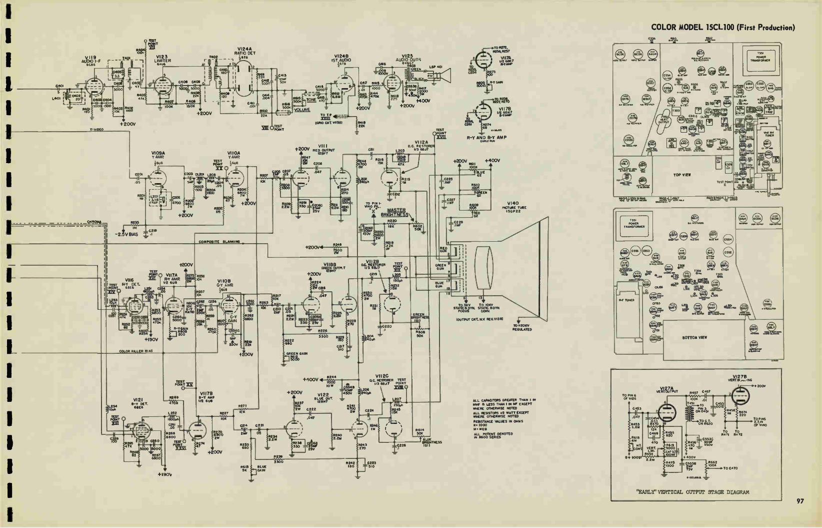
-=
VII9 AUDIO -F
6086
0402 1 ▪ 2 --20 I C-404
180
+200V V-VIDEO
1000
I c201 1 I( 9
.05
VI23 LIMITER 64u6
500QL 5000
2211
R406
10011 150K
V109A Y AMP
¡Era
I L201 3.58
ITRAF cee 12n°
203
+200V
VI24A RATIO DE T
_ _ i6TEI
180 1 I
1 I
1 1
YEE
TEST POINT
XX
01-201 L208
Suc 391.nuo
.05
R202. 6800
1500 >41204 1200
R205 III
+200V
R235 1
0218
- 2. V BIAS •
VIIOA Y AMR
•7
R206 6800
7ve
-1-200V
2211
G413 robe soy
TEST POINT
0207 .05 2
VI 248 1ST AUDIO
6TEI
•
0416 5000T • "'
TONE elifoi
VOLUME TO T P inn
(GRID CKT V11581 R418 22x
* 1-200V
VIII 1.200V RED OUTPUT
1291,7
COMPOSITE BLANKING
II TEST liPe
I I
I Î,13 0 0
VII6 IlS 71 68E 6
c.??? 47
R252 82
;t929504
+190V
COLOR KILLER BIAS
1200V
TEST VII7A R-Y AMP. 1/2 6U8
L251 0254 1800,e/0 D5
0263'1 1 COO
R253 6800
R226 i0K
EN
VII0B G Y 1.MP.
68
10K G-Y RATIO
C264 R2S5 50001 4701,
R-Y GAIN R605 200
C262 C2543
214F I .05 250V
35A
R260 47011
.L254 2100
TEST ,•-•, POINT V
Ian
VI21 8-Y DEI 68E6
7
C- 3▪ 28 100
1
R265 47K
5000/2 5000 —*
R2 r. 82 R267
6800
2 9 0260
TEST POINT
o
8269
4 0K
L252 580 1800.011
0261 .05
R268 6800
TEST POINT mi
+190V
2
VII7B B-7 NAP 1/2 6013
74
r:_
200
65
08 6300 3
47 10( 2W C208
6 's .047
1
-7.
8 214 270
2.2,4
R291 330
• C206c 2544F 25v
0418
I08 IDOOV
414 70K Ii4)8 1
220
VI25 AUDIO OUTR
6v6G1 1403 LSP 401 rr. _ gr3 11.17
+400V +200V
TEST ()POINT
VI i2A D C RESTORER
0211 L203 1'3 6817
1
R2I6
4700 R248
1541 47K
L2Cl2 2401011
I R215 1111
TO PIN I-VI40
180 X MASTER * BRiGHTNES\
R220
±20CN4—le."`""49 7500 2V/
VII8B GREEN OUTPLT
12B/47 t 200V
R224 10K 2W 2216
217 .047 10K
2,
/ IN 0210 C ,e' _.., 27.1/F .0e G, R262 R22I
2214 GAIN
64C
34o _ • R261 " 250v 22x
R227
10K
6270 6800 2W
+200V
7
ICK
2214 0221
*1(-214F
25V
8226
228 270
R222 680
GREEN GAIN
SO&
+200V
Rae
O R234
- 2.2M
P239
3300 P2291 8
C217 510
R244 4-400V 41
low
237 10K 2W
VI22 BLUE OUT
1213H7
0222
.047
R238 22066 330 '3U
• 1.5546
104IF 150V
R24I 4700 2W
P240
CZO6D 50K Tur e600
2W 7+7. 2° 250
VII2B D.C. RESTORER
ii3 6817
Leg
F.M 2W
R23I 11,1
R2I9 22K 1W
TEST POINT
XIX L 20.3
DO 15001
egz2 .9
-LC220
L204 - 240 e
L206 240ph
_T_C225
I 1MF
TO R272, 8256. P257
vi 17A 8 1/2 6BK7
.0- R YAW
00
R-V GAIN
TO 18258, R227 R270
VIi7B 1/2 6E167
4 B-Y ARP TO % R266, 8 2261 R274
i3.6.11,
R-Y AND B-Y AMP EARLY RUN
4200V +400V L R6Il •
100K
G2
10227
8610
GREEN 62
1C2 28
RED GUN
2 3 1
GREEN 9 GUN
7 e
BLUE GUN
GREEN
1011 BRIGHTNESS
VII2C C. RESTORER TEST 1/3 61317 POINT
C224
R243 25V 270
3300
8246 lU
R242 C223 R6I3 BLUE 180 510 5K GAIN
L207 000 , 150911
R608 SOK
R245 I5K
C226
8614 5041
--"TrITUE BRIGHTNESS (GI)
18
VI40 PICTURE TUBE I5GP22
• TO 5K V TO IOKV
STATIC 8 OTN STATIC Et 0714 FOCUS CONY
!OUTPUT CKT, N.Y REG VI38) • TO t2OKV REGULATED
ALL CAPACITORS GREATER THAN I IN 0114F a LESS THAN 1 IN MF EXCEPT WHERE OTHERWISE NOTED
ALL RESISTORS 1/2 WATT EXCEPT WHERE OTHERWISE NOTED
RESISTANCE VALUES IN OHMS K. 1000 M. MEG
ALL POTENT DENOTED IN R600 SERIES
COLOR MODEL 15CL100 (First Production) ce.
Feeikt.ree,e.
et. ;e1
-,Itge=e
6606
G
eetTI-
TOP VIEW
e
TEsT PORI
,t,LE61
TRANSFORMER POWER
T554 in
xge.
1551 POWER
TRANSFORMER
o MAO art
vl.e• 66 iteu,@
¡CDS
MR ORAN up. eankr•
7401
e L159 Oat 6U8 T303 414. nre. gee& L3°3
o R-F TUNER
0163
7s-01152
CI 1
61
C554
C552
@ve.
•••••••••
Ay t • meCLAYA1
BOTTOM VIEW re,
• MARA A
•46 6BL7
TO PIN 6 Of V126
C453
.047
R453 6. 8r.,
8618 4 E.E
111. ONO
+ BOO
VI27A VERT OUTPUT
0454 033 R470
1211 0469
VERT LIN
4454
4619 5000 2473 10014f
R457 0451
100 .01 1451 To 2455
9012 ordIPÉ,4,51 i _ TOC T. ON 8620
C553C R456I. 3014F 470 450V 1W
1> 400V
C5558 2N1F 75V
.1.435A1194
4662 100K
VI27B VERT El/ ...• NG
TO TO 4411 R472
TO 0410
"EARLY" VERTICAL OUTPUT STAGE DIAGRAM
200V
To PINS 2,7,19 OF 9140
LL gs:112,
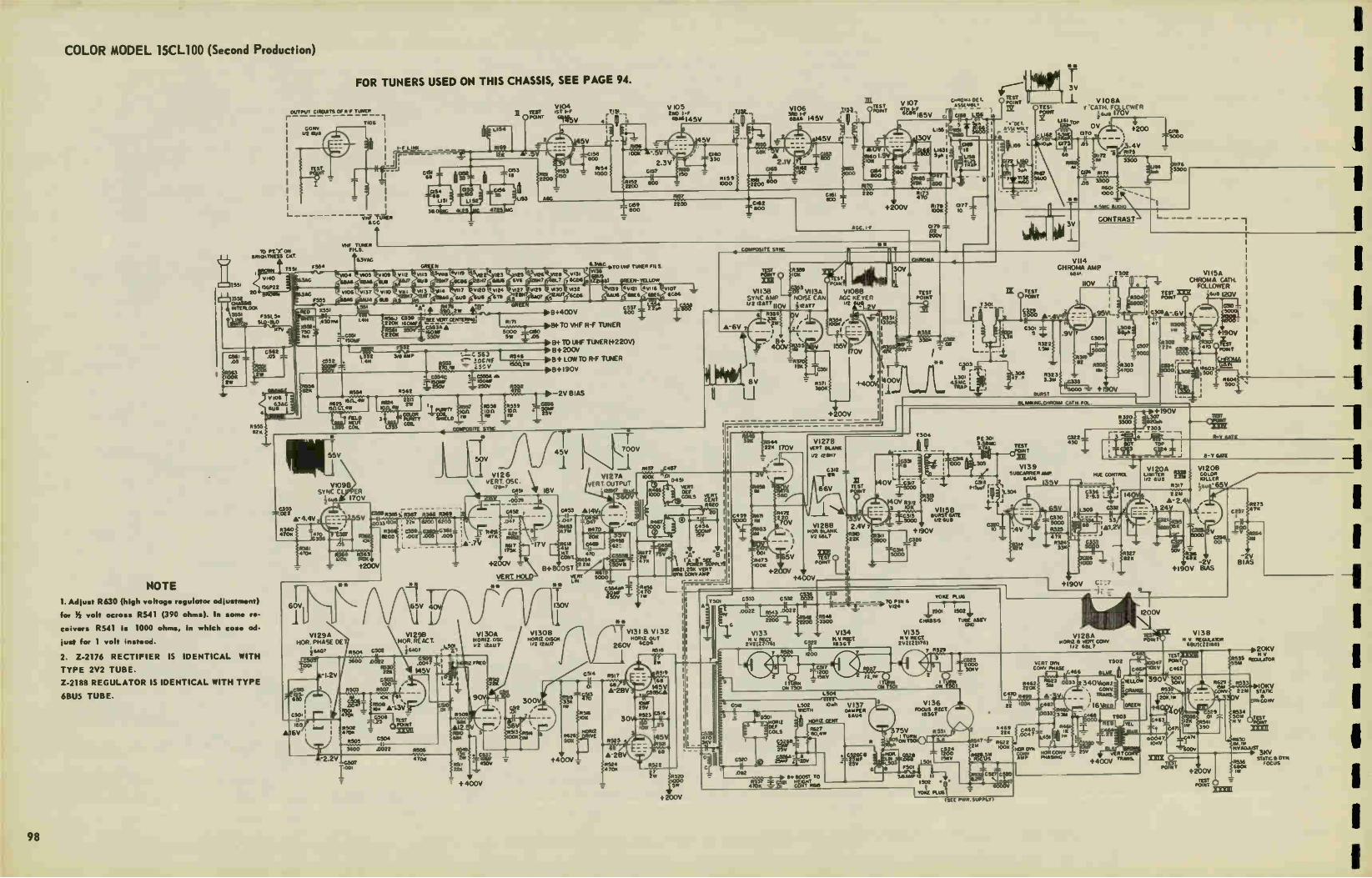
COLOR MODEL 15CL100 (Second Production) **
FOR TUNERS USED ON THIS CHASSIS, SEE PAGE 94.
OUTPUT CIFICUTS OF RP TUNER r
Co,., I/2 OJI/
L.
70 Pt.le ON SRIOITNESS CRT
4555 82K
NOTE 1. Adjust R630 (high voltage regulator adjustment)
for )5 volt across R541 (390 ohms). In some re-
ceivers R541 is 1000 ohms, In which case ad-
just for 1 volt instead.
2. Z-2176 RECTIFIER IS IDENTICAL WITH
TYPE 2V2 TUBE.
Z-2188 REGULATOR IS IDENTICAL WITH TYPE
6BU5 TUBE.
1 TIO6
VHF TUNER FILS.
V109E1 SYNC CL
sue
63.35
a- 4.4V
4340 470K
60V
ir VI29A
HOP. PHASE DEI ¡taw
-2.2V
113VAC
C507
Giss° ir" I _Lies T ri à List
055
r US3 38.011G 41.25?C 4725TAK
4 70« 450V
221(
+ 400V
V104 TEST IST I-F JAL ,
903V 4' II PONT
+400V
—ass 1.00
A-28V 4524 • 70K
V105 240 I -F «We i43V
2263
W >R520 $1000 SW V
+200V
34)84USI-F I45V V106
- A 1 2.IV
are
_C182 800
IVA 220
AGC If
V 107 4Th ir165V
130V I 5 tea 'be: ....S'Sew:RY t.+051 Crtoso — __. 1,,
LI83Id TI. ir
e1857 s°62800
1 :I7Tó --•
+200V MI
079 — .02 toot
»AMP It II 1502
YOKE PLUG
• 1.
ISEE PWR SUPPLY)
TEST 1. Ciin3" 5". °POINT V108A ASS( Wei
C rit °TES' POINT Y CATH Fal'WFR
!Ewe 170v Lulu Toe tm. (pi '
cLIlS"1.5110 9 ars .05
IX TEST POINT
il
68 111884 SI
•A G174 RI 74 0, 3300
R601
** -r 4.5MC Au»
CONTRAST
+200
RI75 te.
im 3V
V 14 CHROMA AMP
68A r 7302
110V
pit
VI 15A CHROMA CATH. FOLLOWER
ig,333EKO8 2OV
0004 IOKV
V138 V FEGULAIOR 68U5 Z21881
4273 •7K
.208V 3 V 5 LATOK
OKV STATIC
057115ONV
4534 ON ,TEs,
‘-'POIPH EXXIL
p. 3KV TT STATIC DYN R156 FOCUS
POINT 680K +200V
TEST rs POINT 5-,
98

COLOR MODEL 15CL100 (Second Production)
V 11 6 AUDIO I - F r
c40.•ov_ 1401
-2V BIAS
A -I.7V
.05
11233
46V
VI23 LIMITE&„, 6Au6 ••••••••
V109A Y AMP
i6u8126V
103V
+200V
TEs7 •
TEBT H-Y OF T.
XZE 1O-Y AMP
PORT î VII 7A V116
I/2 4U8
10113;17 68E162
COLOR KILLER BIAS
V121 13- 1. DE T 613E6
.4V
4 R2195
R2 82
1 1
A-26 1402
VI 24A RATIO OE T 46T8
VIIOA Y AMP
60,45v
COMPOSITE EILANIONG
Vi 10B GY AMP.
160V m2A7 ifue I65V •c.:504p
4socree e to. el - G•T 'DO RAM' 230V
C264 5000 V .-ute 2.0
TEST POINT XS(
0 -
R269
L252
120(AKIA •••
C26I 047
42•118V ,6001)
TEST 0 4v
+190v
VII7B 11.-T AMP 1/2 6118
R227
• -ro-e
Fan 2W
• +200V
•
20L 0V L /226X'
ti0OV
R233 UC
5613 BLUE 5K
=W.
C4I3 R419 104% 50,
C210 211F
200V
• 37
2W c222
90v .047
34
2-2" 2.3V
R239
3300
VI 248 1ST AUDIO
60V
TO TP ILfl --
(GRID CKT V1158)
4226
3300
V122 OLLIE OUT 12807
OV 71
8240 2.211
WW-84J 235
VI25 AUDIO OuTR
310%4 '1', OTTE N
5416 4,0V
330 440011 Im
LSP 401
+200V
1381 OPOINT
SOV r7-11
VII2A o c REST
1203 u 3 60.17
RD PIN I-V140 F1L
VI I 2B DC RESTORER
1/3 68.17
VII2C DC RESTORER TEST
68.17 POINT
1207
150,,K
2205 1511
- ,446v
224E I
V 2243 270
524 2 IC223 180 r5I0
—G26
1C225
2 V SIAM 87V658 1,
11601 50(
TAIGHTNES5 IGO
*SCOPE SYNCED AT I/2 VERT. FREQUENCY. *11 SCOPE SYNCED AT I/O HOR12. FREQUENCY
WAVE SHAPES TAKEN WITH NORMAL CONTROL SE TTINGS & NORMAL SIGNAL APPLIED.
VOLTAGE MEASUREMENTS ARE IN RESPECT TO CHASSIS WITH A 20,00011/VOLT METER. WITH CONTROLS SET FOR NORMAL OPERATION. NO SIGNAL APPLIED.
A MEASURED WITH VTVIII
+400V
12212 +aoov ,5600 di 5011
too«
TO 3KV STATIC &00/1
FOCUS
IS
W To oOKV STATIC &DIN CONV
B- Y GATE
V140 PICTURE TUBE I5GP22
(OUTPUT CKT KV 14E6 ,03E0
- 51V
••
TO 1.20KV
REGULATED
I 0266
1
I TEST I POINT
I R279 47
£328 30
VI I 6 R-Y PEI. 68E6
6800 R254
VI 21 B- T OE T
68E6
TEST POINT
Hum
CA NC.
ALL CAPACITORS GREATER THAN I IN
& LESS T0AN 1 IN MF EXCEPT
*MERE OTMERwISE NOTED
ALL RESISTORS 1/2 WATT EXCEPT WIER( oTHERwISE NOTED
RESISTANCE VALuES IN cmeAS 14 • 1000
S. NEG
ALL poTun m001E0 IN 2400 SERIES
4.4( C 344
R253 6800
+190V
2268
6800
9 £260
5000 5000
= R267 6800
0631 800
+190V
CAL
8.06 „,„, T304
TOP VIEW
et:L.
m,e1 S -etnerr.:
e-e
•
thilet,Pen. "aeZiNte22
T551
POWER TRANSFORMER
BOTTOM VIEW
T551
POWER TRANSFORMER
- • r ,-£.4•417WI

PARTS LIST, MODEL 24C101
ELECTROLYTIC CONDENSERS
REF. Ho mammal I PART NO. I
C3I1 C406 C457 C517 C605 C601A C601B C602A C60213 C602C C602D C603A C60313 C603C
C603D C604
C606
C104
C106 C105 C108 C118 C465 C5I5
I mf., 50 V 5 rnf., 150V 100 mf.. 150V 500 mf. , 15V
500 mi., 15V 30 mt., 450V 60 mi. , 350V 40 mf., 450V 30 rnf., 350V 15 mt., 350V 30 mf., 25V 30 mi., 450V 15 mf., 350V 30 inf., 150V 25 rill., 25V 500 mf. , 125V IK mf., 6V
TRIMMERS:
RCE-090 RCE-056 RCE-I23 RCE-I26 RCE- 126 RCE- I 33 ACE- I33 RCE-122 RCE-122 RCE-122 RCE-122 RCE- 121 ACE-121 RCE-121 RCE-121 RCE-I25 RCE-106
RCY-065 Rd Y -065 RCY-066
RCY-048 RCY-067 RCY-069 RCY-064
(fine tun's)
Yoke balancing Hor. Drive
1-5 mini. 1-5 mrrif. 20-50 mm!. .6-2. 1 mmf. .8-1. 7 mm!. , 1-12 mini., 110-580 mmf.
CONTROLS
DESCRIPTION REF. NO. PART NO.
Volume Brightness Contrast Ho, Hor. Vert. Vert. Vert.
Focus Hor. centering Vert. centering AGC 25K
Capacitor 002rnf...
22K, 8.2K, molded
10, 500 voltage
470 ohms, 1K, 15 50 ohm
1800 50-400
2 meg (on-off)
2 meg ION
Hold 100K Sise
Hold I meg Sise 3 meg Lin. 214, 2w.. w. w. 400 ohms, 25 w. ,svw
500 ohms2w 20 ohrn• 2w
WIRE WOUND
R350 R6 It R401 R510
R456 R458 R462 R601 R604 R605 R425
C451,2
R541
R602 R603
R538, 9
R542
R538,9
RRC- 161 RRC-I58 RRC-161 RAC- 160
RRC-I57 RRC-159 RRW- 068 RAW-065 RRW-066
RRW-067 RRC-140
REK-001
RRW-052
RRW-063 RRW-064
RRW-074
RRW-075 RRW-093
resistor network 005mf. , .005m,.. 8.21( ohms, I/2w,
integrating network ohrn•,Globar
sensitive 25 w. , ww
w., w. w. -250 ohmw. w.
ohms, 10 w. , w. w. ohms, w. w.
COILS
REF. NO. DESCRIPTION PART NO.
L100 L100 L106 L136 L201,2 L203 L206,7 L209 216
L210 L211 400
L2I2, 3 L2I4 L215, 218,20 L2I6 L217
L22I, 404, L504,5 1-401 L402 L403 L500 L501 L600 L601 L602
Choke - .56 oh Choke - .19 oh Trap IF coil & core Choke - 1.4 oh 1st Video IF 2nd Video IF 3rd Video IF & cores Detector
Choke-250 oh. video Choke-110 oh. video
Detector 4.5 mc and core 1.4 uh 5% choke
Choke 31 oh. Trap-4th Video IF 39.75 roc trap coil
Choke 2.2 oh
6. Choke.10uh,hor. Choke- 1000 oh. Choke-220 oh.
10 oh. 1% Hor. osc. & adj. slug Hor. lin. & tuning core Filter choke, 5 hy. Filter choke, 5 hy. Focus
RLI-I44 RU-146 RLI-I59 RI-1-136 RU-133 RLI- I 31 RU-132 RLX-031
RU-I56 RLI-108
RLX-032 RU-139 RLI-142
RLF -024 RU-135
RU-122
R LI-138
RU-155 RU-143 RU-140 RLC-I07 RLD-027 R LF-040 RLF-041 RLF-047
TRANSFORMERS
DESCRIPTION REF. NO, PART 140. I
Vert. Oc. Vert. Output Hor. Output Power, 60 cy, 115V
T450 T451 T502 T601
RT0-103 RT0-097 RTO-104 RTP-310
a
V102
.1-10M tIon Oi_CMAtt•ttl • 4 1933tTON 2.4) RF _
oc
ROO .20
t.'or*
000
•I"
RF TUNER, "D" VERSION
MODELS 17C110, 17C111
(See Page 59.)
•03
5400 /102
vim
CF2 sooT CFI
V103A F.) 9 VI038
¡QM , St OSC ¡IOU ci9
6000
TRANSFORMERS
DESCRIPTION REF. NO. PART NO. STANCOR NO.
Audio Output Yoke
Antenna input Width & ACC c'pl's Ratio detector Video I-F 4th Video I-F Audio I-F 39.75 mc Trap Transformer
T350 DY601 T100 T503 T301 T200 T201 T300 T202 TIO1
RT0-096 RLD-034 RLA-037 RLD-033 RTD-008 RTL-I18 RTL-I19 RTL-120 RTL-I22 RTL-I26
MISCELLANEOUS
REF. 140, DESCRIPTION PART 140.
LS.350 Y200,1
RF Tuner (Early Models) RF Tuner (W Models) Loudspeaker. 12" PM Crystal Diode IN64
RJX-044C RJX-044W 81212D7 IN64
36
Nir Fultt.G
•
MOO 110
UO3
-32 •Ae0831. '1 Gleelk e • •81.-n • re'
Clot
V101 4A64 1ST Re r
4, IF TRAP
40
err 11311
•GC
IL
r3ott
NOV.
VOZ 4C114 00 RF
/If -
P103
2300 toz
f• e
loco
10.0nffl
RF TUNER, EARLY VERSION - MODELS 7C110, 17C111
(See Page 59.)
(See Pages 65 and 67.)
NOT USED
8+ ORANGE LEAD
13+ RED LEAD 250V
6.3 V. AC FILAMENT
A.G.C. BIAS WHITE LEAD
RJX-044C, EARLY PRODUCTION MODELS 200150-151, 240101
NOT USED
B+ ORANGE LEAD
13+ RED LEAD 250V
6.3 V. AC FILAMENT
A.G.0 BIAS WHITE LEAD
B+ 160V 6+250V ORANGE RED
RJX-048WK, •vor PRODUCTION MODELS 20C150-151
RJX-04410, 'Ye PRODUCTION MODELS 200150-151, 240101
'*,FILAMENT
GC WHITE
RJX-0480K. 'CI( PRODUCTION
MODELS 20C150-151
R-F TUNER TERMINAL CONNECTIONS
eon 8.•11 • —
11101 s••• 1ST RF
T100
L..
L
so
•
• •
'urn ezoo
V IOZ
as',
FOS
114,U 1109 1000
ROO 120
r.5
OOTPUT L _
R-F TUNER, RJX-048WK, "WE" PRODUCTION, MODELS 20C150-151
(See Pages 65 and 67.)
(See Pages 65 and 67.) VOZ 6C.136
Iilplettolà • MACON oar- — — —
4
vtgl
R-F TUNER, RJX-044C, EARLY PRODUCTION, MODE1S 20C150-151 AND 24C101
VI
eon • •01_.*_'0N —
V101 4144 IsTUr r
00 LOO
001 2
UM
U01
C•4
R-F TUNER, RJX-044W, "W" PRODUCTION, MODFA 200150-151 AND 244)101
Vt03A "AT?
33 OSC
1000
(See Pages 65 and 67.)
1/102
Art see
100
OUTP0T
loo

RADIOS
1
1
840 RADIO PARTS LIST
ELECTROLYTIC CONDENSERS
REF, NO_
C20IA,I1(,C,
CIO0A,B
C2a4,5.11
C12,13
C23,31.
Cl?. 39,
C27, 37,3
00 l4 C9
C28.32
DESCRIPTION
LI 30.15, 30, 30 rn (el
30/400V; 30/350V
TRIMMERS
PART NO.
RCE -019
RCE-032
RCX-012
RCX-024
RCX-025
RCX-026
RCX-027
RCX-028
RCY-011
RCY-017
Puahbutton
3-30;80-130 mmf
33,34. 185-24520-
55;320-400;165-225
mmf.
40. 20-55;475-575;
320-400 mmf.
2-20;185-245;34-70
mm!.
34-70;40-80;5-45 rrinti
3-30 mml
3-30; 3-30 mmf
CONTROLS
DESCRIPTION REF. MO PART NO.
Volume 2 meg.
Tone Control Asey-treble
Tone Control Ae•'y-ba••
SPECIAL
R45AB
R202AE
R201
EEC -000
EEC-027
EEC-026
FtRT - 001
RRW-016
900 ohmm 6W., 150ohrns, 6W
100 ohm., 2W., variable
COILS
REF. 140, DESCRIeTION PART NO.
L3
L4,13
L5,26
L6
L8
LIS
LI1
LIZ
L14, Is
LI6
L17,18,
L23
L24
L201
1Pca•t RF pra. dummy
FM ant. ch.FMI o•c cath
RF pl. ch. &IF wayetrap
SW band R.F plate ch.
SW band RF loading
SW o•c loading coil
B -C o•c shunt tuning
FM cu.. cathode
IF plate
B'ca•t band is.. shunt
19. 20.1, 2. Coil and
mounting bracket as•
For Pushbuttons
FM power line
IF filament
Choke fil. for powe
RLB -009
RLA-012
RLP-008
RLB-008
14LC-017
RLC-015
RLC-014
RLI-005 R LP-005
RLC-016
y
RLX-002
R LI-002
ELF-OS?
ELF-Sb0
TRANSFORMERS
DESCRIPTION REF. NO PART NO.
BCPB Antenna
Broadca•t antenna
Broadcast. RF coi
Audio Output
Power, 60 cycles
FM discriminatoi lot IF
2nd IF
Broadcast 3d IF
T:
T2
T3
T202
T201
T7
T4
TO
T6
R LA-006
RIA -009
R LB -006
RT0-026
RTP-035
RTD-001
RTL-017
RTL-022
RTL-043
MISCELLANEOUS
REF. NO DESCRIPTION PART NO.
LI
56
P6
J5
P2,7,
P3
P5
J201, 4
P203
J202
J3
P202
J2
52
57
523
55
54
SI
Back and loop ass's,
Pu•hbutton sw. a•siy
Iron core - AM tuning
Connector
Receptacle-for loop
28. Receptacle
Plug-Male phono input
Plug for loop antenna
Receptacle-117V A-C
Plug-on power cable
Recep.(spkr cable plug)
Receptacle -Phono input
Plug-4 Pin arnphenol
for speaker cable
Octal recep& lock ring
Vane tuner (FM coils)
Tuner vane for FM
osc. coil L9
Speaker 12" PM
Phono pick up cartr idg
001 •tylu•
Phono pick up cartradg
003
Switch-Pushbutton
Switch-Squelch
Switch-On-Off
Switch-Treble
Switch-Base
Switcl-i-Band change
RAB -085
RDX-020
REI-006
RJC-012
RJJ-002
RJJ -003
RJP-004
RJP-006
RJP-007
RJP- 008
RJ5-089
RIX-003
RJX-005
RJ X-006
RMM-010
RMM-011
ROP-016
RPX-044
RPX-045
RSP-004 RS5-003
RSV-001
145W-016
RSW -017
RSW -029
818 AND 12K1 RADIO PARTS LIST
ELECTROLYTIC CONDENSERS
REF. 1113 DESCRIPTION PART NO.
C39A
C39B
C39C
C39D
C43
CAB,
C3
C5
C12
30 mf.. 400V
30 rnf., 400V
15 mt._ 400V
20 mfd., 25V
10 mf., 250V
TRIMMERS
RCE-029
RCE-029
RCE-029
RCE-029
RCE-042
RCT-033
RCY-020
RCY-034
RCY-038
C, 0
Capacitor-Tuning
Capacitor
2-20 rnmf.
Air trim. , 1-8 rnmf.
CONTROLS
DESCRIPTION REF. 140. PART NO.
Volume
2.2 ohms
6500
W1REWOUND
ohms
R18
R35
R33.34
RRC-I12
RRN-006
RRT-00 3 ohms & 1220
COILS
REP. HO DESCRIPTION PART NO.
LI, 10
Lls
LZ
L3
L4
LO
L6
L7,9
L8
LI1
L12
L14
Choke
Limiter choke
FM Antenna
Loop Ati•embly
FM R-F Choke
Broadcast Oscillator
FM Choke
FM Coil
FM Oscillator
Choke
FM Power Line Choke
FM Coil
RLI-005
R LI-058
RLI-084
RLL-036
R LB -029
R LC- 066
R LA-012
111.1-057
R LC-067
R LI-005
R LI-044
R LI-007 ,
TRANSFORMERS
DESCRIPTION REF. Ho. PART NO.
Power
Audio Output
-thiecriminators
2nd AM I- F
1.1 AM I- f
FM I- F
T8
T7
T6
TO
T2
TI, 3
4
RTP- 302
RTO- 051
RTD-006
RTL-054
RTL-078
RTL-080
MISCELLANEOUS
REF. NO, DESCRIPTION PART NO.
JI
SI
52
Phono Jack 8. Plug
Switch-Band change
Switch-Tone control
RJP-010
RSW -073
RSW-074
16K1 RADIO PARTS LIST
ELECTROLYTIC CONDENSERS
REF. NO. DESCRIPTION PART MO.
CIA. B.
C38
C39A,
C43
C. D Tuning cap.
.005mf. 1000V
B.C.D. 30-30 mf 250V
10 mi.. 250V
RCT -043
RCC-059
RCE-039
RCE -068
COILS
REF. NO DESCRIPTION PART NO.
1.2
L3
L4
LS
L6, 10,
II
L7
L8
L9
FM antenna coil
Loop assembly
FM R-F coil
B -C Oscillator
Heater choke
Choke coil
FM Oscillator
FM R-F pl o.. cath
Choke in FM lane
R L1-088
RLL-039
R LB-029
RLC-066
RL1-122
ELI-087
RLC- 102
RL1-124
RI.1-044
TRANSFORMERS
DESCRIPTION REF. 140.\ PART NO.
1st I-F AM
2nd I-F AM
let. 2nd 1-F FM
FM Limiter Coil
Output
Power, 60 cycles
Discriminator
T2
TO
TI. 3
T9
T7
T8
TO
RTL- 097
RTL-098
RTL-099
RTL-114
RT0-089
RTP-302
RTD-010
1610 (Concluded)
MISCELLANEOUS
REF NO, DESCRIPTION PART NO
JI
32
J4
PI
P3
R18
R33. 34
SIA,B.
S2A,B,
Phono Jack & female plu RJP-010
Phono power female •oc. R.15-049
Octal connector RJJ-003
Phono plug .ingle pin male RJP-004
Chas pow. plug 3pin male RJC-012 Vol. , cont. 2 ineg tap-
ped at 1 meg.
1220-6500 ohm 9w. ,w.
C. D. Band change sw.
C.D. Tone control sw.
RRC- 141
RRT-003
8.5W-079
ROW -080
820 RADIO PARTS LIST
ELECTROLYTIC CONDENSERS
REF. NO, DESCRIPTION PART NO.
CIA, B
C39A
C39B
C39C
C39D
C43
C.D. Tuning cap.
I. drum a•sembly
15 mfd., 400V
20 mid. , 25V
30 mfd.. 400V
30 mfd., 400V
10 mfd., 250V
RCT-033
RCE-029
RCE-029
RCE-029
RCE-029
RCE-042
CONTROLS
DESCRIPTION EP. NO PART NO
Volume . 2 meg.
6500 1.1220 ohms, ± 10% .
R18
R33. 31
EEC-074
RRT-00 3
COILS
REF. NO, DESCRIPTION PART NO.
LI, 10.
L2
L4
LO
L6
L7.9
L8
LIZ
1,13
II. Choke
FM antenna choke
FM R-F
B-C oscillator
FM o•c. grid choke
FM choke
FM oscillator
FM power line choke FM limiter choke
RL1-005
RLI-056
RLB-027
RLC -066
RLA-012
R LI-057
R LC-067
ELI-044
R LI-058
TRANSFORMERS
DESCRIPTION REF. 140, PART 110.
Output
Power (60 cy. )
1st FM IF
2nd FM IF
3rd FM IF 2nd IF (AM)
1st IF (AM)
r), sc rimi na t or
T7
TO
TI
T3
T4
TO
T2
TO
RT0-051
RTP-061
RTL-080
RTL-080
RTL-080
RTL-054
RTL-078
RIO-006
MISCELLANEOUS
REF. 440, DESCRIPTION PART NO.
J1
PI
P2
P3
P1
SIA,13.(4.
52A,B,r.
Jack - ,Mono Jack
Plug, phono input
Plug. phono motor
Power plug, 3 pan male
Plug, octal base
D. Switch, band change
D. Switch, tone control
and power switch
RJP-010
RJP-004
RJP-003
RJC-012
RJJ-003
RSW-059
RSW-048
IS ,S ,Se
if *r14-11' 11
AS
840 RADIO
(See power supply Page 102.)
ellheitevioswif saw
c>:c7.1 § a
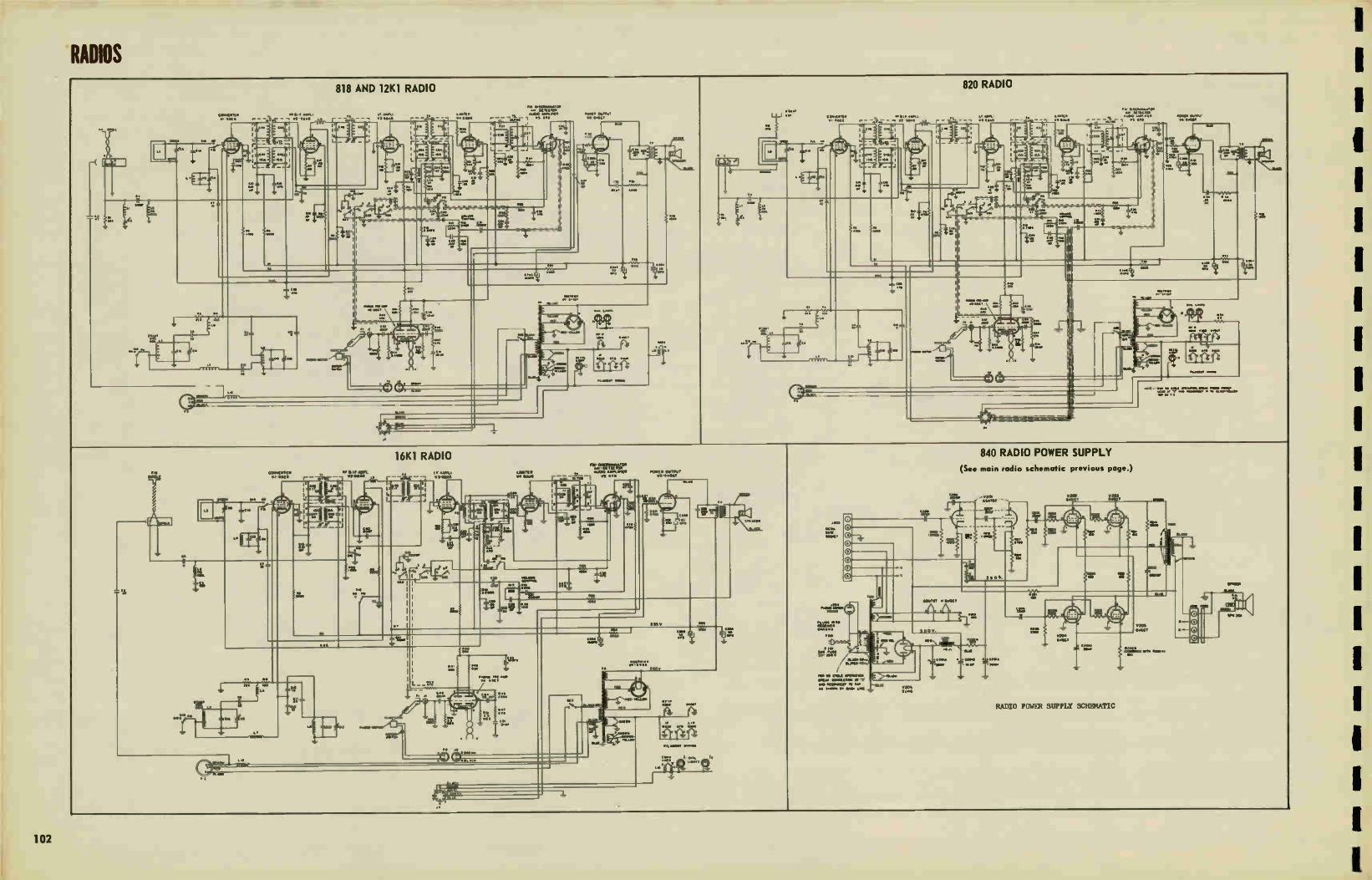
RADIOS
careen. 111 -44111
•••
- - -.7r1 119
.90
9,1
low
818 AND 12K1 RADIO
VI
ta•
l
te Mete V3.011•4
L r-
Vie _
_
•••
--, ell.410•••••1011
ernMte NO10 441.
9 - - •S 140
I '1 11••••• e
•
•••
U..
•••
.9* hot
•••
141110 0119110 14.11491
•••
Owe
•à•
tle
t.
età,
011011 11.1•01•1-1•1•••
•
LIMO
••••
•••••1
—•
0.014
•••••
•••
840 RADIO POWER SUPPLY (See main radio schematic previous page.)
V.11,
•••11
110
eft
*I SIP
16KI RADIO IF •114.1
14 61 . r
U.
1.1111,1111 14 WA
rILVIIMIgjee
-i-urreirtieWnite .",= 1 re eve
-at
u
1.00911 01414T re.erest
411
!MT
011
I MO
•e• à
t:
«400
•
••••,
ant»
gZill."1. 'tee'
4,
NY 1t1:1
‘1•*f
1.110041.
820 RADIO
„.-Vret MOW ----
••••••
.00 \MVO,
ea0..91111
eTte 00. • TA- V
• 010111 WilT04
-
1•0 00 00.11 0011000. # >•0409 011là• 4140•911101 Web 4000149 10 TV
14100 S. tea VX4 to..
9r
10011 1100GT
•01. • C000 4. 419
RADIO POWER SUPPLY SCHEMATIC
11005 11410
:12114 44 MOM
„...401104
Meet
aide
Ire Fa
102

MODELS 121(1, 818, 820.
RADIOS
DIAL CORD STRINGING
I. VETLOVM
MODEL 16K1
MODEL 840
SOCKET VOLTAGE DIAGRAMS
BOTTOM VIEW OF CHASSIS
A
CATHODE t 265
PLATE PLATE 275 AC 275 AC
573GT
PLATE +250
SCREEN +215
6V6 GT 32 AC 32 AC
6 3 AC CATHODE + 11 0
PLATE 6SCy +65 = 678
= 6AU6
SCREEN +90
PLATE +200
SCREEN $175 CATHODE + 85
recj SCREEN
SUPPRESSOR + 85 • 65 PLATE
6E1E6
6 3 AC • 165
63 AC
CAT HOC( + 09
6 3AC 6BA6
613A6
j. ALL VOLTAGES MEASURED TO CHASSIS USING A 20.000 OHM PER VOLT METER
MODELS 121(1, 818, 820.
CATHODE +260
PLATE 275 AC
PLATE 1250
SCREEN t 235
6V6GTIN/6)
573G7 (V7)
6 3AC CATHODE 1-11.0
BOTTOM VIEW OF CHASSIS
PLATE 275 AC
PLATE +50
PLATE 170
6 3AC
6AU6
SCREEN 1100
PLATE t 100
SCREEN t 70 CATHODE 1I 2
GRID SCREEN t120
SUPPRESSOR PLATE
3 AC 1225
6 3AC
6BEG (VI)
VI ri
SCREEN t 95(FM O IDC1
CATHODE +06 PLATE
1235
— 6 3AC 6T3-A6 (v3)
ALL VOLTAGES MEASURED TO CHASSIS USING A 20.000 OHM PER VOLT METER
MODEL 161(1
v13-§.K .7
•••
UTNOM •13
v3-GARS
113•C
SUMO. •ie>
BOU V(ASS,S SHOWN
SSA<
ALL VOLTAGES MEASURED Cii1100(
TO CHASSIS USING A • ,0
20,000 OHM PER VOLT METER
V6- §.W SOMMI RLMISMI•100 COLVI
• SAC
ROE •111
v7-ff.LT
v10-§AjaT
TUNING EYE
14.•Tt •iff
RADIO CHASSIS
CATHODE •20 CATHODE +20 CATHODE +20 PLATE 2 4130
3 IA C 3.IA C 3 MC GATTI 2 PLATE PLATE PLATE •• +305 +305 +305
3 IA C SCER
V206 V205 V204 V203
5U4G 6V6GT 6V6GT 6V6GT
BOTTOM VIEW OF
CHASSIS SHOWN
ALL VOLTAGES MEASURED TO
CHASSIS USING A 20,000
OHM PER VOLT METER
AUDIO AND RADIO POWER CHASSIS
31A C
V2O2
6V6GT
AC
GRO SCREEN +27 +310 PLATE I
4192 Cell
+63
V201
6SN7GT
MODEL 840
03
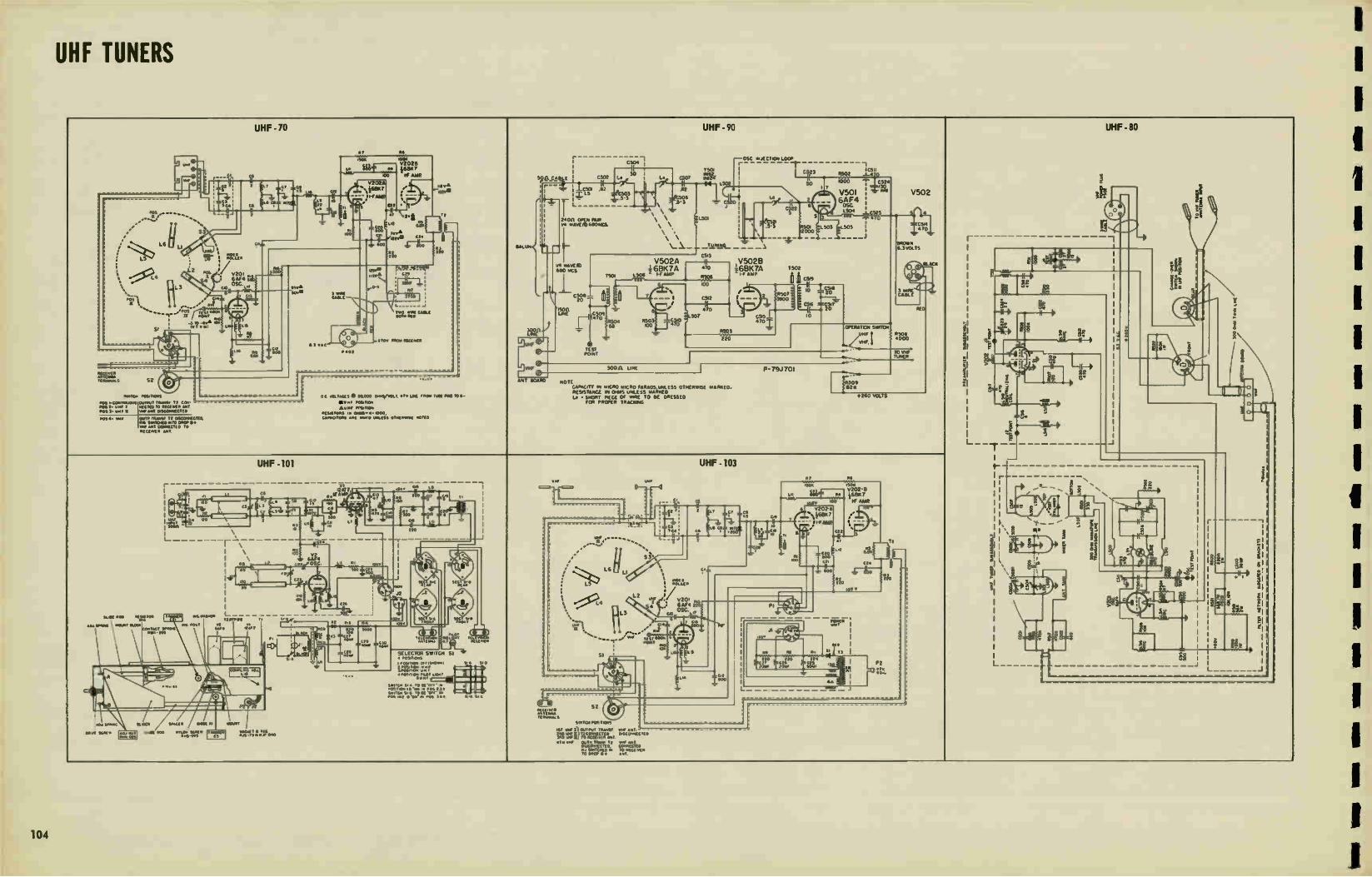
UHF TUNERS
UHF-70
• Re
UHF - 90
r
C504 1 rOSC ei.JECTION Loop
-I-
UHF - 80
nOS *OK noze
U:"7.-.-'-
II fi71 •• 460,7 30
730s
irail/24
lc5.1 r R302 _1_410 4(3
- li
eF AMR 500. CA 2 C302 L
1 ZOO ...... IC12,524 V202 7 , ..r.• r --/
1C301 .82 Z L5 503
.82 L502
5°
L•
7
V50I V502 h (lb
r --1 I •
- 1
ei
--0.
- all r =.-_ - I 'Pr CO 4 4r44
.0 Y.
OK •
GU • .5-3 2 6AF4
6 OSC
;
1 9 L5°4 -LCS25
........5/ ........ ".....
L__ i _.
wet
47 «,à
lle .21 Tt
i Tt
i
841.1.1•1
i i
1
4- -•
24011 OPEN Rai 104 »Kt/DC.804M
\ \ \ \
‘ \ \_ X. -
L501
-Ikee...5- _ _ _
2. .5 3
_ .1
3
R30.
3
303 KW 1.
1•40•16
p.' • s e .. e_.
I ,„ "
L . •
aLLer. I
l
el
•
.. I
§ it
C5.3 V502A V50213
v4 viivE10 680 WCS
T.30. 1_506 i 68K 7A
1-f AMP
-H- 4•0
1 /68K7A 7302
1-F MAP C-3.9
• „ BLACK
• •
1 '3
T V201 Ire weAm PO-IP-sgrer
ces N N l % \ L
i • • ; . 6AF4 U ),
osc L. , ...XL
"Let
..
rboil I I
e . VI
fi 0 .• . a
100 4.• -
C308 à à .. , , _ R307 3900
10 • 3 %IRE CABLE as --net pewp«
à r C0 3 SO«
CAM We l I
I
• gm gie= , C2
if , •
a ,........ •----...,...nr
„,•
, „ sew - , •
5
L _.
TwO Mt WILL ..„ KO 470 _ ASISi_zi5317
RED MP 4309
_ R3.4033 MO
307 C3.5 470
10 I
"I ..
'
r e I 4
•305 OPERATiom swim.
utIF R.
Pitr.41 L 0 11 /
2 e i el › 7
- 220
t velF. /
omen My MOM OMNI>
1 ›. :
7 ' •
-----1 ." P402
;
ROT ora --nmERTO we
•Si zi • 1
300.11 LINE I P- 79J 701
il
il I
. .,
D N I> 22 8.
--f -
-- - - - - reex: Tioeol.•SS 52 1
MOTO.
r
0 e0.000 cers/vosr. dry sme fn.
.
Tole Rolla e-
.
Tole Rolla e-
ANT 1104110 Not CAPACITY IN MICRO WICRO MOODS RESISTANCE IN ONMS UNLESS
000155 OTHERWISE ¡dam«. MARKED
........
Pr ,..
l .,
., t. r •
' 11.- If Le • SNORT PKCE or wow
FOR PlIEPER TRACK« To 8C mimeo +260 VOLTS
I X •mr
S.0.4 à
0 C 40lr•C2S POI PCONO..001 POST. owe I •OS 1.• tn. II
OuTrut TRIOS/ 1 e Car RECTO) TO Ming •10 el« MI 0.111COROCTITO
Byre •01.0.0.0 at.. MOTION
«swan SO onms-a• 'coo. l
1 I
ow e
I
I
1
- I POI •• YU, OOP 111•44, Tt 0•10TINECTOL Ref Swelp4C0 WTO DROP e• we MT COONRCII0 TO 'SCUM • *MT
CAPACITORS An 1440•0 umiss memo( atto
I n
-r - - - S.
- _I
I g
_I
I
r
UHF -101
vr- 00 Le vW
UHF -103
URI • I Re
t- I
I 1
I
-- -
.....__
- •-\
w ... ''..
-
2 1=1-- °---ri no.. eS0a
. I l MAT
Cl• . ' I •
e 0.4.T "N. : C_____________ LN ii2 R4
V202-8 46887
i o ... M
l e ... i
L_ •4
-'.
o «so ari T, '6 r '-, if ASIR is wo •
. .. - gt
sr fr g co
tor, • V2022
's,à689(7 • r ss .' ., r. c.
÷-4 l
I
6. r 8 • r « - -t
2,0 4 •
• One
0 • „ • •• , c. 9 , I •
3.63
«
c« • CO.,.a..g ' r ,, a
i I-F ,
ce . I ̀ , 2
^I I ssg 1,» 1 l
I
3,X. ,;.
r- -• _ -I -I ..... _
i 4 TI TI là 1 1 I
r , s G. • l ••••••Zti A...z•
.... at
0 RS
6r •• L
6AF4 OSC 1. .
I n i:
I P ' 0. if. i rs
: . 1
21. r . e Ss CV ce•
I .4 ,
I a
I , ... r-r
+-• , U.S,
I • il 1 ',1 ..§e
, ; wT0P
: L %1 ROLLE* 1
. i '
iii ffig.5itte,),
à e .
il '
• > in
.«. g
_ _1 'gee "War
Melt ROO .W.g•O• • , wa..•••••••
R•
..,
rean..14 1. ' - -
3 ' ,.• L
- -
es
- 0 é
wt..
12
no v
-I
II
St < y3.
i y L for,
l i . ete4 ^
«
1
ire i % . V20.
,...e t, L z ,,,
t 4 .• 6AF4 e OSC.
t
‘ 7„,• t. L L.7
r - ' 1 IP--- --•
e tà
2 ...• .
........• ''.........-,-....'.
C.3 WNW. 0•T I ...Rue weal 0.00. am POST Se
•-- Pe ws 14/
.4 •CO T•CT sow*
mia - KO Ilar• •;ar T tu, ...
i 8.44 1 I
L - fl
lik: ..-
- -
i
- -
2. III
§§ _I
§ • •
L
IÎÉ -- II
_ _I
• t3, l 2•••••%g. ,.......resT,4404....
51 ' s s 1111 Re Rt.
. 1 .. 3) I It
.7 - - .,.., s •
••• c«
gt SELECTOR SWITCH SI • POLY.. 220 120 Us
1 Cte "
CiS I P2 ' nr
11.01/110/e 0111.0.M S. • $.0 .
• 2060 eorr !Of« 9 a 4.
se A
¡gee::: • trout.. PILOT L.!
,••• a ill a . . 40
• • L •• I
•In . - - - --• as •• 118I.8 - - - --
Cere::.gre;."•'.;• fli.,. $11 ,0 « 'Our w • . ,
L _1
_ •01 00 400W sr POI 311... St • s c
Vae.: 0 • ellYWASS
SR.. POSeTKWS
.
...
; MU W.« SLOP WW1. WOK RI
•Ce•e• Nee on WOE •oo mow «Aim • wee *P.O. os
.1.111
091.41;:470.0 iv wr 2ourrot 70.1,57 .. S7 .• 4..T.
egr..•. %Wet., °'"c-* "° •••• ve« OuTP. TIMM Ti we •••T
06CONNICTEII COMECTID Ru SWITCSILCOI 10 RECL.vel. •0 DM> • • ANT.
I
1
I
104
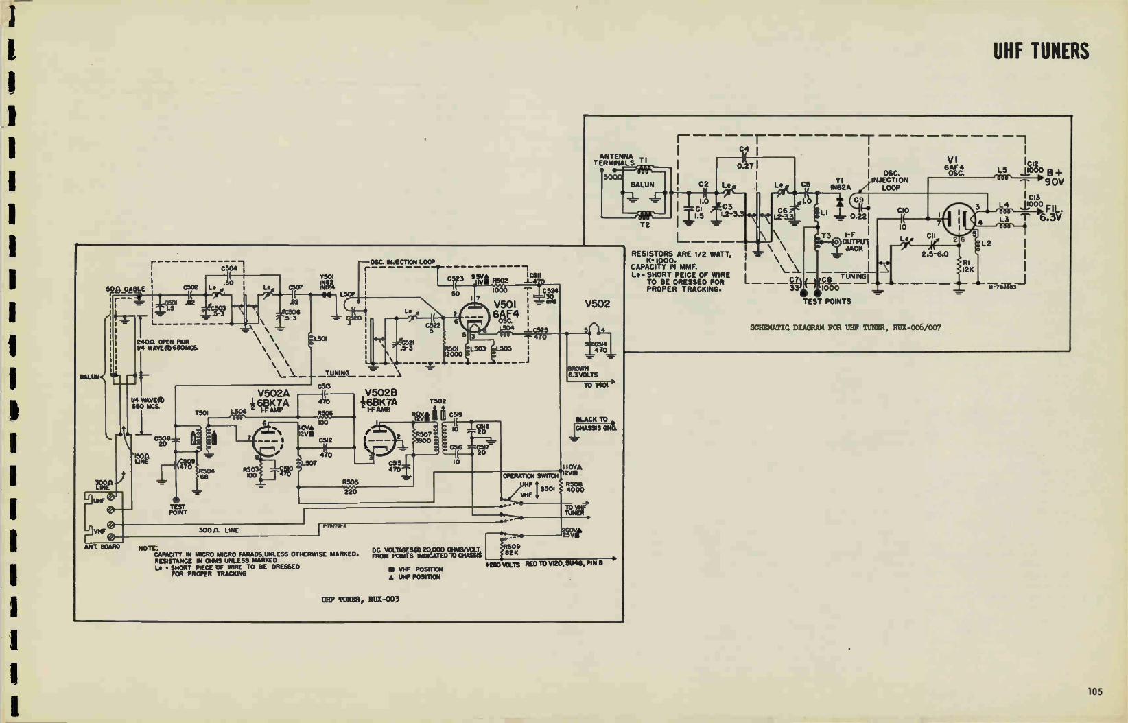
UHF TUNERS
-r C4
ANTENNA TERMINALS T I
5011. CABLE r— r :
1
15011 LINE
LINE
UHF
Ir 0--
ANT. BOARD
C502
IC501 .182 M1.5
L.
24011 OPEN PAIR 14 WAVE 680 MCS.
1/4 WAVEZ 680 MCS.
C508 20
C504
.30 1 e
C503 .5-3
C507 Y501 1N82 INI24
.82
506 .5- 3
TEST POINT
T501
V5024 16BK7A
L506 2 I-F AMP cos-,
R504 68
6
B
L501
---OSC. INJECTION LOOP
L502
C520 .1
TUNING
C5I3 V502B
470 i6BK7A I-F AMP
Le
C521 .5-3
R506 te---ww--te
100 110VA 2V1
C5I2
470 0 L507
R503 C510 00 ."
T 47° f 1 R505
'NAM. 220
C523
C522 5
9 sv• Iva R502 we% 1000 r C524 1 7
V501 60AsFc.4
10511 _1_ A
4 L504 _l_C525 5 3 —r- 4 0
R501 gL503' .L505 12000 .
T502
C5t9
_T_C518 20
C5/6 .4.7-0517 20
10
30011. LINE
V502
_1_470 -.-
BROMWN 6.3 VOLTS
TO T401
BLACK TO 111£91315 GNU
1 I OVA OPERATION SWITCH 12V111
UHF/ S501 4000
R508
• <1" "
• **-
r • II ft er •
NOTE CAPACITY IN MICRO MICRO FARADS.UNLESS OTHERWISE MARKED. RESISTANCE IN OHMS UNLESS MARKED Le - SHORT PIECE OF WIRE TO BE DRESSED
FOR PROPER TRACKING
DC VOLTAGES 20,000 OHMSNOLT, FROM POINTS INDICATED TO CHASSIS
• VHF POSITION A UHF POSITION
UHF TUNER, RUX-003
82K
TO VHF. TUNER •
e 5VVIllt
+260 mays FtED TO VI20, 5U4G, PIN 8
T2
C2
L \ \ \
RESISTORS ARE 1/2 WATT, — K• 1000. \ \
CAPACITY IN MMF. I Le • SHORT PEICE OF WIRE
TO BE DRESSED FOR L ___ D PROPER TRACKING-
5 Y I
IN82A LOOP
C9 1
cio 0.221
T3 I-F OUTPUI JACK ;
—C8 T UNING 1
107)0—
TEST POINTS
1 OSC. INJECTION
VI 6AF4 OSC. L5
I 0 7 4
CII 5 Le 26
2.5-6.0 RI I2K
"=" •=.
SCHEMATIC DIAGRAM FOR UHF TUNER, RUC-006/007
L 2
L 4
L 3
1.1 -78J1303
I Cl2
B + 90V
CI3
1000 FIL. T 6.3V
105
6

PRODUCTION CHANGES
106
PRODUCTION CHANGES MODEL 801
In most cases the change can not be accurately identified
with the serial number of the chassis. The order of listing
below does not indicate the chronological order of the
change.
1. POWER TRANSFORMER, T14 ond V23-The original
transformer, T14, supplied, gave insufficient B plus voltage
(385 volts) when using a Type 5Y3GT rectifier tube, V23.
This resulted in a low anode voltage of 7500 volts for the
picture tube. To increase this voltage, a Type 5V4G tube
was substituted for the 5Y3G tube, V23. At approximately
serial number 2500, a new transformer T14 having Stock
No. RTP-040 was substituted, which gave the correct B
plus voltage of 415 volts when a Type 5Y3G tube was used
as V23. This B plus voltage gives an anode voltage to the
picture tube of 8500 volts.
2. TELEVISION TUNING TRIMMER C112-For approximately
the first 2000 receivers, the tuning trimmer C112 did not
quite have the correct tuning range, making it necessary to
add a fixed 10 mmf. capacitor C114 in series with it. The
shunt capacitor C102 hod a value of 4.7 rnmf. Later pro-
duction trimmer, C114, has the correct range. With this new
value of trimmer, the shunt capacitor C112 was changed to
6.0 mmf. This shunt capacitor in a few receivers was
merely a 5.0 mmf., while in most it will consist of two
capacitors; a 5 rnmf. and a 1.0 mmf. capacitor in parallel.
The early production trimmer has a 1/4 inch 0.0. shaft,
while the late production trimmer is slightly larger and has
a 3,16 inch 0.0. shaft.
3. TONE CONTROL, R69B-The tone control R69B, on early
production receivers was connected in series between the
Volume Control R69A, movable arm, and C39. C72 was a
680 waif, capacitor from C39 to ground. Hum in the audio
dependent upon the tone control setting necessitated a re-
vision as shown in the schematic.
4. TUNED CIRCUIT, L20 and C89-The capacitor, C89,
was originally 240 mmf, and the coil, L20, was fixed-tuned
and wound on a resistor form. This was later changed to
1000 mmf. ond the coil turns were reduced and made var-
iable, resulting in a high Q circuit. This change permitted
adjustment of the trap.
5. RESISTOR, R87-This resistor was changed from 100,000
ohms to 330,000 ohms to prevent excessive beam current in
the picture tube, V8. This excessive beam current caused
the high voltage to be reduced when the Brillionce control
was advanced to maximum with the result that the control
reduced brightness at end of its clockwise travel instead
of increasing brightness.
6. RESISTOR, R47-This resistor has been changed from
Si watt to a 1 watt size. In some cases, the original /4 watt
resistor dissipation is exceeded, especially if the Width
control iron core is nearly all the way in the coil, resulting
in a reduction in the resistance value. This reduced resis-
tance changes the waveshope across C29 so much that the
horizontal multivibrator may lock in at half frequency or not
lock at all. It may also result in the resistor burning out.
7. CHANGE IN HORIZONTAL OUTPUT TRANSFORMER,
79-A new design horizontal output transformer, T9, was used
in late production receivers. This may be identified by the
fact that it has two windings instead of the single winding
design, as characterized the early production receivers.
When the late production transformer is used, a 3900-ohm,
1-watt resistor must be added in series to the existing 6800
ohm, 1-watt resistor, R47. Do not use o single 1-watt resis-
tor for this. The capacitor, C66, should be returned to
ground when the new type transformer is used.
8. HORIZONTAL MULTIVIBRATOR CATHODE SWITCHING
After the first 150 receivers were built, a shorting contact
was added to the filament wafer of the Station Selector
switch so as to stop the horizontal multivibrator os soon as
the Station Selector was switched to "Rodeo" position.
This connects the multivibrator cathode to ground through
the filament circuit when switching to "Radio" so that
"birdies" are not heard on the broadcast band as the tele-
vision tubes cool off after switching from television to
radio reception.
9. SCREEN RESISTOR, R79-This resistor was changed
from on original 47,000 ohms to 33,000 ohms. This reduces
the operating DC voltage on the plate of V7, and gives
greater brightness.
10. ADDITION OF C21-A fixed 10 minf, mico capacitor, C21,
was added across C10 so that the trimmer C10 would peak
at the center of its range.
11. CHANGE IN R63-The 330,000 ohm resistor, R63, was
changed to 220,000 ohms so that the Vertical Hold control
will operate near its mid-adjustment position.
12. REMOVED OF R95-To correct a transient which appear-
ed in the vertical retrace as a white line at the top of the
picture, the 2200 ohm resistor, R95, in series with capa-
citor, C37, was removed. The potentiometer, R58, was re-
connected as o variable resistance as shown on the sche-
matic.
13. VALUE CHANGE OF C52-The original capacity of C52
was 47 mmf. To improve vertical interlace, this capacitor
was changed to 240 mmf.
14. ADDITION OF TUNED CIRCUIT, L21 and C91-A 15.75
kc tuned circuit was added to the cathode of the horizontal
multivibrator, VII. This stabilizes the horizontal AFC
circuit to the extent that it prevents picture wiggles on
noise pulses and echoes. With this addition, the 240 minfd.
capacitor. C56, should be changed to 150 mmf. and the
150,000 ohm resistor, R40, should be increased to 330,000
ohms. This prevents a white line at the left-center of the
picture which may result with installation of L21-C91.
With addition of L21, the capacitor, C30, was changed from
a 40 mfd to a 1.0 mfd, and C92 was changed from 1.0 mfd to
a .05 mfd.
15. CONNECTION OF PRIMARY OF T11-On early product-
ion receivers the primary of T11 was connected to a mid-top
on choke Lb. This connection caused a resonant condition
to develop whcih affected the lower television bands. This
was corrected temporarily by shunting a 47 mmf. capacitor
between the midtap of L10 and ground. Later the primary of
TI1 was connected to the ¡unction of L10 and C101 as
shown on the schematic.
PRODUCTION CHANGES MODELS 805, 8C/,
£07 AND 809
(Early, T, S. U and W Versions)
1) CHASSIS MARKINGS: As production of these models
proceeded, major production changes were identified by
stamping a large letter on the chassis front apron. These
letters are "T", "S", "U", or "W".
"T" VERSION: Change from a molded type horizontal out-
put transformer T311 to a ceramic iron core type transformer
T312. (See production change No. 9).
"S" VERSION: In addition to the "T" change a larger
picture opening was incorporated into the cabinets. Chas-
sis are marked "S". (See production change No. 16).
"U" VERSION: This change changed to a new Horizontal
Automatic Frequency control and Automatic Gain control
circuits. "U" also incorporates the "T" version changes.
"W" VERSION: This letter "W" is used to identify the
change from a 6AU6 second RF amplifier (V2) to a 6AG5
second RF amplifier (V2). (See production change No. 15).
"T", "U", and "S" versions changes are also included in
"W" version.
Note chassis marked BCF in addition to "U" or "W" hove
the broadcast filter added in the antenna circuit os des-
cribed in Production Change No. 10.
2) FOLD-OVER ON "T" VERSION RECEIVERS: On "T"
versions of these receivers, fold-over at the left edge of the
picture when the horizontal hold control is set for best
synchronization has been corrected in late production "T"
versions by the following:
(a).Change R334 from 220K, to 560K, )4 watt resistor, Cat.
No. URD -115.
(b) Connect a 12 mmf., 880 v., mica capacitor, C336, from
the junction of R334 and C330 to B Cat. No. RCU-286.
(c) Disconnect R315 from 277 volt, B plus, and reconnect to
the B plus boost voltage at the ¡unction of C322 and L315.
(d) Change C315 from 68 mmf. to 220 mmf., mica, Cat. No.
UCU-1036.
3) AUDIO INSTABILITY (IN EARLY "T" VERSION RE-
CEIVERS): This appeared as tweets when operating the
focus control at maximum clockwise rotation and has been
cured in late production by reconnection of the 25L6GT
(V19) screen by-pass capacitor, C367. On "T" version
receivers, C367, ground connection was removed from the
B — bus and connected to the junction of R352, R353, and
5341.
(4) TO IMPROVE THE VERTICAL LINEARITY: R299 has
been changed from 3K to 2.2K, 1 w. resistor. This change
also centers the operation of the vertical linearity control.
(5) HORIZONTAL LINEARITY "T" VERSION MODELS:
A transient oscillation which appears os wiggles on vertical
running lines at the top one-half inch of the picture may be
removed by shunting C324 (0.47 mfd.) with o 1200 ohm, )4w.,
carbon resistor (R339). C324 is the capacitor in series with
the horizontal deflection coils.
(6) IMPROVEMENT IN VERTICAL SYNC-EARLY AND
"T" VERSIONS CHASSIS: To improve vertical synchroniza-
tion under noisy conditions such as encountered in "fringe"
areas, the following changes have been mode in production:
(a) Short C265 with a bus wire.
(b) Remove V8-A grid resistor, R274 (2.2 meg.).
(c) Change value of R280 in plate circuit of V8-A from 8200
ohms to 39,000 ohms, Sive., carbon resistor, Cat. No. URD-
087.
(d) Change value of C314 (couples V11-A to V11-B) from
5000 mmf to 1000 mmf., mico, Cat. No. UCU-052.
(e) Change the value of R311 (in grid of V11-B) from its
2.2 meg to 470,000 ohms, )4w., carbon URD-113. R311
should be reconnected between pin 1 and pin 3 of V11-B.
(f) Change value of C293 (grid of VIO-A) from .001 mfd.
to a 150 mmf. mica capacitor, Cat. No. UCU-I532.
(7) TO IMPROVE THE RF STABILITY WHEN OPERATING
ON CHANNEL NO. 2 IN WEAK SIGNAL AREAS: The fol-
lowing changes have been made in late prreivction. When
operating on Channel No. 2 with the contrast control near
maximum clockwise, the picture may become streaked or
blacked out entirely, due to regeneration. This may be cor-
rected as follows:
(a) Replace or short out L206 with a piece of bus wire No.
20 or larger.
(b) At the rear of C213, the tuning capacitor is a terminal
board mounted on the head-end unit. From the ground lug of
this terminal board, connect a 5000 mmf. capacitor, C208,
Cat. No. RCW-3014, to the main chassis. This main chas-
sis ground may be mode by adding a ground lug under the
self-tapping screw which holds the vertical sweep output
transformer.
(8) IMPROVED STABILITY OF HORIZONTAL SWEEP
GENERATOR IN EARLY AND "T" VERSION RECEIVERS
A tuned circuit, L316, Cot, No. RLD-014, and capacitor
C329, Cat. No. UCU-2568, is tuned to 15,750 cycles and
will stabilize the blocking oscillator to reduce the effects
of noise on sync.
For adjustment, see installation control adjustments, fly-
wheel circuit.
L316 and C321 ore added in the B plus supply of V21B as
shown in schematics for "Early" and "T" versions.
L316 is mounted at the rear of the chassis at the left-hand
side, as shown below.
(A) Special U and W Controls
(9) NEW TYPE TRANSFORMER ("T" VERSION): in lote
production Model 805, 806, 807 and 809's, a new type horiz-
ontal sweep output transformer was employed. The new
transformer uses a ceramic iron core. All receivers using
this core will be identified by a large "T" ink-stomped on
the chassis front apron. Receivers ink-stamped "U" "S"
or "W" on the chassis front apron have this new transformer
and other new developments incorporated, as explained
below.
On early production receivers, u 25Z6GT damper tube was
used. Because of the higher peak inverse voltage of this
new transformer, it is necessary to use a 25W4GT damper
tube which has a higher peak inverse voltage rating.
(10) BROADCAST INTERFERENCE: To eliminate inter-
ference from strong broadcast signals, which appear as RF
interference in the picture, choke L259 was removed and
B — bus was connected to B — bus directly with a short
piece of bus wire. A broadcast filter has been added in the
antenna input circuit, and is connected as shown on the
schematic diagram for "U" and "W" versions.
(II) NEW HORIZONTAL AUTOMATIC FREQUENCY CON-
TROL CIRCUIT AND AUTOMATIC GAIN CONTROL CIR-
CUIT ("U" AND "W" VERSIONS): Chassis incorporating
this change can be identified by the large "U" or "W"
Ink-stamped on the chassis front apron. (See schematic).
(12) VOLTAGE DOUBLER CHANGE: "Early" production
receivers used a full-wave voltage doubler type of trans-
forrnerless power supply. This is shown in schematic.
"T" versions and "U" and "W" versions were changed to
a half wave voltage doubler type of circuit shown in sche-
matic diagrams.
(13) SHIPMENT WITH PICTURE TUBE INSTALLED: Late
production receivers were shipped from the factory with
the picture tube installed. Another picture tube mounting
strap was added on these models to secure the picture tube.
Though this extra strop does not have to be removed when
the receiver is installed, it is not necessary to replace it
when the picture tube has been removed or replaced, un-
less the receiver is to be reshipped.
(14) LOW SENSITIVITY, EARLY PRODUCTION: A few
early production models were built with the plate of V6

PRODUCTION CHANGES (3rd video IF) amplifier connected to B plus supply through
a 10K resistor, R278, or to B plus supply through R278
and choke L248 in parallel
To improve the sensitivity of these models, R278 should
be removed and pin 5 of V6 should be connected to the
¡unction of R253, C253, and R252 through choke L248.
Catalog number for L248 is RLF-027.
(15) SECOND RF AMPLIFIER ("W" VERSION): Early
production chassis used a 6AU6 second RF amplifier V2.
This tube was replaced by a 6AG5 tube in later production.
Connections for V2, 6AU6, "U" versions are the same as
connections for V2, 6AU6 of "T" versions, on schematic.
Chassis with (V2) second RF amplifier 6AG5 are stamped
"W".
(16) CHANGE TO LARGER PICTURE ("S" VERSION):
Models 806 and 809 stamped with a large S on the chassis
front apron indicate a cabinet change from a picture size
815" wide, by 6 3/8", to a picture size of 9W' by 7)4"•
Model 807 changed to 9)5" x 7)5" picture opening at the
same time the "W" changes were incorporated. The left
and right sides of the new large picture are now arcs of a
circle 9)5" in diameter.
(17) FLUTTER ON STRONG SIGNALS "U" AND "W"
VERSIONS: intermittent flutter (similar to low frequency
airplane flutter) of picture brilliance on "U" and "W" ver-
sions, in very strong signal oreas, which requires the con-
trast control be set at minimum, has been corrected in
production as follows:
Change C255 from o .05 mfd. capacitor to a .5 mfd. capa-
citor, 200 v., Cat. No. RCC-016. This capacitor is in the
automatic gain control circuit.
Change R280 plate dropping resistor of V8A from 39,000
ohms to 18,000 ohms, h watt, Cot. No. URD-079.
(18) LINEARITY CONTROL ("U" VERSION): "U" version
chassis were built with the potentiometer R402 acting as
both linearity and drive control. L315 linearity control was
removed and the junction of T312 terminal one and R303
was connected directly to the junction of C4I2, R303 and
pin 3 of V15. Capacitor C335 was removed.
On "W" versions, L3I5 and C325 were added to give better
linearity control and are connected as shown in schematic.
PRODUCTION CHANGES MODEL 810
1. TUNING DRIVE: The early production rubber bushing on
the tuning shaft used to drive the tuning condenser caused
some slipping and backlash. This has been replaced by a
new rubber bushing, Stock No. RMW-054, to correct the
trouble. The early production bushing hod Stock No. RMW-
046.
2. HI-VOLTAGE FAILURE: Failure of insulator posts used
for mounting the 8016 1B3GT tube socket was caused by
corona leakage and eventually caused falling off of the
high anode voltage. These early production posts were
textolite Stock No. RII-014. These should be replaced by
ceramic posts, Stock No. RII-017.
3. CONTRAST CONTROL TOO CRITICAL: In strong signal
strength areas, it required adjustment at o critical point of
the contrast control taper. This was corrected by changing
the voltage applied across the contrast control os follows:
Change R74 to a 82,000 ohm resistor, R50 was one resistor
of 120,000 ohms, this now becomes two resistors of R50
82,000 ohms and R108 33,000 ohms with the bias for the
contrast control taken off at the junction of these two re-
sistors. See schematic.
4. ADDITION OF RECTIFIER TO OSCILLATOR FILAMENT:
When the filament of the Type 12AT7 oscillator tube section
was operated on 6.3 volts AC, hum modulation was intro-
duced which become objectinnable in some cases on the
high channels. This was eliminated by operating the fila-
ment of V2A on DC, which was provided by rectifying the
filament voltage by a full-wave selenium rectifier, SRI
(GE Cat. No. RER-003) and filtering the output by a 2000
mfd. capacitor, C102 (GE Cat. No. RCE-083). The choke L6
(GE Cat. No. RLI-005) and capacitor C101 (GE Cat. No.
RCW-3014) were added to eliminate the possibility of any
regeneration at the RF frequencies being introduced by this
filament lead.
5. DRIFT OF HORIZONTAL HOLD ADJUSTMENT: The
very early production receivers showed a tendency to worm
up drift in reference to the Horizontal Hold Control. This
condition was corrected by the following component changes:
(1) Removed R53 (10,000 ohms) resistor from across plate
winding of T16. This requires removal of shield can on
T16.
(2) Remove C46 (120 mmfd) which is in parallel with C49.
(3) Replace R50 (270,000 ohms) with two resistors in series.
One resistor is R50 82,000 ohms from trimmer C49 to ¡unc-
tion. Another resistor is R108 33,000 ohms and will go
from ¡unction to ground. R74 (see 7) will come off junction.
(4) Change R52 (100,000 ohms) to 47,000 ohms.
(5) Change R51 from 3.3 megohm, h watt rating, to same
value 1 watt rating and mount resistor on full length leads
so as to have resistor body hang vertically as far down
away from chassis as possible. Mounting of this resistor is
very important.
(6) Change R48 (560,000 ohms) to 1 rnegohm; All of the
above mentioned resistors are critical as to temperature
coefficient and should be ordered from General Electric re-
placement stock.
(7) Change R74 (470,000 ohms) to 82,000 ohms.
(8) Change R44 from 82,000 ohms, hw., to 2 watt rating.
(9) Change R45 to 100,000 ohms, 1 watt (Cat. No. URE-097),
and reconnect R45 to high B plus (360v.) as shown on
schematic.
(10) Change R47 to 24,000 ohms, h watt (Cat. No. URD-
1082). After these changes are incorporated, it will be
necessary to reset the horizontal blocking oscillator fre-
quency. Following is the procedure:
a. Connect a VTVM to measure the voltage from the ¡unction
of R74 and potentiometer R73 to ground.
b. Tune the receiver to any suitable television signal.
c. Set the front panel Horizontal Hold Control R46 to the
approximate mm-point of its resistance range. Then adjust
the iron core of the blocking oscillator ri,i1 T16 and the set-
ting of the horizontal frequency control trimmer C49 to
bring the picture into horizontal sync and to develop approx.
-12 volts across the contrast control as measured on the
VTVM. The iron core adjustment and the trimmer setting
are interlocking and, therefore, it is necessary to adjust
each of these controls in turn to bring the picture in sync
and also obtain - 12 volts.
d. At the completion of the above adjustments the range of
the front panel horizontal hold control should be checked.
The sync range should fall in the approximate center of the
control and it should be possible to throw the circuit out of
sync by turning the control to either end of its range. Re-
ceivers having the above changes made con be identified by
noting that red glyptal cement has been applied on one of
the nuts holding the shield can of T16.
6. VIDEO "TWEET" RESPONSE ON CHANNEL No. 7: A
cross-hatch pattern on Channel No. 7 set up by local radia-
tion from the 8th harmonic of the 21.9 mc (early production)
sound is cured as follows:
(1) Change ground connection of C4I (.01 mfd.) from pin
No. 1 of V6 socket to the ground terminal on the adjacent
terminal board.
(2) Add copper ground strap to pin No. 5 of V18 socket with
chassis ground as close to socket pin as possible.
(3) Change ground connection of C69 (5000 inmf.) from pin
No. 1 of V18 socket to pin No. 5 of some socket.
(4) Change value of R78 (56,000 ohms) to 150,000 ohms.
7. CHANGE IN 2ND AND 3RD VIDEO IF TRANSFORMER:
The plate winding of the video IF transformers, T12 and
T13, has been increased in inductance to compensate for o
recent lowering in the plate capacity of the Type 6AU6 tube.
In early production receivers where the plate winding in-
ductance is low, if a low capacity 6AU6 tube is substituted,
the 26.3 mc marker will ride up too far on the selectivity
curve. This condition can usually be corrected without
changing the IF transformer by pushing the plate lead in
this winding close to the coil form so as to increase the
distributed capacity and thus compensate for the tube ca-
pacity. In the lote production receivers with the higher in-
ductance IF transformers, if a high capacity Type 6AU6
tube is used, it may be necessary to spread turns on the
plate side of the transformer to affect proper tuning.
8. V2A OSCILLATOR DRIFT: The tube socket for tube V2
originally specified tube socket Stock No. RJS-I20. This
should be changed to read Stock No. RJS-127. This change
in socket composition reduces warm-up drift considerably.
9. VIDEO AND SYNC AMPLIFIER LIMITING: On some re-
ceivers it was not possible to drive the picture tube to full
contrast before the sync pulse would be limited with a re-
sultant loss in vertical and horizontal sync. This was cor-
rected in production by the following changes:
(1) Change R21 to 5600 ohms, )5 watt.
(2) Add resistor RI09, 1000 ohms, h watt, between Pins 6
and 7 of VII after removing the bus wire connecting these
pins.
10. VERTICAL HOLD CONTROL RANGE: To give better
vertical hold control range and sync, the following changes
were made in production.
(1) Remove R38 and connect R37 to Pin 2 of VII as shown
in the schematic.
(2) Change C39 to a .05 mf. 400 volt capacitor.
(3) Change C40 to a .001 mf., 400 volt capacitor, and con-
nect between ¡unction of C37 and R36, and Pin 1 of V9.
(4) Change C37 and C38 to .01 mf., 400 volt capacitors.
These were originally .01 mf., 200 volt capacitors.
(5) Disconnect the B plus from Pin 2 of VII. Connect a re-
sistor R111, 1600 ohms, Y2 watt, from pin 2 of VII to pin 4
of V10, as shown in the schematic.
(6) Remove Capacitor C41, .01 mf., 200 volt, from ¡unction
of R28 and R29. Connect a capacitor C41, .001 mf., 400
volts, from pin 4 of V9 to ground.
(7) Change Resistor R28 to 82,000 ohms, h watt.
(8) Change C30 to a .002 mf., 600 volt capacitor.
(9) Change C31 to a .062 mf., 600 volt capacitor. When these
changes ore mode, it is necessary to check the vertical
hold control to see whether it is possible to go through the
60 cycle speed. This 60 cycle speed setting should be at
least 70 degrees from either end of the control. If the 60
cycle point is closer than 70 degrees from the CCW end of
the control, or if the 60 cycle point cannot be reached at the
CCW end of the control, a resistor, R110, 24,000 ohms, )5
watt, should be inserted between R28 and R29 and the con-
trol rechecked. It should always be possible to pull the
multivibrator out of sync at the maximum CW end of the
control, but it may not always be possible to pull it out of
sync at the CCW end of the control.
II. BLOOM: This is caused by a difference in modulation
level of the television signal, such as is encountered when
switching from one television camera to another. This has
been corrected in the Model 810 receiver by the following
changes:
(1) Connect o 270,000 ohm, h watt, resistor, R112, between
the yellow lead connected to pin 11 of the picture tube and
the center top of the brightness control, R95.
(2) Connect a .1 mf. capacitor, 600 volts (C102) between
yellow lead connected to pin 11 of picture tube and the
¡unction of R95 and the red B plus line.
12. AUDIO IF FREQUENCY CHANGE TO 21.8 MC: All
Model 810 receivers marked with II in a circle in green ink
on the chassis and on the carton, and subsequent Model 810
receivers will be aligned to 21.8 mc. This measure was
taken to eliminate the video interference of o strong Wash-
ington, D.C. FM station operating at 93.9 mc beating with
the Channel No. 4 video carrier (67.25 mc), and forming an
IF frequency which showed on the screen as o herringbone
pattern.
PRODUCTION CHANGES MODELS 817 & 821
("T", "S", "U" & "W" VERSIONS)
NOTE: The circuit of the receiver passed through various
stages and in order to easily identify the circuit contained
in an individual chassis, it was marked with a letter ac-
cording to the following designations:
"T" - Early production
"S" - "T" version plus large picture frame.
"U" - "T" version plus incorporation of a new efficient
AFC circuit and AGC.
"W" - "U" version plus replacement of 2nd RF amplifier
tube 6AU6 by a 6AG5 tube.
1) FOLD-OVER ON "T" VERSION RECEIVERS: On "T"
versions of these receivers, fold-over at the left edge of the
picture when the horizontal hold control is set for best
synchronization has been corrected in late production "T"
versions by the following:
a) Change R334 from 220K, to 560K, h watt resistor, Cot.
No. URD-115.
b) Connect o 12 mmf. 880 v., mica capacitor, C336, from
the junction of R334 and C330 to B-, Cot. No. RCU-286.
c) Disconnect R315 from 277 volt, B plus, and reconnect to
the B plus boost voltage at the junction of C322 and L315.
d) Change C315 from 68 mmf. to 220 rnmf., mica, Cat. No.
UCU-1036. 2) TO IMPROVE THE VERTICAL LINEARITY: R299 has
been changed from 3K to 2.2K, 1w. resistor. This change
also centers the operation of the vertical linearity control.
3) HORIZONTAL LINEARITY "T" VERSION MODELS: A
transient oscillation which appears as wiggles on vertical
running lines at the top one-half inch of the picture may be
removed by shunting C324 (0.47 mfd.) with a 1200 ohm, hw.,
carbon resistor (R339). C324 is the capacitor in series with
the horizontal deflection coils.
4) IMPROVEMENT IN VERTICAL SYNC - "T" VERSION
CHASSIS: To improve vertical synchronization under noisy
conditions such as encountered in "fringe" areas, the fol-
lowing changes hove been made in production:
a) Short C265 with a bus wire.
b) Remove V8-A grid resistor, R274 (2.2 rneg.).
c) Change value of R280 in plate circuit of V8-A from 8200
ohms to 39,000 ohms, hw., carbon resistor, Cat. No.
URD-087.
d) Change value of C3I4 (couples V11-A to V11-B) from
5000 mmf. to 270 mmf. mica, Cot. No. UCU-052.
e) Change the value of R311 (in grid of V11-B) from its
2.2 me g. to 470,000 ohms, hm, carbon URD-I13. R311
should be reconnected between pin 1 and pin 3 of V11-B.
f) Change value of C293 (grid of VIO-A) from .001 mfd.
to a 150 mmf. mico capacitor, Cat. No. UCU-1532.
5) TO IMPROVE THE RF STABILITY WHEN OPERATING
ON CHANNEL NO. 2 IN WEAK SIGNAL AREAS: The fol-
lowing changes have been mode in lote production. When
operating on Channel No. 2 with the contrast control near
maximum clockwise, the picture may become streaked or
blacked out entirely, due to regeneration. This may be cor-
rected as follows:
a) Replace or short out L206 with a piece of bus wire No.
20 or larger.
b) At the rear of C213, the tuning capacitor is a terminal
board mounted on the head-end unit. From the ground lug
of this terminal board, connect a 5000 mmf. capacitor, C208,
Cat. No. RCW-30I4, to the isoin chassis. This main chassis
ground may be made by adding a ground lug under the self-
107

PRODUCTION CHANGES
108
tapping screw which holds the vertical sweep output trans-
former.
6) IMPROVED STABILITY OF HORIZONTAL SWEEP GEN-
ERATOR "T" VERSION RECEIVERS: A tuned circuit,
consisting of L316, Cat. No. RLD-014, and capacitor C329,
Cat No. UCU-2568, is connected in series with the B plus
return of the blocking oscillator transformer, L313, and is
tuned to 15,750 cycles. This will stabilize the blocking
oscillator to reduce the effects of noise on sync.
8) BROADCAST INTERFERENCE: To eliminate interfer-
ence from strong broadcast signals which appear as RF
interference in the picture choke L259 was removed and
B -- bus was connected to B — bus directly with a short
piece of bus wire. A broadcast filter has been added in the
antenna input circuit (RLX-027), and is connected as
shown on the schematic diagram.
9) NEW HORIZONTAL AUTOMATIC FREQUENCY CON-
TROL CIRCUIT AND ATUOMATIC GAIN CONTROL CIR-
CUIT: Chassis incorporating this change can be identified
by the large "U" ink-stamped on the chassis front apron.
10) SHIPMENT WITH PICTURE TUBE INSTALLED: Late
production receivers were shipped from the factory with
the picture tube installed. Two blocks were added on these
models to secure the picture tube. Though these blocks do
not have to be removed when the receiver is installed, it is
not necessary to replace them when the picture tube has
been removed or replaced, unless the receiver is to be
reshipped.
11) SECOND RF AMPLIFIER ("U" VERSION): A few
early production "U" version chassis used a 6AU6 second
RF amplifier V2. This tube was replaced by a 6AG5 tube
in later production. Connections for V2, 6AU6, early
production "U" versions, are the some as connections for
V2, 6AU6 of "T" version, as shown on schematic diagram
for "T" version.
12) PICTURE CENTERING: Receivers using the large
size mask might encounter centering difficulties. The
picture cannot be centered to the right sufficiently far
without neck shadowing. To remedy this condition, the
following circuit change is suggested which will pass
sufficient DC current through the horizontal deflection
coils to move the picture about one inch to the right.
Disconnect the end of resistor R268 (at plate of V8-B) that
ties to B plus and then reconnect it to the junction of C324
and the horizontal deflection coil. This coil is placed
within the current path from B plus to the resistor R268
and the addition of this DC current helps to correct the
centering defect.
13) PICTURE TUBE SHIPPING HARNESS, MODEL 817:
The pix tube is pressed against the mask by means of a
cable harness. This is made of stainless steel and may
become magnetized sufficiently so as to affect the picture
by shifting or distorting it. In order to prevent this un-
desired effect, it is recommended that this cable harness
be removed and discarded at the time that the receiver is
installed.
14) SWIVEL FOCUS COIL, MODEL 821: A new deflection
yoke and focus coil assembly is incorporated in the "U"
and "W" versions of this receiver. The focus coil is fasten-
ed to a bracket which can be moved in any direction with
respect to the neck of the picture tube. This permits more
flexibility in centering and focusing the picture.
15) FLUTTER ON STRONG SIGNALS ("U" & "W" VER-
SIONS): Intermittent flutter (similar to low frequency air-
plane flutter) of picture brilliance on "U" and "W" ver-
sions, in very strong signal areas, which requires the con-
trast control be set at minimum, has been corrected in
production as follows:
Change C255 from o.05 mfd. capacitor to a .5 mfd, capacitor,
200 v., Cat. No. RCC-016. This capacitor is in the auto-
matic gain control circuit.
Change R280 plate dropping resistor of V8A from 39,000
ohms to 18,000 ohms, )4 watt, Cat. No. URD-079.
PRODUCTION CHANGES MODEL 820
I. AUDIO IF REGENERATION: Audio regeneration which
causes a click in the speaker as the tuning control is tuned
through the station can be eliminated by the use of a 5000
ininf capacitor, RCW-30I4, across the audio IF B plus
lead. This capacitor is connected between the B plus and
ground terminals at the terminal board located between the
limiter tube socket, V18, and the discriminator transformer,
T 19.
2. AUTOMATIC GAIN CONTROL (ACC): This circuit is
used to make for greater ease in operation, os it eliminates
to a large extent the necessity of changing the Contrast
control each time that a stronger or weaker station is
selected. It always produces a picture even in the extreme
minimum setting and does not tend to overload on strong
signals when in the maximum contrast position.
Chassis using AGC will be identified by the letter "R"
stamped in ink, located on the chassis front apron and ad-
jacent to the Contrast-Brightness control shaft.
AGC DIAGRAM (R - CHASSIS)
3. AUDIO FREQUENCY RESPONSE: In order to extend the
high frequency audio response and to reduce some of the
"boom" base compensation, the following components
should be removed:
C87, .01 mfd. paper capacitor (Cat. No. UCC-630).
C114, 1000 mmf. mica capacitor (Cat. No. UCU-052).
R96, 82,000 ohm resistor (Cat. No URD-095).
4. REMOVAL OF RETRACE LINES: This circuit is used
to eliminate the need for readjustment of the Brightness or
Contrast control to remove retrace lines from the background
of the picture when o change in cameras or program material
takes place at the transmitter The circuit is shown below
715
RI18 27K
GREEN
VERTICAL SWEEP OUTPUT
BLACK
C85
BRTGHTNESS CONTROL
BRIGHTNESS CONTROL CIRCUIT
S. NEW HORIZONTAL SWEEP OUTPUT TRANSFORMER:
In late production receivers the Horizontal Sweep Output
Transformer was changed from the molded coil and lamin-
ated iron core type to an open coil and ceramic iron type
core. In this new type the danger of insulation breakdown
is greatly reduced. The non-metallic core is composed of
iron oxides embedded in a ceramic base. The core losses
at the comparatively high scanning frequency of 15,750 cps
are very low because the magnetic energy absorbed by the
iron core is extremely small. The high voltage tertiary
winding is wound over the primary and secondary winding,
increasing its distance to the core, and further minimizes
the probability of insulation breakdown and corona effects.
All receivers incorporating this new transformer will hove
a letter "T" stamped on the front apron of the chassis..
This letter supersedes the "R" stomping (see paragraph
No. 2).
6.' DRESS OF PICTURE TUBE ANODE LEAD: The hi-
voltage lead connecting between the picture tube anode
and the 1B3GT rectifier tube should not touch the a quodag
coating of the picture tube. This tube should be so orient-
ed that it does not pull this lead taut. In order to avoid
any corona, this hi-voltage lead should be dressed away as
far as possible from any surrounding object.
PRODUCTION CHANGES MODEL 830
CHASSIS IDENTIFICATION: To identify the receiver chas-
sis incorporating major modifications in production, the
chassis are identified by a letter stamped upon the front
chassis apron adjacent to the Contrast Control shaft. The
following identifications are given with respective mod-
ification and schematic diagram reference.
Chassis Stamp Modification
No marking None (early production)
"T"
Automatic Gain Control added
AGC plus improved Horizontal
Sweep Transformer and circuit
AUTOMATIC GAIN CONTROL
Automatic Gain Control is incorporated in the most part of
the Model 830 production except for an approximate 1000
early production units.
The AGC voltage is derived from the diode detector and
clipper grid circuit. By connecting the contrast control
into the clipper grid circuit, it provides a source of high
bias voltage which varies directly with the amplitude of
the video carrier. The other end of the contrast control
connects to the video detector load resistor to provide a
lower potential bias source with the same characteristic so
that it will provide for a minimum AGC bias when operating
at weak signal strengths.
AGC provides for greater ease in tuning, as it eliminates
to a large extent the necessity of resetting the contrast
control each time a new station is selected. It minimizes air-
plane flutter and other signal strength changes which would
otherwise affect the picture. BIAS RESISTOR R8, OF V5—
On some "R" chassis receivers, the bias resistor R8 was
1000 ohms. This was decreased to 100 ohms to increase
receiver sensitivity.
HORIZONTAL SWEEP OUTPUT CIRCUIT
The use of a new and improved sweep output transformer
and assiocated circuit was introduced after the "R" chas-
sis production change. All ports with the value indicated
below are common to the "T" chassis only.
This new transformer is an open coil type assembly with a
ceramic iron core, in contrast to the earlier type molded
coil assembly with laminated core used in the early and
"R" production chassis. The high voltage tertiary winding
is placed over the primary and secondary so that its dis-
tance to the' core is increased, thus minimizing the pro-
bability of insulation breakdown and corono effect. The
special core, composed of iron oxides suspended in a
ceramic material, is more efficient in reduction of power
losses than the more conventional solid metallic transfor-
mer cores used in earlier sweep output circuits. In addition,
the core itself is an insulator.
ADDITION OF C117, R123, AND C118: The addition of
these components were added in the greater port of "T"
chassis production to improve horizontal sweep output
phasing.
The components R123 and C118 are connected in the sweep
output circuit at the damper tube, V15, plate as shown in
the schematic below.
The capacitor C117 is connected across the cathode re-
sistor R109 of the Phase Inverter Tube, VI1A.
PICTURE TUBE BRIGHTNESS: R53, port of the picture
tube brightness control circuit in "T" chassis receivers,
was changed during this production to fix the minimum bias
on the picture tube. This resistor, shown below, connected
from the Brightness Control to ground, was changed to
220,000 ohms. This change prevents: blooming of the pic-
ture (excess brightness), and change in picture size, os the
Brightness control is advanced to maximum at the clockwise
position.
REMOVAL of RETRACE LINES (R118,R119, C85 and C110):
The components R118, R119, C85 and C110 were added
during "T" chassis production and ore connected as
shown below. The addition of these components results in
a relatively high positive voltage supplied to the picture
tube cathode from the verticol sweep output circuit during
vertical retrace. The picture tube is biased to cut-off, re-
sulting in most of the retrace lines being eliminated from
the screen. This is an operating advantage since it elim-
inates the need for readjustment of the Brightness or Con-
trast Control, to remove retrace lines which oftentimes
accompany a change in cameras or program material that
takes place at the transmitter.
PRODUCTION CHANGES MODEL 835
AUTOMATIC GAIN CONTROL: AGC (Automatic Gain Con-
trol) is incorporated in most production receivers except for
an approximate 1000 early production units. To identify
electrically the chassis having AGC, a letter "R" is
stamped on the front apron of those chassis.
The AGC voltage is derived from the diode detector and
clipper grid circuit By connecting the contrast control
into the clipper grid circuit, it provides a source of high
bias voltage which varies directly with the amplitude of
the video carrier. The other end of the contrast control
connects to the video detector load resistor to provide o
lower potential bias source with the same characteristic so
that it will provide for a minimum AGC bias when operating
at weak signal strengths.
AGC provides for greater ease in tuning, as it eliminates
to a large extent the necessity of resetting the contrast
control each time a new station is selected. It minimizes
airplane flutter and other signal strength changes which
would otherwise affect the picture

PRODUCTION CHANGES BIAS RESISTOR, R8, OF V5 ("R" CHASSIS RECEIVERS):
On some "R" chassis receivers, the bias resistor R8 was
1000 ohms. This was decreased to 100 ohms to increase
sensitivity.
REMOVAL OF RETRACE LINES: By supplying to the
picture tube cathode a relatively high positive voltage
derived from the vertical sweep output circuit during vert-
ical retrace, the picture tube is biased to cut-off, resulting
in most of the retrace lines being eliminated from the screen.
This is an operating advantage since it eliminates the
need for readrustinent of the Brightness or Contrast Control
to remove retrace lines from the screen which oftentimes
accompany a change in cameras or program material that
1akes place at the transmitter.
PRODUCTION CHANGES MODELS 12T1,
12C101, 12C102 AND 12C05
MODELS IOTI, 10T4, 10T6, 10C101, 10C102
1. IF TRAP-Early production receivers hod an IF trap
added in the head-end unit connected between pin 2 of tube
VI and pin 1 on tube V2. All sets with this trap hod the
coil detuned and the screw bent so that the slug could not
be adiusted. On later production receivers, this trap was
removed.
2. IMPROVEMENT OF PICTURE QUALITY-In order to
improve the picture quality of this receiver, the plate load
resistor (R275) of the first video amplifier, V8A, was re-
duced from 2200 ohms to 1500 ohms (URD-053). The re-
duction in gain effected by this change was compensated
for by reducing the value of the screen resistor (R247) of
the first video IF amplifier tube, V4, from 82,000 ohms to
47,000 ohms (URD-089).
3. REDUCTION OF BACKGROUND NOISE DUE TO HAR-
MONICS OF AUDIO IF - Harmonics of the audio IF have a
similar effect on the picture os noise under weaker signal
reception. A simple check for this condition is to short the
limiter, V16, grid to cathode and observe the picture when
receiving o station. If there is a noticeable drop in noise,
the following changes should be made:
An RF choke (L350), RLI-085, and a 5000 mmf. capacitor
(C357), RCW-3014, is added to the sound IF amplifier. This
involves the removal of the connection to the pin 7 of V16
and the junction of resistors R344 and R345 from the B-
bus. These two points are then connected together and re-
turned to B- through the RF choke (L350). The capacitor
(C357) by-posses this choke and connects to chassis
ground (not B-).
The choke location should be from pin 7 of V16 to the
nearest B- bus point, while the capacitor (C357) should
connect from pin 7 of V16 to a ground lug under the dis-
criminator transformer mounting nut. On some receivers it
will be found that the capacitor C357 is added between the
¡unction of R344 and R345 to chassis ground. This capa-
citor location should be moved and connected as indicated
in the above procedure.
4 CHANGE OF BANDWIDTH-Early production receivers
had o bandwidth of 3.5 mc at the 50% response point. In
order to prevent sound in the picture, the IF bandwidth was
reduced by 0.25 mc.
5. CHANNEL No. 11 TRAP: A trap was added to the head-
end unit. Cat. No. RJX-037 is a head-end unit which in-
corporates the trap.
6. 4.5 MC INTERFERENCE: This causes similar condition
described under paragraph (3). In order to completely
eliminate this trouble, a5000 mmf. capacitor (RCW-3014) was
connected between socket terminals No. 4 and No. 7 of
tube V16.
7. CENTERING THE PICTURE: Inability to center the
picture horizontally without neck shadow or the swinging
of the focus coil to an extreme angle from its normal plane,
is caused by excessive current being "bled" through the
horizontal deflection coils. To correct this condition,
the screen voltage connection for the 19BG6 output tube
(V13) was mode directly to B plus as follows: remove the
¡unction of R403 and C411 from junction of C324 and the
horizontal deflection coils. Reconnect the ¡unction of
R403 and C411 to the plus 250-volt bus.
8. NOISE AT LOW SETTING OF VOLUME CONTROL: At
low volume settings, the adjustment of the volume control
produces noise in the speaker which is caused by a cir-
culating current in the volume control induced through the
470 mmf. capacitor, C368. The noise may appear as a
scratching sound similar to a "dirty" volume control or as
a "bloop" as though the receiver wos going in or out of
oscillation.
The capacitor, C368 (470 mmf.), is of a molded mica type
and runs from the B- bus to a terminal on the TB adiacent
to the V18 tube socket bose. Simply remove this capacitor
from the circuit.
9. REDUCTION OF REGENERATION ON CHANNEL NO 6:
a) The 5000 mmf. capacitor (C283) adjacent to the 3rd
video IF coil which connects between the B- bus and
chassis, should hove its leads shortened as much as pos-
sible. Proceed as follows: Shorten the lead to the ground
lug as much as possible by soldering the lead to the chas-
sis immediately below the point where this capacitor con-
nects to the B- bus. Connect an 800 mmf. ceramic capa-
citor (RCW-3026) from pin No. 2 of V4 tube to the B- at the
head-end at the edge of head-end plate next to the 3,16 inch
diameter hole. Realign the video IF to give a flat top
curve at a bias voltage of - 4 volts.
b) The built-in antenna lead must be shortened by 4 feet.
This length is taken off at the end of the lead which runs
under the shelf of the chassis.
c) To reduce regeneration when using a regular antenna
system, reverse the transmission leads at the antenna
terminal board.
d) The bias to the 3rd video IF tube V6 is increased by
reconnecting the ground return side of the grid resistor,
R240, from the 'unction of R221 and R250 to the ¡unction
of R250 and L246. This connects R240 to the opposite
end of the 47-ohm resistor R250.
10. IMPROVEMENT OF HORIZONTAL PULL-IN RANGE:
To improve horizontal pull-in range, the limiting resistor
(R395) in series with the drive control was changed from o
value of 4700 ohms to 10,000 ohms. At the same time the
tolerance on the capacitor C403, 1000 mmf., was changed
from 20% to 10%, the new Stock No. being UCU-1052.
11. CHANGE FROM 6AG5 TO 6BC5 TUBES: Early pro-
duction model 10T6 used 6AG5 type tubes for V2, V4, V5
and V6. These were changed in late production to type
6BC5 tubes. When replacing any 6AG5 tubes use 6BC5 tube
type for replacement.
PRODUCTION CHANGES MODEL 12K1
(continued from Page 46.)
7. CENTERING THE PICTURE: Inability to center the
picture horizontally without neck shadow or the swinging
of the focus coil to on extreme angle with its normal plane,
is caused by excessive current being "bled" through the
horizontal deflection coils. To correct this condition,
the screen voltage connection for the 19BG6 output tube
(V13) was mode directly to B plus as follows: Remove the
junction of R403 and C411 from the ¡unction of C324 and
the horizontal deflection coils. Reconnect the ¡unction of
R403 and C411 to the plus 250 volt bus.
8. NOISE AT LOW SETTING OF VOLUME CONTROL: At
low volume settings, the adjustment of the volume control
produces noise in the speaker which is caused by a cir-
culating current in the volume control induced through the
470 rnmf. capacitor, C368. The noise may appear as a
scratching sound similar to a "dirty" volume control or os
a "bloop" as though the receiver was going in or out of
oscillation.
The capacitor, C368 (470 mmf.), is of a molded mica type
and runs from the B- bus to a terminal on the TB adjacent
to the V18 tube socket base. Simply remove this capacitor
from the circuit.
9. REDUCTION OF REGENERATION OF CHANNEL NO.6:
a. The 5000 mmf. capacitor (C283) adjacent to the 3rd
video IF coil, which connects between the B- bus and
chassis, should have its leads shortened as much as pos-
sible. Proceed as follows: Shorten the lead to the ground
lug os much as possible by soldering the lead to the chas-
sis immediately below the point where this capacitor con-
nects to the B- bus. Connect an 800 mmf. ceramic capa-
citor (RCW-3026) from pin No. 2 of V4 tube to the B- at
the head-end at the edge of head-end plate next to the 3/16
inch diameter hole. Realign the video IF to give a flot top
curve at a bias voltage of -4 volts.
b. The built-in antenna lead must be shortened by 4 feet.
This length is token off at the end of the lead which runs
under the shelf of the chassis.
c. To reduce regeneration when using a regular antenna
system, reverse the transmission leads at the antenna ter-
minal board.
d. The bias to the 3rd video IF tube V6 is increased by re-
connecting the ground return side of the grid resistor,
R240, from the junction of R221 and R250 to the junction
of R250 and L246. This connects R240 to the opposite end
of the 47 ohm resistor R250.
10. IMPROVEMENT OF HORIZONTAL PULL-IN RANGE:
To improve horizontal pull-in range, the limiting resistor
(R395) in series with the drive control was changed from a
value of 4700 ohms to 10,000 ohms. At the some time the
tolerance on the capacitor C403, 1000 mmf. was changed
from 20% to 10%, the new Stock NO. being UCU-1052.
PRODUCTION CHANGES MODEL I2T7
1. SUPPRESSION OF RF OSCILLATION-To minimize the
tendency to oscillate on Channel No. 12 and No. 13, o cer-
amic capacitor. C226, 800 mmf., has been added from pin 3
of the tube V3 to chassis In the head-end unit. Part No. is
RCW-3026.
2. INCREASE OF HORIZONTAL SWEEP-In order to in-
crease horizontal sweep, the following changes were in-
corporated during production: a capacitor, C380, was added
across the terminals 6 and 8 of the horizontal sweep trans-
former. The type used is a 220 mmf. capacitor, 1500 volt,
with a parts No. of RCU-295. At the same time the wiring
of capacitor C376 was changed to connect to terminal 5 of
the damper tube V15, 25WIGT.
In case a capacitor of 220 mmf., 1500 volts is not available,
use two capacitors of values 390 mmf. (port No. UCU-1042,
or 470 mmf. (part No. UCU-1044.) in series connection.
3. INCREASE OF LOW FREQUENCY RESPONSE-To in-
crease the low frequency response of the video amplifier,
the capacitor C268 was changed from a .02 mf. to a .05 mf.
value. The new number is UCC-045.
4. IMPROVEMENT OF HORIZONTAL PULL IN RANGE-In
the biasing network for the horizontal control tube, V12A,
the resistor R379 was changed from a 180,000 to a 270,000
value with a part number of URD-107.
5. TEMPORARY SUBSTITUTION-Because of temporary
procurement difficulties, some receivers were wired with
the following changes:
Resistor R277: a substitution of 180,000 ohms was used in-
stead of the correct value of 220,000 ohms.
Resistor R379: a substitution of 220,000 ohms was used in-
stead of the correct value of 270,000 ohms.
PRODUCTION CHANGES MODELS 16T1, 16T2,
I6C110, 16C111 AND I6C115
1. The Horizontal Drive control R369 has been reconnected,
to remove the effect of the drive control setting on the
horizontal pull-in sensitivity.
If any early production receivers are rewired, R369 potent-
iometer should be changed to one of higher wattage rating.
Catalog number for the higher wattage rating R369, 25K
potentiometer, is RRC-140.
2. Capacitor C268 has been changed from .02 add. to .05 mfd
Cat. No. UCC-045. This change was made to improve the
low frequency response of the video amplifier.
3. To eliminate Barkhausen oscillation (vertical black
beady lines in raster when not receiving o station) the
following resistor was added to early production receivers.
Pin 8 of V14 was connected to B- through o 47 ohm, 1 watt,
resistor, Cat. No. URE-017.
VI3E3 1/2 - I2SN7GT HOR OSC • 11---
3 C365 '800
5 4 /
-
R6386K6
367 33K
L 3 51
EleHOR 0 HOLD (REAR)
ajn
•
6
C 368 5000
C367 _-t800
R 368 'It, 401( C366 1000
R369 fSK
HOR DRIVE
1 C369 6
R371 15K
37C I MEC
Her. Drive Control connections, early production
4. Two mica capacitors, 390 mmf., 500 volt each, were con-
nected in series between terminals 6 and 8 of T351 as a
substitute for C382, 180 mmf.
PRODUCTION CHANGES
14T2, 14T3, 14C102 AND 14C103
16C113 AND 16C116 16T3, 16T4
I. TO CORRECT BENDING AT TOP OF PICTURE-In early production receivers R273, R274 and the sync voltage
take-off capacitor C351 was connected as shown below.
In late production R274 was deleted, R273 was changed to
220 ohms and is reconnected in series with R272, C351,
the sync coupling capacitor, is now connected at the ¡unc-
tion of R272 and R273 as shown in the schematic diagram. 109

PRODUCTION CHANGES 2. ELIMINATION OF VERTICAL LINES AT LEFT SIDE
OF PICTURE (ADDITION OF C371)-Capacitor C371, .05
mfd, 600 volts, was added to later production receivers, to
by-pass transient voltages developed by the horizontal
sweep circuit at the B plus supply. These voltages would
produce the effect of vertical, light and dark bars in the
left part of the picture.
The capacitor, C371, is connected from the B plus terminal
of the terminal strip ad¡acent to the damper tube, V16, on
the chassis side apron and to the B— bus connection of
C374.
PRODUCTION CHANGES MODEL 16K1 or 16K2
1. REDUCTION OF AUDIO BUZZ-The following changes
were mode in the receiver at the start of production to
reduce vertical sweep buzz in the audio output. These
changes are incorporated in all receivers shipped.
a. In the cathode circuit of the audio amplifier tube V20 two
capacitors, C426 (5000 mmf.) and C423 (50 mf.) were re-
moved.
b. At the secondary of the audio interstage transformer
(T406), a 330,000 ohm, )5 watt resistor, R429, was connect-
ed.
2. REDUCTION OF "TWEET" ON CHANNEL NO. 4 AND
OSCILLATION ON CHANNEL NO. 6 a. A capacitor of 800
nunf. was connected between the head-end unit and the
main receiver. The change-over should be made as follows:
With as short a lead as possible, solder one end of an 800
mmf. ceramic capacitor (C227) to the mounting clip of the
trap trimmer (C206) on the head-end unit. The other end of
the capacitor is soldered to a lug fastened securely at the
punched receiver chassis hole adjacent to the tube socket,
V2I.
b. Relocation of the ceramic capacitor C252 from its pre-
sent termination at the 7th B— bus hole of the terminal
board No. 1 and the chassis weld between tube sockets,
V5 and V6. Relocate this capacitor by soldering one end
of it to the 1st hole in the B— bus of the same terminal
strip. The other end is soldered to the chassis hole nearest
L251. For convenience, the capacitor lead may be inserted
through the 3 8 inch hole nearest L251 and then soldered
from the top of the chassis to a cleaned and tinned top
edge of the hole.
PRODUCTION CHANGES MODELS 17T1, 17T2,
17T3, 17C103, 17C104, 17005, 17C107, 17C108
17C109
Some chassis may hove ceramic couplates in the vertical
intergrotor circuit, or coupling the 1st and 2nd audio am-
plifiers. Wiring instructions are shown below.
R301 6SL7 PIN2 1 VVVVv—
C30 3
82K
T.00I
.002 R 302
38K
VERTICAL INTEGRATOR
B+
6S07.PINe 2
R417
250K
R4I9 3
C419 .01MF
JUNCTION R418 P421 R425 4
500K
AUDIO COCPLATE
two different types of sound IF discriminator transformers
have been u-ed during the production of TV receivers
which call for the Stock RTD-008 replacement transformer.
These transformers ore shown below as A and B, and have
the same electrical characteristics. Since the type A does
not have a lettered base, the orientation for connection is
shown in the sketch.
A
•
0
•
E
(A)
A
•
(B)
PRODUCTION CHANGES MODEL 17C110 AND
17C111
1. VIDEO IF CHANGES: Early production receivers used a
resistor R155, 9100 ohms (URD-1096). When the core of the
1st video IF coil RLP-018 was changed, this resistor was
changed to o value of 5600 ohms (URD-167). A change of
the core of the 2nd video IF coil, RLP-019, necessitated o
change of the resistor R159 from 12,000 ohms to 20,000
ohms (URD-1080). With the early core type the value of
capacitor C153 was 18 mmf. and the value of C156 was 24
mmf.
2. GENERAL IMPROVEMENTS: In early production re-
ceivers the following components were used with the given
value:
C356 Capacitor — .015 mf., 200 v., RCN-042
R2I5 Resistor — 1000 ohms, )5w., URD-049
R218 Resistor — 1800 ohms, Yaw., URE-055
Some early production receivers had a capacitor C222, 800
rrimf . from No. 4 of V112 tube.
3. VERTICAL MULTIVIBRATOR CIRCUIT: Early produc-
tion receivers used a I2AU7 tube type for V120 with the
following component values:
R303 - 1500 ohms, 1 watt
R306 -2.2 meg., Yi watt
R308 - 82,000 ohm, )4 watt
C304 - .04 mf., 600 v.
C306 - .0033 mf., 600 v.
The switch-over to the new circuit was made gradually
with some receivers still using one or two components of
the original value.
4. IF TWEETS: In order to remove IF tweets a filament
choke, LI65 (RLF-048), was connected between terminal
pin P4 and filament of tube 6AL5 (V110). Resistor R224
and capacitor C219 were rewired with the capacitor between
secondary of T203 and the junction of R225 and grid con-
nection (Pin 1) of V110 and the resistor R224 from this
¡unction to ground. The bottom end of the secondary was
connected to ground.
5. INCREASE RANGE OF BRIGHTNESS CONTROL: In
order to increase the range of the brightness control resistor,
R175 was changed from 100,000 ohms (URD-097) to a value
of 82,000 ohms (URD-095)
6. DEFLECTION YOKE CHANGES: The early production
yoke RLD-030 which is identified by the markings on the
yoke as follows "M77J11-10-No. 33, blue code dot on the
winding tope" is replaced by the yoke RLD-037. The use
of this improved yoke necessitates the installation of a
variable trimmer, C302, RCY-069. The trimmer is connected
to the yoke terminal No. 8 and chassis ground. A lead is
already provided on the yoke for this purpose.
The trimmer is a single hole mount type and is fastened to
the blank hole between two terminal boards directly above
the yoke assembly with the trimmer screw facing the back
of the receiver. The ground connection is made automatic-
ally through the body of the trimmer capacitor.
Care should be exercised in tightening the mounting nut on
the trimmer os the trimmer is fragile, and can easily be
damaged. A locking nut is provided on the trimmer and
should be screwed down against the mounting nut to hold
the adjustment.
Because of different type deflection coils, it is necessary
to use a different vertical sweep output transformer with
this late type yoke. In order to avoid mistakes when re-
placing yokes and vertical output transformers, the follow-
ing chart will be helpful:
EARLY PRODUCTION
YOKE TRANSFORMER
Cot. No. Stomped on Unit Cat. No. Stamped on Unit
RLD-030 M77111-10
Blue code
dot on wind-
ing tape.
RTP-110 K82J183
LATE PRODUCTION
YOKE TRANSFORMER
Cot, No. Stomped on Unit Cot. No. Stomped on Unit
RLD-037 M77J11- 15
Green code dot on wind-
ing tape.
RT0-102 K82J183-2
On some yokes the capacitor C381 (3.5 mmf.) will be a
short piece of transmission line instead of the disk type
capacitor. To accommodate these, the terminal board ar-
rangement is slightly different on each yoke. The proper
connection for each is shown below.
7. SYNC CIRCUIT WIRING: Lote production receivers had
some changes in the wiring of the horizontal sync circuit.
Due to capacity effects of the various wires and the high
voltage of this circuit the sync circuit did not operate pro-
perly at normal contrast control setting. To eliminate this
trouble the wiring was changed. In cose some early pro-
duction receivers show this defect, rewire the set as follows:
(1) Change deflection yoke lead from terminal CIO to R11.
(2) Change pin connection C10 to R11.
(3) Change video peaking coil connection from C9 to C7 to
C6 and C5.
(4) Lead on C6 change to C7.
(5) Pin connection on C9 change to C6.
(6) Pin connection on C6 change to C7.
(7) Capacitor C166 connected to C7 change to C5.
(8) Resistor R174, 470,000 ohms connected to C7 change to
CS.
8. BRIGHTNESS CONTROL: The range of the Brightness
control was increased by reducing the value of resistor R175
(82,000 ohms) to 56,000 ohms, Port No. URD-091.
9. PLATE DISSIPATION OF TUBE V106: The plate dis-
sipation of the 3rd video IF tube, V106 (6CB6) was reduced
by decreasing the resistance R181, 33,000 ohms to a value
of 18,000 ohms, Parts No. URD-079. At the some time it is
wired across the capacitor C159.
10. INTERFERENCE REDUCTION "W" RF TUNER: In
order to reduce FM interference the resistance R103, 3300
ohms, Yaw. was increased to a value of 5600 ohms, 1 watt,
Part No. URE-067. The RF Tuner with this new resistor is
stamped "W" for easy identification. To compensate for
the higher voltage drop the B plus to the tube V101 was in-
creased from 160 to 250 volts. This is accomplished by
moving the orange wire (B plus 160 volt) to the second lug
from the top and connecting the third lug with the fourth lug
which connects the B plus for V102 to the B plus 250 volts
red lead.
At the some time the resistance R402, 2000 ohms, w.w. 10
watt was changed to a value of 2350 ohms, Port No. RRW-
083.
11. VERTICAL SYNC: In order to reduce vertical sync,
capacitor C308 (.002 mf) was changed to a value of .001
mf. Parts No. UCC-035.
12. RF TUNER, "D" VERSION: In order to reduce oscil-
lator radiation the RF tuner circuit was improved.
13. IMPROVEMENT OF VERTICAL LINEARITY CIRCUIT:
Resistor R306, 330,000 ohms, Yaw., was changed to a value
of 820,000 ohms, URD-I19 in order to improve the vertical
I inearity.
PRODUCTION CHANGES MODELS 20T2,
20C105, 20T106 AND 21C200
VIDEO DETECTOR ASSEMBLY RLX-035-In some as-
semblies a special high efficiency diode is used marked
with a red dot. To maintain the same Q of the circuit and
to obtain proper bandwidth, a resistor of 12,000 ohms is
connected across the diode. In replacing this diode with
the normal type do not use this resistor. In case of doubt
check for proper bandwidth.
On some assemblies the rectifier symbol is stamped on the
top plate to indicate polarity of terminals. When replacing
diode, check to see that both diode and plate markings
are in the some direction.
VERTICAL SWEEP CIRCUIT VERSIONS-Four versions of
this circuit were produced:
A. The early production receiver uses the circuit of sche-
matic diagram. It bears no identification mark on the chas-
sis.
B. The second version improved the vertical linearity by
adding the following components:
1. A capacitor C318, .022 mf., 1000 v. (RCN-044) and o
resistor R422, 6800 ohms, )5W. (URD-093) were added in
series across the vertical output transformer T302.
2. A resistor, R385, 2200 ohms, W. (URD-057) was added
as a grid suppressor in series with the grid pin of VIO,
12BH7.
These version is rubber stamped "A" or "B" on the rear
apron.
C. The third version uses a completely revised circuit to
provide improved interlace. The circuit is shown in the
schematic diagram and the chassis is identified by the
rubber stamped letter "I".
D. Model 21C200 receivers use a different vertical output
circuit using a 25L6GT tube instead of the 12BH7 (see
schematic diagram); to compensate for the different file-
voltage the Globor resistor in the filament string, R457,
was reduced from 31 ohms to 20 ohms (RRW-051), with a
different filament circuit. See schematic diagram.
Below follows a list of ports used for this circuit.
RCC-113
RRW-051
UCC-045
URD-095
URD-I33
URE-041
URD-1033
C306, 307 Capacitor .02 mf, 600v.
R457 Resistor, 20 ohms, Globe,.
C276 Capacitor, .5 mf. 200..
R330, 336 Resistor 82K ohms, )5W.
R331 Resistor, 330G ohms, YaW.
R332 Resistor, 470 ohms, 1W.
R335 Resistor, 220 ohms, )4W.
"LOCAL DISTANT" SWITCH CIRCUIT-In order to prevent
overloading of the sync circuit on very strong stations the
sync is taken without amplification right after the video
detector with switch on "local". For reception of other
stations the switch takes the sync off after amplification
by the video IF amplifier V7, I2AT7 on the "distant"
position.
110

PRODUCTION CHANGES Below follows a list of ports used for this circuit.
RCW-3037
RS W-067
URD-073
URD-081
URD-085
URD-105
URD-121
C284 Copacitot 800 rnmf, ceramic.
5200 Switch, locol-distant switch.
R287 Resistor, 10K ohms, )0Y.
R333 Resistor, 22K ohms, %W.
R262 Resistor, 33K ohms, W.
R286 Resistor, 220K ohms, Y2W.
R288 Resistor, 1 megohm, )5W.
REDUCTION OF HUM AND PICTURE SLIDE-Excessive
hum modulation of the horizontal sweep was reduced by
the following changes:
o. Addition of another 80 rnf capacitor, RCE-I12 across
capacitor C353 in the filter section.
b. Lead dress changes: Red horizontal blanking leod going
to the screen of the picture tube enters chassis through
the slot between horizontal drive control and horizontal
hold and goes directly to its original connection on the
terminal board instead of entering chassis with other boda
through rubber grommet.
The blue leod running from plate of sync amplifier tube,
VII to junction of R352, R353 ond C353 was placed directly
over the resistor R320, 100,000 ohms adjacent to R352 by
taking up slack in the lead.
PRODUCTION CHANGES MODELS 17C125,
20C107, 21C201-C202-C204-C206 21C208, 21C208U-C210-C214, 21TI-T1U-T3
T6
Several mechanical and electrical changes have occurred
during the production of this family of receivers. Listed be-
low are the various items to be considered with reference
to specific production versions. It should be noted that
electrical circuit changes are not chronologically related
to those changes which occurred in the various mechanical
assemblies. To prevent confusion, electrical circuit changes
shall be denoted as 1st, 2nd, 3rd or 4th production versions,
while mechanical assembly changes shall be referred to os
"early," "mid" and "late" production items.
DETECTOR CAN ASSEMBLY,
let and 2nd production: The diode detector is located
under the removable "hat".
3rd and 4th production: To change the diode or any other
component within this assembly, it is merely necessary to
remove the two self-tapping screws at the base of the as-
sembly. The entire assembly may then be pulled off of the
mounting plate. The shield can may then be removed from
the assembly by compressing the two spring tabs on the
top tuning core securing clip.
ELECTRICAL ITEMS
1. HORIZONTAL OUTPUT TUBE: Horizontal output tube
was changed horn 25AV5 to 25BQ6. The 25AV5 tube was
used in first production models only.
2. IMPROVEMENT IN PICTURE QUALITY: The diode
load resistor, R162, was changed from 3900 ohms to 3000
ohms. For identification these receivers were rubber-stamp-
ed on the back apron of the chassis with No. 420.
3. HORIZONTAL SWEEP OUTPUT TRANSFORMER AND
YOKE: In 3rd and 4th production models the horizontal
output transformer and yoke were changed. Receivers using
these revised sweep components bear a label on the high
voltage compartment rear door which indicates the catalog
numbers of the horizontal output transformer and yoke con-
tained therein. Models 17C125 and 20CI07 use horizontal
output transformer RTO-130, 21 models use RT0-129. The
yoke to be used with either of these transformers is RLD-
050. These components should not be used in those re-
ceivers which used the "early" type transformer and yoke,
unless a "late" transformer and a "late" yoke are simul-
taneously installed. These receivers using these "late"
sweep components are rubber-stamped with No. 430 and in-
clude changes of No. 420.
4. DELAYED AGC: In order to improve the operation of the
receiver a new AGC circuit was incorporated in the 3rd and
4th production. Receivers using this new circuit may be
identified by noting the "Local-Fringe Stabilizer" two-
position switch label located on the cabinet back. This
control replaces the original potentiometer and switch, the
label of which reads "Picture Stabilizer" or "Signal
Strength Compensator."
The purpose of this new circuit is two-fold:
o. To prohibit the development of AGC bias for the 2nd
RF stage until o sufficiently strong signal is received which
will remove all conversion noise in the picture. This re-
sults in an improvement of the signal-to-noise ratio on
weak signals while still permitting AGC action by virture of
a non-delayed AGC voltage which is applied to the IF system.
b. To make the AGC fully automatic, thus eliminating the
necessity of adjusting an AGC level potentiometer to suit
particular installation conditions. For easy identification
these receivers were rubber-stamped with No. 401 which also
include changes No. 420 and No. 430.
5. NEW VIDEO AMPLIFIER: A new video amplifier circuit
using a 6BK7-A instead of 12BH7 tube was used in the 4th
production receivers. Receivers and cartons bearing these
receivers ore stamped with the number 1140.
This new circuit has been incorporated, to increase the over-
all receiver bandwidth and to improve the video transient
response. Since this circuit change was incorporated after
the delayed AGC circuit, all receivers equipped with the
new video amplifier also include delayed AGC.
Together with this circuit change, the capacitor C162 in
the video detector is changed from 5 ami to 9 mmf. The
new type tube necessitated a change in the filament string
wiring which permits the operation of a 450 ma. heater
(6BK7-A) partially in series with other filaments and parti-
ally from the filament transformer.
When replacing the filament transformer, (4th production
,nly) T401, be sure to measure the voltage at pin 3 of V106
(3rd video IF). This voltage should read approximately 12.0
volts. If zero or near zero volts are measured at this point
the primary leads should be reversed.
For easy identification receivers incorporating this circuit
change were rubber-stamped with No. 1140. These receivers
include a 3000-ohm diode load resistor and delayed AGC.
6. CHANGE OF PICTURE TUBE IN MODEL 20C107 RE-
CEIVERS: Late production 20C107 receivers were equipped
with a 20DP4A picture tube instead of 20CP4A as used in
the earlier production. Receivers using a 20CP4A tube re-
quire two flat washers on each support rod as a spacing
medium between the flux shield disk and the fibre yoke
support.
Receivers using a 20DP4 picture tube require a "T" spacer
and one flat washer on each support rod as is also required
for the 21-inch models.
7. "LATE" TYPE VIDEO DETECTOR ASSEMBLY: First
second and third production receivers incorporate a video
detector assembly in which the value of C162 is 5 mmf. The
video detector of 4th production receivers incorporate o 9
mmf. capacitor, C162. This change appears in all receivers
which incorporate the 6BK7-A type video amplifier.
PRODUCTION CHANGES MODELS 21C225, C226
C227, C228, C229, C230, C231, C232, C233
21T20-T21
1. VIDEO IF AMPLIFIER: During early production capa-
citor C151 in 38.0 mc trap circuit was changed from 75 to
8 mmf, capacitor C161 in 47.25 mc trap circuit was changed
from 8 to 22 mmf. Together with this change capacitor RI82
47 mmf and R166, 10 ohms at the bottom end of the IF grid
coil, L154, were removed and the coil directly connected to
the coaxial link from the RF tuner.
In receivers bearing these changes, capacitor C141, 39
rnmf, at the output of the RF tuner is omitted. For early
production receivers use replacement RF tuner RJX-056.
2. RF TUNERS: During the 1st production of these receiv-
ers two different types of the "EE" version tuner were
used. Both types incorporate a 6AB4 tube as Ist RF am-
plifier. The early version incorporates the capacitor C141,
see "EE" Version Tuner; this type is used together with
the early type traps L152 and L153 using R166 and C182
in the video input IF circuit, see Deflection Yoke Wiring.
Receivers using the later type traps without R166 and C181
in the input circuit use o "EE" tuner without the capa-
citor C141.
During the 2nd and 3rd production the "BK" version tuner
was incorporated in the receiver, using a 6BK7 tube os 1st
RF amplifier. Receivers with this tuner are stamped with
the number ''453'' or higher. The tuner is easily identifiable
by the tunable cathode choke coil, L100, mounted at the
input transformer T100.
Early type tuners incor Ferrite capacitor C141, so that they
may be used with the early type traps L152 and L153. This
capacitor is connected between the coaxial link and ground.
3. HORIZONTAL SWEEP OUTPUT CIRCUIT: The linearity
of the horizontal sweep was improved by incorporating a
new circuit which used the following new items:
RLD-056 Horizontal Linearity Coil
RLD-058 Horizontal Width Coil
RT0-146 Horizontal Output Transformer
These items should not be used as replacement in earlier
production chassis.
Chassis incorporating this production change bear a rubber
stamp "548" and in most cases also bear a label on the
high-voltage coge which calls attention to the above listed
electrical items.
4. REDUCTION OF IF INTERFERENCE: To assist in the
reduction of IF interference chassis bottom plate, RHS-119
and adjacent channel trap shield can, RHS-112 was added
during the production run.
5. VIDEO AMPLIFIER: The video output tube 6AQ5 was
changed to 6CL6 and the circuitry has been slightly mod-
ified as illustrated in Deflection Yoke Winding. Receivers
incorporating this circuit may be identified by noting the
6CL6 tube type on the tube layout label affixed to the cab-
inet back.
6. BRIGHTNESS CONTROL CIRCUIT: To prove greater
consistency of raster size with respect to changes in the
brightness level a new brightness control circuit was used
in late production receivers. The new brightness control
Cat. No. is RRC-245.
PRODUCTION CHANGES MODELS 17C127,
17T15-17, 21C114-C115-C116-C117-C119,
21C120-C121, 21TIO-T11-T12-T14-T15-T19
1. VIDEO AMPLIFIER TUBE CHANGE: The video am-
plifier was changed during the production from a 6AG7
type to a 6CL6. No other video amplifier circuit changes
were made at this time. Because of different pin con-
nections a different socket adapter, RJS-194, for the 6CL6
is to be used.
2. ELECTROSTATIC PICTURE TUBES (21FP4A): Late
production Models 21T10 and 21711 use the electro-static
picture tube type 21FP4A.
The receiver leaves the factory with the focus lead con-
nected to ground. If the focus requires adjustment, con-
nect the focus lead to B plus or B plus boost instead.
3. VERTICAL LINEARITY CONTROL: During production
the value of this control was changed from 4000 ohms to
2000 ohms. For replacement purposes only the 4000-ohm
unit will be supplied. This will have no effect upon the re-
ceiver performance.
4. RF TUNER: Some late production receivers use a new
RF tuner, RJX-057. This tuner is interchangeable with the
earlier type. This unit however requires different mounting
brackets.
5. POWER TRANSFORMER CHANGE: Late production re-
ceivers use o power transformer with three secondary leads
two for the rectifier plates and one center top as compared
with the early version transformer which has six secondary
leads.
In order to use old type transformer for replacement of new
type transformers merely disregard the red-yellow leads.
ground the two brown leads and connect the two remaining
red leads to the rectifier plates.
6. AGC CIRCUIT CHANGE: In late production receivers
the AGC circuit was changed as indicated in the schematic.
This change results in a wider range of the area control,
permitting slightly increased sensitivity for fringe reception
and better picture stability in the very strong signal oreas.
7. VIDEO IF INPUT CHANGE: Capacitor C174, 800 rami
was added in the input circuit of the video amplifier be-
tween resistors R152 and RI54 and chassis during the last
part of the third production.
8. I.M.F. PICTURE TUBE, MODEL 21710 ONLY: Late
production receivers have a picture tube installed with an
internal magnetic focus unit.
9. CHANGE OF VERTICAL OSCILLATOR CIRCUIT: To
give better interlace and vertical control range, the follow-
ing components of the vertical oscillator circuits were
changed as indicated in the following charts.
Old Part Changed To
Symbol Value Symbol
C206 .001 mf C211
R165 47,000 ohms RI64
R204 100,000 ohms R224
R208 100,000 ohms R225
Value
.0056 ad
56,000 ohms
47,000 ohms
27,000 ohms
DISTORTION IN PICTURE
Cat. No,
RCN-087
URE-091
URD-089
URD-083
Complaints hove been received of extremely block pictures
distorted picture, top of picture pulling and "S" shaped
lines in picture on sets using the "F" chassis.
In most every case, these troubles are caused by improper
setting of the "area" control on the rear of the set. If the
control is set in its extreme clockwise position, the above
picture defects are liable to be found. If the control is set
to its minimum position (counter clockwise) or at too low a
setting, a weak washed out picture containing very poor
blacks will result.
For metropolitan areas, one half range is usually the best
operating position.
In order to set the area control properly, adjust the contrast
control to maximum and then adjust the area control on the
rear of the set to a point where the picture comes in just a
little too block (without pulling). The area control should
then be left alone while the set remains in that location and
various degrees of shading can be obtained by varying the
contrast control as in other set.
HORIZONTAL INSTABILITY
Adjustment of Horizontal Stabilizer Coil, L251:
1. Remove tube V106.
This will remove all sync signals from the sweep systems.
Co not short pin 2, V112, to chassis as is stated in G.E.
preliminary service notes. Use the weakest visible signal
to complete the remainder of the procedure. L251 will tune
to two positions which will bring the picture into sync. The
correct core position is the one with the core almost all
the way into the coil.
2. Short-circuit terminals of coil, L251.
3. Adjust horizontal hold control potentiometer to bring
received picture closely into sync.
4. Remove short-circuit from across terminals of L251.
5. Tune L251 to bring picture back into a closely synced
condition.
6. Replace tube V106. Check lock-in ability of horizontal
sync with strong and weak signals.

pig ma awe tam MN OBI. MIMI Mal OM* Mil Omit gift 111.11 MN allffl Mil Mai Mal ,411.111 Mai IMIIII nit

MIMI II» UM IIIIM mom am ma am am umi um tam mid my mil up min am am mar

ram am am am ame am mum imp ma am um am imaii mu mis IBM IBM NM Min