TRIFLEX Windows Introduction - Nor-par AS
909
January 2012 PipingSolutions, Inc. 6219 Brittmoore Road, Houston, Texas 77041-5114, U.S.A. Telephone: 713-849-3366 * FAX: 713-849-3654 E-mail: [email protected] * Website: www.PipingSolutions.com TRIFLEX Windows Introduction
-
Upload
khangminh22 -
Category
Documents
-
view
0 -
download
0
Transcript of TRIFLEX Windows Introduction - Nor-par AS

January 2012
PipingSolutions, Inc. 6219 Brittmoore Road, Houston, Texas 77041-5114, U.S.A.
Telephone: 713-849-3366 * FAX: 713-849-3654
E-mail: [email protected] * Website: www.PipingSolutions.com
TRIFLEX Windows
Introduction

PipingSolutions, Inc.
January 2012
Copyright 1999, 2000, 2001, 2002, 2008, 2012
PIPINGSOLUTIONS, INC. All Rights Reserved
Published in the United States of America in 1999, 2000, 2001, 2002, 2008, 2012 by:
PIPINGSOLUTIONS, INC. 6219 Brittmoore Road
Houston, Texas 77041-5114

January 2012
Disclaimer
UNDERSTANDING BETWEEN USER (LESSEE) AND PIPINGSOLUTIONS, INC. (PSI) CONCERNING THE SOFTWARE DESCRIBED IN THIS USER’S MANUAL
BY LOADING SOFTWARE ON A COMPUTER, USING THE SOFTWARE AND THIS USER’S MANUAL, YOU (LESSEE) HEREBY BIND YOU AND YOUR COMPANY TO THE TERMS AND CONDITIONS SET FORTH BELOW:
Permitted Use. Lessee hereby agrees that usage of Software is permitted only on a single-user system unless otherwise agreed to in writing by both parties.
Copies and Protection of Software. Lessee agrees not to duplicate, distribute or publish Software and/or related materials without the prior written permission of PSI, nor to allow anyone else to do so. Lessee agrees that his/her obligation to protect the SOFTWARE shall survive termination of the Lease Agreement.
Warranty. The Software is provided “as is”. PSI and/or PSI’s Software Suppliers do not warrant that the Software is free from defects, or that any technical or support services provided by PSI will correct any defects which might exist. PSI and/or PSI’s Software Suppliers have endeavored to provide detailed and accurate information in the User’s Manual; however, such information as well as any output of any kind generated by the Software, including design or analysis calculations produced by the Software intended for review, interpretation, approval and application by the equivalent of a Registered Professional Engineering in the country of use.
EXCEPT AS PROVIDED ABOVE, PSI AND/OR ITS SOFTWARE SUPPLIERS GRANT NO OTHER WARRANTIES, EITHER EXPRESSED OR IMPLIED, ON ANY SOFTWARE OR USER DOCUMENTATION INCLUDING, BUT NOT LIMITED TO, ANY IMPLIED WARRANTIES OF MERCHANTABILITY OR FITNESS FOR A PARTICULAR PURPOSE. THIS EXPRESSED WARRANTY IS IN LIEU OF ALL LIABILITIES OR OBLIGATIONS OF PSI AND/OR SOFTWARE SUPPLIERS FOR DAMAGES INCLUDING, BUT NOT LIMITED TO, CONSEQUENTIAL AND INCIDENTAL DAMAGES AND LOSS OF ANTICIPATORY PROFITS OCCURRING OUT OF, OR IN CONJUNCTION WITH, THE USER OR PERFORMANCE OF THE SOFTWARE OR USE OF THE USER DOCUMENTATION.
Limitation of Liability. Except as provided in Paragraph 3 above, PSI and/or its Software Suppliers shall not be liable for any claims against Lessee or any other party, nor shall PSI’s and/or its Software Suppliers’ be liable for damages, if any, whether based upon contract, negligence, strict liability in tort, warranty, or any other basis, exceed the fee paid by Lessee for the Software.
Miscellaneous. Lessee agrees that these terms and conditions shall be governed by and interpreted under the laws of the State of Texas, U.S.A., and shall prevail over any printed or conflicting terms contained in Lessee’s Purchase Order or any other document issued by Lessee, and they may be modified or waived only by a written agreement signed by authorized representatives of both parties.


TRIFLEX Windows Introduction
January 2012 i
Table of Contents
TRIFLEX Windows User Manual
Introduction to TRIFLEX Windows ....................................................... Chapter 1 1 Welcome to TRIFLEX®Windows ............................................................... 3
1.1 Enhancements and Modifications ......................................................... 3
1.2 Installation ........................................................................................... 3
1.3 TRIFLEX®Windows and Your PC ....................................................... 3
1.3.1 Required Hardware .................................................................... 3
1.3.2 Printers ...................................................................................... 4
1.4 TRIFLEX®Windows Capabilities ........................................................ 5
1.4.1 Input Capabilities ....................................................................... 6
1.4.2 Modeling Capabilities ................................................................ 9
1.4.3 Interactive Reports ................................................................... 10
1.4.4 Definition of Terms ................................................................. 12
Appendix A Installation Instructions for TRIFLEX Windows…………….21
Tutorial .................................................................................................. Chapter 2 Menus and Property Sheets .................................................................... Chapter 3
Data Preparation .................................................................................... Chapter 4 Use of Restraints .................................................................................... Chapter 5
TRIFLEX Windows Theory Manual
Output .................................................................................................... Chapter 6 Rotating Equipment Compliance Reports ................................................ Chapter 7
Triflex Windows Piping Code Compliance Reports ............................ Chapter 8
Triflex Windows Dynamic Capabilities ................................................. Chapter 9 Related Engineering Data ....................................................................... Appendix

PipingSolutions, Inc.
ii January 2012
List of Figures
Figure 1 TRIFLEX Windows Module Relationships ...................................................... 5 Figure 2 Global Checks Example .................................................................................... 7
Figure 3 Complete Piping System Example ................................................................... 12 Figure 4 Example of Data Point Numbers ...................................................................... 14
Figure 5 Example of an Anchor ..................................................................................... 15 Figure 6 Example of a Valve ......................................................................................... 16
Figure 7 Example of a Flange ........................................................................................ 16 Figure 8 Example of a Bend .......................................................................................... 17
Figure 9 Example of a Piping Run ................................................................................. 17 Figure 10 Example of an Expansion Joint ...................................................................... 18

TRIFLEX Windows Introduction
January 2012 iii
1 Welcome to TRIFLEX® Windows
Welcome to the TRIFLEX® Windows piping stress analysis package. It is actually not just one program, but a group of programs—each of which handles a different aspect of the pipe stress problem. TRIFLEX Windows has extensive facilities not just for equation solving, but also for input collection, data management, graphics, and report generation. For additional information not contained in this document, contact PipingSolutions, Inc. at (713) 849-3366 (telephone) and (713) 849-3806 (fax). The Email address is http://[email protected] and the Web address is http://www.pipingsolutions.com.
1.1 Enhancements and Modifications
Please refer to the TRIFLEX Windows Enhancements and Modifications.PDF file for the most recent changes made in TRIFLEX®Windows. This file maybe found in the following default path: c:\Program Files\PipingSolutions\TRIFLEX Windows\Documents.
1.2 Installation
To install TRIFLEX Windows insert the software’s CD-ROM into the computer’s CD drive and setup will start automatically. After the TRIFLEX Windows Startup Screen appears, you click on “TRIFLEX Windows “SETUP” and then follow the settings on the screen for easy loading.
Note: A User Installation Guide is included in Appendix A
1.3 TRIFLEX® Windows and Your PC
There are various system requirements to be met before the user can work on TRIFLEX®
Windows.
1.3.1 Required Hardware
PC with at least a Pentium 100, running Microsoft Windows NT Version 4.0, 2000, Windows ME, Windows 95, Windows 98, XP operating system
32 megabytes (MB) of available memory. Preferably 64 MB.
Approximately 150 Mbytes of disk space is required to install TRIFLEX® Windows with all the HELP files and manuals.
VGA monitor
CD-ROM drive for installation (should have 32-bit CD-ROM drivers installed)

PipingSolutions, Inc.
4 January 2012
Mouse or compatible pointing device.
2 megabytes graphics memory. Suggest an approved graphic accelerator with 32 MB of memory for outstanding performance.
1.3.2 Printers
A local dummy printer needs to be installed if no local printer exists. We suggest installling any local printer supported by the operating systems such as a HP deskjet 500.

TRIFLEX Windows Introduction
January 2012 5
TRIFLEX® Windows Capabilities
Figure 1 shows various TRIFLEX Windows modules and their relation to each other.
Figure 1 TRIFLEX Windows Module Relationships
By way of explanation, the boxes represent modules within TRIFLEX Windows. The cans represent files that store information and the pages represent hardcopy output. Each of these elements is defined below:
Interactive Processor
This processor is the interactive user interface. This module collects input through screen driven menus, displays that input graphically, and/or in report form, and writes the keyword batch file (used to run the analysis). After the analysis, this processor provides output graphics, reports, and interfaces to AutoCAD. For the most part, this section concerns the interactive processor and its use.
Batch File Input
The Batch File Input is the keyword-free format input. The calculate button instructs the interactive processor to write the batch file input, which is then submitted to TRIFLEX
Windows for analysis. This is the file the user would create directly by using a system text editor. The user can send data directly to the TRIFLEX Windows calculator as shown in Figure 1.

PipingSolutions, Inc.
6 January 2012
The Front End
The front-end module of the calculator program reads the batch file input and checks it for errors. If errors are found, it then writes an error file and returns the user to the interactive processor. If no errors are found, it sets up the data for analysis and submits it to either the flexibility matrix, or the stiffness matrix for calculation.
The Error File
As stated above, if an input error exists, an error file is written to the hard disk and displayed on the screen. (Most of these error messages are self-explanatory.) The user may then return to his input to make corrections.
The Porthole File (.PHB)
Central to TRIFLEX Windows’s data handling procedures is the porthole file. TRIFLEX Windows writes one PHB per active case each time it executes. All system input and output is stored in this file. The PHB is stored in the directory and is called TRIFLEX\Jobname\Case No.
The Post Processor
The TRIFLEX Windows post processor writes the hardcopy output reports. It allows the interactive viewing of the deflected position of the piping system.
The Data Exchange Format File (.DXF) (Not activated)
If requested, TRIFLEX Windows will generate a .DXF file of any of the graphical displays produced by the interactive processor. These .DXF files are readable by a large number of PC CAD packages, including AutoCAD™, PRODESIGN II™, CADKEY™ and others. With any of the displays, it is possible to set TRIFLEX Windows up to transfer freely between these CAD packages and the interactive processor.
1.3.3 Input Capabilities
TRIFLEX Windows will accept a keyword-free form at batch style input, but the greatest strength of this version is that it offers menu driven input with graphics displays. This not only makes the input simple and self-explanatory, but also permits easy error detection and correction. These input capabilities are summarized below:

TRIFLEX Windows Introduction
January 2012 7
Online Help
Extensive online help facilities are available. For each input field, a one-line help located at the bottom of the screen tells the user about that field. Thus the bottom line of the screen changes with the cursor’s location. If this one-line help is not sufficiently descriptive, the user may always request a more comprehensive description of each field by click on HELP in the main menu.
Error Checking
Extensive error checking facilities are available in three categories: 1) Local Checks: These are field by field checks which ensure that only permitted data is
entered; that is, only numeric entries are permitted in a delta dimension field. These checks are made at the point of entry and appropriate error messages are displayed.
2) Global Checks: These checks are made to ensure that the relation of one data point to another is correct. For instance, TRIFLEX Windows always checks to make sure that a bend is always followed by a change in direction. It also checks to insure that two branches in a loop terminate at the same point (Figure 2).
Figure 2 Global Checks Example
Some of these errors will be detected visually whenever the user displays the piping geometry graphically. However, a comprehensive check is made whenever the user runs an analysis. Before passing the data to the calculation matrices, TRIFLEX
Windows first does a comprehensive check for input errors. If any are detected, messages are written out and the user is returned to the input phase of the program for editing.

PipingSolutions, Inc.
8 January 2012
3) Manual Inspection: In addition to explicit error checking routines, TRIFLEX
Windows also provides extensive facilities for visually inspecting the data. The most widely used of these is the graphical display of the piping geometry. Equally useful are the input report windows. These reports are summaries of everything the user has input. These manual inspection facilities permit the detection of errors that no automatic routine could detect, such as inadvertently inputting five feet when ten feet was required for a delta dimension.
Editing Facilities
Once an input error is detected it may be easily corrected since any field or entry may be edited. A spreadsheet facility for rapid editing is also provided, as well as insertion and deletion facilities.
Input Graphics
TRIFLEX Windows will display a three-dimensional picture of the piping system as the user builds it. This display is a diagram upon which the user may display additional input information such as node numbers, element symbols, lengths, diameters, etc. The image may be rotated, zoomed, or panned in real time. This feature is very useful when checking geometry and input.
Piping Database
TRIFLEX Windows provides as a standard feature a database of pipe and component properties for automatic look-up by the program. This saves the user the need to search for this data whenever making a run. This database covers the following items:
Pipe schedules and diameter
Pipe material properties
Insulation material properties
Flange lengths and weight data
Valve length and weight data
The user may add to, edit, or save all the data so that it will always be available.
Coordinate Checks
TRIFLEX Windows automatically keeps track of the absolute coordinates of each data point at all times. In this way the integrity of the input may be double-checked.

TRIFLEX Windows Introduction
January 2012 9
1.3.4 Modeling Capabilities
Statics and Dynamics
TRIFLEX Windows is a program capable of performing both static and dynamic analysis of a piping system. Multiple cases may be analyzed for various temperatures, pressures, and weights and/or for any combination thereof. Many kinds of linear and nonlinear, translational and rotational restraints, including spring hangers and friction, may be included in the analysis. These restraints may be skewed if desired. The user may request that spring hangers be designed and selected by the system. For this purpose, catalogues for spring hanger manufacturers are included in the program. Anchor restraints and movements may be specified and any special stress intensification factors may be included.
Other Features
Imperial (ENG), Systems International (SI), Metric (MET), International Units 1 (IU1), and User Defined may be independently selected for input and/or output.
The piping system may be coded in any direction the user desires. Data point numbers need not be in sequential order.
Calculation of friction resistance to pipe movement may be requested. If friction is used in an analysis where an ANSI code report is requested, the frictional effects found in the operating case will be used in the primary and secondary analysis through the use of superpositions.
One-directional restraints may be input.
Limit stops (gap element) may be coded in any direction with or without stiffeners.
Plot of piping system generated on printer or plotter.
Modified flexibility and stress intensification factors calculated for flanged bends.
In-plane and out-plane stress intensification factors are computed based on the Piping Code selected.
Bend pressure stiffening equations from B31.3 and B31.4 may be invoked as an option.
Modified section modulus calculation is performed for reducing branch connections where required by the applicable code.
Stiffness of anchors and restraints may be modified.
Wind load may be specified and TRIFLEX Windows will project the load properly on all pipes.
Any bend radius may be specified.

PipingSolutions, Inc.
10 January 2012
Guides and line stops may be entered on skewed lines without requiring orientation angles.
Skewed pipe may be coded easily by tilting the piping system axis.
Structural support members may be easily included.
Poisson's ratio and/or base temperature may be specified.
A section of pipe may be made to have buoyancy when completely submerged.
Stiff components are provided for non-standard valves and flanges.
Angles for a skewed expansion joint need not be coded. Pressure thrust is automatically calculated when the area is given.
Mitered bends (widely or closely) may be coded as a single bend.
Coordinate changes may be specified in any units desired; i.e., decimal feet, and/or feet; inches and fractions of an inch, or decimal millimeters.
TRIFLEX Windows generates the coefficient of expansion and modulus of elasticity from internal data tables (temperature and material input).
Nozzle flexibilities may be determined.
Isotropic and orthotropic (fiber reinforced plastic) pipe can be handled.
As in the case of input, the output data may also be displayed with the piping display. Thus the user may show the calculated stresses, deflections, and other items right on the display. This is in addition to the input displays discussed above.
1.3.5 Interactive Reports
For each analysis, TRIFLEX Windows can produce a complete set of reports that the user may view interactively before printing. These reports are listed below:
1. Analysis Summary
2. Piping System Geometry
3. Piping System Properties
4. Anchor Description
5. Expansion Joint Description
6. Piping Restraint Description
7. Axis Direction Angles
8. System Deflections and Rotations

TRIFLEX Windows Introduction
January 2012 11
9. Anchor Deflections and Rotations
10. Restraint Deflections and Rotations
11. System Forces and Moments
12. Forces and Moments on Anchors
13. Restraint Forces and Moments on System
14. System Stresses
15. Summary of Maximum System Values
16. NEMA SM 23 Compliance Report
17. API Standard 617 Compliance Report
18. Rotating Equipment Compliance Report (ROT)
19. API Standard 610 Compliance Report
20. ANSI B31.1 Power Piping Code Compliance Report
21. ANSI B31.3 Chemical Plant and Petroleum Refinery Piping Code Compliance Report
22. ANSI B31.4 Liquid Petroleum Transportation Piping Code
23. ANSI B31.8 or DOT Gas Transmission and Distribution Piping System
24. NAVY Piping Code Compliance Report
25. Norwegian Piping Code Compliance Report 26. ASME Class 2 Piping Code Compliance Report
27. ASME Class 3 Piping Code Compliance Report
28. DnV Rules for Submarine Piping
29. Polish Piping Code Compliance
30. Flange Loading Report
31. Modal Frequencies Report
32. Spectral Combination Report
33. Spectrum Specification

PipingSolutions, Inc.
12 January 2012
34. Centroid Report
The purpose of this type of interactive reporting facility is to permit the user to examine the results before printing. In this way, time is not wasted printing unnecessary data that either must be re-analyzed or is not required.
1.3.6 Definition of Terms
The following definitions describe the terms used in the application of the TRIFLEX
Windows program. Most of the terminology is consistent with that generally accepted by piping engineers and analysts; however, several terms are unique to the TRIFLEX Windows program.
Piping System
A set of piping components and restraints connected to form a single continuous network. In Figure 3 the range of piping elements from data points 1000 to 1080, inclusive, would describe a complete piping system.
Figure 3 Complete Piping System Example
Branch
A run of piping whose starting and/or ending point is another run of piping. In Figure 3, the components described between data points 1030 and 1060 would comprise one branch in this piping system.

TRIFLEX Windows Introduction
January 2012 13
Branch Point (BrPt)
A unique location in the piping system where two or more runs of piping intersect. In the above figure, data point 1000 would be a branch point.

PipingSolutions, Inc.
14 January 2012
Data Point Number
A number assigned by the analyst to identify a location in the piping system. The data point describes the specific location in the system and the preceding segment of the piping system.
Figure 4 Example of Data Point Numbers
In Figure 4, the coding for data point 1010 would describe the run of pipe from data point 1000 plus a description of the restraint.
Data Point Type
The term applied to the piping components between the end points (Nodes) of each element of the piping system. The anchor, joint, valve, flange, bend, run and expansion joint are considered data point types in TRIFLEX Windows. In Figure 4, data point 25 could describe either a joint or a valve data point type.
Element
The term used to define an individual piping component or segment of the piping system. In Figure 4, the coding for data point 1020 would be comprised of 2 elements. One element would be the joint or valve, and the other element would be the preceding run of pipe.

TRIFLEX Windows Introduction
January 2012 15
Anchor
A zero-length data point type with six degrees of freedom, relative to the external framework of the system. Three degrees of freedom are translational and three are rotational. All anchor degrees of restraint are two-directional only and all anchors are considered to be attached to the external framework.
Figure 5 Example of an Anchor
Data point 5 is an anchor.
Joint
A data point type is used to describe a valve, a pair of flanges, a structural section such as an I beam or any other piece of equipment used in the piping system whose properties may not be specified as a pipe. When the stiffness of a joint is considered to be much greater than that of adjacent elements, it may be considered rigid. However, flexible joints can also be incorporated into TRIFLEX Windows.
Valve
A data point type used to describe a valve in lieu of using the joint data point type. When properly specified, TRIFLEX Windows will take the valve weight and length from its valve database. In Figure 6, data point 30 could have been used to describe a valve or joint data point type. Note the Valve is Flanged on both ends.

PipingSolutions, Inc.
16 January 2012
Figure 6 Example of a Valve
Flange
A data point type used to describe a flange or pair of flanges in lieu of using the joint data point type. When properly specified, TRIFLEX Windows will take the flange weight and length from its flange database.
Figure 7 Example of a Flange

TRIFLEX Windows Introduction
January 2012 17
Bend
A data point type used to describe an elbow, arc, curved section of pipe or a mitered section of pipe effecting a change in direction. Note in that the Bend data points are placed at the tangent intersection point.
Figure 8 Example of a Bend
Run
A data point type used to describe a straight section of pipe connecting two points in the piping system (see Figure 9).
Figure 9 Example of a Piping Run

PipingSolutions, Inc.
18 January 2012
Expansion Joint
A data point type with six degrees of freedom. Three degrees of freedom are translational and three are rotational. It is used to describe piping items such as sliding expansion joints, corrugated expansion joints, gimbals, etc.
Figure 10 Example of an Expansion Joint
Restraint
A zero-length element through which an external force, moment, or movement is applied to the piping system. It is any support or fixture, which prevents or limits the free movement of the piping system. A restraint has one degree of freedom, which may be translational or rotational. Translational restraints may be specified as one-directional, two-directional, or limit stops, but rotational restraints are always two-directional (Data Point 20).
One-directional
Translational restraints may be one-directional. The restraining action occurs only in the direction specified and resists movement in a direction opposite to the specified restraint direction.
Two-directional (Double acting)
The restraining action occurs in both directions when the restraining action is specified along or about an axis. Data Point 10.

TRIFLEX Windows Introduction
January 2012 19
Limit stops
Limit stops are always translational and, depending on the limits input, will act as one-directional or two-directional restraints. Limit stops allow free movement at a node within specified limits before restricting movement with a specified stiffness. At Data Point 20.
Data Point Type
The term applied to the piping components between the end points (Nodes) of each element of the piping system. The following items are considered data point types in TRIFLEX Windows: Anchor, Restraint, Joint, Valve, Flange, Bend, Run, Expansion Joint.
Bends
Assign a data point at the tangent intersection point of each Bend. This data point also defines the preceding Run of pipe, if any exists.
Joints, Flanges, or Valves
Assign a data point at the end or midpoint of each Joint, Flange, or Valve data point. The data point assigned to a Joint, Flange, or Valve may or may not define a preceding Run of Pipe. If the analyst does not want to define a Joint, Valve or Flange, and a preceding Run of pipe with one data point, then a separate data point should be assigned at the end of the preceding Run of pipe or other segment of the piping system.
Runs
Assign a data point at the end of each Run.
Restraints on Bends, Runs, Valves, Flanges, and Joints
Restraints may be placed on these data point types. The restraint will be located at the end point of runs, flanges, valves and joints unless the user specifies otherwise. Restraints on bends will be located at the bend midpoint unless specified otherwise.
Special Note: The dimensions between data points on the isometric drawing: For all skewed data points, show all dimensional and angle information with respect to the X, Y, and Z axes. Joint lengths should also be shown on the drawing for easy reference. Valve and Flange lengths are not required if the standard lengths contained in TRIFLEX
Windows are used.

PipingSolutions, Inc.
20 January 2012
APPENDIX A
INSTALLATION INSTRUCTIONS
Operates/installs on Windows 95/98, NT 4.0, Windows ME, and Windows 2000 operating systems. System requirements: Pentium; 32MB RAM, 150 MB available disk space, CD drive.
Upon inserting CD-ROM disk, program will start on Auto-Run. Note: Okay on Win 95/98/2000/ME/XP, but does not auto-run on Win NT4.0*.
OR: Inserting CD-ROM disk, click Start> Run> type in D:\setup, (select the proper drive letter for the CD drive), click> OK.
* Networks and Windows NT/2000 may require special installation. Please call PipingSolutions, Inc.
The first screen viewed is the PipingSolutions, inc. installation screen.
CLICK ON TRIFLEX® WINDOWS
SETUP will begin, indicating the InstallShield Wizard is proceeding.
WELCOME screen will appear, STRONGLY suggesting exiting all Window programs which may be running.
Click> NEXT
SOFTWARE LICENSE AGREEMENT screen will appear indicating the legal terms of the use of this program. Read it and . . .
Click> YES
USER INFORMATION screen appears. Type in the appropriate information. Name; Company; Serial --------; (The message states that if this is a DEMONSTRATION MODE installation, type in the word DEMO as the serial number.
Click> NEXT
CHOOSE DESTINATION LOCATION screen appears. It is suggested that the User accept the default location shown.

TRIFLEX Windows Introduction
January 2012 21
Click> NEXT
START COPYING FILES screen appears.
Click> NEXT
The TRIFLEX® Windows Setup screen appears and automatically precedes through the copying program files data transfer. The next screen is the Windows Setup is Completed message. It is suggested to deselect the check box so as not to view the ReadMe.txt files.
Click> FINISH
Click> OK
The next screen is the same as the first one of the PIPINGSOLUTIONS installation choices.
Click> X in the upper left corner. You are now back to your desktop view.
Select Start> Programs> go to the bottom of the drop down listing and find TRIFLEX®
a. You may open TRIFLEX® at this point by a double click.
b. To place a TRIFLEX® shortcut on your desktop (which is suggested):
RIGHT click on the TRIFLEX®, go to SEND_TO, select Desktop (Create Shortcut), then left click> OK to place the new shortcut to the desktop.
c. Find the new TRIFLEX® shortcut icon on the desktop.
d. Drag the new shortcut icon to a location that is convenient for you.
Double click to open TRIFLEX®
The TRIFLEX® screen now appearing indicates that a Valid Activator Setup was not found. Select YES that you wish to run in the DEMONSTRATION MODE with a maximum of 15 elements.
ALADDIN HASP - ACTIVATOR
This is a hardware item required for allowing access to the specific programs available on the CD-ROM and according to the license program level purchased. There is a sequence code only available from PipingSolutions, Inc., which is programmed into the HASP Activator and then provided to the end user at the time of purchase. Installation is simply

PipingSolutions, Inc.
22 January 2012
to press the Activator 25 pin plug into the LPT 1 parallel port. If there is a printer cable attached at this port, remove it, press the HASP plug into place and then replace the printer cable onto the HASP port now available. They operate in conjunction with each other in series. New coding available from PipingSolutions allows additional programs to be accessed and/or continued time or number of runs to be coded as the User requires.
ACTIVATOR MANAGER
The changing of the internal codes in the Aladdin HASP (the Activator,) is easily carried out by entering a new code sequence of alpha and numeric characters. The new code is created at PipingSolutions, Inc. and is communicated to the End User by fax, email or regular US mail.
Note: The ACTIVATOR must be in place on the parallel port, LPT1.
On the Main Menu of the TRIFLEX® screen: Utilities> ActivatorCheck>. Or:
Browse to:
C:\Program Files\PipingSolutions\TriflexWindows\Utilities\ActivatorCheck.exe
(See Graphics on page 2.) Opening the executable presents the main status information screen. Note the serial number that is shown in order to verify that it matches the serial number on the new code sequence report you will have received.
Lease Type: Perpetual or Rental
Note the Days Left number and click on the Date button to verify the currently given dates of operation. Upon entering the new codes, rechecking these data will assure the new codes were successfully entered and that uninterrupted operation is assured.
Lease Type: Limited Runs or Evaluation
Note the Runs Left and/or Days Left settings for verification with current information. Upon entering the new codes, rechecking these data will assure the new codes were successfully entered and that uninterrupted operation is assured.
ENTERING NEW CODE -- On the left side of the screen the large button named Update Activator will take the user directly into the code sequence entry boxes.
Please note that selecting Utilities and then selecting Update Activator will go to the same box.
Each box requires a minimum of six (6) characters for a total of 30 characters. Carefully entering the alpha and numeric sequence as provided, followed by clicking OK, will make

TRIFLEX Windows Introduction
January 2012 23
the new dates effective immediately. The Alpha characters ARE case sensitive, so it is suggested to follow upper/lower case exactly. That’s all there is to it.
For your information, the explanations, definitions and other HELP topics provided by the program are straight forward and easily understood. The User can select Help> Help Topics and even use the Search or Find features as needed.
We stand ready to provide any additional help or explanation as you may require. Please call us at 800-729-2228, from 8 a.m. to 5 p.m., Monday through Friday.


TRIFLEX Windows Introduction
January 2001 25
The User can easily change internal codes by accessing the ActivatorCheck Manager Screen as shown below:

TRIFLEXWindows Tutorial
1
Table of Contents
TRIFLEXWindows User Manual
Introduction to TRIFLEXWindows ...................................................... Chapter 1
Tutorial .................................................................................................. Chapter 2
2 TUTORIAL................................................................................................ 5
2.1 Getting Started ......................................................................................... 5
2.1.1 Main Screen Layout ........................................................................ 6
Status Bar 7
2.1.2 Commands for Graphical Operations............................................... 8
2.1.3 Accessing Data from Piping Model ................................................. 9
2.1.4 Using the Manual and Help Command .......................................... 10
2.2 Opening and Importing Example Piping Model Files ............................. 10
2.2.1 Processing a Previously Built Piping Model .................................. 12
2.2.2 Printing Output Reports................................................................. 13
2.2.3 Append, Insert and Replace Mode ................................................. 14
2.3 Coding the New Sample Problem........................................................... 16
2.3.1 Define the Problem........................................................................ 16
2.3.2 Starting Triflex Windows .............................................................. 18
2.3.3 Coding the Components ................................................................ 21
2.3.3.1Anchor Data Point 1000 21
2.3.3.2 Pipe Data Point 1010 26
2.3.3.3 Branch Connection Data Point 1020 28
2.3.3.4 Pipe & Anchor Data Point 1030 30
2.3.3.5 Elbow Data Point 1040 32
2.3.6 Branch Connection........................................................................ 33
2.3.3.6 Branch Connection Data Point 1050 33
2.3.3.7 Valve Data Point 1060 36
2.3.3.8 Pipe & Anchor Data Points 1060 through 1070 38

TRIFLEXWindows Tutorial
2
2.3.4 Executing a Static Analysis .......................................................... 42
2.3.5 View Run Output .......................................................................... 43
APPENDIX A ................................................................................................ 52
APPENDIX B................................................................................................. 54
APPENDIX B................................................................................................. 58
TRIFLEXWindows Theory Manual Outputs .................................................................................................. Chapter 6
Rotating Equipment Compliance Reports ............................................... Chapter 7
TriflexWindows Piping Code Compliance Reports ............................ Chapter 8
TriflexWindows Dynamic Capabilities ................................................. Chapter 9
Related Engineering Data ....................................................................... Appendix
List of Figures Figure 2.1.0-1 Demo IU1.dta Example ............................................................................ 6
Figure 2.1.1-2 Status Bar Indicator.................................................................................. 7
Figure 2.1.2-1 Graphic Toolbar Buttons .......................................................................... 8
Figure 2.1.3-1 Viewing Anchor Component Properties ................................................... 9
Figure 2.1.3-2 Worksheet ................................................................................................ 9
Figure 2.2.0-1 Display of a Imported Model.................................................................. 11
Figure 2.2.1-1 Calculation Log or Dayfile ..................................................................... 12
Figure 2.2.2-1 Print Report Preview Options ................................................................. 13
Figure 2.2.2-2 Printing Options ..................................................................................... 13
Figure 2.3.1-1 ISO for New Problem............................................................................. 16
Figure 2.3.2-1 Main Screen – Setup Options ................................................................. 18
Figure 2.3.2-2 Project Data ........................................................................................... 19
Figure 2.3.2-3 Modeling Default ................................................................................... 20
Figure 2.3.2-4 Case Definition Data .............................................................................. 20
Figure 2.3.3-1 Node 1000, Anchor Dialog, Type/Location Tab .................................... 21
Figure 2.3.3-2 Node 1000, Anchor Dialog, Initial Mvmt/Rot Tab.................................. 22

TRIFLEXWindows Tutorial
3
Figure 2.3.3-4 Node 1000, Anchor Dialog, Process Tab ................................................ 24
Figure 2.3.3-5 Node 1000, Anchor Dialog, Code Compliance Tab ................................ 24
Figure 2.3.3-6 Node 1000, Anchor Graphic Display...................................................... 25
Figure 2.3.3-7 Node 1010, Pipe Dialog, Pipe Data Tab ................................................. 26
Figure 2.3.3-9 Node 1010, Pipe Graphic Display (rotated) ............................................ 27
Figure 2.3.3-8 Node 1010, Pipe Dialog, Restraints Tab ................................................. 27
Figure 2.3.3-10 Node1020, Branch Dialog, Branch Connection Tab ............................. 28
Figure 2.3.3-11 Node 1020, Branch Joint Graphic Display............................................ 29
Figure 2.3.3-12 Node 1030, Pipe Dialog, Pipe Data Tab................................................ 30
Figure 2.3.3-13 Node 1030, Anchor Dialog, Type Location Data Tab ........................... 31
Figure 2.3.3-15 Node 1040. Elbow Data Dialog, Elbow Data Tab ................................. 32
Figure 2.3.3-16 Node 1040, Elbow Data Graphic Display ............................................. 33
Figure 2.3.3-17 Node 1050, Branch Dialog, Branch Connection Tab............................. 34
Figure 2.3.3-19 Node 1050, Branch Connection Graphic Display.................................. 35
Figure 2.3.3-20 Node 1060, Valve Dialog, Valve Data Tab........................................... 37
Figure 2.3.3-21 Graphic of Node 1060, Valve Dialog, Valve Data Tab ......................... 37
Figure 2.3.3-22 Node 1070, Pipe Dialog, Pipe Data Tab................................................ 38
Figure 2.3.3-23 Node 1070, Anchor Dialog, Type Location Tab ................................... 39
Figure 2.3.3-24 Node 1070, Pipe & Anchor Data Graphic Display ................................ 39
Figure 2.3.3-24 Node 1070, Pipe & Anchor Data Graphic Display ................................ 40
Figure 2.3.3-25 Node 1080, Pipe Data Sheet, Pipe Data Tab ........................................ 40
Figure 2.3.3-26 Node 1080, Anchor Data Sheet, Type Location Tab ............................. 41
Figure 2.3.3-27 Node 1080, Pipe & Anchor Data Graphic Display ................................ 41
Figure 2.3.4-1 Main Screen, Calculate Pull-Down Menu............................................... 42
Figure 2.3.5-1 Output Pull-Down Menu ........................................................................ 43
Figure 2.3.5-2 Output Load Case Pull-Down Menu....................................................... 44
Figure 2.3.5-3 Output Type Pull-Down Menu .............................................................. 44
Figure 2.3.5-4 Output Code Compliance Report............................................................ 45
Figure 2.3.5-5 Output Graphic, Output Display Menu ................................................... 46
Figure 2.3.5-7 Output Graphic Screen ........................................................................... 47
Figure 2.3.5-8 Output Graphic – Deformed Shape......................................................... 47
Figure 2.3.6-1 Output Pull-Down Menu ........................................................................ 49

TRIFLEXWindows Tutorial
4
Figure 2.3.6-2 Report Print Menu.................................................................................. 50
Figure 2.3.6-3 Report Print Preview Sample.................................................................. 50

TRIFLEXWindows Tutorial
5
2 TUTORIAL
2.1 Getting Started
To create a TRIFLEX Windows Icon on your desktop, do the following:
1. Click on the START button in the lower left corner of your screen.
2. Highlight Find and click on Files or Folders.
3. Enter TriflexWindows.exe in the Named field; select all hard drives in the Look in field and click on Find Now. The default path is:
C:\Program Files\PipingSolutions\TriflexWindows
4. Right click on the TriflexWindows.exe file name
5. Highlight Create Shortcut and left click
6. Click YES to respond to the Windows Message to place the TRIFLEX Windows Icon on the desktop.
To execute TRIFLEX Windows, double click on the TRIFLEX Windows Icon on the desktop.
To open an Existing Piping Model, click on FILE and from the pop-up menu, select OPEN. From the path (c:\ProgramsFiles\PipingSolutions\TriflexWindows\Samples\Tutorial01), open Tutorial01.DTA file.

TRIFLEXWindows Tutorial
6
Figure 2.1.0-1 Demo IU1.dta Example
2.1.1 Main Screen Layout
When TRIFLEX is first brought up, the TRIFLEX introduction screen as shown in Figure 2.1.1-1 appears.
Figure 2.1.1-1 TRIFLEX Windows
Graphics Window
Thumb-wheels & Zoom Slider
There are three wheels on the screen. The two thumb-wheels in the lower left corner: Rotx, Roty will rotate the piping system around x-axis and y-axis respectively. There is a third thumb wheel located on the lower right corner. In
Thumb-wheels: The window also includes three thumb-wheels labeled Rotx, Roty, and Dolly. At the bottom right of the window is a slider control labeled Zoom.
The Component toolbar buttons are the same as the components listed at the bottom of the Components pop-up menu. To create a component, click on one of the component buttons or select and click on Component on the Main menu, and then highlight the component you wish and click on it.
Main Menu Component Toolbar
Graphic Toolbar

TRIFLEXWindows Tutorial
7
Orthogonal mode, the thumb wheel will be labeled Zoom and will allow the user to zoom in and out on the model. In Perspective mode, the third thumb-wheel will be labeled Dolly and will enable the user zoom in and out in walk-through style. In Perspective mode, a slider is also provided in the lower right corner to enable the user to zoom in and out.
Note: +y axis is always up (vertical) in a piping model in TRIFLEX.
Toolbars and Menus
On left side of the screen, two Toolbars are provided. The buttons in the left column make up the Components Toolbar. The buttons in the right column make up the Graphic Toolbar.
Along the top of the screen, two rows of the Main Menu are provided. They are similar in style to the standard Microsoft Menu Layout and provide editing facilities, file services, graphic facilities, etc.
Figure 2.1.1-2 Status Bar Indicator
Status Bar
This is located on the bottom view of the screen (Figure 2.1.1-2).
APP - Refers to Append Mode as opposed to INS (Insert) Mode.
EMPTY – Appears when a piping model has not yet been created or loaded.
When a piping model has been created or loaded, the following two items will appear:
3B CURR- Current Component is No. 3 and is a Branch from node 1010 to 1020.
12 TOT- Refers to the piping model having a total of 12 Components.
NOSYS - Appears when a piping model has not been created or loaded. When a piping model has been created or loaded, the following two items will appear to indicate the status of the geometry of the system:
OK- indicates that there is no geometry error.
ERR – indicates that there is a geometry error.

TRIFLEXWindows Tutorial
8
2.1.2 Commands for Graphical Operations
Execute the following commands to become familiar with the Graphic Toolbar. We suggest you start with the Node Labels icon and work up to the Select/View icon, Figure 2.1.2-1.
Figure 2.1.2-1 Graphic Toolbar Buttons
Edit current component
Previous component
Next component
First component
Last component
Insert ahead
Replace current
Append following
Select/View – Arrow used to point at a component and select it / Hand used to move or rotate the piping model
View All - Brings entire piping model into view on screen
Set Home – Allows user to define a view of the piping model as the default view
Go Home – Brings default view on screen
Toggle Axis – Draws X, Y, Z axis - size and position can be changed
Zoom Point – Brings user specified point in the piping model closer
Ortho/Perspective – Right angle view or panorama view
Line/Render – Line or 3D shapes –component colors can be changed
Node Labels – Node number on model – font size can be changed
Node Locate

TRIFLEXWindows Tutorial
9
2.1.3 Accessing Data from Piping Model
To investigate the properties of a piping model, clicking (left mouse button) on the particular component of interest. For instance, clicking on the Anchor will
Figure 2.1.3-1 Viewing Anchor Component Properties
Figure 2.1.3-2 Worksheet
yield a menu such as shown in Figure 2.1.3-1. To modify any property on this component, click on Display Component Dialog and enter the desired data in the

TRIFLEXWindows Tutorial
10
component dialog from the keyboard. An in-depth discussion can be found in Section 2.3.0.
To view entered data for the piping model, including node numbers, delta dimensions, pipe sizes, restraint indicators, pipe material, insulation material, and temperature and pressure for all load cases, click on the component button icon Worksheet, located in the Main Menu. Figure 2.1.3-2. Pressing the Ctrl + Tab keys allows the user to toggle between different screens.
Note: If your Company runs CAD from this system, then check to see what commands are “Hot Keyed”.
2.1.4 Using the Manual and Help Command
To access assistance with specific topics, click on Help on the Main Menu. Index and User Manual will then appear. Clicking on Index will show a list of topics to select from to obtain more detail about any specific topic listed. Clicking on User Manual will show a list of the chapters available for viewing.
The electronic TRIFLEX User’s Manual is located in the default directory:
c:\ProgramFiles\PipingSolutions\TriflexWindows\Manual
The manual is furnished electronically in Adobe Acrobat (*.pfd) format and linked by chapter, figures and index. Click on a chapter and the chapter will appear on the screen.
2.2 Opening and Importing Example Piping Model Files
To open a previously created piping model, click on File in the Main Menu, select option Open and then select the file you wish. By default, the extension of TRIFLEX data files is “.dta”. The complete path is:
c:\ProgramsFiles\PipingSolutions\TriflexWindows\Samples\Tutorial01\Tutorial01.dta
To import a previously created TRIFLEX DOS piping model, click on Utilities in the Main Menu, select option Import File and then click on DOS Triflex Job. By default, the extension of DOS TRIFLEX data files is “.job”. The complete path is:
c:\Programs Files\PipingSolutions\TriflexWindows\Samples\Tutorial01\Tutorial01.job

TRIFLEXWindows Tutorial
11
To display the spreadsheet and the piping model simultaneously on a split screen as shown in Figure 2.2.0-1, open a piping model. The piping model will be displayed on the screen. Click on Windows on the Main Menu and select Tile Vertical. The user will see two windows; one with the piping model and the other will be blank. The user should then click on the Spreadsheet Icon in the Main Menu to obtain the spreadsheet in the blank screen. Click on any component in the piping model and the data for that component will be highlighted in the spreadsheet. Similarly, by clicking on a node in the spreadsheet, the component on the piping model will be highlighted. This is useful in identifying components in a piping model for copying, inserting and deleting.
Note: Models may be built using the spreadsheet and/or in graphic mode as described in section 2.3.0 of this User’s Manual.
Figure 2.2.0-1 Display of a Imported Model
Note: In order to PAN hold down the SHIFT key and left Click on the mouse on the model dragging the chosen area of the model to the center position Appendix A lists Keyboard Control Key.

TRIFLEXWindows Tutorial
12
2.2.1 Processing a Previously Built Piping Model
There are two methods of processing a piping stress analysis. The first is to go to the Main Menu, select Calculate and then select Basic Calculation. The second method is to click on the green arrow on the Main Toolbar. Figure 2.2.1-1 depicts the “run time log” or “calculation log” sometimes known as the “Dayfile”. While the program is executing or after the program has executed, the user should look for the following terms: ERROR; QUIT; EXIT: Normal Termination
Figure 2.2.1-1 Calculation Log or Dayfile
If the last two lines of the dayfile are “QUIT” and “Exit: normal termination”, then TRIFLEX Windows is telling you that the execution was successfully completed. If the word “ERROR” appears, then you must examine your input data to find the error and make corrections. Please note that TRIFLEX generates this report in another window for viewing. To return to the piping model, you must delete or minimize this window.
NOTE: If you have imported a DOS TRIFLEX data file, you must re-define the required case data. To do so, Click on Setup on the Main Menu and then click on the Case Definition. The user must enter the desired case data on the dialog provided.

TRIFLEXWindows Tutorial
13
2.2.2 Printing Output Reports
To print output reports, click on Output on the Main Menu and then click on Print Reports on the Pulldown Menu. The screen in Figure 2.2.2-1 will appear.
Figure 2.2.2-1 Print Report Preview Options
Figure 2.2.2-2 Printing Options

TRIFLEXWindows Tutorial
14
Select the desired load cases and check the reports you wish to review and click the OK button. TRIFLEX will then give you an opportunity to select the printer and printing options as shown in Figure 2.2.2-2 and will then print the reports for you.
2.2.3 Append, Insert and Replace Mode
In order to demonstrate the modification capabilities of TRIFLEX Windows, it is best to either create a short model or refer to Figure 2.1.0-1. TRIFLEX Windows can operate in APPEND mode, INSERT mode or REPLACE mode. To change this mode, click on Components on the Main Menu and then click on the desired mode - Append, Insert or Replace. Alternatively, the user can click on the icons located in the bottom left corner of Main Screen to change the operating mode. See Figure 2.1.2-2 for an explanation of these Icons.
The three modes for modeling a component are as follows: Insert (creates component prior to highlighted or current component), Append (creates component following last component in a branch) and Replace (replaces highlighted or current component). When building a new piping model, the user must be in Append mode. When the user wishes to insert a new component in an existing piping model prior to a highlighted component, the Insert mode should be selected. When the user wishes to replace one highlighted component, the user should select the replace mode. Insert and Replace also are functional for current or last coded components when no component is highlighted. The selected mode will remain the same until the user selects a different mode.
To Insert one or more components, do the following:
1. Turn on the node numbers by clicking on the Node Numbers Icon on the Graphic Toolbar while viewing the piping model.
2. Highlight the component before which you wish to place a new component. Alternatively, you can select this component on the spreadsheet.
3. Click on the Insert Icon in the lower left corner.
4. Select the component you wish to insert from the component toolbar and the desired dialog will appear for you to define the component. Then click OK or press Enter.
Similarly, to Append a component following the last component (must be last component of a branch), click on the desired component on the component toolbar and enter the data on the dialog that appears. Then click OK or press Enter.
To Replace a component, do the following:
1. Turn on the node numbers by clicking on the Node Numbers Icon on the Graphic Toolbar while viewing the piping model.

TRIFLEXWindows Tutorial
15
2. Highlight the component which you wish to replace. Alternatively, you can select this component on the spreadsheet.
3. Click on the Replace Icon in the lower left corner.
4. Select the new component from the component toolbar. The desired dialog will appear for you to define the component. Then click OK or press Enter.
Modifying (Delete, Cut, Paste, Copy and Undo)
The following procedures are recommended for graphically modifying components:
Deleting
1. Click on the component(s) to be deleted.
2. Press the Del (Delete) key.
Cutting (Ctrl + x)
1. Click on the component(s) that are to be cut.
2. Click on Edit on the Main Menu and click on Cut.
Copying (Ctrl + c)
1. Click on the component(s) that are to be copied.
2. Click on Edit on the Main Menu and click on Copy.
Pasting (Ctrl + v) May be used to append one or more components (previously cut or copied components) to the TO node of the highlighted component.
1. Click on the component to which the component(s) are to be pasted.
2. Click on Edit on the Main Menu and click on Paste.
Undo (Ctrl +z) To undo the last operation, click on Edit on the Main Menu and click on Undo.
Note: Appendix A lists Keyboard Control Key.

TRIFLEXWindows Tutorial
16
2.3 Coding the New Sample Problem
The purpose of this section is to demonstrate the entry of data into the TRIFLEX Windows dialogs and to build a small piping model.
A piping model will be generated using the interactive screen capabilities. This model will illustrate a portion of the TRIFLEX Windows features and will provide a solid basis for utilizing all of the TRIFLEX Windows capabilities.
2.3.1 Define the Problem
Objective is to run a static operating case analysis for the piping system shown in Figure 2.3.1-1.
Figure 2.3.1-1 ISO for New Problem
TRIFLEXWindows Tutorial
17
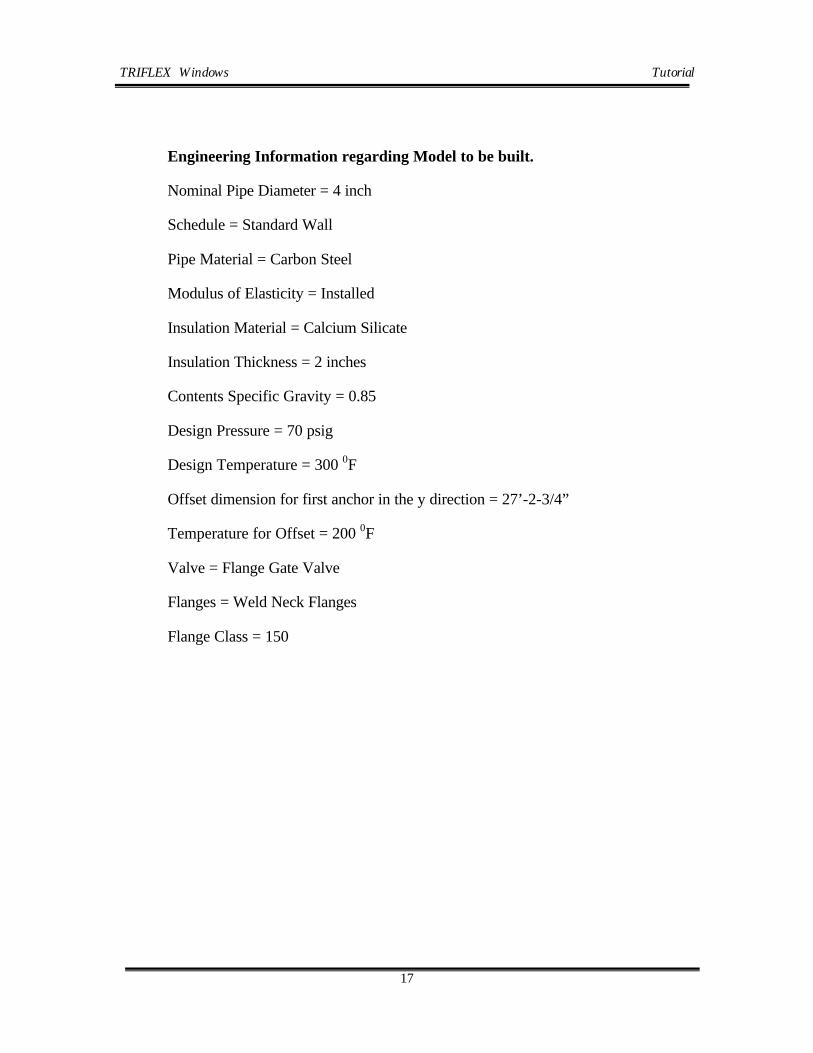
Engineering Information regarding Model to be built.
Nominal Pipe Diameter = 4 inch
Schedule = Standard Wall
Pipe Material = Carbon Steel
Modulus of Elasticity = Installed
Insulation Material = Calcium Silicate
Insulation Thickness = 2 inches
Contents Specific Gravity = 0.85
Design Pressure = 70 psig
Design Temperature = 300 0F
Offset dimension for first anchor in the y direction = 27’-2-3/4”
Temperature for Offset = 200 0F
Valve = Flange Gate Valve
Flanges = Weld Neck Flanges
Flange Class = 150

TRIFLEXWindows Tutorial
18
2.3.2 Starting Triflex Windows
Begin by double clicking on the TRIFLEX Windows icon on your desktop.
After the logo screen appears for a few seconds, the main screen of TRIFLEX Windows will be displayed.
1. From Setup menu, select Project as shown in Figure 2.3.2-1
Figure 2.3.2-1 Main Screen – Setup Options
Complete the fields to define Project Name, Project Account No., Project Cost Code, Engineer’s Name/Initials, etc., as shown in Figure 2.3.2-2. These fields are not mandatory to execute an analysis of the above model.

TRIFLEXWindows Tutorial
19
Figure 2.3.2-2 Project Data
2. From the Setup menu, select Modeling Defaults and the screen shown in Figure 2.3.2-3 will appear.
Use the mouse or tab key to move to Initial Node Number field and enter 1000.
Use the mouse or tab key to move to Node Increment field and enter 10.
Accept the other defaults set by TRIFLEX on this screen.
3. From Setup menu, select Case Definition Data and the screen shown in Figure 2.3.2-4 will appear.
In Case#1, use the mouse to place a check in the box by Process this Case.
In Case#1, use the mouse to place a check in the box by Perform Operating Case Analysis.

TRIFLEXWindows Tutorial
20
Figure 2.3.2-3 Modeling Default
Figure 2.3.2-4 Case Definition Data

TRIFLEXWindows Tutorial
21
2.3.3 Coding the Components
2.3.3.1Anchor Data Point 1000
To specify the anchor at data point 1000, you may either click on Components on the Main Menu and select the Anchor Menu Item, or click on the convenient Anchor Icon on the Component toolbar. The Anchor dialogs will be displayed as shown in Figure 2.3.3-1. All of the input fields on the tabbed Anchor dialogs are for the specification of anchor properties, movements and stiffness (translational and/or rotational).
Figure 2.3.3-1 Node 1000, Anchor Dialog, Type/Location Tab
The anchor at data point 1000 was selected as a Totally Rigid Anchor and this allows the piping system to grow vertically due to the coefficient of expansion of the vessel where it was attached. To view other Anchor dialogs:
1. Select Initial Mvmt/Rots tab – Figure 2.3.3-2
2. Select material for Offset (default is LS – Low Carbon Steel), Temperature of Offset (in our case 200 0F) and type in Offset at a distance of 27 feet, 6 inches (this is typed in as 27-6). This distance is the actual distance from the true anchor to the point where the piping system components begin. TRIFLEXWindows will calculate the vertical growth for data point 1000 from the true anchor point to the start of the piping system as shown in Figure 2.3.3-2.

TRIFLEXWindows Tutorial
22
Figure 2.3.3-2 Node 1000, Anchor Dialog, Initial Mvmt/Rot Tab
3. Select the Pipe Properties Tab as shown in Figure 2.3.3-3.
Use the tab key or the mouse to move to the Nominal Diameter field of the Pipe Size field group. Select 4” from that pull down menu. Notice that the Outside Diameter field is automatically filled in after you move from the Nominal Diameter field. TRIFLEXWindows has a complete set of piping data stored and it automatically retrieves information about the outside diameter for a pipe size with a nominal diameter of 4 inches. Use the tab key or mouse to select the Pipe Schedule field. Select Standard (STD) from that pull down menu.
Use the tab key or your mouse to move to the Material field of the Pipe Material field group. Use the pull down menu to select the Pipe Material.
Note: The pull down menu will list all material codes that TRIFLEXWindows has stored in its internal database. The internal TRIFLEXWindows database may be viewed by the user in Access (look for the Find: triflex.mdb file). This database is listed as: a flange, insulated material, material1, material2, pipe, structural steel, and valve database with the appropriate information under each one.

TRIFLEXWindows Tutorial
23
Figure 2.3.3-3 Node 1000, Anchor Dialog, Pipe Properties Tab
For the purpose of this example, Low Carbon Steel (LS) should be selected. Select carbon steel as the pipe material and note that the pipe density appears. Notice that when the pipe density appears, TRIFLEXWindows will calculate the weight per unit length of the pipe and show it in the appropriate field. If this weight does not agree with the weight in your specifications, you may select the User Defined Material to change the Density value.
Use the tab key or the mouse to move to the Material field of the Insulation field group. Use the pull down menu to select the insulation Material for the Pipe. Use the pull down menu to select (CS) Calcium Silicate as the insulation material. Enter 2 in the insulation thickness field. Notice the calculation of weight is per unit length. If this weight does not agree with the weight in your specifications, select the User Defined Material to change Density value.
4. Select the Process Tab to enter the pressure and temperature of the piping system as shown in Figure 2.3.3-4.
5. Use the tab key or your mouse to move to the Base Temperature field and enter 70 0F.
6. Use the tab key or your mouse to move to the Pressure field and enter 70 psig.
7. Use the tab key or your mouse to move to the Temperature field and enter 300 0F.
8. Select the Code Compliance Tab to enter the Stress Allowable Values and related data as shown in Figure 2.3.3-5

TRIFLEXWindows Tutorial
24
Figure 2.3.3-4 Node 1000, Anchor Dialog, Process Tab
Figure 2.3.3-5 Node 1000, Anchor Dialog, Code Compliance Tab
9 Click the OK or press the Enter key on the Anchor dialogs to save the anchor data. An anchor will be displayed in the graphic window as shown in Figure 2.3.3-6

TRIFLEXWindows Tutorial
25
Figure 2.3.3-6 Node 1000, Anchor Graphic Display

TRIFLEXWindows Tutorial
26
2.3.3.2 Pipe Data Point 1010
To specify the pipe component, do the following
1. Select the convenient Pipe Icon from the Component toolbar.
2. Tab to or use the mouse to move to the Delta Z field of the Dimensions from “From Node” to “To Node” field group. Enter –4’-2” in the Delta Z field to indicate that the pipe segment is 4 foot 2 inches long and that the direction from the From Node to the To Node is in the negative Z direction as shown in Figure 2.3.3-7.
3. Select Restraint Tab as shown in Figure 2.3.3-8.
Figure 2.3.3-7 Node 1010, Pipe Dialog, Pipe Data Tab
4. In the Spring Hanger field group, click on the Existing Spring Hanger check box.
5. Enter 400 lbs in Installed Load field and 168 lbs/in. in the Spring Rate field as shown in Figure 2.3.3-8.

TRIFLEXWindows Tutorial
27
Click OK to save the data and to display the Graphic View shown in Figure 2.3.3-9.
Figure 2.3.3-9 Node 1010, Pipe Graphic Display (rotated)
Figure 2.3.3-8 Node 1010, Pipe Dialog, Restraints Tab

TRIFLEXWindows Tutorial
28
2.3.3.3 Branch Connection Data Point 1020
1. Click the Branch Connection Icon on the Components toolbar to display the Branch Connection Data dialog as shown in Figure 2.3.3-10. The node numbers of the node points are assigned by TRIFLEX automatically. If the user wishes a different labeling of the node points for the Branch Connection, use the pull down menu to select the node number or type in the node number you wish.
Figure 2.3.3-10 Node1020, Branch Dialog, Branch Connection Tab
2. Select the Fabricated Tee radio button from Branch Connection Geometry group.
3. Tab to or use the mouse to move to the Delta Z field of the Dimensions from “From Node” to “To Node” field group. Enter –6’-4” in the Delta Z field to indicate that the pipe segment is 6 foot 4 inches long and that the direction from the From Node to the To Node is in the negative Z direction as shown in Figure 2.3.3-10.
Data Point 1020 is now defined as the midpoint of a Fabricated Tee Branch Connection and will be intensified accordingly. With the indication of the type of Branch Connection, TRIFLEXWindows can calculate the proper stress intensification per the Piping Code specified on the Modeling Default dialog under the Setup.
To specify your own stress intensification factor at a branch connection, select the User Defined radio button from the Branch Connection Geometry group and you can enter the values you wish for the From Node and To Node fields in the Stress Intensification Factor group.

TRIFLEXWindows Tutorial
29
4. Click OK to save the pipe and branch connection data and display the Graphic View shown in Figure 2.3.3-11.
Figure 2.3.3-11 Node 1020, Branch Joint Graphic Display

TRIFLEXWindows Tutorial
30
2.3.3.4 Pipe & Anchor Data Point 1030
1. Click on the Pipe Icon on the Component toolbar.
2. Tab to or use the mouse to move to the Delta Y field of the Dimensions from “From Node” to “To Node” field group. Enter –3’-11-1/4” in the Delta Y field to indicate that the pipe segment is 3 foot 11 1/4 inches long and that the direction from the From Node to the To Node is in the negative Y direction as shown in Figure 2.3.3-12.
3. Click OK to save the pipe data.
Figure 2.3.3-12 Node 1030, Pipe Dialog, Pipe Data Tab
4. Click on the Anchor Icon on the Component toolbar.
5. Verify that the number 1030 is in the Node Label field of the Element field group for the anchor as shown in Figure 2.3.3-13.
6. Click OK to save the anchor data and display the Graphic View shown in Figure 2.3.3-14.

TRIFLEXWindows Tutorial
31
Figure 2.3.3-13 Node 1030, Anchor Dialog, Type Location Data Tab
Figure 2.3.3-14 Node 1030, Pipe and Anchor Graphic Display

TRIFLEXWindows Tutorial
32
2.3.3.5 Elbow Data Point 1040
1 Click on the Elbow Icon on the Component toolbar to display the Elbow Data dialog as shown in Figure 2.3.3-15.
2 Use the pull down menus to select the correct node numbers for the From Node - 1020 and the Tangent Intersection Node - 1040.
3 Tab to or use the mouse to move to the Delta Z field of the Dimensions from “From Node” to “To Node” field group. Enter -4-3-3/16” in the Delta Z field to indicate that the elbow and preceding pipe segment is 4 foot 3 3/16 inches long and that the direction from the From Node to the To Node is in the negative Z direction as shown in Figure 2.3.3-15.
4 Enter 4’ in the Delta X field of the Dimension from “Tangent Intersection To Next Component” group.
Figure 2.3.3-15 Node 1040. Elbow Data Dialog, Elbow Data Tab
5 Click OK to save the elbow data and display the Graphic View shown in Figure 2.3.3-16.

TRIFLEXWindows Tutorial
33
Figure 2.3.3-16 Node 1040, Elbow Data Graphic Display
2.3.6 Branch Connection
2.3.3.6 Branch Connection Data Point 1050
1. Click the Branch Connection Icon on the Components toolbar to display the Branch Connection Data dialog as shown in Figure 2.3.3-17. The node numbers of the node points are assigned by TRIFLEX automatically. If the user wishes a different labeling of the node points for the Branch Connection, use the pull down menu to select the node number or type in the node number you wish.

TRIFLEXWindows Tutorial
34
Notice that the Branch Connection Geometry defaults to “Welding Tee S.I. Only Tc > 1.5*t”. TRIFLEX Windows will default to this selection unless you click on another branch connection type.
2. Tab to or use the mouse to move to the Delta X field of the Dimensions from “From Node” to “To Node” field group. Enter 4’ in the Delta X field to indicate that the pipe segment is 4 foot 0 inches long and that the direction from the From Node to the To Node is in the plus X direction as shown in Figure 2.3.3-17.
Data Point 1050 is now defined as the midpoint of a Welding Tee Branch
Figure 2.3.3-17 Node 1050, Branch Dialog, Branch Connection Tab
Connection and will be intensified accordingly. With the indication of the type of Branch Connection, TRIFLEXWindows can calculate the proper stress intensification per the Piping Code specified on the Modeling Default dialog under the Setup.
4. Select Restraint Tab as shown in Figure 2.3.3-18.

TRIFLEXWindows Tutorial
35
In the Translational Restraint Group field group, click on the Check Box for the +Y restraint.
Figure 2.3.3-18 Node 1050, Branch Connection Dialog, Restraint Data Tab
Figure 2.3.3-19 Node 1050, Branch Connection Dialog Click OK to save the pipe and branch connection data and display the Graphic View shown in Figure 2.3.3-19.
Figure 2.3.3-19 Node 1050, Branch Connection Graphic Display

TRIFLEXWindows Tutorial
36
2.3.3.7 Valve Data Point 1060
Please note that the piping system example calls for a flanged valve to be entered with a preceding segment of pipe between data point 1050 and data point 1060. You may enter the preceding pipe as one data point and the flanged valve as another data point, or you may enter both in one data point as we have done in the following coded dialogs. If desired, the user could also model each flange separately with one data point each and the valve without flanges with another data point. TRIFLEX Windows provides substantial modeling flexibility for the user.
To model the flanged valve with a preceding segment of pipe on one data point dialog, do the following:
1. Click on the Valve Icon on the Component toolbar. TRIFLEX will display the Valve Data dialog as shown in Figure 2.3.3-20.
2. Tab to or use the mouse to move to the Delta X field of the Dimensions from “From Node” to “To Node” field group. Enter 5’-10-1/8” in the Delta X field to indicate that the total length of the pipe segment and the flanged valve is 5 foot 10 1/8 inches long and that the direction from the From Node to the To Node is in the plus X direction as shown in Figure 2.3.3-20.
3. In the Valve Type field group, click on the radio button for Flanged Valve.
4. In Valve Data field group, TRIFLEX will display “Flanged AAAT Std Valve” as the default. For the example problem, a flanged gate valve with weld-neck flanges has been specified. Therefore, click on the pull down menu in the Valve Type field and select the “Flanged Gate Valve”. The class of 150 for the flanges is correct, so no action on the user’s part is required. The other data displayed in the Valve Data field group is displayed for the user to know what data TRIFLEX is using.
5. In the Flange Data field group, TRIFLEX will display “AAAT Std Flanges” as the default. Click on the pull down menu in the Flange Type field and select the “Weld Neck Flange”. The other data displayed in the Flange Data field group is displayed for the user to know what data TRIFLEX is using. In addition, TRIFLEX defaults to flanges on both ends as shown in the check boxes below the flange data.
6. Below the flange data in the “Delta Dimension Coded To” field group, TRIFLEX allows the user to specify the location of the data point on the valve. For our example, we will accept the TRIFLEX default of locating the data point at the weld point on the far end of the valve

TRIFLEXWindows Tutorial
37
Figure 2.3.3-20 Node 1060, Valve Dialog, Valve Data Tab
Click OK to save the pipe and valve data and display the Graphic View shown in Figure 2.3.3-21.
Figure 2.3.3-21 Graphic of Node 1060, Valve Dialog, Valve Data Tab

TRIFLEXWindows Tutorial
38
2.3.3.8 Pipe & Anchor Data Points 1060 through 1070
1. Click on the Pipe Icon on the Component toolbar.
2. Tab to or use the mouse to move to the Delta X field of the Dimensions from “From Node” to “To Node” field group. Enter –3’-3-3/8” in the Delta X field to indicate that the pipe segment is 3 foot 3 3/8 inches long and that the direction from the From Node to the To Node is in the plus X direction as shown in Figure 2.3.3-22.
3. Click OK to save the pipe data.
Figure 2.3.3-22 Node 1070, Pipe Dialog, Pipe Data Tab
4. Click on the Anchor Icon on the Component toolbar.
5. Verify that the number 1070 is in the Node Label field of the Element field group for the anchor as shown in Figure 2.3.3-23.
6. Click OK to save the anchor data and display the Graphic View shown in Figure 2.3.3-24.

TRIFLEXWindows Tutorial
39
Figure 2.3.3-23 Node 1070, Anchor Dialog, Type Location Tab
Figure 2.3.3-24 Node 1070, Pipe & Anchor Data Graphic Display

TRIFLEXWindows Tutorial
40
1. Click on the Pipe Icon on the Component toolbar.
2. Use the pull down menus to select the correct node numbers for the From Node - 1050 and the To Node - 1080.
3. Tab to or use the mouse to move to the Delta Z field of the Dimensions from “From Node” to “To Node” field group. Enter –5’-2-1/8” in the Delta Z field to indicate that the pipe segment is 5 foot 2 1/8 inches long and that the direction from the From Node to the To Node is in the negative Z direction as shown in Figure 2.3.3-25.
Figure 2.3.3-24 Node 1070, Pipe & Anchor Data Graphic Display
4. Click OK to save the pipe data.
5. Click on the Anchor Icon on the Component toolbar.
6. Verify that the number 1080 is in the Node Label field of the Element field group for the anchor as shown in Figure 2.3.3-26.
7. Click OK to save the anchor data and display the Graphic View shown in Figure 2.3.3-27.
Figure 2.3.3-25 Node 1080, Pipe Data Sheet, Pipe Data Tab
The system should graphically look like Figure 2.3.3-27. To display the coordinates axis system on the model, click on the Toggle Axis Icon on the Graphic Toolbar.

TRIFLEXWindows Tutorial
41
Figure 2.3.3-26 Node 1080, Anchor Data Sheet, Type Location Tab
Figure 2.3.3-27 Node 1080, Pipe & Anchor Data Graphic Display

TRIFLEXWindows Tutorial
42
2.3.4 Executing a Static Analysis
To process a TRIFLEXWindows analysis of the piping system you just entered, click on the Green Arrow icon in the Main Menu or from the Setup menu, select the Basic option as shown in Figure 2.3.4-1.
Figure 2.3.4-1 Main Screen, Calculate Pull-Down Menu
Note: A case number must be filled in before TRIFLEX Windows will perform the stress calculations.
Once TRIFLEX has been instructed to process the analysis, the program will begin executing the stress calculations. The status of the calculations will be displayed in the TRIFLEXWindows screen.
While the calculation is in progress, the Calculation Ready/Stop Icon will be displayed as a red stop sign as shown in Figure 2.3.4-2. To stop the calculation process, click the Calculation Ready/Stop Icon and the calculations will be immediately aborted.
Upon completion of the calculation process, the Calculation Ready/Stop Icon will be returned to the green arrow ready state as shown in Figure 2.3.4-1.

TRIFLEXWindows Tutorial
43
2.3.5 View Run Output
To view the results of the stress calculations in spreadsheet format, do the following:
1. From the Output Pull Down menu, select View Results. See Figure 2.3.5-1 below for this menu. The TRIFLEXWindows calculation results will be displayed as shown in Figure 2.3.5-2.
Figure 2.3.5-1 Output Pull-Down Menu
2. Select the Load Case that you wish to view using the Load Case pull down menu as shown in Figure 2.3.5-2.
3. Select the report that you wish to view using the Type Report Selector pull down menu as shown in Figure 2.3.5-3.

TRIFLEXWindows Tutorial
44
Figure 2.3.5-2 Output Load Case Pull-Down Menu
Figure 2.3.5-3 Output Type Pull-Down Menu

TRIFLEXWindows Tutorial
45
To view Code Compliance Report
4. From the Output Pull Down menu, select Piping Code Report similar to that shown in Figure 2.3.5-1. The TRIFLEXWindows calculation results will be displayed as shown in Figure 2.3.5-4.
Figure 2.3.5-4 Output Code Compliance Report
To view the piping model output graphically,
5. Click on the OutPut Display icon in the Main Menu as shown in Figure 2.3.5-5 or, from the Output Pull Down menu, select Select Output Graphic Display similar to that shown in Figure 2.3.5-1. An OutPut display screen will appear in the middle of the screen.
6. In the Output Display screen, click on the Display Pull Down menu as shown in Figure 2.3.5-6 to select the calculated output data that you wish to view.
7. If you select deflections, rotations, forces or moments, you must then select the Line of Action that you wish. Under Line of Action, TRIFLEX will default to Resultant values unless you specify another category. Then click OK.
If you select any of the stresses calculated by TRIFLEX, then you must select either Absolute Value or Sign (+/-) from the Stress Display group. Under the Stress Display group, TRIFLEX will default to Absolute values unless you specify Sign (+/-). Then click OK.

TRIFLEXWindows Tutorial
46
Note: If your piping model does not appear on the screen at this point, then press Control + Tab to toggle between all screens available describing the piping system. Stop when you see the piping model. Alternatively, you can click on the Spreadsheet Icon to toggle between the spreadsheet view and the piping model.
Figure 2.3.5-5 Output Graphic, Output Display Menu
Figure 2.3.5-6 Output Display Screen, Display Pull Down Menu

TRIFLEXWindows Tutorial
47
Figure 2.3.5-7 Output Graphic Screen
Figure 2.3.5-8 Output Graphic – Deformed Shape

TRIFLEXWindows Tutorial
48
To view the piping model with a superimposed deformed shape,
8. In the Output Display screen shown in Figure 2.3.5-6, click on the Display Pull Down menu and select Deflection.
9. Then on the Output Display screen, click on the check box for Show Center Line Deviation and enter a number in the Scale field indicating the multiplier factor to be applied to the deflection shown on the model. Then click OK. A screen showing the deformed piping model will then appear as shown in Figure 2.3.5-8.

TRIFLEXWindows Tutorial
49
2.3.6 Printing
TRIFLEXWindows has an extremely easy to use facility for printing output reports and screens.
1. From the Output Pull Down menu, select Preview Report or Print Report similar to that shown in Figure 2.3.6-1. The Report Print (Print Static / Dynamic Reports) screen will then appear.
Figure 2.3.6-1 Output Pull-Down Menu
2. In Print Report or Preview Report screen, select the Loading Case and the reports from the Available Report group by placing a check in the box adjacent to each desired report as shown in Figure 2.3.6-2.
3. A Preview Report sample screen is shown in Figure 2.3.6-3.

TRIFLEXWindows Tutorial
50
Figure 2.3.6-2 Report Print Menu
Figure 2.3.6-3 Report Print Preview Sample

TRIFLEXWindows Tutorial
51
This completes our TRIFLEX®Windows tutorial. We have by no means covered all the capabilities of the program, but you should have a better understanding of the general approach for building a piping model, executing an analysis and reviewing the results.
To exit TRIFLEX®Windows, click EXIT under FILE. Please remember before you exit TRIFLEX to save your model. To do so, from the File Pull Down menu, select Save As similar to the procedure used in most Windows programs.

TRIFLEXWindows Tutorial
52
APPENDIX A
TRIFLEX Windows Command and Shortcut Keys
(Graphics Mode)
COMMANDS SHORTCUTS
• Help F1 (not active currently)
• Worksheet Toggle F4
• Start Calculation F5
• Print Report Preview F7
• Print Report F8
• Move to End END
• Edit Current Component F9
• Move to First Component HOME
• Insert INS
• Move to Next Component PGDN
• Move to Previous Component PGUP
• Copy CTRL + C
• Cut CTRL + X
• Delete DEL
• New CTRL + N
• Open CTRL + O
• Paste CTRL + V
• Print CTRL + P
• Save CTRL + S
• Undo CTRL + Z

TRIFLEXWindows Tutorial
53
• “Arrow” moves model ARROW KEYS
• Bring up “Start” CTRL + ESC
• Capture display to Clipboard ALT + PRTSC
• Change pointer/manipulator ESC
• Change pointer to manipulator ALT + SHIFT
• Change to manipulator (temporary) ALT
• Display all available windows ALT + ESC
• Manipulator moves model SHIFT
• Next (toggle between graphics CTRL + F6
& spreadsheet input)
• Toggle through all available windows ALT + TAB

TRIFLEXWindows Tutorial
54
APPENDIX B
Procedure to read
* .IN file generated in TRIFLEX Windows into TRIFLEX DOS
The .IN file is created by TRIFLEX Windows during of the run session of the model. This file will be saved with the same name as the name of piping model (by default the name is “untitled”) and has .IN extension.
TRIFLEX Windows will create a .IN file for each defined load case.
Locations where the .IN are saved are: drive:\….\name of the model\1 for the load case 1, drive:\….\name of the model\2 for the load case 2 and so on.
In order to read this files in TRIFLEX DOS follow the next steps:
1. Copy the .IN file to the folder Drive:\AAALIB (the default directory for TRIFLEX DOS installing) to the directory where the TRIFLEX DOS was installed.
2. Run TRIFLEX DOS and select option 5. TRIFLEX Utilities Menu

TRIFLEXWindows Tutorial
55
2. Select Option 3 – Convert into Triflex Format
3. Select Option 5 – Convert Triflex Keyword Files To Triflex Node Data

TRIFLEXWindows Tutorial
56
3. Using arrows button select which file you want to convert ( in our case TESTTR ) and press F10
5. Press any key

TRIFLEXWindows Tutorial
57
6. You can see, edit run, and save the imported pipe model

TRIFLEXWindows Tutorial
58
APPENDIX B
Procedure to read
* .IN file generated in TRIFLEXDOS into TRIFLEX Windows
It is possible to import .IN files and .JOB files written by TRIFLEXDOS in a new empty file opened by TRILEX Window.
In order to read these files in TRIFLEX DOS follow the next steps:
1. Start TRIFLEX Windows program or if it is already started and a file opened select, File and New option from Main Menu.
2. From Main Menu select Utilities, Import Files and Triflex Keyword option.
3. Select the directory where the .IN file is located, select the .IN file and press the OPEN button.
4. The graphic of the pipe system will become visible on the screen.
Follow the rules for editing, running and saving which are specific for TRIFLEX Windows.

TRIFLEXWindows Tutorial
59
APPENDIX A
Installation Instructions
For
TRIFLEX Windows
When installing on a NT machine, the installer needs to login as the NT administrator.
Insert the CD into the CD Reader, the following screen will appear.
Select Install Triflex Windows and follow the instructions.
When the following screen appears enter the fields with the proper information. A proper serial number or the word DEMO must be entered before the “Next” button is made available.
Here you can specify the folder where you want TRIFLEX Windows to be installed. The default settings are:
C:\ProgramFiles\PipingSolutions\TriflexWindows

TRIFLEXWindows Tutorial
60
The next screen will just tell you if you have enough space to install. Hit next, to proceed with the installation. The status bar will tell you the progress of the installation
Triflex Windows is now installed, you can view the release notes by simply hitting “Finish”.
To Run TRIFLEX Windows start Windows Explorer and locate the TRIFLEX executable.
To make a shortcut, simply drag and drop the TRIFLEX icon over to your desktop.

TRIFLEXWindows Tutorial
61
NETWORK INSTALLATION
When installing on a NT machine, the installer needs to login as the NT administrator. Network installation requires a couple of extra steps. The following works fine with Netbios and TCP/IP types of networks.
If you are unfamiliar with the inner workings of Windows and Networking, please have the IT-Department to do the following:
SERVER
It is not necessary to have a full installation of TRIFLEX Windows on the server. The HASP folder can be copied over to the server from the client. However, both SERVER and CLIENT can reside on same computer.
1. Now we need to set up the shortcut for the NHSRVW32 program. Since our Nethasp.ini (this is the user part not the server) is looking for the License Manager called “TRIFLEX”. WE need to make sure we start the LM and give it a name.
2. To give the LM a name, make a shortcut to the NHSRVW32.
3. For NT-Systems, we recommend to place the NHSRVW32 Shortcut at
<SysDRV>:\WINNT\Profiles|All Users\Start Menu\Programs\Startup location. This will assure the access to TRIFLEX Application no matter

TRIFLEXWindows Tutorial
62
which machine was designated as dedicated server or who is working on it.
Right Click on the Icon, left click on Properties Add on to the target line –srvname=TRIFLEX
4. Right Click on the Icon, left click on Properties Add on to the target line –srvname=TRIFLEX
5. Add on to the target line –srvname=TRIFLEX
CLIENT
Move the Nethasp.ini from the HASP folder, which is located in the TRIFLEX Windows folder.
This is a typical content of the Nethasp.ini file.

TRIFLEXWindows Chapter 3
1
Table of Contents
TRIFLEXWindows User Manual
Introduction to TRIFLEXWindows .........................................................Chapter 1
Tutorial ......................................................................................................Chapter 2
CHAPTER 3 .......................................................................................................18
Creating a TRIFLEX Window Icon....................................................................18
3.1.1 Main Screen Layout ..........................................................................20
3.1.1.1 Main Menu 21
3.1.1.2 Component Toolbar 22
3.1.1.3 Graphic Toolbar 23
3.1.1.4 Thumbwheels on Screen including Zoom 25
3.1.1.5 Status Bar 27
3.1.2 Menus……………............................................................................28
3.1.2.1 File Menu 28
3.1.2.1.1 Open ..................................................................................30
3.1.2.1.2 Save As ..............................................................................31
3.1.2.1.3 Autosave ............................................................................31
3.1.2.2 Setup Menu 32
3.1.2.2.1 Input Units.........................................................................34
3.1.2.2.2 Graphic Preferences Sub Menu .........................................38
3.1.2.3 Components Menu 40
3.1.2.3.1 Component Control Menu.................................................42
3.1.2.3.2 Insert, Replace and Append Mode ....................................43
3.1.2.3.3 Edit Component Sub Menu ...............................................45
3.1.2.3.4 Set input Mode Sub Menu.................................................46
3.1.2.4 Edit Menu 47
3.1.2.5 Calculate Menu 49
3.1.2.5.1 Progress Bar Preferences ...................................................50

TRIFLEXWindows Chapter 3
2
3.1.2.6 Output Window 52
3.1.2.7 Utilities Menu 54
3.1.2.7.1 Database Sub Menu...........................................................55
3.1.2.7.2 Import Files Sub Menu......................................................57
3.1.2.7.3 Export Files Sub Menu......................................................58
3.1.2.7.4 Points Distance ..................................................................60
3.1.2.7.5 Connectivity Log...............................................................63
3.1.2.7.6 Activator Check .................................................................63
3.1.2.7.7 WERCO.............................................................................66
3.1.2.7.8 AAAT Catalog...................................................................69
3.1.2.7.9 PSI Home Page ..................................................................70
3.1.2.8 Windows Menu 72
3.1.2.9 Help Menu 73
3.1.2.9.1 Using the Manual and Help Command .............................74
3.1.3 Input Spreadsheet ..............................................................................75
3.1.4 Accessing Data from Piping Model..................................................76
3.1.4.1 Using Color to Check the Input Parameters. 78
3.2 Component Dialog.....................................................................................81
3.2.1 Anchor…...........................................................................................81
3.2.1.1 Anchor Component, Type/Location Tab 81
3.2.1.2 Anchor Component, Pipe Properties, Material Selection 85
3.2.1.3 Anchor Component, Init. Mvts. and Rotations Tab 93
3.2.1.3.1 Anchor Component, Init. Mvts., X, Y, Z axes ..................93
3.2.1.3.2 Anchor Component, Init. Mvts. A, B, C axes ...................96
3.2.1.4 Anchor Component, Vessel Properties 99
3.2.1.5 Vessel Drawing Orientation 104
3.2.2 Pipe…..............................................................................................113
3.2.2.1 Coding Piping Data, Piping Data 113
3.2.2.2 Automatic placement of Multiple Node Points 117
3.2.2.3 Jacketed Pipe 119
3.2.3 Elbow or Bend ................................................................................129
3.2.3.1 Coding Elbow Data, Elbow Data Tab 129
3.2.4 Branch Connection..........................................................................135

TRIFLEXWindows Chapter 3
3
3.2.4.1 Coding Branch Connection, Branch Connection Tab 135
3.2.5 Valves…..........................................................................................140
3.2.5.1 Coding Valve Data, Valve Data Tab 140
3.2.6 Flanges ............................................................................................147
3.2.6.1 Coding Flange Data, Flange Data Tab 147
3.2.6.2 Flange Loading Input Data Setup 153
3.2.7 Reducers..........................................................................................155
3.2.7.1 Coding Reducer Data, Reducer Data Tab 155
3.2.8 Rigid Joint and Structural Member .................................................159
3.2.8.1 Coding Joint Data Tab, Rigid Input 159
3.2.8.2 Coding Joint Tab, Flexible Input 164
3.2.9 Expansion Joint ...............................................................................171
3.2.9.1 Coding Expansion Joint, Expansion Joint Tab 171
3.2.9.2 Expansion Joint, Different Types 177
3.2.10 Release Element ............................................................................178
3.2.10.1 Coding Release Element, X, Y, Z coordinate axes 178
3.2.10.2 Coding Release Element, A,B,C coordinate axes 182
3.2.11 Pressure Relief Valve....................................................................185
3.2.11.1 Pressure Relief Valve DataTab 185
3.3 Common dialogs for all Component Types .............................................191
3.3.1 Pipe Properties Tab .........................................................................191
3.3.1.1 Rippling Property Changes (HOW TO RIPPLE) 194
3.3.2 Process Tab .....................................................................................196
3.3.3 Restraints Tab .................................................................................198
3.3.3.1 Restraints Tab, X, Y, Z coordinate system 203
3.3.3.2 Restraints Tab, L, N, G coordinate system 212
3.3.3.2 Restraints Tab, A, B, C coordinate system 216
3.3.3.3 Spring Hanger/Support 226
3.3.4 Wind Load and Uniform Load Tab ................................................228
3.3.4.1 Wind Loading, Specifying Wind Speed 228
3.3.4.2 Wind Loading, Pressure Force and Shape Factor 235
3.3.4.3 Wind Loading, Actual Load 239
3.3.4.4 Uniform Load 243

TRIFLEXWindows Chapter 3
4
3.3.5 Soil Load Tab..................................................................................248
3.3.5.1 Overview of Soil Modeling 248
3.3.5.2 Understanding the Soil Load Tab 250
3.3.5.3 Soil/Pipe Interaction 257
3.3.5.4 Coding Underground Piping 265
3.3.6 Code Compliance Tabs ...................................................................287
3.3.6.0.1 Fatigue (An Option in Code Compliance)......................287
3.3.6.1 ASME B31.1 Code Compliance 288
3.3.6.2 ASME B31.3 Code Compliance 290
3.3.6.3 ASME B31.4 Code Compliance 293
3.3.6.4 ASME B31.5 Code Compliance 295
3.3.6.5 ASME B31.8 Code Compliance 297
3.3.6.6 U.S Navy General Specifications for Ships, Section 505 299
3.3.6.7 ASME Section III, Division I (Subsection NC) – Class 2 301
3.3.6.8 ASME Section III, Division I (Subsection ND) – Class 3 303
3.3.6.9 SPC1 - Swedish Piping Code (Method 1, Section 9.4) 305
3.3.6.10 SPC2 - Swedish Piping Code (Method 2, Section 9.5) 307
3.3.6.11 TBK5-6 - Norwegian General Rules for Piping System (Annex D- Alternative Method) 310
3.3.6.12 TBK5-6 - Norwegian General Rules for Piping System (Section 10.5) 312
3.3.6.13 DNV - DnV Rules for Submarine Piping System (1981 Edition)….. 315
3.3.6.14 DNV - Submarine Pipeline System -DnV, 1996 Edition 317
3.3.6.15 DNV - Offshore Standard OSF-101 Submarine Pipeline System - DnV, 2000 Edition 319
3.3.6.16 Polska Norma PN-79 / M-34033 321
3.3.6.17 SNIP 2.05-06-95 FSU Transmission Piping Code 326
3.3.6.18 BS7159 Glass Reinforced Plastic Piping Code 329
3.3.6.19 BS8010 British Standard Piping Code 337
3.3.6.20 UKOOA -UK Offshore Operator Association 339
3.3.6.21 NPD Guidelines for Submarine Pipelines and Risers 347
3.3.6.22 Statoil Design, Specifications Offshore Pipeline Systems 349
3.3.6.23 EURO CODE European Standard prEN 13480-3 351

TRIFLEXWindows Chapter 3
5
3.4 General Setup Dialogs .............................................................................353
3.4.1 Modeling Default ............................................................................353
3.4.2 Setup Input/Output English units ....................................................356
3.4.3 Setup Modeling Defaults ................................................................358
3.4.4 Setup Case Definition Data.............................................................364
3.4.5 Occasional Loading Data ................................................................382
3.4.6 Modal Analysis ...............................................................................384
3.4.7 Response Spectrum Analysis ..........................................................384
3.4.8 Time History Analysis ....................................................................384
3.4.9 Configure Graphics Colors .............................................................386
3.4.10 Graphic Preferences ......................................................................388
3.4.11 Save Graphic Setting.....................................................................390
3.4.12 Restore Setting ..............................................................................390
3.5 Importing Interfaces .................................................................................391
3.5.1 Import TRIFLEX® DOS .................................................................396
3.5.2 Import a TRIFLEX keyword file ....................................................398
3.5.3 Import SpreadSheet Input ...............................................................399
3.5.4 Import a Global Positioning system (GPS) file ..............................403
3.5.5 Import a Plant-4D and ALIAS Input File .......................................412
3.5.6 Import CADPipe Input File ............................................................416
3.5.7 Import CALMA V Input File.........................................................419
3.5.8 Import CATIA IV, STEP AP 227 ..................................................422
3.5.9 Import an Intergraph PDS Neutral File into TRIFLEX®Windows.435
3.5.9.1 Generating a Stress Neutral File for PDS 444
3.6 Export Interfaces......................................................................................448
3.6.1 Export a TRIFLEX Keyword file ...................................................450
3.6.2 Export an isoOUT file.....................................................................451
3.6.3 Export a 3D DXF file ......................................................................452
3.6.4 Export a JPEG file...........................................................................456
3.6.5 Export a BITMAP file ....................................................................458
3.6.6 Export a HPGL file .........................................................................460
3.6.7 Export a PostScript file ...................................................................461
3.6.8 Export a SpreadSheet......................................................................462

TRIFLEXWindows Chapter 3
6
3.6.8.1 Export to Excel 462
3.6.8.2 Export to TXT File 465
3.7 Data Bases................................................................................................468
3.7.1 Generic Pipe Database ....................................................................468
3.7.2 Flange Database ..............................................................................470
3.7.3 Valve Data Base..............................................................................472
3.7.3.1 Build your Companies Valve Database 472
3.7.4 Pressure Relief Valve Database ......................................................475
3.7.5 Structural Steel Data Base (Joint) ...................................................478
3.7.6 Pipe Material Database ...................................................................485
3.7.7 Insulation Database .........................................................................487
3.7.8 Fiberglass Pipe Material .................................................................488
3.8 Graphic Manipulation..............................................................................490
3.9 Run TRIFLEX .........................................................................................491
3.9.1 View Run Output ............................................................................494
3.10 Printing...................................................................................................500
3.10.1 Output & View Analysis Results ..................................................500
3.10.1.1 Printing Output Reports (as SpreadSheet) .................................501
3.10.2 Piping Code Report .......................................................................504
3.10.3 Spring Hanger Report ...................................................................505
3.10.4 Color Mapped Graphic Display....................................................506
3.10.4.2 Printing Graphics Output 510
3.10.4.2.1 Printer ............................................................................510
3.10.4.2.2 Graphics Output Print Setup ..........................................511
3.10.5 Preview Reports ............................................................................513
3.10.6 Print Reports .................................................................................515
APPENDIX A- TRIFLEX Windows Command and Shortcut Keys .............518
TRIFLEXWindows Theory Manual

TRIFLEXWindows Chapter 3
7
Data.Preparation…………………………………………..……Chapter 4
Use.of.Restraints……………………………………..………....Chapter 5
Outputs ......................................................................................................Chapter 6
Rotating Equipment Compliance Reports .................................................Chapter 7
TriflexWindows Piping Code Compliance Reports .............................Chapter 8
TriflexWindows Dynamic Capabilities ...................................................Chapter 9
Related Engineering Data ..........................................................................Appendix
List of Figures Figure 3.1.0-1 Demo IU1.dta Example............................................................................. 19
Figure 3.1.1-1 Main Screen Layout .................................................................................. 20
Figure 3.1.1.1-1 Main Menu ............................................................................................. 21
Figure 3.1.1.2-1 Component Toolbar ............................................................................... 22
Figure 3.1.1.3-1 Graphic Toolbar ..................................................................................... 23
Figure 3.1.1.3-2 Manipulation Toolbar............................................................................. 24
Figure 3.1.1.3-3 Status Bar ............................................................................................... 24
Figure 3.1.1.4-1 Demo IU1.dta Example.......................................................................... 25
Figure 3.1.1.5-1 Status Bar ............................................................................................... 27
Figure 3.1.2.1-1 File Menu ............................................................................................... 28
Figure 3.1.2.1.1-1 Open TRIFLEXWindows Project File.............................................. 30
Figure 3.1.2.1.2-1 Save As................................................................................................ 31
Figure 3.1.2.1.3-1 Autosave Default dialog...................................................................... 31
Figure 3.1.2.2-1 Setup Menu ............................................................................................ 32
Figure 3.1.2.2.1-1 Input Units........................................................................................... 34
Figure 3.1.2.2.1-2 Input Units........................................................................................... 35
Figure 3.1.2.2.1-3 Input Units........................................................................................... 35
Figure 3.1.2.2.1-4 Input Units........................................................................................... 36
Figure 3.1.2.2.1-5 Input Units........................................................................................... 36
Figure 3.1.2.2.1-6 Input Units........................................................................................... 37
Figure 3.1.2.2.2-1 Graphic Preferences Sub Menu........................................................... 38

TRIFLEXWindows Chapter 3
8
Figure 3.1.2.3-1 Components Menu ................................................................................. 40
Figure 3.1.2.3.1-1 Components Control Menu ................................................................. 42
Figure 3.1.2.3.3-1 Edit Components Sub Menu ............................................................... 45
Figure 3.1.2.3.4-1 Set Input Mode Sub Menu .................................................................. 46
Figure 3.1.2.4-1 Edit Menu............................................................................................... 47
Figure 3.1.2.5-1 Calculate Menu ...................................................................................... 49
Figure 3.1.2.5.1-1 Progress Bar Preferences..................................................................... 50
Figure 3.1.2.5.1-2 Calculation Progress Log Display Preferences ................................... 50
Figure 3.1.2.6-1 Output Window...................................................................................... 52
Figure 3.1.2.7-1 Utilities Menu......................................................................................... 54
Figure 3.1.2.7.1-1 Databases Sub Menu ........................................................................... 55
Figure 3.1.2.7.2-1 Import Files Sub Menu........................................................................ 57
Figure 3.1.2.7.3-1 Export Files Sub Menu........................................................................ 58
Figure 3.1.2.7.4-1 Points Distance dialog box.................................................................. 60
Figure 3.1.2.7.4-2 Example Points Distance..................................................................... 61
Figure 3.1.2.7.4-3 Example Points Distance..................................................................... 61
Figure 3.1.2.7.4-4 Example Points Distance..................................................................... 62
Figure 3.1.2.7.5-1 Connectivity Log................................................................................. 63
Figure 3.1.2.7.6-1 Activator Check .................................................................................. 63
Figure 3.1.2.7.7-1 WERCO screen................................................................................... 66
Figure 3.1.2.7.7-2 WERCO example “test1”.................................................................... 67
Figure 3.1.2.7.7-3 WERCO example “test1M” (metric) .................................................. 67
Figure 3.1.2.7.8-1 AAA Technology & Specialties Co., Inc. screen................................ 69
Figure 3.1.2.7.9-1 PSI home page screen ......................................................................... 70
Figure 3.1.2.7.9-2 PSI, TRIFLEX Samples screen, start.................................................. 71
Figure 3.1.2.7.9-3 PSI, TRIFLEX Samples screen, end ................................................... 71
Figure 3.1.2.8-1 Windows Menu ...................................................................................... 72
Figure 3.1.2.9-1 Help Menu.............................................................................................. 73
Figure 3.1.3.0-1 Input Spreadsheet ................................................................................... 75
Figure 3.1.4-1 Viewing Anchor Component Properties ................................................... 76
Figure 3.1.4-2 Worksheet.................................................................................................. 76
Figure 3.1.4.1-1 Color, Process Temperature ................................................................... 78
Figure 3.1.4.1-2 Color, Process Temperature ................................................................... 79

TRIFLEXWindows Chapter 3
9
Figure 3.1.4.1-3 Color, Base Temperature ....................................................................... 79
Figure 3.1.4.1-4 Color, Nominal Diameter ....................................................................... 80
Figure 3.1.4.1-5 Color, Wind Load................................................................................... 80
Figure 3.2.1.0-1 Anchor Components, All Tabs............................................................... 81
Figure 3.2.1.2-1 Anchor Dialog, Pipe Properties Screen.................................................. 85
Figure 3.2.1.2-2 Pipe Material Database, Selection of Materials ..................................... 86
Figure 3.2.1.2-3 Pipe Material Database, Selection of Materials ..................................... 86
Figure 3.2.1.2-4 Anchor Dialog, Selection of Materials................................................... 87
Figure 3.2.1.2-5 Table of Materials .................................................................................. 89
Figure 3.2.1.2-6 Table of Insulation Materials ................................................................. 91
Figure 3.2.1.3.1-1 Node 1000, Anchor Dialog, Initial Mvt, X. Y. Z axes........................ 93
Figure 3.2.1.3.2-1 Node 1000, Anchor Dialog, Initial Mvt. A, B, C axes........................ 96
Figure 3.2.1.4-1 Setup Case Definition ............................................................................ 99
Figure 3.2.1.5-1 Example One ........................................................................................ 105
Figure 3.2.1.5-2 Description of Counter Clockwise Orientation.................................... 105
Figure 3.2.1.5-3 Example One ........................................................................................ 106
Figure 3.2.1.5-4 Example One ........................................................................................ 106
Figure 3.2.1.5-5 Example Two ....................................................................................... 108
Figure 3.2.1.5-6 Example Two ....................................................................................... 108
Figure 3.2.1.5-7 Example Two ....................................................................................... 109
Figure 3.2.1.5-8 Example Two ....................................................................................... 109
Figure 3.2.1.5-16 Example Three ................................................................................... 111
Figure 3.2.1.5-17 Example Three ................................................................................... 111
Figure 3.2.1.5-18 Example Three ................................................................................... 112
Figure 3.2.2.0-1 Anchor Component, Pipe Properties Tab............................................. 113
Figure 3.2.2.2-1 Automatic placement of Multiple Node Pts. ........................................ 117
Figure 3.2.2.3-1 Jacketed Steam Line, Core 4”, Jacket 6” ............................................ 119
Figure 3.2.2.3-2 Jacketed Steam Line, Core 4”, Jacket 6” ............................................ 120
Figure 3.2.2.3-3 Jacketed Steam Line, Core 4”, Jacket 6” ............................................ 120
Figure 3.2.2.3-4 Jacketed Steam Line, Core 4”, Jacket 6” ............................................ 121
Figure 3.2.2.3-5 Jacketed Steam Line, Core 4”, Jacket 6” ............................................ 121
Figure 3.2.2.3-6 Jacketed Steam Line, Core 4”, Jacket 6” ............................................ 122
Figure 3.2.2.3-7 Jacketed Steam Line, Core 4”, Jacket 6” ............................................ 122

TRIFLEXWindows Chapter 3
10
Figure 3.2.2.3-8 Jacketed Steam Line, Core 4”, Jacket 6” ............................................ 123
Figure 3.2.2.3-9 Jacketed Steam Line, Core 4”, Jacket 6” ............................................ 123
Figure 3.2.2.3-10 Jacketed Steam Line, Core 4”, Jacket 6” .......................................... 124
Figure 3.2.2.3-11 Jacketed Steam Line, Core 4”, Jacket 6” .......................................... 124
Figure 3.2.2.3-12 Jacketed Steam Line, Core 4”, Jacket 6” .......................................... 125
Figure 3.2.2.3-13 Jacketed Steam Line, Core 4”, Jacket 6” .......................................... 125
Figure 3.2.2.3-14 Jacketed Steam Line, Core 4”, Jacket 6” .......................................... 126
Figure 3.2.2.3-15 Jacketed Steam Line, Core 4”, Jacket 6” .......................................... 126
Figure 3.2.2.3-16 Jacketed Steam Line, Core 4”, Jacket 6” .......................................... 127
Figure 3.2.2.3-17 Jacketed Steam Line, Core 4”, Jacket 6” .......................................... 127
Figure 3.2.2.4-1 Release element for Jacketed Pipe ...................................................... 128
Figure 3.2.3.0-1 Coding Elbow Data, Elbow data Tab................................................... 129
Figure 3.2.4.0-1 Coding Branch Connection, Branch Connection Tab ......................... 135
Figure 3.2.5.0-1 Coding Valve Data, Valve Data Tab.................................................... 140
Figure 3.2.6.0-1 Coding Flange Data, Flange Data Tab ................................................. 147
Figure 3.2.6.1-1 Flange Data Tab, Rupture Disk Holder................................................ 152
Figure 3.2.6.2-1 Flange Loading Input Data Setup ........................................................ 153
Figure 3.2.6.2-2 Flange Loading Input Data Setup ........................................................ 153
Figure 3.2.7.0-1 Coding Reducer Data, Reducer Data Tab ............................................ 155
Figure3.2.8.0-1 Coding Joint Data, Rigid Input ............................................................. 159
Figure3.2.8.2-1 Coding Joint Data, Flexible Input ......................................................... 164
Figure 3.2.8.2-2 Structural Steel Coordinate Axes ......................................................... 167
Figure 3.2.8.2-3 Structural Steel Coordinate Axes ......................................................... 167
Figure 3.2.8.2-4 Structural Steel Coordinate Axes ......................................................... 168
Figure 3.2.8.2-5 Structural “Effective Shear Area”........................................................ 169
Figure 3.2.9.0-1 Coding Expansion Joint, Expansion Joint Tab .................................... 171
Figure 3.2.10.0-1 Coding Joint Data, Joint Data Table .................................................. 178
Figure 3.2.10.2-1 Coding Joint Data, Joint Data Table .................................................. 182
Figure 3.2.10.2-2 Coding Joint Data, Longitudinal Direction Calculator ...................... 184
Figure 3.2.11-1 Coding Pressure Relief Valve, Pressure Relief Valve Tab ................... 185
Figure 3.3.1-1 Anchor Component, Pipe Properties Tab................................................ 191
Figure 3.3.1.1-1 Pipe Properties Tab, Ripple .................................................................. 194
Figure 3.3.1.1-2 Pipe Properties Tab, Ripple .................................................................. 194

TRIFLEXWindows Chapter 3
11
Figure 3.3.2.0-1 Anchor Component, Process Tab......................................................... 196
Figure 3.3.3.0-1 Restraint Tab for General Pipe Support or Restraint ........................... 198
Figure 3.3.3.0-3 XYZ and ABC Coordinate Systems .................................................... 201
Figure 3.3.3.1-1 X,Y,Z coordinate system Pipe Support or Restraint ............................ 203
Figure 3.3.3.1-2 X,Y,Z coordinate system Restraint Tab ............................................... 203
Figure 3.3.3.2-1 L,N,G coordinate system Pipe Support or Restraint ............................ 212
Figure 3.3.3.2-2 L,N,G coordinate system Restraint Tab ............................................... 212
Figure 3.3.3.3-1 A, B, C coordinate system Pipe Support or Restraint .......................... 216
Figure 3.3.3.3-2 A,B,C coordinate system Restraint Tab ............................................... 216
Figure 3.3.3.3-1 Springs - Restraints Tab, Size a Spring Hanger................................... 226
Figure 3.3.4.0-1 Anchor Component, Wind Load Tab................................................... 228
Figure 3.3.4.1-1 Wind Load Tab, X axis, Specifying Wind Speed ................................ 228
Figure 3.3.4.1-2 Wind Load Tab, Z axis, Specifying Wind Speed................................. 229
Figure 3.3.4.1-3 Wind Loads for the Z plane of action .................................................. 231
Figure 3.3.4.1-4 Wind Loads for the Z plane of action .................................................. 231
Figure 3.3.4.1-5 Winds Loads along the X plane ........................................................... 233
Figure 3.3.4.1-6 Wind Loads along the Z plane ............................................................. 234
Figure 3.3.4.2-1 Wind Load Tab, X axis, Pressure Force and Shape Factor.................. 235
Figure 3.3.4.2-2 Wind Load Tab, Z axis, Pressure Force and Shape Factor .................. 235
Figure 3.3.4.2-3 Wind Loads for the Z plane of action .................................................. 236
Figure 3.3.4.2-4 Wind Loads for the Z plane of action .................................................. 236
Figure 3.3.4.2-5 Winds Loads along the X plane ........................................................... 237
Figure 3.3.4.2-6 Wind Loads along the Z plane ............................................................. 238
Figure 3.3.4.3-1 Wind Load Tab, X axis, Actual Load .................................................. 239
Figure 3.3.4.3-2 Wind Load Tab, Z axis, Actual Load................................................... 239
Figure 3.3.4.3-3 Wind Loads for the Z plane of action .................................................. 240
Figure 3.3.4.3-4 Wind Loads for the Z plane of action .................................................. 240
Figure 3.3.4.3-5 Winds Loads along the X plane ........................................................... 241
Figure 3.3.4.3-6 Wind Loads along the Z plane ............................................................. 242
Figure 3.3.4.4-1 Uniform Load Tab, X axis ................................................................... 243
Figure 3.3.4.4-2 Uniform Load Tab, Z axis.................................................................... 243
Figure 3.3.4.4-3 Wind Loads for the Z plane of action .................................................. 244
Figure 3.3.4.4-4 Wind Loads for the Z plane of action .................................................. 245

TRIFLEXWindows Chapter 3
12
Figure 3.3.4.4-5 Winds Loads along the X plane ........................................................... 246
Figure 3.3.4.4-6 Wind Loads along the Z plane ............................................................. 247
Figure 3.3.5.0-1 Anchor Component, Soil Loads Tab.................................................... 248
Figure 3.3.5.2-1 Soil Loads Tab (Use method in ASME B31.1- 2001) ......................... 250
Figure 3.3.5.2-2 Soil Loads Tab (User Defined Loads and Stiffness)............................ 251
Figure 3.3.5.2-3 Soil Loads Tab (Use method in ASME B31.1 - 2001) ........................ 252
Figure 3.3.5.2-4 Soil Loads Tab (User Defined Loads and Stiffness)............................ 254
Figure 3.3.5.2-5 Movement ............................................................................................ 255
Figure 3.3.5.3-1 Soil Displacement Curve ...................................................................... 258
Figure 3.3.5.3-2 Soil Displacement Curve ...................................................................... 259
Figure 3.3.5.3-3 Soil Displacement Curve ...................................................................... 260
Figure 3.3.5.4-1 Anchor Data, Type/Location Tab ........................................................ 265
Figure 3.3.5.4-2 First Anchor, Pipe Properties Tab ........................................................ 266
Figure 3.3.5.4-3 First Anchor, Process Tab .................................................................... 266
Figure 3.3.5.4-4 First Anchor, Initial Mvt/Rots Tab....................................................... 267
Figure 3.3.5.4-5 First Anchor, Wind/Uniform Tab ........................................................ 267
Figure 3.3.5.4-6 First Anchor, Soil Loads Tab ............................................................... 268
Figure 3.3.5.4-7 Soil Loads Tab ..................................................................................... 269
Figure 3.3.5.4-8 Soil Loads Tab ..................................................................................... 269
Figure 3.3.5.4-9 Soil Loads Tab ..................................................................................... 270
Figure 3.3.5.4-10 Soil Loads Tab ................................................................................... 270
Figure 3.3.5.4-11 Soil Loads Tab ................................................................................... 271
Figure 3.3.5.4-12 Soil Loads Tab ................................................................................... 271
Figure 3.3.5.4-13 Soil Loads Tab ................................................................................... 272
Figure 3.3.5.4-14 Soil Loads Tab ................................................................................... 272
Figure 3.3.5.4-15 Elbow Data Tab, Node Point 10 to 100 ............................................. 275
Figure 3.3.5.4-16 Pipe Data Tab, Node Point 100 to 200............................................... 276
Figure 3.3.5.4-17 Pipe Data Tab, Node Point 200 to 300............................................... 277
Figure 3.3.5.4-18 Elbow Data Tab, Node Point 300 to 400 ........................................... 278
Figure 3.3.5.4-19 Pipe Data Tab, Node Point 400 to 500............................................... 278
Figure 3.3.5.4-20 Pipe Data Tab, Node Point 500 to 600............................................... 279
Figure 3.3.5.4-21 Input Spreadsheet, Previously Coded Model..................................... 280
Figure 3.3.5.4-22 Output, View Analysis Results, Restraint Description...................... 281

TRIFLEXWindows Chapter 3
13
Figure 3.3.5.4-23 Output, View Analysis Results, Axial Descriptions .......................... 282
Figure 3.3.5.4-24 Output, View Analysis Results, Restraint Forces & Moments .......... 283
Figure 3.3.5.4-25 Piping System Model, Node points 10 to 300.................................... 285
Figure 3.3.5.4-26 Piping System Model, Node points 10 to 500.................................... 285
Figure 3.3.5.4-27 Piping System Model, Node points 10 to 600.................................... 286
Figure 3.3.6.1-1 Anchor Component, Code Compliance Tab, B31.1 ............................ 288
Figure 3.3.6.2-1 Anchor component, code compliance Tab, B31.3 ............................... 290
Figure 3.3.6.3-1 Anchor Component, Code Compliance Tab, B31.4 ............................ 293
Figure 3.3.6.4-1 Anchor Component, Code Compliance Tab, B31.5 ............................ 295
Figure 3.3.6.5-1 Anchor Component, Code Compliance Tab, B31.8 ............................ 297
Figure 3.3.6.6-1 Anchor Component, Code Compliance Tab, US Navy ....................... 299
Figure 3.3.6.7-1 Anchor Component, Code Compliance Tab, Class 2 .......................... 301
Figure 3.3.6.8-1 Anchor Component, Code Compliance Tab, Class 3 .......................... 303
Figure 3.3.6.9-1 Anchor Component, Code Compliance Tab, SPC1 ............................. 305
Figure 3.3.6.10-1 Anchor Component, Code Compliance Tab, SPC2 ........................... 307
Figure 3.3.6.11-1 Anchor Component, Code Compliance Tab, TBK, 56 ...................... 310
Figure 3.3.6.12-1 Anchor Component, Code Compliance Tab, TBK 5-6 Method 2 ..... 312
Figure 3.3.6.13-1 Anchor Component, Code Compliance Tab, DNV 1981 .................. 315
Figure 3.3.6.14-1 Anchor Component, Code Compliance Tab, DNV 1996 .................. 317
Figure 3.3.6.15-1 Anchor Component, Code Compliance Tab, DNV 2000 .................. 319
Figure 3.3.6.16-1 Anchor Component, Code Compliance Tab, Polska Norma ............. 321
Figure 3.3.6.17-1 Anchor Component, Code Compliance Tab, Russian SNIP.............. 326
Figure 3.3.6.18-1 – Modeling Default, FRP ................................................................... 329
Figure 3.3.6.18-2 - Anchor Component, Pipe Properties Tab, FRP ............................... 331
Figure 3.3.6.18-3 - Anchor Component, Process Tab, FRP ........................................... 332
Figure 3.3.6.18-4 - Anchor Component, Code Compliance Tab, FRP........................... 335
Figure 3.3.6.19-1 Anchor Component, Code Compliance Tab, BS 8010 ...................... 337
Figure 3.3.6.20-1 – Modeling Default, FRP ................................................................... 339
Figure 3.3.6.20-2 - Anchor Component, Pipe Properties Tab, FRP ............................... 341
Figure 3.3.6.20-3 - Anchor Component, Process Tab, FRP ........................................... 342
Figure 3.3.6.20-4 - Anchor Component, Code Compliance Tab, FRP........................... 345
Figure 3.3.6.21-1 Anchor Component, Code Compliance Tab, NPD............................ 347
Figure 3.3.6.22-1 Anchor Component, Code Compliance Tab, STOL.......................... 349

TRIFLEXWindows Chapter 3
14
Figure 3.3.6.23-1 Anchor Component, Code Compliance Tab, EUROCODE .............. 351
Figure 3.4.1-1 Main Screen – Setup Options.................................................................. 353
Figure 3.4.1-2 Project Data ............................................................................................. 354
Figure 3.4.2.0-1 Input English Units .............................................................................. 356
Figure 3.4.2.0-2 Output English Units ............................................................................ 356
Figure 3.4.3.0-1 Main Screen – Setup Options............................................................... 358
Figure 3.4.3.0-2 Spring Hanger Manufacturers .............................................................. 361
Figure 3.4.4.0-1 Setup Case Definition .......................................................................... 364
Figure 3.4.5.0-1 Setup Occasional Loading Data ........................................................... 382
Figure 3.4.6.0-1 Dynamic Data Entry............................................................................. 384
Figure 3.4.9.0-1 Configure Graphics Colors .................................................................. 386
Figure 3.4.9.0-2 Background Color Selection ................................................................ 387
Figure 3.4.10.0-1 Graphic Preferences ........................................................................... 388
Figure 3.4.10.0-2 Graphic Preferences ........................................................................... 389
Figure 3.4.10.0-3 Graphic Preferences ........................................................................... 389
Figure 3.5.0-1 Importing Interfaces ................................................................................ 393
Figure 3.5.1-1 Display of an Imported Model ................................................................ 397
Figure 3.5.3-1 Importing Spreadsheet Input ................................................................... 399
Figure 3.5.3-2 Importing Spreadsheet Input ................................................................... 400
Figure 3.5.3-3 Importing Spreadsheet Input ................................................................... 401
Figure 3.5.3-4 Importing Spreadsheet Input ................................................................... 401
Figure 3.5.3-5 Importing Spreadsheet Input ................................................................... 402
Figure 3.5.3-6 Importing Spreadsheet Input ................................................................... 402
Figure 3.5.4-1 Surveyor G.P.S. tabulated information. ................................................. 403
Figure 3.5.4-2 EXCEL Spreadsheet converted information. ......................................... 404
Figure 3.5.4-3 TRIFLEX Import Screen........................................................................ 405
Figure 3.5.4-4 TRIFLEX Spreadsheet Import Screen ................................................... 405
Figure 3.5.4-5 EXCEL Spreadsheet............................................................................... 406
Figure 3.5.4-6 TRIFLEX Spreadsheet Input .................................................................. 407
Figure 3.5.4-7 TRIFLEX piping model ......................................................................... 407
Figure 3.5.4-8 Surveyor G.P.S. tabulated information. ................................................. 408
Figure 3.5.4-9 TRIFLEX Anchor screen....................................................................... 409
Figure 3.5.4-10 TRIFLEX Restraint screen................................................................... 409

TRIFLEXWindows Chapter 3
15
Figure 3.5.4-11 TRIFLEX Process screen..................................................................... 410
Figure 3.5.4-12 TRIFLEX Soils Loads screen .............................................................. 410
Figure 3.5.4-13 TRIFLEX Piping model....................................................................... 411
Figure 3.5.4-14 TRIFLEX Report Output screen.......................................................... 411
Figure 3.5.5-1 Importing Plant4D................................................................................... 414
Figure 3.5.6-1 Importing CADPipe ................................................................................ 418
Figure 3.5.7-1 Importing CALMA ................................................................................. 421
Figure 3.5.8-1 STEP Converter Main Dialog................................................................. 422
Figure 3.5.8-2 Selection of CATIA STEP File ............................................................. 423
Figure 3.5.8-3 Selection of TRIFLEX *.IN File............................................................. 423
Figure 3.5.8-4 TRIFLEX Import Dialog......................................................................... 424
Figure 3.5.9-1 PDS Import.............................................................................................. 435
Figure 3.5.9-2 PDS Import.............................................................................................. 438
Figure 3.5.9-3 PDS Import.............................................................................................. 443
Figure 3.6.0-1 Exporting Interfaces ................................................................................ 448
Figure 3.6.1-1 TRIFLEX Keyword Export..................................................................... 450
Figure 3.6.2-1 Export a isoOut file ................................................................................. 451
Figure 3.6.3-1 Export a 3D dxf file screen ..................................................................... 452
Figure 3.6.3-2 Export a 3D dxf file screen ..................................................................... 452
Figure 3.6.3-3 Export a 3D dxf file screen ..................................................................... 453
Figure 3.6.3-4 Export a 3D dxf file screen ..................................................................... 453
Figure 3.6.3-5 Check the color of each Layer in AutoCAD........................................... 454
Figure 3.6.3-6 Make sure all Layers in AutoCAD are Black or 250. ............................. 454
Figure 3.6.3-7 Export a 3D dxf file screen ..................................................................... 455
Figure 3.6.4-1 Export a JPEG file screen ....................................................................... 456
Figure 3.6.4-2 Export a JPEG file screen ....................................................................... 457
Figure 3.6.5-1 Export a Bitmap file screen..................................................................... 458
Figure 3.6.5-2 Export a Bitmap file screen..................................................................... 459
Figure 3.6.6-1 Export a HPGL file screen...................................................................... 460
Figure 3.6.7-1 Export a PostScript file screen................................................................ 461
Figure 3.6.8-1 Export a Spreadsheet screen.................................................................... 462
Figure 3.6.8-2 Export a Spreadsheet screen.................................................................... 463
Figure 3.6.8-3 Export a Spreadsheet screen.................................................................... 463

TRIFLEXWindows Chapter 3
16
Figure 3.6.8-4 Export a SpreadSheet screen................................................................... 464
Figure 3.6.8.2-1 Export a SpreadSheet screen................................................................ 465
Figure 3.6.8.2-2 Export a SpreadSheet screen................................................................ 466
Figure 3.6.8.2-3 Export a SpreadSheet screen................................................................ 466
Figure 3.6.8.2-4 Export a SpreadSheet screen................................................................ 467
Figure 3.7.1-1 Pipe Database .......................................................................................... 468
Figure 3.7.2-1 Flange Database ...................................................................................... 470
Figure 3.7.2-2 Flange Database ...................................................................................... 470
Figure 3.7.3.0-1 Valve Database..................................................................................... 472
Figure 3.7.3.1-1 Valve Database..................................................................................... 472
Figure 3.7.4-1 Pressure Relief Valve Database .............................................................. 475
Figure 3.7.4-2 Pressure Relief Valve Database .............................................................. 475
Figure3.7.5-1 Structural Steel Database, User Defined .................................................. 478
Figure 3.7.5-2 Structural Steel Database ........................................................................ 480
Figure 3.7.5-3 Structural Steel Database ........................................................................ 480
Figure 3.7.5-4 Structural Steel Database ........................................................................ 481
Figure 3.7.5-5 Structural Steel Database ........................................................................ 481
Figure 3.7.5-6 Structural Steel Database ........................................................................ 482
Figure 3.7.5-7 Structural Steel Database ........................................................................ 482
Figure 3.7.5-8 Structural Steel Database ........................................................................ 483
Figure 3.7.5-9 Structural Steel Database ........................................................................ 483
Figure 3.7.5-10 Structural Steel Database ...................................................................... 484
Figure 3.7.6-1 Material Database.................................................................................... 485
Figure 3.7.7-1 Insulation Database ................................................................................. 487
Figure 3.7.8-1 Fiberglass Pipe Material Database ......................................................... 488
Figure 3.9.0-1 Main Screen, Calculate Pull-Down Menu .............................................. 491
Figure 3.9.0-2 Main Screen, Calculation Ready/Stop Icon ............................................ 492
Figure 3.9.0-3 Main Screen, Calculation Complete ....................................................... 492
Figure 3.9.1-1 Output Pull-Down Menus ....................................................................... 494
Figure 3.9.1-2 Output Report, View results.................................................................... 494
Figure 3.9.1-3 Output Report, Type Report Selector...................................................... 495
Figure 3.9.1-4 Output Code Compliance Report ............................................................ 496
Figure 3.9.1-5 Output Display Icon................................................................................ 497

TRIFLEXWindows Chapter 3
17
Figure 3.9.1-6 Output Display Dialog ............................................................................ 498
Figure 3.9.1-7 Output Display Deformed Graphics........................................................ 498
Figure 3.10.1.1-1 Output, View Analysis Results .......................................................... 501
Figure 3.10.1.1-2 View, Full Report ............................................................................... 501
Figure 3.10.1.1-3 File, Print ............................................................................................ 502
Figure 3.10.1.1-4 Print, Full Report................................................................................ 502
Figure 3.10.1.1-5 Print, print Options ............................................................................. 503
Figure 3.10.1.1-6 Print, Printer Selection ....................................................................... 503
Figure 3.10.2-1 Piping Code Report ............................................................................... 504
Figure 3.10.3-1 Spring Hanger Report ........................................................................... 505
Figure 3.10.4-1 Graphics Display Control...................................................................... 506
Figure 3.10.4-2 Graphics Display................................................................................... 508
Figure 3.10.4-3 Graphics Display with Show Color Scale ............................................. 508
Figure 3.10.4-4 Graphics Output Print Setup ................................................................. 509
Figure 3.10.4.2.1-1 Printer Setup .................................................................................... 510
Figure 3.10.4.2.2-1 Graphics Output Print Setup ........................................................... 511
Figure 3.10.5-1 Print Report ........................................................................................... 513
Figure 3.10.5-2 Report Print Menu................................................................................. 514
Figure 3.10.6-1 Printing Options .................................................................................... 515
Figure 3.10.6-2 Printing Options .................................................................................... 516

TRIFLEXWindows Chapter 3
18
CHAPTER 3
Note: Whenever you read TRIFLEX or TRIFLEXWindows throughout all User manuals remember it means TRIFLEXWindows. TRIFLEX is a registration mark of TRIFLEX registering the software to PipingSolutions, Inc.
Creating a TRIFLEX Window Icon
There are several ways to create a TRIFLEX Windows Icon on your desktop, is to do the following:
1. Click on the START button in the lower left corner of your screen.
2. Click on Programs .
3. Follow your Programs path on the screen until you find TRIFLEXWindows
4. Right click on the TRIFLEXWindows file name
5. Highlight Create Shortcut and left click
6. Drag your shortcut to your desktop.
7. Rename the shortcut to what you want to identify TRIFLEX. A suggestion is to add the Revision Number of TRIFLEX in the shortcut name.
OR
To create a TRIFLEX Windows Icon on your desktop, do the following:
1. Click on the START button in the lower left corner of your screen.
2. Highlight Find or Search and click on Files or Folders .
3. Enter TriflexWindows.exe in the Named field; select all hard drives in the Look in field and click on Find Now. The default path is:
C:\Program Files\PipingSolutions\TriflexWindows
4. Right click on the TriflexWindows.exe file name
5. Highlight Create Shortcut and left click

TRIFLEXWindows Chapter 3
19
6. Click YES to respond to the Windows Message to place the TRIFLEX Windows Icon on the desktop.
To execute TRIFLEX Windows,
1. Double click on the TRIFLEX Windows Icon on the desktop.
2. To open an Existing Piping Model, click on FILE
3. Select File and OPEN.
4. From the path
(c:\ProgramFiles\PipingSolutions\TriflexWindows \Samples\Tutorial01),
5. open Tutorial01.DTA file.
Figure 3.1.0-1 Demo IU1.dta Example

TRIFLEXWindows Chapter 3
20
3.1.1 Main Screen Layout
When TRIFLEX is first brought up, the TRIFLEX introduction screen as shown in Figure 3.1.1-1 appears.
Figure 3.1.1-1 Main Screen Layout
Thumb-wheels: The window also includes three thumb-wheels labeled Rotx, Roty, and Zoom.
The Component toolbar buttons are the same as the components listed at the bottom of the Components pop-up menu. To create a component, click on one of the component buttons or select and click on Component on the Main menu, and then highlight the component you wish and click on it.
Main Menu Main Toolbar Component Toolbar
Graphics Toolbar
Manipulation Toolbar
Rot X
Rot Y
Zoom
Status Bar

TRIFLEXWindows Chapter 3
21
3.1.1.1 Main Menu
Figure 3.1.1.1-1 Main Menu
(Left to Right)
1. New – Opens a new project File
2. Open – Opens a previously saved project file
3. Save – Saves the active file
4. Cut – Cuts the selected piping components
5. Copy – Copies the selected piping components
6. Paste - Pastes what has previously been copied or cut
7. Print – Prints the current screen
8. About Triflex – Displays window giving version information for Triflex as well as contact information of Piping Solutions, Inc.
9. Help Cursor – Allows the user to click upon an item, which results in the help system explaining that item’s function
10. Worksheet Toggle - the User can add or view components as well as edit, move, replace, insert and append components in the worksheet format
11. Preview Report - This control enables the User to preview reports in a reduced image.
12. Print Reports - This control enables the User to print reports.
13. Select Output Graphics Display - This control brings up a dialog that allows the User to select which aspect of the output is to be exhibited in the graphics view.
14. Show Output Color Scale - This control displays a scale that shows the correspondence between color and the numerical value with which it is associated
15. Response Spectrum Analysis - This dialog allows the User to display and perform response spectrum data for the current piping system.
16. Time History Analysis - This dialog allows the User to define data required for analysis and calculation.
1 2 3 4 5 6 7 8 9 10 11 12 13 14 15 16 17 18

TRIFLEXWindows Chapter 3
22
17. Start Calculator - This command enables the User to start the calculation of system stresses and displacements.
18. Load Cases - Allows the user to select which Load Cases that were applied in the calculation. Used to select report after calculation occurs.
3.1.1.2 Component Toolbar
Figure 3.1.1.2-1 Component Toolbar
-Anchor Component
-Pipe Component
-Elbow Component
-Branch Connection
-Valve
-Flange
-Reducer
-Joint
-Expansion Joint
-Release Element
-Pressure Relief Valve

TRIFLEXWindows Chapter 3
23
3.1.1.3 Graphic Toolbar
Figure 3.1.1.3-1 Graphic Toolbar
-Select/View – Arrow used to point at a component and select it / Hand used to move or rotate the piping model
-Add View – Allows User to define a view of the piping model as the default view
-Recall View – Brings default view on screen
-Toggle Axis – Draws X, Y, Z-axis - size and position can be changed (on/off)
-Zoom Point – Brings User specified point in the piping model closer
-Line/Render – Line or 3D shapes –component colors can be changed (on/off)
-Node Labels – Node number on model – font size can be changed (on/off)
-Freeze Graphics-enables the User to input data and utilize faster edit features for large systems (on/off)
-Show Selected Components- displays components that have been selected. (on/off)
-View All - Brings entire piping model into view on screen
-Ortho/Perspective – Right angle view or panorama view
-Orient View-allows the User to orient the view by selecting one of several options
-Isometric View- shows an isometrics display of a piping system to the User
-Zoom Point- Zooms in on a particular point of selection
-Box Zoom- Zooms in upon a selected box

TRIFLEXWindows Chapter 3
24
Figure 3.1.1.3-2 Manipulation Toolbar
Figure 3.1.1.3-3 Status Bar
Status bar Indicators
This is located on the bottom view of the normal TRIFLEX screen.
Edit current component
Previous component
Next component
First component
Last component
Insert ahead
Replace current
Append following
Status Bar
Manipulation Toolbox

TRIFLEXWindows Chapter 3
25
3.1.1.4 Thumbwheels on Screen including Zoom
Figure 3.1.1.4-1 Demo IU1.dta Example RotX - This dial allows the User to rotate the graphic representation of the piping model about a screen-oriented horizontal axis, extending from the specified object center to the right hand side of the viewable windows. RotY - This dial allows the User to rotate the graphic representation of the piping model about a screen-oriented vertical axis, extending from the specified object center to the top of the viewable windows.
Zoom – allows the user to alter the percentage of zoom upon the piping system.
Note: +y axis is always up (vertical) in a piping model in TRIFLEX.
Other Graphical Commands
In Graphic Mode
Pan – When in graphic mode, that displays the hand shaped cursor as opposed to the selective mode arrow, press SHIFT + LEFT CLICK to move the graphic.
Or if you have a three button or thumbwheel mouse hold down the middle button or thumbwheel, RIGHT CLICK and MOVE.
Rot X
Rot Y
Zoom

TRIFLEXWindows Chapter 3
26
Rotate – In manipulative mode, simply LEFT CLICK and DRAG the object at the angle and speed that the user wishes the object to rotate.
In Select Mode
Set Current Component - To set the current component when in selective mode, LEFT CLICK on the component that is to be current.
Selecting/ Deselecting Current Components - To select or deselect a current components on the graphically displayed piping system, press CTRL + LEFT CLICK.

TRIFLEXWindows Chapter 3
27
3.1.1.5 Status Bar
Figure 3.1.1.5-1 Status Bar
(Left to Right)
1. For Help, press F1 – instructions.
2. Input Mode or Results Ready – type of Mode you are in.
3. Blank Box
When a piping model has been created or loaded, the following two items will appear:
4. 0 CPBD – Refers to number of components in the “Clipboard”.
5. 1 SEL or 0 SEL – Refers to One or Zero components selected.
6. APP - Refers to Append Mode as opposed to INS (Insert) Mode.
7. 1 A CURR – Current component is No. 1
3B CURR- Current Component is No. 3 and is a Branch from node 1010 to 1020.
8. 1 TOT or 12 TOT- Refers to the piping model having a total of 1 or 12 Components.
EMPTY – Appears when a piping model has not yet been created or loaded.
9. 5 or 1000 – Refers to Node Point 5 or 1000 being the current Node Point.
10. NOSYS - Appears when a piping model has not been created or loaded
When a piping model has been created or loaded, the following two items will appear to indicate the status of the geometry of the system:
OK- indicates that there is no geometry error.
ERR – indicates that there is a geometry error.

TRIFLEXWindows Chapter 3
28
3.1.2 Menus……………..
3.1.2.1 File Menu
Figure 3.1.2.1-1 File Menu
COMMAND DESCRIPTION SHORTCUT KEYS
New Use the New File command to create a new project in TRIFLEX.
Ctrl + N
Open Use the Open File command to open an existing TRIFLEX project.
Ctrl + O
Close Use the Close command to close the current TRIFLEX job.
Save Use the Save File command to save the current TRIFLEX job.
Ctrl + S
Save As Use the Save As command to save the current job to a new file name as specified by the User.
Auto Save This command is used to enable or

TRIFLEXWindows Chapter 3
29
disable the AutoSave feature and to specify a backup file name.
Export Spreadsheet Data
Allows user to export the data in the spreadsheet to another application
1 Tutorial01.DTA
2 ……
3 ……
Use this command to open the most recently used data file.
Worksheet Toggle Toggles the input worksheet mode F4
Print Use the Print command to print the contents of the current active view to the selected printer.
Ctrl + P
Print Preview Allows the user to preview what is to be printed.
Setup Printer Use the Setup Printer command to select a printer and/or to specify the setup properties for the printer.
Exit Use the Exit command to leave the TRIFLEX program.

TRIFLEXWindows Chapter 3
30
3.1.2.1.1 Open
Figure 3.1.2.1.1-1 Open TRIFLEXWindows Project File
Look In: Specifies the location in which you want to locate a file or a folder.
File Name: Provides a space for the user to enter the name of the file they want to open.
Files of Type: Lists the types of files to display. (In this case only one file type may be chosen *.DTA)

TRIFLEXWindows Chapter 3
31
3.1.2.1.2 Save As
Figure 3.1.2.1.2-1 Save As
Save In: Specifies the location in which you want to locate a file or a folder.
File Name: Provides a space for the user to enter the name of the file they want to save.
Save as type: Specifies the type of file you are saving.
3.1.2.1.3 Autosave
Figure 3.1.2.1.3-1 Autosave Default dialog

TRIFLEXWindows Chapter 3
32
Enable the Autosave Functionality: Enables the ability to auto save the current file.
Current Working File: Specifies the file name of the current file.
The Backup File Name: Specifies the name of the backup file that would be created.
3.1.2.2 Setup Menu
Figure 3.1.2.2-1 Setup Menu
SETUP COMMAND DESCRIPTION
Project Sets up project data
Project Notes Allows the User to record relevant data
Input Units
(see note 1)
Allows user to define the system of measurement used for input units
Output Units Allows user to define the system of measurement used for output units.
Modeling Defaults Defines default values to be used in data input

TRIFLEXWindows Chapter 3
33
Case Definition Defines particular case specified by the User.
Occasional Loading Defines load requirements for soil, wind, and uniform loads.
Rot. Equip. Rpt. Data Allows the User to access the Rotating Equipment Report.
Flg. Loading Rpt. Data Allows the User to access the Flange Loading Report.
Modal Analysis Defines the resonant vibration frequencies and mode shapes.
Response Spectrum Analysis
Allows the User to perform and display modal analysis in the piping system.
Time History Ana lysis Allows the User to perform operations dealing with abrupt processes.
Configure Graphics Colors
Defines the color setting for components, text, and background.
Restore Defaults Colors
Restores the default graphic settings.
Graphic Preferences Defines font size and scale adjustments. See Graphic Preferences Sub Menu
Save Settings… Allows the User to save current actions.
Restore Settings… Allows the User to go back to original settings.

TRIFLEXWindows Chapter 3
34
3.1.2.2.1 Input Units
Figure 3.1.2.2.1-1 Input Units
The Input Units are chosen by the User and usually depend on your Project requirements. That is where the Project is taking place, and who the client is will dictate what Units you will require. A discussion with your Project and with your Project manager to decide on the Units you will use will save you time in the future.
Note: Once Input Units are selected and the model is developed then TRIFLEX will NOT compensate for the Switch of Input Units to another type of Input Unit. Once selected then you are committed to that Input Unit.
The following pages show the choices for Units.

TRIFLEXWindows Chapter 3
35
Figure 3.1.2.2.1-2 Input Units
Figure 3.1.2.2.1-3 Input Units

TRIFLEXWindows Chapter 3
36
Figure 3.1.2.2.1-4 Input Units
Figure 3.1.2.2.1-5 Input Units

TRIFLEXWindows Chapter 3
37
Figure 3.1.2.2.1-6 Input Units

TRIFLEXWindows Chapter 3
38
3.1.2.2.2 Graphic Preferences Sub Menu
Figure 3.1.2.2.2-1 Graphic Preferences Sub Menu
GRAPHIC PREFERENCES DESCRIPTION
Continuous View All This toggle enables the User to have a continuous view of the piping system as it is being built. (Default is Off.)
Fixed Axis Display Displays a fixed axis with a position and style as set by the User with the Axis Properties dialog.
Axis Properties Enables the User to enter an integer between 1 and 100 to be used to scale the X, Y, Z legs of the Axis Indicator.
Adjust Restraint Scale This function enables the User to enter an integer between 1 and 100 to adjust the relative drawing size of restraint indicators with respect to the dimensions of the pipe or fitting to which they are attached.
Node and Component Labels Enables the User to set the font size by selecting the size (from 4 to 72) by using a slider.

TRIFLEXWindows Chapter 3
39
Set Graphics Acceleration This function enables the User to speed up the manipulation of the objects in the piping system.
Set Isometric View Properties This function enables the User to view the isometric properties of the piping system.
Set Selection Method This function enables the User to choose a method for the component preferences.

TRIFLEXWindows Chapter 3
40
3.1.2.3 Components Menu
Figure 3.1.2.3-1 Components Menu
COMPONENTS DESCRIPTION
Edit Component See Edit Component Sub Menu
Set Input Mode See Set Input Mode Sub Menu
Anchor Will display the Anchor Component used to enter Anchor data. An Anchor can be drawn as a Vessel. Transparent capability is available.
Pipe Will display the Pipe Component used to enter pipe data
Elbow Will display the Elbow Component used to enter elbow data
Branch Connection Will display the Branch Connection Component used to enter branch connection data
Valve Will display the Valve Component used to enter valve data

TRIFLEXWindows Chapter 3
41
Flange Will display the Flange Component used to enter flange data
Reducer Will display the Reducer Component used to enter reducer data
Joint Will display the Joint Component used to enter joint data
Exp. Joint Will display the Expansion Joint Component used to enter expansion joint data
Release Element Will display the Release Element Component used to enter release element data
Pressure Relief Valve Will display the Pressure Relief Valve Component used to enter pressure relief valve data

TRIFLEXWindows Chapter 3
42
3.1.2.3.1 Component Control Menu
Figure 3.1.2.3.1-1 Components Control Menu
(RIGHT CLICK on Desired Component)
ITEM DESCRIPTION
COMPONENT CONTROL
Displays the name of this menu.
Toggle Node Label Toggles the node label for that particular component.
Toggle Component Label
Toggles the label for that particular component.
Select Component Selects that particular component.
Display Component Dialog
Displays the dialog of the clicked upon component.
Component Information
States information such as the Type, Index, and Nodal range of the component.

TRIFLEXWindows Chapter 3
43
3.1.2.3.2 Insert, Replace and Append Mode
In order to demonstrate the modification capabilities of TRIFLEX Windows, it is best to either create a short model or refer to the Tutorial shown in Figure 3.1.0-1. TRIFLEX Windows can operate in APPEND mode, INSERT mode or REPLACE mode. To change this mode, click on Components on the Main Menu and then click on the desired mode - Append, Insert or Replace. Alternatively, the User can click on the icons located in the bottom left corner of Main Screen to change the operating mode. See section 3.1.1.3 for an explanation of these Icons.
The three modes for modeling components are as follows: Insert (creates component prior to highlighted or current component), Append (creates component following last component in a branch) and Replace (replaces highlighted or current component). When building a new piping model, the User will use the Append mode. When the User wishes to insert a new component in an existing piping model prior to a highlighted component, the Insert mode should be selected. When the User wishes to replace one highlighted component, the User should select the replace mode. Insert and Replace also are functional for current or last coded components when no component is highlighted. The selected mode will remain the same until the User selects a different mode.
To Insert one or more components, do the following:
1. Turn on the node numbers by clicking on the Node Numbers Icon on the Graphic Toolbar while viewing the piping model.
2. Highlight the component before which you wish to place a new component. Alternatively, you can select this component on the spreadsheet.
3. Click on the Insert Icon in the lower left corner.
4. Select the component you wish to insert from the component toolbar and the desired dialog will appear for you to define the component. Then click OK or press Enter.
Similarly, to Append a component following the last component (must be last component of a branch), click on the desired component on the component toolbar and enter the data on the dialog that appears. Then click OK or press Enter.
To Replace a component, do the following: Turn on the node numbers by clicking on the Node Numbers Icon on the Graphic Toolbar while viewing the piping model.
1. Highlight the component, which you wish to replace. Alternatively, you can select this component on the spreadsheet.

TRIFLEXWindows Chapter 3
44
2. Click on the Replace Icon in the lower left corner.
3. Select the new component from the component toolbar. The desired dialog will appear for you to define the component. Then click OK or press Enter.
Modifying (Delete, Cut, Paste, Copy and Undo)
The following procedures are recommended for graphically modifying components:
Deleting
1. Click on the component(s) to be deleted.
2. Press the Del (Delete ) key.
Cutting (Ctrl + x)
1. Click on the component(s) that are to be cut.
2. Click on Edit on the Main Menu and click on Cut.
Copying (Ctrl + c)
1. Click on the component(s) that are to be copied.
2. Click on Edit on the Main Menu and click on Copy.
Pasting (Ctrl + v) May be used to append one or more components (previously cut or copied components) to the TO node of the highlighted component.
1. Click on the component to which the component(s) are to be pasted.
2. Click on Edit on the Main Menu and click on Paste.
Undo (Ctrl +z) To undo the last operation, click on Edit on the Main Menu and click on Undo.
Note: In order to PAN hold down the SHIFT key and left Click on the mouse on the model dragging the chosen area of the model to the center position
Refer to Appendix A - Lists Keyboard Control Key.

TRIFLEXWindows Chapter 3
45
3.1.2.3.3 Edit Component Sub Menu
Figure 3.1.2.3.3-1 Edit Components Sub Menu
EDIT COMPONENT DESCRIPTION
Current Use this command to edit the current component.
First Use this command to edit the first component
Last Use this command to edit the last component
Next Use this command to edit the next component.
Prev Use this command to edit the previous component

TRIFLEXWindows Chapter 3
46
3.1.2.3.4 Set input Mode Sub Menu
Figure 3.1.2.3.4-1 Set Input Mode Sub Menu
SET INPUT MODE DESCRIPTION
Insert Use this command to insert a component.
Replace Use this command to replace a component.
Append Use this command to append the component.

TRIFLEXWindows Chapter 3
47
3.1.2.4 Edit Menu
Figure 3.1.2.4-1 Edit Menu
Undo This command reverses the previous component’s editing operations.
Ctrl + Z
Redo Redoes the previous action that was undone. Ctrl + Y
Cut This command removes the selected components from the piping system and places them on the TRIFLEX Windows Clipboard for future pasting operations.
Ctrl + X
Copy This command copies the selected components on to the TRIFLEX Windows Clipboard for future pasting operations.
Ctrl + C
Paste This command removes the currently selected component(s). Note: It does not move them to the TRIFLEX system clipboard.
Ctrl + V
Delete This command removes the currently selected component(s). Note: It does not move them to the TRIFLEX system clipboard.
Del
Renumber Selection Allows user to renumber the selection Ctrl + R
EDIT DESCRIPTION SHORTCUT KEYS

TRIFLEXWindows Chapter 3
48
Find Node Enables the User to find a specific node in the project.
Ctrl + F
Find Next Enables the User to find the next specified node on the project.
F3
Copy Whole Spreadsheet
Enables the User to copy the total spreadsheet to the EXCEL spreadsheet program.
Export Spreadsheet Data
Enables the User to export various spreadsheets.
Toggle Current Component Selection
Toggle the selection status of the current component.
Select Current Branch
Selects the current branch of the current component. Ctrl + B
Deselect Current Branch
Deselects the current branch of the current component.
Shift + Ctrl + B
Select All Selects all components of the piping system Ctrl + A
Deselect All Deselects all selected components of the piping system.
Shift + Ctrl + A
Invert Selection Deselects what is selected and selects everything that is not selected.
Show Selected Components
Shows the components that have been selected.
Rearrange Component List
Rearranges the list of components.

TRIFLEXWindows Chapter 3
49
3.1.2.5 Calculate Menu
Figure 3.1.2.5-1 Calculate Menu
CALCULATE DESCRIPTION SHORTCUT KEYS
Basic Enables the User to start the calculation of system stresses and displacements.
Progress Log Preferences
Enables the User to display various reports, calculations, and to refresh the log before each calculation, and to clear the progress log when it is desired.
Load Case Combination
Enables the User to specify load cases F6
Response Spectrum Analysis
Allows the User to display and perform response spectrum data for the current piping system.
Response Spectrum Log Master
Enables the User to view messages of the analyses and calculations for the piping system.
Time History Analysis
Allows the User to define data required for analysis and calculation.

TRIFLEXWindows Chapter 3
50
3.1.2.5.1 Progress Bar Preferences
Figure 3.1.2.5.1-1 Progress Bar Preferences
Figure 3.1.2.5.1-2 Calculation Progress Log Display Preferences
RADIO BUTTON DESCRIPTION
Display Full Report in Progress Log
Enables the user to Display full report in the Progress Log for future use.
Display Only Calculation Summary in Progress Log
Enables the user to Display only calculation summary in Progress Log for future use.

TRIFLEXWindows Chapter 3
51
Display Only Calculation Confirmation in Progress Log
Enables the user to Display only calculation confirmation in Progress Log for future use.

TRIFLEXWindows Chapter 3
52
3.1.2.6 Output Window
Figure 3.1.2.6-1 Output Window
View Analysis Results This dialog enables the User to view a description of the reports from TRIFLEX’s Output.
Piping Code Report This control enables the User to select piping code reports for the piping system and to look at the values in these reports.
Piping Code Report
- Selected Components
This control enables the User to select piping code reports for the piping system and to look at the selected components in these reports.
API –610 Report Enables the User to access a piping code report.
API – 617 Report Enables the User to access a piping code report.
NEMA Report Enables the User to access a piping code report.
Rot. Equip. Report Enables the User to access a piping code report.
Flange Loading Report Enables the User to access a piping code report.
Spring Hanger Report Enables the User to access a piping code report.
OUTPUT DESCRIPTION SHORTCUT KEYS

TRIFLEXWindows Chapter 3
53
Color Mapped Graphic Display
Displays the output results in graphics.
Show Color Scale Shows the color scale of the output.
Preview Reports Enables the User to preview the reports in reduced image.
F7
Print Reports Enables the User to print reports. F8

TRIFLEXWindows Chapter 3
54
3.1.2.7 Utilities Menu
Figure 3.1.2.7-1 Utilities Menu
UTILITIES DESCRIPTION
Databases Enables the User to view or define data for components. See Databases Sub Menu.
Current Data File Enables the User to see the path of a currently active data file.
Import Files Defines data required to import various files. See Import Files Sub Menu
Export Files Defines data required to export various files. See Export Files Sub Menu
Points Distance Enables the User to view absolute coordinates and distances.
Connectivity Log Enables the User to view any connectivity details of the current piping system.
Activator Check Enables the User to view contents of the activators connected to the computer.
WERCO Opens the WERCO program, if licensed.

TRIFLEXWindows Chapter 3
55
View AAAT Catalog Enables the User to look at AAA Technology’s catalog of products.
3.1.2.7.1 Database Sub Menu
Figure 3.1.2.7.1-1 Databases Sub Menu
DATABASES DESCRIPTION
Pipe Enables the User to browse through all the records in the Pipe Database.
Flange Allows the User to browse through the Flange Database
Valve Allows the User to browse through the valve database after choosing Type, Size, and Rating.
Pressure Relief Valve Allows the User to browse through the pressure relief valve database after choosing Type, Size, and Rating
Structural Steel Allows the User to browse through all the records after choosing a specific structural steel shape.

TRIFLEXWindows Chapter 3
56
Materials Shows all the materials that are listed in the Material combo-box. The left side shows general data and the right side shows properties’ values at different temperatures. These values are to be used for calculation purposes in TRIFLEX.
Insulation Matls Allows the User to browse through all insulation material records stored in the TRIFLEX database.
FRP/GRP Matls Allows the User to browse through all fiberglass reinforced pipe records stored in the TRIFLEX database.

TRIFLEXWindows Chapter 3
57
3.1.2.7.2 Import Files Sub Menu
Figure 3.1.2.7.2-1 Import Files Sub Menu
IMPORT FILES DESCRIPTION
DOS TRIFLEX Job Enables the User to define all data required to import a TRIFLEX DOS File
TRIFLEX Keyword Defines all data required to convert an existing keyword file to the TRIFLEX Windows program.
CAD Import Settings Enables the User to define the settings for the current project. This feature is fashioned after a compass that allows the User to set the directions of the X, Y, Z coordinates, and also to specify a starting node number.
CADPipe This field enables the User to define all data required to import a CADPIPE neutral file.
PDS Files Enables the User to define all data required to export the current project to a PDS File
PDMS Files Enables the User to define all data required to import a PDMS neutral file.

TRIFLEXWindows Chapter 3
58
CALMA Enables the User to define all data required to import a CALMA neutral file.
ALIAS Enables the User to define all data required to import a ALIAS file.
Import Error Messages Enables the User to have a view of the error messages created during the importing procedure
3.1.2.7.3 Export Files Sub Menu
Figure 3.1.2.7.3-1 Export Files Sub Menu
EXPORT FILES DESCRIPTION
TRIFLEX Keyword Enables the User to define all data required to export the current project to a TRIFLEX Keyword File.
isoOut File Enables the User to define all data required to export the current project to an ISO Out File
3D DXF Generates a DXF with an isometric drawing.

TRIFLEXWindows Chapter 3
59
JPEG File Enables the User to define all data required to export the current project to a JPEG File.
Bitmap File Enables the User to define all data required to export the current project to a Bitmap File.
HPGL File Enables the User to define all data required to export the current project to a HPGL File.
PostScript File Enables the User to define all data required to export the current project to a Postscript File
Export Spreadsheet Data to HTML/XLS/TXT
Enables the User to export various spreadsheets such as, XLS Files, HTML Files, and TAB-delimited Files
relief + SchmArt Database

TRIFLEXWindows Chapter 3
60
3.1.2.7.4 Points Distance
Figure 3.1.2.7.4-1 Points Distance dialog box The basic function of this dialog box allows the User to choose the Starting Point, with its global coordinates (X, Y, Z); and the Ending Point with its global coordinates (X, Y, Z). Then the Delta Dimension (DX, DY, DZ Length) between those two points is given by TRIFLEX. However there are TWO different methods to accomplish this task.
Method One:
First, type the Node Number in the box marked “Start Point”. Or the user can use the “Start Point” scroll down box and go to the correct node number and select it that way.
Second, type the Node Number in the box marked “End Point”. Or the user can use the “End Point” scroll down box and go to the correct node number and select it that way. Third, read the Delta Dimension (DX, DY, DZ Length) between the node points you selected. This given by TRIFLEX. We will demonstrate by an example. In the Tutorial model shown in the Figure you find Node pt. 1020 and Node pt. 1030. We want to find the distance of the stanchion, or the distance from node pt. 1020 to node pt. 1030.

TRIFLEXWindows Chapter 3
61
Figure 3.1.2.7.4-2 Example Points Distance Therefore by going to: Utilities, then Points Distance, then making node pt. 1020 the Start Point. Then making node pt. 1030 the End Point. Then clicking back into the Start Point box we get the “Delta Dimension” shown in figure 3.1.2.7.4-3.
Figure 3.1.2.7.4-3 Example Points Distance
This dialog box is very valuable when you are trying to close a loop in a particular model.

TRIFLEXWindows Chapter 3
62
Method Two:
First, in TRIFLEX pick or select your current component.
Second, select “Utilities”, then “Points Distance”
Third, set Start Node to Current.
Fourth, type the Node Number in the box marked “End Point”. Or the user can use the “End Point” scroll down box and go to the correct node number and select it that way.
Figure 3.1.2.7.4-4 Example Points Distance In figure 3.1.2.7.4-4 the User activated (picked) the component with Node Pt. 50 as its end point. Then clicking on “Set Start To Current”. Then typing in 70 as the end point we can see the distance from Node Pt. 50 to Node Pt. 70 as 1 foot in the X direction.
Note: The Points Distance topic refers to dialog box "Delta Dimensions between Two Points" as shown in the Figure 3.1.2.7.4-1.

TRIFLEXWindows Chapter 3
63
3.1.2.7.5 Connectivity Log
Figure 3.1.2.7.5-1 Connectivity Log
This dialog box enables the User to see any errors and to save these connectivity details as a log file.
3.1.2.7.6 Activator Check
Figure 3.1.2.7.6-1 Activator Check

TRIFLEXWindows Chapter 3
64
The main window of the Activator Check program will automatically display the contents of a compatible activator attached to a parallel port of the computer. There are three divisions of the screen: Program Selection, Activator Settings, and Program Options. In addition, a button is located in the lower left corner of the dialog that allows the User to remotely update an activator. Program Selection: The Program Selection buttons allow the User to select which of four locations on the activator to view. When the activator contains fewer than four program settings, only those available on the activator are selectable. Selection 1 is automatically selected at Startup. Activator Settings: This group shows the contents of the activator at the location specified by the Program Selection buttons. Specifically, the fields are Serial Number, Date Last Used, Revision, Activator Type, Program Name, Version, Lease Type, Runs Left, Days Left and Number of Users. Serial Number: This is the 10-digit serial number assigned to this activator and entered by the User during installation. Date Last Used: This is the date the activator was last accessed and updated from a PSI application program. Revision: As the activator lease information is modified using this program, the activator revision is incremented. Thus the revision is an indication of the number of times the plug has been updated. Activator Type: This field will indicate whether the use is for Network or Standalone purposes, and either GIWXK (primarily, but not exclusively, used for DOS programs), or ACQDY (primarily, but not exclusively, used for Windows programs). The latter is an Aladdin code indicating an internal identification scheme for the activator. Program Name: This field is for the name of the PSI Windows application for which this activator location is set. Version: This field describes the version of the application program for which the activator will respond. Under normal circumstances, an update of the activator will be required as the program is modified to include new features and the version number is changed. Version Release Specifications (Version A.B.C) A Major Release. A new Update Code Required.

TRIFLEXWindows Chapter 3
65
B Changes in digits denotes major change in versions . A new Update Code Required.
C All maintenance releases are identified as changes in the third digit of the release number. No new Update Code Required. Lease Type: Currently, PSI supports four lease types: Rental, Limited Runs, Evaluation, and Perpetual. The RUNS LEFT and DAYS LEFT fields depend on which of these options is shown in this field. Runs Left: If the lease type is either Evaluation or Limited Runs, this field will show the number of program executions remaining on the current lease period. Days Left: If the lease type is either Evaluation or Rental, this field gives the number of days remaining on the current lease period. Pressing the “Date” button to the right of this field will give the expiration date of the lease period. Number of Users: If the activator is for NETWORK use, this field shows the number of simultaneous Users allowed under the lease provisions. Program Option: The last group on the right of the screen is Program Options. Each application program may have up to 10 options or added features agreed to under the provisions of the lease. Please consult the User’s Manual for the particular application program to determine the availability and details of such options. Update Activator Button: The Remote Update facility built into PSI’s activator system provides a method to refresh the license data on the activator. If the User should wish to use his/her existing activator for a new version of the application program, or would like to revise or extend lease parameters, then this will be useful. All the User needs to do is select the Update Activator button on the main screen, enter the code supplied by PSI, and he/she will be up and running with the new settings. New data written to the plug should be immediately shown in the main window when the Update Activator button is pressed in the Remote Update Dialog screen.

TRIFLEXWindows Chapter 3
66
3.1.2.7.7 WERCO
The newest version of WERCO is a comprehensive software package for calculating stresses in shells in accordance with the guidelines set forth in the Welding Research Council Bulletins WRC-107 & WRC-297. This software program eliminates the need for hours of tedious hand-calculations and lengthy manual cross-referencing, while it reduces errors.
The latest changes and general features of WERCO will be easily understood by the new User, and our engineers have provided fields for the User to input any data that is required to run the WERCO software program.
The User may click on these radio buttons, and/or enter data into these fields:
Title Options
Code Input Units
Output Units Processing
Geometry (Shell, Attachment, Reinforcing Pad) Loads
Stresses Curve Factors
Figure 3.1.2.7.7-1 WERCO screen

TRIFLEXWindows Chapter 3
67
Example test1 (English units) is shown in the figure.
Figure 3.1.2.7.7-2 WERCO example “test1”
Example test1M (Metric units) is shown in the figure.
Figure 3.1.2.7.7-3 WERCO example “test1M” (metric)

TRIFLEXWindows Chapter 3
68
For additional examples go to FILE, OPEN, then pick one of the different samples for viewing.
All explanations are fully covered by going to HELP, then Help Topics.
Note: WERCO is a separate licensed program. DEMO’S are limited to a Spherical Shell with a 24 in. (610 mm) Inside Radius and a Round Hollow Attachment with a 2 in. (50 mm) Outside Radius.

TRIFLEXWindows Chapter 3
69
3.1.2.7.8 AAAT Catalog
To reach the AAA Technology & Specialties Co., Inc. HOME PAGE.
Type: www.aaatech.com
However when you are in TRIFLEX you can select Utilities, then View AAAT Catalog, then Figure 3.1.2.7.8-1 as shown will come up. That is you are automatically sent to the home page of AAA Technology & Specialties Co., Inc. This is a sister company to PipingSolutions, Inc.
AAA Technology & Specialties Co., Inc can provide ALL of your Pipe Support needs.
Figure 3.1.2.7.8-1 AAA Technology & Specialties Co., Inc. screen

TRIFLEXWindows Chapter 3
70
3.1.2.7.9 PSI Home Page
To reach the PipingSolutions, Inc. HOME PAGE.
Type: www.pipingsolutions.com
Our Internet Home Page is where you can find many helpful items.
For example.
Following this path: www.pipingsolutions.com / Products / TRIFLEX / Samples.
This will allow you to view Power Point Shows . And viewing one of the many Power Point Shows available can solve a particular problem you needed to figure out.
Note: If you do not find the Idea that you are seeking. Then contact the PipingSolutions Inc. staff and a new Power Point Show will be made for you and added to the Home Page. The particular Idea may be available as a Power Point Show but just not on the Home page at this time. Just contact our friendly staff.
PipingSolutions, Inc.
Ph: (713)-849-3366 Fax: (713)-849-3654 Email: [email protected]
Figure 3.1.2.7.9-1 PSI home page screen

TRIFLEXWindows Chapter 3
71
Figure 3.1.2.7.9-2 PSI, TRIFLEX Samples screen, start
Figure 3.1.2.7.9-3 PSI, TRIFLEX Samples screen, end

TRIFLEXWindows Chapter 3
72
3.1.2.8 Windows Menu
Figure 3.1.2.8-1 Windows Menu
WINDOW DESCRIPTION
Arrange Windows Rearranges the windows.
Cascade Windows Shows cascading windows.
Tile Horizontal Tile multiple windows horizontally.
Tile Vertical Tile multiple windows vertically.
1 Tutorial01.dta – Graphics Activates this window.
2 Tutorial01.dta - Spreadsheet Activates this window.

TRIFLEXWindows Chapter 3
73
3.1.2.9 Help Menu
Figure 3.1.2.9-1 Help Menu
HELP DESCRIPTION
Help System Enables the User to conveniently find information about using TRIFLEX Windows.
Display Manual Allows the user to view the manual by chapter in Adobe Acrobat format.
Graphics Driver Info Enables the User to see what Open GL drivers are installed on her/his computer
About TRIFLEX Displays window giving version information for Triflex as well as contact information of Piping Solutions, Inc.

TRIFLEXWindows Chapter 3
74
3.1.2.9.1 Using the Manual and Help Command
To access assistance with specific topics; click on Help on the Main Menu. Index and User Manual will then appear. Clicking on Index will show a list of topics to select from to obtain more detail about any specific topic listed. Clicking on User Manual will show a list of the chapters available for viewing.
The electronic TRIFLEX User’s Manual is located in the default directory:
c:\ProgramFiles\PipingSolutions \TriflexWindows\Manual
The manual is furnished electronically in Adobe Acrobat (*.pfd) format and linked by chapter, figures and index. Click on a chapter and the chapter will appear on the screen.
But, remember this has to be done by YOU the USER!
Please refer to the “Table of Contents” for what each Chapter covers.

TRIFLEXWindows Chapter 3
75
3.1.3 Input Spreadsheet
Figure 3.1.3.0-1 Input Spreadsheet
Set Current Component – LEFT CLICK on the component’s row to set that component current
Selecting Components – LEFT CLICK + CTRL the already current component
Entering/Editing Input Data – Data can be entered or edited simply by a LEFT CLICK on the field and typing in the desired data

TRIFLEXWindows Chapter 3
76
3.1.4 Accessing Data from Piping Model
To investigate the properties of a piping model, clicking (left mouse button) on the particular component of interest. For instance, clicking on the Anchor will yield a menu such as shown in Figure 3.1.4-1. To modify any property on this component, click on Display Component Dialog and enter the desired data in the component dialog from the keyboard. An in-depth discussion can be found in Section 3.0
Figure 3.1.4-1 Viewing Anchor Component Properties
Figure 3.1.4-2 Worksheet

TRIFLEXWindows Chapter 3
77
To view entered data for the piping model, including node numbers, delta dimensions, pipe sizes, restraint indicators, pipe material, insulation material, and temperature and pressure for all load cases, click on the component button icon Worksheet, located in the Main Menu. Figure 3.1.4-2. Pressing the Ctrl + Tab keys allows the User to toggle between different screens.
Note: If your Company runs CAD from this system, then check your CAD system to see what commands are “Hot Keyed”. Compare them with TRIFLEX’s shortcut keys, they may be in conflict.

TRIFLEXWindows Chapter 3
78
3.1.4.1 Using Color to Check the Input Parameters.
1. With the input piping on the screen, click on the Icon which looks like a bending beam.
2. Then click on the desired data group in the Graphic Display Control dialog box. Here we wish to see the process data.
3. Then click on the selection bar entitled, “Select item to display” and select “Temperature”. The color will now show the process temperature of the pipe shown.
Figure 3.1.4.1-1 Color, Process Temperature
4. The user can change to “Base Temperature” or to “Nominal Diameter” or to “Wind Load” or to whatever parameter he wishes to check.
5. See Figure 3.1.4.1-2 through Figure 3.1.4.1-5

TRIFLEXWindows Chapter 3
79
Figure 3.1.4.1-2 Color, Process Temperature
Figure 3.1.4.1-3 Color, Base Temperature

TRIFLEXWindows Chapter 3
80
Figure 3.1.4.1-4 Color, Nominal Diameter
Figure 3.1.4.1-5 Color, Wind Load

TRIFLEXWindows Chapter 3
81
3.2 Component Dialog
3.2.1 Anchor…..
Figure 3.2.1.0-1 Anchor Components, All Tabs
3.2.1.1 Anchor Component, Type/Location Tab
To enter an Anchor component, the User must click on the Anchor Icon on the Component Toolbar on the left border of the dialog, or click on Components on the main menu at the top of the dialog and then on Anchor on the resulting pull down menu. Upon either of these sequences of actions, an Anchor dialog with a series of related dialogs will be presented to the User. Enter the data as noted below:
The data is organized in related data groups on each and every dialog. In the upper left corner of the Anchor dialog, a data group entitled “Element” is available for User data entry. The fields in which data can be entered in this data group are defined below:
Node – In this field, TRIFLEX will generate a Node Number equal to: 1.) The Initial Node Number entered by the User in the Modeling Defaults if this is the first node being entered, or 2.) The next available Node Number based upon the Last coded To Node number plus the node increment specified by the User in the Modeling Defaults. If the node number generated by TRIFLEX is not the desired node number, then the User may select a node number from the drop down combo list in this field or enter a node number, as desired.

TRIFLEXWindows Chapter 3
82
Note:
User Input Component Numbers cannot exceed 998.
User Input Node Numbers cannot exceed 9999.
TRIFLEX Input (computer generated) Node Numbers cannot exceed 32,000.
Name – In this field, the User may specify any name, tag #, line # that will fit within the field. This name indicator will likely assist the User or other interested parties in identifying the significance of the node. Entry of the name in this field is optional.
ü Immediately below the “Element” data, the User will find a data group entitled “Absolute Coordinates”. The default values will be all zeros. If the User wishes to enter coordinates for the first Anchor, TRIFLEX will use this entered coordinate as the starting coordinate. All of the subsequent components’ coordinates will be based upon this starting coordinate. If the User wishes to enter coordinates for a subsequent Anchor, TRIFLEX will use this entered coordinate to compare with the coordinate calculated by TRIFLEX. In the event that the coordinates are different, TRIFLEX will flag this as an error for the User to sort out and correct. The fields in which data can be entered in this data group are defined below:
X, Y and Z – The User can leave these fields blank or enter a numerical value in one, two or three of these fields. The default values will be 0,0,0.
To the immediate right of the “Element” data, the User will find a data group entitled “Type”. The fields in which data can be entered in this data group are defined below:
Anchor is Totally Rigid – If the User wishes to instruct TRIFLEX to consider the anchor to be totally rigid, then the User should accept the selection of this radio button. The default selection for all anchors will be with this radio button selected. Graphically represented as a plate (Rectangular) in the Graphics mode.
Anchor is Totally Free – If the User wishes to instruct TRIFLEX to consider the anchor to be totally free, then the User should click on the radio button just to the left of “Anchor is Totally Free”. TRIFLEX will then consider the anchor to be completely flexible along and about the X, Y and Z-axes. Graphically represented as a round disk in the Graphics mode.

TRIFLEXWindows Chapter 3
83
Note: A system designed with totally free anchors and no restraints will NOT produce a stress solution.
“Y” Axis Rigid – If the User wishes to instruct TRIFLEX to consider the anchor to be totally free along the X and Z-axes and about all axes, then the User should click on the radio button just to the left of “Y” Axis Rigid. TRIFLEX will then consider the anchor to be completely flexible along the X and Z-axes and about the X, Y and Z-axes; but totally rigid along the Y-axis.
User Defined Stiffness – If the User wishes to instruct TRIFLEX to consider the anchor to have specific stiffness along one or more axes or about one or more axes, then the User should click on the radio button just to the left of “User Defined Stiffness”. When this radio button is selected, TRIFLEX will then activate the Translational Stiffness data group and the Rotational Stiffness data group to enable the User to enter the desired stiffness along and about the X, Y and Z-axes.
Immediately below the data group entitled “Type”, the User will find a data group entitled “Translational Stiffness“. The fields in which data can be entered in this data group are further defined below:
X, Y and Z – If the User has selected the User Defined Stiffness radio button, then the User can select Free or Rigid from the drop down combo list in the X, Y and/or Z fields or enter a numerical value in any of these fields to define the desired stiffness.
Immediately to the right of the data group entitled “Translational Stiffness”, the User will find a data group entitled “Rotational Stiffness”. The fields in which data can be entered in this data group are further defined below:
X, Y and Z – If the User has selected the User Defined Stiffness radio button, then the User can select Free or Rigid from the drop down combo list in the X, Y and/or Z fields or enter a numerical value in any of these fields to define the desired stiffness.
Immediately below the “Absolute Coordinates” data group, the User will find additional data fields for one additional anchor option as follows:
Absolute Coordinates data group
Anchor Global Coordinate – This box when checked will allow the entry in the three boxes below it of the Actual global coordinate location of the Anchor in space.
Reset and automatically calculate the Global coordinate – This box when checked will allow TRIFLEX to “reset and automatically calculate the global

TRIFLEXWindows Chapter 3
84
coordinate” of the anchor. This is useful if you do not know the global coordinate of the anchor and want TRIFLEX to do it for you.
Coordinate system for Anchor stiffness and Movements
X,Y,Z Coordinates – This box when checked will allow the use of the X,Y,Z axes for calculation of Anchor Stiffness and Movements.
A,B,C Coordinates – This box when checked will allow the use of the A,B,C axes for calculation of Anchor Stiffness and Movements.
Skewed Anchor Element direction angles – When the A,B,C Coordinate axes are chosen above these boxes allow for input of the skewed Anchor element direction angles.
Show Transparent – This box when checked will allow the anchor if drawn as a Vessel to be Transparent. The amount of Transparency can be changed by going to: Setup / Graphic Preferences / Transparency Adjustment.
Anchor Drawn as Vessel – This box when checked will allow the Anchor, which is normally shown as a plate to be shown as a Vessel. Then go to the Vessel Properties Tab to alter your Vessel Drawing.
Free along “Y” axis when Weight Analysis Processed for Spring Hanger Design - If the User has elected to have TRIFLEX size and select spring hangers in this analysis and wishes to instruct TRIFLEX to consider this anchor to be free along the “Y” only during the Weight Analysis, then the User should place a check in the box immediately to the left of the label “Free along “Y” axis when Weight Analysis Processed for Spring Hanger Design”. The default for this option is that it is not selected. For a further discussion about the use of this option, see the Chapter 5 – Use of Restraints.

TRIFLEXWindows Chapter 3
85
3.2.1.2 Anchor Component, Pipe Properties, Material Selection
Figure 3.2.1.2-1 Anchor Dialog, Pipe Properties Screen
Note: For B31.1 & B31.3 TRIFLEX utilizes a Database for all of the materials reported by ASME. For other Codes TRIFLEX utilizes a generic Database.
In the Setup to this problem we have selected the following piping code.
Setup, Modeling Defaults, Piping Code = “B31.1”. Therefore we know the Piping Code, but what is the material?
All piping models must choose the material for the piping system. The User begins his system by first choosing the Anchor as a starting point. Then he must go to the Pipe Properties Tab and after choosing the Pipe Size he should go to the bar marked “Pipe Material based on B31.1 Table”. This is circled in the dialog box above to show you its location.
Upon clicking on the bar, a new dialog box will appear. I input the first table and the default value of “LS Low Carbon Steel [<0.3% C]” cleared itself from the material.

TRIFLEXWindows Chapter 3
86
Figure 3.2.1.2-2 Pipe Material Database, Selection of Materials
You begin your selection of material by the use of this dialog box. First decide the Table you wish to use. Here we have selected “Table A-3 for Stainless Steel.
Next go to the Group. Here we have selected “Welded Pipe and Tube - Without Filler Metal Austenitic”.
Next go to the Spec. No. and select your particular specification number. Here we have selected A-312 stainless steels.
Next go to your Material Grade. Here we have selected A-312, Grade: TP316L.
Figure 3.2.1.2-3 Pipe Material Database, Selection of Materials
After you have satisfied the dialog box for selection of material from the B31.1 code tables, then click “OK”.

TRIFLEXWindows Chapter 3
87
Figure 3.2.1.2-4 Anchor Dialog, Selection of Materials
Then the Pipe Properties tab will show your selection under material as shown in Figure 3.2.1.2-4.
If you have only the Anchor selected, then you can go on to the next component to be entered since TRIFLEX will automatically fill in the material on all components following. But if you have any additional components after this Anchor then you will need to “Ripple” the material selection to the last component in the piping system. Note how I input “50” as the last component even though it may only be 2 or 3 components. Using a very high number will make sure that all of the components will changed to the same material as you want it to be.
You now have the material selected for your piping system.

TRIFLEXWindows Chapter 3
88
Generic Database of Material
Material – The User can click on the drop down combo list in this field and then select the desired pipe material from the list of available materials. In the event that the desired material is not available in the list, the User can select “User Specified” and enter the desired values for the pipe materia l density and Poisson’s ratio on this dialog as well as the modulus of elasticity and coefficient of expansion on the Process tab.
In the event that the User wishes to enter these properties for one or more materials in the library of materials available on the drop down combo list, all such entries are to be made through “Utilities” then “Databases” then “Materials”.
Density – When the User has selected a pipe material from the drop down combo list in the material field just above, TRIFLEX will select the proper value for the density from the data base in TRIFLEX and will display the value in this field. The field will be grayed out and inaccessible to the User, except through the material field.
When the User has selected “User Specified” from the drop down combo list in the material field just above, TRIFLEX will activate this field and thereby enable the User to enter the desired density of the pipe.
ü The current database supplied with TRIFLEX contains the following piping density properties. The following Table shows the material codes that are within the TRIFLEX database. The column marked Post '90 reflect the material codes that use the latest modulus of elasticity as found in the post '90 ANSI B31.1 and ANSI B31.3 piping codes. The older, Pre '90, codes are maintained within the TRIFLEX program so Users may continue to run older jobs. Users may change the material codes of older piping models to reflect the new materials.

TRIFLEXWindows Chapter 3
89
Material Code
Post ‘90
Code
Pre ‘90
Eng SI MET IU1
Units lbs/in3 N/m3≅ 104 g/cm3 kg/m3
Aluminum AL AL 0.098 0.266 2.71 2713
Austenitic Stainless AS AU 0.290 0.787 8.03 8027
Brass (Yellow) BR BR 0.306 0.831 8.47 8470
Bronze (Phosphor 9%) BZ BZ 0.318 0.863 8.80 8802
Gray Cast Iron CI CI 0.265 0.719 7.34 7335
Carbon Molybdenum Steels MS CM 0.283 0.768 7.83 7833
Copper Nickel (70 Cu- 30 Ni) CN CN 0.323 0.877 8.94 8941
Straight Chrome Steels (12 Cr, 17 Cr, 27 Cr)
SC CR 0.281 0.763 7.78 7778
Low Carbon Steels (< 0.3% C) LS CS 0.283 0.768 7.83 7833
Copper Nickel (Navy Specs) CU CU 0.323 0.877 8.94 8941
High Carbon Steels (> 0.3% C) HS HC 0.283 0.768 7.83 7833
Intermediate Chrome Moly Steel 5 to 9 CrMo
IM IC 0.283 0.768 7.83 7833
K-Monel MK KM 0.306 0.831 8.47 8470
Low Chrome Moly Steels through 3 CrMo
LM LC 0.283 0.768 7.83 7833
Monel ML MO 0.319 0.866 8.83 8830
Nickel Iron Chrome (Ni-Fe-Cr) NC NC 0.300 0.814 8.30 8304
Nickel (3.5% Ni) NK NI 0.322 0.874 8.91 8913
Type 310 Stainless (25 Cr 20 Ni) SL ST 0.290 0.787 8.03 8027
Wrought Iron WI WI 0.280 0.760 7.75 7750
Figure 3.2.1.2-5 Table of Materials

TRIFLEXWindows Chapter 3
90
Weight/Unit Len. - In this field, TRIFLEX will calculate and display the actual weight per unit length of the pipe. The field will be grayed out and inaccessible to the User, except through the material field or density field if the User selected User Specified from the drop down combo list in the material field.
Poisson’s Ratio – In this field, TRIFLEX will display a value of 0.3 for all materials. If the User wishes to alter this value, the User can click on this field and edit it.
Immediately below the data group entitled “Pipe Material”, the User will find a data group entitled “Insulation”. The fields in which data can be entered in this data group are further defined below:
Material – The User can click on the drop down combo list in this field and then select the desired insulation material from the list of available materials. In the event that the desired material is not available in the list, the User can select “User Specified” and enter the desired values for the insulation material density on this dialog.
In the event that the User wishes to enter these properties for one or more materials in the library of insulation materials available on the drop down combo list, all such entries are to be made through “Utilities” then “Databases” then “Insulation Matls”.
Density – When the User has selected an insulation material from the drop down combo list in the material field just above, TRIFLEX will select the proper value for the density from the data base in TRIFLEX and will display the value in this field. The field will be grayed out and inaccessible to the User, except through the material field.
When the User has selected “User Specified” from the drop down combo list in the material field just above, TRIFLEX will activate this field and thereby enable the User to enter the desired density of the insulation.
The current database of insulation materials supplied with TRIFLEX has the following insulation density properties.

TRIFLEXWindows Chapter 3
91
Insulation Material Code Eng SI MET IU1
Units Lb/ft3 N/m3 Kg/m3 Kg/m3
Amosite Asbestos AS 16.0 2513 256 256
Calcium Silicate Thermobestos7
85% Magnesia Calcium Silicate
CS 11.0 1728 176 176
Careytemp7 CT 10.0 1571 160 160
Foam-glass Cellular Glass
FG 9.0 1414 144 144
Fiberglass Owens/Corning 25 ASJ
FS 7.0 1100 112 112
High Temp HT 24.0 3770 384 384
Kaylo 10J KA 2.5 1964 200 200
Mineral Wool M W 8.5 1335 136 136
Perlite Celo-tempJ 1500
PE 13.0 2042 208 208
Styro-Foam ST 1.8 283 29 29
Super-X SX 25.0 3927 400 400
Poly-Urethane 5 to 9 CrMo
UR 2.2 346 35 35
Figure 3.2.1.2-6 Table of Insulation Materials
Weight/Unit Len. - In this field, TRIFLEX will calculate and display the actual weight per unit length of the insulation covering the pipe. The field will be grayed out and inaccessible to the User, except through the material field or density field if the User selected User Specified from the drop down combo list in the material field.

TRIFLEXWindows Chapter 3
92
Thickness – If the User has selected an insulation material, then the User must also specify an insulation thickness in this field. The default value for this field is zero.
Immediately below the data group entitled “Insulation”, the User will find a miscellaneous data item as further defined below:
Total Weight/Unit Len. - In this field, TRIFLEX will display the actual weight per unit length of the pipe itself, the contents and the insulation covering the pipe. The field will be grayed out and inaccessible to the User, except through entry of the contents data, the pipe data and the insulation data fields.

TRIFLEXWindows Chapter 3
93
3.2.1.3 Anchor Component, Init. Mvts. and Rotations Tab
3.2.1.3.1 Anchor Component, Init. Mvts., X, Y, Z axes
Figure 3.2.1.3.1-1 Node 1000, Anchor Dialog, Initial Mvt, X. Y. Z axes
For every anchor in a piping model, the User may enter initial movements and initial rotations, if desired. The initial movements and initial rotations are those that are caused by the growth or shrinkage of connected equipment or the physical movement and/or rotation of the connected equipment resulting from any cause. To enter the required data, the User must click on the Initial Mvt/Rots tab at the top of the screen on each anchor component entered. Upon clicking on the tab, an Initial Movement / Rotations dialog will be presented to the User.
In the upper left corner of the Initial Mvt/Rots dialog, a data group entitled “Initial Movements” is available for User data entry. The default value for each field will be zero. The data is to be entered by the User on a case-by-case basis. In this release of TRIFLEX, six cases can be specified and processed one at a time or in combination. When the User has elected to activate a load case, the User may specify initial movements for each anchor for that particular load case. To activate a load case, the User must go to Setup on the main menu, then Case Definition and then must place a check mark in the Process this Case check box for the desired load case. If this has not been done, the fields for the initial movements will be grayed out. The fields in which data can be entered in this data group are defined below:
X Movement – The numerical value entered in this field for each case by the User represents the movement along the X Axis imposed on the anchor from the installed to operating position for that case.

TRIFLEXWindows Chapter 3
94
Y Movement – The numerical value entered in this field for each case by the User represents the movement along the Y Axis imposed on the anchor from the installed to operating position for that case.
Z Movement – The numerical value entered in this fie ld for each case by the User represents the movement along the Z Axis imposed on the anchor from the installed to operating position for that case.
Immediately below the data group entitled “Initial Movements”, the User will find a data group entitled “Initial Rotations”. The default value for each field will be zero. The data is to be entered by the User on a case-by-case basis. In this release of TRIFLEX, six cases can be specified and processed one at a time or in combination. When the User has elected to activate a load case, the User may specify initial rotations for each anchor for that particular load case. To activate a load case, the User must go to Setup on the main menu, then Case Definition and then must place a check mark in the Process this Case check box for the desired case. If this has not been done, the fields for the initial rotations will be grayed out. The fields in which data can be entered in this data group are defined below:
X Rotation – The numerical value entered in this field for each case by the User represents the rotation about the X Axis imposed on the anchor from the installed to operating position for that case.
Y Rotation – The numerical value entered in this field for each case by the User represents the rotation about the Y Axis imposed on the anchor from the installed to operating position for that case.
Z Rotation – The numerical value entered in this field for each case by the User represents the rotation about the Z Axis imposed on the anchor from the installed to operating position for that case.
ü Immediately below the “Initial Rotations” data, the User will find a data group entitled “Offset Material, Dimensions and Temperatures”. In the event that the User would prefer TRIFLEX to compute the anchor movements based upon the material of the anchor, the change in temperature of the material of the anchor and offset dimensions, then the User may enter this data and TRIFLEX will generate the anchor movements. The fields in which data can be entered in this data group are defined below:
Material – The User can click on the drop down combo list in this field and then select the desired material from the list of available materials for the anchor casing. In the event that the desired material is not available in the list, the User should enter the desired movements in the fields noted above.
In the event that the User wishes to enter the properties for one or more materials in the library of materials available on the drop down combo list, all such entries

TRIFLEXWindows Chapter 3
95
are to be made through “Utilities” then “Databases” then “Materials”. This field is identical to the Material field that is found on the Pipe Properties dialog. The material selected by the User for the anchor casing may be different from the pipe material selected by the User on the Pipe Properties dialog. The material selected by the User on the Pipe Properties dialog will be the default material for the anchor casing material.
Temperature – In this field, the User may enter the temperature of the anchor casing for each of six cases. Data can only be entered in an active field (one that is not grayed out).
ü The default value is the value for base temperature for the system of units selected by the User.
Offset Dimensions – The offset dimensions are the actual dimensions of the anchor casing from the actual fixed point from which growth or shrinkage originates to the node location identified by the User as the anchor point in the piping model. Anchor movements for this data point will be calculated by TRIFLEX based the anchor casing material, the change in temperature experienced by the anchor casing from the installed to operating conditions and the offset dimensions entered by the User. The default values for the offset dimensions will be zero.

TRIFLEXWindows Chapter 3
96
3.2.1.3.2 Anchor Component, Init. Mvts. A, B, C axes
Figure 3.2.1.3.2-1 Node 1000, Anchor Dialog, Initial Mvt. A, B, C axes
For every anchor in a piping model, the User may enter initial movements and initial rotations, if desired. The initial movements and initial rotations are those that are caused by the growth or shrinkage of connected equipment or the physical movement and/or rotation of the connected equipment resulting from any cause. To enter the required data, the User must click on the Initial Mvt/Rots tab at the top of the screen on each anchor component entered. Upon clicking on the tab, an Initial Movement / Rotations dialog will be presented to the User.
In the upper left corner of the Initial Mvt/Rots dialog, a data group entitled “Initial Movements” is available for User data entry. The default value for each field will be zero. The data is to be entered by the User on a case-by-case basis. In this release of TRIFLEX, six cases can be specified and processed one at a time or in combination. When the User has elected to activate a load case, the User may specify initial movements for each anchor for that particular load case. To activate a load case, the User must go to Setup on the main menu, then Case Definition and then must place a check mark in the Process this Case check box for the desired load case. If this has not been done, the fields for the initial movements will be grayed out. The fields in which data can be entered in this data group are defined below:
A Movement – The numerical value entered in this field for each case by the User represents the movement along the A Axis imposed on the anchor from the installed to operating position for that case.
B Movement – The numerical value entered in this field for each case by the User represents the movement along the B Axis imposed on the anchor from the installed to operating position for that case.

TRIFLEXWindows Chapter 3
97
C Movement – The numerical value entered in this field for each case by the User represents the movement along the C Axis imposed on the anchor from the installed to operating position for that case.
Immediately below the data group entitled “Initial Movements”, the User will find a data group entitled “Initial Rotations”. The default value for each field will be zero. The data is to be entered by the User on a case-by-case basis. In this release of TRIFLEX, six cases can be specified and processed one at a time or in combination. When the User has elected to activate a load case, the User may specify initial rotations for each anchor for that particular load case. To activate a load case, the User must go to Setup on the main menu, then Case Definition and then must place a check mark in the Process this Case check box for the desired case. If this has not been done, the fields for the initial rotations will be grayed out. The fields in which data can be entered in this data group are defined below:
A Rotation – The numerical value entered in this field for each case by the User represents the rotation about the A Axis imposed on the anchor from the installed to operating position for that case.
B Rotation – The numerical value entered in this field for each case by the User represents the rotation about the B Axis imposed on the anchor from the installed to operating position for that case.
C Rotation – The numerical value entered in this field for each case by the User represents the rotation about the C Axis imposed on the anchor from the installed to operating position for that case.
ü Immediately below the “Initial Rotations” data, the User will find a data group entitled “Offset Material, Dimensions and Temperatures”. In the event that the User would prefer TRIFLEX to compute the anchor movements based upon the material of the anchor, the change in temperature of the material of the anchor and offset dimensions, then the User may enter this data and TRIFLEX will generate the anchor movements. The fields in which data can be entered in this data group are defined below:
Material – The User can click on the drop down combo list in this field and then select the desired material from the list of available materials for the anchor casing. In the event that the desired material is not available in the list, the User should enter the desired movements in the fields noted above.
In the event that the User wishes to enter the properties for one or more materials in the library of materials available on the drop down combo list, all such entries are to be made through “Utilities” then “Databases” then “Materials”. This field is identical to the Material field that is found on the Pipe Properties dialog. The material selected by the User for the anchor casing may be different from the pipe material selected by the User on the Pipe Properties dialog. The material selected

TRIFLEXWindows Chapter 3
98
by the User on the Pipe Properties dialog will be the default material for the anchor casing material.
Temperature – In this field, the User may enter the temperature of the anchor casing for each of six cases. Data can only be entered in an active field (one that is not grayed out).
ü The default value is the value for base temperature for the system of units selected by the User.
Offset Dimensions – The offset dimensions are the actual dimensions of the anchor casing from the actual fixed point from which growth or shrinkage originates to the node location identified by the User as the anchor point in the piping model. Anchor movements for this data point will be calculated by TRIFLEX based the anchor casing material, the change in temperature experienced by the anchor casing from the installed to operating conditions and the offset dimensions entered by the User. The default values for the offset dimensions will be zero.

TRIFLEXWindows Chapter 3
99
3.2.1.4 Anchor Component, Vessel Properties
Figure 3.2.1.4-1 Setup Case Definition
To create a Vessel Drawing which is the Anchor shown as a Vessel. (Do NOT assume that this is a Vessel program in itself like WERCO. No this is a Vessel Drawing only.) The User must click on the Anchor Icon on the Component Toolbar on the left border of the dialog or click on Components on the main menu at the top of the dialog and then on Anchor on the resulting pull down menu. Upon either of these sequences of actions, a Anchor dialog with a series of related dialogs will be presented to the User. Enter the data as noted below:
Then click on Vessel Properties Tab. The data is organized in related data groups on each and every dialog. In the upper part of the Vessel Properties dialog, a series of five data groups are shown. The first one is “Orientation”, then “Nozzle Location”, then “Head Type”, then “Anchor Location”, then “Pipe Attachment”.
Orientation:
Vertical. When selecting this the Vessel Orientation Vector (VDV) will place a 0 in the X (coordinate), 1 in the Y (coordinate), 0 in the Z (coordinate). Thereby making the Vessel Vertical.
Horizontal. When selecting this the Vessel Orientation Vector (VDV) will place a 1 in the X (coordinate), 0 in the Y (coordinate), 0 in the Z (coordinate). Thereby making the Vessel Horizontal on the X axis.

TRIFLEXWindows Chapter 3
100
Horizontal. You can change the Vessel Orientation Vector (VDV) and place a: 0 in the X (coordinate), 0 in the Y (coordinate), 1 in the Z (coordinate). Thereby making the Vessel Horizontal on the Z axis.
Horizontal. You can change the Vessel Orientation Vector (VDV) and place a: 1 in the X (coordinate), 0 in the Y (coordinate), 1 in the Z (coordinate). Thereby making the Vessel Horizontal on the X - Z axis.
Skewed. When you select this the Vessel Orientation Vector (VDV) and place a: 1 in the X (coordinate), 1 in the Y (coordinate), 0 in the Z (coordinate). Thereby making the Vessel Skewed on the X - Y axis.
Practice on different ways of showing the vessel. Simply vary the placement of the 1’s in the Vessel Orientation (VDV) boxes.
Note: The piping still remains the same. That is if you were going along the +X axis to start with you will still be going along the +X axis with the piping model. The only thing that has changed is that you will now see a Vessel instead of a plate to represent the Anchor. Remember it is a Drawing ONLY.
Nozzle Location:
Positive Head This is where the nozzle will be shown. A positive or curved outward head will be shown. And the nozzle will be starting on that head.
Negative Head This is where the nozzle will be shown. A negative or curved inward head will be shown. And the nozzle will be starting on that head.
Shell This is where the nozzle will be shown. The shell of the Vessel or you could call it the cylinder of the Vessel will shown the nozzle. And the nozzle will be starting on that shell location.
Head Type;
Flat This is where the nozzle will be shown. A flat head will be shown. And the nozzle will be starting on that head.
Hemispherical This is where the nozzle will be shown. A Hemispherical or curved outward head will be shown. And the nozzle will be starting on that head.
Elliptical This is where the nozzle will be shown. An Elliptical or curved outward head will be shown. And the nozzle will be starting on that head.

TRIFLEXWindows Chapter 3
101

TRIFLEXWindows Chapter 3
102
Anchor Location:
Positive Head This is where the Anchor will be placed. A positive or curved outward head will be shown. And the Anchor will be starting on that head.
Negative Head This is where the Anchor will be placed. A negative or curved inward head will be shown. And the Anchor will be starting on that head.
Shell This is where the Anchor will be placed. The shell of the Vessel or you could call it the cylinder of the Vessel will have the Anchor. And the Anchor will be starting on that shell location.
Pipe Attachment:
Square - This is type of pipe attachment that will be shown
Rounded - This is type of pipe attachment that will be shown
Reentrant - This is type of pipe attachment that will be shown
Next comes the four boxes on the left center of the dialog box.
Diameter Diameter of the Vessel.
Length Length of the Vessel
Head Height Head Height of the Vessel Head
Head Thk Head Thickness of the Vessel Head
On the bottom left of the dialog box is where the Vessel Orientation (VDV)
Boxes are located.
X Coordinate
Y Coordinate
Z Coordinate
This was discussed with Orientation at the beginning of this section.

TRIFLEXWindows Chapter 3
103
In the center and toward the right side of the dialog box you will find.
Angular Data: Angles measured CCW (Counter ClockWise) from the +Y direction looking back from the head of the VDV.
Nozzle Location:
Angle CCW from +Y on positive head. (in degrees)
Radial distance from positive head center. (in feet)
True Anchor (Vessel attachment) Location:
Angle CCW from +Y on negative head. (in degrees)
Radial distance from negative head center. (in feet)

TRIFLEXWindows Chapter 3
104
3.2.1.5 Vessel Drawing Orientation
Twelve Examples of the use of Vessel Properties for Anchor (drawings)
(These examples are with the Vessel “Show Transparent” box checked)
(Example One) Vertical
Nozzle Location:
Angle CCW from +X on positive head. 90 (degrees)
Radial distance from positive head center. 2 (feet)
True Anchor (Vessel attachment) Location:
Angle CCW from +X on negative head. 0 (degrees)
Radial distance from negative head center. 0 (feet)

TRIFLEXWindows Chapter 3
105
Figure 3.2.1.5-1 Example One
Figure 3.2.1.5-2 Description of Counter Clockwise Orientation
Y 2 Feet
90 degrees CCW
X
HEAD

TRIFLEXWindows Chapter 3
106
Figure 3.2.1.5-3 Example One
Figure 3.2.1.5-4 Example One

TRIFLEXWindows Chapter 3
107
(Example Two) Horizontal
Nozzle Location:
Angle CCW from +Y on positive head. 90 (degrees)
Radial distance from positive head center. 2 (feet)
True Anchor (Vessel attachment) Location:
Angle CCW from +Y on negative head. 0 (degrees)
Radial distance from negative head center. 0 (feet)

TRIFLEXWindows Chapter 3
108
Figure 3.2.1.5-5 Example Two
Figure 3.2.1.5-6 Example Two

TRIFLEXWindows Chapter 3
109
Figure 3.2.1.5-7 Example Two
Figure 3.2.1.5-8 Example Two

TRIFLEXWindows Chapter 3
110
(Example Three) Vertical
Nozzle Location:
Angle CCW from +X on positive head. 0 (degrees)
Radial distance from positive head center. 0 (feet)
True Anchor (Vessel attachment) Location:
Angle CCW from +X on negative head. 0 (degrees)
Radial distance from negative head center. 0 (feet)

TRIFLEXWindows Chapter 3
111
Figure 3.2.1.5-16 Example Three
Figure 3.2.1.5-17 Example Three

TRIFLEXWindows Chapter 3
112
Figure 3.2.1.5-18 Example Three
End of the Three Examples of Vessel Properties.

TRIFLEXWindows Chapter 3
113
3.2.2 Pipe…..
Figure 3.2.2.0-1 Anchor Component, Pipe Properties Tab
3.2.2.1 Coding Piping Data, Piping Data
To enter a Pipe component, the User must click on the Pipe Icon on the Component Toolbar on the left border of the dialog or click on Components on the main menu at the top of the dialog and then on Pipe on the resulting pull down menu. Upon either of these sequences of actions, a Pipe dialog with a series of related dialogs will be presented to the User. Enter the data as noted below:
The data is organized in related data groups on each and every dialog. In the upper left corner of the Pipe dialog, a data group entitled “Element” is available for User data entry. The fields in which data can be entered in this data group are defined below:
From Node – In this field, TRIFLEX will generate a Node Number equal to the To Node number for the previously entered component. If the node number generated by TRIFLEX is not the desired node number, then the User may select a node number from the drop down combo list in this field or enter a node number, as desired.
To Node - In this field, TRIFLEX will generate a Node Number based upon the From Node number and the node increment specified by the User in the Default Settings. If the Node Number generated by TRIFLEX is not the desired node number, the User may select a node number from the drop down combo list in this field or enter any node number desired.
Name – In this field, the User may specify any name that will fit within the field. This name indicator will likely assist the User or other interested parties in

TRIFLEXWindows Chapter 3
114
identifying the significance of the node. Entry of the name in this field is optional.
ü Immediately below the “Element” data, the User will find a data group entitled “Dimension from “From Node” to “To Node”. The dimension(s) entered in this data group define the vector from the previous node point to the To Node Point (the end point) of the pipe being entered. The fields in which data can be entered in this data group are defined below:
Delta X, Delta Y and Delta Z – If the User is specifying the first component after an anchor, TRIFLEX will assume an “X” dimension equal to one foot if English units are specified or .35 Meters if metric units are specified. If the assumed length is incorrect or if the delta dimension should be along another axis or along two or more axes, the User may simply enter the desired data in the Delta X, Delta Y and/or Delta Z fields.
Abs Length – TRIFLEX will automatically calculate the absolute length and display it in this field. If the vector is in the same direction as the previously entered component, then the User may enter the absolute length desired and TRIFLEX will calculate the Delta X, Delta Y and Delta Z dimensions automatically and will display them in the appropriate fields.
Use the Minimum Length - If the User wishes to instruct TRIFLEX to use the Minimum Length as calculated by TRIFLEX based upon the length of any preceding component, and then the User should place a check in the box immediately to the left of the label “Use the Minimum Length”. TRIFLEX will then replace the absolute length with the minimum required length. This is particularly useful when the Pipe being modeled follows a Bend or a Valve, Flange or Joint with the data point specified at a point other than the end point.
Minimum Length – This field is a display field only. In this field, TRIFLEX displays the minimum length that must be provided between the previous Node Point and the To Node location being entered by the User. The Absolute Length dimension entered by the User must be equal to or greater than the minimum length computed by TRIFLEX.
Number of Intermediate Nodes – If the User enters a number in this field, TRIFLEX will break the pipe into one more segment that the number of intermediate nodes specified in this field. In other words, if the User enters a 2 in this field, TRIFLEX will place two (2) intermediate nodes between the to node and the from node – TRIFLEX will break the pipe into three (3) segments.
Maximum Spacing – The User may specify the maximum spacing between nodes in this field. If the lengths of the pipe components generated by TRIFLEX when the number of intermediate nodes is used by TRIFLEX to generate the intermediate nodes is longer than the length specified by the User in this field,

TRIFLEXWindows Chapter 3
115
then TRIFLEX will generate additional node points until the lengths between intermediate node points is less than the length specified by the User in this field.
To the immediate right of the “Element” data, the User will find a data group entitled “Cold Spring”. The fields in which data can be entered in this data group are defined below:
Cut Short – If the User wishes to tell TRIFLEX to consider a “cut short”, then the User should place a check in the box immediately to the left of the label “Cut Short” and then enter the amount of cut short in the field entitled “Cut Length”.
Cut Long – If the User wishes to tell TRIFLEX to consider a “cut long”, then the User should place a check in the box immediately to the left of the label “Cut Long” and then enter the amount of cut long in the field entitled “Cut Length”.
Cut Length – If the User has placed a check in the Cut Short or the Cut Long check boxes, then the value entered in this field will be the amount of the cut short or long considered by TRIFLEX.
Immediately to the right of the data group entitled “Element Data” and below the data group entitled “Cold Spring”, the User will find a data group entitled “Stress Intensification Factors”. The fields in which data can be entered in this data group are further defined below:
For “From Node” – If the User wishes to specify a numerical stress intensification factor on the beginning of the pipe component, then the User should enter the desired numerical value in this field.
For “To Node” - If the User wishes to specify a numerical stress intensification factor on the end of the pipe component, then the User should enter the desired numerical value in this field.
Immediately below the “Stress Intensification Factors” data group, the User will find additional data fields for miscellaneous data defined as follows:
Show Transparent – This box when checked will allow the anchor if drawn as a Vessel to be Transparent. The amount of Transparency can be changed by going to: Setup / Graphic Preferences / Transparency Adjustment.
Weight Off - If the User wishes to tell TRIFLEX to consider the component being entered as weightless, then the User should place a check in the box immediately to the left of the label “Weight Off”. The default is for weight to be considered.
Buoyancy - If the User wishes to tell TRIFLEX to consider the effects of buoyancy on this component, then the User should place a check in the box immediately to the left of the label “Buoyancy Calculations”. The density of the fluid surrounding the pipe should also be specified on the Setup / Modeling Defaults dialog. The default is for the effects of buoyancy not to be considered.

TRIFLEXWindows Chapter 3
116
Immediately below the miscellaneous data fields, the User will find a data group entitled “Pipe Size”. In this data group, the User can see the pipe Diameter and schedule as entered on a different dialog for this component. If the User wishes to change either the pipe Diameter or the pipe schedule, the User must go to the Pipe Properties tab.
Property Ripple – When the User has modified one or more properties in the Pipe Data Tab, the User can instruct TRIFLEX to modify all subsequent occurrences of these properties that are in an unbroken series from the original revision forward by pressing the Property Ripple button.
Number of Copies – This box plus the next two boxes will allow the user to quickly model multiple components. Here in “Number of Copies” the user will put the number of Duplicate Copies of this particular Component he wishes to create.
Delta Dimensions apply to Each Copy – With the “Number of Copies” box selected above. The user will decide that each duplicate will have the same Delta Dimensions. This will create that number of components following this particular component. And of course will lengthen the span by these components.
Delta Dimensions apply to Entire Span – With the “Number of Copies” box selected above. The user will decide that each duplicate will use the Delta Dimension applied over the Entire Span. This will create that number of components but have their individual lengths divided by the total length, which is the Delta Dimensions given. This will create that number of components following this particular component. And of course have a shorter span.
Pipe Diameter – In this field, the Pipe Diameter specified for this component is displayed.
Pipe Schedule - In this field, the Pipe Schedule specified for this component is displayed.

TRIFLEXWindows Chapter 3
117
3.2.2.2 Automatic placement of Multiple Node Points
Recently TRIFLEX has added the following to the Pipe Data Tab screen
Figure 3.2.2.2-1 Automatic placement of Multiple Node Pts.
Note:
Pipe Data Tab
Number of Copies:
Delta Dimensions apply to Each Copy.
Delta Dimensions apply to Entire Span.
Suppose you want to have 100 feet of pipe with a restraint every 10 feet.
With the above mentioned tools you can do that very easily.
Simply :
Pipe Data Tab

TRIFLEXWindows Chapter 3
118
Number of Copies: 10
Delta Dimensions apply to Each Copy. (select this radio button)
with your DX = 10 ft
Delta Dimensions apply to Entire Span. (leave blank)
Restraint Tab
Select your restraint.
Automatic placement of Multiple Node points are completed.

TRIFLEXWindows Chapter 3
119
3.2.2.3 Jacketed Pipe
The best way to cover Jacketed Pipe is by an example.
Follow through this short example for a Jacketed Steam Line shown below.
Core : 4 inch nominal pipe
Twall = 0.237 inch
No insulation on core pipe
Jacket: 6 inch nominal pipe
Twall = 0.28 inch
No insulation on jacket pipe.
Figure 3.2.2.3-1 Jacketed Steam Line, Core 4”, Jacket 6”
1. Start with a Normal Anchor for the core pipe of 4” nominal pipe.
2. Add a flange on the 4” pipe.
3. Add the 4” nominal pipe.

TRIFLEXWindows Chapter 3
120
Figure 3.2.2.3-2 Jacketed Steam Line, Core 4”, Jacket 6”
Figure 3.2.2.3-3 Jacketed Steam Line, Core 4”, Jacket 6”

TRIFLEXWindows Chapter 3
121
Figure 3.2.2.3-4 Jacketed Steam Line, Core 4”, Jacket 6”
4. Before you get to the elbow remember to model a “Release Element”.
Figure 3.2.2.3-5 Jacketed Steam Line, Core 4”, Jacket 6”

TRIFLEXWindows Chapter 3
122
Figure 3.2.2.3-6 Jacketed Steam Line, Core 4”, Jacket 6”
Figure 3.2.2.3-7 Jacketed Steam Line, Core 4”, Jacket 6”
5. Then the core piping elbow. This must be a Long Radius Elbow.

TRIFLEXWindows Chapter 3
123
Figure 3.2.2.3-8 Jacketed Steam Line, Core 4”, Jacket 6”
Figure 3.2.2.3-9 Jacketed Steam Line, Core 4”, Jacket 6”
6. Finish the core piping with the Flange. This is a 4” Diameter flange.

TRIFLEXWindows Chapter 3
124
Figure 3.2.2.3-10 Jacketed Steam Line, Core 4”, Jacket 6”
Figure 3.2.2.3-11 Jacketed Steam Line, Core 4”, Jacket 6”
7. Now start the Jacket pipe at the end of the First Flange. Note that NO special connection node is required for the Jacket pipe to the Flange.
8. But make sure you Check the box marked “Show Transparent” on the Pipe Data Tab. Remember that you can vary the amount of Transparency by going to:
“Setup / Graphic Preferences / Transparency Adjustment” from the pull down menus..

TRIFLEXWindows Chapter 3
125
Figure 3.2.2.3-12 Jacketed Steam Line, Core 4”, Jacket 6”
Figure 3.2.2.3-13 Jacketed Steam Line, Core 4”, Jacket 6”

TRIFLEXWindows Chapter 3
126
Figure 3.2.2.3-14 Jacketed Steam Line, Core 4”, Jacket 6”
Figure 3.2.2.3-15 Jacketed Steam Line, Core 4”, Jacket 6”
9. When adding the elbow on the Jacket pipe it only needs to be a short radius elbow.

TRIFLEXWindows Chapter 3
127
Figure 3.2.2.3-16 Jacketed Steam Line, Core 4”, Jacket 6”
Figure 3.2.2.3-17 Jacketed Steam Line, Core 4”, Jacket 6”
10 Note that the final connecting point connects to the 4” Flange. No special connecting point is necessary. The only thing to be careful of is your Node point number scheme. Of course the placement of the Release element must be at the correct place to minimize the pipe stress.

TRIFLEXWindows Chapter 3
128
3.2.2.4 Discussion on the Release element for Jacketed Pipe
Figure 3.2.2.4-1 Release element for Jacketed Pipe
The Release Element.
Note the radio button on the left for “Jacketed Piping Spacer”.
The translational Stiffness coordinate boxes must be correct.
Translational X-axis Y-axis Z-axis
Stiffness Free Rigid Rigid
Rotational
Stiffness Free Free Free
What the above is saying is that the release element is on the X-axis pipe.
And it has a gap in the Y-axis and in the Z-axis. Therefore allowing the inner or
Core line connecting to this release element to move along the X-axis, but not along the Y-axis or the Z-axis.
The inner or core line can rotate. The release element or sometimes called a spacer or spider is allowed to rotate in the three planes due to the gap between the spacer and the jacket pipe. This is usually 1/8 of an inch.

TRIFLEXWindows Chapter 3
129
3.2.3 Elbow or Bend
Figure 3.2.3.0-1 Coding Elbow Data, Elbow data Tab
3.2.3.1 Coding Elbow Data, Elbow Data Tab
To enter an Elbow or Bend component, the User must click on the Elbow Icon on the Component Toolbar on the left border of the dialog or click on Components on the main menu at the top of the dialog and then on Elbow on the resulting pull down menu. Upon either of these sequences of actions, an Elbow dialog with a series of related dialogs will be presented to the User. Enter the data as noted below:
The data is organized in related data groups on each and every dialog. In the upper left corner of the Elbow dialog, a data group entitled “Elbow/Bend Element” is available for User data entry. The fields in which data can be entered in this data group are defined below:
From Node – In this field, TRIFLEX will generate a Node Number equal to the To Node number for the previously entered component. If the node number generated by TRIFLEX is not the desired node number, then the User may select a node number from the drop down combo list in this field or enter a node number, as desired.
Tangent Intersection Node - In this field, TRIFLEX will generate a Node Number based upon the From Node number and the node increment specified by the User in the Default Settings. If the Node Number generated by TRIFLEX is not the desired node number, the User may select a node number from the drop down combo list in this field or enter any node number desired.

TRIFLEXWindows Chapter 3
130
Name – In this field, the User may specify any name that will fit within the field. This name indicator will likely assist the User or other interested parties in identifying the significance of the node. Entry of the name in this field is optional.
To the immediate right of the “Elbow/Bend Element” data, the User will find a data group entitled “Elbow/Bend Properties”. The fields in which data can be entered in this data group are defined below:
Elbow or Bend and Fitting Thickness – The first selection to be made by the User is whether the component is an Elbow or a Bend. The default selection is “Elbow”. The radio button just to the left of the Elbow label will be selected indicating that this is the default selection. When the User selects Elbow, the User may also specify the fitting thickness, if it is different from the pipe wall thickness. The default fitting thickness will be the standard pipe wall thickness. The fitting thickness will be used only for the elbow itself, not for the preceding pipe wall thickness, if any. If the User wishes to enter a Bend, the User must select the radio button just to the left of the Bend label.
Long Radius / Short Radius / User Defined Radius – In the next row of fields, the User must select one radio button. The alternatives are Long Radius (the bend radius will be set to 1.5 times the nominal pipe Diameter) or Short Radius (the bend radius will be set to 1.0 times the nominal pipe Diameter) or User Defined Radius in which the User may specify the desired bend radius or bend radius ratio. The default is set by TRIFLEX to Long Radius.
When the User selects either Long Radius or Short Radius, the bend radius ratio and the bend radius to be used by TRIFLEX will be displayed in the Bend Radius and Bend Radius Ratio fields just below the Long and Short Radius radio buttons. Note that these fields are grayed out and the User may not edit the data in these fields. The data in these fields is calculated by TRIFLEX based upon the Long or Short selection by the User.
When the User selects User Defined Radius, the bend radius ratio and the bend radius to be used by TRIFLEX must be entered by the User. The Bend Radius and Bend Radius Ratio fields are just below the Long and Short Radius radio buttons. Note that these fields are not grayed out now and the User must enter the desired data in these fields.
Number of Miter Cuts – If the User wishes to define the entered bend as a Miter Bend, then the User should specify the number of miter cuts in the field provided. TRIFLEX will automatically determine if the miter bend is closely spaced or widely spaced and the appropriate equations as defined in the piping codes will be used by TRIFLEX. Note that Restraints may not be specified on a widely spaced miter bend when specifying more than 1 miter point.

TRIFLEXWindows Chapter 3
131
Number of Bend Segments – If the User has entered a bend, TRIFLEX will split the bend into two segments each equal to one half of the angle. If the User wants TRIFLEX to break the bend into more than two segments, the User may specify the number of segments desired and TRIFLEX will break the bend into the desired number of arcs. Note that a restraint may not be entered on a bend consisting of more than two bend segments or arcs.
Immediately below the “Elbow/Bend Element” data, the User will find a data group entitled “Dimens ion from “From Node” to “Tangent Intersection Point”. The dimension(s) entered in this data group define the vector from the previous node point to the Tangent Intersection Point of the elbow or bend being entered. The fields in which data can be entered in this data group are defined below:
Delta X, Delta Y and Delta Z – If the User is specifying the first component after an anchor, TRIFLEX will assume an “X” dimension equal to the minimum allowed for a ninety (90) degree elbow based upon the properties already entered by the User. If the assumed length is incorrect or if the delta dimension should be along another axis or along two or more axes or if it is to be longer, the User may simply enter the desired data in the Delta X, Delta Y and/or Delta Z fields.
Abs Length – TRIFLEX will automatically calculate the absolute length and display it in this field. If the vector is in the same direction as the previously entered component, then the User may enter the absolute length desired and TRIFLEX will calculate the Delta X, Delta Y and Delta Z dimensions automatically and will display them in the appropriate fields.
Use the Minimum Length - If the User wishes to instruct TRIFLEX to use the Minimum Length as calculated by TRIFLEX based upon the length of any preceding component, and then the User should place a check in the box immediately to the left of the label “Use the Minimum Length”. TRIFLEX will then replace the absolute length with the minimum required length. This is particularly useful when the Elbow or Bend being modeled follows a Bend or a Valve, Flange or Joint with the data point specified at a point other than the end point.
Minimum Length – This field is a display field only. In this field, TRIFLEX displays the minimum length that must be provided between the previous Node Point and the To Tangent Intersection Point Node location being entered by the User. The Absolute Length dimension entered by the User must be equal to or greater than the minimum length computed by TRIFLEX.
Number of Intermediate Nodes – TRIFLEX will break the elbow/bend and preceding pipe into one more segment that the number of intermediate nodes specified by the User in this field. In other words, if the User enters a 2 in this field, TRIFLEX will place two (2) intermediate nodes between the tangent intersection point and the previous or from node – TRIFLEX will break the

TRIFLEXWindows Chapter 3
132
preceding pipe into three (3) segments. Note that an intermediate node point cannot be placed on the bend itself; it must be on the preceding pipe component.
Maximum Spacing – The User may specify the maximum spacing between nodes in this field. If the lengths of the pipe components generated by TRIFLEX when the number of intermediate nodes is used by TRIFLEX to generate the intermediate nodes is longer than the length specified by the User in this field, then TRIFLEX will generate additional node points until the lengths between intermediate node points is less than the length specified by the User in this field.
Immediately to the right of the data group entitled “Dimension from “From Node” to “Tangent Intersection Point”, the User will find data group entitled “Dimension from “Tangent Intersection Point” to “Next Node”. The dimension(s) entered in this data group define the vector from the Tangent Intersection Point of the elbow or bend being entered to the Next Node Point. The next node point may be at any point on the following pipe component or on the following valve or flange or joint or on the following elbow, etc. TRIFLEX will default to delta dimension that will yield a ninety-degree bend or elbow and will be in the most “Y” direction by default. The fields in which data can be entered in this data group are further defined below:
Delta X, Delta Y and Delta Z – A length equal to the bend radius is defaulted to by TRIFLEX. If this dimension is incorrect or if the delta dimension should be along another axis or along two or more axes or if it is to be longer, the User may simply enter the desired data in the Delta X, Delta Y and/or Delta Z fields.
Abs Length – Given the Delta X, Delta Y and Delta Z dimensions, TRIFLEX will automatically calculate the absolute length and display it in this field.
Immediately to the right of the data group entitled “Dimension from Tangent Intersection Point” to “Next Node”, the User will find a data group entitled “Flanged Ends”. Two check boxes are provided for the User to indicate if the ends are considered to be flanged or not. If either end or both ends are checked, TRIFLEX will modify the flexibility of the bend or elbow in accordance with the provisions of the specified piping code. The fields in which data can be entered in this data group are further defined below:
Near End - If the User wishes to tell TRIFLEX that the “Near End” of the elbow or bend is to be considered as flanged, then the User should place a check in the box immediately to the left of the label “Near End”.
Far End - If the User wishes to tell TRIFLEX that the “Far End” of the elbow or bend is to be considered as flanged, then the User should place a check in the box immediately to the left of “Far End”.

TRIFLEXWindows Chapter 3
133
Immediately below the data group entitled “Flanged Ends”, the User will find a data group entitled “SI Factors and Flex Factor”. The fields in which data can be entered in this data group are further defined below:
For “From Node” – If the User wishes to specify a numerical stress intensification factor on the beginning of the pipe section preceding the elbow or bend defined in this component, then the User should enter the desired numerical value in this field.
For “Bend” - If the User wishes to specify a special stress intensification factor on the elbow or bend defined in this component, then the User should enter the desired numerical value in this field.
Bend Flex Factor - If the User wishes to specify a special flexibility factor for the elbow or bend defined in this component, then the User should enter the desired numerical value in this field.
Immediately below the data groups entitled “Flanged Ends” and “Dimension from Tangent Intersection Point” to “Next Node”, the User will find a data group entitled “Restraint Attachment Point on Bend Centerline”. In this data group, the User can tell TRIFLEX where on the bend or elbow centerline the User wishes to attach a restraint. The fields in which data can be entered in this data group are further defined below:
Near - If the User wishes to tell TRIFLEX to attach the entered restraint on the centerline of the elbow or bend at the near end of the elbow or bend, then the User should place a check in the box immediately to the left of the label “Near”.
Mid - If the User wishes to tell TRIFLEX to attach the entered restraint on the centerline of the elbow or bend at the mid point of the elbow or bend, then the User should place a check in the box immediately to the left of the label “Mid”.
Far - If the User wishes to tell TRIFLEX to attach the entered restraint on the centerline of the elbow or bend at the far end of the elbow or bend, then the User should place a check in the box immediately to the left of the label “Far”.
Angle Deg - If the User wishes to tell TRIFLEX to attach the entered restraint on the centerline of the elbow or bend at a specific angle from the near end of the elbow or bend, then the User should enter the number of degrees from the Near End to the attachment point in the blank provide.
Immediately below the Dimension data groups, the User will find a data group entitled “Pipe Size”. In this data group, the User can see the pipe Diameter and schedule as entered on a different dialog for this component. If the User wishes to change either the pipe Diameter or the pipe schedule, the User must go to the Pipe Properties tab.

TRIFLEXWindows Chapter 3
134
Pipe Diameter – In this field, the Pipe Diameter specified for this component is displayed.
Pipe Schedule - In this field, the Pipe Schedule specified for this component is displayed.
Immediately to the right of the “Pipe Size” data group, the User will find additional data fields for miscellaneous data defined as follows:
Weight Off - If the User wishes to tell TRIFLEX to consider the component being entered as weightless, then the User should place a check in the box immediately to the left of the label “Weight Off”. The default is for weight to be considered.
Buoyancy - If the User wishes to tell TRIFLEX to consider the effects of buoyancy on this component, then the User should place a check in the box immediately to the left of the label “Buoyancy Calculations”. The density of the fluid surrounding the pipe should also be specified on the Setup / Modeling Defaults dialog. The default is for the effects of buoyancy not to be considered.
Property Ripple – When the User has modified one or more properties in the Pipe Data Tab, the User can instruct TRIFLEX to modify all subsequent occurrences of these properties that are in an unbroken series from the original revision forward by pressing the Property Ripple button.

TRIFLEXWindows Chapter 3
135
3.2.4 Branch Connection
Figure 3.2.4.0-1 Coding Branch Connection, Branch Connection Tab
3.2.4.1 Coding Branch Connection, Branch Connection Tab
To enter a Branch Connection component, the User must click on the Branch Connection Icon on the Component Toolbar on the left border of the dialog or click on Components on the main menu at the top of the dialog and then on Branch Connection on the resulting pull down menu. Upon either of these sequences of actions, a Branch Connection dialog with a series of related dialogs will be presented to the User. Enter the data as noted below:
The data is organized in related data groups on each and every dialog. In the upper left corner of the Branch Connection dialog, a data group entitled “Element” is available for User data entry. The fields in which data can be entered in this data group are defined below:
From Node – In this field, TRIFLEX will generate a Node Number equal to the To Node number for the previously entered component. If the node number generated by TRIFLEX is not the desired node number, then the User may select a node number from the drop down combo list in this field or enter a node number, as desired.
To Node - In this field, TRIFLEX will generate a Node Number based upon the From Node number and the node increment specified by the User in the Default Settings. If the Node Number generated by TRIFLEX is not the desired node number, the User may select a node number from the drop down combo list in this field or enter any node number desired.

TRIFLEXWindows Chapter 3
136
Name – In this field, the User may specify any name that will fit within the field. This name indicator will likely assist the User or other interested parties in identifying the significance of the node. Entry of the name in this field is optional.
Immediately below the “Element” data, the User will find a data group entitled “Dimension from “From Node” to “To Node”. The dimension(s) entered in this data group define the vector from the previous node point to the To Node Point (the end point) of the Branch Connection being entered. The fields in which data can be entered in this data group are defined below:
Delta X, Delta Y and Delta Z – If the User is specifying the first component after an anchor, TRIFLEX will assume an “X” dimension equal to one foot if English units are specified or .35 Meters if metric units are specified. If the assumed length is incorrect or if the delta dimension should be along another axis or along two or more axes, the User may simply enter the desired data in the Delta X, Delta Y and/or Delta Z fields.
Abs Length – TRIFLEX will automatically calculate the absolute length and display it in this field. If the vector is in the same direction as the previously entered component, then the User may enter the absolute length desired and TRIFLEX will calculate the Delta X, Delta Y and Delta Z dimensions automatically and will display them in the appropriate fields.
Use the Minimum Length - If the User wishes to instruct TRIFLEX to use the Minimum Length as calculated by TRIFLEX based upon the length of any preceding component, and then the User should place a check in the box immediately to the left of the label “Use the Minimum Length”. TRIFLEX will then replace the absolute length with the minimum required length. This is particularly useful when the Pipe being modeled follows a Bend or a Valve, Flange or Joint with the data point specified at a point other than the end point.
Minimum Length – This field is a display field only. In this field, TRIFLEX displays the minimum length that must be provided between the previous Node Point and the To Node location being entered by the User. The Absolute Length dimension entered by the User must be equal to or greater than the minimum length computed by TRIFLEX.
Number of Intermediate Nodes – If the User enters a number in this field, TRIFLEX will break the pipe leading into the Branch Connection into one more segment that the number of intermediate nodes specified in this field. In other words, if the User enters a 2 in this field, TRIFLEX will place two (2) intermediate nodes between the To node and the From node – TRIFLEX will break the pipe leading into the Branch Connection into three (3) segments.
Maximum Spacing – The User may specify the maximum spacing between nodes in this field. If the lengths of the pipe leading into the Branch Connection

TRIFLEXWindows Chapter 3
137
component generated by TRIFLEX when the number of intermediate nodes is used by TRIFLEX to generate the intermediate nodes is longer than the length specified by the User in this field, then TRIFLEX will generate additional node points until the lengths between intermediate node points is less than the length specified by the User in this field.
To the immediate right of the “Element” data, the User will find a data group entitled “Branch Connection Geometry”. The User may select one radio button and, in some selections, additional data fields will be made active for the User to enter additional data as defined below. The User is to code a branch connection component only the first time the User defines the branch connection as a To Node. If the User codes away from the branch connection or codes into the branch connection again, the User need only define these members as Pipe components and no Stress Intensification Factors need be indicated. TRIFLEX will automatically intensify all three branches of a branch connection.
Welding Tee S.I. Only (Tc > 1.5 T) – The Welding Tee S.I. Only radio button is the default selection. By accepting the radio button “Welding Tee S.I. Only”, the User instructs TRIFLEX to consider the end of the Pipe defined in this component to be a branch intersection and for all three pipes intersecting at this point to be intensified by the applicable piping code stress intensification factors for a welding tee.
Weld-in Contour Insert (Vesselet® or Sweep-o-let®) - By selecting the radio button “Weld-in Contour Insert”, the User instructs TRIFLEX to consider the end of the Pipe defined in this component to be a branch intersection and for all three pipes intersecting at this point to be intensified by the applicable piping code stress intensification factors for a weld-in contour insert.
Weld-on Fitting (Pipet® or Weld-o-let®) - By selecting the radio button “Weld-on Fitting, the User instructs TRIFLEX to consider the end of the Pipe defined in this component to be a branch intersection and for all three pipes intersecting at this point to be intensified by the applicable piping code stress intensification factors for a weld-on fitting.
Fabricated Tee - By selecting the radio button “Fabricated Tee”, the User instructs TRIFLEX to consider the end of the Pipe defined in this component to be a branch intersection and for all three pipes intersecting at this point to be intensified by the applicable piping code stress intensification factors for a fabricated tee. When the Fabricated Tee radio button is selected, the reinforcing pad thickness field is made active for the User to enter a reinforcing pad thickness, if additional reinforcement is provided at the branch intersection. Entry of the reinforcing pad thickness is optional.
Extruded Tee (Tc < 1.5T) (not an extrusion tee) - By selecting the radio button “Extruded Tee (Tc < 1.5T”, the User instructs TRIFLEX to consider the end of the Pipe defined in this component to be a branch intersection and for all three

TRIFLEXWindows Chapter 3
138
pipes intersecting at this point to be intensified by the applicable piping code stress intensification factors for an extruded tee. When the Extruded Tee radio button is selected, the crotch radius field is made active for the User to enter the applicable crotch radius. Entry of the crotch radius is mandatory. Note: An extrusion tee is not the same as an extruded tee. If the User has an extrusion tee, it is highly recommended that the User consult with the vendor to obtain the correct stress intensification factors.
Latrolet® (per Bonney Forge) - By selecting the radio button “Latrolet®”, the User instructs TRIFLEX to consider the end of the Pipe defined in this component to be a branch intersection and for all three pipes intersecting at this point to be intensified by the applicable piping code stress intensification factors for a Latrolet.
ASME Branch Connections - By selecting the radio button “ASME Branch Connections”, the User instructs TRIFLEX to consider the end of the Pipe defined in this component to be a branch intersection.
When the “ASME Branch Connections” radio button is selected, TRIFLEX will activate the SI Factors according to ASME Code data group that can be found just below the Stress Intensification Factor data group on the right edge of the dialog. TRIFLEX will default to ASME B31.1 Fig. D1 (a). This means that TRIFLEX will calculate the stress intensification factors in accordance with the equation set forth in ASME B31.1 Fig. D1 (a). If the User wishes, ASME B31.1 Fig. D1 (b), ASME B31.1 Fig. D1 (c) or ASME B31.1 Fig. D1 (d) may be selected by clicking on the radio button just to the left of each such field. For more information about these equations, please refer to ASME B31.1 Fig. D1.
User Defined - When the radio button “User Defined” is selected, TRIFLEX will activate the “for To Node” SI Factor in the stress intensification factor data group. See the discussion for this data group for more details.
Immediately below the “Branch Connection Geometry” data group, the User will find additional data fields for miscellaneous data defined as follows:
Weight Off - If the User wishes to instruct TRIFLEX to consider the component being entered as weightless, then the User should place a check in the box immediately to the left of the label “Weight Off”. The default is for weight to be considered.
Buoyancy - If the User wishes to instruct TRIFLEX to consider the effects of buoyancy on this component, then the User should place a check in the box immediately to the left of the label “Buoyancy Calculations”. The density of the fluid surrounding the Branch Connection should also be specified on the Setup / Modeling Defaults dialog. The default is for the effects of buoyancy not to be considered.

TRIFLEXWindows Chapter 3
139
Immediately to the right of the data group entitled “Branch Connection Geometry”, the User will find a data group entitled “Stress Intensification Factor”. The fields in which data can be entered in this data group are further defined below:
For “From Node” – If the User wishes to specify a numerical stress intensification factor on the beginning of the Branch Connection component, then the User should enter the desired numerical value in this field.
For “To Node” - If the User wishes to specify a numerical stress intensification factor on the end of the Branch Connection component, then the User should enter the desired numerical value in this field. This value will be used on all pipes intersecting at this branch connection point.
Immediately below the “Stress Intensification Factor” data group, the User will find a data group entitled “SI Factor according to ASME Code”. The details of this data group have been given under the ASME Branch Connections discussion.
“SI Factor according to ASME Code”
ANSI B31.1, fig.D.1 (a)
ANSI B31.1, fig.D.1 (b)
ANSI B31.1, fig.D.1 (c)
ANSI B31.1, fig.D.1 (d)
Immediately below the “SI Factor according to ASME Code” data group, the User will find a data group entitled “Pipe Size”. In this data group, the User can see the Pipe Diameter and schedule as entered on a different dialog for this component. If the User wishes to change either the Pipe Diameter or the Pipe schedule, the User must go to the Pipe Properties tab.
Pipe Diameter – In this field, the Pipe Diameter specified for this component is displayed.
Pipe Schedule - In this field, the Pipe Schedule specified for this component is displayed.
Property Ripple – When the User has modified one or more properties in the Pipe Data Tab, the User can instruct TRIFLEX to modify all subsequent occurrences of these properties that are in an unbroken series from the original revision forward by pressing the Property Ripple button.

TRIFLEXWindows Chapter 3
140
3.2.5 Valves…..
Figure 3.2.5.0-1 Coding Valve Data, Valve Data Tab
3.2.5.1 Coding Valve Data, Valve Data Tab
To enter a Valve component with or without a preceding Pipe, the User must click on the Valve Icon on the Component Toolbar on the left border of the dialog or click on Components on the main menu at the top of the dialog and then on Valve on the resulting pull down menu. Upon either of these sequences of actions, a Valve dialog with a series of related dialogs will be presented to the User. Enter the data as noted below:
The data is organized in related data groups on each and every dialog. In the upper left corner of the Valve dialog, a data group entitled “Element” is available for User data entry. The fields in which data can be entered in this data group are defined below:
From Node – In this field, TRIFLEX will generate a Node Number equal to the To Node number for the previously entered component. If the node number generated by TRIFLEX is not the desired node number, then the User may select a node number from the drop down combo list in this field or enter a node number, as desired.
To Node - In this field, TRIFLEX will generate a Node Number based upon the From Node number and the node increment specified by the User in the Default Settings. If the Node Number generated by TRIFLEX is not the desired node number, the User may select a node number from the drop down combo list in this field or enter any node number desired.

TRIFLEXWindows Chapter 3
141
Name – In this field, the User may specify any name that will fit within the field. This name indicator will likely assist the User or other interested parties in identifying the significance of the node. Entry of the name in this field is optional.
Immediately below the “Element” data, the User will find a data group entitled “Dimension from “From Node” to “To Node”. The dimension(s) entered in this data group define the vector from the previous node point to the To Node Point (the point where the User is placing the Node) of the valve being entered. The fields in which data can be entered in this data group are defined below:
Delta X, Delta Y and Delta Z – If the User is specifying the first component after an anchor, TRIFLEX will assume an “X” dimension equal to one foot, if English units are specified, or .35 Meters, if metric units are specified. If the node being defined follows another component other than an anchor, the assumed dimension will be along the vector line defined by the previous component. If the assumed length is incorrect or if the delta dimension should be along another axis or along two or three axes, the User may enter the desired data in the Delta X, Delta Y and/or Delta Z fields.
Abs Length – TRIFLEX will automatically calculate the absolute length and display it in this field. If the vector is in the same direction as the previously entered component, then the User may enter the absolute length desired and TRIFLEX will automatically calculate the Delta X, Delta Y and Delta Z dimensions and will display them in the appropriate fields.
Use the Minimum Length - If the User wishes to instruct TRIFLEX to use the Minimum Length as calculated by TRIFLEX based upon the length of the valve, any flanges and the preceding component, then the User should place a check in the box immediately to the left of the label “Use the Minimum Length”. TRIFLEX will then replace the absolute length with the minimum required length. This is particularly useful when the User desires to place a valve fitting make-up with the previous component and it eliminates the need for the User to perform manual math calculations.
Minimum Length – This field is a display field only. In this field, TRIFLEX displays the minimum length that must be provided between the previous Node Point and the To Node location being entered by the User. The Absolute Length dimension entered by the User must be equal to or greater than the minimum length computed by TRIFLEX.
Number of Intermediate Nodes – If the User enters a number in this field, TRIFLEX will break the pipe preceding the valve into one more segment that the number of intermediate nodes specified in this field. In other words, if the User enters a 2 in this field, TRIFLEX will place two (2) intermediate nodes between the to node and the from end of the valve. TRIFLEX will then break the pipe into three (3) segments.

TRIFLEXWindows Chapter 3
142
Maximum Spacing – The User may specify the maximum spacing between nodes in this field. If the lengths of the pipe components generated by TRIFLEX when the number of intermediate nodes is used by TRIFLEX to generate the intermediate nodes is longer than the length specified by the User in this field, then TRIFLEX will generate additional node points until the lengths between intermediate node points is less than the length specified by the User in this field.
Immediately below the data group entitled “Dimension from “From Node” to “To Node”, the User will find a data group entitled “Valve Type”. In this data group, the User must instruct TRIFLEX whether the valve is a flanged valve or a welded valve.
Flanged Valve – The flanged valve radio button is the default selection. By accepting the radio button “Flanged Valve”, the User is telling TRIFLEX that a flanged valve is desired.
Welded Valve - To tell TRIFLEX that a Welded Valve is desired, by clicking on the radio button immediately preceding “Welded Valve”, the User is telling TRIFLEX that a welded valve is desired.
To the immediate right of the “Element” data group, the User will find a data group entitled “Valve Data”. The fields in which data can be entered in this data group are defined below:
Type – The User must select a Valve Type from the drop down combo list in this field. The default valve type is the Flanged AAAT Standard Valve. From our staff’s past experience, this valve is an average valve. The Type of valve, along with the Rating, allows TRIFLEX to search through the valve database to find the desired valve. The current TRIFLEX Valve database consists of four flanged valve types and four welded valve types. In addition, the User may select “User Specified” in order to be able to enter their own weight and length. The valve types available in TRIFLEX are:
Flanged – AAAT Std. Valve, Globe Valve, Gate Valve, Swing Check Valve and User Specified
Welded - AAAT Std. Valve, Globe Valve, Gate Valve, Swing Check Valve and User Specified
Class Rating - The User must select a class rating from the drop down combo list in this field. The available class ratings are 150, 300, 400, 600, 900 and 1500. Given the valve type and the class rating, TRIFLEX will look up the appropriate corresponding weight, length, and insulation factor to be used in the calculations.
Valve Length – The data shown in this field is looked up from the database by TRIFLEX or, if the User Specified valve is selected, the User can enter a desired value in this field.

TRIFLEXWindows Chapter 3
143
Valve Weight – The data shown in this field is looked up from the database by TRIFLEX or, if the User Specified valve is selected, the User can enter a desired value in this field.
Operator Weight – the User enters the value shown in this field. The weight entered will be applied by TRIFLEX at the centroid of the valve.
Insulation Factor (ft, mm, m, mm) - if the User has specified the Type and Class Rating, the program will extract the insulation factor for the specified valve from the database. The User can input an insulation factor by overriding the value extracted from the database. The insulation factor is a value that when multiplied times the insulation weight per unit length will result in the weight of insulation to be placed on the valve. For example, an insulation factor of 1.5 means that the weight of insulation to be added to the valve weight will be equivalent to the weight of one foot of insulation on the adjacent pipe times a 1.5 factor when using the ENG input units.
If the User wants to enter a valve length or a valve weight or an insulation factor that is different than those selected by TRIFLEX from the TRIFLEX database, then the User should select User Specified on the Valve Type and then enter the desired values.
To the immediate right of the “Valve Data” data group, the User will find a data group entitled “Flange Data”. The fields in which data can be entered in this data group are defined below:
Type – The User must select a Flange Type from the drop down combo list in this field. The default valve type is the AAAT Standard Flange. From our staff’s past experience, this flange is an average flange. The Type of flange, along with the Rating, allows TRIFLEX to search through the flange database to find the desired flange. The current TRIFLEX Flange database consists of five flange types. In addition, the User may select “User Specified” in order to be able to enter their own weight and length. The flange types available in TRIFLEX are:
AAAT Std. Flange, Blind Flange, Lap Joint Flange, Slip-on Flange, Weld Neck Flange and User Specified.
Flange Length – The data shown in this field is looked up from the database by TRIFLEX or, if the User Specified flange is selected, the User can enter a desired value in this field.
Flange Weight – The data shown in this field is looked up from the database by TRIFLEX or, if the User Specified flange is selected, the User can enter a desired value in this field.
Insulation Factor (ft, mm, m, mm) - if the User has specified the Type and Class Rating, the program will extract the insulation factor for the specified flange from the database. The User can input an insulation factor by overriding the

TRIFLEXWindows Chapter 3
144
value extracted from the database. The insulation factor is a value that when multiplied times the insulation weight per unit length of adjoining pipe will result in the weight of insulation to be placed on the flange. For example, an insulation factor of 1.5 means that the weight of insulation to be added to the flange weight will be equivalent to the weight of one foot of insulation on the adjacent pipe times a 1.5 factor when using the ENGLISH (or Imperial) input units.
If the User wants to enter a flange length or a flange weight or an insulation factor that is different than those selected by TRIFLEX from the TRIFLEX database, then the User should select User Specified on the Flange Type and then enter the desired values.
Flange on “From End” - If the User wishes to instruct TRIFLEX to have a flange on the beginning end or from end of the valve, then the User should place a check in the box immediately to the left of the label “Flange on From End”.
Flange on “To End” - If the User wishes to instruct TRIFLEX to have a flange on the far end or to end of the valve, then the User should place a check in the box immediately to the left of the label “Flange on To End”.
Immediately below the data groups entitled “Valve Data” and “Flange Data”, the User will find a data group entitled “Delta Dimension Coded To”. If the User has selected a Flanged Valve in the Valve Type, then the Flanged Valve data fields on the right of this data group will be active and the Welded Valve data fields on the left of this data group will be inactive. If the User has selected a Welded Valve in the Valve Type, then the Welded Valve data fields on the left of this data group will be active and the Flanged Valve data fields on the right of this data group will be inactive.
The fields in which data can be entered in this data group will be either for Welded Valve or Flanged Valve exclusively as further defined below:
Welded Valve
Far End Weld Point – If the User wishes to locate the Node Point at the Far End Weld Point of the valve, then the User should click on the radio button in front of the label “Far End Weld Point”. When the User selects this modeling option, the entire valve length precedes the Node Point. When the User selects a welded valve, this node point location is the default.
Mid Point of the Valve – If the User wishes to locate the Node Point at the Mid Point of the valve, then the User should click on the radio button in front of the label “Mid Point of the Valve”. When the User selects this modeling option, one half of the valve length precedes the Node Point and one half of the valve follows the node point. In such case, the User must not specify a delta dimension to the next Node Point of less than one half of the valve length

TRIFLEXWindows Chapter 3
145
Near End Weld Point – If the User wishes to locate the Node Point at the Near End Weld Point of the valve, then the User should click on the radio button in front of the label “Near End Weld Point”. When the User selects this modeling option, the entire length of the valve follows the Node Point. In such case, the User must not specify a delta dimension to the next Node Point of less than the valve length
Flanged Valve
Far End Weld Point – If the User wishes to locate the Node Point at the Weld Point of the flange on the far end of the valve, then the User should click on the radio button in front of the label “Far End Weld Point”. When the User selects this modeling option, the entire valve length precedes the Node Point. When the User selects a flanged valve, this node point location is the default.
Far End Flange Face – If the User wishes to locate the Node Point at the flange face on the far end of the valve, then the User should click on the radio button in front of the label “Far End Flange Face”. When the User selects this modeling option, the entire valve length precedes the Node Point and the far end flange follows the node point.
Mid Point of the Valve – If the User wishes to locate the Node Point at the Mid Point of the valve, then the User should click on the radio button in front of the label “Mid Point of the Valve”. When the User selects this modeling option, one half of the valve length plus the near end flange length precedes the Node Point and one half of the valve length plus the far end flange length follows the node point. In such case, the User must not specify a delta dimension to the next Node Point of less than one half of the valve length plus the far end flange length.
Near End Flange Face – If the User wishes to locate the Node Point at the flange face on the near end of the valve, then the User should click on the radio button in front of the label “Near End Flange Face”. When the User selects this modeling option, the entire length of the valve plus the far end flange length follows the Node Point. In such case, the User must not specify a delta dimension to the next Node Point of less than the valve length plus the far end flange length.
Immediately below the data group entitled “Delta Dimension Coded To - Welded Valve”, the User will find additional data fields for miscellaneous data defined as follows:
SI Factor for “From Node” – If the User wishes to specify a numerical stress intensification factor on the beginning of the pipe section preceding the valve defined in this component, then the User should enter the desired numerical value in this field.

TRIFLEXWindows Chapter 3
146
Weight Off - If the User wishes to tell TRIFLEX to consider the component being entered as weightless, then the User should place a check in the box immediately to the left of the label “Weight Off”. The default is for weight to be considered.
Buoyancy - If the User wishes to tell TRIFLEX to consider the effects of buoyancy on this component, then the User should place a check in the box immediately to the left of the label “Buoyancy Calculations”. The density of the fluid surrounding the pipe should also be specified on the Setup / Modeling Defaults dialog. The default is for the effects of buoyancy not to be considered.
Immediately to the right of the miscellaneous data fields, the User will find a data group entitled “Pipe Size”. In this data group, the User can see the pipe Diameter and schedule as entered on a different dialog for this component. If the User wishes to change either the pipe Diameter or the pipe schedule, the User must go to the Pipe Properties tab.
Pipe Diameter – In this field, the Pipe Diameter specified for this component is displayed.
Pipe Schedule - In this field, the Pipe Schedule specified for this component is displayed.
Property Ripple – When the User has modified one or more properties in the Pipe Data Tab, the User can instruct TRIFLEX to modify all subsequent occurrences of these properties that are in an unbroken series from the original revision forward by pressing the Property Ripple button.

TRIFLEXWindows Chapter 3
147
3.2.6 Flanges
Figure 3.2.6.0-1 Coding Flange Data, Flange Data Tab
3.2.6.1 Coding Flange Data, Flange Data Tab
ü To enter a Flange component with or without a preceding Pipe, the User must click on the Flange Icon on the Component Toolbar on the left border of the dialog or click on Components on the main menu at the top of the dialog and then on Flange on the resulting pull down menu. Upon either of these sequences of actions, a Flange dialog with a series of related dialogs will be presented to the User. Enter the data as noted below:
The data is organized in related data groups on each and every dialog. In the upper left corner of the Flange dialog, a data group entitled “Element” is available for User data entry. The fields in which data can be entered in this data group are defined below:
From Node – In this field, TRIFLEX will generate a Node Number equal to the To Node number for the previously entered component. If the node number generated by TRIFLEX is not the desired node number, then the User may select a node number from the drop down combo list in this field or enter a node number, as desired.
To Node - In this field, TRIFLEX will generate a Node Number based upon the From Node number and the node increment specified by the User in the Default Settings. If the Node Number generated by TRIFLEX is not the desired node

TRIFLEXWindows Chapter 3
148
number, the User may select a node number from the drop down combo list in this field or enter any node number desired.
Name – In this field, the User may specify any name that will fit within the field. This name indicator will likely assist the User or other interested parties in identifying the significance of the node. Entry of the name in this field is optional.
ü Immediately below the “Element” data, the User will find a data group entitled “Dimension from “From Node” to “To Node”. The dimension(s) entered in this data group define the vector from the previous node point to the To Node Point (the point where the User is placing the Node) of the flange being entered. The fields in which data can be entered in this data group are defined below:
Delta X, Delta Y and Delta Z – If the User is specifying the first component after an anchor, TRIFLEX will assume an “X” dimension equal to one foot, if English units are specified, or .35 Meters, if metric units are specified. If the node being defined follows another component other than an anchor, the assumed dimension will be along the vector line defined by the previous component. If the assumed length is incorrect or if the delta dimension should be along another axis or along two or three axes, the User may enter the desired data in the Delta X, Delta Y and/or Delta Z fields.
Abs Length – TRIFLEX will automatically calculate the absolute length and display it in this field. If the vector is in the same direction as the previously entered component, then the User may enter the absolute length desired and TRIFLEX will automatically calculate the Delta X, Delta Y and Delta Z dimensions and will display them in the appropriate fields.
Use the Minimum Length - If the User wishes to instruct TRIFLEX to use the Minimum Length as calculated by TRIFLEX based upon the length of the flange(s) and the preceding component, then the User should place a check in the box immediately to the left of the label “Use the Minimum Length”. TRIFLEX will then replace the absolute length with the minimum required length. This is particularly useful when the User desires to place a flange or flange pair fitting make-up with the previous component and it eliminates the need for the User to perform manual math calculations.
Minimum Length – This field is a display field only. In this field, TRIFLEX displays the minimum length that must be provided between the previous Node Point and the To Node location being entered by the User. The Absolute Length dimension entered by the User must be equal to or greater than the minimum length computed by TRIFLEX.
Number of Intermediate Nodes – If the User enters a number in this field, TRIFLEX will break the pipe preceding the flange into one more segment that the

TRIFLEXWindows Chapter 3
149
number of intermediate nodes specified in this field. In other words, if the User enters a 2 in this field, TRIFLEX will place two (2) intermediate nodes between the to node and the from end of the flange. TRIFLEX will then break the pipe into three (3) segments.
Maximum Spacing – The User may specify the maximum spacing between nodes in this field. If the lengths of the pipe components generated by TRIFLEX when the number of intermediate nodes is used by TRIFLEX to generate the intermediate nodes is longer than the length specified by the User in this field, then TRIFLEX will generate additional node points until the lengths between intermediate node points is less than the length specified by the User in this field.
ü To the immediate right of the “Element” data group, the User will find a data group entitled “Flange Data”. The fields in which data can be entered in this data group are defined below:
Type – The User must select a Flange Type from the drop down combo list in this field. The default flange type is the AAAT Standard Flange. From our staff’s past experience, this flange is an average flange. The Type of flange, along with the Rating, allows TRIFLEX to search through the flange database to find the desired flange. The current TRIFLEX Flange database consists of five flange types. The flange types available in TRIFLEX are: AAAT Std. Flange, Blind Flange, Lap Joint Flange, Slip On Flange & Weld Neck Flange
Class Rating - The User must select a class rating from the drop down combo list in this field. The available class ratings are 150, 300, 400, 600, 900 and 1500. Given the flange type and the class rating, TRIFLEX will look up the appropriate corresponding weight, length, and insulation factor to be used in the calculations.
Flange Length – The data shown in this field is looked up from the data base by TRIFLEX or can be entered (over-typed) by the User, if desired.
Flange Weight – The data shown in this field is looked up from the data base by TRIFLEX or can be entered (over-typed) by the User, if desired.
Insulation Factor (ft, mm, m, mm) - if the User has specified the Type and Class Rating, the program will extract the insulation factor for the specified flange from the database. The User can input an insulation factor by overriding the value extracted from the database. The insulation factor is a value that when multiplied times the insulation weight per unit length will result in the weight of insulation to be placed on the flange. For example, an insulation factor of 1.5 means that the weight of insulation to be added to the flange weight will be equivalent to the weight of one foot of insulation on the adjacent pipe times a 1.5 factor when using the ENG input units.
ü If the User wants to enter a flange length or a flange weight or an insulation factor that is different than those selected by TRIFLEX from the

TRIFLEXWindows Chapter 3
150
TRIFLEX database, then the User should select User Specified on the Flange Type and then enter the desired values.
Number of Flanges - The User can specify one flange or two flanges by clicking on the radio button in front of one or two. TRIFLEX defaults to two.
ü When the User selects One Flange, the User will also then be given the opportunity to define the orientation of the flange face. TRIFLEX defaults to a flange facing forward or in the direction that the User is coding. For the User to instruct TRIFLEX to orient the flange face in the From direction, the User must place a check mark in the check box just to the left of the field entitled “Flange is facing backward”.
Immediately below the data group entitled “Flange Data”, the User will find a data group entitled “Delta Dimension Coded To”. If the User has selected One Flange in the Number of Flanges radio buttons, then the Single Flange data fields at the top of this data group will be active and the Flange Pair data fields at the bottom of this data group will be inactive. If the User has selected Two Flanges in the Number of Flanges radio buttons, then the Flange Pair data fields at the bottom of this data group will be active and the Single Flange data fields at the top of this data group will be inactive.
The fields in which data can be entered in these data groups will be either for Single Flange or Flange Pair exclusively as further defined below:
Single Flange
Far End of Flange – If the User wishes to locate the Node Point at the Far End of the flange, then the User should click on the radio button in front of the label “Far End of Flange”. When the User selects this modeling option, the entire flange length precedes the Node Point. When the User selects a single flange, this node point location is the default.
Near End of Flange – If the User wishes to locate the Node Point at the Near End of the flange, then the User should click on the radio button in front of the label “Near End of Flange”. When the User selects this modeling option, the entire length of the flange follows the Node Point. In such case, the User must not specify a delta dimension to the next Node Point of less than the flange length
Flange Pair
Far End Weld Point – If the User wishes to locate the Node Point at the Weld Point of the flange on the far end of the flange pair, then the User should click on the radio button in front of the label “Far End Weld Point”. When the User selects this modeling option, the entire flange pair length precedes the Node Point. When the User selects a flange pair, this node point location is the default.

TRIFLEXWindows Chapter 3
151
Mid Point of Flange Pair – If the User wishes to locate the Node Point at the Mid Point of the flange pair, then the User should click on the radio button in front of the label “Mid Point of the Flange Pair”. When the User selects this modeling option, the length of one flange precedes the Node Point and the length of one flange follows the node point. In such case, the User must not specify a delta dimension to the next Node Point of less than one flange length.
Near End Weld Point – If the User wishes to locate the Node Point at the Weld Point of the flange on the near end of the flange pair, then the User should click on the radio button in front of the label “Near End Weld Point”. When the User selects this modeling option, the entire length of the flange pair follows the Node Point. In such case, the User must not specify a delta dimension to the next Node Point of less than the length of the flange pair.
ü Immediately to the right of the “Flange Data” data fields, the User will find a data group entitled “Pipe Size”. In this data group, the User can see the pipe Diameter and schedule as entered on a different dialog for this component. If the User wishes to change either the pipe Diameter or the pipe schedule, the User must go to the Pipe Properties tab.
Pipe Diameter – In this field, the Pipe Diameter specified for this component is displayed.
Pipe Schedule - In this field, the Pipe Schedule specified for this component is displayed.
ü Immediately below the data group entitled “Pipe Size”, the User will find additional data fields for miscellaneous data defined as follows:
SI Factor for “From Node” – If the User wishes to specify a numerical stress intensification factor on the beginning of the pipe section preceding the flange defined in this component, then the User should enter the desired numerical value in this field.
Buoyancy - If the User wishes to tell TRIFLEX to consider the effects of buoyancy on this component, then the User should place a check in the box immediately to the left of the label “Buoyancy Calculations”. The density of the fluid surrounding the pipe should also be specified on the Setup / Modeling Defaults dialog. The default is for the effects of buoyancy not to be considered.
Weight Off - If the User wishes to tell TRIFLEX to consider the component being entered as weightless, then the User should place a check in the box immediately to the left of the label “Weight Off”. The default is for weight to be considered
Property Ripple – When the User has modified one or more properties in the Pipe Data Tab, the User can instruct TRIFLEX to modify all subsequent occurrences of these properties that are in an unbroken series from the original revision forward by pressing the Property Ripple button.

TRIFLEXWindows Chapter 3
152
Figure 3.2.6.1-1 Flange Data Tab, Rupture Disk Holder
Rupture Disk Holder – When the User selects the box in the dialog marked “Rupture Disk Holder” TRIFLEX will then give the User the options shown in Figure 3.2.6.1-1 above. That is; Holder Thickness, and Holder Weight.

TRIFLEXWindows Chapter 3
153
3.2.6.2 Flange Loading Input Data Setup
Figure 3.2.6.2-1 Flange Loading Input Data Setup
Figure 3.2.6.2-2 Flange Loading Input Data Setup

TRIFLEXWindows Chapter 3
154
Section VIII, Division 1 Code Rules state that …"proper allowance shall be made if connections are subject to external loads other than external pressure." TRIFLEX will convert the external loadings to equivalent pressure and add it to the design pressure to compare flange design pressures with ANSI B16.5 or API Standard 605.
This dialog box enables the User to enter values for:
Flange Data Point: This field enables the User to assign a number for each significant location.
Flange Material: This field enables the User to enter the flange material required by the User or according to Code.
ANSI Flange rating: This field enables the User to specify the flange rating/class as specified by the User or according to Code. (Ratings are 75, 150, 300,400, 600, 1500, or 2500.)
Design Temperature: This field enables the User to specify the design temperature for the temperature of the flange.
Gasket Width: This field enables the User to specify the width of the gasket as specified by the User or according to Code.
Gasket Inside Diameter: This field enables the User to specify the inside Diameter of the opening of the gasket as specified by the User or according to Code.
Safety Factor: This field enables the User to specify the safety factor for the materials. Please refer to the pertinent Code/Standards for the correct allowable factor.

TRIFLEXWindows Chapter 3
155
3.2.7 Reducers
Figure 3.2.7.0-1 Coding Reducer Data, Reducer Data Tab
3.2.7.1 Coding Reducer Data, Reducer Data Tab
To enter a Reducer component, the User must click on the Reducer Icon on the Component Toolbar on the left border of the dialog or click on Components on the main menu at the top of the dialog and then on Reducer on the resulting pull down menu. Upon either of these sequences of actions, a Reducer dialog with a series of related dialogs will be presented to the User. Enter the data as noted below:
The data is organized in related data groups on each and every dialog. In the upper left corner of the Reducer dialog, a data group entitled “Element” is available for User data entry. The fields in which data can be entered in this data group are defined below:
From Node – In this field, TRIFLEX will generate a Node Number equal to the To Node number for the previously entered component. If the node number generated by TRIFLEX is not the desired node number, then the User may select a node number from the drop down combo list in this field or enter a node number, as desired.
To Node - In this field, TRIFLEX will generate a Node Number based upon the From Node number and the node increment specified by the User in the Default Settings. If the Node Number generated by TRIFLEX is not the desired node number, the User may select a node number from the drop down combo list in this field or enter any node number desired.

TRIFLEXWindows Chapter 3
156
Name – In this field, the User may specify any name that will fit within the field. This name indicator will likely assist the User or other interested parties in identifying the significance of the node. Entry of the name in this field is optional.
Immediately below the “Element” data, the User will find a data group entitled “Dimension from “From Node” to “To Node”. The dimension(s) entered in this data group define the vector from the previous node point to the To Node Point (the end point) of the reducer being entered. The fields in which data can be entered in this data group are defined below:
Delta X, Delta Y and Delta Z – The delta dimensions shown in the spaces provided are calculated by TRIFLEX based upon the vector direction defined in the previous component and the reducer length entered by the User. TRIFLEX will assume a dimension equal to one foot if English units are specified or .35 Meters if metric units are specified. The vector direction will be the same as the previously entered component. If the assumed length is incorrect, the User may enter the desired length in the Reducer Length field. Entering the reducer length may only change the delta dimensions.
Abs Length – TRIFLEX will automatically calculate the absolute length and display it in this field. Entering the reducer length may only change the Absolute Length.
ü Immediately below the data group entitled Dimension from “From Node” to “To Node”, the User will find a data group entitled “Stress Intensification Factor”. The fields in which data can be entered in this data group are further defined below:
For “From Node” – If the User wishes to specify a numerical stress intensification factor on the beginning of the reducer component, then the User should enter the desired numerical value in this field.
For “To Node” - If the User wishes to specify a numerical stress intensification factor on the end of the reducer component, then the User should enter the desired numerical value in this field.
Immediately to the right of the Element data group, the User will find a data group entitled “Size of Connected Pipes”. In this data group, the User can see the pipe Diameter and schedule for the From Node, but should not change it in this data group. In this data group, the User can see and enter the desired pipe Diameter and schedule for the To Node. The pipe size data for the To Node is then automatically transferred by TRIFLEX to the Pipe Properties dialog.
From Node Pipe Size
From Node Nom. Dia. – In this field, the Pipe Diameter specified for the from end of this component is displayed.

TRIFLEXWindows Chapter 3
157
Outside Diameter - In this field, the Outside Diameter specified for the From end of this component is displayed.
Schedule - In this field, the Schedule specified for the from end of this component is displayed.
Thickness - In this field, the Thickness specified for the from end of this component is displayed.
To Node Pipe Size
To Node Nom. Dia. – In this field, the Pipe Diameter for the to end of the reducer is to be entered by the User. It must be a different Diameter than the Diameter specified for the From Node.
Outside Diameter - In this field, the Outside Diameter for the to end of the reducer is displayed based upon the Nominal Diameter entered by the User.
Schedule - In this field, the Schedule for the to end of the reducer is to be entered by the User. The default value for this field will be “Standard”. The User may select the schedule from the drop down combo list in this field or enter the schedule, as desired. If the pipe wall thickness is not represented by a schedule, then the User can select “Custom” from the drop down combo list and specify the desired wall thickness in the following field.
Thickness - In this field, the Thickness specified for the to end of the reducer is displayed. If desired, the User may enter a numerical value for the thickness in this field.
ü Immediately below the “Size of Connected Pipes” data group, the User will find a data group entitled “Reducer Geometry”. In this data group, the User must tell TRIFLEX whether the reducer is concentric or eccentric and, if eccentric, what the orientation is.
Concentric – The concentric radio button is the default selection. By accepting the radio button “Concentric”, the User instructs TRIFLEX to consider the reducer to be concentric.
Eccentric – Flat Side Down – By clicking on this radio button, the User instructs TRIFLEX to consider the reducer to have the outside Diameter of the From pipe and the To pipe on the same elevation on the bottom side. In so doing, TRIFLEX will automatically calculate the offset in the centerline of the to pipe and incorporate it into the piping model.
Eccentric – Flat Side Up – By clicking on this radio button, the User tells TRIFLEX to consider the reducer to have the outside Diameter of the from pipe and the to pipe on the same elevation on the topside. In so doing, TRIFLEX will

TRIFLEXWindows Chapter 3
158
automatically calculate the offset in the centerline of the to pipe and incorporate it into the piping model.
Eccentric – Flat Side User Defined – By clicking on this radio button, the User tells TRIFLEX to consider the reducer to have the outside Diameter of the from pipe and the to pipe on the same plane on a User specified orientation. When the User selects this radio button, the data field labeled “Flat Side Orientation Angle” will be made active to enable the User to enter the proper orientation angle. In so doing, TRIFLEX will automatically calculate the offset in the centerline of the to pipe and incorporate it into the piping model.
For lines running along the vertical axis, TRIFLEX will consider the flat side orientation angle equal to zero when aligned with the +X axis. For lines in the horizontal plane, TRIFLEX will consider the flat side orientation angle equal to zero when aligned with the +Y axis.
Reducer Length – In this field, the User must specify the desired length of the reducer, if other than the TRIFLEX default length. TRIFLEX will default to a length of one foot, if English units are specified, or .35 Meters, if metric units are specified.
Reducer Weight - In this field, the User must specify the weight of the reducer.
Immediately below the “Reducer Geometry” data group, the User will find additional data fields for miscellaneous data defined as follows:
Weight Off - If the User wishes to tell TRIFLEX to consider the component being entered as weightless, then the User should place a check in the box immediately to the left of the label “Weight Off”. The default is for weight to be considered.
Buoyancy - If the User wishes to tell TRIFLEX to consider the effects of buoyancy on this component, then the User should place a check in the box immediately to the left of the label “Buoyancy Calculations”. The density of the fluid surrounding the reducer should also be specified on the Setup / Modeling Defaults dialog. The default is for the effects of buoyancy not to be considered.
Property Ripple – When the User has modified one or more properties in the Pipe Data Tab, the User can instruct TRIFLEX to modify all subsequent occurrences of these properties that are in an unbroken series from the original revision forward by pressing the Property Ripple button.

TRIFLEXWindows Chapter 3
159
3.2.8 Rigid Joint and Structural Member
Figure3.2.8.0-1 Coding Joint Data, Rigid Input
3.2.8.1 Coding Joint Data Tab, Rigid Input
To enter a Joint component, the User must click on the Joint Icon on the Component Toolbar on the left border of the dialog or click on Components on the main menu at the top of the dialog and then on Joint on the resulting pull down menu. Upon either of these sequences of actions, a Joint dialog with a series of related dialogs will be presented to the User. Enter the data as noted below:
The data is organized in related data groups on each and every dialog. In the upper left corner of the Joint dialog, a data group entitled “Element” is available for User data entry. The fields in which data can be entered in this data group are defined below:
From Node – In this field, TRIFLEX will generate a Node Number equal to the To Node number for the previously entered component. If the node number generated by TRIFLEX is not the desired node number, then the User may select a node number from the drop down combo list in this field or enter a node number, as desired.
To Node - In this field, TRIFLEX will generate a Node Number based upon the From Node number and the node increment specified by the User in the Default Settings. If the Node Number generated by TRIFLEX is not the desired node

TRIFLEXWindows Chapter 3
160
number, the User may select a node number from the drop down combo list in this field or enter any node number desired.
Name – In this field, the User may specify any name that will fit within the field. This name indicator will likely assist the User or other interested parties in identifying the significance of the node. Entry of the name in this field is optional.
Rigid/Flexible – Immediately below the Name Field, the User is given the option to define whether the joint is rigid or flexible. A flexible joint is used to model structural members like angles, beams, channels, etc. A rigid joint is used to model anything that is completely rigid such as a casing for a piece of rotating equipment or a special valve, etc. The User is given two radio buttons to select from – rigid or flexible. TRIFLEX defaults to rigid. If the User wishes to select flexible, then the User must click on flexible.
Here we have selected Rigid
Immediately below the “Element” data, the User will find a data group entitled “Dimension from “From Node” to “To Node”. The dimension(s) entered in this data group define the vector from the previous node point to the To Node Point (the point where the User is placing the Node) of the Joint being entered. The fields in which data can be entered in this data group are defined below:
Delta X, Delta Y and Delta Z – If the User is specifying the first component after an anchor, TRIFLEX will assume an “X” dimension equal to one foot, if English units are specified, or .35 Meters, if metric units are specified. If the node being defined follows another component other than an anchor, the assumed dimension will be along the vector line defined by the previous component. If the assumed length is incorrect or if the delta dimension should be along another axis or along two or three axes, the User may enter the desired data in the Delta X, Delta Y and/or Delta Z fields.
Abs Length – TRIFLEX will automatically calculate the absolute length and display it in this field. If the vector is in the same direction as the previously entered component, then the User may enter the absolute length desired and TRIFLEX will automatically calculate the Delta X, Delta Y and Delta Z dimensions and will display them in the appropriate fields.
Use the Minimum Length - If the User wishes to instruct TRIFLEX to use the Minimum Length as calculated by TRIFLEX based upon the length of the Joint and the preceding component, then the User should place a check in the box immediately to the left of the label “Use the Minimum Length”. TRIFLEX will then replace the absolute length with the minimum required length. This is particularly useful when the User desires to place a Joint fitting make-up with the previous component (especially if the previous component is a bend or a flange,

TRIFLEXWindows Chapter 3
161
valve or joint with the data point located at a point other than the end point) and it eliminates the need for the User to perform manual math calculations.
Minimum Length – This field is a display field only. In this field, TRIFLEX displays the minimum length that must be provided between the previous Node Point and the To Node location being entered by the User. The Absolute Length dimension entered by the User must be equal to or greater than the minimum length computed by TRIFLEX.
Number of Intermediate Nodes – If the User enters a number in this field, TRIFLEX will break the pipe preceding the Joint, if any, into one more segment that the number of intermediate nodes specified in this field. In other words, if the User enters a 2 in this field, TRIFLEX will place two (2) intermediate nodes between the From Node and the From End of the Joint. TRIFLEX will then break the pipe into three (3) segments.
Maximum Spacing – The User may specify the maximum spacing between nodes in this field. If the lengths of the pipe components generated by TRIFLEX when the number of intermediate nodes is used by TRIFLEX to generate the intermediate nodes is longer than the length specified by the User in this field, then TRIFLEX will generate additional node points until the lengths between intermediate node points is less than the length specified by the User in this field.
To the immediate right of the “Element” data group, the User will find a data group entitled “Joint Properties”. The fields in which data can be entered in this data group are defined below:
Weight – This field is provided to enable the User to enter a specific weight that will be applied by TRIFLEX at the centroid of the Joint Element, excluding the preceding pipe. If the User wishes the joint to be weightless, the User can enter a zero in this field. The default values for a Rigid Joint are: Weight = 0, and Use Absolute Length.
Use Absolute Length – TRIFLEX gives the user the choice to use Absolute Length for the Joint Properties.
Length – This field is provided to enable the User to enter a specific length for the Joint Element itself. The User is not required to enter a joint length if the joint length is equal to the absolute length as entered in the delta dimensions. If the User wishes the joint to be preceded by a segment of pipe, then the User should enter the desired length in this field. The default value is Absolute Length.
Immediately below the data groups entitled “Joint Properties”, the User will find a data group entitled “Delta Dimension To “To Node””. The fields in which data can be entered in this data group are defined below:
Near – If the User wishes to locate the Node Point at the Near End of the Joint, then the User should click on the radio button in front of the label “Near”. When

TRIFLEXWindows Chapter 3
162
the User selects this modeling option, the entire length of the Joint follows the Node Point. In such case, the User must not specify a delta dimension to the next Node Point of less than the Joint length.
Mid – If the User wishes to locate the Node Point at the Mid Point of the Joint, then the User should click on the radio button in front of the label “Mid”. When the User selects this modeling option, one half of the Joint length precedes the Node Point and one half of the Joint follows the node point. In such case, the User must not specify a delta dimension to the next Node Point of less than one half of the Joint length
Far – If the User wishes to locate the Node Point at the Far End of the Joint, then the User should click on the radio button in front of the label “Far”. When the User selects this modeling option, the entire Joint length precedes the Node Point. The default location for the node point location on a joint is the “Far” point or the end of the joint.
Immediately below the data group entitled “Delta Dimension To “To Node”” Joint Properties
For “From Node” – If the User wishes to specify a numerical stress intensification factor on the beginning of the pipe section preceding the Joint defined in this component, then the User should enter the desired numerical value in this field.
Immediately below the data group entitled “Stress Intensification Factor”, the User will find additional data fields for miscellaneous data defined as follows:
Show Transparent – This box when checked will allow the Joint to be Transparent. The amount of Transparency can be changed by going to: Setup / Graphic Preferences / Transparency Adjustment.
Weight Off - If the User wishes to tell TRIFLEX to consider the component being entered as weightless, then the User should place a check in the box immediately to the left of the label “Weight Off”. TRIFLEX will treat the Joint and the preceding Pipe coded on this component, if any, as weightless, if the User places a check in this check box. The default is for weight to be considered.
Buoyancy - If the User wishes to tell TRIFLEX to consider the effects of buoyancy on this component, then the User should place a check in the box immediately to the left of the label “Buoyancy Calculations”. The density of the fluid surrounding the pipe should also be specified on the Setup / Modeling Defaults dialog. The effects of Buoyancy will only be applied to pipe members that precede joints and will not be applied to joints themselves. The default is for the effects of buoyancy not to be considered.
Immediately below the miscellaneous data fields, the User will find a data group entitled “Pipe Size”. In this data group, the User can see the pipe Diameter and

TRIFLEXWindows Chapter 3
163
schedule as entered on a different dialog for this component. If the User wishes to change either the pipe Diameter or the pipe schedule, the User must go to the Pipe Properties tab.
Pipe Diameter – In this field, the Pipe Diameter specified for this component is displayed.
Pipe Schedule - In this field, the Pipe Schedule specified for this component is displayed.
Property Ripple – When the User has modified one or more properties in the Pipe Data Tab, the User can instruct TRIFLEX to modify all subsequent occurrences of these properties that are in an unbroken series from the original revision forward by pressing the Property Ripple button.

TRIFLEXWindows Chapter 3
164
3.2.8.2 Coding Joint Tab, Flexible Input
Figure3.2.8.2-1 Coding Joint Data, Flexible Input
To the immediate right of the “Element” data group, the User will find a data group entitled “Joint Properties”. The fields in which data can be entered only when the user has selected rigid are defined below:
Weight – This field is provided to enable the User to enter a specific weight that will be applied by TRIFLEX at the centroid of the Joint Element, excluding the preceding pipe, only when the user has selected rigid. When the user has selected flexible then this field is grayed out and the user is unable to change this field. The weight is calculated as you would expect. That is (Density) x (Shape of joint) x (Length of joint).
Flexible Joint Properties – Immediately below the Name Field, the User is given the option to define whether the joint is rigid or flexible. A flexible joint is used to model structural members like angles, beams, channels, etc.
When the User in the Element Data Group selects a Flexible Joint, the third column in the right portion of the data dialog is displayed in which the User is to enter data. The data group at the top of the column is entitled “Flexible Joint Properties”. Data must be entered in this data group as follows:
Structural Shape – The Structural Shape box will allow you to choose what shape you want to use. The pull down box will allow you to choose.

TRIFLEXWindows Chapter 3
165
In the Structural Steel database, TRIFLEX incorporates the AISC standard shapes, dimensions, and properties for W, M, S, H shapes, Channels, Angles, Round Bar, Square Bar, Structural Tubing, etc.
An easy to use “User Defined” tool allows the user to input new and unconventional shapes in the Steel Database. (Discussion of the “Structural Steel Database” for User Defined is covered in the next sub-section.)
Designation – The User can click on the drop down combo list in this field and then select the desired structural member from the list of available members. In the event that the desired member is not ava ilable, or in the event that the User wishes to enter a library of frequently used structural shapes, all such entries are made through “Utilities” then “Databases” then “Structural Steel”. See next sub-section for details.
Moment of Inertia about “B” Axis – When the User has selected a structural member in the field labeled “Designation”; this field will automatically be filled by TRIFLEX with the appropriate property value. When the User has selected “User Specified” in the field labeled “Designation”, the User is expected to enter the appropriate property value in this field.
Moment of Inertia about “C” Axis – When the User has selected a structural member in the field labeled “Designation”, this field will automatically be filled by TRIFLEX with the appropriate property value. When the User has selected “User Specified” in the field labeled “Designation”, the User is expected to enter the appropriate property value in this field.
Torsional Constant “K” – K is used to describe the Torsional constant. Unfortunately, this same variable is used to describe the polar moment of inertia of a shape. These are NOT the same thing. To add to the confusion, in the case of a circular member they are numerically equal. With other shapes, severe miscalculations result when the polar moment of inertia is used as the Torsional constant. The polar moment of inertia is the sum of the X and Y moments of inertia. For an I-beam where t is the element thickness. For a W8x24, the polar moment of inertia is approximately 101 in4 whereas the Torsional constant is only 0.35 in4. Since Φ is inversely proportional to J, this error could result in grossly under-calculating the stress.
Distance from Centerline to Outer Surface on “B” Axis – When the User has selected a structural member in the field labeled “Designation”, this field will automatically be filled by TRIFLEX with the appropriate property value. When the User has selected “User Specified” in the field labeled “Designation”, the User is expected to enter the appropriate property value in this field.
Distance from Centerline to Outer Surface on “C” Axis – When the User has selected a structural member in the field labeled “Designation”, this field will automatically be filled by TRIFLEX with the appropriate property value. When

TRIFLEXWindows Chapter 3
166
the User has selected “User Specified” in the field labeled “Designation”, the User is expected to enter the appropriate property value in this field.
Cross Sectional Area – When the User has selected a structural member in the field labeled “Designation”, this field will automatically be filled by TRIFLEX with the appropriate property value. When the User has selected “User Specified” in the field labeled “Designation”, the User is expected to enter the appropriate property value in this field.
Orientation of B axis ccw (counter clock wise) from MNU direction vector – Orientation of the B vector. This is usually 0 degrees. Which will mean that the B vector is UP. This then will set the C axis 90 degrees to the B axis. By entering this data, the User defines to TRIFLEX how to orient the structural properties.
Mirror C axis – Flips the C axis 180 degrees. Used when you want to show the Structural Steel member 180 degrees to what TRIFLEX automatically shows.
Shear Distribution Factor for Forces Parallel to “B” Axis – This field is provided to allow the User to specify the Shear Distribution Factor for forces acting parallel to the “B” axis of the flexible joint. This factor is multiplied times the force acting along the “B” axis. This factor may be considered as a stress intensification factor for the shearing force acting on the member attachment. It is generally taken to be the area of the member defined by the component divided by the area of the attachment, for example, a beam clip:
Beam Area / Clip Area = 41.2/11.2 = 3.71
Shear Distribution Factor for Forces Parallel to “C” Axis – This field is provided to allow the User to specify the Shear Distribution Factor for forces acting parallel to the “C” axis of the flexible joint. This factor is multiplied times the force acting along the “C” axis. This factor may be considered as a stress intensification factor for the shearing force acting on the member attachment.
The following are examples to show different coordinate axes.

TRIFLEXWindows Chapter 3
167
Examples of Coordinate Axes.
Figure 3.2.8.2-2 Structural Steel Coordinate Axes
TRIFLEX defines the B axis as the MNU (most nearly up) in the case of a
Channel as shown. (Note: Due to limitations of my drawing program the centroid may be shown a little off. Be careful)
Then TRIFLEX defines the C axis 90 degrees to the B axis as shown.
Figure 3.2.8.2-3 Structural Steel Coordinate Axes
Above is similar to what you see in the Structural Steel Handbook.
The Y axis is up in the Structural Steel Handbook as shown.
Then similar to what is in the Structural Steel Handbook the X axis is 90 degrees to the Y axis as shown.
Note: Due to limitations of the drawing program the centroid may be shifted.

TRIFLEXWindows Chapter 3
168
Figure 3.2.8.2-4 Structural Steel Coordinate Axes
Now we must discuss the X axis, Y axis similar to what you see in the Structural Steel Handbook and the X axis, Y axis, Z axis shown in the bottom left corner of TRIFLEX.
The X-axis, Y-axis similar to what you see in the Structural Steel Handbook is shown above in large axes. And is identified as X and Y.
While the X-axis, Y-axis, Z-axis shown in the bottom left hand corner is TRIFLEX’s coordinate axes.
Do NOT think that these two different axes representation are the same, they are NOT. They are two separate and distinct representative axes. You will note in the above example of the channel that the Structural steel handbook axes are X and Y while the TRIFLEX axes are Z and Y.
The USER must use the correct identifiers. Use the correct numbers similar to the Values from the Structural Steel Handbook and be VERY careful about the Axes.
Note: Due to limitations of the drawing program the centroid may be shifted.
Orientation of B axis CCW (Counter Clock Wise) from MNU direction vector (continued) – Orientation of the B vector. This is usually 0 degrees. Which will mean that the B vector is UP. Of course for SKEWED Steel profiles, this will NOT be zero. USER to define.
If the User puts 30 degrees (for example) then the Steel profile will be rotated about the A axis 30 degrees. B will be MNU “Most Nearly Up”.
Mirror C axis – Flips the C axis 180 degrees. Used when you want to show the Structural Steel member 180 degrees to what TRIFLEX automatically shows.

TRIFLEXWindows Chapter 3
169
Shear Distribution Factor for Forces Parallel to “B” Axis – This field is provided to allow the User to specify the Shear Distribution Factor for forces acting parallel to the “B” axis of the flexible joint. This factor is multiplied times the force acting along the “B” axis. This factor may be considered as a stress intensification factor for the shearing force acting on the member attachment. It is generally taken to be the area of the member defined by the component divided by the area of the attachment, for example, a beam clip:
Beam Area / Clip Area = 41.2/11.2 = 3.71
Shear Distribution Factor for Forces Parallel to “C” Axis – This field is provided to allow the User to specify the Shear Distribution Factor for forces acting parallel to the “C” axis of the flexible joint. This factor is multiplied times the force acting along the “C” axis. This factor may be considered as a stress intensification factor for the shearing force acting on the member attachment.
Above Reference: Structural Steel Handbook.
Figure 3.2.8.2-5 Structural “Effective Shear Area”

TRIFLEXWindows Chapter 3
170
Note: Shear Distribution factor for Forces Parallel to B and C axis is the Cross Sectional Area divided by the Effective Shear Area.
Shear Distribution Factor Example 1:
For a Rectangular Solid with dimensions “b x c”, the Effective Shear Area is given as “5/6 bc”.
The cross sectional area is bc.
The Shear factor in the B and in the C direction will then be
Bc/ (5/6 bc) = 1.2
(Example 1) B axis
b
C axis
c
Shear Distribution Factor Example 2:
For a Hollow Rectangular tube, c in the C direction, b in the B direction, t = wall thickness, the cross sectional area is approximately 2 (b+c)t
For shear forces parallel to B, the shear Factor is 2 (b+c)t / 2 t b = 1 + c / b.
(Example 2) B axis
b
C axis
c

TRIFLEXWindows Chapter 3
171
3.2.9 Expansion Joint
Figure 3.2.9.0-1 Coding Expansion Joint, Expansion Joint Tab
3.2.9.1 Coding Expansion Joint, Expansion Joint Tab
To enter an Expansion Joint component, the User must click on the Expansion Joint Icon on the Component Toolbar on the left border of the dialog or click on Components on the main menu at the top of the dialog and then on Expansion Joint on the resulting pull down menu. Upon either of these sequences of actions, a Expansion Joint dialog with a series of related dialogs will be presented to the User. Enter the data as no ted below:
The data is organized in related data groups on each and every dialog. In the upper left corner of the Expansion Joint dialog, a data group entitled “Element” is available for User data entry. The fields in which data can be entered in this data group are defined below:
From Node – In this field, TRIFLEX will generate a Node Number equal to the To Node number for the previously entered component. If the node number generated by TRIFLEX is not the desired node number, then the User may select a node number from the drop down combo list in this field or enter a node number, as desired.
To Node - In this field, TRIFLEX will generate a Node Number based upon the From Node number and the node increment specified by the User in the Default Settings. If the Node Number generated by TRIFLEX is not the desired node number, the User may select a node number from the drop down combo list in this field or enter any node number desired.

TRIFLEXWindows Chapter 3
172
Name – In this field, the User may specify any name that will fit within the field. This name indicator will likely assist the User or other interested parties in identifying the significance of the node. Entry of the name in this field is optional.
Immediately below the “Element” data, the User will find a data group entitled “Dimension from “From Node” to “To Node”. The dimension(s) entered in this data group define the vector from the previous node point to the To Node Point (the mid point) of the expansion joint being entered. The fields in which data can be entered in this data group are defined below:
Delta X, Delta Y and Delta Z – If the User is specifying the first component after an anchor, TRIFLEX will assume an “X” dimension equal to one foot if English units are specified or .35 Meters if metric units are specified. If the assumed length is incorrect or if the delta dimension should be along another axis or along two or more axes, the User may simply enter the desired data in the Delta X, Delta Y and/or Delta Z fields. The minimum dimension that can be entered is one half the length of the expansion joint entered by the User on this dialog.
Abs Length – TRIFLEX will automatically calculate the absolute length from the From Point to the mid point of the Expansion Joint and display it in this field. If the vector is in the same direction as the previously entered component, then the User may enter the absolute length desired and TRIFLEX will calculate the Delta X, Delta Y and Delta Z dimensions automatically and will display them in the appropriate fields.
Use the Minimum Length - If the User wishes to instruct TRIFLEX to use the Minimum Length as calculated by TRIFLEX based upon the length of any preceding component, and then the User should place a check in the box immediately to the left of the label “Use the Minimum Length”. TRIFLEX will then replace the absolute length with the minimum required length. This is particularly useful when the piping component being modeled follows a Bend or a Valve, Flange or Joint with the data point specified at a point other than the end point.
Minimum Length – This field is a display field only. In this field, TRIFLEX displays the minimum length that must be provided between the previous Node Point and the To Node location being entered by the User. The Absolute Length dimension entered by the User must be equal to or greater than the minimum length computed by TRIFLEX.
Number of Intermediate Nodes – If the User enters a number in this field, TRIFLEX will break the pipe preceding the expansion joint into one more segment that the number of intermediate nodes specified by the User in this field. In other words, if the User enters a 2 in this field, TRIFLEX will place two (2) intermediate nodes between the to node and the beginning of the expansion joint – TRIFLEX will break the pipe into three (3) segments.

TRIFLEXWindows Chapter 3
173
Maximum Spacing – The User may specify the maximum spacing between nodes in this field. If the lengths of the pipe components generated by TRIFLEX when the number of intermediate nodes is used by TRIFLEX to generate the intermediate nodes is longer than the length specified by the User in this field, then TRIFLEX will generate additional node points until the lengths between intermediate node points is less than the length specified by the User in this field.
Immediately below the data group entitled “Dimension from “From Node” to “To Node”, the User will find a data group entitled “Coordinate System”. The User must select one of the two coordinate systems listed below:
X, Y, and Z Coordinate System - If the User wishes to enter the expansion joint flexibilities along and about the X, Y, Z axis system, then the User accept the radio button being selected for this option.
A, B, C Coordinate System - If the User wishes to enter the expansion joint flexibilities along and about an axis system that is skewed with respect to the X, Y, Z-axis system, then the User should select this option by clicking on the radio button just to the left of the text. When this coordinate system is selected, the User will be expected to define the orientation angles as defined later in the discussion for this component.
Immediately below the data group entitled “Coordinate System”, the User will find additional data fields for miscellaneous data defined as follows:
Weight Off - If the User wishes to tell TRIFLEX to consider the component being entered as weightless, then the User should place a check in the box immediately to the left of the label “Weight Off”. The default is for weight to be considered.
Buoyancy - If the User wishes to tell TRIFLEX to consider the effects of buoyancy on this component, then the User should place a check in the box immediately to the left of the label “Buoyancy Calculations”. The density of the fluid surrounding the pipe should also be specified on the Setup / Modeling Defaults dialog. The default is for the effects of buoyancy not to be considered.
Property Ripple – When the User has modified one or more properties in the Pipe Data Tab, the User can instruct TRIFLEX to modify all subsequent occurrences of these properties that are in an unbroken series from the original revision forward by pressing the Property Ripple button.
Immediately to the right of the data group entitled “Element”, the User will find a data group entitled “Expansion Joint Stiffness”. The fields in which data can be entered in this data group are further defined below:
Translational Stiffness – The User may enter the desired translational stiffness along the axial direction (along the axis of the expansion joint) and along the Lateral directions (along each of the two perpendicular axes). The first of the two

TRIFLEXWindows Chapter 3
174
lateral translational stiffness will be the one oriented most vertically and the second of the two lateral translational stiffness will be the one oriented most horizontally. However, if the expansion joint is oriented along the Y-axis, then the three values must be the axial (along the Y axis), the lateral along the X-axis second, and the lateral along the Z-axis third.
To define the desired translational stiffness along each of the three axes, then the User can select Free or Rigid from the drop down combo list in each of the fields or enter a numerical value in any of these fields.
Rotational Stiffness – The User may enter the desired rotational stiffness about the axial direction (torsion about the axis of the expansion joint) and about the Lateral directions (bending about the two perpendicular axes). The first of the two lateral rotational stiffness will be the one about the axis oriented most vertically and the second of the two lateral rotational stiffness will be the one about the axis oriented most horizontally. However, if the expansion joint is oriented along the Y-axis, then the three values must be the axial (about the Y axis), the lateral about the X-axis second, and the lateral about the Z-axis third.
To define the desired rotational stiffness about each of the three axes, then the User can select Free or Rigid from the drop down combo list in each of the fields or enter a numerical value in any of these fields.
Immediately below the data group entitled “Expansion Joint Stiffness”, the User will find a data group entitled “Skewed Expansion Joint Angles”. If the User has selected the A, B, C Coordinate System, then TRIFLEX will activate this data group for the User to enter the C Axis angles. Given the C Axis and the axial direction, TRIFLEX has the required data to properly orient and apply the translational and rotational stiffness. The fields in which data is to be entered in this data group are defined below:
C angle - X Axis, C angle - Y Axis and C angle - Z Axis – When the expansion joint is oriented along an axis that is skewed with respect to the X axis and/or the Y axis and/or the Z axis, the User must define the angle in degrees between the C Axis and the X axis, between the C Axis and the Y axis and between the C Axis and the Z axis. The angles should always be 180 degrees or less.
Immediately below the data group entitled “Skewed Expansion Joint Angles”, the User will find a data group entitled “Expansion Joint Physical Properties”. In the fields in this data group, the User is to enter the physical properties that describe the expansion joint. The fields in which data is to be entered in this data group are further defined below:
Length of Bellows – In this field, the User is to enter the physical length of the bellows. Since the User is to define the delta dimension to the middle of the expansion joint, the delta dimension must be greater than or equal to one half of

TRIFLEXWindows Chapter 3
175
the length of the bellows. The delta dimension for the component following the expansion joint must also allow for the second half of the bellows.
Bellows O.D. – In this field, the User is to enter the physical outside Diameter of the corrugated section of the expansion point. This value is used to properly represent the expansion joint in the graphic model.
Pressure Thrust Area (Active only Without Tie-Rods) - In this field, the User is to enter the effective pressure thrust area. This value is commonly available from the manufacturer of the expansion joint being used. When tie rods do not restrain the expansion joint, the pressure thrust load will be exerted by the expansion joint on the pipe on both ends of the expansion joint. The pressure thrust load is determined by multiplying the pressure thrust area by the internal pressure.
With Tie Rods – When “With Tie Rods” is selected, TRIFLEX will make the axial spring constant as rigid and pressure thrust forces will not be applied to the pipe components on either side of the expansion joint. TRIFLEX defaults to an expansion joint with tie rods and, therefore, the radio button just to the left of the “With Tie Rods” label is selected. In the event that the User does not desire to have tie rods, the User should select the other option.
Without Tie Rods – To select this option, click on the radio button just to the left of the “Without Tie Rods” label. When “Without Tie Rods” is selected, TRIFLEX will use the axial spring constant entered by the User and pressure thrust forces will be generated and applied to the pipe components on either side of the expansion joint.
Immediately below the data group entitled “Expansion Joint Physical Properties”, the User will find a data group entitled “Pipe Size”. In this data group, the User can see the pipe Diameter and schedule as entered on a different dialog for this component. If the User wishes to change either the pipe Diameter or the pipe schedule, the User must go to the Pipe Properties tab.
Pipe Diameter – In this field, the Pipe Diameter specified for this component is displayed.
Pipe Schedule - In this field, the Pipe Schedule specified for this component is displayed.
Immediately below the data group entitled “Expansion Joint Physical Properties” and to the right of the data group entitled “Pipe Size”, the User will find an additional data group entitled “Stress Intensification Factor”. Data may be entered as follows:
SI Factor for “From Node” – If the User wishes to specify a numerical stress intensification factor on the beginning of the pipe section preceding the expansion

TRIFLEXWindows Chapter 3
176
joint defined in this component, then the User should enter the desired numerical value in this field.

TRIFLEXWindows Chapter 3
177
3.2.9.2 Expansion Joint, Different Types
The Six types of Expansion Joints are as follows:
1. Untied single bellows
2. Tied single bellows
3. Hinged single bellows
4. Gimballed single bellows
1. Untied universal bellows
2. Tied universal bellows
Expansion Joints connect to the pipe in four possible ways:
1. Welded
2. Slip-on
3. Weld neck flange
4. Plate flange
Using these basic types the User can vary the Input to accommodate Expansion joints like “Packed Expansion Joints”.
Additional Information on Expansion joints is given in Chapter 4, Section 4.2.11

TRIFLEXWindows Chapter 3
178
3.2.10 Release Element
Figure 3.2.10.0-1 Coding Joint Data, Joint Data Table
3.2.10.1 Coding Release Element, X, Y, Z coordinate axes
To enter a Release Element component, the User must click on the Release Element Icon on the Component Toolbar on the left border of the dialog or click on Components on the main menu at the top of the dialog and then on Release Element on the resulting pull down menu. Upon either of these sequences of actions, a Release Element dialog with a series of related dialogs will be presented to the User. Enter the data as noted below:
The data is organized in related data groups on each and every dialog. In the upper left corner of the Release Data dialog, a data group entitled “Element” is available for User data entry. The fields in which data can be entered in this data group are defined below:
From Node – In this field, TRIFLEX will generate a Node Number equal to the To Node number for the previously entered component. If the node number generated by TRIFLEX is not the desired node number, then the User may select a node number from the drop down combo list in this field or enter a node number, as desired.
To Node - In this field, TRIFLEX will generate a Node Number based upon the From Node number and the node increment specified by the User in the Default Settings. If the Node Number generated by TRIFLEX is not the desired node number, the User may select a node number from the drop down combo list in this field or enter any node number desired.

TRIFLEXWindows Chapter 3
179
Name – In this field, the User may specify any name that will fit within the field. This name indicator will likely assist the User or other interested parties in identifying the significance of the node. Entry of the name in this field is optional.
Immediately below the “Element” data, the User will find a data group entitled “Release Element Type”. The data group contains three options for the User to select from. Each option has a radio button just to the left of it.
Totally Rigid – This is the default selection. When the User selects this option, TRIFLEX will treat the release element as totally rigid for all analyses processed.
Totally Free - When the User selects this option, TRIFLEX will treat the release element as totally free for all analyses processed.
User Defined - When the User selects this option; TRIFLEX will treat the release element as having the stiffness as defined by the User in a separate portion of the dialog.
Pinned Connection - When the User selects this option, TRIFLEX will treat the release element as a pinned connection for all analyses processed.
Jacketed Piping Spacer - When the User selects this option a spacer or sometimes called a spider is used. This is a spacer between the core pipe (inside pipe) and the jacket pipe (outside pipe) of a jacketed piping system. Section 3.2.2.3 covers this and Figure 3.2.2.3-5 and Figure 3.2.2.3-6 are the dialog screens to review.
Free along “Y” axis when Weight Analysis Processed for Spring Hanger Design - If the User has elected to have TRIFLEX size and select spring hangers in this analysis and wishes to instruct TRIFLEX to consider this release element to be free along the “Y” only during the Weight Analysis, then the User should place a check in the box immediately to the left of the label “Free along “Y” axis when Weight Analysis Processed for Spring Hanger Design”. The default for this option is that it is not selected. For a further discussion about the use of this option, see the Chapter 5 – Use of Restraints.
Free along “All” axes when Weight Analysis Processed for Spring Hanger Design - If the User has elected to have TRIFLEX size and select spring hangers in this analysis and wishes to instruct TRIFLEX to consider this release element to be free along all axes only during the Weight Analysis, then the User should place a check in the box immediately to the left of the label “Free along “All” axes when Weight Analysis Processed for Spring Hanger Design”. The default for this option is that it is not selected. For a further discussion about the use of this option, see the Chapter 5 – Use of Restraints.

TRIFLEXWindows Chapter 3
180
Immediately below the two hanger design options, the User will find a data group entitled “Coordinate System”. The User must select one of the two coordinate systems listed below:
X, Y, and Z Coordinate System - If the User wishes to enter the release element flexibilities along and about the X, Y, Z-axis system, then the User accepts the radio button being selected for this option.
A, B, C Coordinate System - If the User wishes to enter the release element flexibilities along and about an axis system that is skewed with respect to the X, Y, Z-axis system, then the User should select this option by clicking on the radio button just to the left of this text. When this coordinate system is selected, the User will be expected to define the orientation angles as defined later in the discussion for this component.
Immediately to the right of the data group entitled “Element”, the User will find a data group entitled “Release Element Stiffness”. The fields in which data can be entered in this data group are further defined below:
Translational Stiffness – The User may enter the desired translational stiffness along the axial direction (along the axis of the release element) and along the Lateral directions (along each of the two perpendicular axes). The first of the two lateral translational stiffness will be the one oriented most vertically and the second of the two lateral translational stiffness will be the one oriented most horizontally. However, if the release element is oriented along the Y-axis, then the three values must be the axial (along the Y axis), the lateral along the X-axis second, and the lateral along the Z-axis third.
To define the desired translational stiffness along each of the three axes, then the User can select Free or Rigid from the drop down combo list in each of the fields or enter a numerical value in any of these fields.
Rotational Stiffness – The User may enter the desired rotational stiffness about the axial direction (torsion about the axis of the expansion joint) and about the Lateral directions (bending about the two perpendicular axes). The first of the two lateral rotational stiffness will be the one about the axis oriented most vertically and the second of the two lateral rotational stiffness will be the one about the axis oriented most horizontally. However, if the expansion joint is oriented along the Y-axis, then the three values must be the axial (about the Y axis), the lateral about the X-axis second, and the lateral about the Z-axis third.
To define the desired rotational stiffness about each of the three axes, then the User can select Free or Rigid from the drop down combo list in each of the fields or enter a numerical value in any of these fields.
Immediately below the data group entitled “Release Element Stiffness”, the User will find a data group entitled “Skewed Release Element Angles”. If the User has

TRIFLEXWindows Chapter 3
181
selected the A, B, C Coordinate System, then TRIFLEX will activate this data group for the User to enter the A Axis and C Axis angles. Given the orientation of the A Axis and the C Axis, TRIFLEX has the required data to properly orient and apply the translational and rotational stiffness. The fields in which data is to be entered in this data group are defined below:
A angle - X Axis, A angle - Y Axis and A angle - Z Axis – When the Release Element is skewed with respect to the X axis and/or the Y axis and/or the Z axis, the User must define the angle in degrees between the A Axis and the X axis, between the A Axis and the Y axis and between the A Axis and the Z axis. The angles should always be 180 degrees or less.
C angle - X Axis, C angle - Y Axis and C angle - Z Axis – When the Release Element is skewed with respect to the X axis and/or the Y axis and/or the Z axis, the User must define the angle in degrees between the C Axis and the X axis, between the C Axis and the Y axis and between the C Axis and the Z axis. The angles should always be 180 degrees or less.
Immediately below the data group entitled “Skewed Release Element Angles”, the User will find a data group entitled “Pipe Size”. In this data group, the User can see the pipe Diameter and schedule as entered on a different dialog for this component. If the User wishes to change either the pipe Diameter or the pipe schedule, the User must go to the Pipe Properties tab.
Pipe Diameter – In this field, the Pipe Diameter specified for this component is displayed.
Pipe Schedule - In this field, the Pipe Schedule specified for this component is displayed.

TRIFLEXWindows Chapter 3
182
3.2.10.2 Coding Release Element, A,B,C coordinate axes
Figure 3.2.10.2-1 Coding Joint Data, Joint Data Table
A, B, C Coordinate System - If the User wishes to enter the release element flexibilities along and about an axis system that is skewed with respect to the X, Y, Z-axis system, then the User should select this option by clicking on the radio button just to the left of this text. When this coordinate system is selected, the User will be expected to define the orientation angles as defined later in the discussion for this component.
Immediately to the right of the data group entitled “Element”, the User will find a data group entitled “Release Element Stiffness”. The fields in which data can be entered in this data group are further defined below:
Translational Stiffness – The User may enter the desired translational stiffness along the axial direction (along the axis of the release element) and along the Lateral directions (along each of the two perpendicular axes). The first of the two lateral translational stiffness will be the one oriented most vertically and the second of the two lateral translational stiffness will be the one oriented most horizontally. However, if the release element is oriented along the Y-axis, then the three values must be the axial (along the Y axis), the lateral along the X-axis second, and the lateral along the Z-axis third.
To define the desired translational stiffness along each of the three axes, then the User can select Free or Rigid from the drop down combo list in each of the fields or enter a numerical value in any of these fields.
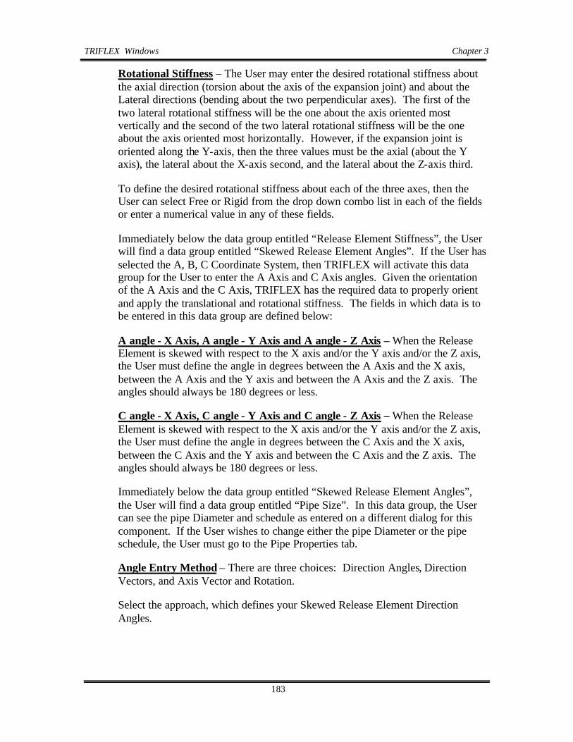
TRIFLEXWindows Chapter 3
183
Rotational Stiffness – The User may enter the desired rotational stiffness about the axial direction (torsion about the axis of the expansion joint) and about the Lateral directions (bending about the two perpendicular axes). The first of the two lateral rotational stiffness will be the one about the axis oriented most vertically and the second of the two lateral rotational stiffness will be the one about the axis oriented most horizontally. However, if the expansion joint is oriented along the Y-axis, then the three values must be the axial (about the Y axis), the lateral about the X-axis second, and the lateral about the Z-axis third.
To define the desired rotational stiffness about each of the three axes, then the User can select Free or Rigid from the drop down combo list in each of the fields or enter a numerical value in any of these fields.
Immediately below the data group entitled “Release Element Stiffness”, the User will find a data group entitled “Skewed Release Element Angles”. If the User has selected the A, B, C Coordinate System, then TRIFLEX will activate this data group for the User to enter the A Axis and C Axis angles. Given the orientation of the A Axis and the C Axis, TRIFLEX has the required data to properly orient and apply the translational and rotational stiffness. The fields in which data is to be entered in this data group are defined below:
A angle - X Axis, A angle - Y Axis and A angle - Z Axis – When the Release Element is skewed with respect to the X axis and/or the Y axis and/or the Z axis, the User must define the angle in degrees between the A Axis and the X axis, between the A Axis and the Y axis and between the A Axis and the Z axis. The angles should always be 180 degrees or less.
C angle - X Axis, C angle - Y Axis and C angle - Z Axis – When the Release Element is skewed with respect to the X axis and/or the Y axis and/or the Z axis, the User must define the angle in degrees between the C Axis and the X axis, between the C Axis and the Y axis and between the C Axis and the Z axis. The angles should always be 180 degrees or less.
Immediately below the data group entitled “Skewed Release Element Angles”, the User will find a data group entitled “Pipe Size”. In this data group, the User can see the pipe Diameter and schedule as entered on a different dialog for this component. If the User wishes to change either the pipe Diameter or the pipe schedule, the User must go to the Pipe Properties tab.
Angle Entry Method – There are three choices: Direction Angles, Direction Vectors, and Axis Vector and Rotation.
Select the approach, which defines your Skewed Release Element Direction Angles.

TRIFLEXWindows Chapter 3
184
Set Axes to “LNG” – By clicking on this box you will get the “Longitudinal Direction Calculator as shown in Figure 3.2.10.2-2.
This will give you the ability to define your Longitudinal Direction. Which will define the LNG axes.
Figure 3.2.10.2-2 Coding Joint Data, Longitudinal Direction Calculator
Pipe Diameter – In this field, the Pipe Diameter specified for this component is displayed.
Pipe Schedule - In this field, the Pipe Schedule specified for this component is displayed.

TRIFLEXWindows Chapter 3
185
3.2.11 Pressure Relief Valve
Figure 3.2.11-1 Coding Pressure Relief Valve, Pressure Relief Valve Tab
3.2.11.1 Pressure Relief Valve DataTab
To enter a Pressure Relief Valve component with or without a preceding Pipe, the User must click on the Pressure Relief Valve Icon on the Component Toolbar on the left border of the dialog or click on Components on the main menu at the top of the dialog and then on Pressure Relief Valve on the resulting pull down menu. Upon either of these sequences of actions, a Pressure Relief Valve dialog with a series of related dialogs will be presented to the User. Enter the data as noted below:
The data is organized in related data groups on each and every dialog. In the upper left corner of the Pressure Relief Valve dialog, a data group entitled “Element” is available for User data entry. The fields in which data can be entered in this data group are defined below:
From Node – In this field, TRIFLEX will generate a Node Number equal to the To Node number for the previously entered component. If the node number generated by TRIFLEX is not the desired node number, then the User may select a node number from the drop down combo list in this field or enter a node number, as desired.
To Node - In this field, TRIFLEX will generate a Node Number based upon the From Node number and the node increment specified by the User in the Default Settings. If the Node Number generated by TRIFLEX is not the desired node number, the User may select a node number from the drop down combo list in this field or enter any node number desired.

TRIFLEXWindows Chapter 3
186
Name – In this field, the User may specify any name that will fit within the field. This name indicator will likely assist the User or other interested parties in identifying the significance of the node. Entry of the name in this field is optional.
Immediately below the “Element” data, the User will find a data group entitled “Dimension from “From to Mid Node”. The dimension(s) entered in this data group define the vector from the previous node point to the To Node Point (the point where the User is placing the Node) of the valve being entered. The fields in which data can be entered in this data group are defined below:
Delta X, Delta Y and Delta Z – If the User is specifying the first component after an anchor, TRIFLEX will assume an “X” dimension equal to one foot, if English units are specified, or .35 Meters, if metric units are specified. If the node being defined follows another component other than an anchor, the assumed dimension will be along the vector line defined by the previous component. If the assumed length is incorrect or if the delta dimension should be along another axis or along two or three axes, the User may enter the desired data in the Delta X, Delta Y and/or Delta Z fields.
Abs Length – TRIFLEX will automatically calculate the absolute length and display it in this field. If the vector is in the same direction as the previously entered component, then the User may enter the absolute length desired and TRIFLEX will automatically calculate the Delta X, Delta Y and Delta Z dimensions and will display them in the appropriate fields.
Use the Minimum Length - If the User wishes to instruct TRIFLEX to use the Minimum Length as calculated by TRIFLEX based upon the length of the valve, any flanges and the preceding component, then the User should place a check in the box immediately to the left of the label “Use the Minimum Length”. TRIFLEX will then replace the absolute length with the minimum required length. This is particularly useful when the User desires to place a valve fitting make-up with the previous component and it eliminates the need for the User to perform manual math calculations.
Minimum Length – This field is a display field only. In this field, TRIFLEX displays the minimum length that must be provided between the previous Node Point and the To Node location being entered by the User. The Absolute Length dimension entered by the User must be equal to or greater than the minimum length computed by TRIFLEX.
Number of Intermediate Nodes – If the User enters a number in this field, TRIFLEX will break the pipe preceding the valve into one more segment that the number of intermediate nodes specified in this field. In other words, if the User enters a 2 in this field, TRIFLEX will place two (2) intermediate nodes between the to node and the from end of the valve. TRIFLEX will then break the pipe into three (3) segments.

TRIFLEXWindows Chapter 3
187
Maximum Spacing – The User may specify the maximum spacing between nodes in this field. If the lengths of the pipe components generated by TRIFLEX when the number of intermediate nodes is used by TRIFLEX to generate the intermediate nodes is longer than the length specified by the User in this field, then TRIFLEX will generate additional node points until the lengths between intermediate node points is less than the length specified by the User in this field.
Immediately below the data group entitled “Dimension from “From Node” to “To Node”, the User will find a data group entitled “Valve Type”. In this data group, the User must instruct TRIFLEX whether the valve is a flanged valve or a welded valve.
Flanged Pressure Relief Valve – The flanged valve radio button is the default selection. By accepting the radio button “Flanged Valve”, the User is telling TRIFLEX that a flanged valve is desired.
Welded Pressure Relief Valve - To tell TRIFLEX that a Welded Valve is desired, by clicking on the radio button immediately preceding “Welded Valve”, the User is telling TRIFLEX that a welded valve is desired.
Threaded Pressure Relief Valve – The threaded valve radio button changes the end connection to threaded. By accepting the radio button “Threaded Valve”, the User is telling TRIFLEX that a threaded valve is desired.
To the immediate right of the “Element” data group, the User will find a data group entitled “PRV Data”. The fields in which data can be entered in this data group are defined below:
Type – The User must select a Pressure Relief Valve (or PRV) Type from the drop down combo list in this field. The default PRV type is the Flanged AAAT Standard PRV. From our staff’s past experience, this PRV is an average PRV. The Type of PRV, along with the Rating, allows TRIFLEX to search through the PRV database to find the desired PRV. The current TRIFLEX PRV database consists of four flanged PRV types and four welded PRV types. In addition, the User may select “User Specified” in order to be able to enter their own weight and length. The Pressure Relief Valve types available in TRIFLEX are:
Flanged – AAAT Std. PRV Valve, Crosby PRV Valve, and User Specified
Welded - AAAT Std. PRV Relief Valve, and User Specified
Class Rating - The User must select a class rating from the drop down combo list in this field. The available class ratings are 150, 300, 600, 1500, 2500, 3705 and 5000. Given the valve type and the class rating, TRIFLEX will look up the appropriate corresponding weight, length, and insulation factor to be used in the calculations.

TRIFLEXWindows Chapter 3
188
PRV Height – The data shown in this field is looked up from the database by TRIFLEX or, if the User Specified valve is selected, the User can enter a desired value in this field.
Inlet Length – The data shown in this field is looked up from the database by TRIFLEX or, if the User Specified valve is selected, the User can enter a desired value in this field.
Inlet Diameter – The data shown in this field is looked up from the database by TRIFLEX or, if the User Specified valve is selected, the User can enter a desired value in this field.
Exit Length – The data shown in this field is looked up from the database by TRIFLEX or, if the User Specified valve is selected, the User can enter a desired value in this field.
Exit Diameter – The data shown in this field is looked up from the database by TRIFLEX or, if the User Specified valve is selected, the User can enter a desired value in this field.
PRV Weight – The data shown in this field is looked up from the database by TRIFLEX or, if the User Specified valve is selected, the User can enter a desired value in this field. The weight entered will be applied by TRIFLEX at the centroid of the Inlet Section of the Pressure Relief Valve.
Insulation Factor (ft, mm, m, mm) - if the User has specified the Type and Class Rating, the program will extract the insulation factor for the specified valve from the database. The User can input an insulation factor by overriding the value extracted from the database. The insulation factor is a value that when multiplied times the insulation weight per unit length will result in the weight of insulation to be placed on the valve. For example, an insulation factor of 1.5 means that the weight of insulation to be added to the valve weight will be equivalent to the weight of one foot of insulation on the adjacent pipe times a 1.5 factor when using the ENG input units.
If the User wants to enter a valve length or a valve weight or an insulation factor that is different than those selected by TRIFLEX from the TRIFLEX database, then the User should select User Specified on the Valve Type and then enter the desired values.
Directly below “PRV Data” group, the user will find a data group entitled “Direction From PRV Mid to Next Node”. The dimension(s) entered in this data group define the vector from the Mid node point to the Next Node Point (the point where the User is placing the Node) of the valve being entered. The fields in which data can be entered in this data group are defined below:
Delta X, Delta Y and Delta Z – If the User is specifying the first component after an anchor, TRIFLEX will assume an “X” dimension equal to one foot, if

TRIFLEXWindows Chapter 3
189
English units are specified, or .35 Meters, if metric units are specified. If the node being defined follows another component other than an anchor, the assumed dimension will be along the vector line defined by the previous component. If the assumed length is incorrect or if the delta dimension should be along another axis or along two or three axes, the User may enter the desired data in the Delta X, Delta Y and/or Delta Z fields.
To the immediate right of the “PRV Data” data group, the User will find a data group entitled “Flange Data”. The fields in which data can be entered in this data group are defined below:
Type – The User must select a Flange Type from the drop down combo list in this field. The default valve type is the AAAT Standard Flange. From our staff’s past experience, this flange is an average flange. The Type of flange, along with the Rating, allows TRIFLEX to search through the flange database to find the desired flange. The current TRIFLEX Flange database consists of five flange types. In addition, the User may select “User Specified” in order to be able to enter their own weight and length. The flange types available in TRIFLEX are:
AAAT Std. Flange, Blind Flange, Lap Joint Flange, Slip-on Flange, Weld Neck Flange and User Specified.
Flange Length – The data shown in this field is looked up from the database by TRIFLEX or, if the User Specified flange is selected, the User can enter a desired value in this field.
Flange Weight – The data shown in this field is looked up from the database by TRIFLEX or, if the User Specified flange is selected, the User can enter a desired value in this field.
Insulation Factor (ft, mm, m, mm) - if the User has specified the Type and Class Rating, the program will extract the insulation factor for the specified flange from the database. The User can input an insulation factor by overriding the value extracted from the database. The insulation factor is a value that when multiplied times the insulation weight per unit length of adjoining pipe will result in the weight of insulation to be placed on the flange. For example, an insulation factor of 1.5 means that the weight of insulation to be added to the flange weight will be equivalent to the weight of one foot of insulation on the adjacent pipe times a 1.5 factor when using the ENG input units.
If the User wants to enter a flange length or a flange weight or an insulation factor that is different than those selected by TRIFLEX from the TRIFLEX database, then the User should select User Specified on the Flange Type and then enter the desired values.

TRIFLEXWindows Chapter 3
190
Flange on “From End” - If the User wishes to instruct TRIFLEX to have a flange on the beginning end or from end of the valve, then the User should place a check in the box immediately to the left of the label “Flange on From End”.
Flange on “To End” - If the User wishes to instruct TRIFLEX to have a flange on the far end or to end of the valve, then the User should place a check in the box immediately to the left of the label “Flange on To End”.
Immediately below the data group entitled “Flange Data”, the User will find additional data fields for miscellaneous data defined as follows:
SI Factor for “From Node” – If the User wishes to specify a numerical stress intensification factor on the beginning of the pipe section preceding the valve defined in this component, then the User should enter the desired numerical value in this field.
Weight Off - If the User wishes to tell TRIFLEX to consider the component being entered as weightless, then the User should place a check in the box immediately to the left of the label “Weight Off”. The default is for weight to be considered.
Buoyancy - If the User wishes to tell TRIFLEX to consider the effects of buoyancy on this component, then the User should place a check in the box immediately to the left of the label “Buoyancy Calculations”. The density of the fluid surrounding the pipe should also be specified on the Setup / Modeling Defaults dialog. The default is for the effects of buoyancy not to be considered.
Immediately below the data group for the miscellaneous data fields, the User will find the Property Ripple button. See Section 3.3.1.1 to learn the Ripple command.

TRIFLEXWindows Chapter 3
191
3.3 Common dialogs for all Component Types
3.3.1 Pipe Properties Tab
Figure 3.3.1-1 Anchor Component, Pipe Properties Tab
For every piping system to be properly analyzed, the User must enter basic piping properties. To enter these required piping properties, the User must click on the Pipe Properties tab at the top of the screen on the first component entered. Upon clicking on the tab, a Pipe Properties dialog will be presented to the User.
The data is organized in related data groups on this dialog. In the upper left corner of the Pipe Properties dialog, a data group entitled “Pipe Size” is available for User data entry. The fields in which data can be entered in this data group are defined below:
Nominal Dia. – In this field, TRIFLEX will display the default pipe size of 6” for the first pipe component. If the desired nominal Diameter is any size other than 6”, the User may select a different nominal Diameter from the drop down combo list in this field. In the event that the User does not find the desired nominal Diameter in the list provided, the User may select “User Specified” and enter the exact outside Diameter of the pipe for this particular pipe size and application or can add the desired nominal pipe Diameter to the library of pipe Diameters by clicking on “Utilities” then “Databases” then “Pipe”.
Outside Dia. - When the User has entered a nominal Diameter, TRIFLEX will display, in this field, the outside Diameter of the pipe that TRIFLEX looked up in the internal database for the nominal Diameter selected by the User. The field will be grayed out and inaccessible to the User, except through the Nominal Diameter field. When the User has selected “User Specified” in the Nominal

TRIFLEXWindows Chapter 3
192
Diameter field, TRIFLEX will activate the field and thereby enable the User to enter an actual outside Diameter of the pipe.
Pipe Schedule – When the User has entered a nominal Diameter; the User may select the desired pipe schedule from the drop down combo list in this field. In the event that the User does not find the desired pipe schedule in the list provided, the User may select “User Specified” and enter the exact pipe wall thickness or can add the desired custom pipe Diameter and pipe schedule/wall thickness to the library of pipe Diameters by clicking on “Utilities” then “Databases” then “Pipe”.
Pipe Wall Thickness – When the User has entered a Nominal Diameter and a Pipe Schedule, TRIFLEX will display, in this field, the wall thickness of the pipe that TRIFLEX looked up in the internal database for the nominal Diameter and schedule selected by the User. In the event that the User did not find the desired pipe schedule in the list provided and the User selected “User Specified”, the User may then enter the exact pipe wall thickness in this field.
Inside Dia. - In this field, TRIFLEX will calculate and display the actual inside Diameter of the pipe. From the User-entered outside Diameter, TRIFLEX will subtract two times the pipe wall thickness. The resultant value will be displayed in this field. The field will be grayed out and inaccessible to the User, except through the appropriate pipe size fields.
Corrosion Allow. - If the User specifies a corrosion allowance in this field, TRIFLEX will perform a worst-case analysis (i.e., for calculating the forces and moments, the full un-corroded wall thickness will be assumed). For calculating stresses, the program will assume that the pipe is in the fully corroded state. The default value for this field is zero.
ü Immediately below the “Pipe Size” data, the User will find a data group entitled “Contents”. The data entered in this data group define the weight of the contents of the component defined on the node dialog. The fields in which data can be entered in this data group are defined below:
Specific Gravity - If the User specifies a numeric value in this field, TRIFLEX will consider the value to be the liquid specific gravity of the contents of the component defined on the node dialog. TRIFLEX will calculate the weight per unit length for the contents based upon the specific gravity entered by the User and the inside Diameter of the piping component. This value will then be shown in the Weight/Unit Len. Field located immediately below this field. The default value for this field is zero. For water filled piping, the User should enter a contents specific gravity of 1.0.
Weight/Unit Len. - In this field, TRIFLEX will calculate and display the actual weight per unit length of the contents of the pipe. The field will be grayed out and inaccessible to the User, except through the specific gravity field.

TRIFLEXWindows Chapter 3
193
To the immediate right of the data group entitled “Pipe Size”, the User will find a data group entitled “Pipe Material”. The fields in which data can be entered in this data group are defined in section “3.2.1.2 Anchor Component, Pipe Properties, Material Selection”. Note the difference between Generic Database and the ASME Database.

TRIFLEXWindows Chapter 3
194
3.3.1.1 Rippling Property Changes (HOW TO RIPPLE)
Figure 3.3.1.1-1 Pipe Properties Tab, Ripple
Ripple - Is simply copying an attribute from the component that you are on to the component you select as a change point. That is “Ripple” from component 3 which would be the current component to component 21. The reason being that at component 22 you would have a different attribute. In figure 3.3.1.1-2 we can see that the Pipe Size changes after component 21. Therefore a Ripple from component number 1 to component number 21 could change the pipe size of all existing pipe that is 8 inches in diameter in this example.
Figure 3.3.1.1-2 Pipe Properties Tab, Ripple

TRIFLEXWindows Chapter 3
195
Ripple Size – When the User has modified one or more properties in the Pipe Size data group, the User can instruct TRIFLEX to modify all subsequent occurrences of these properties that are in an unbroken series from the original revision forward by pressing the Ripple Size button.
Ripple Contents – When the User has modified one or more properties in the Contents data group, the User can instruct TRIFLEX to modify all subsequent occurrences of these properties that are in an unbroken series from the original revision forward by pressing the Ripple Contents button.
Ripple Material – When the User has modified one or more properties in the Pipe Material data group, the User can instruct TRIFLEX to modify all subsequent occurrences of these properties that are in an unbroken series from the original revision forward by pressing the Ripple Material button.
Ripple Insulation – When the User has modified one or more properties in the Pipe Insulation data group, the User can instruct TRIFLEX to modify all subsequent occurrences of these properties that are in an unbroken series from the original revision forward by pressing the Ripple Insulation button.

TRIFLEXWindows Chapter 3
196
3.3.2 Process Tab
Figure 3.3.2.0-1 Anchor Component, Process Tab
For every piping system to be properly analyzed, the User must enter basic piping properties and process data. To enter the required data, the User must click on the Process tab at the top of the screen on the first component entered. Upon clicking on the tab, a Process dialog will be presented to the User.
In the upper left corner of the Process dialog, a data group entitled “Material” is available for User data entry. The fields in which data can be entered in this data group are defined below:
Material – This field is identical to the Material field that is found on the Pipe Properties dialog, except that is not accessible. The field is a display field only and is grayed out. The information is provided for the User to see the material that the User selected on the Pipe Properties dialog. In the event that the User wishes to change this material, the User must return to the Pipe Properties dialog.
Base Temperature – In this field, the User can specify the base or ambient temperature at time of fabrication / installation. The default value assumed by TRIFLEX is 70 degrees F or 21 degrees C.
The remaining data that can be entered by the User on this dialog is requested on a case-by-case basis. In this release of TRIFLEX, six cases can be specified and processed one at a time or in combination. When a piping material is selected by the User from the database contained in TRIFLEX, the User may specify, on this dialog, the internal pressure, the temperature and whether the installed or operating modulus of elasticity is to be used. When the User selects “User Specified” for the piping material, the User may specify the modulus of elasticity

TRIFLEXWindows Chapter 3
197
and the coefficient of expansion to be used in the analysis. The User can also enter the temperature when “User Specified” is selected for material; however, the temperature entry has no effect on the analysis of User Specified materials.
Pressure – In this field, the User may enter the internal pressure for each of six cases. Data can only be entered in an active field (one that is not grayed out). To activate a case, the User must go to Setup on the main menu, then Case Definition and then must place a check mark in the Process this Case check box for the desired case. The default value is zero.
Temperature – In this field, the User may enter the temperature for each of six cases. Data can only be entered in an active field (one that is not grayed out). The default value is the value for ambient temperature for the system of units selected by the User. The default value is Zero.
Use Installed Modulus / Use Operating Modulus – The selection of one or the other of these options is accomplished by the provision of two radio buttons. The default selection is “Use Installed Modulus”. The User should select the Installed Modulus when performing piping code compliance studies. The User can select Use Operating Modulus in order to calculate loads on equipment if allowed by the equipment vendor. Use of the operating temperature modulus will also more accurately calculate distributed loads for the internal weight effect in an automated spring hanger sizing analyses. The resultant deflections using the operating modulus will also be more accurately calculated.
Modulus of Elasticity – When the User has selected a material from the material database contained within TRIFLEX; this field will be grayed out or inactive. In this field, the value of Modulus of Elasticity that TRIFLEX has selected from the TRIFLEX database will be displayed. When the User has selected “User Specified” for the piping material, the User may enter in this field the value of the modulus of elasticity to be used by TRIFLEX in the analysis.
Coeff. Of Expansion – When the User has selected a material from the material database contained within TRIFLEX; this field will be grayed out or inactive. In this field, the value of coefficient of expansion that TRIFLEX has selected from the TRIFLEX database will be displayed. When the User has selected “User Specified” for the piping material, the User may enter in this field the value of the coefficient of expansion to be used by TRIFLEX in the analysis.
Ripple Material – When the User has modified one or more properties in the Pipe Material data group, the User can instruct TRIFLEX to modify all subsequent occurrences of these properties that are in an unbroken series from the original revision forward by pressing the Ripple Material button.

TRIFLEXWindows Chapter 3
198
3.3.3 Restraints Tab
Figure 3.3.3.0-1 Restraint Tab for General Pipe Support or Restraint
Restraints may be entered on the following components: Pipe, Bend/Elbow, Branch Connection, Valve, Flange, Reducer and Joint. A Restraint is not a component in TRIFLEX; it is an attachment to a piping component that enables an external action to be applied on the piping system. To enter a restraint on the piping system, select any of the above noted components and the Restraint tab will be displayed as one of the tabs along the top edge of the component dialogs. To enter a restraint, click on the Restraint tab at the top of the dialog and the Restraint dialog will be presented to the User. Enter the data as noted below:
The data is organized in related data groups on the Restraint dialog. In the upper left corner of the “Restraint” dialog, a data group entitled “Element” is available for User data entry. The fields in which data can be entered in this data group are defined below:
Load Case – This field is reserved for future use and is grayed out at this time.
Node Num. – In this field, TRIFLEX displays the To Node number for the component on which the restraints are to be applied. The field is grayed out since the node number may not be altered on this dialog.
Name – Entry of the name in this field is optional and is grayed out and not available for use in this case.
Immediately below the “Element” data, the User will find a data group entitled “Coordinate System”. In this data group, the User defines the axis system that will be used to describe the restraint action. TRIFLEX provides three different axis systems to choose from: 1) the standard X, Y, Z axis system, 2) the L, N, G

TRIFLEXWindows Chapter 3
199
axis system which enables a User to enter restraints along the axis of the pipe and along the axes perpendicular to the pipe, 3) and the A, B, C axis system which enables a User to enter restraints along an axis system that may be skewed in relationship to the X, Y, Z axis system as well as the L, N, G axis system. The User clicks on a radio button to select the desired axis system. The options available for the User are defined below:
X, Y, Z Coord. System – The default axis system is the X, Y, and Z-axis system. The radio button to the left of this title will be selected as the default. When the User selects the X, Y, Z coordinate system, all restraint action specified by the User will be applied along the X, Y or Z-axes. No orientation angles are required when the X, Y, Z coordinate system is selected. When the X, Y, Z coordinate system is selected by the User, TRIFLEX will display the Translational Restraint Action data group and the Rotational Restraint Action data group with the X axis, Y axis and Z axis headings and orientation angles will not be accepted as input.
L, N, G Coord. System – When the User selects the L, N, G coordinate system; all restraint action specified by the User will be applied along the L, N or G axes. No orientation angles are required to be entered by the User. TRIFLEX will automatically compute the orientation angles internally when the User selects the L, N, and G coordinate system. The axis convention for the L, N, and G coordinate system is as follows:
L is along the axis of the pipe and positive in the direction of coding.
N is normal to the pipe and most vertical.
G is perpendicular to the pipe and horizontal (guide).
When the L, N, G coordinate system is selected by the User, TRIFLEX will display the Translational Restraint Action data group and the Rotational Restraint Action data group with the L axis, N axis and G axis headings.
A, B, C Coord. System – When the User selects the A, B, C coordinate system, all restraint action specified by the User will be applied along the A, B or C axes. Orientation angles must be entered by the User when the A, B, C coordinate system is selected. The A, B, C axis system is a standard right hand rule axis system that can be oriented as desired by the User. The User simply must orient the A, B, and C axis system with respect to the X, Y Z axis system. When the A, B, C coordinate system is selected by the User, TRIFLEX will display the Translational Restraint Action data group and the Rotational Restraint Action data group with the A axis, B axis and C axis headings.
Use Directional Vectors – This option is the default when the User selects the A, B, And C Coordinate System. When the User selects this option, the User must specify the vectorial direction of a skewed restraint. The length of the X, Y, and Z vectors must be coded from the point of the restraint attachment on the pipe to

TRIFLEXWindows Chapter 3
200
the point of restraint attachment on the external structure. The resultant of the X, Y, and Z vectors defines the orientation of the A axis along which the restraint action will be applied. When this option is selected, the User can only enter a restraint along or about the A axis.
The User must enter the directional vectors in decimal values in the three fields provided - the X-axis, the Y-axis and the Z-axis. Note: these vectors only provide the A axis orientation and the resultant specific length has no significance.
Use Action Angles – When the User selects the A, B, C coordinate system and wishes to enter restraints along or about more than one axis; the User should select this option. This enables the User to specify the angles between the X, Y, Z coordinate system and the A, B, and C coordinate system along and about which the User can enter restraints.
The User must define the orientation of the A axis and the C axis in order for TRIFLEX to completely orient the A, B, C coordinate system in relation to the X, Y, Z coordinate sys tem. The User must specify the angles that the A-axis makes with the +X, +Y, and +Z-axes and the C-axis makes with the +X, +Y, and +Z-axes. The angles specified will be between 0 and 180 degrees.

TRIFLEXWindows Chapter 3
201
Figure 3.3.3.0-3 XYZ and ABC Coordinate Systems
Immediately below the data group entitled “Coordinate System”, the User will find an individual data item defined as follows:
Friction Coefficient – The default condition for this field is grayed out and inaccessible for data entry. In order for the User to be able to enter a coefficient of frictional resistance to movement, the User must have done one of the following:
Selected the X, Y, Z Coordinate System and have selected a +Y or a +/- Y or a –Y restraint
Selected the L, N, G Coordinate System and have selected a +N or a +/- N or a –N restraint
Selected the A, B, C Coordinate System and have selected a +B or a +/- B or a –B restraint
The coefficient of frictional resistance must be determined by the User and entered in this field. If this field is left blank, the frictional resistance will be considered to be zero. The actual frictional restraining force is iteratively calculated by TRIFLEX. Section 5 in the TRIFLEX User Manual contains an in-depth discussion of modeling with frictional restraints.

TRIFLEXWindows Chapter 3
202
Immediately to the right of the data group entitled “Element”, the User will find a data group entitled “Translational Restraint Action”. When the X, Y, Z coordinate system is selected by the User, TRIFLEX will display the Translational Restraint Action data group with the X axis, Y axis and Z axis headings. When the L, N, G coordinate system is selected by the User, TRIFLEX will display the Translational Restraint Action data group with the L axis, N axis and G axis headings. When the A, B, C coordinate sys tem is selected by the User, TRIFLEX will display the Translational Restraint Action data group with the A axis, B axis and C axis headings. The fields in which data can be entered in this data group are defined below:

TRIFLEXWindows Chapter 3
203
3.3.3.1 Restraints Tab, X, Y, Z coordinate system
Figure 3.3.3.1-1 X,Y,Z coordinate system Pipe Support or Restraint
Figure 3.3.3.1-2 X,Y,Z coordinate system Restraint Tab
Note: X Axis check can only be placed in one check box for each translational axis action.

TRIFLEXWindows Chapter 3
204
+ By placing a check in this check box, the User instructs TRIFLEX to apply a one directional restraint acting in the + X direction. This restraint resist movement in the negative X direction and allows movement in the positive X direction.
+ And - By placing a check in this check box, the User instructs TRIFLEX to apply a two directional translational restraint acting in the + and - X direction. This restraint resist movement in the positive and negative X directions. In other words, all movement along the X-axis will be prevented.
- By placing a check in this check box, the User instructs TRIFLEX to apply one directional restraint acting in the - X direction. This restraint resist movement in the positive X direction and allows movement in the negative X direction.
Limit Stops - By placing a check in this check box, the User instructs TRIFLEX to apply limit stop acting along the X-axis.
A limit stop is a device that will prevent further movement of a pipe after it has moved a specified allowed distance. This type of restraining action has also been referred to as a gap element. Through the use of limit stops and the limit fields, it is possible to code movement limits for a data point. It is also possible to code an initial movement of the pipe with the condition that if the pipe would tend to move away from this point, it may. By simply coding any one limit and zero (0) as the other limit, a one-directional limit stop may be coded. Users may code different gap spaces in each direction (positive and negative). In addition, both gaps can be specified with the same sign resulting in an initial movement being imposed and then a gap until the larger movement is encountered.
When a check is placed in the limit stop check box, the labels of the following three fields will be altered to allow the User to enter the following data:
Upper Limit – In this field, the User may specify the upper limit for the limit stop along the X-axis. The upper limit will be the most positive value for the limit stop.
Lower Limit – In this field, the User may specify the lower limit for the limit stop along the X-axis. The lower limit will be the least positive value for the limit stop.
Stiffness - In this field, the User may specify the stiffness of the limit stop along the X-axis. This stiffness will only come into effect after the pipe has deflected freely to the limit position of the limit stop. If no value for stiffness is specified by the User, TRIFLEX will assume the limit stop restraint to be totally rigid. To enter a definable value for the stiffness, the User must type the desired numerical value in this field.

TRIFLEXWindows Chapter 3
205
When no check mark is placed in any of the four check boxes at the top of this column, the labels of the three fields following the Limit Stop check box will be as set forth below and will allow the User to enter the following data:
Movement - In this field, the User may define a Movement that the User wishes to impose on the pipe at the restraint location. If the Movement is to be applied to the pipe in the negative X direction, then the User must enter the numerical value preceded by a negative sign. When the User has entered a Movement along the X-axis, the Force and Stiffness fields are grayed out in order to prevent the User from entering data in these fields. When the User enters a movement in this field, TRIFLEX will impose this Movement on the piping system and will hold the piping system at that position in the analysis.
Force - In this field, the User may define a Force that the User wishes to impose on the pipe at the restraint location. If the Force is to be applied to the pipe in the negative X direction, then the User must enter the numerical value preceded by a negative sign. If the Force is to be applied to the pipe in the positive X direction, then the User need not enter any sign. When a User has entered a Force along the X-axis, the Stiffness field will default to Free and the Movement field will be grayed out in order to prevent a movement from being entered in this field by the User. When the User enters a numerical value for the Force in this field, TRIFLEX will imposed this force on the piping system and will continue to apply this Force no matter where the piping system moves.
Stiffness - The default for the Stiffness field is “FREE”. To enter a definable value for the stiffness, the User must type the desired numerical value in this field. To make the stiffness Free after having entered some other value, simply type F and TRIFLEX will display the word FREE.
When no check mark is placed in any of the top four check boxes and no values are entered for movement, force and stiffness, the User still has the option to instruct TRIFLEX to apply a damper at the Node Location as follows:
Damper - By placing a check in this check box, the User instructs TRIFLEX to apply a damper acting in the + and - X direction. A damper is a two directional restraint that is considered to be totally rigid when an occasional loading case is being processed and totally free when an operating case is being processed. In other words, all movement along the X-axis will be allowed by the damper in the operating case but will be prevented in the occasional load case.
NOTE: Y-Axis check can only be placed in one check box for each translational axis action.
+ By placing a check in this check box, the User instructs TRIFLEX to apply a one directional restraint acting in the + Y direction. These restraints resist movement in the negative Y direction and allow movement in the positive Y direction.

TRIFLEXWindows Chapter 3
206
+ And - By placing a check in this check box, the User instructs TRIFLEX to apply a two directional translational restraint acting in the + and - Y direction. These restraints resist movement in the positive and negative Y directions. In other words, all movement along the Y-axis will be prevented.
- By placing a check in this check box, the User instructs TRIFLEX to apply a one directional restraint acting in the - Y direction. These restraints resist movement in the positive Y direction and allow movement in the negative Y direction.
Limit Stops - By placing a check in this check box, the User instructs TRIFLEX to apply limit stop acting along the Y-axis. For more details concerning the application of a typical limit stop, see the discussion for limit stop acting along the X-axis.
When a check is placed in the limit stop check box, the labels of the following three fields will be altered to allow the User to enter the following data:
Upper Limit – In this field, the User may specify the upper limit for the limit stop along the Y-axis. The upper limit will be the most positive value for the limit stop.
Lower Limit – In this field, the User may specify the lower limit for the limit stop along the Y-axis. The lower limit will be the least positive value for the limit stop.
Stiffness - In this field, the User may specify the stiffness of the limit stop along the Y-axis. This stiffness will only come into effect after the pipe has deflected freely to the limit position of the limit stop. If no value for stiffness is specified by the User, then TRIFLEX will assume the limit stop restraint to be totally rigid. To enter a definable value for the stiffness, the User must type the desired numerical value in this field.
When no check mark is placed in any of the four check boxes at the top of this column, the labels of the three fields following the Limit Stop check box will be as set forth below and will allow the User to enter the following data:
Movement - In this field, the User may define a Movement that the User wishes to impose on the pipe at the restraint location. If the Movement is to be applied to the pipe in the negative Y direction, then the User must enter the numerical value preceded by a negative sign. When the User has entered a Movement along the Y-axis, the Force and Stiffness fields are grayed out in order to prevent the User from entering data in these fields. When the User enters a movement in this field, TRIFLEX will impose this Movement on the piping system and will hold the piping system at that position in the analysis.

TRIFLEXWindows Chapter 3
207
Force - In this field, the User may define a Force that the User wishes to impose on the pipe at the restraint location. If the Force is to be applied to the pipe in the negative Y direction, then the User must enter the numerical value preceded by a negative sign. If the Force is to be applied to the pipe in the positive Y direction, then the User need not enter any sign. When a User has entered a Force along the Y-axis, the Stiffness field will default to Free and the Movement field will be grayed out in order to prevent a movement from being entered in this field by the User. When the User enters a numerical value for the Force in this field, TRIFLEX will imposed this force on the piping system and will continue to apply this Force no matter where the piping system moves.
Stiffness - The default for the Stiffness field is “FREE”. To enter a definable value for the stiffness, the User must type the desired numerical value in this field. To make the stiffness Free after having entered some other value, simply type F and TRIFLEX will display the word FREE.
When no check mark is placed in any of the top four check boxes and no values are entered for movement, force and stiffness, the User still has the option to instruct TRIFLEX to apply a damper at the Node Location as follows:
Damper - By placing a check in this check box, the User instructs TRIFLEX to apply a damper acting in the + and - Y direction. A damper is a two directional restraint that is considered to be totally rigid when an occasional loading case is being processed and totally free when an operating case is being processed. In other words, all movement along the Y-axis will be allowed by the damper in the operating case but will be prevented in the occasional load case.
Note: Z Axis check can only be placed in one check box for each translational axis action.
+ By placing a check in this check box, the User instructs TRIFLEX to apply a one directional restraint acting in the + Z direction. This restraint resists movement in the negative Z direction and allows movement in the positive Z direction.
+ And - By placing a check in this check box, the User instructs TRIFLEX to apply a two directional translational restraint acting in the + and - Z direction. These restraints resist movement in the positive and negative Z directions. In other words, all movement along the Z-axis will be prevented.
- By placing a check in this check box, the User instructs TRIFLEX to apply a one directional restraint acting in the - Z direction. These restraints resist movement in the positive Z direction and allow movement in the negative Z direction.

TRIFLEXWindows Chapter 3
208
Limit Stops - By placing a check in this check box, the User instructs TRIFLEX to apply limit stop acting along the Z-axis. For more details concerning the application of a typical limit stop, see the discussion for limit stop acting along the X-axis
When a check is placed in the limit stop check box, the labels of the following three fields will be altered to allow the User to enter the following data:
Upper Limit – In this field, the User may specify the upper limit for the limit stop along the Z-axis. The upper limit will be the most positive value for the limit stop.
Lower Limit – In this field, the User may specify the lower limit for the limit stop along the Z-axis. The lower limit will be the least positive value for the limit stop.
Stiffness - In this field, the User may specify the stiffness of the limit stop along the Z-axis. This stiffness will only come into effect after the pipe has deflected freely to the limit position of the limit stop. If no value for stiffness is specified by the User, TRIFLEX will assume the limit stop restraint to be totally rigid. To enter a definable value for the stiffness, the User must type the desired numerical value in this field.
When no check mark is placed in any of the four check boxes at the top of this column, the labels of the three fields following the Limit Stop check box will be as set forth below and will allow the User to enter the following data:
Movement - In this field, the User may define a Movement that the User wishes to impose on the pipe at the restraint location. If the Movement is to be applied to the pipe in the negative Z direction, then the User must enter the numerical value preceded by a negative sign. When the User has entered a Movement along the Z-axis, the Force and Stiffness fields are grayed out in order to prevent the User from entering data in these fields. When the User enters a movement in this field, TRIFLEX will impose this Movement on the piping system and will hold the piping system at that position in the analysis.
Force - In this field, the User may define a Force that the User wishes to impose on the pipe at the restraint location. If the Force is to be applied to the pipe in the negative Z direction, then the User must enter the numerical value preceded by a negative sign. If the Force is to be applied to the pipe in the positive Z direction, then the User need not enter any sign. When a User has entered a Force along the Z-axis, the Stiffness field will default to Free and the Movement field will be grayed out in order to prevent a movement from being entered in this field by the User. When the User enters a numerical value for the Force in this field, TRIFLEX will imposed this force on the piping system and will continue to apply this Force no matter where the piping system moves.

TRIFLEXWindows Chapter 3
209
Stiffness - The default for the Stiffness field is “FREE”. To enter a definable value for the stiffness, the User must type the desired numerical value in this field. To make the stiffness Free after having entered some other value, simply type F and TRIFLEX will display the word FREE.
When no check mark is placed in any of the top four check boxes and no values are entered for movement, force and stiffness, the User still has the option to instruct TRIFLEX to apply a damper at the Node Location as follows:
Damper -By placing a check in this check box, the User instructs TRIFLEX to apply a damper acting in the + and - Z direction. A damper is a two directional restraint that is considered to be totally rigid when an occasional loading case is being processed and totally free when an operating case is being processed. In other words, all movement along the Z-axis will be allowed by the damper in the operating case but will be prevented in the occasional load case.
Immediately below the data group entitled “Translational Restraint Action”, the User will find a data group entitled “Rotational Restraint Action”. When the X, Y, Z coordinate system is selected by the User, TRIFLEX will display the Rotational Restraint Action data group with the X axis, Y axis and Z axis headings. When the L, N, G coordinate system is selected by the User, TRIFLEX will display the Rotational Restraint Action data group with the L axis, N axis and G axis headings. When the A, B, C coordinate system is selected by the User, TRIFLEX will display the Rotational Restraint Action data group with the A axis, B axis and C axis headings. The fields in which data can be entered in this data group are defined below:
X, Y, Z coordinate system
X Axis
+ And - By placing a check in this check box, the User instructs TRIFLEX to apply a two directional rotational restraint acting about the X axis. These restraints resist rotation about the X-axis in the positive and negative directions. In other words, all rotations about the X-axis will be prevented.
When no check mark is placed in the + and - check box, the User may enter data in the following three fields:
Rotation - In this field, the User may define a Rotation that the User wishes to impose on the pipe at the restraint location. If the Rotation is to be applied to the pipe about the X-axis in the negative direction, then the User must enter the numerical value preceded by a negative sign. When the User has entered a Rotation about the X-axis, the Moment and Stiffness fields are grayed out in order to prevent the User from entering data in these fields. When the User enters a

TRIFLEXWindows Chapter 3
210
rotation in this field, TRIFLEX will impose this Rotation on the piping system and will hold the piping system at that position in the analysis.
Moment - In this field, the User may define a Moment that the User wishes to impose on the pipe at the restraint location. If the Moment is to be applied to the pipe about the X-axis in the negative direction, then the User must enter the numerical value preceded by a negative sign. If the Moment is to be applied to the pipe about the X-axis in the positive direction, then the User need not enter any sign. When a User has entered a Moment about the X-axis, the Stiffness field will default to Free and the Rotation field will be grayed out in order to prevent a rotation from being entered in this field by the User. When the User enters a numerical value for the Moment in this field, TRIFLEX will impose this moment on the piping system and will continue to apply this Moment no matter where the piping system moves.
Stiffness - The default for the Stiffness field is “FREE”. To enter a definable value for the stiffness, the User must type the desired numerical value in this field. To make the stiffness Free after having entered some other value, simply type F and TRIFLEX will display the word FREE.
Y Axis
+ And - By placing a check in this check box, the User instructs TRIFLEX to apply a two directional rotational restraint acting about the Y axis. These restraints resist rotation about the Y-axis in the positive and negative directions. In other words, all rotations about the Y-axis will be prevented.
When no check mark is placed in the + and - check box, the User may enter data in the following three fields:
Rotation - In this field, the User may define a Rotation that the User wishes to impose on the pipe at the restraint location. If the Rotation is to be applied to the pipe about the Y-axis in the negative direction, then the User must enter the numerical value preceded by a negative sign. When the User has entered a Rotation about the Y-axis, the Moment and Stiffness fields are grayed out in order to prevent the User from entering data in these fields. When the User enters a rotation in this field, TRIFLEX will impose this Rotation on the piping system and will hold the piping system at that position in the analysis.
Moment - In this field, the User may define a Moment that the User wishes to impose on the pipe at the restraint location. If the Moment is to be applied to the pipe about the Y-axis in the negative direction, then the User must enter the numerical value preceded by a negative sign. If the Moment is to be applied to the pipe about the Y-axis in the positive direction, then the User need not enter any sign. When a User has entered a Moment about the Y-axis, the Stiffness field will default to Free and the Rotation field will be grayed out in order to prevent a

TRIFLEXWindows Chapter 3
211
rotation from being entered in this field by the User. When the User enters a numerical value for the Moment in this field, TRIFLEX will impose this moment on the piping system and will continue to apply this Moment no matter where the piping system moves.
Stiffness - The default for the Stiffness field is “FREE”. To enter a definable value for the stiffness, the User must type the desired numerical value in this field. To make the stiffness Free after having entered some other value, simply type F and TRIFLEX will display the word FREE.
Z Axis
+ And - By placing a check in this check box, the User instructs TRIFLEX to apply a two directional rotational restraint acting about the Z axis. These restraints resist rotation about the Z-axis in the positive and negative directions. In other words, all rotations about the Z-axis will be prevented.
When no check mark is placed in the + and - check box, the User may enter data in the following three fields:
Rotation - In this field, the User may define a Rotation that the User wishes to impose on the pipe at the restraint location. If the Rotation is to be applied to the pipe about the Z-axis in the negative direction, then the User must enter the numerical value preceded by a negative sign. When the User has entered a Rotation about the Z-axis, the Moment and Stiffness fields are grayed out in order to prevent the User from entering data in these fields. When the User enters a rotation in this field, TRIFLEX will impose this Rotation on the piping system and will hold the piping system at that position in the analysis.
Moment - In this field, the User may define a Moment that the User wishes to impose on the pipe at the restraint location. If the Moment is to be applied to the pipe about the Z-axis in the negative direction, then the User must enter the numerical value preceded by a negative sign. If the Moment is to be applied to the pipe about the Z-axis in the positive direction, then the User need not enter any sign. When a User has entered a Moment about the Z-axis, the Stiffness field will default to Free and the Rotation field will be grayed out in order to prevent a rotation from being entered in this field by the User. When the User enters a numerical value for the Moment in this field, TRIFLEX will impose this moment on the piping system and will continue to apply this Moment no matter where the piping system moves.
Stiffness - The default for the Stiffness field is “FREE”. To enter a definable value for the stiffness, the User must type the desired numerical value in this field. To make the stiffness Free after having entered some other value, simply type F and TRIFLEX will display the word FREE.

TRIFLEXWindows Chapter 3
212
3.3.3.2 Restraints Tab, L, N, G coordinate system
Figure 3.3.3.2-1 L,N,G coordinate system Pipe Support or Restraint
Figure 3.3.3.2-2 L,N,G coordinate system Restraint Tab
Note: L Axis check can only be placed in one check box for each translational axis action. The L axis is coincident with the axis of the pipe.

TRIFLEXWindows Chapter 3
213
+ And - By placing a check mark in this check box, the User instructs TRIFLEX to apply a two directional translational restraint acting in the + and - L direction. This restraint will resist movement in the positive and negative L directions. In other words, all movement along the axis of the pipe will be prevented.
Limit Stops - By placing a check mark in this check box, the User instructs TRIFLEX to apply limit stop acting along the L axis.
A limit stop is a device that will prevent further movement of a pipe after it has moved a specified allowed distance. This type of restraining action has also been referred to as a gap element. Through the use of limit stops and the limit fields, it is possible to code movement limits for a data point. It is also possible to code an initial movement of the pipe with the condition that if the pipe would tend to move away from this point, it may. By simply coding any one limit and zero (0) as the other limit, an one-directional limit stop may be coded. Users may code different gap spaces in each direction (positive and negative). In addition, both gaps can be specified with the same sign resulting in an initial movement being imposed and then a gap until the larger movement is encountered.
When a check is placed in the limit stop check box, the labels of the following three fields will be altered to allow the User to enter the following data:
Upper Limit – In this field, the User may specify the upper limit for the limit stop along the L axis. The upper limit will be the most positive value for the limit stop.
Lower Limit – In this field, the User may specify the lower limit for the limit stop along the L axis. The lower limit will be the least positive value for the limit stop.
Stiffness - In this field, the User may specify the stiffness of the limit stop along the L axis. This stiffness will only come into effect after the pipe has deflected freely to the limit position of the limit stop. If the User specifies no value for stiffness, TRIFLEX will assume the limit stop restraint to be totally rigid. To enter a definable value for the stiffness, the User must type the desired numerical value in this field.
Note: N Axis check mark can only be placed in one check box for each translational axis action). The N axis is normal to the pipe and the +N direction is the most vertical.
+ By placing a check mark in this check box, the User instructs TRIFLEX to apply a one directional restraint acting in the + N direction. These

TRIFLEXWindows Chapter 3
214
restraints resist movement in the negative N direction and allow movement in the positive N direction.
+ And - By placing a check mark in this check box, the User instructs TRIFLEX to apply a two directional translational restraint acting in the + and - N direction. These restraints resist movement in the positive and negative N directions. In other words, all movement along the N axis will be prevented.
- By placing a check mark in this check box, the User instructs TRIFLEX to apply a one directional restraint acting in the - Y direction. These restraints resist movement in the positive N direction and allow movement in the negative N direction.
Limit Stops - By placing a check mark in this check box, the User instructs TRIFLEX to apply limit stop acting along the N axis. For more details concerning the application of a typical limit stop, see the discussion for limit stop acting along the L axis.
When a check mark is placed in the limit stop check box, the labels of the following three fields will be altered to allow the User to enter the following data:
Upper Limit – In this field, the User may specify the upper limit for the limit stop along the N axis. The upper limit will be the most positive value for the limit stop.
Lower Limit – In this field, the User may specify the lower limit for the limit stop along the N axis. The lower limit will be the least positive value for the limit stop.
Stiffness - In this field, the User may specify the stiffness of the limit stop along the N axis. This stiffness will only come into effect after the pipe has deflected freely to the limit position of the limit stop. If no value for stiffness is specified by the User, TRIFLEX will assume the limit stop restraint to be totally rigid. To enter a definable value for the stiffness, the User must type the desired numerical value in this field.
Note: G Axis check can only be placed in one check box for each translational axis action. The G axis is normal to the pipe and the most horizontal.
+ And - By placing a check mark in this check box, the User instructs TRIFLEX to apply a two directional translational restraint acting in the + and - G direction. These restraints resist movement in the positive and negative G directions. In other words, all movement along the Z-axis will be prevented.

TRIFLEXWindows Chapter 3
215
Limit Stops - By placing a check mark in this check box, the User instructs TRIFLEX to apply limit stop acting along the G axis. For more details concerning the application of a typical limit stop, see the discussion for limit stop acting along the L axis
When a check mark is placed in the limit stop check box, the labels of the following three fields will be altered to allow the User to enter the following data:
Upper Limit – In this field, the User may specify the upper limit for the limit stop along the G axis. The upper limit will be the most positive value for the limit stop.
Lower Limit – In this field, the User may specify the lower limit for the limit stop along the G axis. The lower limit will be the least positive value for the limit stop.
Stiffness - In this field, the User may specify the stiffness of the limit stop along the G axis. This stiffness will only come into effect after the pipe has deflected freely to the limit position of the limit stop. If no value for stiffness is specified by the User, TRIFLEX will assume the limit stop restraint to be totally rigid. To enter a definable value for the stiffness, the User must type the desired numerical value in this field.
ü Immediately below the data group entitled “Translational Restraint Action”, the User will find a data group entitled “Rotational Restraint Action”. Rotational restraints may not be specified when the User has selected the L, N, G coordinate system. Therefore, all of the data fields in this data group are grayed out. The User can enter no data in this data group.

TRIFLEXWindows Chapter 3
216
3.3.3.2 Restraints Tab, A, B, C coordinate system
Figure 3.3.3.3-1 A, B, C coordinate system Pipe Support or Restraint
Figure 3.3.3.3-2 A,B,C coordinate system Restraint Tab
A, B, C coordinate system (with Use Directional Vectors selected and the X vector, the Y vector and the Z vector specified)

TRIFLEXWindows Chapter 3
217
Note: An Axis check mark can only be placed in one check box for each translational axis action. The resultant of the X vector, the Y vector and the Z vector defines the A axis.
+ By placing a check mark in this check box, the User instructs TRIFLEX to apply a one directional restraint acting in the + A direction. These restraints resist movement in the negative a direction and allow movement in the positive a direction.
+ And - By placing a check mark in this check box, the User instructs TRIFLEX to apply a two directional translational restraint acting in the + and - A direction. These restraints resist movement in the positive and negative a direction. In other words, all movement (plus or minus) along the A axis will be prevented.
- By placing a check mark in this check box, the User instructs TRIFLEX to apply a one directional restraint acting in the - A direction. These restraints resist movement in the positive a direction and allow movement in the negative a direction.
Limit Stops - Limit stops may not be specified when the User has selected the A, B, C coordinate system. Therefore, this data field is grayed out.
ü When no check mark is placed in any of the check boxes at the top of this column, the labels of the three fields following the Limit Stop check box will be as set forth below and will allow the User to enter the following data:
Movement - In this field, the User may define a Movement that the User wishes to impose on the pipe at the restraint location. If the Movement is to be applied to the pipe in the negative a direction, then the User must enter the numerical value preceded by a negative sign. When the User has entered a Movement along the A axis, the Force and Stiffness fields are grayed out in order to prevent the User from entering data in these fields. When the User enters a movement in this field, TRIFLEX will impose this Movement on the piping system and will hold the piping system at that position in the analysis.
Force - In this field, the User may define a Force that the User wishes to impose on the pipe at the restraint location. If the Force is to be applied to the pipe in the negative a direction, then the User must enter the numerical value preceded by a negative sign. If the Force is to be applied to the pipe in the positive a direction, then the User need not enter any sign. When a User has entered a Force along the A axis, the Stiffness field will default to Free and the Movement field will be grayed out in order to prevent a movement from being entered in this field by the User. When the User enters a numerical value for the Force in this field, TRIFLEX will impose this force on the piping system and will continue to apply this Force no matter where the piping system moves.

TRIFLEXWindows Chapter 3
218
Stiffness - The default for the Stiffness field is “FREE”. To enter a definable value for the stiffness, the User must type the desired numerical value in this field. To make the stiffness Free after having entered some other value, simply type F and TRIFLEX will display the word FREE.
Damper - Dampers may not be specified when the User has selected the A, B, C coordinate system and has selected the Use Directional Vectors option. Therefore, this data field is grayed out.
Note: That in the B Axis no data can be entered to describe a restraint acting along the B axis and therefore all data fields are grayed out.
Note: That in the C Axis no data can be entered to describe a restraint acting along the C axis and therefore all data fields are grayed out.
Immediately below the data group entitled “Translational Restraint Action”, the User will find a data group entitled “Rotational Restraint Action”. The fields in which data can be entered in this data group are defined below:
A, B, C coordinate system (with Use Directional Vectors selected and the X vector, the Y vector and the Z vector specified)
A Axis
+ And - By placing a check mark in this check box, the User instructs TRIFLEX to apply a two directional rotationa l restraint acting about the A axis. This restraint resist rotation about the A axis in the positive and negative directions. In other words, all rotations about the A axis will be prevented.
When no check mark is placed in the + and - check box, the User may enter data in the following three fields:
Rotation - In this field, the User may define a Rotation that the User wishes to impose on the pipe at the restraint location. If the Rotation is to be applied to the pipe about the A axis in the negative direction, then the User must enter the numerical value preceded by a negative sign. When the User has entered a Rotation about the A axis, the Moment and Stiffness fields are grayed out in order to prevent the User from entering data in these fields. When the User enters a rotation in this field, TRIFLEX will impose this Rotation on the piping system and will hold the piping system at that position in the analysis.
Moment - In this field, the User may define a Moment that the User wishes to impose on the pipe at the restraint location. If the Moment is to be applied to the pipe about the A axis in the negative direction, then the User must enter the numerical value preceded by a negative sign. If the Moment is to be applied to the pipe about the A axis in the positive direction, then the User need not enter

TRIFLEXWindows Chapter 3
219
any sign. When a User has entered a Moment about the A axis, the Stiffness field will default to Free and the Rotation field will be grayed out in order to prevent a rotation from being entered in this field by the User. When the User enters a numerical value for the Moment in this field, TRIFLEX will impose this moment on the piping system and will continue to apply this Moment no matter where the piping system moves.
Stiffness - The default for the Stiffness field is “FREE”. To enter a definable value for the stiffness, the User must type the desired numerical value in this field. To make the stiffness Free after having entered some other value, simply type F and TRIFLEX will display the word FREE.
Note: That in the B Axis no data can be entered to describe a restraint acting about the B axis and therefore all data fields are grayed out. That in the C Axis no data can be entered to describe a restraint acting about the C axis and therefore all data fields are grayed out.
A, B, C coordinate system (with Use Action Angles selected and the A-X, A-Y, A-Z, C-X, C-Y and C-Z angles specified)
Note: That in the A Axis a check mark can only be placed in one check box for each translational axis action.
+ By placing a check mark in this check box, the User instructs TRIFLEX to apply a one directional restraint acting in the + A direction. These restraints resist movement in the negative a direction and allow movement in the positive a direction.
+ And - By placing a check mark in this check box, the User instructs TRIFLEX to apply a two directional translational restraint acting in the + and - A direction. These restraints resist movement in the positive and negative a direction. In other words, all movement along the A axis will be prevented.
- By placing a check mark in this check box, the User instructs TRIFLEX to apply a one directional restraint acting in the - A direction. These restraints resist movement in the positive a direction and allow movement in the negative a direction.
Limit Stops - Limit stops may not be specified when the User has selected the A, B, C coordinate system. Therefore, this data field is grayed out.
ü When no check mark is placed in any of the check boxes at the top of this column, the labels of the three fields following the Limit Stop check box will be as set forth below and will allow the User to enter the following data:

TRIFLEXWindows Chapter 3
220
Movement - In this field, the User may define a Movement that the User wishes to impose on the pipe at the restraint location. If the Movement is to be applied to the pipe in the negative a direction, then the User must enter the numerical value preceded by a negative sign. When the User has entered a Movement along the A axis, the Force and Stiffness fields are grayed out in order to prevent the User from entering data in these fields. When the User enters a movement in this field, TRIFLEX will impose this Movement on the piping system and will hold the piping system at that position in the analysis.
Force - In this field, the User may define a Force that the User wishes to impose on the pipe at the restraint location. If the Force is to be applied to the pipe in the negative a direction, then the User must enter the numerical value preceded by a negative sign. If the Force is to be applied to the pipe in the positive a direction, then the User need not enter any sign. When a User has entered a Force along the A axis, the Stiffness field will default to Free and the Movement field will be grayed out in order to prevent a movement from being entered in this field by the User. When the User enters a numerical value for the Force in this field, TRIFLEX will impose this force on the piping system and will continue to apply this Force no matter where the piping system moves.
Stiffness - The default for the Stiffness field is “FREE”. To enter a definable value for the stiffness, the User must type the desired numerical value in this field. To make the stiffness Free after having entered some other value, simply type F and TRIFLEX will display the word FREE.
Damper -Dampers may not be specified when the User has selected the A, B, C coordinate system. Therefore, this data field is grayed out.
Note: That in the B Axis a check mark can only be placed in one check box for each translational axis action.
+ By placing a check mark in this check box, the User instructs TRIFLEX to apply a one directional restraint acting in the + B direction. These restraints resist movement in the negative B direction and allow movement in the positive B direction.
+ And - By placing a check mark in this check box, the User instructs TRIFLEX to apply a two directional translational restraint acting in the + and - B direction. These restraints resist movement in the positive and negative B directions. In other words, all movement along the B axis will be prevented.
- By placing a check mark in this check box, the User instructs TRIFLEX to apply a one directional restraint acting in the - B direction. These restraints resist movement in the positive B direction and allow movement in the negative B direction.

TRIFLEXWindows Chapter 3
221
Limit Stops - Limit stops may not be specified when the User has selected the A, B, C coordinate system. Therefore, this data field is grayed out.
ü When no check mark is placed in any of the check boxes at the top of this column, the labels of the three fields following the Limit Stop check box will be as set forth below and will allow the User to enter the following data:
Movement - In this field, the User may define a Movement that the User wishes to impose on the pipe at the restraint location. If the Movement is to be applied to the pipe in the negative B direction, then the User must enter the numerical value preceded by a negative sign. When the User has entered a Movement along the B axis, the Force and Stiffness fields are grayed out in order to prevent the User from entering data in these fields. When the User enters a movement in this field, TRIFLEX will impose this Movement on the piping system and will hold the piping system at that position in the analysis.
Force - In this field, the User may define a Force that the User wishes to impose on the pipe at the restraint location. If the Force is to be applied to the pipe in the negative B direction, then the User must enter the numerical value preceded by a negative sign. If the Force is to be applied to the pipe in the positive B direction, then the User need not enter any sign. When a User has entered a Force along the B axis, the Stiffness field will default to Free and the Movement field will be grayed out in order to prevent a movement from being entered in this field by the User. When the User enters a numerical value for the Force in this field, TRIFLEX will impose this force on the piping system and will continue to apply this Force no matter where the piping system moves.
Stiffness - The default for the Stiffness field is “FREE”. To enter a definable value for the stiffness, the User must type the desired numerical value in this field. To make the stiffness Free after having entered some other value, simply type F and TRIFLEX will display the word FREE.
Damper - Dampers may not be specified when the User has selected the A, B, C coordinate system. Therefore, this data field is grayed out.
Note: That in the C Axis a check mark can only be placed in one check box for each translational axis action.
+ By placing a check mark in this check box, the User instructs TRIFLEX to apply a one directional restraint acting in the + C direction. These restraints resist movement in the negative C direction and allow movement in the positive C direction.
+ And - By placing a check mark in this check box, the User instructs TRIFLEX to apply a two directional translational restraint acting in the + and - C direction. These restraints resist movement in the positive and

TRIFLEXWindows Chapter 3
222
negative C directions. In other words, all movement along the C axis will be prevented.
- By placing a check mark in this check box, the User instructs TRIFLEX to apply a one directional restraint acting in the - C direction. These restraints resist movement in the positive C direction and allow movement in the negative C direction.
Limit Stops - Limit stops may not be specified when the User has selected the A, B, C coordinate system. Therefore, this data field is grayed out.
When no check mark is placed in any of the check boxes at the top of this column, the labels of the three fields following the Limit Stop check box will be as set forth below and will allow the User to enter the following data:
Movement - In this field, the User may define a Movement that the User wishes to impose on the pipe at the restraint location. If the Movement is to be applied to the pipe in the negative C direction, then the User must enter the numerical value preceded by a negative sign. When the User has entered a Movement along the C axis, the Force and Stiffness fields are grayed out in order to prevent the User from entering data in these fields. When the User enters a movement in this field, TRIFLEX will impose this Movement on the piping system and will hold the piping system at that position in the analysis.
Force - In this field, the User may define a Force that the User wishes to impose on the pipe at the restraint location. If the Force is to be applied to the pipe in the negative C direction, then the User must enter the numerical value preceded by a negative sign. If the Force is to be applied to the pipe in the positive C direction, then the User need not enter any sign. When a User has entered a Force along the C axis, the Stiffness field will default to Free and the Movement field will be grayed out in order to prevent a movement from being entered in this field by the User. When the User enters a numerical value for the Force in this field, TRIFLEX will impose this force on the piping system and will continue to apply this Force no matter where the piping system moves.
Stiffness - The default for the Stiffness field is “FREE”. To enter a definable value for the stiffness, the User must type the desired numerical value in this field. To make the stiffness Free after having entered some other value, simply type F and TRIFLEX will display the word FREE.
Damper - Dampers may not be specified when the User has selected the A, B, C coordinate system. Therefore, this data field is grayed out.
ü Immediately below the data group entitled “Translational Restraint Action”, the User will find a data group entitled “Rotational Restraint Action”. The fields in which data can be entered in this data group are defined below:

TRIFLEXWindows Chapter 3
223
A, B, C coordinate system (with Use Action Angles selected and the A-X, A-Y, A-Z, C-X, C-Y and C-Z angles specified)
A Axis
+ And - By placing a check mark in this check box, the User instructs TRIFLEX to apply a two directional rotational restraint acting about the A axis. This restraint resist rotation about the A axis in the positive and negative directions. In other words, all rotations about the A axis will be prevented.
When no check mark is placed in the + and - check box, the User may enter data in the following three fields:
Rotation - In this field, the User may define a Rotation that the User wishes to impose on the pipe at the restraint location. If the Rotation is to be applied to the pipe about the A axis in the negative direction, then the User must enter the numerical value preceded by a negative sign. When the User has entered a Rotation about the A axis, the Moment and Stiffness fields are grayed out in order to prevent the User from entering data in these fields. When the User enters a rotation in this field, TRIFLEX will impose this Rotation on the piping system and will hold the piping system at that position in the analysis.
Moment - In this field, the User may define a Moment that the User wishes to impose on the pipe at the restraint location. If the Moment is to be applied to the pipe about the A axis in the negative direction, then the User must enter the numerical value preceded by a negative sign. If the Moment is to be applied to the pipe about the A axis in the positive direction, then the User need not enter any sign. When a User has entered a Moment about the A axis, the Stiffness field will default to Free and the Rotation field will be grayed out in order to prevent a rotation from being entered in this field by the User. When the User enters a numerical value for the Moment in this field, TRIFLEX will impose this moment on the piping system and will continue to apply this Moment no matter where the piping system moves.
Stiffness - The default for the Stiffness field is “FREE”. To enter a definable value for the stiffness, the User must type the desired numerical value in this field. To make the stiffness Free after having entered some other value, simply type F and TRIFLEX will display the word FREE.
B Axis
+ And - By placing a check mark in this check box, the User instructs TRIFLEX to apply a two directional rotational restraint acting about the B axis. This restraint resists rotation about the B axis in the positive and negative directions. In other words, all rotations about the B axis will be prevented.

TRIFLEXWindows Chapter 3
224
When no check mark is placed in the + and - check box, the User may enter data in the following three fields:
Rotation - In this field, the User may define a Rotation that the User wishes to impose on the pipe at the restraint location. If the Rotation is to be applied to the pipe about the B axis in the negative direction, then the User must enter the numerical value preceded by a negative sign. When the User has entered a Rotation about the B axis, the Moment and Stiffness fields are grayed out in order to prevent the User from entering data in these fields. When the User enters a rotation in this field, TRIFLEX will impose this Rotation on the piping system and will hold the piping system at that position in the analysis.
Moment - In this field, the User may define a Moment that the User wishes to impose on the pipe at the restraint location. If the Moment is to be applied to the pipe about the B axis in the negative direction, then the User must enter the numerical value preceded by a negative sign. If the Moment is to be applied to the pipe about the B axis in the positive direction, then the User need not enter any sign. When a User has entered a Moment about the B axis, the Stiffness field will default to Free and the Rotation field will be grayed out in order to prevent a rotation from being entered in this field by the User. When the User enters a numerical value for the Moment in this field, TRIFLEX will impose this moment on the piping system and will continue to apply this Moment no matter where the piping system moves.
Stiffness - The default for the Stiffness field is “FREE”. To enter a definable value for the stiffness, the User must type the desired numerical value in this field. To make the stiffness Free after having entered some other value, simply type F and TRIFLEX will display the word FREE.
C Axis
+ And - By placing a check mark in this check box, the User instructs TRIFLEX to apply a two directional rotational restraint acting about the C axis. This restraint resists rotation about the C axis in the positive and negative directions. In other words, all rotations about the C axis will be prevented.
When no check mark is placed in the + and - check box, the User may enter data in the following three fields:
Rotation - In this field, the User may define a Rotation that the User wishes to impose on the pipe at the restraint location. If the Rotation is to be applied to the pipe about the C axis in the negative direction, then the User must enter the numerical value preceded by a negative sign. When the User has entered a Rotation about the C axis, the Moment and Stiffness fields are grayed out in order to prevent the User from entering data in these fields. When the User enters a

TRIFLEXWindows Chapter 3
225
rotation in this field, TRIFLEX will impose this Rotation on the piping system and will hold the piping system at that position in the analysis.
Moment - In this field, the User may define a Moment that the User wishes to impose on the pipe at the restraint location. If the Moment is to be applied to the pipe about the C axis in the negative direction, then the User must enter the numerical value preceded by a negative sign. If the Moment is to be applied to the pipe about the C axis in the positive direction, then the User need not enter any sign. When a User has entered a Moment about the C axis, the Stiffness field will default to Free and the Rotation field will be grayed out in order to prevent a rotation from being entered in this field by the User. When the User enters a numerical value for the Moment in this field, TRIFLEX will impose this moment on the piping system and will continue to apply this Moment no matter where the piping system moves.
Stiffness - The default for the Stiffness field is “FREE”. To enter a definable value for the stiffness, the User must type the desired numerical value in this field. To make the stiffness Free after having entered some other value, simply type F and TRIFLEX will display the word FREE.
Immediately below the data group entitled “Rotational Restraint Action”, the User will find a data group entitled “Spring Hanger”. The fields in which data can be entered in this data group are defined in sub-section “3.3.3.3 Springs”.

TRIFLEXWindows Chapter 3
226
3.3.3.3 Spring Hanger/Support
Figure 3.3.3.3-1 Springs - Restraints Tab, Size a Spring Hanger
Size a Spring Hanger - By placing a check mark in this check box, the User can instruct TRIFLEX to size a spring hanger at this node location. When the X, Y, Z coordinate system is selected, the spring hanger will be considered to act along the Y-axis. When the L, N, G coordinate system is selected by the User, the spring hanger will be considered to act along the N axis. When the A, B, C coordinate system is selected by the User, the spring hanger will be considered to act along the B axis. Please note that the User may not place a check mark in the “Existing Spring Hanger” check box if a check mark has been placed in this “Size a Spring Hanger” check box.
Allowed Load Variation – The default value that appears in this field is 25 percent. The User can enter any other desired numerical value in this field.
No. Of Spring Hangers - The default value that appears in this field is “1” which means that TRIFLEX will default to sizing one spring hanger at this location. The User can enter another desired numerical value in this field to indicate the number of spring hangers that the User wants TRIFLEX to size at this location. If a number of two or more is entered by the User, TRIFLEX will divide the total load carried at this node location by the number of desired spring hangers and will size the hangers based upon the resulting loads.
Existing Spring Hanger - By placing a check mark in this check box, the User can instruct TRIFLEX to use the existing spring hanger data entered by the User in the following two fields at this node location. When the X, Y, Z coordinate system is selected, the spring hanger will be considered to act along the Y-axis. When the L, N, G coordinate system is selected by the User, the spring hanger will be considered to act along the N axis. When the A, B, C coordinate system is
TRIFLEXWindows Chapter 3
227
selected by the User, the spring hanger will be considered to act along the B axis. Please note that the User may not place a check mark in the “Size a Spring Hanger” check box if a check mark has been placed in this “Existing Spring Hanger” check box.
Installed Load - When modeling an existing spring, the User should enter the installed load and the spring rate (in the following field) for the spring hanger. If the installed load is unknown, the User should enter the operating load with a spring rate of 1. By specifying the operating load as essentially a constant load, the load applied to the piping system by TRIFLEX at this location at operating conditions will be equal to the load found in the field at operating conditions. The movement from this type of analysis may be used to re-size the spring hanger, if the User desires.
Spring Rate – The User should enter the spring rate for the spring hanger only when the existing installed load is known. If the installed load is unknown, the User should enter the operating load with a spring rate of 1.

TRIFLEXWindows Chapter 3
228
3.3.4 Wind Load and Uniform Load Tab
Figure 3.3.4.0-1 Anchor Component, Wind Load Tab
3.3.4.1 Wind Loading, Specifying Wind Speed
Figure 3.3.4.1-1 Wind Load Tab, X axis, Specifying Wind Speed

TRIFLEXWindows Chapter 3
229
Figure 3.3.4.1-2 Wind Load Tab, Z axis, Specifying Wind Speed
For every piping system where wind or uniform loads are to be considered, the User must enter the wind load data or the uniform load data. To enter the required data, the User must click on the Wind Loads tab at the top of the screen on the first component on which the wind or uniform loads are to be applied. Upon clicking on the tab, a Wind Load dialog will be presented to the User.
The data is organized in related data groups on this dialog. On the first line of the Wind Load dialog, TRIFLEX®Windows provides three radio buttons for the User to select from. The default is “None”. If the User wishes to enter Wind Loads, the User should click on the Wind Loading radio button. If the User wishes to enter Uniform Loads, the User should click on the Uniform Loading radio button.
If the “None” radio button is selected, all fields on the dialog will be grayed out and inaccessible by the User.
ü If the User selects Wind Loading, the Wind Loading data group will be made active as will the Load Angles data group. Immediately below the three radio buttons and in the left column of the Wind Loads dialog, a data group entitled “Wind Loading” will be available for User data entry. The fields in which data can be entered in this data group are defined below:
Wind Speed – In this field, the User may enter a numerical value for the Wind Speed. When a value is entered in this field, TRIFLEX®Windows will calculate the Wind Load based upon the projected pipe shape. In the event that the pipe is insulated, the projected pipe shape will include the insulation.
From ANSI A58.1 (1982) Para. - 6.5 Velocity Pressure

TRIFLEXWindows Chapter 3
230
Velocity Pressure (lbs/ft5) @ height z = 0.00256 x KHz (IV)5
Where:
KHz = Velocity pressure exposure (Table 6)
I = Importance Factor (Table 5)
V = Wind speed (MPH) (Fig 1 or Table 7)
Wind Load: (lbs per linear inch of pipe) calculated by TRIFLEX:
Where:
V1 = Wind speed supplied by User in the Wspeed field to accommodate extraneous factors.
Hz x I x V speed WindSuggested =
When the User enters Wind Speed, TRIFLEX will automatically calculate additional loads and stresses that result from the wind loads. The true effect of the wind loads will be projected onto the piping system.
Wind Pressure – In this field, the User may enter a numerical value for the Wind Pressure. When a value is entered in this field, TRIFLEX will calculate the resulting Wind Load based upon the projected pipe area and the shape factor. In the event that the pipe is insulated, the projected pipe shape will include the insulation.
Shape Factor – The factor for a flat surface is 1.0. The factor for a cylinder is typically considered to be 0.6. See the latest version of the ANSI A58.1 Standard for further data.
Wind Load – In this field, the User may enter the actual numerical value for the Wind Load that is to be applied to each unit length of the pipe. When a value is entered in this field, TRIFLEX will simply apply the entered load. No calculations for projected area will be performed, no shape factor will be considered and entering pipe insulation will have no effect. Wind load must be entered as a positive number.
If the User selects Uniform Loading, the Uniform Loading data group will be made active as will the Load Angles data group. Immediately below the data

TRIFLEXWindows Chapter 3
231
group entitled “Wind Loading”, a data group entitled “Uniform Loading” will be available for User data entry. The field in which data can be entered in this data group is defined below:
Uniform Load – In this field, the User may enter the actual numerical value for the Uniform Load that is to be applied to each unit length of the pipe. When a value is entered in this field, TRIFLEX will simply apply the entered load. No calculations for projected area will be performed, no shape factor will be considered and entering pipe insulation will have no effect. Uniform load must be entered as a positive number.
When the User selects Wind Loading or Uniform Loading, the Load Angles data group will be made active. Immediately to the right of the data group entitled “Wind Loading”, a data group entitled “Load Angles” will be available for User data entry. The fields in which data can be entered in this data group are defined below:
Wind or Uniform Loading Angles – In this data group, the User may enter the angles between the wind or uniform load vector and the actual numerical value for the global X, Y, and Z-axes. These angles must be between 0 and 180 degrees.
Load - Angles
X - Axis 90 degrees
Y - Axis 90 degrees
Z - Axis 0 degrees
Figure 3.3.4.1-3 Wind Loads for the Z plane of action
Load Vector – In this data group, the User may enter 1 or -1 for the plane which the wind actually acts onto the pipe. Plus 1 follows for that plane and minus 1 is against that plane.
Load Vector
X - Axis 0
Y - Axis 0
Z - Axis 1
Figure 3.3.4.1-4 Wind Loads for the Z plane of action

TRIFLEXWindows Chapter 3
232

TRIFLEXWindows Chapter 3
233
Figure 3.3.4.1-5 Winds Loads along the X plane
The load angles for this figure are:
L-angles-X=180.00
L-angles-Y=90.00
L-angles-Z=90.00

TRIFLEXWindows Chapter 3
234
Figure 3.3.4.1-6 Wind Loads along the Z plane
The load angles for this figure are:
L-angles-X=90.00
L-angles-Y=90.00
L-angles-Z=0.00
Ripple– When the User has modified one or more data entries on the Wind Loads dialog, the User can instruct TRIFLEX to modify all subsequent occurrences of these data entries that are in an unbroken series from the original revision forward by pressing the Ripple button.

TRIFLEXWindows Chapter 3
235
3.3.4.2 Wind Loading, Pressure Force and Shape Factor
Figure 3.3.4.2-1 Wind Load Tab, X axis, Pressure Force and Shape Factor
Figure 3.3.4.2-2 Wind Load Tab, Z axis, Pressure Force and Shape Factor
For every piping system where wind or uniform loads are to be considered, the User must enter the wind load data or the uniform load data. To enter the required data, the User must click on the Wind Loads tab at the top of the screen on the first component on which the wind or uniform loads are to be applied. Upon clicking on the tab, a Wind Load dialog will be presented to the User.
The data is organized in related data groups on this dialog. On the first line of the Wind Load dialog, TRIFLEX®Windows provides three radio buttons for the User to select from. The default is “None”. If the User wishes to enter Wind Loads,

TRIFLEXWindows Chapter 3
236
the User should click on the Wind Loading radio button. If the User wishes to enter Uniform Loads, the User should click on the Uniform Loading radio button.
If the “None” radio button is selected, all fields on the dialog will be grayed out and inaccessible by the User.
ü If the User selects Wind Loading, the Wind Loading data group will be made active as will the Load Angles data group. Immediately below the three radio buttons and in the left column of the Wind Loads dialog, a data group entitled “Wind Loading” will be available for User data entry. The fields in which data can be entered in this data group are defined below:
Load Angles – In this data group, the User may enter the angles between the wind or uniform load vector and the actual numerical value for the global X, Y, and Z-axes. These angles must be between 0 and 180 degrees.
Load - Angles
X - Axis 90 degrees
Y - Axis 90 degrees
Z - Axis 0 degrees
Figure 3.3.4.2-3 Wind Loads for the Z plane of action
Load Vector – In this data group, the User may enter 1 or -1 for the plane which the wind actually acts onto the pipe. Plus 1 follows for that plane and minus 1 is against that plane.
Load Vector
X - Axis 0
Y - Axis 0
Z - Axis 1
Figure 3.3.4.2-4 Wind Loads for the Z plane of action

TRIFLEXWindows Chapter 3
237
Figure 3.3.4.2-5 Winds Loads along the X plane
The load angles for this figure are:
L-angles-X=180.00
L-angles-Y=90.00
L-angles-Z=90.00

TRIFLEXWindows Chapter 3
238
Figure 3.3.4.2-6 Wind Loads along the Z plane
The load angles for this figure are:
L-angles-X=90.00
L-angles-Y=90.00
L-angles-Z=0.00
Ripple– When the User has modified one or more data entries on the Wind Loads dialog, the User can instruct TRIFLEX to modify all subsequent occurrences of these data entries that are in an unbroken series from the original revision forward by pressing the Ripple button.

TRIFLEXWindows Chapter 3
239
3.3.4.3 Wind Loading, Actual Load
Figure 3.3.4.3-1 Wind Load Tab, X axis, Actual Load
Figure 3.3.4.3-2 Wind Load Tab, Z axis, Actual Load
For every piping system where wind or uniform loads are to be considered, the User must enter the wind load data or the uniform load data. To enter the required data, the User must click on the Wind Loads tab at the top of the screen on the first component on which the wind or uniform loads are to be applied. Upon clicking on the tab, a Wind Load dialog will be presented to the User.
The data is organized in related data groups on this dialog. On the first line of the Wind Load dialog, TRIFLEX®Windows provides three radio buttons for the User to select from. The default is “None”. If the User wishes to enter Wind Loads,

TRIFLEXWindows Chapter 3
240
the User should click on the Wind Loading radio button. If the User wishes to enter Uniform Loads, the User should click on the Uniform Loading radio button.
If the “None” radio button is selected, all fields on the dialog will be grayed out and inaccessible by the User.
ü If the User selects Wind Loading, the Wind Loading data group will be made active as will the Load Angles data group. Immediately below the three radio buttons and in the left column of the Wind Loads dialog, a data group entitled “Wind Loading” will be available for User data entry. The fields in which data can be entered in this data group are defined below:
Load Angles – In this data group, the User may enter the angles between the wind or uniform load vector and the actual numerical value for the global X, Y, and Z-axes. These angles must be between 0 and 180 degrees.
Load - Angles
X - Axis 90 degrees
Y - Axis 90 degrees
Z - Axis 0 degrees
Figure 3.3.4.3-3 Wind Loads for the Z plane of action
Load Vector – In this data group, the User may enter 1 or -1 for the plane which the wind actually acts onto the pipe. Plus 1 follows for that plane and minus 1 is against that plane.
Load Vector
X - Axis 0
Y - Axis 0
Z - Axis 1
Figure 3.3.4.3-4 Wind Loads for the Z plane of action

TRIFLEXWindows Chapter 3
241
Figure 3.3.4.3-5 Winds Loads along the X plane
The load angles for this figure are:
L-angles-X=180.00
L-angles-Y=90.00
L-angles-Z=90.00

TRIFLEXWindows Chapter 3
242
Figure 3.3.4.3-6 Wind Loads along the Z plane
The load angles for this figure are:
L-angles-X=90.00
L-angles-Y=90.00
L-angles-Z=0.00
Ripple– When the User has modified one or more data entries on the Wind Loads dialog, the User can instruct TRIFLEX to modify all subsequent occurrences of these data entries that are in an unbroken series from the original revision forward by pressing the Ripple button.

TRIFLEXWindows Chapter 3
243
3.3.4.4 Uniform Load
Figure 3.3.4.4-1 Uniform Load Tab, X axis
Figure 3.3.4.4-2 Uniform Load Tab, Z axis
For every piping system where wind or uniform loads are to be considered, the User must enter the wind load data or the uniform load data. To enter the required data, the User must click on the Wind Loads tab at the top of the screen on the first component on which the wind or uniform loads are to be applied. Upon clicking on the tab, a Wind Load dialog will be presented to the User.
The data is organized in related data groups on this dialog. On the first line of the Wind Load dialog, TRIFLEX®Windows provides three radio buttons for the User to select from. The default is “None”. If the User wishes to enter Wind Loads,

TRIFLEXWindows Chapter 3
244
the User should click on the Wind Loading radio button. If the User wishes to enter Uniform Loads, the User should click on the Uniform Loading radio button.
If the “None” radio button is selected, all fields on the dialog will be grayed out and inaccessible by the User.
ü If the User selects Wind Loading, the Wind Loading data group will be made active as will the Load Angles data group. Immediately below the three radio buttons and in the left column of the Wind Loads dialog, a data group entitled “Wind Loading” will be available for User data entry. The fields in which data can be entered in this data group are defined below:
Uniform Load – In this field, the User may enter the actual numerical value for the Uniform Load that is to be applied to each unit length of the pipe. When a value is entered in this field, TRIFLEX will simply apply the entered load. No calculations for projected area will be performed, no shape factor will be considered and entering pipe insulation will have no effect. Uniform load must be entered as a positive number.
When the User selects Wind Loading or Uniform Loading, the Load Angles data group will be made active. Immediately to the right of the data group entitled “Wind Loading”, a data group entitled “Load Angles” will be available for User data entry. The fields in which data can be entered in this data group are defined below:
Load Angles – In this data group, the User may enter the angles between the wind or uniform load vector and the actual numerical value for the global X, Y, and Z-axes. These angles must be between 0 and 180 degrees.
Load - Angles
X - Axis 90 degrees
Y - Axis 90 degrees
Z - Axis 0 degrees
Figure 3.3.4.4-3 Wind Loads for the Z plane of action

TRIFLEXWindows Chapter 3
245
Load Vector – In this data group, the User may enter 1 or -1 for the plane which the wind actually acts onto the pipe. Plus 1 follows for that plane and minus 1 is against that plane.
Load Vector
X - Axis 0
Y - Axis 0
Z - Axis 1
Figure 3.3.4.4-4 Wind Loads for the Z plane of action

TRIFLEXWindows Chapter 3
246
Figure 3.3.4.4-5 Winds Loads along the X plane
The load angles for this figure are:
L-angles-X=180.00
L-angles-Y=90.00
L-angles-Z=90.00

TRIFLEXWindows Chapter 3
247
Figure 3.3.4.4-6 Wind Loads along the Z plane
The load angles for this figure are:
L-angles-X=90.00
L-angles-Y=90.00
L-angles-Z=0.00
Ripple– When the User has modified one or more data entries on the Wind Loads dialog, the User can instruct TRIFLEX to modify all subsequent occurrences of these data entries that are in an unbroken series from the original revision forward by pressing the Ripple button.

TRIFLEXWindows Chapter 3
248
3.3.5 Soil Load Tab
Figure 3.3.5.0-1 Anchor Component, Soil Loads Tab
3.3.5.1 Overview of Soil Modeling
In this section we will discuss one of the strengths of TRIFLEX®Windows, that is modeling underground piping. To do this we need to understand soil and soil modeling.
Soil resistance to pipe movement is specified as a system of variable spring stiffness. As the pipe moves against the soil, the soil will offer a resistance to that movement. Since soil is non- linear in nature, the resistance may vary as the movement increases. TRIFLEX allows up to four sets of movements / stiffness for each direction considered in the analysis. This enables the user to better define the soil properties.
However before we jump into this subject we must consider the steps we must take to approach this problem. We must follow the following checklist or when we get to the end and want to see our underground piping system and find that it is modeled as an above ground piping system we will get frustrated to say the least.
Checklist for Underground Pipe Modeling.
1. Go to Setup in the Main Menu.

TRIFLEXWindows Chapter 3
249
2. If you are starting a Project, then it would be a good time to Input the Project Data under the Setup Pull Down menu, and select Project.
3. If you are starting an analysis, then select the Input Units under the Setup Pull Down menu, and select Input Units. (Always check your Units)
4. Do the same for the Output Units. (Always check your Units)
5. Next under the Setup Pull Down menu, select Modeling Defaults, or what code you want to use. The Piping Code used most often for underground piping is B31.8 – (DOT Guidelines) ASME Gas Transmission & Distribution System Code .
A. To start with make sure the “density of surrounding fluids” is input as zero. )ftlbs/ 0 3( If you input the density of water )ftlbs/ 34.62( then you are modeling offshore piping and not underground piping.
B. If this is a High Pressure Gas Transmission line then checking the following is recommended.
• Include rotational pressure deformation.
• Include translational pressure deformation.
• Include pressure stiffening effects.
C. Also the “User Defined maximum number of iterations allowed to solve for non-linear restraints” should be a high number like 200.
D. Friction deviation tolerance in Percent (%). This will be referenced later in this section on soil modeling. Default is 20.
E. Maximum spacing with respect to Diameter is input as zero. This will be referenced later in this section on soil modeling.
6. Next under the Setup Pull Down menu, select Case Definition Data. By skipping this before beginning soil modeling you will miss the fact that YOU the USER must check “Soil Interaction” in this screen or you will NOT have underground piping but above ground piping. Remember the frustration I mentioned. Well this is where it comes from. Therefore check off “Soil Interaction” under LOAD CASE # 1 and continue.
7. If you have Seismic to consider then you will go to the “Occasional Loading” selection next. For more on Seismic see section 3.3.5 Occasional Loading Data and section 3.4.6 Mode Shapes and Frequencies. Also see pages 28 thru 45 of this manual and the check boxes discussed.
8. Note: When you model underground piping the piping shown in your model will look like it has whiskers or small fins or heat exchangers attached to

TRIFLEXWindows Chapter 3
250
the piping. Do not worry this is correct and is shown in TRIFLEX®Windows this way. The soil spring effect or “system of variable spring stiffness” where shown in the original DOS version of TRIFLEX with spring symbols. This will become very important to determine where your underground piping ends and where you’re above ground piping begins.
3.3.5.2 Understanding the Soil Load Tab
For every piping system where soil loading is to be considered, the User must enter the soil related data. To enter the required data, the User must click on the Soil Loads tab at the top of the screen on the first component on which the soil loads are to be applied. Upon clicking on the tab, a Soil Loads dialog will be presented to the User.
Figure 3.3.5.2-1 Soil Loads Tab (Use method in ASME B31.1- 2001)
The data is organized in related data groups on this dialog. On the first line of the Soil Loads dialog, TRIFLEX®Windows provides three radio buttons for the User to select from. The default is “None”. If the User wishes to consider Soil Loads, the User can select between the middle radio button and the right radio button. Each radio button and resultant option is explained in the following text.
If the User selects the left most radio button (“None”), all fields on the dialog will be grayed out and inaccessible by the User.
If the User selects the middle radio button (Use method specified in ASME B31.1 - 2001), all the fields in the ASME B31.1 Appendix VII Soil Parameters data

TRIFLEXWindows Chapter 3
251
group will be made active and available for data entry. See Figure 3.3.5.2-1. Immediately below the three radio buttons, a data group entitled “ASME B31.1 - 2001 Appendix VII Soil Parameters” will be available for User data entry. The data group entitled Table of Soil Loads and Stiffness will be grayed out and inaccessible for data entry.
Figure 3.3.5.2-2 Soil Loads Tab (User Defined Loads and Stiffness)
If the User selects the right-most radio button (User Defined Loads and Stiffness), all the fields in the Table of Soil Loads and Stiffness data group will be made active and available for data entry. See Figure 3.3.5.2-2 above. The data group entitled “ASME B31.1 - 2001 Appendix VII Soil Parameters” will be grayed out and inaccessible for data entry.
The fields in which data can be entered in these data groups are defined below:

TRIFLEXWindows Chapter 3
252
First, the middle radio button (Use method specified in ASME B31.1 - 2001)
Figure 3.3.5.2-3 Soil Loads Tab (Use method in ASME B31.1 - 2001)
The middle radio button (Use method specified in ASME B31.1 - 2001), data can be entered by the User in the following fields in the ASME B31.1 - 2001 Appendix VII Soil Parameters data group:
Density – In this field, the User may enter a numerical value for the density of the soil surrounding the pipe. This value is used to calculate vertical load and stiffness.
Density Units: lbs/ft3., N/m3, kg/m3, kg/m3 (Always check your Units)
Backfill - In this field, TRIFLEX®Windows will display the default backfill – “NONE”. The User must select the desired backfill from the drop down combo list in this field. The backfill type must be entered if the User wants TRIFLEX to use the data found in Table VII-3.2.3 in Marston's formula for pipes buried below three times the pipe Diameter. The available selections are:
ü Damp Top Soil
Saturated Top Soil
Damp Yellow Clay
Saturated Yellow Clay
Dry Sand

TRIFLEXWindows Chapter 3
253
Wet Sand
Depth – In this field, the User must enter the depth – the distance from grade to the centerline of the pipe. This value is needed for the calculation of the vertical load and the soil stiffness. The User may enter the load coefficient, undoing the effect of depth on the load calculation.
Depth Units: in, mm, cm, mm (Always check your Units)
Trench Width - In this field, the User must enter the trench width – the width of the trench that was dug in which the pipe is buried. This value is needed if the User wishes TRIFLEX to apply Marston's formula for pipes buried below three times the pipe Diameter.
Trench Width: in, mm, cm, mm (Always check your Units)
As soon as the vertical load is calculated, it appears in the Vertical Load field in the Table of Soil Loads and Stiffness data group. The User can modify any of the values displayed in the Table of Soil Loads and Stiffness data group.
Load Coefficient – In this field, the load coefficient calculated by TRIFLEX®Windows according to Table VII-3.2.3 of the ASME B31.1 - 2001 Appendix VII will be displayed. The User may override the value by entering a different numerical value in this field. The load coefficient is used for the calculation of vertical loads and applied to pipes buried more than three pipe Diameters below grade.
Horizontal Stiffness Factor - In this field, the User must enter the horizontal stiffness factor. This value is needed in order to calculate the lateral stiffness. Recommended values below are from ASME B31.1 - 2001, Appendix VII-3.2.2:
ü Loose soil 20
Medium soil 30
Dense or compact soil 80
Axial Friction Coefficient - In this field, the User may specify the upper limit for the axial frictional force as a fraction of the resultant normal forces acting on the pipe. The normal forces consist of the lateral and transverse components, each dependent on the respective stiffness and movement. The total weight of the soil above the pipe, the pipe, and the pipe contents are loads that would be considered in these forces acting on the pipe.
As the User enters the above listed data variables, TRIFLEX®Windows performs calculations in accordance with the procedures set forth in the ASME B31.1 - 2001 Appendix VII Soil Parameters. As the data is entered and the calculations

TRIFLEXWindows Chapter 3
254
performed, TRIFLEX places the calculated values in the data fields in the Table of Soil Loads and Stiffness data group located at the bottom of the dialog.
Second, the right-most radio button (User Defined Loads and Stiffness)
Figure 3.3.5.2-4 Soil Loads Tab (User Defined Loads and Stiffness)
If the User selects the right-most radio button (User Defined Loads and Stiffness), all the fields in the Table of Soil Loads and Stiffness data group will be made active and available for data entry. The data group entitled “ASME B31.1 - 2001 Appendix VII Soil Parameters” will be grayed out and inaccessible for data entry.
Axial Friction Coefficient - In this field, the User may specify the upper limit for the axial frictional force as a fraction of the resultant normal forces acting on the pipe. The normal forces consist of the lateral and transverse components, each dependent on the respective stiffness and movement. The total weight of the soil above the pipe, the pipe, and the pipe contents are loads that would be considered in these forces acting on the pipe.
Vertical Load - In this field, the User may specify the desired vertical load. The vertical load is parallel to the pull of gravity (the direction the force of weight acts), regardless of the orientation of the pipe. The User may estimate the load (per unit length) from the weight of backfill (density, depth, width).
Vertical Load Units: lbs/in, N/mm, kg/cm, N/mm (Always check your Units)
The remainder of the data that can be entered in the fields in the Table of Soil Loads and Stiffness data group is divided into four additional sub-groups as described below. Each sub-group contains the stiffness for the specified range of movements. The soil resistance to pipe movement is specified by the User as a system of variable spring stiffness. As the pipe moves against the soil, the soil will offer a resistance to that movement. Since soil is non-linear in nature, the

TRIFLEXWindows Chapter 3
255
resistance may vary as the movement increases. TRIFLEX®Windows allows up to four pairs of movements and stiffness for each direction considered in the analysis. This enables the User to more accurately define the soil properties.
Movements and Stiffness Units: (inches, lbs/ft/ft), (mm, N/m/m), (cm, kg/m/m), (mm, N/m/m)
The significance of movement and stiffness pairs is best explained by considering the following example. Consider the following Table (regardless of units).
Movement Stiffness
1 1000
3 500
4 -200
Figure 3.3.5.2-5 Movement
All forces in the following are per unit length of the piping.
For movement ? 1 resistance is (1000)(1 unit of movement), up to 1000 force
for 1 < movement ? 3 resistance is (1000 + (500)(3 units - 1) up to 2000 force
For 3 < movement ? 4 resistance is (2000 - (200)(4 units - 3) up to 1800 force
For movement > 4 resistances is 1800 force (implied zero stiffness).
NOTE: The negative stiffness indicates soil loses strength.
Axial Direction - The axial direction is determined by the pipe direction, or tangent to the bend. When values are specified by the User in the movement and soil stiffness fields, as well as the Axial Friction coefficient field, both will be used in the analysis.
Lateral Direction - The lateral direction for a run of pipe is perpendicular to the axis of the pipe and horizontal. For an elbow (bend), this direction is in the radial direction. The bend beginning and bend end points will be treated as bend points and, therefore, will use the radial direction.

TRIFLEXWindows Chapter 3
256
Transverse Up - The transverse up direction for a run of pipe is the upward direction and perpendicular to the axis of the pipe. For an elbow (bend), this direction is perpendicular to the axial and radial direction.
Transverse Down - The transverse down direction for a run of pipe is the downward direction and perpendicular to the axis of the pipe. For an elbow (bend), this direction is perpendicular to the axial and radial direction.
The stiffness for the Transverse Down direction may be altered to reflect a well-packed condition. A value such as 1,000,000 pounds per foot per foot length of pipe may be used to indicate a well-packed condition. The coding of this number may be accomplished by entering the numerical value in the following fashion, 1E6.
Ripple – When the User has modified one or more data entries on the Soil Loads dialog, the User can instruct TRIFLEX®Windows to modify all subsequent occurrences of these data entries that are in an unbroken series from the original revision forward by pressing the Ripple button.

TRIFLEXWindows Chapter 3
257
3.3.5.3 Soil/Pipe Interaction
Soil / Pipe interactions in TRIFLEX®Windows are simulated by using spring stiffness to simulate the elastic / plastic properties of the soil that surrounds the pipe. An axial coefficient of soil friction is also available.
The soil spring stiffness that will be applied at the end of each element to simulate soil resistance, k(i, j), (lbs/ft), is a function of the stiffness of the soil per unit length of the pipe (k), i.e. pounds per foot stiffness per foot of pipe length.
kl = k j) (i, (Equation 1)
where:
k = stiffness of soil per unit length of the pipe, lbs/ft/(ft of pipe length)
l = element length, feet (one half of the element lengths of both elements terminating at this point)
Reference ASME B31.1-2001, Appendix VII-4.2 The stiffness of the soil (lbs/ft) defines the resistance of the soil or backfill to pipe movement due to the bearing pressure at the pipe / soil interface. It must be noted that the above k is a combination of the k and the d in VII-4.2.2, equation 12. (Note the Units)
TRIFLEX offers the guidelines provided in Appendix VII of the ASME B31.1 - 2001 Power Piping Code Book to automatically calculate soil stiffness. Alternatively, TRIFLEX®Windows also allows users to input their own stiffness values. The user may input predetermined soil stiffness. Up to four stiffness for each soil / pipe interaction along with a range of movement for each stiffness may be input by the user.
Suggested element lengths (l) when performing an analysis of underground pipe depends completely upon the piping system being coded. In the area where movement against the soil is expected to be significant, the element length should be shorter than in the area where movement is not expected to be significant.

TRIFLEXWindows Chapter 3
258
ASME B31.1 - 2001, in these areas of high movements, suggest that the element length be between 2 and 3 pipe Diameters.
The coding of an underground piping system in TRIFLEX®Windows does not require users to code these short element lengths. Coding in TRIFLEX for underground piping only requires the coding of anchors, elbows, tees, reducers, valves, and / or flanges. Extremely long lengths will be coded on many data points. The breaking up of the buried portions into elements of convenient lengths is internally performed by the TRIFLEX®Windows program based on the default values set by the user.
Soil Spring Stiffness
There are many methods that have been developed to determine the soil spring stiffness. TRIFLEX®Windows offers an automatic calculation of this spring stiffness based on the methods specified in the ASME B31.1 - 2001 Appendix VII and an alternate method of inputting up to four soil spring stiffness for up to four possible movements of the pipe against the soil. This second type of method provides a means to improve the definition of the soil / pipe interactions. Each soil spring stiffness may have it's own yield displacement value. TRIFLEX offers these four ranges because, testing has shown that soil is stiffest for very small movements, but becomes less stiff as the pipe movements increase.
The following set of charts help to describe the expression, Soil Spring Stiffness. The first chart is the most basic. It demonstrates the soil resistance (R) against the soil displacement (δ). After the soil has reached ultimate yield displacement, the soil will offer an Ultimate Soil Resistance (Ru) (a constant force).
Figure 3.3.5.3-1 Soil Displacement Curve

TRIFLEXWindows Chapter 3
259
The second chart shows a model that reflects four different soil spring stiffness. Each of the straight lines reflected indicate a continuing softening of the soil until it reaches its ultimate yield displacement.
Figure 3.3.5.3-2 Soil Displacement Curve
TRIFLEX®Windows also allows for the coding of any soil spring stiffness. The values may be for progressive softening, softening and stiffening, or even a stiffness with a negative value to indicate that the soil has a strength loss. These possible methods are demonstrated in the following diagrams.

TRIFLEXWindows Chapter 3
260
1 2
3
(1) Progressive Softening (2) Stiffening and Softening (3) Strength Loss
Soil Models
Figure 3.3.5.3-3 Soil Displacement Curve
Element Lengths
The length of a piping element to be analyzed is dependent on whether the element is within a critical area or not. Elbows and tees may be classified as critical areas.
A critical area is that area where the soil will have an influence on the movement of the pipe.
Critical areas will required more points to better simulate the soil. In TRIFLEX®Windows, only the total critical and non-critical lengths need to be coded. TRIFLEX will break up these total lengths into the needed convenient lengths to properly simulate the soil properties based on spacing data provided by the user.
ASME B31.1 - 2001 recommends a spacing of no more than 3 pipe Diameters for critical areas.
To determine the length of pipe for which this critical spacing should be used, ASME B31.1 - 2001 recommends applying the following formula:

TRIFLEXWindows Chapter 3
261
in ,43
= lβπ
(Equation 2)
where
β = is calculate using equation (4) in paragraph VII-3.2.4 of the ASME B31.1-2001, Appendix VII.
4EIk
= 1/4
β (Equation 3) (in-1, mm-1, cm-1, mm-1)
where
k = soil stiffness, (lbs/in/in, N/mm/mm, kg/cm/cm, N/mm/mm)
E = Young's modulus for pipe, (lbs/in2, N/mm2, kg/cm2, N/mm2)
I = area moment of inertia for pipe, (in.4, mm.4, cm.4, mm.4)
Non-critical areas may have any spacing that the user prefers.
Soil Spring Orientation
Simulation of soil stiffness is accomplished by using spring stiffness within the TRIFLEX®Windows program. Four spring stiffness are used at each point on the piping system modeled by the user and generated by the TRIFLEX program. These spring orientations are discussed below:
Run of Pipe, Valve, Flange, Joint
The orientation of the set of springs to simulate soil for these elements are as follows:
1) Axial direction of the pipe
2) Transverse horizontal direction of the pipe (perpendicular to the axis of the pipe and horizontal)

TRIFLEXWindows Chapter 3
262
3) The transverse Up direction
4) The transverse Down direction
The actual direction of the up and down direction is the direction that is perpendicular to the axial direction and the transverse horizontal directions.
The element is set up with one set of springs to simulate the soil. This will be at the end of the element.
Elbow
The orientation of the set of springs to simulate soil for an elbow is as follows:
1) Axial direction of the elbow
2) Radial direction (transverse)
3) The Up direction
4) The Down direction
The actual direction of the up and down direction is the direction that is perpendicular to the axial and radial directions.
The elbow is set up with three sets of springs. The first at the beginning of the elbow (near juncture of the run pipe and the beginning of the elbow). The second at the mid point of the declared bend. The third at the end point of the elbow (far juncture of the elbow and the beginning of the run pipe).
NOTE: The up and down direction are along the same axis. TRIFLEX®Windows allows a user to code different stiffness for the up and down direction. The movement of the pipe determines which stiffness TRIFLEX should use for the analysis.
Spacing and Data Point Numbering for Run Pipes and Elbows
Run Pipes

TRIFLEXWindows Chapter 3
263
Users are encouraged to code only the minimum number of required data screens to input a job with soil properties. The breaking up of each user coded element will be performed by TRIFLEX®Windows. The length of each element will be based on one of three parameters.
The first parameter is a Global Value . It will apply to all coded delta dimensions unless overridden through use of a Local Value . This is the field, Maximum spacing on the ”Elbow Data Tab” or “Pipe Data Tab” screens . If this field is left blank and soil parameters have been input, this parameter will default to 3 pipe Diameters, even though it will have zero in the Max. Spacing . 0 . ft box.
The second parameter is a Local Value . It will be used only on the element where it was coded. This is the Maximum Spacing field found on each ”Elbow Data Tab” or “Pipe Data Tab” screen. Use of this parameter will override the Maximum Spacing. Users may find it convenient to use this field on non-critical lengths.
The third parameter is also a Local Value . It will be used only on the element where it was coded. This is the Number of Intermediate Data Points field found on each ”Elbow Data Tab” or “Pipe Data Tab” screen. Use of this parameter will also override the Maximum Spacing.
Elbows (Bends)
When an elbow is specified, three sets of soil springs will be placed on that elbow. The first set is placed on the bend beginning point, the second at the bend mid-point, and the third at the bend end point. All three of these points will have the orientation of these springs for elbows as defined in the following section.
When three points on an elbow will not adequately define the soil / pipe interaction for an elbow, the elbow may be broken up in to as many as nine elbows, which would result in 19 sets of springs beings used on that elbow. Users may tell TRIFLEX®Windows how many elbows to break up an elbow by placing a value in the field No of Bends on the bend detail screen.

TRIFLEXWindows Chapter 3
264
The following equation may be used to determine how many sets of springs will be placed on an elbow where the user has specified No of Bends .
1 + 2* Bends) of (No = setsSpring

TRIFLEXWindows Chapter 3
265
3.3.5.4 Coding Underground Piping
The following input screens demonstrate through a tutorial how to code a piping system for underground piping in the TRIFLEX®Windows program.
Given Information
The following soil characteristics for the soil were obtained from the ASME B31.1 - 2001, Appendix VII, paragraph VII-6.1.2:
Soil density (w) = 130 lbs/ft3 Trench width (Bd) = 36in.= (12 ft)
Pipe depth (H) = 144 in. = (12 ft) Coeff. of Friction ( µ ) = 0.3 to 0.5 max.
Backfill = Dry sand Horizontal Stiff Fact(Ck)= 80
The following screens are shown only to reflect the input of each of these values.
Figure 3.3.5.4-1 Anchor Data, Type/Location Tab
Pipe
Size =12 inch (nominal) Sch. = Std. Thickness (t) = 0.375 inch
Corrosion = 0 Insulation = none Specific Gravity = 0
Material = CS = Carbon Steel Pipe.
Operating Conditions

TRIFLEXWindows Chapter 3
266
T ambient = 70 °F T1 = 140 °F P1 = 100 psig
Figure 3.3.5.4-2 First Anchor, Pipe Properties Tab
Figure 3.3.5.4-3 First Anchor, Process Tab

TRIFLEXWindows Chapter 3
267
Figure 3.3.5.4-4 First Anchor, Initial Mvt/Rots Tab
Figure 3.3.5.4-5 First Anchor, Wind/Uniform Tab

TRIFLEXWindows Chapter 3
268
Figure 3.3.5.4-6 First Anchor, Soil Loads Tab
First, the middle radio button (Use method specified in ASME B31.1)
Remember the given information.
Soil density (w) = 130 lbs/ft3 Trench width (Bd) = 36in.= (12 ft)
Pipe depth (H) = 144 in. = (12 ft) Coeff. of Friction ( µ ) = 0.3 to 0.5 max.
Backfill = Dry sand Horizontal Stiff Fact(Ck)= 80

TRIFLEXWindows Chapter 3
269
The density of the soil, 130 lbs/ft3 is input into the Density field. This value will be used to calculate the vertical load of the soil on the pipe.
Figure 3.3.5.4-7 Soil Loads Tab
The depth of the pipe below grade, 144 in. (12 ft), should be coded in the Depth field.
Figure 3.3.5.4-8 Soil Loads Tab

TRIFLEXWindows Chapter 3
270
The type of backfill should be coded in the next field. Use the pull down menu to select the backfill. This type indicator (Dry Sand) is used for looking up the Cd value when using the Marston's equation.
Figure 3.3.5.4-9 Soil Loads Tab
The trench width is coded into the next field, 36 inches (3 ft).
Figure 3.3.5.4-10 Soil Loads Tab

TRIFLEXWindows Chapter 3
271
With the given data TRIFLEX is able to determine the Load coefficient value Cd.
Note how the Load Coefficient is now calculated for you, note “2.22’.
Figure 3.3.5.4-11 Soil Loads Tab
Next the user should code in the axial coefficient of friction between the soil and the pipe, “0.3’. See screen below.
Figure 3.3.5.4-12 Soil Loads Tab

TRIFLEXWindows Chapter 3
272
The user should now code in the horizontal stiffness factor of the soil. Horizontal stiffness = 80 (This example).
Figure 3.3.5.4-13 Soil Loads Tab
TRIFLEX®Windows calculates the soil stiffness based on the data provided by the user. This data is calculated and shown in the screen below in the appropriate fields. The values shown have the units of pounds per foot of pipe per foot length of pipe. See Table of Soil Loads and Stiffness in screen below.
Figure 3.3.5.4-14 Soil Loads Tab

TRIFLEXWindows Chapter 3
273
Determining Length or Critical Length Example
In determining the length to code for the piping system, the determination of whether this is in a critical area or not is important. Since elbows are considered to be critical areas we will use the equation provided by the ASME B31.1 - 2001 to determine the length of a critical area.
Equation 5 and 15 will be used to determine this delta dimension. See length in Equation 20.
wDNC = k hkh (Equation 4)
80 = CK (Equation 5)
4.3 + H/D 0.285 = N h (Equation 6)
)ft/in /(1728ftlbs/ 130 = w 333 (Equation 7)
inlbs/ 0.0752 = w 3 (Equation 8)
in 12.75 = D (Equation 9)
12.75))(0.0752)((80)(7.519 = k h (Equation 10)
lbs/in 577 = K H (Equation 11)
TRIFLEX®Windows uses the soil stiffness in units of lbs/ft/ft.
)ft/in )(144inlbs/ (577 = k 222h (Equation 12)
lbs/ft/ft 83,088 = k (Equation 13)

TRIFLEXWindows Chapter 3
274
]/(4EI)k[ = 1/4hβ (Equation 14)
]in psi)(279.3 10 x psi/4(27.9 [577 = 46β (Equation 15)
in 0.01166 = -1β (Equation 16)
Critical length is now based on the following equation.
βπ 4 3
(Equation 17)
(0.01166) (4) 3
= lπ
(Equation 18)
inches 202 = l (Equation 19)
For this job we have selected 20 feet. This value is greater than the critical length figure of 202 inches or 16.83 feet.
This critical length (Note we have a 12 inch pipe) will be divided into equal lengths of no more than 3 pipe Diameters (36 inches for a 12 inch pipe), the default of TRIFLEX®Windows for pipe underground. This default setting may be overridden on the Job Defaults Screen if the user desires.

TRIFLEXWindows Chapter 3
275
See the bottom left hand corner of the screen shown below. “Number of Intermediate Nodes” can be changed. Or the Maximum spacing can be changed. Therefore these are the locations to change your defaults. TRIFLEX®Windows calculates the intermediate nodes, but the User can override that number. See screen below.
Figure 3.3.5.4-15 Elbow Data Tab, Node Point 10 to 100
The user would therefore only have to code one screen to represent this 20 ft.
Assuming the User did not change the default values mentioned above.

TRIFLEXWindows Chapter 3
276
As this same critical length should be coded when leaving an elbow, the same length (20 ft) is coded for the next data point.
Figure 3.3.5.4-16 Pipe Data Tab, Node Point 100 to 200
The total length of the segment (From node 100 to node 400) running along the X-axis is 100 ft between elbows. With 2 elbows each having a critical length of 20 ft, the user is left to code 60 ft of pipe (From node 200 to node 300) as not being a critical length. Coding this segment of 60 feet will allow the user to tell TRIFLEX®Windows what spacing to used between generated data points. Doing this will allow the user to control the spacing between each generated data point on this non-critical length of 60 ft.

TRIFLEXWindows Chapter 3
277
The following screen shows that the user has indicated that an override of the default value of 3 pipe Diameters (36 inches for a 12 inch pipe) is requested. This requested spacing on this data point is that no data point should have a delta dimension greater than 15 feet. See bottom left corner of the screen shown below, max spacing.
Figure 3.3.5.4-17 Pipe Data Tab, Node Point 200 to 300

TRIFLEXWindows Chapter 3
278
The following screen continues with the modeling of the piping system. This element coded with 20 feet is the critical area before the bend. Since no overrides of data point spacing are indicated, TRIFLEX®Windows will use the default of 3 pipe Diameters (36 inches for a 12 inch pipe).
Figure 3.3.5.4-18 Elbow Data Tab, Node Point 300 to 400
This next screen shows the 20 feet coded for the critical length after the elbow.
Figure 3.3.5.4-19 Pipe Data Tab, Node Point 400 to 500

TRIFLEXWindows Chapter 3
279
The next screen coded shows the remaining 380 feet of non-critical length. The critical spacing of no more than 3 pipe Diameters is again overridden with the request to have data point spacing at a distance no greater than 15 feet for all generated nodes. The end point of this length of pipe is considered to be a free ended pipe.
Figure 3.3.5.4-20 Pipe Data Tab, Node Point 500 to 600
Although the user coded just 7 input screens (From Anchor node point 10 to free pipe end node point 600), a total of 66 data points and 186 springs will be generated by TRIFLEX®Windows to more accurately model the soil / pipe interaction.

TRIFLEXWindows Chapter 3
280
Output of this Critical Length Example
The first report shown in this discussion is the Piping System Geometry. From this report, the user may see the generated data points and their respective lengths. TRIFLEX®Windows does generate a data point to be one pipe Diameter from all anchors and branch points. This is seen as data point 11 with a segment length of 1.00 feet. Three springs called SOIL REST., for soil restraint, are also shown for data point 11. Data point 12 has a piping segment length of 2.92 feet. This length is less than the maximum spacing set up by default or the user's input of no more than 3 pipe Diameters (3 feet for a 12 inch pipe). Spacing between data points will always be divided up into equal segment lengths.
Figure 3.3.5.4-21 Input Spreadsheet, Previously Coded Model
The second report shown on the following page is the Piping Restraint Description. This report has many labels for each column indicating what the value in that column represents. The columns of interest when soil properties have been specified are the axis of the soil restraint, coefficient of friction, resultant frictional percentage of the actually specified coefficient of friction times the two normal forces acting on the pipe, and the stiffness (lbs/in) of the resultant spring used to simulate friction.

TRIFLEXWindows Chapter 3
281
When more than one stiffness and range of movements are input, the stiffness that was last used in the analysis will be the one shown in the stiffness column.
Calculation of stiffness shown in the stiffness column follows the following equation:
( )L + L 21
* inches 12foot 1
* pipe of foot / footlbs
) Stiffness(Soil = inlbs
used Stiffness 21
(Equation 20)
where
L1 = Length of segment preceding the data point (feet)
L2 = Length of segment following the data point (feet)
Reference: ASME B31.1-2001, Appendix VII-4.1 thru VII-6.5
Figure 3.3.5.4-22 Output, View Analysis Results, Restraint Description

TRIFLEXWindows Chapter 3
282
All restraints for soil are modeled as skewed restraints. This skewness allows for soil properties to be considered on a piping system when it follows the X, Y, Z axis system or it is skewed with respect to this axis system. The A – SOIL will always be the axial restraint, representing the direction the pipe was coded.
The B - SOIL will always be the transverse up and transverse down. On an elbow B - SOIL will be perpendicular to the axial and radial direction. The C - SOIL will always be the lateral on a run of pipe and the radial direction within an elbow. The angles of these restraints to the X, Y, Z axis system may be seen on the report named Axis Description (Skewed Angles).
Figure 3.3.5.4-23 Output, View Analysis Results, Axial Descriptions

TRIFLEXWindows Chapter 3
283
The final screen shown in this discussion is the Restraint Forces and Moments on System. This report will print out the forces exerted on the piping system along each one of the previously described axes. Each data point will therefore be seen with three line of loads. The first line for each data point will be the axial loads with respect to the X, Y, Z axis system. The second line will be the transverse up or transverse down (perpendicular to the axial and radial direction on an elbow). The third line will be the lateral direction for a run element and the radial direction for an elbow. The axial force shown may be comprised of one or two different effects. One the axial frictional force, the second the forces experienced when a user coded Soil Stiffness and a Range of Movement.
The values seen in these columns are the forces that the soil is exerting on the pipe while the pipe tries to move against the soil.
Figure 3.3.5.4-24 Output, View Analysis Results, Restraint Forces & Moments
A review of data point 13 shows that the axial force due to friction had an opposing force of 1148 lbs. The transverse down force is 4024 lbs. This is the soil force exerted on the pipe to keep it from moving downward. The lateral force is 181 lbs.

TRIFLEXWindows Chapter 3
284
The calculated friction force of 1148 lbs is generated as follows:
F + F = pipe on force Normal 2y
2x (Equation 21)
22 1814024 + = NF (Equation 22)
00.4028 = NF (Equation 23)
NF*0.3 = FF (Equation 24)
4028* 0.3 = FF (Equation 25)
1208 = FF (Equation 26)
Note: 1148 lbs. given in the output is within the 20% range of the value of 1208 given in equation 27 above.
Remember we have a min. friction of ‘0.3” and a max. friction of “0.5”
And on the Modeling Default Screen we allowed 20% for the friction tolerance.

TRIFLEXWindows Chapter 3
285
Model of Piping System
Figure 3.3.5.4-25 Piping System Model, Node points 10 to 300
Node points 10 to 100 (Starting Anchor point to First Elbow)
Model of Piping System
Figure 3.3.5.4-26 Piping System Model, Node points 10 to 500
Node points 100 thru 400 (First Elbow to Second Elbow)

TRIFLEXWindows Chapter 3
286
Model of Piping System
Figure 3.3.5.4-27 Piping System Model, Node points 10 to 600
Node points 400 thru 600 (Second Elbow to End of Pipe)

TRIFLEXWindows Chapter 3
287
3.3.6 Code Compliance Tabs
3.3.6.0.1 Fatigue (An Option in Code Compliance)
To Perform Fatigue Analysis
Suggestion use Tutorial01.DTA file located in the Demo Samples folder with the following path: C:\Program Files\PipingSolutions\TRIFLEXWindows\Demo Samples folder as a test file and then:
1) Go to Setup, Modeling Default and check the Perform Fatigue Analysis box.
2) Go to Setup and Cyclic Loading. Enter the projected number of cycles from the manufacture. (600,000).
3) Make sure that you are not running a Mode Shape & Frequency Case. Go to Setup and Case Definition makes sure the last button is NOT checked for Mode Shapes & Frequencies.
4) Calculate using the Green Calculate Arrow or Calculate Base Calculation.
5) Go to Output, Piping Code Compliance and move the bottom slide bar to the right to bring the next three columns into view. These columns are: Maximum allowable cycle, Usage Factor (This Case); and Cumulative Usage Factor.
(Double click on the column heading to sort in ascending or descending order.)
6) Find the node number that Usage Factor >1 (or if you prefer .80). Double click on that component (1030). The Input Dialog sheet will be brought up. Click on the Code Compliance Tab and look for The Fatigue Curve that suite the situation. If no Fatigue curves exist then click on Define Fatigue Curve and enter the Fatigue curve that fits the situation. Once define save and rerun the analysis using the new definition.

TRIFLEXWindows Chapter 3
288
3.3.6.1 ASME B31.1 Code Compliance
For a piping system code compliance analysis to be processed, the User must enter the necessary pipe material data. To enter the required data, the User must click on the Code Compliance tab at the top of the screen on the first component entered. Upon clicking on the tab, a Code Compliance dialog will be presented to the User.
The data group where all of the required data is to be entered is entitled “B31.1 Power Piping Compliance Data”. The fields in which data can be entered in this data group are defined below:
Figure 3.3.6.1-1 Anchor Component, Code Compliance Tab, B31.1
Conservative Allowable, C – This field is a check box field. The default is with this check box checked – in other words, TRIFLEX defaults to the application of conservative stress allowable. If the user wishes TRIFLEX to add the unused portion of the primary stress allowable to the allowable value for the secondary stress allowable value, then the User should eliminate the check in the check box. Please note that this election can only be made on the first component in the piping system.
Joint Factor, E – In this field, the User should enter the weld joint factor for the welding process used in the manufacture of the pipe. The default value is 1.0.
Allowable Cold Stress, Sc – In this field, the User must enter a value for the allowable cold stress based upon the piping materials selected by the User.

TRIFLEXWindows Chapter 3
289
The remaining allowable stress data that can be entered by the User on this dialog is requested on a case-by-case basis. In this release of TRIFLEX, six cases can be specified and processed one at a time or in combination. When the User has elected to activate a load case, the User must specify the hot allowable stress value for that particular load case. To activate a case, the User must go to Setup on the main menu, then Case Definition and then must place a check mark in the Process this Case check box for the desired case.
Note: Sc, Sh for B31.1 & B31.3 will automatically change if the Material is from the B31.1 / B31.3 Database.
Allowable Hot Stress, Sh – In this field for each activated load case, the User must enter a value for the allowable hot stress based upon the piping materials selected by the User. Data can only be entered in an active field (one that is not grayed out). To activate a case, the User must go to Setup on the main menu, then Case Definition and then must place a check mark in the Process this Case check box for the desired case.
Stress Range Reduction Factor, F – The User should enter the desired stress range reduction factor based upon the number of cycles the piping system is expected to be subjected to. A default value of 1.0 will be assumed if the User does not enter this factor.
Coefficient in Code Book, Y - The User should enter the desired “Y” factor, based upon the Code Book. A default value of 0.4 will be assumed if the User does not enter this factor. See Table 304-1.1 of the B31.1 Power Piping Code Book for reference.
Occasional Load Factor, K – The User can enter a value for the occasional load factor, if desired. A value of 1.15 should be entered for occasional loads acting less than 10 percent of the operating period and a value of 1.2 should be entered for loads acting for less than one percent of the operating period. A value of 1.2 will be assumed, if the User does not specify the factor.
Mill Tolerance, Mt – The User may enter a value for the mill tolerance in percent. The default is 12 1/2 percent.
Ripple – When the User has modified one or more data entries on the Code Compliance dialog, the User can instruct TRIFLEX to modify all subsequent occurrences of these data entries that are in an unbroken series from the original revision forward by pressing the Ripple button.

TRIFLEXWindows Chapter 3
290
3.3.6.2 ASME B31.3 Code Compliance
For a piping system code compliance analysis to be processed, the User must enter the necessary pipe material data. To enter the required data, the User must click on the Code Compliance tab at the top of the screen on the first component entered. Upon clicking on the tab, a Code Compliance dialog will be presented to the User.
The data group where all of the required data is to be entered is entitled “B31.3 Process Plant and Refinery Piping Compliance Data”. The fields in which data can be entered in this data group are defined below:
Figure 3.3.6.2-1 Anchor component, code compliance Tab, B31.3
Conservative Allowable, C – This field is a check box field. The default is with this check box checked – in other words, TRIFLEX defaults to the application of conservative stress allowable. If the user wishes TRIFLEX to add the unused portion of the primary stress allowable to the allowable value for the secondary stress allowable value, then the User should eliminate the check in the check box. Please note that this election can only be made on the first component in the piping system.
Joint Factor, E – In this field, the User should enter the weld joint factor for the welding process used in the manufacture of the pipe. The default value is 1.0.
Allowable Cold Stress, Sc – In this field, the User must enter a value for the allowable cold stress based upon the piping materials selected by the User.
The remaining allowable stress data that can be entered by the User on this dialog is requested on a case-by-case basis. In this release of TRIFLEX, six cases can be specified and processed one at a time or in combination. When the User has

TRIFLEXWindows Chapter 3
291
elected to activate a load case, the User must specify the hot allowable stress value for that particular load case. To activate a case, the User must go to Setup on the main menu, then Case Definition and then must place a check mark in the Process this Case check box for the desired case.
Note: Sc, Sh for B31.1 & B31.3 will automatically change if the Material is from the B31.1 / B31.3 Database.
Allowable Hot Stress, Sh – In this field for each activated load case, the User must enter a value for the allowable hot stress based upon the piping materials selected by the User. Data can only be entered in an active field (one that is not grayed out). To activate a case, the User must go to Setup on the main menu, then Case Definition and then must place a check mark in the Process this Case check box for the desired case.
Stress Range Reduction Factor, F – The User should enter the desired stress range reduction factor based upon the number of cycles the piping system is expected to be subjected to. A default value of 1.0 will be assumed if the User does not enter this factor.
Coefficient in Code Book, Y - The User should enter the desired “Y” factor, based upon the Code Book. A default value of 0.4 will be assumed if the User does not enter this factor. See Table 304-1.1 of the B31.3 Process Plant and Refinery Piping Code Book for reference.
Occasional Load Factor, K – The User can enter a value for the occasional load factor, if desired. A value of 1.15 should be entered for occasional loads acting less than 10 percent of the operating period and a value of 1.2 should be entered for loads acting for less than one percent of the operating period. A value of 1.2 will be assumed, if the User does not specify the factor.
Mill Tolerance, Mt – The User may enter a value for the mill tolerance in percent. The default is 12 1/2 percent.
For minimum wall thickness calculation according DIN 2413 Code - to activate the DIN calculations the user need to check the box “Calculate the minimum design wall thickness according DIN”
Degree of utilization of design stress in the weld - In this field, the User should enter the degree of utilization of design stress in the weld used in the manufacture of the pipe. The default value is 1.0.
Pipe rated for a temperature over 120oC (258oF) – In this check box the USER can enter the service condition for piping system. By default the box is unchecked. In this case the calculations will be done according the formulae for

TRIFLEXWindows Chapter 3
292
load case I. If the check box is checked the calculation will be done according the formulae for load case II. (DIN 2413 – Part 1 – Table 3)
Maximum permissible stress under static loading– In this field for all activated load case the User must enter a value for the maximum permissible stress based upon the piping materials selected by the User. The default value is 20,000 psi.
Fatigue - In this check box the USER can enter the service condition for piping system. If the check box is checked the calculations will be done according the formulae for load case I and III. The higher value for minimum thickness will be displayed. (DIN 2413 – Part 1 – Table 3)
Pressure Amplitude - In this field for all activated load case the User must enter a value for the stress amplitude. Equation (4) (DIN 2413 – Part 1 – Table 3) shall be used to account for fatigue failure at constant stress amplitude. The default value is 1000 psi.
Ripple – When the User has modified one or more data entries on the Code Compliance dialog, the User can instruct TRIFLEX to modify all subsequent occurrences of these data entries that are in an unbroken series from the original revision forward by pressing the Ripple button.

TRIFLEXWindows Chapter 3
293
3.3.6.3 ASME B31.4 Code Compliance
For a piping system code compliance analysis to be processed, the User must enter the necessary pipe material data. To enter the required data, the User must click on the Code Compliance tab at the top of the screen on the first component entered. Upon clicking on the tab, a Code Compliance dialog will be presented to the User.
The data group where all of the required data is to be entered is entitled “B31.4 Liquid Petroleum Piping Compliance Data”. The fields in which data can be entered in this data group are defined below:
Figure 3.3.6.3-1 Anchor Component, Code Compliance Tab, B31.4
Restrained – This field is a check box field. The default is with this check box not checked – in other words, TRIFLEX defaults to unrestrained piping. In general, restrained piping is underground piping with the soil restraining free movement of the piping. If the User wishes to define a portion of a piping system as “restrained piping”, then the User should place a check in the check box by clicking on the box. For restrained piping, TRIFLEX will compute the longitudinal expansion stress from the equation given in B31.4 Section 419.6.4(b).
SMYS – In this field, the User must enter a value for the specified Minimum Yield Strength of the pipe to be covered by the Code Compliance. The default value is 20,000 psi.
Joint Factor, E – In this field, the User should enter the weld joint factor for the welding process used in the manufacture of the pipe. The default value is 1.0.

TRIFLEXWindows Chapter 3
294
Ripple – When the User has modified one or more data entries on the Code Compliance dialog, the User can instruct TRIFLEX to modify all subsequent occurrences of these data entries that are in an unbroken series from the original revision forward by pressing the Ripple button.

TRIFLEXWindows Chapter 3
295
3.3.6.4 ASME B31.5 Code Compliance
For a piping system code compliance analysis to be processed, the User must enter the necessary pipe material data. To enter the required data, the User must click on the Code Compliance tab at the top of the screen on the first component entered. Upon clicking on the tab, a Code Compliance dialog will be presented to the User.
ü The data group where all of the required data is to be entered is entitled “B31.5 – Refrigeration Piping Code Compliance Data”. The fields in which data can be entered in this data group are defined below:
Figure 3.3.6.4-1 Anchor Component, Code Compliance Tab, B31.5
Conservative Allowable, C – This field is a check box field. The default is with this check box checked – in other words, TRIFLEX defaults to the application of conservative stress allowable. If the user wishes TRIFLEX to add the unused portion of the primary stress allowable to the allowable value for the secondary stress allowable value, then the User should eliminate the check in the check box. Please note that this election can only be made on the first component in the piping system.
Joint Factor, E – In this field, the User should enter the weld joint factor for the welding process used in the manufacture of the pipe. The default value is 1.0.
Allowable Cold Stress, Sc – In this field, the User must enter a value for the allowable cold stress based upon the piping materials selected by the User. The default value is 20,000 psi.

TRIFLEXWindows Chapter 3
296
Allowable Hot Stress, Sh – In this field for each activated load case, the User must enter a value for the allowable hot stress based upon the piping materials selected by the User. Data can only be entered in an active field (one that is not grayed out). To activate a case, the User must go to Setup on the main menu, then Case Definition and then must place a check mark in the Process this Case check box for the desired case. The default value is 20,000 psi.
The remaining allowable stress data that can be entered by the User on this dialog is requested on a case-by-case basis. In this release of TRIFLEX, six cases can be specified and processed one at a time or in combination. When the User has elected to activate a load case, the User must specify the hot allowable stress value for that particular load case. To activate a case, the User must go to Setup on the main menu, then Case Definition and then must place a check mark in the Process this Case check box for the desired case.
Stress Range Reduction Factor, F – The User should enter the desired stress range reduction factor based upon the number of cycles the piping system is expected to be subjected to. A default value of 1.0 will be assumed if the User does not enter this factor.
Coefficient in Code Book, Y - The User should enter the desired “Y” factor, “Coefficient for Materials” based upon the Code Book. A default value of 0.4 will be assumed if the User does not enter this factor. See sub-section 504.1.1 (b) of the B31.5 Refrigeration Piping & Heat Transfer Components Code Book for reference.
Occasional Load Factor, K – The User should enter the desired Occasional Load Factor as defined in the piping code. A default value of 1.33 will be assumed if the User does not enter a numerical value in this field.
Mill Tolerance, Mt – The User may enter a value for the mill tolerance in percent. The default is 12 1/2 percent.
Ripple – When the User has modified one or more data entries on the Code Compliance dialog, the User can instruct TRIFLEX to modify all subsequent occurrences of these data entries that are in an unbroken series from the original revision forward by pressing the Ripple button.

TRIFLEXWindows Chapter 3
297
3.3.6.5 ASME B31.8 Code Compliance
For a piping system code compliance analysis to be processed, the User must enter the necessary pipe material data. To enter the required data, the User must click on the Code Compliance tab at the top of the screen on the first component entered. Upon clicking on the tab, a Code Compliance dialog will be presented to the User.
ü The data group where all of the required data is to be entered is entitled “B31.8 or DOT Guidelines – Gas Transmission & Distribution Systems Code Compliance Data”. The fields in which data can be entered in this data group are defined below:
Figure 3.3.6.5-1 Anchor Component, Code Compliance Tab, B31.8
SMYS – In this field, the User must enter a value for the specified Minimum Yield Strength of the pipe to be covered by the Code Compliance. The default value is 35,000 psi.
Design Factor, F – In this field, the User should enter the design factor for steel pipe as described in DOT Section 192.111. The default value is 1.0.
Joint Factor, E – In this field, the User should enter the weld joint factor for the welding process used in the manufacture of the pipe. The default value is 1.0.
Temperature De-rating Factor, T – In this field, the User should enter the temperature de-rating factor as described in DOT Section 192.115. The default value is 1.0.
Offshore – This field is a check box field. The default is with this check box not checked – in other words, TRIFLEX defaults to onshore piping. If the User

TRIFLEXWindows Chapter 3
298
wishes TRIFLEX to analyze a portion of a piping system using the offshore criteria, then a check should be placed in the check box for the first component to be analyzed using the offshore criteria.
Design Factor for Hoop Stress, F1 – The User should enter the desired design factor for Hoop Stress as defined in the piping code. A default value of 0.72 will be assumed if the User does not enter a numerical value in this field.
Design Factor for Longitudinal Stress, F2 – The User should enter the desired design factor for Longitudinal Stress as defined in the piping code. A default value of 0.8 will be assumed if the User does not enter a numerical value in this field.
Design Factor for Combined Stress, F3 – The User should enter the desired design factor for Combined Stress as defined in the piping code. A default value of 0.9 will be assumed if the User does not enter a numerical value in this field.
The last two lines of this dialog are radio buttons that provide the User with the ability to select between the two stress equations that are available in TRIFLEX for calculating combined stresses. The first radio button is “Use the Tresca Combined Stress - Offshore”. When the User selects Offshore, TRIFLEX will default to “Use the Tresca Combined Stress - Offshore” radio button being selected. The second radio button is “Use the Von Mises Combined Stress - Offshore”. If the User desires the combined stresses to be calculated using the Von Mises equation, then the User should check the second radio button.
Ripple – When the User has modified one or more data entries on the Code Compliance dialog, the User can instruct TRIFLEX to modify all subsequent occurrences of these data entries that are in an unbroken series from the original revision forward by pressing the Ripple button.

TRIFLEXWindows Chapter 3
299
3.3.6.6 U.S Navy General Specifications for Ships, Section 505
For a piping system code compliance analysis to be processed, the User must enter the necessary pipe material data. To enter the required data, the User must click on the Code Compliance tab at the top of the screen on the first component entered. Upon clicking on the tab, a Code Compliance dialog will be presented to the User.
The data group where all of the required data is to be entered is entitled “U.S. Navy General Specifications for Ships, Section 505”. The fields in which data can be entered in this data group are defined below:
Figure 3.3.6.6-1 Anchor Component, Code Compliance Tab, US Navy
Allowable Operating Stress, SE – In this field, the User must enter a value for the allowable operating stress based upon the piping materials selected by the User. The default value is 20,000 psi.
Allowable Cold Stress, Sc – In this field, the User must enter a value for the allowable cold stress based upon the piping materials selected by the User. The default value is 20,000 psi.
The remaining allowable stress data that can be entered by the User on this dialog is requested on a case-by-case basis. In this release of TRIFLEX, six cases can be specified and processed one at a time or in combination. When the User has elected to activate a load case, the User must specify the hot allowable stress value for that particular load case. To activate a case, the User must go to Setup on the main menu, then Case Definition and then must place a check mark in the Process this Case check box for the desired case.

TRIFLEXWindows Chapter 3
300
Allowable Hot Stress, Sh – In this field for each activated load case, the User must enter a value for the allowable hot stress based upon the piping materials selected by the User. Data can only be entered in an active field (one that is not grayed out). To activate a case, the User must go to Setup on the main menu, then Case Definition and then must place a check mark in the Process this Case check box for the desired case. The default value is 20,000 psi.
Stress Range Reduction Factor, F – The User should enter the desired stress range reduction factor, based upon the number of cycles the piping system is expected to be subjected to. A default value of 1.0 will be assumed if the User does not enter this factor.
Mill Tolerance, Mt – The User may enter a value for the mill tolerance in percent. The default is 12 1/2 percent.
Coefficient in Code Book, Y - The User should enter the desired “Y” factor, based upon the Code Book. A default value of 0.4 will be assumed if the User does not enter this factor. See Table 304-1.1 of Section 505 of the U.S. Navy Piping Code.
Occasional Load Factor, K – The User can enter a value for the occasional load factor, if desired. A value of 1.15 should be entered for occasional loads acting less than 10 percent of the operating period and a value of 1.2 should be entered for loads acting for less than one percent of the operating period. A default value of 1.2 will be assumed, if the User does not specify the factor.
Joint Factor, E – In this field, the User should enter the weld joint factor for the welding process used in the manufacture of the pipe. The default value is 1.0.

TRIFLEXWindows Chapter 3
301
3.3.6.7 ASME Section III, Division I (Subsection NC) – Class 2
ü For a piping system code compliance analysis to be processed, the User must enter the necessary pipe material data. To enter the required data, the User must click on the Code Compliance tab at the top of the screen on the first component entered. Upon clicking on the tab, a Code Compliance dialog will be presented to the User.
Figure 3.3.6.7-1 Anchor Component, Code Compliance Tab, Class 2
The data group where all of the required data is to be entered is entitled “ASME Class 2, Section III, Subsection NC Compliance Data”. The fields in which data can be entered in this data group are defined below:
SMYS – In each of the fields for each of the active cases, the User must enter a value for the specified Minimum Yield Strength of the pipe to be covered by the Code Compliance. The default value is 35,000 psi to activate a case; the User must go to Setup on the main menu, then Case Definition and then must place a check mark in the Process this Case check box for the desired case.
Allowable Hot Stress, Sh – In this field for each activated load case, the User must enter a value for the allowable hot stress based upon the piping materials selected by the User. Data can only be entered in an active field (one that is not grayed out). The default value is 15,000 psi
Allowable Stress at Room Temperature, Sc – In this field, the User must enter a value for the allowable stress at room temperature based upon the piping materials selected by the User. The default value is 15,000 psi
Stress Range Reduction Factor, F – The User should enter the desired stress range reduction factor, based upon the total number N of full temperature cycles

TRIFLEXWindows Chapter 3
302
over total number of years during which system is expected to be in service, from Table NC-3611.2 (e)-1. A default value of 1.0 will be assumed if the User does not enter this factor.
Building Settlement - When the User places a check in the check box entitled “BS”; TRIFLEX will perform the stress analysis considering the specified anchor movements to be non-repeated anchor movements. In other words, TRIFLEX will treat the entered anchor movements as predicted building settlement and TRIFLEX will apply equation (10a) rather than equation (10).
Level – In accordance with NC-3611.1, the User may select one of the leve ls of service from the drop down combo list in this field. The choices for the Stress Limits are A, B, C, or D. The default is Stress Limit A.
ECH - ASME CLASS 1 NB-3672.5 allows the use of the operating modulus to determine the actual moments and forces. In this field, the User should enter the ratio of the installed modulus of elasticity over the operating modulus of elasticity. In order to generate the correct stress values, TRIFLEX will multiply the calculated expansion stresses by this ratio. A default value of 1.0 will be assumed if the User does not enter this factor.
Coefficient Y - The User should enter the desired “Y” factor, based upon the piping Code Book. A default value of 0.4 will be assumed if the User does not enter this factor.
MTP - Mill Tolerance Percentage – The User may enter a value for the mill tolerance in percentage of the wall thickness. The default is 12 1/2 percent.
MT - Mill Tolerance – The User may enter a value for the mill tolerance in percent. The default is 0.05 inches or 1.27 mm.
Ripple – When the User has modified one or more data entries on the Code Compliance dialog, the User can instruct TRIFLEX to modify all subsequent occurrences of these data entries that are in an unbroken series from the original revision forward by pressing the Ripple button.

TRIFLEXWindows Chapter 3
303
3.3.6.8 ASME Section III, Division I (Subsection ND) – Class 3
For a piping system code compliance analysis to be processed, the User must enter the necessary pipe material data. To enter the required data, the User must click on the Code Compliance tab at the top of the screen on the first component entered. Upon clicking on the tab, a Code Compliance dialog will be presented to the User.
Figure 3.3.6.8-1 Anchor Component, Code Compliance Tab, Class 3
The data group where all of the required data is to be entered is entitled “ASME Class 3, Section III, Subsection ND Compliance Data”. The fields in which data can be entered in this data group are defined below:
SMYS – In each of the fields for each of the active cases, the User must enter a value for the specified Minimum Yield Strength of the pipe to be covered by the Code Compliance. The default value is 35,000 psi to activate a case; the User must go to Setup on the main menu, then Case Definition and then must place a check mark in the Process this Case check box for the desired case.
Allowable Hot Stress, Sh – In this field for each activated load case, the User must enter a value for the allowable hot stress based upon the piping materials selected by the User. Data can only be entered in an active field (one that is not grayed out). The default value is 15,000 psi
Allowable Stress at Room Temperature, Sc – In this field, the User must enter a value for the allowable stress at room temperature based upon the piping materials selected by the User. The default value is 15,000 psi.
Stress Range Reduction Factor, F – The User should enter the desired stress range reduction factor, based upon the total number N of full temperature cycles

TRIFLEXWindows Chapter 3
304
over total number of years during which system is expected to be in service, from Table ND-3611.2 (e)-1. A default value of 1.0 will be assumed if the User does not enter this factor.
Building Settlement - When the User places a check in the check box entitled “BS”; TRIFLEX will perform the stress analysis considering the specified anchor movements to be non-repeated anchor movements. In other words, TRIFLEX will treat the entered anchor movements as predicted building settlement and TRIFLEX will apply equation (10a) rather than equation (10).
Level – In accordance with ND-3611.1, the User may select one of the levels of service from the drop down combo list in this field. The choices for the Stress Limits are A, B, C, or D. The default is Stress Limit A.
ECH - ASME CLASS 1 NB-3672.5 allows the use of the operating modulus to determine the actual moments and forces. In this field, the User should enter the ratio of the installed modulus of elasticity over the operating modulus of elasticity. In order to generate the correct stress values, TRIFLEX will multiply the calculated expansion stresses by this ratio. A default value of 1.0 will be assumed if the User does not enter this factor.
Coefficient Y - The User should enter the desired “Y” factor, based upon the piping Code Book. A default value of 0.4 will be assumed if the User does not enter this factor.
MTP - Mill Tolerance Percentage – The User may enter a value for the mill tolerance in percentage of the wall thickness. The default is 12 1/2 percent.
MT - Mill Tolerance – The User may enter a value for the mill tolerance in percent. The default is 0.05 inches or 1.27 mm.
Ripple – When the User has modified one or more data entries on the Code Compliance dialog, the User can instruct TRIFLEX to modify all subsequent occurrences of these data entries that are in an unbroken series from the original revision forward by pressing the Ripple button.

TRIFLEXWindows Chapter 3
305
3.3.6.9 SPC1 - Swedish Piping Code (Method 1, Section 9.4)
For a piping system code compliance analysis to be processed, the User must enter the necessary pipe material data. To enter the required data, the User must click on the Code Compliance tab at the top of the screen on the first component entered. Upon clicking on the tab, a Code Compliance dialog will be presented to the User.
Figure 3.3.6.9-1 Anchor Component, Code Compliance Tab, SPC1
The data group where all of the required data is to be entered is entitled “Swedish Piping Code (Method 1 Section 9.4) Compliance Data”. The fields in which data can be entered in this data group are defined below:
The allowable stress data that can be entered by the User on this dialog is requested on a case-by-case basis. In this release of TRIFLEX, six cases can be specified and processed one at a time or in combination. When the User has elected to activate a load case, the User must specify the hot allowable stress value for that particular load case. To activate a case, the User must go to Setup on the main menu, then Case Definition and then must place a check mark in the Process this Case check box for the desired case.
Allowable Hot Stress, Sh – In this field for each activated load case, the User must enter a value for the allowable hot stress based upon the piping materials selected by the User. Data can only be entered in an active field (one that is not grayed out). The default value is 20,000 psi.
Strength Factor for Circumferential Welds, Zc – The User should enter the desired strength factor for Circumferential Welds as defined in the piping code. A default value of 1.0 will be assumed if the User does not enter a numerical value in this field.

TRIFLEXWindows Chapter 3
306
Strength Factor for Longitudinal Welds, Zl – The User should enter the desired strength factor for Longitudinal and Spiral Welds as defined in the piping code. A default va lue of 1.0 will be assumed if the User does not enter a numerical value in this field.
Mill Tolerance, Mt – The User may enter a value for the mill tolerance in percent in the field provided on the left or in inches / mm in the field provided on the right. A numerical value may only be entered one of the two fields. The default value is 12 1/2 percent.
Ripple – When the User has modified one or more data entries on the Code Compliance dialog, the User can instruct TRIFLEX to modify all subsequent occurrences of these data entries that are in an unbroken series from the original revision forward by pressing the Ripple button.

TRIFLEXWindows Chapter 3
307
3.3.6.10 SPC2 - Swedish Piping Code (Method 2, Section 9.5)
For a piping system code compliance analysis to be processed, the User must enter the necessary pipe material data. To enter the required data, the User must click on the Code Compliance tab at the top of the screen on the first component entered. Upon clicking on the tab, a Code Compliance dialog will be presented to the User.
Figure 3.3.6.10-1 Anchor Component, Code Compliance Tab, SPC2
The data group where all of the required data is to be entered is entitled “Swedish Piping Code (Method 2 Section 9.5) Compliance Data”. The fields in which data can be entered in this data group are defined below:
M - When the User places a check in the check box entitled “M”; TRIFLEX will perform the stress analysis using the alternate method of determining Sr (allowable range of stress). The program will select the smaller of Sr? and Sr? as calculated by equations 9:43 and 9:44 respectively.
L - When the User places a check in the check box entitled “L”; TRIFLEX will perform the stress analysis using the liberal equation in determining the Allowable for Loads related to displacement [equation (9:40)].
P - When the User places a check in the check box entitled “P”, TRIFLEX will perform the stress analysis using the alternate pressure term, as shown in paragraph 9.5.3.2, in equations 9:37, 9:38, and 9:40.
RM – In this field, the User must enter a value for the Ultimate Tensile Strength of the pipe at room temperature to be covered by the Code Compliance. The default value is 35,000 psi.

TRIFLEXWindows Chapter 3
308
Allowable Cold Stress, F1 – In this field, the User must enter a value for the allowable stress at room temperature based upon the piping materials selected by the User. The default value is 20,000 psi.
ü The allowable hot stress data that can be entered by the User on this dialog is required on a case-by-case basis. In this release of TRIFLEX, six cases can be specified and processed one at a time or in combination. When the User has elected to activate a load case, the User must specify the allowable hot stress value for that particular load case. To activate a case, the User must go to Setup on the main menu, then Case Definition and then must place a check mark in the Process this Case check box for the desired case.
Allowable Hot Stress, F2 – In this field for each activated load case, the User must enter a value for the allowable hot stress based upon the piping materials selected by the User. Data can only be entered in an active field (one that is not grayed out). The default value is 20,000 psi.
Stress Range Reduction Factor, FR – The User should enter the desired stress range reduction factor, based upon the total number N of full temperature cycles over total number of years during which the piping system is expected to be in service. A default value of 1.0 will be assumed if the User does not enter this factor.
Occasional Load Factor, K – The User can enter a value for the occasional load factor, if desired. A value of 1.15 should be entered for occasional loads acting less than 10 percent of the operating period and a value of 1.2 should be entered for loads acting for less than one percent of the operating period. A value of 1.2 will be assumed, if the User does not specify the factor.
Strength Factor for Circumferential Welds, Zc – The User should enter the desired strength factor for Circumferential Welds as defined in the piping code. A default value of 1.0 will be assumed if the User does not enter a numerical value in this field.
Strength Factor for Longitudinal Welds, Zl – The User should enter the desired strength factor for Longitudinal and Spiral Welds as defined in the piping code. A default value of 1.0 will be assumed if the User does not enter a numerical value in this field.
Mill Tolerance, Mt – The User may enter a value for the mill tolerance in percent in the field provided on the left or in inches / mm in the field provided on the right. A numerical value may only be entered one of the two fields. The default value is 12 1/2 percent.
Ripple – When the User has modified one or more data entries on the Code Compliance dialog, the User can instruct TRIFLEX to modify all subsequent

TRIFLEXWindows Chapter 3
309
occurrences of these data entries that are in an unbroken series from the original revision forward by pressing the Ripple button.

TRIFLEXWindows Chapter 3
310
3.3.6.11 TBK5-6 - Norwegian General Rules for Piping System (Annex D- Alternative Method)
For a piping system code compliance analysis to be processed, the User must enter the necessary pipe material data. To enter the required data, the User must click on the Code Compliance tab at the top of the screen on the first component entered. Upon clicking on the tab, a Code Compliance dialog will be presented to the User.
The data group where all of the required data is to be entered is entitled “Norwegian Piping Code TBK 5 – 6 Alternative Method”. The fields in which data can be entered in this data group are defined below:
Figure 3.3.6.11-1 Anchor Component, Code Compliance Tab, TBK, 56
The allowable stress data that can be entered by the User on this dialog is requested on a case-by-case basis. In this release of TRIFLEX, six cases can be specified and processed one at a time or in combination. When the User has elected to activate a load case, the User must specify the hot allowable stress value for that particular load case. To activate a case, the User must go to Setup on the main menu, then Case Definition and then must place a check mark in the Process this Case check box for the desired case.
Allowable Hot Stress, Sh – In this field for each activated load case, the User must enter a value for the allowable hot stress based upon the piping materials selected by the User. Data can only be entered in an active field (one that is not grayed out). The default value is 20,000 psi.

TRIFLEXWindows Chapter 3
311
Strength Factor for Circumferential Welds, Zc – The User should enter the desired strength factor for Circumferential Welds as defined in the piping code. A default value of 1.0 will be assumed if the User does not enter a numerical value in this field.
Strength Factor for Longitudinal Welds, Zl – The User should enter the desired strength factor for Longitudinal and Spiral Welds as defined in the piping code. A default value of 1.0 will be assumed if the User does not enter a numerical value in this field.
Mill Tolerance, Mt – The User may enter a value for the mill tolerance in percent in the field provided on the left or in inches / mm in the field provided on the right. A numerical value may only be entered one of the two fields. The default value is 12 1/2 percent.
Ripple – When the User has modified one or more data entries on the Code Compliance dialog, the User can instruct TRIFLEX to modify all subsequent occurrences of these data entries that are in an unbroken series from the original revision forward by pressing the Ripple button.

TRIFLEXWindows Chapter 3
312
3.3.6.12 TBK5-6 - Norwegian General Rules for Piping System (Section 10.5)
For a piping system code compliance analysis to be processed, the User must enter the necessary pipe material data. To enter the required data, the User must click on the Code Compliance tab at the top of the screen on the first component entered. Upon clicking on the tab, a Code Compliance dialog will be presented to the User.
The data group where all of the required data is to be entered is entitled “Norwegian Piping TBK 5 – 6 (Method 2) Code Compliance Data”. The fields in which data can be entered in this data group are defined below:
Figure 3.3.6.12-1 Anchor Component, Code Compliance Tab, TBK 5-6 Method 2
M - When the User places a check in the check box entitled “M”; TRIFLEX will perform the stress analysis using the lower temperature equations for Sr
Lesser of:
Sr = 1,25 f1 + 0,25 f2 or Sr = fr Rs – f2
ü Based on the corresponding information in Table 2 from the TBK5-6, 1990 Code Book.
Rs
1 = Carbon Steel - 290 N/mm2
2 = Austenitic Stainless Steel - 400 N/mm2

TRIFLEXWindows Chapter 3
313
3 = Copper alloys, annealed - 150 N/mm2
4 = Copper alloys, cold worked - 100 N/mm2
5 = Aluminum - 130 N/mm2
6 = Titanium - 300 N/mm2
When the User leaves the check box entitled “M” unchecked or blank, TRIFLEX will perform the stress analysis using the following equation for high temperatures.
Sr = fr (1,25 R1 + 0,25 R2)
The default is with this check box checked – in other words, TRIFLEX uses the lower temperature equations for Sr.
L - When the User places a check in the check box entitled “L”; TRIFLEX will perform the stress analysis using the liberal equation in determining the Allowable for Loads related to displacement [equation (9:35)]. The default is with this check box checked – in other words, TRIFLEX defaults to using the liberal equation
P - When the User places a check in the check box entitled “P”, TRIFLEX will perform the stress analysis using the alternate pressure term, as shown in paragraph 9.5.3.2, in equations 9:32, 9:33, and 9:35. The default is with this check box checked – in other words, TRIFLEX defaults to using the alternate pressure term.
RM – In this field, the User must enter a value for the Ultimate Tensile Strength of the pipe at room temperature to be covered by the Code Compliance. The default value is 35,000 psi
Allowable Cold Stress, F1 – In this field, the User must enter a value for the allowable stress at room temperature based upon the piping materials selected by the User. The default value is 20,000 psi.
ü The allowable hot stress data that can be entered by the User on this dialog is required on a case-by-case basis. In this release of TRIFLEX, six cases can be specified and processed one at a time or in combination. When the User has elected to activate a load case, the User must specify the allowable hot stress value for that particular load case. To activate a case, the User must go to Setup on the main menu, then Case Definition and then must place a check mark in the Process this Case check box for the desired case.
Allowable Hot Stress, F2 – In this field for each activated load case, the User must enter a value for the allowable hot stress based upon the piping materials

TRIFLEXWindows Chapter 3
314
selected by the User. Data can only be entered in an active field (one that is not grayed out). The default value is 20,000 psi.
Stress Range Reduction Factor, FR – The User should enter the desired stress range reduction factor, based upon the total number N of full temperature cycles over total number of years during which the piping system is expected to be in service. A default value of 1.0 will be assumed if the User does not enter this factor.
Occasional Load Factor, K – The User can enter a value for the occasional load factor, if desired. A value of 1.15 should be entered for occasional loads acting less than 10 percent of the operating period and a value of 1.2 should be entered for loads acting for less than one percent of the operating period. A value of 1.2 will be assumed, if the User does not specify the factor.
Strength Factor for Circumferential Welds, Zc – The User should enter the desired strength factor for Circumferential Welds as defined in the piping code. A default value of 1.0 will be assumed if the User does not enter a numerical value in this field.
Strength Factor for Longitudinal Welds, Zl – The User should enter the desired strength factor for Longitudinal and Spiral Welds as defined in the piping code. A default value of 1.0 will be assumed if the User does not enter a numerical value in this field.
Mill Tolerance, Mt – The User may enter a value for the mill tolerance in percent in the field provided on the left or in inches / mm in the field provided on the right. A numerical value may only be entered one of the two fields. The default value is 12 1/2 percent.
Ripple – When the User has modified one or more data entries on the Code Compliance dialog, the User can instruct TRIFLEX to modify all subsequent occurrences of these data entries that are in an unbroken series from the original revision forward by pressing the Ripple button.

TRIFLEXWindows Chapter 3
315
3.3.6.13 DNV - DnV Rules for Submarine Piping System (1981 Edition)…..
ü For a piping system code compliance analysis to be processed, the User must enter the necessary pipe material data. To enter the required data, the User must click on the Code Compliance tab at the top of the screen on the first component entered. Upon clicking on the tab, a Code Compliance dialog will be presented to the User.
The data group where all of the required data is to be entered is entitled “DnV Rules for Submarine Pipeline Systems Compliance Data”. The fields in which data can be entered in this data group are defined below:
Figure 3.3.6.13-1 Anchor Component, Code Compliance Tab, DNV 1981
Specific Material Yield Strength, F – In this field, the User must enter a value for the Specific Material Yield Strength of the pipe to be covered by the Code Compliance. A default value of 35,000 psi will be assumed if the User does not enter a value.
Weld Joint Factor, KW – In this field, the User should enter the weld joint factor for the welding process used in the manufacture of the pipe. A default value of 1.0 will be assumed if the User does not enter a value.
Temperature Reduction Factor, KT – In these fields, the User should enter the temperature reduction factor(s) applicable for this piping component. A default value of 1.0 will be assumed if the User does not enter a value.
Hoop Stress Design Factor, NH – The User should enter the desired hoop stress design factor as defined in the piping code. A default value of 1.0 will be assumed if the User does not enter a numerical value in this field.

TRIFLEXWindows Chapter 3
316
Equivalent Stress Design Factor, NEP – The User should enter the desired equivalent stress design factor as defined in the piping code. A default value of 1.0 will be assumed if the User does not enter a numerical value in this field.
Mill Tolerance in Percent, MTP – The User may enter a value for the mill tolerance in percent in this field. The default value is zero percent. A numerical value may only be entered in this field or in the following mill tolerance field, but not both.
Mill Tolerance in Dimensional Unit, MT – The User may enter a value for the mill tolerance in inches, mm or cm in this field. The default value is zero. A numerical value may only be entered in this field or in the previous mill tolerance field, but not both.
1996 Edition (can only be checked at first component) - When the User places a check in this check box; TRIFLEX will perform the stress analysis using the equations set forth in the 1996 edition of the DnV Rules for Submarine Pipeline Systems. The default is with this check box checked – in other words, TRIFLEX defaults to the 1996 edition.
Ripple – When the User has modified one or more data entries on the Code Compliance dialog, the User can instruct TRIFLEX to modify all subsequent occurrences of these data entries that are in an unbroken series from the original revision forward by pressing the Ripple button.

TRIFLEXWindows Chapter 3
317
3.3.6.14 DNV - Submarine Pipeline System -DnV, 1996 Edition
Figure 3.3.6.14-1 Anchor Component, Code Compliance Tab, DNV 1996
ü For a piping system code compliance analysis to be processed, the User must enter the necessary pipe material data. To enter the required data, the User must click on the Code Compliance tab at the top of the screen on the first component entered. Upon clicking on the tab, a Code Compliance dialog will be presented to the User.
The data group where all of the required data is to be entered is entitled “DnV Rules for Submarine Pipeline Systems Compliance Data, 1996 Edition”. The fields in which data can be entered in this data group are defined below:
Specific Material Yield Strength, F – In this field, the User must enter a value for the Specific Material Yield Strength of the pipe to be covered by the Code Compliance. A default value of 35,000 psi will be assumed if the User does not enter a value.
Weld Joint Factor, KW – In this field, the User should enter the weld joint factor for the welding process used in the manufacture of the pipe. A default value of 1.0 will be assumed if the User does not enter a value.

TRIFLEXWindows Chapter 3
318
Temperature Reduction Factor, KT – In these fields, the User should enter the temperature reduction factor(s) applicable for this piping component. A default value of 1.0 will be assumed if the User does not enter a value.
Hoop Stress Design Factor, NH – The User should enter the desired hoop stress design factor as defined in the piping code. A default value of 1.0 will be assumed if the User does not enter a numerical value in this field.
Equivalent Stress Design Factor, NEP – The User should enter the desired equivalent stress design factor as defined in the piping code. A default value of 1.0 will be assumed if the User does not enter a numerical value in this field.
Mill Tolerance in Percent, MTP – The User may enter a value for the mill tolerance in percent in this field. The default value is zero percent. A numerical value may only be entered in this field or in the following mill tolerance field, but not both.
Mill Tolerance in Dimensiona l Unit, MT – The User may enter a value for the mill tolerance in inches, mm or cm in this field. The default value is zero. A numerical value may only be entered in this field or in the previous mill tolerance field, but not both.
Ripple – When the User has modified one or more data entries on the Code Compliance dialog, the User can instruct TRIFLEX to modify all subsequent occurrences of these data entries that are in an unbroken series from the original revision forward by pressing the Ripple button.

TRIFLEXWindows Chapter 3
319
3.3.6.15 DNV - Offshore Standard OSF-101 Submarine Pipeline System - DnV, 2000 Edition
Figure 3.3.6.15-1 Anchor Component, Code Compliance Tab, DNV 2000
For a piping system code compliance analysis to be processed, the User must enter the necessary pipe material data. To enter the required data, the User must click on the Code Compliance tab at the top of the screen on the first component entered. Upon clicking on the tab, a Code Compliance dialog will be presented to the User.
The data group where all of the required data is to be entered is entitled “OSF 101”. The fields in which data can be entered in this data group are defined below:
Specific Material Yield Strength, F – In this field, the User must enter a value for the Specific Material Yield Strength of the pipe to be covered by the Code Compliance. A default value of 35,000 psi will be assumed if the User does not enter a value.
Weld Joint Factor, KW – In this field, the User should enter the weld joint factor for the welding process used in the manufacture of the pipe. A default value of 1.0 will be assumed if the User does not enter a value.
Temperature Reduction Factor, KT – In these fields, the User should enter the temperature reduction factor(s) applicable for this piping component. A default value of 1.0 will be assumed if the User does not enter a value.

TRIFLEXWindows Chapter 3
320
Hoop Stress Design Factor, NH – The User should enter the desired hoop stress design factor as defined in the piping code. A default value of 1.0 will be assumed if the User does not enter a numerical value in this field.
Equivalent Stress Design Factor, NEP – The User should enter the desired equivalent stress design factor as defined in the piping code. A default value of 1.0 will be assumed if the User does not enter a numerical value in this field.
Mill Tolerance in Percent, MTP – The User may enter a value for the mill tolerance in percent in this field. The default value is zero percent. A numerical value may only be entered in this field or in the following mill tolerance field, but not both.
Mill Tolerance in Dimensional Unit, MT – The User may enter a value for the mill tolerance in inches, mm or cm in this field. The default value is zero. A numerical value may only be entered in this field or in the previous mill tolerance field, but not both.
Ripple – When the User has modified one or more data entries on the Code Compliance dialog, the User can instruct TRIFLEX to modify all subsequent occurrences of these data entries that are in an unbroken series from the original revision forward by pressing the Ripple button.

TRIFLEXWindows Chapter 3
321
3.3.6.16 Polska Norma PN-79 / M-34033
Figure 3.3.6.16-1 Anchor Component, Code Compliance Tab, Polska Norma
For a piping system code compliance analysis to be processed, the User must enter the necessary pipe material data. To enter the required data, the User must click on the Code Compliance tab at the top of the screen on the first component entered. Upon clicking on the tab, a Code Compliance dialog will be presented to the User.
DT – Design Temperature is Higher
This field is used to indicate that the design temperature is higher (H) if the check box is checked or lower (L) than the limit temperature for the pipe material if the check box is unchecked.
HRS – Working Time above 100,000 hrs
This check box will be checked when the user should specify that the piping system will have a working time above 100,000 hrs.
RM
(psi, N/mm2, kg/cm2, N/mm2)
RM is the Specified Minimum Tensile strength (minimal value) at room temperature( Rm ).

TRIFLEXWindows Chapter 3
322
Reto
(psi, N/mm2, kg/cm2, N/mm2)Reto is Real Yield point (minimal value) at design temperature ( Ret o
).
Rz(2e5)to (psi, N/mm2, kg/cm2, N/mm2)
Rz(2e5)to is the Specified Temporary Creep Strength (average value) at 2*105 hours in
Design temperature to ( R t)10*z(2 o5 ).
Rz(1e5)to (psi, N/mm2, kg/cm2, N/mm2)
Rz(1e5)to is the Specified Temporary Creep Strength (average value) at 105 hours in design
temperature to ( R t)10z( o5 ).
R1(1e5)to (psi, N/mm2, kg/cm2, N/mm2)
R1(1e5)to is the Specified Creep Strength limit (average value) with 1% permanent
elongation, at 105 hours and in design temperature to ( R t)101( o5 ).
Z (Default: 1)
Strength factor of weld connection
1.0 - for seamless pipe
0.9 -for pipes with longitudinal double-sided wall
0.8 -for pipes with longitudinal one side weld as well as for pressure welded

TRIFLEXWindows Chapter 3
323
M (Default: 0)
Pipe material (for reference, see table 2) shall be specified as:
0 - Boiler steel pipes 1 - Quality pipes made from C.S. with specified impact strength
2 - Other C.S. pipes
L (Default: 0)
Pressure level (for reference, see table 2) shall be specified as:
0 - pipes destined for pipelines where internal pressure and additional external loads occur.
1 - pipes destined for pipelines where only internal pressure occurs
X1 and X2
X1and X2 is coefficients – accordingly to Table 2 (Chapter 8-Polish Code) – depending on material grade (quality) and working conditions.
Mill Tolerance Percentage for C1 (Default: 12.5%)
Mill tolerance specified as a percent.
Delta %
The maximum minus allowance for creep stress value in time of 2x10⁵ hrs at design temperature to. (Rz(2e5)to)

TRIFLEXWindows Chapter 3
324
C2 – CA, from Prop. Tab (in, mm, cm, mm)
C2 - Allowance taking account at corrosion influence. For nonagressive water and steam (with no solid particles, which can cause wall thickness abrasion - equals
C2 = ( 0.3 up to 1.0 mm )
X4
X4 = see table 3 (Chapter 8 – Polish Code)
If working time is less than or equal to 100,000 hours X4 =1.65.
C3 (in, mm, cm, mm)
Allowance for wall thickness taking into account because of thinning during bending process. There are 3 options:
C3- Mechanical Bending
C3- Electric Induction Bending
C3- Input by User
Wall Thickness Equation
Dz –Ext. Dia – the thickness for wall pipe will be calculated using external Diameter Dz
Dw – Int. Dia - the thickness for wall pipe will be calculated using internal Diameter Dw
Special Allowable
The user can specify 20, 21, or 22 to indicate the equation to be used to calculate the allowable stress value.

TRIFLEXWindows Chapter 3
325
Eq. 20
Equation (20) -For design conditions at indicated pipeline points for periodic material creep control.
Eq. 21
Equation (21) -For a case of maximum short-lived pressure or temperature increase.
Eq. 22
Equation (22) -For hydrostatic test.
Rz(1e5)to+dt
Creep strength (mean value) – when permanent elongation equals to 1% in time of 105 hrs at design temperature to+dt (Rz(10
5 ) to + ∆t )

TRIFLEXWindows Chapter 3
326
3.3.6.17 SNIP 2.05-06-95 FSU Transmission Piping Code
Figure 3.3.6.17-1 Anchor Component, Code Compliance Tab, Russian SNIP
For a piping system code compliance analysis to be processed, the User must enter the necessary pipe material data. To enter the required data, the User must click on the Code Compliance tab at the top of the screen on the first component entered. Upon clicking on the tab, a Code Compliance dialog will be presented to the User.
LF
Loading Factor
There are two options:
- Loads are factored
- Loads are nominal
The default option is “Loads are factored”
LC
Loading Condition
There are two options:
- Above ground

TRIFLEXWindows Chapter 3
327
- Under ground
The default option is “Above ground”.
M
Coefficient for pipeline category Sec 2.3 Table 1 - M
This filed is used to specify the Coefficient for pipeline category Sec 2.3 Table 1.
K1
Coefficient for pipeline category Sec 2.3 Table 1
This field is used to specify the material dependent reliability coefficient (K1) Sec 8.3 Table 9.
K2
Material dependent reliability coefficient Sec8.3 Table 10 - K2
This field is used to specify the material dependent reliability coefficient (K2) Sec 8.3 Table 10.
KN
Reliability coefficient for pipeline characteristic - KN
This field is used to specify the reliability coefficient for pipeline characteristic (KN) Sec 8.3 Table 11.
R1N
Ultimate Tensile Strength - R(1,n) psi, N/mm2, kg/cm2, N/mm2
This field is used to specify the Ultimate Tensile Strength.

TRIFLEXWindows Chapter 3
328
R2N
Yield Strength - R(2,n) psi, N/mm2, kg/cm2, N/mm2
This field is used to specify the Yield Strength.

TRIFLEXWindows Chapter 3
329
3.3.6.18 BS7159 Glass Reinforced Plastic Piping Code
When creating a piping system using Fiberglass Reinforced Plastic Pipe the user needs to select the Modeling Defaults dialog under the Setup command under the Main Menu. Once the user has selected the Modeling Defaults screen, there are three changes that need to be implemented:
1) Change the Piping Code to read “BS7159- Fiberglass Reinforced Plastic Pipe”;
2) Select the “Includes Translational Pressure deformations” box;
3) Select the “Includes Rotational Pressure Deformation” box. The later two action items tell TRIFLEX that the Bourdon Pressure Effect will be considered in the analysis.
Figure 3.3.6.18-1 – Modeling Default, FRP

TRIFLEXWindows Chapter 3
330
Note: Bourdon Pressure Effect-
The Bourdon pressure effect causes: straight pipes to displace along the x axis (elongate) and bends to elongate along the line that connects the bend near and far nodes. The Bourdon effect is always considered when plastic pipe is used. The impact of the Bourdon effect can be appreciable in long pipe runs or high pressures or large diameter bends (especially next to sensitive equipment). The two Bourdon options that are available are:
Option #1 Include rotational pressure deformations
If the elbows or bends are fabricated using ho t or cold bending then this will cause a slight oval shape of the bend cross section. This will cause the bend to straighten out when pressurized. Fixed end moments are associated with the opening that do not exist when the original shape of the bend cross section is circular.
Option #2 Include translational pressure deformation
If bend or elbow has a circular cross section such as a system that has forged or welded fitting on the bend or elbow.
Bourdon Effect and TRIFLEX
TRIFLEX allows the user to control two effects of internal pressure. These are the translational deformation due to pressure, and INDEPENDENTLY, the rotational deformation due to pressure. The latter comes to play within the context of elbows. So, the user may control the translationa l or the rotational effects through the defaults screen.
With a bend, both in-plane directions participate because there is NO unique preferred direction. Actually, there are two, such as entry to the bend, and exit from it. Usually, programs take the entry and an in plane normal.
The next set is to build the piping model. As always TRIFLEX starts each model with an Anchor. However, under the Piping Properties of the Anchor dialog screen, Reinforced Fiberglass pipe material needs to be checked to do the BS-7159 analysis.

TRIFLEXWindows Chapter 3
331
Figure 3.3.6.18-2 - Anchor Component, Pipe Properties Tab, FRP
Recent research has been conducted that shows that physical properties calculated by using the equations given in BS 7159 are likely to yield properties substantially different in magnitude from those you will obtain from the manufacturer of the FRP/GRP pipe you may be using. Therefore, it is highly recommended that each user obtain these properties from the appropriate FRP/GRP pipe manufacturer and use only these properties in the analysis of FRP/GRP piping systems.
Pipe Density (lbs/in3, N/mm3 104, g/cm3, kg/m3)
The user is to enter the density of the FRP/GRP material as obtained from the manufacturer.

TRIFLEXWindows Chapter 3
332
Figure 3.3.6.18-3 - Anchor Component, Process Tab, FRP
Pressure (psig, k-N/m2, kg/cm2, bars)
Modulus of Elasticity
Eaxial (m-PSI, k-N/m2 x 10-6, m-kg/cm2, m-N/mm2)
The user is to enter the modulus of elasticity in the axial direction of the Fiber Reinforced Plastic Pipe being modeled.
Ehoop (m-PSI, k-N/m2 x 10-6, m-kg/cm2, m-N/mm2)
The user is to enter the modulus of elasticity in the circumferential (hoop) direction of the Fiber Reinforced Plastic Pipe being modeled.
Gax/hoop (m-PSI, k-N/m2 x 10-6, m-kg/cm2, m-N/mm2)
The user is to enter the modulus of elastic shear between the radial and the hoop directions of the Fiber Reinforced Plastic Pipe being modeled, as it pertains to torsion.

TRIFLEXWindows Chapter 3
333
Coefficient of Expansion
Exp (in/100 ft, mm/m, cm/100 m, mm/m)
The coefficient of expansion is to reflect the amount of growth per unit length of pipe. This value is available from the FRP/GRP pipe vendor’s catalog. While modeling a fiber reinforced plastic piping system you may only specify T1 in the load case combinations field on the case data screen.
The following guidelines may assist you in properly analyzing your piping systems:
1. The design temperature change for non- insulated pipe systems containing liquids is generally recommended to be eighty-five (85) percent of the difference between the ambient temperature and the process temperature.
2. The design temperature change for non insulated pipe systems containing gases is generally recommended to be eighty (80) percent of the difference between the ambient temperature and the process temperature.
3. The design temperature change for insulated pipe systems containing liquids or gases is generally recommended to be one hundred (100) percent of the difference between the ambient temperature and the process temperature.
4. For piping systems operating at temperatures above the ambient temperature, your base temperature should be taken to be the lowest encountered ambient temperature.
5. For piping systems operating at temperatures below the ambient temperature, your base temperature should be taken to be the highest encountered ambient temperature.
6. The coefficient of expansion for unlined FRP/GRP piping varies between 1.7 and 2.5 times that of carbon steel depending on the type of reinforcement in

TRIFLEXWindows Chapter 3
334
the pipe wall. Obtain the proper coefficient of expansion from the manufacturer of the FRP/GRP pipe you are using.
7. The coefficient of expansion for lined FRP/GRP piping systems operating at a relatively low temperature (40 degrees C) is found to be significantly higher than that for unlined FRP/GRP pipe. As the operating temperature increases to 60 degrees C, the effect of the PVC lining decreases. At 60 degrees C and above, the influence of the PVC lining can be ignored.
Poisson's ratio
This ratio is defined by the formula:
Axial strain = [ (axial stress / Eaxial)] - [( Pois ratio) x (hoop stress / Ehoop)]
For FRP/GRP pipe, the flexibility and stress intensification factors for smooth and mitered bends are calculated by TRIFLEX based upon the guidelines provided in BS 7159 as follows:
For FRP/GRP pipe, the flexibility and stress intensification factors for smooth and mitered bends are calculated by TRIFLEX based upon the guidelines provided in BS 7159 as follows:
For FRP/GRP pipe, the flexibility and stress intensification factors for molded and fabricated tees are calculated by TRIFLEX based upon the guidelines provided in BS 7159 as follows:
A piping system may consist of both fiberglass reinforced plastic pipes as well as metal (isotropic) pipes. In such cases, take care to change properties at the point where the transition occurs. The applicable stresses for the steel pipes will be found in the stress report following the forces and moments reports and the applicable stresses for the fiberglass reinforced plastic pipes will be found in the BS 7159 Code Compliance report following the standard output.
Remember that it is highly recommended that you contact the manufacturer of the fiberglass reinforced plastic pipes that you are using in your piping system for the exact values for the properties you must use to obtain an accurate piping analysis!
ü For a piping system code compliance analysis to be processed, the User must enter the necessary pipe material data. To enter the required data, the User must click on the Code Compliance tab at the top of the screen on

TRIFLEXWindows Chapter 3
335
the first component entered. Upon clicking on the tab, a Code Compliance dialog will be presented to the User.
The data group where all of the required data is to be entered is entitled “DnV Rules for Submarine Pipeline Systems Compliance Data, 1981 Edition”. The
fields in which data can be entered in this data group are defined below:
Figure 3.3.6.18-4 - Anchor Component, Code Compliance Tab, FRP

TRIFLEXWindows Chapter 3
336
Design Stress (psi, k-N/m2, kg/cm2, N/mm2)
The design stress to be entered by the user is the numeric value of the Maximum Combined Stress as obtained from the FRP/GRP pipe manufacturer.
Design Strain (Unit less)
The design strain (,Ν) to be entered by the user is the numeric value of the maximum allowed strain as obtained from the FRP/GRP pipe manufacturer. The sum of the circumferential strain induced by pressure and the circumferential tensile strain resulting from the longitudinal compressive stress induced by temperature change shall not exceed the design strain.
Laminate Type (1, 2 or 3)
For specific details concerning the laminate types, please consult the BS 7159 Code for the Design and Construction of Glass Reinforced Plastics Piping Systems for Individual Plants or Sites. Section four of BS 7159 describes the three types of laminates and section seven of BS 7159 describes the flexibility factors and stress intensification factors for bends and branch connections for each laminate type.
Laminate Type 1 - All chopped strand mat (CSM) construction with an internal and an external surface tissue reinforced layer.
Laminate Type 2 - Chopped strand mat (CSM) and woven roving (WR) construction with an internal and an external surface tissue reinforced layer.
Laminate Type 3 - Chopped strand mat (CSM) and multi- filament roving construction with an internal and an external surface tissue reinforced layer.

TRIFLEXWindows Chapter 3
337
3.3.6.19 BS8010 British Standard Piping Code
Figure 3.3.6.19-1 Anchor Component, Code Compliance Tab, BS 8010
For a piping system code compliance analysis to be processed, the User must enter the necessary data on the Code Compliance dialog. To enter the required data, the User must click on the Code Compliance tab at the top of the screen on the first component modeled in the piping system. Upon clicking on the tab, the BS8010 Piping Code Compliance dialog will be presented to the User.
The data group in which the required data is to be entered is entitled “BS8010 Code for Pipelines Compliance Data”. The fields in which data can be entered in this dialog are defined below:
SMYS – In this field, the User must enter a value for the Specified Minimum Yield Strength of the pipe to be covered by the Code Compliance. If the User does not enter a value in this field, TRIFLEX will assume the default value of 35,000 psi for the SMYS.
Hoop Stress Design Factor, FDH – In this field, the User should enter the Hoop Stress Design Factor (FDH) as described in the BS8010 Code for Pipelines. If the

TRIFLEXWindows Chapter 3
338
User does not enter a value in this field, TRIFLEX will assume the default value of 1.0.
Equivalent Stress Design Factor, FD – In this field, the User should enter the Equivalent Stress Design Factor (FD) as described in the BS8010 Code for Pipelines. If the User does not enter a value in this field, TRIFLEX will assume the default value of 1.0.
Mill Tolerance in Percent, MTP – The User may enter a value for the mill tolerance in percent in this field. The default is 12 1/2 percent. This field will be grayed out if the User enters mill tolerance in a fixed amount in the following field.
Mill Tolerance in Dimensional Units, MT – The User may enter a value for the mill tolerance in inches / mm. There is no assumed default value in this field. This field will be grayed out if the User enters mill tolerance as a percentage of the entered wall thickness in the previous field.
Ripple – When the User has modified one or more data entries on the Code Compliance dialog, the User can instruct TRIFLEX to modify all subsequent occurrences of these data entries that are in an unbroken series from the original revision forward by pressing the Ripple button.

TRIFLEXWindows Chapter 3
339
3.3.6.20 UKOOA -UK Offshore Operator Association
When creating a piping system using Fiberglass Reinforced Plastic Pipe the user needs to select the Modeling Defaults dialog under the Setup command under the Main Menu. Once the user has selected the Modeling Defaults screen, there are three changes that need to be implemented:
4) Change the Piping Code to read “BS7159- Fiberglass Reinforced Plastic Pipe”;
5) Select the “Includes Translational Pressure deformations” box;
6) Select the “Includes Rotational Pressure Deformation” box. The later two action items tell TRIFLEX that the Bourdon Pressure Effect will be considered in the analysis.
Figure 3.3.6.20-1 – Modeling Default, FRP

TRIFLEXWindows Chapter 3
340
Note: Bourdon Pressure Effect-
The Bourdon pressure effect causes: straight pipes to displace along the x axis (elongate) and bends to elongate along the line that connects the bend near and far nodes. The Bourdon effect is always considered when plastic pipe is used. The impact of the Bourdon effect can be appreciable in long pipe runs or high pressures or large diameter bends (especially next to sensitive equipment). The two Bourdon options that are available are:
Option #1 Include rotational pressure deformations
If the elbows or bends are fabricated using hot or cold bending this will cause a slight ovalization of the bend cross section. This will cause the bend to straighten out when pressurized. Fixed end moments are associated with the opening that do not exist when the original shape of the bend cross section is circular.
Option #2 Include translational pressure deformation
If bend or elbow has a circular cross section such as a system that has forged or welded fitting on the bend or elbow.
Bourdon Effect and TRIFLEX
TRIFLEX allows the user to control two effects of internal pressure. These are the translational deformation due to pressure, and INDEPENDENTLY, the rotational deformation due to pressure. The latter comes to play within the context of elbows. So, the user may control the translational or the rotational effects through the defaults screen.
With a bend, both in-plane directions participate because there is NO unique preferred direction. Actually, there are two, such as entry to the bend, and exit from it. Usually, programs take the entry and an in-plane normal.
The next set is to build the piping model. As always TRIFLEX starts each model with an Anchor. However, under the Piping Properties of the Anchor dialog screen, Reinforced Fiberglass pipe material needs to be checked to do the BS-7159 analysis.

TRIFLEXWindows Chapter 3
341
Figure 3.3.6.20-2 - Anchor Component, Pipe Properties Tab, FRP
Recent research has been conducted that shows that physical properties calculated by using the equations given in BS 7159 are likely to yield properties substantially different in magnitude from those you will obtain from the manufacturer of the FRP/GRP pipe you may be using. Therefore, it is highly recommended that each user obtain these properties from the appropriate FRP/GRP pipe manufacturer and use only these properties in the analysis of FRP/GRP piping systems.
Pipe Density (lbs/in3, N/mm3 104, g/cm3, kg/m3)
The user is to enter the density of the FRP/GRP material as obtained from the manufacturer.

TRIFLEXWindows Chapter 3
342
Figure 3.3.6.20-3 - Anchor Component, Process Tab, FRP
Pressure (psig, k-N/m2, kg/cm2, bars)
Modulus of Elasticity
Eaxial (m-PSI, k-N/m2 x 10-6, m-kg/cm2, m-N/mm2)
The user is to enter the modulus of elasticity in the axial direction of the Fiber Reinforced Plastic Pipe being modeled.
Ehoop (m-PSI, k-N/m2 x 10-6, m-kg/cm2, m-N/mm2)
The user is to enter the modulus of elasticity in the circumferential (hoop) direction of the Fiber Reinforced Plastic Pipe being modeled.
Gax/hoop (m-PSI, k-N/m2 x 10-6, m-kg/cm2, m-N/mm2)
The user is to enter the modulus of elastic shear between the radial and the hoop directions of the Fiber Reinforced Plastic Pipe being modeled, as it pertains to torsion.

TRIFLEXWindows Chapter 3
343
Coefficient of Expansion
Exp (in/100 ft, mm/m, cm/100 m, mm/m)
The coefficient of expansion is to reflect the amount of growth per unit length of pipe. This value is available from the FRP/GRP pipe vendor’s catalog. While modeling a fiber reinforced plastic piping system you may only specify T1 in the load case combinations field on the case data screen.
The following guidelines may assist you in properly analyzing your piping systems:
1. The design temperature change for non- insulated pipe systems containing liquids is generally recommended to be eighty-five (85) percent of the difference between the ambient temperature and the process temperature.
2. The design temperature change for non insulated pipe systems containing gases is generally recommended to be eighty (80) percent of the difference between the ambient temperature and the process temperature.
3. The design temperature change for insulated pipe systems containing liquids or gases is generally recommended to be one-hundred (100) percent of the difference between the ambient temperature and the process temperature.
4. For piping systems operating at temperatures above the ambient temperature, your base temperature should be taken to be the lowest encountered ambient temperature.
5. For piping systems operating at temperatures below the ambient temperature, your base temperature should be taken to be the highest encountered ambient temperature.
6. The coefficient of expansion for unlined FRP/GRP piping varies between 1.7 and 2.5 times that of carbon steel depending on the type of reinforcement in

TRIFLEXWindows Chapter 3
344
the pipe wall. Obtain the proper coefficient of expansion from the manufacturer of the FRP/GRP pipe you are using.
7. The coefficient of expansion for lined FRP/GRP piping systems operating at a relatively low temperature (40 degrees C) is found to be significantly higher than that for unlined FRP/GRP pipe. As the operating temperature increases to 60 degrees C, the effect of the PVC lining decreases. At 60 degrees C and above, the influence of the PVC lining can be ignored.
Poisson's ratio
This ratio is defined by the formula:
Axial strain = [ (axial stress / Eaxial)] - [( Pois ratio) x (hoop stress / Ehoop)]
For FRP/GRP pipe, the flexibility and stress intensification factors for smooth and mitered bends are calculated by TRIFLEX based upon the guidelines provided in BS 7159 as follows:
For FRP/GRP pipe, the flexibility and stress intensification factors for smooth and mitered bends are calculated by TRIFLEX based upon the guidelines provided in BS 7159 as follows:
For FRP/GRP pipe, the flexibility and stress intensification factors for molded and fabricated tees are calculated by TRIFLEX based upon the guidelines provided in BS 7159 as follows:
A piping system may consist of both fiberglass reinforced plastic pipes as well as metal (isotropic) pipes. In such cases, take care to change properties at the point where the transition occurs. The applicable stresses for the steel pipes will be found in the stress report following the forces and moments reports and the applicable stresses for the fiberglass reinforced plastic pipes will be found in the BS 7159 Code Compliance report following the standard output.
Remember that it is highly recommended that you contact the manufacturer of the fiberglass reinforced plastic pipes that you are using in your piping system for the exact values for the properties you must use to obtain an accurate piping analys is!
ü For a piping system code compliance analysis to be processed, the User must enter the necessary pipe material data. To enter the required data, the User must click on the Code Compliance tab at the top of the screen on

TRIFLEXWindows Chapter 3
345
the first component entered. Upon clicking on the tab, a Code Compliance dialog will be presented to the User.
The data group where all of the required data is to be entered is entitled “DnV Rules for Submarine Pipeline Systems Compliance Data, 1981 Edition”. The fields in which data can be entered in this data group are defined below:
Figure 3.3.6.20-4 - Anchor Component, Code Compliance Tab, FRP

TRIFLEXWindows Chapter 3
346
Design Stress (psi, k-N/m2, kg/cm2, N/mm2)
The design stress to be entered by the user is the numeric value of the Maximum Combined Stress as obtained from the FRP/GRP pipe manufacturer.
Design Strain (Unit less)
The design strain (,Ν) to be entered by the user is the numeric value of the maximum allowed strain as obtained from the FRP/GRP pipe manufacturer. The sum of the circumferential strain induced by pressure and the circumferential tensile strain resulting from the longitudinal compressive stress induced by temperature change shall not exceed the design strain.
Laminate Type (1, 2 or 3)
For specific details concerning the laminate types, please consult the BS 7159 Code for the Design and Construction of Glass Reinforced Plastics Piping Systems for Individual Plants or Sites. Section four of BS 7159 describes the three types of laminates and section seven of BS 7159 describes the flexibility factors and stress intensification factors for bends and branch connections for each laminate type.
Laminate Type 1 - All chopped strand mat (CSM) construction with an internal and an external surface tissue reinforced layer.
Laminate Type 2 - Chopped strand mat (CSM) and woven roving (WR) construction with an internal and an external surface tissue reinforced layer.
Laminate Type 3 - Chopped strand mat (CSM) and multi- filament roving construction with an internal and an external surface tissue reinforced layer.

TRIFLEXWindows Chapter 3
347
3.3.6.21 NPD Guidelines for Submarine Pipelines and Risers
Figure 3.3.6.21-1 Anchor Component, Code Compliance Tab, NPD
For a piping system code compliance analysis to be processed, the User must enter the necessary data on the Code Compliance dialog. To enter the required data, the User must click on the Code Compliance tab at the top of the screen on the first component modeled in the piping system. Upon clicking on the tab, the Submarine Pipelines and Risers Norwegian Petroleum Directorate for Piping Code Compliance dialog will be presented to the User.
The data group in which the required data is to be entered is entitled “Norwegian Petroleum Directorate for Submarine Pipelines and Risers” Code for Pipelines Compliance Data”. The fields in which data can be entered in this dialog are defined below:
Specific Material Yield Strength, F – In this field, the User must enter a value for the Specific Material Yield Strength of the pipe to be covered by the Code Compliance. A default value of 20,000 psi will be assumed if the User does not enter a value.
Weld Joint Factor, KW – In this field, the User should enter the weld joint factor for the welding process used in the manufacture of the pipe. A default value of 1.0 will be assumed if the User does not enter a value.

TRIFLEXWindows Chapter 3
348
Temperature Reduction Factor, KT – In these fields, the User should enter the temperature reduction factor(s) applicable for this piping component. A default value of 1.0 will be assumed if the User does not enter a value.
Hoop Stress Design Factor, NH – The User should enter the desired hoop stress design factor as defined in the piping code. A default value of 1.0 will be assumed if the User does not enter a numerical value in this field.
Equivalent Stress Design Factor, NEP – The User should enter the desired equivalent stress design factor as defined in the piping code. A default value of 1.0 will be assumed if the User does not enter a numerical value in this field.
Mill Tolerance in Percent, MTP – The User may enter a value for the mill tolerance in percent in this field. The default value is zero percent. A numerical value may only be entered in this field or in the following mill tolerance field, but not both.
Mill Tolerance in Dimensional Unit, MT – The User may enter a value for the mill tolerance in inches, mm or cm in this field. The default value is zero. A numerical value may only be entered in this field or in the previous mill tolerance field, but not both.
Ripple – When the User has modified one or more data entries on the Code Compliance dialog, the User can instruct TRIFLEX to modify all subsequent occurrences of these data entries that are in an unbroken series from the original revision forward by pressing the Ripple button.

TRIFLEXWindows Chapter 3
349
3.3.6.22 Statoil Design, Specifications Offshore Pipeline Systems
Figure 3.3.6.22-1 Anchor Component, Code Compliance Tab, STOL
For a piping system code compliance analysis to be processed, the User must enter the necessary data on the Code Compliance dialog. To enter the required data, the User must click on the Code Compliance tab at the top of the screen on the first component modeled in the piping system. Upon clicking on the tab, the "Design, Specification Offshore Installations-Offshore Pipeline Systems -F-SD-101", 1987 by Statoil for Piping Code Compliance dialog will be presented to the User.
The data group in which the required data is to be entered is entitled “Statoil Specification Offshore Pipeline Systems” Code for Pipelines Compliance Data”. The fields in which data can be entered in this dialog are defined below:
Specific Material Yield Strength, F – In this field, the User must enter a value for the Specific Material Yield Strength of the pipe to be covered by the Code Compliance. A default value of 20,000 psi will be assumed if the User does not enter a value.
Weld Joint Factor, KW – In this field, the User should enter the weld joint factor for the welding process used in the manufacture of the pipe. A default value of 1.0 will be assumed if the User does not enter a value.

TRIFLEXWindows Chapter 3
350
Temperature Reduction Factor, KT – In these fields, the User should enter the temperature reduction factor(s) applicable for this piping component. A default value of 1.0 will be assumed if the User does not enter a value.
Hoop Stress Design Factor, NH – The User should enter the desired hoop stress design factor as defined in the piping code. A default value of 1.0 will be assumed if the User does not enter a numerical value in this field.
Equivalent Stress Design Factor, NEP – The User should enter the desired equivalent stress design factor as defined in the piping code. A default value of 1.0 will be assumed if the User does not enter a numerical value in this field.
Mill Tolerance in Percent, MTP – The User may enter a value for the mill tolerance in percent in this field. The default value is zero percent. A numerical value may only be entered in this field or in the following mill tolerance field, but not both.
Mill Tolerance in Dimensional Unit, MT – The User may enter a value for the mill tolerance in inches, mm or cm in this field. The default va lue is zero. A numerical value may only be entered in this field or in the previous mill tolerance field, but not both.
Ripple – When the User has modified one or more data entries on the Code Compliance dialog, the User can instruct TRIFLEX to modify all subsequent occurrences of these data entries that are in an unbroken series from the original revision forward by pressing the Ripple button.

TRIFLEXWindows Chapter 3
351
3.3.6.23 EURO CODE European Standard prEN 13480-3
Figure 3.3.6.23-1 Anchor Component, Code Compliance Tab, EUROCODE
For a piping system code compliance analysis to be processed, the User must enter the necessary data on the Code Compliance dialog. To enter the required data, the User must click on the Code Compliance tab at the top of the screen on the first component modeled in the piping system. Upon clicking on the tab, the "European Code prEN 13480-3", the Piping Code Compliance dialog will be presented to the User.
The data group in which the required data is to be entered is entitled “Euro Piping Code Compliance Data”. The fields in which data can be entered in this dialog are defined below:
Minimum Cold Stress (fc)
The basic material allowable stress value at room temperature.

TRIFLEXWindows Chapter 3
352
Maximum Hot Stress (fh)
The material allowable stress at temperature consistent with the loading under consideration.
Stress Range Reduction Factor U
The stress range reduction factor for cyclic conditions for total number N of full temperature cycles over total number of years during which system is expected to be in service from Table 12.1.3-1
Occasional Load Factor k
Factor specified by the analyst, based upon the duration of the occasional loads (12.3-3)
Joint Coefficient Z
The joint coefficient z shall be used in the calculation of the thickness of components, which include one of several butt welds, other than circumferential (4.5)
Mill Tolerance
Manufacturer mill tolerance in percent or millimeters.
Temp Over 120o C
If the design temperature is above 120o C the User must check this check box
Ripple When the User has modified one or more data entries on the Code Compliance dialog, the User can instruct TRIFLEX to modify all subsequent occurrences of these data entries that are in an unbroken series from the original revision forward by pressing the Ripple button.

TRIFLEXWindows Chapter 3
353
3.4 General Setup Dialogs
3.4.1 Modeling Default
The purpose of this section is to demonstrate the entry of data into the TRIFLEX® Windows dialogs and to build a small piping model.
A piping model will be generated using the interactive screen capabilities. This model will illustrate a portion of the TRIFLEX® Windows features and will provide a solid basis for utilizing all of the TRIFLEX® Windows capabilities.
Begin by double clicking on the TRIFLEX® Windows icon on your desktop.
After the logo screen appears for a few seconds, the main screen of TRIFLEX® Windows will be displayed.
Figure 3.4.1-1 Main Screen – Setup Options

TRIFLEXWindows Chapter 3
354
From Setup menu, select Project as shown in Figure 3.4.1-1, complete the fields to define Project Name, Project Account No., Project Cost Code, Engineer’s Name/Initials, etc., as shown in Figure 3.4.1-2. These fields are not mandatory to execute an analysis the above model. A detail discussion appears below.
Figure 3.4.1-2 Project Data
The first step in creating a new piping model data file is to provide TRIFLEX® with descriptive information about the piping system being modeled. To access the Project Data dialog, the User must click on Setup on the main menu and then Project on the drop down combo list. A Project dialog will then be presented to the User. Enter the data as noted below:
Project – In this field, the User should enter a descriptive title for the piping system being modeled. This line of title will appear at the top of every page of output.
Project Account No. – In this field, the User may enter a project account number, if desired.
Project Cost Code – In this field, the User may enter a project cost code, if desired.
Engineer’s Name / Initials – In this field, the User may enter his or her initials.
Engineer’s Employee No. – In this field, the User may enter his or her employee number.
Client’s Name - In this field, the User may enter the name of the client for whom the work is being performed.

TRIFLEXWindows Chapter 3
355
Plant’s Name - In this field, the User may enter the name of the plant at which the piping system being analyzed is located.
Plant’s Location - In this field, the User may enter the location of the plant where the piping system is being analyzed.
Current Line Num. - In this field, the User may enter the line number of the piping system being analyzed.
Note: - In order to Save a TRIFLEX file. The use of “Project” is not required, however the use of “Project” is recommended if you have multiple Projects or wish to Archive multiple Projects in the future.

TRIFLEXWindows Chapter 3
356
3.4.2 Setup Input /Output English units
Figure 3.4.2.0-1 Input English Units
Figure 3.4.2.0-2 Output English Units
The next step in creating a new piping model data file is to select the system of units that will be used throughout the piping model to define the piping system and all related data. The systems of units may not be changed once the piping model is started. To access the Input Units dialog, the User must click on Setup on the main menu and then Input Units on the drop down combo list. An Input Units dialog will then be presented to the User. Enter the data as noted below:
System of Units – In this field, a drop down combo list is provided for the User to click on and select the desired system of units. Four systems of units are available:

TRIFLEXWindows Chapter 3
357
3. English (Imperial)
4. SI Metric
5. MKS Metric
6. IU1 Metric
ü When the User selects the desired system of units, the screen immediately below the drop down combo list will display the variables in the calculations performed by TRIFLEX and the units that TRIFLEX will use for each. To see the units used by TRIFLEX for each variable, simply select the system of units and then see the desired field for the units that will be used by TRIFLEX for the specific variable.
Note: After a User has selected a system of Units, then the User must continue with that system of Units in his model. A User cannot flip-flop with different system of Units in his model. For example, if a user chooses English for his system of Units and builds his model, then after partially through his model he decides to change to SI Metric he will NOT be able to do so.

TRIFLEXWindows Chapter 3
358
3.4.3 Setup Modeling Defaults
Figure 3.4.3.0-1 Main Screen – Setup Options
Note:
User Input Component Numbers cannot exceed 998.
User Input Node Numbers cannot exceed 9999.
TRIFLEX Input (computer generated) Node Numbers cannot exceed 32,000.
ü The next step in creating a new piping model data file is to define the modeling defaults that will be used throughout the piping model as the User defines it. If the modeling defaults are changed after the initial modeling has been completed, then the new values will be applied on all cases processed after the defaults were changed. To access the Modeling Defaults dialog, the User must click on Setup on the main menu and then Modeling Defaults on the drop down combo list. A Modeling Defaults dialog will then be presented to the User. Enter the data as noted below:
Piping Code – TRIFLEX contains the guidelines and rules for computing the deflections, rotations, forces, moments and stresses in a piping system based upon a number of different piping codes. Each piping code has its own unique rules for performing the calculations to determine if a piping system meets the code requirements. For instance, stress intensification and flexibility factors are

TRIFLEXWindows Chapter 3
359
calculated by TRIFLEX in accordance with the piping code selected by the User and applied at bends, miters, reducers and branch connections through out the piping system. A piping code must be selected by the User from the drop down combo list in this field, even if a code compliance analysis is not requested. The piping codes currently included in TRIFLEX Windows are as follows:
B31.1 - ASME Power Piping Code
B31.3 - ASME Process Piping Code
Fatigue – Fatigue Analysis. This currently applies to piping systems designed using B31.1, B31.3, B31.4, B31.5, and B31.8 piping codes.
B31.4 - ASME Pipeline Transportation Systems for Liquid Hydrocarbons and
Other Liquids Code
B31.5 - ASME Refrigeration Piping and Heat Transfer Components Code.
B31.8 - (DOT Guidelines) ASME Gas Transmission & Distribution Systems Code
U.S. Navy - General Specifications for Ships, Section 505
Class 2 – ASME Section III, Subsection NC Code
Class 3 – ASME Section III, Subsection ND Code
SPC1 - Swedish Piping Code (Method 1 - Section 9.4)
SPC2 - Swedish Piping Code (Method 2 - Section 9.5)
TBK51 - Norwegian General Rules for Piping Systems (Annex D - Alternative
Method)
TBK52 - Norwegian General Rules for Piping Systems (Section 10.5)
DNV - DnV (Det Norske Veritas) Rules for Submarine Pipeline Systems, 1981 & 1996
DNV – DnV Offshore Standard OS-F101 Submarine Pipeline System, 2000 Edition
POL1 – Polska Norma PN-79 / M34033 Steam and Water Piping
SNIP - (Russian Piping Code) 2.05-06-95 FSU Transmission Piping Code
BS7159 – Glass Reinforced Plastic Piping Code

TRIFLEXWindows Chapter 3
360
BS8010 – British Standard Piping Code
UKOOA- UK Offshore Operator Association
NPD - (Norwegian) Guidelines for Submarine Pipelines and Risers
Statoil Design, Specifications Offshore Pipeline Systems
EURO CODE - European Standard prEN 13480-3
Additional piping codes will be incorporated in TRIFLEX Windows in the near future.
Use Maximum Stress Intensification Factors in all Cases - When a check is placed in this check box, TRIFLEX will apply the larger of the in plane and out-of-plane stress intensification factors for each node point in the analysis. This also applies to any Code Compliance Analysis calculations requested. The default is with the check box unchecked.
Include Rotational Pressure Deformations - When a check is placed in this check box, TRIFLEX will consider the effect of internal pressure on the elbow or bend to cause the elbow to rotate to an angle that is greater than the installed angle. In essence, the elbow or bend opens up because of the effect of internal pressure. The default is with a check in the check box.
Include Translational Pressure Deformations - When a check is placed in this check box, TRIFLEX will consider the effect of internal pressure on the pipe to cause the pipe to elongate or lengthen. The default is with a check in the check box.
Include Pressure Stiffening Effects - When a check is placed in this check box, TRIFLEX will consider, in accordance with the appropriate Piping Code, the stiffening effect of internal pressure on bends and elbows. The default is with the check box unchecked.
Multiple Cases for Displacement Stress Range - When a check is placed in this check box, TRIFLEX will calculate the thermal stress range by computing thermal loads in two or more operating analyses in combination and then using the largest stress range between all load sets as the thermal stress range for the code compliance calculations. The default is with the check box unchecked.
Relax Material Minimum Temperature Limit (Piping Codes May Require Additional Material Testing) - Just as it states. When selecting this box the material minimum temperature will be relaxed.
Sea Level (Feet) - The User can enter the Elevation if known.

TRIFLEXWindows Chapter 3
361
Density of Surrounding Fluid - This field is provided to enable a User to enter the density of the fluid surrounding the pipe when buoyancy effects are to be considered. The default is with this field blank as most piping stress analyses are of piping systems in an open-air environment.
Spring Hanger Manufacturer - If spring hangers are to be sized and selected in this piping stress analysis, then the manufacturer of the spring hangers from whose product line the selection and sizing is to be based must be selected by the User from the drop down combo list in this field. When one of the following vendors is selected, TRIFLEX will choose the proper size and series spring hangers from the selection available from the selected vendor. The selection of the required hangers will be based upon the load being carried and the required installed to operating travel as determined by TRIFLEX. Spring hangers from the following manufacturers are available in TRIFLEX:
Basic Engineers Bergen & Paterson Bergen - Power Piping
Comet Support Springs Carpenter & Paterson Equal (AAA Technology)
Flexider (Table 5) Flexider (Table 6) Flexider (Table 5 revised)
Grinnell (Anvil) Inoflex Lisega
Nordon NPS Stalowa Wola
Figure 3.4.3.0-2 Spring Hanger Manufacturers
Size Spring Hangers For All positive Loads - To size spring hangers, TRIFLEX will first perform a Weight Analysis to determine the loads at each support point where the spring hangers are to be sized. When a check is placed in this check box and the support loads in the Weight Analysis are found to be positive (greater than zero), TRIFLEX will proceed with the Operating Case Analysis to determine the required support movements. For a detailed explanation of the procedure used by TRIFLEX to properly size spring hangers, see Section 5 of this User’s manual.
When this check box is left unchecked and the support loads in the Weight Analysis are found to be less than fifty (50) pounds, TRIFLEX will not proceed with the Operating Case Analysis to determine the required support movements. TRIFLEX will stop with the results of the Weight Analysis and will allow the User to make the necessary spring support decisions. Note that some spring hanger manufacturers do not supply spring hangers to carry loads less than 50 pounds. The default assumption made by TRIFLEX is with the check box unchecked.

TRIFLEXWindows Chapter 3
362
Use M iddle 75% of Available Travel Range to Size Spring Hangers - When the User places a check mark in this check box, TRIFLEX will eliminate twelve and one half percent from the top of the working range and the same twelve and one half percent from the bottom of the working range. Then, TRIFLEX will size the spring hangers using the resultant seventy-five percent of the working range as shown on the Spring Hanger Size and Series Selection Table. Using this process, the User will typically get a more conservative spring hanger for the application. The default assumption is with the check box unchecked.
User Defined Maximum Number of Iterations Allowed to Solve for Non-linear Restraints - In this field, the User may specify the maximum number of iterations to be allowed for TRIFLEX to converge on a solution. When using non- linear restraints in a piping system (one-way restraints, limit stops, soil properties, or when considering friction), TRIFLEX must iterate to find the resulting restraint action. The program defaults to a maximum of ten (10) iterations unless the desired number of iterations is entered in this field.
When coding jobs with soil parameters, it is recommended that the number of iterations be increased. Increasing the number of iterations does not significantly increase the time used to perform the analysis. It only increases the possibility of a more accurate solution. With a higher number of iterations specified, TRIFLEX will be allowed to iterate more times when trying to converge on a solution. For typical piping system analysis, twenty (20) iterations is generally more than enough to allow TRIFLEX to converge on a reasonably accurate solution.
Friction Deviation Tolerance (Percent) - The frictional force computed by TRIFLEX must satisfy the following conditions:
1. If the displacement is zero (or negligible), then the frictional force must be less than or equal to the limit.
2. Else, if sliding occurs, then the frictional force must be equal to the limit.
Coulomb as the product of the normal reaction, multiplied by the coefficient of friction, has established the above-mentioned “limit”.
While checking for condition (2) above, TRIFLEX allows for a tolerance. That is, if the User specifies a tolerance of 20%, any frictional force in the range of 0.8 to 1.2 times the limit will be accepted by TRIFLEX in the calculations.
Considering friction in a piping stress analysis is not an exact science. Specifying a very low friction deviation tolerance is generally not recommended unless the piping stress analyst has specific engineering data to support such assumptions.
Max. Spacing with Respect to Diameter - In this field, the User may specify the default maximum spacing between consecutive node points as a multiple of the nominal pipe Diameter. When the Number of Intermediate Node Points or the Maximum Spacing between Node Points is specified on node point dialogs, such

TRIFLEXWindows Chapter 3
363
entries will override the value entered in this field. The Maximum Spacing with Respect to Diameter on this dialog defaults to zero (no automatic spacing of node points will be imposed) except when soil properties have been specified. Then, the Maximum Spacing with Respect to Diameter on this dialog defaults to three (3) nominal pipe Diameters.
TRIFLEX will add the newly created node points to the input and use node point numbers that were generated by adding one to the previous To node point number for each node point to be generated. In cases where many node points will be generated by TRIFLEX, it is strongly recommended that the increment between node point numbers coded by the User be sufficiently large so that the generated node point numbers will not be numerically larger than the following Bold node points. (See Note at the beginning of Section 3.4.3)
This feature is also very useful when building a piping model for dynamic (Modal) analysis. By stating the Diameter spacing with respect to the nominal Diameter, TRIFLEX will create intermediate node points at a spacing no greater than this value times the nominal pipe Diameter. For instance, if a value of 7 is specified as the spacing with respect to the nominal pipe Diameter and an 8-inch nominal pipe Diameter is specified, there will be a maximum distance between node points of 56 inches.
Initial Node Number - In this field, the User may specify the desired node number for the first node point. TRIFLEX will default to an initial node number of “5”.
Node Increment - In this field, the User may specify a number that TRIFLEX is to add to the previous To node point to determine the next To node point number. It is highly recommended that an increment of at least three, if not five, be specified. TRIFLEX will default to an increment of 5, if the User does not enter a value in this field.
Specify the Vector from Intersection Point to Exit Point on Elbow Dialog - The User helps the program and makes the flow easier by checking this box. It makes the User provide the information on each elbow, as it is being input. And provides the next vector for ease of graphics presentation.

TRIFLEXWindows Chapter 3
364
3.4.4 Setup Case Definition Data
Figure 3.4.4.0-1 Setup Case Definition
In order for TRIFLEX to perform a piping flexibility analysis properly, the User must define what analyses are to be performed and what conditions and data are to be considered. To enter the required data, the User must click on Setup on the Main Menu and then on Case Definition on the drop down list. Upon clicking Case Definition, a Case Definition Data dialog will be presented to the User.
In the left column, the conditions and data that can be considered are listed. To the right of the left most columns, six columns of check boxes are provided for the User to define the conditions and data that are to be considered in each case. The conditions and data that may be considered in case number one can be checked in the number one column of check boxes. The conditions and data that may be considered in case number two can be checked in the number two column of check boxes, etc. The conditions and data that the User can instruct TRIFLEX to consider on a case-by-case basis are defined below:
Process this Case - When a check mark is placed in this check box, TRIFLEX will execute the analysis or analyzes specified with the load conditions selected in the column of check boxes directly below this check box. When this check box is

TRIFLEXWindows Chapter 3
365
left blank, no analysis will be processed for this load case. The default will be with the check box left blank.
Perform Operating Case Analysis - When a check mark is placed in this check box, TRIFLEX will set up the options to process an operating case analysis when the execute command is pressed after the piping model is built. When a check is placed in this check box, TRIFLEX automatically places a check in the following check boxes:
q Perform Hydrotest Case Analysis – Grayed out/Not available.
q Perform Piping Code Compliance Analysis – The User may also place a check in this box if a piping code compliance report is desired.
ü Temperature – Checked when the Perform Operating Case is checked.
ü Pressure – Checked when Perform Operating Case is checked.
ü Pipe Weight – Checked when Perform Operating Case is checked.
ü Contents Weight Included – Checked when Perform Operating Case is selected. The User can remove the check mark.
ü Insulation Weight Included – Checked when Perform Operating Case is selected. The User can remove the check mark.
ü Anchor Movements Included – Checked when Perform Operating Case is selected. The User can remove the check mark.
ü Restraint Movements Included – Checked when Perform Operating Case is selected. The User can remove the check mark.
ü Restraint Loads Included – Checked when Perform Operating Case is selected. The User can remove the check mark.
q Soil Interaction Included – The User may place a check in this box to instruct TRIFLEX to consider Soil Modeling, if desired.
q Wind included with Weight – The User may place a check in this box to instruct TRIFLEX to consider the effects of Wind in combination with weight, if desired.
Note: The User can only select one of the two Wind options – not both.
q Wind Loading as Occasional Load – The User may place a check in this box to instruct TRIFLEX to consider the effects of Wind as an occasional load, if desired.

TRIFLEXWindows Chapter 3
366
q Seismic Loads – Static Equivalent – The User may place a check in this box to instruct TRIFLEX to consider the effects of Seismic Loads, if desired. The User may not select Seismic Loads if Wind loads have been selected.
q Mode Shapes and Frequencies – Grayed out/Not available.
TRIFLEX automatically grays out the fields that the User is not permitted to select. The User may select any of the conditions listed above so long as the program does not gray out the check boxes.
Perform Hydrotest Case (P+Wt w/1.0) –A check should be placed in this box if the User wants TRIFLEX to process a pressure plus weight analysis with the piping system filled with water and the temperature set to 70 degrees F or 21 degrees C. When this option is selected, the check boxes with and without checks will be as follows:
q Perform Operating Case Analysis – Grayed out/Not available.
ü Perform Hydrotest Case Analysis – The User has placed a check mark in this check box.
q Perform Piping Code Compliance Analysis – Grayed out/Not available.
q Temperature – Grayed out/Not available.
ü Pressure – Grayed out with check mark.
ü Pipe Weight - Grayed out with check mark.
ü Contents Weight Included – Grayed out with check mark.
q Insulation Weight Included - The User may place a check mark in this box if insulation is on the pipe when the hydrotest case is processed.
q Anchor Movements Inc luded - The User may place a check mark in this box if entered anchor movements are to be considered. Generally, no anchor movements are included in hydrotest cases.
q Restraint Movements Included - The User may place a check mark in this box if entered restraint movements are to be considered. Generally, no restraint movements are included in hydrotest cases.
ü Restraint Loads Included – TRIFLEX places a check mark in this box so that restraint loads, such as spring hanger initial loads, will be considered.
q Soil Interaction Included – The User may place a check mark in this box to instruct TRIFLEX to consider soil modeling, if desired.

TRIFLEXWindows Chapter 3
367
q Wind included with Weight – The User may place a check mark in this box to instruct TRIFLEX to add the effects of Wind directly with the effect of weight.
q Wind Loading as Occasional Load – Grayed out/Not available.
q Seismic Loads – Static Equivalent – Grayed out/Not available.
q Mode Shapes and Frequencies – Grayed out/Not available.
Note: In all cases above where the fields are defined as “grayed out”, the User will be prohibited from entering a check mark in these check boxes. Where it is stated that the User will be allowed to place a check the check box, if desired, the User will be allowed to do so.
Perform Piping Code Compliance Analyses – By placing a check in this check box, the User instructs TRIFLEX to process the analyses necessary for TRIFLEX to generate a code compliance report. This is a pre-packaged combination of runs combined according to a pre-prescribed set of rules within TRIFLEX. The User can process only the analyses required for a code compliance analysis or the User can process an operating case analysis as well as the analyses required for a code compliance analysis. The check box combinations for each of these two scenarios are as follows:
With No Operating Case Analysis
q Perform Operating Case Analysis – When the Perform Piping Code Compliance option is selected by the User, a check mark is placed in this box by TRIFLEX. When the User does not want an operating cases analysis, the User can remove the check mark from this check box.
q Perform Hydrotest Case Analysis – Grayed out/Not available.
ü Perform Piping Code Compliance Analysis – The User has placed a check in this box to obtain a piping code compliance report.
q Temperature – Checked automatically when Piping Code Compliance is checked. When Piping Code Compliance and Perform Operating Case are unchecked, this box will be available for the User to select.
q Pressure – Checked automatically when Perform Operating Case is checked. When Piping Code Compliance and Perform Operating Case is unchecked, this box will be available for the User to select.
q Pipe Weight – Checked automatically when Piping Code Compliance is checked. When Piping Code Compliance and Perform Operating Case are unchecked, this box will be available for the User to select.

TRIFLEXWindows Chapter 3
368
ü Contents Weight Included – Checked automatically when Perform Operating Case is selected. The User can remove the check mark.
ü Insulation Weight Included – Checked automatically when Perform Operating Case is selected. The User can remove the check mark.
ü Anchor Movements Included – Checked when the Piping Code Compliance is selected. The User can remove the check mark.
ü Restraint Movements Included - Checked when the Piping Code Compliance is selected. The User can remove the check mark.
ü Restraint Loads Included - Checked when the Piping Code Compliance is selected. The User can remove the check mark.
q Soil Interaction Included – The User may place a check in this box to instruct TRIFLEX to consider Soil Modeling, if desired.
q Wind included with Weight – The User may place a check in this box to instruct TRIFLEX to consider the effects of Wind in combination with weight, if desired.
Note: The User can only select one of the two Wind options – not both.
q Wind Loading as Occasional Load – The User may place a check in this box to instruct TRIFLEX to consider the effects of Wind as an occasional load, if desired.
q Seismic Loads – Static Equivalent – The User may place a check in this box to instruct TRIFLEX to consider the effects of Seismic Loads, if desired.
Note: The User may not select Seismic Loads if Wind Loads have been selected.
q Mode Shapes and Frequencies – Grayed out/Not available.
With Operating Case Analysis
ü Perform Operating Case Analysis – By placing a check mark in this box, the User instructs TRIFLEX to perform an operating case analysis, including the effects of temperature, pressure and system weight.
q Perform Hydrotest Case Analysis – Grayed out/Not available.
ü Perform Piping Code Compliance Analysis – The User has placed a check in this box to obtain a piping code compliance report.

TRIFLEXWindows Chapter 3
369
ü Temperature – Checked automatically when the Piping Code Compliance or Perform Operating Case is checked. When Piping Code Compliance and Perform Operating Case are unchecked, this box will be available for the User to select.
ü Pressure – Checked automatically when the Piping Code Compliance or Perform Operating Case is checked. When Piping Code Compliance and Perform Operating Case are unchecked, this box will be available for the User to select.
ü Pipe Weight – Checked automatically when the Piping Code Compliance or Perform Operating Case is checked. When Piping Code Compliance and Perform Operating Case are unchecked, this box will be available for the User to select.
ü Contents Weight Included – When the Perform Piping Code Compliance option is selected by the User, a check mark is placed in this box by TRIFLEX. When the User does not want an operating cases analysis, the User can remove the check mark from this check box.
ü Insulation Weight Included – When the Perform Piping Code Compliance option is selected by the User, a check mark is placed in this box by TRIFLEX. When the User does not want an operating cases analysis, the User can remove the check mark from this check box.
ü Anchor Movements Included – Checked when Piping Code Compliance is selected. The User can remove the check mark.
ü Restraint Movements Included – Checked when Piping Code Compliance is selected. The User can remove the check mark.
ü Restraint Loads Included –Checked when Piping Code Compliance is selected. The User can remove the check mark.
q Soil Interaction Included – The User may place a check in this box to instruct TRIFLEX to consider Soil Modeling, if desired
q Wind included with Weight – The User may place a check in this box to instruct TRIFLEX to consider the effects of Wind in combination with weight, if desired.
Note: The User can only select one of the two Wind options – not both.
q Wind Loading as Occasional Load – The User may place a check in this box to instruct TRIFLEX to consider the effects of Wind as an occasional load, if desired.

TRIFLEXWindows Chapter 3
370
q Seismic Loads – Static Equivalent – The User may place a check in this box to instruct TRIFLEX to consider the effects of Seismic Loads, if desired.
Note: The User may not select Seismic Loads if Wind Loads have been selected.
q Mode Shapes and Frequencies – Grayed out/Not available.
Note: In all cases above where the check boxes are defined as “grayed out”, the User will be prohibited from entering a check mark in these check boxes. Where it is stated that the User will be allowed to place a check mark in the check box, if desired, the User will be allowed to do so. In addition, the User is allowed to remove any of the check marks that the program generates automatically as a result of the selection of the pre-packaged “Perform Piping Code Compliance Analysis” option.
Temperature – In this field, the User may place a check mark to instruct TRIFLEX to consider the effects of a change in temperature. This field will automatically be checked when the User checks the Perform Operating Case Analysis option. When this option has been selected, the check mark will appear in this check box. When the User places a check mark in the Perform Hydrotest Case check box. When the User places a check mark in the Perform Piping Code Compliance Analysis check box, a check mark will be placed in this field. When the User places a check mark in this field, mode shapes and frequencies may not be selected. Therefore, the mode shapes and frequencies check box will be grayed out.
A check mark may be placed in this check box by the User to request that TRIFLEX process an analysis considering the effects of temperature change only. In addition, the User may place a check mark in this check box as well as either or both of the check boxes labeled Pressure and Pipe Weight. In such a case, the User can specify a Temperature plus Pressure analysis by placing a check mark in the Temperature and Pressure check boxes, or the User can specify a Temperature plus Pipe Weight analysis by placing a check mark in the Temperature and Pipe Weight check boxes, or the User can specify a Temperature plus Pressure plus Pipe Weight analysis by placing a check mark in the Temperature, Pressure and Pipe Weight check boxes
Pressure – In this field, the User may place a check mark to instruct TRIFLEX to consider the effects of a change in pressure. This field will automatically be checked when the User checks any of the following options: Perform Operating Case and Perform Hydrotest Case. When these options have been selected, the check mark will appear in this check box and will be grayed out.
When the User places a check mark in this field, mode shapes and frequencies may not be selected. Therefore, the mode shapes and frequencies check box will

TRIFLEXWindows Chapter 3
371
be grayed out. See the last paragraph under Temperature for combinations of Temperature, Pressure and Pipe Weight for a discussion of combination loadings.
Pipe Weight – In this field, the User may place a check mark to instruct TRIFLEX to consider the effects of weight. This field will automatically be checked when the User checks any of the following options: Perform Operating Case and Perform Hydrotest Case. When these options have been selected, the check mark will appear in this check box and will be grayed out.
When the User places a check mark in this field, mode shapes and frequencies may not be selected. Therefore, the mode shapes and frequencies check box will be grayed out. See the last paragraph under Temperature for combinations of Temperature, Pressure and Pipe Weight for a discussion of combination loadings.
Contents Weight - In this field, the User may place a check mark to instruct TRIFLEX to consider the effects of the weight of the contents in the piping. This check box can be checked along with any other option including the mode shapes and frequencies so long as pipe weight is also checked. In other words, the User cannot specify contents weight to be considered without specifying that pipe weight be part of the piping analysis.
Insulation Weight - In this field, the User may place a check mark to instruct TRIFLEX to consider the effects of the weight of the insulation on the piping. This check box can be checked along with any other option including the mode shapes and frequencies so long as pipe weight is also checked. In other words, the User cannot specify insulation weight to be considered without specifying that pipe weight be part of the piping analysis.
Anchor Movements - In this field, the User may place a check mark to instruct TRIFLEX to consider the effects of anchor movements. A check mark is automatically placed in this check box when the User checks either of the following options: Perform Operating Case and Perform Piping Code Compliance. This check box is left unchecked for all other cases, but the User can place a check in this check box in combination with all other check boxes.
Restraint Movements - In this field, the User may place a check mark to instruct TRIFLEX to consider the effects of restraint movements. A check mark is automatically placed in this check box when the User checks either of the following options: Perform Operating Case and Perform Piping Code Compliance. This check box is left unchecked for all other cases, but the User can place a check in this check box in combination with all other check boxes.
Restraint Loads - In this field, the User may place a check mark to instruct TRIFLEX to consider the effects of restraint loads. A check mark is automatically placed in this check box when the User checks any of the following options: Perform Operating Case, Perform Hydrotest Case and Perform Piping Code Compliance. This check box is left unchecked for all other cases, but the

TRIFLEXWindows Chapter 3
372
User can place a check in this check box in combination with all other check boxes.
Soil Interaction – In this field, the User may place a check mark to instruct TRIFLEX to consider the effects of the soil springs generated by TRIFLEX as a result of the User’s soil specification data. This check box can be checked along with any other option other than the mode shapes and frequencies.
With Operating Case Analysis specified with no Code Compliance selected
ü Perform Operating Case Analysis – By placing a check mark in this box, the User instructs TRIFLEX to perform an operating cases analysis including the effects of temperature, pressure and system weight.
q Perform Hydrotest Case Analysis – Grayed out/Not available.
q Perform Piping Code Compliance Analysis – The User may also place a check in this box if a piping code compliance report is desired. For this example, the check box will be left blank.
ü Temperature – Checked automatically when the Perform Operating Case is checked. When the Perform Operating Case is unchecked, this box will be available for the User to select.
ü Pressure –– Checked automatically when the Perform Operating Case is checked. When Perform Operating Case is unchecked, this box will be available for the User to select.
ü Pipe Weight – Checked when the Perform Operating Case is checked. When the Perform Operating Case is unchecked, this box will be available for the User to select.
ü Contents Weight Included – Checked when the Perform Operating Case is selected. The User can remove the check mark.
ü Insulation Weight Included – Checked when the Perform Operating Case is selected. The User can remove the check mark.
ü Anchor Movements Included – Checked when Perform Operating Case is selected. The User can remove the check mark.
ü Restraint Movements Included – Checked when Perform Operating Case is selected. The User can remove the check mark.
ü Restraint Loads Included - Checked when Perform Operating Case is selected. The User can remove the check mark.

TRIFLEXWindows Chapter 3
373
ü Soil Interaction Included – The User may place a check in this box to instruct TRIFLEX to consider Soil Modeling, if desired.
q Wind included with Weight – The User may place a check in this box to instruct TRIFLEX to consider the effects of Wind in combination with weight, if desired.
q Wind Loading as Occasional Load – The User may place a check in this box to instruct TRIFLEX to consider the effects of Wind as an occasional load, if desired.
q Seismic Loads – Static Equivalent – The User may place a check in this box to instruct TRIFLEX to consider the effects of Seismic Loads, if desired.
Note: The User may not select Seismic Loads if Wind Loads have been selected.
q Mode Shapes and Frequencies – Grayed out/Not available.
With Operating Case Analysis with Piping Code Compliance Analysis
ü Perform Operating Case Analysis – By placing a check mark in this box, the User instructs TRIFLEX to perform an operating case analysis, including the effects of temperature, pressure and system weight.
q Perform Hydrotest Case Analysis – Grayed out.
ü Perform Piping Code Compliance Analysis – By placing a check mark in this box, the User instructs TRIFLEX to perform a Piping Code Compliance Report.
ü Temperature - Checked automatically when the piping Code Compliance or Perform Operating Case is checked.
ü Pressure – Checked automatically when the Piping Code Compliance or Perform Operating Case is checked.
ü Pipe Weight – Checked automatically when the Piping Code Compliance or Perform Operating Case is checked.
ü Contents Weight Included – Checked when the Perform Operating Case is selected. The User can remove the check mark.
ü Insulation Weight Included – Checked when Perform Operating Case is selected. The User can remove the check mark.

TRIFLEXWindows Chapter 3
374
ü Anchor Movements Included – Checked when Piping Code Compliance or Perform Operating Case are selected. The User can remove the check mark.
ü Restraint Movements Included – Checked when Piping Code Compliance or Perform Operating Case is selected. The User can remove the check mark.
ü Restraint Loads Included – Checked when Piping Code Compliance or Perform Operating Case is selected. The User can remove the check mark.
ü Soil Interaction Included – The User may place a check in this box to instruct TRIFLEX to consider Soil Modeling, if desired
q Wind included with Weight – The User may place a check in this box to instruct TRIFLEX to add the effects of Wind directly with the effects of weight. Wind cannot be considered if Soil is.
q Wind Loading as Occasional Load – The User may place a check in this box to instruct TRIFLEX to add the effects of Wind directly with the effects of Wind as an occasional load. Wind cannot be considered if Soil is.
q Seismic Loads – Static Equivalent – The User may check this box if the Piping Code Compliance option is selected.
q Mode Shapes and Frequencies – Grayed out/Not available.
With Piping Code Compliance Analysis – No Operating Case Analysis
q Perform Operating Case Analysis – By placing a check mark in this box, the User instructs TRIFLEX to perform an operating case analysis, including the effects of temperature, pressure and system weight. For the noted option, this check box will be left blank.
q Perform Hydrotest Case Analysis – Grayed out/Not available.
ü Perform Piping Code Compliance Analysis – The User has placed a check in the check box to obtain a Piping Code Compliance Report. For the noted option, this check box will be checked.
q Temperature – Checked automatically when the Piping Code or Perform Operating Case is checked. When Piping Code Compliance and Perform Operating Case are unchecked, this box will be available for the User to select.

TRIFLEXWindows Chapter 3
375
q Pressure – Checked automatically when the Piping Code or Perform Operating Case is checked. When Piping Code Compliance and Perform Operating Case are unchecked, this box will be available for the User to select.
q Pipe Weight Included – Checked automatically when the Piping Code or Perform Operating Case is checked. When Piping Code Compliance and Perform Operating Case are unchecked, this box will be available for the User to select.
ü Contents Weight Included – When the Perform Piping Code Compliance option is selected by the User, a check mark is placed in this box by TRIFLEX. When the User does not want an operating cases analysis, the User can remove the check mark from this check box.
ü Insulation Weight Included – When the Perform Piping Code Compliance option is selected by the User, a check mark is placed in this box by TRIFLEX. When the User does not want an operating cases analysis, the User can remove the check mark from this check box.
ü Anchor Movements Included – Checked when Piping Code Compliance is selected. The User can remove the check mark.
ü Restraint Movements Included – Checked when Piping Code Compliance is selected. The User can remove the check mark.
ü Restraint Loads Included – Checked when Piping Code Compliance is selected. The User can remove the check mark.
ü Soil Interaction Included – The User may place a check in this box to instruct TRIFLEX to consider Soil Modeling, if desired.
q Wind included with Weight – The User may place a check in this box to instruct TRIFLEX to consider the effects of Wind in combination with weight, if desired. Wind cannot be considered if Soil interaction is.
Note: The User can only select one of the two Wind options -- not both.
q Wind Loading as Occasional Load – The User may place a check in this box to instruct TRIFLEX to consider the effects of Wind as an occasional load, if desired. Wind cannot be considered if Soil interaction is.
q Seismic Loads – Static Equivalent – The User may place a check in this box to instruct TRIFLEX to consider the effects of Seismic Loads, if desired.
Note: The User may not select Seismic Loads if Wind Loads have been selected.

TRIFLEXWindows Chapter 3
376
q Mode Shapes and Frequencies – Grayed out/Not available.
Wind included with Weight – In this field, the User may place a check mark to instruct TRIFLEX to consider the effects of wind loads in conjunction with the pipe weight. If a check mark is placed in this check box, the User may specify a: Perform Operating Case Analysis or a Perform Hydrotest Case Analysis or a Perform Piping Code Compliance Analysis.
For piping code compliance analyses where only an operating case analysis is processed and results are compared with a code allowable, the User is encouraged to select this option. For piping code compliance analyses where multiple analyses are processed and results are taken selectively from these analyses, the User should not select this option
When the Wind included with Weight is checked, the Load Case options may be elected as follows:
ü Perform Operating Case Analysis – The User may place a check mark in this check box.
q Perform Hydrotest Case Analysis – If Perform Operating Case Analysis or if Perform Piping Code Compliance Analysis is checked, then this check box will be grayed out and may not be checked.
ü Perform Piping Code Compliance Analysis – The User may place a check mark in this check box, if desired.
ü Temperature – The User may place a check mark in this check box if any of the check boxes listed above in this column are not checked.
ü Pressure – The User may place a check mark in this check box if any of the check boxes listed above the Temperature option in this column are not checked.
ü Pipe Weight – The User may place a check mark in this check box is any of the check boxes listed above the Temperature option in this column are not checked.
ü Contents Weight Included – The User may place a check mark in this check box if the Pipe Weight is checked.
ü Insulation Weight Included - The User may place a check mark in this check box if the Pipe Weight is checked.
ü Anchor Movements Included - The User may place a check mark in this check box.

TRIFLEXWindows Chapter 3
377
ü Restraint Movements Included – The User may place a check mark in this check box.
ü Restraint Loads Included – The User may place a check mark in this check box.
ü Soil Interaction Included – The User may place a check mark in this check box.
Wind Included with Weight
q Wind Loading as Occasional Load – Grayed out/Not available.
q Seismic Loads – Option not available with Wind Included with Weight.
q Mode Shapes and Frequencies –. Option not available with Wind Included with Weight.
Wind Loads as an Occasional Load – In this field, the User may place a check mark to instruct TRIFLEX to consider the effects of wind loads as an occasional load. This should only be selected when a User has requested a Piping Code Compliance analysis with or without an Operating Case Analysis. If this check box is checked, the User may not specify any of the following analyses (Perform Hydrotest Case Analysis.
In addition, when Wind Loads as an Occasional Load is checked, the Load Case options are as follows:
ü Perform Operating Case Analysis – The User may place a check mark in this check box.
q Perform Hydrotest Case Analysis – Grayed out/Not available.
ü Perform Piping Code Compliance Analysis – The User must place a check mark in this check box.
ü Temperature – TRIFLEX automatically places a check mark in this check box.
ü Pressure – TRIFLEX automatically places a check mark in this check box..
ü Pipe Weight – TRIFLEX automatically places a check mark in this check box.
ü Contents Weight Included – The User may place a check mark in this check box.

TRIFLEXWindows Chapter 3
378
ü Insulation Weight Included – The User may place a check mark in this check box.
ü Anchor Movements Included - The User may place a check mark in this check box.
ü Restraint Movements Included – The User may place a check mark in this check box.
ü Restraint Loads Included – The User may place a check mark in this check box.
ü Soil Interaction Included – The User may place a check mark in this check box.
q Wind included with Weight – Not available with Wind Loads as Occasional Load.
ü Wind Loading as Occasional Load – The User has placed a check mark in this check box.
q Seismic Loads – Not available with Wind Loads as Occasional Load.
q Mode Shapes and Frequencies – Grayed out/Not available.
Static Equivalent Seismic Loading – In this field, the User may place a check mark to instruct TRIFLEX to consider the effects of User Specified percentages of gravity along the X, Y and Z-axes as an occasional load. By checking this check box, the User instructs TRIFLEX to apply the gravity loading multiplied by the factors entered by the User on the occasional loading dialog. This check box must only be selected when the User has checked the Piping Code Compliance Analysis.
With Operating Case Analysis specified – This option is not available.
With Operating Case Analysis with Piping Code Compliance Analysis
ü Perform Operating Case Analysis – The User has placed a check mark in this check box.
q Perform Hydrotest Case Analysis – Grayed out/Not available.
ü Perform Piping Code Compliance Analysis – The User must place a check mark in this check box.
ü Temperature –TRIFLEX automatically places a check mark in this check box.

TRIFLEXWindows Chapter 3
379
ü Pressure – TRIFLEX automatically places a check mark in this check box.
ü Pipe Weight – TRIFLEX automatically places a check mar k in this check box.
ü Contents Weight Included – TRIFLEX automatically places a check mark in this check box.
ü Insulation Weight Included – TRIFLEX automatically places a check mark in this check box.
ü Anchor Movements Included – TRIFLEX automatically places a check mark in this check box.
ü Restraint Movements Included – TRIFLEX automatically places a check mark in this check box.
ü Restraint Loads Included – TRIFLEX automatically places a check mark in this check box.
ü Soil Interaction Included – The User may place a check mark in this check box.
q Wind included with Weight – Not available with Seismic Loading.
q Wind Loading as Occasional Load – Not available with Seismic Loading.
ü Seismic Loads – Static Equivalent – The User may place a check mark in this check box.
q Mode Shapes and Frequencies – Grayed out/Not available.
With Piping Code Compliance Analysis – No Operating Case Analysis
q Perform Operating Case Analysis – The User has not placed a check mark in this check box.
q Perform Hydrotest Case Analysis – Grayed out/Not available.
ü Perform Piping Code Compliance Analysis – The User can place a check mark in this check box and in this example, it is selected.
q Temperature – The User may place a check mark in this check box if any of the check boxes listed above in this column are not checked.
q Pressure – The User may place a check mark in this check box if any of the check boxes listed above the Temperature option in this column are not checked.

TRIFLEXWindows Chapter 3
380
q Pipe Weight – The User must place a check mark in this check box if any of the check boxes listed above the Temperature option in this column are not checked.
ü Contents Weight Included – The User may place a check mark in this check box.
ü Insulation Weight Included – The User may place a check mark in this check box.
ü Anchor Movements Included – The User may place a check mark in this check box.
ü Restraint Movements Included – The User may place a check mark in this check box.
ü Restraint Loads Included – The User may place a check mark in this check box.
ü Soil Interaction Included – The User may place a check mark in this check box.
q Wind included with Weight – Grayed out/Not available. Wind cannot be considered if Soil is.
q Wind Loading as Occasional Load – Grayed out/Not available. Wind cannot be considered if Soil is.
ü Seismic Loads – Static Equivalent – The User may place a check mark in this check box.
q Mode Shapes and Frequencies – Grayed out/Not available.
Mode Shapes and Frequencies – In this field, the User may place a check mark to instruct TRIFLEX to perform a modal analysis. Checks may be placed in the fields where check marks are shown.
q Perform Operating Case Analysis – Grayed out/Not available.
q Perform Hydrotest Case Analysis – Grayed out/Not available.
q Perform Piping Code Compliance Analysis – Grayed out/Not available.
q Temperature – Grayed out/Not available.
q Pressure – Grayed out/Not available.
q Pipe Weight – Grayed out/Not available.

TRIFLEXWindows Chapter 3
381
ü Contents Weight Included – Grayed out/Not available.
ü Insulation Weight Included – Grayed out/Not available.
q Anchor Movements Included - Grayed out/Not available.
q Restraint Movements Included - Grayed out/Not available.
ü Restraint Loads Included – The User may place a check mark in this check box.
q Soil Interaction Included – Grayed out/Not available.
q Wind included with Weight – Grayed out/Not available. Wind cannot be considered if Soil is.
q Wind Loading as Occasional Load – Grayed out/Not available. Wind cannot be considered if Soil is.
q Seismic Loads – Static Equivalent – Gray out/Not available.
ü Mode Shapes and Frequencies – The User may place a check mark in this check box.

TRIFLEXWindows Chapter 3
382
3.4.5 Occasional Loading Data
Figure 3.4.5.0-1 Setup Occasional Loading Data
When the User wishes to simulate an occasional load as a percentage of gravity along one, two or three axes, the User should place a check in the Seismic Loads – Static Equivalent field on the Load Case dialog for the desired load case. When the check is properly placed in the Load Case dialog for a specific load case, the X, Y and Z Gravity Factor fields for that specific load case in the Occasional Loading Data dialog will be made active.
X, Y and Z fields - the User may enter the desired magnitude of the gravity factor. Gravity factors may be positive or negative to indicate the application direction of the occasional loading.
Note: The User may enter different gravity factors for each load case, if desired. In order to obtain a piping code compliance analysis, the User must also request that TRIFLEX process this analysis on the Load Case dialog by placing a check in the Perform Piping Code Compliance Analysis check box.

TRIFLEXWindows Chapter 3
383
Operating + RSA = Operating Case + the Response Spectrum Analysis
Operating – RSA = Operating Case - the Response Spectrum Analysis
Operating + Max RSA = Operating Case + the Maximum Response Spectrum Analysis
Note: Available ONLY when RSA analysis is selected.

TRIFLEXWindows Chapter 3
384
3.4.6 Modal Analysis
Refer to Chapter 9, TRIFLEXWindows Dynamic Capability for FULL description.
However the basic dialog is given below.
Figure 3.4.6.0-1 Dynamic Data Entry
In order for TRIFLEX to perform a modal analysis of a piping system, the User must define several items of information in addition to the basic piping model. To enter the required data, the User must click on Setup on the Main Menu and then on Modal Analysis on the drop down list. Upon clicking Modal Analysis, a Modal Analysis Data dialog will be presented to the User. The User must accept the default values or enter the data desired as follows:
No. of Mode Shapes – In this field, the User is to enter the desired number of modes or frequencies to be calculated. The default is 10.
Maximum Frequency – In this field, the User is to specify the cut-off (maximum) frequency (default value = 100 Hz.) for the analysis in Hertz or cycles/sec. When TRIFLEX processes the analysis, it will stop determining frequencies when the frequency exceeds the cut-off frequency entered by the User.
3.4.7 Response Spectrum Analysis
Refer to Chapter 9, TRIFLEXWindows Dynamic Capability.
3.4.8 Time History Analysis

TRIFLEXWindows Chapter 3
385
Refer to Chapter 9, TRIFLEXWindows Dynamic Capability.

TRIFLEXWindows Chapter 3
386
3.4.9 Configure Graphics Colors
Figure 3.4.9.0-1 Configure Graphics Colors
Graphic Color Preferences can be selected for:
1. Background
2. Text
3. Any Graphic Component
Once one of the above items is selected, the User can then select from a predetermined selection of “Basic Colors” or create a custom color for use.

TRIFLEXWindows Chapter 3
387
Figure 3.4.9.0-2 Background Color Selection
To select a “Basic Color” click on the “Basic Color” and select OK.
To create a “Custom Color” depress the Define Custom Color Bar and select the color by clicking on the color in the box above the Hue, Sat., Lum, Red, Green, Blue boxes in the lower right hand side of the dialog box.
Note: When Cutting graphics to a final report it may be useful to change the background to white and the Text to Black.
To make coarse adjustments use the sliding color scale on the right next to the color box. To make fine adjustments to the color use the Hue, Sat., Lum, Red, and Green, Blue input controls.
To save this color as a custom color, depress the Add to the Custom Colors bar.

TRIFLEXWindows Chapter 3
388
3.4.10 Graphic Preferences
Figure 3.4.10.0-1 Graphic Preferences
The User may select the following:
1. Continuous All Views - This allows the User to automatically have the graphics centered on the screen every time a new component is selected.
2. Adjust Axis Scale – The User can select an integer between 1 and 100 for the X, Y, and Z leg of the axis indicator.
3. Adjust Restraint Scale – This enables the User to select an integer between 1 and 100 to adjust the relative size of the restraint indicator with respect to the dimension of the pipe or fitting to which they are attached. The options are used to indicate the value in the Nominal Restraint field and the Spring field.
In the Restraint Scale Adjustment dialog box - The default values for the Restraints, springs, and Soil parameters are given. The check boxes to the right of the values will toggle them on or off.

TRIFLEXWindows Chapter 3
389
Figure 3.4.10.0-2 Graphic Preferences
4. Set Graphic Font Size – The User can select the Graphic Font Size , using an integer from 4 to 72.
Use of the radio buttons for Node Labels as well as Component Labels is explained next to the radio button.
Figure 3.4.10.0-3 Graphic Preferences
Note the Default Values Shown.

TRIFLEXWindows Chapter 3
390
3.4.11 Save Graphic Setting
This allows the User to save the settings previously chosen from Graphic Color Settings and Graphic Preferences. This setting is stored as an TRIFLEXWindows.ini file in the User’s specified path.
3.4.12 Restore Setting
This allows the User to restore the previously saved setting (TRIFLEXWindows.ini file) from a path determined by the User.

TRIFLEXWindows Chapter 3
391
3.5 Importing Interfaces
Import/Export Capabilities
TRIFLEX® Windows can import and export old TRIFLEX® DOS keyword and job files.
TRIFLEX® Windows has multiple import interfaces (see table below).
IMPORT
Company Product Extension What is Imported
AAA Technology
TRIFLEX DOS *.IN Geometry, Units,
Material Properties,
Insulation, Temperature, Restraints
Pressure,
Occasional Loads.
ALIAS I-Sketch *.PCF Geometry, Units,
Material Properties,
Insulation, Temperature, Restraints
Pressure,
AVEVA / CADCentre
PDMS *.PDM Geometry, Units,
Material Properties,
Insulation, Temperature, Restraints
Pressure,
CALMA CALMA *.CLM Geometry, Units,

TRIFLEXWindows Chapter 3
392
Material Properties,
Insulation, Temperature, Restraints
Pressure,
DASSULT / IBM
CATIA IV STEP 227 Geometry, Units,
DASSULT / IBM
CATIA IV *.PCF Geometry, Units,
Material Properties,
Insulation, Temperature, Restraints
Pressure,
INTERGRAPH PDS *.PDS Geometry, Units,
Material Properties,
Insulation, Temperature, Restraints
Pressure,
ORANGE SYSTEMS
CADPipe *.ude Geometry, Units,
Material Properties,
Insulation, Temperature, Restraints
Pressure,
TRIFLEX® Windows can export to tab-delimited TXT files as well. This allows SQL database applications such as Access or ORACLE to import the results directly from TRIFLEX® Windows into their proprietary format (column header names are also exported).

TRIFLEXWindows Chapter 3
393
Graphics can be exported to high-quality image files in the JPEG, BMP, HPGL and PS (PostScript) formats. The resolution can be set dynamically so that the files may be used for poster printing.
Since TRIFLEX format (isoout file) Windows version 2.3.1 it is possible to export directly to PCF. These files can be read by I-Sketch and then converted to any other format that is available including *.dxf.
TRIFLEX® Windows can export a 3D model of your piping system to any program that can read the DXF format.
TRIFLEX® Windows can export in html and .xls file formats.
(For Export Interfaces See Chapter 3, section 3.6)
Figure 3.5.0-1 Importing Interfaces
IMPORT FILES SUB MENU DESCRIPTION
DOS TRIFLEX Job Enables the User to define all data required to import a TRIFLEX DOS File
(*.JOB) Format
TRIFLEX Keyword Defines all data required to convert an existing TRILFEX file (Old Revision) to the TRIFLEX® Windows program (latest Revision).
(*.IN) TRIFLEX Keyword Format
SpreadSheet Input Enables the User to define the settings for the

TRIFLEXWindows Chapter 3
394
current project. This feature is fashioned after a compass that allows the User to set the directions of the X, Y, Z coordinates, and also to specify a starting node number.
USER DEFINED INPUT
Spreadsheet Input
Surveyors GPS data from Pipelines, Onshore and Offshore applications, etc.
Limited only by the User.
ALIAS Enables the User to define all data required to import an ALIAS file.
(*.PCF) Format (I-Sketch)
AutoPLANT This field enables the User to define all data required to import an AutoPLANT neutral file. (Bentley – Rebis)
(*.PCF) ALIAS Piping Component Format
CADPipe This field enables the User to define all data required to import a CADPipe neutral file.
(*.ude) ORANGE SYSTEMS Format
CALMA Enables the User to define all data required to import a CALMA neutral file.
(*.CLM) CALMA Format
CATIA IV This field enables the User to define all data required to import a CATIA IV neutral file.
(STEP 227) DASSULT / IBM Format
STEP (ISO 10303) AP227 file.
(*.PCF) DASSULT / IBM Format
PDMS Enables the User to define all data required to import a PDMS neutral file.
(*.PDM) AVEVA / CADCentre Format

TRIFLEXWindows Chapter 3
395
PDS Files Enables the User to define all data required to export the current project to a PDS File
(*.PDS) INTERGRAPH Format
Plant 4D This field enables the User to define all data required to import a Plant 4D neutral file. (CEA Systems).
(*.PCF) ALIAS Piping Component Format
Import Error Messages
Enables the User to have a view of the error messages created during the importing procedure

TRIFLEXWindows Chapter 3
396
3.5.1 Import TRIFLEX® DOS
To open a previously created piping model, click on File in the Main Menu, select option Open and then select the file you wish. By default, the extension of TRIFLEX® data files is “.dta”. The complete path is:
c:\ProgramFiles\PipingSolutions \TriflexWindows\Samples\Tutorial01\Tutorial01.dta
To import a previously created TRIFLEX® DOS piping model, click on Utilities in the Main Menu, select option Import File and then click on DOS Triflex Job. By default, the extension of DOS TRIFLEX® data files is “.job”.
Job files created by DOS.
To display the spreadsheet and the piping model simultaneously on a split screen as shown in Figure 2.2.0-1, open a piping model. The piping model will be displayed on the screen. Click on Windows on the Main Menu and select Tile Vertical. The User will see two windows; one with the piping model and the other will be blank. The User should then click on the Spreadsheet Icon in the Main Menu to obtain the spreadsheet in the blank screen. Click on any component in the piping model and the data for that component will be highlighted in the spreadsheet. Similarly, by clicking on a node in the spreadsheet, the component on the piping model will be highlighted. This is useful in identifying components in a piping model for copying, inserting and deleting.
Note: Models may be built using the spreadsheet and/or in graphic mode as described in section 2.3.0 of this User’s Manual.

TRIFLEXWindows Chapter 3
397
Figure 3.5.1-1 Display of an Imported Model
If the User is Importing into TRIFLEX by the spreadsheet approach he should consider going to the first component and cycling through each dialog screen.
TRIFLEX will not be able to catch errors that come about by building a model through the spreadsheet approach since it bypasses all error checking. Cycling through the dialog screens will show the User many things the User may have forgotten. For example the elbows may need to be long radius and the dialog screen will show the User that they are short radius and the User may need to correct this in the model.

TRIFLEXWindows Chapter 3
398
3.5.2 Import a TRIFLEX keyword file
Defines all data required to convert an existing TRILFEX® file (Old Revision) to the TRIFLEX® Windows program (latest Revision).
(*.IN) TRIFLEX® Keyword Format
Importing a TRIFLEX Keyword File, Editing the Resulting Data & Processing the Analysis Using TRIFLEXWindows
1. Start up TRIFLEXWindows
2. Click on UTILITIES
3. Click on IMPORT FILES
4. Click on TRIFLEX Keyword
5. Locate the path where the old revision of your file resides.
6. Scan the balance of the data to insure that it is correct. Make any of the desired changes and process the analysis.
7. Execute the analysis by either of the following methods:
a) On the Main Menu, select Calculate and then from the pull down Menu, select Basic Calculation, or
b) Click on the Green Calculate Arrow icon located just below the Help item on the Main Menu.

TRIFLEXWindows Chapter 3
399
3.5.3 Import SpreadSheet Input
To Import a Spreadsheet with values, which correspond to, values used in TRIFLEX do the following:
1. Create an Excel Spreadsheet like the one shown below.
2. Note that your Excel spreadsheet columns will be values for the following:
Component Column A
From Node point Column B
To Node point Column C
Delta X distance Column D
Delta Y distance Column E
Delta Z distance Column F
Nominal Pipe Size Column G
Pipe Wall Thickness. Column H
Figure 3.5.3-1 Importing Spreadsheet Input
3. When you have a ANCHOR component make both the From Node Point
and the To Node Point the same node point number.

TRIFLEXWindows Chapter 3
400
4. The TRIFLEX file will then look like the one below after you have gone through the steps to Import your spreadsheet.
5. Simply:
a) Utilities
b) Import Files
c) Spreadsheet Input
6. Up comes the screen you see below.
Figure 3.5.3-2 Importing Spreadsheet Input
7. Go to your Excel spreadsheet file and Copy the portion of your Excel spreadsheet file to the clipboard.

TRIFLEXWindows Chapter 3
401
Figure 3.5.3-3 Importing Spreadsheet Input
8. Go to TRIFLEX’s Spreadsheet Input and put the cursor in the Upper Left hand corner of TRIFLEX’s Spreadsheet and Click on “Paste”.
Figure 3.5.3-4 Importing Spreadsheet Input
9. Click on “Convert to Components”.
10. And view the TRIFLEX piping model. Both in spreadsheet mode and graphics mode.

TRIFLEXWindows Chapter 3
402
Figure 3.5.3-5 Importing Spreadsheet Input
Figure 3.5.3-6 Importing Spreadsheet Input
11. Now is where you will want to check all the components to see if you have want you want. That is Material, Process conditions, Restraints, Soil loads, etc. But you have successfully Imported a spreadsheet into TRIFLEX.
12. Go through the dialog screens and double-check all your values.
13. When satisfied with the Input, Run the file.

TRIFLEXWindows Chapter 3
403
3.5.4 Import a Global Positioning system (GPS) file
The following will show you how to import a surveyor’s G.P.S. tabulated table of information, which in this case is for a cross-country underground pipeline, into TRIFLEX. However you could use this with Off Shore pipelines or any large piping system, which a surveyor can provide a mapping for.
The surveyor provided the G.P.S. data listed below in a tabular form:
Figure 3.5.4-1 Surveyor G.P.S. tabulated information.
As in section 3.5.3 on Importing Spreadsheet Input, do the following:
1. The user MUST now rearrange the surveyor’s data into the TRIFLEX input spreadsheet format; note that the ground elevation corresponds to the Y direction, and no additional information is used.
2. Reformatting the data can be done using Microsoft EXCEL program.

TRIFLEXWindows Chapter 3
404
Figure 3.5.4-2 EXCEL Spreadsheet converted information.
3. Start TRIFLEX
4. Simply:
a) Utilities
b) Import Files
c) Spreadsheet Input

TRIFLEXWindows Chapter 3
405
Figure 3.5.4-3 TRIFLEX Import Screen
5. Up comes the screen you see below.
Figure 3.5.4-4 TRIFLEX Spreadsheet Import Screen

TRIFLEXWindows Chapter 3
406
6. Go to your Excel spreadsheet file and Copy the portion of your Excel spreadsheet file to the clipboard.
Figure 3.5.4-5 EXCEL Spreadsheet
7. Copy into the clipboard the data from the EXCEL spreadsheet and paste it into TRIFLEX.

TRIFLEXWindows Chapter 3
407
Figure 3.5.4-6 TRIFLEX Spreadsheet Input
5. Select the radio button for Absolute coordinate conversion.
6. Convert the TRIFLEX “Spreadsheet Input” into a piping model, by clicking on Convert to Components.
Figure 3.5.4-7 TRIFLEX piping model
10. Note how TRIFLEX has converted the G.P.S. data into a piping model.
The Key is to have the spreadsheet data in their correct columns and nothing extra in the spreadsheet data that you are pasting into TRIFLEX.

TRIFLEXWindows Chapter 3
408
The locations for anchors and supports and tunnels are very easy to identify because the G.P.S. locations and Node Numbers are identical
Figure 3.5.4-8 Surveyor G.P.S. tabulated information.
11. Next using “Anchor” and “Restraints” dialogs the user can set the boundary conditions

TRIFLEXWindows Chapter 3
409
Figure 3.5.4-9 TRIFLEX Anchor screen
Figure 3.5.4-10 TRIFLEX Restraint screen

TRIFLEXWindows Chapter 3
410
12. Using the powerful “Ripple” tools from each dialog screen the USER can easily set the operating conditions and soil loads for different areas of the model.
Figure 3.5.4-11 TRIFLEX Process screen
Figure 3.5.4-12 TRIFLEX Soils Loads screen

TRIFLEXWindows Chapter 3
411
Figure 3.5.4-13 TRIFLEX Piping model
Figure 3.5.4-14 TRIFLEX Report Output screen
13. It only remains to run TRIFLEX and check the results.
Now you have successfully taken G.P.S. tabulated data and Imported it into TRIFLEX and created a piping model. All this done without the very lengthy step-by-step approach used by other Pipe Stress Programs.

TRIFLEXWindows Chapter 3
412
3.5.5 Import a Plant -4D and ALIAS Input File
This procedure enables the User to define all data required to import a Plant-4D or an ALIAS file.
(*.PCF) Format PCF stands for Piping Component File.
ALIAS uses isogen. “Isogen” is a defacto standard for automatic generation and is supplied to all major plant design software vendors. This format can be used to import data into TRIFLEX.
Note: Any major plant design system, which utilizes PCF format, can selectively be Imported into TRIFLEX by following the procedures outlined below. Example of Plant-4D or ALIAS (*.PCF) Import. Importing Plant-4D or an ALIAS (*.PCF) File, Editing the Resulting Data & Processing the Analysis Using TRIFLEXWindows
1. Start up TRIFLEXWindows
2. Click on UTILITIES
3. Click on IMPORT FILES
4. Click on ALIAS
5. Locate the path where PCF files (*.PCF) reside. In TRIFLEX Windows, the PCF file folder resides under the following path:
C:\Program Files\PipingSolutions\TRIFLEXWindows\Samples\PCF Examples
Select and view the (*. PCF) file.
6. When the desired view of the piping system is achieved, click on the V+ button (2rd button down) on the Graphics Toolbar. This will set this new view of the piping model as the New View for the piping model.
7. At this point, the User needs to review the data and add any new data as found to be necessary.
a) Click on SETUP, then on PROJECT and enter the desired data.
b) Click on SETUP, then on OUTPUT UNITS and select the desired System of Units.

TRIFLEXWindows Chapter 3
413
c) Click on SETUP, then on MODELING DEFAULTS and enter the desired data.
d) Click on SETUP, then on CASE DEFINITION and select the desired analysis conditions.
e) Click on the INPUT SPREADSHEET button on the Main Menu bar. The worksheet will then be displayed for the User to review the data.
f) Scroll to the top of the spreadsheet and double click on the word ANCHOR on the first line. The Anchor dialog will then be displayed. Notice what the Anchor flexibility is defined as. If Totally Free. Click on the Totally Rigid radio button.
g) Click on the INITIAL MVTS/ROTS tab. Enter any desired anchor movements and rotations.
h) Click on the PIPE PROPERTIES tab. Check the data. Enter Pipe Size, Contents, Pipe Materials, and/or pipe insulation (if none came over in the data from PCF). Be sure to press RIPPLE so that the entered data will be propagated throughout the piping model. If the contents or the pipe insulation varies throughout the piping system, then you must go to each pipe segment where the changes occur and enter/ripple the proper va lues.
i) Click on the PROCESS tab. Check the data. Enter the pressure and temperature values, if the displayed values are not the desired values. If a code compliance analysis is to be processed, then the USE INSTALLED MODULUS radio button is to be selected (default). If the User expects to process a rotating equipment analysis or simply wishes to see the true movements at operating conditions, then the USE OPERATING MODULUS radio button should be selected. If the pressure and/or temperature varies throughout the piping system, then the User must go to each pipe segment where the changes occur and enter/ripple the proper values.
j) Click on the WIND LOADS tab. No wind load data will be brought over from the data conversion. The User may enter the desired data. Once the data is entered, press RIPPLE so that the entered data will be propagated throughout the piping model.
k) Click on the SOIL LOADS tab. No soil load data will be brought over from the data conversion. The User may enter the desired data. Once the data is entered, press RIPPLE so that the entered data will be propagated through the piping model.
l) Click on the CODE COMPLIANCE tab. No code compliance data will be brought over from the data conversion. The User may enter the

TRIFLEXWindows Chapter 3
414
desired data. Once the data is entered, press RIPPLE so that the entered data will be propagated through the piping model.
m) Looking at the graphics model of the piping system, there may be some Valves that have distance and appear to be OK. But you must look at all Valves. All valves come across as user-specified because the length was input. All Valve data will not transfer across. And if it did, you as the Stress Analysis cannot be sure that the CAD personnel have added the Valve data correctly. For example look at the screen capture below and see that the Weights are missing. This is common since the weights of valves are not always readily available. And Operator weight as well. Also note that the Class did not come across. Double-check that as well.
Figure 3.5.5-1 Importing Plant4D
n) Looking at the graphics model of the piping system, there may be some flanges that are facing forward when they should be facing backward. Double click on each flange and place a check mark in the check box in the field labeled “FLANGE IS FACING BACKWARD” which can be found in the middle of the Flange dialog. Also as previously mentioned double check the weight of the flange, and class as well.
o) Scan the balance of the data to insure that it is correct. Make any of the desired changes and process the analysis.

TRIFLEXWindows Chapter 3
415
8. Execute the analysis by either of the following methods:
a) On the Main Menu, select Calculate and then from the pull down Menu, select Basic Calculation, or
b) Click on the Green Calculate Arrow icon located just below the Help item on the Main Menu.

TRIFLEXWindows Chapter 3
416
3.5.6 Import CADPipe Input File
This procedure enables the User to define all data required to import a CADPipe neutral file.
(*.ude) ORANGE SYSTEMS Format Example of CADPIPE (*.UDE) Import. Importing CADPIPE (*.UDE) File, Editing the Resulting Data & Processing the Analysis Using TRIFLEXWindows
1. Start up TRIFLEXWindows
2. Click on UTILITIES
3. Click on IMPORT FILES
4. Click on CADPIPE
5. Locate the path where UDE files (*.UDE) reside. In TRIFLEX Windows, the CADPIPE file folder resides under the following path:
C:\Program Files\PipingSolutions\TRIFLEXWindows\Samples\CADPIPE Examples
Select and view the (*. UDE) file.
6. When the desired view of the piping system is achieved, click on the V+ button (2rd button down) on the Graphics Toolbar. This will set this new view of the piping model as the New View for the piping model.
7. At this point, the User needs to review the data and add any new data as found to be necessary.
a) Click on SETUP, then on PROJECT and enter the desired data.
b) Click on SETUP, then on OUTPUT UNITS and select the desired System of Units.
c) Click on SETUP, then on MODELING DEFAULTS and enter the desired data.
d) Click on SETUP, then on CASE DEFINITION and select the desired analysis conditions.

TRIFLEXWindows Chapter 3
417
e) Click on the INPUT SPREADSHEET button on the Main Menu bar. The worksheet will then be displayed for the User to review the data.
f) Scroll to the top of the spreadsheet and double click on the word ANCHOR on the first line. The Anchor dialog will then be displayed. Notice what the Anchor flexibility is defined as. If Totally Free. Click on the Totally Rigid radio button.
g) Click on the INITIAL MVTS/ROTS tab. Enter any desired anchor movements and rotations.
h) Click on the PIPE PROPERTIES tab. Check the data. Enter Pipe Size, Contents, Pipe Materials, and/or pipe insulation (if none came over in the data from CADPIPE). Be sure to press RIPPLE so that the entered data will be propagated throughout the piping model. If the contents or the pipe insulation varies throughout the piping system, then you must go to each pipe segment where the changes occur and enter/ripple the proper values.
i) Click on the PROCESS tab. Check the data. Enter the pressure and temperature values, if the displayed values are not the desired values. If a code compliance analysis is to be processed, then the USE INSTALLED MODULUS radio button is to be selected (default). If the User expects to process a rotating equipment analysis or simply wishes to see the true movements at operating conditions, then the USE OPERATING MODULUS radio button should be selected. If the pressure and/or temperature varies throughout the piping system, then the User must go to each pipe segment where the changes occur and enter/ripple the proper values.
j) Click on the WIND LOADS tab. No wind load data will be brought over from the data conversion. The User may enter the desired data. Once the data is entered, press RIPPLE so that the entered data will be propagated throughout the piping model.
k) Click on the SOIL LOADS tab. No soil load data will be brought over from the data conversion. The User may enter the desired data. Once the data is entered, press RIPPLE so that the entered data will be propagated through the piping model.
l) Click on the CODE COMPLIANCE tab. No code compliance data will be brought over from the data conversion. The User may enter the desired data. Once the data is entered, press RIPPLE so that the entered data will be propagated through the piping model.
m) Looking at the graphics model of the piping system, there may be some Valves that have distance and appear to be OK. But you must

TRIFLEXWindows Chapter 3
418
look at all Valves. All valves come across as user-specified because the length was input. All Valve data will not transfer across. And if it did, you as the Stress Analysis cannot be sure that the CAD personnel have added the Valve data correctly. For example look at the screen capture below and see that the Weights are missing. This is common since the weights of valves are not always readily available. And Operator weight as well. Also note that the Class did not come across. Double-check that as well.
Figure 3.5.6-1 Importing CADPipe
n) Looking at the graphics model of the piping system, there may be some flanges that are facing forward when they should be facing backward. Double click on each flange and place a check mark in the check box in the field labeled “FLANGE IS FACING BACKWARD” which can be found in the middle of the Flange dialog. Also as previously mentioned double check the weight of the flange, and class as well.
o) Scan the balance of the data to insure that it is correct. Make any of the desired changes and process the analysis.
8) Execute the analysis by either of the following methods:
a) On the Main Menu, select Calculate and then from the pull down Menu, select Basic Calculation, or
b) Click on the Green Calculate Arrow icon located just below the Help item on the Main Menu.

TRIFLEXWindows Chapter 3
419
3.5.7 Import CALMA V Input File
This procedure enables the User to define all data required to import a CALMA file.
(*.CLM) CALMA Format Example of CALMA (*.CLM) Import. Importing CALMA (*.CLM) File, Editing the Resulting Data & Processing the Analysis Using TRIFLEXWindows
1. Start up TRIFLEXWindows
2. Click on UTILITIES
3. Click on IMPORT FILES
4. Click on CALMA
Locate the path where CALMA files (*.CLM) reside.
Select and view the (*. CLM) file.
5. When the desired view of the piping system is achieved, click on the V+ button (2rd button down) on the Graphics Toolbar. This will set this new view of the piping model as the New View for the piping model.
6. At this point, the User needs to review the data and add any new data as found to be necessary.
a) Click on SETUP, then on PROJECT and enter the desired data.
b) Click on SETUP, then on OUTPUT UNITS and select the desired System of Units.
c) Click on SETUP, then on MODELING DEFAULTS and enter the desired data.
d) Click on SETUP, then on CASE DEFINITION and select the desired analysis conditions.
e) Click on the INPUT SPREADSHEET button on the Main Menu bar. The worksheet will then be displayed for the User to review the data.

TRIFLEXWindows Chapter 3
420
f) Scroll to the top of the spreadsheet and double click on the word ANCHOR on the first line. The Anchor dialog will then be displayed. Notice what the Anchor flexibility is defined as. If Totally Free. Click on the Totally Rigid radio button.
g) Click on the INITIAL MVTS/ROTS tab. Enter any desired anchor movements and rotations.
h) Click on the PIPE PROPERTIES tab. Check the data. Enter Pipe Size, Contents, Pipe Materials, and/or pipe insulation (if none came over in the data from CALMA). Be sure to press RIPPLE so that the entered data will be propagated throughout the piping model. If the contents or the pipe insulation varies throughout the piping system, then you must go to each pipe segment where the changes occur and enter/ripple the proper values.
i) Click on the PROCESS tab. Check the data. Enter the pressure and temperature values, if the displayed values are not the desired values. If a code compliance analysis is to be processed, then the USE INSTALLED MODULUS radio button is to be selected (default). If the User expects to process a rotating equipment analysis or simply wishes to see the true movements at operating conditions, then the USE OPERATING MODULUS radio button should be selected. If the pressure and/or temperature varies throughout the piping system, then the User must go to each pipe segment where the changes occur and enter/ripple the proper values.
j) Click on the WIND LOADS tab. No wind load data will be brought over from the data conversion. The User may enter the desired data. Once the data is entered, press RIPPLE so that the entered data will be propagated throughout the piping model.
k) Click on the SOIL LOADS tab. No soil load data will be brought over from the data conversion. The User may enter the desired data. Once the data is entered, press RIPPLE so that the entered data will be propagated through the piping model.
l) Click on the CODE COMPLIANCE tab. No code compliance data will be brought over from the data conversion. The User may enter the desired data. Once the data is entered, press RIPPLE so that the entered data will be propagated through the piping model.
m) Looking at the graphics model of the piping system, there may be some Valves that have distance and appear to be OK. But you must look at all Valves. All valves come across as user-specified because the length was input. All Valve data will not transfer across. And if it did, you as the Stress Analysis cannot be sure that the CAD personnel

TRIFLEXWindows Chapter 3
421
have added the Valve data correctly. For example look at the screen capture below and see that the Weights are missing. This is common since the weights of valves are not always readily available. And Operator weight as well. Also note that the Class did not come across. Double-check that as well.
Figure 3.5.7-1 Importing CALMA
n) Looking at the graphics model of the piping system, there may be some flanges that are facing forward when they should be facing backward. Double click on each flange and place a check mark in the check box in the field labeled “FLANGE IS FACING BACKWARD” which can be found in the middle of the Flange dialog. Also as previously mentioned double check the weight of the flange, and class as well.
o) Scan the balance of the data to insure that it is correct. Make any of the desired changes and process the analysis.
7. Execute the analysis by either of the following methods:
a) On the Main Menu, select Calculate and then from the pull down Menu, select Basic Calculation, or
b) Click on the Green Calculate Arrow icon located just below the Help item on the Main Menu.

TRIFLEXWindows Chapter 3
422
3.5.8 Import CATIA IV, STEP AP 227
STEP AP227 to TRIFLEX Converter
I. Introduction
TRIFLEX is a piping stress analysis program written and maintained by PipingSolutions, Inc., Houston, Texas. In order to process files created by CATIA IV, as implemented and utilized by companies using CATIA IV, a conversion routine was written by PipingSolutions, accepting as input the STEP (ISO-10303) Application Protocol 227 files created by CATIA, and producing as output, a TRIFLEX neutral file. The TRIFLEX neutral file, or IN file, can then be imported into TRIFLEX, bringing in geometrical attributes suitable for processing.
II. Converter Operation
Figure 3.5.8-1 STEP Converter Main Dialog
Double clicking on the STEP Converter Icon brings up the screen as shown in Figure 1. To start, click on the ‘Click Here to Begin’ button in the center of the dialog. The following Windows standard file dialog appears (Figure 2). Select the STEP text file to be converted and press OPEN. The STEP file should be a standard ISO-10303 data file as detailed in ISO-10303, AP 11. At present, compressed format and short entity names are not accepted. By default, the STEP file should have extensions of *.STP or *.STEP. Alternatively *.TXT may be used.

TRIFLEXWindows Chapter 3
423
After selecting the file to be converted, and pressing ‘OPEN’, another standard file dialog appears asking for the file name in which the conversion is to be stored. This file must have extension *.IN. By default, a file with the same base name as the STEP file and the proper extension is suggested by the dialog. To use this name, press ‘SAVE’.
Figure 3.5.8-2 Selection of CATIA STEP File
Figure 3.5.8-3 Selection of TRIFLEX *.IN File
Depending on the speed and capability of the computer and the size of the CATIA piping model several seconds may elapse after which the opening screen (Figure 1) will reappear. If you have more files to convert, you may press the ‘Click Here to Begin’ button once more, to repeat the process or, if you are through, press the ‘Finish’ button. A file has been created in the selected folder with the selected name capable of being imported into TRIFLEX.

TRIFLEXWindows Chapter 3
424
In order to get the file into TRIFLEX, start the TRIFLEX program. When the opening screen is present, Select from the Main Menu, UTILITIES/IMPORT FILES/TRIFLEX KEYWORD (See Figure 3.5.9-4).
Figure 3.5.8-4 TRIFLEX Import Dialog
Again a standard Windows file dialog will appear, requesting the selection of the *.IN file to be imported into TRIFLEX. After selecting the file, pressing ‘OPEN’, and waiting a few seconds for processing, a graphical representation of the piping system as originally input into CATIA will appear in TRIFLEX. At this point, the user may make necessary changes to the TRIFLEX components, set up Process, Code Compliance, and Case Definitions and perform a stress analysis. Reference the TRIFLEX Manual for details.
III. Security
The STEP Converter program is tied into the TRIFLEXWindows security system. In order to run the software, TRIFLEXWindows version 2.2.0 or later must be installed on the machine and a valid activator setup, local or network, found and validated. Further, evaluation versions of PipingSolutions’ software are time limited independently of the TRIFLEXWindows activator setup to ensure that only the latest versions of the software are available and run.

TRIFLEXWindows Chapter 3
425
IV. Limitations, Rules, and Caveats
There are several restrictions that should be noted and observed when using the STEPConverter.
1. Only ‘Long Form’ Step files are permissible.
2. It is assumed that each component in the STEP file is defined by an entry under PIPING_COMPONENT_DEFINITION entity with a ‘#5’ in the fifth field. Further the type of component is fully contained in the DESCRIPTIVE_REPRESENTATION_ITEM/part name entity and it is one of the following:
BRANCH NAMES
TEE
BOSS
TEE REDUCING
LATERAL
LATERAL REDUCING
CROSS
CROSS REDUCING
WELDED LATROLET STANDARD WEIGHT
WELDED LATROLET DOUBLE EXTRA STRONG
SOCKET WELD LATROLET
THREADED LATROLET
SOCKET WELD OLET
THREADED OLET
WELDED OLET
WELDED ELBOWLET DOUBLE EXTRA STRONG
SOCKET WELD ELBOWLET
THREADED ELBOWLET

TRIFLEXWindows Chapter 3
426
NIPOLET 3 1/2"
NIPOLET 4 1/2"
NIPOLET 5 1/2"
NIPOLET 6 1/2"
WYE
HALF COUPLING
THERMAL SLEEVE
FLANGE NAMES
FLANGE BLIND
FLANGE FOUNDATION
FLANGE LAP
FLANGE ORIFICE
FLANGE SILBRAZED
FLANGE SLIP ON
FLANGE SLIP ON REDUCING
FLANGE SOCKETWELD
FLANGE SOCKETWELD REDUCING
FLANGE SPECTACLE
FLANGE THREADED
FLANGE THREADED REDUCING
FLANGE WELDNECK
FLANGE WELDNECK LONG
FLANGE WELDNECK REDUCING
ELBOW NAMES
MITER ELBOW
ELBOW 45 LONG RADIUS

TRIFLEXWindows Chapter 3
427
ELBOW 45 SHORT RADIUS
ELBOW 45 LONG TANGENT
ELBOW 45 SHORT TURN
ELBOW 45 BELL END LONG RADIUS
ELBOW 45 BELL END LONG TANGENT
ELBOW 45 STREET
ELBOW 90
ELBOW 90 REDUCING
ELBOW 90 SHORT RADIUS
ELBOW 90 LONG RADIUS
ELBOW 90 SHORT TURN
ELBOW 90 LONG TURN
ELBOW 90 BELL END SHORT RADIUS
ELBOW 90 BELL END LONG RADIUS
ELBOW 90 BELL END LONG TANGENT
ELBOW 90 STREET LONG RADIUS
ELBOW 90 STREET SHORT RADIUS
RETURN BEND LONG RADIUS
RETURN BEND SHORT RADIUS
ADAPTOR
BELLMOUTH
BOSS ORIFICE
BUSHING
BUSH-FLUSH
BUSHING REDUCING

TRIFLEXWindows Chapter 3
428
CAP
COUPLING
COUPLING-REDUCING
EXPANSION JOINT
CLOSURE FITTING
BULKHEAD PENETRATION
INSERT
NIPPLE
ORIFICE
PLUG
REDUCER CONCENTRIC
REDUCER ECCENTRIC
SLEEVE
SPOOL PIECE
STUB END
SWAGE CONCENTRIC
SWAGE ECCENTRIC
TAIL PIECE
THEMAL SLEEVE
UNION
UNION NUT
UNION ASSEMBLY
GASKET NAMES
GASKET
GASKET RASIED FACE FLANGES
GASKET FLAT FACE FLANGES

TRIFLEXWindows Chapter 3
429
MISC
BLANK FLANGE COVER
FILTER
FLOW VENTURI
GAGE
ORIFICE PLATE
SEA CHEST
SPACER
BLIND FLANGE.SPECTACLE
SPECIALTY ITEM 1
SPECIALTY ITEM 2
SPLASH PLATE
STRAINER BASKET TYPE
STRIANER CONICAL
STRAINER T TYPE
STRAINER Y TYPE
SUCTION
STEAM TRAP BUCKET TYPE
PIPE
TUBE
VALVES
BALL
BALL.STRAIGHT.2-WAY
BALL3-WAY
BUTTERFLY.HIGHPERFORMANCE

TRIFLEXWindows Chapter 3
430
CHECK
CHECK.LIFT
CHECK.PISTON
CHECK.STOP
STOP CHECK.ANGLE
CHECK.SWING
CHECK.WAFER
CHECK.UNION END
CONTROL.FLOW
CONTROL.ACTUATOR OPERATED
CONTROL.MANUAL.PILOT OPERATED
CONTROL.SOLENOIDOPERATED.2-WAY
CONTROL.SOLENOIDOPERATED.3-WAY
DUO-CHECK.WAFER
DIAPHRAGM
DIAPHRAGM.HANDWHEEL
FLOAT
GATE
GATE.CONTROL
GATE.DIAPHRAGM CONTROL
GATE.UNION END
GLOBE HOSE
GLOBE UNION END
GLOBE
GLOBE AIR OPERATED
GLOBE ANGLE
GLOBE ANGLE CAPPED
GLOBE.CONTROL

TRIFLEXWindows Chapter 3
431
GLOBE.CAPPED
GLOBE.DIAPHRAGM CONTROL
GLOBE.NEEDLE
GLOBE.SOLENOID
GLOBE.STOP CHECK
GLOBE.STOP
GLOBE.UNCAPPED
GLOBE.Y-PATTERN.STOP
Y-PATTERN.GLOBE.HANDWHEEL
NEEDLE
PLUG
PLUG.LEVER
PLUG-3-WAY
PLUG-3-WAY.LEVER
PLUG-4-WAY
PLUG-4-WAY.LEVER
PRESSURE REDUCING
PRESSURE RELIEF
PRESSURE REGULATING
PRESSURE SAFETY
RELIEF
RELIEF ANGLE
RELIEF.DIRECT SPRING.ANGLE
ROTARY.TRIPLE OFFSET(VANESSA)
RELIEF.PILOT ACTUATED.ANGLE
SOLENOID
TEMPERATURE REGULATING
VENT AND DRAIN

TRIFLEXWindows Chapter 3
432
3. The material used for the component is contained in the DESCRIPTIVE_REPRESENTATION_ITEM/material category entity and it is one of the following:
ALUMINUM
NAVAL BRASS
BUNA-N
BRASS
BRONZE
CHROMOLY-STEEL
CARBON STEEL
COPPER
CUNI 70:30
CUNI 80:20
CUNI 90:10
ETHYLENE PROPYLENE
CAST IRON
FIBERGLASS
FLOUROCARBON
GUN METAL
GALVANIZED STEEL
GLASS REINFORCED PLASTIC
ALLOY 625
NICRFE ALLOY 600
K-MONEL
NICKEL-ALUMINUM-BRONZE
NICKEL-COPPER

TRIFLEXWindows Chapter 3
433
NYLON
NEOPRENE
PLASTIC
PVC
RUBBER
SYNTHETIC RUBBER
CRES 304
CRES 304L
CRES 305
CRES 316
CRES 316L
TITANIUM
VARIOUS
VALVE BRONZE
4. Relevant information regarding the component is contained in the DESCRIPTIVE_REPRESENTATION_ITEM/ pipe nominal OD and DESCRIPTIVE_REPRESENTATION_ITEM/ schedule entities.
5. All connections to the component are contained in the CARTESIAN_POINT/connect point and DIRECTION entities associated with the component definition.
6. Every connection between two or more components is delineated in a PLANT_ITEM_CONNECTION entity with an appropriate back reference to the nodes being connected.
7. The unit system used by the STEP file has all length dimensions in millimeters.
8. The unit system used by the converted IN file, will result in USCS units with length given in feet, Diameter and thickness dimensions in inches.
9. The STEPConverter only attempts to recreate the geometrical data in the original STEP file from CATIA. This implies that components (or representations of components) and their connectivity are brought into TRIFLEX.

TRIFLEXWindows Chapter 3
434
10. TRIFLEX *.IN files have a limited scope in representing a piping model, therefore, when necessary, the closest representation possible is made. TRIFLEX *.IN files have no means of handling a variety of the component types given in item #2 and those which can be represented quite often will not be represented properly in the graphical rendition because of the type of component. At present, for example, TRIFLEX has no way of modeling a CAP. Instead a RIGID JOINT is inserted into the TRIFLEX model. Also, there is no provision within the *.IN file to differentiate between various types of valves, flanges, or reducers. The default type is used in these cases. The user may go into the TRIFLEX dialog for the component and either replace it with a component more suitable for the task, or change the description parameters in order to achieve a better graphical representation of the piping model. The model as imported and modified with process data, should, however, yield an acceptable stress analysis. It is highly recommended that the user go through each component contained in the converted file to assess the accuracy and suitability of the modeling parameters assigned by the conversion process before relying upon the results of the analysis, however.
V. Troubleshooting
Occasionally, a particular file may not convert properly. TRIFLEX may respond with an error message or by simply not displaying the graphical representation of the piping system and giving no error message. In such a situation the user should attempt to find a file by the name of BASENAME.log in the folder containing the *.IN file where BASENAME is the same as the root of *.IN file. Opening this file with NOTEPAD.EXE will often reveal the error location. In addition there are two files, Tempfile1.temp and Tempfile2.temp, which are produced during the conversion and may lead to the error location. These two files are overwritten whenever a new conversion is done, so in order to inspect the appropriate files, do only the erroneous conversion and then press the ‘Finish’ button on the Converter’s main dialog. Should an error message be presented, the TRIFLEX location of the problem can be determined. Tempfile1 and Tempfile2 will then allow the tracing of the error back to a particular record in the STEP file.

TRIFLEXWindows Chapter 3
435
3.5.9 Import an Intergraph PDS Neutral File into TRIFLEX®Windows
Importing an Intergraph PDS Neutral File, Editing the Resulting Data and Processing an Analysis Using TRIFLEX
1. Start up TRIFLEX®Windows
2. Click on UTILITIES
3. Click on IMPORT FILES
4. Click on PDS IMPORT SETTINGS
Figure 3.5.9-1 PDS Import 5. Click on UTILITIES
6. Click on IMPORT FILES
7. Click on PDS FILES
8. Locate the path where PDS Neutral files (*.NEU) or (*.N) reside. In the standard TRIFLEX® Windows, examples of PDS Neutral files reside under the following path:
c:\Program Files\PipingSolutions\TRIFLEXWindows\Samples
\PDS Files
Select the (*.NEU) or (*.N) file, which should be viewed.
a. Enter Starting Node Number.
b. Enter Node Increment.
c. Select the X-axis orientation
d. Flanged or Welded Valve
e. Valve type
f. Valve rating.
g. Flange type
h. Flange rating
i. Click OK

TRIFLEXWindows Chapter 3
436
9. The piping model will be displayed on the screen. In many piping models imported from PDS, the coordinates of the piping system will cause the piping model to appear very distant. Often it will only be represented on the screen with a spec that is barely visible. To identify the location of the piping model , do the following:
a) Click on the NODE LABELS button on the Graphics Toolbar. The spec should then be visible with a group of tightly displayed node numbers.
b) Click on the ZOOM button on the Graphics Toolbar. Then place the cursor near the tightly displayed node numbers, press the left mouse button and drag the cursor to make a box around the tightly displayed node numbers. When the mouse left button is released, TRIFLEX® will re-display the piping model in the window in a larger size. Perform this operation several times until the piping system is the desired size.
10. In Graphic Mode (a hand will show for the cursor when placed in the viewing area), click on the ZOOM POINT button (6th button down) on the Graphics Toolbar. Then place the target on the piping model at the point on the model to be the center point for rotation of the piping system on the screen and then click the left mouse button. TRIFLEX® will bring the selected point in the piping system into the center of the screen and will zoom out on it.
11. When the desired view of the piping system is achieved, click on the Add View (V+) button on the Graphics Toolbar. This will set this new view of the piping model as the New Viewing Position for the piping model.
12. To Recall the View previously Set. Click on the Recall View (VR) button on the Graphics Toolbar.
13. At this point, the User needs to review the data and add data as found to be necessary.
a) Click on SETUP, then on PROJECT and enter the desired data.
b) Click on SETUP, then on INPUT UNITS and select the desired System of Units.
c) Click on SETUP, then on OUTPUT UNITS and select the desired System of Units.
d) Click on SETUP, then on MODELING DEFAULTS and enter the desired data.

TRIFLEXWindows Chapter 3
437
e) Click on SETUP, then on CASE DEFINITION and select the desired analysis conditions.
f) Click on WORKSHEET button on the Main Menu bar. The work sheet will then be displayed for the User to review the data.
g) Scroll to the top of the spreadsheet and double click on the word ANCHOR on the first line. The Anchor dialog will then be displayed. Notice that the Anchor flexibility is defined as totally Rigid. Click on the Totally Rigid radio button.
h) Click on the INITIAL MVTS/ROTS tab. Enter any desired anchor movements and rotations.
i) Click on the PIPE PROPERTIES tab. Check the data. Enter contents properties and or pipe insulation,(if none came over in the data from PDS). Be sure to press RIPPLE so that the entered data will be propagated through the piping model. If the contents or the pipe insulation varies throughout the piping system, then you must go to each pipe segment where the changes occur and enter/ripple the proper values.
j) Click on the PROCESS tab. Check the data. Enter the pressure and temperature values, if the displayed values are not the desired values. If a code compliance analysis is to be processed, then the USE INSTALLED MODULUS radio button is to be selected (default). If the User expects to process a rotating equipment analysis or simply wishes to see the true movements at operating conditions, then the USE OPERATING MODULUS radio button should be selected. If the pressure and/or temperature varies throughout the piping system, then the User must go to each pipe segment where the changes occur and enter/ripple the proper values.
k) Click on the WIND LOADS tab. No wind load data will be brought over from PDS in the data conversion. The User may enter the desired data. Once the data is entered, press RIPPLE so that the entered data will be propagated through the piping model.
l) Click on the SOIL LOADS tab. No soil load data will be brought over from PDS in the data conversion. The User may enter the desired data. Once the data is entered, press RIPPLE so that the entered data will be propagated through the piping model.

TRIFLEXWindows Chapter 3
438
m) Click on the CODE COMPLIANCE tab. No code compliance data will be brought over from PDS in the data conversion. The User may enter the desired data. Once the data is entered, press RIPPLE so that the entered data will be propagated through the piping model.
n) Looking at the graphics model of the piping system, there may be some Valves that have distance and appear to be OK. But you must look at all Valves. All valves come across as user-specified because the length was input. All Valve data will not transfer across. And if it did, you as the Stress Analysis cannot be sure that the CAD personnel have added the Valve data correctly. For example look at the screen capture below and see that the Weights are missing. This is common since the weights of valves are not always readily available. And Operator weight as well. Also note that the Class did not come across. Double-check that as well.
Figure 3.5.9-2 PDS Import
o) Looking at the graphics model of the piping system, there may be some flanges that are facing forward when they should be facing backward. Double click on each flange and place a check mark in the check box in the field labeled “FLANGE IS FACING BACKWARD” which can be found in the middle of the Flange dialog. Also as previously mentioned double check the weight of the flange, and class as well.
p) Scan the balance of the data to insure that it is correct. Make any of the desired changes and process the analysis.
13) Execute the analysis by either of the following methods:

TRIFLEXWindows Chapter 3
439
a) On the Main Menu, select Calculate and then from the pull down Menu, select Basic Calculation, or
b) Click on the Green Calculate Arrow icon located just below the Help item on the Main Menu.

TRIFLEXWindows Chapter 3
440
New Example of Intergraph PDS Import.
Importing an Intergraph PDS Neutral File, Editing the Resulting Data & Processing the Analysis Using TRIFLEXWindows
1. 1.Start up TRIFLEXWindows
2. Click on UTILITIES
3. Click on IMPORT FILES
4. Click on PDS IMPORT SETTINGS
a. Enter the Starting Node Number
b. Enter the Node Increment
c. Select the X-Axis Orientation from the pull down menu provided in this field
d. Click on the OK button
5. Click on UTILITIES
6. Click on IMPORT FILES
7. Click on PDS FILES
8. Locate the path where PDS Neutral files (*.NEU or *.N) reside. In the TRIFLEXWindows, PDS Neutral files reside under the following path:
C:\Program Files\PipingSolutions\TRIFLEXWindows\Samples\PSDExamples
Select and view the (*. NEU or *.N) file.
9. The piping model will be displayed on the screen. In many piping models imported from PDS, the coordinates of the piping system will cause the piping model to appear very distant. Often it will only be represented on the screen with a speck that is barely visible. To identify the location of the piping model, do the following:
a) Click on the NODE LABELS button (9th button down) on the Graphics Toolbar. The speck should then be visible with a group of tightly displayed node numbers.

TRIFLEXWindows Chapter 3
441
b) Click on the ZOOM button (15th button down or the last button) on the Graphics Toolbar. Then place the cursor near the tightly displayed node numbers, press the left mouse button and drag the cursor to make a box around the tightly displayed node numbers. When the left mouse button is released, TRIFLEX will re-display the piping model in the window in a larger size. Perform this operation several times until the piping system is the desired size.
10. In Graphic Mode (a hand will show for the cursor), click on the ZOOM POINT button (14th button down) on the Graphics Toolbar. Then place the target on the piping model at the point on the model to be the center point for rotation of the piping system on the screen and then click the left mouse button. TRIFLEX will bring the selected point in the piping system into the center of the screen and will zoom in on it.
11. When the desired view of the piping system is achieved, click on the V+ button (2rd button down) on the Graphics Toolbar. This will set this new view of the piping model as the New View for the piping model.
12. At this point, the User needs to review the data and add any new data as found to be necessary.
a. Click on SETUP, then on PROJECT and enter the desired data.
b. Click on SETUP, then on OUTPUT UNITS and select the desired System of Units.
c. Click on SETUP, then on MODELING DEFAULTS and enter the desired data.
d. Click on SETUP, then on CASE DEFINITION and select the desired analysis conditions.
e. Click on the WORKSHEET button on the Main Menu bar. The worksheet will then be displayed for the User to review the data.
f. Scroll to the top of the spreadsheet and double click on the word ANCHOR on the first line. The Anchor dialog will then be displayed. Notice that the Anchor flexibility is defined as totally free. Click on the Totally Rigid radio button.
g. Click on the INITIAL MVTS/ROTS tab. Enter any desired anchor movements and rotations.
h. Click on the PIPE PROPERTIES tab. Check the data. Enter Pipe Size, Contents, Pipe Materials, and/or pipe insulation (if none came over in the data from PDS). Be sure to press RIPPLE so that the entered data will be propagated throughout the piping model. If the contents or the pipe

TRIFLEXWindows Chapter 3
442
insulation varies throughout the piping system, then you must go to each pipe segment where the changes occur and enter/ripple the proper values.
i. Click on the PROCESS tab. Check the data. Enter the pressure and temperature values, if the displayed values are not the desired values. If a code compliance analysis is to be processed, then the USE INSTALLED MODULUS radio button is to be selected (default). If the User expects to process a rotating equipment analysis or simply wishes to see the true movements at operating conditions, then the USE OPERATING MODULUS radio button should be selected. If the pressure and/or temperature varies throughout the piping system, then the User must go to each pipe segment where the changes occur and enter/ripple the proper values.
j. Click on the WIND LOADS tab. No wind load data will be brought over from PDS in the data conversion. The User may enter the desired data. Once the data is entered, press RIPPLE so that the entered data will be propagated throughout the piping model.
k. Click on the SOIL LOADS tab. No soil load data will be brought over from PDS in the data conversion. The User may enter the desired data. Once the data is entered, press RIPPLE so that the entered data will be propagated through the piping model.
l. Click on the CODE COMPLIANCE tab. No code compliance data will be brought over from PDS in the data conversion. The User may enter the desired data. Once the data is entered, press RIPPLE so that the entered data will be propagated through the piping model.
m. Looking at the graphics model of the piping system, there may be some Valves that have distance and appear to be OK. But you must look at all Valves. All valves come across as user-specified because the length was input. All Valve data will not transfer across. And if it did, you as the Stress Analysis cannot be sure that the CAD personnel have added the Valve data correctly. For example look at the screen capture below and see that the Weights are missing. This is common since the weights of valves are not always readily available. And Operator weight as well. Also note that the Class did not come across. Double-check that as well.

TRIFLEXWindows Chapter 3
443
Figure 3.5.9-3 PDS Import
n. Looking at the graphics model of the piping system, there may be some flanges that are facing forward when they should be facing backward. Double click on each flange and place a check mark in the check box in the field labeled “FLANGE IS FACING BACKWARD” which can be found in the middle of the Flange dialog. Also as previously mentioned double check the weight of the flange, and class as well.
o. Scan the balance of the data to insure that it is correct. Make any of the desired changes and process the ana lysis.
13) Execute the analysis by either of the following methods:
a) On the Main Menu, select Calculate and then from the pull down Menu, select Basic Calculation, or
b) Click on the Green Calculate Arrow icon located just below the Help item on the Main Menu.
Intergraph is a registered trademark and PDS is trademark of Intergraph Corporation. Plant Design System (PDS) is an Intergraph software product. TRIFLEXWindows is a registered trademark and product of PipingSolutions, Inc.

TRIFLEXWindows Chapter 3
444
3.5.9.1 Generating a Stress Neutral File for PDS
Note: This Procedure is from Intergraph’s reference guide.
Before Using This Command you must have access to an existing PDS Piping Model containing a completed pipeline.
Operating Sequence
1. Enter PDS from either the Shortcut to pds icon or from Start, Programs, PD_SHELL
2. Select Project Number Select the PDS project from which the neutral file will be generated. Select the Pipe Stress Analysis button. The system will display the Plant Design – Stress Analysis form.
3. Enter 3-D Model Number(s) Select a Model No field and key in a valid model number. Do not key in the .dgn filename. The software checks the model number for validity and either accepts the entry and moves the cursor to the next Model No field or displays an error message in the message field.
4. Select the Pipeline Names field adjacent to the Model No field selected in the previous step and key in a valid pipeline name. The software accepts the entry and moves to the next Pipeline Names field.
5. Select the Stress Output Node: Path field and key in the desired location of the neutral file.
6. Select the Stress Defaults File field and key in the location of the defaults file. Note: There are 2 defaults files delivered with PDS, defaults.dat and triflex.dat These files are located in the product directory C:\win32app\ingr\PDSTRESS\dat

TRIFLEXWindows Chapter 3
445
7. Select the Confirm button to accept the data displayed on the form and begin generating the neutral file. The system displays the message "Creating Neutral File" When the neutral file generation is completed, the system displays a status form. The status form displays any processing information, warning messages and/or error messages that occur during the generating process. Use the scroll bar and buttons to scroll through the information displayed on the status screen. Refer to the section Warning and Error Messages for detailed descriptions of each warning and error message.
Refer to PDS Stress Analysis Interface (PD_STRESS) Reference Guide DEA503920 for information not covered in this write up

TRIFLEXWindows Chapter 3
446
Generating a Stress Neutral File for PDS
This section describes how to generate neutral files interactively.
NOTE: Operating System = NT40.
Before Using This Command
You must have access to an existing PDS Piping Model containing a completed pipeline.
Operating Sequence
1. Enter PDS from either the Shortcut to PDS icon or from Start, Programs, PD_SHELL.
2. Select a Project Number.
3. Select the PDS project from which the neutral file will be generated.
4. Select the Pipe Stress Analysis button.
The system will display the Plant Design – Stress Analysis form.
5. Enter 3-D Model Number(s).
Select a Model No field and key in a valid model number. Do not key in the .dgn filename.
The software checks the model number for validity and either accepts the entry and moves the cursor to the next Model No field, or displays an error message in the message field.
6. Select the Pipeline Names field adjacent to the Model No field selected in the previous step and key in a valid pipeline name.
The software accepts the entry and moves to the next Pipeline Names field.
7. Select the Stress Output Node: Path field and input the desired location of the neutral file.
8. Select the Stress Defaults File field and input the location of the defaults file.
Note: There are 2 defaults files delivered with PDS: defaults.dat and triflex.dat. These files are located in the product directory :\win32app\ingr\PDSTRESS\dat.

TRIFLEXWindows Chapter 3
447
9. Select the Confirm button: This will accept the data displayed on the form and begin generating the neutral file.
The system displays the message:
Creating Neutral File
When the neutral file generation is completed, the system displays a status form.
The status form displays any processing information, warning messages and/or error messages that occur during the neutral file generating process. Use the scroll bar and buttons to scroll through the information displayed on the status screen. For detailed descriptions of each warning and error message, refer to the Warning & Error messages which appear in the manual.
For information not covered in this procedure, refer to the Intergraph document named PDS Stress Analysis Interface (PD_STRESS) Reference Guide (DPDS3-P3-200025A).
Intergraph is a registered trademark and PDS is trademark of Intergraph Corporation. Plant Design System (PDS) is an Intergraph software product.

TRIFLEXWindows Chapter 3
448
3.6 Export Interfaces
Import/Export Capabilities
TRIFLEX® Windows can import and export old TRIFLEX® DOS keyword and job files.
TRIFLEX® Windows has multiple export interfaces (see table below).
Figure 3.6.0-1 Exporting Interfaces
EXPORT FILES SUB MENU DESCRIPTION
TRIFLEX Keyword Enables the User to define all data required to export the current project to a TRIFLEX Keyword File.
(*.IN) TRIFLEX Keyword Format
isoOut File Enables the User to define all data required to export the current project to an ISO Out File
(*.iOUT) isoOut Format
3D DXF Generates a DXF with an isometric drawing.
(*.dxf) 3D.dxf Format

TRIFLEXWindows Chapter 3
449
ANY SYSTEM
JPEG File Enables the User to define all data required to export the current project to a JPEG File.
(*.jpg) JPEG Format
Bitmap File Enables the User to define all data required to export the current project to a Bitmap File.
(*.bmp) Bitmap Format
HPGL File Enables the User to define all data required to export the current project to a HPGL File.
(*.hgl) HPGL Format
PostScript File Enables the User to define all data required to export the current project to a PostScript File
(*.eps) PostScript Format
Export Spreadsheet Data to HTML / XLS / TXT
Enables the User to export various spreadsheets such as, XLS Files, HTML Files, and TAB-delimited Files
relief + Enables the User to define all data required to export the current project to a SchmArt Database File.
(*.mdb) SchmArt Database Format

TRIFLEXWindows Chapter 3
450
3.6.1 Export a TRIFLEX Keyword file
Enables the User to define all data required to export the current project to a TRIFLEX® Keyword File.
(*.IN) TRIFLEX® Keyword Format
1. While in TRIFLEXWindows (you have just finished and are in Graphics mode)
2. Click on UTILITIES
3. Click on Export Files
4. Click on TRIFLEX Keyword
5. Locate the folder where you want to store your TRIFLEX Keyword file (*.in). Using TRIFLEX Windows, the Samples file folder is shown as an example.
C:\Program Files\PipingSolutions\TRIFLEXWindows\Samples\
Figure 3.6.1-1 TRIFLEX Keyword Export
Note: When you SAVE a TRIFLEX model a “*.DTA” file is saved; and a “*.RES” folder is created. Within the “*.RES” folder there exists a folder called “1” (or case 1). Within the “1” folder you will find the “*.IN” fo lder.

TRIFLEXWindows Chapter 3
451
3.6.2 Export an isoOUT file
Enables the User to define all data required to export the current project to an ISO Out File
(*.iOUT) isoOut Format Format of “Smart Stress Iso” by Nor-Par Online
1. While in TRIFLEXWindows (you have just finished and are in Graphics mode)
2. Click on UTILITIES
3. Click on Export Files
4. Click on isoOut File
5. Locate the folder where you want to store your isoOut file (*.iOUT). In TRIFLEX Windows, the Samples file folder is shown as an example.
C:\Program Files\PipingSolutions\TRIFLEXWindows\Samples\
Figure 3.6.2-1 Export a isoOut file
Note: You can use any “File name”.
6. Now, we have successfully Exported an Interface with “Smart Stress Iso”.

TRIFLEXWindows Chapter 3
452
3.6.3 Export a 3D DXF file
Follow each Figure below to Export a 3D dxf file to AutoCAD. Any program that uses the DXF format can read this file.
Figure 3.6.3-1 Export a 3D dxf file screen
Figure 3.6.3-2 Export a 3D dxf file screen

TRIFLEXWindows Chapter 3
453
Figure 3.6.3-3 Export a 3D dxf file screen
Figure 3.6.3-4 Export a 3D dxf file screen
Record these values for future use.
Node Number Font Size, and Dimension for Font Size.

TRIFLEXWindows Chapter 3
454
Figure 3.6.3-5 Check the color of each Layer in AutoCAD
Figure 3.6.3-6 Make sure all Layers in AutoCAD are Black or 250.

TRIFLEXWindows Chapter 3
455
Figure 3.6.3-7 Export a 3D dxf file screen
Then is should look like Figure 3.6.3-7 shown.
If your result in AutoCAD is not to your liking, you will need to return to TRIFLEX and Export a 3D DXF file again. This time you will want to change the values shown in Figure 3.6.3-3; that is the “Node Number for Font Size”, and “Dimension for Font Size”. These values you “recorded for future use”.
Then is should look like Figure 3.6.3-7 shown.

TRIFLEXWindows Chapter 3
456
3.6.4 Export a JPEG file
Enables the User to define all data required to export the current project to a JPEG File. (Commonly used with Digital Photographs)
(*.jpg) JPEG Format
7. While in TRIFLEXWindows (you have just finished and are in Graphics mode)
8. Click on UTILITIES
9. Click on Export Files
10. Click on JPEG File
11. Locate the folder where you want to store your JPEG file (*.jpg). In TRIFLEX Windows, the Samples file folder is shown as an example.
C:\Program Files\PipingSolutions\TRIFLEXWindows\Samples\
Figure 3.6.4-1 Export a JPEG file screen

TRIFLEXWindows Chapter 3
457
12. Next the JPEG Image Options dialog box will appear. You can decide the Image Resolution, and the Image Quality level you want.
Figure 3.6.4-2 Export a JPEG file screen
Guidelines on Resolution from JPEG 2000 • Digital Camera
Resolution: 8192 x 8192 Pixels. (e.g. 4096 x 3112 Pixels from 35 mm film scans)
• Printing and Scanning (dots per inch means Pixels per inch)
Resolution: 4800 x 1200 dpi (High Quality Printer)
Resolution: 600 x 600 dpi (Low Quality Printer) • TRIFLEX default
Resolution: 690 x 432 Pixels
Image Quality Level: 7
A suggestion is warranted here. Larger Resolution means Larger File Sizes.

TRIFLEXWindows Chapter 3
458
3.6.5 Export a BITMAP file
Enables the User to define all data required to export the current project to a Bitmap File. (Commonly used with Paint type programs)
(*.bmp) Bitmap Format
1. While in TRIFLEXWindows (you have just finished and are in Graphics mode)
2. Click on UTILITIES
3. Click on Export Files
4. Click on Bitmap File
5. Locate the folder where you want to store your Bitmap file (*.bmp). In TRIFLEX Windows, the Samples file folder is shown as an example.
C:\Program Files\PipingSolutions\TRIFLEXWindows\Samples\
Figure 3.6.5-1 Export a Bitmap file screen

TRIFLEXWindows Chapter 3
459
6. Next the Bitmap image resolution dialog box will appear. You can decide the Image resolution, and the Estimated file size you want.
Figure 3.6.5-2 Export a Bitmap file screen
Guidelines on Resolution from JPEG 2000 • Digital Camera
Resolution: 8192 x 8192 Pixels. (e.g. 4096 x 3112 Pixels from 35 mm film scans)
• Printing and Scanning (dots per inch means Pixels per inch)
Resolution: 4800 x 1200 dpi (High Quality Printer)
Resolution: 600 x 600 dpi (Low Quality Printer) • TRIFLEX default
Resolution: 1024 x 768 Pixels
Estimated file size: 2.25 Mb
A suggestion is warranted here. Larger Resolution means Larger File Sizes.

TRIFLEXWindows Chapter 3
460
3.6.6 Export a HPGL file
Enables the User to define all data required to export the current project to a HPGL File. (Hewlett Packard Graphics Language)
(*.hgl) HPGL Format
1. While in TRIFLEXWindows (you have just finished and are in Graphics mode)
2. Click on UTILITIES
3. Click on Export Files
4. Click on HPGL File
5. Locate the folder where you want to store your HPGL file (*.hgl). In TRIFLEX Windows, the Samples file folder is shown as an example.
C:\Program Files\PipingSolutions\TRIFLEXWindows\Samples\
Figure 3.6.6-1 Export a HPGL file screen

TRIFLEXWindows Chapter 3
461
3.6.7 Export a PostScript file
Enables the User to define all data required to export the current project to a PostScript File (Adobe PostScript is a Font type)
(*.eps) PostScript Format (Encapsulated PostScript)
1. While in TRIFLEXWindows (you have just finished and are in Graphics mode)
2. Click on UTILITIES
3. Click on Export Files
4. Click on PostScript File
5. Locate the folder where you want to store your PostScript file (*.eps). In TRIFLEX Windows, the Samples file folder is shown as an example.
C:\Program Files\PipingSolutions\TRIFLEXWindows\Samples\
Figure 3.6.7-1 Export a PostScript file screen

TRIFLEXWindows Chapter 3
462
3.6.8 Export a SpreadSheet
3.6.8.1 Export to Excel
Follow each Figure below to Export a SpreadSheet into an Excel file.
Figure 3.6.8-1 Export a Spreadsheet screen
Note: Here I am Exporting the Exact (Full spreadsheet) viewed in TRIFLEX. The user could select certain sections to copy and paste into Excel if the user required this. This approach is used in creating specialty reports for clients.
Contact PipingSolutions staff for details on Specialty Reports created from TRIFLEX input and output.

TRIFLEXWindows Chapter 3
463
Figure 3.6.8-2 Export a Spreadsheet screen
Figure 3.6.8-3 Export a Spreadsheet screen

TRIFLEXWindows Chapter 3
464
Figure 3.6.8-4 Export a SpreadSheet screen

TRIFLEXWindows Chapter 3
465
3.6.8.2 Export to TXT File
Note: it is recommended that you use a Font: “Courier New”, Size: “9” for a Portrait size page.
Follow each Figure below to Export a SpreadSheet into a TXT File or Word file.
Figure 3.6.8.2-1 Export a SpreadSheet screen

TRIFLEXWindows Chapter 3
466
Figure 3.6.8.2-2 Export a SpreadSheet screen
Figure 3.6.8.2-3 Export a SpreadSheet screen

TRIFLEXWindows Chapter 3
467
Figure 3.6.8.2-4 Export a SpreadSheet screen
The circled items show the “Courier New” font and Font size of “9” as previously mentioned.

TRIFLEXWindows Chapter 3
468
3.7 Data Bases
3.7.1 Generic Pipe Database
Figure 3.7.1-1 Pipe Database The Generic Pipe Database can be Changed or Updated. But the ASME Database for B31.1, B31.3 cannot be changed by the User. The basic function of this database dialog box is to enable the User to browse through all the records in the Pipe Database. Depending upon the different standards that can be selected by the User, the Physical Properties are shown in a given set of units.
Note: Like all databases within TRIFLEX, TRIFLEX’s Standard Pipe Database should not be changed by the User due to the risk of potential loss of valuable information.

TRIFLEXWindows Chapter 3
469
Other databases within TRIFLEX include: Pipe database, Material database, Insulation database, Fiberglass or FRP database, Valve database, Flange database, Pressure Relief Valve database, Structural Steel database. Nominal Diameter: {Enter Text} Pipe O.D.: {Enter Text}
Physical Data------------------------------
Iron Pipe Size: {Enter Text}
Schedule No.: {Enter Text}
Stainless Steel Schedule No.: {Enter Text}
Wall: {Enter Text}
First, Last, Previous, Next Buttons: {Enter Text}
New,
Delete,
Save
Buttons:

TRIFLEXWindows Chapter 3
470
3.7.2 Flange Database
Figure 3.7.2-1 Flange Database
Figure 3.7.2-2 Flange Database The basic function of this database dialog box is to allow the User to browse through the Flange Database. After choosing the flange type, pipe size, and pressure class, all records can be accessed.

TRIFLEXWindows Chapter 3
471
Note: Like all databases within TRILFEX, TRIFLEX’s Standard Flange Database should not be changed by the User due to the risk of potential loss of valuable information.
Other databases within TRIFLEX include: Pipe database, Material database, Insulation database, Fiberglass or FRP database, Valve database, Flange database, Pressure Relief Valve database, Structural Steel database.
Pipe Size: Nominal Pipe Size Pressure Class: 75, 150, 300, 400, 600, 1500, or 2500 Manufacturer: AAAT Std. Flange, Blind Flange, Lap Joint Flange, Slip On Flange, Weld Neck Flange, User-Specified Query Database Button: When pressed this will tell you if there is such a recode in the Flange Database. If there is NOT then you will see the following message. “There is no such record in flange database!” Weight: Very Important. You need the weight and length for a flange. If you do not have this information, then this is where you add the weight of the particular flange you need to use in the analysis. Length: Very Important. You need the weight and length for a flange. If you do not have this information, then this is where you add the length of the particular flange you need to use in the analysis. New, Delete, Save Buttons: New starts a NEW flange. Delete will DELETE a particular flange. Save will SAVE what you have done. Whether it was a new addition or a deletion.

TRIFLEXWindows Chapter 3
472
3.7.3 Valve Data Base
Figure 3.7.3.0-1 Valve Database
3.7.3.1 Build your Companies Valve Database
Figure 3.7.3.1-1 Valve Database The basic function of this database dialog box is to allow the User to browse through the valve database after choosing Type, Size, and Rating. Like other databases, TRIFLEX’s Standard Value Database should not be changed by the User due to the risk for loss of valuable information.

TRIFLEXWindows Chapter 3
473
Note: Like all databases within TRILFEX, TRIFLEX’s Standard Valve Database should not be changed by the User due to the risk of potential loss of valuable information.
Other databases within TRIFLEX include: Pipe database, Material database, Insulation database, Fiberglass or FRP database, Valve database, Flange database, Pressure Relief Valve database, Structural Steel database.
In addition when the User specifies a valve type, then this selection should be carried forward for all the subsequent valves, unless the User enters a different valve type. Pipe Size: Nominal Pipe Size Pressure Class: 150, 300, 400, 600, 900, 1500 Manufacturer: Flanged AAAT Std. Valve Flanged Check Valve Flanged Gate Valve Flanged Globe Valve Welded AAAT Std. Valve Welded Check Valve Welded Gate Valve Welded Globe Valve Query Database Button: When pressed this will tell you if there is such a record in the Valve Database. If there is NOT then you will see the following message. “There is no such record in Valve database!” Type: Flanged Valve or Welded Valve. Insulation: Thickness (in inches) of insulation around the Valve. Length: Very Important. You need the weight and length for a Valve. If you do not have this information, then this is where you add the length of the particular Valve you need to use in the analysis. Weight: Very Important. You need the weight and length for a Valve. If you do not have this information, then this is where you add the weight of the particular Valve you need to use in the analysis.

TRIFLEXWindows Chapter 3
474
New, Delete, Save Buttons: New starts a NEW valve. Delete will DELETE a particular valve. Save will SAVE what you have done. Whether it was a new addition or a deletion.

TRIFLEXWindows Chapter 3
475
3.7.4 Pressure Relief Valve Database
Figure 3.7.4-1 Pressure Relief Valve Database
Figure 3.7.4-2 Pressure Relief Valve Database The basic function of this database dialog box is to allow the User to browse through the pressure relief valve database after choosing Inlet Nominal, Exit Nominal Diameter, Orifice Area, Pressure, and Type. Like other databases, TRIFLEX’s Pressure Relief Value Database should not be changed by the User due to the risk for loss of valuable information.

TRIFLEXWindows Chapter 3
476
Note: Like all databases within TRILFEX, TRIFLEX’s Standard Valve Database should not be changed by the User due to the risk of potential loss of valuable information.
Other databases within TRIFLEX include: Pipe database, Material database, Insulation database, Fiberglass or FRP database, Valve database, Flange database, Pressure Relief Valve database, Structural Steel database. In addition when the User specifies a valve type, then this selection should be carried forward for all the subsequent valves, unless the User enters a different valve type. Inlet Nominal: 1-1/2 inch (example) Exit Nominal Diameter: 1-1/2 inch (example) Orifice Area: 0.50 in^2 (example) Pressure: 150 lbs (example) Pressure (possible choices) 150, 300, 600, 1500, 2500, 3705, 5000 Manufacturer: Flanged AAAT Std. PRV Flanged Crosby PRV Threaded Crosby PRV Welded AAAT PRV Type: Flanged PPV Threaded PPV Welded PPV Insulation Factor: 3.5 inch (example) Valve Height: 3 ft (example) Inlet To: 0.75 ft (example) Mid To: 0.75 ft (example) Valve (weight): 45 lbs. (example) Weight: Very Important. You need the weight for a pressure relief Valve. If you do not have this information, then this is where you add the weight of the particular pressure relief Valve you need to use in the analysis.

TRIFLEXWindows Chapter 3
477
Query Database Button: When pressed this will tell you if there is such a record in the PRV Valve Database. If there is NOT then you will see the following message. “There is no such record in PRV database!” New, Delete, Save Buttons: New starts a NEW valve. Delete will DELETE a particular valve. Save will SAVE what you have done. Whether it was a new addition or a deletion.

TRIFLEXWindows Chapter 3
478
3.7.5 Structural Steel Data Base (Joint)
Figure3.7.5-1 Structural Steel Database, User Defined The basic function of this database dialog box is to allow the User to Input, Edit and Catalog User Defined Custom Structural Shapes and Browse to his Input after choosing a specific structural steel shape.
Note: Like all databases within TRILFEX, TRIFLEX’s Structural Steel Database should not be changed by the User due to the risk of potential loss of valuable information.
Other databases within TRIFLEX include: Pipe database, Material database, Insulation database, Fiberglass or FRP database, Valve database, Flange database, Pressure Relief Valve database, Structural Steel database.

TRIFLEXWindows Chapter 3
479
Designation: The Structural Item. Moment of Inertia about B (axis) (in4) Moment of inertia about the B axis. IB (in4) Structural Steel Handbook Moment of Inertia about B Moment of Inertia about C (axis) (in4) Moment of inertia about the C axis. IC (in4) Structural Steel Handbook Moment of Inertia about C Torsion Const., K: (in4) Structural Steel Handbook, Torsional Constant, K Distance from centroid to the Structural Steel Handbook, extreme fiber along the B axis. Distance from centroid to extreme fiber along CB: (in) the B-axis. Distance from centroid to the Structural Steel Handbook, extreme fiber along the C axis. Distance from centroid to extreme fiber along CC: (in) the C-axis. Cross Sectional Area. Cross Sectional Area A: (in2) New, Delete, Save Buttons: New Item to add to the Database Delete the Item shown from the Database Save the Item shown to the Database

TRIFLEXWindows Chapter 3
480
The following steps are used to create a NEW structural steel profile
1. Select Structural Steel
Figure 3.7.5-2 Structural Steel Database
2. Select NEW after dialog comes up.
Figure 3.7.5-3 Structural Steel Database
1. Utilities
2. Database
3. Structural Steel

TRIFLEXWindows Chapter 3
481
3. Input the shape or profile of the NEW structural Shape
Figure 3.7.5-4 Structural Steel Database
The Graph below shows you the proper way to define the shape.
Figure 3.7.5-5 Structural Steel Database
Note: The points to define your shape must be Input in counter clockwise order or CCW.
B axis
C axis 2 3
1 4
Note: the points to define your shape must be Input in counter clockwise order or CCW.

TRIFLEXWindows Chapter 3
482
4. Once the shape is defined TRIFLEX will fill in the values for you.
Figure 3.7.5-6 Structural Steel Database
5. When the User wishes to input his newly created profile or shape. Then when you begin with the Joint Data Tab the User must select “User Defined” as shown.
Figure 3.7.5-7 Structural Steel Database
Note: Care must be taken to correctly input the Torsional Constant, K. Here we have a temporary incorrect value of “0 or 1”.
User to Calculate.

TRIFLEXWindows Chapter 3
483
6. Select his newly created profile or shape by selecting “his description” in this case New shape No 1, which is found under the “Designation” box in the Joint Data Tab as shown.
Figure 3.7.5-8 Structural Steel Database
7. The profile or shape can now be seen in TRIFLEX.
Figure 3.7.5-9 Structural Steel Database
Note: that the Mirror C axis was checked in this example. Therefore allowing the user to see his shape exactly as Input.

TRIFLEXWindows Chapter 3
484
8. Below is an Isometric view of the New Shape.
Figure 3.7.5-10 Structural Steel Database
The profile or shape can now be seen in TRIFLEX.
Note: that the Mirror C axis was checked in this example. Therefore allowing the user to see his shape exactly as Input.

TRIFLEXWindows Chapter 3
485
3.7.6 Pipe Material Database
Figure 3.7.6-1 Material Database
The basic function of this database dialog box is to show all the materials that are listed in the Material combo-box. The left side shows general data and the right side shows properties’ values at different temperatures. These values are to be used for calculation purposes in TRIFLEX.
Note: Like all databases within TRILFEX, TRIFLEX’s Material Database should not be changed by the User due to the risk of potential loss of valuable information.
Other databases within TRIFLEX include: Pipe database, Material database, Insulation database, Fiberglass or FRP database, Valve database, Flange database, Pressure Relief Valve database, Structural Steel database.

TRIFLEXWindows Chapter 3
486
Material: {Enter Text} Material Code: {Enter Text} Description: {Enter Text} Density: {Enter Text} Insert/Delete Row Buttons: {Enter Text} New, Delete, Save Buttons: {Enter Text}

TRIFLEXWindows Chapter 3
487
3.7.7 Insulation Database
Figure 3.7.7-1 Insulation Database The basic function of this database dialog box is to allow the User to browse through all insulation material records stored in the TRIFLEX database. The density and thermal conductivities are shown for each material and the User is allowed to input his/her own data into the database.
Note: Like all databases within TRILFEX, TRIFLEX’s Insulation Database should not be changed by the User due to the risk of potential loss of valuable information.
Other databases within TRIFLEX include: Pipe database, Material database, Insulation database, Fiberglass or FRP database, Valve database, Flange database, Pressure Relief Valve database, Structural Steel database. Material: {Enter Text} Density: {Enter Text} New, Delete, Save Buttons: {Enter Text}

TRIFLEXWindows Chapter 3
488
3.7.8 Fiberglass Pipe Material
Figure 3.7.8-1 Fiberglass Pipe Material Database The basic function of this database dialog box is to allow the User to browse through all insulation material records stored in the TRIFLEX database. The density and thermal conductivities are shown for each material and the User is allowed to input his/her own data into the database.
Note: Like all databases within TRILFEX, TRIFLEX’s Insulation Database should not be changed by the User due to the risk of potential loss of valuable information.
Other databases within TRIFLEX include: Pipe database, Material database, Insulation database, Fiberglass or FRP database, Valve database, Flange database, Pressure Relief Valve database, Structural Steel database.

TRIFLEXWindows Chapter 3
489
Material: Centricast EP 1.5” – 14” Centricast RB – 2530 1” Centricast RB – 2530 1.5” – 4” Centricast RB – 2530 6” – 14” F - Chem 100 Mil 14” – 72” Description: (example) Centricast RB – 2530 1” Density: (example) 0.067 lbs/in^3 Insert/Delete Row: Inserting a row in the table shown. Deleting a row in the table shown New, Delete, Save Buttons: New Item for this database Delete an item shown from the database Save the item shown in the database

TRIFLEXWindows Chapter 3
490
3.8 Graphic Manipulation
Practice with your mouse in TRIFLEX’s graphic mode and use all the different commands given in Appendix A, “TRIFLEX Windows Command and Shortcut Keys”. See Appendix A at the end of this Chapter.

TRIFLEXWindows Chapter 3
491
3.9 Run TRIFLEX
Refer to Chapter Two and view Tutorial. The Tutorial covers running TRIFLEX step by step.
A quick review is covered here.
To process a TRIFLEXWindows analysis of the piping system you just entered, click on the Green Arrow icon in the Main Menu or from the Setup menu, select the Basic option as shown in Figure 3.9.0-1.
Figure 3.9.0-1 Main Screen, Calculate Pull-Down Menu

TRIFLEXWindows Chapter 3
492
Figure 3.9.0-2 Main Screen, Calculation Ready/Stop Icon
Figure 3.9.0-3 Main Screen, Calculation Complete
Note: A case number must be filled in before TRIFLEX Windows will perform the stress calculations.

TRIFLEXWindows Chapter 3
493
Once TRIFLEX has been instructed to process the analysis, the program will begin executing the stress calculations. The status of the calculations will be displayed in the TRIFLEXWindows screen.
While the calculation is in progress, the Calculation Ready/Stop Icon will be displayed as a red stop sign as shown in Figure 3.9.0-2. To stop the calculation process, click the Calculation Ready/Stop Icon and the calculations will be immediately aborted.
Upon completion of the calculation process, the Calculation Ready/Stop Icon will be returned to the green arrow ready state as shown in Figure 3.9.0-3.

TRIFLEXWindows Chapter 3
494
3.9.1 View Run Output
Figure 3.9.1-1 Output Pull-Down Menus
To view the results of the stress calculations in spreadsheet format, do the following: From the Output Pull Down menu, select View Results. See Figure 3.9.1-1 for this menu. The TRIFLEXWindows calculation results will be displayed as shown in Figure 3.9.1-2
Figure 3.9.1-2 Output Report, View results

TRIFLEXWindows Chapter 3
495
To view Code Compliance Report
1. Select the Load Case that you wish to view using the Load Case pull down menu as shown in Figure 3.9.1-2 as 1:THERM+PRESS+WT.
2. Select the report that you wish to view using the Type Report Selector pull down menu as shown in Figure 3.9.1-3.
Figure 3.9.1-3 Output Report, Type Report Selector

TRIFLEXWindows Chapter 3
496
3. From the Output Pull Down menu, select Piping Code Report similar to that shown in Figure 3.9.1-1. The TRIFLEXWindows calculation results will be displayed as shown in Figure 3.9.1-4.
Figure 3.9.1-4 Output Code Compliance Report
To view the piping model output graphically,
4. Click on the Output Display icon in the Main Menu Bar as shown in Figure 3.9.1-5 or, from the Output Pull Down menu, select Output Graphic Display similar to that shown in Figure 3.9.1-1. An Output display screen will appear in the middle of the screen.

TRIFLEXWindows Chapter 3
497
Figure 3.9.1-5 Output Display Icon
5. In the Output Display screen, click on the Display Pull Down menu as shown in Figure 3.9.1-6 to select the calculated output data that you wish to view.
6. If you select deflections, rotations, forces or moments, you must then select the Line of Action that you wish. Under Line of Action, TRIFLEX will default to Resultant values unless you specify another category. Then click OK.
If you select any of the stresses calculated by TRIFLEX, then you must select either Absolute Value or Sign (+/-) from the Stress Display group. Under the Stress Display group, TRIFLEX will default to Absolute values unless you specify Sign (+/-). Then click OK.
Note: If your piping model does not appear on the screen at this point, then press Control + Tab to toggle between all screens available describing the piping system. Stop when you see the piping model. Alternatively, you can click on the Spreadsheet Icon to toggle between the spreadsheet view and the graphical piping model.

TRIFLEXWindows Chapter 3
498
Figure 3.9.1-6 Output Display Dialog
Figure 3.9.1-7 Output Display Deformed Graphics
ü
To view the piping model with a superimposed deformed shape,
7. In the Output Display screen shown in Figure 3.9.1-7, click on the Display Pull Down menu and select Deflection.
8. Then on the Output Display screen, click on the check box for Show Center Line Deviation and enter a number in the Scale field indicating the multiplier factor to be applied to the deflection shown on the model. Then click OK. A

TRIFLEXWindows Chapter 3
499
screen showing the deformed piping model will then appear as shown in Figure 3.9.1-7.

TRIFLEXWindows Chapter 3
500
3.10 Printing
3.10.1 Output & View Analysis Results
The User can view and print the ANSI/ASME Code Compliance Report in different ways.
The following is the list of ways the user can view and print the Report:
• Full Report • Center of Gravity • Piping System Geometry • Piping System Properties • Piping System Weights • Anchor Description • Anchor Initial Movements, Translation and Rotation • Restraint Description • Piping System Movements • Local Movements • Anchor Movements • Restraint Movements • Local Forces and Moments • System Forces and Moments • Anchor Forces and Moments • Restraint Forces and Moments • System Stresses - this Load Case • Maximum System Value
The Load Cases are viewed in the pull down box and each different load case can be viewed and printed by the different ways mentioned above.

TRIFLEXWindows Chapter 3
501
3.10.1.1 Printing Output Reports (as SpreadSheet) TRIFLEXWindows has also created a facility to view and Print Out Reports using Spreadsheet format. The most important spreadsheet to print out is the Piping Code Report. Follow the screens below to view the Piping Code Report, Full Report.
Figure 3.10.1.1-1 Output, View Analysis Results
Figure 3.10.1.1-2 View, Full Report

TRIFLEXWindows Chapter 3
502
Figure 3.10.1.1-3 File, Print
Figure 3.10.1.1-4 Print, Full Report

TRIFLEXWindows Chapter 3
503
Below is the “Print Options” dialog screen within TRIFLEX.
In Figure 3.10.1.1-5, we see that TRIFLEX will print out the spreadsheet by the Print Order that the User has specified. Shown is the “Over then down” approach to printing out the spreadsheet. This is a common approach which is normally used by Excel to print out an Excel spreadsheet. The dialog box explains itself.
Figure 3.10.1.1-5 Print, print Options
Figure 3.10.1.1-6 Print, Printer Selection

TRIFLEXWindows Chapter 3
504
3.10.2 Piping Code Report
Figure 3.10.2-1 Piping Code Report
The previous section discussed the approach to printout a spreadsheet type of report.
When working with the Piping Code Report as shown in Figure 3.10.2-1 the user can eliminate a lot of paper output and go right to the most important line items by Double-Clicking on the top of the column he wants to have the result for.
This will sort the column by lowest to highest values. Placing the lowest value on the top of the column.
Then Double-Clicking on the column marked “Sustained Stress Actual” once again will sort the column by highest to lowest values. Placing the highest value on the top of the column.
With this approach the User can immediately see the highest value of that chosen column. In this case the highest value of the “Sustained Stress Actual”.
By doing this the user will see any values which have been yellow highlighted by TRIFLEX to indicate that they are OVERSTRESSED.
The user may only want to Print Out that line or a group of lines.

TRIFLEXWindows Chapter 3
505
3.10.3 Spring Hanger Report
Figure 3.10.3-1 Spring Hanger Report
This report is Vidal when ordering the spring from a spring hanger manufacturer.
AAA Technology for example would receive the spring hanger report with great interest since it gives the information required to build the spring, which will satisfy your Pipe Stress Analysis and satisfy the piping system requirements.
Refer to AAA technology’s catalog on Springs for more information, or go to AAA Technology’s web site. Section 3.1.2.7.8 will show you how to connect to the web site.
Then “File”, “Print” will print out this Report.

TRIFLEXWindows Chapter 3
506
3.10.4 Color Mapped Graphic Display
When a User wishes to print out many different Parameters in a Graphics format from his piping system. The User goes to Output, then to Color Mapped Graphic Display.
The dialog screen shown in Figure 3.10.4-1 gives the user many choices to show graphically. Input Parameters, Calculation Results, Piping Code Results all can be displayed graphically. Figure 3.10.4-1 shows that the User wishes to display the Deflection which is from the Calculation Results (Note Tab).
Figure 3.10.4-1 Graphics Display Control
When ready with your choices on the dialog and clicking OK, then the graphic display will show your requested information. Figure 3.10.4-2 shows the deflected shape of the piping system. Note that the “Show Center Line Deviation” box was checked. This shows the centerline of the piping system and shows it in the deflected shape.
Graphic Display Control Tabs
Input Parameters Calculation Results
Piping Code Results
(B31.3 example)
Base Temperature
Deflection
(show centerline)
Wall Thickness Design
Pressure Rotation
Wall Thickness Required

TRIFLEXWindows Chapter 3
507
Temperature Force
Sustained Stress Actual
Modulus of Elasticity
Moment
Sustained Stress Allowed
Coefficient of Expansion
Longitudinal Stress
(NON-CODE)
Sustained Stress Percent
Shear Stress
(NON-CODE)
Expansion Stress Actual
Principal Stress
(NON-CODE)
Expansion Stress Allowed
Octahedral Stress
(NON-CODE)
Expansion Stress Percent
Bending Stress
(NON-CODE)
Data Sequence
Torsional Stress
(NON-CODE)
Hoop Stress
(NON-CODE)
Expansion Stress
(NON-CODE)

TRIFLEXWindows Chapter 3
508
Figure 3.10.4-2 Graphics Display
After viewing your deflected shape output and are ready to continue with the printout of your system. Go to Output and click on “Show Color Scale” and a scale with the correct parameters will be added to the display screen. See Figure 3.10.4-3 to view “Show Color Scale” with the deflected system.
Figure 3.10.4-3 Graphics Display with Show Color Scale
Then “File”, “Print” will bring up the Graphics Output Print Setup dialog box shown in Figure 3.10.4-4.
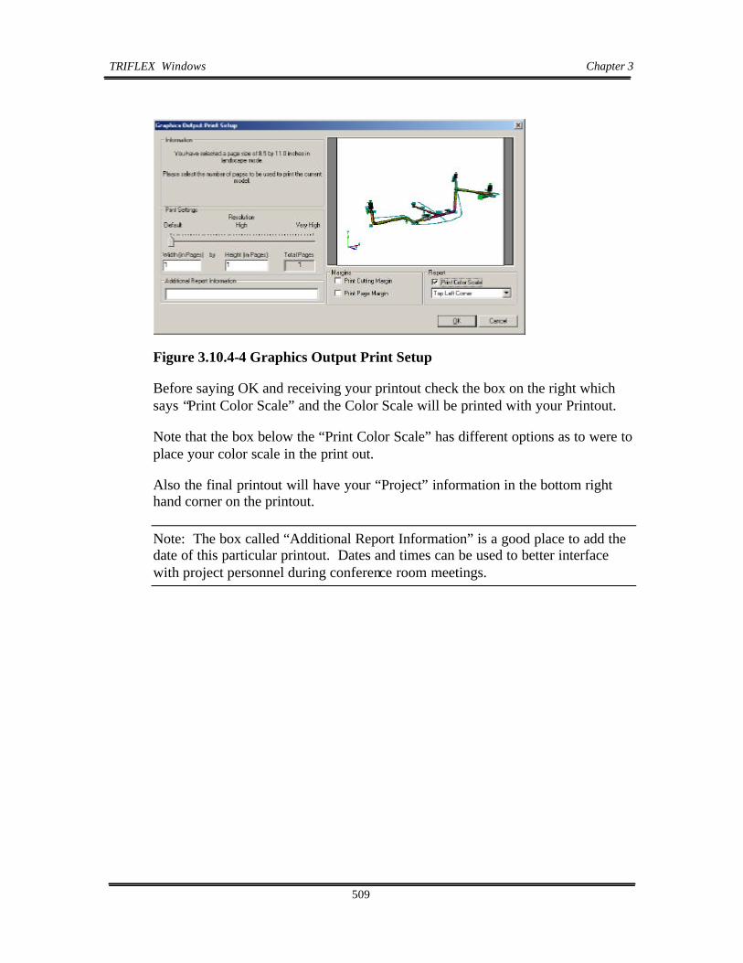
TRIFLEXWindows Chapter 3
509
Figure 3.10.4-4 Graphics Output Print Setup
Before saying OK and receiving your printout check the box on the right which says “Print Color Scale” and the Color Scale will be printed with your Printout.
Note that the box below the “Print Color Scale” has different options as to were to place your color scale in the print out.
Also the final printout will have your “Project” information in the bottom right hand corner on the printout.
Note: The box called “Additional Report Information” is a good place to add the date of this particular printout. Dates and times can be used to better interface with project personnel during conference room meetings.

TRIFLEXWindows Chapter 3
510
3.10.4.2 Printing Graphics Output
3.10.4.2.1 Printer
Figure 3.10.4.2.1-1 Printer Setup
Printer
Name Tektronix Phaser 860DP by Xerox
Status Ready
Type Tektronix Phaser 860DP by Xerox
Where USB001
Paper Letter
Size 8-1/2 x 11
Source Specifies where the paper you want to use is located in the printer.
Orientation Portrait or Landscape Properties Allows the user to select specific features about the existing printer selected.

TRIFLEXWindows Chapter 3
511
3.10.4.2.2 Graphics Output Print Setup
Dialog is displayed following the print dialog.
Figure 3.10.4.2.2-1 Graphics Output Print Setup
Information
Gives information of your previous printing selections, and questions upon the number of pages the item to be printed should take up.
Resolution
Allows user to set the resolution of the item to be printed on a scale from default to very high resolution. Caution: the higher the resolution, the more memory is required, the slower your PC will operate.
Width (in Pages)
Allows the User to decide upon how many page widths (this is set at 8-1/2” x 11”) should be printed.
Height (in Pages)
Allows the User to decide upon how many page heights (this is set at 8-1/” x 11”) should be printed.

TRIFLEXWindows Chapter 3
512
Note: Changing Width and Height pages becomes useful when trying to create a larger output for Project Conference Reviews.
Additional Report Information
Allows the User to input any further information that will be displayed on the printed copy. Here you can put the date and time of the printout. This is very useful when working within project organizations.
Margins
Allows the user to decide between a cutting margin or a page margin.
Report
Gives the user the option of inserting a color scale in their specified location on the printed copy.
See Graphics Output Print Setup Dialogue

TRIFLEXWindows Chapter 3
513
3.10.5 Preview Reports
From the Output Pull Down menu, select Preview Report or Print Report similar to that shown in Figure 3.10.5-1. The Report Print (Print Static / Dynamic Reports) screen will then appear.
Figure 3.10.5-1 Print Report
1. In Print Report or Preview Report screen, select the Load Cases and the reports from the Available Report group by placing a check in the box adjacent to each desired report as shown in Figure 3.10.5-1.
2. A Preview Report sample screen is shown in Figure 3.10.5-2
Note: The above procedure will produce Preformatted Output Reports. These reports are the same reports produced in TRIFLEX DOS.

TRIFLEXWindows Chapter 3
514
Figure 3.10.5-2 Report Print Menu
After viewing CLOSE the viewing window to return to the model.
To exit TRIFLEX®Windows, click EXIT under FILE.
To EXIT from the File Pull Down menu, select Save As similar to the procedure used in most Windows programs.

TRIFLEXWindows Chapter 3
515
3.10.6 Print Reports
To print output reports, click on Output on the Main Menu and then click on Print Reports on the Pull down Menu. The screen in Figure 3.10.3.2-1 will appear.
Figure 3.10.6-1 Printing Options
Select the desired load cases and check the reports you wish to review and click the OK button. TRIFLEX will then give you an opportunity to select the printer and printing options as shown in Figure 3.10.6-2 and will then print the reports for you.

TRIFLEXWindows Chapter 3
516
Figure 3.10.6-2 Printing Options
The Print Setup (shown in Figure 3.10.6-2) dialog has been previously discussed under section 3.10.4.2.1
Note: If an “NT” Operating system is employed; the User must assign a local Printer to the Print device.

TRIFLEXWindows Chapter 3
517

TRIFLEXWindows Chapter 3
518
APPENDIX A- TRIFLEX Windows Command and Shortcut Keys
(Graphics Window)
COMMANDS SHORTCUTS
Function Keys
• Help Topics F1
• (not active) F2
• (not active) F3
• Worksheet Toggle F4
• Start Calculation F5
• (not active currently) F6
• Preview Report F7
• Print Report F8
• Edit Current Component F9
• Find Next Component F10
• Find Previous Component F11
• (not active currently) F12
COMMANDS SHORTCUTS
Movement Keys
• Move to End END
• Move to First Component HOME
• Move to Next Component F10
• Move to Previous Component F11

TRIFLEXWindows Chapter 3
519
COMMANDS SHORTCUTS
Control Keys
• Delete DEL
• Insert INS
• New CTRL + N
• Open CTRL + O
• Copy CTRL + C
• Cut CTRL + X
• Paste CTRL + V
• Print CTRL + P
• Save CTRL + S
• Undo CTRL + Z
• Redo CTRL + Y

TRIFLEXWindows Chapter 3
520
COMMANDS SHORTCUTS
Control Keys
• Bring up “Start” CTRL + ESC
• Full Screen Capture to Clipboard PRT SCREEN
• Current Window Capture to Clipboard ALT + PRT SCREEN
• Change pointer/manipulator ESC
• Change pointer to manipulator ALT + SHIFT
• Change to manipulator (temporary) ALT
• Moves to next available window ALT + ESC
• Moves Entire model considered SPAN SHIFT+ Hand (click Arrow)
• Graphic “Hand Mode” Right Click + Hold Down
Middle Wheel of Mouse
• Next (toggle between graphics CTRL + F6
& Spreadsheet input)
• Toggle through all available windows ALT + TAB
• Renumber Selection (must be selected first) CTRL + R
• Find Node CTRL + F
• Select Current Branch CTRL + B
• Deselect Current Branch Shift + CTRL + B
• Select All CTRL + A
• Deselect All Shift + CTRL + A
• Zoom (with Graphic “Hand Mode”) Left Click + Hold Down
Middle Wheel of Mouse
• Pan Shift + Left Click on Object

Table of Contents
TRIFLEX® Windows User Manual
Chapter 4
Coding A Standard TRIFLEX® Analysis . . . . . . . . . . . . . . . . . . . . . . . . . . . . . . . . . 1
4.1 Coding A Standard TRIFLEX® Analysis . . . . . . . . . . . . . . . . . . . . . . . . . . . . . . . 2
4.2 Sample Coded Data Points . . . . . . . . . . . . . . . . . . . . . . . . . . . . . . . . . . . . . . . . . . 4
4.2.1 Anchors . . . . . . . . . . . . . . . . . . . . . . . . . . . . . . . . . . . . . . . . . . . . . . . . . 4
4.2.2 Bends . . . . . . . . . . . . . . . . . . . . . . . . . . . . . . . . . . . . . . . . . . . . . . . . . . . 6
4.2.3 Joints . . . . . . . . . . . . . . . . . . . . . . . . . . . . . . . . . . . . . . . . . . . . . . . . . . 10
4.2.4 Flanges . . . . . . . . . . . . . . . . . . . . . . . . . . . . . . . . . . . . . . . . . . . . . . . . 11
4.2.5 Valves . . . . . . . . . . . . . . . . . . . . . . . . . . . . . . . . . . . . . . . . . . . . . . . . . 13
4.2.6 Pipes . . . . . . . . . . . . . . . . . . . . . . . . . . . . . . . . . . . . . . . . . . . . . . . . . . 16
4.2.7 Reducers . . . . . . . . . . . . . . . . . . . . . . . . . . . . . . . . . . . . . . . . . . . . . . . 16
4.2.8 Restraint Modeling . . . . . . . . . . . . . . . . . . . . . . . . . . . . . . . . . . . . . . . 16
4.2.9 Cold Spring . . . . . . . . . . . . . . . . . . . . . . . . . . . . . . . . . . . . . . . . . . . . . 19
4.2.10 Branch Connections . . . . . . . . . . . . . . . . . . . . . . . . . . . . . . . . . . . . . . 20
4.2.11 Expansion Joints . . . . . . . . . . . . . . . . . . . . . . . . . . . . . . . . . . . . . . . . . 21

2
Coding A Standard TRIFLEX Analysis
4.1 Coding A Standard TRIFLEX Analysis
Below is a step-by-step procedure provided as a guide for setting up a problem for analysis. These are general instructions on what to do and when to do it.
1) Decide which Piping Code and Standards will govern the design of the system.
2) Make an isometric drawing of the piping system.
3) Note all Anchors and Restraints on the isometric drawing.
4) Organize all physical properties of the piping system including the following:
Pipe Material (carbon steel, etc.) or Modulus of ElasticityTemperature (degrees F) or Coefficient of Expansion (inches/100 feet)Internal or External Pressure (psig)Pipe Nominal Diameter or Actual O.D., if Non-Standard PipePipe Wall Thickness (inches) or Pipe ScheduleCorrosion Allowance (inches)Insulation (weight/feet) or Insulation Type and ThicknessPipe Contents (weight/feet) or Contents Specific GravityBend Properties (radius, miters, etc.)Valve Properties (weight and length, or rating and line size)Flange Properties (weight and length, or rating and line size)Branch Connections (weld-on-fitting, welding tee, fab. tee with pad thickness, etc.)
5) Note the following information for each Anchor, as applicable:
Initial movements (usually from thermal expansion or contraction) or Spring Rates(Translational and Rotational), if the Anchor is to be modeled as flexible or partiallyflexible.
6) Note the following information for each Restraint, as applicable:
Initial Movement, Initial Rotation, Initial Force or Initial Moment. Spring Rates(Translational and Rotational), if the Restraint is to have a Flexibility. Direction ofRestraint Action (Positive or Negative), if Restraint is to be one directional.
7) Record additional information such as cold spring and wind load, if applicable.
8) Orient the Global (overall) axis system on the isometric drawing for easy reference. The

3
standard right-hand rule axis system is used with Y as the vertical axis. All weightcalculations are based upon gravity exerting a negative Y force on the piping system.
9) Assign data point numbers on the system isometric drawing. A data point must beassigned to any location in the system for which output data is desired. The data pointdescribes the specific location in the system and the preceding segment of the pipingsystem. To review the procedure for data point assignment, see the Example described inChapter 2 of this User Manual. The following guidelines
Data Point TypeThe term applied to the piping components between the end points (Nodes) of eachelement of the piping system. The following items are considered to be data point types inTRIFLEX: Anchor, Pipe, Bend, Branch Connection, Joint, Valve, Flange, Reducer,Expansion Joint and Release Element.
AnchorThe first data point in a piping model must be an Anchor. An anchor is a zero lengthcomponent that defines the connectivity between the piping system and the external world. Assign a data point to every terminal point of the piping model unless it is a free end.
PipeAssign a data point at the end of each Run of Pipe.
Bend or ElbowAssign a data point at the tangent intersection point of each Bend. This data point mayalso define the preceding Run of pipe, if any exists.
Branch ConnectionAssign a data point to the mid-point of the branch connection. The mid-point is theintersection of the center lines of the branches.
Joint, Flange, or ValveAssign a data point at the end or midpoint of each Joint, Flange, or Valve. The data pointassigned to a Joint, Flange, or Valve may or may not define a preceding Run of pipe. Ifthe analyst does not want to define a Joint, Valve or Flange, and a preceding Run of pipewith one data point, then a separate data point should be assigned at the end of thepreceding Run of pipe or other segment of the piping system. (See sample coded datapoints in Section 4.2).
ReducerAssign a data point at the end of each Reducer.

4
Expansion JointsAssign a data point at the midpoint of each Expansion Joint.
Release ElementsAssign a data point at each Release Element. A release element is essentially a zero lengthexpansion joint used to define a connection between two piping components.
Restraints on Bends, Runs, Valves, Flanges, and JointsRestraints may be placed on these data point types. The restraint will be located at theend point of runs, flanges, valves and joints. Restraints on bends will be located at thebend mid-point unless specified otherwise.
10) Note the dimensions between data points on the isometric drawing. For all skewed datapoints, show all dimensional and angle information with respect to the X, Y, and Z-axes. Joint lengths should also be shown on the drawing for easy reference. Valve and Flangelengths are not required if the standard lengths contained in TRIFLEX are used.
4.2 Sample Coded Data Points
4.2.1 ANCHORS
Rigid Anchor (with no initial movements)
See the component labeled as data point #85 in the Example No. 1 for details ofcoding a rigid anchor with no anchor movements.
Rigid Anchor (with initial X, Y, and Z translations)
See the component labeled as data point #5 in the Example No. 1 for details ofcoding a rigid anchor with initial X, Y, and Z translations coded to representanchor movements.
Rigid Anchor (with temperature and X, Y and Z dimensions from true anchorwhere the piece of equipment is actually fixed to the anchor data point that youhave modeled.)
See the component labeled as data point #5 in the Example No. 2 for details ofcoding a rigid anchor with a temperature of 350 degrees F for the anchorcomponent and X = - 4 feet, Y = + 2.5 feet and Z = zero feet from the true anchorto the point at which the User has coded the anchor point for the analysis. Oncethe Calculate Initial Movement button is pressed, TRIFLEX generates the initialX, Y and Z translations at the anchor data point #5 based upon the enteredtemperature and the delta dimensions.

5
Flexible Anchor (FREE END) coded as a totally flexible anchor as a startingpoint for a new branch
See the component labeled as data point #15 in the Example No. 2 for details ofcoding a totally flexible anchor as a beginning of a branch that is being coded froman unknown location back to a known branch point in the piping system.
Flexible Anchor (FREE END) coded as a totally flexible anchor at the end of abranch
See the component labeled as data point #25 in the Example No. 2 for details ofcoding a totally flexible anchor as an anchor coded at the end of a branch.
Flexible Anchor (FREE END) coded as a pipe with no connection to any othermember
See the component labeled as data point #35 in the Example No. 2 for details ofcoding a pipe connected to the piping system on one end and totally free on theother end.
Intermediate Anchor coded as a Rigid Anchor
See the component labeled as data point #45 in the Example No. 2 for details ofcoding an intermediate anchor in between two sections of straight pipe. If desired,the User may enter any flexibilities along and/or about the 3 axes.
Intermediate Anchor coded as three translational and three rotationalRestraints
See the component labeled as data point #60 in the Example No. 2 for details ofcoding a straight pipe with rigid translation restraints along the X, Y and Z axesand rigid rotational restraints about the X, Y and Z axes. If desired, the User mayenter any flexibilities along or about the 3 axes by entering restraint flexibilities onthe dialog under the Restraints tab.
Rigid Anchor With Initial Translation (Vessel Head) and Rigid Translational Restraint off Vessel Shell (Knee Brace Support)
See the component labeled as data point #5 in the Example No. 3 for details ofcoding an anchor with an imposed vertical movement to simulate a nozzleconnected to the center of a head on the top of a vertical vessel. Note that thedelta dimension on data point number 10 is to the midpoint of the flange pairabove the nozzle to head connection point.

6
See the component labeled as data point #25 in the Example No. 3 for details ofcoding a rigid +Y restraint that moves upward with the vessel shell as it grows butpermits the pipe to move up off the knee brace support if the pipe moved up morethan the vessel at that point. A limit stop is entered along the Y axis with a lowerlimit movement imposed and the upper limit specified as a much larger numberwhich will never restrict the pipe. Entering a limit stop requires a lower limit to beentered as well as an upper limit. Note that this knee brace only provides verticalsupport. It does not restrict movement in the lateral plane.
Capped End coded as a Free End
See the component labeled as data point #35 in the Example No. 2 for details ofcoding a pipe connected to the piping system on one end and totally free on theother end.
Flanged Free End coded as a pair of flanges with no connection to any otherpiping component beyond the flange pair
See the components labeled as data point #70 & 75 in the Example No. 2 fordetails of coding a pipe connected to the piping system on one end and followed bya weld neck flange (data point #70) and then followed by a blind flange (data point#75).
4.2.2. BENDS
Standard Long Radius Elbow
See the component labeled as data point #40 in the Example No. 2 for details ofcoding a standard long radius bend.
Standard Short Radius Elbow
See the component labeled as data point #55 in the Example No. 2 for details ofcoding a standard short radius bend.
Elbow with User Defined Radius
See the component labeled as data point #80 in the Example No. 2 for details ofcoding an elbow with a non-standard bend radius. In the example, we have codeda 4 D elbow and because it is defined as an elbow, the fitting thickness can beentered for only the bend arc.

7
Bend with User Defined Radius
See the component labeled as data point #85 in the Example No. 2 for details ofcoding an bend with a non-standard bend radius. In the example, we have coded a3 D bend.
Miter Bend (closely-spaced)
See the component labeled as data point #45 in the Example No. 1 for details ofcoding a closely spaced miter bend with four miter cuts and a bend radius ratio of2 and a flange pair immediately following the miter bend. The flange pairfollowing the bend has been defined by specifying the data point at the beginningof the flange pair.
Miter Bend (widely spaced)
See the component labeled as data point #30 in the Example No. 1 for details ofcoding a widely spaced miter bend with two miter cuts and a bend radius ratio of3.
Standard Long Radius Elbow with a Rigid One-Directional +Y Restraintlocated at the midpoint of the elbow
See the component labeled as data point #40 in the Example No. 1 for details ofcoding a long radius elbow with a rigid one-directional restraint acting in the +Ydirection resisting -Y movement. The restraint is attached at the midpoint of theelbow, not the tangent intersection point.
Elbow with an existing Spring Support attached to the Bend Mid-Point
See the component labeled as data point #40 in the Example No. 3 for details ofcoding a long radius elbow with an existing spring hanger attached at the midpointof the elbow, not the tangent intersection point. The spring hanger has a knowninstalled load and spring rate.
Elbow with One End Flanged and a Spring Support at Bend Mid-Point
See the components labeled as data points #10 and 15 in Example No.4 for detailsof coding a long radius bend with a single flange immediately preceding the bend. The flange is welded directly to the near end or leading end of the bend. Note ondata point #10, the minimum length for the single flange has been checked toindicate to TRIFLEX that the flange is being entered with no preceding segment of

8
pipe. To indicate to TRIFLEX that you are entering a single flange rather than aflange pair (default) on data point #10, the radio button for one flange shown inthe Flange data area of the dialog should be checked. TRIFLEX defaults to twoflanges. The default orientation of the single flange in TRIFLEX is facing forward. In this Example, a flange facing backwards is what is desired. Therefore, a checkis placed in the “Flange is facing backward” check box.
As for the elbow, it has been coded as a standard long radius elbow with a checkmark in the “Near End” check box in the Flange Ends area of the dialog. With thisbox checked, TRIFLEX will modify the flexibility characteristic for this elbowbased upon the criteria contained in the piping code selected. To indicate toTRIFLEX where you wish to have the spring hanger connected to the elbow, youmust place a check mark in one of the Near, Mid or Far check boxes in theRestraint Attachment Point on Bend Centerline area of the bend dialog. In thisexample, the Mid Point has been selected.
Standard Long Radius Bend (with a +Y translational restraint acting at theend point of the bend).
See the component labeled as data point #25 in the Example No. 4 for details ofcoding a long radius elbow with an restraint acting in the +Y direction attached atend point of the elbow, not the tangent intersection point. Therefore, a checkmark has been placed in Far check box in the Restraint Attachment Point on BendCenterline area of the bend dialog. In addition, a check mark has been placed inthe +Y restraint check box on the restraint dialog for this component.
Standard Long Radius Bend (with a -Z translational restraint acting at a pointthat is sixty [60] degrees from the beginning weld point of the bend).
See the component labeled as data point #30 in the Example No. 4 for details ofcoding a long radius elbow with an restraint acting in the -Z direction attached at apoint on the elbow that is sixty (60) degrees from the beginning weld point andthirty (30) degrees from the ending weld point. To indicate the angle ofattachment from the beginning of the bend, the check marks in the Near, Mid, Farcheck boxes should be removed and the angle in degrees should be entered in thefield provided placed in the Restraint Attachment Point on Bend Centerline area ofthe bend dialog. In addition, a check mark has been placed in the -Z restraintcheck box on the restraint dialog for this component.
Base Ell Support modeled from a Branch Point to a Rigid Anchor below anElbow
See the components labeled as data points #20, 25, 30, 35 and 40 in the Example

9
No. 8 for details of coding a Base Ell Support as long radius elbow with ansupport leg coded from a branch point just above the weld point to an anchor pointbelow the tangent intersection point of the elbow. In this example, the base ell legis rigidly anchored to the ground or structure below the elbow. Note that thetemperature, pressure, contents and insulation have been removed from thecomponent described by data point 40.
Base Ell Support modeled from a Branch Point to an Anchor below an Elbow -the Anchor is free in all directions except the Y axis
See the components labeled as data points #55, 60, 65, 70 and 75 in the ExampleNo. 8 for details of coding a Base Ell Support as long radius elbow with ansupport leg coded from a branch point just above the weld point to an anchor pointbelow the tangent intersection point of the elbow. In this example, the anchorlocated at the bottom of the base ell leg is free along the X and Z axes and aboutX, Y and Z and rigid along the Y axis. Note that the temperature, pressure,contents and insulation have been removed from the component described by datapoint 75. Note further that the branch connection must be outside of the elbowitself. The branch point can not be on the elbow between weld points. It can beon the weld point, if desired by the user.
Base Ell Support modeled from a Branch Point to a Free End below an Elbow -the free end has a +Y restraint acting on it to allow for lift off
See the components labeled as data points #90, 95, 100, 105, 110 and 115 in theExample No. 8 for details of coding a Base Ell Support as long radius elbow withan support leg coded from a branch point just above the weld point to a free endon the base ell leg below the tangent intersection point of the elbow. In thisexample, the branch from the equipment nozzle is coded back to the weld pointjust above the elbow and the free end at the bottom of the base ell leg has a +Yrestraint on it which allows for the pipe to lift off the structure without hold downrestraint. The direction of coding a branch from the equipment to the branch pointis opposite that traversed in the two examples just above. Note that thetemperature, pressure, contents and insulation have been removed from thecomponent described by data point 115. Note further that the branch connectionmust be outside of the elbow itself. The branch point can not be on the elbowbetween weld points. It can be on the weld point, if desired by the user.
Base Ell Support modeled from a Branch Point to a Free End below an Elbow -the free end has a +Y restraint acting on it to allow for lift off and africtional resistance
See the components labeled as data points #145, 150, 155, 160, 165 and 175 in the

10
Example No. 8 for details of coding a Base Ell Support as long radius elbow withan support leg coded from a branch point just above the weld point to a free endon the base ell leg below the tangent intersection point of the elbow. In thisexample, the branch from the equipment nozzle is coded back to the weld pointjust above the elbow and the free end at the bottom of the base ell leg has a +Yrestraint on it which allows for the pipe to lift off the structure without hold downrestraint. The direction of coding a branch from the equipment to the branch pointis opposite that traversed in the first two examples above. On the +Y restraint, afriction coefficient of 0.3 is specified to resist movement in the X-Z plane. Notethat the temperature, pressure, contents and insulation have been removed fromthe component described by data point 175. Note further that the branchconnection must be outside of the elbow itself. The branch point can not be on theelbow between weld points. It can be on the weld point, if desired by the user.
Dead or Dummy Leg coded as an extension of a line through a branchconnection
See the components labeled as data points #130, 135 and 170 in the Example No.8 for details of coding a dummy leg support as an extension of a branchconnection. Data point 135 is coded as a free end with a +Y restraint resisting -Ymovement. Note that the temperature, pressure, contents and insulation have beenremoved from the component described by data point 135. Note further that thebranch connection must be outside of the elbow itself. The branch point can notbe on the elbow between weld points. It can be on the weld point, if desired by theuser.
Dummy Leg coded as an extension of a line through an elbow
See the components labeled as data points #170, 180 and 190 in the Example No.8 for details of coding a dummy leg support as an extension of a line through anelbow. Data point 180 is coded as a free end with a +Y restraint resisting -Ymovement. Note that the temperature, pressure, contents and insulation have beenremoved from the component described by data point 190. Note that the branchconnection must be outside of the elbow itself. The branch point can not be on theelbow between weld points. It can be on the weld point, if desired by the user.
4.2.3 JOINTS
Rigid Joint with no preceding run of pipe
See the component labeled as data point #60 in Example No. 3 for details ofcoding a Rigid Joint with no preceding run of pipe. The objective of thiscomponent is to fill the distance between the previous data point to the defined

11
data point with a totally rigid member that weighs 35 pounds as entered by theUser. Note that the length specified by the delta dimensions must be equal to thelength specified by the User in the Rigid Joint Properties area of the dialog. If thedelta dimension is longer than the joint length, the difference will be considered asa preceding run of pipe. If the delta dimension is shorter than the joint length,TRIFLEX will not accept the data entry on this dialog.
Rigid Joint with a preceding run of pipe
See the component labeled as data point #65 in Example No. 3 for details ofcoding a Rigid Joint with a preceding run of pipe. The objective of this componentis to partially fill the distance between the previous data point to the defined datapoint with a totally rigid member that weighs 25 pounds and has a length of 1.125ft. as entered by the User and to precede the rigid joint with a run of pipe with thesame properties previously specified.
Rigid Joint with a one-directional +Y restraint
See the component labeled as data point #70 in Example No. 3 for details ofcoding a Rigid Joint with a preceding run of pipe and with a one-directional +Yrestraint located at the far end. The objective of this component is to partially fillthe distance between the previous data point to the defined data point with atotally rigid member that weighs 25 pounds and has a length of 1 ft and a +Yrestraint located at the end of the Rigid Joint.
Skewed Flexible Joint made of a structural beam shape
See the component labeled as data point #75 in Example No. 3 for details ofcoding a Flexible Joint without a preceding run of pipe. The objective of thiscomponent is to completely fill the distance between the previous data point to thedefined data point with a flexible member (a W6x12 beam) and have the length ofthe beam component equal to the resultant of the delta dimensions entered by theUser.
4.2.4 FLANGES
Single Flange facing backwards starting a branch
See the component labeled as data point #10 in Example No. 4 for details ofcoding a single flange starting a branch and facing backwards to bolt up to a pieceof equipment. The flange is welded directly to the near end or leading end of the

12
bend that follows the flange. Note on data point #10, the minimum length for thesingle flange has been checked to indicate to TRIFLEX that the flange is beingentered with no preceding segment of pipe. To indicate to TRIFLEX that you areentering a single flange rather than a flange pair (default) on data point #10, theradio button for one flange shown in the Flange data area of the dialog should bechecked. TRIFLEX defaults to two flanges. The default orientation of the singleflange in TRIFLEX is facing forward. In this Example, a flange facing backwardsis desired. Therefore, a check is placed in the “Flange is facing backward” checkbox. Note that the delta dimension is coded from the Anchor point to the Far Endof the Single Flange as shown on the Bend dialog.
Flange Pair with the Delta Dimension coded to the Mid Point of the FlangePair
See the component labeled as data point #60 in Example No.1 for details of codinga flange pair with the delta dimension to be mid point of the flange pair. Note thatin the Flange Data area of the dialog, the Two Flanges radio button has beenselected and in the Delta Dimension Coded To area of the dialog, the Mid Point ofFlange Pair has been selected.
Flange Pair coded as two individual flanges and with a +Y restraint Acting atthe Mid Point of the Flange Pair
See the components labeled as data points #75 and #80 in Example No.1 fordetails of coding a flange pair with a +Y restraint acting at the mid point of theflange pair. Note that the first flange is coded as a single flange and labeled as datapoint #75. In the Flange Data area of the dialog, the One Flange radio button hasbeen selected and in the Delta Dimension Coded To area of the dialog, the Far Endof Flange has been selected. In addition, a check mark has been placed in the +Yrestraint check box on the restraint dialog for this component.
The second flange is labeled as data point #80 and it is also coded as a singleflange. In the Flange Data area of the dialog, the One Flange radio button hasbeen selected and a check is placed in the “Flange is facing backward” check boxto cause TRIFLEX to have it face to face with the preceding flange. In the DeltaDimension Coded To area of the dialog, the Far End of Flange has been selected.
Weldneck Flange followed by a Blind Flange to end a branch
See the components labeled as data points #70 and #75 in Example No.2 fordetails of coding a weldneck flange followed by a blind flange. Note that the firstflange is coded as a single flange and labeled as data point #70. In the Flange Dataarea of the dialog, the One Flange radio button has been selected and in the Delta

13
Dimension Coded To area of the dialog, the Far End of Flange has been selected.
The second flange is labeled as data point #75 and it is also coded as a singleflange. In the Flange Data area of the dialog, the One Flange radio button hasbeen selected. In the Delta Dimension Coded To area of the dialog, the Far End ofFlange has been selected. In the Flange Type pull down menu, Blind Flange hasbeen selected.
4.2.5 VALVES
Flanged Valve coded with two Flanges and a preceding Pipe and the DataPoint located at the Far End Weld Point
See the component labeled as data point #45 in Example No. 3 for details ofcoding a valve with a flange attached on the preceding end and a flange on thefollowing end of the valve and a pipe preceding the valve and flanges. The datapoint is located at the far end weld point. To indicate to TRIFLEX that a flangedvalve is desired rather than a welded valve, the flanged valve radio button in theValve Type area of the dialog in the lower left of the dialog is selected. This is acombined component consisting of a flanged valve, two flanges and a precedingsegment of pipe. Note on data point #45, the minimum length for the valve andtwo flanges is listed beneath the delta dimensions. The minimum length is the sumof the length of the valve and two times the length of the Slip On flange listed inthe upper right of the valve dialog. To indicate to TRIFLEX that a flange isdesired on both ends of the valve, a check mark is placed in the “Flange on ToEnd” and in the “Flange on From End” boxes in the Flange Data area of the dialog. Note that the delta dimension is coded from the preceding data point to the FarEnd Weld Point, the default location.
Flanged Valve coded with two Flanges and a preceding Pipe and the DataPoint located at the Far End Flange Face
See the component labeled as data point #70 in Example No. 1 for details ofcoding a valve with a flange attached on the preceding end and a flange on thefollowing end of the valve and a pipe preceding the valve and flanges. To indicateto TRIFLEX that a flanged valve is desired rather than a welded valve, the flangedvalve radio button in the Valve Type area of the dialog in the lower left of thedialog is selected. This is a combined component consisting of a flanged valve,two flanges and a preceding segment of pipe. Note on data point #70, theminimum length for the valve and two flanges is listed beneath the deltadimensions. The minimum length is the sum of the length of the valve and twotimes the length of the flange listed in the upper right of the valve dialog. Toindicate to TRIFLEX that a flange is desired on both ends of the valve, a check

14
mark is placed in the “Flange on To End” and in the “Flange on From End” boxesin the Flange Data area of the dialog. Note that the delta dimension is coded fromthe preceding data point to the Far End Flange Face. The default location for thedata point is the Far End Weld Point.
Flanged Valve coded with two Flanges and a preceding Pipe as a Flange with apreceding segment of pipe, a Valve without flanges and a preceding segment ofpipe, and without a following flange. Each component is defined by anindividual Data Point located at the Far End of that component
See the components labeled as data points #35, 40 and 45 in Example No. 4 fordetails of coding a valve with a flange attached on the preceding end and a flangeon the following end of the valve and a pipe preceding the valve and flanges. Datapoint #35 defines the preceding segment of pipe and the first flange. Data point#40 defines the valve with no flanges and data point #45 defines the second flange.
Starting with data point #35, a single flange with a preceding segment of pipe iscoded. The delta dimension is entered as 4 feet and the minimum length is shownas 1.33333 feet. The minimum length is the sum of the preceding bend radius fromthe tangent intersection point to the weld point plus the length of one flange. Toindicate to TRIFLEX that a single forward facing flange is desired, the One Flangeradio button in the Flange Data area of the dialog is selected and the check boxindicating that Flange is Facing Backwards is left blank. This is a combinedcomponent consisting of a flange and a preceding segment of pipe. Note that thedelta dimension is coded from the preceding data point to the Far End of theFlange, the default location.
Next, data point #40 is coded to describe the valve with no flanges or precedingsegment of pipe. The delta dimension is entered by placing a check mark in the“Use the Minimum Length” check box. This action sets the delta dimension to thelength shown in the minimum length field and insures that there is no precedingsegment of pipe. In the Flange Data area of the dialog, the “Flange on From End”and “Flange on To End” check boxes are to be left blank. Note that the deltadimension is coded from the preceding data point to the Far End Flange Face, thedefault location.
Next data point #45 is coded to describe the flange that follows the valve. There isno preceding segment of pipe. The delta dimension is entered by placing a checkmark in the “Use the Minimum Length” check box. This action sets the deltadimension to the length shown in the minimum length field and insures that there isno preceding segment of pipe. To indicate to TRIFLEX that a single backwardfacing flange is desired, the One Flange radio button in the Flange Data area of the

15
dialog is selected and a check mark is placed in the check box indicating thatFlange is Facing Backwards. Note that the delta dimension is coded from thepreceding data point to the Far End of the Flange, the default location.
Flanged Valve connected to a piece of equipment on the From End andfollowed by a Flange with the delta dimension coded to the Far Flange Face
See the component labeled as data point #60 in Example No.4 for details of codinga flanged valve connected to an equipment nozzle on the From side and beingfollowed by a flange on the To End. This is a typical piping arrangement when aline starts at a heat exchanger, a turbine, a compressor or a pump. The anchor iscoded as data point #55. Anchor movements are coded to simulate the growth ofthe piece of equipment.
Then, review data point #60. It is coded to describe the valve with no precedingflange but with one following flange. There is no preceding segment of pipe. Inthe Flange Data area of the dialog, click on the check mark in the “Flange on FromEnd” to remove it. Select the correct valve and flange type and flange rating. Then the delta dimension is entered by placing a check mark in the “Use theMinimum Length” check box located beneath the delta dimension area of thedialog. This action sets the delta dimension to the length shown in the minimumlength field and insures that there is no preceding segment of pipe. Note that thedelta dimension is coded from the preceding data point (the anchor) to the Far EndFlange Face. The default location for the data point will be the far end weld point.
Note that the length of the flange that immediately follows the valve will beincluded in the minimum length of the following component.
Welded Valve coded with a preceding Pipe and the Data Point located at theFar End Weld Point
See the component labeled as data point #75 in Example No. 4 for details ofcoding a welded valve with a pipe preceding the valve. The data point is located atthe far end weld point. The first step is to indicate to TRIFLEX that thecomponent is a welded valve not a flanged valve. To so indicate, the welded valveradio button in the Valve Type area of the dialog in the lower left corner must beselected. In the valve data area of the dialog, the type of welded valve must beselected, i.e. gate, globe, check, etc. Note on data point #75, the minimum lengthfor the valve is listed beneath the delta dimensions. The minimum length is thelength of the welded valve plus any length carried over from a previouscomponent. Note that the delta dimension is coded from the preceding data pointto the Far End Weld Point, the default location.

16
4.2.6 PIPES
Run of Pipe
See the component labeled as data point #70 in Example No. 4 for details ofcoding a straight run of pipe.
Run of Pipe With Insulation Thickness and Type Specified
See the component labeled as data point #55 in Example No. 1 for details ofcoding a straight run of pipe with an insulation type specified by the user from thedata base of insulation materials in the TRIFLEX library.
Run of Pipe (skewed element with respect to two global axes)
See the component labeled as data point #12 in Example No. 1 for details ofcoding a straight run of pipe that is skewed at 45 deg with regards to the “X” and“Y” axes.
4.2.7 REDUCERS
Concentric Reducer
See the component labeled as data point #35 in Example No. 6 for details ofcoding a concentric reducer.
Eccentric Reducer
See the component labeled as data point #45 in Example No. 6 for details ofcoding a eccentric reducer with the flat side down.
4.2.8 RESTRAINT MODELING
Run of Pipe With One-Directional +Y Pedestal-Type Support
See the component labeled as data point #55 in Example No. 7 for details ofcoding a straight segment of pipe with a single acting +”Y” Restraint.
Run of Pipe With Line Stop with no axial movement allowed
See the component labeled as data point #100 in Example No. 7 for details ofcoding a straight segment of pipe with an Axial Restraint acting along the “X”

17
axis.
Run of Pipe With Line Stop with positive and negative axial movement allowed
See the component labeled as data point #105 in Example No. 7 for details ofcoding a straight segment of pipe with an axial limit stop acting along the “X” axiswith 3/4" positive movement and -1/4" negative movement allowed.
Run of Pipe With Rigid Guides and Vertical Support
See the component labeled as data point #10 in Example No. 7 for details ofcoding a straight segment of pipe with a plus “Y” single acting restraint and aguide acting along the “Z” axis. The pipe is running along the “X” axis andtherefore the guide or lateral restraints are acting along the “Z” axis. No lateralmovement is allowed.
Run of Pipe With a Vertical Support and Rigid Guides Allowing for +/- 1/4" ofmovement along the “Z” axis
See the component labeled as data point #110 in Example No. 7 for details ofcoding a straight segment of pipe with a plus “Y” single acting restraint and aguide acting along the “Z” axis and allowing for a + or - .25" of movement alongthe “Z” axis. The pipe is running along the “X” axis.
Run of Pipe with a Vertical Support and Rigid Guides Allowing for +/- 1/4" ofmovement along the “Z” axis and a Rigid Line Stop allowing for +/- ½" ofmovement along the “X” axis.
See the component labeled as data point #25 in Example No. 7 for details ofcoding a straight segment of pipe with a plus “Y” single acting restraint, a guideacting along the “Z” axis and allowing for a + or - .25" of movement along the “Z”axis and a line stop acting along the “X” axis and allowing for a + or - .5" ofmovement along the “X” axis. The pipe is running along the “X” axis.
Run of Pipe with a Vertical Support and a Rigid Line Stop with an imposedmovement of -.2" and allowing for more negative movement along the “Z” axisup to a maximum of -1".
See the component labeled as data point #120 in Example No. 7 for details ofcoding a straight segment of pipe with a plus “Y” single acting restraint and a limitstop along the “Z” axis imposing a movement of -.2" and allowing for furthermovement in the negative “Z” direction to a maximum of 1". The pipe is running

18
along the “Z” axis.
Run of Pipe with a +”Y” Restraint and an Imposed Force Acting along the “Z”Axis in the Negative Direction
See the component labeled as data point #20 in Example No. 7 for details ofcoding a straight segment of pipe with a plus “Y” single acting restraint and a forceof 500 pounds acting in the negative “Z” direction. A spring constant of 345pounds per inch of travel is also specified. If the User wishes the force to be aconstant force no matter what the movement of the pipe, the User should specifythe spring constant or stiffness as “FREE”. The pipe is running along the “X” axis.
Run of Pipe with an Imposed Movement along the “Z” Axis.
See the component labeled as data point #15 in Example No. 7 for details ofcoding a straight segment of pipe with an imposed movement equal to .15 inchesalong the “Z” axis in the plus direction. The pipe is running along the “X” axis.
Skewed Run of Pipe With Radial Guides entered using the LNG CoordinateSystem
See the component labeled as data point #40 in Example No. 7 for details ofcoding a straight segment of pipe that is skewed with respect to the “Y and “Z”axes and has plus and minus radial restraints acting at ninety (90) degree intervalsaround the pipe. The pipe is running along an axis that is 45 from the “Y” and “Z”axes.
Skewed Run of Pipe With Radial Guides entered using the ABC CoordinateSystem
See the component labeled as data point #40 in Example No. 7 for details ofcoding a straight segment of pipe that is skewed with respect to the “Y and “Z”axes and has plus and minus radial restraints acting at ninety (90) degree intervalsaround the pipe. The pipe is running along an axis that is 45 from the “Y” and “Z”axes.
Spring Hanger Design With Adjacent Anchor Free Along Vertical Axis
See the components labeled as data points #90 and 95 in Example No. 4 for detailsof coding a piping component, in this case a bend, with a request that TRIFLEXsize a spring hanger at that restraint location. In addition, since the spring hangeris less than four pipe diameters horizontally from the adjacent anchor, the user has

19
requested that TRIFLEX free the vertical axis when the weight analysis isprocessed by TRIFLEX to determine the proper load to be carried by the springhanger at this location.
Existing Variable Load Spring Hanger specified on a Bend
See the component labeled as data point #15 in Example No. 4 for details ofcoding a piping component, in this case a bend, with an existing variable springhanger specified. The User has entered the desired initial load (600 pounds) andspring constant (150 pounds per inch) in the data described on the restraint datatab for this component.
Constant Effort Spring Hanger specified on a Run of Pipe
See the component labeled as data point #100 in Example No. 4 for details ofcoding a piping component, in this case a run of straight pipe, with an existingconstant effort spring hanger specified. The User has entered the desired load(1,200 pounds) to be exerted on the pipe. Since the spring hanger is a constanteffort spring, the spring constant is entered as (.1 pounds per inch) in the datadescribed on the restraint data tab for this component.
4.2.9 COLD SPRING
Cut Short
See the component labeled as data point #95 in Example No. 2 for details ofcoding a Cut Short. The User begins by selecting a Pipe Component. Thedirection of the pipe run along which the cut short is to be applied is shown in thedelta dimension fields. The User then places a check in the Cut Short check boxand enters the amount of the cut short in the field entitled Cut Length. Whentemperature is included in the analysis conditions, TRIFLEX will shrink the CutLength to ZERO. Note, for Cut Short to be considered, the User must specifyTemperature in the Case Options.
Cut Long
See the component labeled as data point #110 in Example No. 2 for details ofcoding a Cut Long. The User begins by selecting a Pipe Component. Thedirection of the pipe run along which the cut long is to be applied is shown in thedelta dimension fields. The User then places a check in the Cut Long check boxand enters the amount of the cut long in the field entitled Cut Length. Whentemperature is included in the analysis conditions, TRIFLEX will expand the CutLength to two time the entered length. Note, for Cut Long to be considered, the

20
User must specify Temperature in the Case Options.
4.2.10 BRANCH CONNECTIONS
Welding Tee
See the component labeled as data point #10 in Example No. 2 for details ofcoding a Welding Tee. Note that on the first component entered by the User tomodel the Welding Tee, the Branch Connection component is selected and theWelding Tee radio button is checked. From this data entry, TRIFLEX will knowthat all branches that enter or leave data point #10 will be considered to have theWelding Tee Stress Intensification Factor. The User need not specify the branchconnection type for any other pipe entering or leaving the branch connection.
Weld-in Contour Insert
See the component labeled as data point #20 in Example No. 2 for details ofcoding a Weld-in Contour Insert. For clarification, a vessel-o-let or a sweep-o-letare considered to be Weld-in Contour Inserts. Note that on the first componententered by the User to model the Weld-in Contour Insert, the Branch Connectioncomponent is selected and the Weld-in Contour Insert radio button is checked. From this data entry, TRIFLEX will know that all branches that enter or leave datapoint #20 will be considered to have the Weld-in Contour Insert StressIntensification Factor. The User need not specify the branch connection type forany other pipe entering or leaving the branch connection.
Weld-on Fitting
See the component labeled as data point #30 in Example No. 2 for details ofcoding a Weld-on Fitting. For clarification, a weld-o-let is considered to be aWeld-on Fitting. Note that on the first component entered by the User to modelthe Weld-on Fitting, the Branch Connection component is selected and the Weld-on Fitting radio button is checked. From this data entry, TRIFLEX will know thatall branches that enter or leave data point #30 will be considered to have the Weld-on Fitting Stress Intensification Factor. The User need not specify the branchconnection type for any other pipe entering or leaving the branch connection.
Reinforced Fabricated Tee
See the component labeled as data point #65 in Example No. 2 for details ofcoding a Reinforced Fabricated Tee. Note that on the first component entered bythe User to model the Reinforced Fabricated Tee, the Branch Connectioncomponent is selected and the Fabricated Tee radio button is checked. If the

21
Fabricated Tee is to be unreinforced, then the field entitled Reinforcing PadThickness is to be left blank. If the Fabricated Tee is to be reinforced as thisexample shows, then the field entitled Reinforcing Pad Thickness should be filledin with the pad thickness. In this example, the pad thickness is equal to the wallthickness of the pipe. From this data entry, TRIFLEX will know that all branchesthat enter or leave data point #65 will be considered to have the ReinforcedFabricated Tee Stress Intensification Factor. The User need not specify the branchconnection type for any other pipe entering or leaving the branch connection.
Extruded Tee
See the component labeled as data point #50 in Example No. 4 for details ofcoding an Extruded Tee. Note that on the first component entered by the User tomodel the Extruded Tee, the Branch Connection component is selected and theExtruded Tee radio button is checked. For an Extruded Tee, the User must enterthe Crotch Radius in the field below the Extruded Tee label. From this data entry,TRIFLEX will know that all branches that enter or leave data point #50 will beconsidered to have the Extruded Tee Stress Intensification Factor. The User neednot specify the branch connection type for any other pipe entering or leaving thebranch connection.
User Specified Stress Intensification Factor
See the component labeled as data point #85 in Example No. 4 for details ofcoding a branch connection where the User specifies the Stress IntensificationFactor to be used by TRIFLEX for all legs of the branch connection. Note that onthe first component entered by the User to model the branch connection with aUser-specified SIF, the Branch Connection component is selected and the UserDefined radio button is checked. When the User checks the User Defined radiobutton, the cursor will appear in the Stress Intensification Factor data area in the“for To Node” field. The User must enter the desired SIF in this data field. Fromthis data entry, TRIFLEX will know that all branches that enter or leave data point#85 will be considered to have the Stress Intensification Factor as defined by theUser. The User need not specify the branch connection type for any other pipeentering or leaving the branch connection.
4.2.11 EXPANSION JOINTS
Single Expansion Joint without tie-rods
See the component labeled as data point #20 in Example No. 6 for details ofcoding an expansion joint without tie rods. When an expansion joint is specified,

22
the delta dimension defines the distance between the previous data point and thecenter point of the expansion joint. Note that when coding an expansion jointwithout tie rods, the User should enter a translational stiffness along the axis of theexpansion joint. TRIFLEX will automatically place a pressure thrust force oneither side of the expansion joint since no tie rods are specified. The pressurethrust will be equal to the internal pressure times the pressure thrust area enteredby the User.
Single Expansion Joint with tie-rods
See the component labeled as data point #55 in Example No. 6 for details ofcoding an expansion joint with tie rods. When an expansion joint is specified, thedelta dimension defines the distance between the previous data point and the centerpoint of the expansion joint. Note that when coding an expansion joint with tierods, the User should not enter a translational stiffness along the axis of theexpansion joint. TRIFLEX will not place a pressure thrust force on either side ofthe expansion joint since no tie rods are specified.
Tied Universal Expansion Joint Assembly
See the components labeled as data points #70, 75, 80, 85, 90 and 95 in ExampleNo. 6 for details of coding a tied universal expansion joint assembly. Thisassembly is modeled by defining each bellows unit as a single expansion joint withtie rods and removing the temperature and pressure from the pipe spool betweenthe two expansion joints. By modeling in this manner, the expansion joint will berigid along the axis of the assembly and will not grow from temperature orpressure. When each expansion joint is specified, the delta dimension defines thedistance between the previous data point and the center point of the expansionjoint. Note that when coding an expansion joint with tie rods, the User should notenter a translational stiffness along the axis of the expansion joint. TRIFLEX willnot place a pressure thrust force on either side of the expansion joint since no tierods are specified.

TRIFLEXWindows Chapter 5
1
Table of Contents TRIFLEXWindows User Manual
Introduction to TRIFLEXWindows ...................................................... Chapter 1
Tutorial ................................................................................................. Chapter 2
Data Entry ............................................................................................. Chapter 3
Data Preparation .................................................................................... Chapter 4
Use of Restraints ................................................................................... Chapter 5
5 Restraints.................................................................................................... 3
5.1.1 What Is A Restraint? ....................................................................... 3
5.1.2 Use of Restraints to Inhibit Movements........................................... 4
5.1.3 Use of Restraints to Impose Movements.......................................... 6
5.1.4 How To Use Restraints To Impose Variable or Constant Loads....... 7
5.1.5 How to Represent Wind Loads........................................................ 8
5.1.6 Use of Restraint Flexibility to Simulate Friction.............................. 8
5.1.6.1 Friction Sample Problem 9
5.1.7 Use of Restraints to Simulate Pressure Thrust ................................. 9
5.1.8 Restraints on Various Piping Data Point Types ............................... 9
5.1.8.1 Anchors 9
5.1.8.2 Bends 10
5.1.8.3 Joints, Valves, and Flanges 10
5.1.8.4 Expansion Joints 11
5.1.8.5 Runs 11
5.1.9 One-Directional and Two-Directional Restraints ........................... 11
5.1.9.1 Two-Directional Restraints 12
5.1.9.2 One-Directional Restraints 13
5.2 Manual Selection of Spring Hangers ............................................. 13
5.2.1 Manual Selection 13
5.3 Spring Hanger Output Report........................................................ 16

TRIFLEXWindows Chapter 5
2
5.4 Expansion Joints ........................................................................... 17
TRIFLEXWindows Theory Manual TRIFLEX Output ................................................................................... Chapter 6
Rotating Equipment Compliance Reports ............................................... Chapter 7
TriflexWindows Piping Code Compliance Reports ............................ Chapter 8
TriflexWindows Dynamic Capabilities................................................. Chapter 9
Related Engineering Data ........................................................................Appendix

TRIFLEXWindows Chapter 5
3
5 Restraints This section is a reference book of engineering solutions to actual piping problems. Restraints and their use are explained in detail. A rigid or flexible restraint is defined, and a detailed explanation is provided for when and how to use the proper type of restraint to simulate numerous piping situations. The input for restraints is found either in the Restraint Tab window, which can be found on all components except Anchor, Expansion Joint and Release Element
5.1.1 What Is A Restraint? A restraint is an attachment to a piping data point (Run, Bend, Joint, Valve, or Flange) which causes an external action (force, moment, deflection or rotation) to be applied to the piping system. It can also limit or prevent the free translation or rotation of the piping. Characteristics of restraints are:
1) A restraint may be translational or rotational and one-directional or two-directional.
2) A restraint may have a spring constant only, or it may have a spring constant and
an initial load.
3) It may be rigid (no flexibility and/or initial load) with no initial movement. 4) It may be rigid with an initial movement.
In TRIFLEX, a restraint has one degree of freedom and can act along or about only one axis (known as a degree of freedom). For example, a Y translational Restraint acts only along the vertical axis and does not resist X or Z deflections or X, Y, or Z rotations. Restraints may be along or about the global or local axis system. In TRIFLEX, two types of restraints are used: rigid and flexible.
Rigid -These include all supports, guides, stops, and other fixtures which restrict movement (anchors not included).
Flexible -These include supports which impose varying or constant loads on the piping system. Two-directional rigid or flexible restraints may act along or about any axis. The restraint axis may be skewed in any manner with respect to the global axis system.
5.1.2 Use of Restraints to Inhibit Movements

TRIFLEXWindows Chapter 5
4
When a rigid support or guide is used to prevent the pipe from moving along an axis or from rotating about an axis at a data point, TRIFLEX rigidly restrains the pipe along or about that axis. Rigid restraints acting along the X-, Y-, or Z-axis with no imposed initial movements, may be double- acting or one-directional. A two-directional restraint will restrain movement in both the positive and the negative directions along its axis. One-directional restraints will resist movement in either the positive axis direction or the negative axis direction, but not both. Refer to Section 5.1.9 for a discussion of one-directional restraints. The forces and moments printed in the TRIFLEX output reports are the loads exerted on the piping system by restraints. The direction of the load action may be determined by the sign of the load. For example, a Y-axis restraint with a Y-axis force is indicated in the TRIFLEX Output Report as 5000 pounds. The absence of a sign always means positive. This force is being exerted by the restraint on the piping system. The piping system is pushing down on the restraint causing a reaction of 5000 pounds. If a rigid, double-acting restraint, acting along the Y-axis is input (by entering Y in the Rigid Restraint field of the detail portion of the data entry screen), the following considerations are applicable:
1) If the restraint exerts an upward force on the pipe (i.e., the pipe tries to move downward):
a) The axis action in the PIPING RESTRAINT DESCRIPTION report will be Y.
The absence of a plus or minus sign indicates that the restraint is double-acting along the Y-axis. The Initial Movement and the Initial Load columns both contain zeros (0). The Spring Rate column contains RIGD to indicate that TRIFLEX considers the restraint to be totally rigid.
b) The DY deflection in the RESTRAINT DEFLECTIONS AND ROTATIONS
report is 0.000. A magnitude of 0.000 indicates that the pipe was not allowed to move at all along the Y-axis.
c) The F-Y force in the RESTRAINT FORCES AND MOMENTS ON SYSTEM
report is positive. The pipe is pushing down on the restraint.
2) If the restraint exerts a downward force on the pipe (i.e., the pipe tries to move upward):
a) The axis action in the PIPING RESTRAINT DESCRIPTION report is Y. The Initial Movement and the Initial Load columns both contain zeros. The Spring Rate column contains RIGD to indicate that TRIFLEX considers the restraint to

TRIFLEXWindows Chapter 5
5
be totally rigid.
b) The DY deflection in the RESTRAINT DEFLECTIONS AND ROTATIONS report is zero. A magnitude of 0.000 indicates that the pipe was not allowed to move at all along the Y-axis.
c) The F-Y force in the RESTRAINT FORCES AND MOMENTS ON SYSTEM
report is negative at data point 10. The negative sign indicates that the force acts on the pipe in a negative Y direction. The pipe is trying to lift off of the restraint.
If a rigid one-directional (single-acting) restraint acting along the Y- axis is input in the plus Y sense (by entering +Y in the Rigid Restraint field), the following considerations are applicable:
1) If the restraint exerts an upward force on the pipe (i.e., the pipe tries to move downward):
a) The axis action in the PIPING RESTRAINT DESCRIPTION report will be +Y.
The plus sign indicates that the Restraint is one-directional and acts in the positive direction along the Y-axis. The Spring Rate column of this same report will contain RIGD, to indicate that TRIFLEX is considering the restraint as totally rigid.
b) The DY deflection in the RESTRAINT DEFLECTIONS AND ROTATIONS
report is zero. A magnitude of 0.000 indicates that the pipe was not allowed to move at all along the Y-axis.
c) The F-Y force in the RESTRAINT FORCES AND MOMENTS ON SYSTEM
report will be positive at data points 105 and 205. The absence of a minus sign indicates that the force acts on the pipe in the positive Y direction. The pipe is pushing down on the restraint.
2) If the pipe moves upward (i.e., the pipe moves away from the restraint):
a) The axis action in the PIPING RESTRAINT DESCRIPTION report is +Y. The plus indicates that the restraint is one-directional and acts in the positive direction along the Y-axis. The Spring Rate column of this same report will contain FREE (d.p. 900 above) to indicate that TRIFLEX is taking the Restraint as totally flexible.
b) The DY deflection in the RESTRAINT DEFLECTIONS AND ROTATIONS
report is positive.
c) The F-Y force in the RESTRAINT FORCES AND MOMENTS ON SYSTEM report is zero.

TRIFLEXWindows Chapter 5
6
5.1.3 Use of Restraints to Impose Movements When a rigid support or guide is used to force deflection along an axis, or rotation about an axis of a pipe, TRIFLEX rigidly restrains the pipe along or about the designated axis while forcing the pipe to deflect or rotate to the position described by the user's initial movement data. Restraints with imposed initial movements are double-acting and must be rigid. An exception is the use of limit stops with initial movement. See the discussion on limit stops in this section, on the use of limit stops. The force and moment printed in the RESTRAINT FORCES AND MOMENTS ON THE SYSTEM report is the actual load exerted on the piping system by the restraint as a result of the analysis conditions, the restraint's rigidity and the imposed movement. Movements may be imposed with the use of skewed restraints. If the restraint is a Y restraint with a 1/4 inch upward movement: input the 0.25" movement in the Restraint Sub Detail Window:
1) If the restraint exerts an upward force on the pipe (i.e., the pipe tries to move downward):
a) The Axis Action in the PIPING RESTRAINT DESCRIPTION report is Y (d.p.
500 above). The Initial Movement column contains 0.250. The absence of a minus sign indicates that the movement entered was in the positive direction. The Initial Load column contains a zero to indicate that no initial load is considered. The Spring Rate column contains RIGD to indicate that TRIFLEX considers the restraint to be totally rigid.
b) The DY deflection in the RESTRAINT DEFLECTIONS AND ROTATIONS
report is 0.250. The absence of a minus sign indicates that the movement of the pipe was in the positive Y direction. The magnitude of 0.250 indicates that the pipe moved upward 0.250 inches and was held there by the restraint.
c) The F-Y force in the RESTRAINT FORCES AND MOMENTS ON SYSTEM
report is positive. The absence of a minus sign indicates that the restraint acts on the pipe in the positive Y direction. The positive force indicates the magnitude of the force exerted on the pipe to prevent the pipe from moving more than 0.250 inches above the original location.
2) If the restraint exerts a downward force on the pipe (i.e., the pipe tries to move
upward more than 1/4 inches and away from the restraint):
a) The axis action in the PIPING RESTRAINT DESCRIPTION report is Y (data point 714 above). The absence of a plus or minus sign indicates that the restraint is double-acting along the Y-axis. The Initial Movement column contains 0.250. The absence of a minus sign indicates that the movement entered was in the positive direction. The Initial Load column will contain a zero to indicate that no

TRIFLEXWindows Chapter 5
7
initial load is considered. The Spring Rate column contains RIGD to indicate that TRIFLEX considers the restraint to be totally rigid.
b) The DY deflection in the RESTRAINT DEFLECTIONS AND ROTATIONS
report is 0.250. The absence of a minus sign indicates that the pipe moved in the positive Y direction. The magnitude of 0.250 indicates that the pipe moved upward 0.250 inches and was held there by the restraint.
c) The F-Y force in the RESTRAINT FORCES AND MOMENTS ON SYSTEM
report is negative. The negative sign indicates that the restraint acts on the pipe in the negative Y direction. The negative force indicates the magnitude of the force exerted on the pipe to prevent it from moving more that 1/4 inch upward.
5.1.4 How To Use Restraints To Impose Variable or Constant Loads Flexible restraints are required to impose a force or a moment on the piping system at a data point location. The restraint may be free with a stiffness of one (1) lb/in or one (1) in-lb/deg. A restraint can also have any stiffness less than total rigidity. To input a non-rigid restraint, the user should open the Restraints Window by striking from either the Node Detail window or the Physical Properties window of the Node Input screen. (Note: function key usage is defined at the bottom of the input screen, so you should see " : Restraints" at the bottom of your screen. If you do not, press until it appears). The Restraints window permits the specification of a wide variety of non-rigid restraints. To model a constant effort spring support acting vertically, enter the operating load in the Load field under Existing Spring or in the Y field of the Force column under Restraint at the bottom left of the screen. The latter example will place a force of 2000 lbs. along the Y-axis. The form will accomplish the same result. For additional information on a constant effort spring support, see Section 4.2 Sample Coded Data Points. To model a variable spring support acting vertically: Enter both the installed load, and a stiffness equal to the spring rate for the spring hanger selected. Thus, using the Load and Rate fields under the label Existing Spring, or by using the Y Force and Stiffness fields under the label RESTRAINTS will accomplish the same results. If you do not know the installed load or the spring rate required, enter Y in the SPRING? field followed by the load variation in %, and TRIFLEX will select a spring. Horizontally-acting springs can be modeled by using the X Force and Z Force fields, followed by the load and spring rate. For additional information on variable spring supports, see Section 4.2 Sample Coded Data Points. A detailed discussion of Spring Support Selection Techniques follows in Section 5.2 entitled Manual Selection of Spring Hangers and Section 5.3 entitled Automatic Spring Hanger Sizing.
TRIFLEXWindows Chapter 5
8
5.1.5 How to Represent Wind Loads To represent a wind load, you can:
1) use the TRIFLEX wind load or wind speed capability 2) use the TRIFLEX uniform load capability 3) use a concentrated load acting in the direction of the wind at data points
throughout the portion of the piping system receiving the wind load The concentrated load should be located at the centroid of the projected area that the restraint represents. The load should be equal to the wind force per square foot multiplied by the number of square feet of projected area multiplied by a shape factor.
5.1.6 Use of Restraint Flexibility to Simulate Friction To simulate friction using TRIFLEX, the friction field has been provided on : Restraints Specifications window. In this field, the user specifies the coefficient of static friction. The coefficient is usually taken from engineering handbooks for whatever materials are involved. For dry steel on dry steel a typical coefficient is 0.40. However, if a piping system were to be coded with the correct coefficient, the system would be under complete static friction at all points which is an extreme condition. For modelling purposes, a coefficient of 1/2 the standard value is often times used. Analysts normally consider a piping system to be frictionless, which is not true, but friction can safely be ignored in most cases. To consider a system as completely frictional is also not a true case. The analyst must use his judgement on when to utilize friction effects.
5.1.6.1 Friction Sample Problem The sample problem in this section was analyzed using frictional restraints which resist horizontal pipe motion due to thermal expansion, internal pressure thrust, and piping system weight. Frictional restraints have been placed at locations where friction forces are expected to resist pipe motion. Note in the PIPING RESTRAINT DESCRIPTION report that each friction restraint has been broken into three restraints: +Y, X and Z. Resistance to pipe motion is taken care of by the two horizontal restraints. These restraints are generated by the TRIFLEX program. The coefficient of friction of .15 is listed as well as the resultant percent of friction. The support frictional and normal forces are shown in the RESTRAINT FORCES AND MOMENTS ON SYSTEM report on the next page.

TRIFLEXWindows Chapter 5
9
5.1.7 Use of Restraints to Simulate Pressure Thrust To simulate pressure thrust in an Expansion Joint, a positive and negative restraint should be entered to act outwardly away from the bellows, along the axis of the pipe on either side of the Expansion Joint. Both restraint initial loads should be equal to the effective area of the Expansion Joint multiplied by the pressure. For examples of pressure thrust coding, see Section 4.2 entitled "Sample Coded Data Points". TRIFLEX will automatically calculate the pressure thrust and direction when given the effective cross sectional area of the expansion joint.
5.1.8 Restraints on Various Piping Data Point Types Restraints may be placed on Run, Bend, Joint, Valve, and Flange Data Point Types only.
5.1.8.1 Anchors An anchor has six possible degrees of freedom or rigidity. Three are in translation and three are in rotation. An anchor is similar in function to the application of six restraints at the same location. Anchors are assumed to be rigid unless non-zero stiffnesses are specified as the translational and/or rotational stiffness. This can be done using the fields SCX, SCY, SCZ, (translational stiffness) and RCX, RCY, RCZ (rotational stiffness) in the Anchor Detail window. An imposed movement at an anchor may be specified along or about any or all axes. Stiffnesses and movements may be coded along or about the same axis. This feature will help to accurately model your piping system. Anchors restrict movement to the extent defined. They act in both the positive and the negative sense. Initial loads are not permissible on anchors. However, loads may be specified at the same location as an anchor by using a zero-length run data point. An anchor may be used to model a two-directional restraint. To model a rigid Y restraint, an anchor should be specified with the anchor stiffness fields set as follows: SCX=1, SCY=0, SCZ=1, RCX=1, RCY=1, RCZ=1. This allows freedom in all directions except along the Y-axis by specifying very low stiffnesses along and about all axes except Y, where it is treated as infinite stiff. Because all anchor axes are two-directional, this model of a Y restraint may only be two-directional. For an in-depth discussion of single-acting or one-directional restraints versus double-acting restraints, see Section 5.1.9 entitled "One-Directional and Two-Directional Restraints".
5.1.8.2 Bends Bends may have as many as six restraints specified on them at any point on the bend centerline. Both rotational and translational restraints may be applied to bends. Any or all of these restraints may be rigid, with or without restraint movements, or may be flexible, with or without initial

TRIFLEXWindows Chapter 5
10
restraint loads. The field N/M/F in the Bend Detail window will control the placement of restraints on bends. Entering N will place the restraint on the near weld point of the bend. Entering F will place the restraint on the far weld point of the bend. Entering M will place the restraint at the midpoint of the bend, which is the default. However, you may place a restraint at any point along the bend arc by using the Restraint Attached Point field of the : Restraints Specifications window. The point of attachment must be on the centerline of the bend arc. The angle field on the Node Detail screen is another way of coding the restraint attachment on a bend. The number of degrees should be the angle created between the beginning weld point of the elbow to the point of attachment. To simulate a base ell support, several methods are available. Restraints, as well as other modeling techniques which closely represent the true situation, may be used to simulate base ells (see Section 4.2 Sample Coded Data Points).
5.1.8.3 Joints, Valves, and Flanges Joints, valves, and flanges may be specified with as many as six restraints. Both rotational and translational restraints may be applied to these Data Point Types. Any or all of these restraints may be rigid, with or without restraint movements, or may be flexible, with or without initial restraint loads. The restraint is assumed to act at the data point location unless restraint attachment distances are specified for the data point. Eccentric loads on joints, valves, and flanges may be modeled in any of the following ways:
1) A series of rigid joints may be specified such that a zero-length joint with the desired eccentric load specified as its weight will occur at the desired location.
2) One joint may be entered with the joint weight acting at the centroid of the joint.
The moment which results from the eccentric load may be entered on the joint as a moment equal to the desired load.
5.1.8.4 Expansion Joints Restraints may not act directly on Expansion Joint Data Point Types. Pressure thrust may be modeled on expansion joint data point types by using the AREA field (Expansion Joint Detail window), or use restraints to model pressure thrust and enter them at run data points preceding and following the expansion joint. Restraints should also be used to model pipe guides on both sides of an expansion joint. See section 5.4 entitled "Expansion Joints" and section 4.2 entitled "Sample Coded Data Points" for examples of coded expansion joints. Also, for an in-depth discussion regarding piping systems (d) containing expansion joints, please refer to the Sixth Edition (1993) of the Standards of the Expansion Joint Manufacturers Association.

TRIFLEXWindows Chapter 5
11
5.1.8.5 Runs Run Data Points may have up to a maximum of six restraints at one location. Rotational and translational restraints may be applied to runs. The restraint location will always be at the end of the run. Restraints on runs may be rigid with or without restraint movements, or may be flexible with or without initial restraint loads. Restraints may also be applied at Run Data Points where a Cold Spring is specified.
5.1.9 One-Directional and Two-Directional Restraints Definitions - One- and Two-Directional Restraints A two-directional (double acting) restraint exerts force on a piping system and prevents positive or negative movement along the restraint axis. A one-directional (single acting) restraint exerts a force on a piping system if the pipe tends to move toward the restraint. If the piping tends to move away from the restraint, no force is exerted on the piping. Modeling Techniques To obtain a correct piping system flexibility analysis without using one- directional restraints, TRIFLEX automatically follows the procedure given below:
1) A flexibility analysis is processed with all 1-D restraints, modeled as rigid 2-D restraints.
2) After performing the analysis, TRIFLEX checks the direction of the forces
exerted by each restraint. Those restraints where the forces exerted are negative (-), that is, the pipe wants to move up, are respecified as totally flexible.
3) The flexibility analysis is then repeated with the new restraint conditions.
4) After performing the flexibility analysis, TRIFLEX verifies these assumptions
regarding the restraint actions. The restraint loads are checked to identify any rigid restraint exerting a force opposite in sense to that expected. If the restraint force acts opposite to the entered direction, a negative resultant force will be calculated for each such location. These restraints will then be made totally flexible. The restraint deflections will also be checked to determine if any flexible restraint has deflected in an incorrect direction. If a plus Y restraint is entered and made flexible and if the deflection is in the negative Y direction, then the restraint will be specified as rigid in the next analysis. After changing all such restraints to rigid, another analysis will be processed.
5) After performing a revised analysis of the piping system, restraint results are
checked to verify that each restraint acts as intended.

TRIFLEXWindows Chapter 5
12
The above procedures are followed until proper restraint modeling is achieved. In many piping systems, this iterative process may require several analyses. The One-Directional Restraint option is selected by specifying the restraint axis with a positive (+) or a negative (-) sign preceding the axis identifier. All necessary restraint modeling is carried out internally by TRIFLEX and the additional partial calculations are repeated until the correct restraint force and deflection directions are achieved. One-directional translational restraints may be specified along the X, Y, Z, A, B, and/or C axes. To prevent the analysis of an incorrect modeling situation, the restraint solution process is terminated after ten partial iterations, and the results of the tenth analysis restraint model are printed. The description listed in the Restraint Description report describes the set up of the restraints for the next iteration. This report may be studied to determine why the piping system is failing to converge. This limit may be changed using the MAXIMUM ITERATIONS field on the JOB DEFAULTS screen. In cases where ten iterations are processed, carefully check the restraint modeling techniques that were used in coding the piping system restraints; i.e., the One-Directional Restraints.
5.1.9.1 Two-Directional Restraints All rotational restraints and restraints with initial movements or loads are treated by TRIFLEX as two-directional. The following example illustrates the input requirements for a rigid, Two-Directional "X" Restraint.
5.1.9.2 One-Directional Restraints TRIFLEX will consider a restraint to be one-directional if the restraint is specified in the RIGID RESTRAINTS field set as a one-directional translational restraint (i.e., use of a plus or minus sign when designating the keyword R/ ), and weight has been specified as one of the load conditions included in the analysis. The analyst should use piping engineering experience in deciding which restraints to specify as rigid one-directional and which to specify as totally flexible two-directional restraints. At the locations where the analyst feels certain that the restraint will be active in restraining the piping system, a rigid one-directional restraint should be entered. If the piping system is skewed with respect to the global axis system, a +N restraint can be utilized. A +N (normal) restraint provides a one-directional support which is normal to the pipe and does not require the analyst to input A and C angles on : Restraints Specification window. At the locations where the analyst feels certain that the restraints will not be active in restraining the piping system, the restraint should be omitted or should be specified as a totally flexible Two-Directional Restraint.

TRIFLEXWindows Chapter 5
13
Most piping systems have a mixture of both one-directional and two-directional restraints. To model such a situation, specify the desired one and two-directional restraints in the RIGID RESTRAINTS field in the Detail window of the Node Input screen. As many rigid restraints as desired may be used at a data point by simply listing them in this field. To specify a two-directional restraint, do not enter a sign. Thus if a data point has a one-directional restraint in the +Y direction and a two-directional restraint along the X-axis, then enter +Y X in the RIGID RESTRAINTS field.
5.2 Manual Selection of Spring Hangers
5.2.1 Manual Selection The manual selection of spring hangers is a two-step procedure that is carried out after the analyst is satisfied that the piping system meets the design requirements for thermal expansion or contraction. Also refer to Section 5.3 for Automatic Spring Hanger Sizing. In cases where the stress determination may be made visually, only two analyses are required to size the spring hanger and verify its effectiveness. The two-step procedure described below is considerably different from those explained in other computer program user manuals or in piping design handbooks. This procedure eliminates the guesswork in sizing springs and provides all of the data necessary to size spring hangers made by any manufacturer. The procedure is:
1) Process a Weight Only analysis of the piping system under the following conditions:
a) Remove imposed thermal movements from all anchors and restraints on the
CASE DATA Options screen.
b) Code one-directional restraints where spring hangers are to be located.
c) Code one-directional and two-directional restraints throughout the piping system at all restraint locations where applicable.
d) Make the Y-axis flexible on all anchors located less than four pipe diameters of
pipe length in a horizontal direction from the proposed spring support location. These anchors are made flexible by specifying Y in the field FREE. This will allow the spring support, rather than the Anchor, to carry the vertical weight load.
From the weight analysis, we obtain the weight load which should be carried by the spring at operating conditions. Due to the unpredictable distribution of weight on system supports, you may find that the support carries far more weight than would have been manually calculated, or that the pipe does not even rest on the support. If the supported load is zero or negative, the proposed spring hanger should be relocated to achieve a more optimum weight distribution and the weight analysis reprocessed.
2) Process an Operating case analysis (T+P+W) when satisfied with the distribution
of weight throughout the system. Make these changes:

TRIFLEXWindows Chapter 5
14
a) Replace all imposed thermal movements on anchors and restraints where applicable.
b) Make all anchors rigid along the Y-axis which had been made free along the
Y-axis.
c) The y force, obtained from the TRIFLEX output report of the weight analysis, should be specified as the initial restraint load on each spring hanger by specifying the load and rate under the Existing Spring options on
Restraints Specifications screen. From this operating case analysis you obtain the following:
a) The true configuration of the piping system.
b) The deflections of each support location where a spring hanger is proposed. Given the deflection and the hot load, you may size the desired spring hangers from any hanger manufacturer's catalog.
Modeling Instructions The Manual Selection of Spring Hangers discussed in section 5.2, requires at least two separate computer analyses to size spring hangers. If you desire, TRIFLEX will automatically perform the Spring Hanger Sizing procedure as outlined in this section. For TRIFLEX to automatically size spring hangers you should:
1) Specify an operating (T+P+W) case on the CASE DATA screen. If a Code Compliance is also to be processed with Spring Hanger Sizing, specify the appropriate B31 screen.
2) TRIFLEX has a possible selection of one through fourteen vendors. To
specify a particular vendor the following abbreviations may be used in the Spring Hanger Manufacturers field on the JOB DEFAULTS screen.
BE - Basic Engineers GR - ITT Grinnell BP - Bergen & Paterson IF - Inoflex CO - Comet Support Springs LI - Lisega CP - Carpenter & Paterson ND - Nordon EQ - Equal (AAA Technology) NP - NPS F1 - Flexider (Table 5) PP - Power Piping F2 - Flexider (Table 6) SW - Stalowa Wola F5 - Flexider (Table 5, revised)
The vendor reports will be printed alphabetically. If no vendor is specified, then the default vendors will be EQUAL and Grinnell. If SHALL is specified, all twelve vendors will be reported.

TRIFLEXWindows Chapter 5
15
3) When performing a Piping Code Report together with a Spring Hanger Sizing report, it is necessary to select a spring for the subsequent thermal and pressure plus weight analyses. To ensure the proper spring hanger selection, specify the spring manufacturer and spring range on the JOB DEFAULTS screen. For spring range, please note:
a) Minimum range springs are the default.
b) To use mid-range springs of the vendor specification enter Y (for yes) in
the Med Range Spring? field.
4) In some spring hanger sizing runs, some points are found to support less than 50 lbs. When this occurs, the operating analysis is suppressed and the weight analysis is printed. However, by entering Y (for yes) in the Spring Hanger Run? field (JOB DEFAULT screen), the program will continue to run. At the locations that carry less than 50 lbs., but greater than 0 lbs., the program will use the load as a factor. If the restraint carries no weight, then the restraint will be treated as totally free.
The coding on the NODE DATA screen is basically the same as that for the operating case except that where spring hangers are desired, you should enter Y in the SPRING? field of the Restraints Specification screen. The next field, Spring Var.(%), is for the load variation in percentage.
Load~Variation~=~{installed load~-~operating load} over {operating~load} (c) Use of this field will instruct TRIFLEX to limit the load variation to no more than the
percentage specified (Default is 25%). [TRIFLEX will determine the operating load to be carried by the spring hanger and the as-drawn-to-operating deflections for each.] If two or more springs are desired at a location in a piping system, you may enter the request for additional springs in the field No. of Springs:
Where the Spring Hanger attachment location is within four pipe diameters in a horizontal plane from a rigid anchor or expansion joint, you may enter Y in the field FREEHY for the anchor or zero-length expansion joint detail. This allows the spring hanger, which is sufficiently close to a rigid anchor or expansion joint, to carry essentially the entire vertical force rather than share the load with the anchor. If the pipe is relatively far from the anchor, the entire load will not be carried by the spring since the pipe between the anchor and the support location is flexible. Do not use FREEHY in
such instances. In the sample problem below, FREEHY has been specified for data point 5. The restraint at data point 20 (proposed spring hanger location) is within four pipe diameters of the anchor (data point 5). FREEHY has not been specified at data points 45 and 90 since the restraint at data point 100 was more than fur pipe diameters away from data point 105, and a valve is between data points 45 and 55. The internal analysis procedure utilized by TRIFLEX is the same as that outlined for the manual method described in Section 5.2.

TRIFLEXWindows Chapter 5
16
5.3 Spring Hanger Output Report The output will consist of the following reports: 1) Operating Case Analysis (Thermal + Pressure + Weight). All anchors and expansion joints which had a FREEHY specified will be treated as rigid for this analysis.
2) Spring Hanger Sizing Report. This will show the as-drawn-to-operating deflection, the operating load for the springs at each specified data point, the minimum required and mid-range spring hanger with the calculated installed load, the spring rate, and the percent load variation.
A minimum required hanger is sized using the entire recommended working range of the spring hanger as specified in the manufacturer's catalog. A mid-range hanger is sized using the middle seventy-five (75%) percent of the recommended working range of the spring hanger as specified in the manufacturer's catalog. After the Spring Hanger Sizing report is generated, you may select the range criterion which approximates company policy and specify springs accordingly.
5.4 Expansion Joints Expansion joints may be modeled easily and accurately using TRIFLEX. Expansion joints are like anchors in many respects. The major difference between them is that flexible anchors act as springs between the pipe and the rigid external system, while expansion joints act as internal springs between two sections of pipe and are both free to move with respect to the rigid external system. To model an expansion joint, an expansion joint data point type with a run of pipe should be coded to the centroid of the expansion joint. The stiffnesses for the Expansion Joint Data Point Type shall be specified in the fields EJT and EJR in the Expansion Joint Detail window. Torsional flexibility is generally ignored because of its relative rigidity. Axial, lateral, and angular spring rates are generally entered depending upon the particular Expansion Joint configuration being modeled. When entering the expansion joints, you should be aware of their effect on the piping system. While adding significant flexibility to a piping system, an expansion joint may create a significant pressure thrust problem. Pressure thrust is the effect of internal pressure forcing the ends of the expansion joint apart axially. Pressure thrust is also the effect of external pressure forcing the ends of the expansion joint together axially. When a pipe contains pressure, the longitudinal fibers of the pipe restrain the pipe from excessive axial extension. When an expansion joint contains pressure, the axial spring rate of the expansion joint, or some external means such as tie-rods or piping anchors, resist the tendency of the expansion joint to expand

TRIFLEXWindows Chapter 5
17
axially. In any piping system containing significant internal pressure or vacuum, you must provide either tie-rods or external anchors sufficient in design to resist the pressure thrust. Pressure thrust is calculated as follows: Pressure~Thrust~=~(P)(A) where Pressure thrust, lbs. P = Internal pressure (+) or vacuum (-), psig A = Effective area of the Expansion Joint, in.2 Where tie-rods are specified and you do not want to model the tie-rods in a closed-loop fashion, do not enter the axial spring rate or the AREA of the expansion joint. For the piping segments inside the tie-rod connectors, the coefficient of expansion should be zero or the temperature ambient. Where tie-rods are not specified, enter the expansion joint area utilizing the field AREA=. See Section 4.2 Sample Coded Data Points for illustrations. You should be aware that if the axial force tending to compress the expansion joint is greater than the pressure thrust in an expansion joint having tie-rods, the tie-rods will not absorb the pressure thrust and the expansion joint will compress by an amount determined by the axial flexibility and the axial force minus the pressure thrust force. Adequate guiding of the piping involved in an expansion joint installation is important to ensure the efficient operation of the expansion joint. The following is taken from Standards of the Expansion Joint Manufacturers Association, Inc. In locating pipe alignment guides for applications involving axial movement only, it is generally recommended that the Expansion Joint be located close to an Anchor and that the first pipe guide be located a maximum distance of four pipe diameters from the end of the bellows. The distance between the first pipe guide and the second must be a maximum of fourteen pipe diameters. Intermediate alignment guides beyond the second guide are also recommended and should be placed using the following equation taken from the above referenced standard. Maximum intermediate guide spacing for any pipe material or thickness may be calculated using the following formula: L~=~0.131 sqrt{{EI} over {pa~ plusminus~ fe_x }} where L = Maximum intermediate guide space, (feet) E = Modulus of elasticity of pipe material, (psi) I = Moment of inertia of pipe, (in4) p = Design pressure, (psig) a = Bellows effective area, (in2)

TRIFLEXWindows Chapter 5
18
f = Bellows initial spring rate per convolution, (lb/in/conv.) e = Axial stroke of bellows per convolution, (in/conv.) Note: When bellows is compressed in operation, use +~ line~fe_x~ line when extended, use -~ line~fe_x~ line TRIFLEX supplies you with all the information required to specify an expansion joint. After the analysis, the deflections and rotations may be checked to verify that the expansion joint having the properties which were used in the analysis will safely absorb the deflections and rotations.

TRIFLEXWindows Chapter 5
19
If the deflections at the ends of an expansion joint are in opposite directions, the total deflection for the expansion joint is the sum of their absolute values. In other words, if the left side of an expansion joint moves to the left and the right side moves to the right, the total movement absorbed by the expansion joint would be the sum of both deflections ignoring the positive or negative sign as shown below: DATA POINT DX DY DZ RX RY RZ 45 RUN END 0.562 0.000 0.121 0.031 0.102 0.002 50 RUN END 0.500 0.000 0.121 0.031 0.102 0.002 50 EXPN JOINT 0.250 0.000 0.121 0.031 0.102 0.002 Total Movement = 3/4" Extension If the deflections at the ends of an expansion joint are in the same direction, the total deflection for the expansion joint is the difference in their absolute values. The two possibilities for this type motion are shown below: TOTAL MOVEMENT = 1/4" EXTENSION TOTAL MOVEMENT = 1/4" COMPRESSION The procedure for calculating total angular rotation for expansion joints is identical to the procedure for deflections. After determining the total translations and rotations of the expansion joint, be sure to check the manufacturer's literature to see that the joint can safely absorb the total travel. If a bellows type joint is being used, a larger number of convolutions will increase the total translation and rotation which can be absorbed. Occasionally, situations arise in piping systems where the ability to allow the pipe to move along an axis a specified distance before a restraint is encountered is desirable. This ability is further enhanced when the pipe can be moved initially a specified distance and then is free to move an additional specified distance before a restraint with a known or unknown stiffness is encountered. In TRIFLEX the limit stop fields may be utilized to accomplish this effect. These fields are found on Restraint Specifications screen. On this screen, TRIFLEX permits the user to specify the most positive (upper) limit, the least positive (lower) limit, and the stiffness (spring constant) of the limit stop. Limits stops may be skewed if desired. Modeling Techniques
1) Limit stop with positive and negative axis limit specified:

TRIFLEXWindows Chapter 5
20
Conditions exist where you may want to allow the pipe to be free to move in both the positive and negative directions before a restraint is encountered. The following screen input example illustrates the input requirements for this type of limit stop usage:
This limit stop allows the pipe freedom to move 1.5 inches in both the positive and negative Z-axis directions before a flexible restraint with a stiffness of 100,000 lbs/in is encountered. The specified limits allow the pipe to move freely a total of 3.0 inches. (1.5 inches in the positive direction to 1.5 inches in the negative direction).
2) Limit stop with only one limit specified:
Conditions exist where you may wish to allow the pipe to be free to move in only one axis direction for a specified distance before a restraint is encountered and not allow the pipe to move in the other axis direction. The following example illustrates the input requirements for this type of limit stop usage:
The above limit stop is free to move 2.25 inches in the negative X-axis direction before a rigid restraint is encountered and is restrained in the positive X-axis direction from movement.
3) Limit stop with positive initial movement specified: You may wish to allow the pipe to move in the positive axis direction for a specified distance before a rigid restraint is encountered, and also initially move the pipe in the same axis direction. The following example illustrates the input requirements for this type of limit stop usage: The above limit stop has an initial movement of 2.00 inches in the positive X-axis direction. The pipe is then free to move another 3.5 inches in the positive X-axis direction before a rigid restraint is encountered.
4) Limit stop with negative initial movement specified:
You may wish to allow the pipe to move in the negative axis direction for a specified distance before a rigid restraint is encountered, and also initially move the pipe in the same axis direction. The following example illustrates the input requirements for this type of limit stop usage: The above limit stop at data point 20 has an initial movement of -1.50 inches in the negative X-axis direction. The pipe is then free to move another 1.5 inches in the negative X-axis direction.

TRIFLEX® Windows Chapter 6
1
Table of Contents
TRIFLEX Windows User Manual
Introduction to TRIFLEX Windows ...................................................... Chapter 1 Tutorial .................................................................................................. Chapter 2
Data Entry ............................................................................................. Chapter 3 Data Preparation .................................................................................... Chapter 4
Use of Restraints ................................................................................... Chapter 5 TRIFLEX Output ................................................................................... Chapter 6
6.0 TRIFLEX Output ........................................................................................ 2
6.1 Analysis Summary ............................................................................... 2
6.2 Piping System Geometry ....................................................................... 3
6.3 Piping System Properties ....................................................................... 4
6.4 Anchor Description ............................................................................... 5
6.5 Expansion Joint Description .................................................................. 5
6.6 Piping Restraint Description .................................................................. 6
6.7 Axis Direction Angles ........................................................................... 7
6.8 System Deflections and Rotations ......................................................... 7
6.9 Anchor Deflections and Rotations ......................................................... 8
6.10 Restraint Deflections and Rotations ..................................................... 8
6.11 System Forces and Moments ............................................................... 8

TRIFLEX® Windows Chapter 6
2
6.12 Forces and Moments on Anchors ........................................................ 8
6.13 Restraint Forces and Moments on System ........................................... 8
6.14 System Stresses ................................................................................... 9
6.15 Summary of Maximum System Values................................................ 9
TRIFLEX Windows Theory Manual Rotating Equipment Compliance Reports ............................................... Chapter 7
Triflex Windows Piping Code Compliance Reports ............................ Chapter 8
Triflex Windows Dynamic Capabilities ................................................. Chapter 9
Related Engineering Data ....................................................................... Appendix

TRIFLEX® Windows Chapter 6
2
6 TRIFLEX Output
6.1 Analysis Summary
This report contains general information concerning the piping system geometry and physical properties of the system under analysis.
Problem Title
The title or description of the piping system as coded by the analyst on the TITLE cards.
Load Conditions
The conditions or combination of loading conditions (temperature, pressure and/or weight) considered in the analysis.
Piping Elements Analyzed
The total number of TRIFLEX-generated nodes in the piping system at which movement, load, and stress calculations are performed.
Location of System Centroid
The coordinates of the weight centroid of the piping system.
Total System Forces
The summation of the forces on anchors and restraints in the piping system due to system weight and uniform load.
Total System Moments
The summation of the moments on anchors and restraints in the piping system due to system weight and uniform load.
Accuracy of Computations
The summation of all forces and moments at each Branch Intersection Point acting on all branches connecting at each point will be printed if any summation of total forces or moments is greater than 5. These summations should be zero or very nearly zero regardless of the type of analysis. The summation of forces and moments at each Branch Intersection Point is used to indicate the computational accuracy of the analysis. By comparing the amount of the unbalance at a Branch Intersection Point along a given axis, with the smallest of the reactions along the same axis, acting on any branch connecting to the Branch Intersection Point, the analyst can determine the

TRIFLEX® Windows Chapter 6
3
error in the computations at the Branch Intersection Point. Unless the forces and moments are of significant magnitude (several hundred pounds or foot -pounds generally), the accuracy comparison is not required.
For example, if the unbalance of F-X is 200 lbs. And the smallest F-X acting on a branch at the Branch Intersection Point is 8000 lbs., the error due to unbalance is no greater than 2.50%.
6.2 Piping System Geometry
This report lists the coordinates and physical properties of each piping node considered in the analysis. All nodes in the piping system at which calculations were performed are listed with the following physical properties for each piping segment.
Data Point
The number assigned by the analyst or generated by TRIFLEX at the node describing the piping component.
Node Location
The type of piping segment considered by the program at this Data Point: Anchor, Run, Restraint, Joint, Flange, Valve, Expansion Joint or Bend (bends are calculated as two elements). In cases where the segment may be divided into more than one element, the appropriate portion of the segment is also listed such as Run End, Bend Mid, or Bend End. An asterisk indicates that a Branch Intersection Point is located at this node.
X, Y, Z Coordinates
Distance from the original starting point anchor to the node location specified. This distance is based on the global axis system specified by the analyst.
Segment Length
The true length of the piping segment from the previous node location to the given node location. For a Bend, the segment length is the developed length of arc.
Pipe O.D.
The actual outside diameter of the piping segment. If the node location is a restraint, a joint, flange, valve, or an anchor adjacent to a component, the pipe O.D. is given as zero.

TRIFLEX® Windows Chapter 6
4
Wall Thickness
The actual pipe wall thickness. This value is zero if no pipe O.D. is given.
Bend Radius
The radius of the bend at the Data Point. For any other Data Point type, this column is left blank.
Bend Angle
The angle in degrees traversed by this segment of the bend.
6.3 Piping System Properties
Expand Coefficient
The coefficient of linear thermal expansion used in the analysis. A negative value indicates thermal contraction.
Modulus Elasticity
The modulus of elasticity used in the analysis.
Pressure
A positive value indicated internal pressure and a negative value indicates external pressure.
Joint Weight
The weight of the joint, valve or flange taken from the data point information. For valve and flange data point types, this weight is generated internally on the basis of the flange rating, pipe size, insulation, and contents.
Pipe Weight
The weight of one linear unit of pipe
Added Weight
The weight of one linear unit of insulation plus the weight of contents in the pipe.

TRIFLEX® Windows Chapter 6
5
Corrosion Allowance
The amount of allowance for material removed in threading from corrosion, erosion, etc.
Uniform Load
The uniform load acting on the piping at this location.
6.4 Anchor Description
This report gives information concerning anchor spring rates and anchor initial movements for each anchor in the piping system.
Data Point
The number assigned by the analyst to the anchor.
Translational Stiffness
The resistance to translation of the anchor along the X-, Y-, and Z-axis. A zero (0) in the Translational Stiff field indicates total rigidity and one) 1) indicates complete freedom.
Initial Translation
These X, Y, and Z values indicate the initial anchor deflections along the respective axes entered by the analyst.
Initial Rotation
These X, Y, and Z values indicate the initial anchor rotations in degrees about the respective axes as entered by the analyst.
6.5 Expansion Joint Description
This report gives information concerning expansion joint spring rates in the piping system.
Data Point
The number assigned by the analyst to the expansion joint.

TRIFLEX® Windows Chapter 6
6
Translational Stiffness
The resistance to translation of the expansion joint along the X-, Y-, and Z-axis or along the axial and transverse axes respectively. A zero) 0) in the Translational Stiff field indicates total rigidity and one (1) indicates complete freedom.
Rotational Stiffness
The resistance to rotation of the expansion joint and the X-, Y-, and Z-axis or about axial and transverse axes respectively. A zero (0) in the Rotational Stiff field indicates total rigidity and one) 1) indicates complete freedom.
6.6 Piping Restraint Description
This report gives restraint type, axis, initial movement, initial load spring rates, and axis direction angles for each restraint in the piping system.
Data Point
The number assigned by the analyst or generated by TRIFLEX for the restraint.
Type
The type of movement resisted by the restraint: translational for resistance to translation along an axis, or rotational for resistance to rotation about an axis spring, guide, stop, limit stop, or pressure thrust.
Axis
The axis along or about which the restraint acts. A plus or minus sign is printed for one-directional restraints to indicate the direction in which the restraining force or moment is to act if the pipe tends to move against it. The absence of a plus or minus sign indicates that the restraint is double acting along or about the restraint axis. The axis system shown in Figure A-1 in Appendix B (page 19) indicates the directions of positive-acting restraints.
Upper Limit
The upper limit specified by the analyst for his limit stops.
Coefficient F
Coefficient of friction at restraint position specified by analyst.

TRIFLEX® Windows Chapter 6
7
Lower Limit
The lower limit specified by the analyst for his limit stop.
% Friction
Percent of friction force applied in X and Z directions.
Initial Movement
The initial translation entered by the analyst along the action axis for translational restraints or the initial rotation (degrees) entered by the analyst about the action axis for rotational restraints. If a restraint has any load or movement given to it, it is considered to be a two-directional restraint.
Initial Load
The initial force exerted by a flexible translational restraint or the initial moment exerted by a flexible rotational restraint.
Spring Rate
The change in restraint resistance per unit of movement. If a translational spring rate along the Y-axis is 100 lb/in, a change in restraint load will be 300 pounds when a deflection of 3 inches occurs. If the restraint is considered inflexible or rigid, then RIGD is printed. FREE indicates total flexibility.
6.7 Axis Direction Angles
If the restraint is coded as skewed, the direction angles orienting and the c axes with the Global Axes system are printed.
6.8 System Deflections and Rotations
This report gives the movements of each piping node from its as-drawn condition to its analysis conditions. For each data point number, the translational and rotational movements calculated at each node location in the system are printed.

TRIFLEX® Windows Chapter 6
8
6.9 Anchor Deflections and Rotations
This report shows the translational and rotational movements computed for each Anchor from its as-drawn condition to its analysis conditions. Rigid anchor deflections are the initial movements entered by the analyst.
6.10 Restraint Deflections and Rotations
This report contains the translational and rotational movements computed for each restraint from its as-drawn condition to its analysis conditions.
6.11 System Forces and Moments
This report shows the forces and moments that act at each node location in the piping system, from the next segment of the piping system, to the segment defined by the data point. These reactions are caused by the loading conditions specified by the analyst and by the effects of any restraints and anchors in the system.
6.12 Forces and Moments on Anchors
This summary report contains the forces and moments acting on anchors. These forces and moments are actions on the anchor by the piping system at analysis conditions.
The forces and moments along and about the X-, Y-, and Z-axes are printed with their vector resultants. The X-, Y-, Z-Global Axis system is used to present force and moment data for all anchors and expansion joints.
6.13 Restraint Forces and Moments on System
This report gives the forces and moments exerted on the piping by the restraints in the piping system. The load is given as a force or moment, depending upon the type of restraint. For restraints along the X-, Y-, or Z-axis, the load is along or about the restraint action axis with a sign relative to the Global X-, Y-, Z- axis system. For skewed restraints, the component forces or moments acting along or about the X-, Y-, and Z-axes will be printed. The sign of the resultant, if positive, indicates that the restraint acts in the direction specified by the analyst. If the resultant is negative, the restraint acts opposite to that entered by the analyst.

TRIFLEX® Windows Chapter 6
9
6.14 System Stresses
This report gives the stress intensification factors and the calculated stresses for each node location in the piping system. Restraint, Valve, Flange, and Expansion Joint Data Points are excluded. The stress intensification factors are calculated using the equations given by ANSI B31.3, unless another specific B31 Code Compliance reports option or the Max. S. I. Factor option has been selected.
6.15 Summary of Maximum System Values
This report lists the maximum values for deflections, rotations, forces, moments and stresses, and the node locations at which they occur in the piping system.
6.16 Mohr’s Circle for Stresses

TRIFLEX® Windows Chapter 6
10

TRIFLEX® Windows Chapter 6
11
6.17 TRIFLEX System Stress Equation

TRIFLEX® Windows Chapter 6
12
6.18 TRIFLEX Axes Systems

TRIFLEX Windows Introduction
13

TRIFLEX Windows Rotating Equipment Compliance Reports
1
Table of Contents
TRIFLEXWindows User Manual
Introduction to TRIFLEXWindows ...................................................... Chapter 1
Tutorial .................................................................................................. Chapter 2
Menus and Property Sheets .................................................................... Chapter 3
Data Preparation .................................................................................... Chapter 4
Use of Restraints ................................................................................... Chapter 5
TRIFLEXWindows Theory Manual
Outputs .................................................................................................. Chapter 6
Rotating Equipment Compliance Reports .............................................. Chapter 7
1 Rotating Equipment Compliance Reports.................................................... 2
1.1 NEMA SM 23 Compliance Report........................................................ 3
1.2 API Standard 617 Compliance Report ................................................. 14
1.3 ROT - Rotating Equipment Compliance Report................................... 24
1.4 API Standard 610 Compliance Report........................................................... 29
1.5 Vertical In-Line Pumps ....................................................................... 33
1.6 API Standard 610 Sixth Edition Output Discussion ............................. 34
TRIFLEXWindows Piping Code Compliance Reports ....................... Chapter 8
TRIFLEXWindowsDynamic Capabilities ............................................. Chapter 9
Related Engineering Data ....................................................................... Appendix

TRIFLEXWindows Rotating Equipment Compliance Reports
2
1 Rotating Equipment Compliance Reports
This preface is meant to introduce the user to the Rotating Equipment Reports contained in TRIFLEXWindows. The following Rotating Equipment Compliance sections have been written to assist the analyst in evaluating the forces and moments exerted upon the equipment casing and nozzles from the piping systems attached to it. From the necessary input data, TRIFLEXWindows will compute the actual forces and moments on the casing and nozzles of the rotating equipment, as well as the allowable forces and moments in accordance with the NEMA Standard SM 23, the API Standard 617, and the API Standard 610, or a manufacturer’s general loading standards. TRIFLEXWindows will then compare the actual loads with those allowed. TRIFLEXWindows will also, by simply coding the existing forces, moments, and the rotating equipment geometry, produce the requested Rotating Equipment Report (see samples).
When working with steam turbines, one frequently must comply with the NEMA (National Electrical Manufacturer’s Association) Standard SM 23.
When working with centrifugal compressors, one frequently must comply with the API Standard 617. This is similar in many ways to the NEMA Standard SM 23.
When working with centrifugal pumps, one frequently must comply with the API Standard 610.
On some occasions, when working with turbines, compressors or pumps, the user is given the allowable nozzle and casing maximum loads by the manufacturer rather than the stipulation of having to comply with one of the standards. The analyst should utilize the Rotating Equipment Compliance Report (ROT) when this situation occurs.
Reactions printed by TRIFLEXWindows in a flexibility analysis are based on the modulus of elasticity of the material as specified by the analyst. Most piping codes allow the analyst to reduce the reactions on the nozzles by the use of the modulus of elasticity at the operating condition. The proper way to do this is to specify the operating modulus when running an analysis with a Rotating Equipment Compliance Report request. The effects of Cold Spring may also be considered in this type of analysis.
TheRotating Equipment Compliance Reports eliminate the need for the analyst to perform manual calculations when checking rotating equipment.

TRIFLEXWindows Rotating Equipment Compliance Reports
3
1.1 NEMA SM 23 Compliance Report
The NEMA Standard SM 23 was written to provide the manufacturer, the engineering consultant, and the client with a specific set of guidelines for the design, selection, shipment, and use of single and multi-stage steam (or other gas) turbines. The criteria for allowable forces and moments on turbine nozzles and casings is established in Part 8 of publication SM 23. The use of expansion joints and good piping design practices are discussed in detail in this publication. The analyst should be certain to read those discussions prior to attempting to design turbine piping systems.
The TRIFLEXWindows generated NEMA SM 23 Compliance Report has been developed to eliminate the costly man-time required to manually check piping system loads on steam turbines. Manual calculations are not only tedious, but the likelihood of mathematical errors is extremely high. By coding all major piping systems connected to the turbine in one analysis and by coding the necessary NEMA 23 screen, TRIFLEXWindows will perform the prescribed checks as defined in Part 8 of this industry standard.
NEMA Coding Instructions
1. Align the centerline of the equipment shaft along either the X- or Z-axis, whichever is more convenient for the analyst.
2. Code the piping system from some point outside of the turbine casing to the face of one of its nozzles. The data point number at the flange face will be referred to later as a nozzle number. Remember not to code the flange that comes with the equipment.
3. From the face of this flange, code a joint data point type to a common point within the casing (normally the point of resolution).
4. Code all piping systems coming into the casing following Steps 2 and 3 above. Up to four (4) nozzles may be coded.
5. Remember that all flanges must have unique numbers. If the common joint point was placed at the location of one of the flanges, two numbers will be required: one for the flange and one for the joint.
6. After completing the final line to this common joint point, an anchor should be placed at this location. This can be achieved by filling in the Anchored? field with a Y on the last input screen. After saving that screen TRIFLEXWindows will bring up an anchor screen so the user may fill in any necessary information.

TRIFLEXWindows Rotating Equipment Compliance Reports
4
7. Code as many NEMA data sets as required. The NEMA data set contains the data point number of each nozzle, the data point number of the point of resolution and the factor number.
Problems containing more than one piece of equipment should have the data sets stacked as follows:

TRIFLEXWindows Rotating Equipment Compliance Reports
5

TRIFLEXWindows Rotating Equipment Compliance Reports
6

TRIFLEXWindows Rotating Equipment Compliance Reports
7

TRIFLEXWindows Rotating Equipment Compliance Reports
8

TRIFLEXWindows Rotating Equipment Compliance Reports
9
found to be much higher than the allowable, in which case the allowable force value will be a negative quantity. This negative quantity occurs when the (500) (D) term in the allowable force equation is less than the resultant moment acting on the nozzle. Consequently, the excessive bending moments must be reduced. To lower the magnitudes of the bending moments on the nozzle, the following measures can be employed:
• Add flexibility to the piping system so that the force causing the bending moment will be reduced.
• Insert Restraints (Supports, Guides, or Stops) to reduce or eliminate the bending moment.
If the nozzle forces and moments are acceptable, but the combined forces along an axis or the combined moments about an axis are excessive, then a more detailed examination is required. If the force along any one of the axes is excessive, it will be relatively simple to determine the source of the problem because the forces are algebraic summations of the forces acting on all of the nozzles. Therefore, the analyst should be able to readily identify the nozzle load causing the problem. Corrective measures, as mentioned above, should be employed to reduce the excessive nozzle force.
If the moment about any one of the axes is excessive, the source of the problem is more difficult to locate than when only forces are involved. The moment values computed are algebraic summations of the moments acting at all the nozzles on the casing about a given axis, plus the forces acting on nozzles other than the point of resolution, which will cause a moment about the given axis. The components of the resolved moments at the point of resolution can be directly obtained from the TRIFLEXWindows analysis. The components from each Branch are the moments computed by TRIFLEXWindows at the end of the last data point in each Branch which ties to the Branch Point at the point of resolution. To correct the problem, determine which nozzle is causing the overload situation. Then determine which force or moment must be reduced to bring the components of the combined resultants within the allowable.
If the nozzle forces and moments are acceptable and the summations along and about the axes are acceptable, but the combined resultants resolved at the specified point are not acceptable, then the piping systems attached to the equipment need to be modified only slightly in some manner. This modification will reduce the magnitudes of the components of the combined resultants, and thereby reduce the combined resultant loads resolved at the point of resolution. When problems are encountered by the analyst processing a NEMA analysis, the step-by-step approach outlined above is recommended.

TRIFLEXWindows Rotating Equipment Compliance Reports
10
The second example shows how to generate a NEMA Report when the loads on all nozzles are known. This method may be extended to generate the NEMA Report along with an analysis of any one line (inlet piping for example), provided the other nozzle loadings are known.
The inlet nozzle is represented by data points 5, 10, and 20, and the exhaust nozzle by data points 50, 55, 60, and 65. The turbine casing is modeled as a joint (d.p. 25) and is fixed at the point where it is desired to resolve casing forces and moments. In this example, the casing temperature is assumed to be 70o F and no nozzle movements are given since these were considered when the nozzle loads were determined.
Notice that terminal points are represented as anchors. Also note that forces and moments are applied at run data points with a limit of three restraint axes per data point.

TRIFLEXWindows Rotating Equipment Compliance Reports
11

TRIFLEXWindows Rotating Equipment Compliance Reports
12

TRIFLEXWindows Rotating Equipment Compliance Reports
13

TRIFLEXWindows Rotating Equipment Compliance Reports
14
1.2 API Standard 617 Compliance Report
The API Standard 617 was written to provide the manufacturer, the engineering consultant, and the client with a general specification for centrifugal compressors in refinery service. The policy regarding allowable forces and moments on compressors is set forth in the API Standard 617 on page 10 in section II, topic number 9. The policy, extracted directly from the API Standard 617, is as follows:
Compressors shall be designed to withstand external forces and moments at least equal to 1.85 times the values calculated in accordance with NEMA SM 23. Whenever possible, these allowable forces and moments should be increased after considering such factors as location and degree of compressor supports, nozzle length and degree of reinforcement, and casing configuration and thickness. The allowable forces and moments shall be shown on the outline drawing.
It is well to note that the second edition of the Standard was written in 1963. Even in 1963 the necessity for the application of special analytical techniques in designing piping connected to compressors was recognized. The most recent edition of the Standard was published in 1979. Analytical techniques have advanced to the point were TRIFLEXWindows will, when coded in the proper fashion, generate a complete analysis of the piping systems connected to the compressor as well as a complete nozzle and casing loading calculation in accordance with the API Standard 617.
API Standard 617 Input Instructions
1. Align the centerline of the equipment shaft along either the X- or Z- axis, whichever is the more convenient for the analyst.
2. Code the piping system from some point outside the compressor casing to the face of one of its nozzles. . The data point number at the flange face will be referred to later as a nozzle number. Remember not to code the flange that comes with the equipment
3. From the face of this flange, code a joint data point type to a common point within the casing (normally the point of resolution).
4. Code all piping systems (items 2 and 3) coming into the casing. Up to four (4) nozzles may be coded.
5. Remember that all flanges must have unique numbers. If the common joint point was placed at the location of one of the flanges, two numbers will be required, one for the flange and one for the joint.

TRIFLEXWindows Rotating Equipment Compliance Reports
15
6. After completing the final line to this common joint point, an anchor should be placed at this location. This can be achieved by entering Y in the ANCHOR? Field of the Node Input screen describing the joint.
7. On the API 617 input screen (found under the Rotating Equipment Menu), code as many API data sets as required. The API data set contains the data point number of each nozzle, the data point number of the point of resolution, and the factor number.
8. Problems containing more than one piece of equipment should have the API data sets stacked back to back as shown next:

TRIFLEXWindows Rotating Equipment Compliance Reports
16

TRIFLEXWindows Rotating Equipment Compliance Reports
17

TRIFLEXWindows Rotating Equipment Compliance Reports
18

TRIFLEXWindows Rotating Equipment Compliance Reports
19
adjacent to the allowable force value. This warning flag indicates that the combination of the actual force and the actual moment is excessive. In most situations, one of the bending moments acting on the nozzle is somewhat higher than the allowable. In some situations it is found to be much higher than the allowable, in which case the allowable force value will be a negative quantity. This negative quantity occurs when the (500) (1.85) (D) term in the allowable force equation is less than the resultant moment acting on the nozzle. Consequently, the excessive bending moments must be reduced. To lower the magnitudes of the bending moments on the nozzle, the following measures can be employed:
• Add flexibility to the piping system so that the force causing the bending moment will be reduced.
• Insert Restraints in the form of Supports, Guides or Stops to reduce or eliminate the bending moment.
If the nozzle forces and moments are acceptable, but the combined forces along an axis or the combined moments about an axis are excessive, then a more detailed examination is required. If the force along any one of the axes is excessive, then it will be relatively simple to determine the source of the problem because the forces are algebraic summations of the forces acting on all of the nozzles. Therefore, the analyst should be able to readily identify the nozzle load causing the problem. Corrective measures as mentioned above should be employed to reduce the excessive nozzle force.
If the moment about any one of the axes is excessive, the source of the problem is more difficult to locate than when only forces are involved. The moment values computed are algebraic summations of the moments acting at all the nozzles on the casing about a given axis, plus the forces acting on nozzles other than the point of resolution (which will cause a moment about the given axis). The components of the resolved moments at the point of resolution can be directly obtained from the TRIFLEXWindows analysis. The components from each Branch are the moments computed by TRIFLEXWindows at the end of the last data point in each Branch (which ties to the Branch Intersection Point at the point of resolution). To correct the problem, you determine which nozzle is causing the overload situation. Then determine which force or moment must be reduced to bring the components of the combined resultants within the allowable.
If the nozzle forces and moments are acceptable and the summations along and about the axes are acceptable, but the combined resultants resolved at the specified point are not acceptable, then the piping systems attached to the equipment need to be modified only slightly in some manner. This modification will reduce the magnitudes of the components of the combined resultants, and thereby reduce the combined resultant loads resolved at the specified point. When problems are encountered by the analyst processing an API analysis, the step-by-step approach outlined above is recommended.

TRIFLEXWindows Rotating Equipment Compliance Reports
20
The second example shows how to generate an API Report when the loads on all nozzles are known. This method may be extended to generate the API Report along with an analysis of any one line (section piping for example), provided the other nozzle loadings are known.
The section nozzle is represented by data points 5, 10, 15, and 20; discharge nozzle by data points 50, 55, 60, and 65. The compressor casing is modeled as a joint (d.p. 25) and is fixed at the point where it is desired to resolve casing forces and moments. In this example, the casing temperature is assumed to be 70o F and no nozzle movements are given since these were considered when the nozzle loads were determined.
Notice that terminal points are represented as anchors. Also note that forces and moments are applied at run data points with a limit of three restraint axes per data point.

TRIFLEXWindows Rotating Equipment Compliance Reports
21

TRIFLEXWindows Rotating Equipment Compliance Reports
22

TRIFLEXWindows Rotating Equipment Compliance Reports
23

TRIFLEXWindows Rotating Equipment Compliance Reports
24
1.3 ROT - Rotating Equipment Compliance Report
The Rotating Equipment Compliance Report is a multi-purpose capability that has been written to aid the pipe stress analyst in organizing and calculating the forces and moments acting on equipment nozzles and casings. This report is especially helpful in eliminating the hand calculations involved in resolving forces and moments at a given location on the casing. The analyst must specify the allowable forces and moments on the nozzles and the casing. TRIFLEXWindows computes the actual forces and moments acting at each nozzle, resolves these loads to a location specified by the analyst, and compares the calculated values with the allowable value input by the analyst. A piece of rotating equipment (with as few as two nozzles or as many as four nozzles) can be handled. with TRIFLEXWindows automatically revolving the forces and moments about a point specified by the analyst. The specified point may be anywhere on the equipment casing, and the combined resultant forces and moments will be computed about its location. This makes the Rotating Equipment Compliance Report (ROT) handy for calculating forces and moments on expander-compressors, turbines, compressors, pumps, or any other piece of equipment for which nozzle loading allowables are specified by the manufacturer.
Rotating Equipment Compliance Report Input Instructions
1. Align the centerline of the equipment shaft along either the X-, Y-, or Z-axis, whichever is the more convenient for the analyst, and in accordance with loading specifications set forth by the manufacturer.
2. Code the piping system from some point outside of the rotating equipment casing to the face of one of its nozzles. The data point number at the flange face (remember not to code the flange that comes with the equipment) will be referred to later as a nozzle number (NOS=).
3. From the face of this flange, code a joint data point type to a common point within the casing (normally the point of resolution).
4. Code all piping systems (items 2 and 3) coming into the casing. Up to four (4) nozzles may be coded.
5. Remember that all flanges must have unique numbers. Two numbers will be required if the common joint point was placed at the location of one of the flanges, one for the flange and one for the joint.
6. After completing all lines to this common point, an anchor data point type must be placed at the point of resolution. It will also require its own unique number. After the anchor data point, code another joint data point back to the common joint point. If the anchor is already placed at this common point, a zero length joint will be required (see examples).

TRIFLEXWindows Rotating Equipment Compliance Reports
25
7. Code the Vendors Rotating Equipment Compliance input screen as required. Each input line contains the data point number of each nozzle, the data point number of the anchor at the point of resolution, and the allowable forces and moments for each. This requires five lines of input. The last line must be for the anchor data point and which resolution is to occur.
8. Problems containing more than one piece of equipment should have each piece separated by an X line like the following:

TRIFLEXWindows Rotating Equipment Compliance Reports
26

TRIFLEXWindows Rotating Equipment Compliance Reports
27

TRIFLEXWindows Rotating Equipment Compliance Reports
28

TRIFLEXWindows Rotating Equipment Compliance Reports
29
1.4 API Standard 610 Compliance Report

TRIFLEXWindows Rotating Equipment Compliance Reports
30

TRIFLEXWindows Rotating Equipment Compliance Reports
31

TRIFLEXWindows Rotating Equipment Compliance Reports
32

TRIFLEXWindows Rotating Equipment Compliance Reports
33
1.5 Vertical In-Line Pumps

TRIFLEXWindows Rotating Equipment Compliance Reports
34
1.6 API Standard 610 Sixth Edition Output Discussion

TRIFLEXWindows Rotating Equipment Compliance Reports
35

TRIFLEXWindows Rotating Equipment Compliance Reports
36

TRIFLEXWindows Rotating Equipment Compliance Reports
37

TRIFLEXWindows Rotating Equipment Compliance Reports
38

TRIFLEXWindows Rotating Equipment Compliance Reports
39

TRIFLEXWindows Rotating Equipment Compliance Reports
40
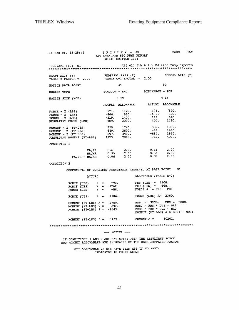
TRIFLEXWindows Rotating Equipment Compliance Reports
41

TRIFLEXWindows Rotating Equipment Compliance Reports
42
This Page Intentionally Left Blank

TRIFLEX®Windows Chapter 8
1
8.0 PIPING CODE COMPLIANCE REPORTS .....................................................2
8.0.1 Analysis Procedure ........................................................................................... 6 8.0.1.1 Performing a Thermal Analysis ...................................................................... 7 8.0.1.2 Performing a Weight + Pressure Analysis ...................................................... 7 8.0.1.3 Performing a Weight Factor Analysis............................................................. 8
8.0.2 With Non-linear Restraints Discussion........................................................... 8
8.1.0 Code Compliance Reports..................................................................................... 9 8.1.1 ASME ANSI B31.1 Power Piping Code Compliance .................................... 9 8.1.2 ANSI/ASME B31.3 Chemical Plant and Petroleum Refinery Piping Code Compliance Report – DIN 2413 Design of Steel Pressure Pipes ................................. 15 8.1.3 ANSI B31.4 Liquid Petroleum Transportation Piping Code ........................ 24 8.1.4 ANSI B31.8 Gas Transmission and Distribution Piping Systems................ 32 8.1.5 NAVY S505 Piping Code Compliance ........................................................ 44 8.1.6 ASME Class 2 Components - Section III Subsection NC ............................ 50 8.1.7 ASME Class 3 Components - Section III Subsection ND............................ 58 8.1.8 Swedish Piping Code Compliance (Section 9.4 - Method 1) SPC1 ............ 66 8.1.9 Swedish Piping Code Compliance (Section 9.5 - Method 2) ....................... 73 8.1.10 Norwegian Piping Code Compliance (Section Annex D-Alternative Method) 80 8.1.11 TBK 5-6 Norwegian Piping Code Compliance (Section 10.5)..................... 87 8.1.12 DNV Rules for Submarine Pipeline Systems, 1981 by Det norske Veritas . 94 8.1.13 DNV Rules for Submarine Pipeline Systems, 1996 by Det norske Veritas . 97 8.1.14 DNV Rules for Submarine Pipeline Systems, 2000 by Det norske Veritas 100 8.1.15 "Guidelines for Design, Fabrication, Submarine Pipelines and Risers", 1984 by the Norwegian Petroleum Directorate ................................................................... 103 8.1.16 Design, Specifications Offshore Installations, Offshore Pipeline Systems - F-sd-101", 1987 by Statoil.............................................................................................. 107 8.1.17 Polska Norma PN-79 / M-34033 ............................................................... 110 8.1.18 SNIP 2.05-06-85 - FSU Transmission Piping Code ................................... 125 8.1.19 BS 7159 : 1989 - British Standard Code of Practice for Design and Construction of Glass Reinforced Plastics (GRP) Piping Systems for Individual Plants or Sites 133 8.1.20 UKOOA – SPECIFICATION & RECOMMENDED PRACTICE FOR THE USE OF GRP PIPING OFFSHORE........................................................................... 140 8.1.21 BS 8010 Pipelines Subsea Piping Code Compliance Report...................... 147 8.1.22 EURO CODE –European Standard prEN 13480-3 .................................... 150

TRIFLEX®Windows Chapter 8
2
8.0 Piping Code Compliance Reports
The Piping Code Compliance Reports generated by TRIFLEX®Windows were designed to provide the piping stress User with a quick and efficient means of comparing a piping system design for compliance with that allowed by a given piping code.
Compliance reports for the following piping codes are presently available:
B31.1 - Power Piping Code
B31.3 - Chemical Plant and Petroleum Refinery Piping Code
B31.4 - Liquid Petroleum Transportation Piping Code
B31.8 - DOT Guidelines for Gas Transmission and Distribution Piping System
NAVY - General Specifications for Ships of the U.S. Navy, Section 505
CLAS2 - ASME Section III - Division 1 (Subsection NC)
CLAS3 - ASME Section III - Division 1 (Subsection ND)
SPC1 - Swedish Piping Code (Method 1 - Section 9.4)
SPC2 - Swedish Piping Code (Method 2 - Section 9.5)
TBK5-1 - Norwegian General Rules for Piping Systems (Method 1 Section 9.4)
TBK5-2 - Norwegian General Rules for Piping Systems (Method 2 Section 9.5)
DNV - DnV Rules for Submarine Pipeline Systems, 1981 by Det norske Veritas
DNV - DnV Rules for Submarine Pipeline Systems, 1996 by Det norske Veritas
DNV - DnV Rules for Submarine Pipeline Systems, 2000 by Det norske Veritas
NPD - Guidelines for Design, Fabrication and Installation, Submarine Pipelines and Risers, 1984 by the Norwegian Petroleum Directorate
STOL - Design, Specifications Offshore Installations -F-sd-101 by Statoil
POL1 - Polska Norma PN-79 / M-34033 Steam and Water Piping
SNIP - 2.05-06-85 - FSU Transmission Piping Code
BS7159 - British Standard Code for Glass Reinforced Plastic Piping Systems
UKOOA -UK Offshore Operator Association
BS8010 - British Standard Code for Piping Systems
EURO – European Standard prEN 13480-3

TRIFLEX®Windows Chapter 8
3
With a minimum amount of additional data input by the User, TRIFLEX®Windows will compute the minimum required wall thickness, the allowable pressure and the allowable stress values, and compare them with the actual calculated values found for the piping system.
The discussions that follow will familiarize the piping stress User with:
• stress requirements of the various piping codes
• input requirements for the TRIFLEX®Windows Compliance Reports
• solution techniques applied by TRIFLEX®Windows in the Compliance Reports.
The design temperature or expansion coefficient used in coding a TRIFLEX®Windows Piping Code Compliance run should reflect the total range of temperature expected during the operation of the piping system. This can be accomplished in one computer run by specifying the "Design Temperature" as the expected operating (HOT) temperature and by specifying the Base Temperature as the minimum temperature expected during the life of the system.
If a piping system operates cryogenically, then the minimum temperature expected (Design Temperature) should be specified as the operating temperature, and the maximum temperature expected should be specified as the Base Temperature.
The various piping codes are very specific in prohibiting the use of Cold Spring to reduce expansion stresses. For example, ANSI B31.3, paragraph 319.2.4 states:
"Inasmuch as the service life of a system is affected more by the range of variation than by the magnitude of stress at a given time, no credit for cold spring is permitted in stress range calculations."
See also ANSI B31.1, Para. 119.9, ANSI B31.4, Para. 419.6.4 (b) and (c), and Department of Transportation Guide for Gas Transmission and Distribution Piping Systems, Para. 832.37.
In Figure 1 Cold Spring Drawing, the calculated stress magnitude of 25000 psi represented by the solid line (no credit taken for Cold Spring) is the same as the 25000-psi stress range that will exist after several thermal cycles of the system. The operating temperature stress that will be measured after several cycles will be less than 25000 psi due to the "Self-Springing" discussed in ANSI B31.3, Para. 319.2.3; i.e., the stress that is relieved at operating temperature by "Self-Springing" shows up at ambient temperature as a stress of opposite sign.
Now, if we consider taking credit for 50% Cold Spring, we will calculate an expansion stress of 12,500 psi for the operating temperature case and a stress of 12500 psi in the opposite direction for the ambient temperature case (see the dashed line). The Expansion Stress Range is still 25000 psi, so the Cold Spring has done nothing to relieve the stress

TRIFLEX®Windows Chapter 8
4
range between the maximum hot and maximum cold conditions. This explains why credit for Cold Spring should not be taken in Piping Code Compliance Analyses.
The piping codes are explicit in stating that the modulus of elasticity at installation temperature must be used to calculate the magnitude of the Thermal Stress Range. For example, ANSI B31.3, Para. 319.4.4 (a) states:
"Bending and torsional stresses shall be computed using the as installed modulus of elasticity E(a) and then combined in accordance with Equation 17 to determine the computed displacement stress range SE, which shall not exceed the allowable stress range SA in 302.3.5(d)."
See also ANSI B31.1, Para. 119.6.4 A; ANSI B31.4, Para. 419.6.2, and DOT Guide for Gas Transmission and Distribution Piping Systems, Para. 832.38.
Note: The Code Compliance Reports are designed to inform the User as to whether the piping system stresses calculated as per the code formulas are within the allowable stresses specified.
The User is warned that under certain conditions stresses far in excess of those printed in the Compliance Reports may be present in the piping system. Therefore, all of the analyses generated in the TRIFLEX®Windows output should be studied carefully.

TRIFLEX®Windows Chapter 8
5
Figure 1 Cold Spring Drawing

TRIFLEX®Windows Chapter 8
6
The Code Compliance Report generated by TRIFLEX®Windows organizes and compares the computed and allowable design values. Each data point with a diameter and a wall thickness will be checked for its:
pressure-containing ability ability to sustain the dead weight + pressure distribution at operating conditions ability to conform without failure to a different shape as a result of displacement
strains and thermal expansion or contraction.
TRIFLEX®Windows will compute the Longitudinal Stress due to Sustained Loads, the Longitudinal Stress due to Occasional Loads, if any, and the Displacement Stress Range (Thermal Expansion Stress). These stress values are compared with the allowable stress values computed from basic material parameters input by the User. If Occasional Loads are to be considered, TRIFLEX®Windows applies a specified portion of the normal weight force to each piping component in one, two, or all three of the Global X, Y, Z directions and then compares these computed stresses with the applicable Code allowable.
To process a Code Compliance Analysis, the User should code the piping system in the ordinary manner. No single-analysis options, multiple-analysis options, or other B31 Code Compliance options should be requested. Non-linear Restraints, Flange Loading, Spring Hanger Design, and Rotating Equipment Reports may be requested.
When considering Occasional Loads, gravity factors should be specified in the CASE DATA Screen. All of the data on all node input screens might be specified in the usual manner with one exception:
TRIFLEX®Windows allows the User to consider "Dampers" or "Snubbers" in an analysis. A "Damper" is treated as a totally flexible restraint in the Thermal Analysis and in the Weight + Pressure Analysis. When TRIFLEX®Windows processes the required Weight Factor Analyses, the restraint becomes totally rigid and restricts movement in the specified directions.
To request a Code Compliance Report, the User must:
1. Enter in the "Piping Code Report?" field on the CASE DATA Screen.
Enter the hot and cold allowable on the PIPING CODE COMPLIANCE REPORT Screen.
8.0.1 Analysis Procedure
When a request for Code Compliance has been made, TRIFLEX®Windows will process at least two analyses prior to the B31 Compliance Report, a Thermal and then a Weight + Pressure Analysis. More than one type of report can be requested. TRIFLEX®Windows will perform an operating analysis (temperature, pressure, weight) to satisfy the requirements for other reports. These reports can include a request for an Operating

TRIFLEX®Windows Chapter 8
7
Analysis, a Flange Loading Analysis, Rotating Equipment Report, a Spring Hanger Design, or the use of non-linear restraints (one-directional, limit stops).
Note: If any of the above requested reports are made and occasional load gravity factors are given, the operating analysis will be performed with the occasional load factors acting simultaneously with temperature, pressure, and weight.
TRIFLEX®Windows processes the above requested analyses from the input data submitted and internally structures the data to match the Code Compliance requirements.
8.0.1.1 Performing a Thermal Analysis
In the Thermal Analysis TRIFLEX®Windows does the following:
• Excludes the effects of weight.
• Excludes the displacement stresses due to the effects of pressure (optional, may be included on the JOB DEFAULT Screen).
• Excludes all forces and moments input by the User.
• Excludes the initial loads on all flexible restraints (spring hangers, etc.,).
• Includes the initial Anchor and Restraint movements as input by the User.
• For Anchor displacements due to earthquake, this displacement must be specified by the User, and added to the thermal displacement to give a total displacement to satisfy the Code Requirements.
• Excludes dampers.
8.0.1.2 Performing a Weight + Pressure Analysis
In the Weight + Pressure Analysis TRIFLEX®Windows does the following:
• Excludes the effects of temperature.
• Excludes the initial Anchor and Restraint movements as input by the User.
• Includes the displacement stresses due to the effects of pressure (default, may be excluded on the JOB DEFAULT Screen).
• Includes the initial loads on all flexible restraints (spring hangers, etc.,).
• Includes all forces and moments as input by the User.
• Excludes dampers.
When Occasional Loads are requested, TRIFLEX®Windows processes additional Weight Factor Analyses.

TRIFLEX®Windows Chapter 8
8
8.0.1.3 Performing a Weight Factor Analysis
In each Weight Factor Analysis TRIFLEX®Windows does the following:
• Excludes the effects of temperature, pressure and weight.
• Excludes the initial Anchor and Restraint movements due to thermal and earthquake effects as input by the User.
• Includes the effects of the piping system weight multiplied by the input Weight Factor applied along the axis specified by the User; i.e., X, Y, and Z.
• Includes the effects of damper restraints.
8.0.2 With Non-linear Restraints Discussion
When a Piping Code Compliance Analysis is processed in this manner:
• Restraints which TRIFLEX®Windows finds acting on the piping system in the Operating Case Analysis will also act on the piping system in the Thermal Analysis and in the Weight + Pressure Analysis.
• Restraints which do not exert loads on the piping system in the Operating Case Analysis will be ignored in the Thermal Analysis and in the Weight + Pressure Analysis. For this reason the Weight + Pressure Analysis may show the pipe deflecting in the negative Y direction at a support location even though a rigid support exists at that location, and the weight of the pipe is actually suspended from other supports and/or Anchors.
For the purposes of determining the longitudinal pressure and weight stresses according to the piping codes, no support should be considered at locations where the pipe has moved away from the support in the operating condition.

TRIFLEX®Windows Chapter 8
9
8.1.0 Code Compliance Reports
8.1.1 ASME ANSI B31.1 Power Piping Code Compliance
The ANSI B31.1 Compliance Report consists of three Output Reports. The first Output Report lists all of the B31.1 Code Compliance Data specified by the User. The second Output Report contains the node identification, the design wall thickness vs. the required wall thickness, sustained stresses vs. allowed and expansion stresses vs. allowed. The third Output Report is generated only if the User requested Occasional Loads Analyses. This report contains a summary of all occasional stresses about each axis requested, the sustained longitudinal stress, and the resultant occasional stress vs. its allowable.
Output units and equations shown in this section are for the English system. Output units are available for the following:
(1) English (ENG) (3) Metric (MET)
(2) System International (SI) (4) International Units 1 (IU1)
Constants in equations are modified for each different system of units where necessary.
The first Output Report contains the following information:
FROM TO ALLOWABLE HOT STRESS
WITH WELD F. psi
ALLOWABLE COLD
STRESS psi
ALLOWABLE HOT STRESS
psi
STRESS RANGE
REDUCTION FACTOR
OCCASIONAL FATIGUE FACTOR
Y COEFFICIENT
MILL TOLERANCE
From and To Data Numbers
The range of data point numbers for which the specified properties apply.
Allowable Operating Stress (SE)
The maximum allowable stress in material due to internal pressure and joint efficiency at the design temperature, psi.
Allowed Cold Stress (SC)
The basic material allowable stress at the minimum (cold) temperature from the Allowable Stress Tables.

TRIFLEX®Windows Chapter 8
10
Allowed Hot Stress (SH)
The basic material allowable stress at the maximum (hot) temperature from the Allowable Stress Tables.
Stress Range Reduction Factor
Stress range reduction Factor for cyclic conditions for total number N of full temperature cycles over total number of years during which system is expected to be in operation, from Table 102.3.2(C).
Occasional Load Factor K
Factor specified by the User based upon the duration of the occasional loads.
Y-Coefficient
As per Table 104.1.2(A) in the ANSI/ASME B31.1 Code Book.
Mill Tolerance
Manufacturer mill tolerance in percent or inches.
The second Output Report contains the following information:
Data Point
Node Location
SEC 104.1.2 WALL
THICKNESS DESIGN in
SEC 104.1.2 WALL
THICKNESS REQUIRED in
SEC 104.8.1(11)
SUSTAINED STRESS
ACTUAL psi
SEC 104.8.1(11)
SUSTAINED STRESS
ALLOWED psi
SEC 104.8.1(11)
SUSTAINED STRESS
PERCENT
SEC 104.8.3(13)
EXPANSION STRESS
ACTUAL psi
SEC 104.8.3(13)
EXPANSION STRESS
ALLOWED psi
SEC 104.8.3(13)
EXPANSION STRESS
PERCENT
Data Point
The number assigned by the User to each significant location.
Node Location
The "Node" description defines the piping segment types; i.e., Anchor, Run, Joint, Valve, Flange, Bend, or Expansion Joint. The "Location" description defines the exact point on the piping segment where the calculated values apply.

TRIFLEX®Windows Chapter 8
11
Design Wall Thickness vs. Required Thickness
The Design Wall Thickness is the value input by the User. The required Wall Thickness value is calculated by TRIFLEX®Windows using the following B31.1 Code Equations (Section 104.1.2, Equation 3) and the internal pressure supplied by the User.
where:
tmin = minimum pipe wall thickness, inches
P = internal design pressure as input by the User, psig
Do = actual pipe outside diameter, inches
SE = maximum allowable stress in material due to internal pressure and joint efficiency at the design temperature, psi
y = a coefficient having the values given in the Table 104.1.2(A)
A = corrosion and wear allowance, inches
where:
treq = required wall thickness, inches
MT = User supplied mill tolerance, percent or inches (default is 12.5%)
Stresses Due To Sustained Loads vs. Allowed Stresses
Stresses due to Sustained loads are the algebraic summations of the Longitudinal Pressure Stress and Longitudinal Weight Stress. They are calculated using the following B31.1 Code Equation (Section 104.8.1, Equation 11):
where:
A + Py) + (SE 2
D P = t omin 1
MT+ t = t or MT)/100- (100.0
t = t reqreq minmin
S Z
M 0.75i + 4tD P = S h
AoL ≤⎟
⎠⎞
⎜⎝⎛ 3

TRIFLEX®Windows Chapter 8
12
P = pressure, psig
i = stress intensification factor; the term (0.75i) shall never be taken as less than 1.0
MX = moment about the X-axis, inch-pounds
MY = moment about the Y-axis, inch-pounds
MZ = moment about the Z-axis, inch-pounds
Sh = basic material allowable stress at maximum (hot) temperature from the Allowable Stress Tables, psi
As can be seen from the equation, the longitudinal stress due to the combined pressure and weight stresses shall be less than or equal to Sh.
The first term in ANSI/ASME B31.1, Equation 11 will be replaced by
where:
d = Do - 2⋅t
when the alternate pressure option is selected.
For full-size outlet connections:
For reduced outlet branch connections:
where:
Z = section modulus, in3
Ze = effective section modulus of reduced branch, in3
M + M + M = M 2Z
2Y
2XA
)d - D(d P
22o
2
⎟⎟⎠
⎞⎜⎜⎝
⎛
Dd - D
32 = Z
o
44oπ
tr = Z e2be π 7

TRIFLEX®Windows Chapter 8
13
rb = branch mean cross-sectional radius, inches
te = effective branch wall thickness (lesser of tnh and i⋅tnb)
tnh = nominal wall thickness of main pipe, inches
tnb = nominal wall thickness of branch, inches
Thermal Expansion Stress Range
The extent of the Thermal Expansion Stress Range induced is computed in the Thermal Analysis processed by TRIFLEX®Windows. This stress range must satisfy the following ANSI/ASME B31.1 Code Equation (Section 104.8.3, Equation 13):
)S - S( f + S ZMi = S LhA
cE ≤ 8
where:
where:
Sc = basic material allowable stress at minimum (cold) temperature from the Allowable Stress Tables, psi
Note: If Occasional Loads have been requested, a third Output Report appears.
Node Location
The "Node" description defines the piping segment types; i.e., Anchor, Run, Joint, Valve, Flange, Bend, or Expansion Joint. The "Location" description defines the exact point on the piping segment where the calculated values apply.
Occasional Stresses
Occasional Stresses for each direction requested are computed in the Weight Factor Analyses.
The moments at each piping location from each Weight Factor Analysis are combined in the following manner:
)S 0.25 + S (1.25 f = S HCA 9
⎟⎠
⎞⎜⎝
⎛Z
M 0.75i = S GF(axis)O 10

TRIFLEX®Windows Chapter 8
14
where:
Stresses Due To Sustained Loads
Stresses due to Sustained Loads are the algebraic summations of the Longitudinal Pressure Stress and Longitudinal Weight Stress.
Stresses Due to Occasional Loads vs. Allowed Stresses
Stresses due to Occasional Loads, SLO, are the algebraic summations of the Longitudinal Sustained Weight Stress, the Longitudinal Pressure Stress, and Occasional Stress. (ANSI/ASME B31.1, Equation 12).
where:
As can be seen from the equation, the Longitudinal Stress due to Occasional Loads shall be less than or equal to k⋅Sh.
where:
k = 1.15 for occasional loads acting less than 10% of operating period (see Para. 102.2.4)
= 1.2 for occasional loads acting less than 1% of operating period (see Para. 102.2.4).
⎟⎠⎞
⎜⎝⎛
ZM 0.75i +
t4D P = S A
n
oL
S k Z
M + M 0.75i + t4D P = S h
BA
n
oLO ≤⎟
⎠⎞
⎜⎝⎛ 12
)M + M + M( = M 2Z
2Y
2XGF(Y)
)M + M + M( = M 2Z
2Y
2XGF(Z)
)M + M + M( = M 2Z
2Y
2XGF(X)
)M + M + M( = M 2ZGF
2YGF
2XGFB )()()(

TRIFLEX®Windows Chapter 8
15
8.1.2 ANSI/ASME B31.3 Chemical Plant and Petroleum Refinery Piping Code Compliance Report – DIN 2413 Design of Steel Pressure Pipes
The ANSI B31.3 Compliance Report consists of three Output Reports. The first Output Report lists all of the B31.3 Code Compliance Data specified by the User. The second Output Report contains the node identification, the design wall thickness vs. required wall thickness, sustained stresses vs. allowed and displacement stresses vs. allowed. The third Output Report is generated only if Occasional Loads Analyses were requested by the User. This report contains a summary of all occasional stresses about each axis requested, the sustained longitudinal stress, and the resultant occasional stress vs. its allowable.
Output units and equations shown in this section are for the English system and the System International (SI). Output units are available for the following:
(1) English (ENG) (3) System International (SI)
(2) Metric (MET) (4) International Units 1 (IU1)
Constants in equations are modified for each different system of units where necessary.
The first Output Report contains the following information:
FROM TO
ALLOWABLE HOT
STRESS WITH WELD
F. psi
ALLOWABLE COLD
STRESS psi
ALLOWABLE HOT
STRESS psi
STRESS RANGE
REDUCTION FACTOR
OCCASIONAL FATIGUE FACTOR
Y COEFFICIENT
MILL TOLERANCE
Rated over 120 deg.
C
Fatigue Failure
Constant Stress
Amplitude psi
The first DIN 2413 Output Report contains the following information:
FROM TO
Degree of Weld
Utilization (DIN 2413)
ALLOWABLE COLD STRESS
N/mm^2
ALLOWABLE HOT
STRESS N/mm^2
STRESS RANGE
REDUCTION FACTOR
OCCASIONAL FATIGUE FACTOR
Maximum Permissible
Stress N/mm^2
MILL TOLERANCE
Rated over 120 deg. C
Fatigue Failure
Constant Stress
Amplitude KPa
FROM and TO Data Numbers
The range of data point numbers for which the specified properties apply.
Allowable Operating Stress (SE)
The maximum allowable stress in material due to internal pressure and joint efficiency at the design temperature, psi.

TRIFLEX®Windows Chapter 8
16
Allowed Cold Stress (SC)
The basic material allowable stress at the minimum metal temperature expected during the displacement cycle under analysis, psi.
Allowed Hot Stress (SH)
The basic material allowable stress at the maximum metal temperature expected during the displacement cycle under analysis, psi.
Stress Range Reduction Factor
Stress range reduction Factor for displacement cyclic conditions for total number N of cycles over the expected life (from Table 302.3.5).
Occasional Load Factor K
Factor specified by the User, based upon the duration of the occasional loads.
Y-Coefficient
As per Table 304.1.1 in the ANSI/ASME B31.3 Code Book.
Mill Tolerance
Manufacturer mill tolerance in percent or (inches or millimeters).
Degree of Weld Utilization
Degree of utilization of the design stress in the weld - Nυ - DIN 2413.
Maximum Permissible Stress
Maximum permissible stress under static loading - zulσ - DIN 2413.
Rated Over 120oC
Pipes subjected to predominantly static loading and rated for a temperature over 120OC.
Fatigue Failure
Pipes subjected to fatigue loading and rated for a temperature up to 120OC.
Constant Stress Amplitude
∨∧
− pp = pressure amplitude

TRIFLEX®Windows Chapter 8
17
The second Output Report contains the following information:
Data Point
Node Location
WALL THICKNESS DESIGN in
WALL THICKNESS
REQUIRED in
SUSTAINED STRESS
ACTUAL psi
SUSTAINED STRESS
ALLOWED psi
SUSTAINED STRESS
PERCENT
EXPANSION STRESS
ACTUAL psi
EXPANSION STRESS
ALLOWED psi
EXPANSION STRESS
PERCENT
Data Point
The number assigned by the User to each significant location.
Node Location
The "Node" description defines the piping segment types; i.e., Anchor, Run, Joint, Valve, Flange, Bend, or Expansion Joint. The "Location" description defines the exact point on the piping segment where the calculated values apply.
Design Wall Thickness vs. Required Thickness according B31.3
The User inputs values for the wall thickness as per B31.3. (Section 304.1.2, Equation 3a) and the User-supplied internal pressure:
c+ t = t m
where:
tm = minimum pipe wall thickness, inches
P = internal design pressure as input by the User, psig
DO = actual pipe outside diameter, inches
S = stress value for material from Table A-1, psi
E = quality factor from Table A-1A or A-1B
Y = a coefficient having the values given in the Table 304.1.1
c = corrosion and wear allowance, inches
PY) + (SE 2D P = t O

TRIFLEX®Windows Chapter 8
18
where:
treq = required wall thickness, inches
MT = User supplied mill tolerance, percent or inches (default is 12.5%)
Design Wall Thickness vs. Required Thickness according DIN 2413
The Design Wall Thickness is input by the User. The required Wall Thickness is calculated by TRIFLEX® using the following DIN 2413 Code Equations (Part 1, Table 3):
21 ccss ++= ϑ
I. Pipes subjected to predominantly static loading and rated for a temperature up to 120OC:
II. Pipes subjected to predominantly static loading and rated for a temperature over 120OC:
for: 67.1≤i
a
dd
for: 267.1 ≤<i
a
dd
Nzul
av
pds
υσ2=
12
+=
Nzul
av
p
ds
υσ
13
−=
Nzul
av
p
ds
υσ
MT+ t = t or MT)/100- (100.0
t = t reqreq minmin

TRIFLEX®Windows Chapter 8
19
III. Pipes subjected to fatigue loading and rated for a temperature up to 120OC:
For fatigue failure at constant stress amplitude:
where:
s= required thickness of the pipe
vs = design wall thickness of the pipe
1c = lower limit deviation for wall thickness
c2 = factor to allow for corrosion or wear
da = pipe outside diameter
di = pipe inside diameter
zulσ = maximum permissible stress under static loading
Nυ = degree of utilization of the design stress in the weld
p = design pressure
zulσ = maximum permissible stress under fatigue loading
∨∧
− pp = pressure amplitude
Stresses Due To Sustained Loads vs. Allowed Stresses
Stresses due to Sustained loads are the algebraic summations of the Longitudinal Pressure Stress and Longitudinal Weight Stress. They are calculated using the following Longitudinal Stress Equation [Section 302.3.5(c)]:
S Z
)Mi( + )Mi(
)d-D(4
F + )d - D(
dP = S h
2oo
2ii
22o
A22
o
2
L ≤±π
12−
−
=
∨∧ Nzul
av
pp
ds
υσ

TRIFLEX®Windows Chapter 8
20
where:
SL = the sum of longitudinal stress due to pressure, weight, and other sustained loads
FA = axial force, lbs
iI = in-plane stress intensification factor
io = out-plane stress intensification factor
MI = in-plane bending moment, inch-pounds
Mb = out-plane bending, inch-pounds
Sh = basic material allowable stress at maximum (hot) temperature from the Allowable Stress Tables, psi
As can be seen from the equation, the longitudinal stress due to the combined pressure and weight stresses shall be less than or equal to Sh.
The third term in the longitudinal stress equation will be replaced by:
when the request for no intensification factors (SUSNSI) in the sustained load case is selected.
For full-size outlet connections:
For reduced outlet branch connections:
where:
Z = section modulus, in3
Ze = effective section modulus of reduced branch, in3
r2 = mean branch cross-sectional radius, inches
TS = effective branch wall thickness (lesser of Th and ii⋅Tb), inches
ZM + M 2
o2i
⎟⎟⎠
⎞⎜⎜⎝
⎛
Dd - D
32 = Z
o
44oπ
Tr = Z S22e π

TRIFLEX®Windows Chapter 8
21
Th = thickness of pipe matching run of tee or header exclusive of reinforcing elements, inches
Tb = thickness of pipe matching branch, inches
d = inside diameter of pipe Do - 2 • t inches
Displacement Stress Range
The extent of the Displacement Stress Range induced is computed in the Thermal Analysis processed by TRIFLEX®. This stress range must satisfy the following ANSI/ASME B31.3 Code (Section 319.4.4, Equation 17):
where:
Sb = resultant bending stress, psi
St = torsional stress, psi
= Mt/2Z
Mt = torsional moment, psi
where:
Sc = basic material allowable stress at minimum (cold) temperature from the Allowable Stress Tables, psi
When the liberal method is selected SA is replaced by the following equation when SL is less than or equal to Sh:
If Occasional Loads have been requested, a third Output Report will appear.
S S4 + S = S A2t
2bE ≤
)S 0.25 + S (1.25 f = S hcA
)S - S( f + )S 0.25 + S (1.25 f = S LhhcA
Z)Mi( + )Mi(
= S2
oo2
iib

TRIFLEX®Windows Chapter 8
22
Occasional Stresses for each direction requested are computed in the Weight Factor Analyses.
The moments at each piping location from each Weight Factor Analysis are combined in the following manner:
Stresses Due To Sustained Loads
Stresses due to Sustained Loads are the algebraic summations of the Longitudinal Pressure Stress and Longitudinal Weight Stress.
Stresses Due to Occasional Loads vs. Allowed Stresses
Stresses due to Occasional Loads, SLO, are the algebraic summations of the Longitudinal Sustained Weight Stress, the Longitudinal Pressure Stress, and Occasional Stresses (B31.3, Section 302.3.6).
where:
ZM = S GF(axis)
O
)Mi( + )Mi( = M 2oo
2iiGF(X)
)Mi( + )Mi( = M 2oo
2iiGF(Y)
)Mi( + )Mi( = M 2oo
2iiGF(Z)
kS Z
M + Z
)Mi( + )Mi(
)d - D(4
F + )d - D(
d P = S hB
2oo
2ii
22o
A22
o
2
LO ≤±π
M + M + M = M 2GF(Z)
2GF(Y)
2GF(X)B
Z)Mi( + )Mi(
)d - D(
4
F + )d - D(
d P = S2
oo2
ii
22o
A22
o
2
L ±π

TRIFLEX®Windows Chapter 8
23
As can be seen from the equation, the Longitudinal Stress due to Occasional Loads shall be less than or equal to k⋅Sh. where:
K = as much as 1.33 times the basic allowable stress given in Appendix A.

TRIFLEX®Windows Chapter 8
24
8.1.3 ANSI B31.4 Liquid Petroleum Transportation Piping Code
The ANSI B31.4 Compliance Report consists of three to four separate Output Reports. The first Output Report lists all of the B31.4 Code Compliance Data specified by the User. The second Output Report contains the node identification, Hoop stress compared to its allowable and the design shear stress compared to its allowable. The third Output Report contains the node identification, design wall thickness vs. required wall thickness, the sustained stresses compare to its allowable and the expansion Stress range compare to its allowable. The fourth report contains a summary of all occasional stresses about each axis requested, the sustained longitudinal stress, and the resultant occasional stress vs. its allowable.
Output units and equations shown in this section are for the English system. Output units are available for the following:
(1) English (ENG) (3) Metric (MET)
(2) System International (SI) (4) International Units 1 (IU1)
Constants in equations are modified for each different system of units where necessary.
The first Output Report contains the following information:
FROM TO MINIMUM YIELD STRENGTH psi
WELD JOINT FACTOR
From and To Data Number
The range of data point numbers for which the specified properties apply.
Specified Minimum Yield Strength (SMYS), psi
From Code Tables.
Weld Joint Factor (E)
From Code Tables.

TRIFLEX®Windows Chapter 8
25
The second Output Report contains the following information:
Data Point
Node Location
HOOP STRESS
psi
HOOP ALLOWED
psi
SHEAR STRESS
psi
SHEAR ALLOWED
psi
WALL THICKNESS DESIGN in
WALL THICKNESS REQUIRED
in
SUSTAINED STRESS ACTUAL
psi
SUSTAINED STRESS
ALLOWED psi
EXPANSION STRESS
ACTUAL psi
EXPANSION STRESS
ALLOWED psi
Data Point
The number assigned by the User to each significant location.
Node Location
The "Node" description defines the piping segment types; i.e., Anchor, Run, Joint, Valve, Flange, Bend, or Expansion Joint. The "Location" description defines the exact point on the piping segment where the calculated values apply.
Hoop Stress
The standard hoop stress equation:
where:
Shoop = hoop stress, psi
P = design pressure, psig
D = actual outside diameter, in
t = given wall thickness, in
c = corrosion allowance, in
is compared with (0.72)(E)(SMYS). If the S value is greater than (0.72)(E)(SMYS) a *B31* flag will be printed along side of the value.
where:
E = weld joint factor
SMYS = specified minimum yield strength, psi
c) - (t 2D P = S hoop

TRIFLEX®Windows Chapter 8
26
Design and Allowed Shear Stress
Shear stress is computed in the Weight + Pressure Analysis processed by TRIFLEX. No other effects such as temperature or pressure (optional) are considered.
where:
Sp = maximum principal stress, psi
Ssh = secondary shear stress, psi
SL = sum of longitudinal stresses due to pressure and other sustained loadings
ii = in-plane intensification factor
io = out-plane intensification factor
Mi = in-plane bending moment, in-lbs
Mo = out-plane bending moment, in-lbs
Z = section modulus, in3
FA = axial force, lbs
Awall = area of the pipe wall, in2
The allowable stress value in shear is calculated in accordance with B31.4 [Section 402.3.1,e].
0.45SMYS 2S or S of greater = S p
shshear ≤
⎟⎠⎞
⎜⎝⎛
⎟⎠⎞
⎜⎝⎛
2ZM +
2)S - S( = S t
2HL
2
sh
Z)Mi( + )Mi(
AF +
A2t) - P(OD = S
2oo
2ii
wall
A
wallL ±
S + 2
)S + S( = S shHL
p

TRIFLEX®Windows Chapter 8
27
The third Output Report contains the following information:
Data Point
The number assigned by the User to each significant location.
Node Location
The "Node" description defines the piping segment types; i.e., Anchor, Run, Joint, Valve, Flange, Bend, or Expansion Joint. The "Location" description defines the exact point on the piping segment where the calculated values apply.
Design Wall Thickness vs. Required Thickness
The Design Wall Thickness is input by the User. The required Wall Thickness is calculated by TRIFLEX using the following B31.4 Code Equations (Section 404.1.2) and the User-supplied internal pressure:
where:
t = pressure design wall thickness as calculated in accordance with Para. 404.1.2,
tn = nominal wall thickness satisfying requirements for pressure and allowances, inches
Pi = internal design pressure as input by the User, psig
D = actual pipe outside diameter, inches
S = applicable allowable stress value in accordance with Para. 402.3.1, psi
= 0.72≅E≅SMYS
E = weld joint factor (see Para. 402.4.3)
Stresses Due to Sustained Loads vs. Allowed Stresses
Stresses due to Sustained Loads, SL, are the algebraic summations of the Longitudinal Pressure Stress and Longitudinal Sustained Weight Stress. SL is calculated using the following B31.4 Code Equation (Section 419.6.4(c)]:
S2D P = t i
A + t = tn

TRIFLEX®Windows Chapter 8
28
where:
SA =0.72≅SMYS
The second term in the longitudinal stress equation will be replaced by
when a request of no intensifications factors (SUSNSI) in the sustained load case is selected.
Expansion Stress Range Compared to Allowed Stress
Unrestrained Piping
If the "FROM" data point number specified in the B314 data set is not preceded by a minus sign, the entire range of data points covered by the B314 data set will be treated as unrestrained. For unrestrained piping, the expansion stress is computed in the Thermal Analysis processed by TRIFLEX. No other effects, such as weight and pressure (optional), are considered by TRIFLEX in the Thermal Analysis.
The expansion stress for Runs, Branches, Elbows, and Miter Bends is calculated using the following B31.4 Code Equation [Section 419.6.4(a)]:
where:
SE = Computed expansion stress, psi
Sb=equivalent bending stress, psi
St = torsional stress, psi
= Mt/2Z
Z)Mi( + )Mi(
= S2
oo2
iib
A
2oo
2ii
L SZ
)Mi( + )Mi( +
A)-4(tPD = S 75.0≤
Z)M( + )M( 2
o2
i
AtbE SS + SS ≤= 22 4

TRIFLEX®Windows Chapter 8
29
The allowed expansion stress range for unrestrained piping is given by the following equation:
SA =0.72≅SMYS
Restrained Piping
If the "FROM" data point number specified in the B314 data set for a range of data point properties is negative (preceded by a minus sign), then the entire range of data points described on the B314 data set is considered to be restrained piping. For restrained piping,
TRIFLEX computes the longitudinal expansion stress from the equation given in B31.4 Section 419.6.4(b):
where:
SL = Longitudinal compressive stress, psi
E = Modulus of elasticity of steel, psi
Sh = Hoop stress due to fluid pressure, psi
T1 = Temperature at time of installation, degrees F
T2 = Maximum or minimum operating temperature, degrees F
α = Linear coefficient of thermal expansion, inches/inches/degrees F
ν = Poisson's ratio = 0.3 for steel.
The term (α)(T2 - T1) is determined from information input by the User.
The net longitudinal stress becomes compressive for moderate increases of T2 and that according to the commonly used maximum shear theory of failure, this compressive stress adds directly to the hoop stress to increase the equivalent tensile stress available to cause yielding. This equivalent tensile stress shall not be allowed to exceed 90% of the specified minimum yield strength of the pipe.
If Occasional Loads have been requested, a fourth Output Report will be generated.
The fourth Output Report contains the following information:
Data Point
S - )T - T(E = S h12L να

TRIFLEX®Windows Chapter 8
30
The number assigned by the User to each significant location.
Node Location
The "Node" description defines the piping segment types; i.e., Anchor, Run, Joint, Valve, Flange, Bend, or Expansion Joint. The "Location" description defines the exact point on the piping segment where the calculated values apply.
Occasional Stresses
Occasional Stresses for each direction requested are computed in the Weight Factor Analyses.
Moments at each piping location from each Weight Factor Analysis are combined thusly:
Stresses Due To Sustained Loads
Stresses due to Sustained Loads are the algebraic summations of the Longitudinal Pressure
Stress and Longitudinal Weight Stress.
Stresses Due to Occasional Loads vs. Allowed Stresses
Stresses due to Occasional Loads, SLO, are the algebraic summations of the Longitudinal Sustained Weight Stress, the Longitudinal Pressure Stress, and Occasional Stresses. (B31.4, Section 402.3.3)
Z)Mi( + )Mi(
+ A)-4(t
PD = S2
oo2
iiL
)Mi( + )Mi( = M 2oo
2iiGF(X)
)Mi( + )Mi( = M 2oo
2iiGF(Y)
)Mi( + )Mi( = M 2oo
2iiGF(Z)
ZM
S axisGFO
)(=

TRIFLEX®Windows Chapter 8
31
where:
As can be seen from the equation, the Longitudinal Stress due to Occasional Loads shall be less than or equal to 0.80≅SMYS.
SMYS0.80 Z
M + Z
)Mi( + )Mi(
A)) - (4(tDP = S B
2oo
2iii
LO .≤±
2)(
2)(
2)( ZGFXGFXGFB MMMM ++=

TRIFLEX®Windows Chapter 8
32
8.1.4 ANSI B31.8 Gas Transmission and Distribution Piping Systems
The ANSI B31.8 Code Compliance Report capability in TRIFLEX can be processed for onshore piping systems and for offshore piping systems. The equations for computing stresses in the piping components are different for the Onshore criteria and for the Offshore criteria. As a result, the section immediately following this paragraph covers the Offshore piping systems and the section covering the Onshore piping is provided immediately following the conclusion of the Offshore discussion.
OFFSHORE PIPING
The ANSI B31.8 Compliance Report for Offshore piping consists of three separate Output Reports in the pre-formatted reports and two separate Output Reports in the spreadsheet output. The third pre-formatted Output Report contains the node identification, the longitudinalstress actual vs. the longitudinal stress allowed, and the combined stress based upon either the Tresca or the Von Mises equations as specified by the User vs. the combined stress allowed. The second spreadsheet Output Report contains all of the data presented in the second and third pre-formatted Output Reports.
Output units and equations shown in this section are for the System International (SI) system and International Units 1 (IU1). Output units are available for the following:
1) English (ENG) 3) Metric (MET)
2) System International (SI) 4) International Units 1 (IU1)
Constants in equations are modified for each different system of units where necessary.
The first Output Report contains the following information:
FROM TO
MINIMUM YIELD
STRENGTH Para.
841.11(a) psi
DESIGN FACTOR
WELD JOINT
FACTOR
TEMP DERATING FACTOR
Para. 841.11(a)
OFFSHORE FACTOR 1
Para. A842.221
OFFSHORE FACTOR 2
Para. A842.222
OFFSHORE FACTOR 3
Para. A842.223
ALTER COMBINE STRESS
Para. A842.223
From and To
The number assigned by the User to each significant location in the piping model.
SMYS - Spec. Min. Yield Strength

TRIFLEX®Windows Chapter 8
33
TRIFLEX displays the value entered by the User for the Specified Minimum Yield Strength of the pipe. Refer to Section 841.11(a) of the B31.8 Piping Code for more specific information.
Temperature Derating Factor, T
TRIFLEX displays the value entered by the User for the temperature de-rating factor as described in DOT Section 192.115. Refer to Section 841.11(a) of the B31.8 Piping Code for more specific information.
Design Factor for Hoop Stress, F1
TRIFLEX displays the value entered by the User for Hoop Stress Design Factor. Refer to Section A842.221 of the B31.8 Piping Code for more specific information.
Design Factor for Long. Stress, F2
TRIFLEX displays the value entered by the User for Longitudinal Stress Design Factor. Refer to Section A842.222 of the B31.8 Piping Code for more specific information.
Design Factor for Combined Stress, F3
TRIFLEX displays the value entered by the User for Combined Stress Design Factor. Refer to Section A842.223 of the B31.8 Piping Code for more specific information.
Combined Stress Theory
TRIFLEX will display ATresca@ if the User has specified that the Tresca equation be used to calculate the combined stress value at this node location or AVon Mises@ if the User has specified that the Von Mises equation be used to calculate the combined stress value at this node location. Refer to Section A842.223 of the B31.8 Piping Code for more specific information.
The Report of Calculated Results for the Offshore capability contains the information described below. The data listed below is provided in one report in the spreadsheet capability and in two reports in the pre-formatted reports capability.
The second Output Report contains the following information:
Data Point
Node Location
DESIGN WALL
THICKNESS in
WALL THICKNESS
MINIMUM REQUIRED
Para. A842.221 in
HOOP STRESS ACTUAL
psi
HOOP STRESS
ALLOWED Para.
A842.221 psi
HOOP STRESS ACTUAL
vs. ALLOWED
LONGITUDINAL STRESS
ACTUAL psi
LONGITUDINAL STRESS
ALLOWED Para. A842.222
psi
LONGITUDINAL STRESS
ACTUAL vs. ALLOWED
COMBINED STRESS ACTUAL
psi
COMBINED STRESS THEORY
Para. A842.223
COMBINED STRESS
ALLOWED Para.
A842.223 psi
COMBINED STRESS ACTUAL
vs. Allowed(%)
Data Point

TRIFLEX®Windows Chapter 8
34
The number assigned by the User to each significant location in the piping model.
Node Location
The Node Location defines the exact point on the piping component at which the values are calculated; i.e., Anchor, Run Beg, Run End, Joint, Valve, Flange, Bend Beg, Bend Mid, Bend End, Reducer Beg, Reducer End, Release Element or Expansion Joint.
Wall Thickness - Design vs. Wall Thickness - Minimum Required
The Design Wall Thickness is entered by the User. The Minimum Required Wall Thickness is calculated by TRIFLEX using the following B31.8 Code Equation (Section A842.221, the User-entered internal pressure and the external pressure calculated by TRIFLEX using the density of the surrounding fluid and the depth of the pipe):
where:
t = required wall thickness as calculated in accordance with Para. A842.221,
inches
Pi = internal design pressure, psi
Pe = external pressure, psi
D = nominal outside diameter of pipe, inches
F1 = hoop stress design factor obtained from Table A842.22
S = specified minimum yield strength (SMYS), psi
T = temperature derating factor obtained from Table A841.116A
tn = minimum required wall thickness satisfying the pressure and allowances requirements, inches
c = corrosion allowance, in
Hoop Stresses - Actual vs. Hoop Stresses - Allowed
For pipelines and risers, the tensile hoop stress due to the difference between internal and external pressures shall not exceed the values shown below as described in the B31.8 Code Equation (Section A842.221):
c+t=tn
T SF 2D )P- P( = t
1
ei
T SF S 1h ≤

TRIFLEX®Windows Chapter 8
35
where:
Sh = hoop stress, psi
Pi = internal design pressure, psi
Pe = external pressure, psi
D = nominal outside diameter of pipe, inches
t = nominal wall thickness, inches
F1 = hoop stress design factor obtained from Table A842.22
S = specified minimum yield strength (SMYS), psi
T = temperature derating factor obtained from Table A841.116A
Hoop Stress - Actual / Allowed (%)
TRIFLEX displays the percentage of the actual calculated hoop stress for the specific node divided by the allowed hoop stress. A number greater than 100 indicates that the actual calculated stress exceeds the allowed stress.
Longitudinal Stress - Actual vs. Longitudinal Stress - Allowed
For pipelines and risers, the longitudinal stress shall not exceed the values shown below as described in the B31.8 Code Equation (Section A842.222):
where:
SL = maximum longitudinal stress, psi (positive tensile or negative compressive)
F2 = longitudinal stress design factor obtained from Table A842.22
S = specified minimum yield strength (SMYS), psi
2tD )P - P( = S eih
SF S 2L ≤

TRIFLEX®Windows Chapter 8
36
∗ ∗ = absolute value
Longitudinal Stress - Actual / Allowed (%)
In this column, TRIFLEX displays the percentage of the actual calculated longitudinal stress for the specific node divided by the allowed longitudinal stress. A number greater than 100 indicates that the actual calculated stress exceeds the allowed stress.
Combined Stress - Actual vs. Allowed
According to Para. A842.223 of the B31.8 Piping Code, the combined stress shall not exceed the value given by the maximum shear stress equation (Tresca combined stress):
where:
SL = maximum longitudinal stress, psi
Sh = hoop stress, psi
F3 =combined stress design factor obtained from Table A842.23
S = specified minimum yield strength (SMYS), psi
Ss = tangential shear stress, psi
Alternatively, according to Para. A842.223 of the B31.8 Piping Code, the User can require that the combined stress be calculated using the Maximum Distortional Energy Theory (Von Mises combined stress) and that the resulting longitudinal stress values not exceed the value given by the following longitudinal stress equation (Von Mises combined stress):
where:
SL = maximum longitudinal stress, psi
Sh = hoop stress, psi
F3 = combined stress design factor obtained from Table A842.22
S = specified minimum yield strength (SMYS), psi
]S + ) 2S -
2S ( [ 2 SF 2
s2hL
3 ≥
)S3 + S + SS - S ( SF 2s
2LhL
2h3 ≥

TRIFLEX®Windows Chapter 8
37
Ss = tangential shear stress, psi
Combined Stress Theory
TRIFLEX lists the theory that the User has selected by which the combined stress values are to be calculated. The stress theory that TRIFLEX defaults to is Tresca=s maximum shear stress equation, however, the User may request that the stress values be calculated in accordance with Von Mises Maximum Distortional Energy equation.
Combined Stresses - Actual / Allowed (%)
TRIFLEX displays the percentage of the actual calculated combined stress for the specific node point divided by the allowed combined stress. A number greater than 100 indicates that the actual calculated stress exceeds the allowed stress.
ONSHORE PIPING
The ANSI B31.8 Compliance Report for Onshore piping consists of four separate Output Reports in the pre-formatted reports and two separate Output Reports in the spreadsheet output. The third pre-formatted Output Report contains the node identification; the longitudinal sustained plus occasional stress actual vs. its allowable and the expansion stress vs. its allowable. The fourth pre-formatted Output Report contains a summary of all occasional stresses resulting from loads applied along each axis specified by the User, the longitudinal sustained stress actual, and the longitudinal sustained and occasional stress actual. The second spreadsheet Output Report contains all of the data presented in the second, third and fourth pre-formatted Output Reports.
Output units and equations shown in this section are for the System International (SI) system and International Units 1 (IU1). Output units are available for the following:
1) English (ENG) 3) Metric (MET)
2) System International (SI) 4) International Units 1 (IU1)
Constants in equations are modified for each different system of units where necessary.

TRIFLEX®Windows Chapter 8
38
The first Output Reports contains the following information:
FROM TO
MINIMUM YIELD
STRENGTH Para.
841.11 (a) N/mm^2
DESIGN FACTOR
Para. 841.11 (a)
WELD JOINT
FACTOR Para.
841.11 (a)
TEMPERATURE DERATING
FACTOR Para. 841.11 (a)
From and To Data Numbers
The range of data point numbers for which the specified properties apply.
SMYS - Spec. Min. Yield Strength
TRIFLEX displays the value entered by the User for the Specified Minimum Yield Strength of the pipe. Refer to Section 841.11(a) of the B31.8 Piping Code for more specific information.
Design Factor, F
TRIFLEX displays the value entered by the User for the design factor as described in DOT Section 192.111 for steel pipe. Refer to Section 841.11(a) of the B31.8 Piping Code for more specific information.
Longitudinal Joint Factor, E
TRIFLEX displays the value entered by the User for the weld joint factor for the welding process used in the manufacture of the pipe. Refer to Section 841.11(a) of the B31.8 Piping Code for more specific information.
Temperature Derating Factor, T
TRIFLEX displays the value entered by the User for the temperature de-rating factor as described in DOT Section 192.115. Refer to Section 841.11(a) of the B31.8 Piping Code for more specific information.
The Report of Calculated Results for the Onshore capability contains the below information. The data listed below is provided in one report in the spreadsheet capability and in three reports in the pre-formatted reports capability.

TRIFLEX®Windows Chapter 8
39
Data Point
Node Location
DESIGN WALL
THICKNESS mm.
WALL THICKNESS
MINIMUM REQUIRED
Para. 841.11 mm.
COMBINED STRESS ACTUAL
Para. 833.4 (a)+(b)+(c) N/mm^2
COMBINED STRESS
ALLOWED Para. 833.4
841.11 N/mm^2
COMBINED STRESS ACTUAL
vs. Allowed(%)
LONGITUDINAL STRESS
ACTUAL Due to Sus. & Occa. Para. 841.11
and 833.4 (b)+(c) N/mm^2
LONGITUDINAL STRESS
ALLOWED Due to Sus. & Occa.
Para. 833.4 N/mm^2
LONGITUDINAL STRESS
ACTUAL vs. ALLOWED
COMBINED STRESS ACTUAL Due to
Expansion Para. 833.2
N/mm^2
COMBINED STRESS
ALLOWED Due to
Expansion Para. 833.3
N/mm^2
COMBINED STRESS ACTUAL
vs. ALLOWED
Data Point
The number assigned by the User to each significant location in the piping model.
Node Location
The “Node” description defines the piping segment types; i.e, Anchor, Run, Joint, Valve, Flange, Bend, or Expansion Joint. The “Location” description defines the exact point on the piping segment where the calculated values apply.
Wall Thickness - Design vs. Wall Thickness - Minimum Required
The Design Wall Thickness is entered by the User. The Minimum Required Wall Thickness is calculated by TRIFLEX using the following B31.8 Code Equation (Section 841.11 and the User-entered internal pressure):
where:
t = required wall thickness as calculated in accordance with Para. 841.11, inches
Pi = internal design pressure, psi (see Para. 841.111)
Pe = external pressure, psi
D = nominal outside diameter of pipe, inches
S = specified minimum yield strength, psi [see Para. 841.112 and 817.13(h)]
F = design factor obtained from Table 841.114A
E = longitudinal joint factor obtained from Table 841.115A [see Para. 817.13(d)]
c+t=t n
TEFS2D )P - P( = t ei

TRIFLEX®Windows Chapter 8
40
T = temperature derating factor obtained from Table A841.116A
tn = minimum required wall thickness satisfying the pressure and allowances requirements, inches
c = corrosion allowance, in
For Onshore Piping Systems where internal and external pressure exists, the User should enter the differential pressure as the internal pressure.
Combined Stress - Actual vs. Combined Stress - Allowed
According to paragraph 833.4 of the B31.8 Piping Code, the total of the following stresses shall not exceed the specified minimum yield strength S:
a) the combined stress due to expansion SE;
b) the longitudinal pressure stress as defined in paragraph 841.11 of the piping code, SFT;
c) the longitudinal bending stress due to external loads, such as weight of pipe and contents, wind or seismic, etc.,. Wind or seismic will be treated as occasional loads.
The sum of the combined stress due to expansion, SE, the longitudinal pressure stress and longitudinal bending stresses due to sustained and occasional loads should not exceed the Specified Minimum Yield Strength, S. The allowable value for the sum of these stresses calculated by TRIFLEX is given in the following equation:
Combined Stress - Actual / Allowed (%)
TRIFLEX displays the percentage of the actual calculated combined stress for the specific node point divided by the allowed combined stress. A number greater than 100 indicates that the actual calculated stress exceeds the allowed stress.
Longitudinal Stress Due to Sustained & Occasional Loads - Actual vs. Longitudinal Stress Due to Sustained & Occasional Loads - Allowed
Stresses due to Sustained Loads, SL, are the algebraic summations of the Longitudinal Pressure Stress and Longitudinal Stress due to Sustained Loads (pipe weight, contents weight and insulation weight). The Longitudinal Stress due to Occasional Loads is those resulting from conditions such as wind and earthquake. SL with the Occasional Loads is calculated using the following B31.8 Code Equation [Section 833.4 (b) and (c)]:
S= S (combined) A

TRIFLEX®Windows Chapter 8
41
where:
P = design pressure, psi
OD = outside diameter, in
t = nominal wall thickness, in
c = corrosion allowance, in
i = stress intensification factor
Z = section modulus of pipe, in3
Mi = in-plane bending moment, in-lbs
Mo = out-of-plane bending moment, in-lbs
The sum of the longitudinal pressure and bending stresses from sustained and occasional loads should not exceed 75% of the allowable stress in the hot condition. The allowable value for the sum of the longitudinal stresses calculated by TRIFLEX is given in the following equation:
In all comparisons, when the allowed value is less than the value found for the piping system, a *B31 flag is printed to the right side of the comparison.
When the User places a check in the box in the option on the Code Data dialog for no intensifications factors to be included in the longitudinal bending stresses, TRIFLEX will replace the second term in the longitudinal stress equation with the following:
Longitudinal Stress Due to Sustained & Occasional Loads - Actual/Allowed (%)
In this column, TRIFLEX displays the percentage of the actual calculated longitudinal sustained & occasional stress for the specific node point divided by the allowed longitudinal sustained & occasional stress. A number greater than 100 indicates that the actual calculated stress exceeds the allowed stress.
ZM i +
ZM + M i +
c) - (t 4D P = S B
2o
2ii
L
M + M + M = M 2GF(Z)
2GF(Y)
2GF(X)B
ZM + M 2
o2i

TRIFLEX®Windows Chapter 8
42
Combined Stress due to Expansion, SE - Actual vs. Combined Stress due to Expansion, SE - Allowed
The expansion stress is computed in the Thermal Analysis processed by TRIFLEX. No other effects such as weight and/or pressure are considered in this Thermal Analysis. The expansion stress is calculated using the following B31.8 Code Equation [Section 833.2]:
where:
SE = combined expansion stress, psi
Sb = resultant bending stress, psi
= i Mb/z
St = torsional stress, psi
= Mt/2z
Mb = resultant bending moment in-lb
i = stress intensification factor
The allowed expansion stress range is calculated by TRIFLEX using the following equation [Section 833.3]:
Combined Stress due to Expansion, SE - Actual / Allowed (%)
In this column, TRIFLEX displays the percentage of the actual calculated expansion stress for the specific node point divided by the allowed expansion stress. A number greater than 100 indicates that the actual calculated stress exceeds the allowed stress.
If Occasional Loads have been requested, the data listed below will be generated. In the spreadsheet capability, the data will be listed to the right of the data listed above. In the pre-formatted reports capability, the data will be listed in a fourth report.
Longitudinal Bending Stresses due to Occasional Loads by Axis
Occasional Stresses resulting from occasional loads applied in each direction specified by the User are computed in the Weight Factor Analyses and displayed in the columns entitled X Occasional Stress, Y Occasional Stress and Z Occasional Stress. The Occasional Stress is calculated using the following equation:
S0.75 = S A
S4 + S = S 2t
2bE
ZM = S GF(axis)
O

TRIFLEX®Windows Chapter 8
43
The moments at each piping location from each Weight Factor Analysis are combined in the following manner:
The stresses resulting from the X Weight Factor Analysis are listed in the first stress column. The stresses resulting from the Y Weight Factor Analysis are listed in the second stress column. The stresses resulting from the Z Weight Factor Analysis are listed in the third stress column.
Longitudinal Bending Stress due to Resultant Occasional Loads
The Resultant Occasional Stresses are calculated using the following equation:
where:
SLO = resultant longitudinal occasional stress, psi
i = stress intensification factor
Z = section modulus of pipe, in3
where:
M + M = M 2o
2iGF(X)
M + M = M 2o
2iGF(Z)
M + M = M 2o
2iGF(Y)
ZM i = S B
LO
M + M + M = M 2GF(Z)
2GF(Y)
2GF(X)B
)M + M + M( = M 2Z
2Y
2XGF(X)
)M + M + M( = M 2Z
2Y
2XGF(Y)
)M + M + M( = M 2Z
2Y
2XGF(Z)

TRIFLEX®Windows Chapter 8
44
8.1.5 NAVY S505 Piping Code Compliance
The NAVY Piping Code Compliance Report consists of two to three Output Reports. The first Output Report lists all of the NAVY S505 Piping Code Compliance Data specified by the User. The second Output Report contains the node identification, sustained stresses vs. allowed stresses, and displacement stresses vs. allowed stresses. The third Output Report is generated only if Occasional (temporary) Loads Analyses were requested by the User. This report contains a summary of all occasional stresses about each axis requested, the sustained stress, and the resultant occasional stress vs. its allowable stress.
Output units and equations shown in this section are for the English system. Output units are available for the following:
(1) English (ENG) (3) Metric (MET)
(2) System International (SI) (4) International Units 1 (IU1)
The first Output Report contains the following information:
FROM TO
OPERATING HOT
STRESS WITH WELD
F. psi
ALLOWABLE COLD
STRESS psi
ALLOWABLE HOT
STRESS psi
STRESS RANGE
REDUCTION FACTOR
OCCASIONAL FATIGUE FACTOR
Y COEFFICIENT
MILL TOLERANCE
From and to Data Numbers
The range of data point numbers for which the specified properties apply.
Allowable Operating Stress (SE)
The maximum allowable stress in material due to internal pressure and joint efficiency at the design temperature, psi.
Allowed Cold Stress (SC)
The basic material allowable stress at the minimum (cold) temperature from the Allowable Stress Tables, psi.

TRIFLEX®Windows Chapter 8
45
Allowed Hot Stress (SH)
The basic material allowable stress at the maximum (hot) temperature from the Allowable Stress Tables, psi.
Stress Range Reduction Factor
Factor specified by User to reduce stress allowable because of cyclic conditions.
Occasional Load Factor K
Factor specified by the User, based upon the duration of the occasional loads.
Y-Coefficient
Per the NAVY Code Book (Table VII).
Mill Tolerance
Manufacturer mill tolerance in percent or (inches or millimeters).
The second Output Report contains the following information:
Data Point
Node Location
WALL THICKNESS DESIGN in
WALL THICKNESS REQUIRED
in
SUSTAINED STRESS
ACTUAL psi
SUSTAINED STRESS
ALLOWED psi
SUSTAINED STRESS
PERCENT
EXPANSION STRESS
ACTUAL psi
EXPANSION STRESS
ALLOWED psi
EXPANSION STRESS
PERCENT
Data Point
The number assigned by the User to each significant location.
Node Location
The "Node" description defines the piping segment types; i.e., Anchor, Run, Joint, Valve, Flange, Bend, or Expansion Joint. The "Location" description defines the exact point on the piping segment where the calculated values apply.
Design Wall Thickness vs. Required Thickness
The Design Wall Thickness is input by the User. The required Wall Thickness is calculated by TRIFLEX using the following equation and the User-supplied internal pressure:

TRIFLEX®Windows Chapter 8
46
where:
tmin = minimum pipe wall thickness, inches
P = internal design pressure as input by the User, psig
Do = actual pipe outside diameter, inches
SE = maximum allowable stress in material due to internal pressure and joint efficiency at the design temperature, psi
y = a coefficient having the values given in the Table VII
A = corrosion and wear allowance, inches
where:
treq = required thickness, in
MT = User supplied mill tolerance, percent or (inches or mm) (default is 12.5%)
Stresses Due To Sustained Loads vs. Allowed Loads
Stresses due to Sustained loads are the algebraic summations of the Longitudinal Pressure Stress and Longitudinal Weight Stress. They are calculated using the following equation:
where:
SL = the sum of longitudinal stress due to pressure, weight, and other sustained loads
P = pressure, psig
OD = Outside diameter, inches
A + Py) + 2(SE
DP = t o⋅min
MT)/100- (100.0t = treq
min
S ZM i +
4tOD P = S h
AL ≤
22oiA MMM +=

TRIFLEX®Windows Chapter 8
47
Mi = in-plane bending moment, inch-pounds
Mo = out-plane bending, inch-pounds
i = stress intensification factor
As can be seen from the equation, the longitudinal stress due to the combined pressure and weight stresses shall be less than or equal to the Sh.
For full-size outlet connections:
For reduced outlet branch connections:
where:
Z = section modulus, in3
Ze = effective section modulus of reduced branch, in3
rm = the mean radius of the branch, inches
ts = effective wall thickness of branch (the smaller of th and i≅tb), inches
th = nominal wall thickness of main pipe, inches
tb = nominal wall thickness of branch, inches
OD = the nominal outside diameter of the pipe, inches
ID = inside diameter of pipe OD - 2≅t, inches
Expansion Stress Range
The extent of the expansion stress range induced is computed in the Thermal Analysis processed by TRIFLEX. This stress range must satisfy the condition:
where:
⎟⎟⎠
⎞⎜⎜⎝
⎛OD
ID - OD 32
= Z44π
S Z
M + Mi + M SS= S A
2o
2i
2t
tbE ≤=+)(
42
22
tr = Z sme2π

TRIFLEX®Windows Chapter 8
48
Z
iMS b
b = effective bending stress
ZM
St t
2= effective torsional stress
Sc = basic material allowable stress at minimum (cold) temperature from the Allowable Stress Tables, psi
Sh = basic material allowable stress at maximum (hot) temperature from the Allowable Stress Tables, psi
An alternative formula is:
where:
Mi = in-plane bending moment, inch-pounds
Mo = out-plane bending, inch-pounds
Mt = torsional moment, inch-pounds
which will be used when the liberal method is requested. If Occasional Loads have been requested, a third Output Report will be generated.
The third Output Report contains the following information:
Occasional Stresses
Occasional Stresses for each direction requested are computed in the Weight Factor Analyses.
where:
The moments at each piping location from each Weight Factor Analysis are combined in the following manner:
⎟⎠⎞
⎜⎝⎛
ZM 0.75i = S B
O
M + M + M = M 2GF(Z)
2GF(Y)
2GF(X)B
)S - S( f + S Z
M + Mi + M = S LhA
2o
2i
2t
E ≤)(2
)25.025.1( HCA SSfS +=

TRIFLEX®Windows Chapter 8
49
)M + M + M( = M 2o
2i
2tGF(X)
)M + M + M( = M 2o
2i
2tGF(Y)
)M + M + M( = M 2o
2i
2tGF(Z)
Stresses Due To Sustained Loads
Stresses due to Sustained Loads are the algebraic summations of the Longitudinal Pressure Stress and Longitudinal Weight Stress.
Stress Due to Occasional Loads vs. Allowed Stresses
Stresses due to Occasional Loads, SLO, are the algebraic summations of the Longitudinal Sustained Weight Stress, the Longitudinal Pressure Stress, and Occasional Stress.
As can be seen from the equation, the Longitudinal Stress due to Occasional Load shall be less than or equal to k Sh .
ZM + M i +
4tODP = S
2o
2i
L⋅
S k Z
M 0.75i + ZM i +
t 4OD P = S h
BA
nLO ≤

TRIFLEX®Windows Chapter 8
50
8.1.6 ASME Class 2 Components - Section III Subsection NC
The ASME Class 2 Compliance Report consists of three Output Reports. The first Output Report lists all of the Class 2 Code Compliance Data specified by the User. The second Output Report contains the node identification, the design wall thickness vs. the required wall thickness, sustained stresses vs. allowed and expansion stresses vs. allowed. The third Output Report is generated only if Occasional Loads Analyses were requested by the User. This report contains a summary of all occasional stresses about each axis requested, the sustained longitudinal stress, and the resultant occasional stress vs. its allowable.
Output units and equations shown in this section are for the English system. Output units are available for the following:
(1) English (ENG) (3) Metric (MET)
(2) System International (SI) (4) International Units 1 (IU1)
Constants in equations are modified for each different system of units where necessary.
The first Output Report contains the following information:
FROM TO MATERIAL YIELD STRENGTH psi
ALLOWABLE COLD STRESS psi
ALLOWABLE HOT STRESS psi
STRESS RANGE REDUCTION
FACTOR
EXPANSION STRESS RATIO
From and To Data Point Numbers
The range of data point numbers for which the specified properties apply.
Specific Minimum Yield (SY)
Material yield strength at temperature consistent with the loading under consideration.
Minimum Stress (SC)
The basic material allowable stress value at room temperature from Tables I-7.0, psi.
Maximum Stress (SH)
The material allowable stress at temperature consistent with the loading under consideration.

TRIFLEX®Windows Chapter 8
51
Stress Range Reduction Factor
The stress range reduction factor for cyclic conditions for total number N of full temperature cycles over total number of years during which system is expected to be in service from Table NC-3611.2 (e)-1.
Ratio of Installed to Operating Modulus
When using Para. NB-3672.5, which allows the use of the hot (operating) modulus to be used in determining moments and forces and hence the expansion stresses, this multiplier will be used to increase the stresses by the ratio of the installed to operating modulus of elasticity, psi. If the installed modulus was used in the analysis a ratio of 1.0 should be used. The second Output Report contains the following information:
The second Output Report contains the following information:
Data Point Node Location
SUSTAINED STRESS
ACTUAL psi
SUSTAINED STRESS
ALLOWED psi
EXPANSION STRESS
ACTUAL psi
EXPANSION STRESS
ALLOWED psi
TOTAL STRESS
ACTUAL psi
TOTAL STRESS
ALLOWED psi
Data Point
The number assigned by the User to each significant location.
Node Location
The "Node" description defines the piping segment types; i.e., Anchor, Run, and Bend. The "Location" description defines the exact point on the piping segment where the calculated values apply.
Stresses Due to Sustained Loads Vs. Allowed Stresses
Stresses due to Sustained Loads, SSL, are the algebraic summations of the Longitudinal Pressure Stress and Longitudinal Weight stress. SSL is calculated using the following ASME Class 2 Code Equation (NC-3652, Equation 8):

TRIFLEX®Windows Chapter 8
52
where:
Z = Section modulus, in3
tn = Nominal thickness, inches
Do = Outside diameter, inches
P = Internal design pressure, psi
MA = Resultant moment loading on cross section due to weight and other sustained loads, in-lbs
B1, B2 = primary stress indices for the specific product under investigation (NB-3680) see the table at the end of this section
Sh = Material allowable stress at temperature consistent with the loading under consideration, psi
For full-size outlet connections:
For reduced outlet branch connections:
where:
Ze = effective section modulus of reduced branch, in3
rb = branch mean cross-sectional radius, inches
te = effective branch wall thickness (lesser of tnh and i≅tnb)
S 1.5 Z
M B + t 2D P B = S h
A2
n
o1SL ≤
M + M + M = M 2Z
2Y
2XA
⎟⎟⎠
⎞⎜⎜⎝
⎛
Dd - D
32 = Z
o
44oπ
tr = Z e2be π

TRIFLEX®Windows Chapter 8
53
tnh = nominal wall thickness of main pipe, inches
tnb = nominal wall thickness of branch, inches
d = inside diameter of pipe Do - 2≅t, inches
Thermal Expansion Stress vs. Allowed Stresses
For Service Loading for which Level A and B Service Limits are designated, the requirements of either equation (10) or equation (11) must be met. (NC-3653.2)
a) The calculated thermal expansion stresses must be in compliance with Eq. (10):
where:
MC = range of resultant moments due to thermal expansion, in-lbs; also include moment effects of anchor displacements due to earthquake.
f = Stress range reduction factor
Sc = Basic material allowable stress value at room temperature from Tables I-7.0, psi
b) The stress values resulting from any single non-repeated anchor movements must be in compliance with equation (10a):
where:
MD = resultant moment due to any single non-repeated anchor movement (e.g. predicted building settlement), in-lbs
Sc = Basic material allowable stress value at room temperature from Tables I-7.0, psi
S ZM i = S A
CE ≤
( )S 0.25 + S 1.25 f = S hcA
S 3 ZM i = S C
DE ≤

TRIFLEX®Windows Chapter 8
54
c) The stress values resulting from effects of pressure, weight, other sustained loads and thermal expansion must be in compliance with equation (11) (Total Stress):
If Occasional Loads have been requested, a third Output Report will be generated and contains the following information:
Data Point
The number assigned by the User to each significant location.
Node Location
The "Node" description defines the piping segment types; i.e., Anchor, Run, Joint, Valve, Flange, Bend, or Expansion Joint. The "Location" description defines the exact point on the piping segment where the calculated values apply.
Occasional Stresses
Occasional Stresses for each direction requested are computed in the Weight Factor Analyses. The moments at each piping location from each Weight Factor analysis are combined in the following manner:
where:
)M + M + M( = M 2Z
2Y
2XGF(Y)
)M + M + M( = M 2Z
2Y
2XGF(Z)
)M + M + M( = M 2Z
2Y
2XGF(X)
)S + S( Z
M i + Z
M i 0.75 + t 4D P = S Ah
CA
n
OTE ≤⎟
⎠⎞
⎜⎝⎛
⎟⎠⎞
⎜⎝⎛
⎟⎠
⎞⎜⎝
⎛Z
M 0.75i = S GF(axis)O

TRIFLEX®Windows Chapter 8
55
Stresses Due To Sustained Loads
Stresses due to Sustained Loads are the algebraic summations of the Longitudinal Pressure Stress and Longitudinal Weight Stress
Stresses Due to Occasional Loads vs. Allowed Stresses
Stresses due to Occasional Loads, SOL, are the algebraic summations of the Longitudinal Sustained Weight Stress, the Longitudinal Pressure Stress, and Occasional Stress. SOL for Levels A or B is calculated using the following ASME Class 2 Code, Equation (NC-3653.1, Eq. 9):
But not greater than 1.5≅Sy.
where:
MB = Resultant moment loading on cross section due to occasional loads, in-lbs.
The allowable stress to be used for a Level C Service (NC-3654) is 2.25 Sh, but not greater than 1.8 Sy.
The allowable stress to be used for a Level D Service (NC-3655) is 3.0 Sh, but not greater than 2 Sy.
M + M + M = M 2GF(Z)
2GF(Y)
2GF(X)B
S 1.5 Z
M B + t 2D P B = S h
A2
n
o1SL ≤
S 1.8 Z
M + M B + t 2D P B = S h
BA2
n
o1OL ≤⎟
⎠⎞
⎜⎝⎛max

TRIFLEX®Windows Chapter 8
56
Reference Table NB-3681(a)-1
Reference Table NB-3681(a)-1 Fig NC-3673.2(b)-1
Code Internal Pressure (B1)
Moment Loading (B2)
Stress Intensification Factor
Straight pipe, remote from welds or other discontinuities
0.5 1.0 1.0
Longitudinal butt welds in straight pipe
(a) flush LBWF 0.5 1.0 1.0
(b) as-welded t > 3/16 in LBWAW 0.5 1.0 1.0
(c) as-welded t # 3/16 in LBWAW 0.5 1.0 1.0
Girth butt welds between nominally identical wall thickness items
(a) flush GBWF 0.5 1.0 1.9
(b) as-welded GBWAW 0.5 1.0 1.9
Girth fillet weld to socket weld, fittings, socket weld valves, slip-on or socket welding flanges
GFW 0.75 1.5 2.1
NB-4250 Transitions TAPTR 0.5 1.0 1.9
Transitions within a 1:3 slope envelope TAPTR 0.5 1.0 1.9
Butt welding reducers per ANSI B16.9 or MSS SP-87
RED 0.5 1.0 NC-3673.2(b)-1
Curved pipe or butt welding elbows NC-3673.2(b)-1
Branch connections NC-3643 0.5 1.0 NC-3673.2(b)-1
Butt welding tees NC-3673.2(b)-1
Circumferential fillet welds CFW 0.5 1.0 2.1
Socket welded joints SWJ 0.5 1.0 2.1
Threaded pipe joint or threaded flange THPF 0.5 1.0 NC-3673.2(b)-1
Brazed joint BJ 0.5 1.0 2.1

TRIFLEX®Windows Chapter 8
57
For a curved pipe or butt welding elbow (NB-3683.7)
0.5 > nor 0.0 < not but h 0.4 + 0.1- = B1
1.0 < not but h1.3 = B 2/32
For a tee:
0.5 = B1
1.0 < not but h0.9 = B 2/32

TRIFLEX®Windows Chapter 8
58
8.1.7 ASME Class 3 Components - Section III Subsection ND
The ASME Class 3 Compliance Report consists of three Output Reports. The first Output Report lists all of the Class 3 Code Compliance Data specified by the User. The second Output Report contains the node identification, the design wall thickness vs. the required wall thickness, sustained stresses vs. allowed and expansion stresses vs. allowed. The third Output Report is generated only if Occasional Loads Analyses were requested by the User. This report contains a summary of all occasional stresses about each axis requested, the sustained longitudinal stress, and the resultant occasional stress vs. its allowable.
Output units and equations shown in this section are for the English system. Output units are available for the following:
(1) English (ENG) (3) Metric (MET)
(2) System International (SI) (4) International Units 1 (IU1)
Constants in equations are modified for each different system of units where necessary.
The first Output Report contains the following information:
FROM TO MATERIAL YIELD STRENGTH psi
ALLOWABLE COLD STRESS psi
ALLOWABLE HOT STRESS psi
STRESS RANGE REDUCTION FACTOR
EXPANSION STRESS RATIO
From and To Data Point Numbers
The range of data point numbers for which the specified properties apply.
Specific Minimum Yield (SY)
Material yield strength at temperature consistent with the loading under consideration.
Minimum Stress (SC)
The basic material allowable stress value at room temperature from Tables I-7.0, psi.
Maximum Stress (SH)
The material allowable stress at temperature consistent with the loading under consideration.

TRIFLEX®Windows Chapter 8
59
Stress Range Reduction Factor
The stress range reduction factor for cyclic conditions for total number N of full temperature cycles over total number of years during which system is expected to be in service from Table ND-3611.2(e)-1.
Ratio of Installed to Operating Modulus
When using Para. NB-3672.5, which allows the use of the hot (operating) modulus to be used in determining moments and forces and hence the expansion stresses, this multiplier will be used to increase the stresses by the ratio of the installed to operating modulus of elasticity, psi. If the installed modulus was used in the analysis, a ratio of 1.0 should be used.
The second Output Report contains the following information:
Data Point Node Location
SUSTAINED STRESS ACTUAL psi
SUSTAINED STRESS ALLOWED psi
EXPANSION STRESS ACTUAL psi
EXPANSION STRESS ALLOWED psi
TOTAL STRESS ACTUAL psi
TOTAL STRESS ALLOWED psi
Data Point
The number assigned by the User to each significant location.
Node Location
The "Node" description defines the piping segment types; i.e., Anchor, Run, and Bend. The "Location" description defines the exact point on the piping segment where the calculated values apply.
Stresses Due to Sustained Loads Vs. Allowed Stresses
Stresses due to Sustained Loads, SSL, are the algebraic summations of the Longitudinal Pressure Stress and Longitudinal Weight stress. SSL is calculated using the following ASME Class 3 Code (ND-3652, Equation 8):
where:
S 1.5 Z
M B + t 2D P B = S h
A2
n
o1SL ≤

TRIFLEX®Windows Chapter 8
60
Z = Section modulus, in3
tn = Nominal thickness, inches
Do = Outside diameter, inches
P = Internal design pressure, psi
MA = Resultant moment loading on cross section due to weight and other sustained loads, in-lbs
B1, B2 = primary stress indices for the specific product under investigation (NB-3680) see the table at the end of this section
Sh = Material allowable stress at temperature consistent with the loading under consideration, psi
For full-size outlet connections:
For reduced outlet branch connections:
where:
Ze = effective section modulus of reduced branch, in3
rb = branch mean cross-sectional radius, inches
te = effective branch wall thickness (lesser of tnh and i≅tnb)
tnh = nominal wall thickness of main pipe, inches
tnb = nominal wall thickness of branch, inches
d = inside diameter of pipe Do - 2≅t, inches
M + M + M = M 2Z
2Y
2XA
⎟⎟⎠
⎞⎜⎜⎝
⎛
Dd - D
32 = Z
o
44oπ
tr = Z e2be π

TRIFLEX®Windows Chapter 8
61
Thermal Expansion Stress vs. Allowed Stresses
For Service Loading for which Level A and B Service Limits are designated, the requirements of either equation (10) or equation (11) must be met. (ND-3653.2)
a) The calculated thermal expansion stresses must be in compliance with equation (10):
where:
MC = range of resultant moments due to thermal expansion, in-lbs; also include moment effects of anchor displacements due to earthquake.
f = Stress range reduction factor
Sc = Basic material allowable stress value at room temperature from Tables I-7.0, psi
b) The stress values resulting from any single non-repeated anchor movements must be in compliance with Equation (10a):
where:
MD = resultant moment due to any single non-repeated anchor movement (e.g. predicted building settlement), in-lbs
Sc = Basic material allowable stress value at room temperature from Tables I-7.0, psi
c) The stress values resulting from effects of pressure, weight, other sustained loads and thermal expansion must be in compliance with Equation (11) (Total Stress):
S ZM i = S A
CE ≤
( )S 0.25 + S 1.25 f = S hcA
S 3 ZM i = S C
DE ≤
)S + S( Z
M i + Z
M i 0.75 + t 4D P = S Ah
CA
n
OTE ≤⎟
⎠⎞
⎜⎝⎛
⎟⎠⎞
⎜⎝⎛

TRIFLEX®Windows Chapter 8
62
If Occasional Loads have been requested, a third Output Report will be generated and contains the following information.
Occasional Stresses
Occasional Stresses for each direction requested are computed in the Weight Factor Analyses. The moments at each piping location from each Weight Factor Analysis are combined in the following manner:
⎟⎠
⎞⎜⎝
⎛Z
M 0.75i = S GF(axis)O
Stresses Due To Sustained Loads
Stresses due to Sustained Loads are the algebraic summations of the Longitudinal Pressure Stress and Longitudinal Weight Stress.
Stresses Due to Occasional Loads vs. Allowed Stresses
Stresses due to Occasional Loads, SOL, are the algebraic summations of the Longitudinal Sustained Weight Stress, the Longitudinal Pressure Stress, and Occasional Stress.
SOL for Levels A or B is calculated using the following ASME Class 3 Code (ND-3653.1, Equation 9):
)M + M + M( = M 2Z
2Y
2XGF(X)
)M + M + M( = M 2Z
2Y
2XGF(Y)
)M + M + M( = M 2Z
2Y
2XGF(Z)
S 1.8 Z
M + M B + t 2D P B = S h
BA2
n
o1OL ≤⎟
⎠⎞
⎜⎝⎛max
S 1.5 Z
M B + t 2D P B = S h
A2
n
o1SL ≤

TRIFLEX®Windows Chapter 8
63
But not greater than 1.5≅Sy.
where:
MB = Resultant moment loading on cross section due to occasional loads, in-lbs
The allowable stress to be used for a Level C Service (ND-3654) is 2.25 Sh, but not greater than 1.8 Sy.
The allowable stress to be used for a Level D Service (ND-3655) is 3.0 Sh but not greater than 2.Sy .
M + M + M = M 2GF(Z)
2GF(Y)
2GF(X)B

TRIFLEX®Windows Chapter 8
64
Reference Table NB-3681(a)-1
Reference Table NB-3681(a)-1, Fig. ND-3673.2(b)-1 Code Internal Pressure (B1)
Moment Loading (B2)
Stress IntensificationFactor
Straight pipe, remote from welds or other discontinuities 0.5 1.0 1.0
Longitudinal butt welds in straight pipe
(a) flush LBWF 0.5 1.0 1.0
(b) as-welded t > 3/16 in LBWAW 0.5 1.0 1.0
(c) as-welded t # 3/16 in LBWAW 0.5 1.0 1.0
Girth butt welds between nominally identical wall thickness items
(a) flush GBWF 0.5 1.0 1.9
(b) as-welded GBWAW
0.5 1.0 1.9
Girth fillet weld to socket weld, fittings, socket weld valves, slip-on or socket welding flanges
GFW 0.75 1.5 2.1
NB-4250 Transitions TAPTR 0.5 1.0 1.9
Transitions within a 1:3 slope envelope TAPTR 0.5 1.0 1.9
Butt welding reducers per ANSI B16.9 or MSS SP-87 RED 0.5 1.0 ND-3673.2(b)-1
Curved pipe or butt welding elbows (a) (a) ND-3673.2(b)-1
Branch connections ND-3643 0.5 1.0 ND-3673.2(b)-1
Butt welding tees (a) (a) ND-3673.2(b)-1
Circumferential fillet welds CFW 0.5 1.0 2.1
Socket welded joints SWJ 0.5 1.0 2.1
Threaded pipe joint or threaded flange THPF 0.5 1.0 ND-3673.2(b)-1
Brazed joint BJ 0.5 1.0 2.1

TRIFLEX®Windows Chapter 8
65
(a) For a curved pipe or butt-welding elbow (NB-3683.7)
0.5 > nor 0.0 < not but h 0.4 + 0.1- = B1
1.0 < not but h1.3 = B 2/32
(b) For a tee:
0.5 = B1
1.0 < not but h0.9 = B 2/32

TRIFLEX®Windows Chapter 8
66
8.1.8 Swedish Piping Code Compliance (Section 9.4 - Method 1) SPC1
The Swedish Piping Code Compliance Report for Method 1 consists of two Output Reports. The first report lists all of the Swedish Piping Code Compliance Data specified by the User. The second report contains the node identification, wall thickness vs. required wall thickness and Comparative stresses vs. the allowed stress.
Output units and equations shown in this section are for the System International (SI) system and International Units 1 (IU1). Output units are available for the following:
(1) English (ENG) (3) System International (SI)
(2) Metric (MET) (4) International Units 1 (IU1)
Constants in equations are modified for each different system of units where necessary.
The first report contains the following information:
FROM TO PERMISSIBLE STRESS psi
CIRCUMFERENCIAL FACTOR
LONGITUDINAL FACTOR
MILL TOLERANCE
From and To Data Numbers
The range of data point numbers for which the specified properties apply.
Circumferential Weld Strength Factor
The strength factor of circumferential welds specified by the User per Section 5.5.2.
Longitudinal Weld Strength Factor
The strength factor of longitudinal or spiral welds specified by the User per Section 5.5.1.
Allowable Value of the Effective Stress at the Design Temperature
The allowable stress specified by the User at the design metal temperature.

TRIFLEX®Windows Chapter 8
67
Mill Tolerance
Manufacturer mill tolerance in percent or millimeters.
The second Output Report contains the following information:
Data Point Node Location
WALL THICKNESS DESIGN in
WALL THICKNESS REQUIRED
in
INSIDE PIPE RJ'
psi
INSIDE PIPE RJ''
psi
OUTSIDE PIPE RJ' psi
OUTSIDE PIPE RJ''
psi
COMPARATIVE STRESS
ALLOWED psi
Data Point
The number assigned by the User to each significant location.
Node Location
The "Node" description defines the piping segment types; i.e., Anchor, Run, Joint, Valve, Flange, Bend, or Expansion Joint. The "Location" description defines the exact point on the piping segment where the calculated values apply.
Design Wall Thickness and Required Wall Thickness
The Design Wall Thickness is input by the User. The required Wall Thickness is calculated by TRIFLEX®Windows using the following equation and the User-supplied internal pressure (Section 6.1.3):
where:
Smin = minimum pipe wall thickness, mm
Snom min = minimum nominal pipe wall thickness including allowances for corrosion, wear and minus tolerance, mm
Snom = nominal pipe wall thickness, mm
p + z 20m p D = S
1tn
y
σmin
ψ c) + S( = S nom minmin

TRIFLEX®Windows Chapter 8
68
Seff = usable thickness, mm
m = 1
p = Pressure as input by the User, bar (gauge)
Dy = Actual pipe outside diameter, mm
σtn = allowable stress at a given design temperature, N/mm2
z(zl) = joint efficiency of longitudinal (spiral) weld according to Sec. 5.5.
c = corrosion and wear allowance, mm
ψ = coefficient allowing wall thickness minus tolerance; see Sec. 5.6
MT = Manufacturer mill tolerance in percent (default of 12.5%)
Effective Stresses
In Method 1 "no distinction is made between stresses caused by loads related to forces or stresses caused by loads related to displacement". The simultaneous action of axial, tangential, radial stresses and shear stress due to torque is referred to as the effective stress. This stress is based on the deformation hypothesis (Von Mises theorem) and is expressed in the equation shown below.
[ ] τσσσσσσσ 2v
2ra
2rt
2atj 3 + )( + ) - ( + ) - (
21 = ⋅−11
where all stresses are expressed in N/mm2
σj = Effective stress
σt = Tangential stress due to internal pressure
σa1 = Resultant axial stress
= combination of axial stresses due to pressure and loads
σr = radial stress due to internal pressure
τv = shear stress due to Torque.
100MT - 1
1 = ψ
c-S = S nomeff ψ

TRIFLEX®Windows Chapter 8
69
The additional subscript u in a stress symbol means the outside of the pipe, and an i means inside.
Stresses Due to Internal Pressure
Symbols:
Di = inside diameter of pipe, (Di = Dy - 2 ≅ Seff), mm
Dy = nominal outside diameter of pipe mm
p = internal pressure in bar
Seff = usable wall thickness of pipe mm
σap = axial stress N/mm2
σt = tangential stress N/mm2
Axial Stress
For thin-walled pipes (Seff # 0,05 Di), the axial stress is approximately
Tangential Stress
inside of pipe:
outside of pipe:
The relationship between σti and σtu is
S 40D p =
eff
iapσ
)D - D( 10)D + D( p
= = 2i
2y
2i
2y
tti σσ max
)D-D( 10D p 2 = =
2i
2y
2i
ttu σσ min
2 =
10
p = tu
DD
ap
i
y
σσ⎥⎦⎤
⎢⎣⎡
2
2

TRIFLEX®Windows Chapter 8
70
For thin-walled pipes (Seff # 0,05 Di) the tangential stress is approximately
Radial Stress
inside of pipe:
outside of pipe:
For thin-walled pipes, it can be assumed that σr (σri) = 0.
Stresses Due to Force and Displacement Controlled loads
Di = inside diameter of pipe in mm = Dy - 2 ≅ Snom
Dy = nominal outside diameter of pipe in mm
Snom = nominal pipe wall thickness mm
Mb = resultant bending moment in N-mm
Mv = resultant torque in N-mm
N = resultant force (tensile or compressive) along pipe in N
10p - = titu σσ
S 20D p = =
eff
ituti σσ
10p - = riσ
0 = ruσ
)D - D( 4
= A 2i
2y
π

TRIFLEX®Windows Chapter 8
71
σa = axial stress in N/mm2
τv = shear stress in N/mm2
k1 = stress intensifier
inside of pipe:
outside of pipe:
Resultant Axial Stress
Stresses due to internal pressure combined with stresses due to loads related to forces and loads related to displacement.
inside of pipe:
σσσ aiapali + =
outside of pipe:
⎟⎟⎠
⎞⎜⎜⎝
⎛
DD - D
32 = W
i
4i
4y
iπ
⎟⎟⎠
⎞⎜⎜⎝
⎛
DD - D
32 = W
y
4i
4y
yπ
k WM
AN = 1
i
ba ±σ
W 2M =
i
vvτ
k WM
AN = 1
y
ba ±σ
W 2M =
y
vvτ
σσσ aoapalo + =

TRIFLEX®Windows Chapter 8
72
Allowable Value of Effective Stress σj
where:
σa2 = Total axial stress σal, less bending stress in the axial direction.
z = Strength factors of circumferential welds.
Note 1: In the case of non-prestressing (no cold spring) the factor 1.35 σtn may be set equal to 1.5 σtn.
Note 2: When σa2 < 0 formula 9.8 becomes σj # 1.35 σtn
σσσσtna2j
a 1,35 ) - ( + z
2≤ (9:8)

TRIFLEX®Windows Chapter 8
73
8.1.9 Swedish Piping Code Compliance (Section 9.5 - Method 2)
The Swedish Piping Code Compliance Report for Method 2 consists of three Output Reports. The first Output Report lists all of the Swedish Piping Code Compliance Data specified by the User. The second Output Report contains the node identification, forced controlled load stresses vs. allowed stresses, and displacement controlled load stresses vs. allowed stresses. The third Output Report is generated only if Occasional (temporary) Loads Analyses were requested by the User. This report contains a summary of all occasional stresses about each axis requested, the forced controlled load stress, and the resultant occasional stress vs. its allowable stress.
Output units and equations shown in this section are for the System International (SI) system and International Units 1 (IU1). Output units are available for the following:
(1) English (ENG) (3) Metric (MET)
(2) System International (SI) (4) International Units 1 (IU1)
Constants in equations are modified for each different system of units where necessary.
The first Output Report contains the following information:
FROM TO
ULTIMATE TENSILE
STRENGTH psi
ALLOWABLE COLD
STRESS psi
ALLOWABLE HOT
STRESS psi
STRESS RANGE
REDUCTION FACTOR
OCCASIONAl FATIGUE FACTOR
CIRCUMFERENCIAL FACTOR
LONGITUDINAL FACTOR
MILL TOLERANCE
From and to Data Numbers
The range of data point numbers for which the specified properties apply.
Ultimate Tensile Strength (RM), N/mm2
The Ultimate Tensile Strength of the material at room temperature.
Allowed Cold Stress (F1), N/mm2
The basic material allowable stress at the "shut-down" metal temperature specified by the User.
Allowed Hot Stress (F2), N/mm2
The basic material allowable stress at the design metal temperature specified by the User.
Stress Range Reduction Factor (FR)

TRIFLEX®Windows Chapter 8
74
Factor specified by User to reduce stress allowable because of cyclic conditions.
Occasional Load Factor K
Factor specified by the User, based upon the duration of the occasional loads.
ZL
Strength factor for longitudinal and spiral welds, (5.5.1).
ZC
Strength factor for circumferential welds, (5.5.2).
Mill Tolerance
Manufacturer mill tolerance in percent or millimeters.
The second Output Report contains the following information:
Data Point
Node Location
WALL THICKNESS DESIGN in
WALL THICKNESS
REQUIRED in
SUSTAINED STRESS ACTUAL
psi
SUSTAINED STRESS
ALLOWED psi
SUSTAINED STRESS
PERCENT
EXPANSION STRESS
ACTUAL psi
EXPANSION STRESS
ALLOWED psi
EXPANSION STRESS
PERCENT
OCCASIONAL WIND psi
SUSTAINED STRESS psi
OCCASIONAL ACTUAL psi
OCCASIONAL ALLOWED psi
OCCASIONAL PERCENT
Data Point
The number assigned by the User to each significant location.
Node Location
The "Node" description defines the piping segment types; i.e., Anchor, Run, Joint, Valve, Flange, Bend, or Expansion Joint. The "Location" description defines the exact point on the piping segment where the calculated values apply.
Design Wall Thickness vs. Required Thickness
The Design Wall Thickness is input by the User. The required Wall Thickness is calculated by TRIFLEX using the following equation and the User-supplied internal pressure (Section 6.1.3):
p + z 20m p D = S1tn
y
σmin 30
ψ c) + S( = S nom minmin 31

TRIFLEX®Windows Chapter 8
75
where:
Smin = minimum pipe wall thickness, mm
Snom min = minimum nominal pipe wall thickness including allowances for corrosion, wear and minus tolerance, mm
Snom = nominal pipe wall thickness, mm
Seff = usable thickness, mm
m = 1
p = Pressure as input by the User, bar (gauge)
Dy = Actual pipe outside diameter, mm
σtn = allowable stress at a given design temperature, N/mm2
z(zl) = joint efficiency of longitudinal (spiral) weld according to Section 5.5.
c = corrosion and wear allowance, mm
ψ = coefficient allowing for wall thickness minus tolerance; see Section 5.6
MT = Manufacturer mill tolerance in percent (default of 12.5%)
Stresses Due To Forced Controlled Loads (9.5.3.2)
Stresses due to Forced controlled loads are the algebraic summations of the Longitudinal Pressure Stress and Longitudinal Weight Stress. They are calculated using the following equation (Section 9.5.3.2, Equation 9:37):
c-S = S nomeff ψ
32
100MT - 1
1 = ψ

TRIFLEX®Windows Chapter 8
76
where:
z = joint efficiency for a circumferential weld according to Section 5.5.2
σtn 1 = allowable stress at room temperature N/mm2
σtn 2 = allowable stress at design temperature N/mm2
k1 = stress intensifier
The factor 0,75 ≅ k1 in the above formulas shall not be less than 1,0.
As can be seen from the equation, the longitudinal stress due to the combined pressure and weight stresses shall be less than or equal to the σtn 2.
For full-size outlet connections:
For reduced outlet branch connections:
where:
ra = the mean radius of the branch, mm
SΝ = effective wall thickness of branch (the smaller of Sh and k1 ≅ Sa), mm
Sh = nominal wall thickness of main pipe, mm
Sa = nominal wall thickness of branch, mm
σ 2 tny
A1
eff
y WM k 0,75 +
z S 4D p
≤⎟⎟⎠
⎞⎜⎜⎝
⎛ 33
M + M + M = M 2z
2y
2xA
⎟⎟⎠
⎞⎜⎜⎝
⎛
DD - D
32 = W
y
2i
2y
yπ 35
S’r = W 2aa π 36

TRIFLEX®Windows Chapter 8
77
Dy = the nominal outside diameter of the pipe, mm
Di = inside diameter of pipe Dy - 2≅Snom, mm
Wy = bending resistance of pipe with respect to the inside outside diameter, mm3
Wa = effective bending resistance of reduced branch, mm3
Displacement Controlled Loads
The extent of the stress range induced by displacement-controlled loads is computed in the Thermal Analysis processed by TRIFLEX. This stress range must satisfy the condition (Section 9.5.3.2, Eq. 9:39):
When the liberal method is requested, an alternative formula will be used:
The moments for each piping location found by the Thermal Analysis of the piping system are combined in the following manner:
where:
σ1 = smaller of 0,267 ≅ Rm or σtn 1
S W
M kr
y
c1 ≤ 37
S + WM k +
WM k 0,75 +
tz S 4D p
rtn2y
c1
y
A1
eff
y σ≤⎟⎟⎠
⎞⎜⎜⎝
⎛⎟⎟⎠
⎞⎜⎜⎝
⎛ 38
M + M + M = M 2z
2y
2xc
) 0,17 + (1,17 f = S 21r σσ 40

TRIFLEX®Windows Chapter 8
78
σ2 = smaller of 0,367 ≅ Rm or σtn 2
When requested as an option, the allowable of Sr is selected as follows for certain conditions of material and temperatures. The limits 0,267 ≅ Rm and 0,367 ≅ Rm is disregarded if Sr is selected equal to the smaller of SrΝ and SrΟ,
where:
and:
Occasional Stresses, N/mm2
Occasional Stresses for each direction requested are computed in the Weight Factor Analyses.
The moments at each piping location from each Weight Factor Analysis are combined in the following manner:
where:
σσ tn2tn1r 0,20 + 1,17 =’ S 41
) - mmN/ f(290 = "S tn22
r σ 42
⎟⎟⎠
⎞⎜⎜⎝
⎛
WM k 0,75 = S
y
gf(axis)1o
M + M + M = M 2z
2y
2xgf(X) 44
M + M + M = M 2z
2y
2xgf(Y) 45
M + M + M = M 2z
2y
2xgf(Z) 46

TRIFLEX®Windows Chapter 8
79
Stresses Due To Forced Controlled loads (9.5.3.2)
Stresses due to Forced controlled loads are the algebraic summations of the Longitudinal Pressure Stress and Longitudinal Weight Stress. They are calculated using the following equation (Section 9.5.3.2, Equation 9:37):
where:
Stresses Due to Occasional Loads vs. Allowed Stresses
Stresses due to Occasional Loads, SLO, are the algebraic summations of the Longitudinal Sustained Weight Stress, the Longitudinal Pressure Stress, and Occasional Stress.
For normal and temporary force controlled loads:
Where MB is the square root of the sum of the squares of the resultant moments from the weight factor analysis. They are combined as follows:
As can be seen from the equation, the Longitudinal Stress due to Occasional Load shall be less than or equal to 1,2 ≅ σtn 2.
⎟⎟⎠
⎞⎜⎜⎝
⎛
WM k 0,75 +
z S 4D p
y
A1
eff
y 47
M + M + M = M 2z
2y
2xA
σ tn2y
BA1
eff
y 1,2 W
M + M k 0,75 + z T 4
D p≤⎟⎟
⎠
⎞⎜⎜⎝
⎛ 49
M+ M + M = M 2gfZ
2gfY
2gfXB

TRIFLEX®Windows Chapter 8
80
8.1.10 Norwegian Piping Code Compliance (Section Annex D-Alternative Method)
The Norwegian Piping Code Compliance Report for the alternative method consists of two Output Reports. The first report lists all of the Norwegian Piping Code Compliance Data specified by the User. The second report contains the node identification, wall thickness vs. required wall thickness and Comparative stresses vs. the allowed stress.
Output units and equations shown in this section are for the System International (SI) system and International Units 1 (IU1). Output units are available for the following:
(1) English (ENG) (3) Metric (MET)
(2) System International (SI) (4) International Units 1 (IU1)
Constants in equations are modified for each different system of units where necessary.
The first Output Report contains the following information:
FROM TO PERMISSIBLE STRESS psi
CIRCUMFERENCIAL FACTOR
LONGITUDINAL FACTOR
MILL TOLERANCE
From and To Data Numbers
The range of data point numbers for which the specified properties apply.
Circumferential Weld Strength Factor
The strength factor of circumferential welds specified by the User per Clause 14.6.3.
Longitudinal Weld Strength Factor
The strength factor of longitudinal or spiral welds specified by the User per Clause 14.6.3.
Permissible Stress at the Design Temperature, N/mm2
The allowable stress specified by the User at the design metal temperature.
Mill Tolerance
Manufacture mill tolerance in percent or millimeters.

TRIFLEX®Windows Chapter 8
81
The second Output Report contains the following information:
Data Point Node Location
WALL THICKNESS DESIGN in
WALL THICKNESS REQUIRED
in
INSIDE PIPE RJ'
psi
INSIDE PIPE RJ''
psi
OUTSIDE PIPE RJ'
psi
OUTSIDE PIPE RJ''
psi
COMPARATIVE STRESS
ALLOWED psi
Data Point
The number assigned by the User to each significant location.
Node Location
The "Node" description defines the piping segment types; i.e., Anchor, Run, Joint, Valve, Flange, Bend, or Expansion Joint. The "Location" description defines the exact point on the piping segment where the calculated values apply.
Design Wall Thickness and Required Wall Thickness, mm
The Design Wall Thickness is input by the User. The required wall thickness is calculated by TRIFLEX using the following equation and the User-supplied internal pressure (Section 7.1.2, Equation 7.1, 7.2):
where:
Tmin = minimum pipe wall thickness, mm
Tmin+ = minimum nominal pipe wall thickness in mm including allowances for corrosion, wear and minus tolerance
T = wall thickness of pipe, mm
Teff = usable wall thickness, mm
p +z f 2m p D = T min 51
p c) + T( = T s+ minmin 52

TRIFLEX®Windows Chapter 8
82
m = 1
p = Pressure as input by the User, N/mm2
D = Actual pipe outside diameter, mm
f = permissible stress at design temperature, N/mm2
z(zl) = strength factor of longitudinal (spiral) weld, Clause 14.6.3
c = corrosion and wear allowance, mm
ps = coefficient allowing for minus tolerance of wall thickness; Clause 6.7.
MT = Manufacturer mill tolerance in percent (default of 12.5%)
Comparative Stresses
In the alternative method, "no distinction is made between stresses caused by loads related to forces or stresses caused by loads related to displacement". The simultaneous action of axial, tangential, radial stresses and shear stress due to torque is referred to as the comparative stress. This stress is based on the deformation hypothesis (Von Mises theorem) and is expressed in the equation shown below.
where all stresses are expressed in N/mm2
Rj = Comparative stress
Rt = Tangential stress due to internal pressure
Ral = Resultant axial stress
100MT - 1
1 =ps 53
c - pT = T
seff
τ 2av
2ral
2rt
2altj 3 +] )R - R( + )R - R( + )R - R[(
21 = R 54

TRIFLEX®Windows Chapter 8
83
= combination of axial stresses due to pressure and loads
Rr = Radial stress due to internal pressure
τav = shear stress due to torque
The additional subscript u in a stress symbol means the outside of the pipe, i means inside.
Stresses Due to Internal Pressure
Symbols:
Di = inside diameter of pipe, (Di = D - 2 ≅ Teff), mm
D = outside diameter of pipe, mm
p = internal pressure, N/mm2
Teff = usable wall thickness of pipe, mm
Rap = axial stress, N/mm2
Rr = radial stress, N/mm2
Rt = tangential stress, N/mm2
(a) Axial Stress
For pipes with thin walls (Teff # 0,05 Di), the formula (9.10) may be written as:
where Rap indicates an approximate stress.
(b) Tangential stress
- inside of pipe:
2R =
1 - )D(D/p =
)D - D(D p = R tu
2i
2i
2
2i
ap 55
T 4D p = R
eff
iap 56

TRIFLEX®Windows Chapter 8
84
- outside of pipe:
The relationship between Rti and Rtu is
For pipe with thin wall teff # 0,05 Di), it can be assumed that
Rr(Rri) = 0
Radial Stress
Stresses due to loads related to force and loads related to displacement (except stresses caused by internal pressure).
Symbols
Di = inside diameter of pipe, mm (D - 2 ≅ T)
D = outside diameter of pipe in mm
)D - D()D + D( p = R = R 2
i2
2i
2
maks tti 57
)D - D(D p 2 = R = R 2
i2
2i
ttu min 58
p - R = R titu 59
T 2D p = R = R
eff
ituti 60
p- = Rri 61
0 = Rru 62
)D - D( 4
= A 2i
2π

TRIFLEX®Windows Chapter 8
85
T = wall thickness of pipe, mm
Mb = resultant bending moment in N-mm
Mv = resultant torque in N-mm
N = resultant force (tensile or compressive) along pipe in N
k1 = stress intensifier
Ra = axial stress, N/mm2
τv = shear stress, N/mm2
- On the inside of the pipe:
- On the outside of the pipe:
Resultant Axial Stress
k WM
AN = R 1
i
ba ± 63
W 2M =
i
vvτ 64
k WM
AN = R 1
y
ba ± 65
W 2M =
y
vvτ 66
D)D - D(
32 = W
y
4i
4
iπ
D)D - D(
32 = W
i
4i
4
iπ

TRIFLEX®Windows Chapter 8
86
- stresses due to internal pressure combined with stresses due to loads related to forces and loads related to displacement.
- On the inside of the Pipe:
Rali = Rap + Rai
- On the outside of the Pipe:
Ralo = Rap + Rao
Allowable Value of Effective Stress Rj
where:
Ra2 = the resulting axial stress Ral, less bending stress in the axial direction.
z = Strength factors of circumferential welds.
Note 1: In the case of non-prestressing (no cold spring), the factor 1.35-� f may be set equal to 1.5 ≅ f .
Note 2: When Ra2 < 0 formula 9.8 becomes Rj # 1.35 ≅ f.
f 1,35 2)R - R( + z
2Raj
a ≤ 67

TRIFLEX®Windows Chapter 8
87
8.1.11 TBK 5-6 Norwegian Piping Code Compliance (Section 10.5)
The TBK 5-6 Compliance Report consists of three Output Reports. The first Output Report lists all of the TBK 5-6 Code Compliance Data specified by the User. The second Output Report contains the node identification, stresses caused by loads related to forces vs. allowed stresses, and stresses caused by loads related to displacement vs. allowed stresses. The third Output Report is generated only if Occasional (temporary) Loads Analyses were requested by the User. This report contains a summary of all occasional stresses about each axis requested, the stresses caused by loads related to forces, and the resultant occasional stress vs. its allowable stress.
Output units and equations shown in this section are for the System International (SI) system and International Units 1 (IU1). Output units are available for the following:
(1) English (ENG) (3) Metric (MET)
(2) System International (SI) (4) International Units 1 (IU1)
Constants in equations are modified for each different system of units where necessary.
The first Output Report contains the following information:
FROM TO
ULTIMATE
TENSILE
STRENGTH
psi
ALLOWABLE
COLD
STRESS psi
ALLOWABLE
HOT STRESS
psi
STRESS
RANGE
REDUCTION
FACTOR
OCCASIONAl
FATIGUE
FACTOR
CIRCUMFERENCIAL
FACTOR
LONGITUDINAL
FACTOR
MILL
TOLERANCE
From and to Data Numbers
The range of data point numbers for which the specified properties apply.
Ultimate Tensile Strength (RM), N/mm2
The Ultimate Tensile Strength of the material at room temperature.
Allowed Cold Stress (F1), N/mm2
The basic material allowable stress at the "shut-down" metal temperature specified by the User.
Allowed Hot Stress (F2), N/mm2

TRIFLEX®Windows Chapter 8
88
The basic material allowable stress at the design metal temperature specified by the User.
Stress Range Reduction Factor (FR)
Factor specified by User to reduce stress allowable because of cyclic conditions.
Occasional Load Factor K
Factor specified by the User, based upon the duration of the occasional loads.
ZL
Strength factor for longitudinal and spiral welds according to clause 14.6.3
ZC
Strength factor for circumferential welds according to clause 14.6.3
Mill Tolerance
Manufacturer mill tolerance in percent or millimeters.
The second Output Report contains the following information:
Data
Point
Node
Location
WALL
THICKNESS
DESIGN in
WALL
THICKNESS
REQUIRED
in
SUSTAINED
STRESS
ACTUAL psi
SUSTAINED
STRESS
ALLOWED
psi
SUSTAINED
STRESS
PERCENT
EXPANSION
STRESS
ACTUAL psi
EXPANSION
STRESS
ALLOWED
psi
EXPANSION
STRESS
PERCENT
Data Point
The number assigned by the User to each significant location.
Node Location
The "Node" description defines the piping segment types; i.e., Anchor, Run, Joint, Valve, Flange, Bend, or Expansion Joint. The "Location" description defines the exact point on the piping segment where the calculated values apply.
Design Wall Thickness vs. Required Thickness, mm
The Design Wall Thickness is input by the User. The required wall thickness is calculated by TRIFLEX using the following equation and the User-supplied internal pressure (Section 7.1.2, Equation 7.1, 7.2):
68

TRIFLEX®Windows Chapter 8
89
where:
P c) + T( = T s+ minmin
Tmin = minimum pipe wall thickness, mm
Tmin+ = minimum nominal pipe wall thickness in mm including allowances for corrosion, wear and minus tolerance
T = wall thickness of pipe, mm
Teff = usable wall thickness, mm
m = 1
p = Pressure as input by the User, N/mm2
D = Actual pipe outside diameter, mm
f = permissible stress at design temperature, N/mm2
z(zl) = strength factor of longitudinal (spiral) weld according to clause 14.6.3
c = corrosion and wear allowance, mm
Ps = coefficient allowing for minus tolerance of wall thickness; see clause 6.7
100MT - 1
1 =
MT = Manufacturer mill tolerance in percent (default of 12.5%)
c - PT = T
seff
Stresses Due To Loads related to Forces (10.5.3.2)
Stresses due to Loads related to Forces are the algebraic summations of the Longitudinal Pressure Stress and Longitudinal Weight Stress. They are calculated using the following equation (Section 10.5.3.2, Equation 10.72):
p +z f 2m p D = T min

TRIFLEX®Windows Chapter 8
90
f W
M k 0,75 + z T 4
D p2
A1
eff
≤
where:
z = strength factor for circumferential welds, see clause 14.6.3
f1 = permissible stress in cold condition N/mm2
f2 = permissible stress in hot condition N/mm2
k1 = stress intensifier
The factor 0,75 ≅ k1 in the above formulas shall not be less than 1,0.
As can be seen from the equation, the longitudinal stress due to the combined pressure and weight stresses shall be less than or equal to the f2.
For full-size outlet connections:
For reduced outlet branch connections:
where:
Di = D - 2t, mm
rg = the mean radius of the branch, mm
TΝ = effective wall thickness of branch (the smaller of Th and k1 ≅ Tg), mm
Th = nominal wall thickness of main pipe, mm Tg=nominal wall thickness of branch, mm
D = outside diameter of the pipe, mm
Di = inside diameter of pipe ( = D - 2≅Tmin), mm
M + M + M = M 2z
2y
2xA
D)D - D(
32 = W
4i
4π
T’ r = W 2gg π (

TRIFLEX®Windows Chapter 8
91
W = section modulus of bending mm3
Wg = effective section modulus of bending for a reduced branch mm3
Loads Related to Displacement
The extent of the stress range induced by loads related to displacement is computed in the Thermal Analysis processed by TRIFLEX. This stress range must satisfy the condition (Section 10.5.3.2, Equation 10.19):
An alternative formula is:
which will be used when the liberal method is requested.
The moments for each piping location found by the Thermal Analysis of the piping system are combined in the following manner:
M + M + M = M 2z
2y
2xc
where:
)R 0,25 + R (1,25 f = S 21rr
where:
R1 = smaller of 0,250 ≅ Rm or f1
R2 = smaller of 0,250 ≅ Rm or f2
fr = stress range reduction factor based on load cycles
Rm = ultimate tensile strength at room temperature
Note: When requested as an option by using the Alternate Material field, the allowable of Sr is selected as follows:
S WM k
rc1 ≤
S + f WM k +
WM k 0,75 +
z T 4D p
r2c1A1
eff
≤

TRIFLEX®Windows Chapter 8
92
where:
Rs is the permissible extent of stress for 7000 load cycles (See Table 10.2.)
Sr is set equal to the smaller of S'r and S"r
If Sr is negative, formula (10.10) shall be used
Table 10.2
Material
Rs N/mm2
Carbon and low alloy steel
Austenitic Stainless steel
Copper alloys, annealed
Copper alloys, cold worked
Aluminum
Titanium
290
400
150
100
130
200
Occasional Stresses, N/mm2
Occasional Stresses for each direction requested are computed in the Weight Factor Analyses.
The moments at each piping location from each Weight Factor Analysis are combined in the following manner:
f 0,25 + f 1,25 =’ S 21r 69
f - R f = "S 2srr 70
WM k 0,75
= S gf(axis)1O

TRIFLEX®Windows Chapter 8
93
Stresses Due To Loads related to Forces (10.5.3.2), N/mm2
Stresses due to loads related to forces are the algebraic summations of the Longitudinal Pressure Stress and Longitudinal Weight Stress. They are calculated using the following equation (Section 10.5.3.2, Equation 10.7):
Stress Due to Occasional Loads Vs. Allowed Stresses, N/mm2
Stresses due to Occasional Loads are the algebraic summations of the Longitudinal Sustained Weight Stress, the Longitudinal Pressure Stress, and Occasional Stress.
For normal and temporary force controlled loads:
Where MB is the square root of the sum of the squares of the resultant moments from the weight factor analysis. They are combined as follows:
As can be seen from equation 10.8, the Longitudinal Stress due to Occasional Load shall be less than or equal to 1,2 ≅ f2.
)M + M + M( = M 2z
2y
2xGF(X) 71
)M + M + M( = M 2z
2y
2xGF(Y) 72
)M + M + M( = M 2z
2y
2xGF(Z) 73
WM k 0,75 +
z T 4D p A1
eff
f 1,2 W
)M + M( k 0,75 + z T 4
D p2
BA1
eff
≤
M + M + M = M 2gf(Z)
2gf(Y)
2gf(X)B

94
8.1.12 DNV Rules for Submarine Pipeline Systems, 1981 by Det norske Veritas
The DnV Compliance Report consists of two Output Reports. The first Output Report lists all of the DnV Code Compliance Data specified by the User. The second Output Report contains the node identification, hoop stresses vs. allowed stresses, and equivalent stresses vs. allowed stresses.
Output units and equations shown in this section are for the System International (SI) system and International Units 1 (IU1). Output units are available for the following:
(1) English (ENG) (3) System International (SI)
(2) Metric (MET) (4) International Units 1 (IU1)
Constants in equations are modified for each different system of units where necessary.
The first Output Report contains the following information:
FROM TO MATERIAL
YIELD STRENGTH psi
WELD JOINT
FACTOR
TEMP. REDUCTION
FACTOR
HOOP STRESS DESIGN FACTOR
EQUIVALENT STRESS DESIGN
FACTOR
From and to Data Numbers
The range of data point numbers for which the specified properties apply.
Specified Minimum Yield Strength (F1)
Specified minimum yield strength.
Weld Factor (KW)
Strength factor for weld joints.
Temperature Reduction Factor (K1)
Temperature reduction factor.
Hoop Stress Design Factor (NH)

TRIFLEX®Windows Chapter 8
95
Hoop stress design factor.
Design Factor, Equivalent Stress (ηEP)
Equivalent stress design factor
The second Output Report contains the following information:
DATA POINT
NODE LOCATION
HOOP STRESS
psi HOOP
ALLOWED psiEQUIVALENT STRESS psi
EQUIVALENT ALLOWED psi
Data Point
The number assigned by the User to each significant location.
Node Location
The node description defines the piping segment types; i.e., anchor, run, joint, valve, flange, bend, or expansion joint. The location description defines the exact point on the piping segment where the calculated values apply.
Hoop Stress Actual vs. Permissible
Hoop stress are based on the following equation:
y i e = ( P - P ) D2 t
σ
where:
σy = Hoop Stress, N/mm2
Pi = Internal Pressure, N/mm2
Pe = External Pressure (considered 0)
D = Nominal Outside Diameter of Pipe, mm
t = tn - tc
tn = Nominal wall thickness, mm
tc = Any erosion or corrosion allowance to be subtracted from the nominal wall thickness, mm

96
and is not to exceed the permissible value σyp:
yp h p 1 = kσ η σ
where:
σyp = permissible hoop stress, N/mm2
ηh = design factor, hoop stress
σP = specified minimum yield strength, N/mm2
Equivalent Stress vs. Permissible (4.2.2.8)
Equivalent stress is defined as
τσσσσσ 2xyyx
2y
2xe 3 + - + =
where:
σe = Equivalent Stress, N/mm2
σx = total longitudinal stress, N/mm2
σy = total hoop stress, N/mm2
τxy = total tangential shear stress, N/mm2
and is not to exceed σyp as shown below:
where:
σyp = permissible value, N/mm2
ηep = usage factor
k1 = temperature derating factor
yp ep p 1 = kσ η σ

TRIFLEX®Windows Chapter 8
97
8.1.13 DNV Rules for Submarine Pipeline Systems, 1996 by Det norske Veritas
The DnV Compliance Report consists of two Output Reports. The first Output Report lists all of the DnV Code Compliance Data specified by the User. The second Output Report contains the node identification, hoop stresses vs. allowed stresses, longitudinal stresses vs. allowed stresses and equivalent stresses vs. allowed stresses.
Output units and equations shown in this section are for the System International (SI) system and International Units 1 (IU1). Output units are available for the following:
(1) English (ENG) (3) System International (SI)
(2) Metric (MET) (4) International Units 1 (IU1)
Constants in equations are modified for each different system of units where necessary.
The first Output Report contains the following information:
FROM TO MATERIAL YIELD STRENGTH psi
WELD JOINT FACTOR
TEMP. REDUCTION
FACTOR
HOOP STRESS DESIGN FACTOR
EQUIVALENT STRESS DESIGN
FACTOR
From and to Data Numbers
The range of data point numbers for which the specified properties apply.
Specified Minimum Yield Strength (F1)
Specified minimum yield strength.
Weld Factor (KW)
Strength factor for weld joints.
Temperature Reduction Factor (K1)
Temperature reduction factor
Hoop Stress Design Factor (NH)

98
Hoop stress design factor.
Design Factor, Equivalent Stress (ηEP)
Equivalent stress design factor
The second Output Report contains the following information:
DATA POINT NODE
LOCATION
HOOP STRESS
PSI
HOOP ALLOWED
PSI EQUIVALENT STRESS PSI
EQUIVALENT ALLOWED
PSI LONGITUDINAL
STRESS PSI LONGITUDINAL ALLOWED PSI
Data Point
The number assigned by the User to each significant location.
Node Location
The node description defines the piping segment types; i.e., anchor, run, joint, valve, flange, bend, or expansion joint. The location description defines the exact point on the piping segment where the calculated values apply.
Hoop Stress Actual vs. Permissible
Hoop stress are based on the following equation:
where:
σy = Hoop Stress, N/mm2
Pi = Internal Pressure, N/mm2
Pe = External Pressure (considered 0)
D = Nominal Outside Diameter of Pipe, mm
t = tn - tc
tn = Nominal wall thickness, mm
y i e = ( P - P ) D2 t
σ

TRIFLEX®Windows Chapter 8
99
tc = Any erosion or corrosion allowance to be subtracted from the nominal wall thickness, mm
and is not to exceed the permissible value σyp:
where:
σyp = permissible hoop stress, N/mm2
ηh = design factor, hoop stress
σP = specified minimum yield strength, N/mm2
Equivalent Stress vs. Permissible (4.2.2.8)
Equivalent stress is defined as:
where:
σe = Equivalent Stress, N/mm2
σx = total longitudinal stress, N/mm2
σy = total hoop stress, N/mm2
τxy = total tangential shear stress, N/mm2
The following stress conditions are to be satisfied:
where:
σyp = permissible value, N/mm2
ηep = usage factor
k1 = temperature derating factor
yp h p 1 = kσ η σ
τσσσσσ 2xyyx
2y
2xe 3 + - + =
k 1pepx σησ ≤
k 1pepyp σησ ≤

100
8.1.14 DNV Rules for Submarine Pipeline Systems, 2000 by Det norske Veritas
The DnV Compliance Report consists of two Output Reports. The first Output Report lists all of the DnV Code Compliance Data specified by the User. The second Output Report contains the node identification, hoop stresses vs. allowed stresses, longitudinal stresses vs. allowed stresses and equivalent stresses vs. allowed stresses.
Output units and equations shown in this section are for the System International (SI) system and International Units 1 (IU1). Output units are available for the following:
(1) English (ENG) (3) System International (SI)
(2) Metric (MET) (4) International Units 1 (IU1)
Constants in equations are modified for each different system of units where necessary.
The first Output Report contains the following information:
FROM TO MATERIAL
YIELD STRENGTH psi
WELD JOINT
FACTOR
TEMP. REDUCTION
FACTOR
HOOP STRESS DESIGN FACTOR
EQUIVALENT STRESS DESIGN FACTOR
From and to Data Numbers
The range of data point numbers for which the specified properties apply.
Specified Minimum Yield Strength (F1)
Specified minimum yield strength.
Weld Factor (KW)
Strength factor for weld joints.
Temperature Reduction Factor (K1)
Temperature reduction factor.
Hoop Stress Design Factor (NH)
Hoop stress design factor.

TRIFLEX®Windows Chapter 8
101
Design Factor, Equivalent Stress (ηEP)
Equivalent stress design factor.
The second Output Report contains the following information:
Data Point
Node Location
HOOP STRESS
psi
HOOP ALLOWED
psi EQUIVALENT STRESS psi
EQUIVALENT ALLOWED
psi LONGITUDINAL
STRESS psi LONGITUDINAL ALLOWED psi
Data Point
The number assigned by the User to each significant location.
Node Location
The node description defines the piping segment types; i.e., anchor, run, joint, valve, flange, bend, or expansion joint. The location description defines the exact point on the piping segment where the calculated values apply.
Hoop Stress Actual vs. Permissible
Hoop stress are based on the following equation:
where:
σy = Hoop Stress, N/mm2
Pi = Internal Pressure, N/mm2
Pe = External Pressure (considered 0)
D = Nominal Outside Diameter of Pipe, mm
t = tn - tc
tn = Nominal wall thickness, mm
tc = Any erosion or corrosion allowance to be subtracted from the nominal wall thickness, mm
y i e = ( P - P ) D2 t
σ

102
and is not to exceed the permissible value σyp:
where:
σyp = permissible hoop stress, N/mm2
ηh = design factor, hoop stress
σP = specified minimum yield strength, N/mm2
Equivalent Stress vs. Permissible
Equivalent stress is defined as
where:
σe = Equivalent Stress, N/mm2
σx = total longitudinal stress, N/mm2
σy = total hoop stress, N/mm2
τxy = total tangential shear stress, N/mm2
The following stress conditions are to be satisfied
where:
σyp = permissible value, N/mm2
ηep = usage factor
k1 = temperature derating factor
yp h p 1 = kσ η σ
τσσσσσ 2xyyx
2y
2xe 3 + - + =
k 1pepx σησ ≤
k 1pepyp σησ ≤

TRIFLEX®Windows Chapter 8
103
8.1.15 "Guidelines for Design, Fabrication, Submarine Pipelines and Risers", 1984 by the Norwegian Petroleum Directorate
The NPD Compliance Report consists of two Output Reports. The first Output Report lists all of the NPD Code Compliance Data specified by the User. The second Output Report contains the node identification, hoop stresses vs. allowed stresses, and equivalent stresses vs. allowed stresses.
Output units and equations shown in this section are for the System International (SI) system and International Units 1 (IU1). Output units are available for the following:
(1) English (ENG) (3) Metric (MET)
(2) System International (SI) (4) International Units 1 (IU1)
Constants in equations are modified for each different system of units where necessary.
The first Output Report contains the following information:
FROM TO MATERIAL
YIELD STRENGTH psi
WELD JOINT
FACTOR
TEMP. REDUCTION
FACTOR
HOOP STRESS DESIGN FACTOR
EQUIVALENT STRESS DESIGN
FACTOR
From and to Data Numbers
The range of data point numbers for which the specified properties apply.
Specified Minimum Yield Strength (F1)
Material Yield Strength.
Weld Factor (KW)
Strength factor for weld joint factor.
Temperature Reduction Factor (KT)
Temperature reduction factor.
Hoop Stress Design Factor (NH)

TRIFLEX®Windows Chapter 8
104
Hoop Stress design factor.
Design Factor, Equivalent Stress (NEP)
Equivalent stress design factor.
The second Output Report contains the following information:
DATA POINT
NODE LOCATION
HOOP STRESS psi
HOOP ALLOWED psi
EQUIVALENT STRESS psi
EQUIVALENT ALLOWED psi
Data Point
The number assigned by the User to each significant location.
Node Location
The "Node" description defines the piping segment types; i.e., Anchor, Run, Joint, Valve, Flange, Bend, or Expansion Joint. The "Location" description defines the exact point on the piping segment where the calculated values apply.
Hoop Stress Actual vs. Permissible
Hoop stress is based on the following equation from section 5.4.2.2:
where:
σy = Hoop Stress, N/mm2
Pi = Internal Pressure, N/mm2
Pe = External Pressure (considered 0), N/mm2
Dmax = Outside Diameter of Pipe mm
tmin = tn - tft - tc, mm
tn = Nominal wall thickness of pipe, mm
t 2t 2 - D )P - P( = eiy
min
minmaxσ

TRIFLEX®Windows Chapter 8
105
tft = Fabrication tolerance, percent or mm
tc = erosion or corrosion allowance to be subtracted, mm
and is not to exceed the permissible value σyp of Section 5.4.2.1:
where:
σyp = permissible hoop stress, N/mm2
ηh = design factor, hoop stress, N/mm2
σF = specified minimum yield strength, N/mm2
kw = weld joint factor
kt = temperature factor
Equivalent Stress vs. Permissible (5.4.2.3)
Equivalent stress is defined as:
where:
σe = Equivalent Stress, N/mm2
σx = total longitudinal stress, N/mm2
σy = total hoop stress, N/mm2
τxy = total tangential shear stress, N/mm2
N = axial force, N
k k = twfhyp σησ
τσσσσσ 2xyyx
2y
2xe 3 + - + =
σσσσ Mx
Nx
pxx + = ±
10 W
M + M + AN +
A 4)t 2 - (D
P = 32o
2i
wwix _minπ
σ

TRIFLEX®Windows Chapter 8
106
Mi = in-plane bending moment, N-m
Mo = out-of-plane bending moment, N-m
and is not to exceed σep as shown below:
where:
σep = permissible value, N/mm2
ηep = design factor, equivalent stress
σF = specified minimum yield strength, N/mm2
k k = twFepep σησ
mm ,D
)t2 - (D - D32
= W 344
minπ
mm ),)t2 - (D - D( 4
= A 222w min
π

TRIFLEX®Windows Chapter 8
107
8.1.16 Design, Specifications Offshore Installations, Offshore Pipeline Systems - F-sd-101", 1987 by Statoil
The Statoil Compliance Report consists of two Output Reports. The first Output Report lists all of the Statoil Code Compliance Data specified by the User. The second Output Report contains the node identification, hoop stresses vs. allowed stresses, and equivalent stresses vs. allowed stresses.
Output units and equations shown in this section are for the English system and the System International (SI). Output units are available for the following:
(1) English (ENG) (3) Metric (MET)
(2) System International (SI) (4) International Units 1 (IU1)
Constants in equations are modified for each different system of units where necessary.
The first Output Report contains the following information:
FROM TO
MATERIAL YIELD
STRENGTH psi
WELD JOINT
FACTOR
TEMP. REDUCTION
FACTOR
HOOP STRESS DESIGN FACTOR
EQUIVALENT STRESS DESIGN FACTOR
From and to Data Numbers
The range of data point numbers for which the specified properties apply.
Specified Minimum Yield Strength (F1), N/mm2
Material Yield Strength.
Weld Factor (KW)
Strength factor for weld joint factor.
Temperature Reduction Factor (KT)
Temperature reduction factor.

TRIFLEX®Windows Chapter 8
108
Hoop Stress Design Factor (NH)
Hoop Stress design factor.
Design Factor, Equivalent Stress (NEP)
Equivalent stress design factor.
The second Output Report contains the following information:
DATA POINT
NODE LOCATION
HOOP STRESS psi
HOOP ALLOWED psi
EQUIVALENT STRESS psi
EQUIVALENT ALLOWED psi
Data Point
The number assigned by the User to each significant location.
Node Location
The "Node" description defines the piping segment types; i.e., Anchor, Run, Joint, Valve, Flange, Bend, or Expansion Joint. The "Location" description defines the exact point on the piping segment where the calculated values apply.
Hoop Stress Actual vs. Permissible
Hoop stress is based on the following equation from Section 5.4.2.2:
where:
σy = Hoop Stress N/mm2
Pi = Internal Pressure N/mm2
Pe = External Pressure (consider 0)
Dmax = Outside Diameter of Pipe mm
tmin = Minimum wall thickness mm
= (nominal wall thickness - allowable tolerances for fabrication)
t2t2 - D)P - P( = eiy
min
minmax
⋅⋅
⋅σ

TRIFLEX®Windows Chapter 8
109
and is not to exceed the permissible value σyp of Section 5.4.2.1:
where:
σyp = permissible hoop stress, N/mm2
ηh = design factor, hoop stress, N/mm2
σF = specified minimum yield strength, N/mm2
kw = weld joint factor
kt = temperature factor
Equivalent Stress vs. Permissible (5.4.2.3)
Equivalent stress is defined as
where:
σe = Equivalent Stress N/mm2
σx = total longitudinal stress N/mm2
σy = total hoop stress N/mm2
τxy = total tangential shear stress N/mm2
and is not to exceed σep as shown below:
where:
σep = permissible value N/mm2
ηep = design factor, equivalent stress
σF = specified minimum yield strength N/mm2
kk = twFhyp ⋅⋅⋅σησ
τσσσσσ 2xyyx
2y
2xe 3 + - + = ⋅⋅
kk = twFepep ⋅⋅⋅σησ

TRIFLEX®Windows Chapter 8
110
8.1.17 Polska Norma PN-79 / M-34033
The PN-79 / M-34033 Compliance Report consists of two Output Reports. The first report lists the PN-79 / M-34033 data specified by the User. The second report contains the node identification, the design wall thickness vs. required wall thickness, sustained stresses vs. allowed, and displacement stresses vs. allowed.
Output units and equations shown in this section are for the English system and the System International (SI). Output units are available for the following:
(1) English (ENG) (3) System International (SI)
(2) Metric (MET) (4) International Units 1 (IU1)
Constants in equations are modified for each different system of units where necessary.
It is not our intent to duplicate the Polska Norma PN-79 / M- 34033 Codebook, but only to highlight the areas dealing with the calculation of stresses in the pipe. This report is in fact the input echo data for Code Compliance.
The first Output Report contains the following information:
FROM TO RM, Rz(2e5)to, Rz(1e5)to, R1(1e5)to, N/mm^2
DESC. DELTA %
RETO, Rz(2e5)to, R1(1e5)to, Rz(1e5)to+dt, N/mm^2
DESC. Z MILL TOLERANCE PRECENTAGE FOR C1
WORK HOURS 100000- 200000
TEMP LEVEL
PRESSURE LEVEL
EQUATION NO.
From and To Data Numbers The range of data point numbers for which these specified properties apply.
Allowable Stress
Depending upon the conditions to be evaluated, one or two allowable stress values are furnished by the User for TRIFLEX to calculate the permissible stress for the piping system. These allowables are provided in the following manner:
(a.) When the design temperature is not higher than the limit temperature, the following two stresses are supplied by the User:
mR (76) - Specified Minimum Tensile Strength at room temperature (psi, N/mm2)
oe tR (77) - Specified Yield Point (minimal value) at design temperature (psi, N/mm2)
(b.) When the design temperature is higher than the limit temperature, the following two conditions may exist:

TRIFLEX®Windows Chapter 8
111
1.) The User will furnish:
z(2*10 )t5oR (78) Temporary Creep Strength (average value) at 2*105 hours
at the design temperature to (psi, N/mm2)
and
∆ (79) Maximal negative deviation of temporary creep strength at 105 hours and at the design temperature to. (percent)
2.) Or, the User will furnish:
R t)10z( o5 (80) Temporary Creep Strength (average value) at 105 hours at
the design temperature to. (psi, N/mm2)
and
1( 10 )t5oR (81) Creep Strength Limit (average value) with 1% permanent
elongation, at 104 hours and at the design temperature to. (psi, N/mm2)
R tt)10z( o5 + Temporary Creep Strength (average value) at 105 hours at
the temperature to + t. (psi, N/mm2)
Two of these values are presented in the columns:
In the column named DESC are described which value are presented in the previous column.
DELTA % Maximal negative deviation of temporary creep strength at 105 hours and at the design temperature to.(percent)
Z : Strength factor of weld connection
1.0 - for seamless pipe
0.9 - for pipes with longitudinal double-sided wall
0.8 - for pipes with longitudinal one side weld as well as for pressure welded
RETO R1(1e5)to N/mm^2 RM Rx(2e5)to Rz(1e5)to N/mm^2

TRIFLEX®Windows Chapter 8
112
Mill Tolerance
Manufacturer mill tolerance. (percent) or (inches or millimeters))
Work Hours 100000- 200000
Specify if working time is above 100000 and up to 200000 hours
Temp Level
The L-tag says that the design temperature is not higher than the limit temperature for this material, while the H-tag says that the design temperature is higher than the limit temperature for this material.
Pressure Level (for reference, see Table 2) shall be specified as:
0 - pipes destined for pipelines where internal pressure and additional external loads occur.
1 - pipes destined for pipelines where only internal pressure occurs
Equation No.
The number of equation used to calculate the permissible stress.
The second report contains the following information:
Data Point
Node Location
Allowable Stress k n/mm^2
Wall Thickness Design mm.
Wall Thickness Require mm.
Comparative Stress n/mm^2
Cross Sec Point
Permissible Stress n/mm^2
Comparative Stress Percentage
Creep Permissible Stress n/mm^2
Comparative Stress vs Creep Percentage
Data Point
The number assigned by the User to each significant location.
Node Location
Node Location is comprised of two columns. The node defines the piping segment types; i.e., anchor, run, joint, valve, flange, bend, or expansion joint. The location defines the exact point on the piping segment (beg, mid, end) where the calculated values apply.

TRIFLEX®Windows Chapter 8
113
Allowable Stress k
Permissible stress for wall thickness calculations. (psi, N/mm2)
Wall Thickness Required
The required wall thickness is calculated by TRIFLEX using PN-79/M-34033 code requirements. (in,mm)
Wall Thickness Design
The design wall thickness is input by the User. (in, mm)
Comparative Stress
A sum of stresses in pipeline’s elements – caused by internal pressure and external forces action accordingly to formula (16). (psi, N/mm2)
Cross Sec Point
Location where the comparative stress occurs. (Table I-2.)
Permissible Stress
Allowable stress level for permissible stress. (psi, N/mm2)
Comparative Stress Percentage
Percentage of comparative stress vs. permissible stress.
Rules Concerned with Tubes Wall Thickness Calculations
Polska Norma PN-79 / M-34033 should be used for systems in the range of temperatures as for steel tubes, but not higher than 560o C ( 833 K) - for which the proportion of external diameter Dz to internal diameter Dw equals:
Dz / Dw ≤ 1.7
Polska Norma PN-79 / M-34033 is not concerned with:
• tubes that are produced out of austenitic steel grades
• tubes and elements made of tubes that are subjected to different Codes.
Wall Thickness Calculations The design wall thickness is input by the User. The required wall thickness is calculated by TRIFLEX using the following PN-79/M-34033 Section 2 code equations:

TRIFLEX®Windows Chapter 8
114
o
owo
Pzka
PDg
−⋅⋅
⋅=
3.2 or
o
oz
Pzka
PD
+⋅⋅
⋅3.2
(1)
where:
go = Calculated wall thickness, (inches, mm)
Po = Internal design pressure as input by the User, psig
Dz = Actual pipe outside diameter, inches, mm
Dw = Actual pipe inside diameter, inches, mm
k = Permissible stress
a = Coefficient depending on quotient Dz by Dw
z = Strength factor of weld connection
Nominal wall thickness of a straight segment of pipeline -to be calculated according to the following formula:
(2)
As for bends, the bigger of the following (calculated according to formulas) values should be used:
1) for inside generating line of bend - ( RDz−2 )
(3)
2) for outside generating line of bend - ( RDz+2 )
(4)
Values to be Used for Calculations:
Tube’s Diameter: The tube’s diameter should be as indicated in appropriate subject Standards.
Calculations: The calculations shall be performed as based at Dz (when production of tubes is based at constant external diameter), or as based at Dw (where technology of tube’s production is based at constant internal diameter).
21 CCgg o ++≥
211 CCgAg o ++⋅≥
3212 CCCgAg o +++⋅≥

TRIFLEX®Windows Chapter 8
115
Material’s Strength Properties
The values of Rmto and Rzto that are to be used for calculations should correspond to those indicated in appropriate Polish Standards or smallest values according to different Standards; for Rz(ee5)to; Rz(2ee5)to; R1(ee5)to; (as based at PN-H-84024, or mean values based at different Standards).
The values of Reto in the temperatures range between 20o C up to limit temperature can be linearly interpolated out of the lowest values of Ret1 and Ret2, in the ranges closest to temperatures t1 and t2 (as given values in appropriate Standards).
In cases where the period for pipeline’s work is restricted, the User is allowed to use values as interpolated linearly in double logarithmic co-ordinate system out of mean values of Rz(2ee5)to or Rz(ee5)to and R1(ee5)to or Rz(ee5)to and R1(ee5)to .
Values of Allowable Stresses for Steel Tubes:
1.) The Design temperature does not exceed limit temperature.
For given steel grade, the lower out of values shall be used as calculated below:
(5)
or
(6)
where:
x1 and x2 are coefficients (see Table 2), depending on material grade (quality) and working conditions.
1xRk mI =
2xR
k oetII =

TRIFLEX®Windows Chapter 8
116
15.1)10*2(min)( 5
otzIIIR
k =
4
)10( 5
X
Rk otzIV =
Table 2
Tube’s kind Coefficient A1) B2)
Steel boiler tubes X1 2,68 2,60
X2 1,73 1,65
Quality tubes of carbon steel with impact properties acc. to relevant Standard
X1
2,75
2,60
X2 1,80 1,65
Tubes of other carbon steels
X1
2,90
2,75
X2 2,00 1,80
1) Tubes destined for pipelines, where there are internal pressure and external forces acting.
2) Tubes destined for pipelines, where there is internal pressure only.
Design Temperature is Higher than Limit Temperature
For given steel grade, the lower out of values shall be used as calculated here:
a) working time is above 100000 and up to 200000 hours, uses the following formula:
(7)
where:
(8)
or when there is no Rz to( * )2 105 value for given material, the lowest value as calculated by
the following formulas are to be used:
(9)
oo tztzRR
)10*2()10*2(min)( 55100
100⋅
∆−=

TRIFLEX®Windows Chapter 8
117
(10)
(11)
where: x4 = according to Table 3.
Table 3
Tube’s kind Coefficient A1) B1)
Boiler and alloy steels X4 1,73 1,65
1) A i B as in Table 2.
b) working time is less than or equal to 100,000 hours, use the lowest of the values calculated according to formulas (9); (10); (11), with X4 value set to 1.65.
Coefficient α - according to Table 4.
Table 4
Dz / Dw 1.4 1.5 1.6 1.7
a 1.000 1.025 1.050 1.075
Coefficient z –for tubes bearing Steel Mill Certificates should be as follows:
1.0 For seamless tubes
0.9 for welded tubes (longitudinal double side weld)
z - Coefficient
0.8 for welded tubes (longitudinal one side weld) and resistant welded tubes
Bigger coefficient values can be used, when Producer will guarantee to keep such a value, and nondestructive testing will be done for the whole weld.
C1 Coefficient – For as drawn and as-rolled tubes (without welding seams), and for tubes with welding seams (drawn afterwards), the Coefficient to be used depends upon on allowed minus tolerance for wall thickness, and as it is stated in appropriate Standards and of C2 Coefficient shown below and calculated according to Table 5.
otV Rk
)10(1 5=
15.11)10( 5 PR
k otzVI+
=

TRIFLEX®Windows Chapter 8
118
oz g
DzRDC+
=5.23
Table 5
ag % 10 12.5 15.0 17.5
C1 1) mm 0.11(go + C2 ) 0.14(go + C2 ) 0.18(go + C2 ) 0.21(go + C2 )
1) For different ag - C1 = ag (go + C2 ) / (100 - ag )
For tubes with welding seams (not drawn afterwards) or resistant welded, the C1 Coefficient should be equal to sum of maximum biggest lower wall thickness tolerance for wall thickness and a value of biggest possible wall thickness thinning, when performing further shaping operations.
C2 Coefficient - For non-aggressive water and steam (with no solid particles, which can cause wall thickness abrasion) C2 value = (0.3 up to 1.0 mm). [Designer’s decision.]
C3 Coefficient - Which takes into account the wall thickness thinning at external generatrix during bending process, or otherwise shaped by different plastic deformation:
a) For bends with R ≥ 3Dz made of tubes with Dz ≤ 406.4 mm according to formulas
- For mechanical bending (12)
- For electric induction bending (12a)
b) For bends produced using different technological methods (as compared with “a” above) and where R < 3Dz, as well as for tubes with Dz > 406.4 mm, the Producer’s given values should be used instead.
Corrective Coefficients A1 and A2. (Coefficients are concerned with as-bend only)
The required reinforcing of wall thickness at internal bend’s generatrix should be calculated accordingly to formula (13) or Table 6, depending on quotient g / Dz.
a) For bends made of thin wall tubes, where quotient g / Dz ≤ 0.04 as per the formula:
m
m
DR
DRA
−
−=
2212
1 (13)
b) For bends made of tubes, where g
Dz> 0 04. according to Table 6.
oz gR
DC23 =

TRIFLEX®Windows Chapter 8
119
Table 6
g / Dz
0.05 0.10 0.15 0.20 0.25
R/Dz
A1
1 1.62 1.82 2.01 Not applicable
Not applicable
1.5 1.25 1.43 1.51 1.62 1.74
2 1.21 1.25 1.30 1.35 1.39
3 1.12 1.14 1.15 1.17 1.19
4 1.095 1.114 1.131 1.149 1.167
5 1.075 1.093 1.108 1.127 1.146
6 1.056 1.072 1.088 1.104 1.121
The allowed weakening of wall thickness at external bend’s generatrix should be calculated according to the formula below:
m
m
DR
DRA
+
+=
2212
2 (14)
where:
(15)
Pipeline’s Material Stresses
The comparative stresses in pipelines σzr. should be calculated as a sum of stresses in pipeline’s elements caused by internal pressure and the external forces action by the below formula:
2222 3τσσσσσσσσσσ +−−−++= trraatratzr (16)
ozm gDD −=

TRIFLEX®Windows Chapter 8
120
The highest σzr. Stress value as calculated for subsequent points of tubes and bents should be used for such calculations.
Permissible stresses - Safety Factors
1) For pipelines, where the basis for elements wall thickness calculations – values of Rm or Reto (taking into account the short lived pressure or temperature increases), the following should be fulfilled:
Reto / σzr. ≥ 1.25 ( σzr. ≤ Reto / 1.25 ) (17)
2) For pipelines, where the basis for wall thickness calculations was Rz(2ee5)to, the following should be completed:
Reto / σzr. ≥ 1.25 ( σzr. ≤ Reto / 1.25 ) (18)
Where the minimum Rz min.(2ee5 )to value should be as calculated using appropriate formula (8).
3) For pipelines, where the basis for wall thickness calculations was R z(ee5) to or R 1 (ee5)
to, the following should be completed:
R 1 (ee5) to / (σzr. ≥ 1.1 (σzr. ≤ R 1 (ee5) to / 1.1) (19)
4) For pipeline’s particular nodal points, where creep strength periodic control is taking place, the following shall be completed:
R z(10ee5)to / σzr ≥ 1.25 (σzr. ≤ R z(10ee5)to / 1.25) (20)
5) Where maximal short-lived pressure or temperature increase occurs, the following condition should be fulfilled:
R z(10ee5)to +t / σzr. ≥ 1.1 ( σzr. ≤ R z(10ee5)to +t / 1.1) (21)
6) In case of requirement for hydrostatic test, the following formula should be satisfied:
Reto / σzr ≥ 1.1 (σzr. ≤ Reto / 1.1) (22)
Formulas developed for partial stresses calculations for straight pieces due to internal pressure po, bending Mg and torsion Ms actions are according to Drawing I-1 and Table I-1.

TRIFLEX®Windows Chapter 8
121
Drawing I-1
Table I-1
For point of cross section
Type of Stress
Caused by I II
Hoop Stress σt internal pressure action p
uo
212 −
puuo
2
211
+−
internal pressure action 1
12 −u
po Axial Stress
σa = Σ
resultant bending moment action I
DM zg
2
IDM wg
2
Radial Stres σr internal pressure action 0 -po
Shear Stress τ torsional moment action M DI
s z
4
M DI
s w
4
I – in cm4 ; Dz and Dw - in cm ; Mg and Ms - in daN * cm ( kG * cm). Coefficient u – according to point 8.
Formulas developed for partial stresses calculations for bend’s walls due to internal pressure po , bending Mg and torsion Ms actions are according to Drawing I-2 and Table I-2.

TRIFLEX®Windows Chapter 8
122
Table I-2
Type of Stress
Hoop Stress σt Axial Stress σa Radial Stressσr
Shear Stress τ
For point of cross section
Caused by internal pressure action and bending moment in arc plane
(M'g )
Caused by internal pressure, bending moment in arc plane (M'g )and bending moment in
plane perpendicular to arc plane (M''g )
Caused by internal pressure action
Caused by torsional moment action
I p
uM D
Ino
g z21 22 1−+
−⎛
⎝⎜⎜
⎞
⎠⎟⎟
'
pu
M DI
mog z1
1 22 −+
'
0.0 M DI
Ss m
4 1
II p
uu
M DI
nog w
2
2 1
11 2
+−
+'
pu
M DI
mog w1
1 22 −+
'
-po M DI
Ss m
4 1
III 1
'
2
2
211 n
IDM
uup wg
o +−+ p
uM D
Imo
g w11 22 −+
−⎛
⎝⎜
⎞
⎠⎟
'
-po M DI
Ss m
4 2
IV p
uM D
Ino
g z21 22 1−+
−⎛
⎝⎜⎜
⎞
⎠⎟⎟
'
pu
M DI
mog z1
1 22 −+
−⎛
⎝⎜⎜
⎞
⎠⎟⎟
'
0.0 M D
ISs m
4 2
V ( )pu
M DI
n nog z2
1 22 1 2−+ −
'
pu
M DIo
g z11 22 −+
''
0.0 M DI
s m
4
VI ( )p
uu
M DI
n nog w
2
2 1 211 2
+−
+−⎛
⎝⎜⎜
⎞
⎠⎟⎟ +
'
) pu
M DIo
g w11 22 −+
''
-po M DI
s m
4
VII ( )p
uu
M DI
n nog w
2
2 1 211 2
+−
+−⎛
⎝⎜⎜
⎞
⎠⎟⎟ +
'
pu
M DIog w1
1 22 −+
−⎛
⎝⎜⎜
⎞
⎠⎟⎟
''
-po M D
Is m
4
VIII ( )pu
M DI
n nog z2
1 22 1 2−+ −
'
pu
M DIog z1
1 22 −+
−⎛
⎝⎜
⎞
⎠⎟
' '
0.0 M D
Is m
4

TRIFLEX®Windows Chapter 8
123
Drawing I-2
I - in cm4 ; Dz and Dw - in cm; Mg' and Mg" as well as Ms - in daN * cm (kG * cm)
The User is allowed to calculate the comparative stresses (σzr.) occurring in bent tubes under the assumption that extreme values of axial and hoop stresses are existing in the same points of cross section of bend. When using this simplification for λ < 1.472, the real comparative stress shall not be bigger than calculated stresses.
where:
Axial moment of inertia for perpendicular cross section of tube
I = π / 64 (Dz4 - Dw4 ) - Dz and Dw (in cm) (I-2)
where:
Dw + Dz - g1 ; (I-3)
g1 = g – ( C1 + C2 ) (I-4)
C1 Coefficient – according to Table 5 taken as for „g”
u - Coefficient
uDD
z
w= (I-5)
where: Dw – according to formulas I-3 & I-4.
n1 and n2 Coefficients
n1 2
181 12
=+
λλ
(I-6)
nrRm
2
2
22 121 12
=++
*λλ
(I-7)

TRIFLEX®Windows Chapter 8
124
where:
λ =g Rrm
12 (I-8)
rD
mm= =
2D Dz w+
4 (I-9)
g1 -according to Formula (I-4)
m - Coefficient
m =−+
12 212 1
2
2λλ
For λ ≥ 1.472 (I-10)
m =+2
35 6
12
2
Kλ
472.1 <λFor (I-11)
where:
K jj
=+ −+ −
12 112 10
2
2
λλ
(I-12)
j - value depending at λ according to Table I-3 below:
Table I-3
λ 0 0.05 0.1 0.2 0.3 0.5 0.75 1.0
0.1764 1 0.7625 0.5684 0.3074 0.07488 0.03526 0.02026
Intermediate λ values can be obtained using linear interpolation.
S1 and S2 Coefficients
(I-13)
(I-14)
RrS
m−=
1
12
RrS
m+=
1
11

TRIFLEX®Windows Chapter 8
125
8.1.18 SNIP 2.05-06-85 - FSU Transmission Piping Code
The SNIP 2.05-06-85 Compliance Report consists of three Output Reports. The first Output Report lists the entire SNIP 2.05-06-85 Code Compliance Data specified by the User. The second Output Report contains the node identification, the hoop stress vs. the hoop stress allowable and the longitudinal axial stress vs. the allowed longitudinal axial stress, the longitudinal stress and allowables for both the tensile fiber and compressive fiber, and the stress intensity (combined stress) actual vs. the allowable.
Output units and equations shown in this section are for the English system. Output units are available for the following:
(1) English (ENG) (4) System International (SI)
(2) Metric (MET) (5) International Units 1 (IU1)
The first Output Report contains the following information:
FROM TO LOAD
FACTOR LF
LOADING CONDITION
LC
PIPELINE CATEGORY
COEFF M
MATERIAL DEPENDENT RELIABILITY COEFF K1
MATERIAL DEPENDENT RELIABILITY COEFF K2
LINE RELIABILITY COEFF KN
ULTIMATE TENSILE
YIELD STRENGTH
R1
ULTIMATE TENSILE
YIELD STRENGTH
R2
From and to Data Numbers
The range of data point numbers for which the specified properties apply.
Load Factor
The load factor states whether the loads are factored (YES) are nominal (NO).
Loading Condition
The loading condition states whether the pipe is above or below ground (YES) (NO).
M
The coefficient for pipeline category from Section 2.3, Table 1.
K1
Material dependent reliability coefficient k1 from Section 8.3, Table 9.

TRIFLEX®Windows Chapter 8
126
K2
Material dependent reliability coefficient k2 from Section 8.3, Table 10.
KN
Reliability coefficient kn for pipeline characteristic Section 8.3, Table 11.
R1N
Ultimate tensile strength (R(1,n)).
R2N
Yield strength (R(2,n)).
The second Output Report contains the following information:
DATA POINT
NODE LOCATION
HOOP STRESS ACTUALpsi
HOOP STRESS
ALLOWEDpsi
HOOP STRESS PERCENTAGE
LONGITUDINAL AXIAL
ACTUALpsi
LONGITUDINAL AXIAL
ALLOWEDpsi
LONGITUDINAL AXIAL
PERCENTAGE
LONGITUDINAL STRESS
TENSILE FIBER
ACTUALpsi
LONGITUDINAL STRESS
TENSILE FIBER ALLOWEDpsi
LONGITUDINAL STRESS
TENSILE FIBER PERCENTAGE
LONGITUDINAL STRESS
COMPRESSIVE FIBER
ACTUALpsi
LONGITUDINAL STRESS
COMPRESSIVE FIBER
ALLOWEDpsi
LONGITUDINAL STRESS
COMPRESSIVE FIBER
PERCENTAGE
STRESS INTENSITY COMBINED ACTUALpsi
STRESS INTENSITY COMBINED
ALLOWEDpsi
STRESS INTENSITY COMBINED
PERCENTAGE
Data Point
The number assigned by the User to each significant location.
Node Location

TRIFLEX®Windows Chapter 8
127
The “node” description defines the piping segment types; i.e., anchor, run, joint, valve, flange, bend, or expansion joint. The “location” description defines the exact point on the piping segment where the calculated values apply.
hoopS = P(OD - 2t)
2t (Equation 1)82
Hoop Stress
where:
Shoop = hoop stress (psi, N/mm2, kg/cm2, N/mm2)
P = design pressure (gauge), (psi,k-N/m2, kg/cm2, bars)
t = nominal wall thickness, (in, mm, cm, mm)
If a corrosion allowance and / or a mill tolerance are provided, they will be removed from the nominal wall thickness prior to calculations. Both corrosion allowance and mill tolerance for the SNIP 2.05-06-85 default to 0.0.
Hoop Stress Allowable
Hoop stress is compared to:
If the loads are factored:
hoop ,a llow 1S = R (Equation 2)83)
If the loads are nominal:
hoop,allow 3S = R (Equation 2) 84)
where:
kkRm
= Rn1
n)(1,1 ⋅
⋅ (85)
k0.9Rm
= Rn
n)(2,3 ⋅
⋅ (86)
m = Coefficient for pipeline category from Section 2.3, Table 1.

TRIFLEX®Windows Chapter 8
128
k1 = Material dependent reliability coefficient k1 from Section 8.3, Table 9.
Kn = Reliability coefficient kn for pipeline characteristic Section 8.3, Table 11.
R(1,n) = Ultimate Tensile Strength (psi, N/mm2, kg/cm2, N/mm2)
R(2,n) = Yield Strength (psi, N/mm2, kg/cm2, N/mm2)
Longitudinal Axial Stress
L,axial
a2
wallS =
F + 4
P(OD - 2t )
A
π
(Equation 3)
The longitudinal axial stress is determined using the following equation:
where:
Fa = axial force, (lbs, N, kg, N)
Awall = Area of the wall of the pipe (in2, mm2, cm2, mm2)
Longitudinal Axial Stress Allowable
Longitudinal axial stress is compare to the following allowable:
Longitudinal axial stress is checked only when loads are factored.
Loads are factored
If the pipe is above ground:
R = S 24allow axialL, ⋅ψ (Equation 4)
where:
k kRm
= Rn2
n)(2,2
⋅⋅
(87)
If S 0.0 then = 1.0L,axial 4≥ ψ (88)
If S < 0.0 and SR
1.0L,axialhoop
2≤ 0)
4
2h o o p
2
h o o p
2 = 1 - 0 .7 5
SR
- 0 .5 S
Rψ ⎛
⎝⎜⎞⎠⎟
1)

TRIFLEX®Windows Chapter 8
129
If S < 0.0 and SR
> 1.0 = 0.0L,axialhoop
12ψ (892)
k2 = Material dependent reliability coefficient k2 from Section 8.3, Table 10.
If the pipe is below ground:
R = S 12allow axialL, ⋅ψ (903) (Equation 4)
where:
1.0 = then 0.0 S If axialL, ψ 2≥ (14)
.0 = then 1.0 R
S and 0.0 < S If1
hoopaxialL, 02ψ> (15)
2
2hoop
1
hoop
1 = 1 - 0.75
SR
- 0.5 SR
ψ ⎛⎝⎜
⎞⎠⎟
(16)
1.0 R
S and 0.0 < S If1
hoopaxialL, ≤ (15)
Longitudinal Stress in Tensile Fiber
A
)2t - P(OD4
+ F +
Z)M i( + )M i(
+ = Swall
2a2
oo2
iitL,
π
(91) (Equation 5)
Longitudinal Tensile Stress Allowable
Factored Loads
If pipe is above ground:
R = S 24allow-t L, ⋅ψ (92) (Equation 7a)
where:
k kRm
= Rn2
n)(2,2 ⋅
⋅
If S 0.0 then = 1.0L,t 4≥ ψ (93)

TRIFLEX®Windows Chapter 8
130
If S < 0.0 and SR
> 1.0 = 0.0L,thoop
24ψ )
RS 0.5 -
RS 0.75 - 1 =
2
hoop
2
hoop2
4 ⎟⎟⎠
⎞⎜⎜⎝
⎛ψ (94)
If S < 0.0 and SR
> 1.0 = 0.0L,thoop
24ψ (95)
)
If pipe is below ground, then longitudinal stress is not checked.
Loads are nominal
If pipe is above ground, then longitudinal stress is not checked.
If pipe is below ground:
R = S 33allow-t L, ⋅ψ (96
where:
If S 0.0 then = 1.0L,t 3≥ ψ (97)
If S < 0.0 and SR
1.0L,thoop
3≤ )
3
2hoop
3
hoop
3 = 1 - 0.75
SR
- 0.5 SR
ψ ⎛⎝⎜
⎞⎠⎟
(98)
If S < 0.0 and SR
> 1.0 = 0.0L,thoop
33ψ (99)
Longitudinal Stress in Compressive Fiber
L,ci i
2o o
2 a2
wallS = -
(i M ) + (i M )Z
+ F +
4P(OD - 2t )
A
π
100)(Eq. 6)
Longitudinal Compressive Stress Allowable
Factored Loads

TRIFLEX®Windows Chapter 8
131
If pipe is above ground:
R = S 24allow-c L, ⋅ψ (101) (Equation 7b)
where:
k kRm
= Rn2
n)(2,2 ⋅
⋅ (102)
If S 0.0 then = 1.0L,c 4≥ ψ (103)
1.0 R
S and 0.0 < S If2
hoopcL, ≤ (104)
RS 0.5 -
RS 0.75 - 1 =
2
hoop
2
hoop2
4 ⎟⎟⎠
⎞⎜⎜⎝
⎛ψ (105)
0.0 = 1.0 > R
S and 0.0 < S If 42
hoopcL, ψ (106)
If pipe is below ground, then longitudinal stress is not checked.
Loads are nominal
If pipe is above ground, then longitudinal stress is not checked.
If pipe is below ground:
R = S 33allow-c L, ⋅ψ (107
where:
If S 0.0 then = 1.0L,c 3≥ ψ ()
If S < 0.0 and SR
1.0L,choop
3≤ (108)
3
2hoop
3
hoop
3 = 1 - 0.75
SR
- 0.5 SR
ψ ⎛⎝⎜
⎞⎠⎟
109)
If S < 0.0 and SR
> 1.0 = 0.0L,choop
33ψ (110)

TRIFLEX®Windows Chapter 8
132
Stress Intensity
i,act hoop2
hoop L L2
t2S = S - S S + S + 3 S (111) (Equation 8)
Li i
2o o
2 a2
wallS =
(i M ) + (i M )Z
+ F +
4P(OD - 2t )
A±
π
(38)
tAS =
M2 Z
(1129)
Stress Intensity Allowable
If pipe is above ground:
i,allow 2S = R (40)
If pipe is below ground, then stress intensity is not checked.
Loads are Nominal
If pipe is above ground, then stress intensity is not checked.
If pipe is below ground
i,allow 3S = R (1131)

TRIFLEX®Windows Chapter 8
133
8.1.19 BS 7159 : 1989 - British Standard Code of Practice for Design and Construction of Glass Reinforced Plastics (GRP) Piping Systems for Individual Plants or Sites
The BS 7159 Compliance Report consists of two Output Reports. The first Output Report lists all of the required design data that has been specified by the User. The second Output Report contains the following information for each point in the piping system where deflections, rotations, forces, moments and stresses are calculated: the Data Point Number, the Node Location, the Circumferential Stress, the Longitudinal Stress, the Torsional Stress and the Combined Stress vs. the Allowed Combined Stress.
Output units and equations shown in this section are for the System International (SI) units system. Output units are available for the following:
(1) English (ENG) (3) Metric (MET)
(2) System International (SI) (4) International Units 1 (IU1)
Constants in equations are modified for each different system of units where necessary.
The first Output Report contains the following information:
FROM TO DESIGN STRESS psi
DESIGN STRAIN
LAMINATE TYPE
From and To Data Point Numbers
The range of data point numbers for which the specified properties apply..
Design Stress (psi, k-N/m2, kg/cm2, N/mm2)
The design stress to be entered by the User is the numeric value of the Maximum Combined Stress as obtained from the FRP/GRP pipe manufacturer.
Design Strain (Unit-less)
The design strain (,Ν) to be entered by the User is the numeric value of the maximum allowed strain as obtained from the FRP/GRP pipe manufacturer. The sum of the circumferential strain induced by pressure and the circumferential tensile strain resulting from the longitudinal compressive stress induced by temperature change shall not exceed the design strain.

TRIFLEX®Windows Chapter 8
134
Laminate Type (1, 2 or 3)
For specific details concerning the laminate types, please consult the BS 7159 Code for the Design and Construction of Glass Reinforced Plastics Piping Systems for Individual Plants or Sites. Section 4 of BS 7159 describes the three types of laminates and Section 7of BS 7159 describes the flexibility factors and stress intensification factors for bends and branch connections for each laminate type.
Type 1 - All chopped strand mat (CSM) construction with an internal and an external surface tissue reinforced layer.
Type 2 - Chopped strand mat (CSM) and woven roving (WR) construction with an internal and an external surface tissue reinforced layer.
Type 3 - Chopped strand mat (CSM) and multi-filament roving construction with an internal and an external surface tissue reinforced layer.
Note 1: When a User specifies “FR” in a piping model, only the stiffness method should be specified to obtain a solution.
Note 2: When performing a BS 7159 code compliance analysis, the User should only specify a static analysis in the Case Data.
Note 3: In reviewing the output results of an analysis of a fiberglass-reinforced plastic piping system, valid stress results are given on the code compliance report. Any stresses calculated and displayed on the System Stresses Report are to be disregarded or ignored. The flexibility factors and stress intensification factors used by TRIFLEX are not shown on any report. They are computed in accordance with the BS 7159 Code and used in the computation of the stresses in the BS 7159 Code Compliance Report.
The second Output Report contains the following information:
Data Point Node Location
CIRCUMFERENTIAL STRESSpsi
LONGITUDINAL STRESSpsi
TORSIONAL STRESS psi
COMBINED STRESS
psi
ALLOWED STRESS
psi
Data Point
The number assigned by the User to each significant location.
Node Location
The "Node" description defines the piping segment types; i.e., Anchor, Run, Joint, Valve, Flange, Bend, or Expansion Joint. The "Location" description defines the exact point on the piping segment where the calculated values apply; i.e., Begin (Beg), Mid Point (Mid) or End (End).

TRIFLEX®Windows Chapter 8
135
Circumferential Stress
The total Circumferential Stress ΦΝ is the sum of the Circumferential Pressure Stress ΦΝp and the Circumferential Bending Stress ΦΝb, i.e.,
ΦΝ = ΦΝp + ΦΝb (7.20)
where values for these circumferential stresses may be obtained as follows:
(a) Circumferential Pressure Stress
ΦΝp = mp(Di + td) / 20td (7.21)
where:
m is the pressure stress multiplier for a straight pipe (=1) or a bend as applicable.
See Section 7.3.1.7 and Figure 7.1 in the BS 7159 Code for the pressure stress multiplier for a bend. See also Section 3.2.6.18 in the TRIFLEX User’s Manual for this same information
p is the internal pressure (gauge) (bar)
Di is the internal diameter (mm)
td is the design thickness of the reference laminate (mm)
(b) Circumferential Bending Stress
For straight pipes, ΦΝb should be taken as zero.
For bends:
ΦΝb = {(Di + 2td) / 2I} {(MiSlFΝi)2 + (MoSlFΝo)2}0.5 (7.22)
where:
Mi is the maximum in-plane bending moment (N-mm)
Mo is the maximum out-of-plane bending moment (N-mm)
SlFΝi is the circumferential stress intensification factor, in-plane
See Section 7.3.1.4 and Figure 7.1 in the BS 7159 Code for the circumferential stress intensification of a bend. Also see Section 3.2.6.18 in the TRIFLEX User’s Manual for this same information;
SlFΝo is the circumferential stress intensification factor, out-of-plane.

TRIFLEX®Windows Chapter 8
136
See Section 7.3.1.4 and Figure 7.1 in the BS 7159 Code for the circumferential stress intensification for a bend. Also see Section 3.2.6.18 in the TRIFLEX User’s Manual for this same information;
I is the second moment of area about an axis through the centroid normal to the axis of the pipe (mm4)
Di is the internal diameter of the fitting (mm)
td is the design thickness of the reference laminate (mm)
Longitudinal Stress
The total Longitudinal Stress Φx is the sum of the Longitudinal Pressure Stress Φxp and the Longitudinal Bending Stress Φxb, i.e.,
Φx = Φxp + Φxb (7.23)
where values for these circumferential stresses may be obtained as follows:
a) Longitudinal Pressure Stress
This stress may be calculated for both straight pipe and bends from the following equation:
Φxp = p(Di + td) / 40td (7.24)
where:
p is the internal pressure (gauge) (bar)
Di is the internal diameter (mm)
td is the design thickness of the reference laminate (mm)
b) Longitudinal Bending Stress
For straight pipe:
Φxb = {(Di + 2td) / 2I} (Mi2 + Mo
2)0.5 (7.25)
For bends:
Φxb = {(Di + 2td) / 2I} {(MiSlFxi)2 + (MoSlFxo)2}0.5 (7.26)
where for equations (7.24), (7.25) and (7.26):

TRIFLEX®Windows Chapter 8
137
p is the internal pressure (gauge) (bar)
Di is the internal diameter (mm)
td is the design thickness of the reference laminate (mm)
I is the second moment of area about an axis through the centroid normal to the axis of the pipe (mm4)
Mi is the maximum in-plane bending moment (N-mm)
Mo is the maximum out-of-plane bending moment (N-mm)
SlFxi is the longitudinal stress intensification factor, in-plane bending.
See Section 7.3.1.4 and Figure 7.1 in the BS 7159 Code for the longitudinal stress intensification for a bend for in-plane bending. See also Section 3.2.6.18 in the TRIFLEX User’s Manual for this same information;
SlFxo is the longitudinal stress intensification factor out-of-plane bending.
See Section 7.3.1.4 and Figure 7.1 in the BS 7159 Code for the longitudinal stress intensification for a bend for out-of-plane bending. See also Section 3.2.6.18 in the TRIFLEX User’s Manual for this same information.
Torsional Stress
For both straight pipes and bends, the Torsional Stress Φs is given by:
Φs = M(Di + 2td) / 4I (7.27)
where:
Ms is the maximum torsional moment (N-mm)
Di is the internal diameter (mm)
td is the design thickness of the reference laminate (mm)
I is the second moment of area about an axis through the centroid normal to the axis of the pipe (mm4)
Combined Stress - (branch connections)
The combined stress at a branch junction should be determined from the following equation:

TRIFLEX®Windows Chapter 8
138
ΦcB = {(ΦΝp + ΦbB)2 + 4ΦsB2}0.5 (7.28)
where:
ΦcB is the branch-combined stress (MPa)
ΦΝp is the branch-circumferential pressure stress (MPa)
ΦbB is the non-directional bending stress (MPa)
ΦSB is the branch-torsional stress (MPa)
Stress functions - (branch connections)
Circumferential Pressure Stress
The Circumferential Pressure Stress ΦΝp should be determined from the following equation:
ΦΝp = mp(Di + tM) / 20tM (7.29)
where:
m is the pressure stress multiplier.
See Equation 7.15 and Figures 7.12 and 7.16 in the BS 7159 Code for data on the pressure stress multiplier. See also Section 3.2.6.18 in the TRIFLEX User’s Manual for this same information;
p is the internal pressure (gauge) (bar)
Di is the internal diameter of the main header section of the tee at the junction of the branch (mm)
tM is the minimum thickness of the reference laminate(s) of the tee main header section of at the branch junction (mm)
Non-directional Bending Stress.
The Non-directional Bending Stress at branch junctions should be the greatest value applicable to each of the three connections determined as follows:
a) The bending stress in the branch as it comes out of the main header section of the tee, ΦbB, as given by the equation:
ΦbB = {(Di + 2td) / 2I} {(MiSlFBi)2 + (MoSlFBo)2}0.5 (7.30)

TRIFLEX®Windows Chapter 8
139
where:
Di is the internal diameter of the main header section of the tee at the junction of the branch (mm)
td is the design thickness of the reference laminate (mm)
I is the second moment of area about an axis through the centroid normal to the axis of the main header section of the tee (mm4)
Mi is the in-plane bending moment in either end of the main header section of the tee at the junction of the branch; (N-mm)
Mo is the out-of-plane bending moment in either end of the main header section of the tee at the junction of the branch; (N-mm)
SlFBi is the in-plane stress intensification factor, bending.
SlFxo is the out-of-plane stress intensification factor, bending.
b) The bending stress at the branch junction as it comes out of the main header section of the tee should be determined as for the main header section of the tee, but with the in- and out-of-plane moments being those applicable to the branch connection. The radius should be that of the branch. The moment of inertia should be that calculated using the branch radius and the lesser of the main thickness or branch thickness multiplied by the out-of-plane stress intensification factor of the branch.
(c) The torsional stress at the branch junction as it comes out of the main header section of the tee should be the value applicable at any connection and where the torsional stress is as defined for straight pipe sections and bends in Section 7.3.4.3 of the BS 7159 Code.

TRIFLEX®Windows Chapter 8
140
8.1.20 UKOOA – SPECIFICATION & RECOMMENDED PRACTICE FOR THE USE OF GRP PIPING OFFSHORE
The UKOOA Compliance Report consists of two Output Reports. The first Output Report lists all of the required design data that has been specified by the User. The second Output Report contains the following information for each point in the piping system where deflections, rotations, forces, moments and stresses are calculated: the Data Point Number, the Node Location, the Circumferential Stress, the Longitudinal Stress, the Torsional Stress and the Combined Stress vs. the Allowed Combined Stress.
Output units and equations shown in this section are for the System International (SI) units system. Output units are available for the following:
1) English (ENG) 3) Metric (MET)
2) System International (SI) 4) International Units 1 (IU1)
Constants in equations are modified for each different system of units where necessary.
The first Output Report contains the following information:
FROM TO DESIGN STRESS psi
DESIGN STRAIN
LAMINATE TYPE
From and To Data Point Numbers
The range of numbers for which the specified properties are to be applied.
Design Stress (psi, k-N/m2, kg/cm2, N/mm2)
The design stress to be entered by the User is the numeric value of the Maximum Combined Stress as obtained from the FRP/GRP pipe manufacturer.
Design Strain (Unit-less)
The design strain (,Ν) to be entered by the User is the numeric value of the maximum allowed strain as obtained from the FRP/GRP pipe manufacturer. The sum of the circumferential strain induced by pressure and the circumferential tensile strain resulting from the longitudinal compressive stress induced by temperature change shall not exceed the design strain.

TRIFLEX®Windows Chapter 8
141
Laminate Type (1, 2 or 3)
For specific details concerning the laminate types, please consult the BS 7159 Code for the Design and Construction of Glass Reinforced Plastics Piping Systems for Individual Plants or Sites. Section 4 of BS 7159 describes the three types of laminates and Section 7 of BS 7159 describes the flexibility factors and stress intensification factors for bends and branch connections for each laminate type.
Type 1 - All chopped strand mat (CSM) construction with an internal and an external surface tissue reinforced layer.
Type 2 - Chopped strand mat (CSM) and woven roving (WR) construction with an internal and an external surface tissue reinforced layer.
Type 3 - Chopped strand mat (CSM) and multi-filament roving construction with an internal and an external surface tissue reinforced layer. NOTE 1: When a User specifies “FR” in a piping model, only the stiffness method should be specified to
obtain a solution. NOTE 2: When performing a UKOOA code compliance analysis, the User should only specify a static
analysis in the Case Data. NOTE 3: In reviewing the output results of an analysis of a fiberglass-reinforced plastic piping system,
valid stress results are given on the code compliance report. Any stresses calculated and displayed on the System Stresses Report are to be disregarded or ignored. The flexibility factors and stress intensification factors used by TRIFLEX are not shown on any report. They are computed in accordance with the BS 7159 Code and used in the computation of the stresses in the BS 7159 Code Compliance Report.
The second Output Report contains the following information:
Data Point Node Location
CIRCUMFERENTIAL STRESSpsi
LONGITUDINALSTRESSpsi
TORSIONAL STRESS psi
COMBINED STRESS
psi
ALLOWED STRESS
psi
Data Point
The number assigned by the User to each significant location in the piping system.
Node Location
The "Node" description defines the piping segment types; i.e., Anchor, Run, Joint, Valve, Flange, Bend, or Expansion Joint. The "Location" description defines the exact point on the piping segment where the calculated values apply; i.e., Begin (Beg), Mid Point (Mid) or End (End).

TRIFLEX®Windows Chapter 8
142
Circumferential Stress
The total Circumferential Stress ΦΝ is the sum of the Circumferential Pressure Stress ΦΝp and the Circumferential Bending Stress ΦΝb, i.e.
ΦΝ = ΦΝp + ΦΝb (7.20)
where values for these circumferential stresses may be obtained as follows:
a) Circumferential Pressure Stress
ΦΝp = mp(Di + td) / 20td (7.21)
where:
m is the pressure stress multiplier for a straight pipe (=1) or a bend as applicable. See Section 7.3.1.7 and Figure 7.1 in the BS 7159 Code for the pressure stress multiplier for a bend. See also Section 3.2.6.18 in the TRIFLEX User’s Manual for this same information;
p is the internal pressure (gauge) (bar)
Di is the internal diameter (mm)
td is the design thickness of the reference laminate (mm)
b) Circumferential Bending Stress
For straight pipes, ΦΝb should be taken as zero.
For bends:
ΦΝb = {(Di + 2td) / 2I} {(MiSlFΝi)2 + (MoSlFΝo)2}0.5 (7.22)
where:
Mi is the maximum in-plane bending moment (N-mm)
Mo is the maximum out-of-plane bending moment (N-mm)
SlFΝi is the circumferential stress intensification factor, in-plane.
See Section 7.3.1.4 and Figure 7.1 in the BS 7159 Code for the circumferential stress intensification for a bend. See also Section 3.2.6.18 in the TRIFLEX User’s Manual for this same information;
SlFΝo is the circumferential stress intensification factor, out-of-plane.

TRIFLEX®Windows Chapter 8
143
See Section 7.3.1.4 and Figure 7.1 in the BS 7159 Code for the circumferential stress intensification for a bend. See also Section 3.2.6.18 in the TRIFLEX User’s Manual for this same information;
I is the second moment of area about an axis through the centroid normal to the axis of the pipe (mm4)
Di is the internal diameter of the fitting (mm)
td is the design thickness of the reference laminate (mm)
Longitudinal Stress
The total Longitudinal Stress Φx is the sum of the Longitudinal Pressure Stress Φxp and the Longitudinal Bending Stress Φxb, i.e.,
Φx = Φxp + Φxb (7.23)
where values for these circumferential stresses may be obtained as follows:
a) Longitudinal Pressure Stress
This stress may be calculated for both straight pipe and bends from the following equation:
Φxp = p(Di + td) / 40td (7.24)
where:
p is the internal pressure (gauge) (bar)
Di is the internal diameter (mm)
td is the design thickness of the reference laminate (mm)
b) Longitudinal Bending Stress
For straight pipe:
Φxb = {(Di + 2td) / 2I} (Mi2 + Mo
2)0.5 (7.25)
For bends:
Φxb = {(Di + 2td) / 2I} {(MiSlFxi)2 + (MoSlFxo)2}0.5 (7.26)
where for equations (7.24), (7.25) and (7.26):
p is the internal pressure (gauge) (bar)

TRIFLEX®Windows Chapter 8
144
Di is the internal diameter (mm)
td is the design thickness of the reference laminate (mm)
I is the second moment of area about an axis through the centroid normal to the axis of the pipe (mm4)
Mi is the maximum in-plane bending moment (N-mm)
Mo is the maximum out-of-plane bending moment (N-mm)
SlFxi is the longitudinal stress intensification factor, in-plane bending.
See Section 7.3.1.4 and Figure 7.1 in the BS 7159 Code for the longitudinal stress intensification for a bend for in-plane bending. See also Section 3.2.6.18 in the TRIFLEX User’s Manual for this same information;
SlFxo is the longitudinal stress intensification factor, out-of-plane bending.
See Section 7.3.1.4 and Figure 7.1 in the BS 7159 Code for the longitudinal stress intensification for a bend for out-of-plane bending. See also Section 3.2.6.18 in the TRIFLEX User’s Manual for this same information;
Torsional Stress
For both straight pipes and bends, the Torsional Stress Φs is given by:
Φs = M(Di + 2td) / 4I (7.27)
where:
Ms is the maximum torsional moment (N-mm)
Di is the internal diameter (mm)
td is the design thickness of the reference laminate (mm)
I is the second moment of area about an axis through the centroid normal to the axis of the pipe (mm4)
Combined Stress - (branch connections)
The combined stress at a branch junction should be determined from the following equation:
ΦcB = {(ΦΝp + ΦbB)2 + 4ΦsB2}0.5 (7.28)
where:

TRIFLEX®Windows Chapter 8
145
ΦcB is the branch combined stress (MPa)
ΦΝp is the branch circumferential pressure stress (MPa)
ΦbB is the non-directional bending stress (MPa)
ΦSB is the branch torsional stress (MPa)
Stress functions - (branch connections)
Circumferential Pressure Stress.
The Circumferential Pressure Stress ΦΝp should be determined from the following equation:
ΦΝp = mp(Di + tM) / 20tM (7.29)
where:
m is the pressure stress multiplier.
See Equation 7.15 and Figures 7.12 and 7.16 in the BS 7159 Code for data on the pressure stress multiplier. See also Section 3.2.6.18 in the TRIFLEX User’s Manual for this same information.
p is the internal pressure (gauge) (bar)
Di is the internal diameter of the main header section of the tee at the junction of the branch (mm)
tM is the minimum thickness of the reference laminate(s) of the main header section of the tee at the junction of the branch (mm)
Non-directional Bending Stress
The Non-directional Bending Stress at branch junctions should be the greatest value applicable to each of the three connections determined as follows:
a) The bending stress in the branch as it comes out of the main header section of the tee, ΦbB, as given by the equation:
ΦbB = {(Di + 2td) / 2I} {(MiSlFBi)2 + (MoSlFBo)2}0.5 (7.30)
where:
Di is the internal diameter of the main header section of the tee at the junction of the branch (mm)

TRIFLEX®Windows Chapter 8
146
td is the design thickness of the reference laminate (mm)
I is the second moment of area about an axis through the centroid normal to the axis of the main header section of the tee (mm4)
Mi is the in-plane bending moment in either end of the main header section of the tee at the junction of the branch; (N-mm)
Mo is the out-of-plane bending moment in either end of the main header section of the tee at the junction of the branch; (N-mm)
SlFBi is the in-plane stress intensification factor, bending.
SlFxo is the out-of-plane stress intensification factor, bending.
b) The bending stress at the branch junction as it comes out of the main header section of the tee should be determined as for the main header section of the tee but with the in- and out-of-plane moments being those applicable to the branch connection. The radius should be that of the branch. The moment of inertia should be that calculated using the branch radius and the lesser of the main thickness or branch thickness multiplied by the out-of-plane stress intensification factor of the branch.
c) The torsional stress at the branch junction as it comes out of the main header section of the tee should be the value applicable at any connection, where the torsional stress is as defined for straight pipe sections and bends in Section 7.3.4.3 of the BS 7159 Code.

TRIFLEX®Windows Chapter 8
147
8.1.21 BS 8010 Pipelines Subsea Piping Code Compliance Report
The BS 8010 Compliance Report consists of two Output Reports. The first Output Report lists all of the BS 8010 Code Compliance Data specified by the User. The second Output Report contains the node identification, hoop stresses vs. allowed and equivalent stresses vs. allowed.
Output units and equations shown in this section are for the English system and the System International (SI). Output units are available for the following:
1) English (ENG) 3) System International (SI)
2) Metric (MET) 4) International Units 1 (IU1) Constants in equations are modified for each different system of units where necessary.
The first Output Report contains the following information:
FROM TO MATERIAL
YIELD STRENGTH psi
HOOP STRESS DESIGN FACTOR
EQUIVALENT STRESS DESIGN
FACTOR
From and To Data Numbers
The range of data point numbers for which the specified properties apply.
Material Yield Strength SMYS
Specified Minimum Yield Strength of the pipe to be covered by the Code Compliance.
Hoop Stress Design Factor, FDH
The Hoop Stress Design Factor (FDH) as described in the BS8010 Code for Pipelines.
Equivalent Stress Design Factor, FD
Equivalent Stress Design Factor (FD) as described in the BS8010 Code for Pipelines.
The second Output Report contains the following information:
Data Point
Node Location
HOOP STRESS psi
HOOP ALLOWED psi
EQUIVALENT STRESS psi
EQUIVALENT ALLOWED psi
Data Point
The number assigned by the User to each significant location.

TRIFLEX®Windows Chapter 3
148
Node Location
The node description defines the piping segment types; i.e., anchor, run, joint, valve, flange, bend, or expansion joint. The location description defines the exact point on the piping segment where the calculated values apply.
Hoop Stress Actual vs. Permissible
Hoop stress are based on the following equation:
where:
σh = Hoop Stress, N/mm2
Pi = Internal Pressure, N/mm2
Pe = External Pressure (considered 0)
D = Nominal Outside Diameter of Pipe, mm
t = tn - tc
tn = Nominal wall thickness, mm
tc = Any erosion or corrosion allowance to be subtracted from the nominal wall thickness, mm
and is not to exceed the permissible value σA:
where:
σA = the allowable stress, N/mm2
fd = design factor, hoop stress
σy = specified minimum yield stress, N/mm2
Equivalent Stress vs. Permissible (4.2.5.4)
Equivalent stress is defined as shown in the following equation:
t 2D )P - P( = eihσ
f ydA σσ =
τσσσσσ 2Lh
2L
2he 3 + - + =

TRIFLEX®Windows Chapter 8
149
where:
σe = Equivalent Stress, N/mm2
σL = total longitudinal stress, N/mm2
σh = total hoop stress, N/mm2
τ = the shear stress, N/mm2
and is not to exceed the permissible value σA:
where:
σA = the allowable stress, N/mm2
fd = design factor, hoop stress
σy = specified minimum yield stress, N/mm2
k 1pepx σησ ≤
f ydA σσ =

TRIFLEX®Windows Chapter 8
150
8.1.22 EURO CODE –European Standard prEN 13480-3
The European Standard prEN 13480-3 Compliance Report consists of three Output Reports. The first Output Report lists all of the European Standard prEN 13480-3 Code Compliance Data specified by the User. The second Output Report contains the node identification, the design wall thickness vs. the required wall thickness, sustained stresses vs. allowed and expansion stresses vs. allowed. The third Output Report is generated only if Occasional Loads Analyses are requested by the User. This report contains a summary of all occasional stresses about each axis requested, the sustained longitudinal stress, and the resultant occasional stress vs. its allowable.
Output units and equations shown in this section are for the English system. Output units are available for the following systems:
(1) English (ENG) (3) Metric (MET)
(2) System International (SI) (4) International Units 1 (IU1)
Constants in equations are modified for each different system of units where necessary.
The first Output Report contains the following information:
FROM TO ALLOWABLE COLD STRESS
N/mm^2
ALLOWABLE HOT STRESS
N/mm^2
STRESS RANGE
REDUCTION FACTOR U
OCCASIONAL LOAD FACTOR
JOINT COEFFICIENT Z
MILL TOLERANCE
TEMP OVER 120C
From and To Data Point Numbers
The range of data point numbers for which the specified properties apply.
Minimum Cold Stress (fc)
The basic material allowable stress value at room temperature.
Maximum Hot Stress (fh)
The material allowable stress at temperature consistent with the loading under consideration.
Stress Range Reduction Factor U
The stress range reduction factor for cyclic conditions for total number N of full temperature cycles over total number of years during which system is expected to be in service from Table 12.1.3-1.
Occasional Load Factor k
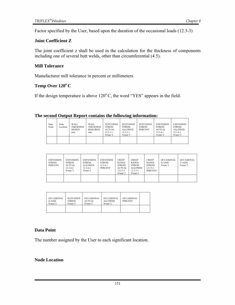
TRIFLEX®Windows Chapter 8
151
Factor specified by the User, based upon the duration of the occasional loads (12.3-3)
Joint Coefficient Z
The joint coefficient z shall be used in the calculation for the thickness of components including one of several butt welds, other than circumferential (4.5).
Mill Tolerance
Manufacturer mill tolerance in percent or millimeters.
Temp Over 120o C
If the design temperature is above 120o C, the word “YES” appears in the field.
The second Output Report contains the following information:
Data Point
Node Location
WALL THICKNESS DESIGN mm.
WALL THICKNESS REQUIRED mm.
SUSTAINED STRESS ACTUAL 12.3.2-1 N/mm^2
SUSTAINED STRESS ALLOWED 12.3.2-1 N/mm^2
SUSTAINED STRESS PERCENT
EXPANSION STRESS ACTUAL 12.3.4-1 N/mm^2
EXPANSION STRESS ALLOWED 12.3.4-1 N/mm^2
EXPANSION STRESS PERCENT
EXPANSION STRESS ACTUAL 12.3.4-2 N/mm^2
EXPANSION STRESS ALLOWED 12.3.4-2 N/mm^2
EXPANSION STRESS 12.3.4-1 PERCENT
CREEP RANGE STRESS ACTUAL 12.3.5-1 N/mm^2
CREEP RANGE STRESS ALLOWED 12.3.5-1 N/mm^2
CREEP RANGE STRESS 12.3.5-1 PERCENT
OCCASIONAL X-AXIS N/mm^2
OCCASIONAL Y-AXIS N/mm^2
OCCASIONAL Z-AXIS N/mm^2
SUSTAINED STRESS N/mm^2
OCCASIONAL ACTUAL N/mm^2
OCCASIONAL ALLOWED N/mm^2
OCCASIONAL PERCENT
Data Point
The number assigned by the User to each significant location.
Node Location

TRIFLEX®Windows Chapter 8
152
The "Node" description defines the piping segment types; i.e., Anchor, Run, and Bend. The "Location" description defines the exact point on the piping segment where the calculated values apply.
Wall Thickness Design vs. Required Thickness
The Design Wall Thickness is the value input by the User. The required Wall Thickness value is calculated by TRIFLEX®Windows using the following PrEN 13480-3 Code Equations (Section 6.1) and the internal pressure supplied by the User.
a) at a temperature up to and including 120o C
or
b) at a temperature above 120o C, and where DO/Di ≤1.7
or
c) at a temperature above 120o C, and where DO/Di >1.7
where:
e = minimum pipe wall thickness, mm
pc = internal design pressure as input by the User N/mm2
Do = actual pipe outside diameter, mm
Di = actual pipe outside diameter, mm
zfDpe Oc
⋅⋅⋅
=2
c
ic
pzfDpe
⋅+⋅⋅⋅
=22
( ) cc
Oc
pzpfDpe
22 +−⋅
=
( )zpfDpe
c
ic
⋅−⋅⋅
=22
⎟⎟⎠
⎞⎜⎜⎝
⎛+−
−=c
cO
pfzpfzDe 1
2

TRIFLEX®Windows Chapter 8
153
f = maximum allowable stress in material due to internal pressure N/mm2
z = the joint coefficient
The ordered (minimum) thickness required is:
eord = (e + c0 + c2) 100/(100-x)
where:
c0 = the corrosion or erosion tolerances
c2 = the thinning allowance for possible thinning
during the manufacturing process
x = manufacturer mill tolerance in percent (%)
Stresses Due to Sustained Loads vs. Allowed Stresses
The sum of primary stresses 1σ due to the calculation pressure, pc and the resultant moment MA from weight and other sustained mechanical loads shall satisfy the following equation:
f Z
Mi + e d p
= A
n
oc ≤⋅⋅75.0
41σ (12.3.2.1)
where:
M + M + M = M 2Z
2Y
2XA
Z = Section modulus, in3
en = Nominal thickness, inches
do = Outside diameter, mm
pc = Internal design pressure, N/mm2
MA = Resultant moment loading on cross section due to weight and other sustained loads, N-mm
i = stress intensification factor
f = Material allowable stress at temperature consistent with the loading under consideration, psi
⎟⎟⎠
⎞⎜⎜⎝
⎛
dd - d
32 = Z
o
i4o
4π

TRIFLEX®Windows Chapter 8
154
For full-size outlet connections:
For reduced outlet branch connections (Table F1):
where:
Ze = effective section modulus of reduced branch, mm3
rb = branch mean cross-sectional radius, inches
ex = effective branch wall thickness (lesser of en and i≅enb)
en = nominal wall thickness of main pipe, mm
enb = nominal wall thickness of branch, mm
di = inside diameter of pipe, mm
Stresses Due to Occasional or Exceptional Loads
The sum of primary stresses, σ 2, due to internal pressure, pc, resultant moment
MA, from weight and other sustained mechanical loads and resultant moment,
MB, from occasional or exceptional loads shall satisfy the following equation:
kf Z
M i +
ZM i 0.75 +
e 4d p
= BA
n
Oc ≤⎟⎠⎞
⎜⎝⎛
⎟⎠⎞
⎜⎝⎛ 75.02σ (12.3.3-1)
where:
MB = the resultant moment from the occasional or exceptional loads which shall be determined by using the most unfavorable combination of the following loads:
Wind loads (TB ≤TB/10)
Snow loads
Dynamic loads from switching operations (TB ≤TB/100)
Seismic loads (TB ≤TB/10)
Effects of the anchor displacements due to earthquake may be excluded if they are included in the equation (12.3.4-1).
er = Z x2be π

TRIFLEX®Windows Chapter 8
155
Unless specified otherwise, the following agreement applies:
a) the action time T corresponds to the bracketed values referring to the operating time TB
b) snow and wind are not applied simultaneously
c) loading with TB ≤TB/100 are not applied simultaneously
k =1 if the occasional load is acting for more than 10% in any 24-hour operating period, e.g. normal snow, normal wind
k =1.15 if the occasional load is acting for less than 10% in any 24-hour operating period
k =1.2 if the occasional load is acting less than 1% in any 24-hour operating period; e.g., dynamic loading due to valve closing/opening, design basis earthquake
k =1.3 for exceptional loads with very low probability e.g. very heavy snow/wind (1.75 x normal)
k =1.8 for safe shutdown earthquake
pc = is the maximum calculation pressure occurring at the considered loading condition, the calculation pressure shall be taken as a minimum
“f” shall be determined for the calculation temperature
Stress Range Due to Thermal Expansion and Alternating Loads
The stress range, σ 3, due to resultant moment, Mc, from thermal expansion and alternating loads, e.g. seismic loads, shall satisfy the following equation:
f ZM i = a
C ≤3σ (12.3.4-1)
where:
( )c
hhca E
Ef 0.25 + f 1.25 U = f (12.1.3-1)
U = stress range reduction factor (Table 12.1.3-1)
EC = the value of the modulus of elasticity at the minimum metal temperature consistent with the loading under consideration

TRIFLEX®Windows Chapter 8
156
Eh = the value of the modulus of elasticity at the maximum metal temperature consistent with the loading under consideration
fc = the basic allowable stress at the minimum metal temperature consistent with the loading under consideration
fh = the allowable stress at the maximum metal temperature consistent with the loading under consideration
Where the conditions of equation (12.3.4-1) are not met, the sum of stresses σ 4 due to calculation pressure pc, resultant moment, MA, from sustained mechanical loads and the resultant moment, MC, from thermal expansion and alternating loads shall satisfy the following equation:
)f +(f Z
M i + Z
M i 0.75 + e 4d p
= aCA
n
Oc ≤⎟⎠⎞
⎜⎝⎛
⎟⎠⎞
⎜⎝⎛
σ 4 (12.3.4-2)
where:
MC = range of resultant moments due to thermal expansion and alternating loads which shall be determined from the greatest difference between moments using the modulus of elasticity at the relevant temperatures.
Particular attention shall be given to:
• longitudinal expansion, including terminal point movements, due to thermal expansion and internal pressure
• terminal point movements due to earthquake if anchor displacement effect were omitted from equation (12.3.3-1)
• terminal point movements due to wind
• frictional forces
• the condition of the piping during shutdown shall be considered
• cold spring, if any, applied during installation shall not be taken in account. The operating case pertinent to MC shall be designed as if not cold spring was applied.
Additional Conditions for the Creep Range
For piping operating within the creep range, stresses σ 5, due to calculation pressure pc, resultant moment MA, from weight and other sustained mechanical loadings, and the resultant moment, MC for thermal expansion and alternating loadings, shall satisfy the following equation:

TRIFLEX®Windows Chapter 8
157
f Z
M i + Z
M i 0.75 + e 4d p
= CA
n
Oc ≤⎟⎠⎞
⎜⎝⎛
⎟⎠⎞
⎜⎝⎛
35σ (12.3.5-1)
Stress Due to a Single Non-repeated Anchor Movement
σ 6 = the resultant moment MD due from a single non-repeated anchor/restraint movement shall satisfy the following equation:
)2;min( 2.06 tpD R3f
ZM i = ≤σ (12.3.6-1)
where:
MD = the resultant moment due to any single non-repeated anchor movement (e.g., predicted building settlement), in-N

TRIFLEXWindows Chapter 9
1
CHAPTER 9
9.0 TRIFLEX WINDOWS DYNAMIC CAPABILITIES __________________ 3
9.0 TRIFLEX WINDOWS DYNAMIC CAPABILITIES __________________ 3 9.0.1 Modal Analysis Methodology____________________________________ 3 9.0.2 Modeling Considerations _______________________________________ 4
9.1 Modal Analysis __________________________________________________ 5 9.1.1 TRIFLEX Input for Modal Analysis_______________________________ 5 9.1.2 TRIFLEX Output for Modal Analysis _____________________________ 6 9.1.3 Modal Analysis Program Verification ____________________________ 11
9.1.3.1 Benchmark Problem ________________________________________ 11
9.2 Response Spectrum Analysis (RSA) ________________________________ 13 9.2.1 Response Spectrum Analysis Data Entry __________________________ 14
9.2.1.1 Spectrum Control Data ______________________________________ 14 9.2.1.2 Spectrum Definition ________________________________________ 19
9.2.2 TRIFLEX Output for Response Spectrum Analysis__________________ 22
9.3 Time History Analysis ___________________________________________ 25 9.3.1 Time History Data Entry_______________________________________ 28
9.3.1.1 Edit Time Functions ________________________________________ 29 9.3.1.2 Nodal Excitation Dialog _____________________________________ 32 9.3.1.3 Analysis__________________________________________________ 36
9.3.2 TRIFLEX Output for Time History Analysis_______________________ 40
Figure 9.1.1 Case Definition Data .................................................................................. 5 Figure 9.1.2 Dynamic Data Entry ................................................................................... 6 Figure 9.1.3 Modal Frequencies ..................................................................................... 7 Figure 9.1.4 System movements....................................................................................... 8 Figure 9.1.5 System Forces and Moments ....................................................................... 9 Figure 9.1.6 System Stresses ......................................................................................... 10 Figure 9.1.7 Maximum System values............................................................................ 10 Figure 9.1.8 NRC Benchmark Problem ......................................................................... 11 Figure 9.2.1 Load Case Data Dialog............................................................................. 14 Figure 9.2.2 Occasional Loading data .......................................................................... 15 Figure 9.2.3 Response Spectrum Analysis Dialog......................................................... 16 Figure 9.2.4 Zero Period Acceleration .......................................................................... 18 Figure 9.2.5 Spectrum Definition Dialog....................................................................... 20 Figure 9.2.6 Spectrum Chart ......................................................................................... 21

TRIFLEXWindows Chapter 9
2
Figure 9.2.7 Running the RSA ....................................................................................... 22 Figure 9.2.8 RSA Analysis Load Case ........................................................................... 23 Figure 9.2.9 Piping Code Report with RSA ................................................................... 23 Figure 9.3.1. Case Definition Data Screen .............................................................. 26 Figure 9.3.2 Dynamic Data Entry .............................................................................. 27 Figure 9.3.3 Time History Analysis Dialog................................................................. 27 Figure 9.3.4 Linear Function Chart ........................................................................... 29 Figure 9.3.5 Harmonic Function Chart ......................................................................... 30 Figure 9.3.6 Periodic Function Chart ........................................................................ 31 Figure 9.3.7 Table Function Dialog ........................................................................... 32 Figure 9.3.8 Nodal Excitation Dialog......................................................................... 33 Figure 9.3.9 Water Hammer Spreadsheet................................................................... 34 Figure 9.3.10 Analysis Tab ........................................................................................... 37 Figure 9.3.11 Modes versus Relative Modal Response Chart ........................................ 38 Figure 9.3.12 Running the THA Analysis....................................................................... 40 Figure 9.3.13 THA Analysis Load Case......................................................................... 41 Figure 9.3.13 Piping Code Report with THA................................................................. 42 Figure 9.3.14 Output Graphics for THA........................................................................ 43

TRIFLEXWindows Chapter 9
3
9.0 TRIFLEX WINDOWS Dynamic Capabilities The TRIFLEX WINDOWS program was developed by PIPINGSOLUTIONS, INC., to aid the piping engineer and analyst in the design of complex piping systems incorporating the effects of dynamic phenomena. TRIFLEX predicts the: 1) Mechanical resonant frequencies and mode shapes of the piping system. 2) Response spectrum analysis. 3) Time history analysis. This brief guide has the following purposes:
• Explanation of input data preparation for Users familiar with TRIFLEX • Explanation of output results • Modeling suggestions, precautions for the piping engineer • Verification based on industry benchmark problem.
9.0.1 Modal Analysis Methodology TRIFLEX Dynamics is based on recent work done by mechanical engineering experts in university research laboratories in the past decades. The formulation has a sound Finite Element basis with a stiffness method, which lends itself to dynamic analyses. The nodes generated by the pre-processor are efficiently renumbered so that: (a) larger piping systems can be handled, and (b) the computations required for convergence to a free vibration solution are
minimized. Since the solution of the eigenvalue (frequencies) problem consumes more time than the corresponding static problem, the number of dynamic degrees of freedom is reduced by neglecting rotational inertia of every node. Even the translational masses (or inertia) are lumped and distributed equally at the two nodes of a run and this has been found satisfactory. Extensive care has been taken in the formulation of element stiffness matrices, assemblage to form the global matrix for the piping system and the iterative solution technique so that: (a) available core memory in the computer is utilized to the maximum extent. (b) I/O to disk storage, and hence overhead to the job, are minimized.

TRIFLEXWindows Chapter 9
4
9.0.2 Modeling Considerations
• TRIFLEX uses the latest available techniques and automatically tries to optimize the nodes to minimize solution time, improve accuracy of results and minimize use of memory
• All weight data are converted to mass input data and external loads are ignored • Modal analysis can handle any linear restraints features coded by the User for a
static run. In order to eliminate the need to retype or edit an existing input file, which has non-linear boundary restraints, TRIFLEX has the following conventions:
- 1-D Restraints are treated as rigid two way restraints - Limit stops with positive and negative gaps will be treated as FREE - Limit stops with the same signs will be treated as RIGID - Limit stops with zero dimension gaps will be treated as RIGID - Friction coded at data points is ignored - Requested Spring Hangers sizing will abort the job. Users are advised to
replace this request for a spring hanger size with the resultant spring hanger previously sized in a static analysis
- Dampers are treated as rigid restraints - All initial movements are set to zero
• Modal analysis should be performed with more CAUTION than static analysis.
Solution algorithms are very sensitive to poor coding, e.g., sudden variations of stiffnesses between two adjacent pipe elements. The practice of coding very short runs or bends (i.e., less than 0.1") should be avoided in the context of dynamic analysis
• The User should use the “Maximum spacing with respect to diameter” for
automatic intermediate point generation between two data points when encountering long runs. A minimum of one intermediate points should be placed between two consecutive restrained points, and two consecutive elbows or bends
• TRIFLEX has been extensively benchmarked both for accuracy and speed
against the published results of the NRC (Nuclear Regulatory Commission, Washington, D.C.).

TRIFLEXWindows Chapter 9
5
9.1 Modal Analysis 9.1.1 TRIFLEX Input for Modal Analysis Modal Analysis is carried out in order to extract the natural frequencies and the associated mode shapes. A piping system consists of elastic components (pipes, fittings, flexible restraints) and distributed masses (pipes, fittings, rigid components). Once displaced from static equilibrium, the system will oscillate at a combination of the mode shapes, each vibrating at the associated frequency. Frequencies and mode-shapes are instrumental in the linear prediction and analysis of time-varying phenomena.
Figure 9.1.1 Case Definition Data

TRIFLEXWindows Chapter 9
6
To run a Modal Analysis, the User must:
1. Check the box for “Mode Shapes and Frequencies” for one of Load case # in the “Load case“ dialog.
2. Complete the top line of the DYNAMICS DATA ENTRY SCREEN; that is,
specify the number of mode shapes derived and the maximum allowable natural frequency.
No. of Mode Shapes: Specify the number of modes or frequencies to be calculated. The default value is 10. If calculations occurs in “Demo Mode” the number of Mode Shapes need to be reset to two.
Figure 9.1.2 Dynamic Data Entry
Max. Freq.: Specify the cut-off frequency (default value = 100 Hz.) for the analysis in Hertz or cycles/sec. Only those frequencies with the corresponding mode shape from among the required number of modes that are below the specified number for Hertz will be retained. To run the model the User has two options. The User can either do a left mouse click on the green arrow from the top of the Main Screen or select “Basic Calculation” option from “Calculate” command of the Main Screen. 9.1.2 TRIFLEX Output for Modal Analysis Following the normal system description reports, the program also reports the following reports for a modal analysis. MODAL FREQUENCIES Natural frequencies are printed in ascending order. Frequencies (RAD/SEC as well as CYCLES/SEC) and Period are listed for each mode.

TRIFLEXWindows Chapter 9
7
To obtain this report in spreadsheet format select the “Output” and “View Analysis Results” dialog from “Main Screen”. The name of the report is “Modal Frequencies”. (Fig. 9.3) To obtain this report select “print Preview” or “Print” option from “Output” dialog of “Main Screen” and select the check box for “Modal Frequencies”. MODE SHAPE Mode shapes, i.e., deflections and rotations, are printed with the maximum value of the displacement normalized to 100. The KEY here is "shape" and not the actual value of deflection or rotation. In order to emphasize this subtle point, the deflections are printed as non-dimensional and the rotations are DIMENSIONAL, e.g., deg./100 inch. A report with deflections and rotations can be displayed for each calculated frequency.
Figure 9.1.3 Modal Frequencies
To obtain this report select the “Print Preview” or “Print” option from “Output” dialog of “Main Screen” and select the check box for “System Deflections & Rotations”.

TRIFLEXWindows Chapter 9
8
A similar report can be obtained in spreadsheet format by selecting “Output” and “View Results” dialog from “Main Screen”. The name of the report is “System Movements”. (Fig. 9.4) FORCES AND STRESSES The force report and the stress report generated for each mode correspond to a maximum deflection of 1 in. (25.4 mm), whereas the non-dimensional 100 is used in the mode shape report.
Figure 9.1.4 System movements
To obtain this report select the “Print Preview” or “Print” option from “Output” dialog of “Main Screen” and select the check box for “System Forces & Moments” and/or “System Stresses”. A similar report can be obtained in spreadsheet format by selecting the “Output” and “View Results” dialog from “Main Screen”. The names of the reports are “System Forces & Moments” and “System Stresses”.

TRIFLEXWindows Chapter 9
9
MAXIMUM SUMMARY The maximums of deflections, rotations, forces, moments, stresses, and the corresponding data points are printed for each frequency. To obtain this report select the “Print Preview” or “Print” option from “Output” dialog of “Main Screen” and select the check box for “Sum. Max. Sys. Values”. The same items can be obtained in spreadsheet format selecting “Output” and “View Description” dialog from “Main Screen”. The names of the reports are “Maximum System Values”.
Figure 9.1.5 System Forces and Moments

TRIFLEXWindows Chapter 9
10
Figure 9.1.6 System Stresses
Figure 9.1.7 Maximum System values

TRIFLEXWindows Chapter 9
11
9.1.3 Modal Analysis Program Verification This section presents a comparison of the program generated solution with a known solution for a selected benchmark problem. This provides a confirmation of the adequacy of the program for modal analysis of piping systems. 9.1.3.1 Benchmark Problem The benchmark problem is stored under the file name NRC.dta in the folder “Samples” under the folder where TRIFLEX WINDOWS was installed. It simulates a 3-1/2 inch diameter water line extending between two elevations. It is a simple configuration joining two anchors and having numerous intermediate supports. The geometric and material properties of the pipe elements are given below:
Pipe outside diameter = 3.5 in Pipe wall thickness = 0.216 in Pipe density = 0.403 lb/in3 Young's Modulus of Elasticity = 25,800,000 psi Poisson's Ratio = 0.3
Figure 9.1.8 NRC Benchmark Problem

TRIFLEXWindows Chapter 9
12
This sample problem used is published in Bezler, P., Subudhi, M. and Hartzman, M., "Piping Benchmark Problems", Dynamic Analysis independent Support Motion Response Spectrum,” Regulatory Commission, NUREG/CR-1677, Vol. 2, August 1985. Load the example job NRC.dta from the “Samples” folder. Keep the “by default” setting for number of mode shapes and for maximum frequencies where 10 vibration modes and the associated natural frequencies, bounded by a cut-off frequency of 100 Hz. are required. Perform the analysis. The following table reflects the modal frequencies, and a comparison of the modal frequencies to those found in the above mentioned book.
Mode number Frequency NRC Frequency TRIFLEX Difference
1 6.04 6.03 -0.16% 2 6.26 6.24 -0.32%
3 7.76 7.94 2.32% 4 8.94 8.86 -0.89% 5 12.44 12.42 -0.16% 6 12.83 12.81 -0.16% 7 14.30 13.92 -2.66% 8 15.49 15.42 -0.45% 9 16.37 16.18 -1.16%
10 18.54 18.35 -1.02%
Comparison of Natural Frequencies of Benchmark Problem

TRIFLEXWindows Chapter 9
13
9.2 Response Spectrum Analysis (RSA) The response spectrum method is commonly used in the nuclear piping industry to account for earthquake forces in the design of piping systems. It is a probabilistic method used to estimate the maximum response of a multi-degree-of-freedom system subjected to seismic loads. For a particular earthquake ground motion, the response spectrum method gives the maximum responses of a family of single-degree-of-freedom oscillators. A piping system is a multi-degree-of-freedom system and can be decomposed into its normal modes of vibration. Then the maximum response in each mode can be obtained using the response spectrum. The individual maximum modal responses are combined to obtain an estimate of the maximum piping system response. Several methods of combining the modal responses are available in TRIFLEX. In order to request a Response Spectra Analysis, the User must: 1. Specify a “Modal Shapes and Frequencies” load case on the Case Definition Data
Screen. 2. Specify a “Code Compliance Analysis” load case on the Case Definition Data Screen
having Response Spectrum as Occasional Load. (Figure 9.2.1) 3. Specify the number of mode shapes derived and the maximum allowable natural
frequency in DYNAMICS DATA ENTRY SCREEN. (Figure 9.1.2) 4. Specify the method of combining the results from operating case with the results from
occasional loads. (Figure 9.2.2) 5. Complete the data in “Spectrum Control Data” and “Spectrum Definition”. 6. Run the analysis for mode shapes and frequencies and all the static load cases. 7. Run the response spectra post processing analysis. Response spectrum analysis is implemented as a post-processing of modal analysis. The User must select a modal load case (Modes Shapes and Frequencies) and for post-processing at least another load case including an operating case, performing a code compliance analysis having response spectrum as occasional load. For the load cases selected having “Response Spectra as Occasional Load” the User should select also the method of combining the results from operating case with the results from occasional loads. Three combining methods are available: Operating + RSA, Operating – RSA and Operating + Max RSA. The combining method can be chosen in “Occasional Loading Data” dialog, under “Setup” and “Occasional Loading” options.

TRIFLEXWindows Chapter 9
14
Figure 9.2.1 Load Case Data Dialog
9.2.1 Response Spectrum Analysis Data Entry This section describes the additional input data required in the context of a response spectrum run on TRIFLEX. For inputting the basic data such as the piping system geometry, properties, restraints, etc., the User should refer to the input data sections of the TRIFLEX manual dealing with static analysis.
To complete the necessary data, the User should open the dialog “Response Spectrum Analysis” dialog under “Setup” option. The dialog shown on Figure 9.2.3 will appear on the screen. 9.2.1.1 Spectrum Control Data The User should choose or fill in the following data:

TRIFLEXWindows Chapter 9
15
Figure 9.2.2 Occasional Loading data
Spectral Combination Method The various combination methods available are briefly described below along with their corresponding codes. In this context, the term intermodal combination refers to combining the responses from individual modes. Similarly, the term intramodal combination refers to combining the responses from individual spectra. The User may specify any of these methods for Spectral Combination. The following codes are available to allow the User to specify the method of combining the individual modal and/or spectral responses: NRC
Clustered method for intermodal combination, then SRSS method for intramodal combination
A-S Absolute summation for intramodal combination, then "Square Root of the Sum of
Squares" (SRSS) method for intermodal combination. This is the default.

TRIFLEXWindows Chapter 9
16
A-A Absolute summation for intermodal combination, then Absolute summation for
intermodal combination. AL-S Algebraic summation for intermodal combination, then the SRSS method for
intermodal combination. AL-C Algebraic summation for intramodal combination, then the Clustered method for
intermodal combination.
Figure 9.2.3 Response Spectrum Analysis Dialog
AL-N Algebraic summation for intramodal combination, then the NAVY Method for
intermodal combination.

TRIFLEXWindows Chapter 9
17
S-S SRSS method for intermodal combination, then SRSS method for intramodal
combination. C-S Clustered method for intermodal combination, then SRSS method for intramodal
combination. S-C SRSS method for intramodal combination, then Clustered method for intermodal
combination. S-N SRSS method for intramodal combination, then NAVY method for intermodal
combination. N-S NAVY method for intermodal combination, then SRSS method for intramodal
combination. Clustering Specify the modal clustering percentage criterion for closely spaced modes. If not specified, a default value of 10% will be used in accordance with NRC guidelines. This option has meaning only if the User codes a spectral combination method for intermodal combination. Combined Reports Check the box if the responses in individual spectra are to be combined. Uncheck the box if only responses in individual spectra are desired and that no combination must be performed. Zero Period Acceleration The requirement of this section (Missing Mass Correction) will assure inclusion of any local inertia effects that may be overlooked otherwise. The summation is on all the modes already included in the analysis.
SD Gen. Method / Spectra The User can specify his/her own code in the SD Gen. Method field. The User will then be required to complete the data shown on the Spectrum Definition tab. The program offers also two types of library response spectra, HOUSNER or the NEWMARK. Either of the two types of library spectra can be used in place of User-defined data. The User can specify the HOUSNER or the NEWMARK type by choosing it from the SD Gen. Method / Spectra drop down menu.

TRIFLEXWindows Chapter 9
18
Figure 9.2.4 Zero Period Acceleration
Specification of these spectra requires that values must be specified in the MGA, DF and SAF (NEWMARK only) fields. DF- Damping Factor Specify the damping for the HOUSNER or for the NEWMARK spectrum. It is expressed as a percentage of the critical damping. Stored HOUSNER spectra are available for 0.0, 0.5, 1.0, 2.0, 5.0, 10 and 20% of critical damping. The DF value is not applicable when the User specifies the spectra directly using the Freq/Periods and the Accel/Disp/Vel fields shown on the Spectrum Definition tab. MGA- Maximum Ground Acceleration Specify the maximum ground acceleration. It is expressed in terms of “g”. The MGA value is not applicable when the User inputs the spectra directly using the Freq/Periods and Accel/Disp/Vel fields shown on the Spectrum Definition tab. SAF- Soil Amplification Factor Specify the soil amplification factor in the context of the NEWMARK spectra. FX- Scaling Factor X Allows the User to specify a scaling factor for the X-direction spectral loading table. The acceleration/velocity/displacement values specified will be multiplied by this scaling factor. If not specified, a default value of 0 will be used.

TRIFLEXWindows Chapter 9
19
FY- Scaling Factor Y Allows the User to specify a scaling factor for the Y-direction spectral loading table. The acceleration/velocity/displacement values specified will be multiplied by this scaling factor. If not specified, a default value of 0 will be used. FZ- Scaling Factor Z Allows the User to specify a scaling factor for the Z-direction spectral loading table. The acceleration/velocity/displacement values specified will be multiplied by this scaling factor. If not specified, a default value of 0 will be used. Scaling Factor Allows the User to specify a scaling factor that is applied to all the X, Y, and Z directions after applying the individual scaling factors as specified in the FX, FY, and FZ fields. If not specified, a default value of 1.0 will be used. Interpolation Method Allows the User to specify the method of interpolation between the sampling points on a spectrum. Type LIN to specify linear interpolation and LOG to specify logarithmic interpolation. 9.2.1.2 Spectrum Definition If the User specifies his/her own spectrum name in the SD Gen. Method field of the Spectrum Control Data tab, then the User will be required to complete the data shown on the Spectrum Definition screen. If the User selected one of two types of library response spectra, HOUSNER or the NEWMARK, the generated data will appear in Spectrum Definition screen. The Spectrum Definition screen is shown in Figure 9.2.5. The following sections will give an explanation on how to fill in the data fields of these screens: Spectrum Name In this drop down box will appear the spectrum names specified by the User and/or library spectrum names.
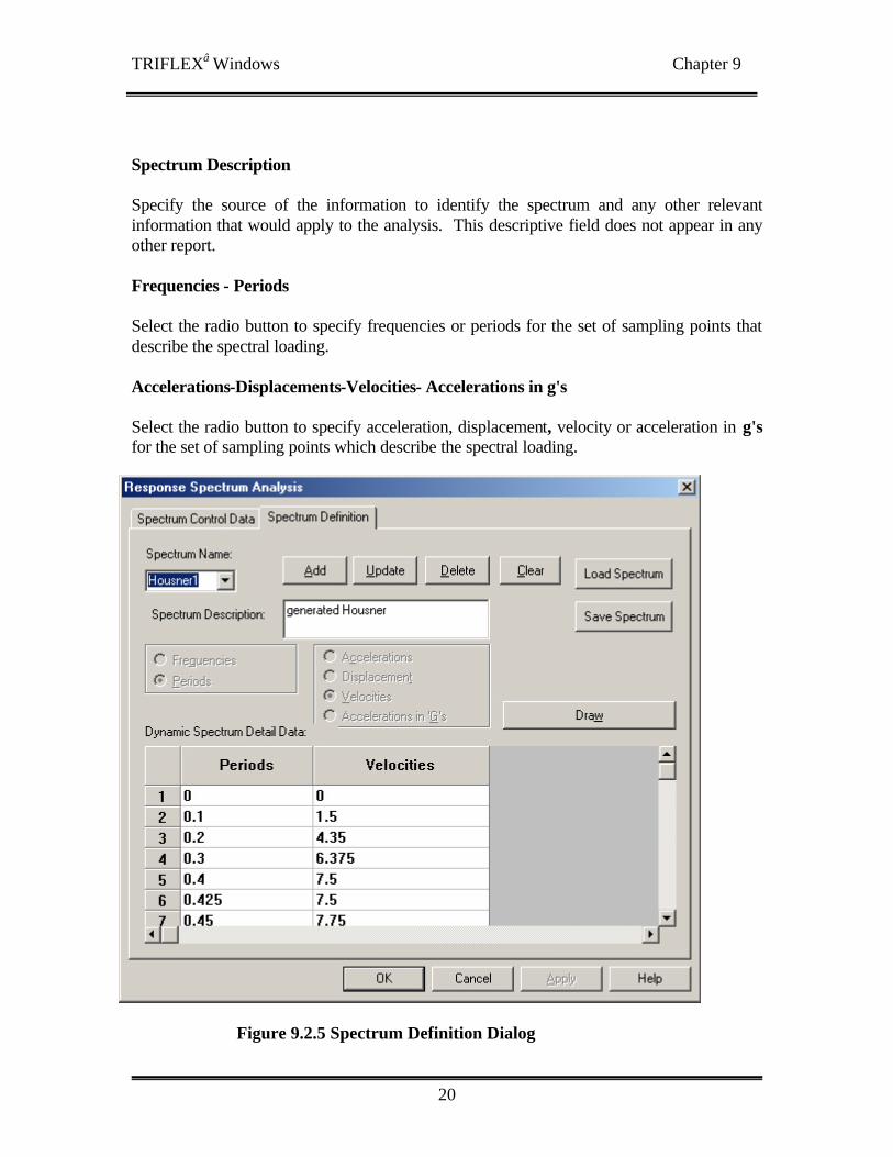
TRIFLEXWindows Chapter 9
20
Spectrum Description Specify the source of the information to identify the spectrum and any other relevant information that would apply to the analysis. This descriptive field does not appear in any other report. Frequencies - Periods Select the radio button to specify frequencies or periods for the set of sampling points that describe the spectral loading. Accelerations-Displacements-Velocities- Accelerations in g's Select the radio button to specify acceleration, displacement, velocity or acceleration in g's for the set of sampling points which describe the spectral loading.
Figure 9.2.5 Spectrum Definition Dialog

TRIFLEXWindows Chapter 9
21
Add Button Add a new spectrum to the list of spectrum available for this piping model. Update Button Update the data for the spectrum specified in the Spectrum Name field. Delete Button Delete the spectrum specified in the Spectrum Name field. Clear Button Clear the data for the spectrum specified in the Spectrum Name field.
Figure 9.2.6 Spectrum Chart

TRIFLEXWindows Chapter 9
22
Load Spectrum Button Load a spectrum from a file. Save Spectrum Button Save the spectrum data to a file. 9.2.2 TRIFLEX Output for Response Spectrum Analysis To run the RSA analysis the User has two options: 1. The User can click with the mouse on RSA icon located on the top part of the TRIFLEX Main Screen.
2. The User can select Response Spectrum Analysis option under Calculate option located on the top part of the TRIFLEX Main Screen.
Figure 9.2.7 Running the RSA

TRIFLEXWindows Chapter 9
23
To run RSA the icon RSA and Response Spectrum Analysis options should be available. If these options are grayed out TRIFLEX doesn’t have all the necessary data to run RSA post processing.
Figure 9.2.8 RSA Analysis Load Case
Figure 9.2.9 Piping Code Report with RSA

TRIFLEXWindows Chapter 9
24
The results will be stored in LOAD CASE #7. This load case will have maximum four sub load cases, maximum three corresponding to the spectrums entered and a combined one. The COMBINED sub load case will be attached to all the load cases which have selected the RSA as occasional load. All the output reports and graphics features available for a regular static load case are also available for the load case #7. The Piping Code Compliance Report is not available for this load case. The Piping Code Compliance Report is available for all the static load cases, which have selected RSA as occasional load.

TRIFLEXWindows Chapter 9
25
9.3 Time History Analysis The sequence of operations performed on a piping system, excited by time-dependent loads, is defined as Time History Analysis in TRIFLEX. Time History Analysis deals with abrupt processes (firing of a valve, breakdown of a pump), sustained excitations (rotating / reciprocating equipment, earthquakes), real-life "static" loads (pulling the stops, bringing a system to the operating state). All the above pose possible time-varying responses, the extremes of which are greater than the static response. Method of Analysis Having obtained a modal solution (frequencies and mode-shapes), the User may "excite" the system in many ways, generating snap-shots of the response. Our procedure is based on the superposition of modes. Initial conditions and excitations are projected along the modes, taking advantage of the orthogonality. Time integration of the (uncoupled) modal equations of motion is carried out analytically. The procedure is accurate, economical, and free of the restrictions so often hampering numerical integration schemes. Limitations 1) Linear dynamics is presumed. All nonlinear properties must be linearized before
attempting TRIFLEX dynamic capabilities. 2) Rotational loads (moments, initial rotations) are not supported. Force /
displacement couples must be applied accordingly. 3) Time dependent excitations are limited to linear and harmonic time functions. A
sequence of time clips must be used to approximate other excitations (periodic linear pulses are supported).
4) The "rigid body" ("pseudo-static") response left over after the above-mentioned
excitations and initial conditions have been projected along the available modes, is not accounted for.
In order to request a Time History Analysis (THA), the User must: 1. Specify a “Modal Shapes and Frequencies” load case on the Case Definition Data
Screen. 2. Specify a “Code Compliance Analysis” load case on the Case Definition Data Screen
having Time History as Occasional Load. (Figure 9.3.1)

TRIFLEXWindows Chapter 9
26
3. Specify the number of mode shapes derived and the maximum allowable natural frequency in DYNAMICS DATA ENTRY SCREEN. (Figure 9.3.2)
Figure 9.3.1. Case Definition Data Screen
4. Run the model for Modal Analysis and the Static Cases
5. Complete the necessary data in “Time History Analysis” dialogs (Figure 9.3.3) 6. Run the Time History post processing analysis Time History analysis is implemented as a post-processing of modal analysis. The User must select a modal load case (Modes Shapes and Frequencies) and for post-processing at least an other load case including an operating case, performing a code compliance analysis having time history as occasional load.

TRIFLEXWindows Chapter 9
27
The results will be stored in LOAD CASE #8. This load case will have a number of sub load cases corresponding to the numbers of snap shot selected. The maximum values for each component are stored in “Time History MAX” sub load case.
Figure 9.3.2 Dynamic Data Entry
The “Time History MAX” sub load case will be attached to all the load cases, which have selected the THA as occasional load. All the output reports and graphics features available for a regular static load case are also available for the load case #8. The Piping Code Compliance Report is not available for this load case.
Figure 9.3.3 Time History Analysis Dialog

TRIFLEXWindows Chapter 9
28
The Piping Code Compliance Report is available for all the static load cases which have selected THA as occasional load. Summary of Time History Definitions Excitations Set A storage grouping where nodal loads are detailed, including their association with time functions. Selected Set The only excitations set which will be applied for the following time history analysis. Inactive Set An excitation set which is available but is not used for the following time history analysis. Water Hammer Set A dialog, where pipeline information pertaining to water hammer loads, is detailed. The Water Hammer Set can be saved as an Excitation Set. Most Meaningful Mode The mode with the greatest contribution to the response. Usually, most of the excitations project along this mode. Besides, low natural frequency or near resonance, amplify the modal contribution. Attenuation The modal participation in, or contribution to, the resultant response. Quantitatively, the ratio between the (particular) modal response and the most meaningful modal response. Meaningful Band The band of the lowest modes where the attenuation is still above a certain criterion (our default - 5%). Logically, higher modes are considered meaningless noise (only in the simulation interval context). Least Meaningful Period The period of the highest mode (shortest period) in the meaningful band. 9.3.1 Time History Data Entry Time History input begins after a piping system has been analyzed for a modal analysis. The number of modes necessary to properly perform a true representation of the time domain action of forces on the piping system is always an individual determination. Later on during the Time History Analysis, a screen showing Significant modes will help the User determine if enough modes have been requested. To get the “Time History Analysis “ dialog (Figure 9.3.3) the User should select the “Time History Analysis” option under “Setup “ menu from the TRIFLEX Main Screen.

TRIFLEXWindows Chapter 9
29
The dialog has three tabs (sub dialogs) “Edit Time Functions”, “Nodal Excitations” and “Analysis”. 9.3.1.1 Edit Time Functions Time functions are used to define the time dependent forces on a piping system. There are eight (8) predefined time functions provided and those functions may be "strung together" to define the hydraulic time dependent transient. The User can define new functions choosing a “Name” and a “Type” for each function entered. As “Type” the function can be linear, harmonic, periodic or table. When a specific Time Function is needed to describe a load on a piping system, this should be added to this screen. LABEL Each time function is identified by a Unique label. Time Function Type The following time variations are supported. Linear
Figure 9.3.4 Linear Function Chart Harmonic Given a frequency and a lead time (phase), a trigonometric cosine is generated.
value
time
C
D
B A
ABAtime
CDCvalue
−−
=−
−

TRIFLEXWindows Chapter 9
30
Figure 9.3.5 Harmonic Function Chart
A = frequency, converted according to C. B = lead, in seconds. C = frequency unit selector : Hz for Hertz (cycles/sec). RPM for RPM (rev/min). else radians/sec (no conversion). D = irrelevant, ignored. Periodic A periodically repetitive sequence of linear pulses is generated. The User may
control the active time, inactive time, and the linear characteristics.
period = A+B value (time+period)=value (time) for time<=A
A
CDtimeCvalue
−⋅+=
for A < time < A+B value =0, etc.
))(cos()( leadtfrequencytvalue +⋅=

TRIFLEXWindows Chapter 9
31
Figure 9.3.6 Periodic Function Chart A B C D - Time Function Parameters The time function parameters A, B, C, and D are defined as follows: Linear - A,B => time values (MUST NOT coincide). - C,D => the corresponding function values. Harmonic - A => circular frequency - B => lead time (phase) in seconds. - C => frequency units - D => ignored Periodic - A => pulse active time (sec) - B => inactive time (sec) - C => pulse value at the beginning - D => value at the end of the active time Table Using the drop down box from “Type” field, the User can select “Table” function type. The values for this function can be input in a table which appears when the User select “Edit Time / Function Table” button. (Figure 9.3.7) Comments The comments text is saved and passed to the analysis program as such. The only effect of comments is in the clarification of the input data echo, reflecting the User's intentions. Blank comments are permitted. In the bottom part of the “Time Function” dialog a function chart shows the shapes for all the functions, predefined or User-defined.
value
time
C
D
A A+B

TRIFLEXWindows Chapter 9
32
Figure 9.3.7 Table Function Dialog
9.3.1.2 Nodal Excitation Dialog The “Nodal Excitation” dialog is shown in Figure 9.3.8. The User can define multiple sets of nodal excitations, but only one set can be selected at any time. In each set, a point (node) is associated with a time function, a time shift (arrival), a time clip (shut-off), direction, and magnitude. The process is repeated as necessary. The same node may be excited in several ways. Time Function Name The time function name specifies the time-dependence of the dynamic load. The User can select from the drop down box the predefined functions names and User-defined function names. These functions should be previously defined in the “Time Function” dialog. Start Time/Finish Time The "time" parameter appearing in the various time functions is measured with respect to an arrival (start-up) time, thus enabling time leads and lags, varying throughout the piping system. As time (absolute) passes the shut-off value, the excitation value is forced to vanish. Point From the drop down box, the User may select a data point NUMBER or a static load TYPE. If several data points have the same number, an anchor or a restraint will be selected. In the

TRIFLEXWindows Chapter 9
33
list, the generated intermediate nodes numbers are also available. The static load TYPE, “Pressure”, “Temperature” and “Weight” are available for selection at the end of the list. Hence, Users are advised to code non-rigid boundaries where excitations are expected.
Figure 9.3.8 Nodal Excitation Dialog
Direction The direction along which a force (or displacement) is applied is specified as X, Y, or Z. If the data point is a restraint, A, B, or C will be selected at the time of the simulation. This field is ignored when a static load TYPE is specified. Multiplier The time function values (determined by Time Function Name, Start Time, Finish Time) are multiplied by this load value. Excitation Type The User specifies whether the excitation value corresponds to a force, or to a displacement. This field is ignored when a static load TYPE is specified. Excitation Sets Using the “Add Set”, “Delete Set” and “Rename Set”, the User can create a list of different sets of loads, which can be applied to the system. Only one set can be selected at any time.

TRIFLEXWindows Chapter 9
34
Delete Selected Excitations Using this option the User can delete one or more rows from the active spreadsheet set of nodal excitations. The rows should be selected before deletion. Water Hammer Clicking on this button the water hammer spreadsheet will appear on the screen. (This is an easy way to input nodal excitations for a water hammer load.) Each pipeline in the system may be associated with fluid properties, pertaining to the water hammer effect. Shock forces may be calculated and associated with the STEP and RAMP functions (see our default time functions set). When the User exits this dialog the water hammer nodal excitation set will be created and saved in Nodal excitation tab.
Figure 9.3.9 Water Hammer Spreadsheet
The water hammer dialog has two spreadsheets that are tiled vertically. When the dialog is opened for the first time the left spreadsheet contains data about the geometry of the piping system and the right spreadsheet will appear empty. In between the two spreadsheets are two buttons marked “<” and “>”. The buttons allow the User to move one or multiple rows from the left spreadsheet to the right spreadsheet and vice versa. In order to be moved, the rows should be selected. Using as reference the “from” node and “to” node, the User may build in the right spreadsheet a sequence of lines starting with the node where the cause for water hammer happens. The right spreadsheet may or may not include all the lines from the left spreadsheet. When the User moves the information from the left spreadsheet to the right spreadsheet the columns for From, To, Xdir, Ydir, Zdir and Length are filled up.

TRIFLEXWindows Chapter 9
35
Fluid Name The water hammer utility program supports a list of common fluids. The User can select from the drop down box: WATER - Fresh water SALT W - Salt Water M OIL - Machine oil Kerosene - Kerosene If your fluid is not in this list, then the following data will need to be input manually: Fluid Bulk Modulus of Elasticity By definition, the ratio between the hydrostatic pressure (dilatational stress) and the relative decrease in volume (dilation, sum of axial strains). A bulk modulus value of 100 ksi means that a pressure of 1 ksi will cause a volumetric decrease of 1 percent. This value is ESSENTIAL for the calculation of the acoustic shock wave speed in the fluid. Fluid Specific Gravity Fluid specific gravity will be used to calculate the Mass Density by use of the following equations: mass density = specific gravity * 62.4 lbm/ft3 = specific gravity * 1000 kgm/m3 This value is ESSENTIAL for the calculation of the acoustic shock wave speed in the fluid. Fluid Mass Flow Rate The number you enter must agree with your selection for INPUT units. A positive flow rate implies the flow ALONG the coded pipeline direction. Naturally, a negative rate implies flow AGAINST the coded pipeline direction. The value entered will be considered as an ABRUPT DROP, that when multiplied by the speed of sound, yields the unbalance force. If the "Abruptness" seems too conservative, then scale down the rate which will allow for "gradual" valve characteristics. The continuity law mandates that flow rates may change only at network nodes, sources, or sinks. It seems advisable to follow this rule. If the data for Fluid, Bulk Modulus, Specific Gravity and Flow are the same for multiple rows, the User can fill the info only for one row. The row can be selected and, after that, copied into the clipboard using “Copy” button. To fill the other rows with the info from the clipboard, the User should select the rows and hit the “Paste “ button.

TRIFLEXWindows Chapter 9
36
Time of Start of Shock The water hammer utility program uses this value to calculate the end of rise, start of fall and end of fall for the shock wave action in the pipeline. By default, values are carried from the previous pipelines, incremented by the products of the speed of sound and the line length. It seems advisable to follow the default along a "winding" pipeline until a node (intersection or branch end) is reached. At that stage, each branch then has to be treated separately. Of course, the User has the option to modify the above-mentioned values that are no more than computer program "recommended values". To calculate the time values, the User should select the cells where he/she prefers the time to be calculated, and then hit the “Calculate” button. The calculated time can be overwritten. Direction of Flow The User can select the direction of the flow for each pipe segment choosing the arrow sign placed between the From and the To node points. The arrow pointing indicates the point of impact of the flow of fluid. After all of the input data is input, press OK to convert this input data into Nodal Excitations. These excitations will be converted and saved into a Nodal Excitation Set. 9.3.1.3 Analysis The “Analysis” tab is shown in Figure 9.3.10. In this dialog are several groups of data. Edit Control Parameters Global Damping Factor The User may specify the damping factor (i.e., greek "zeta" of the common Mechanical Vibrations textbooks) as a fraction of the critical damping. The effects of damping on free (unexcited) systems are: No damping factor=0 Oscillations of constant amplitude Subcritical factor<1 Oscillations of decreasing amplitude Supercritical factor>1 No oscillation, dampening Critical factor factor=1 No oscillation, milder dampening The User would refer to a text (e.g., Thomson, "Theory of Vibration with Applications", Prentice-Hall, 1981, pp. 25-34) for a method to estimate the damping factor.

TRIFLEXWindows Chapter 9
37
Figure 9.3.10 Analysis Tab Enable Parameter Revision Using this check box the User may wish to have run-time control over the simulation in terms of duration and interval. There is an abundance of information about the attenuating response of each mode to each excitation. This information is crucial to the specification of the number of modes requested during modal analysis. During a parameters revision session, modal responses to excitations are depicted in a summary manner (chart bars). (Figure 9.3.11) The User may record this information for future use, and specify the ACTUAL preliminary simulation parameters for the run. Time Simulation Parameters Using radio buttons the User can accept the calculated values (“Use Recommended Simulation Values”) or he/she can input his/her- own values (“Use Custom Simulation Parameters”). The number of preliminary simulation results obtained, and hence the amount of computation, can be determined by the computer. Yet, the User may override the above by providing non-zero values. Attenuation Criterion All excitations are "resolved along" the modes, thus yielding the modal approximation. Usually, the higher natural frequency the mode is associated with, the less contribution

TRIFLEXWindows Chapter 9
38
(attenuation) of the excitation response is made. The measure used is the ratio between a particular modal response and the greatest ever encountered. The attenuation criterion is used in determining the least meaningful natural period. The period of the highest mode, the attenuation of which is not less than the specified criterion, determines the snap-shots interval. Thus, weak-response high modes are not allowed to incur a high volume of simulation results.
Figure 9.3.11 Modes versus Relative Modal Response Chart
A zero value implies ALL modes must be considered for the determination of the least meaningful period. A value greater than (or equal to) unity, implies ONLY the most significant mode will be considered. The criterion affects ONLY the interval of recording simulation results, not the calculation. Time Simulation Parameters The User may control the number of simulation results generated. That number is determined by "End Simulation" time and by "Simulation Interval". Obviously, the demand on disk volume and on computer time increases as the volume of results does. However, excessively long intervals may degrade time history analysis to a low quality, not-so-funny, cartoon. Hence, the following controls are made available to the User. The “Start Simulation” time has the value zero and the cell is grayed out.

TRIFLEXWindows Chapter 9
39
NOTE: The snap shots interval does not affect the integration accuracy. Short "bursts" and "spikes" are accounted for internally, regardless of the prescribed interval.
By default, the simulation interval is determined by the least meaningful interval; i.e., the lowest among:
1) the least meaningful natural period, 2) the time intervals between arrivals and FINITE shut-offs, and 3) the Periodic Pulses Active Times. One-eighth (1/8) of the above will be taken unless the User specifies a NON-ZERO
entry. The recommended values will be calculated in the following way: Final time = Latest finite shutoff + longest natural period. Interval = 1/8 of the least meaningful period (or the excitation period). Beginning Users are advised to accept our suggestions. Our advice to the perplexed User, not having the faintest idea about the right choice of the simulation parameters: Use the default until you gain some insight into the dynamics of a problem. Varying this time may result in an incomplete detail of the analysis. Snapshot Generation Default Data All the data items under this group are grayed out. They are calculated values. Number of Simulator Generated Snaps The numbers of snaps calculated according starting, ending and simulation interval Starting at (seconds) A zero value is enforced Ending at (seconds) Simulation results will be recorded until time passes this value. By default, the greatest
FINITE shut-off time is incremented by the greatest natural period, thus yielding an estimate for the END.
Interval Simulation Interval. Snapshot Generation This group of data determines how the calculated values in the simulation process are inspected and taken in order to calculate “Time History MAX” sub-load case.
Starting at (seconds) This field is the starting time of the reaction. Adjustments to this field are possible.

TRIFLEXWindows Chapter 9
40
Ending at (seconds) This field indicates the finishing time of the reaction. Adjustments to this field are
possible. Caution should be exercised until a better understanding of the complete time frame is appreciated.
Intervals Skipped between Snapshots
Adjusting this factor would tell TRIFLEX to eliminate certain time frames. A zero value for this field means that all the feasible snapshots between Starting and Ending time will be available in output.
Number of Snapshots
The numbers of snaps calculated according starting time/ending time and interval skipped. The maximum value determined by the volume of data is limited to 1000. By adjusting starting time/ending time and interval, the User is able to inspect all the simulated data.
9.3.2 TRIFLEX Output for Time History Analysis To run the THA analysis the User has two options:
Figure 9.3.12 Running the THA Analysis

TRIFLEXWindows Chapter 9
41
1. The User can click with the mouse on the THA icon located on the top part of the TRIFLEX Main Screen.
2. The User can select the Time History Analysis option under the Calculate option located on the top part of the TRIFLEX Main Screen. To run THA the icon THA and Time History Analysis options should be enabled. If TRIFLEX does not have all the necessary data to run THA post-processing, then these options are grayed out. The results will be stored in LOAD CASE #8. This load case will have a number of sub load cases equal with number of snap shots selected to be inspected plus a sub load case named Time History MAX.
Figure 9.3.13 THA Analysis Load Case
The Time History MAX sub load case will be attached to all the load cases that have selected the THA as occasional load. All the output reports and graphics features available for a regular static load case are also available for the load case #8. The Piping Code Compliance Report is not available for this load case.

TRIFLEXWindows Chapter 9
42
The Piping Code Compliance Report is available for all the static load cases, which have selected RSA as occasional load.
Figure 9.3.13 Piping Code Report with THA

TRIFLEXWindows Chapter 9
43
Figure 9.3.14 Output Graphics for THA

![Sitti Ghaiyah dan Anisa Nor Fitria [Energi Terbarukan]](https://static.fdokumen.com/doc/165x107/63169096c32ab5e46f0dd650/sitti-ghaiyah-dan-anisa-nor-fitria-energi-terbarukan.jpg)