Tribological Aspects of Thermally Sprayed Red Mud-Fly Ash and Red Mud-Al Coatings on Mild Steel
18
____________________________________________________________________________________________ *Corresponding author: Email: [email protected]; American Chemical Science Journal 4(6): 1014-1031, 2014 ISSN: 2249-0205 SCIENCEDOMAIN international www.sciencedomain.org Tribological Aspects of Thermally Sprayed Red Mud-Fly Ash and Red Mud-Al Coatings on Mild Steel Harekrushna Sutar 1* , Subash Chandra Mishra 1 , Santosh Kumar Sahoo 1 , Himanshu Sekhar Maharana 1 and Ananta Prasad Chakraverty 1 1 Department of Metallurgical and Materials Engineering, National Institute of Technology, Rourkela, 769008, Odisha, India. Authors’ contributions This work was carried out in collaboration between all authors. Author HS designed the study, performed the experiments wrote the protocol and wrote the first draft of the manuscript. Authors HSM and APC managed the analyses of the study. Authors SCM and SKS supervised. All authors read and approved the final manuscript. Article Information DOI: 10.9734/ACSj/2014/12691 Editor(s) : (1) Zhi-Cheng TAN, Thermo chemistry Laboratory, Dalian Institute of Chemical Physics, Chinese Academy of Sciences, Dalian, China. (2) Sang Hak LEE, Professor, Department of Chemistry, Kyungpook National University Daegu, 702-701, KOREA. Reviewers : (1) Anonymous, University of Ibadan; Nigeria. (2) Anonymous, RIEIT, India. (3) Anonymous, East Point College of Engineering and Technology, India. Peer review History: http://www.sciencedomain.org/review-history.php?iid=528&id=16&aid=5884 Received 13 th July 2014 Accepted 14 th August 2014 Published 25 th August 2014 ABSTRACT The present research work explains the dry sliding wear characteristics of thermally sprayed red mud and its composite coatings. Composite of red mud, fly ash and aluminium are plasma sprayed at 6, 9, 12 and 15 kW operating power levels. The coatings were experimented to study the tribological behaviour like dry sliding wear behaviour, XRD phase transformation, coating thickness, coating morphology, wear Original Research Article
Transcript of Tribological Aspects of Thermally Sprayed Red Mud-Fly Ash and Red Mud-Al Coatings on Mild Steel
____________________________________________________________________________________________
*Corresponding author: Email: [email protected];
American Chemical Science Journal4(6): 1014-1031, 2014
ISSN: 2249-0205
SCIENCEDOMAIN internationalwww.sciencedomain.org
Tribological Aspects of Thermally Sprayed RedMud-Fly Ash and Red Mud-Al Coatings on Mild
Steel
Harekrushna Sutar1*, Subash Chandra Mishra1, Santosh Kumar Sahoo1,Himanshu Sekhar Maharana1 and Ananta Prasad Chakraverty1
1Department of Metallurgical and Materials Engineering, National Institute of Technology,Rourkela, 769008, Odisha, India.
Authors’ contributions
This work was carried out in collaboration between all authors. Author HS designed thestudy, performed the experiments wrote the protocol and wrote the first draft of the
manuscript. Authors HSM and APC managed the analyses of the study. Authors SCM andSKS supervised. All authors read and approved the final manuscript.
Article Information
DOI: 10.9734/ACSj/2014/12691Editor(s):
(1) Zhi-Cheng TAN, Thermo chemistry Laboratory, Dalian Institute of Chemical Physics, Chinese Academy ofSciences, Dalian, China.
(2) Sang Hak LEE, Professor, Department of Chemistry, Kyungpook National University Daegu, 702-701, KOREA.Reviewers:
(1) Anonymous, University of Ibadan; Nigeria.(2) Anonymous, RIEIT, India.
(3) Anonymous, East Point College of Engineering and Technology, India.Peer review History: http://www.sciencedomain.org/review-history.php?iid=528&id=16&aid=5884
Received 13th July 2014Accepted 14th August 2014
Published 25th August 2014
ABSTRACT
The present research work explains the dry sliding wear characteristics of thermallysprayed red mud and its composite coatings. Composite of red mud, fly ash andaluminium are plasma sprayed at 6, 9, 12 and 15 kW operating power levels. Thecoatings were experimented to study the tribological behaviour like dry sliding wearbehaviour, XRD phase transformation, coating thickness, coating morphology, wear
Original Research Article

American Chemical Science Journal, 4(6): 1014-1031, 2014
1015
morphology, wear mechanism and co-efficient of friction. 10% Fly ash and 5% aluminiumpowder were mixed separately by weight with pure red mud and sliding wear test wasconducted using pin on disc wear test machine. The test was performed with trackdiameter of 100 mm and at sliding speed of 100 rpm (0.523 m/s) at a normal load of 20 N.Coating property was discriminated by variation of sliding time length. Operating powerwas found to be remarkable variable for wear rate, coating thickness, coating morphologyand friction coefficient. Significant increase in wear resistance was observed with fly ashand aluminium addition, resulting in an increase in interfacial bond strength and dense filmformation.
Keywords: Red mud; fly ash; aluminium; plasma coating; sliding wear behaviour.
ABBREVIATIONS
SEM: Scanning Electron Microscope; FESEM: Filed Emission Scanning ElectronMicroscope; EDS: Energy Dispersion Spectroscopy; XRD: X-Ray Diffraction; N: Newton;F: Frictional Force in N; µ: Co- efficient of Friction; R: Applied normal load in N; l: Length inmm; Ø: Diameter in mm; ∆m: Mass Loss in mg.
1. INTRODUCTION
In the present scenario coating technologies manifest a promising momentum for emergingmaterials. Wear resistive coatings claim to be better tribological applications. Surfacemodification by improving wear resistance is most widely adopted by plasma sprayingtechnique, which could affirm a great versatility and its application to a wide spectrum ofmaterials. Wear resistive coatings can protect against different wear mediums like abrasive,adhesive and corrosive. Some common wear resistive coating materials are nickel, iron,cobalt and molybdenum based alloys, carbides of ceramic and tungsten [1-2]. Investigationspertaining to the erosion wear behaviour of plasma sprayed ceramic coatings by usingTaguchi Technique being reported [3]. Evaluation and characterization of plasma sprayedCu slag-Al composite coatings on metal substrates has been outlined [4].
In retrospection, literatures made available regarding the wear behaviour of WC with 12%Co coatings produced by Air Plasma Spraying method at different standoff distances [5].Examinations on the basis of the wear behaviour of Mo and Mo+NiCrBSi thermally sprayedcoatings being performed for the application as next generation ring face coatings [6].Almost all plasma sprayed ceramic coatings portrayed favourable tribological performance inlinear contact at high temperatures: high anti-wear resistance and easy to be lubricatedowing to the oil storage of pores in coatings [7-9]. But needful to say, plasma sprayedceramic coatings exhibit some failure mechanisms during sliding such as plasticdeformation, brittle fracture and polish effects [10], which in turn demands a few additives,which could reduce the friction and wear of plasma sprayed ceramic coatings [11].
Several factors may influence the tribological behaviour of a coated surface ramified as: thegeometry of the contact including macro geometry and topography of the surfaces; thematerial characteristics; basic mechanical properties as well the microstructure and finallythe operating parameters controlling the coating deposition [12].

American Chemical Science Journal, 4(6): 1014-1031, 2014
1016
Red mud as an industrial waste material is considered to be the material of choice forcoating applications. It is behoving to mention here that, red mud in present decade shouldbe considered as an alternative wealth for replacing some conventional expensive coatingmaterials. Utilization of red mud and its implications made available in literature [13] in greatdetails. Few results on the basis of wear behaviour of red mud were being reported by someresearchers. In addition to above, morphology and solid particle erosion wear behaviour ofred mud and fly ash composite were being available in literature [14]. Characteristics ofplasma sprayed pure red mud coatings were being reported [15]. Red mud as filling materialis also found to be the wear enhancing agent for metals [16].
Data pertaining to dry sliding wear behaviour of fly ash and aluminium added red mudcomposite coatings are not available in literature and needs to be addressed. The presentinvestigation is an attempt to report the wear behaviour of fly ash, aluminium and red mudcomposite coatings at different operating power subjected to normal laboratory conditions.
2. MATERIALS AND METHODS
2.1 Formulation of Coating Precursor
The coating powder was formulated considering the raw materials as red mud (RM), fly ash(FA) and aluminium (Al). The powder mixture made up of red mud and different percentageof fly ash and aluminium was being prepared separately. In addition, pure red mud powderwas also considered as coating material for the sake of comparison analysis. Coating of thevarious combinations of mixed powders was conducted on one side cross section of the mildsteel substrate. Table 1 shows the detail amalgam of the powder composite.
Table 1. Powders used for coating deposition
Sl.no. Coating material Mixture composition (by weight %)1 Red Mud 1002 Red Mud +Fly Ash 90 + 103 Red Mud +Aluminium 95 + 05
The primary raw material as red mud was collected in powder form from National AluminiumCompany (NALCO) located at Damonjodi in the state of odisha, India. The as-receivedpowder was sieved to obtain particles in the required size range of 80-100 µm. Raw fly ashwas collected from the captive power plant of Rourkela steel plant, India and sieved tomaintain the same size range as that of red mud powder. Aluminium powder is procuredfrom Rourkela market and sized to the same size range. Coating powders were extensivelyprepared by thorough mixing using V shaped blender.
2.2 Development of Substrate
The principal source for substrate preparation is mild steel rod available commercially. Thebar was chopped to l = 42 mm and Ø= 15 mm each. The test pieces were grit blasted fromone side cross section at a pressure of 4 kg/cm2 using alumina grits of grit size 80. The deadlock distance in the shot blasting was in-between 120-150 mm. The mean roughness of thecross sections was found to be 5.8 µm. Hereafter the sample pieces are scrubbed in anultrasonic cleaning unit followed by immediate plasma spraying.

American Chemical Science Journal, 4(6): 1014-1031, 2014
1017
2.3 Plasma Spraying Operation
Plasma spraying was headed up at the Laser and Plasma technology division of BhabhaAtomic Research Centre, Mumbai, India by arrogating conventional atmospheric plasmaspraying (APS) set up. The plasma input power was ranged from 6 to 15 kW by steering thegas flow rate, voltage and arc current. The powder feed rate was maintained to be constantat 15gm/min by using a turntable type volumetric powder feeder. Plasma generationdemanded the suitability by purging Argon as primary and Nitrogen as secondary gas agent.Spraying was done at an angle of 90º by maintaining the powder feeding as external to thegun. The detailed operating parameters are revealed in Table 2.
Table 2. Operating parameters during coating deposition
Operating parameters ValuesPlasma arc current (Ampere) 200,225,250,300Arc voltage (Volt) 30,40,48,50Torch input power (kW) 6,9,12,15Plasma gas(Argon), (litre/min) 20Secondary gas (Nitrogen), (litre/min) 2Career gas(Argon) Flow rate (litre/min) 7Powder feed rate (gm/min) 15Torch to base distance (mm) 110Arc length range (mm) 2,3,6,8,11
Fig. 1. Comprehensive outline of pin on disc machine
American Chemical Science Journal, 4(6): 1014-1031, 2014
1018
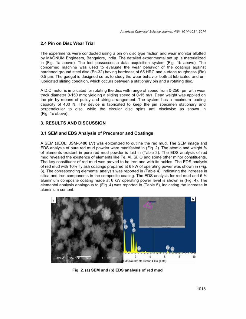
2.4 Pin on Disc Wear Trial
The experiments were conducted using a pin on disc type friction and wear monitor allottedby MAGNUM Engineers, Bangalore, India. The detailed experimental set up is materializedin (Fig. 1a above). The tool possesses a data acquisition system (Fig. 1b above). Theconcerned machine was used to evaluate the wear behavior of the coatings againsthardened ground steel disc (En-32) having hardness of 65 HRC and surface roughness (Ra)0.5 µm. The gadget is designed so as to study the wear behavior both at lubricated and un-lubricated sliding condition, which occurs between a stationary pin and a rotating disc.
A D.C motor is implicated for rotating the disc with range of speed from 0-250 rpm with weartrack diameter 0-150 mm; yielding a sliding speed of 0-15 m/s. Dead weight was applied onthe pin by means of pulley and string arrangement. The system has a maximum loadingcapacity of 400 N. The device is fabricated to keep the pin specimen stationary andperpendicular to disc, while the circular disc spins anti clockwise as shown in(Fig. 1c above).
3. RESULTS AND DISCUSSION
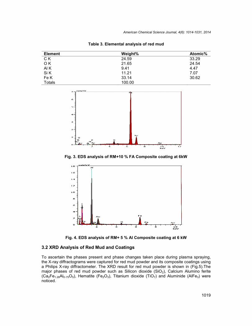
3.1 SEM and EDS Analysis of Precursor and Coatings
A SEM (JEOL; JSM-6480 LV) was epitomized to outline the red mud. The SEM image andEDS analysis of pure red mud powder were manifested in (Fig. 2). The atomic and weight %of elements existent in pure red mud powder is laid in (Table 3). The EDS analysis of redmud revealed the existence of elements like Fe, Al, Si, O and some other minor constituents.The key constituent of red mud was proved to be iron and with its oxides. The EDS analysisof red mud with 10% fly ash coatings prepared at 6 kW of operating power was shown in (Fig.3). The corresponding elemental analysis was reported in (Table 4), indicating the increase insilica and iron components in the composite coating. The EDS analysis for red mud and 5 %aluminium composite coating made at 6 kW operating power level is shown in (Fig. 4). Theelemental analysis analogous to (Fig. 4) was reported in (Table 5), indicating the increase inaluminium content.
Fig. 2. (a) SEM and (b) EDS analysis of red mud
American Chemical Science Journal, 4(6): 1014-1031, 2014
1019
Table 3. Elemental analysis of red mud
Element Weight% Atomic%C K 24.59 33.29O K 21.65 24.54Al K 9.41 4.47Si K 11.21 7.07Fe K 33.14 30.62Totals 100.00
Fig. 3. EDS analysis of RM+10 % FA Composite coating at 6kW
Fig. 4. EDS analysis of RM+ 5 % Al Composite coating at 6 kW
3.2 XRD Analysis of Red Mud and Coatings
To ascertain the phases present and phase changes taken place during plasma spraying,the X-ray diffractograms were captured for red mud powder and its composite coatings usinga Philips X-ray diffractometer. The XRD result for red mud powder is shown in (Fig.5).Themajor phases of red mud powder such as Silicon dioxide (SiO2), Calcium Alumino ferite(Ca2Fe1.28Al0.75O5), Hematite (Fe2O3), Titanium dioxide (TiO7) and Aluminide (AlFe3) werenoticed.

American Chemical Science Journal, 4(6): 1014-1031, 2014
1020
Table 4. Elemental analysis of RM+10 % FA Composite coated at 6 kW
Element Weight % Atomic %Fe K 38.13 25.90O K 21.74 42.61Ti K 14.02 9.18Si K 15.10 7.93Al K 6.59 7.66Cr K 2.14 1.29C K 1.99 5.20Ca K 0.29 0.22Au K 0.00 0.00Mg K 0.00 0.00Totals 100 % 100
Table 5. Elemental analysis of RM+5 % Al Composite coated at 6kW
Element Weight % Atomic %Fe K 39.13 26.89O K 22.74 41.61Ti K 9.00 9.18Si K 14.10 7.93Al K 11.61 5.46Cr K 1.14 2.39C K 1.99 5.20Ca K 0.29 0.22Au K 0.00 0.00Mg K 0.00 0.00Totals 100 % 100
Fig. 5. XRD of Red Mud Powder collected from NALCO
American Chemical Science Journal, 4(6): 1014-1031, 2014
1021
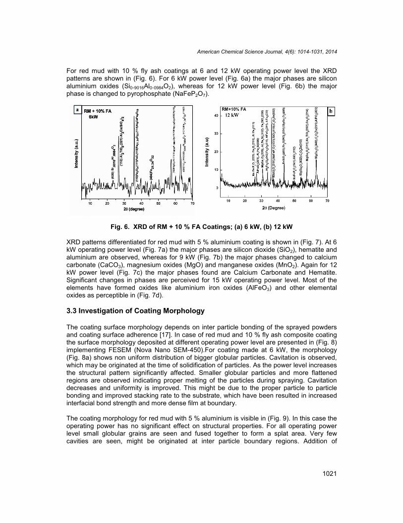
For red mud with 10 % fly ash coatings at 6 and 12 kW operating power level the XRDpatterns are shown in (Fig. 6). For 6 kW power level (Fig. 6a) the major phases are siliconaluminium oxides (Si0.9016Al0.0984O2), whereas for 12 kW power level (Fig. 6b) the majorphase is changed to pyrophosphate (NaFeP2O7).
Fig. 6. XRD of RM + 10 % FA Coatings; (a) 6 kW, (b) 12 kW
XRD patterns differentiated for red mud with 5 % aluminium coating is shown in (Fig. 7). At 6kW operating power level (Fig. 7a) the major phases are silicon dioxide (SiO2), hematite andaluminium are observed, whereas for 9 kW (Fig. 7b) the major phases changed to calciumcarbonate (CaCO3), magnesium oxides (MgO) and manganese oxides (MnO2). Again for 12kW power level (Fig. 7c) the major phases found are Calcium Carbonate and Hematite.Significant changes in phases are perceived for 15 kW operating power level. Most of theelements have formed oxides like aluminium iron oxides (AlFeO3) and other elementaloxides as perceptible in (Fig. 7d).
3.3 Investigation of Coating Morphology
The coating surface morphology depends on inter particle bonding of the sprayed powdersand coating surface adherence [17]. In case of red mud and 10 % fly ash composite coatingthe surface morphology deposited at different operating power level are presented in (Fig. 8)implementing FESEM (Nova Nano SEM-450).For coating made at 6 kW, the morphology(Fig. 8a) shows non uniform distribution of bigger globular particles. Cavitation is observed,which may be originated at the time of solidification of particles. As the power level increasesthe structural pattern significantly affected. Smaller globular particles and more flattenedregions are observed indicating proper melting of the particles during spraying. Cavitationdecreases and uniformity is improved. This might be due to the proper particle to particlebonding and improved stacking rate to the substrate, which have been resulted in increasedinterfacial bond strength and more dense film at boundary.
The coating morphology for red mud with 5 % aluminium is visible in (Fig. 9). In this case theoperating power has no significant effect on structural properties. For all operating powerlevel small globular grains are seen and fused together to form a splat area. Very fewcavities are seen, might be originated at inter particle boundary regions. Addition of

American Chemical Science Journal, 4(6): 1014-1031, 2014
1022
aluminium to red mud might have helped in joining of molten particles during in flighttraverse as aluminium remains in molten state for longer time after leaving plasma jet.
Fig. 7. XRD of Red Mud + 5 % Al; Coatings (a) 6 kW, (b) 9 kW, (c) 12 kW, (d) 15 kW
3.4 Investigation of Coating Thickness
Thickness of Red Mud + 5 % aluminium coatings on mild steel substrate are measured onpolished cross-sections of the samples using FESEM. Five readings were taken on eachsample and the values are averaged. The mean coating thickness is increased withoperating power. The minimum coating thickness is found to be 195 µm for 6 kW operatingpower. The maximum coating thickness is reported to be 873 µm for 15 kW power. Resultsare revealed in (Fig. 10). With increase in power level thermal flux increases, this increasesthe enthalpy of the system. When feed material passes through plasma most of theprecursor powder particles get melted and also some disintegrated which flies off. Themolten particles which are at much higher temperature when strikes the substrate getsplatted and deposition volume increases thereby causing the rise in coating thickness withpower. The influence of operating power level on coating thickness is graphicallyrepresented in (Fig. 11).

American Chemical Science Journal, 4(6): 1014-1031, 2014
1023
Fig. 8. Coating Morphology for RM + 10 % FA; (a) 6 kW, (b) 9 kW, (c) 12 kW (d) 15 kW
3.5 Diagnosis of Sliding Wear Rate
At incipient, the pin and disc surfaces are polished duly with emery papers for ensuring asmooth contact with coating samples. The wear tests were conducted as per ASTM G-99standard for different time range under un-lubricated (dry) condition in a normal laboratorycondition at ambience temperature and relative humidity. The specimens were weighedbefore and after each wear test by using electronic weighing machine with accuracy up tosecond decimal limit (0.001 mg). Specimens were taken care of in particular by cleaning withwoolen cloth to avoid entrapment of wear debris and to maintain a distinct wear mechanism.The specimens were cleaned with tetrachloroethylene solution before and after each test.Wear rate was expressed as mass loss (∆m) of the coated specimen after each test. Co-efficient of friction was assessed using the correlation F = µR [18];

American Chemical Science Journal, 4(6): 1014-1031, 2014
1024
Fig. 9. Coating Morphology for RM + 5 % Al; (a) 6 kW, (b) 9 kW, (c) 12 kW (d) 15 kW
Where F is frictional force in N. R is applied normal load in N. µ is co-efficient of friction. Thefrictional force (F) was quantified directly from the data acquisition tool in N at each timeintervals.
All wear experiments were carried out at a constant normal load of 20 N and a fixed speed of100 rpm (0.523 m/s).The track diameter was fixed at 100 mm. The total duration of slidingtime was retained according to the extent of coating layer occurrence. The minimum andmaximum duration of sliding time was 54 and 90 minutes respectively.
The first step of the experiment includes the sliding wear of pure red mud coatings fordifferent operating power level. Mass loss against sliding time is pictured in (Fig. 12). Thetotal duration of sliding time prevails up to 54 minute. At beginning, up to 6 minute amoderate mass loss was observed. Afterwards from 6 to 36 minute a steady mass loss wasdetected. Then the situation of constant mass loss initiates and titled as break-in phase. Thebreak-in phase continues up to end of the experiment.

American Chemical Science Journal, 4(6): 1014-1031, 2014
1025
Fig. 10. Snapshot of Coating thickness for RM + 5 % Al (a) 6 kW, (b) 9 kW, (c) 12 kW,(d) 15 kW
It is interesting to notice that the mass loss rate declines with increasing operating powerlevel up to 12 kW. This is the optimum power level in our experiment. For 15 kW power levelthe mass loss rate lies in between 9 and 12 kW. This is surprising and not obvious, may bedue to improper particle to particle bonding and poor stacking to the substrate which in turnlowered the hardness as well as density due to poor interfacial bond strength formation atborder line.
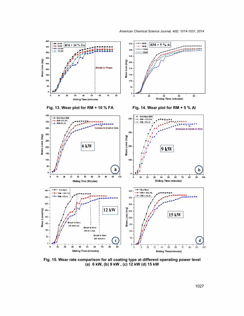
(Figs. 13 and 14) represents the mass loss against sliding time for Red Mud + 10 % FA andRed Mud + 5 % Al respectively considering all coating power level. The optimum power levelfor minimum mass loss lied as the same as earlier for all coating type. The results aredifferentiated by sliding time length and reaching the break-in phase in behind time. For RedMud + 10 % FA coating the sliding time prevailed up to 75 minute with break-in phaseslaunched at 54 minute. Whereas for Red Mud + 5 % Al coating the sliding time continued upto 90 minute and break-in phase originated at 66 minute.

American Chemical Science Journal, 4(6): 1014-1031, 2014
1026
Fig. 11. Graphical presentation of RM+5% Al composite coating thickness withoperating power
Fig. 12. Mass loss curves for red mud
American Chemical Science Journal, 4(6): 1014-1031, 2014
1027
Fig. 13. Wear plot for RM + 10 % FA Fig. 14. Wear plot for RM + 5 % Al
Fig. 15. Wear rate comparison for all coating type at different operating power level(a) 6 kW, (b) 9 kW , (c) 12 kW (d) 15 kW
American Chemical Science Journal, 4(6): 1014-1031, 2014
1028
The variation of wear rates (mass loss) for each coating type with sliding time werecompared for different operating power level in (Fig. 15 above). This prominently displays acomprehensive recognition to the readers. From the results it is obvious that a significantgrowth in wear resistance was contrived with fly ash and aluminium addition to red mudresulting in stronger interfacial bond strength and dense film formation at boundary layer.
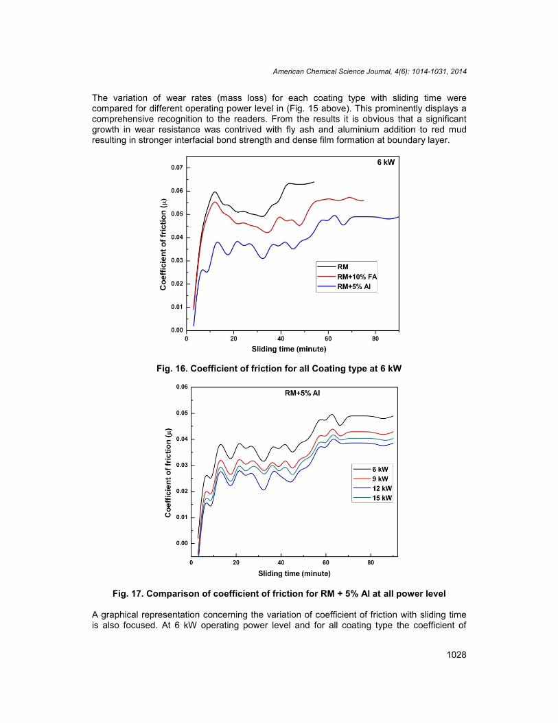
Fig. 16. Coefficient of friction for all Coating type at 6 kW
Fig. 17. Comparison of coefficient of friction for RM + 5% Al at all power level
A graphical representation concerning the variation of coefficient of friction with sliding timeis also focused. At 6 kW operating power level and for all coating type the coefficient of
American Chemical Science Journal, 4(6): 1014-1031, 2014
1029
friction plot is presented in (Fig.16 above). For all sliding time the coefficient of friction ismaximum for red mud and minimum for Red Mud + 5 % Al coating. At incipient, the frictionalvalues are extreme followed by a curly trend and finally static values. Frictional values arecompared for different operating power level for Red Mud + % 5 Al coating in (Fig. 17above). As like mass loss an optimum operating power level also observed for frictioncoefficient. The effectiveness of frictional force is maximum at 6 kW and minimum at 12 kWwas detected.
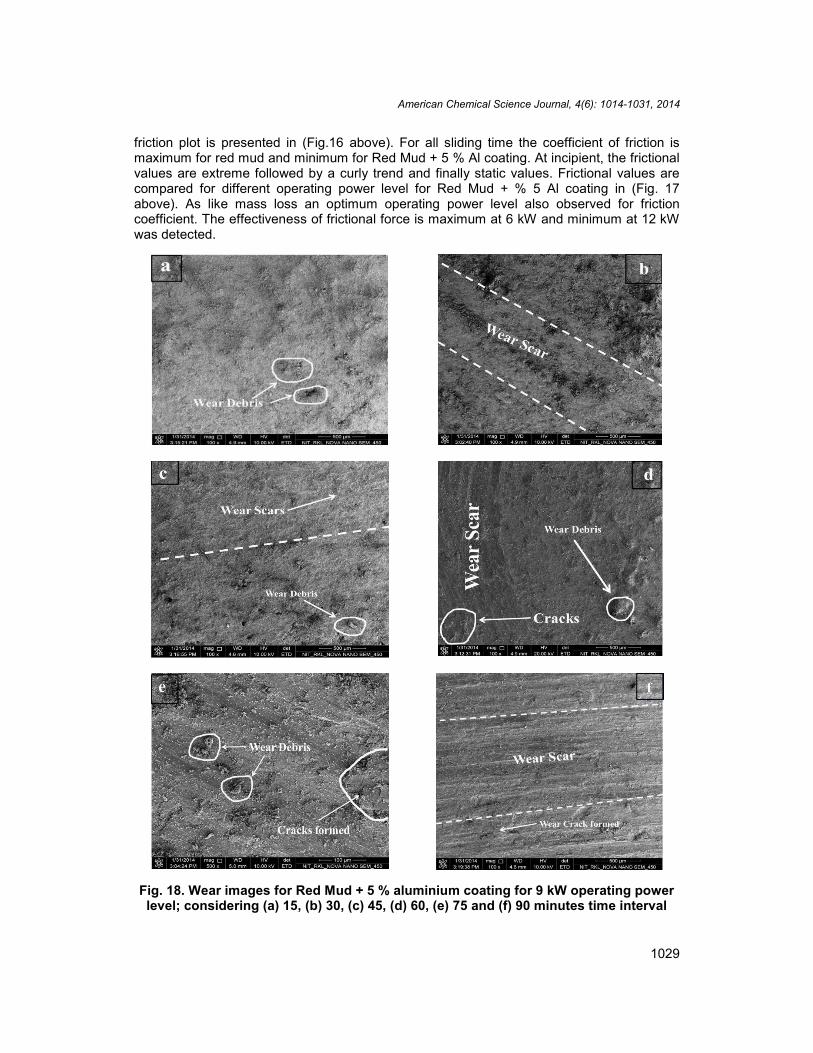
Fig. 18. Wear images for Red Mud + 5 % aluminium coating for 9 kW operating powerlevel; considering (a) 15, (b) 30, (c) 45, (d) 60, (e) 75 and (f) 90 minutes time interval
American Chemical Science Journal, 4(6): 1014-1031, 2014
1030
Wear morphology for designated coating samples were emphasized using FESEM. (Fig. 18above) illustrates the wear images for Red Mud + 5 % aluminium coating (for 9 kW operatingpower level) considering for time intervals of 15, 30, 45, 60, 75 and 90 minutes. Wear scars,debris and cracked sections formed are being visible. The wear morphology pattern modifieswith time impacting the surface roughness leading to interruption of its contact mechanism.The wear characteristics recasts due to variation of hardness of the inter layers with time.After the break-in phase, increase in sliding distance cannot reform the contact area causinga relatively steady wear rate. Hence it can be winded up that the wear takes place byabrasion and adhesion mechanism due to development of shear stress in between hardparticles of the two surfaces in contact. The same mechanism is relevant for all coating type.
4. CONCLUSION
The present experimental study remarks some noteworthy conclusions. Red mud, the wastegenerated from alumina plant is significantly coat able on mild steel using thermal plasmaspraying technique with acceptable wear resistance. Addition of fly ash and aluminium withred mud diminishes the wear rate by amplifying the coating mechanism. It is observed thatinitially the wear rate increases at a slow pace and then boosted up with sliding distance forall coating type and finally becomes still. Operating power level authenticates as remarkablevariable for coating property; which enriches the coating resistance, but eventually withreaching an optimum value indicating some other governing parameters. This work is aportfolio for future investigators to discover many other aspects of red mud and its compositecoatings. Thermal security of these coatings may be evaluated for better claiming in hightemperature applications. Corrosive wear behavior under different operating conditions maybe explored to identify suitable application areas. Post heat treatment of these coatings mayalso be fetched to study regarding the improvement in coating features.
COMPETING INTERESTS
Authors have declared that no competing interests exist.
REFERENCES
1. Kushner BA, Novinski ER. Thermal spray coating. ASM Hand book. 1992;18(829-833).
2. Crook P. Friction and wear of hard facing alloy. ASM Hand book. 1992;18:(758-765).3. Mishra SC, Das S, Satapathy Alok, Ananthapadmanabhan PV, Sreekumar KP.
Erosion wear analysis of plasma sprayed ceramic coating using the taguchi technique.Tribology Transactions. 2009;52(3):401-404.
4. Mantry S, Jha BB, Satapathy A. Evaluation and characterization of plasma sprayed cuslag-al composite coatings on metal substrates. Journal of Coatings. 2013;7:842-865.DOI: 10.1155/2013/842865.
5. Afzal M, Ajmal M, Khan AN. Wear behavior of WC-12% co coatings produced by airplasma spraying at different standoff distances. Tribology Transactions.2014;57(1):94-103.
6. Waynea SF, Sampath S, Anand V. Wear mechanisms in thermally sprayed mo-basedcoatings. Tribology Transactions. 1994;37(3):636-640.
7. Wang Y, Jin Y, Wen S. The analysis of the friction and wear mechanisms of plasma-sprayed coatings at 450°C. Wear. 1998;128:265–276.

American Chemical Science Journal, 4(6): 1014-1031, 2014
1031
8. Wang Y, Jin Y, Wen S. The analysis of the chemical structure and properties ofceramic surface films in friction using SEM, AES and Micro-region X-ray diffraction.Wear. 1998;128:277–290.
9. Wang Y, Jin Y, Wen S. The inspection of sliding surface and subsurface of plasma-sprayed using scanning acoustic microscopy. Wear. 1998;134:399–411.
10. Vijande-Diaz R, Belzunce J, Fernandez E, Rincon A, Pérez MC. Wear andmicrostructure in fine ceramic coatings. Wear. 1991;148:233–331.
11. Wei J, Xue Q. Effects of additives on friction and wear behaviour of Cr2O3 coatings.Wear. 1993;160:61–65.
12. Homberg K, Mathews A, Ronkainen H. Coatings tribology-contact mechanisms andsurface design. Tribology International. 1998;31(1-3):107-120.
13. Sutar H, Mishra SC, Sahoo SK, Chakraverty AP, Maharana HS. Progress of red mudutilization: An overview. American Chemical Science Journal. 2014;4(3):255-279.
14. Sutar H, Mishra SC, Sahoo SK, Satapathy A, Kumar V. Morphology and solid particleerosion wear behaviour of red mud composite coatings. Natural Science.2012;4(11):832-838.
15. Satapathy A, Sutar H, Mishra SC, Sahoo SK. Characterization of plasma sprayed purered mud coatings: An analysis. American Chemical Science Journal. 2013;3(2):151-163.
16. Prasad N, Sutar H, Mishra SC, Sahoo SK, Acharya SK. Dry sliding wear behavior ofaluminium matrix composite using red mud an industrial waste. International ResearchJournal of Pure and Applied Chemistry. 2013;3(1):59-74.
17. Satapathy A. Thermal spray coating of red mud on metals. PhD Thesis, NationalInstitute of Technology, Rourkela, Odisha, India; 2005.
18. Bolton W. Higher engineering science. Routledge, New York. 2011;78._________________________________________________________________________© 2014 Sutar et al.; This is an Open Access article distributed under the terms of the Creative Commons AttributionLicense (http://creativecommons.org/licenses/by/3.0), which permits unrestricted use, distribution, and reproductionin any medium, provided the original work is properly cited.
Peer-review history:The peer review history for this paper can be accessed here:
http://www.sciencedomain.org/review-history.php?iid=528&id=16&aid=5884